program educational objectives and program outcomes m.e
TRANSCRIPT
1
Program Educational Objectives and Program Outcomes
M.E. (CAD/CAM Engg.) Program
Program Educational Objectives:
To impart fundamental knowledge to students in the latest technological topics on
Computer Aided Design, Computer Aided Manufacturing and Computer Aided
Engineering Analysis and to prepare them for taking up further research in the areas.
To create congenial environment that promotes learning, growth and imparts ability to
work with inter-disciplinary groups in professional, industry and research organizations.
To broaden and deepen their capabilities in analytical and experimental research
methods, analysis of data, and drawing relevant conclusions for scholarly writing and
presentation.
To provide guidance to students for their choices in research and professional career
outlook and to encourage students to take up research.
Program Outcomes:
At the completion of the M.E. program in CAD/CAM Engineering, the student will be able to
Apply/develop solutions or to do research in the areas of Design and simulation in
Mechanical Engineering.
Have abilities and capabilities in developing and applying computer software and
hardware to mechanical design and manufacturing fields.
Review and document the knowledge developed by scholarly predecessors and critically
assess the relevant technological issues.
Formulate relevant research problems; conduct experimental and/or analytical study and
analyzing results with modern mathematical / scientific methods and use of software
tools.
Design and validate technological solutions to defined problems and communicate
clearly and effectively for the practical application of their work.
2
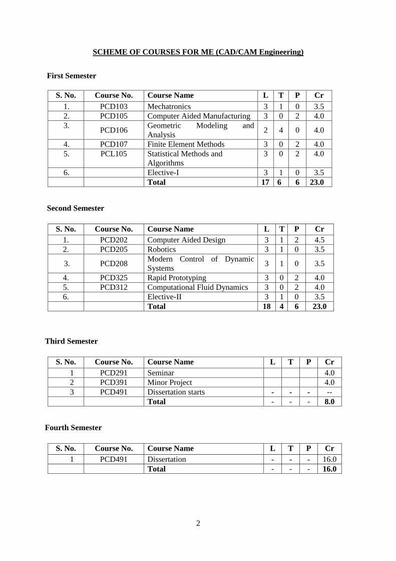
SCHEME OF COURSES FOR ME (CAD/CAM Engineering)
First Semester
S. No. Course No. Course Name L T P Cr
1. PCD103 Mechatronics 3 1 0 3.5
2. PCD105 Computer Aided Manufacturing 3 0 2 4.0
3. PCD106
Geometric Modeling and
Analysis 2 4 0 4.0
4. PCD107 Finite Element Methods 3 0 2 4.0
5. PCL105 Statistical Methods and
Algorithms
3 0 2 4.0
6. Elective-I 3 1 0 3.5
Total 17 6 6 23.0
Second Semester
S. No. Course No. Course Name L T P Cr
1. PCD202 Computer Aided Design 3 1 2 4.5
2. PCD205 Robotics 3 1 0 3.5
3. PCD208 Modern Control of Dynamic
Systems 3 1 0 3.5
4. PCD325 Rapid Prototyping 3 0 2 4.0
5. PCD312 Computational Fluid Dynamics 3 0 2 4.0
6. Elective-II 3 1 0 3.5
Total 18 4 6 23.0
Third Semester
S. No. Course No. Course Name L T P Cr
1 PCD291 Seminar 4.0
2 PCD391 Minor Project 4.0
3 PCD491 Dissertation starts - - - --
Total - - - 8.0
Fourth Semester
S. No. Course No. Course Name L T P Cr
1 PCD491 Dissertation - - - 16.0
Total - - - 16.0
3
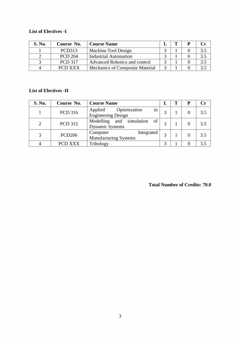
List of Electives -I
S. No. Course No. Course Name L T P Cr
1 PCD313 Machine Tool Design 3 1 0 3.5
2 PCD 204 Industrial Automation 3 1 0 3.5
3 PCD 317 Advanced Robotics and control 3 1 0 3.5
4 PCD XXX Mechanics of Composite Material 3 1 0 3.5
List of Electives -II
S. No. Course No. Course Name L T P Cr
1 PCD 316 Applied Optimization in
Engineering Design 3 1 0 3.5
2 PCD 315 Modelling and simulation of
Dynamic Systems 3 1 0 3.5
3 PCD206 Computer Integrated
Manufacturing Systems 3 1 0 3.5
4 PCD XXX Tribology 3 1 0 3.5
Total Number of Credits: 70.0
4
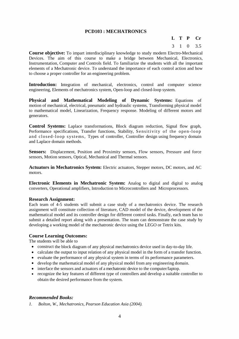
PCD103 : MECHATRONICS
L T P Cr
3 1 0 3.5
Course objective: To impart interdisciplinary knowledge to study modern Electro-Mechanical
Devices. The aim of this course to make a bridge between Mechanical, Electronics,
Instrumentation, Computer and Controls field. To familiarize the students with all the important
elements of a Mechatronic device. To understand the importance of each control action and how
to choose a proper controller for an engineering problem.
Introduction: Integration of mechanical, electronics, control and computer science
engineering, Elements of mechatronics system, Open-loop and closed-loop system.
Physical and Mathematical Modeling of Dynamic Systems: Equations of motion of mechanical, electrical, pneumatic and hydraulic systems, Transforming physical model
to mathematical model, Linearization, Frequency response. Modeling of different motors and
generators.
Control Systems: Laplace transformations, Block diagram reduction, Signal flow graph,
Performance specifications, Transfer functions, Stability, Sens i t i v i t y o f the open -loop
and c losed - loop sys t ems , Types of controller, Controller design using frequency domain
and Laplace domain methods.
Sensors: Displacement, Position and Proximity sensors, Flow sensors, Pressure and force
sensors, Motion sensors, Optical, Mechanical and Thermal sensors.
Actuators in Mechatronics System: Electric actuators, Stepper motors, DC motors, and AC
motors.
Electronic Elements in Mechatronic System: Analog to digital and digital to analog
converters, Operational amplifiers, Introduction to Microcontrollers and Microprocessors.
Research Assignment: Each team of 4-5 students will submit a case study of a mechatronics device. The research
assignment will constitute collection of literature, CAD model of the device, development of the
mathematical model and its controller design for different control tasks. Finally, each team has to
submit a detailed report along with a presentation. The team can demonstrate the case study by
developing a working model of the mechatronic device using the LEGO or Tetrix kits.
Course Learning Outcomes: The students will be able to
construct the block diagram of any physical mechatronics device used in day-to-day life.
calculate the output to input relation of any physical model in the form of a transfer function.
evaluate the performance of any physical system in terms of its performance parameters.
develop the mathematical model of any physical model from any engineering domain.
interface the sensors and actuators of a mechatronic device to the computer/laptop.
recognize the key features of different type of controllers and develop a suitable controller to
obtain the desired performance from the system.
Recommended Books:
1. Bolton, W., Mechatronics, Pearson Education Asia (2004).
5
2. Anslander, D. M. and Kampf, C. J., Mechatronics: Mechanical System Interfacing,
Prantice Hall (1995).
3. Kamm, L. J., Understanding Electro-Mechanical Engineering, An Introduction to
Mechatronics, Prantice Hall of India (2000).
4. Alciatore, D. G. and Histand, M. B., Introduction to Mechatronics and Measurement
System, McGraw Hill (1999).
5. Doebelin, E.O., Measurement Systems, Application & Design, McGraw Hill (2004).
6. Nagrath, I. J. and Gopal, M., Control System Engineering, New Age International (2008).
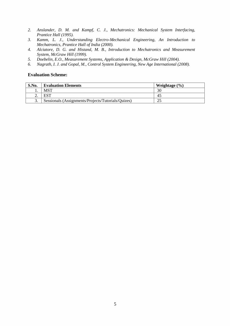
Evaluation Scheme:
S.No. Evaluation Elements Weightage (%)
1. MST 30
2. EST 45
3. Sessionals (Assignments/Projects/Tutorials/Quizes) 25
6
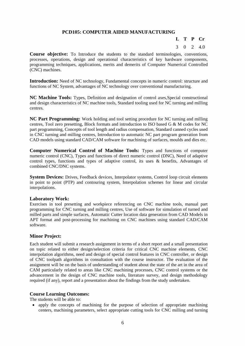
PCD105: COMPUTER AIDED MANUFACTURING
L T P Cr
3 0 2 4.0
Course objective: To Introduce the students to the standard terminologies, conventions,
processes, operations, design and operational characteristics of key hardware components,
programming techniques, applications, merits and demerits of Computer Numerical Controlled
(CNC) machines.
Introduction: Need of NC technology, Fundamental concepts in numeric control: structure and
functions of NC System, advantages of NC technology over conventional manufacturing.
NC Machine Tools: Types, Definition and designation of control axes,Special constructional
and design characteristics of NC machine tools, Standard tooling used for NC turning and milling
centres.
NC Part Programming: Work holding and tool setting procedure for NC turning and milling
centres, Tool zero presetting, Block formats and introduction to ISO based G & M codes for NC
part programming, Concepts of tool length and radius compensation, Standard canned cycles used
in CNC turning and milling centres, Introduction to automatic NC part program generation from
CAD models using standard CAD/CAM software for machining of surfaces, moulds and dies etc.
Computer Numerical Control of Machine Tools: Types and functions of computer
numeric control (CNC), Types and functions of direct numeric control (DNC), Need of adaptive
control types, functions and types of adaptive control, its uses & benefits, Advantages of
combined CNC/DNC systems.
System Devices: Drives, Feedback devices, Interpolator systems, Control loop circuit elements
in point to point (PTP) and contouring system, Interpolation schemes for linear and circular
interpolations.
Laboratory Work: Exercises in tool presetting and workpiece referencing on CNC machine tools, manual part
programming for CNC turning and milling centres, Use of software for simulation of turned and
milled parts and simple surfaces, Automatic Cutter location data generation from CAD Models in
APT format and post-processing for machining on CNC machines using standard CAD/CAM
software.
Minor Project:
Each student will submit a research assignment in terms of a short report and a small presentation
on topic related to either design/selection criteria for critical CNC machine elements, CNC
interpolation algorithms, need and design of special control features in CNC controller, or design
of CNC toolpath algorithms in consultation with the course instructor. The evaluation of the
assignment will be on the basis of understanding of student about the state of the art in the area of
CAM particularly related to areas like CNC machining processes, CNC control systems or the
advancement in the design of CNC machine tools, literature survey, and design methodology
required (if any), report and a presentation about the findings from the study undertaken.
Course Learning Outcomes: The students will be able to:
apply the concepts of machining for the purpose of selection of appropriate machining
centers, machining parameters, select appropriate cutting tools for CNC milling and turning
7
equipment, set-up, program, and operate CNC milling and turning equipment.
create and validate NC part program data using manual data input (MDI) and automatically
using standard commercial CAM package for manufacturing of required component using
CNC milling or turning applications.
produce an industrial component by interpreting 3D part model/ part drawings using
Computer Aided Manufacturing technology through programming, setup, and ensuring safe
operation of Computer Numerical Control (CNC) machine tools.
create and demonstrate the technical documentation for design/ selection of suitable drive
technologies, precision components and an overall CNC machine tool system for automation
of machining operations using appropriate multi-axis CNC technology.
Recommended Books:
1. Koren, Y., Computer Control of Manufacturing systems, McGraw Hill (2009).
2. Suh Suk-Hwan, Kang Seong-Kyoon, Chung Dae-Hyuk, Stroud Ian., Theory and Design of
CNC Systems, 2008, Springer-Verlag London Limited
3. Smith Peter, CNC programming handbook, 2nd edition, 2003, Industrial Press Inc.
4. Groover, M. P. and Zimmers, E. W., CAD/CAM:Computer Aided Design & Manufacturing,
2006, Pearson Education India
5. Hood-Daniel P., and Kelly J.F., Build Your Own CNC Machine, 2009, Springer-Verlag New
York
6. Manuals of CAD/CAM Software Package on CAM Module and CNC Machines.
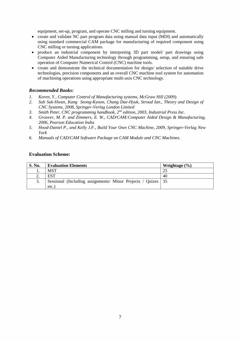
Evaluation Scheme:
S. No. Evaluation Elements Weightage (%)
1. MST 25
2. EST 40
3. Sessional (Including assignments/ Minor Projects / Quizes
etc.)
35
8
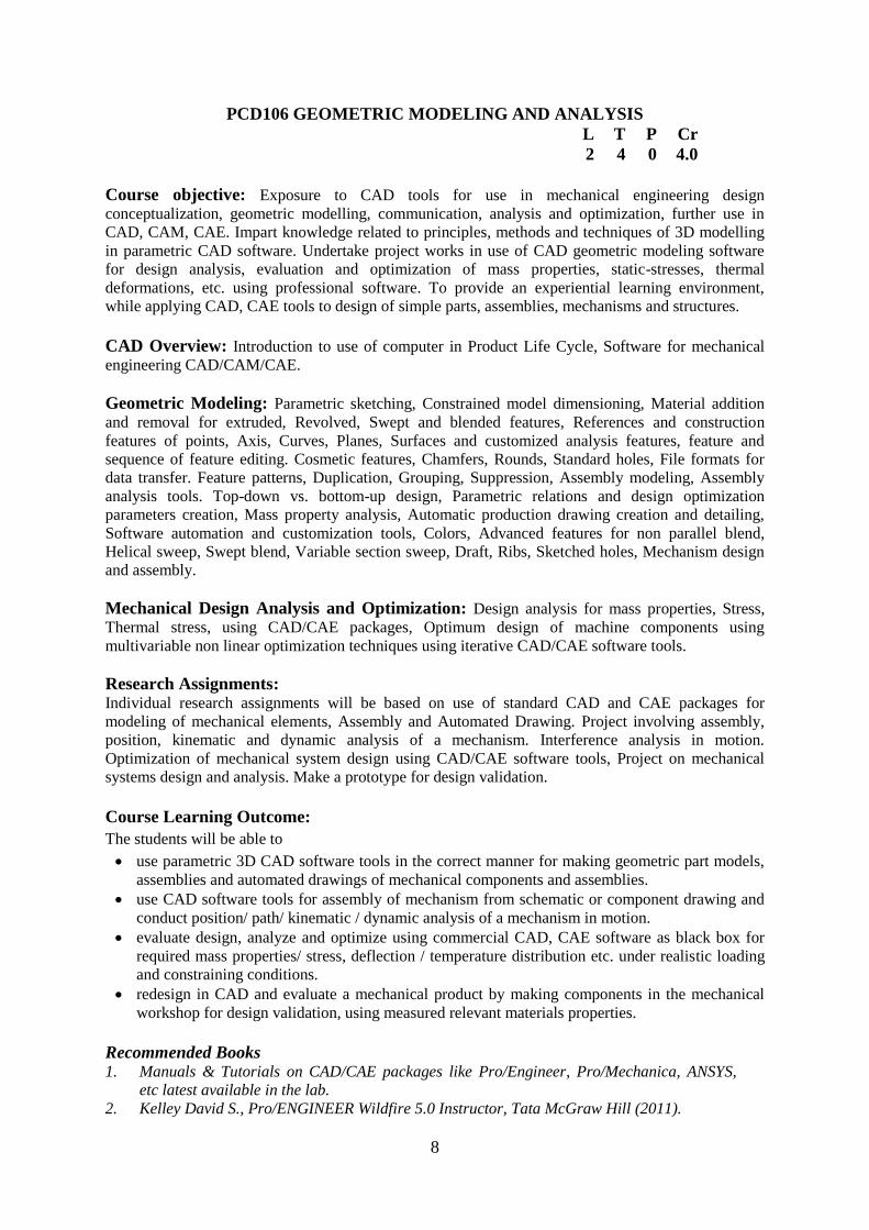
PCD106 GEOMETRIC MODELING AND ANALYSIS
L T P Cr
2 4 0 4.0
Course objective: Exposure to CAD tools for use in mechanical engineering design
conceptualization, geometric modelling, communication, analysis and optimization, further use in
CAD, CAM, CAE. Impart knowledge related to principles, methods and techniques of 3D modelling
in parametric CAD software. Undertake project works in use of CAD geometric modeling software
for design analysis, evaluation and optimization of mass properties, static-stresses, thermal
deformations, etc. using professional software. To provide an experiential learning environment,
while applying CAD, CAE tools to design of simple parts, assemblies, mechanisms and structures.
CAD Overview: Introduction to use of computer in Product Life Cycle, Software for mechanical
engineering CAD/CAM/CAE.
Geometric Modeling: Parametric sketching, Constrained model dimensioning, Material addition
and removal for extruded, Revolved, Swept and blended features, References and construction
features of points, Axis, Curves, Planes, Surfaces and customized analysis features, feature and
sequence of feature editing. Cosmetic features, Chamfers, Rounds, Standard holes, File formats for
data transfer. Feature patterns, Duplication, Grouping, Suppression, Assembly modeling, Assembly
analysis tools. Top-down vs. bottom-up design, Parametric relations and design optimization
parameters creation, Mass property analysis, Automatic production drawing creation and detailing,
Software automation and customization tools, Colors, Advanced features for non parallel blend,
Helical sweep, Swept blend, Variable section sweep, Draft, Ribs, Sketched holes, Mechanism design
and assembly.
Mechanical Design Analysis and Optimization: Design analysis for mass properties, Stress,
Thermal stress, using CAD/CAE packages, Optimum design of machine components using
multivariable non linear optimization techniques using iterative CAD/CAE software tools.
Research Assignments: Individual research assignments will be based on use of standard CAD and CAE packages for
modeling of mechanical elements, Assembly and Automated Drawing. Project involving assembly,
position, kinematic and dynamic analysis of a mechanism. Interference analysis in motion.
Optimization of mechanical system design using CAD/CAE software tools, Project on mechanical
systems design and analysis. Make a prototype for design validation.
Course Learning Outcome:
The students will be able to
use parametric 3D CAD software tools in the correct manner for making geometric part models,
assemblies and automated drawings of mechanical components and assemblies.
use CAD software tools for assembly of mechanism from schematic or component drawing and
conduct position/ path/ kinematic / dynamic analysis of a mechanism in motion.
evaluate design, analyze and optimize using commercial CAD, CAE software as black box for
required mass properties/ stress, deflection / temperature distribution etc. under realistic loading
and constraining conditions.
redesign in CAD and evaluate a mechanical product by making components in the mechanical
workshop for design validation, using measured relevant materials properties.
Recommended Books 1. Manuals & Tutorials on CAD/CAE packages like Pro/Engineer, Pro/Mechanica, ANSYS,
etc latest available in the lab.
2. Kelley David S., Pro/ENGINEER Wildfire 5.0 Instructor, Tata McGraw Hill (2011).

9
3. Shih Randy H., Introduction to Finite Element Analysis Using Creo Simulate 1.0, SDC
Publications, USA (2011, ISBN: 978-1-58503-670-7, ISBN (Book + Software on Disk): 978-
1-58503-731-5
4. Toogood Roger Ph.D., P. Eng., Zecher Jack P.E., Creo Parametric 1.0 Tutorial and
MultiMedia DVD, SDC Publications, USA (2012), ISBN: 978-1-58503-692-9, ISBN (Book
+ Software on Disk): 978-1-58503-730-8
5. Shih Randy H., Parametric Modeling with Creo Parametric 1.0-An Introduction to Creo
Parametric 1.0, SDC Publications, USA (2011) ISBN: 978-1-58503-661-5, ISBN (Book +
Software on Disk): 978-1-58503-729-2
6. Sidheswar, N., Kannaiah, P. and Sastry, V. V. S., Machine Drawing, McGraw Hill (2001).
7. Shigley, J. E., Mechanical Engg. Design, McGraw Hill (2008).
8. Spotts, M. F. and Shoup, T. E., Design of Machine Elements, Dolly Kindersley (2006).
Evaluation Scheme:
S.No. Evaluation Elements Weightage (%)
1. MST (Formal Test on Software) 25
2. EST (Formal Test on Software) 35
3. Sessionals
Research Projects (Presentation of CAD CAE, Prototype, Technical
Report)
40
10
PCD107 FINITE ELEMENT METHODS
L T P Cr
3 0 2 4.0
Course objective: To develop the skills needed to apply Finite Element Methods to problems
in Mechanical Engineering.
Approximate Solution Methods: Finite Difference Method, Finite Element Methods, Ritz
and Rayleigh Ritz methods, Method of weighed residuals, General concepts, Point collocation,
Subdomain collocation, Least squares, Galerkin method.
Introduction to Finite Element Method: Introduction to variational calculus, The
differential of a function, Euler-Lagrange equation, Geometric & natural boundary conditions,
Basic Concept of Finite Element Method, Principle of potential energy, 1D elements, Derivation
of Stiffness and Mass matrices for a bar, A beam and A shaft, Comparison with Analytical
results, Interpolation and shape functions, Solution of static problems and case studies in stress
analysis of mechanical components, FEA using 2D and 3D elements, Plain strain and plain stress
problems, FE using plates / shell elements, analysis using Isoparametric Elements.
Laboratory Work:
Programming of the different concepts covered in lectures using C++/MATLAB language,
demonstration of analysis software for finite element analysis.
Minor Project:
Students will be given different 2D /3D components for structural/thermal/ fluid flow FEM
analysis to be done using C++/MATLAB programming. The components are to be analyzed
using different linear / higher order elements i.e., triangular, axisymmetric, quadrilateral,
tetrahedral and hexahedral elements.
Course Learning Outcomes: The students will be able to
apply the procedure involved to solve a problem using Finite Element Methods.
develop the element stiffness matrices using different approach.
analyze a 2D problem using line, triangular, axisymmetric and quadrilateral element.
analyze a 3D problem using tetrahedral and hexahedral elements.
Recommended Books:
1. Zienkiewicz, O. C., The Finite Element Method, Butterworth Heinemann (2002).
2. Huebner, K. H., Dewhirst, D. L., Smith, D. E. and Byrom, T. G., The Finite Element
Methods for Engineers, John Wiley (2000).
3. Reddy, J. N., An Introduction to the Finite Element Method, McGraw Hill (2001).
4. Bathe, K. J., Finite Element Procedures, Prentice Hall of India (2008).
5. Cook, R. D., Concepts and Applications of Finite Element Analysis, John Wiley and Sons
(2001).
6. Buchman, G. R., Finite Element Analysis, Schaum’s Outlines, McGraw Hill (1995).
7. Chandrupatla, T. R. and Belgundu, A. D., Introduction to Finite Elements in Engineering,
Prentice Hall of India (1997).
8. Jordan, C. Calculus of Finite Differences, American Mathematical Society (1979).

11
Evaluation Scheme:
S.No. Evaluation Elements Weightage (%)
1. MST 25
2. EST 40
3. Sessionals ( Lab Evaluations/ Quizzes/ Minor Projects) 35
12
PCD202 COMPUTER AIDED DESIGN
L T P Cr
3 1 2 4.5
Course objective: To impart the parametric fundamentals to create and manipulate geometric
models using curves, surfaces and solids.
Introduction: Definition and scope of CAD/CAM, Introduction to design process and role of
computers in the design process.
Transformations: 2D and 3D transformations.
Curves and Surfaces: Analytical, Synthetic curves with advantages, Disadvantages,
Comparison with parametric curves, Geometric modeling curves and surfaces, Representation,
Wire frame models, Parametric representations, Parametric curves and surfaces, Manipulations of
curves and surfaces, DDA, Bresenham’s /Mid point line, circle, ellipse algorithms.
Solid modeling: Solid models, Fundamentals of solid modeling, Different solid representation
schemes, Half -spaces, Boundary representation (B-rep), Constructive solid geometry (CSG),
Sweep representation, Analytic solid modeling, Perspective, Parallel projection, Hidden line
removal algorithms.
CAD/CAM Data Exchange Formats: Types of file formats & their exchange, Graphics
standards.
Laboratory Work:
Graphics programming in C++/MATLAB for geometric modeling of different Curves, Surfaces
and Solid primitives. The generated geometric models will have the capability to be modified as
per the user’s requirements.
Minor Project:
Students will be given different 2D/3D shapes to be generated by graphics programming in
C++/MATLAB using surface and solid modeling schemes. Students can also be given projects
based on geometric modeling in Rapid Prototyping.
Course Learning Outcomes: The students will be able to
create the different wireframe primitives using parametric representations.
create surface primitives using parametric modeling.
create the different solid primitives using the different representation schemes.
apply geometric transformations on the created wireframe, surface and solid models.
Recommended Books
1. Zeid, I., CAD/CAM, McGraw Hill (2008).
2. Rogers, D. F. and Adams, J. A., Mathematical Elements for Computer Graphics, McGraw
Hill (1989).
3. Rogers, D. F., Procedural Elements for Computer Graphics, McGraw Hill (2008).
4. Rooney, J. and Steadman, P., Principles of Computer Aided Design, prentice Hall (1988).
5. Rooney, J. and Steadman, P., Computer Aided Design, Pitman/Open University (1987).
6. Mallineuse, G., Computational Concepts and Methods, Kogan Page Ltd. (1986).
13
7. Rayan, D. L., Computer Aided Graphical Design, Marcel Dekker (1981).
8. Radhakrishnan, P. and Kothandaraman, C. P., Computer Graphics & Design, Dhanpat Rai
Publication (2005).
9. Krishnamoorathy, C. S. and Rajeev, J. S., Computer Aided Design (Software and Analysis
Tools), Narosa Publication House (2005).
Evaluation Scheme:
S.No. Evaluation Elements Weightage (%)
1. MST 25
2. EST 35
3. Sessionals ( Tutorial/ Lab Evaluations/ Quizzes/ Minor
Projects)
40
14
PCD205 : ROBOTICS
L T P Cr
3 1 0 3.5
Course objective: To introduce the students to the standard terminologies, applications, design
specifications, and mechanical design aspects both kinematics, Trajectory planning, work cell
control and dynamics of industrial robotic manipulators
Introduction: Definition of robot, types and classifications, standard terminologies related to
robotics, key design specifications used for selection of robotic manipulators for various
applications, robotic applications in modern automated industries, research and non-industrial
environments.
Robot Kinematics: Homogeneous co-ordinates and co-ordinate transformations, Forward and
inverse kinematics for serial robotic manipulators.
Robot Dynamics: Introduction to Lagrangian and Newton-Euler formulations for serial robotic
manipulators.
Robot in Work Place: Robot Trajectory planning considering velocity and acceleration. Work
cell organization in robotics environment, Work cell design and control, Introduction to robot
vision and image processing.
Laboratory Work: Exercises in programming of robots, Exercises in design and layout of robot workplace.
Research Assignment: Each student will submit a research assignment based on design of 4 to 6 degrees of freedom
robotic arm designed by him using available CAD tool. Assignment will constitute collection of
literature, 3D CAD modelling, verification of robot design in mechanism design module of 3D
CAD package to define the work envelop of the robotic arm, creation of 2D drawings of the
various parts required to fabricate the robot and implementation of inverse kinematics algorithm
of the selected robot design using a suitable programming environment like MATLAB, VC++ or
MathCAD.
Course Learning Outcomes: Students will be able to:
apply the concepts of coordinate transformations for development of arm equation and
subsequently the inverse kinematics model for given serial manipulator.
apply the concepts of robotic workspace analysis for design of robotic manipulator for
required work cell applications.
design and analyze the workcell environment for given robotic manipulator configuration
and workcell devices for required integrated industrial application.
develop and analyze the mathematical model for trajectory planning, resolved motion rate
control and dynamics model for a given serial robotic manipulator.
develop the algorithms for design of robotic work cell controller and its programming for
given serial robotic manipulator.
Recommended Books:
1. Schilling, R.J., Fundamentals of Robotics Analysis and Control, Prentice Hall of India
(2006).
15
2. Fu, K.S., Gonzalez, R.C. and Lee, C.S.G., Robotics: Control, Sensing, Vision, and
Intelligence, McGraw Hill (1987).
3. Craig, J.J., Introduction to Robotics: Mechanics and Control, prentice Hall (2004).
4. Deb, S.R., Robotics and Flexible Automation, McGraw Hill (2004).
5. Saha, S.K., Introduction to Robotics, McGraw Hill (2008).
6. Niku, S.B., Introduction to Robotics: Analysis, system, application, Dorling kingsley (2006).
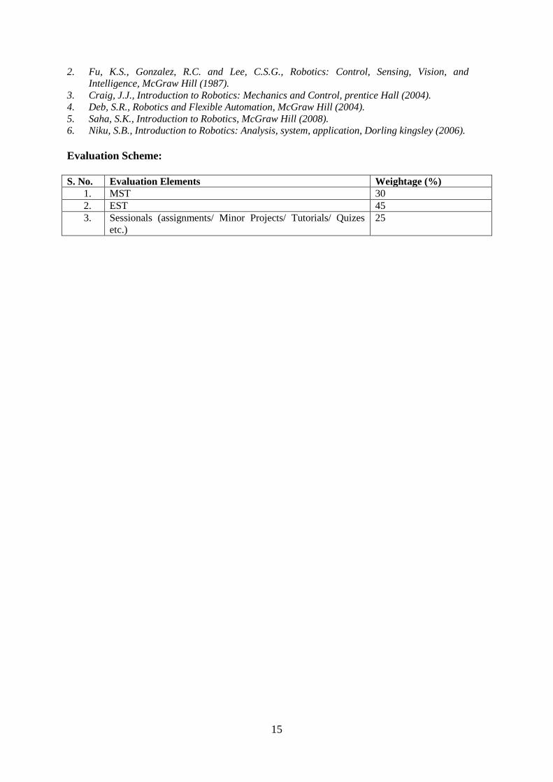
Evaluation Scheme:
S. No. Evaluation Elements Weightage (%)
1. MST 30
2. EST 45
3. Sessionals (assignments/ Minor Projects/ Tutorials/ Quizes
etc.)
25
16
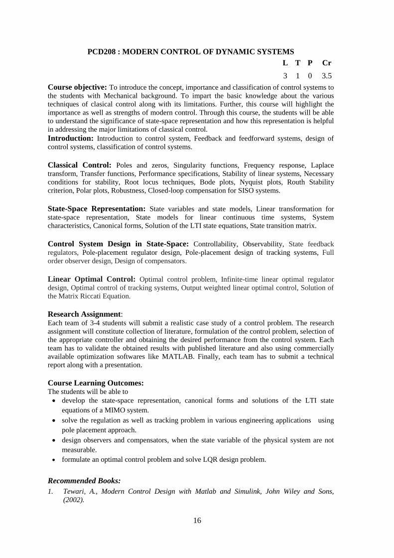
PCD208 : MODERN CONTROL OF DYNAMIC SYSTEMS
L T P Cr
3 1 0 3.5
Course objective: To introduce the concept, importance and classification of control systems to
the students with Mechanical background. To impart the basic knowledge about the various
techniques of clasical control along with its limitations. Further, this course will highlight the
importance as well as strengths of modern control. Through this course, the students will be able
to understand the significance of state-space representation and how this representation is helpful
in addressing the major limitations of classical control.
Introduction: Introduction to control system, Feedback and feedforward systems, design of
control systems, classification of control systems.
Classical Control: Poles and zeros, Singularity functions, Frequency response, Laplace
transform, Transfer functions, Performance specifications, Stability of linear systems, Necessary
conditions for stability, Root locus techniques, Bode plots, Nyquist plots, Routh Stability
criterion, Polar plots, Robustness, Closed-loop compensation for SISO systems.
State-Space Representation: State variables and state models, Linear transformation for
state-space representation, State models for linear continuous time systems, System
characteristics, Canonical forms, Solution of the LTI state equations, State transition matrix.
Control System Design in State-Space: Controllability, Observability, State feedback
regulators, Pole-placement regulator design, Pole-placement design of tracking systems, Full
order observer design, Design of compensators.
Linear Optimal Control: Optimal control problem, Infinite-time linear optimal regulator
design, Optimal control of tracking systems, Output weighted linear optimal control, Solution of
the Matrix Riccati Equation.
Research Assignment: Each team of 3-4 students will submit a realistic case study of a control problem. The research
assignment will constitute collection of literature, formulation of the control problem, selection of
the appropriate controller and obtaining the desired performance from the control system. Each
team has to validate the obtained results with published literature and also using commercially
available optimization softwares like MATLAB. Finally, each team has to submit a technical
report along with a presentation.
Course Learning Outcomes: The students will be able to
develop the state-space representation, canonical forms and solutions of the LTI state
equations of a MIMO system.
solve the regulation as well as tracking problem in various engineering applications using
pole placement approach.
design observers and compensators, when the state variable of the physical system are not
measurable.
formulate an optimal control problem and solve LQR design problem.
Recommended Books:
1. Tewari, A., Modern Control Design with Matlab and Simulink, John Wiley and Sons,
(2002).

17
2. Ogata, K., Modern Control Engineering, Prentice Hall of India Pvt. Ltd., 2010.
3. Nagrath, I. J. and Gopal, M, Control Systems Engineering, New Age International
Publishers, (2006).
4. Kuo, B. C., Digital Control Systems, Oxford University Press, (2006).
5. Richard C. Dorf and Robert H. Bishop, Modern Control Systems, Pearson, (2011).
Evaluation Scheme:
S.No. Evaluation Elements Weightage (%)
1. MST 30
2. EST 45
3. Sessionals (Assignments/Projects/Tutorials/Quizes) 25
18
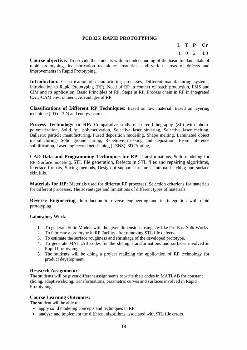
PCD325: RAPID PROTOTYPING
L T P Cr
3 0 2 4.0
Course objective: To provide the students with an understanding of the basic fundamentals of
rapid prototyping, its fabrication techniques, materials and various areas of defects and
improvements in Rapid Prototyping.
Introduction: Classification of manufacturing processes, Different manufacturing systems,
Introduction to Rapid Prototyping (RP), Need of RP in context of batch production, FMS and
CIM and its application; Basic Principles of RP, Steps in RP, Process chain in RP in integrated
CAD-CAM environment, Advantages of RP.
Classifications of Different RP Techniques: Based on raw material, Based on layering
technique (2D or 3D) and energy sources.
Process Technology in RP: Comparative study of stereo-lithography (SL) with photo-
polymerization, Solid foil polymerization, Selective laser sintering, Selective laser melting,
Ballastic particle manufacturing, Fused deposition modeling, Shape melting, Laminated object
manufacturing, Solid ground curing, Repetitive masking and deposition, Beam inference
solidification, Laser engineered net shaping (LENS), 3D Printing,
CAD Data and Programming Techniques for RP: Transformations, Solid modeling for
RP, Surface modeling, STL file generation, Defects in STL files and repairing algorithms, Interface formats, Slicing methods, Design of support structures, Internal hatching and surface
skin fills.
Materials for RP: Materials used for different RP processes, Selection criterions for materials
for different processes, The advantages and limitations of different types of materials.
Reverse Engineering: Introduction to reverse engineering and its integration with rapid
prototyping.
Laboratory Work:
1. To generate Solid Models with the given dimensions using s/w like Pro-E or SolidWorks.
2. To fabricate a prototype in RP Facility after removing STL file defects.
3. To estimate the surface roughness and shrinkage of the developed prototype.
4. To generate MATLAB codes for the slicing, transformations and surfaces involved in
Rapid Prototyping.
5. The students will be doing a project realizing the application of RP technology for
product development.
Research Assignment: The students will be given different assignments to write their codes in MATLAB for constant
slicing, adaptive slicing, transformations, parametric curves and surfaces involved in Rapid
Prototyping.
Course Learning Outcomes: The student will be able to:
apply solid modeling concepts and techniques in RP.
analyze and implement the different algorithms associated with STL file errors.
19
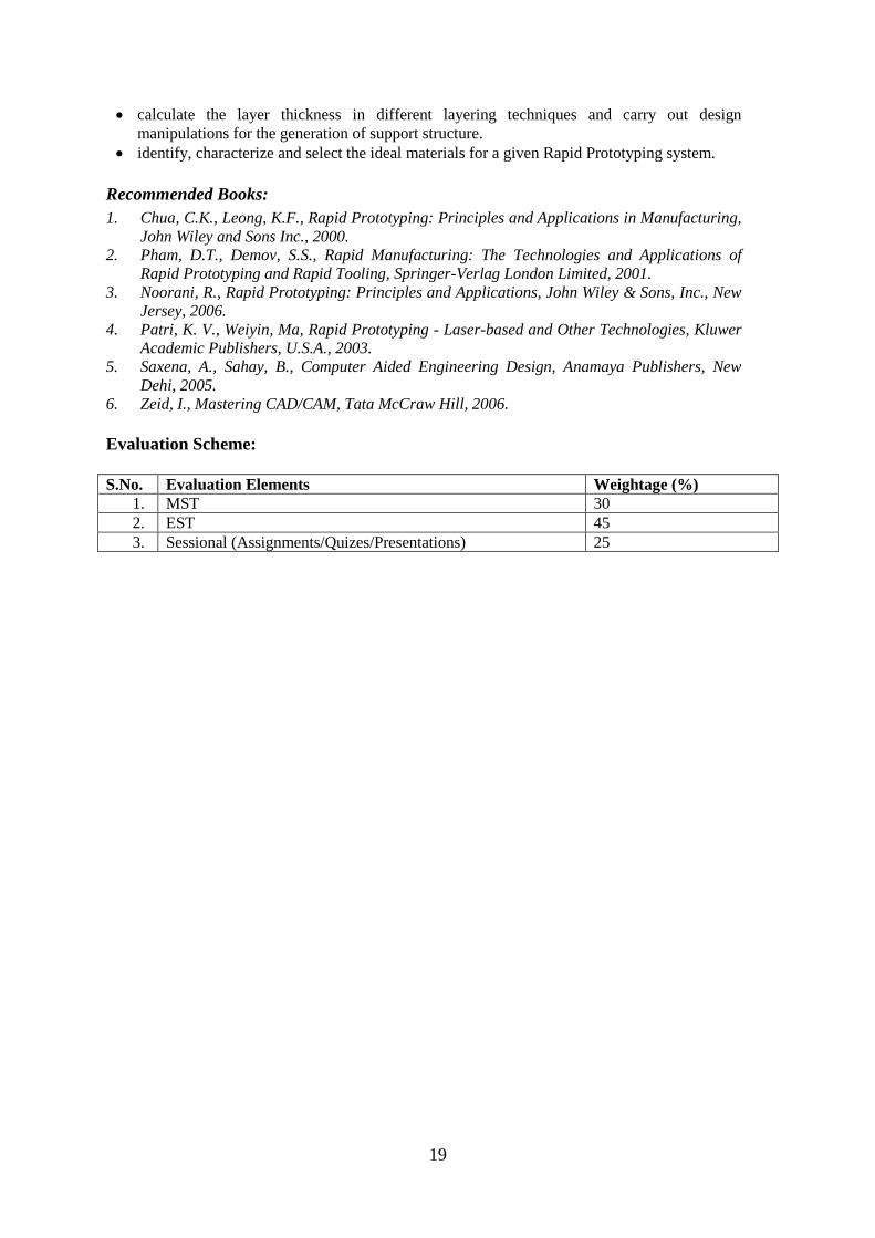
calculate the layer thickness in different layering techniques and carry out design
manipulations for the generation of support structure.
identify, characterize and select the ideal materials for a given Rapid Prototyping system.
Recommended Books:
1. Chua, C.K., Leong, K.F., Rapid Prototyping: Principles and Applications in Manufacturing,
John Wiley and Sons Inc., 2000.
2. Pham, D.T., Demov, S.S., Rapid Manufacturing: The Technologies and Applications of
Rapid Prototyping and Rapid Tooling, Springer-Verlag London Limited, 2001.
3. Noorani, R., Rapid Prototyping: Principles and Applications, John Wiley & Sons, Inc., New
Jersey, 2006.
4. Patri, K. V., Weiyin, Ma, Rapid Prototyping - Laser-based and Other Technologies, Kluwer
Academic Publishers, U.S.A., 2003.
5. Saxena, A., Sahay, B., Computer Aided Engineering Design, Anamaya Publishers, New
Dehi, 2005.
6. Zeid, I., Mastering CAD/CAM, Tata McCraw Hill, 2006.
Evaluation Scheme:
S.No. Evaluation Elements Weightage (%)
1. MST 30
2. EST 45
3. Sessional (Assignments/Quizes/Presentations) 25
20
PCD312: COMPUTATIONAL FLUID DYNAMICS
L T P Cr
3 0 2 4
Course Objective: To impart the knowledge of governing equations for fluid flow and different
turbulence models. To learn about the numerical methods used to solve the partial differential
equation. To solve the fluid flow problem using CFD tool.
Introduction: Motivation and role of computational fluid dynamics, Concept of modeling and
simulation.
Governing Equations of Fluid Dynamics: Continuity equation, Momentum equation, Energy
equation, Various simplifications, Dimensionless equations and parameters, Convective and
conservation forms, Incompressible invisid flows Basic flows, Source panel method, and Vortex panel
method.
Nature of Equations: Classification of PDE, General behaviour of parabolic, Elliptic and
hyperbolic equations, Boundary and initial conditions.
Finite Difference Method: Discretization, Various methods of finite differencing, Stability,
Method of solutions.
Finite Volume Method: Steady one dimension convection and diffusion, Properties of
discretization schemes, Various methods of finite volume scheme.
Turbulence Modelling: Turbulence, effect of turbulence on N-S equations, different turbulent
modelling scheme.
Incompressible Viscous Flows: Stream function-vorticity formulation, Primitive variable
formulation, Solution for pressure, Applications to internal flows and boundary layer flows.
Laboratory work: Use of commercial software for CFD analysis. Introduction of open foam software.
Minor Project: Design of Energy conversion system using commercial software like ANSYS FLUENT/CFX.
Course Learning Outcomes: The students will be able to
acquire the knowledge of various types of fluid flow governing equations.
analyze the internal fluid flow phenomena of thermal and fluid system.
acquire enough knowledge to design of the Engineering systems using commercial
computational code.
design the thermal system using CFD.
Recommended Books:
1. Ghosdastidar, P. S., Computer Simulation of Flow and Heat Transfer, McGraw Hill (1998)
2. Roache, P. J., Computational Fluid Dynamics, Hermosa (1998).
3. Wendt, J. F., Computational Fluid Dynamics An Introduction, Springer-Verlag (2008).
4. Muralidhar, K. and Sundararajan, T., Computational Fluid Flow and Heat Transfer, Narosa
(2008) 2nd ed.
5. Jaluria, Y. and Torrance, K. E., Computational Heat Transfer, Taylor & Francis (2003).
6. Patankar, S. V., Numerical Heat Transfer and Fluid Flow, Taylor & Francis (2007).

21
Evaluation Scheme:
S.No. Evaluation Elements Weightage (%)
1. MST 25
2. EST 40
3. Sessionals ( Assignments/Projects/Tutorials/Quizes/Lab
Evaluations)
35
22
PCD313 : MACHINE TOOL DESIGN
L T P Cr
3 1 0 3.5
Course objective: To impart the fundamental notions of the machine tools including the
different types, construction, applications and their technological capabilities. To provide
exposure to the systematic methods for solving the problems of designing machine tools and their
components by exploring the various design aspects of machine tools elements like transmissions,
structures, materials, kinematics, dynamics and construction of machine tools, etc.
Introduction: Classification of Machine Tools and their technological capabilities, General
requirement of machine tool design.
Machine Tool Drives: Introduction to kinematics of machine tools, Mechanical, hydraulic and
electrical drives, Stepped and step less regulations of speed and feed; Layout of spindles drive
and feed drive in machine tools; Structural diagram, Ray diagram; Design of speed box and feed
box.
Design of Machine tool structures: Function & Requirement of Machine Tool Structure,
Design Criteria from Strength & Stiffness considerations. Role of Static & Dynamic Stiffness in
the design, Factors affecting stiffness of machine tool structures & methods of improving it, Basic
Design procedure of machine tool structures, Design of bed, head stock, etc. Dynamics of
machine tools.
Design of Guideways: Function and Types, Design of hydrostatic, hydrodynamic and
antifriction guideways.
Design of spindles and spindle supports: Function & Requirements of Spindle Units, their
Materials, Design of Spindle, Requirements of Spindle Supports, Selection of sliding and
antifriction bearings.
Research Assignment: Students in a group of 3/4 will submit a research assignment based on the design and analysis of a
machine tool/ machine tool component. Assessment of the assignment will be done based on the
literature review, design, analysis and optimization of the selected machine tool / component
along with the presentation and submission of the technical report.
Course Learning Outcomes: The students will be able to:
analyze constructions and kinematic schemata of different types of machine tools.
construct ray diagrams and speed spectrum diagrams for speed and feed box.
develop the conceptual design, manufacturing framework and systematic analysis of design
problems on the machine tools.
apply the design procedures on different types of machine tool and/or machine tool
components.
Recommended Books:
1. Mehta, N. M., Machine Tool Design & Numerical Control, McGraw Hill ( 2012).
2. Sen, G.C. and Bhattacharya, A., Machine Tools, Central Book Agency (1989).
3. Rao P.N., Manufacturing Technology: Metal cutting and Machine Tools, McGraw Hill
23
(2013).
4. Basu, S. K. and Pal, D.K., Design of Machine Tools, Allied Publishers (2008).
5. . Acherkhan, N.S., Machine Tool Design, University Press of the Pacific, (2000).
6. Boothroyd G and Knight Wiston A., Fundamentals of Machining And Machine Tools, CRC
Press (2005).
7. Sharma, P. C., A Text Book Of Machine Tools & Tool Design, S. Chand Limited,(2005)
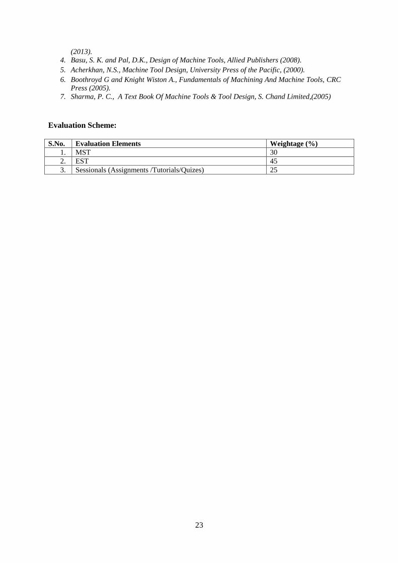
Evaluation Scheme:
S.No. Evaluation Elements Weightage (%)
1. MST 30
2. EST 45
3. Sessionals (Assignments /Tutorials/Quizes) 25
24
PCD315 : MODELLING AND SIMULATION OF DYNAMIC SYSTEMS
L T P Cr
3 1 0 3.5
Course objective: To impart knowledge about the energy interaction of different components
of a system. To model systems residing in different energy domains and to control directly the
theoretical and real systems. Provide students with the ability to apply modelling technique for
analysis and synthesis of thermal, mechanical, biological systems etc.
Modelling in multi-energy domain through bond graphs: Introduction to bond graphs,
Power variables of bond graphs and models of simple circuits, Reference power directions, Bond
graph elements and their constitutive relations, Causality, Generation of system equations from
bond graph models. The Idea of activation.
System Modelling: Modelling of a system of rigid bodies, structural systems, Hydraulic
systems, Thermal systems, electronic and mechatronic systems.
Modelling of multi body systems: mechanisms, parallel and hybrid manipulators and
vehicles.
Advanced topics in bond graph modelling of physical systems: Elements of multi-bond
graphs, Thermo-mechanical bond graphs and continuous systems, bond graph for welding
dynamics and plant water dynamics, thermal modelling of twin tube shock absorber and car cabin
exposed to sunlight.
Control System: Modelling systems for control strategies and design of control strategies in
physical domain.
Numerical prototyping as modelling for design and synthesis using computational tools like
SYMBOLS, MATLAB etc.
Research Assignment: The students work in groups to model different dynamic systems through Bond Graph. Project
activity include group formation and selection of team leader, preparation of questionnaire,
computer usage in Bond Graph modelling and control using SYMBOLS, conversion of Bond
Graph model into Simulink model in MATLAB through signal flow graph, presentation( at least
three in a semester), final technical report and daily diary.
Course Learning Outcomes: The students will be able to
model of rigid bodies, structural systems, hydraulic systems, thermal systems, electronic and
mechatronic systems.
understand and model mechanisms, manipulators, vehicles etc.
analyze and model of different control strategies in physical domain.
model welding dynamics and plant water dynamics.
realize thermal modelling of twin tube shock absorber and car cabin exposed to sunlight.
Recommended Books 1. A. Mukherjee, R. Karmakar, A.K. Samantaray, Bond Graph in Modeling, Simulation and
fault Identification, CRC Press, FL (2006).
2. D.C. Karnopp, D.L. Margolis, R.C. Rosenberg, System Dynamics, Modeling and Simulation
of Mechatronic Systems, John Wiley & Sons, N, (2000).
3. B Ould Bouamama , J Thoma , Jean U Thom, Modelling and Simulation in Thermal and
Chemical Engineering: A Bond Graph Approach, Springer, New York (2000).

25
4. Dean Karnopp, Vehicle Dynamics, Stability, and Control, CRC Press (2013).
5. R. Merzouki, A.K. Samantaray, P.M. Pathak, B. Ould Bouamama, Intelligent Mechatronic
Systems: Modeling, Control and Diagnosis, Springer, New York (2012).
6. Borutzky, W., Bond graphs: a methodology for modelling multidisciplinary dynamic
systems, SCS Publishing House, Erlangen, San Diego (2004).
Evaluation Scheme:
S.No. Evaluation Elements Weightage (%)
1. MST 30
2. EST 45
3. Sessionals (Assignments/Micro Projects, Presentation,
Technical Report)
25
26
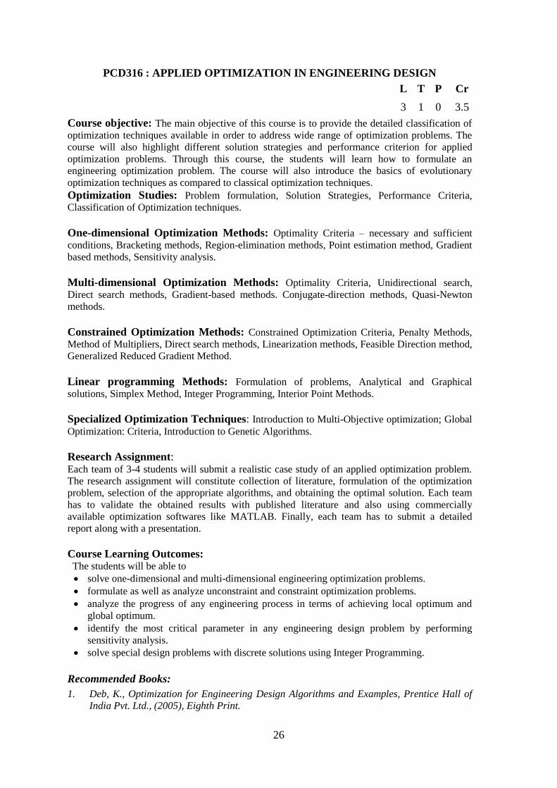
PCD316 : APPLIED OPTIMIZATION IN ENGINEERING DESIGN
L T P Cr
3 1 0 3.5
Course objective: The main objective of this course is to provide the detailed classification of
optimization techniques available in order to address wide range of optimization problems. The
course will also highlight different solution strategies and performance criterion for applied
optimization problems. Through this course, the students will learn how to formulate an
engineering optimization problem. The course will also introduce the basics of evolutionary
optimization techniques as compared to classical optimization techniques.
Optimization Studies: Problem formulation, Solution Strategies, Performance Criteria,
Classification of Optimization techniques.
One-dimensional Optimization Methods: Optimality Criteria – necessary and sufficient
conditions, Bracketing methods, Region-elimination methods, Point estimation method, Gradient
based methods, Sensitivity analysis.
Multi-dimensional Optimization Methods: Optimality Criteria, Unidirectional search,
Direct search methods, Gradient-based methods. Conjugate-direction methods, Quasi-Newton
methods.
Constrained Optimization Methods: Constrained Optimization Criteria, Penalty Methods,
Method of Multipliers, Direct search methods, Linearization methods, Feasible Direction method,
Generalized Reduced Gradient Method.
Linear programming Methods: Formulation of problems, Analytical and Graphical
solutions, Simplex Method, Integer Programming, Interior Point Methods.
Specialized Optimization Techniques: Introduction to Multi-Objective optimization; Global
Optimization: Criteria, Introduction to Genetic Algorithms.
Research Assignment: Each team of 3-4 students will submit a realistic case study of an applied optimization problem.
The research assignment will constitute collection of literature, formulation of the optimization
problem, selection of the appropriate algorithms, and obtaining the optimal solution. Each team
has to validate the obtained results with published literature and also using commercially
available optimization softwares like MATLAB. Finally, each team has to submit a detailed
report along with a presentation.
Course Learning Outcomes: The students will be able to
solve one-dimensional and multi-dimensional engineering optimization problems.
formulate as well as analyze unconstraint and constraint optimization problems.
analyze the progress of any engineering process in terms of achieving local optimum and
global optimum.
identify the most critical parameter in any engineering design problem by performing
sensitivity analysis.
solve special design problems with discrete solutions using Integer Programming.
Recommended Books:
1. Deb, K., Optimization for Engineering Design Algorithms and Examples, Prentice Hall of
India Pvt. Ltd., (2005), Eighth Print.
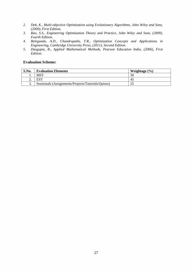
27
2. Deb, K., Multi-objective Optimization using Evolutionary Algorithms, John Wiley and Sons,
(2009), First Edition.
3. Rao, S.S., Engineering Optimization Theory and Practice, John Wiley and Sons, (2009),
Fourth Edition.
4. Belegundu, A.D., Chandrupatla, T.R., Optimization Concepts and Applications in
Engineering, Cambridge University Press, (2011), Second Edition.
5. Dasgupta, B., Applied Mathematical Methods, Pearson Education India, (2006), First
Edition.
Evaluation Scheme:
S.No. Evaluation Elements Weightage (%)
1. MST 30
2. EST 45
3. Sessionals (Assignments/Projects/Tutorials/Quizes) 25
28
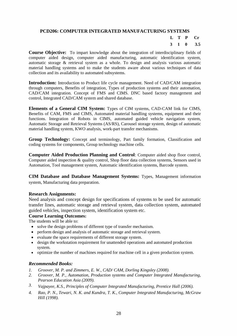
PCD206: COMPUTER INTEGRATED MANUFACTURING SYSTEMS
L T P Cr
3 1 0 3.5
Course Objective: To impart knowledge about the integration of interdisciplinary fields of
computer aided design, computer aided manufacturing, automatic identification system,
automatic storage & retrieval system as a whole. To design and analysis various automatic
material handling systems and to make the students aware about various techniques of data
collection and its availability to automated subsystems.
Introduction: Introduction to Product life cycle management. Need of CAD/CAM integration
through computers, Benefits of integration, Types of production systems and their automation,
CAD/CAM integration. Concept of FMS and CIMS. DNC based factory management and
control, Integrated CAD/CAM system and shared database.
Elements of a General CIM System: Types of CIM systems, CAD-CAM link for CIMS,
Benefits of CAM, FMS and CIMS, Automated material handling systems, equipment and their
functions. Integration of Robots in CIMS, automated guided vehicle navigation system,
Automatic Storage and Retrieval Systems (AS/RS), Carousel storage system, design of automatic
material handling system, KWO analysis, work-part transfer mechanisms.
Group Technology: Concept and terminology, Part family formation, Classification and
coding systems for components, Group technology machine cells.
Computer Aided Production Planning and Control: Computer aided shop floor control,
Computer aided inspection & quality control, Shop floor data collection systems, Sensors used in
Automation, Tool management system, Automatic identification systems, Barcode system.
CIM Database and Database Management Systems: Types, Management information
system, Manufacturing data preparation.
Research Assignments:
Need analysis and concept design for specifications of systems to be used for automatic
transfer lines, automatic storage and retrieval system, data collection system, automated
guided vehicles, inspection system, identification system etc.
Course Learning Outcomes:
The students will be able to:
solve the design problems of different type of transfer mechanism.
perform design and analysis of automatic storage and retrieval system.
evaluate the space requirements of different storage system.
design the workstation requirement for unattended operations and automated production
system.
optimize the number of machines required for machine cell in a given production system.
Recommended Books:
1. Groover, M. P. and Zimmers, E. W., CAD/ CAM, Dorling Kingsley (2008).
2. Groover, M. P., Automation, Production systems and Computer Integrated Manufacturing,
Pearson Education Asia (2009).
3. Vajpayee, K.S., Principles of Computer Integrated Manufacturing, Prentice Hall (2006).
4. Rao, P. N., Tewari, N. K. and Kundra, T. K., Computer Integrated Manufacturing, McGraw
Hill (1998).

29
Evaluation Scheme:
S.No. Evaluation Elements Weightage (%)
1. MST 30
2. EST 45
3. Sessionals (Assignments / Projects / Tutorials / Quizes) 25
30
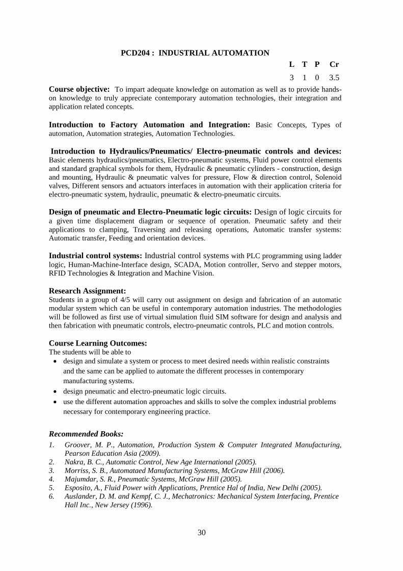
PCD204 : INDUSTRIAL AUTOMATION
L T P Cr
3 1 0 3.5
Course objective: To impart adequate knowledge on automation as well as to provide hands-
on knowledge to truly appreciate contemporary automation technologies, their integration and
application related concepts.
Introduction to Factory Automation and Integration: Basic Concepts, Types of
automation, Automation strategies, Automation Technologies.
Introduction to Hydraulics/Pneumatics/ Electro-pneumatic controls and devices: Basic elements hydraulics/pneumatics, Electro-pneumatic systems, Fluid power control elements
and standard graphical symbols for them, Hydraulic & pneumatic cylinders - construction, design
and mounting, Hydraulic & pneumatic valves for pressure, Flow & direction control, Solenoid
valves, Different sensors and actuators interfaces in automation with their application criteria for
electro-pneumatic system, hydraulic, pneumatic & electro-pneumatic circuits.
Design of pneumatic and Electro-Pneumatic logic circuits: Design of logic circuits for
a given time displacement diagram or sequence of operation. Pneumatic safety and their
applications to clamping, Traversing and releasing operations, Automatic transfer systems:
Automatic transfer, Feeding and orientation devices.
Industrial control systems: Industrial control systems with PLC programming using ladder
logic, Human-Machine-Interface design, SCADA, Motion controller, Servo and stepper motors,
RFID Technologies & Integration and Machine Vision.
Research Assignment: Students in a group of 4/5 will carry out assignment on design and fabrication of an automatic
modular system which can be useful in contemporary automation industries. The methodologies
will be followed as first use of virtual simulation fluid SIM software for design and analysis and
then fabrication with pneumatic controls, electro-pneumatic controls, PLC and motion controls.
Course Learning Outcomes: The students will be able to
design and simulate a system or process to meet desired needs within realistic constraints
and the same can be applied to automate the different processes in contemporary
manufacturing systems.
design pneumatic and electro-pneumatic logic circuits.
use the different automation approaches and skills to solve the complex industrial problems
necessary for contemporary engineering practice.
Recommended Books:
1. Groover, M. P., Automation, Production System & Computer Integrated Manufacturing,
Pearson Education Asia (2009).
2. Nakra, B. C., Automatic Control, New Age International (2005).
3. Morriss, S. B., Automataed Manufacturing Systems, McGraw Hill (2006).
4. Majumdar, S. R., Pneumatic Systems, McGraw Hill (2005).
5. Esposito, A., Fluid Power with Applications, Prentice Hal of India, New Delhi (2005).
6. Auslander, D. M. and Kempf, C. J., Mechatronics: Mechanical System Interfacing, Prentice
Hall Inc., New Jersey (1996).

31
Evaluation Scheme:
S.No. Evaluation Elements Weightage (%)
1. MST 30
2. EST 45
3. Sessional ( Assignments/Projects/Tutorials/Quizes) 25
32
PCD317 : ADVANCED ROBOTICS AND CONTROL
L T P Cr
3 1 0 3.5
Course objective: To impart the advanced knowledge in the areas of serial manipulators
namely: kinematics, dynamics, trajectory planning, and linear and non-linear control.
Review of robot manipulators: Review of forward kinematics, inverse kinematics and
manipulator dynamics.
Path and Trajectory Planning: Joint-space schemes, Cartesian-space schemes, configuration
space, path planning using potential fields, avoiding local minima, probabilistic roadmap
methods; Trajectory planning: PTP method using via points.
Linear Control of Manipulators: Feedback Control schemes for robotics: Proportional,
Derivative and Integral Control, regulation problem, tracking problem, model based control and
trajectory-following control.
Nonlinear Control of Manipulators: Feed forward control, Feedback Linearization, PD
control with gravity compensation, computed toque control, sliding mode Control, Lyapunov
stability analysis, Introduction to Cartesian based control schemes.
Introduction to Redundant Manipulators: Singularity and Workspace analysis,
redundancy resolution, obstacle avoidance and singularity avoidance.
Research Assignment: Each student will submit a research assignment based on design of 4 to 6 degrees of freedom
robot arm, performed by him in PCD-205 will be carried forward. The student has to develop a
MATLAB code for 2-3 control algorithms assigned to him. Research assignment will constitute
collection of literature on control algorithms, the development of the controller and
implementation of the controller on different robots for different control tasks. Finally, the
student has to submit a detailed report and presentation justifying the comparison of different
control schemes.
Course Learning Outcomes: The students will be able to
develop the MATLAB code for implementation of kinematic and dynamic model of serial
manipulators.
develop and apply the mathematical model for path as well as trajectory planning of robots
in joint space and Cartesian space.
formulate and apply the control problem of robotic manipulators using linear control
schemes
formulate and apply the control problem of robotic manipulators using non-linear control
schemes.
apply the concepts of multi-tasking of redundant manipulators like redundancy resolution,
obstacle avoidance and singularity avoidance.
Recommended Books:
1. Fu, K. S., Gonzalez, R. C. and Lee, C. S., Robotics: Control, Sensing, Vision, and
Intelligence, McGraw Hill (1987).
2. Schilling, R. J., Fundamentals of Robotics Analysis & Control, Prentice Hall of India
(2003).
33
3. Craig, J. J., Introduction to Robotics: Mechanics and Control, Pearson Education (2004).
4. Spong, M. W. Hutchinson, S. and Vidyasagar, M: Robot Modeling and Control, Wiley
(2006)
5. Nakamura, Y: Advanced Robotics: Redundancy and Optimization, Addison-Wesley Pub. Co.
(1991)
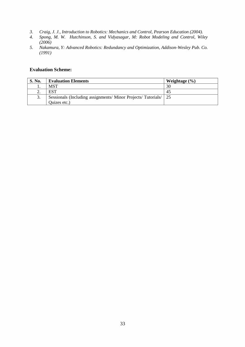
Evaluation Scheme:
S. No. Evaluation Elements Weightage (%)
1. MST 30
2. EST 45
3. Sessionals (Including assignments/ Minor Projects/ Tutorials/
Quizes etc.)
25
34
PCDXXX MECHANICS OF COMPOSITE MATERIALS
L T P Cr
3 1 0 3.5
Course objective: To develop an understanding of the linear elastic analysis of
composite materials. This understanding will include concepts such as anisotropic
material behavior, prediction of stiffness and strength of composites, analysis of
laminated composite plates, and failure of composites.
Introduction: Definition, Characteristics, Classification, Fabrication of composites,
Fiber-reinforced composites, Applications of composites, Performance of structural
composites, Mechanical behavior of composite materials.
Micro mechanical Behavior of Lamina: Rule of mixture, Prediction of elastic
constants, Stiffness, Strength, Thermal and moisture expansion. Mechanics of materials
approach to stiffness, Elasticity approach to stiffness, Halpin-Tsai equations, Mechanics
of materials approach to strength.
Macro mechanical Behavior of Lamina: Stress-strain relations for anisotropic
materials, Stiffness, Compliances and engineering constants for orthotropic materials,
Restriction on elastic constants, Stress-strain relations of orthotropic lamina along
principal and arbitrary material direction, Transformation of elastic constants.
Macro mechanical Behavior of Laminate: Classification of laminates, Classical
lamination theory: Stress-strain variation in a laminate, Resultant laminate forces and
moments, First order shear deformation theory, Special cases of laminate stiffness.
Bending analysis of laminated plates and beams: Governing equations for bending of
laminated beams and plates, Equilibrium equations, Equilibrium equations in terms of
displacements, Application of beam/plate theories, Closed form solution of governing
equations: Application to simply supported plates.
Failure Mechanics of Composite Materials: Strengths of an orthotropic lamina, Biaxial
strength criteria for orthotropic lamina, Maximum stress failure criteria, Maximum strain
failure criteria, Tsai-Hill, Hoffman, Tsai-Wu failure criteria.
Research Assignment
Research assignment will constitute collection of literature, problem formulation
(mathematical model) required for design micromechanical and macromechanical
analysis of composites. The bending and failure analysis of composites will be performed
and the influence of parameters such as material orthotropy, lamination sequence, loading
conditions will be examined. The assignment also includes technical report writing and
seminar presentation.
Course Learning Outcomes: The students will be able to
identify the properties of fiber and matrix materials used in commercial composites,
35
as well as some common manufacturing techniques.
predict the elastic properties of both long and short fiber composites based on the
constituent properties.
relate stress, strain and stiffness tensors using ideas from matrix algebra.
analyze a laminated plate in bending, including finding laminate properties from
lamina properties.
predict the failure strength of a laminated composite plate.
use contemporary software tools such as MATLAB for solving and displaying results.
Recommended Books:
1 Jones, R. M., Mechanics of Composite Materials, CRC Press,New Delhi, 1998. 2 Reddy, J. N., Mechanics of Laminated Composite Plates and Shells: Theory and
Analysis, CRC Press, New Delhi, 2003. 3 Kaw, A., Mechanics of Composite Materials, CRC Press, New Delhi, 2005. 4 Agrawal, B.D. and Broutman, L. J., Analysis and Performance of Fiber Composites,
John Wiley & Sons, New York, 1990.
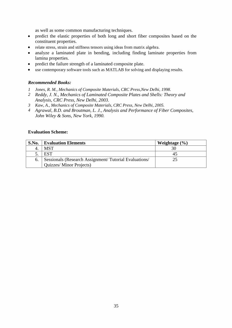
Evaluation Scheme:
S.No. Evaluation Elements Weightage (%)
4. MST 30
5. EST 45
6. Sessionals (Research Assignment/ Tutorial Evaluations/
Quizzes/ Minor Projects)
25
36
PCD XXX TRIBOLOGY
L T P Cr
3 1 0 3.5
Course Objectives: To develop an understanding on the principles and engineering
significance of tribology. It highlights the tribological considerations for the design of various
machine elements.
Introduction: Introduction to tribology, Interdisciplinary approach, Economic aspects, Surface
properties and characterization, Elements of contact mechanics.
Friction Wear and Lubrication: Causes of friction and wear, Theories of friction and wear,
Measurement and control of friction and wear. Regimes of lubrication, Lubricant additives,
Generalized Reynold’s equation, Various mechanisms of flow, Shear stress, Load carrying
capacity and pressure development in an oil film.
Design of Tribological Elements: Tribological consideration in design, Conceptual design,
Classification of tribological components, Tribology in higher and lower kinematic pairs,
Design and performance analysis of hydrostatic, Hydrodynamic journal bearings and squeeze
film bearing. Mathematical modelling and numerical simulation of elastic deformation and flow
in bearings and gears. Tribological considerations in IC engine, Composite materials and metal
working.
Nanotribology: Introduction to Nanotribology and nanomechanics, Measurement and
application of friction and wear at nanoscale.
Research Assignment/Minor Project: Research assignment will constitute collection of data from journals, libraries, industry and
other sources followed by the critical review on the recent trends in engine tribology,
nanotribology, composite tribology, industrial lubrication system, metal working tribology etc.
Minor projects includes case studies on the design of bearings for gear box, design of
lubrication systems in IC engine, Pneumatic tyres, Mechanical seals, etc. Modeling and
simulation of film thickness and elastic deformation in HL and EHL lubrication. It will also
include technical report writing and seminar presentation.
Course Learning Outcomes (CLO): The students will be able to:
identify the causes of wears and friction in different contact surfaces.
perform design calculations of hydrostatic and hydrodynamic lubrication for basic
problems.
design and analyze the performance of bearings.
analyze the tribological systems in IC engine.
Recommended Books: 1. Arnell R. D., Davies P. B., Halling J. and Whomes T. L. , Tribology: Principles and
Design Applications, First edition, Springer-verlag,New York, 1991.
2. Hutchings I.M., Tribology: Friction and wear of engineering materials, Edward Arnold,
London, 1992.
3. Stolarski, T.A., Tribology in Machine Design, Butterworth-Heinemann, Oxford, Boston,
2000.
37
4. Majumdar B.C., Introduction to Tribology of Bearings, S. Chand Publishing, New Delhi,
2010.
5. Bhushan, B., Principles and Applications of Tribology, Second edition, John Wiley & Sons,
UK, 2013.
6. Sahoo P., Engineering Tribology, PHI, New Delhi, 2005.
7. Bowden, F.P., Tabor, D., Friction: Introduction to Tribology, Heinemann Educational
Publishers, London, 1974.
8. Ludema K C, Friction, Wear, Lubrication: A textbook in Tribology, CRC Press, US, 2010.
Evaluation Scheme:
S.No. Evaluation Elements Weightage (%)
4. MST 30
5. EST 45
6. Sessionals (Assignments/ Presentation, Technical Report,
Quizzes, Tutorials)
25