programmable attenuators & attenuator/switch controllers€¦ · · 2017-03-14programmable...
TRANSCRIPT
Revision Date: 9/30/2012
199
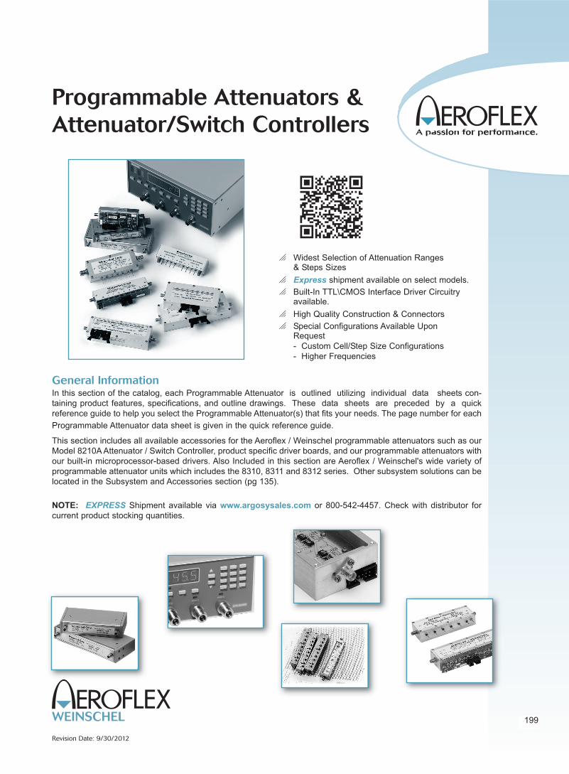
Programmable Attenuators &
Attenuator/Switch Controllers
General InformationIn this section of the catalog, each Programmable Attenuator is outlined utilizing individual data sheets con-
taining product features, specifications, and outline drawings. These data sheets are preceded by a quick
reference guide to help you select the Programmable Attenuator(s) that fits your needs. The page number for each
Programmable Attenuator data sheet is given in the quick reference guide.
This section includes all available accessories for the Aeroflex / Weinschel programmable attenuators such as our
Model 8210A Attenuator / Switch Controller, product specific driver boards, and our programmable attenuators with
our built-in microprocessor-based drivers. Also Included in this section are Aeroflex / Weinschel's wide variety of
programmable attenuator units which includes the 8310, 8311 and 8312 series. Other subsystem solutions can be
located in the Subsystem and Accessories section (pg 135).
NOTE: EXPRESS Shipment available via www.argosysales.com or 800-542-4457. Check with distributor for
current product stocking quantities.
o Widest Selection of Attenuation Ranges & Steps Sizes
o Express shipment available on select models.
o Built-In TTL\CMOS Interface Driver Circuitryavailable.
o High Quality Construction & Connectors
o Special Configurations Available UponRequest
- Custom Cell/Step Size Configurations
- Higher Frequencies

Frequency Attenuation Step Insertion Maximum Connector Average Peak
Model Range Range Size Loss, Max. SWR Type Power Power Page
Number (GHz) (dB) (dB) (dB) (Watts) (Watts) No.
3200T-1E dc-3.0 0-127 1 4.70 1.30-1.40* SMA 1 50 215
3200T-2E 0-63.75 0.25 4.70 1.30-1.40*3201T-1E 0-31 1 3.25 1.25-1.40*
3205T-1E 0-70 10 2.60 1.25-1.40*
3205T-2E 0-55 5 2.60 1.25-1.40*
3205T-3E 0-1.5 0.1 2.60 1.25-1.40*
3206T-1E 0-63 1 3.70 1.25-1.35*
3209T-1E 0-64.5 0.1 5.50 1.35-1.45*
3404T-15 dc-6.0 0-15 1 2.60 1.30-1.45* SMA 1 50 222
3404T-55 0.55 5 2.60
3404T-70 0-70 10 2.60
3406T-55 0-55 1 3.80
3408T-55.75 0-55.75 0.25 5.00
3408T-103 0-103 1 5.00
* VARIES WITH FREQUENCY.
s EXPRESS Shipment available via www.argosysales.com or 800-542-4457.
Check with Distributor for other available models.
5305 Spectrum Drive, Frederick, MD 21703-7362 s TEL: 301-846-9222, 800-638-2048 s Fax: 301-846-9116
web: www.aeroflex.com/weinschel s email: [email protected]
200
Revision Date: 9/30/2012
Programmable Attenuators
Frequency Attenuation Step Insertion Maximum Connector Average Peak
Model Range Range Size Loss, Max. SWR Type Power Power Page
Number (GHz) (dB) (dB) (dB) (Watts) (Watts) No.
s 3200-1E dc-3.0 0-127 1 4.70 1.30-1.40* SMA 1 50 209
s 3200-2E 0-63.75 0.25 4.70 1.30-1.40*3201-1E 0-31 1 3.25 1.25-1.40*
3205-1E 0-70 10 2.60 1.25-1.40*
3205-2E 0-55 5 2.60 1.25-1.40*
3205-3E 0-1.5 0.1 2.60 1.25-1.40*
3206-1E 0-63 1 3.70 1.25-1.35*
3209-1E 0-64.5 0.1 5.50 1.35-1.45*
3404-15 dc-6.0 0-15 1 2.60 1.30-1.45* SMA 1 50 218
3404-55 0.55 5 2.60
3404-70 0-70 10 2.60
3406-55 0-55 1 3.80
3408-55.75 0-55.75 0.25 5.00
3408-103 0-103 1 5.00
Relay Switched Programmable Attenuators, Basic Models . . . DC-6 GHz
Relay Switched Programmable Attenuators, with built-in Microprocessor-Base Driver . . .
DC-6 GHz (For use with Aeroflex / Weinschel 8210A Controller)

201
5305 Spectrum Drive, Frederick, MD 21703-7362 s TEL: 301-846-9222, 800-638-2048 s Fax: 301-846-9116
web: www.aeroflex.com/weinschel s email: [email protected] Date: 9/30/2012
Programmable Attenuators
Frequency Attenuation Step Insertion Maximum Connector Average PeakModel Range Range Size Loss, Max. SWR Type Power Power PageNumber (GHz) (dB) (dB) (dB) (Watts) (Watts) No.
150T-11 dc-18.0 0-11 1 2.2 1.50-1.90* 3.5mm 1 100 224
150T-15 0-15 1 2.2 1.50-1.90*
150T-31 0-31 1 2.6 1.50-1.90*
150T-62 0-62 2 2.6 1.50-1.90*
150T-70 0-70 10 2.6 1.35-1.70*
150T-75 0-75 5 2.2 1.50-1.90*
150T-110 0-110 10 2.2 1.50-1.90*
151T-11 dc-4.0 0-11 1 0.9 1.50 3.5mm 1 100 224
151T-15 0-15 1 0.9 1.50
151T-31 0-31 1 0.9 1.50
151T-62 0-62 2 1.1 1.50
151T-70 0-70 10 0.7 1.35
151T-75 0-75 5 0.9 1.50
151T-110 0-110 10 0.9 1.50
152T-55 dc-26.5 0-55 5 2.98 1.40-1.90* 3.5mm 1 100 224152T-70 0-70 10 2.98 1.40-1.90*
152AT-70 0-70 10 2.98 1.40-1.90*
152T-75 0-75 5 2.98 1.40-1.90*
152T-90 0-90 10 2.98 1.40-1.90*
Relay Switched Programmable Attenuators, Basic Models . . . dc - 40.0 GHz
Frequency Attenuation Step Insertion Maximum Connector Average Peak
Model Range Range Size Loss, Max. SWR Type Power Power Page
Number (GHz) (dB) (dB) (dB) (Watts) (Watts) No.
150-11 dc-18.0 0-11 1 2.2 1.50-1.90* 3.5mm 1 100 228150-15 0-15 1 2.2 1.50-1.90*
150-31 0-31 1 2.6 1.50-1.90*
150-62 0-62 2 2.6 1.50-1.90*
150-70 0-70 10 2.6 1.35-1.70*
150-75 0-75 5 2.2 1.50-1.90*150-110 0-110 10 2.2 1.50-1.90*
151-11 dc-4.0 0-11 1 0.9 1.50 3.5mm 1 100 228151-15 0-15 1 2.2 1.50
151-31 0-31 1 2.6 1.50
151-62 0-62 2 2.6 1.50
151-70 0-70 10 2.6 1.35
151-75 0-75 5 2.2 1.50151-110 0-110 10 2.2 1.50
152-55 dc-26.5 0-55 5 2.98 1.40-1.90* 3.5mm 1 100 228152-90 dc-26.5 0-90 10 2.98 1.40-1.90*
152-110 dc-26.5 0-110 10 2.98 1.40-1.90*
153-70 dc-40.0 0-70 10 3.00 1.30-2.10* 2.92mm 1 100 233
153-110 0-110 10 4.00
(New)
* VARIES WITH FREQUENCY.
Relay Switched Programmable Attenuators, with built-in Microprocessor-Based Driver . . .
dc - 26.5 GHz (For use with Aeroflex / Weinschel 8210A Controller)

5305 Spectrum Drive, Frederick, MD 21703-7362 s TEL: 301-846-9222, 800-638-2048 s Fax: 301-846-9116
web: www.aeroflex.com/weinschel s email: [email protected]
202
Revision Date: 4/18/2013
Programmable Attenuators
Frequency Attenuation Step Insertion Loss, Maximum Average
Model Range Range Size Maximum SWR Power Connector Page
Number (GHz) (dB) (dB) (dB) Type No.
4202-63 0.4-6.0 0-63 1 7.0 2.00 +20 dBm SMA 235(New)
4203-31.75 0.2- 3.0 0-31.75 0.25 4.5 1.40 +24 dBm SMA 237
4203-63 0-63 1
(New)
4205-31.5 0.4-6.0 0-31.5 0.5 3.0 - 4.0* 1.50-1.70* +23 dBm SMA 239
4205-63.5 0-63.5 0.5 4.5 - 6.0* 1.50-1.80*
4205-95.5 0-95.5 0.5 6.5 - 8.0* 1.60-2.00*
(New)
4226-63 0.8-3.0 0-63 1 3.75 1.50 +28 dBm SMA 241
4228-63.75 0.8-2.5 0-63.75 0.25 4.50 1.50
4228-103 0.8-3.0 0-103 1 5.50 1.50
4238-63.75 10 MHz-2.5 0-63.75 0.25 6.75 - 9.25* 1.60 +30 dBm SMA 243
4238-103 103 1 6.75 - 9.25*
4246-63 10 MHz-2.5 0-63 1 8.00 - 10.00* 2.00 +36 dBm SMA 245
4248-63.75 0-63.75 0.25 10.50 - 13.00*
4248-103 103/1 10.50 - 13.00*
4258-63.75 2.0 to 6.0 0-63.75 0.25 4.5 2.00 +20 dBm SMA 247
(New)
* Varies with frequency.
Solid-state & Digital Attenuators . . . to 6 GHz
203
5305 Spectrum Drive, Frederick, MD 21703-7362 � TEL: 301-846-9222, 800-638-2048 � Fax: 301-846-9116web: www.aeroflex.com/weinschel � email: [email protected]
Revision Date: 9/25/2012
Programmable Attenuators
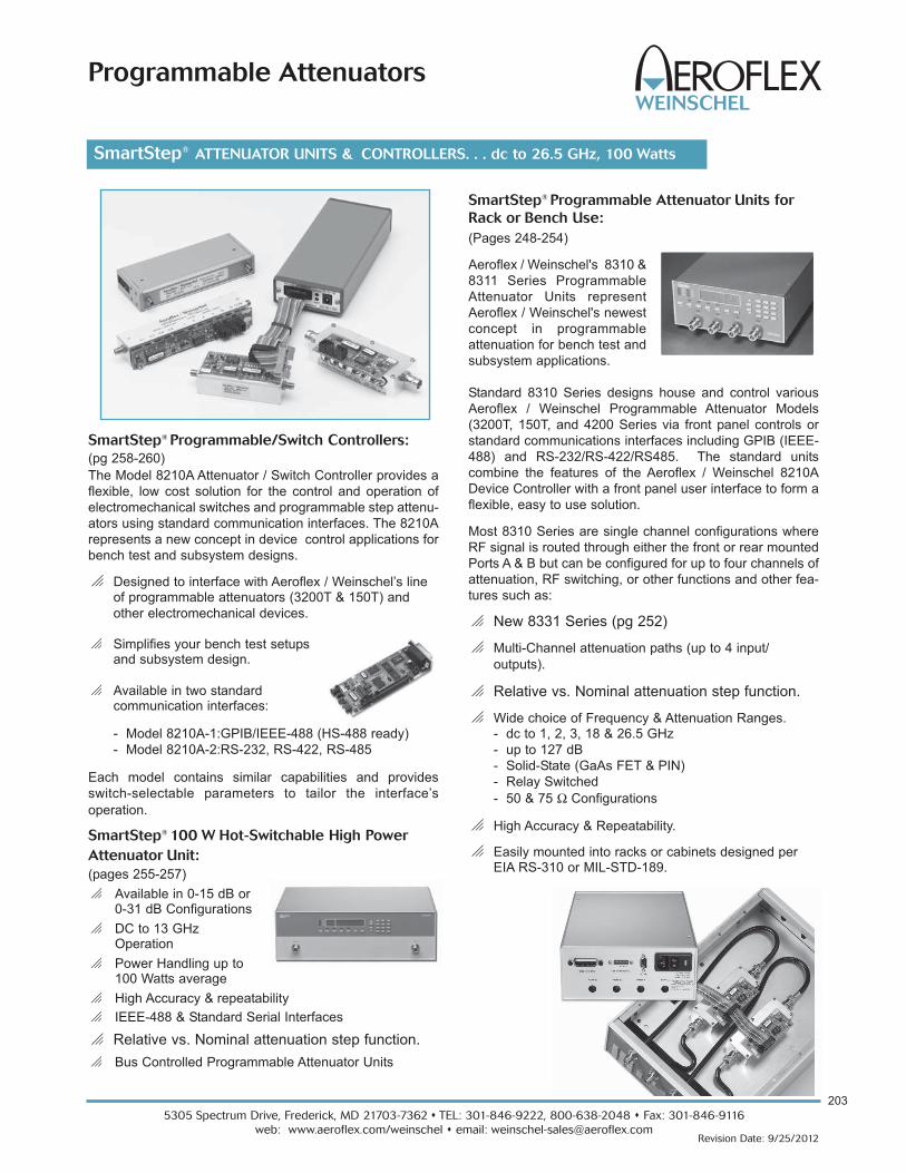
SmartStep® Programmable Attenuator Units for
Rack or Bench Use:
(Pages 248-254)
Aeroflex / Weinschel's 8310 &
8311 Series Programmable
Attenuator Units represent
Aeroflex / Weinschel's newest
concept in programmable
attenuation for bench test and
subsystem applications.
Standard 8310 Series designs house and control various
Aeroflex / Weinschel Programmable Attenuator Models
(3200T, 150T, and 4200 Series via front panel controls or
standard communications interfaces including GPIB (IEEE-
488) and RS-232/RS-422/RS485. The standard units
combine the features of the Aeroflex / Weinschel 8210A
Device Controller with a front panel user interface to form a
flexible, easy to use solution.
Most 8310 Series are single channel configurations where
RF signal is routed through either the front or rear mounted
Ports A & B but can be configured for up to four channels of
attenuation, RF switching, or other functions and other fea-
tures such as:
o New 8331 Series (pg 252)
o Multi-Channel attenuation paths (up to 4 input/
outputs).
o Relative vs. Nominal attenuation step function.
o Wide choice of Frequency & Attenuation Ranges.- dc to 1, 2, 3, 18 & 26.5 GHz
- up to 127 dB
- Solid-State (GaAs FET & PIN)
- Relay Switched
- 50 & 75 Ω Configurations
o High Accuracy & Repeatability.
o Easily mounted into racks or cabinets designed perEIA RS-310 or MIL-STD-189.
SmartStep® Programmable/Switch Controllers:
(pg 258-260)
The Model 8210A Attenuator / Switch Controller provides a
flexible, low cost solution for the control and operation of
electromechanical switches and programmable step attenu-
ators using standard communication interfaces. The 8210A
represents a new concept in device control applications for
bench test and subsystem designs.
o Designed to interface with Aeroflex / Weinschel’s line of programmable attenuators (3200T & 150T) and
other electromechanical devices.
o Simplifies your bench test setupsand subsystem design.
o Available in two standard communication interfaces:
- Model 8210A-1:GPIB/IEEE-488 (HS-488 ready)
- Model 8210A-2:RS-232, RS-422, RS-485
Each model contains similar capabilities and provides
switch-selectable parameters to tailor the interface’s
operation.
SmartStep® 100 W Hot-Switchable High Power
Attenuator Unit:
(pages 255-257)
o Available in 0-15 dB or0-31 dB Configurations
o DC to 13 GHzOperation
o Power Handling up to100 Watts average
o High Accuracy & repeatability
o IEEE-488 & Standard Serial Interfaces
o Relative vs. Nominal attenuation step function.
o Bus Controlled Programmable Attenuator Units
SmartStep® ATTENUATOR UNITS & CONTROLLERS. . . dc to 26.5 GHz, 100 Watts

5305 Spectrum Drive, Frederick, MD 21703-7362 s TEL: 301-846-9222, 800-638-2048 s Fax: 301-846-9116
web: www.aeroflex.com/weinschel s email: [email protected]
204
Revision Date: 1/7/2013
Programmable Attenuators
What are the applications of Aeroflex / Weinschel
programmable attenuators?
Aeroflex / Weinschel's programmable attenuators are used
to control the power of radio frequency and microwave sig-
nals. Applications include control of input power to signal
measuring systems, control of output power from signal
generating systems, adjustment power for BIT error rate
testing, controlling losses in a signal path and simulating the
signal fading of a microwave communication system....to
name just a few.
How do they work?
Aeroflex / Weinschel's programmable attenuators consist of
a series of attenuation pads (cells) that are selectively
inserted into the signal path via a control signal. An exam-
ple is a series of cells such as 1, 2, 4, 8 and 16 dB arranged
in a binary sequence. Such an attenuator is called a binary
attenuator. Combinations of cells are switched "on" to pro-
vide attenuation steps from 0 dB to 31 dB. Another example
is a unit having cell values of 10, 20 and 40 dB which will
provide 10 dB steps between 0 dB and 70 dB.
How are the attenuators switched?
The basic structure of a programmable attenuator is shown
below. There are several ways the attenuator pads are
switched in and out of the RF path. Aeroflex / Weinschel's
3200 series uses TO-5 can relay switches. These are use-
ful up to 2.0 GHz and higher. Aeroflex / Weinschel's 150
series operate up to 26.5 GHz and utilize reed switches
housed within a precision machined cavity.
Aeroflex / Weinschel also manufactures programmable
attenuators using solid state switching that offers faster
switching speeds but their frequency range is more limited
than mechanical step attenuators. Whereas mechanically
switched attenuators operate from DC to their maximum fre-
quency, solid state attenuators have a lower frequency limit.
Solid state attenuators also have lower isolation between
control and through path.
Frequently Asked Questions about Programmable Attenuators....
How fast do the attenuators switch?
Switching speed of mechanically switched attenuators is
typically between 6 and 35 msec. This is the maximum time
between the application of the switching command to the
cell and the cessation of contact bounce. This time is a func-
tion of switch structure and size.
What is a latching and
non-latching attenuator?
Non-latching is also called
momentary or fail-safe. For
the non-latching type, the
attenuator is switched to the
attenuation "on" position only
so long as control power is applied to
the switch. As soon as power is
removed the switch reverts to it passive state or fail-safe
state...usually the zero dB state. In latching attenuators
each cell stays in the last setting even if power is removed.
Latching attenuators have two control lines. One control line
causes the attenuator to switch to the "attenuation on" set-
ting while the other control line causes the attenuator to
switch to the zero dB setting. There is normally a permanent
magnet that holds the switch stable in either position.
Each version has its advantages and disadvantages. The
non-latching switch requires constant power to the solenoid
when in the "on" position. On the other hand the latching
version requires greater switch current to overcome it's per-
manent magnet.
How are the attenuators controlled?
The Model 3200 and 3400 Series non-latching attenuators
require only one 12 volt control line per cell. The direction of
control current is not important.
The Model 150 Series is a latching version using one posi-
tive 5 volt or 24 volt common return line and two grounding
control lines.
In order for switching to be guaranteed the voltage between
common and control must be held within specified limits.
Power supply regulation must be kept within range even
while heavy switching current is being drawn. Any cable
voltage drops must be added to the minimum control volt-
age to obtain the required power supply voltage at the
attenuator.
Aeroflex / Weinschel's programmable attenuators, such as
the Model 3200T, 3400T and 150T Series feature on-board
TTL drivers. TTL driver boards are also available for most
models.

205
5305 Spectrum Drive, Frederick, MD 21703-7362 s TEL: 301-846-9222, 800-638-2048 s Fax: 301-846-9116
web: www.aeroflex.com/weinschel s email: [email protected] Date: 1/7/2013
Programmable Attenuators
What is the switch life of these programmable
attenuators?
Specified life for mechanical switches is normally in the
range of 1 to 10 million switching. This specification is per
switch, independent of the other switches in the attenuator.
For the Model 150 series attenuators the specification is 5
million cycles, i.e. one cycle is the switch moving in both
directions. These specifications are based on the mechani-
cal life of the switch, however, other factors have an impact
on attenuator life. High power operation can have an
adverse effect on the switch contact surfaces. This can
reduce the overall life of the switch by causing the attenua-
tor performance to go outside it's specification.
What is monotonicity?
A programmable step attenuator is considered monotonic if
it's attenuation always increases when it is commanded to
increase. This applies on a per frequency basis. For
instance the 20 dB setting at 1 GHz will always be less than
the 21 dB setting at 1 GHz. This does not necessarily mean
that the 20 dB setting at 1 GHz will always be less than the
21 dB setting 18 GHz. Monotonicity is influenced by the
SWR of the individual attenuator cells as the cells are com-
bined to form an attenuation value. It is also influenced by
the summation of individual cell attenuation tolerances as
the cells are combined.
What is the difference between insertion loss and
incremental attenuation?
Programmable attenuators have insertion loss and also
incremental attenuation. Insertion loss is the loss through
the attenuator when all cells are switched to zero dB. It is
the residual loss of the device itself. Insertion loss usually
increases with frequency reaching several dB at the higher
frequencies and generally has very flat frequency response.
Incremental attenuation is the attenuation values of the
attenuators cells relative to the insertion loss. Since inser-
tion loss is always present, the performance of a
programmable attenuator is always given as incremental
attenuation relative to insertion loss. Insertion loss is con-
sidered part of the fixed performance of the system path in
which the programmable attenuator is located.
What is the advantages of Attenuators with built-in
driver circuitry?
These attenuators feature an internal microcontroller-based
driver that provides a TTL-level digital interface for control
of the attenuator relays (Figure 1). This card simplifies
operation and interfacing requirements, while at the same
time providing for greatly enhanced flexibility over past
designs. User-selectable modes of operation include both
parallel and serial bus. The parallel mode provides a simple,
one-bit per relay on/off control with internal pullups for use
primarily in single attenuator applications. This mode allows
the attenuator to be controlled via a variety of methods,
such as a TTL-level digital output port, or mechanical tog-
gle switches. The serial mode provides a two-wire serial bus
structure and protocol for connecting a number of devices to
a single host control interface, suitable for use in larger sys-
tem and sub-system applications. The built-in driver™
contains non-volatile configuration memory that is used to
hold a wide variety of attenuator and driver-dependent para-
meters, including serial number, attenuator cell dB values,
relay configurations, and switching requirements, which are
all accessible via the digital interface. This frees the system
designer from such low-level details, allowing faster inte-
gration. In either operational mode, the microcontroller
enters an idle condition during periods of inactivity, turning
off all on-board clocks, reducing EMI concerns, and lower-
ing power consumption. On-board regulation for the digital
circuitry allows the programmable attenuator to operate
from a single input supply voltage.
Figure 1. Digital Driver Circuitry
Non-Volatile
Configuration
Memory
Single-Chip
Microcontroller
Relay
Drivers
TTL/CMOS
Compatible
Digital Interface
+12 to
+15 V
Input
To
Attenuator
Relays
EMI
Filters
+5 V
Regulator
How can I control the Attenuators with built-in drivers?
The communications interface (Model 8210A) provides a
flexible, low cost solution for the operation of programma-
ble step attenuators and other electromechanical devices
under computer control. Designed to interface to Aeroflex /
Weinschel’s line of programmable attenuators built-in intel-
ligent drivers, the Model 8210A represents a new concept in
device control applications for bench test and subsystem
designs. The 8210A communications interface provides a
high-level interface from various industry standard commu-
nications interfaces, including IEEE-488 and RS232
/RS422/RS485, to the programmable attenuators serial
Driver Interface Bus.

5305 Spectrum Drive, Frederick, MD 21703-7362 s TEL: 301-846-9222, 800-638-2048 s Fax: 301-846-9116
web: www.aeroflex.com/weinschel s email: [email protected]
206
Revision Date: 9/30/2012
Programmable Attenuators
Weinschel has been a major supplier of
programmable attenuators to the RF industry for over
30 years. Historically the most demanding specifica-
tions for these components have been low insertion loss and SWR,
combined with a reasonable life expectancy of several million
switching cycles. This was usually adequate for RF instruments
like spectrum analyzers and signal generators, wherein the
attenuator bandwidth rather than the switching speed was of prime
concern. To achieve wide bandwidths the programmable attenua-
tors were mostly of electromechanical design and the linearity of
these passive components was not only assumed but never
questioned by any customer. Intermodulation distortion discus-
sions and problems were usually limited to components such as
amplifiers, mixers and filters.
In recent years, however, wireless communication systems
employing complex digital modulation schemes, increased chan-
nel capacity, high transmit power and extremely low receiver
sensitivity have put into question the linearity of passive compo-
nents. Even very low level multi-tone intermodulation products
generated by attenuators can seriously degrade the efficiency of
a system/ instrument if these products fall within the user pass-
band. For two closely spaced tones at frequencies f1 and f2, the
third order IM products at 2f1 - f2 and 2f2 - f1 , are the most
harmful distortion products. They are harmful because they are
located close to f1 and f2 and virtually impossible to filter out. In
today's base stations the multicarrier power amplifier (MCPA) is
replacing banks of single-channel amplifiers and their corre-
sponding power combining network. MCPAs have the capability
of carrying a number of modulation schemes simultaneously and
can also employ schemes such as dynamic-channel-allocation
(DCA) to use the allocated frequency spectrum more efficiently.
The in-band intermodulation distortion (IMD) performance of
these amplifiers is extremely critical and needs to be measured
using low distortion programmable multi-tone generators whose
IMD performance must be quite superior. This is discussed in the
two case studies cited here.
Electromechanical programmable attenuators obviously
provide a far superior IMD performance than
their corresponding solid state
counterparts employing semi-
conductor switching elements.
However, their slow switch speed, in the order of millisec-
onds, and short switch life in the order of 5-10 million cycles
make them unattractive in some applications like cell phone test-
ing and other ATE systems. Solid State programmable attenuators
do overcome these two problems and are therefore included here
for IMD performance comparison. It is not the intent of this brief
article to go into the theory of intermodulation distortion. The goal
here is to provide some good basic IMD test data for a
variety of commercial programmable attenuators and let the end
user select the most appropriate type for his application.
Measurement System and Parameters...All test data presented here was generated using a
commercially available Passive IM Analyzer, Summitek Model
SI-800A which provides a fully integrated system for characteriz-
ing distortion produced by cables, attenuators and other passive
devices. Although the system is capable of measuring both,
through and reflected IM3, IM5, IM7 and IM9, the focus here is
only on through IM for the most troublesome third order product,
IM3. To carry out a meaningful comparison between different
attenuators all measurements were carried out using two equal
amplitude input tones at 869 MHz (f1) and 891 MHz(f2) , the IM3
frequency being 847 MHz (2f1-f2). Input carrier power was
stepped in increments of 1 dB from -7dBm to +27dBm. All exter-
nal adapters and cables were carefully selected to maintain the
system's residual IM level of around -120 dBm. Although the sys-
tem permitted receiver measurements between -70 to -120 dBm
we restricted all measurements between -85 to -110 dBm by
using a calibrated low IM coupler and attenuators at the output
port of the DUT. One must be aware that the accuracy of such
small signal measurements can easily be off by 2 to 3 dB so
restricting the measurement dynamic range helps reduce the
receiver non-linearity error. Measurements were done over sev-
eral days to ensure stability and repeatability.
Distortion Comparison for Basic Types of
Programmable Attenuators...The programmable attenuators discussed here are the
switched type with a discrete number of `cells'. Switching
between the zero and attenuate state on each cell is achieved by
a DPDT switch configuration. The cell values are usually in a
binary sequence. For example a 6 cell/6 bit unit could have 1, 2,
4, 8, 16 and 32 dB sections providing a 63 dB dynamic range in
1dB increments. Four basic families of programmable attenua-
tors are compared, each family being identified by the switch
element used to achieve the transfer from zero to attenuate state.
For the purposes of distortion comparison it was deemed
necessary to select units with similar electrical length and/or
programmability. Both the electromechanical units, TO5 relay
and edge-line type, had an electrical length of about 20 cms. The
two solid state units had 6 cell programmability yielding 63 dB in
1 dB step size. All IM3 vs Pin measurements were done with
the attenuators programmed to be in their characteristic zero
insertion loss state. The zero state was selected because it
generated the highest IM3 levels. The graph below shows the
obvious compromise in IMD performance for the two solid state
Intermodulation Distortion in Programmable Attenuators....
207
5305 Spectrum Drive, Frederick, MD 21703-7362 s TEL: 301-846-9222, 800-638-2048 s Fax: 301-846-9116
web: www.aeroflex.com/weinschel s email: [email protected] Date: 9/30/2012
Programmable Attenuators
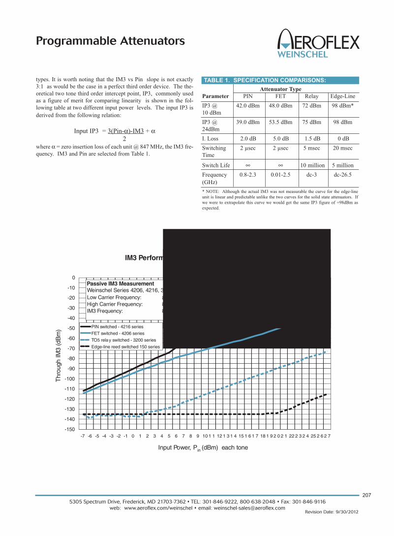
types. It is worth noting that the IM3 vs Pin slope is not exactly
3:1 as would be the case in a perfect third order device. The the-
oretical two tone third order intercept point, IP3, commonly used
as a figure of merit for comparing linearity is shown in the fol-
lowing table at two different input power levels. The input IP3 is
derived from the following relation:
Input IP3 = 3(Pin-α)-IM3 + α2
where α = zero insertion loss of each unit @ 847 MHz, the IM3 fre-
quency. IM3 and Pin are selected from Table 1.
IM3 Performance of Electromechanical & Solid StateProgrammable Attenuators
-150
-140
-130
-120
-110
-100
-90
-80
-70
-60
-50
-40
-30
-20
-10
0
-7 -6 -5 -4 -3 -2 -1 0 1 2 3 4 5 6 7 8 9 10 1 1 12 1 3 1 4 15 1 6 1 7 18 1 9 2 0 2 1 22 2 3 2 4 25 2 6 2 7
Input Power, Pin (dBm) each tone
Thr
ough
IM3
(dB
m) PIN switched - 4216 series
FET switched - 4206 series
TO5 relay switched - 3200 series
Edge-line reed switched 150 series
Weinschel Series 4206, 4216, 3200 & 150Low Carrier Frequency: 869.0 MHzHigh Carrier Frequency: 891.0 MHzIM3 Frequency: 847.0 MHz
Passive IM3 Measurement
Attenuator Type
Parameter PIN FET Relay Edge-Line
IP3 @ 42.0 dBm 48.0 dBm 72 dBm 98 dBm*
10 dBm
IP3 @ 39.0 dBm 53.5 dBm 75 dBm 98 dBm
24dBm
I. Loss 2.0 dB 5.0 dB 1.5 dB 0 dB
Switching 2 µsec 2 µsec 5 msec 20 msec
Time
Switch Life ∞ ∞ 10 million 5 million
Frequency 0.8-2.3 0.01-2.5 dc-3 dc-26.5
(GHz)
* NOTE: Although the actual IM3 was not measurable the curve for the edge-line
unit is linear and predictable unlike the two curves for the solid state attenuators. If
we were to extrapolate this curve we would get the same IP3 figure of +98dBm as
expected.
TABLE 1. SPECIFICATION COMPARISONS:
5305 Spectrum Drive, Frederick, MD 21703-7362 s TEL: 301-846-9222, 800-638-2048 s Fax: 301-846-9116
web: www.aeroflex.com/weinschel s email: [email protected]
208
Revision Date: 9/30/2012
Programmable Attenuators
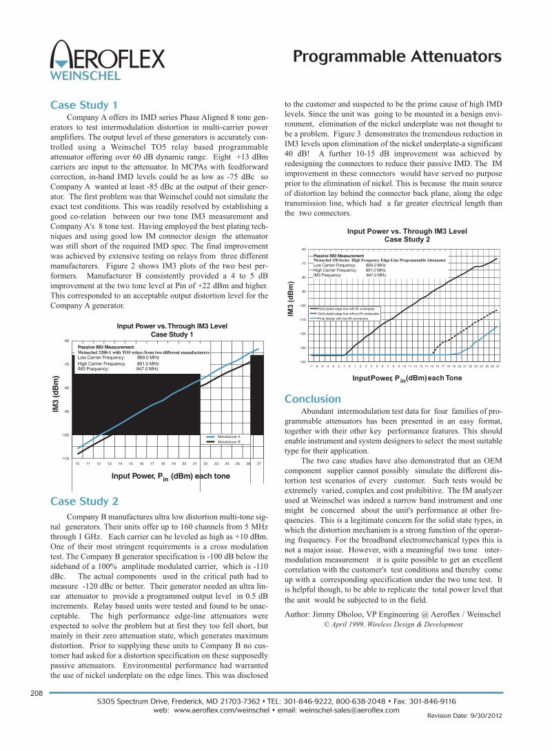
Case Study 1Company A offers its IMD series Phase Aligned 8 tone gen-
erators to test intermodulation distortion in multi-carrier power
amplifiers. The output level of these generators is accurately con-
trolled using a Weinschel TO5 relay based programmable
attenuator offering over 60 dB dynamic range. Eight +13 dBm
carriers are input to the attenuator. In MCPAs with feedforward
correction, in-band IMD levels could be as low as -75 dBc so
Company A wanted at least -85 dBc at the output of their gener-
ator. The first problem was that Weinschel could not simulate the
exact test conditions. This was readily resolved by establishing a
good co-relation between our two tone IM3 measurement and
Company A's 8 tone test. Having employed the best plating tech-
niques and using good low IM connector design the attenuator
was still short of the required IMD spec. The final improvement
was achieved by extensive testing on relays from three different
manufacturers. Figure 2 shows IM3 plots of the two best per-
formers. Manufacturer B consistently provided a 4 to 5 dB
improvement at the two tone level at Pin of +22 dBm and higher.
This corresponded to an acceptable output distortion level for the
Company A generator.
Case Study 2
Company B manufactures ultra low distortion multi-tone sig-
nal generators. Their units offer up to 160 channels from 5 MHz
through 1 GHz. Each carrier can be leveled as high as +10 dBm.
One of their most stringent requirements is a cross modulation
test. The Company B generator specification is -100 dB below the
sideband of a 100% amplitude modulated carrier, which is -110
dBc. The actual components used in the critical path had to
measure -120 dBc or better. Their generator needed an ultra lin-
ear attenuator to provide a programmed output level in 0.5 dB
increments. Relay based units were tested and found to be unac-
ceptable. The high performance edge-line attenuators were
expected to solve the problem but at first they too fell short, but
mainly in their zero attenuation state, which generates maximum
distortion. Prior to supplying these units to Company B no cus-
tomer had asked for a distortion specification on these supposedly
passive attenuators. Environmental performance had warranted
the use of nickel underplate on the edge lines. This was disclosed
to the customer and suspected to be the prime cause of high IMD
levels. Since the unit was going to be mounted in a benign envi-
ronment, elimination of the nickel underplate was not thought to
be a problem. Figure 3 demonstrates the tremendous reduction in
IM3 levels upon elimination of the nickel underplate-a significant
40 dB! A further 10-15 dB improvement was achieved by
redesigning the connectors to reduce their passive IMD. The IM
improvement in these connectors would have served no purpose
prior to the elimination of nickel. This is because the main source
of distortion lay behind the connector back plane, along the edge
transmission line, which had a far greater electrical length than
the two connectors.
ConclusionAbundant intermodulation test data for four families of pro-
grammable attenuators has been presented in an easy format,
together with their other key performance features. This should
enable instrument and system designers to select the most suitable
type for their application.
The two case studies have also demonstrated that an OEM
component supplier cannot possibly simulate the different dis-
tortion test scenarios of every customer. Such tests would be
extremely varied, complex and cost prohibitive. The IM analyzer
used at Weinschel was indeed a narrow band instrument and one
might be concerned about the unit's performance at other fre-
quencies. This is a legitimate concern for the solid state types, in
which the distortion mechanism is a strong function of the operat-
ing frequency. For the broadband electromechanical types this is
not a major issue. However, with a meaningful two tone inter-
modulation measurement it is quite possible to get an excellent
correlation with the customer's test conditions and thereby come
up with a corresponding specification under the two tone test. It
is helpful though, to be able to replicate the total power level that
the unit would be subjected to in the field.
Author: Jimmy Dholoo, VP Engineering @ Aeroflex / Weinschel
© April 1999, Wireless Design & Development
Input Power vs.Through IM3 LevelCase Study 1
-115
-105
-95
-85
-75
-65
10 11 12 13 14 15 16 17 18 19 20 21 22 23 24 25 26 27
Input Power, Pin (dBm) each tone
IM3
(dB
m)
Manufacturer A
Manufacturer B
Weinschel 3200-1 with TO5 relays from two different manufacturersLow Carrier Frequency: 869.0 MHzHigh Carrier Frequency: 891.0 MHzIM3 Frequency: 847.0 MHz
Passive IM3 Measurement
Input Power vs. Through IM3 LevelCase Study 2
-140
-130
-120
-110
-100
-90
-80
-70
-60
-7 -6 -5 -4 -3 -2 -1 0 1 2 3 4 5 6 7 8 9 10 11 12 13 14 15 16 17 18 19 20 21 22 23 24 25 26 27
InputPower, Pin(dBm)each Tone
IM3
(dB
m)
Gold plated edge-line with Ni underplate
Gold plated edge-line without Ni underplate
Final design with low IM connectors
Weinschel 150 Series High Frequency Edge-Line Programmable AttenuatorLow Carrier Frequency: 869.0 MHzHigh Carrier Frequency: 891.0 MHzIM3 Frequency: 847.0 MHz
Passive IM3 Measurement
209
5305 Spectrum Drive, Frederick, MD 21703-7362 s TEL: 301-846-9222, 800-638-2048 s Fax: 301-846-9116
web: www.aeroflex.com/weinschel s email: [email protected] Date: 3/17/2013
Programmable Attenuators
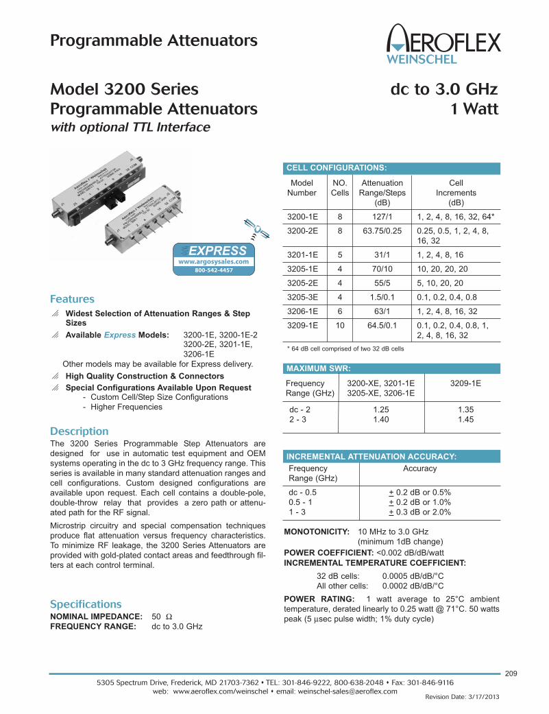
Model NO. Attenuation Cell
Number Cells Range/Steps Increments
(dB) (dB)
3200-1E 8 127/1 1, 2, 4, 8, 16, 32, 64*
3200-2E 8 63.75/0.25 0.25, 0.5, 1, 2, 4, 8,
16, 32
3201-1E 5 31/1 1, 2, 4, 8, 16
3205-1E 4 70/10 10, 20, 20, 20
3205-2E 4 55/5 5, 10, 20, 20
3205-3E 4 1.5/0.1 0.1, 0.2, 0.4, 0.8
3206-1E 6 63/1 1, 2, 4, 8, 16, 32
3209-1E 10 64.5/0.1 0.1, 0.2, 0.4, 0.8, 1,
2, 4, 8, 16, 32
* 64 dB cell comprised of two 32 dB cells
CELL CONFIGURATIONS:
DescriptionThe 3200 Series Programmable Step Attenuators are
designed for use in automatic test equipment and OEM
systems operating in the dc to 3 GHz frequency range. This
series is available in many standard attenuation ranges and
cell configurations. Custom designed configurations are
available upon request. Each cell contains a double-pole,
double-throw relay that provides a zero path or attenu-
ated path for the RF signal.
Microstrip circuitry and special compensation techniques
produce flat attenuation versus frequency characteristics.
To minimize RF leakage, the 3200 Series Attenuators are
provided with gold-plated contact areas and feedthrough fil-
ters at each control terminal.
Model 3200 Series dc to 3.0 GHz
Programmable Attenuators 1 Wattwith optional TTL Interface
Features
o Widest Selection of Attenuation Ranges & StepSizes
o Available Express Models: 3200-1E, 3200-1E-23200-2E, 3201-1E,
3206-1E
Other models may be available for Express delivery.
o High Quality Construction & Connectors
o Special Configurations Available Upon Request- Custom Cell/Step Size Configurations
- Higher Frequencies
Specifications NOMINAL IMPEDANCE: 50 ΩFREQUENCY RANGE: dc to 3.0 GHz
INCREMENTAL ATTENUATION ACCURACY:
Frequency Accuracy
Range (GHz)
dc - 0.5 + 0.2 dB or 0.5%
0.5 - 1 + 0.2 dB or 1.0%
1 - 3 + 0.3 dB or 2.0%
MONOTONICITY: 10 MHz to 3.0 GHz
(minimum 1dB change)
POWER COEFFICIENT: <0.002 dB/dB/watt
INCREMENTAL TEMPERATURE COEFFICIENT:
32 dB cells: 0.0005 dB/dB/°C
All other cells: 0.0002 dB/dB/°C
POWER RATING: 1 watt average to 25°C ambient
temperature, derated linearly to 0.25 watt @ 71°C. 50 watts
peak (5 μsec pulse width; 1% duty cycle)
www.argosysales.com 800-542-4457
EXPRESS
MAXIMUM SWR:
Frequency 3200-XE, 3201-1E 3209-1E
Range (GHz) 3205-XE, 3206-1E
dc - 2 1.25 1.35
2 - 3 1.40 1.45

5305 Spectrum Drive, Frederick, MD 21703-7362 s TEL: 301-846-9222, 800-638-2048 s Fax: 301-846-9116
web: www.aeroflex.com/weinschel s email: [email protected] Date: 3/17/2013
Programmable Attenuators
MODEL NUMBER DESCRIPTION:
320X-YE For a basic 3 GHz model*
320X-YE-1 Add -1 for a TTL driver board with a 10 pin
ribbon cable connector
320X-YE-2 Add -2 for a TTL driver board with a 15 pin
D connector
* Use the Cell Configuration table to determine X and Y
for available attenuation ranges.
210
Specifications - Con’t
RATED SWITCH LIFE: 5 million cycles operations per cell
@ 0 dBm
SWITCHING TIME: 6 msec. maximum at nominal rated
voltage
RELEASE TIME: 3 msec maximum
CYCLING RATE: 5 Hz maximum per relay
OPERATING VOLTAGE: +12 Vdc (+4 / -2 V)
OPERATING CURRENT: 30 mA typical per cell @ +12V
TEMPERATURE RANGE (Operating): -55°C to +71°C
TEST DATA: Test data is available at additional cost.
CONNECTORS: SMA female connectors per MIL-STD-348
interface dimensions - mate nondestructively with
MIL-C-39012 connectors.
CONTROL TERMINALS: 0.040 inch. (1 mm) diameter
solderable leads. May be used with PC board sockets/
receptacles.
CONSTRUCTION:
Housing: Aluminum
Connectors: Stainless steel body and beryllium
copper contacts.
Control terminals: Brass/Copper, Silver plated
WEIGHT (Typical):
3200-1E & 3200-2E: 117 g (4.1 oz)
3201-1E: 89 g (3.1 oz)
3205-1E, 3205-2E, 3205-3E: 77 g (2.7 oz)
3206-1E: 99 g (3.5 oz)
3209-1E: 159 g (5.6 oz)
CONTROL CONFIGURATION: Standard Unit: One terminal is connected to case ground
and the remaining terminals are provided for activation of
individual cells. Attenuation is fail-safe to "0" setting in the
absence of a control voltage. Application of a voltage (+) to
a particular cell causes it to switch to the attenuate position.
Units with TTL Option: Units with this option are supplied
with a very low profile connectorized TTL interface board
mounted directly to the control terminals. This TTL interface
option is available with either a 10 pin ribbon cable connec-
tor or a 15 pin "D" connector (limited models), refer to list
below. Each type is supplied with a mating connector. Refer
to Physical Dimensions for mating connector pin/wiring
details. Two wires are specified for supply voltage and
ground. The remaining wires will accept TTL control signals
to activate or de-activate a particular attenuation cell. A TTL
high will energize a cell to the high attenuation state,
whereas a TTL low will maintain a cell in its zero attenuation
state.
To order 3200 Series Attenuators with this option add -1 to
basic model number for ribbon cable connector and -2 for
the "D" connector. Example: Model 3201-1E with a TTL
interface board would be 3201-1E-1. Mating connector is
provided. To order a TTL Driver board separately for an
existing 3200 Series Attenuator, use the following:
Basic TTL BD Kit Part No. TTL BD Part No.
Model No. 10 Pin Ribbon 15 Pin "D" CONN
3200-1E, 3200-2E 101-1781 101R-1798-000**
3201-1E 101-1780 101R-1798-001**
3205-1E, 3205-2E 101-1780 101R-1798-001**
3205-3E
3206-1E 101-1780 101R-1798-001**
3209-1E 101-1804-000* N/A
* 14 pin ribbon connector.
** 3 FT TTL Interface Cable Part No. 101-1805 supplied with unit.
Note: Control is non-latching and requires a continuous
control signal for the period of time in which attenuation is
required.
INTERFACE CONNECTOR: Option -1(Models 3200, 3201,
3205 and 3206): 10 pin .025 square post header on .1
center, mates with Amp connector 746285-1 or equivalent.
Option -1 (3209): 14 pin .025 square post header on .1
center, mates with Amp connector 746285-2 or equivalent.
Option -2: 15 pin D Socket Connector, mates with Cannon
connector DA-15S or equivalent.
MAXIMUM INSERTION LOSS (dB):
Frequency 3200-1E 3201-1E 3205-1E, 3205-2E 3206-1E 3209-1E
Range (GHz) 3200-2E 3205-3E
dc - 0.5 2.50 1.70 1.50 2.20 3.00
0.5 - 1.0 3.20 2.20 1.75 2.40 3.60
1.0 - 1.5 3.50 2.50 2.00 2.80 4.20
1.5 - 2.0 4.00 2.80 2.25 3.10 4.60
2.0 - 3.0 4.70 3.25 2.60 3.70 5.50

211
5305 Spectrum Drive, Frederick, MD 21703-7362 s TEL: 301-846-9222, 800-638-2048 s Fax: 301-846-9116
web: www.aeroflex.com/weinschel s email: [email protected] Date: 3/17/2013
Programmable Attenuators
INPUT VOLTAGE: VIN High= +2.0V minimum
+5.0V typical
Vcc maximum
VIN Low = 0 minimum
0.8 maximum
INPUT CURRENT: IIN (VIN=2.4 V) = 55 μA
IIN (VIN=3.85 V) = 280 μA
SUPPLY CURRENT (Digital Section): ICC=25.0 mA
maximum
SUPPLY CURRENT (per cell continuos): 30 mA per cell
SUPPLY VOLTAGE: VCC=+12.0 to +15V
TEMPERATURE RANGE (Operating): -40°C to +70°C
MODELS WITH BUILT-IN DRIVERS: All 3200s are avail-
able with an intelligent interface\driver cards. These are
designed to interface with our 8210A Series Controllers
which greatly simplifies computer control applications. Refer
to 3200T Series data sheet for more information.
PHYSICAL DIMENSIONS:
TTL DRIVER SPECIFICATIONS:
Aeroflex / Wein
NOTE: All dimensions are given in mm (inches) and are maximum, unless otherwise specified.
Model No. No. Cells A B C D
3200-XE 8 101.6 (4.0 7 EQ SPCS @ 10.16 (.40) = 71.1 (2.80) 88.9 (3.50) 95.2 (3.75)
3201-XE 5/4 76.2 (3.00) 4 EQ SPCS @ 10.16 (.40) = 40.64 (1.60) 63.5 (2.50) 69.8 (2.75)
3205-XE 4 58.9 (2.32) 3 EQ SPCS @ 10.16 (.40) = 30.5 (1.20) 46.2 (1.82) 52.6 (2.07)
3206-XE 6 81. 3+0.5 5 EQ SPCS @ 10.16 (.40) = 50.8 (2.00) 68.6 (2.70) 75.18 (2.96)
(3.20+0.02

5305 Spectrum Drive, Frederick, MD 21703-7362 s TEL: 301-846-9222, 800-638-2048 s Fax: 301-846-9116
web: www.aeroflex.com/weinschel s email: [email protected]
212
Revision Date: 3/17/2013
Programmable Attenuators
TTL Conn 3200-1E-1 3200-2E-1 3201-1E-1 3205-1E-1 3205-2E-1 3205-3E-1 3206-1E-1
PIN No. (J3) dB (Cell) dB (Cell) dB (Cell ) dB (Cell) dB (Cell) dB (Cell ) dB (Cell)
1 32 0.25 NC NC NC NC NC
2 1 0.5 NC NC NC NC NC
3 2 1 1 NC NC NC 1
4 32* 2 2 10 5 0.1 2
5 4 4 4 20 10 0.2 4
6 8 8 8 20 20 0.4 8
7 16 16 16 20 20 0.8 16
8 32* 32 NC NC NC NC 32
9 COM COM COM COM COM COM COM
10 +Vcc +Vcc +Vcc + Vcc + Vcc +Vcc + Vcc
PHYSICAL DIMENSIONS:
*64 dB cell comprised of two 32 dB cells
**60 dB cell comprised of two 30 dB cells
NC = Not Connected
Control Connector J3 Pin Locations:
Model No. E
3200-XE-1 37.8 (1.49)
3201-XE-1 18.8 (0.74)
3206-XE-1 18.8 (0.74)
TTL OPTION -1 (3205):
TTL OPTION -1 (3200, 3201, 3206):
NOTE: All dimensions are given in mm (inches) and are maximum, unless otherwise specified.
Aeroflex / Weinschel

213
5305 Spectrum Drive, Frederick, MD 21703-7362 s TEL: 301-846-9222, 800-638-2048 s Fax: 301-846-9116
web: www.aeroflex.com/weinschel s email: [email protected] Date: 3/17/2013
Programmable Attenuators
NOTE: All dimensions are given in mm (inches) and are maximum, unless otherwise specified.
TTL Driver Option -2 (3200, 3201, 3205):
Model No. A
3200-XE-2 101.6 (4.00)
3201-XE-2 76.2 (3.00)
3205-XE-2 76.2 (3.00)
"D" Conn 3200-1E-2 3200-2E-2 3201-1E-2 3205-1E-2 3205-2E-2 3205-3E-2 Cable (P/N 101-1805)
PIN No. (J3) dB (Cell) dB (Cell) dB (Cell ) dB (Cell) dB (Cell) dB (Cell) Color Code
1 32 32 NC NC NC NC BRN
2 16 16 NC NC NC NC YEL
3 8 8 NC NC NC NC GRN
4 4 4 16 20 20 0.8 LT BLU
5 32 0.25 1 NC NC NC VIO
6 1 0.5 2 10 5 0.1 GRY
7 2 1 4 20 10 0.2 WHT
8 32* 2 8 20 20 0.4 WHT/BLK
9 NC NC NC NC NC NC RED
10 GND GND GND GND GND GND BLK
11 NC NC NC NC NC NC - - -
12 NC NC NC NC NC NC - - -
13 NC NC NC NC NC NC - - -
14 NC NC NC NC NC NC - - -
15 +Vcc +Vcc +Vcc +Vcc +Vcc +Vcc ORN
*64 dB cell comprised of two 32 dB cells
**60 dB cell comprised of two 30 dB cells
NC = Not Connected
Control Connector J3 Pin Locations:
PHYSICAL DIMENSIONS:

5305 Spectrum Drive, Frederick, MD 21703-7362 s TEL: 301-846-9222, 800-638-2048 s Fax: 301-846-9116
web: www.aeroflex.com/weinschel s email: [email protected]
214
Revision Date: 3/17/2013
Programmable Attenuators
PHYSICAL DIMENSIONS:
NOTE: All dimensions are given in mm (inches) and are maximum, unless otherwise specified.
Model 3209-1E:
Model 3209-1E-1 (TTL Option -1):

215
5305 Spectrum Drive, Frederick, MD 21703-7362 s TEL: 301-846-9222, 800-638-2048 s Fax: 301-846-9116
web: www.aeroflex.com/weinschel s email: [email protected] Date: 9/30/2012
Programmable Attenuators
Specifications NOMINAL IMPEDANCE: 50 ΩFREQUENCY RANGE: dc to 3.0 GHz
DescriptionThis line of intelligent programmable step attenuators with a
built-in digital interface are designed to simplify the control
and integration of these devices into subsystem and bench
applications. This series of Programmable Step Attenuators
is designed for use in automatic test equipment and OEM
systems operating in the dc to 3 GHz frequency range.
These models are available in many standard attenuation
ranges and cell configurations. Each cell contains a double-
pole, double-throw relay that provides a minimum loss or
attenuated path for the RF signal.
Microstrip circuitry and special compensation techniques
produce flat attenuation versus frequency characteristics.
To minimize RF leakage, the 3200T Series Attenuators are
provided with gold-plated contact areas and feedthrough fil-
ters at each control terminal.
Model 3200T dc to 3.0 GHz
SmartStep® Programmable Attenuators 1 Watt
with built-in Microprocessor-Based Driver
For Use with Weinschel 8210A Controller
Features
o Widest Selection of Attenuation Ranges & Steps Sizes
o Built-In TTL\CMOS Interface Driver Circuitry
o High Quality Construction and Connectors
o Special Configurations Available Upon Request- Custom Cell/Step Size Configurations
- Higher Frequencies (See 3400 Series)
Model NO. Attenuation Cell
Number Cells Range/Steps Increments
(dB) (dB)
3200T-1E 8 127/1 1, 2, 4, 8, 16, 32, 64*
3200T-2E 8 63.75/0.25 0.25, 0.5, 1, 2, 4, 8,
16, 32
3201T-1E 5 31/1 1, 2, 4, 8, 16
3201T-2E 5 120/10 10, 20, 30, 60**
3205T-1E 4 70/10 10, 20, 20, 20
3205T-2E 4 55/5 5, 10, 20, 20
3205T-3E 4 1.5/0.1 0.1, 0.2, 0.4, 0.8
3206T-1E 6 63/1 1, 2, 4, 8, 16, 32
3209T-1E 10 64.5/0.1 0.1, 0.2, 0.4, 0.8, 1,
2, 4, 8, 16, 32
*64 dB cell comprised of two 32 dB cells
CELL CONFIGURATIONS:
INCREMENTAL ATTENUATION ACCURACY:
Frequency Accuracy
Range (GHz)
dc - 0.5 + 0.2 dB or 0.5%
0.5 - 1 + 0.2 dB or 1.0%
1 -3 + 0.3 dB or 2.0%
MONOTONICITY: 10 MHz to 3.0 GHz
(minimum 1 dB change)
POWER COEFFICIENT: <0.002 dB/dB/watt
INCREMENTAL TEMPERATURE COEFFICIENT:
30 & 32 dB cells: 0.0005 dB/dB/°C
All other cells: 0.0002 dB/dB/°C
MAXIMUM SWR:
Frequency 3200T-XE, 3201T-1E 3209T-1E
Range (GHz) 3205T-XE, 3206T-1E
dc - 2 1.25 1.35
2 - 3 1.40 1.45

5305 Spectrum Drive, Frederick, MD 21703-7362 s TEL: 301-846-9222, 800-638-2048 s Fax: 301-846-9116
web: www.aeroflex.com/weinschel s email: [email protected]
216
Revision Date: 9/30/2012
Programmable Attenuators
POWER RATING: 1 watt average to 25°C ambient tem-
perature, derated linearly to 0.25 watt @ 71°C. 50 watts
peak (5 μsec pulse width; 1% duty cycle)
RATED SWITCH LIFE: 5 million cycles operations per cell
@ 0 dBm
CYCLING RATE: 5 Hz maximum per relay
DRIVER INTERFACE:
Input Supply Voltage: +12.0 to +15 V
Control Signals: TTL/CMOS compatible
Interface Modes: parallel / serial
DC Characteristics (at 25 °C):
Parameter Specification
VIL Low-level input V: -0.5 V min, 0.8 V max
VIH High-level input V: 2.0 V min, 5.25 V max
IPU Pullup current 50 μA min, 400 μA max
VIN Supply Voltage: +12.0 to +15.0 V
IIN Supply current: 25 mA
(digital section)
ICELL Supply current: 30 mA (per cell)
continuous
TEMPERATURE RANGE (Operating): -20°C to +70°C
TEST DATA: Test data is available at additional cost.
CONNECTORS: SMA female connectors per MIL-STD-348
interface dimensions - mate nondestructively with
MIL-C-39012 connectors.
INTERFACE CONNECTOR: 14 pin .025 square post
header on .1 center. Mates with Amp connector 746285-2 or
equivalent.
CONSTRUCTION:
Housing: Aluminum
Connectors: Stainless steel body and beryllium
copper contacts.
WEIGHT: 3200T-XE 165 g (8.4 oz)
3201T-XE 132 g (7.3 oz)
3205T-XE 132 g (7.3 oz)
3206T-XE 132 g (7.3 oz)
3209T-XE 218 g (9.7 oz)
ACCESSORIESProgrammable Attenuator/Switch Controller: The Model
8210A Programmable Attenuator/Switch Controller provides
a flexible, low cost solution for the operation of programma-
ble step attenuators and other electromechanical devices
under computer control. Designed to interface to Aeroflex /
Weinschel's intelligent programmable attenuators, the
8210A represents a new concept in device control
applications for bench test and subsystem designs. The
8210A provides a high-level interface from various industry
standard communications interfaces, including IEEE-488
and RS232/RS422/RS485, to the programmable
attenuator’s serial Driver Interface Bus.
CONTROL CONFIGURATION
These programmable attenuators feature an internal micro-
controller-based driver that provides a TTL-level digital
interface for control of the attenuator relays. This card sim-
plifies operation and interfacing requirements, while at the
same time providing for greatly enhanced flexibility over
past designs. User-selectable modes of operation include
both parallel and serial bus. The parallel mode provides a
simple, one-bit per relay on/off control with internal pullups
for use primarily in single attenuator applications. This mode
allows the attenuator to be controlled via a variety of meth-
ods, such as a TTL-level digital output port, or mechanical
toggle switches. The device bus provides a two-wire serial
bus structure and protocol for connecting a number of
devices to a single host control interface, suitable for use in
larger system and sub-system applications. The digital
interface contains non-volatile configuration memory that is
used to hold a wide variety of attenuator and driver-depen-
dent parameters, including serial number, attenuator cell dB
values, relay configurations, and switching requirements,
which are all accessible via the digital interface.
In either operational mode, the microcontroller enters an
idle condition during periods of inactivity, turning off all
on-board clocks, reducing EMI concerns, and lowering
power consumption. On-board regulation for the digital
circuitry allows the attenuator to operate from a single input
supply voltage.
Specifications - Con’t
MAXIMUM INSERTION LOSS (dB):
Frequency 3200T-1E 3201T-1E 3205T-1E, 3205T-2E 3206T-1E 3209T-1E
Range (GHz) 3200T-2E 3205T-3E
dc - 0.5 2.50 1.70 1.50 2.20 3.00
0.5 - 1.0 3.20 2.20 1.75 2.40 3.60
1.0 - 1.5 3.50 2.50 2.00 2.80 4.20
1.5 - 2.0 4.00 2.80 2.25 3.10 4.60
2.0 - 3.0 4.70 3.25 2.60 3.70 5.50

217
5305 Spectrum Drive, Frederick, MD 21703-7362 s TEL: 301-846-9222, 800-638-2048 s Fax: 301-846-9116
web: www.aeroflex.com/weinschel s email: [email protected] Date: 9/30/2012
Programmable Attenuators
PHYSICAL DIMENSIONS:
"D"
34.0(1.34)MAX
NOTE: All dimensions are given in mm (inches) and are maximum, unless otherwise specified.
Model No. No. Cells A B C D
3200T-XE 8 101.6 (4.0) 31.8 (1.25) 88.9 (3.50) 95.2 (3.75)
3201T-XE 5/4 76.2 (3.00) 19.1 (0.75) 63.5 (2.50) 69.8 (2.75)
3205T-XE 4 72.4 (2.85) 19.1 (0.75) 46.2 (1.82) 52.6 (2.07)
3206T-XE 6 81. 3+0.5 21.46 (0.85) 68.6 (2.70) 75.18 (2.96)
(3.20+0.02
Model 3200T, 3201T, 3205T, & 3206T:
Model 3209T:

5305 Spectrum Drive, Frederick, MD 21703-7362 s TEL: 301-846-9222, 800-638-2048 s Fax: 301-846-9116
web: www.aeroflex.com/weinschel s email: [email protected]
218
Revision Date: 9/30/2012
Programmable Attenuators
Models 3404, 3406 & 3408 dc to 6.0 GHz
Programmable Attenuators 1 Wattwith optional TTL Interface
Model NO. Attenuation Cell
Number Cells Range/Steps Increments
(dB) (dB)
3404-15 4 15/1 1, 2, 4, 8
3404-55 4 55/5 5, 10, 20, 20
3404-70 4 70/10 10, 20, 20, 20
3406-55 6 55/1 1, 2, 4, 8, 16, 24
3408-55.75 8 55.75/0.25 0.25, 0.5, 1, 2, 4, 8,
16, 24
3408-103 8 103/1 1, 2, 4, 8, 16, 24, 48*
*48 dB cell comprised of two 24 dB cells
CELL CONFIGURATIONS:
DescriptionThe 3400 Series Programmable Step Attenuators are
designed for use in automatic test equipment and OEM
systems operating in the dc to 6 GHz frequency range. This
series is available in many standard attenuation ranges and
cell configurations. Custom designed configurations are
available upon request. Each cell contains a double-pole,
double-throw relay that provides a zero path or
attenuated path for the RF signal.
Microstrip circuitry and special compensation techniques
produce flat attenuation versus frequency characteristics.
The microstrip construction, using thin-film circuit
elements, ensures product uniformity. To minimize RF
leakage, the 3400 Series Attenuators are provided with
gold-plated contact areas and feedthrough filters at each
control terminal.
Features
o Higher Frequency range to 6 GHz.
o Wide Selection of Attenuation Ranges & Step Sizes
- 0 to 15 dB in 1 dB steps
- 0 to 55 dB in 1 dB steps
- 0 to 55.75 in 0.25 dB steps
- 0 to 103 dB in 1 dB steps
- 0 to 70 dB in 10 dB steps
o High Quality Construction & Connectors
o Special Configurations Available Upon Request
Specifications NOMINAL IMPEDANCE: 50 ΩFREQUENCY RANGE: dc to 6.0 GHz
INCREMENTAL ATTENUATION ACCURACY:
Frequency Accuracy
Range (GHz)
dc - 3 +0.3 dB or 2% whichever is greater
3 - 6 +0.4 dB or 3% whichever is greater
MAXIMUM SWR:
Frequency Range (GHz) SWR
dc - 3 1.30
3 - 6 1.45
MONOTONICITY: dc to 6.0 GHz (minimum 1 dB change)
POWER RATING: 1 watt average to 25°C ambient
temperature, derated linearly to 0.25 watt @ 70°C. 50 watts
peak (5 μsec pulse width; 1% duty cycle)
POWER COEFFICIENT: <0.005 dB/dB/watt
RATED SWITCH LIFE: 5 million cycles operations per cell
@ 0 dBm
SWITCHING TIME: 6 msec. maximum at nominal rated
voltage
RELEASE TIME: 5 msec maximum
CYCLING RATE: 5 Hz maximum per relay
OPERATING VOLTAGE: +12 Vdc (+13 V maximum; +9 V
minimum)
OPERATING CURRENT: 17 mA typical per cell @ +12 V
TEMPERATURE RANGE (Operating): -30°C to +70°C
TEST DATA: Test data is available at additional cost.
MAXIMUM INSERTION LOSS (dB):
Frequency 3404-15 3406-55 3408-55.75
Range (GHz) 3404-55 3408-103
3404-70
dc - 3 1.80 2.60 3.40
3 - 6 2.60 3.80 5.00

219
5305 Spectrum Drive, Frederick, MD 21703-7362 s TEL: 301-846-9222, 800-638-2048 s Fax: 301-846-9116
web: www.aeroflex.com/weinschel s email: [email protected] Date: 9/30/2012
Programmable Attenuators
SPECIFICATIONS - Con’t
CONNECTORS: SMA female connectors per MIL-STD-348
interface dimensions - mate nondestructively with
MIL-C-39012 connectors. eads. May be used with PC board
sockets/ receptacles.
CONTROL TERMINALS: 0.040 inch. (1 mm) diameter
solderable leads. May be used with PC board sockets/
receptacles.
CONSTRUCTION:
Housing: Aluminum
Connectors: Stainless steel body and beryllium
copper contacts.
Control terminals: Brass/Copper, Silver plated
WEIGHT (Typical): 3404-X: 99 g (3.5 oz)
3406-X: 99 g (3.5 oz)
3408-X: 135 g (4.8 oz)
CONTROL CONFIGURATION: Standard Unit: One terminal is connected to case ground
and the remaining terminals are provided for activation of
individual cells. Attenuation is fail-safe to "0" setting in the
absence of a control voltage. Application of a voltage (+) to
a particular cell causes it to switch to the attenuate position.
Units with TTL Option: Units with this options are supplied
with a very low profile connectorized TTL interface board
mounted directly to the control terminals. This TTL interface
option is available with a 10 pin ribbon cable connector and
is supplied with a mating connector. Refer to Physical
Dimensions for mating connector pin/wiring details. Two
wires are specified for supply voltage and ground. The
remaining wires will accept TTL control signals to activate or
de-activate a particular attenuation cell. A TTL high will
energize a cell to the high attenuation state, whereas a TTL
low will maintain a cell in its zero attenuation state.
To order 3400 Series Attenuators with this option add -1 to
basic model number for ribbon cable connector. Example:
Model 3406-63 with a TTL interface would be 3406-63-1.
Note: Control is non-latching and requires a continuous
control signal for the period of time in which attenuation is
required.
TTL DRIVER SPECIFICATIONS:
INTERFACE CONNECTOR: Option -1: 10 pin .025 square
post header on .1 center, mates with Amp connector
746285-1 or equivalent
INPUT VOLTAGE: VIN High= +2.0V minimum
+5.0V typical
Vcc maximum
VIN Low = 0 minimum
0.8 maximum
INPUT CURRENT: IIN (VIN=2.4 V) = 55 μA
IIN (VIN=3.85 V) = 280 μA
SUPPLY CURRENT: ICC=25 mA maximum per cell
SUPPLY VOLTAGE: VCC=+12.0 to +15 V
MODELS WITH BUILT-IN DRIVERS: Most 3400s are avail-
able with an intelligent interface\driver cards. These are
designed to interface with our 8210A Series Controllers
which greatly simplifies computer control applications. Refer
to Model 3406T and 3408T data sheet for more information.

5305 Spectrum Drive, Frederick, MD 21703-7362 s TEL: 301-846-9222, 800-638-2048 s Fax: 301-846-9116
web: www.aeroflex.com/weinschel s email: [email protected]
220
Revision Date: 9/30/2012
Programmable Attenuators
A
B
C
D
Aeroflex / Weinschel
PHYSICAL DIMENSIONS:
NOTE: All dimensions are given in mm (inches) and are nominal, unless otherwise specified.
Model No. No. Cells A B C D
3408-X 8 136.1 (5.36) 123.4 (4.86) 7 EQ SPCS @ 15.20 (.60) = 106.7 (4.20) 128.5 (5.06)
3406-X 6 105.7 (3.66) 93.0 (3.66) 5 EQ SPCS @ 15.20 (.60) = 76.0 (3.00) 98.0 (3.86)
3404-X 4 75.18 (2.96) 62.48 (2.46 3 EQ SPCS @ 15.20 (.60) = 45.72 (1.80) 67.56 (2.66)
221
5305 Spectrum Drive, Frederick, MD 21703-7362 s TEL: 301-846-9222, 800-638-2048 s Fax: 301-846-9116
web: www.aeroflex.com/weinschel s email: [email protected] Date: 9/30/2012
Programmable Attenuators
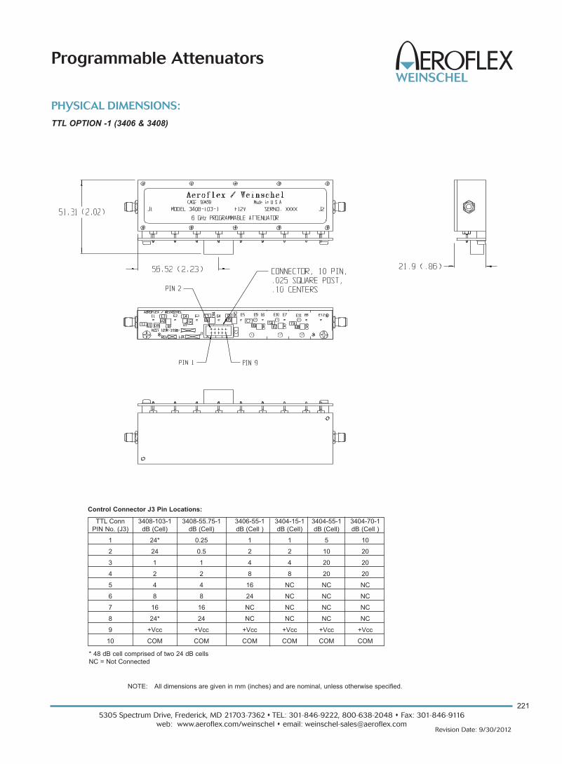
PHYSICAL DIMENSIONS:
TTL OPTION -1 (3406 & 3408)
NOTE: All dimensions are given in mm (inches) and are nominal, unless otherwise specified.
TTL Conn 3408-103-1 3408-55.75-1 3406-55-1 3404-15-1 3404-55-1 3404-70-1
PIN No. (J3) dB (Cell) dB (Cell) dB (Cell ) dB (Cell) dB (Cell) dB (Cell )
1 24* 0.25 1 1 5 10
2 24 0.5 2 2 10 20
3 1 1 4 4 20 20
4 2 2 8 8 20 20
5 4 4 16 NC NC NC
6 8 8 24 NC NC NC
7 16 16 NC NC NC NC
8 24* 24 NC NC NC NC
9 +Vcc +Vcc +Vcc +Vcc +Vcc +Vcc
10 COM COM COM COM COM COM
* 48 dB cell comprised of two 24 dB cells
NC = Not Connected
Control Connector J3 Pin Locations:

5305 Spectrum Drive, Frederick, MD 21703-7362 s TEL: 301-846-9222, 800-638-2048 s Fax: 301-846-9116
web: www.aeroflex.com/weinschel s email: [email protected]
222
Revision Date: 9/30/2012
Programmable Attenuators
Models 3404T, 3406T & 3408T dc to 6.0 GHz
SmartStep® Programmable Attenuators 1 Watt
with built-in Microprocessor-Based Driver
For Use with Weinschel 8210A Controller
DescriptionThis line of intelligent programmable step attenuators with a
built-in digital interface are designed to simplify the control
and integration of these devices into subsystem and bench
applications. This series of Programmable Step Attenuators
is designed for use in automatic test equipment and OEM
systems operating in the dc to 6 GHz frequency range.
These models are available in many standard attenuation
ranges and cell configurations. Each cell contains a double-
pole, double-throw relay that provides a minimum loss or
attenuated path for the RF signal.
Microstrip circuitry and special compensation techniques
produce flat attenuation versus frequency characteristics.
The microstrip construction, using thick-film circuit
elements, ensures product uniformity. To minimize RF leak-
age, the 3400T Series Attenuators are provided with
gold-plated contact areas and feedthrough filters at each
control terminal.
Features
o Higher Frequency range to 6 GHz.
o Wide Selection of Attenuation Ranges & Step Sizes
- 0 to 15 dB in 1 dB steps
- 0 to 55 dB in 1 dB steps
- 0 to 55.75 in 0.25 dB steps
- 0 to 103 dB in 1 dB steps
- 0 to 70 dB in 10 dB steps
o High Quality Construction & Connectors
o Built-In TTL\CMOS Interface Driver Circuitry
o Special Configurations Available Upon Request
Specifications NOMINAL IMPEDANCE: 50 ΩFREQUENCY RANGE: dc to 6.0 GHz
INCREMENTAL ATTENUATION ACCURACY:
Frequency Accuracy
Range (GHz)
dc - 3 +0.3 dB or 2% whichever is greater
3 - 6 +0.4 dB or 3% whichever is greater
MAXIMUM SWR:
Frequency Range (GHz) SWR
dc - 3 1.30
3 - 6 1.45
MONOTONICITY: dc to 6.0 GHz (minimum 1 dB change)
POWER RATING: 1 watt average to 25°C ambient
temperature, derated linearly to 0.25 watt @ 70°C. 50 watts
peak (5 μsec pulse width; 1% duty cycle)
POWER COEFFICIENT: <0.005 dB/dB/watt
RATED SWITCH LIFE: 5 million cycles operations per cell
@ 0 dBm
SWITCHING TIME: 6 msec. maximum at nominal rated
voltage
RELEASE TIME: 5 msec maximum
SWITCHING SPEED: 5 Hz maximum per relay
OPERATING VOLTAGE: +12V (+13V maximum; +9V min-
imum)
OPERATING CURRENT: 17 mA typical per cell @ +12V
TEMPERATURE RANGE (Operating): -30°C to +70°C
MAXIMUM INSERTION LOSS (dB):
Frequency 3404T-15 3406T-55 3408T-55.75
Range (GHz) 3404T-55 3408T-103
3404T-70
dc - 3 1.80 2.60 3.40
3 - 6 2.60 3.80 5.00
Model NO. Attenuation Cell
Number Cells Range/Steps Increments
(dB) (dB)
3404T-15 4 15/1 1, 2, 4, 8
3404T-55 4 55/5 5, 10, 20, 20
3404T-70 4 70/10 10, 20, 20, 20
3406T-55 6 55/1 1, 2, 4, 8, 16, 24
3408T-55.75 8 55.75/0.25 0.25, 0.5, 1, 2, 4, 8,
16, 24
3408T-103 8 103/1 1, 2, 4, 8, 16, 24, 48*
*48 dB cell comprised of two 24 dB cells
CELL CONFIGURATIONS:
223
5305 Spectrum Drive, Frederick, MD 21703-7362 s TEL: 301-846-9222, 800-638-2048 s Fax: 301-846-9116
web: www.aeroflex.com/weinschel s email: [email protected] Date: 9/30/2012
Programmable Attenuators
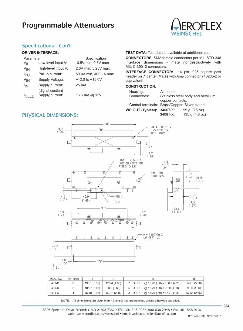
Specifications - Con’t
TEST DATA: Test data is available at additional cost.
CONNECTORS: SMA female connectors per MIL-STD-348
interface dimensions - mate nondestructively with
MIL-C-39012 connectors.
INTERFACE CONNECTOR: 14 pin .025 square post
header on .1 center. Mates with Amp connector 746285-2 or
equivalent.
CONSTRUCTION:
Housing: Aluminum
Connectors: Stainless steel body and beryllium
copper contacts.
Control terminals: Brass/Copper, Silver plated
WEIGHT (Typical): 3406T-X: 99 g (3.5 oz)
3408T-X: 135 g (4.8 oz)
DRIVER INTERFACE:
Parameter Specification
VIL Low-level input V: -0.5V min, 0.8V max
VIH High-level input V: 2.0V min, 5.25V max
IPU Pullup current: 50 μA min, 400 μA max
VIN Supply Voltage: +12.0 to +15.0V
IIN Supply current: 25 mA
(digital section)
ICELL Supply current: 16.6 mA @ 12V
“A”
“B”
“C”
“D”
49.9(1.93)
PHYSICAL DIMENSIONS:
NOTE: All dimensions are given in mm (inches) and are nominal, unless otherwise specified.
Model No. No. Cells A B C D
3408-X 8 136.1 (5.36) 123.4 (4.86) 7 EQ SPCS @ 15.20 (.60) = 106.7 (4.20) 128.5 (5.06)
3406-X 6 105.7 (3.66) 93.0 (3.66) 5 EQ SPCS @ 15.20 (.60) = 76.0 (3.00) 98.0 (3.86)
3404-X 4 75.18 (2.96) 62.48 (2.46 3 EQ SPCS @ 15.20 (.60) = 45.72 (1.80) 67.56 (2.66)

5305 Spectrum Drive, Frederick, MD 21703-7362 s TEL: 301-846-9222, 800-638-2048 s Fax: 301-846-9116
web: www.aeroflex.com/weinschel s email: [email protected]
228
Revision Date: 9/30/2012
Programmable Attenuators
Model 150 dc to 18.0 GHz
Model 151 dc to 4.0 GHz
Model 152 dc to 26.5 GHz
Relay Switched Programmable Attenuators
DescriptionThe Model 150, 151 and 152 Programmable Step
Attenuators represent the widest variety of programmable
attenuators available. This attenuator design is the result of
an extensive development program and offers long reliable
operation with exceptional accuracy and repeatability.
These attenuators can provide programmable adjustments
of RF signal levels in precise steps of 1 dB, 5 dB, 10 dB, or
with custom steps available. Each attenuator consists of a
cascaded assembly of
switched attenuator cells
(Figure 1). The attenuator
elements located in the
attenuator cell are created
by a thin-film process
which provides excep-
tional long-term stability,
low power and tempera-
ture coefficients. This
series uses a reed switch-
ing structure that provides
rapid switching together
with low insertion loss.
Other features include:
o Broadband Frequency Coverage
o High Accuracy and Repeatability
o Long Life, 5 Million Cycles Per Cell
o 3, 4, and 5 Cell Configurations
PROGRAMMABILITY: In each programmable step
Attenuator, solenoids are used to switch the internal resistor
card of each cell into and out of the circuit. Once the cell is
switched, the solenoid is magnetically latched into position
and is able to withstand extreme shock and vibration.
Internal circuitry is included to interrupt the coil current after
switching is complete. This reduces power dissipation even
if power is continuously applied. The switching time for each
cell is rated at 20 msec maximum which includes the con-
tact settling time.
BROADBAND ACCURACY & LOW SWR: The use of
Aeroflex / Weinschel's proprietary thin-film resistor process
provides these programmable step attenuators with a high
degree of accuracy and the lowest possible SWR uncer-
tainty (refer to specifications for actual values). This thin film
process permits the construction of circuits which are truly
distributed and without stray reactances, even at the higher
microwave frequencies.
RELIABILITY: Each programmable step attenuator is
composed of 3 to 5 (4 in most models) cells. As with all
mechanical designs, usable life becomes a primary concern
to the user. With this in mind Aeroflex / Weinschel backs all
these attenuators with a rated switch life of 5 million
operations per cell. Standardized testing is also performed
on each programmable step attenuator over its operating
frequency range by a computer controlled Aeroflex /
Weinschel Attenuation Measurement System which is
traceable to NIST standards.
ENVIRONMENTAL: These Model 150 Programmable Step
Attenuators have undergone an extensive environmental
qualification program and have been subjected to
temperature, shock, vibration, and humidity conditions per
MIL-STD-202F. These programmable step attenuators
operate within these specifications at an ambient
temperature of -20° to +75°C. Operating beyond these
limits will adversely affect the accuracy and could damage
the internal circuitry.
For additional information on the 150 Series, visit our website @ www.aeroflex.com/AW/programmables.htm
Figure 1. Cell Schematic
RoHS��

229
5305 Spectrum Drive, Frederick, MD 21703-7362 s TEL: 301-846-9222, 800-638-2048 s Fax: 301-846-9116
web: www.aeroflex.com/weinschel s email: [email protected] Date: 9/30/2012
Programmable Attenuators
VOLTAGE MODEL(S)
+ 24 V with 150-XX, 151-XX, 152-XX,
Viking Connector 152A-XX
+ 24 V with 150-XX-1, 151-XX-1, 152-XX-1
Ribbon Cable 152A-XX-1
+ 5 V with 150-XX-2, 151-XX-2, 152-XX-2
Viking Connector 152A-XX-2
+ 5 V with 150-XX-3, 151-XX-3, 152-XX-3
Ribbon Cable 152A-XX-3
Cell 1 Cell 2 Cell 3 Cell 4 Cell 5
ATTN Cells ATTN ATTN ATTN ATTN ATTN Power
Value No. Bypass Element Bypass Element Bypass Element Bypass Element Bypass Element +Vdc
11 dB 4 0 dB 1 dB 0 dB 4 dB 0 dB 2 dB 0 dB 4 dB - - - - - -
15 dB 4 0 dB 1 dB 0 dB 8 dB 0 dB 2 dB 0 dB 4 dB - - - - - -
31 dB 5 0 dB 1 dB 0 dB 8 dB 0 dB 2 dB 0 dB 16 dB 0 dB 4 dB
62 dB 5 0 dB 2 dB 0 dB 32 dB 0 dB 16 dB 0 dB 4 dB 0 dB 8 dB
55 dB 4 0 dB 5 dB 0 dB 10 dB 0 dB 20 dB 0 dB 20 dB - - - - - -
70 dB 4 0 dB 10 dB 0 dB 20 dB 0 dB 20 dB 0 dB 20 dB - - - - - -
3 0 dB 10 dB 0 dB 40 dB 0 dB 20 dB - - - - - - - - - - - -
75 dB 4 0 dB 5 dB 0 dB 40 dB 0 dB 20 dB 0 dB 10 dB - - - - - -
90 dB 4 0 dB 10 dB 0 dB 30 dB 0 dB 20 dB 0 dB 30 dB - - - - - -
110 dB 4 0 dB 10 dB 0 dB 40 dB 0 dB 20 dB 0 dB 40 dB - - - - - -
Round PIN # 5 6 9 10 7 8 11 12 3 4 1
Conn.
3 & 4 Cell Wire Violet Yellow Orange Blue Black Green Brown White - - - - - - Red
5 Cell Color Black White Green Orange Blue WHT/BLK RED/BLK GRN/BLK ORN/BLK BLU/BLK Red
Ribbon PIN# 13 2 3 9 11 5 4 10 8 7 6
Cable Wire Orange Yellow Blue Brown Purple Black Gray White Orange yellow Red
Conn. Color
Table provides standard attenuation ranges, increments, and cell configurations for all Aeroflex / Weinschel Programmable Step
Attenuators (Models 150, 151, 152, & 152A)
150 Series Cell Configurations...
Specifications NOMINAL IMPEDANCE: 50 ΩFREQUENCY RANGE: Model 151: dc to 4 GHz
Model 150: dc to 18 GHz
Model 152: dc to 26.5 GHz
OPERATIONAL VOLTAGE: + 24V Nominal (+20V mini-
mum to +30V maximum) or +5V Nominal (+4V minimum* to
+7V maximum)*Minimum operating voltage derated to +4.25 V @ 55°C and further
derated to +4.5 V @ 75°C
POWER RATING: 1 watt average, 100 watts peak
(5 μsec pulse width; 0.5% duty cycle)
TEMPERATURE: -20° to +75°C operating
TEMPERATURE COEFFICIENT: < 0.0001 dB/dB/°C
POWER SENSITIVITY: < 0.001 dB/dB/ Watt
RATED SWITCH LIFE: 5 million cycles per cell
RF INPUT CONNECTORS: Rugged female 3.5 mm
connectors which mate nondestructively with SMA male
connectors per MIL-STD-39012.
CONTROL CONNECTOR: 12 pin Viking TNP12-101
connector with 5' cable or 14 conductor 16" ribbon cable
with connector (shown below):
SWITCHING TIME: 20 msec (includes settling time)
CYCLING RATE: 4 Hz max per relay
CONTROL PULSE WIDTH: 20 msec (minimum)
SWITCHING CURRENT: 125 mA @ +24V per cell
300 mA @ +5V per cell
REPEATABILITY: +0.1 dB typical per cell
VIBRATION: MIL-STD-202F, Method 204D Cond B
ALTITUDE: MIL-STD-202F, Method 105C Cond B,
50,000 Ft.
SHOCK: MIL-STD -202F, Method 213B Cond B,
except 10G, 6 msec
HUMIDITY: MIL-STD-202F, Method 103B,
Cond. B (96 Hrs. @ 95%, RH)
EMC: Radiated interference is within the requirements of
MIL-STD-461 method RE02, VDE 0871 and CISPR
Publication II.
WEIGHT: 5 Cell 350 g (12 oz)
4 Cell 290 g (9.0 oz)
3 Cell 230 g (8.0 oz)
VOLTAGE/CONNECTOR OPTIONS:
Ribbon Cable Models Round (Viking)Cable Models

Frequency Attenuation Setting (dB)Range (GHz) 5 10 15 20 25 30 35 40 45 50 55
dc-4 0.2 0.3 0.4 0.4 0.4 0.6 0.6 0.7 0.7 0.8 1.0
4-12.4 0.3 0.4 0.5 0.5 0.5 0.7 0.8 0.9 0.9 1.0 1.3
12.4-18 0.4 0.4 0.5 0.5 0.5 0.8 1.0 1.1 1.1 1.2 1.6
18-26.5 0.5 0.5 0.6 0.6 0.6 0.9 1.2 1.4 1.4 1.5 2.0
Model 152-55:
Frequency Attenuation Setting (dB)
Range (GHz) 2 4 6 8 10 12 14 16 18 20 22 24 26 28 30 32
dc-4 0.3 0.3 0.3 0.4 0.4 0.5 0.5 0.5 0.5 0.5 0.5 0.5 0.5 0.5 0.6 0.6
4-12.4 0.4 0.4 0.4 0.5 0.5 0.6 0.6 0.6 0.7 0.7 0.7 0.8 0.8 0.8 0.8 0.8
12.4-18 0.5 0.5 0.5 0.6 0.6 0.6 0.8 0.8 0.8 0.8 0.8 1.0 1.0 1.0 1.2 1.2
Model 150/151-62:
Frequency Attenuation Setting (dB)Range (GHz) 34 36 38 40 42 44 46 48 50 52 54 56 58 60 62
dc-4 0.6 0.6 0.7 0.7 0.7 0.8 0.8 0.8 0.9 0.9 0.9 1.0 1.0 1.0 1.2
4-12.4 1.0 1.0 1.1 1.1 1.3 1.4 1.4 1.4 1.5 1.6 1.6 1.6 1.8 1.8 1.8
12.4-18 1.4 1.4 1.6 1.6 1.8 1.8 2.0 2.0 2.0 2.2 2.2 2.2 2.4 2.4 2.4
Frequency Attenuation Setting (dB)Range (GHz) 10 20 30 40 50 60 70 80 90
dc-4 0.3 0.5 0.6 0.7 0.8 1.0 1.1 1.1 1.2
4-12.4 0.4 0.5 0.7 0.9 1.0 1.3 1.5 1.6 1.7
12.4-18 0.5 0.6 0.8 1.1 1.2 1.4 1.7 1.8 2.1
18-26.5 0.5 0.6 0.9 1.4 1.5 1.8 2.3 2.4 2.8
Model 152-70 & 152-90:
Frequency Attenuation Setting (dB)Range (GHz) 10 20 30 40 50 60 70 80 90 100 110
dc-4 0.2 0.3 0.5 0.7 0.9 1.0 1.2 1.4 1.6 1.7 1.9
4-12.4 0.4 0.7 0.9 1.2 1.5 1.8 2.1 2.4 2.7 3.0 3.0
12.4-18 0.4 0.8 1.2 1.6 2.0 2.4 2.8 3.2 3.6 4.0 4.0
18-26.5 0.5 0.9 1.3. 2.0 2.2 2.6 3.2 3.6 4.0 4.2 4.6
Model 150/151-70, 150/151/152-110, 152A-70:
Frequency Attenuation Setting (dB)Range (GHz) 1 2 3 4 5 6 7 8 9 10 11 12 13 14 15 16
dc-4 0.2 0.2 0.3 0.3 0.3 0.3 0.4 0.4 0.5 0.4 0.5 0.5 0.5 0.5 0.5 0.5
4-12.4 0.4 0.4 0.5 0.4 0.6 0.6 0.7 0.6 0.7 0.6 0.7 0.7 0.7 0.7 0.7 0.7
12.4-18 0.5 0.5 0.6 0.6 0.6 0.6 0.7 0.7 0.8 0.8 0.8 0.8 0.8 0.8 0.8 0.8
Model 150/151-31:
Frequency Attenuation Setting (dB)Rang
e
(GHz) 17 18 19 20 21 22 23 24 25 26 27 28 29 30 31
dc-4 0.5 0.6 0.6 0.6 0.6 0.6 0.6 0.6 0.7 0.7 0.7 0.7 0.7 0.8 0.8
4-12.4 0.8 0.8 0.9 0.9 0.9 0.9 0.9 0.9 1.1 1.0 1.0 1.0 1.0 1.1 1.1
12.4-18 0.9 0.9 1.0 1.0 1.0 1.0 1.1 1.1 1.2 1.2 1.2 1.2 1.2 1.3 1.3
Frequency Attenuation Setting (dB)
Range (GHz) 1 2 3 4 5 6 7 8 9 10 11 12 13 14 15
dc-4 0.2 0.2 0.3 0.3 0.3 0.3 0.4 0.4 0.4 0.4 0.5 0.5 0.5 0.5 0.5
4-12.4 0.3 0.3 0.4 0.4 0.5 0.5 0.6 0.6 0.6 0.6 0.7 0.7 0.7 0.7 0.7
12.4-18 0.5 0.6 0.6 0.6 0.6 0.7 0.7 0.7 0.7 0.8 0.8 0.8 0.8 0.8 0.8
18-26.5 0.5 0.6 0.7 0.8 0.9 0.9 0.9 1.0 1.1 1.1 1.1 1.1 1.1 1.1 1.1
Model 150/151/152-11 & 150/151/152-15:
Frequency Attenuation Setting (dB)Range (GHz) 5 10 15 20 25 30 35 40 45 50 55 60 65 70 75
dc-4 0.2 0.2 0.4 0.4 0.5 0.5 0.7 0.7 0.9 0.9 1.1 1.1 1.2 1.2 1.4
4-12.4 0.3 0.3 0.6 0.6 0.9 0.9 1.2 1.2 1.5 1.5 1.8 1.8 2.1 2.1 2.1
12.4-18 0.4 0.4 0.8 0.8 1.2 1.2 1.6 1.6 2.0 2.0 2.4 2.4 2.8 2.8 2.8
Model 150/151-75:
5305 Spectrum Drive, Frederick, MD 21703-7362 s TEL: 301-846-9222, 800-638-2048 s Fax: 301-846-9116
web: www.aeroflex.com/weinschel s email: [email protected]
230
Revision Date: 9/30/2012
Programmable Attenuators
MAXIMUM SWR (50 Ω Characteristic Impedance):
Frequency (GHz)
APPLICABLE MODELS dc-4 4-18 18-26.5
151-11, 151-15, 151-31, 150-62, 1.50 - - - - - -
151-75, 151-110
150-11, 150-15, 150-31, 151-62, 1.50 1.90 - - -
150-75, 150-110
151-70 (3 cell) 1.35 - - - - - -
150-70 (3 cell) 1.35 1.70 - - -
152A-70 (3 cell) 1.40 1.70 1.80
152-55, 152-70, 152-90, 152-110 1.40 1.60 1.90
ATTENUATION ACCURACY (+dB with respect to 0 dB reference):
MAXIMUM INSERTION LOSS (dB):
Frequency (GHz)
APPLICABLE MODELS dc-4 4-18 18-26.5
151-11, 151-15, 151-75, 151-110 0.90 - - - - - -
150-11, 150-15, 150-75, 150-110 0.90 2.20 - - -
151-31, 150-62 (5 cell) 1.10 - - - - - -
150-31, 151-62 (5 cell) 1.10 2.60* - - -
151-70 (3 cell) 0.70 - - - - - -
150-70 (3 cell) 0.70 1.60 - - -
152A-70 (3 cell) 0.90 2.00 2.98
152-55, 152-70, 152-90, 152-110 0.90 2.00 2.98
*4-12.4 is 1.80, 12.4-18 is 2.60

231
5305 Spectrum Drive, Frederick, MD 21703-7362 s TEL: 301-846-9222, 800-638-2048 s Fax: 301-846-9116
web: www.aeroflex.com/weinschel s email: [email protected] Date: 9/30/2012
Programmable Attenuators
PHYSICAL DIMENSIONS:
Models 150, 151, & 152:
DIM A B C
3 cell 82.3 (3.28) 76.2 (3.0) 104.6 (4.12)
4 cell 110.7 (4.36) 103.7 (4.08) 133.6 (5.25)
5 cell 136.1 (5.36) 129.1 (5.08) 159.5 (6.28)
NOTE:
1. All dimensions are given in mm (inches) and are maximum, unless otherwise specified.
2. Unit available with RoHS compliant materials, specify when ordering.

5305 Spectrum Drive, Frederick, MD 21703-7362 s TEL: 301-846-9222, 800-638-2048 s Fax: 301-846-9116
web: www.aeroflex.com/weinschel s email: [email protected]
232
Revision Date: 9/30/2012
Programmable Attenuators
Frequency Range/ NO. Attenuator Range/Step Size
Voltage/Connector Cells 11/1 dB 15/1 dB 55/5 dB 31/1 dB 62/2 dB 70/10 dB 75/5 dB 90/10 dB 110/10 dB
dc-4 GHz/+24 V/ 4 151-11 NA N/A 151-75 N/A 151-110Viking Connector 3 N/A
5 151-31 151-62
dc-18 GHz/+24 V/ 4 150-11 150-15 N/A 150-75 N/A 150-110
Viking Connector 3 150-70
5 150-31 150-62
dc-26.5 GHz/+24 V/ 4 N/A N/A 152-55 N/A N/A 152-90 N/A
Viking Connector 3 N/A N/A
dc-4 GHz/+24 V/ 4 151-11-1 NA N/A 151-75-1 N/A 151-110-1
Ribbon Cable 3 N/A
5 151-31-1 151-62-1
dc-18 GHz/+24 V/ 4 150-11-1 150-15-1 N/A N/A N/A 150-110-1
Ribbon Cable 3 150-70-1
5 150-31-1 150-62-1
dc-26.5 GHz/+24 V/ 4 N/A N/A 152-55-1 N/A N/A N/A N/A 152-90-1 152-110-1
Ribbon Cable 3
dc-4 GHz/+5 V/ 4 151-11-2 151-15-2 N/A 151-75-2 N/A 151-110-2
Viking Connector 3 N/A
5 151-31-2 151-62-2
dc-18 GHz/+5 V/ 4 150-11-2 150-15-2 N/A 150-75-2 N/A 150-110-2
Viking Connector 3 150-70-2
5 150-31-2 150-62-2
dc-26.5 GHz/+5 V/ 4 N/A N/A 152-55-2 N/A N/A N/A 152-90-2 152-110-2
Viking Connector 3 N/A
dc-4 GHz/+5 V/ 4 151-11-3 N/A N/A N/A N/A N/A
Ribbon Cable 3 N/A
5 151-31-3 151-62-3
dc-18 GHz/+5 V/ 4 150-11-3 150-15-3 N/A 150-75-3 N/A 150-110-3
Ribbon Cable 3 150-70-3
5 150-31-3 150-62-3
dc-26.5 GHz/+5 V/ 4 N/A N/A 152-55-3 N/A N/A 152-90-3 152-110-3
Ribbon Cable 3 N/A
N/A = Not Available
150 Series Ordering Guide...
OPTIONAL TEST DATA: Test Data is available at an addi-
tional cost for all programmable step attenuators models.
Sweep Data across the programmable attenuator’s
frequency band starting at 0.05 to 18.0/26.5 GHz for all
primary cells with markers at 0.05, 4.0, 8.0, 12.4, 18.0 and
26.5 GHz. VSWR and Attenuation provided.
MODELS WITH BUILT-IN TTL/CMOS INTERFACE\
DRIVER CIRCUIT: Aeroflex / Weinschel offers versions of
the 150 series with built-in TTL/CMOS interfaces. This
generation of intelligent attenuators will greatly simplify as
well as provide an economical solution to 150 series driver
problems. Refer to Model 150T, 151T, and 152T data sheet
for more information.
ACCESSORIES

5305 Spectrum Drive, Frederick, MD 21703-7362 s TEL: 301-846-9222, 800-638-2048 s Fax: 301-846-9116
web: www.aeroflex.com/weinschel s email: [email protected]
224
Revision Date: 9/30/2012
Programmable Attenuators
Model 150T dc to 18.0 GHz
Model 151T dc to 4.0 GHz
Model 152T dc to 26.5 GHz
SmartStep® Relay Switched Programmable Attenuators,
with built-in Microprocessor-Based Driver
For Use with Weinschel 8210A Controller
DescriptionAeroflex / Weinschel’s line of intelligent programmable step
attenuators with a built-in TTL interface (Figure 1). These
models are designed to simplify the control and integration
of these devices into subsystem and bench applications.
These intelligent attenuators offer the same long reliable
operation with exceptional accuracy and repeatability as
with our other 150 Series Programmable Attenuators. They
provide programmable adjustments of RF signal levels in
precise steps of 1 dB, 5 dB, 10 dB, or with custom steps
available. Each attenuator consists of a cascaded assembly
of switched attenuator cells and a internal TTL interface.
The attenuator elements located in the attenuator cell are
created by a thin-film process which provides exceptional
long-term stability, low power and temperature coefficients.
This series of step attenuators uses a reed switching struc-
ture that provides rapid switching together with low insertion
loss.
BUILT-IN DRIVER CIRCUITRY: These programmable
attenuators feature an internal microcontroller-based driver
that provides a TTL-level digital interface for control of the
attenuator relays. This card simplifies operation and inter-
facing requirements, while at the same time providing for
greatly enhanced flexibility over past designs. User selec-
table modes of operation include both parallel and serial
bus. The parallel mode provides a simple, one-bit per relay
on/off control with internal pullups for use primarily in single
attenuator applications. This mode allows the attenuator to
be controlled via a variety of methods, such as a TTL-level
digital output port, or mechanical toggle switches. The
device bus provides a two-wire serial bus structure and
protocol for connecting a number of devices to a single host
control interface, suitable for use in larger system and
sub-system applications. The driver interface contains
non-volatile configuration memory that is used to hold a
wide variety of attenuator and driver-dependent parame-
ters, including serial number, attenuator cell dB values,
relay configurations, and switching requirements, which are
all accessible via the digital interface. This frees the system
designer from such low-level details, allowing faster inte-
gration. In either operational mode, the microcontroller
enters an idle condition during periods of inactivity, turning
off all on-board clocks, reducing EMI concerns, and lower-
ing power consumption. On-board regulation for the digital
circuitry allows the programmable attenuator to operate
from a single input supply voltage.
Other features include:
o Wide Variety of Frequency & Attenuation Ranges
o Broadband Frequency Coverage
o High Accuracy and Repeatability
o Long Life, 5 Million Cycles Per Cell
o Common 14 pin Interface Connector
o Custom Attenuation Ranges
For additional information on the 150 Series, visit our website @ www.aeroflex.comw/AW/programmables.htm
Non-Volatile
Configuration
Memory
Single-Chip
Microcontroller
Relay
Drivers
TTL/CMOS
Compatible
Digital Interface
+12 to
+15 V
Input
To
Attenuator
Relays
EMI
Filters
+5 V
Regulator
Figure 1. Built-In Driver Circuitry
DC-DC
Converter
RoHS��

225
5305 Spectrum Drive, Frederick, MD 21703-7362 s TEL: 301-846-9222, 800-638-2048 s Fax: 301-846-9116
web: www.aeroflex.com/weinschel s email: [email protected] Date: 9/30/2012
Programmable Attenuators
Frequency (GHz)
APPLICABLE MODELS dc-4 4-18 18-26.5
151T-11, 151T-15, 151T-31, 1.50 - - - - - -
151-62T, 151T-75, 151T-110
150T-11, 150T-15, 150T-31 1.50 1.90 - - -
150T-62, 150T-75, 150T-110
151T-70 (3 cell) 1.40 - - - - - -
150T-70 (3 cell) 1.40 1.60 - - -
152AT-70 (3 cell) 1.40 1.60 1.90
152T-55, 152T-70, 152-75, 152T-90 1.40 1.60 1.90
Specifications NOMINAL IMPEDANCE: 50 ΩFREQUENCY RANGE: Model 151T: dc to 4 GHz
Model 150T: dc to 18 GHz
Model 152T: dc to 26.5 GHz
DRIVER INTERFACE:
Input Supply Voltage: +12.0 to +15.0V
Control Signals: TTL/CMOS compatible
Interface Modes: parallel / serial
DC Characteristics (at 25 °C):
Digital Interface:
Parameter Specification
VIL Low Level input: -0.5 min, 0.8V max
VIH High Level input: 2.0 min, 5.25V max
IPU Pullup Current 50 μA min, 400 μA max
Power Supply:
VIN Supply Voltage: +12.0 to +15.0V
IIN Supply current: 25 mA
ICELL Supply Current: 150 mA (per cell, switching)
POWER RATING: 1 watt average, 100 watts peak
(5 μsec pulse width; 0.5% duty cycle)
TEMPERATURE: -20° to +70°C operating
TEMPERATURE COEFFICIENT: <0.0001 dB/dB/C
POWER SENSITIVITY: <0.001 dB/dB/ Watt
RATED SWITCH LIFE: 5 million cycles per cell
RF INPUT CONNECTORS: Rugged female 3.5 mm which
mate nondestructively with SMA male connectors per MIL-
STD-39012.
INTERFACE CONNECTOR: 14 pin .025 square post
header on .1 center. Mates with Amp connector 746285-2 or
equivalent (one mating connector included with each unit).
SWITCHING TIME: 20 msec (includes settling time)
CYCLING RATE: 4 Hz max per relay
CONTROL PULSE WIDTH: 20 msec (minimum)
REPEATABILITY: +0.1 dB typical per cell
VIBRATION*: MIL-STD-202F, Method 204D Cond B
ALTITUDE*: MIL-STD-202F, Method 105C Cond B,
50,000 Ft.
SHOCK*: MIL-STD -202F, Method 213B Cond B,
except 10G, 6 msec
HUMIDITY*: MIL-STD-202F, Method 103B,
Cond. B (96 Hrs. @ 95%, RH).
MAXIMUM INSERTION LOSS (dB):
Frequency (GHz)
APPLICABLE MODELS dc-4 4-18 18-26.5
151T-11, 151T-15, 151T-75, 0.90 - - - - - -
151T-110
150T-11, 150T-15, 150T-75, 0.90 2.20 - - -
150T-110
151T-31, 151T-62 (5 cell) 1.10 ---- ----
150T-31, 150T-62 (5 cell) 1.10 2.60* ----
151T-70 (3 cell) 0.70 - - - - - -
150T-70 (3 cell) 0.70 1.60 - - -
152AT-70 (3 cell) 0.90 2.00 2.98
152T-55, 152T-70, 152T-75, 0.90 2.00 2.98
152T-90
MAXIMUM SWR (50 Ω Characteristic Impedance):
Cell 11 15 31 55 62 70 70 75 90 110
1 1 1 1 5 2 10 10 5 10 10
2 4 8 16 10 32 20 40 40 30 40
3 2 2 2 20 16 20 20 20 20 20
4 4 4 8 20 4 20 -- 10 30 40
5 -- -- 4 -- 8 -- -- -- -- --
*4-12.4 is 1.80, 12.4-18 is 2.60
Programmable Attenuator/Switch Controller: The Model
8210A Programmable Attenuator/Switch Controller provides
a flexible, low cost solution for the operation of programma-
ble step attenuators and other electromechanical devices
under computer control. Designed to interface to Aeroflex /
Weinschel's intelligent programmable attenuators, the
8210A represents a new concept in device control applica-
tions for bench test and subsystem designs. The 8210A
provides a high-level interface from various industry stan-
dard communications interfaces, including IEEE-488 and
RS232/RS422/RS485, to the programmable attenuator's
serial Driver Interface Bus.
OPTIONAL TEST DATA: Test Data is available at an addi-
tional cost for all programmable step attenuators models.
Sweep Data across the programmable attenuator’s
frequency band starting at 0.05 to 18.0/26.5 GHz for all pri-
mary cells with markers at 0.05, 4.0, 8.0, 12.4, 18.0 and
26.5 GHz. VSWR and Attenuation provided.
ACCESSORIES
WEIGHT: 5 Cell 350 g (12 oz)
4 Cell 290 g (9.0 oz)
3 Cell 230 g (8.0 oz)
CELL CONFIGURATIONS:

Frequency Attenuation Setting (dB)
Range (GHz) 5 10 15 20 25 30 35 40 45 50 55
dc-4 0.2 0.3 0.4 0.4 0.4 0.6 0.6 0.7 0.7 0.8 1.0
4-12.4 0.3 0.4 0.5 0.5 0.5 0.7 0.8 0.9 0.9 1.0 1.3
12.4-18 0.4 0.4 0.5 0.5 0.5 0.8 1.0 1.1 1.1 1.2 1.6
18-26.5 0.5 0.5 0.6 0.6 0.6 0.9 1.2 1.4 1.4 1.5 2.0
Model 152T-55:
Frequency Attenuation Setting (dB)Range (GHz) 10 20 30 40 50 60 70 80 90 100 110
dc-4 0.2 0.3 0.5 0.7 0.9 1.0 1.2 1.4 1.6 1.7 1.9
4-12.4 0.4 0.7 0.9 1.2 1.5 1.8 2.1 2.4 2.7 3.0 3.0
12.4-18 0.4 0.8 1.2 1.6 2.0 2.4 2.8 3.2 3.6 4.0 4.0
18-26.5 0.6 0.7 0.9 1.5 1.6 2.2 2.9 --- --- --- ---
Model 150T/151T-70, 150T/151T-110, 152AT-70:
Frequency Attenuation Setting (dB)
Range (GHz) 2 4 6 8 10 12 14 16 18 20 22 24 26 28 30 32
dc-4 0.3 0.3 0.3 0.4 0.4 0.5 0.5 0.5 0.5 0.5 0.5 0.5 0.5 0.5 0.6 0.6
4-12.4 0.4 0.4 0.4 0.5 0.5 0.6 0.6 0.6 0.7 0.7 0.7 0.8 0.8 0.8 0.8 0.8
12.4-18 0.5 0.5 0.5 0.6 0.6 0.6 0.8 0.8 0.8 0.8 0.8 1.0 1.0 1.0 1.2 1.2
Model 150T/151T-62:
Frequency Attenuation Setting (dB)
Range (GHz) 1 2 3 4 5 6 7 8 9 10 11 12 13 14 15
dc-4 0.2 0.2 0.3 0.3 0.3 0.3 0.4 0.4 0.4 0.4 0.5 0.5 0.5 0.5 0.5
4-12.4 0.3 0.3 0.4 0.4 0.5 0.5 0.6 0.6 0.6 0.6 0.7 0.7 0.7 0.7 0.7
12.4-18 0.5 0.6 0.6 0.6 0.6 0.7 0.7 0.7 0.7 0.8 0.8 0.8 0.8 0.8 0.8
18-26.5 0.5 0.6 0.7 0.8 0.9 0.9 0.9 1.0 1.1 1.1 1.1 1.1 1.1 1.1 1.1
Model 150T/151T/152T-11 & 150T/151T/152T-15:
Frequency Attenuation Setting (dB)
Range (GHz) 5 10 15 20 25 30 35 40 45 50 55 60 65 70 75
dc-4 0.2 0.2 0.4 0.4 0.5 0.5 0.7 0.7 0.9 0.9 1.1 1.1 1.2 1.2 1.4
4-12.4 0.3 0.3 0.6 0.6 0.9 0.9 1.2 1.2 1.5 1.5 1.8 1.8 2.1 2.1 2.1
12.4-18 0.4 0.4 0.8 0.8 1.2 1.2 1.6 1.6 2.0 2.0 2.4 2.4 2.8 2.8 2.8
Model 150T/151T-75:
Frequency Attenuation Setting (dB)Range (GHz) 34 36 38 40 42 44 46 48 50 52 54 56 58 60 62
dc-4 0.6 0.6 0.7 0.7 0.7 0.8 0.8 0.8 0.9 0.9 0.9 1.0 1.0 1.0 1.2
4-12.4 1.0 1.0 1.1 1.1 1.3 1.4 1.4 1.4 1.5 1.6 1.6 1.6 1.8 1.8 1.8
12.4-18 1.4 1.4 1.6 1.6 1.8 1.8 2.0 2.0 2.0 2.2 2.2 2.2 2.4 2.4 2.4
Frequency Attenuation Setting (dB)
Range (GHz) 1 2 3 4 5 6 7 8 9 10 11 12 13 14 15 16
dc-4 0.2 0.2 0.3 0.3 0.3 0.3 0.4 0.4 0.5 0.4 0.5 0.5 0.5 0.5 0.5 0.5
4-12.4 0.4 0.4 0.5 0.5 0.6 0.6 0.7 0.6 0.7 0.6 0.7 0.7 0.7 0.7 0.7 0.7
12.4-18 0.5 0.5 0.6 0.6 0.6 0.6 0.7 0.7 0.8 0.8 0.8 0.8 0.8 0.8 0.8 0.8
Model 150T/151T-31:
Frequency Attenuation Setting (dB)Range (GHz) 17 18 19 20 21 22 23 24 25 26 27 28 29 30 31
dc-4 0.5 0.6 0.6 0.6 0.6 0.6 0.6 0.6 0.7 0.7 0.7 0.7 0.7 0.8 0.8
4-12.4 0.8 0.8 0.9 0.9 0.9 0.9 0.9 0.9 1.1 1.0 1.0 1.0 1.0 1.1 1.1
12.4-18 0.9 0.9 1.0 1.0 1.0 1.0 1.1 1.1 1.2 1.2 1.2 1.2 1.2 1.3 1.3
Frequency Attenuation Setting (dB)Range (GHz) 10 20 30 40 50 60 70 80 90
dc-4 0.3 0.5 0.6 0.7 0.8 1.0 1.1 1.1 1.2
4-12.4 0.4 0.5 0.7 0.9 1.0 1.3 1.5 1.6 1.7
12.4-18 0.5 0.6 0.8 1.1 1.2 1.4 1.7 1.8 2.1
18-26.5 0.5 0.6 0.9 1.4 1.5 1.8 2.3 2.4 2.8
Model 152T-70, 152T-90:
Frequency Attenuation Setting (dB)Range (GHz) 5 10 15 20 25 30 35 40 45 50 55 60 65 70 75
dc-4 0.2 0.2 0.4 0.4 0.5 0.5 0.7 0.7 0.9 0.9 1.1 1.1 1.2 1.2 1.4
4-12.4 0.3 0.3 0.6 0.6 0.9 0.9 1.2 1.2 1.5 1.5 1.8 1.8 2.1 2.1 2.1
12.4-18 0.4 0.4 0.8 0.8 1.2 1.2 1.6 1.6 2.0 2.0 2.4 2.4 2.8 2.8 2.8
Model 150T/151T/152T-75:
18 - 26.5 0.5 0.5 0.9 0.9 1.2 1.2 1.6 1.6 2.0 2.0 2.4 2.4 2.8 2.8 2.8
5305 Spectrum Drive, Frederick, MD 21703-7362 s TEL: 301-846-9222, 800-638-2048 s Fax: 301-846-9116
web: www.aeroflex.com/weinschel s email: [email protected]
226
Revision Date: 9/30/2012
Programmable Attenuators
ATTENUATION ACCURACY (+dB with respect to 0 dB reference):

227
5305 Spectrum Drive, Frederick, MD 21703-7362 s TEL: 301-846-9222, 800-638-2048 s Fax: 301-846-9116
web: www.aeroflex.com/weinschel s email: [email protected] Date: 9/30/2012
Programmable Attenuators
PHYSICAL DIMENSIONS:
Models 150T, 151T, & 152T:
DIM A B C
3 cell 83.3 (3.28) 76.2 (3.0) 101.6 (4.00)
4 cell 110.7 (4.36) 103.6 (4.08) 129.2 (5.09)
5 cell 136.1 (5.36) 129.1 (5.08) 154.4 (6.08)
Frequency Range NO. Attenuator Range/Step Size
Cells 11/1 dB 15/1 dB 31/1 dB 55/5 dB 62/2 dB 70/10 dB 75/5 dB 90/10 dB 110/10 dB
dc-4 GHz 4 151T-11 151T-15 N/A 151T-75 N/A 151T-110
3 151T-70
5 151T-31 151T-62
dc-18 GHz 4 150T-11 150T-15 N/A 150T-75 N/A 150T-110
3 150T-70
5 150T-31 150T-62
dc-26.5 GHz 4 N/A NA N/A 152T-55 NA 152T-70 152T-75 152T-90 N/A
3 152AT-70
150T Series Ordering Guide...
NOTE:
1. All dimensions are given in mm (inches) and are maximum, unless otherwise specified.
2. Unit available with RoHS compliant materials, specify when ordering.

5305 Spectrum Drive, Frederick, MD 21703-7362 s TEL: 301-846-9222, 800-638-2048 s Fax: 301-846-9116
web: www.aeroflex.com/weinschel s email: [email protected]
228
Revision Date: 3/6/2013
Programmable Attenuators
Model 150 dc to 18.0 GHz
Model 151 dc to 4.0 GHz
Model 152 dc to 26.5 GHz
Relay Switched Programmable Attenuators
DescriptionThe Model 150, 151 and 152 Programmable Step
Attenuators represent the widest variety of programmable
attenuators available. This attenuator design is the result of
an extensive development program and offers long reliable
operation with exceptional accuracy and repeatability.
These attenuators can provide programmable adjustments
of RF signal levels in precise steps of 1 dB, 5 dB, 10 dB, or
with custom steps available. Each attenuator consists of a
cascaded assembly of
switched attenuator cells
(Figure 1). The attenuator
elements located in the
attenuator cell are created
by a thin-film process
which provides excep-
tional long-term stability,
low power and tempera-
ture coefficients. This
series uses a reed switch-
ing structure that provides
rapid switching together
with low insertion loss.
Other features include:
o Broadband Frequency Coverage
o High Accuracy and Repeatability
o Long Life, 5 Million Cycles Per Cell
o 3, 4, and 5 Cell Configurations
PROGRAMMABILITY: In each programmable step
Attenuator, solenoids are used to switch the internal resistor
card of each cell into and out of the circuit. Once the cell is
switched, the solenoid is magnetically latched into position
and is able to withstand extreme shock and vibration.
Internal circuitry is included to interrupt the coil current after
switching is complete. This reduces power dissipation even
if power is continuously applied. The switching time for each
cell is rated at 20 msec maximum which includes the con-
tact settling time.
BROADBAND ACCURACY & LOW SWR: The use of
Aeroflex / Weinschel's proprietary thin-film resistor process
provides these programmable step attenuators with a high
degree of accuracy and the lowest possible SWR uncer-
tainty (refer to specifications for actual values). This thin film
process permits the construction of circuits which are truly
distributed and without stray reactances, even at the higher
microwave frequencies.
RELIABILITY: Each programmable step attenuator is
composed of 3 to 5 (4 in most models) cells. As with all
mechanical designs, usable life becomes a primary concern
to the user. With this in mind Aeroflex / Weinschel backs all
these attenuators with a rated switch life of 5 million
operations per cell. Standardized testing is also performed
on each programmable step attenuator over its operating
frequency range by a computer controlled Aeroflex /
Weinschel Attenuation Measurement System which is
traceable to NIST standards.
ENVIRONMENTAL: These Model 150 Programmable Step
Attenuators have undergone an extensive environmental
qualification program and have been subjected to
temperature, shock, vibration, and humidity conditions per
MIL-STD-202F. These programmable step attenuators
operate within these specifications at an ambient
temperature of -20° to +75°C. Operating beyond these
limits will adversely affect the accuracy and could damage
the internal circuitry.
For additional information on the 150 Series, visit our website @ www.aeroflex.com/AW/programmables.htm
Figure 1. Cell Schematic
RoHS��
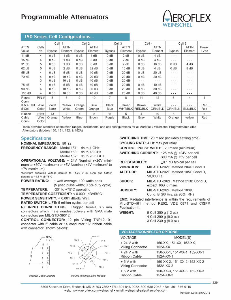
229
5305 Spectrum Drive, Frederick, MD 21703-7362 s TEL: 301-846-9222, 800-638-2048 s Fax: 301-846-9116
web: www.aeroflex.com/weinschel s email: [email protected] Date: 3/6/2013
Programmable Attenuators
VOLTAGE MODEL(S)
+ 24 V with 150-XX, 151-XX, 152-XX,
Viking Connector 152A-XX
+ 24 V with 150-XX-1, 151-XX-1, 152-XX-1
Ribbon Cable 152A-XX-1
+ 5 V with 150-XX-2, 151-XX-2, 152-XX-2
Viking Connector 152A-XX-2
+ 5 V with 150-XX-3, 151-XX-3, 152-XX-3
Ribbon Cable 152A-XX-3
Cell 1 Cell 2 Cell 3 Cell 4 Cell 5
ATTN Cells ATTN ATTN ATTN ATTN ATTN Power
Value No. Bypass Element Bypass Element Bypass Element Bypass Element Bypass Element +Vdc
11 dB 4 0 dB 1 dB 0 dB 4 dB 0 dB 2 dB 0 dB 4 dB - - - - - -
15 dB 4 0 dB 1 dB 0 dB 8 dB 0 dB 2 dB 0 dB 4 dB - - - - - -
31 dB 5 0 dB 1 dB 0 dB 8 dB 0 dB 2 dB 0 dB 16 dB 0 dB 4 dB
62 dB 5 0 dB 2 dB 0 dB 32 dB 0 dB 16 dB 0 dB 4 dB 0 dB 8 dB
55 dB 4 0 dB 5 dB 0 dB 10 dB 0 dB 20 dB 0 dB 20 dB - - - - - -
70 dB 4 0 dB 10 dB 0 dB 20 dB 0 dB 20 dB 0 dB 20 dB - - - - - -
3 0 dB 10 dB 0 dB 40 dB 0 dB 20 dB - - - - - - - - - - - -
75 dB 4 0 dB 5 dB 0 dB 40 dB 0 dB 20 dB 0 dB 10 dB - - - - - -
90 dB 4 0 dB 10 dB 0 dB 30 dB 0 dB 20 dB 0 dB 30 dB - - - - - -
110 dB 4 0 dB 10 dB 0 dB 40 dB 0 dB 20 dB 0 dB 40 dB - - - - - -
Round PIN # 5 6 9 10 7 8 11 12 3 4 1
Conn.
3 & 4 Cell Wire Violet Yellow Orange Blue Black Green Brown White - - - - - - Red
5 Cell Color Black White Green Orange Blue WHT/BLK RED/BLK GRN/BLK ORN/BLK BLU/BLK Red
Ribbon PIN# 13 2 3 9 11 5 4 10 8 7 6
Cable Wire Orange Yellow Blue Brown Purple Black Gray White Orange yellow Red
Conn. Color
Table provides standard attenuation ranges, increments, and cell configurations for all Aeroflex / Weinschel Programmable Step
Attenuators (Models 150, 151, 152, & 152A)
150 Series Cell Configurations...
Specifications NOMINAL IMPEDANCE: 50 ΩFREQUENCY RANGE: Model 151: dc to 4 GHz
Model 150: dc to 18 GHz
Model 152: dc to 26.5 GHz
OPERATIONAL VOLTAGE: + 24V Nominal (+20V mini-
mum to +30V maximum) or +5V Nominal (+4V minimum* to
+7V maximum)*Minimum operating voltage derated to +4.25 V @ 55°C and further
derated to +4.5 V @ 75°C
POWER RATING: 1 watt average, 100 watts peak
(5 μsec pulse width; 0.5% duty cycle)
TEMPERATURE: -20° to +75°C operating
TEMPERATURE COEFFICIENT: < 0.0001 dB/dB/°C
POWER SENSITIVITY: < 0.001 dB/dB/ Watt
RATED SWITCH LIFE: 5 million cycles per cell
RF INPUT CONNECTORS: Rugged female 3.5 mm
connectors which mate nondestructively with SMA male
connectors per MIL-STD-39012.
CONTROL CONNECTOR: 12 pin Viking TNP12-101
connector with 5' cable or 14 conductor 16" ribbon cable
with connector (shown below):
SWITCHING TIME: 20 msec (includes settling time)
CYCLING RATE: 4 Hz max per relay
CONTROL PULSE WIDTH: 20 msec (minimum)
SWITCHING CURRENT: 125 mA @ +24V per cell
300 mA @ +5V per cell
REPEATABILITY: +0.1 dB typical per cell
VIBRATION: MIL-STD-202F, Method 204D Cond B
ALTITUDE: MIL-STD-202F, Method 105C Cond B,
50,000 Ft.
SHOCK: MIL-STD -202F, Method 213B Cond B,
except 10G, 6 msec
HUMIDITY: MIL-STD-202F, Method 103B,
Cond. B (96 Hrs. @ 95%, RH)
EMC: Radiated interference is within the requirements of
MIL-STD-461 method RE02, VDE 0871 and CISPR
Publication II.
WEIGHT: 5 Cell 350 g (12 oz)
4 Cell 290 g (9.0 oz)
3 Cell 230 g (8.0 oz)
VOLTAGE/CONNECTOR OPTIONS:
Ribbon Cable Models Round (Viking)Cable Models
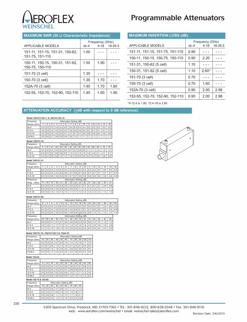
Frequency Attenuation Setting (dB)Range (GHz) 5 10 15 20 25 30 35 40 45 50 55
dc-4 0.2 0.3 0.4 0.4 0.4 0.6 0.6 0.7 0.7 0.8 1.0
4-12.4 0.3 0.4 0.5 0.5 0.5 0.7 0.8 0.9 0.9 1.0 1.3
12.4-18 0.4 0.4 0.5 0.5 0.5 0.8 1.0 1.1 1.1 1.2 1.6
18-26.5 0.5 0.5 0.6 0.6 0.6 0.9 1.2 1.4 1.4 1.5 2.0
Model 152-55:
Frequency Attenuation Setting (dB)Range (GHz) 2 4 6 8 10 12 14 16 18 20 22 24 26 28 30 32
dc-4 0.3 0.3 0.3 0.4 0.4 0.5 0.5 0.5 0.5 0.5 0.5 0.5 0.5 0.5 0.6 0.6
4-12.4 0.4 0.4 0.4 0.5 0.5 0.6 0.6 0.6 0.7 0.7 0.7 0.8 0.8 0.8 0.8 0.8
12.4-18 0.5 0.5 0.5 0.6 0.6 0.6 0.8 0.8 0.8 0.8 0.8 1.0 1.0 1.0 1.2 1.2
Model 150/151-62:
Frequency Attenuation Setting (dB)Range (GHz) 34 36 38 40 42 44 46 48 50 52 54 56 58 60 62
dc-4 0.6 0.6 0.7 0.7 0.7 0.8 0.8 0.8 0.9 0.9 0.9 1.0 1.0 1.0 1.2
4-12.4 1.0 1.0 1.1 1.1 1.3 1.4 1.4 1.4 1.5 1.6 1.6 1.6 1.8 1.8 1.8
12.4-18 1.4 1.4 1.6 1.6 1.8 1.8 2.0 2.0 2.0 2.2 2.2 2.2 2.4 2.4 2.4
Frequency Attenuation Setting (dB)Range (GHz) 10 20 30 40 50 60 70 80 90
dc-4 0.3 0.5 0.6 0.7 0.8 1.0 1.1 1.1 1.2
4-12.4 0.4 0.5 0.7 0.9 1.0 1.3 1.5 1.6 1.7
12.4-18 0.5 0.6 0.8 1.1 1.2 1.4 1.7 1.8 2.1
18-26.5 0.5 0.6 0.9 1.4 1.5 1.8 2.3 2.4 2.8
Model 152-70 & 152-90:
Frequency Attenuation Setting (dB)Range (GHz) 10 20 30 40 50 60 70 80 90 100 110
dc-4 0.2 0.3 0.5 0.7 0.9 1.0 1.2 1.4 1.6 1.7 1.9
4-12.4 0.4 0.7 0.9 1.2 1.5 1.8 2.1 2.4 2.7 3.0 3.0
12.4-18 0.4 0.8 1.2 1.6 2.0 2.4 2.8 3.2 3.6 4.0 4.0
18-26.5 0.5 0.9 1.3. 2.0 2.2 2.6 3.2 3.6 4.0 4.2 4.6
Model 150/151-70, 150/151/152-110, 152A-70:
Frequency Attenuation Setting (dB)Range (GHz) 1 2 3 4 5 6 7 8 9 10 11 12 13 14 15 16
dc-4 0.2 0.2 0.3 0.3 0.3 0.3 0.4 0.4 0.5 0.4 0.5 0.5 0.5 0.5 0.5 0.5
4-12.4 0.4 0.4 0.5 0.4 0.6 0.6 0.7 0.6 0.7 0.6 0.7 0.7 0.7 0.7 0.7 0.7
12.4-18 0.5 0.5 0.6 0.6 0.6 0.6 0.7 0.7 0.8 0.8 0.8 0.8 0.8 0.8 0.8 0.8
Model 150/151-31:
Frequency Attenuation Setting (dB)Rang
e
(GHz) 17 18 19 20 21 22 23 24 25 26 27 28 29 30 31
dc-4 0.5 0.6 0.6 0.6 0.6 0.6 0.6 0.6 0.7 0.7 0.7 0.7 0.7 0.8 0.8
4-12.4 0.8 0.8 0.9 0.9 0.9 0.9 0.9 0.9 1.1 1.0 1.0 1.0 1.0 1.1 1.1
12.4-18 0.9 0.9 1.0 1.0 1.0 1.0 1.1 1.1 1.2 1.2 1.2 1.2 1.2 1.3 1.3
Frequency Attenuation Setting (dB)Range (GHz) 1 2 3 4 5 6 7 8 9 10 11 12 13 14 15
dc-4 0.2 0.2 0.3 0.3 0.3 0.3 0.4 0.4 0.4 0.4 0.5 0.5 0.5 0.5 0.5
4-12.4 0.3 0.3 0.4 0.4 0.5 0.5 0.6 0.6 0.6 0.6 0.7 0.7 0.7 0.7 0.7
12.4-18 0.5 0.6 0.6 0.6 0.6 0.7 0.7 0.7 0.7 0.8 0.8 0.8 0.8 0.8 0.8
18-26.5 0.5 0.6 0.7 0.8 0.9 0.9 0.9 1.0 1.1 1.1 1.1 1.1 1.1 1.1 1.1
Model 150/151/152-11 & 150/151/152-15:
Frequency Attenuation Setting (dB)Range (GHz) 5 10 15 20 25 30 35 40 45 50 55 60 65 70 75
dc-4 0.2 0.2 0.4 0.4 0.5 0.5 0.7 0.7 0.9 0.9 1.1 1.1 1.2 1.2 1.4
4-12.4 0.3 0.3 0.6 0.6 0.9 0.9 1.2 1.2 1.5 1.5 1.8 1.8 2.1 2.1 2.1
12.4-18 0.4 0.4 0.8 0.8 1.2 1.2 1.6 1.6 2.0 2.0 2.4 2.4 2.8 2.8 2.8
Model 150/151-75:
5305 Spectrum Drive, Frederick, MD 21703-7362 s TEL: 301-846-9222, 800-638-2048 s Fax: 301-846-9116
web: www.aeroflex.com/weinschel s email: [email protected]
230
Revision Date: 3/6/2013
Programmable Attenuators
MAXIMUM SWR (50 Ω Characteristic Impedance):
Frequency (GHz)
APPLICABLE MODELS dc-4 4-18 18-26.5
151-11, 151-15, 151-31, 150-62, 1.50 - - - - - -
151-75, 151-110
150-11, 150-15, 150-31, 151-62, 1.50 1.90 - - -
150-75, 150-110
151-70 (3 cell) 1.35 - - - - - -
150-70 (3 cell) 1.35 1.70 - - -
152A-70 (3 cell) 1.40 1.70 1.80
152-55, 152-70, 152-90, 152-110 1.40 1.60 1.90
ATTENUATION ACCURACY (+dB with respect to 0 dB reference):
MAXIMUM INSERTION LOSS (dB):
Frequency (GHz)
APPLICABLE MODELS dc-4 4-18 18-26.5
151-11, 151-15, 151-75, 151-110 0.90 - - - - - -
150-11, 150-15, 150-75, 150-110 0.90 2.20 - - -
151-31, 150-62 (5 cell) 1.10 - - - - - -
150-31, 151-62 (5 cell) 1.10 2.60* - - -
151-70 (3 cell) 0.70 - - - - - -
150-70 (3 cell) 0.70 1.60 - - -
152A-70 (3 cell) 0.90 2.00 2.98
152-55, 152-70, 152-90, 152-110 0.90 2.00 2.98
*4-12.4 is 1.80, 12.4-18 is 2.60

231
5305 Spectrum Drive, Frederick, MD 21703-7362 s TEL: 301-846-9222, 800-638-2048 s Fax: 301-846-9116
web: www.aeroflex.com/weinschel s email: [email protected] Date: 3/6/2013
Programmable Attenuators
PHYSICAL DIMENSIONS:
Models 150, 151, & 152:
DIM A B C
3 cell 82.3 (3.28) 76.2 (3.0) 105.7 (4.16)
4 cell 110.7 (4.36) 103.7 (4.08) 133.6 (5.25)
5 cell 136.1 (5.36) 129.1 (5.08) 159.5 (6.28)
NOTE:
1. All dimensions are given in mm (inches) and are maximum, unless otherwise specified.
2. Unit available with RoHS compliant materials, specify when ordering.

5305 Spectrum Drive, Frederick, MD 21703-7362 s TEL: 301-846-9222, 800-638-2048 s Fax: 301-846-9116
web: www.aeroflex.com/weinschel s email: [email protected]
232
Revision Date: 3/6/2013
Programmable Attenuators
Frequency Range/ NO. Attenuator Range/Step Size
Voltage/Connector Cells 11/1 dB 15/1 dB 55/5 dB 31/1 dB 62/2 dB 70/10 dB 75/5 dB 90/10 dB 110/10 dB
dc-4 GHz/+24 V/ 4 151-11 NA N/A 151-75 N/A 151-110Viking Connector 3 N/A
5 151-31 151-62
dc-18 GHz/+24 V/ 4 150-11 150-15 N/A 150-75 N/A 150-110
Viking Connector 3 150-70
5 150-31 150-62
dc-26.5 GHz/+24 V/ 4 N/A N/A 152-55 N/A N/A 152-90 N/A
Viking Connector 3 N/A N/A
dc-4 GHz/+24 V/ 4 151-11-1 NA N/A 151-75-1 N/A 151-110-1
Ribbon Cable 3 N/A
5 151-31-1 151-62-1
dc-18 GHz/+24 V/ 4 150-11-1 150-15-1 N/A N/A N/A 150-110-1
Ribbon Cable 3 150-70-1
5 150-31-1 150-62-1
dc-26.5 GHz/+24 V/ 4 N/A N/A 152-55-1 N/A N/A N/A N/A 152-90-1 152-110-1
Ribbon Cable 3
dc-4 GHz/+5 V/ 4 151-11-2 151-15-2 N/A 151-75-2 N/A 151-110-2
Viking Connector 3 N/A
5 151-31-2 151-62-2
dc-18 GHz/+5 V/ 4 150-11-2 150-15-2 N/A 150-75-2 N/A 150-110-2
Viking Connector 3 150-70-2
5 150-31-2 150-62-2
dc-26.5 GHz/+5 V/ 4 N/A N/A 152-55-2 N/A N/A N/A 152-90-2 152-110-2
Viking Connector 3 N/A
dc-4 GHz/+5 V/ 4 151-11-3 N/A N/A N/A N/A N/A
Ribbon Cable 3 N/A
5 151-31-3 151-62-3
dc-18 GHz/+5 V/ 4 150-11-3 150-15-3 N/A 150-75-3 N/A 150-110-3
Ribbon Cable 3 150-70-3
5 150-31-3 150-62-3
dc-26.5 GHz/+5 V/ 4 N/A N/A 152-55-3 N/A N/A 152-90-3 152-110-3
Ribbon Cable 3 N/A
N/A = Not Available
150 Series Ordering Guide...
OPTIONAL TEST DATA: Test Data is available at an addi-
tional cost for all programmable step attenuators models.
Sweep Data across the programmable attenuator’s
frequency band starting at 0.05 to 18.0/26.5 GHz for all
primary cells with markers at 0.05, 4.0, 8.0, 12.4, 18.0 and
26.5 GHz. VSWR and Attenuation provided.
MODELS WITH BUILT-IN TTL/CMOS INTERFACE\
DRIVER CIRCUIT: Aeroflex / Weinschel offers versions of
the 150 series with built-in TTL/CMOS interfaces. This
generation of intelligent attenuators will greatly simplify as
well as provide an economical solution to 150 series driver
problems. Refer to Model 150T, 151T, and 152T data sheet
for more information.
ACCESSORIES
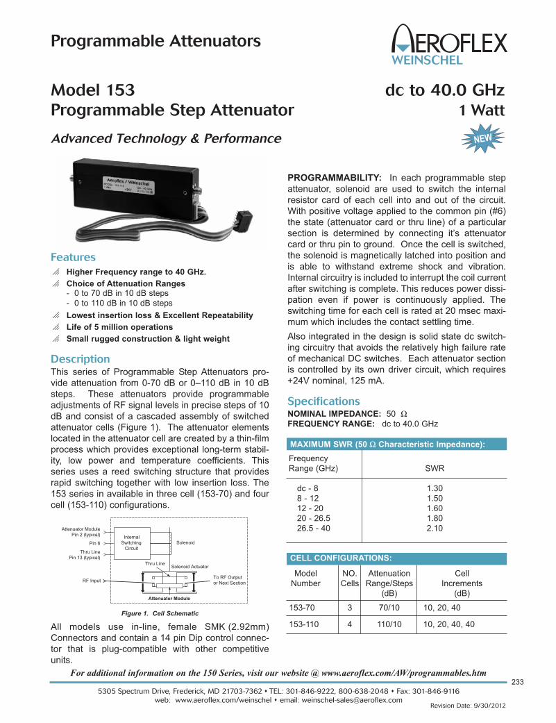
For additional information on the 150 Series, visit our website @ www.aeroflex.com/AW/programmables.htm233
5305 Spectrum Drive, Frederick, MD 21703-7362 s TEL: 301-846-9222, 800-638-2048 s Fax: 301-846-9116
web: www.aeroflex.com/weinschel s email: [email protected] Date: 9/30/2012
Programmable Attenuators
Model 153 dc to 40.0 GHz
Programmable Step Attenuator 1 Watt
Advanced Technology & Performance
Model NO. Attenuation Cell
Number Cells Range/Steps Increments
(dB) (dB)
153-70 3 70/10 10, 20, 40
153-110 4 110/10 10, 20, 40, 40
CELL CONFIGURATIONS:
Description
This series of Programmable Step Attenuators pro-
vide attenuation from 0-70 dB or 0–110 dB in 10 dB
steps. These attenuators provide programmable
adjustments of RF signal levels in precise steps of 10
dB and consist of a cascaded assembly of switched
attenuator cells (Figure 1). The attenuator elements
located in the attenuator cell are created by a thin-film
process which provides exceptional long-term stabil-
ity, low power and temperature coefficients. This
series uses a reed switching structure that provides
rapid switching together with low insertion loss. The
153 series in available in three cell (153-70) and four
cell (153-110) configurations.
All models use in-line, female SMK (2.92mm)
Connectors and contain a 14 pin Dip control connec-
tor that is plug-compatible with other competitive
units.
Features
o Higher Frequency range to 40 GHz.
o Choice of Attenuation Ranges- 0 to 70 dB in 10 dB steps
- 0 to 110 dB in 10 dB steps
o Lowest insertion loss & Excellent Repeatability
o Life of 5 million operations
o Small rugged construction & light weight
Specifications NOMINAL IMPEDANCE: 50 ΩFREQUENCY RANGE: dc to 40.0 GHz
MAXIMUM SWR (50 Ω Characteristic Impedance):
Frequency
Range (GHz) SWR
dc - 8 1.30
8 - 12 1.50
12 - 20 1.60
20 - 26.5 1.80
26.5 - 40 2.10
PROGRAMMABILITY: In each programmable step
attenuator, solenoid are used to switch the internal
resistor card of each cell into and out of the circuit.
With positive voltage applied to the common pin (#6)
the state (attenuator card or thru line) of a particular
section is determined by connecting it’s attenuator
card or thru pin to ground. Once the cell is switched,
the solenoid is magnetically latched into position and
is able to withstand extreme shock and vibration.
Internal circuitry is included to interrupt the coil current
after switching is complete. This reduces power dissi-
pation even if power is continuously applied. The
switching time for each cell is rated at 20 msec maxi-
mum which includes the contact settling time.
Also integrated in the design is solid state dc switch-
ing circuitry that avoids the relatively high failure rate
of mechanical DC switches. Each attenuator section
is controlled by its own driver circuit, which requires
+24V nominal, 125 mA.
Solenoid
Solenoid ActuatorThru Line
Attenuator Module
Attenuator ModulePin 2 (typical)
Thru LinePin 13 (typical)
Pin 6
RF Input
InternalSwitching
Circuit
To RF Outputor Next Section
Figure 1. Cell Schematic

5305 Spectrum Drive, Frederick, MD 21703-7362 s TEL: 301-846-9222, 800-638-2048 s Fax: 301-846-9116
web: www.aeroflex.com/weinschel s email: [email protected]
234
Revision Date: 9/30/2012
Programmable Attenuators
Specifications - Con’t
REPEATABILITY:
±0.03 dB to 18 GHz
±0.05 dB to 26.5 GHz
±0.08 dB to 40 GHz
TEMPERATURE RANGE:
Operating: -0°C to +70°C
Non-Operating: -55°C to +85°C
ALTITUDE: Operating: 4.6 km (440 mm Hg)
Non-operating: 15 km
SHOCK: Operating: 10g, 6 ms, on 6 sides, 3 blows
Non-operating: 500 g, 1.8 ms, in 6 directions
HUMIDITY: 0 to 95% relative humidity
EMC: MIL-STD-461, Method RE02, VDE 0871, CISPR#2
TEST DATA: Test data is available at additional cost.
CONNECTORS: 2.92mm connectors - mate nondestruc-
tively with SMA connectors per MIL-C-39012, 3.5mm, SMK,
and other 2.92mm connectors.
CONTROL CONNECTOR: 14 conductor 16" ribbon cable
with connector (shown below):
PHYSICAL DIMENSIONS:
NOTE: All dimensions are given in mm (inches) and are nominal, unless otherwise specified.
Model No. No. Cells A B
153-70 3 76.2 (3.0) 90.2 (3.55)
153-110 4 102.9 (4.05) 115.8 (4.6)
SWITCHING SPEED: 20 msec. maximum
OPERATING VOLTAGE: +24V nominal, +20V minimum;
+30V maximum
SWITCHING CONTROL CURRENT: 125 mA typical per
cell @ +24V nominal, Model 153-70 (3 cells) and 153-110
(4 cells).
SOLENOID COIL IMPEDANCE: 190 ΩSOLENOID COIL INDUCTANCE: 65 mH
POWER RATING: 1 watt average, 100 watts peak
(5 μsec pulse width, 0.5% duty cycle)
RF POWER SENSITIVITY: 0.001 dB/dB/W
SWITCH LIFE: 5 million (minimum operations per cell)
Frequency Attenuation (dB)
Range (GHz) 10 20 30 40 50 60 70 80-110
DC - 8 0.3 0.5 0.6 0.7 0.8 1.0 1.1 1.4
8 - 12 0.4 0.5 0.7 0.9 1.0 1.3 1.5 2.0
12 - 20 0.5 0.6 0.8 1.1 1.2 1.4 1.7 2.2
20 - 26.5 0.7 0.8 1.0 1.5 1.6 1.9 2.3 2.8
26.5 - 40 0.9 1.0 1.2 1.7 1.9 2.3 2.6 3.2
ATTENUATOR ACCURACY (+ dB):
MAXIMUM INSERTION LOSS (dB):
0
0
0.5
1.0
4.040
Frequency (GHz)
)Bd( ssol noitresnI
153-70 153-110
3.5
3.0
2.5
2.0
1.5
10 20 30
WEIGHT (Typical): 153-70: 170 g (6 oz)
153-110: 213 g (7.5 oz)
Pin Wire 153-70 153-110Number Color
1 - - - - - - - - -
2 White 10 dB Cell Attenuator 10 dB Cell Attenuator
3 Violet 40 dB Cell Thru Line 40 dB Cell 1 Thru Line
4 Green - - - 40 dB Cell 2 Thru Line
5 Orange 20 dB Cell Attenuator 20 dB Cell Attenuator
6 Brown +24Vdc +24Vdc
7 - - - - - - - - -
8 - - - - - - - - -
9 Red 40 dB Cell Attenuator 40 dB Cell 1 Attenuator
10 Yellow - - - 40 dB Cell 2 Attenuator
11 Blue 20 dB Cell Thru Line 20 dB Cell Thru Line
12 Grey - - - - - -
13 Black 10 dB Cell Thru Line 10 dB Cell Thru Line
14 - - - - - - - - -

235
5305 Spectrum Drive, Frederick, MD 21703-7362 s TEL: 301-846-9222, 800-638-2048 s Fax: 301-846-9116
web: www.aeroflex.com/weinschel s email: [email protected] Date: 9/30/2012
Programmable Attenuators
Model 4202 0.4 to 6 GHz
Digital Attenuatorwith Built-in TTL Driver
Features
o Ideal for Automated Test Equipment (ATE), WiMAX,3G Fading Simulators, Engineering/Production Test
Lab environments
o Excellent Repeatability & Performance
o Custom Configurations Available Upon Request
o Ruggedized Construction
Description
Aeroflex / Weinschel’s new line of MMIC Digital Attenuator
operates over the 0.4 to 6 GHz frequency range and pro-
vides an attenuation range from 0 to 63 in 1 dB increments.
Specifications NOMINAL IMPEDANCE: 50 ΩFREQUENCY RANGE: 0.4 to 6.0 GHz
ATTENUATION RANGE/STEPS: 0-63 in 1 dB steps
ATTENUATION INCREMENTS: 1, 2, 4, 8, 16, 32 dB
ATTENUATION ACCURACY: + 1 dB or 4%
INSERTION LOSS: 7.0 dB maximum
MAXIMUM SWR: 2.0:1
POWER RATING: 20 dBm (100 mW) maximum
SWITCHING SPEED: 300 nsec maximum
CONTROL LOGIC: TTL
OPERATING VOLTAGE: +5 V @ 20 mA
TEMPERATURE RANGE: 0°C to + 70°C
TEST DATA: Test data can be provided at additional cost.
CONNECTORS: SMA female connector - mates nonde-
structively with other SMA connector per MIL-C-39012,
3.5mm and other 2.92mm connector.
CONTROL CONNECTOR: AMP-Latch 10 pin ribbon cable
connector mates with AMP P/N 746285-1 (supplied with
each unit)
CONTROL CONFIGURATION: Units are supplied with a
built-in TTL interface. Each unit is supplied with a mating 10
pin connector (Amp 746285-1). Refer to Physical
Dimensions for mating connector pin/wiring details. Two
wires are specified for supply voltage and ground. The
remaining wires will accept TTL control signals to activate
or de-activate a particular attenuation cell. A TTL high will
energize a cell to the high attenuation state, whereas a TTL
low will maintain a cell in its zero attenuation state.
WEIGHT: 83 g (2.92 oz)
Attenuation Performace Plot
RoHS��

5305 Spectrum Drive, Frederick, MD 21703-7362 s TEL: 301-846-9222, 800-638-2048 s Fax: 301-846-9116
web: www.aeroflex.com/weinschel s email: [email protected]
236
Revision Date: 9/30/2012
Programmable Attenuators
57.79[2.275]
9.53
2.36[.09]
9.53
44.45[1.75]
8.89[.35]
6.48[.26]
6.48[.26]
18.59[.73]
17.46[.69]
22.86[.90]
#4-40 UNC-Bx 3.0 [.12] DEEP 2X
PIN 1
PIN 2
2-56 UNC-2Bx 3.0 [.12] DEEP2 PLACES EACH SIDE
[.37] [.37]
39.73[1.56]
40.01[1.58]
9.91[.39]
NOTE: All dimensions are given in mm (inches) and are maximum, unless otherwise specified.
TTL Conn Designation
PIN No. (J3)
1 1.0
2 2.0
3 4.0
4 8.0
5 16.0
6 32.0
7 NC
8 NC
9 +5V
10 COM
NC = Not Connected
Control Connector
J3 Pin Locations:
PHYSICAL DIMENSIONS:

237
5305 Spectrum Drive, Frederick, MD 21703-7362 s TEL: 301-846-9222, 800-638-2048 s Fax: 301-846-9116
web: www.aeroflex.com/weinschel s email: [email protected] Date: 9/30/2012
Programmable Attenuators
Model 4203 0.2 to 3 GHz
Digital Attenuatorwith Built-in TTL Driver
Features
o Ideal for Automated Test Equipment (ATE), WiMAX,3G Fading Simulators, Engineering/Production Test
Lab environments
o Excellent Repeatability & Performance
o Custom Configurations Available Upon Request
o Ruggedized Construction
Description
Aeroflex / Weinschel’s new line of MMIC Digital Attenuator
operates over the 0.2 to 3 GHz frequency range and is in a
variety of attenuation ranges.
Specifications NOMINAL IMPEDANCE: 50 ΩFREQUENCY RANGE: 0.2 to 3.0 GHz
MAXIMUM SWR: 1.4:1
POWER RATING: +24 dBm maximum
SWITCHING SPEED: 1 μSec maximum
CONTROL LOGIC: TTL
OPERATING VOLTAGE: +5 V @ 20 mA
TEMPERATURE RANGE: 0°C to + 70°C
TEST DATA: Test data can be provided at additional cost.
CONNECTORS: SMA female connector - mates nonde-
structively with other SMA connector per MIL-C-39012,
3.5mm and other 2.92mm connector.
CONTROL CONNECTOR: AMP-Latch 10 pin ribbon cable
connector mates with AMP P/N 746285-1 (supplied with
each unit)
CONTROL CONFIGURATION: Units are supplied with a
built-in TTL interface. Each unit is supplied with a mating
10 pin connector (Amp 746285-1). Refer to Physical
Dimensions for mating connector pin/wiring details. Two
wires are specified for supply voltage and ground. The
remaining wires will accept TTL control signals to activate
or de-activate a particular attenuation cell. A TTL high will
energize a cell to the high attenuation state, whereas a TTL
low will maintain a cell in its zero attenuation state.
WEIGHT: 83 g (2.92 oz)
RoHS��
Model Attenuation Attenuation
Number Range/Steps Increments
(dB) (dB)
4203-31.75 0 -31.75 / 0.25 0.25, 0.5, 1, 2, 4, 8, 16
4203-63 0-63 / 1 1, 2, 4, 8, 16, 32
CELL CONFIGURATIONS:
ATTENUATION ACCURACY:
CELL 0.25 0.50 1 2 4 8 16 32
dB +0.15 +0.15 +0.2 +0.2 +0.3 +0.4 +0.6 +1.2
Frequency (GHz) 4203-31.75 4203-63
0.2 - 3.0 4.5 4.0
MAXIMUM INSERTION LOSS (dB):

Aeroflex/WeinschelCAGE CODE 93459 MADE IN THE USAPART No:XXXXSER No: XXXX0.2-3GHz 31.75dB/0.25dB
57.79[2.275]
2.36[.09]
44.45[1.75]
8.89[.35]
7.39[.29]
18.59[.73]
17.46[.69]
22.86[.900] 2X #4-40 UNC-B
X 3.05 [.12] DEEP
2X 2-56 UNC-2BX 3.05 [.12] DEEP
39.73[1.56]
40.01[1.58]
8.89[.35]
9.53[.38]TYP
PIN 1
PIN 2
47.63[1.88]
16.00[.63]
11.76[.46]
12.70[.50]
8.89[.35]
40.01[1.575]
2.36[.09]
39.73[1.564]
4X #2-56 UNC-2BX 4.83[.19] DEEP
5305 Spectrum Drive, Frederick, MD 21703-7362 s TEL: 301-846-9222, 800-638-2048 s Fax: 301-846-9116
web: www.aeroflex.com/weinschel s email: [email protected]
238
Revision Date: 9/30/2012
Programmable Attenuators
NOTE: All dimensions are given in mm (inches) and are maximum, unless otherwise specified.
TTL Conn 4203-31.75 4203-63
PIN No. (J3) dB (Cell) dB (Cell)
1 0.25 1.0
2 0.5 2.0
3 1.0 4.0
4 2.0 8.0
5 4.0 16.0
6 8.0 32.0
7 16.0 NC
8 NC NC
9 +5V +5V
10 GND GND
NC = Not Connected
Control Connector
J3 Pin Locations:
PHYSICAL DIMENSIONS:

239
5305 Spectrum Drive, Frederick, MD 21703-7362 s TEL: 301-846-9222, 800-638-2048 s Fax: 301-846-9116
web: www.aeroflex.com/weinschel s email: [email protected] Date: 5/30/2013
Programmable Attenuators
Model 4205 0.2 to 6 GHz
Digital AttenuatorTTL & USB Control, SMA Connectors
Features
o Ideal for Automated Test Equipment (ATE), WiMAX,LTE, WiFi, 3G/4G Fading Simulators, Engineering/
Production Test Lab environments
o Excellent Solid-state Repeatability & Performance
o Uninterrupted RF when changing attenuation values
o Ruggedized Construction
Description
Aeroflex / Weinschel's New series of MMIC Digital
Attenuators operates over the 0.2 to 6 GHz frequency range
and is in a variety of attenuation ranges up to 95.5 dB in 0.5
dB steps. These units can be controlled using either
parallel TTL or USB interfaces.
Specifications NOMINAL IMPEDANCE: 50 ΩFREQUENCY RANGE: 0.2 to 6.0 GHz
POWER RATING: +23 dBm maximum
SWITCHING SPEED: 1 μsec maximum
CONTROL LOGIC: TTL or USB
OPERATING VOLTAGE: +5 V @ 50 mA
TEMPERATURE RANGE: 0°C to + 70°C
TEST DATA: Test data can be provided at additional cost.
CONNECTORS: SMA female connectors - mates nonde-
structively with other SMA connectors per MIL-C-39012,
3.5mm and other 2.92mm connectors.
CONTROL CONNECTOR: The TTL control connector is an
AMP-Latch 10 pin ribbon cable connector that mates with
AMP P/N 746285-1 (supplied with each unit). The USB is a
5-pin female series B mini socket and mates with most stan-
dard USB 5-pin male series B mini plug connectors.
WEIGHT: 83 g (2.92 oz)
Control Software Included
Aeroflex / Weinschel’s Labview based USB Control Center
Software (AUCS) can also be used in the operation of this
series of digital attenuators. The AUCS will allow the user to
setup, control and perform test and measurements using
these digital attenuators over a standard USB 2.0 commu-
nication interface.
RoHS��
Model Attenuation Attenuation
Number Range/Steps Increments
(dB) (dB)
4205-31.5 0 -31.5 / 0.5 0.5, 1, 2, 4, 8, 16
4205-63.5 0-63.5 / 0.5 0.5, 1, 2, 4, 8, 16, 32
4205-95.5 0-95.5 / 0.5 0.5, 1, 2, 4, 8, 16, 32, 32
CELL CONFIGURATIONS:
ATTENUATION ACCURACY (dB):
dB range 4205-31.5 4205-63.5 4205-95.5
1 to 7.5 dB + 0.5 + 0.5 + 0.5
8 to 11.5 dB + 1.0 + 1.0 + 1.0
12 to 31.5 + 1.25 + 1.25 + 1.25 or 4%
32 to 63.5 - - - + 1.25 + 1.25 or 4%
64 to 85 dB - - - - - - + 1.25 or 4%
86 to 95 dB - - - - - - + 5 %
Frequency (GHz) 4205-31.5 4205-63.5 4205-95.5
0.2 - 3.0 3.0 4.5 6.5
3.0 - 6.0 4.0 6.0 8.0
MAXIMUM INSERTION LOSS (dB):
Frequency (GHz) 4205-31.5 4205-63.5 4205-95.5
0.2 - 0.8 1.50 1.80 2.00
0.8 - 5.0 1.50 1.50 1.60
5.0 - 6.0 1.70 1.50 1.90
MAXIMUM SWR:

VIEW ASCALE 4 : 1
CA
GE
: 93459M
OD
EL: 4205-63.5
SE
RN
O: X
XX
X0.2-6GHz 0-63.5dB / 0.5dB
9.5[.38]
63.5[2.50] 9.5
[.38]
10.9[.43] 10.9
[.43]
47.5[1.87]
8.4[.33]
6.6[.26]
6.6[.26]
17.1[.68]
29.21[1.150]
9.0[.36]
44.3[1.75]
63.5[2.50]
5.6[.22]
9.0[.36]
17.1[.68]
29.21[1.150]
10.2[.40]
43.18[1.700]
2.2[.09]
59.18[2.330]
2X 4-40 UNC-2B� 4.1[.16]
4X 2-56 UNC-2B� 4.1[.16]
2.2[.09]
59.18[2.330]
10.2[.40]
43.18[1.700]
4X 2-56 UNC-2B� 4.1[.16]
2X 4-40 UNC-2B� 4.1[.16]
PIN 1 PIN 2
PIN 1 PIN 5
SEE VIEW
A
13.8[.54]
5305 Spectrum Drive, Frederick, MD 21703-7362 s TEL: 301-846-9222, 800-638-2048 s Fax: 301-846-9116
web: www.aeroflex.com/weinschel s email: [email protected]
240
Revision Date: 5/30/2013
Programmable Attenuators
PHYSICAL DIMENSIONS:
TTL Conn 4205-31.5 4205-63.5 4205-95.5
PIN No. (J3) dB (Cell) dB (Cell) dB (Cell )
1 0.5 0.5 0.5
2 1 1 1
3 2 2 2
4 4 4 4
5 8 8 8
6 16 16 16
7 NC 32 32
8 NC NC 32
9 +5V +5V +5V
10 GND GND GND
NC = Not Connected.
TTL Control Connector J4 Pin Locations:
NOTE: All dimensions are given in mm (inches) and are maximum, unless otherwise specified.
CONTROL CONFIGURATION:
Units are supplied with both parallel-TTL and USB 2.0 inter-
faces. The mode of operation is determined by the source
of DC power to the unit. NOTE: Do not simultaneously con-
nect DC power to the J4 TTL connector while the USB is
connected.
USING TTL CONTROL: Each unit is supplied with a
mating 10 pin connector (Amp 746285-1). Refer to Physical
Dimensions for mating connector pin/wiring details. Two
pins are specified for supply voltage and ground. The
remaining pins will accept TTL control signals to activate or
de-activate a particular attenuation cell. A TTL high will
energize a cell to the high attenuation state, whereas a TTL
low will maintain a cell in its zero attenuation state.
USING USB CONFIGURATION: The USB interface is
compatible with standard USB 2.0 interfaces. In USB mode,
DC power to the attenuator is provided by the host USB
connection. The attenuator operates as a USB CDC device
and accepts simple ASCII text commands. This allows the
unit to be controlled from any system capable of sending
data via a standard COM port-style interface.
USB Conn Function
PIN No. (J3)
1 V BUS +5 V
2 Data-
3 Data+
4 ID (NC)
5 GND
USB Control Connector J3 Pin Locations:

241
5305 Spectrum Drive, Frederick, MD 21703-7362 s TEL: 301-846-9222, 800-638-2048 s Fax: 301-846-9116
web: www.aeroflex.com/weinschel s email: [email protected] Date: 9/30/2012
Programmable Attenuators
Model NO. Attenuation Cell
Number Cells Range/Steps Increments
(dB) (dB)
4228-103 8 103/1 1, 2, 4, 8, 16, 24, 48
4228-63.75 8 63.75/0.25 0.25, 0.5, 1, 2, 4, 8,
16, 32
4226-63 6 63/1 1, 2, 4, 8, 16, 32
Models 4226 & 4228 0.8 to 2.5/3.0 GHz
Pin Switched Programmable Attenuators
Low Insertion Loss, Fast Switching
Specifications NOMINAL IMPEDANCE: 50 ΩFREQUENCY RANGE: 4226-63: 0.8 to 3.0 GHz
4228-63.75: 0.8 to 2.5 GHz
4228-103: 0.8 to 3.0 GHz
CELL CONFIGURATIONS:
MAXIMUM SWR:
Frequency Range (GHz) SWR
0.8 - 3.0 (2.5) 1.50
Frequency (GHz) 4226-63 4228-63.75 4228-103
0.8 - 3.0 (2.5) 3.75 4.50 5.50
MONOTONICITY: 4226-63 & 4228-103: 0.8 to 3.0 GHz
4228-63.75: 0.8 to 2.5 GHz
(minimum 1 dB
change)
3rd ORDER INTERMODULATION (IM3): -55 dBm typical,
measured with two +10 dBm tones @ 869 MHz (f1) and
891 MHz (f2), the IM3 frequency being 847 MHz (2f1-f2).
IP3 (input) = +41 dBm
The input IP3 is derived from the following relationship:
IP3 = 3(Pin-α)-IM3 + α
where α = the insertion loss (dB) at the IM3 frequency;
Pin=single tone input power (dBm).
POWER RATING: +24 dBm operating
+30 dBm (1 dB compression point)
SWITCHING TIME: 2 μsec. maximum
OPERATING VOLTAGE: +5 V + 5% @ 160 mA for 6 cell/
200 mA for 8 cell typical
TEMPERATURE RANGE (Operating): 0°C to +70°C
TEMPERATURE COEFFICIENT: < 0.002 dB/dB/°C
CONNECTORS: SMA female connectors - mate nonde-
structively with MIL-C-39012 connectors.
CONTROL CONNECTOR: AMP-Latch 10 pin ribbon cable
connector mates with AMP P/N 746285-1 (supplied with
each unit)
WEIGHT: 4226-X 160 g (5.7 oz)
4228-X 210 g (7.4 oz)
CONTROL CONFIGURATION: Units are supplied with a
built-in TTL interface. Each unit is supplied with a mating 10
pin connector (Amp 746285-1). Refer to Physical
Dimensions for mating connector pin/wiring details. Two
wires are specified for supply voltage and ground. The
remaining wires will accept TTL control signals to activate
or de-activate a particular attenuation cell. A TTL high will
energize a cell to the high attenuation state, whereas a TTL
low will maintain a cell in its zero attenuation state.
DRIVER SPECIFICATIONS:
minimum maximum
VIH Input High Level 2.0 V 5.3 V
VIL Input Low Level -0.3 V 0.8 V
IPU Input Pull-up Current 500 μA Typical
Note: Inputs have 10K pull-up resistors.
MAXIMUM INSERTION LOSS (dB):
FeaturesIdeal for use in Wireless/Cellular, RF Simulation/Emulation,
& Communication Test Applications.
o Available in 6 and 8 Cell Configurations -103 dB/1 dB steps
63 dB/1 dB steps
63.75/0.25 dB steps
o High accuracy & fast switching speed
o Built-in TTL Driver Circuitry
o Special Configurations Available Upon Request.- Custom Cell/Step Size & Frequency Bands
2
INCREMENTAL ATTENUATION ACCURACY:
CELL 0.25 0.50 1 2 4 8 16 24 32 48
dB +0.1 +0.15 +0.2 +0.2 +0.2 +0.2 +0.3 +0.4 +0.6 +0.8
RoHS��

5305 Spectrum Drive, Frederick, MD 21703-7362 s TEL: 301-846-9222, 800-638-2048 s Fax: 301-846-9116
web: www.aeroflex.com/weinschel s email: [email protected]
242
Revision Date: 9/30/2012
Programmable Attenuators
Model No. A B C D
4226-X 94.79 (3.73) 71.15 (2.80) 76.20 (3.00) 71.15 (2.80)
4228-X 123.24 (4.85) 99.59 (4.85) 76.20 (3.00) 99.59 (4.85)
PHYSICAL DIMENSIONS:
Models 4226 & 4228:
TTL Conn 4226-63 4228-63.75 4228-103
PIN No. (J3) dB (Cell) dB (Cell) dB (Cell )
1 1 0.25 1
2 2 0.50 2
3 4 1 4
4 8 2 8
5 16 4 16
6 32 8 24
7 NC 16 48
8 NC 32 NC*
9 +5V +5V +5V
10 COM COM COM
NC = Not Connected
* For Factory use only.
Control Connector J3 Pin Locations:
NOTE:
1. All dimensions are given in mm (inches) and are maximum, unless
otherwise specified.
2. Unit available with RoHS compliant materials, specify when ordering.
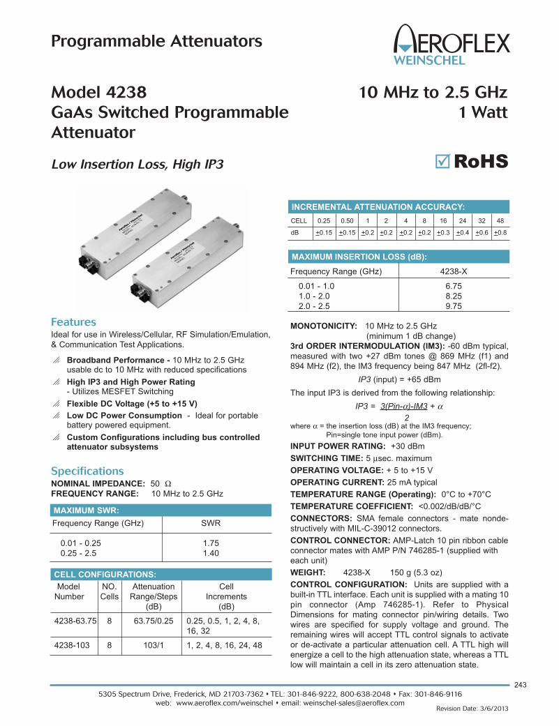
243
5305 Spectrum Drive, Frederick, MD 21703-7362 s TEL: 301-846-9222, 800-638-2048 s Fax: 301-846-9116
web: www.aeroflex.com/weinschel s email: [email protected] Date: 3/6/2013
Programmable Attenuators
Frequency Range (GHz) 4238-X
0.01 - 1.0 6.75
1.0 - 2.0 8.25
2.0 - 2.5 9.75
Specifications NOMINAL IMPEDANCE: 50 ΩFREQUENCY RANGE: 10 MHz to 2.5 GHz
CELL CONFIGURATIONS:
Model NO. Attenuation Cell
Number Cells Range/Steps Increments
(dB) (dB)
4238-63.75 8 63.75/0.25 0.25, 0.5, 1, 2, 4, 8,
16, 32
4238-103 8 103/1 1, 2, 4, 8, 16, 24, 48
MAXIMUM SWR:
Frequency Range (GHz) SWR
0.01 - 0.25 1.75
0.25 - 2.5 1.40
MONOTONICITY: 10 MHz to 2.5 GHz
(minimum 1 dB change)
3rd ORDER INTERMODULATION (IM3): -60 dBm typical,
measured with two +27 dBm tones @ 869 MHz (f1) and
894 MHz (f2), the IM3 frequency being 847 MHz (2fl-f2).
IP3 (input) = +65 dBm
The input IP3 is derived from the following relationship:
IP3 = 3(Pin-α)-IM3 + α
where α = the insertion loss (dB) at the IM3 frequency;
Pin=single tone input power (dBm).
INPUT POWER RATING: +30 dBm
SWITCHING TIME: 5 μsec. maximum
OPERATING VOLTAGE: + 5 to +15 V
OPERATING CURRENT: 25 mA typical
TEMPERATURE RANGE (Operating): 0°C to +70°C
TEMPERATURE COEFFICIENT: <0.002/dB/dB/°C
CONNECTORS: SMA female connectors - mate nonde-
structively with MIL-C-39012 connectors.
CONTROL CONNECTOR: AMP-Latch 10 pin ribbon cable
connector mates with AMP P/N 746285-1 (supplied with
each unit)
WEIGHT: 4238-X 150 g (5.3 oz)
CONTROL CONFIGURATION: Units are supplied with a
built-in TTL interface. Each unit is supplied with a mating 10
pin connector (Amp 746285-1). Refer to Physical
Dimensions for mating connector pin/wiring details. Two
wires are specified for supply voltage and ground. The
remaining wires will accept TTL control signals to activate
or de-activate a particular attenuation cell. A TTL high will
energize a cell to the high attenuation state, whereas a TTL
low will maintain a cell in its zero attenuation state.
FeaturesIdeal for use in Wireless/Cellular, RF Simulation/Emulation,
& Communication Test Applications.
o Broadband Performance - 10 MHz to 2.5 GHzusable dc to 10 MHz with reduced specifications
o High IP3 and High Power Rating- Utilizes MESFET Switching
o Flexible DC Voltage (+5 to +15 V)
o Low DC Power Consumption - Ideal for portablebattery powered equipment.
o Custom Configurations including bus controlledattenuator subsystems
2
INCREMENTAL ATTENUATION ACCURACY:
CELL 0.25 0.50 1 2 4 8 16 24 32 48
dB +0.15 +0.15 +0.2 +0.2 +0.2 +0.2 +0.3 +0.4 +0.6 +0.8
Model 4238 10 MHz to 2.5 GHz
GaAs Switched Programmable 1 Watt
Attenuator
Low Insertion Loss, High IP3
MAXIMUM INSERTION LOSS (dB):
RoHS��

5305 Spectrum Drive, Frederick, MD 21703-7362 s TEL: 301-846-9222, 800-638-2048 s Fax: 301-846-9116
web: www.aeroflex.com/weinschel s email: [email protected]
244
Revision Date: 3/6/2013
Programmable Attenuators
J1
J3
J2
Aeroflex / Weinschel
PHYSICAL DIMENSIONS:
Model 4238:
TTL Conn 4238-103 4238-63.75
PIN No. (J3) dB (Cell) dB (Cell)
1 1 0.25
2 2 0.50
3 4 1
4 8 2
5 16 4
6 24 8
7 48 16
8 NC* 32
9 +5 to 15V +5 to 15V
10 COM COM
Control Connector J3 Pin Locations:
NC = Not Connected
* For Factory use only.
NOTE:
1. All dimensions are given in mm (inches) and are maximum, unless
otherwise specified.
2. Unit available with RoHS compliant materials, specify when ordering.

245
5305 Spectrum Drive, Frederick, MD 21703-7362 s TEL: 301-846-9222, 800-638-2048 s Fax: 301-846-9116
web: www.aeroflex.com/weinschel s email: [email protected] Date: 3/6/2013
Programmable Attenuators
Frequency Range 4246 4248
10 MHz - 1 GHz 8.0 10.5
1 - 2 GHz 9.0 12.0
2 - 2.5 GHz 10.0 13.0
Specifications NOMINAL IMPEDANCE: 50 ΩFREQUENCY RANGE: 10 MHz to 2.5 GHz
CELL CONFIGURATIONS:
Model NO. Attenuation Cell
Number Cells Range/Steps Increments
(dB) (dB)
4246-63 6 63/1 1, 2, 4, 8, 16, 32
4248-63.75 8 63.75/0.25 0.25, 0.50, 1, 2, 4, 8
16, 32
4248-103 8 103/1 1, 2, 4, 8, 16, 24, 48*
*48 dB cell comprised of two 24 dB cells
MAXIMUM SWR:
Frequency Range SWR
10 - 100 MHz 2.00
100 MHz - 200 MHz 1.60
200 MHz - 2.5 GHz 1.40
MONOTONICITY: 10 MHz to 2.5 GHz
(minimum 1 dB change)
3rd ORDER INTERMODULATION (IM3): -43 dBm typical,
measured with two +27 dBm tones @ 869 MHz (f1) and
894 MHz (f2), the IM3 frequency being 844 MHz (2fl-f2).
IP3 (input) = +58 dBm
The input IP3 is derived from the following relationship:
IP3 = 3(Pin-α)-IM3 + α
where α = the insertion loss (dB) at the IM3 frequency;
Pin=single tone input power (dBm).
POWER RATING: 4 Watts maximum
SWITCHING TIME: 5 μsec. maximum
OPERATING VOLTAGE: + 5 V to +15V
OPERATING CURRENT: 25 mA typical
INCREMENTAL RELATIVE PHASE:
+5° between 0 and.25, 1, 2, 4, 8, 16 dB
+10° between 0 and 32, 48 dB
TEMPERATURE RANGE (Operating): 0°C to +70°C
TEMPERATURE COEFFICIENT: <0.002/dB/dB/°C
CONNECTORS: SMA female connectors - mate nonde-
structively with MIL-C-39012 connectors.
CONTROL CONNECTOR: AMP-Latch 10 pin ribbon cable
connector mates with AMP P/N 746285-1 (supplied with
each unit)
CONSTRUCTION:
Housing: Aluminum
Connectors: Stainless steel body and beryllium
copper contacts.
WEIGHT: Model 4246: 227 g (8.0 oz)
Model 4248: 300 g (10.6 oz)
FeaturesIdeal for use in Wireless/Cellular, RF simulation/Emulation,
& Communication Test Applications.
o Broadband Performance - 10 MHz to 2.5 GHz
o High IP3 and High Power Rating- Utilizes MESFET Switching
o Flexible DC Voltage (+5 to +15 V)
o Low DC Power Consumption - Ideal for portablebattery powered equipment.
o Custom Configurations including bus controlledattenuator subsystems
2
Models 4246 & 4248 10 MHz to 2.5 GHz
Phase Compensated GaAs Switched 4 Watts
Programmable Attenuator
Low Insertion Loss, High IP3
MAXIMUM INSERTION LOSS (dB):
INCREMENTAL ATTENUATION ACCURACY:
CELL 0.25 0.50 1 2 4 8 16 24 32 48
dB +0.15 +0.15 +0.2 +0.2 +0.2 +0.2 +0.3 +0.4 +0.6 +0.8
RoHS��

5305 Spectrum Drive, Frederick, MD 21703-7362 s TEL: 301-846-9222, 800-638-2048 s Fax: 301-846-9116
web: www.aeroflex.com/weinschel s email: [email protected]
246
Revision Date: 3/6/2013
Programmable Attenuators
B
A
PHYSICAL DIMENSIONS:
TTL Conn 4238-63 4240-63.75 4240-103
PIN No. (J3) dB (Cell) dB (Cell) dB (Cell)
1 1 0.25 1
2 2 0.50 2
3 4 1 4
4 16 2 8
5 32 4 16
6 8 8 24
7 NC 16 48
8 NC* 32 NC*
9 +5 Vdc +5 Vdc +5 Vdc
10 COM COM COM
Control Connector J3 Pin Locations:
NOTE:
1. All dimensions are given in mm (inches) and are maximum, unless
otherwise specified.
2. Unit available with RoHS compliant materials, specify when ordering.
NC = Not Connected
* For Factory use only.
Model No. A B
4246-X 82.50 (3.25) 122.50 (4.81)
4248-X 118.10 (4.65) 157.7 (6.21)
CONTROL CONFIGURATION: Units are supplied with a
built-in TTL interface. Each unit is supplied with a mating 10
pin connector (Amp 746285-1). Refer to Physical
Dimensions for mating connector pin/wiring details. Two
wires are specified for supply voltage and ground. The
remaining wires will accept TTL control signals to activate
or de-activate a particular attenuation cell. A TTL high will
energize a cell to the high attenuation state, whereas a TTL
low will maintain a cell in its zero attenuation state.

247
5305 Spectrum Drive, Frederick, MD 21703-7362 s TEL: 301-846-9222, 800-638-2048 s Fax: 301-846-9116
web: www.aeroflex.com/weinschel s email: [email protected] Date: 9/30/2012
Programmable Attenuators
Model 4258 2 to 6 GHz
Digitally Controlled Variable PIN Attenuatorwith Built-in TTL Driver
Features
o Low Cost Design Solution
o Excellent Repeatability & Performance
o Custom Configurations Available Upon Request
o Highly Accurate Stepping
o Ruggedized Construction
Description
This new digitally controlled PIN diode attenuator provides
excellent performance in the frequency range of 2-6 GHz.
Attenuation levels up to 63.75 dB are programmable in
increments of 0.25 dB while maintaining continuous signal.
Each unit has an integrated driver consisting of an
EEPROM, D/A and V/I converter with stable attenuation
from 0 to +70 °C.
Physical Dimensions
Specifications NOMINAL IMPEDANCE: 50 ΩFREQUENCY RANGE: 2.0 to 6.0 GHz
ATTENUATION RANGE/STEPS: 0-63.75 in 0.25 dB steps
ATTENUATION FLATNESS: +2 dB maximum
INSERTION LOSS: 4.5 dB maximum
MAXIMUM SWR: 2.0:1
POWER RATING: 20 dBm (100 mW) maximum
SWITCHING SPEED: 1 μsec maximum
OPERATING VOLTAGE: +15 V @ 100 mA
TEMPERATURE RANGE: 0°C to + 70°C
TEST DATA: Test data can be provided at additional cost.
CONNECTORS: SMA female connector - mates nonde-
structively with other SMA connector per MIL-C-39012,
3.5mm and other 2.92mm connector.
CONTROL CONNECTOR: 15 pin D-sub connector, mates
with Cannon connector DA-15S or equivalent.
WEIGHT: 83 g (2.92 oz)
Aeroflex / WeinschelCAGE CODE 93459 MADE IN THE USA
VARIABLE PIN ATTENUATORFREQ: 2 - 6 GHz
MODEL: 4258-63.75SERNO: XXXX
J3
J1 J2
69.85 [2.75]
12.70 [.50]
2.54 [.10] 45.72 [1.800]
38.10 [1.500]
32.91 [1.30]
2.97 [.12]
70.38 [2.77]
10.21 [.40]
12.70 [.50] 25.40 [1.000]
20.68 [.81]
50.80 [2.00]
65.81 [2.59]
12.25 [.48]
25.40 [1.00]
2X, CONNECTORSMA, FEMALE
CONNECTOR15 PIN D, MALE
4X 2-56 UNC - 2B X 6.35[.250] DEEP
2X 2-56 UNC - 2BX 6.35[.250] DEEP
NOTE: All dimensions are given in mm (inches) and are maximum, unless otherwise specified.
TTL Conn Designation
PIN No. (J3)
1 0.25
2 0.50
3 1.0
4 2.0
5 4.0
6 8.0
7 16.0
8 32.0
9 NC
10 NC
11 NC
12 NC
13 +15V
14 -15V
15 GND
NC = Not Connected
Control Connector
J3 Pin Locations:
RoHS��

5305 Spectrum Drive, Frederick, MD 21703-7362 s TEL: 301-846-9222, 800-638-2048 s Fax: 301-846-9116
web: www.aeroflex.com/weinschel s email: [email protected]
248
Revision Date: 9/30/2012
Programmable Attenuators
Applications Applications for the 8310 and 8311 Series range from
providing control of a single Programmable Attenuator in a
bench test/lab environment using a PC and a terminal emu-
lator, to complex system applications where the 8310/8311
Series are employed to control many devices to create cus-
tom/ semi-custom subsystems to reduce overall design
cost. Aeroflex / Weinschel can provide a variety of custom
designed driver interfaces for various devices, such as RF
switches, relays, pin attenuators, motorized step attenua-
tors, displays, and other devices, as well as complete
subsystem design and integration services. Contact us with
your specialized needs.
For additional information on the Model 8310, visit our website @ www.aeroflex.com/AW/8310.htm
Multi-Channel 19” Rack Size Versions
DescriptionAeroflex / Weinschel’s 8310 and 8311Series Programmable
Attenuator Units represent a new concept in programmable
attenuation for bench test and subsystem applications.
Standard 8310 Series designs house and control various
Aeroflex / Weinschel Programmable Attenuator Models
(3200T, 150T, and 4200 Series) via front panel controls or
standard communications interfaces including GPIB (IEEE-
488), Ethernet and RS-232/RS-422/RS485. This series
combines the features of the Aeroflex / Weinschel 8210A
Device Controller with a front panel user interface to form a
flexible, easy to use solution.
Most 8310 Series are single channel configurations where
RF signal is routed through either the front or rear mounted
Ports A & B but can be configured for up to four channels of
attenuation, RF switching, amplification or other functions.
Multiple programmable attenuators can be used inconjuc-
tion with other coaxial devices such as switches, power
combiners, directional couplers, and filters creating single or
multichannel subsystems.
Models 8310 & 8311
Programmable Attenuator UnitsRS232\RS422/RS485
Now Available with Ethernet Control!
Features
o Provides a flexible, easy to program, low cost solutionfor your bench test/calibration setups and subsystem
applications.
o Multi-Channel attenuation paths (up to 4 input/outputsfor 8310 & up to 6 input/outputs for 8311)
o Relative vs. Nominal attenuation step function.
o Wide choice of Frequency & Attenuation Ranges.- dc to 1, 2, 3, 6 & 18 GHz
- NEW dc to 6 GHz Models
- up to 127 dB
- Solid-State (GaAs FET *& PIN)
- Relay Switched
o Models with Ethernet Option - Specify when ordering.
o Accuracy & Repeatability.
o Designed to interface with Aeroflex / Weinschel’s lineof digitally controlled programmable attenuators and
other electromechanical devices.
o Designed to interface with industry standard communication interfaces:
- GPIB/IEEE-488 (HS-488 ready)
- RS-232, RS-422, RS-485
- New Models with Ethernet Control (10 BaseT)
o Rack Configurable: Model 8310 Series can be rackmounted either as a single unit using Rack Mounting Kit
(P/N 193-8033-1) or two Model 8310's can be mounted
together using Rack Mounting Kit (P/N 193-8033-2).
These kits fit into any rack or cabinet that is designed
per EIA RS-310 or MIL-STD-189. Rack ears are sup-
plied with Model 8311 Series units.
IEEE-488

249
5305 Spectrum Drive, Frederick, MD 21703-7362 s TEL: 301-846-9222, 800-638-2048 s Fax: 301-846-9116
web: www.aeroflex.com/weinschel s email: [email protected] Date: 9/30/2012
Programmable Attenuators
Model No Attenuation Frequency Insertion Loss SWR No of Attenuator Connector Conn
Value (dB) Range (GHz) (maximum) (Maximum) Channels Model No.* Type** Location
8310-136-F 63.75/0.25 0.8-2.5 6.0 1.6 1 4228-63.75 N/F Front
8310-136-R 63.75/0.25 0.8-2.5 6.0 1.6 1 4228-63.75 N/F Rear
8310-136-2-F 63.75/0.25 0.8-2.5 6.0 1.6 2 4228-63.75 N/F Front
8310-136-2-R 63.75/0.25 0.8-2.5 6.0 1.6 2 4228-63.75 N/F Rear
8310-137-F 63/1 0.8-3.0 4.7 1.6 1 4226-63 N/F Front
8310-137-R 63/1 0.8-3.0 4.7 1.6 1 4226-63 N/F Rear
8310-137-2-F 63/1 0.8-3.0 4.7 1.6 2 4226-63 N/F Front
8310-137-2-R 63/1 0.8-3.0 4.7 1.6 2 4226-63 N/F Rear
8310-138-F 103/1 0.8-3.0 6.0 1.6 1 4228-103 N/F Front
8310-138-R 103/1 0.8-3.0 6.0 1.6 1 4228-103 N/F Rear
8310-138-2-F 103/1 0.8-3.0 6.0 1.6 2 4228-103 N/F Front
8310-138-2-R 103/1 0.8-3.0 6.0 1.6 2 4228-103 N/F Rear
8310-138-3-T 103/1 0.8-3.0 6.0 1.6 3 4228-103 N/F Front/Rear
8310-138-4-T 103/1 0.8-3.0 6.0 1.6 4 4228-103 N/F Front/Rear
* Refer to Individual data sheet for detailed specifications on internal programmables.
** Add Suffix S to end of Model number for SMA connectors. Add N to the end of the Model number for ethernet option, IEEE-488 bus not included.
Specifications
Ordering Guide...8310 Series with 4200 Programmables
Input Power Requirements ac 100 to 240 Vac, 50/60 Hz, 50 Watts
Environmental Operating Temperature 0 to +50°C
Storage Temperature: 67° to +167 °F (-55° to +75°C)
Humidity: 96%
Altitude: 40,000' (12,192M)
IEEE-488 Bus (1) Connector: 24-pin per IEEE-488.1
Protocols: per IEEE-488.2
Indicators: Remote (RMT), Listen (LSN), Talk (TLK), SRQ (SRQ)
RS-232 Bus (2) Connector: 9-pin male D
Serial I/O Signals: TXD, RXD, RTS, CTS, DTR, GND
Baud Rates: 2400, 9600, 19200, and 38400
Data Bits: 8
Handshaking: None, RTS/CTS, XON/XOFF
Parity: None, Odd, Even
Indicators: Tx (Transmit) and Rx (Receive)
RS-422 BUS (3) Connector: 9-pin male D
RS-485 Bus (4) Signals: TXD+, TDX-, RXD+, RTX-, RTS+, RTS-, CTS+, CTS-, and signal GND
Baud Rates: 2400, 9600, 19200, and 38400
Data Bits: 8
Handshaking: None, RTS/CTS, XON/XOFF
Parity: None, Odd, Even
Indicators: Tx (Transmit) and Rx (Receive)
Ethernet TC/IP 10 Base T Connector: Standard RJ45
Console Connector: 9-pin male D
RF Characteristics(5) See ordering guides (pg 128 through 130)
1. GPIB/IEEE-488 model allows user-selectable addresses, Not included with Models with ethernet option.
2. RS-232 can be used with standard PC serial port for short and medium distances (up to approximately 50 ft).
3. RS-422, designed for very long distance communications (4000 ft) and & optimized as a single node protocol, typically with one device connected to a
single port.
4. RS-485, designed for very long distance communications (4000 ft) & optimized for multi-drop connections that can used to create a low cost network.
5. Refer to Individual data sheet for detailed specifications on internal programmables.
SPECIFICATION DESCRIPTION
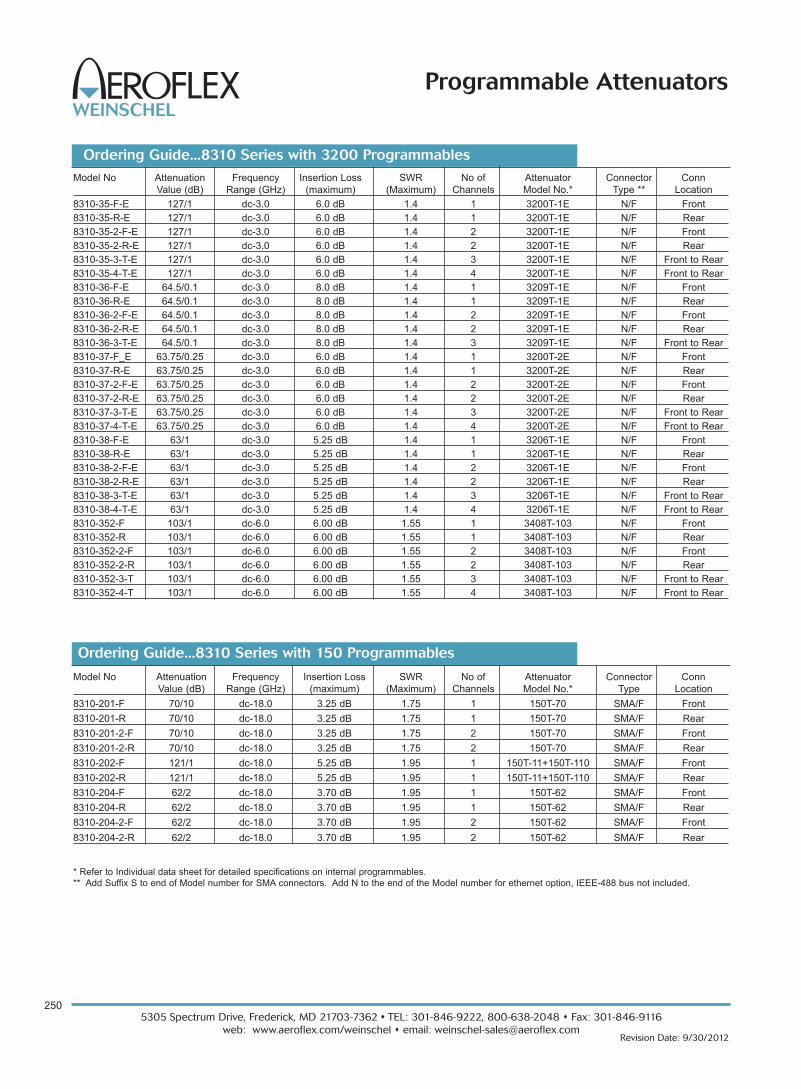
5305 Spectrum Drive, Frederick, MD 21703-7362 s TEL: 301-846-9222, 800-638-2048 s Fax: 301-846-9116
web: www.aeroflex.com/weinschel s email: [email protected]
250
Revision Date: 9/30/2012
Programmable Attenuators
Model No Attenuation Frequency Insertion Loss SWR No of Attenuator Connector Conn
Value (dB) Range (GHz) (maximum) (Maximum) Channels Model No.* Type Location
8310-201-F 70/10 dc-18.0 3.25 dB 1.75 1 150T-70 SMA/F Front
8310-201-R 70/10 dc-18.0 3.25 dB 1.75 1 150T-70 SMA/F Rear
8310-201-2-F 70/10 dc-18.0 3.25 dB 1.75 2 150T-70 SMA/F Front
8310-201-2-R 70/10 dc-18.0 3.25 dB 1.75 2 150T-70 SMA/F Rear
8310-202-F 121/1 dc-18.0 5.25 dB 1.95 1 150T-11+150T-110 SMA/F Front
8310-202-R 121/1 dc-18.0 5.25 dB 1.95 1 150T-11+150T-110 SMA/F Rear
8310-204-F 62/2 dc-18.0 3.70 dB 1.95 1 150T-62 SMA/F Front
8310-204-R 62/2 dc-18.0 3.70 dB 1.95 1 150T-62 SMA/F Rear
8310-204-2-F 62/2 dc-18.0 3.70 dB 1.95 2 150T-62 SMA/F Front
8310-204-2-R 62/2 dc-18.0 3.70 dB 1.95 2 150T-62 SMA/F Rear
Model No Attenuation Frequency Insertion Loss SWR No of Attenuator Connector Conn
Value (dB) Range (GHz) (maximum) (Maximum) Channels Model No.* Type ** Location
8310-35-F-E 127/1 dc-3.0 6.0 dB 1.4 1 3200T-1E N/F Front
8310-35-R-E 127/1 dc-3.0 6.0 dB 1.4 1 3200T-1E N/F Rear
8310-35-2-F-E 127/1 dc-3.0 6.0 dB 1.4 2 3200T-1E N/F Front
8310-35-2-R-E 127/1 dc-3.0 6.0 dB 1.4 2 3200T-1E N/F Rear
8310-35-3-T-E 127/1 dc-3.0 6.0 dB 1.4 3 3200T-1E N/F Front to Rear
8310-35-4-T-E 127/1 dc-3.0 6.0 dB 1.4 4 3200T-1E N/F Front to Rear
8310-36-F-E 64.5/0.1 dc-3.0 8.0 dB 1.4 1 3209T-1E N/F Front
8310-36-R-E 64.5/0.1 dc-3.0 8.0 dB 1.4 1 3209T-1E N/F Rear
8310-36-2-F-E 64.5/0.1 dc-3.0 8.0 dB 1.4 2 3209T-1E N/F Front
8310-36-2-R-E 64.5/0.1 dc-3.0 8.0 dB 1.4 2 3209T-1E N/F Rear
8310-36-3-T-E 64.5/0.1 dc-3.0 8.0 dB 1.4 3 3209T-1E N/F Front to Rear
8310-37-F_E 63.75/0.25 dc-3.0 6.0 dB 1.4 1 3200T-2E N/F Front
8310-37-R-E 63.75/0.25 dc-3.0 6.0 dB 1.4 1 3200T-2E N/F Rear
8310-37-2-F-E 63.75/0.25 dc-3.0 6.0 dB 1.4 2 3200T-2E N/F Front
8310-37-2-R-E 63.75/0.25 dc-3.0 6.0 dB 1.4 2 3200T-2E N/F Rear
8310-37-3-T-E 63.75/0.25 dc-3.0 6.0 dB 1.4 3 3200T-2E N/F Front to Rear
8310-37-4-T-E 63.75/0.25 dc-3.0 6.0 dB 1.4 4 3200T-2E N/F Front to Rear
8310-38-F-E 63/1 dc-3.0 5.25 dB 1.4 1 3206T-1E N/F Front
8310-38-R-E 63/1 dc-3.0 5.25 dB 1.4 1 3206T-1E N/F Rear
8310-38-2-F-E 63/1 dc-3.0 5.25 dB 1.4 2 3206T-1E N/F Front
8310-38-2-R-E 63/1 dc-3.0 5.25 dB 1.4 2 3206T-1E N/F Rear
8310-38-3-T-E 63/1 dc-3.0 5.25 dB 1.4 3 3206T-1E N/F Front to Rear
8310-38-4-T-E 63/1 dc-3.0 5.25 dB 1.4 4 3206T-1E N/F Front to Rear
8310-352-F 103/1 dc-6.0 6.00 dB 1.55 1 3408T-103 N/F Front
8310-352-R 103/1 dc-6.0 6.00 dB 1.55 1 3408T-103 N/F Rear
8310-352-2-F 103/1 dc-6.0 6.00 dB 1.55 2 3408T-103 N/F Front
8310-352-2-R 103/1 dc-6.0 6.00 dB 1.55 2 3408T-103 N/F Rear
8310-352-3-T 103/1 dc-6.0 6.00 dB 1.55 3 3408T-103 N/F Front to Rear
8310-352-4-T 103/1 dc-6.0 6.00 dB 1.55 4 3408T-103 N/F Front to Rear
Ordering Guide...8310 Series with 3200 Programmables
* Refer to Individual data sheet for detailed specifications on internal programmables.
** Add Suffix S to end of Model number for SMA connectors. Add N to the end of the Model number for ethernet option, IEEE-488 bus not included.
Ordering Guide...8310 Series with 150 Programmables

251
5305 Spectrum Drive, Frederick, MD 21703-7362 s TEL: 301-846-9222, 800-638-2048 s Fax: 301-846-9116
web: www.aeroflex.com/weinschel s email: [email protected] Date: 9/30/2012
Programmable Attenuators
Model No Attenuation Frequency Insertion Loss SWR No of Attenuator Connector Conn
Value (dB) Range (GHz) (maximum) (Maximum) Channels Model No.* Type Location
8311-38-6-F-E 63/1 dc-2.0 5.25 dB 1.40 6 3206T-1E N/F Front
8311-38-12-T-E 63/1 dc-2.0 5.25 dB 1.40 12 3206T-1E N/F Front-Rear
8311-137-6-F 63/1 0.8-3.0 4.70 dB 1.60 6 4226-63 N/F Front
8311-202-2-F 121/1 dc-18.0 5.25 dB 1.95 2 150T-11+150T-110 SMA/F Front
8311-202-3-F 121/1 dc-18.0 5.25 dB 1.95 3 150T-11+150T-110 SMA/F Front
8311-204-6-F 62/2 dc-18.0 3.70 dB 1.95 6 150T-62 SMA/F Front
8311-352-6-F 103/1 dc-6.0 6.00 dB 1.55 6 3408T-103 SMA/F Front
8311-352-9-T 103/1 dc-6.0 6.00 dB 1.55 9 3408T-103 SMA/F Front-Rear
Ordering Guide...8311 Series!
Physical Dimensions
NOTE:
1. All dimensions are given in mm (inches) and are maximum, unless otherwise specified.
2. Connector location (Front/Rear) may vary depending on Model ordered.
Connector Type DIM A
N 29.2 (1.15)
SMA 8.6 (0.34)
BNC 18.8 (0.74)
F 9.65 (0.38)
8310 Series:
8311 Series:
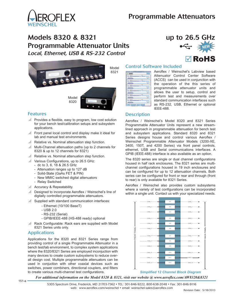
Features
o Provides a flexible, easy to program, low cost solutionfor your bench test/calibration setups and subsystem
applications.
o Front panel local control and display make it ideal forlab and manual test environments.
o Relative vs. Nominal attenuation step function.
o Multi-Channel attenuation paths (up to 2 channels for8320 & up to 12 channels for 8321)
o Relative vs. Nominal attenuation step function.
o Various Configurations, up to 26.5 GHz:- dc to 3, 6, 18 & 26.5 GHz
- Attenuation ranges up to 127 dB
- Solid-State (GaAs FET & PIN)
- New MMIC switched digital attenuators
- Relay Switched
o Accuracy & Repeatability.
o Designed to incorporate Aeroflex / Weinschel’s line ofdigitally controlled programmable attenuators.
o Supplied with standard communication interfaces:
- Ethernet (10/100 BaseT)
- USB 2.0
- RS-232 (Serial)
- GPIB/IEEE-488 (HS-488 ready) optional
o Rack Configurable: Rack ears are supplied with Model8321 Series units only.
Applications
Applications for the 8320 and 8321 Series range from
providing control of a single Programmable Attenuator in a
bench test/lab environment, to complex system applications
where the 8320/8321 Series are employed inconjuction with
many devices to create custom subsystems to reduce over-
all design cost. Multiple programmable attenuators can be
used in conjuction with other coaxial devices such as
switches, power combiners, directional couplers, and filters
to create various multi-channel test configurations. Simplified 12 Channel Block Diagram
CHAN_1
CHAN_2
CHAN_3
FRO
NT
PA
NE
L
BA
CK
PA
NE
L
AT1
AT2
AT3
AT4
AT5
AT6
AT7
AT8
AT9
AT10
AT11
AT12
CHAN_4
CHAN_5
CHAN_6
CHAN_7
CHAN_8
CHAN_9
CHAN_10
CHAN_11
CHAN_12
CHAN_1
CHAN_2
CHAN_3
CHAN_4
CHAN_5
CHAN_6
CHAN_7
CHAN_8
CHAN_9
CHAN_10
CHAN_11
CHAN_12
5305 Spectrum Drive, Frederick, MD 21703-7362 s TEL: 301-846-9222, 800-638-2048 s Fax: 301-846-9116
web: www.aeroflex.com/weinschel s email: [email protected]
151-a
Revision Date: 5/18/2013
Programmable Attenuators
For additional information on the Model 8320 & 8321, visit our website @ www.aeroflex.com/AW8320&8321
Control Software IncludedAeroflex / Weinschel’s Labview based
Attenuator Control Center Software
(ACCS) can be used in conjunction with
the operation of the this series of
programmable attenuator units and
allows the user to setup, control and
perform test and measurements over
standard communication interfaces such
as RS-232, USB, Ethernet or optional
IEEE-488.
Description
Aeroflex / Weinschel’s Model 8320 and 8321 Series
Programmable Attenuator Units represent a new stream-
lined approach in programmable attenuation for bench test
and subsystem applications. Standard 8320 and 8321
Series designs house and control various Aeroflex /
Weinschel Programmable Attenuator Models (3200-XE,
3400, 150T, and 4200 Series) via front panel controls,
ethernet, USB and Serial communications interfaces. A
GPIB (IEEE-488) interface is also available as an option.
The 8320 series are single or dual channel configurations
housed in half rack enclosures. The 8321 series are multi-
channel configurations housed in 19 inch enclosures and
can be configured for up to 12 attenuation channels. Both
series can be configured for front or rear and through (front
to rear) is only available for 8321 Series.
Aeroflex / Weinschel also provides custom subsystems
where a variety of test configurations can be incorporated
within a single unit. Contact us with your specialized needs.
Models 8320 & 8321 up to 26.5 GHz
Programmable Attenuator UnitsLocal, Ethernet, USB & RS-232 Control
RoHS��Model
8321
Model
8320
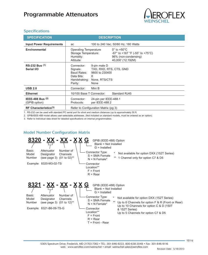
151-b
5305 Spectrum Drive, Frederick, MD 21703-7362 s TEL: 301-846-9222, 800-638-2048 s Fax: 301-846-9116
web: www.aeroflex.com/weinschel s email: [email protected] Date: 5/18/2013
Programmable Attenuators
Specifications
Input Power Requirements ac 100 to 240 Vac, 50/60 Hz, 180 Watts
Environmental Operating Temperature 0° to +50°C
Storage Temperature: -67° to +167 °F (-55° to +75°C)
Humidity: 96% (non-condensing)
Altitude: 40,000' (12,192M)
RS-232 Bus (1) Connector: 9-pin male D
Serial I/O Signals: TXD, RXD, RTS, CTS, GND
Baud Rates: 9600 to 230400
Data Bits: 8
Handshaking: None, RTS/CTS
Parity: None
USB 2.0 Connector: Mini B
Ethernet 10/100 Base T Connector: Standard RJ45
IEEE-488 Bus (2) Connector: 24-pin per IEEE-488.1
(GPIB option) Protocols: per IEEE-488.2
RF Characteristics(3) Refer to Configuration Matrix (pg 3)
1. RS-232 can be used with standard PC serial port for short and medium distances (up to approximately 50 ft.
2. GPIB/IEEE-488 model allows user-selectable addresses, (Not included on standard models, must be ordered as an option).
3. Refer to Individual data sheet for detailed specifications on internal programmables.
SPECIFICATION DESCRIPTION
Model Number Configuration Matrix
* Not available for option DXX (152T Series)
** 1 Channel only for option C7 & D5
8320 - XX - XX - X X G
Basic
Model
Number
Connector
Location**
F = Front
R = Rear
Attenuator
Designator
(see page 3)
Number of
Channels
(01 to 02)**
Connector Type
S = SMA Female
N = N Female*
Example: 8320-M3-02-TS
* Not available for option DXX (152T Series)
** Up to 6 Channels for option F & R (Front or Rear)
Up to 10 Channels for option C & D (150T
& 152T Series)
Up to 5 Channels for option C7 & D5
GPIB (IEEE-488) Option
Blank = Not Installed
G = Installed
8321 - XX - XX - X X G
Basic
Model
Number
Connector
Location**
F = Front
R = Rear
T = Front - Rear
Attenuator
Designator
(see page 3)
Number of
Channels
(01 to 12)**
Connector Type
S = SMA Female
N = N Female*
Example: 8321-B6-09-TS-G
GPIB (IEEE-488) Option
Blank = Not Installed
G = Installed

RoHs compliance dependent on attenuator installed. Some attenuators are NOT compliant.
5305 Spectrum Drive, Frederick, MD 21703-7362 s TEL: 301-846-9222, 800-638-2048 s Fax: 301-846-9116
web: www.aeroflex.com/weinschel s email: [email protected]
151-c
Revision Date: 5/18/2013
Programmable Attenuators
Electro-mechanical
Frequency
Range
Attenuator
DesignationAttenuator Model
Range
(dB)
Step Size
(dB)
Insertion Loss
(maximum)
VSWR
(maximum) RoHs
DC-3 GHz A
1 3205-1E 70 10 3.75 dB 1.4
2 3205-2E 55 5 3.75 dB 1.4
3 3205-3E 1.5 0.1 3.75 dB 1.4
4 3201-1E 31 1 4.00 dB 1.4
5 3206-1E 63 1 4.25 dB 1.4
6 3200-1E 127 1 5.25 dB 1.4
7 3200-2E 63.75 0.25 5.25 dB 1.4
8 3209-1E 64.5 0.1 6.00 dB 1.4
DC-6 GHz B
1 3404-15 15 1 3.50 dB 1.55
2 3404-55 55 5 3.50 dB 1.55
3 3404-70 70 10 3.50 dB 1.55
4 3406-55 55 1 4.50 dB 1.55
5 3408-55.75 55.75 0.25 6.00 dB 1.55
6 3408-103 103 1 6.00 dB 1.55
DC-18 GHz C
1 150T-70 70 10 3.25 dB 1.75 2 150T-15 15 1 3.50 dB 1.95 3 150T-75 75 5 3.50 dB 1.95 4 150T-110 110 10 3.50 dB 1.95 5 150T-31 31 1 3.75 dB 1.95 6 150T-62 62 2 3.75 dB 1.95 7 150T-15 & 150T-110 125 1 5.25 dB 1.95
DC-26.5 GHz D
1 152AT-70 70 10 4.75 dB 1.95 2 152T-15 15 1 5.00 dB 1.95 3 152T-75 75 5 5.00 dB 1.95 4 152T-90 90 10 5.00 dB 1.95 5 152T-90 & 152T-15 105 1 6.50 dB 1.95
Solid State
0.8 to 2.5/3 GHz J
1 4226-63 63 1 4.75 dB 1.6
2 4228-63.75 63.75 0.25 6.00 dB 1.6
3 4228-103 103 1 6.00 dB 1.6
0.01 to 2.5 GHz K1 4238-63.75 63.75 0.25 10.00 dB 1.75
2 4238-103 103 1 10.00 dB 1.75
0.01 to 2.5 GHz L
1 4246-63 63 1 11.00 dB 2.0
2 4248-63.75 63.75 0.25 14.00 dB 2.0
3 4248-103 103 1 14.00 dB 2.0
0.2 to 6 GHz M
1 4205-31.5 31.5 0.5 4.00 dB 1.8 2 4205-63.5 63.5 0.5 6.00 dB 1.8 3 4205-95.5 95.5 0.5 8.50 dB 2.0

4
5305 Spectrum Drive, Frederick, MD 21703-7362 s TEL: 301-846-9222, 800-638-2048 s Fax: 301-846-9116
web: www.aeroflex.com/weinschel s email: [email protected] Date: 5/18/2013
Programmable Attenuators
Physical Dimensions
Aero
flex /
Wein
sche
lCA
GE C
ODE
9345
9
MAD
E IN
USA
MO
DE
L:
SER
NO
:
SER
IAL
LIN
K
AC
T
LAN
USB
GP
IB
CH
AN
12
BC
HA
N 9
BC
HA
N 8
BC
HA
N 6
BC
HA
N 5
BC
HA
N 3
BC
HA
N 2
BC
HA
N 4
BC
HA
N 1
BC
HA
N 1
0B
CH
AN
11
BC
HA
N 7
B
8321 SE
RIE
S
CH
AN 5
AC
HA
N 4
AC
HA
N 3
AC
HA
N 2
AC
HA
N 1
AC
HA
N 7
AC
HA
N 6
AC
HA
N 12
AC
HA
N 11
AC
HA
N 10
AC
HA
N 9
AC
HA
N 8
A76.20[3.000]
5.97[.24]
465.12[18.312]
425.20[16.74]
482.60[19.00]
88.14[3.47]
.25 X .40 LONG SLOT, 4X[6.35] [10.16]
304.80[12.00]
1.27[.05]
DIM“A”
POWERSWITCH
POWER INPUT115/230 VAC0.5A 50/60Hz
CONNECTOR,9 PIN D MALE,
RS232
CONNECTOR,USB, MINI B
CONNECTOR,ETHERNET RJ45
2
22
2
13.21[.52]
28.70[1.13]
TYP FRONT AND REAR
[1.250]
37.97 [1.50]TYPICAL FRONT
AND REAR8.74[.34]
349.25[13.75]
11X 31.75 =
TYPICAL FRONTAND REAR
31.75[1.250]
TYPICAL FRONT
AND REAR
8XCONNECTOR,TYPE N FEMALE
4XHOLE PLUG
8XCONNECTOR,TYPE N FEMALE
4XHOLE PLUG
CONNECTOR,PER IEEE 488.2
PROTOCOL
19.3[.76]
TYP FRONTAND REAR
NOTE:
1. All dimensions are given in mm (inches).
2. Connectors and hole plugs are installed as required and determined by number of channel in unit. 2 channel shown for Model
8320 and 8 channel unit shown for 8321.
3. Connector location (Front/Rear) may vary depending on Model ordered.
Connector Type DIM A
N 14.7 (0.60)
SMA 5.21 (0.21)
Model 8321, Standard 19 in Rack Unit up to 12 channels:
Connector Type DIM A
N 14.7 (0.60)
SMA 5.21 (0.21)
Model 8320, Half Rack Unit, 1 or 2 channels:

5305 Spectrum Drive, Frederick, MD 21703-7362 s TEL: 301-846-9222, 800-638-2048 s Fax: 301-846-9116
web: www.aeroflex.com/weinschel s email: [email protected]
252
Revision Date: 5/30/2013
Programmable Attenuators
For additional information on the Model 8331, visit our website @ www.aeroflex.com/AW8331
Simplified 12 Channel Block Diagram
CHAN_1
CHAN_2
CHAN_3
FRO
NT
PA
NE
L
BA
CK
PA
NE
L
AT1
AT2
AT3
AT4
AT5
AT6
AT7
AT8
AT9
AT10
AT11
AT12
CHAN_4
CHAN_5
CHAN_6
CHAN_7
CHAN_8
CHAN_9
CHAN_10
CHAN_11
CHAN_12
CHAN_1
CHAN_2
CHAN_3
CHAN_4
CHAN_5
CHAN_6
CHAN_7
CHAN_8
CHAN_9
CHAN_10
CHAN_11
CHAN_12
DescriptionAeroflex / Weinschel’s New 8331 Series Programmable
Attenuator Units offer a lower cost solution for automated
bench test and subsystem applications. Standard 8331
Series designs house and control various Aeroflex /
Weinschel Programmable Attenuator Models (3200-XE,
3400, 150T, and 4200 Series) via ethernet, USB 2.0 and
Serial communications interfaces.
Most 8331 Series are multi-channel configurations where
RF signal is routed through either the front or rear mounted
Ports. This series can be configured for up to 12 indepen-
dent channels of attenuation. Multiple programmable
attenuators can be used in conjuction with other coaxial
devices such as switches, power combiners, directional
couplers, and filters creating various multichannel test
configurations.
Aeroflex / Weinschel also provides custom subsystems
where a variety of test configurations can be incorporated
within a single unit. Contact us with your specialized needs.
Models 8331 up to 26.5 GHz
Programmable Attenuator UnitEthernet, USB & RS-232 Control
Features
o Provides a flexible, easy to program, low cost solutionfor your bench test/calibration setups and subsystem
applications.
o Multi-Channel attenuation paths (up to 12 channels)
o Relative vs. Nominal attenuation step function.
o Various Configurations, up to 26.5 GHz:- dc to 3, 6, 18 & 26.5 GHz
- up to 127 dB
- Solid-State (GaAs FET & PIN)
- New MMIC switched digital attenuators
- Relay Switched
o Accuracy & Repeatability.
o Designed to incorporate Aeroflex / Weinschel’s line ofdigitally controlled programmable attenuators.
o Designed to interface with industry standard communication interfaces:
- RS-232 (Serial)
- Ethernet (10/100 BaseT)
- USB 2.0
o Rack Configurable: Rack ears are supplied withModel 8331 Series units.
o Ideal for Automated Test Equipment (ATE), WiMAX, 3GFading Simulators, Engineering/Production Test Lab
environments.
Applications
Designed with budget and performance concerns in mind,
these devices offer superior RF characteristics suitable for
automated bench testing in wireless backhaul, fading
simulation, and other high performance wireless
applications.
Control Software IncludedAeroflex / Weinschel’s Labview based
Attenuator Control Center Software (ACCS)
can be used in conjunction with the opera-
tion of the this series of programmable
attenuator units and allows the user to setup,
control and perform test and measurements
over standard communication interfaces
such as RS-232, USB 2.0 or Ethernet.
RoHS��

253
5305 Spectrum Drive, Frederick, MD 21703-7362 s TEL: 301-846-9222, 800-638-2048 s Fax: 301-846-9116
web: www.aeroflex.com/weinschel s email: [email protected] Date: 5/30/2013
Programmable Attenuators
Specifications
Input Power Requirements ac 100 to 240 Vac, 50/60 Hz, 180 Watts
Environmental Operating Temperature 0° to +50°C
Storage Temperature: -67° to +167 °F (-55° to +75°C)
Humidity: 96% (non-condensing)
Altitude: 40,000' (12,192M)
RS-232 Bus (1) Connector: 9-pin male D
Serial I/O Signals: TXD, RXD, RTS, CTS, GND
Baud Rates: 9600 to 230400
Data Bits: 8
Handshaking: None, RTS/CTS
Parity: None
USB 2.0 Connector: Mini B
Ethernet 10/100 Base T Connector: Standard RJ45
RF Characteristics(2) Refer to Configuration Matrix (pg 254)
1. RS-232 can be used with standard PC serial port for short and medium distances (up to approximately 50 ft).
2. Refer to Individual data sheet for detailed specifications on internal programmables.
SPECIFICATION DESCRIPTION
Physical Dimensions
Aero
flex /
Wein
sche
lCA
GE C
ODE
9345
9
MAD
E IN
USA
MO
DE
L:
SER
NO
:
SE
RIA
LLN
K
AC
T
LAN
CH
AN 1
BC
HA
N 2
BC
HAN
3B
CH
AN
4B
CH
AN 5
BC
HA
N6
BC
HAN
7B
CH
AN
8B
CH
AN
9B
CH
AN
10B
CH
AN11
BC
HA
N12
B
US
B
CH
AN 1
AC
HA
N 2
AC
HAN
3A
CH
AN
4A
CH
AN 5
AC
HA
N 6
AC
HA
N 8
AC
HAN
9A
CH
AN 10
AC
HA
N 11
AC
HAN
12A
CH
AN 7
A
8331 SE
RIE
S
POW
ER
STAT
76.20[3.000]
5.97[.24]
465.12[18.312]
425.20[16.74]
482.60[19.00]
88.14[3.47]
.25 X .40 LONG SLOT, 4X[6.35] [10.16]
304.80[12.00]
1.27[.05]
DIM“A”
4XHOLE PLUG
8XCONNECTOR,SMA FEMALE
8XCONNECTOR,SMA FEMALE
4XHOLE PLUG
POWERSWITCH
POWER INPUT115/230 VAC0.5A 50/60Hz
CONNECTOR,9 PIN D MALE,
RS232
CONNECTOR,USB, MINI B
(OPTION NOTAVAILABLE)
CONNECTOR,ETHERNET RJ45
2
2
2
2
5.21[.21]
349.25[13.75]
11X 31.75 =
TYPFRONT AND REAR
28.70[1.13]
TYP FRONT AND REAR
[1.250]
31.75[1.250]
TYP FRONT AND REAR
37.97[1.50]
TYP FRONT AND REAR
8.74[.34]
19.30[.76]
TYP FRONT AND REAR
NOTE:
1. All dimensions are given in mm (inches).
2. Connectors and hole plugs are installed as required and determined by number of channel
in unit. 8 channel unit shown
3. Connector location (Front/Rear) may vary depending on Model ordered.
Connector Type DIM A
N 14.7 (0.60)
SMA 5.21 (0.21)
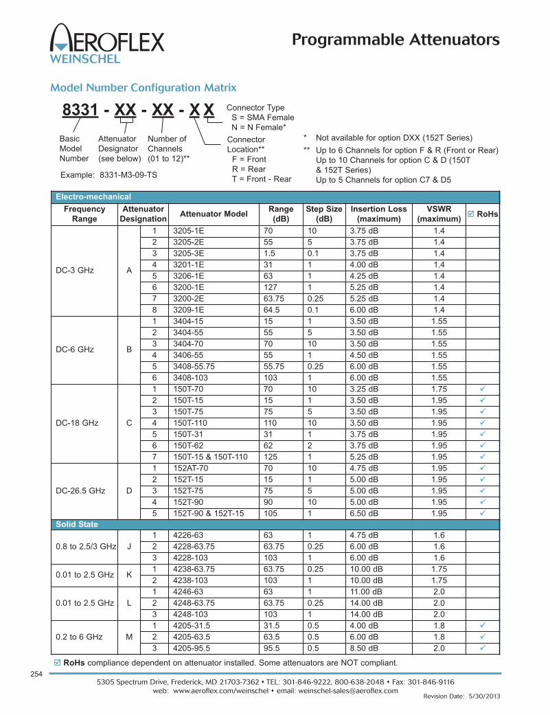
RoHs compliance dependent on attenuator installed. Some attenuators are NOT compliant.
5305 Spectrum Drive, Frederick, MD 21703-7362 s TEL: 301-846-9222, 800-638-2048 s Fax: 301-846-9116
web: www.aeroflex.com/weinschel s email: [email protected]
254
Revision Date: 5/30/2013
Programmable Attenuators
Model Number Configuration Matrix
* Not available for option DXX (152T Series)
** Up to 6 Channels for option F & R (Front or Rear)
Up to 10 Channels for option C & D (150T
& 152T Series)
Up to 5 Channels for option C7 & D5
8331 - XX - XX - X X
Basic
Model
Number
Connector
Location**
F = Front
R = Rear
T = Front - Rear
Attenuator
Designator
(see below)
Number of
Channels
(01 to 12)**
Connector Type
S = SMA Female
N = N Female*
Electro-mechanical
Frequency
Range
Attenuator
DesignationAttenuator Model
Range
(dB)
Step Size
(dB)
Insertion Loss
(maximum)
VSWR
(maximum) RoHs
DC-3 GHz A
1 3205-1E 70 10 3.75 dB 1.4
2 3205-2E 55 5 3.75 dB 1.4
3 3205-3E 1.5 0.1 3.75 dB 1.4
4 3201-1E 31 1 4.00 dB 1.4
5 3206-1E 63 1 4.25 dB 1.4
6 3200-1E 127 1 5.25 dB 1.4
7 3200-2E 63.75 0.25 5.25 dB 1.4
8 3209-1E 64.5 0.1 6.00 dB 1.4
DC-6 GHz B
1 3404-15 15 1 3.50 dB 1.55
2 3404-55 55 5 3.50 dB 1.55
3 3404-70 70 10 3.50 dB 1.55
4 3406-55 55 1 4.50 dB 1.55
5 3408-55.75 55.75 0.25 6.00 dB 1.55
6 3408-103 103 1 6.00 dB 1.55
DC-18 GHz C
1 150T-70 70 10 3.25 dB 1.75 2 150T-15 15 1 3.50 dB 1.95 3 150T-75 75 5 3.50 dB 1.95 4 150T-110 110 10 3.50 dB 1.95 5 150T-31 31 1 3.75 dB 1.95 6 150T-62 62 2 3.75 dB 1.95 7 150T-15 & 150T-110 125 1 5.25 dB 1.95
DC-26.5 GHz D
1 152AT-70 70 10 4.75 dB 1.95 2 152T-15 15 1 5.00 dB 1.95 3 152T-75 75 5 5.00 dB 1.95 4 152T-90 90 10 5.00 dB 1.95 5 152T-90 & 152T-15 105 1 6.50 dB 1.95
Solid State
0.8 to 2.5/3 GHz J
1 4226-63 63 1 4.75 dB 1.6
2 4228-63.75 63.75 0.25 6.00 dB 1.6
3 4228-103 103 1 6.00 dB 1.6
0.01 to 2.5 GHz K1 4238-63.75 63.75 0.25 10.00 dB 1.75
2 4238-103 103 1 10.00 dB 1.75
0.01 to 2.5 GHz L
1 4246-63 63 1 11.00 dB 2.0
2 4248-63.75 63.75 0.25 14.00 dB 2.0
3 4248-103 103 1 14.00 dB 2.0
0.2 to 6 GHz M
1 4205-31.5 31.5 0.5 4.00 dB 1.8 2 4205-63.5 63.5 0.5 6.00 dB 1.8 3 4205-95.5 95.5 0.5 8.50 dB 2.0
Example: 8331-M3-09-TS
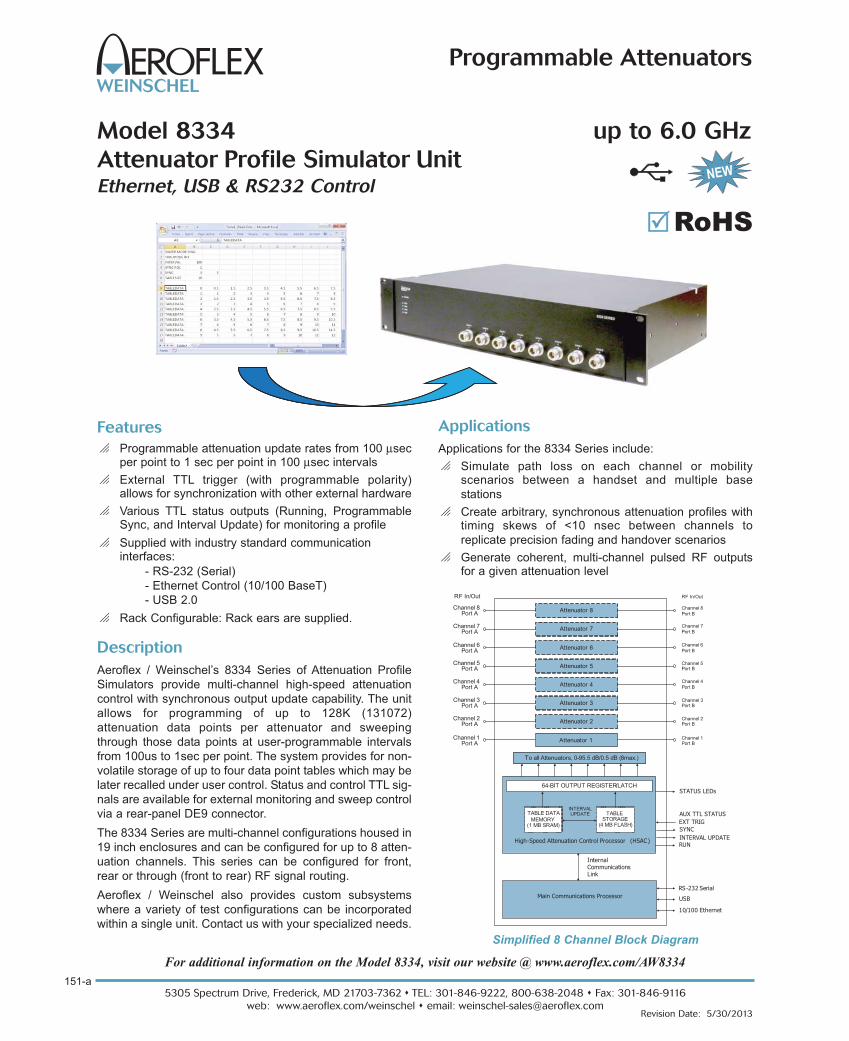
Simplified 8 Channel Block Diagram
Main Communications Processor USB
10/100 Ethernet
Internal Communications Link
RS-232 Serial
High-Speed Attenuation Control Processor (HSAC)
SYNC
AUX TTL STATUS
INTERVAL UPDATERUN
EXT TRIG
64-BIT OUTPUT REGISTER/LATCHSTATUS LEDs
INTERVAL UPDATETABLE DATA
MEMORY(1 MB SRAM)
TABLE STORAGE
(4 MB FLASH)
To all Attenuators, 0-95.5 dB/0.5 dB (8max.)
Attenuator 1
Attenuator 2
Attenuator 3
Attenuator 4
Attenuator 5
Attenuator 6
Attenuator 7
Attenuator 8
RF In/Out RF In/Out
Channel 1Port A
Channel 2Port A
Channel 3Port A
Channel 4Port A
Channel 5Port A
Channel 6Port A
Channel 7Port A
Channel 8Port A
Channel 1Port B
Channel 2Port B
Channel 3Port B
Channel 4Port B
Channel 5Port B
Channel 6Port B
Channel 7Port B
Channel 8Port B
5305 Spectrum Drive, Frederick, MD 21703-7362 s TEL: 301-846-9222, 800-638-2048 s Fax: 301-846-9116
web: www.aeroflex.com/weinschel s email: [email protected]
151-a
Revision Date: 5/30/2013
Programmable Attenuators
For additional information on the Model 8334, visit our website @ www.aeroflex.com/AW8334
Model 8334 up to 6.0 GHz
Attenuator Profile Simulator UnitEthernet, USB & RS232 Control
Features
o Programmable attenuation update rates from 100 μsecper point to 1 sec per point in 100 μsec intervals
o External TTL trigger (with programmable polarity) allows for synchronization with other external hardware
o Various TTL status outputs (Running, ProgrammableSync, and Interval Update) for monitoring a profile
o Supplied with industry standard communication interfaces:
- RS-232 (Serial)
- Ethernet Control (10/100 BaseT)
- USB 2.0
o Rack Configurable: Rack ears are supplied.
Description
Aeroflex / Weinschel’s 8334 Series of Attenuation Profile
Simulators provide multi-channel high-speed attenuation
control with synchronous output update capability. The unit
allows for programming of up to 128K (131072)
attenuation data points per attenuator and sweeping
through those data points at user-programmable intervals
from 100us to 1sec per point. The system provides for non-
volatile storage of up to four data point tables which may be
later recalled under user control. Status and control TTL sig-
nals are available for external monitoring and sweep control
via a rear-panel DE9 connector.
The 8334 Series are multi-channel configurations housed in
19 inch enclosures and can be configured for up to 8 atten-
uation channels. This series can be configured for front,
rear or through (front to rear) RF signal routing.
Aeroflex / Weinschel also provides custom subsystems
where a variety of test configurations can be incorporated
within a single unit. Contact us with your specialized needs.
RoHS��
Applications
Applications for the 8334 Series include:
o Simulate path loss on each channel or mobility scenarios between a handset and multiple base
stations
o Create arbitrary, synchronous attenuation profiles withtiming skews of <10 nsec between channels to
replicate precision fading and handover scenarios
o Generate coherent, multi-channel pulsed RF outputsfor a given attenuation level

151-b
5305 Spectrum Drive, Frederick, MD 21703-7362 s TEL: 301-846-9222, 800-638-2048 s Fax: 301-846-9116
web: www.aeroflex.com/weinschel s email: [email protected] Date:
Programmable Attenuators
Specifications
Input Power Requirements ac 100 to 240 Vac, 50/60 Hz, 180 Watts
Environmental Operating Temperature 0° to +50°C
Storage Temperature: -40° to +167 °F (-40° to +75°C)
Humidity: 96% (non-condensing)
Altitude: 40,000' (12,192M)
RS-232 Bus (1) Connector: 9-pin male D
Serial I/O Signals: TXD, RXD, RTS, CTS, GND
Baud Rates: 9600 to 230400
Data Bits: 8
Handshaking: None, RTS/CTS
AUX Connector: 9-pin male D
Signals: SYNC, EXT TRIG, INTERVAL UPDATE, RUN, GND
USB 2.0 Connector: Mini B
Ethernet 10/100 Base T Connector: Standard RJ45
RF Characteristics(3) Refer to Configuration Matrix (below)
1. RS-232 can be used with standard PC serial port for short and medium distances (up to approximately 50 ft.
2. Refer to Individual data sheet for detailed specifications on internal programmables.
SPECIFICATION DESCRIPTION
Model Number Configuration Matrix
* up to 6 Channel units only available for option F & R
8334 - M3 - XX - X N
Basic
Model
Number
Connector Location
F = Front *
R = Rear *
T = Thru
Attenuator
Designator
Number of
Channels
(01 to 08)
Connector Type
N = N Female
Example: 8334-M3-08-TN
Solid State (Only)
Frequency
Range
Attenuator
DesignationAttenuator Model
Range
(dB)
Step Size
(dB)
Insertion Loss
(maximum)
VSWR
(maximum) RoHs
0.2 to 6 GHz M 3 4205-95.5 95.5 0.5 8.50 dB 2.0
RoHs compliance dependent on attenuator installed. Some attenuators are NOT compliant.

5305 Spectrum Drive, Frederick, MD 21703-7362 s TEL: 301-846-9222, 800-638-2048 s Fax: 301-846-9116
web: www.aeroflex.com/weinschel s email: [email protected]
151-c
Revision Date: 5/30/2013
Programmable Attenuators
Physical Dimensions
Aero
flex /
Wein
sche
lCA
GE C
ODE
9345
9
MAD
E IN
USA
MO
DE
L:
SERN
O:
CH
AN
1A
CH
AN
2A
CH
AN
4A
CH
AN
5A
CH
AN
6A
CH
AN
7A
CH
AN
8A
CH
AN
3A
8334 SE
RIE
S
POW
ER
STAT
ARM
TRIG
RU
N
SER
IAL
LNK
A
CT
LAN
CH
AN
1B
CH
AN
2B
CH
AN
3B
CH
AN
4B
CH
AN
5B
CH
AN
6B
CH
AN
7B
CH
AN
8B
US
B
AU
X
76.20[3.000]
5.97[.24]
465.12[18.312]
425.20[16.74]
482.60[19.00]
88.14[3.47]
.25 X .40 LONG SLOT, 4X[6.35] [10.16]
304.80[12.00]
1.27[.05]
13.21[.52]
POWERSWITCH
POWER INPUT115/230 VAC0.5A 50/60Hz
CONNECTOR,9 PIN D MALE,
RS232
CONNECTOR,USB, MINI B
(OPTION NOTAVAILABLE)
CONNECTOR,ETHERNET RJ45
2
22
2
13.21[.52]
28.70[1.13]
TYP FRONT AND REAR
[1.250]
164.97[6.50]
TYP FRONT AND REAR
8.74[.34]
6XCONNECTOR,TYPE N FEMALE
2XHOLE PLUG
6XCONNECTOR,TYPE N FEMALE
2XHOLE PLUG
222.25[8.750]
7X 31.75 =
TYP FRONTAND REAR
31.75[1.250]
TYP FRONTAND REAR
19.30[.76]
TYP FRONTAND REAR
NOTE:
1. All dimensions are given in mm (inches).
2. Connectors and hole plugs are installed as required and determined by number of channel in unit. Six channel unit shown.
3. Connector location (Front/Rear) may vary depending on Model ordered.
Standard 19 in Rack Unit up to 8 channels:

255
5305 Spectrum Drive, Frederick, MD 21703-7362 s TEL: 301-846-9222, 800-638-2048 s Fax: 301-846-9116
web: www.aeroflex.com/weinschel s email: [email protected] Date: 9/30/2012
Programmable Attenuators
DescriptionAeroflex / Weinschel's design approach uses a highly
adaptable platform that allows configuration of the step
attenuator to the customers requirements. When the con-
troller requests a new attenuation level the input switch
terminates the input signal into a 50 Ohm load. (See Figure
1) This input switch is hot switchable at 100 Watts of input
power. This will remove the high power signal from the main
signal path. With no signal connected to the attenuator path
the controller then commands the series of relays to config-
ure the attenuator for the requested attenuation value. Then
the input switch re-connects the input signal to the attenua-
tor path. The system can be operated with either a remote
controller (IEEE-488 or RS-232) or through front panel
control.
Model 8312
High Power Programmable Attenuator
RS232\RS422
100 Watt Hot Switching Capability
Features
o Available in 0-15 dB or 0-31 dB Configurations.
o Provides a flexible, easy to program, low cost solutionfor your bench test/calibration setups and subsystem
applications.
o Relative vs. Nominal attenuation step function.
o DC to 13.0 GHz Operation.
o High Accuracy & Repeatability.
o Power Handling up to 100 Watts average
o Designed to interface with industry standard communication interfaces:
- GPIB/IEEE-488 (HS-488 ready)
- RS-232, RS-422
o Built-in monitoring for switching input power into theload in case of fan failure.
o Rack Configurable: A Rack Mounting Kit is includedfor easily mounting the Model 8312 into any rack or
cabinet that is designed per EIA RS-310 or
MIL-STD-189.
HIGH POWERHOT SWITCH
RF INRFOUT
50 , 100 W
TERMINATION
Ω1 dB
100 W
OPTIONAL
SMARTSTEPCONTROLLER
POWER
SUPPLY
DeviceInterfaceBus
2 dB100 W
4 dB100 W
8 dB100 W
16 dB100 W
Figure 1. Model 8312 Block Diagram
For additional information on the Model 8312, visit our website @ www.aeroflex.com/AW/8312.htm
Note: If power failure should occur, the unit will remain in the last selected attenuation state.
IEEE-488

5305 Spectrum Drive, Frederick, MD 21703-7362 s TEL: 301-846-9222, 800-638-2048 s Fax: 301-846-9116
web: www.aeroflex.com/weinschel s email: [email protected]
256
Revision Date: 9/30/2012
Programmable Attenuators
Input Power Requirements AC 100 to 240 Vac, 50/60 Hz, 50 Watts
Environmental Operating Temperature 0 to +50°C
Storage Temperature: 67° to +167 °F (-55° to +75°C)
Humidity: 96%
Altitude: 40,000' (12,192M)
IEEE-488 Bus Connector: 24-pin per IEEE-488.1
Protocols: per IEEE-488.2
Indicators: Remote (RMT), Listen (LSN), Talk (TLK), SRQ (SRQ)
RS-232 Bus Connector: 9-pin male D
Signals: TXD, RXD, RTS, CTS, DTR, GND
Baud Rates: 2400, 9600, 19200, and 38400
Data Bits: 8
Handshaking: None, RTS/CTS, XON/XOFF
Parity: None, Odd, Even
Indicators: Tx (Transmit) and Rx (Receive)
RS-422 BUS(3) Connector: 9-pin male D
Signals: TXD+, TDX-, RXD+, RTX-, RTS+, RTS-, CTS+, CTS- and signal GND
Baud Rates: 2400, 9600, 19200, and 38400
Data Bits: 8
Handshaking: None, RTS/CTS, XON/XOFF
Parity: None, Odd, Even
Indicators: Tx (Transmit) and Rx (Receive)
RF Characteristics(4) Connectors: Type N, Female
Frequency Range: dc - 13 GHz
Impedance: 50 Ω
SWR: 50 MHz - 5 GHz: 1.60 (Maximum)
5 GHz - 13 GHz: 2.30 (Maximun)
Attenuation Range: 15 dB/1 dB steps (8312-15-F)
31 dB/1 dB steps (8312-31-F)
RF Power Rating: 50 MHz - 5 GHz: 100 Watts (Maximum)
5 GHz - 13 GHz: 50 Watts (Maximum)
Attenuation Settings: 100, 000 selections (minimum)
Attenuation Update Rate: 1 second (Typical)
Incremental Accuracy: Frequency 1-15 dB 16-31 dB
50 MHz - 3 GHz: +0.6 dB +0.8 dB
3 GHz - 5 GHz: +0.6 dB +0.8 dB
5 GHz - 13 GHz: +2.5 dB +3.0 dB
Insertion Loss (dB): Frequency Range 8312-15-X 8312-31-X
50 MHz - 3 GHz: 3.0 3.5
3 GHz - 5 GHz: 4.0 4.5
5 GHz - 13 GHz: 7.0 8.0
1. GPIB/IEEE-488 model allows user-selectable addresses.
2. RS-232 can be used with standard PC serial port for short and medium distances (up to approximately 50 ft).
3. RS-422, designed for very long distance communications (4000 ft) and & optimized as a single node protocol, typically with one device connected to a
single port.
4. Refer to Individual data sheet for detailed specifications on internal programmables.
SPECIFICATION DESCRIPTION
Specifications

257
5305 Spectrum Drive, Frederick, MD 21703-7362 s TEL: 301-846-9222, 800-638-2048 s Fax: 301-846-9116
web: www.aeroflex.com/weinschel s email: [email protected] Date: 9/30/2012
Programmable Attenuators
Physical Dimensions
NOTE: All dimensions are given in mm (inches) and are maximum, unless otherwise specified.
* Available in 0-15 dB and 0-31 dB configurations only!
MODEL NUMBER DESCRIPTION:
Example:
8312 - XX - X
Basic
Model
Number
Connector Location
F = Front
R = Rear
Attenuation
Value (dB)*

5305 Spectrum Drive, Frederick, MD 21703-7362 s TEL: 301-846-9222, 800-638-2048 s Fax: 301-846-9116
web: www.aeroflex.com/weinschel s email: [email protected]
258
Revision Date: 9/30/2012
Programmable Attenuators
001-378 Deskmount Power Supply, +15 V
95-250 Vac, 47-63 Hz ac input
193-8013 Interconnect Cable
193-8012 Attenuator Mounting Kit: This kit
includes all hardware to allow the
user to mount one attenuator onto
the Model 8210A
DescriptionModel 8210A represents a new concept in device control
applications and provides a high level interface from various
industry standard communications interfaces to the serial
Driver Interface Bus.
The Device Interface Bus (DIB) is a system for connecting
a number of relatively low-speed I/O devices to a host, pro-
viding a simple, uniform and inexpensive way to control a
variety of devices via a single port. The DIB is based on the
two-wire serial bus and several software protocol layers that
allow the Model 8210A to address up to 125 peripheral
devices with serial data rates of up to 100 KHz. The DIB
may also be used to supply DC power to the devices, result-
ing in a simple, low-cost interconnection system.
This Programmable attenuator/switch controller is available
in two models, each providing a different type of communi-
cations interface to suit user configuration requirements.
Each model contains similar capabilities, and provides
switch-selectable parameters to the interfaces’ operation.
Model 8210A
SmartStep® Programmable Attenuator/
Switch Controller RS232\RS422/RS485
A Logical Interface for Switchable Devices!
Features
o Provides a flexible, powerful, low cost solution for buscontrol of programmable step attenuators and other
switchable devices under computer control.
o Designed to interface with Aeroflex / Weinschel’s lineof intelligent programmable attenuators and other
electromechanical devices.
o Simplifies your bench test setups and subsystemdesign.
o Available in two standard communication interfaces:
- Model 8210A-1: GPIB/IEEE-488 (HS-488 ready)
- Model 8210A-2: RS-232, RS-422, RS-485
Applications Applications for the 8210A range from providing control of a
single Programmable Attenuator in a bench test/lab envi-
ronment using a PC and a terminal emulator, to complex
system applications where the 8210A is employed to control
many devices to create custom/semi-custom subsystems to
reduce overall design cost. Aeroflex / Weinschel can pro-
vide a variety of custom designed driver interfaces for
various devices, such as RF switches, relays, PIN attenua-
tors, displays and other devices, as well as complete
subsystem design and integration services. Contact us with
your specialized needs.
Typical Capacity: Control a subsystem consisting of 32
individual 8-cell programmable attenuators plus 16
DPDT switches.
For additional information on the Model 8210A, visit our website @ www.aeroflex.com/AW/8210A
Accessories:
PART NUMBER DESCRIPTION
IEEE-488

259
5305 Spectrum Drive, Frederick, MD 21703-7362 s TEL: 301-846-9222, 800-638-2048 s Fax: 301-846-9116
web: www.aeroflex.com/weinschel s email: [email protected] Date: 9/30/2012
Programmable Attenuators
DC Input Connector: 2.5mm barrel style
Requirements: +12 to +15 Vdc @ 250 mA
Driver Interface Connector: 14-pin 0.025" square post header @ 0.1" centers. Mates with
AMP 746285-2 or equivalent.
Signals : SDA serial data
SDC serial clock
VDC DC supply voltage
GND ground
VDC Output Current: 2 A maximum
Maximum Cable Length: 10 Meters (1000 pF maximum capacitance)
Data Transfer Rate: 100 KHz
Environmental Operating Temperature: 0 to +50°C
Storage Temperature: -55° to +75°C (67° to +167°F)
Humidity: 95%
Altitude: 40,000' (12,192M)
IEEE-488 Bus(1) Connector: 24-pin per IEEE-488.1
Protocols: per IEEE-488.2
Indicators: Remote, Listen
RS-232 Bus(2) Connector: 9-pin male D
Signals: TXD, RXD, RTS, CTS, DTR, GND
Baud Rates: 2400, 9600, and 19200, 38400
Data Bits: 8
Handshaking: None, RTS/CTS, XON/XOFF
Parity: None, Odd, Even
Indicators: Tx (Transmit) and Rx (Receive Active)
RS-422 Bus(3) & Connector: 9-pin male D(Model 8210-2)
RS-485 Bus(4) Signals: TXD+, TDX-, RXD+, RTX-, RTS+, RTS-, CTS+, CTS-, & signal GND
Baud Rates: 2400, 9600, and 19200, 38400
Data Bits: 8
Handshaking: None, RTS/CTS, XON/XOFF
Parity: None, Odd, Even
Indicators: Tx (Transmit) and Rx (Receive Active)
Notes:1. GPIB/IEEE-488 model allows user-selectable addresses.
2. RS-232 can be used with standard PC serial port for short and medium distances (up to approximately 50 ft).
3. RS-422, designed for very long distance communications (4000 ft) & optimized as a single node protocol, typically with one device connected to a
single port.
4. RS-485, designed for very long distance communications (4000 ft) & optimized for multi-drop connections that can used to create a low cost network.
Specifications
SPECIFICATION DESCRIPTION

5305 Spectrum Drive, Frederick, MD 21703-7362 s TEL: 301-846-9222, 800-638-2048 s Fax: 301-846-9116
web: www.aeroflex.com/weinschel s email: [email protected]
260
Revision Date: 9/30/2012
Programmable Attenuators
Physical Dimensions
NOTE:
1. All dimensions are given in mm (inches) and are maximum, unless otherwise specified.
2. Unit weight: 318 g (11.2 oz)
Model 8210A-2 (RS-232/RS-422/RS-485):
Model 8210A-1 (IEEE-488):