programming software for graphic operator terminals e300, e600
TRANSCRIPT

E-Designer
Programming Software forGraphic Operator Terminals
E300, E600, E610,E615, E700, E710,E900, E900VT and E910
Operation Manual
INDUSTRIAL AUTOMATIONMITSUBISHI ELECTRIC
MITSUBISHI ELECTRIC
Art. no.: 14996809 11 2004Version-C


About this Manual
The texts, illustrations, diagrams and examples in this manual are only intended as aids to help explain the functioning, operation, use and programming of the
E-Designer programming and documentation system.
If you have any questions regarding the installation and operation of the soft-ware described in this manual, please do not hesitate to contact your sales of-
fice or one of your Mitsubishi distribution partners.
You can also obtain information and answers to frequently asked questions from our Mitsubishi website under
www.mitsubishi-automation.com.
The E-Designer software is supplied under a legal license agreement and may only be used and copied subject to the terms of this License Agreement.
No part of this manual may be reproduced, copied, stored in any kind of infor-mation retrieval system or distributed without the prior express written consent
of MITSUBISHI ELECTRIC.
MITSUBISHI ELECTRIC reserves the right to change the specifications of its products and/or the contents of this manual at any time and without prior notice.
November 2004


Safety instructions
General
Read the safety precautions carefully.
Check the delivery for transportation damage. If damage is found, notify the supplier as soon as possible.
The terminal fulfills the requirements of article 4 of EMC directive 89/336/EEC.
Do not use the terminal in an environment with high explosive hazards.
The supplier is not responsible for modified, altered or reconstructed equipment.
Use only parts and accessories manufactured according to specifications of the supplier.
Read the installation and operating instructions carefully before installing, using or repairing the terminal.
Replacing the battery incorrectly may result in explosion. Only use batteries recommended by the supplier.
Never pour fluids into any openings in the terminal. This may cause fire or electrical shock.
Only qualified personnel may operate the terminal.
During installation
The terminal is designed for stationary installation on a plane surface.
Put the terminal on a stable surface during installation. Dropping it or letting it fall may cause da-mage.
Install the terminal according to the accompanying installation instructions.
Ground the terminal according to the accompanying installation instructions.
Only qualified personnel may install the terminal.
Separate the high voltage, signal and supply cables.
Make sure that the voltage and polarity of the power source is correct before connecting the ter-minal to the power outlet.
The openings on the enclosure are for air convection. Do not cover these openings.
Do not place the terminal where it might be exposed to strong magnetic fields.
Do not install the terminal in direct sunlight.
Peripheral equipment must be appropriate for the application.
Some terminal models have a laminated film over the display to reduce the risk of scratches. To avoid static electricity that might damage the terminal, carefully remove the film.
UL Installation
Power, input and output (I/O) wiring must be in accordance with Class I, Division 2 wiring me-thods (Article 501-4 (b) of the National Electrical Code, NFPA 70) and in accordance with the au-thority having jurisdiction.
E-Designer i
During use
Keep the terminal clean.
Emergency stop and other safety functions may not be controlled from the terminal.
Do not touch the keys, displays, etc. with sharp objects.
Be aware that the terminal is operable and registers button presses and input via the touch screen even when background lighting is not on.
Service and maintenance
The agreed warranty applies.
Clean the display and face with a soft cloth and mild detergent.
Only qualified personnel should carry out repairs.
Dismantling and scrapping
The terminal or parts thereof shall be recycled according to local regulations.
The following components contain substances that might be hazardous to health and the en-vironment: lithium battery, electrolytic capacitor and display.
ii

Contents
1 Introduction
1.1 Programming . . . . . . . . . . . . . . . . . . . . . . . . . . . . . . . . . . . . . . . . . . . . . . . . . .1 - 3
1.2 Connection of the terminal to the controller . . . . . . . . . . . . . . . . . . . . . . . . . . .1 - 3
1.3 Status display and control . . . . . . . . . . . . . . . . . . . . . . . . . . . . . . . . . . . . . . . .1 - 4
1.4 Location of the terminal . . . . . . . . . . . . . . . . . . . . . . . . . . . . . . . . . . . . . . . . . .1 - 4
1.5 Compact solutions . . . . . . . . . . . . . . . . . . . . . . . . . . . . . . . . . . . . . . . . . . . . . .1 - 5
2 Installation
2.1 The programming tool . . . . . . . . . . . . . . . . . . . . . . . . . . . . . . . . . . . . . . . . . . .2 - 1
2.1.1 System requirements . . . . . . . . . . . . . . . . . . . . . . . . . . . . . . . . . . . . .2 - 1
2.1.2 Installing the programming tool . . . . . . . . . . . . . . . . . . . . . . . . . . . . . .2 - 1
2.1.3 The menu bar . . . . . . . . . . . . . . . . . . . . . . . . . . . . . . . . . . . . . . . . . . .2 - 1
2.1.4 The status field . . . . . . . . . . . . . . . . . . . . . . . . . . . . . . . . . . . . . . . . . .2 - 2
2.2 Connecting the terminal to a PC. . . . . . . . . . . . . . . . . . . . . . . . . . . . . . . . . . . .2 - 2
2.3 Downloading the system program . . . . . . . . . . . . . . . . . . . . . . . . . . . . . . . . . .2 - 2
3 Terminal functions
3.1 The operation modes, RUN, PROG and SETUP . . . . . . . . . . . . . . . . . . . . . . .3 - 1
3.1.1 Switching between modes . . . . . . . . . . . . . . . . . . . . . . . . . . . . . . . . .3 - 1
3.1.2 Configuration mode, SETUP. . . . . . . . . . . . . . . . . . . . . . . . . . . . . . . .3 - 2
3.1.3 Programming mode, PROG . . . . . . . . . . . . . . . . . . . . . . . . . . . . . . . .3 - 3
3.1.4 Run mode, RUN . . . . . . . . . . . . . . . . . . . . . . . . . . . . . . . . . . . . . . . . .3 - 3
3.2 The keyboard in the terminal . . . . . . . . . . . . . . . . . . . . . . . . . . . . . . . . . . . . . .3 - 4
3.2.1 Alphanumeric keys . . . . . . . . . . . . . . . . . . . . . . . . . . . . . . . . . . . . . . .3 - 4
3.2.2 Arrow keys . . . . . . . . . . . . . . . . . . . . . . . . . . . . . . . . . . . . . . . . . . . . .3 - 5
3.2.3 Built-in function keys . . . . . . . . . . . . . . . . . . . . . . . . . . . . . . . . . . . . . .3 - 5
3.2.4 Key sequences . . . . . . . . . . . . . . . . . . . . . . . . . . . . . . . . . . . . . . . . . .3 - 5
3.2.5 Switches on E610, E615, E615T and E910 . . . . . . . . . . . . . . . . . . . .3 - 6
3.3 Setting the real-time clock . . . . . . . . . . . . . . . . . . . . . . . . . . . . . . . . . . . . . . . .3 - 6
3.4 Diagnostic page . . . . . . . . . . . . . . . . . . . . . . . . . . . . . . . . . . . . . . . . . . . . . . . .3 - 7
3.5 ”Joystick function . . . . . . . . . . . . . . . . . . . . . . . . . . . . . . . . . . . . . . . . . . . . . . .3 - 8
iii

Contents
iv
4 General
4.1 Method for programming a project . . . . . . . . . . . . . . . . . . . . . . . . . . . . . . . . . .4 - 1
4.2 Efficient communication . . . . . . . . . . . . . . . . . . . . . . . . . . . . . . . . . . . . . . . . . .4 - 2
4.2.1 Signals affecting the communication time. . . . . . . . . . . . . . . . . . . . . .4 - 2
4.2.2 Signals not affecting the communication time. . . . . . . . . . . . . . . . . . .4 - 2
4.2.3 How to make the communication more efficient . . . . . . . . . . . . . . . . .4 - 3
4.2.4 Operator images . . . . . . . . . . . . . . . . . . . . . . . . . . . . . . . . . . . . . . . . .4 - 3
4.3 Menu structure . . . . . . . . . . . . . . . . . . . . . . . . . . . . . . . . . . . . . . . . . . . . . . . . .4 - 4
4.4 Block. . . . . . . . . . . . . . . . . . . . . . . . . . . . . . . . . . . . . . . . . . . . . . . . . . . . . . . . .4 - 4
4.5 Signal format . . . . . . . . . . . . . . . . . . . . . . . . . . . . . . . . . . . . . . . . . . . . . . . . . .4 - 5
5 Programming with the programming tool
5.1 Start the programming tool . . . . . . . . . . . . . . . . . . . . . . . . . . . . . . . . . . . . . . . .5 - 1
5.2 Select language . . . . . . . . . . . . . . . . . . . . . . . . . . . . . . . . . . . . . . . . . . . . . . . .5 - 1
5.3 Create a project . . . . . . . . . . . . . . . . . . . . . . . . . . . . . . . . . . . . . . . . . . . . . . . .5 - 1
5.4 Update driver . . . . . . . . . . . . . . . . . . . . . . . . . . . . . . . . . . . . . . . . . . . . . . . . . .5 - 4
5.4.1 From Internet, . . . . . . . . . . . . . . . . . . . . . . . . . . . . . . . . . . . . . . . . . . .5 - 4
5.4.2 From disk . . . . . . . . . . . . . . . . . . . . . . . . . . . . . . . . . . . . . . . . . . . . . .5 - 4
5.5 Change project settings . . . . . . . . . . . . . . . . . . . . . . . . . . . . . . . . . . . . . . . . . .5 - 5
5.5.1 Change terminal . . . . . . . . . . . . . . . . . . . . . . . . . . . . . . . . . . . . . . . . .5 - 5
5.5.2 Change controller . . . . . . . . . . . . . . . . . . . . . . . . . . . . . . . . . . . . . . . .5 - 5
5.6 Creating a block with the Block Manager . . . . . . . . . . . . . . . . . . . . . . . . . . . . .5 - 6
5.6.1 Define block . . . . . . . . . . . . . . . . . . . . . . . . . . . . . . . . . . . . . . . . . . . .5 - 7
5.6.2 Define the complete block header. . . . . . . . . . . . . . . . . . . . . . . . . . . .5 - 8
5.7 Show terminal around the working area . . . . . . . . . . . . . . . . . . . . . . . . . . . . .5 - 11
5.7.1 Define function keys . . . . . . . . . . . . . . . . . . . . . . . . . . . . . . . . . . . . .5 - 11
5.7.2 Define LEDs . . . . . . . . . . . . . . . . . . . . . . . . . . . . . . . . . . . . . . . . . . .5 - 11
5.7.3 Create text strips . . . . . . . . . . . . . . . . . . . . . . . . . . . . . . . . . . . . . . . .5 - 11

Contents
5.8 I/O Browser. . . . . . . . . . . . . . . . . . . . . . . . . . . . . . . . . . . . . . . . . . . . . . . . . . .5 - 11
5.9 Programming blocks. . . . . . . . . . . . . . . . . . . . . . . . . . . . . . . . . . . . . . . . . . . .5 - 12
5.10 Graphic Block Manager . . . . . . . . . . . . . . . . . . . . . . . . . . . . . . . . . . . . . . . . .5 - 13
5.10.1 Open Graphic Block Manager. . . . . . . . . . . . . . . . . . . . . . . . . . . . . .5 - 13
5.10.2 Mouse, keys and cursor . . . . . . . . . . . . . . . . . . . . . . . . . . . . . . . . . .5 - 13
5.10.3 Toolbox . . . . . . . . . . . . . . . . . . . . . . . . . . . . . . . . . . . . . . . . . . . . . . .5 - 15
5.10.4 Create object . . . . . . . . . . . . . . . . . . . . . . . . . . . . . . . . . . . . . . . . . . .5 - 16
5.10.5 Select several objects . . . . . . . . . . . . . . . . . . . . . . . . . . . . . . . . . . . .5 - 16
5.10.6 Place object. . . . . . . . . . . . . . . . . . . . . . . . . . . . . . . . . . . . . . . . . . . .5 - 16
5.10.7 Group objects . . . . . . . . . . . . . . . . . . . . . . . . . . . . . . . . . . . . . . . . . .5 - 18
5.10.8 Create series. . . . . . . . . . . . . . . . . . . . . . . . . . . . . . . . . . . . . . . . . . .5 - 18
5.10.9 Symbols . . . . . . . . . . . . . . . . . . . . . . . . . . . . . . . . . . . . . . . . . . . . . .5 - 19
5.11 Text block Manager . . . . . . . . . . . . . . . . . . . . . . . . . . . . . . . . . . . . . . . . . . . .5 - 20
5.11.1 Open Text Block Manager . . . . . . . . . . . . . . . . . . . . . . . . . . . . . . . .5 - 20
5.11.2 Mouse and keys . . . . . . . . . . . . . . . . . . . . . . . . . . . . . . . . . . . . . . . .5 - 20
5.11.3 Toolbox . . . . . . . . . . . . . . . . . . . . . . . . . . . . . . . . . . . . . . . . . . . . . . .5 - 20
5.11.4 Define text block . . . . . . . . . . . . . . . . . . . . . . . . . . . . . . . . . . . . . . . .5 - 20
5.12 Symbol Manager . . . . . . . . . . . . . . . . . . . . . . . . . . . . . . . . . . . . . . . . . . . . . .5 - 21
5.12.1 Add a static symbol in a block. . . . . . . . . . . . . . . . . . . . . . . . . . . . . .5 - 23
5.13 Change I/O . . . . . . . . . . . . . . . . . . . . . . . . . . . . . . . . . . . . . . . . . . . . . . . . . . .5 - 24
5.14 Change BDTP station. . . . . . . . . . . . . . . . . . . . . . . . . . . . . . . . . . . . . . . . . . .5 - 25
5.15 I/O Crossreference . . . . . . . . . . . . . . . . . . . . . . . . . . . . . . . . . . . . . . . . . . . . .5 - 25
5.15.1 Presentation . . . . . . . . . . . . . . . . . . . . . . . . . . . . . . . . . . . . . . . . . . .5 - 26
5.16 Other managers/editors . . . . . . . . . . . . . . . . . . . . . . . . . . . . . . . . . . . . . . . . .5 - 27
5.17 The File menu. . . . . . . . . . . . . . . . . . . . . . . . . . . . . . . . . . . . . . . . . . . . . . . . .5 - 28
5.18 The Edit menu . . . . . . . . . . . . . . . . . . . . . . . . . . . . . . . . . . . . . . . . . . . . . . . .5 - 28
5.19 The View menu. . . . . . . . . . . . . . . . . . . . . . . . . . . . . . . . . . . . . . . . . . . . . . . .5 - 28
5.19.1 Block List . . . . . . . . . . . . . . . . . . . . . . . . . . . . . . . . . . . . . . . . . . . . . .5 - 29
5.19.2 Block Manager . . . . . . . . . . . . . . . . . . . . . . . . . . . . . . . . . . . . . . . . .5 - 29
5.19.3 Symbol Manager . . . . . . . . . . . . . . . . . . . . . . . . . . . . . . . . . . . . . . . .5 - 29
5.19.4 I/O crossreference. . . . . . . . . . . . . . . . . . . . . . . . . . . . . . . . . . . . . . .5 - 29
5.19.5 Name list . . . . . . . . . . . . . . . . . . . . . . . . . . . . . . . . . . . . . . . . . . . . . .5 - 29
5.19.6 Toolbars . . . . . . . . . . . . . . . . . . . . . . . . . . . . . . . . . . . . . . . . . . . . . .5 - 30
5.19.7 Options . . . . . . . . . . . . . . . . . . . . . . . . . . . . . . . . . . . . . . . . . . . . . . .5 - 31
v

Contents
vi
5.20 The Functions menu. . . . . . . . . . . . . . . . . . . . . . . . . . . . . . . . . . . . . . . . . . . .5 - 32
5.20.1 Function Keys . . . . . . . . . . . . . . . . . . . . . . . . . . . . . . . . . . . . . . . . . .5 - 32
5.20.2 LED . . . . . . . . . . . . . . . . . . . . . . . . . . . . . . . . . . . . . . . . . . . . . . . . . .5 - 32
5.20.3 Alarm Groups . . . . . . . . . . . . . . . . . . . . . . . . . . . . . . . . . . . . . . . . . .5 - 32
5.20.4 Alarms . . . . . . . . . . . . . . . . . . . . . . . . . . . . . . . . . . . . . . . . . . . . . . . .5 - 32
5.20.5 Time Channels . . . . . . . . . . . . . . . . . . . . . . . . . . . . . . . . . . . . . . . . .5 - 32
5.20.6 Passwords. . . . . . . . . . . . . . . . . . . . . . . . . . . . . . . . . . . . . . . . . . . . .5 - 32
5.20.7 Message library. . . . . . . . . . . . . . . . . . . . . . . . . . . . . . . . . . . . . . . . .5 - 32
5.20.8 Macros . . . . . . . . . . . . . . . . . . . . . . . . . . . . . . . . . . . . . . . . . . . . . . .5 - 32
5.20.9 Data exchange . . . . . . . . . . . . . . . . . . . . . . . . . . . . . . . . . . . . . . . . .5 - 32
5.21 The Setup menu . . . . . . . . . . . . . . . . . . . . . . . . . . . . . . . . . . . . . . . . . . . . . . .5 - 33
5.21.1 System Signals . . . . . . . . . . . . . . . . . . . . . . . . . . . . . . . . . . . . . . . . .5 - 33
5.21.2 Index Registers . . . . . . . . . . . . . . . . . . . . . . . . . . . . . . . . . . . . . . . . .5 - 37
5.21.3 Country Settings . . . . . . . . . . . . . . . . . . . . . . . . . . . . . . . . . . . . . . . .5 - 37
5.21.4 Multi language. . . . . . . . . . . . . . . . . . . . . . . . . . . . . . . . . . . . . . . . . .5 - 38
5.21.5 Date/Time Format . . . . . . . . . . . . . . . . . . . . . . . . . . . . . . . . . . . . . . .5 - 39
5.21.6 Online Settings: . . . . . . . . . . . . . . . . . . . . . . . . . . . . . . . . . . . . . . . . .5 - 39
5.21.7 Terminal Options. . . . . . . . . . . . . . . . . . . . . . . . . . . . . . . . . . . . . . . .5 - 40
5.21.8 Alarm settings . . . . . . . . . . . . . . . . . . . . . . . . . . . . . . . . . . . . . . . . . .5 - 41
5.21.9 Peripherals . . . . . . . . . . . . . . . . . . . . . . . . . . . . . . . . . . . . . . . . . . . .5 - 41
5.21.10 Netzwerk . . . . . . . . . . . . . . . . . . . . . . . . . . . . . . . . . . . . . . . . . . . . . .5 - 44
5.21.11 Recipe settings . . . . . . . . . . . . . . . . . . . . . . . . . . . . . . . . . . . . . . . . .5 - 44
5.22 The Block Manager menu . . . . . . . . . . . . . . . . . . . . . . . . . . . . . . . . . . . . . . .5 - 45
5.22.1 Settings for Block Manager . . . . . . . . . . . . . . . . . . . . . . . . . . . . . . . .5 - 45
5.23 The Object menu . . . . . . . . . . . . . . . . . . . . . . . . . . . . . . . . . . . . . . . . . . . . . .5 - 46
5.24 The Layout menu . . . . . . . . . . . . . . . . . . . . . . . . . . . . . . . . . . . . . . . . . . . . . .5 - 46
5.25 The Transfer menu . . . . . . . . . . . . . . . . . . . . . . . . . . . . . . . . . . . . . . . . . . . . .5 - 46
5.26 The Window menu . . . . . . . . . . . . . . . . . . . . . . . . . . . . . . . . . . . . . . . . . . . . .5 - 47
5.27 The Help menu . . . . . . . . . . . . . . . . . . . . . . . . . . . . . . . . . . . . . . . . . . . . . . . .5 - 47

Contents
6 Graphic presentation and maneuvring
6.1 General parameters . . . . . . . . . . . . . . . . . . . . . . . . . . . . . . . . . . . . . . . . . . . . .6 - 1
6.1.1 Colors . . . . . . . . . . . . . . . . . . . . . . . . . . . . . . . . . . . . . . . . . . . . . . . . .6 - 1
6.1.2 Scaling . . . . . . . . . . . . . . . . . . . . . . . . . . . . . . . . . . . . . . . . . . . . . . . .6 - 1
6.1.3 Offset Gain Calculation . . . . . . . . . . . . . . . . . . . . . . . . . . . . . . . . . . . .6 - 1
6.1.4 Font . . . . . . . . . . . . . . . . . . . . . . . . . . . . . . . . . . . . . . . . . . . . . . . . . . .6 - 2
6.1.5 Access. . . . . . . . . . . . . . . . . . . . . . . . . . . . . . . . . . . . . . . . . . . . . . . . .6 - 2
6.1.6 Dynamics . . . . . . . . . . . . . . . . . . . . . . . . . . . . . . . . . . . . . . . . . . . . . .6 - 3
6.2 Graphic objects. . . . . . . . . . . . . . . . . . . . . . . . . . . . . . . . . . . . . . . . . . . . . . . . .6 - 7
6.2.1 Static/dynamic graphic objects . . . . . . . . . . . . . . . . . . . . . . . . . . . . . .6 - 7
6.2.2 Dynamic handling of bitmap . . . . . . . . . . . . . . . . . . . . . . . . . . . . . . . .6 - 7
6.2.3 Dynamic digital graphic objects. . . . . . . . . . . . . . . . . . . . . . . . . . . . . .6 - 8
6.2.4 Dynamic analog graphic objects . . . . . . . . . . . . . . . . . . . . . . . . . . . . .6 - 8
6.3 Maneuvring graphic blocks. . . . . . . . . . . . . . . . . . . . . . . . . . . . . . . . . . . . . . .6 - 33
6.3.1 Select maneuvrable objects . . . . . . . . . . . . . . . . . . . . . . . . . . . . . . .6 - 33
6.3.2 Digital object . . . . . . . . . . . . . . . . . . . . . . . . . . . . . . . . . . . . . . . . . . .6 - 33
6.3.3 Analog object . . . . . . . . . . . . . . . . . . . . . . . . . . . . . . . . . . . . . . . . . .6 - 33
6.3.4 Other objects . . . . . . . . . . . . . . . . . . . . . . . . . . . . . . . . . . . . . . . . . . .6 - 35
6.4 Using the touch screen. . . . . . . . . . . . . . . . . . . . . . . . . . . . . . . . . . . . . . . . . .6 - 35
6.4.1 Digital object . . . . . . . . . . . . . . . . . . . . . . . . . . . . . . . . . . . . . . . . . . .6 - 35
6.4.2 Analog object . . . . . . . . . . . . . . . . . . . . . . . . . . . . . . . . . . . . . . . . . .6 - 36
6.4.3 Other objects . . . . . . . . . . . . . . . . . . . . . . . . . . . . . . . . . . . . . . . . . . .6 - 36
6.4.4 Alphanumeric keyboard . . . . . . . . . . . . . . . . . . . . . . . . . . . . . . . . . .6 - 37
6.4.5 List of options . . . . . . . . . . . . . . . . . . . . . . . . . . . . . . . . . . . . . . . . . .6 - 38
6.4.6 Calibrate the touch screen . . . . . . . . . . . . . . . . . . . . . . . . . . . . . . . .6 - 38
7 Text-based presentation and maneuvring
7.1 General parameters . . . . . . . . . . . . . . . . . . . . . . . . . . . . . . . . . . . . . . . . . . . . .7 - 1
7.1.1 Scaling . . . . . . . . . . . . . . . . . . . . . . . . . . . . . . . . . . . . . . . . . . . . . . . .7 - 1
7.1.2 Offset Gain Calculation . . . . . . . . . . . . . . . . . . . . . . . . . . . . . . . . . . . .7 - 1
7.1.3 Access. . . . . . . . . . . . . . . . . . . . . . . . . . . . . . . . . . . . . . . . . . . . . . . . .7 - 2
7.2 Text object . . . . . . . . . . . . . . . . . . . . . . . . . . . . . . . . . . . . . . . . . . . . . . . . . . . .7 - 3
7.2.1 Dynamic text object . . . . . . . . . . . . . . . . . . . . . . . . . . . . . . . . . . . . . . .7 - 3
7.3 Maneuvre text block . . . . . . . . . . . . . . . . . . . . . . . . . . . . . . . . . . . . . . . . . . . . .7 - 9
7.3.1 Digital object . . . . . . . . . . . . . . . . . . . . . . . . . . . . . . . . . . . . . . . . . . . .7 - 9
7.3.2 Analog object . . . . . . . . . . . . . . . . . . . . . . . . . . . . . . . . . . . . . . . . . . .7 - 9
vii

Contents
viii
8 Trends
8.1 Historical trend . . . . . . . . . . . . . . . . . . . . . . . . . . . . . . . . . . . . . . . . . . . . . . . . .8 - 1
8.1.1 Calculation of trend size . . . . . . . . . . . . . . . . . . . . . . . . . . . . . . . . . . .8 - 1
8.1.2 Presentation in run mode . . . . . . . . . . . . . . . . . . . . . . . . . . . . . . . . . .8 - 2
8.2 Real-time trend . . . . . . . . . . . . . . . . . . . . . . . . . . . . . . . . . . . . . . . . . . . . . . . . .8 - 2
8.3 Defining trend objects. . . . . . . . . . . . . . . . . . . . . . . . . . . . . . . . . . . . . . . . . . . .8 - 3
8.4 Transfer of trend data . . . . . . . . . . . . . . . . . . . . . . . . . . . . . . . . . . . . . . . . . . . .8 - 5
8.5 Backup of trend data . . . . . . . . . . . . . . . . . . . . . . . . . . . . . . . . . . . . . . . . . . . .8 - 6
9 Message library
10 Alarm handling
10.1 Alarm grouping . . . . . . . . . . . . . . . . . . . . . . . . . . . . . . . . . . . . . . . . . . . . . . . .10 - 1
10.2 Alarm message. . . . . . . . . . . . . . . . . . . . . . . . . . . . . . . . . . . . . . . . . . . . . . . .10 - 3
10.3 Alarm settings. . . . . . . . . . . . . . . . . . . . . . . . . . . . . . . . . . . . . . . . . . . . . . . . .10 - 5
10.4 Alarm import . . . . . . . . . . . . . . . . . . . . . . . . . . . . . . . . . . . . . . . . . . . . . . . . . .10 - 7
10.5 Alarms in run mode . . . . . . . . . . . . . . . . . . . . . . . . . . . . . . . . . . . . . . . . . . . .10 - 8
10.5.1 Block linked to alarm . . . . . . . . . . . . . . . . . . . . . . . . . . . . . . . . . . . . .10 - 9
10.6 Graphic alarm page in run mode . . . . . . . . . . . . . . . . . . . . . . . . . . . . . . . . . .10 - 9
11 Recipe handling
11.1 Calculation of recipe size . . . . . . . . . . . . . . . . . . . . . . . . . . . . . . . . . . . . . . . .11 - 2
11.2 Recipe settings and recipe directory . . . . . . . . . . . . . . . . . . . . . . . . . . . . . . .11 - 2
11.2.1 Recipe directory . . . . . . . . . . . . . . . . . . . . . . . . . . . . . . . . . . . . . . . .11 - 3
11.3 Creating a recipe with the terminal . . . . . . . . . . . . . . . . . . . . . . . . . . . . . . . . .11 - 4
11.4 Append recipe . . . . . . . . . . . . . . . . . . . . . . . . . . . . . . . . . . . . . . . . . . . . . . . .11 - 4
11.5 Transferring recipes to the controller . . . . . . . . . . . . . . . . . . . . . . . . . . . . . . .11 - 5
11.6 Delete recipe . . . . . . . . . . . . . . . . . . . . . . . . . . . . . . . . . . . . . . . . . . . . . . . . .11 - 5
11.7 Using recipes in a PC. . . . . . . . . . . . . . . . . . . . . . . . . . . . . . . . . . . . . . . . . . .11 - 5
11.8 Creating and transferring recipes with the controller program . . . . . . . . . . . .11 - 6

Contents
12 Password
12.1 Defining security levels. . . . . . . . . . . . . . . . . . . . . . . . . . . . . . . . . . . . . . . . . .12 - 1
12.2 Defining password . . . . . . . . . . . . . . . . . . . . . . . . . . . . . . . . . . . . . . . . . . . . .12 - 1
12.3 Logging in . . . . . . . . . . . . . . . . . . . . . . . . . . . . . . . . . . . . . . . . . . . . . . . . . . . .12 - 2
12.4 Password for project transfer . . . . . . . . . . . . . . . . . . . . . . . . . . . . . . . . . . . . .12 - 2
12.5 Overriding password. . . . . . . . . . . . . . . . . . . . . . . . . . . . . . . . . . . . . . . . . . . .12 - 2
12.6 Change password during run mode . . . . . . . . . . . . . . . . . . . . . . . . . . . . . . . .12 - 2
13 Printouts
13.1 Connection to printer . . . . . . . . . . . . . . . . . . . . . . . . . . . . . . . . . . . . . . . . . . .13 - 1
13.2 Project printouts . . . . . . . . . . . . . . . . . . . . . . . . . . . . . . . . . . . . . . . . . . . . . . .13 - 2
13.3 Text block reports . . . . . . . . . . . . . . . . . . . . . . . . . . . . . . . . . . . . . . . . . . . . . .13 - 2
13.4 Graphic block printouts. . . . . . . . . . . . . . . . . . . . . . . . . . . . . . . . . . . . . . . . . .13 - 2
13.5 Defining the printout . . . . . . . . . . . . . . . . . . . . . . . . . . . . . . . . . . . . . . . . . . . .13 - 3
13.6 Printer settings . . . . . . . . . . . . . . . . . . . . . . . . . . . . . . . . . . . . . . . . . . . . . . . .13 - 4
13.7 Setting of communication port . . . . . . . . . . . . . . . . . . . . . . . . . . . . . . . . . . . .13 - 5
13.8 Control codes to printer . . . . . . . . . . . . . . . . . . . . . . . . . . . . . . . . . . . . . . . . .13 - 5
13.9 Printer status . . . . . . . . . . . . . . . . . . . . . . . . . . . . . . . . . . . . . . . . . . . . . . . . .13 - 5
14 Time control
14.1 Defining time channels . . . . . . . . . . . . . . . . . . . . . . . . . . . . . . . . . . . . . . . . . .14 - 1
14.2 Presentation in run mode . . . . . . . . . . . . . . . . . . . . . . . . . . . . . . . . . . . . . . . .14 - 2
14.3 Language handling . . . . . . . . . . . . . . . . . . . . . . . . . . . . . . . . . . . . . . . . . . . . .14 - 2
14.3.1 Multi language support . . . . . . . . . . . . . . . . . . . . . . . . . . . . . . . . . . .14 - 2
14.3.2 This is how to translate texts in the programming tool . . . . . . . . . . .14 - 4
14.3.3 Import/Export. . . . . . . . . . . . . . . . . . . . . . . . . . . . . . . . . . . . . . . . . . .14 - 5
14.3.4 Application languages in RUN mode . . . . . . . . . . . . . . . . . . . . . . . .14 - 5
ix

Contents
x
15 Language management
15.1 Creating additional application languages . . . . . . . . . . . . . . . . . . . . . . . . . . .15 - 1
15.2 Translating/Editing texts in the programming tool . . . . . . . . . . . . . . . . . . . . .15 - 3
15.3 Settings for the application language . . . . . . . . . . . . . . . . . . . . . . . . . . . . . . .15 - 4
15.3.1 User-defined system languages . . . . . . . . . . . . . . . . . . . . . . . . . . . .15 - 4
15.4 Export . . . . . . . . . . . . . . . . . . . . . . . . . . . . . . . . . . . . . . . . . . . . . . . . . . . . . . .15 - 5
15.5 Import . . . . . . . . . . . . . . . . . . . . . . . . . . . . . . . . . . . . . . . . . . . . . . . . . . . . . . .15 - 5
15.6 Show index . . . . . . . . . . . . . . . . . . . . . . . . . . . . . . . . . . . . . . . . . . . . . . . . . . .15 - 5
15.7 Cross reference . . . . . . . . . . . . . . . . . . . . . . . . . . . . . . . . . . . . . . . . . . . . . . .15 - 5
15.8 Copy object. . . . . . . . . . . . . . . . . . . . . . . . . . . . . . . . . . . . . . . . . . . . . . . . . . .15 - 5
15.9 Choose Unicode font . . . . . . . . . . . . . . . . . . . . . . . . . . . . . . . . . . . . . . . . . . .15 - 6
15.10 Application languages in run mode . . . . . . . . . . . . . . . . . . . . . . . . . . . . . . . .15 - 6
16 Unicode
16.1 Introduction. . . . . . . . . . . . . . . . . . . . . . . . . . . . . . . . . . . . . . . . . . . . . . . . . . .16 - 1
16.2 Unicode in the programming tool . . . . . . . . . . . . . . . . . . . . . . . . . . . . . . . . . .16 - 1
16.3 Terminal font. . . . . . . . . . . . . . . . . . . . . . . . . . . . . . . . . . . . . . . . . . . . . . . . . .16 - 1
16.3.1 Character sizes for user and system texts . . . . . . . . . . . . . . . . . . . .16 - 1
16.4 Multiple language functions . . . . . . . . . . . . . . . . . . . . . . . . . . . . . . . . . . . . . .16 - 2
16.5 Limitations when Unicode is used . . . . . . . . . . . . . . . . . . . . . . . . . . . . . . . . .16 - 3
17 System Monitor
18 Index addressig

Contents
19 Communication
19.1 Communication with two controllers (Dual drivers) . . . . . . . . . . . . . . . . . . . .19 - 1
19.1.1 Addressing . . . . . . . . . . . . . . . . . . . . . . . . . . . . . . . . . . . . . . . . . . . .19 - 2
19.1.2 Examples of configurations where dual drivers are used in the terminal:. . . . . . . . . . . . . . . . . . . . . . . . . . . . . . . . . . . . . . . . . .19 - 3
19.2 Data exchange between controllers . . . . . . . . . . . . . . . . . . . . . . . . . . . . . . . .19 - 4
19.3 Transparent mode . . . . . . . . . . . . . . . . . . . . . . . . . . . . . . . . . . . . . . . . . . . . .19 - 5
19.3.1 Connection of PC or other computer system . . . . . . . . . . . . . . . . . .19 - 5
19.3.2 Connection of two terminals in Transparent mode . . . . . . . . . . . . . .19 - 6
19.3.3 Connection of three terminals in Transparent mode . . . . . . . . . . . . .19 - 7
19.4 Passthrough mode . . . . . . . . . . . . . . . . . . . . . . . . . . . . . . . . . . . . . . . . . . . . .19 - 8
19.5 The terminal as a communication interface (No protocol mode) . . . . . . . . . .19 - 9
19.6 Modem connection . . . . . . . . . . . . . . . . . . . . . . . . . . . . . . . . . . . . . . . . . . . .19 - 15
20 Network communication
20.1 Examples of possible networks . . . . . . . . . . . . . . . . . . . . . . . . . . . . . . . . . . .20 - 2
20.2 Network communication through ETHERNET . . . . . . . . . . . . . . . . . . . . . . . .20 - 9
20.2.1 How to make a connection . . . . . . . . . . . . . . . . . . . . . . . . . . . . . . . .20 - 9
20.2.2 Ethernet connections . . . . . . . . . . . . . . . . . . . . . . . . . . . . . . . . . . .20 - 10
20.3 Serial network communication . . . . . . . . . . . . . . . . . . . . . . . . . . . . . . . . . . .20 - 13
20.3.1 Serial connection. . . . . . . . . . . . . . . . . . . . . . . . . . . . . . . . . . . . . . .20 - 18
20.4 Network services . . . . . . . . . . . . . . . . . . . . . . . . . . . . . . . . . . . . . . . . . . . . .20 - 23
20.4.1 Application transfer server . . . . . . . . . . . . . . . . . . . . . . . . . . . . . . .20 - 23
20.4.2 BDTP (Beijer Data Transport Protocol) . . . . . . . . . . . . . . . . . . . . . .20 - 23
20.4.3 BDTP Client . . . . . . . . . . . . . . . . . . . . . . . . . . . . . . . . . . . . . . . . . .20 - 25
20.4.4 BDTP Server . . . . . . . . . . . . . . . . . . . . . . . . . . . . . . . . . . . . . . . . . .20 - 27
20.4.5 FTP Server . . . . . . . . . . . . . . . . . . . . . . . . . . . . . . . . . . . . . . . . . . .20 - 28
20.4.6 SMTP Client . . . . . . . . . . . . . . . . . . . . . . . . . . . . . . . . . . . . . . . . . .20 - 29
20.4.7 Terminal controller . . . . . . . . . . . . . . . . . . . . . . . . . . . . . . . . . . . . .20 - 33
20.4.8 Transparent mode. . . . . . . . . . . . . . . . . . . . . . . . . . . . . . . . . . . . . .20 - 33
20.4.9 WWW Server . . . . . . . . . . . . . . . . . . . . . . . . . . . . . . . . . . . . . . . . .20 - 34
20.5 Network accounts . . . . . . . . . . . . . . . . . . . . . . . . . . . . . . . . . . . . . . . . . . . . .20 - 35
xi

Contents
xii
21 Network functions in the terminal
21.1 FTP server . . . . . . . . . . . . . . . . . . . . . . . . . . . . . . . . . . . . . . . . . . . . . . . . . . .21 - 1
21.1.1 Root library . . . . . . . . . . . . . . . . . . . . . . . . . . . . . . . . . . . . . . . . . . . .21 - 2
21.1.2 The ALARMS directory . . . . . . . . . . . . . . . . . . . . . . . . . . . . . . . . . . .21 - 2
21.1.3 The HTML directory . . . . . . . . . . . . . . . . . . . . . . . . . . . . . . . . . . . . .21 - 2
21.1.4 The RECIPE directory. . . . . . . . . . . . . . . . . . . . . . . . . . . . . . . . . . . .21 - 3
21.1.5 The TRENDS directory . . . . . . . . . . . . . . . . . . . . . . . . . . . . . . . . . . .21 - 4
21.1.6 The IMAGES directory . . . . . . . . . . . . . . . . . . . . . . . . . . . . . . . . . . .21 - 4
21.2 SMTP client . . . . . . . . . . . . . . . . . . . . . . . . . . . . . . . . . . . . . . . . . . . . . . . . . .21 - 5
21.3 Terminal mirroring – the terminal applet. . . . . . . . . . . . . . . . . . . . . . . . . . . . .21 - 6
21.3.1 Signed applet . . . . . . . . . . . . . . . . . . . . . . . . . . . . . . . . . . . . . . . . . .21 - 7
21.3.2 Feedback of input and wait cursor . . . . . . . . . . . . . . . . . . . . . . . . . .21 - 8
21.3.3 Activate Java console . . . . . . . . . . . . . . . . . . . . . . . . . . . . . . . . . . . .21 - 8
21.4 WWW Server . . . . . . . . . . . . . . . . . . . . . . . . . . . . . . . . . . . . . . . . . . . . . . . . .21 - 9
21.4.1 Save HTML files with FTP. . . . . . . . . . . . . . . . . . . . . . . . . . . . . . . .21 - 14
21.5 Recommendations and limitations for network communication . . . . . . . . . .21 - 15
21.5.1 Transparent mode through Ethernet . . . . . . . . . . . . . . . . . . . . . . . .21 - 15
21.5.2 Passthrough mode through Ethernet . . . . . . . . . . . . . . . . . . . . . . .21 - 16
21.5.3 No protocol mode . . . . . . . . . . . . . . . . . . . . . . . . . . . . . . . . . . . . . .21 - 16
21.5.4 Packaging of signals . . . . . . . . . . . . . . . . . . . . . . . . . . . . . . . . . . . .21 - 16
21.5.5 Alarm handling . . . . . . . . . . . . . . . . . . . . . . . . . . . . . . . . . . . . . . . .21 - 16
21.5.6 Index in network client. . . . . . . . . . . . . . . . . . . . . . . . . . . . . . . . . . .21 - 16
22 LEDs
22.1 The extra LEDs on E900 VT. . . . . . . . . . . . . . . . . . . . . . . . . . . . . . . . . . . . . .22 - 1
23 Function keys
23.1 Definitions. . . . . . . . . . . . . . . . . . . . . . . . . . . . . . . . . . . . . . . . . . . . . . . . . . . .23 - 2
23.1.1 Other functions for function and touch keys . . . . . . . . . . . . . . . . . . .23 - 4
23.2 Jump to block with function keys . . . . . . . . . . . . . . . . . . . . . . . . . . . . . . . . . .23 - 5
23.3 The extra function keys on E900 VT . . . . . . . . . . . . . . . . . . . . . . . . . . . . . . .23 - 5

Contents
24 Macro
24.1 Add macro . . . . . . . . . . . . . . . . . . . . . . . . . . . . . . . . . . . . . . . . . . . . . . . . . . .24 - 1
24.2 Insert event/Append event . . . . . . . . . . . . . . . . . . . . . . . . . . . . . . . . . . . . . . .24 - 2
24.3 Edit . . . . . . . . . . . . . . . . . . . . . . . . . . . . . . . . . . . . . . . . . . . . . . . . . . . . . . . . .24 - 2
24.4 Activate macro . . . . . . . . . . . . . . . . . . . . . . . . . . . . . . . . . . . . . . . . . . . . . . . .24 - 3
25 Expansion card
25.1 IFC PBDP. . . . . . . . . . . . . . . . . . . . . . . . . . . . . . . . . . . . . . . . . . . . . . . . . . . .25 - 1
25.2 IFC MC . . . . . . . . . . . . . . . . . . . . . . . . . . . . . . . . . . . . . . . . . . . . . . . . . . . . . .25 - 1
25.3 IFC 128E . . . . . . . . . . . . . . . . . . . . . . . . . . . . . . . . . . . . . . . . . . . . . . . . . . . .25 - 1
25.4 IFC ETTP and IFC ETCX . . . . . . . . . . . . . . . . . . . . . . . . . . . . . . . . . . . . . . . .25 - 1
25.5 IFC PI . . . . . . . . . . . . . . . . . . . . . . . . . . . . . . . . . . . . . . . . . . . . . . . . . . . . . . .25 - 1
25.6 IFC GA . . . . . . . . . . . . . . . . . . . . . . . . . . . . . . . . . . . . . . . . . . . . . . . . . . . . . .25 - 1
26 Transferring projects
26.1 Installation of the terminal. . . . . . . . . . . . . . . . . . . . . . . . . . . . . . . . . . . . . . . .26 - 1
26.2 Transfer settings. . . . . . . . . . . . . . . . . . . . . . . . . . . . . . . . . . . . . . . . . . . . . . .26 - 2
26.3 TCP/IP transfer. . . . . . . . . . . . . . . . . . . . . . . . . . . . . . . . . . . . . . . . . . . . . . . .26 - 5
26.4 Serial transfer . . . . . . . . . . . . . . . . . . . . . . . . . . . . . . . . . . . . . . . . . . . . . . . . .26 - 5
26.5 Modem transfer . . . . . . . . . . . . . . . . . . . . . . . . . . . . . . . . . . . . . . . . . . . . . . .26 - 6
26.5.1 Modem settings. . . . . . . . . . . . . . . . . . . . . . . . . . . . . . . . . . . . . . . . .26 - 6
26.5.2 Communication settings . . . . . . . . . . . . . . . . . . . . . . . . . . . . . . . . . .26 - 7
27 Technical data
27.1 Membrane keyboard. . . . . . . . . . . . . . . . . . . . . . . . . . . . . . . . . . . . . . . . . . . .27 - 9
27.1.1 Solvent resistance for Autotex 2 . . . . . . . . . . . . . . . . . . . . . . . . . . . .27 - 9
27.1.2 Environmental data . . . . . . . . . . . . . . . . . . . . . . . . . . . . . . . . . . . . .27 - 10
27.2 Drawings. . . . . . . . . . . . . . . . . . . . . . . . . . . . . . . . . . . . . . . . . . . . . . . . . . . .27 - 11
27.3 Character tables . . . . . . . . . . . . . . . . . . . . . . . . . . . . . . . . . . . . . . . . . . . . . .27 - 29
xiii

Contents
xiv
Introduction
1 Introduction
Production rates in modern industrial environments are steadily increasing and operator tasks at machines or on production lines are becoming increasingly more complex and involve more responsibility. The operator must be able to obtain information on current status easily and quickly, and be able to influence the operation of the machine just as easily. The functions in the controllers are also increasing and becoming more advanced, enabling more complicated proc-esses to be controlled efficiently. The operator terminals make human-machine communication simple and safe even for the most advanced processes.
The graphical operator panels have been developed to meet the requirements set for human-machine communication when controlling or monitoring different applications in the manufac-turing and process industries, etc. They simplify the operator’s work since they can easily be adapted to the working environment, which means that the operator can continue to use the con-cepts he or she is familiar with.
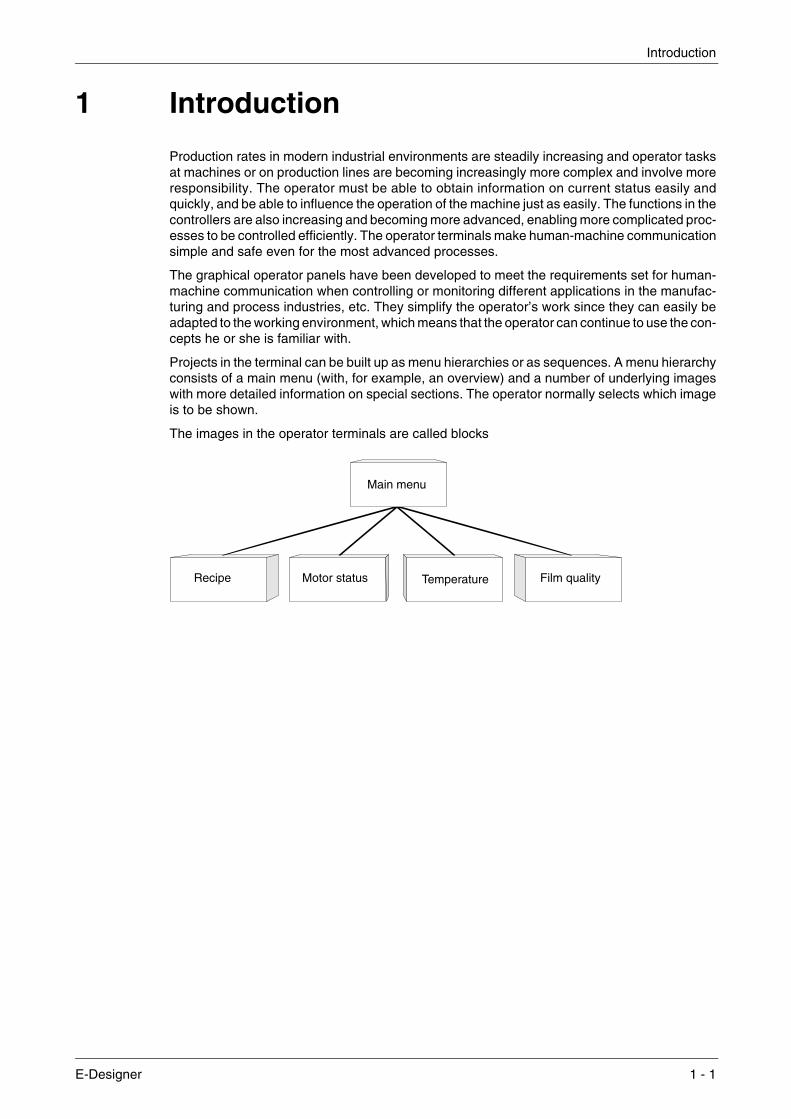
Projects in the terminal can be built up as menu hierarchies or as sequences. A menu hierarchy consists of a main menu (with, for example, an overview) and a number of underlying images with more detailed information on special sections. The operator normally selects which image is to be shown.
The images in the operator terminals are called blocks
Main menu
Recipe Motor status Temperature Film quality
E-Designer 1 - 1

Introduction
A sequence is also based on a main menu, from which the operator selects a sequence showing the blocks in a predetermined order. Normally displaying of the blocks is controlled by the con-troller program.
The functions in the terminal enable graphical or text-based presentation and maneuvring. There are also functions for alarm handling, printouts, trends, recipe handling, and time control, etc..
The functions are not only easy to use in the terminal, they are also cost-efficient in comparison with conventional solutions with buttons, indicator lamps, time relays, preset counters and seven-day clocks. There are also functions to increase the application of the controller.
Main menu
Pre-wash
Main wash
Rinsing
Spin
End of
Setup
drying
program
1 - 2
Programming Introduction
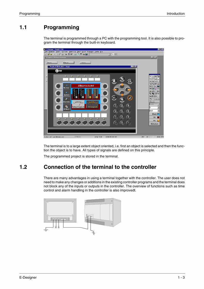
1.1 Programming
The terminal is programmed through a PC with the programming tool. It is also possible to pro-gram the terminal through the built-in keyboard.
The terminal is to a large extent object oriented, i.e. first an object is selected and then the func-tion the object is to have. All types of signals are defined on this principle.
The programmed project is stored in the terminal.
1.2 Connection of the terminal to the controller
There are many advantages in using a terminal together with the controller. The user does not need to make any changes or additions in the existing controller programs and the terminal does not block any of the inputs or outputs in the controller. The overview of functions such as time control and alarm handling in the controller is also improvedt.
E-Designer 1 - 3
Introduction Status display and control
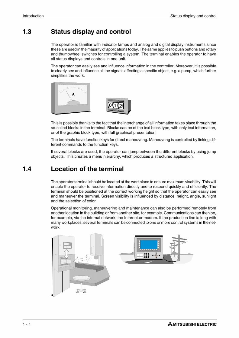
1.3 Status display and control
The operator is familiar with indicator lamps and analog and digital display instruments since these are used in the majority of applications today. The same applies to push buttons and rotary and thumbwheel switches for controlling a system. The terminal enables the operator to have all status displays and controls in one unit.
The operator can easily see and influence information in the controller. Moreover, it is possible to clearly see and influence all the signals affecting a specific object, e.g. a pump, which further simplifies the work.
This is possible thanks to the fact that the interchange of all information takes place through the so-called blocks in the terminal. Blocks can be of the text block type, with only text information, or of the graphic block type, with full graphical presentation.
The terminals have function keys for direct maneuvring. Maneuvring is controlled by linking dif-ferent commands to the function keys.
If several blocks are used, the operator can jump between the different blocks by using jump objects. This creates a menu hierarchy, which produces a structured application.
1.4 Location of the terminal
The operator terminal should be located at the workplace to ensure maximum visability. This will enable the operator to receive information directly and to respond quickly and efficiently. The terminal should be positioned at the correct working height so that the operator can easily see and maneuver the terminal. Screen visibility is influenced by distance, height, angle, sunlight and the selection of color.
Operational monitoring, maneuvering and maintenance can also be performed remotely from another location in the building or from another site, for example. Communications can then be, for example, via the internal network, the Internet or modem. If the production line is long with many workplaces, several terminals can be connected to one or more control systems in the net-work.
1 - 4

Compact solutions Introduction
1.5 Compact solutions
External units such as barcode scanners, weighing machines, and modems, can be connected through the terminal to the controller. All that is required is for the unit to be connected to an RS232 interface, and that communication is made through ASCII protocol. Data entering the ter-minal is written directly to the controller register.
A unit working in parallel may also be connected. It can be an additional terminal or a personal computer with the programming tool for the control system. Via the terminal, the control system can be programmed at the same time as the terminal is communicating with the control system.
When two remote systems are to connected to one and the same terminal (dual drivers are used in the terminal), it is possible to exchange data (analog and digital signals) between the control systems.
For information on installation, please see the installation manual that was supplied with the ter-minal.
Operator terminal in Transparent mode.
Operator termial with contro system and barcode reader connected
Dual drivers can be used when different systems are connected
E-Designer 1 - 5

Introduction Compact solutions
1 - 6

The programming tool Installation
2 Installation
2.1 The programming tool
The programming tool is a program package used to develop projects for operator terminals in the E-series. The functions in the programming tool depend on which terminal is used.
In the programming tool we recommend using a mouse. Refer to the Windows User’s Guide for short commands.
In the programming tool a project is created with graphic blocks and text blocks, which are then transferred to the terminal. The programming is described in chapter Programming with the programming tool.
Help texts are available for all functions. The help text for the current function is obtained by pressing the F1 key. By pressing the help button in the toolbox and then clicking on a function, information is shown on the function.
2.1.1 System requirements
To use the programming tool a PC with at least 55 Mb of available memory and Microsoft Windows 9x/NT/2000/Me/XP is required. The programming tool can be used on either a color or monochrome screen. Microsoft Internet Explorer version 5.0 or later must be installed on the computer.
2.1.2 Installing the programming tool
The programming tool is supplied on a CD. When you place the CD in your CD ROM drive the installation will start automatically. If not, select RUN in the Start menu and enter D:\setup.exe (if D: is the CD ROM drive). Select to install the programming tool by clicking on the name and following the instructions.
The installation creates an icon for the programming tool in the E-Designer group. You can find the programming tool by clicking on Start and selecting Program/E-Designer/E-Designer. The manual can be read directly from the CD by clicking on Manuals.
2.1.3 The menu bar
From the menu bar you can reach a number of pull-down menus; File, Edit, View, Functions, Setup, Object, Layout, Transfer, Window and Help. The file menu contains functions affect-ing the entire project. In the Edit menu there are functions to cut, copy and paste. The different editors, e.g. block managers, alarm manager and symbol manager are shown in the View menu. The basic settings for the terminal are made in the Setup menu. The Object menu is only available in the different managers and contains all the objects. The objects are also included in the toolbox. The Layout menu is only available in the graphic block manager and contains functions for the positioning of objects in graphic blocks. The functions in the Transfer menu are used to transfer projects between the programming tool and the terminal. The Window menu contains general Windows functions. You can also make grid settings and define the search path to external programs, such as Paintbrush. The Help menu contains the help functions for the program.
E-Designer 2 - 1

Installation Connecting the terminal to a PC
2.1.4 The status field
The status bar is shown at the bottom of the window in the programming tool. On the View menu there is a function to show/hide the status field.
The left part of the status field describes the menu function for the function selected in the menu. A short description of the function the cursor points to is shown for the functions in the toolbox.
The right part of the status field indicates which of the following keys are activated:
OVR Overwrite (Insert key) CAP Caps Lock NUM Num Lock
Coordinates, line and column, in the block manager are also shown.
2.2 Connecting the terminal to a PC
To connect the controller to the terminal, use the cable recommended in the driver manual for the selected controller.
NOTE ❙ The power must be switched off when connecting.
2.3 Downloading the system program
In the terminal there is a system program (operative system), which is stored in the terminal’s memory on delivery. The system program can be exchanged, e.g. to update to newer versions. Transferring the system program to the terminal requires the following:
● PC
● Transfer cable between the PC and the terminal.
● The PC program SYSLOAD.EXE (available as an icon in the program group HMI Tools). See the manual for HMI Tools to install the program group.
● File with new system program (*.BIN).
Terminal
PC
RS422 RS232C
MAC-PROG/9-CAB=CAB5
CAB6
2 - 2

Downloading the system program Installation
Transfers are made in the following steps:
� Connect the cable between the PC and terminal.
� The PC program is started by selecting Program\HMI Tools\System Loader in the Start menu.
No settings need to be made in the terminal.
Under Options/Comm Settings you can set the communication port and transfer speed.
The system program can also be downloaded through a modem for remote updating of terminals.
NOTE ❙ When downgrading a terminal it is important to ensure that the box Overwrite PLC driver is checked.
If downloading of a new system program (*.bin file) fails when you click Send in the HMI Tools System Loader, the terminal is automatically placed in sysload mode. When the terminal is in sysload mode, it is ready to make a new try at downloading the system program.
E-Designer 2 - 3

Installation Downloading the system program
2 - 4

The operation modes, RUN, PROG and SETUP Terminal functions
3 Terminal functions
This chapter describes the different modes in the terminal, the keyboard and the information page in the terminal. For a description of the different key sequences, see chapter Key sequences.
3.1 The operation modes, RUN, PROG and SETUP
The terminal has three operation modes. E610, E615, E615T and E910 do not have the pro-gramming mode PROG.
● The configuration mode, Setup, where the basic settings are made, e.g. selection of con-troller, menu language and printer settings.
● Programming mode, Prog, where the terminal can be programmed and where changes can easily be made during system set-up.
● Run-time mode, Run, where the application is run.
3.1.1 Switching between modes
Switch between PROG and RUN
Switch between programming, PROG, and run-time, RUN, by pressing the keys [¨] and [MAIN] simultaneously. The possibility of switching between PROG and RUN from the terminal can be controlled with a password. For further information, refer to chapter Programming with the programming tool.
Switch between PROG and SETUP
To switch between programming, PROG and configuration, SETUP, press [LEAVE] until the start-up menu is shown and then press any key. Press [LEAVE] to return to PROG.
Switch between RUN and SETUP
Press [¨] and [MAIN] simultaneously to enter programming mode, PROG. You can now press any key when the start-up menu is shown to enter the configuration mode, SETUP. To return to run mode, RUN, press [¨] and [MAIN].
The following key sequences correspond to the key sequence [¨] + [MAIN]: E710: [F1] + [F2] + [F4]
In E610, E615, E615T and E910 you set the switch on the side/back of the terminal in position 4 to access the configuration mode Setup. For normal mode the switch should be in position 0. See also chapter Key sequences and Switch on E610, E615, E615T and E910.
E-Designer 3 - 1
Terminal functions The operation modes, RUN, PROG and SETUP
3.1.2 Configuration mode, SETUP
This section describes functions which cannot be performed with the programming tool. For settings through the programming tool refer to chapter Programming with the programming tool.
Erasing the memory
In the Setup menu in the terminal there is a function Erase memory. This function erases the terminal’s application memory. All blocks and definitions for alarms, time channels, function keys and system signals are erased.
NOTE ❙ When the memory is erased all the data stored in the terminal is lost. The language selection parameter is not affected by this function. Other parameters are erased or given their default values.
Setting of expansion memcard
Under Memcard maintenance you can select to format an installed PCMCIA memory card or to transfer to or from a memory card. You can format the memory card as a backup card or as an expansion card. Under MemCard transfer you can select to transfer: project to memory card, project from memory card, delete project on memory card, recipe to memory card, recipe from memory card, or to delete recipes on the memory card. For further information, refer to the manual for IFC MC.
Contrast setting
The contrast settings are made in the programming mode under Setup/Contrast setting or in run mode through a jump to system block 997. By pressing on the function key + the display becomes brighter, and by pressing on - it becomes darker. Return to the previous level by pressing EXIT.
E615T has no contrast setting.
Applicable only for E900 and E910.
Color intensity on the display (background light) can be controlled through a data register and a command, DIM, specified on the command line under Setup/System signals in the program-ming tool. See the section The Setup nenu in chapter Programming with the programming tool.
NOTE ❙ Contrast is affected by ambient temperature. If the terminal is programmed in a room where the temperature deviates significantly from the location where the terminal will be placed, any contrast settings should be made after 15-30 minutes in the actual ambient temperature.
Parameter Description
Enter Memory is erased. The configuration menu is shown automatically when the eras-ure is completed.
Prev Return to previous level without erasing the memory.
3 - 2

The operation modes, RUN, PROG and SETUP Terminal functions
3.1.3 Programming mode, PROG
Edit
The application is built up in the programming tool. Certain modifications can, however, be made when the terminal is in the programming mode by choosing Edit. The help line in the terminal shows what can be done using the function keys.
Transfer
The project is normally transferred to the terminal form the programming tool. By using the func-tion Automatic terminal RUN/TRANSFER switching in the programming tool, the program automatically sets the terminal in transfer mode. When the terminal is in programming mode, it can be manually set to the transfer mode by choosing Transfer.
3.1.4 Run mode, RUN
Run mode is the mode where the application is run. Block 0 will automatically be shown on the display when transferring to run mode.
The built-in keyboard in the terminal is used to mark and change values in run mode.
If a communication error occurs between the terminal and the controller an error message will be shown on the display. The terminal starts automatically when the communication is resumed.
To obtain a watch-dog function where the controller can detect if a communication error has occurred, the terminal clock can be continuously transferred to a register in the controller (see section Date/Time format is chapter Programming with the programming tool). The controller checks if the register is updated, and if not an alarm indicating a communication error is acti-vated in the controller.
The descriptions of objects/functions also include how the different objects/functions function in run mode.
E-Designer 3 - 3

Terminal functions The keyboard in the terminal
3.2 The keyboard in the terminal
3.2.1 Alphanumeric keys
From the alphanumeric keyboard the following characters can be entered in dynamic text and numerical objects during run mode in the terminal.
0-9 A-Z a-z ! ? < > ( ) + / * = × % # : ’ @ National characters
Numeric values are entered by pressing the respective key once. A to Z are entered by pressing the respective keys two to five times, and the lower case letters a to z are entered by pressing the respective keys 6 to 9 times. The delay time interval between pressing can be set (see sec-tion, Terminal options in chapter Programming with the programming tool). If the key is not pressed within the delay time interval the cursor moves to the next position.
National characters are entered by pressing the keys C1-C4 two to nine times. This enables non-standard characters on the alphanumeric keyboard to be available in the terminal. (See section, Country settings in chapter Programming with the programming tool).
NOTE ❙ In the programming tool all characters in the selected character set (see section, Country Set-tings in the chapter Programming with the programming tool) are used in static text, with the exception of reserved characters. Enter the required character by pressing the Alt key and simultaneously pressing 0 (zero) on the numeric keyboard on the PC, followed by the char-acter code.
Reserved characters
The ASCII characters 0-32 (Hex 0-1F) and 127 are reserved for internal functions in the terminal and must be used in any projects or files in the terminal. The characters are used as control char-acters.
@
Arrow keys
Alphanumeric keys
Built-in function keys
3 - 4

The keyboard in the terminal Terminal functions
3.2.2 Arrow keys
The arrow keys are used to move the cursor in a menu or dialog.
3.2.3 Built-in function keys
Not all the keys are available on all terminals.
The key [↵] ([ENTER]) is used to confirm the setting made and to go to the next line/level.
The key [PREV] is used to return to the previous block.
The key [LIST] is used to bring up the alarm list.
The key [ACK] is used to acknowledge alarms in the alarm list.
The key [MAIN] is used to jump to block 0 in run mode.
The key [←] is used to delete characters to the left of the cursor.
NOTES ❙ When the main block (block number 0) has been shown the [PREV] key will not work, since the block history is deleted when the main block is shown.
❙ With expansion card IFC 128E it is possible to put all the keys on an external keyboard. For further information, refer to the manual for IFC 128E.
3.2.4 Key sequences
Key sequences on the terminal have the following functions.
On E710, touch is calibrated by pressing [F1] + [F2] + [F5].
Terminal-mo-del
Function
Sysload Self-test Switch between PROG and RUN Diagnostic page
E300 [← ] + [F1] [← ] + [MAIN] [← ] + [PREV]
E600 [← ] + [F1] [← ] + [MAIN] [← ] + [PREV]
E700 [← ] + [F1] [← ] + [MAIN] [← ] + [PREV]
E710 [F1] + [F2] + [F8] [F1] + [F2] + [F7] [F1] + [F2] + [F4] Touch key
E900 [← ] + [F1] [← ] + [MAIN] [← ] + [PREV]
+
+
+
+
E-Designer 3 - 5

Terminal functions Setting the real-time clock
3.2.5 Switches on E610, E615, E615T and E910
To be able t access the various modes on E610, E615, E615T and E910 the power feed to the terminal is interrupted by placing the switch on the side/rear of the terminal as shown in the fol-lowing table and theraeafter reconnecting the power feed.
3.3 Setting the real-time clock
The real-time clock in the terminal is set under Setup, Date/Time.
Select the alternative Set Terminal clock. The date and time are now shown. Press [SET] to change the settings. Enter the required date and time. In editing mode you move the cursor with the arrow keys. Press [NEXT] to return or cancel the setting before pressing [ENTER].
The real-time clock can also be set in run mode through a maneuvrable clock object and during the transfer of projects from a PC to the terminal, see chapter Transferring projects.
NOTE ❙ By using a command, a digital signal can be used to indicate when the real-time clock’s bat-tery needs to be changed. See the section Commands in the chapter Programming with the programming tool.
Switch position Function
0 Run mode (normal mode), RUN
1 Sysload
2 Calibrate touch
3 Dragging cross
4 Configuration mode, SETUP
5 Programming/transfer mode, PROG/TRANSFER
8 Activates self-test function
9 Erases the clock memory
3 - 6

Diagnostic page Terminal functions
3.4 Diagnostic page
The terminal contains an diagnostic page. The diagnostic page is activated by pressing the key combination [←] and [PREV] simultaneously in RUN mode. A function or touch key can also be used/configured to call up the information page.
The current terminal, system program version and hardware version are shown at the top of the information page.
Parameter Description
STARTS Number of times the terminal has been started.
RUN Number of hours the terminal has been running.
CFL Number of hours the backlighting has been switched on.
32×C MIN:21 MAX:38 (example)
Current working temperature, lowest measured temperature and highest measured temperature. Applies only to E300(hardware version 02750D - E710.
DYNAMIC MEMORY Available RAM memory (working memory) in number of bytes.
FLASH MEM PROJ Available Flash memory (project memory) in number of bytes.
FLASH MEM BACK Available Flash memory on the backup memory card (IFC MC) in number of bytes.
FLASH CACHEHITS Percent of block/allocation cache hits in the file system.
FLASH ALLOCS Max percent of used/active allocations per block in the file system.
DRIVER 1 Current driver and driver version.
DIGITAL I/O’s The number of digital signals linked to controller 1 continuously monitored (STATIC) and the number in the current block (MONITOR).
ANALOG I/O’s The number of analog signals linked to controller 1 continuously monitored (STATIC) and the number in the current block (MONITOR).
I/O POLL The time in ms between two readings of the same signal in controller 1.
PKTS The number of signals in each package transferred between the terminal and controller 1. See section Efficient communication in chapter General.
TOUT1 The number of timeouts in communication with controller 1.
CSUM1 The number of checksum errors in communication with controller 1.
BYER The number of byte errors in the communication.
DRIVER 2 Current driver and driver version. The parameters for Driver 2 are only shown if controller 2 is defined in the project.
DIGITAL I/O’s The number of digital signals linked to controller 2 continuously monitored (STATIC) and the number in the current block (MONITOR).
ANALOG I/O’s The number of analog signals linked to controller 2 continuously monitored (STATIC) and the number in the current block (MONITOR).
I/O POLL The time in ms between two readings of the same signal in controller 2.
PKTS The number of signals in each package transferred between the terminal and controller 2. See section Efficient communication in chapter General.
TOUT2 The number of timeouts in communication with controller 2.
CSUM2 The number of checksum errors in communication with controller 2.
1/2/3 Current port for FRAME; OVERRUN and PARITY. 1=RS-422-port, 2=RS-232C-port and 3=RS-485-port.
FRAME The number of frame errors in each port.
OVERRUN The number of overrun errors in each port.
PARITY The number of parity errors in each port.
E-Designer 3 - 7

Terminal functions ”Joystick function
3.5 ”Joystick function
Not applicable for E610, E615, E615T, E710 and E910.
This function makes it possible to use the arrow keys as function keys. On the command line under System Signals you enter the command AK and an address. For example, AKM100 (the command AK and memory cell M100).
Memory cell M100 is the enable signal and the following 4 memory cells have functions accord-ing to the following control blocks.
If you press on an arrow when the enable signal is on, the memory cell corresponding to the key you press will be set to one. When the enable signal is set to one the arrow keys will not have their normal functions.
Example The following examples can be used to disable the joystick function and return to the normal function. Do as follows:
� Create a block defined as 1st man obj.
� Enter the static text JOYSTICK.
� Create a digital object with the following settings:
Memory cell Description
Mn0 Enabled. The arrow keys are disabled. Disabled = normal function.
Mn1 Left arrow
Mn2 Down arrow
Mn3 Up arrow
Mn4 Right arrow
3 - 8

”Joystick function Terminal functions
Click Enable operator input under the tab Access.
Click OK.
The text block after making the settings in the example
E-Designer 3 - 9

Terminal functions ”Joystick function
3 - 10

Method for programming a project General
4 General
This chapter describes the system structure of the terminal and its basic functions. There is also an explanation of the general principles, object parameters, and joint functions applicable in the terminal.
4.1 Method for programming a project
The graphical structure of the application in the terminal constitutes a well-arranged monitoring tool for the operator. It is important to organize the application well and to consider which func-tions are necessary. Start with the overall view, and then work down to the detailed level. When a project is programmed you start with the functions in your application. Each function becomes one or more blocks, depending on how complex the function is. A project can contain both graphic and text blocks, and each block can contain static and dynamic objects. The blocks should be arranged in hierarchies to achieve a structured application, and to simplify work pro-cedures for the machine operator. The application can also be organized as sequence controls.
It is possible to test the complete application, or parts of it, before it is put in run mode.
Block 0
Block n
Block 14
Block 13
Block 12
Block 11
Block 10 Block 20
Block 0
Block m
E-Designer 4 - 1

General Efficient communication
4.2 Efficient communication
To make the communication between the terminal and the controller quick and efficient the following should be noted about how the signals are read and how the reading can be optimized.
4.2.1 Signals affecting the communication time
Only signals to objects in the current block are read continuously. This also includes signals for object dynamics. Signals to objects in other blocks are not read, thus the number of blocks does not affect the communication time.
Besides the signals to objects in the current block, the terminal reads the following signals from the controller continuously:
● Display signals (Block Header)
● Print signals (Block Header)
● LED registers
● Alarm signals
● Remote acknowledge signals on alarms and alarm groups
● Login signal (Passwords)
● Logout signal (Passwords)
● Registers for trend curves
● Bargraph registers if using min/max indicators
● New display register
● Buzzer register
● Backlight signal
● Cursor control block
● Recipe control block
● Library index register
● Index Registers
● Controller clock register if the controller clock is used in the terminal
● List erase signal (Alarm Settings)
● No protocol control register
● No protocol on signal
4.2.2 Signals not affecting the communication time
The following signals do not affect the communication time:
● Signals linked to function keys
● Time channels
● Objects in the alarm messages
4 - 2

Efficient communication General
4.2.3 How to make the communication more efficient
Group controller signals consecutively
Signals from the controller are read most rapidly if all signals in the list above are consecutive. If for example, 100 signals are defined, the quickest way to read these is to link them, for exam-ple, M0-M99 If the signals are spread (e.g. X4, Y30, M100 etc.) the updating is slower.
Efficient block changes
Block changes are carried out most rapidly and efficiently through the block jump function on the function keys or through a jump object. Display signals in the block header should only be used when the controller is to force the presentation of another block. The New display register can also be used if the controller is to change the block. This does not affect communication as much as a larger number of Display signals.
Use the clock in the terminal
An extra load is put on communication if the clock in the controller is used, since the clock reg-ister must be read up to the terminal. Downloading of the clock to the controller also creates an extra load. The interval between downloads should therefore be as long as possible.
Packaging of signals
When signals are to be transferred between the terminal and controller, they are not all trans-ferred at the same time. They are divided into packages, each containing a number of signals, instead. The number of signals in each package depends on which driver is used.
To make communication as fast as possible the number of packages has to be minimized. Con-secutive signals require a minimum number of packages, but it is perhaps not always possible to program it this way. In such cases there is a “gap” between two signals. This gap in the max-imum distance between two signals which can still be kept in the same package. The size of the gap depends on which driver is used.
4.2.4 Operator images
Using graphic blocks for operator communication
Text blocks are mainly intended to be used for report printouts. They are slower and take up more memory than graphic blocks.
Using 3D effect for elegant operator images
Combinations of objects with frames and 3D rectangles can be effective. In this context the “light” appears to come from the top left-hand corner, i.e. there is shadowing on the bottom and right-hand edges on raised objects and on the upper and left-hand edges on inset objects.
Signal 1 2 3 4 5 6 7 8 9 10
Used. X X X X X
Waste
E-Designer 4 - 3

General Menu structure
4.3 Menu structure
The terminal is divided into three modes (function areas), configuration, programming and run mode. Programming and configuration are normally carried out with the programming tool. In each respective mode there are a number of different levels, depending on the function. Each level consists of a menu where you make a selection or enter parameters before going to the next level (menu).
The application is built up of blocks, graphic blocks and/or text blocks (primarily for report print-outs). Values from the controller are shown and changed in the blocks. Each block has a number between 0 and 989 allocated by the programmer. The blocks 990-999 are reserved for special purposes, so-called system blocks. The terminal is object-orientated, which means that a block can contain all the signals linked to an object for the control and monitoring of, for example, a pump.
4.4 Block
A block header is defined for each block. The block numbers, type of blocks and status words etc. are specified in the block header. The functions Alarms, Time channels, System Monitor, E-mail and Contrast settings can also be invoked as blocks. These are designated system blocks.
In the other terminals a maximum of 990 blocks can be defined.
NOTE ❙ The block type cannot be changed for a defined block.
Run modeProgramming modeConfiguration mode
Sel
ectio
n of
Sys
tem
sig
nals
Inde
x re
gist
erLa
ngua
ge
Level 1
Level 2
Level 3
Edi
t
Blo
ck li
st
Tran
sfer
Blo
ck
Ala
rms
Fun
ctio
n ke
ys
LED
Tim
e ch
anne
ls
Block n
Block 0
Gra
phic
blo
ck
co
ntro
ller
syst
em
4 - 4
Signal format General
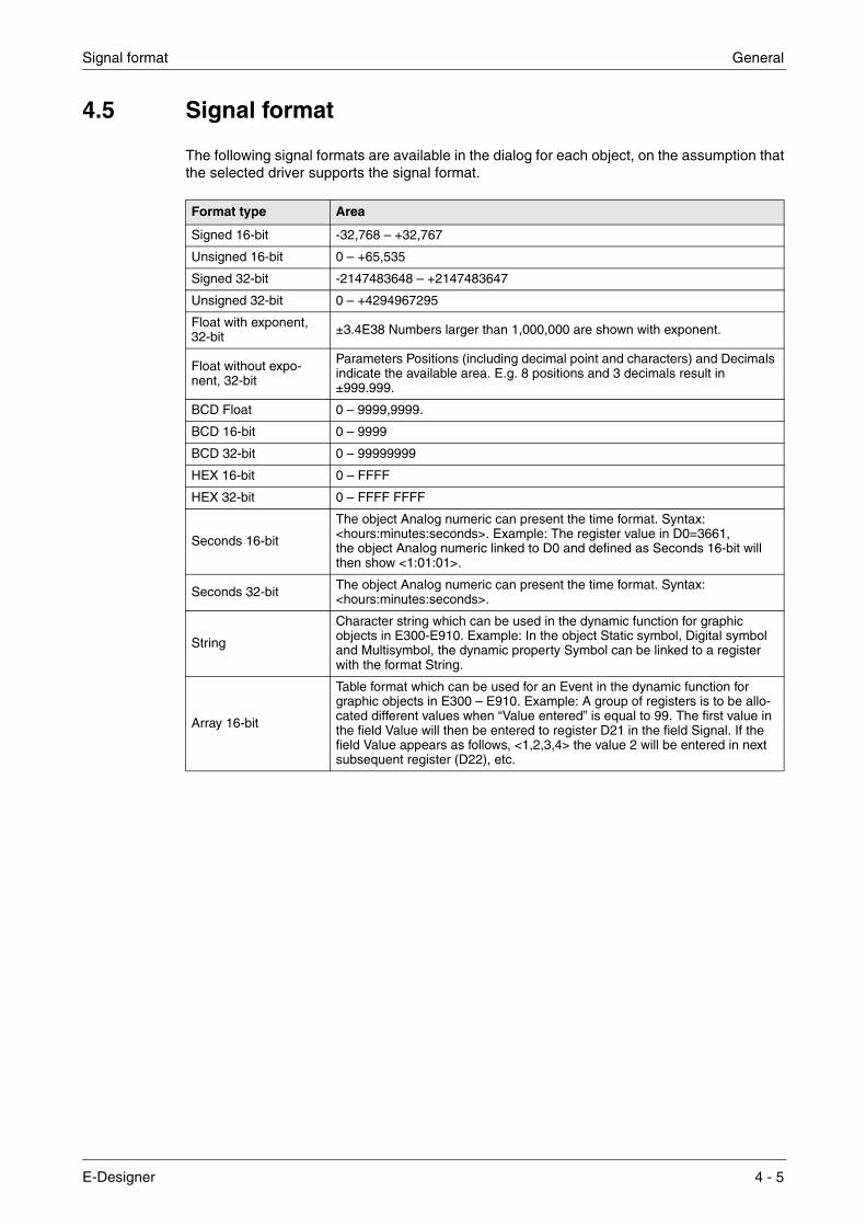
4.5 Signal format
The following signal formats are available in the dialog for each object, on the assumption that the selected driver supports the signal format.
Format type Area
Signed 16-bit -32,768 – +32,767
Unsigned 16-bit 0 – +65,535
Signed 32-bit -2147483648 – +2147483647
Unsigned 32-bit 0 – +4294967295
Float with exponent, 32-bit ±3.4E38 Numbers larger than 1,000,000 are shown with exponent.
Float without expo-nent, 32-bit
Parameters Positions (including decimal point and characters) and Decimals indicate the available area. E.g. 8 positions and 3 decimals result in ±999.999.
BCD Float 0 – 9999,9999.
BCD 16-bit 0 – 9999
BCD 32-bit 0 – 99999999
HEX 16-bit 0 – FFFF
HEX 32-bit 0 – FFFF FFFF
Seconds 16-bit
The object Analog numeric can present the time format. Syntax: <hours:minutes:seconds>. Example: The register value in D0=3661, the object Analog numeric linked to D0 and defined as Seconds 16-bit will then show <1:01:01>.
Seconds 32-bit The object Analog numeric can present the time format. Syntax: <hours:minutes:seconds>.
String
Character string which can be used in the dynamic function for graphic objects in E300-E910. Example: In the object Static symbol, Digital symbol and Multisymbol, the dynamic property Symbol can be linked to a register with the format String.
Array 16-bit
Table format which can be used for an Event in the dynamic function for graphic objects in E300 – E910. Example: A group of registers is to be allo-cated different values when “Value entered” is equal to 99. The first value in the field Value will then be entered to register D21 in the field Signal. If the field Value appears as follows, <1,2,3,4> the value 2 will be entered in next subsequent register (D22), etc.
E-Designer 4 - 5

General Signal format
4 - 6

Start the programming tool Programming with the programming tool
5 Programming with the programming tool
This chapter describes how the terminal is programmed by using the programming tool. For installation, refer to chapter Installation.
All the functions in the programming tool can be reached from the menu bar.
5.1 Start the programming tool
Click on Start/Program/E-Designer/E-Designer.
The menus File, Settings, Window and Help come up in the menu bar when the programming tool is started.
5.2 Select language
Under Settings/Menu language you select the language the program is to be presented in, i.e. menu texts and object names, etc. In this manual we assume that you have selected Englishas the language.
5.3 Create a project
A new project is created under File/New. In the dialog box Project Settings you select the type of terminal, controller and color scheme to use in the project. All the alternatives are not available for every type of terminal. Click OK to create a new project.
E-Designer 5 - 1

Programming with the programming tool Create a project
Terminal
Press Change.
Select the terminal model and version (system program) for the actual terminal model.
Controller
The controller the terminal is to be connected to is selected here. Click the Change button to dis-play the following dialog. The list shows the installed drivers. You select the manufacture, pro-tocol and model. Click OK to finish. If you do not want to make any changes, click Cancel.
It is possible to use two drivers in the same project, i.e. the terminal can use two drivers. The driver for the second controller is selected in the same way as for the first. For further information on two drivers in the terminal, refer to section Communication with two controllers (Dual drivers) in chapter Communication.
5 - 2

Create a project Programming with the programming tool
Color scheme:
You can create your own color scheme and save it under a separate name. The color scheme determines the color of the background, menus, dialogs, and objects, etc. When you select an object in the toolbox or the menu the colors of the object are shown in the colors defined in the selected color scheme.
When you select Change the following dialog is shown. You can change an existing color scheme or create a new one.
The button Apply updates all colors in the project, with the exception of lines, circles, rectangles and arcs.
E-Designer 5 - 3

Programming with the programming tool Update driver
5.4 Update driver
5.4.1 From Internet,
To update available drivers to the latest version, or to install new drivers, you use the function File/Update terminal drivers/from Internet. All projects must be closed before this function is used. It must be possible to connect the computer to the Internet, but it is not necessary to have a web browser. A list of all the drivers which can be downloaded from the Internet is shown when the connection is established.
The list shows the version numbers of the available drivers and the version numbers of the installed drivers. Select the driver(s) you want to install in the programming tool. The function Mark newer selects all drivers available in a newer version than the one you have installed, including all the drivers which are not installed. Select Download. Each driver takes up approx-imately 500 kb and can be used as soon as downloading is complete.
5.4.2 From disk
To update available drivers to the latest version, or to install new drivers, you use the function File/Update terminal drivers/from Disk. All projects must be closed before this function is used. Select to open the mpd file in the catalog where the driver file is. A list of the drivers which can be installed is now shown.
The list shows the version numbers of the available drivers and the version numbers of the installed drivers. Select the driver(s) you want to install in the programming tool. The function Mark newer selects all drivers available in a newer version than the one you have installed, including all the drivers which are not installed. Select Download. Each driver takes up approx-imately 500 kb and can be used as soon as downloading is complete.
5 - 4

Change project settings Programming with the programming tool
5.5 Change project settings
Both the selected terminal and controller can be changed for the project. Select File/Project Settings and click Change for the parameter Terminal and/or Controller.
5.5.1 Change terminal
If you update the system program in the terminal to a newer version you must change to the cor-rect terminal version in the menu Project Settings. The new functionality in the new terminal version cannot be utilized if this is not done.
5.5.2 Change controller
If you change the controller in the project to a system with another name for the signals used, these must be changed. This is easily done by using the internal name list, see section Name list.
� Select View/Name list.
� Click on the button Undefined to insert all I/Os used in the project in the name list.
� Click on the button Export to export the name list to a text file. Enter a name and click Save. Define how the text file is to be separated.
� Open the text file in a text editor, e.g. Wordpad.
� Change all I/Os to signals used in the new controller, and save the file as a text file.
� Click on the button Import in the dialog Name list, and click No to the question if invalid I/Os should be removed.
� Click on the button Rebind to update all new I/Os in the project with the new names.
� Select File/Project Settings and click Change.
Select the new controller to be used and click OK twice.
E-Designer 5 - 5

Programming with the programming tool Creating a block with the Block Manager
5.6 Creating a block with the Block Manager
When a project is created, the Block Manager is shown. All blocks included in the application are presented here. The main block, block number 0, is created automatically when a new project is created.
NOTE ❙ E900 and E910 do not have the block Contrast. Only E610, E615, E615T, E700, E710, E900 and E910 have the block System Monitor.
The Block Manager includes a toolbox containing the following functions.
Selects blocks and creates new blocks.
Adds a new block.
Defines the block header for the selected block.
Makes a jump to the new block to be created with the cursor.
Makes a jump with the function key to the new block to be created with the cursor.
Adds a block jump for the pointer key.
Deletes a selected block.
Opens the selected block for editing.
Setting for the Block Manager.
Zoom in
Zoom out
5 - 6

Creating a block with the Block Manager Programming with the programming tool
5.6.1 Define block
When you have decided to add on a block, the following dialog is shown. This is a simplification of the complete block header. When you click on OK, i.e. create a block, the block is shown/opened.
Block name:
A name for the block can be entered here. The block name is shown in the Block Manager and in the block list.
Block no:
The number of the block. If a block already exists with the number given, the defined values will be filled in automatically. Block 0 is created automatically when starting and must always be used in a project.
Block type
Select block type, graphic or text.
Block width
Select the character size for the text block. The character size cannot be changed for a defined object.
Template
Here you can copy a block template to the block, or save the block as a block template.
E-Designer 5 - 7
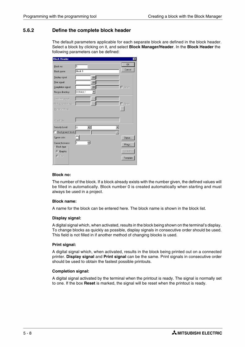
Programming with the programming tool Creating a block with the Block Manager
5.6.2 Define the complete block header
The default parameters applicable for each separate block are defined in the block header. Select a block by clicking on it, and select Block Manager/Header. In the Block Header the following parameters can be defined:
Block no:
The number of the block. If a block already exists with the number given, the defined values will be filled in automatically. Block number 0 is created automatically when starting and must always be used in a project.
Block name:
A name for the block can be entered here. The block name is shown in the block list.
Display signal:
A digital signal which, when activated, results in the block being shown on the terminal’s display. To change blocks as quickly as possible, display signals in consecutive order should be used. This field is not filled in if another method of changing blocks is used.
Print signal:
A digital signal which, when activated, results in the block being printed out on a connected printer. Display signal and Print signal can be the same. Print signals in consecutive order should be used to obtain the fastest possible printouts.
Completion signal:
A digital signal activated by the terminal when the printout is ready. The signal is normally set to one. If the box Reset is marked, the signal will be reset when the printout is ready.
5 - 8

Creating a block with the Block Manager Programming with the programming tool
Recipe directory
Select a recipe directory in which all recipes created in the block will be saved. See chapterRecipe handling.
Send mail signal:
The text block is sent as an e-mail message when the given digital signal is set to one. The block name corresponds to the e-mail message subject.
NOTE ❙ Only text blocks can be sent as e-mail messages.
Mail completion signal:
A digital signal activated by the terminal when the message has been sent. The signal is nor-mally set to one. If the box Reset is marked, the signal will be reset when the message has been sent.
Mail to address:
The address of the e-mail recipient is given here. Select up to 8 recipients from the list shown when you click the ... button. The list of e-mail addresses is defined under Setup/Network/ Services/SMTP Client in the dialog shown when you click the button Edit..
Attach file:
The name of a trend or recipe file to be attached with the message is given here. If there is a trend file or a recipe file with the same name, the trend file will be sent.
Security Level:
A security level (0-8) for the block is given here. If a security level of > 0 is given, the operator must log-in with a password corresponding to the given security level or higher.
Background block:
It is possible here to select another block lying as a background in the actual block. For example, if you want to use the same background in more than one block. When the Graphic Block Man-ager is active you can, with the function Window/Show Background Block select whether the background block is to be shown when the actual block is edited.
Cursor color:
Applies only to graphic blocks. You can select the color of the cursor in the graphic block here.
Cursor thickness:
Applies only to graphic blocks. You can choose between three different cursor thicknesses.
Block type
You select whether the block is to be a graphic or text block here. It is not possible to change the type of a defined block.
Block width:
Only shown if the block is a text block. Select the character size for the text block. It is not possible to change the character size for a defined object in a text block.
Fkeys:
Local function keys for the block are defined here. See also chapter Function keys.
E-Designer 5 - 9

Programming with the programming tool Creating a block with the Block Manager
Keyfield:
Only applicable E300. The lead texts for the functions keys are defined here. Enter an optional text of a maximum of six characters. The bottom line in the block is used. For other terminals, refer to chapter Graphic presentation and maneuvering.
Template:
Here you can copy a block template to the block, or save the block as a block template.
Status:
Indicates the status of the display in run mode. The status word does not affect the system blocks. The parameters in the status word have the following functions.
Cursor off: (text block only) indicates if the cursor is to be visible in the block in run mode.
Put cursor at first man. object: (text block only) indicates if the cursor is to go to the first maneuvrable object in the block instead of at the top left.
Disable main menu key: Indicates if the [MAIN] key is to be disabled in run mode when the block is visible on the display.
Disable alarm list key: Indicates if the [LIST] key is to be disabled in run mode when the block is visible on the display.
More indication: (text block only) Indicates if the + character is to be shown at the bottom and top right on the display when there is more in the block below or above what can be seen on the display.
Auto data entry: Indicates if the cursor is to move automatically to the next maneuvrable object after an input. The cursor can only be placed on maneuvrable objects in this position.
Disable PREV function: Indicates if the [PREV] key and the function “Return to previous block” for the function keys is to be disabled in run mode when the block can be seen on the display.
Disable ENTER function: Only valid for digital objects. Indicates if the [ENTER] key is to be disabled in run mode when the block can be seen on the display.
5 - 10

Show terminal around the working area Programming with the programming tool
5.7 Show terminal around the working area
For the terminals there are the functions View/Options/Show Terminal. When this function is active an image of the actual terminal is drawn around the working area on the active block. The terminal image has pressure-sensitive surfaces on the function keys, LEDs and text fields.
5.7.1 Define function keys
When you double-click on a function key you can select to define a local or global function key. The Editor for the selected function is then shown. For definition of function keys, see chapter Function keys.
5.7.2 Define LEDs
The Editor for definition of LEDs is shown when you double-click on an LED. For definition of LEDs, see chapter LEDs.
5.7.3 Create text strips
If you double click on a field in the text strip a dialog will be shown where you can enter text, select adjust text, or select the font. This function enables complete text strips to be made and printed out on plastic film, which can then be used on the terminal.
5.8 I/O Browser
If you create a local name list in your project you can select I/O signals from this name list with the button I/O when you define your objects. The button I/O is included in all dialogs which allow you to give an address. The I/O Browser has incremental searching. This means that searching begins immediately when you start entering in the characters in the Name/Address field. The I/O list is sorted by signals or names.
E-Designer 5 - 11
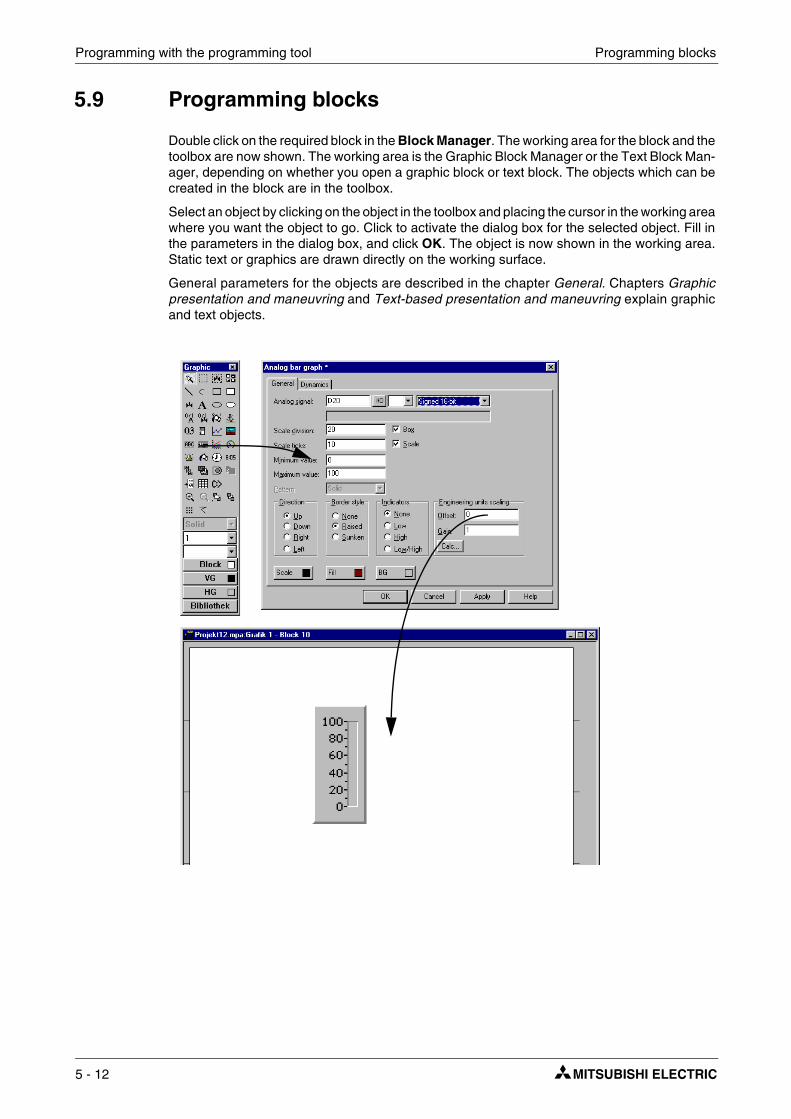
Programming with the programming tool Programming blocks
5.9 Programming blocks
Double click on the required block in the Block Manager. The working area for the block and the toolbox are now shown. The working area is the Graphic Block Manager or the Text Block Man-ager, depending on whether you open a graphic block or text block. The objects which can be created in the block are in the toolbox.
Select an object by clicking on the object in the toolbox and placing the cursor in the working area where you want the object to go. Click to activate the dialog box for the selected object. Fill in the parameters in the dialog box, and click OK. The object is now shown in the working area. Static text or graphics are drawn directly on the working surface.
General parameters for the objects are described in the chapter General. Chapters Graphic presentation and maneuvring and Text-based presentation and maneuvring explain graphic and text objects.
5 - 12

Graphic Block Manager Programming with the programming tool
5.10 Graphic Block Manager
This section describes the Graphic Block Manager in the programming tool. It is based on the Windows standard.
Graphic blocks with static and dynamic graphics are created in the Graphic Block Manager.
5.10.1 Open Graphic Block Manager
The Graphic Block Manager opens when you double click on a defined graphic block in the Block Manager or in the block list.
5.10.2 Mouse, keys and cursor
The following section describes how the mouse and keys are used in the Graphic Block Manager. The different shapes of the cursor are also explained.
The mouse is used to:
● Select objects in the toolbox.
● Select an object by clicking on it.
● Select several objects by clicking outside the objects, holding the left mouse button pressed, and dragging a frame around the required objects.
● Move an object by holding the mouse button pressed on the object and then moving the mouse.
● Change the size of an object by holding the mouse button pressed on an object handle and then moving the mouse.
● Activate the parameter dialog by double clicking on an object.
The picture below shows what a marked object looks like.
The keys are used to:
● Create an object through the menu Object.
● Move the cursor with the arrow keys.
● Move the cursor on pixel level by pressing the combination [Ctrl] + [arrow key].
● Select/deselect an object by placing the cursor in it and clicking [SPACE].
● Select several objects by selecting Object/Select area and dragging a frame around the object with [SPACE] and the arrow keys.
E-Designer 5 - 13
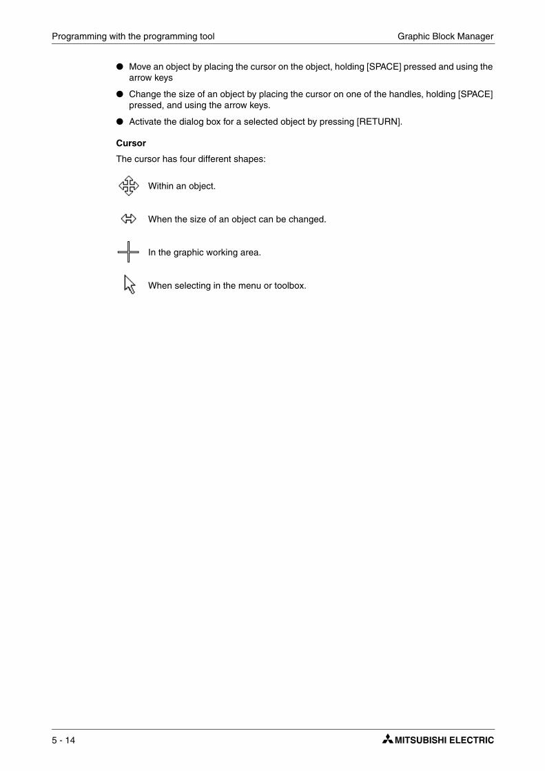
Programming with the programming tool Graphic Block Manager
● Move an object by placing the cursor on the object, holding [SPACE] pressed and using the arrow keys
● Change the size of an object by placing the cursor on one of the handles, holding [SPACE] pressed, and using the arrow keys.
● Activate the dialog box for a selected object by pressing [RETURN].
Cursor
The cursor has four different shapes:
Within an object.
When the size of an object can be changed.
In the graphic working area.
When selecting in the menu or toolbox.
5 - 14

Graphic Block Manager Programming with the programming tool
5.10.3 Toolbox
In the Manager, the toolbox is used to create objects in the block. All functions are also available in the menus. The following list describes the functions in the toolbox. See chapter Graphic pesentation and maneuvring.
Marking pointer
Area marking
Create symbol
Zoom in
Zoom out
Put on top
Put to background
Grid
Line pattern
Line thickness
Font size
Background color for the block
Foreground color for the object
Background color for the object
Import/export symbols
E-Designer 5 - 15

Programming with the programming tool Graphic Block Manager
5.10.4 Create object
Click on the required object in the toolbox, place the pointer on the working area where you want to place the object, and click. Static graphics are shown when you click in the working area. For dynamic objects the dialog is shown for the actual object, and when you click on OK in the dialog they are also shown on the screen.
When the object is drawn it is marked with handles, and the function marking mode is activated.
Static graphics
The static graphic objects are line, arc, ellipse, rectangle, symbol, text and decorations, and are used to draw background graphics. When static graphic objects are created you can link signals to the objects under Dynamics, and in so doing make them dynamic.
Dynamic objects
The dynamic objects are linked to signals to create control and monitoring functions. For more detailed information of the definition of objects, refer to chapter Graphic presentation and maneuvring.
5.10.5 Select several objects
In Graphic Block Manager objects can be selected in two different ways.
● Click on the left mouse button, hold it pressed and drag a frame around the required object. The last created object will be shown with filled-in handles.
● Select the marking pointer in the toolbox. Press the key [Shift] while selecting the required object. The last selected object will be shown with filled-in handles.
5.10.6 Place object
To simplify the positioning of objects there are a number of functions in the menu Layout. Under this menu it is possible to select Align, Make same size, Space evenly and Tile. The functions are also available in a separate toolbox.
Two or more objects must be marked for the functions to be available. The functions calculate positioning on the basis of one or two reference objects. For Align, Make same size and Tilethe last selected/created object is the reference object, section Select several objects. For the function Space evenly, the top and underlying objects and the objects at the far left and right are the reference objects. The reference objects are not affected by the functions.
5 - 16
Graphic Block Manager Programming with the programming tool
Align Under Align there are six menu alternatives to align the object horizontally and vertically.
Left Aligns the marked object with straight left edge according to the left edge of the reference object.
Right Aligns the marked object with straight right edge according to the right edge of the reference object.
Top Aligns the marked object with straight top edge according to the top edge of the reference object.
Bottom Aligns the marked object with straight bottom edge according to the bottom edge of the reference object.
Vertical center The selected objects are centred vertically according to the reference object.
Horizontal center The selected objects are centred horizontally according to the reference object.
Make same size Under Make same size there are three functions to make marked objects the same size.
Width Adjusts marked objects so that the width is the same as the reference object.
Height Adjusts marked objects so that the height is the same as the reference object.
Both Adjusts marked objects so that they have exactly the same size as the reference object.
Space evenly Under Space evenly there are two functions to adjust the distance between marked objects.
Vertical Adjusts marked objects so that the space between the objects in the vertical plane is the same. The top and lower objects do not move. At least three objects must be marked.
Horizontal Adjusts marked objects so that the space between the objects in the horizontal plane is the same. The objects to the left and right do not move. At least three objects must be marked.
Tile Under Tile there are two functions to adjust marked objects so that they are edge to edge.
Vertical Adjusts marked object in the vertical plane so that they are edge to edge with the reference object.
Horizontal Adjusts marked object in the horizontal plane so that they are edge to edge with the reference object.
E-Designer 5 - 17

Programming with the programming tool Graphic Block Manager
5.10.7 Group objects
In the menu Layout there are functions to group several objects. Select the required objects and select the function Layout/Group. The grouped objects are treated as one object, the size of which can be changed. The color and font can be changed individually for the objects in the group object. When you click on an object in the group of objects the editing dialog for the object is shown.
With the function Layout/Ungroup you ungroup a group object.
Save and read group objects
By pressing the button Library in the toolbox in Graphic Block Manager you can save or read/use grouped objects.
5.10.8 Create series
In Graphic Block Manager you can create series of objects. First create two rows and/or columns with the same object.
Thereafter select the objects and select the function Object/Create series.
A dialog is now shown where you can select to create rows or columns, the number of rows/columns, and in which direction the series should be expanded. When you click on OK, the programming tool will create a table with the specified number of lines or columns.
5 - 18
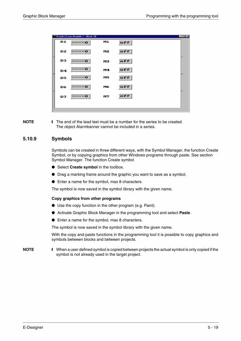
Graphic Block Manager Programming with the programming tool
NOTE ❙ The end of the lead text must be a number for the series to be created. The object Alarmbanner cannot be included in a series.
5.10.9 Symbols
Symbols can be created in three different ways, with the Symbol Manager, the function Create Symbol, or by copying graphics from other Windows programs through paste. See section Symbol Manager. The function Create symbol
● Select Create symbol in the toolbox.
● Drag a marking frame around the graphic you want to save as a symbol.
● Enter a name for the symbol, max 8 characters.
The symbol is now saved in the symbol library with the given name.
Copy graphics from other programs
● Use the copy function in the other program (e.g. Paint).
● Activate Graphic Block Manager in the programming tool and select Paste.
● Enter a name for the symbol, max 8 characters.
The symbol is now saved in the symbol library with the given name.
With the copy and paste functions in the programming tool it is possible to copy graphics and symbols between blocks and between projects.
NOTE ❙ When a user defined symbol is copied between projects the actual symbol is only copied if the symbol is not already used in the target project.
E-Designer 5 - 19

Programming with the programming tool Text block Manager
5.11 Text block Manager
In Text Block Manager, dialogs and reports are built up. A text block can consist of static texts and dynamic objects. Static texts are texts which cannot be changed during the execution of the program. Dynamic objects are objects which can be linked to signals in the controller. There are seven types of dynamic objects – digital, analog, jump, date/time, column, multiple choice and text objects.
5.11.1 Open Text Block Manager
The manager opens when you double click on a defined text block in the Block Manager or in the block list. In the Block List you select a defined block, or create a new text block.
5.11.2 Mouse and keys
Click on the beginning of the text to be marked, and drag the mouse pointer over the text. Press the shift and arrow key at the same time to select the text if using the keyboard.
The cut function erases selected text.
The character End of line is inserted by pressing [Ctrl] [Enter].
Double click or press [F4] on an object to show the object’s parameters.
5.11.3 Toolbox
In Text Block Manager there is a toolbox with the following functions. All functions are also avail-able in the menus. See chapter Text-based presentation and maneuvring for information on how the different objects are defined and used in text blocks.
Zoom in
Zoom out
ASCII options list. Selection of characters not available on the keyboard.
5.11.4 Define text block
Static text
Text Block Manager is a text editor where static text is entered. The Windows functions copy/paste can be used to copy/paste text in or between blocks, or between other Windows programs such as Microsoft Word. This enables simple documentation of the application.
Dynamic objects
Dynamic objects can be defined anywhere in the text. Select the type of object in the toolbox or in the menu Object. A dialog is then shown where the object is defined.
The dynamic object is indicated with the character # followed by one or more '-' depending on the number of positions the object occupies. For more detailed information of the definition of dynamic objects, refer to chapter Text-based presentation and maneuvring.
5 - 20

Symbol Manager Programming with the programming tool
5.12 Symbol Manager
The Symbol Manager is activated under View/Symbol Manager. In the Symbol Manager there are functions for the import and export of bitmap symbols. User defined symbols can also be cre-ated and deleted from the symbol library. The user defined symbols are shown in the symbols list. The pre-defined symbols are not shown since they cannot be changed. How symbols are created is also described in section Graphic Block Manager. The programming tool is delivered with a number of symbol libraries containing different symbols, e.g. pump symbols.
Transp. color
A color in an imported symbol can be selected to be transparent.
No. of colors
You can select symbols with 16 or 256 colors on terminals with color displays when handling symbols.
Export symbols
Symbols can be exported in BMP format to be used in other applications.
Import symbols
The import function makes it possible to reuse symbols from other applications. Image files in the format bmp, cmp, dcx, fpx, jpg, mpt, pcd, png, tga, tif and pcx can be imported to the symbol library from another Windows program, e.g. Paint. Only black/white BMP files can be used in E300, E600 and E610.
E-Designer 5 - 21

Programming with the programming tool Symbol Manager
The programming tool is delivered with a number of symbol libraries containing different symbols, e.g. pump symbols. The symbols are saved in the folder c:\Program\E-Designer\ E-Designer\lib\bitmap\.
Create
The function Create is used to draw a new symbol. When you click on the Create button you are asked to name the symbol you want to create. A bitmap manager opens when you click OK. Bit-map manager functions as a standard drawing program, depending on the limitations of the actual terminal.
Delete
When the right mouse button is pressed, you can draw with the background color. If the back-ground is white it will seem as if you are deleting.
Edit
The function Edit activates the Bitmap Manager for a defined symbol.
Duplicate
The Duplicte function is used to create a copy of the current symbol with a new name.
5 - 22

Symbol Manager Programming with the programming tool
More function
The More function is used to add more information to the symbol:
File name: Indicates the file name if the symbol was imported from a file.
Date created: Indicates the date the symbol was created.
Source: Indicates the source of the symbol. None: Unknown source Bitmap file: Imported from bitmap file Clipboard: Imported from clipboard
(Copy & Paste function) Graphic block: Created in a graphic block
Comments: You can add your own comments on the symbol here.
Delete
The function Delete is used to delete a symbol from the project.
5.12.1 Add a static symbol in a block
Click on the object Symbol in the toolbox, place the pointer on the working area in the block where you want to place the symbol, and click. The dialog Static symbol is shown when you click in the working area.
Genera
Others
The functions under Dynamics are described in section General parameters in chapter Graphic presentation and maneuvring.
Parameter Description
Symbol Select the symbol to be shown.
Use dynamic bitmaps Only applicable for E900 and E910. See section Dynamic handling of bitmap in chapter “Graphic presentation and maneuvring”.
Resizable When selected, the object’s X and Y size can be changed.
E-Designer 5 - 23
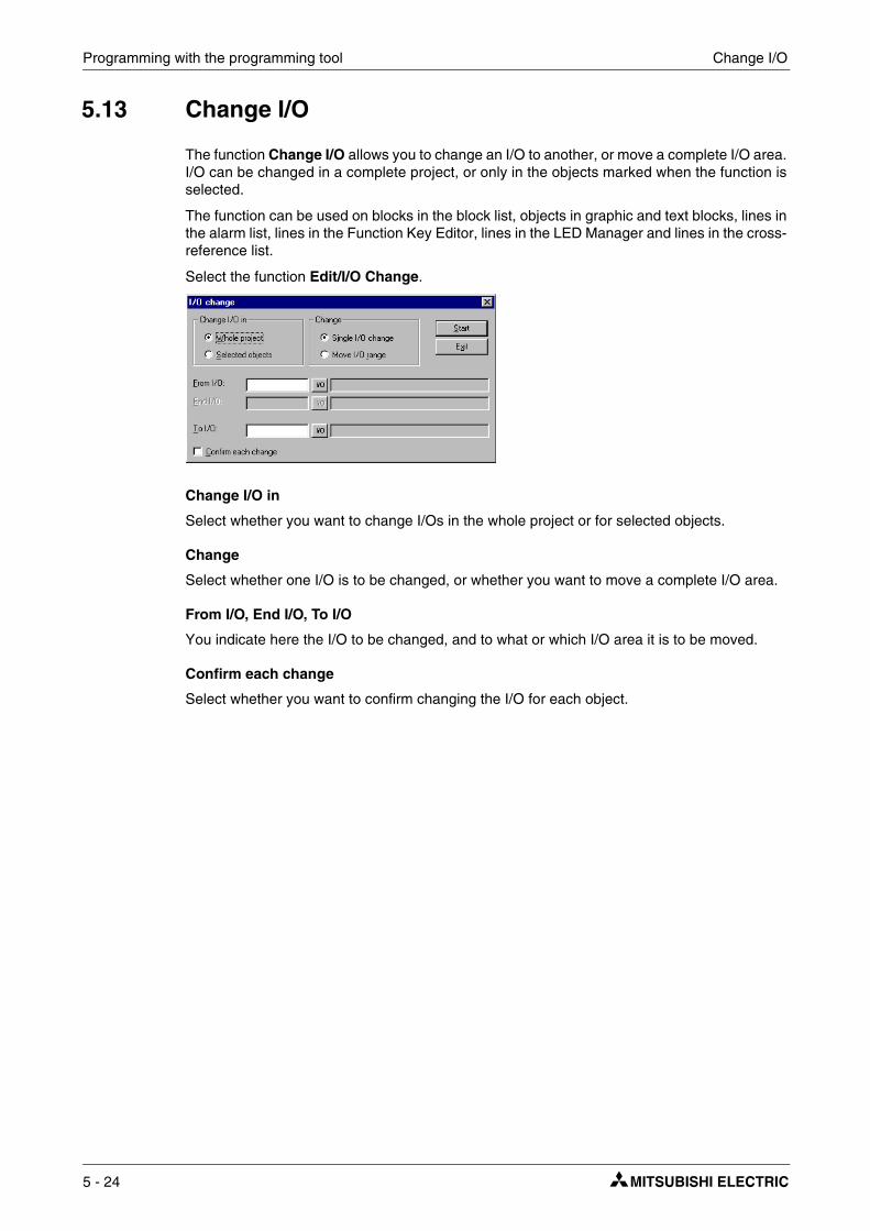
Programming with the programming tool Change I/O
5.13 Change I/O
The function Change I/O allows you to change an I/O to another, or move a complete I/O area. I/O can be changed in a complete project, or only in the objects marked when the function is selected.
The function can be used on blocks in the block list, objects in graphic and text blocks, lines in the alarm list, lines in the Function Key Editor, lines in the LED Manager and lines in the cross-reference list.
Select the function Edit/I/O Change.
Change I/O in
Select whether you want to change I/Os in the whole project or for selected objects.
Change
Select whether one I/O is to be changed, or whether you want to move a complete I/O area.
From I/O, End I/O, To I/O
You indicate here the I/O to be changed, and to what or which I/O area it is to be moved.
Confirm each change
Select whether you want to confirm changing the I/O for each object.
5 - 24

Change BDTP station Programming with the programming tool
5.14 Change BDTP station
This function allows you to change the index numbering in a BDTP client project included in a BDTP network. For example, from station 1 to station 3. Select the function Edit/BDTP Station Change.
Change station in
Select whether you want to change the index numbering in the whole project or for marked objects.
From station, To station
The index number to be changed is indicated here, and to which BDTP station index number it is to be changed to.
Confirm each change
Select if you want to confirm changing the BDTP station for each object.
5.15 I/O Crossreference
The function crossreference is used to document I/Os in a well-arranged way. Select the function View/I/O crossreference.
In the dialog shown you can indicate Start I/O and End I/O. If the Start I/O field is left empty all I/Os to the value in the End I/O field will be included. If the End I/O field is left empty all I/Os from the value in the Start I/O field will be included. If both fields are left empty all I/Os will be included in the list.
E-Designer 5 - 25

Programming with the programming tool I/O Crossreference
5.15.1 Presentation
The results of the function are presented in a list with two levels. The first level shows which I/Os are used and how many objects refer to each respective I/O.
The second level is reached by double clicking on the + character to the left of the I/O. The objects containing the I/O you have clicked on will now be shown. The + character becomes a - minus character.
A line in the list can be marked and copied to the clipboard, from where it can be pasted in, for example, a Microsoft Word document.
5 - 26

Other managers/editors Programming with the programming tool
5.16 Other managers/editors
The programming tool also has managers/editors for function keys, LEDs, alarms, alarm groups, passwords, time channels, message libraries, macros, and data transfers. These man-agers/editors are activated from the menu Functions and are handled in a similar way. The parameters in respective managers are described in the respective chapters.
Defined function keys, LEDs, alarms, alarm groups, time channels, message libraries, macros and data transfers are shown in a list in respective editors. Add on new definitions with Append or Insert. Change a definition by selecting it, making the changes, and clicking Update. To sim-plify the handling of more than one definition, click Update or Append the first time, and then [RETURN]. The functions Append and Update are active until the other is activated. With Delete or Clear a selected definition can be removed. Exit from the manager with Exit. The fol-lowing example describes the Alarms Manager.
The alarms are numbered automatically. If Append is used the alarm definition will be placed last in the alarm list, and if Insert is used the new definition will be placed on top of the marked line in the list. Subsequent alarm definitions will be renumbered. Click Update to confirm changes made.
E-Designer 5 - 27

Programming with the programming tool The File menu
5.17 The File menu
On the menu File are functions for creating, opening, saving and closing projects. Functions for printer settings, printout previews, document header creation and printout activation are also accessed from this menu, as well as functions for testing the project and changing project set-tings.
The function Export peoject transfer file is for exporting projects to Palm Pilots for temporary storage. Palm Pilots can then export the projects to other terminals, but cannot display them. This function can be useful for moving projects between terminals when performing project updates, for example.
With the function MELSEC I/O Naming you can select whether an internal name list is to be used, or if a name list from MELSEC MEDOC or GX IEC Developer is to be imported. The func-tion can only be used if a driver for MELSEC PLC systems from Mitsubishi Electric is used.
5.18 The Edit menu
On the menu Edit are functions for cutting, copying, pasting, undoing and selecting all. The Findfunction is accessible when editing multiple-language texts. The menu also includes the func-tions Change I/O, Change BDTP station and Default controller.
5.19 The View menu
On the menu View there are function managers for block handling, symbol handling, cross-ref-erencing and name list. There are also functions to set different viewing alternatives in the pro-gram. Some functions are standard for Windows and some are unique for the programming tool. A description is provided here of those unique for the programming tool.
5 - 28

The View menu Programming with the programming tool
5.19.1 Block List
The block list shows which blocks are included in the application. New blocks are created from the block list with the button New and defined blocks are opened with Open. The block header is shown when you select New. The default parameters for the block are defined in the block header. You can open the dialog for the block header for blocks marked in the list by pressing the button Header. Remove marked blocks with the button Delete.
5.19.2 Block Manager
The Block Manager shows which blocks are included in the application graphically. You can create new blocks here, define the block header and define jumps with the functions in the toolbox.
5.19.3 Symbol Manager
This selection activates the Symbol Manager. In Symbol Manager you can create your own symbols, or modify existing symbols. You can also create a library of symbols in the format BMP. The symbols in Symbol Manager are then available in the symbol list when you create static or dynamic symbol objects. See section Symbol Manager.
5.19.4 I/O crossreference
Under I/O crossreference you can document I/Os in a well-arranged way. See section I/O Crossreference.
5.19.5 Name list
Under Name list you define a local name list for the signals used. Signals in the project which are not named can be inserted in the name list with the function Undefined. New signals can be added and existing names can be edited and updated. The function Update updates the project with the changes made in the name list.
A name list can be exported to a text file, and a text file can be imported to a name list. The con-tents of the file can be separated either with a semicolon, comma or space. An internal name list can be sorted. The text file should not contain national characters.
NOTE ❙ In the function MELSEC I/O Naming in the File menu you must select Internal name list onlyto use the name list. This function only functions if drivers for MELSEC PLC systems are used.
E-Designer 5 - 29

Programming with the programming tool The View menu
If you have linked a driver-specific name list to your project you can select I/O signals from this name list with the button Connect file.
5.19.6 Toolbars
Under toolbars you can show/hide different toolbars in the program.
Toolbar
Select to show the toolbar.
Controller toolbar
Select to show toolbar for currently selected controller.
Language toolbar
Select to show toolbar for currently selected application language.
Status Bar
Select to show the status bar.
Toolbox Block Manager
Select to show toolbox for Block Manager.
Toolbox
Select to show the toolbox.
Align Toolbox
Show toolbox for the align functions.
5 - 30
The View menu Programming with the programming tool
5.19.7 Options
Show Terminal
A terminal is drawn around the working area in the Graphic Manager. From the drawn terminal you can go to the managers to define LEDs, function keys and text strips. When you double click on a function, e.g. a function key, the dialog to define function keys will be shown.
Show Background Block
Only applicable for graphic block. Background blocks are shown when editing in the Graphic Block Manager.
Show language index
Applicable only when multiple-language support is used. Displays index number for text in the application.
Tool tips
Show lead texts for the function the cursor points to.
Use block list
You can select whether the program is to activate the block list or the Block Manager when you a new project is created.
Use terminal font
You can select whether the program text you enter in the dialog windows is to be shown with terminal font.
Use Unicode font
Choose a Unicode font in the font dialog box. The font is used in the programming tool when mul-tiple-language support is used.
E-Designer 5 - 31

Programming with the programming tool The Functions menu
5.20 The Functions menu
In the menu Functions there are function managers for function keys, LEDs, alarm groups, alarms, time channels, passwords, message libraries, macros and data exchange.
5.20.1 Function Keys
Global and local function keys are defined under Function keys. See chapter Function keys.
5.20.2 LED
Under LED you define the functions for the LEDs. See chapter LEDs.
5.20.3 Alarm Groups
Under Alarm Groups you can group alarms, e.g. according to degree of seriousness, so that they can be identified and rectified more quickly and easily. See chapter Alarm handling.
5.20.4 Alarms
Alarm messages and which signals are to activate the alarms are defined under Alarms. See chapter Alarm handling.
5.20.5 Time Channels
Under Time Channels you define time channels to be used to control events in the process at special times. See chapter Time control.
5.20.6 Passwords
Under Passwords you define passwords for the different security levels in the application. See chapter Password.
5.20.7 Message library
Under Message library you create message tables, where values between 0 and 65,535 are linked to texts. See chapter Message library.
5.20.8 Macros
Under Macros you create events which influence all function keys and pointer keys. See chapter Macro.
5.20.9 Data exchange
Under Data exchange you define which conditions data exchange should utilize between selected controllers. See chapter Communication.
5 - 32

The Setup menu Programming with the programming tool
5.21 The Setup menu
In the menu Setup there are functions to configure the terminal.
5.21.1 System Signals
Setting of handshake signals between the terminal and the controller.
Current display reg
Data register in the controller, which in run mode contains the number of the block shown on the display. The data register is updated automatically by the terminal when changing blocks. This register does not affect the selection of blocks.
New display reg
A data register in the controller, which controls which block is to be shown on the display.
Buzzer reg
A register, the value of which determines how the buzzer is to sound. See the table of tones and scales below. The buzzer is off if the value is 0. The units in the table are in Hz.
Backlight signal
Digital signal which controls whether the display is to be switched on or off.
Reverse signal
Only applicable for E600.
Digital signal which controls whether the display is to have black text on a white background (standard, signal reset) or white text on a black background (signal set to one).
C D E F G A H
Contra 33 37 41 44 49 55 62
Large 65 73 82 87 98 110 123
Small 131 147 165 175 196 220 247
One 262 294 330 349 392 440 494
Two 523 587 659 698 784 880 988
Three 1046 1174 1318 1397 1568 1760 1975
Four 2093 2348 2636 2794 3136 3520 3950
Five 4186
E-Designer 5 - 33
Programming with the programming tool The Setup menu
Cursor. ctrl. block:
The start register to a control block is given in the terminal, which enters the current cursor posi-tion in the graphic block to the data register in the controller.
Start register in a control block in E610, E615,E615T, E710 and E910, which enters the current pointer position in the graphic block to the register in the controller.
Cursor. move reg
Through a register you can control the position of the cursor in a graphic block. The values in the register have the following implications. The register must be allocated the value 0 between the same command for Move. To optimize the function it is recommended to use it together with the function Cursor. Ctrl block.
Printer status reg:
You can read the status of a printer connected to the terminal via the expansion card for parallel printer through a register. The register can assume the following values.
If the printer status register has the value 1-4, i.e. does not function normally, the terminal will ignore all printouts until the register assumes the value zero.
Register Description
0 Current graphic cursor position X (in pixels), 0-239 in E300 and E600 and 0-319 in E700 and E900.
1 Current graphic cursor position Y (in pixels), 0-63 in E300, 0-127 in E600 and 0-239 in E700 and E900.
2
Status register 0 Normal 1 The user tries to move down, but there is no object below. 2 The user tries to move up, but there is no object above. 3 The user tries to move to the left, but there is no object to the left. 4 The user tries to move to the right, but there is no object to the right.
Register Description
0 X co-ordinate (in pixels), 0-319.
1 Y co-ordinate (in pixels), 0-239.
2Status register 0 Not pressed 1 Pressed
Registerwert Description
1 Moves the cursor to the first maneuvrable object.
2 Moves the cursor to the next maneuvrable object.
3 Moves the cursor one step up.
4 Moves the cursor one step down.
5 Moves the cursor one step to the left.
6 Moves the cursor one step to the right.
Registerwert Description
0 OK. The printer is functioning as it should.
1 General error. Check port and printer settings.
2 No paper. Put paper in the printer.
3 No memory. The printer’s memory is full.
4 Not connected. The printer is not correctly connected. Check port and printer set-tings, including the cable.
5 - 34

The Setup menu Programming with the programming tool
Library index reg:
Used for indexing of the message libraries. The number of the library the texts are to be collected from is indicated in the message object. If an index register is defined, the content in the index register is added to the number given in the object. This makes it possible to control from which library the texts are to be taken with a register.
Commands
On the commands line it is possible to give one or more of the following commands. The com-mands are separated by blank characters.
Command Description Supported by
BR BatchRead. Forces terminal into Transparent mode communication when MELSEC controller used. E300-E910
BSDBaud Switching Disable for Transparent mode communication with FX2N and Q. BSD must be set in the terminal that is not connected to controller 2.
E300-E910
Rx Maximum number of re-sends. x=total tries. Applies to communica-tion with the controller. Example: R5@2 applies to controller 2. E300-E910
Tx Global timeout in x total ms. Applies to communication with the con-troller. Example: T10000@1 applies to Timeout for controller 1. E300-E910
AKx Activates Joystick function. See the section Joystick-Funktion. E300-E910
DD Disable Delete of alarms on alarm list. When specified, inactive and acknowledged alarms cannot be deleted from the alarm list. E300-E910
LOBxReplaces the digital signal x when the real-time clock’s battery requi-res replacement. Example: LOBM0 will reset M0 when the battery requires replacement.
E300-E910
MDx
When dual drivers are used: If communication to a controller fails, the terminal will continue to communicate with the other system. The ter-minal will try to connect to disconnected system every tenth second. The command MDx is used to change the interval; x is the time in ms.
E300-E910
NTx Timeout in x number of ms for messages in No protocol mode. E300-E910
RPDRUN/PROG DISABLE. Disables capability to switch between RUN/PROG with the [BACKSPACE] and [MAIN] keys. If RPD is used, the terminal can only switch modes via the programming tool.
E300-E910
SW Converts text with Swedish ASCII (7-bit) characters to 8-bit IBM PC extended ASCII when printing. E300-E910
BFF Block Form Feed. Adds page breaks after each block when printing. E300-E910
BCTO Displays message “BDTP comm. Error” the first time only that a BDTP client tries to reconnect to an unavailable BDTP server. E300-E910
DGP Deletes the alarm group from alarm printouts. E300-E910
FTNO Deletes rows with OFF flags in trend files when FTP is used. E300-E910
JAAL Locks operator terminal keys and touch screen when a terminal applet is active. E300-E910
PDxxxxxxxx Password that protects access to TRANSFER menu. See the chapter Password. E300-E910
PSxxxxxxxxPassword that overrides all other password levels. Useful for support and maintenance, for example. See the chapter Password for more information.
E300-E910
SJAFx
Displays the name of the logged-in user when a Java applet is active. If no name has been defined, the word JAVA will be displayed. The name is displayed at the upper-right corner. x = character size and can be a value between 1 and 7.
E300-E910
TESOSnStorage of one trend sample only when the signal Activate is set to 1. If n=*, all trend objects are affected. If n=T, only trend objects that begin with T are affected.
E300-E910
E-Designer 5 - 35

Programming with the programming tool The Setup menu
TBUP Used for backup copy of trend files on memory expansion cards. See the chapter Trends. E600-E910
DBKLDeactivates locking of keys and touch screen if background lighting requires replacement. With the default setting, keys and touch screen are locked if background lighting is inoperable.
E610-E910
DNBW
Deactivates warning message “No block x”. The message is other-wise displayed if a block jump is configured to a block number that does not exist or when the function New picture register is used to permit a data register in the controller to control the block that is pre-sented on the display.
E610-E910
NHDThe command enables graphic blocks to be printed on laser printers without headers (which contain block names, block numbers, dates and times).
E610-E910
NMAN Activates warning message “Not maneuverable” for operator termi-nals with touch screens
E610-E910 with touch screen
TCD Touch Calibrate Disable disables calibration of the touch screen.E610-E910 with touch screen
DIMxxx
Data register, xxx, that contains a value between -63 and +63 that controls color intensity on the display. -63 entails that the display is at maximum darkness. +63 entails that the display is at maximum lightness. The normal value is 0.
E900-E910
Command Description Supported by
5 - 36
The Setup menu Programming with the programming tool
5.21.2 Index Registers
Index addressing of dynamic objects. For further information, see chapter Index addressing.
5.21.3 Country Settings
Character set:
The selection of the character set will influence the character table used in the terminal and which national characters will be available.
Different national characters (see the section the Terminal keyboard in the chapter General) are used depending on the selected character set.
The national characters are not used when Slavic or Russian is selected.
Language:
Select menu language in the terminal; British English, German, Swedish or American English. The default setting for menu texts in the terminal is British English.
Character set Character table in graphic-based terminals
Swedish 437
German 437
French 850
Spanish 850
Norwegian/Danish 850
Russian 866
Slavic 852
Greek 869
Unicode –
Swedish German French Spanish Nor/Dan
C1 Å Ü È Ñ Å
C2 Ä Ä É É Æ
C3 Ö Ö Ê Ó Ö
C4 å ß è Á Ø
C5 ä ü é ñ å
C6 ö ä ê é æ
C7 ö ó ö
C8 ß á ø
E-Designer 5 - 37

Programming with the programming tool The Setup menu
5.21.4 Multi language
New language
Start the wizard to create multiple languages for an application.
Edit
Here you can edit translated texts in the application languages.
Setup
The structure tree is displayed for the languages in the application. For information on the set-tings that can be made, see the chapter Language management.
Export
This function exports the user texts to a text file in ANSI, OEM or Unicode format. Choose to export either user texts or system texts. After making your choice, the Export Multi language texts dialog box is displayed. Here you can specify where the file will be saved and its format. Under Encoding, you can choose ANSI/OEM, which entails that languages created in the ANSI/OEM format will be exported, or Unicode, which entails that all languages will be exported to a file in Unicode format.
Import
This function imports a language that can subsequently used in the terminal. Choose to import either user texts or system texts. After making your choice, the Import Multi language textsdialog box is displayed. Indicate the name of the text file that you want to import. If the existing language in the project is in ANSI/OEM format and a language in Unicode format is imported, the imported language is converted to ANSI/OEM. This entails that all characters not included in ANSI/OEM are displayed as question marks.
Show index
This function is for displaying the language index instead of texts in the object. You may enter text even when though the language index is shown. The new text will then receive a new lan-guage index.
Cross reference
Shows a cross-reference list of the indexes for the various blocks in the application.
Reuse index
If this function is active when an object is copied, a new object is created with the same index.
Choose Unicode font
Choose the Unicode font that will be used in the programming tool.
5 - 38

The Setup menu Programming with the programming tool
5.21.5 Date/Time Format
Setting of the date and time format.
Date format:
The format can be YY-MM-DD, YYMMDD, DD.MM.YY, DD/MM/YY or MM/DD/YY where Y=year, M=month and D=day.
Time format:
The format can be HH:MM:SS or HH:MM where H=hour, M=minute and S=second.
Clock used:
Terminal means that the terminal’s built-in clock is used, and controller 1 or 2 means that the clock in controller 1 or 2 is used.
Clock→Controller system 1/2:
Select if the clock in the terminal is to be transferred to a data register in the controller 1 or 2.
NOTE ❙ In those cases where the controller has an activated real-time clock and the terminal clock is to be transferred to the same data register, the controller clock has precedence.
Update interval:
Indicate how often the terminal is to transfer the clock data to the controller. The value is given in seconds, and 60 seconds is recommended. A shorter updating interval will make communi-cation between the terminal and the controller slower.
Controller register:
Enter the start address for storage of the date/time in the controller.
For information on how the date and time is saved, refer to the manual for the controller used. The terminal saves information in the same order as the default setting for the controller.
Daylight saving:
The start and end of summer or daylight saving time are defined here. State the Day of week, Week In Month, Month, Hour and Adjust. You can choose between European and US standard.
To disable the function for summer time leave both fields for the month blank.
5.21.6 Online Settings:
Permits changing of selected function in RUN mode.
E-Designer 5 - 39
Programming with the programming tool The Setup menu
5.21.7 Terminal Options
BG:
Select the background color in the terminal by clicking BG.
FG:
Select the color of the text in the terminal by clicking FG.
Window:
Select the color of the windows shown on the terminals’ display.
Screen save time:
The time in minutes after the last event on the display when it will switch off. The default setting is 0 which means that the display never switches off. This function optimizes the service-life of the display.
Key delay time (ms):
The time interval in ms between pressing the same key before the cursor automatically moves to the next position. Used for input of ASCII characters (A-Z etc.). See section Alphanumeric keys in chapter Terminal functions.
Key beep:
Indicates whether the terminal will beep when a key is pressed.
Key repeat:
Indicates if a function will repeat as long as the key is pressed. Function keys and input of alpha-numeric characters (A-Z etc.) are not repeated.
Display color
Only applicable for E600.
Select whether the display on the terminal is to have a black text on a white background (Normal) or white text on a black background (Reverse).
Trend settings:
General settings for all trends.
Store changed samples
Select to only store samples in trends if the value has been changed since the last sample.
Store all samples
Select to store all samples in trends even if the value has not been changed since the last sample. The parameters are valid in general for all defined trends.
FTP delimiter
The terminal can save the content in the files created in the terminal, and which can be reached through FTP with different types of delimiter characters (separators). The content in files, e.g. recipe and trend files, can be separated with Tab or the characters semicolon or comma. See also chapter Network functions in the terminal.
5 - 40

The Setup menu Programming with the programming tool
5.21.8 Alarm settings
General settings for alarm list. For further information, see chapter Alarm handling.
5.21.9 Peripherals
All communication configuring is made under Setup/Peripherals. The units defined for the system are shown when you select Peripherals. You can use drag-and-drop to move the devices.
Port settings
Select the appropriate port and right-click to view current configurations or to change the con-figuration for a port.
RS232C
When you select the RS-232C port and right-click, the following dialog box is displayed. Select the transfer speed, parity, number of data bits and stop bits for the port.
E-Designer 5 - 41

Programming with the programming tool The Setup menu
RS422
When you select the RS-422 port and click Edit, or click with the right mouse button, the fol-lowing dialog is shown. You select the transfer speed, parity, number of data bits and stop bits for the port.
RS485
Only applicable for E610 and E615 and E615T.
When you select the RS-485 port and click Edit, or click with the right mouse button, the fol-lowing dialog is shown. Select the transfer speed, parity, number of data bits and stop bits for the port.
NOTE ❙ The terminals E610 and E615 and E615T have three physical ports. Only two of these can be used at the same time, hence the designations Port 1 and Port 2 in the dialog Config-uration of peripherals.
Expansion slots
When you select an Expansion slots and click Edit, or click on the right mouse button, you can define which expansion card you want to use and apply the settings for respective cards. For fur-ther information, refer to the manual for respective expansion cards.
5 - 42

The Setup menu Programming with the programming tool
Printer
Select Printer and right-click to display the dialog box for printer settings.
Printer type:
Select printer, None, HP PCL5 or Standard text.
Page length:
The number of lines to be printed out before form feed. If the page length is set 0 there will be no form feed. The default setting is 60.
Paper type:
Select type of paper.
Graphic orientation:
Select whether the graphic printout is to be vertical or horizontal.
Text orientation:
Select whether the report printout is to be vertical or horizontal.
Graphic size:
Select the size of the graphic printout.
Printer disable signal:
Digital signal to stop the printout.
Handshake:
Select the required type of handshaking between the printer and terminal; XON/XOFF or CTS/RTS. Refer to the printer manual for information on suitable handshaking.
Newline Character:
Select the required line end/newline character; CR/LF, CR, LF or none.
Screen dump:
Printout of the screen. You can select Normal or Inverted printout.
NOTE ❙ The printer settings are used for parameters such as character set, character size and margins.
E-Designer 5 - 43
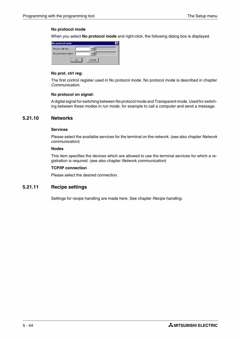
Programming with the programming tool The Setup menu
No protocol mode
When you select No protocol mode and right-click, the following dialog box is displayed.
No prot. ctrl reg:
The first control register used in No protocol mode. No protocol mode is described in chapter Communication.
No protocol on signal:
A digital signal for switching between No protocol mode and Transparent mode. Used for switch-ing between these modes in run mode, for example to call a computer and send a message.
5.21.10 Networks
Services
Please select the available services for the terminal on the network. (see also chapter Network communication)
Nodes
This item specifies the devices which are allowed to use the terminal services for which a re-gistration is required. (see also chapter Network communication)
TCP/IP connection
Please select the desired connection.
5.21.11 Recipe settings
Settings for recipe handling are made here. See chapter Recipe handling.
5 - 44
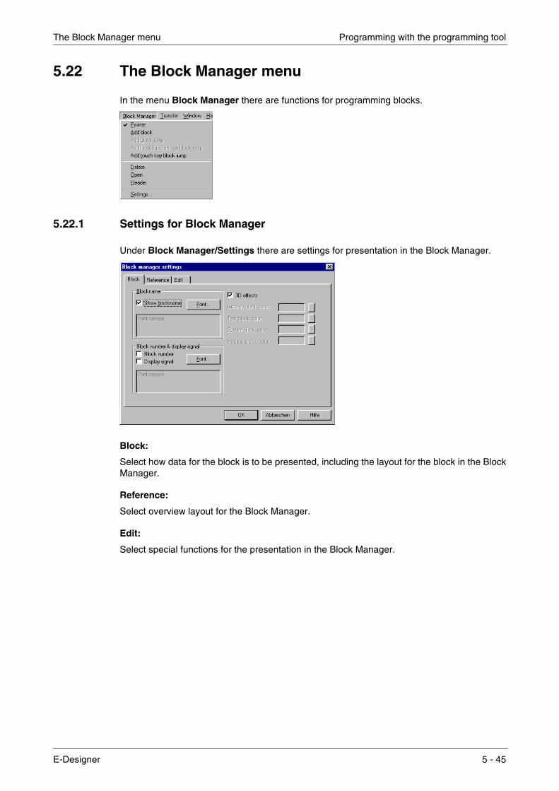
The Block Manager menu Programming with the programming tool
5.22 The Block Manager menu
In the menu Block Manager there are functions for programming blocks.
5.22.1 Settings for Block Manager
Under Block Manager/Settings there are settings for presentation in the Block Manager.
Block:
Select how data for the block is to be presented, including the layout for the block in the Block Manager.
Reference:
Select overview layout for the Block Manager.
Edit:
Select special functions for the presentation in the Block Manager.
E-Designer 5 - 45
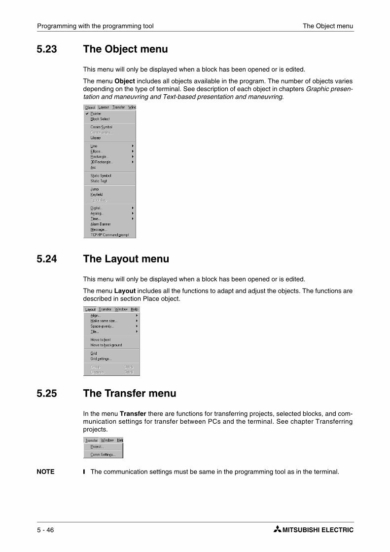
Programming with the programming tool The Object menu
5.23 The Object menu
This menu will only be displayed when a block has been opened or is edited.
The menu Object includes all objects available in the program. The number of objects varies depending on the type of terminal. See description of each object in chapters Graphic presen-tation and maneuvring and Text-based presentation and maneuvring.
5.24 The Layout menu
This menu will only be displayed when a block has been opened or is edited.
The menu Layout includes all the functions to adapt and adjust the objects. The functions are described in section Place object.
5.25 The Transfer menu
In the menu Transfer there are functions for transferring projects, selected blocks, and com-munication settings for transfer between PCs and the terminal. See chapter Transferring projects.
NOTE ❙ The communication settings must be same in the programming tool as in the terminal.
5 - 46

The Window menu Programming with the programming tool
5.26 The Window menu
The menu Window includes all the functions standard to Windows.
5.27 The Help menu
The menu Help offers help about the use of the E-Designer and information about the version of the software as well as help about the current selected controller.
E-Designer 5 - 47

Programming with the programming tool The Help menu
5 - 48

General parameters Graphic presentation and maneuvring
6 Graphic presentation and maneuvring
This chapter presents the graphic objects in tabular form and then describes each object separately. It is only valid for terminals supporting graphics.
6.1 General parameters
6.1.1 Colors
Colors allow more realistic objects with 3D effects and shadowing to be created. Apart from background and foreground colors for the blocks, it is also possible to select colors for scales and curves in the graphic objects.
When configuring the terminal you select the colors for the background, text and windows. Colors can be defined for the axes and curves in graphic objects.
6.1.2 Scaling
The parameters Offset and Gain are used to change the scale of the controller value to a value shown in accordance with the following equation.
Panel value = Offset+Gain*Controller value
When the value for an object is changed from the terminal in run mode, the scale is changed to the value shown in accordance with the following equation.
Controller value = (Panel value-Offset)/Gain
Scaling does not affect the defined maximum and minimum values, or the number of decimal places.
NOTE ❙ The functions Increment and Decrement affect the Controller value for the maneuvrable object, and not the Panel value.
6.1.3 Offset Gain Calculation
The function Offset Gain calculation is a tool to calculate the offset and gain parameters. Spec-ify the value of Offset and Gain under General for the object and click on Calculation. The fol-lowing dialog is now shown.
Enter the range for the controller value and panel value. The function calculates the correct val-ues for the parameters Offset and Gain.
E-Designer 6 - 1

Graphic presentation and maneuvring General parameters
6.1.4 Font
Fontsize If you select Resizable this means that you can change the character size freely by marking the text and dragging the handle. Fixed means that you select a fixed size for the text from the options list.
3D Effect You can select the 3D effect on the text here.
Style You can select whether the text is to be italic or underlined. No marking means that the text is normal.
Shadow You can select shadowing of the text here.
6.1.5 Access
Under Access you specify whether the object is to be maneuvrable, and the Minimum and Maximum input value for the object (and maneuvring). You can also select the security level for the object. The security levels are defined under Functions/Passwords. See chapter Passwort.
6 - 2

General parameters Graphic presentation and maneuvring
6.1.6 Dynamics
Dynamics increases the number of signals that must be updated in the block, which affects the updating time for the block. The functions are described below under Dynamics.
Property
Specify a signal to control a property under Property. You can select digital or analog controlling.
Digital
Select the property in the list you want to be controlled by the controller. The property can only be used once per object/signal. A used property is marked in red. Enter a signal or click on the button I/O to select the signal through the I/O Browser. You can also specify OFF and ON values. If no OFF/ON values are given, the OFF value is set to 0 and the ON value to 1.
Analog
Select the property in the list you want to be controlled by the controller. The property can only be used once per object/signal. A used property is marked in red. Enter a signal or click on the button I/O to select the signal through the I/O Browser. The length can be specified if the format is of the type string.
NOTES ❙ If you select analog controlling for a property which can only assume digital values, On and Off, the property will be On as long as the signal does not have the value Zero.
❙ In order to be able to influence Offset/Gain in an object, Offset/Gain must be defined to something other than 0/1 in the object from the beginning.
❙ The Visible property shall not be used with the Positions property.
❙ Dynamic texts are not converted to Unicode. Question marks are shown instead. See the chapter Unicode for additional information.
E-Designer 6 - 3

Graphic presentation and maneuvring General parameters
Size
Under Size you indicate values for Width, Height, and Origin. You define two analog signals, where the value of the signals determines the size of the object in X axis (width) and Y axis (height).
NOTE ❙ If an unreasonable value is given, e.g. a value which means that the object cannot be drawn on the display, the value will be ignored.
Signal
Specify an analog signal.
Value min width/height
Specify the analog signal’s minimum value.
Value max width/height
Specify the analog signal’s maximum value.
Min width/height
Specify the object’s minimum width/height in pixels when the Minimum value = defined value.
Max width/height
Specify the object’s maximum width/height in pixels when the Minimum value = defined value.
Origin
You select the starting point for the object when it is drawn on the display.
6 - 4

General parameters Graphic presentation and maneuvring
Move
Under Move you specify two analog signals, the values of which correspond to the X (width) and Y coordinates (height) for the object.
NOTE ❙ If an unreasonable value is given, e.g. a value which means that the object cannot be drawn on the display, the value will be ignored.
Signal
Specify an analog signal.
Value From
Specify the analog signal’s minimum value.
Value To
Specify the analog signal’s maximum value.
From X/Y position
Specify the object’s X and Y co-ordinates, i.e. the pixel value on the display, when the value in the parameter Value From = defined value.
To X/Y position
Specify the object’s X and Y co-ordinates, i.e. the pixel value on the display, when the value in the parameter Value To = defined value.
E-Designer 6 - 5

Graphic presentation and maneuvring General parameters
Event
Under Event you specify the following parameters. You can update existing events, add new events, or delete events with the buttons in the dialog.
Event name
You select an optional event name from the list.
Condition
You select a condition here from the list. There are four conditions to choose from.
Action
You select here what is to be affected, Digital I/O, Analog I/O, or if a macro is to be run. A maximum of 30 macro events can be linked to the same signal.
Signal
You select here the signal to be influenced when the condition is fulfilled.
Value
You select here the value the influenced signal is to assume when the condition is fulfilled.
Conditions Description
Equal toEvent takes place on the given signal when the value of the object is the same as the value defined in the box (Arrow in the above fig.). The value must be entered by the operator.
Not equal toEvent takes place on the given signal when the value of the object is NOT the same as the value defined in the box (Arrow in the above fig.). The value must be entered by the operator.
Greater thanEvent takes place on the given signal when the value of the object is greater than the value defined in the box (Arrow in the above fig.). The value must be entered by the operator.
Less thanEvent takes place on the given signal when the value of the object is less than the value defined in the box (Arrow in the above fig.). The value must be entered by the operator.
6 - 6

Graphic objects Graphic presentation and maneuvring
6.2 Graphic objects
6.2.1 Static/dynamic graphic objects
Static graphic objects are used to draw graphics. Graphic objects can be given dynamic prop-erties under Dynamics.
NOTE ❙ Static objects always come behind dynamic objects during presentation.
6.2.2 Dynamic handling of bitmap
Only applicable for E900 and E910.
If you check the box Use dynamic bitmaps for a static symbol object, the terminal will collect the specified bitmap file (namn.bmp) from the library IMAGES in the terminal’s file system. The bitmap image is presented on the terminal’s display in run mode. The image to be presented must be transferred to the library IMAGES in the terminal through FTP transfer. It will then be possible through FTP to add, replace, or remove dynamic bitmap images on the terminal’s dis-play by writing over, entering or deleting BMP files in the library IMAGES. The image for a dynamic bitmap image object is only shown in the terminal in run mode. The bitmap images in the library are not shown (available) in the programming tool. See section FTP server in chapter Network functions in the terminal.
Symbol Object
Line
Arc
Rectangle, filled, Decoration
Symbol See section Symbol Manager in the chapter Programming with the program-ming tool.
Static text
Ellipse, filled
Keyfield
Poly line
E-Designer 6 - 7

Graphic presentation and maneuvring Graphic objects
6.2.3 Dynamic digital graphic objects
Digital graphic objects are always linked to digital signals in the controller.
6.2.4 Dynamic analog graphic objects
Analog graphic objects are linked to registers in the controller.
Symbol Object Description
Digital text Switches between two texts depending on the status of a digital signal.
Digital symbol Switches between two symbols depending on the status of a digital signal.
Digital Fill Used to fill in a framed area in one or two colors, depending on the status of a digital signal.
Symbol Object Description
Analog numeric Input and presentation of values in numeric form.
Bargraph Presents values in the form of bargraphs.
Diagram Used to draw X/Y diagrams based on the content in data registers.
VU meter Creates a graphic VU meter on the display.
ASCII Handles ASCII strings in graphic blocks.
Slide Enables the value of an analog signal to be increased or decreased.
Trend Presents values collected from data registers in curve form.
Speedometer Creates a graphic speedometer on the display.
Analog FillUsed to fill in a framed area in one of 16 colors, depending on the value of a register.(Only applicable for E615, E700, E710, E900 and E910)
Multisymbol Shows one of up to eight different symbols, depending on the value in a data register. Also allows symbols to be moved over to the display.
Multiple choice Links to a data register, which can assume up to eight different states. A text of up to 30 characters can be linked to each state.
Message An object which shows texts from a Message Library.
Numeric table Creates a table with numeric objects.(from E600)
6 - 8
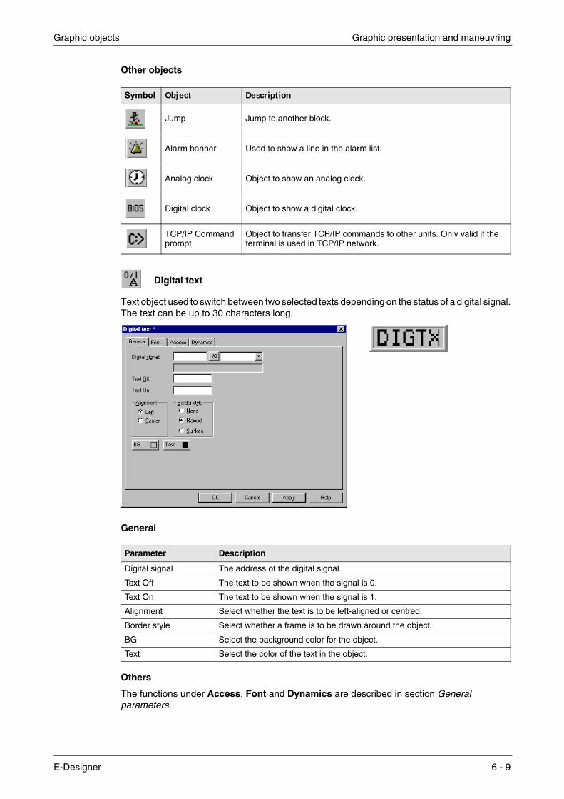
Graphic objects Graphic presentation and maneuvring
Other objects
Digital text
Text object used to switch between two selected texts depending on the status of a digital signal. The text can be up to 30 characters long.
General
Others
The functions under Access, Font and Dynamics are described in section General parameters.
Symbol Object Description
Jump Jump to another block.
Alarm banner Used to show a line in the alarm list.
Analog clock Object to show an analog clock.
Digital clock Object to show a digital clock.
TCP/IP Command prompt
Object to transfer TCP/IP commands to other units. Only valid if the terminal is used in TCP/IP network.
Parameter Description
Digital signal The address of the digital signal.
Text Off The text to be shown when the signal is 0.
Text On The text to be shown when the signal is 1.
Alignment Select whether the text is to be left-aligned or centred.
Border style Select whether a frame is to be drawn around the object.
BG Select the background color for the object.
Text Select the color of the text in the object.
E-Designer 6 - 9

Graphic presentation and maneuvring Graphic objects
Digital symbol
Object used to switch between two selected symbols depending on the status of a digital signal.
General
Others
The functions under Access and Dynamics are described in section General parameters.
Parameter Description
Digital signal Address of the signal.
Symbol OFF Select the symbol to be shown when the signal is 0.
Symbol ON Select the symbol to be shown when the signal is 1.
Resizable When selected the object’s X and Y size can be changed.
6 - 10
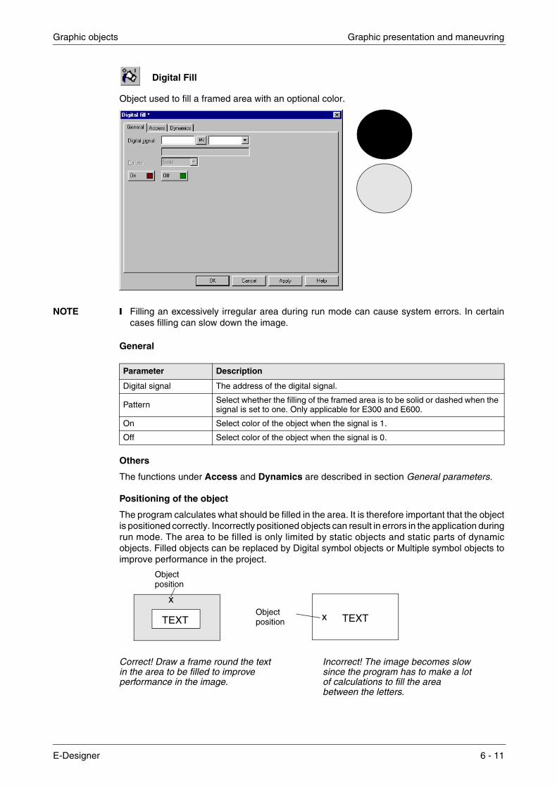
Graphic objects Graphic presentation and maneuvring
Digital Fill
Object used to fill a framed area with an optional color.
NOTE ❙ Filling an excessively irregular area during run mode can cause system errors. In certain cases filling can slow down the image.
General
Others
The functions under Access and Dynamics are described in section General parameters.
Positioning of the object
The program calculates what should be filled in the area. It is therefore important that the object is positioned correctly. Incorrectly positioned objects can result in errors in the application during run mode. The area to be filled is only limited by static objects and static parts of dynamic objects. Filled objects can be replaced by Digital symbol objects or Multiple symbol objects to improve performance in the project.
Correct! Draw a frame round the text Incorrect! The image becomes slow in the area to be filled to improve since the program has to make a lot performance in the image. of calculations to fill the area
between the letters.
Parameter Description
Digital signal The address of the digital signal.
Pattern Select whether the filling of the framed area is to be solid or dashed when the signal is set to one. Only applicable for E300 and E600.
On Select color of the object when the signal is 1.
Off Select color of the object when the signal is 0.
TEXT TEXTxObjectposition
x
Objectposition
E-Designer 6 - 11

Graphic presentation and maneuvring Graphic objects
Jump
Object to jump to another block. Enables a menu hierarchy to be built up in the project. By press-ing the key [PREV] on the terminal it is possible to return to previous blocks (nine levels back-wards). See chapter Function keys.
General
NOTE ❙ An error message is received if a jump to a block that does not exist is made during run mode.
Others
The functions under Font and Dynamics are described in section General parameters.
Parameter Description
Current block The number of the current block is shown here. Cannot be changed.
Jump to block Indicate the number or name of the block to which the jump it to be made.
Text Enter an optional text to be shown in the object.
Positions The number of positions the text is to occupy.
Alignment Select whether the text is to be left-aligned or centred.
Border style Select whether a frame is to be drawn around the object.
Text Select the color of the text in the object.
BG Select the background color for the object.
6 - 12

Graphic objects Graphic presentation and maneuvring
Analog numeric
Object for input and presentation of values in numeric form. Used to create an input field.
Gneral
Others
The functions under Access, Font and Dynamics are described in section General parameters.
Parameter Description
Analog signal Address of the signal.
Positions The number of positions the entered value should be given, including comma and minus characters.
Zero fill Select whether zeros are to be written in empty positions.
Decimals The number of decimals the entered value should be given.
Engineering unitsscaling Used to scale register value. See section General parameters.
Border style Select whether a frame is to be drawn around the object.
Alignment Select whether the input field is to be left-aligned or centred.
Text Select the color of the text in the object.
BG Select the background color for the object.
E-Designer 6 - 13

Graphic presentation and maneuvring Graphic objects
Analog Bargraph
Object which presents whole or decimal numbers in the form of a bargraph.
General
Dynamics
The functions under Dynamics are described in section General parameters.
Parameter Description
Analog signal Address of the signal.
Scale division Indicates how the scale is to be divided.
Box Select whether a box is to be drawn around the bargraph.
Scale ticks Indicates the interval between scale ticks shown.
Scale Select whether the scale is to be shown on the bargraph.
Minimum value The minimum value the signal can assume.
Maximum value The maximum value the signal can assume.
Pattern Select whether the bargraph filling is to be solid or dashed. Only applicable for E300 and E600.
Direction Select whether the bargraph is to be presented to the right, left, upwards or downwards.
Border style Select whether a frame is to be drawn around the object.
Indicators
Indicate whether the maximum and/or minimum values for the signal are to shown on the axis. The indicators are reset when the terminal is started. Resetting can also be carried out in run mode by selecting the bargraph and clicking ENTER (point to the bargraph if the terminal has a touch screen). The indicators only function for 16-bit numbers.
Engineering units scal-ing Used to scale the register value. See section General parameters.
Scale Select the color of the scale in the object.
Fill Select fill color.
BG Select the background color for the object.
6 - 14

Graphic objects Graphic presentation and maneuvring
Diagram
Object used to draw X/Y diagrams based on the content in registers in the controller. This is a real-time function. The object is normally used for non-time-based presentations. Time-based displaying with a sample time of <1 second can be shown if the controller handles the collection of data.
As an example we have selected the value in the register 0 as the first X co-ordinate, and the value in the register 10 as the first Y co-ordinate. We have set the number of register pairs to 4. The table and the figure below illustrate our example.
General
X coordinate Register Value Y coordinate Register Value
X0 0 0 Y0 10 11
X1 1 41 Y1 11 40
X2 2 51 Y2 12 85
X3 3 92 Y3 13 62
Parameter Description
Scale division The interval between scale numbers on the Y and X axis.
Scale ticks The interval between the scale ticks shown on the Y and X axis.
Minimum value The minimum value for the X and Y co-ordinates.
Maximum value The maximum value for the X and Y co-ordinates.
Border style Select whether a frame is to be drawn around the object.
Grid A grid is drawn in the diagram when selected.
BG Select the background color for the object.
Scale Select the color of the scale in the diagram.
Grid Select the color of the grid in the diagram.
X0,Y0
X1,Y1
X2,Y2
X3,Y3
E-Designer 6 - 15

Graphic presentation and maneuvring Graphic objects
Curves
In E300 and E600 one curve can be defined, and in E610, E615, E700, E710, E900 and E910 two curves can be defined.
Access
Only applicable for E900.
Dynamics
The functions under Dynamics are described in section General parameters.
Parameter Description
Graph name Specify a name for the respective curve.
X Analog signal The data register containing the first X co-ordinate for the respective curve.
Y Analog signal The data register containing the first Y co-ordinate for the respective curve.
Register pair count The number of register pairs to be drawn either as dots or bars. Max. 49 register pairs.
Value form
Select whether the diagram is to be a bargraph or curve diagram. In the bargraph a bar is drawn for each register pair. In curve diagrams the X/Y co-ordinates are drawn as points between which a line is drawn.
Curve Select the color for respective curves.
Thickness Select the thickness of the curve lines.
Parameter Description
Current graph signal Register, the value of which determines which curve is to be edited during run mode.
Current cursor signal Register, the value of which determines which point on the curve is to be edited during run mode.
X Edit step Indicates the interval between the steps when you press the arrow keys during run mode.
Y Edit step Indicates the interval between the steps when you press the arrow keys during run mode.
Enable operator input curve 1-2 Select for respective curve if it can be maneuvred during run mode.
6 - 16

Graphic objects Graphic presentation and maneuvring
VU meter
Object to create a graphic VU meter on the display.
General
Dynamics
The functions under Dynamics are described in section General parameters.
Parameter Description
Analog signal Address of the signal.
Scale division Indicates how the scale is to be divided.
Scale ticks Indicates the interval between scale ticks shown.
Minimum value The minimum value the signal can assume.
Maximum value The maximum value the signal can assume.
Border style Select whether a frame is to be drawn around the object.
Engineering units scaling Used to scale the register value. See section General parameters.
Needle Select the color of the needle in the object.
Scale Select the color of the scale in the object.
BG Select the background color for the object.
E-Designer 6 - 17

Graphic presentation and maneuvring Graphic objects
ASCII
Object for handling ASCII strings in graphic blocks. In ASCII objects it is possible to present texts stored in the CPU data register. The texts should be in IBM extended ASCII format. If SW is indi-cated in the command line in System signals, the text is converted from 8-bit IBM extended ASCII to Swedish 7-bit ASCII.
General
Others
The functions under Access, Font and Dynamics are described in section General parameters.
Parameter Description
Analog signal Indicate the data register where the text for the first position is stored.
Positions Indicate the number of positions the text is to occupy on the display.
Alignment Select whether the text is to be left-aligned or centred.
Border style Select whether a frame is to be drawn around the object.
Text Select the color of the text in the object.
BG Select the background color for the object.
6 - 18

Graphic objects Graphic presentation and maneuvring
Slide
Object which shows the value for an analog signal in a slide, and which makes it possible to increase or decrease the value of the analog signal.
General
NOTE ❙ The data type formats BCD float and Float with exponent cannot be used in slide objects.
Others
The functions under Access and Dynamics are described in section General parameters.
Parameter Description
Analog signal Address of the signal.
Scale division Indicates how the scale is to be divided.
Scale ticks Indicates the interval between scale ticks shown.
Minimum value The minimum value the object can assume.
Maximum value The maximum value the object can assume.
Engineering units scaling Used to scale register value. See section General parameters.
Direction Select whether the object is to be presented vertically or to the right.
Border style Select whether a frame is to be drawn around the object.
Scale Select the color of the scale in the object.
Button Select the color of the indicator button in the object.
BG Select the background color for the object.
E-Designer 6 - 19

Graphic presentation and maneuvring Graphic objects
Trend
Object which presents collected values from analog signals. See also chapterTrends.
General
Parameter Description
NameIndicate the name of the trend object. The name must be unique for each object. The name may have a maximum of eight characters. This parameter is mandatory. Not applicable for E300.
Sample interval The interval in time between the collection of data. The minimum value is 1 second.
Sample count The number of values to be stored. The maximum number of values is 65,534. For E600 the maximum is 4,800. Not applicable for E300.
Sample full limit Indicate the number of samples when Sample full signal is to be set to one. Not applicable for E300.
Sample full signal Indicates a digital signal which is set to one when the number of samples indicated under Sample full limit is reached. Not applicable for E300.
Enable sampling signal
The digital signal which, when it is set to one, starts collecting data. If the signal is reset, the collecting stops. The parameter is not mandatory. Not applicable for E300.
Erase samples signal Indicate a digital signal which, when it is set to one, deletes all historical trend data. Not applicable for E300.
Y scale Select whether the Y scale is to be off, seen to the left, the right, or both.
Minimum value The minimum value on the Y axis is collected from the indicated register.
6 - 20

Graphic objects Graphic presentation and maneuvring
Curves
NOTE ❙ In E300 and E600 only two curves can be used. E300 only has real-time trends.
Dynamics
The functions under Dynamics are described in section General parameters.
NOTE ❙ If you copy a block containing a trend object, you must change the name of the trend object. No two trend objects can have the same name.
Maximum value The maximum value of the Y axis is collected from the indicated controller register.
Division Indicates how the scale on the Y axis is to be divided.
Ticks Indicates the interval between scale ticks shown.
Time scale The time scale to be shown in the trend diagram.
Division Indicates how the scale on the X axis is to be divided.
Ticks Indicates the interval between scale ticks shown.
Border style Select whether a frame is to be drawn round the object.
Grid Select whether a grid is to be shown in the object.
Scale Select the color of the scale in the object.
Grid Select a suitable color for the grid.
BG Select the background color for the object.
Parameter Description
Analog signal The analog signals which the object is to collect and present the values of. Only 16-bit numbers can be used.
Color Select the color for respective curves.
Offset and Gain Used to scale the register value. See section General parameters.
Parameter Description
E-Designer 6 - 21

Graphic presentation and maneuvring Graphic objects
Speedometer
Object to create a graphic speedometer on the display.
General
Dynamics
The functions under Dynamics are described in section General parameters.
Parameter Description
Analog signal Address of the signal.
Scale division Indicates how the scale is to be divided.
Scale ticks Indicates the interval between scale ticks shown.
Minimum value The minimum value the object can show.
Maximum value The maximum value the object can show.
Angle Indicates the angle, working area, for the object. 10-360 degrees.
Engineering units scaling Used to scale register value. See section General parameters.
Border style Select whether a frame is to be drawn around the object.
Needle Select the color of the needle in the object.
Scale Select the color of the scale in the object.
BG Select the background color for the object.
Show bar When selected an arc is shown around the speedometer. It is possible to change the settings when selected.
Indicator Select to show Needle, Arc or Both.
Arc settings Indicate Low and High value, and the colors to be shown for the different intervals.
6 - 22

Graphic objects Graphic presentation and maneuvring
Alarmbanner
Object used to show a line in the alarm list.
General
NOTES ❙ An alarm can be acknowledged in the alarm line by selecting the box Enable acknowledge under Access.
❙ The foreground color of the alarm text is determined by the alarm group definition.
Others
The functions under Access, Font and Dynamics are described in section General parameters.
Parameter Description
List line numberIndicate the number of the line in the alarm list which the information is to be collected from (1 = first line, 2 = second line, etc.) if the indicated alarm group is shown in the alarm list.
Positions The number of positions to be shown.
Alarm group Indicate which alarm group is to be shown on the alarm line. The object will be shown in the color specified for the alarm group.
Show day of the week Select whether the weekday is to be shown in the alarm line.
Show Date Select whether the date is to be shown in the alarm line.
Show Time Select whether the time is to be shown in the alarm line.
Show Symbol Select whether alarm symbols are to be shown in the alarm line. See chapter “Alarm handling”.
Show Active alarms only
Select whether you only want active alarms to be shown on the alarm line. If no alarm is active the alarm line object will be empty. The alarm must be inactive, not acknowledged, before the next alarm can be shown in the alarm banner.
Show Repeat Count Indicates how many times the alarm has been repeated. See chapter “Alarm handling”.
Border style Select whether a frame is to be drawn around the object.
BG Select the background color for the object.
E-Designer 6 - 23

Graphic presentation and maneuvring Graphic objects
Analog Fill
Object used to fill in a framed area with one of 256 colors, depending on the value of a register. The colors are determined in accordance with the following table:
For limitations and positioning of the object, refer to section Digital Fill.
Parameter Description
Analog signal Enter the data register, the value of which determines the color of the object. See table below.
Register value Color Register value Color
0 Black 8 Grey
1 Blue 9 Light blue
2 Green 10 Light green
3 Cyan 11 Light cyan
4 Red 12 Light red
5 Magenta 13 Light magenta
6 Yellow 14 Light yellow
7 Light grey 15 White
6 - 24

Graphic objects Graphic presentation and maneuvring
Analog clock
Time object for presenting analog clock.
General
NOTE ❙ To set the clock in run mode a maneuvrable Date/Time object (Digital clock) must be defined.
Dynamics
The functions under Dynamics are described in section General parameters.
Parameter Description
Border style Select whether the clock is to be shown with a frame.
Show seconds Select whether the clock is to be shown with a seconds hand.
BG Select the background color for the object.
Scale Select the color of the scale in the object.
Hand Select the color of the hands in the object.
E-Designer 6 - 25

Graphic presentation and maneuvring Graphic objects
Digital clock
Time object for presenting digital clock, weekday and date.
General
NOTE ❙ To set the clock in run mode a maneuvrable Date/Time object (Digital clock) must be defined.
Others
The functions under Access, Font and Dynamics are described in section General parameters.
Parameter Description
Day of the week Select whether the weekday is to be shown.
Date Select whether the date is to be shown.
Time Select whether the time is to be shown.
Time Format The time can be presented in the format AM/PM or 24 hours.
Border style Select whether a frame is to be drawn around the object.
BG Select background color.
Text Select the color of the text in the object.
6 - 26

Graphic objects Graphic presentation and maneuvring
Multisymbol
Object which can show one of up to eight different symbols, depending on the value in a data register.
General
Dynamics
The functions under Dynamics are described in section General parameters.
Parameter Description
Analog signal The data register which determines which symbol is to be shown. If the register contains the value 1, then symbol 1 will be shown accordingly, etc.
Symbol 0-7 Select the symbol to be shown. If the register value is 0, the symbol 0 will be shown, etc.
Resizable
If selected you can change the X and Y size of the symbols. The permitted X value is 0-239 for E300, 0-239 for E600, 0-319 for E610/E615/E700/E710 and 0-639 for E900/E910. The permitted Y value is 0-63 for E300, 0-127 for E600, 0-239 for E610/E615/E700/E710 and 0-479 for E900/E910.
E-Designer 6 - 27

Graphic presentation and maneuvring Graphic objects
Multiple choice
Objects which can have different modes. The object is linked to a data register, which can assume up to eight different modes. Each mode can be allocated a text with a maximum of 30 characters.
General
Others
The functions under Font, Access and Dynamics are described in section General parameters.
Parameter Description
Analog signal The data register which determines which text is to be shown.
Text 0-7 The texts to be shown for respective object modes.
Operator selectable 0-7 When selected the object can be maneuvred to this mode when the terminal is in run mode.
Alignment Select whether the text is to be left-aligned or centred.
Border style Select whether a frame is to be drawn around the object.
BG Select the background color for the object.
Text Select the color of the text in the object.
6 - 28

Graphic objects Graphic presentation and maneuvring
Touch key
Only applicable for E610, E615, E710 and E910. See also section Using the touch screen and chapter Function keys.
The object is a pressure-sensitive surface with similar functions to a function key. It can be used to change images and control memory cells, etc.
General
An invisible, pressure-sensitive surface can be used to define the area for block changes in an overview image, e.g. a machine. The detailed images are linked to invisible, pressure-sensitive surfaces placed on selected parts of the machine. The detailed image is shown when the oper-ator clicks on one of these surfaces.
Others
The functions under Access and Dynamics are described in section General parameters.
Parameter Description
I/O Type of signal influenced by the object. Predefined functions are described in chapter Function keys.
Event
Indicate how the signal is to be influenced by the object. Set means that the signal is set to one when the object is actuated. Grouped means that all signals belonging to a touch key with the relevant group number are reset. The group number is given under Group number. Max 8 touch keys can be included in a group. Dec Analog means that the analog signal linked to the function key will decrease the value by the value given under Value. Momentary means that the signal is set to one as long as the object is actuated. Reset means that the signal is reset when the object is actu-ated. Set Analog means that the analog signal linked to the function key is allocated the value given under Value.Toggle means that the signal is alternately set to one or reset when the object is actuated. Inc Analog means that the analog signal linked to the function key will increase the value by the value given under Value.
Jump to block Jump to another block when the object is actuated. Indicate the number or name of the block to which the jump is to be made.
Other function For a description of this function, see chapter Function keys.
Macro For a description of this function, see chapter Macro.
Button style Select the required type of button: circular, rectangular or invisible.
BG Select the background color for the object.
E-Designer 6 - 29

Graphic presentation and maneuvring Graphic objects
Message
Object which presents texts from message libraries.
General
The required Input range area is set under Access. An area of a maximum of 64 texts can be maneuvred in run mode. Indicate the number of the first and last text in the area.
NOTE ❙ The number of positions should not be 0 when the function indexed message library is used, otherwise automatic length adjusting will not work.
For further information, see chapter Message library.
Others
The functions under Font, Access and Dynamics are described in section General parameters.
Parameter Description
Analog signal Analog signal which controls which text selected from message libraries is to be shown.
Library Select the number of the required message library. Defined under Functions/Message Library.
Positions The number of positions the text is to be presented with. 0 = automatic length adjusting.
Alignment Select whether the text is to be left-aligned right-aligned or centered.
Border style Select whether the text is to be shown with a frame.
Text Select the color of the text.
BG Select the background color for the object.
6 - 30

Graphic objects Graphic presentation and maneuvring
Analog numeric table
Not applicable for E300.
Object to create a table of analog numeric objects.
General
The input direction of the table is specified under Access. The signals in the table are calculated according to the given direction.
Others
The functions under Font, Access and Dynamics are described in section General parameters.
NOTE ❙ The minimum and maximum value are only used when the object is maneuvrable.
Parameter Description
Analog signal The first signal to be presented in the table.
Columns Indicate the number of columns in the table.
Zero fill Select whether zeros are to be written in empty positions.
Rows Indicate the number of lines in the table.
Positions The number of positions the entered value should be given.
Decimals The number of decimals the entered value should be given.
Alignment Select whether the input field is to be left-aligned or centred.
Table border style Select whether a frame is to be drawn around the table.
Item border style Select whether a frame is to be drawn around each separate cell in the table.
Text Select the color of the text in the object.
BG Select the background color for the object.
Engineering units scaling Used to scale register value. See section General parameters.
E-Designer 6 - 31

Graphic presentation and maneuvring Graphic objects
TCP/IP command prompt
A window in which TCP/IP commands can be entered and sent between terminals and PCs in a TCP/IP network. Previous commands can be recovered with the arrow keys [Up] and [Down] in run mode.
General
Others
The functions under Font and Dynamics are described in section General parameters.
Commands for the TCP/IP command prompt
For more information on the TCP/IP network, refer to chapter Network communication.
Parameter Description
No.of columns Width of the window.
No. of rows Height of the window.
Border style Select which type of frame is to be drawn around the window.
Enable accelerator keys
Select whether the function keys F1-F4 or arrow keys 1-4 should enter predefined commands in the window.
Accelerator keys Enter optional command to be written with the command prompt when respective keys are pressed.
BG Select the background color for the window.
Text Select the color of the text in the window.
Befehl Description
IPCONFIG Collects and shows current IP address for the terminal.
PING Checks if a host is available.
ROUTE Shows/adds/deletes routes.
ARP Shows/adds/deletes IP/hardware address.
6 - 32

Maneuvring graphic blocks Graphic presentation and maneuvring
6.3 Maneuvring graphic blocks
Not applicable for E610, E615, E710 and E910.
Step between the maneuvrable objects with the arrow keys. Selected objects are highlighted with a blinking frame.
6.3.1 Select maneuvrable objects
The arrow keys are used to jump between maneuvrable objects. Objects are selected according to the following principle: The position of the cursor is assumed to be the centre of a cross. If you press the right arrow, the first object found in area A according to the diagram below will be selected. If the system cannot find an object in the narrow field to the right it will search in area a. The down arrow searches in area B and b, the left arrow in area C and c, and the up arrow in area D and d.
6.3.2 Digital object
Digital objects, text, symbol and filled objects, switch status when [ENTER] is pressed. If the Increment and Decrement functions have been linked to function keys, the signal linked to the object with these function keys will be set to one or reset.
6.3.3 Analog object
ASCII object
Move the cursor to the object and press [ENTER]. Enter the required text and finish with [ENTER].
Message object
Place the cursor on the object and press [ENTER]. A list of options will now be shown with all maneuvrable statuses. If you step to the required status and press [ENTER] the analog signal linked to the object will be set to this status.
Multiple choice object
Place the cursor on the object and press [ENTER]. A list of options will now be shown with all maneuvrable statuses. If you step to the required status and press [ENTER] the analog signal linked to the object will be set to this status.
Numeric object
Enter the value and press [ENTER] to maneuvre numeric objects. If the value entered is too high or too low the indicated maximum or minimum values for the object will be shown. This infor-mation is also shown if you press [ENTER] when the object is maneuvrable.
Cursorposition
d
A
aB
b
C
cD
E-Designer 6 - 33

Graphic presentation and maneuvring Maneuvring graphic blocks
Numerical table object
When the table object is selected you press [ENTER] to select the first cell in the table. Use the arrow keys to move the cursor between cells. Change the value for the marked cell and press [ENTER].
Slide object
The object is maneuvred with the arrow keys by placing the cursor on the object and pressing [ENTER]. The value can now be increased or decreased with the arrow keys. Finish with [ENTER]. The value is increased/decreased with the number corresponding to the “Scale ticks” in the object. Finish with [ENTER].
The object can also be maneuvred with the functions Increment and Decrement, on the assump-tion that they are linked to the function keys, see chapter Function keys.
Bargraph
The min/max indicators for bargraphs can be set to the current value (reset) by pressing [ENTER] when the cursor is placed on the object.
For terminals with touch screens the min/max indicators are reset when you point at the bargraph.
Trend object
Not applicable for E300.
Trend curves can show historic data in run mode. Mark the required trend object and press [ENTER]. A dialog box will now be shown, where the time interval and date for the data to be pre-sented can be selected. At the bottom of the box, ”History” is shown. To return to real-time dis-play, press [ENTER] again. Trend data is stored in files, the name of which are indicated when the trend objects are defined.
6 - 34
Using the touch screen Graphic presentation and maneuvring
6.3.4 Other objects
Digital clock
The digital clock (real-time clock) is changed by marking the object and giving the required time. Finish with [ENTER].
NOTE ❙ If the controller clock is used and you want to set it, this must be done in run mode.
Jump object,
Mark the object and press [ENTER].
TCP/IP Command prompt
TCP/IP commands can be written in on a marked line. The previous commands are shown when you press the arrow keys [Up] and [Down].
6.4 Using the touch screen
This section is only applicable for E610, E615, E615T, E710 and E910.
Terminals with touch screens do not have a built-in keyboard. All maneuvering is done with the touch screen by pressing distinctly with a finger for more than 30 ms. Because of its sensitivity you should only press one point on the display at once. If you press two points at the same time the display will interpret this as a point midway between the two points.
NOTES ❙ Objects CANNOT be maneuvred in text blocks in terminals with touch screens.
❙ If you press on an object that is not maneuverable the text not maneuverable is displayed. If you press on an object that has a password the text Access denied is displayed.
6.4.1 Digital object
Digital objects, text, symbol and filled objects, switch status when you press them with your finger.
E-Designer 6 - 35

Graphic presentation and maneuvring Using the touch screen
6.4.2 Analog object
ASCII object
Press on the object and an alphanumeric keyboard will be shown on the display. Enter the required text by using this keyboard, and finish with [ENTER].
Multiple choice object
Press on the object and a list of options will be shown. Select the required object by touching it.
Numeric object
Press on the object and a numeric keyboard will be shown. Enter the required value by using this keyboard, and finish with [ENTER].
Numerical table object
Press on a cell in the table object and a numeric keyboard will be shown. Enter the required value by using this keyboard, and finish with [ENTER].
Slide object
The object is maneuvred by pressing on the button in the object and dragging it.
Bargraph
The min/max indicators can be reset by pressing on the bargraph.
Trend object
Trend curves can show historic data in run mode. A row of buttons is shown under the trend when you press on the object.
Double arrow Moves the trend one display sideways. Single arrow Moves the trend a 1/2 display sideways. - Zooms up the trend. + Zooms down the trend. ^ Returns to default setting.
Return to real-time display by pressing the object again.
6.4.3 Other objects
Digital clock
A numeric keyboard is shown when you press the object. Enter the required time by using this keyboard, and finish with [ENTER].
Jump object,
Touch the object to jump.
6 - 36

Using the touch screen Graphic presentation and maneuvring
6.4.4 Alphanumeric keyboard
The alphanumeric keyboard is shown when, an ASCII object is maneuvred, for example.
The alphanumeric keyboard and selection list with special characters.
A numeric keyboard is displayed when a numeric object is maneuvered, for example.
Key Description
A-Ö Used to enter required text.
ESC Closes down the keyboard and returns to previous level.
← Deletes a character to the left.
CLR Deletes all written characters.
CLR Deletes all written characters.
@ Used to enter the @ character.
DEL Deletes the character the cursor is placed on.
↵ Confirms the settings made and closes the keyboard.
» Moves the cursor to the right.
« Moves the cursor to the left.
a-z Alternates between upper and lower case letters.
0-9 Alternates between letters, numbers and special characters.
SPC Opens a selectable list of special characters.
E-Designer 6 - 37
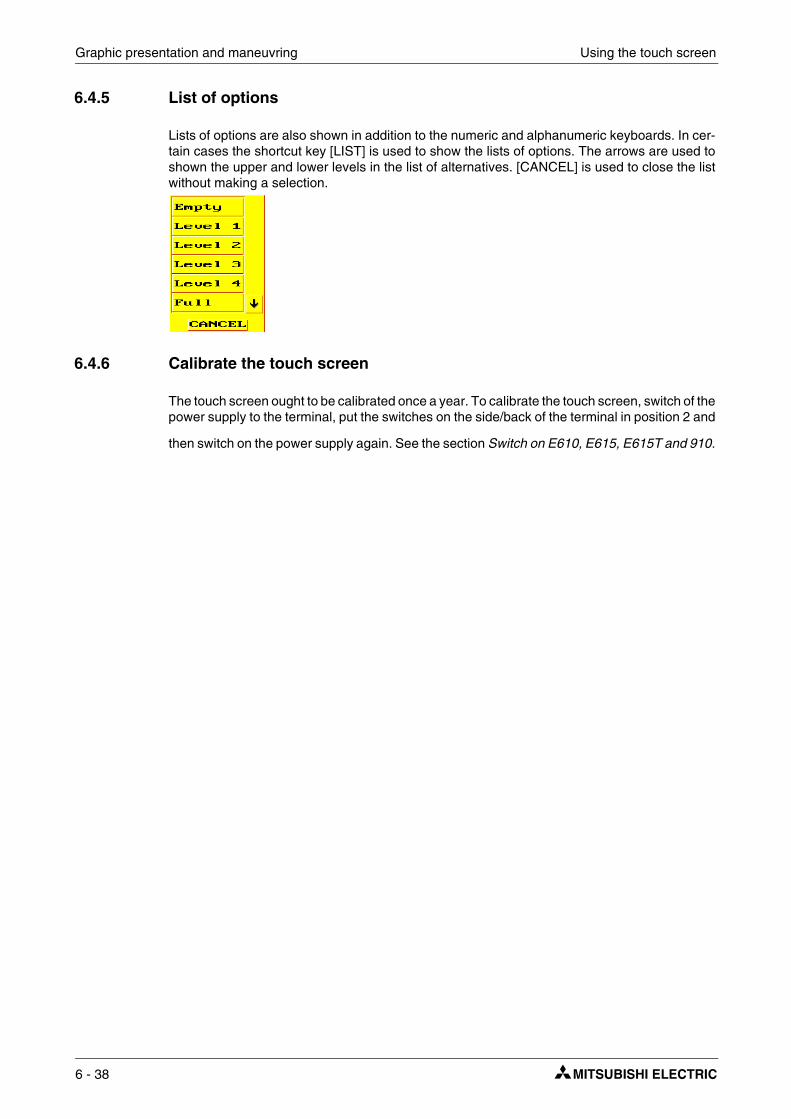
Graphic presentation and maneuvring Using the touch screen
6.4.5 List of options
Lists of options are also shown in addition to the numeric and alphanumeric keyboards. In cer-tain cases the shortcut key [LIST] is used to show the lists of options. The arrows are used to shown the upper and lower levels in the list of alternatives. [CANCEL] is used to close the list without making a selection.
6.4.6 Calibrate the touch screen
The touch screen ought to be calibrated once a year. To calibrate the touch screen, switch of the power supply to the terminal, put the switches on the side/back of the terminal in position 2 and
then switch on the power supply again. See the section Switch on E610, E615, E615T and 910.
6 - 38

General parameters Text-based presentation and maneuvring
7 Text-based presentation and maneuvring
Text-based presentation and maneuvring are appropriately used for the generation of different types of report printouts. These can be daily reports or status reports, etc. Reports are built up text blocks, which can contain both static and dynamic text. For examples of what a report can look like, refer to chapter Printouts. This chapter presents text objects in tabular form. Every object is then described separately.
NOTE ❙ Text-based printouts are not supported when Unicode is used.
7.1 General parameters
7.1.1 Scaling
The parameters Offset and Gain are used to change the scale of the controller value to a value shown in accordance with the following equation.
Panel value = Offset+Gain*Controller value
When the value for an object is changed from the terminal in run mode, the scale is changed to the value shown in accordance with the following equation.
Controller value = (Panel value-Offset)/Gain
Scaling does not affect the defined maximum and minimum values, or the number of decimal places.
NOTE ❙ The functions Increment and Decrement affect the Controller value for the maneuvrable object, and not the Panel value.
7.1.2 Offset Gain Calculation
The function Offset Gain Calculation is a tool to calculate the Offset and Gain parameters. Specify the value of Offset and Gain under General for the object and click on Calculation. The following dialog is now shown.
Enter the interval for the controller value and panel value. The function calculates the correct values for the parameters Offset and Gain.
E-Designer 7 - 1

Text-based presentation and maneuvring General parameters
7.1.3 Access
Under Access you specify whether the object is to be maneuvrable, and the Minimum and Maximum input value for the object (and maneuvring). You can also select the security level for the object. The security levels are defined under Functions/Passwords. See chapter Password.
For the object Message the dialog appears as follows.
Specify the Input range the first and last text in the area. An area of a maximum of 64 texts can be maneuvred in run mode.
7 - 2

Text object Text-based presentation and maneuvring
7.2 Text object
7.2.1 Dynamic text object
Digital text
Text object used to switch between two entered texts depending on the status of a digital signal.
Access
The functions under Access are described in section General parameters.
Symbol Object Description
Digital text Switches between two texts depending on the status of a digital signal.
Multiple choice
Links to a data register, which can assume eight different states. A text of up to 30 characters can be linked to each state.
Analog numeric Presents values in numeric form.
Bargraph Presents values in the form of bar diagrams.
Text Handles ASCII strings.
Jump Jump to another block.
Date/Time Setting of date and time.
Message An object which shows texts from a Message Library.
Parameter Description
Digital signal Address of the signal. See section General parameters.
Text Off The text shown when the signal is zero (off).
Text On The text shown when the signal is one (on).
E-Designer 7 - 3

Text-based presentation and maneuvring Text object
Multiple choice
The object is linked to an analog signal, which can assume 8 different states. A text of up to 30 characters can be linked to each state.
Access
Not valid for E700 and E900.
The functions under Access are described in section General parameters.
Parameter Description
Analog signal The register which determines which text is to be shown.
Text 0-7 The texts to be shown for respective states of the object.
Operator selectable 0-7 Indicates if it is possible to maneuvre to this status in run mode. See section Maneuvre text block.
7 - 4

Text object Text-based presentation and maneuvring
Analog numeric
An object which presents values in numeric form, as whole or decimal numbers.
General
Access
The functions under Access are described in section General parameters.
Parameter Description
Analog signal Address of the signal.
Positions The number of positions the object uses. Characters such as minus signs or decimal points must be included.
Zero fill Select whether zeros are to be written in empty positions.
Decimals The number of decimals the object is to be presented with.
Engineering units scaling Indicates the scaling of the value, see section General parameters.
E-Designer 7 - 5

Text-based presentation and maneuvring Text object
Bargraph
Presents values in the form of bargraphs. The bar will be shown horizontally.
Text
Object to handle ASCII strings. It is possible to present texts stored in the controller’s data register. The texts should be IBM extended ASCII format. The texts can be changed during run mode from the terminal by opening and closing the input field with [ENTER].
If SW is indicated in the command line in System signals, the text is converted from 8 bit IBM extended ASCII to Swedish 7 bit ASCII.
Access
The functions under Access are described in section General parameters.
Parameter Description
Analog signal Address of the signal.
Positions The number of positions the signal uses.
Direction Indicates whether the bar is to be presented to the right or left.
Min value The minimum value for the object.
Max value The maximum value for the object.
Engineering units scaling Used to scale register value. See section General parameters.
Parameter Description
Analog signal The register where the text for the first position is stored.
Positions Each register contains two characters (assumes two positions). The default setting is 8 positions, which corresponds to four registers.
7 - 6

Text object Text-based presentation and maneuvring
Jump
Object which performs jump to another block. Jump objects allow menu hierarchies to be built up in the application. To return to the previous block press the [PREV] key (up to nine levels backwards), see chapter “Function keys”
NOTE ❙ An error message is received if a jump to a block that does not exist is made during run mode.
Date and time
Object for setting the date and time. The date and time objects collect data from the real-time clock in the terminal or the controller.
NOTE ❙ To set the clock in run mode a maneuvrable Date and time object must be defined.
Access
The functions under Access are described in section General parameters.
Parameter Description
Current block Indicates the number of the current block.Jump to block Indicate the number or name of the block to which the jump is to be made.
Parameter Description
Day of the week Select whether the weekday is to be shown. Requires two positions.
Date Select whether the date is to be shown. Use the format indicated under the Date/time format in the configuration.
Time Select whether the time is to be shown. Use the format indicated under the Date/time format in the configuration.
E-Designer 7 - 7
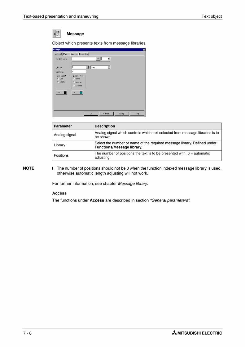
Text-based presentation and maneuvring Text object
Message
Object which presents texts from message libraries.
NOTE ❙ The number of positions should not be 0 when the function indexed message library is used, otherwise automatic length adjusting will not work.
For further information, see chapter Message library.
Access
The functions under Access are described in section “General parameters”.
Parameter Description
Analog signal Analog signal which controls which text selected from message libraries is to be shown.
Library Select the number or name of the required message library. Defined under Functions/Message library.
Positions The number of positions the text is to be presented with. 0 = automatic adjusting.
7 - 8

Maneuvre text block Text-based presentation and maneuvring
7.3 Maneuvre text block
The text block consists of text lines with static and dynamic objects. The dynamic objects show the current status of the signals the objects are linked to. Certain dynamic objects are maneu-vrable, which means that you can change their status and value during run mode.
To change a maneuvrable object you use the arrow keys to move the cursor to the correct po-sition so that the object can be marked. Text blocks can be scrolled vertically, but not horizon-tally.
NOTE ❙ Objects in text blocks CANNOT be maneuvred in terminals with touch screens.
7.3.1 Digital object
Digital objects are maneuvred by marking the required object. Press [ENTER] to change the status of the object.
7.3.2 Analog object
Analog objects and Date and time objects
The objects are maneuvred by positioning the cursor on the right object. The new value is then entered. Finish with [ENTER]. Before [ENTER] is pressed it is possible to abort the new value by leaving the field with [↑] or [↓]. The old value will then be retained.
Text object
Maneuvre a text object by stepping to the object and pressing [ENTER], whereby an input field is shown. Depending on where the object is placed on the display, the input field will either be on the first or last line. If the text is longer than the width of the display it is possible to scroll in the input field. Press [ENTER] to complete the entry.
Message object,
Maneuvre a message object by stepping to the object with the arrow keys and pressing [ENTER]. A list of options will now be shown with all the maneuvrable states on the display. Step to the required state, press [ENTER] and the analog signal linked to the object will be set.
Multiple choice object
Maneuvre a multiple choice object by stepping to the object with the arrow keys and pressing [ENTER]. A list of options will now be shown with all the maneuvrable states on the display. Step to the required state, press [ENTER] and the analog signal linked to the object will be set.
Jump object,
Mark the object and press [ENTER].
Bargraph
The indicators for min and max values can be set to the current value for the bar object by first marking the object and then pressing [ENTER].
E-Designer 7 - 9

Text-based presentation and maneuvring Maneuvre text block
7 - 10

Historical trend Trends
8 Trends
This chapter describes the functions trends, real-time trends and historical trends.
8.1 Historical trend
Only applicable for E600, E610, E615, E700, E710, E900 and E910.
These functions mean that analog values from the controller can be collected and presented in a trend object during run mode. The presentation is in curve form. The collected values are stored in the terminal’s project memory.
It is possible to define several independent trend curves in the same or different blocks. The number is limited by the size of the project memory and its degree of utilization.
The time interval between the collection of data, and how many values are to be stored, are defined in the trend object.
8.1.1 Calculation of trend size
It is possible to calculate how much space trend data will take up in the project memory with the following equation.
S = TOS + AK (28 + (645 * ((AS / 100) + 1))
TOS = TrendObjectSize; if all parameters for a trend object are changed, TOS = 320 bytes.
AK = the number of defined curves in the trend object.
AM = the number of Samples rounded-off to the nearest hundred.
S = the number of bytes.
NOTE ❙ The terminal’s RAM can limit the number of trends in a project. This limitation depends on other objects and functions used in the project.
Historical trend data
Project memory
E-Designer 8 - 1

Trends Real-time trend
8.1.2 Presentation in run mode
Trend curves can show historic data in run mode. Mark the required trend object and press [ENTER]. A dialog box will now be shown, where the time interval and date for the data to be presented can be selected. At the bottom of the box, ”History” is shown. To return to real-time display, press [ENTER] again. Trend data is stored in files, the name of which are indicated when the trend objects are defined.
8.2 Real-time trend
Only applicable for E300.
Real-time trend means that analog values from the controller can be presented in a trend object during run mode. The presentation is in curve form. No values are stored in the terminal’s project memory, and no historical data can be shown.
It is possible to define several independent trend curves in the same or different blocks. A maximum of 10 trends can be used in one application.
8 - 2

Defining trend objects Trends
8.3 Defining trend objects
Trend objects are defined as other dynamic objects in a block. The object can be linked to up to six analog signals (a maximum of 10 trends per project in E300 and E600). As opposed to other objects, the trend object must be named with a name of 1-8 characters. The first character must be a letter or a number. Trend names may contain the characters A-Z, 0-9 and _. Otherwise, the standard for file names in MS-DOS is followed. The following parameters are defined for trend objects. Under Setup/Terminal Options you can decide whether trends are to be stored when changed, or if all samples are to be stored. For further information, see section The Setup menu.
General
Parameter Description
NameSpecify the name of the trend object. The name must be unique for each object. The name may have a maximum of eight characters. This parameter is mandatory. Not applicable for E300.
Sampling interval The interval in time between the collection of data. The minimum value is 1 second.
Sample count The number of values to be stored. The maximum number of values is 65,534. For E600 the maximum number is 4800. Not applicable for E300.
Sample full limit Specify the number of samples when Sample full signal is to be set to one. Not applicable for E300.
Sample full signal Specify a signal which is set to one when the number of samples indicated under Sample full limit is reached. Not applicable for E300.
Enable sampling signal
The digital signal which, when it is set to one, starts collecting data. If the signal is reset, the collecting stops. The parameter is not mandatory. Not applicable for E300.
Erase samples signal Indicate a digital signal which, when it is set to one, deletes all historical trend data. Not applicable for E300.
Y scale Select whether the Y scale is to be invisible, seen to the left, the right, or in both directions.
Minimum value The minimum value on the Y axis is collected from the indicated register.
Maximum value The maximum value of the Y axis is collected from the indicated controller register.
Division Indicates how the scale on the Y axis is to be divided.
Ticks Indicates the interval between scale ticks shown.
E-Designer 8 - 3

Trends Defining trend objects
Curves
NOTE ❙ In E300 and E600 only two curves can be used. E300 only has real-time trends.
Dynamics
The functions under Dynamics are described in section General parameters.
NOTE ❙ If a block is copied containing a trend object, the name of the trend object must be changed. Two trend objects can not have the same name.
Time range The time range to be shown in the trend diagram.
Division Indicates how the scale on the X axis is to be divided.
Ticks Indicates the interval between scale ticks shown.
Border style Select whether a border is to be drawn round the object.
Grid Select whether a grid is to be shown in the object.
Scale Select the color of the scale in the object.
Grid Select a suitable color for the grid.
BG Select the background color for the object.
Parameter Description
Analog signal The analog signals which the object is to collect and present the values of. Only 16 bit numbers can be used.
Color Select the color for respective curves.
Offset and Gain Used to scale the register value. See section General parameters.
Parameter Description
8 - 4

Transfer of trend data Trends
8.4 Transfer of trend data
Not applicable for E300.
With the program HMI Tools File Transfer (icon in the program group HMI Tools) installed on the PC, it is possible for trend data, recipes and alarm lists to be transferred to/from the PC for statistical calculations and other types of presentation and storage.
It is also possible through FTP to transfer trend data, recipes, alarm lists, html files, terminal applets and bitmap images between a terminal and a PC. A FTP client program must be installed in the PC. In the program group HMI Tools there is a program, FTP Transfer, which functions as a standard FTP client.
Trend files can be opened directly in Excel for statistical calculations. See separate manual for HMI Tools.
Trend files
The names of trend files are specified for each trend when the trend object is defined. Files will be allocated the extension .SKV. The format for each line in the trend file is the following: DDDD;TTTT;AAAA;BBBB;CCCC;DDDD;EEEE;FFFF:
The oldest value is shown on the first line in the file, and the most recent on the last line. The for-mat .SKV can be imported directly to Microsoft Excel. In Excel you can use the diagram manager to create statistical diagrams. It is not possible to change something in the file and then send it back to the terminal. The following diagram shows an example of how it can appear in Excel.
Format Description
DDDD Date format specified in Setup.
TTTT Time format specified in Setup.
AAAA Trend curve 1.
BBBB Trend curve 2 (if defined).
CCCC Trend curve 3 (if defined).
DDDD Trend curve 4 (if defined).
EEEE Trend curve 5 (if defined).
FFFF Trend curve 6 (if defined).
E-Designer 8 - 5

Trends Backup of trend data
8.5 Backup of trend data
Not applicable for E300.
It is possible to copy trend data files from the ordinary project memory in the terminal to a PCM-CIA memory card if the expansion card IFC MC is fitted in the terminal. The memory card in the terminal must be formatted as a backup card. For further information on how this is done, refer to the manual for the expansion card IFC MC. Thereafter you can access the memory card in the terminal through FTP, or take the memory card to an arbitrary terminal with the expansion card IFC MC installed, and through FTP transfer upload trend data from the memory card to a PC for further processing. Trend files which have been backed-up can be found in the catalog (library) “backup” in the terminal’s catalog structure. To read/write trend data files from/to the ter-minal to the PC there must be a FTP client program installed on the PC, e.g. HMI Tools FTP Transfer program.
Backup of trend files from the terminal’s project memory to the backup PCMCIA card placed in the expansion card IFC MC in the terminal is done with the help of the command TBUP and a memory cell entered on the command line in the programming tool. Select Setup/System Signals in the programming tool.
Enter the command TBUP followed by a memory cell, e.g. M10. The memory cell can now be connected to a function or touch key. When the memory cell is activated from the key, all trend files from the terminal’s project memory will be backed-up on the memory card. When the backup is ready the terminal will reset the memory cell specified on the command line.
NOTES ❙ No sampling is made to trends in the process of being backed-up. Even if all trends are bakked-up, a trend is only locked during the time it is being backed-up.
❙ There is only one version of each trend on the memory card. If a trend which already exists on the memory card is backed-up, the old trend will be deleted and replaced by the new trend.
❙ The PCMCIA memory card in the terminal’s expansion card IFC MC must be formatted as a backup card.
8 - 6

Message library
9 Message library
With the function message library you can create text tables, where values between 0 and 65,535 are linked to texts. The message library function can be used for presentation of each sequence step in sequence control. Another possible application is to present error codes. An analog signal generates error codes connected to texts in a text library. This function can also be used to give analog values specific values, depending on the selected texts.
The message library is one of several text tables, each containing up to 512 text strings. Each text string can be 40 characters long. Activate under Functions/Message library.
A message library is edited by selecting a library and clicking Edit. Several editing windows can be displayed at the same time.
Parameter Description
Library Specify a number for the message library.
Name Specify a name for the message library.
Parameter Description
Text no. Specify a number for the text, 0 – 65,535.
Text The text presented when the current signal assumes the text number for the text.
E-Designer 9 - 1

Message library
Example The following example illustrates how the function can be used. We have a sequence control where each step in the sequence is to be presented by a text.
Start by creating a message library called Machine2.
� Select Functions/Message Library.
� Specify a number for the library. In this case 2. And a name for the library. In this case Machine2.
� Click on Add.
You have now created a message library called Machine2. You should now define the different texts in the library.
� Select the library and click on Edit.
In this dialog you define Text number and Text. Text number: is the value of the analog signal linked to the Message object, and Name is the text shown in the Message object.
D0=0
D0=1
D0=2
D0=3
The article is placed on the conveyor.
Fit detail X
Fit detail Y
The article is taken off the conveyor
9 - 2

Message library
When the message library is ready you create a message object in the application. The mes-sage object can be created in both text blocks and graphic blocks.
� Select the object Message in the toolbox. Place the cursor where you want the object to go, and click.
� Specify the analog signal which is to control which text is to be displayed.
� In the field Library, you select the message library from which the texts are to be collected.
� Select whether the object is to be maneuvrable, and between which texts it can be switched during maneuvring in the Access tab.
E-Designer 9 - 3

Message library
9 - 4

Alarm grouping Alarm handling
10 Alarm handling
This chapter describes the alarm handling function. The function is used to call the attention of the operator to events in the process requiring immediate action. It is divided into alarm groups, alarm messages, and an alarm list. The alarms can be divided into groups to create an order of priority. An alarm message determines which signal is to activate an alarm and the text to be shown when the signal is activated. The alarm list contains alarms activated during run mode.
NOTE ❙ Alarm printouts are not supported when Unicode is used. See the chapter Unicode for ad-ditional information.
10.1 Alarm grouping
In the terminal alarms can be divided into different groups depending on the type of terminal used. Each group can be allocated different color attributes (E610, E615, E615T, E700, E710, E900 and E910). Alarms can be sorted in group order in the alarm block. It is not necessary to define alarm groups.
Terminal Number of alarm groups
E300 4
E600 4
E700 and E900 16
E610, E615, E615T and E710 3-5 (depending on selected character size)
E910 7-11 (depending on selected character size)
Alarm list 18.2.97 20:11:40 coveyor 2 empty 18.2.97 20:35:09 Queue full 19.2.97 03:29:12 Low pressure
E-Designer 10 - 1

Alarm handling Alarm grouping
Defining alarm groups
Alarm groups are defined under Functions/Alarm groups. The attributes for alarms in the group are determined in the following dialog box.
Parameter Description
Group name An optional name for the alarm group.
Summary notify
Active: - Digital signal which is set to one when there are active alarms in the group. Unack: - Digital signal which is set to one when there are unacknowledged alarms in the group.Remote acknowledging: - Digital signal which when it is set to one acknowledges all alarms in the group simultaneously.
ColorsIndicates colors for active, acknowledged, inactive alarms, and for the normal status of the alarm. Only applicable for E610, E615, E615T, E700, E710, E900 and E910.
10 - 2

Alarm message Alarm handling
10.2 Alarm message
Alarm messages are defined under Functions/Alarms. The alarm message is entered with a maximum of 78 characters in E900 and E910, 38 characters in E300 – E710. More characters can be shown if you select a small character size in the alarm list. The message can contain dig-ital or analog dynamic data (as in the case of text blocks), which can be digital or analog. The alarm text can show data from the objects Analog numeric and Digital text. The toolbox is shown when the cursor is in the input field Alarmtext, from where you can select to add an object.
You can define up to 300 alarms, depending on the application.
Parameter Description
Alarm text An optional alarm text (can also include certain dynamic objects).
Signal Specify the signal (digital or analog) which when it assumes the specified status generates the alarm.
Alarm when
Digital signal is: On/Off - Select On if a signal set to one is to generate an alarm, and select Off if a reset signal is to generate an alarm.Analog signal is: Equal to- An alarm is generated when the value of the given analog alarm signal is equal to the value specified in the subsequent field.Not equal to- An alarm signal is generated when the given value of the ana-log alarm signal is not equal to the value specified in the subsequent field.Less than - An alarm signal is generated when the given value of the analog alarm signal is less than the value specified in the subsequent field.Greater than - An alarm signal is generated when the given value of the analog alarm signal is greater than the value specified in the subsequent field.
Acknowledge notify Digital signal activated when the alarm is acknowledged. The signal is normally set to one.
Reset If the box is marked Reset, the above signal will be reset when the alarm is acknowledged.
Remote acknowledge Digital signal which acknowledges the alarm when it is activated.
Alarm group Indicates the alarm group for the definition (the alarm).
E-Designer 10 - 3

Alarm handling Alarm message
NOTE ❙ The value defined for an analog alarm signal cannot be controlled from a register. Hysteresis is not supported. Only 16-bit values are supported.
Info block
A block number or block name for a text or graphic block is given here. This makes it possible to give the operator a “help page” with, for example, infor-mation on the alarm and requisite procedures. If the field is left empty this means that no block is linked to the alarm. If the information block is a text block, it will be included if the alarm is sent as an e-mail. See section Alarms in run mode and SMTP client.
Mail to address:Alarms can be sent as e-mail messages to pre-defined recipients. The alarm text will then be the subject of the message. See section Alarm settings and SMTP client.
Ack. requiredIndicates whether the alarm is to be acknowledged or not. A tick in the box means that the alarm must be acknowledged, and no tick means that the alarm functions as an event alarm, e.g. information.
History
Indicates when the alarm is to be taken out of the alarm list. A tick means that the alarm will remain in the list until the list is full. No tick means that the alarm will be taken out of the list when it is acknowledged and no longer active. If the parameter Acknowledge required is not marked, the alarm will be taken out of the list as soon as it is no longer active.
To printer Whether the alarm message is to be printed out directly on the printer if the alarm status changes is indicated here.
Repeat count
A counter for the alarm in the alarm list will be shown if the box is selected, which counts the number of times the alarm is generated. The alarm must be acknowledged for it to be presented as a new alarm message in the alarm list.
Import See section Alarm import.
Parameter Description
10 - 4

Alarm settings Alarm handling
10.3 Alarm settings
In Setup/Alarm settings the general settings for the alarms and alarm lists are made. Alarms take up different amounts of space in the alarm list, depending on the length of the alarm text and the number of objects included. The space an alarm takes up can be calculated with the fol-lowing dialog.
S=42 + NC
S = Number of bytes. NC = The number of characters in the alarm text.
The alarm list is re-written when it is full. 25% is deleted, so that only 75% remains. Example: An alarm text of 38 characters, where each alarm takes up 80 bytes in the alarm list, resulting in 1024 (list size =1 kbytes)/80 → Max 12 alarms in the alarm list. When the 13th alarm is gener-ated the alarm list will be re-written and only the last 9 alarms will remain in the list.
Parameter Description
Active signal Indicates the digital signal the terminal sets to one when there is an active alarm.
Unack. signal Indicates the digital signal the terminal sets to one when there is an unac-knowledged alarm.
List erase signal Indicates a digital signal which when set to one deletes non-active alarms in the list.
Reset Means that the signal given on the List erase signal list is reset when the alarm list is deleted.
List size
Indicates the list size in the number of kbytes for E300, E600, E610, E615, E700, E710, E900 and E910. NOTE that when the system allocates memory equal to that which is specified in List size, the actual size of the alarm list is double the indicated size.The performance of the project is adversely affected if the list size is over 10 kbytes.
Enable alarms signal
Indicates a digital signal which when set to one activates alarm handling in the terminal. This parameter makes it possible to switch on/off alarm han-dling in the terminal. The parameter should not be used if alarm handling is to be active all the time.
Default font sizeIndicates the default font size in the alarm list. The default font size in the alarm list is always shown after restart or start-up, and after switching between operation modes.
E-Designer 10 - 5

Alarm handling Alarm settings
Alarm Symbol
Indicates when the alarm symbol is to be shown. In text blocks ALARM is shown, and in graphic blocks a bell is shown in the top right-hand corner of the display.No means that the alarm symbol is never shown.Unacknowledged means that the alarm symbol is shown when there are unacknowledged alarms in the alarm list.Active means that the alarm symbol is shown when there are active alarms in the alarm list.All means that the alarm symbol is shown when there are active and/or unacknowledged alarms in the alarm list.
Send e-mail
Indicates when an alarm is to be sent as an e-mail message.Always means that an alarm is always sent as an e-mail message when the status of the alarm changes.Active means that an alarm is sent as an e-mail message when the alarm is activated.Inactive means that an alarm is sent as an e-mail message when the alarm is inactivated.Acknowledge means that an alarm is sent as an e-mail message when the alarm is acknowledged.
Backlight
Indicates when the background light is to be switched on during an alarm. On means that the light is switched on when the alarm symbol is shown (default setting).Off means that the background light is not affected by alarms.Timer means that the light is switched on when a new alarm is activated, and switched off when the time for the screen saver has run out.
Alarm cursor In E610, E615, E700, E710, E900 and E910 the color of the cursor in the alarm list can be changed.
Parameter Description
10 - 6

Alarm import Alarm handling
10.4 Alarm import
It is possible to import alarm texts from name lists (generated from the programming tool for the controller). The project in the programming tool must be linked to a name list before alarm importing can be carried out. Select the relevant name file under View/Namelist. Now select Functions/Alarms and click on the button Import to define the alarm import.
Start I/O
Indicate the address for the first I/O of the import from the name file. Can be analog or digital signal.
End I/O
Indicate the address for the last I/O for the import from the name file. Can be analog or digital signal, but must be of the same type as Start I/O
Alarm settings
All alarms imported (Start I/O to End I/O) when you click on the button Import will have the same settings as the settings defined in the box Alarm Settings in the dialog (Alarm Import). For a description of the parameters, refer to section Alarm message.
The parameters, signal type, analog or digital and alarm group must be specified before an alarm import can be made.
E-Designer 10 - 7

Alarm handling Alarms in run mode
10.5 Alarms in run mode
In text blocks, alarms are indicated by showing the text ■ALARM■ in the upper-right corner of the display. In graphic blocks a bell flashes in the upper-right corner of the display when an alarm is activated. Indication can be deselected in Configuration mode or under Setup/Alarm settings in the programming tool.
Alarms are presented in an alarm list with predefined alarm texts. The alarm list contains the lat-est alarms and is arranged in alarm group order according to definition, so that the latest alarms are shown at the top of the list. The size of the alarm list in the number of kbytes is determined in configuration mode or under Setup/Alarm Settings in the programming tool. If there is a jump to an alarm block (system block no. 990), the alarm list will be shown.
The number of times the alarm has been generated (if selected), the status of the alarm, the time it was activated, became inactive or was acknowledged, is shown for every alarm, depending on the chosen display format.
The counter for the alarm in the alarm list, which is shown if the box Repeat count is checked for the alarm in the Alarm dialog, is shown as follows.
Alarms can have the following status.
Alarm times can be shown in the following format.
To access the alarm block you can either define a jump to system block 990 in a block, press [LIST] or allow the controller to present the list through Display signal for block 990.
To acknowledge an alarm place the cursor on the line where the alarm is and click [ACK], point
at the symbol or acknowledge with a function key. If a printer is connected the alarms can be printed out as they occur, or change status. In which case this is specified when the alarm is defined. Alarms will be printed out with the number of events, date, time, status, and alarm text.
Display format Explanation
(12)Means that the alarm has been generated 12 times. The alarm must be acknowledged for it to be presented as a new alarm message in the alarm list.
>999)Means that the alarm has been generated more than 999 times without being acknowledged between each time. The counter counts to a maximum of 999.
Symbol Status
* Active, Unacknowledged
$ Active, Unacknowledged
- Active, Acknowledged
<blank> Inactive, Acknowledged
Display format Explanation
S The time when the alarm was activated. The time the alarm was first activated is shown for repeated alarms.
E The time when the alarm was inactivated. The time the alarm was last inactive is shown for repeated alarms.
A The time when the alarm was acknowledged.
10 - 8
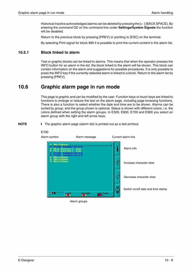
Graphic alarm page in run mode Alarm handling
Historical inactive acknowledged alarms can be deleted by pressing the [←] (BACK SPACE). By entering the command DD on the command line under Settings/System Signals the function will be disabled.
Return to the previous block by pressing [PREV] or pointing to [ESC] on the terminal.
By selecting Print signal for block 990 it is possible to print the current content in the alarm list.
10.5.1 Block linked to alarm
Text or graphic blocks can be linked to alarms. This means that when the operator presses the INFO button for an alarm in the list, the block linked to the alarm will be shown. This block can contain information on the alarm and suggestions for possible procedures. It is only possible to press the INFO key if the currently selected alarm is linked to a block. Return to the alarm list by pressing [PREV].
10.6 Graphic alarm page in run mode
This page is graphic and can be modified by the user. Function keys or touch keys are linked to functions to enlarge or reduce the text on the alarm page, including page browsing functions. There is also a function to select whether the date and time are to be shown. Alarms can be sorted by group, and the group shown is optional. Status is shown with different colors, i.e. the colors defined when setting the alarm groups. In E300, E600, E700 and E900 you select an alarm group with the right and left arrow keys.
NOTE ❙ The graphic alarm page (alarm list) is printed out as a text printout.
E700
Switch on/off date and time stamp
Alarm symbol Alarm message Current alarm line
Alarm info
Decrease character sitze
Alarm groups
Increase character sitze
i
E-Designer 10 - 9
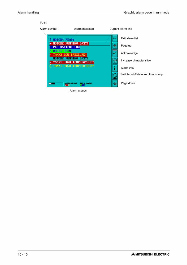
Alarm handling Graphic alarm page in run mode
E710
Alarm symbol Alarm message Current alarm line
Acknowledge
Alarm info
Alarm groups
Increase character sitze
Exit alarm list
Page up
Page down
iSwitch on/off date and time stamp
10 - 10

Recipe handling
11 Recipe handling
This chapter describes the function recipe handling. The function Recipe handling means that all the dynamic data in one or more blocks, i.e. the signals and their values, can be saved to file in run mode. The operator can then download the files to the controller, which will start working with the new values. By using the function for recipe handling it is possible to reuse large sets of parameters. The user can create recipe libraries consisting of files containing different sets of parameters. This function improves the efficiency of time-critical productions where the exhange of similar products must be done quickly, such as in the manufacturing of units in dif-ferent colors. Recipe files can be created from the terminal, the controller, or from a PC with the program HMI Tools.
Recipe files are stored in the terminal. To use recipe handling the functions for storing, loading, deleting and adding recipes must be linked to the function or touch keys, see chapter Function keys.
Recipe files can be sent as attachmentsfrom the terminals which have e-mail functions.
The figure below illustrates the principle of how recipehandling functions.
The PC is used to program the terminal. With the program File Transfer (in HMI Tools) the PC can be used to backup recipes, or to create new recipes.
The recipe block can collect values from the controller, which through the terminal are stored as a recipe.
The function Load recipe can be defined in any block, e.g. a block used to start the process.
Download recipes to the controller with the function Load recipe
Recipe file
M100M1020 D1D102
1025100121123D103
Create recioe fileswith the functionSave recipe.
E-Designer 11 - 1
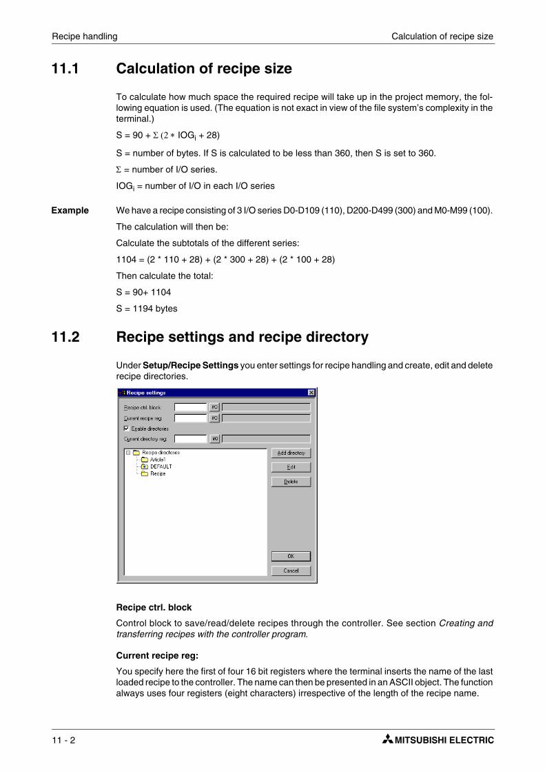
Recipe handling Calculation of recipe size
11.1 Calculation of recipe size
To calculate how much space the required recipe will take up in the project memory, the fol-lowing equation is used. (The equation is not exact in view of the file system’s complexity in the terminal.)
S = 90 + Σ (2 ∗ IOGi + 28)
S = number of bytes. If S is calculated to be less than 360, then S is set to 360.
Σ = number of I/O series.
IOGi = number of I/O in each I/O series
Example We have a recipe consisting of 3 I/O series D0-D109 (110), D200-D499 (300) and M0-M99 (100).
The calculation will then be:
Calculate the subtotals of the different series:
1104 = (2 * 110 + 28) + (2 * 300 + 28) + (2 * 100 + 28)
Then calculate the total:
S = 90+ 1104
S = 1194 bytes
11.2 Recipe settings and recipe directory
Under Setup/Recipe Settings you enter settings for recipe handling and create, edit and delete recipe directories.
Recipe ctrl. block
Control block to save/read/delete recipes through the controller. See section Creating and transferring recipes with the controller program.
Current recipe reg:
You specify here the first of four 16 bit registers where the terminal inserts the name of the last loaded recipe to the controller. The name can then be presented in an ASCII object. The function always uses four registers (eight characters) irrespective of the length of the recipe name.
11 - 2
Recipe settings and recipe directory Recipe handling
Enable directories
If the box is selected you can create a recipe directory in the terminal. See section Recipe directory.
Current directory reg:
You specify here the first of four 16 bit registers where the terminal inserts the name of the recipe directory specified for the block. The name can then be presented in an ASCII object. The func-tion always uses four registers (eight characters) irrespective of the length of the recipe direc-tory. See section Recipe directory.
11.2.1 Recipe directory
Recipes created in the terminal can be saved in different recipe directories (folders) in the ter-minal’s memory, or on a memory card if the expansion card IFC MC is used in the terminal. The use of recipe directories ensures a better structure and more simple handling of recipes in appli-cations with a large number of recipes. It is possible to create 32 different recipe directories in one level. Recipe directories are saved under the directory RECIPE in the root directory in the terminal’s memory. A recipe directory is linked to one or more blocks in the block header for the block. All recipes created in the block will then be saved in the selected recipe directory.
Recipe directories are created, edited and deleted under Setup/Recipe Settings in the pro-gramming tool. Defined recipe directories are shown in a list, according to the structure in the directory. Add new recipe directories with the button Add directory. Recipe directories must be named with a name having 1-8 characters. The first character must be a letter or digit, and the name must contain the characters A-Z, 0-9 and _. Otherwise, the standard for file names in MS-DOS is followed.
Change a recipe directory by selecting it and clicking Edit. Delete deletes selected recipe directories.
Recipe directory in run mode
In run mode recipe directories can be created and deleted with the functions Make recipe direc-tory and Delete recipe directory. The functions are linked to function keys or touch keys. With the function Change recipe directory for function keys or touch keys it is possible in run mode to change/select recipe directories for the current block. A list of options for available recipe directories is shown when the function key or touch key for Change recipe directory is pressed. Select one and press [ENTER]. The recipe in the block will now be saved in the selected recipe directory. See section Function keys.
NOTE ❙ Recipe directories created in the programming tool cannot be deleted with a function key or touch key linked to the function Delete recipe directory. Recipe directories created in the ter-minal do not accompany the terminal project when a project is uploaded from the terminal to the programming tool (The function Receive in the dialog project transfer).
Recipe handling between terminal and PC is performed with the program HMI Tools File Trans-fer and HMI Tools FTP Transfer. See section Using recipes in a PC and the manual for HMI Tools.
E-Designer 11 - 3

Recipe handling Creating a recipe with the terminal
11.3 Creating a recipe with the terminal
When the application is programmed you determine which block or blocks are to be used to save recipes, or alternatively the function Append recipe is used in run mode. All the signals to be included in the recipe are defined in the recipe block. All the dynamic values in the block are stored in the recipe file. All digital and analog objects, with the exception of trend objects, can be used as recipe parameters.
In run mode a jump is made to the block containing the recipe parameters. Enter the required values in the dynamic objects and press the function or touch key linked to Save recipe. The name must have 1-8 characters. The first character must be a letter or digit, and the name must contain the characters A-Z, 0-9 and _. Otherwise, the standard for file names in MS-DOS is fol-lowed. Recipe files are stored in the terminal, either in the recipe directory specified for the block or in one and the same recipe directory if no separate recipe directories have been created under Setup/Recipe Settings.
11.4 Append recipe
The function Append recipe can be linked to function and touch keys and makes it possible in run mode to add signals and their values from the current block to an existing recipe. I.e. the operator can save signals and their values from several different blocks in a joint recipe. New signals are added to a recipe, and signals already existing in the recipe will be updated when the function is activated. The name of the recipe to which the current block’s signals and their values are to be added is specified when the function or touch key for Append recipe is pressed. If the function is activated and there are no recipes saved in the terminal, a new recipe will be created in the terminal. Similarly, a new recipe will be created if the same recipe directory for the block is not given. To add signals from another block to a recipe the same, or no recipe directory, must therefore be given for both blocks.
NOTE ❙ If a string is added to an existing recipe with strings the strings must be separated by address space. Otherwise the previous near string will be increased.
11 - 4

Transferring recipes to the controller Recipe handling
11.5 Transferring recipes to the controller
In run mode recipes are transferred to the controller with the function Load recipe. This function means that the signals and their values stored in the file are transferred to the controller. A list of options for available recipe directories is shown when the function or touch key for Load recipe is pressed. Select one, and press [ENTER]. The controller will then run with the down-loaded values.
11.6 Delete recipe
In run mode the selected recipe can be deleted from the terminal memory with the function Delete recipe. Press the function or touch key linked to Delete recipe. A list of options will now be shown with the available recipe files. Select the file to be deleted, and press [ENTER]. Confirm with [ENTER] or press [PREV] to abort.
11.7 Using recipes in a PC
With the program HMI Tools File Transfer (icon in the program group HMI Tools) in the PC, the terminal will be treated as a unit in the PC. This means that the PC can be used to make backup copies of files in the terminal, e.g. recipe files. New recipes can be created in the PC and trans-ferred to the terminal.
Recipe files are stored in the PC in .SKV format, which can be brought up in Excel. The files can be edited in Excel and then used in the plant again. The files must end with the instruction END. See the example below.
M100;1 M102;0 D0;25 D50;12 END
It is also possible to transfer recipe files between the terminal and the PC through FTP with the program HMI Tools FTP Transfer (standard FTP client). For further information, refer to the manual for HMI Tools.
NOTE ❙ When Unicode is used, there are limitations pertaining to recipe files in .skv format. See the chapter Unicode for additional information
E-Designer 11 - 5

Recipe handling Creating and transferring recipes with the controller program
11.8 Creating and transferring recipes with the controller program
Through a control block in the controller you can create, transfer and delete recipe files in the ter-minal. The files created from the controller program are compatible with the recipe files created from the terminal. I.e. recipe files created in the controller program can be downloaded into the terminal, and vice versa. The control block appears as follows.
Under Setup/Recipe settings you define the first register in the control block. This and the seven following registers are used as control registers. The control block is described in the fol-lowing table.
Register Content Description
Ctrl reg 0 Command
Command register set by the controller. Available commands: 0: No command. 1. Save recipe to terminal. 2. Read recipe from terminal. 3. Delete recipe from terminal. 4. Create recipe directory. 5. Change recipe directory. 6. Delete recipe directory.
Ctrl reg 1 Handshake
Handshake register set by terminal. 0. Ready for new command. 1. OK 2. Recipe file write error. 3. Recipe file not found.
Ctrl reg 2 File name char. 1-2 Name of recipe file/recipe directory in the terminal.
Ctrl reg 3 File name char. 3-4
Ctrl reg 4 File name char. 5-6
Ctrl reg 5 File name char. 7-8
Ctrl reg 6 Start data register The first data register to be read/written to/from recipe file.
Ctrl reg 7 Number of registers Number of registers to be read/written to/from recipe file.
Save recipenn+1n+2
.
Register Value
Terminal Controller
Program in
123
Data
Ctrl.
Recipe file 1
.
.
n+m
534470
76789
nn+1n+2.
89
.
.
n+m
76991
76789
Register Value
Recipe file x
01...
n 123n+1n+2..
n+m..
Ctrl.reg. 0Ctrl.reg. 1.
Ctrk.reg. 7..
Register Value
534470
265346
Download recipeDelete recipeName of recipefile
Reciperegister
Control-block
MOV
MOV
controller
.
11 - 6
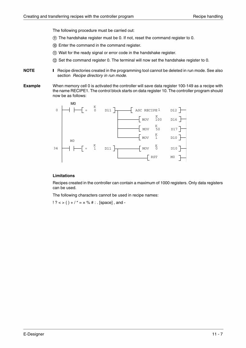
Creating and transferring recipes with the controller program Recipe handling
The following procedure must be carried out:
The handshake register must be 0. If not, reset the command register to 0.
Enter the command in the command register.
� Wait for the ready signal or error code in the handshake register.
� Set the command register 0. The terminal will now set the handshake register to 0.
NOTE ❙ Recipe directories created in the programming tool cannot be deleted in run mode. See also section Recipe directory in run mode.
Example When memory cell 0 is activated the controller will save data register 100-149 as a recipe with the name RECIPE1. The control block starts on data register 10. The controller program should now be as follows:
Limitations
Recipes created in the controller can contain a maximum of 1000 registers. Only data registers can be used.
The following characters cannot be used in recipe names:
! ? < > ( ) + / * = × % # : . [space] , and -
= 0 D11K
= 1 D11K
ASC RECIPE D12
MOV 100 D16
MOV 50 D17
MOV 1 D10
MOV 0 D10
RST M0
K
K
K
K
0
34
M0
M0
1
E-Designer 11 - 7

Recipe handling Creating and transferring recipes with the controller program
11 - 8

Defining security levels Password
12 Password
This chapter describes the handling of security levels and passwords in the terminal. It is a func-tion which makes it possible to create a security system for the plant. The operators can easily be assigned different authorizations in the plant.
Blocks, function/touch keys and maneuvrable objects can be allocated a security level. Each security level is allocated a password. To access the different levels the user must login with password for the relevant security level, or higher. It is not necessary to use this function.
12.1 Defining security levels
Blocks, function/touch keys and maneuvrable objects can, when they are defined, be allocated a security level. A security level (0-8) is specified in the dialog box for the object under the Access tab after the Enable operator input has been selected. If security level 0 is given, the object will be available for everyone, i.e. login will not be requested.
12.2 Defining password
Under Functions/Password you define passwords for the security levels 1-8.
Parameter Description
Password 1-8 Enter password for security level 1-8.
Confirm question 1-8
Enter the question, with a maximum of 20 characters, to be answered by the operator before maneuvring of an object with the defined security level is possible. This function will not function if a function or touch key has been defined with the security level.
Comment 1-8 Enter comments/description for the password/security level. This parameter does not need to be used.
Login signalSpecify the digital signal, which when it is set to one generates the input field for logging in. The input field for logging in can also be linked to a function or touch key, see chapter Function keys.
Logout signalSpecify a signal, which when it is set to one logs out the current user. The function can also be linked to a function or touch key, see chapter Function keys.
E-Designer 12 - 1

Password Logging in
12.3 Logging in
If the box for Automatic login under Functions/Password is not checked the login will either be controlled from a function or touch key, or through a digital signal from the controller (Login sig-nal). If the function key linked to the function Login to specified security level is pressed, or the digital signal is activated, the input field for login will be shown. Specify password. The password is linked to a security level, see above.
12.4 Password for project transfer
On the command line under Setup/System Signals you can enter the command PDxxxxxxxx. The command means that a password (xxxxxxxx) must be given to access the functions in the menu TRANSFER in the terminal. When transferring projects from the programming tool to the terminal this password must be given in the terminal.
12.5 Overriding password
On the command row under Setup/System signals..., the command PSxxxxxxxx can be entered. When the password is entered (xxxxxxxx), the command overrides all other password levels and the user gains access to everything in the terminal. This is useful, for example, in per-forming support and maintenance. On the command line, only capital letters may be specified.
12.6 Change password during run mode
The password can be changed during run mode with the function Change login password for function or touch keys. When function or touch keys linked to Change login password are pres-sed a dialog box is shown, where the password for respective security levels can be changed. See chapter Function keys.
NOTES ❙ It is not possible to select a security level on block 0.
❙ After logging out, the [PREV] key and function Return to previous block are ignored for function and touch keys to prevent unauthorized persons accessing block protected by pass-words.
Login level regA register in the controller to control the security level can be specified here. The value in the register determines the current security level, value 0 = no security level, 1 = security level 1, etc.
Current level reg Specify a register from where the terminal can present the current security level (0-8).
Login timeout Specify the time in minutes which the terminal can remain inactive before the user is automatically logged out. If 0 is given there will be no logout.
Password RUN/PROG
You can specify a password to be given for manual switching from RUN to PROG mode. The function is not used for switching from PROG to RUN or when Automatic terminal RUN/TRANSFER switching is used from the programming tool.
Automatic login
Specify if the login window is to be automatically shown when trying to access password-protected blocks, objects or keys. The function is only applicable for terminals with touch screens, since it is not possible to place the cursor on password-protected objects without being logged in on the correct security level for the object.
Parameter Description
12 - 2

Connection to printer Printouts
13 Printouts
This chapter describes how report printouts are made in the terminal. Different types of reports, e.g. daily reports and event reports, can easily be created for production follow-up. The following diagram shows the principle for generating daily reports.
13.1 Connection to printer
The printer should have a serial interface and an IBM character set (850). The settings for the printer are made in the dialog under Setup/Peripherals. For configuration of the printer, refer to the printer manual.
NOTE ❙ The expansion card IFC PI must be installed in the terminal to connect a printer with parallel interface to the terminal.
Examples of printer:
Serial printer Panasonic KX-P1092
Parallel printer HP Laserjet GL HP Laserjet 1100
Terminal
Printer
RS422 RS232C
E-Designer 13 - 1

Printouts Project printouts
13.2 Project printouts
Choose File/Print... to print the project.
Choose the portions of the project to be printed by clicking the boxes. Click Setup to configure the printer. Click Preview to view the printout before sending it to the printer.
13.3 Text block reports
Reports are created as text blocks with static and dynamic text. The width of the reports is a max-imum of 150 characters. In the text block you write an optional text, e.g. a table header, and other static text which is always printed. To print the values from the process you define the dynamic object which presents the value for the signal the object is linked to. See chapter Text-based presentation and maneuvring. You can decide when the report is to be printed through time channels, for example.
NOTE ❙ Text blocks cannot be printed if Unicode is used.
13.4 Graphic block printouts
In E300, E600, E610, E615, E700, E710, E900 and E910 it is possible to print out graphic blocks on an Epson FX-80 compatible printer. In E610, E615, E700, E710, E900 and E910 graphic blocks can also be printed on an HP PCL5/PCL5C/PCL6 compatible printer (through IFC PI). Graphic blocks can only be printed when they are displayed on the screen (screen dump). Only black and white graphics are supported.
If the command NHD is given on the command line under Setup/System Signals graphic blocks will be printed out on a laser printer without header (normally includes block name, block number, date and time).
NOTES ❙ Epson FX-80 graphics do not support grey scales.
❙ For graphic block printouts the printer’s internal memory should be at least 5 MB.
❙ The alarm block, i.e. the graphic block which contains the alarm list is printed out as a text printout.
❙ If the [PREV] key on the terminal is pressed when a graphic block is being printed, the printout will be cancelled.
13 - 2

Defining the printout Printouts
13.5 Defining the printout
The printout is defined in the block header. You obtain the block header from the Block Manager or the block list. The parameter Print signal in the block header indicates the digital signal, which when it is set to one activates the printout of the block. A digital Completion signal is also indicated here, which is set to one by the terminal when the printout is complete. If the box Resetis selected, the signal will be reset instead.
E-Designer 13 - 3

Printouts Printer settings
13.6 Printer settings
The printer settings are made under Setup/Peripherals/Printer/Edit.... For more detailed infor-mation concerning printers, refer to the manuals for respective printers. The printer musts sup-port an IBM expanded ASCII character set. If graphic blocks are to be printed, the printer must support Epson FX-80, HP PCL5 or HP PCL6 graphics. If you use the expansion card IFC PI it is possible to print on a HP printer (with PCL5 or PCL6 support), i.e. a printer with parallel interface.
Parameter Description
Printer type Select printer, None, standard text or installed printer, e.g. HP PCL5.
Page length The number of lines to be printed out before form feed. If the page length is set 0 there will be no form feed.
Paper type Select the paper type according to the installed printer.
Graphic orientation Select whether the graphic printout is to be vertical or horizontal.
Text orientation Indicates whether the report printout is to be vertical or horizontal if a PCL5 compatible printer is used.
Printer disable signalIndicates a digital signal, which when it is set to one, stops the printout. The port where the printer is connected can then be used for other communi-cation, e.g. Transparent mode. Not applicable if IFC PI is used.
Newline character Line end character; CR/LF, CR, LF or none.
Handshake Indicates whether handshaking between printer and terminal is to be with XON/XOFF or CTS/RTS.
Screen dump Possibility to print out the screen, normal or inverted.
13 - 4

Setting of communication port Printouts
13.7 Setting of communication port
The settings for the communication port are made under Setup/Peripherals/RS-232C or RS-422. When you mark RS-232C or RS-422, click Edit.... See the manual for the connected printer for the correct settings.
13.8 Control codes to printer
In a text block you can enter control codes to the printer. You enter %% followed by a number between 1 and 31. 1 to 31 are control codes to the printer. For example, you can enter %%12, which means paper feed. Refer to the printer manual for a description of the control codes. A command must be followed by a space. Page feed (%%12) is specified at the end of the line. The character %% must not be used in the text. It is possible to have more than one command on a line.
13.9 Printer status
It is possible to read the status of a printer connected via the expansion card for parallel printer by using a printer status register. The register is selected under Setup/System signals. For a description of the printer status register, refer to the section System Signals in chapter Programming with the programming tool.
Parameter Description
Baud rate Select the baudrate for the communication; it should be the same as for the external unit.
Parity Select the parity; it should be the same as for the external unit.
Data bits Select the number of data bits; it should be the same as for the external unit.
Stop bits Select the number of stop bits; it should be the same as for the external unit.
E-Designer 13 - 5

Printouts Printer status
13 - 6
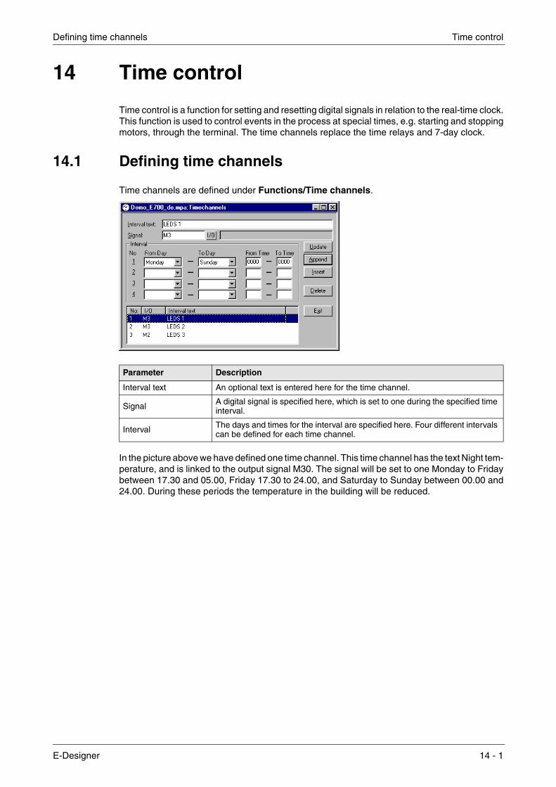
Defining time channels Time control
14 Time control
Time control is a function for setting and resetting digital signals in relation to the real-time clock. This function is used to control events in the process at special times, e.g. starting and stopping motors, through the terminal. The time channels replace the time relays and 7-day clock.
14.1 Defining time channels
Time channels are defined under Functions/Time channels.
In the picture above we have defined one time channel. This time channel has the text Night tem-perature, and is linked to the output signal M30. The signal will be set to one Monday to Friday between 17.30 and 05.00, Friday 17.30 to 24.00, and Saturday to Sunday between 00.00 and 24.00. During these periods the temperature in the building will be reduced.
Parameter Description
Interval text An optional text is entered here for the time channel.
Signal A digital signal is specified here, which is set to one during the specified time interval.
Interval The days and times for the interval are specified here. Four different intervals can be defined for each time channel.
E-Designer 14 - 1

Time control Presentation in run mode
14.2 Presentation in run mode
The page with the time channels is shown when system block 991 is activated, either through a jump object or through a digital signal linked to the block. The values of the time channels can be read and/or changed. To change the value of the time channels in run mode, the alternative Time channels under Setup/Online settings must be marked.
To read or change the values for a time channel you move the cursor to the required line and press [ENTER] or point to the required line if the terminal has a touch screen. Press [OK] to exit the definition of the time channels. Exit the time channel menu with [PREV] or point to Cancel if the terminal has a touch screen. The block from which the time channel block was activated will then be shown.
14.3 Language handling
The programming tool supports multi language applications for the operator terminals. With the multi language function you can create your application just as usual in an optional language and then translate it in the programming tool. You can use a maximum of 10 languages in one application.
14.3.1 Multi language support
Create additional language files for the application under Setup/Country Settings by clicking on the button Create multi languages support. We recommend that you first create your com-plete application (the complete terminal project) in the programming tool, and then create the multi language function for the application. The optimization function tries to reduce the number of texts (No:) in the language if the application contains several objects with the same texts. These objects will then be linked to the same text numbers (No:).
User language and System language are translated in two steps but in the same language name, i.e. there are two different language files with the same language name.
14 - 2

Language handling Time control
User language
Select to create a new user language or a new system language. User language is the texts entered when the project is programmed. System language is the texts which already exist when a new project is created, and the texts in the terminal’s system program. A new system language can be created if the existing system language in the terminal is uploaded from the terminal.
Name
Specify a name for the language to be created.
Copy from
Select to copy all the texts from an existing language, i.e. a previously created language. If it is the first language in the multi language function which is to be created, select Existing Lan-guage and give it a name (see next parameter). The texts from the active project will then be copied.
Existing Language, Name
The name of the language for the existing project is given when the first language in the multi language function is to be created, i.e. a name for the language in which the application has been created.
Get syst. languages from terminal
Collects texts in the system language from the terminal (requires that the actual terminal is con-nected to the PC in accordance with chapter “Transferring projects”.)
User language
Current language in the application language manager. The currently selected language can be edited in the box Texts.
System language
The current system language in the application language manager. The currently selected language can be edited in the box Texts.
E-Designer 14 - 3
Time control Language handling
Character set
The selection of the character set will influence the character table used in the terminal and which national characters will be available. See section Country Settings.
Language choice reg
A data register in the controller the value (0-9) of which in run mode controls which application language (0-9) the terminal is to use.
Texts
All system texts in the terminal (passwords, time channels etc.) support the multi language appli-cation. It is possible to use the pre-defined system languages, or to create your own (new). All types of characters in the selected character set can be used in the application language. A text string is linked to several different objects. The maximum number of text strings for each lan-guage depends on the available project memory in the terminal. The following space is available for each language:
E300 - E615= 64kbyte/language E700 - E910= 128kbyte/language
At the bottom left in the window Texts there is information on the memory for the selected lan-guage (language file). The information is shown in the format X/Y, where X is the memory used and Y is the available memory for each language, e.g. Size 7/128.
14.3.2 This is how to translate texts in the programming tool
You can either select to make the translation in the dialog Application language, or to export texts to another program, make the translation there and then import them again, see also the section below.
The column marked grey is the one containing the texts to be translated. Select a line, enter the correct text in the field, and click Update. Select the next text, and repeat. The easiest way is to work with the keyboard: The first text is automatically selected, enter the correct text, press Enter and use the arrow key to move down the selection to the next line, and repeat.
14 - 4

Language handling Time control
14.3.3 Import/Export
You can select to export a language to, for example, Excel, translate it there and then import it to the programming tool. The selected language is the one that will be exported, or alternatively the imported file will go to the selected column. If you are going to import a language you first cre-ate the language so that there is an empty column with the name of the language in the dialog Application languages.
The following dialog window comes up when you click on Export or Import:
It is not usually necessary to make any changes. The column separator should be tab, and in so far as there are no other columns in the file texts are exported to or imported from, the fields in Columns do not need to be changed. No: is the number of the column in the file you export to or import from which shows the number for text that is translated. Text is the number of the column in the file you export to or import from which shows the texts exported/imported.
NOTE ❙ If a project with several application languages is opened in MAC Programmer+ all objects with several application language texts will be replaced with the character @ followed by an index number, e.g. "@55".
14.3.4 Application languages in RUN mode
It is possible to replace application languages in the terminal in run mode by changing the value (0-9) given in the Language choice register. Note that the terminal redraws/rewrites the com-plete block when a new language is selected in run mode (RUN). If there is a cursor in the ter-minal it will then be placed on the first maneuvrable object in the current block. In configuration mode, Setup, on the terminal it is possible to change the current Language choice register, selected Character set, and system language for all languages.
E-Designer 14 - 5

Time control Language handling
14 - 6

Creating additional application languages Language management
15 Language management
The programming tool supports several language applications for the E-series’ operator termi-nals. We advise that the entire application be created in one language in the programming tool. Using the multiple language support function, you can later easily translate all texts in the appli-cation to other languages. Translation can be performed directly in the programming tool or the text can exported as a text file and translated in other software. The translated file is later imported back into the programming tool. A maximum of 10 languages can be created for an application.
Each text in the application can be allocated an arbitrary index. To optimize the function and reduce the total number of texts, a text can be used several times in the application, copied and reused. These texts are linked to the same index.
The application language contains user texts and is linked to a system language that contains system texts. User texts are those texts that are entered when the project is programmed and system texts are those texts that already exist when a new project is created as well as texts that already exist in the terminal’s system program.
15.1 Creating additional application languages
Choose Setup/Multi language.../New language. This starts the Multiple Languages wizard, a self-descriptive sequence of dialog boxes for creating additional application languages. Follow the instructions in the respective dialog boxes and select or type the desired parameter values or name(s).
Choose to copy all texts from an existing language, i.e. a previously created language. Language 1 is the language in which the application was created (basic language).
E-Designer 15 - 1
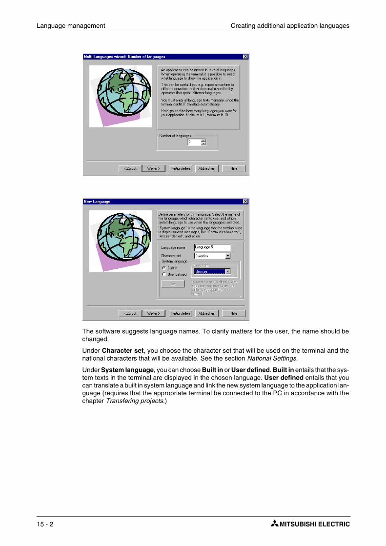
Language management Creating additional application languages
The software suggests language names. To clarify matters for the user, the name should be changed.
Under Character set, you choose the character set that will be used on the terminal and the national characters that will be available. See the section National Settings.
Under System language, you can choose Built in or User defined. Built in entails that the sys-tem texts in the terminal are displayed in the chosen language. User defined entails that you can translate a built in system language and link the new system language to the application lan-guage (requires that the appropriate terminal be connected to the PC in accordance with the chapter Transfering projects.)
15 - 2

Translating/Editing texts in the programming tool Language management
This is where the Language control register is specified. Its value (0-9) during runtime deter-mines the application language (0-9) that the terminal will use.
Click Finish to close the wizard. A structure tree is now displayed with the languages you have created.
15.2 Translating/Editing texts in the programming tool
Choose Setup/Multi language.../Edit.
This is where the translations for the various languages are entered in the respective table cells. Move the cursor between the rows and columns with the arrow keys. You can search within the text list with the menu command Edit/Find.
An application language can also be exported as a text file and translated in another program, such as Excel or Notepad. The text file is thereafter imported back to the application. See the sections Export and Import.
E-Designer 15 - 3

Language management Settings for the application language
15.3 Settings for the application language
Choose Setup/Multi language.../Setup.
Right-click User language to change the register that determines the displayed language.
When you right-click the language name, you can choose between the following menu commands:
Right-click Character set to change the character set (also applies to Unicode) for the language.
Right-click System language to change the selected system language or create a new one.
15.3.1 User-defined system languages
To create a user-defined system language, choose User defined, choose the language that would like to copy from and click Get. The Language Transfer dialog box opens. Click Receive to retrieve the built-in system language from the terminal. System texts are now accessible for editing under Setup/Multi language.../Edit. You can also choose to export the texts as a text file and edit them in another program.
All system texts in the terminal (passwords, time channels, etc.) support the multiple language application. You can use the predefined system languages or create your own (new). All types of characters that exist in the character set can be used in the application language. A text string is linked to several different objects. The maximum number of text strings for each language depends on available project memory in the terminal. The following spaces are available for each language:
E300 - E615= 64 KB/language E700 - E910= 128 KB/language
At the bottom left of the Application Language dialog box, information is displayed on memory size for selected languages (language file). The information is displayed in the format X/Y. X is the utilized memory and Y is the available memory for each language (for example, 7/128).
Menu command Description
New language Creates a copy of the selected language
Character set Chooses/edits character set
System language Chooses/edits system language
Delete language Deletes the selected language
Rename Changes name of selected language
Properties Specifies data register with the value that determines the displayed language
15 - 4

Export Language management
15.4 Export
You can choose to export a language to Excel, for example, translate it there, and then import it back to the programming tool.
Choose Setup/Multi language.../Export. Choose User texts (or System texts). In the dis-played dialog box, specify the name of the file to be exported and indicate if it is to be an ANSI, OEM or Unicode text file.
ANSI/OEM entails that languages created in the ANSI/OEM format will be exported, and Uni-code entails that all languages will be exported to a file in the Unicode format. Editing a Unicode-format file in another application requires that a Unicode font be selected in that application.
15.5 Import
Choose Setup/Multi language/Import. Choose User texts (or System texts). The Import Multi language texts dialog box is displayed. Choose the name of the text file that you would like to import. If the existing language in the project in is in ANSIOEM format and a language in Unicode format is imported, the imported language will be converted to ANSI/OEM.This means that all characters not included in the ANSI/OEM range will be displayed as question marks.
NOTE ❙ If a project with several application languages is opened in MAC Programmer+ will replace all objects with several application language texts with the character @ followed by an index number (for example, "@55").
15.6 Show index
Each object that displays text in a multiple language application is linked to an index. An index can be linked to different objects with the same texts. Choose Setup/Multi language/Show index to display the index number for the object texts.
15.7 Cross reference
Choose Setup/Multi language/Cross reference. On the displayed cross-reference list you can right-click an object to edit it. The cross-reference list has support for incremental searching when you specify an index number.
15.8 Copy object
When Reuse index is active and an object is copied, the copy will be assigned the same index. This entails that objects with the same index need only be translated once. Changes made to a text will be seen at all locations where the same index number exists.
NOTE ❙ If an object is deleted that has copies with the same index number, only the selected object is deleted.
E-Designer 15 - 5
Language management Choose Unicode font
15.9 Choose Unicode font
Here you can choose a Unicode font if an increased number of characters is needed to create the application languages.
15.10 Application languages in run mode
You can change the application language in the terminal in run mode by changing the value (0-9) in the specified language selection register. Note that the terminal redraws/rewrites the entire block when a new language is selected in run mode (RUN). If there is a cursor in the terminal,this will be placed at the first maneuverable object in the current block.
15 - 6

Introduction Unicode
16 Unicode
16.1 Introduction
Unicode is a global standard for character encoding where 16-bit values are used to represent the characters from many of the world’s languages. Previous standards for character encoding, such as the Microsoft Windows ANSI character set, use 8-bit character values or combinations of 8-bit values to represent the characters used in a certain language or geographical region.
In Microsoft Windows 2000 and Windows XP, IMEs (Input Method Editors) are used to permit the computer user to write in complex characters and symbols, such as those used Chinese, with a standard keyboard. The character sets installed in the computer are used. IMEs for var-ious languages are added under Control Panel/Keyboard/Input language. When new char-acter sets are installed, all necessary characters are added to the system.
16.2 Unicode in the programming tool
Unicode is supported in the operator terminals E300- E910 with the most recent version of the sys-tem program (firmware). The Unicode characters can be used in projects and/or system texts.
Unicode has built-in support in Microsoft Windows XP and Windows 2000.
The programming tool uses a Unicode character set to display Unicode characters in the com-puter’s dialog boxes. Only those Unicode characters that are used in the project will be down-loaded to the operator terminal during the project transfer.
16.3 Terminal font
A character set is used in the operator terminal to display Unicode characters.The character set in the terminal contains approximately 35,000 characters but is not complete according to the Unicode standard. When a project is transferred to the terminal, only the characters that are used in the terminal are downloaded. If a character that is not available is used, it is replaced by a black square, both in the programming tool and the operator terminal. The project test that can be performed when transferring the project checks that all used characters are present in the character set in the terminal.
16.3.1 Character sizes for user and system texts
Unicode characters are processed as bitmaps (point matrices). The predefined character size is 8 x 16 pixels but can be changed. Sometimes the character size 16 x 16 must be chosen for complicated characters, such as those used in Chinese, to avoid failure of certain pixels to be displayed and that characters be misinterpreted by the operator. If a large character size is cho-sen, menu windows may not always have space in small terminals.
E-Designer 16 - 1

Unicode Multiple language functions
16.4 Multiple language functions
Switching between display of object text and index number
When the T/@ button is selected on the Language toolbar, the programming tool displays the index number (@number) in the object instead of the text. In the @ mode, new text (in ANSI/OEM, not Unicode) can be specified to link the object to a new index and release it from the other objects and the original index. By specifying @number, the object can be linked to new indexes. See the chapter Language management for more information.
Export and import of files in Unicode format
System and user texts can be exported and imported under Setup/Multi language.... An exported file in Unicode format can be edited in a text editor such as Notepad. Choose a Unicode font in the text editor.
When a file is exported, the ANSI/OEM or Unicode format can be chosen. If ANSI/OEM is cho-sen, only languages in ANSI/OEM format will be exported to a file in ANSI/OEM format. If Uni-code is chosen, all languages will be exported to a file in Unicode format.
When a file in ANSI/OEM format is imported, you can choose whether or not an existing lan-guage will be updated, or if there is none previously, to add one.
When a file in Unicode format is imported, you can choose whether or not an existing language will be updated, or if there is none previously, to add one. If the existing language is in ANSI/OEM format, the imported language (in Unicode format) will be converted to ANSI/OEM form. Char-acters not supported by ANSI/OEM will be replaced by question marks.
Memory usage
When Unicode is used, memory is allocated in accordance with the following formula:
Languages size: Each string requires 22 + total characters in the string x 4 bytes.
Character set size: The character set that is transferred requires the total number of unique char-acters x 34 bytes, which means, for example, that transfer of 1000 characters requires 34 KB.
Memory usage for a Unicode language is the language’s size + the character set’s size.
Performance
The drawing of Unicode characters is somewhat slower than the drawing of ANSI/OEM char-acters, which is primarily because Unicode characters have more pixels to be drawn.
When the operator terminal is started, the Unicode character set is read into memory, which can take time if the character set is large.
16 - 2

Limitations when Unicode is used Unicode
16.5 Limitations when Unicode is used
Text block
Text blocks are not supported when Unicode is used. If a Unicode character set is chosen in an existing project, the dialog box below will be displayed.
Save recipe and alarm history
HMI Tools File Transfer and FTP client do not support Unicode characters. The skv file that can be used to edit recipes on a PC or for alarm history will, when Unicode is used, contain index numbers (@xxx) instead of texts. You can search in the project for corresponding text in the ter-minal. If texts are desired in the skv file, the terminal project has to be changed to a character set in ANSI/OEM format.
Dynamic texts
Texts can be controlled vial control system signals by choosing Dynamics/Properties for the selected object.
These texts will not be converted to Unicode; question marks will be displayed instead.
Time channels block
The standard block Time channels, which can be configured in RUN mode, must use the prese-lected character size 8 x 16 in the E300 and E600 operator terminals. The input window will oth-erwise be too large for the screen and the block will not be configurable.
E-Designer 16 - 3

Unicode Limitations when Unicode is used
16 - 4

System Monitor
17 System Monitor
Only applicable for E610, E615, E700, E710, E900 and E910.
The system monitor is a block where the operator can view or change the values for control sig-nals in run mode. The values are presented as decimal, hexadecimal and ASCII values. The system monitor is always available in the terminals. To use the system monitor during run mode you create a block jump from another block to the system monitor block. The editing box is needed to add on control signals. This is shown when you press [ENTER] or alternatively point to the button NEW on the terminal when the system monitor is active.
E-Designer 17 - 1

System Monitor
17 - 2

Index addressig
18 Index addressig
Without index registering an object is always connected to the same register, and only the value in this register can be shown in the object. With index registering, however, it is possible to select during run mode from which register an object is to collect the shown value. This can be done by adding the value in the index register to the address of the register which is the analog signal in the object. In general this can be formulated as:
Display value = the content in Register (the Object’s address + the content in the Index register)
If the content in the Index register is 2 and the address of the register specified in the object is 100, the value shown in the object will be collected from address 102. If the value in the Index register is changed to 3, the value in the object will be collected from address 103 instead.
Which register is to be the index register is defined in the individual project. This is done under Setup/Index register. Up to eight different index registers can be used in each project, and each index register can be used for more than one object.
The objects used in the project will specify whether index registering is to be used, and if so, which index register. This is done by selecting in the dialog for the object I1 to I8 in the box to the right of the indicated address signal for the object. In the example below, D100 is the analog signal and I1 is the index register used.
In the following example, three motors are to be controlled from one block. The torque and speed for the three motors are stored in six different registers. One of the motors will be selected in one block, and then only the current torque and speed for this motor will be shown in the block. If another motor is selected, the current torque and speed will be shown for this motor instead. This is possible with index registering.
Register D0 is defined under Setup/Index register as Index register 1. The value in the register will determine for which motor the torque and speed are to be shown.
Motor 1
Torque in register D101Speed in register D201
Motor 2 Motor 3
Torque in register D102Speed in register D202
Torque in register D103Speed in register D203
E-Designer 18 - 1
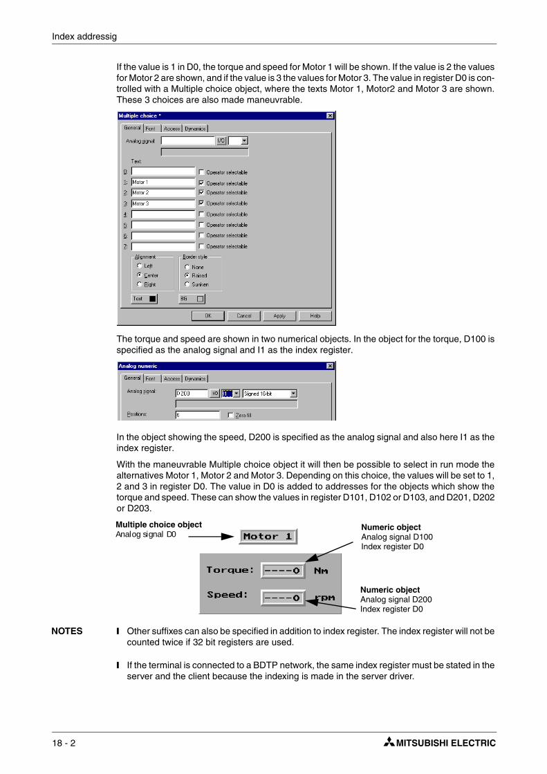
Index addressig
If the value is 1 in D0, the torque and speed for Motor 1 will be shown. If the value is 2 the values for Motor 2 are shown, and if the value is 3 the values for Motor 3. The value in register D0 is con-trolled with a Multiple choice object, where the texts Motor 1, Motor2 and Motor 3 are shown. These 3 choices are also made maneuvrable.
The torque and speed are shown in two numerical objects. In the object for the torque, D100 is specified as the analog signal and I1 as the index register.
In the object showing the speed, D200 is specified as the analog signal and also here I1 as the index register.
With the maneuvrable Multiple choice object it will then be possible to select in run mode the alternatives Motor 1, Motor 2 and Motor 3. Depending on this choice, the values will be set to 1, 2 and 3 in register D0. The value in D0 is added to addresses for the objects which show the torque and speed. These can show the values in register D101, D102 or D103, and D201, D202 or D203.
NOTES ❙ Other suffixes can also be specified in addition to index register. The index register will not be counted twice if 32 bit registers are used.
❙ If the terminal is connected to a BDTP network, the same index register must be stated in the server and the client because the indexing is made in the server driver.
Multiple choice objectAnalog signal D0
Numeric objectAnalog signal D100Index register D0
Numeric objectAnalog signal D200Index register D0
18 - 2

Communication with two controllers (Dual drivers) Communication
19 Communication
19.1 Communication with two controllers (Dual drivers)
It is possible to use two different drivers in the terminal, which means that the terminal can com-municate with two different controllers simultaneously. The controllers can be connected in series to the serial ports on the terminal and through Ethernet to the expansion cards IFC ETTP or IFC ETCX.
Addressing of the signals in the controllers is carried out as normal for each respective controller in accordance with the manual for the driver.
Select File/Project Settings in the programming tool.
Select Controller by clicking on Change for Controller 1 respective Controller 2. If the selected driver for Controller 1 does not support dual drivers you cannot select a driver for Controller 2. Click on OK.
Select Setup/Peripherals. Drag Controller 1 and Controller 2 to the connection ports where the respective controllers are connected. It is possible to use RS-232C, RS-422, RS-485 (E610 and E615), including expansion cards IFC PBDP and IFC ETTP or IFC ETCX. For further infor-mation on the connection of controllers to the terminal, refer to the manual for respective drivers.
E-Designer 19 - 1

Communication Communication with two controllers (Dual drivers)
19.1.1 Addressing
Addressing of the signals in the controllers is carried out as normal for each respective controller in accordance with the manual for the driver. The controller to which a created object is to be linked is selected by clicking the button corresponding to the required controller (1 or 2) in the tool field in the programming tool. Controller 1 is always pre-set when a project is created or opened.
If button 1 is pressed the signal is linked to an object created for Controller 1 and if button 2 is pressed the signal is linked to an object created for Controller 2.
It is also possible to click on the I/O button in the object created and select which controller the object is to be connected to from the I/O Browser.
To address a signal in controller 2 when controller 1 is preset, the signal must be given the addi-tion @2 and correspondingly @1 for controller 1 if controller 2 is preset.
Example Controller 1 is preset. Register D0 in controller 2 is to be connected to a potentiometer. D0@2 is entered in the field Analog signal in the dialog for the potentiometer.
I/O Crossreference
The function I/O crossreference to show I/Os in a well-arranged manner can be used for both Controller 1 and Controller 2. The crossreference shows the preset controller.
Name list
The name list with attendant functions is supported for both controller 1 and 2.
NOTE ❙ If communication with a controller is lost, the terminal will continue to communicate with the other system. The terminal will try to connect to the disconnected system every tenth second, which can affect cimmunication with the operable cintroller. The interval can be changed by using a command. See the section Commands in the chapter Programming with the pro-gramming tool.
19 - 2

Communication with two controllers (Dual drivers) Communication
19.1.2 Examples of configurations where dual drivers are used in the terminal:
Terminal communicating with one controller and one frequency converter.
Terminal communicating in series with one controller via Ethernet with controller of other make.
Terminal communicating with two different makes of controller via Ethernet.
Terminal communicating with one make of controller in series or via Ethernet and with another make of controller via PROFIBUS DP.
TCP/UDP
RS232/RS422
TCP/UDP
TCP/UDP
RS232/RS422
PROFIBUS DP
E-Designer 19 - 3

Communication Data exchange between controllers
19.2 Data exchange between controllers
When two controller are connected to one and the same terminal (dual drivers are used in the terminal) it is possible to exchange data (analog and digital signals) between the controllers. Two controllers can thus each be connected to their respective terminal in a BDTP network. For addressing, see the section BDTP (Beijer Data Transport Protocol). The signals do not have to be of the same type in the two controllers. The exchange of data takes place in a virtual data channel, which goes between controller 1 and 2. You can define eight different data channels. The transfer of data can take place at intervals or during events. The conditions for how the transfer is made and which interval of signals are to be transferred for each data channel are specified under Functions/Data exchange.
Click Add when the settings for a data channel have been defined.
NOTE ❙ The function Data exchange functions like any other function in the terminal and therefore gives the same priority as other functions. Example: If the terminal is occupied (occupied with performing other functions) and a request for Data exchange is made, this will affect the trans-fer time and the exchange of data between the controllers will take longer than usual.
Parameter Description
Area
Start I/O 1 - Start address for the data channel for controller 1. (The subsequent fields are used to specify an index register and signal format.) See chapter Index addressing and Signal format.)Start I/O 2 - Start address for the data channel for controller 2. (The subsequent fields are used to specify an index register and signal format.) See chapter Index addressing and Signal format.)
Mode Specify if the signals for the data channel are digital or analog.
Size Specify the number of signals to be transferred (start address + subsequent) in the data channel. Max number of signals for a data channel is 255.
Flow 1 => 2
Trigg signal - A digital signal which controls the data transfer from controller 1 to controller 2 for the data channel. The signal status has the following implications:0 - Inactive.1 - Transfer.Interval - Specifies the time in seconds between cyclical transfers of data channels. The interval parameter should be zero if it is not used. If the value is greater than 0 the parameter has a higher priority than the Trigger signal, and therefore a trigger signal cannot trigger transfers. The maximum number of seconds is 65,535.
Flow 2 => 1
Trigg signal - A digital signal which controls the data transfer from controller 2 to controller 1 for the data channel. The signal status has the following implications:0 - Inactive.1 - Transfer.Interval - Specifies the time in seconds between cyclical transfers of data channels. The interval parameter should be zero if it is not used. If the value is greater than 0 the parameter has a higher priority than the Trigger signal, and therefore a trigger signal cannot trigger transfers. The maximum number of seconds is 65,535.
19 - 4

Transparent mode Communication
19.3 Transparent mode
In Transparent mode a communication port (programming/printer port) on the terminal which is not connected to the controller can be used to connect additional units working in parallel with the controller. These units can be terminals or a PC with programming tools for the controller or a master operator system.
For information on whether Transparent mode will function together with the connected con-troller, refer to the respective driver manual.
19.3.1 Connection of PC or other computer system
A PC with a programming tool or another computer system is connected directly to a commu-nication port on the terminal, in this case the programming/printer port.
Terminal connected to the programming/printer port.
Settings in the terminal and PC
The following settings must be made in the terminal and PC for Transparent mode to function:
In the terminal project in the programming tool the communication settings are made under Setup/Peripherals. Drag the unit Transparent mode to the required communication port (to the port where the PC is to be connected to the terminal). Click with the right mouse button on the unit to set Transparent mode (if this is supported by the driver, see the manual for the driver). The settings for the port where the PC is connected must correspond with the settings in the program in the PC (the programming tool for the controller).
TerminalController
PC
RS232
RS422
E-Designer 19 - 5

Communication Transparent mode
19.3.2 Connection of two terminals in Transparent mode
Additional terminals can be connected to the same controller with Transparent mode. We describe here how two terminals are connected. Additional terminals are connected in a similar way.
Cable connections
When two terminals are to be connected to one controller the first terminal is connected in accordance with the description in the Installation Manual. A cable is connected between the two terminals as shown in the following illustration. The cable is connected between the free port on the first terminal and the corresponding port on the second terminal. If the distance is more than 15 metres for RS232 communication, a signal amplifier must be used.
Settings in the first terminal
In the programming tool the communication settings are made under Setup/Peripherals. The settings for the port connected to the controller are set as normal. The settings for the port con-nected to the other terminal are optional.
Settings in the second terminal
In the programming tool the communication settings are made under Setup/Peripherals. The controller should be placed on the port used to connect the second terminal to the first terminal. The settings for this port should be the same as for the first terminal on the port where the second terminal is connected.
316
215
78
215
316
78
25-pin 25-pin
RS422 RS232
3
2
5
2
3
5
9-pin 9-pin
Cable between two terminals for RS232 communication
Cable between two terminals for RS-422 communication
D-sub Female D-sub Female
D-sub MaleD-sub Male
19 - 6

Transparent mode Communication
Transfer speeds
The transfer speed can vary between 600-57,600 baud. It is recommended to use the highest possible transfer speed between the terminals to achieve the best performance. The commu-nication speed decreases with the number of connected terminals according to the following table.
19.3.3 Connection of three terminals in Transparent mode
A third terminal can be connected with a cable to Terminal 2 in the network as shown in the above diagram. The settings for the third terminal should be the same as the settings in the sec-ond terminal.
Number of terminals
Access time to controller
Terminal 1 Terminal 2 Terminal 3 Terminal 4
1 100% - - -
2 50% 50% - -
3 50% 25% 25% -
4 50% 25% 12,5% 12,5%
RS422 RS232 RS422
Terminal 1 Terminal 2 Terminal 3
E-Designer 19 - 7

Communication Passthrough mode
19.4 Passthrough mode
With the function Passthrough mode it becomes possible to set the terminal in a mode which enables communication between the programming tool for the connected controller on a PC and the controller to be established through the terminal. This is a joint function with the Transparent mode function and in similarity with Transparent mode only supports one controller. This means that Transparent or Passthrough mode can only be used on one of the terminal’s communica-tion ports. When Passthrough mode is activated and the PC communicates with the controller through the terminal, communication between the terminal and connected controller will stop. This is the difference between Passthrough and Transparent mode. A terminal where commu-nication in Passthrough mode is in progress becomes locked for the operator, and only shows an empty display with the text Passtrough.
Terminal connected to the programming/printer port.
Passthrough mode for one of the connected controllers is activated and deactivated from the program HMI Tools Connect, which is available as an icon in the program group HMI Tools. See the manual for HMI Tools
Settings in the terminal and PC
The following settings must be made in the terminal and PC for Passthrough mode to function:
In the terminal project in the programming tool the communication settings are made under Setup/Peripherals. Drag the unit Transparent mode to the required communication port (to the port from which the PC is to be connected to the terminal). Click on the unit with right mouse but-ton to set Passthrough mode. The settings for the port where the PC is connected must corre-spond with the settings in the program in the PC (the program-ming tool for the controller).
TerminalController
PC
RS232
RS422
19 - 8

The terminal as a communication interface (No protocol mode) Communication
19.5 The terminal as a communication interface (No protocol mode)
No protocol mode is used to connect different controller, or to connect external units such as bar-code scanners or weighing instruments to the controller. The controller controls what is to be sent to the communication port. Data entering the communication port is entered directly in the controller register. Communication takes place with the transfer of the data register area accord-ing to the following control block.
Click on the right mouse button on No Protocol Mode under Setup/Peripherals.
Register Description
Ctrl reg 0Start register for the transmission data buffer. The first register in the buffer area contains the total number of bytes to be sent. The following registers contain the data to be sent. The maximum buffer size is 127 registers = 254 bytes.
Ctrl reg 1 Command register for transmission. Set to 1 by the controller when transmission is requested. Set to 0 by the terminal when transmission is completed.
E-Designer 19 - 9

Communication The terminal as a communication interface (No protocol mode)
Under Setup/Peripherals you drag the unit No protocol mode to the communication port you want to use. Click on the right mouse button to define which register is to be the first control reg-ister in the transfer area. This and the five following registers are used as control registers.
The controller can switch between No protocol mode and Transparent/printer mode during run mode. Specify a digital signal in the dialog for the parameter No protocol signal.
Ctrl reg 2Start register for the reception data buffer. The first register in the bufferarea contains the total number of bytes received. The following registers contain the received data. The maximum buffer size is 127 registers = 254 bytes.
Ctrl reg 3
Command register for reception. - Set to 0 by the controller when it is ready to receive. - Set to 1 by the terminal when the message is available. - Set to -1 (FFFF) on error message (e.g. too short). - Set to 2 by the controller when clearing of the port buffer is required. - Set to 3 by the terminal when clearing of the port buffer is completed. The port buffer is automatically cleared on start up and when switching between Transparent mode and No protocol mode, i.e. the register receives the value 3.
Ctrl reg 4 End code (1 or 2 bytes) on the received message.
Ctrl reg 5 Length of the received message. If 0, the end code is used.
Register Description
Ctrl reg 0Ctrl reg 1
Ctrl reg 2
Ctrl reg 3
Register r0
Register r1
Register r2
Reception data bufferTransmission data buffer
Control block
Register t0
Register t1
Register t2...
.
.
.
Register t0
Register r0
Number of bytes
DataNumber of bytes
Data
19 - 10

The terminal as a communication interface (No protocol mode) Communication
Example of using the No Protocol mode
The following example describes the use of the No Protocol mode for a weighing system. The diagram below shows a three-stage block diagram for the communication.
The terminal functions as a master system for the weighing system, i.e. it continuously asks for the current weight. The protocol appears as follows.
Terminal
⏐STX⏐?⏐CR⏐LF⏐
Weighing system
⏐STX⏐Weight in kg⏐CR⏐LF⏐
The example is from the programming tool GX Developper for the Mitsubishi Electrics PLC system. D0 – D5 contains the commands regisers. D10 is the first register in the send buffer. D20 is the first register in the receive buffer.The program in the PLC system appears as follows:
Number Description
Initiation of question to the Weighing-machine: ⏐STX⏐?⏐CR⏐LF⏐Note the order of the commands in D11 and D12.D11=⏐?⏐STX⏐= H3F02D12=⏐LF⏐CR⏐= H0A0D
0
1
2
Wait mode
Sends query on current weight
Waiting for current weight
Receiving complete
Transmission complete
Start of transmissionM100
M11
MOVP
MOVP
H3F02
H0A0D
M8002
D11
D12
SENDREG 1
SENDREG 2
INITPULSE
E-Designer 19 - 11

Communication The terminal as a communication interface (No protocol mode)
Number Description
D0 = Start of the send buffer, K10 = D10
� D2 = Start of the receive buffer, K20 = D20
� D4 = End code /CR, CF
� D5 = 0, use end code
� Step 0 wait
MOVP
MOVP
MOVP
MOVP
M8002
M2
M0
M8002
M14 M1
11
32
D0
M0
D2
D4
D5
K10
K20
HA0D
K0
STARTREGSEND
INITPULSE
INITPULSE
STEP0STEP2
STEP0
STEP1RECE.OK
STARTREGRECE.
ENDCODE
RECE.LENGHTH
�
�
�
�
Initiation of command registers D0 – D5
Send/Receive-Sequence
19 - 12

The terminal as a communication interface (No protocol mode) Communication
Number Description
Step 1, send
� Step 2, receive
�Step 0, wait First program cycle in the wait state the send "ok" signal and the receive "ok" signal are cleared.
M0
M1
M1
M2
M100
M11
M2
M0
38
43
48
51
M1
M2
STEP1
STEP2
STEP0
STEP1
STEP1
STEP2
STEP2
STEP0
SENDACTIVE
SENDOK
PLS
RST
RST
M0
M16
M16
M11
M14
HELPRELAY
SENDOK
RECE.OK
STEP0
HELPRELAY
�
�
Output
E-Designer 19 - 13

Communication The terminal as a communication interface (No protocol mode)
Number Description
� D10 = 4; number of bytes (signs) which will be sent to the weighing-machine
� D1 = 1; activates transmission of question to the weighing-machine
� Comparison if D1 = 0, if D1 = 0 the transmission is finished
� Activate the receive buffer
�The value of D3 is checked. If M13 is set and the value of D3 equals "1", a new weighing result is ready.
54
60
66
74
80
88
M1
M1
M1
M1
M2
STEP1
STEP1
STEP1
STEP1
STEP2
MOVP
MOVP
CMP
CMP
MOVP
D10
D1
M10
M13
END
D3
K4
K1
D1
D3
K0
K0
K1
NBRSENDBYTES
COMM.REGSEND
COMM.REGSEND
COMM.REGRECE.
COMM.REGRECE.
�
�
�
�
�
Step 2, receiving weight
Step 1, transmission of question
19 - 14

Modem connection Communication
19.6 Modem connection
A modem can be used to create a call-up connection to a PC. The settings for the connection are made under Setup/Peripherals. Right-click Modem to display the dialog box.
Control block reg:
The communication is established with three control registers in a control block. The first register in the control block is defined in the Control block reg in the dialog. The function of the control registers is described in the following table.
Register Description
Ctrl reg 0
Contains commands describing how the controller is to call up and establish communication.0Wait for command. 1-10Call up with the phone number entered in the field Phone
No 1-10. Maximum of 40 characters. 11Call up with a phone number stored in the controller.
This number is stored as an ASCII string, which begins in the third control register and the following registers. The string can contain a maximum of 40 characters, i.e. 20 registers. It is not necessary to use all the registers. The last register read must contain the ASCII code 0.
101-110An initiation string is sent to the modem. Enter Hayes modem command commands in the field Phone No 1-10. Command 101 sends the string in the field Phone No 1, etc.
111An initiation string stored in the controller is sent to the modem. Enter Hayes modem commands beginning in the third control register. See command 11 for details.
255Hang up command.
E-Designer 19 - 15

Communication Modem connection
Init:
Modem initiation string
Timeout
The number of seconds before the line is disconnected when idle. The default value is 30 seconds. Times between 5 and 600 seconds can be given.
Dial mode:
Select between pulse and tone.
Phone numbers 1-10:
Complete phone number for call up.
Ctrl reg 1
The second control register is used as a status register. It contains the results of the modem commands. The status register can contain the following:Status codes0Command executed successfully. 1Dialling in progress. 2Modem has established connection. 3Modem detected a ring signal.Error codes101No connection. 102Modem detected lost carrier. 103Unspecified error from modem. 104Modem gets no dial tone. 105Busy when dialling. 106No answer when dialling. 107No reply from modem. 255Unknown error/status.
Ctrl reg 2
The terminal can call up with a phone number stored in the controller. This num-ber is stored as an ASCII string, which begins in the third control register and the following registers. The string can contain a maximum of 40 characters, i.e. 20 registers. It is not necessary to use all the registers. The last register read must contain the ASCII code 0.
Register Description
19 - 16

Network communication
20 Network communication
This chapter describes how operator terminals communicate in a network. The network com-munication takes place through TCP/IP (Transport Control Protocol/Internet Protocol). TCP/IP is a standardized set of protocols which enable sharing with other systems and units. The oper-ator terminals can be connected in a network in many different ways, through Ethernet or seri-ally. The expansion card IFC ETTP or IFC ETCX must be used in all terminals if Ethernet is used. IFC ETTP is used to connect terminals with twisted pair cable, and IFC ETCX is used for con-nection with coaxial cable. A HUB is required if twisted pair cable is used. For further information on TCP/IP, refer to the RFCs published on the Internet. You will find them at: ftp://ftp.sunet.se/pub/internet-documents/rfc.
Information and explanations of concepts and expressions used can be found at the Internet address http://www.whatis.com.
The terminal network is a Client/Server network. Only clients have access to data in the network. Servers only supply data to clients. A terminal can be both a Client and Server at the same time in order to both supply data and have access to data from other terminals. Up to 20 different cli-ents can have access to data from the same Server. A client can have access to data from up to 16 different Servers.
All terminals must have an IP address. IP addresses from 192.168.0.0 to 192.168.254.254 are recommended for internal networks.
It is possible to use standardized Internet tools, such as web browser, e-mail server and FTP cli-ent, with the terminal. You can build a home-page in a PC and download it to the terminal. The home-page can contain real-time data from the controller or the terminal. Through Internet and a web browser you can then change values, set signals and acknowledge alarms etc. through script.
The terminal can also send e-mail for special events such as alarm and status reports. In most cases there are special start up documents for the different network services and functions, which can be downloaded from the home-page www.e-terminals.com.
E-Designer 20 - 1

Network communication Examples of possible networks
20.1 Examples of possible networks
Example 1 This Ethernet network is designed for one controller together with several terminals.
Terminal 1 (192.168.1.1)
Terminal 1 must be a Server. Clients have access to the controller through the Server.
Terminal 1192.168.1.1Server
Terminal 2192.168.1.2Client
Terminal 3192.168.1.3Client
PC192.168.1.x
Controller
Setup/Network/TCP/IP Connenctions
Setup/Network/ServicesSelect BDTP Server and click Edit
20 - 2
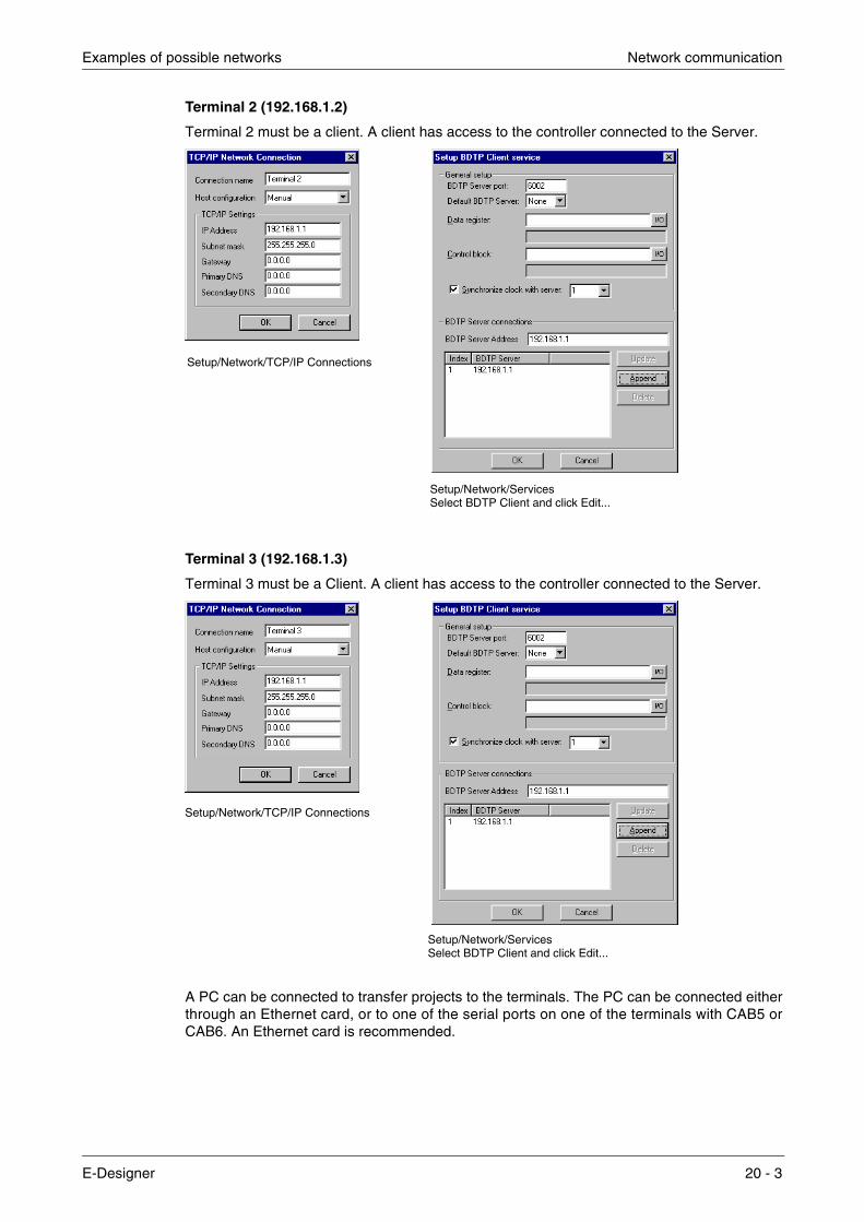
Examples of possible networks Network communication
Terminal 2 (192.168.1.2)
Terminal 2 must be a client. A client has access to the controller connected to the Server.
Terminal 3 (192.168.1.3)
Terminal 3 must be a Client. A client has access to the controller connected to the Server.
A PC can be connected to transfer projects to the terminals. The PC can be connected either through an Ethernet card, or to one of the serial ports on one of the terminals with CAB5 or CAB6. An Ethernet card is recommended.
Setup/Network/TCP/IP Connections
Setup/Network/ServicesSelect BDTP Client and click Edit...
Setup/Network/TCP/IP Connections
Setup/Network/ServicesSelect BDTP Client and click Edit...
E-Designer 20 - 3
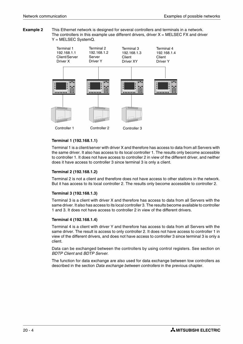
Network communication Examples of possible networks
Example 2 This Ethernet network is designed for several controllers and terminals in a network. The controllers in this example use different drivers, driver X = MELSEC FX and driver Y = MELSEC SystemQ.
Terminal 1 (192.168.1.1)
Terminal 1 is a client/server with driver X and therefore has access to data from all Servers with the same driver. It also has access to its local controller 1. The results only become accessible to controller 1. It does not have access to controller 2 in view of the different driver, and neither does it have access to controller 3 since terminal 3 is only a client.
Terminal 2 (192.168.1.2)
Terminal 2 is not a client and therefore does not have access to other stations in the network. But it has access to its local controller 2. The results only become accessible to controller 2.
Terminal 3 (192.168.1.3)
Terminal 3 is a client with driver X and therefore has access to data from all Servers with the same driver. It also has access to its local controller 3. The results become available to controller 1 and 3. It does not have access to controller 2 in view of the different drivers.
Terminal 4 (192.168.1.4)
Terminal 4 is a client with driver Y and therefore has access to data from all Servers with the same driver. The result is access to only controller 2. It does not have access to controller 1 in view of the different drivers, and does not have access to controller 3 since terminal 3 is only a client.
Data can be exchanged between the controllers by using control registers. See section on BDTP Client and BDTP Server.
The function for data exchange are also used for data exchange between tow controllers as described in the section Data exchange between controllers in the previous chapter.
Terminal 1192.168.1.1Client/Server
Terminal 2192.168.1.2Server
Terminal 3192.168.1.3Client
Controller 1 Controller 2 Controller 3
Terminal 4192.168.1.4Client
Driver X Driver Y Driver XY Driver Y
20 - 4

Examples of possible networks Network communication
Beispiel 3 This Ethernet network is a normal configuration where a PC is included. The PC has access to all terminals in the network to transfer projects. The PC can be connected either through an Ethernet card, or to one of the serial ports on one of the terminals with CAB5 or CAB6. An Ethernet card is recommended. The example assumes that the same drivers are used. To change the controller, refer to section BDTP Client and BDTP Server..
Terminal 1 (192.168.1.1)
Terminal 1 is a client/server and therefore has access to data from all Servers. It has access to its local controller 1. The result is access to controller 1 and 2.
Terminal 2 (192.168.1.2)
Terminal 2 is a client/server and therefore has access to data from all Servers. It has access to its local controller 2. The result is access to controller 1 and 2.
Terminal 3 (192.168.1.3)
Terminal 3 is a client and therefore has access to data from all Servers. It has access to its local controller 3. The result is access to controller 1, 2 and 3.
Terminal 4 (192.168.1.4)
Terminal 4 is a client and therefore has access to data from all Servers and therefore to con-trollers 1 and 2.
Data can be exchanged between the controllers by using control registers. See section on BDTP Client and BDTP Server.
The function for data exchange are also used for data exchange between tow controllers as described in the section Data exchange between controllers in the previous chapter.
NOTE ❙ When a project is transferred to a terminal this station will stop immediately. If the terminal is a Server, all Clients who request data from this Server will receive an error message.
Terminal 1192.168.1.1Client/Server
Terminal 2192.168.1.2Client/Server
Terminal 3192.168.1.3Client
Controller 1 Controller 2 Controller 3
Terminal 4192.168.1.4Client
PC192.168.1.X
E-Designer 20 - 5
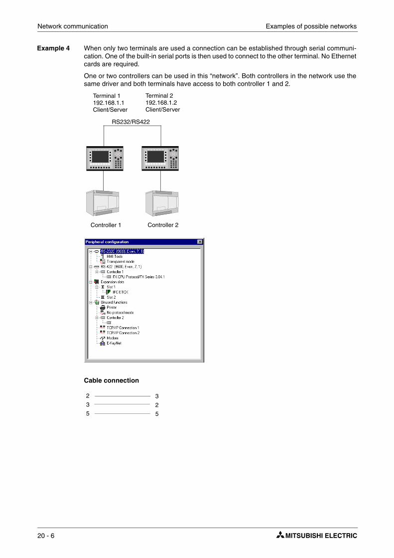
Network communication Examples of possible networks
Example 4 When only two terminals are used a connection can be established through serial communi-cation. One of the built-in serial ports is then used to connect to the other terminal. No Ethernet cards are required.
One or two controllers can be used in this “network”. Both controllers in the network use the same driver and both terminals have access to both controller 1 and 2.
Cable connection
Terminal 1192.168.1.1Client/Server
Terminal 2192.168.1.2Client/Server
Controller 1 Controller 2
RS232/RS422
2
3
5
3
2
5
20 - 6

Examples of possible networks Network communication
Terminal 1 (192.168.1.1)
Terminal 1 is a client/server and therefore has access to data from the other Server. It also has access to its local controller 1. The terminal is also a server for terminal 2. The result is access to controller 1 and 2.
Example If "1 > D0" is set in an analog object, D0 from controller 2 is read via BDTP.
Peripheral coniguration/TCP/IP Connection//Select
Setup/Network/Services/BDTP client bzw. Server/Select
E-Designer 20 - 7

Network communication Examples of possible networks
Terminal 2 (192.168.1.2)
Terminal 2 is a client/server and therefore has access to data from the other Server. It also has access to its local controller 2. The terminal is also a server for terminal 1. The result is access to controller 1 and 2.
Examle If "1 > D0" is set in an analog object, D0 from controller 2 is read via BDTP.
Peripheral coniguration/TCP/IP Connection//Select
Setup/Network/Services/BDTP client bzw. Server/Select
20 - 8
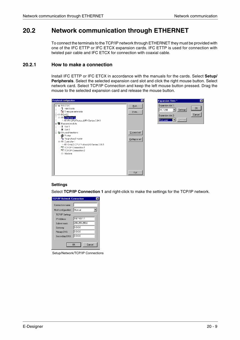
Network communication through ETHERNET Network communication
20.2 Network communication through ETHERNET
To connect the terminals to the TCP/IP network through ETHERNET they must be provided with one of the IFC ETTP or IFC ETCX expansion cards. IFC ETTP is used for connection with twisted pair cable and IFC ETCX for connection with coaxial cable.
20.2.1 How to make a connection
Install IFC ETTP or IFC ETCX in accordance with the manuals for the cards. Select Setup/Peripherals. Select the selected expansion card slot and click the right mouse button. Select network card. Select TCP/IP Connection and keep the left mouse button pressed. Drag the mouse to the selected expansion card and release the mouse button.
Settings
Select TCP/IP Connection 1 and right-click to make the settings for the TCP/IP network.
Setup/Network/TCP/IP Connections
E-Designer 20 - 9

Network communication Network communication through ETHERNET
Connection name
Enter an optional name for the connection. The parameter is not mandatory.
Host configuration
Select Manual to use the TCP/IP settins made in the dialog box. Select the other alternatives when a server provides the terminal with one or several of the TCP/IP parameters.
IP Address and Subnet mask
State the node’s network identity. Connection in a network is made according to Ethernet stand-ards. For a local network between the terminal, using the addresses192.168.0.0 – 192.168.254.254 is recommended.
Gateway
Specify the network device in the local network that can identify other networks on the Internet.
Primary DNS and Secondary DNS
State the servers containing information on a part of the DNS database.
Click OK after all settings have been made.
20.2.2 Ethernet connections
The section below shows three examples of Ethernet connections.
Connection between two terminals with twisted pair cable (TP)
The maximum length between the terminals is 100m. The cable is a CAT5 (crosscoupled) pair twisted cable,equipped with RJ45 connectors.
NOTE ❙ If the communication does not work properly and the LED marked Link on IFC ETTP does not light up, then connections 3 and 6 are probably switched.
Node 1 Node 2
1
2
3
6
3
6
1
2
20 - 10
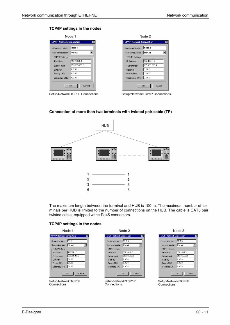
Network communication through ETHERNET Network communication
TCP/IP settings in the nodes
Connection of more than two terminals with twisted pair cable (TP)
The maximum length between the terminal and HUB is 100 m. The maximum number of ter-minals per HUB is limited to the number of connections on the HUB. The cable is CAT5 pair twisted cable, equipped withe RJ45 connectors.
TCP/IP settings in the nodes
Node 1 Node 2
Setup/Network/TCP/IP Connections Setup/Network/TCP/IP Connections
HUB
1
2
3
6
1
2
3
6
Node 1 Node 2
Setup/Network/TCP/IP Setup/Network/TCP/IP
Node 3
Setup/Network/TCP/IP Connections Connections Connections
E-Designer 20 - 11

Network communication Network communication through ETHERNET
Connection with coaxial cablel
The coaxial cable RG58 is used in the network. There must be bus endings of 50 Ohm. Several coaxial cables can be connected together with repeaters to obtain a longer network. The net-work will then consist of different segments.
The maximum length of a segment is 185 m, with a maximum number of 30 units in each seg-ment. Four repeaters can be serial connected, which means that five segments may be serial connected. Only three of the segments can have units connected. This means that there must be at least two empty segments in the network. The RG58 network cable must be grounded in one side.
HUB Repeater
Repeater Repeater
Segment 1 Segment 2
20 - 12

Serial network communication Network communication
20.3 Serial network communication
How to make a connection
Select Setup/Peripherals. Drag the TCP/IP Connection 1 icon from Unused functions to RS-232C or RS-422. The blinking arrows indicate where it is possible to drop it. TCP/IP Connection 1 must be used before TCP/IP Connection 2 can be used.
NOTE ❙ The parity setting on the port connected to the TCP/IP connection must be NONE.
Setup
Select TCP/IP Connection 1 and right-click to make the settings for the TCP/IP network.
Connection name
Enter an optional name for the connection. The parameter is not mandatory.
Serial protocol
The protocol PPP is used for serial communication.
User name
Indicate the user name used when logging in.
Setup/PeripheralsSelect TCP/IP Connection placed on serial port and click Edit...
E-Designer 20 - 13
Network communication Serial network communication
Password
Indicate the password used when logging in.
Connect signal
Digital signal which establishes the connection when it is set to one and disconnects when it is reset.
Connected reg
Analog register, which can have the following status.
0 Disconnected (PPP Client) 1 Waiting for a connection (PPP Server) 2 Connected as a PPP Client 3 Connected as a PPP Server 7 Connection error
Use logon script
This function is used to automate a serial logon. The script will vary depending on which server and modem you connect to. The terminal supports the following commands.
● WAIT: Text, x Waits for the text Text in x seconds. x does not need to be given.
● SEND: Text Sends the text Text
● 3. LABEL: Label Label becomes a reference point in the script.
● 4. ONERR: Label Jumps to Label when an error occurs in previous command.
● 5. MESSAGE: Shows a Message box with the message Message.
● 6. END: Ends the script.
● 7. SLEEP: x Sleeps for x seconds.
● 8. COUNTER: y Counts up a counter each time the script passes “COUNTER:” an error is generated if the figure is reached, which “ONERR:” takes care of.
Variables:
%USERNAME Compare with the names in Accounts.
%PASSWORDCompare with the passwords in Accounts.
Example 1: WAIT: login:, 10 SEND: JOHN WAIT: password:,10 SEND: HELLO
20 - 14

Serial network communication Network communication
Example 2: The following script sends the text “CLIENT”. If the transmission fails a message box with the text “Send Failed” is shown. If the transmission is successful we wait for the text “CLIENT-SERVER”. If this text does not appear within10 seconds, a message box with the text “Receive Failed” is displayed.
SEND: CLIENT ONERR: Send Failure WAIT: CLIENTSERVER,10 ONERR: Receive Failure END: LABEL: Send Failure MESSAGE: Send Failure END: LABEL: Receive Failure MESSAGE: Receive Failed END:
Example 3: The following script sends the text “login”. and then waits for the receiver to send a user name. The name is checked so that it matches one of the user names in Accounts. The script then con-tinues by sending “password:” and then waits for the receiver to send a password. The password is compared with the password in Accounts for the user name sent.
Normally no script is needed. If you connect to a Windows NT server the script will be as follows.
SEND: login: WAIT: %USERNAME SEND: password: WAIT:%PASSWORD
PPP – Login verification method
Select method to validate the user identity. Does not normally need to be changed. This parameter is only used for PPP connection.
Act as
For PPP you select if the terminal is to act as a PPP Client and/or PPP Server, i.e. if the terminal is to call up or be called.
Connect at boot
For PPP connection the terminal can automatically connect to another terminal or PC on start-up.
Advanced
By selecting Advanced it is possible to define additional parameters.
Use VJ compression of IP headers
Compression of IP headers. Does not normally need to be changed. This parameter is only used for PPP connection.
Request/provide remote address
The request/providing of the remote node’s IP address. Should be 0.0.0.0 if you want the IP address provided from the remote node. This parameter is only used for PPP connection.
Use remote address as gateway
Should be checked if you want to let the remote node’s IP address be the gateway, i.e. the connection port to another network. The default setting is OFF. This parameter is only used for PPP connection.
E-Designer 20 - 15

Network communication Serial network communication
NOTE ❙ If the parameter Use remote address as gateway is not checked and you use a sub network, the communication with the network will not function. This also means that e-mail can be sent from the terminal, but that you cannot login on the terminal from outside, e.g. with a FPT client or web browser.
Request/provide local address
The request/providing of the remote node’s IP address. Should be 0,0.0.0 if you want the IP address provided from the remote node. This parameter is only used for PPP connection.
NOTE ❙ If the Request/provide local address addresses are changed when the terminal is the server, or both server and client, the new addresses will be saved. If the terminal is the client the addresses are set to 0.0.0.0. If the terminal is changed to be the server, or both server and client, the saved addresses will be used..
Modem
The parameters under Modem are indicated if the connection is made through a modem. A special cable is also needed, as shown in the figure below.
Enable modem
Check the box if you are using a modem.
Disconnect if idle (min)
Disconnects if the connection has been idle for the given number of minutes. 0 means that the connection is never disconnected.
Telephone number
Indicate the telephone number to be called.
Modem setup string
String which initiates the modem. For further information, refer to the documentation for the modem.
Remote192.168.1.2Local192.168.1.1
Remote0.0.0.0Local0.0.0.0
Node 1 Node 2
2
3
5
2
3
7
7
884
9-pin female 25-pin male
Setup/PeripheralsSelect TCP/IP Connection placed on serial
Now click the button Modem...
620shldshld
port and click Edit.
connectorconnector
20 - 16

Serial network communication Network communication
TCP/IP
Parameters for TCP/IP connection.
Host configuration
Select Manual to use the TCP/IP settings made in the dialog box. Select the other alternatives when a server provides the terminal with one or several of the TCP/IP parameters.
IP Address and Subnet mask
State the node’s network identity. Connection in a network is made according to Ethernet stand-ards. For a local network between the terminals, using the addresses 192.168.0.0 – 192.168.254.254 is recommended.
Gateway
Specify the network device in the local network that can identify other networks on the Internet.
Primary DNS and Secondary DNS
Indicate the server(s) containing information on a part of the DNS database.
Setup/Network/TCP/IP connection placed on serial portClick on the button TCP/IP.
E-Designer 20 - 17

Network communication Serial network communication
20.3.1 Serial connection
PPP connection between two terminals.
PPP connection between a terminal and a PC.
PPP Client PPP Server
Settings under TCP/IP, IP Address,
2
3
5
3
2
5
Setup/PeripheralsSelect TCP/IP Connection placed on serial port and click Edit...
Setup/PeripheralsSelect TCP/IP Connection placed on serial port and click Edit...
Subnet mask and Gateway, are of no importancein this case. PPP will change parameters.
PPP ServerPC with Generic Null modem
CAB5
(Remodem) installed
20 - 18

Serial network communication Network communication
Settings in the terminal
Settings in the PC
The following images illustrate how you set the different dialogs to create a serial PPP connec-tion between a PC with Windows XP and a terminal. In this document we assume that the user has installed a Generic Null modem and defined a port for Serial cable for remote connection between two PCs.
For Windows XP select the function New connection according to the following search path:
Start\Program\Accessories\Comonication\Create a new connection and follow the informations on the screen.
Settings under TCP/IP, IP Address,
The check box Use logon script in
Setup/PeripheralsSelect TCP/IP Connection placed on serial port, select Use logon script,and click Edit script...
Subnet mask and Gateway, are of no importancein this case. PPP will change the parameters.Note that if PAP is selected as Login verification method, the User name and Passwordmust be given.
previous image must be selected.
E-Designer 20 - 19

Network communication Serial network communication
Select the correct type of Network.
Fill in the telephone number und the corresponding country. Select, which users should be allowed using the connection.
Select a name for your new connection.
20 - 20
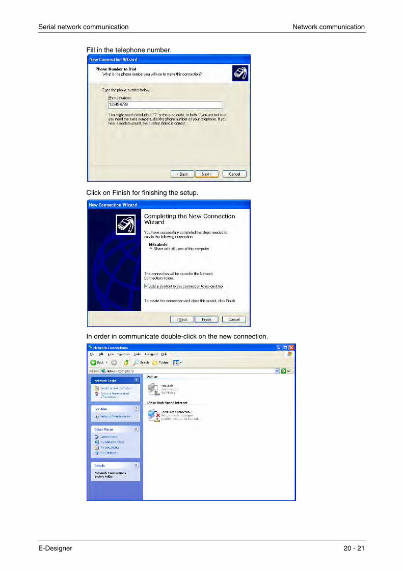
Serial network communication Network communication
Fill in the telephone number.
Click on Finish for finishing the setup.
In order in communicate double-click on the new connection.
E-Designer 20 - 21

Network communication Serial network communication
In the next window you are requested to confirm the dialing. Click on Dial.
NOTE ❙ The images are only applicable for Windows XP. For a description of serial connection bet-ween terminal and PC with other Windows operative systems, refer to the start up document on our home-page, www.e-terminals.com.
20 - 22

Network services Network communication
20.4 Network services
Under Setup/Network/Services you select the services the terminal is to provide in the network. Mark the relevant function and click on Edit...
20.4.1 Application transfer server
Transfer of project through TCP/IP. Click Edit... and enter the number of the port to be given to enable the transfer. Does not normally need to be changed.
20.4.2 BDTP (Beijer Data Transport Protocol)
BDTP (Beijer Data Transport Protocol) is a protocol which uses client/server communication. A client asks for information and a server provides clients with information. The BDTP server listens to the I/O request from the BDTP client. The terminal can be client, server, or both. The client can collect data from a maximum of 16 servers. The server IP addresses are given in the BDTP client. Each server can provide 20 clients with information.
Network communication through BDTP is used to connect two or more terminals to one or two controllers or several operator terminals to two or more controllers, with retention of perform-ance. One example is production lines with one terminal at each work station.
If the BDTP server fails, the client will continue to work with the system to which it is physically connected. The client will not restart when it tries to connect to the server. When the server becomes active, BDTP communication will continue as previously.
E-Designer 20 - 23

Network communication Network services
The figure below shows an example of a network.
BDTP Server
Controller
BDTP Client BDTP Client BDTP Client
Controller Controller
BDTP Client
X0
192.168.1.x192.168.1.x
192.168.1.x
192.168.1.x
192.168.1.x
12345
192.168.1.x...
.
.
BDTP Server1>X0
1>X0
x=1–254
20 - 24
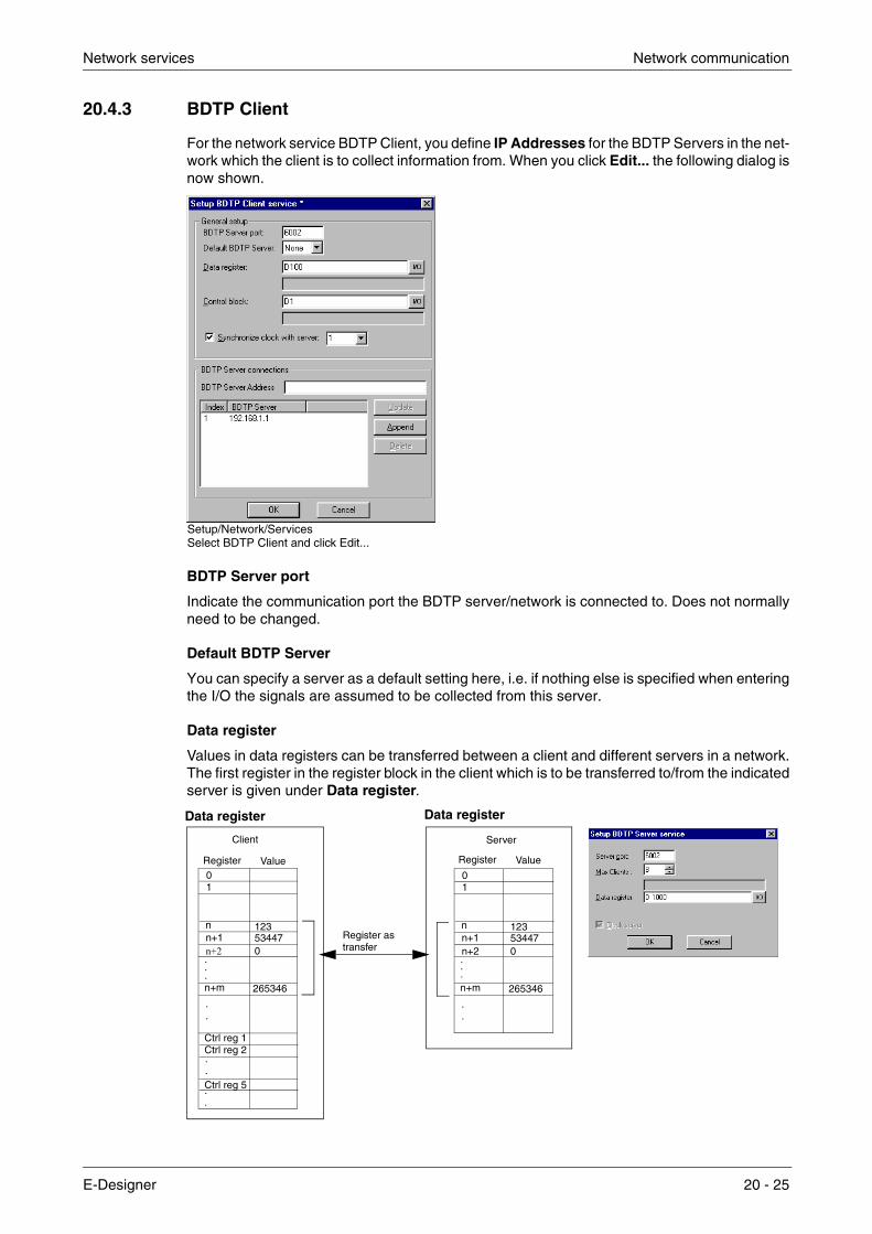
Network services Network communication
20.4.3 BDTP Client
For the network service BDTP Client, you define IP Addresses for the BDTP Servers in the net-work which the client is to collect information from. When you click Edit... the following dialog is now shown.
BDTP Server port
Indicate the communication port the BDTP server/network is connected to. Does not normally need to be changed.
Default BDTP Server
You can specify a server as a default setting here, i.e. if nothing else is specified when entering the I/O the signals are assumed to be collected from this server.
Data register
Values in data registers can be transferred between a client and different servers in a network. The first register in the register block in the client which is to be transferred to/from the indicated server is given under Data register.
Setup/Network/ServicesSelect BDTP Client and click Edit...
nn+1n+2
.
Register Value
123
.
.
n+m
534470
265346
Ctrl reg 1Ctrl reg 2
Ctrl reg 5
01
.
.
.
.
.
.
nn+1n+2
.
123
.
.
n+m
534470
265346
01
.
.
Client Server
Register Value
Register as
Data register Data register
transfer
E-Designer 20 - 25

Network communication Network services
Control block
Under Control block you indicate the first register in the control block in the client, which takes up a total of five registers as follows.
The transfer must be handled as follows:
� The handshake register must be 0. If not, reset the command register to 0.
� Enter the command in the command register.
� Wait for the ready signal or error code in the handshake register.
� Set the command register 0. The terminal will now set the handshake register to 0.
Synchronize clock with server
Indicate if the client clock is to be synchronized with a selected server (terminal). The server is selected by giving the number of the server in the entry field. If the clock in the client is changed locally the change will also be transferred to the selected server.
BDTP Server Address
Under BDTP Server Address you indicate the IP addresses to the servers from which the client can retrieve data. The addresses will be indexed in the order they are entered.
When objects are programmed in the project you must indicate from which server the address is to be taken. In the address field in the object dialogs you specify the following:
server index>device
If, for example, 2>D15 is indicated in the address field the value for the object will be collected from register D15 in the server with index 2.
It is possible to change the server index in a client program with the function BDTP Station change. See section Change BDTP station.
NOTE ❙ If there is no controller connected to the BDTP Client (the terminal) the units Controller 1 and Controller 2 must be moved from RS-232C/RS-422/RS-485 to Unused functions in the dialog Peripheral configuration, Setup/Peripherals.
Register Content Description
Ctrl reg 1 Command
Command register set in the client. Available commands: 0:No command. 1:Transfer values in register from client to server indicated in control
register 3. 2:Transfer values in register from server indicated in control
register 3 to client.
Ctrl reg 2 Handshake
Handshake register set by client. 0: Ready for new command. 1: OK 2: Transmission error.
Ctrl reg 3 Server index The number of the server in the network the transfer is to be made with.
Ctrl reg 4 Index registerThe value in the index register is added to the address of the register indicated under Data register. If zero is given, the register block will start with the address given under Data register.
Ctrl reg 5 Number of registers
The number of registers, the values of which are to be transferred to/from the given server.
20 - 26

Network services Network communication
20.4.4 BDTP Server
Handles requests from clients, i.e. provides clients (terminals) with information on requests from the client (terminal). Click Edit... and indicate port. Does not normally need to be changed.
Server port
Communication port for the BDTP server. Does not normally need to be changed.
Max Clients
The maximum number of BDTP clients (terminals) in the network.
Data register
Values in data registers can be transferred between a server and different clients in a network. The first register in the register block in the server which is to be transferred to/from the indicated client is given under Data register. The type of register does not have to be the same in client and server. For more information on transferring data, see section BDTP Client.
NOTE ❙ It is only possible to control the transfer of data from clients.
Clock server
Indicate whether the server clock is to be the clock other clients in the network synchronize with. See also section BDTP Client. Only applicable for older terminal versions.
Setup/Network/ServicesSelect BDTP Server and click Edit...
nn+1n+2
.
Register Value
123
.
.
n+m
534470
265346
Ctrl reg 0Ctrl reg 1
Ctrl reg 4
01
.
.
.
.
.
.
nn+1n+2
.
123
.
.
n+m
534470
265346
01
.
.
Client Server
Register Ctrl reg al
Register astransfer
E-Designer 20 - 27

Network communication Network services
20.4.5 FTP Server
This function makes it possible to collect or submit files to/from the terminal from a PC. The FTP server in the terminal allows transfers in passive mode (PASV). Passive mode should be used if the terminal is not connected Point-to-Point. You will not always know in advance what is used between the client and server, e.g. router-baser fire walls or gateways. By using passive mode you avoid further errors. Web browsers always use this mode. It is also possible to use passive mode during point-to-point connection. National characters in file names are not supported. Ter-minals do not use dates on files. For more information on the FTP server in the terminal, refer to chapter Network functions in the terminal.
Select FTP Server under Setup/Network/Service and click on Edit... to enter the settings for the function.
Control Port number
The default value is 21 and should not be changed.
Data Port number
The default value is 20 and should not be changed.
Request login
You indicate here whether the user must login to access the FTP server (the terminal). Users are defined under Setup/Network/Accounts ,see section Network accounts. If you select that users do not need to login, all users will have full access to the FTP server.
Pre Login Text
Text shown before request for the user to login. E.g. “The terminal requires login, specify login information”.
Post Login Text
Text shown when user has logged in. E.g. “You are now logged in”.
Connection Timeout (min)
The time the FTP connection is allowed to be inactive before the FTP server (the terminal) breaks the connection. The default value is 10 minutes.
Setup/Network/ServicesSelect FTP Server and click Edit...
20 - 28

Network services Network communication
20.4.6 SMTP Client
This function allows e-mail to be sent from the terminal. An e-mail server is need to use the func-tion SMTP client, where messages are sent by the terminal. The recipient then collects the mes-sage. You can use your Internet provider’s e-mail server or a local e-mail server. Trend and recipe files can also be attached with a message. The attached files can be read with HMI Tools. A maximum of 20 messages can be sent at the same time. Select SMTP client under Setup/Network/Service and click on Edit... The following settings are entered here.
Server port
Connection port 25. Does not normally need to be changed.
Mail Server
The IP address to the e-mail server or the alias name (DNS server) for the SMTP e-mail server. If you specify an alias name the IP address to the DNS server must be given under Setup/Net-work/TCP/IP Connections.
My Domain Name
The domain name (e-mail address) of the terminal, or some other domain name, used to login the SMTP server. E.g. the domain name in [email protected] is master.com.
My Mail Address
Enter your e-mail address. The name is shown as sender for the recipient. It should preferably be a genuine address, which the mail server can return error messages to.
Send via Connection
Indicate which TCP/IP connection should be used to send. Note that TCP/IP connection 1 must be used before TCP/IP connection 2 can be used.
Predefined Recipients
A pre-defined list of a maximum of 16 recipients, e-mail addresses which the terminal is to send e-mail to. A recipient address can contain a maximum of 60 characters.
Setup/Network/ServicesSelect SMTP Server and click Edit...
E-Designer 20 - 29

Network communication Network services
Alarm through e-mail
In the same way as alarms can be printed on a printer, they can also be sent as e-mail. The com-plete alarm list can be sent by sending block 990 (see section Report through e-mail). Each alarm can be connected to one or more of the e-mail addresses as in the configuration of the SMTP client. Under Setup/Alarm Settings you make a general setting for which status of alarms are to be sent as e-mail. See chapter Alarm handling.
Info block
If an information block is indicated, and it is a text block, it will be included in the message. For further information, see chapter Alarm handling.
Mail to address:
You indicate here who is to receive the message. Select up to 8 recipients from the predefined list in the dialog Setup SMTP Client service.
Report through e-mail
In the same way as text blocks can be printed on a printer, they can also be sent as e-mail. Alarm block, block no. 990, can also be sent as e-mail.
NOTE ❙ Only text blocks can be sent. Only the alarm block 990 can be sent as e-mail from the system blocks. Trend and recipe files can be sent as attached files.There are limitations when Uni-code is used. For more information, see the chapter Unicode.
Functions/Alarms
20 - 30

Network services Network communication
Block name
If a name is given for the text block it will be sent as a subject/message.
Send mail signal:
The message is sent when the given digital signal is set to one.
Mail completion signal:
A digital signal activated by the terminal when the message has been sent. The signal is nor-mally set to one by the terminal. If the box Reset is selected the signal is reset when the message has been sent.
Mail to address:
The address of the e-mail recipient is given here. Select up to 8 recipients from the list shown when you click the … button. The list of e-mail addresses is defined in the dialog Setup SMTP Client service under Setup/Network/Services.
Attach file:
The name of a trend or recipe file to be attached with the message is given here. If there is a trend file or a recipe file with the same name, the trend file will be sent. The text file should not contain national characters such as Å, Ä and Ö.
E-mail through system block
By making a block jump to the system block Mail, 993, you can write and send messages during RUN mode.
Block-Manager/Block header (for a text block)
E-Designer 20 - 31

Network communication Network services
E700
E615
Send E-mail to
Enter the recipient here. You can write in the address or select it from the global list shown when you click on the button LIST on terminals with keyboards, and on the MAIL button on terminals with touch screens.
Subject
You enter the subject message here. Max 50 characters. The actual text in the message can be max 10 lines with 50 characters.
20 - 32

Network services Network communication
20.4.7 Terminal controller
Used for RUN/TRANSFER switching through TCP/IP. Click Edit and enter the number of the port to be given to enable the transfer. The port number does not normally need to be changed. Check the box Request authentication if the user name and password must be given before the transfer. Users are defined under Setup/Network/Accounts.
20.4.8 Transparent mode
Used for communication in Transparent/Passthrough mode (see also the chapters Communi-cation and Network functions) in terminal networks through Ethernet. Click Edit Transparent mode. The unit must then be connected to a TCP/IP Connection in Setup/Peripherals.
IP Settings
Port number 6004. Does not normally need to be changed. Select required protocol, UDP or TCP.
Controller
Select if Transparent/Passthrough mode is to be connected to Controller 1 or Controller 2.
Mode
Select communication mode Transparent or Passthrough. A time in seconds is specified in the field Timeout, after which the terminal will return to RUN mode from the Passthrough status if no Passthrough communication has occurred.
NOTE ❙ If the programming tool for the controller does not support project transfer through TCP/IP a PC program to convert the COM port to TCP/IP must be used in the PC to communicate with the controller in Transparent mode through the TCP/IP network.
E-Designer 20 - 33

Network communication Network services
20.4.9 WWW Server
This a function to configure the www server in the terminal. A web server is a program, which by using the client/server model and Hypertext Transfer Protocol (HTTP) handles files building home-pages for Internet users (who have computers which have HTTP clients). See also chap-ter Network functions in the terminal.
Port number
The default setting is 80 and does not normally need to changed.
Account name
Selecting an account name protects the HTML pages in the terminal with a password. The accounts are defined under Setup/Network/Accounts.
Account name
The account name you entered in the previous dialog is shown here.
Password
Enter a password. All HTML pages are protected with this Account name/Password.
The following are added to the HTML page header to protect a separate page with another Account name/Password.
<HTML> <HEAD> <META name=”superuser” content=”12345”>* </HEAD>
The rest of the HTML code is placed here.
</HTML>
* “superuser” is the account name and “12345” is the password.
NOTE ❙ The above must be used in the header. The parameters Name and Content must correspond to an account name and password.
Setup/Network/Accounts
20 - 34
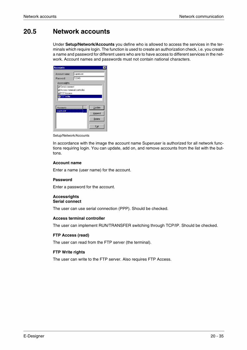
Network accounts Network communication
20.5 Network accounts
Under Setup/Network/Accounts you define who is allowed to access the services in the ter-minals which require login. The function is used to create an authorization check, i.e. you create a name and password for different users who are to have access to different services in the net-work. Account names and passwords must not contain national characters.
In accordance with the image the account name Superuser is authorized for all network func-tions requiring login. You can update, add on, and remove accounts from the list with the but-tons.
Account name
Enter a name (user name) for the account.
Password
Enter a password for the account.
Accessrights Serial connect
The user can use serial connection (PPP). Should be checked.
Access terminal controller
The user can implement RUN/TRANSFER switching through TCP/IP. Should be checked.
FTP Access (read)
The user can read from the FTP server (the terminal).
FTP Write rights
The user can write to the FTP server. Also requires FTP Access.
Setup/Network/Accounts
E-Designer 20 - 35

Network communication Network accounts
20 - 36

FTP server Network functions in the terminal
21 Network functions in the terminal
This chapter describes how the functions FTP Server, SMTP Client, terminal applet and WWW server function in the terminal. For respective function settings, refer to chapter Network communication.
21.1 FTP server
FTP (File Transport Protocol), a standard Internet protocol, is the easiest way of exchanging files between computers on the Internet. FTP is an application protocol which uses the Internet’s TCP/IP protocols. FTP is normally used to transfer home-pages from their creators to the server where everybody on the Internet can access them. It is also suitable for downloading programs and other files from another server (terminal) to your own computer.
When the terminal functions as an FTP server it is possible to upload/download files to/from the terminal. To upload/download files it is necessary to have a FTP client program in the PC, e.g. HMI Tools, Internet Explorer, Windows Commander or some other standard FTP program.
Some libraries show files with a length of 0. This means that the file contains dynamic data, i.e. the size of the file changes. This also means that even if the length is 0 the file may not be empty. The terminal does not use the date on the files, which means that the time shown is not relevant. The terminal can save the content in all files, which can be reached through FTP with different types of delimiter characters (separators). The content in the files can be separated either with → [TAB] or the characters ; or :. The settings for FTP delimiter characters are made under Setup/Terminal Options in the programming tool. The file name must not contain national characters. The terminal’s FTP server can handle a maximum of 3 connected clients at the same time.
NOTE ❙ Files in the different directories use up the project memory. Information on the available project memory is included in the file info.txt in the root directory.
E-Designer 21 - 1

Network functions in the terminal FTP server
21.1.1 Root library
The root directory (current terminal name) contains the following directories, ALARMS, HTML, RECIPES and TRENDS. For E900 and E910 there is also an IMAGES directory, see section The IMAGES directory. Only the directories the user (account) has access to are shown. There is also info.txt here containing information on the terminal.
The file info.txt
The file info.txt contains information on the terminal in accordance with the following example:
E700 Boot version: 4.07 Firmware version:V6.00 Build number: 320 Driver1: QnA/Q CPU Protocol/Q Series 3.06.1 Driver2: FX CPU Protocol/FX Series 3.04.1 Dynamic memory: 304,237 bytes available Project memory: 184,700 bytes available IP address:192.168.98.1
Nothing can be deleted from the root directory, even if you have write access. If the directories HTML, RECIPE or IMAGES (E900/E910) are deleted, the contents in respective directories will be deleted but the directories will remain.
21.1.2 The ALARMS directory
The directory is only shown if there is an alarm defined in the terminal and the terminal is in RUN mode. The alarm groups are shown as SKV files with 0 length. This does not need to mean that there are no alarms. The files can only be read. To read a file it must be opened with the attribute READ. READWRITE will cause an error.
File format
Each alarm is stored on a line ending with [carriage return][linefeed].
Syntax (E700 and larger terminals). The selected delimiter character is the; semicolon character here.
status;activedate;activetime;inactivedate;inactivetime;ackdate;acktime;alarmtext
All fields are always there. If the alarm is not acknowledged, the fields for date and time will be empty.
Syntax (other terminals)
status;activedate;activetime;alarmtext
The file ends with END [carriage return][line feed]
21.1.3 The HTML directory
The data files handled by the web server are stored here. You can create subdirectories. The start file (the HTML page shown as the first home-page in the web browser) must always be called index.htm.
File format
The file format depends on the type of file. A standardized file format such as HTML etc. is used here.
21 - 2

FTP server Network functions in the terminal
21.1.4 The RECIPE directory
The different recipes in recipe directories are shown as SKV files with 0 length, which does not mean that the recipe is empty. It is possible to both read and write files in this directory.
File format
Each recipe value is stored on a line ending with [carriage return][linefeed].
Syntax, the selected delimiter character is the ; semicolon character here.
device;value;datatype;length
The file ends with
END [carriage return][linefeed]
If the data type is array (AR), one value will be shown on each line. The first line will be shown as above. The following lines will only contain;value
Data types for analog signals
Type Explanation
empty Signed 16-bit
+ Unsigned 16-bit
L Signed 32-bit
L+ Unsigned 32-bit
RB BCD format float
RF Float with exponent
SB BCD format 16-bit
LB BCD format 32-bit
SH Hexadecimal 16-bit
LH Hexadecimal 32-bit
RD Float
AR Array of signed 16-bit
ST String of characters
BI Bit 0 or 1
E-Designer 21 - 3

Network functions in the terminal FTP server
21.1.5 The TRENDS directory
The directory is only available if there are trends defined in the terminal and the terminal is in RUN mode. The trend objects are shown as SKV files with 0 length. It is only possible to read files. To read a file it must be opened with the attribute READ. READWRITE will cause an error. Curve 1 must be used for a trend to be valid.
File format
Each sampling is stored on a line ending with [carriage return][linefeed].
Syntax, the selected delimiter character is the ; semicolon character here.
date;time;value1;value2;value3;value4;value5;value6;OFF
The file ends with
END [carriage return][linefeed]
Only the number of curves in the trend are transferred, i.e. no empty fields.
OFF is included in the sampling in the following cases, and indicates a pause in the sampling.
● When the terminal enters run mode, a copy of the last stored sampling is added. The copy is marked with OFF. As soon as valid values reach the terminal, new values are stored without OFF marking.
● When the Trend-enable signal is used, should the signal go low the sample is marked with OFF. When the signal goes high a new value is stored without OFF marking.
● When you transfer stored trend values through FTP or HMITools, a sample will be stored with OFF marking. When the transfer is ready a new sample is stored without OFF marking.
21.1.6 The IMAGES directory
Only applicable for E900 and E910
In terminals E900 and E910 there are also IMAGES directories. Images in the format BMP can be saved in the directory. The bitmap images are presented in Static symbol objects in the ter-minal in RUN mode. It is only possible to write, replace and delete files in this library. However, it is not possible to create sub-directories. If you check the box Use dynamic bitmaps for a static symbol object, the terminal will collect the specified bitmap file (name.bmp) from the directory IMAGES in the terminal’s file system. The bitmap image is presented on the terminal’s display in RUN mode. The image to be presented must be transferred to the directory through FTP. It will then be possible through FTP to add, replace, or remove dynamic bitmap images on the ter-minal’s display by writing over, entering or deleting BMP files in the directory IMAGES. The image for a dynamic bitmap image object is only shown in the terminal in RUN mode. The bitmap images in the directory are not shown (available) in the programming tool.
NOTES ❙ Define the same X and Y size for the BMP image in the directory as for the symbol object defined in the programming tool.
❙ It is not possible to read (collect) files from the IMAGES directory.
❙ When transferring a BMP file to the IMAGES directory, the transfer will stop for a short moment when the terminal converts the standard BMP format to the terminal’s own BMP format.
21 - 4

SMTP client Network functions in the terminal
21.2 SMTP client
SMTP (Simple Mail Transfer Protocol) is a TCP/IP protocol used to send and receive e-mail. Since SMTP has limited functions to store received messages it is normally used together with one or two other protocols, POP3 or IMAP. These protocols allow the user to save messages in a server mailbox from where they can be collected later. This means that SMTP is normally used to send e-mail, and POP3 or IMAP to receive messages stored in the local server. The ter-minals can function as a SMTP client, i.e. send e-mail. To use the SMTP client function it is nec-essary to have an e-mail server. You can use your Internet provider’s e-mail server. It is also possible to use a local e-mail server. See also the section Network services in chapter Network communication.
E-mail server
SMTP Client
Terminal
PC
POP3 Cliente.g. MicrosoftOutlook Express
POP3SMTP
E-Designer 21 - 5

Network functions in the terminal Terminal mirroring – the terminal applet
21.3 Terminal mirroring – the terminal applet
On the Internet, where the object-oriented language Java is used, an applet is a small program which can be downloaded and run in a web browser via a web page. Terminal applets can per-form interactive animations, direct calculations or other simple tasks without having to send a user request back to the server.
From a PC, it is possible to reflect the terminal in Microsoft Internet Explorer by the applet pre-senting an image of the terminal on the screen. The image is updated at regular intervals as requested. The terminal mirroring has the same function as the actual terminal. The terminal can be activated by clicking with the mouse on the buttons in the terminal image or with the key-board. On a terminal with a touch screen, you click directly on the screen. Text strips for the ter-minal are not shown in the applet.
The applet is compressed in a cab file. The first time the applet is used, it is downloaded and installed in the browser. This can either be done from the terminal’s file system or locally from the computer’s hard disk. The cab file shall not be decompressed manually; this is done in the browser.
For the applet to be able to be installed and run from the terminal, the cab file must be transferred to the terminal’s HTML directory via FTP. A web page (htm file) that contains html code for load-ing and running the applet (see the following example) is also transferred to the terminal’s HTML directory. Moreover, the web server must be activated in the terminal.
Connection to the web server in the terminal is accomplished by entering the terminals’ host name or IP address and the name of the web page in the web browser (for example, terminal1.domain.com/terminal1.htm or 192.168.98.75/terminal1.htm). When the web page has been downloaded, there should be a terminal symbol with the text “Terminal Interaction”. The Applet application starts when you click the symbol. At startup, the applet connects to the network service Terminal Controller (port number 6001 is preset). The port number can be configured in html code via an applet parameter. If login is defined for the function Terminal Controller, a login dialog box is displayed. User data that is entered is verified against the users defined under Setup/Network/Accounts.
If you choose to run locally, the cab file and the htm file can be placed together at an arbitrary location on the hard disk. The terminal’s host name (for example, terminal1.domain.com or 192.168.98.75, see applet parameter below) must then also be specified in html code. In this case, the cab file is loaded directly from the hard disk, and the web server is not used. In other respects, it is run in the same way as above, i.e. by loading the htm file.
The cab file is thus loaded the first time only or when the applet needs to be reinstalled in the browser.
21 - 6

Terminal mirroring – the terminal applet Network functions in the terminal
21.3.1 Signed applet
Because the applet is signed with a software certificate, it can be installed in the browser. The first time the certificate is used (i.e. the first time a signed applet is downloaded) a security warn-ing is displayed.
In this warning, you are informed that the applet has been signed with a certificate issued by Bei-jer Electronics AB. You must answer Yes to the security warning for the applet to be installed. You can also choose to always trust content signed with this certificate. If this is done, the cer-tificate is added to the browser and the security warning will not be displayed in the future.
In Internet Explorer under Tools/Internet Options/Temporary Internet Files/Settings/View Objects, you can view the applets installed in the browser. You can also view version informa-tion and when the applets were installed. Additionally, applets can be uninstalled here.
Example <HTML> <APPLET code=COM.beijerelectronics.hmi.terminalapplet.E700.TERMAPPL
width=117 height=101>
<PARAM NAME=useslibrary VALUE=”Terminal Applet E700”> <PARAM NAME=useslibrarycodebase VALUE=”e700appl.cab”> <PARAM NAME=useslibraryversion VALUE=”0,1,20,2”>
</APPLET> </HTML>
The applets appearance and behavior can be controlled with the following applet parameters in html code:
Parameter Description Default value
TermCtrlPort Specifies port number for network service Terminal Controller 6001
Background Color behind terminal image on web page in the format RRGGBB (hexadecimal 00 - FF)
B7F58D (light green)
Title Title in applet window Terminal view
HostNameInTitleSpecifies if the host name will be included in the title, for example “Terminal view - 192.168.98.1” or “Terminal view - Terminal1.domain.com”
YES
ScrUpdInterval Start value for update interval in seconds 10
Label Label in applet view Terminal Interaction
LabelFontSize Character size of label 12
LabelBoldStyle Specifies if label will be displayed in bold font NO
E-Designer 21 - 7
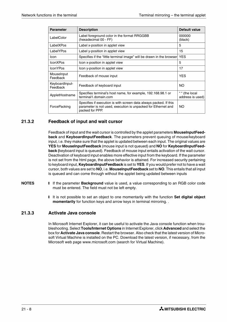
Network functions in the terminal Terminal mirroring – the terminal applet
21.3.2 Feedback of input and wait cursor
Feedback of input and the wait cursor is controlled by the applet parameters MouseInputFeed-back and KeyboardInputFeedback. The parameters prevent queuing of mouse/keyboard input, i.e. they make sure that the applet is updated between each input. The original values are YES for MouseInputFeedback (mouse input is not queued) and NO for KeyboardInputFeed-back (keyboard input is queued). Feedback of mouse input entails activation of the wait cursor. Deactivation of keyboard input enables more effective input from the keyboard. If the parameter is not set from the html page, the above behavior is attained. For increased security pertaining to keyboard input, KeyboardInputFeedback is set to YES. If you would prefer not to have a wait cursor, both values are set to NO, i.e. MouseInputFeedback set to NO. This entails that all input is queued and can come through without the applet being updated between inputs
NOTES ❙ If the parameter Background value is used, a value corresponding to an RGB color code must be entered. The field must not be left empty.
❙ It is not possible to set an object to one momentarily with the function Set digital object momentarily for function keys and arrow keys in terminal mirroring. .
21.3.3 Activate Java console
In Microsoft Internet Explorer, it can be useful to activate the Java console function when trou-bleshooting. Select Tools/Internet Options in Internet Explorer, click Advanced and select the box for Activate Java console. Restart the browser. Also check that the latest version of Micro-soft Virtual Machine is installed on the PC. Download the latest version, if necessary, from the Microsoft web page www.microsoft.com (search for Virtual Machine).
LabelColor Label foreground color in the format RRGGBB (hexadecimal 00 - FF)
000000 (black)
LabelXPos Label x-position in applet view 5
LabelYPos Label y-position in applet view 15
Icon Specifies if the “little terminal image” will be drawn in the browser YES
IconXPos Icon x-position in applet view 5
IconYPos Icon y-position in applet view 17
MouseInputFeedback Feedback of mouse input YES
KeyboardInput-Feedback Feedback of keyboard input NO
AppletHostname Specifies terminal’s host name, for example, 192.168.98.1 or terminal1.domain.com
“ “ (the local address is used)
ForcePackingSpecifies if execution is with screen data always packed. If this parameter is not used, execution is unpacked for Ethernet and packed for PPP.
NO
Parameter Description Default value
21 - 8
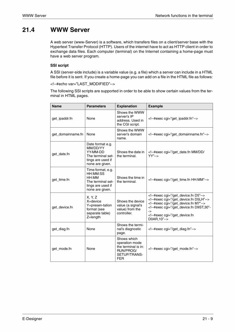
WWW Server Network functions in the terminal
21.4 WWW Server
A web server (www-Server) is a software, which transfers files on a client/server base with theHypertext Transfer Protocol (HTTP). Users of the internet have to act as HTTP client in order toexchange data files. Each computer (terminal) on the Internet containing a home-page musthave a web server program.
SSI script
A SSI (server-side include) is a variable value (e.g. a file) which a server can include in a HTMLfile before it is sent. If you create a home-page you can add on a file in the HTML file as follows:
<!--#echo var=”LAST_MODIFIED”-->
The following SSI scripts are supported in order to be able to show certain values from the ter-minal in HTML pages.
Name Parameters Explanation Example
get_ipaddr.fn None
Shows the WWW server’s IP address. Used in the CGI script.
<!--#exec cgi=”get_ipaddr.fn”-->
get_domainname.fn NoneShows the WWW server’s domain name.
<!--#exec cgi=”get_domainname.fn”-->
get_date.fn
Date format e.g. MM/DD/YYYY-MM-DDThe terminal set-tings are used if none are given.
Shows the date in the terminal.
<!--#exec cgi=”/get_date.fn MM/DD/YY”-->
get_time.fn
Time format, e.g. HH:MM:SSHH:MMThe terminal set-tings are used if none are given.
Shows the time in the terminal. <!--#exec cgi=”/get_time.fn HH:MM”-->
get_device.fn
X, Y, ZX=deviceY=presen-tation format (see separate table)Z=length
Shows the device value (a signal’s value) from the controller.
<!--#exec cgi=”/get_device.fn D5”--><!--#exec cgi=”/get_device.fn D5LH”--><!--#exec cgi=”/get_device.fn M7”--><!--#exec cgi=”/get_device.fn D9ST,30”--><!--#exec cgi=”/get_device.fn D0AR,10”-->
get_diag.fn NoneShows the termi-nal’s diagnostic page.
<!--#exec cgi=”/get_diag.fn”-->
get_mode.fn None
Shows which operation mode the terminal is in: RUN/PROG/SETUP/TRANS-FER
<!--#exec cgi=”/get_mode.fn”-->
E-Designer 21 - 9

Network functions in the terminal WWW Server
Presentation format for get_device.fn
Automatic updating
The HTML page is not normally updated automatically, but by adding the following code in the HTML page this creates automatic updating.
<meta http-equiv=”Refresh”CONTENT=”5”>
CONTENT indicates how often the page will be updated (in seconds).
Name Length Explanation Example
None None Shows the value as signed 16-bit. <!--#exec cgi=/get_device.fn D1”-->
+ None Shows the value as unsigned 16-bit. <!--#exec cgi=/get_device.fn D3+”-->
L None Shows the value as signed 32-bit. <!--#exec cgi=/get_device.fn D7L”-->
L+ None Shows the value as unsigned 32-bit. <!--#exec cgi=/get_device.fn D2L+”-->
RB None Shows the value as 32-bit float BCD <!--#exec cgi=/get_device.fn D10RB”-->
RF None Shows the value as 32-bit IEEE float <!--#exec cgi=/get_device.fn D8RF”-->
RD NoneShows the value as 32-bit IEEE float wit-hout exponent.
<!--#exec cgi=/get_device.fn D1RD”-->
SB None Shows the value as 16-bit BCD. <!--#exec cgi=/get_device.fn D3SB”-->
LB None Shows the value as 32-bit BCD. <!--#exec cgi=/get_device.fn D7LB”-->
SH None Shows the value as 16-bit HEX. <!--#exec cgi=/get_device.fn D2SH”-->
LH None Shows the value as 32-bit HEX. <!--#exec cgi=/get_device.fn D1LH”-->
ARThe number of values to be shown.
Shows the values as signed 16-bit. <!--#exec cgi=/get_device.fn D5AR,10”-->
STNumber of cha-racters in the string.
Shows a number of registers as a string. <!--#exec cgi=”/get_device.fn D9ST,30”-->
21 - 10

WWW Server Network functions in the terminal
Example of HTML page with SSI script
<HTML> <HEAD> <meta http-equiv=”Refresh”CONTENT=”5”> </HEAD>
<!--#exec cgi="/get_ipaddr.fn"--><BR> <!--#exec cgi="/get_domainname.fn"--><BR> <BR> Sone IO:<BR> <!--#exec cgi="/get_date.fn MM/DD/YY"--><BR> <!--#exec cgi="/get_time.fn HH:MM"--><BR> D5 = <!--#exec cgi="/get_device.fn D5"--><BR> M7=<!--#exec cgi="/get_device.fn M7"--><BR> D9 (string) = <!--#exec cgi="/get_device.fn D9ST,30"--><BR> D0-D9 =<!--#exec cgi="/get_device.fn D0AR, 10"--><BR> D8013 = <!--#exec cgi="/get_device.fn D8013"--><BR> </HTML>
CGI script
CGI (Common Gateway Interface) is a standard method for a web server to handle data to and from the user. When the user requests a home-page (by clicking on a link or entering the address in the web browser) the server sends back the required page. If you fill in a dialog on the home-page and send it, it is normally received by an application program. The server sends a confirmation. The method of sending data between server and application is called CGI, and is part of the HTTP protocol.
The following CGI script is supported in order to change values in the terminal:
Name Parameters Explanation Examples
set_date.fn
Date format, e.g. MM/DD/YYYY-MM-DDThe terminal set-tings are used if none are given.
Used together with FORM to set the date in the ter-minal.
<FORM ACTION="http://<!--#exec cgi="/get_ipaddr.fn"-->/set_date.fn" METHOD="POST"><INPUT SIZE=10MAXLENGTH=10NAME="YY:MM:DD"><INPUT TYPE="submit" VALUE="Submit"></FORM>
E-Designer 21 - 11

Network functions in the terminal WWW Server
set_time.fn
Time format, e.g.HH:MM:SSHH:MMThe terminal set-tings are used if none are given.
Used together with FORM to set the time in the ter-minal.
<FORM ACTION="http://<!--#exec cgi="/get_ipaddr.fn"-->/set_time.fn" METHOD="POST"><INPUT SIZE=10MAXLENGTH=10NAME="HH:MM:SS"><INPUT TYPE="submit" VALUE="Submit"> </FORM>
set_device.fn
XY X = device Y = presentation format (see sepa-rate table)e.g. D0L+ D5SH
Used together with FORM to set a device (a signal) in the controller.
<FORM ACTION="http://<!--#exec cgi="/get_ipaddr.fn"-->/set_device.fn" METHOD="POST"><INPUT SIZE=10MAXLENGTH=10NAME="D0L"><INPUT TYPE="submit" VALUE="Submit"> </FORM>
set_mode.fn
RUN PROG SETUP TRANSFER
Used together with FORM to change the termi-nal’s operation mode.
<FORM ACTION="http://<!--#exec cgi="/get_ipaddr.fn"-->/set_mode.fn" METHOD="POST"><SELECT NAME="MODE"><OPTION VALUE="RUN">Run<OPTION VALUE="PROG">Prog<OPTION VALUE="SETUP">Setup<OPTION VALUE="TRANSFER">Transfer</SELECT><INPUT TYPE="submit" VALUE="Submit"></FORM>
push_key.fn (see separate table)
Used to simulate pressing a key in the terminal.
<FORM ACTION="http://<!--#exec cgi="/get_ipaddr.fn"-->/push_key.fn" METHOD="POST"><SELECT NAME="F2"><OPTION VALUE="SET">Set<OPTION VALUE="RESET">Reset<OPTION VALUE="TOGGLE">Toggle</SELECT><INPUT TYPE="submit" VALUE="Submit"> </FORM><FORM ACTION="http://<!--#exec cgi="/get_ipaddr.fn"-->/push_key.fn" METHOD="POST"><INPUT SIZE=1MAXLENGTH=1NAME="Key"><INPUT TYPE="submit" VALUE="Submit"></FORM>
Name Parameters Explanation Examples
21 - 12

WWW Server Network functions in the terminal
Presentation format for set_device.fn
Parameters for push_key.fn
Name Explanation
None Sets the value as signed 16-bit.
+ Sets the value as unsigned 16-bit.
L Sets the value as signed 32-bit.
L+ Sets the value as unsigned 32-bit.
RB Sets the value as 32-bit float BCD
RF Sets the value as 32-bit IEEE float
RD Sets the value as 32-bit IEEE float without exponent.
SB Sets the value as 16-bit BCD.
LB Sets the value as 32-bit BCD.
SH Sets the value as 16-bit HEX.
LH Sets the value as 32-bit HEX.
ST Sets a number of registers as a string.
Parameter Explanation Example
KEY
Can assume the values: A-Z 0-9 ACK LIST MAIN PREV BACKSPACE ENTER UP DOWN LEFT RIGHT
<FORM ACTION="http://<!--#exec cgi="/get_ipaddr.fn"-->/push_key.fn" METHOD="POST">Key = <SELECT NAME="Key"> <OPTION VALUE="ENTER">Enter <OPTION VALUE="A">A<OPTION VALUE="B">B <OPTION VALUE="1">1 <OPTION VALUE="2">2 <OPTION VALUE="3">3 <OPTION VALUE="UP">Up <OPTION VALUE="DOWN">Down <OPTION VALUE="LEFT">Left <OPTION VALUE="RIGHT">Right <OPTION VALUE="PREV">Prev </SELECT> <INPUT TYPE="submit" VALUE="Submit"> <P> </FORM>
F1-F22
Can assume the values: SET RESET TOGGLE
<FORM ACTION="http://<!--#exec cgi="/get_ipaddr.fn"-->/push_key.fn" METHOD="POST"><SELECT NAME="F2"> <OPTION VALUE="SET">Set <OPTION VALUE="RESET">Reset <OPTION VALUE="TOGGLE">Toggle </SELECT><INPUT TYPE="submit" VALUE="Submit"></FORM>
E-Designer 21 - 13

Network functions in the terminal WWW Server
Example of HTML page with SSI and CGI script:
<HTML> <FORM ACTION="http://<!--#exec cgi="/get_ipaddr.fn"-->/set_date.fn" METHOD="POST"> Set date here (YY:MM:DD): <INPUT SIZE=10
MAXLENGTH=10 NAME="YY:MM:DD" VALUE="<!--#exec cgi="/get_date.fn"-->">
<INPUT TYPE="submit" VALUE="Submit"> <P> </FORM> <FORM ACTION="http://<!--#exec cgi="/get_ipaddr.fn"-->/set_time.fn" METHOD="POST"> Set time here (HH:MM:SS): <INPUT SIZE=10
MAXLENGTH=10 NAME="HH:MM:SS" VALUE="<!--#exec cgi="/get_time.fn"-->">
<INPUT TYPE="submit" VALUE="Submit"> <P> </FORM> <FORM ACTION="http://<!--#exec cgi="/get_ipaddr.fn"-->/set_device.fn" METHOD="POST"> D0 = <INPUT SIZE=10
MAXLENGTH=10 NAME="D0" VALUE="<!--#exec cgi="/get_device.fn D0"-->">
<INPUT TYPE="submit" VALUE="Submit"> </FORM> </HTML>
21.4.1 Save HTML files with FTP
To transfer and save HTML files to the terminal, a standard FTP client program must be used, e.g. HMI Tools FTP Client (See section “FTP server”).
The files are saved in (transferred to) the HTML directory in the terminal’s file system.
The name of the files should be in DOS 8.3 format, i.e. the name has max 8 characters and the extension is HTM.
NOTE ❙ The file INDEX.HTM must always be used (must be available in the terminal).
21 - 14

Recommendations and limitations for network communication Network functions in the terminal
21.5 Recommendations and limitations for network communication
To make the communication between terminals and controllers in a terminal network (BDTP net-work) quick and efficient it is important to optimize the transfer of signals in the network. Read chapter Efficient communication and carefully follow the rules described there to optimize the network functionality in the terminals. The maximum number of signals that can be transferred in a terminal network is 3000.
Example 1 A terminal network consists of three clients and one server. Each client has access to 1000 sig-nals, i.e. the server can handle (transfer to the different clients) 3000 signals. This is also the case even if the address areas for the signals in the clients correspond. Accordingly, it is not pos-sible to transfer more signals in the terminal network
Example 2 The server’s task is to collect together the addresses the clients are asking for. Thereafter the server asks for the status in the controller, which is then distributed to respective clients.
A terminal network (BDTP network) consists of 1 server and 5 clients. Each terminal contains 50 alarms with the same address. For the server this means that 50 addresses must be checked with the controller, but the server will then also distribute 50 alarms to the respective client (5X50). The server therefore has 250 alarms to distribute.
21.5.1 Transparent mode through Ethernet
For the function Transparent mode (see chapter Communication) to function with communi-cation through Ethernet (the TCP/IP protocol) the following requirements must be fulfilled.
● The driver and its programming tool must support communication in Transparent mode. For information, refer to the manual for respective driver and controller.
● If the programming tool for the controller does not support project transfer through TCP/IP a PC program to convert the COM port to TCP/IP must be used in the PC to communicate with the controller in Transparent mode through the TCP/IP network.
E-Designer 21 - 15

Network functions in the terminal Recommendations and limitations for network communication
21.5.2 Passthrough mode through Ethernet
With the program HMI Tools Connect (an icon in the program group HMI Tools ) it is possible to activate/deactivate a communication port for communication in Passthrough mode (Transparent mode if this is supported by the drivers, see chapter Communication). For the function Pass-through mode (see chapter Communication) to function with communication through Ethernet (the TCP/IP protocol), the following requirements must be fulfilled.
● If the programming tool for the controller does not support project transfer through TCP/IP, a PC program to convert the COM port to TCP/IP must be used in the PC which is to communicate with the controller in Transparent mode through the TCP/IP network.
For further information refer to the section on Transparent and Passthrough mode, to the manual for HMI Tools and to the manuals for the actual drivers.
21.5.3 No protocol mode
The function No protocol mode, when one or more terminals are used as communication inter-face (see also chapter Communication), is not recommended in a large terminal network (BDTP network). A large network refers to a BDTP network, where a large number of signals are trans-ferred between server and clients. Control registers and control signals are transferred when the terminal is used as a communication interface, and these influence the communication time and adversely affect the performance of the network. See also Efficient communication.
21.5.4 Packaging of signals
To make the communication between terminals and controllers, in for example a network, quick and efficient it is important to optimize the transfer of signals in the network. Read chapter Effi-cient communication and carefully follow the rules described there to optimize the network func-tionality in the terminals. This applies to all stations in the terminal network. If the packing of sig-nals is not used this may result in an increase in the updating times.
21.5.5 Alarm handling
The terminal network is a Client/Server network. Servers provide data, e.g. alarm signals, to cli-ents. A large number of different signals influence the communication time between terminals and controllers in the network, which means that the number of these signals should be limited. For further information, see chapter Efficient communication. The number of alarm signals the network receives must not exceed the number the server can handle in the complete network. One server can handle up to 300 alarms, depending on the application and terminal. This means that the network must not contain more than a total of 300 alarms.
21.5.6 Index in network client
Index addressing, which makes it possible to select in run mode from which register an object is to collect the shown value, see also chapter Index addressing, cannot be used in terminals functioning as BDTP clients. BDTP clients only use the BDTP server’s index register. If, how-ever, a terminal which is a BDTP client also has a local controller, normal handling of index addressing is applicable in accordance with the chapter Index addressing.
21 - 16

The extra LEDs on E900 VT LEDs
22 LEDs
This chapter is applicable for terminals with LEDs.
The terminal has built-in LED, which are connected to a register defined under Functions/LEDs. The contents in the register determine the color, and appropriate blinking function of the LEDs according to the following table.
22.1 The extra LEDs on E900 VT
The Terminal E900 VT has 28 external LEDs supported by the built-in expansion card IFC 64E. The expansion card is selected automatically in expansion slot 1 when you select the terminal E900 VT under File/Project Settings.
Register value (Hex) Register value (Dez) Blinking frequency (Hz) Color
00 0 - None
01 1 - Green
02 2 - Red
11 17 5 Green
12 18 5 Red
21 33 2,5 Green
22 34 2,5 Red
31 49 1,2 Green
32 50 1,2 Red
41 65 0,6 Green
42 66 0,6 Red
E-Designer 22 - 1

LEDs The extra LEDs on E900 VT
The extra, built-in LEDs can only be connected to digital signals, i.e. they cannot assume analog values from the terminal.
Press the right mouse button on IFC 64E under Setup/Peripherals to write in the preferred starting address for the LEDs.
The expansion card IFC 64E handles 32 extra LEDs, but the terminal E900 VT can only handle 28. However, the expansion card reserves 32 digital signals consecutively from the starting address. The LEDs are grouped together in 4 groups with 7 LEDs in each group. The last signal in each group of 8 is not used. If the starting address is M1 then M8, M16, M24 and M32 are not used for the external LEDs, but they will still be reserved for the interface (IFC 64E) and cannot be used for anything else in the application. See also the following example.
Start I/O: M50 Last occupied I/O: M81 I/O for last LED: M80
M50 M58
M66 M74 M80
22 - 2

Function keys
23 Function keys
This chapter describes how the function keys are used. A function key is linked to a signal in that its address is given after the respective key or by selecting a function from the list of options. The signal linked to a function key is activated according to the function indicated when the function key was defined.
NOTE ❙ It is only possible to activate two signals connected to function keys at the same time. I.e. if more than two function keys are pressed at the same time only the first two will be activated.
The terminals have a different number of built-in function keys, depending on the terminal model.
E-Designer 23 - 1

Function keys Definitions
23.1 Definitions
There are two ways of defining function keys; globally and locally. Global function keys are defined and used in the complete application, i.e. they are valid in all blocks. Local function keys are defined and used in one block. A global definition is always accessible in run mode, on the assumption that the block shown in the display does not have any local definitions for the actual function key. Local definitions have a higher priority than global definitions. Global definitions are defined under Functions/Function Keys. Local function keys are defined in the relevant block’s block header under F-keys.
Function Description
I/OThe signal activated by the function key. (The subsequent field is used to specify an index register and signal format. See chapter Index addressing and Signal format.)
Event
With the function Event it is possible to select how the key will activate the given signal. Under Event there are the following alternatives: Momentary means that the signal is set to one as long as the key is active. Toggle means that the signal is set to one or reset alternately when the key is activated. Set to one means that the signal is set to one when the key is activated, and remains set to one. Reset means that the signal is reset when the key is activated, and remains reset. Grouped means that all signals belonging to a function key with the relevant group number are reset. The group number is given in the field Group No. A maximum of 8 function keys can be included in a group.Set Analog means that the analog signal linked to the function key is allocated the value given in the field Value.Inc analog means that the analog signal linked to the function key will increase the value by the value given in the field Value. Dec analog means that the analog signal linked to the function key will decrease the value by the value given in the field Value.
Set analog object to Allocates maneuvrable analog object selected with the cursor the entered value.
Increment analog object with or set digital object to one
Increases the value for the selected maneuvrable analog object with the entered value or sets the selected maneuvrable digital object to one.
23 - 2

Definitions Function keys
Decrement analog object with or resets digital object
Decreases the value for the selected maneuvrable analog object with the entered value or resets the selected maneuvrable digital object.
Set digital object momentarily Sets the selected digital object to one as long as the key is pressed.
Jump to block Jump to block with the given name/number.
Security levelThe function keys can be defined with a security level. The security level means that the operator must login with a password for the same or higher security level to be able to use the function key.
Other function The function or touch key is linked to one of the functions in the list of options. See separate table “Other functions for function and touch keys”.
MacroThe selected macro is run. See chapter Macro. With the button Edit macro you change the name of the selected macro or change the macro event for the selected event.
Function Description
E-Designer 23 - 3

Function keys Definitions
23.1.1 Other functions for function and touch keys
Function Description
Load recipe Collect recipe from the memory in the terminal.
Save recipe Save recipe to the memory in the terminal.
Delete recipe Delete recipe from the memory in the terminal.
Append recipe Adds signals and their values from the current block to an existing recipe. See chapter Recipe handling
Login to specified security level Login. See chapter Password.
Logout Logout.
Change login pass-word Change password.
Scroll one page up Scroll the page in text block and in alarm list.
Scroll one page down Scroll the page in text block and in alarm list.
Zoom up text size Increase text size in the alarm list.
Zoom down text size Reduce text size in the alarm list.
Save recipe on memory card Save recipe in the memory card defined as backup.
Load recipe from memory card Collect recipe from the memory card defined as backup.
Erase recipe on memory card Delete recipe from the memory card defined as backup.
Save project on memory card Save project in the memory card defined as backup.
Load project from memory card Collect project from the memory card defined as backup.
Erase project on memory card Delete project from the memory card defined as backup.
Acknowledge alarm Acknowledge alarm in the alarm list.
Show alarm list Show alarm list (block 990).
Jump to info block con-nected to the alarm
Jump to a block linked to the alarm. Applicable for selected alarm line or in the alarm list. See chapter Alarm handling.
List alarm groups Select from which alarm group the alarm should be shown in the alarm list.
Return to previous block
Show “previous block” functions in nine levels backwards. When block 0 is shown it is not possible to jump to the previous block with this function. Block jumping cannot be made with this function if log on is made in run mode at a higher security level than the current level.
Jump to main block (block 0) Shows the start block, block number 0.
Show object info Shows min and max values for analog object in the Text block in operating mode.
Enter Corresponds to pressing the Enter key.
Show diagnostic page Shows the diagnostics page. See chapter Terminal functions.
TCP/IP Connect Initiates connection during serial TCP/IP connection.
TCP/IP Disconnect Disconnects serial TCP/IP connection.
Change recipe direc-tory Edit recipe directory in the terminal. See chapter Recipe handling.
Make recipe directory Create recipe directory in the terminal. See chapter Recipe handling.
Delete recipe directory Delete recipe directory in the terminal. See chapter Recipe handling.
23 - 4

Jump to block with function keys Function keys
23.2 Jump to block with function keys
This function makes it possible to use function keys to jump to blocks without having to use Display signal. When the key is defined, locally or globally, you select Jump to block in the select list.
Changing blocks through function keys is the quickest way of changing blocks, and does not occupy digital signals in the controller.
23.3 The extra function keys on E900 VT
The Terminal E900 VT has 28 external function keys supported by the built-in expansion card IFC 64E. The expansion card is selected automatically in expansion slot 1 when you select the terminal E900 VT under File/Project Settings.
The extra, built-in function keys can only be connected to digital signals, and therefore cannot be used like the other function keys.
Click the right mouse button on IFC 64E under Setup/Peripherals to enter the preferred starting address for the function keys.
E-Designer 23 - 5

Function keys The extra function keys on E900 VT
The expansion card IFC 64E handles 32 extra function keys, but the terminal E900 VT can only handle 28. However, the expansion card reserves 32 digital signals consecutively from the start-ing address. The function keys are grouped together in four groups with seven function keys in each group. The last signal in each group of 8 is not used. If the starting address is M1 then M8, M16, M24 and M32 are not used for the external function keys, but they will still be reserved for the interface (IFC 64E) and cannot be used for anything else in the application. See also the fol-lowing example.
Start I/O: M50 Last occupied I/O: M81 I/O for last function key: M80
M50 M58
M66 M74 M80
23 - 6

Add macro Macro
24 Macro
This chapter describes how you create macros, i.e. link several events in the terminal together to one single command. If you often perform the same commands and settings in the terminal you can use macros to automate these maneuvres, i.e create a macro for them. A macro is acti-vated from local and/or global function and touch keys. The function Macro is activated under Functions/Macro.
24.1 Add macro
When you push the button Add macro, the following dialog is shown. There is no limitation to the number of macros that can be defined.
Specify an optional name for the macro, the name must be unique. When you click OK the macro is shown with the specified name in the list.
E-Designer 24 - 1

Macro Insert event/Append event
24.2 Insert event/Append event
When you push the button Insert event/Append event, the following dialog is shown. Each macro can contain max eight different events (lines).
24.3 Edit
With the button Edit you change the name of the selected macro or change the macro event for the selected event. You can also double click on the macro or macro event to edit.
Parameter Description
I/O
Specify the signal to be linked to an event in the macro. In the field Event, select which event is to be linked to the signal in the macro. You can choose between the following events:Set - means that the digital signal is set to one and remains set to one when the macro is activated from a key.Grouped means that signals belonging to a function key with the current group number are reset. The group number is given in the field, Group No. A maximum of 8 function keys can be included in a group.Dec analog - means that the analog signal will decrease the value by the value indicated in the field Value when the macro is activated from a key.Reset - means that the digital signal is reset and remains reset when the macro is activated from a key.Set Analog - means that the analog signal is given the value by the value indicated in the field Value when the macro is activated from a key.Toggle - means that the digital signal is set to one and reset alternately when the macro is activated from a key.Inc analog - means that the analog signal will increase the value by the value indicated in the field Value when the macro is activated from a key.
Jump to blockIndicate the number of the name of the block to which a block jump is to be made when the macro is activated from a key. A block jump can only be the last event in a macro, since a block jump ends the macro.
24 - 2

Activate macro Macro
24.4 Activate macro
The macro is activated from the function or touch keys. Each key (global or local) can be linked to a macro. The required macro for the key is selected in the dialogs for local and global function and touch keys.
E-Designer 24 - 3

Macro Activate macro
24 - 4

IFC PBDP Expansion card
25 Expansion card
It is possible to connect different expansion cards in the terminal to expand communication possibilities.
25.1 IFC PBDP
The expansion card IFC PBDP allows terminals to be connected and communicate as slave units in a PROFIBUS network. For card settings refer to the manual for IFC PBDP, and for net-work settings refer to the manual for configuration of the PROFIBUS network.
25.2 IFC MC
With the expansion card IFC MC you can connect a PCMCIA card to the terminal. You can select between using the memory card to expand the project memory, to use it as backup, or to move files between terminals. For further information, refer to the manual for IFC MC.
25.3 IFC 128E
IFC 128E is an expansion card for the connection of external function keys. Up to 128 external function keys can be connected. For further information, refer to the manual for IFC 128E.
25.4 IFC ETTP and IFC ETCX
The expansion cards IFC ETTP and IFC ETCX are is for Ethernet network communication through TCP/IP through twisted-pair cables or coaxial cables. For further information, refer to the manual for IFC ETTP and IFC ETCX.
25.5 IFC PI
IFC PI is an expansion card which makes it possible to connect a printer through the parallel port to the terminal. The RS232C port on the expansion card cannot be used for external commu-nication. For further information, refer to the manual for IFC PI.
25.6 IFC GA
Only applicable for E900 and E910.
IFC GA is an expansion card which makes it possible to connect a bus connection module, A7GT-BUS-EUN/A7GT-BUS2-EUN from Mitsubishi Electric, to the terminals E900 T, E900 VT and E910 T. IFC GA supports bus connections for the PLC types MELSEC AnA, AnS, AnSH, AnU, QnA and QnAS from Mitsubishi Electric. For further information, refer to the manual for IFC GA.
E-Designer 25 - 1

Expansion card IFC GA
25 - 2

Installation of the terminal Transferring projects
26 Transferring projects
To use a project in the terminal it has to be transferred from the PC where it is programmed to the terminal.
Connect the PC where the programming tool is installed to the terminal with cable CAB5 or CAB6.
26.1 Installation of the terminal
It is not normally necessary to install the terminal. The transfer of projects is controlled from the programming tool. When necessary the transfer parameters are set in the terminal in configu-ration mode under Setup/Port Parameters/E-Designer.
NOTE ❙ The communication settings must be the same in the programming tool as in the terminal.
Terminal
PC
RS422 RS232C
Terminal
PC
RS422 RS232C
CAB6
CAB5
E-Designer 26 - 1

Transferring projects Transfer settings
26.2 Transfer settings
The transfer of projects is controlled from the programming tool. In the programming tool under Transfer/Project you can select what is to be transferred.
Parameter Description
Percent complete Shows how much of the project has been transferred during the transfer.
Byte count (Kb) Shows how many kilobytes have been transferred during the transfer.
Time elapsed Shows how much time has elapsed since the functions Send, Receive or Verify were activated.
Status Shows the transfer status and which part of the project is being transferred. E.g. settings, block, alarm groups, symbols and function keys.
Info Shows the defined driver to be transferred to the terminal.
Retries In the event of transfer problems the programming tool makes a number of retries before the transfer shuts down.
Terminal Version When contact has been established with the terminal, the current terminal type and its system program version number are shown.
Test project on send Automatically tests the project before transfer.
Automatic terminal RUN/TRANSFER switching
The terminal is automatically set in transfer mode and returns after transfer to the mode the terminal was in before the transfer.
Check terminal version Compares the system program version in the terminal with the installed version for the project in the programming tool.
Send complete project Select whether the complete project is to be transferred.
26 - 2

Transfer settings Transferring projects
The communication parameters are set under Transfer/Comm Settings or by selecting Setupin the dialog Project Transfer.
Partial send options
BlockNone: No blocks to be sent to terminal. All: All blocks to be sent to terminal. From To: Specify an interval of blocks to be sent to the terminal. Alarms: Select if alarms are to be sent to the terminal. Symbols: Select if symbols are to be sent to the terminal. Time channels: Select if time channels are to be sent to the terminal. LEDs: Select if LEDs are to be sent to the terminal. Macros: Select if macros are to be sent to the terminal. Message library:Select if message library is to be sent to the terminal. Setup: Select if configurations under Settings are to be sent to the
terminal. Function keys: Select if function keys are to be sent to the terminal. Passwords: Select if passwords are to be sent to the terminal. Data exchange Select if data transfer is to be sent to the terminal.
Delete Trend data:All stored trend data in the terminal is deleted. Recipe data:All stored recipe data in the terminal is deleted.
Download driver
Never: Driver never downloaded. Always: Driver always downloaded. Automatic: Driver will be downloaded to the terminal when the driver in
terminal and the defined driver in the current project are not the same, or the same version.
For E50 the parameters are applicable both for the driver and system program.
Set terminal clock The clock in the PC is transferred to the terminal.
Send Transfer the project to the terminal with the current settings.
ReceiveThe programming tool imports the project from the terminal. The current pro-ject in the programming tool is overwritten. There must be an active project in the programming tool if you are to upload a project from the terminal.
Verify Checks that the project in the programming tool is the same as in the terminal.
Stop Interrupts the transfer in progress.
Settings Installation of transfer parameters. Must be the same as in the terminal. See table below.
Parameter Description
E-Designer 26 - 3

Transferring projects Transfer settings
Settings in the dialog Communication parameters.
NOTES ❙ If other programs are run under Windows at the same time as a project is transferred, this can lead to communication errors. This is avoided by closing other programs.
❙ Links to signals will be included when transferring blocks.
Parameter Description
Use TCP/IP transfer Select if the project is to be transferred through TCP/IP. See section “TCP/IP transfer”.
Use serial transfer Select if serial transfer of the project is to be used. See section “Serial transfer”.
Use modem transfer Select if modem transfer of the project is to be used. See section “Modem transfer”.
Port Select communication port for the PC.
Baudrate Transfer speed (bits/second).
Timeout (ms) Indicate the number of milliseconds between retries.
Retries Indicate the number of retries before the transfer shuts down.
Speed set manually
Only used for older terminal versions during modem communication. The transfer speed must then be set manually in the terminal and in the pro-gramming tool, they must be the same. The terminal must also be manually set in transfer mode.
Parity Select type of parity control.
Databits Number of databits for the transfer. Must be 8 bits.
Stopbits Select the number of stopbits for the transfer.
26 - 4

TCP/IP transfer Transferring projects
26.3 TCP/IP transfer
When transferring through TCP/IP you must select Use TCP/IP transfer under Transfer/Comm Settings. When you press Send in the dialog Project Transfer the following dialog is shown.
Host address
Indicate the IP address of the terminal you want to transfer to.
Terminal control port
Specify the TCP/IP port number for RUN/TRANSFER switching. Does not normally need to be changed. The default setting is 6001.
Transfer port
Specify the TCP/IP port number for the transfer (project transfer server). Does not normally need to be changed. The default setting is 6000.
User ID
Specify a user name to be used to verify RUN/TRANSFER switching. Not used if the terminal is already in transfer mode.
Password
Specify a password to be used to verify RUN/TRANSFER switching. Not used if the terminal is already in transfer mode.
Save password in project
Saves the password and user name so that you will not need to give them next time.
26.4 Serial transfer
For serial transfer you select Use serial transfer under Transfer/Comm Settings. When you press Send in the dialog Project Transfer the project will be transferred to the terminal.
E-Designer 26 - 5

Transferring projects Modem transfer
26.5 Modem transfer
To transfer by modem you select Use modem transfer under Transfer/Comm Settings. When you press Send in the dialog Project Transfer the project will be transferred to the terminal.
26.5.1 Modem settings
The settings on the modem connected to the operator terminal should be set as follows:
AT &F E0 Q1 &D0 &K0 &W
The settings on the modem connected to the PC should be set as follows:
AT &F &D0 &K0 &W
The table below describes the modem commands.
NOTE ❙ The modem must be set to autoanswer for the transfer to function.
Befehl Description
AT Informs the modem that a command is coming. All command strings are preceded by AT.
&F Loads the modem’s default settings.
E0 Echo off.
Q1 Command answer off.
&D0 Modem ignores the DTR signal.
&K0 No flow control.
&W Saves settings.
26 - 6
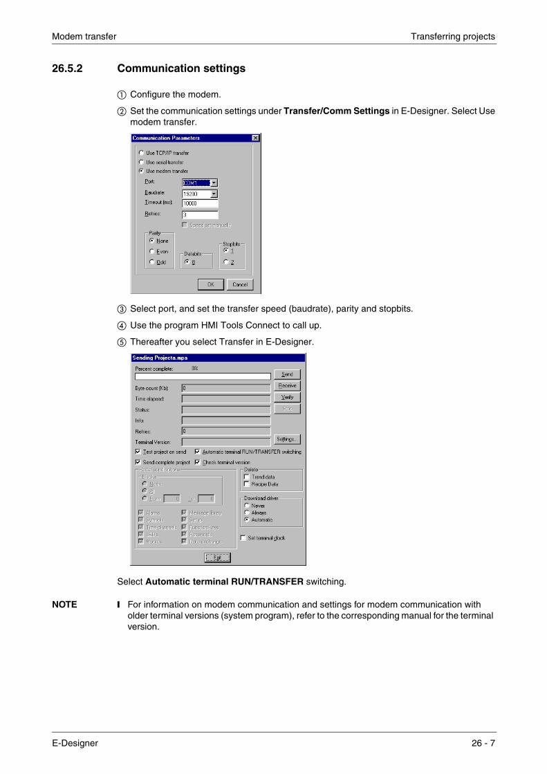
Modem transfer Transferring projects
26.5.2 Communication settings
� Configure the modem.
� Set the communication settings under Transfer/Comm Settings in E-Designer. Select Use modem transfer.
� Select port, and set the transfer speed (baudrate), parity and stopbits.
� Use the program HMI Tools Connect to call up.
� Thereafter you select Transfer in E-Designer.
Select Automatic terminal RUN/TRANSFER switching.
NOTE ❙ For information on modem communication and settings for modem communication with older terminal versions (system program), refer to the corresponding manual for the terminal version.
E-Designer 26 - 7

Transferring projects Modem transfer
26 - 8

Technical data
27 Technical data
E300
Parameter Data
Front panel Width 214 x height 194 x depth 6 mm.
Mounting depth 69 mm excl. D-sub and 110 mm incl. D-sub.
Mounting hole refer to drawing S-02721
Front panel seal IP 65, NEMA 4, NEMA 4X (indoor use only)
Rear panel seal IP 20
Keyboard material Membrane keyboard with polyester snap discs. Overlay film of Autotex F207 with print on reverse side. 1 million operations.
Reverse side material Yellow chrome-plated steel plate.
Weight Excl. D-sub: 1.5 kg.
Serial port RS-422 9-pin D-sub contact, chassis-mounted male connector with standard locking screws 4-40 UNC.
Serial port RS-232 9-pin D-sub contact, chassis-mounted male connector with standard locking screws 4-40 UNC.
Expansion slots 1 built-in expansion slot.
Memory Flash memory, 400 kb for application.
Real-time clock ±10 PPM + error resulting from ambient temperature and supply voltage. Total max error: 1 min./month = 12 min./year. Battery life for real-time clock: 10 years.
Power consumption at rated voltage
Without load: 300 mA. Max load: 450 mA.
DisplayLCD display (liquid crystal), 240x64 pixels, monochrome, 4 rows of 20 characters or 8 rows of 40 characters. Background light lifetime 50,000 h at ambient temperature of +25°C. LED.
Active area of display, WxH 127.2 x 33.9 mm
Contrast setting Programmierbar
Supply voltage
+24 VDC (20-30 VDC), 3-pin jack connection block. CE: The power supply must conform with the requirements for SELV accor-ding to IEC 950 or IEC 742. UL: must conform with requirements for class 2 supply voltages.
Fuse 1 AT, Littelfuse R452 001 (Nano2 SMF Slo-Blo). Placed on the back under the casing near the 24 V connector.
Ambient temperature +0 ° to +50 °C
Storage temperature -20 ° to +70 °C
Relative humidity Max 85% non-condensing.
EMC tests on the terminalThe terminal complies with the requirements in paragraph four in the directive 89/336/EEC. Noise tested according to: EN50081-1 emission and EN50082-2 immunity.
UL approval UL 508, UL 1604 (Class I Div 2)
DNV approvalDet Norske Veritas type approval certificate. Location classes: Temperature A, Humidity B, Vibration A, Enclosure C (panel front only).
MTBF (Mean time between failure) (h) 104 322
E-Desinger 27 - 1

Technical data
E600
Parameter Data
Front panel Width 214 x height 232 x depth 5 mm.
Mounting depth 69 mm excl. D-sub and 110 mm incl. D-sub.
Mounting hole refer to drawing S-03509
Front panel seal IP 65, NEMA 4, NEMA 4X (indoor use only)
Rear panel seal IP 20
Keyboard material Membrane keyboard with polyester snap discs. Overlay film of Autotex F207 with print on reverse side. 1 million operations.
Reverse side material Yellow chrome-plated steel plate.
Weight Excl. D-sub: 1.4 kg.
Serial port RS-422 25-pin D-sub contact, chassis-mounted female connector with standard locking screws 4-40 UNC.
Serial port RS-232 9-pin D-sub contact, chassis-mounted male connector with standard locking screws 4-40 UNC.
Expansion slots 1 built-in expansion slot.
Memory Flash memory, 400 kb for application.
Real-time clock ±10 PPM + error resulting from ambient temperature and supply voltage. Total max error: 1 min./month = 12 min./year. Battery life for real-time clock: 10 years.
Power consumption at rated voltage
Without load: 300 mA. Max load: 450 mA.
DisplayLCD display (liquid crystal), 240x128 pixels, monochrome, 16 rows of 40 characters. Background light lifetime 50,000 h at ambient temperature of +25°C. CFL.
Active area of display, WxH 120.0 x 64.0 mm
Contrast setting Programmierbar
Supply voltage
+24 VDC (20-30 VDC), 3-pin jack connection block. CE: The power supply must conform with the requirements for SELV accor-ding to IEC 950 or IEC 742. UL: must conform with requirements for class 2 supply voltages.
Fuse 1 AT, Littelfuse R452 001 (Nano2 SMF Slo-Blo). Placed on the back under the casing near the 24 V connector.
Ambient temperature +0 ° to +50 °C
Storage temperature -20 ° to +70 °C
Relative humidity Max 85% non-condensing.
EMC tests on the terminalThe terminal complies with the requirements in paragraph four in the directive 89/336/EEC. Noise tested according to: EN50081-1 emission and EN50082-2 immunity.
UL approval UL 508, UL 1604 (Class I Div 2)
DNV approvalDet Norske Veritas type approval certificate. Location classes: Temperature A, Humidity B, Vibration A, Enclosure C (panel front only).
MTBF (Mean time between failure) (h) 61 368
27 - 2

Technical data
E610
Parameter Data
Front panel Width 200 x height 150 x depth 5 mm.
Mounting depth 70 mm excl. D-sub and 70 mm incl. D-sub.
Mounting hole refer to drawing S-03611
Front panel seal IP 65, NEMA 4, NEMA 4X (indoor use only)
Rear panel seal IP 20
Material in front panel Membrane keyboard with polyester snap discs. Overlay film of Autotex F207 with print on reverse side. 1 million operations.
Reverse side material Yellow chrome-plated steel plate.
Weight Excl. D-sub: 1.5 kg.
Serial port RS-85 4-pin jack connection block, chassis-mounted male connector.
Serial port RS-422 25-pin D-sub contact, chassis-mounted female connector with standard locking screws 4-40 UNC.
Serial port RS-232 9-pin D-sub contact, chassis-mounted male connector with standard locking screws 4-40 UNC.
Expansion slots 1 built-in expansion slot.
Memory Flash memory, 400 kb for application.
Real-time clock ±10 PPM + error resulting from ambient temperature and supply voltage. Total max error: 1 min./month = 12 min./year. Battery life for real-time clock: 10 years.
Power consumption at rated voltage
Without load: 250mA. Max load: 400 mA.
DisplayLCD display (liquid crystal), 320x240 pixels, 16 grey scales, graphics and text. Background light lifetime 25,000 h at ambient temperature of +25°C. Touch screen. CFL.
Active area of display, WxH 115.2 x 86.4 mm
Contrast setting Programmable
Supply voltage
+24 VDC (20-30 VDC), 3-pin jack connection block. CE: The power supply must conform with the requirements for SELV accor-ding to IEC 950 or IEC 742. UL: must conform with requirements for class 2 supply voltages.
Fuse 1 AT, Littelfuse R452 001 (Nano2 SMF Slo-Blo). Placed on the back under the casing near the 24 V connector.
Ambient temperature +0 ° to +50 °C
Storage temperature -20 ° to +70 °C
Relative humidity Max 85% non-condensing.
EMC tests on the terminalThe terminal complies with the requirements in paragraph four in the directive 89/336/EEC. Noise tested according to: EN50081-1 emission and EN61000-6-2 immunity.
MTBF (Mean time between failure) (h) 92 578
E-Desinger 27 - 3

Technical data
E615
Parameter Data
Front panel Width 200 x height 150 x depth 5 mm.
Mounting depth 70 mm excl. D-sub and 70 mm incl. D-sub.
Mounting hole refer to drawing S-03611
Front panel seal IP 65, NEMA 4, NEMA 4X (indoor use only)
Rear panel seal IP 20
Material in front panel Membrane keyboard with polyester snap discs. Overlay film of Autotex F207 with print on reverse side. 1 million operations.
Reverse side material Yellow chrome-plated steel plate.
Weight Excl. D-sub: 1.5 kg.
Serial port RS485 4-pin jack connection block, chassis-mounted male connector.
Serial port RS-422 25-pin D-sub contact, chassis-mounted female connector with standard locking screws 4-40 UNC.
Serial port RS-232 9-pin D-sub contact, chassis-mounted male connector with standard locking screws 4-40 UNC.
Expansion slots 1 built-in expansion slot.
Memory Flash memory, 400 kb for application.
Real-time clock ±10 PPM + error resulting from ambient temperature and supply voltage. Total max error: 1 min./month = 12 min./year. Battery life for real-time clock: 10 years.
Power consumption at rated voltage
Without load: 250mA. Max load: 400 mA.
DisplayLCD display (liquid crystal), 320x240 pixels, 256 colors, graphics and text. Background light lifetime 25,000 h at ambient tempera-ture of +25°C. Touch screen. CFL.
Active area of display, WxH 115.2 x 86.4 mm.
Contrast setting Programmable
Supply voltage
+24 VDC (20-30 VDC), 3-pin jack connection block. CE: The power supply must conform with the requirements for SELV accor-ding to IEC 950 or IEC 742. UL: must conform with requirements for class 2 supply voltages.
Fuse 1 AT, Littelfuse R452 001 (Nano2 SMF Slo-Blo). Placed on the back under the casing near the 24 V connector.
Ambient temperature +0 ° to +50 °C
Storage temperature -20 ° to +70 °C
Relative humidity Max 85% non-condensing.
EMC tests on the terminalThe terminal complies with the requirements in paragraph four in the directive 89/336/EEC. Noise tested according to: EN50081-1 emission and EN61000-6-2 immunity.
MTBF (Mean time between failure) (h) 73 458
27 - 4

Technical data
E700
Parameter Data
Front panel Width 276 x height 198 x depth 5.7 mm.
Mounting depth 87 mm excl. D-sub and 110 mm incl. D-sub.
Mounting hole refer to drawing S-02412
Front panel seal IP 65, NEMA 4, NEMA 4X (indoor use only)
Rear panel seal IP 20
Keyboard material Membrane keyboard with polyester snap discs. Overlay film of Autotex F207 with print on reverse side. 1 million operations.
Reverse side material Yellow chrome-plated steel plate.
Weight Excl. D-sub: 1.7 kg.
Serial port RS-422 25-pin D-sub contact, chassis-mounted female connector with standard locking screws 4-40 UNC.
Serial port RS-232 9-pin D-sub contact, chassis-mounted male connector with stan-dard locking screws 4-40 UNC.
Expansion slots 2 built-in expansion slots.
Memory Flash memory, 400 kb.
Real-time clock ±10 PPM + error resulting from ambient temperature and supply voltage. Total max error: 1 min./month = 12 min./year. Battery life for real-time clock: 10 years.
Power consumption at rated voltage
Without load: 300 mA. Max load with expansion card: 550 mA.
DisplayLCD display (liquid crystal), 320x240 pixels, 256 colors, graphics and text. Background light lifetime: 25,000 h at ambient tempera-ture of +25°C. CFL.
Active area of display, WxH 115.2 x 86.4 mm
Contrast setting Programmable
Supply voltage
+24 VDC (20-30 VDC), 3-pin jack connection block. CE: The power supply must conform with the requirements for SELV accor-ding to IEC 950 or IEC 742. UL: must conform with requirements for class 2 supply voltages.
Fuse 1 AT, Littelfuse R452 001 (Nano2 SMF Slo-Blo). Placed on the back under the casing near the 24 V connector.
Ambient temperature +0 ° to +50 °C
Storage temperature -20 ° to +70 °C
Relative humidity Max 85% non-condensing.
EMC tests on the terminalThe terminal complies with the requirements in paragraph four in the directive 89/336/EEC. Noise tested according to: EN50081-1 emission and EN50082-2 immunity.
UL approval UL 508, UL 1604 (Class I Div 2)
DNV approvalDet Norske Veritas type approval certificate. Location classes: Temperature A, Humidity B, Vibration A, Enclosure C (panel front only).
MTBF (Mean time between failure) (h) 84 496
E-Desinger 27 - 5

Technical data
E710
Parameter Data
Front panel Width 211.5 x height 198 x depth 5.7 mm.
Mounting depth 87 mm excl. D-sub and 110 mm incl. D-sub.
Mounting hole refer to drawing S-02412
Front panel seal IP 65, NEMA 4, NEMA 4X (indoor use only)
Rear panel seal IP 20
Material in front panel Autoflex EB A180.
Reverse side material Yellow chrome-plated steel plate.
Weight Excl. D-sub: 1.7 kg.
Serial port RS-422 25-pin D-sub contact, chassis-mounted female connector with standard locking screws 4-40 UNC.
Serial port RS-232 9-pin D-sub contact, chassis-mounted male connector with standard locking screws 4-40 UNC.
Expansion slots 2 built-in expansion slots.
Memory Flash memory, 400 kb.
Real-time clock ±10 PPM + error resulting from ambient temperature and supply voltage. Total max error: 1 min./month = 12 min./year. Battery life for real-time clock: 10 years.
Power consumption at rated voltage
Without load: 300 mA. Max load with expansion card: 550 mA.
DisplayLCD display (liquid crystal), 320x240 pixels, 256 colors, graphics and text. Background light lifetime: 25,000 h at ambient tempera-ture of +25°C. Touch screen. CFL.
Active area of display, WxH 115.2 x 86.4 mm
Contrast setting Programmable
Supply voltage
+24 VDC (20-30 VDC), 3-pin jack connection block. CE: The power supply must conform with the requirements for SELV accor-ding to IEC 950 or IEC 742. UL: must conform with requirements for class 2 supply voltages.
Fuse 1 AT, Littelfuse R452 001 (Nano2 SMF Slo-Blo). Placed on the back under the casing near the 24 V connector.
Ambient temperature +0 ° to +50 °C
Storage temperature -20 ° to +70 °C
Relative humidity Max 85% non-condensing.
EMC tests on the terminalThe terminal complies with the requirements in paragraph four in the directive 89/336/EEC. Noise tested according to: EN50081 -2 emission and EN50082-2 immunity.
UL approval UL 508, UL 1604 (Class 1 Div 2)
DNV approvalDet Norske Veritas type approval certificate. Location classes: Temperature A, Humidity B, Vibration A, Enclosure C (panel front only).
MTBF (Mean time between failure) (h) 96 352
27 - 6

Technical data
E900 T and E900 VT
Parameter Data
Front panel Width 367 x height 274 x depth 6.0 mm. (335 x 420 x 6.0 for E900 VT)
Mounting depth 90 mm excl. D-sub and 110 mm incl. D-sub.
Mounting hole refer to drawing S-03028 (S-03107 for E900 VT)
Front panel seal IP 65, NEMA 4
Rear panel seal IP 20
Keyboard material Membrane keyboard with polyester snap discs. Overlay film of Autotex F207 with print on reverse side. 1 million operations.
Reverse side material Yellow chrome-plated steel plate.
Weight Excl. D-sub: 3.5 kg. (4.0 kg for E900 VT.)
Serial port RS-422 25-pin D-sub contact, chassis-mounted female connector with standard locking screws 4-40 UNC.
Serial port RS-232 9-pin D-sub contact, chassis-mounted male connector with standard locking screws 4-40 UNC.
Expansion slots 2 built-in expansion slots. (1 slot for E900 VT.)
Memory Flash memory, 1600 kb for application.
Real-time clock ±10 PPM + error resulting from ambient temperature and supply voltage. Total max error: 1 min./month = 12 min./year. Battery life for real-time clock: 10 years.
Power consumption at rated voltage Max: 0.17 – 0.35 A (240 – 100 VAC).
Display TFT display, 640x480 pixels, 256 colors, graphics and text. Back-ground light lifetime: 25,000 h at ambient temperature of +25°C.
Active area of display, WxH 211.2 x 158.4 mm
Contrast setting Programmierbar
Fuse External AC: F2.5 A, Internal DC: T4 A
Supply voltage 100-240 VAC
Ambient temperature +0 ° to +50 °C
Storage temperature -20 ° to +70 °C
Relative humidity Max 85% non-condensing.
EMC tests on the terminalThe terminal complies with the requirements in paragraph four in the directive 89/336/EEC. Noise tested according to: EN50081-2 emission and EN50082-2 immunity.
UL approval UL 1604 (Class I Div 2), UL 1950.
DNV approvalDet Norske Veritas type approval certificate. Location classes: Temperature A, Humidity B, Vibration A, Enclosure C (panel front only).
MTBF (Mean time between failure) (h) 68 676 (91 867 for E900 VT)
E-Desinger 27 - 7

Technical data
E910 T
Parameter Data
Front panel Width 290 x height 247 x depth 6.0 mm.
Mounting depth 109 mm excl. D-sub and 130 mm incl. D-sub.
Mounting hole refer to drawing S-02857
Front panel seal IP 65, NEMA 4
Rear panel seal IP 20
Material in front panel Overlay film of Autotex F207 with print on reverse side. 1 million operations.
Reverse side material Yellow chrome-plated steel plate.
Weight Excl. D-sub: 3.3 kg.
Serial port RS-422 25-pin D-sub contact, chassis-mounted female connector with standard locking screws 4-40 UNC.
Serial port RS-232 9-pin D-sub contact, chassis-mounted male connector with standard locking screws 4-40 UNC.
Expansion slots 2 built-in expansion slots.
Memory Flash memory, 1600 kb for application.
Real-time clock ±10 PPM + error resulting from ambient temperature and supply voltage. Total max error: 1 min./month = 12 min./year. Battery life for real-time clock: 10 years.
Power consumption at rated voltage Max: 0,17 – 0,35 A (240 – 100 V WS)
DisplayTFT display, 640x480 pixels, 256 colors, graphics and text. Back-ground light lifetime: 25,000 h at ambient temperature of +25°C. Touch screen
Active area of display, WxH 211.2 x 158.4 mm
Contrast setting Programmable
Fuse External AC: F2.5 A, Internal DC: T4 A
Supply voltage 100-240 VAC
Ambient temperature +0 ° to +50 °C
Storage temperature -20 ° to +70 °C
Relative humidity Max 85% non-condensing.
EMC tests on the terminalThe terminal complies with the requirements in paragraph four in the directive 89/336/EEC. Noise tested according to: EN50081-2 emission and EN50082-2 immunity.
UL approval UL 1604 (Class I Div 2), UL 1950
DNV approvalDet Norske Veritas type approval certificate. Location classes: Temperature A, Humidity B, Vibration A, Enclosure C (panel front only).
MTBF (Mean time between failure) (h) 84 511 für E910 T
27 - 8
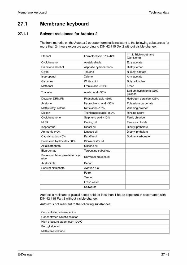
Membrane keyboard Technical data
27.1 Membrane keyboard
27.1.1 Solvent resistance for Autotex 2
The front material on the Autotex 2 operator terminal is resistant to the following substances for more than 24 hours exposure according to DIN 42 115 Del 2 without visible change..
Autotex is resistant to glacial acetic acid for less than 1 hours exposure in accordance with DIN 42 115 Part 2 without visible change.
Autotex is not resistant to the following substances:
Ethanol Formaldehyde 37%-42% 1.1.1. Trichloroethane (Genklene)
Cyclohexanol Acetaldehyde Ethylacetate
Diacetone alcohol Aliphatic hydrocarbons Diethyl ether
Glykol Toluene N-Butyl acetate
Isopropanol Xylene Amylacetate
Glycerine White spirit Butycellosolve
Methanol Fromic acic <50% Ether
Triacetin Acetic acid <50% Sodium hypchlorite<20% (Bleach)
Dowanol DRM/PM Phosphoric acid <30% Hydrogen peroxide <25%
Acetone Hydrochloric acid <36% Potassium carbonate
Methyl ethyl ketone Nitric acid <10% Washing powder
Dioxan Trichloracetic acid <50% Rinsing agent
Cyclohexanone Sulphuric acid <10% Ferric chloride
MIBK Cutting oil Ferrous chloride
Isophorone Diesel oil Dibutyl phthalate
Ammonia<40% Linseed oil Diethyl phthalate
Caustic soda <40% Paraffin oil Sodium carbonate
Potassium hydroxide <30% Blown castor oil
Alkalicarbonate Silicone oil
Bicarbonate Turpentine substitute
Potassium ferrocyanide/ferricya-nide Universal brake fluid
Acetonitrile Decon
Sodium bisulphate Aviation fuel
Petrol
Teepol
Fresh water
Saltwater
Concentrated mineral acids
Concentrated caustic solution
High pressure steam over 100°C
Benzyl alcohol
Methylene chloride
E-Desinger 27 - 9
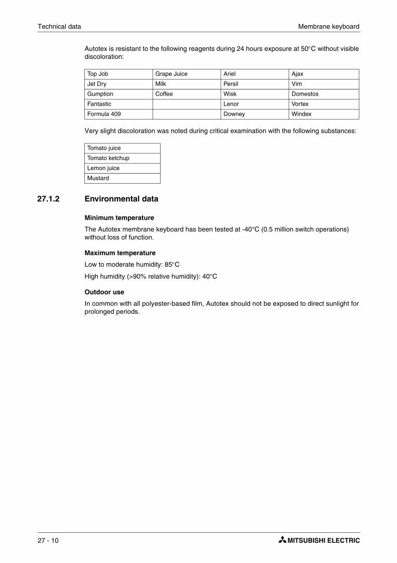
Technical data Membrane keyboard
Autotex is resistant to the following reagents during 24 hours exposure at 50°C without visible discoloration:
Very slight discoloration was noted during critical examination with the following substances:
27.1.2 Environmental data
Minimum temperature
The Autotex membrane keyboard has been tested at -40°C (0.5 million switch operations) without loss of function.
Maximum temperature
Low to moderate humidity: 85°C
High humidity (>90% relative humidity): 40°C
Outdoor use
In common with all polyester-based film, Autotex should not be exposed to direct sunlight for prolonged periods.
Top Job Grape Juice Ariel Ajax
Jet Dry Milk Persil Vim
Gumption Coffee Wisk Domestos
Fantastic Lenor Vortex
Formula 409 Downey Windex
Tomato juice
Tomato ketchup
Lemon juice
Mustard
27 - 10

Drawings Technical data
27.2 Drawings
E-series RS-232/RS422
Pin no
Pin no
Pin no
Nam
eN
ame
Nam
e
12
1
+5 V
> 2
00 m
A+T
xD
Tx/
Rx+
TxD
-TxD
Onl
y fo
r E
50 w
ith 2
32-2
5-A
DP.
On
all o
ther
term
inal
s,no
t con
nect
ed.
Pin
no
20 c
onne
cted
to p
in n
o 21
inte
rnal
in th
e te
rmin
al
Onl
y fo
r E
50, E
100,
E15
0
Onl
y fo
r E
50
Onl
y fo
r E
610,
E61
5
Tx/
Rx-
RxD
+RxD
0 V
0 V
-RxD
CT
S+R
TS
RT
S-R
TS
+CT
S
-CT
S
TxD
RxD
CT
S
RT
S
+5 V
<50
mA
+5 V
<20
0 m
A
0 V
4)
1) 2)1) 3) 3) 3) 3)
4)
1) 2) 3)
215
233
3516
4
D-s
ub9-
pin
Mal
e
D-s
ub25
-pin
Fem
ale
4-pi
nP
lug-
in b
lock
74
817
95 20
12,1
324
, 25
18 9 10 22 23147, 821
Sig
nal d
irect
ion
Sig
nal d
irect
ion
Sig
nal d
irect
ion
Term
inal
Term
inal
Term
inal
XX
XX
XX
XX
X
16 7 8 9
2 3 4 5
10
114 15 16 17 18 19 20 21 22 23 24 25
2 3 4 5 6 7 8 9 11 12 13
RS
-232
RS
-422
RS
-485
1 2 3 4
E-Desinger 27 - 11

Technical data Drawings
E300 Outline drawing
Ø4,
5–8
st
211,
530
395,
7
198
14924,5 24,5
81 81
99,7
599
,75
161
19,2
519
,25
1310
,518
8
M4x
15
Ø10
–4 s
t
MA
X 7
6M
AX
110
300
27 - 12

Drawings Technical data
E300 Text strip
4 5,25
8 10,5
190
190
10,4
10,4
21,2
5
21,2
5
21,2
5
21,2
5
21,2
5
21,2
5
21,2
5
21,2
5
21,2
5
21,2
5
21,2
5
21,2
5
21,2
5
21,2
5
Text
max
7 x
19,7
5
Text
max
9,5
x 19
,75
E-Desinger 27 - 13

Technical data Drawings
E600 Outline drawing
RS
-232
24V
DC
RS
-422
1412
188
M4x
15
60,5
MA
X 1
10
3930
14922,5
232
214
5
MA
X 7
6
90 110
19,5
161
19,5
100
100
5 5
ø10
ø4,
5
E
27 - 14

Drawings Technical data
E600 Text strip
5,9 3,9
11,8 7,8
188,
5
188,
5
10,2
5
10,2
5
20,5
20,5
20,5
20,5
20,5
20,5
20,5
20,5
20,5
20,5
20,5
20,5
20,5
Text
max
11 x
17,
5
Text
max
7 x
17,5
20,5
E-Desinger 27 - 15

Technical data Drawings
E610/E615 Outline drawing
24V
DC
RS
-422
RS
-485
138 8,78,7
150
200
183
89
69
MA
X 7
6
MAX 76
5
RS
-23
2
139 (5.47)
188
(7.4
0)
27 - 16
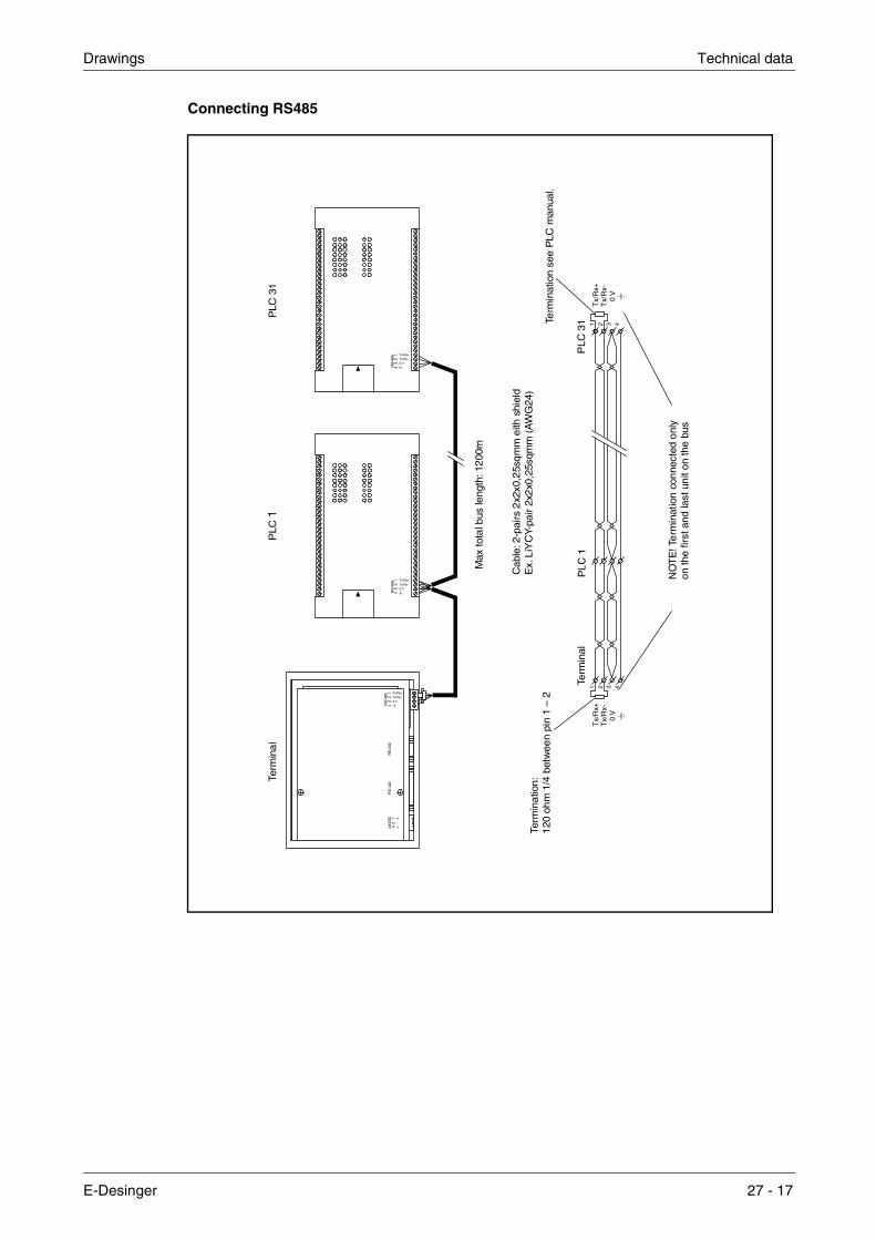
Drawings Technical data
Connecting RS485
RS
-485
43
21 Tx/Rx+
Tx/Rx-0 V
24V
DC
RS
-422
RS
-232
RS
-485
32
1
Tx/Rx+Tx/Rx-0 V
RS
-485
43
21 Tx/Rx+
Tx/Rx-0 V
Term
ina
lP
LC 1
PLC
31
+-
43
21
Tx/
Rx+
Tx/
Rx+
Tx/
Rx-
Tx/
Rx-
0 V
0 V
11
22
33
44
Term
ina
tion
:1
20 o
hm
1/4
bet
wee
n pi
n 1
– 2
Term
inal
PLC
31Te
rmin
atio
n se
e P
LC m
anua
l.
Max
tota
l bus
leng
th: 1
200
m
Cab
le: 2
-pai
rs 2
x2x0
,25s
qm
m e
ith s
hiel
dE
x. L
iYC
Y-pa
ir 2x
2x0
,25s
qmm
(A
WG
24)
NO
TE
! Te
rmin
atio
n co
nne
cted
onl
y o
n th
e fi
rst a
nd la
st u
nit
on
the
bus
E-Desinger 27 - 17
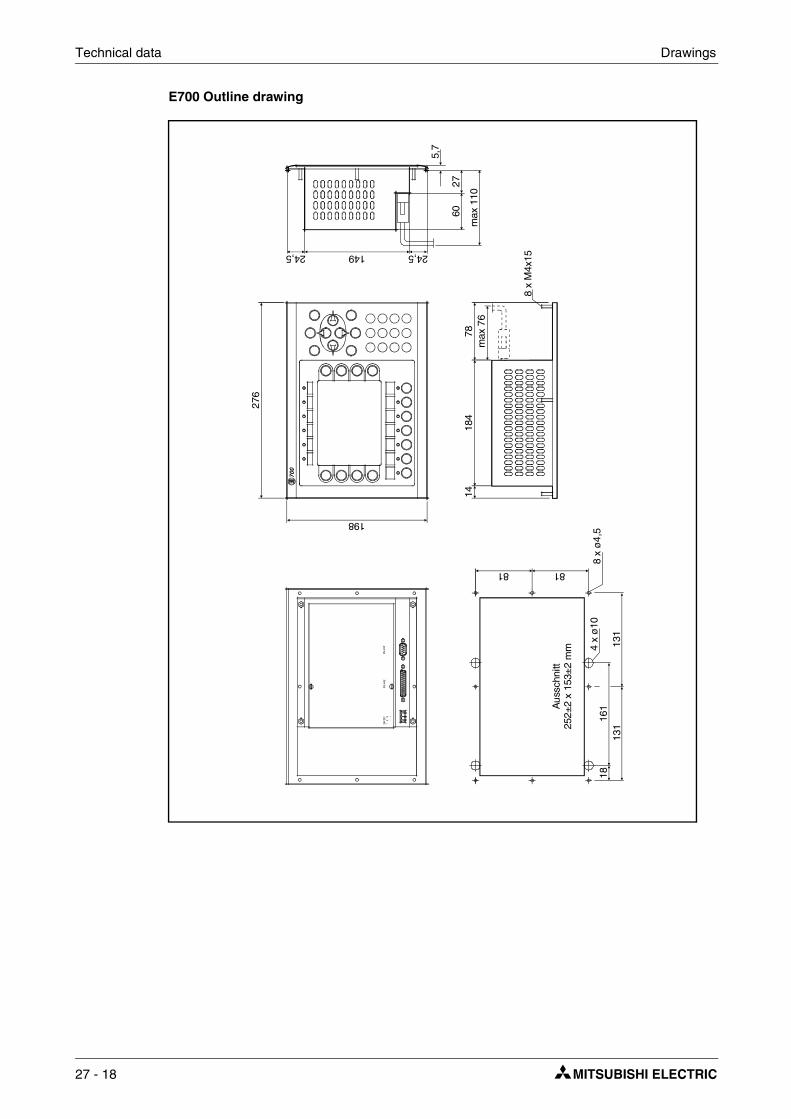
Technical data Drawings
E700 Outline drawing
60
max
110
276
184
78m
ax 7
6
8 x
M4x
15
14
24,5149
198
24,5
27
5,7
81
1816
1Aus
schn
itt25
2±2
x 15
3±2
mm
131
131
4 x
ø10
8 x
ø4,
5
81
27 - 18
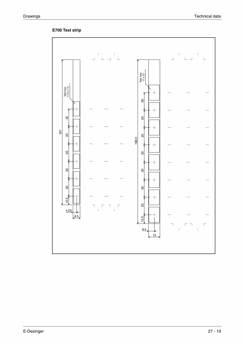
Drawings Technical data
E700 Text strip
4,25
6,5
8,5
13
167
188,
5
10,5
10,5
2020
2020
20
2020
2020
2020
20
Text
max
17,5
x 7
,5
Text
max
17 x
12
E-Desinger 27 - 19

Technical data Drawings
E710 Outline drawing
211,
5
184
60
max
110
24,514924,5
27
5,7
13,
514
198
98,7
516
1
Aus
schn
itt18
5±2
x 1
53±
2 m
m
8181
18,
2518
,25
98,7
5
max
76
27 - 20

Drawings Technical data
E710 Text strip
4,5
9
186
9,5
2020
2020
2020
20Te
xt m
ax17
x 7
E-Desinger 27 - 21

Technical data Drawings
E900 Outline drawing
367
274
311
42
M4x
20
14
61m
ax. 1
10
20 45
max. 70
18524
29
6 119
10 x
ø4,
5
119
186,516
117
117
5
117
5
27 - 22

Drawings Technical data
E900 Text strip
4,75 6,25
5,5
9,5 12,5
11
257
257
79
10 10
30,5
21 21
21 21
21 21
21 21
21 21
21 21
21 21
21 21
21 21
Text
max
19 x
8,5
Text
max
19 x
12
Text
max
60 x
10
Sca
le 1
:1 (i
f A4-
copy
)
E-Desinger 27 - 23

Technical data Drawings
E900 VT Outline drawing
311
M4x
20
12,5
ma
x. 7
5
335
430
VT
61
max
. 110
20 45
MAX 70
18523
29
6
IFC 64E External keyboard
11,5
27 - 24

Drawings Technical data
E900 VT Text strip
166,5
21212121212130 10,5
Text max8,5 x 19 mm
Text max11,5 x 19mm
12,5
12,5
12,5
9,5
Left
Right
E-Desinger 27 - 25

Technical data Drawings
E910 Outline drawing
61
2320174
max. 70
23
48
130
5
262
290
137
72
107107
137
5
8 x
ø4
,5
5
214
x 1
61
247
M4
x 2
0
10m
ax. 7
515
5 5
27 - 26

Drawings Technical data
Programming cable RS232C
TX
D2 3 5 7 8 6 1 4
RX
DG
ND
RX
DT
XD
GN
DR
TS
DS
RC
TS
DC
DD
TR
Text
PC
PC
Max
15
Max 33
4-40
4-40
Bla
ckG
ray
Gra
y
Text
:Te
xt:
Text
:O
PE
RAT
OR
TE
RM
INA
LC
AB
5/2,
5mor C
AB
5/3m
PC
PC
PC
PC
4-40
4-40
PC
9- p
in D
-sub
Fem
ale
Shi
eld
con
nec
ted
to D
-sub
cov
er
Shi
eld
conn
ecte
d to
D-s
ub c
ove
r
9- p
in D
-sub
Fem
ale
2 3 5
E-Desinger 27 - 27

Technical data Drawings
Programming cable RS422
2 4 3 55 8
P1
Bro
wn
Ji-H
aw c
able
Bro
wn
LIY
CY-
cabl
e
P2
Bla
ckG
ray
P3
Red
Whi
te
P4
Yello
wYe
llow
P5
Ora
nge
Gre
en
+10
V
15 17 16 1818 714
120
2 8 3 7 5
RX
D
CT
S
TX
D
RT
S
+5
V
0 V
+ + + ++ +- - - -- -
(TX
D)
(RT
S)
(RX
D)
(CT
S)
0 V
4-40
4-40
Gra
y
Gra
y
Met
aliz
ed p
last
ic c
over
4-40
25-p
in M
ALE
9-pi
n F
EM
ALE
4-40
CAB6
Shi
eld
conn
ecte
d to
D
-su
b co
ver
Shi
eld
co
nnec
ted
to
D-s
ub c
over
Ope
rato
r te
rmin
al
PC
27 - 28

Character tables Technical data
27.3 Character tables
Character table 437
The first characters, 0-127, are the same as in character table 850
E-Desinger 27 - 29

Technical data Character tables
Character table 850
Characters 0-127, 0-31 and 127 are reserved as control characters and must not be used.
Character table 850
Characters 128-255
27 - 30

Character tables Technical data
Character table 852
Character table 866
E-Desinger 27 - 31

Technical data Character tables
Character table 869
27 - 32

Index
A
Access, . . . . . . . . . . . . . . . . . . . . . . . 6-2, 7-2Activate Java console, . . . . . . . . . . . . . . . 21-8Alarm groups, . . . . . . . . . . . . . 5-27, 5-32, 10-1Alarm handling,. . . . . . . . . . . . . . . . . . . . 5-32Alarm messages, . . . . . . . . . . . . . . . . . . 10-3Alarmbanner object,. . . . . . . . . . . . . . . . . 6-23Alarms, . . . . . . . . . . . . . . . . . . . . . 5-27, 10-1
Acknowledging required, . . . . . . . . . . . 10-4Alarm groups, . . . . . . . . . . . . . . . . . . 10-1Alarm list, . . . . . . . . . . . . . . . . . . . . . 5-41Alarm messages, . . . . . . . . . . . . . . . . 10-3Define alarm group, . . . . . . . . . . . . . . 10-2Define alarm list, . . . . . . . . . . . . . . . . 10-5Define alarm message, . . . . . . . . . . . . 10-3Graphic alarm page, . . . . . . . . . . . . . . 10-9History, . . . . . . . . . . . . . . . . . . . . . . 10-4Maneuvre, . . . . . . . . . . . . . . . . . . . . 10-8Print out, . . . . . . . . . . . . . . . . . . . . . 10-4
Align, . . . . . . . . . . . . . . . . . . . . . . . . . . 5-16Alphanumeric keys, . . . . . . . . . . . . . . . . . . 3-4Analog clock, . . . . . . . . . . . . . . . . . . . . . 6-25Analog fill object, . . . . . . . . . . . . . . . . . . . 6-24Analog numeric object, . . . . . . . . . . . . . . . 6-13Analog object,. . . . . . . . . . . . . . . . . . . . . . 6-8ANSI, . . . . . . . . . . . . . . . . . . . . . . . . . . 16-1Append, . . . . . . . . . . . . . . . . . . . . . . . . 5-27Application languages . . . . . . . . . . . . . . . 15-1Application languages in run mode,. . . . . . . 15-6
Language management, . . . . . . . . . . . 15-6Application, . . . . . . . . . . . . . . . . . . . . . . . 4-1ASCII objects,. . . . . . . . . . . . . . . . . . . . . 6-18Attach file, . . . . . . . . . . . . . . . . . . . . . . . . 5-9
B
Background block, . . . . . . . . . . . . . . . . . . . 5-9Backlight,. . . . . . . . . . . . . . . . . . . . . . . . 5-33Backup of trend data, . . . . . . . . . . . . . . . . . 8-6Bargraph, . . . . . . . . . . . . . . . . . . . . 6-14, 7-6Block header, . . . . . . . . . . . . . . . . . . . . . . 5-8Block linked to alarm, . . . . . . . . . . . . . . . . 10-9Block list, . . . . . . . . . . . . . . . . . . . . . . . . 5-29Block Manager menu, . . . . . . . . . . . . . . . 5-45Block Manager,. . . . . . . . . . . . . . . . . . . . . 5-6
Setup, . . . . . . . . . . . . . . . . . . . . . . . 5-45Block template, . . . . . . . . . . . . . . . . . 5-7, 5-10Block, . . . . . . . . . . . . . . . . . . . . . . . . . . . 4-4
Create, . . . . . . . . . . . . . . . . . . . . . . . 5-6Edit, . . . . . . . . . . . . . . . . . . . . . . . . 5-28Jump to block,. . . . . . . . . . . . . . . . . . 23-5Program, . . . . . . . . . . . . . . . . . . . . . 5-12
Built-in function keys, . . . . . . . . . . . . . . . . . 3-5Buzzer, . . . . . . . . . . . . . . . . . . . . . . . . . 5-33
C
Change controller system, . . . . . . . . . . . . . 5-5Change I/O, . . . . . . . . . . . . . . . . . . . . . . . 5-24Change project settings,. . . . . . . . . . . . . . . 5-5Change terminal, . . . . . . . . . . . . . . . . . . . 5-5Character set, . . . . . . . . . . . . . . . . . 5-37, 16-1Clock,
Analog, . . . . . . . . . . . . . . . . . . . . . . . 6-25Digital,. . . . . . . . . . . . . . . . . . . . . . . . 6-26
Color scheme,Create/change, . . . . . . . . . . . . . . . . . . 5-3
Colors, . . . . . . . . . . . . . . . . . . . . . . . . . . 6-1Command line, . . . . . . . . . . . . . . . . . . . . . 5-35Communication error, . . . . . . . . . . . . . . . . 3-3Communication with PC, . . . . . . . . . . . . . . 19-5Communication with two controller systems . . 19-1Communication with two terminals,. . . . . . . . 19-6Communication, . . . . . . . . . . . . . . . . . . . . 3-3Configuration mode, . . . . . . . . . . . . . . . . . 3-1Connection to printer, . . . . . . . . . . . . . . . . 13-1Contrast setting, . . . . . . . . . . . . . . . . . . . . 3-2Control codes to printer . . . . . . . . . . . . . . . 13-5Controller system, . . . . . . . . . . . . . . . . . . . 5-2Controller-Datenaustausch,. . . . . . . . . . . . . 19-4Co-ordinates, . . . . . . . . . . . . . . . . . . . . . . 2-2Copy graphics, . . . . . . . . . . . . . . . . . . . . . 5-19Country Settings . . . . . . . . . . . . . . . . . . . . 5-37Create application language, . . . . . . . . . . . . 15-1Create object, . . . . . . . . . . . . . . . . . . . . . 5-16Create project, . . . . . . . . . . . . . . . . . . . . . 5-1Create series, . . . . . . . . . . . . . . . . . . . . . 5-18Create text strips, . . . . . . . . . . . . . . . . . . . 5-11Crossreference, . . . . . . . . . . . . . . . . . . . . 5-25
Presentation, . . . . . . . . . . . . . . . . . . . 5-26
D
Data exchange, . . . . . . . . . . . . . . . . 5-32, 19-4Data transfer between controller systems, . . . 19-4Date format,. . . . . . . . . . . . . . . . . . . . . . . 5-39Date object, . . . . . . . . . . . . . . . . . . . . . . . 7-7Define security level, . . . . . . . . . . . . . . . . . 12-1Define the block header,. . . . . . . . . . . . . . . 5-8Diagnostic page . . . . . . . . . . . . . . . . . . . . 3-7Diagram, . . . . . . . . . . . . . . . . . . . . . . . . . 6-15Digital symbol object,. . . . . . . . . . . . . . . . . 6-10Digital text object, . . . . . . . . . . . . . . . . . . . 6-9Display signal, . . . . . . . . . . . . . . . . . . . . . 5-8Drucker,
Anschluss, . . . . . . . . . . . . . . . . . . . . . 13-1Druckeranschluss, . . . . . . . . . . . . . . . . . . 13-1Druckereinstellungen, . . . . . . . . . . . . . . . . 5-43Dual drivers, . . . . . . . . . . . . . . . . . . . . . . 19-1
Addressing, . . . . . . . . . . . . . . . . . . . . 19-2Dynamics, . . . . . . . . . . . . . . . . . . . . . . . . 6-3
E-Designer i

Index
E
E-Designer,Block Manager menu, . . . . . . . . . . . . . 5-45Functions menu, . . . . . . . . . . . . . . . . 5-32Install, . . . . . . . . . . . . . . . . . . . . . . . . 2-1Layout menu, . . . . . . . . . . . . . . . . . . 5-46Menü Hilfe, . . . . . . . . . . . . . . . . . . . . 5-47Object menu, . . . . . . . . . . . . . . . . . . 5-46Setup menu, . . . . . . . . . . . . . . . . . . . 5-33Transfer menu, . . . . . . . . . . . . . . . . . 5-46View menu, . . . . . . . . . . . . . . . . . . . 5-28Window menu, . . . . . . . . . . . . . . . . . 5-47
Edit menu, . . . . . . . . . . . . . . . . . . . . . . . 5-28Engineering units, . . . . . . . . . . . . . . . . . . . 7-1Erasing the memory, . . . . . . . . . . . . . . . . . 3-2Error message, . . . . . . . . . . . . . . . . . . . . . 3-3Event, . . . . . . . . . . . . . . . . . . . . . . . . . . . 6-6Expansion card slots, . . . . . . . . . . . . . . . . 5-42Expansion card, . . . . . . . . . . . . . . . . . . . 25-1
IFC MC, . . . . . . . . . . . . . . . . . . . . . . . 8-6Export and import of files in Unicode format, . 16-2External keyboard,. . . . . . . . . . . . . . . . . . . 3-5
F
File menu, . . . . . . . . . . . . . . . . . . . . . . . 5-28Filled object,
Digital, . . . . . . . . . . . . . . . . . . . . . . . 6-11Function keys, . . . . . . . . . . . . 5-27, 5-32, 23-1
Define,. . . . . . . . . . . . . . . . . . . . . . . 23-2Global,. . . . . . . . . . . . . . . . . . . . . . . 23-2Jump to block,. . . . . . . . . . . . . . . . . . 23-5Local, . . . . . . . . . . . . . . . . . . . . . . . 23-2
Functions menu, . . . . . . . . . . . . . . . . . . . 5-32
G
Gain, . . . . . . . . . . . . . . . . . . . . . . . . 6-1, 7-1Grafikblock-Manager,
Tasten, . . . . . . . . . . . . . . . . . . . . . . 5-13Grafikobjekte,
Nachricht,. . . . . . . . . . . . . . . . . . . . . 6-30Graphic alarm page, . . . . . . . . . . . . . . . . 10-9Graphic Block Manager, . . . . . . . . . . . . . . 5-13
Create object, . . . . . . . . . . . . . . . . . . 5-16Create series, . . . . . . . . . . . . . . . . . . 5-18Cursor, . . . . . . . . . . . . . . . . . . . . . . 5-14Dynamic objects, . . . . . . . . . . . . . . . . 5-16Group objects,. . . . . . . . . . . . . . . . . . 5-18Keys,. . . . . . . . . . . . . . . . . . . . . . . . 5-13Mouse, . . . . . . . . . . . . . . . . . . . . . . 5-13Open, . . . . . . . . . . . . . . . . . . . . . . . 5-13Place object, . . . . . . . . . . . . . . . . . . . 5-16Select several objects, . . . . . . . . . . . . 5-16Static graphics, . . . . . . . . . . . . . . . . . 5-16Toolbox,. . . . . . . . . . . . . . . . . . . . . . 5-15
Graphic block, . . . . . . . . . . . . . . . . . . . . . 4-4Graphic object,
Alarmbanner, . . . . . . . . . . . . . . . . . . . 6-23Analog clock, . . . . . . . . . . . . . . . . . . . 6-25Analog Fill, . . . . . . . . . . . . . . . . . . . . . 6-24Analog numeric, . . . . . . . . . . . . . . . . . 6-13Analog, . . . . . . . . . . . . . . . . . . . . . . . 6-8ASCII objects,. . . . . . . . . . . . . . . . . . . 6-18Bargraph,. . . . . . . . . . . . . . . . . . . . . . 6-14Diagram, . . . . . . . . . . . . . . . . . . . . . . 6-15Digital clock, . . . . . . . . . . . . . . . . . . . . 6-26Digital Fill, . . . . . . . . . . . . . . . . . . . . . 6-11Digital symbol, . . . . . . . . . . . . . . . . . . 6-10Digital text . . . . . . . . . . . . . . . . . . . . . 6-9Digital,. . . . . . . . . . . . . . . . . . . . . . . . 6-8Jump, . . . . . . . . . . . . . . . . . . . . . . . . 6-12Maneuvre, . . . . . . . . . . . . . . . . . . . . . 6-33Multiple choice, . . . . . . . . . . . . . . . . . . 6-28Multisymbol, . . . . . . . . . . . . . . . . . . . . 6-27Numeric table, . . . . . . . . . . . . . . . . . . 6-31Slide, . . . . . . . . . . . . . . . . . . . . . . . . 6-19Speedometer, . . . . . . . . . . . . . . . . . . . 6-22Static, . . . . . . . . . . . . . . . . . . . . . . . . 6-7TCP/IP, . . . . . . . . . . . . . . . . . . . . . . . 6-32Touch key, . . . . . . . . . . . . . . . . . . . . . 6-29Trend, . . . . . . . . . . . . . . . . . . . . . . . . 6-20VU meter, . . . . . . . . . . . . . . . . . . . . . 6-17
Grid,. . . . . . . . . . . . . . . . . . . . . . . . . . . . 5-15Group objects, . . . . . . . . . . . . . . . . . . . . . 5-18
I
I/O Crossreference, . . . . . . . . . . . . . . . . . . 5-29IFC MC, . . . . . . . . . . . . . . . . . . . . . . . . . 8-6IME, . . . . . . . . . . . . . . . . . . . . . . . . . . . . 16-1Index addressing, . . . . . . . . . . . . . . . . . . . 5-37Indexadressierung, . . . . . . . . . . . . . . . . . . 18-1Input Method Editors,. . . . . . . . . . . . . . . . . 16-1Insert,. . . . . . . . . . . . . . . . . . . . . . . . . . . 5-27Install driver, . . . . . . . . . . . . . . . . . . . . . . 5-4Internet, . . . . . . . . . . . . . . . . . . . . . . . . . 5-4
J
Java console,. . . . . . . . . . . . . . . . . . . . . . 21-8Joystick function . . . . . . . . . . . . . . . . . . . . 3-8Jump object, . . . . . . . . . . . . . . . . . . 6-12, 7-7
K
Key beep, . . . . . . . . . . . . . . . . . . . . . . . . 5-40Key delay, . . . . . . . . . . . . . . . . . . . . . . . . 5-40Key field,. . . . . . . . . . . . . . . . . . . . . . . . . 5-10Key repeat, . . . . . . . . . . . . . . . . . . . . . . . 5-40Key sequences, . . . . . . . . . . . . . . . . . . . . 3-5Keyboard, Alphanumeric keys, . . . . . . . . . . 3-4
E-Designer ii

Index
L
Language management, . . . . . . . . . . . . . . 15-6Copy object, . . . . . . . . . . . . . . . . . . . 15-5Cross reference, . . . . . . . . . . . . . . . . 15-5Edit, . . . . . . . . . . . . . . . . . . . . . . . . 5-38Export,. . . . . . . . . . . . . . . . . . . 5-38, 15-5Import,. . . . . . . . . . . . . . . . . . . 5-38, 15-5Multi language applications, . . . . . . . . . 15-1New language, . . . . . . . . . . . . . . . . . 5-38Setup, . . . . . . . . . . . . . . . . . . . . . . . 5-38Show index, . . . . . . . . . . . . . . . . . . . 15-5
Language settings, . . . . . . . . . . . . . . . . . 5-37Language, . . . . . . . . . . . . . . . . . . . . . . . 5-37Languages, . . . . . . . . . . . . . . . . . . . . . . 5-38Layout menu, . . . . . . . . . . . . . . . . . . . . . 5-46LEDs, . . . . . . . . . . . . . . . . . . . . . . 5-27, 5-32
Define,. . . . . . . . . . . . . . . . . . . . . . . 22-1Levels, . . . . . . . . . . . . . . . . . . . . . . . . . . 4-4Library index register,. . . . . . . . . . . . . . . . 5-35Login, . . . . . . . . . . . . . . . . . . . . . . . . . . 12-2
M
Macro,Activate . . . . . . . . . . . . . . . . . . . . . . 24-3
Mail signal,. . . . . . . . . . . . . . . . . . . . . . . . 5-9Make same size, . . . . . . . . . . . . . . . . . . . 5-16Maneuvrable object,. . . . . . . . . . . . . . . . . 6-33
Analog object, . . . . . . . . . . . . . . . 6-33, 7-9Digital object, . . . . . . . . . . . . . . . 6-33, 7-3
Maneuvre graphic blocks, . . . . . . . . . . . . . 6-33Maneuvre text block. . . . . . . . . . . . . . . . . . 7-9Menü Hilfe, . . . . . . . . . . . . . . . . . . . . . . 5-47Message library, . . . . . . . . . . . . . . . . 5-32, 9-1Message object, . . . . . . . . . . . . . . . . . . . . 7-8Method,. . . . . . . . . . . . . . . . . . . . . . . . . . 4-1Modem connection, . . . . . . . . . . . . . . . . . 19-15Move object,. . . . . . . . . . . . . . . . . . . . . . . 6-5Multi language applications,. . . . . . . . . . . . 15-1Multi language setup, . . . . . . . . . . . . . . . . 15-3Multiple choice object, . . . . . . . . . . . . 6-28, 7-4Multisymbol object, . . . . . . . . . . . . . . . . . 6-27
N
Nachrichtenobjekt,. . . . . . . . . . . . . . . 6-30, 7-8Name list, . . . . . . . . . . . . . . . . . . . . . . . 5-29National characters, . . . . . . . . . . . . . . . . . . 3-4Network accounts, . . . . . . . . . . . . . . . . . . 20-35Network communication through IFC ET, . . . 20-9Network communication,. . . . . . . . . . . . . . 20-1Network services, . . . . . . . . . . . . . . . . . . 20-23No protocol mode, . . . . . . . . . . . . . . . . . . 19-9Numeric table, . . . . . . . . . . . . . . . . . . . . 6-31Numeric values, . . . . . . . . . . . . . . . . . . . . 3-4
O
Object menu, . . . . . . . . . . . . . . . . . . . . . . 5-46Offset Gain Calculation, . . . . . . . . . . . . . . . 7-1Offset Gain Calculation,Engineering units, . . . 6-1Offset, . . . . . . . . . . . . . . . . . . . . . . . 6-1, 7-1Operation modes, . . . . . . . . . . . . . . . . . . . 3-1
Prog,. . . . . . . . . . . . . . . . . . . . . . . . . 3-1Run, . . . . . . . . . . . . . . . . . . . . . . . . . 3-1Setup, . . . . . . . . . . . . . . . . . . . . . . . . 3-1Switching, . . . . . . . . . . . . . . . . . . . . . 3-1
Operator images, . . . . . . . . . . . . . . . . . . . 4-3Overriding password,. . . . . . . . . . . . . . . . . 12-2
P
Passthrough mode, . . . . . . . . . . . . . . . . . . 19-8Passwords, . . . . . . . . . . . . . . . 5-27, 5-32, 12-1
Change during run mode, . . . . . . . . . . . 12-2Define . . . . . . . . . . . . . . . . . . . . . . . . 12-1
Print out alarm,. . . . . . . . . . . . . . . . . . . . . 10-4Printer settings, . . . . . . . . . . . . . . . . . . . . 13-4Printer signal,. . . . . . . . . . . . . . . . . . . . . . 5-8Printer status,. . . . . . . . . . . . . . . . . . . . . . 5-34Printer, . . . . . . . . . . . . . . . . . . . . . . . . . . 5-43
Connection, . . . . . . . . . . . . . . . . . . . . 13-1Profibus DP, . . . . . . . . . . . . . . . . . . . . . . 25-1Prog, . . . . . . . . . . . . . . . . . . . . . . . . . . . 3-1Programming mode, . . . . . . . . . . . . . . . . . 3-1
Prog,. . . . . . . . . . . . . . . . . . . . . . . . . 3-3Programming tool,
Edit menu, . . . . . . . . . . . . . . . . . . . . . 5-28File menu, . . . . . . . . . . . . . . . . . . . . . 5-28
Programming, . . . . . . . . . . . . . . . . . . 4-1, 5-1Project printouts,. . . . . . . . . . . . . . . . . . . . 13-2Project transfer, . . . . . . . . . . . . . . . . . . . . 12-2Project,
Close, . . . . . . . . . . . . . . . . . . . . . . . . 5-28Create, . . . . . . . . . . . . . . . . . . . 5-1, 5-28Open, . . . . . . . . . . . . . . . . . . . . . . . . 5-28Program, . . . . . . . . . . . . . . . . . . . 4-1, 5-1Save, . . . . . . . . . . . . . . . . . . . . . . . . 5-28Test, . . . . . . . . . . . . . . . . . . . . . . . . . 5-28Transfer, . . . . . . . . . . . . . . . . . . 5-46, 26-1
E-Designer iii
Index
R
Raster, . . . . . . . . . . . . . . . . . . . . . . . . . 5-15Real-time clock
Set,. . . . . . . . . . . . . . . . . . . . . . . . . . 3-6Real-time trend, . . . . . . . . . . . . . . . . . . . . 8-2Recipe directory, . . . . . . . . . . . . . . . . 5-9, 11-2
In run mode, . . . . . . . . . . . . . . . . . . . 11-3Recipe handling, . . . . . . . . . . . . . . . . . . . 11-1Recipe settings, . . . . . . . . . . . . . . . . . . . 11-2Recipe,
Append, . . . . . . . . . . . . . . . . . . . . . . 11-4Calculate size,. . . . . . . . . . . . . . . . . . 11-2Create, . . . . . . . . . . . . . . . . . . . . . . 11-4Delete,. . . . . . . . . . . . . . . . . . . . . . . 11-5Files, . . . . . . . . . . . . . . . . . . . . . . . . 11-1Through the controller program, . . . . . . 11-6Transfer through FTP,. . . . . . . . . . . . . 11-5Transfer, . . . . . . . . . . . . . . . . . . . . . 11-5Using recipes in a PC, . . . . . . . . . . . . 11-5
Report printouts, . . . . . . . . . . . . . . . . . . . 13-1Define printout, . . . . . . . . . . . . . . . . . 13-3Port parameters, . . . . . . . . . . . . . . . . 13-5Printer settings, . . . . . . . . . . . . . . . . . 13-4
Reports, . . . . . . . . . . . . . . . . . . . . . . . . 13-2Reserved characters, . . . . . . . . . . . . . . . . . 3-4RS-232,. . . . . . . . . . . . . . . . . . . . . . . . . 5-41RS-422,. . . . . . . . . . . . . . . . . . . . . . . . . 5-42RS-485,. . . . . . . . . . . . . . . . . . . . . . . . . 5-42Run mode, . . . . . . . . . . . . . . . . . . . . . 3-1, 3-3Run, . . . . . . . . . . . . . . . . . . . . . . . . . 3-1, 3-3
S
Scaling, . . . . . . . . . . . . . . . . . . . . . . . 6-1, 7-1Screen saver time,. . . . . . . . . . . . . . . . . . 5-40Security levels, . . . . . . . . . . . . . . . . . . . . 12-1Select language, . . . . . . . . . . . . . . . . . . . . 5-1Select maneuvrable objects, . . . . . . . . . . . 6-33Serial connection, . . . . . . . . . . . . . . . . . . 20-13Serial network communication,. . . . . . . . . . 20-13Setup menu,. . . . . . . . . . . . . . . . . . . . . . 5-33Setup, . . . . . . . . . . . . . . . . . . . . . . . . . . . 3-1Show index, . . . . . . . . . . . . . . 5-31, 5-38, 15-5Show terminal, . . . . . . . . . . . . . . . . . . . . 5-11Signal format, . . . . . . . . . . . . . . . . . . . . . . 4-5Signed applet, . . . . . . . . . . . . . . . . . . . . 21-7Slide, . . . . . . . . . . . . . . . . . . . . . . . . . . 6-19Space evenly,. . . . . . . . . . . . . . . . . . . . . 5-16Speedometer,. . . . . . . . . . . . . . . . . . . . . 6-22Start E-Designer,. . . . . . . . . . . . . . . . . . . . 5-1Static graphics, . . . . . . . . . . . . . . . . . . . . 5-16Static objects, . . . . . . . . . . . . . . . . . . . . . . 6-7Status field, . . . . . . . . . . . . . . . . . . . . . . . 2-2Summer time, . . . . . . . . . . . . . . . . . . . . . 5-39Switch between PROG and RUN,. . . . . . . . . 3-1Switch between PROG and SETUP, . . . . . . . 3-1
Switch between RUN and SETUP, . . . . . . . . 3-1Switching between modes, . . . . . . . . . . . . . 3-1Symbol handling, . . . . . . . . . . . . . . . . . . . 5-28Symbol Manager, . . . . . . . . . . . . . . . . . . . 5-21
Create symbols, . . . . . . . . . . . . . . . . . 5-22Delete symbol, . . . . . . . . . . . . . . . . . . 5-23Duplicate symbol, . . . . . . . . . . . . . . . . 5-22Export, . . . . . . . . . . . . . . . . . . . . . . . 5-21Import, . . . . . . . . . . . . . . . . . . . . . . . 5-21More function,. . . . . . . . . . . . . . . . . . . 5-23The Edit function, . . . . . . . . . . . . . . . . 5-22
Symbols,Create, . . . . . . . . . . . . . . . . . . . . . . . 5-19
System block, . . . . . . . . . . . . . . . . . . . . . 4-4System language,
User-defined, . . . . . . . . . . . . . . . . . . . 15-4System monitor, . . . . . . . . . . . . . . . . . . . . 17-1System program
Downloading, . . . . . . . . . . . . . . . . . . . 2-2System signals . . . . . . . . . . . . . . . . . . . . . 5-33
T
TCP/IP object, . . . . . . . . . . . . . . . . . . . . . 6-32TCP/IP transfer, . . . . . . . . . . . . . . . . . . . . 26-5Technical data,. . . . . . . . . . . . . . . . . . . . . 27-1Template, . . . . . . . . . . . . . . . . . . . . . . . . 5-7Terminal applet, . . . . . . . . . . . . . . . . . . . . 21-6Terminal font,. . . . . . . . . . . . . . . . . . . . . . 16-1Terminal mirroring, . . . . . . . . . . . . . . . . . . 21-6Terminal options, . . . . . . . . . . . . . . . . . . . 5-40Terminal-Controller,. . . . . . . . . . . . . . . . . 20-33Test project,. . . . . . . . . . . . . . . . . . . . . . . 5-28Text block Manager, . . . . . . . . . . . . . . . . . 5-20
Define, . . . . . . . . . . . . . . . . . . . . . . . 5-20Dynamic objects, . . . . . . . . . . . . . . . . . 5-20Keys, . . . . . . . . . . . . . . . . . . . . . . . . 5-20Mouse, . . . . . . . . . . . . . . . . . . . . . . . 5-20Open, . . . . . . . . . . . . . . . . . . . . . . . . 5-20Static text, . . . . . . . . . . . . . . . . . . . . . 5-20Toolbox, . . . . . . . . . . . . . . . . . . . . . . 5-20
Text block,. . . . . . . . . . . . . . . . . . . . . . . . 4-4Text object,
Analog object,. . . . . . . . . . . . . . . . . . . 7-5Bargraph,. . . . . . . . . . . . . . . . . . . . . . 7-6Date object, . . . . . . . . . . . . . . . . . . . . 7-7Jump object,. . . . . . . . . . . . . . . . . . . . 7-7Message,. . . . . . . . . . . . . . . . . . . . . . 7-8Multiple choice object, . . . . . . . . . . . . . 7-4Text object, . . . . . . . . . . . . . . . . . . . . 7-6
Text strips, . . . . . . . . . . . . . . . . . . . . . . . 5-11Textobjekt,
Dynamische, . . . . . . . . . . . . . . . . . . . 7-3Nachricht, . . . . . . . . . . . . . . . . . . . . . 7-8
The menu bar, . . . . . . . . . . . . . . . . . . . . . 2-1The terminal as a communication interface, . . 19-9Tile, . . . . . . . . . . . . . . . . . . . . . . . . . . . . 5-16
E-Designer iv

Index
Time channels, . . . . . . . . . . . . . . . . 5-27, 5-32Define,. . . . . . . . . . . . . . . . . . . . . . . 14-1Maneuvre, . . . . . . . . . . . . . . . . . . . . 14-2
Time control, . . . . . . . . . . . . . . . . . . . . . 14-1Time format,. . . . . . . . . . . . . . . . . . . . . . 5-39Time object, . . . . . . . . . . . . . . . . . . . . . . . 7-7Tool field,. . . . . . . . . . . . . . . . . . . . . . . . 5-30Toolbox, . . . . . . . . . . . . . . . . . . . . . . . . 5-12Touch screen,. . . . . . . . . . . . . . . . . . . . . 6-35Transfer menu, . . . . . . . . . . . . . . . . . . . . 5-46Transfer Trend data,
Through FTP . . . . . . . . . . . . . . . . . . . 8-5Transfer,
Modem, . . . . . . . . . . . . . . . . . . . . . . 26-6Project, . . . . . . . . . . . . . . . . . . . . . . 26-1Serial, . . . . . . . . . . . . . . . . . . . . . . . 26-5Setup, . . . . . . . . . . . . . . . . . . . . . . . 26-2TCP/IP, . . . . . . . . . . . . . . . . . . . . . . 26-5
Translating terminal language, . . . . . . . . . . 15-3Transparent mode, . . . . . . . . . . . . . . . . . 19-5Trend diagram, . . . . . . . . . . . . . . . . . . . . 6-20Trend, . . . . . . . . . . . . . . . . . . . . . . . . . . . 8-1
History, . . . . . . . . . . . . . . . . . . . 6-34, 8-2HMI Tools, . . . . . . . . . . . . . . . . . . . . . 8-5Real-time trend,. . . . . . . . . . . . . . . . . . 8-2Trend files, . . . . . . . . . . . . . . . . . . . . . 8-5Trend object,. . . . . . . . . . . . . . . . . . . . 8-3
U
Undo, . . . . . . . . . . . . . . . . . . . . . . . . . . . 5-28Unicode font, . . . . . . . . . . . . . . . . . . . . . . 15-6Unicode, . . . . . . . . . . . . . . . . . . . . . . . . . 16-1
Dynamic texts, . . . . . . . . . . . . . . . . . . 16-3Limitations,. . . . . . . . . . . . . . . . . . . . . 16-3Memory usage, . . . . . . . . . . . . . . . . . . 16-2Performance, . . . . . . . . . . . . . . . . . . . 16-2Save recipe and alarm history, . . . . . . . . 16-3Text block, . . . . . . . . . . . . . . . . . . . . . 16-3
Unicode-font . . . . . . . . . . . . . . . . . . . . . . 5-38Update driver,
From disk, . . . . . . . . . . . . . . . . . . . . . 5-4From Internet, . . . . . . . . . . . . . . . . . . . 5-4
Update,. . . . . . . . . . . . . . . . . . . . . . . . . . 5-27User-defined system language, . . . . . . . . . . 15-4
V
View menu, . . . . . . . . . . . . . . . . . . . . . . . 5-28Vorgehensweise, . . . . . . . . . . . . . . . . . . . 4-1VU meter, . . . . . . . . . . . . . . . . . . . . . . . . 6-17
W
Wait cursor, . . . . . . . . . . . . . . . . . . . . . . . 21-8Watch-dog, . . . . . . . . . . . . . . . . . . . . . . . 3-3Window menu, . . . . . . . . . . . . . . . . . . . . . 5-47Working area, . . . . . . . . . . . . . . . . . 5-11, 5-12
E-Designer v

vi
Index


HEADQUARTERS
MITSUBISHI ELECTRIC EUROPEEUROPE B.V.German BranchGothaer Straße 8D-40880 RatingenPhone: +49 (0) 2102 / 486-0Fax: +49 (0) 2102 / 486-1120e mail: [email protected]
MITSUBISHI ELECTRIC FRANCEEUROPE B.V.French Branch25, Boulevard des BouvetsF-92741 Nanterre CedexPhone: +33 1 55 68 55 68Fax: +33 1 55 68 56 85e mail: [email protected]
MITSUBISHI ELECTRIC IRELANDEUROPE B.V.Irish BranchWestgate Business Park, BallymountIRL-Dublin 24Phone: +353 (0) 1 / 419 88 00Fax: +353 (0) 1 / 419 88 90e mail: [email protected]
MITSUBISHI ELECTRIC ITALYEUROPE B.V.Italian BranchVia Paracelso 12I-20041 Agrate Brianza (MI)Phone: +39 039 6053 1Fax: +39 039 6053 312e mail: [email protected]
MITSUBISHI ELECTRIC SPAINEUROPE B.V.Spanish BranchCarretera de Rubí 76-80E-08190 Sant Cugat del VallésPhone: +34 9 3 / 565 3131Fax: +34 9 3 / 589 2948e mail: [email protected]
MITSUBISHI ELECTRIC UKEUROPE B.V.UK BranchTravellers LaneGB-Hatfield Herts. AL10 8 XBPhone: +44 (0) 1707 / 27 61 00Fax: +44 (0) 1707 / 27 86 95e mail: [email protected]
MITSUBISHI ELECTRIC JAPANCORPORATIONOffice Tower “Z” 14 F8-12,1 chome, Harumi Chuo-KuTokyo 104-6212Phone: +81 3 6221 6060Fax: +81 3 6221 6075
MITSUBISHI ELECTRIC USAAUTOMATION500 Corporate Woods ParkwayVernon Hills, IL 60061Phone: +1 847 / 478 21 00Fax: +1 847 / 478 22 83
MIDDLE EAST REPRESENTATIVE
Ilan & Gavish Ltd. ISRAELAutomation Service24 Shenkar St., Kiryat ArieIL-49001 Petah-TiqvaPhone: +972 (0) 3 / 922 18 24Fax: +972 (0) 3 / 924 07 61e mail: [email protected]
EUROPEAN REPRESENTATIVES
GEVA AUSTRIAWiener Straße 89AT-2500 BadenPhone: +43 (0) 2252 / 85 55 20Fax: +43 (0) 2252 / 488 60e mail: [email protected]
TEHNIKON BELARUSOktjabrskaya 16/5, Ap 704BY-220030 MinskPhone: +375 (0)17 / 22 75 704Fax: +375 (0)17 / 22 76 669e mail: [email protected]
Getronics b.v. BELGIUMControl SystemsPontbeeklaan 43B-1731 Asse-ZellikPhone: +32 (0) 2 / 467 17 51Fax: +32 (0) 2 / 467 17 45e mail: [email protected]
TELECON CO. BULGARIA4, A. Ljapchev Blvd.BG-1756 SofiaPhone: +359 (0) 2 / 97 44 05 8Fax: +359 (0) 2 / 97 44 06 1e mail: —
INEA CR d.o.o. CROATIALosinjska 4 aHR-10000 ZagrebPhone: +385 (0) 1 / 36 940-01Fax: +385 (0) 1 / 36 940-03e mail: [email protected]
AutoCont CZECH REPUBLICControl Systems s.r.o.Nemocnicni 12CZ-702 00 Ostrava 2Phone: +420 59 / 6152 111Fax: +420 59 / 6152 562e mail: [email protected]
louis poulsen DENMARKindustri & automationGeminivej 32DK-2670 GrevePhone: +45 (0) 70 / 10 15 35Fax: +45 (0) 43 / 95 95 91e mail: [email protected]
UTU Elektrotehnika AS ESTONIAPärnu mnt.160iEE-11317 TallinnPhone: +372 (0) 6 / 51 72 80Fax: +372 (0) 6 / 51 72 88e mail: [email protected]
Beijer Electronics OY FINLANDAnsatie 6aFIN-01740 VantaaPhone: +358 (0) 9 / 886 77 500Fax: +358 (0) 9 / 886 77 555e mail: [email protected]
UTECO A.B.E.E. GREECE5, Mavrogenous Str.GR-18542 PiraeusPhone: +302 (0) 10 / 42 10 050Fax: +302 (0) 10 / 42 12 033e mail: [email protected]
Meltrade Automatika Kft. HUNGARY55, Harmat St.HU-1105 BudapestPhone: +36 (0)1 / 2605 602Fax: +36 (0)1 / 2605 602e mail: [email protected]
SIA POWEL LATVIALienes iela 28LV-1009 RigaPhone: +371 784 / 22 80Fax: +371 784 / 22 81e mail: [email protected]
EUROPEAN REPRESENTATIVES
UAB UTU POWEL LITHUANIASavanoriu pr. 187LT-2053 VilniusPhone: +370 (0) 52323-101Fax: +370 (0) 52322-980e mail: [email protected]
INTEHSIS SRL MOLDOVACuza-Voda 36/1-81MD-2061 ChisinauPhone: +373 (0)2 / 562 263Fax: +373 (0)2 / 562 263e mail: [email protected]
Getronics b.v. NETHERLANDSControl SystemsDonauweg 2 BNL-1043 AJ AmsterdamPhone: +31 (0) 20 / 587 67 00Fax: +31 (0) 20 / 587 68 39e mail: [email protected]
Beijer Electronics AS NORWAYTeglverksveien 1N-3002 DrammenPhone: +47 (0) 32 / 24 30 00Fax: +47 (0) 32 / 84 85 77e mail: [email protected]
MPL Technology Sp. z o.o. POLANDul. Sliczna 36PL-31-444 KrakówPhone: +48 (0) 12 / 632 28 85Fax: +48 (0) 12 / 632 47 82e mail: [email protected]
Sirius Trading & Services srl ROMANIAStr. Biharia No. 67-77RO-013981 Bucuresti 1Phone: +40 (0) 21 / 201 1146Fax: +40 (0) 21 / 201 1148e mail: [email protected]
INEA d.o.o. SLOVENIAStegne 11SI-1000 LjubljanaPhone: +386 (0) 1-513 8100Fax: +386 (0) 1-513 8170e mail: [email protected]
Beijer Electronics AB SWEDENBox 426S-20124 MalmöPhone: +46 (0) 40 / 35 86 00Fax: +46 (0) 40 / 35 86 02e mail: [email protected]
ECONOTEC AG SWITZERLANDPostfach 282CH-8309 NürensdorfPhone: +41 (0) 1 / 838 48 11Fax: +41 (0) 1 / 838 48 12e mail: [email protected]
GTS TURKEYDarülaceze Cad. No. 43 Kat. 2TR-80270 Okmeydani-IstanbulPhone: +90 (0) 212 / 320 1640Fax: +90 (0) 212 / 320 1649e mail: [email protected]
CSC Automation Ltd. UKRAINE15, M. Raskova St., Fl. 10, Office 1010UA-02002 KievPhone: +380 (0) 44 / 238-83-16Fax: +380 (0) 44 / 238-83-17e mail: [email protected]
EURASIAN REPRESENTATIVES
Avtomatika Sever Ltd. RUSSIALva Tolstogo St. 7, Off. 311RU-197376 St PetersburgPhone: +7 812 / 11 83 238Fax: +7 812 / 11 83 239e mail: [email protected]
CONSYS RUSSIAPromyshlennaya St. 42RU-198099 St PetersburgPhone: +7 812 / 325 36 53Fax: +7 812 / 147 20 55e mail: [email protected]
Electrotechnical RUSSIASystems SiberiaPartizanskaya St. 27, Office 306RU-121355 MoscowPhone: +7 095/ 416-4321Fax: +7 095/ 416-4321e mail: [email protected]
Electrotechnical RUSSIASystems SiberiaShetinkina St. 33, Office 116RU-630088 NovosibirskPhone: +7 3832 / 22-03-05Fax: +7 3832 / 22-03-05e mail: [email protected]
Elektrostyle RUSSIAul. Garschina 11RU-140070 MoscowPhone: +7 095 / 514 9316Fax: +7 095 / 514 9317e mail: [email protected]
Elektrostyle RUSSIAKrasnij Prospekt 220-1Office No. 312RU-630049 NovosibirskPhone: +7 3832 / 10 66 18Fax: +7 3832 / 10 66 26e mail: [email protected]
ICOS RUSSIAIndustrial Computer Systems ZaoRyazanskij Prospekt 8a, Office 100RU-109428 MoscowPhone: +7 095 / 232 - 0207Fax: +7 095 / 232 - 0327e mail: [email protected]
NPP Uralelektra RUSSIAul. Sverdlova 11aRU-620027 EkaterinburgPhone: +7 34 32 / 53 27 45Fax: +7 34 32 / 53 27 45e mail: [email protected]
SSMP Rosgidromontazh Ltd. RUSSIA23, Lesoparkovaya Str.RU-344041 Rostov On DonPhone: +7 8632 / 36 00 22Fax: +7 8632 / 36 00 26e mail: —
STC Drive Technique RUSSIAul. Bajkalskaja 239, Office 2 - 23RU-664075 IrkutskPhone: +7 3952 / 24 38 16Fax: +7 3952 / 23 02 98e mail: [email protected]
STC Drive Technique RUSSIAPoslannikov Per. 9, str.1RU-107005 MoscowPhone: +7 095 / 790-72-10Fax: +7 095 / 790-72-12e mail: [email protected]
AFRICAN REPRESENTATIVE
CBI Ltd. SOUTH AFRICAPrivate Bag 2016ZA-1600 IsandoPhone: +27 (0) 11/ 928 2000Fax: +27 (0) 11/ 392 2354e mail: [email protected]
INDUSTRIAL AUTOMATION
MITSUBISHI ELECTRIC
MITSUBISHI ELECTRICGothaer Straße 8 Phone: +49 2102 486-0 Fax: +49 2102 486-7170 www.mitsubishi-automation.deD-40880 Ratingen Hotline: +49 1805 000-765 [email protected] www.mitsubishi-automation.com