prohelp millennium production monitoring · pdf fileprohelp millennium production monitoring...
TRANSCRIPT

ProHelp Millennium
Production Monitoring System
PLC Subsystems for 10X and 5XS Based MIU’s
ProHelp 1000 Release 1.4xProHelp Millennium Release 2.xx
Installation, Application,Specifications, and Wiring Diagrams
MANUAL # 710-0078REV C
7/28/98

Copyright © 1998 MATTEC 710-0078 REV Ci
ATTENTION
This manual assumes the reader has a level of understanding of ProHelp, ProHelp 1000, andProHelp Millennium especially with the current System Manager Module. In addition,while function keys are used to invoke various menu items, use of a mouse is alsointegrated, and typically the statement “Press [Fx]” can be interpreted as “click on”. Pleaseresolve any questions immediately with the MATTEC Customer Service Department.
IMPORTANT MATTEC PHONE NUMBERSMATTEC Customer Service Department.............(513) 683-1075
NOTE: Not all ProHelp System features are described herein. Your installation may notinclude all these functions due to the software options you purchased, or the computerhardware purchased, or the type of machine interface units purchased.

Copyright © 1998 MATTEC 710-0078 REV Cii
TABLE OF CONTENTS
1. MIU/PLC Interface Description............................................................................................................... 1-12. Special Requirements/Restrictions ........................................................................................................... 2-13. PLC Interfaces.......................................................................................................................................... 3-1
3.1 Allen Bradley ................................................................................................................................... 3-13.2 Barber Coleman MACO 8000.......................................................................................................... 3-23.3 Battenfeld Unilog 4000B.................................................................................................................. 3-33.4 Buhl PPC 90..................................................................................................................................... 3-43.5 Cincinnati Milacron/Fanuc ACT ...................................................................................................... 3-53.6 Cincinnati Milacron Camac VLC/VEL ............................................................................................ 3-73.7 Cincinnati Milacron Camac XTA/XTC............................................................................................ 3-93.8 Cincinnati Milacron Camac XTL ................................................................................................... 3-103.9 Cincinnati Milacron Ferromatic ..................................................................................................... 3-123.10 Engel EC88/CC90 .......................................................................................................................... 3-133.11 Gefran Elettronica .......................................................................................................................... 3-143.12 Gefran Elettronica Negri EL2 ........................................................................................................ 3-163.13 Gefran NegriBossi Printer PLC...................................................................................................... 3-193.14 GE Fanuc........................................................................................................................................ 3-203.15 HPM CMD90 ................................................................................................................................. 3-213.16 Inoex Saveomat .............................................................................................................................. 3-223.17 Inoex Saveomat 93 ......................................................................................................................... 3-233.18 Klöckner FMT................................................................................................................................ 3-243.19 Klöckner MPC-80 .......................................................................................................................... 3-253.20 Krauss Maffei ................................................................................................................................. 3-273.21 MAC 90 PLC ................................................................................................................................. 3-283.22 Maruka Toyo .................................................................................................................................. 3-293.23 Mitsubishi MAC-VI ....................................................................................................................... 3-313.24 Moog Mopac 22MP ....................................................................................................................... 3-323.25 Moog Mopac 22 ............................................................................................................................. 3-333.26 Netstall ........................................................................................................................................... 3-343.27 Nissei - 9000G, 8300F and 9300T ................................................................................................. 3-363.28 Nissei 8000..................................................................................................................................... 3-403.29 SCI Scoremaster ............................................................................................................................. 3-423.30 Siemens AS511 .............................................................................................................................. 3-443.31 Siemens Demag.............................................................................................................................. 3-453.32 Siemens 944 ................................................................................................................................... 3-473.33 Toshiba EX100............................................................................................................................... 3-493.34 Toshiba V10 ................................................................................................................................... 3-503.35 VanDorn CRT-C ............................................................................................................................ 3-51
3.35.1 Single Setpoint Values ........................................................................................................... 3-523.35.2 Single System Values ............................................................................................................. 3-533.35.3 Peripheral Device Actual Data ............................................................................................... 3-543.35.4 Process Monitor Data ............................................................................................................. 3-56
3.36 VanDorn 4500................................................................................................................................ 3-583.37 Windsor Printer PLC...................................................................................................................... 3-60
4. PLC Status - MIU 10X............................................................................................................................. 4-14.1 Communications............................................................................................................................... 4-14.2 Current Values.................................................................................................................................. 4-1
5. Installation Checklist ................................................................................................................................ 5-15.1 PLC Interface Summary ................................................................................................................... 5-25.2 Loop-Back Test ................................................................................................................................ 5-3
6. Wiring Diagrams ...................................................................................................................................... 6-16.1 MIU 10X .......................................................................................................................................... 6-1

Copyright © 1998 MATTEC 710-0078 REV Ciii
6.1.1 Allen Bradley ........................................................................................................................... 6-46.1.2 Barber Coleman MACO 8000/VanDorn CRT-B ..................................................................... 6-46.1.3 Battenfeld Unilog 4000B.......................................................................................................... 6-56.1.4 Buhl PPC90.............................................................................................................................. 6-56.1.5 Cincinnati Milacron ACT......................................................................................................... 6-66.1.6 Cincinnati Milacron CAMAC XTL.......................................................................................... 6-66.1.7 Cincinnati Milacron CAMAC XTA/XTC ................................................................................ 6-76.1.8 Cincinnati Milacron CAMAC VLC/VEL................................................................................. 6-76.1.9 Cincinnati Milacron Ferromatic ............................................................................................... 6-86.1.10 Engel EC88/CC90 .................................................................................................................... 6-86.1.11 Gefran Elettronica .................................................................................................................... 6-96.1.12 Gefran Elettronica Negri EL2................................................................................................... 6-96.1.13 Gefran NegriBossi Printer ...................................................................................................... 6-106.1.14 GE Fanuc................................................................................................................................ 6-106.1.15 HPM CMD90 ......................................................................................................................... 6-116.1.16 Inoex Saveomat ...................................................................................................................... 6-116.1.17 Inoex Saveomat 93 ................................................................................................................. 6-126.1.18 Klockner FMT........................................................................................................................ 6-126.1.19 Klockner MPC-80 .................................................................................................................. 6-136.1.20 Krauss Maffei ......................................................................................................................... 6-136.1.21 Mac 90.................................................................................................................................... 6-146.1.22 Maruka Toyo .......................................................................................................................... 6-146.1.23 Mitsubishi MAC-VI ............................................................................................................... 6-146.1.24 Moog Mopac 22 MP (Modicon Protocol).............................................................................. 6-156.1.25 Moog Mopac 22 ..................................................................................................................... 6-156.1.26 Netstall ................................................................................................................................... 6-166.1.27 Nissei 9000G, 8300F and 9300T............................................................................................ 6-176.1.28 Nissei 8000............................................................................................................................. 6-196.1.29 SCI Scoremaster ..................................................................................................................... 6-206.1.30 Siemens/DEMAG NCIII ........................................................................................................ 6-206.1.31 Siemens 944 ........................................................................................................................... 6-216.1.32 Toshiba EX 100...................................................................................................................... 6-216.1.33 Toshiba V10 ........................................................................................................................... 6-226.1.34 VanDorn EL Path Finder........................................................................................................ 6-226.1.35 VanDorn CRT-C .................................................................................................................... 6-236.1.36 VanDorn 4500 ........................................................................................................................ 6-236.1.37 Windsor Printer ...................................................................................................................... 6-24
7. Appendix A - Cincinnati Milacron XTL .................................................................................................. 7-17.1 Read/Write Vector Definitions......................................................................................................... 7-2

Copyright © 1998 MATTEC 710-0078 REV Civ
TABLE OF FIGURES
Figure 1-1 MIU Definition Page ...................................................................................................................... 1-2Figure 3-1 Allen Bradley PLC Definition Page................................................................................................ 3-1Figure 3-2 Barber Coleman MACO 8000 PLC Definition Page..................................................................... 3-2Figure 3-3 Battenfeld Unilog 4000B PLC Definition Page.............................................................................. 3-3Figure 3-4 Buhl PPC90 PLC Definition Page .................................................................................................. 3-4Figure 3-5 Cincinnati Milacron ACT PLC Definition Page ............................................................................. 3-5Figure 3-6 Cincinnati Milacron CAMAC VLC/VEL PLC Definition Page..................................................... 3-7Figure 3-7 Cincinnati Milacron CAMAC XTA/XTC PLC Definition Page .................................................... 3-9Figure 3-8 Cincinnati Milacron CAMAC XTL PLC Definition Page............................................................ 3-10Figure 3-9 Cincinnati Milacron Ferromatic PLC Definition Screen .............................................................. 3-12Figure 3-10 Engel EC88/CC90 PLC Definition Page .................................................................................... 3-13Figure 3-11 Gefran Elettronica PLC Definition Page .................................................................................... 3-14Figure 3-12 Gefran Elettronica Negri EL2 PLC Definition Screen................................................................ 3-16Figure 3-13 Gefran NegriBossi Printer Definition Screen........................................................................ 3-19Figure 3-14 GE Fanuc PLC Definition Screen............................................................................................... 3-20Figure 3-15 HPM CMD 90 PLC Definition Page .......................................................................................... 3-21Figure 3-16 Inoex Saveomat PLC Definition Page ........................................................................................ 3-22Figure 3-17 Inoex Saveomat 93 PLC Definition Page ................................................................................... 3-23Figure 3-18 Klöckner FMT PLC Definition Page.......................................................................................... 3-24Figure 3-19 Klöckner MPC-80 PLC Definition Page .................................................................................... 3-25Figure 3-20 Krauss Maffei PLC Definition Page ........................................................................................... 3-27Figure 3-21 Mac 90 PLC Definition Page...................................................................................................... 3-28Figure 3-22 Maruka Toyo PLC Definition Page ............................................................................................ 3-29Figure 3-23 Mitsubishi MAC-VI PLC Definition Page ................................................................................. 3-31Figure 3-24 Moog MOPAC 22MP PLC Definition Page .............................................................................. 3-32Figure 3-25 Moog MOPAC 22 PLC Definition Page .................................................................................... 3-33Figure 3-26 Netstall PLC Definition Screen .................................................................................................. 3-34Figure 3-27 Nissei PLC Definition Page........................................................................................................ 3-36Figure 3-28 Nissei 8000 PLC Definition Page............................................................................................... 3-40Figure 3-29 SCI Scoremaster PLC Definition Page ....................................................................................... 3-42Figure 3-30 Siemens AS511 PLC Definition Page ........................................................................................ 3-44Figure 3-31 Siemens DEMAG PLC Definition Page ..................................................................................... 3-45Figure 3-32 Siemens 944 PLC Definition Page ............................................................................................. 3-47Figure 3-33 Toshiba EX100 PLC Definition Page......................................................................................... 3-49Figure 3-34 Toshiba V10 PLC Definition Page ............................................................................................. 3-50Figure 3-35 VanDorn CRT-C PLC Definition Page ...................................................................................... 3-51Figure 3-36 VanDorn 4500 PLC Definition Page .......................................................................................... 3-58Figure 3-37 Windsor Printer PLC Definition Screen ..................................................................................... 3-60Figure 6-1 PLC Jumper Settings ...................................................................................................................... 6-1Figure 6-2 Basic RS 232 Wiring ...................................................................................................................... 6-2Figure 6-3 Basic RS 485 Wiring ...................................................................................................................... 6-2Figure 6-4 Basic Current Loop Wiring ............................................................................................................ 6-3Figure 6-5 Allen Bradley.................................................................................................................................. 6-4Figure 6-6 Barber Coleman.............................................................................................................................. 6-4Figure 6-7 Battenfeld Unilog 4000B................................................................................................................ 6-5Figure 6-8 Buhl ................................................................................................................................................ 6-5Figure 6-9 Cinti. Milacron ACT/FANUC ........................................................................................................ 6-6Figure 6-10 Cinti. Milacron CAMAC XTL ..................................................................................................... 6-6Figure 6-11 Cinti. Milacron Camac XTA/XTC ............................................................................................... 6-7Figure 6-12 Cinti. Milacron VLC/VEL............................................................................................................ 6-7Figure 6-13 Cincinnati Milacron Ferromatic.................................................................................................... 6-8Figure 6-14 Engel EC88/CC90 ........................................................................................................................ 6-8Figure 6-15 Gefran Elettronica......................................................................................................................... 6-9

Copyright © 1998 MATTEC 710-0078 REV Cv
Figure 6-16 Gefran Elettronica Negri EL2....................................................................................................... 6-9Figure 6-17 Gefran NegriBossi Printer .......................................................................................................... 6-10Figure 6-18 GE Fanuc .................................................................................................................................... 6-10Figure 6-19 HPM CMD 90 ............................................................................................................................ 6-11Figure 6-20 Inoex Saveomat .......................................................................................................................... 6-11Figure 6-21 Inoex Saveomat 93 ..................................................................................................................... 6-12Figure 6-22 Klöckner FMT ............................................................................................................................ 6-12Figure 6-23 Klöckner MPC80........................................................................................................................ 6-13Figure 6-24 Krauss Maffei ............................................................................................................................. 6-13Figure 6-25 Mac 90........................................................................................................................................ 6-14Figure 6-26 Maruka Toyo .............................................................................................................................. 6-14Figure 6-27 Mitsubishi MAC VI.................................................................................................................... 6-15Figure 6-28 Moog Mopac 22 MP................................................................................................................... 6-15Figure 6-29 Moog Mopac 22 ......................................................................................................................... 6-16Figure 6-30 Netstall........................................................................................................................................ 6-16Figure 6-31 Nissei 9000G - 25 Pin D-sub ...................................................................................................... 6-17Figure 6-32 Nissei 9000G - 9 Pin D-sub ........................................................................................................ 6-17Figure 6-33 Nissei 8300 F.............................................................................................................................. 6-18Figure 6-34 Nissei 9300T............................................................................................................................... 6-18Figure 6-35 Nissei 8000 ................................................................................................................................. 6-19Figure 6-36 SCI Scoremaster ......................................................................................................................... 6-20Figure 6-37 Siemens Demag NCIII................................................................................................................ 6-20Figure 6-38 Siemens 944................................................................................................................................ 6-21Figure 6-39 Toshiba EX100........................................................................................................................... 6-21Figure 6-40 Toshiba V10 ............................................................................................................................... 6-22Figure 6-41 VanDorn EL Path Finder ............................................................................................................ 6-22Figure 6-42 VanDorn CRT-C......................................................................................................................... 6-23Figure 6-43 VanDorn 4500 ............................................................................................................................ 6-23Figure 6-44 Windsor Printer .......................................................................................................................... 6-24

Copyright © 1998 MATTEC 710-0078 REV C1-1
1. MIU/PLC Interface Description
The Machine Interface Unit (MIU) to Programmable Logic Control (PLC) Interface allows for the collectionof machine parameter data from the database contained within the PLC. This type of interface is an optionalfeature of the ProHelp Monitoring system.
The PLC Interface unit allows machine parameter data to be optionally supplied by the PLC. Data collectedfrom the PLC will be assigned to an appropriate machine parameter field. Of the thirteen (13) machineparameter fields available in ProHelp, eleven (11) of these may be assigned to display data from the PLC database and are identified as follows:
Machine ParameterDefault Name Decimal Places----------------- ----------------------------------Pulse 2 1 (2 in high resolution monitoring)Pulse 3 1 (2 in high resolution monitoring)Pulse 4 1 (2 in high resolution monitoring)Analog 1 up to 4Analog 2 up to 4Analog 3 up to 4Analog 4 up to 4Analog 5 up to 4Analog 6 up to 4Analog 7 up to 4Analog 8 up to 4
NOTE: "Analog 7" and "Analog 8" will automatically be set for the same number of decimal places as"Analog 6".
NOTE: Machine parameter names may be changed to suit the user; refer to the ProHelp Operator’s Manualsfor more information.
The "CYC TIME" and "Pulse 1" machine parameters are not available for assignment from the PLC, and mustbe provided to the MIU. The cycle time signal is used to initiate data requests from the PLC and to maintainminimal monitoring in the event of a PLC communication failure. Once a PLC data item has been assigned toa machine parameter field, normal limit checking will be applied. Any machine parameter collected from thePLC will be included in the Process Parameter report and is available to ProHelp/SPC monitoring functions.The range of values for machine parameter data is from -32767 to 32767 (regardless of the origin of the data).
Two error conditions specific to MIU/PLC data collection exist and are displayed on the real time screen. Thefirst of these two conditions, MIU/PLC communications failure, exists when serial communications betweenthe MIU and the PLC have ceased and is indicated on the real time display by a purple box just to the left ofthe machine parameters field. The second condition exists when the time it takes the PLC to provide the MIUwith a requested set of data exceeds the machine cycle time. This error condition is indicated on the real timedisplay by a gold box just to the left of the machine parameters field. This error indicates that for any givencycle there was not a complete set of machine parameter data collected. ProHelp/SPC automatic and manualdata collection from the MIU is disabled when either of the above conditions exist. Under normal workingconditions, the real time display will show a black box just to the left of the machine parameters field.
The MIU maintains a timer that indicates the time required to collect the machine parameter data from thePLC. This timer can be displayed from the MIU front panel on the service display.

Copyright © 1998 MATTEC 710-0078 REV C1-2
MIU/PLC interfacing is provided by firmware installed in the MIU for a specific PLC and is supported byProHelp Release 2.1 or greater.
NOTE: This document assumes a working knowledge of ProHelp operations. Please refer to the ProHelp1000 Operator’s Manual # 710-0039, ProHelp (Millennium Release 2.4x) Operator’s Manual #710-0068,ProHelp (Millennium Release 2.5x) Operator’s Manual #710-0073, ProHelp (Millennium Release 2.6x)Operator’s Manual #710-0087, ProHelp (Millennium Release 2.7x) Operator’s Manual #710-0088 for moreinformation.
Figure 1-1 MIU Definition Page
NOTE: This is a typical PLC Definition Page
This screen ( Figure 1-1 MIU Definition Page) is accessed through System Manager. Once in this screen, foreach MIU, place the cursor on the “PLC “ field. Use of the space bar will display a pick list of available PLCinterfaces. Select the desired interface and hit “Enter”. Signals available for the different types of PLCinterfaces are then selected via that PLC’s MIU Definition Page. These are described in the appropriatesection of the manual
.

Copyright © 1998 MATTEC 710-0078 REV C2-1
2. Special Requirements/Restrictions
The following list contains nine Mattec supported PLC interfaces that have special requirements orrestrictions:
Buhl PPC 90The customer's cycle time must be 14 seconds or greater.
Cincinnati Milacron ACTThe customer's cycle time must be 10 seconds or greater.
Cincinnati Milacron XTLThe customer's cycle time must be 7 seconds or greater.
Siemens AS511/Demaga. The restriction on the customer's minimum cycle time depends on both the type of control (for
example - VanDorn EL Path Finder) and the parameters selected. For a specific application,after the parameters desired and the type of control are determined, contact Mattec'sEngineering Department for the required cycle time.
b. Standard resolution for time values are required.
Battenfeld Unilog 4000Ba. Only 10 parameters (instead of 11) can be monitored.b. The software revision on the Unilog 4000B must be 5.04 or greater.
SCI ScoremasterCurrently, only 8 parameters can be monitored via the PLC:
1. cycle time2. fill time3. screw recovery time4. mold open time5. packing time6. corrected shot size7. cushion8. pressure at transfer
Klöckner MPC-80The customer's cycle time must be 20 seconds or greater.
Gefran ElettronicaThe customer's cycle time must be 8 seconds or greater.
NOTE: All times are based on the assumption that all PLC parameters are enabled.
NisseiAll Nissei controls use a fiber optic converter. The interface switch on the converter will allowcorrect operation in one setting only.
Copyright © 1998 MATTEC 710-0078 REV C3-1
3. PLC Interfaces
This chapter contains the various MIU/PLC interfaces that Mattec Corporation currently supports, and theinformation necessary to install and setup a particular interface for monitoring.
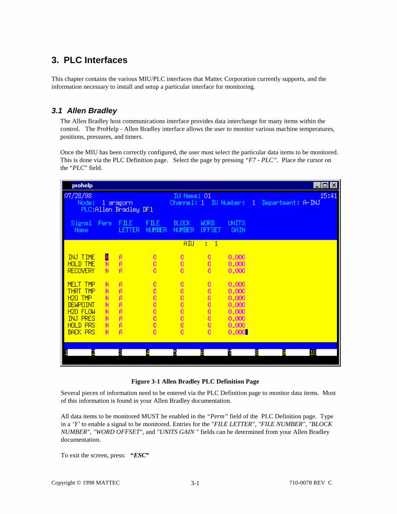
3.1 Allen BradleyThe Allen Bradley host communications interface provides data interchange for many items within thecontrol. The ProHelp - Allen Bradley interface allows the user to monitor various machine temperatures,positions, pressures, and timers.
Once the MIU has been correctly configured, the user must select the particular data items to be monitored.This is done via the PLC Definition page. Select the page by pressing “F7 - PLC”. Place the cursor onthe “PLC” field.
Figure 3-1 Allen Bradley PLC Definition Page
Several pieces of information need to be entered via the PLC Definition page to monitor data items. Mostof this information is found in your Allen Bradley documentation.
All data items to be monitored MUST be enabled in the “Perm” field of the PLC Definition page. Typein a ‘Y’ to enable a signal to be monitored. Entries for the "FILE LETTER", "FILE NUMBER", "BLOCKNUMBER", "WORD OFFSET", and "UNITS GAIN " fields can be determined from your Allen Bradleydocumentation.
To exit the screen, press: “ESC”

Copyright © 1998 MATTEC 710-0078 REV C3-2
3.2 Barber Coleman MACO 8000
The Barber Coleman MACO 8000 host communications interface provides data interchange for manyitems within the control. The ProHelp - MACO 8000 interface allows the user to monitor variousmachine temperatures, positions, pressures, and timers.
Once the MIU has been correctly configured, the user must select the particular data items to bemonitored. This is done via the PLC Definition page. Select the page by pressing “F7 - PLC”. Placethe cursor on the “PLC” field.
Figure 3-1 Barber Coleman MACO 8000 PLC Definition Page
Several pieces of information need to be entered via the PLC Definition page to monitor data items. Mostof this information is found in your Barber Coleman MACO 8000 documentation.
All data items to be monitored MUST be enabled in the “Perm” field of the PLC Definition page. Typein a ‘Y’ to enable a signal to be monitored. Entries for the "DATA TYPE", "DATA ID", "MODULEADDRES", "PARM TYPE", "PARM DESC", and "PARM #" fields can be determined from your BarberColeman MACO 8000 documentation.
To exit the screen, press: “ESC”

Copyright © 1998 MATTEC 710-0078 REV C3-3
3.3 Battenfeld Unilog 4000B
The Battenfeld Unilog 4000B host communications interface provides data interchange for many itemswithin the controller. The ProHelp - UNILOG interface allows the user to monitor various machinetemperatures, positions, pressures, and timers. Please refer to the PLC manufacturer for a list of availableparameters and their identifiers. Before continuing, please refer to Section 2 "SpecialRequirements/Restrictions".
Once the MIU has been correctly configured, the user must select the particular data items to be monitored.This is done via the PLC Definition page. Select the page by pressing “F7 - PLC”. Place the cursor onthe “PLC” field.
Figure 3-1 Battenfeld Unilog 4000B PLC Definition Page
Two items of information need to be entered via the PLC Definition page to monitor data items in theUnilog 4000B control.
All data items to be monitored MUST be enabled in the “Perm” field of the PLC Definition page. Typein a ‘Y’ to enable a signal to be monitored. The Unilog 4000B PLC Definition page requires both a linenumber and gain for each parameter. The "LINE NUMBER" is acquired from the Unilog 4000B's textEPROM and can be viewed from the CRT interface on the Battenfeld machine. Contact Battenfeld forinformation on the location of these values. The "GAIN" entry is for scaling the Pulse values in theProHelp system (i.e. to remove the automatic one place decimal, place a 10 in the “GAIN” column. If nogain is required, place a 1 in the column).
To exit the screen, press: “ESC”

Copyright © 1998 MATTEC 710-0078 REV C3-4
3.4 Buhl PPC 90
The Buhl PPC 90 host communications interface provides data interchange for many items within thecontroller. The ProHelp - Buhl interface allows the user to monitor various machine temperatures,positions, pressures, and timers. This interface supports both the IMP 2020 and the PPC 2022 Buhlmachines. Refer to the PLC manufacturer for a list of available parameters and their identifiers (BUHL -Manl 4, revision 02, Feb 1990) . Before continuing, please refer to Section 2 "SpecialRequirements/Restrictions".
Once the MIU has been correctly configured, the user must select the particular data items to be monitored.This is done via the PLC Definition page. Select the page by pressing “F7 - PLC”. Place the cursor onthe “PLC” field.
Figure 3-1 Buhl PPC90 PLC Definition Page
In order to monitor data from the Buhl controller, two items of information need to be entered via the PLCDefinition page. All data items to be monitored MUST be enabled in the “Perm” field of the PLCDefinition page. Type in a ‘Y’ to enable a signal to be monitored. Entries for the "ITEM ID" field can bedetermined from your Buhl PPC 90 Host Communications Protocol Documentation (Manl 4, revision 02,Feb 1990). The "GAIN" field is for scaling the Pulse values in the ProHelp system (i.e. to remove theautomatic one place decimal, place a 10 in the “GAIN” column. If no gain is required, place a 1 in thecolumn).
NOTE: If an invalid "ITEM ID" is entered, the value of 32769 or -32767 will be displayed as the currentvalue.
To exit the screen, press: “ESC”

Copyright © 1998 MATTEC 710-0078 REV C3-5
3.5 Cincinnati Milacron/Fanuc ACT
The Cincinnati Milacron Fanuc/ACT host communication interface provides data interchange for manyitems within the controller. The ProHelp - ACT interface allows the user to monitor various machinetemperatures, positions, pressures, and timers. Before continuing, please refer to Section 2 "SpecialRequirements/Restrictions".
Once the MIU has been correctly configured, the user must select the particular data items to be monitored.This is done via the PLC Definition page. Select the page by pressing “F7 - PLC”. Place the cursor onthe “PLC” field.
Figure 3-1 Cincinnati Milacron ACT PLC Definition Page
Five items of information need to be entered via the PLC Definition page to monitor data items in the ACTPLC.
All data items to be monitored must be enabled in the “Perm” field of the PLC Definition page. Type in a‘Y’ to enable a signal to be monitored. The entries for the "SBC1", "SBC2", "OFFSET", "LENGTH", and"GAIN" fields can be determined from your Cincinnati Milacron ACT documentation.
NOTE: The "GAIN" field must contain a positive integer (a "GAIN" of zero will force the data value tobe zero). The "SBC1" field should be set to a value between 1 - 7 and the "SBC2" field should be set tovalue between 0 - 9. These values are the same as command 1 and command 2 as described in theCincinnati Milacron ACT documentation. The definitions for these translated values are in the tablebelow. The "OFFSET" field is the data column described in the Cincinnati Milacron ACT documentationdefining the starting point of the desired data to be displayed. The "LENGTH" field is the length of theparameter and is shown in the Cincinnati Milacron documentation.
Cincinnati Milacron ACT SBC1 Parameters

Copyright © 1998 MATTEC 710-0078 REV C3-6
ProHelp Entry ACT Request ACT Reply Definition1 C E Request max and min data2 D F Request max and min data (res)3 G I Request injection molding data4 H J Request injection molding data (res)5 K L Request monitoring data6 M N Request diagnostic or alarm data7 S T Request machine status
PLC Defintion Example:_______________________________________________________________
In Cincinnati Milacron's ACT manual, the following is displayed:
CMD I2: molding dataColumn No. length contents-------------------------------------1 ~ 2 2 extruder step4 ~ 8 6 back pressure 1
If the parameter to be monitored is back pressure 1, then SBC1 is '3' (from the table on the previouspage - CMD I2 = ProHelp Entry '3'), SBC2 is '2' (CMD I2), the OFFSET is "4" (the first ColumnNumber), and the LENGTH is '6'.
To exit the screen, press: “ESC”

Copyright © 1998 MATTEC 710-0078 REV C3-7
3.6 Cincinnati Milacron Camac VLC/VEL
The Cincinnati Milacron CAMAC VLC/VEL host communications interface provides data interchangefor many items within the controller. The ProHelp - CAMAC VLC/VEL interface allows the user tomonitor various machine temperatures, positions, pressures, and timers.
Once the MIU has been correctly configured, the user must select the particular data items to bemonitored. This is done via the PLC Definition page. Select the page by pressing “F7 - PLC”. Placethe cursor on the “PLC” field.
NOTE: The Cincinnati Milacron CAMAC VLC/VEL controller is essentially identical to the CAMACXTA/XTC controller (from a data monitoring stand point). The difference lies in the "Units Gain" and"Units Offset" data entries.
Figure 3-1 Cincinnati Milacron CAMAC VLC/VEL PLC Definition Page
Five items of information need to be entered via the PLC Definition page to monitor data items in theCAMAC VLC/VEL control.
All data items to be monitored MUST be enabled in the “Perm” field of the PLC Definition page. Type ina ‘Y’ to enable a signal to be monitored. Entries for the "PACKET #", "COMM_VEC(#)", "UNITS GAIN",and "UNITS OFFSET" fields can be determined from your Cincinnati Milacron CAMAC VLC/VELdocumentation.
To exit the screen, press: “ESC”

Copyright © 1998 MATTEC 710-0078 REV C3-8
NOTES:
1. Data monitored in the CAMAC VLC/VEL controllers is in measuring units, and the "UNITS GAIN"and "UNITS OFFSET" fields need to be set to the appropriate values. Refer to your Cincinnati MilacronCAMAC VLC/VEL documentation to determine the correct values for these fields.
2. The middle two jumpers on the MBA board activate the RCV and SEND 121 ohm resistors. Thesejumpers should be removed for proper operation. The MBA board is located behind the aluminum guardpanel on the VLC/VEL Cincinnati Milacron machine.
PLC Definition Example:_______________________________________________________________
To determine the "UNITS GAIN" and "UNITS OFFSET" for the screw position (cushion or transfer),search Cincinnati Milacron's documentation for the section "SLOPES FOR LCD CONVERSIONS" andfind "SCREW POSITION" (Packet 139, comm_vec 1385).
Through ProHelp, get the value at packet 139, comm_vec 1385 (For this step, set GAIN = to 1 andOFFSET = to 0). If the value were 5776 (ignore all decimal place locations) then 1/5776 (1 divided by5776) = 0.000173. From this, "UNITS GAIN" from the cushion position (or transfer position) becomes0.173 (remove leading zero).
For the offset, search Cincinnati Milacron's documentation for the section "OFFSETS FOR LCDCONVERSION" and find "SCREW POSITION".
Through ProHelp, get the value and place it in the "UNITS OFFSET" column for the cushion position(No calcs. needed - normally offset is zero).
3. Slave addresses are never 0. Normally the slave address is 1. See the Cincinnati Milacron hostinterface specification.
WARNING: Once the proper slave address is determined, 0's for any enabled signal will cause themachine control to lock up.

Copyright © 1998 MATTEC 710-0078 REV C3-9
3.7 Cincinnati Milacron Camac XTA/XTC
The Cincinnati Milacron CAMAC XTA/XTC host communications interface provides data interchange formany items within the controller. The ProHelp - CAMAC XTA/XTC interface allows the user to monitorvarious machine temperatures, positions, pressures, and timers.
Once the MIU has been correctly configured, the user must select the particular data items to be monitored.This is done via the PLC Definition page. Select the page by pressing “F7 - PLC”. Place the cursor onthe “PLC” field.
Figure 3-1 Cincinnati Milacron CAMAC XTA/XTC PLC Definition Page
Five items of information need to be entered via the PLC Definition page to monitor data items in theCAMAC XTA/XTC controller.
All data items to be monitored MUST be enabled in the “Perm” field of the PLC Definition page. Type ina ‘Y’ to enable a signal to be monitored. Entries for the "PACKET #", "COMM_VEC(#)", "UNITS GAIN",and "UNITS OFFSET" fields can be determined from your Cincinnati Milacron CAMAC XTA/XTCdocumentation.
NOTE: Data monitored in the CAMAC XTA/XTC controllers is in process units; and unless otherwisenoted, the "UNITS GAIN" field should be set for a value of 1.000, and the "UNITS OFFSET" field set for avalue of 0. Refer to your Cincinnati Milacron CAMAC XTA/XTC documentation for more information.
To exit the screen, press: “ESC”

Copyright © 1998 MATTEC 710-0078 REV C3-10
3.8 Cincinnati Milacron Camac XTL
The Cincinnati Milacron CAMAC XTL host communications interface provides data interchange for manyitems within the controller. The ProHelp - CAMAC XTL interface allows the user to monitor variousmachine temperatures, positions, pressures and timers. Before continuing, please refer to Section 2"Special Requirements/Restrictions".
Once the MIU has been correctly configured, the user must select the particular data items to be monitored.This is done via the PLC Definition page. Select the page by pressing “F7 - PLC”. Place the cursor onthe “PLC” field.
Figure 3-1 Cincinnati Milacron CAMAC XTL PLC Definition Page
Four pieces of information are needed for each item that will be monitored - the “ITEM”, “ SCALE”,“SLOPE”, and “OFFSET” vector numbers.
All data items to be monitored MUST be enabled in the “Perm” field of the PLC Definition page. Type a'Y' to enable a signal to be monitored. Entries for the "ITEM VEC#", "SCALE VEC#", "SLOPE VEC#",and the "OFFSET VEC#" fields can be determined form your Cincinnati Milacron CAMAC XTLdocumentation. When entering an “ITEM VEC#”, note the convert index associated with the item. The“SCALE VEC#”, “SLOPE VEC#”, and the “OFFSET VEC#” can then be determined by matching thecorrect convert index from the SCALING DATA table. (Reference Appendix A of this manual.)
To exit the screen, press: “ESC”

Copyright © 1998 MATTEC 710-0078 REV C3-11
NOTES:
1. For CONVERT index numbers greater than or equal to 255, take the convert number and subtract 255from it. Additionally, ignore all negative CONVERT numbers (assume absolute value).
2. In s_miu, the decimal places column for the analog signals changes the precision of the number, ratherthan the location of the decimal. For example, if the number displayed at the CAMAC XTL PLC is0.659, then ProHelp would yield the following results:
3. Dec Pls <would be displayed as …>
0 01 0.62 0.653 0.659
The precision of the first three signal values cannot be changed.
3. The time required for the MIU to gather data from the PLC can be as long as 6 seconds; therefore, theCAMAC XTL PLC interface is not recommended for cycle times less than 7 seconds.
4. The 'Slave Address' in ProHelp must be the same as the 'Machine ID' at the CAMAC XTL
5. The host communication baud rate at the CAMAC XTL must be set to 4800.
PLC Definition Example:_______________________________________________________________
In figure 3.7.2, PULSE 2 contains a RW_CONV_VEC number (ITEM VEC # - 1175) for "Zone 1"temperature (Refer to Table "ACTUAL CYCLE DATA" - Cincinnati Milacron's XTL Documentation).
For Zone 1 temperature, the Convert Index is zero (Unity), therefore, the Scale (SCALE VEC #)RW_CONV_VEC number is 1040, the Slope (SLOPE VEC #) is 1080, and the offset (OFFSET VEC#) is 1120 (Scale, Slope, and Offset is located in the Table "SCALING DATA" - Cincinnati Milacron'sXTL Documentation).

Copyright © 1998 MATTEC 710-0078 REV C3-12
3.9 Cincinnati Milacron Ferromatic
The Cincinnati Milacron Ferromatic host communications interface provides data interchange for manyitems within the controller. The ProHelp - Ferromatic interface allows the user to monitor various machinetemperatures, positions, pressures and timers. Before continuing, please refer to Section 2 "SpecialRequirements/Restrictions".
Once the MIU has been correctly configured, the user must select the particular data items to be monitored.This is done via the PLC Definition page. Select the page by pressing “F7 - PLC”. Place the cursor onthe “PLC” field.
NEED REAL SCREEN HERE:
Figure 3-1 Cincinnati Milacron Ferromatic PLC Definition Screen
NEED REAL TEXT IN THIS PART: Four pieces of information are needed for each item that will bemonitored - the “ITEM”, “ SCALE”, “SLOPE”, and “OFFSET” vector numbers.
All data items to be monitored MUST be enabled in the “Perm” field of the PLC Definition page. Type a'Y' to enable a signal to be monitored. Entries for the "ITEM VEC#", "SCALE VEC#", "SLOPE VEC#",and the "OFFSET VEC#" fields can be determined form your Cincinnati Milacron CAMAC XTLdocumentation. When entering an “ITEM VEC#”, note the convert index associated with the item. The“SCALE VEC#”, “SLOPE VEC#”, and the “OFFSET VEC#” can then be determined by matching thecorrect convert index from the SCALING DATA table. (Reference Appendix A of this manual.)
To exit the screen, press: “ESC”

Copyright © 1998 MATTEC 710-0078 REV C3-13
3.10 Engel EC88/CC90
The Engel EC88/CC90 host communications interface provides data interchange for many items withinthe controller. The ProHelp - Engel interface allows the user to monitor various machine temperatures,positions, pressures, and timers.
Once the MIU has been correctly configured, the user must select the particular data items to bemonitored. This is done via the PLC Definition page. Select the page by pressing “F7 - PLC”. Placethe cursor on the “PLC” field.
Figure 3-1 Engel EC88/CC90 PLC Definition Page
Two items of information need to be entered via the PLC Definition page to monitor data items in theEngel controller.
All data items to be monitored MUST be enabled in the “Perm” field of the PLC Definition page. Type ina ‘Y’ to enable a signal to be monitored. Entries for the "GROUP MEMBER" and "MEMBER NUMBER"fields can be determined from your Engel EC88/CC90 documentation.
NOTE: The EC88/CC90's host communications port must be configured for 4800 baud.
To exit the screen, press: “ESC”

Copyright © 1998 MATTEC 710-0078 REV C3-14
3.11 Gefran Elettronica
The Gefran Elettronica host communications interface provides data interchange for many items within thecontrol. The ProHelp - Gefran Elettronica interface allows the user to monitor various registers withinGefran controllers. Before continuing, please refer to Section 2 "Special Requirements/Restrictions".
Once the MIU has been correctly configured, the user must select the particular data items to be monitored.This is done via the PLC Definition page. Select the page by pressing “F7 - PLC”. Place the cursor onthe “PLC” field.
Figure 3-1 Gefran Elettronica PLC Definition Page
All data items to be monitored MUST be enabled in the “Perm” field of the PLC definition page. Type ina ‘Y’ to enable a signal to be monitored. Five items of information need to be entered via the PLCDefinition page to monitor data items in the Gefran Elettronica control. The Gefran Elettronica PLCDefinition page requires a MIU speed, “PLC ADDRESS”, “DATA TYPE”, “DATA ADDRESS”, “GAIN”and “PLC TYPE”.
The "MIU SPEED" entry is the baud rate of the PLC interfaced to the MIU. The baud rates to choose fromare 1200, 4800 and 9600. If this field is changed, the MIU's power must be cycled.
To select a particular baud rate:
Place the cursor on the entryPress: left shift button downHit: greater than sign (>)Once you see the correct selection:Press: (enter)

Copyright © 1998 MATTEC 710-0078 REV C3-15
The "PLC ADDRESS" entry is the address of the PLC that is being used to monitor a particular parameter.
The "DATA TYPE" entry is the number of bytes to be read from the PLC (refer to the Gefran PLC Manualunder the Memory Map section). A (W) represents 2 bytes and a (B) represents 1 byte.
To select (W) or (B):
Place cursor on the entryPress: left shift button downHit: greater than sign (>)Once you see the correct selection:Press: (enter)
The "DATA ADDRESS" entry is the address of the data register at the PLC (refer to the Gefran PLCManual under the Memory map section). See note.
The "GAIN" entry is for scaling the pulse values in the ProHelp system (i.e. to remove the automatic oneplace decimal, place a 10 in the “GAIN” column. If no gain is required place a 1 in the column).
The "PLC TYPE" entry is a 6 character label to represent the type of PLC used for a particular parameter.
NOTE: ALL NUMERIC ENTERIES MUST BE IN DECIMAL FORM. For example, address H6F wouldbe 111 in decimal. See Appendix A - Hexidecimal to Decimal Conversion Table.
To exit the screen, press: “ESC”

Copyright © 1998 MATTEC 710-0078 REV C3-16
3.12 Gefran Elettronica Negri EL2
The Gefran Elettronica Negri EL2 host communications interface provides data interchange for many itemswithin the control. The ProHelp - Negri EL2 interface allows the user to monitor various registers withinGefran controllers. Before continuing, please refer to Section 2 "Special Requirements/Restrictions".
Once the MIU has been correctly configured, the user must select the particular data items to be monitored.This is done via the PLC Definition page. Select the page by pressing “F7 - PLC”. Place the cursor onthe “PLC” field.
Figure 3-1 Gefran Elettronica Negri EL2 PLC Definition Screen
NEED REAL DATA HERE: All data items to be monitored MUST be enabled in the “Perm” field ofthe PLC definition page. Type in a ‘Y’ to enable a signal to be monitored. Five items of information needto be entered via the PLC Definition page to monitor data items in the Gefran Elettronica control. TheGefran Elettronica PLC Definition page requires a MIU speed, “PLC ADDRESS”, “DATA TYPE”,“DATA ADDRESS”, “GAIN” and “PLC TYPE”.
The "MIU SPEED" entry is the baud rate of the PLC interfaced to the MIU. The baud rates to choose fromare 1200, 4800 and 9600. If this field is changed, the MIU's power must be cycled.
To select a particular baud rate:
Place the cursor on the entryPress: left shift button downHit: greater than sign (>)

Copyright © 1998 MATTEC 710-0078 REV C3-17
Once you see the correct selection:Press: (enter)
The "PLC ADDRESS" entry is the address of the PLC that is being used to monitor a particular parameter.
The "DATA TYPE" entry is the number of bytes to be read from the PLC (refer to the Gefran PLC Manualunder the Memory Map section). A (W) represents 2 bytes and a (B) represents 1 byte.
To select (W) or (B):
Place cursor on the entryPress: left shift button downHit: greater than sign (>)Once you see the correct selection:Press: (enter)
The "DATA ADDRESS" entry is the address of the data register at the PLC (refer to the Gefran PLCManual under the Memory map section). See note.
The "GAIN" entry is for scaling the pulse values in the ProHelp system (i.e. to remove the automatic oneplace decimal, place a 10 in the “GAIN” column. If no gain is required place a 1 in the column).
The "PLC TYPE" entry is a 6 character label to represent the type of PLC used for a particular parameter.
NOTE: ALL NUMERIC ENTERIES MUST BE IN DECIMAL FORM. For example, address H6F wouldbe 111 in decimal. See Appendix A - Hexidecimal to Decimal Conversion Table.
To exit the screen, press: “ESC”
NOTES: Parameter Address List for Gefran EL2 NegriBossi PLC
NBV2R07 and NBV2R10 Software:Melt Temp 43,054 (A82E)Mould Temp - Moving 43,056 (A830)Mould Temp - Fixed 43,058 (A832)Filling Time 43,060 (A834)Plasticising Time 43,062 (A836)Cycle Time 43,064 (A838)Clamping Force 43,066 (A83A)Cushion Position 43,068 (A83C)Switchover Position 43,070 (A83E)Plasticising Position 43,072 (A840)Max Injector Speed 43,074 (A842)Max Screw Rotate Speed 43,078 (A846)Mean Screw Rotate Speed 43,080 (A848)Max Injection Pressure 43,082 (A84A)Switchover Hydraulic Pressure 43,084 (A84C)Max Back Pressure 43,086 (A84E)Mean Back Pressure 43,088 (A850)Cavity Pressure Switchover 43,090 (A852)Max Cavity Pressure 43,092 (A854)Injection Energy 43,094 (A856)

Copyright © 1998 MATTEC 710-0078 REV C3-18
NBV1R101 and NBV3R50 Software:Melt Temp 43,168 (A8A0)Mould Temp - Moving 43,170 (A8A2)Mould Temp - Fixed 43,172 (A8A4)Filling Time 43,174 (A8A6)Plasticising Time 43,176 (A8A8)Cycle Time 43,178 (A8AA)Clamping Force 43,180 (A8AC)Cushion Position 43,182 (A8AE)Switchover Position 43,184 (A8B0)Plasticising Position 43,186 (A8B2)Max Injector Speed 43,188 (A8B4)Max Screw Rotate Speed 43,192 (A8B8)Mean Screw Rotate Speed 43,194 (A8BA)Max Injection Pressure 43,196 (A8BC)Switchover Hydraulic Pressure 43,198 (A8BE)Max Back Pressure 43,200 (A8C0)Mean Back Pressure 43,202 (A8C2)Cavity Pressure Switchover 43,204 (A8C4)Max Cavity Pressure 43,206 (A8C6)Injection Energy 43,208 (A8C8)
PLC address must always be "0" zero. Data Type for all of the above listed parameters must be "W".MIU speed must be set at 9600.

Copyright © 1998 MATTEC 710-0078 REV C3-19
3.13 Gefran NegriBossi Printer PLC
The Gefran NegriBossi Printer PLC host communications interface provides data interchange for manyitems within the control. The ProHelp Gefran NegriBossi Printer PLC interface allows the userWHAT?
Once the MIU has been correctly configured, the user must select the particular data items to be monitored.This is done via the PLC Definition page. Select the page by pressing “F7 - PLC”. Place the cursor onthe “PLC” field.
Figure 3-1 Gefran NegriBossi Printer Definition ScreenAll data items to be monitored MUST be enabled in the “Perm” field of the PLC definition page. Type ina ‘Y’ to enable a signal to be monitored. Four items of information need to be entered via the PLCDefinition page to monitor data items in the Gefran NegriBossi Printer PLC control. The GefranNegriBossi Printer PLC Definition page requires a PLC address, “PARM NUM”, “UNITS GAIN” and“UNITS OFFSET”.
NOTES: Machine must be set to "auto print" every cycle. Parameters can be identified by the last 10cycles screen on the machine control panel or by the following printout example.
Printer Example:Cycle No. Cycle Time
(sec)Inject Time(sec)
Plast Time(sec)
Cushi Size(mm)
Hydra Peak(bar)
13 58.0 6.3 12.5 1.4 20

Copyright © 1998 MATTEC 710-0078 REV C3-20
3.14 GE Fanuc
The GE Fanuc interface provides data interchange for many items within the control. The ProHelp GEFanuc interface allows the user to monitor various registers within GE Fanuc controllers. Beforecontinuing, please refer to Section 2 "Special Requirements/Restrictions".
Once the MIU has been correctly configured, the user must select the particular data items to be monitored.This is done via the PLC Definition page. Select the page by pressing “F7 - PLC”. Place the cursor onthe “PLC” field.
Figure 3-1 GE Fanuc PLC Definition Screen
All data items to be monitored MUST be enabled in the “Perm” field of the PLC definition page. Type ina ‘Y’ to enable a signal to be monitored. Three items of information need to be entered via the PLCDefinition page to monitor data items in the GE Fanuc PLC control. The Gefran NegriBossi Printer PLCDefinition page requires a “SEGMNT”, “SEGMNT OFFSET” and “UNITS GAIN”.
To exit the screen, press: “ESC”
Copyright © 1998 MATTEC 710-0078 REV C3-21
3.15 HPM CMD90
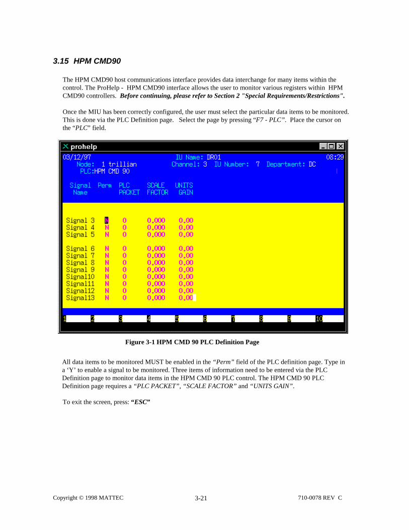
The HPM CMD90 host communications interface provides data interchange for many items within thecontrol. The ProHelp - HPM CMD90 interface allows the user to monitor various registers within HPMCMD90 controllers. Before continuing, please refer to Section 2 "Special Requirements/Restrictions".
Once the MIU has been correctly configured, the user must select the particular data items to be monitored.This is done via the PLC Definition page. Select the page by pressing “F7 - PLC”. Place the cursor onthe “PLC” field.
Figure 3-1 HPM CMD 90 PLC Definition Page
All data items to be monitored MUST be enabled in the “Perm” field of the PLC definition page. Type ina ‘Y’ to enable a signal to be monitored. Three items of information need to be entered via the PLCDefinition page to monitor data items in the HPM CMD 90 PLC control. The HPM CMD 90 PLCDefinition page requires a “PLC PACKET”, “SCALE FACTOR” and “UNITS GAIN”.
To exit the screen, press: “ESC”

Copyright © 1998 MATTEC 710-0078 REV C3-22
3.16 Inoex Saveomat
The Inoex Saveomat host communications interface provides data interchange for many items within thecontrol. The ProHelp - Inoex Saveomat interface allows the user to monitor various registers within InoexSaveomat controllers. Before continuing, please refer to Section 2 "Special Requirements/Restrictions".
Once the MIU has been correctly configured, the user must select the particular data items to be monitored.This is done via the PLC Definition page. Select the page by pressing “F7 - PLC”. Place the cursor onthe “PLC” field.
Figure 3-1 Inoex Saveomat PLC Definition Page
All data items to be monitored MUST be enabled in the “Perm” field of the PLC definition page. Type ina ‘Y’ to enable a signal to be monitored. Two items of information need to be entered via the PLCDefinition page to monitor data items in the Inoex Saveomat PLC control. The Inoex Saveomat PLCDefinition page requires a “PLC PARM #” and “UNITS GAIN”.
To exit the screen, press: “ESC”

Copyright © 1998 MATTEC 710-0078 REV C3-23
3.17 Inoex Saveomat 93
The Inoex Saveomat 93 host communications interface provides data interchange for many items withinthe control. The ProHelp - Inoex Saveomat 93 interface allows the user to monitor various registers withinInoex Saveomat 93 controllers. Before continuing, please refer to Section 2 "SpecialRequirements/Restrictions".
Once the MIU has been correctly configured, the user must select the particular data items to be monitored.This is done via the PLC Definition page. Select the page by pressing “F7 - PLC”. Place the cursor onthe “PLC” field.
Figure 3-1 Inoex Saveomat 93 PLC Definition Page
All data items to be monitored MUST be enabled in the “Perm” field of the PLC definition page. Type ina ‘Y’ to enable a signal to be monitored. Two items of information need to be entered via the PLCDefinition page to monitor data items in the Inoex Saveomat 93 PLC control. The Inoex Saveomat 93 PLCDefinition page requires a "PARM ID” and “UNITS GAIN”.
The following item is a key point in making the Inoex Saveomat 93 interface operate correctly: The baudrate should be configured for 9600 (no partity).
Inoex 93 Screen DescriptionPARM ID - This number is used to choose the data position in the data stream.
GAIN - This number is used to change decimal places to a resolution ProHelp can understand. ProHelpcan only use 0 to 3 decimal places.
To exit the screen, press: “ESC”

Copyright © 1998 MATTEC 710-0078 REV C3-24
3.18 Klöckner FMT
The Klöckner Ferromatik Desma (FMT) host communications interface provides data interchange formany items within the controller. The ProHelp - Klöckner interface allows the user to monitor variousmachine temperatures, positions, pressures, and timers. This interface supports the Klöckner machine withthe Phillips Control as opposed to the MPC80.
Once the MIU has been correctly configured, the user must select the particular data items to be monitored.This is done via the PLC Definition page. Select the page by pressing “F7 - PLC”. Place the cursor onthe “PLC” field.
Figure 3-1 Klöckner FMT PLC Definition Page
Three items of information need to be entered via the PLC Definition page to monitor data items in theKlöckner controller.
All data items to be monitored MUST be enabled in the “Perm” field of the PLC Definition page. Type ina ‘Y’ to enable a signal to be monitored. Entries for the "ITEM ID", "INDEX X", and "INDEX Y" fieldscan be determined from your Klöckner FMT documentation. For array values, the "INDEX X" and"INDEX Y" fields contain the dimensional array index for the variable arrays. (These fields should containa 0 if the item is not included in an array).
To exit the screen, press: “ESC”

Copyright © 1998 MATTEC 710-0078 REV C3-25
3.19 Klöckner MPC-80
The Klöckner Ferromatik Desma MPC-80 host communications interface provides data interchange formany items within the controller. The ProHelp - Klöckner interface allows the user to monitor variousmachine temperatures, positions, pressures, and timers. Before continuing, please refer to Section 2"Special Requirements/Restrictions".
Once the MIU has been correctly configured, the user must select the particular data items to be monitored.This is done via the PLC Definition page. Select the page by pressing “F7 - PLC”. Place the cursor onthe “PLC” field.
Figure 3-1 Klöckner MPC-80 PLC Definition Page
One item of information is needed to be entered via the PLC Definition page to monitor data items in theKlöckner MPC-80 controller.
All data items to be monitored MUST be enabled in the “Perm” field of the PLC Definition page. Type ina ‘Y’ to enable a signal to be monitored. Entries for the "ITEM ID" field can be determined from yourKlöckner MPC-80 documentation.
To exit the screen, press: “ESC”

Copyright © 1998 MATTEC 710-0078 REV C3-26
NOTES:
1. All enabled “ITEM IDs” must be in one of the following formats:XXXXXX (single parameter)XXXXXX.XX (array value)XXXXXX.XX.XX (two dimensional array value)
X = A letter or a number
2. Host communications use the only printer port available on the MPC-80.
3. Page 5 on the MPC-80 must be set to "host" for the port configuration.

Copyright © 1998 MATTEC 710-0078 REV C3-27
3.20 Krauss Maffei
The Krauss Maffei host communications interface provides data interchange for many items within thecontrol. The ProHelp - Krauss Maffei interface allows the user to monitor various registers the controllers.Before continuing, please refer to Section 2 "Special Requirements/Restrictions".
Once the MIU has been correctly configured, the user must select the particular data items to be monitored.This is done via the PLC Definition page. Select the page by pressing “F7 - PLC”. Place the cursor onthe “PLC” field.
Figure 3-1 Krauss Maffei PLC Definition Page
All data items to be monitored MUST be enabled in the “Perm” field of the PLC definition page. Type ina ‘Y’ to enable a signal to be monitored. Three items of information need to be entered via the PLCDefinition page to monitor data items in the Krauss Maffei PLC control. The Krauss Maffei PLCDefinition page requires a "PARM TYPE”, "PARM NUM", and “UNITS GAIN”.
To exit the screen, press: “ESC”
Copyright © 1998 MATTEC 710-0078 REV C3-28
3.21 MAC 90 PLC
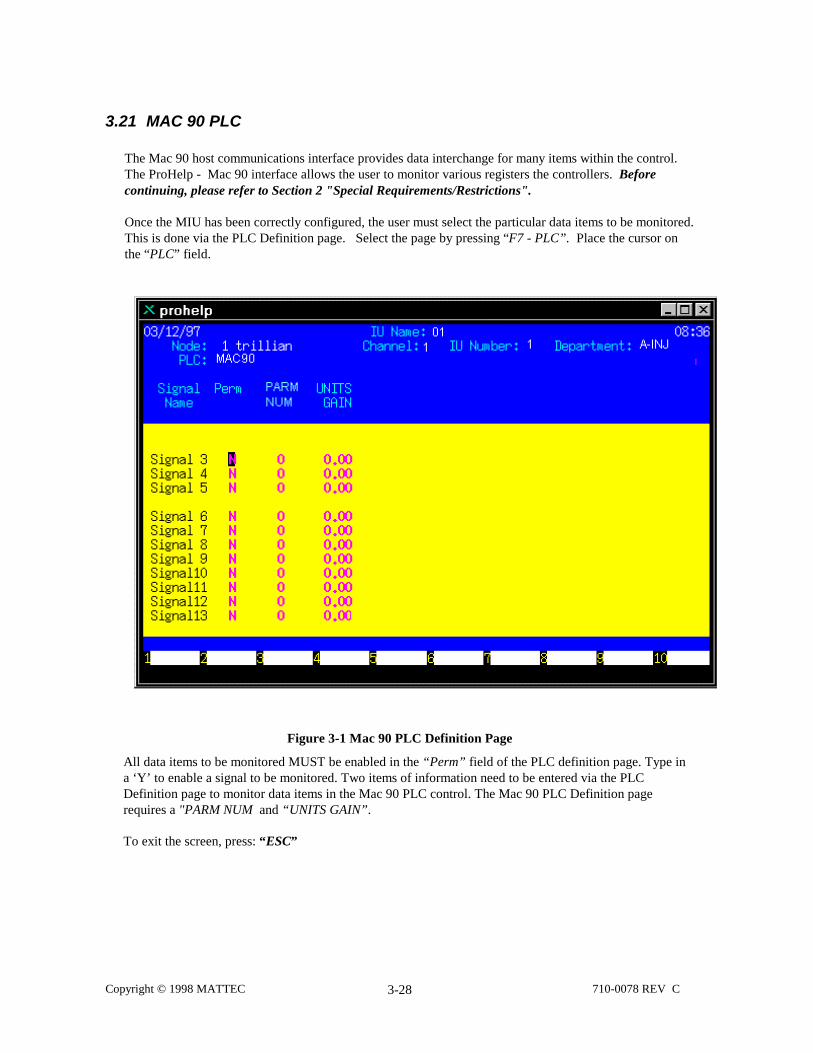
The Mac 90 host communications interface provides data interchange for many items within the control.The ProHelp - Mac 90 interface allows the user to monitor various registers the controllers. Beforecontinuing, please refer to Section 2 "Special Requirements/Restrictions".
Once the MIU has been correctly configured, the user must select the particular data items to be monitored.This is done via the PLC Definition page. Select the page by pressing “F7 - PLC”. Place the cursor onthe “PLC” field.
Figure 3-1 Mac 90 PLC Definition Page
All data items to be monitored MUST be enabled in the “Perm” field of the PLC definition page. Type ina ‘Y’ to enable a signal to be monitored. Two items of information need to be entered via the PLCDefinition page to monitor data items in the Mac 90 PLC control. The Mac 90 PLC Definition pagerequires a "PARM NUM and “UNITS GAIN”.
To exit the screen, press: “ESC”
Copyright © 1998 MATTEC 710-0078 REV C3-29
3.22 Maruka Toyo
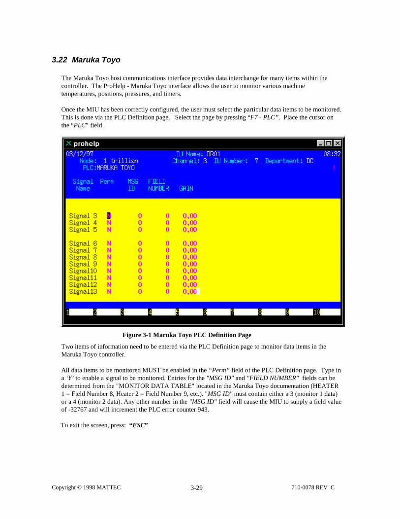
The Maruka Toyo host communications interface provides data interchange for many items within thecontroller. The ProHelp - Maruka Toyo interface allows the user to monitor various machinetemperatures, positions, pressures, and timers.
Once the MIU has been correctly configured, the user must select the particular data items to be monitored.This is done via the PLC Definition page. Select the page by pressing “F7 - PLC”. Place the cursor onthe “PLC” field.
Figure 3-1 Maruka Toyo PLC Definition Page
Two items of information need to be entered via the PLC Definition page to monitor data items in theMaruka Toyo controller.
All data items to be monitored MUST be enabled in the “Perm” field of the PLC Definition page. Type ina ‘Y’ to enable a signal to be monitored. Entries for the "MSG ID" and "FIELD NUMBER" fields can bedetermined from the "MONITOR DATA TABLE" located in the Maruka Toyo documentation (HEATER1 = Field Number 8, Heater 2 = Field Number 9, etc.). "MSG ID" must contain either a 3 (monitor 1 data)or a 4 (monitor 2 data). Any other number in the "MSG ID" field will cause the MIU to supply a field valueof -32767 and will increment the PLC error counter 943.
To exit the screen, press: “ESC”

Copyright © 1998 MATTEC 710-0078 REV C3-30
NOTES:
1. For communications to operate, the PLC printer mode must be turned on at the Maruka Toyo PLC viathe control panel.
2. The PLC baud rate should be set to 4800. This is accomplished by setting PLC DPSW 4 on the edgeof the PLC MPU board, switch 5 OFF and switch 6 ON.

Copyright © 1998 MATTEC 710-0078 REV C3-31
3.23 Mitsubishi MAC-VI
The Mitsubishi MAC-VI host communications interface provides data interchange for many items withinthe control. The ProHelp - Mitsubishi MAC-VI interface allows the user to monitor various registerswithin Mitsubishi MAC-VI controllers. Before continuing, please refer to Section 2 "SpecialRequirements/Restrictions".
Once the MIU has been correctly configured, the user must select the particular data items to be monitored.This is done via the PLC Definition page. Select the page by pressing “F7 - PLC”. Place the cursor onthe “PLC” field.
Figure 3-1 Mitsubishi MAC-VI PLC Definition Page
To exit the screen, press: “ESC”

Copyright © 1998 MATTEC 710-0078 REV C3-32
3.24 Moog Mopac 22MP
The Moog MOPAC 22MP (Modicon Protocol) host communications interface provides data interchangefor many items within the control. The ProHelp - MOPAC 22 interface allows the user to monitor variousmachine temperatures, positions, pressures, and timers.
Once the MIU has been correctly configured, the user must select the particular data items to be monitored.This is done via the PLC Definition page. Select the page by pressing “F7 - PLC”. Place the cursor onthe “PLC” field.
Figure 3-1 Moog MOPAC 22MP PLC Definition Page
Three items of information need to be entered via the PLC Definition page to monitor data items in theMOPAC 22MP control.
All data items to be monitored MUST be enabled in the “Perm” field of the PLC Definition page. Type ina ‘Y’ to enable a signal to be monitored. Entries for the "HV" and "LV" fields can be determined from yourMoog MOPAC 22MP documentation ("COMMUNICATING WITH THE MOPAC 22"). The "GAIN" fieldis for scaling the Pulse values in the ProHelp system (i.e. to remove the automatic one place decimal, placea 10 in the “GAIN” column. If no gain is required, place a 1 in the column).
To exit the screen, press: “ESC”

Copyright © 1998 MATTEC 710-0078 REV C3-33
3.25 Moog Mopac 22
The Moog MOPAC 22 host communications interface provides data interchange for many items within thecontrol. The ProHelp - MOPAC 22 interface allows the user to monitor various machine temperatures,positions, pressures, and timers.
Once the MIU has been correctly configured, the user must select the particular data items to be monitored.This is done via the PLC Definition page. Select the page by pressing “F7 - PLC”. Place the cursor onthe “PLC” field.
Figure 3-1 Moog MOPAC 22 PLC Definition Page
Three items of information need to be entered via the PLC Definition page to monitor data items in theMOPAC 22 control.
All data items to be monitored MUST be enabled in the “Perm” field of the PLC Definition page. Type ina ‘Y’ to enable a signal to be monitored. Entries for the "LOW ADDRES" and "HIGH ADDRES" fields canbe determined from your Moog MOPAC 22 documentation.
To exit the screen, press: “ESC”

Copyright © 1998 MATTEC 710-0078 REV C3-34
3.26 Netstall
The Netstall host communications interface provides data interchange for many items within the control.The ProHelp - Netstall interface allows the user to monitor various machine temperatures, positions,pressures, and timers.
Once the MIU has been correctly configured, the user must select the particular data items to be monitored.This is done via the PLC Definition page. Select the page by pressing “F7 - PLC”. Place the cursor onthe “PLC” field.
Figure 3-1 Netstall PLC Definition Screen
All data items to be monitored MUST be enabled in the “Perm” field of the PLC Definition page. Type ina ‘Y’ to enable a signal to be monitored. Entries for the "PARM NUM" and "UNITS GAIN" fields can bedetermined from your Netstall documentation.
To exit the screen, press: “ESC”

Copyright © 1998 MATTEC 710-0078 REV C3-35
NOTE:PI Manufacturing Parallel/Serial Converter
Parallel/Serial Converter Framing
4800 Baud1 Stop8 DataNo-parity
Parallel/Serial Converter Switch Settings
1,2 On3-8 Off

Copyright © 1998 MATTEC 710-0078 REV C3-36
3.27 Nissei - 9000G, 8300F and 9300T
The Nissei host communications interface provides data interchange for many items within the controller.The ProHelp - Nissei 9000G, 8300F, and 9300T interface allows the user to monitor various machinetemperatures, positions, pressures, and timers.
Once the MIU has been correctly configured, the user must select the particular data items to be monitored.This is done via the PLC Definition page. Select the page by pressing “F7 - PLC”. Place the cursor onthe “PLC” field.
Figure 3-1 Nissei PLC Definition Page
All data items to be monitored MUST be enabled in the “Perm” field of the PLC Definition page. Type a‘Y’ to enable a signal to be monitored. Three items of information need to be entered via the PLCDefinition page to monitor data items in the Nissei controller: a PLC address, “ITEM NUMBER”, and“GAIN”.
To exit the screen, press: “ESC”
NOTE:
1. The "PLC Address" field contains the address of the PLC that is sent to the MIU. It can bedetermined from the switch settings on the PLC controller board.
2. Entries for the "ITEM NUMBER" field can be determined from the "Molding Condition Save" tablein Section 5-2 of your Nissei NC8300 FT-10 Communication spec.

Copyright © 1998 MATTEC 710-0078 REV C3-37
3. The "GAIN" entry is for scaling the pulse values in the ProHelp system. For example, to remove theautomatic one place decimal, place a 10 in the "GAIN" column. If no gain is required, place a 1 inthe column.

Copyright © 1998 MATTEC 710-0078 REV C3-38
See table below.
0.01 Divide by 100 0.10 Divide by 10 1.00 Normal
10.00 Multiply by 10100.00 Multiply by 100
Switch Settings
The following settings apply to the Nissei 9000G (25 Pin D sub connector):
Dip 1 1 OFF Dip 2 1 ON2 OFF 2 OFF3 OFF 3 OFF4 OFF 4 OFF5 OFF 5 OFF6 OFF 6 OFF7 OFF 7 OFF8 ON 8 OFF
• Switch selection definition:• Baud Rate = 4800• Host Slave Address = 1
The following settings apply to the Nissei 9000G (9 Pin D sub connector):
• Software switches are on the LCD Screen of the Control• Baud Rate = 4800• Host Slave Address = 1
The following settings apply to the Nissei 8300F (FT-10):
Dip 1 1 OFF Dip 2 1 ON2 OFF 2 OFF3 OFF 3 OFF4 OFF 4 OFF5 OFF 5 OFF6 OFF 6 OFF7 OFF 7 OFF8 ON 8 OFF
• Switch selection definition:• Baud Rate = 4800• Host Slave Address = 1
The following settings apply to the Nissei 9300T:The MIU is the Master and will initiate communications.
• MIU Poll Request → [EOT] [Mach address] ['tx'] [ENQ] [BCC]• Nissei 9300 Response ← [ACK]• Nissei 9300 Response ← [STX] ['HO'] [Data] [ETX] [BCC]• MIU Response ← [ACK]
MACHINE SETUP NOTES:

Copyright © 1998 MATTEC 710-0078 REV C3-39
1. Hit the Compile key on controller screen panel. Change baud rate on screen to the above framing.2. Find the PC board mounted on the controller door behind the front panel screen. Look for DIP 1
underneath the bottom of board. Put switch #4 of DIP 1 in the ON position. Next, cycle the power ofmachine.
3. After machine has re-powered, hit the Shift key and the Main Data key at the same time. Look for theword "NC-NET" on the screen. Touch the word to toggle it on or off. Make sure it is ON. Set DIP 1switch #4 OFF and recycle the machine.
NOTE:
Nissei requires isolation between their 9 pin and the outside world for warranty purposes. They suggest aTelebyte RS-232 Isolation DB25 - DB25, Model #282, Phone 1-800-835-3298.

Copyright © 1998 MATTEC 710-0078 REV C3-40
3.28 Nissei 8000
The Nissei 8000 host communications interface provides data interchange for many items within thecontroller. The ProHelp - Nissei 8000 interface allows the user to monitor various machine temperatures,positions, pressures, and timers.
Once the MIU has been correctly configured, the user must select the particular data items to be monitored.This is done via the PLC Definition page. Select the page by pressing “F7 - PLC”. Place the cursor onthe “PLC” field.
Figure 3-1 Nissei 8000 PLC Definition Page
All data items to be monitored MUST be enabled in the “Perm” field of the PLC Definition page. Type a‘Y’ to enable a signal to be monitored. Three items of information need to be entered via the PLCDefinition page to monitor data items in the Nissei controller: a PLC address, “PARM NUMBER”,"PARM LENGTH" and “UNITS GAIN”.
To exit the screen, press: “ESC”

Copyright © 1998 MATTEC 710-0078 REV C3-41
Switch Settings
The following apply to the Nissei 8000:
Baud Dip 1 OFF Func Dip 1 ON Addr Dip 1 OFF2 OFF 2 OFF 2 OFF3 OFF 3 OFF 3 OFF4 OFF 4 OFF 4 OFF5 OFF 5 OFF 5 OFF6 OFF 6 OFF 6 OFF7 ON 7 ON 7 OFF8 OFF 8 OFF 8 ON
Host Slave Address = 1

Copyright © 1998 MATTEC 710-0078 REV C3-42
3.29 SCI Scoremaster
The SCI Scoremaster host communications interface provides data interchange for many items within thecontrol. The ProHelp - Scoremaster interface allows the user to monitor various machine temperatures,positions, pressures, and timers. Before continuing, please refer to Section 2 "SpecialRequirements/Restrictions".
Once the MIU has been correctly configured, the user must select the particular data items to be monitored.This is done via the PLC Definition page. Select the page by pressing “F7 - PLC”. Place the cursor onthe “PLC” field.
Figure 3-1 SCI Scoremaster PLC Definition Page
To exit the screen, press: “ESC”
NOTE:
1. Valid machine addresses range from 225 to 255.

Copyright © 1998 MATTEC 710-0078 REV C3-43
2. The following parameters can be monitored:
Name Bytes Format Units Packet Offsetcyctim 2 xx.xx seconds 0filltim 2 xx.xx seconds 2rectim 2 xx.xx seconds 4opentim 2 xx.xx seconds 6tottim 4 xx.xx seconds 8corrss 4 x.xxx inches 12cushion 2 x.xxx inches 16hydtfr 2 xxxxx psi 18

Copyright © 1998 MATTEC 710-0078 REV C3-44
3.30 Siemens AS511
The Siemens AS511 host communications interface provides data interchange for many items within thecontroller. The ProHelp - AS511 interface allows the user to monitor various machine temperatures,positions, pressures, and timers. Before continuing, please refer to Section 2 "SpecialRequirements/Restrictions".
Once the MIU has been correctly configured, the user must select the particular data items to be monitored.This is done via the PLC Definition page. Select the page by pressing “F7 - PLC”. Place the cursor onthe “PLC” field.
Figure 3-1 Siemens AS511 PLC Definition Page
Three items of information need to be entered via the PLC Definition page to monitor data items in theAS511 controller.
All data items to be monitored MUST be enabled in the “Perm” field of the PLC Definition page. Type ina ‘Y’ to enable a signal to be monitored. Entries for the "BLOCK NUMBER" and "ITEM NUMBER" fieldscan be determined from the manufacturers documentation. The "GAIN" field is for scaling the Pulse valuesin the ProHelp system (i.e. to remove the automatic one place decimal, place a 10 in the “GAIN” column.If no gain is required, place a 1 in the column).
To exit the screen, press: “ESC”

Copyright © 1998 MATTEC 710-0078 REV C3-45
3.31 Siemens Demag
The Siemens DEMAG host communications interface provides data interchange for many items within thecontroller. The ProHelp - DEMAG interface allows the user to monitor various machine temperatures,positions, pressures, and timers. Before continuing, please refer to Section 2 "SpecialRequirements/Restrictions".
Once the MIU has been correctly configured, the user must select the particular data items to be monitored.This is done via the PLC Definition page. Select the page by pressing “F7 - PLC”. Place the cursor onthe “PLC” field.
Figure 3-1 Siemens DEMAG PLC Definition Page
Four items of information need to be entered via the PLC Definition page to monitor data items in theDEMAG controller.
All data items to be monitored MUST be enabled in the “Perm” field of the PLC Definition page. Type ina ‘Y’ to enable a signal to be monitored. Entries for the "BLOCK NUMBER" and "ITEM NUMBER" fieldscan be determined from your Siemens DEMAG documentation. The "DATA TYPE" field must contain oneof the following:
0 = Display as is (normal)1 = BCD Data (usually positions)2 = Floating Point (usually timers)
The "GAIN" column must contain one of the following:

Copyright © 1998 MATTEC 710-0078 REV C3-46
0.01 (Divide by 100) 0.10 (Divide by 10) 1.00 (Normal) 10.00 (Multiply by 10)100.00 (Multiply by 100)
To exit the screen, press: “ESC”
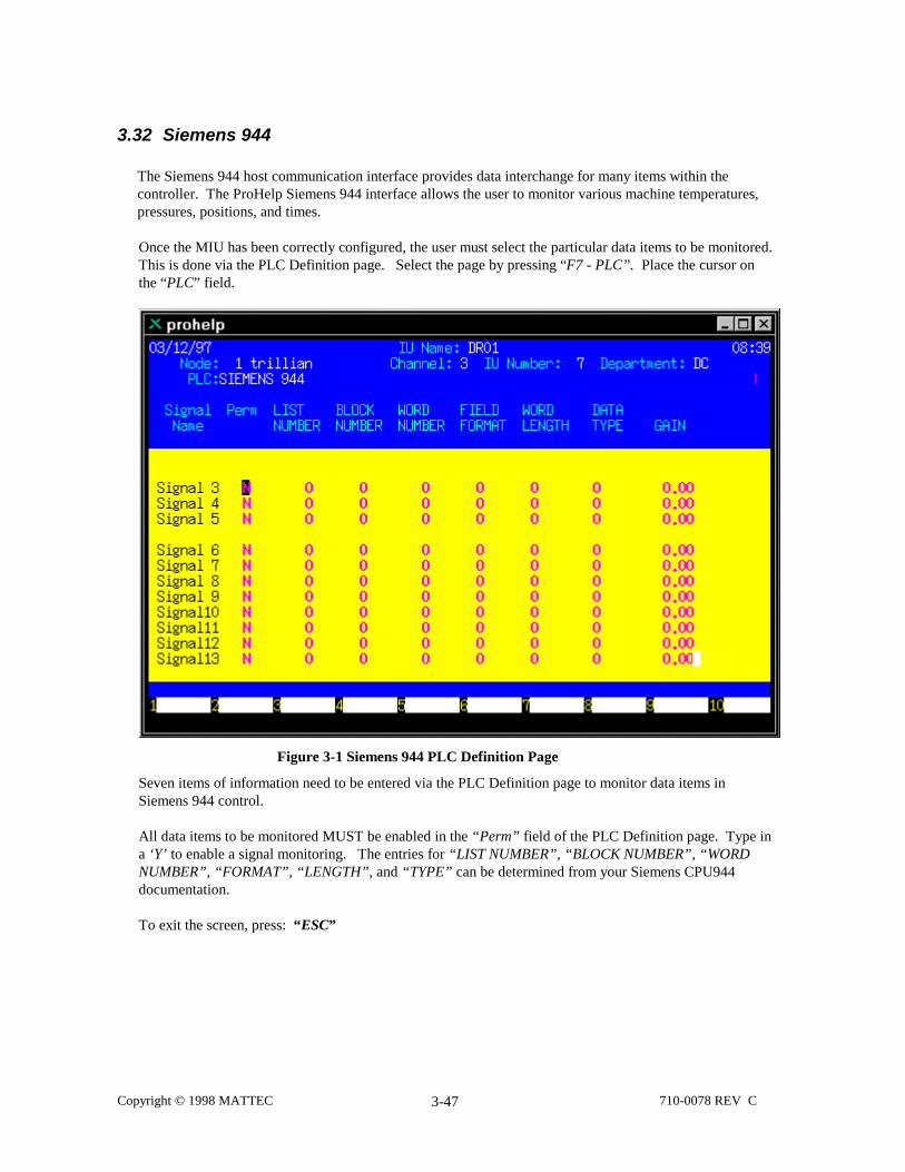
Copyright © 1998 MATTEC 710-0078 REV C3-47
3.32 Siemens 944
The Siemens 944 host communication interface provides data interchange for many items within thecontroller. The ProHelp Siemens 944 interface allows the user to monitor various machine temperatures,pressures, positions, and times.
Once the MIU has been correctly configured, the user must select the particular data items to be monitored.This is done via the PLC Definition page. Select the page by pressing “F7 - PLC”. Place the cursor onthe “PLC” field.
Figure 3-1 Siemens 944 PLC Definition Page
Seven items of information need to be entered via the PLC Definition page to monitor data items inSiemens 944 control.
All data items to be monitored MUST be enabled in the “Perm” field of the PLC Definition page. Type ina ‘Y’ to enable a signal monitoring. The entries for “LIST NUMBER”, “BLOCK NUMBER”, “WORDNUMBER”, “FORMAT”, “LENGTH”, and “TYPE” can be determined from your Siemens CPU944documentation.
To exit the screen, press: “ESC”

Copyright © 1998 MATTEC 710-0078 REV C3-48
NOTES:
1. If “LIST NUMBER”, “BLOCK NUMBER”, or “WORD NUMBER” is changed while theSiemens 944 is still running, the correct data will not be displayed until the next machine cycle.
2. If the signal being monitored is an OP, operator panel signal, then zeros must be entered for“BLOCK NUMBER” and “WORD NUMBER”. DO NOT use negatives.
3. If there are problems retrieving the requested signals, check the general PLC errors at the MIUService Display

Copyright © 1998 MATTEC 710-0078 REV C3-49
3.33 Toshiba EX100
The Toshiba EX100 host communications interface provides data interchange for many items within thecontroller. The ProHelp - Toshiba interface allows the user to monitor various machine temperatures,positions, pressures and timers.
Once the MIU has been correctly configured, the user must select the particular data items to be monitored.This is done via the PLC Definition page. Select the page by pressing “F7 - PLC”. Place the cursor onthe “PLC” field.
Figure 3-1 Toshiba EX100 PLC Definition Page
Two pieces of information are needed for each item that will be monitored - the “DEVICE/REGISTER”number and the “GAIN”.
All data items to be monitored MUST be enabled in the “Perm” field of the PLC Definition page. Type a‘Y’ to enable a signal to be monitored.
The following items are key points in making the Toshiba-MIU interface operate correctly:1 The baud rate on the EX100 should be configured for 4800 (no partity).2 The Slave Address must correspond to the Station number of the EX100.3 The PROGMR-LINK switch must be in the LINK position on the EX100.
NOTE: changes to any of the switches on the EX100 are not valid until power is cycled.
4 Jumper J-9 on the MIU must be OFF.

Copyright © 1998 MATTEC 710-0078 REV C3-50
3.34 Toshiba V10
The Toshiba V10 host communications interface provides data interchange for many items within thecontroller. The ProHelp - Toshiba interface allows the user to monitor various machine temperatures,positions, pressures and timers.
Once the MIU has been correctly configured, the user must select the particular data items to be monitored.This is done via the PLC Definition page. Select the page by pressing “F7 - PLC”. Place the cursor onthe “PLC” field.
Figure 3-1 Toshiba V10 PLC Definition Page
To exit the screen, press: “ESC”

Copyright © 1998 MATTEC 710-0078 REV C3-51
3.35 VanDorn CRT-C
The VanDorn CRT-C host communications interface provides data interchange for many items within thecontrol. The ProHelp - to - CRT-C interface allows the user to monitor the following types of data fromthe CRT-C control:
1) Single Setpoint values2) Single System values3) Process Monitor Data4) Peripheral Device Actual Data
Once the MIU has been correctly configured, the user must select the particular data items to be monitored.This is done via the PLC Definition page. Select the page by pressing “F7 - PLC”. Place the cursor onthe “PLC” field.
Figure 3-1 VanDorn CRT-C PLC Definition Page
Several pieces of information need to be entered via the PLC Definition page to monitor data items. Mostof this information is found in the VanDorn documentation shipped to the user.
All data items to be monitored MUST be enabled in the “Perm” field of the PLC Definition page. Type ina ‘Y’ to enable a signal to be monitored.
To exit the screen, press: “ESC”

Copyright © 1998 MATTEC 710-0078 REV C3-52
3.35.1 Single Setpoint Values
For Single Setpoint items, the following additional fields require user information: "SBC1", "SBC2","SBC3", "SCALE FACTOR", "ITEM TYPE", "ITEM LENGTH", and "OFFSET or PM#", where:
SBC1 is always a 21.
SBC2 and SBC3 are listed in the Single Setpoint description for each item in the VanDorn CRT-C HostCommunication Specification.
SCALE FACTOR is determined by the number of decimal places specified by the user via the MIUDefinition page (display precision), and the actual number of decimal places that the data item isrepresented, internal to the interface (actual precision). This information can be found in the descriptionfor each data item (in the "Units" explanation) in the VanDorn CRT-C Host CommunicationSpecification.
NOTE: SCALE FACTOR only applies to binary data types.
Display precision is fixed for "Pulse 2", "Pulse 3", and "Pulse 4". Up to four (4) decimal places may bedisplayed for the "Analog" signals; see Section 1 of this document.
Actual precision is determined from the divisor of the RV (raw value) for a particular data item. Forexample, the actual precision of the Process Control Position Cut-off Setpoint Value data item is three(3) decimal places (RV / 1000 implies 3 decimal places). The actual precision for an item in the ProcessControl Holding Pressure Profile Time Setpoint Array is two (2)decimal places (RV / 100 implies 2decimal places).
NOTE: Any data item without a divisor for the raw value implies an actualprecision of zero decimal places.
Thus, the SCALE FACTOR for any given data item is calculated from the following equation:
SCALE FACTOR = (display precision) - (actual precision)
For example, the SCALE FACTOR for any item in the Process Control Holding Pressure Profile TimeSetpoint Array, with a display precision set for two (2) decimal places, is 0 ( 2 - 2 = 0 ). The SCALEFACTOR for any item in the Process Control Velocity Profile Position Set Point Array, with a displayprecision set for one (1) decimal place, is 1 ( 1 - 0 = 1 ).
ITEM TYPE is determined from the "Format" listed in the Single Setpoint Data description for eachitem in the VanDorn CRT-C Host Communication Specification, where:
BIN = 1FLOATING POINT = 2ASCII = 3
ITEM LENGTH is determined from the "Length" listed in the Single Setpoint Data description for eachitem, except when the item is communicated in an array of values.In these cases, the length is considered to be the length of a single item in the array.
OFFSET or PM# for those Single Setpoints which are communicated as single items is always 0.

Copyright © 1998 MATTEC 710-0078 REV C3-53
For those Single Setpoints which are communicated in an array of values, the OFFSET is determinedfrom the Setpoint Data description for each item in the VanDorn CRT-C Host CommunicationSpecification and using the following formula:
(SPN - 1) * Item Length = FBN where:
SPN = the Setpoint item in the array to be monitored Item Length = the length of an item in the array
FBN = the OFFSET to be entered in the "OFFSET or PM#" field.
For example, to monitor the third item in the Process Control Velocity Profile Position Setpoint Arraywith a display precision of zero decimal places, the following information should be entered via thePLC Definition page:
SignalName
Perm SBC1 SBC2 SBC3 ScaleFactor
ItemType
ItemLength
Offset orPM#
Analog 2 Y 21 21 2B 0 1 2 4
To monitor the Process Control Cushion Setpoint Value with a display precision of two decimal places,the following information should be entered via the PLC Definition page:
SignalName
Perm SBC1 SBC2 SBC3 ScaleFactor
ItemType
ItemLength
Offset orPM#
Analog 2 Y 21 21 31 -1 1 2 0
3.35.2 Single System Values
For Single System items, the following additional fields require user information: "SBC1", "SBC2","SBC3", "SCALE FACTOR", "ITEM TYPE", "ITEM LENGTH", and "OFFSET or PM#", where:
SBC1 for Single System is always a 23.
SBC2 and SBC3 are listed in the System Data description for each item in the VanDorn CRT-C HostCommunication Specification.
SCALE FACTOR is determined as follows:
SCALE FACTOR = (display precision) - (actual precision)
NOTE: SCALE FACTOR only applies to binary data types.
ITEM TYPE is determined from the "Format" listed in the System Data description for each item in theVanDorn CRT-C Host Communication Specification, where:
BIN = 1 FLOATING POINT = 2 ASCII = 3

Copyright © 1998 MATTEC 710-0078 REV C3-54
ITEM LENGTH is determined from the "Length" listed in the System Data description for each item,except when the system data is communicated in an array of values. In these cases, the length isconsidered to be the length of a single item in the array.
OFFSET or PM# for those System Data items which are communicated as single items is always 0.
For those System Data items which are communicated in an array of values, the OFFSET is determinedfrom the System Data description for each item in the VanDorn CRT-C Host CommunicationSpecification and using the following formula:
(SPN - 1) * Item Length = FBN
where:
SPN = the Setpoint item in the array to be monitored. Item Length = the length of an item in the array. FBN = the OFFSET to be entered in the "OFFSET or PM#" field.
For example, to monitor the fourth item in the Mold Changer Sequence Array with a display precisionset to zero decimal places, the following information should be entered via the PLC Definition page:
SignalName
Perm SBC1 SBC2 SBC3 ScaleFactor
ItemType
ItemLength
Offset orPM#
Analog 3 Y 23 26 27 0 1 1 3
To monitor the Current Parts Requested Value with a display precision set to zero decimal places, thefollowing information should be entered via the PLC Definition page:
SignalName
Perm SBC1 SBC2 SBC3 ScaleFactor
ItemType
ItemLength
Offset orPM#
Analog 3 Y 23 26 25 0 1 4 0
3.35.3 Peripheral Device Actual Data
For Peripheral Device Actual Data items, the following additional fields require user information:"SBC1", "SBC2", "SBC3", "SCALE FACTOR", "ITEM TYPE", "ITEM LENGTH", and "OFFSET orPM#", where:
SBC1 for Peripheral Device Data is always a 27 for VDOI software levels 1 through 19.SBC1 for Peripheral Device Data is always a 28 for VDOI software levels 20 and above.
SBC2 is always a 31 for VDOI software levels 1 through 19.SBC2 is always a 23 for VDOI software levels 20 and above.
NOTE: Refer to your VanDorn representative for information on the VDOIsoftware levels.
SBC3 is determined from the following tables:
For VDOI Software levels 1 through 19:

Copyright © 1998 MATTEC 710-0078 REV C3-55
SBC3 Description21 Peripheral Device # 1 Actual Array22 Peripheral Device # 2 Actual Array23 Peripheral Device # 3 Actual Array24 Peripheral Device # 4 Actual Array25 Peripheral Device # 5 Actual Array26 Peripheral Device # 6 Actual Array27 Peripheral Device # 7 Actual Array28 Peripheral Device # 8 Actual Array29 Peripheral Device # 9 Actual Array
For VDOI Software levels 20 and above:
SBC3 Description21 Device # 1 Volatile Memory Array22 Device # 2 Volatile Memory Array23 Device # 3 Volatile Memory Array24 Device # 4 Volatile Memory Array25 Device # 5 Volatile Memory Array26 Device # 6 Volatile Memory Array27 Device # 7 Volatile Memory Array28 Device # 8 Volatile Memory Array29 Device # 9 Volatile Memory Array2A Device # 10 Volatile Memory Array2B Device # 11 Volatile Memory Array2C Device # 12 Volatile Memory Array2D Device # 13 Volatile Memory Array2E Device # 14 Volatile Memory Array2F Device # 15 Volatile Memory Array30 Device # 16 Volatile Memory Array
SCALE FACTOR is determined as follows:
SCALE FACTOR = (display precision) - (actual precision)
NOTE: SCALE FACTOR only applies to binary data types.
ITEM TYPE is determined from the Peripheral Device descriptions in the VanDorn CRT-C HostCommunication Specification.
ITEM LENGTH is determined from the Peripheral Device descriptions in the VanDorn CRT-C HostCommunication Specification.
OFFSET or PM# is determined from the Peripheral Device descriptions in the VanDorn CRT-C HostCommunication Specification.For example, to monitor the High Alarm Setpoint Absolute String for an AEC Dryer (VDOI Softwarelevels 1 through 19), with a display precision set to two decimal places, the following informationshould be entered via the PLC Definition page:

Copyright © 1998 MATTEC 710-0078 REV C3-56
SignalName
Perm SBC1 SBC2 SBC3 ScaleFactor
ItemType
ItemLength
Offset orPM#
Analog 3 Y 27 31 21 2 3 3 7
To monitor the Zone A Process Temp Setpoint for a DME Hot Runner System (VDOI Software levels20 and above) with a display precision set to one decimal place, the following information should beentered:
SignalName
Perm SBC1 SBC2 SBC3 ScaleFactor
ItemType
ItemLength
Offset orPM#
Analog 4 Y 28 23 23 1 1 2 6
3.35.4 Process Monitor Data
Process Monitor Data items only require information in the "SBC1", "SCALE FACTOR", and "OFFSETor PM#" fields, where:
SBC1 is always a 25.
SBC2 is not used.
SBC3 is not used.
SCALE FACTOR is determined as follows:
SCALE FACTOR = (display precision) - (actual precision)
NOTE: SCALE FACTOR only applies to binary data types.
ITEM TYPE is not used.
ITEM LENGTH is not used.
OFFSET or PM# is obtained from the following table:
Data item to be monitored Offset or PM #Peak Die Cavity Pressure 1Actual Cushion Position 2Velocity at Cutoff 3Screw Position at Cutoff 4Injection Pressure at Cutoff 5Logic Processor Timer 1 - Cycle time 6Logic Processor Timer 2 - Injection time 7Logic Processor Timer 3 - Screw Rotate time 8Logic Processor Timer 4 - Mold Close time 9Logic Processor Timer 5 - Mold Open time 10Logic Processor Timer 6 - Optional time 11Temperature - Zone 1 12Temperature - Zone 2 13Temperature - Zone 3 14

Copyright © 1998 MATTEC 710-0078 REV C3-57
Temperature - Zone 4 15Temperature - Zone 5 16Temperature - Zone 6 17Temperature - Zone 7 18Temperature - Zone 8 19
For example, to monitor Actual Cushion Position, with a display precision set to three decimal places,the following information should be entered via the PLC Definition page:
SignalName
Perm SBC1 SBC2 SBC3 ScaleFactor
ItemType
ItemLength
Offset orPM#
Analog 2 Y 25 0 0 3 0 0 2
To monitor Temperature - Zone 3, with a display precision set to zero, the following information shouldbe entered via the PLC Definition page:
SignalName
Perm SBC1 SBC2 SBC3 ScaleFactor
ItemType
ItemLength
Offset orPM#
Analog 2 Y 25 0 0 0 0 0 14

Copyright © 1998 MATTEC 710-0078 REV C3-58
3.36 VanDorn 4500
The VanDorn 4500 host communications interface provides data interchange for many items within thecontrol. The ProHelp - to - VanDorn 4500 interface allows the user to monitor the following types of data.
Once the MIU has been correctly configured, the user must select the particular data items to be monitored.This is done via the PLC Definition page. Select the page by pressing “F7 - PLC”. Place the cursor onthe “PLC” field.
Figure 3-1 VanDorn 4500 PLC Definition Page
Several pieces of information need to be entered via the PLC Definition page to monitor data items. Mostof this information is found in the VanDorn documentation shipped to the user.
VanDorn 4500 Descriptors
Device ID - This field descriptor is the device ID that the machine controller manufacturer sets on theirmachine. The device ID is a hexadecimal value.
Address - This field descriptor is the address that the SPI equipment is set at. This value is between 32 -255.
Cmd1 - This field descriptor is the first byte listed next to the POLL descriptor of the process parameterthat is selected to monitor. Cmd1 is a hexadecimal value and can be found in the SPI device specification.
Cmd2 - This field descriptor is the second byte listed next to the POLL descriptor of the process parameterthat is selected to monitor. Cmd2 is also a hexadecimal value and can be found in the SPI devicespecification.

Copyright © 1998 MATTEC 710-0078 REV C3-59
Temp Zone - This field descriptor is a temperature zone value between 1-8. A 0 must be placed in thisfield if a non-temperature parameter is selected.
Gain - This field descriptor is a value between 0.0 and 32.767 and will be multiplied by the value receivedfrom the controller. If a 0.0 is left in this field there will be no gain on the selected signal.
VanDorn 4500 PLC Screen Notes
1) Formats of the selected parameter can be Numeric or 8 - 4 Byte Numeric only. In the case of Numeric, avalue of 0 must be entered in the Temp Zone descriptor. In the case of 8 - 4 Byte Numeric, a valuebetween 1 - 8 must be entered in the Temp Zone descriptor representing 4 Byte Numeric floats 1 - 8.
2) If a selected parameter is not available through the VanDorn 4500 machine controller, a forced 0 will beplaced in the signal value.
VanDorn 4500 PLC Screen Setup Example
VanDorn/SPI Document -
Barrel Temperature Zones 1 - 8 Present Value
Poll: 71-7F 20Select:Format: 8 - 4 Byte NumericUnits: Degrees FahrenheitRequired: Yes
Peak Hydraulic Injection Pressure
Poll: 31-3F 82Select:Format: NumericUnits: PSIRequired: No
To exit the screen, press: “ESC”

Copyright © 1998 MATTEC 710-0078 REV C3-60
3.37 Windsor Printer PLC
The Windsor Printer PLC host communications interface provides data interchange for many items withinthe control. The ProHelp Windsor Printer PLC interface allows the user
Once the MIU has been correctly configured, the user must select the particular data items to be monitored.This is done via the PLC Definition page. Select the page by pressing “F7 - PLC”. Place the cursor onthe “PLC” field.
Figure 3-1 Windsor Printer PLC Definition Screen
All data items to be monitored MUST be enabled in the “Perm” field of the PLC definition page. Type ina ‘Y’ to enable a signal to be monitored. Four items of information need to be entered via the PLCDefinition page to monitor data items in the Windsor Printer PLC control. The Windsor Printer PLCDefinition page requires a PLC address, “PARM NUM”, “UNITS GAIN” and “UNITS OFFSET”.
NOTES: Machine must be set to "auto print" every cycle. Parameters can be identified by the ProcessMonitoring Setting screen on the machine control panel or by the following printout example.

Copyright © 1998 MATTEC 710-0078 REV C3-61
Printer Example:
PROCESS MONITORING SETTINGDATA COLLECTION - LAST TEN CYCLESC CYC INJ PLC TZ2 SIP EIP IPR HPR BPR0 63,6 9,9 9,9 250 155 21,3 88 31 71 65,2 9,9 9,5 249 155 21,3 88 31 72 63,4 9,2 9,9 250 153 21,3 88 31 73 64,7 9,9 9,7 250 155 21,3 88 31 74 63,5 9,6 9,9 249 152 21,3 88 31 75 63,1 9,9 9,9 250 156 21,3 88 31 76 64,8 9,9 9,9 251 155 21,3 88 31 77 63,3 9,8 9,8 250 154 21,3 88 31 78 65,2 9,9 9,9 250 155 21,3 88 31 79 63,1 9,9 9,9 250 155 21,3 88 31 7
If PLC errors occur, check control panel for "Printer not Ready Error". Press Cancel to clear.

Copyright © 1998 MATTEC 710-0078 REV C4-1
4. PLC Status - MIU 10X
4.1 Communications
The status of the MIU to PLC communications, as well as the raw data values from the PLC can beviewed at the MIU service display. The service display can be reached by entering “22” <MIUInformation> at the Main Menu, and selecting Item 2. The status of the transmission and data receptioncan be seen, as well as the time required to collect the data. In addition, the raw values of all enabledparameters is displayed.
4.2 Current Values
The actual values received from the PLC can be viewed at the MIU by selecting Menu 12 <ViewParameters>. The actual data values for the last PLC data request will be displayed
PULSE 2PULSE 3PULSE 4ANALOG 1ANALOG 2ANALOG 3ANALOG 4ANALOG 5ANALOG 6ANALOG 7ANALOG 8

Copyright © 1998 MATTEC 710-0078 REV C5-1
5. Installation Checklist
Installation of a PLC interface is easily accomplished by following the checklist below:
1. Check the MIU and PLC serial board for the following items:
a) EPROM - each PLC interface has a corresponding EPROM, verify the part number and latestrevisions; refer to Section 5.1 of this manual.
b) The MIU must have the proper interface jumpers set (i.e. RS-232, RS-485/422, or current loop).The type is defined in section 6 of this manual for each interface. The jumper configuration isfound in the MIU Wiring / Installation Guide, 710-0043, as well as in this manual.
2. Verify that the correct wiring configuration has been used - refer to the wiring diagrams located inSection 6.
3. The BAUD rate setting for the serial port in the PLC must match the baud rate listed in Section 5.1
4. Check the MIU configuration record of the appropriate machine # for the proper PLC interface andparameter settings.
5. If communications cannot be established, perform the loop back test as described in this manual.
NOTE: A "JOB" must be assigned and running on the ProHelp system before any data requests will be madeof the control.
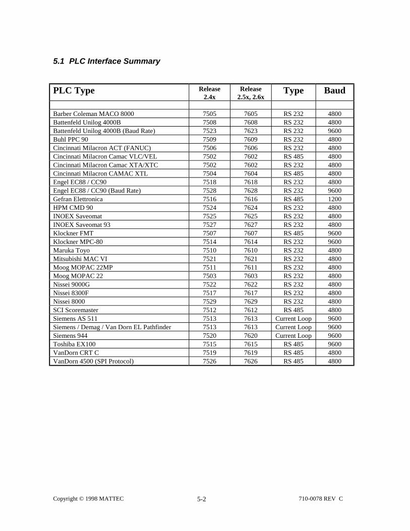
Copyright © 1998 MATTEC 710-0078 REV C5-2
5.1 PLC Interface Summary
PLC Type Release2.4x
Release2.5x, 2.6x
Type Baud
Barber Coleman MACO 8000 7505 7605 RS 232 4800Battenfeld Unilog 4000B 7508 7608 RS 232 4800Battenfeld Unilog 4000B (Baud Rate) 7523 7623 RS 232 9600Buhl PPC 90 7509 7609 RS 232 4800Cincinnati Milacron ACT (FANUC) 7506 7606 RS 232 4800Cincinnati Milacron Camac VLC/VEL 7502 7602 RS 485 4800Cincinnati Milacron Camac XTA/XTC 7502 7602 RS 232 4800Cincinnati Milacron CAMAC XTL 7504 7604 RS 485 4800Engel EC88 / CC90 7518 7618 RS 232 4800Engel EC88 / CC90 (Baud Rate) 7528 7628 RS 232 9600Gefran Elettronica 7516 7616 RS 485 1200HPM CMD 90 7524 7624 RS 232 4800INOEX Saveomat 7525 7625 RS 232 4800INOEX Saveomat 93 7527 7627 RS 232 4800Klockner FMT 7507 7607 RS 485 9600Klockner MPC-80 7514 7614 RS 232 9600Maruka Toyo 7510 7610 RS 232 4800Mitsubishi MAC VI 7521 7621 RS 232 4800Moog MOPAC 22MP 7511 7611 RS 232 4800Moog MOPAC 22 7503 7603 RS 232 4800Nissei 9000G 7522 7622 RS 232 4800Nissei 8300F 7517 7617 RS 232 4800Nissei 8000 7529 7629 RS 232 4800SCI Scoremaster 7512 7612 RS 485 4800Siemens AS 511 7513 7613 Current Loop 9600Siemens / Demag / Van Dorn EL Pathfinder 7513 7613 Current Loop 9600Siemens 944 7520 7620 Current Loop 9600Toshiba EX100 7515 7615 RS 485 9600VanDorn CRT C 7519 7619 RS 485 4800VanDorn 4500 (SPI Protocol) 7526 7626 RS 485 4800
Copyright © 1998 MATTEC 710-0078 REV C5-3
5.2 Loop-Back Test
An MIUs PLC related hardware can be tested using manual diagnostic's loop-back test (PLC is Comm 3).All jumpers must be in place at the time you apply power to the MIU (changing anything duringdiagnostics will void all results). Com Port diagnostics can be invoked by re-booting the MIU andselecting the diagnostics mode during boot. Tests are available to check the com port as well as in loopback mode.
JUMPER WIRES FOR LOOP-BACK
See the "Module Description" Section of this Manual
RS-232 Jump pin 1 to pin 2 and pin 3 to pin 4.RS-485 Jump pin 1 to pin 3 and pin 2 to pin 4.CURRENT LOOP Jump pin 1 to pin 3 and pin 2 to pin 4.

Copyright © 1998 MATTEC 710-0078 REV C6-1
6. Wiring Diagrams
6.1 MIU 10X
This application note describes the interface connections to currently supported PLC interfaces. Thoseinterface types supported are those that use one of three standard communications protocols. RS-232C, RS-422/RS-485, and Current Loop. Current implementation requires that shielded communications cable be usedto minimize noise problems, and that the PLC end be defined as the “source”. Thus, the shield should begrounded at the PLC end only. However, if necessary, provision has been made to allow tying the shield toground at the MIU end.
The PLC interface on the MIU 10X board has been designed to allow any one of the three communicationsprotocols depending on the jumper settings. Refer to Manual 710-0043 for the correct jumper settings.
J A 6 J B 6 J C 6 J D 6 J E 6
J A 6 J B 6 J C 6 J D 6 J E 6
J A 6 J B 6 J C 6 J D 6 J E 6
R S - 4 8 5
R S - 2 3 2
C u r r e n t L o o p
C O M 3 - P L C C o m m u n i c a t i o n s M o d e
Figure 6-1 PLC Jumper Settings

Copyright © 1998 MATTEC 710-0078 REV C6-2
BASIC I/O TERMINALS FOR RS-232C INTERFACES ARE:
1
2
3
4
TB6
SIGNAL GND
CTS (CLEAR TO SEND)
RTS (REQUEST TO SEND)
RD (RECEIVE DATA)
TD (TRANSMIT DATA)
5
Figure 6-2 Basic RS 232 Wiring
BASIC I/O TERMINALS FOR RS-485C INTERFACES ARE:
1
2
3
4
TB6
SIGNAL GND
RX- (RECEIVE DATA NOT)
RX+(RECEIVE DATA)
TD-(TRANSMIT DATA NOT)
TD+(TRANSMIT DATA)
5
Figure 6-3 Basic RS 485 Wiring

Copyright © 1998 MATTEC 710-0078 REV C6-3
BASIC I/O TERMINALS FOR CURRENT LOOP INTERFACES ARE:
1
2
3
4
TB6
SIGNAL GND
TX+ (TRANSMIT DATA PLUS)
TX- (TRANSMIT DATA MINUS)
RX+ (RECEIVE DATA PLUS)
RX- (RECEIVE DATA MINUS)
5
Figure 6-4 Basic Current Loop Wiring

Copyright © 1998 MATTEC 710-0078 REV C6-4
6.1.1 Allen Bradley
VENDOR TYPE - ALLEN BRADLEY INTERFACE TYPE - RS-232
5
1
2
3
4
GND
RX
TX
RTS
CTS
TB6
2 (TD)
3 (RD)
___________25 PIN D-SUB
7
4 (RTS)
5 (CTS)
6 (DTR)
8 (DSR)
20 (CD)
Figure 6-1 Allen Bradley
6.1.2 Barber Coleman MACO 8000/VanDorn CRT-B
VENDOR TYPE - BARBER COLMAN MACO 8000 (Van Dorn CRT-8)
INTERFACE TYPE - RS-232C
5
1
2
3
4
GND
RX
TX
RTS
CTS
TB6
MACO 8000MOTHER BOARD TERM BLK.ON INSTA-SET MODULE29
28 (SIGNAL GND)
25 (DSR)
31 (DTR)
27 (RTS)
33 (CTS)
24 (TD)
30 (RD)
23 (SHIELD)
34
Figure 6-1 Barber Coleman

Copyright © 1998 MATTEC 710-0078 REV C6-5
6.1.3 Battenfeld Unilog 4000B
VENDOR TYPE - BATTENFELD UNILOG 4000B INTERFACE TYPE - RS-232
5
1
2
3
4
GND
RX
TX
RTS
CTS
TB6
9 PIN D-SUB
7 (SIGNAL GND)
5 (RTS)
4 (CTS)
2 (TD)
3 (RD)
Figure 6-1 Battenfeld Unilog 4000B
6.1.4 Buhl PPC90
VENDOR TYPE - BUHL PLC INTERFACE TYPE - RS-232
5
1
2
3
4
GND
RX
TX
RTS
CTS
TB6
7 (RTS)
8 (CTS)
3 (TD)
2 (RD)
5 (SIGNAL GND)
4 (DTR)
6 (DSR)
Figure 6-1 Buhl

Copyright © 1998 MATTEC 710-0078 REV C6-6
6.1.5 Cincinnati Milacron ACT
VENDOR TYPE - CINCINNATI MILACRON ACT/FANUC
INTERFACE TYPE - RS-232
5
1
2
3
4
GND
RX
TX
RTS
CTS
TB6
2 (TD)
3 (RD)
___________25 PIN D-SUB
7
4 (RTS)
5 (CTS)
6 (DTR)
8 (DSR)
20 (CD)
Figure 6-1 Cinti. Milacron ACT/FANUC
6.1.6 Cincinnati Milacron CAMAC XTL
VENDOR TYPE - CINCINNATI MILACRON CAMAC XTL T-DROP
INTERFACE TYPE - RS-485
1
2
3
4
TX-
TX+
RX+
RX-
TB6
CAMAC XTL9 PIN D-SUB
9 (TD/)
7 (RD/)
6 (RD)
CASE
8 (TD)
5
Figure 6-1 Cinti. Milacron CAMAC XTL

Copyright © 1998 MATTEC 710-0078 REV C6-7
6.1.7 Cincinnati Milacron CAMAC XTA/XTC
VENDOR TYPE - CINCINNATI MILACRON CAMAC XTA/XTC VER-1
INTERFACE TYPE - RS-232C
5
1
2
3
4
GND
RX
TX
RTS
CTS
TB6
CAMAC XTA/XTCRS10 SCREW TERMINALS
7 (TD)
8 (RD)
6 (SIGNAL GND)
9 (RTS)
10 (CTS)
11 (DTR)
12 (DSR)
Figure 6-1 Cinti. Milacron Camac XTA/XTC
6.1.8 Cincinnati Milacron CAMAC VLC/VEL
VENDOR TYPE - CINCINNATI MILACRON VLC/VEL
INTERFACE TYPE - RS-485
1
2
3
4
TD-
TD+
RX+
RX-
TB6
VCL/VEL25 PIN D-SUB
2 (TD/)
3 (RD/)
4 (RD)
17
1 (TD)
73 533 3106
5
Figure 6-1 Cinti. Milacron VLC/VEL

Copyright © 1998 MATTEC 710-0078 REV C6-8
6.1.9 Cincinnati Milacron FerromaticPUT CORRECT WIRING DIAGRAM IN
VENDOR TYPE - CINCINNATI MILACRON VLC/VEL
INTERFACE TYPE - RS-485
1
2
3
4
TD-
TD+
RX+
RX-
TB6
VCL/VEL25 PIN D-SUB
2 (TD/)
3 (RD/)
4 (RD)
17
1 (TD)
73 533 3106
5
Figure 6-1 Cincinnati Milacron Ferromatic
6.1.10 Engel EC88/CC90
VENDOR TYPE - ENGEL EC88/CC90 INTERFACE TYPE - RS-232C
5
1
2
3
4
GND
RX
TX
RTS
CTS
TB6
2 (TD)
3 (RD)
7 (GND)
5 (CTS)
4 (RTS)
Figure 6-1 Engel EC88/CC90

Copyright © 1998 MATTEC 710-0078 REV C6-9
6.1.11 Gefran Elettronica
VENDOR TYPE - GEFRAN INTERFACE TYPE - RS-485
1
2
3
4
TX-
TX+
RX+
RX-
TB6
NOTE: RS 485 PORT AJ 15, J 16USE J 16FOR MATTEC CONNECTIONSET JUMPERS E94/75 ANDE98/71
4 (TD/)
8 (RD/)
9 (RD)
1 (SHIELD)
5 (TD)
5
Figure 6-1 Gefran Elettronica
6.1.12 Gefran Elettronica Negri EL2
VENDOR TYPE - GEFRAN EL2 NegriBossi INTERFACE TYPE - RS-232
5
1
2
3
4
GND
TX
RTS
CTS
9 PIN D-SUB
7 (SIGNAL GND)
2
3
RX
TB6
Figure 6-1 Gefran Elettronica Negri EL2
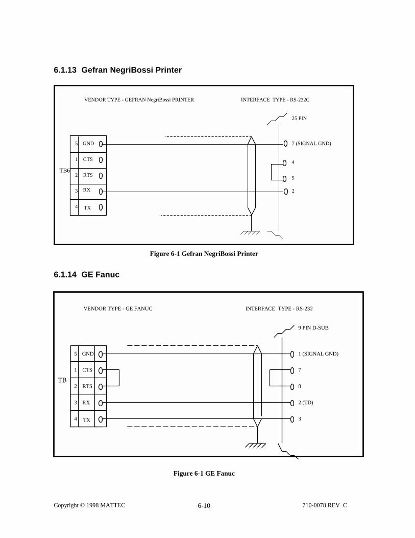
Copyright © 1998 MATTEC 710-0078 REV C6-10
6.1.13 Gefran NegriBossi Printer
VENDOR TYPE - GEFRAN NegriBossi PRINTER INTERFACE TYPE - RS-232C
5
1
2
3
4
GND
TX
RTS
CTS
25 PIN
7 (SIGNAL GND)
2
5
RX
TB6
4
Figure 6-1 Gefran NegriBossi Printer
6.1.14 GE Fanuc
Figure 6-1 GE Fanuc
VENDOR TYPE - GE FANUC INTERFACE TYPE - RS-232
5
1
2
3
4
GND
RX
TX
RTS
CTS
TB
9 PIN D-SUB
1 (SIGNAL GND)
7
8
2 (TD)
3

Copyright © 1998 MATTEC 710-0078 REV C6-11
6.1.15 HPM CMD90
VENDOR TYPE - HPM CMD 90 INTERFACE TYPE - RS-232
5
1
2
3
4
GND
RX
TX
RTS
CTS
TB6
2 (TD)
3 (RD)
___________25 PIN D-SUB
7
4 (RTS)
5 (CTS)
6 (DTR)
8 (DSR)
20 (CD)
Figure 6-1 HPM CMD 90
6.1.16 Inoex Saveomat
VENDOR TYPE - INOEX SAVEOMAT INTERFACE TYPE - RS-232
5
1
2
3
4
GND
RX
TX
RTS
CTS
TB6
2 (TD)
3 (RD)
___________25 PIN D-SUB
7
4 (RTS)
5 (CTS)
6 (DTR)
8 (DSR)
20 (CD)
Figure 6-1 Inoex Saveomat
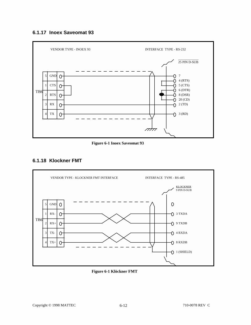
Copyright © 1998 MATTEC 710-0078 REV C6-12
6.1.17 Inoex Saveomat 93
VENDOR TYPE - INOEX 93 INTERFACE TYPE - RS-232
5
1
2
3
4
GND
RX
TX
RTS
CTS
TB6
2 (TD)
3 (RD)
___________25 PIN D-SUB
7
4 (RTS)
5 (CTS)
6 (DTR)
8 (DSR)
20 (CD)
Figure 6-1 Inoex Saveomat 93
6.1.18 Klockner FMT
VENDOR TYPE - KLOCKNER FMT INTERFACE INTERFACE TYPE - RS-485
5
1
2
3
4
GND
TX-
TX+
RX+
RX-
TB6
KLOCKNER9 PIN D-SUB
3 TXDA
4 RXDA
8 RXDB
1 (SHIELD)
9 TXDB
Figure 6-1 Klöckner FMT

C
6.1.19 Klockner MPC-80
VENDOR TYPE - KLOCKNER MPC 80 INTERFACE TYPE - RS-232C
5
1
2
3
4
GND
RX
TX
RTS
CTS
TB6
2 (TD)
3 (RD)
7 (GND)
Figure 6-1 Klöckner MPC80
6.1.20 Krauss Maffei
VENDOR TYPE - KRAUSS MAFFEI INTERFACE TYPE - RS-232
opyright © 1998 MATTEC 710-0078 REV C6-13
Figure 6-1 Krauss Maffei
5
1
2
3
4
GND
RX
TX
RTS
CTS
TB6
2 (TD)
3 (RD)
___________25 PIN D-SUB
7
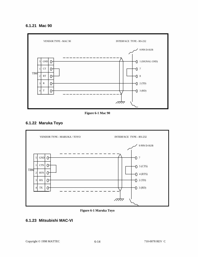
Co
6.1.21 Mac 90
6.
T
6.
pyright © 1998 MATTEC 710-0078 REV C6-14
Figure 6-1 Mac 90
1.22 Maruka Toyo
VENDOR TYPE - MARUKA / TOYO INTERFACE TYPE - RS-232
5
1
2
3
4
GND
RX
TX
RTS
CTS
B6
9 PIN D-SUB
7
2 (TD)
3 (RD)
5 (CTS)
4 (RTS)
Figure 6-1 Maruka Toyo
1.23 Mitsubishi MAC-VI
VENDOR TYPE - MAC 90 INTERFACE TYPE - RS-232
5
1
2
3
4
GND
R
T
RT
CT
TB6
9 PIN D-SUB
1 (SIGNAL GND)
7
8
2 (TD)
3 (RD)

Copyright © 1998 MATTEC 710-0078 REV C6-15
VENDOR TYPE - MITSUBISHI MAC IV INTERFACE TYPE - RS-232
5
1
2
3
4
GND
RX
TX
RTS
CTS
TB6
9 PIN D-SUB
1 (SIGNAL GND)
5 (CTS)
4 (DTR)
2 (TD)
3 (RD)
Figure 6-1 Mitsubishi MAC VI
6.1.24 Moog Mopac 22 MP (Modicon Protocol)
VENDOR TYPE - MOOG MOPAC 22 MP INTERFACE TYPE - RS-232C
5
1
2
3
4
GND
RX
TX
RTS
CTS
TB6
MOOG MOPAC 2225 PIN MALE “D” SUBPORT “B”
7 (SIGNAL GND)
4 (RTS)
5 (CTS)
20 (DTR)
6 (DSR)
2 (TD)
3 (RD)
1 (SHIELD)
Figure 6-1 Moog Mopac 22 MP
6.1.25 Moog Mopac 22

Copyright © 1998 MATTEC 710-0078 REV C6-16
VENDOR TYPE - MOOG MOPAC 22 INTERFACE TYPE - RS-232C
5
1
2
3
4
GND
RX
TX
RTS
CTS
TB6
MOOG MOPAC 2225 PIN MALE “D” SUBPORT “B”
7 (SIGNAL GND)
4 (RTS)
5 (CTS)
20 (DTR)
6 (DSR)
2 (TD)
3 (RD)
1 (SHIELD)
Figure 6-1 Moog Mopac 22
6.1.26 NetstallPUT CORRECT WIRING DIAGRAM IN:
2
3
4
5
6
TX
RCV
TB6
7
2 TX
3 RCV
VENDOR TYPE - NETSTALL INTERFACE TYPE - RS232DP_________25 Pin Male
1
Figure 6-1 Netstall

Copyright © 1998 MATTEC 710-0078 REV C6-17
6.1.27 Nissei 9000G, 8300F and 9300T
VENDOR TYPE - NISSEI 9000G INTERFACE TYPE - RS-232
5
1
2
3
4
GND
RX
TX
RTS
CTS
TB6
2 (TD)
3 (RD)
___________
25 PIN D- SUB
7
Figure 6-1 Nissei 9000G - 25 Pin D-sub
VENDOR TYPE - NISSEI 9000G INTERFACE TYPE - RS-232
5
1
2
3
4
GND
RX
TX
RTS
CTS
TB6
2 (TD)
3 (RD)
___________9 PIN D-SUB
5
Figure 6-2 Nissei 9000G - 9 Pin D-sub

Copyright © 1998 MATTEC 710-0078 REV C6-18
VENDOR TYPE - NISSEI 8300F INTERFACE TYPE - RS-232
5
1
2
3
4
GND
RX
TX
RTS
CTS
TB6
2 (TD)
3 (RD)
___________25 PIN D-SUB
7
Figure 6-3 Nissei 8300 F
5
1
2
3
4
CTS
RTS
RX
TX
TB6
5
3 (RD)
2 (TD)
VENDOR TYPE - NISSEI 9300T INTERFACE TYPE - RS232C___________9 PIN D-SUB
GNDTelebyte RS232
IsolationOB25
DTE
DCE
7 7
2
3 2
3
Figure 6-4 Nissei 9300T

Copyright © 1998 MATTEC 710-0078 REV C6-19
6.1.28 Nissei 8000
VENDOR TYPE - NISSEI 8000 INTERFACE TYPE - RS-232
5
1
2
3
4
GND
RX
TX
RTS
CTS
TB6
2 (TD)
3 (RD)
___________25 PIN D-SUB
7
Figure 6-1 Nissei 8000

Copyright © 1998 MATTEC 710-0078 REV C6-20
6.1.29 SCI Scoremaster
VENDOR TYPE - SCI SCOREMASTER INTERFACE TYPE - RS-485
1
2
3
4
TX-
TX+
RX+
RX-
TB6
NOTE: RS 485 PORT AJ 15, J 16USE J 16FOR MATTEC CONNECTIONSET JUMPERS E94/75 ANDE98/71
4 (TD/)
8 (RD/)
9 (RD)
1 (SHIELD)
5 (TD)
5
Figure 6-1 SCI Scoremaster
6.1.30 Siemens/DEMAG NCIII
VENDOR TYPE - SIEMANS DEMAG NCIII VANDORN EL PATH FINDER
INTERFACE TYPE - CURRENT LOOP
1
2
3
4
RX+
RX-
TX-
TX+
TB6
____________________15 PIN MALE “D” SUB
9 (R+)
6 (T+)
7 (T-)
5 (SHIELD)
2 (R-)
15
GND (N/C)
5
Figure 6-1 Siemens Demag NCIII

Copyright © 1998 MATTEC 710-0078 REV C6-21
6.1.31 Siemens 944
VENDOR TYPE - SIEMANS DEMAG NCIII VANDORN EL PATH FINDER
INTERFACE TYPE - CURRENT LOOP
1
2
3
4
RX+
RX-
TX-
TX+
TB6
____________________15 PIN MALE “D” SUB
9 (R+)
6 (T+)
7 (T-)
5 (SHIELD)
2 (R-)
15
GND (N/C)
5
Figure 6-1 Siemens 944
6.1.32 Toshiba EX 100
VENDOR TYPE - TOSHIBA EX100
5
1
2
3
4
GND
TX-
TX+
RX+
RX-
TB6
TXB
RXB
RXA
SIGNAL GROUND
TXA
TRM
Figure 6-1 Toshiba EX100
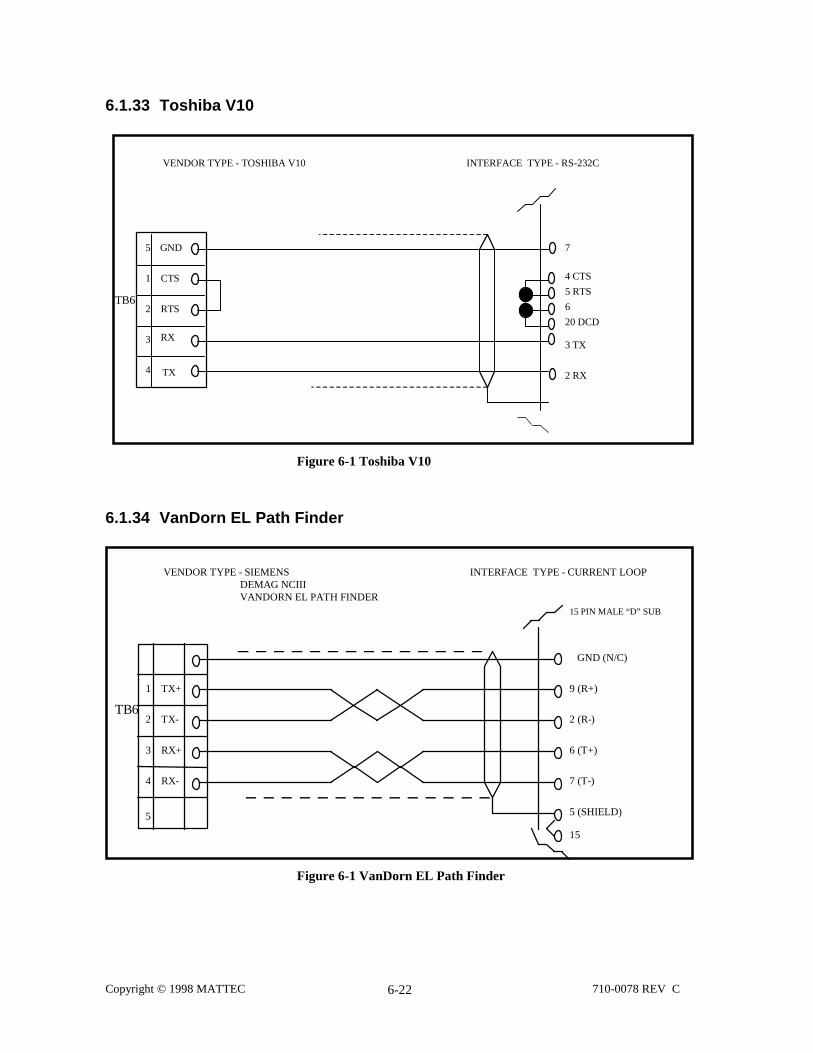
Copyright © 1998 MATTEC 710-0078 REV C6-22
6.1.33 Toshiba V10
VENDOR TYPE - TOSHIBA V10 INTERFACE TYPE - RS-232C
5
1
2
3
4
GND
TX
RTS
CTS
7
3 TX
2 RX
RX
TB6
4 CTS
5 RTS
6
20 DCD
Figure 6-1 Toshiba V10
6.1.34 VanDorn EL Path Finder
VENDOR TYPE - SIEMENS DEMAG NCIII VANDORN EL PATH FINDER
INTERFACE TYPE - CURRENT LOOP
5
1
2
3
4
RX+
RX-
TX-
TX+
TB6
15 PIN MALE “D” SUB
9 (R+)
6 (T+)
7 (T-)
5 (SHIELD)
2 (R-)
15
GND (N/C)
Figure 6-1 VanDorn EL Path Finder

Copyright © 1998 MATTEC 710-0078 REV C6-23
6.1.35 VanDorn CRT-C
VENDOR TYPE - VAN DORN CRT-C INTERFACE TYPE - RS-485
1
2
3
4
TX-
TX+
RX+
RX-
TB6
VANDORN CRT-C25 PIN MALE “D” SUB
21 (TD/ )
12 (RD/ )
25 (RD )
1 (SHIELD)
9 (TD )
7 (SIGNAL GND)
5
Figure 6-1 VanDorn CRT-C
6.1.36 VanDorn 4500
VENDOR TYPE - VANDORN 4500
NOTE: The case of the B&B Converter must be grounded to earth ground.
1
2
3
4
5
CTS
RTS
GND
TX
RX
TB6
5
9
4
8
3 (RD)
SPI9 PIN
232 485
2
3
7
TD (A)
RD (A)
TD (B)
RD (B)
SHIELD
B & B ConverterRS232 ----->RS485
Figure 6-1 VanDorn 4500

Copyright © 1998 MATTEC 710-0078 REV C6-24
6.1.37 Windsor Printer
VENDOR TYPE - WINDSOR PRINTER INTERFACE TYPE - RS-232
5
1
2
3
4
GND
TX
RTS
CTS
25 PIN
7 (SIGNAL GND)
3
20
RX
TB6
5
Figure 6-1 Windsor Printer

Copyright © 1998 MATTEC 710-0078 REV C7-1
7. Appendix A - Cincinnati Milacron XTL
The following data is for example purposes only. Refer to the appropriate Cincinnati Milacron Manual forup-to-date and accurate information.
The first 1040 RW_CONV_VEC registers (numbers 0 - 1039) make up a block of registers that are alwaysreserved for specific types of information. Other blocks that follow are reserved for additional information.The size of these additional register blocks fluctuates depending on system requirements. The following tableexplains how to determine the first and last register of these additional blocks, which deal with:
• Scaling, Slope• Offset• Host Captured Values• Hot Runner Zones• Additional COMM_VECs• Alarms• Actual Vectors• Faults
Register Block First Register of Block Last Register of BlockScaling 1040 1039+ Integer Value in COMM_VEC 89
Slope Last register of Scaling block + 11040 + 80 = 1120
Last register of Scaling block + IntegerValue in COMM_VEC 89
Offset Last register of Slope block + 11120 + 80 = 1200
Last register of Slope block + IntegerValue in COMM_VEC 89
Host CapturedValues (Item #)
Last register in Offset block +11200 + 80 = 1280
Last register in Offset block + IntegerValue in COMM_VEC 33
Hot RunnerZones
Last register in Host Captured Valuesblock + 11280 + 80 = 1360
Last register in Host Captured Valuesblock + Integer Value in COMM_VEC 69multiplied by 6
AdditionalCOMM_VECs
Last register in Hot Runner Zones block +11360 + 80 = 1440
Last register in Hot Runner Zones block +Integer Value in COMM_VEC 83 minus1040
Alarms Last register in Additional COMM_VECsblock +11440 + 80 = 1520
Last register in Additional COMM_VECsblock + Integer Value in COMM_VEC 85
Actual Vector Last register in Alarms block +11520 + 80 = 1600
Last register in Alarms block + IntegerValue in COMM_VEC 84
Faults Last register in Actual Vector block + 11600 + 80 = 1680
Last register in Actual Vector block +Integer Value in COMM_VEC 87

Copyright © 1998 MATTEC 710-0078 REV C7-2
7.1 Read/Write Vector Definitions
Host ComputerThe following table provides information on the software Read/Write Host Computer Convert Vector. Thecolumns in this table are explained below.
RW_HOST-VEC# Indicates the index number in the vector
Description Describes the function of the index
Convert Indicates an index number on one of the factory setup screens that provides aconversion value for the RW_HOST_VEC
RW-HOST-VEC#0 DESCRIPTIONBit #
0 Manual mode1 Single Cycle2 Continuous Cycle3 Active alarm4 Cycle interrupt5 Auto mold change6 Setpoint has changed since last sample7 Cycle completed8 Setup9 Scheduled down time
10 Repairs11 Material12 Running13 SPC data ready1415
RW_HOST_VEC# DESCRIPTION CONVERT
0 Status word 01 Cycle time 242 Fill time 233 Recovery time 234 Cushion position 235 Inject transfer position 156 Inject transfer pressure 167 Cavity transfer pressure 198 Inject position at start of injection 159 Cycle count (0-30000 low) 0
RW_HOST_VEC# DESCRIPTION CONVERT

Copyright © 1998 MATTEC 710-0078 REV C7-3
10 Cycle count (number of times low register hit 30000high)
0
11 Bad part count (0 - 30000 low) 012 Bad part count (number of times low register hit
30000 high)0
13 Oil temp 2414 Nozzle temp 2415 Zone 1 temp 2416 Zone 2 temp 2417 Zone 3 temp 2418 Feed throat temp 2419 Zone 4 temp 24
RW_HOST_VEC# DESCRIPTION CONVERT
20 Nozzle temp 2421 Sprue bushing 2422 Zone 5 temp 2423 Zone 6 temp 2424 5th to last setpoint changed 025 4th to last setpoint changed 026 3rd to last setpoint changed 027 2nd to last setpoint changed 028 Last setpoint changed 029 Data getter cycle time 23
RW_HOST_VEC# DESCRIPTION CONVERT
30 Data getter clamp close fast time 2331 Data getter clamp close slow time 2332 Data getter clamp tonnage build time 2333 Data getter clamp breakaway time 2334 Data getter clamp open fast time 2335 Data getter clamp open slow time 2336 Data getter inject decompression time 2337 Data getter clamp open position at stop 138 Data getter clamp close time 2339 Data getter clamp open time 23

Copyright © 1998 MATTEC 710-0078 REV C7-4
RW_HOST_VEC# DESCRIPTION CONVERT
40 Data getter clamp decompression time 2341 Data getter shot size 1542 Data getter clamp pressure 5243 Actual viscosity 044 Cycle time (low register for full 32 bits) 5145 Cycle time (high register for full 32 bits) 5146 Inject fill time (low register for full 32 bits) 5147 Inject fill time (low register for full 32 bits) 5148 Recovery time (low register for full 32 bits) 5149 Power consumption 0
RW_HOST_VEC# DESCRIPTION CONVERT
50 Recovery time (high register for full 32 bits) 5151 Cycle counter (low register for full 32 bits) 052 Cycle counter (high register for full 32 bits) 053 Bad part counter (low register for full 32 bits) 054 Bad part counter (high register for full 32 bits) 055 Peak injection pressure during profile 1656 Position for peak injection pressure during profile 1557 Minimum injection position during pack and hold 1558 Pressure at minimum injection position during pack
and hold16
59 Clamp fast close time (low register for 32 bits) 51
RW_HOST_VEC# DESCRIPTION CONVERT
60 Clamp fast close time (high register for 32 bits) 5161 Clamp slow close time (low register for 32 bits) 5162 Clamp slow close time (high register for 32 bits) 5163 Clamp lockover time (low register for 32 bits) 5164 Clamp lockover time (high register for 32 bits) 5165 Injection position at start of injection 1566 Injection decompress before time (low register for 32
bits)51
67 Injection decompress before time (high register for32 bits)
51
68 Injection position after decompress before 1569 Injection decompress after time (low register for 32
bits)51
RW_HOST_VEC# DESCRIPTION CONVERT

Copyright © 1998 MATTEC 710-0078 REV C7-5
70 Injection decompress after time (high register for 32bits)
51
71 Clamp breakaway time (low register for 32 bits) 5172 Clamp breakaway time (high register for 32 bits) 5173 Clamp open fast time (low register for 32 bits) 5174 Clamp open fast time (high register for 32 bits) 5175 Clamp open slow time (low register for 32 bits) 5176 Clamp open slow time (high register for 32 bits) 5177 Cycle count (low register for 32 bits) 078 Cycle count (high register for 32 bits) 079 Eject forward time (low register for 32 bits) 51
RW_HOST_VEC# DESCRIPTION CONVERT
80 Eject forward time (high register for 32 bits) 5181 Eject maximum forward position 1082 Eject retract time (low register for 32 bits) 5183 Eject retract time (high register for 32 bits) 5184 Eject minimum retract position 1085 Clamp tonnage 486 Time for peak injection pressure during profile (low
register)51
87 Time for peak injection pressure during profile (highregister)
51
88 End of injection time (low register for 32 bits) 5189 Time of injection time (high register for 32 bits) 51
RW_HOST_VEC# DESCRIPTION CONVERT
90 Peak cavity pressure 1991 Peak cavity pressure time (low register for 32 bits) 5192 Peak cavity pressure time (high register for 32 bits) 5193 Peak injection velocity 1594 Peak injection velocity time (low register for 32 bits) 5195 Peak injection velocity time (high register for 32 bits) 5196 Clamp close command time (low register for 32 bits) 5197 Clamp close command time (high register for 32 bits) 5198 Clamp open command time (low register for 32 bits) 5199 Clamp open command time (high register for 32 bits) 51

Copyright © 1998 MATTEC 710-0078 REV C7-6
RW_HOST_VEC# DESCRIPTION CONVERT
100 Injection start time (low register for 32 bits) 51101 Injection start time (high register for 32 bits) 51102 Injection recovery start time (low register for 32 bits) 51103 Injection recovery start time (high register for 32
bits)51
104 Clamp pressure gauge 52105 Overall clamp close time (low register) 51106 Overall clamp close time (high register) 51107 Overall clamp open time (low register) 51108 Overall clamp open time (high register) 51109 Clamp decompression time (low register) 51
RW_HOST_VEC# DESCRIPTION CONVERT
110 Clamp decompression time (high register) 51111 Number of scan overruns 0112113114115116117118119
NOTE: To find the value of the index that is used by the host computer, add the value of 1220 to theRW_HOST_VEC.

Copyright © 1998 MATTEC 710-0078 REV C7-7
MachineThe following table provides information on the software Read/Write Machine Convert Vector. The columnsin this table are explained below.
RW_HOST-VEC# Indicates the index number in the vector
Description Describes the function of the index
Eng, Met Indicates the conversion factor for both Engineering and Metric units
Rev Indicates the revision number for the index
Save Indicates whether or not the information in this index is saved with the mold data
Item # starts at1280
Scaling starts at1040
Slope starts at1120
OFFSet starts at1200
Zone 1 = 1295 1064 1144 1224
Item # = (RW_HOST_VEC#) + 1280 = 15 + 1280 = 1295Scaling = Convert + 1040 = 24 + 1040 = 1064Slope = Convert + 1120 = 24 + 1120 = 1144Offset = Convert + 1200 = 24 + 1200 = 1224
Continue this formula for all items needed.
Peak Injection Pressure during Profile =
Item # starts at1280
Scaling starts at1040
Slope starts at1120
OFFSet starts at1200
1335 1056 1136 1216
Item # = (RW_HOST_VEC#) + 1280 = 55 + 1280 = 1335Scaling = Convert + 1040 = 16 + 1040 = 1056Slope = Convert + 1120 = 16 + 1120 = 1136Offset = Convert + 1200 = 16 + 1200 = 1216