project #1090-6410
TRANSCRIPT
ALBERTA REMVUE ENGINE FUEL MANAGEMENT
AND VENT GAS CAPTURE AGGREGATION PROJECT
Greenhouse Gas Emissions Reduction
Offset Project Plan
For The Period: 1 January, 2013 – 31 December, 2020
FINAL REPORT, version 2.3
20 December, 2013
Prepared by: Blue Source Canada ULC (Project Proponent) Suite 700, 717-7
th Avenue SW
Calgary, Alberta T2P 3R5 T: (403) 262-3026 F: (403) 269-3024 www.bluesourceCAN.com
Page i
Prepared by: Blue Source Canada ULC 700, 717 7
th Ave. SW, Calgary, AB, T2P 0Z3 Tel:(403) 262-3026 Fax:(403) 269-3024
Contents Contents ......................................................................................................................................................... i
List of Figures ............................................................................................................................................... iii
List of Tables ................................................................................................................................................ iii
List of Abbreviations .................................................................................................................................... iv
1 Project Scope and Site Description ....................................................................................................... 1
1.1 Contact Information ...................................................................................................................... 3
2 Introduction .......................................................................................................................................... 4
2.1.1 Technology 1a: REMVue Air/fuel Ratio Controller ................................................................ 5
2.1.2 Technology 2: REMVue SlipStream® ............................................................................. 5
2.2 Project Participants and Sub-Projects Included ............................................................................ 6
2.3 Conditions prior to project initiation ............................................................................................ 7
2.3.1 Technology 1a: REMVue Air/fuel Ratio Controller ................................................................ 7
2.3.2 Technology 2: REMVueSlipStream®.............................................................................. 7
2.4 Description of how the project will achieve GHG emission reductions/removals ..................... 10
2.4.1 Technology 1a: REMVue Air/fuel Ratio Controller .............................................................. 10
2.4.2 Technology 2: REMVueSlipStream®............................................................................ 12
2.5 Project eligibility ......................................................................................................................... 12
2.5.1 Flexibility mechanisms ........................................................................................................ 16
2.5.2 Other Methodology Changes Pre-Approved by Alberta Environment ............................... 17
2.6 Subproject technologies, products, services and the expected level of activity ........................ 17
2.6.1 Technology 1 Services ......................................................................................................... 17
2.6.2 Technology 2 Services ......................................................................................................... 18
2.7 Identification of Risks .................................................................................................................. 18
2.7.1 Regulatory Requirements & Project Impacts ...................................................................... 20
3 Inventory of Sources and Sinks ........................................................................................................... 22
3.1 Quantification of estimated GHG emissions/removals .............................................................. 23
3.1.1 Justification for excluding sources and sinks ...................................................................... 23
3.1.2 Quantification of Source and Sinks ..................................................................................... 23
3.1.3 Source/Sink Contingent Data Collection Procedures .......................................................... 24

Page ii
Prepared by: Blue Source Canada ULC 700, 717 7
th Ave. SW, Calgary, AB, T2P 0Z3 Tel:(403) 262-3026 Fax:(403) 269-3024
3.2 Estimate of total GHG emission reductions/removals enhancements attributable for the
project 26
4 IDENTIFICATION OF BASELINE ............................................................................................................ 26
4.1 Functional Equivalence ............................................................................................................... 27
5 QUANTIFICATION PLAN ...................................................................................................................... 27
5.1 Baseline Emissions ...................................................................................................................... 28
5.1.1 Technology 1/1b: REMVue AFR Controller/EcoPlug ........................................................... 28
5.1.2 Technology 2: REMVue Slipstream ..................................................................................... 28
5.2 Project Emissions ........................................................................................................................ 29
5.3 Determination of Brake Specific Fuel Consumption ................................................................... 29
5.3.1 The Simple Method ............................................................................................................. 29
5.3.2 The Advanced Method ........................................................................................................ 29
5.3.3 The Flexibility Mechanism................................................................................................... 30
5.3.4 The Master Method ............................................................................................................ 31
5.3.5 Subproject Technology 1b: EcoPlug BSFC Determination .................................................. 32
6 MONITORING PLAN............................................................................................................................. 33
6.1 Technology 1/1b: REMVue AFR/EcoPlug .................................................................................... 33
6.2 Technology 2: REMVue Slipstream ............................................................................................. 34
6.3 Contingent Data Monitoring ....................................................................................................... 36
7 DATA INFORMATION MANAGEMENT SYSTEM AND RECORDS .......................................................... 40
7.1 Data Control ................................................................................................................................ 40
7.2 Data Management ...................................................................................................................... 40
7.3 Data Management and QA/QC at Blue Source ........................................................................... 42
7.3.1 Back-up Procedures at Blue Source .................................................................................... 42
7.3.2 Document Retention Policy at Blue Source ........................................................................ 42
8 PROJECT DEVELOPER SIGNATURES ..................................................................................................... 43
9 STATEMENT OF SENIOR REVIEW ........................................................................................................ 44
10 REFERENCES .................................................................................................................................... 45
Appendix A – IT Backup Procedure for Blue Source ................................................................................... 46
Appendix B – Data Retention Policy at Blue Source ................................................................................... 47
Appendix C – Risk Matrix ............................................................................................................................ 48
Page iii
Prepared by: Blue Source Canada ULC 700, 717 7
th Ave. SW, Calgary, AB, T2P 0Z3 Tel:(403) 262-3026 Fax:(403) 269-3024
Appendix D – Subproject List ...................................................................................................................... 50
Appendix E – Confidential Methodology: The Master Map ....................................................................... 54
List of Figures FIGURE 1: OVERVIEW OF LOCATION OF SUB-PROJECTS CURRENTLY INCLUDED IN PROJECT ...................................... 6
FIGURE 2: SIMPLIFIED PFD OF SUBPROJECT TECHNOLOGIES, PRE-PROJECT. DIAMOND SHAPES REPRESENT
SOURCES SPECIFIC TO THE REMVUE SLIPSTREAM SUBPROJECT. ......................................................................... 9
FIGURE 3: COMBUSTION MECHANISM ....................................................................................................................... 10
FIGURE 4: POST-PROJECT REMVUE AFR SYSTEM ........................................................................................................ 11
FIGURE 5: ECOPLUG FULL SECTION VIEW.................................................................................................................... 11
FIGURE 6: POST-PROJECT VENT GAS CAPTURE REMVUE SLIPSTREAM CONFIGURATION ........................................... 12
FIGURE 7: SIMPLIFIED PFD OF SUBPROJECT TECHNOLOGIES, POST-PROJECT. DIAMOND SHAPES REPRESENT
SOURCES SPECIFIC TO THE REMVUE SLIPSTREAM SUBPROJECT ........................................................................ 22
FIGURE 8: IMS FLOW CHART ....................................................................................................................................... 41
List of Tables TABLE 1: SUMMARY OF PROJECT PARTICIPANTS AND SUB-PROJECTS BY TYPE ............................................................ 6
TABLE 2: ELIGIBLE ENGINE TYPES FOR REMVUE AFR INSTALLATION ............................................................................ 7
TABLE 3: RISK MATRIX ................................................................................................................................................. 19
TABLE 4: EMISSION FACTORS USED FOR EFM AND VGC SUBPROJECTS ...................................................................... 25
TABLE 5: OFFSET TONNES ANTICIPATED PER YEAR ..................................................................................................... 26
TABLE 6: PROJECTION BASED BASELINE IDENTIFICATION (ALBERTA ENVIRONMENT, OCTOBER 2009) ..................... 27
TABLE 7: ENGINE CLASSIFICATION ............................................................................................................................... 30
TABLE 8: EFM DATA MONITORING PLAN .................................................................................................................... 33
TABLE 9: VGC DATA MONITORING PLAN ..................................................................................................................... 34
TABLE 10: CONTINGENT DATA MONITORING AND COLLECTION FOR ALL SOURCES .................................................. 36
TABLE 11: METERING MAINTENANCE AND CALIBRATION DETAILS SUGGESTED TABLE LAYOUT ............................... 42
TABLE 12: SUBPROJECT TRACKING LIST – PROJECT TYPE: EFM SYSTEM TYPE: REMVUE AFR ..................................... 51
TABLE 13: SUBPROJECT TRACKING LIST – PROJECT TYPE: VGC SYSTEM TYPE: REMVUE SLIPSTREAM........................ 53

Page iv
Prepared by: Blue Source Canada ULC 700, 717 7
th Ave. SW, Calgary, AB, T2P 0Z3 Tel:(403) 262-3026 Fax:(403) 269-3024
List of Abbreviations AEOR Alberta Emissions Offset Registry
AENV Alberta Environment (now Alberta Environment & Sustainable Resource Development)
AER Alberta Energy Regulator
AFR Air/fuel Ratio
ASD Advanced Shut Down
Blue Source Blue Source Canada ULC
BMP Best Management Practice
BSFC Brake Specific Fuel Consumption
CACs Criteria Air Contaminants
CAPP Canadian Association of Petroleum Producers
CH4 Methane
CO2 Carbon Dioxide
CO2e Carbon Dioxide-equivalent
EFM Engine Fuel Management
ESRD Environment & Sustainable Resource Development
GHG Greenhouse gas
GOR Gas to Oil Ratio
GWP Global Warming Potential
HFC Hydrofluorocarbon(s)
IMS Information Management System
LFE Large Final Emitter
N2O Nitrous Oxide
NA Naturally Aspirated
NPV Net Present Value
OPR Offset Project Report
PFC Perfluorocarbon(s)
RECs Renewable Energy Credits
SCADA Supervisory Control and Data Acquisition
SF6 Sulphur Hexafluoride
SGER Specified Gas Emitters Regulation
SS Sources and Sinks
TC Turbocharged
TEG Triethylene Glycol
VGC Vent Gas Capture

Page 1
Prepared by: Blue Source Canada ULC 700, 717 7
th Ave. SW, Calgary, AB, T2P 0Z3 Tel:(403) 262-3026 Fax:(403) 269-3024
1 Project Scope and Site Description
The project title is: Alberta REMVue Engine Fuel Management and Vent Gas Capture Aggregation Project
The project’s purpose(s) and objective(s) are:
The project objective is two-fold: 1) To increase the fuel efficiency and thus reduce combustion emissions attributed to the operation of both lean burn and rich burn engines, and 2) To capture otherwise vented emissions from engine packing, casing, etc. and re-inject into a natural gas combustion engine. The greenhouse gas reductions will be achieved through the retrofit installation of various engine management technologies on existing or new engine units within Alberta. This can include engine modification in the form of air/fuel ratio (AFR) control, vent gas capture systems and other features to improve engine start performance such as improved spark plug design.
Date when the project began:
The earliest subproject began on 16 July, 2003 and is a result of actions taken on, or after, 1 January, 2002.
Credit start date: 1 January, 2013
Credit duration period: 1 January, 2013 to December 31, 2020
Expected lifetime of the project:
The technology lifetime of the REMVue Air/fuel Controllers and REMVue SlipStream vent gas capture systems will be equivalent to the lifetime of the engine or compressor package to which they are installed and can reasonably be expected to be in excess of 15-20 years. Specific to the REMVue EcoPlug, the expected lifetime can be in excess of two years; however plug replacements typically occur on an annual basis. Subprojects involving the substitution of standard spark plugs with EcoPlugs will be subject to plug performance and site maintenance practice.
Estimated emissions reductions:
The total project emission reductions from this project are estimated to be 188,527 tonnes of CO2e as follows:
2013 23,566
2014 23,566
2015 23,566
2016 23,566
2017 23,566
2018 23,566
2019 23,566

Page 2
Prepared by: Blue Source Canada ULC 700, 717 7
th Ave. SW, Calgary, AB, T2P 0Z3 Tel:(403) 262-3026 Fax:(403) 269-3024
2020 23,566
ALL YEARS 188,527
Applicable Quantification Protocol(s):
The quantification protocol used is the Quantification Protocol for Engine Fuel management and Vent Gas Capture Projects (version 1.0, October 2009) (the “Protocol”) published by Alberta Environment (AENV).
Protocol(s) Justification: The project activities outlined herein are included in the scope of the protocol as they result in the implementation of an improved engine management system that results in the conversion of a rich burn engine to a lean burn engine, the improved combustion efficiency of new spark plugs, or the capture and commercial use of previously vented emissions from engine packing. These retrofits will reduce fuel consumption and vented emissions associated with day to day operations. These actions are considered beyond business as usual as increasing fuel efficiency of operations is not regulated by Alberta Environment and Sustainable Resource Development (ESRD) or by the Alberta Energy Regulator (AER). They are above and beyond current industry practice regarding engine operation and vented emissions.
Other Environmental Attributes:
This project is not generating any other environment credits (such as Renewable Energy Certificates (RECs)). There are no opportunities for potential double counting as this project is only registered with the AEOR.
Legal land description of the project or the unique latitude and longitude:
The subprojects are located in Alberta. Refer to the project registration package (included at time of project submission) for the subproject tracking form for detailed location information.
Ownership: Blue Source Canada is the aggregator and project proponent for this project. Via the agreements with each participating company (i.e. the owners of the technologies that have been installed), Blue Source is given authority to aggregate and register the project's Offset Credits. The ownership model varies with each participating company depending on the respective agreements. In some cases ownership is defined by the Direct Purchase agreement with transfer of title occurring at time of registration, while other agreements follow the Agency model, with title remaining with the subproject owner until time of sale. For each participating company, the respective agreements will be made available at time of verification to define ownership of all subprojects .
Reporting details: The first reporting period for the project will cover the period from 1 January, 2013 to 31 December, 2013. Subsequent reporting is expected to occur annually covering the duration of each calendar year.
Verification details: The verifier will be an independent third-party that meets the requirements outlined in the Specified Gas Emitters Regulation (SGER). An acceptable

Page 3
Prepared by: Blue Source Canada ULC 700, 717 7
th Ave. SW, Calgary, AB, T2P 0Z3 Tel:(403) 262-3026 Fax:(403) 269-3024
verification standard (e.g. ISO14064-3) will be used and the verifier will be vetted to ensure technical competence with this project type.
Project activity & registration:
This project meets the requirements for offset eligibility as outlined in section 3.1 of the Technical Guidance for Offset Project Developers (version 4.0, February 2013). In particular: 1. The project occurs in AB: as outlined above;
2. The project results from actions not otherwise required by law and
beyond business as usual and sector common practices: Offsets being claimed under this project originate from voluntary actions. The project activities (i.e. engine fuel management and vent gas capture) do not occur at SGER regulated facilities and are not required by law. The project uses a government approved quantification protocol, which indicates that the activity is undertaken by less than 40% of the industry and is therefore not considered to be sector common practice;
3. The project results from actions taken on or after January 1, 2002: as
outlined above;
4. The project reductions/removals are real, demonstrable, quantifiable and verifiable: the project is creating real reductions that are not a result of shutdown, cessation of activity or drop in production levels. The emission reductions are demonstrable, quantifiable and verifiable as outlined in the remainder of this plan.
5. The project has clearly established ownership: The program participants
must have superior claim of ownership over any other person or company to the emissions reductions created by the subproject. Ownership will be demonstrated through confidential documents reviewed by Blue Source and made available to the verifier. Title to the offsets will be transferred to Blue Source from the program participants through a contractual agreement.
6. The project will be counted once for compliance purposes: The project
credits will be registered with the Alberta Emissions Offset Registry (AEOR) which tracks the creation, sale and retirement of credits. Credits created from the specified reduction activities have not been, and will not be, created, recorded or registered in more than one trading registry for the same time period.
1.1 Contact Information Project Participant (s) Contact Information
Apache Canada LTD. Steve Flesch Business Financial Advisor
Suite 2800, 421-7th Ave S.W. Calgary, Alberta Canada T2P 4K9

Page 4
Prepared by: Blue Source Canada ULC 700, 717 7
th Ave. SW, Calgary, AB, T2P 0Z3 Tel:(403) 262-3026 Fax:(403) 269-3024
t: 403.531.6540 f: 403.264.7142 e: [email protected]
Web: www.apachecorp.com
Canadian Natural Chris Vander Pyl Greenhouse Gas Advisor t: 403.514.7596 f: 403.514.7677 e: [email protected]
Suite 2500, 855-2 Street S.W. Calgary, Alberta Canada T2P 4J8 Web: www.cnrl.com
Centrica Energy Canada
Travis McKellar
Regulatory Analyst
t: 403.776.2143
Suite 1200 525 – 8 Ave S.W.
Calgary, Alberta
Canada T2P 1G1
Web: www.centrica.com
Conoco Philips Canada Adam Schink Carbon Management t: 403.532.5174 e: Adam.Schink@ conocophillips.com
401 9 Ave S.W. Calgary, Alberta Canada T2P 2H7 Web: www.conocophillips.ca
Talisman Energy Inc. Greg Unrau Senior Environmental Specialist t: 403.701.8906 e: [email protected]
Suite 2000, 888 - 3rd Street S.W. Calgary, Alberta Canada T2P 5C5 Web: www.talisman-energy.com
Project Aggregator/ Proponent
Blue Source Canada ULC Kelly Parker Carbon Services Project Analyst t: 403.262.3026 x260 f: 403.269.3024 e: [email protected]
Suite 700 717 - 7th Avenue S.W. Calgary, Alberta Canada T2P 0Z3 Web: www.bluesourcecan.com
2 Introduction In 2008, the Alberta government partnered with the energy industry to encourage the adoption of best
management practices with respect to fuel gas energy consumption. The partnership recognized the
impact of reducing consumption by 10% would equate to 2.1 million tonnes of CO2e reductions per year
or the equivalent removal of 500,000 cars off Alberta roads (CAPP, 2008). As a result, the Canadian
Association of Petroleum Producers (CAPP) developed The Fuel Gas Best Management Practices (BMPs),
a series of 17 modules identifying methods of efficient use of fuel gas in 17 separate upstream oil and
gas applications.
REM Technology Inc., a division of Spartan Controls Ltd, has developed a number of technologies that
address issues discussed in the BMPs. These are:
Page 5
Prepared by: Blue Source Canada ULC 700, 717 7
th Ave. SW, Calgary, AB, T2P 0Z3 Tel:(403) 262-3026 Fax:(403) 269-3024
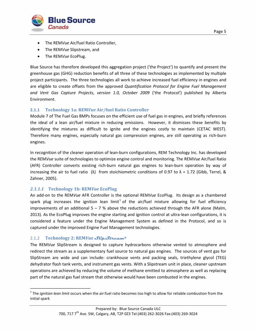
The REMVue Air/fuel Ratio Controller,
The REMVue Slipstream, and
The REMVue EcoPlug.
Blue Source has therefore developed this aggregation project ('the Project') to quantify and present the
greenhouse gas (GHG) reduction benefits of all three of these technologies as implemented by multiple
project participants. The three technologies all work to achieve increased fuel efficiency in engines and
are eligible to create offsets from the approved Quantification Protocol for Engine Fuel Management
and Vent Gas Capture Projects, version 1.0, October 2009 ('the Protocol') published by Alberta
Environment.
2.1.1 Technology 1a: REMVue Air/fuel Ratio Controller
Module 7 of The Fuel Gas BMPs focuses on the efficient use of fuel gas in engines, and briefly references
the ideal of a lean air/fuel mixture in reducing emissions. However, it dismisses these benefits by
identifying the mixtures as difficult to ignite and the engines costly to maintain (CETAC WEST).
Therefore many engines, especially natural gas compression engines, are still operating as rich-burn
engines.
In recognition of the cleaner operation of lean-burn configurations, REM Technology Inc. has developed
the REMVue suite of technologies to optimize engine control and monitoring. The REMVue Air/fuel Ratio
(AFR) Controller converts existing rich-burn natural gas engines to lean-burn operation by way of
increasing the air to fuel ratio (λ) from stoichiometric conditions of 0.97 to λ = 1.72 (Gibb, Terrel, &
Zahner, 2005).
2.1.1.1 Technology 1b: REMVue EcoPlug
An add-on to the REMVue AFR Controller is the optional REMVue EcoPlug. Its design as a chambered
spark plug increases the ignition lean limit1 of the air/fuel mixture allowing for fuel efficiency
improvements of an additional 5 – 7 % above the reductions achieved through the AFR alone (Malm,
2013). As the EcoPlug improves the engine starting and ignition control at ultra-lean configurations, it is
considered a feature under the Engine Management System as defined in the Protocol, and so is
captured under the improved Engine Fuel Management technologies.
2.1.2 Technology 2: REMVue SlipStream®
The REMVue SlipStream is designed to capture hydrocarbons otherwise vented to atmosphere and
redirect the stream as a supplementary fuel source to natural gas engines. The sources of vent gas for
SlipStream are wide and can include: crankhouse vents and packing seals, triethylene glycol (TEG)
dehydrator flash tank vents, and instrument gas vents. With a Slipstream unit in place, cleaner upstream
operations are achieved by reducing the volume of methane emitted to atmosphere as well as replacing
part of the natural gas fuel stream that otherwise would have been combusted in the engines.
1 The ignition lean limit occurs when the air:fuel ratio becomes too high to allow for reliable combustion from the
initial spark
Page 6
Prepared by: Blue Source Canada ULC 700, 717 7
th Ave. SW, Calgary, AB, T2P 0Z3 Tel:(403) 262-3026 Fax:(403) 269-3024
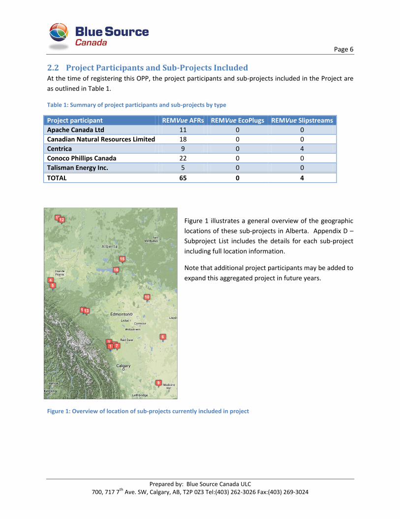
2.2 Project Participants and Sub-Projects Included At the time of registering this OPP, the project participants and sub-projects included in the Project are
as outlined in Table 1.
Table 1: Summary of project participants and sub-projects by type
Project participant REMVue AFRs REMVue EcoPlugs REMVue Slipstreams
Apache Canada Ltd 11 0 0
Canadian Natural Resources Limited 18 0 0
Centrica 9 0 4
Conoco Phillips Canada 22 0 0
Talisman Energy Inc. 5 0 0
TOTAL 65 0 4
Figure 1 illustrates a general overview of the geographic
locations of these sub-projects in Alberta. Appendix D –
Subproject List includes the details for each sub-project
including full location information.
Note that additional project participants may be added to
expand this aggregated project in future years.
Figure 1: Overview of location of sub-projects currently included in project
Page 7
Prepared by: Blue Source Canada ULC 700, 717 7
th Ave. SW, Calgary, AB, T2P 0Z3 Tel:(403) 262-3026 Fax:(403) 269-3024
2.3 Conditions prior to project initiation
2.3.1 Technology 1a: REMVue Air/fuel Ratio Controller
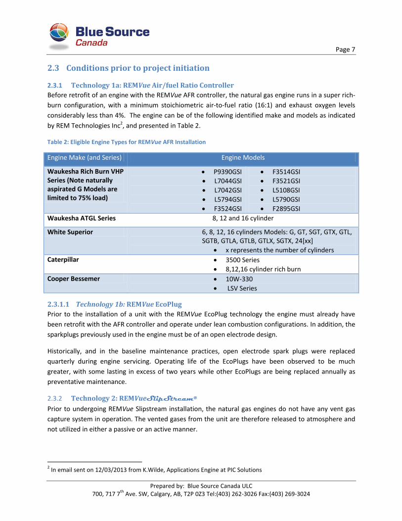
Before retrofit of an engine with the REMVue AFR controller, the natural gas engine runs in a super rich-
burn configuration, with a minimum stoichiometric air-to-fuel ratio (16:1) and exhaust oxygen levels
considerably less than 4%. The engine can be of the following identified make and models as indicated
by REM Technologies Inc2, and presented in Table 2.
Table 2: Eligible Engine Types for REMVue AFR Installation
Engine Make (and Series) Engine Models
Waukesha Rich Burn VHP Series (Note naturally aspirated G Models are limited to 75% load)
P9390GSI
L7044GSI
L7042GSI
L5794GSI
F3524GSI
F3514GSI
F3521GSI
L5108GSI
L5790GSI
F2895GSI
Waukesha ATGL Series 8, 12 and 16 cylinder
White Superior 6, 8, 12, 16 cylinders Models: G, GT, SGT, GTX, GTL, SGTB, GTLA, GTLB, GTLX, SGTX, 24[xx]
x represents the number of cylinders
Caterpillar 3500 Series
8,12,16 cylinder rich burn
Cooper Bessemer 10W-330
LSV Series
2.3.1.1 Technology 1b: REMVue EcoPlug
Prior to the installation of a unit with the REMVue EcoPlug technology the engine must already have
been retrofit with the AFR controller and operate under lean combustion configurations. In addition, the
sparkplugs previously used in the engine must be of an open electrode design.
Historically, and in the baseline maintenance practices, open electrode spark plugs were replaced
quarterly during engine servicing. Operating life of the EcoPlugs have been observed to be much
greater, with some lasting in excess of two years while other EcoPlugs are being replaced annually as
preventative maintenance.
2.3.2 Technology 2: REMVueSlipStream®
Prior to undergoing REMVue Slipstream installation, the natural gas engines do not have any vent gas
capture system in operation. The vented gases from the unit are therefore released to atmosphere and
not utilized in either a passive or an active manner.
2 In email sent on 12/03/2013 from K.Wilde, Applications Engine at PIC Solutions

Page 8
Prepared by: Blue Source Canada ULC 700, 717 7
th Ave. SW, Calgary, AB, T2P 0Z3 Tel:(403) 262-3026 Fax:(403) 269-3024
Discussed further in section 2.7.1, some subprojects may be subject to the requirements of ERCB
Directive D060 on Upstream Petroleum Industry Flaring, Incinerating and Venting. Should this be the
case, the baseline conditions for these subprojects will be the capture and subsequent combustion
(through flare or incinerator) of the previously vented fuel.

Page 9
Prepared by: Blue Source Canada ULC 700, 717 7
th Ave. SW, Calgary, AB, T2P 0Z3 Tel:(403) 262-3026 Fax:(403) 269-3024
Included Sources/Sinks
B1 Fuel Extraction & Processing
B2 Fuel Delivery
B3 Facility Operation
B4 Unit Operation
B6 Flaring of Process Emissions
B5b Venting of Emissions Captured in
the Project
B5a Venting of Process Emissions
B7 Electricity Usage
B8 Development of Site
B9 Building Equipment
B10 Transportation of Equipment
B11 Construction on Site
B12 Testing of Equipment
B13 Site Decommissioning
Figure 2: Simplified PFD of subproject technologies, pre-project. Diamond shapes represent sources specific to the REMVue SlipStream subproject.
Page 10
Prepared by: Blue Source Canada ULC 700, 717 7
th Ave. SW, Calgary, AB, T2P 0Z3 Tel:(403) 262-3026 Fax:(403) 269-3024
2.4 Description of how the project will achieve GHG emission reductions/removals The ability of the aggregation project to achieve GHG emission reductions presents itself through the
application of the three technology types described in the introduction. It is feasible that for one engine,
all three technologies or any combination thereof could be installed and operational simultaneously.
Therefore any one engine could demonstrate the GHG emission reductions resulting from the
application of any combination of the three technologies.
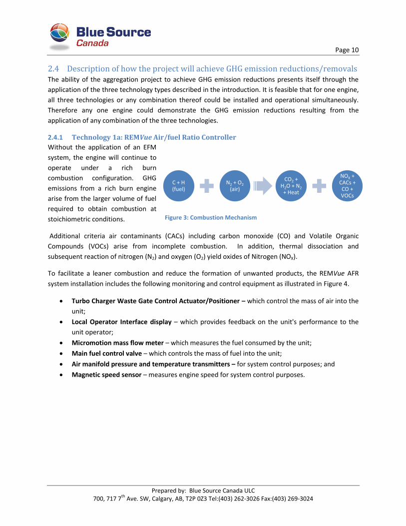
2.4.1 Technology 1a: REMVue Air/fuel Ratio Controller
Without the application of an EFM
system, the engine will continue to
operate under a rich burn
combustion configuration. GHG
emissions from a rich burn engine
arise from the larger volume of fuel
required to obtain combustion at
stoichiometric conditions.
Additional criteria air contaminants (CACs) including carbon monoxide (CO) and Volatile Organic
Compounds (VOCs) arise from incomplete combustion. In addition, thermal dissociation and
subsequent reaction of nitrogen (N2) and oxygen (O2) yield oxides of Nitrogen (NOX).
To facilitate a leaner combustion and reduce the formation of unwanted products, the REMVue AFR
system installation includes the following monitoring and control equipment as illustrated in Figure 4.
Turbo Charger Waste Gate Control Actuator/Positioner – which control the mass of air into the
unit;
Local Operator Interface display – which provides feedback on the unit's performance to the
unit operator;
Micromotion mass flow meter – which measures the fuel consumed by the unit;
Main fuel control valve – which controls the mass of fuel into the unit;
Air manifold pressure and temperature transmitters – for system control purposes; and
Magnetic speed sensor – measures engine speed for system control purposes.
C + H (fuel)
N2 + O2 (air)
CO2 + H2O + N2
+ Heat
NOX + CACs + CO + VOCs
Figure 3: Combustion Mechanism

Page 11
Prepared by: Blue Source Canada ULC 700, 717 7
th Ave. SW, Calgary, AB, T2P 0Z3 Tel:(403) 262-3026 Fax:(403) 269-3024
Figure 4: Post-Project REMVue AFR System
After the installation of the REMVue AFR system, the engine is converted to lean burn operation. The
AFR Controller adds excess air to achieve an air-to-fuel ratio greater than 20:1, and up to 17% excess
oxygen (Environmental Protection Agency, 2009). The engine is operating closer to the lean ignition limit
reducing the amount of air and fuel required for combustion and subsequent release of GHG emissions.
Additionally, the increase in air reduces the exhaust temperature thereby exponentially decreasing NOX
formation.
2.4.1.1 Technology 1b: REMVue EcoPlug
Considered an add-onto the REMVue AFR Engine Management
System, the REMVue EcoPlug aids in engine starting and ignition
control in ultra-lean combustion conditions. It extends the
ignition lean limit of the air-fuel mixture allowing even greater
air-to fuel ratios of 30:1 or higher (Malm, 2013). The chambered
spark plug has two distinct features:
Small diameter platinum wires fused to the center
electrode lowers voltage required for spark;
Tangential orifices enhance micro-turbulence mixing
Once the mixture is ignited in the chamber, the hot gases expand
from the orifices with much greater energy than initially provided
by the electrode spark thereby igniting the rest of the fuel
mixture. Additional fuel savings of 3 to 7% result from the simple
exchange of open electrode spark plugs with EcoPlugs, which in Figure 5: EcoPlug Full Section View
Page 12
Prepared by: Blue Source Canada ULC 700, 717 7
th Ave. SW, Calgary, AB, T2P 0Z3 Tel:(403) 262-3026 Fax:(403) 269-3024
turn results in even greater GHG emission reductions from more efficient combustion.
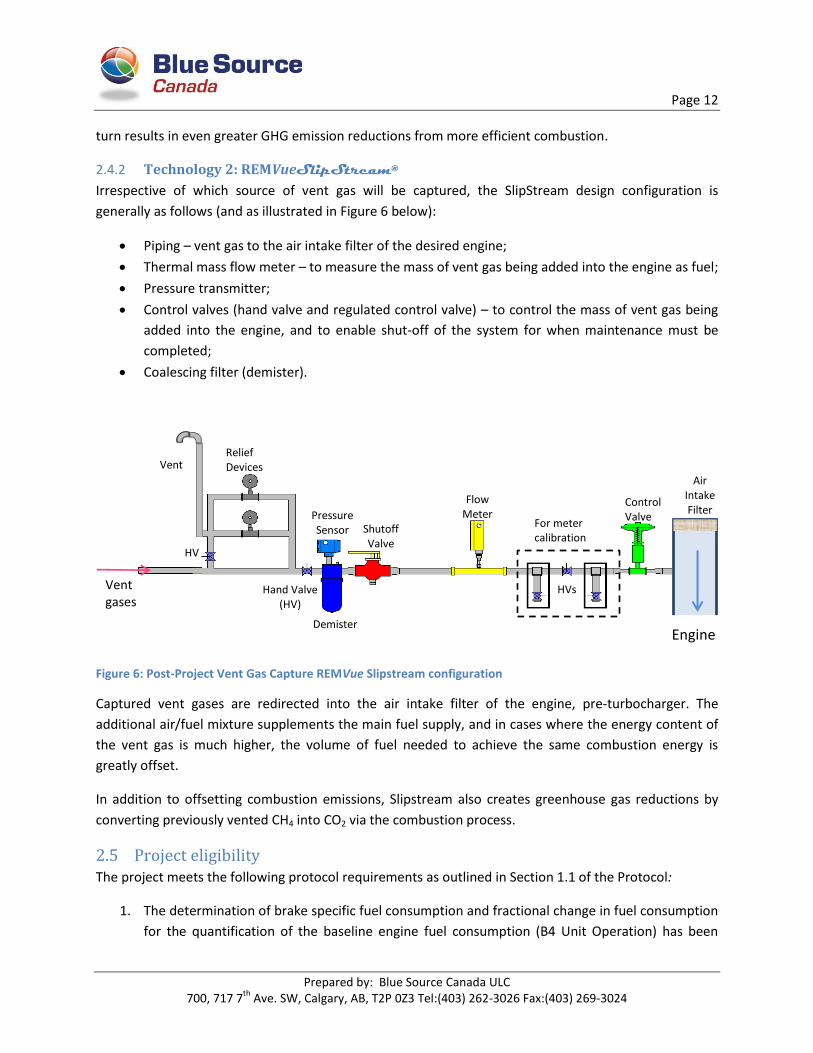
2.4.2 Technology 2: REMVueSlipStream®
Irrespective of which source of vent gas will be captured, the SlipStream design configuration is
generally as follows (and as illustrated in Figure 6 below):
Piping – vent gas to the air intake filter of the desired engine;
Thermal mass flow meter – to measure the mass of vent gas being added into the engine as fuel;
Pressure transmitter;
Control valves (hand valve and regulated control valve) – to control the mass of vent gas being
added into the engine, and to enable shut-off of the system for when maintenance must be
completed;
Coalescing filter (demister).
Figure 6: Post-Project Vent Gas Capture REMVue Slipstream configuration
Captured vent gases are redirected into the air intake filter of the engine, pre-turbocharger. The
additional air/fuel mixture supplements the main fuel supply, and in cases where the energy content of
the vent gas is much higher, the volume of fuel needed to achieve the same combustion energy is
greatly offset.
In addition to offsetting combustion emissions, Slipstream also creates greenhouse gas reductions by
converting previously vented CH4 into CO2 via the combustion process.
2.5 Project eligibility The project meets the following protocol requirements as outlined in Section 1.1 of the Protocol:
1. The determination of brake specific fuel consumption and fractional change in fuel consumption
for the quantification of the baseline engine fuel consumption (B4 Unit Operation) has been
Shutoff Valve
Demister
Flow Meter
Control Valve
Air Intake Filter
Engine
Relief Devices
Vent gases
Vent
For meter calibration
Pressure Sensor
HV
HVs Hand Valve (HV)

Page 13
Prepared by: Blue Source Canada ULC 700, 717 7
th Ave. SW, Calgary, AB, T2P 0Z3 Tel:(403) 262-3026 Fax:(403) 269-3024
completed according to the guidelines discussed in Appendix C. During the completion of Pre
and Post-Audits to measure the fractional change in fuel consumption the project proponent
must note any changes made to the engine or the equipment that is powered by the engine
(e.g. compressor) that could impact the measured BSFC. These changes could include the
addition / removal of equipment or other modifications made to the engine or the prime mover
that could impact the load on the engine (i.e. reduced frictional load through compressor
retrofits etc.). Project proponents would have to demonstrate that these changes have not
impacted the validity of the fuel savings calculated from measured data during the Pre and Post-
Audits.
Response: Blue Source has developed an Engine Map of Pre and Post audit values across the Waukesha
VHP series of engines, and may develop further Engine Maps for future deliveries. The Engine Map has
been developed in accordance with the guidance listed in Appendix C of the Protocol and includes data
from over 72 engines within the same make and classification. This Engine Map will be used as the
default calculation approach, as outlined in section 5.3.4.
Application of the Master method ensures a direct comparison of BSFC at the same measured load and
RPM both pre and post audit. For instance, any changes to the engine which affect the engine load and
subsequent BSFC determination would not be captured as the Master method would simply reference
another BSFC measured from a different, equivalent load and RPM set-point recorded from an engine of
the same make, classification and EFM technology. If the simple and advanced methods are used as
described in the protocol, the project proponent will reference the Post-audit performance analysis notes
recorded by Power Ignition and Controls, noting engine modifications and whether the impact on the
engine load is significant.
2. The engine modification must not impair the functionality of the unit, process or overall facility
such that additional energy inputs are required as demonstrated by facility process flow
diagrams and/or unit operational performance data. Unit operational data may include engine
operating hours, records of down time or other records to demonstrate that the engine fuel
management system and/or the combustion of captured vent gases does not de-rate the engine
or cause a significant increase in down time (and potentially increase compressor start gas
emissions). The project proponent would need to show that the use of other units (engines)
and/or supplemental fuels is not needed to compensate for increased parasitic loads, reduced
fuel energy content and/or decreased engine power output. Functional equivalence may be
demonstrated through an affirmation from the project developer or other qualified third party;
Response: No additional energy inputs achieved though the installation of new units, or supplemental
fuel to the engine is needed due to the installation of the REMVue AFR, EcoPlug or Slipstream
Technologies. Specific to the SlipStream technology, the captured vent gas is not an additional source of
energy but rather a replacement fuel source used to supply the main functionality of the engine as a
prime mover.

Page 14
Prepared by: Blue Source Canada ULC 700, 717 7
th Ave. SW, Calgary, AB, T2P 0Z3 Tel:(403) 262-3026 Fax:(403) 269-3024
3. There must not be any regulations requiring the capture and destruction or conservation of vent
gas emissions from the processes and/or units impacted by the project activity that have been
quantified in the baseline as vented GHG emissions under SS B5b Venting of Emissions Captured
in the Project. Project proponents should refer to the November 16, 2006 version of the Alberta
Energy and Resources Conservation Board (ERCB) Directive 60 (D60) Upstream Petroleum
Industry Flaring, Incineration and Venting for further guidance on restrictions on flaring and
venting of solution gas and other types of vent gases. D60 provides sector specific performance
standards for flaring and venting that must be met by operators as well as decision trees to
evaluate whether gas can be economically conserved instead of vented or flared. Conservation
opportunities are evaluated as economic or uneconomic based on the criteria listed in Section
2.8 of D608. It should be noted that D60 does not prescribe any one particular conservation
option and the use of solution gas for supplemental fuel could be compared to re-injection of
the solution gas for reservoir pressure maintenance as a conservation option, each with
significantly different GHG implications.
Response: None of the activities quantified within this aggregated project are a direct result of
regulatory requirements, and all have been undertaken voluntarily as a beyond business as usual
activity.
4. The engine management system implemented as a result of the protocol must comply with all
other air emissions regulations in Alberta, particularly NOX requirements. The following
guidelines are intended to assist project proponents in evaluating whether their project activity
of capturing a vent gas stream may be considered to be surplus to regulation, but should in no
way be seen as an exhaustive list of requirements or a replacement for the guidance in D60 and
other regulations enforced by the ERCB or Alberta Environment.
a. If the ERCB determines that an individual source of vent gas has sufficient flow rate to
sustain stable combustion and must be flared according to D60 Section 8.1, then the
project proponent will not be eligible for offsets from venting in the baseline under SS
B5b.
b. If a project is not covered under criteria 3.a) but involves the recovery and use of
solution gas at levels exceeding the 900 m3/day threshold specified in Section 2.3 of
D60 and is also deemed to be economic to implement one or more conservation
activities as specified in Section 2.8 of D60, then the project may not be eligible for
offsets from venting under SS B5b. If the captured volume of solution gas cannot sustain
stable combustion and is less than the threshold or deemed to be uneconomic to
conserve then the project activity may be eligible for offsets from venting.
c. As stated in Section 8.3 of D60, if the total facility benzene emission limits specified in
Directive 039 Revised Program to Reduce Benzene Emissions from Glycol Dehydrators
are exceeded at the project site then venting may not be permitted and the project may
not be eligible for offsets from venting in the baseline under SS B5b.
Page 15
Prepared by: Blue Source Canada ULC 700, 717 7
th Ave. SW, Calgary, AB, T2P 0Z3 Tel:(403) 262-3026 Fax:(403) 269-3024
Response: Subprojects involving the application of the Vent Gas Capture (VGC) technologies have all
been deemed uneconomic under the D060 guidelines, and as well the captured volume of solution gas is
unable to maintain stable combustion. All VGC activities in this aggregation project have been evaluated
as such and therefore are eligible to create offsets. Specific to VGC applications regarding the capture of
flash gas from glycol dehydrators, all subproject activities go above and beyond reducing benzene
beyond the permitted benzene emission limits. Stationary combustion technology has evolved today such
that from engine combustion alone, over 98% of the benzene is destroyed (Gibb, Terrel, & Zahner, 2005).
The application of VGC is an additional activity effectively reducing the amount of benzene destruction.
5. For projects where the combustion of vent gases is required under D60 (or other applicable
regulation) or where the baseline practice already involved the flaring or incineration of the
waste gas stream, then the baseline condition is the flaring of the waste gas stream. The project
proponent can claim offsets following the Flexibility Mechanism in Appendix A, to quantify GHG
reductions from reduced fuel gas consumption for flaring and engine operation. The project
proponent must demonstrate that the re-direction of the waste gases to the engine actually
results in reduced flare fuel usage as evidenced by metered volumes of waste gas sent to
flare/incinerator and/or volumes of supplemental fuel consumed or through engineering
designs for the flare/incinerator unit;
Response: Where applicable, the quantification of GHG reductions for subprojects required to conserve
solution gas under D060 have been compared against baseline GHG emissions resulting from flaring or
incineration of the gas stream. Project GHG reductions occur through the reduced fuel gas consumption
and reduced flaring emissions where applicable. This is evaluated on an individual subproject basis.
6. The boundary of the project activity must not include the quantification of baseline GHG
emissions from engine fuel combustion and vent gas emissions that are subject to regulation
under the Alberta Specified Gas Emitter Regulation.
Response: None of the subprojects included will be from regulated SGER Large Final Emitter (LFE)
facilities.
7. The quantification of reductions achieved by the project is based on actual measurement and
monitoring (except where indicated in this protocol) as indicated by the proper application of
this protocol; and,
Response: Quantification of reductions achieved by the EFM subproject technologies are based upon the
accumulated pre and post audit data measurements collected in accordance with Appendix C of the
Protocol. Quantification of reductions achieved by the VGC subproject technologies are based upon a
minimum monthly reconciliation of available measurements as indicated by the Protocol.
8. The project must meet the requirements for offset eligibility as specified in the applicable
regulation and guidance documents for the Alberta Offset System. [Of particular note:

Page 16
Prepared by: Blue Source Canada ULC 700, 717 7
th Ave. SW, Calgary, AB, T2P 0Z3 Tel:(403) 262-3026 Fax:(403) 269-3024
a. [The date of equipment installation, operating parameter changes or process
reconfiguration are initiated or have effect on the project on or after January 1, 2002 as
indicated by facility records;]
b. [The project may generate emission reduction offsets for a period of 8 years unless an
extension is granted by Alberta Environment, as indicated by facility and offset system
records. Additional credit duration periods require a reassessment of the baseline
condition; and,]
c. [Ownership of the emission reduction offsets must be established as indicated by facility
records.]
Response: The project meets all of the requirements for offset eligibility as specified in section 3.1 of the
Technical Guidance for Offset Project Developers (version 4.0, February 2013).
2.5.1 Flexibility mechanisms
This aggregation applies the following flexibility mechanisms as outlined on page 9 of the Protocol:
2. For project scenarios where it is not possible to measure the brake specific fuel consumption
before and after the installation of a new engine management system the project proponent
may use fractional fuel savings data from other engines of the same make and classification. The
project proponent should apply the protocol flexibility mechanism under the SS “B4 Unit
Operation” to ensure that the estimation of the baseline fuel consumption is overly conservative
across the full spectrum of engine speeds and loads. The use of this approach is contingent on
there being sufficient data from at least 5 similar engines of the same make and classification
operating with the same type of engine management system. For further details, refer to
Appendix A.
Justification: Occasionally, the Engine Map of Pre and Post audit values does not encompass the
operating conditions of a specific engine. If this should occur, an average of the fractional BSFC savings
will be used to estimate the associated GHG reductions as outlined in Appendix A of the protocol.
3. Engine fuel management systems and vent gas capture systems can be installed on a single
engine or on multiple units at multiple sites. As such, the protocol allows for flexibility in
quantifying offsets from multiple installations
Justification: This project plan allows for the aggregation of three subproject technologies from multiple
engine units and participants. An aggregated subproject tracking sheet has been created in accordance
with the Protocol Requirements and will be uploaded with the project documents at time of registration
and serialization.
5. Site specific emission factors may be substituted for the generic emission factors indicated in
this protocol document. The methodology for generation of these emission factors must be
sufficiently robust to ensure accuracy. In particular, project proponents that conduct site
specific engine exhaust gas emission testing may develop dynamic emission factors for use

Page 17
Prepared by: Blue Source Canada ULC 700, 717 7
th Ave. SW, Calgary, AB, T2P 0Z3 Tel:(403) 262-3026 Fax:(403) 269-3024
under SS “B4 Unit Operation” such that the project and baseline conditions have distinct
emission factors for methane and nitrous oxide. The development of these emission factors
must follow the US Environmental Protection Agency (EPA) 40 CFR Part 60 Guidelines (i.e.
Method 7E for NOX and Methods 18 or 25A for methane). Exhaust gas analyses must be
completed for each load and RPM set point during the Pre and Post-Audits to ensure that the
baseline and project emission factors are representative of the full range of operating conditions
for the original engine and the modified engine.
Justification: Where available, site specific CO2 emission factors will be used. If no site specific data is
available, the emission factors will be sourced from the most recent published version of Environment
Canada’s National Inventory Report.
2.5.2 Other Methodology Changes Pre-Approved by Alberta Environment
No other methodology changes have occurred that require approval from Alberta Environment.
2.6 Subproject technologies, products, services and the expected level of activity
2.6.1 Technology 1 Services
Uptake of the REMVue AFR controller is expected to be the highest of the included subproject
technologies in this aggregation plan due to the volume of rich burn engines in operation throughout
Alberta’s oil and gas operations. There are also many proven examples of the technology’s field success
increasing engine performance and reliability. However, remote field sites, cost of purchasing,
installation and labour, and logistics are still factors hindering the deployment of REMVue AFR.
The newest technology in REM Technology’s suite of EFM tools, the REMVue EcoPlug still has many
hurdles to overcome before achieving status as an industry standard practice, including increasing
technology awareness, proof of concept in the field, and acceptance as a superior product. Therefore,
the level of activity for this subproject technology is expected to be low.
Once a participant has decided to purchase and install the REMVue AFR Controller and/or REMVue
EcoPlug, they have a few technology and service options to decide upon. The following data monitoring
and control panels can vary between each REMVue installation depending upon the requirements and
preferences of the site manager and project participant.
The following overview is an excerpt from the REM Technology website3:
REMVue 500 – The REMVue 500 is an advanced single system engine/compressor control and
monitoring system. It is capable of monitoring and control of key compressor and engine parameters
including but not limited to:
the Air/fuel Control
3REM Technology Inc (2012) REMVue 500.REM Technology Inc. Retrieved November 27, 2013 from
http://www.remtechnology.com/products/rem/remvue-500.aspx
Page 18
Prepared by: Blue Source Canada ULC 700, 717 7
th Ave. SW, Calgary, AB, T2P 0Z3 Tel:(403) 262-3026 Fax:(403) 269-3024
Governor Control
Process/Load Control
Compressor Flow
Compressor Horsepower
REMVue 500/ASD – In addition to the features included in the REMVue 500 system, the REMVue
500/ASD (Advanced Shut Down) integrates a control and safety shutdown sequence with
remote/local set points.
GHG Data Logger (GHGDL) – A standalone data logging device to the REMVue 500 suite, the
installation of the GHG data logger provides an 18 month data historian, capturing key parameters
at user defined intervals.
In lieu of the REM Technology’s data collection system, some project participants have a pre-established
Supervisory Control and Data Acquisition (SCADA) system preferred by their company, such as
Detechtion Technologies Enalysis™ web-enabled software tool. These robust SCADA systems provide at
a minimum the same service as the GHG Data Logger, or internal panel historian, and often include
additional trending, data manipulation tools, and fleet management capabilities.
2.6.2 Technology 2 Services
The SlipStream technology has the additional flexibility in that the captured vent gas can be from
multiple sources including, but not limited to:
VGC from Flash tanks;
VGC from instrument gas;
VGC from compressor packing seals and crankcase vents.
As the functionality of the SlipStream unit does not change depending on the source captured,
functional equivalence between each subproject application is upheld. Because of the specific
technology application, site performance requirements, and overall cost of the system, the expected
level of activity for SlipStream is expected to remain steady with only a few installations each year.
REM Emissions Monitor - To capture the success of the SlipStream system, the REM Emissions Monitor:
1) performs all data collection calculations and 2) measures, calculates and records the data for 18
months, thereby minimizing data losses from data capture and storage limitations.
2.7 Identification of Risks Table 3 presents the following risk categories and associated consequences. Risk level analysis is
performed using the aid developed and presented in Appendix C – Risk Matrix.

Page 19
Prepared by: Blue Source Canada ULC 700, 717 7
th Ave. SW, Calgary, AB, T2P 0Z3 Tel:(403) 262-3026 Fax:(403) 269-3024
Table 3: Risk matrix
Risk Category Consequence Severity Probability Mitigation Risk Level
Regulatory Risk
ESRD mandates that each engine require an EFM
system
Low Medium
Many EFM technologies exist for rich
burn as well as lean burn
configurations. Changing the
engine configuration from rich burn
to lean burn would still be
considered additional.
Low
Regulatory Risk
D060 lowers the conservation
requirement of vent gas to 500 m3
or less.
High Low
Subprojects will be screened to
ensure the requirements of
D060 are not applicable
Moderate
Technological Risk
Changes to the engine operating
system have adverse effects on
engine performance
Low Medium
Trained technicians install and
optimize EFM and VGC
systems to their best
performance. Annual
maintenance by project
participant ensures engine
is in prime condition.
Low
Project Risk
Market forces such as low
natural gas prices, or a shift in the
energy efficiency targets, decrease
likelihood of
Medium Low
Many installations are
already deployed and operating. The
energy efficiency
Low

Page 20
Prepared by: Blue Source Canada ULC 700, 717 7
th Ave. SW, Calgary, AB, T2P 0Z3 Tel:(403) 262-3026 Fax:(403) 269-3024
Risk Category Consequence Severity Probability Mitigation Risk Level
project proponents to invest in the
upgrade
targets will likely increase
as time progresses and awareness and
focus on the economy of fuel
savings and impact of social
license heighten.
Project Risk
Sites included in the aggregation
pool may shut-in, negating any benefits from
improved equipment installs
High Moderate
As a normal occurrence in the oil and gas sector, some sites may be
affected during the course of
the project. This is unlikely to
occur in multiple locations
simultaneously.
Moderate
2.7.1 Regulatory Requirements & Project Impacts
Energy Resources Conservation Board (ERCB) Directive D060, revised edition November 3, 2011 has
placed restrictions with respect to venting and flaring activities within the upstream oil and gas industry.
As outlined in section 2.5, paragraph 5, projects which are required to conserve gas under D060 or
another regulation will have an identified baseline of combustion of the waste gas stream.
This regulation requires evaluation on an individual subproject basis. Subprojects will be evaluated for:
3 month rolling average volumetric flow rate >900 m3/day AND an Economic Evaluation yields
Net Present Value (NPV) > $(- 50,000);
The gas:oil ratio (GOR) is greater than 3000 m3/m3; or
Flared volumes are greater than 900 m3/day per site and the flare is within 500 m of an existing
residence, regardless of economics.
If a subproject should display any of the above properties, the project participant will be asked for proof
of ERCB’s approval decision to continue venting before inclusion into the aggregation pool is complete.

Page 21
Prepared by: Blue Source Canada ULC 700, 717 7
th Ave. SW, Calgary, AB, T2P 0Z3 Tel:(403) 262-3026 Fax:(403) 269-3024
In addition, project participants will be required to confirm that no subprojects are within site
boundaries of a Large Final Emitter (LFE) (i.e. a regulated site under the SGER).

Page 22
Prepared by: Blue Source Canada ULC 700, 717 7
th Ave. SW, Calgary, AB, T2P 0Z3 Tel:(403) 262-3026 Fax:(403) 269-3024
3 Inventory of Sources and Sinks The Protocol contains a list of baseline and project sources and sinks (SSs) that were deemed applicable for projects developed according to the
protocol. The SSs for the Project are identified in Figure 7, below.
Included Sources/Sinks
P1 Fuel Extraction & Processing
P2 Fuel Delivery
P3 Facility Operation
P4 Unit Operation
P6 Flaring of Process Emissions
P5b Venting of Emissions Captured in
the Project
P5a Venting of Process Emissions
P7 Electricity Usage
P8 Development of Site
P9 Building Equipment
P10 Transportation of Equipment
P11 Construction on Site
P12 Testing of Equipment
P13 Site Decommissioning
Figure 7: Simplified PFD of subproject technologies, post-project. Diamond shapes represent sources specific to the REMVue SlipStream subproject

Page 23
Prepared by: Blue Source Canada ULC 700, 717 7
th Ave. SW, Calgary, AB, T2P 0Z3 Tel:(403) 262-3026 Fax:(403) 269-3024
3.1 Quantification of estimated GHG emissions/removals The following equations serve as the basis for calculating the emission reductions from the comparison
of the baseline and project conditions as per the Protocol:
Emissions Baseline= sum of the emissions under the baseline condition = Emissions Fuel Extraction / Processing = emissions under SS B1 Fuel Extraction and Processing
Emissions Unit Operation = emissions under SS B4 Unit Operation
Emissions Venting of Emissions Captured in Project = emissions under SS B5b Venting of Emissions Captured in Project
Emissions Project = sum of the emissions under the project condition =
Emissions Fuel Extraction / Processing = emissions under SS P1 Fuel Extraction and Processing
Emissions Unit Operation = emissions under SS P4 Unit Operation
Emissions Capture of Vent Gases = emissions under SS P5b Capture of Vent Gases
3.1.1 Justification for excluding sources and sinks
As stated in the Protocol not all parameters are applicable to all EFM or VGC systems. Those sources and
sinks (SSs) that are not applicable will be excluded as the input variables will be zeroes. As such, the
project developer can exclude sources and sinks that are not applicable to their project with reasonable
justification.
The following SSs have been excluded from quantification for subprojects employing EFM systems:
Emissions under SS (B5b) Venting of Emissions Captured in Project
Emissions under SS (P5b) Capture of Vent Gases
These SSs have been excluded from Technology 1 quantification as there is no capture of vent gases for
subprojects employing EFM systems such as the REMVue AFR controller. However, for quantification of
VGC subprojects these two sources will be included.
3.1.2 Quantification of Source and Sinks
The general methods of quantification (as listed in the Protocol) for the required greenhouse gas
calculations are as follows. Table 5 includes the emission factors relevant to the Project.
SS B1/P1 Fuel Extraction and Processing– The fuel avoided from the implementation of the EFM
technology like REMVue AFR or VGC system such as Slipstream would have otherwise been extracted
and processed in the baseline configuration. Note that this value is obtained from SS B4 and is equal to
the metered fuel consumption in the project condition multiplied by the Fractional Change in fuel
consumption from the baseline to the project.

Page 24
Prepared by: Blue Source Canada ULC 700, 717 7
th Ave. SW, Calgary, AB, T2P 0Z3 Tel:(403) 262-3026 Fax:(403) 269-3024
SS B4/P4 Unit Operation- Calculated based on the continuous measurement of mass flow rate of fuel
into the engine in the Project Condition. In project configurations where vent gases are captured and fed
back into the engine for supplemental fuel, the total fuel consumption is the sum of the main fuel gas
stream and the supplemental vent gas fuel, expressed as an energy equivalent quantity of the primary
fuel (e.g. natural gas).
SS B5b/P5b Venting – Continuous measurement of the vent gas flow rate into the unit on a mass basis
in the project condition.
Note SSs B4/P4 and B5b/P5b can also be calculated using contingent data collection methods (see
section 3.1.3).
3.1.3 Source/Sink Contingent Data Collection Procedures
The following contingent data collection procedures are adapted from table 2.6 of the Protocol:
SS B4 Unit Operation – Calculation of average fuel consumption per hour of operation over previous
and following months where fuel consumption measurements are available. Total fuel consumption is
calculated based on reconciliation of unit operating hours from facility records multiplied by the average
hourly fuel consumption.
SSB5b Venting of Emissions Captured in Project – Reconciliation of vent gas consumption on an hourly
basis where consistent flow rates can be demonstrated. Total vent gas consumption can also be
calculated based on reconciliation of unit operating hours from facility records multiplied by the average
hourly vent gas consumption, for vent gas streams with consistent flow rates. Project proponents may
need to demonstrate that vent gas sources are consistent in flow rate as intermittent vent sources may
not be fully measurable at this frequency.
Page 25
Prepared by: Blue Source Canada ULC 700, 717 7
th Ave. SW, Calgary, AB, T2P 0Z3 Tel:(403) 262-3026 Fax:(403) 269-3024
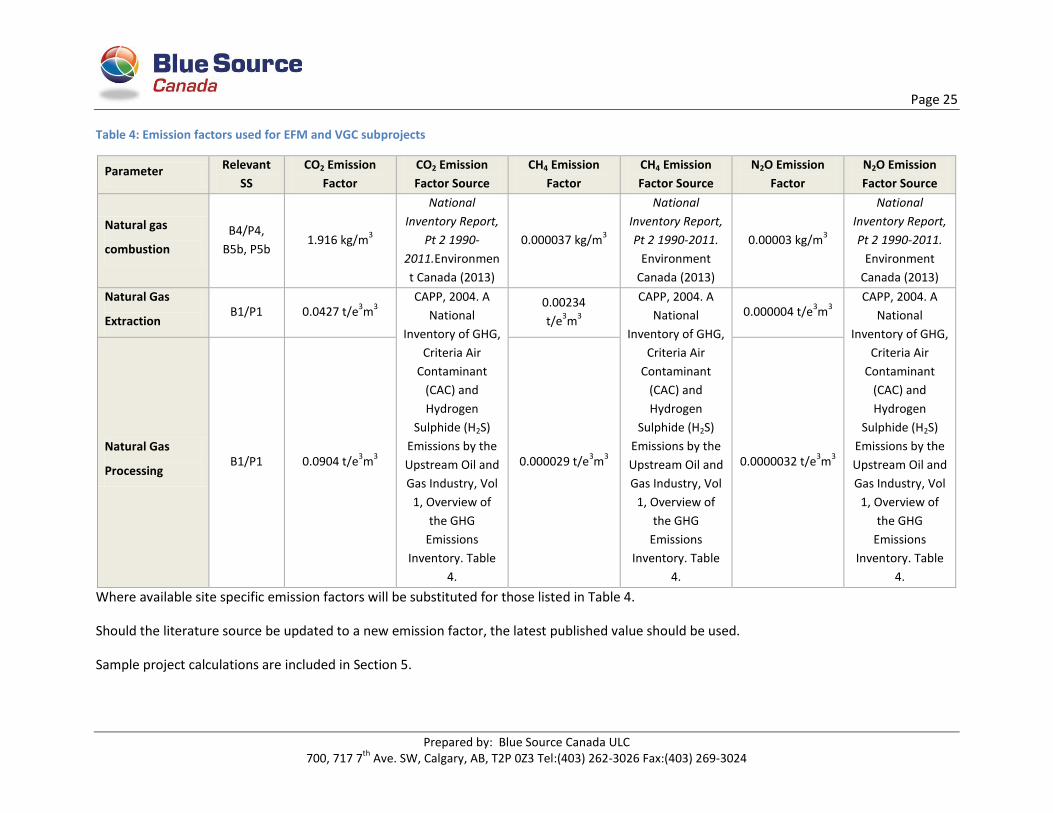
Table 4: Emission factors used for EFM and VGC subprojects
Parameter Relevant
SS
CO2 Emission
Factor
CO2 Emission
Factor Source
CH4 Emission
Factor
CH4 Emission
Factor Source
N2O Emission
Factor
N2O Emission
Factor Source
Natural gas
combustion
B4/P4,
B5b, P5b 1.916 kg/m
3
National
Inventory Report,
Pt 2 1990-
2011.Environmen
t Canada (2013)
0.000037 kg/m3
National
Inventory Report,
Pt 2 1990-2011.
Environment
Canada (2013)
0.00003 kg/m3
National
Inventory Report,
Pt 2 1990-2011.
Environment
Canada (2013)
Natural Gas
Extraction B1/P1 0.0427 t/e
3m
3
CAPP, 2004. A
National
Inventory of GHG,
Criteria Air
Contaminant
(CAC) and
Hydrogen
Sulphide (H2S)
Emissions by the
Upstream Oil and
Gas Industry, Vol
1, Overview of
the GHG
Emissions
Inventory. Table
4.
0.00234
t/e3m
3
CAPP, 2004. A
National
Inventory of GHG,
Criteria Air
Contaminant
(CAC) and
Hydrogen
Sulphide (H2S)
Emissions by the
Upstream Oil and
Gas Industry, Vol
1, Overview of
the GHG
Emissions
Inventory. Table
4.
0.000004 t/e3m
3
CAPP, 2004. A
National
Inventory of GHG,
Criteria Air
Contaminant
(CAC) and
Hydrogen
Sulphide (H2S)
Emissions by the
Upstream Oil and
Gas Industry, Vol
1, Overview of
the GHG
Emissions
Inventory. Table
4.
Natural Gas
Processing B1/P1 0.0904 t/e
3m
3 0.000029 t/e
3m
3 0.0000032 t/e
3m
3
Where available site specific emission factors will be substituted for those listed in Table 4.
Should the literature source be updated to a new emission factor, the latest published value should be used.
Sample project calculations are included in Section 5.
Page 26
Prepared by: Blue Source Canada ULC 700, 717 7
th Ave. SW, Calgary, AB, T2P 0Z3 Tel:(403) 262-3026 Fax:(403) 269-3024
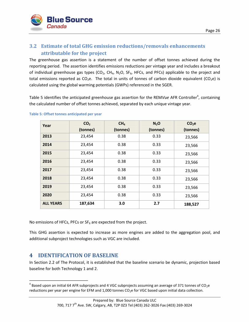
3.2 Estimate of total GHG emission reductions/removals enhancements
attributable for the project The greenhouse gas assertion is a statement of the number of offset tonnes achieved during the
reporting period. The assertion identifies emissions reductions per vintage year and includes a breakout
of individual greenhouse gas types (CO2, CH4, N2O, SF6, HFCs, and PFCs) applicable to the project and
total emissions reported as CO2e. The total in units of tonnes of carbon dioxide equivalent (CO2e) is
calculated using the global warming potentials (GWPs) referenced in the SGER.
Table 5 identifies the anticipated greenhouse gas assertion for the REMVue AFR Controller4, containing
the calculated number of offset tonnes achieved, separated by each unique vintage year.
Table 5: Offset tonnes anticipated per year
Year CO2
(tonnes)
CH4
(tonnes)
N2O
(tonnes)
CO2e
(tonnes)
2013 23,454 0.38 0.33 23,566
2014 23,454 0.38 0.33 23,566
2015 23,454 0.38 0.33 23,566
2016 23,454 0.38 0.33 23,566
2017 23,454 0.38 0.33 23,566
2018 23,454 0.38 0.33 23,566
2019 23,454 0.38 0.33 23,566
2020 23,454 0.38 0.33 23,566
ALL YEARS 187,634 3.0 2.7 188,527
No emissions of HFCs, PFCs or SF6 are expected from the project.
This GHG assertion is expected to increase as more engines are added to the aggregation pool, and
additional subproject technologies such as VGC are included.
4 IDENTIFICATION OF BASELINE In Section 2.2 of The Protocol, it is established that the baseline scenario be dynamic, projection based
baseline for both Technology 1 and 2.
4 Based upon an initial 64 AFR subprojects and 4 VGC subprojects assuming an average of 371 tonnes of CO2e
reductions per year per engine for EFM and 1,000 tonnes CO2e for VGC based upon initial data collection.
Page 27
Prepared by: Blue Source Canada ULC 700, 717 7
th Ave. SW, Calgary, AB, T2P 0Z3 Tel:(403) 262-3026 Fax:(403) 269-3024
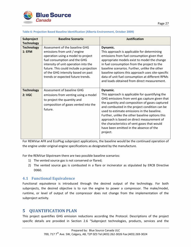
Table 6: Projection Based Baseline Identification (Alberta Environment, October 2009)
Subproject Technology
Baseline Scenario Justification
Technology 1: EFM
Assessment of the baseline GHG emissions from unit / engine operation using a model to project fuel consumption and the GHG intensity of unit operation into the future. This could include a projection of the GHG intensity based on past trends or expected future trends.
Dynamic. This approach is applicable for determining emissions from fuel consumption given that appropriate models exist to model the change in fuel consumption from the project to the baseline scenarios. Further, unlike the other baseline options this approach uses site-specific data of unit fuel consumption at different RPMs and loads obtained from direct measurement.
Technology
2: VGC
Assessment of baseline GHG
emissions from venting using a model
to project the quantity and
composition of gases vented into the
future.
Dynamic. This approach is applicable for quantifying the GHG emissions from vent gas capture given that the quantity and composition of gases captured and combusted in the project condition can be used to estimate emissions in the baseline. Further, unlike the other baseline options this approach is based on direct measurement of the characteristics of vent gases that would have been emitted in the absence of the project.
For REMVue AFR and EcoPlug subproject applications, the baseline would be the continued operation of
the engine under original engine specifications as designated by the manufacture.
For the REMVue Slipstream there are two possible baseline scenarios:
1) The vented source gas is not conserved or flared;
2) The vented source gas is combusted in a flare or incinerator as stipulated by ERCB Directive
D060.
4.1 Functional Equivalence Functional equivalence is introduced through the desired output of the technology. For both
subprojects, the desired objective is to run the engine to power a compressor. The make/model,
runtime, or level of output of the compressor does not change from the implementation of the
subproject activity.
5 QUANTIFICATION PLAN This project quantifies GHG emission reductions according the Protocol. Descriptions of the project
specific details are provided in Section 2.6 “Subproject technologies, products, services and the
Page 28
Prepared by: Blue Source Canada ULC 700, 717 7
th Ave. SW, Calgary, AB, T2P 0Z3 Tel:(403) 262-3026 Fax:(403) 269-3024
expected level of activity”. Detailed calculations for the project will be provided to the verifier. The
following section lists all relevant equations for quantifying GHG emission reductions from the project.
Emission Reduction = Emissions Baseline – Emissions Project
Emissions Baseline = sum of the emissions under the baseline condition.
1. Emissions Fuel Extraction/Processing = emissions under SS (B1) Fuel Extraction and Processing
2. Emissions Unit Operation = emissions under SS B4 Unit Operation
3. Emissions Capture of Vent Gases = emissions under SS B5b Venting of Emissions Captured in
Project
Emissions Project = sum of the emissions under the project condition.
4. Emissions Fuel Extraction and Processing = emissions under SS (P1) Fuel Extraction / Processing
5. Emissions Unit Operation = emissions under SS (P4) Unit Operation
6. Emissions Capture of Vent Gases = emissions under SS (P5b) Capture of Vent Gases
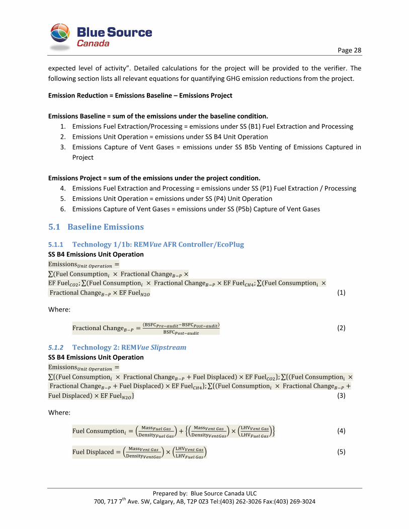
5.1 Baseline Emissions
5.1.1 Technology 1/1b: REMVue AFR Controller/EcoPlug
SS B4 Emissions Unit Operation
∑
∑ ∑
(1)
Where:
)
(2)
5.1.2 Technology 2: REMVue Slipstream
SS B4 Emissions Unit Operation
∑{ ) } ∑{
) } ∑{
) } (3)
Where:
(
) {(
) (
)} (4)
(
) (
) (5)
Page 29
Prepared by: Blue Source Canada ULC 700, 717 7
th Ave. SW, Calgary, AB, T2P 0Z3 Tel:(403) 262-3026 Fax:(403) 269-3024
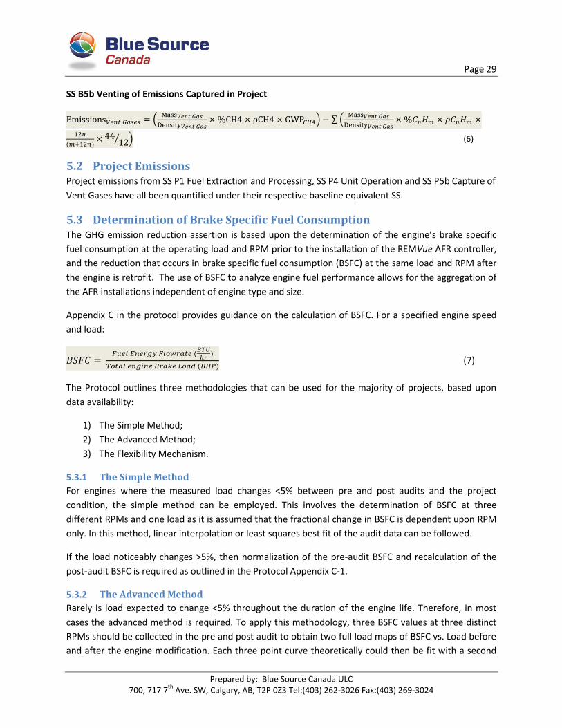
SS B5b Venting of Emissions Captured in Project
(
) ∑(
)
⁄ ) (6)
5.2 Project Emissions Project emissions from SS P1 Fuel Extraction and Processing, SS P4 Unit Operation and SS P5b Capture of
Vent Gases have all been quantified under their respective baseline equivalent SS.
5.3 Determination of Brake Specific Fuel Consumption The GHG emission reduction assertion is based upon the determination of the engine’s brake specific
fuel consumption at the operating load and RPM prior to the installation of the REMVue AFR controller,
and the reduction that occurs in brake specific fuel consumption (BSFC) at the same load and RPM after
the engine is retrofit. The use of BSFC to analyze engine fuel performance allows for the aggregation of
the AFR installations independent of engine type and size.
Appendix C in the protocol provides guidance on the calculation of BSFC. For a specified engine speed
and load:
)
) (7)
The Protocol outlines three methodologies that can be used for the majority of projects, based upon
data availability:
1) The Simple Method;
2) The Advanced Method;
3) The Flexibility Mechanism.
5.3.1 The Simple Method
For engines where the measured load changes <5% between pre and post audits and the project
condition, the simple method can be employed. This involves the determination of BSFC at three
different RPMs and one load as it is assumed that the fractional change in BSFC is dependent upon RPM
only. In this method, linear interpolation or least squares best fit of the audit data can be followed.
If the load noticeably changes >5%, then normalization of the pre-audit BSFC and recalculation of the
post-audit BSFC is required as outlined in the Protocol Appendix C-1.
5.3.2 The Advanced Method
Rarely is load expected to change <5% throughout the duration of the engine life. Therefore, in most
cases the advanced method is required. To apply this methodology, three BSFC values at three distinct
RPMs should be collected in the pre and post audit to obtain two full load maps of BSFC vs. Load before
and after the engine modification. Each three point curve theoretically could then be fit with a second
Page 30
Prepared by: Blue Source Canada ULC 700, 717 7
th Ave. SW, Calgary, AB, T2P 0Z3 Tel:(403) 262-3026 Fax:(403) 269-3024
order polynomial trend line, used to calculate the BSFC at a specified load. For occasions where the
monthly average RPM differs significantly from the pre and post RPM set-points, linear interpolation or
least squares of best fit is recommended to determine the fractional change.
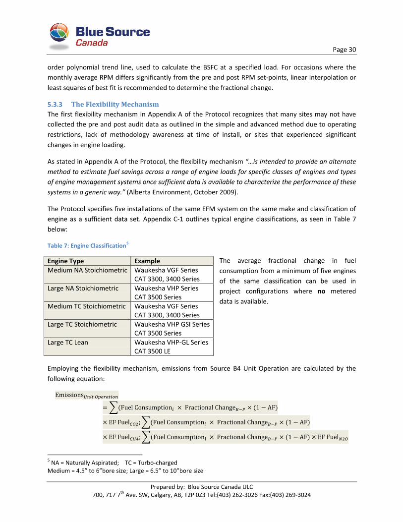
5.3.3 The Flexibility Mechanism
The first flexibility mechanism in Appendix A of the Protocol recognizes that many sites may not have
collected the pre and post audit data as outlined in the simple and advanced method due to operating
restrictions, lack of methodology awareness at time of install, or sites that experienced significant
changes in engine loading.
As stated in Appendix A of the Protocol, the flexibility mechanism “…is intended to provide an alternate
method to estimate fuel savings across a range of engine loads for specific classes of engines and types
of engine management systems once sufficient data is available to characterize the performance of these
systems in a generic way.” (Alberta Environment, October 2009).
The Protocol specifies five installations of the same EFM system on the same make and classification of
engine as a sufficient data set. Appendix C-1 outlines typical engine classifications, as seen in Table 7
below:
Table 7: Engine Classification5
The average fractional change in fuel
consumption from a minimum of five engines
of the same classification can be used in
project configurations where no metered
data is available.
Employing the flexibility mechanism, emissions from Source B4 Unit Operation are calculated by the
following equation:
∑ )
∑ )
∑ )
5 NA = Naturally Aspirated; TC = Turbo-charged
Medium = 4.5” to 6”bore size; Large = 6.5” to 10”bore size
Engine Type Example
Medium NA Stoichiometric Waukesha VGF Series CAT 3300, 3400 Series
Large NA Stoichiometric Waukesha VHP Series CAT 3500 Series
Medium TC Stoichiometric Waukesha VGF Series CAT 3300, 3400 Series
Large TC Stoichiometric Waukesha VHP GSI Series CAT 3500 Series
Large TC Lean Waukesha VHP-GL Series CAT 3500 LE

Page 31
Prepared by: Blue Source Canada ULC 700, 717 7
th Ave. SW, Calgary, AB, T2P 0Z3 Tel:(403) 262-3026 Fax:(403) 269-3024
Where: AF = the standard deviation of Fractional Change in Fuel Consumption determined from the five
engine data sets, used to account for variability in site operating conditions and maintenance practices.
Blue Source Canada has developed a proprietary methodology to characterize the BSFC performance of
specific engine classes for the EFM system: REMVue AFR Controllers.
5.3.4 The Master Method
Often subprojects are faced only with historic data limitations but have robust data collection methods
for the project conditions. To address this specific case, Blue Source has followed the Protocol guidance
to develop an improved estimation model. The improved methodology recognizes the accuracy of using
metered project data as outlined in the Advanced Method, with provisions allowing for generic
characterization of engine performance described in the flexibility mechanism. By combining the two
approaches, Blue Source has the ability to create a Master Map, performing a type of mathematical
interpolation of BSFC based upon a much more robust data set of measured engine performance.
This methodology, referred to as the Master Method, collects all available pre and post installation
performance tests for a defined engine make and classification creating two BSFC maps for a full range
of engine load and speeds, before and after the engine retrofit. The details of this approach, and the
master engine performance maps themselves are considered proprietary and so are only included in the
confidential Appendix E, which is not publicly available. However, full details of both the maps and the
methodology will be made available to the third-party verifier.
For the first project reporting period, two Master Maps (one pre-condition, one post-condition) have
been created for the large, turbocharged engines manufactured by Waukesha and classified as the VHP
GSI series. This includes the following six engine models:
F2895 GSI
F3521 GSI
L7042 GSI
L5108 GSI
L5790 GSI
P9390 GSI
Note that the Waukesha VHP GSI Series 4 engines underwent a series of enhancements to the cylinder
head components and valves, air/fuel ratio control, cam tappet rollers, piston and cylinder liners.
Therefore Series 4 engines are deemed to operate significantly different than the original VHP GSI series
and have been excluded from the creation of this Map.
For future reporting periods, with the available pre and post audit data new Master Maps can be
created, capturing the performance of different engine makes and classifications.

Page 32
Prepared by: Blue Source Canada ULC 700, 717 7
th Ave. SW, Calgary, AB, T2P 0Z3 Tel:(403) 262-3026 Fax:(403) 269-3024
5.3.5 Subproject Technology 1b: EcoPlug BSFC Determination
Subprojects that apply technology 1b EcoPlugs, are required to collect post-installation performance
results and use the data collected to either apply an adjustment factor to the post BSFC value obtained
from the Master Map, or to recalculate the post BSFC from the newly sourced data. Once sufficient data
has been collected (from a minimum of 5 engines of the same make and classification) it is feasible that
a new Master Map could be created to capture the post installation BSFC at specific load and RPM set-
points. Further explanation of the methodology employed will be required in the Offset Project Report
once this AFR add on is included in the aggregation.

Page 33
Prepared by: Blue Source Canada ULC 700, 717 7
th Ave. SW, Calgary, AB, T2P 0Z3 Tel:(403) 262-3026 Fax:(403) 269-3024
6 MONITORING PLAN
6.1 Technology 1/1b: REMVue AFR/EcoPlug Table 8: EFM Data monitoring plan
Source/sink identifier or name:
B1 Fuel Extraction and Processing
B4 Unit Operation B4 Unit Operation
Data parameter: Volume of Natural Gas Combusted for B4
Total Fuel Consumption in Project Condition
Fractional Change in Fuel Consumption from Baseline to Project due to Implementation of an Air-Fuel Ratio Controller
Estimation, modeling, measurement or calculation approaches:
direct metering direct metering and monthly aggregation of values
Estimated
Data unit: e3m3 e3m3 %
Source/origin: Direct metering of fuel consumption of unit. Note that this value is obtained from B4 and is equal to the metered fuel consumption in the project condition multiplied by the Fractional Change in fuel consumption from the baseline to the project.
Calculated based on the continuous measurement of mass flow rate of fuel into the engine in the Project Condition. In project configurations where vent gases are captured and fed back into the engine for supplemental fuel, the total fuel consumption is the sum of the main fuel gas stream and the supplemental vent gas fuel, expressed as an energy equivalent quantity of the primary fuel (e.g. natural gas).
Fractional Change in fuel consumption from the baseline to the project condition is calculated based on measured BSFC values from pre and post installation, corrected for actual project loads and engine RPMs on a monthly basis. Fractional Change = (BSFC Pre-Audit – BSFC Post-Audit)/ BSFC Post-Audit. Refer to Appendix C for a step by step procedure to determine the fractional change in fuel consumption. Refer to Table C.3 in Appendix C (page 62) for a summary of monitoring requirements in the project

Page 34
Prepared by: Blue Source Canada ULC 700, 717 7
th Ave. SW, Calgary, AB, T2P 0Z3 Tel:(403) 262-3026 Fax:(403) 269-3024
Source/sink identifier or name:
B1 Fuel Extraction and Processing
B4 Unit Operation B4 Unit Operation
condition.
Monitoring frequency:
Continuous Continuous BSFC Values determined from recorded load and RPM values at a minimum of monthly monitored readings.
Description and justification of monitoring method:
Most accurate method for determining parameter
Most accurate method for determining parameter
Most accurate method for determining parameter
Uncertainty: Stated Meter Manufacturer’s Tolerance
Stated Meter Manufacturer’s Tolerance n/a
6.2 Technology 2: REMVue Slipstream Table 9: VGC Data Monitoring Plan
Source/sink identifier or name:
B4 Unit Operation
B4 Unit Operation
B4 Unit Operation
B4 Unit Operation
B4 Unit Operation
B4 Unit Operation
B4 Unit Operation
Data parameter:
Total Quantity of Fuel Displaced Through Use of Vent Gases as Supplemental Fuel in Project
Mass of Fuel Gas Fed into the Engine from the Main Fuel Supply
Density of Fuel Gas
Mass of Vent as Consumed in the Engine as a Supplemental Fuel Source
Density of Vent Gas
Lower Heating Value of Vent Gas
Lower Heating Value of Fuel Gas
Estimation, modeling, measurement
Calculation Continuous Metering
Measurement
Measurement Measurement
3rd Party Measurement, or Calculation
3rd Party Measurement, or Calculation
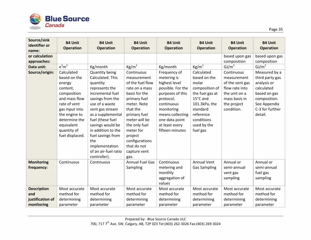
Page 35
Prepared by: Blue Source Canada ULC 700, 717 7
th Ave. SW, Calgary, AB, T2P 0Z3 Tel:(403) 262-3026 Fax:(403) 269-3024
Source/sink identifier or name:
B4 Unit Operation
B4 Unit Operation
B4 Unit Operation
B4 Unit Operation
B4 Unit Operation
B4 Unit Operation
B4 Unit Operation
or calculation approaches:
based upon gas composition
based upon gas composition
Data unit: e3m3 Kg/month Kg/m3 Kg/month Kg/m3 GJ/m3 GJ/m3
Source/origin: Calculated based on the energy content, composition and mass flow rate of vent gas input into the engine to determine the equivalent quantity of fuel displaced.
Quantity being Calculated. This quantity represents the incremental fuel savings from the use of a waste vent gas stream as a supplemental fuel (these fuel savings would be in addition to the fuel savings from the implementation of an air-fuel ratio controller).
Continuous measurement of the fuel flow rate on a mass basis for the primary fuel meter. Note that the primary fuel meter will be the only fuel meter for project configurations that do not capture vent gas.
Frequency of metering is highest level possible. For the purposes of this protocol, continuous monitoring means collecting one data point at least every fifteen minutes
Calculated based on the molar composition of the fuel gas at 15°C and 101.3kPa, the standard reference conditions used by the fuel gas
Continuous measurement of the vent gas flow rate into the unit on a mass basis in the project condition.
Measured by a third party gas analysis or calculated based on gas composition. See Appendix C-3 for further detail.
Monitoring frequency:
Continuous Continuous Annual Fuel Gas Sampling
Continuous metering and monthly aggregation of values
Annual Vent Gas Sampling
Annual or semi-annual vent gas sampling
Annual or semi-annual fuel gas sampling
Description and justification of monitoring
Most accurate method for determining parameter
Most accurate method for determining parameter
Most accurate method for determining parameter
Most accurate method for determining parameter
Most accurate method for determining parameter
Most accurate method for determining parameter
Most accurate method for determining parameter

Page 36
Prepared by: Blue Source Canada ULC 700, 717 7
th Ave. SW, Calgary, AB, T2P 0Z3 Tel:(403) 262-3026 Fax:(403) 269-3024
Source/sink identifier or name:
B4 Unit Operation
B4 Unit Operation
B4 Unit Operation
B4 Unit Operation
B4 Unit Operation
B4 Unit Operation
B4 Unit Operation
method:
Uncertainty: n/a Stated Meter Manufacturer’s Tolerance
Stated Lab Analysis’ Tolerance
Stated Meter Manufacturer’s Tolerance
Stated Lab Analysis’ Tolerance
Stated Lab Analysis’ Tolerance
Stated Lab Analysis’ Tolerance
Provide the details for any deviations for the protocol including the justification and rationale:
n/a n/a n/a n/a n/a n/a n/a
6.3 Contingent Data Monitoring For data where measurements are unavailable, the data monitoring will follow the contingent procedures as outlined in Appendix B of the
Protocol and pasted below for ease of reference:
Table 10: Contingent Data Monitoring and Collection for all sources
Project/ Baseline
SS Parameter Unit Measurement/Estimation Contingency Method Frequency Justification
B4 Unit Operation
Total Fuel Consumption in project Condition/Fuel Consumption
m3 Measurement Interpolation of previous and following measurements
Continuous metering and monthly average of values
Frequency of metering is highest level possible
P6 Flaring of Process Emissions
Volume of Fuel used to Supplement Flaring Of process Emissions
m3 Estimated Calculated based on flare design specifications (flare tip diameter and flare stack diameter), flow rate of gases flared, typical heat value of gas stream
Monthly Method represents reasonable diligence when more accurate method is unachievable. If metered data is unavailable project
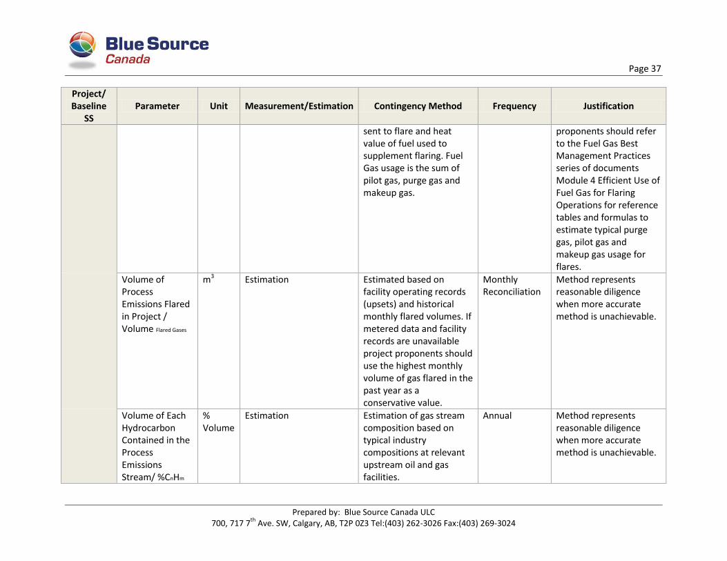
Page 37
Prepared by: Blue Source Canada ULC 700, 717 7
th Ave. SW, Calgary, AB, T2P 0Z3 Tel:(403) 262-3026 Fax:(403) 269-3024
Project/ Baseline
SS Parameter Unit Measurement/Estimation Contingency Method Frequency Justification
sent to flare and heat value of fuel used to supplement flaring. Fuel Gas usage is the sum of pilot gas, purge gas and makeup gas.
proponents should refer to the Fuel Gas Best Management Practices series of documents Module 4 Efficient Use of Fuel Gas for Flaring Operations for reference tables and formulas to estimate typical purge gas, pilot gas and makeup gas usage for flares.
Volume of Process Emissions Flared in Project / Volume Flared Gases
m3 Estimation Estimated based on facility operating records (upsets) and historical monthly flared volumes. If metered data and facility records are unavailable project proponents should use the highest monthly volume of gas flared in the past year as a conservative value.
Monthly Reconciliation
Method represents reasonable diligence when more accurate method is unachievable.
Volume of Each Hydrocarbon Contained in the Process Emissions Stream/ %CnHm
% Volume
Estimation Estimation of gas stream composition based on typical industry compositions at relevant upstream oil and gas facilities.
Annual Method represents reasonable diligence when more accurate method is unachievable.
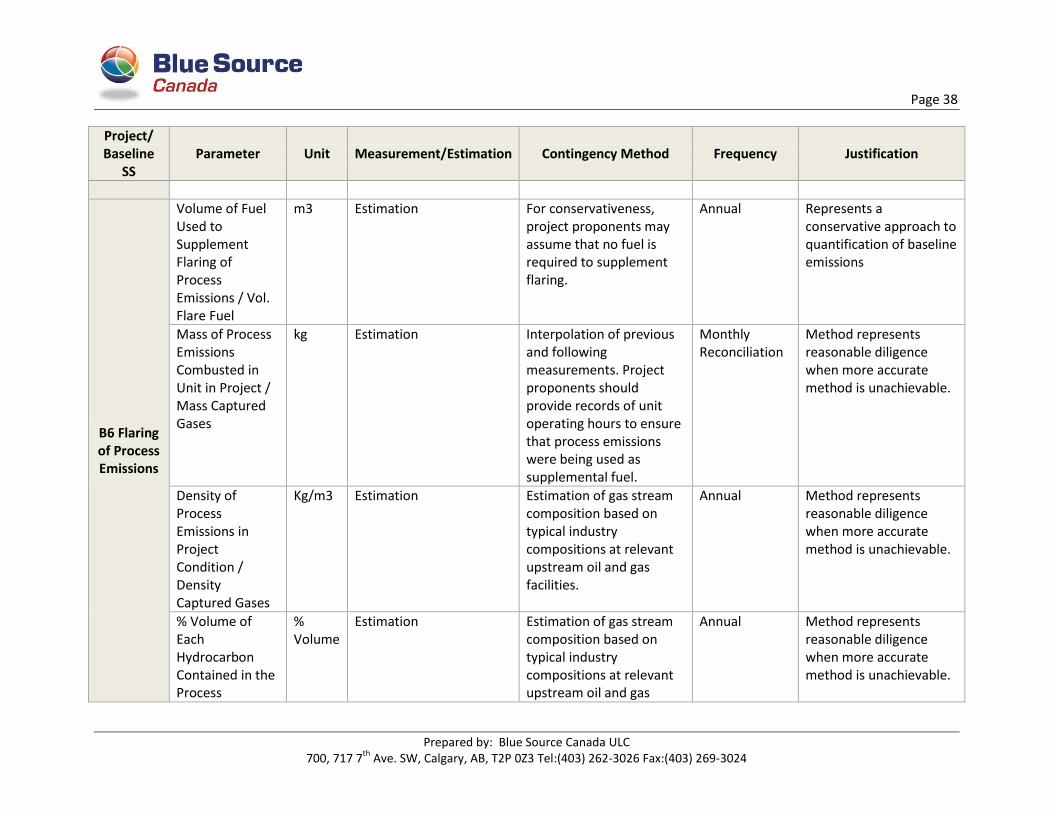
Page 38
Prepared by: Blue Source Canada ULC 700, 717 7
th Ave. SW, Calgary, AB, T2P 0Z3 Tel:(403) 262-3026 Fax:(403) 269-3024
Project/ Baseline
SS Parameter Unit Measurement/Estimation Contingency Method Frequency Justification
B6 Flaring of Process Emissions
Volume of Fuel Used to Supplement Flaring of Process Emissions / Vol. Flare Fuel
m3 Estimation For conservativeness, project proponents may assume that no fuel is required to supplement flaring.
Annual Represents a conservative approach to quantification of baseline emissions
Mass of Process Emissions Combusted in Unit in Project / Mass Captured Gases
kg Estimation Interpolation of previous and following measurements. Project proponents should provide records of unit operating hours to ensure that process emissions were being used as supplemental fuel.
Monthly Reconciliation
Method represents reasonable diligence when more accurate method is unachievable.
Density of Process Emissions in Project Condition / Density Captured Gases
Kg/m3 Estimation Estimation of gas stream composition based on typical industry compositions at relevant upstream oil and gas facilities.
Annual Method represents reasonable diligence when more accurate method is unachievable.
% Volume of Each Hydrocarbon Contained in the Process
% Volume
Estimation Estimation of gas stream composition based on typical industry compositions at relevant upstream oil and gas
Annual Method represents reasonable diligence when more accurate method is unachievable.
Page 39
Prepared by: Blue Source Canada ULC 700, 717 7
th Ave. SW, Calgary, AB, T2P 0Z3 Tel:(403) 262-3026 Fax:(403) 269-3024
Project/ Baseline
SS Parameter Unit Measurement/Estimation Contingency Method Frequency Justification
Emissions Stream/ %CnHm
facilities.

Page 40
Prepared by: Blue Source Canada ULC 700, 717 7
th Ave. SW, Calgary, AB, T2P 0Z3 Tel:(403) 262-3026 Fax:(403) 269-3024
7 DATA INFORMATION MANAGEMENT SYSTEM AND RECORDS The Information Management System (IMS) created for this aggregation is intended to direct and collect
GHG data monitoring activities for both the project and baseline data monitoring requirements. The
system outlined below will describe the robustness, transparency and automation that have been built
to reflect a reasonable level of assurance with respect to the following objectives outlined in Section 5.1
of the Technical Guidance for Offset Project Developers, version 4.0, February 2013:
Completeness
Accuracy
Validity
Restricted Access
7.1 Data Control Controls exist throughout the data management system, but are essential whenever there is a transfer or exchange of data or information. Examples of data controls used consistently throughout the aggregation include:
passwords on computers; read access requirements on files; Management review of reports.
7.2 Data Management Data management procedures will vary depending on the type and format of data received. Manually
sourced data will be scanned and electronically saved to an identified folder within the project
information file. Manual data will be checked for completeness, reasonableness and transcription errors
with any findings identified and discussed with the project participant.
Other data is sourced directly from project participants’ online SCADA systems. Information obtained
from these systems are often directly downloaded into an excel file and copied into the Blue Source
excel based quantification calculator and Map Modeller input files. Copies of the downloaded content
will be saved in a unique project folder under the date it was downloaded from the online system.
All data gathered for the project will be stored at Blue Source for a period of seven years after the end of
the project crediting period.
Figure 8 on the following page illustrates the data flow and origin from project participants and third
parties to Blue Source.

Page 41
Prepared by: Blue Source Canada ULC 700, 717 7
th Ave. SW, Calgary, AB, T2P 0Z3 Tel:(403) 262-3026 Fax:(403) 269-3024
Figure 8: IMS Flow Chart
For subprojects with metering in place, a metering maintenance and calibration details table must be
included in the Offset Project Report (OPR). Suggested table format is below:
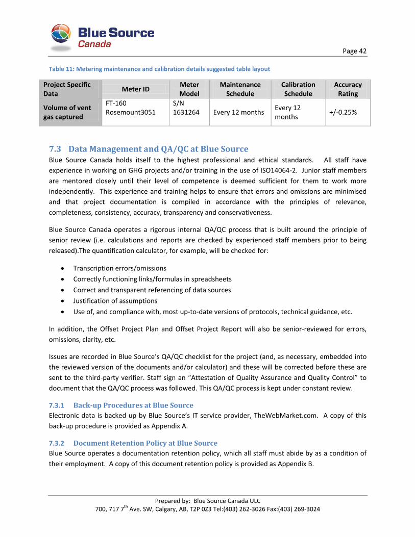
Page 42
Prepared by: Blue Source Canada ULC 700, 717 7
th Ave. SW, Calgary, AB, T2P 0Z3 Tel:(403) 262-3026 Fax:(403) 269-3024
Table 11: Metering maintenance and calibration details suggested table layout
Project Specific Data
Meter ID Meter Model
Maintenance Schedule
Calibration Schedule
Accuracy Rating
Volume of vent gas captured
FT-160 Rosemount3051
S/N 1631264 Every 12 months
Every 12 months
+/-0.25%
7.3 Data Management and QA/QC at Blue Source Blue Source Canada holds itself to the highest professional and ethical standards. All staff have
experience in working on GHG projects and/or training in the use of ISO14064-2. Junior staff members
are mentored closely until their level of competence is deemed sufficient for them to work more
independently. This experience and training helps to ensure that errors and omissions are minimised
and that project documentation is compiled in accordance with the principles of relevance,
completeness, consistency, accuracy, transparency and conservativeness.
Blue Source Canada operates a rigorous internal QA/QC process that is built around the principle of
senior review (i.e. calculations and reports are checked by experienced staff members prior to being
released).The quantification calculator, for example, will be checked for:
Transcription errors/omissions
Correctly functioning links/formulas in spreadsheets
Correct and transparent referencing of data sources
Justification of assumptions
Use of, and compliance with, most up-to-date versions of protocols, technical guidance, etc.
In addition, the Offset Project Plan and Offset Project Report will also be senior-reviewed for errors,
omissions, clarity, etc.
Issues are recorded in Blue Source’s QA/QC checklist for the project (and, as necessary, embedded into
the reviewed version of the documents and/or calculator) and these will be corrected before these are
sent to the third-party verifier. Staff sign an “Attestation of Quality Assurance and Quality Control” to
document that the QA/QC process was followed. This QA/QC process is kept under constant review.
7.3.1 Back-up Procedures at Blue Source
Electronic data is backed up by Blue Source’s IT service provider, TheWebMarket.com. A copy of this
back-up procedure is provided as Appendix A.
7.3.2 Document Retention Policy at Blue Source
Blue Source operates a documentation retention policy, which all staff must abide by as a condition of
their employment. A copy of this document retention policy is provided as Appendix B.
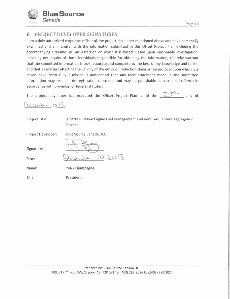

Page 44
Prepared by: Blue Source Canada ULC 700, 717 7
th Ave. SW, Calgary, AB, T2P 0Z3 Tel:(403) 262-3026 Fax:(403) 269-3024
9 STATEMENT OF SENIOR REVIEW This offset project plan was prepared by Kelly Parker, Carbon Services Project Analyst, Blue Source
Canada and senior reviewed by Graham Harris, Vice President Technical Services, Blue Source Canada.
Although care has been taken in preparing this document, it cannot be guaranteed to be free of errors
or omissions.
Prepared by: Senior reviewed by:
Kelly Parker Graham Harris 17/12/2013 20/12/2013
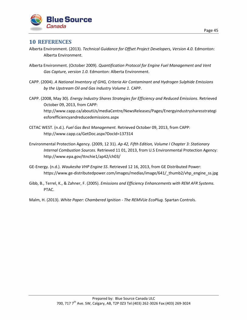
Page 45
Prepared by: Blue Source Canada ULC 700, 717 7
th Ave. SW, Calgary, AB, T2P 0Z3 Tel:(403) 262-3026 Fax:(403) 269-3024
10 REFERENCES Alberta Environment. (2013). Technical Guidance for Offset Project Developers, Version 4.0. Edmonton:
Alberta Environment.
Alberta Environment. (October 2009). Quantification Protocol for Engine Fuel Management and Vent
Gas Capture, version 1.0. Edmonton: Alberta Environment.
CAPP. (2004). A National Inventory of GHG, Criteria Air Contaminant and Hydrogen Sulphide Emissions
by the Upstream Oil and Gas Industry Volume 1. CAPP.
CAPP. (2008, May 30). Energy Industry Shares Strategies for Efficiency and Reduced Emissions. Retrieved
October 09, 2013, from CAPP:
http://www.capp.ca/aboutUs/mediaCentre/NewsReleases/Pages/Energyindustrysharesstrategi
esforefficiencyandreducedemissions.aspx
CETAC WEST. (n.d.). Fuel Gas Best Management. Retrieved October 09, 2013, from CAPP:
http://www.capp.ca/GetDoc.aspx?DocId=137314
Environmental Protection Agency. (2009, 12 31). Ap 42, Fifth Edition, Volume I Chapter 3: Stationary
Internal Combustion Sources. Retrieved 11 01, 2013, from U.S Environmental Protection Agency:
http://www.epa.gov/ttnchie1/ap42/ch03/
GE-Energy. (n.d.). Waukesha VHP Engine SS. Retrieved 12 16, 2013, from GE Distributed Power:
https://www.ge-distributedpower.com/images/medias/image/641/_thumb2/vhp_engine_ss.jpg
Gibb, B., Terrel, K., & Zahner, F. (2005). Emissions and Efficiency Enhancements with REM AFR Systems.
PTAC.
Malm, H. (2013). White Paper: Chambered Ignition - The REMVUe EcoPlug. Spartan Controls.

Appendix A – IT Backup Procedure for Blue Source
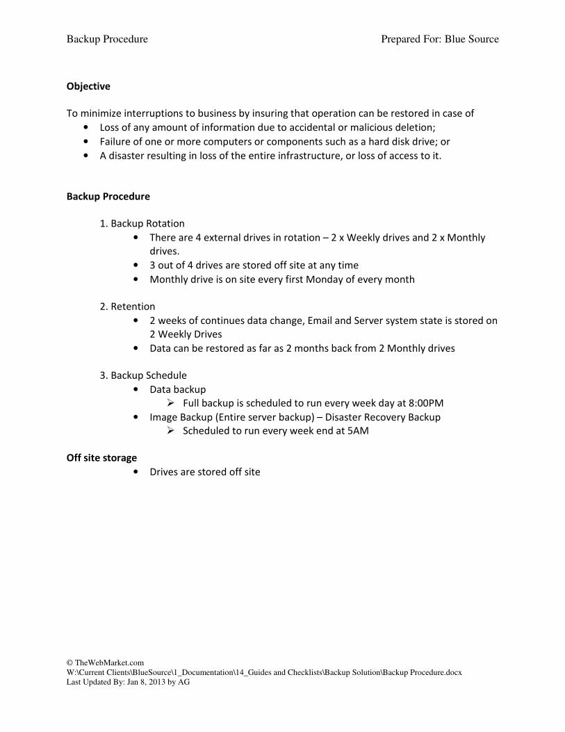
Backup Procedure Prepared For: Blue Source
© TheWebMarket.com
W:\Current Clients\BlueSource\1_Documentation\14_Guides and Checklists\Backup Solution\Backup Procedure.docx
Last Updated By: Jan 8, 2013 by AG
Objective
To minimize interruptions to business by insuring that operation can be restored in case of
• Loss of any amount of information due to accidental or malicious deletion;
• Failure of one or more computers or components such as a hard disk drive; or
• A disaster resulting in loss of the entire infrastructure, or loss of access to it.
Backup Procedure
1. Backup Rotation
• There are 4 external drives in rotation – 2 x Weekly drives and 2 x Monthly
drives.
• 3 out of 4 drives are stored off site at any time
• Monthly drive is on site every first Monday of every month
2. Retention
• 2 weeks of continues data change, Email and Server system state is stored on
2 Weekly Drives
• Data can be restored as far as 2 months back from 2 Monthly drives
3. Backup Schedule
• Data backup
� Full backup is scheduled to run every week day at 8:00PM
• Image Backup (Entire server backup) – Disaster Recovery Backup
� Scheduled to run every week end at 5AM
Off site storage
• Drives are stored off site

Appendix B – Data Retention Policy at Blue Source
Last Revision: January 8, 2013
Document Retention Policy, version 1.3.
1. All documents relevant to Offset Projects will be kept, in at least
electronic format, and where possible, in hardcopy format, for
a. At least 10 years beyond the last year in which credits are created
(e.g. a project that creates credits between 2000-2008 will have
all records kept until at least 2018), or
b. As required by the Offset Project Program
whichever period is longer.
2. Hard copy documents will be kept in project folders in our Blue Source
head office location, which is currently Suite 700, 717 – 7th Av SW,
Calgary, AB, T2P 0Z3. All electronic documents will be saved to the
appropriate project folder on the Calgary Server (“S:\ drive”).
3. The S:\ drive will be backed up in accordance with Blue Source’s IT
Backup Procedure, which may change from time to time.
4. Blue Source’s preference is to keep all documents in electronic form,
wherever possible.
5. All employees will comply with this policy as a condition of their
employment.
Yvan Champagne
President, Blue Source Canada ULC

Appendix C – Risk Matrix
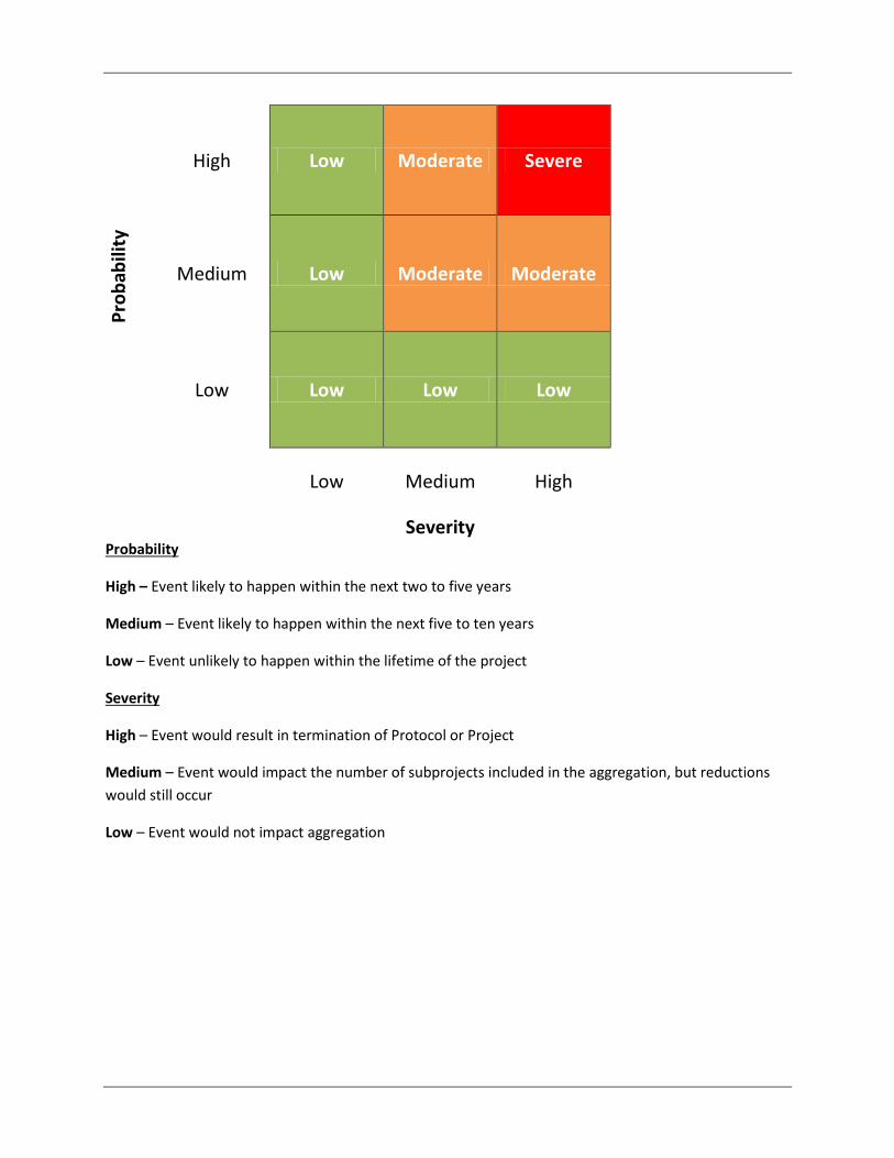
Pro
bab
ility
High Low Moderate Severe
Medium Low Moderate Moderate
Low Low Low Low
Low Medium High
Severity Probability
High – Event likely to happen within the next two to five years
Medium – Event likely to happen within the next five to ten years
Low – Event unlikely to happen within the lifetime of the project
Severity
High – Event would result in termination of Protocol or Project
Medium – Event would impact the number of subprojects included in the aggregation, but reductions
would still occur
Low – Event would not impact aggregation
Appendix D – Subproject List

Table 12: Subproject Tracking List – Project Type: EFM System Type: REMVue AFR
Project Participant Company Name
Legal Land Location Facility Unique Spartan
Identifier Waukesha VHP Series
Engine Model
Apache Canada Ltd 4-11-34-8W5 D-Battery (Planned Install 2Q 2013)
Ricinus Unit #3 5235 P9390GSI
4-22-34-8W5 D-Battery Ricinus 4-11 Unit #2 11771 P9390GSI
12-18-36-8W5 Field Ricinus12-18 Unit #1 12319 P9390GSI
10-29-67-10W6 South Chinook
Wapiti 13732 L7042GSI
06-08-65-09W6 South Chinook
Wapiti 13737 L7042GSI
13-05-39-08W4 Kessler Provost Unit #K200 13840 L7042GSI
LSD Confirmation Required WEST PEMBINA 14649 L5108GSI
03-20-34-04W5 South Caroline 09183-AA L7042GSI
03-20-34-04W5 South Caroline 09183-AB L7042GSI
01-11-35-06W5 North Caroline - North and South Units 9449-AA P9390GSI
01-11-35-06W5 North Caroline - North and South Units 9499-AB P9390GSI
Canadian Natural 09-28-14-11-W4M Alderson 09-28 15763 L7042GSI
LSD Confirmation Required Bellis 15705 F3521GSI
10-15-59-16-W4M Bellis 10-15 #3 15118 P9390GSI
11-17-97-06-W6M Chinchaga 11-17 C-200 20134 F3521GSI
01-24-96-05-W6M Chinchaga C-100 Progas 20135 L5108GSI
01-24-96-05-W6M Chinchaga C2000 or C2100 20133 P9390GSI
LSD Confirmation Required Crooked Lake 10-22 14673 L7042GSI
01-24-52-20-W5M Edson W.01-24 #1 24404 L5790GSI
01-24-52-20-W5M Edson W.01-24 #3 13638 L7042GSI
08-05-53-21-W5M Galloway 08-05 14976-AA F3521GSI
06-07-78-01-W5M Mistahae 06-07 26415 L7042GSI
LSD Confirmation Required Mitsue 13330 L7042GSI
12-30-72-04W5M Mitsue 17204 L7042GSI
14-29-38-22-W4M Nevis 14-29 14464-AA F3521GSI
LSD Confirmation Required Nipisi 14518 P9390GSI

Project Participant Company Name
Legal Land Location Facility Unique Spartan
Identifier Waukesha VHP Series
Engine Model
LSD Confirmation Required Nipisi Operating Center 12516 P9390GSI
LSD Confirmation Required Slave Lake 13947 L7042GSI
LSD Confirmation Required Slave Lake Field Office 14909 F3521GSI
Centrica Energy Canada 12-01-016-10W4 Medicine Hat 11447 L7042GSI
13-33-051-08W5 Medicine Hat, Project 3 9018 L7042GSI
13-33-051-08W5 Medicine Hat-PROJECT 3 13690 L7042GSI
13-33-051-08W5 Medicine Hat, Project 3 28843 L7042GSI
15-22-040-03W5 Gilby 12307 P9390GSI
02-27-015-04W4 PROJECT 3A 15123 L7042GSI
09-10-018-03W4 PROJECT 4 15126 L7042GSI
15-22-040-03W5 GILBY FIELD OFFICE 15341 P9390GSI
15-22-040-03W5 GILBY FIELD OFFICE 15342 P9390GSI
Conoco Phillips Canada 10-09-Y045-08W5 Alder Flats PN18979 L7042GSI
10-09-045-08W5 Alder Flats PN18980 L7042GSI
01-15-047-08W5 Alder Flats 01-15 PN16680 L7042GSI
14-15-059-24W5 Berland Plant PN25690 L7042GSI
04-07-044-03W5 Buck Lake 04-07 PN20125 Model Confirmation
11-20-041-04W5 Gilby Gas Plant PN20124/28288 L7042GSI
11-26-049-11W5 Lodgepole 11-26 Comp Stn PN27779 L7042GSI
12-36-060-09W6 Lovett 12-36-060-9W6 PN20126/20502 Model Confirmation
08-11-031-21W4 Morrin Plant PN21188 L7042GSI
08-11-031-21W4 Morrin Plant PN21254 L7042GSI
08-11-031-21W4 Morrin Plant PN21255 L7042GSI
11-12-049-17W5 Peco 11-12 PN20127/15089 L7042GSI
11-27-047-15W5 Peco 11-27 PN20128/11992 F3521GSI
14-07-048-15W5 Peco 14-07 Compressor PN20121/24314 L7042GSI
12-01-049-16W5 Peco Gas Plant PN25489 L7042GSI
12-01-049-16W5 Peco Sweet Gas Plant PN10719 L5108GSI
06-09-046-08W5 Pembina Comp Stn 06-09 PN25561 L7042GSI
06-12-043-08W5 South Clearwater PN30843 L7042GSI
07-19-034-25W4 Three Hills 07-19 Field Booster PN21238 L7042GSI

Project Participant Company Name
Legal Land Location Facility Unique Spartan
Identifier Waukesha VHP Series
Engine Model
11-18-066-10W6 Wapiti 11-18 PN25467 F3521GSI
04-23-066-08W6 Wapiti South Block Comp Stn C-330 PN20129/RM-01838-
AA P9390GSI
04-23-066-08W6 Wapiti South Block Comp Stn C-331 PN20130/RM-13213-
AA P9390GSI
Talisman Energy Inc. LSD Confirmation Required Pass Creek 11229 L7042GSI LSD Confirmation Required Tony Creek 11231 L7042GSI LSD Confirmation Required Saxon 11232 P9390GSI
03-29-062-20 W5 Bigstone 18303 P9390GSI
14-20-56-23W5 Wild River 27247 F3521GSI Table 13: Subproject Tracking List – Project Type: VGC System Type: REMVue SlipStream
Project Participant
Company Name Legal Land Location Facility
Unique Spartan Identifier
Engine Make Engine Model
Centrica Energy Canada
09-08-016-04W4 Medicine Hat ID Confirmation Waukesha 3524 GSI
09-08-016-04W4 Medicine Hat ID Confirmation Waukesha 3524 GSI
09-20-016-04W4 Medicine Hat RM-15902-AB Waukesha 3524 GSI
09-20-016-04W4 Medicine Hat ID Confirmation Waukesha 3524 GSI
09-28-015-04W4 Medicine Hat ID Confirmation Waukesha 3524 GSI
09-28-016-04W4 Medicine Hat ID Confirmation Waukesha 3524 GSI
13-33-051-08W5 Medicine Hat, Project 3
ID Confirmation Waukesha 7042 GSI
13-33-051-08W5 Medicine Hat, Project 3
ID Confirmation Waukesha 7042 GSI LSD Confirmation Required Ferrier ID Confirmation White Superior 8GTL-825 LSD Confirmation Required Gilby ID Confirmation Waukesha 9390 GSI LSD Confirmation Required Gilby Field Office ID Confirmation Waukesha 9390 GSI LSD Confirmation Required Gilby Field Office ID Confirmation Waukesha 9390 GSI LSD Confirmation Required Ferrier ID Confirmation White Superior 8GTL-825 LSD Confirmation Required Ferrier ID Confirmation White Superior 8GTL-825
Appendix E – Confidential Methodology: The Master Map Made available to Third- Party Verifiers