project definition report - wikimedia...project definition report revisions njt 06-046 2680 8-21-08...
TRANSCRIPT

Trans-Hudson Express (THE) Project
Preliminary Engineering
Project Definition Report August 21, 2008

Project Definition Report Revisions
NJT 06-046 2680 8-21-08 REV 3
i
REVISION HISTORY
Revision Date Description 0 12/11/07 Issued for NJ TRANSIT review 1 1/18/08 Incorporates post 100% plans 2 4/4/08 Incorporates Final PE plans 3 8/21/08 Incorporates Extended PE updates

Project Definition Report Contents
NJT 06-046 2680 8-21-08 REV 3
ii
Project Definition Report
Table of Contents
EXECUTIVE SUMMARY ...................................................................... E-1 1 INTRODUCTION ....................................................................................1-1
1.1 Scope of This Report...............................................................1-1 1.2 Project Overview......................................................................1-1 1.2.1 Service Level Increases ......................................................................1-1 1.2.2 ARC Tracks and Tunnels ....................................................................1-1 1.2.3 Loop Tracks.........................................................................................1-2 1.2.4 Frank R. Lautenberg Station Upgrade.................................................1-3 1.2.5 West End Wye.....................................................................................1-3 1.2.6 NY Penn Station Expansion ................................................................1-3 1.2.7 Tunnel and Station Ventilation.............................................................1-3 1.2.8 Maintenance and Storage Facilities ....................................................1-4 1.2.9 Rolling Stock........................................................................................1-4 1.3 Project Objectives ...................................................................1-4 1.4 Sub- Project Packages....................................................................1-5
2 DESIGN STANDARDS...........................................................................2-1 2.1 General .....................................................................................2-1 2.2 Acronyms .................................................................................2-1 2.3 Codes, Manuals, Specifications, and Standards ..................2-3
3 ALIGNMENT CONSIDERATIONS .........................................................3-1 3.1 Overview...................................................................................3-1 3.2 Horizontal Alignment Description ..........................................3-1 3.2.1 New Jersey..........................................................................................3-1 3.2.2 Hudson River.......................................................................................3-3 3.2.3 New York .............................................................................................3-3 3.2.4 NY Penn Station Expansion ................................................................3-4 3.3 Maintenance and Storage Facilities .......................................3-4 3.4 Vertical Alignment Description...............................................3-5 3.4.1 New Jersey..........................................................................................3-5 3.4.2 Hudson River.......................................................................................3-6 3.4.3 New York .............................................................................................3-6
4 OPERATIONS AND CAPACITY ............................................................4-1 4.1 General .....................................................................................4-1 4.2 Project Elements......................................................................4-1 4.2.1 New Jersey Loop Track and Surface Alignments................................4-1 4.3 Tunnels and Caverns ..............................................................4-4 4.4 NY Penn Station Expansion....................................................4-6 4.4.1 NYPSE Service Plan ...........................................................................4-6 4.4.2 NYPSE Operations.............................................................................4-7 4.4.3 Station Operations Center ...................................................................4-7 4.5 Railroad Systems.....................................................................4-8

Project Definition Report Contents
NJT 06-046 2680 8-21-08 REV 3
iii
4.6 Kearny Mid-day Storage Yard.................................................4-8 4.6.1 Rail Access to Yard ...........................................................................4-11 4.6.2 Trainwasher.......................................................................................4-11 4.6.3 Fueling and Sanding Facility .............................................................4-11 4.6.4 Service Functions ..............................................................................4-12 4.6.5 Yard Operations ................................................................................4-12 4.6.6 Welfare Facility ..................................................................................4-12
5 PE ALTERNATIVE DEVELOPMENT .....................................................5-1 5.1 General .....................................................................................5-1 5.2 New Jersey Surface PE Alternative Assessment..................5-1 5.3 Hudson River PE Alternative Assessment ............................5-3 5.4 New York PE Alignment Assessment ....................................5-3 5.5 Station Alternative Assessment .............................................5-4 5.6 Station Entrances ....................................................................5-5 5.7 Fan Plants.................................................................................5-6 5.7.1 New Jersey Fan Plants........................................................................5-6 5.7.2 New York Fan Plants...........................................................................5-7 5.8 Kearny Yard..............................................................................5-7
6 GEOTECHNICAL CONDITIONS ............................................................6-1 6.1 Geologic Settings ....................................................................6-1 6.1.1 Regional Geology ................................................................................6-1 6.2 New Jersey Geology................................................................6-2 6.2.1 New Jersey Physiography ...................................................................6-2 6.2.2 New Jersey Bedrock Geology .............................................................6-2 6.2.3 New Jersey Overburden Geology .......................................................6-3 6.3 Hudson River Physiography...................................................6-4 6.3.1 Hudson River Physiography ................................................................6-4 6.3.2 Hudson River Bedrock Geology ..........................................................6-4 6.3.3 Hudson River Overburden Geology ....................................................6-4 6.4 New York Geology ...................................................................6-5 6.4.1 New York Physiology...........................................................................6-5 6.4.2 New York Bedrock Geology ................................................................6-5 6.4.3 New York Overburden Geology..........................................................6-5 6.5 Site Geotechnical Conditions .................................................6-6 6.5.1 Kearny Yard.........................................................................................6-6 6.5.2 Loop Tracks.........................................................................................6-7 6.5.3 NJ Surface Alignments ........................................................................6-9 6.5.4 Palisades Tunnels .............................................................................6-10 6.5.5 Hudson River Tunnels .......................................................................6-13 6.5.6 Manhattan Tunnels and NY Penn Station Expansion........................6-16 6.6 References .............................................................................6-21
7 ENVIRONMENTAL.................................................................................7-1 7.1 Introduction..............................................................................7-1 7.2 Preliminary Environmental Site Assessment........................7-1 7.3 Subsurface Investigations ......................................................7-4 7.4 Environmental Subsurface Investigation Report..................7-5
8 SEISMIC DESIGN...................................................................................8-1 8.1 General .....................................................................................8-1

Project Definition Report Contents
NJT 06-046 2680 8-21-08 REV 3
iv
8.2 Regional Security ....................................................................8-1 8.2.1 Seismic Hazard ...................................................................................8-1 8.2.2 Design peak Ground Motion Parameters and Design Response Spectra ................................................................................................8-2 8.3 Geotechnical Seismic Design.................................................8-3 8.3.1 Railroad Bridge Structures ..................................................................8-3 8.3.2 Abutments and Retaining Walls ..........................................................8-3 8.3.3 Embankment Seismic Slope Stability ..................................................8-4 8.3.4 Box Structures and Cut-and Cover Tunnels........................................8-4 8.3.5 TBM Tunnels Constructed in Hard Rock - Manhattan and Palisades
Tunnels................................................................................................8-5 8.3.6 TBM Tunnels Constructed in Soft Ground...........................................8-6 8.3.7 Tunnel Constructed in Sandstone – Hudson Tunnels .........................8-7 8.3.8 Shafts ..................................................................................................8-7 8.3.9 NYPSE – Station Cavern.....................................................................8-9 8.4 Structural Seismic Analysis and Design for Underground
Structures...............................................................................8-10 8.4.1 Running Tunnels of Segmental Linings.............................................8-10 8.4.2 Caverns .............................................................................................8-12 8.4.3 Shafts ................................................................................................8-16 8.4.4 Utility and Entrance Tunnels..............................................................8-19 8.4.5 Cut and Cover Structures ..................................................................8-20 8.4.6 Retaining Walls and Abutments of Palisades Tunnels Sub-Project ..8-20 8.4.7 Tonnelle Avenue Bridge of Palisades Tunnel Sub-Project ................8-21 8.5 Structural Seismic Analysis and Design for New Jersey
Surface Structures.................................................................8-21 8.5.1 Preliminary Design of Long Multi-Span Viaducts...............................8-22 8.5.2 Preliminary Design of Short Multi-Span Viaducts ..............................8-22 8.5.3 Preliminary Design of the Koppers Road Bridge ...............................8-22 8.5.4 Retaining Walls and Abutments ........................................................8-22
9 UNDERGROUND AND LINE STRUCTURES ........................................9-1 9.1 Loop Track ...............................................................................9-1 9.1.1 Middle Penhorn Creek Bridge .............................................................9-1 9.1.2 Other Bridges ......................................................................................9-2 9.1.3 Retaining Walls....................................................................................9-4 9.2 NJ Surface Alignment .............................................................9-5 9.3 Proposed Use of Mechanically Stabilized Earth (MSE) Walls .........................................................................................9-6 9.4 Palisades Tunnels ...................................................................9-8 9.5 Hudson River Tunnels...........................................................9-10 9.6 Manhattan Tunnels ................................................................9-11 9.7 Station, Cavern, Tunnels, and Shafts...................................9-13
10 BORED TUNNEL LINING.....................................................................10-1 11 STATION AND ENTRANCES ..............................................................11-1
11.1 NY Penn Station Expansion and Entrance Facilities..........11-1 11.2 Functional Elements: Space Program .................................11-2 11.2.1 NYPSE Station Complex ...................................................................11-2 11.2.2 NYPSE Cavern..................................................................................11-3 11.2.3 Station Entrances and Egress/Accessibility Cores ............................11-4

Project Definition Report Contents
NJT 06-046 2680 8-21-08 REV 3
v
11.2.4 Space Planning for NYPSE Components..........................................11-5 11.2.5 Architectural Considerations..............................................................11-5 11.2.6 Program Methodology .......................................................................11-6 11.2.7 Program Summary ............................................................................11-6 11.3 Station Entrance Structures .................................................11-8 11.3.1 Entrance No. 1: Southeast Eight Avenue/ 34th Street........................11-8 11.3.2 Entrance No. 2: Southwest Seventh Avenue/ 34th Street ..................11-8 11.3.3 Entrance No. 3: Northwest Seventh Avenue/ 34th Street...................11-8 11.3.4 Entrance No. 4: Southwest Sixth Avenue/ 34th Street .......................11-8 11.3.5 Entrance No. 5: Northwest Sixth Avenue/ 34th Street........................11-8 11.4 Electrical Power .....................................................................11-9 11.4.1 Design Factors ................................................................................11-10 11.4.2 Technologies ...................................................................................11-10 11.5 Station/Entrances HVAC .....................................................11-11 11.6 Plumbing ..............................................................................11-12 11.7 Fire Protection .....................................................................11-12 11.8 Frank R. Lautenberg Station...............................................11-13 11.8.1 Station Configuration .......................................................................11-14 11.8.2 Station Architecture .........................................................................11-14 11.8.3 Station Structures ............................................................................11-14 11.8.4 Electrical ..........................................................................................11-15 11.8.5 Station HVAC ..................................................................................11-16 11.9 Plumbing ..............................................................................11-17
12 FAN PLANT FACILITIES .....................................................................12-1 12.1 Introduction............................................................................12-1 12.2 Fan Plant Configurations ......................................................12-2 12.2.1 Fan Plants .........................................................................................12-3 12.3 Mechanical and Electrical Equipment..................................12-5 12.3.1 Tunnel Ventilation..............................................................................12-5 12.3.2 Fan Plant HVAC ................................................................................12-5 12.3.3 Plumbing............................................................................................12-5 12.3.4 Fire Protection ...................................................................................12-6 12.3.5 Tunnel Drainage Pumping Station.....................................................12-7 12.3.6 Electrical Power Distribution System.................................................12-7
13 KEARNY YARD FACILITIES ...............................................................13-1 13.1 Introduction............................................................................13-1 13.2 Sustainability .........................................................................13-1 13.3 Welfare Facility ......................................................................13-1 13.3.1 Welfare Facility HVAC .......................................................................13-2 13.3.2 Welfare Facility Sanitary and Vent System........................................13-3 13.3.3 Welfare Facility Fire Alarm/ Protection ..............................................13-3 13.4 Control Tower ........................................................................13-4 13.4.1 Control Room ....................................................................................13-4 13.4.2 Control Tower HVAC .........................................................................13-4 13.4.3 Control Tower Toilet ..........................................................................13-4 13.5 Trainwasher............................................................................13-5 13.5.1 Trainwasher Layout ...........................................................................13-5 13.5.2 Train Washing Capacity ....................................................................13-5 13.5.3 Train Wash Cycle ..............................................................................13-5

Project Definition Report Contents
NJT 06-046 2680 8-21-08 REV 3
vi
13.5.4 Trainwasher Heating and Ventilation.................................................13-6 13.6 Fueling and Sanding Facility ................................................13-6 13.6.1 Fueling Problems...............................................................................13-7 13.6.2 Fuel Pumps and Fueling Crane.........................................................13-7 13.6.3 Fueling Facility Operator’s Booth ......................................................13-7 13.6.4 Sanding System ................................................................................13-7 13.7 Pit/Pedestal Tracks................................................................13-8 13.8 Electrical.................................................................................13-8 13.8.1 Welfare Facility/Control Tower Electrical ...........................................13-8 13.8.2 Yard Electrical ...................................................................................13-8 13.8.3 Exterior Lighting.................................................................................13-9
14 REAL ESTATE PROPERTY, ROW, EASEMENTS..............................14-1 14.1 Authorization and Oversight.................................................14-1 14.2 Real Estate Property Interests..............................................14-2
15 CIVIL, MPT, UTILITIES AND SURVEY ................................................15-1 15.1 Civil .......................................................................................15-1 15.1.1 Loop Tracks Sub Project Package ....................................................15-1 15.1.2 NJ Surface Alignments Sub Project Package ...................................15-1 15.1.3 Palisades Tunnels Sub Project Package...........................................15-2 15.1.4 Hudson River Tunnels Sub Project Package ....................................15-2 15.1.5 Manhattan Tunnels Sub Project Package .........................................15-2 15.1.6 NY Penn Station Expansion Sub Project Package............................15-3 15.1.7 Kearny Yard Sub Project Package ....................................................15-3 15.2 Maintenance & Protection of Traffic ....................................15-4 15.2.1 Loop Tracks Sub Project Package ....................................................15-4 15.2.2 NJ Surface Alignments Sub Project Package ...................................15-4 15.2.3 Palisades Tunnels Sub Project Package...........................................15-4 15.2.4 Hudson River Tunnels Sub Project Package ....................................15-5 15.2.5 Manhattan Tunnels Sub Project Package .........................................15-5 15.2.6 New York Penn Station Expansion Sub Project Package .................15-5 15.2.7 Kearny Yard Sub Project Package ....................................................15-6 15.3 Utilities....................................................................................15-6 15.3.1 Loop Tracks Sub Project Package ....................................................15-6 15.3.2 NJ Surface Alignments Sub Project Package ...................................15-7 15.3.3 Palisades Tunnels Sub Project Package...........................................15-7 15.3.4 Hudson River Tunnels Sub Project Package ....................................15-8 15.3.5 Manhattan Tunnels Sub Project Package .........................................15-8 15.3.6 New York Penn Station Expansion Sub Project Package .................15-8 15.3.7 Kearny Yard Sub Project Package ....................................................15-9 15.4 Survey.....................................................................................15-9 15.4.1 Horizontal Control ..............................................................................15-9 15.4.2 Vertical Control ..................................................................................15-9
16 FIRE/LIFE SAFETY ..............................................................................16-1 16.1 Introduction............................................................................16-1 16.2 New York Penn Station Expansion (NYPSE) .......................16-1 16.2.1 Center Platforms................................................................................16-2 16.2.2 Side Platform .....................................................................................16-2 16.2.3 Mezzanine Level................................................................................16-2 16.2.4 Ancillary Facilities ..............................................................................16-2

Project Definition Report Contents
NJT 06-046 2680 8-21-08 REV 3
vii
16.2.5 Fire Separation ..................................................................................16-3 16.2.6 Electrical Systems and Lighting.........................................................16-3 16.2.7 Occupant Load ..................................................................................16-3 16.2.8 Fire Protection Systems ....................................................................16-3 16.3 Tunnels ...................................................................................16-4 16.3.1 Emergency Evacuation and Cross Passageways .............................16-4 16.4 ARC Tracks and Frank R. Lautenberg Station Upgrade.....16-4 16.4.1 Station Description ............................................................................16-4 16.4.2 Electrical Systems and Lighting.........................................................16-4 16.4.3 Occupant Load ..................................................................................16-5 16.4.4 Fire Protection Systems ....................................................................16-5 16.5 Kearny Yard............................................................................16-5 16.5.1 Welfare Facility and Tower ................................................................16-5 16.5.2 Fueling and Standing Facility ............................................................16-5 16.5.3 Train Wash Facility ............................................................................16-5 16.6 Emergency Ventilations Systems ........................................16-6 16.7 Electrical Systems and Lighting...........................................16-6 16.8 Signaling and Train Control..................................................16-6 16.9 Traction Power System .........................................................16-7 16.10 Communication......................................................................16-7 16.11 Fire/Life Safety (F/LS) Committee ........................................16-8
17 RAILWAYS SYSTEMS.........................................................................17-1 17.1 Introduction............................................................................17-1 17.2 Traction Electrification..........................................................17-1 17.2.1 Overview............................................................................................17-1 17.2.2 Traction Power ..................................................................................17-2 17.2.3 Overhead Contact System ................................................................17-3 17.2.4 Corrosion Control ..............................................................................17-5 17.3 Communications Systems....................................................17-5 17.3.1 Overview............................................................................................17-5 17.3.2 Communication Backbone System....................................................17-5 17.3.3 Ethernet LAN .....................................................................................17-7 17.3.4 Passenger Communication System ..................................................17-7 17.3.5 Closed- Circuit Television System.....................................................17-9 17.3.6 Telephone System...........................................................................17-11 17.3.7 Radio and Wireless Systems...........................................................17-13 17.3.8 Fire Alarm System ...........................................................................17-17 17.3.9 Access Control and Intrusion Detection System..............................17-18 17.3.10 Supervisory Control and Data Acquisition Systems ........................17-19 17.3.11 Ticket Vending Machines ................................................................17-20 17.4 Signaling and Train Control................................................17-21 17.4.1 Interlockings ....................................................................................17-21 17.4.2 Track Circuits...................................................................................17-22 17.4.3 Return Bonding................................................................................17-22 17.4.4 Signal Power ...................................................................................17-22 17.4.5 Track Switch Heaters ......................................................................17-23 17.4.6 Switches ..........................................................................................17-23 17.4.7 Signals.............................................................................................17-23 17.5 Trackwork.............................................................................17-23

Project Definition Report Contents
NJT 06-046 2680 8-21-08 REV 3
viii
17.5.1 Ballasted Surface Track ..................................................................17-24 17.5.2 Resilient Ties in Tunnel Track .........................................................17-25 17.5.3 Special Trackwork ...........................................................................17-25 17.5.4 Ancillary Devices .............................................................................17-26 17.5.5 Grade Crossings..............................................................................17-27
18 TUNNEL VENTILATION.......................................................................18-1 18.1 General ...................................................................................18-1 18.1.1 Tunnel Fan Plants .............................................................................18-1 18.1.2 Emergency Ventilation System..........................................................18-1 18.2 System Concept.....................................................................18-1 18.3 Normal Operation ..................................................................18-2 18.4 Congested Operation ............................................................18-2 18.5 Station Emergency Ventilation .............................................18-4 18.5.1 Platform and Mezzanine Levels ........................................................18-4 18.5.2 Adjoining Tunnels ..............................................................................18-5 18.5.3 Station Fan Plants .............................................................................18-5
19 INTEGRATION AND INTERFACE .......................................................19-1 20 CONSTRUCTABILITY, LAYDOWN AREAS, AND SCHEDULE .........20-1
20.1 Constructability .....................................................................20-1 20.1.1 Design Packages Construction Methods...........................................20-1 20.1.2 Construction Techniques...................................................................20-4 20.2 Work Site Access...................................................................20-4 20.3 Laydown Areas ......................................................................20-5 20.4 Schedule.................................................................................20-5
21 PERMITS AND APPROVALS ..............................................................21-1 21.1 Federal ....................................................................................21-1 21.1.1 United States Army Corps of Engineers............................................21-1 21.1.2 United States Environmental Protection Agency...............................21-2 21.1.3 United States Fish and Wildlife Service.............................................21-2 21.1.4 National Marine Fisheries Service.....................................................21-2 21.2 State .......................................................................................21-3 21.2.1 New Jersey........................................................................................21-3 21.2.2 New York ...........................................................................................21-6 21.3 Other .....................................................................................21-15
22 THIRD PARTY APPROVAL AND COORDINATION ...........................22-1 22.1 Site- Specific Permits ............................................................22-1 22.2 Third Party Coordination Actions ........................................22-1
23 CONSTRUCTION PACKAGING ..........................................................23-1 23.1 Introduction............................................................................23-1

Project Definition Report Contents
NJT 06-046 2680 8-21-08 REV 3
ix
List of Figures
Figure 1-1. Project Alignment ...................................................................................1-2 Figure 3-1. Project Alignment ...................................................................................3-1 Figure 3-2. Station Cross Section .............................................................................3-4 Figure 3-3. Project profile..........................................................................................3-6 Figure 4-1. Surface Tracks Alignment ......................................................................4-4 Figure 4-2. Kearny Yard Schematic Diagram .........................................................4-10 Figure 6-1. Bedrock Geological Map- New Jersey Segment ..................................6-22 Figure 6-2. Surficial Geological Map- New Jersey Segment ..................................6-23 Figure 8-1. Racking Deformations of a Box-Shaped Tunnel ....................................8-4 Figure 8-2. Ovaling Deformations of a Circular Tunnel.............................................8-5 Figure 8-3. Typical Sectional Geometry of the Station Cavern (top of rock varies)..................................................................................8-9 Figure 9-1. Proposed Location for MSE Walls- New Jersey Surface Structures ......9-7 Figure 9-2. Typical Section of MSE Wall ..................................................................9-7 Figure 11-1. Station Composite Site Plan.................................................................11-1 Figure 18-1. Tunnel Ventilation Scheme...................................................................18-4 Figure 23-1. Preliminary Construction Packaging - New Jersey...............................23-3 Figure 23-2. Preliminary Construction Packaging – New York .................................23-4
List of Tables
Table 1-1. Sub-Project Packages ............................................................................1-5 Table 2-1. Acronyms................................................................................................2-1 Table 2-2. Codes, Manuals Specifications and Standards ......................................2-3 Table 6-1. Subsurface Stratigraphy in Hoboken....................................................6-13 Table 6-2. Subsurface Stratigraphy in Hudson River ............................................6-14 Table 6-3. Subsurface Stratigraphy in Manhattan from Bulkhead to Shafts at Con
Edison Site ...........................................................................................6-14 Table 6-4. Overburden Stratigraphy ......................................................................6-17 Table 6-5. Mica Schist Locations...........................................................................6-18 Table 11-1. Public Spaces and Circulation..............................................................11-7 Table 11-2. Ancillary and Back-of-House ................................................................11-7 Table 22-1. Third Party Entities - Federal................................................................22-2 Table 22-2. Third Party Entities - New Jersey .........................................................22-2 Table 22-3. Third Party Entities - New York ............................................................22-3 Table 23-1. Preliminary Contract Packaging ...........................................................23-2 Table 23-2. Draft Preliminary Construction Schedule..............................................23-5

Project Definition Report Executive Summary
NJT 06-046 2680 8-21-08 REV 3
E-1
Executive Summary The service plan for The Trans-Hudson Express Tunnel Project (THE Project) increases Hudson River crossing rail capacity from an existing no-build capacity of 23 trains per hour (TPH) to a 2030 build capacity of 48 TPH during the Peak Hour to midtown Manhattan.
This additional capacity would be provided by constructing two new tracks along the south side of the existing NEC from Frank R. Lautenberg Station through two tunnels under the Palisades and the Hudson River, and connecting them to a new station to be constructed under West 34th Street between Eighth and Sixth Avenues in midtown Manhattan, New York Penn Station Expansion (NYSPE).
Ridership forecast models indicate significant increase in customer demand between New Jersey and Manhattan. This demand cannot be accommodated within the existing facilities in Penn Station New York (PSNY). This project provides the infrastructure necessary to accommodate this future growth and will provide a transfer-free ride from the Morris & Essex (M&E), Main Line, Bergen County, Pascack Valley and Raritan Valley lines and the Bayhead Jersey Coast line service into the NYPSE underneath 34th Street between Eighth and Sixth Avenues.
THE Project generally can be characterized into eight distinct elements.
1. New Jersey surface alignments – two new tracks running along the south side of the existing NEC from west of the Frank R. Lautenberg Station to the Palisades tunnel portal on the east side of Tonnelle Avenue. The surface alignment section consists of portions being built on embankment, retained embankment and viaduct structure. Viaduct structures are required along the NEC west of the station over the Interchange 15X ramps extending through the Frank R. Lautenberg Station and over Seaview Avenue; over Norfolk Southern Croxton Yards; over Secaucus Road and adjacent open waters and over the NYS&W and Conrail freight lines. The surface alignment also includes modifications to the Frank R. Lautenberg Station to construct a new center platform along the south side of the station to provide connectivity between the two new ARC tracks and the existing station.
2. Secaucus Loop Tracks – the new loop tracks connect the Main Line tracks to the new ARC tracks following the alignment of the existing Norfolk Southern Boonton Line.
3. Kearny Yard mid-day storage – a new 28 train mid-day storage rail yard at an inactive brownfield property in Kearny, New Jersey. The yard has access off of the M&E Line.
4. Palisades Tunnels – two 5,100-foot long bored tunnels under the Palisades with the tunnel portal located on the east side of Tonnelle Avenue.
5. Hudson River – two 7,300-foot long bored tunnels under the Hudson River with a fan plant located in northern Hoboken adjacent to the city waste water treatment plant and the Hudson-Bergen Light Rail line.

Project Definition Report Executive Summary
NJT 06-046 2680 8-21-08 REV 3
E-2
6. Manhattan Tunnels – two expanding to four bored tunnels and associated caverns leading to and through the NYPSE in Manhattan. Fan plants are located along the alignment at Twelfth Avenue and Dyer Avenue.
7. NYPSE – an expansion of PSNY with a new station cavern under 34th Street between Eighth and Sixth Avenues providing a six-track three-level cavern with three lower-level tracks and three upper-level tracks and a center level mezzanine. Two fan plants are provided for the station, one located on 33rd Street and the other located on 35th Street. The station includes high rise escalator and ADA elevator connections. The station connects with the New York City subway systems at Eighth, Seventh and Sixth Avenues and the Port Authority PATH system.
8. Railroad Systems - The Railroad Systems are designed to tolerate single points of failure (SPOF) without losing a complete system (e.g., traction power, communication, signaling, etc.). The systems are designed to be operable from either the Rail Operation Center (ROC) in New Jersey, or the Station Operation Center (SOC) in New York. One center will be in control of a given systems at any one time, though different systems will be operable from different centers (e.g. traction power from ROC and signaling from SOC).
Generally, THE Project passes through four distinct geologic settings from that of the soft grounds in the area of the New Jersey surface alignments, the hard rock diabase of the Palisades, the soft grounds of the Hudson River and the hard rock schist in Manhattan. The subsurface conditions to be encountered within THE Project are summarized in Chapter 5 the geotechnical conditions at each of the project segments are addressed based on previous investigations and the results of recent subsurface investigations conducted during the Preliminary Engineering (PE) phase of The Project.
A contaminated materials environmental assessment was conducted for THE Project in two stages; a Preliminary Environmental Site Assessment (PESA) and further evaluation of selected locales through subsurface investigations.
Construction of THE Project will require various permits and approvals from federal, state and local regulatory authorities. Permit applications will require submission of project plans and supporting documentation for review and approval by the regulatory agencies. The regulatory agencies will review the permit application to determine compliance with their regulations.
Third party coordination requirements addressed in this report include those related to railroads, utilities, and public agencies, and include regulatory compliance, traffic maintenance/protection, construction code compliance, infrastructure protection and site access.

Project Definition Report Chapter 1. Introduction
NJT 06-046 2680 8-21-08 REV 3
1-1
1. INTRODUCTION In July 2005, the NJ TRANSIT Board of Directors, based on the findings of the Access to the Region’s Core (ARC) Major Investment Study (MIS) and Draft Environmental Impact Study (DEIS), designated the Trans-Hudson Express Tunnel Project (THE Project) as the DEIS Locally Preferred Alternative (LPA). THE Project will provide both increased capacity into Manhattan and redundancy in Trans-Hudson rail operations. The service plan for THE Project will increase peak hour capacity to 48 trains per hour to Manhattan from an existing no-build capacity of 23 trains per hour.
NJ TRANSIT awarded a contract for Preliminary Engineering (PE) to THE Partnership, a Joint Venture of PB Americas, Inc., STV Inc., and DMJM+Harris. Notice to Proceed was effective August 18, 2006, authorizing PE. The goal of PE was to further develop the concept plan prepared during the DEIS phase considering operational, environmental and cost impacts. During PE, THE Project design was sufficiently advanced to establish a high degree of credibility of both the cost estimate for programming of future funding requirements and the construction schedule. Subsequent to PE, there was an Extended PE Phase where there were continued investigations to refine the design to mitigate environmental impacts and address comments received during the DEIS process.
1.1 Scope of This Report This Project Definition Report (PDR) and PE Design Drawings present preliminary engineering design level detail for all engineering and associated regulatory and community coordination performed in accordance with the contract scope of work. Design concepts described in this report form the basis for relevant portions of the FEIS prepared for THE Project. This report reflects design developments advanced during Extended PE. When the Record of Decision (ROD) has been obtained, these concepts will be used to advance the Final Design for THE Project.
1.2 Project Overview
1.2.1 Service Level Increases Under the build scenario, the service plan for THE Project increases capacity from an existing no-build operation of 23 trains per hour (TPH) to a 2030 build operation of 48 TPH during the Peak Hour to midtown Manhattan. This will be an increase of 109% over the existing 2005 service level to Manhattan. This translates into a ridership increase of 119% from the existing 2005 no-build level of 18,589 trans-Hudson peak hour trips to the 2030 build level of 40,682 trips.
1.2.2 ARC Tracks and Tunnels THE Project will provide two new Access to the Region’s Core (ARC) tracks just along the south side of Amtrak’s NEC between the west side of the Frank R. Lautenberg Station and the west side of the Palisades in New Jersey. From there, the new tracks will lead to two new ARC tunnels under the Palisades in

Project Definition Report Chapter 1. Introduction
NJT 06-046 2680 8-21-08 REV 3
1-2
northern Hudson County, and the Hudson River, as shown in Figure 1-1 Project Alignment.
The proposed ARC tunnels will descend and turn southward under the Palisades through Union City and Hoboken. The new tunnels will cross under the Hudson River from Hoboken and under the east shore bulkhead in New York City near West 28th Street, then turn northeasterly and pass under West 34th Street to the site of the new NY Penn Station Expansion (NYPSE) between Eighth and Sixth Avenues.
Figure 1-1 Project Alignment
1.2.3 Loop Tracks THE Project will include new loop tracks (Secaucus Connection) to connect NJ TRANSIT’s Main Line directly to the new ARC tracks west of the Frank R. Lautenberg Station. The connecting loop tracks will provide transfer-free ride

Project Definition Report Chapter 1. Introduction
NJT 06-046 2680 8-21-08 REV 3
1-3
service to New York City on the Main Line (including New York Metropolitan Transportation Authority (MTA) Metro-North express service on the Port Jervis Line); NJ TRANSIT’s Pascack Valley Line (including New York MTA Metro-North express service to Rockland County); and NJ TRANSIT’s Bergen County Line.
1.2.4 Frank R. Lautenberg Station Upgrade The Frank R. Lautenberg Station will be modified to include a new center platform on the south side of the existing station to accommodate transfers between the two new upper-level ARC tracks and mid-town direct service.
1.2.5 West End Wye THE Project will include improvements to NJ TRANSIT’s West End Wye in Jersey City to create a higher-speed connection with associated interlocking improvements to NJ TRANSIT’s Morris & Essex (M&E) Line. This improved connection, in concert with the proposed loop tracks, will provide the operational capacity to move trains seamlessly from the new ARC westbound track to the westbound M&E, and from the eastbound M&E to the eastbound ARC track. The improved connection will also support moves to and from the proposed Kearny mid-day train storage yard.
1.2.6 NY Penn Station Expansion The new station expansion will be constructed as a single 96-foot-wide (approximate outer width) cavern, separated into three levels. Three tracks will be located on each of the upper and lower levels, two serving a wide center island platform and one a single side platform.
The approximate 2,275-foot-long cavern will be excavated under the center of West 34th Street. The station will include a mid-level mezzanine housing a large waiting area for NJ TRANSIT passengers, ticketing, equipment rooms and back-of- house office space for NJ TRANSIT Rail Operations. Escalators and elevators will provide access from the mezzanine to the two platform levels and the five street entrances along West 34th Street between Eighth and Sixth Avenues. The entire complex will be compliant with the Americans with Disabilities Act’s Accessibility Guidelines. The design accommodates underground connections to the Sixth, Seventh, Eighth Avenue and Broadway subway lines, and the Port Authority Trans-Hudson (PATH) 33rd Street Station via the Herald Square concourse.
1.2.7 Tunnel and Station Ventilation To meet the ventilation requirements of the New Jersey Palisades tunnel section, a fan plant is proposed to be located at the tunnel portal on the east side of Tonnelle Avenue and a fan plant is proposed to be located in northern Hoboken, just north of the North Hudson Waste Water Treatment Plant adjacent to the Hudson-Bergen Light Rail line. A final determination as to the need for the fan plant on the east side of Tonnelle Avenue will be made during Final Design and as Fire / Life Safety committee coordination continues.
To meet ventilation requirements in Manhattan, four fan plants are proposed. These fan plants will be located as follows:

Project Definition Report Chapter 1. Introduction
NJT 06-046 2680 8-21-08 REV 3
1-4
• In the general vicinity of West 28th Street and Twelfth Avenue
• Dyer Avenue and West 33rd Street
• 35th Street between Seventh and Eighth Avenues
• 33rd Street between Seventh and Sixth Avenues
Fan plants will be designed with input from the community to ensure that they complement surrounding neighborhoods in New Jersey and mid-town Manhattan.
1.2.8 Maintenance and Storage Facilities The location for the mid-day rail yard is an inactive brownfield property in Kearny, New Jersey. Train access to the yard will be via a new lead track from the M&E Lines on the west side of the Lower Hack Bridge. The yard will provide storage for 28 trainsets. The design includes fueling/sanding and car wash facilities and pit/pedestal tracks.
1.2.9 Rolling Stock To support THE Project Operating Plan, NJ TRANSIT has initiated a procurement program to obtain new Dual-Powered Locomotives that will allow diesel trains currently operating in non-electrified territories to convert to catenary power on the new ARC system to travel into New York City. This procurement is being managed in NJ TRANSIT’s Equipment Engineering Department.
1.3 Project Objectives • To increase the core capacity of the NJ TRANSIT system by expanding
commuter rail capacity crossing from New Jersey into Manhattan and expanding station capacity in mid-town Manhattan
• To provide economic stimulus for the construction industry and long-term economic growth in the metropolitan area
• To develop a project team that is committed to delivering a fully operational, high-quality transit system on schedule, within the approved budget, and with minimum risks
• To meet or exceed affirmative action goals for employment and disadvantaged business utilization
• To design and construct a commuter rail system that meets the enumerated design and construction quality standards and that will provide excellent transit service between New Jersey and New York
• To significantly expand and improve public transportation services for all passengers, particularly the disabled and mass-transit dependent
• To ensure that the system will be able to meet or exceed national quality standards for transit operations

Project Definition Report Chapter 1. Introduction
NJT 06-046 2680 8-21-08 REV 3
1-5
• To meet or exceed all environmental requirements established by the regulatory and permitting agencies
• To institute a safety and security program that meets applicable safety requirements of New Jersey and New York
1.4 Sub-Project Packages To facilitate project management during PE, THE Project was subdivided into the eight sub-project design packages listed in Table 1-1 Sub-Project Packages. This report compiles, summarizes and augments the information presented in the eight sub-project 50% design reports submitted previously.
Table 1-1 Sub-Project Packages
Package Number Title Description
1 Loop Tracks • NJT Main Line west of Secaucus Junction to connection point on NEC
• Main Line connection to M&E Line through wye track at West End Interlocking
2 NJ Surface Alignments • West of Frank R. Lautenberg Station to the east of Conrail tracks near Tonnelle Avenue.
3 Palisades Tunnels • Staged construction of a new Tonnelle Avenue Bridge over the ARC tracks.
• Tunnel portal on the east side of Tonnelle Avenue.
• Rock tunneling from the Tonnelle Avenue shaft to the Hoboken shaft (5,100 feet)
4 Hudson River Tunnels Soft ground tunneling and rock tunneling from the Hoboken Shaft and Vent Plant to the Twelfth Avenue shaft (7,300 feet)
5 Manhattan Tunnels Rock tunneling (totaling 22,300 feet) from the Twelfth Avenue shaft to the end of the Station Cavern at Sixth Avenue
6 NY Penn Station Expansion
Expansion from the bored tunnels of the Manhattan Tunnels into a three-level station cavern beneath West 34th Street, between Sixth and Eighth Avenues, and the construction of ancillary and entrance facilities
7 Railroad Systems Complete railroad systems for THE Project
8 Kearny Yard Kearny Yard from the lead track at the M&E Line

Project Definition Report Chapter 2. Design Standards
NJT 06-046 2680 8-21-08 REV 3 2-1
2. DESIGN STANDARDS
2.1 General The current edition of the applicable codes, standards, manuals, guidelines, specifications, etc., will be used for design. More stringent criteria listed below will govern.
For a description of applicable codes and standards for the following designs, see the report titled: Codes and Standards, Guidelines and Reference Standard Reports, dated October 1, 2007:
• New York Penn Station Expansion (NYPSE)
• Frank R. Lautenberg Station Modifications
• Kearny Yard Facilities
• Fan Plants
These documents are to be used in accordance with the requirements that are specified by the individual owner or operating agency that has possession of the facility being designed, modified, or rehabilitated as a part of THE Project. These agencies include NJ TRANSIT, Amtrak, MTA, NJDOT, NYSDOT or NYCDOT.
If a conflict exists between designated documents, the requirements of the more stringent document shall apply unless otherwise specifically directed by the owner or agency associated with that facility.
2.2 Acronyms
Table 2-1. Acronyms lists commonly used relevant acronyms. Codes, standards, manuals, guidelines and specifications from these sources are used for this project:
Table 2-1 Acronyms
ADA Americans with Disability Act
AAR Association of American Railroads
AASHTO American Association of State Highway and Transportation Officials
ACI American Concrete Institute
AISC American Institute of Steel Construction, Inc
ANSI American National Standards Institute
API American Petroleum Institute
AREMA American Railway Engineering and Maintenance of Way Association
ASCE American Society of Civil Engineers
ASME American Society of Mechanical Engineers

Project Definition Report Chapter 2. Design Standards
NJT 06-046 2680 8-21-08 REV 3 2-2
ASTM American Society of Testing and Materials
ATC Applied Technology Council
AWC American Wood Council
AWS American Welding Society
CEM Coastal Engineering Manual
EIA Electronic Industries Alliance
FCC Federal Communications Commission
FHWA Federal Highway Administration
FRA Federal Railroad Administration
FTA Federal Transit Administration
IBC International Building Code
8IEC International Electrotechnical Commission
IEEE Institute of Electrical and Electronics Engineers
ITA International Tunnelling Association
LIRR Long Island Rail Road
MCEER Multidisciplinary Center for Earthquake Engineering Research (formerly the National Center for Earthquake Engineering Research)
MDE Maximum Design Earthquake
MTA Metropolitan Transportation Authority [of New York]
NEMA National Electrical Manufacturers Association
NESC National Electrical Safety Code
NFPA US National Fire Protection Association
NJDEP New Jersey Department of Environmental Protection
NJDOT New Jersey Department of Transportation
NJMC New Jersey Meadowlands Commission
NRC National Research Council
NRCS Natural Resources Conservation Service
NYCDDC New York City Department of Design and Construction
NYCDEP New York City Department of Environmental Protection
NYCDOT New York City Department of Transportation
NYCT New York City Transit
NYSDOT New York State Department of Transportation
ODE Operating Design Earthquake

Project Definition Report Chapter 2. Design Standards
NJT 06-046 2680 8-21-08 REV 3 2-3
OSHA Occupational Safety and Health Administration
PCI Prestressed Concrete Institute
PIARC Permanent International Association of Road Congresses - World Road Assoc.
RCSC Research Council on Structural Connections, c/o AISC
SSESC Standards for Soil Erosion and Sediment Control
TIA Telecommunication Industry Association
TMS The Masonry Society
UBC Uniform Building Code
UCC Uniform Construction Code
UL Underwriters Laboratories
USGS United States Geological Survey
2.3 Codes, Manuals, Specifications, and Standards Specific documents that are used for design include:
Table 2-2 Codes, Manuals Specifications and Standards
AASHTO LRFD Design Bridge Specifications, 4th edition
ACI 201.2R-01 Guide to Durable Concrete
ACI 305R-99 Hot weather concreting
ACI 308.1-98 Standard Specification for Curing Concrete Recommended Practice for Curing Concrete
ACI 308R-01 Guide to Curing Concrete
ACI 315 Details and Detailing of Concrete Reinforcement
ACI 318-05 Building Code Requirements for Structural Concrete, and Commentary
ACI 359.1R-92 Analysis and Design of Reinforced and Prestressed Concrete Guideway Structures,
ACI 530-05 / ASCE 5-05 / TMS 402-05
Building Code Requirements for Masonry Structures, and Commentary
ACI 531.1-05 / ASCE 6-05 / TMS 602-05 Specification for Masonry Structures, and Commentary
ACI SP-66(04) ACI Detailing Manual-2004
ADAAG Americans with Disabilities Act Accessibility Guidelines
AISC Code of Practice for Steel Buildings and Bridges

Project Definition Report Chapter 2. Design Standards
NJT 06-046 2680 8-21-08 REV 3 2-4
AISC Steel Construction Manual 13th Edition
Amtrak Standards and Criteria
ANSI/AISC 341-05 Seismic Provisions for Structural Steel Buildings
ANSI/AISC 360-05 Specifications for Structural Steel Buildings
AREMA Manual for Railway Engineering 2006
ASCE 37-02 Minimum Design Loads on Structures during Construction
ASCE 7-02 Minimum Design Loads for Buildings and Other Structures
ASME A17.1 Safety Code for Elevators and Escalators Handbook
ASTM American Society for Testing and Materials.
ATC-32-1 Improved Seismic Design Criteria for California Bridges: Resource Document
AWC National Design Specification for Wood Construction, 2005
AWS D1.1 Structural Welding Code for Steel
AWS D1.5 Bridge Welding Code
CEM 2002 U.S. Army Engineer Waterways Experiment Station (WES), Coastal and Hydraulics Laboratory (CHL) Coastal Engineering Manual
FHWA Manual of Uniform Traffic Control Devices
FHWA-HI-99-012 Training Course in Geotechnical and Foundation Engineering: Geotechnical Earthquake Engineering - Participants Manual, 1999
FHWA-NHI-00-043 Mechanically Stabilized Earth Walls and Reinforced Soil Slopes Design and Construction Guidelines, 2000
FHWA-NHI-99-025 Earth Retaining Structures, 1999
FHWA-SA-96-069R Manual for Design & Construction of Soil Nail Walls, 1999
IBC-2006 International Building Code
ICEA Insulated Cable Engineers Association
Idriss and Sun
Idriss, I. M. and Sun, J. I., “ A Computer Program for Conducting Equivalent Linear Seismic Response Analyses of Horizontally Layered Soil Deposits”, Center for Geotechnical Modeling, Department of Civil and Environmental Engineering, University of California at Davis, 1992
IEEE Institute of Electrical and Electronic Engineers
ITA Fire Guidelines Guidelines for Structural Fire Resistance for Road Tunnels, Working Group No. 6 Maintenance and Repair, May 2004

Project Definition Report Chapter 2. Design Standards
NJT 06-046 2680 8-21-08 REV 3 2-5
MCEER-97-0022 Proceedings of the NCEER Workshop on Evaluation of Liquefaction Resistance of Soils, edited by T.L. Youd and I.M. Idriss, 12/31/97
MCEER-98-0005 Screening Guide for Rapid Assessment of Liquefaction Hazard at Highway Bridge Sites, by T. L. Youd, 6/16/98.
Monograph 7 Wang, J., “Seismic Design of Tunnels – A Simple State-of-the-Art Design Approach”, 1991 William Barclay Parsons Fellowship, Parsons Brinckerhoff, 1993
MTA-LIRR Standards and Criteria
MTA-NYCT DG 452A: 2004
Structural Design Guidelines, Subway and Underground Structures
MTA-NYCT DG 453 Field Design Standards Issue No. 2 dated March 12, 1998
NACE National Association of Corrosion Engineers
NEMA National Electrical Manufactures Association
NFPA 101 Code for Safety to Life from Fire in Buildings and Structures
NFPA 130 Standard for Fixed Guideway Transit and Passenger Rail Systems
NJ TRANSIT Manual MW-4 for Construction, Maintenance, and Inspection of Track
NJ TRANSIT Signal Engineering Manual
OP-5a, b – Signal Spacing SC-12 – Signal Lighting Circuit Lengths SC-13 – Switch Machines SC-14 – Track Circuit Length SC-29 – Signal Heads SK-OP-5 – Train Stopping Distance Curves 2 Sheets SM-12 – Housing Construction and Finish SM-13 – Pipeline for Switches

Project Definition Report Chapter 2. Design Standards
NJT 06-046 2680 8-21-08 REV 3 2-6
NJ TRANSIT Signal Standard Plans
CS-8017-A (Switch Cranks) S-400-A (Bonding Sheets 1 and 2) S-401 (Cab Signal Bonding) S-2001-C (“DRAFT” Equipment Housing Installation) S-3100 (Track Circuit Rack Sheets 1 and 2) S-4550-B (“DRAFT” Ground Mast Signals) S-4551-B (“DRAFT” Signal Bridge) S-4560 (“DRAFT” Standard Clear to Next Interlocking Signal) S-8000-E (“DRAFT” Switch Layout Sheets 1-4) S-8001-B (Front Rods) S-8002-B (Rods) S-8003-A (Lock Rods Sheets 1-4) S-8004-C (“DRAFT” Base Plates Sheet 1 and 3) S-8005-C (Point Detector Rods) S-8006 (Point Detector Lugs Sheets 1 and 2) S-8007 (Switch Bolts) S-8222-C (Switch Layout 39 Foot Sheets 1 and 2) S-8225 (“DRAFT” Switch Layout 39 Foot Concrete Ties Sheets 1 and 2) S-8400 (“DRAFT” Switch Layout on Concrete Ties Sheets 1 and 2) S-9002-A (Grounding Application) S-9050-C (Typical Track Circuit Connections)
NJDEP NJDEP Stormwater Best Management Practice Manual, (2004)
NJDOT NJDOT Roadway Design Manual
NJMC NJMC Code Book February, (2004)
NRC-65-1972 Expansion Joints in Buildings Technical Report
NRCS NRCS Urban Hydrology for Small Watershed, (1986)
NYCBC New York City Building Code
NYCDDC Division of Infrastructure Design Guidelines and Directives
NYCDDC Street Design Procedures
NYCDDCOSHA Division of Infrastructure Design Guidelines and Directives
NYCDEP Sewer Design Standards
NYCDOT Bureau of Highways Guidelines for the Design of Curbs, Sidewalks, Roads, Storm Drainage Structures and Other Infrastructure Components
NYCDOT Standard Details of Construction
NYCRR New York Code Rules & Regulations of the State of New York Title 17 Transportation (B) (2005)
NYSBC 2002 New York State Building Code 2002

Project Definition Report Chapter 2. Design Standards
NJT 06-046 2680 8-21-08 REV 3 2-7
NYSC 2002 New York State Code 2002 (includes New York State Building Code)
NYSDOT Bridge Manual 4th Edition, April 2006, incl. LRFD Blue Pages Feb 2005 and Bridge Detail (BD) Sheets July 2006
NYSDOT Highway Design Manual
OSHA Occupational Safety and Health Administration
PCI: 2004 Design Handbook - Precast and Prestressed Concrete, 6th Edition
RCSC 2004 Specifications for Structural Joints using ASTM-A-325 or A-490 Bolts
SSESC-NJ Standard For Soil Erosion and Sediment Control in New Jersey, November 1999
Project Definition Report Chapter 3. Alignment Considerations
NJT 06-046 2680 8-21-08 REV 3
3-1
3. ALIGNMENT CONSIDERATIONS
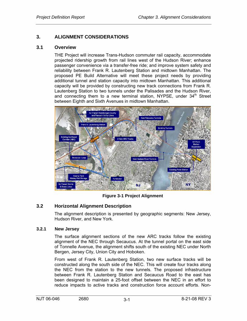
3.1 Overview THE Project will increase Trans-Hudson commuter rail capacity, accommodate projected ridership growth from rail lines west of the Hudson River; enhance passenger convenience via a transfer-free ride; and improve system safety and reliability between Frank R. Lautenberg Station and midtown Manhattan. The proposed PE Build Alternative will meet these project needs by providing additional tunnel and station capacity into midtown Manhattan. This additional capacity will be provided by constructing new track connections from Frank R. Lautenberg Station to two tunnels under the Palisades and the Hudson River, and connecting them to a new terminal station, NYPSE, under 34th Street between Eighth and Sixth Avenues in midtown Manhattan.
Figure 3-1 Project Alignment
3.2 Horizontal Alignment Description The alignment description is presented by geographic segments: New Jersey, Hudson River, and New York.
3.2.1 New Jersey The surface alignment sections of the new ARC tracks follow the existing alignment of the NEC through Secaucus. At the tunnel portal on the east side of Tonnelle Avenue, the alignment shifts south of the existing NEC under North Bergen, Jersey City, Union City and Hoboken.
From west of Frank R. Lautenberg Station, two new surface tracks will be constructed along the south side of the NEC. This will create four tracks along the NEC from the station to the new tunnels. The proposed infrastructure between Frank R. Lautenberg Station and Secaucus Road to the east has been designed to maintain a 25-foot offset between the NEC in an effort to reduce impacts to active tracks and construction force account efforts. Non-

Project Definition Report Chapter 3. Alignment Considerations
NJT 06-046 2680 8-21-08 REV 3
3-2
precluded interlocking configurations along the NEC provide sufficient future flexibility between the existing and the new tracks to permit subsequent construction of crossovers that would if constructed, facilitate emergency operations and periodic closures for maintenance. Vehicle design speeds are kept to 80 mph between the Loop Track tie-in location and Secaucus Road. East of Secaucus Road, the design speed reduces to 60 mph. The 60 mph design speed is maintained to the 34th Street approach curves in Manhattan.
The two proposed ARC tracks lead to the two new tunnels, descending and turning southward deeply under the Palisades. The two tunnels under the Palisades to the Hudson River are approximately 1.0 mile each in length. The tunnel structure may be constructed to permit future connection of the Northern Branch within the Palisades project segment. This proposed service will merge into the ARC tunnels with a design maximum authorized speed (MAS) of 60 mph.
THE Project alignment includes three new loop tracks (Secaucus Connection) that connect from the Main Line tracks on the lower level of Frank R. Lautenberg Station to the new ARC and NEC tracks. The loop tracks utilize the former Boonton Line right-of-way (ROW), and allow Main, Bergen County and Pascack Valley Lines and Port Jervis trains to continue to NYPSE on the new ARC tracks and tunnels or to PSNY (via Loop 3) through the existing NEC and North River Tunnels. The connection from the Main, Bergen County and Pascack Valley and Port Jervis lines to the NEC create a direct, transfer-free ride for passengers from Northern New Jersey and Orange and Rockland counties into midtown Manhattan. The loop track connections eliminate the need for transfers at Frank R. Lautenberg Station for the Main, Bergen County, and Pascack Valley Lines, where passengers must transfer from the lower level to upper level platforms along the NEC for service to mid-town Manhattan.
The Loop Track configuration has incorporated sufficient lateral clearance for the following locations:
• Existing future overbuild foundations at Frank R. Lautenberg Station
• New Jersey Turnpike Interchange 15X ramp piers
• PSE&G utilities (currently crossing under the Former Boonton Line)
Loop Track operating speeds are designed for 30 mph to minimize travel time and maintain system capacity. Creation of the Loop Tracks will require modification of the Main Line tracks between the Frank R. Lautenberg Station lower level and West End Interlocking. Under the proposed configuration, Main Line tracks 1 and 2 will be operationally combined into one track south of the station. This combined track will rise above the Loop Track 2 structure and connect to existing Main Line Track 1 south of the Norfolk Southern 3rd Track bridge. Main Line 4 will extend south of the lower level station and rise above both Loop Track 1 and Loop Track 2 structures before connecting to existing Track 2 south of the Norfolk Southern 3rd Track bridge. Main Line Track 3 will be shifted eastward to provide sufficient space for the additional tracks. South of the 3rd Track bridge additional crossovers (including non-precluded crossovers) have been included to support current and future operations.
NJ TRANSIT’s proposed use of the former Boonton Line will require relocation of the existing Norfolk Southern’s existing storage capabilities on the Boonton

Project Definition Report Chapter 3. Alignment Considerations
NJT 06-046 2680 8-21-08 REV 3
3-3
Line onto two proposed tracks west of the existing ROW. These tracks will reconnect onto the existing Boonton Line underneath the existing NEC structure over the Boonton Line.
THE Project alignment also includes improvements to the West End Wye, an existing slow-speed single-track connection between the Main Line and the M&E Lines south of Frank R. Lautenberg Station in Jersey City, which would create a higher-speed, double-track connection with associated interlocking improvements along the M&E Lines. This improved connection will support train moves to and from the proposed Kearny Yard in Kearny, New Jersey. The proposed yard accommodates midday storage. The yard design includes 28 tracks with inspection, fueling, car wash, and crew facilities. The yard will accommodate both electric and dual-powered trainsets. Equipment stored on the site during the day would operate in electric mode exclusively.
3.2.2 Hudson River Two single-track tunnels will be bored under the Hudson River in an easterly direction from the Hoboken shaft to the Twelfth Avenue shaft at West 28th Street in Manhattan. The separation distance between the tunnels under the Hudson River is approximately 35 feet and as the tunnels approach Manhattan the distance increases to pass through the pile foundations elements of the abandoned Route 9A (Westside Highway) viaduct.
3.2.3 New York The proposed configuration includes new track connections to the proposed NYPSE Station. The station expansion is located under West 34th Street between Eighth and Sixth Avenues. The Manhattan segment will be constructed via rock tunnel boring TBM launched from the Twelfth Avenue shaft located on the west side of Block 674 (between 28th and 29th Streets and Eleventh and Twelfth Avenues—currently occupied by Con Edison). At this location two equilateral No. 20 switches will enable train service to split into four single track tunnels. The shaft includes two flood gates to protect the NYPSE incase of a mid-Hudson Tunnel breach. The flood gates have been located over the non-moveable portion of the No. 20 switches. The inner two tunnels will begin to rising towards 34th Street, while the two outer tunnels gently rise and level out towards 34th Street. The upper tracks will pass vertically over the lower tracks, enabling the construction/operation of a two-level Upper and Lower (Hotel) Interlocking and a two-level terminal track in the new NYPSE. These four tracks will extend in a northeasterly direction at a diagonal toward the intersection of Ninth Avenue and 34th Street where they will turn eastward and align directly below 34th Street at Upper and Lower (Hotel) Interlocking. The distance between Warrington (Split) and Upper and Lower (Hotel) Interlockings will accommodate two full train lengths in each of the four tunnels. Both upper and lower level tracks proceed eastward through a 30 mph interlocking with maximizes parallel routing to a new 3-over-3 deep-track terminal. The 30 mph interlocking speed significantly increases the equipment exchange time (exchanging a stopped vehicle on the terminal approach tracks with a platformed vehicle) and system capacity.

Project Definition Report Chapter 3. Alignment Considerations
NJT 06-046 2680 8-21-08 REV 3
3-4
3.2.4 NY Penn Station Expansion On both the upper and lower levels, the two-track alignment will proceed through Upper and Lower (Hotel) Interlocking and become three-track alignments for the NYPSE platforms.
Figure 3-2 Station Cross Section
The station cavern has been located 200 feet from NYC Water Tunnel #1 located beneath the east side of Sixth Avenue to comply with NYCDEP requirements. Additional overrun trackage will be added to the upper and lower levels to permit equipment entering the platforms to proceed at 30 mph prior to receiving a code change approximately midway through the platform. This alignment will reduce passenger running time by permitting gradual speed reduction from 60 mph beneath the Hudson River to 45 mph as the train approaches 34th Street, and then to 30 mph turning onto 34th Street through the Upper and Lower (Hotel) Interlocking and the western portion of the platform. At this point braking can be applied to comfortably decelerate to the eastern end of the platform.
3.3 Maintenance and Storage Facilities Yard capacity requirements are based on the required fleet expansion to support the new service and the proposed operating plan. The mid-day storage requirement is 28 trainsets.
The proposed site in Kearny, NJ was determined to best meet the criteria and satisfy the operational requirements of the proposed service. Train storage facilities at Kearny Yard would include the following basic requirements:
• Primary access into the yard from westbound Morris and Essex Lines for mid-day storage of trainsets returning from NYPSE, with the ability to process an inbound train every three minutes (20 trainsets per peak hour).

Project Definition Report Chapter 3. Alignment Considerations
NJT 06-046 2680 8-21-08 REV 3
3-5
• Access into the yard from eastbound Morris and Essex Lines (this access would also support inserting a train from the yard onto the Morris and Essex Lines westbound, including non-revenue movements of trains to/from the adjacent NJ TRANSIT Meadows Maintenance Complex (MMC).
• Configuration for both electric and dual-Powered trainsets.
• Sufficient train storage for a minimum of 28 trainsets on a layout of 20 tracks. Trainsets would be 12 Electric Multiple-Unit (EMU) cars or 11 coaches plus a dual-powered locomotive; therefore, conceptual design would provide storage tracks with sufficient length for 12-car trainsets.
• Control Tower
• Train Wash Facility
• Covered service and inspection tracks for compliance with Federal Railroad Administration (FRA)-required inspections before trains re-enter into service. Heavy repair and routine maintenance would take place at the existing MMC, opposite the Morris and Essex Lines from the proposed Kearny Yard.
• Welfare facilities for personnel
• Storage for equipment and materials
• Locomotive Fueling/Sanding Facility with associated locomotive servicing.
• Access roadways and parking
• Stormwater runoff detention facility. Detained water would be released into the Hackensack River after attenuation and application of “Best Management Practices” treatment, as regulated by New Jersey Department of Environmental Protection (NJDEP). Grades of the proposed yard would be raised between 15 feet and 25 feet above existing conditions, using suitable materials from the tunnels excavation. The required increase of the yard site elevation is controlled by the elevation of the point on the existing Morris and Essex Lines where the lead to the yard begins and by limitations on track profile grade within the yard.
3.4 Vertical Alignment Description
3.4.1 New Jersey Vertically, the Loop Track alignments extend from the existing lower level of the Frank R. Lautenberg Station, continue over the existing structure over Penhorn Creek prior to vertically descending conforming to the 100 year flood elevation. The Loop Tracks continue at the minimum design flood consistent with the 100 year flood elevation along the former Boonton Line. As the tracks curve towards to NEC, they rise to meet the proposed ARC tracks along the south side of the NEC. The elevation of the new ARC tracks along the NEC have been established to match the existing NEC to allow sufficient clearances over the NJ Turnpike Interchange 15X interchange ramps and the Frank R. Lautenberg Station lower level services (Main Line, Bergen County, and Pascack Valley Lines).

Project Definition Report Chapter 3. Alignment Considerations
NJT 06-046 2680 8-21-08 REV 3
3-6
Creation of track connections from the lower level of Frank R. Lautenberg Station to the former Boonton Line (via the Loop Track underpass thru-structures) require reconstruction of Main Line Tracks 1 and 4 onto bridge structures over the Loop Tracks. Main Line grades will crest over the Loop Tracks with approximately a 1.6% maximum grade. The Main Line 3 will be reconstructed into a new track infrastructure which is east of the current alignment at an elevation which will enable construction of both the temporary and final adjacent configurations without retaining walls. All Main Line Tracks rejoin their existing vertical profiles north of the Norfolk Southern 3rd Track bridge.
The West End Wye track connection from the Main Line to M&E Line replicates the existing trackbed northward to the Norfolk Southern 3rd Track bridge. North of this structure, the West End Wye leaves the existing Mainline, descends below the NJ Turnpike Entrance structure prior to meeting the former Boonton Line consistent with the 100 year flood elevation.
Extensions of the proposed ARC tracks eastward from the Frank R. Lautenberg Station parallel the existing NEC tracks passing over Croxton Yard, Secaucus Road, New York Susquehanna & Western (NYS&W) and Conrail Tracks. Beyond NYS&W and Conrail, the tracks transition to a 1.9% (2.0% equivalent) downward grade. This grade enables the proposed tracks to be constructed under a new staged construction Tonnelle Avenue bridge. This grade continues under the Palisades to the Hoboken Shaft.
Figure 3-3 Project Profile
3.4.2 Hudson River The proposed profile under the Hudson River has been adjusted to minimize mixed face-rock conditions subsurface rock outcroppings under the eastern NJ pier limit. The profile design influences from the Palisades vertical alignment to the west and the Manhattan vertical alignment to the east have allowed the Hudson River profile to have sufficient depth below the Hudson River to avoid impacting the river bottom with a security blanket over shallow tunnels and the existing historic bulkhead along the eastern bank of the Hudson River in Manhattan.
3.4.3 New York The proposed configuration extends the 0.8% descending grade from the Hudson River portion of the project. Warrington (Split) Interlocking, comprised of two No. 20 equilaterals, bifurcates the two cross river tunnel tracks into 2 upper level and 2 lower level bound tracks. Once separated, the upper level tracks begin to transition to a 1.75% grade passing 11 feet under the MTA’s proposed Number 7 Line Extension structural invert. The upper level tracks continue to rise transitioning through a 0.92% Upper (Hotel) Interlocking grade to a 0.2% upper platform track grade through the station. The lower level tracks extending from Warrington (Split) Interlocking transition from a descending

Project Definition Report Chapter 3. Alignment Considerations
NJT 06-046 2680 8-21-08 REV 3
3-7
0.8% Hudson Tunnel grade to a 0.2% platform grade. This grade continues through the platform (including any additional track runoff).
The elevation of the track levels through the station cavern has been developed to meet the geotechnical requirements for constructing the 3-over-3 terminal. The geotechnical investigations conducted during Preliminary Engineering identified the conditions of the rock and revealed depressions in the rock profile along 34th Street. Analysis indicated that the cavern crown for the NYPSE required a minimum rock cover of 45 feet to maintain rock stability during construction.

Project Definition Report Chapter 4. Operations and Capacity
NJT 06-046 2680 8-21-08 REV 3
4-1
4. OPERATIONS AND CAPACITY 4.1 General
The goal of THE Project is to increase the existing Peak Hour train capacity between New Jersey and Manhattan from the current 23 Trains Per Hour (TPH), as currently available through the existing North River Tunnels (NRT), to an overall total of 48 TPH. THE Project will accomplish this by constructing two new high-speed tunnels under the Hudson River that will connect New Jersey to NYPSE.
The NYPSE, beneath 34th Street between Eighth and Sixth Avenues, will be a six-track, three-over-three station, with the three upper level tracks and three lower level tracks separated by a connecting mezzanine. The station will be able to process up to 25 TPH during the Peak Hour. Combined with the 23 TPH capacity currently provided in the North River Tunnels, the overall capacity of the new facility and existing Penn Station New York (PSNY) will achieve the 48 TPH objective.
Additional benefits to be provided by THE Project will include a level of redundancy in Trans-Hudson rail operations that does not exist today and the introduction of a transfer-free service to all NJ TRANSIT branches that currently require passengers to transfer trains to reach Manhattan, namely:
• North Jersey Coast Line Bay Head Service
• Boonton Line west of Montclair
• Pascack Valley Line (PVL)
• Main Line (ML) and Bergen County Line (BCL)
• Port Jervis Line
• Raritan Valley Line(RVL)
This enhancement will be made possible through the addition of a new fleet of dual-powered locomotives that can operate in both diesel and electric territory.
4.2 Project Elements
4.2.1 New Jersey Loop Track and Surface Alignments The Loop Track portion of THE Project extends from just west of the lower level Main Line platforms at the Frank R. Lautenberg Station, and a point just east of Lower Hack Bridge on the Morristown (M&E) Line, to the upper level at Frank R. Lautenberg Station.
A series of four loop tracks will directly connect train operations on the Main Line at the lower level with new ARC and existing NEC track infrastructure on the upper level at Frank R. Lautenberg Station. Loop 0 will connect Main Line 4 on the lower level of Frank R. Lautenberg Station to Loop 1 and Manhattan-bound ARC Track 0 on the upper level. Loop 1 will connect eastbound lower level traffic on Main Lines 2 and 1 to ARC Track 0. The configuration of Loop 0 also allows one portion of Loop 1 to be used by westbound trains while at the same time the other section is being used by eastbound traffic. Loop 2 will

Project Definition Report Chapter 4. Operations and Capacity
NJT 06-046 2680 8-21-08 REV 3
4-2
connect westbound traffic on ARC Track 1 to Main Lines 1 and 3 on the lower level.
Loop 3 will connect with the NEC in the center of the upper level of Frank R. Lautenberg Station, and will provide bi-directional access for Main, Bergen County, Pascack Valley trains, as well as Kearny Yard trains, to and from PSNY. This connection will allow all NJ TRANSIT NYPSE service to operate out of PSNY during off-peak periods should it be necessary to shut down the NYPSE or the ARC tunnels for maintenance or other reasons. Likewise, all NJ TRANSIT service destinations will be accessible from the NYPSE should PSNY or the NRT be shut down for similar reasons.
The configuration of the Loop Tracks significantly mitigates the restrictions inherent in existing Laurel Interlocking, restrictions that could only otherwise be addressed by grade separation. The parallel routing capability and flexibility offered by the design, combined with optimized track geometry, allows for a Maximum Authorized Speed (MAS) of 30 MPH throughout the loop tracks, thereby contributing to THE Project’s achievement of its capacity goals.
In addition, a siding has been provided on Loop Track 3 to provide for storage of a dual powered rescue locomotive that would be available to assist in moving a disabled train from the surface areas and the tunnels. A No. 10 turnout from this siding has been provided to expedite movements in and out of this siding.
As part of the design, Main Line 4 will be extended over Loops 1 and 2 to West End Interlocking which will allow service to Hoboken to operate from station Tracks 2 and 4. This connection will also provide the flexibility necessary to reroute a dual-powered train that fails to convert to electric mode, as required, on the lower level of Frank R. Lautenberg Station to Hoboken with minimal impact.
Also included in this package are improvements to the West End Wye that will create a higher speed (30 MPH), double track connection with West End Interlocking, and associated interlocking improvements along the M&E Line. This improved connection, in concert with the Loop Tracks, will provide the operational capacity to move trains seamlessly between Kearny Yard and the M&E Line, the ARC tracks and the NEC.
The New Jersey Surface Alignment portion of THE Project extends approximately 13,000 feet from just west of the new south side platform at Frank R Lautenberg Station to the new bridge at Tonnelle Avenue.
The alignment features two new tracks located to the south of the existing south platform on NEC Track 2 at Frank R. Lautenberg Station. Though the tracks will be able to be used in either direction, Track 0 will be primarily for inbound (eastbound) traffic, while Track 1 will be primarily for outbound (westbound) trains. These tracks will connect directly and solely to the ARC tunnels, and will have no interface with the NEC east of Frank R. Lautenberg Station. This configuration would essentially create two separate sections of east/west railroad operations acting more or less independently of each other. At Frank R. Lautenberg Station, the two southernmost tracks would connect NJ TRANSIT to the NYPSE exclusively. The existing NEC tracks to the north would connect Amtrak and NJ TRANSIT to PSNY.

Project Definition Report Chapter 4. Operations and Capacity
NJT 06-046 2680 8-21-08 REV 3
4-3
Placing both ARC tracks south of the existing NEC infrastructure substantially reduces interface with Amtrak, which should have a beneficial impact on costs and scheduling during construction, and afterwards in daily operations. Yet, full interconnectivity between the NEC and the ARC tracks will still be available with this configuration. All NJ TRANSIT service options are available with this alignment.
Optimized track geometry allows for a maximum authorized speed of 80 MPH throughout this section. To fully realize the high-speed capacity of this track section, all Main Line, Bergen County Line and Pascack Valley Line trains scheduled to stop at Frank R. Lautenberg Station will stop on the lower level. Only Midtown Direct trains operating via the Kearny Connection will stop at the new south side island platform on the upper level.
The design will be such that should it be desired to add additional connections from the ARC tracks to the NEC east of Frank R. Lautenberg Station in the future (shown as dotted orange in Figure 4-1), it will be possible. The exact configuration of the non-precluded crossovers has not been established at this time.
Just west of the tunnel portals an eastbound controlled signal will be installed on each ARC track to act as a holding signal should a train ahead become disabled. These signals will help minimize the potential of a second train becoming involved with an incident in the tunnel ahead.
Also included in this section of the project are two No. 20 crossover switches located east of Frank R. Lautenberg Station that will provide interconnectivity between Tracks 0 and 1. These switches will allow trains to operate bi-directionally on a single track between NYPSE and New Jersey during emergencies, or to allow scheduled maintenance in one of the ARC tunnels.
In order to fully realize the high-speed capacity of this section of track, all Main Line, Bergen County Line and Pascack Valley Line trains scheduled to stop at Frank R. Lautenberg Station will do so on the lower level, with only Midtown Direct trains operating to NYPSE via the Kearny Connection scheduled to stop at the new south side island platform on the upper level.

Project Definition Report Chapter 4. Operations and Capacity
NJT 06-046 2680 8-21-08 REV 3
4-4
Figure 4-1 Surface Tracks Alignment
4.3 Tunnels and Caverns THE Project consists of three tunnel sections. The Palisades Tunnel portion of THE Project extends a distance of approximately 5,100 feet and runs from its portal on the east side of Tonnelle Avenue to the Hoboken shaft, approximately 1,500 feet west of the Hudson River. Optimized track geometry will allow a maximum authorized speed of 60 MPH throughout this section of the tunnel. Approximately 2,500 feet east of the

Project Definition Report Chapter 4. Operations and Capacity
NJT 06-046 2680 8-21-08 REV 3
4-5
Tonnelle Avenue portal, provision may be made for a possible future connection of the Northern Branch to the ARC tunnels. Eastbound interlocked signals will be installed prior to the Northern Branch connection being made to control eastbound trains approaching the floodgates located at the Hoboken shaft. These signals can be placed at stop to halt eastbound trains should the floodgates be activated. There will be no additional elements in the Palisades section that will make any further operational contributions.
The Hudson River Tunnels extend approximately 7,300 feet from the Hoboken shaft in New Jersey to the Twelfth Avenue shaft in Manhattan. After leaving New Jersey, the two tunnels will cross under the Hudson River running in a generally northeast direction approximately 55 feet below the bottom of the river channel, before entering Manhattan at 28th Street. At the Twelfth Avenue shaft, they connect with the Manhattan Tunnels package.
The Manhattan Tunnels portion of THE Project will span a distance of approximately 5,300 feet from the tunnel entry point in Manhattan to the east end of the station platforms at the NYPSE. The two tunnels will enter Manhattan approximately 150 feet below surface level at 28th Street, proceed diagonally northeast, and split into a four-track alignment at Warrington (Split) Interlocking beneath the block formed by the intersections of 28th and 29th Streets and Eleventh and Twelfth Avenues. The four tunnels turn eastward at the intersection of Eighth Avenue and 34th Street and run directly below 34th Street to Sixth Avenue.
At Warrington (Split) Interlocking the two tunnels will divide into four tunnels, with two new tunnel bores leading to the upper level of the NYPSE. Each set of two tunnels will connect to Upper and Lower (Hotel) Interlocking on either the upper or the lower level west of the station cavern. The incoming trains’ final routing onto a station track will be determined at Upper or Lower (Hotel) Interlocking. There is room for two trainsets to occupy each of the four tracks between Warrington (Split) and Upper and Lower (Hotel) Interlockings. This optimized length increases the system’s ability to clear trains from the main track and make following movements to other tracks, thus maximizing tunnel train capacity.
The tunnels will be designed with a horizontal ventilation duct running along the side portion of each tunnel opposite the benchwall. The benchwall will be located to facilitate placement of cross-passageways between each tunnel. This configuration will allow the ventilation and egress requirements of NFPA 130. Alternate ventilation designs are being considered for the Palisades and Hudson River tunnel segments to create an independent exhaust duct along the length of the main tunnels. The ventilation design either will create two ventilation zones within the length of the Palisades tunnels and three ventilation zones within the length of the Hudson River Tunnels or provide multiple damper controlled openings to not restrict the number of zones. The ventilation zones are coordinated with the train signal system design to deliver 25 trains per hour through the tunnels. In Manhattan the ventilation design is modified to preclude any ventilation-imposed restrictions to the signal system design on the New York approach to the NYPSE. The ventilation system design will be finalized during Final Design.

Project Definition Report Chapter 4. Operations and Capacity
NJT 06-046 2680 8-21-08 REV 3
4-6
Though longer in linear feet than the existing NRT, the running time from Frank R. Lautenberg Station to the NYPSE will be less than the current running time through the NRT due to enhanced track geometry that will permit higher speeds. The maximum authorized speed of trains as they enter the Manhattan section of the ARC tunnels will be 60 MPH through Warrington (Split) Interlocking. Trains will slow to 45 MPH approaching 34th Street, and slow further to 30 MPH through Upper and Lower (Hotel) Interlocking and the entrance to the station platforms. The maximum grade in this section is 1.9% (2% equivalency) at the transition point to the Palisades Tunnel at the Hoboken shaft.
4.4 NY Penn Station Expansion NYPSE extends beneath 34th Street for approximately 2,255 feet between Sixth and Eighth Avenues. The tunnel bores between these boundaries will be excavated to form a single cavern that will provide the space necessary to house a six-track station with three tracks on an upper level and three tracks on a lower level, separated by a mezzanine that will connect the two by vertical circulation elements (VCE’s). Included in this cavern will be space needed for interlockings and other operational infrastructure necessary for routing trains into and out of the station, and space within the station itself for customer, employee, operational and mechanical functions.
The station track numbering system will be a continuation of that used at the existing Penn Station, with Tracks 22, 23 and 24 on the upper level numbered south to north, and Tracks 25, 26 and 27 on the lower level, also numbered south to north. NYPSE will be capable of processing up to 25 trains per hour (TPH) during the Peak Hour.
The Upper and Lower (Hotel) Interlockings will be designed to maximize routing options and flexibility. They will support parallel moves in all cases, except when an eastbound train is arriving on the northernmost station track in each cavern, or a westbound train is departing from the southernmost track. Westbound departing trains will be able to begin acceleration to 30 MPH immediately upon leaving the platform, and eastbound arriving trains will be able to maintain 30 MPH until reaching mid-platform where the train will receive a code change to 15 MPH. The location of the bumping posts will be consistent with stopping distance, approximately 142 feet, required by that speed.
There will be one island platform and one side platform on each level. The island platform will be 30 feet wide and the side platform will be 15 feet wide. All platforms will be 1,020 feet long and will enable maximum NJ TRANSIT train consists of up to 12 units to fully platform.
In addition, sidings have been provided on the upper and lower level platforms to provide for storing dual powered rescue locomotives. These vehicles would have access to a disabled train on any level within the station itself, the interlockings or the tunnels.
4.4.1 NYPSE Service Plan The service scheduled to operate into NYPSE will include the following:
• All dual-powered Main Line trains

Project Definition Report Chapter 4. Operations and Capacity
NJT 06-046 2680 8-21-08 REV 3
4-7
• All dual-powered Bergen County Line trains
• All dual-powered Pascack Valley Line trains
• All dual-powered Raritan Valley Line trains
• All dual-powered outer branch NJCL trains
• All dual-powered Montclair-Boonton Line trains
• All dual-powered Morris & Essex Lines trains
• All dual-powered Port Jervis Line trains
• All MidTown Direct (Kearny Connection) electric service
All future dual-powered service will operate into the NYPSE, providing potential efficiencies in transportation and maintenance of equipment by having dual-powered rolling stock originate at one New York terminal.
This service plan assumes that Amtrak, NJ TRANSIT Northeast Corridor and Inner Zone North Jersey Coast Line (non-Bay Head) trains will continue to operate to existing PSNY, and that a robust level of service to Hoboken will be maintained.
4.4.2 NYPSE Operations To achieve a station capacity of 25 TPH at the NYPSE, a terminal equipment manipulation will be developed featuring a platform cycle time of 15 minutes for revenue-to-revenue train turns and a platform cycle time of 12 minutes for revenue-to-non-revenue or non-revenue-to-revenue train turns. The cycle time will include two minutes for a train to depart a platform and two minutes for the next train to arrive. Actual dwell time on the station platform will be 11 and 8 minutes, respectively, in the peak hour. These station dwells will be supported by various features including:
• An evenly distributed “up-down-up-down” arrival pattern to take advantage of the new 3-over-3 station layout
• Wide platforms with multiple means of egress
• State-of-the-art vertical circulation elements
• Optimized interlocking throat design that enables trains to enter and leave the station at 30 MPH
• An operating plan that incorporates drop-back crews to enable more expeditious crew turns
• An active supervisory presence with local operations controlled from a Station Operations Center located on the mezzanine.
4.4.3 Station Operations Center Local train operations will be coordinated from a Station Operations Center (SOC) located at the west end of the mezzanine. The limits of NYPSE dispatcher control will extend through the ARC tunnels and Loop Tracks to the lower level of Frank R. Lautenberg Station on the Main Line, through the West End Wye to the M&E Line, and the ARC surface tracks. NJ TRANSIT’s TMAC

Project Definition Report Chapter 4. Operations and Capacity
NJT 06-046 2680 8-21-08 REV 3
4-8
supervisory control system and operating rules will be expanded to include this new territory. The SOC will interface with Amtrak at Penn Station Central Control (PSCC) regarding movements to or from the NEC via Loop 3. There will be redundant secondary control from NJ Transit’s Rail Operations Center (ROC) in New Jersey.
Transportation Supervisors at the SOC will oversee train movement, respond to emergencies, develop contingency plans, and coordinate the manipulation of crews and equipment in the manner required for a high-volume operation of this type. Station public address announcements and display of train information on public monitors will be made from the SOC.
Adjacent to the SOC will be a train crew standby room where crews will be available to be used as necessary. Attached to the SOC will be an Incident Room from where major incidents can be managed by senior operating department managers and other personnel.
In addition to the Amtrak interface noted above, the SOC will interface or communicate with the ROC, NJ Transit’s Train Operations Center (TOC) in existing PSNY, and Amtrak 40 Office.
4.5 Railroad Systems A system can be generally defined as a combination of interacting elements organized to achieve one or more stated purposes. If the elements of a complex mechanism such as THE Project do not operate in a coordinated and synergistic manner, the system, as a whole, will not operate as effectively as desired, or is possible. The systems associated with THE Project, and upon which its ability to achieve its stated goals depend, are:
• Traction Power
• Communications
• Signaling
• Train Control Architecture
• Track
Each of the Railroad Systems elements is described in detail in Chapter 17 of this document.
4.6 Kearny Mid-Day Storage Yard A key component of this complex system will be a newly constructed rail storage yard located on property owned by the Hudson County Improvement Authority, located between the NEC and the M&E Line tracks that lie west of the Hackensack River in Kearny, New Jersey.
The proposed Kearny Mid-Day Storage Yard will be a 20-track facility capable of storing 28 12-unit train sets. The yard will be comprised of two primary components – an east yard consisting of 12 stub-ended storage tracks each capable of storing a 12-unit train set, and a west yard consisting of 8 double-ended storage tracks each capable of storing two full 12-unit train sets. The east yard will have two pit/pedestal tracks for inspections. The west yard will

Project Definition Report Chapter 4. Operations and Capacity
NJT 06-046 2680 8-21-08 REV 3
4-9
have a locomotive fueling and sanding facility on the north side and a trainwasher on the south side (see Figure 4-2).
After arriving in the morning at the NYPSE and discharging passengers, those equipment sets not turning for westbound revenue trains, or non-revenue trains, to other locations will be sent to Kearny Yard for mid-day storage and servicing. The east end yard entrance will be capable of processing 20 TPH, or one every three minutes.
Later in the afternoon this equipment will return to NYPSE to provide westbound PM Peak revenue service. Although Kearny Yard is envisioned as primarily supporting NYPSE operations, some equipment from PSNY may also be sent to Kearny Yard for service and mid-day storage before being sent back to PSNY to represent PM Peak service from that location. It is intended that the service functions associated with the level of contact time available between AM and PM peak periods will be performed at Kearny Yard.

Project Definition Report Chapter 4. Operations and Capacity
NJT 06-046 2680 8-21-08 REV 3
4-10
Figure 4-2 Kearny Yard Schematic Diagram

Project Definition Report Chapter 4. Operations and Capacity
NJT 06-046 2680 8-21-08 REV 3
4-11
4.6.1 Rail Access to Yard At the east end of the yard there will be three separate entrance switches, and associated lead tracks, for westbound trains to enter the yard from the M&E Line. These three entrances, combined with existing and new crossovers between M&E Tracks 3 and 1, will provide substantial flexibility at the east end of the yard, allowing multiple sets equipment to enter or exit simultaneously.
Switches in the yard throat area at the east end of the yard will be interlocked and controlled from the ROC for at least one train-length into the yard on all tracks to allow trains to clear the main track for following movements. The configuration of the throat includes two signal-protected pocket tracks that can be used as switching leads for up to 12-car drill moves, allowing yard switching to be accomplished at the east end of the yard without fouling the M&E main track, or preventing other trains from entering or leaving the yard. Derails will be placed on yard leads at their clearance points with the M&E main tracks to protect against trains encroaching upon the main track without proper authority.
In addition, a short westward facing track, with associated main track switch and crossover, will allow direct access to M&E Tracks 3 and 1 for movements from the yard to the west. This connection will allow direct westbound access to M&E Tracks 3 and 1, and will facilitate the movement of shop equipment to or from the Meadowlands Maintenance Facility (MMC).
4.6.2 Trainwasher A bi-directional train washer is located on the southernmost track in the west yard, and will be activated automatically as the train approaches the facility. The train washer will include a “no-wash” feature that will allow trains to run through without the wash being activated.
Trains will operate through the wash at 3 MPH, taking four minutes for an entire 12-car consist to pass through the structure. There is sufficient footage on the wash track for a 12-car train to occupy the track on either side of the wash without fouling any other tracks. As many trains as can be processed will be washed as they arrive in the yard after the AM peak period, with additional consists being drilled over by yard crews during the day.
The wash is being designed to allow up to 80% of previously used fluid to be recycled for subsequent washings. Only the final rinse will involve fresh water. Immediately to the south of the wash track will be a parking and storage area for wash and other materials.
4.6.3 Fueling and Sanding Facility The fueling facility will be located on the northernmost track in the main portion of the yard. The fueling area itself is 1,060 feet long and has six separate fueling stations, with one located every 170 feet along this length of track. The location of the fueling nozzles has been designed to allow a 12-car diesel multiple unit (DMU) train to be fueled intact. Though DMU equipment is not currently used on the NJ TRANSIT system, this facility is being designed to accommodate it should it be acquired in the future.
Since the current PE Operating Plan calls for all dual-powered locomotives to operate into and out of NYPSE, this yard will be a key fueling location for these

Project Definition Report Chapter 4. Operations and Capacity
NJT 06-046 2680 8-21-08 REV 3
4-12
engines. Due to the larger fuel tanks required by locomotives, higher volume nozzles will be located at either end of the fueling facility track to fuel locomotives on either end of a consist at a faster rate.
A locomotive sanding system will be installed to provide sand at each end of the fueling facility.
4.6.4 Service Functions Being a mid-day storage facility, it is expected that after the morning peak period empty equipment will be cycled to Kearny Yard where certain service functions will be performed before the equipment is sent back to the eastern terminals to represent westbound trains during the PM peak period. The trains would be cleaned and mopped, toilet-serviced, inspected to the extent required, and light repairs or other maintenance performed as necessary. Toilet servicing will be provided by mobile carts that will be able to unload effluent at one of three locations located throughout the yard. For maintenance functions beyond those noted, the equipment would be sent to the MMC.
4.6.5 Yard Operations Remotely controlled switches and signals governing movements entering or leaving the M&E Line main track will be controlled by the NJ TRANSIT dispatcher at the ROC. After receiving permission from the yardmaster to allow a train into the yard, the dispatcher will line interlocked switches and display signals to allow the move. At the End of Block sign located at the limits of ROC control territory, the train crew will contact the yardmaster via radio for yard track assignment and permission to enter the yard. Upon being notified by the yardmaster that a train is ready to depart the yard, the dispatcher will display the route for a train to leave.
Under the current design, once beyond the limits of ROC control within the yard, switches will be hand-operated and lined by train crews or switchtenders. Train movements within the yard will be made by permission of the yardmaster. There will be no signals in the yard other than those used to control access to, or from, the main track.
4.6.6 Welfare Facility A Welfare Facility, capable of supporting 577 employees over three shifts, will be constructed on the north side of the yard for Transportation, Maintenance of Equipment, Electric Traction, and Maintenance of Way personnel. Included in the Transportation contingent will be road crews, yard crews, yardmasters, and supervisors. Elevated above the Welfare Facility will be a yard control office, from where movements and activities in the yard will be coordinated. A PA system will be installed at Kearny Yard to assist yard personnel in performing necessary functions.

Project Definition Report Chapter 5. PE Alternative Development
NJT 06-046 2680 8-21-08 REV 3
5-1
5. PE ALTERNATIVE DEVELOPMENT
5.1 General During the course of performing THE Project PE, the conceptual DEIS Build Alternative served as the initial basis for design and modifications were made to arrive at the current project configuration. While performing PE, additional engineering analysis and design were performed and modifications were made to optimize the engineering design, address public input, reduce cost, and reduce impact to both the environment and existing infrastructure. Additionally design modifications were evaluated to reduce construction risks associated with the project. These improvements to the DEIS Build Alternative have been incorporated into the PE alternative. This chapter describes the modifications to the DEIS Build Alternative and provides the reasons for the refinements. Project elements summarized in this chapter include alignment, station, ancillary facilities, rail equipment, maintenance and storage facilities, and costs.
The most significant difference between the DEIS Build Alternative and the Refined Build Alternative is the elimination of the shallow connecting tunnels to existing PSNY. The elimination of the connection significantly reduces project costs and impacts while still achieving the desired 48 TPH service goal. The PE alternative includes further refinements to the key elements of the DEIS Build Alternative, including new track capacity along the NEC beginning in Secaucus and continuing in a tunnel under the Palisades designed to minimize disruption to existing services, the direct connection from the Main, Bergen County and Pascack Valley lines to the NEC designed to improve operating efficiencies; and a deep tunnel under the Hudson River and west side of Manhattan to new station capacity under West 34th Street designed to minimize surface disruptions.
5.2 New Jersey Surface PE Alternative Assessment The refinements in the New Jersey surface alignment sections are as follows:
A. The two new ARC tracks will be constructed entirely on the south side of the NEC from the west side of Frank R. Lautenberg Station to the tunnel portal entrance on the west side of Tonnelle Avenue in North Bergen. This is a change from the DEIS Build Alternative where one new track was to be built on each side of the NEC. Locating the two new tracks entirely on the south side of the NEC eliminated a crossing that would have been required under the NEC at the western end of the project to connect the westbound track on the north side of the NEC to the loop tracks on the south side of the NEC. Likewise, at the east end of the New Jersey surface alignment, a crossing from the tunnel portal on the south side of the NEC would have been required to the track on the north side of the NEC.
Locating the two new ARC tracks on the south side of the NEC reduces the construction risk with two new railroad crossings under the NEC. Additionally, the new ARC tracks were offset from the NEC by approximately 25 feet to minimize disruption to NEC

Project Definition Report Chapter 5. PE Alternative Development
NJT 06-046 2680 8-21-08 REV 3
5-2
operations. The design refinements reduced the dependency on Amtrak to address risks identified by Amtrak with regard to the availability of Amtrak labor resources needed to construct the ARC project concurrent with other major projects on Amtrak property (i.e., East Side Access).
B. The Main Line tracks south of the Frank R. Lautenberg Station will be raised to allow the Secaucus Connection loop tracks to run at-grade under the elevated Main Line as they curve southward to follow the alignment of the Boonton Line prior to connecting to the NEC and new ARC tracks. In the DEIS alignment the loop tracks crossed below the Main Line tracks in a u-section and covered box section to follow the Boonton Line tracks. This alignment eliminated staged construction of new underpass structures under the operating Main Line tracks and the pump station that would have been required for the depressed u-section.
C. The loop tracks where they connect to the new ARC Tracks and NEC are realigned from the DEIS because they would no longer have to connect to a track on the north side of the NEC. The tracks would be realigned to the south and east to connect to the two new ARC tracks on the south side of the NEC.
D. A new island platform and associated station areas will be provided at Frank R. Lautenberg Station between the two new south side tracks. The proposed platform was added in response to input from NJ TRANSIT rail operations to accommodate passenger intra-state and inter-state travel via Secaucus on the two new tracks on the south side of the NEC. The DEIS alternative provided tracks accessing both the north and south sides of the station.
E. Reconfiguration of the Norfolk Southern (former Boonton Line) and Main Line track connection to Kearny Yard will segregate NJ TRANSIT and Norfolk Southern operations and eliminate impacts on Norfolk Southern storage of equipment. The reconfiguration of the Norfolk Southern and Main Line track connection will segregate the freight and passenger operations, eliminating potential operating conflicts
F. A second, higher-speed track connection will be added to the existing West End Wye. The existing slow-speed single track connection will be retained. This reconfiguration was made based on additional operational analysis that identified that it would only be necessary to add a single higher-speed connection. The constructability review further identified that re-construction of the existing slow speed connection would require taking the track out of service for up to 18 months, which was determined to be impractical from an operations perspective. The new higher-speed track connection was re-designed to minimize impacts to the historic-eligible James Avenue bridge.
G. The PE alignment modifies the profile to utilize an elevated structure to cross over the NYS&W and Conrail tracks versus the DEIS alternative where the Palisades tunnel profile was projected to cross

Project Definition Report Chapter 5. PE Alternative Development
NJT 06-046 2680 8-21-08 REV 3
5-3
under the NYS&W and Conrail tracks with the tunnel portal 950 feet west of the freight railroads. The elevated profile descends eastward to pass under a new structure at Tonnelle Avenue and locates the portal for the Palisades tunnels approximately 300 feet east of Tonnelle Avenue. The elevated profile eliminates the impacts of the staged tunneling under the freight railroads. Additionally, as a result of this refinement, the project alignment under the Palisades in Union City is 45-55 feet higher than in the DEIS. Construction cost associated with eliminating the approach U-section approaching the extended tunnel section and extended cut and cover tunnel section reduced project costs.
5.3 Hudson River PE Alternative Assessment The general alignment of the ARC project under the Hudson River has not changed from the DEIS Build Alternative. The refinements under the Hudson River are as follows:
A. The DEIS alternative provided track connections to both NYSPE and PSNY. The elimination of the tunnel connection from the new ARC tunnels to PSNY in the PE alternative allows for a deeper tunnel under the Hudson River and into Manhattan. The DEIS connection required a shallower tunnel alignment, with cut-and-cover construction from the Hudson River to Tenth Avenue under Hudson River Park, Route 9A, Con Ed Workout Facility (Block 674), Block 675, city streets, the historic High Line, LIRR West Side Yard Maintenance Facility, and the Eastern Rail Yard. Reprofiling of Amtrak’s Empire Line would also be necessary.
The PE Alternative tunnel alignment provides a minimum of 50 feet of cover between the top of the tunnel and the river bed and would not require a mid-river cofferdam and would eliminate impacts to the Hudson River bottom and aquatic organisms that inhabit the river bottom. The top of the PE Alternative tunnels are 127 feet below grade where it crosses below the historic Hudson River Bulkhead, 31 feet below the timber piles supporting the bulkhead structure. The southernmost of the two Hudson River tunnels in the PE Alternative will pass 18 feet to the north of Pier 66. The construction of the PE Alternative will not require a cofferdam on the eastern shoreline of the Hudson River eliminating construction-related environmental impacts to the Hudson River, Hudson River Park (including re-constructed Pier 66) and historic Hudson River Bulkhead.
5.4 New York PE Alignment Alternative Assessment The general PE alternative refinements in New York alignment are as follows:
A. The geotechnical exploration program conducted during PE further identified the rock quality along 34th Street and also identified the extent of a depression in the rock profile west of Eighth Avenue. Based on this additional information and geotechnical analysis, it was determined that the crown of the NYPSE station cavern needed

Project Definition Report Chapter 5. PE Alternative Development
NJT 06-046 2680 8-21-08 REV 3
5-4
to be lowered to maintain sufficient rock cover for rock stability over the cavern during construction. Based on the need to lower the station elevation to provide the required rock cover, the project profile in Manhattan was lowered below that provided in the DEIS. The new tunnels will cross below NYCT’s proposed No. 7 Line subway extension. As a result of the increased depth of NYPSE, a single set of tail tracks to the upper level of the station was initially considered to cross over the NYCDEP Water Tunnel No. 1 while the tail tracks at the lower level were eliminated because they were at the same elevation of the water tunnel. During the Extended PE design effort and through additional coordination with NYCDEP, the upper level tail tracks were deferred from the project to eliminate the risk associated with boring over the water tunnel and to comply with NYCDEP requirements to maintain a 200 foot buffer around the water tunnel. The tail tracks may be considered for another project some time in the future when NYCDEP Water Tunnel No. 3 is in service and there is redundancy for water supply in Manhattan.
B. Lowering the tunnel profile to the new lower station elevation eliminated the ability to maintain the PSNY connector with acceptable grades from the lower ARC profile up to PSNY. Eliminating the connection to PSNY, eliminated the need for cut-and-cover construction under properties on the west side of Manhattan which also addressed concerns with regard to disruption of service to existing customers and project risk with regard to schedule and constructability. Amtrak, NJ TRANSIT and LIRR representatives have raised concerns with regard to construction-related service disruptions that would adversely affect their customers. Additional concerns were raised by MTA, HYDC and NYC regarding construction and project schedule risks and environmental impacts associated with cut-and-cover construction on the west side of Manhattan. The elimination of the tunnel connection to existing tracks in PSNY eliminates impacts to historic resources (Hudson River Bulkhead, High Line), parklands (Hudson River Park), transportation services (LIRR, Amtrak) and private property (Block 675).
C. To further address NYCDEP’s requirement to maintain a 200-foot buffer around Water Tunnel No. 1, the NY alignment was modified to shift the cavern westward approximately 80 feet.
D. The track connection from the new ARC tunnels to NYPSE has been redesigned to improve the speed at which trains can approach the station, resulting in additional station capacity. This configuration would achieve the 48 trains per peak hour service goal established in the DEIS utilizing both PSNY and NYPSE.
5.5 Station Alternative Assessment A. The PE alternative station, NYPSE, features a single, 3-track-over-
3-track cavern that will fit within the curb-to-curb limits of West 34th Street between Eighth and Sixth Avenues. The single, six-track cavern configuration completely under West 34th Street eliminates

Project Definition Report Chapter 5. PE Alternative Development
NJT 06-046 2680 8-21-08 REV 3
5-5
the subsurface impacts to 26 private properties on the north side of the street. The station has an upper and lower track level with a mezzanine in between. The single cavern configuration is deeper than the two cavern configuration in the DEIS Build Alternative to provide for sufficient rock cover above the top of the wider single cavern. The NYPSE mezzanine is at a depth of 153 feet. The station has center-island and side platforms that accommodate 12-car multiple unit trainsets.
Property easements are required for rock bolts that extend beyond the limits of the station cavern on either side. New easements are also required for underground passageways and for connections to escalators, stairways and elevators
In the PE alternative, the service plan utilizes six station tracks.
The DEIS Build Alternative NYPSE was configured as two, 2-track-over-2-track caverns under West 34th Street between Eighth Avenue and Sixth Avenue. The station was configured with upper and lower track levels with a mezzanine on the level between the tracks. The southern station cavern was to be totally within the curb-to-curb limits under West 34th Street. The northern cavern extended beyond northern curb line of West 34th under private properties. Although the station could accommodate eight tracks, only six tracks would be outfitted. The space for the other two tracks was reserved for future growth. The station mezzanine would be 115 feet below street level. The station would have center island platforms that would accommodate 12-car multiple unit trainsets.
5.6 Station Entrances A. The PE NYPSE Alternative provides five street entrances versus the
six identified in the DEIS Build Alternative. An evaluation of the six street entrances was undertaken during PE, considering anticipated passenger circulation demand forecasts from the DEIS and new preliminary engineering station designs. Based on this evaluation, five street level entrances with three sets of high rise escalators to the mezzanine were selected as the most cost-effective way to meet anticipated demand. As a result of this evaluation, all DEIS-identified optional station entrances were eliminated. The passenger circulation elements (stairways, escalators, and corridors) of the remaining five entrances were redesigned to provide the same ingress and egress capacity as the DEIS Build Alternative.
The locations of the five street entrances are:
• Eighth Avenue Southeast: Southeast corner of Eighth Avenue and West 34th Street
• Seventh Avenue Northwest: Northwest corner of Seventh Avenue and West 34th Street
• Seventh Avenue Southwest: Southwest corner of Seventh Avenue and West 34th Street

Project Definition Report Chapter 5. PE Alternative Development
NJT 06-046 2680 8-21-08 REV 3
5-6
• Broadway Northwest: Northwest corner of Broadway and West 34th Street
• Broadway Southwest: Southwest corner of Broadway and West 34th Street
The sixth DEIS street entrance location that was eliminated was:
• Eighth Avenue Northeast: Northeast corner of Eighth Avenue and West 34th Street
Optional street entrance locations provided for in the DEIS included:
• Optional Eighth Avenue Southwest: Southwest corner of Eighth Avenue and West 34th Street
• Optional West 35th Street: Mid-block on West 35th Street between Seventh and Eight Avenues
• Optional West 34th Street: Mid-block on West 34th Street between Sixth and Fifth Avenues
As in the DEIS Build Alternative, underground pedestrian connections are provided to existing PSNY, the NYCT subway stations at Eighth, Seventh and Sixth Avenues and Broadway, and PATH at Sixth Avenue.
The PE alternative identified three additional locations, distinct from the above street entrances, for three pairs of elevators to provide for public access in compliance with the Americans with Disabilities Act (ADA). The PE alternative also includes an additional non-public elevator entrance for staff and maintenance use. Stairways in each of the elevator bank locations provide emergency egress and ingress by emergency personnel. The DEIS did not specifically identify locations for the ADA entrances. The locations of the four ADA Access/Emergency Personnel Access elevator entrances are:
• Southeast corner of Eighth Avenue and West 34th Street • Southwest corner of Seventh Avenue and West 34th Street • Southwest corner of Broadway and West 34th Street • Employee only entrance -Mid-block on West 34th Street between
Ninth and Eighth Avenues
5.7 Fan Plants
5.7.1 New Jersey Fan Plants Two fan plants are located in New Jersey for the PE Alternative. One on the west side of the Palisades located on the east side of Tonnelle Avenue and one on the east side of the Palisades in northern Hoboken.
The DEIS Alternative provided two options for a fan plant in North Bergen, with one site east and one site west of Tonnelle Avenue. The proposed fan plant is to be located on the east side of Tonnelle Avenue. The fan plant at Tonnelle Avenue has the potential to be eliminated pending final design of the tunnel ventilation system and conclusion of the Fire / Life / Safety meetings.

Project Definition Report Chapter 5. PE Alternative Development
NJT 06-046 2680 8-21-08 REV 3
5-7
The northern Hoboken site is consistent for both the PE and DEIS Alternative with minor modifications to reflect the site-specific design.
5.7.2 New York Fan Plants The number of fan plants in Manhattan is reduced from six in the DEIS Alternative to four in the PE Alternative. A number of physical changes in the alignment resulted in a modification to the ventilation design concept that permitted the proposed consolidations and resulting elimination of two of the original fan plants in Manhattan. These physical changes include the reconfiguration of NYPSE to a single cavern, elimination of connector tunnels to PSNY, and simplification of the tunnel network between the Hudson River and NYPSE.
Fan plant locations on West 34th Street in the DEIS Build Alternative were combined to reduce the total number of fan plants and moved off West 34th Street to areas with less pedestrian and vehicular traffic. The locations are:
1. Twelfth Avenue Fan Plant - Northeast corner of West 28th Street and Twelfth Avenue or Optional Twelfth Avenue Fan Plant – Southeast corner of West 28th Street and Twelfth Avenue
2. Dyer Avenue Fan Plant – Northeast corner of West 33rd Street and Dyer Avenue ramps
3. 33rd Street Fan Plant – North side of West 33rd Street just east of Seventh Avenue
4. 35th Street Fan Plant – South side of West 35th Street just west of Seventh Avenue
5.8 Kearny Yard During PE, a more compact maintenance and mid-day storage yard was designed. As a result, the PE Alternative only requires the use of the Koppers Coke site, eliminating the need for the adjacent Standard Chlorine and Diamond Shamrock properties. It provides the same storage and track capacity (28 trainsets) and functional facilities as the DEIS Build Alternative. The Koppers Coke site requires from 15-30 feet of fill. The rail connection to the yard from the M&E Line was re-designed for the more compact yard configuration and requires the replacement of the historic Koppers Road Bridge. The yard design does not preclude the use of the perimeter along the Hackensack River for a bikeway or greenway.

Project Definition Report Chapter 6. Geotechnical Conditions
NJT 06-046 2680 8-21-08 REV 3
6-1
6. GEOTECHNICAL CONDITIONS This chapter summarizes the geologic setting of THE Project area and addresses the geotechnical conditions at each of the project segments, based on previous investigations and the results of recent subsurface investigations conducted by THE Partnership for the Preliminary Engineering (PE) phase of The Project.
6.1 Geologic Setting The following sections describe THE Project regional geology, physiography, bedrock geology, and overburden geology.
6.1.1 Regional Geology Geologic structure, lithology, and stratigraphy of rock and soils in the project region are complex and reflect a complex sequence of tectonic, erosional, and depositional events.
At least five major phases of deformation are believed to have affected the project region during the Taconic, Acadian, and Appalachian orogenies (440 to 260 million years ago). The oldest rocks in the project region, mostly in New York, show effects of thrusting and isoclinal folding, intrusion, retrograde metamorphism, folding of earlier structures and fabrics, reactivation of ductile faults, hydrothermal mineralization and brittle normal faulting.
During the Mesozoic era, widespread extension initiated the rifting associated with the Atlantic passive margin and generated the sedimentary and igneous infilling of the Newark rift basins. A diabase sill as much as 1500 feet thick, as well as smaller diabase stocks and dikes, was intruded into the sedimentary units during early Jurassic time, at the same time as the beginning of a succession of basaltic lava flows. The composite thickness of sedimentary and igneous rocks which accumulated in the Newark Basin is believed to be about 24,000 feet.
The extension abruptly halted, and following long periods of erosion, the region was glaciated several times during the Pleistocene epoch. Pre- and post-glacial erosion profoundly affected bedrock topography. In New Jersey, the topography of the bedrock surface in the project region shows two narrow, deep, glacially scoured troughs, one on either side of the New Jersey Meadowlands. In New York, pronounced differential erosion along contacts, shear zones, and areas underlain by weak or fractured rock also produced an irregular bedrock surface.
As the Late Wisconsin-age ice front retreated from its southernmost location at Perth Amboy, moraine-dammed meltwaters formed a series of glacial lakes in the region whose levels and areal extent were controlled by evolving outlet elevations. Glacial lake sediments accumulated in the bedrock trough of the Hudson River but were later mostly eroded by meltwater floods following the breach of the morainal dam across the Narrows.
Marine incursion into the Hudson River trough followed, producing a thick sequence of post-glacial estuarine deposits. Variations in texture and composition reflect their accumulation under variable rates of Holocene and

Project Definition Report Chapter 6. Geotechnical Conditions
NJT 06-046 2680 8-21-08 REV 3
6-2
late-Pleistocene post-glacial sea-level rise and isostatic adjustment. Other post-glacial materials deposited in the project region include stream deposits in terraces and as alluvium, wetlands deposits in swamps, estuaries, and marshes, eolian deposits adjacent to plains and terraces, and talus deposits at the base of rock cliffs. A large percentage of soils in the site area were altered by excavation or filling for residential, commercial, or industrial purposes.
6.2 New Jersey Geology
6.2.1 New Jersey Physiography The New Jersey portion of the project area is located within the Piedmont physiographic province, a broad lowland interrupted by long, northeast-trending ridges and uplands. The most prominent physiographic feature in the eastern part of the province is the Palisades, a north-south topographic ridge near the Hudson River that rises above the surrounding lowlands of the Meadowlands.
6.2.2 New Jersey Bedrock Geology Most of the project area in New Jersey is underlain by rocks of the Newark Basin, a northeast-trending Late Triassic-Early Jurassic rift basin filled with a thick sequence of sedimentary rocks and intrusive and extrusive igneous rocks. Along the eastern margin of the Newark Basin, Triassic sedimentary rocks unconformably overlie Proterozoic and Paleozoic metamorphic rocks of the Manhattan Prong. The topography of the bedrock surface shows two narrow, deep, glacially scoured troughs, one on either side of the New Jersey Meadowlands.
Metamorphic rocks in the project area in New Jersey occur only along the Hudson River waterfront in Hoboken and Jersey City, south of THE Project. These rocks include medium- to coarse-grained layered mica schist and serpentinite.
Sedimentary rocks in the New Jersey project area are stratigraphically within the Newark Group. The Stockton Formation (Late Triassic) is a light gray to light brown arkosic sandstone. This formation creates the basal beds of the Newark Basin and occurs in a narrow band along the Hudson River. The Lockatong Formation consists of gray and black siltstones and argillite, and in the project area, also includes a unit of light gray arkosic sandstone. It is mapped on either side of the Palisades ridge. The Lockatong Formation (Late Triassic) was locally thermally metamorphosed to hornfels where it was intruded by the Palisades diabase sill. The Passaic Formation consists predominantly of red-brown sandy mudstone and siltstone, although west of Kearny and north of Newark, it is principally sandstone. Gray-bed sequences of laminated shale, siltstone, and mudstone are present at Secaucus and Kearny. The Passaic Formation is the rock unit underlying most of the Hackensack and lower Passaic River basins.
The Palisades Diabase is a dark gray to black, fine- to coarse-grained diabase as much as 1500 feet thick which was concordantly intruded as a sill into the Lockatong Formation. The diabase is the dense, resistant rock that underlies the topographically prominent Palisades ridge along the Hudson River, as well as Laurel Hill and Little Snake Hill near the Hackensack River.

Project Definition Report Chapter 6. Geotechnical Conditions
NJT 06-046 2680 8-21-08 REV 3
6-3
The strike of bedding throughout the sedimentary rocks of the Newark Basin generally parallels the north-northeast trend of the basin, and the dip is gentle to the northwest. Strata are locally folded into open troughs and arches, crossed by many small normal faults.
6.2.3 New Jersey Overburden Geology Thickness of surficial materials in the New Jersey project area ranges from less than a few feet in areas of rock outcrops at the Palisades and Laurel Hill to greater than 150 feet at a glacially eroded bedrock trough in the vicinity of North Bergen. Surficial materials consist of deposits of glacial, eolian, alluvial, and marsh/estuarine origin. Weathered bedrock is present beneath the surficial deposits in some portions of the study area.
The Rahway till is the surficial unit directly overlying bedrock. Its mapped exposures are in the vicinity of Secaucus and along the Palisades. It is a nonstratified, compact deposit with 5 to 20 percent pebbles, cobbles, and boulders in a reddish-brown matrix of poorly sorted sand, silt, and clay. Its thickness is generally less than 30 feet. In areas underlain by diabase and on the sandstone and serpentinite bedrock east of the Palisades, the Rahway till is silty, locally loose, and generally less than six feet thick.
Overlying the till, deposits of glacial Lake Bayonne are mapped as a surface unit along the west flank of the Palisades ridge, at scattered locations near the Hudson River, and near the Passaic River. The unit includes both deltaic deposits of sand, sand and gravel, and silty sand and lake-bottom deposits of fine sand, silt, and clay. Thickness ranges from about 25 feet to over 100 feet in the Meadowlands east of Kearny.
West of the Palisades, glacial Lake Hackensack deposits overlie the Lake Bayonne deposits and similarly include sandy deltaic deposits and lake-bottom deposits of varved silt to very fine sand and clay. Regional thickness is typically 40 to 60 feet.
Post-glacial tidal marsh and estuarine deposits of Holocene and late-Pleistocene age overlie most of the glacial lake deposits. They consist of peat and muck of organic, clayey silt, as much as 10 feet thick, overlying and interbedded with laminated and thinly bedded fine sand and silt. They are as much as 20 feet thick.
Passaic terrace deposits, consisting of moderately sorted sand and gravel, are present along the Passaic River in the vicinity of Newark and Harrison. Light brown eolian deposits of very fine to medium sand occur locally near Laurel Hill and just west of Penhorn Creek.
Earth and manmade materials that have been placed as fill include gravel, sand, silt, clay, trash, cinders, ash, and construction debris. Along the Hudson River shoreline in Hoboken and Weehawken, large land areas along the shoreline were reclaimed by filling in the tidal marsh and other low-lying areas with a variety of materials including shotrock from tunnel construction, construction debris, clean granular fill, cinders, ash, and garbage.

Project Definition Report Chapter 6. Geotechnical Conditions
NJT 06-046 2680 8-21-08 REV 3
6-4
6.3 Hudson River Geology
6.3.1 Hudson River Physiography The Hudson River portion of the project area is located between the Piedmont physiographic province on the west and the Manhattan Prong of the New England Upland physiographic province on the east. The Hudson River has a channel morphology that reflects the three navigational channels maintained by the U. S. Army Corps of Engineers: 1) a central channel 45 feet deep from Upper New York Harbor to West 59th Street; 2) a New York channel 40 feet deep through the length of the project area; and 3) a New Jersey channel along the Weehawken-Edgewater waterfront that is 40 feet deep south of Weehawken and 30 feet deep north of Weehawken. The Hudson River estuary system is a major waterway of the northeastern United States
6.3.2 Hudson River Bedrock Geology The topography of the bedrock surface underlying the Hudson River shows a narrow, deep, glacially scoured trough that extends to more than 300 feet below sea level. The elevation of the bottom of the bedrock trough generally rises downstream toward Upper New York Harbor.
The eastern part of the Hudson River channel is underlain by metamorphic rocks of the Manhattan Prong. These rocks consist primarily of mica schist of the Hartland (Middle Ordovician to Lower Cambrian) and Manhattan Schist (Lower Cambrian) formations. The dominant rock type on the east side of the channel is gray, layered, fine- to medium-grained mica schist. Serpentinite probably associated with the Hartland Formation is present about mid-channel. The Manhattan Schist is present west of mid-channel and extends to the Hoboken-Jersey City waterfront. Thrust faults have been inferred in the metamorphic rocks, including Cameron’s Line, a major regional structure.
The western part of the Hudson River channel is underlain by northwest-dipping sedimentary rocks of the Newark Group, which unconformably overlie the older rocks of the Manhattan Prong. The sedimentary formations include the Stockton Formation (Upper Triassic), a light gray to light brown arkosic sandstone, with arkosic conglomerate and red siltstone lenses, overlain by the Lockatong Formation (Upper Triassic) of gray and black siltstones and argillite.
6.3.3 Hudson River Overburden Geology The maximum total thickness of surficial materials overlying bedrock of the Hudson River along the tunnel alignment is about 300 feet, with a complex stratigraphy of glacial, fluvial, lacustrine, and estuarine deposits.
Directly overlying bedrock, but generally only on the western side of the Hudson River channel, is a thin, discontinuous layer of gravelly Rahway glacial till. Elsewhere, the bedrock of the Hudson River trough is directly overlain by deposits of glacial Lake Bayonne, consisting of a lower unit of lacustrine-fan sand and gravel in the deeper parts of the trough and an upper unit of lake-bottom silt and clay. Thickness of the Lake Bayonne sediments is variable, but reaches a maximum of about 50 feet. Similar, but younger, lacustrine-fan and lake-bottom deposits of glacial Lake Hudson were deposited in the channel, but

Project Definition Report Chapter 6. Geotechnical Conditions
NJT 06-046 2680 8-21-08 REV 3
6-5
were later mostly eroded by meltwater floods. They are discontinuously present.
The glacial lake deposits are, in turn, overlain by a thick sequence of post-glacial estuarine deposits of gray, organic clayey silt and silty clay with traces of fine sand and shells. Deposited as a result of marine incursion into the Hudson River trough during and after post-glacial sea-level rise, they are up to about 200 feet thick. Variations in texture and composition reflect their accumulation under variable rates of Holocene and late-Pleistocene post-glacial sea-level rise and isostatic adjustment.
The uppermost surficial material in the Hudson River in the project area is a black, organic silty clay, which occurs primarily on the eastern side of the channel.
6.4 New York Geology
6.4.1 New York Physiography The New York portion of the project area is location within the Manhattan Prong of the New England Upland Physiographic Province of the Appalachian Range. Topography is largely controlled by bedrock geology. Manhattan’s elongate ridges trend generally northeast, as does the established street grid. A topographic map of Manhattan, prepared in by Egbert Viele in 1865 before heavy urbanization, shows stream channels trending generally north-south or northwest-southeast in the project vicinity.
6.4.2 New York Bedrock Geology The New York portion of the project area is underlain by an assemblage of folded and faulted middle Paleozoic-age metamorphic and igneous rocks. The Hartland Formation (Lower Cambrian to Middle Ordovician) and the Manhattan Schist (Lower Cambrian) are the rock formations underlying most of the alignment. They consist of gray interbedded schist, schistose gneiss, gneiss, and amphibolite, with pegmatite intrusions of various ages. Other rock types include a granitic intrusion west of about Ninth Avenue and minor amounts of talc schist, chlorite schist, marble, and serpentinite.
Rock structure generally follows the regional northeast structural trend, parallel to the long axis of Manhattan Island. With many localized variations, foliation strike is typically northeast, with steep dips to the northwest or southeast in a series of northeast-trending folds. Based largely on earthquake fault plane solutions, the current regional stress field in southeastern New York State, including Manhattan, is believed to be compressive with an east-northeast maximum horizontal stress orientation.
6.4.3 New York Overburden Geology Surficial material directly overlying bedrock in Manhattan is primarily dense glacial till consisting of a mixture of clay, silt, sand, gravel and boulders. Decomposed rock is also encountered at some locations. The more complex stratigraphy near the Hudson River shoreline, including the project area, includes man-made fill and glacial, fluvial, lacustrine and estuarine deposits.

Project Definition Report Chapter 6. Geotechnical Conditions
NJT 06-046 2680 8-21-08 REV 3
6-6
Historical records indicate that present-day land areas of Manhattan along the Hudson River extend beyond the original shoreline. Filled for urban development, these areas are typically former bays or tidal marshes with organic deposits beneath the fill.
6.5 Site Geotechnical Conditions
6.5.1 Kearny Yard 6.5.1.1 Site History
The Koppers Seaboard site occupies approximately 173 acres, with 133 acres located above mean high water level. It is the location of a former integrated tar, coke, and coke by-products facility. The site is bounded to the north and east by the Hackensack River; to the west by property belonging to the Standard Chlorine Chemical Co., Inc.; and to the south by the NJ TRANSIT Morris & Essex rail lines that traverse the Hackensack River over the Lower Hack Bridge.
As a result of the former use, there were contaminated structures and processing facilities on the site that have been mostly demolished and removed. The soil and groundwater are contaminated by by-products of coke and tar processing, including a plume of dense non-aqueous phase liquid (DNAPL) contaminants in the eastern portion of the site. The original meadow mat and organic soils at the site provide a natural cutoff to vertical migration of these contaminants, but do not prevent migration into the Hackensack River. In addition, coke and tar wastes had been used in the past to modify and raise the existing dikes along the river boundary of the site.
The site is currently owned by the Hudson County Improvement Authority (HCIA). A 1987 Administrative Consent Order addressed the NJDEP-mandated environmental remediation of the site. The original Remedial Action Work Plan (RAWP) for the site was proposed in April 1998 and approved by NJDEP in May 1998. Safety Kleen (SK) was to complete all the remediation work at the site and then operate and maintain the constructed remedies.
As a result of SK’s subsequent inability to secure additional dredging contracts and wetland permits from USACOE, the bankruptcy of SK’s parent company, and litigation initiated by HCIA, SK did not complete the full scope of the site remediation work. Under a 2003 Settlement Agreement, Beazer East, Inc., agreed to complete the remaining portion of that work. A Remedial Action Work Plan Addendum (RAWPA) was submitted in April 2004, along with subsequent revisions. NJDEP issued a Notice of Deficiency in November 2006 requesting modification to the RAWPA. The outstanding issues have been addressed in addenda to the RAWPA submitted to NJDEP in March and August 2007, and approved by NJDEP in August 2007.
6.5.1.2 Geotechnical Conditions The site in the vicinity of the existing bulkhead is relatively level with existing ground surface elevations between Elev. +303 feet and Elev. +305 feet based on THE Project Datum (equivalent to Elev. +5.7 feet and Elev. 7.7 feet NGVD 1929). Further inland, the ground surface elevations vary by as much as 10 to

Project Definition Report Chapter 6. Geotechnical Conditions
NJT 06-046 2680 8-21-08 REV 3
6-7
15 feet, and stockpiles of processed dredged material (PDM) are stacked as high as 40 feet for eventual use as site fill.
Information from available borings indicate that the site is underlain by silty sand fill material, overlying peat and or organic silty clay (also known as meadow mat) over sand with silt which, in turn, is underlain by varved clay and silt, glacial till and fine-to-medium-grained sandstone.
The fill stratum varies in thickness from one to 15 feet. Standard penetration test (SPT) N-values vary from 2 to 76 blows per foot (bpf), with an average of 24 bpf. The peat and organic soil layer thickness ranges between one and 9 feet. Beyond the southeastern portion of the yard area, the thickness of the organic clay layer increases to over 35 feet. The SPT N-values vary from 0 (weight of rods) to 19 bpf. Underlying the organic soil stratum is a 1-foot to 10-foot thick deposit of medium dense sand with varying amounts of silt. In this stratum, the SPT N-values range from 0 to 26 bpf, with an average of 11 bpf, indicating that this stratum is generally loose to medium dense.
Underlying the sand and silt layer is a reddish brown layer of varved clay, which can be subdivided into an upper stiff overconsolidated layer 3 to 8 feet thick and a lower slightly to normally consolidated layer varying in thickness from 15 to 70 feet. SPT-N values vary from 9 to 28 for the upper stiff layer and zero (WOR) to 10 bpf for the lower layer. Glacial till was encountered below a depth of 50 to 90 feet. Glacial till is a 5- to 30-foot thick layer, consisting of boulders, cobbles, gravel and sand within a silt and clay matrix. The till is generally dense to very dense with SPT N-values generally between 5 and 98 bpf, with an average value of 39 bpf.
Bedrock was encountered beneath the till. Groundwater was encountered on average at Elev. +300 feet.
6.5.2 Loop Tracks The sequence of the soil overburden stratigraphy remains constant throughout the Loop Track Segment, while the thickness of the various strata varies throughout.
The following paragraphs in this subsection present a generalized description of the observed soil stratigraphy in order of increasing depth:
6.5.2.1 Miscellaneous Fill This material has been placed throughout the site in all developed areas and to construct the existing railroad embankments. The fill material is typically less than 10 feet thick in developed areas adjacent to the existing railroad embankments, but occasionally increases up to 25 feet in thickness. The existing railroad embankments rise from 20 feet to 35 feet above the normal topography along the corridor. Miscellaneous fill consists of gravel, sand, cinders, brick, wood, and debris. Historical records indicate that the existing NEC embankment is comprised of granular fill with zones of boulder-sized material. Compactness generally ranges from very loose to medium dense.
6.5.2.2 Organic Soils This stratum represents the tidal marsh deposits that are encountered at the surface in undeveloped areas or immediately under the miscellaneous fill in

Project Definition Report Chapter 6. Geotechnical Conditions
NJT 06-046 2680 8-21-08 REV 3
6-8
developed areas. The organic soils range up to 15 feet in thickness with the thicker zones encountered in undeveloped areas. This stratum consists of very soft to soft vegetative matter (meadow mat and peat) mixed with organic silt. The organic soils are typically brown to dark brown and gray in color and are very compressible.
6.5.2.3 Transition Sand/Clay This stratum is usually, but not always, encountered between the organic soils and the underlying varved soils. The transition zone normally consists of a thin fine sand layer overlying a gray and brown mottled clay, occasionally streaked with organics, and ranges up to 5 feet in thickness.
6.5.2.4 Varved Silt and Clay This material consists of glacial lake deposits comprising gray brown and/or red brown stiff to very soft deposits of varved silt and clay. This stratum ranges up to 50 feet in thickness. Laboratory test data indicates that the upper 10 to 20 feet of this stratum is generally over consolidated with a typical over consolidation ratio (OCR) ranging between 2 and 4. The deeper zones are typically normally consolidated.
6.5.2.5 Glacial Till This stratum consists of red brown glacially deposited sand, silt, clay, gravel, cobbles and boulders overlying the weathered bedrock or bedrock. The compactness of this stratum generally ranges from dense to very dense. The thickness of the glacial till ranges from a thin veneer up to 25 feet thick.
6.5.2.6 Bedrock The bedrock underlying the Loop Track Segment generally consists of interbedded red brown and gray medium-hard to hard sandstone, siltstone and shale. Bedrock is encountered at depths ranging from 40 feet to 130 feet below the ground surface, except in the Laurel Hill and Little Snake Hill vicinity, where gray diabase bedrock is encountered at relatively shallow depths. The bedrock is shallowest in the Loop Track area and deepens along the Wye Connector and towards the Hackensack River.
6.5.2.7 Groundwater The groundwater table within the Loop Track Segment is generally encountered at approximately Elev. +300 feet. An exception is observed in the vicinity of the proposed Wye Connector crossing over West Side Avenue where observation well readings show the groundwater table at Elev. +309 feet. Pools of standing water in wetlands areas are typically at approximately Elev. +300 feet.
6.5.2.8 Malanka Landfill The Malanka Landfill lies along the south side of the NEC embankment, posing special geotechnical and environmental challenges for the proposed track alignments within this property. The landfill is about 2,700 feet long, 750 feet wide (at its widest point) and 45 feet high. It is located between the NJ TRANSIT Main/Bergen County/Pascack Valley line and the former Boonton line. The landfill runs parallel to the toe of the NEC embankment. It has an

Project Definition Report Chapter 6. Geotechnical Conditions
NJT 06-046 2680 8-21-08 REV 3
6-9
elongated triangular shape with its longest side along the Amtrak ROW line. The toe of the landfill is on the order of 100 feet from the NEC centerline.
A 1,800-foot long pond consisting of trapped surface water currently lies between the landfill and NEC embankment. It is covered over by a timber access platform left over from construction of the Frank R. Lautenberg Station. The pond depth appears to fluctuate, but normally ranges between one and three feet, with a water surface elevation of +6 to +7 feet NGVD (Elev. +304 feet to Elev. 305 feet based on THE Project Datum).
The landfill covers about 32 acres. Side slopes generally range from 2.5H:1V to 6H:1V, and are about 2.5H:1V along the northern slope adjacent to the NEC. The landfill is not capped and the cover is a thin soil veneer or soil mixed with waste (as discovered along portions of the northern edge side slope). Waste, consisting of concrete and other debris, is exposed at portions of the northern edge slope. Much of the landfill, except for access roads and yard-type areas, is covered with sparse vegetation.
Based on soil borings drilled for THE Project, the bottom of the waste material appears to be at approximately El. 290 feet, which is about 60 feet below the highest point of the landfill. The waste contains a variety of materials including wood, glass, plastic, metal, ropes, plastic bags and paper. High levels of methane were measured in almost all the boring sites. The waste is underlain by alternating layers of coarse to fine sand with varying amounts of silt and gravel and layers of clay and silt with varying amounts of sand and gravel. A thin layer of peat about six inches thick was occasionally encountered immediately below the waste in some borings. The rock was encountered at elevations ranging from El. 250 to El. 275.
Groundwater observations during the drilling operation indicate a groundwater table in the range of El. 300 to El. 305 feet. Note that the groundwater table is higher than the bottom of the waste by about 10 to 15 feet which may be attributed to the fill being dumped in standing water in the early use of the landfill and/or compression or displacement of the peat layer under the fill weight.
6.5.3 NJ Surface Alignments The order of the soil overburden stratigraphy remains constant throughout the NJ Surface Alignments Segment, while the thickness of the various strata varies throughout.
The following paragraphs in this subsection present a generalized description of the observed soil stratigraphy in order of increasing depth:
6.5.3.1 Miscellaneous Fill This material has been placed throughout the site in all developed areas and to construct the existing railroad embankments. The fill material ranges six feet to 15 feet in thickness in developed areas adjacent to the existing railroad embankments. The existing railroad embankments rise from 20 to 35 feet above the normal topography along the corridor. Miscellaneous fill consists of gravel, sand, cinders, brick, wood, and debris. Historical records indicate that the existing NEC embankment is comprised of granular fill with boulder-sized inclusions. Compactness generally ranges from very loose to medium dense.

Project Definition Report Chapter 6. Geotechnical Conditions
NJT 06-046 2680 8-21-08 REV 3
6-10
6.5.3.2 Organic Soils This stratum represents the tidal marsh deposits that are encountered at the surface in undeveloped areas or immediately under the miscellaneous fill in developed areas. The organic soils range from 5 feet to 15 feet in thickness with the thicker zones encountered in undeveloped areas. This stratum consists of very soft to soft vegetative matter (meadow mat and peat) mixed with organic silt. The organic soils are typically brown to dark brown and gray in color and are very compressible.
6.5.3.3 Transition Sand/Clay This stratum is usually, but not always, encountered between the organic soils and the underlying varved soils. The transition zone normally consists of a thin fine sand layer overlying a gray and brown mottled clay, occasionally streaked with organics, and ranges up to 5 feet in thickness.
6.5.3.4 Varved Silt and Clay This material consists of glacial lake deposits comprising gray brown and/or red brown stiff to very soft deposits of varved silt and clay. This stratum ranges up to 125 feet in thickness along the alignment east of Secaucus Road. The thickness only ranges up to 40 feet along the alignment west of Secaucus Road Laboratory test data indicates that the upper 10 to 20 feet of this stratum is generally overconsolidated with a typical overconsolidation ratio (OCR) in the range of 2 to 4. The lower zones are typically normally consolidated.
6.5.3.5 Glacial Till This stratum consists of red brown glacially deposited sand, silt, clay, gravel, cobbles and boulders overlying the weathered bedrock or bedrock. The compactness of this stratum generally ranges from dense to very dense. The thickness of the glacial till ranges from a thin veneer up to 25 feet thick.
6.5.3.6 Bedrock The bedrock underlying the NJ Surface Alignment Segment generally consists of interbedded red brown and gray medium-hard to hard sandstone, siltstone and shale. Bedrock is encountered at depths ranging from 40 to 170 feet below the ground surface, except in the Laurel Hill and Little Snake Hill vicinity, where gray diabase bedrock is encountered at relatively shallow depths.
The groundwater table along the NJ Surface Alignment Segment is generally encountered at approximately Elev. +300 feet. Pools of standing water in wetlands areas are typically at Elev. +300 feet.
6.5.3.7 Malanka Landfill The north edge of the Malanka Landfill is adjacent to the south side of the NEC embankment. The characteristics of this landfill are described above in Section 5.2.2.8 of the Loop Track geotechnical site conditions.
6.5.4 Palisades Tunnels 6.5.4.1 Overburden The Rahway till is the surficial unit directly overlying bedrock along the Palisades Tunnels segment. It is a nonstratified, compact deposit with pebbles,

Project Definition Report Chapter 6. Geotechnical Conditions
NJT 06-046 2680 8-21-08 REV 3
6-11
cobbles, and boulders in a reddish-brown matrix of poorly sorted sand, silt, and clay. In areas underlain by the diabase and on the sandstone east of the Palisades, the Rahway till is generally less than 6 feet thick and is the only soil unit, except for fill, that overlies the bedrock.
Overlying the till, deltaic deposits of sand, sand and gravel, and silty sand and lake-bottom deposits of fine sand, silt, and clay occur along the west flank of the Palisades ridge and at scattered locations near the Hudson River. The unit includes both Thickness is variable, but typically about 25 feet.
Post-glacial tidal marsh and estuarine deposits overlie most of the glacial lake deposits on either side of the Palisades ridge. They consist of peat and muck of organic, clayey silt overlying and interbedded with laminated and thinly bedded fine sand and silt.
A large percentage of soils in the Palisades Tunnels area have been altered by excavation or filling for residential, commercial, or industrial purposes. Earth and manmade materials that have been emplaced include gravel, sand, silt, clay, trash, cinders, ash, and construction debris.
6.5.4.2 Rock Lithology and Intact Rock Properties Rock types anticipated within the Palisades Tunnels segment are sandstone, shale, hornfels, and diabase.
The Palisades Diabase is the igneous rock unit through which most of the Palisades Tunnels segment will be excavated. The diabase is dark gray, fine- to coarse-grained, and slightly weathered to unweathered. Preliminary rock laboratory test results indicate unconfined compressive strengths for the diabase ranging from about 9,000 psi to 49,000 psi.
Sandstone of the Stockton Formation is present on the east side of the Palisades and in the vicinity of the Hoboken shaft. The sandstone is typically light gray to light brown arkosic sandstone with arkosic conglomerate and siltstone lenses. A zone of weathered and partially decomposed rock is in places present above sound bedrock. Preliminary rock laboratory test results indicate unconfined compressive strength for the sandstone to range from about 6,000 psi to as much as 29,000 pounds per square inch (psi). . Average density of the siltstones and sandstones is about 150 pounds per cubic foot (pcf).
Hornfels resulting from contact metamorphism of the Lockatong Formation is present at the lower diabase contact in the western portion of the Palisades Tunnels. The hornfels is dark gray to dark brown, fine grained, and slightly to moderately weathered. Preliminary rock laboratory test results indicate unconfined compressive strength ranging from about 18,000 psi to 28,000 psi.
Some shale of the Lockatong Formation is also anticipated to be encountered by the Palisades Tunnels west of the Hoboken Shaft. Preliminary rock laboratory test results indicate unconfined compressive strength for the shale to be about 10,000 psi.

Project Definition Report Chapter 6. Geotechnical Conditions
NJT 06-046 2680 8-21-08 REV 3
6-12
Rock Mass Discontinuities Contacts: The contact between the Lockatong and Stockton Formations appears to be reportedly gradational and interfingering. The contact between diabase and underlying hornfels crosses the alignment in the vicinity of Palisades Avenue and was encountered at depth 285 ft. The contact zone was slightly weathered but generally intact.
Faulting: A major fault has been mapped striking nearly perpendicular to the Palisades Tunnels alignment and dipping steeply to the east. Its mapped trace length is about 14 miles.
Based on preliminary information from the subsurface investigation, faulting does occur within the diabase along the Palisades Tunnels alignment. Evidence of faulting was observed in rock core from several Palisades including many healed fractures with soft infillings. Observed smooth, polished slickensided fractures indicated two different episodes of fault movement along two different sets of fractures.
Fracturing: Joints in the diabase generally formed in response both to cooling and to tectonic stresses. Orientations appear to vary over the length of the Palisades Tunnels. Based on preliminary information from the subsurface investigation, there appear to be at least two sets of near-vertical joints in the diabase along the alignment, and one or more sets dipping 20 to 50 degrees. Spacing of fractures in the diabase along the Palisades Tunnels segment appears to be generally moderate (8 inches to 2 feet) to very wide (greater than 6 feet) spaced.
Three major joint sets were observed in the sedimentary rocks in the Palisades Tunnels. Two are steeply, one striking northeast and one striking northwest. The northeast-striking set is the dominant joint set. Joints along bedding planes constitute the third major joint set and dip about 20 degrees to the northwest.
6.5.4.3 Groundwater Along the portal approach, cut-and-cover section and Tonnelle Shaft section of the Palisades Tunnels segment, groundwater levels are likely to be within the overburden, probably within about 10 feet of the ground surface. Overburden permeability is likely to be low in fine-grained, clay-rich soils, but higher in sandy layers. Bedrock permeability is also likely to be low, but close fracturing within the hornfels, particularly at its contacts with the Lockatong units to the west and the diabase to the east, may produce significant groundwater inflows in excavations below the water table.
Along the portion of the Palisades Tunnels segment to be excavated in diabase, the groundwater table is likely to be a lower, subdued version of ground surface topography. Groundwater is likely to be deeper near the crest of the Palisades and nearer to the ground surface on the side slopes. Preliminary information from the ongoing subsurface investigation suggests that multiple groundwater regimes, with multiple water levels, are present along the alignment.
Permeability in both the diabase and in the overlying till is likely to be low, except for zones of faulting and open fractures that could produce significant water inflows during excavation. Preliminary information from the subsurface

Project Definition Report Chapter 6. Geotechnical Conditions
NJT 06-046 2680 8-21-08 REV 3
6-13
investigation indicates that some zones of high permeability are present in the diabase at discrete fractures, mostly near-vertical.
6.5.5 Hudson River Tunnels 6.5.5.1 General
Based on subsurface information obtained to date and the current tunnel alignment, construction of the Hudson River Tunnels will encounter the following tunneling conditions:
• TBM tunneling in rock (sandstone)
• TBM tunneling in mixed face conditions (portions with ground treatment)
• TBM tunneling in soft ground,
6.5.5.2 Overburden Thickness of overburden soils along the alignment ranges from approximately 35 feet to over 300 feet, with greatest overburden thickness within the Hudson River Channel. At the Hoboken Shaft site, overburden thickness ranges from approximately 45 to 70 feet. At the Twelfth Avenue Shaft site in Manhattan, overburden ranges from approximately 105 to 130 feet.
The maximum total thickness of surficial materials overlying bedrock of the Hudson River along the tunnel alignment is about 300 feet, with a complex stratigraphy of glacial, fluvial, lacustrine and estuarine deposits, as described in Section 5.1.2.3.
A large percentage of soils along the Hudson River shoreline have been altered by excavation or filling for residential, commercial, or industrial purposes. Earth and manmade materials that have been emplaced include gravel, sand, silt, clay, trash, cinders, ash and construction debris.
For preliminary engineering purposes, the subsurface stratigraphy in the Hoboken, Hudson River and New York bulkhead areas are summarized in Table 6-1, Table 6-2 and Table 6-3.
Table 6-1 Subsurface Stratigraphy in Hoboken
Stratum Number Stratum Name Description
1 Fill Multi-colored SAND with varying amounts of gravel, silt, clay, cinders and miscellaneous debris
2 Localized Peat/ Organic Soils
Localized deposits of black fibrous PEAT with some silt or clay And/or gray organic silty CLAY with trace of peat fibers; normally less than 5 feet in thickness lying on top of Marine Clay
3 Clay and Silt Gray slightly organic silty CLAY and/or clayey SILT with trace of shell fragments and plant fibers and with low to high plasticity

Project Definition Report Chapter 6. Geotechnical Conditions
NJT 06-046 2680 8-21-08 REV 3
6-14
4
Glacial Deposits / Decomposed Rock
Red to gray brown silty SAND with gravels and/or cobbles Fine grained zone: red to gray brown SILT and CLAY Local decomposed rock zone
5 Bedrock Refer to rock section of this chapter for description of bedrock
Table 6-2 Subsurface Stratigraphy in Hudson River
Stratum Number Stratum Name Description
1 Organic Clay and Silt
Dark gray to black organic CLAY and SILT with high plasticity
2 Clay and Silt Gray slightly organic silty CLAY and/or clayey SILT with trace of shell fragments and with low to high plasticity
3
Glacial Deposits / Decomposed Rock
Red to gray brown silty SAND with gravels and/or cobbles Fine grained zone: red to gray brown SILT with clay Local decomposed rock zone
4 Bedrock Refer to rock section of this chapter for description of bedrock
Table 6-3 Subsurface Stratigraphy in Manhattan from Bulkhead to Shafts at Con Edison Site
Stratum Number Stratum Name Description
1 Fill Heterogeneous mixture of mostly sand, with silt, gravel, and miscellaneous debris such as rock fragments, concrete, brick, cinders, and roots
2 Clay and Silt
Black organic CLAY and SILT with trace to little fine sand in seams And/or gray slightly organic to inorganic silty CLAY with occasional shell fragments
3
Glacial Deposits / Decomposed Rock
Red to gray brown silty SAND with gravels and/or cobbles Fine grained zone: red to gray brown SILT with clay Local decomposed rock zone
4 Bedrock Refer to rock section of this chapter for description of bedrock

Project Definition Report Chapter 6. Geotechnical Conditions
NJT 06-046 2680 8-21-08 REV 3
6-15
6.5.5.3 Rock Lithology and Intact Rock Properties Rock types anticipated within the Hudson Tunnels segment are sandstone on the New Jersey side of the river, and mica schist, serpentinite, and amphibolite.
The sandstone is of the Stockton Formation. It is typically light gray to light brown arkosic sandstone with arkosic conglomerate and siltstone lenses. A zone of weathered and partially decomposed rock is in places present above sound bedrock. Preliminary rock laboratory test results indicate unconfined compressive strength for the sandstone to range from about 6,000 psi to as much as 29,000 pounds per square inch (psi). Average density of the siltstones and sandstones is about 150 pounds per cubic foot (pcf).
It is anticipated full face rock conditions will be encountered between the Hoboken Shaft and approximate Sta. P0 1174+30.
Mica schist, amphibolite, and serpentinite are present in the eastern portion of the Hudson River Tunnels alignment. Full face conditions are anticipated between approximate Sta. EB2 1223+66 and the Twelfth Avenue Shafts.
The mica schist is medium gray to dark gray, fine- to medium-grained or fine- to coarse-grained. Foliation in the mica schist is generally defined by parallel alignment of platy minerals (schistosity) or by gneissic compositional banding.
Unconfined compressive strength in the mica schist is largely controlled by rock fabric. Preliminary rock laboratory test results for mica schist indicate unconfined compressive strength ranging from about 3000 psi to 14,000 psi. Strengths were lowest when failure was influenced by foliation. Average density of the mica schist was found to be about 173 pounds per cubic foot (pcf).
The serpentinite is a dense, medium to dark green, fine- to medium-grained rock that is unweathered to slightly weathered. Fibrous mineral are visible and may be asbestiform. Based on preliminary sample study and results of testing on similar rocks, unconfined compressive strength of serpentinite is expected to be about 15,000 psi.
The amphibolite is a dense, black, fine- to medium-grained rock. It is anticipated to be of relatively high strength.
Rock Mass Discontinuities Faulting: Kings Bluff, the section of the Palisades ridge in Weehawken immediately east of the Lincoln Tunnel approach helix, is a diabase fault block, bounded on the west by a major fault with a broad crushed zone, and on the east by an associated splay. The north-striking fault has a mapped trace length of about 2 miles and has several other associated splays, some of which may extend far enough south to intercept the Hudson River Tunnels. A fault zone encountered in two Preliminary Engineering borings drilled offshore of Hoboken is likely to be related to this fault.
Fracturing: Three major joint sets were observed in the sedimentary rocks on the western side of the Hudson Tunnels segment. Two are steeply dipping, one striking northeast and one striking northwest. The northeast-striking set is the

Project Definition Report Chapter 6. Geotechnical Conditions
NJT 06-046 2680 8-21-08 REV 3
6-16
dominant joint set. Joints along bedding planes constitute the third major joint set and dip about 20 degrees to the northwest.
Fracturing occurs at a wide range of orientations in rock along the eastern segment of the alignment. Two joint sets appear to be present throughout. The most dominant set is subparallel to foliation in the schists, typically striking north or slightly east of north and dips 50 to 80 degrees west. The next most dominant joint set is nearly horizontal, with a range of dip angles less than about 20 degrees.
6.5.5.4 Groundwater Along the east and western margin of the Hudson River Tunnels segment, groundwater levels are likely to be within the overburden, probably within about 10 feet of the ground surface. Overburden permeability is likely to be low in fine-grained, clay-rich soils, but higher in sandy layers. Based on preliminary review of available data, bedrock permeability in sandstone-siltstone rock on the New Jersey side and in the metamorphic rock on the New York side is also likely to be low.
6.5.6 Manhattan Tunnels and NY Penn Station Expansion 6.5.6.1 Historic Shoreline, Stream Channels and Bedrock Valleys
The historic Manhattan shoreline, as shown in Viele’s pre-development topographic maps, crosses the Manhattan Tunnels alignment between Tenth and Eleventh Avenues. The western portion of the Manhattan Tunnels alignment was thus formerly submerged or occupied by near-shore wetlands which were later filled for urban development.
Stream channels that formerly drained upland areas have also been filled as part of Manhattan’s urban growth. Many of these stream channels developed along weaknesses in the underlying bedrock and are manifested by a depressed bedrock surface as well as weathered discontinuities in the rock below.
As mapped by Viele, former stream channels trending north-south crossed the Manhattan Tunnels alignment between Sixth and Seventh Avenues and between Fifth and Sixth Avenues. These stream channels have been confirmed by drilling, and top of rock is about 10 feet to 20 feet deeper than at adjacent areas. Evidence of faulting was observed at both bedrock valleys.
An additional bedrock valley, not shown as a stream channel on the Viele map, appears to be present about 200 feet east of Seventh Avenue, where two borings encountered bedrock 30 to 40 feet deeper than at adjacent areas.
6.5.6.2 Overburden Thickness of overburden soils along the alignment ranges from less than five feet to over 90 feet, with greatest overburden thickness at the western shaft site at 29th Street and least overburden thickness above the granite rocks underlying the alignment between Ninth and Tenth Avenues.
Preliminary subsurface investigation data indicate the overburden stratigraphy described in Table 6-4.

Project Definition Report Chapter 6. Geotechnical Conditions
NJT 06-046 2680 8-21-08 REV 3
6-17
Table 6-4 Overburden Stratigraphy
Stratum F Fill
Heterogeneous mixture of mostly sand, with silt, gravel and miscellaneous debris, such as rock fragments, concrete, brick, cinders and roots
Stratum S Silt / Clayey Silt / Silty Sand
Inorganic SILT to Clayey SILT or silty SAND. This stratum is discontinuous.
Stratum O/C Organics / Clay
Black organic Silty CLAY to dark gray organic SILT with trace to little fine sand in seams or gray Silty CLAY with occasional shell fragments (Marine Clay). Stratum encountered within Stratum S as well as between Strata S and T, respectively. This stratum is discontinuous.
Stratum T Glacial Till / Decomposed Rock
Red brown to light brown, coarse to fine SAND, little Silt to Clayey Silt with trace to some Gravel. Some Decomposed Rock is found locally within this stratum and exhibits similar properties (density, unit weight, etc.) to the Till. This stratum overlies the bedrock and contains cobbles and boulders or intact, unweathered corestones in a matrix of decomposed rock. This stratum is discontinuous.
6.5.6.3 Rock Lithology and Intact Rock Properties Excavations along the Manhattan Tunnels alignment will encounter several distinct rock types, principally mica schist, granitic rocks of various compositions and pegmatite, with lesser amounts of amphibolite, hornblende-biotite schist, talc schist, chlorite schist, gneissic schist, granitic gneiss and aplite. General intact rock properties of these rock types are described in the following sections. Actual intact engineering properties for each rock type will vary depending on degree of weathering, effects of faulting or folding, and petrology.
Mica Schist: The mica schist is medium gray or dark gray to black, fine- to medium-grained or fine- to coarse-grained schist. Biotite and muscovite mica together constitute about 20 percent of the rock, with biotite predominating. The schist is typically enriched in biotite within a few feet of a granite interface.
Almandine garnet is the most conspicuous accessory mineral in rocks of the mica schist, in places constituting as much as an estimated 15 percent of the rock in grains up to 0.4 inch across. Pyrite and magnetite are other common accessory minerals.
Bands of quartz-feldspar and mica, about 0.25 to 0.5 inches thick and subparallel to foliation, are in places sufficiently abundant for the rock to be classified as gneissic schist or schistose gneiss.
Foliation in the mica schist is generally defined by parallel alignment of platy minerals (schistosity) or by gneissic compositional banding. Schistosity in the

Project Definition Report Chapter 6. Geotechnical Conditions
NJT 06-046 2680 8-21-08 REV 3
6-18
mica schist is typically distinct and well-defined, forming surfaces along which the rock tends to split. Schistosity is consistently planar and smooth in schists found west of about Tenth Avenue and elsewhere is variably planar, wavy, or crenulated. Foliation is more irregular in the gneissic schists and the schistose gneisses, but the rock similarly tends to be weakest along schistosity or gneissic banding.
West of about Eighth Avenue, foliation in the mica schist typically strikes north or slightly east of north and dips 50 to 80 degrees west. East of about Eighth Avenue foliation in the mica schist typically strikes about N20E and dips about 70 degrees northwest.
Unconfined compressive strength in the mica schist is largely controlled by rock fabric. Preliminary rock laboratory test results for mica schist indicate unconfined compressive strength ranging from about 3000 psi to 14,000 psi. Strengths were lowest when failure was influenced by foliation. Average density of the mica schist was found to be about 173 pounds per cubic foot (pcf).
Average density of the mica schist is about 173 pounds per cubic foot (pcf).
Mica schist appears to be the predominant rock type at the following locations along the Manhattan Tunnels alignment:
Table 6-5 Mica Schist Locations
Approximate Stationing Approximate Street Location
1226+00 to 1235+00 From Twelfth Avenue Shaft to near 10th Avenue
1260+00 to 1271+00 From between 8th and 9th Avenues to between 7th and 8th Avenues
1274+00 to 1295+00 From 7th Avenue to between 5th and Madison Avenues
Granite: Granitic rocks occur along the alignment mostly in a pluton underlying a portion of LIRR West Side Yard and extending east to between Eighth and Ninth Avenues. Rocks of the pluton are of variable mineralogical composition, appearing to consist primarily of granodiorite but also including true granite, quartz monzonite, and quartz diorite. They are typically fine- to medium-grained, phaneritic, and enriched in mafic minerals near contacts with the host rock. Color is pink to gray. Quartz content varies from less than 20 percent to greater than 50 percent. Other essential minerals are plagioclase feldspar, potassium feldspar, muscovite and lesser biotite. Almandine garnet is a minor accessory mineral. Mineral alignment is present at some locations, and there is petrographic evidence of strain hardening.
Granitic rocks along the alignment are generally massive and do not have a pervasive rock fabric, except for faint gneissic banding and faint mineral grain alignment.
The granite rocks show an intrusive relationship with the surrounding schists, sometimes with schist inclusions. The contact is irregular and interfingering, constituting a zone rather than a discrete boundary. Within the contact zone,

Project Definition Report Chapter 6. Geotechnical Conditions
NJT 06-046 2680 8-21-08 REV 3
6-19
granite rocks and schist rocks occur in steeply dipping alternating units 2 to 100 feet thick. In some cases, pegmatites veins are present between schist and granite, distorting the foliation in the schist. At many locations, the interface between the granite and the schist is associated with reduced rock quality, indicated by drilling fluid loss, low RQD, fracture zones, and high packer-test permeability. The granite-schist interfaces are typically parallel to foliation in the schists, dipping 70 to 90 degrees.
Average unconfined compressive strength in the granite rocks ranges from about 11,000 psi to 23,000 psi, based on preliminary rock laboratory test results. Average density of the granite rocks is about 163 pcf
Granite is the predominant rock type between Stas. 1235+00 and 1260+00 (from near 10th Avenue to between 8th and 9th Avenues) along the Manhattan alignment.
Pegmatite: Pegmatites occur as 5- to 10-foot thick lenses or veins within the mica schist and within the granitic rocks, as well in a single megacrystalline unit more than 90 feet thick in at least one location along the alignment. Generally of granitic composition, the pegmatites are light gray to white to salmon-pink coarse-grained rocks with potassium feldspar, quartz, and plagioclase feldspar as essential minerals and a variety of accessory minerals. Pegmatites both parallel and cross-cut the fabric of the adjacent rock, and some are in gradational contact with medium-grained granite rocks of similar composition. Mineral grains are angular, and boundaries are jagged and sutured, with some quartz boundaries fused.
The pegmatites do not have a pervasive rock fabric.
Unconfined compressive strength in the pegmatites is typically about 13,000 psi, base on preliminary rock laboratory testing results, Average density of the pegmatite is about 161 pcf.
A megacrystalline pegmatite unit, with potassium feldspar crystals greater than four inches across, was observed in one boring and is anticipated to occur between Stas. 1271+00 and 1274+00 (west of 7th Avenue) along the Manhattan alignment.
Talc Schist and Chlorite Schist: Talc schist and chlorite schist are fine-to-medium-grained schists in which talc and chlorite, respectively, are the platy minerals whose parallel alignment produces the rock’s schistosity. Chlorite group minerals, talc, sillimanite, muscovite, and plagioclase, are principal minerals, and calcite, magnetite, apatite, and various other minerals are common accessories. In Manhattan, talc schist and chlorite schist are sometimes found in proximity to shear zones bounding serpentinite bodies.
The talc and chlorite schists are highly susceptible to weathering and are likely to deteriorate rapidly upon exposure to moisture and atmospheric conditions. They are soft, fissile, and relatively weak. Based on preliminary sample study and results of testing on similar rocks, unconfined compressive strength is about 3,000 psi. Density of the talc schist and chlorite schist is variable.
Talc schist and chlorite schist have only been encountered at two locations along the Manhattan Tunnels alignment: on 29th Street about 200 feet east of

Project Definition Report Chapter 6. Geotechnical Conditions
NJT 06-046 2680 8-21-08 REV 3
6-20
the proposed shaft location and on 34th Street about 100 feet east of Eighth Avenue.
Rock Mass Discontinuities The orientation and condition of rock mass discontinuities such as contacts, hydrothermal veins, faults, foliation, fractures, and joint sets and will influence support requirements and ground behavior during excavation. They are briefly described in the paragraphs below.
Contacts: Contacts between various rock types can represent zones of weakness. The granite-schist interface shows evidence of faulting and hydrothermal alteration at some locations. Many of the granite-schist contacts encountered in borings had associated pegmatite breccias, healed fractures, and weak bands of biotite.
Alteration and hydrothermal mineralization: Alteration has occurred due to passage of water, steam and volatile gases through the rock mass. Observed hydrothermal mineralizations on fracture surfaces include chlorite, pyrite, epidote, and other minerals. Metallic deposits occurring as veins and flakes were also observed along the alignment between Tenth and Eleventh Avenues and are associated with quartz veins up to three feet thick.
Faulting: Rocks along the Manhattan Tunnels alignment have been affected by ductile faulting and various stages of brittle faulting. Although most rock sections showing signs of faulting are more intensely weathered than adjacent rock, in some cases the fault-affected zones are tightly annealed and intact, with no apparent reduction in rock quality compared to adjacent rock.
Evidence of faulting along the alignment was observed at the bedrock valleys between Sixth and Seventh Avenues and between Fifth and Sixth Avenues. Evidence of faulting at these locations includes dip-slip and strike-slip slickensides; thick clay coatings on polished and slickensided fracture surfaces; healed breccias; and fault gouge. Clay coatings observed on some fracture surfaces represent either fault gouge or intensified weathering along water-bearing discontinuities. Faults at both locations appear to be steeply dipping.
Fracturing: Fracture spacing observed in borings along the Manhattan Tunnels alignment ranged from extremely close (less than 0.75 inch) to wide (greater than six feet).
Fracturing occurs at a wide range of orientations in rock along the alignment. Two joint sets appear to be present throughout. The dominant set is subparallel to foliation in the schists. West of about Eighth Avenue, this foliation joint set typically strikes north or slightly east of north and dips 50 to 80 degrees west. East of about Eighth Avenue, this joint set typically strikes about N20E, and dips about 70 degrees northwest. Granite and pegmatite rocks, which have no pervasive foliation or other fabric, typically exhibit joints subparallel to foliation in nearby schists.
The next most dominant joint set is nearly horizontal, with a range of dip angles less than about 20 degrees. These low-angle joints are undulatory and may be continuous for hundreds of feet, as observed in subsurface construction elsewhere in New York City.

Project Definition Report Chapter 6. Geotechnical Conditions
NJT 06-046 2680 8-21-08 REV 3
6-21
One to three additional joint sets appear to be present, depending on location and rock type.
6.5.6.4 Groundwater Groundwater levels observed during drilling were generally near the top of rock. Drilling fluid loss was reported at several borings, and deeper groundwater levels are anticipated at these locations. A hydraulic connection between the Hudson River and adjacent rock units is possible near the western shaft site.
Zones of highest permeability estimated from packer testing generally coincided with zones of fluid circulation loss during drilling and zones of fracturing identified in downhole acoustic televiewer (ATV) logs.
6.6 References • Key Environmental, Inc., Final Remedial Action Work Plan Addendum,
Former Koppers Seaboard Site, Kearny, New Jersey, prepared for Beazer East, Inc., March 2007, Vols I, II & III.
• Key Environmental Inc., Remedial Action Work Plan, Former Kopper’s Seaboard Site, Kearny, New Jersey, April 1998, Vols. III-B and III-C.
• Transit Link Consultants, August 11, 2006, “Kearny Site – Draft Conceptual Engineering Development Analysis”.
• Transit Link Consultants, November 2006, “Koppers Coke Site Due Diligence”
• Converse Consultants East, Report of Geotechnical Investigation – Design Modifications to the Northeast Corridor – Secaucus Transfer/Allied Junction Station, submitted to Edwards & Kelcey, Inc. for New Jersey Transit, July 6, 1990, revised October 26, 1990, vols. I and II.
• Converse Consultants East, NEC Modifications – New Jersey Transit – Secaucus-Allied Transfer – Boring Locations – Final Transmittal, submitted to Edwards & Kelcey, Inc. for New Jersey Transit, August 13, 1992, vols. I and II.
• Edwards & Kelcey, Inc., Report – Foundation Investigation - Proposed Pole Line (138 kV Relocation) – Northeast Corridor Modifications – Secaucus, New Jersey, October 1994.
• Transit Link Consultants, Access to the Region’s Core Environmental Impact Statement - Geotechnical Data Report, NJTransit Contract No. 03-118, Task 4.1, September 1, 2006
.

Project Definition Report Chapter 6. Geotechnical Conditions
NJT 06-046 2680 8-21-08 REV 3
6-22
Figure 6-1 Bedrock Geologic Map – New Jersey Segment

Project Definition Report Chapter 6. Geotechnical Conditions
NJT 06-046 2680 8-21-08 REV 3
6-23
Figure 6-2 Surficial Geologic Map – New Jersey Segment

Project Definition Report Chapter 7. Environmental
NJT 06-046 2680 8-21-08 REV 3
7-1
7. ENVIRONMENTAL
7.1 Introduction A contaminated materials assessment was conducted for THE Project in two stages; a Preliminary Environmental Site Assessment (PESA) and further evaluation of selected locales through subsurface investigations.
The PESA was conducted (by others), as part of the DEIS to determine the likelihood and nature of possible contamination at those areas where construction activities could have potentially disturbed soil, soil gas, rock, or groundwater flow. The PESA examined the proposed surface alignment, the proposed tunnel sections that would be built in soil, rather than rock, and each proposed station area. The PESA addressed all potential shaft sites, off-street staging sites and the storage and maintenance yard sites under consideration.
In the second stage, the PESA results were evaluated to determine the likelihood for contamination at specific project areas, so that these areas could be further tested and analyzed to preclude contamination effects. Although groundwater samples from bedrock will be collected to determine the potential for such impacts, contamination can be highly localized and is sometimes not released until construction begins.
7.2 Preliminary Environmental Site Assessment The PESA was performed in accordance with the American Society for Testing and Materials (ASTM) 1527-00 Standard Practice for Environmental Site Assessments: Phase I Environmental Site Assessment (Phase 1 ESA) Process. Based on the PESA results, sites with known contaminated materials were identified, both along the NEC and at other rail lines and facility locations in the project area. The Phase I ESA was conducted at accessible properties ─ both vacant and developed ─ and buildings within approximately 200 feet of both sides of each affected railroad segment. The intent of the Phase I study was to evaluate whether Recognized Environmental Conditions (RECs) could be identified, based on past and current usage of the affected properties.
Based on the likelihood of potential contamination, the information collected during the Phase I ESA was divided into three groups:
• Category A included sites where the improvements and usage do not reasonably appear to have affected the soil, soil gas or groundwater, and, therefore, do not warrant additional analysis.
• Category B included sites that have a slightly greater potential for contamination, but still appear unlikely to warrant additional analysis, based on dates, types of operations and regulatory status.

Project Definition Report Chapter 7. Environmental
NJT 06-046 2680 8-21-08 REV 3
7-2
• Category C included sites with potential contamination that could affect the project area and should undergo additional analysis, including:
o The acquisition of site records through the Federal Freedom of Information Act (FOIA) or New Jersey’s Open Public Records Act (OPRA)
o Potential sampling events as part of a Phase II Environmental Investigation
Based upon a review of DEIS during the Phase I ESA, a total of 418 sites, in New Jersey, were identified as potentially contaminated. Of these, 151 were determined to warrant further evaluation because of potential for impact to the project area.
Several sites, both potentially contaminated and on the NJDEP list of Known Contaminated Sites, are located west of the proposed tunnel entrance in North Bergen. These include:
• National Retail Transportation at 2820 16th Street, North Bergen
• JH Pantheon IV at 401 Penhorn Avenue, Secaucus
• Mand Realty, Secaucus
• 900 Penhorn Avenue, Secaucus
Soils and groundwater contaminated with petroleum may be encountered at the National Retail Transportation, Mand Realty and 900 Penhorn Avenue sites. Potential contaminants associated with the JH Pantheon IV site include volatile organic compounds (VOCs), semi-volatile organic compounds (SVOCs), metals and petroleum hydrocarbons.
The former McKay’s Landfill site occupies an 11-acre area between the NEC and Penhorn Avenue. According to NJDEP files, the site is both a solid waste landfill and a chromium site (NJDEP Chromium Site No. 40).
Other potential and known contaminated sites in the vicinity of the proposed access shaft in North Bergen include:
• A dry cleaner at 2400 Tonnelle Avenue
• A gasoline station at 2501 Tonnelle Avenue
• A Public Storage, Inc., facility at 2100 Tonnelle Avenue (NJDEP Known Contaminated Site)
• A gasoline station at 1810 Tonnelle Avenue
• A Known Contaminated Site at 2001 Tonnelle Avenue
The DEIS also identified several potentially contaminated sites at the location of the proposed fan plant and access shaft in Hoboken. Specific areas of concern include Detroit Steel Products at Jefferson and 18th Street, an auto repair garage at 19 18th Street, and a gasoline tank at 78 18th Street.
The proposed Kearny Yard will be located on the western and central portions of the former Koppers Site. The total land area of the proposed rail yard is approximately 90 acres. The site is situated on a peninsula along the Hackensack River and across from the PSE&G Hudson Generating Station.

Project Definition Report Chapter 7. Environmental
NJT 06-046 2680 8-21-08 REV 3
7-3
The western portion of the proposed yard will be located adjacent to Standard Chlorine Chemical Company and Diamond Shamrock, both known contaminated sites.
Koppers Coke was a coke plant/coal tar processing facility which closed in 1974. In March 1988, the Hudson County Improvement Authority (HCIA) purchased the site from Beazer East, the successor to the Koppers Company. In October 1997, a remedial action work plan (RAWP) was submitted to NJDEP and was approved in May 1998. The principal strategy of the approved RAWP is to contain contaminants on site, using a subsurface barrier system along the Hackensack River, and to cap the site using processed dredge materials (PDM). An interim remedial measure (IRM) would be used to recover free product and natural attention of the on-site Light Non-Aqueous Phase Liquids (LNAPL) and Dense Non-Aqueous Phase Liquids (DNAPL) groundwater plumes, confined by the subsurface barriers, were strategies for groundwater concerns. The IRM is located on the eastern portion of the site that will not be utilized as part of the proposed rail yard. The remedial approach for groundwater on the central and western portions of the site is natural attenuation and establishment of a Classification Exception Area (CEA).
Beazer East submitted a RAWP Addendum (RAWPA) in December 2005 to NJDEP. The purpose of this RAWPA was to complete the remaining remedial activities and construction. The RAWPA requested that the amount of PDM be substantially reduced below the original 4.5 million cubic yards to approximately 1.5 million cubic yards (remaining on-site stockpile plus 400,000 cubic yards to be provided by Great Lakes Dock and Dredge Company). Additionally, the RAWPA requested that the in-place permeability of the PDM be increased to 1 X 10⁻⁵ cm/sec. In support of the request for the increased permeability, the RAWPA also included an extension of the IRM through additional recovery wells and the installation of a reactive treatment.
Based on a July 11, 2006 letter, NJDEP conditionally approved the December RAWPA, but requested additional information and clarification regarding the proposed surface cover for the site. NJDEP also required that Beazer East obtain concurrence from USEPA to allow contaminated materials to be placed under a cap in accordance with the National Contingency Plan (55 FR 8758-8760, March 8, 1998). In addition, NJDEP required that Beazer East provide a permanent remedy for groundwater contaminated with dissolved organic compounds, submit a soil reuse plan, and characterize Hackensack River sediments prior to proposed excavation activities.
On November 21, 2006, the NJDEP issued a Notice of Deficiency (NOD) pertaining to the RAWPA pursuant to NJDEP’s recently promulgated “Grace Period” rules. The NOD provided specific comments and requirements to be addressed in the final RAWPA. On March 1, 2007, Beazer East submitted a Final RAWPA to address the November 21, 2006 NOD. The final RAWPA included the following information regarding proposed remedial activities for the site:
• Proposal for the consolidation and placement of contaminated materials under a cap.
• Plans for soil erosion, sediment control and air monitoring during remediation activities.

Project Definition Report Chapter 7. Environmental
NJT 06-046 2680 8-21-08 REV 3
7-4
• Plans for final surface cover. • Plans for the use of the eastern part of the site by Great Lakes Dredge
and Dock Company (GLDD) to process dredge spoils. • A revised treatment system (“funnel and gate” remedy) for dissolved
contaminants in the groundwater on the eastern portion of the site to serve as a permanent remedy for groundwater contamination.
• Plans for the characterization of sediments prior to and following removal of contaminated sediments from the Hackensack River.
• Plans for the installation of additional DNAPL recovery wells on the eastern portion of the site.
As a result of PCB contamination within the Hudson River, a 200-mile stretch of the river, from Hudson Falls, New York, to the Battery of New York City, has been designated a Superfund site by EPA
Other potential areas of environmental concern include spills and releases associated with historic use of areas within the Project limits of the subproject Manhattan Tunnels, as a rail yard and train station, as well as potential undocumented spills or releases associated with former commercial uses. Within the portion of the project area in New York, a total of 209 potentially contaminated sites were identified during the Phase I ESA. The 51 sites identified as Category C sites were determined to warrant further analysis.
As described in the DEIS, no subsurface testing was performed for the project alignment as part of the PESA, which was the first phase of a comprehensive contaminated materials assessment conducted for the THE Project.
7.3 Subsurface Investigations Since completion of the DEIS, subsurface site investigations along the corridor have begun at certain sites identified in the PESA as warranting further analysis. This program includes both field screening (Phase I ESA) to determine potential contamination, and collection of soil and groundwater (Phase II ESA) samples that were sent to a laboratory for analysis.
Environmental sampling data is considered necessary for two reasons:
• It guides health and safety procedures and other measures needed to protect both workers and the community.
• It indicates whether special handling or disposal of spoils or excavated material is likely to be required.
• Required for PAECE Report.
Soil Sampling Environmental soil samples will be collected at various locations along the proposed alignment and at proposed stations, ventilation shafts, maintenance yards, staging areas and other areas that will be impacted by the project. They will generally be collected within the unconsolidated materials.
Groundwater Sampling Groundwater samples will be collected from temporary monitoring wells installed along the proposed alignment. Samples may also be collected from open boreholes using a baler, pump or other appropriate device to typify the

Project Definition Report Chapter 7. Environmental
NJT 06-046 2680 8-21-08 REV 3
7-5
highly turbid character of a dewatering sump discharge. Soil and groundwater samples from New Jersey will be collected in general accordance with the Technical Requirements for Site Remediation (TRSR), N.J.A.C. 7:26E and the New Jersey Department of Environmental Protection’s (NJDEP) August 2005 Field Sampling Procedures Manual (FSPM) and, soil and groundwater samples from Manhattan will be collected in general accordance with the New York State Department of Environmental Conservation (NYSDEC) Draft DER-10, Technical Guidance for Site Investigation and Remediation.
Demolition Debris The disposal of demolition debris and other building waste from structures that will be razed as part of the project may contain asbestos and other hazardous materials.
7.4 Environmental Subsurface Investigation Report The Environmental Subsurface Investigation Report will address the following:
• Description of the project corridor and environmental setting
• Previous environmental studies
• Description of the boring/monitoring well locations
• Field and laboratory methods
• Findings and conclusions

Project Definition Report Chapter 8 Seismic Design
NJT 06-046 2680 8-21-08 REV 3
8-1
8. SEISMIC DESIGN
8.1 General THE Project generally can be characterized by eight distinct elements as indicated in Section 1.4 (Sub-Project Packages). In terms of seismic design as well as the description of various elements of the underground and surface structures including general ground characterizations, this chapter should be read in conjunction with THE Tunnel Project Preliminary Engineering Seismic Report, THE Tunnel Project Preliminary Engineering Geotechnical Interpretive Report (GIR) dated December 21, 2007 and the Tunnel Project Design Criteria Manual dated February 14, 2008.
Preliminary Engineering seismic analyses and designs for all major surface and underground structures reside in corresponding Sub-Project Packages as described below:
• The seismic analyses and designs for the structures of Sub-Project Package Numbers 3, 4, 5 and 6 are described in Section 8.4. These Sub-Project Packages are mainly related to engineering of tunnels, caverns, and other underground structures. For a more comprehensive discussion of methodology and results of the analyses and design, please refer to Chapter 4 of THE Tunnel Project Preliminary Engineering Seismic Report.
• The seismic analyses and designs for structures of Sub-Project
Package Numbers 1, 2 and 8 are described in Section 8.5. The structures of these Sub-Project Packages are mainly surface structures and include viaducts. For a more comprehensive discussion of the methodology and results of the analyses and design, please refer to Chapter 5 of THE Tunnel Project Preliminary Engineering Seismic Report.
• A brief description of regional seismicity and geotechnical aspect of
seismic design for THE Project is given in Sections 8.2 and 8.3 respectively. For a more comprehensive discussion of these two topics, please refer to Chapters 2 and 3 of THE Tunnel Project Preliminary Engineering Seismic Report.
8.2 Regional Seismicity 8.2.1 Seismic Hazard
THE Project Design Criteria Manual adopts a two-level earthquake hazard design approach for tunnel and railroad bridge structures. The two earthquake hazard levels are the Operating Design Earthquake (ODE) and the Maximum Design Earthquake, (MDE), defined as follows:
1. The Operating Design Earthquake is defined as an earthquake event that has a return period of 500 years. There should be no interruption in rail service during or after the ODE. When subjected to the ODE, structures should be designed to respond essentially in

Project Definition Report Chapter 8 Seismic Design
NJT 06-046 2680 8-21-08 REV 3
8-2
an elastic manner. There should be no collapse, and no damage to primary structural elements. Only minimal damage to secondary structural elements should be permitted, and such damage should be minor and easily repairable. The structure should remain fully operational immediately after the earthquake, allowing a few hours for inspection.
2. The Maximum Design Earthquake is defined as an earthquake event that has a return period of 2,500 years. Following the MDE, some interruption in rail service should be permitted to allow for inspection and repairs. When project structures are subjected to the MDE, it is acceptable that they will behave in an inelastic manner. There should be no collapse with danger to life, and any structural damage should be controlled and limited to elements that are easily accessible and can be readily repaired. Structures should be designed with adequate strength and ductility to survive loads and deformations imposed on them during the MDE, thereby preventing collapse and maintaining life safety.
8.2.2 Design Peak Ground Motion Parameters and Design Response Spectra A detailed discussion and tabulation of design peak ground motion parameters and design response spectra can be found in Sections 2.3 and 2.4 respectively of THE Tunnel Project Preliminary Engineering Seismic Report.
The peak ground motion values in terms of acceleration, velocity and displacement for rock site (Classes A and B) and for stiff soil sites (Classes C and D) were presented in Tables 2-1 and 2-2 in the aforementioned seismic report. It must be noted that the values of peak ground velocity and displacement for soft soil sites (Classes E and F) should be established for specific structures when applicable, accounting for local soil conditions. In addition, the preliminary site specific response analyses for soil Class F should be performed and the design peak ground velocity and displacement determined when applicable for specific structures.
The horizontal acceleration response spectra for 5 percent damping for Site Classes A, B, C, D and E for the ODE and MDE were presented in Tables 2-3 and 2-4 respectively in the aforementioned seismic report. These horizontal spectra are applicable for the analysis of structures under seismic motions in any horizontal direction.
The vertical acceleration spectra for seismic design of tunnel and railroad bridge structures should be taken as 70 percent of the horizontal spectral values. For soil sites classified as Class F, a special investigation study should be performed to properly investigate the dynamic properties of the soils and to develop the site specific design soil spectra.

Project Definition Report Chapter 8 Seismic Design
NJT 06-046 2680 8-21-08 REV 3
8-3
8.3 Geotechnical Seismic Design 8.3.1 Railroad Bridge Structures
A detailed discussion and presentation on the geotechnical seismic design of railroad bridge structures can be found in Section 3.2 of THE Tunnel Project Preliminary Engineering Seismic Report.
The application of the appropriate ground motion parameters and response spectra in the seismic design analysis for the railroad bridge structures requires evaluation of the appropriate site class for the soil profile at each individual bridge structure location. THE Partnership has performed the site class evaluation at each proposed railroad bridge structure site included in the Loop Track, NJ Surface Alignments, Palisades, and Kearny Yard Design Packages. The data used were obtained from the subsurface exploration program conducted for the preliminary engineering phase of THE Project. These data include soil boring and rock coring logs, soil laboratory test results, and shear wave velocity profiles obtained using a seismic cone penetrometer. A summary of the site soil profile class for each individual bridge structure is shown in Table 3-1 of THE Tunnel Project Preliminary Engineering Seismic Report. Seismic analysis requirements for railroad bridges and discussion on liquefaction potential are presented in Section 3.2.4 and 3.2.5 of the aforementioned seismic report.
8.3.2 Abutments and Retaining Walls A detailed discussion and presentation on the geotechnical seismic design of abutments and retaining walls can be found in Section 3.3 of THE Tunnel Project Preliminary Engineering Seismic Report.
For conventional reinforced concrete abutments and retaining walls, seismic loads expressed in terms of the dynamic earth pressures outlined in the Section 3.3.1 and 3.3.2 of the aforementioned seismic report should be used. Special consideration should be given to the yielding/non-yielding nature of the walls in determining the dynamic earth pressures. For retaining walls that are allowed to accommodate limited deformations, the reduced dynamic earth pressures included in the tabulation below may be used, depending on their functional requirements during MDE and ODE. The aforementioned seismic report presents the total static and dynamic (seismic) active earth pressure factors and pressure diagrams recommended for the seismic design of conventional abutment and retaining wall structures appurtenant to the railroad bridge structures. The methodology for computing translational stiffness of abutments under seismic loading was presented in Section 3.3.2 of the seismic report.

Project Definition Report Chapter 8 Seismic Design
NJT 06-046 2680 8-21-08 REV 3
8-4
Seismic design of mechanically stabilized earth (MSE) walls should be in accordance with FHWA-NHI-00-043, “Mechanically Stabilized Earth Walls and Reinforced Soil Slopes - Design and Construction Guidelines,” except that the design seismic coefficients shall be based on the project specific design earthquakes.
8.3.3 Embankment Seismic Slope Stability
A detailed discussion and presentation on embankment seismic slope stability can be found in Section 3.4 of THE Tunnel Project Preliminary Engineering Seismic Report.
The conventional pseudo-static seismic stability analyses (the seismic coefficient – factor of safety procedure) should be performed to evaluate the seismic stability of the proposed embankments. In the analyses, the horizontal seismic coefficient, kh, for MDE and ODE will be in accordance with data provided in the aforementioned seismic report.
8.3.4 Box Structures and Cut-and-Cover Tunnels A detailed discussion and presentation on the geotechnical seismic design of box structures and cut-and-cover tunnels can be found in Section 3.5 of THE Tunnel Project Preliminary Engineering Seismic Report.
Box-shaped structures generally undergo three primary modes of deformation during seismic shaking: racking, axial and curvature. The racking deformation is caused primarily by seismic waves propagating perpendicular to the tunnel longitudinal axis. Vertically propagating shear waves are generally considered the most critical type of waves for this mode of deformation (see Figure 8-1).
Figure 8-1. Racking Deformations of a Box-Shaped Tunnel The stiffness of the soils immediately surrounding the structures, as well as the racking stiffness of the box-shaped tunnel structure, plays an

Project Definition Report Chapter 8 Seismic Design
NJT 06-046 2680 8-21-08 REV 3
8-5
important role in the complex soil-structure interaction analysis. Preliminary structural racking analysis of the Tonnelle Ave cut-and-cover box structure (tunnel) was performed and presented in Section 4.6 of THE Tunnel Project Preliminary Engineering Seismic Report. Also, as the project evolved into more detailed design stage including the tunnel ventilation been closer defined; the Tonnelle Avenue box structure (tunnel) was replaced with an open-cut U-section and was accompanied with the Tonnelle Avenue Fan Plant deletion. This baseline change to the project work elements is being addressed in this report and will be further addressed in the subsequent design stages of THE Project.
8.3.5 TBM Tunnels Constructed in Hard Rock – Manhattan and Palisades Tunnels A detailed discussion and presentation on the geotechnical seismic design of TBM tunnels constructed in hard rock – Manhattan and Palisades Tunnels can be found in Section 3.6 of THE Tunnel Project Preliminary Engineering Seismic Report.
For circular tunnel structures (e.g., constructed by TBM) the most critical type of deformation is ovaling deformation (see Figure 8-2), which, similar to that for the box-shaped tunnels, is caused by the vertically propagating shear waves.
Figure 8-2. Ovaling Deformations of a Circular Tunnel
Based on subsurface information currently available, the tunnel structures in the Manhattan Segment package will be constructed in fair-to-good rock (primarily in Manhattan Schist). The tunnel structures in the Palisades package will also be constructed in fair-to-good rock (primarily in Jurassic Diabase). Based on subsurface information currently available — primarily the hardness and strength of the Manhattan Schist and Jurassic Diabase — it is anticipated that the racking deformations imposed by the ground

Project Definition Report Chapter 8 Seismic Design
NJT 06-046 2680 8-21-08 REV 3
8-6
(i.e., the rock) to the tunnel structures will be small and should not govern the lining design. On the basis of the project seismic design criteria and the existing boring/coring information, the rock can be considered as hard rock, namely, Site Class A with a shear wave traveling velocity equal to or greater than 5,000 ft/sec. For purposes of preliminary analysis, the shear wave velocity can be assumed to be 5,000 ft/sec. The corresponding design peak ground velocity (PGV) values are 0.36 ft/sec for MDE and 0.11 ft/sec for ODE. The resulting maximum free-field ground shear strains in rock for MDE and ODE, and hence the resulting diameter change due to ovaling effect were computed and shown in Section 3.6 of THE Tunnel Project Preliminary Engineering Seismic Report. The preliminary evaluation using the ovaling deformation procedure outlined in THE Project Design Criteria Manual (Seismic Design Criteria, Section 9.14.6) indicates that the seismically induced tunnel lining diameter changes due to the ovaling effect are relatively small and are not expected to be of engineering significance. This preliminary conclusion should be confirmed by more refined structural analysis in the project final design phase.
8.3.6 TBM Tunnels Constructed in Soft Ground A detailed discussion and presentation on the geotechnical seismic design of TBM tunnels constructed in soft ground can be found in Section 3.7 of THE Tunnel Project Preliminary Engineering Seismic Report. Based on subsurface information currently available, the tunnel structures in the Hudson River Segment package will be constructed primarily in two distinctly different formations. Along the eastern portion of the alignment, the tunnel will be constructed mainly in soft-to-very-soft estuarine silts/clay, with very low stiffness value. The in-situ shear wave velocity of the estuarine silts/clay is expected to be in the range from 400 ft/sec to 500 ft/sec at the tunnel elevation. The in-situ shear wave velocity values will have to be reduced in the analysis to account for the strain-level dependent soil softening effects during the earthquake excitations. For purposes of preliminary analysis, the “effective” shear wave velocity is assumed to be 270 ft/sec for the MDE case and 340 ft/sec for the ODE case. Based on the subsurface conditions, the site overlain by the soft estuarine silts/clay should be classified as Site Class F. According to THE Project seismic design criteria, the design peak ground velocity (PGV) for site class should be derived based on site-specific site response analysis (i.e., SHAKE computer analysis). However, due to the lack of a field measured shear wave velocity profile, the site response analysis has not been performed for the PE phase. For this

Project Definition Report Chapter 8 Seismic Design
NJT 06-046 2680 8-21-08 REV 3
8-7
preliminary analysis, the PGV values in soft estuarine silts/clay are assumed to be 1.22 ft/sec for MDE and 0.42 ft/sec for ODE. The resulting maximum free-field ground shear strains (in soft estuarine silts/clay) for MDE and ODE, and hence the resulting diameter change due to ovaling effect were computed and shown in Section 3.7 of THE Tunnel Project Preliminary Engineering Seismic Report.
8.3.7 Tunnel Constructed in Sandstone – Hudson Tunnels A detailed discussion and presentation on the geotechnical seismic design of tunnel constructed in hard rock – tunnel constructed in sandstone - Hudson Tunnels can be found in Section 3.8 of THE Tunnel Project Preliminary Engineering Seismic Report. For tunnel constructed in sandstone (primarily along the western portion of the alignment under the Hudson River) it is anticipated that the racking deformations imposed by the ground (i.e., the sandstone) to the tunnel structures should be small and should not govern the lining design. Based on the project seismic design criteria, the existing boring/coring information, and in-situ shear wave velocity measurements, the sandstone rock can be considered as medium-hard-to-hard rock, with typical shear wave velocities ranging between 6,000 and 8,000 ft/sec (namely in the Site Class A category). For preliminary analysis the shear wave velocity was assumed to be 5,000 ft/sec. The design peak ground velocity (PGV) values were conservatively assumed to be 0.36 ft/sec for MDE and 0.11 ft/sec for ODE (i.e., those recommended for Site Class A in project seismic design criteria). The resulting maximum free-field ground shear strains (in sandstone) for MDE and ODE, and hence the resulting diameter change due to ovaling effect were computed and shown in Section 3.8 of THE Tunnel Project Preliminary Engineering Seismic Report. The preliminary results indicate that the seismically induced tunnel lining diameter changes due to the ovaling effect are relatively small and are not expected to be of engineering significance.
8.3.8 Shafts
A detailed discussion and presentation on the geotechnical seismic design of shafts can be found in Section 3.9 of THE Tunnel Project Preliminary Engineering Seismic Report.
• Hoboken and Twelfth Avenue Shaft At the Twelfth Avenue Shaft the bedrock is overlain by approximately 145 feet of soil overburden, including about 20 feet of fill and 70 feet of soft-to-medium-firm organic slit and clay, plus 55 feet of glacial deposit. At the Hoboken Shaft, the bedrock is overlain by approximately 10 to 15 feet of fill, 5 feet of very soft

Project Definition Report Chapter 8 Seismic Design
NJT 06-046 2680 8-21-08 REV 3
8-8
organics/peat, 45 feet of very soft estuarine silts/clay, and 15 to 20 feet of very dense glacial deposits. The main seismic consideration for the design of vertical shaft structures at these locations should be given to the curvature strains and shear forces of the lining resulting from the vertically propagating shear waves. Internal force and deformation demands are particularly critical because the shaft is embedded in deep, soft deposits and penetrates into the underlying very stiff/hard formations (glacial till and rock). Potential stress concentrations at the soil-rock interface must be properly accounted for under the seismic conditions.
A site-specific site response analysis has been performed to address this issue at each shaft site. The analysis estimates the depth-dependent, free-field ground displacement profile extending from ground surface through the thick soil overburden, into the underlying rock to the elevation where shaft and tunnel connect. The estimated free-field ground displacement profile was then imposed onto the vertical shaft structure (which was simulated as a beam element in this global analysis), using soil/rock springs along the axis of the shaft structure to account for the soil-structure interaction effect.
THE Tunnel Project Preliminary Engineering Seismic Report presents the soil properties considered in deriving the input data for the free-field site response analysis (under the MDE design earthquake event) at the Twelfth Avenue Manhattan Shaft site using the PROSHAKE computer program. The report presented the recommended subgrade modulus to be used under the seismic loading conditions (when subject to free-field ground shear deformations) and the free-field shear deformation profile for the Twelfth Avenue Shaft. Figure 3-5 of the report presents the soil properties, the recommended subgrade modulus and the free-field shear deformation profile for the Hoboken Shaft.
• S2 Shaft and 35th Street Fan Plant Shaft (Manhattan Side)
Based on the subsurface conditions at the Tunnel Shaft S2 location, bedrock consisting primarily of pegmatite/mica schist is encountered at a shallow depth (between EL 310’ and EL 318’). Therefore the S2 shaft can be reasonably considered to be entirely embedded in rock formation. Subsurface conditions at the 35th Street Fan Plant location suggest that bedrock consists primarily of granite/mica schist. Similar to the S2 shaft location, bedrock here is also encountered at a relatively shallow depth (between EL 325’ and EL 330’). The Fan Plant shaft is therefore also considered to be entirely embedded in rock formation for preliminary design purpose.
The rock properties used in the analysis for both shafts and the recommended horizontal rock sub-grade modulus to be used under the seismic loading conditions (when subject to free-field ground shear deformations) for both shafts were presented in Section 3.9.2

Project Definition Report Chapter 8 Seismic Design
NJT 06-046 2680 8-21-08 REV 3
8-9
of THE Tunnel Project Preliminary Engineering Seismic Report, along with the free-field shear deformation profiles for both shafts.
8.3.9 NYPSE – Station Cavern
A detailed discussion and presentation on the geotechnical seismic design of station cavern can be found in Section 3.10 of THE Tunnel Project Preliminary Engineering Seismic Report.
The proposed sectional dimensions of the NYPSE cavern structures vary along the alignment. The excavated height of the cavern varies from approximately 80 to 90 feet, and the width varies from about 62 feet to 96 feet. A typical sectional geometry of the cavern structure is presented in Figure 8-3. In general, a long cavern structure is expected to undergo three primary modes of deformation during seismic shaking: racking, axial, and curvature. The racking deformation is caused primarily by seismic waves propagating perpendicular to the tunnel longitudinal axis. Vertically propagating shear waves are generally considered the most critical type for this mode of deformation. For practical purpose, the cavern structure can be analyzed in a manner similar to the racking analysis of the rectangular structure under seismic loading condition, depicted in Figure 8-1.
Figure 8-3 Typical Sectional Geometry of the Station Cavern (top of rock varies)
NOTE: All elevations shown are approximate and vary along the track alignment.
Based on subsurface information currently available, the NYPSE cavern structures will be constructed in fair-to-good rock (primarily Manhattan

Project Definition Report Chapter 8 Seismic Design
NJT 06-046 2680 8-21-08 REV 3
8-10
Schist). It is anticipated that the racking deformations imposed by the ground (i.e., the Manhattan Schist) to the cavern structures should be small and are not expected to govern the cavern structure design. Based on THE Project Design Criteria Manual and existing boring/coring information, the rock can be considered as hard rock, namely, Site Class A with a shear wave traveling velocity equal to or greater than 5,000 ft/sec. For preliminary analysis, the effective shear wave traveling velocity can be assumed to equal 5,000 ft/sec, with a typical unit weight of 170 pcf and a Poisson Ratio of about 0.23. The corresponding design peak ground velocity (PGV) values are 0.36 ft/sec for MDE and 0.11 ft/sec for ODE.
The resulting maximum free-field ground shear strains in rock for MDE and ODE, and hence, the free-field racking displacements and actual racking displacements were computed and shown in Section 3.10 of THE Tunnel Project Preliminary Engineering Seismic Report. These displacements are not expected to be of engineering significance.
8.4 Structural Seismic Analysis and Design for Underground Structures This chapter presents the procedures and results of the seismic analysis of various structures in THE Project for Sub-Project Package Numbers 3, 4, 5 and 6, focusing mainly on underground structures, as follows: • Sub-Project Package Number 3 – Palisades Tunnels
• Sub-Project Package Number 4 – Hudson River Tunnels
• Sub-Project Package Number 5 – Manhattan Tunnels
• Sub-Project Package Number 6 – NY Penn Station Expansion
Procedures and results of preliminary seismic analysis for surface structures including viaducts are presented in Chapter 8.5 - Structural Seismic Analysis and Design for New Jersey Surface Structures, which includes those in Sub-Project Package Number 1 (Loop Track), Sub-Project Package Number 2 (Surface Alignments NJ – Portal Bridge to Palisades) and Sub-Project Package Number 8 (Kearny Yard).
8.4.1 Running Tunnels of Segmental Linings
• Palisades Running Tunnel and Manhattan Running Tunnel of Segmental Linings
A detailed discussion and presentation on the structural seismic analysis and design of Palisades Running Tunnel and Manhattan Running Tunnel of Segmental Linings can be found in Section 4.1.1 of THE Tunnel Project Preliminary Engineering Seismic Report.

Project Definition Report Chapter 8 Seismic Design
NJT 06-046 2680 8-21-08 REV 3
8-11
The interior radius and thickness of the tunnel linings are 12’-3” and 12”, respectively, for both the Palisades and Manhattan Running Tunnels.
It must be emphasized that seismic loads rarely govern the design of deep tunnels inside rock. However, for completeness of analysis, ovaling deformation as well as axial and curvature deformation were considered for both the Maximum Design Earthquake (MDE) and the Operating Design Earthquake (ODE) of the Palisades and Manhattan Running Tunnels of Segmental Linings. In computing seismic demand due to ovaling deformation of the tunnel, both the full-slip condition and no-slip condition were considered.
Seismic demand was also computed for the vertical seismic excitation due to the self weight of the tunnel liners and rock loads. Seismic demand due to ovaling deformation and vertical seismic excitation were combined based on THE Project design criteria. Based on the maximum free-field shear strain of 7.2 x 10⁻⁵ for MDE and 2.2 x 10⁻⁵ for ODE (per geotechnical memorandum) and for a tunnel radius of 12.75 feet, the maximum diameter changes were computed as 0.034 inches for MDE and 0.01 inches for ODE. Seismic demands due to ovaling deformation for both the full-slip and no-slip conditions were combined with the seismic demand due to vertical seismic excitation per the Project Design Criteria Manual.
Per the Project Design Criteria Manual, load factors for both seismic loads and static loads, such as dead load, water load, and other loads, are all 1.0. Therefore, the two-dimensional model in the static analysis was used, and the analysis was performed using the same type of load combinations that were used in the static analysis, but with all load factors adjusted to 1.0.
Critical load combinations were selected from this analysis. Force and moment demand from these critical load combinations were combined with the seismic demand due to ovaling deformation and vertical seismic excitation. A strength reduction factor of 1.0 was used for the seismic design for both the MDE and ODE.
Axial forces, Pu, and the resulting moment, Mu, were input into PCACOL, the software program that was used to develop the interaction diagram and design the reinforcement in the liner. Each pair of axial force, Pu, and moment, Mu, constitutes a point to be plotted in the interaction diagram computed by the PCACOL program. If the point lies within the interaction diagram, the Capacity/Demand (C/D) ratio is greater than one, which means the section and reinforcement are acceptable. If the point falls outside the interaction diagram, the C/D ratio is smaller than one, and the reinforcement must be increased if the section depth remains unchanged.
Based on the results of the preliminary analysis, it was concluded that the lining thickness and reinforcement of the tunnel are adequate under MDE and ODE seismic events. In addition, for axial and curvature deformation

Project Definition Report Chapter 8 Seismic Design
NJT 06-046 2680 8-21-08 REV 3
8-12
analysis, the maximum strains due to combined axial and curvature deformations were found to be insignificant as indicated in Section 4.1.1 of the aforementioned seismic report.
• Hudson River Running Tunnel of Segmental Linings A detailed discussion and presentation on the structural seismic analysis and design of Hudson River Running Tunnel of Segmental Linings can be found in Section 4.1.2 of THE Tunnel Project Preliminary Engineering Seismic Report.
The portion of the Hudson River Running Tunnel that was embedded in soft estuarine silts/clay was considered since it is more critical than the portion in which the tunnel was embedded in sandstone rock. The tunnel at the soft/hard ground interface will be analyzed for seismic event during the final engineering phase; likely tunnel segments of different types will be introduced in this area.
The interior radius and thickness of the tunnel linings are 12’-3” and 16”, respectively. Methodology in computing seismic demand is similar to the case for Palisades Running Tunnel and Manhattan Running Tunnel of Segmental Linings and is described in details in Section 4.1.2 of the aforementioned seismic report.
Based on the maximum free-field shear strain of 0.0045 for MDE (per geotechnical memorandum) and 0.0012 for ODE, for a tunnel radius of 12.917 feet, the maximum diameter changes were computed as 0.89 inches for MDE and 0.27 inches for ODE. Seismic demand due to ovaling deformation for both the full-slip and no-slip conditions was combined with the seismic demand due to vertical seismic excitation per the Project Design Criteria Manual.
Load factors and load combinations are similar to the case for Palisades Running Tunnel and Manhattan Running Tunnel of Segmental Linings and are described in details in Section 4.1.2 of aforementioned seismic report. Based on the results of the preliminary analysis, it was concluded that the lining thickness and reinforcement of the tunnel are adequate under MDE and ODE seismic events. In addition, for axial and curvature deformation analysis, the maximum strains due to combined axial and curvature deformations were found to be insignificant as indicated in Section 4.1.2 of the aforementioned seismic report.
8.4.2 Caverns
• Palisades Wye Cavern

Project Definition Report Chapter 8 Seismic Design
NJT 06-046 2680 8-21-08 REV 3
8-13
A detailed discussion and presentation on the structural seismic analysis and design of Palisades Wye Cavern can be found in Section 4.2.1 of THE Tunnel Project Preliminary Engineering Seismic Report.
Two sections of the Palisades Wye Caverns (one of the largest and one of medium size) were considered.
It must be emphasized that seismic loads rarely govern the design of deep tunnels inside rock. However, for completeness of analysis, racking deformation as well as axial and curvature deformation were considered for both MDE and ODE of the Palisades Wye Caverns. Seismic demand was also computed for the vertical seismic excitation. Seismic demand due to racking deformation and vertical seismic excitation were combined, based on the Project Design Criteria Manual.
Two-dimensional finite-element models using the commercial program LARSA were set up to perform the racking analysis.
For the largest wye cavern, based on the maximum free-field shear strain of 7.2 x 10⁻⁵ for MDE (per geotechnical memorandum), for a wye cavern structure height of 32.8 feet, the differential free-field relative displacement corresponding to the top and bottom elevations of the cavern structure was found to be 0.0283 inches. The two-dimensional finite-element model was used to compute the racking ratio (3.08) that gave a racking deformation of 0.087 inches. Seismic demand due to this racking deformation was combined with the seismic demand due to vertical seismic excitation per the Project Design Criteria Manual. Similarly, for a medium sized wye cavern, based on the maximum free-field shear strain of 7.2 x 10⁻⁵ for MDE (per geotechnical memorandum) and for a wye cavern structure height of 27.15 feet, the differential free-field relative displacement corresponding to the top and the bottom elevations of the cavern structure was found to be 0.0235 inches. The two-dimensional finite-element model was used to compute the racking ratio (3.08) that gave a racking deformation of 0.072 inches. Seismic demand due to this racking deformation was combined with the seismic demand due to vertical seismic excitation per the Project Design Criteria Manual. It should be noted that for both cases (wye cavern of the largest size and wye cavern of medium size), MDE is more critical than ODE.
Per the Project Design Criteria Manual, the load factors for seismic load and for static loads, such as dead load, water load, and other loads, are all 1.0. Therefore, the two-dimensional model in the static analysis of Wye Cavern was used, and the analysis was performed using the same type of load combinations used in the static analysis, but with all load factors adjusted to 1.0. Critical load combinations were selected from this analysis. Force and moment demand from these critical load combinations were combined with the seismic demand due to racking deformation and vertical seismic excitation. A strength reduction factor of 1.0 was used for seismic design for both MDE and ODE.

Project Definition Report Chapter 8 Seismic Design
NJT 06-046 2680 8-21-08 REV 3
8-14
Axial forces, Pu, and moment, Mu, were input into PCACOL to develop the interaction diagram for the structural elements and design reinforcement in the structural elements of the cavern. Each pair of axial force Pu and moment Mu constitutes a point to be plotted in the interaction diagram computed by the PCACOL program. If the point lies within the interaction diagram, the C/D ratio is larger than one, which means the section and reinforcement are acceptable. If the point falls outside the interaction diagram, the C/D ratio is smaller than one, and the reinforcement must be increased if the section depth remains unchanged. Based on the results of the preliminary analysis, it was concluded that the lining thickness and reinforcement of both caverns (cavern of the largest size and cavern of medium size) are adequate under MDE and ODE seismic events. In addition, for axial and curvature deformation analysis, the maximum strains due to combined axial and curvature deformations were found to be insignificant as indicated in Section 4.2.1 of the aforementioned seismic report.
• Warrington (Split) Interlocking Cavern
A detailed discussion and presentation on the structural seismic analysis and design of Warrington (Split) Interlocking Cavern can be found in Section 4.2.2 of THE Tunnel Project Preliminary Engineering Seismic Report. A Warrington (Split) Interlocking Cavern of medium size was considered. The Methodology for computing seismic demand is similar to the case for Palisades Wye Cavern and is described in detail in Section 4.2.2 of the aforementioned seismic report. Two-dimensional finite-element models using the commercial program LARSA were set up to perform the racking analysis. For a split interlocking cavern of medium size, based on the maximum free-field shear strain of 7.2 x 10⁻⁵ for MDE (per geotechnical memorandum) and for the medium split interlocking cavern structure height of 33.86 feet, the differential free-field relative displacement corresponding to the top and bottom elevations of the cavern structure was found to be 0.029 inches. The two-dimensional finite-element model was used to compute the racking ratio (3.054) that gave a racking deformation of 0.089 inches. The seismic demand due to this racking deformation was combined with the seismic demand due to vertical seismic excitation per the Project Design Criteria Manual. It must be noted that MDE is more critical than ODE. Load factors and load combinations are similar to the case for Palisades Wye Cavern and are described in detail in Section 4.2.2 of the aforementioned seismic report. Based on the results of the preliminary analysis, it was concluded that the lining thickness and reinforcement of (medium) Warrington (Split) Interlocking Cavern are adequate under MDE and ODE seismic events. In

Project Definition Report Chapter 8 Seismic Design
NJT 06-046 2680 8-21-08 REV 3
8-15
addition, for axial and curvature deformation analysis, the maximum strains due to combined axial and curvature deformations were found to be insignificant as indicated in Section 4.2.2 of the aforementioned seismic report.
• Dyer Avenue Cavern A detailed discussion and presentation on the structural seismic analysis and design of Dyer Avenue Cavern can be found in Section 4.2.3 of THE Tunnel Project Preliminary Engineering Seismic Report. The Methodology for computing seismic demand is similar to the case for Palisades Wye Cavern and is described in details in Section 4.2.3 of the aforementioned seismic report.
Two-dimensional finite-element models using the commercial program LARSA were set up to perform the racking analysis. Based on the maximum free-field shear strain of 7.2 x 10⁻⁵ for MDE (per geotechnical memorandum) and for the cavern structure height to be conservatively taken as 104 feet, the differential free-field relative displacement corresponding to the top and the bottom elevations of the cavern structure was found to be 0.09 inches. The Two-dimensional finite-element model was used to compute the racking ratio (3.073) that gave a racking deformation of 0.28 inches. Seismic demand due to this racking deformation was combined with the seismic demand due to vertical seismic excitation per the Project Design Criteria Manual. Load factors and load combinations are similar to the case for Palisades Wye Cavern and are described in details in Section 4.2.3 of the aforementioned seismic report. Based on the results of the preliminary analysis, it was concluded that the lining thickness and reinforcement of the arch portion of the cavern liner are adequate under MDE and ODE seismic events. In addition, for axial and curvature deformation analysis, the maximum strains due to combined axial and curvature deformations were found to be insignificant as indicated in Section 4.2.3 of the aforementioned seismic report.
• Station Cavern and Upper and Lower (Hotel) Interlocking Cavern
A detailed discussion and presentation on the structural seismic analysis and design of Station Cavern and Upper and Lower (Hotel) Interlocking Cavern can be found in Section 4.2.4 of THE Tunnel Project Preliminary Engineering Seismic Report. The methodology for computing seismic demand is similar to the case for Palisades Wye Cavern and is described in detail in Section 4.2.4 of the aforementioned seismic report.

Project Definition Report Chapter 8 Seismic Design
NJT 06-046 2680 8-21-08 REV 3
8-16
Two-dimensional finite-element models using the commercial program LARSA were set up to perform the racking analysis. Based on the maximum free-field shear strain of 7.2 x 10⁻⁵ for MDE (per geotechnical memorandum) and for the station cavern structure height of 83.9 feet, the differential free-field relative displacement corresponding to the top and the bottom elevations of the cavern structure was found to be 0.072 inches. The two-dimensional, finite-element model was used to compute the racking ratio (3.075) that gave a racking deformation of 0.22 inches. Seismic demand due to this racking deformation was combined with the seismic demand due to vertical seismic excitation per the Project Design Criteria Manual. Note that MDE is more critical than ODE.
Load factors and load combinations are similar to the case for Palisades Wye Cavern and are described in detail in Section 4.2.4 of the aforementioned seismic report. Based on the results of the preliminary analysis, it was concluded that the lining thickness and reinforcement of Station Cavern are adequate under MDE and ODE seismic events. In addition, for axial and curvature deformation analysis, the maximum strain due to combined axial and curvature deformations was found to be insignificant as indicated in Section 4.2.4 of the aforementioned seismic report.
Similarly, the same conclusions apply for Upper and Lower (Hotel) Interlocking cavern. Based on the results of the preliminary analysis, it was concluded that the lining thickness and reinforcement of Upper and Lower (Hotel) Interlocking Cavern are adequate under MDE and ODE seismic events.
8.4.3 Shafts
• Hoboken Shaft and Twelfth Avenue Shaft
A detailed discussion and presentation on the structural seismic analysis and design of Hoboken Shaft and Twelfth Avenue Shaft can be found in Section 4.3.1 of THE Tunnel Project Preliminary Engineering Seismic Report. Three-dimensional finite-element models using the commercial program LARSA were set up to perform seismic analysis of the Hoboken Shaft and Twelfth Avenue Shaft. Owing to the symmetrical nature of both structural geometry and loadings, half of the structural shaft was considered in the finite-element model for both shafts. For both cases, free-field shear deformation along the length of shaft (per geotechnical memorandum) was input as displacements of the ground supports that are connected to the shaft. Stiffness of ground supports was computed by using sub-grade modulus of ground as depicted from the geotechnical memorandum. Resulting force and moment demands were

Project Definition Report Chapter 8 Seismic Design
NJT 06-046 2680 8-21-08 REV 3
8-17
combined with demands from static analysis based on load combinations per the Project Design Criteria Manual. Based on the results of the preliminary analysis, it was concluded that the lining thickness and reinforcement of both the Hoboken and Twelfth Avenue Shafts are adequate under MDE event. The ODE event was not analyzed in the PE stage of the project and because it was not expected to be of engineering significance.
• Dyer Avenue Shaft
A detailed discussion and presentation on the structural seismic analysis and design of Dyer Avenue Shaft can be found in Section 4.3.2 of THE Tunnel Project Preliminary Engineering Seismic Report.
Since the shaft was relatively shallow (45 feet deep) and embedded inside rock, seismic demand was not expected to be of engineering significance. Therefore, two-dimensional or three-dimensional analysis was not warranted in the PE phase. However, Site Class B rock was conservatively assumed, and an axial and curvature deformation analysis was performed. The maximum strains due to combined axial and curvature deformations were found to be insignificant as indicated in Section 4.3.2 of the aforementioned seismic report.
• 35th Street Shaft and Shaft S2
A detailed discussion and presentation on the structural seismic analysis and design of 35th Street Shaft and Shaft S2 can be found in Section 4.3.3 of THE Tunnel Project Preliminary Engineering Seismic Report. Finite-element models using the commercial program LARSA were set up to perform seismic analysis of the 35th Street Shaft and Shaft S2. For both cases, free-field shear deformation along the length of shaft (per geotechnical memorandum) was input as displacements of the ground supports that are connected to the shaft. Stiffness of ground supports was computed by using sub-grade modulus of ground as depicted from the geotechnical memorandum. Resulting force and moment demands were combined with demands from static analysis based on load combinations per the Project Design Criteria Manual. Based on the results of the preliminary analysis, it was concluded that the lining thickness and reinforcement of both the 35th Street Shaft and Shaft S2 are adequate under the MDE event. The ODE event was not analyzed in the PE stage of the project because it is not expected to be of engineering significance.
• Fan Plants

Project Definition Report Chapter 8 Seismic Design
NJT 06-046 2680 8-21-08 REV 3
8-18
A detailed discussion and presentation on the structural seismic analysis and design of Fan Plants can be found in THE Tunnel Project Preliminary Engineering Seismic Report. Tonnelle Avenue Fan Plant - Per geotechnical memorandum, Site Class B was recommended for the seismic design of the Tonnelle Avenue Fan Plant. An importance factor of 1.5 was used per Table 1604.5 of IBC 2006 (NJ Edition). Following the procedures outlined in ASCE 7-05 and IBC 2006 (NJ Edition), it was determined that the Tonnelle Avenue Fan Plant should be designed for Seismic Design Category C. An equivalent lateral force procedure was then used for the preliminary design.
Hoboken Fan Plant - Per geotechnical memorandum, Site Class B was recommended for the seismic design of the Hoboken Fan Plant. An importance factor of 1.5 was used per Table 1604.5 of IBC 2006 (NJ Edition). Following the procedures outlined in ASCE 7-05 and IBC 2006 (NJ Edition), it was determined that the Hoboken Fan Plant should be designed for Seismic Design Category C. Equivalent lateral force procedure was then used for the preliminary design.
Twelfth Avenue Fan Plant - Per geotechnical memorandum, Site Class D was recommended for the seismic design of the Twelfth Avenue Fan Plant. An importance factor of 1.5 was used per Table 1604.5 of NYC-BC 2003. Following the procedures outlined in ASCE 7-03 and NYC-BC 2003, it was determined that the Twelfth Avenue Fan Plant should be designed for Seismic Design Category D. Equivalent lateral force procedure was then used for the preliminary design.
Dyer Avenue Fan Plant - Per geotechnical memorandum, Site Class B was recommended for the seismic design of the Dyer Avenue Fan Plant. An importance factor of 1.5 was used per Table 1604.5 of NYC-BC 2003. Following procedures the outlined in ASCE 7-03 and NYC-BC 2003, it was determined that the Dyer Avenue Fan Plant should be designed for Seismic Design Category C. Equivalent lateral force procedure was then used for the preliminary design.
33rd Street Fan Plant - Per geotechnical memorandum, Site Class B was recommended for the seismic design of the 33rd Street Fan Plant. An importance factor of 1.5 was used per Table 1604.5 of NYC-BC 2003. Following procedures the outlined in ASCE 7-03 and NYC-BC 2003, it was determined that the 33rd Street Fan Plant should be designed for Seismic Design Category C. Equivalent lateral force procedure was then used for the preliminary design.
35th Street Fan Plant - Per geotechnical memorandum, Site Class B was recommended for the seismic design of the 35th Street Fan Plant. An importance factor of 1.5 was used per Table 1604.5 of NYC-BC 2003. Following the procedures outlined in ASCE 7-03 and NYC-BC 2003, it was determined that the 35th Street Fan Plant should be designed for Seismic Design Category C. Equivalent lateral force procedure was then used for the preliminary design.

Project Definition Report Chapter 8 Seismic Design
NJT 06-046 2680 8-21-08 REV 3
8-19
8.4.4 Utility and Entrance Tunnels A detailed discussion and presentation on the structural seismic analysis and design of utility and entrance tunnels could be found in THE Tunnel Project Preliminary Engineering Seismic Report.
Utility Tunnel UT3 - It must be emphasized that seismic loads rarely govern the design of deep tunnels in reasonably good rock, as is the case for UT3. However, for completeness of analysis, racking deformation, as well as axial and curvature deformation, were considered for both Maximum Design Earthquake (MDE) and Operating Design Earthquake (ODE) of Utility Tunnel UT3. Seismic demand was also computed for the vertical seismic excitation. Seismic demand due to racking deformation and vertical seismic excitation were combined, based on the Project Design Criteria Manual.
Two-dimensional finite-element models using the commercial program LARSA were set up to perform racking analysis.
Based on the maximum free-field shear strain of 7.2 x 10⁻⁵ for MDE (per geotechnical memorandum) and for the station cavern structure height of 28.6 feet, the differential free-field relative displacement corresponding to the top and bottom elevations of the cavern structure was found to be 0.0247 inches. The two-dimensional finite-element model was used to compute the racking ratio (3.07) that gave a racking deformation of 0.076 inches. Seismic demand due to this racking deformation was combined with the seismic demand due to vertical seismic excitation per the Project Design Criteria Manual. Note that MDE is more critical than ODE in this case. Per the Project Design Criteria Manual, load factors for seismic and static loads, such as dead load, water load, and other loads, are all 1.0. Therefore, the two-dimensional model in the static analysis of Utility Tunnel UT3 was used, and analysis was performed using the same type of load combinations used in the static analysis, but with all load factors adjusted to 1.0. Critical load combinations were selected from this analysis. Force and moment demand from these critical load combinations were then combined with the seismic demand due to racking deformation and vertical seismic excitation. A strength reduction factor of 1.0 was used for seismic design for both MDE and ODE. Axial forces, Pu, and moment, Mu, were input into PCACOL to develop the interaction diagram for the structural elements and design reinforcement in the structural elements of the tunnel. Each pair of axial force Pu and moment Mu constitutes a point to be plotted in the interaction diagram computed by the PCACOL program. If the point lies within the interaction diagram, the C/D ratio is larger than one, which means the section and reinforcement are acceptable. If the point falls outside the interaction diagram, the C/D ratio is smaller than one; the reinforcement must be increased if the section depth remains unchanged.

Project Definition Report Chapter 8 Seismic Design
NJT 06-046 2680 8-21-08 REV 3
8-20
Based on the results of the preliminary analysis, it was concluded that the lining thickness and reinforcement of Utility Tunnel UT3 are adequate under MDE and ODE seismic events. In addition, for axial and curvature deformation analysis, the maximum strains due to combined axial and curvature deformations were found to be insignificant as indicated in Section 4.5.1 of the aforementioned seismic report.
Utility Tunnel UT5 - Methodology in computing seismic demand is similar to the case for Utility Tunnel UT3 and is described in details in Section 4.5.2 of the aforementioned seismic report. Based on the results of the preliminary analysis, it was concluded that the lining thickness and reinforcement of Utility Tunnel UT5 are adequate under MDE and ODE seismic events. In addition, for axial and curvature deformation analysis, the maximum strain due to combined axial and curvature deformations was found to be insignificant as indicated in Section 4.5.2 of the aforementioned seismic report.
Entrance Tunnel ET3 - Methodology in computing seismic demand is similar to the case for Utility Tunnel UT3 and is described in details in Section 4.5.3 of the aforementioned seismic report. Based on the results of the preliminary analysis, it was concluded that the lining thickness and reinforcement of Entrance Tunnel ET3 are adequate under MDE and ODE seismic events. In addition, for axial and curvature deformation analysis, the maximum strains due to combined axial and curvature deformations were found to be insignificant as indicated in Section 4.5.3 of the aforementioned seismic report.
8.4.5 Cut and Cover Structures
A detailed discussion and presentation on the structural seismic analysis and design of Cut and Cover Structures can be found in Section 4.6 of THE Tunnel Project Preliminary Engineering Seismic Report. Also, as the project progressed into a more detailed design stage and the tunnel ventilation design became better defined, the Tonnelle Avenue box structure was deleted and replaced with an open-cut U-section leading to the Tonnelle Avenue portal.
8.4.6 Retaining Walls and Abutments of Palisades Tunnels Sub-Project
A detailed discussion and presentation on the structural seismic analysis and design of Retaining Walls and Abutments can be found in Section 4.7 of THE Tunnel Project Preliminary Engineering Seismic Report. Seismic analysis based on the Mononobe-Okabe method was performed. For preliminary design of retaining walls, only MDE was considered. The height of the retaining wall is 12 feet and remains constant at the east end, but gradually decreases from 12 feet to 3 feet on the north end. Seismic analysis was performed for the 12-foot- high wall on the east side. On the north end, analysis was performed for a 6-foot-high wall. This was taken as the typical wall height for the wall of varying height at the north end.

Project Definition Report Chapter 8 Seismic Design
NJT 06-046 2680 8-21-08 REV 3
8-21
For the 6-foot-high wall supported on spread footings, horizontal acceleration taken as half the peak MDE acceleration, 0.17 g, was applied. The vertical acceleration was ignored. Factors of safety for sliding and overturning were calculated to be 1.07 and 2.76, respectively, and are satisfactory. Moreover, stem thickness, reinforcement, and footing were checked accordingly. Maximum bearing pressure under the footing was computed as 2.68 ksf (less than 3 ksf = 1.5 x 2 ksf allowable) and is therefore satisfactory. For the 12-foot high wall supported on piles, horizontal acceleration was taken as 1.5 times the horizontal acceleration for the case of wall supported on battered piles (1.5 x 0.17 g = 0.255 g) per Section 7.4.3 of AASHTO Division 1A Seismic Design. Maximum axial load on piles considering the effect of batter was computed as 79.2 kips (less than 1.33 x 300 kips = 400 kips, allowable) and is therefore satisfactory. Maximum lateral load on piles was found to be 5.6 kips (less than 1.5 x 8 kips = 12 kips) and is satisfactory. Stem thickness and reinforcement, as well as size of footing at toe and heel, were also checked.
8.4.7 Tonnelle Avenue Bridge of Palisades Tunnel Sub-Project
A detailed discussion and presentation on the structural seismic analysis and design of Tonnelle Avenue Bridge can be found in Section 4.8 of THE Tunnel Project Preliminary Engineering Seismic Report. For preliminary design of abutment, wing-walls and piers, only MDE was considered. For abutment and wing-walls, the applied horizontal acceleration was taken as half the peak MDE acceleration, 0.17 g. The vertical acceleration was ignored. Factors of safety for sliding and overturning of abutment were calculated to be 1.2 and 1.4, respectively, and are satisfactory. Moreover, thickness and reinforcement of the abutment footing, as well as the stem of the abutment and wing-walls, were checked and designed accordingly. Due to the high eccentricity of the moment, the resultant force under the abutment footing was outside the kern of the section. Therefore, force redistribution was taken into account, and the maximum bearing pressure under the abutment footing was found to be 31 ksf (less than the 120 ksf allowable) which is satisfactory. For piers, maximum bearing pressure under the pier footing was found to be 8.7 (less than the 120 ksf allowable) and is therefore satisfactory. Footing size was designed accordingly.
8.5 Structural Seismic Analysis and Design for New Jersey Surface Structures This chapter presents the procedures and results of the seismic analyses of various New Jersey surface structures in THE Project Included in this chapter are bridges and retaining walls of the following Sub-Project packages: • Sub-Project Package Number 1 - (Loop Track)

Project Definition Report Chapter 8 Seismic Design
NJT 06-046 2680 8-21-08 REV 3
8-22
• Sub-Project Package Number 2 - (Surface Alignments)
• Sub-Project Package Number 8 - (Kearny Yard)
A detailed discussion and presentation on the structural seismic analysis and design of all structures of the above Sub-Projects can be found THE Tunnel Project Preliminary Engineering Seismic Report. 8.5.1 Preliminary Design of Long Multi-Span Viaducts
Structures that were considered long, multi-span bridges include Station Viaduct, Croxton Yard Viaduct and Meadowlands Viaduct. All three are part of the New Jersey Surface Alignments Package.
Both MDE and ODE were considered for PE design. Acceleration response spectra for 5 percent damping and for Soil Site Class D was used, as given in Tables 9-6 and 9-7 of the DCM. Peak ground motion parameters from DCM Table 9-10 were used. Analysis was performed using multimode spectral analysis Procedure 2, as provided in AREMA Section 1.4.5. Description of computer modeling, methodology of analysis and findings can be found in Section 5.1 of the aforementioned seismic report.
8.5.2 Preliminary Design of Short Multi-Span Viaducts
In this section, the bridge crossing Conrail and NYS&W tracks was considered a short multi-span bridge. For PE design, both MDE and ODE were considered. Acceleration response spectra for 5 percent damping and for Soil Site Class D was used, as given in Tables 9-6 and 9-7 of the DCM. Peak ground motion parameters from DCM Table 9-10 were used. Analysis was performed using multimode spectral analysis Procedure 2, as provided in AREMA Section 1.4.5. Description of computer modeling, methodology of analysis and findings can be found in Section 5.2 of the aforementioned seismic report.
8.5.3 Preliminary Design of the Koppers Road Bridge
The Koppers Road Bridge reconstruction involves replacement and extension of a pile-supported, twin-box, reinforced concrete culvert structure that passes under NJ TRANSIT’s Morris and Essex line. Racking analysis was considered for MDE only for PE design. Description of computer modeling, methodology of analysis and findings can be found in Section 5.3 of the aforementioned seismic report.
8.5.4 Retaining Walls and Abutments As indicated in Section 5.4 of the aforementioned seismic report, retaining walls and abutments for the James Avenue Bridges and West Side Avenue Bridges were considered. Seismic analysis of retaining walls and abutments was based on the Mononobe-Okabe method. For PE design, only MDE was considered. A list of Loop and Surface Alignments retaining walls is shown in the aforementioned seismic report. The table shows the varying wall heights and lengths throughout the surface

Project Definition Report Chapter 8 Seismic Design
NJT 06-046 2680 8-21-08 REV 3
8-23
alignment portion of the project. Methodology of analysis and findings can be found in Section 5.4 of the aforementioned seismic report.

Project Definition Report Chapter 9. Underground and Line Structures
NJT 06-046 2680 8-21-08 REV 3
9-1
9. UNDERGROUND AND LINE STRUCTURES
9.1 Loop Track
9.1.1 Middle Penhorn Creek Bridge The Middle Penhorn Creek Bridge, located about 500 feet south of the Frank R. Lautenberg Station along the Main, Bergen County and Pascack Valley Lines, requires a reconstruction and extension of the existing bridge structure over the waterway, which is channeled through a culvert. The culvert runs underneath the existing bridge, spans about 13 feet, and carries approximately four feet of overburden soil in the area between the overlying tracks. Structural components of the culvert include a concrete soffit slab, nine-foot high concrete walls, and pile foundations. The existing culvert structure will remain unchanged except for modifications to the east headwall. The existing bridge spans over the existing culvert and has a span length of approximately 29 feet. This bridge consists of precast prestressed concrete (PPC) box beams supported on pile bent abutments. The PPC box beams are positioned beneath the tracks only; between tracks, the grade is maintained by soil cover atop the existing culvert. Approach slabs are provided at each track at the existing bridge.
The existing bridge and culvert structure will be extended at the east, in order to carry the re-aligned Track MM3 over Penhorn Creek. Stem wall abutments will be constructed to support new PPC adjacent box beams and the ballasted track above. New wing walls, placed parallel to Track MM3, will be constructed of reinforced concrete along the east extension of the structure.
It will be necessary to modify the existing structures to accommodate proposed tracks MM4, L0, L1, and L2 at the crossing. These tracks are generally lower than the existing tracks and will require reconstruction of the existing pile caps to obtain sufficient clearance for PPC box beams and tracks. Demolition will include existing pile caps and portions of the existing culvert top slab that are located below tracks MM4, L0, L1, and L2. The existing pile caps will be replaced at a lower elevation with new reinforced concrete cap beams. Existing piles will be retained to provide foundation support.
New PPC box beams will be placed and aligned with each track to carry rail over the waterway.
Additional ROW will be required at the east extension to the bridge to accommodate re-aligned track MM3, the bridge structure and grading of the new embankment.
Rail traffic on the Main, Bergen County and Pascack Valley Lines must be maintained at all times. Interruptions and outages will only be considered during night hours and, potentially, on selected weekends.
Structural excavation will be limited to a few feet below the existing groundwater levels and hence will entail only minor sumping. Contaminated soils may be present in materials scheduled to be removed from excavation. A soil remediation plan will likely be necessary to commence the construction work.

Project Definition Report Chapter 9. Underground and Line Structures
NJT 06-046 2680 8-21-08 REV 3
9-2
9.1.2 Other Bridges The existing Main Line MM1 and MM4 tracks are currently at grade, but will need to be raised to cross the Loop Tracks on bridges. Construction staging is a vital part of the construction of these two bridges, since existing traffic has to be maintained and, additionally, these two bridges cross at a high angle of skew. The HP14 piles and the pile caps supporting the bridges over Track L1 and Track L2 will be constructed in shallow excavations. The walls and roof effectively form an underpass thru-structure (box structure without floors) 20 feet wide around which new embankments can be formed to raise the existing Main Line tracks over the top of these structures to accommodate the Loop Tracks. The Track L2 structure carries both Track MM1 and Track MM4, and is 287 feet long. The Track L1 structure only carries Track MM4 and is 240 feet long.
Two existing under-grade utility crossings are located at the point where the Loop Tracks converge with the wye track along the former NJ TRANSIT Boonton Line. One is the PSE&G utility pipe crossing at approximate Sta. L2 189+00 (Sta. W1 169+00); the second is the Lower Penhorn Creek drainage pipe crossing at approximate Sta. L2 191+50 (Sta. W1 166+50). Currently, the two existing tracks cross over the underground utility conduits, whose exact locations are unknown. There is no evidence that an existing structure is in-place to carry the tracks over these utilities. It is assumed that the utility conduits are covered with overburden soil, though the PSE&G pipes may be encased with sleeves through the crossing. The overall condition and structural load-carrying capacity of the existing utility conduits are unknown. Consequently, relieving platforms will be constructed above the existing utility pipe crossings to carry all additional loads from the proposed new tracks so as not to influence the existing utilities. The relieving platforms will consist of precast prestressed concrete (PPC) box beams supported by cast-in-place reinforced concrete integral abutment seats bearing on deep foundation piling. The PSE&G relieving platform has a span length of 44 feet using 54-inch deep precast prestressed concrete box beams and will carry five tracks. The drainage pipe crossing has a span length of 29 feet using 48-inch deep prestressed precast concrete box beams and will carry four tracks and an access road. Loads from overburden soil, ballast, and tracks will be transferred to the abutment seats, into the piling and ultimately away from the existing utilities. The relieving platforms have been proportioned to carry dead load, live load, impact and buoyancy. The relieving platform will be constructed in stages to maintain at least one track in service at all times. Temporary support of excavation will likely be required to construct the abutment seats when adjacent to active tracks. The construction of the relieving platforms will be mostly above the groundwater table, which is at approximately El. 300. Hence excavation or construction in the wet is not of concern. Conventional pumping should be sufficient to keep the excavation dry.
New track adjacent to the existing lower wye track will provide operating rail from the loop rail segments, across the lower Hackensack Bridge and into Kearny Yard. The horizontal alignment for the proposed wye track is generally offset north of the existing wye track, and will require construction of three new bridge structures. These bridges will carry the proposed track over an existing siding track and two local streets. Several walls will be required to retain track

Project Definition Report Chapter 9. Underground and Line Structures
NJT 06-046 2680 8-21-08 REV 3
9-3
embankment and to isolate the effect new track embankments have on existing structures. Additional ROW will be required to accommodate the new track alignment and structures. The new James Avenue Bridge will require replacement of the retaining walls and abutment north of the existing bridge tracks; temporary support of the remaining soils must ensure that the existing bridge, which carries the Morris & Essex Line over James Avenue, remains unaffected by construction activities. The 80-foot span will consist of four 72-inch deep steel plate deck girders supporting a steel plate trough with ballasted track. The reinforced concrete abutments and wing walls are supported on HP14 steel piles. The West Side Avenue Bridge is heavily skewed, with a span of about 68 feet and is clear of adjacent structures; the superstructure and substructure is similar to that of the James Avenue Bridge. Both bridges provide an under-clearance of at least 14’-6”. Access to properties and businesses in the vicinity of the proposed wye track construction must be maintained at all times. Driveway access plans and temporary detours may be necessary. Special provisions shall include limiting street closures to one street at a time; simultaneous closing of West Side Avenue and James Avenue will be prohibited. The Siding Track Bridge carrying Track W1 is similar to the Main Line MM1 and MM4 bridges except that the clear width is 22 feet and the structure length is 144 feet; the vertical under-clearance is 23 feet. The structure roof will provide support for a ballasted track bed for the proposed Wye Track. The adjacent existing wye track, as well as adjacent existing tracks of the Main, Bergen County, and Pascack Valley Lines must be maintained during construction.
An access bridge with a walkway and 24-feet wide roadway is required across the five proposed tracks in the vicinity of Tracks L1 and L2. The 3-span bridge has spans of about 66 feet over Tracks NS1 and W1, 32 feet over Track L2, and 65-feet over Track L1. The deck consists of seven 33-inch deep 4-feet wide box beams with concrete overlay and parapets. Clearance of 23 feet above the tracks is provided. Adjacent abutments and walls are founded on 14-inch diameter concrete-filled pipe piles. An access road bridge with similar construction details is required over the PSE&G utility pipe crossing adjacent to the relieving platform described above. It will provide a minimum 24’-4” vertical under-clearance. The 11-degree skew bridge has a span of nearly 57 feet. An access road bridge with similar construction details is also required over Lower Penhorn Creek. It will provide a minimum 18’-10” vertical under-clearance. The 34-degree skew bridge has a span of about 58 feet.
Loop tracks L1, L2, and L3 are supported on trestle structures as they pass through the Malanka Landfill. The trestles supporting track L1, L2, and L3 are about 1550, 1490, and 390 feet long respectively. Each trestle structure is comprised of four 4 feet wide by 5 feet deep pre-stressed precast concrete (PPC) box structures. Due to the varying topography of the landfill, the elevation of the proposed tracks varies between about 10 to 40 feet below the present top of the landfill. The landfill will be stripped back and over-excavated in order to allow construction of the new trestles. For some portions of the trestles the final grade will be below the tops of the pier caps. For those portions the PPC girders will bear on elastomeric bearings. However, for other portions of the trestles where the final grade is above the tops of the pier caps, in order to avoid burying the bearings in the fill, integral structures will be used. The integral portions of the trestles will not have bearings or joints. The PPC

Project Definition Report Chapter 9. Underground and Line Structures
NJT 06-046 2680 8-21-08 REV 3
9-4
girders will typically span 65 feet and bear on pile-bent type piers supported on H-piles (HP14). The H-piles were chosen because they are non-displacement piles and can be driven through the landfill waste material with less difficulty compared to displacement piles such as pipe piles or prestressed precast concrete piles. All piles will be driven to refusal into rock to allow utilization of their full structural capacity.
9.1.3 Retaining Walls Because sufficient sub-surface soils information was not yet available, the preliminary design includes the use of cast-in-place concrete, soldier pile/lagging, and crib type retaining walls. Later in the preliminary design phase, after partially completing the subsurface investigation program, THE Partnership prepared and submitted a white paper that was a conceptual assessment of the feasibility of the use of Mechanically Stabilized Earth (MSE) type retaining walls on THE Project. (See “THE Project White Paper, Mechanically Stabilized Earth (MSE) Walls – Their Use On the Trans Hudson Express (THE) Tunnel Project”, Revision 1, submitted March 7, 2008 to NJ Transit.) The white paper reported as follows:
• Substantial cost savings would be achieved by the use of MSE walls where such walls are suitable, and
• The use of MSE type walls was feasible for either the partial or full length of most of the project retaining walls.
Section 9.3 summarizes the possible uses for MSE type walls on THE Project.
Two of the existing Main, Bergen County and Pascack Valley Lines must be raised to cross over the new Tracks L1 and L2. This requires fill between retaining walls. Pile-supported retaining walls are required each side of Track MM1 to the north of the Track L2 underpass thru-structure. Wall LA on the east side is 1,333 feet long and up to 20 feet high, and Wall LB on the west side is of similar height and 992 feet long. Similar walls are needed each side of the adjacent Track MM4 to the north of the L1 underpass thru-structure bridge; Wall LC is 979 feet long and up to 32 feet tall on the east side and Wall LD is 1,395 feet long on the west side and up to 36 feet tall. Between the underpass thru-structure, on the west side of Track MM4, a section of wall 115 feet long and up to 30 feet tall is required, Wall LE. To the south of the underpass thru-structure, the wall on the east side of Track MM1 is 611 feet long and up to 22 feet high (Wall LF) and on the west side of Track MM4, Wall LG is 497 feet long and up to 30 feet high.
Two retaining walls are proposed in the vicinity of the NEC where Loop Track 3 meets with the existing NEC tracks, just east of the former Boonton Line. These walls are necessary because of the grade differences between the proposed loop track 3 and the existing NEC tracks. Wall LI, will be required to support Loop Track 3 as it ascends at an approximate 1.95% grade to the top of the NEC embankment elevation. The other retaining wall, wall LH will be located in a cut section of the existing embankment and will serve to support NEC rail traffic. Since the existing NEC embankment is constructed from shot rock, the spoils of previous tunnel excavation, wall LH will be an anchored soldier pile and lagging retaining wall, about 1,258 feet long and will be constructed at least 5 feet from the existing track centerline before the bench in

Project Definition Report Chapter 9. Underground and Line Structures
NJT 06-046 2680 8-21-08 REV 3
9-5
the embankment is constructed. Wall LI is in a fill section along the slope of the existing embankment and will create a soil bench, for which a 550-feet long crib wall up to 15 feet high will be used (10 feet above grade), placed upon a concrete base.
At the northern end of the Siding Track Bridge, a pile-supported cantilever type wall (Wall LK) 208 feet long is required on the east side of the siding to the west of Track W1. It will consist of five sections, each of constant height, the tallest being 24 feet high. Between Siding Track Bridge and West Side Avenue Bridge, pile-supported cantilever retaining walls 33 feet high are needed. These walls are 201 feet long (Wall LL) on the west side of Track W1 and 179 feet long (Wall LM) on the east side. A similar wall (Wall LN) is also needed west of the James Avenue Bridge on the north side of Track W1, 718 feet long and up to 36 feet high.
South of the Access Road Bridge, the access roadway is set on top of fill between tied retaining walls 355 feet long (Walls LO and LP). The fill and walls up to 20 feet high are supported on footings supported by concrete-filled pipe piles. All the walls higher than 20 feet will form hollow sections (without fill) with a top slab supported on floor beams at 15 feet centers. The hollow sections are also founded on pile supported footings. After crossing the tracks, the access road runs parallel to the tracks between similar walls of decreasing height. On the north side (east to west) are Walls LR, and LU. On the south side are Walls LS and LT.
9.2 NJ Surface Alignment When encroachment on adjacent properties and topographic features appears feasible, newly constructed embankments up to approximately 25 feet in height will be placed with 2:1 side slopes to meet existing ground elevations. Retained embankments will be used when encroachment on adjacent waterways, roadways or commercial properties must be minimized. Elevated structures will be used when multiple underlying features, facilities or services must be maintained, or to avoid the settlements associated with placements of new embankments.
The Station Viaduct begins just east of the Boonton line and carries two tracks through the Malanka Landfill, over the New Jersey Turnpike Interchange 16X, through the Frank R. Lautenberg station, and terminates just east of Seaview Drive. The total length of the viaduct is about 6470 feet over about 100 spans. Parallel span viaducts carry the tracks through the station with some additions and modifications to the existing station structure being required. Within the Malanka Landfill, spans are 65 feet, and through the station spans are 60 feet except where clearance beneath the viaduct would be inadequate or surface features so dictate; prestressed precast concrete box beams 60-inch and 72-inch deep are used. Above the roadways, 81-inch deep steel plate through-girders are used. The spans above the NJ TRANSIT Main Line use 60-inch steel plate through-girders, and Seaview Drive is spanned using Steel plate through-girders up to 108 inches deep. The concrete substructures are founded on H piles (14 inch). The portion of the Station Viaduct that passes through the Malanka Landfill will be carried on pile-bent type substructures supported by 24” diameter concrete filled pipe piles. Because of the relatively

Project Definition Report Chapter 9. Underground and Line Structures
NJT 06-046 2680 8-21-08 REV 3
9-6
large diameter of the pipe piles, pre-drilling may be needed to advance the piles through obstructions within the landfill material.
Within the Malanka Landfill, a cast-in-place concrete bridge carries Track ExtS0 over Loop Tracks L1 and L2 below. Tracks L1 and L2 pass under Track ExtS0 in a twin-cell concrete box tunnel.
A short section of embankment carries the tracks from the station viaduct to the two parallel 12-span Croxton Yard Viaducts. The steel plate through-girders are 104 inch deep over County Road and 60 inches deep elsewhere. The concrete substructures are founded on HP14 steel piles.
Retaining walls flank a portion of the south side of the embankment between Croxton Yard Viaducts and the 27-span Meadowlands Viaduct. These walls incorporate a 10-feet by 6-feet pile supported box culvert located about 414 feet from the start of the southern wall. A 108-feet long length of retaining wall up to 30 feet high is needed spanning this culvert on the northern side. The southern 2,748-feet long wall will serve to minimize encroachment into the existing, adjacent drainage channel, commercial parking lots and a vehicular drive. The pile-supported retaining walls will be designed for earth pressure, hydrostatic pressure, live load surcharge and seismic loads. Adjacent to the wall about 1,140 feet from the western end on the outside face is an 84-foot by 15-foot pile supported platform level with the track, and an access stair down to existing grade.
The Meadowlands Viaduct consists of 60-inch deep precast prestressed concrete box beams. Each span is 65 feet long and carries track SO and SI. The concrete abutments are founded on 12-inch diameter concrete-filled steel pipe piles. The westernmost concrete pier is a wall pier founded on 14-inch diameter concrete-filled steel pipe piles, while the other piers are of the “pile bent” type and consist of a pile cap supported by five vertical 18-inch diameter concrete-filled steel pipe piles.
The eastward curve of the alignment is carried on embankment. A new bridge over NYS&W and Conrail parallels the existing Northeast Corridor bridge. The parallel 2-span bridges, each about 73 feet long, consist of 78-inch steel plate through-girders. The center piers are each carried by two caissons socketed into rock and are strengthened by a crash wall adjacent to the existing under-tracks. The abutment walls beneath the tracks are similarly supported, while the wing walls and wall between are supported on steel H-piles. An embankment up to 30 feet high carries the alignment from this bridge to the Tonnelle Avenue Bridge.
9.3 Proposed Use of Mechanically Stabilized Earth (MSE) Walls Of the 24 retaining walls on the New Jersey portions of THE Project (namely the New Jersey Surface Alignments, Loop Tracks and Kearny Yard Sub Projects), 20 walls, either partially or entirely, are candidates for MSE construction. As reported above, the use of MSE type walls was introduced later during Preliminary Engineering as a potential cost reduction measure. As Preliminary Engineering progresses, MSE type walls will be utilized in locations where conditions are found to be appropriate in the ongoing subsurface soil investigation program.

Project Definition Report Chapter 9. Underground and Line Structures
NJT 06-046 2680 8-21-08 REV 3
9-7
Figure 9-1 shows an overall project plan of the New Jersey portion of THE Project, in which the portions of retaining walls that may be candidates for MSE type construction are shown as a heavy solid line.
Figure 9-1 Proposed Locations for MSE Walls - New Jersey Surface Structures
The lengths of the 19 retaining walls in the Loop Tracks sub-project area total 11,311 linear feet. Individual walls range in length from 115 linear feet to 1,395 linear feet, and are 10 feet to 32 feet high. It may be possible to use MSE construction for at least 15 of those walls, totaling 4,412 linear feet.
The total length of the two retaining walls in the New Jersey Surface Alignments sub-project is 2,855 feet. Both walls have an average height of 31 feet. It may be possible to use MSE type wall construction for approximately 70% of that wall length, a total of 1,999 linear feet.
The total length of the three retaining walls in the Kearny Yard sub-project is 730 linear feet. These walls vary in height from 10 and 16 feet. All three of these walls are candidates for MSE type construction for 100% of their length.
MSE walls used on THE Project will consist of four main components: facing elements, reinforcing elements, reinforced backfill, and a drainage system to minimize the development of hydrostatic pressure on the wall (see Figure 9-2).

Project Definition Report Chapter 9. Underground and Line Structures
NJT 06-046 2680 8-21-08 REV 3
9-8
Facing elements will be precast concrete panels with a minimum thickness of 5.5 inches and metallic reinforcements will be galvanized mild steel strips.
Figure 9-2 Typical Section of MSE Wall
During final design,
• A project-specific design criteria for MSE walls will be developed that addresses settlement control, reinforcing strap materials, backfill material, and facing elements,
• The final determination of locations where MSE walls are appropriate will be made based upon the completed geotechnical investigation program, and
• Construction specifications will be provided that establish strict controls for quality of materials, compaction of backfill, contractor qualifications, and requirements for adherence to quality control consistent with industry standards.
9.4 Palisades Tunnels In the close proximity and east of Palisades Tunnels there is a new staged- construction box beam bridge (Tonnelle Avenue Bridge) to be built over the new ARC tracks passing under Tonnelle Avenue while maintaining the avenue’s highway traffic. Open cut construction (for approximately 300 feet) extends from the east side of the Tonnelle Avenue Bridge to the Palisades Tunnels west portal where the bored tunnels begin. In the near proximity of the open cut construction east of Tonnelle Avenue a traction power station will be located. The bored tunnels end at a shaft in Hoboken. The open cut will be

Project Definition Report Chapter 9. Underground and Line Structures
NJT 06-046 2680 8-21-08 REV 3
9-9
bordered by retaining walls to maximize the at-grade surface area for the traction power station.
The tunnel bores are approximately 5,100 feet in length. The first 4,770 feet or so of each bore will be mined in Palisades Diabase, while the remaining length is expected to pass through a series of sedimentary rocks, including sandstones, argillite, hornfels, siltstones and shales. Each tunnel may include a section, approximately 950 feet long, which may be enlarged to construct wye caverns to accommodate a future connection to the Northern Branch rail line. The cavern sections start approximately 2,760 feet from the start of each bored tunnel. The tunnels are sized for the car body clearance, traction power clearance, a duct bench on top of which is an emergency walkway, a ventilation duct and other utilities. Emergency cross-passages will be provided at intervals not exceeding 800 feet.
The excavation for the tunnels will be completed by TBM. The ground conditions in which the Palisades tunnels will be constructed afford the option of utilizing precast concrete segments or cast-in-place lining as permanent ground support. If a cast in place final lining is used, temporary support consisting primarily of 8-foot long temporary rock bolts will be installed on either a spot or pattern basis depending on the quality of the rock. When the first tunnel bore is complete it is anticipated that the machine would be disassembled as necessary and removed from the shaft, and then disassembled further for transport by truck back to Tonnelle Avenue for reassembly and the second bore. Alternatively to avoid interference between contractors of the Palisades and the Hudson River tunnels at the Hoboken shaft, the Palisades contractor could be directed to remove the Palisade TBM by backing the machines back to the Tonnelle Avenue access and staging area.
The electrically powered TBM will require both a 13.8 kV and a 480 V supply, both to be obtained from the local electric utility network through a temporary substation to be constructed at the Tonnelle Avenue access and staging area.
The Palisades Wye Caverns will be slightly staggered and will have a stepped or alternatively funneled configuration to accommodate a future turnout for the proposed Northern Branch Connection. At their western ends where a short adit will be provided in each cavern for the future single track tunnel connections, the Wye Caverns are 64.5 feet wide and 36 feet high. The 5-step shape of each cavern permits considerable reuse of forms and will limit the variety of forms needed for the permanent cast-in-place concrete liner placement. To accommodate the turnouts, the ventilation ducts must follow the outer wall. At the western end of each cavern, the ventilation duct splits into one branch continuing into the adit for the future tunnel and, via an overhead connection, a second branch that continues along the main tunnel outer wall. The caverns are designed to support the combined rock and hydrostatic loads under a drained condition, enveloped by waterproofing membranes. They will be constructed by enlarging the TBM tunnels in multiple drift excavations by drill and blast, ensuring that the amount and depth of overbreak is limited, while maintaining the inherent strength and self-supporting capability of the rock mass.

Project Definition Report Chapter 9. Underground and Line Structures
NJT 06-046 2680 8-21-08 REV 3
9-10
To provide flexibility to Contractors in the selection of their means and methods, minimum 12-inch cast-in-place fully waterproofed concrete liners are permitted as an alternative permanent liner for the Palisades bored tunnels.
9.5 Hudson River Tunnels Two TBM tunnels with an approximate excavated diameter of 27.5 feet will cross under the Hudson River. They will be constructed using a pressurized-face TBM with precast concrete segments, launched from a shaft in Hoboken, just east of the Palisades and adjacent to the Hudson-Bergen Light Rail Transit tracks where they turn towards the shore. The segmental lining is discussed in Chapter 10. The shaft has an external diameter of 116 feet in rock and 120 feet inside the slurry wall excavation support in the overlying soft ground. Initially used as a construction shaft for launching the Hudson River tunnel TBMs, the shaft may act as a receiving shaft for the Palisades tunnel TBM before its permanent use as part of the Hoboken Fan Plant; for the permanent use of the Hoboken shaft as a fan plant, a permanent concrete lining will be constructed which will reduce the internal diameter to 110 feet. A 146-foot external diameter receiving shaft (refer to Manhattan Tunnels, below) will be located just southeast of the intersection of Twelfth Avenue and W 29th Street in Manhattan, from which the TBM will be removed. After completing the first tunnel, the TBM will be returned to the Hoboken shaft to bore the second tunnel if a single TBM is used.
The Hoboken Shaft is located in an area with deep compressible soils overlying fractured rock and/or sandy soils. Strict groundwater drawdown control needs to be implemented to control induced settlements of the ground surface and existing structures in the vicinity of the shaft. The TBM will launch through a structural framed opening that will be constructed through the slurry wall panels comprising the wall of the shaft at the interface and into mixed face ground conditions. To reduce TBM launching risks and to control groundwater drawdowns, the overburden soils will be jet grouted while the rock will be treated with permeation grouting. The TBM proceeds through full-face soft ground for approximately 500 feet and then encounters approximately 300 feet of mixed-face ground conditions. Selected portions of the mixed-face will be jet grouted as above. Beyond the full-face ground location, the TBM will excavate approximately 1,800 feet rock and into a short mixed face section (without ground treatment). The TBM will then excavate through soft weak river deposits for approximately 4,100 feet. The TBM will enter into mined entry tunnels that extend westward from the Twelfth shaft through the mixed face conditions. The mixed face conditions in this area include overlying soft compressible or loose sandy soils. In this mixed face area, the overburden within the mined tunnel horizon needs to be stabilized with ground freezing from within the Twelfth Avenue shaft. The Hudson River Entry Tunnels at the Twelfth Avenue shaft will be oversized to permit the TBM to drive into the Twelfth Avenue shaft. Emergency cross-passageways will be provided at intervals of not more than 800 feet; some will be mined in rock while the remainder will use SEM construction requiring ground improvement anticipated to be ground freezing (with liquid nitrogen).

Project Definition Report Chapter 9. Underground and Line Structures
NJT 06-046 2680 8-21-08 REV 3
9-11
Only limited information is available about historical structures and foundations in the Manhattan waterfront that includes Pier 67, the Manhattan bulkhead, metal shed buildings adjacent to the bulkhead, remnants of the elevated West Side Highway, a large sewer on Route 9A, a possible historical “finger” pier at the intersection of 28th Street and Twelfth Avenue, and a possible second historical bulkhead line near the retrieval shaft. It is expected that these structures with the exception of the Westside Highway are founded on timber piles, in common use at the time of their construction. The now razed elevated Westside Highway was founded on clusters of 18-inch diameter concrete filled steel pipe piles. The alignment has been selected to minimize potential encounters with any of these items.
Pier 67 was built in 1882 and demolished in 1970. Remnants of this pier are believed to be left underground. It is understood that a relieving platform supported on timber piles surrounded by cobbles, boulders and riprap was used. Pile lengths used are uncertain but the typical lengths used in the Manhattan waterfront area are believed to be between 40 and 85 feet since timber longer than 85 feet was hard to obtain. Longer piles may exist since timber splicing was possible at the time of their installation. Documents obtained from the Municipal Archive in New York suggest timber piles of the Manhattan bulkhead near 34th Street extend down to approximately 100 feet below the ground surface. Further studies will be executed in the next design phase to confirm the location of these possible obstructions.
9.6 Manhattan Tunnels Equilateral track switches are located in the vicinity of Twelfth Avenue, just west of the proposed Manhattan construction access shaft. The switches will transition the two tracks approaching from beneath the Hudson River into four tracks leading to the New York Penn Station Expansion caverns. The tracks will continue to separate as they move eastward, requiring the construction of varying width split interlocking transition caverns. The caverns transition into bored tunnels at approximately 200 feet from the western limit of the future MTA No. 7 Line tunnels under Eleventh Avenue. Four 27’–6” excavated diameter tunnel drives totaling approximately 18,940 linear feet will be completed in Manhattan. Two hard rock, shielded Tunnel Boring Machines (TBMs) will be employed to bore through the rock horizon consisting primarily of gneiss, schist, granitic rocks, and pegmatite. The TBMs will primarily use precast concrete segments, but will also be configured to erect temporary ground support elements of steel ribs, rock dowels and rock bolts. Temporary ground support is used for the sections of cavern type enlargements. Emergency cross-passages will be mined between the bores at intervals.
The construction access shaft located at the Con Edison property at Twelfth Avenue between W 28th and W 29th Streets will initially be used as a launch shaft for the Manhattan drives before later being used as retrieval shaft for the Hudson River TBMs, and finally as part of a permanent fan plant. No TBM retrieval shaft is planned at the end of the TBM drive at the end of the station cavern; therefore, the TBMs must be configured to be pulled back through the completed tunnels after the excavation drives are complete and retrieved through the construction access shaft at Twelfth Avenue. This shaft has an internal diameter of 152 feet, an 11-foot thick base slab, and an internal depth

Project Definition Report Chapter 9. Underground and Line Structures
NJT 06-046 2680 8-21-08 REV 3
9-12
below grade of approximately 150 feet. The temporary lining, which consists of a 4.5 foot thick slurry wall within the soft ground, portion of the excavation has been sized such that no permanent lining and no internal walls are required while the shaft is being used for construction access. A temporary rock support system within the lower portions of the shaft will consist of rock bolts, rock dowels and shotcrete. The support design is controlled by hydrostatic and ground loads assuming an undrained condition. Strict groundwater control is needed to mitigate groundwater drawdown that would induce the soft compressible soils to settle.
For the stepped cast-in-place concrete alternative for the lining of the Warrington (Split) Interlocking Caverns, in order to facilitate the repetitive use of concrete forms, four constant-sized cross-sections are used. The internal radius of the cavern crown in all four cross-sections has been set at 28 feet for the two smaller cross sections and 35 feet for the two larger-cross sections. The radii of the cavern inverts are set to maintain the same maximum cavern depth below the springline.
Ventilation ducts within the caverns will have required cross-sectional areas not less than 150 square feet. These ducts will be located on the outside face of each cavern up to the start of the bored tunnels. Half the duct area will transition overhead to connect to the adjacent bored tunnel duct, so that as they emerge from the cavern, each pair of TBM tunnels will be equipped with ventilation ducts on their outside faces. Consequently, each pair of TBM tunnels (from a given cavern) will have walkways on the inside face so that cross-passages between them can be provided for emergency egress.
The minimum rock separation between the two upper TBM tunnels and the two proposed MTA No. 7 Line Extension Project tunnels that pass overhead will be 11 feet. This separation is considered sufficient to avoid significant constructability issues and major cost impacts for both projects. The alignment low points are within the Warrington (Split) interlocking caverns.
Preliminary cost estimates/schedules indicate that it would be advantageous to install a precast concrete segmental lining. The proposed lining thickness is 12 inches and is surrounded by a 6-inch grout layer, giving a nominal excavated diameter of 27 feet 6 inches. The precast lining would be applicable for approximately 8,880 feet (47%) of the combined tunnel lengths. This one-pass approach would ensure that the permanent lining would be installed concurrent with the excavation advance in the four tunnel drives between the Warrington (Split) Interlocking caverns and the Upper and Lower (Hotel) Interlocking Crossover cavern.
To provide flexibility to Contractors in the selection of their means and methods, minimum 12-inch cast-in-place fully waterproofed concrete liners are permitted as an alternative permanent liner for the Manhattan bored tunnels. The contract documents will specify precast liners or other stabilization measures in the area where the tunnels cross under the NYCT No. 7 line to meet the requirements of NYCT.
The remaining approximately 10,060 feet (53%) of the total combined tunnel lengths will be constructed through areas that will be enlarged into caverns by controlled drill and blast methods subsequent to the TBM excavation. In these areas, temporary tunnel support will be installed concurrent with the excavation

Project Definition Report Chapter 9. Underground and Line Structures
NJT 06-046 2680 8-21-08 REV 3
9-13
advance, consisting primarily of pattern rock dowels or rock bolts and possibly steel rib sections in some limited areas. This temporary support is designed to stabilize the tunnels during the construction phase and will mostly become redundant as the cavern enlargement takes place. The temporary ground support during enlargement will consist of additional rock dowels or rock bolts, as well as the addition of shotcrete. Permanent ground support of all of these areas will be with cast-in-place concrete.
9.7 Station Cavern, Tunnels and Shafts The NY Penn Station Expansion caverns consist of two main sections to be excavated entirely in rock. The Upper and Lower (Hotel) Interlocking Cavern at the western end of the complex, and the Station Cavern at the eastern end. Dimensions given are approximate excavated sizes.
The first 420 feet at the western end of the Upper and Lower (Hotel) Interlocking Caverns are at the upper level only, requiring an opening 62 feet wide by 35 feet high. The cavern then deepens to a total height of 80 feet over a distance of 398 feet to include the mezzanine and lower levels. For the final 274 feet before reaching the Station Cavern, the Upper and Lower (Hotel) Interlocking Caverns expand northwards to become 84 feet wide and its height increases to average 84 feet. The total length of these caverns is 1,092 feet.
The Station Cavern is 1,600 feet long, 90 feet high and approximately 96 feet wide. Including the full depth portion of the Upper and Lower (Hotel) interlocking Cavern, the total length of the enlarged cavern complex will be 2,275 feet. These sections will be constructed in bedrock approximately 90 feet (measured to the crown) beneath street level. The caverns will be situated within Manhattan’s 34th Street right-of-way (ROW) and will extend from midway between Eighth and Ninth Avenues eastward to the western edge of Broadway. The three-level cavern’s horseshoe configuration is sized to accommodate two train platform levels; a lower platform level will be constructed at the cavern invert level, and an upper platform level will be at the third level. The mezzanine will be situated on the second level between the two platform levels and will house the station ancillary rooms in the east and west ends of the cavern. The main passenger circulation area will be located within the mezzanine level. The invert profile of the three consecutive caverns will follow an upward grade of 0.2% from west to east. This grade will create a low point at the Twelfth Avenue shaft area, where the track drainage water will be collected in a sump/pump room and discharged to the city sewer system.
The Station Cavern and the Upper and Lower (Hotel) Interlocking Cavern sections will be lined with minimum 3-foot thick sidewalls and a minimum 2’-6” and 2’-3” thick arched crown liners, respectively.
One fan plant is located on 35th Street between Seventh and Eighth Avenues which requires a vertical elliptically shaped shaft 85 feet by 70 feet in plan view. A horizontal utility tunnel (UT4) 20 feet wide, 24 feet high and 102 feet long, connects it directly to the mezzanine level. A second utility tunnel (UT3) 39 feet wide by 32 feet high, extends from the fan plant shaft eastwards parallel to the Station Cavern for a distance of 595 feet. Two utility tunnels at the western

Project Definition Report Chapter 9. Underground and Line Structures
NJT 06-046 2680 8-21-08 REV 3
9-14
end, 23 feet wide (UT1) and 39 feet wide (UT2), both 130 feet long, connect directly to the Station Cavern mezzanine.
A second fan plant is located on 33rd Street (between Sixth and Seventh Avenues) and requires a vertical shaft 44 feet by 95.5 feet in plan view. A horizontal utility tunnel (UT6) 31 feet wide by 33 feet high runs north from this shaft and is perpendicular to the Station Cavern for 122 feet; a tunnel under the invert (UT5) 360 feet long, 25 feet wide and 26 feet high connects the eastern end of the Station Cavern.
On the south side of the Station Cavern, there are three vertical egress/ accessibility cores each containing two elevators and stairs. Core No. 1 at the western end of the station is connected to the NJ TRANSIT ancillary space by a 25-foot long tunnel, 10 feet wide by 12.5 feet high. A second 115 foot long ADA tunnel, 14 feet wide by 14 feet high, connects the egress core to the western end of the public space at the mezzanine level. The shaft is 120 feet deep from top of floor of the existing One Penn Plaza Garage to the bottom of the elevator pit, and 43 feet by 34 feet in plan view. Core No. 2 near the center of the mezzanine is connected to the station by a 17-foot long tunnel, 14 feet wide by 15 feet high; the shaft is 135 feet deep from top of floor of the existing LIRR Concourse to the bottom of the elevator pit, and circular shaped (42 feet diameter) in plan area. Core No. 3 at the eastern end of the station is connected to the mezzanine by a 200-foot long ADA tunnel 14 feet wide by 14 feet high; the shaft is 150 feet deep from top of floor of the existing store basement to the bottom of the elevator pit, and 60 feet by 20 feet.
On the south side of the station, there are also three escalator shafts/tunnels from the mezzanine level to the upper concourse that connects with existing MTA facilities, each with several turns. Escalator Tunnel No. 1 is located just west of the central elevator core and has a 40-foot long horizontal access tunnel 31.5 feet wide by 21 feet high. The sloping shaft section is 31.5 feet wide and 24 feet high, and exceeds 350 feet in length. Escalator Tunnel No. 2 has similar cross-sections and is located east of the central elevator core. Tunnel No. 2 has a short access tunnel and a sloping shaft section that exceeds 350 feet in length. Escalator Tunnel No. 3 is larger, with an access tunnel 46 feet long by 38.5 feet wide and 20 feet high, and a sloping shaft section 300 feet long, 38.5 feet wide and 29 feet high.
The design and layout of the cavern, utility and escalator tunnels are based on a combination of empirical, numerical stress-strain and force equilibrium methods. The alignment passes through varying primary rock types ranging from granite to mica schist to pegmatite, and then back to mica schist. Key geotechnical parameters and standard rock mass classifications were established for each ground category, from which temporary ground support requirements were estimated. Ground support systems are being checked for reasonableness using numerical modeling by stress-strain and force equilibrium analytical methods, taking into consideration the staged excavation of each cavern opening that proceeds from the four tunnels (each having a 27’–6” excavated diameter) that will first be bored through the cavern portion of the alignment using tunnel boring machines.

Project Definition Report Chapter 10. Bored Tunnel Lining
NJT 06-046 2680 8-21-08 REV 3
10-1
10. BORED TUNNEL LINING The project will afford contractor flexibility in using either precast concrete segments or cast-in-place concrete linings in various sections of the tunnels. Precast segments are built to form a ring. Using precast segments necessitates the use of a shielded Tunnel Boring Machine (TBM). The rings are formed inside the rear of the TBM shield. Currently, both bolted and/or doweled segment joint connections are feasible.
Considering the current transit projects in the New York Metropolitan area with TBM rock tunnels, a cast-in-place concrete lining is also a viable lining alternative for the Palisades and Manhattan tunnels.
The internal radius of all running tunnel concrete linings is 12’-3”. The lining thickness for the Palisades and Manhattan tunnels is 12 inches, and for the Hudson River tunnel the thickness is 16 inches.
In the case of a precast concrete segmental liner, each ring would consist of four 67.5° segments, one 69° segment and a 21° key segment. Segments are tapered to accommodate the curved parts of the alignment. A combination grout hole/erector socket will be located centrally in each segment. Each segment has three dowels in the circumferential joints with exception of the key segment that has one dowel. Radial joints are bolted. The inside surface of all segments are cast with small dimples to indicate permissible drilling locations for anchorage of ancillary structures. Each segment will have a production identification number.
The cast-in-place concrete lining alternative will be completely waterproofed. High-quality concrete is required for the tunnel lining to achieve long-term durability and to meet the required design life of 100 years. Precast segments are designed to have a minimum characteristic strength of 8,700 psi. A minimum reinforcement ratio will be specified to minimize cracking and spalling during segment handling and installation. Cast-in-place concrete linings have a minimum characteristic strength of 5,000 psi.
Liner design takes into account, but is not necessarily limited to, the following design items:
• Self weight of structure
• Ground loads (groundwater, overburden)
• Surcharge
• Live and impact loads assuming Cooper E-80 loading
• Temperature
• Seismic loadings
• Fire impacts

Project Definition Report Chapter 10. Bored Tunnel Lining
NJT 06-046 2680 8-21-08 REV 3
10-2
Precast segmental linings also take the following loads into account:
• Handling and transport
• Demolding
• TBM thrusting (during excavation)
• Segment grouting pressures (e.g., backfill grout)
• Segment/ring installation misalignments
• Segment stacking
The segment crack control is important for durability and will be examined further during Final Design. Potential groundwater-induced corrosion is anticipated in certain areas, primarily where the tunnel sections are to pass through shale rock. The corrosion protection will likely require the use of surface coatings on the outer segment surfaces in contact with the surrounding ground. Other corrosion protection measures also will be considered pending geotechnical and environmental ground testing results and analyses.
The liner security blast and fire analysis is discussed in separate reports. To minimize explosive spalling during the fire event, micro-polypropylene fibers will be added to the concrete mix; in addition, a special spray-on fireproofing layer is being considered if, in the future, the tunnel fireproofing requirements are expanded.
Groundwater infiltration will be minimized by the use of (hydrophilic) sealing strips on all joint surfaces of the precast liners. These seals are able to withstand high groundwater pressures. Circumferential joints have a caulking groove on the inside face, dowel sockets passing centrally through the joint, a thin plywood packer, a gasket and the hydrophilic sealing strip. Radial joints have a caulking groove on the inside face, an arrangement for bolting passing centrally through the joint, a gasket and a hydrophilic sealing strip. A coal tar epoxy coating is applied to all extrados surfaces. The gaskets are located on both mating surfaces.

Project Definition Report Chapter 11. Station and Entrances
NJT 06-046 2680 8-21-08 REV 3
11-1
11. STATION AND ENTRANCES
11.1 NY Penn Station Expansion and Entrance Facilities THE Project will create a major new passenger rail terminal approximately 150’ feet under 34th Street between Sixth and Eighth Avenues. The new station complex will provide a network of underground passageways to the existing New York Penn Station (PSNY) and to the adjoining LIRR and NYCT subway lines. NYPSE will incorporate six new tracks to serve expanded NJ TRANSIT operations in Manhattan. NYPSE will consist of a deep-mined cavern that will contain a spacious mid-level mezzanine connected by escalators and stairs to upper and lower train platforms.
Escalators and elements will transport arriving passengers from the mezzanine level to upper passageways connecting NJ TRANSIT passenger traffic to:
• The Long Island Railroad (LIRR) Concourse in PSNY
• The New York City Transit (NYCT) subway stations at Sixth, Seventh and Eighth Avenues
• PATH at Herald Square
• Street level
Five new street entrances to NYPSE will be located within existing or planned buildings at the intersections of Eighth Avenue, Seventh Avenue and Sixth Avenue (Herald Square) with 34th Street. The new “in-building” entrances will permit removal of five existing NYCT street entrances that currently contribute significantly to congestion on some of New York’s most densely traveled sidewalks. Proposed new underground passageways under 34th Street will link new entrances at Sixth and Seventh Avenues to divert pedestrian traffic from the very busy surface intersections at Sixth and Seventh Avenues (see Figure 11-1).
Figure 11-1 Station Composite Site Plan

Project Definition Report Chapter 11. Station and Entrances
NJT 06-046 2680 8-21-08 REV 3
11-2
11.2 Functional Elements: Space Program The architectural configuration and capacity of NYPSE address a passenger-flow projection and a space program developed jointly with NJ TRANSIT. The station has been designed to accommodate projected public circulation, station operations and back-of-house support functions. It will include ancillary areas that will house the ventilation and power distribution equipment. The public areas and station entrances are being developed on the basis of:
• Passenger flow projections for 2030, updated to reflect current NJ TRANSIT passenger forecasts
• NFPA 130, 2007 edition, egress criteria
• NFPA 101, 2006 edition
• New York City Building Code (NYCBC), adopted July 2007
Preferred entrance locations were identified and established the basis for the Preliminary Engineering submission.
To achieve the design objectives and be responsive to all project stakeholders, THE Project has been working collaboratively with the following public agencies:
• PANY&NJ
• NYCT
• MTA
• LIRR
• New York State Historic Preservation Office
• New York City Department of City Planning
• New York City Department of Traffic
THE Project has consulted with and continues to expect to consult with civic groups including, but not limited to, the 34th Street Partnership, the Municipal Arts Society and the New York Landmarks Conservancy. The NJ TRANSIT on-going outreach program has the objective of assuring that all relevant stakeholders are given an opportunity to contribute to the planning and design process.
11.2.1 NYPSE Station Complex The station complex has been conceived as a completely integrated facility that will provide:
• Seamless passenger traffic circulation between the new train platforms and three existing NYCT subway stations at Sixth, Seventh and Eighth Avenues
• Convenient connections to the LIRR and Amtrak
The station design includes four major elements, each with its own planning, design and construction challenges. These elements include:

Project Definition Report Chapter 11. Station and Entrances
NJT 06-046 2680 8-21-08 REV 3
11-3
• A three-level station cavern mined out of rock and containing six new tracks: three tracks located on the upper level, three on the lower, and a mid-level mezzanine.
• Five station entrances, two located on Sixth Avenue, two on Seventh Avenue, and one on Eighth Avenue
• Three “high rise” escalator banks, mined out of rock and leading from the mezzanine to the entrances on Sixth, Seventh and Eighth Avenues
• Two fan plant buildings located at 35th Street and 33rd Street. These facilities consist of multilevel building structures to house station mechanical and electrical support equipment, each with large ventilation shafts mined out of rock and leading to the east and west ends of the cavern.
The first three NYPSE elements are detailed below; the new fan plants are described in Chapter 12.
11.2.2 NYPSE Cavern The “3-track-over-3-track” station cavern is viewed as the most cost-effective configuration for the six-track NYPSE. The station cavern structure is 96 feet wide, and lies within the 100-foot wide street right-of-way (ROW) that establishes the north and south building lines of 34th Street.
Within the cavern, the mid-level mezzanine is located approximately 150 feet below street level, beneath the upper 3-track platform level, and above the lower 3-track platform level. Both upper and lower platform levels contain a single side-platform to serve one track on the north side of the cavern and a center-island platform to serve two tracks on the south side. Each platform is approximately 1,020 feet long with overrun spaces at both ends. Ancillary rooms for station operations and equipment extend approximately 270 feet to the east and 960 feet to the west, for a total station cavern length of approximately 2,255 feet.
Vertical Circulation Elements (VCEs) within the three-level cavern will include stairs, escalators and two elevators per platform, which connect both upper and lower platforms to the mezzanine. Three high-rise VCEs and a system of new upper passageways will connect the mezzanine to:
• PSNY’s LIRR Concourse and Amtrak
• Three NYCT subway stations at Sixth, Seventh and Eighth Avenues
• PATH at Herald Square
• Five new “in-building” station entrances on or near 34th Street
The public spaces and circulation elements of the NYPSE have been evaluated and sized using the Legion pedestrian simulation model. The Legion model is based on the pedestrian capacity and level of service (LOS) methodology contained in John J. Fruin’s Pedestrian Planning and Design (1987) and subsequent manuals such as the Transit Capacity and Quality of Service Manual (TRB, 2003), both of which are adopted as guidelines for this project.

Project Definition Report Chapter 11. Station and Entrances
NJT 06-046 2680 8-21-08 REV 3
11-4
The computer model used for determining passenger circulation and flow capacity as well as vertical circulation element quantities is produced by Legion, a British consulting firm- Legion Studio 2006, Enhancement Pack 3, Beta 7. This software has been used to simulate both AM and PM pedestrian flows based on the 2030 peak hour volumes generated by NJ TRANSIT for all major levels of NYPSE: the lower and upper platforms; the station cavern mezzanine; upper level concourses into NYCT stations, LIRR and Amtrak; as well as street/sidewalk level entries. The Legion software uses travel times for horizontal surfaces, escalators and stairs that correlate with those established by Fruin’s publication and the subsequent TRB transit capacity manual.
Fruin’s pedestrian LOS methodology evaluates the capacity and comfort of active pedestrian spaces, and is used to evaluate the sizes of platforms, mezzanines and corridors, and the number and width of vertical circulation elements (stairs and escalators). Pedestrian LOS thresholds related to walking are based on the freedom to select desired walking speeds, the ability to bypass slower-moving pedestrians, the ability to cross a pedestrian traffic stream, to walk in the reverse direction of a major pedestrian flow, and to maneuver without conflicts with other pedestrians or changes in walking speed. The LOS for queuing areas is based on available standing space, perceived comfort and safety, and the ability to maneuver from one location to another.
Levels of Service are rated on a scale of A through F, each LOS being defined by a specific range of pedestrian densities (square feet per person), speeds, flows or spacing, depending on the station element being evaluated. LOS C/D (the cusp between LOS C and LOS D) is the minimum sustained design LOS being applied to the public areas and elements of the NYPSE. It is the LOS standard considered appropriate for passenger rail stations, which is the equivalent of 7 to 10 sf per person.
11.2.3 Station Entrances and Egress/Accessibility Cores The station street entrances have been designed to accommodate the combined projected NJ TRANSIT, current PSNY and current NYCT passenger flows and to relieve severe sidewalk congestion. These entrances will provide enough capacity to replace five existing on-sidewalk NYCT subway entrances with in-building street entrances.
The high-rise VCE at Herald Square will connect at approximately 15 feet below the street level to an expansion of the existing NYCT mezzanine of the Herald Square Subway Complex to create a new pedestrian passageway below 34th Street and connection to PATH.
The high-rise VCEs to the Seventh Avenue and Eighth Avenue entrances will connect at approximately 30 feet below street level to passageways to the LIRR Concourse Level of PSNY and the planned Moynihan Station. These VCEs lead to connections, at approximately 15 feet below street level, to the NYCT subway stations at Seventh and Eighth Avenues.
Besides the high-rise escalators, three code-compliant station egress/accessibility cores connect the mezzanine to the street to provide ADA accessibility, emergency egress and fire department ingress. Each core will consist of two elevators and two emergency stairways. A fourth core provides access directly to non-public areas on the west end of the station mezzanine.

Project Definition Report Chapter 11. Station and Entrances
NJT 06-046 2680 8-21-08 REV 3
11-5
The sizes, circulation functions and locations of these station egress cores conform to the requirements of ADAAG, NFPA 130/101, and BCNYC/IBC.
11.2.4 Space Planning for NYPSE Components The development of a space program established the requirements to support the planning and design of the NYPSE facilities. The requirements identify the parameters to be used to develop the preferred adjacencies and quantify the space required (in gross square feet, gsf) to support the identified functions.
The space requirements have been developed in full coordination with NJ TRANSIT and include the station areas that are designated for public and non-public (back-of-house) uses, which include the following:
Public Passenger Use: Standing, waiting and queuing areas on the platforms and mezzanine; public restrooms; staffed ticketing and ticket vending machines (TVM’s)
Back-of-House Functions: Passenger services, Station Operations Center (SOC), maintenance of equipment (M of E), terminal administration, NJ TRANSIT Police, transportation, engineering and mechanical, electrical and support facilities.
11.2.5 Architectural Considerations The location, size and adjacencies of the station’s major functional elements are critical to the successful operation and public use of the facility. The major delineation of spaces within the facility occurs between the public areas and back-of-house (i.e., support) space. Generally, the major differences between public and support areas involve access, circulation, occupancy/use and treatment of space. Tables 11.1 and 11.2 reflect this partitioning, and the detailed information for each of the station’s functional areas will differ according to the area’s intended use.
Other considerations with planning and architectural implications have influenced the total space requirements and layout of the NYPSE including the following:
Expansion/Growth. The station is being designed to accommodate 2030 ridership forecasts. The spaces within the cavern, public areas and back-of-house areas are planned to accommodate this ridership estimate and the corresponding quantity of NJ TRANSIT personnel to operate the station and trains.
Accessibility. Accessibility for disabled passengers and staff complies with the codes/standards/guidelines stipulated by NFPA 130, and ADAAG
Security. Security requirements were developed based on a needs identification and risk assessment. Space or operating requirements identified as a result of the risk assessment will be incorporated into the PE submission.
Acoustics. Acoustical design requirements will be incorporated into the station architecture during Final Design. The acoustical requirements will influence the selection of materials, sound absorption enhancements and spatial separation of functions.

Project Definition Report Chapter 11. Station and Entrances
NJT 06-046 2680 8-21-08 REV 3
11-6
11.2.6 Program Methodology The NYPSE Space Program incorporates the results of significant data-gathering activity, including working sessions with NJ TRANSIT, site tours of PSNY and Penn Station Newark, research into contemporary transit projects, and the team members’ experience with facilities of similar size, scope and urban context. After the required information was assembled, appropriate codes and standards were applied and the preliminary space estimates were compiled. Staffing projections were included to generate spatial requirements for selected areas where headcount is the key parameter.
11.2.7 Program Summary The NYPSE Space Program subdivides the station into the following categories:
• Public Spaces and Circulation
• Ancillary and Back-of-House
Public Spaces and Circulation. The floor space requirements for Public Areas and Circulation (expressed in gross square feet (gsf)) are summarized as follows:

Project Definition Report Chapter 11. Station and Entrances
NJT 06-046 2680 8-21-08 REV 3
11-7
Table 11-1. Public Spaces and Circulation
Use Required
Space (gsf)
Public Circulation 153,614VCE & Columns 23,467
Public Spaces and Circulation Subtotal 177,081
The public spaces and circulation areas, which include the upper and lower level platforms and the mezzanine, are sized to accommodate the incoming train capacities on the platforms. The mezzanine is designed to handle the expected number of passengers waiting for outbound trains during the PM rush.
The ancillary and back-of-house areas have been allocated to the mezzanine level, which is the preferred location for each of the required functions.
Ancillary and Back-of-House The following table summarizes the floor space typically required to support operation and maintenance of train service and station facilities for the NYPSE.
Table 11-2. Ancillary and Back-of-House
Use Required
Space (gsf)
Passenger Services 6,857 NJ TRANSIT Police 4,589 Terminal Administration and Management 5,306 Equipment Maintenance 2,828 Transportation 14,507 Engineering 13,444 Building Infrastructure 46,022 Service Corridor 36,797
Ancillary and Back-of-House Subtotal 130,350
Program Results Through work sessions with NJ TRANSIT and internal design and coordination, the team has accommodated the public space and back-of-house requirements presented in this report. Further review and discussions with NJ TRANSIT has been done to advance and refine the space configuration for the PE submission.

Project Definition Report Chapter 11. Station and Entrances
NJT 06-046 2680 8-21-08 REV 3
11-8
11.3 Station Entrance Structures
11.3.1 Entrance No. 1: Southeast Eighth Avenue / 34th Street Station Entrance No. 1 is located on the surface in a new head house at the southeast corner of Eighth Avenue and 34th Street. The entrance will tie into the adjacent NYCT Eighth Avenue subway station and the LIRR Concourse in PSNY. The existing sidewalk entry will be terminated.
This entrance will also include two elevators and two emergency stairs, which will be located adjacent to and connect with the new entrance as well.
11.3.2 Entrance No. 2: Southwest Seventh Avenue/34th Street Station No. 2 will be located at the southwest corner of Seventh Avenue and 34th Street. An existing NYC subway sidewalk entrance will be demolished and incorporated into the new entrance. The new entrance will also tie into an existing subway underpass.
11.3.3 Entrance No. 3: Northwest Seventh Avenue/ 34th Street Entrance No. 3 will be located at the northwest corner of Seventh Avenue and 34th Street in the current Nelson Tower and adjacent Citibank. The street-level entrance will be in Citibank and the Nelson Tower. The passageway will descend to the basement level and pass through the Citibank basement before crossing under 34th Street and connecting to Entrance #2 and the new station complex.
The entrance will also connect to the existing NYCT Seventh Avenue station. An existing NYCT subway street entrance will be demolished and incorporated into the entrance.
The crossing of 34th Street is envisioned to be a staged cut-and-cover operation. The elevation of the crossing will start at the same elevation as the existing basement level, but will begin to descend as it crosses under 34th Street to meet with the LIRR level of Entrance #2.
11.3.4 Entrance No. 4: Southwest Sixth Avenue/34th Street Station Entrance No. 4 will be located at the southwest corner of Sixth Avenue and 34th Street, which is currently a Daffy’s department store within Herald Center. The street level entrance will be located in the existing building and will tie into the existing NYCT Sixth Avenue subway station mezzanine. An existing NYCT sidewalk entrance will be demolished and incorporated into the NJ TRANSIT entrances inside the building.
The existing NYCT mezzanine will be expanded to accommodate this entrance and Entrance #5 at the northwest corner of Sixth Avenue and 34th Street. The expansion will take place under 34th Street and will be accomplished by a staged cut-and-cover operation. The expansion will lead to the escalator tunnel cavern that will, in turn, lead into the new station complex.
11.3.5 Entrance No. 5: Northwest Sixth Avenue/34th Street Station Entrance No 5 is located at the northwest corner of Sixth Avenue and 34th Street, which is currently a Sunglass Hut and Macy’s Department Store.

Project Definition Report Chapter 11. Station and Entrances
NJT 06-046 2680 8-21-08 REV 3
11-9
The existing Sunglass Hut building will be demolished and replaced with a new entrance structure, which will be designed to support the existing Macy’s sign.
An existing NYCT street entrance currently located in front of Sunglass Hut will be demolished and incorporated into the new entrance.
11.4 Electrical Power Power Distribution
The station will be powered by two independent 13.8 kV feeders. One feeder will originate from a PSE&G utility substation at the Hoboken Fan Plant; the other from a utility substation supplied by Con Edison and located at the Twelfth Avenue Fan Plant. For purposes of reliability, each feeder will be installed in a separate duct bank and routed separately. The feeders will terminate in a 13.8 kV switchgear assembly that will enable load transfer to the alternate feeder in the event of power loss. Switchgear will include grounding switches for the safe grounding of an incoming feeder for maintenance and repair operations
Unit Substations Unit substations will be provided at the east and west ends of the station to provide power for station lighting, communications, ventilation, elevators, escalators, pumps and miscellaneous mechanical loads. The substations will also provide power for tunnel lighting, pumps and communication equipment. Each substation will be double-ended, with a 13.8 kV primary and 480 V secondary voltage.
A unit substation will be provided at each fan plant for powering the emergency ventilation fans. An additional unit substation at the 35th Street Fan Plant will provide power for the chiller plant. The additional unit substations are described in Chapter 13, Fan Plant Facilities.
Emergency Power Generators located at the 35th Street Fan Plant will supply the code required emergency loads, including emergency lighting, exit lights, fire and booster pumps and the building smoke purge and stair pressurization fans. Tunnel lighting loads will also be backed-up by these emergency generators, as will be some escalators and elevators.
Terminal Management System The Terminal Management System will have operational and supervisory control of station support functions, including station HVAC, major electrical systems, the fire alarm system, escalators, elevators, etc.
Fire Alarm System The fire alarm system will include manual pull stations, smoke and temperature detectors and the required water flow, tamper and fire pump alarm indications. Horns and strobes will provide audible and visual alarms. A Fire Command Post and an Auxiliary Fire Command Post will be provided in accordance with the requirements of NFPA 130 and the New York City Fire Department (NYCFD). A smoke purge panel will also be provided in accordance with the local code requirements.

Project Definition Report Chapter 11. Station and Entrances
NJT 06-046 2680 8-21-08 REV 3
11-10
11.4.1 Design Factors The lighting in the NYPSE will be designed to comply with five key requirements:
• Integration with architecture and structure
• Achievement of criteria
• Ease of maintenance
• Cost-effectiveness
• Sustainability
Integration with architecture and structure refers not only to the location of light fixtures and equipment in relation to architecture, but also to the techniques that provide appropriate emphasis on architectural surfaces and that enhance and support the appearance of vertical, horizontal, and overhead (ceiling) surfaces.
Lighting fixtures and components will be located such that they can be easily maintained; i.e., no fixtures will be mounted directly over the trackway. Luminaires will be located so as to maximize public safety and minimize the potential for either deliberate vandalism or inadvertent damage by other station systems or equipment.
All aspects of the lighting design will be evaluated for cost-effectiveness. Considerations will include:
• Standardization of light sources, luminaires and components for procurement simplicity
• At least three manufacturers must be available for any luminaire type specified.
The lighting will be designed to comply with the New York State Energy Conservation Construction Code and New York State Executive Order 111 (NYS EO 111). Lamps will be energy-efficient, long-life, and TCLP-compliant. The lighting will be designed with appropriate power allowances, as set forth in ASHRAE/IESNA 90.1-1999. For prescriptive path compliance, it is anticipated that the building-area methodology will be used.
11.4.2 Technologies In keeping with the parameters outlined in the Design Criteria Manual (DCM), light sources will be energy-efficient, long-life, commercially available and will have good color rendering and high efficacy. Linear fluorescent sources will be the principal light source for public areas. Compact fluorescent sources will be used where downlights are proposed. Metal halide sources will be used in high volume spaces where high efficacy coupled with tight optical characteristics are required. Induction sources will be used in difficult-to-maintain areas as needed. As the design progresses, light sources will be standardized for procurement and inventory simplicity.

Project Definition Report Chapter 11. Station and Entrances
NJT 06-046 2680 8-21-08 REV 3
11-11
Luminaires will be suitable for a minimum 30-year life and attain a minimum ingress protection (IP) rating of 64. Commercially-available equipment will be used wherever feasible. To the extent feasible all luminaires will be maintainable without the use of tools.
11.5 Station/Entrances HVAC Platform and Mezzanine Levels
The station platform levels will be equipped with limited air conditioning (air “tempering”) and ventilation. The station mezzanine level will be provided with heating, ventilation and air conditioning, using custom field-erected, horizontal draw-through type air conditioning units. All handling systems will be provided with outdoor air booster supply fans.
Air conditioning units serving the mezzanine will be equipped with centrifugal supply fans, chilled water cooling coils, steam preheat coils, filters and mixing box. Units serving the platforms will be similar except without any steam preheat coils. Platform air handling units will be similar, but without preheating coils.
• The ancillary and back office spaces on the mezzanine level will be provided with separate heating, ventilation and air conditioning by means of dedicated, commercial, packaged, factory-fabricated air conditioning units. Packaged HVAC units will be equipped with supply fans, chilled-water cooling coils, steam preheat coils, filters, mixing box and separate return/exhaust fan. All air conditioning systems will be provided with air-side economizer controls, capable of operations with up to 100% outdoor air.
• Outdoor air supply to the air conditioning systems will be provided by two outdoor air intake shafts originating at the two station fan plants. The outdoor air supply shafts will terminate at the extreme east and west ends of the mezzanine level. Air conditioning systems will be installed on the levels of the spaces they serve, located within mechanical equipment rooms beyond the commuter-occupied east and west ends of the station.
Chilled water for air conditioning systems will be supplied by a remote central centrifugal chilled water plant, to be located in the 35th Street Fan Plant. It is proposed that steam for the preheat coils of the mezzanine level air conditioning systems be supplied by steam PRV stations installed within each fan plant.
Station utility spaces will be provided with exhaust ventilation in conformance with Code minimum requirements. Commercial, packaged, self-contained type air conditioning units will be provided for elevator and escalator machine rooms.
Automatic temperature controls systems will be of the electric/electronic type. Emergency smoke purge ventilation of the platforms and mezzanine will be provided as described in Chapter 17.

Project Definition Report Chapter 11. Station and Entrances
NJT 06-046 2680 8-21-08 REV 3
11-12
Station High Rise Escalator Banks, Upper Level Mezzanine Connections to NJCT and LIRR and Street Entries/Headhouses
The high rise escalator banks will be spot cooled using custom fan-coil units installed at the mezzanine landings, intermediate landings and the top landings of each of the three banks of escalators. The upper level mezzanine connections and the street entry headhouses will be spot cooled using commercial packaged air handling units. They will be located on roof tops or in upper mezzanine level equipment rooms as part of the entrance headhouses. Chiller plants will likewise be located on available roof areas. Mini-substations with required transformer and switching equipment will also provided as part of the mezzanine level equipment rooms.
Maintenance/Operations Support Maintenance/Operations Support spaces will be provided with both air conditioning and ventilation as described previously for ancillary and/or back office spaces. Such air conditioning systems will be in accordance with the specific design requirements and directives of NJ Transit, and in accordance Code requirements.
11.6 Plumbing The Plumbing (sanitary, vent and potable water) systems for the station complex are being developed in accordance with the New York City Construction Code.
Sanitary System The station will be provided with four sewage ejectors at the lower platform level. These ejectors will pick up all the plumbing fixtures for the station and pump to the combined sewers below street level. The sewage ejector pumps will discharge through the 35th Street Fan Plant and the 33rd Street Fan Plant and connect to New York City combined sewer system.
Potable Water System Potable water service for the station will enter from the 35th Street and 33rd Street Fan Plants and loop within the station and back-of-house areas through the mezzanine level ceiling. All areas of the station requiring potable water will be supplied by this loop. A backflow preventer will be provided within 2’-0” from the building wall in the basement area, as required by The New York City Department of Environmental Protection.
Plumbing Systems Riser Diagrams The system riser diagrams are included in the 100% PE submission. The riser diagrams will be further developed during the Final Design to reflect the architectural configuration of the buildings.
Infiltration Pumping System An infiltration duplex pumping system has been provided with a sand filter. It will be further developed during the Final Design.

Project Definition Report Chapter 11. Station and Entrances
NJT 06-046 2680 8-21-08 REV 3
11-13
11.7 Fire Protection The fire protection system design for the station complex (sprinkler, fire standpipe, FM200) will be developed in accordance with the New York City Construction Code and NFPA 130.
Fire Standpipe and Sprinkler Systems The fire standpipe and sprinkler service for the station will enter from the 35th Street and 33rd Street Fan Plants and loop through the station and back-of-house areas through the mezzanine level ceiling. All areas of the station requiring a fire standpipe or a sprinkler system will be supplied by the loop. A backflow preventer will be provided within 2’-0” of the building wall in the basement area for both services as required by The New York City DEP. The station will have a fire standpipe throughout and a sprinkler system in accordance with NFPA 130 requirements.
Fire Protection Riser Diagrams The preliminary systems risers are included in the 100% PE Submission. These diagrams will be further developed in Final Design as the architectural design is progressed in Final Design.
Clean Agent Fire Extinguishing System All electrical rooms will be protected in accordance with NFPA 2001, Clean Agent Fire Extinguishing Systems. It is proposed that a system similar to and consistent with the FM 200 Fire Suppression System be used to meet these requirements.
11.8 Frank R. Lautenberg Station The conformed set of design drawings of the Rail Transfer Station for the Secaucus Transfer Program, dated 10/1/1999 and prepared by Edwards and Kelcey, Inc., were used as the existing conditions for the proposed modifications.
The scope of work for the Frank R. Lautenberg Station at Secaucus Junction will include selected demolition and renovation, space relocation and new construction to accommodate the projected changes in passenger circulation and capacity related to THE Project overall service plan.
The station complex will be modified to include a new center platform on the south side of the existing station to facilitate a “one-seat” ride for passengers on the Main, Bergen County and Pascack Valley lines. The added ARC tracks and associated platform will require the functional re-use of an area of the existing station and will require relocation of the existing back-of-house office space, mechanical equipment and circulation functions currently contained within the enclosed first two structural bays of the south side of the station.
In support of this new station configuration, modification to the existing vertical circulation elements (VCEs), including stairs, escalators and elevators, will also be made.
With the addition of the new platform and two tracks, vehicular access for busses, trucks, the bus loop and (limited) staff parking will be relocated to the south in a configuration similar to what exists today. These areas are currently

Project Definition Report Chapter 11. Station and Entrances
NJT 06-046 2680 8-21-08 REV 3
11-14
located directly adjacent to the south in an area that was delineated as impervious coverage in the original Secaucus Junction Station project. These relocated areas will also include pedestrian walkways, which connect to the station at several points including the stairs and escalators to the platforms and concourse.
11.8.1 Station Configuration Modifications to and relocation of several areas within the station will be required as a result of the alignment of the two new tracks (at platform level) and the associated displacement of these areas. Specifically, the footprint of the following areas will be relocated or replaced, pending final space programming decisions:
• First Mezzanine offices, conference room, storage, locker rooms and the mail room supporting the custodial services will be relocated to the Concourse level.
• Second Mezzanine level staff offices and storage to support the facilities engineering services operations, including mechanical, electrical and structural will be relocated to the Concourse level
• Second Mezzanine level mechanical equipment room (housing floor-mounted in-line vaneaxial diesel fume exhaust fans, supply and return air distribution ductwork serving the First and Second Mezzanine offices, and station wet and dry sprinkler systems) will be relocated to adjacent vacant space to the east, previously identified as future retail.
11.8.2 Station Architecture The architecture of the new and renovated facilities will use materials, design elements, lighting, signing and mechanical services which are fully compatible and equal in quality with the existing station. Circulation capacity, fare collection equipment and new stairs and escalators will be architecturally integrated into existing spaces, extending and replicating wherever possible the existing architectural character of the station.
11.8.3 Station Structures Proposed South Tracks and Center Platform
As part of the NJ Surface Alignment package, two new tracks, designated Tracks S0 and S1, will be added adjacent to and south of the existing NEC tracks at the Frank R. Lautenberg Station. The two new tracks will be spaced 36’-8” on centers, with a 25’-6” wide center platform. Each of the two proposed tracks and the center platform will be carried by separate structures. The proposed alignment of the new tracks will be on a slight skew to the train station and along a tangent segment of the track horizontal alignment. The profile of new Tracks S0 and S1 passes through the station building at the elevation of the existing NEC tracks. The top elevation of the new platform will be set at 4’-3” above the top of rail.
Impact to the Existing Station Building Structures

Project Definition Report Chapter 11. Station and Entrances
NJT 06-046 2680 8-21-08 REV 3
11-15
Due to the location of the two new tracks and center platform on the south side of existing Track 2, the southern part of the existing station building will be modified to accommodate aerial structures and the proposed center platform for the proposed track. The existing station concourse, mezzanine and the NEC platform level structures will be removed and/or reframed to meet the functional requirements. Therefore, the escalators rising from the platform level to the upper mezzanine level will be relocated southward. New passenger access overpass bridges connecting the new platform to the main station building will also be constructed.
The following elements of the existing station framing system will be affected:
• The building floors, support beams, and stringers within the area of the proposed track viaducts and platform will be removed and new beams/stringers will be constructed.
• Most of the existing columns will remain; a few will be retrofitted as required.
• Some of the existing grade beams will be re-constructed at the foundation level of the new station viaduct structure.
• The existing shear walls and crash walls at the east and west facades of the station will be completely or partially removed and reconstructed to clear the proposed track aerial structures.
• The lower platforms at the NJT Main Line and their ancillary rooms and vertical circulation elements will be modified to accommodate the new viaduct piers.
Structural Design Codes and Standards Station structural components will be designed in conformance with the following design codes and standards:
• THE Project Design Criteria Manual
• AREMA “Manual for Railway Bridges” 2006
• The New Jersey Uniform Construction Code latest edition and the 1993 BOCA codes
• “Building Code Requirements for Structural Concrete, ACI 318” of the American Concrete Institute (ACI), 2002 Edition
11.8.4 Electrical The portion of the station to be renovated has existing electrical facilities, conduits and lighting that may need to be relocated. Public and NJ TRANSIT office areas will be provided with new lighting, power, receptacles and an extension of the fire alarm system to match the present design.
Power, status control and lighting will be provided for all escalator and elevator access points to the new platform. Power will be provided to any required HVAC equipment.

Project Definition Report Chapter 11. Station and Entrances
NJT 06-046 2680 8-21-08 REV 3
11-16
The platform lighting in covered areas will be fluorescent, sealed and gasketed for use in damp locations and will include electronic ballast for maximum efficiency and to match the existing lighting system. Platform lighting in non covered areas will be Metal Halide installed in poles to match present design. Outdoor lighting will be relocated to accommodate the relocated site features and supplemented, as necessary.
Electrical Demolition Considering that this station facility was completed in 2003, virtually all the existing facilities must be considered new. Following is a list of those elements within the footprint of the facility that will require removal to permit modification of the Station:
• Removal of existing conduit and wiring to escalators, HVAC equipment, lighting and fire alarm devices affected by the new construction.
• Removal and storage of electrical lighting, panels and equipment to be reinstalled later.
• Removal and storage of existing deluge panels in the sprinkler valve room.
Electrical Installation The station structure will require modification of its electrical facilities to reflect the new station configuration. The following electrical elements will be addressed in the renovated station facility:
• Develop new electrical and fire alarm panels to accommodate the revised station configuration
• Develop an Uninterruptible Power Supply (UPS) to prevent momentary power loss of the platform lighting fixtures.
• Develop new conduit and wiring for the HVAC equipment, lighting, escalators, elevators and fire alarm devices.
• Develop a new lighting plan to reflect the revised station configuration.
• Develop new conduit and wiring for Fare Equipment.
Power
The substation and emergency generator installed as part of the original Secaucus Junction Project has sufficient capacity to power the proposed modifications. No major changes to the existing substation are envisioned.
11.8.5 Station HVAC Existing HVAC Systems Serving the South Concourse
The areas impacted by the new ARC tracks that will require renovation include a mezzanine-level waiting area, First and Second Mezzanine level offices and locker rooms, a mezzanine level mechanical equipment room and “future” retail space on the station concourse level. Following is a summary of the existing systems impacted by the proposed renovations:

Project Definition Report Chapter 11. Station and Entrances
NJT 06-046 2680 8-21-08 REV 3
11-17
• The existing public and “back of house” space is air conditioned by a roof-mounted, DX, air-cooled, gas-fired air conditioning unit.
• The First and Second Mezzanine level offices and locker rooms are heated, ventilated and air conditioned by a roof-mounted, DX, air-cooled, gas-fired air conditioning unit.
• Supply and return air distribution ductwork for the air conditioning systems are concealed above ceilings and behind walls throughout the occupied spaces. All existing air conditioning ductwork serving the waiting area will be impacted by the proposed new ARC tracks and reconfiguration of the remaining spaces.
Proposed HVAC Systems Renovation The south concourse renovations will require the following changes to the HVAC systems:
• The existing roof-mounted constant volume and variable air volume type air conditioning units and associated air distribution ductwork systems serving the areas to be renovated, will remain. Their associated supply and return air ductwork systems ill be modified.
• A new roof-mounted variable air volume type, DX, air-cooled, gas-fired air conditioning unit and associated ductwork distribution system will be added.
• The new supply and return air distribution ductwork systems will be concealed above ceilings and behind wall construction
• The existing diesel exhaust system will be modified to avoid interferences with the new work.
• The existing Main Switchgear Room exhaust fan and ductwork will be replaced with a new roof-mounted exhaust fan and exhaust ductwork system, whose location and routing have been established as part of the 90% Preliminary Engineering (PE) phase.
• New elevator and escalator machine rooms will each be air conditioned and heated by means of dedicated, packaged, air-cooled, DX air conditioning units and electric unit heaters.
• All new HVAC systems will be provided in accordance with the requirements of the International Mechanical Code and with the International Energy Conservation and Construction Code.
11.9 Plumbing Plumbing and Fire Protection
As stated, the present station will be renovated to accommodate the two new ARC tracks and island platform. With the proposed ARC tracks to be located between columns K27 and K25 and between M27 and M25 of the existing station, the existing escalators will need to be relocated to make room for these two new tracks. As a result of these changes the existing office area on the mezzanine will be relocated.

Project Definition Report Chapter 11. Station and Entrances
NJT 06-046 2680 8-21-08 REV 3
11-18
The portion of the station that is being renovated has an existing sprinkler system and a sprinkler system valve room that supplies sprinkler service for the complete station, a fire standpipe system, roof drains and leader and two toilets with an electric water cooler. A sprinkler valve room is located in the area of the new tracks. The valve room will be relocated to a new permanent area prior to demolishing the existing valve room. The relocated plumbing and fire protection systems will be developed in accordance to the National Plumbing Code 2003 and the International Building Code 2006, respectively.
Plumbing and Fire Protection Demolition The following existing systems will be removed to develop the new station configuration:
• Sprinklers in the renovated area
• Hose stations
• Two toilets and electric water cooler
• Roof drainage leaders (as required)
• Sprinkler valve room
• Five-inch cold water main and a six-inch gas main in the sprinkler valve room
Certain other existing piping systems that will be impacted by the proposed new tracks could not be identified or traced from available as-builts. These will be defined further during final design.
Plumbing and Fire Protection Installation
The new station will require modifications to the plumbing and fire protection scheme to reflect the new station configuration. The following mechanical modifications will be addressed in the renovated station facility:
• Installation of new sprinklers as required by the new station layout
• Installation of new hose stations as required by the new layout
• Re-piping and installation of two new toilets and the electric water cooler in the relocated office area(s).
• Reinstallation of existing roof drainage leaders in the new location
• Redesign and installation of the new sprinkler valve room. The sprinkler system for the existing station is required to be operable at all times. Therefore the valve room will be relocated to a permanent area and connected to the pertinent systems before the existing valve room is demolished.
• Reinstallation of the piping that was removed to make room for the new tracks and platform.
• Rerouting of the existing five-inch cold water main and six-inch gas main

Project Definition Report Chapter 12. Fan Plant Facilities
NJT 06-046 2680 8-21-08 REV 3
12-1
12. FAN PLANT FACILITIES
12.1 Introduction During the Preliminary Engineering Phase of THE Project, the ventilation system requirements played an essential role in the development of the tunnel design. The ventilation system must not only provide fresh air and remove heated air from the tunnels under normal operating conditions, but during emergencies, must also mitigate any incident involving fire or smoke in the tunnel in compliance with the Fire/Life safety (F/LS) codes as defined in US National Fire Protection Association (NFPA) 130. This chapter provides a description of ventilation system facilities and utility requirements needed to support the normal and emergency operations of that system.
Similarly, the Preliminary Engineering of the fan plant facilities required for the New York Penn Station Expansion (NYPSE) and the approach tunnels played an extremely important role in the development of the station complex design. Advancing the fan plant concepts and sites established by the Draft Environmental Impact Statement (DEIS), THE Project has evaluated and identified preferred site locations and configurations for the fan plants to properly ventilate the station and adjoining tunnels.
The DEIS Report generally located eight fan plants along the alignment to provide the necessary ventilation and smoke evacuation routes for a tunnel section during an incident. As a result of studies during Preliminary Engineering, two facilities in New York identified in the DEIS were eliminated as unnecessary to the overall concept of the tunnel ventilation system. After evaluating and refining the options, THE Project identified five fan plant locations needed to properly support tunnel ventilation. The necessity of the Tonnelle Avenue fan plant will be confirmed during Final Design and through additional Fire / Life Safety meeting coordination. The fan plants are as follows:
• Tonnelle Avenue Fan Plant on the east side of Tonnelle Avenue
• Hoboken Fan Plant adjacent to the HBLRTS in Hoboken, New Jersey
• Twelfth Avenue Fan Plant on the west side of New York City at 28th Street
• Dyer Avenue Fan Plant on 33rd Street in Manhattan
• 35th Street Fan Plant located just west of Seventh Avenue on 35th Street).
• 33rd Street Fan Plant between Sixth and Seventh Avenues in Manhattan.
These facilities have been developed during Preliminary Engineering into multi-level structures that will house the tunnel ventilation fans and supporting facilities needed to operate and maintain the ventilation equipment. Each has been developed in accordance with NFPA 130 and the applicable codes and ordinances of the municipality/state in which the building is located.

Project Definition Report Chapter 12. Fan Plant Facilities
NJT 06-046 2680 8-21-08 REV 3
12-2
12.2 Fan Plant Configuration The architecture and physical configuration of each fan plant building will accommodate the range of electrical, mechanical, communication, plumbing and fire protection equipment required to support the tunnel ventilation. The architecture of each facility has been developed to assimilate the fan plants into each of the unique surrounding neighborhoods while providing the space for all equipment required to support the operation of the system. Each structure will be compliant with NFPA 130 for emergency egress for maintenance personnel.
The buildings’ above and below-grade configuration, size and positioning will respond to the following considerations:
• The unique physical conditions and depth of the tunnels, including the horizontal and vertical shaft alignments.
• The spatial requirements to house critical facility equipment, including tunnel fans, electrical substation equipment, building ventilation equipment, plumbing and fire protection. At two locations (Hoboken and Twelfth Avenue), flood gates will be provided at tunnel level.
• Spatial requirements for operational and maintenance personal, including, egress stairs, control rooms and toilet room facilities
• Exhaust and supply ventilation shafts.
• The environmental and access characteristics of the site, as established by the DEIS
Although the full capacity of each fan plant will normally be used only in the rare event of a fire emergency, every fan will need to be individually tested once a month. In addition to each fan’s sound attenuators, further attenuation was incorporated into the fan plant design, such that the noise levels emanating from the fans during the testing periods would not exceed the levels stipulated by the local noise codes.
Each fan plant facility was developed to be self-sustaining, that is, each fan plant will contain a 13.8 kV double ended unit substation that will step down the service to 480V. Individual step down transformers will provide 4160 volt power for the high pressure fans (600 and 700 HP). Each substation in each fan plant will be served by a dual-electrical distribution system derived from services supplied by PSE&G in New Jersey and Con Edison in New York. This dual service provides a level of redundancy required for this type of facility. A generator will be furnished to supply the code-required emergency loads, including emergency lighting, exit lights, fire and booster pumps, and the building smoke purge and stair pressurization fans. The emergency generator will also provide back-up power to the tunnel lighting loads. Building support systems, including heating, ventilation, plumbing and fire protection will be provided for each fan plant.

Project Definition Report Chapter 12. Fan Plant Facilities
NJT 06-046 2680 8-21-08 REV 3
12-3
12.2.1 Fan Plants
12.2.1.1 Tonnelle Avenue Fan Plant The Tonnelle Avenue Fan Plant will be situated on the east side of Tonnelle Avenue, on a site presently occupied by a McDonald’s restaurant and a commercial storage facility. The area in which the fan plant is to be located is zoned for industrial and highway business commercial uses.
Supporting the facility will be a structural “box,” approximately 60 feet by 100 feet, configured to meet requirements of the facility. The underground portion of the facility will be configured as a foundation to support the fan plant structure above.
Ventilation shafts above the tunnels will connect the track level spaces via the linear smoke extraction ducts to a plenum above the tunnels. Emergency egress stairs will be incorporated into the shafts to extend from track level to the surface, providing NJ TRANSIT personnel and fire department access.
The building will be clad in cost-effective, high quality, low maintenance exterior cladding compatible with requirements of the neighborhood. The interior will be utilitarian and largely unfinished except as may be required by code.
12.2.1.2 Hoboken Fan Plant The Hoboken Fan Plant will be located on a small parcel of land in the northeast corner of Hoboken, just south of West 18th Street. The parcel is located adjacent to the Hudson-Bergen Light Rail System, directly across from the Hoboken City Sewage Treatment Plant. The ventilation concept consists of three pair of reversible fans: one pair of high pressure fans will serve the tunnel ventilation ducts while the other two pair of low pressure fans will serve the trainways. A silencer will be positioned immediately before and after each fan in the fan plant. A bypass duct will be provided for each pair of fans serving the trainway below. Flood gates will be provided at track level at the Hoboken site.
The building substructure will be a circular shaft, approximately 130 feet in diameter (120 feet clear inside). The superstructures will consist of reinforced concrete frame systems (concrete beams, columns and walls). As with all fan plants, the ventilation shafts will connect to the main running tunnels as well as the linear smoke extraction ducts in each tunnel at track level. Emergency egress stairs will be incorporated into the shafts to extend from track level to the surface, providing NJ TRANSIT personnel and fire department access to each tunnel. The Hoboken Fan Plant building will be developed in accordance with the New Jersey Uniform Construction Code/International Building Code, New Jersey Edition (NJUCC/IBC-NJ) as well as NFPA 130.
The Hoboken Fan plant will serve as the entry point for the PSE&G electrical service that will provide one half of the dual service that will power THE Project facilities. This service will be initially configured to supply temporary construction power for the TBMs that will originate at this location.
Building architecture will be developed to minimize overall building height and to architecturally assimilate the plant into the surrounding neighborhood of Hoboken. On site parking will be provided for maintenance and emergency egress.

Project Definition Report Chapter 12. Fan Plant Facilities
NJT 06-046 2680 8-21-08 REV 3
12-4
12.2.1.3 Twelfth Avenue Fan Plant The Twelfth Avenue Fan Plant will be located on the western end of Block 674 in Manhattan (bounded by Eleventh and Twelfth Avenues and 28th and 29th Streets). The ventilation concept and fan configuration is similar to the Hoboken facility, but the majority of the building is below grade, with the exception of the ventilation shafts. These are contained in a substantial above-grade building located in the southwest sector of the site along 28th Street. To minimize the above-grade dimensions of the building, the six axial flow fans with reversible motors will be mounted vertically within the below grade structure, directly above the basement level plenums. The building structure below grade will be a circular shaft, approximately 150 feet in diameter (140 feet clear inside). The ventilation shafts will connect to the main running tunnels as well as the linear smoke extraction ducts for each tunnel at track level. Flood gates will be provided at track level at the Twelfth Avenue facility.
The Twelfth Avenue Fan Plan building will be developed in accordance with the International Building Code (IBC) and the New York City Building Code as well as NFPA 130. Emergency egress stairs will be incorporated into the shafts to extend from track level to the surface, providing NJ TRANSIT personnel and fire department access to each tunnel.
The Twelfth Avenue Fan plant will serve as the entry point for the Con Edison electrical service that will provide one half of the dual service that will power THE Project facilities. As with the Hoboken Fan Plant, this service will initially be configured for the temporary construction power for the Manhattan TBMs.
12.2.1.4 Dyer Avenue Fan Plant The Dyer Avenue Fan Plant is located on West 33rd Street in Manhattan. The neighborhood contains highly divergent building types, including the St. Michaels’s Catholic school. The open cut approaches to the Lincoln Tunnel lie to the west of the Dyer Fan Plant. The architecture of the fan plant will form an appropriate response to these various elements, without attempting to conceal its basic industrial nature.
Various New York City zoning design controls determine a number of building design features, which has been developed to be as visually compatible with the surrounding existing structures as possible. The current concept will require several variances, including its proposed industrial use.
12.2.1.5 35th Street Fan Plant Two locations were identified: one on 35th Street, just west of Seventh Avenue (East Option), and the second, also on 35th Street, west of Eighth Avenue (West Option).
The site west of Eighth Avenue is located on an existing parking garage that extends between 34th Street and 35th Street. The existing parking garage site was the only one available that would not require the costly demolition of an existing high-rise commercial building or a historic structure (the Manhattan Center Auditorium).
Although this fan plant option is located west of the station proper, the ventilation duct runs are approximately the same distance to the mechanical equipment rooms as the East Option site. Access to freight elevators is from the west end of

Project Definition Report Chapter 12. Fan Plant Facilities
NJT 06-046 2680 8-21-08 REV 3
12-5
the back of house space on the mezzanine level. This location meets all the key criteria for site selection and provides the additional benefits of being a through-the-block site with additional space for construction lay down and excavation removal. This fan plant was developed to be visually and architectural compatible with the adjacent buildings on 35th as well as 34th Streets. This section of 35th Street has lower vehicular traffic and a lower level of pedestrian activity due to limited storefront commercial facilities.
The East Option is proposed to be located just west of Seventh Avenue. The size of this property is smaller than the West Option. It’s location on 35th Street placed the structure just west of the midpoint of the station mezzanine, providing easy access to the freight elevator directly from the mezzanine. This location also provides more cost and schedule benefits to the cavern mining operations.
12.2.1.6 33rd Street Fan Plant A site was chosen on 33rd Street, west of Sixth Avenue that met the criteria to support the requirements of the tunnel/station ventilation. Architectural design and materials will be responsive to the metal and glass façade of adjoining properties on West 33rd Street. All internal and external facilities will be consistent with the other 5 fan plant buildings discussed above. Additionally, to provide retail continuity along 33rd Street, space for a small street level retail facility will be included in the building. Louvers will be located above street level to reflect their functional requirements and will be visually organized within the modernist, metal skinned simplicity of the building.
12.3 Mechanical and Electrical Equipment
12.3.1 Tunnel Ventilation Each fan plant will contain a series of low pressure (LP) and high pressure (HP) fans. The Hoboken and Twelfth Avenue Fan Plants will each contain four LP fans and three HP fans. The LP fans will be reversible and driven by a 250 horsepower (hp) motor. The HP fans operate in exhaust only and driven by a 500 hp motor. One HP fan in each plant will serve as a standby.
The Dyer Avenue and 35th Street Fan Plants will each contain four LP fans and two HP fans. The HP fans operate in exhaust only and driven by a 700 hp motor. The LP fans at Dyer Avenue will be the same as those at Hoboken/12th Avenue. The LP fans at 35th Street will be reversible driven by a 400 hp motor. These fans will serve the approach tunnels and the station emergency ventilation system.
The 33rd Street Fan Plant will contain four LP fans. Each fan will be reversible driven by a 400 hp motor. These fans will serve the station emergency ventilation system.
The LP fans will have 480 Volt motors and start sequentially “across the line” to decrease system starting time. The HP fans will have 4160 Volt motors. The HP fan motor starters will be of the reduced-voltage type, rated at 4160 Volts, and equipped with individual cast resin transformers.

Project Definition Report Chapter 12. Fan Plant Facilities
NJT 06-046 2680 8-21-08 REV 3
12-6
12.3.2 Fan Plant HVAC Mechanical and electrical equipment and utility rooms within each fan plant structure, including the building substation, will be provided with exhaust systems and outdoor air makeup ventilation. Equipment room ventilation systems will be provided with capacities adequate to maintain the respective spaces within the equipment upper temperature limits, typically 104°F.
In addition to the building HVAC equipment to condition the air within each fan plant, the 35th Street Fan Plant will also contain the chiller plant for the Station HVAC system. The equipment within the building will include the centrifugal chillers, primary and secondary chilled water pumps, cooling and condenser water pumps and auxiliaries.
12.3.3 Plumbing The sanitary, vent, storm and potable water systems for the Fan Plants will be fully developed in accordance with the New Jersey Uniform Construction Code (NJUCC), Sub-code (National Standard Plumbing Code) or the New York City Construction Codes, depending upon which state the fan plant is located. The riser diagrams will be further defined as the building layout and floor configuration are finalized in Final Design.
The storm water system will consist of roof drains and downspouts. Rainwater will be conveyed via roof drains to a vertical leader. The system will discharge to the local municipality storm water sewer system.
The sanitary sewer system will include all soil and waste piping from all interior plumbing fixtures, floor drains and the sewage ejector with associated piping. The sanitary sewer for the Fan Plants will discharge to local municipality sanitary sewer system. Where lower areas of the fan plants cannot discharge by gravity, the waste will be pumped and connected to the street side of the house trap.
A potable water system including hot water heater and hot water distribution piping and pipe accessories will be provided. The system will be connected to the local municipal water service in accordance with the NJUCC or the NYC Construction Codes. A backflow preventer will be provided as required by the New Jersey Department of Environmental Protection or the New York City Department of Environmental Protection, as applicable.
12.3.4 Fire Protection The fire protection provisions for the Fan Plants, sprinkler, fire standpipe and fire pumps will be developed in accordance with the International Building Code, New Jersey Edition, or the New York City Construction Codes. All electrical areas will be protected in accordance with NFPA 2001; the requirements of “Clean Agent Fire Extinguishing Systems” FM 200 will be incorporated into the design.
The buildings will be equipped with an automatic sprinkler system throughout. The system will be designed per ordinary hazard 0.15 gpm/ft2 over the most remote 1500 square feet. The booster fire pump will take suction from a single city main, as required by the applicable codes.
A class III automatic fire standpipe system will be provided throughout. A fire pump will be required to meet the IBC, New Jersey Edition, or the NYC

Project Definition Report Chapter 12. Fan Plant Facilities
NJT 06-046 2680 8-21-08 REV 3
12-7
Construction Codes, as applicable. The sprinkler and fire standpipe service will be equipped with a backflow preventer, as required by the State of New Jersey Department of Environmental Protection or the NYC Department of Environmental Protection. The fire department connection for the sprinkler system and the fire standpipe system will be provided as required by International Building Code, New Jersey Edition.
12.3.5 Tunnel Drainage Pumping Station Drainage in the tunnel sections will be designed to accommodate the firewater discharge of two 500-gpm fire hoses. This discharge will be drained to a central location and pumped directly to a municipal sewer. Two smaller 100 gpm pumps will be provided to treat small flows thru an oil-water separator before discharging it into the city sewers.
12.3.6 Electrical Power Distribution System Two independent electrical services will provide the “house” power for the fan plants and the project:
• A 26.5 kV service will originate from a PSE&G supplied utility substation located near the Hoboken Fan Plant. The service will enter the Hoboken Fan Plant through an entry manhole, then on to a substation within the building where the power from PSE&G will be stepped down to 13.8 kV.
• Con Edison will provide the second service, comprised of six (6) 13.2 kV feeders, at the Twelfth Avenue site. The six feeders will enter the site via 3 property line manholes, then on to a series of isolation transformers to segregate the Con Edison circuits from the NJ TRANSIT system.
From these site entry locations, the service will be routed through the distribution switchgear to the systems 13.8 kV power distribution utilization points. Each of the feeders will terminate in 13.8 KV switchgear assemblies that will be configured to transfer the loads to either feeder, should either supplier loose power. Switchgear will include grounding switches that will permit the safe grounding of an incoming feeder for maintenance and repair operations.
The services will then be distributed and routed separately through both tunnels to the other fan plants, each containing a double ended substation, which will include two cast resin transformers, to step down the primary voltage to 480 Volts. Each substation will be capable of supplying the full power load of the fan plant, including the service required for the tunnel ventilation fans. The substation will be developed to include other necessary equipment to serve as a fully functional facility to power the fan plant by supplying power for lighting, mechanical loads and the miscellaneous needs of the fan plant. The dual feed configuration will provide a level of redundancy throughout the tunnel portion of the project to provide the 480V service to the fan plant and that section of the tunnel.
In the event of a regional power outage or other situation where the fan plant completely looses power, an emergency generator is provided to power those facilities mandated by NFPA 130, including tunnel lighting, communication equipment, emergency lighting, exit lights, fire and booster pumps and tunnel emergency lighting.

Project Definition Report Chapter 12. Fan Plant Facilities
NJT 06-046 2680 8-21-08 REV 3
12-8
At the 35th Street Fan Plant, an additional unit substation will be furnished to power the station chiller plant. The served loads will include the centrifugal chillers, primary and secondary chilled water pumps, cooling and condenser water pumps and auxiliaries. The chiller plant unit substation will be fed by two feeders originating at the station’s 13.8 KV switchgear assembly, which is independent of the emergency-ventilation feeders.

Project Definition Report Chapter 13. Kearny Yard Facilities
NJT 06-046 2680 8-21-08 REV 3
13-1
13. KEARNY YARD FACILITIES
13.1 Introduction The Kearny Yard will contain a number of fully and partially enclosed facilities which are required to support the maintenance operations at this site. These facilities include:
• Welfare Facility
• Control Tower
• Trainwasher
• Fueling and Sanding Facility
13.2 Sustainability As established as THE Project in June, 2007, the Sustainable design approach includes adherence to the principles and guidelines for sustainability as developed by NJ Transit, Port Authority of New York & New Jersey, and executive orders legislated in New Jersey and New York.
Specifically, the facilities contained within the Kearny Yard site are being evaluated to incorporate the following sustainable objectives:
• Energy efficiency
• Material resource conservation
• Water conservation and site management
• Indoor environmental quality
• Operations and maintenance
In addition to the overall sustainability objectives, the design of the Welfare Facility in Kearny Yard will be in accordance with United States Green Building Council (USGBC) guidelines to attain a LEED Silver Certification for the building.
13.3 Welfare Facility A one-story Welfare Facility will be located on the north side of the Yard to accommodate mechanical, transportation, and administrative personnel who will be responsible for the maintenance and operation of the yard and trains. No provision (i.e., design configuration, surplus engineering system capacity, infrastructure expansion) has been made to accommodate growth in this facility. An adjacent parking lot is planned to accommodate 75 cars for the three-shift operation.
The Welfare Facility will contain the following:
• Lockers, showers, and restroom facilities for both the mechanical and transportation groups. Locker space will be provided for the projected population of 577 staff members.
• Offices and support space for the administrative personnel

Project Definition Report Chapter 13. Kearny Yard Facilities
NJT 06-046 2680 8-21-08 REV 3
13-2
• Shared facilities including a lunchroom and storage space for equipment and spare parts
• MEP/FP and communication areas required to operate the building
The general subdivision of the 20,000+/- gsf Welfare Facility will be as follows:
• Mechanical 4,000 gsf
• Transportation 7,500 gsf
• Administration/Management 2,500 gsf
• Shared Facilities 5,000 gsf
• Infrastructure 1,000 gsf
As the design of the Welfare Facility will adhere to the USGBC’s sustainability guidelines as noted in section 12.2, the sitting and orientation of the building, selection of materials and systems, building efficiencies and energy savings will be optimized in order to minimize the environmental impact to the site. In addition, the team will integrate the functionality of the facility into the design and be responsive to any historical or contextual cues as appropriate.
13.3.1 Welfare Facility HVAC The Welfare Facility will be heated, ventilated and air conditioned by a packaged, roof-mounted, commercial-grade, variable-air-volume (VAV), DX, air-cooled HVAC unit, equipped with an integral, indirect, gas-fired heating furnace. Each conditioned zone of VAV control will be provided with an electronic, pressure-independent, VAV-duct terminal unit(s) with DDC controls and associated space heating and cooling thermostat. VAV-duct terminal units serving perimeter zones will be factory provided with integral electric heating coils.
13.3.1.1 Locker Rooms and Toilets The locker rooms and toilets will be air conditioned by constant volume (CAV) duct terminal units, and will be exhausted by roof-curb-mounted centrifugal exhaust fan(s), associated exhaust ductwork, and ceiling registers. Supplemental heating will be provided by recessed, ceiling-mounted, electric cabinet heaters in the locker rooms and toilets.
13.3.1.2 Telecommunication Room The Telecommunication Room will be heated, ventilated, and air conditioned by a dedicated, packaged, DX, split-system, air-cooled air conditioning unit, with integral humidifier and electric heating coil.
13.3.1.3 Mechanical and Electrical Equipment Rooms The mechanical and electrical equipment rooms will be exhaust ventilated by roof–mounted, centrifugal exhaust fans and associated exterior, wall-mounted, makeup air intake louvers, equipped with automatic motorized dampers.
Mechanical equipment rooms will be heated by indirect, gas-fired unit heaters, equipped with associated prefabricated double-wall breechings and chimneys.

Project Definition Report Chapter 13. Kearny Yard Facilities
NJT 06-046 2680 8-21-08 REV 3
13-3
Electrical equipment rooms will be heated by suspended or wall-bracket-mounted electric unit heaters.
The domestic hot water heater room will be equipped with “low” and “high” exterior, wall-mounted, combustion air intake and relief air louvers, featuring motorized dampers. These dampers will be interlocked to open and close intermittently with the operation of the gas-fired domestic hot water heater burner.
13.3.1.4 Equipment Controls All equipment will be specified to include integral, factory provided, pre-wired, automatic, electric temperature controls. The roof-mounted VAV air conditioning unit will be furnished with a digital, electronic, remote temperature control panel, equipped with integral set-point adjustment switches and monitor and alarm indicating pilot lights. The control panel will be wall-mounted in the Welfare Facility manager’s office.
13.3.2 Welfare Facility Sanitary and Vent System A sanitary and vent system will be provided with a house trap and fresh air inlet. The sanitary system will connect to the local sanitary sewer. The vent system will be carried full-size to the Welfare Facility roof.
13.3.2.1 Stormwater System Roof drains and stormwater leaders carrying the stormwater from the roof of the Welfare Facility and Control Tower will be provided and sized per local code requirements. A house trap will be provided near the exit from the facility.
13.3.2.2 Potable Water System A potable water system with a meter and backflow preventer will be provided for the facility. The meter and backflow preventer will be located within 2’–0” of the building wall in the meter room on the first floor, according to code requirements.
Two gas-fired hot water heaters will be provided, one to supply the domestic hot water for the plumbing fixtures in the facility, and one to provide hot water to the car service locations that will be spaced along the paved service roads within the yard storage tracks.
13.3.2.3 Compressed Air System Compressed air will be provided at the car service locations and at the train maintenance inspection pits. A duplex packaged air compressor with integral dryer will be installed in the Welfare Facility mechanical room.
13.3.2.4 Natural Gas System A natural gas system will supply natural gas both to the heating system and the domestic hot water system. A gas meter will be installed per the local code and local utility requirements.
13.3.3 Welfare Facility Fire Alarm/Protection A fire alarm system will be installed to protect the Welfare Facility, Control Tower and other facilities requiring protection. The fire alarm system will

Project Definition Report Chapter 13. Kearny Yard Facilities
NJT 06-046 2680 8-21-08 REV 3
13-4
include fire alarm panels, manual pull-stations, horns and strobes, smoke detectors and connections to remote monitoring locations, such as the Rail Operations Center (ROC) at MMC and the local fire department.
No fire protection system (sprinkler or fire standpipe) is required for the Employee Welfare Facility and Control Tower based on code compliance for a B occupancy, (office building). Fire Protection Hydrants will be provided throughout the Yard.
13.4 Control Tower The Control Tower will be a three-story facility and will provide space for the yardmaster to operate and control train movement into and out of the yard. The Control Tower will be centrally located adjacent to the northern edge of the site to maximize visibility of train movement and switching.
Access to the Control Tower will be through an enclosed staircase from the ground level of the Welfare Facility. The upper two stories of the Tower will contain mechanical support space on the second floor and the yard control and yardmaster’s restroom on the third floor.
13.4.1 Control Room The yard Control Room will contain full-height glazing on three of its four sides with views to the east, south, and west to monitor train activity. Desktop CCTV monitors will be provided to view selected areas of the yard which will not be visible from the yard Control Room because of insufficient height.
13.4.2 Control Tower HVAC Control Tower HVAC will be supplied by a roof-mounted, constant volume, DX, air-cooled, HVAC unit, equipped with an integral electric heating coil or an integral indirect gas-fired heating furnace.
Electric baseboard radiation heating will be provided along the perimeter of the Control Room to offset the transmission and infiltration heat losses associated with the Control Room’s proportionately large exterior wall glazing and roof area.
The Control Tower toilet room will be exhaust-ventilated by means of a roof mounted centrifugal exhaust fan with associated exhaust ductwork and ceiling register. The toilet room will be heated by a wall recessed or ceiling mounted electric cabinet heater. All equipment will be specified to be factory provided and pre-wired with integral electric automatic temperature controls.
13.4.3 Control Tower Toilet The Control Tower office will include a toilet with a water closet, lavatory, and electric water cooler. Potable hot and cold water will be supplied from within the Welfare Facility. The toilet and lavatories will be piped to the building sanitary systems and the vent system.

Project Definition Report Chapter 13. Kearny Yard Facilities
NJT 06-046 2680 8-21-08 REV 3
13-5
13.5 Trainwasher The trainwasher will be a one-story building containing:
• The bi-directional main washing area, which will be sized to allow a 12-car consist to pass through
• A trainwasher equipment room
• An electrical room
13.5.1 Trainwasher Layout Because this building will only be used for train washing, no staff space will be required. The trainwasher will be located on the southernmost track of the yard.
The trainwasher will be split into three sections. The center section will be a 200-foot long by 50-foot wide traditional weather-tight structure. The facility will include a main washbay, equipment room and electrical room. The entire building, including the washbay, will be heated to lengthen the train washing season. Bi-fold doors operated through the washer system will close, as necessary, depending on ambient weather conditions and time of day.
The trainwasher equipment room and electrical room located within adjacent enclosed areas will be weather-tight, with the exterior wall cladded in a prefabricated metal wall panel, with metal louvers in selected locations above an 8-foot high masonry wall. The 200-foot long by 20-foot wide covered open canopies on each end of the building will house the acid application plus dwell. This will provide time for the acid to act on the vehicles on the inbound side and a collection pan for water not removed by the air strippers on the outbound side. The wash bay and canopies will be approximately 30 feet high to enable the catenary to run through. The equipment room and electrical room will be approximately 20 feet high.
The trainwasher will be provided with a domestic water service from the Welfare Facility that will include a reduced-pressure backflow preventer as required by code.
13.5.2 Train Washing Capacity Within approximately four minutes, the trainwasher will be capable of washing either a 12-car multiple-unit (MU) train or a train consist of 11 cars plus one locomotive on either end. The trainwasher will be able to wash up to six trains per hour. Sufficient lead and tail track will enable a train to proceed through the trainwasher without interruption. Below-ground pits will hold the water collected from the wash bay for recycling. Approximately 80 percent of the water used will be recycled. Above-ground tanks will hold cleaning agents and clean, recycled water.
13.5.3 Train Wash Cycle For each wash, the train will first proceed through an acid spray arch which will soften the dirt on the train. At the next spray arch, alkaline detergent will be sprayed on the cars to neutralize the acid. The train will then be scrubbed by a series of vertical and slanted brushes rotating in opposite directions. High pressure spinning sprayers will clean any remaining areas the brushes couldn’t

Project Definition Report Chapter 13. Kearny Yard Facilities
NJT 06-046 2680 8-21-08 REV 3
13-6
reach. Preliminary recycled water and final fresh water rinses will clear the train of any remaining detergent. Air strippers will be provided at the end of the wash cycle to remove as much water as possible from the clean equipment.
13.5.4 Trainwasher Heating and Ventilation The trainwasher covered canopies will be open to the ambient environment and will not be heated or mechanically ventilated, but the center building containing the majority of the trainwasher will be heated and mechanically ventilated.
During the winter, the tempered, minimum outdoor air ventilation will be supplied to the trainwasher building by an indoor 100% outdoor-air makeup unit, equipped with an indirect, gas heating furnace.
The outdoor air intake for the makeup air supply system will be provided by a dedicated, roof-curb-mounted outdoor air intake hood, ducted to the inlet of the makeup air unit supply fan. Makeup air will be relieved both by an exterior relief air damper and louver in the trainwasher equipment room and by exterior filtration through the electrical room. This arrangement will maintain a “positive pressurization” of each of the three spaces. The domestic hot water heater(s) in the mechanical equipment room will be provided with “low” and “high” exterior-wall-mounted combustion air intake and relief air louvers with motorized dampers.
13.5.4.1 Seasonal Modes of Operation During the winter, the washbay and trainwasher equipment room will be heated by indirect gas-fired unit heaters. Each indirect gas-fired unit heater will be provided with a double-wall, prefabricated breeching and chimney, terminating three feet above the roof. The electrical equipment room will be heated by means of electric unit heaters.
During the summer, the washbay, trainwasher equipment room and electrical equipment room will each be provided with 100% outdoor air supply and relief by dedicated, SWSI centrifugal supply fans. The fans will be equipped with integral weather housing, an outdoor air intake hood, and exterior wall-mounted relief air louvers with motorized dampers, interlocked with their respective associated supply fans.
13.5.4.2 Temperature Controls All automatic temperature controls will be electric and electronic direct digital controls (DDC) for standalone temperature control of all unitary equipment and systems. Seasonal changeover control indexing between the winter and summer operating modes will be automated, based on outdoor ambient dry-bulb temperature, as sensed by an outdoor air temperature sensor.
13.6 Fueling and Sanding Facility The facility to house the Fueling and Sanding Facility will consist of two weather-protection canopies located at the extreme end locations of the fueling/sanding stations. This arrangement will accommodate locomotives on either end of the train. Sand storage silos will be located at first and third quarter points along the fueling track to minimize pressurized sand runs.

Project Definition Report Chapter 13. Kearny Yard Facilities
NJT 06-046 2680 8-21-08 REV 3
13-7
Intermediate stations at 170 foot intervals will provide convenient access to refill the married pair diesel and electric multiple unit fuel tanks or sand reservoirs. An operator’s booth will be provided at a central facility location.
13.6.1 Fueling Positions The fueling facility will include six fueling positions spaced at every other car length for married pair diesel multiple units, so that single spotting will be adequate for any train configuration. Dual-mode diesel/electric locomotive-driven trains will be fueled from a single fuel crane with sufficient delivery rate capability to accommodate their large on-board fuel tanks. The number of fuel storage tanks required to store sufficient fuel is yet to be determined. A fuel truck off-loading ramp will be provided at this location to fill the storage tanks.
13.6.2 Fuel Pumps and Fueling Crane To provide diesel fuel delivery to the trains multiple pumps will be brought on line, as necessary, depending on the number of activated fueling positions. Each fueling position will be fitted with a fueling crane to provide flexibility in train spotting. It has not been determined yet if top-off lubrication facilities will also be provided.
13.6.3 Fueling Facility Operator’s Booth The Fueling Facility operator’s booth will be a pre-assembled covered building located along the fueling track. It will be sized to include space for the fueling operator and workspace to process the paperwork associated with the fueling operation.
The booth’s structural components will be extruded aluminum channels welded at all intersections. Minimal 1/8” clear tempered safety glass glazing will be provided on all four sides. The single, lockable, swing door with glazing will not open on the side nearest the tracks. Wall panels will consist of fiberglass reinforced plastic attached to the structural members with fasteners. The ceiling and floor will consist of a single layer of particle board.
The building will be heated, ventilated and air conditioned by a packaged air conditioning unit, equipped with an integral electric heating coil and a minimum, outdoor-air intake ventilation capacity of at least 20 cfm. The booth will also be provided with an electric cabinet heater.
13.6.4 Sanding System A sanding system on the fueling track will be included to service up to 12-car trains. The only practical way to distribute sand to these multiple locations over the large distance will be through a pneumatic-fed system. Even so, two complete systems will be required to accommodate the length involved. Each system will include a sand storage silo and will sand half the length of the consist. With proper spacing of the sand silos, it will only be necessary to convey the sand approximately 250 feet in each direction from the sand storage silos. Sanding locations will be provided on both sides of the track because of the present configuration of the railway equipment sand ports.

Project Definition Report Chapter 13. Kearny Yard Facilities
NJT 06-046 2680 8-21-08 REV 3
13-8
13.7 Pit/Pedestal Tracks Two inspection pits between the rails, each with twelve car capacity, will be provided in the stub-ended yard. The rails will be supported on concrete pedestals with sufficient openings between pedestals to mount proper under-car lighting, electric receptacles, and compressed air outlets. The floor between and outside the two tracks will be depressed below the top of rail to provide access to the equipment below the car floor. The spacing between tracks will not be modified from the normal alternating 14- and 20-foot yard track spacing, thereby creating a narrow work aisle on each side of the tracks. A canopy approximately 32 feet wide by 12 car long will cover the area. Catenary and overhead lighting will be hung from the canopy roof. The sides and ends of the canopy will be open.
13.8 Electrical
13.8.1 Welfare Facility/Control Tower Electrical The Welfare Facility will be provided with a 480-Volt service from the Yard substation to support the office, locker rooms, air conditioning equipment, and ancillary mechanical loads. Most of the loads will be backed up by emergency panels supplied from the emergency generator.
The Control Tower will also be provided with 480-Volt power for all equipment, including lighting, receptacles, air conditioning, and all other mechanical loads. UPS will be provided for critical systems.
Adequate indoor lighting will be supplied throughout the Welfare Facility and the Control Tower. All lighting fixtures will be fluorescent for maximum efficiency and long life. In damp locations, fixtures will be gasketed and designed for industrial use. Ballasts will be low-loss electronic type. Unmanned and other appropriate areas will have local switches and/or occupancy sensors.
13.8.2 Yard Electrical Yard electrical service will be supplied by a medium-voltage service from Public Service Gas and Electric (PSE&G). Separate feeders will originate at the medium-voltage service to supply the following Yard loads:
• Two feeders will power a 2250/3000 kVA double-ended substation that will step down the voltage to 480 Volt for the following loads:
1. Welfare Facility
2. Yard Control Tower
3. 75 car parking facility
4. Train storage yard area lighting
5. Hotel load for two 10- to 12- car trains
6. Yard Switch heaters

Project Definition Report Chapter 13. Kearny Yard Facilities
NJT 06-046 2680 8-21-08 REV 3
13-9
• One feeder will power a unit substation that will step down the primary voltage to 480 volts to serve the trainwasher.
• One feeder will supply power to a 750kVA unit substation that will step down the primary voltage to 480 Volt, to serve the Fueling and Sanding Facilities.
Emergency power will be provided for all Fire/Life Safety loads, including the fire alarm system, emergency lighting and critical communication systems. Energy power will be provided by a standby diesel emergency generator.
13.8.3 Exterior Lighting Exterior lighting will be designed to meet or exceed the illumination levels and uniformity standards recommended by the Illuminating Engineering Society of North America (IESNA). The exception will be the storage track aisleway areas, which will have 10 foot candle lighting level. Outdoor lighting fixtures will be designed to use high-pressure sodium lamps that feature high efficiency and low re-lamping cost. Fixtures will be designed with low-loss ballasts. Designs will use cutoff luminaires to minimize light pollution. Housings will be corrosion resistant and gasketed for reduced maintenance.
In the storage track areas, light fixtures will be supported by an independent pole and head span suspension system, equally spaced between the catenary suspension system. In other outdoor areas, lighting fixtures will be mounted, where practical, on high-mast poles equipped with lowering mounting rings.
Lighting in fueling areas will use explosion-proof fixtures and wiring, in accordance with electrical codes. Lighting controls will be programmable with photocell and timing control features.

Project Definition Report Chapter 14. Property, ROW, Easements
NJT 06-046 8-21-08 REV 3
14-1
14. REAL ESTATE PROPERTY, ROW, EASEMENTS The partnership between NJ TRANSIT and the Port Authority of New York & New Jersey (PANYNJ) will secure real estate property rights and interests required for the construction, operation and maintenance of THE Project. The following sections describe the proposed real estate property interests needed for THE Project.
14.1 Authorization and Oversight As the FTA Grantee and project sponsor, NJ TRANSIT is the primary point of contact with the FTA, and will manage the acquisition of real estate property interests and rights necessary to construct, operate and maintain THE Project in New Jersey, and oversee/coordinate with PANYNJ the real estate acquisitions/relocations in Manhattan/New York State.
To memorialize the continued joint commitment of NJ TRANSIT and the PANYNJ toward the advancement of THE Project, the two agencies have executed in August 2007 a Memorandum of Understanding (MOU) which establishes a framework upon which the agencies will advance THE Project’s planning, development, design, engineering, real estate acquisition and related activities.
NJ TRANSIT will work in partnership with the PANYNJ in administering the real estate property acquisition/relocation process to ensure consistency with appropriate laws and regulations.
NJ TRANSIT will acquire property rights and interests in New Jersey through the process of New Jersey Statute Title 20:3-1 et seq. (Eminent Domain Act of 1971); NJSA Title 27: 25-13 (NJ TRANSIT acquisition enabling Act); and as governed by NJSA 27: 7-72 et seq. (Uniform Transportation Replacement Housing and Relocation Act).
NJ TRANSIT will own all property acquired and all improvements constructed in New Jersey subject to FTA rules and regulations.
The NJ TRANSIT Board of Directors (the Board) will authorize all New Jersey real estate acquisitions.
PANYNJ will acquire private property rights and interests in New York through the New York State Eminent Domain Procedure Law (EDPL). The Port Authority will administer the acquisition/relocation process for privately owned property and will also coordinate acquisitions of public property and easements with the State and City of New York.
The PANYNJ will own all property acquired and all improvements constructed in New York subject to FTA rules and regulations. NJ TRANSIT will be provided with the right to operate and maintain its passenger rail service and stations within THE Project limits under a proposed lease agreement with the PANYNJ. The PANYNJ will bring THE Project before its Board for certification. In addition, it is anticipated that during the same timeframe the Board will act to designate PANYNJ as a condemnor for THE Project.

Project Definition Report Chapter 14. Property, ROW, Easements
NJT 06-046 8-21-08 REV 3
14-2
14.2 Real Estate Property Interests Acquisition is anticipated for approximately 430 temporary and permanent property interests in the Borough of Manhattan and New Jersey communities in connection with THE Project. The real estate property interests required for THE Project are described in the Real Estate Acquisition Management Plan (RAMP).

Project Definition Report Chapter 15. Civil, MPT, Utilities, and Survey
NJT 06-046 2680 8-21-08 REV 3
15-1
15. CIVIL, MPT, UTILITIES AND SURVEY
15.1 Civil
15.1.1 Loop Tracks Sub Project Package The loop track area is proposed on lands owned by Secaucus Brownfields (Malanka Landfill), PSE&G, and NJ Turnpike. The Loop Tracks alignment, south of the Frank R. Lautenberg Station, will impact Amtrak’s Northeast Corridor, NJ TRANSIT Main Line, Norfolk Southern’s Boonton Line, access roads used by PSE&G, NJ Turnpike, and the Malanka Landfill, Hudson County Pump House at Penhorn Creek, and wetland areas.
Storm runoff will be collected through under-drain pipes to low point inlets and will travel by to a sump pit. The loop tracks will pass under the New Jersey Turnpike (NJTP) viaduct Exit 15X ramp. These tracks will impact the existing detention basin located below the ramp viaduct which will be modified and redesigned as per NJTP and NJDEP storm drainage design criteria.
The existing pump house at the mouth of the Penhorn Creek will be impacted by the proposed alignment. Ongoing discussions with Hudson County will guide the relocation process for this structure.
Temporary roads are proposed based on the access needs for the existing owners, and operating and maintenance requirements of NJ TRANSIT, Amtrak, and Norfolk Southern.
15.1.2 NJ Surface Alignments Sub Project Package The surface alignments tracks run on the south side of the Northeast Corridor through Secaucus and North Bergen. In Secaucus on the south side of the Frank R. Lautenberg Station, between the Main Line and Seaview Drive, the proposed viaduct structure will impact the existing service road and the parking lot area at grade. Consequently, a new service road along with new parking facilities will be designed. Major design elements include restoring the existing service road, bus service lane, existing parking lot, drainage, and utilities. The tracks will continue east towards Tonnelle Avenue in North Bergen through a series of embankments, retained fill, bridge structures, and viaducts.
South of the Frank R. Lautenberg Station, drainage for the reconfigured parking lot and service area will be collected through storm pipe with multiple relocated discharge pointing along the southern edge of the lot. Drainage design for the viaducts will include storm runoff and drainage of the ballasted track roadbed along the proposed viaduct.
Between County Road and Penhorn Creek, subsurface runoff will be collected through channel along the embankment toe of slope line and will be discharged at Penhorn Creek. Along the retained earth sections, storm runoff will be collected through a storm underdrain between the compacted sub-grade and ballasted grade. An existing Hudson County Penhorn Creek Pump house located near Secaucus Road, will be impacted and may require relocation

Project Definition Report Chapter 15. Civil, MPT, Utilities, and Survey
NJT 06-046 2680 8-21-08 REV 3
15-2
Temporary roads are proposed based on the access needs for the existing owners, and operating and maintenance requirements of NJ TRANSIT and Amtrak.
15.1.3 Palisades Tunnels Sub Project Package Due to the deep alignment under the Palisades, the civil work in this package is primarily the area at Tonnelle Avenue in North Bergen. Here, the alignment transitions from at-grade on embankment to a cut section under the new Tonnelle Avenue bridge to the tunnel portal section. Additionally, a new Traction Power substation will be constructed in this area. The new bridge, which will carry Tonnelle Avenue over the ARC alignment, will require staged construction. Utility relocations and MPT are required and will be discussed later in this chapter.
Site drainage for the at-grade track area and Substation will follow existing drainage patterns, but may require an easement to connect to the public system.
15.1.4 Hudson River Tunnels Sub Project Package For the construction of the proposed tunnel access shaft and vent plant at the north end of Hoboken, existing buildings will be demolished.
Site restoration after the construction of the fan plant will include final grading, drainage, driveways, and vehicle parking areas for the ventilation plant. Ingress and egress locations for the final site development will consider the minimum design flood elevations, and will be graded carefully to mitigate potential flooding to adjacent properties.
15.1.5 Manhattan Tunnels Sub Project Package Block 674, located between Eleventh and Twelfth Avenues and between 28th and 29th Streets, is owned and occupied by Con Edison. The west side of the block is needed to build the tunnel access shaft.
For the Twelfth Avenue shaft construction, one building will be partially demolished to provide room for the shaft and for construction staging areas. Once the work is completed, a fan plant will be constructed in this location and the remaining area will be restored to a usable condition.
Before THE Project can occupy the west side of the lot, THE Project will need to temporarily relocate a portion of Con Edison’s existing maintenance facility yard to Lots 1 and 12 of Block 675. These properties will be cleared and Con Edison replacement facilities will be constructed. The western half of the site will be cleared and used as a construction staging area and for shaft construction. At the completion of the tunnel construction, a fan plant will be constructed.
Grading, drainage, and site restoration issues are being studied for the various phases of development and use of this site.
Dyer Avenue, located between Ninth & Tenth Avenues and between 33rd and 34th Streets, is presently a private street-level parking lot. A fan plant is proposed for this site. The final fan plant structure will be situated between an existing building and the retaining wall that supports the ramps at Dyer Avenue.

Project Definition Report Chapter 15. Civil, MPT, Utilities, and Survey
NJT 06-046 2680 8-21-08 REV 3
15-3
15.1.6 NY Penn Station Expansion Sub Project Package Where cut-and-cover methods will be used, construction of the NYPSE elements will impact existing roadway, curbing, sidewalks and street furniture. Specifically, roadways will be impacted on 34th Street west of Broadway, and on 34th Street west of Seventh Avenue. Sidewalks will be impacted at the entrance and fan plant locations. Streets and sidewalks will be restored using in-kind replacement and will conform with published New York City Department of Transportation (NYCDOT) design standards and requirements. The restoration plans for the roadway and sidewalks, will require NYCDOT review and approval prior to construction.
15.1.7 Kearny Yard Sub Project Package A proposed 24-foot wide maintenance road with two entrances will be provided around the outer perimeter of the Yard. One entrance will be located on the west side of the Yard; the other will be a redesign of the existing Koppers Road on the east side. Both entrances will connect to the Belleville Turnpike (Route 7).
it is assumed that the Yard’s existing condition at the time of construction will be as described in the Final Remedial Action Work Plan Addendum (RAWPA), Volumes I and II, by Beazer East, Inc., dated March 2007. Because of the site’s contamination, the primary remedial objectives depict the placement of imported Processed Dredge Material (PDM) as a capping material and as surface cover material to attain final grade. The removal or modification of monitoring wells, recovery wells and associated conveyance piping, and wall barriers will need to be carefully evaluated and approved by the New Jersey Department of Environmental Protection (NJDEP) so that the functionality of the site’s remedial components will not be compromised by the construction of the proposed Yard.
Stormwater management and drainage improvements will require permits for the construction of the proposed Kearny Yard and associated facilities. Preparatory studies will address the site drainage and runoff characteristics that can be expected to result from the proposed yard construction.
The site’s overall discharge currently drains into several wetlands located in the central and northwest portions of the site. The water quality basin areas for the proposed additions are the ballasted tracks and all associated structures, parking and maintenance roadways, which are measured to occupy approximately 71 acres.
The proposed NJ TRANSIT facilities will require a stormwater management plan based on Best Management Practices (BMP) and consistent with NJDEP stormwater regulations.
Because the area of study is greater than 20 acres, the National Resource Conservation Service TR-55 Handbook, “Urban Hydrology for Small Watersheds” (1986) was used to estimate the runoff peak discharge, volume, and time of concentration (Tc). A Type III storm distribution and 24-hour rainfall data were used for the analysis for New Jersey.
It is assumed that the entire disturbed area of the Yard will be draining toward three proposed basins. The proposed drainage option is to place storm

Project Definition Report Chapter 15. Civil, MPT, Utilities, and Survey
NJT 06-046 2680 8-21-08 REV 3
15-4
drainpipes between each track at a design depth to be determined during the design phase. Discharge from the drains will be collected, ultimately, by 36-inch reinforced concrete pipes (RCP), which will discharge to the basins. The pipe sizes and locations will be determined at a later stage. The yard will be assumed to be mostly flat. A treatment device will be installed near the outlet structures of each BMP to treat the runoff of the 1.25-inch-in-2-hour storm event, per NJDEP regulations.
All storm drain conveyance systems such as pipes and culverts should be designed in accordance with NJ TRANSIT criteria. Two oil water separators will be provided on site: one adjacent to the Fuel Facility and the other near the two inspection pits to treat the runoff before discharging it to the basins.
There are three water quality basins along the river side of the Kearny Yard site. These basins collect the site run-off and water from the yard underdrain system. The basins will discharge to the Hackensack River. Two of the basins will be modified from those being constructed through the Beazer Remedial Action Work plan (RAWP). However, the outfall locations remain the same except that the gabion mattress outfall protection blankets will be enlarged to accommodate increased outfall velocities. The third basin is a newly proposed basin and requires a new outfall to the Hackensack River.
15.2 Maintenance & Protection of Traffic Maintenance and Protection of Traffic (MPT) will be required at numerous locations in the New Jersey and New York in order to protect and maintain the safe movement of vehicles and pedestrians around the work areas.
15.2.1 Loop Tracks Sub Project Package MPT plans will be required for the proposed bridge structures over James Avenue and West Side Avenue near the NJ TRANSIT M&E Line. MPT measures includes road closures, detours, and staged construction using temporary lane closures.
MPT may also be required for providing access to the PSE&G and NJ Turnpike properties within the Loop Track area. MPT plans will be developed after the access requirements are fully researched through the title and deed searches.
15.2.2 NJ Surface Alignments Sub Project Package The elevated track/viaduct structures along the south side of the Northeast Corridor will require bridge structures over the NJ Turnpike 15X Interchange Ramp just west of the Frank R. Lautenberg Station, Seaview Drive east of the station, County Road east of the Croxton Yard, and Secaucus Road. Site specific maintenance and protection of traffic plans including street closures with detours, and staged construction using temporary lane closures
15.2.3 Palisades Tunnels Sub Project Package The new bridge structure carrying Tonnelle Avenue over the ARC alignment will require significant MPT planning and measures. The new bridge will be constructed in three primary stages, two lanes at a time, while maintaining two lanes of traffic in each direction on Tonnelle Avenue.

Project Definition Report Chapter 15. Civil, MPT, Utilities, and Survey
NJT 06-046 2680 8-21-08 REV 3
15-5
15.2.4 Hudson River Tunnels Sub Project Package There are no anticipated MPT requirements at the Hoboken shaft and vent plant site since the proposed area of work is within existing parcels and away from major roadways. The MPT requirements on the New York side of the river will be discussed in Section 15.2.5.
15.2.5 Manhattan Tunnels Sub Project Package MPT measures are being developed for the west, north and south sides of Block 674 (Con Edison) which is where the proposed tunnel access shaft and vent plant structure will be constructed. At 29th Street on the north side of the block between Twelfth and Eleventh Avenues, the tunnel access shaft will encroach into roadway. MPT will be required for road closures and single lane closures. Additional but minor MPT will be required on the south side of the block at 28th Street between Twelfth and Eleventh Avenues for the construction of the proposed vent plant building. A parking lane is anticipated to be closed along Twelfth Avenue to allow the contractor to have access around the perimeter of the shaft. Appropriate MPT will include a lane closure. During the shaft construction and tunnel mucking operation, the contractor based on the approved means and methods may opt to close a sidewalk and potentially a curb lane for the queuing of construction vehicles. The contractor will seek such permits from the NYCDOT for this purpose.
MPT will also be required for the construction of the Dyer Avenue Fan Plant on 33rd Street between Tenth and Ninth Avenues. Although the majority of the construction will occur within the property boundary, a sidewalk and a short length of parking lane closure will likely be necessary to construct the shaft slurry walls.
15.2.6 New York Penn Station Expansion Sub Project Package MPT plans will be developed to address disruptions to pedestrian and vehicular traffic caused by construction activities. Currently the project area experiences heavy traffic and pedestrian volumes during normal conditions. Construction in this area will result in significant impacts to vehicle flow, pedestrian flow, regular and commercial parking and potential disruptions to business and residential property access.
MPT plans intended to control and mitigate these impacts must be reviewed and approved by NYCDOT prior to construction. An essential requirement of these plans is to provide for the safe, clear and efficient movement of vehicles and pedestrians around the construction areas. The NYCDOT Office of Construction Mitigation and Coordination (NYCDOT OCMC) is the presiding authority over MPT-related work.
The following MPT measures may be required to facilitate the construction. Specifics to these plans will be developed in the final design.
Construction involving street openings will require lane closures. Because of existing heavy traffic conditions, any work on 34th Street will have to be staged to mitigate potential congestion. The NYCDOT will likely require that the construction maintain a minimum of two lanes in each direction, except for nights or weekends. This will require staged construction of roadway pavement areas.

Project Definition Report Chapter 15. Civil, MPT, Utilities, and Survey
NJT 06-046 2680 8-21-08 REV 3
15-6
Work requiring sidewalk openings will require reducing the sidewalk widths. Because of the existing heavy pedestrian flows, any sidewalk work on 34th Street or the major avenues will need to be staged in order to maintain acceptable levels of service.
Traffic detours will be used when streets or sidewalks are fully closed. At this time, full closures are not anticipated.
Loss of parking due to construction activities must be examined and approved by NYCDOT. In particular, losses of commercial parking spaces must be examined because of the impacts to area businesses that require spaces for deliveries and pick-ups.
15.2.7 Kearny Yard Sub Project Package MPT will be required at the two proposed construction entrances to the yard site off of Route 7. MPT will likely only include advance warning signage for construction vehicles entering and exiting the access roads. The west access road is west of the present Owens Corning factory, while the east entrance is at Koppers Road east of the factory.
15.3 Utilities New utilities will be installed when the existing utilities are in conflict with the proposed alignment. In each case, the new utility will be constructed according to the responsible utility company’s standards. When it has been determined that a new utility will be necessary, a proposed alignment will be chosen to minimize and/or avoid the impacts to surrounding structures. Vertical and horizontal clearances will be designed in accordance with the utility company’s standards. If existing utilities cannot be relocated, they will be supported and protected in place during construction. The utility support system will follow the utility owner’s standards of practice.
15.3.1 Loop Tracks Sub Project Package The existing utility drawings are based on records received from PSE&G, Transco Gas, United Water, Amerada Hess Corporations, and the Frank R. Lautenberg (formerly Secaucus Transfer) Station construction drawings. These plans show the approximate locations of underground and overhead utility facilities. The following utilities are located in the package:
• Underground/overhead electrical
• Fly Ash Discharge from PSE&G facility
• Pump Station
• Sewer
• Water Main
• 10” Fuel Lines
• Telecom Ductbank
New overhead electrical lines, as well as towers for these facilities, telecom ducts and a new pump house will be installed and subsequently need utility

Project Definition Report Chapter 15. Civil, MPT, Utilities, and Survey
NJT 06-046 2680 8-21-08 REV 3
15-7
agreements will need to be executed. The other utilities will be supported and protected in place.
15.3.2 NJ Surface Alignments Sub Project Package The existing utility drawings have been based on record drawings received to date from PSE&G, United Water, Amerada Hess Corporation, North Bergen MUA, Secaucus MUA, Adesta Telecommunication, AT&T, Qwest telecommunication, and Frank R. Lautenberg Station Construction Drawings. These plans show the approximate locations of underground and overhead utility facilities. The following utilities are located in the package:
• Underground/overhead electrical including tower structures
• Water Main
• Penhorn Creek Pump Station
• Sewer
• Fuel lines
• Telecom ductbank
To avoid conflicts with the proposed piers of the elevated train structure, PSE&G gas, underground electrical facilities, overhead and tower structures will be relocated. Secaucus MUA Water and sewer pipes located in the vicinity of the Frank R. Lautenberg Station will also be relocated to avoid conflict the new station configuration. A new pumping station will also be constructed. Utility agreements will be needed for both the public and private utilities.
North Bergen MUA sewer and water pipes, an Amerada Hess 10” fuel line and Qwest telecommunication ducts will have to be supported and protected in place during construction and utility agreements should not be needed.
15.3.3 Palisades Tunnels Sub Project Package The existing utility drawings have been based on record drawings received to date from PSE&G, New Jersey DOT, North Hudson Sewerage Authority, United Water, and Duke Energy Gas Transmission. These plans show the approximate locations of underground and overhead utility facilities. The following utilities are located in the package:
• Underground/overhead electrical including tower structures
• Water Main
• Sewer
• Telecom ductbank
• Gas Main
To avoid conflicts with the proposed bridge structure for Tonnelle Avenue, PSE&G electric will be relocated between the structures beams. The 12” water line in the street will be supported and protected from the bridge structure. The PSE&G gas main will be supported over the new tracks on an independent structure on the east side of the highway bridge. Utility agreements will be needed for both the public and private utilities.

Project Definition Report Chapter 15. Civil, MPT, Utilities, and Survey
NJT 06-046 2680 8-21-08 REV 3
15-8
15.3.4 Hudson River Tunnels Sub Project Package The existing utility drawings have been based on record drawings received to date from PSE&G, New Jersey DOT, North Hudson Sewerage Authority, United Water, and Duke Energy Gas Transmission in New Jersey. In Manhattan, the existing utility drawings have been based on record drawings received to date from New York City Department of Environmental Protection (NYCDEP), ConEdison and Empire City Subway (ECS). These plans show the approximate locations of underground and overhead utility facilities. The following utilities are located in the package:
• Underground/overhead electrical including tower structures
• Water Main
• Sewer
• Telecom ductbank
• Gas Main
To avoid conflicts with the proposed Twelfth Avenue shaft in New York, a new 12” water line will be rerouted, ConEdison electrical manholes will be installed for the TBM machine and a sewer pressure relief manhole will be needed. Utility agreements will needed for both the public and private utilities
15.3.5 Manhattan Tunnels Sub Project Package The existing utility drawings have been based on record drawings received to date from NYCDEP, ConEdison and ECS. These plans show the approximate locations of underground utility facilities. The following utilities are located in the package:
• Sewer
• Water
• Gas
• Steam
• Underground Electric
• Telecommunication
To avoid conflicts proposed launch shaft, a new NYCDEP 12” water line will be installed, ConEdison electrical manholes will be installed for the TBM machine and a NYCDEP sewer pressure relief manhole will be needed. Utility agreements will be needed for both the public and private utilities.
15.3.6 New York Penn Station Expansion Sub Project Package The existing utility drawings have been based on record drawings received to date from NYCDEP, ConEdison and ECS. These plans show the approximate locations of underground utility facilities. The following utilities are located in the package:
• Sewer
• Water

Project Definition Report Chapter 15. Civil, MPT, Utilities, and Survey
NJT 06-046 2680 8-21-08 REV 3
15-9
• Gas
• Steam
• Underground Electric
• Telecommunication
To avoid conflicts at the various station entrances, NYCDEP sewers and water mains will be relocated and new sewer manhole will be installed. ConEdison‘s electric, gas and steam will be removed and new facilities will be installed. ECS will also have to be relocated. Utility agreements will be needed for both the public and private utilities.
15.3.7 Kearny Yard Sub Project Package The existing utility drawings have been based on record drawings received to date from PSE&G, and Kearny MUA These plans show the approximate locations of underground and overhead utility facilities. The following utilities are located in the package:
• Gas
• Sanitary sewer
A new gravity sanitary sewer and pump station will be installed in this area for the Kearny MUA. A utility agreement will be needed for the public utility.
15.4 Survey
15.4.1 Horizontal Control All horizontal controls will be based on the New Jersey State Plane Coordinate System, NAD '83, in the appropriate zone. The precision of any Secondary horizontal ground control surveys will be 1:50,000, as a minimum. All subsequent horizontal surveys shall, as a minimum, have a precision of 1:25,000.
15.4.2 Vertical Control New York City Transit (NYCT) Datum -200’ will be the project-wide vertical datum for all work within the project extents in both New Jersey and New York. This project-wide vertical datum (i.e., NYCT-200’) will be based upon the North American Vertical Datum of 1988 (NAVD88) converted to NAVD 1929 using (NGS) National Geodetic Survey program Corpscon Ver. 6 ( Project elevation 0.00 equals NYCT elevation -200.00)
The precision of the vertical ground control and of supporting vertical ground surveys shall be at least Second Order, Class I, as defined by the Federal Geodetic Control Committee and published under the title Classifications, Standards of Accuracy and General Specification of Geodetic Control Stations, authored by the National Geodetic Survey in February 1974. New Geospatial Positioning Accuracy Standards, July 1988. Order of Survey Group C, Order 1 (1 part in 100,000).

Project Definition Report Chapter 16. Fire/Life Safety
NJT 06-046 2680 8-21-08 REV 3
16-1
16. FIRE/LIFE SAFETY Fire/Life Safety (F/LS) design considerations for THE Project will comply with the Design Criteria Manual and NFPA 130: Standard for Fixed Guideway Transit and Passenger Rail Systems, 2007 Edition and its associated standards, as they are referenced therein.
See the memorandum titled ‘NY Penn Station Expansion: Codes and Standards, Guidelines, and Reference Standards”, dated April 12, 2007 and Codes and Standards, Guidelines and Reference Standard Report, dated October 1, 2007 Rev 0.
16.1 Introduction THE Project alignment and its design present special challenges from the Fire/Life Safety needs point of view, particularly passenger circulation and evacuation.
This scope of this chapter is to address THE Project Fire/Life Safety approach and design considerations, including design consideration for systems and emergency means of egress from the NY Penn Station Expansion, Frank R. Lautenberg Station, THE Tunnels and Kearny Yard. This chapter does not address emergency planning and response and recovery procedures. As the project progresses from Preliminary Engineering (PE) into Final Design (FD) and construction, the necessary emergency preparedness plans will be developed to address the detailed protocols for handling emergencies.
Especially challenging is the alignment section passing through mid-town Manhattan resulting from the area’s congestion from nearby office buildings, Madison Square Garden, various NY City Transit lines, Penn Station NY (PSNY) and other retail facilities such as Macy’s. This congestion has also limited the available space for locating and designing the fan plants in the region. Examples of these challenges include the need to dissipate smoke at street level over the congested streets potentially causing them to be saturated with that smoke. Another example involves life-threatening events that would require evacuating one or more of the adjacent facilities (mentioned above).
Emergency preparedness scenarios and procedures will be addressed in an emergency preparedness plan that will be developed in future project phases. Additionally a System Security and Emergency Management Preparedness Program Plan (SSEMPPP) outline and narrative and a Fire/Life Safety Report are being developed for this Preliminary Engineering Phase of THE Project. The combination of both the SSEMPPP and the Fire Life Safety Report address the impact of emergencies on the region and its surrounding communities
16.2 New York Penn Station Expansion (NYPSE) The station design includes three levels – lower and upper platform levels and a mezzanine level. The upper and lower level platforms have the same design configuration, which includes three tracks, one center platform serving two trains, and one side platform.

Project Definition Report Chapter 16. Fire/Life Safety
NJT 06-046 2680 8-21-08 REV 3
16-2
The mezzanine level provides access and egress to the lower level or upper level platforms and to the street, adjacent buildings and subway lines. There is no direct access to the street from the upper and lower level platforms. As such, the mezzanine level has been established as the point of safety when calculating station emergency evacuation times per NFPA-130.
16.2.1 Center Platforms Each center platform (same configuration for both platform levels) includes stairways and escalators connecting the three levels, plus emergency stairways, at each platform end.
Two sets of elevators are provided at each of the center platforms (lower and upper levels). These elevators connect the platform levels with the mezzanine level. Areas of refuge located at the elevators will be provided along the platforms consistent with NFPA 130 and ADA Accessibility guidelines.
16.2.2 Side Platform The side platform (same configuration for both platform levels) has a single train capacity and is provided with stairways and escalators. Elevators and stairways are located at each end of the platform with areas of refuge.
16.2.3 Mezzanine Level The mezzanine level is located between the lower and upper level platforms. Access to either platform level is through the mezzanine, as is access to and from the street.
The mezzanine design includes:
• High-rise escalator banks leading to the upper mezzanines/concourses that serve NYCT stations and LIRR/AMTRAK facilities in NY Penn Station
• Elevators and stairways connecting the both upper and lower platforms to the mezzanine level
• Passenger waiting, circulation, ticketing, restrooms, and train information systems
• Freight, non-public elevators serve the upper and lower side and center platforms in the non-public ancillary area west of the mezzanine leading to the fan plant located at 35th Street between Seventh and Eight Avenue. Non-public freight elevators located in the 35th Street Fan Plant located between Seventh and Eighth Avenues are accessed through the mezzanine level
• Ancillary facilities located at both the east and west ends of the mezzanine level, as described below
16.2.4 Ancillary Facilities The majority of the station ancillary facilities are located on the mezzanine level at the east and west ends of station.
The ancillary facilities are located on each station level as follows:

Project Definition Report Chapter 16. Fire/Life Safety
NJT 06-046 2680 8-21-08 REV 3
16-3
• Transportation Department: Mezzanine Level
• Traction Power Substation (TPSS): Mezzanine Level
• Offices: Mezzanine Level
• Station Operations Center (SOC): Mezzanine Level
• Police Department: Mezzanine Level
• Passenger supporting areas: Mezzanine Level
• Terminal infrastructure, such as mechanical, electrical, and trash rooms: All levels and at both ends
• Engineering Department: all levels and at both ends
• Uninterruptible Power Supply (UPS): Lower Level
• Electrical Rooms: Electrical Rooms will be provided on each level for local power distribution
• Battery Room: Lower Level
• First Aid Rooms: four on the Upper and Lower Levels and three on the Mezzanine Level
16.2.5 Fire Separation Fire separation between the various station facilities and elements are designed in accordance with section 5.2.3 of NFPA 130.
16.2.6 Electrical Systems and Lighting Electrical systems, including emergency power for station and emergency ventilation fans, wiring, and lighting (including emergency lighting) will be designed in accordance with NFPA 130 and with NFPA 70, 2005: National Electric Code. The lower platform level will include an Uninterruptible Power Supply (UPS) room that will provide emergency power for lighting, ventilation, elevators and escalators.
16.2.7 Occupant Load THE Partnership has performed calculations to determine conformance with the requirements of NFPA 130 for emergency evacuation as outlined in NFPA 130, 2007, Section 5.5.5 and Annex C.
16.2.8 Fire Protection Systems The station design includes protective signaling, emergency communications, standpipe and automatic sprinkler systems, portable fire extinguishers and a blue light system, including emergency overhead traction power shut off. A fire command center will be provided at street level in accordance with NFPA 130 and other applicable codes and standards.
An under-platform mist system will be provided in NYPSE in the event of a fire under rail equipment in the station.

Project Definition Report Chapter 16. Fire/Life Safety
NJT 06-046 2680 8-21-08 REV 3
16-4
16.3 Tunnels The Manhattan Tunnels are approximately 6,000 feet long including the station cavern area, the Hudson River Tunnels are approximately 7,300-feet long and the Palisades Tunnels are approximately 5,100-feet long.
16.3.1 Emergency Evacuation and Cross Passageways When it is necessary to evacuate a train in an emergency, passengers will leave the train under the supervision of NJ TRANSIT personnel and cross into the adjacent tunnel to a point of safe refuge. The fan plants include emergency access for emergency responders.
NFPA 130 requires that the maximum distance between exits in underground enclosed tunnels is 2,500 feet. Simultaneously, NFPA 130 permits the use of cross passageways in lieu of emergency exit stairways, spaced at a distance not to exceed 800 feet. The design of the cross passageways spacing meets the NFPA 130 requirements.
Cross passageways will include the necessary emergency communication systems, signage and blue light stations. Fire doors will also be provided at these passageways to seal tunnel sections from each other in a fire emergency. The cross-passageways will serve as the path to a point of safety in the adjacent non-incident tunnel. In an emergency, where the need to evacuate the train arises, supervised passenger evacuation will proceed. Passengers will leave the incident train under the supervision of NJ TRANSIT personnel and cross into the adjacent tunnel section into a point of safety.
The stairways located in the fan plants will be used by first responders to enter the tunnels. Evacuation and operating procedures will continue to be developed in future phases of THE Project. Tabletop exercises and field drills will be conducted prior to revenue service.
16.4 ARC Tracks and Frank R. Lautenberg Station Upgrade
16.4.1 Station Description The design of the ARC modifications have been planned and designed as an upgrade to the existing Frank R. Lautenberg Station. This upgrade would include a center platform with two tracks to provide passenger access for trains connecting with NYPSE.
As the design progresses, vertical circulation linking the new platform to the existing station and the street will be provided in accordance with NFPA 130, 2007, and other relevant circulation and egress requirements of NJ TRANSIT.
The following paragraphs describe the proposed fire/life safety design features.
16.4.2 Electrical Systems and Lighting Electrical systems, the emergency power supply for station wiring and lighting (including emergency lighting) is designed in accordance with NFPA 130, in concert with NFPA 70, 2005: “National Electric Code” (NEC).

Project Definition Report Chapter 16. Fire/Life Safety
NJT 06-046 2680 8-21-08 REV 3
16-5
16.4.3 Occupant Load Occupant load, emergency exiting/means of egress and evacuation time calculations will be provided at a later date. The calculations will be based on NFPA 130, Section 5.5.5 and Annex C of the Standard.
16.4.4 Fire Protection Systems The station design will include protective signaling, emergency communications, standpipe and automatic sprinkler systems, portable fire extinguishers.
16.5 Kearny Yard Kearny Yard will be designed and constructed as a 20-track facility with a capacity for 28 trains of 12-car consist, each. Fire hydrants will be provided throughout the yard in accordance with NFPA requirements and other relevant codes and standards.
The yard will include two primary components, an East and a West Yard. The East Yard will include two pit/pedestal tracks for inspection, and the West Yard will include a locomotive fueling and sanding facility on the north side and a train wash facility at the southern end.
The welfare facility is designed for 577 employees with 3-shift coverage. This facility is located on the North side of the yard.
16.5.1 Welfare Facility and Tower The Kearny Yard Welfare Facility and Control Tower have been classified as an office building that would only require provision for fire hydrants. To that end, the present design provides fire hydrants for fire suppression. Evacuation from the building and provision for emergency exits with the associated emergency signage will be provided in accordance with NFPA 101 and other relevant codes and standards.
16.5.2 Fueling and Sanding Facility As stated, the West Yard will include a fueling facility on the north side. The fueling facility will include above-ground fuel tanks and fueling/sanding stations, at approximately 170-foot intervals along the track. The fuel tanks will be located to the north side of the access road; the six fueling stations will be located on a designated track approximately 40 feet to 50 feet from the tanks, and on the south side of the access road. To increase the separation distance between the tanks, fueling stations and storage tracks, the design includes two runaround tracks, one south of the fueling stations and one north of the first storage track. This will provide separations of approximately 45 to 50 feet between the storage track and the fueling stations, and 85 – 100 feet between the storage track and fuel tanks. Fall protection will be required for platforms and walkways four (4) feet above the ground.
16.5.3 Train Wash Facility The train wash facility will be located on the south side of the West Yard. The facility will include all the necessary equipment and chemical storage to wash

Project Definition Report Chapter 16. Fire/Life Safety
NJT 06-046 2680 8-21-08 REV 3
16-6
trains as they pass through. Fire hydrants and other fire protection and suppression systems will be provided in accordance with the NJ Uniform Fire Code and other applicable codes and standards, as listed below.
16.6 Emergency Ventilation Systems NY Penn Station Expansion (NYPSE) will extend westward approximately 2,275 feet under 34th Street from Sixth Avenue in Midtown Manhattan to a point just east of Ninth Avenue.
The station will include entrances to adjacent buildings and subway lines, including Penn Station, NY (PSNY). As such, the design of NYPSE considers the impact of such collateral facilities from an emergency response and recovery (ERR) viewpoint.
The NYPSE design includes detailed vertical circulation planning. The mezzanine level provides access/egress to/from the lower or upper level platforms and to the street, adjacent buildings, and subway lines. There will be no direct access to the street from the upper and lower level platforms. As such, the mezzanine level has been established as the point of safety for the purpose of calculating station emergency evacuation times per NFPA-130.
NYPSE emergency ventilation will be provided through two fan plants. In the event of a fire, smoke or fume emergency, ventilation will be zoned and will provide all three station levels with the ability to supply fresh air and exhaust the smoke, heat, and fumes to facilitate emergency evacuation.
Fan plants will provide ventilation to the tunnels connecting NYPSE and Tonnelle Avenue. In the event of fire, smoke, or fumes, emergency ventilation will be controlled through a linear duct system and dampers. Each fan plant will include a set of fans connected to the linear duct system to exhaust heat and smoke through the opened dampers in the tunnel that will be activated at the incident site. Another set of fans will be installed at each fan plant to provide outside air (supply) into the trainway of the incident tunnel.
Emergency fan operation will be controlled by the Station Operations Center (SOC), backed up by redundant controls at the Rail Operation Center (ROC). Emergency planning procedures and safety-related electrical and mechanical requirements are detail in other chapters of this document.
16.7 Electrical Systems and Lighting Electrical systems, emergency power for the station, and emergency ventilation fans, wiring, and lighting (including emergency lighting) will be designed in accordance with NFPA 130, in concert with NFPA 70, 2005: “National Electric Code” (NEC).
The NYPSE lower platform level will include an Uninterruptible Power Supply (UPS) room which will supply emergency power for lighting, ventilation (HVAC), elevators, and escalators.
16.8 Signaling and Train Control Signaling and Train Control includes a diverse arrangement of safe and reliable signal equipment and circuitry. The New Penn Station Expansion and tunnel

Project Definition Report Chapter 16. Fire/Life Safety
NJT 06-046 2680 8-21-08 REV 3
16-7
portions of the new alignment will involve totally new construction. Kearny Yard and portions of the Loop Track will interface with existing NJ TRANSIT commuter rail lines. With the exception of interlockings and tunnel signals, all train control will be via cab signal; no wayside signals will be installed. All Interlocking control logic will be microprocessor based. Track switches will be dual control, high voltage electric machines. Control of these systems will be from the Station Operations Center (SOC) with a redundant system in the Rail Operations Center (ROC).
The signal system will not pinpoint the location of a train in the Tunnels in the event of an emergency and the ventilation system requires activation. THE Partnership is currently evaluating technological support systems to assist in pinpointing train location.
16.9 Traction Power System The traction power system configuration is 12KV, 25Hz, and is derived from Amtrak’s generation and transmission network. The system will have sectionalized power zones at the Vent Shafts at Tonnelle Avenue, Hoboken, Twelfth Avenue and throughout the station to facilitate maintenance and emergency response in the event of an incident requiring the catenary system to be de-energized. The system is further sectionalized outside of the tunnel at interlockings and points along the right-of-way.
As required by NFPA 130 blue light station will be located in the tunnel at emergency access points, each side of a cross passageway, end of station platforms and traction power substations. The blue light station is currently being designed with a catenary de-energizing power button to remove power at the location of the incident. The catenary grounding system will have power ground switches that can be operated by the power directors located in the ROC.
16.10 Communications The communication system is comprised of a redundant radio system that will permit the communication with trains from the SOC, ROC and Penn Station Control Center. The Fire Life Safety Committee is working closely with the emergency response agencies to ensure the inclusion of the appropriate emergency response frequencies. A blue light system will be installed in the tunnels and New York Penn Station Expansion to comply with NFPA 130 requirements, located at:
• The ends of the station platforms
• Each side of the cross passageway
• Emergency egress points
• Traction power substations
Other systems that will support fire life safety such as CCTV, fire alarm systems, telephone systems are provide to support fire/life safety.

Project Definition Report Chapter 16. Fire/Life Safety
NJT 06-046 2680 8-21-08 REV 3
16-8
16.11 Fire/Life Safety (F/LS) Committee A F/LS Committee has been established for THE Project. The New York and New Jersey jurisdictions of the F/LS Committee has met and commenced their activities in support of THE Project. The F/LS Committee has been presented with THE Project design features and their input has been discussed at the F/LS Committee meetings. The Committee will continue to review the design of the yard and will provide recommendations, as necessary.

Project Definition Report Chapter 17. Railway Systems
NJT 06-046 2680 8-21-08 REV 3
17-1
17. RAILWAY SYSTEMS 17.1 Introduction
This section describes the Railroad Systems. In general, the following design considerations apply:
• The Railroad Systems are designed to tolerate single points of failure (SPOF) without losing a complete system (e.g., traction power, communication, signaling, etc.).
• The systems are designed to be operable from either the Rail Operation Center (ROC) in New Jersey, or the Station Operation Center (SOC) in New York. One center will be in control of a given system at any one time, though different systems will be operable from different centers (e.g. traction power from ROC and signaling from SOC).
17.2 Traction Electrification
17.2.1 Overview 17.2.1.1 Traction Power Source
The traction power system recommended for THE Project will obtain power from Amtrak’s existing 25 Hz power system for the loops tracks, and between Frank R. Lautenberg Station and NYPSE. The 12KV, 25Hz system will require the following facilities and upgrades:
• Substation No. 41A: from 138 kV to 12 kV, 25 Hz
• Switching station No. 43C: 12 kV, 25 Hz
• Modifications to Amtrak’s existing substations at several locations:
o Kearny Substation No. 41
o Hackensack Substation No. 42
o Penn Station 31st Street Switching Station No. 43A
o Penn Station Seventh Avenue Switching Station No. 43B
The Overhead Contact System (OCS) for the proposed Kearny Yard will require 27.6 kV, 60 Hz as an in-kind expansion of the electrification of NJ TRANSIT’s Morris & Essex (M&E) Line.
Alternatives to this approach have been analyzed as part of the preliminary engineering process. The alternatives considered were:
• Alternative 1: 27.6 kV 60 Hz for the entire electrified route
• Alternative 2: 27.6 kV 60 Hz for the tunnel and NYPSE only
• Alternative 3: 12 kV 25 Hz for the entire electrified route (except Kearny Yard)
As stated above, Alternative 3 was selected.
Project Definition Report Chapter 17. Railway Systems
NJT 06-046 2680 8-21-08 REV 3
17-2
17.2.1.2 Facility Power Supply The Power Supply for the facilities in NYPSE and the tunnel is discussed in detail in Design Package 6, NY Penn Station Expansion (NYPSE).
17.2.2 Traction Power 17.2.2.1 Overview 25 Hz Power The traction power system will provide electrical power throughout the proposed system to power the trains operating within the electrified territory. As discussed in section 17.2.1, the recommended design includes 25 Hz electrical power for the NYPSE, the Tunnels, the NJ Surface Alignment and the Loop Tracks.
60 Hz Power Traction power for the Kearny Yard and the M&E Line connection to the Bergen County Line at West End Interlocking will be at 25 kV, 60 Hz.
17.2.2.2 Power Distribution Across OCS Sections To enhance system reliability, redundant power distribution circuits will be provided for each OCS section, and power will be provided to each end of each OCS section. The traction power system and OCS will form an electrical network for which a single point of failure will not shut down the entire network.
The network of OCS 25 Hz circuits is illustrated in the OCS Sectionalizing Diagrams. Each OCS network will terminate at either a traction power substation or switching station, each of which appears on the Traction Power Proposed One Line Diagrams.
The 25 Hz traction power system will interface with both:
• The existing Amtrak electrical transmission system that furnishes power at 138 kV (high voltage) on the incoming side
• The OCS which distributes electrical power at 12 kV (medium voltage) on the outgoing side
17.2.2.3 Interfaces Taps off the OCS will be provided along the right-of-way (ROW) to power track switch heating equipment. Individual outdoor transformers that are generally pad-mounted and tailored for those unique loads will be included as part of traction power.
Besides the obvious interface with OCS, traction power will also interface with the communication and Supervisory Control and Data Acquisition (SCADA) systems. These interfaces will provide the following essential services:
• Blue light emergency telephones (BLTEL) to communicate with power dispatchers
• Intrusion and automatic fire detection for asset physical security

Project Definition Report Chapter 17. Railway Systems
NJT 06-046 2680 8-21-08 REV 3
17-3
• Supervisory control and data acquisition capability to enable remote monitoring and control by the power dispatchers
17.2.3 Overhead Contact System 17.2.3.1 Catenary Type Design The overhead contact system will be of a fixed-termination design, consisting of two types of catenary construction: simple and compound catenaries. The simple catenary is designed for train speeds up to 60 mph and will be used in the Tunnels, the Loop Tracks, and Kearny Yard. The compound catenary is designed for train speeds of up to 90 mph on the NJ Surface Alignment between the Loop Tracks and the tunnel portal.
17.2.3.2 Insulation All catenary power systems, regardless of voltage, will comply with the insulation requirements of the 27.6 kV system, which include the following:
• Basic Insulation Level (BIL): 250 kV
• Insulation Leakage Distance: 40 to 47 inches
• Normal Static Minimum Clearance: 11 inches
The catenary system will be insulated according to NESC requirements.
17.2.3.3 Feeders Two bare feeders and two negative returns will feed the Loop Tracks catenaries from the new Substation 41A near the Tonnelle Avenue fan plant. Along the portion within the NJ Surface Alignment segment, the feeders and rail return feeders will be supported by the catenary structures along the south track.
Two new feeders and two negative returns will power the entire Kearny Yard at approximately equal load. These will provide power from the existing NJ TRANSIT Mason Substation No. 2. These feeders will be added to the north columns of the existing catenary structures for the M&E line. One feeder will have adequate capacity to supply the whole yard and the second will be redundant for operational reliability.
17.2.3.4 Voltage/Phase Gap Because this project will use both a 12 kV, 25 Hz and a 27.6 kV, 60 Hz power supply, a voltage/phase gap will be required to separate the systems. Track magnets will be positioned on both sides of the voltage/phase gap to open the train circuit breakers before the gap. Only one voltage/phase gap arrangement will be required and will be installed in connection track W1 between the Loop Tracks and the M&E lines.
17.2.3.5 Sectionalizing It will be necessary to sectionalize the OCS into segments to isolate them for efficient multi-track service during maintenance activities and emergency operations.
An overlap method will be adopted to sectionalize the catenary for the Main Lines while a section insulator approach will be used for yard tracks, turnouts

Project Definition Report Chapter 17. Railway Systems
NJT 06-046 2680 8-21-08 REV 3
17-4
and crossovers. A proposed method to sectionalize and ground sections of catenary in the tunnels in the event of emergency operation is shown on the drawings.
The sectionalizing arrangement for the catenary in Kearny Yard is shown on the drawings. An alternate power supply will be available for the Yard to isolate a portion of the Yard for maintenance purposes or faults.
17.2.3.6 Conductor Bridges Under the Floodgates To operate the tunnel floodgates, THE Partnership proposes to install movable rigid conductor bridges, similar to those recently installed by Amtrak beneath the floodgates in the North River tunnels. The movable rigid conductor bridges will contain sensor devices to open them for floodgate operation. Conductor bridges will be required beneath the floodgates at the Hoboken and Twelfth Avenue fan plants. Details of the conductor bridge will be developed during the final design phase.
17.2.3.7 Overhead Clearance
• The heights of the structure clearances and the contact wire and the catenary system overhead clearances will comply with American Railway Engineering and Maintenance of Way Association (AREMA) and (National Electric Safety Code) NESC requirements.
17.2.3.8 Catenary Structure The catenary will be designed with pull-off and push-off arrangements to stagger the catenary in contact with the pantograph. For the NJ Surface Alignment, Loop Tracks, and Kearny Yard, the catenary structures will be wide-flange steel columns on drilled shafts, bolted-base foundations. In the tunnels, the catenary support will be bolted to the tunnel roof. In the NYPSE, the catenary or overhead rigid conductor rail supports will be bolted to the ceiling, tunnel roof, or wall along the tracks.
Along the NJ Surface Alignment and Loop Tracks, if space is available between tracks, a single center pole with cantilevers is preferred. There are cases that the columns of the catenary structures will be anchored directly to the top of the bridge piers of the viaduct or to the haunch at the top of the retaining wall.
17.2.3.9 Spacing In general, spacing of the catenary supports will adhere to the following:
• Tunnels: Vertical supports will be spaced every 50 feet. Registration assemblies (pull-off and push-off) will be used every 200 feet on tangent track and closer, as required, for curves.
• NYPSE: (Same as above for catenary in tunnels.) For rigid conductor rail design, if chosen, spacing of the support will be approximately every 35 feet.
• NJ Surface Alignment and Loop Tracks: 220 feet maximum support spacing on tangent tracks and shorter spacing on curves, as required. It is anticipated that backbone assemblies will be needed for loop tracks at sharp curves.

Project Definition Report Chapter 17. Railway Systems
NJT 06-046 2680 8-21-08 REV 3
17-5
• Kearny Yard: 275-foot maximum support spacing on tangent tracks and shorter spacing for curved tracks, as required. The catenary for the pit and fuel tracks will have supports spaced every 50 feet and attached to the canopy purlins.
17.2.3.10 OCS Foundation Layout Foundation layouts for catenary structures are complete for the NJ Surface Alignment, Loop Tracks and Kearny Yard including M&E connection as shown on the drawings.
17.2.3.11 Interfaces
An OCS construction overlap at the connection between the Loop Track L3 to Amtrak’s existing rescue loop track at the west end of the Frank R. Lautenberg Station will require coordination with Amtrak. This will define the interface between the NJ TRANSIT and Amtrak maintenance responsibilities.
17.2.4 Corrosion Control A corrosion control study is being performed as part of Preliminary Engineering. A separate report will be provided.
17.3 Communication Systems
17.3.1 Overview The communication systems will support NJ TRANSIT communications and operations within THE Project region. The communication systems will enable train operators to communicate with dispatchers in the new Station Operations Center (SOC) to be constructed in NYPSE and at the Rail Operations Center (ROC) in Kearny. Personnel in the SOC will be able to communicate with NJ TRANSIT Operations, emergency response organizations, and others.
The communication will include built-in redundancy with no single point of failure (SPOF). The communication systems design will incorporate fiber optics, fixed cables, radio, electronic subsystems, computers, and related equipment into an integrated, flexible configuration that can be modified and expanded easily, as required.
Given the rapid rate of technological advance, the Railroad Systems described in this design package are subject to change. These systems are placeholders based on the current state-of-the-art technology. Technological developments that become available between the Preliminary Design and the Final Design may cause parts of this design package to be modified.
17.3.2 Communication Backbone System The Fiber Optic based Communication Backbone will transport system data to and from the tunnels over fiber optic cables. A synchronous optical network (SONET) system is proposed as a placeholder for the system’s Layer 1 transport technology. A diversely routed, self-healing ring configuration will be incorporated for purposes of survivability and reliability. The fiber backbone will be routed through redundant, geographically diverse fiber paths situated in different tunnels, and will continue in a diverse configuration from the portal to the existing NJ TRANSIT fiber plant in Secaucus. In the event of a fiber cut or

Project Definition Report Chapter 17. Railway Systems
NJT 06-046 2680 8-21-08 REV 3
17-6
equipment failure, network traffic will be re-routed automatically in the opposite direction around the ring to avoid dropping backbone traffic.
The fiber route will have local terminations in the NYPSE and in various locations within the tunnels. These locations will include cross-passageways, ventilation buildings and NYPSE communication rooms. Additionally, a copper cable backbone will be installed in the tunnels to support the BLTEL.
17.3.2.1 Fiber Network The backbone fibers will be run in separate conduits and inner ducts through the tunnels to enhance site survivability and ensure a continuous flow of information between locations. The redundancy configuration will be such that a single fiber cable cut or failure of communication equipment will not cause a service interruption. Three four-inch conduits in the knee wall duct bank will be installed in each tunnel to support the communication network. Three low-smoke, zero-halogen (LSZH) inner ducts will be installed in each four-inch conduit to provide capacity for future expansion. The first two conduits will be used for NJ TRANSIT’s networks. The third conduit of the group will be reserved for outside-agency communications through the tunnels. Crossover conduits will be installed in the cross-passageways to provide connection paths between the tunnel conduits and cable terminations from each tunnel.
The backbone fiber cables will be subdivided into four groups in each tunnel: Express Fibers, Local Fibers, Vent Wall Fibers and Copper Cable.
17.3.2.2 Interfaces to Existing NJ TRANSIT Networks Fiber cables will be run diversely from the portal to connect with the NJ TRANSIT Communication Backbone fiber ring at the Frank R. Lautenberg Station. One cable will be run inside the duct bank on the south side of the surface tracks. The second cable route will be attached to the catenary structures on the north side of the tracks. These cables will provide the interface between the existing NJ TRANSIT fiber network and the new fiber cables in the tunnels.
An existing NJ TRANSIT fiber ring currently interconnects Secaucus with the Rail Operations Center (ROC) in Kearny. Fibers in the existing NJ TRANSIT cable will be used to interface the new systems to the ROC. Spare fibers will be used during installation of the proposed system to prevent interruption of active services. The existing fiber backbone will be extended to the new Kearny Yard location to integrate that location into the network.
Fibers will be run in diverse conduits between NYPSE and PSNY to support communications between the old and new stations. At each end, these fibers will be terminated on Fiber Termination Panels.
17.3.2.3 Radio Communication System The radio communication system design will use electrical-to-optical-to-electrical technology to transport radio signals in the tunnels in the Communication Backbone. Dedicated fibers of the Local Fiber group will transport radio signals into the tunnels.

Project Definition Report Chapter 17. Railway Systems
NJT 06-046 2680 8-21-08 REV 3
17-7
17.3.2.4 Project Package Interconnections Fiber Optic cables will connect the individual NJ TRANSIT locations using SONET equipment. The minimum bandwidth of these SONET terminals will be an OC48, so that a full bandwidth Gigabit Ethernet (GigE) can be provisioned in the equipment. A Resilient Packet Ring (RPR), also known as IEEE 802.17, will be used to increase the efficiency of Ethernet and IP services provided over the SONET network.
17.3.3 Ethernet LAN Many Local Area Networks (LANs) will be implemented to support the day-to-day operations of the fiber-based communication system, and a method will be needed to transport data to key locations within the system. It is proposed that an IP-based Ethernet LAN sub-network ride on the Layer 1 SONET network, and that Gigabit Ethernet (GigE) circuits transport the LAN, SCADA, and signal infrastructure data from point to point.
The “Local Fiber LAN” network in the tunnels will use Ethernet switches equipped with both GigE fiber ports and Power Over Ethernet (PoE) 10/100 Mbps electrical ports for local connections. These Ethernet switches need to be specifically designed to operate reliably in industrially harsh environments.
In the tunnel cross-passageways, Ethernet switches will be installed to provide access for CCTV cameras, among other applications. These will be backhauled via the “Local Fiber” to one of the central network nodes. This “Local Fiber” LAN will be combined in the core switch and be transported to the CCTV LAN within the NYPSE for recording and local control. This data must be routed correctly, as not to overload the bandwidth (data streams) from other LANs that will co-exist in the station.
A device such as the Cisco Catalyst 6500 will aggregate the separate LAN traffic streams for long-haul transport. This unit will provide the core capabilities that will support the smaller LANs.
Smaller LANs will be combined to access the GigE data pipes at the “on/off ramps” of the backbone network. Traffic will be segregated by the virtual LANs to maintain the data integrity of the LAN subsystems. For example, individual VLANs will be used to separate signal and access control transport systems within the Gigabit data streams.
17.3.4 Passenger Communication System 17.3.4.1 Overview The two major components of the Passenger Communication System (PCS) are the Dynamic Signage and the Public Address (PA) systems, which will operate in a coordinated manner to meet Americans With Disabilities Act (ADA) requirements and to keep travelers informed of train movements and related events.
• The Dynamic Signage system will display visual information throughout the station. The monitors will show, for example, train schedules, track assignments, and text messages on different types of monitors.

Project Definition Report Chapter 17. Railway Systems
NJT 06-046 2680 8-21-08 REV 3
17-8
• The PA system will exchange information (using Text-to-Speech technology) and broadcast pre-recorded audio messages to provide the Dynamic Signage text messages required by ADA rules.
The NYPSE system will be designed and equipped to interface with the existing Penn Station PCS system on the Seventh Avenue concourse through an extension of the Communications Backbone fiber.
At the Frank R. Lautenberg Station, it will be necessary to expand the station’s PA and visual display systems to accommodate the proposed addition of new platform tracks. This additional electronic equipment will be interfaced to the existing station systems. All PCS electronic equipment will be backed-up by an uninterruptible power supply (UPS).
17.3.4.2 Public Address System Public Address (PA) announcements will be originated and controlled both locally and remotely by NJ TRANSIT personnel. PA announcement generation and control equipment will be installed in both the SOC and the ROC to create, store, transmit, and remotely trigger station announcements at different locations. This centralized PA control equipment will be capable of targeting either a single station zone or a combination of zones for simultaneous announcement broadcast.
PA Central Equipment The PA central equipment will include the switching, controls, noise-reduction devices, amplifiers, limiters, and test equipment necessary to operate and support the PA system. Broadcast audio levels will be adjustable according to the local ambient noise levels within the target audio zones by sampling the ambient noise levels with ambient-sensing microphones. All control equipment will be IP-based to enable remote access over the Ethernet LAN backbone. Devices mounted beyond the limits of standard Ethernet wiring will use fiber optic Ethernet extenders. PA station equipment will be accessible locally, both at the PA equipment cabinets and at the Emergency Management Panel of the Fire/Life Safety (F/LS) system. NJ TRANSIT or emergency responders will be able to access microphones located either at the PA announcer workstation or at the F/LS panels to broadcast announcements to station patrons.
PA Station Amplifier Configuration To avoid complete loss of audio announcement capability in any station zone, redundant amplifiers and speaker circuits will be arranged so that each PA amplifier will drive alternate speakers in a station zone. Speakers in the station will be spaced 15 feet apart to provide complete coverage for the PA system.
Kearny Yard The PA equipment installed in the Welfare Facility communication room at Kearny Yard will enable NJ TRANSIT personnel to make announcements to Yard employees. The Yard Master will be provided with local access to the system via microphone and a dial-up interface. Speakers in the yard will be mounted on light poles outside the yard’s catenary structures perimeter.

Project Definition Report Chapter 17. Railway Systems
NJT 06-046 2680 8-21-08 REV 3
17-9
17.3.4.3 Dynamic Signage System The primary function of the Dynamic Signage system will be to display train departure schedules and track assignments throughout the station passenger areas. These signs will also display text-based passenger information messages on topics such as passenger safety, travel alerts, scheduled maintenance, and station closures. The Dynamic Signage will support prerecorded messages and text displays.
IP Control Connections All Dynamic Signage control equipment will be Internet Protocol (IP) based to support remote access over the Ethernet backbone. Devices mounted outside the limits of standard Ethernet wiring will use fiber optic Ethernet extenders to ensure proper operation.
Display Equipment LCD flat panel monitors will be mounted throughout the station to convey many different types of information to the passengers as described below. Forty-inch LCD monitors are the current NJ TRANSIT display monitor standard for stations. Big boards, gate boards, train information displays and platform displays will be used to display information to the passengers.
17.3.4.4 Information Kiosks NJ TRANSIT information kiosks may be installed on the NYPSE mezzanine level to provide passengers access to the NJ TRANSIT web site for current transit information. The kiosk design standard will be provided by NJ TRANSIT at time of final construction. Power and Ethernet cables will be run to each kiosk location.
17.3.5 Closed-Circuit Television System 17.3.5.1 Overview A closed-circuit television (CCTV) system will be installed to monitor new station facilities and parts of the trainway. The CCTV system will support several operational functions, including access and security control, lawsuit verification, train operation, and passenger assistance. The CCTV system provided by NICE Systems is currently the NJ TRANSIT agency-wide standard.
The CCTV system will include monitors, cameras, camera controllers, video recording and storage, and video management software/hardware. CCTV cameras will be deployed at the NYPSE, Kearny Yard, the new platform at Frank R. Lautenberg Station, and at several locations as described in section 17.3.5.3. The CCTV system will support a multi-level user hierarchy in which users will be able to control cameras and access video information based on their assigned access level.
Pan-tilt-zoom (PTZ) and fixed cameras will be deployed to monitored locations according to operational requirements. These will be digital IP cameras with integrated video compression capability. Either Ethernet or fiber optic cables will connect each camera to the nearest communication access point. Video recording and storage equipment will be located in Kearny Yard, Frank R. Lautenberg Station, and NYPSE. The communication access points in the

Project Definition Report Chapter 17. Railway Systems
NJT 06-046 2680 8-21-08 REV 3
17-10
tunnels will normally be at the nearest cross-passageway. Equipment in the tunnel will be protected from environmental hazards using NEMA 4X enclosures. In stations and at Kearny Yard, the communication access points will be in communication rooms and closets.
The existing CCTV system at Frank R. Lautenberg Station will be extended by deploying additional cameras to the new platform. These cameras will be connected to existing video processing equipment with expanded video storage equipment in the communication rooms. The CCTV system at each location will be connected to the Communications Backbone System so that video from any camera in the system will be available to properly authorized users at any viewing location, including the ROC. New video monitoring workstations will be installed at Kearny Yard and the NYPSE SOC. These workstations are in control of the PTZ cameras.
17.3.5.2 Video Recording Video images will be recorded continuously and archived for up to 90 days using digital video recording equipment. New video recording equipment will be installed at Kearny Yard and NYPSE. Per current NJ TRANSIT standards, under normal circumstances videos will be recorded at lower image quality (e.g., CIF at 15 frames-per-second), but will be adjusted automatically to higher image quality (e.g., 4CIF at 30fps) when pre-defined events occur, such as the triggering of an intrusion alarm. The recorded video data will be retrieved as needed and transported over the communication network to the operation centers for viewing by authorized users. The CCTV controller/servers and video recording equipment will be redundant for reliability purposes.
17.3.5.3 Camera Locations Camera locations will be selected according to operational needs and NJ TRANSIT guidelines, which call for cameras to be installed at the following locations: ticket vending machines, automatic teller machines, ticket booths (inside and outside), platforms/mezzanine levels, waiting rooms, inside elevator cabs, elevator/escalator landings, stairways and exits (emergency and normal), building/yard perimeter, restricted areas, entrances/exits, passenger information telephones (PITs), public pay telephones (which also serve as emergency call-boxes), NJ TRANSIT Police Department (NJTPD) offices, cash counting rooms, restroom entrances, interlockings, tunnel portals, tunnel cross-passageways and additional locations as required by THE Project Security Plan.
17.3.5.4 Access Control and Security CCTV cameras designated for access control and security will interface with the Access Control and Intrusion Detection (AC&ID) system. For example, a CCTV camera will be triggered if unauthorized access is attempted to a secured room or area. Video analytic equipment will be used to detect possible intrusions or other events that triggered the system. Operations staff will be alerted and the triggered camera image will be displayed on operator monitors.
17.3.5.5 Cameras at Emergency Telephone Locations CCTV cameras and emergency telephones will be installed inside elevator cabs, near Passenger Information Telephones, and at public telephones (see

Project Definition Report Chapter 17. Railway Systems
NJT 06-046 2680 8-21-08 REV 3
17-11
17.3.6.5). The emergency telephones will interface with the CCTV system via software or hardwired interfaces, such as dry contact closures. When a caller presses a button on the telephones to request assistance, a camera in the caller’s vicinity will be “Engaged”. The Operations staff will be alerted to monitor the camera and initiate a two-way conversation with the caller.
17.3.6 Telephone System The Telephone System will provide both emergency and non-emergency voice-grade communications for THE Project.
The Telephone System includes administrative telephones, NJ TRANSIT maintenance telephones, passenger information telephones, elevator emergency telephones, and BLTEL. They will be connected to the new local IP-PBXs (Private Branch Exchange) for call routing and call processing. One IP-PBX will be installed at NYPSE, another IP-PBX will be installed at Kearny Yard to support telephones at that location. The IP-PBXs will be connected to existing NJ TRANSIT PBXs over the Communication Backbone. The Telephone System is considered a critical system and will be backed up by the UPS (30 minutes minimum) to provide uninterrupted operation in the event of commercial power loss. Backup power generators will start supplying power before the UPS battery is depleted.
The public telephones will constitute an independent system and will be connected to the local telephone company.
17.3.6.1 Administrative Telephones Administrative telephones will be used to support daily NJ TRANSIT operations. They will be installed in the station, yard, equipment rooms, offices, fan plants, traction power substations, and Central Instrument Houses (CIHs). Administrative telephones in infrequently occupied rooms will use low-cost analog telephones. Administrative telephones in offices will use Voice over Internet Protocol (VoIP) technology. Telephone jacks will be installed in the station and yard areas to make one telephone line available for each office occupant.
17.3.6.2 NJ TRANSIT Maintenance Telephones A NJ TRANSIT Maintenance Telephone (formerly known as a T-Box telephone) will be deployed inside each tunnel cross-passage. They will be used by NJ TRANSIT maintenance personnel for internal communication. The telephones will have a handset and keypad capable of dialing numbers within the NJ TRANSIT phone system. It will be inside an enclosure to protect it from environmental hazards.
17.3.6.3 Passenger Information Telephones Passenger Information Telephones (PITs) will be provided at selected locations throughout NYPSE and at the new platform of the Frank R. Lautenberg Station. They will enable travelers to request emergency help and request travel assistance from the NJ TRANSIT Travel Information Center (TIC). A PIT will also be located at each Area-of-Refuge, per ADA requirements.
Each PIT will include an “Information” button, an “Emergency” button and a hands-free keypad. A press of the “Information” button will establish an

Project Definition Report Chapter 17. Railway Systems
NJT 06-046 2680 8-21-08 REV 3
17-12
automatic two-way connection to NJ TRANSIT personnel at the TIC. Pressing the “Emergency” button will establish an automatic two-way connection to the NJ TRANSIT Police. These telephones will also enable selected Operations personnel to monitor the audio announcements being made at the station from a remote location.
The PITs will be weatherproofed, vandal-proofed and will support remote programming and diagnostics. The PITs will be connected to the station IP-PBX system for call processing.
17.3.6.4 Public Pay Telephones Public pay telephones will be deployed for passenger convenience and emergency reporting throughout the NYPSE and at the new platform of Frank R. Lautenberg Station. They will be located on both the paid and unpaid sides of the station. Teletypewriter (TTY) devices for hearing-impaired passengers will be installed according to the ADA guidelines.
Pay telephones also allow no-cost 911 calling capability for emergency reporting purposes. NFPA 130 requires these phones to be located within 300 feet travel distance from any point in the public areas.
THE Project will provide the required space, power, and conduits (with pull tapes) for the public telephones, which will be furnished, installed and connected to the Public Switched Telephone Network (PSTN) by the local telephone company. THE Project will install an independent conduit system for this purpose and will route the conduit to a public telephone room, which will serve as the demarcation point for public telephone connections. These conduits and associated manholes and pull boxes will be segregated from NJ TRANSIT’s private network infrastructure.
17.3.6.5 Elevator Emergency Telephones Emergency Telephones will be installed inside elevator cabs and at landings in the NYPSE and Frank R. Lautenberg Station for passengers. These ADA compliant hands-free telephones will include a single pushbutton to request help during an emergency. As discussed in 17.3.5.5, a CCTV camera will be activated to provide visual monitoring of the caller during an emergency call. Emergency calls will be automatically routed to NJ TRANSIT personnel at the SOC, and a visual image of the emergency call in progress will be transmitted.
The elevator emergency telephones will be environmentally hardened for outdoor usage, such as extended temperature, vandal-proof, and moisture-proof. They will support remote programming and diagnostic features. The telephone wires will be routed through the Elevator Machine Room to the Communication Room and connected to the station PBX.
17.3.6.6 Blue Light Emergency Telephones Blue light stations will be positioned along the track for use by Emergency Service or other authorized personnel to communicate with the power dispatcher to request power disconnection. Per NFPA 130, blue light stations will be located at each side of a tunnel cross-passageway, the ends of tunnel station platforms, traction power substations, emergency access points in tunnels and all other locations deemed necessary by the authority having jurisdiction (e.g., FDNY, local municipal fire departments).

Project Definition Report Chapter 17. Railway Systems
NJT 06-046 2680 8-21-08 REV 3
17-13
At each blue light station, an emergency trip switch (ETS) will enable authorized personnel to disconnect traction power directly. A BLTEL will enable personnel to communicate with NJ TRANSIT power dispatchers to report emergencies and/or request power shutoff. The BLTELs will auto-dial the appropriate dispatcher’s telephone number at the press of a button.
The BLTELs at blue light stations will be connected via copper cables (both power and communications) to a local IP-PBX in the NYPSE. For redundancy purposes, the BLTELs mounted on opposite sides of tunnel cross-passageways will be connected to separate Communication Backbone cables. BLTELs will be programmed to identify themselves to the dispatcher answering the call and will support remote programming and diagnostics. Each BLTEL will be installed in a NEMA 4X enclosure and will be environmentally hardened, weatherproofed, and vandal-proofed.
17.3.6.7 Local PBX The BLTELs, elevator emergency telephones, NJ TRANSIT maintenance telephones, PITs, and administrative telephones will be connected to new IP-PBXs to be installed in NYPSE and Kearny Yard. The existing PBX at Frank R. Lautenberg Station will remain in service. When the new PBXs become operational, NJ TRANSIT internal telephone traffic will be routed through the NJ TRANSIT Communication Backbone rather than through the PSTN.
The new IP-PBXs will be converged systems that will support both traditional analog and VoIP telephones. They will support reliable integration with existing NJ TRANSIT systems and various redundant configurations for high reliability and availability. All key components of the IP-PBXs will be redundant, including redundant processors, power supplies, servers, and control modules.
The new and existing PBXs will be interconnected using T-1 and/or IP trunks established over the redundant Communication Backbone. The new IP-PBX systems will be connected to the PSTN for outside calls and as backup to the NJ TRANSIT private network. The IP-PBX systems will continue to function even when the NJ TRANSIT private fiber network fails.
17.3.7 Radio and Wireless Systems 17.3.7.1 Private Radio System The tunnel Private Radio System will provide NJ TRANSIT staff and Public Safety agencies with routine and emergency radio communications to ensure safety, efficient and reliable operations for the NJ TRANSIT rail in THE Tunnel. This section describes the Private Radio System that will be installed in the confined new tunnels and NYPSE. The Loop Tracks, NJ Surface Alignment, and Kearny Yard are in the open space, and they are well within the coverage of the existing NJ TRANSIT radio network umbrella. It is expected that the Welfare building in Kearny Yard will have adequate radio coverage as it is within the vicinity of the NJ TRANSIT radio site. The system design, however, will make sure that the radio communications in a moving train when in and out of the tunnels will be seamless.
The type of Radio System equipment will be compatible with the existing NJ TRANSIT radio system and will also employ the fiber optic signal distribution technology to provide efficient and reliable system. The designed radio system

Project Definition Report Chapter 17. Railway Systems
NJT 06-046 2680 8-21-08 REV 3
17-14
will be future proof and open to incorporate the latest technologies as they become available.
System Performance Criteria: The Private Radio System will meet the following performance criteria:
1. Coverage reliability performance will be 95% of the location, 95% of the time, or greater.
2. Minimum received signal throughout the tunnels and NY Penn Station Extension will be -95 dBm.
3. Delivered Audio Quality (DAQ) will be 3.4 or greater, meaning “speech understandable without repetition, some noise present.” DAQ 3.4 corresponds to a SIND equivalent of 20dB.
4. Bit Error Rate (BER) will be determined in final design.
5. The Private Radio System will meet all 2-way coverage performance criteria using 1W hand-held radio.
RAMS Criteria: The private radio system will meet the following Reliability, Availability, Maintainability and Safety/Security (RAMS) Criteria:
1. The system will provide full functionality in all operational and environmental conditions, normal and emergency, encountered in the coverage areas of the station, ancillary sites and the tunnels.
2. The availability of the system (i.e. availability of the all system hardware, software, cabling, and antennas) will be greater than 99.9% (i.e. failure will not exceed approx. 8.76 Hours per annum)
3. Any system components requiring access for operation or maintenance purposes will be located in accessible areas within the public or private areas of the station, preferably within the communications equipment rooms or closets (to the degree possible).
The components will meet the following RAMS Criteria: 1. System components will have a Mean Time Between Failure (MTBF) of
>=100,000 hours.
2. System components will have a Mean Time To Repair (MTTR) of <= 4 hours.
3. All components/parts of the Private radio system will be designed to have a minimum service life of 15 years.
4. All components of the private radio system and RF signal distribution infrastructure will be designed so that at the event of failure, it is possible to resume service by simple replacement of the failed unit/component.
5. The system vendor /contractor will be required to guarantee that all components will be available for a minimum of 15 years.
Radio System Users:

Project Definition Report Chapter 17. Railway Systems
NJT 06-046 2680 8-21-08 REV 3
17-15
Based on discussions with NJ TRANSIT, the users of the Private Radio System are identified and the number of channels for each user is defined. To effectively design the Radio System to accommodate all the identified users, the system will be grouped into several users groups. For details of the channels and frequencies and user groups, refer to 90% PE drawings (Private Radio System Frequency Plan).
Design Approach: Radio Equipment Rooms: The initial design started putting radio head-end equipment in the NYPSE private radio room. Considering that the signals for V/TAC, U/TAC, and I/TAC radios as well as North Hudson regional Fire and Hoboken Fire will have to be picked off the air, and that the NJ TRANSIT radio signals would have to be fed from the New Jersey side to protect services in the event that the NYPSE equipment is disabled, it was decided to locate the main head-end equipment in New Jersey. The Tonnelle Avenue Fan Plant was reelected because it is the closest location to the tunnel portal with adequate space for an environmental controlled equipment room. The NYPSE private radio room will house the remote radio equipment nodes to cover the NYPSE and for the future growth.
Interface to FDNY and NYPD: It is anticipated that the FDNY and NYPD radio signals can be fetched through their base stations located in the vicinity of NYPSE. Further discussions with FDNY and NYPD to confirm we can tap into their radio sources for the signal interface. In the absence of such a commitment, the design will also consider picking up the FDNY and NYPD signals off-the-air.
Antenna sites for off-air interface: The Tonnelle Avenue Fan Plant will be the antenna site in New Jersey for the National Common Channels, interoperability channels, New Jersey North Hudson Regional Fire and Hoboken Fire Department radios off-the-air interfaces.
The Manhattan Twelfth Avenue Fan plant is a proposed location for the antenna site in NY for NYPD, FDNY, NYC EMS, MTA Transit Police radios interface, as it has less obstacles from the neighboring buildings. Interface to the 700MHz radios will be located at the New York antenna site since the New York site has less total channels than the New Jersey site.
RF Channelization: All signals tapped off-the-air will be channelized in both uplink and downlink paths to ensure quality and clean signals for the radio system. For the 800 MHz Trunking radio uplink transmission from the tunnels and NYPSE, there will be several cellular services operated in the nearby frequency bands, and therefore the channelization of the 800MHz uplink transmission will be implemented in the system.
NJ TRANSIT operations and 800MHz radios: Base Stations for The NJ TRANSIT operations radio and 800 MHz radio will be installed in the Tonnelle Avenue equipment room. The backhaul of the radios to the radio control point will be through T1 lines. The exact bandwidth of the T1 Lines will be determined in the Final Design.
Leaky Cable (LCX) Configuration: As the system will contain large numbers of channels with concentration in the VHF, UHF, and 800MHz, and some of the VHF channels are simplex, the Tx and Rx will be placed on separate LCXs to

Project Definition Report Chapter 17. Railway Systems
NJT 06-046 2680 8-21-08 REV 3
17-16
avoid intermodulations. The separation of Tx and Rx will separate the congested total channels in half for each cable, thus dramatically reducing the risk of intermodulation. Intermodulation could cause the radio system malfunction and even make it not work. The Link Budget calculation indicates that the system downlink requires a minimum of 24.6 dBm per channel at the Remote Node output port. An additional 1.5dB would be required for a Duplexer, should Tx and Rx be placed in the same cable. This will reduce the total number of radio channels put on an amplifier from 10 to 8, requiring additional amplifiers. This results in reduction in system reliability as more active components have to be introduced. However, a concern over maintaining communications with a train located in the tunnels in an emergency situation has prompted the consideration of making the leaky cables redundant. If one LCX is damaged, the other will still be functioning and radio coverage will remain intact. The redundant LCX configuration will require two more LCXs to the system, installed on the opposite walls of the tunnels.
In the Final Design stage, a frequency analysis and intermodulation study will be performed. If the results allow us to combine the Tx and Rx on a same cable, then the redundant LCX configuration may not require two more LCXs.
Link Budget Calculations: The Link Budget Calculations for the tunnel radio coverage are listed in Drawing CM-TD-794.
Station Radio Coverage and Distributions: Station radio coverage will be provided by using the amplifiers at the NYPSE private radio room. Distribution to the lower platform areas will be via risers. Additional amplifiers can be added to the distribution system if needed. The LCX will be used for the office and equipment room coverage, while the point source antennas will be used for the public areas and platforms where metal ceilings will be employed. The point source antennas will be paired, one delivering VHF and UHF bands signals and the other delivering the 700MHz/800MHz signals.
Remote Monitoring and Alarm: The Private Radio System will be equipped with a Remote Monitoring and Alarm System which can automatically monitor and report any active component status from remote locations such as in the tunnels. At each remote location there will be a SNMP communications network monitoring module that links each component (or inputs to be monitored) to a centrally located management system via the communications Ethernet backbone network throughout the tunnels and NYPSE.
In the central monitoring location, the management system software will show the health status of the each component and its location by active map visualization (GUI). Alarm points can be set at different levels to show the status (normal, warning, or critical). The planned central locations for the status monitoring will be in the SOC and Radio equipment room.
4.9 GHz Public Safety Wi-Fi System: It is assumed that the licensed 4.9 GHz Public Safety channels will be assigned to NJ TRANSIT and the exact frequencies will be available for the system design. The system will be linked to the central location, such as SOC, (could be multiple locations if required) via the Communications Ethernet Backbone network. Refer to Drawing CM-BD-739 for more detail.

Project Definition Report Chapter 17. Railway Systems
NJT 06-046 2680 8-21-08 REV 3
17-17
Kearny Yard Wi-Fi for Vehicle Diagnostics: The Kearny Yard Wi-Fi will be based on the existing NJ TRANSIT Wi-Fi system infrastructure which includes a central location capable of uploading, downloading, and storing collected information. The Wi-Fi Access Points will be installed along the tracks in the yard and will be networked to the existing Wi-Fi infrastructure so that the collected vehicle data can be delivered to the central location for storage and processing. The Access Points locations in the Yard will be detailed in the Detail Design.
17.3.7.2 Public Radio System For budgetary reasons, the Public Radio System will not be provided in THE Project Preliminary Engineering. However, the preliminary system design will incorporate sufficient flexibility and scalability to ensure that the system can be easily implemented at a later date.
To provide adequate space for the Public Radio System in THE Project, THE Partnership has developed conceptual designs of the Public Radio System architecture based on the following assumptions.
The Public Radio System will support the 800MHz and 1900MHz cellular bands by Cingular Wireless, Verizon Wireless, Sprint and T-Mobile, as well as 2.4GHz WLAN services. The system assumes that each service provider will supply own base stations (BTS) to be located in the Commercial Wireless Room on Mezzanine level of the NYPSE. The system design assumes the total channels per each provider are as follows:
800MHz 1900MHz Cingular Wireless 2 4 Verizon Wireless 2 2 Sprint 4 2 T-Mobile 0 4
Remote Bi-Directional Amplifier (BDA) nodes will be located in every other Cross passageways in the tunnels. The distance between nodes is approximately 1400 ft. Each LCX run will be about 700 ft.
The LCX cables will be tuned to the cellular bands of 800MHz to 1900MHz for optimum performance. Two LCX cables will be installed per tunnel; one carries uplink signals and one carries downlink signals.
Wi-Fi (2.4GHz) commercial services will be a part of Public Radio System. The architecture of the Wi-Fi (2.4GHz) will be similar to the 4.9GHz Wi-Fi system (refer to Drawing CM-DB-739).
17.3.8 Fire Alarm System This section summarizes the fire alarm system (FAS) proposed for THE Project, focusing on the communication requirements.
The fire alarm system will be installed to protect passengers and NJ TRANSIT employees and assets. It will monitor NYPSE, associated ancillary buildings (e.g., fan plants) and CIHs in the tunnel. It will be an integral part of the Fire/Life Safety system, which will interface with the fire suppression system,

Project Definition Report Chapter 17. Railway Systems
NJT 06-046 2680 8-21-08 REV 3
17-18
building management systems, SCADA systems, and the emergency public address system. The FAS will include manual pull stations, smoke and heat detectors, water flow detectors, tamper and fire pump alarm indications, horn/strobes, remote annunciators, fire alarm control panels (FACPs) and smoke purge panel.
The FAS will be a microprocessor-controlled, addressable, network-enabled intelligent system. FACPs will be installed at various locations/buildings throughout THE Project. Individual field devices (e.g., detectors and notification devices) will be connected to the FACPs by dedicated wires and conduits. FACPs within the same complex will be connected by dedicated wires. The FACPs in the various complexes will communicate with each other over the IP/Ethernet LAN and/or using dedicated fibers from the fiber optic Communication Backbone. The network transport for the FACPs will be based on a redundant system with UPS power backup (30 minutes, minimum). In addition, FACPs at the various locations will be connected to the local fire department fire alarm monitoring system via telephone lines. The fire alarm system will be compliant with the local fire codes and be approved by local code officials and fire departments.
17.3.9 Access Control and Intrusion Detection System This section describes the Access Control and Intrusion Detection (AC&ID) System which will authorize entry at various locations within the NJ TRANSIT property upon verification of proper identification and credentials. The System will also monitor the conditions of entry violation and will have the ability to disable identifications that have been stolen and credentials of individuals who have been separated from NJ TRANSIT service. The NJ TRANSIT standard for AC&ID system is the Lenel System. The AC&ID System for the new tunnels and NYPSE will follow the NJ TRANSIT standard and will be integrated into the existing AC&ID and be compatible with the existing system.
Principal components of the AC&ID System will include the Human Resources database, a redundant server, the system management component, the intrusion alarm control panel, the monitor stations, system controllers, identification readers and the reader interface.
The server based system uses Structured Query Language (SQL) as its database. Client monitor stations can be located anywhere and access to the AC&ID System is via NJ TRANSIT IP based Communications Backbone Network by log in with the authorized user name and password.
One important and intelligent component in the AC&ID System is system controller. A system controller can support up to 32 reader interfaces, and each reader interface can support one or two reader devices. The reader interface will also interface with the magnetic contact switches and magnetic locks on the doors that are to be controlled. The locations of the accesses need to be controlled are shown in the drawings.
The Access Control server and system management workstations will be located in the ROC. A redundant server located in the NYPSE main Communication Room will be available to restore system operation in the event of primary server failure. At pre-set intervals, the redundant servers will

Project Definition Report Chapter 17. Railway Systems
NJT 06-046 2680 8-21-08 REV 3
17-19
automatically download the most current employee credential records from the Human Resources Database to update the internal access control database.
One Intrusion Alarm Control Panel will be located in the SOC and will interface with both the CCTV system and the FAS. In the event of an unauthorized entry, the CCTV system will aim and zoom a nearby PTZ camera to focus on the violation location point. In the event of a fire emergency, the fire alarm panel will alert the Intrusion Detection and Access Control system to operate the affected door/access lock, either to open for evacuation or to initiate fire-safe / fire-secure operations.
A second Intrusion Alarm Control Panel will be located in Kearny Yard for local access control and intrusion detection. It will be set up to monitor and control the Yard gate and the welfare facilities.
Identification readers will be installed at the main access to vital areas, such as the mechanical, electrical, communications, and signal rooms in stations and tunnels. Readers will also be installed to control access to offices.
The existing ID reader in NJ TRANSIT today is contactless Smart card type. The new tunnels and NYPSE AC&ID System will be using the similar Smart card to be compatible with the overall NJ TRANSIT system.
In addition, a key system will be distributed to the key personnel in NJ TRANSIT to allow bypass access to certain rooms. The key system will be connected to the Access Control & Intrusion Detection to initiate an alarm when bypassing the original system. The alarm then can be cleared by the required password or code from the intruder.
17.3.10 Supervisory Control and Data Acquisition Systems 17.3.10.1 Overview Currently, NJ TRANSIT has two supervisory control systems in operation: the Traction Power SCADA system controls the power system, and the Signal Code System (SCS) controls the Signals System. Both SCADA systems are located at the ROC. In addition, NJ TRANSIT receives information on train movements on the NEC from Amtrak’s Penn Station Central Control (PSCC). New independent SCADA systems will be needed for the Tunnel Systems and the NYPSE, and new Remote Terminal Unit (RTU)s will be added to the existing systems.
The two new SCADA systems will be designed as redundant systems, so that no single failure of hardware, software, firmware, or communications will cause loss of control and monitoring functionality.
The following four subsections briefly describe the existing and proposed SCADA systems.
17.3.10.2 Power System SCADA The power system SCADA will control and monitor circuit breakers and disconnect switches. Analog data will be collected from transformers, breakers, relays, and battery systems. Existing RTUs will be replaced at Amtrak Substations 41 and 42, because the number of new points is too great for the existing units to accommodate. New RTUs will be installed at

Project Definition Report Chapter 17. Railway Systems
NJT 06-046 2680 8-21-08 REV 3
17-20
Substations 41A and 43C. New control and indication points will be added at existing Amtrak Substations 43A and 43B.
The existing Traction Power SCADA servers and workstations will be upgraded at the ROC to add the new substations and control/indication points. A new SCADA server and new workstations will be installed at the SOC as a backup for the Traction Power system. This master station will duplicate the data that is available at the ROC. Though the ROC will be the normal location of the operators who will run the Traction Power system, NJ TRANSIT will have the flexibility to operate the system from the SOC.
17.3.10.3 Signal Code System For information on the Signal Code System (SCS), please refer to section 17.4.
17.3.10.4 Tunnel Systems Additional SCADA servers and workstations will be installed at the SOC and ROC for the Tunnel Systems. The Tunnel Systems facilities to be controlled and monitored include fan plants, tunnel cross-passageways, dampers, drainage/sewer injectors and stormwater pumping stations.
RTUs will be installed at the fan plants and drainage/sewer injectors to control and monitor fans, pumps, and electrical power. Mini-RTUs will be installed both at the tunnel cross-passageways to monitor door positions and at the damper locations to control and monitor dampers. In addition, a train location sensor design currently under investigation will be installed at the damper locations (which occur every 400 feet) to provide train location information. The train location data may be used to determine the appropriate damper openings during a fire. An emergency stop strobe light will be installed at these locations to stop trains in the tunnel when the system is active.
17.3.10.5 Building Management Systems (BMS) The Building Management System (BMS) SCADA servers and workstations stations will be installed in the Building System Management Center (BSMC), a dedicated room at NYPSE. The intent of the BMS SCADA will be to monitor the operation and maintenance of the various building management sub-systems.
Facilities to be monitored with the BMS include electrical systems, HVAC, fire suppression, drainage/sewer injectors and escalators/elevators.
The BMS will provide the Human Machine Interface (HMI) to enable remote operators to monitor the state of the various BMS facilities at plant level and exercise supervisory control over them. In addition, the BMS will act as a repository of all status data received from the plant-level systems, as well as an event logger for all actions taken at the plant level, station level, or any remote location that may cause a change in state of any BMS.
17.3.11 Ticket Vending Machines Currently, NJ TRANSIT Ticket Vending Machines mostly use leased lines from public telephone company to connect to the NJ TRANSIT fare collection center at Newark. Each machine utilizes one leased line. NJ TRANSIT will be migrating to newer machines. They will support IP/Ethernet interfaces which

Project Definition Report Chapter 17. Railway Systems
NJT 06-046 2680 8-21-08 REV 3
17-21
allow the TVMs to connect to the fare collection center over the NJ TRANSIT LAN and communications backbone system.
17.4 Signaling and Train Control The NYPSE, the Tunnel portions, and the NJ Surface Alignment, including Frank R. Lautenberg Station, will be controlled by the SOC. The Loop Tracks will be controlled by the ROC. Handover between the SOC and the ROC will take place between the NJ Surface Alignment package segment and the Loop Tracks. In the event of a system malfunction or emergency, each control center (ROC and SOC) will have the ability to control the entire alignment.
The NYPSE, the Tunnels portions, the NJ Surface Alignment, and the Loop Tracks segments of the new alignment will involve new construction. Kearny Yard interlockings and portions of the Loop Track will interface with existing NJ TRANSIT commuter rail lines. In such cases, compatible signal logic will be employed. Train control will be a cab/no wayside system. Signals will only be installed at interlocking limits. All Interlocking control logic will be microprocessor based Alstom Vital Processor Interlocking (VPI) or approved equal, relying on a single microprocessor. Track switches will be dual-control, high-voltage electric machines.
The Preliminary Engineering (PE) design is based on safe braking requirements as per NJ TRANSIT’s Signal Engineering Manual SK-OP-5. Block layout design, control lines, safe braking curves, signal locations, turnout sizes, point of switches (PS) and insulated joints (IJ) including stationing included in the 90% PE Design submission.
17.4.1 Interlockings Interlocking CIH sizes may vary. Several interlocking locations will potentially be expanded due to future projects such as Advanced Speed Enforcement System (ASES) II Positive Train Control (PTC). THEP will make provisions in to these interlocking CIH’s to accommodate the installation of related equipment housings, and provide conduit space for power and communication cables.
The maximum footprint of a CIH will be 10 feet wide by 40 feet long and will be installed per NJ TRANSIT Standards. Positioned adjacent to each CIH will be an electrical equipment cabinet and a snow melter case. Snow melters are not required in the tunnel portions and the NYPSE. The maximum total footprint including the CIHs and the two structures will be 24 feet wide by 85 feet long. Depending on location and soil conditions, these structures may be installed on piers or atop elevated structures. In some instances, elevated cantilevers may be required to comply with NJ TRANSIT standards pertaining to distance from gauge of track.
It is anticipated that Warrington (Split) and West Gate Interlockings will have signal control rooms carved into the stone cavern walls and not utilize standard signal housings.
Interlocking CIHs will be self-contained and will be equipped with intrusion prevention and fire protection in the tunnel sections. The CIHs will interface with the Communication System for SCADA and Signal Code System (SCS) applications. New dual SCS processor RTUs will be installed at the new CIHs to be located along the railroad to control and monitor interlocking operation

Project Definition Report Chapter 17. Railway Systems
NJT 06-046 2680 8-21-08 REV 3
17-22
and provide train location. The existing Train Management and Control (TMAC) system servers and workstations at the ROC will be upgraded for the new railroad segment. A new SCS server and workstation will be installed at the SOC as backup for the SCS system. THE Partnership anticipates using the TMAC SCS equipment at the new SOC facility. All the RTUs will communicate with the ROC/SOC servers and workstations. The Signal Code System will also monitor and control the flood-gate operation.
Per NJ TRANSIT standards, each CIH will be equipped with a Local Control Panel (LCP) and a means of communicating with the Train Dispatcher. As per NJ TRANSIT standard, the LCP will not be cage separated from the signal apparatus.
17.4.2 Track Circuits Power Frequency AC track circuits will be used for THE Project construction including Interlockings at the NYPSE, the Tunnel portions, NJ Surface Alignment, and Loop Tracks. Power frequency track circuits operate on an AC signal source of 100 Hz or 250 Hz.
Double rail power frequency track circuits use both rails to carry signal and electric traction return power. Insulated joints define block limits and impedance bonds allow traction power return current to flow unimpeded. Power frequency track circuits provide broken rail protection and comply with FRA requirements. Coupled with vital processor logic the architecture of the power frequency track circuit can be considered highly maintainable and reliable as well as configurable for numerous speed control options.
17.4.3 Return Bonding Consideration will be given to return and cross bonding in the design of conduit in the tunnel and cavern areas. Return bonding design will be performed in final design engineering to insure broken rail protection and train detection is not compromised.
17.4.4 Signal Power Generally, except for interlockings at the M&E line, the same 60 Hz signal power will be used throughout THE Project, though different power sources will be used.
17.4.4.1 NYPSE and Tunnel Portions For the new interlockings at the NYPSE and in the Tunnel portions, the signal power will be provided from the fan plant vent shafts. The power scheme will incorporate location specific frequency converters powered from primary and secondary 60 Hz commercial feeds with generator backup. In this scenario, 13.8 kV, 60 Hz power will be stepped down to 480 V to power the signal CIHs. The 480 V power will be stepped down to 110 volts and converted to 100 Hz and 250 Hz by the solid state local frequency converters to power the track circuits and train control applications.
Phase synchronization of the 100 Hz signal power between adjacent CIH locations will be maintained by a vital serial link between the adjacent vital signal processors. This vital link will ensure that any phase shift in commercial

Project Definition Report Chapter 17. Railway Systems
NJT 06-046 2680 8-21-08 REV 3
17-23
power will not result in a loss of insulated joint protection between track circuits fed from the 100 cycle frequency converters at adjacent CIH locations.
17.4.4.2 NJ Surface Alignment and Loop Tracks A single phase from the 13.2 kV system (4,160 volts 60 Hz power) will be fed from the Tonnelle Avenue Fan Plant to a substation at Lautenberg Station. 480 volts will then be fed to the CIH’s at Loop West and East and Lautenberg West and East Interlockings. The power feed at Tonnelle Avenue will be backed up by a 60 Hz generator in the event of power failure. In addition, a secondary power feed of 480 volts will serve as a back up if the distribution cable from Tonnelle Avenue should become compromised. Solid state local frequency converters will be used for track circuit and train control 100 Hz and 250 Hz energy at the CIH’s.
17.4.4.3 Kearny Yard It is proposed that interlockings on the M&E Line that interface with Kearny Yard will be powered from the existing two primary signal lines that run along the entire M&E Line. This power is rated at 2,400 V, 100 Hz, and resides on the catenary structures. Load calculations were prepared to confirm the feasibility.
17.4.5 Track Switch Heaters In addition to the OCS, the traction power system will supply the track switch heater power at all outdoor locations. For the Loop Tracks and the NJ Surface Alignment packages, the track switch heater power source will be the 25 Hz system; in the Kearny Yard these devices will be powered by the M&E Line, 60 Hz system.
17.4.6 Switches Except for Kearny Yard, the switch machines used on THE Project will be dual-control, high voltage electric switch machines. In territories where existing signal interlockings are located, every effort will be made to design and install switches that are currently used on that particular section. Typically, General Railway Signal (Alstom) Model 5F (or equivalent) switch machines will be proposed. Kearny Yard outside the interlocking will use hand thrown switches.
17.4.7 Signals Wayside signals will only be associated with interlockings. Recommended wayside signal units will be Alstom type “G”, Safetran type “V” or Safetran Unilens II. Some tunnel interlockings and the NYPSE interlockings will be located within cavern areas that have been carved from stone and interface with the more narrow bored tunnel sections. For most cavern signal applications, NJ TRANSIT type G signal units will be installed. Close clearance situations will require the wall mounting of Safetran Unilens II or equivalent compact signal unit. Standard right hand mounting will be the design. Conduit routing to signals will be made at final design.
17.5 Trackwork Because of the intensity of projected train operations on THE Project trackage, the key objective in design of the track structure must be to provide a serviceable route that meets operational goals while requiring a minimum of

Project Definition Report Chapter 17. Railway Systems
NJT 06-046 2680 8-21-08 REV 3
17-24
maintenance. The track standards in the project will be closely based upon existing NJ TRANSIT track design standards, to provide continuity in maintenance operations and to minimize the inventory of replacement parts that must be stocked by NJ TRANSIT.
Trackage in the Hudson River Tunnel and along the NYPSE tracks will be designed with resilient tie blocks for reasons discussed in 17.5.2.
17.5.1 Ballasted Surface Track The standard track form for all surface tracks will be ballasted track. The ballasted track structure on Main Line tracks will follow existing NJ TRANSIT practice by using 136RE welded rail on concrete ties. Main track turnouts will also incorporate 136RE high-strength welded rail and concrete ties and will follow existing railroad standards. Yard and secondary tracks will be constructed with secondhand or new industrial-quality welded rail and new wooden ties. Secondary tracks in this context are generally defined as low speed tracks used for non-revenue train operations, such as sidings for work trains or rescue engines. Turnouts in yard and secondary track will incorporate new 136RE high-strength welded rail on timber ties.
Ballasted track will be the track form of choice in surface track, even on bridges and in short underground sections, unless specific local conditions compel the Project Team to consider other choices. Building ballasted tracks across and under bridges minimizes the number of transitions from ballasted to non-ballasted track. These transition areas are inherently difficult to maintain because changes in track modulus at those points result in elevated dynamic loads on the track structure: furthermore, the railroad must interrupt its surfacing operations at these areas and transition or “run off” their track raises to meet fixed points in the track alignment, resulting in discontinuities in the track profile. In summary, despite the fact that ballasted track may impose larger dead loads and a larger dynamic clearance envelope, resulting in slightly larger costs for overhead or undergrade structures, ballasted track is the preferred method of construction in surface tracks. The only transition point between ballasted and direct fixation tracks will occur at the west portal.
17.5.1.1 Ballast Track Cross-Sections Ballasted track will have cross sections conforming to the standards of NJ TRANSIT or the owner of the track involved. Cross sections will include subballast and ballast layers of the thickness required by railroad standards. The subballast sections will be cross-sloped to promote drainage. The cross sections will provide a firm, flat surface adjacent to main tracks wherever possible, for employees to walk and stand clear of trains. These walking surfaces will be formed by extending the subballast layer outward roughly three feet beyond the toe of the ballast section.
17.5.1.2 Ballast Mats The Draft Environmental Impact Statement (DEIS) identified a small number of adjacent land users, north of the Northeast Corridor and east of Frank R. Lautenberg Station, who might be affected by construction of new tracks closer to their properties. The DEIS proposed the use of ballast mats under track sections built adjacent to the affected properties, as a satisfactory means of vibration mitigation in this area.

Project Definition Report Chapter 17. Railway Systems
NJT 06-046 2680 8-21-08 REV 3
17-25
17.5.2 Resilient Ties in Tunnel Track Track construction methods in which the rails are directly affixed to a concrete base slab, rather than through an intervening layer of ties and ballast, are referred to as “direct fixation”. Direct fixation offers sizable economies over ballasted track in tunnel sections because this track form provides a more compact track support structure that results in cost-saving reductions in the tunnel diameter. In addition, direct fixation track holds the alignment to which it was built, unlike ballasted track, which can settle and shift under load. Direct fixation track, therefore, eliminates the need to make allowances in the tunnel size for future track surfacing and realignment.
The recommended track form for the tunnel sections involves the use of a form of direct fixation track known as resilient tie blocks (RTBs). RTBs are essentially short precast concrete ties, usually supporting only one running rail except in turnouts that are partially embedded in a layer of concrete on the tunnel floor.
In this track form, the RTBs are encased in rubber boots, which provide electrical isolation of the rails from the tunnel invert, as well as a small amount of resilience in the lateral direction. Beneath the precast blocks, inside the rubber boot, is a relatively soft pad of closed-cell polyurethane, about ¾-inch thick, which provides resilience under vertical load. The track is typically constructed by attaching the blocks to the rails, setting the rails to their final elevation and alignment, then pouring a layer of embedding concrete to support the blocks vertically and laterally at their designed positions.
Although RTBs are in less common usage in the United States than direct fixation rail fasteners (“DF fasteners”) resilient ties are the recommended track form for THE tunnel. Recent rail tunnel construction projects worldwide have shown that RTBs can be installed rapidly, reducing construction costs, and they are compiling a favorable service history under high density railroad loadings in Europe, Asia and in tests at the Transportation Test Center in Pueblo, CO.
The DEIS indicated that the tunnel segments of the project would not have noise and vibration impacts on neighboring receptors during rail operations. However, a recent refinement in the location of the west tunnel portal would move the portal closer to populated areas, raising the possibility that ground-borne noise and vibration mitigation may be needed in this area. Certain adjustments may be required to the track structure to provide this mitigation, if needed, such as specially designed fasteners or floating slabs. As part of the FEIS, the acoustic mitigation needs will be identified and addressed in Final Design, if necessary.
17.5.3 Special Trackwork Turnouts will conform to existing railroad standards to the maximum extent possible. This will enable the railroads to maintain the new trackage using their existing inventories of spare parts.
The turnout standards currently envisioned to be used on this project are listed below. In accordance with NJ TRANSIT standard practice, all the listed turnouts will have railbound manganese steel (RBM) frogs, rather than movable

Project Definition Report Chapter 17. Railway Systems
NJT 06-046 2680 8-21-08 REV 3
17-26
point frogs. As mentioned above, all turnouts located in main tracks will be designed for concrete ties or resilient tie blocks.
• No. 20 NJ TRANSIT Standard, tangential geometry
• No. 20 NJ TRANSIT Standard, AREMA type secant geometry, (used only where tangential does not fit)
• No. 15 NJ TRANSIT Standard
• No. 10 NJ TRANSIT Standard
• No. 8 NJ TRANSIT Standard
Non-standard turnout designs may be required to suit site specific conditions, but their usage will be minimized to the extent possible. As of this writing, the project alignment requires use of the following non-standard turnouts.
• No. 20 Equilateral. Based upon NJ TRANSIT standard tangential geometry, providing diverging speeds of 60 mph, this turnout will be designed on resilient tie blocks for Warrington (Split) Interlocking in Manhattan, where the proposed main track splits from two into four tracks.
• No. 15 Double Slip Switch. Similar to existing Amtrak/SEPTA designs, this turnout will be designed on resilient tie blocks to provide 30 mph movements toward the station platforms.
• A turnout for 60 mph diverging movements will be designed geometrically to NJ TRANSIT standards. This turnout would not be part of the base configuration, but would be needed in the future if a direct connection were to be built from THE Project track to the Northern Branch corridor in North Bergen. THE Project is making allowances in its tunnel design to provide adequate space for such a turnout, although when/if this turnout would be installed is not certain.
Where project construction requires reconfiguration of existing facilities owned by other railroads, new turnouts on the affected railroad will follow the standards of that railroad.
17.5.4 Ancillary Devices 17.5.4.1 Wayside Lubricators Wayside track lubricators will be specified for new trackage, generally on curves greater than five degrees. Research over the past 20 years has shown rail lubrication to provide many benefits, including reduced rail wear, reduced wheel wear, lower forces on the track structure and energy conservation. Lubricators will be electrically powered and triggered by wheel sensing devices to apply a specified amount of lubricant. Similarly to Povtec Protection IV devices full consideration will also be given to providing low-rail friction modifiers on curves.
17.5.4.2 Stub Tracks If any stub tracks are constructed in this segment of the project, ends of tracks will be outfitted with appropriate train arrestor devices. In yard tracks, these will be simple bumping blocks. In main tracks, friction buffers will be provided, designed to stop trains traveling at a specified speed with acceptable levels of

Project Definition Report Chapter 17. Railway Systems
NJT 06-046 2680 8-21-08 REV 3
17-27
deceleration and resulting train forces. For temporary stub tracks for work equipment use only, wheel stops may be fashioned from used ties with their ends buried in the ballast.
17.5.5 Grade Crossings Grade crossings in the Kearny Yard are proposed to be extruded rubber flangeway materials against the rail, with asphalt compacted between the rubber elements. Since all train movements in Kearny Yard are at low speeds, and grade crossings will be used only by railroad employees, no active warning devices (i.e. gates or flashers) are currently considered in Kearny Yard. No other grade crossings are currently proposed outside the tunnel.
Grade crossings within the tunnel will be provided for pedestrian use only. These crossings likely will be constructed of fiberglass structural members and gratings, because this material is non-flammable, does not corrode, and is readily removable for track maintenance.

Project Definition Report Chapter 18. Tunnel Ventilation
NJT 06-046 2680 8-21-08 REV 3
18-1
18. TUNNEL VENTILATION
18.1 General The tunnel ventilation system for THE Project is being developed to provide acceptable air temperatures throughout the tunnel network under normal and congested operating conditions. The ventilation system is also being developed to control the movement of smoke and heat associated with a train fire to facilitate passenger evacuation and fire-fighting operations.
To meet these ventilation objectives, THE Project will implement a system-wide concept that includes four tunnel fan plants, two station fan plants, and a tunnel duct extraction system. The DEIS located four potential fan plants to ventilate the tunnels, specific properties were identified as appropriate sites for fan plant development and connection to the running tunnels. The final determination of the need for the fan plant at Tonnelle Avenue will be determine during Final Design and through additional Fire / Life Safety meeting coordination.
18.1.1 Tunnel Fan Plants The first fan plant is located on the east side of Tonnelle Avenue at the western limit of the Palisades Tunnels. A fan plant will be located in Hoboken, between the Palisades Tunnels and the Hudson River Tunnels. The third tunnel fan plant will be developed in Manhattan on the Con Edison property at Twelfth Avenue and 28th Street. The fourth tunnel fan plant will be located in Manhattan at Dyer Avenue and 33rd Street. Two additional fan plants will be developed to serve the NYPSE. These plants are located on 35th and 33rd Streets.
18.1.2 Emergency Ventilation System The emergency ventilation system will be developed in accordance with the latest edition of National Fire Protection Association (NFPA) 130, “Standard for Fixed Guideway Transit and Passenger Rail Systems.” The following discussion summarizes the anticipated operation of the entire tunnel ventilation system.
18.2 System Concept Under normal operating conditions, when trains are moving freely through the tunnels during the warmer months, the ventilation approach will rely on the piston effect of moving trains to generate airflows that will exchange tunnel air with outside air and remove train-generated heat.
Under congested (or perturbed) conditions, when trains are stopped or moving slowly, the ventilation system will prevent tunnel air from reaching temperatures above the maximum design operating temperatures of the onboard equipment.
In an emergency involving a stopped train and a tunnel fire, the system will be able to control the movement of hot gases and smoke to maintain visibility and keep emergency egress routes smoke-free.
To satisfy the expected ventilation requirements, each tunnel fan plant will contain two pairs of low pressure fans, and either two or three high pressure

Project Definition Report Chapter 18. Tunnel Ventilation
NJT 06-046 2680 8-21-08 REV 3
18-2
fans. All fans will be vertically mounted axial flow type. The fans will connect to the tunnels through independent shafts. The high pressure fans will serve the duct extraction system that runs throughout the tunnels. These fans will operate in exhaust mode only during a smoke emergency.
The low pressure fans will be reversible and will connect to all the running tunnels through a series of motor-operated dampers. These fans will be able to supply air to or exhaust air from the tunnels. Each fan will have an isolation damper and sound attenuators located at both ends. The two independent shafts serving the running tunnels will also have by-pass capability in the fan plant to enable the exchange of tunnel air with outside air without having to operate the fans.
18.3 Normal Operation During normal summer operation, the tunnel fan plants will be configured in by-pass mode to remove train-generated heat from the tunnels via the piston effect (airflows will be developed by freely moving trains). In most cases, the independent shaft concept will preclude the recirculation of airflow from one trainway to another to maximize the effectiveness of the ventilation concept.
The Subway Environment Simulation (SES) program was used to evaluate air temperature, humidity, and wall surface temperature throughout the tunnels for comparison with tunnel temperature design criteria. In this evaluation, the SES program was also used to determine station platform and mezzanine internal cooling load requirements to meet temperature and humidity design conditions established for these locations.
18.4 Congested Operation Under congested conditions, when trains are stopped or moving slowly for extended periods, the trainway fan systems may be required to ventilate the tunnels to remove train generated heat. In this situation, alternate fan plants will be operated in push-pull (supply-exhaust) mode. The independent shaft concept would enable each trainway to be ventilated separately, as required. The SES program was used to evaluate the rise in air temperature surrounding a train and determine the fan operation required to maintain acceptable conditions for onboard equipment operation.
An emergency ventilation system design utilizing a tunnel duct system has been developed to allow the 2030 design year train capacity of 25 trains per hour to be achieved through the tunnels. The tunnel sections between the Tonnelle Avenue Portal and the Twelfth Avenue shaft have an alternate ventilation system design available different from the tunnel approaches to the station cavern east of Twelfth Avenue. Both configurations provide a smoke-free path for people to evacuate toward and through the cross-passageways to the non-incident tunnel. The evacuation path to the cross-passageways could be through the train and/or via the walkways.
In the event of an incident, passengers would be evacuated from the non-incident tunnel by a rescue train. This concept is intended to comply with the requirement of NFPA 130 for providing a tenable environment along the path of egress from a tunnel fire involving a stopped train. The performance of the

Project Definition Report Chapter 18. Tunnel Ventilation
NJT 06-046 2680 8-21-08 REV 3
18-3
tunnel duct system concept was evaluated through a combination of Computational Fluid Dynamics (CFD) and SES analyses.
To facilitate evacuating passengers from a tunnel fire involving a train stopped in a tunnel, a typical transit system ventilation system would normally be operated to move fresh outside air in the opposite direction of evacuating passengers to clear the egress path of smoke. Since the direction of passenger evacuation depends upon the location of the fire relative to the train, the ventilation system would normally be operated to move air over the length of the train, in either direction. To accomplish this, fan plants located on one side of the incident tunnel section would operate in supply mode, and the fan plants located on the opposite side of the incident tunnel would be operated to exhaust.
The spacing requirements for this emergency operation assume that no more than one train would be stopped in a ventilation zone; i.e., the tunnel section between fan plants. To not create restrictions on train operations created by defined ventilation zones and to support train throughput capacity and recovery time requirements, the basis for the development of the ventilation system was established as “unrestricted” train operations. The ventilation design was evaluated to address a tunnel fire that occurs when multiple trains are located between fan plants.
This concept requires that the running tunnels and station approach cavern include a continuous extraction duct connected to the fan plants. These ducts include motor-operated dampers spaced approximately 400 feet apart. If a fire involves a stopped train, the adjoining tunnel (with the exception of a few locations in the Manhattan Tunnels) would become the safe refuge for evacuating passengers. When the general location of the fire has been identified, the closest dampers on both sides of the fire will be opened and the fans will be activated to extract heat and smoke from the vicinity of the fire.
The make-up air for the exhausted smoke would come from both ends of the tunnel and through the cross-passageways opened by evacuating passengers. The amount of ventilation needed would be based on containing the smoke and heat within the region between the open dampers. The duct extraction concept would provide a smoke-free path outside the containment zone for people to evacuate in both directions toward and through the cross-passageways. The evacuation path to the cross-passageways could be through the train and/or via the walkways.
Another option was evaluated as an alternative to the 400-foot spaced dampers in the Palisades and Hudson River running tunnels. The 2030 operating plan capacity cannot be achieved limiting one train in the ventilation zone between a fan plant located at Tonnelle Avenue and the fan plant in Hoboken and the zone between the Hoboken fan plant and the Twelfth Avenue fan plant. The length of these ventilation zones require headways between trains that do not permit the required capacity to be achieved. Intermediate fan plants cannot be provided along the lengths of these tunnels because of the depth of the tunnels under the Palisades and the width of the Hudson River.
Train capacity analyses were performed to identify the number of ventilation zones that would be required along the length of the tunnel sections between the Tonnelle Avenue portal and the Twelfth Avenue fan plant to provide the

Project Definition Report Chapter 18. Tunnel Ventilation
NJT 06-046 2680 8-21-08 REV 3
18-4
necessary train spacing to achieve the 2030 operating plan. Two zones are required within the Palisades tunnel segment and three zones are required within the Hudson River tunnel segment. The train control system is to be designed so that only one train stops in a ventilation zone. Since intermediate fan plants can not be located along the length of the Palisades and Hudson River tunnels to reduce the length of the ventilation zones, a concept was developed to create multiple ventilation zones within these tunnel segments utilizing a duct extraction system. The ducts connect to the high pressure exhaust fans to create supplemental extraction points along the length of the tunnels allowing a traditional push-pull ventilation configuration to be created. The fan plants incorporate an internal damper system to control the direction of the exhaust ventilation. With this multiple zone ventilation concept, a fan plant is not required at Tonnelle Avenue. A graphic of the multiple zone system between the Tonnelle Avenue portal and the Twelfth Avenue shaft is shown in Figure 18-1 Tunnel Ventilation Scheme.
Figure 18-1 Tunnel Ventilation Scheme
The ventilation system design for the running tunnels between the Tonnelle Avenue portal and the Twelfth Avenue shaft will limit the number of trains in the Palisades and Hudson River Tunnels in each direction to two and three, respectively. . The final ventilation configuration for the tunnels between the Tonnelle Avenue portal and the Twelfth Avenue shaft will be determined during Final Design and through additional Fire / Life Safety meeting coordination.
18.5 Station Emergency Ventilation
18.5.1 Platform and Mezzanine Levels The NYPSE platforms and mezzanine levels will have provisions for emergency smoke exhaust. Exhaust ducts will extend from the centers of the mezzanine and platforms to the mechanical equipment rooms located at each end of the station. At these rooms the local ducts will connect to common exhaust ducts that will lead to the fan plants at street level. The duct connections to the common exhaust ducts will include isolation dampers to direct the air to be exhausted from selected ducts, as required.
The capacity and operation of the emergency ventilation system are being developed to comply with the requirements of the latest edition of NFPA 130. These requirements are generally stated as follows:

Project Definition Report Chapter 18. Tunnel Ventilation
NJT 06-046 2680 8-21-08 REV 3
18-5
• Provide a tenable environment along the path of egress from a fire incident.
• Where the station emergency ventilation system provides protection for the concourse (in this case the mezzanine level) from exposure to the effects of a train fire, confirm through engineering analysis that the concourse is permitted to be defined as a point of safety.
Accordingly, various concepts and exhaust capacities were evaluated using Computational Fluid Dynamics (CFD) to meet these requirements for a train fire at various locations in the station. These concepts included exhausting from the incident platform and either pressurizing non-incident locations using the normal HVAC supply air systems to deliver 100 % outside air, or exhausting from other non-incident locations. In addition, the performance and operation of the emergency ventilation system was evaluated for a trash fire at various locations in the mezzanine.
18.5.2 Adjoining Tunnels In the vicinity of the station duct connections to the common ducts that lead to the station fan plants at street level, the duct system will include dampers to enable the full capacity of the station emergency ventilation system to be delivered to the adjoining tunnels at either the upper or lower level. At the west end of the station, this capability will be coordinated with the operation of the Dyer Avenue fan plant to control the movement of smoke and heat from a stopped train and a tunnel fire.
18.5.3 Station Fan Plants The fan systems serving the emergency smoke exhaust ducts at the platform and mezzanine levels will be located in the 35th Street and the 33rd Street fan plants. Each fan plant will serve half the station. To satisfy the expected exhaust capacity, each fan plant will house four vertically-mounted axial flow fans. All four fans will connect to a common shaft leading to the mechanical spaces at both ends of the mezzanine level. Each fan will have an isolation damper and sound attenuators.
The fans in the 35th Street Fan Plant will be reversible to enable them to exhaust air through the platform and mezzanine duct systems as well as supply air to or exhaust air from the adjoining tunnels. The shaft connecting the fans in the fan plants to the station below will have bypass capability to exchange tunnel air with outside air without having to operate the fans (known as the “piston effect” of moving trains).
The 35th Street fan plant will also house a separate pair of vertically-mounted axial flow fans to serve the duct extraction system. That system will run in both the upper and lower trackway levels between the station and the Dyer Avenue Fan Plant. These two fans will only operate in exhaust mode. They will operate in conjunction with similar fans at the Dyer Avenue Fan Plant to address a tunnel fire that occurs when multiple trains are positioned between fan plants. The fans above and the duct extraction system below will be connected by an independent shaft.
The number and type of fans installed in the 33rd Street Fan Plant to serve the platform and mezzanine ducts below will be the same as those in the 35th

Project Definition Report Chapter 18. Tunnel Ventilation
NJT 06-046 2680 8-21-08 REV 3
18-6
Street plant. The 33rd Street Fan Plant fans may also require bypass capability to address future train operations east of the station.

Project Definition Report Chapter 19. Integration and Interface
NJT 06-046 2680 8-21-08 REV 3
19-1
19. INTEGRATION AND INTERFACE THE Partnership’s Integration Manager and Integration Management Team are tasked with developing and implementing as part of the System-wide Technical Development a comprehensive, systematic, documented, verifiable, and continuous integration process through THE Project Preliminary Engineering. The process should be suitable to be continued through Final Engineering and in support of construction, testing, and commissioning.
The integration management process is described in an Integration Management Plan and is supported by a computerized Interface Management Database. The Interface Management Database is used to identify and track interfaces and generate reports during Preliminary Engineering and is equipped to cover testing and training requirements during later phases of the project.
The System Safety and Security Certification–Systems Integration has been adapted to meet the specific needs of THE Partnership’s Design Package/Design Discipline organizational structure, as required by NJ TRANSIT. In particular, this has involved the development of an interface report form called an Interface Definition Report. Each Interface Definition Report is a living document that systematically identifies and formally documents an interface, establishes the requirements for addressing it in the design, and designates an Interface Integrator responsible for certifying that the necessary integration has been incorporated into the design. As each interface is refined and the relevant design specifications are progressed into Final Engineering the Interface Definition Report is revised to reflect the current status of the interface.
The Integration and Management Team:
• Directs designers to adhere to the Integration Management Plan process
• Controls the specific descriptions of the interfaces
• Designates the parties responsible for resolving interface matters, wherever possible, at the design discipline level
• Updates the interface descriptions to track progress towards integration
• Conducts regular Technical Working Group Meetings on a monthly basis and ad hoc meetings as required.
• Coordinates with relevant parties to certify interfaces to the extent required in Preliminary Engineering.
Design integration of THE Project systems, facilities, and interfaces is performed by the Design Disciplines under the control of Technical Working Groups established by the Integration Manager. Each Technical Working Groups is organized around a particular grouping of design disciplines and addresses inter-package discipline related issues and related third party considerations. The purpose of a Technical Working Groups is to review the progress towards integration of each relevant interface for conformity with overall project goals. For PE the organization of the Technical Working Groups reflects the Project Organization Chart and WBS. The various relevant design disciplines are combined into the following Technical Working Groups:

Project Definition Report Chapter 19. Integration and Interface
NJT 06-046 2680 8-21-08 REV 3
19-2
TWG 1 – Tunnels and Right-of-Way – Focused on the bored tunnel, surface alignment and Kearny Yard design packages, including the modifications to Frank R. Lautenberg Station.
TWG 2 – Traction Power – Focused on traction power sub-stations, feeders, and the power distribution system (catenary or third rail).
TWG 3 – NY Penn Station Expansion – Focused on the NYPSE design package, as well as the other cavern structures adjacent to it.
TWG 4 – Systems and Rail Operations – Focused on communications and train control, as well as how trains are to operate on THE Project.
The Integration Manager develops the schedule of Technical Working Groups meetings and monthly meetings are conducted for each Technical Working Groups. Other Ad Hoc meetings are held as needed to explore in greater detail particular interface issues that cross Technical Working Groups areas of interest.
Interface Certification for Preliminary Engineering is in the form of sign-off of an Interface Certification Form by the assigned Interface Integrator. Once the Interface Integrator for a particular interface determines that integration has been completed for that interface the relevant Interface Certification Form is generated from the Interface Management Database and presented to the Interface Integrator for sign-off.
In addition to providing for management of integration within THE Project, the Integration Management Plan process is equally applicable to interfaces between THE Project and other projects and outside parties. In all such cases, the Interface Integrator is designated from THE Project Preliminary Engineering team. The requirements for interface certification are exactly the same as for an internal interface and the Interface Management Database is used to monitor and track progress. If, in the process of managing the integration of an outside project/party agency the Integration Manager deems it necessary to have an Ad Hoc Meeting with the outside party, then this is organized through THE Project Third Party Coordination team.

Project Definition Report Chapter 20. Constructability, Laydown Areas, and Schedule
NJT 06-04 2680 8-21-08 REV 3
20-1
20. CONSTRUCTABILITY, LAYDOWN AREAS, AND SCHEDULE
20.1 Constructability
20.1.1 Design Packages Construction Methods 1. Loop Track The Loop Track area will be constructed through two construction packages, the Loop Tracks and West End Wye Track improvements. The construction for the loop track will consist of at grade structures, embankments, retained cut and bridge structures.
2. NJ Surface Alignments The NJ Surface Alignment package consists of four (4) construction packages. The configuration is double track built on embankment, retained embankment and aerial structure. The aerial structures are required over Malanka Landfill, through Frank R. Lautenberg Station and the interchange 15X ramps, Croxton Yard and Secaucus Road extending over open waters. Utility relocation for the surface alignments is included in this package. The existing Frank R. Lautenberg Station will be modified and an additional platform will be added.
3. Palisades Tunnels The Palisades Tunnel design package consists of an embankment leading from the Conrail crossing to a new bridge at Tonnelle Avenue, a retained open-cut east of Tonnelle Avenue to the tunnel portals. The potential fan plant is located at the tunnel portal on the east side of Tonnelle Avenue.
The tunnels will be excavated using one TBM making two drives, one for each tunnel. The TBM assembled in the excavation for the Tonnelle Avenue Fan Plant. Tunnel excavation will proceed to the East toward the Hoboken shaft where the TBM will be removed. The removal of the TBM at the Hoboken shaft will require coordination between the different contracts. The tunnels will be supported using pre-cast concrete segments or cast-in-place linings.
Each tunnel will have a wye cavern excavated using drill and blast methods for the enlargement. The wye caverns are for possible future expansion of the system to connect to the Northern Branch. Cross passages will be excavated using drill and blast methods and will be lined with cast-in-place concrete.
The invert slab, and walkway / duct bench will be cast-in-place concrete. The ventilation duct wall will be made up of pre-cast panels bolted in place. The ventilation duct in the wye caverns will be cast-in-place concrete.
4. Hudson River Tunnels The Hudson River Tunnel design package has three (3) major components, the Hoboken Fan Plant and two TBM excavated tunnels under the Hudson River.
The Hoboken Fan shaft will be excavated using slurry wall support through the overburden and drill and blast methods in the rock portion. The tunnels will be excavated using two TBMs excavating concurrently. The TBM will be required to excavate both rock and soft ground materials. The TBMs will be removed at the Twelfth Avenue shaft, this will require coordination between the Hudson

Project Definition Report Chapter 20. Constructability, Laydown Areas, and Schedule
NJT 06-04 2680 8-21-08 REV 3
20-2
River and Manhattan contracts. A combination of jet grouting and rock grouting will be employed at the breakout of the Hoboken shaft, soil rock interface zones as well at the break in zone of the Twelfth Avenue shaft. The TBM excavated tunnels will be lined using pre-cast concrete segments. The cross passages will be excavated and supported using two different methods depending on the existing soil or rock conditions. Cross passages in the soft ground or soil areas will be pre-supported using ground freezing techniques. The cross passages in rock areas will be excavated using drill and blast methods. The cross passages for both conditions will be lined with cast-in-place concrete.
The invert slab, and walkway / duct bench will be cast-in-place concrete. The ventilation duct wall will be made up of pre-cast panels bolted in place.
To prevent accidental flooding of the Manhattan Tunnels a drop gate structure will be constructed in the Twelfth Avenue shaft. The Hoboken Shaft will be constructed to allow future instillation of a drop gate to prevent flooding of the Palisades Tunnel.
The internal concrete in the Twelfth Avenue Fan Shaft and the remainder of the fan plant design is included in this package.
5. Manhattan Tunnels
The Manhattan Tunnel design package has three distinct components, The excavation of the Twelfth Avenue Fan Shaft, the Dyer Avenue Fan Plant and Shaft as well as four (4) TBM excavated tunnels with the associated wye caverns and cross passages. The package will be constructed in five construction contracts; two of which will be combined with portions of other design packages. The Twelfth Avenue Fan Plant Structure and Fit out contract will combine elements of Project Sub Package No. 4 and 5. The Dyer Avenue Fan Plant and Upper and Lower (Hotel) Interlocking contract will combine elements of Project Sub Package No. 5 and 6.
The Twelfth Avenue Fan Plant Shaft will be excavated using slurry wall support through the overburden soil. The lower area in rock will be excavated using drill and blast methods. The shaft will be lined using cast-in-place concrete.
The wye caverns start at the Twelfth Avenue Shaft and continue until there is sufficient pillar space between the TBM tunnels. The wye caverns will be excavated using drill and blast methods. The cavern lining will be cast-in-place concrete. The tunnels will be excavated using two TBMs. The TBMs will be assembled in the Twelfth Avenue Shaft and launched from the end of the wye caverns. The TBMs will excavate the upper tunnels to the east end of the station cavern. The TBMs will then be disassembled and brought back through the tunnel for reassembly to excavate the lower tunnels. The TBMs will be disassembled in the lower tunnels and removed from the job site. The TBM tunnels will be lined with pre-cast concrete segments except in areas that will be enlarged under follow on contracts these areas will have temporary support using rock bolts.
The Dyer Avenue Fan Shaft will be constructed using solider piles and lagging through the overburden. The rock excavation will be accomplished using drill and blast methods. The excavation of the shaft will be in two phases to coordinate with the tunnel contract to allow the lower tunnel excavation to proceed concurrently with the Upper and Lower (Hotel) Interlocking excavation.

Project Definition Report Chapter 20. Constructability, Laydown Areas, and Schedule
NJT 06-04 2680 8-21-08 REV 3
20-3
The invert slab, and walkway / duct bench will be cast-in-place concrete. The ventilation duct wall will be made up of pre-cast panels bolted in place. The ventilation duct in the wye caverns will be cast-in-place concrete.
6. NY Penn Station Expansion The NY Penn Station Expansion will be constructed under five (5) construction contracts; one contract will be combined with part of Project Sub Package No 5. The design package includes the NY Penn Station cavern excavation and internal structure as well as finishes and passenger movement facilities. There two complete fan plants included in the package, along with four (4) ADA elevators and five entrances using escalators which provide connections to the new mezzanine areas, existing NY Penn Station, and existing subway facilities.
The station cavern and the Upper and Lower (Hotel) interlocking cavern are excavated using drill and blast methods enlarging the TBM excavated tunnels. The Upper and Lower (Hotel) Interlocking is excavated from the Dyer Avenue Shaft. The remaining cavern is excavated from the 33rd and 35th Streets vent plant shafts using multiple heading drill and blast methods. Ground support is rock bolts and shotcrete. The lining is cast-in-place concrete. The internal structure is a combination of steel members and cast-in-place concrete
The fan shafts are excavated through the overburden using slurry support. The rock portions are excavated using drill and blast methods with rock bolts and shotcrete support.
The ADA elevators and the entrances are excavated using solider pile and lagging support through the overburden and drill blast methods for the rock excavation. The structures are lined with cast-in-place concrete.
7. Railroad Systems Traction Power Traction power facilities will be constructed in accordance with well established railroad installation procedures. Each element of construction is based on previously installed facilities. Critical constructability issues that will require refinement include scheduling outages with Amtrak to tie into the 138 kV, 25 Hz transmission network and available staged outages for the modifications required at the existing Amtrak substations.
Overhead Contact System The activities in this category include installing a complete catenary system, including the supporting structures for the Loop Tracks, NJ Surface Alignment, Palisades Tunnel, Hudson River Tunnel, Manhattan Tunnel, NYPSE and Kearny Yard. The completed catenary will require a total of 200,000 lineal feet of catenary wires and 45,000 lineal feet feeder cables. It is anticipated that several working groups are required to perform the tasks simultaneously.
The foundations for the catenary structures will be designed as part of the OCS design effort, but will be constructed under various civil packages.
Approximately twenty-four existing Amtrak and NJ TRANSIT catenary structures will require modification or replacement. Staging plans will need to be established with Amtrak and NJ TRANSIT to establish nighttime and/or weekend schedules to work at the connections and adjacent to existing tracks.

Project Definition Report Chapter 20. Constructability, Laydown Areas, and Schedule
NJT 06-04 2680 8-21-08 REV 3
20-4
Signal Work Signal construction will follow closely after the track bed is installed. It is considered prudent to install signal conduit, signal housings, and associated equipment when track construction is nearly complete. This approach reduces the possibility of damage to the signal equipment and provides a safer work environment. The signal equipment installation can coincide with work on other disciplines such as Electric Traction and Communications. Installation of most interlockings and connecting cables should be straightforward. Signal work in tunnels and on elevated structures will entail additional planning.
Track Ballasted track construction will involve common procedures already well understood by the regional trackwork construction contracting community.
Direct fixation track construction in the tunnel segments will be based on a booted resilient tie design which is relatively new to the region. Nevertheless, the construction techniques necessary for this design are widely used in the construction of direct fixation and embedded railroad and rail transit tracks nationwide. Hence the regional track contracting community is expected to be able to bid and construct this type of trackwork with a high degree of confidence and accuracy.
8. Kearny Yard The Kearny Yard Package consists of a mid-day storage yard on the Koppers Site. The work will be constructed in three construction contracts.
The embankment construction will require the installation of wick drains and other under drain systems for consolidation and environmental mitigation. The embankment will be constructed using the spoils from the tunnel and cavern excavation. The embankment construction will be dependent on all the excavation contracts for materials and the net construction progress rate.
The civil works include track sub bed preparation, installation of retaining walls, installation of pit/pedestal track, utility instillation and site drainage facilities.
The building work includes pile foundations and structures for a welfare building, fueling/sanding facility and train wash facilities.
20.1.2 Construction Techniques The anticipated construction techniques are standard for the work of this project. The contracting community has experience and competency using these techniques
20.2 Work Site Access The work access is variable through out the project. The surface work of the Kearny Yard, Loop Track and the NJ surface alignment will use temporary construction roads throughout the work area. This will limit access to the work areas and will result in linear construction in many areas. The surface and loop track packages included permanent emergency life/safety access roads along the alignments which may be used for initial contactor access.

Project Definition Report Chapter 20. Constructability, Laydown Areas, and Schedule
NJT 06-04 2680 8-21-08 REV 3
20-5
The tunnel contracts are accessed at fan plant sites and there are sufficient work areas to perform the tasks required.
The access for the NY Penn Station Expansion is very limited. The contractor will need to build multi-level office and materials handling facilities at each of the three shaft sites. The ADA elevator and station entrances will require temporary lane closures on 34th Street for access to the work areas.
The systems contractors will access the work area from the Tonnelle Avenue Fan Plant site.
20.3 Laydown Areas The availability of laydown areas varies across the project. The surface work contracts will have limited storage along the construction access roads. The contractor will need to obtain off-site lay down areas to stage materials.
The tunnel contractors will have limited storage at the fan shaft sites used for tunnel excavation. The contractors will need to closely monitor material flow due to the restricted storage area at the various sites, but this can be managed without complete reliance on just in time delivery. Excavated materials will need to be removed on a daily basis. The pre-cast segment manufactures will need to have sufficient storage capacity at their manufacturing facility to allow as needed delivery to the tunnel contractors.
The NY Penn Station Expansion Contractors will have no laydown areas. The contractor will need to obtain off site storage facilities for construction materials. The use of just in time delivery to the work area will be required for all construction and permanent materials.
The systems contractors will be required to obtain off-site storage facilities for their materials.
20.4 Schedule The Partnership has developed a Master Project Schedule for the Construction Packages included in the Construction Package Plan, which is consistent with the Detail Schedule for THE Project.
The main features of the Master and Detail Summary Schedules for THE Project are:
• Establishes the baseline project schedule and budget.
• Uses a Work Breakdown Structure (WBS) coding structure to identify specific work task break-downs.
• Identifies predecessor and successor relationships between the project activities necessary to maintain project progress.
• Identifies external and internal restraints that have influence over maintaining overall project progress.
• Provides a method of measuring and reporting actual progress against the plan as well as providing early identification and warning of deviations requiring corrective or mitigating action to maintain project objectives.
Project Definition Report Chapter 20. Constructability, Laydown Areas, and Schedule
NJT 06-04 2680 8-21-08 REV 3
20-6
The Master and Detail Summary Schedules for THE Project will serve four (4) functions:
1. Establish a benchmark to monitor the progress of the project.
2. Assist the team to plan the execution of project activities.
3. Identify internal and external restraints (e.g. manpower requirements, inputs from other organizations, etc.).
4. Provide the tools required to plan and measure the performance of work tasks required to achieve successful completion of all tasks meeting the prescribed completion dates.
The Master and Detail Summary Schedules for THE Project have been developed to allow for presentation of project progress at various reporting levels appropriate for different levels of responsibility within the contract packages. The WBS has been developed to detail, track, and report progress for discrete activities within the project in relationship to the established milestone dates.

Project Definition Report Chapter 21. Permits and Approvals
NJT 06-046 2680 8-21-08 REV 3
21-1
21. PERMITS AND APPROVALS Construction of THE Project will require various permits and approvals from federal, state and local regulatory authorities. The agencies and their respective permits/approvals are detailed in this chapter. Permit applications will require submission of project plans and supporting documentation for review and approval by the regulatory agencies. The regulatory agencies will review the permit application to determine compliance with their regulations.
21.1 Federal It will be necessary to coordinate with the US Army Corps of Engineers, US Environmental Protection Agency, US Fish and Wildlife Service and the National Marine Fisheries Service. Each of these agencies are discussed below with the applicable permit and/or approval.
21.1.1 United States Army Corps of Engineers 21.1.1.1 Section 404/10 Individual Permit The USACE was given jurisdiction over all navigable waters of the United States, which are defined (33 CFR Part 329), by the Rivers and Harbors Acts of 1890 (superseded) and 1899 (33 U.S.C. 401, et seq.). The geographic jurisdiction of the Rivers and Harbors Act of 1899 includes Section 404 (33 U.S.C. 1344), which was an amendment to the Federal Water Pollution Control Act of 1972. The Secretary of the Army, acting through the Chief of Engineers, is authorized to issue permits, after notice and opportunity for public hearings, for the discharge of dredged or fill material into waters of the United States. Such discharges must be in accordance with guidelines developed by the Environmental Protection Agency (EPA) in conjunction with the Secretary of the Army; these guidelines are known as the 404(b)(1) Guidelines.
The overall project will require a Section 404/10 Individual Permit from the USACE for impacts to waters of the United States including wetlands in the Hackensack Meadowlands District.
The USACE regulates the dredging and filling of waters of the United States including wetlands and will be primarily concerned with the direct impacts to these resources. In order to issue a permit, it will be necessary to demonstrate that the project has avoided and minimized to the greatest extent practicable these impacts. Potential measures to avoid and/or minimize impacts include:
• Alignment modification
• Construction of rail facility on structure
• Installation of retaining walls
• Use of steep slopes
The permit application will require an Alternatives Analysis which demonstrates that such measures have been investigated. If such measures are not feasible, the reasoning behind their rejection needs to be stated. Plausible reasons may include, but are not limited to, excessive cost, design does not meet applicable

Project Definition Report Chapter 21. Permits and Approvals
NJT 06-046 2680 8-21-08 REV 3
21-2
standards, and the alternative causes residential and/or commercial displacements.
The USACE’s review of the Section 404/10 Permit application will trigger inter-agency coordination with the USEPA, USFWS, and the NMFS during the public notice period. These agencies will have an opportunity to provide comment on the overall project. This consultation process will enable the federal agencies to place conditions on the permit. Such conditions may include:
• Timing restrictions for in-water construction
• Wetland mitigation requirements (i.e., compensation ratios, etc.)
• Cultural resource mitigation requirements
• Turbidity and sedimentation restrictions
21.1.2 United States Environmental Protection Agency 21.1.2.1 Input / Coordination (no permit) Although a permit will not be formally obtained from the USEPA, they will have input during the USACE Section 404/10 review process as a consequence of inter-agency coordination. The USEPA will likely be interested in the magnitude of the wetland impact resulting from the project. Accordingly, it will be necessary to demonstrate that wetland impacts have been avoided and minimized.
21.1.3 United States Fish and Wildlife Service 21.1.3.1 Input / Coordination (no permit) Although a permit will not be formally obtained from the USFWS, they will have input during the USACE Section 404/10 review process as a consequence of inter-agency coordination. The USFWS will likely be concerned about potential impacts to threatened and endangered species that may occur in the vicinity of the project. If such species are present, construction activities which may interfere with their nesting and breeding seasons may not be permitted.
To protect migratory fisheries, the USFWS will likely request an in-water moratorium on construction activities in the Hackensack River and Penhorn Creek during the time period when such fish migrate up river to spawn.
21.1.4 National Marine Fisheries Service 21.1.4.1 Input / Coordination (no permit) Although a permit will not be formally obtained from the NMFS, they will have input during the USACE Section 404/10 review process as a consequence of inter-agency coordination. Like the USFWS, the NMFS will be concerned about impacts that may occur in the Hackensack River and Penhorn Creek to existing fisheries. In addition to the threatened and endangered species, the NMFS will also be concerned about Essential Fish Habitat which is found within the Hackensack River. As such, the NMFS will likely recommend that a moratorium on in-water construction be placed to protect the fisheries.

Project Definition Report Chapter 21. Permits and Approvals
NJT 06-046 2680 8-21-08 REV 3
21-3
21.2 State Coordination will be required with New Jersey and New York states and local environmental agencies and other regulatory agencies.
21.2.1 New Jersey In New Jersey, coordination will be required with the New Jersey Department of Environmental Protection and the Hudson-Essex-Passaic Soil Conservation District. Each of these agencies are discussed below with the applicable permit and/or approval.
21.2.1.1 New Jersey Department of Environmental Protection Tidelands Conveyance (NJDEP) The NJDEP Bureau of Tidelands Management (BTM) has jurisdiction over the use of lands waterward of the Mean High Water (MHW) line in the State of New Jersey. Considered property of the state, use of these lands requires approval from the Tidelands Resource Council through an application with the BTM. Approval is required for lands currently flowed by the tide and/or lands that were once flowed by the tide if a Tidelands Instrument was never granted for such development. The BTM will be concerned with determining the fair market value of the adjacent uplands so as to determine the appropriate “selling price” of the tidelands.
New Jersey Pollution Discharge Elimination System Permit (NJDEP) The NJPDES Permit will be required for any dewatering that is necessary during construction of the project. This permit will ensure that water is properly treated, if necessary, prior to discharge into surface waters or groundwater. The primary concern of the NJDEP will be to ensure that contaminated water is not directly discharged without necessary treatment. The treatment will ensure that the discharge meets the applicable NJDEP Water Quality standards. It is anticipated that this permit will be obtained by the Contractor.
Waterfront Development Permit and Water Quality Certificate (NJDEP) The project will require a Waterfront Development Permit (WDP) and Water Quality Certificate (WQC) from the NJDEP. These approvals will necessitate compliance with the Coastal Zone Management regulations (N.J.A.C. 7:7E) and Section 401 of the Clean Water Act (33 USC §§ 1251 et seq.).
Issues of concern for the NJDEP will include:
• Timing restrictions for in-water construction
• Wetland mitigation requirements (i.e., compensation ratios, etc.)
• Cultural resource mitigation requirements
• Turbidity and sedimentation restrictions
• Existing contamination at an NJDEP ‘Known Contaminated Site‘ (i.e., Koppers Coke).
• Public access to the waterfront
• Flood Hazard Area control rules, N.J.A.C. 7:13

Project Definition Report Chapter 21. Permits and Approvals
NJT 06-046 2680 8-21-08 REV 3
21-4
New Jersey Pollution Discharge Elimination System Permit (NJPDES), General Permit for Stormwater Discharge Associated with Construction and Mining Activity – Request for Authorization (NJDEP) As part of the submission to the Hudson-Essex-Passaic Soil Conservation District (HEPSCD), an application will be submitted for a NJPDES General Permit for Stormwater Discharge Associated with Construction Activity. This application is required for projects that disturb more than one (1) acre of soil and ensures that stormwater derived on a project site is properly handled prior to discharge off-site. The concern of the NJDEP will be to ensure that proper stormwater management controls are in-place so that erosion and sedimentation are not problematic during construction of the proposed facility.
NJDEP Stormwater Management Regulations THE Tunnel project meets the definition of "major development" as it will disturb more than 1 acre of land and create more than 1/4 acre of new impervious surface. As such, the project must comply with the NJDEP Stormwater Management Rules at N.J.A.C. 7:8.
The proposed project will be designed to meet the erosion control and stormwater runoff quality standards at N.J.A.C. 7:8-5.4 and 5.5, to the maximum extent possible. NJDEP requires 80% TSS removal for new impervious pavement and 50% TSS removal for reconstruction of existing impervious pavement from stormwater runoff. These standards shall be met by incorporating structural and non-structural stormwater management measures into the design.
Structural stormwater management measures will include the construction of stormwater management basins and the installation of manufactured treatment devices. Even with these measures, it is anticipated that the stormwater runoff quality standards will not be met. Accordingly, a waiver for strict compliance with the water quality requirements will be requested as per N.J.A.C. 7:8-5.2(e).
New Jersey Department of Environmental Protection – Remedial Action Selection Report/Work Plan (NJDEP) The Kearny Yard site is a Known Contaminated Site according to the NJDEP Bureau of Site Remediation (BSR), and is undergoing remediation for groundwater contamination. Coordination with BSR will be required to ensure that the proposed rail yard does not interfere with the on-going groundwater remediation activities.
Treatment Works Approval (NJDEP) The NJDEP, Division of Water Quality administers the Treatment Works Approval program. Treatment Works Approvals are a type of construction permit wherein the NJDEP evaluates the design of new sewer lines and other wastewater conveyance facilities (force mains, pumping stations, etc.), as well as downstream conveyance and treatment capacity.
The applicable regulations note that a Treatment Works Approval (TWA) is not required to build, install, modify, or operate any sewer lateral that will convey less than 8,000 gallons per day (gpd) of projected flow. If the project’s intended flow is greater than 8,000 gpd, then a TWA will be required.

Project Definition Report Chapter 21. Permits and Approvals
NJT 06-046 2680 8-21-08 REV 3
21-5
NJDEP – Sanitary Landfill Disruption Permit The NJDEP Bureau of Landfill and Recycling Management (BLRM) has jurisdiction over existing and proposed landfills. The landfills are managed, at a minimum, to ensure for statically stable facilities; proper leachate collection systems; and the stability of the landfill liners. Approval from the BLRM is required for the disruption of a landfill. The BLRM will be interested in the extent of the proposed project impact on the Malanka landfill; the schedule of activities; the purpose of the disruption and other pertinent factors such as the removal of the waste, control measures for odors, gases, leachate, surface water, dust, litter, insects, and rodents; and the details of the Health and Safety Plan.
NJDEP – State Historic Preservation Office Section 106 Consultation The State Historic Preservation Office (SHPO) of the NJDEP will be primarily concerned with any sites, buildings, structures, areas or objects significant in the history, architecture, archaeology, or culture of the State, its communities, or the nation. Should any project appear to plan or cause any change, beneficial or adverse, in the quality of any historic, architectural, archaeological, or cultural property that is listed on the National or State Register of Historic Places, it must be demonstrated that the proposed project will avoid or mitigate adverse impacts to such properties, to explore all feasible and prudent alternatives, and to give due consideration to feasible and prudent plans that would avoid or mitigate adverse impacts to such property or properties. As discussed above for the USACE Section 404/10 permit, an Alternatives Analysis must be conducted for the proposed project that demonstrates any impacts to significant historic or cultural resources have been avoided to the maximum extent practicable and that any unavoidable impacts have been mitigated.
The cultural resources issues should be managed in accordance with the project’s Programmatic Agreement (PA), which specifies the anticipated types of resources and how they should be treated during future phases of the project. The SHPO will want to see that the project progresses in accordance with the terms of the PA.
Issues could include:
• Physical impact to any eligible or listed historic resource
• Location of staging areas and their relation to eligible or listed resources
• Potential impact to archaeological resources associated with construction activities
• Any changes in the design or construction approach that would take any project activities outside of the existing approved corridor
• Ensure local consultation as specified in PA
21.2.1.2 New Jersey Department of Community Affairs Construction Permit (NJDCA)

Project Definition Report Chapter 21. Permits and Approvals
NJT 06-046 2680 8-21-08 REV 3
21-6
Construction of buildings at the site must meet the requirements of the Uniform Construction Code (N.J.A.C. 5.23). To demonstrate compliance, it will be necessary to submit a Construction Permit Application to the NJDCA.
21.2.1.3 Hudson-Essex-Passaic Soil Conservation District Soil Erosion and Sediment Control Plan Certification Soil erosion and sediment control plan certification will be required for The Project since more than 5,000 square feet of soil will be disturbed. The Hudson-Essex-Passaic Soil Conservation District (HEPSCD) will be concerned with the overall stabilization of the soils during and after the construction of the proposed improvements. The design of the facilities will need to consider proper erosion control measures such as silt fence, catch basin filters, and wheel cleaning blankets. The primary concern will likely be the temporary and permanent stabilization of the soil and the off-site transport of soils.
NJPDES General Permit for Stormwater Discharge Associated with Construction and Mining Activities- Request for Authorization As part of the submission to the HEPSCD, an application will be submitted for an NJPDES General Permit for Stormwater Discharge Associated with Construction Activity. This application is required for projects that disturb more than one (1) acre of soil and ensures that storm water derived on a project site is properly handled prior to discharge off-site. The concern of the NJDEP will be to ensure that proper storm water management controls are in-place so that erosion and sedimentation are not problematic during construction of the proposed facility.
21.2.1.4 New Jersey Meadowlands Commission The NJMC will review project plans to determine compliance with regulations and building codes. From an environmental permitting perspective, the NJMC’s main concern will likely focus on stormwater management at the Kearny Yard. Development of this site will require compliance with the NJDEP Stormwater Management (N.J.A.C. 7:8) regulations and other NJMC requirements. Standard structural stormwater management measures (i.e., stormwater management basins and/or manufactured treatment devices) should be sufficient to meet the regulatory requirements.
Construction of buildings at the site must meet the requirements of the NJMC (N.J.A.C. 19:4 [Site Plan Review] and 19:5 [Construction Plan Review]). Additionally, these structures must meet the requirements of the Uniform Construction Code (N.J.A.C. 5.23).
21.2.2 New York In New York, coordination will be required with the New York Department of State, the New York State Department of Environmental Conservation, the New York State Office of Parks, Recreation, and Historic Preservation, the New York State Office of General Services, the New York City Department of Environmental Protection, the Hudson River Park Trust, and the New York City Department of City Planning. Each of these agencies is discussed below with the applicable permit and/or approval.

Project Definition Report Chapter 21. Permits and Approvals
NJT 06-046 2680 8-21-08 REV 3
21-7
21.2.2.1 New York State Department of State Coastal Zone Consistency Determination (NYSDOS) The New York State Department of State oversees all permit activities in the state’s coastal waterways, their adjacent shorelines, and in some inland waters including the Harlem River. A permit is required for any federal, state or local action within the coastal areas of New York State.
The project must demonstrate compliance with the NYSDOS Coastal Management Program’s 44 State Coastal Policies. Issues of concern within the state coastal zone include the following:
• Physical alteration of greater than two (2) acres of land along the shoreline, land under water or coastal waters
• Reduction of existing or potential public access along coastal waters
• Mining, excavation or dredging activities or the placement of dredge or fill materials in coastal waters
• Impacts to freshwater or tidal wetlands
• Impacts to federally designated flood and/or state designated erosion hazard area
• Impacts to state designated significant fish and/or wildlife habitat
• Impacts to state, county or local parks
• Impacts to historic resources listed on the National or State Register of Historic Places
The project must also demonstrate compliance with all City coastal policies contained in the New York City Department of City Planning (NYCDCP) Waterfront Revitalization Program. These policies are similar to the state policies but apply strictly to specific areas within New York City.
The NYSDOS will review all federal permits (i.e., the USACE Section 404/10 Permit), applications for federal funding, as well as their own Coastal Zone Consistency application. The NYSDOS will coordinate directly with the NYCDCP regarding project consistency with the WRP coastal policies. Following review of all documents, the NYSDOS will make a recommendation for approval or denial of the Coastal Zone Consistency Determination.
The primary concern of the NYSDOS will be to ensure that the construction of the proposed facility is aligned with coastal zone policies so as to avoid or minimize impacts (e.g. flooding, water quality impacts to coastal waters, maintenance of public waterfront access, and visual quality along the waterfront) to the greatest extent practicable.
The USACE will not issue any permits without an approved Coastal Zone Consistency Determination.
21.2.2.2 New York State Department of Environmental Conservation State Environmental Quality Review Act Approval (NYSDEC)

Project Definition Report Chapter 21. Permits and Approvals
NJT 06-046 2680 8-21-08 REV 3
21-8
SEQRA approval is required for projects determined to have an environmental impact on the project area and its surrounding community. For projects where actions are considered to have a significant environmental impact (Type I), a SEQRA Environmental Impact Statement (EIS) is required. For Type II actions, where environmental impacts would not be significant, no EIS is required.
The basic purpose of SEQR is to incorporate the consideration of environmental factors into the existing planning, review and decision-making processes of state, regional and local government agencies at the earliest possible time. To achieve this goal, SEQR requires that all agencies determine whether the actions they directly undertake, fund or approve may have a significant impact on the environment and if it is determined that the action may have a significant adverse impact, that an EIS be prepared.
Primary concerns of SEQR are to determine whether an action will have a substantial adverse change in existing air quality, ground or surface water quality; traffic or noise levels, a substantial increase in solid waste production; a substantial increase in potential for erosion, flooding, leaching or drainage problems; the removal or destruction of large quantities of vegetation or fauna; substantial interference with the movement of any resident or migratory fish or wildlife species; impacts on significant habitat area; substantial adverse impacts on threatened or endangered animal or plant species, or the habitat of such a species; or other significant adverse impacts to the natural environment.
As with the USACE Section 404/10 permit, it must be demonstrated that the project first avoids, and then minimizes, any adverse environmental impacts to the maximum extent practicable. After this has been adequately demonstrated, the project must propose mitigation measures to offset any unavoidable adverse impacts. Furthermore, as with the USACE Section 404/10 permit, an Alternatives Analysis must also be conducted, which demonstrates implementation of avoidance and minimization measures (see USACE Section 404 permit, above, for additional information).
Section 401 Water Quality Certification (NYSDEC) Any applicant proposing an action that could result in a discharge of a pollutant to the state’s waters is required to obtain a certification from the state. The state will certify that the materials to be discharged into a wetland or waterway will comply with the applicable effluent limitations, water quality standards, and any other applicable conditions of the state law. This certification will be filed for jointly with the aforementioned USACOE Section 404/10 Individual Permit.
The primary concern of the NYSDEC, with respect to the aforementioned certification, is to ensure that the construction of the proposed facility does not pose adverse impacts to water quality and the local ecosystem.
State Pollution Discharge Elimination System Permit (NYSDEC) New York State has a state program which has been approved by the USEPA for the control of wastewater and stormwater discharges in accordance with the Clean Water Act. Under New York State law, the program is known as the State Pollutant Discharge Elimination System (SPDES) and is broader in scope than that required by the Clean Water Act in that it controls point source discharges to groundwater as well as surface waters. Depending on the type and quantity of discharge and disturbance associated with the proposed project

Project Definition Report Chapter 21. Permits and Approvals
NJT 06-046 2680 8-21-08 REV 3
21-9
(i.e., gallons of discharge per day), a SPDES General or Individual Permit for Stormwater Discharges from Construction Activity may be required.
The primary concern of the NYSDEC, with respect to the aforementioned permit, is the overall protection of surface and groundwater from potential impacts from the construction of the proposed facility.
Soil Erosion Control Permit (NYSDEC) New York State’s Standard and Specifications for Erosion and Sediment Control were developed in cooperation with the United States Department of Agriculture (USDA) - Natural Resources Conservation Service, the New York State Soil and Water Conservation Committee, the NYSDEC and other state and local agencies for use by planners, design engineers, developers, contractors, landscape architects, property owners, and resource managers. The purpose of these standards is to protect water quality and to meet the minimum standards set forth by the NYSDEC for stormwater discharges associated with construction activities. The standards and specifications provide criteria on minimizing erosion and sediment impacts from construction activities involving soil disturbance. These standards and specifications include measures that may be implemented to avoid and/or minimize soil erosion and sedimentation impacts from site clearing activities that expose soils.
The primary concern of the NYSDEC, with respect to the aforementioned certification, is to ensure that the construction of the proposed facility does not pose adverse impacts to water quality and the local ecosystem as a result of land clearing that could allow sediments to be carried by runoff to downslope to receiving waterbodies and to prevent or minimize sheet flow from cleared sites from causing erosion to receiving waterbodies.
Remedial Action Plan (NYSDEC) As part of the Preliminary Engineering services for this project, environmental investigations will be performed to investigate potential areas of contaminated materials and hazardous waste identified during the Draft Environmental Impact Statement (DEIS) that may impact project design and construction.
Based on a review of historic information for this area, soil borings will be conducted across the area to determine the presence of contaminated soil that may be impacted by construction activities.
Upon completion of site investigation activities and receipt of all analytical results, an Environmental Site Investigation Report will be prepared and will include the following elements:
• Sample location plan
• Summary of site investigation activities
• Summary of analytical results compared to applicable criteria and standards.
• Laboratory analytical data packages
The soil sample results will be compared to the NYSDEC STARS Memo #1 TCLP Alternative Guidance Values and the recommended soil cleanup objectives (RSCOs) from the NYSDEC TAGM HWR-92-4046, Determination of

Project Definition Report Chapter 21. Permits and Approvals
NJT 06-046 2680 8-21-08 REV 3
21-10
Soil Cleanup Objectives and Cleanup Levels. Groundwater sample results will be compared to the Class GA (fresh groundwater) standards referenced in the NYSDEC’s Technical and Operational Guidance Series (TOGS) 1.1.1., Ambient Water Quality Standards and Guidance Values and Groundwater Effluent Limitations (June 1998), TOGS 1.1.1. Errata and Addendums dated January 1999, April 2000, and June 2004, and New York City Department of Environmental Protection (NYCDEP), Bureau of Wastewater Treatment, Limitations for Effluent to Sanitary and Combined Sewers.
Hazardous Waste Management, Transportation and Disposal Documentation (NYSDEC) The NYSDEC identifies hazardous waste and other waste management requirements in 6 NYCRR Parts 360 through 376. The federal, state, and local Departments of Transportation (DOT) have requirements for transportation of wastes containing hazardous materials. Depending on the nature of the material, federal, state, and local regulations require the use of special containers or construction of impoundments for on-site storage of the material to prevent the release of hazardous materials to the environment. Facilities that receive hazardous materials require federal, state, and local permits to accept the waste. The waste facilities require representative waste sampling and laboratory analysis prior to accepting material for disposal.
Wastes containing hazardous materials require special handling, storage, transportation, and disposal methods to prevent releases that could impact human health or the environment. The NYSDEC requires the implementation of fugitive dust control measures at sites that contain elevated concentrations of SVOCs and metals (TAGM 4031, Fugitive Dust Suppression and Particulate Monitoring Program). To confirm the effectiveness of the dust control measures, Community Air Monitoring Plans that are approved by the New York State Department of Health are implemented if applicable.
Underground Storage Tank Removal Permits Site clearing, excavating, and building demolition can lead to the discovery of underground and/or aboveground storage tanks. The removal of petroleum storage tanks is regulated by NYSDEC (6 NYCRR Part 613.9), which requires that tanks no longer in use be closed in place or removed according to specific requirements. Petroleum-contaminated soils surrounding the tanks, separate phase product on the water table, or contaminants dissolved in the groundwater must also be removed (6 NYCRR Part 611.6). Also, if necessary, Article 12 of the New York Navigation Law provides notification and management requirements for spills to the waters of the state.
21.2.2.3 New York State Office of Parks, Recreation, and Historic Preservation State Historic Preservation Office Section 106 Consultation The Historic Preservation Office (HPO) of the NYSDEC will be primarily concerned with any sites, buildings, structures, areas or objects significant in the history, architecture, archaeology, or culture of the state, its communities or the nation. Should any project appear to plan or cause any change, beneficial

Project Definition Report Chapter 21. Permits and Approvals
NJT 06-046 2680 8-21-08 REV 3
21-11
or adverse, in the quality of any historic, architectural, archaeological, or cultural property that is listed on the National or State Register of Historic Places, it must be demonstrated that the proposed project will avoid or mitigate adverse impacts to such properties, to explore all feasible and prudent alternatives, and to give due consideration to feasible and prudent plans that would avoid or mitigate adverse impacts to such property or properties. As discussed above for the USACE Section 404/10 permit, an Alternatives Analysis must be conducted for the proposed project that demonstrates any impacts to significant historic or cultural resources have been avoided to the maximum extent practicable and that any unavoidable impacts have been mitigated.
The cultural resources issues should be managed in accordance with the project’s Programmatic Agreement (PA), which specifies the anticipated types of resources and how they should be treated during future phases of the project. The HPO will want to see that the project progresses in accordance with the terms of the PA.
Potential Cultural Resources issues include:
• Physical impact to any eligible or listed historic resource
• Location of staging areas and their relation to eligible or listed resources
• Potential impact to archaeological resources associated with construction activities
• Changes in the design or construction approach that would extend beyond the existing approved corridor
• Ensure local consultation with NYLPC and others as specified in PA
21.2.2.4 New York State Office of General Services Permit to Occupy State-owned Underwater Lands An applicant proposing to occupy state-owned underwater lands must obtain a permit authorizing the use of such lands. The use of the lands is granted upon the issuance of a permit or interim permit (which grants use of an easement). Use of the easement is generally authorized for a duration of 25 years, after which time, the application must be renewed.
Review of the application generally takes 45 to 60 days. The OGS permit cannot be issued until all other applicable permits and approvals have been obtained. Notification is provided to government officials, adjacent property owners and all interested parties, who are then allowed 20 days to respond.
This permit will be filed for jointly with the aforementioned USACOE Section 404/10 Individual Permit.
The primary concern of the NYSOGS, with respect to the aforementioned permit, is to ensure impacts to underwater lands and adjacent property owners in the project area are minimized.
21.2.2.5 New York State Department of Labor (NYSDOL) Asbestos Abatement Notification

Project Definition Report Chapter 21. Permits and Approvals
NJT 06-046 2680 8-21-08 REV 3
21-12
The Asbestos Control Bureau of NYSDOL oversees the abatement of toxic hazards associated with asbestos fiber during the rehabilitation, reconstruction or demolition of buildings and other structures originally constructed with asbestos or asbestos containing materials. The Bureau enforces the New York State Labor Law and Industrial Code Rule 56 (Asbestos). Requirements of this code include the licensing of contractors, certification of all persons working on asbestos projects, filing of notifications of large asbestos projects, and pre-demolition survey of buildings to identify any asbestos, which may be present, to ensure proper abatement of asbestos materials.
21.2.2.6 New York City Department of Environmental Protection Asbestos Abatement Activities (NYCDEP) The owner of every structure where asbestos abatement activity will occur is responsible for the performance of the asbestos abatement activities by his/her agent, contractor, employee, or other representative. Each building owner is responsible for determining the amount of asbestos-containing material that may be disturbed during the course of work.
The size and scope of the overall project, with particular reference to the total amount of asbestos-containing material that will be disturbed determines the reporting or filing requirements established in the Asbestos Control Program Rules. An asbestos project is defined as any form of work that will disturb more than 25 linear feet or more than 10 square feet of asbestos-containing material. Dewatering Permit/Sanitary Sewer Discharge (NYCDEP) A dewatering permit (approval) will be required if the temporary discharge of groundwater into public sewers is greater than 10,000 gallons per day. This ensures that the NYCDEP will be aware of potential impacts to their sewage treatment plants. The main process requirements for obtaining this approval are the submission of a detailed de-watering scheme and a groundwater discharge permit; this will indicate the quantity to be discharged, and the location of the sewer. This permit is valid for one year.
The primary concern of the NYCDEP, with respect to the aforementioned permit, is the overall protection of water quality as a result of dewatering and sanitary sewer discharge from the construction of the proposed facility.
New York City Noise Code Requirements (NYCDEP) New York City regulates the noise levels generated from construction sites through the New York City Noise Code. NYCDEP is the regulatory agency that enforces and interprets the Code. The Noise Code requires a Noise Control Plan for major construction projects, which defines the construction activities at each construction site, and identifies the noise control measures (noise barriers, mufflers, etc.) and administrative controls (time of day, distance to sensitive areas, etc.) to be implemented to ensure compliance with acceptable noise levels. The Noise Control Plan must be submitted to and approved by NYCDEP prior to construction. Storm Sewer Connection Permit (NYCDEP) An application for permit to install a connection to a sanitary sewer may be required and if so, must be filled-out by a licensed master plumber and submitted to NYCDEP Department of Water and Sewer Operations - Division of

Project Definition Report Chapter 21. Permits and Approvals
NJT 06-046 2680 8-21-08 REV 3
21-13
Permitting and Connections. Information required for the permit includes location and specifications of the existing sewer connection. Additionally, if privately-owned, consent will need to be obtained from the land-owner. If approved, the permit is valid for 30 days. The primary concern of the NYCDEP, with respect to the aforementioned permit, is to ensure that the capacity of the stormwater system is maintained in the event of any new connections.
Tunnel Permit (NYCDEP) NYCDEP requires a Tunnel Permit for construction activities involving new tunnels within New York City. The permit application includes the description and timing of work activities, proposed truck routes, and other relevant project details. The Tunnel Permit sets limitations on allowable noise, vibration, and blasting levels associated with the project, and in particular, criteria for nighttime work. Noise levels required by the Tunnel Permit adhere to the New York City Noise Code. The primary purpose of the Permit is to coordinate the construction work with NYCDEP to ensure safe working conditions and acceptable environmental conditions in areas that may affect public and residential areas.
21.2.2.7 New York City Department of City Planning (NYCDCP) City Environmental Quality Review For actions within NYC, the SEQRA process is implemented through the City Environmental Quality Review (CEQR) Act. To review the environmental issues related to projects within the City, and to afford the public an opportunity to participate in identifying such consequences, all discretionary decisions of an agency to approve, fund, or directly undertake an action are subject to review under SEQRA/CEQR (unless explicitly excluded or exempted under the regulations).
Waterfront Revitalization Program (WRP) Determination While NYCDCP has no formal permitting process with respect to Waterfront Revitalization Determinations, they provide input directly to NYSDOS for Coastal Zone Consistency; therefore the NYSDOS will provide guidance for this approval.
The primary concern of the NYCDCP will be to ensure that the construction of the proposed facility is aligned with coastal zone policy so as to avoid or minimize impacts (e.g. flooding) to the greatest extent practicable.
Uniform Land Use Review Procedure Coordination for City Map and Zoning Changes Any proposed New York City zoning text and map amendments require approval by the New York City Planning Commission (CPC) and the New York City Council under Section 200 and 201 of the City Charter and the City’s Uniform Land Use Review Procedure (ULURP). The ULURP requires applications affecting land use in the City to be publicly reviewed. ULURP, set forth by Sections 197-c and 197-d of the City Charter, is a process specifically designed to allow public review of proposed actions at four levels: Community Board, Borough President, CPC, and City Council. The procedure sets time

Project Definition Report Chapter 21. Permits and Approvals
NJT 06-046 2680 8-21-08 REV 3
21-14
limits for review at each stage to ensure a maximum total review period of approximately seven (7) months.
The process begins with certification by CPC that the ULURP application is complete; certification will be made with the Notice of Completion of the Draft Environmental Impact Statement (DEIS), as required by SEQRA/CEQR.
The application is then referred to the relevant Community Board(s). The Community Board(s) have up to 60 days to review and discuss the proposal, hold a public hearing, and adopt a resolution regarding the actions. Once this is complete, the Borough President has up to 30 days to review the actions. CPC then has up to 60 days for review of the application, during which time a public hearing is held. Typically this hearing is held jointly with the CEQR hearing on the DEIS. Comments made at the DEIS public hearing are incorporated into a Final Environmental Impact Statement (FEIS). In compliance with the SEQRA/CEQR requirement that findings and decision must wait 10 days after the Notice of Completion, the FEIS must be completed at least 10 days before the CPC makes any decisions. After CPC review and approval, the ULURP is forwarded to the City Council. Following the Council vote, the Mayor could veto the action. The City Council may override a mayoral veto.
There are numerous actions associated with THE Project that are subject to ULURP. In addition to the zoning map amendments, the Proposed Action also includes zoning text amendments subject to review by the CPC and City Council under Section 200 and 201 of the New York City Charter. Zoning text amendments are not subject to ULURP.
21.2.2.8 New York City Landmarks Preservation Commission Approval A landmark is a building, property, or object that has been designated by the Landmarks Preservation Commission (LPC) because it has a special character or special historical or aesthetic interest or value as part of the development, heritage or cultural characteristics of the city, state or nation. A landmark is not always a building; it may be a bridge, park, water tower, pier, cemetery, building lobby, sidewalk clock, fence, or even a tree. There are three types of landmarks: individual (exterior), interior, and scenic. The LPC may also designate areas of the city as historic districts.
Exterior landmarks are those for which only the exterior features have been designated. An interior landmark is an interior space that has been designated. A scenic landmark is a landscape feature or group of features that has been designated, and an historic district is an area of the city designated by the LPC that represents at least one period or style of architecture typical of one or more areas in the city’s history. An historic district has a distinct “sense of place”.
The LPC is responsible for identifying and designating the city’s landmarks and the buildings in the city’s historic districts. They also regulate changes to designated buildings and structures.
If a landmark property is to be impacted by the project, a permit from the LPC to perform such work will be required. By law, the LPC must review any proposals for alterations to landmark buildings and determine whether they

Project Definition Report Chapter 21. Permits and Approvals
NJT 06-046 2680 8-21-08 REV 3
21-15
have any effect on the significant features of a building or a historic district. Any effect must be harmonious or appropriate. Some applications for work on a landmarked property require a Public Hearing.
The primary concerns of the LPC are to ensure that existing or potential New York City landmarks are protected, and that projects do not directly, or indirectly, impact the significant elements of these resources. Key issues will include:
• Direct physical impact to any landmark building or its property;
• Direct physical impact to high probability archaeological areas as specified in the Section 106 documentation and the PA; and
• Construction impacts such as vibration
21.2.2.9 Hudson River Park Trust Approval The Hudson River Park Trust oversees all permit activities in the namesake park and its adjacent shorelines. A permit may be required for any federal, state or local action within the aforementioned areas. Specifically, a permit may be required for construction (including excavation) that takes place on park property (including the water).
If applicable, there is a minimum of a 30 day lead time required to file for an HRPT permit; there is no specific review timeline.
The primary concern of the HRPT is to ensure that the intended land uses of the park are maintained in a safe manner.
21.3 Other • Amtrak – Site Access Agreement
• Amtrak – Site Investigation and Borings Agreement
• Amtrak – Force Account Agreement
• Amtrak – Operating Agreement
• Amtrak – PSNY Construction Agreement
• Amtrak – NEC Construction Agreement
• CATV/Data Carrier(s) – Agreement – Construction and Force
• CATV/Data Carrier(s) – Utility Protection/Relocation
• CATV/Data Carrier(s) – Service for construction and/or new build
• Con Edison – Power Drop Approval
• Con Edison – Service for construction and/or new build
• Con Edison – Utility Protection/Relocation
• Empire City Subway – Utility Protection/Relocation
• Empire City Subway – Agreement – Construction and Force

Project Definition Report Chapter 21. Permits and Approvals
NJT 06-046 2680 8-21-08 REV 3
21-16
• Empire City Subway – Service for Construction and/or New Build
• FDNY – Fire Life Safety
• FDNY – Blast Materials and Control
• FDNY – Blasting Permit
• FDNY – Emergency Response Coordination
• Local and Joint Sewer Authorities – Utility Protection/Relocation
• Local and Joint Sewer Authorities – Agreement – Construction and Force
• Local and Joint Sewer Authorities – Service for Construction and/or New Build
• MTA – NYCT Subway – Infrastructure
• MTA Legal – Access, Borings, Force
• New York City Department of Buildings (NYCDOB) – Construction and Demolition Permits; sidewalk, crane and derricks and after hours work permits, and building pavers plan
• New York City Department of Parks & Recreation – Street Tree Pruning and/or Removal Permits
• New York City Department of Transportation (NYCDOT) – Maintenance and Protection of Traffic Plans (MPTs)
• New York City Police Department (NYPD) and New York Fire Department (FDNY) – Design and Construction Coordination.
• NYCDOT – Construction Permits including Street and Sidewalk Closures, Building Pavers Plan, Excavation, and Utilities
• Verizon NY – Agreement – Construction and Force
• Verizon NY – Utility Protection/Relocation
Other permits may be associated with the overall project; however, they are not identified since the applicable regulatory agency does not have jurisdiction for this section of THE Project.

Project Definition Report Chapter 22. Third Party Approval and Coordination
NJT 06-046 2680 8-21-08 REV 3
22-1
22. THIRD PARTY APPROVAL AND COORDINATION Third party coordination requirements addressed in this chapter include those related to railroads, utilities, and public agencies, and include regulatory compliance, traffic maintenance/protection, construction code compliance, infrastructure protection and site access for major institutional actors particular to THE Project. Note that property acquisition is addressed in Chapter 13.
22.1 Site-Specific Permits The design packages that make up THE Project constitute one of several organizing factors for third party-coordination requirements. Many permits, such as federal and state natural resource permits or construction code permits for work within one state, may need to be pursued on a project-wide basis. Other third-party requirements will be site-specific and particular to a single construction contract, and will continue to be defined during the project.
22.2 Third Party Coordination Actions Tables 22-1Error! Reference source not found., 22-2, and 22-3 identify Federal, New Jersey and New York third-party entities that require coordination with during design and construction of THE Project. THE Project’s Third Party Coordination Plan and Database define the criteria for categorizing and prioritizing the handling of third party coordination issues throughout the project. The plan and database also address the permits, agreements and other coordination (typically information sharing or project coordination) required for each third party entity, issues to be coordinated, and coordination type.
Table 22-1 Third Party Entities – Federal
Third Party Entity Third Party Type
US Green Building Council (USGBC) Advocacy Army Corps of Engineers Agency Bureau of Alcohol, Tobacco and Firearms Agency Coast Guard Agency Department of Homeland Security Agency Environmental Protection Agency Agency Federal Aviation Administration Agency Federal Railroad Administration Agency Federal Transportation Administration Agency Fish and Wildlife Service Agency National Marine Fisheries Service Agency
Table 22-2 Third Party Entities – New Jersey
Third Party Entity Third Party Type
Hackensack Riverkeeper Advocacy NJ Tidelands Resource Council Advocacy Emergency Preparedness Committee of NJ Agency

Project Definition Report Chapter 22. Third Party Approval and Coordination
NJT 06-046 2680 8-21-08 REV 3
22-2
Third Party Entity Third Party Type Hudson County Engineering Agency Hudson County Transportation Department Agency Hudson-Essex-Passaic Soil Conservation District Agency NJ DEP Green Acres Program Agency NJ Department of Community Affairs Agency NJ Department of Environmental Protection Agency NJ Department of Transportation Agency NJ DOT Office of State Safety Oversight Agency NJ Meadowlands Commission Agency NJ Turnpike Authority Agency North Hudson Regional Fire and Rescue Authority Agency Beazer East Inc. Property Owner PSEG Properties Property Owner 21st Century Rail Corporation Railroad Amtrak Railroad CONRAIL Railroad CONRAIL Shared Assets Railroad CSX Railroad Norfolk Southern Railroad NYS&W Railroad AboveNet Utility ADESTA LLC Utility Amerada Hess Utility AT&T Utility Cablevision of Hudson Utility Comcast Utility Hoboken Utility Hudson County Improvement Authority Utility Jersey City Municipal Utilities Authority Utility Kearny MUA Utility Level 3/Looking Glass Network Utility North Bergen MUA Utility North Hudson Sewerage Authority Utility North Jersey District Water Supply Commission Utility Owens Corning Utility Passaic Valley Sewerage Commission Utility PSE&G (Power supply) Utility PSE&G Electric Transmissions Utility PSE&G Gas Utility PSE&G Underground Electric Utility Qwest Utility Secaucus Department of Public Works Utility Secaucus MUA Utility Secaucus Town Engineer Utility Spectra Energy Utility Sprint Nextel Utility United Water Utility

Project Definition Report Chapter 22. Third Party Approval and Coordination
NJT 06-046 2680 8-21-08 REV 3
22-3
Third Party Entity Third Party Type Verizon - Hudson/Bergen Division Utility Verizon - Kearny Division Utility Verizon Business Utility Williams Gas Pipeline Utility
Table 22-3 Third Party Entities – New York
Third Party Entity Third Party Type
Municipal Arts Society of NY Advocacy NY Landmarks Conservancy Advocacy Emergency Preparedness Committee of NY Agency Empire State Development Corporation Agency FDNY Agency Hudson River Park Trust Agency Moynihan Station Development Corporation Agency MTA CCC Agency MTA Legal Agency MTA-NYCT Subway Agency NY DOT Office of State Safety Oversight Agency NY Penn Station Security Task Force Agency NYC Arts Commission Agency NYC Department of Buildings Agency NYC Department of City Planning Agency NYC Department of Design and Construction Agency NYC Department of Environmental Protection Agency NYC Department of Transportation Agency NYC Landmarks Preservation Commission Agency NYPD Agency NYS Department of Environmental Conservation Agency NYS Department of Labor Agency NYS Department of State Agency NYS Department of Transportation Agency NYS Office of General Services Agency NYS Office of Parks, Recreation and Historic Preservation
Agency
NYS Office of State Building Codes Agency Church of Saint Michael of NYC Property Owner Macy's Property Owner Amtrak Railroad MetroNorth Railroad Railroad MTA LIRR Railroad NY Penn Station Operations Railroad Con Edison Corp Utility Empire City Subway Utility

Project Definition Report Chapter 23. Construction Packaging
NJT 06-04 2680 23-1 8-21-08 REV 3
23. CONSTRUCTION PACKAGING
23.1 Introduction The Partnership has developed a Master Project Schedule for the Construction Packages included in the Construction Contract Package Plan, which is consistent with the Detail Schedule for THE Project.
The main features of the Master and Detail Summary Schedules for THE Project are:
• Establishes the baseline project schedule and budget.
• Uses a Work Breakdown Structure (WBS)) coding structure to identify specific work task break-downs.
• Identifies predecessor and successor relationships between the project activities necessary to maintain project progress.
• Identifies external and internal restraints that have influence over maintaining overall project progress.
• Provides a method of measuring and reporting actual progress against the plan as well as providing early identification and warning of deviations requiring corrective or mitigating action to maintain project objectives.
The Master and Detail Summary Schedules for THE Project will serve four functions:
1. Establish a benchmark to monitor the progress of the project.
2. Assist the team to plan the execution of project activities.
3. Identify internal and external restraints (e.g. manpower requirements, inputs from other organizations, etc.).
4. Provide the tools required to plan and measure the performance of work tasks required to achieve successful completion of all tasks meeting the prescribed completion dates.
The Master and Detail Summary Schedules for THE Project have been developed to allow for presentation of project progress at various reporting levels appropriate for different levels of responsibility within the contract packages. The WBS has been developed to detail, track, and report progress for discrete activities within the project in relationship to the established milestone dates.

Project Definition Report Chapter 23. Construction Packaging
NJT 06-046 2680 8-21-08 REV 3
23-2
Table 23-1. Preliminary Contract Packaging
IIIJTRANSIT
~
THE Tunnel Project - Contract Package Construction Cost Estimate Ranges
IAprii 2008 - Contract " ,
INo., Contract Start Contract Value
ILoop ".,.
ILO"' T,"ck ",,"',"e ' , ,& FRL s","" C1 Later2009 Und .. $3CSOm
'.,' C2
.A".nm~h-W_'"
IU
""" " " " NJ C3 2<>10 Und« ' " m
l o:'!;:'~:;h ":."~i:': Cm""" "" "edge '"" pde.' HL ""ig" c. Mid 2010 ,
IVmdPc'" I '" l '"c,"de.' 'u, , "edge, Later 20 10 Und« $100m
C5
IVmdpc<& , e." S,de u , ,p""e"e ilBridge,
CS Earlv 2011 Und« $100m
• A" "Mge C7
Ii ,,,"n.>
,"h," & Mm, '""ee' . C8 Mid 2009
, , 'm' m' " • -,,,,rt "''", ,,"c"' , u"ct ","ch & V,e< C. Ip lenumWall Earlv 2012 Und..-$50 m
i
, T",,,'. C1' Late 2009 Und .. $360m
, "" e,m, ' ,'," UP< & 'e<,,"" , , ,,"ek U"" , u,"m , C11 Under $100m , "
Ear1v20 13
IU
""" • C Ie"""g Earlv 2009
, ,,,,,,,eI. Fmm T~'fth A" Sh," 'n b ' T"ck. 1@34th 51. Sta
C12
'000"' ;& U" g",,,m C13 Mid 2010
, F"" P'"" , , - C1' Und..- $60 m Ear1v2016
.'weom.M'C ""UP, & 'm,,",,' , C1. I D rai~ ~ Duct Bench & V ent P lenum W all - Su perstructure Mid 2012 Under $100m
IN,e,. -,n.~ , uti,.., Aa">, Lmm '
Earlv 2010
Ii i & Excavate Shaft@35th Street Fa n Plant C16A
I ~:;e~~a~~~:~~k Under Dra in , O.Jct Bench & -Ve~t -Pl en~~~:I~n s ,
,,, ,., " M"@ '''' otre" ce" c',m Early 2010
I ~Y p,~~ -","ioe , - , , C'.,,:,,~"' , C16B
I , T rack Under Dram, O.J ct Bench & V ent Plenum W all
I ~YIIP'"" ",''':" , - S"titr" Fmi.h" (, , '. C17
" Early2016 Und .. $350m
IF" p,"", ,,' 33m " , " "dF" 0", - Early 2016
IF" p,"", ,,' ,AD'. , F"'Ju' - C18
Icomer{ Duan e Reade) • ., ,u,mg" ' ''~ -~ A~, &AUA ."'~ otr "'" e,~
C1. Later 20 10 Und .. $360m
, .#2 - ,Wee< Cgm, ,, , )
• # 3 - , We .. Ctrme; ( , i
.,, - ,m., Is'"" )
,oopm & AUA em,y (H"'," ' q ,
, .#5 - 5"'&' , - N ,rth We,,' • Hill)
,- NJ , NJ
, - A( G,," " , ek,op 'c,"' '" U, " , ek C20 Mid 2015
IRR Poww. T"nn" ; &Comm., ocs.
t-umlsn &. In Sla 11 t-<a llro ao , , pee" Early 2015
IFpm,'" & ' "~, II R,ilm,d - New Je;,"Y L,"p, ' "'" 021
I""",n, ",a
IK"myY"d C22 L".2009 IK" myY"d C,iI Wmk
C23 E arly 2013
IKe,my"," , , E arly 2015 Und .. $50 m C2 •
'P - T"nn" F.n>, ' • E"
,"m'~ .'"~,,' All e'"" ,"" .. ~" , Under $100m C2' Mid 2015
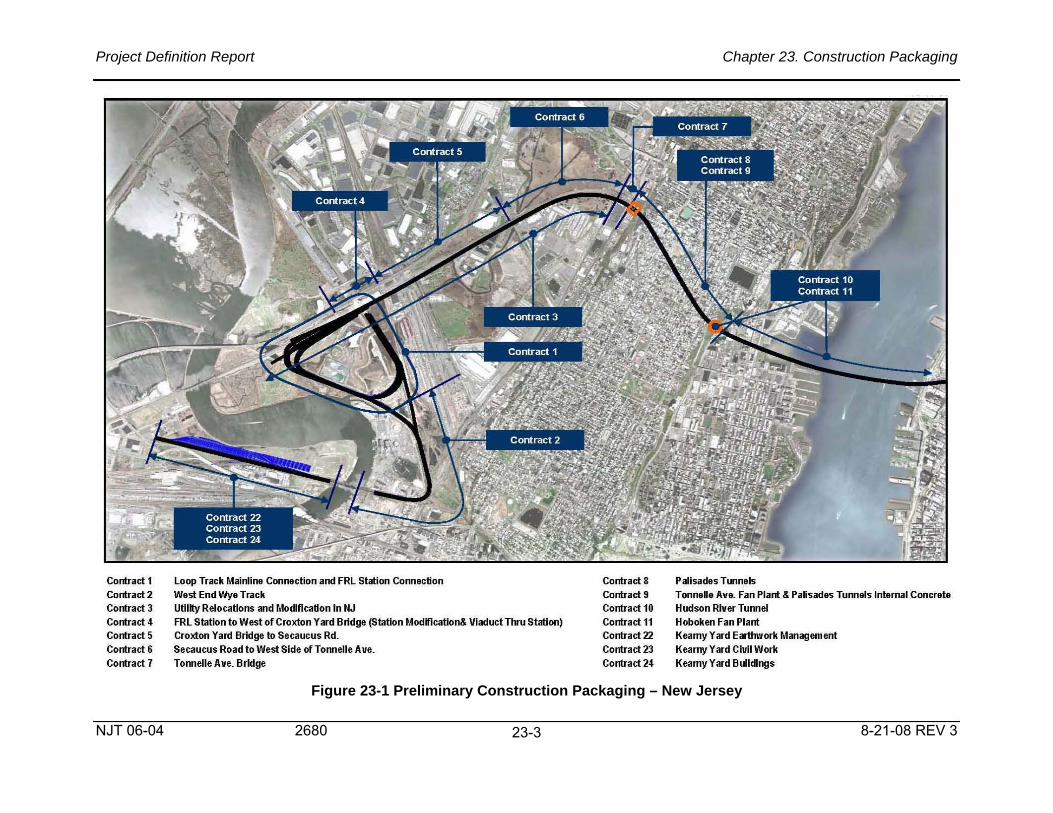
Project Definition Report Chapter 23. Construction Packaging
NJT 06-04 2680 8-21-08 REV 3
23-3
Figure 23-1 Preliminary Construction Packaging – New Jersey
Contract 1
Contract 2
Contract 3
Contract 4
Contract 5
Contract 6
Contract 7
loop Track Mainline Connection and FRl Station Connection
West End Wye Track
Utility Relocations and Mocification in NJ
FRl Station to West of Croxton Yard Bridge (Station Modification& Viaduct Thru Station)
Croxton Yard Bridge to Secaucus Rd.
Secaucus Road to West Side ofTonnelle Ave.
TomelleAve. Bridge
Contract 8
Contract 9
Contract 10
Contract 11
Contract 22
Contract 23
Contract 24
Palisades Tunnels
TonneUe Ave. Fan Plant & Paisades Tunnels Internal Concrete
Hudson River Tunnel
Hoboken Fan Plant
Kearny Yard Earthwork Management
Kearny Yard Civil Work
Kearny Yard Buildings

Project Definition Report Chapter 23. Construction Packaging
NJT 06-04 2680 8-21-08 REV 3
23-4
Figure 23-2. Preliminary Construction Packaging – New York
Co .. ,,","
Co" "dl3
Co .. ,,", " Co....., ...
Ccrt>d 10
...... b,T...,. ..
r..., .\w. 9.11_,1 Eooo"'-',8.C,,,,,,10 _ ... ~'" a,,,,m
r..., Aw." " """ T . .... Avo. """ .....
C, rt_ , 8
C, _ ' O -_. C, rt_21 --"
""" ..... _ "3l"''''''''''' Wf'!E , -.,.
T"".., •• ... .... " .. "'_ ... _ .. ..... """ C, ... , ......... _"'_

Project Definition Report Chapter 23. Construction Packaging
NJT 06-04 2680 8-21-08 REV 3
23-5
Table 23-2. Draft Preliminary Construction Schedule
CO>. ___ ., ... . "".. ... " ,."" .. I I I OI> • .-yR __ a __ ....... " ........ "-,, CH· ..... ___ , , ......... ,Upte_ .. O, ..... ,,,._ .. """.,, C • • • C .... .., .... ' ........... R . ........ C"" • ..,Y ....... ........ ,. __ .• "-,, " .... ' . e H . ___ • R ... __ .. . _A .. ........ e ................... . ___ """'-,, ,. ... " 017 · • ...-" .......... ... ,,- "-,, , OH •• __ .................... ...... . C, ....... _ _.- ... ~" C" •• _ " ........... C ..... , ......... stnx ...... , _ ,.. ... ~., ....... O' • • __ "-_ao ......... _ ,,"- " ... " C11·_ ........ 0 ..... , .......... "' ...... , . .... '"' .... " ,. ..... I CU · .. _ ...... _...-.-R __ ·.CII_'., .. ...,·C ....... _ .,- "-,, c ... """, A_ . ........ _ ............ 0.-. "" ..... " ,,, .. ,, 0' • . ""'"" .......................... _ ",,,_.,, n ... " I I I C .. . _A ......... O ..... , ......... _ . . ..... ~ ... -" .. """ C"". 0' '' ·'''' • , ... SO _ ." ......... ...... 00-.. """', ... . ,,', .... ,. ' ...... , C"·N,,"" .. -."',_ ......... -. , _ .... _" ~-.,
C .. . ,"' •• ,""_, ............... _., ..... '" ... ~" .. ""." C • • • _ ........... .. ' ... " .. ..... CZ. · Tr .. _ · .. "' _ _ .. Tr .... ~ ... ToK"-" DO'T'Kk '" " ... ,. "-,, I I C,, · . ............................. ' ....... " "-,, C".K_y • • ~ __ .... __ .,- .., .. "
I I I I on . K_"'I Y. ' 0"'-" .. "-,, " ..... C" ·K_ . .... _ , ......... ,. ..... C,. ..... , .... _ .......... , .... '.,O_ ... , ..... " .. _., .-......... 0_._
"'-" ,. .... II .............. _ . ......... 0 __ ," ' ...... "-' "'_.lO .. '''-'' .. ""." -
~~~" -.~,, ~ ~'''' ''M,"'' · I ~ ="w.: __ Cllrrent WOfklng Schedule & Contract Packaging
I~ '-'~-'''''''' .-