project description – city of ukiah recycled water project
DESCRIPTION
Project DescriptionTRANSCRIPT
March 2013 0
Project Description – City of Ukiah Recycled Water Project
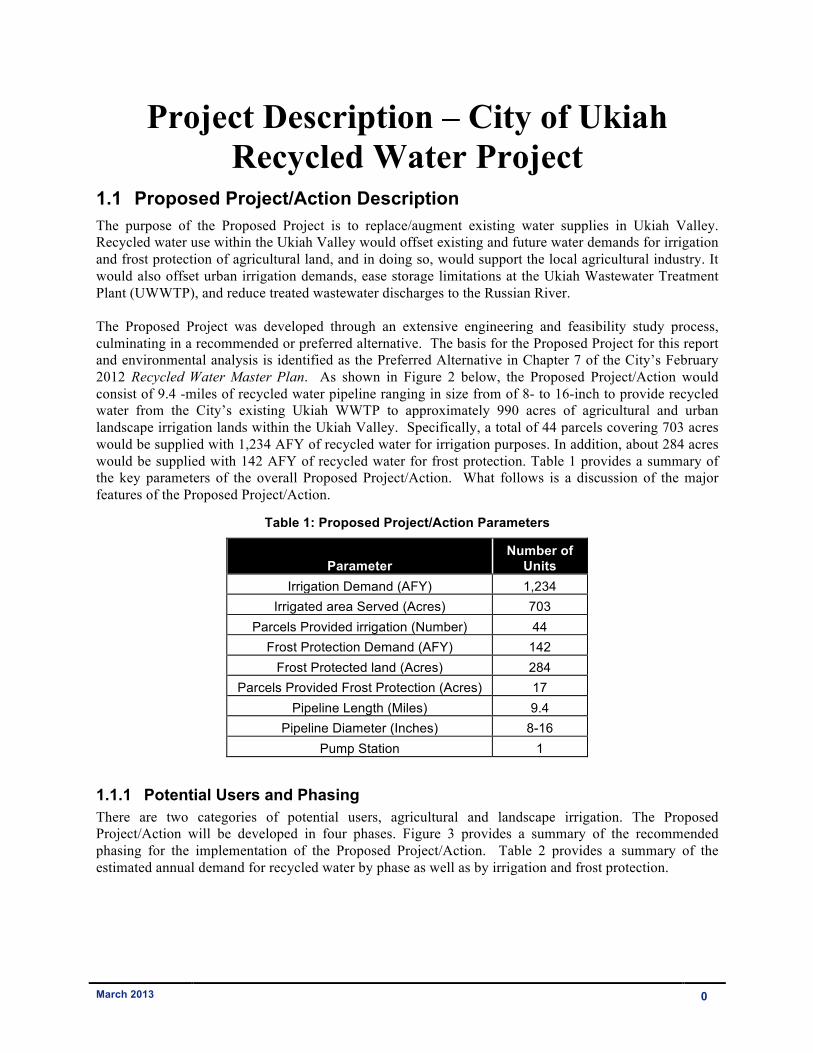
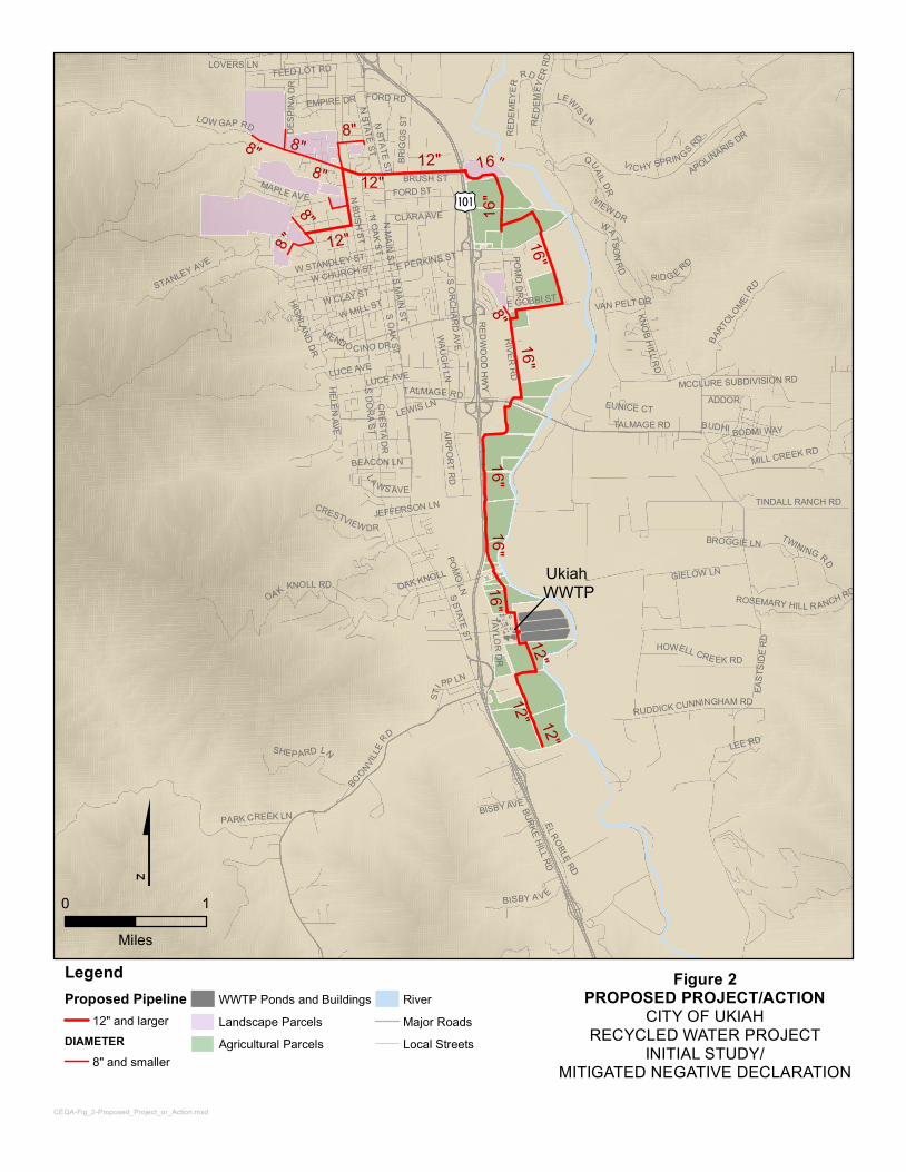
1.1 Proposed Project/Action Description The purpose of the Proposed Project is to replace/augment existing water supplies in Ukiah Valley. Recycled water use within the Ukiah Valley would offset existing and future water demands for irrigation and frost protection of agricultural land, and in doing so, would support the local agricultural industry. It would also offset urban irrigation demands, ease storage limitations at the Ukiah Wastewater Treatment Plant (UWWTP), and reduce treated wastewater discharges to the Russian River. The Proposed Project was developed through an extensive engineering and feasibility study process, culminating in a recommended or preferred alternative. The basis for the Proposed Project for this report and environmental analysis is identified as the Preferred Alternative in Chapter 7 of the City’s February 2012 Recycled Water Master Plan. As shown in Figure 2 below, the Proposed Project/Action would consist of 9.4 -miles of recycled water pipeline ranging in size from of 8- to 16-inch to provide recycled water from the City’s existing Ukiah WWTP to approximately 990 acres of agricultural and urban landscape irrigation lands within the Ukiah Valley. Specifically, a total of 44 parcels covering 703 acres would be supplied with 1,234 AFY of recycled water for irrigation purposes. In addition, about 284 acres would be supplied with 142 AFY of recycled water for frost protection. Table 1 provides a summary of the key parameters of the overall Proposed Project/Action. What follows is a discussion of the major features of the Proposed Project/Action.
Table 1: Proposed Project/Action Parameters
Parameter Number of
Units Irrigation Demand (AFY) 1,234
Irrigated area Served (Acres) 703 Parcels Provided irrigation (Number) 44
Frost Protection Demand (AFY) 142 Frost Protected land (Acres) 284
Parcels Provided Frost Protection (Acres) 17 Pipeline Length (Miles) 9.4
Pipeline Diameter (Inches) 8-16 Pump Station 1
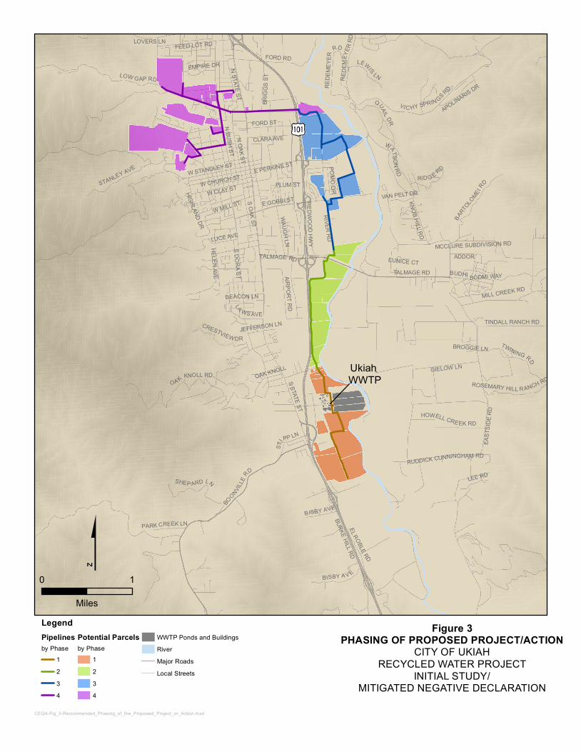
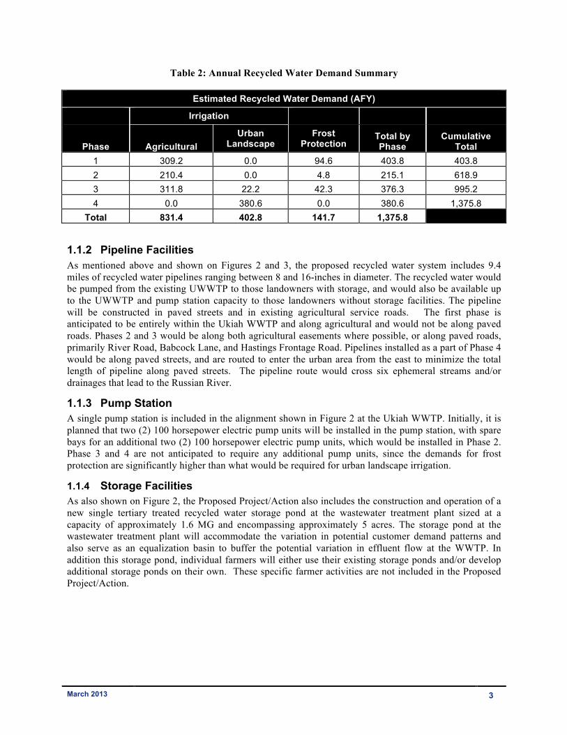
1.1.1 Potential Users and Phasing There are two categories of potential users, agricultural and landscape irrigation. The Proposed Project/Action will be developed in four phases. Figure 3 provides a summary of the recommended phasing for the implementation of the Proposed Project/Action. Table 2 provides a summary of the estimated annual demand for recycled water by phase as well as by irrigation and frost protection.
Ukiah WWTP
IÆ
16"
12"
8"
12"
16"
16"
8"16"
12"
8"8"
16"8"
12"
8"
16"12"
8"
16"
12"
REDWOOD HWY
BOONVILLE
RD
TALMAGE RD
EAST
SIDE R
D
S STATE ST
S DORA ST
LOW GAP RD
N BUSH STN STATE ST
E GOBBI ST
VI C HY SPRIN GS RD
FORD RD
OA K KNOLL RD
BURKE HILL RD
RUDDICK CUNNINGHAM RD
N OAK STS OAK ST
TWINING RD
WATSON RD
GIELOW LN
QUAIL DR
HELEN AVE
W CLAY ST
RIVER RD
W MILL ST
MILL CREEK RD
FEED LOT RD
W STANDLEY ST
STANLEY AVE E PERKINS ST
DESP
INA D
R
FORD ST
BARTO
LOMEI R
D
BISBY A V E
MAPLE AVE
WAUGH LN
BRIG
GS ST
EMPIRE DR
AIRPORT RD
SHEP ARD LN
S ORCHARD AVE
W CHURCH ST
REDE
MEYE
R RD
TAYLOR DRADDOR
LEWIS LN
S MAIN ST
BRUSH ST
CLARA AVE
HOWELL CRE EK RD
KNOB HILL RD
TINDALL RANCH RD
STIPP LN
LA WS AVE
BEACON LN
CRESTVIEW DR
LOVERS LN
BUDHI
VIEW DR
POMO DR
APOLINARIS DR
RIDG E RD
N MAIN ST
LUCE AVE
ROSEMARY HILL RANCH RD
LEE RD
EL ROBLE RD
PARK CREEK LN
VAN PELT DR
JEFFERSON LN
MCCLURE SUBDIVISION RD
OAK KNOLL
MENDO CINO DR
TALMAGE RDEUNICE CT
BODMI WAY
CRESTA DR
POMO LN
HIGHLAND DR
BROGGIE LNN STATE ST
LUCE AVE
BISBY AVE
REDE
MEYE
R RD
LEWIS LN
$0 1
MilesLegendProposed Pipeline
12" and largerDIAMETER
8" and smaller
WWTP Ponds and BuildingsLandscape ParcelsAgricultural Parcels
RiverMajor RoadsLocal Streets
CEQA-Fig_2-Proposed_Project_or_Action.mxd
Figure 2PROPOSED PROJECT/ACTION
CITY OF UKIAHRECYCLED WATER PROJECT
INITIAL STUDY/MITIGATED NEGATIVE DECLARATION
Ukiah WWTP
REDWOOD HWY
BOONVILLE
RD
TALMAGE RD
EAST
SIDE R
D
S STATE ST
S DORA ST
LOW GAP RD
N BUSH STN STATE ST
E GOBBI ST
VI C HY SPRIN GS RD
FORD RD
OA K KNOLL RD
BURKE HILL RD
RUDDICK CUNNINGHAM RD
N OAK STS OAK ST
TWINING RD
WATSON RD
GIELOW LN
QUAIL DR
HELEN AVE
W CLAY ST
RIVER RD
W MILL ST
MILL CREEK RD
FEED LOT RD
W STANDLEY ST
STANLEY AVE E PERKINS ST
FORD ST
BARTO
LOMEI R
D
BISBY A V E
WAUGH LN
BRIG
GS ST
EMPIRE DR
AIRPORT RD
SHEP ARD LN
W CHURCH ST
REDE
MEYE
R RD
ADDOR
LEWIS LN
CLARA AVE
HOWELL CRE EK RD
KNOB HILL RD
TINDALL RANCH RD
STIPP LN
LA WS AVE
BEACON LN
CRESTVIEW DR
LOVERS LN
BUDHI
POMO DR
APOLINARIS DR
RIDG E RD
LUCE AVE
ROSEMARY HILL RANCH RD
LEE RD
EL ROBLE RD
PARK CREEK LN
VAN PELT DR
JEFFERSON LN
MCCLURE SUBDIVISION RD
OAK KNOLL
TALMAGE RD EUNICE CT
BODMI WAY
HIGHLAND DR
BROGGIE LN
PLUM ST
BISBY AVE
RED E
MEYE
R RD
LegendPipelinesby Phase
1234
Potential Parcelsby Phase
1234
WWTP Ponds and BuildingsRiverMajor RoadsLocal Streets
CEQA-Fig_3-Recommended_Phasing_of_the_Proposed_Project_or_Action.mxd
0 1
Miles
Figure 3PHASING OF PROPOSED PROJECT/ACTION
CITY OF UKIAHRECYCLED WATER PROJECT
INITIAL STUDY/MITIGATED NEGATIVE DECLARATION
March 2013 3
Table 2: Annual Recycled Water Demand Summary
Estimated Recycled Water Demand (AFY)
Irrigation
Phase
Agricultural Urban
Landscape Frost
Protection Total by Phase
Cumulative Total
1 309.2 0.0 94.6 403.8 403.8 2 210.4 0.0 4.8 215.1 618.9 3 311.8 22.2 42.3 376.3 995.2 4 0.0 380.6 0.0 380.6 1,375.8
Total 831.4 402.8 141.7 1,375.8
1.1.2 Pipeline Facilities As mentioned above and shown on Figures 2 and 3, the proposed recycled water system includes 9.4 miles of recycled water pipelines ranging between 8 and 16-inches in diameter. The recycled water would be pumped from the existing UWWTP to those landowners with storage, and would also be available up to the UWWTP and pump station capacity to those landowners without storage facilities. The pipeline will be constructed in paved streets and in existing agricultural service roads. The first phase is anticipated to be entirely within the Ukiah WWTP and along agricultural and would not be along paved roads. Phases 2 and 3 would be along both agricultural easements where possible, or along paved roads, primarily River Road, Babcock Lane, and Hastings Frontage Road. Pipelines installed as a part of Phase 4 would be along paved streets, and are routed to enter the urban area from the east to minimize the total length of pipeline along paved streets. The pipeline route would cross six ephemeral streams and/or drainages that lead to the Russian River.
1.1.3 Pump Station A single pump station is included in the alignment shown in Figure 2 at the Ukiah WWTP. Initially, it is planned that two (2) 100 horsepower electric pump units will be installed in the pump station, with spare bays for an additional two (2) 100 horsepower electric pump units, which would be installed in Phase 2. Phase 3 and 4 are not anticipated to require any additional pump units, since the demands for frost protection are significantly higher than what would be required for urban landscape irrigation.
1.1.4 Storage Facilities As also shown on Figure 2, the Proposed Project/Action also includes the construction and operation of a new single tertiary treated recycled water storage pond at the wastewater treatment plant sized at a capacity of approximately 1.6 MG and encompassing approximately 5 acres. The storage pond at the wastewater treatment plant will accommodate the variation in potential customer demand patterns and also serve as an equalization basin to buffer the potential variation in effluent flow at the WWTP. In addition this storage pond, individual farmers will either use their existing storage ponds and/or develop additional storage ponds on their own. These specific farmer activities are not included in the Proposed Project/Action.
March 2013 4
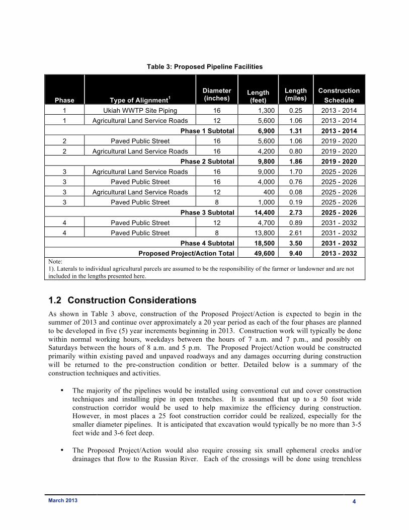
Table 3: Proposed Pipeline Facilities
Phase Type of Alignment1
Diameter (inches)
Length (feet)
Length (miles)
Construction
Schedule 1 Ukiah WWTP Site Piping 16 1,300 0.25 2013 - 2014 1 Agricultural Land Service Roads 12 5,600 1.06 2013 - 2014
Phase 1 Subtotal 6,900 1.31 2013 - 2014 2 Paved Public Street 16 5,600 1.06 2019 - 2020 2 Agricultural Land Service Roads 16 4,200 0.80 2019 - 2020
Phase 2 Subtotal 9,800 1.86 2019 - 2020 3 Agricultural Land Service Roads 16 9,000 1.70 2025 - 2026 3 Paved Public Street 16 4,000 0.76 2025 - 2026 3 Agricultural Land Service Roads 12 400 0.08 2025 - 2026 3 Paved Public Street 8 1,000 0.19 2025 - 2026
Phase 3 Subtotal 14,400 2.73 2025 - 2026 4 Paved Public Street 12 4,700 0.89 2031 - 2032 4 Paved Public Street 8 13,800 2.61 2031 - 2032
Phase 4 Subtotal 18,500 3.50 2031 - 2032 Proposed Project/Action Total 49,600 9.40 2013 - 2032
Note: 1). Laterals to individual agricultural parcels are assumed to be the responsibility of the farmer or landowner and are not included in the lengths presented here.
1.2 Construction Considerations As shown in Table 3 above, construction of the Proposed Project/Action is expected to begin in the summer of 2013 and continue over approximately a 20 year period as each of the four phases are planned to be developed in five (5) year increments beginning in 2013. Construction work will typically be done within normal working hours, weekdays between the hours of 7 a.m. and 7 p.m., and possibly on Saturdays between the hours of 8 a.m. and 5 p.m. The Proposed Project/Action would be constructed primarily within existing paved and unpaved roadways and any damages occurring during construction will be returned to the pre-construction condition or better. Detailed below is a summary of the construction techniques and activities.
• The majority of the pipelines would be installed using conventional cut and cover construction techniques and installing pipe in open trenches. It is assumed that up to a 50 foot wide construction corridor would be used to help maximize the efficiency during construction. However, in most places a 25 foot construction corridor could be realized, especially for the smaller diameter pipelines. It is anticipated that excavation would typically be no more than 3-5 feet wide and 3-6 feet deep.
• The Proposed Project/Action would also require crossing six small ephemeral creeks and/or drainages that flow to the Russian River. Each of the crossings will be done using trenchless
March 2013 5
construction techniques1 and will be done in the dry season and will not occur during rainy weather and during the months between October 15 and through April 1.
• Dewatering of the pipeline as a result of hydrostatic testing during construction as well as any
dewatering as a result of operations and maintenance activities shall be discharged to land and not into any creeks, drainages, or waterways and shall require prior approval from the North Coast Regional Water Quality Control Board (North Coast RWQCB).
Construction activities for this kind of project will typically occur with periodic activity peaks, requiring brief periods of significant effort followed by longer periods of reduced activities. In order to characterize and analyze potential construction impacts, the City has assumed that each phase of the project would be constructed by two (2) crews of 10-15 workers each and would proceed at a rate of approximately 500-1,000 feet per day. However, specific details may change or vary slightly. Staging areas for storage of pipe, construction equipment, and other materials would be placed at locations that would minimize hauling distances and long-term disruption.
Excavation and grading activities would be necessary for construction of the Proposed Project/Action. Excavated materials resulting from site preparation would either be used on-site during construction or disposed of at a fill area authorized by the City. It is not anticipated that any soils would be imported for this project. Additional truck trips would be necessary to deliver materials, equipment, and asphalt-concrete to the site. During peak excavation and earthwork activities, the Proposed Project/Action could generate up to 40 round-trip truck trips per day. In support of these activities and for the assumptions for this document, the types of equipment that may be used at any one time during construction may include, but not limited to:
• Track-mounted excavator
• Backhoe
• Grader
• Crane
• Dozer
• Compactor
• Trencher/boring machine
• End and bottom dump truck
• Front-end loader
• Water truck
• Flat-bed delivery truck
• Forklift
1 Trenchless technology is a type of subsurface construction work that requires few trenches or no continuous trenches. It is a rapidly growing sector of the construction and civil engineering industry. Trenchless technology can be defined as "a family of methods, materials, and equipment capable of being used for the installation of new or replacement or rehabilitation of existing underground infrastructure with minimal disruption to surface traffic, business, and other activities.” Trenchless construction includes such construction methods as tunneling, micro-tunneling (MTM), horizontal directional drilling (HDD) also known as directional boring, pipe ramming (PR), pipe Jacking (PJ), moling, horizontal auger boring (HAB) and other methods for the installation of pipelines and cables below the ground with minimal excavation. Large diameter tunnels such as those constructed by a tunnel boring machine (TBM), and drilling and blasting techniques are larger versions of subsurface construction. The difference between trenchless and other subsurface construction techniques depends upon the size of the passage under construction. Trenchless construction requires considering soil characteristics and the loads applied to the surface. In cases where the soil is sandy, the water table is at shallow depth, or heavy loads like that of urban traffic are expected, the depth of excavation has to be at a depth such that the pressure of the load on the surface does not affect the bore, otherwise there is danger of surface caving in.
March 2013 6
• Compressor/jack hammer
• Asphalt paver & roller
• Street sweeper
It is recognized that details of the construction activities and methods may change slightly as the specific details will be developed during final design and by the selected contractor. However, this description provides sufficient information to base the conclusions to probable environmental impacts associated with construction activities for this kind of project. Therefore, as long as the construction methods are generally consistent with these methods and do not conflict with any of the City’s design standards or established ordinances, and does not create any new potential environmental impacts that are not described within this document, then no new environmental analyses will likely be required for any minor change in construction activities, timing, and/or schedule.
1.3 Compliance with CCR Title 22 and State Board’s Recycled Water Policy
The Proposed Project/Action will be designed and operated in accordance with the applicable requirements of California Code of Regulations (CCR) Title 22 and any other state or local legislation that is currently effective or may become effective as it pertains to recycled water. The State Board adopted a Recycled Water Policy (RW Policy) in 2009 to establish more uniform requirements for water recycling throughout the State and to streamline the permit application process in most instances. As part of that process, the State Board prepared an Initial Study and Mitigated Negative Declaration for the use of recycled water. That document and the environmental analyses contained within are incorporated by reference for this document and Proposed Project/Action. The newly adopted RW Policy includes a mandate that the State increase the use of recycled water over 2002 levels by at least 1,000,000 AFY by 2020 and by at least 2,000,000 AFY by 2030. Also included are goals for storm water reuse, conservation and potable water offsets by recycled water. The onus for achieving these mandates and goals is placed both on recycled water purveyors and potential users. The State Board has designated the Regional Water Quality Control Boards as the regulating entity for the Recycled Water Policy. In this case, the North Coast RWQCB is responsible for permitting recycled water projects throughout the North Coast Area and including Mendocino County. The Proposed Project/Action will be provided high quality unrestricted use tertiary treated recycled water from UWWTP and made available to users within the Ukiah Valley. All irrigation systems will be operated in accordance with the requirements of Title 22 of the CCR, the State Board Recycled Water Policy, and any other local legislation that is effective or may become effective as it pertains to recycled water and any reclamation permits issued by the North Coast RWQCB. Recycled water permits typically require the following:
• Irrigation rates will match the agronomic rates of the plants being irrigated;
• Control of incidental runoff through the proper design of irrigation facilities;
• Implementation of a leak detection program to correct problems within 72 hours or prior to the release of 1,000 gallons whichever occurs first;
• Management of ponds containing recycled water to ensure no discharges; and
• Irrigation will not occur within 50 feet of any domestic supply wells, unless certain conditions have been met as defined in Title 22.
March 2013 7
1.4 Operational Plans The City will enforce an irrigation schedule among its users. The irrigation schedule is assumed as follows:
• Agricultural Irrigation: 6 AM to 6 PM • Landscape Irrigation: 6 PM to 5 AM • Frost Protection Irrigation: Only as required
By irrigating using the above scheduling, peak flows are reduced and pipe sizing is optimized.
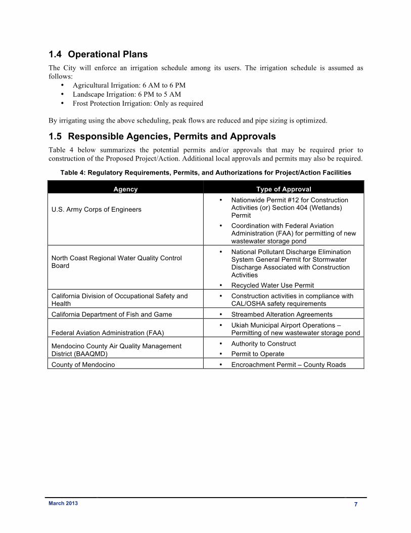
1.5 Responsible Agencies, Permits and Approvals Table 4 below summarizes the potential permits and/or approvals that may be required prior to construction of the Proposed Project/Action. Additional local approvals and permits may also be required.
Table 4: Regulatory Requirements, Permits, and Authorizations for Project/Action Facilities
Agency Type of Approval
U.S. Army Corps of Engineers
• Nationwide Permit #12 for Construction Activities (or) Section 404 (Wetlands) Permit
• Coordination with Federal Aviation Administration (FAA) for permitting of new wastewater storage pond
North Coast Regional Water Quality Control Board
• National Pollutant Discharge Elimination System General Permit for Stormwater Discharge Associated with Construction Activities
• Recycled Water Use Permit California Division of Occupational Safety and Health
• Construction activities in compliance with CAL/OSHA safety requirements
California Department of Fish and Game • Streambed Alteration Agreements
Federal Aviation Administration (FAA) • Ukiah Municipal Airport Operations –
Permitting of new wastewater storage pond
Mendocino County Air Quality Management District (BAAQMD)
• Authority to Construct • Permit to Operate
County of Mendocino • Encroachment Permit – County Roads
March 2013 8
1.6 No Project/Action Alternative Under the No Project/Action Alternative, the City’s Proposed Project/Action would not be constructed. For this analysis, it is assumed that the existing baseline condition and the future No Project/Action condition are the same. That is, the No Project/Action Alternative assumes that none of the Proposed Project/Action facilities would be constructed. Individual farmers may implement and or construct their own water supply or frost protection facilities, but these would be speculative at best and therefore are not considered further as part of this analysis. As a result, the impact description and summary compares the Proposed Project/Action to the existing conditions now and into the future assuming that the City would not construct any facilities to meet the objectives of the Proposed Project/Action. Again, the No Project/Action which assumes that none of the proposed facilities will be constructed now or in the future.