project final report - cordis.europa.eu · developments (diesel engine and turbine) to electricity...
TRANSCRIPT

1
PROJECT FINAL REPORT
Grant Agreement no.: 227303
Project acronym: BIOLIQUIDS-CHP
Project title: Engine and turbine combustion for combined heat and powerproduction
Funding Scheme: Collaborative Project
Project period: 1 January 2009 - 31 December 2011
Coordinator: BTG Biomass Technology Group BV (The Netherlands)
Project website: http://www.bioliquids-chp.eu
Content:
I. Executive summary
II. Summary description of project context and objectives
III. Description of the main S&T results/foregrounds
IV. Potential impact
V. Website and contact details of project partners

2
I. Executive summaryThe Bioliquids-CHP project involved resarch and technology development (RTD) in the following areas: (a)bioliquids upgrading, (b) modifications of prime movers (engines and turbine) to enable efficient use ofbioliquids, (c) pollutant emission reduction, and (d) techno-economic and environmental assessment of thedeveloped systems.
Regarding the research on bioliquids, several batches of biofuels have been produced or purchased,characterised and upgraded. These biofuels included fast pyrolysis oil made from pine and straw, straightvegetable oil (i.e. sunflower oil), and biodiesel. These biofuels were characterised and their ageing behaviourwas monitored. RTD activities focused on upgrading fast pyrolysis oil and on preparing blends or emulsionsfor use in engines/turbine. Different approaches for upgrading fast pyrolysis oil were investigated, including(a) partial dewatering and fractionation, (b) solids removal in a centrifuge, (c) esterification of acidiccomponents with alcohol, and (d) mild hydrodeoxygenation under elevated pressure in the presence ofhydrogen and a catalyst. The production of tertiary blends of fast pyrolysis oil, biodiesel and alcohol was alsoinvestigated.
RTD on engines/turbine initially focused on identifying and implementing modifications that would enablethe use of bioliquids. The engines/turbine considered in the project include two internal combustion (IC)engines, a newly developed external combustion engine and a micro gas turbine (MGT).
BTG ran tests with a Chinese diesel engine (Jiang Dong 1-cylinder 20-kWe), running it on diesel oil,biodiesel, sunflower oil, ethanol and fast pyrolysis oil. They characterised the engine and identified requiredmodifications and suitable materials to manufacture fast pyrolysis oil resistant engine parts. An extensivetesting programme was implemented to understand the combustion behaviour of a range of biofuels and tosteer further development and modifications. A significant achievement was the operation of the engine for 40hrs on pure fast pyrolysis oil without any change of fuel pump or injector, and without significant effect on theflue gas emissions. Similar results are not found in literature.
NAMI modified and extensively tested a Russian diesel engine (YMZ-238M2). It was was assembled on a testbench with a generator, an exhaust gas cleaning system (developed and supplied by BIC), a heat unit and amicroprocessor control system. The exhaust gas cleaning system consists of a syngas reactor and DeNox unit.BIC carried out extensive research to identify and select the most suitable catalysts.
The third project partner working on engines is Encontech. They deevelop and modified a Rankine-cycleengine and a Stirling/Manson-type single-piston external combustion engine. First individual enginecomponents were improved and tested, and later the complete engines. The improvements resulted in thedesign of an unparalleled versatile new heat engine that can use any heat source (including a variety ofbioliquids) from 50 to 1000 oC and is easy scalable in the range 1-1000 kWe per cylinder.
The University of Florence worked onm a micro gas turbine (Garrett GTP 30-67). The turbine was adaptedwith minor modifications for vegetable oil and biodiesel, and characterised using diesel oil. Computationalfluiddynamic simulations were carried out on the combustor to assess major modifications required forbiofuels feeding. This work led to the design, construction and assembly of a modified combustor chamber.Testing with biodiesel and vegetable oil showed a reduction in flue gas emissions, and the modification isconsidered successful. Test runs with fast pyrolysis oil have not yet been successful mainly due to stabilityproblems with the oil feeding pump.
Finally, the project assessed the developed systems in terms of economic and environmental performance, andidentified market opportunities for prospective users of the developed systems. Aston University prepered apartial database of prime movers using bioliquids in CHP mode in partner EU countries, and developed anMS-Excel model for economic evaluation, sensitivity analysis and case studies.
Additional project achievements are the organisation of final dissemination event in Brussels and thepreapration and publication of a comprehensive set of training and education materials on bioliquids.

3
II. Summary description of project context and objectives
Concept and project objectives
Ideas behind the projectThe EC has set a target to increase the share of CHP in the European energy supply from the current 10% to18% in 2010. One of the objectives is to develop distributed energy systems for remote regions with specialemphasis on the integration of renewable energy in these solutions. To date the implementation of small-scale(50 to 1000 kWe), direct biomass-to-electricity CHP-systems has been limited due to:
- Relative high investment and running costs;- Poor reliability and availability, and- Low acceptability by the end-user
The reasons causing these intrinsic problems are manifold, but main causes are:- The presence of contaminants in biomass;- The limited availability of uniform types of biomass;- The non-uniform appearance of biomass, and- Its general low energetic density (especially in terms of GJ/m3), causing huge volumes of biomass
stocks to be stored near the electricity production unit.
A specific pre-treatment technique, fast pyrolysis, is able to address most of these problems. It can produceclean and energy dense liquids from non-uniform, contaminated and fluffy biomass. In addition, the biomassconversion can be de-coupled (in place, time and scale) from power generatin. The heart of the powerproduction system can then be an engine, viz. either a diesel engine or a gas turbine. Unfortunately, the liquidsresulting from fast pyrolysis have rather different characteritics than conventional fossil fuels: they are acidic(pH ~ 3), contain high contents of oxygen and (~25 wt%) water, have low heating content (~18 MJlitre), poorlubrication properties, high ignition temperature (compared to fossil diesel), typically contain fuel boundnitrogen (yielding NOx) and are susceptible for further polymerisation.
The aim of the project “Bioliquids-CHP” was to develop and demonstrate a cost-effective, biomass basedcombined heat and power (CHP) system by using liquids derived from fast pyrolysis as intermediate liquid byeither modifying the engine, upgrading the fuel or a combination thererof.
The project builds further on the ‘best practice’ pre-treatment technology, producing cheap fast pyrolysis oils(or emulsions in vegetable oils), to be used for high-efficiency engines (diesel and gas turbine). Russianengines, though a bit less efficient than the European ones, are more flexible towards fuel quality. However, itmay be very beneficial or even necessary to start from such a robust, and potentially more reliable, engine.Gaps in knowledge to be investigated include the upgrading of fast pyrolysis oils (a.o. de-watering,emulsifying, hydrotreating, catalytic cracking) and effective use in diesel engines and turbines (injector relatedissues, pumping problems, combustion characteristics). Technical as well as non-technical barriers for furtherimplementation will be identified. Experts from Europe and Russia will be involved in the complete chain, intheir own specific part of their expertise, from pyrolysis (upgrading, with / without catalyst), through enginedevelopments (diesel engine and turbine) to electricity production.
Bioliquids-CHP aimed to develop combined heat and power (CHP) system by using liquids derived from fastpyrolysis as intermediate liquid. In this way the biomass conversion is de-coupled from the power production.
Progress beyond the state of the art
Fuel from fast pyrolysis of biomass and other biofuels
The worldwide leaders of processing of biomasses into liquid biofuels through the fast pyrolsyis processinclude Ensyn/Envergent (Canada/USA), BTG Biomass Technology Group BV, (the Netherlands), andMetso/VTT (Finland). Technologies developed can be classified as:

4
- Fluidised bed;- Circulating fluidised bed;- Rotating cone, and- Ablative pyrolysis (cone or disc-types);
Fast pyrolysis is a moderate temperature (ca 500 C) process in which biomass (crops, wood or other organicmaterial) is rapidly heated in the absence of oxygen. As a result, it decomposes to generate mostly vapoursand aerosols and some charcoal. After cooling and condensation a dark brown mobile liquid is formed, with aheating value about half of that of conventional fuel oil. While it is related to the traditional pyrolysisprocesses for making charcoal, fast pyrolysis is an advanced process carefully controlled to give high yields ofliquid. The obtained fuel (about 75% wt of the biomass is transformed into a dense oil) turns out to have a costcomparable, although still higher, to that of fossil fuels. There have been significant advances in the science,technology and applications of pyrolysis liquids in recent years, particularly with respect to applications wherethe crude liquid is increasingly being considered directly for heat and power with minimum upgrading.Compared to the original biomass, fast pyrolysis oil has a significant increase in the energy density on avolumetric basis (5 to 10 MJ/m3 for wood compared to 18-23 MJ/m3 for fast pyrolysis oil).
A typical issue of fast pyrolysis oil for application as an engine fuel is its low heat content, the high ignitiontemperature, its corrosive properties and its low polymerisation temperature (<100 °C) For this reason, fastpyrolysis oil cannot be used in a diesel engine or turbine without some modification to the injection system. Itis also not possible to directly use fast pyrolysis oil as an additive to conventional diesel fuel or to biodieselsince it is not miscible with these liquids.
The approach adopted in Bioliquids-CHP is the modification of the prime mover, upgrading the bioliquids ora combination of both to achieve the economic optimum.
Fast pyrolysis oil upgrading
The lack of availability and consistency of fast pyrolysis oil used to be a serious problem in developing engineapplications, but significant progress was made tackling this issue in the zeroes. Still, fast pyrolysis oil is highin oxygen content (up to 45 wt%) due to mainly aliphatic and aromatic alcohols, ethers, ketones, carboxylicacids and water. These oxygenated compounds (more than 400 different compounds, including acids,alcohols, aldehydes, esters, ketones and aromatic compounds are identified) are responsible for somedeleterious properties of fast pyrolysis oil: high viscosity, non-volatility, poor calorific value, corrosiveness,immiscibility with fossil fuels, thermal instability and trend to polymerisation on storage and transportation.Hence, the pyrolysis oils needs upgrading to reduce the oxygen content. The properties that most negativelyaffect fast pyrolysis oil fuel quality are low heating value, incompatibility with conventional fuels, solidscontents, high viscosity, incomplete volatility and chemical instability. In the Bioliquids project furtherupgrading the fast pyrolysis oil has been explored to simplify its use in prime movers. Critical properties foruse as engine fuel are char content, acidity, poor lubrication and ignition behaviour. Some of the propertiescan be dealt with by modifying the engine (poor lubrication, ignition behaviour), but this may result in veryexpensive modifications. It can be much more effective to improve the pyrolysis oil quality; char can beremoved by using filtration technologies, ignition improvers and stabilizers can be added etc. A directfeedback and feed forward with engine research should result in the optimum fast pyrolysis oil quality.
Options that were investigated include both physical and chemical upgrading. Options for the latter are in-situmeasures (e.g. catalytic cracking using hydrocarbon cracking catalysts) and close-coupled (e.g. partialhydrogenation).
Fast pyrolysis oil engine development
Of all the different fuels to be tested in the project, pyrolysis oil will be the most difficult one to use.The useof latter one in engines/turbines has a lot of technical implications due to different composition, differentphysical, chemical and technical characteristics visa-a-vis diesel oil. The main issues are:

5
Maintenance of power and fuel consumption characteristic on equal level with traditional fuelledengine. It is a problem because fast pyrolysis oil has a modified chemical characteristics and physicalcharacteristics of working body such as low level of calorific value;
Neutralization of toxic components in exhaust gas especially NOx; Rebuilding fuel injection system due to different viscosity-temperature characteristics; Fast pyrolysis oil is more aggressive towards engine materials. This fact requires the replacement of
materials (also plastics) used in fuel storage and fuel injection systems especially in gaskets; The structure and characteristics of fast pyrolysis oils depend on the initial feedstock;
Summarizing, to develop a successful fast pyrolysis oil CHP development is required on both aspects of thechain, the fuel and the engine: in both tasks European and Russian researchers will collaborate:
Fuel:- Upgrading the oil to minimize engine modifications: this upgrading will start with physical upgrading,
but may include chemical upgrading as well (a.o. catalytic processes); the processes may be done in-bed (during pyrolysis), or ex-bed by modifying the liquid oil after production; additionally blends andemulsions will be prepared.
Engine/turbine:- Re-design of the injection system, including alternative materials or coatings, injection needle and
pump elements. Installation of a water jacket around the tip of the injector may be required to cool itas much as possible.
- Preheating of the combustion air inlet up to 130°C through the use of an in-line heater to overcomethe ignition problems or increasing compression ratio;
- Modification of the fuel circulation loop, including the installation of stainless steel mesh filters tocapture the char and the particles formed within the system.
Exhaust abatement in bio-fuel and diesel engines
Of the various pollutants emitted by diesel engines and gas turbines, the emission of carbon containingmolecules and materials (CO, unburned hydrocarbons, soot and particulate) is strongly dependent on thecombustion chamber temperature. When using biofuels, and specifically fast pyrolysis oil, in some cases thelow heat content of the fuel has led to the combustion temperature to be not sufficiently high to obtaincomplete combustion, leading to the emission of pollutants such as CO and particulates. Bioliquids-CHPaimed to address theis problem by proper injection, compression ratios, heat loss reduction etc.
Other typical pollutants emitted by diesel engines are sulphur oxides (mainly SO2) and nitrogen oxides (NOx)and sulphur oxides (mainly SO2). The sulphur content of biofuels is normally negligible, and sulphur oxidesdo not constitute a problem. Nitrogen oxides result either from the presence of nitrogen in the fuel, or from theformation of "prompt" NOx. The relatively low nitrogen content of fast pyrolysis ysis oil combined with theapplication of NOx abating traps technology may result in NOxemission levels that for fast pyrolysis oil to belower than than for diesel oil. Biolioquids-CHP aims to further adopt the NOx abatement in an effort toachieve a near "zero-emission" device which could be used e.g. in conjunction with electrical motors toprovide a near zero pollution hybrid propulsion system. The project considered a NOx storage/reductionsystem that would permit near 100% conversion of NOx over a range of temperatures, and circumvents thecurrent drawback of this system (i.e. sulphur intolerance) due to the absence of sulphur in fast pyrolysis oil.Among others, the reaction of selective catalytic reduction (SCR) of NOx by injecting small amounts ofreducer gas in the engine exhausts was investigsted. Candidate reducers include unsaturated hydrocarbons,propane, primary diesel fuel, ammonia, urea and syngas (CO/H2 mixture).

Overall project stategy
The aim of the project “Bioliquids-CHP” was to develop and demonstrate a cost-effective, biomass basedcombined heat and power (CHP) system by using liquids derived from fast pyrolysis as intermediate liquid byeither modifying engines, upgrading and/or blending biofuels or a combination thererof. Commercialapplication of such units is expected in the capacity range of 50-1000 kWe . The project focuses on three mainissues i) the development of the engine, ii) fuel preparation, and iii) emission control (NOx). Each of theactivities have been implemented in a separate work package. Eventually, the different options have beenevaluated in an economic, technical and environmental assessment study.
Project structure
The overall structure of the project is illustrated in Figure 1.
WP 6 (UAS):Assessments
WP 1+2 (BTG):Bio-liquids prod.and upgrading WP4 (NAMI):
Engines
WP 0 (BTG):Coordination
WP 5 (BIC):Emission reduction
WP3 (UFL);Micro GasTurbines
F
6
igure 1: Graphical representation of work packages and their interrelation

Description of the main S&T results/foregrounds
WP1: Bioliquids selection, production & characterisationThe objectives of this WP were to select different types of bioliquids and to produce fast pyrolysis oil fromdifferent sources in sufficient quantities as required. All bioliquids used in the project were characterised.
Selection & production of bioliquidsA range of different bioliquids was evaluated for use in prime movers. The ‘primary’ bioliquids are biodiesel,pure vegetable oil and fast pyrolysis oil. The biodiesel (FAME) was produced from rapeseed and purchased inGermany. The vegetable oil used was sunflower oil that was purchased in Italy. The fast pyrolysis oil wasproduced in BTG’s pilot plant (Figure 2). Two batches of pine derived pyrolysis oil (in total 1,500 kg) and onebatch of straw derived oil (~100 kg) were produced and used for the experiments. Additionally, a batch offast pyrolysis oil was produced from wheat straw. ‘Secondary’ (bio-)liquids used are bio-ethanol and butanol.These were used in a few cases to improve fast pyrolysis oil properties. Additionally, bio-ethanol was addedas a rinsing fuel in BTG’s diesel engine when switching fuels from diesel to fast pyrolysis oil and vice versa.
Properties of bioliquidsFor all bioliquids a range of properties were determined and these are summarised in Table I. Fast pyrolysisoil differs significantly from (rapeseed-derived) biodiesel and sunflower oil with respect to acidity (pH),tendency to carbon formation (MCRT), water content and density. For use in prime movers relevant propertiesare e.g. the heating value, Cetane number and viscosity. The viscosity of liquids can be lowered by preheatingthe fuel as illustrated in Figure 4 and Figure 5. For use in stationary diesel engines, the viscosity of the fuelshould be below 17-20 cSt.
Another important property of any bioliquid -but in pasuitable method to study this aspect is the change inwas monitored for the different bioliquids during a couthe viscosity was measured on a regular basis. The oboil was negligible. The ageing behaviour of fast pyrolAgeing can be kept within acceptable limits as long asError! Reference source not found.. The relation betcan be described with the following Arrhenius like equ
ݒ∆ ݏ =ݕݐݏ 3.6 ∗ 1
Figure 2: Pyrolysis pilot plant at BTG Ft
igure 3: Kinematic viscosity of biofuels as a function of the
7
rticular for fast pyrolysis oil- is its ageing behaviour. Akinematic viscosity over time. This change in viscosityple of months. The bioliquids were stored at 40 °C andserved change in viscosity for biodiesel and sunflowerysis oil is a strong function of the storage temperature.the temperature is kept below 40-50 °C as illustrated inween aging of fast pyrolysis oil and storage temperatureation:
0ଵଵ ோ ,ହସଽ (%/day)
emperature.

Table 1: Properties of the primary liquids
Property unit Biodiesel SunflowerOil
Fast Pyrolysis Oil Bio-EthanolA
Bio-Butanol
Pine I Pine II StrawC wt% 77.3 77.5 42.8 45.5 48.6 50.9 64.9H wt% 12.1 11.9 7.6 5.8 7.9 12.7 13.5N wt% <0.01 <0.01 <0.01 <0.01 0.4 <0.01 <0.01O (Balance) wt% 10.6 10.6 49.6 48.8 43.0 36.4 21.6Water content wt% - - 21.7 25.4 21.2 - -Ash content wt% - - 0.047 0.016 0.053 - -Solids content wt% - - 0.27 0.04 1.28 - -Density kg/m3 871 910 1,207 1,170 1,184 780 810LHV MJ/kg 27.1 37.4 17.1 16.1 20.1 27.1 34.4HHV MJ/kg 40.2 40.0 18.7 18.8 21.9 30 37.4LHV MJ/Ltr 32.7 34.0 20.6 18.8 23.8 21.4 27.9pH - - - 2.85 2.85 3.3 - -MCRT wt% - 0,06 - 15.1 - - -Kinematic viscosity- 20°C cSt 6.9 80.7 65.1 - 80.4 1.5 3.6
-40 °C cSt 4.2 40.6 20.0 13.0 21.2 1.1 2.8Cetane Number - ~60 ~40 ~10-25 - - ~8-15 17
Contaminants ppmCl <10 <10 <10 n.d. 240 n.d n.d.Fe 1.3 2.2 11 11Mg 3.7 4.4 6 37Mn <1 <1 1.2 12Ca 1.3 5.2 15 135Sr <1 <1 <1 1.3Sn <1 >1 <1 2.6Si 2.0 42.9 6.6 83P <1 2.3 <1 15Al 5.3 6.6 35 48K 14.4 13.4 21 254Na 18.4 17.8 20 22
Note A: 4wt% of Beraid (Cetane improver) is added to the fuel;
WP2: Bioliquids upgrading & blendingFast pyrolysis oil (sometimes also refered to as bio-oil) is ctested. It has been tested in engines in the past with limited srequiring a pilot fuel or additives for successful engine comadverse effects on engine components due to its acidic charapossible to upgrade fast pyrolysis oil with conventional fuels
Ftfuntion of the storage temperature
igure 5: Change in viscosity as a function of storage
Figure 4: Change in viscosity of fast pyrolysis oil as a8
onsidered the most difficult fuel of the bioliquidsuccess. Fast pyrolysis oil has poor combustibility,bustion. In addition, fast pyrolysis oil could havecteristics and the presence of particulates. It is notas they are immiscible.
ime for different fuels at 40C

A series of tests were designed to attempt the upgrading of fast pyrolysis oil to enable or simplify itsapplication in prime movers. The main objective of WP2 is the production ofcharacteristics through i) physical treatment, ii) chemical treatment, iii) preparation of emulsions usingdifferent bioliquids or iv) preparation of blends using different bioliquids.
Physical treatment
Removing water from fast pyrolysis oil
Fast pyrolysis oil from biomass typically contains about 25wt%water. This high water content reduces the energy content valueand has a negative impact on ignition properties. Therefore,partial removal of water may be advantageous. Inpicture is shown of the film evaporator used in the laboratory.Typical throughput is 1-2 kg/hr of oil, a pressure of 100mbar, and a temperature of 50-60 °C. Inwater leads to an increase in oil viscosity (seeageing becomes more severe. For low water contents (< 10 wt%it is hardly possible to obtain sufficient lower viscosity at anacceptable fuel preheat temperature. Adding ethanol to thedewatered fast pyrolysis oil can offset these detrimental impacts.
Figure 7: Kinematic viscosity as function of the water content in
Reducing solids content in fast pyrolysis oil
Untreated fast pyrolysis oil can have a high solids content. When applied in prime movers this can easito plugging and wear of e.g. fuel pump and injector. Devices tested on different scales on their suitability forsolids removal include a self-cleaning scraper filter, a batch centrifuge, a selfcentrifugal filter separator. The best results (high solids removal, easy operation and limited oil loss) wereobtained with the self-cleaning centrifuge (see
A series of tests were designed to attempt the upgrading of fast pyrolysis oil to enable or simplify itsapplication in prime movers. The main objective of WP2 is the production of biofuels with improved fuelcharacteristics through i) physical treatment, ii) chemical treatment, iii) preparation of emulsions usingdifferent bioliquids or iv) preparation of blends using different bioliquids.
pyrolysis oil
yrolysis oil from biomass typically contains about 25wt%water. This high water content reduces the energy content valueand has a negative impact on ignition properties. Therefore,partial removal of water may be advantageous. In Figure 6 apicture is shown of the film evaporator used in the laboratory.
2 kg/hr of oil, a pressure of 100-20060 °C. Inconveniently, removing
water leads to an increase in oil viscosity (see Figure 7) and oilageing becomes more severe. For low water contents (< 10 wt%)it is hardly possible to obtain sufficient lower viscosity at anacceptable fuel preheat temperature. Adding ethanol to the
pyrolysis oil can offset these detrimental impacts.
Kinematic viscosity as function of the water content in fast pyrolysis oil and for different temperatures
pyrolysis oil
pyrolysis oil can have a high solids content. When applied in prime movers this can easito plugging and wear of e.g. fuel pump and injector. Devices tested on different scales on their suitability for
cleaning scraper filter, a batch centrifuge, a self-cleaning centrifuge, and aor. The best results (high solids removal, easy operation and limited oil loss) were
cleaning centrifuge (see Figure 8).
Figure 6: Lab-scale film evaporator toremove water from
9
A series of tests were designed to attempt the upgrading of fast pyrolysis oil to enable or simplify itsbiofuels with improved fuel
characteristics through i) physical treatment, ii) chemical treatment, iii) preparation of emulsions using
pyrolysis oil and for different temperatures.
pyrolysis oil can have a high solids content. When applied in prime movers this can easily leadto plugging and wear of e.g. fuel pump and injector. Devices tested on different scales on their suitability for
cleaning centrifuge, and aor. The best results (high solids removal, easy operation and limited oil loss) were
scale film evaporator toremove water from fast pyrolysis oil

Figure
Flowrate
[kg/h]
1 246
2 171
3 180
4 n.d.
Chemical treatment
Through chemical treatment specificchanged. Two approaches were explored, i.e. mild hydrotreatment andreactive distillation with an alcohol.
Mild hydrotreatment of fast pyrolysis oil
Mild hydrotreatment implies catalytic treatment ofthe presence of hydrogen at elevated pressure. The resultingpyrolysis oil has reduced acidity, increased energy content andimproved ignition and thermal stability properties. The hydrotreatmentis performed in BTG’s hydrogenation unitpatented catalyst developed jointly with the Boreskov Institute ofCatalysis (BIC) and Rijksuniversiteit Groningen (RUG). The operatingpressure is typically around 200 bar, andto 350 °C. The hydrogen consumption is about 10fuel produced is referred to as “Mild-
Reactive distillation of fast pyrolysis oil
Fast pyrolysis oil was treated with an alcohol in a reactive distillaprocess and in the presence of a catalyst. The resultinghas a lower acidity and water content, and a higher energy content. Theoperating pressure is typically 300 mbar. The best results were obtainedat a reactor temperature of 85 °C, with butanol as reactant and applyinga solid acid catalyst (Nafion SEC13). During the process the butanolreacts with the acids in the fast pyrolysis oil to form esters.removed via the vapour phase. This fuel is referred to as “POBesides butanol also octanol and glycerol have been tested. Withglycerol no useful results were obtained. In Table
Figure 8: GEA Self-cleaning centrifuge
Table 2: Results with GEA centrifuge
Flowrate
[kg/h]
Cleaning freq.
[minutes]
Ash content
[wt.%]
246 8 0.06
171 15 0.033
180 15 0.041
n.d. 5 0.019
Through chemical treatment specific fast pyrolysis oil properties can bechanged. Two approaches were explored, i.e. mild hydrotreatment and
pyrolysis oil
Mild hydrotreatment implies catalytic treatment of fast pyrolysis oil inthe presence of hydrogen at elevated pressure. The resulting fastpyrolysis oil has reduced acidity, increased energy content and
stability properties. The hydrotreatmentis performed in BTG’s hydrogenation unit (Figure 9), applying apatented catalyst developed jointly with the Boreskov Institute ofCatalysis (BIC) and Rijksuniversiteit Groningen (RUG). The operatingpressure is typically around 200 bar, and reactor temperatures can be upto 350 °C. The hydrogen consumption is about 10-20 gram/kg oil. The
-HDO”.
pyrolysis oil
yrolysis oil was treated with an alcohol in a reactive distillationprocess and in the presence of a catalyst. The resulting fast pyrolysis oilhas a lower acidity and water content, and a higher energy content. Theoperating pressure is typically 300 mbar. The best results were obtained
°C, with butanol as reactant and applyinga solid acid catalyst (Nafion SEC13). During the process the butanol
pyrolysis oil to form esters. Water isremoved via the vapour phase. This fuel is referred to as “PO-Ester”.Besides butanol also octanol and glycerol have been tested. Withglycerol no useful results were obtained. In Table 3 some further information on these tests are given.
Figure 9: HDO test unit at BTG
10
some further information on these tests are given.
HDO test unit at BTG

11
Table 3: Process conditions for reactive distillation / esterification of fast pyrolysis oil
Alcohol/amount (g)Bio-oil
amount (g)Catalyst (g) T (°C)
TAN (mgKOH/g)
Viscosity(40 °C)
Sample 1 1-butanol / 12.9 100.2 2.95 100-110 50.5 61.4
Sample 2 1-butanol / 12.7 103.0 2.95 80-85 43.0 127.5
Sample 3 1-octanol / 12.0 101.6 3.03 80-85 26.1 160.9
Emulsification and blending
Emulsification
Emulsification of fast purolysis oil with diesel fuel was investigated as an economic solution for improvingand upgrading fast purolysis oil properties. The emulsion of biodiesel in fast purolysis oil was preparedstarting from a batches of EN14214-compliant biodiesel supplied by Novaol (Italy) and 25 liters of fastpyrolysis oil from fast pyrolysis of pine by BTG (The Netherland). Atlox 4912 was selected as theemulsifying agent (surfactant) after the screening phase among almost 40 polar and apolar surfactants.
The procedure for the emulsification was as follow:1. The surfactant Atlox 4912 was dissolved in biodiesel at about 45˚C; 2. The biodiesel/surfactant solution was cooled down to room temperature;3. The solution is emulsified with BCO under vortex mixing for 5 minutes at room temperature.
The final composition of the emulsion was: bio-oil 94.75 wt.%, surfactant 0.25 wt.%, biodiesel 5 wt%. Oncethe emulsification process was completed, a dense phase, referred to as “cream”, floated at the top of the mainphase, i.e. the emulsion, which could be easily removed by mechanical means.
Blending
A series of tests was designed to blend fast pyrolysis oil with biodiesel in the presence of an alcohol in orderto overcome some of the disadvantages of use of either fuel by itself. Fast pyrolysis oil is immiscible withbiodiesel, however, the presence of an alcohol allows the blend to stabilize and form a single homogeneousphase. The alcohols used as co-solvent were ethanol, 1-butanol or 2-propanol. As the alcohol is bio derived,the use of a 100% renewable liquid fuel in engines could take advantage of incentives potentially available forrenewable power.
Experiments were carried out in which variable proportions of the three components were planned and testedin order to build three phase diagrams (one per alcohol used), with the objective to identify the boundarybetween a homogeneous one phase blend and a multiple phase blend. Tests were designed to cover a widespectrum of proportions for all three alcohols, using the sample homogeneity (visual aspect) after 48h as themain criteria.
The tests were documented through the characterization of selected homogenous samples, the estimation ofparticular properties such as heating value and elemental composition for all samples, while at the same timephotographic evidence was gathered for all samples. Three-phase charts were prepared for each of thealcohols highlighting the area in which the blend is a homogeneous one-phase liquid (see Figure 10). Blendsusing butanol showed the largest area of stable one-phase blends, followed by mixtures using propanol whileblends containing ethanol showed the smallest homogeneous one-phase area. A new development wasachieved during the upgrading through blending as the concept proved to be successful.

12
The most important feature of this achievement is the ability to, within the component limitations, tailor theblend to target the end user requirements if necessary, e.g. heating value, viscosity or flash point. A number ofhomogeneous one-phase blends were tested for stability, viscosity, pH and density. A patent has been appliedfor, for the blending concept and the concept was nominated among the best 10 ideas in the Cleantech OpenUK 2011 competition.
Figure 10: Three phase chart for bio-oil/biodiesel/butanol blends, showing homogenous blend andphase separation
Properties of upgraded bioliquidsIn Table 4 the properties of upgraded fast pyrolysis oils are presented. As starting point the first batch of fastpyrolysis oil (Pine I) was used. Clear differences can be observed for e.g. heating value, water content,viscosity and carbon residue. In all cases the fuel remained acidic.
Table 4: Properties of modified fast pyrolysis oils
Property unit Emulsion PO-Ester Mild HDO BlendC wt% 44.4 58.4 67.6 54.5H wt% 6.4 7.4 8.1 8.7N wt% <0.1 <0.1 <0.1 <0.1O (balance) wt% 49.2 34.2 24.2 36.8Water content wt% 22.8 6.6 6.7 17.2Ash content wt% 0.298 0.018 0.017 0.01Solids content wt% - - - 0.02Density kg/m3 1,198 1,158 1,106 998LHV, calculated MJ/kg 16.3 24.0 27.0 23.8LHV MJ/ltr 19.5 28.0 29.9 23.8pH - 2.1 3.0 3.1 3.0MCRT wt% 18 20 11 8Kinematic viscosity (40 °C) cSt 36 115 149 7Acid number mg KOH/g - 22 - 53Carbonyl number mg BuO/g 133 112 10 -
Which of the investigated upgrading techniques is the best depends on the end-use of the pyrolysis oil. In CHPapplication (engine or turbine) a low solid, homogeneous fuel is required. Filtration/centrifuging will alwaysbe required to obtain and guarantee sufficient low solids content. Solids removal has a limited effect onpyrolysis oil price (< 5% change). Depending on the feedstock used for the PO some dewatering may berequired. This is e.g. the case with straw-derived pyrolysis oil. Generally, the chemical upgraded pyrolysis oilfuels, emulsions and blends showed a somewhat improved combustion behaviour in the engine compared tocrude pyrolysis oil (see WP4). However, in all cases the pyrolysis oil remained acidic and a full retrofit of theengine is still required. In parallel it was demonstrated that the engine could run on pure pyrolysis oil (filtratednot chemical treated). Therefore, it is concluded that chemical upgrading the oil does not improve the overalleconomics.
Single phase blendMultiple phase blend
1-butanol Biodiesel
Bio-oil from fast pyrolysis

13
WP3: Micro Gas Turbine
The main objective of WP3 was to develop micro gas turbine components (and eventually turbines) that aretolerant towards the bio-liquids mixtures and the upgraded fast pyrolysis oils. The engines should beapplicable for CHP systems in a power range of 50 to a few hundred kWe.
Modification of the micro gas turbineA Garrett GTP-3067 micro gas turbine (MGT) was selected based on three main requirements: robustness,simple design and silo-shaped combustion chamber. A test rig, comprising the engine itself, auxiliary andinstruments, was built. The performance of the MGT was compared with a reference turbine i.e. a CapstoneC30 MGT modified to run on straight vegetable oil as feedstock.
A parametric study was carried out on the Garrett turbine to assess the necessary modifications to the fuel lineto make it capable of working on a variety of biofuels, i.e. vegetable oil, biodiesel, bio-ethanol and fastpyrolysis oil. With the aid of RE-CORD personnel, a detailed survey of the scientific literature on the possiblematerial compatibility issues related with the use of fast pyrolysis oil and first generation biofuels was carriedout to select the proper materials for the pump. RE-CORD also assisted with analytical determinations onbiofuels and material selection. A gear pump with AISI 316 shafts and body and PEEK gears was selected andinstalled on the MGT fuel line circuit because these materials were found to be among the most toleranttoward fast pyrolysis oil aggressiveness, and the pump could supply the required head and flow rate. Testingof the pumps with “conventional” biofuels and diesel was successfully passed.
A preliminary set of adaptations was made to the engine, and a test campaign carried out with “conventional”biofuels (bio-ethanol, biodiesel, vegetable oil). The test campaign yielded sufficient understanding of theproblems that could arise operating the MGT on fast pyrolysis oil, and the necessary modifications werecarried out on the test rig (see Figure 3 for the final test rig layout).
The modification of the MGT combustion chamber, needed to accommodate fast pyrolysis oil burning, wasassisted by 0 and 3D computational fluid dynamics (CFD) simulations carried out on both cold and reactiveenvironment; see Figure 11 and Figure 12 for illustrations of the output from these simulations. The newcombustor (Figure 14) features several modifications compared to the original one, e.g. a different airrepartition among combustion zone, less air entrance in the primary zone, a diminished jet penetrations, andincreased flame temperature and temperature homogeneity.
After these preliminary tests, it was decided to proceed to fast pyrolysis oil testing. A specific switchprocedure was studied and adopted in order to avoid an abrupt modification of fuel flow rate and combustionconditions inside the combustion chamber. When a mixture of ethanol (80%) and fast pyrolysis oil (20%) wasfed to the MGT, the engine could be operated for approx. 3 minutes; during this interval, it was necessary toincrease the pump flow rate because the engine could not maintain a constant rotational speed, and after threeminutes a sudden decrease of the engine rotational speed happened, causing the shut-down of the system. Itwas tried to recover the full speed state by re-operating the start-up procedure five times, but it was notpossible to operate the pump. An inspection of the pump was then carried out, and it was found that thegraphite buckles that sustain the gears during normal operation were eroded (see Figure 15), causing the stopof the pump. No damages were found on the PEEK gears, nor on the AISI 316 shaft (see Figure 16). Thepump was sent back to the supplier, repaired, mounted again on the test rig and tested, but showed the samebehaviour.
Figure 11: temperature field of the original combustor(same scale of figure 2).
Figure 12: temperature field of the original combustor(same scale of figure 2).

Figure 13: Layout of the MGT with highlighted the newmeasurement point and the tanks for biofuels testing.
Figure 15: Damages on the graphite buckles on the leftside of the NAX10 pump.
Testing of the micro gas turbineTesting of the MGT was varied out with the help of RETagliaferri company mechanical workshop in Scarperia. In the first test campaign, tcharacterized when running with diesel and thenthe respective performance (e.g. hourly consumption, fuel injection pressure and temperature, exhaust gasestemperature, O2, CO and NOx concentrations at the stack) compared to the baseline reference values on diesel.The effect of fuel preheating on CO concentration in the exhaust was investigated between 80°C and 120°C.Biodiesel preheating largely effects the CO concentration: at 80°C a redu37% compared to diesel at 20°C, and 51% compared to biodiesel at 20°C could be measured. To avoid engineshut-down, vegetable oil and vegetable oil/biodiesel mixtures had to be preheated at 120with vegetable oil was only possible preheating at 120°C and with a minimum load of 5 kW; preheatedvegetable oil generates CO emissions very similar to diesel at 20°C. CO emission of mixtures were foundmidway between and vegetable oil and biodiesel atbe always of few ppm for all fuels.Figure 18. During this test phase it was determined that the rethe original one when fed with diesel, leading to an almost sixconfirming that the combustion conditions were largely improved; conversely, NOx increased twoFigure 19 and Figure 20.
Evaluation and assessmentThe experiences gained during this project led to the a remarkable advancement in the knowof bioliquids in micro gas turbine; the basic project of a retrofit package was carried out, including a guide forthe selection of proper materials and the development of a newly designed combustor, that can be potentiallyadapted to a wide range of existing engines that are characterizechamber.
ayout of the MGT with highlighted the newmeasurement point and the tanks for biofuels testing.
Figure 14: Layout of the modified
Damages on the graphite buckles on the left Figure 16: PEEK gear and shaftwithstood contact with fast pyrolysis oil perfectly.
of the MGT was varied out with the help of RE-CORD personnel at both the Montepaldi premise andcompany mechanical workshop in Scarperia. In the first test campaign, t
characterized when running with diesel and then tested with vegetable oil, biodiesel and their mixtures, andthe respective performance (e.g. hourly consumption, fuel injection pressure and temperature, exhaust gases
ntrations at the stack) compared to the baseline reference values on diesel.The effect of fuel preheating on CO concentration in the exhaust was investigated between 80°C and 120°C.Biodiesel preheating largely effects the CO concentration: at 80°C a reduction of CO concentration of approx.37% compared to diesel at 20°C, and 51% compared to biodiesel at 20°C could be measured. To avoid engine
down, vegetable oil and vegetable oil/biodiesel mixtures had to be preheated at 120etable oil was only possible preheating at 120°C and with a minimum load of 5 kW; preheated
vegetable oil generates CO emissions very similar to diesel at 20°C. CO emission of mixtures were foundmidway between and vegetable oil and biodiesel at the same preheating temperature;
Some results with the original combustor are reported in. During this test phase it was determined that the re-designed combustor performed far better that
the original one when fed with diesel, leading to an almost six-fold reduction of the CO concentrations,confirming that the combustion conditions were largely improved; conversely, NOx increased two
The experiences gained during this project led to the a remarkable advancement in the knowe; the basic project of a retrofit package was carried out, including a guide for
the selection of proper materials and the development of a newly designed combustor, that can be potentiallyadapted to a wide range of existing engines that are characterized by the same geometry of the combustion
14
ayout of the modified combustor.
PEEK gear and shaft. Both elementspyrolysis oil perfectly.
CORD personnel at both the Montepaldi premise andcompany mechanical workshop in Scarperia. In the first test campaign, the MGT was first
tested with vegetable oil, biodiesel and their mixtures, andthe respective performance (e.g. hourly consumption, fuel injection pressure and temperature, exhaust gases
ntrations at the stack) compared to the baseline reference values on diesel.The effect of fuel preheating on CO concentration in the exhaust was investigated between 80°C and 120°C.
ction of CO concentration of approx.37% compared to diesel at 20°C, and 51% compared to biodiesel at 20°C could be measured. To avoid engine
down, vegetable oil and vegetable oil/biodiesel mixtures had to be preheated at 120-130°C. Operationetable oil was only possible preheating at 120°C and with a minimum load of 5 kW; preheated
vegetable oil generates CO emissions very similar to diesel at 20°C. CO emission of mixtures were foundNOx emission resulted to
Some results with the original combustor are reported in Figure 17 anddesigned combustor performed far better that
reduction of the CO concentrations,confirming that the combustion conditions were largely improved; conversely, NOx increased two-fold, see
The experiences gained during this project led to the a remarkable advancement in the know-how on the usee; the basic project of a retrofit package was carried out, including a guide for
the selection of proper materials and the development of a newly designed combustor, that can be potentiallyd by the same geometry of the combustion

Figure 17: CO concentration in the exhaust (referred to15 vol.% oxygen) for diesel oil (at 20 and 120°C) andbiodiesel (at 20, 80, 100, 120°C).
Figure 19: CO concentration (referred to 15 vol.%oxygen) in the exhaust for the modified combuswith diesel (light blue line); for comparison arereported the previous measured values.
WP4: Diesel Engines
The main objective of WP4 was to develop engine components (and eventually engines) that are toleranttowards the bio-liquids mixtures and the upgraded fastCHP systems in a power range of 50
To attain this challenging objective three different approaches that are in line with the expertise of theparticipants were implemented:
Modification of a conventional diesel engine to enable fuelling ofoil derived liquids.
Development of a CHP system based on a conventional diesel engine operated on mixtures ofpyrolysis oil derived liquids and diesel fuel.
Development of new energy efficient external combustion engines capable of operation on a varietyof bioliquids, including fast pyrolysis liquids.
The developments were led by BTG, NAMI and ECT (Encontech) respectively.
0
500
1000
1500
2000
2500
0 5 10
CO
conce
ntr
ati
on
[pp
m]
@15%
O2
net power output [kWel]
Diesel_20°C diesel_120°C
BD_20°C BD_80°C
BD_100°C BD_120°C
: CO concentration in the exhaust (referred to(at 20 and 120°C) and
Figure 18: CO concentration in the exhaust (referredto 15 vol.% oxygen) for pure vegatmixtures with biodiesel.
: CO concentration (referred to 15 vol.%oxygen) in the exhaust for the modified combustor fedwith diesel (light blue line); for comparison arereported the previous measured values.
Figure 20: NOx concentration (referred to 15 vol.%oxygen) in the exhaust for the modified combustor fedwith diesel (light blue line); for comparison arereported the previous measured values.
The main objective of WP4 was to develop engine components (and eventually engines) that are tolerantliquids mixtures and the upgraded fast pyrolysis oils. The engines should be applicable for
CHP systems in a power range of 50 – 1000 kWe.
To attain this challenging objective three different approaches that are in line with the expertise of the
ional diesel engine to enable fuelling of fast pyrolysis oil and
Development of a CHP system based on a conventional diesel engine operated on mixtures ofpyrolysis oil derived liquids and diesel fuel.
f new energy efficient external combustion engines capable of operation on a varietypyrolysis liquids.
The developments were led by BTG, NAMI and ECT (Encontech) respectively.
15 20
0
500
1000
1500
2000
2500
0 5
CO
con
centr
ati
on
[ppm
]@
15%
O2
net power outp
VO 100 % VO 75 %
VO 50 % VO 25 %
BD 100% Diesel
0
10
20
30
40
50
60
70
0 5 10 15
ppm
Electrical Load
NOx @15%O
15
: CO concentration in the exhaust (referredto 15 vol.% oxygen) for pure vegatable oil and several
concentration (referred to 15 vol.%oxygen) in the exhaust for the modified combustor fed
; for comparison arereported the previous measured values.
The main objective of WP4 was to develop engine components (and eventually engines) that are tolerantoils. The engines should be applicable for
To attain this challenging objective three different approaches that are in line with the expertise of the
pyrolysis oil and fast pyrolysis
Development of a CHP system based on a conventional diesel engine operated on mixtures of fast
f new energy efficient external combustion engines capable of operation on a variety
10 15 20tput [kWel]
15 20 25 30
Load (kW)
15%O2Diesel_T_amb
Diesel_120°C
Biodiesel_T_amb
BD_120°C
VO_120°C
Diesel_Nuovo_Liner

16
Modification of a conventional CI-engine to enable fuelling of fast pyrolysis oil (FPO) and FPO-derivedliquids (BTG)
Introduction.Diesel engines are internal combustion engines operated on the basis of a Diesel (compression ignition, CI)cycle. In this type of volumetric machines, finely pulverized combustible is injected inside the cylinder or anadjacent chamber, where it vaporizes and self-ignites, due to the temperature of the compressed air. Due to thecharacteristics of the combustion process, diesel engines are more tolerant towards a lower quality fuel, aswell as generally more efficient, when compared to gasoline engines.
Diesel-cycle engines have a wide range of applications; and are widely used for commercial freight,construction, heavy truck, agricultural machines, and infrastructure maintenance. The diesel-cycle’s inherentcombustion efficiency advantage over Otto-cycle engines (powered by gasoline), and diesel fuel’s dominantposition in the refined petroleum products market, make this kind of engines a key technology for theintroduction of liquid biofuels in the energy market.
Modification required.In a conventional compression-ignition engine liquid fuels can be converted efficiently into electric power.When fast pyrolysis oil is used, various engine modifications are required, due to the rather specificcharacteristics of this fuel.
Fast pyrolysis oil is acidic and therefore all piping and devices in contact with fast pyrolysis oil should becorrosion resistant. The fuel injection pump and fuel injector should be made from surface treatedstainless steel;
Fast pyrolysis oil typically contains 20-25 wt% water, lubrication is poor and small particles (< 20 µm)might be present. This may cause severe abrasive wear, in particular in the injector, and therefore the fastpyrolysis oil needs to be filtrated;
The viscosity of fast pyrolysis oil is higher than that of mineral diesel, and strongly depends on watercontent and temperature. Reducing the water content would further increase viscosity. To achievesufficient low viscosities (< 17 cSt) the fuels can be preheated;
Fast pyrolysis oil is sensitive to re-polymerisation, in particular, if temperature rises above 50-60 °C. Re-polymerisation may result in small particles in the oil and increased viscosity;
Fast pyrolysis oil is more difficult to ignite, and higher temperatures are required at the end of thecompression stage to achieve complete combustion. This is achieved by preheating the incoming air.Alternatively, the compression ratio can be increased. Additionally, the fuel injection timing can beadapted;
The energy content of fast pyrolysis oil is about half that of mineral diesel, and therefore for the sameoutput double the amount of fuel needs to be injected.
Engine test facilityBTG converted a standard Jiang Dong CI-engine to allow it to run on fast pyrolysis oils (and all other biofuelsconsidered). Three fuel vessels are installed containing engine start-up fuel (mineral diesel), rinsing fluid (e.g.ethanol) and test fuel, respectively (see Figure 21). The test fuel can be preheated to about 100 °C, and theincoming air can be controlled at temperatures between 20 and 220 °C. Two pistons are available, onecorresponding to a compression ratio of 17.6 and another one to a ratio of 22.4. A generator connected to theengine converts the mechanical power into electricity. Up to six electrical heaters can be switched on to varythe electrical load in 1 kWe steps between 1 kWe and 12 kWe.
The original fuel pump and fuel injector were replaced by a complete, dedicated stainless steel fuel injectionsystem. BTG constructed both parts in-house, as suitable suppliers for such parts could not be identified.

At several positions in the engine temperatures and pressures can be measured and logged. A fast responsepressure indicator and oscilloscope areapplied to measure fuel injection pressure.Two analysers are installed, measuring gascomponents , and soot and rotational speedrespectively. The actual power output ismeasured with a smart power analyser.
ResultsTo overcome the poor ignition properties offast pyrolysis oil a higher temperature isrequired in the engine cylinder when thefuel is injected. This can be achieved byincreasing the air inlet temperature or thecompression ratio. For fast pyrolysis oilfuelling an air inlet temperature of around100°C is required at a compression ratio of17.6. By increasing this ratio to 22.4 the airinlet temperature can be reduced with 40°C.
Figure 22: Fuel consumption and CO emissions as a function of time on stream for
Adapting the fuel injecting timing may have some advantages formeans that more time is available to ignite the fuel and to achieve complete combustion. It appears that theoptimal timing for engine operation onbiodiesel. Early injection of fast pyrolysis oil resulted in severe operational problems. For ethanol it wasadvantageous to inject fuel earlier.
In duration tests, the CO emissions andwas operated for a period of 40 hours, spread over several days (a couple of hours each daythe first hours of operation the engine performance imfurther development real long duration testing will be important.
All bioliquids described before (sunflower oil and biodiesel, neat and treatedemulsifications) were tested in the diesel engine. Generally, the upgraded liquids were easier to igniteresulting in lower CO emissions and higher NOless pronounced . The liquids remain acidic, and thus a modified injection system will be required in all cases
At several positions in the engine temperatures and pressures can be measured and logged. A fast responsepressure indicator and oscilloscope areapplied to measure fuel injection pressure.Two analysers are installed, measuring gas
and rotational speedrespectively. The actual power output ismeasured with a smart power analyser.
To overcome the poor ignition properties ofpyrolysis oil a higher temperature is
required in the engine cylinder when theThis can be achieved by
increasing the air inlet temperature or thepyrolysis oil
fuelling an air inlet temperature of around100°C is required at a compression ratio of17.6. By increasing this ratio to 22.4 the air
rature can be reduced with 40°C.
Fuel consumption and CO emissions as a function of time on stream for fast
Adapting the fuel injecting timing may have some advantages for fast pyrolysis oil fuelling. Early injectionmeans that more time is available to ignite the fuel and to achieve complete combustion. It appears that theoptimal timing for engine operation on fast pyrolysis oil is very comparable to that of sunflower oil and
pyrolysis oil resulted in severe operational problems. For ethanol it was
In duration tests, the CO emissions and fast pyrolysis oil fuel consumption were monitored when the enginewas operated for a period of 40 hours, spread over several days (a couple of hours each daythe first hours of operation the engine performance improved somewhat and then it stabilized. Obviously, forfurther development real long duration testing will be important.
All bioliquids described before (sunflower oil and biodiesel, neat and treated fast pyrolysis oil, blends andtested in the diesel engine. Generally, the upgraded liquids were easier to ignite
resulting in lower CO emissions and higher NOx (see Figure 23), whereas the effect on overall efficiency was. The liquids remain acidic, and thus a modified injection system will be required in all cases
Figure 21: Engine test facility
17
At several positions in the engine temperatures and pressures can be measured and logged. A fast response
fast pyrolysis oil fuelling
pyrolysis oil fuelling. Early injectionmeans that more time is available to ignite the fuel and to achieve complete combustion. It appears that the
pyrolysis oil is very comparable to that of sunflower oil andpyrolysis oil resulted in severe operational problems. For ethanol it was
pyrolysis oil fuel consumption were monitored when the enginewas operated for a period of 40 hours, spread over several days (a couple of hours each day, see Figure 22). In
proved somewhat and then it stabilized. Obviously, for
pyrolysis oil, blends andtested in the diesel engine. Generally, the upgraded liquids were easier to ignite
on overall efficiency was. The liquids remain acidic, and thus a modified injection system will be required in all cases.
18
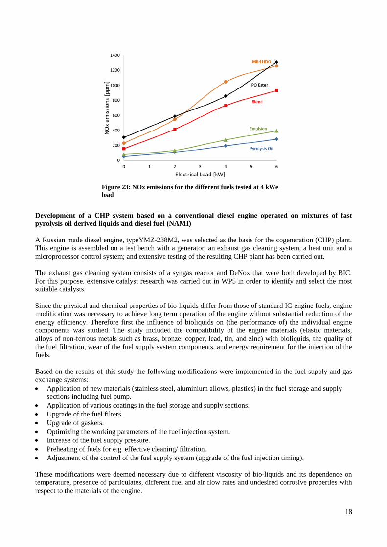
Development of a CHP system based on a conventional diesel engine operated on mixtures of fastpyrolysis oil derived liquids and diesel fuel (NAMI)
A Russian made diesel engine, typeYMZ-238M2, was selected as the basis for the cogeneration (CHP) plant.This engine is assembled on a test bench with a generator, an exhaust gas cleaning system, a heat unit and amicroprocessor control system; and extensive testing of the resulting CHP plant has been carried out.
The exhaust gas cleaning system consists of a syngas reactor and DeNox that were both developed by BIC.For this purpose, extensive catalyst research was carried out in WP5 in order to identify and select the mostsuitable catalysts.
Since the physical and chemical properties of bio-liquids differ from those of standard IC-engine fuels, enginemodification was necessary to achieve long term operation of the engine without substantial reduction of theenergy efficiency. Therefore first the influence of bioliquids on (the performance of) the individual enginecomponents was studied. The study included the compatibility of the engine materials (elastic materials,alloys of non-ferrous metals such as brass, bronze, copper, lead, tin, and zinc) with bioliquids, the quality ofthe fuel filtration, wear of the fuel supply system components, and energy requirement for the injection of thefuels.
Based on the results of this study the following modifications were implemented in the fuel supply and gasexchange systems: Application of new materials (stainless steel, aluminium allows, plastics) in the fuel storage and supply
sections including fuel pump. Application of various coatings in the fuel storage and supply sections. Upgrade of the fuel filters. Upgrade of gaskets. Optimizing the working parameters of the fuel injection system. Increase of the fuel supply pressure. Preheating of fuels for e.g. effective cleaning/ filtration. Adjustment of the control of the fuel supply system (upgrade of the fuel injection timing).
These modifications were deemed necessary due to different viscosity of bio-liquids and its dependence ontemperature, presence of particulates, different fuel and air flow rates and undesired corrosive properties withrespect to the materials of the engine.
Figure 23: NOx emissions for the different fuels tested at 4 kWeload
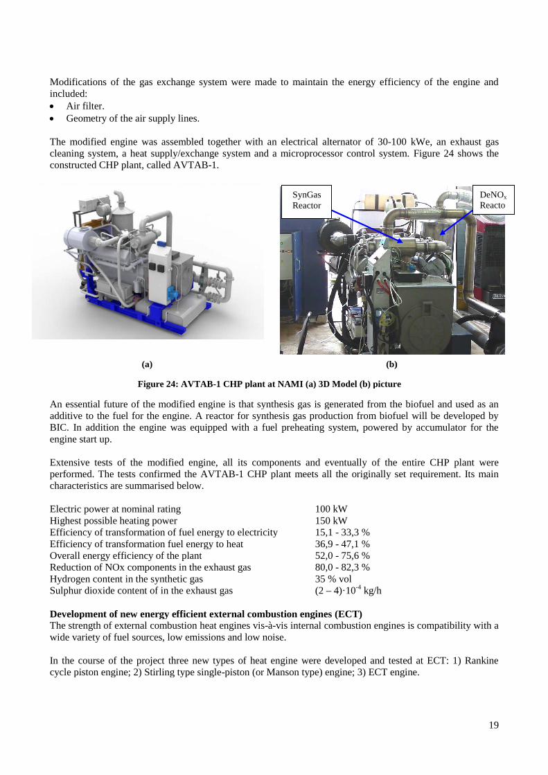
Modifications of the gas exchange system were made to maintain the energy efficiency of the engine andincluded: Air filter. Geometry of the air supply lines.
The modified engine was assembled together with acleaning system, a heat supply/exchange system and a microprocessor control system.constructed CHP plant, called AVTAB
(a)
Figure 24: AVTAB
An essential future of the modified engine is that synthesis gas is generated from the biofuel and usedadditive to the fuel for the engine. A reactor for synthesis gas production from biofuel will be developBIC. In addition the engine was equipped with a fuel preheating system, powered by accumulator fengine start up.
Extensive tests of the modified engine,performed. The tests confirmed the AVTABcharacteristics are summarised below.
Electric power at nominal ratingHighest possible heating powerEfficiency of transformation of fuel energy to electricityEfficiency of transformation fuel energy to heatOverall energy efficiency of the plantReduction of NOx components in the exhaust gasHydrogen content in the synthetic gasSulphur dioxide content of in the exhaust gas
Development of new energy efficient external combustion enginesThe strength of external combustion heat engines viswide variety of fuel sources, low emissions and low noise.
In the course of the project three new types of heat engine were developed and tested at ECT: 1) Racycle piston engine; 2) Stirling type single
Modifications of the gas exchange system were made to maintain the energy efficiency of the engine and
Geometry of the air supply lines.
The modified engine was assembled together with an electrical alternator of 30-100 kWe, ancleaning system, a heat supply/exchange system and a microprocessor control system.constructed CHP plant, called AVTAB-1.
(b)
: AVTAB-1 CHP plant at NAMI (a) 3D Model (b) picture
An essential future of the modified engine is that synthesis gas is generated from the biofuel and usedfuel for the engine. A reactor for synthesis gas production from biofuel will be develop
BIC. In addition the engine was equipped with a fuel preheating system, powered by accumulator f
Extensive tests of the modified engine, all its components and eventually of the entire CHP plantThe tests confirmed the AVTAB-1 CHP plant meets all the originally set requirement. Its
characteristics are summarised below.
100 kW150 kW
Efficiency of transformation of fuel energy to electricity 15,1 - 33,3 %Efficiency of transformation fuel energy to heat 36,9 - 47,1 %Overall energy efficiency of the plant 52,0 - 75,6 %
components in the exhaust gas 80,0 - 82,3 %Hydrogen content in the synthetic gas 35 % volSulphur dioxide content of in the exhaust gas (2 – 4)·10-4 kg/h
Development of new energy efficient external combustion engines (ECT)l combustion heat engines vis-à-vis internal combustion engines is compatibility
wide variety of fuel sources, low emissions and low noise.
In the course of the project three new types of heat engine were developed and tested at ECT: 1) Racle piston engine; 2) Stirling type single-piston (or Manson type) engine; 3) ECT engine.
SynGasReactor
Modifications of the gas exchange system were made to maintain the energy efficiency of the engine and
100 kWe, an exhaust gascleaning system, a heat supply/exchange system and a microprocessor control system. Figure 24 shows the
(b)
1 CHP plant at NAMI (a) 3D Model (b) picture
An essential future of the modified engine is that synthesis gas is generated from the biofuel and usedfuel for the engine. A reactor for synthesis gas production from biofuel will be develop
BIC. In addition the engine was equipped with a fuel preheating system, powered by accumulator f
all its components and eventually of the entire CHP plant1 CHP plant meets all the originally set requirement. Its
vis internal combustion engines is compatibility
In the course of the project three new types of heat engine were developed and tested at ECT: 1) Rapiston (or Manson type) engine; 3) ECT engine.
DeNOx
as aned byor the
nkine
as aned byor the
weremain
with a
nkine
19
as aned byor the
weremain
with a
nkine
Reactor
The results obtained show that the engines each is an effective alternatives and supplements to the establishedmethods of energy conversion - internal combustion en
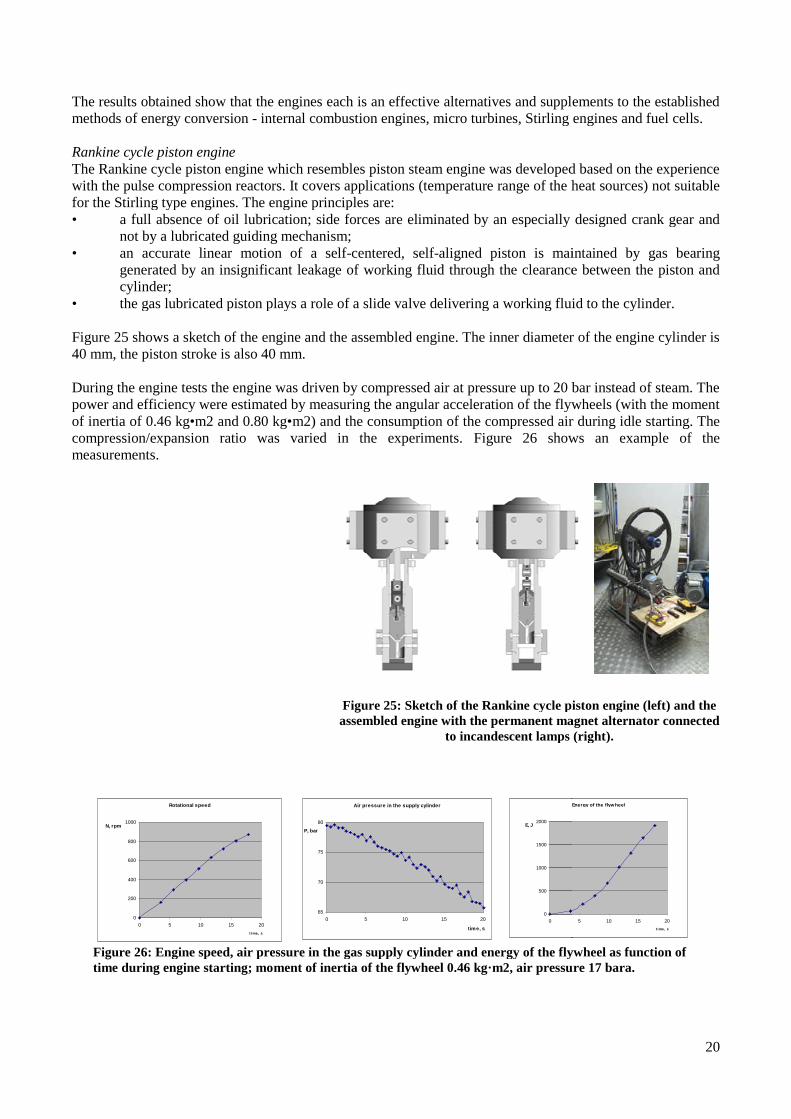
Rankine cycle piston engineThe Rankine cycle piston engine which resembles piston steam engine was developed based on the experiencewith the pulse compression reactors. It covers applications (temfor the Stirling type engines. The engine principles are:• a full absence of oil lubrication; side forces are eliminated by an especially designed crank gear and
not by a lubricated guiding mechanism;• an accurate linear motion of a self
generated by an insignificant leakage of working fluid through the clearance between the piston andcylinder;
• the gas lubricated piston plays a role of a slide va
Figure 25 shows a sketch of the engine and the assembled engine. The inner diameter of the engine cylinder is40 mm, the piston stroke is also 40 mm.
During the engine tests the engine was driven by compressed air at pressure up to 20 bar instead of steam. Thepower and efficiency were estimated by measuring the angular acceleration of the flywheels (with the momentof inertia of 0.46 kg•m2 and 0.80 kg•compression/expansion ratio was varied in the experiments.measurements.
Figure 26: Engine speed, air pressure in the gas supply cylinder and energy of the flywheel as function oftime during engine starting; moment of inertia of the flywheel 0.46 kg·m2, air pressure 17 bara.
Rotational speed
0
200
400
600
800
1000
0 5 10 15 20
t ime, s
N, rpm
The results obtained show that the engines each is an effective alternatives and supplements to the establishedinternal combustion engines, micro turbines, Stirling engines and fuel cells.
The Rankine cycle piston engine which resembles piston steam engine was developed based on the experiencewith the pulse compression reactors. It covers applications (temperature range of the heat sources) not suitablefor the Stirling type engines. The engine principles are:
a full absence of oil lubrication; side forces are eliminated by an especially designed crank gear andnot by a lubricated guiding mechanism;
accurate linear motion of a self-centered, self-aligned piston is maintained by gas bearinggenerated by an insignificant leakage of working fluid through the clearance between the piston and
the gas lubricated piston plays a role of a slide valve delivering a working fluid to the cylinder.
shows a sketch of the engine and the assembled engine. The inner diameter of the engine cylinder is40 mm, the piston stroke is also 40 mm.
During the engine tests the engine was driven by compressed air at pressure up to 20 bar instead of steam. Thepower and efficiency were estimated by measuring the angular acceleration of the flywheels (with the momentof inertia of 0.46 kg•m2 and 0.80 kg•m2) and the consumption of the compressed air during idle starting. Thecompression/expansion ratio was varied in the experiments. Figure 26 shows an example of the
: Engine speed, air pressure in the gas supply cylinder and energy of the flywheel as function oftime during engine starting; moment of inertia of the flywheel 0.46 kg·m2, air pressure 17 bara.
Air pressure in the supply cylinder
65
70
75
80
0 5 10 15 20
time, s
P, bar
Energy of the flyw heel
0
500
1000
1500
2000
0
E, J
Figure 25: Sketch of the Rankine cycle piston engine (left) and theassembled engine with the permanent magnet alternator connected
to incandescent lamps (right).
20
The results obtained show that the engines each is an effective alternatives and supplements to the establishedgines, micro turbines, Stirling engines and fuel cells.
The Rankine cycle piston engine which resembles piston steam engine was developed based on the experienceperature range of the heat sources) not suitable
a full absence of oil lubrication; side forces are eliminated by an especially designed crank gear and
aligned piston is maintained by gas bearinggenerated by an insignificant leakage of working fluid through the clearance between the piston and
lve delivering a working fluid to the cylinder.
shows a sketch of the engine and the assembled engine. The inner diameter of the engine cylinder is
During the engine tests the engine was driven by compressed air at pressure up to 20 bar instead of steam. Thepower and efficiency were estimated by measuring the angular acceleration of the flywheels (with the moment
m2) and the consumption of the compressed air during idle starting. Theshows an example of the
: Engine speed, air pressure in the gas supply cylinder and energy of the flywheel as function oftime during engine starting; moment of inertia of the flywheel 0.46 kg·m2, air pressure 17 bara.
Energy of the flyw heel
5 10 15 20
t ime, s
Sketch of the Rankine cycle piston engine (left) and theassembled engine with the permanent magnet alternator connected
to incandescent lamps (right).

For the tests at higher driving pressure the enginealternator (Wind Blue Power DC-500) with electrical power up to 15 kW.
Based on the results obtained it can be predicted that without any optimization the current engine can generateabout 5 kW by the use of hot steam at the pressure of about 100 bar. By making larger cylinders e.g. 120 mmdiameter, and without further optimization, the power will have to increase to 45 kW per cylinder. This meansthat very compact multi-cylinder engine fuelled with bioelectrical power in the range of 50 –
Stirling/Manson type single piston external combustion engine
Novel external combustion engine was proposed. It can be viewed as a Stirling engine utilizing Mansoncycle1. The fundamental difference compared with Stirling engines is that the engine has only one moving part(piston). It can be called Stirling type Single Piston External Combustion (SSPEC) engine. Another importantfeature of the SSPEC engine is that the
Figure 27 explains the principle of the engine. A – Maximum amount of the working fluid in the cylinder; the pressure in the cylinder is higher than the
pressure outside the cylinder, the piston/displacer moves up and more working fluid is coming to the hotpart of the cylinder; the heating of the working fluid leads to the pressure increase which occurs fasterthan the pressure decrease due to the increase of the free volume in the cylinder.
B - The valve opens, the pressure of the working fluid equalizes with the pressure outside theand the amount of the working fluid in the cylinder becomes minimum.
C - The piston/displacer starts to move down; this stage is similar to stage A, the difference is that now theamount of the working fluid in the cylinder is minimal and the prepressure outside it.
D - The valve opens, the pressure of the working fluid equalizes with the pressure outside the cylinder,and the amount of the working fluid in the cylinder becomes maximum.
Figure 27displacer with regenerator, 35 - crank gear with alternator; 6
1Manson A.D. A Novel Hot-air Engine, http://www.stirlingengines.org.uk/work/cyc2.html
For the tests at higher driving pressure the engine (crank gear) was connected to a permanent magnet500) with electrical power up to 15 kW.
Based on the results obtained it can be predicted that without any optimization the current engine can generatef hot steam at the pressure of about 100 bar. By making larger cylinders e.g. 120 mm
diameter, and without further optimization, the power will have to increase to 45 kW per cylinder. This meanscylinder engine fuelled with bio-liquids can be made for mini
1000 kW.
Stirling/Manson type single piston external combustion engine
Novel external combustion engine was proposed. It can be viewed as a Stirling engine utilizing MansonThe fundamental difference compared with Stirling engines is that the engine has only one moving part
(piston). It can be called Stirling type Single Piston External Combustion (SSPEC) engine. Another importantfeature of the SSPEC engine is that the amount of the working fluid changes in the cycle.
explains the principle of the engine. In operation four stages can be distinguished. ThMaximum amount of the working fluid in the cylinder; the pressure in the cylinder is higher than the
pressure outside the cylinder, the piston/displacer moves up and more working fluid is coming to the hoting of the working fluid leads to the pressure increase which occurs faster
than the pressure decrease due to the increase of the free volume in the cylinder.The valve opens, the pressure of the working fluid equalizes with the pressure outside the
and the amount of the working fluid in the cylinder becomes minimum.The piston/displacer starts to move down; this stage is similar to stage A, the difference is that now the
amount of the working fluid in the cylinder is minimal and the pressure in the cylinder is less than the
The valve opens, the pressure of the working fluid equalizes with the pressure outside the cylinder,and the amount of the working fluid in the cylinder becomes maximum.
27: SSPEC engine principle: 1 –cylinder, 2 -displacer with regenerator, 3 – piston, 4 - piston seal,
crank gear with alternator; 6 - valve.
http://www.stirlingengines.org.uk/work/cyc2.html
21
(crank gear) was connected to a permanent magnet
Based on the results obtained it can be predicted that without any optimization the current engine can generatef hot steam at the pressure of about 100 bar. By making larger cylinders e.g. 120 mm
diameter, and without further optimization, the power will have to increase to 45 kW per cylinder. This meansids can be made for mini-CHP systems with
Novel external combustion engine was proposed. It can be viewed as a Stirling engine utilizing MansonThe fundamental difference compared with Stirling engines is that the engine has only one moving part
(piston). It can be called Stirling type Single Piston External Combustion (SSPEC) engine. Another importantamount of the working fluid changes in the cycle.
In operation four stages can be distinguished. These stages are:Maximum amount of the working fluid in the cylinder; the pressure in the cylinder is higher than the
pressure outside the cylinder, the piston/displacer moves up and more working fluid is coming to the hoting of the working fluid leads to the pressure increase which occurs faster
The valve opens, the pressure of the working fluid equalizes with the pressure outside the cylinder,
The piston/displacer starts to move down; this stage is similar to stage A, the difference is that now thessure in the cylinder is less than the
The valve opens, the pressure of the working fluid equalizes with the pressure outside the cylinder,
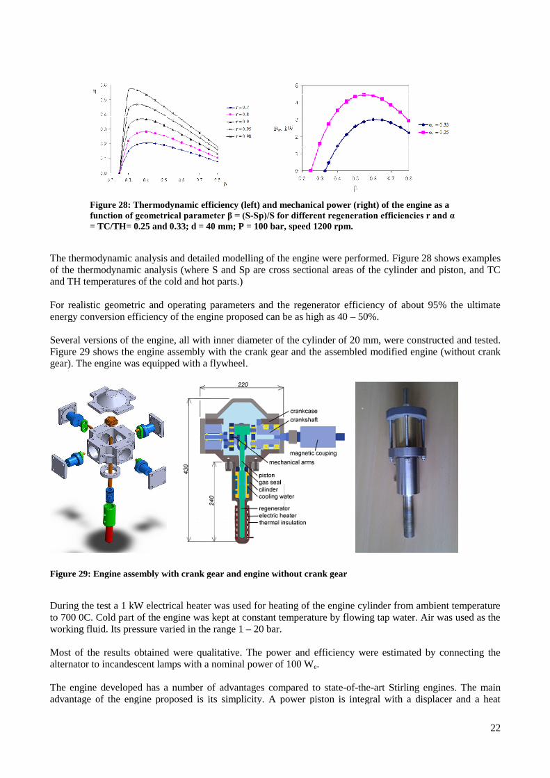
Figure 28: Thermodynamic efficiency (left) andfunction of geometrical parameter β = (S= TC/TH= 0.25 and 0.33; d = 40 mm; P = 100 bar, speed 1200 rpm.
The thermodynamic analysis and detailed modelling of the engine were performed.of the thermodynamic analysis (where S and Sp are cross sectional areas of the cylinder and piston, and TCand TH temperatures of the cold and hot parts.)
For realistic geometric and operating parameters and the regenerator efficiency of about 95% the ultimateenergy conversion efficiency of the engine proposed can be as high as 40
Several versions of the engine, all with inner diameter of the cylinder of 20 mm, were coFigure 29 shows the engine assembly with the crank gear and the assembledgear). The engine was equipped with a flywheel
Figure 29: Engine assembly with crank gear and engine without crank gear
During the test a 1 kW electrical heater was used for heating of the engine cylinder from ambient temperatureto 700 0C. Cold part of the engine was kept at constant temperature by flowing tap water. Air was used as theworking fluid. Its pressure varied in the range 1
Most of the results obtained were qualitative. The power and efficiency were estimated by connecting thealternator to incandescent lamps with a nominal power of 100 W
The engine developed has a number of advantages compared tadvantage of the engine proposed is its simplicity. A power piston is integral with a displacer and a heat
Thermodynamic efficiency (left) and mechanical power (right) of the engine as afunction of geometrical parameter β = (S-Sp)/S for different regeneration efficiencies r and α = TC/TH= 0.25 and 0.33; d = 40 mm; P = 100 bar, speed 1200 rpm.
The thermodynamic analysis and detailed modelling of the engine were performed. Figureof the thermodynamic analysis (where S and Sp are cross sectional areas of the cylinder and piston, and TCand TH temperatures of the cold and hot parts.)
ric and operating parameters and the regenerator efficiency of about 95% the ultimateenergy conversion efficiency of the engine proposed can be as high as 40 – 50%.
Several versions of the engine, all with inner diameter of the cylinder of 20 mm, were coshows the engine assembly with the crank gear and the assembled modified
uipped with a flywheel.
Engine assembly with crank gear and engine without crank gear
During the test a 1 kW electrical heater was used for heating of the engine cylinder from ambient temperatureto 700 0C. Cold part of the engine was kept at constant temperature by flowing tap water. Air was used as the
n the range 1 – 20 bar.
Most of the results obtained were qualitative. The power and efficiency were estimated by connecting thealternator to incandescent lamps with a nominal power of 100 We.
The engine developed has a number of advantages compared to state-of-the-art Stirling engines. The mainadvantage of the engine proposed is its simplicity. A power piston is integral with a displacer and a heat
22
mechanical power (right) of the engine as aSp)/S for different regeneration efficiencies r and α
Figure 28 shows examplesof the thermodynamic analysis (where S and Sp are cross sectional areas of the cylinder and piston, and TC
ric and operating parameters and the regenerator efficiency of about 95% the ultimate
Several versions of the engine, all with inner diameter of the cylinder of 20 mm, were constructed and tested.modified engine (without crank
During the test a 1 kW electrical heater was used for heating of the engine cylinder from ambient temperatureto 700 0C. Cold part of the engine was kept at constant temperature by flowing tap water. Air was used as the
Most of the results obtained were qualitative. The power and efficiency were estimated by connecting the
art Stirling engines. The mainadvantage of the engine proposed is its simplicity. A power piston is integral with a displacer and a heat
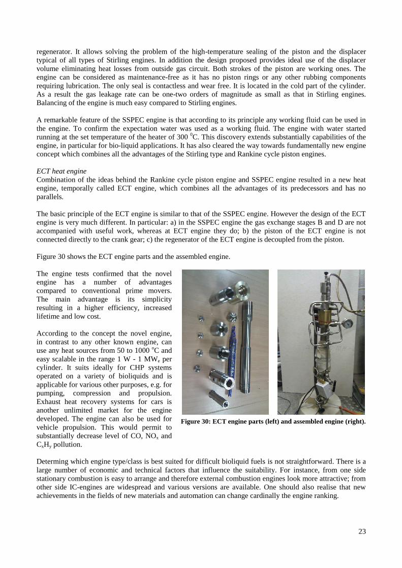
regenerator. It allows solving the problem of the hightypical of all types of Stirling engines. In addition the design proposed provides ideal use of the displacervolume eliminating heat losses from outside gas circuit. Both strokes of the piston are working ones. Theengine can be considered as maintenarequiring lubrication. The only seal is contactless and wear free. It is located in the cold part of the cylinder.As a result the gas leakage rate can be oneBalancing of the engine is much easy compared to Stirling engines.
A remarkable feature of the SSPEC engine is that according to its principle any working fluid can be used inthe engine. To confirm the expectation water warunning at the set temperature of the heater of 300engine, in particular for bio-liquid applications. It has also cleared the way towardsconcept which combines all the advantages of the Stirling type and Rankine cycle piston engines.
ECT heat engineCombination of the ideas behind the Rankine cycle piston engine and SSPEC engine resulted in a new heatengine, temporally called ECT engine, which combines all the advantages of its predecessors and has noparallels.
The basic principle of the ECT engine is similar to that of the SSPEC engine. However the design of the ECTengine is very much different. In particularaccompanied with useful work, whereas at ECT engine they do; b) the piston of the ECT engine is notconnected directly to the crank gear; c) the regenerator of the ECT engine is decoupled fro
Figure 30 shows the ECT engine parts and the assembled engine.
The engine tests confirmed that the novelengine has a number of advantagescompared to conventional prime movers.The main advantage is its simplicityresulting in a higher efficiency, increasedlifetime and low cost.
According to the concept the novel engine,in contrast to any other known engine, canuse any heat sources from 50 to 1000easy scalable in the range 1 W - 1 MWcylinder. It suits ideally for CHP systemsoperated on a variety of bioliquids andapplicable for various other purposes, e.g. forpumping, compression and propulsion.Exhaust heat recovery systems for cars isanother unlimited market for the enginedeveloped. The engine can also be used forvehicle propulsion. This would permit tosubstantially decrease level of CO, NOCxHy pollution.
Determing which engine type/class is best suited for difficult bioliquid fuelslarge number of economic and technical factors that influence the suitability. Forstationary combustion is easy to arrange and therefore external combustion engines look more attractive; fromother side IC-engines are widespread and various versions are available. One should also realise that newachievements in the fields of new materials and automation can change cardinally the engine ranking.
regenerator. It allows solving the problem of the high-temperature sealing of the piston and the displatypical of all types of Stirling engines. In addition the design proposed provides ideal use of the displacervolume eliminating heat losses from outside gas circuit. Both strokes of the piston are working ones. Theengine can be considered as maintenance-free as it has no piston rings or any other rubbing componentsrequiring lubrication. The only seal is contactless and wear free. It is located in the cold part of the cylinder.As a result the gas leakage rate can be one-two orders of magnitude as small as that in Stirling engines.Balancing of the engine is much easy compared to Stirling engines.
A remarkable feature of the SSPEC engine is that according to its principle any working fluid can be used inthe engine. To confirm the expectation water was used as a working fluid. The engine with water startedrunning at the set temperature of the heater of 300 0C. This discovery extends substantially capabilities of the
liquid applications. It has also cleared the way towards fundamentally new engineconcept which combines all the advantages of the Stirling type and Rankine cycle piston engines.
Combination of the ideas behind the Rankine cycle piston engine and SSPEC engine resulted in a new heatECT engine, which combines all the advantages of its predecessors and has no
The basic principle of the ECT engine is similar to that of the SSPEC engine. However the design of the ECTengine is very much different. In particular: a) in the SSPEC engine the gas exchange stages B and D are notaccompanied with useful work, whereas at ECT engine they do; b) the piston of the ECT engine is notconnected directly to the crank gear; c) the regenerator of the ECT engine is decoupled fro
shows the ECT engine parts and the assembled engine.
The engine tests confirmed that the novelengine has a number of advantagescompared to conventional prime movers.The main advantage is its simplicityresulting in a higher efficiency, increased
According to the concept the novel engine,in contrast to any other known engine, canuse any heat sources from 50 to 1000 oC and
1 MWe percylinder. It suits ideally for CHP systemsoperated on a variety of bioliquids and isapplicable for various other purposes, e.g. forpumping, compression and propulsion.Exhaust heat recovery systems for cars isanother unlimited market for the enginedeveloped. The engine can also be used forvehicle propulsion. This would permit to
bstantially decrease level of CO, NOx and
which engine type/class is best suited for difficult bioliquid fuels is not straightforwardlarge number of economic and technical factors that influence the suitability. Forstationary combustion is easy to arrange and therefore external combustion engines look more attractive; from
engines are widespread and various versions are available. One should also realise that newthe fields of new materials and automation can change cardinally the engine ranking.
Figure 30: ECT engine parts (left) and assembled engine
23
temperature sealing of the piston and the displacertypical of all types of Stirling engines. In addition the design proposed provides ideal use of the displacervolume eliminating heat losses from outside gas circuit. Both strokes of the piston are working ones. The
free as it has no piston rings or any other rubbing componentsrequiring lubrication. The only seal is contactless and wear free. It is located in the cold part of the cylinder.
ll as that in Stirling engines.
A remarkable feature of the SSPEC engine is that according to its principle any working fluid can be used ins used as a working fluid. The engine with water started
C. This discovery extends substantially capabilities of thefundamentally new engine
concept which combines all the advantages of the Stirling type and Rankine cycle piston engines.
Combination of the ideas behind the Rankine cycle piston engine and SSPEC engine resulted in a new heatECT engine, which combines all the advantages of its predecessors and has no
The basic principle of the ECT engine is similar to that of the SSPEC engine. However the design of the ECT: a) in the SSPEC engine the gas exchange stages B and D are not
accompanied with useful work, whereas at ECT engine they do; b) the piston of the ECT engine is notconnected directly to the crank gear; c) the regenerator of the ECT engine is decoupled from the piston.
is not straightforward. There is alarge number of economic and technical factors that influence the suitability. For instance, from one sidestationary combustion is easy to arrange and therefore external combustion engines look more attractive; from
engines are widespread and various versions are available. One should also realise that newthe fields of new materials and automation can change cardinally the engine ranking.
ECT engine parts (left) and assembled engine (right).

24
WP5: Emission reduction
IntroductionHigh NOx content in the diesel exhaust gases represents a serious ecological problem which is addressed nowby using several approaches. One of them is based on the reaction of selective catalytic reduction (SCR) ofNOx by a reducer gas injected to the exhausts in a small amount. Unsaturated hydrocarbons, propane, primarydiesel fuel, ammonia, urea and mixture of hydrogen and carbon monoxide (synthesis gas) to be an efficientNOx reducer as well. The synthesis gas can be produced with catalysts by the reactions of steam reforming,autothermal reforming (ATR) or partial oxidation of upgrading fast pyrolysis oils or diesel fuel. WP5therefore aims at the development of catalysts and a system for NOx removal from diesel engine exhaustgases; through ATR of diesel fuel to synthesis gas followed by NOx reduction by synthesis gas in SCR orLNT regimes.Catalysts and reactor for fossil diesel and bioliquids autothermal reforming to synthesis gas.
The following most promising catalysts for ATR of fuels into syngas were synthesized and tested: А3: Co3O4/MnO2/BaO/Fechral Net; А5: Rh/Al2O3/Net+ А6: Ni/BaO/La2O3/Al2O3/Net.
All catalysts were tested in the reactions of ATR of diesel fuel and biodiesel fuel under the followingconditions: О2/С = 0.5-0.6, Н2О/C = 1.5-2, contact time 0.3-0.3 s, inlet reactor temperature 200-400°C. Respective product distribution was as follows (on dry basis): for ATR of diesel fuel H2 = 32%, СН4 = 1%,СО2 = 12%, СО = 11%, N2 = 44%, syngas yield was 2.88 NL per 1 g of diesel fuel, hydrogen yield – 18moles per 1 mole of diesel fuel; for ATR of biodiesel: H2 = 24%, СН4 = 1%, СО2 = 15%, СО = 6%, N2 =34%, syngas yield was 1.85-2.2 NL per 1 g of biodiesel fuel; ATR of fast pyrolysis oil: H2 = 26%, СН4 =1.2%, СО2 = 14%, СО = 13%, N2 = 45.8%. Reactor for synthesis gas production was manufactured (seeFigure 32). Its parameters are as follows: inner diameter, 100 mm, catalyst block dimensions (diameter х length), 100x150 mm, and reactor type - axial.
Catalysts and reactor for selective NOx reductionIn total 25 different catalysts for selective NOx reduction were synthesized. All catalysts were tested for thereaction of selective NOx reduction. Catalyst 2% Ag/Al2O3 showed the best characteristics. The catalystconsists of 2-3 mm diameter spheres impregnated with a solution of silver nitrate. This catalyst was taken asthe most promising one for the development of selective NOx reduction module. The experiments showed thatin order to provide high reaction degrees of NOx, autothermal conversion of diesel fuel should be performedso that the reaction products contain synthesis gas, methane and unreacted diesel fuel residue. In this case, theas-prepared multicomponent reducing agent can provide high conversion of NOx in the temperature range250-500 oС.
Pilot catalyst batch (60 liter) and radial type DeNOx reactor were manufactured (see Figure 31). Parameters ofradial type DeNOx reactor: inner diameter 120 mm, thickness of catalyst bed 100 mm, external diameter 380mm, length of reactor 516 mm.
Catalyst manufacturing and system development; Exhaust gas cleaning systemA system for NOx- cleanup from exhaust gases was developed and assembled. Tentative experiments provedsufficient DeNOx efficiency: NOx conversion was 80% in temperature range 250-350 0C; fuel penalty forsynthesis gas production 3-5%.

Figure
(a)
Figure 32: Schema (a) and general view (b) of the DeNOPseudoseptum; 4
Discussion of emission reduction sysThe project aimed to develop a multiprovide 80% conversion of NOx in the temperature interval of 250should not exceed 3% of total fuel consumption in the engine. Direct use of hydrocarbons for deNOx purposesis inappropriate as it causes 5-6% fuel penalty and requires high reaction temperatures. Urea is an efficientsingle-component reducer at temperatures of 370and inability to be used at temperatures below minus 18fact, urea appears additional reagent onboard a vehicle. In this regard, the use of fuel (diesel+ biofuel)reforming products for deNOx purposes is much more appropriate. The fuel reforming products consist ofsyngas, methane and unsaturated hydrocarbons. This multi500°C; fuel penalty with this approach is below 3%. In case of LNT, fuel penalty is below 1.5%.
Figure 31: General view of synthesis gas reactor
Schema (a) and general view (b) of the DeNOx reactor. Legend: 1- Exhaust gas inlet; 2Pseudoseptum; 4- Outlet gas reservoir; 5- Clean gas after DeNO
stem performanceThe project aimed to develop a multi-component NOx reducing agent on the base of the v
in the temperature interval of 250-500°C. The fuel penalty for deNOx processshould not exceed 3% of total fuel consumption in the engine. Direct use of hydrocarbons for deNOx purposes
6% fuel penalty and requires high reaction temperatures. Urea is an efficientcomponent reducer at temperatures of 370-500°C. Its application is limited because of relative toxicity
and inability to be used at temperatures below minus 18-19°C (which are common in Siberia in winter). Infact, urea appears additional reagent onboard a vehicle. In this regard, the use of fuel (diesel+ biofuel)reforming products for deNOx purposes is much more appropriate. The fuel reforming products consist ofyngas, methane and unsaturated hydrocarbons. This multi-component mixture allows NO
500°C; fuel penalty with this approach is below 3%. In case of LNT, fuel penalty is below 1.5%.
25
(b)
Exhaust gas inlet; 2-Catalyst; 3-Clean gas after DeNOx.
reducing agent on the base of the vehicle fuel to500°C. The fuel penalty for deNOx process
should not exceed 3% of total fuel consumption in the engine. Direct use of hydrocarbons for deNOx purposes6% fuel penalty and requires high reaction temperatures. Urea is an efficient
500°C. Its application is limited because of relative toxicity(which are common in Siberia in winter). In
fact, urea appears additional reagent onboard a vehicle. In this regard, the use of fuel (diesel+ biofuel)reforming products for deNOx purposes is much more appropriate. The fuel reforming products consist of
component mixture allows NOx reduction at 250-500°C; fuel penalty with this approach is below 3%. In case of LNT, fuel penalty is below 1.5%.
26
WP6: Assessments
In the last WP the benefits of using bioliquids in CHP (cogeneration) mode were evaluated in a number ofassessments including: State of the art Environmental performance Technical and economic performance Information for developers
State of the artA preliminary study of the current prime mover technologies, in addition to a database, was completed inorder to establish a starting point and used to illustrate the state of the art and the advantages anddisadvantages of the technologies. The prime mover technologies review included piston internal combustionengines, turbines, organic Rankine cycle (ORC) systems and Stirling engines from the economic (capital cost)and performance (efficiency) point of view. More information on the technologies can be found in theTechnologies Summary incluided in the Promotion Pack handed out during the project completion workshop.
As information for CHP units below 1000kWe using bioliquids is scarce, a decision was made to expand thescope and include CHP units using biomass for the partner countries. The making of the database washindered by the lack of reliable and detailed information. A database of units using biomass for CHP wasdeveloped for the Netherlands and for the United Kingdom but unfortunately it was not possible to build asimilar database for Russia and Italy. The database includes unit electrical capacity, location, fuel and primemover, among other items of information.
In an attempt to highlight the innovative frame of the project, Parallel Sets diagrams were used for thedatabase graphic representation, condensing the conventional set of charts normally used for databaserepresentation into a single easy to understand diagram. The tool allows the visualization of large amounts ofcategorized data in a simple interactive chart as a step to identify the market and correlate to past and presentexperiences. The number of horizontal bars (categories) is variable. Each horizontal bar has sub-categoriesfrom which the data is further expanded. Although this is an interactive tool, a modified print out can be madeand is included in Figure 33. The figures have three categorized horizontal bars:
Feedstock: With Food waste, Short Rotation Coppice (SRC), Vegetable oils, Wood waste, Other wasteand an additional sub-category for items with no details.
Size: Disaggregated as units below 400 kWe, units between 400 kWe and 1000 kWe, units above 1000kWe and units with no details as sub-categories.
Prime mover: For information regarding the specific prime mover, piston internal combustion engines,gas turbines, steam turbines and no details.
The link between each category is a coloured ‘ribbon’. The value of any individual ribbon within any categoryis displayed with the cursor. It is also important to note that the width of each ribbon is proportional to thenumber of units in each category.
Environmental performanceA number of pollutants are produced during the combustion of fuels. Carbon monoxide (CO) is emitted during(inefficient) combustion, nitrogen oxides (NOx) are very much fuel and combustion conditions specific,sulphur dioxide (SO2) is released when using fuels with sulphur content and combustion plants are alsoresponsible for the emissions of particulates. A reduction in overall emissions when exploiting biomass as fuelis expected by 2030 when compared to the situation in 2005 (European Environment Agency, 2008,‘Maximizing the environmental benefits of Europe’s bioenergy potential’), as shown in Table 5:
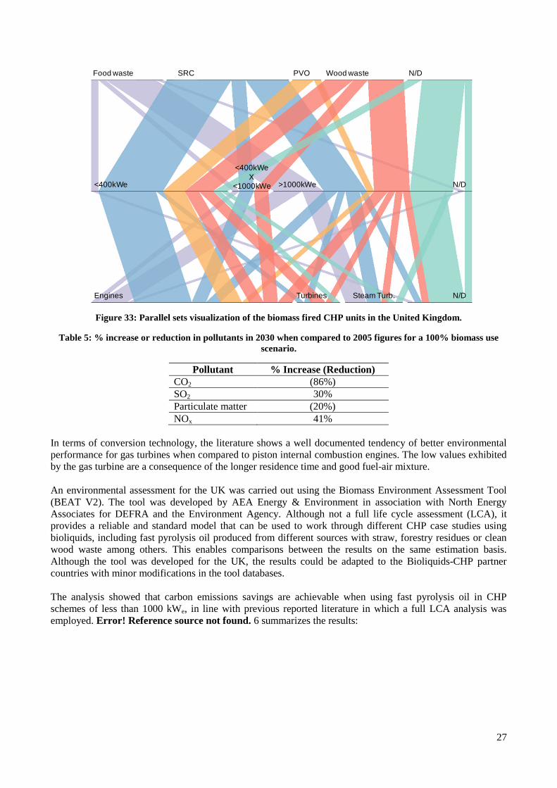
27
Figure 33: Parallel sets visualization of the biomass fired CHP units in the United Kingdom.
Table 5: % increase or reduction in pollutants in 2030 when compared to 2005 figures for a 100% biomass usescenario.
Pollutant % Increase (Reduction)CO2 (86%)SO2 30%Particulate matter (20%)NOx 41%
In terms of conversion technology, the literature shows a well documented tendency of better environmentalperformance for gas turbines when compared to piston internal combustion engines. The low values exhibitedby the gas turbine are a consequence of the longer residence time and good fuel-air mixture.
An environmental assessment for the UK was carried out using the Biomass Environment Assessment Tool(BEAT V2). The tool was developed by AEA Energy & Environment in association with North EnergyAssociates for DEFRA and the Environment Agency. Although not a full life cycle assessment (LCA), itprovides a reliable and standard model that can be used to work through different CHP case studies usingbioliquids, including fast pyrolysis oil produced from different sources with straw, forestry residues or cleanwood waste among others. This enables comparisons between the results on the same estimation basis.Although the tool was developed for the UK, the results could be adapted to the Bioliquids-CHP partnercountries with minor modifications in the tool databases.
The analysis showed that carbon emissions savings are achievable when using fast pyrolysis oil in CHPschemes of less than 1000 kWe, in line with previous reported literature in which a full LCA analysis wasemployed. Error! Reference source not found. 6 summarizes the results:
Food waste SRC PVO Wood waste N/D
<400kWe >1000kWe N/D
Engines Turbines N/DSteam Turb.
<400kWeX
<1000kWe

28
Table 6: Equivalent CO2 emissions increment (savings) when compared to gas in a 1000kWe piston internalcombustion engine using fast pyrolysis oil in CHP mode.
CHP scheme g CO2
equivalent/kWh% emission increment
(saving)Gas fired 616.90 0.0Oil fired 857.60 39.0100% forestry residue 48.93 (92.1)100% SRC 109.46 (82.3)
The diversity of use of biomass for energy and the diversity of conditions in each country has limited thenumber of LCA studies for fast pyrolysis oil as fuel for CHP, especially when compared to the number ofLCA studies of biomass for transportation.
The savings in CO2 emissions for the different bioliquids developed during the Bioliquids-CHP project areexpected overall to be similar to that of fast pyrolysis oil, however, each particular upgrading methodologywill have an impact that will lower the savings expressed in Error! Reference source not found.. Althoughthis impact has not been quantified, it can be expressed in qualitative terms referenced to the energy used tomake fast pyrolysis oil, as shown in Table7:
Table 7. Overall impact of selected bioliquids when compared to pyrolysis oil
Bioliquid Items to consider in addition tothe production of bio-oil
Overall impact compared to bio-oil
30/30/40 butanolblend
Production, transport andstorage of biodiesel andbutanol.
Biodiesel has a higherenvironmental impact than bio-oildue to higher production inputs.Butanol impact is also higher thanbio-oil but less than biodieselagain due to high biomassproduction and distillationrequirements. Quantitative data isnot feasible due to dependency onfeedstock and process for bothbiodiesel and butanol.
Mixing energy for theproduction of the blend.
FPO ester Production, transport andstorage of butanol
Slightly higher impact than bio-oilproduction due to higher impact ofbutanol production as definedabove. Catalyst production andprocess energy are relativelyinsignificant.
Catalyst production
Distillation process energyconsumption
Mild HDO Catalyst production Slightly higher impact than bio-oilproduction because of hydrogenrequirement. Catalyst productionand process energy are relativelyinsignificant.
Hydrotreatment processenergy consumption
Therefore the increase in emissions and its impact on CO2 saving potential is expected to be slightly higherwhen using any of the bioliquid produced by the Bioliquids-CHP project.
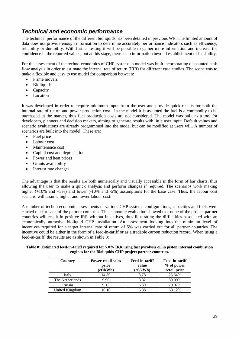
29
Technical and economic performanceThe technical performance of the different bioliquids has been detailed in previous WP. The limited amount ofdata does not provide enough information to determine accurately performance indicators such as efficiency,reliability or durability. With further testing it will be possible to gather more information and increase theconfidence in the reported values, but at this stage, there is no information beyond establishment of feasibility.
For the assessment of the techno-economics of CHP systems, a model was built incorporating discounted cashflow analysis in order to estimate the internal rate of return (IRR) for different case studies. The scope was tomake a flexible and easy to use model for comparison between: Prime movers Bioliquids Capacity Location
It was developed in order to require minimum input from the user and provide quick results for both theinternal rate of return and power production cost. In the model it is assumed the fuel is a commodity to bepurchased in the market, thus fuel production costs are not considered. The model was built as a tool fordevelopers, planners and decision makers, aiming to generate results with little user input. Default values andscenario evaluations are already programmed into the model but can be modified at users will. A number ofscenarios are built into the model. These are: Fuel price Labour cost Maintenance cost Capital cost and depreciation Power and heat prices Grants availability Interest rate changes
The advantage is that the results are both numerically and visually accessible in the form of bar charts, thusallowing the user to make a quick analysis and perform changes if required. The scenarios work makinghigher (+10% and +5%) and lower (-10% and -5%) assumptions for the base case. Thus, the labour costscenario will assume higher and lower labour cost.
A number of techno-economic assessments of various CHP systems configurations, capacities and fuels werecarried out for each of the partner countries. The economic evaluation showed that none of the project partnercountries will result in positive IRR without incentives, thus illustrating the difficulties associated with aneconomically attractive bioliquid CHP installation. An assessment looking into the minimum level ofincentives required for a target internal rate of return of 5% was carried out for all partner countries. Theincentive could be either in the form of a feed-in-tariff or as a tradable carbon reduction record. When using afeed-in-tariff, the results are as shown in Table 8:
Table 8: Estimated feed-in-tariff required for 5.0% IRR using fast pyrolysis oil in piston internal combustionengines for the Bioliquids-CHP project partner countries.
Country Power retail salesprice
(c€/kWh)
Feed-in-tariffvalue
(c€/kWh)
Feed-in-tariff% of powerretail price
Italy 14.80 3.78 25.54%
The Netherlands 9.90 8.82 89.09%
Russia 9.12 6.39 70.07%
United Kingdom 10.10 6.88 68.12%

The level of incentive requires basically that the price of power is almost doubled from the current localprices. The sensitivity analysis shows that, for all countries, the largest impact on the IRR is the fuel price, asillustrated in Figure 34 for the UK:
Figure 34: Sensitivity study for the UK using fast pyrolysis oil in piston internal combustion engines.
The economic performance comparison of different prime movers using different bioliquids in the partner’scountries was limited to those bioliquids with the highest heating value, as the heating value and heat andpower output are directly associated. In order to simulate the bioliqheating value relative to bio-oil. The different bioliquids heating values and difference relative to biodetailed in Table 9. The bioliquids selected for economic evaluation comparison and their price are shown inTable 10.
Table 9. Bioliquids heating value and heating value increase factor
Bioliquid
Bio-oil30/30/40 butanol blendDry FPO + ethanolFPO emulsion with 5% biodieselFPO esterFPO sugarsMild HDO
Table 10. Selected bioliquids assumed price per country
Bioliquid
Bio-oil30/30/40 butanol blendFPO esterMild HDO
An estimation of the feed-in-tariff required for a 5.0% IRR was carried out for the Bioliquidscountries for each of the bioliquids detailed inFigure 35:
The level of incentive requires basically that the price of power is almost doubled from the current localprices. The sensitivity analysis shows that, for all countries, the largest impact on the IRR is the fuel price, as
for the UK:
Sensitivity study for the UK using fast pyrolysis oil in piston internal combustion engines.
mparison of different prime movers using different bioliquids in the partner’scountries was limited to those bioliquids with the highest heating value, as the heating value and heat andpower output are directly associated. In order to simulate the bioliquid price, this was linked to the increase in
oil. The different bioliquids heating values and difference relative to bio9. The bioliquids selected for economic evaluation comparison and their price are shown in
Table 9. Bioliquids heating value and heating value increase factor
Heating value(MJ/kg)
Heating value increase factor
17.0 1.0025.9 1.5218.7 1.10
FPO emulsion with 5% biodiesel 16.3 0.9623.5 1.3818.4 1.0827.0 1.59
Table 10. Selected bioliquids assumed price per country
BioliquidPrice (Euro/GJ)
Italy Netherlands Russia UK7.92 8.14 7.04 7.65
30/30/40 butanol blend 12.06 12.40 10.72 11.6510.94 11.25 9.73 10.5712.57 12.93 11.18 12.15
tariff required for a 5.0% IRR was carried out for the Bioliquidscountries for each of the bioliquids detailed in Table , using the three main prime movers and is shown in
30
The level of incentive requires basically that the price of power is almost doubled from the current localprices. The sensitivity analysis shows that, for all countries, the largest impact on the IRR is the fuel price, as
Sensitivity study for the UK using fast pyrolysis oil in piston internal combustion engines.
mparison of different prime movers using different bioliquids in the partner’scountries was limited to those bioliquids with the highest heating value, as the heating value and heat and
uid price, this was linked to the increase inoil. The different bioliquids heating values and difference relative to bio-oil are
9. The bioliquids selected for economic evaluation comparison and their price are shown in
Table 9. Bioliquids heating value and heating value increase factor
Heating value increase factor
1.001.521.100.961.381.081.59
UK7.65
11.6510.5712.15
tariff required for a 5.0% IRR was carried out for the Bioliquids-CHP partner, using the three main prime movers and is shown in

31
Figure 35: Value of the feed-in-tariff for a 5.0% IRR in different prime movers using different bioliquidsin the Bioliquids-CHP partner countries
The figure illustrates several important details: The more mature the prime mover technology requires lower feed-in-tariff incentive for a target 5%
IRR, thus, engines require lower incentives when compared to turbines, and turbines require less feed-in-tariff incentives when compared to ORC systems. The maturity of the prime mover technology isthen a major factor to consider and future efforts should be targeted primarily to developing enginesto achieve commercial viability.
The figure also shows that the basic bioliquid, bio-oil, is financially more attractive that the bioliquidsderived from it. This is only true if the price assumptions are as projected in this exercise. Althoughsome of the bioliquids produced for this project have enhanced properties, e.g., lower viscosity,bioliquids with increased heating values would require larger incentives when compared to bio-oil.
The Netherlands consistently require the highest level of incentives when compared among theBioliquids-CHP partner countries, whereas Italy regularly requires the lowest level of feed-in-tariff. Acombination of local parameters (fuel price, power and heat sales price, labour wages) has a largerimpact on the market in the Netherlands when compared to the other partner countries.
Information for developersMost legislation associated with planning and regulation that would affect small scale CHP are containedwithin the scope of local administration powers. The best advice we can offer to anyone looking into smallscale bioliquid CHP is to refer to the local authority in which the scheme will be installed. In the UK, localauthorities are responsible for determining planning application for renewable energy projects below 50MWe
and planning permission is always required except for units of <50kWe or <45kWth
When looking at the potential markets in which a bioliquid-CHP installation could succeed, it is necessary tosegregate by location, thus:
For the UK the largest opportunities are in the sewage treatment and wood industries. Buildings are alsopotential large customers; however this would require the development of new heat distributioninfrastructure.
0
5
10
15
20
25
30
35
Engi
nes
+b
io-o
il
Engi
ne
s+3
0/3
0/4
0b
len
d
Engi
ne
s+FP
Oe
ste
r
Engi
ne
s+M
ildH
DO
Turb
ine
+b
io-o
il
Turb
ine
+30
/30
/40
ble
nd
Turb
ine
+FP
Oes
ter
Turb
ine
+Mild
HD
O
OR
C+
bio
-oil
OR
C+
30
/30
/40
ble
nd
OR
C+F
PO
este
r
OR
C+M
ildH
DO
Fee
d-i
n-t
ari
ffva
lue
(c€
/kW
h)
for
5.0
%IR
R
Italy The Netherlands Russia United Kingdom

32
In the Netherlands the most promising opportunities are in the agricultural sector, in particular ingreenhouse applications and possibly in the development of district heating networks. Both the foodand chemical industries, with current low to medium intake of CHP installations, are the sector with thelargest market potential.
For Italy there is a marked interest in bioliquids use in the form of pure vegetable oil for power and heatgeneration, with an estimated increase of over 600% (number of units) for 2020 when compared to the2007 situation. The reconvention of part of the sugar infrastructure plants into bioenergy power plants isalso in plans. The food industry is among the largest potential users, followed by the chemical industry(both in terms of capacity and number of units).
Availability of biomass materials on site is an important factor for biomass cogeneration, but the use of heat asan energy source is the limiting factor. Thus, opportunities for installing biomass cogeneration in sites withoutthe feedstock or with related activities are narrow. The Cogeneration Observatory and Dissemination Europeproject (CODE) made available in 2010 its first report on the potential for CHP in the EU with informationsupplied by the member states. It is envisaged that an additional cogeneration capacity of 122 GWe iseconomically feasible which could be in operation by 2020. Although this figure encompasses a widespectrum of size (capacity), range of applications and fuels, biomass is expected to make a contribution ofabout 8% of total growth or 10 GWe, of which 2 GWe could be in the capacity scale of below 1000 kWe.

33
IV. Potential impact
ImpactImpacts can be evaluated in terms of a variety of criteria as listed below. Areas where BioliquidsCHP havecontributed are underlined and discussed below:• Policy (government and agencies) – advice, information, consultation• Industry – companies, trade associations, training future technologists, commercialisation, developing
advanced technologies, solving industrial problems• Economy – exploitation of IPR, new technology, exports, competitiveness, new and/or growing markets• Public – engagement, education, promotion• Society – sustainability, CO2 reduction, quality of life• Research – academic community, new research projects, publications• Strategic and Social – Bio-liquid producers, plant manufacturers, SMEs, investment, local domestic and
small industrial applications, regulations, education and training, rural development, farming andagriculture
PolicyInformation has been provided to policy makers through publications and meetings, notably the projectcompletion seminar held in Brussels in November 2011. The important contributions have been in promotingthe use of bioliquids, promoting small power and heat generation technology and producing fact sheets onperformance and cost.
IndustryInformation has been provided through publications and meetings, notably the project completion seminar.The important contributions have been in promoting the use of bioliquids, promoting small power and heatgeneration technology and producing fact sheets on performance and cost. These will enable industry tobecome aware of bioliquids as a commercial renewable energy source and the availability of suitable smallscale CHP plants to utilise these renewable liquids in cost effective applications. It is believed that theadditional information will encourage existing market players to become more active and encourage newentrants both in bioliquids supply and in small scale CHP systems. In addition, there has been extensivecontact with many of the players in the EU, especially in Italy, Netherlands and the UK, which has also servedto provide information and encouragement.
EconomyThe market for energy and power in Europe is vast. As the targets for renewable energy become morefocussed and pressures to displace fossil fuels grow, policy makers and industry will increasingly look todecentralised small scale CHP to provide more efficient and cost effective energy supplies. Estimates of thesize of this market sector suggest an increase from 2GWe in 2000 to 20GWe in 2020. With investmentsranging from 300 to 800 € per kW, this represents a massive potential growth area.
Public and societyAs CHP provides a greater proportion of the heat and power needs in a more decentralised economy, therewill be substantial impacts on users, i.e. the public. They will be involved more in local decision making andderive more benefits from locally sited heat power units, and this will improve their sense of ownership andinvolvement, as well as a greater awareness of their contributions to sustainability and carbon reduction.
ResearchA number of significant developments have emerged from the research concerning both bioliquids productionand their use in engines and turbines. Several new ideas would benefit from further development and these arebeing explored by several partners as discussed in the Exploitation Plan and other reports.

34
Market analysis of CHPEarly assessments2 in 2004 estimated that the only way to reach the cogeneration target set by the EU from9% in 1997 to 18% in 2010 was including micro-generation (less than 1MWe) in the CHP mix, albeit with arange of fuels from natural gas, biomass and waste. In the same study biomass based CHP was expected toincrease its presence from 2GWe in 2000 to 20GWe in 2020, of which it is assumed small scale biomassfuelled would contribute with 3.6GWe.
BIOCOGEN3 reported in 2003 that the contribution of biomass to cogeneration could be of 11 GWe by 2010with an additional 9GWe for 2020. The forecast shows that the domestic sector could grow to 28% of the EUcogeneration capacity by 2020 from virtually zero contribution in 1999, however, this can only be possible iftechnological improvements and policy changes are implemented.
The EU-funded Cogeneration Observatory and Dissemination Europe4 project (CODE) releases in 2010 itsfirst report on the potential for CHP in the EU with information supplied by the EC Member Sstates. In here itis envisaged that an additional cogeneration capacity of 122 GWe is economically feasible and which could bein operation in by 2020. Although this figure encompasses a wide spectrum of size (capacity), range ofapplications and fuels, biomass is expected to make a contribution. If a similar assumption to the previousreport is made, this is, about 8% of total growth as biomass based CHP or 10 GWe, of which 2 GWe could bein the capacity scale of below 1000 kWe.
Strategic and socialMuch attention in renewable energy has focussed on large scale applications and opportunities, while smallscale local applications have been largely neglected due to relatively poor economics and poor appreciation ofthe potential and opportunities at domestic, local and regional levels. The focus of the project on CHP up to 1MWe has enabled SMEs and organisations involved in promotion and development of small power and heat tobecome aware of the technologies and opportunities for this sector. The communities who can contribute tothe deployment of the technologies range from the farming and agricultural communities who provide thebasic raw materials of biomass for fast pyrolysis to produce bio-oil; and vegetable oils and vegetable oilupgrading into biodiesel, followed by distribution of these bioliquids. A major contribution to ruraldevelopment can therefore be anticipated. Another sector can develop and market small scale CHP systemsbased on these bioliquids with benefits for manufacturing, equipment suppliers and consultancy, as well aslocal and regional government through planning and regulations. The small scale of the proposeddevelopments mean that SMEs are well placed to exploit all stage of the bio-energy-CHP chain and thereby toderive synergies and collaborations that would otherwise be more difficult to establish. The noveldevelopment in liquids, emulsions, blends and their utilisation in a variety of heat and power generationdevices will benefit bioliquid producers and plant manufacturers and create employment and new investmentespecially for SMEs. One of the major byproducts or side benefits has been directly in education and trainingof all the researchers engaged on the project and indirectly through their subsequent employment and therange of publications from the project.
ExploitationExploitation has been evaluated through questionnaires sent to all partners and these are reported in theExploitation Plan. While each partner is responsible for their own exploitation, a summary of the opportunitiesidentified is shown in Table 11 on the next page.
2 Lymberopoulos, N (2004). ‘Microturbines and their application in bio-energy’. Centre for Renewable EnergySources. Greece. Available from:http://ec.europa.eu/energy/efficiency/studies/doc/industry/microturbines_bioenergy.pdf [Accessed on 24 May 2010]
3 BIOCOGEN (2003). ‘Final Technical Report’. Centre for Renewable Energy Sources. Available from:http://www.cres.gr/biocogen/pdf/market_analysis.pdf [Accessed on 24 May 2010]
4 Cogeneration Observatory And Dissemination Europe (2009). ‘European potential for cogeneration’. Brussels,Belgium. Available from: http://www.code-project.eu/wp-content/uploads/2011/02/290110-CODE-European-summary-report.pdf [Accessed on 19 May 2010]

35
Table 11: Summary of exploitation plans in relevant areas.
TechnologyPatent(s)planned
Licensingplanned
Publicationsplanned
DeNOx system P L Stirling cycle P L Rankine cycle P L Engine fuel system P J BO-BD emulsions P Micro turbine J CHP power plant P LProducts Bio-liquid blends P L J TEA CHP model J CHP database J DeNOx catalysts P L Piston engine P L Rankine engine P L CHP power plant LKnow-how All partners have know-how which they
plan to exploitP L J
Main Dissemination Activities
BrochureAn English language project brochure was produced early in 2010 and this was then translated into Russian.The brochure provides an overview of the project, the partners, their experience and facilities andcontributions to the project. It is a useful summary of the project and has been used by partners aspromotional material and disseminated at conferences and events.
WebsiteThe project website has been available at www.bioliquids-chp.eu since the first year of the project and hasbeen regularly updated with information, news, deliverables, training and education materials, promotionalmaterials and details of project events.
Promotional PacksA promotional pack was distributed to around 60 delegates at the Final Workshop and 140 further copies arebeing sent to partners for distribution to relevant Target Groups. The packs included several publicitybrochures and publicity information for the BioliquidsCHP project; partner summary sheets; fact sheets onbioliquids, environmental performance, case studies and technologies.
WorkshopThe final joint dissemination event was organised on 8 November 2011 in Brussels entitled “Symposium onusing bioliquids in engines and turbines in CHP applications” and attracted a very encouraging audience ofover 55 attendees from industry, government and academia. The event included reports from all projectpartners on their achievements. There were also presentations from the EC and Russian Ministry of Scienceand relevant case studies and experience from Industry.

36
Final Project BrochureA final project brochure is being finalised for bulk distribution to partners for re-distribution to theirstakeholders. This will include a report on the project and the activities and results from the partners.
Publications
Peer reviewed journal and book publications
1. Alcala A and Bridgwater AV, "Biomass fuelled combined heat and power -situation in the UK and theNetherlands", Proceedings of the Bioten conference on biomass bioenergy and biofuels, Bridgwater AV(Editor) 2011, CPL Press,
2. Bridgwater, AV, Alcala A (2011). Biomass-based small and micro combined heat and power (CHP)systems: application and status in the United Kingdom. In: Beith, R Small and micro combined heat andpower (CHP) systems: Advanced design, performance, materials and applications. Cambridge:Woodhead Publishing. p427-458.
3. Bridgwater AV, “Upgrading biomass fast pyrolysis liquids”, Accepted for publication in EnvironmentalProgress and Sustainable Energy (2012).
4. Beld, B van der, “The use of pyrolysis oil and pyrolysis oil derived fuels in diesel engines for CHPapplications”, Accepted for publication in Applied Energy (2012).
Planned publications
A number of joint publications with both EU and Russian partners have been agreed and the scope of threepossible joint articles are detailed below:
Table 7: Planned publications
Scope/Topic Partners and primary Responsibility
Use of bio-liquid blends in engines and micro-turbines andcomparison of engines and turbines running on bio-liquids - results
CREAR, BTG, Aston
Comparison of properties of upgraded bio-oil and blends with bio-oil Aston, BTG, BIC, CREAR. A draft isbeing circulated in March 2012
DeNox catalysts for engines BIC, NAMI

37
Papers submitted for review in peer reviewed journals
Bridgwater AV, Alcala A, "Blends of bio-oil and biodiesel for heat and power applications", Paper submittedto Fuel, February 2012
Figure 36: The project's scientific coordinator, Dr. Bert van deBeld, at the tcb conference in Chicago (September 2011)
V. Website and contact details of project partners
Project website www.bioliquids-chp.eu
Project coordination
Bert van de Beld, Scientific CoordinatorBTG Biomass Technology Group BV, Tel. +31-53 486 2288, Email: [email protected]
John Vos , Project Manager,BTG Biomass Technology Group BV, Tel. +31-53-486 1186, Email: [email protected]
Partners
EnConTech BV (NL) University of Florence, CREAR (Italy) Boreskov Institute of Catalysis, Siberian Branch of Russian Academy of Sciences (Russia) Federal State Unitary Enterprise 'Central Scientific Research Automobile and Automotive Engines
Institute' - FSUE 'NAMI' (Russia) Aston University (United Kingdom) The Likhachev Plant (AMO ZIL) (Russia)