project final report - cordis.europa.eu · rotorcraft domain are addressed by the green rotorcraft...
TRANSCRIPT

PROJECT FINAL REPORT
Grant Agreement number: 270563
Project acronym: ADHERO
Project title: Aerodynamic Design Optimisation of a Helicopter Fuselage
including a Rotating Rotor Head
Funding Scheme: Article 171 of the Treaty
Date of latest version of Annex I against which the assessment will be made: 17/09/2010
Project Period: from 01.01.2011 to 30.06.2014
Name, title and organisation of the scientific representative of the project's coordinator:
Dr. Christian Breitsamter,
Professor, Akademischer Direktor
Institute of Aerodynamics and Fluid Mechanics
Technische Universität München
Boltzmannstr. 15
85748 Garching
Tel: +49 89 289 16137
Fax: +49 89 289 16139
E-mail: [email protected]
Project website address: www.ADHeRo.de

2
1. Final Publishable Summary
1.1 Executive Summary
The reduction of emissions is clearly one of - if not - the most challenging task of our society and the aeronautical
industry today. Within CleanSky environmental issues in the rotorcraft domain are addressed by the Green Rotorcraft
Integrated Technology Demonstrator (GRC ITD). Even though, fixed wing aircraft generally outperform rotorcraft in
fuel efficiency, range, speed and noise, rotorcraft are still of high importance.
There are several reasons for that. First, rotorcraft provide unique Vertical Take-Off and Landing (VTOL) capabilities.
Thus, they can operate in areas with limited infrastructure or in airspace where other aircraft cannot. Second, they can
excel in scenarios where economy of time is crucial, e.g. search and rescue (SAR) missions. Finally, rotorcraft are
deployed when they outperform other applicable forms of transport in dynamic productivity, i.e. payload multiplied by
range and speed divided by costs. Examples are the crew change on oil platforms or the transport of service personnel to
offshore wind farms. To be able to provide these services at reduced environmental impact, measures are taken by the
GRC to reduce emissions and increase fuel efficiency of rotorcraft.
In many cases, the missions described above are performed by light weight utility helicopters. Therefore, it is desirable
raising the efficiency of this helicopter class. The power requirements of light weight utility helicopters in fast level
flight results to 55 % from parasite drag, to 40 % from the main rotor and to 5 % from the tail rotor. Thus, aiming on
parasite drag constitutes a promising approach for obtaining a more efficient utility helicopter design.
Parasite drag is generally reduced by optimizing an aircraft’s shape. Unfortunately, practical considerations dominate
the design process of utility helicopters. In consequence it is not always possible choosing the optimal shape. Therefore,
solutions for the aerodynamic design have to be developed accounting for these operational constraints.
The main objective of the GRC project ADHeRo (Aerodynamic Design Optimization of a Helicopter Fuselage
including a Rotating Rotor Head) is reducing the parasite drag of light weight utility helicopters in fast level flight,
without increasing the fuselage down force. The latter fact is important to avoid additional power requirements for the
main and tail rotor, which would deteriorate the gain in efficiency obtained through parasite drag reduction.
Analyzing the drag decomposition of this helicopter class reveals that the parasite drag of the fuselage, the landing gear
and the rotor head causes some 70 % of the total parasite drag. Thus, significant reduction of emissions and fuel
consumption can be achieved by optimizing the aerodynamic design of these components. For this reason, the focus
within ADHeRo is set on the aerodynamic optimization of the fuselage, the landing gear and the rotor head. Whenever
feasible, aerodynamic design optimizations are achieved by shape optimization. As already mentioned, this is not
always possible. In these cases, efficiency gains are achieved through the application of passive flow control devices,
i.e. strakes and vortex generators.
The aerodynamic analyses are primarily performed through wind tunnel (W/T) experiments. Besides the identification
of feasible drag reduction methods, the experiments allow determining the gain in efficiency through the selected design
modifications. In summary, this led to a sounded database not available before. The database provides a large set of
global and local data including aerodynamic forces, surface pressure distributions and velocity field data. For the data
collection a new W/T model was designed and manufactured. Since detailed drag analysis is the main scope of
ADHeRo, the model design reflects to that. One important constraint for precise drag evaluation through W/T
experiments is the elimination of aerodynamic interaction of the model support with the flow field of the model. Hence,
a specific tail sting mount is used. Furthermore, the model rotor head reproduces the full kinematic complexity of the
original design. This includes the rotation of the rotor head and the collective and cyclic pitch motion of the rotor
blades. In addition to the experimental investigations, numerical simulations were performed for selected cases to
support the analysis of experimental results.
During the course of the project several design modifications to a baseline model were considered. Through the first
phase of the project the status quo was determined for the baseline configuration representing current production type
light weight utility helicopter. Thus providing the reference data for all subsequent design modifications. In the second
and third phase of the ADHeRo project the effect on drag of modifications to the original design were studied. The
modification include new faired landing gears (18 % drag reduction), a smoothed cabin bottom (2.7 % drag reduction),
passive flow control devices at the aft-body (1.4 % drag reduction) and a new mast fairing (1.5 % drag reduction). Thus
the investigated configurations exceeded the expected drag benefits with almost 24 % on aggregate. In consequence, the
power requirements for light weight utility helicopters could be reduced by 10 % or more through ADHeRo. This could
result in a reduction in fuel consumption of similar magnitude. Through the wind tunnel tests performed on the selected
modifications, already technology readiness level four is achieved (TRL4, i.e. component and/or breadboard validation
in laboratory environment). Considering the planned flight tests on the technology demonstrator even technology
readiness level 6 will be reached (TRL 6, i.e. system/subsystem model or prototype demonstration in a relevant
environment). Hence, the prospective benefits could enter market within a short period after project completion. Thus,
ADHeRo helps reducing the environmental impact of services provided by light weight utility helicopters and their
operational costs in the near future. Overall, this could further improve the societal implication of helicopter services as
a beneficiary means both for society and industry.

3
1.2 Summary Description of the Project Context and the Main Objectives
Reducing emissions is clearly one of - if not - the most challenging task of our society and the aeronautical industry
today. To speed up the progress in reducing emissions in air transport, the European Commission together with the
European Aeronautical Industry launched the CleanSky program. Under CleanSky, environmental issues in the
rotorcraft domain are addressed by the Green Rotorcraft Consortium (GRC). Even though fixed-wing aircraft generally
outperform rotorcraft in terms of fuel efficiency, range, speed, and noise, rotorcraft are still of high importance.
There are several reasons for that. First of all rotorcraft provide unique Vertical Take-Off and Landing (VTOL)
capabilities. Thus, they can operate in areas with limited infrastructure or in airspace where other aircraft cannot.
Second, they can excel in scenarios where economy of time is crucial, e.g. Search and Rescue (SAR) missions and
Helicopter Emergency Medical Services (HEMS). Finally, rotorcraft are deployed when they outperform other
applicable forms of transport in dynamic productivity, i.e. payload multiplied by range and speed divided by costs.
Examples are the crew change on oil platforms, the transport of service personnel to offshore wind farms and executive
transport.
Thus measures are taken by the GRC to reduce emissions and to increase the fuel efficiency and productivity of
rotorcraft. The GRC subproject ADHeRo (Aerodynamic Design Optimization of a Helicopter Fuselage including a
Rotating Rotor Head) contributes to achieving this goal by aiming to reduce parasite drag for Twin Engine Light (TEL)
- class utility helicopters in fast level flight without increasing the fuselage down force.
TEL-class helicopters play an important role in today’s air services. The TEL-class includes helicopters with a
Maximum Take of Weight (MTOW) below 4 metric tons and with two engines installed. The missions performed by
this helicopter class include HEMS, SAR missions, law enforcement, offshore supply and executive transport. In the
helicopter fleet from the year 2000, the TEL-class accounted for approximately 10% of the global flight hours
performed by civil helicopters. Thus improving the efficiency in the TEL-class can have a relevant impact on the
ecological foot print of the global helicopter fleet. For this reason, a state-of-the-art TEL utility helicopter with a
bearingless main rotor system is subject to the optimization performed through ADHeRo.
MTOW Pi Po Pp PTR
1.4 metric tons 11 % 29 % 55 % 5 %
4.5 metric tons 21 % 33 % 41 % 5 %
Table 1. Power breakdown in percentage of total power of two helicopters with 1.4 and 4.5 metric tons
MTOW in level flight (185 km/h).
To assess viable approaches for improving the efficiency of a helicopter, the breakdown of the total power requirements
can be indicative. Stroub and Rabbott present values for the total power requirements PTOT for a helicopter in forward
level flight.
PTOT = Pi + Po + Pp + PTR (1)
The total power requirements are defined by the induced power Pi, profile power Po, parasite power Pp and tail rotor
power PTR (single-rotor design). Values for each of the power fractions for helicopters characterized by 1.4 and 4.5
metric tons MTOW in level flight at 185 km/h are presented in table 1. From table 1 it becomes evident that the biggest
contributor to the total power requirements in cruise, for helicopters within the envelope of the TEL-class, is the
parasite power with some 50 %. The parasite power is the amount of power required to compensate the losses due to the
existence of parasite drag. Thus aiming to reduce parasite drag is a promising approach for increasing the efficiency of
TEL-class helicopters. In order to identify the biggest contributors, the parasite drag breakdown is assessed based on the
ADHeRo baseline model; see Fig. 1.
Fig. 1. Parasite drag breakdown in percentage of total parasite drag for the ADHeRo baseline model of a
TEL-class utility helicopter in level flight (cruising condition).

4
The parasite drag fractions given in Fig. 1 reveal that the three biggest contributors are the rotor head, the landing skids
and the fuselage. Together they account for 78 % of the total parasite drag. For the investigated class of helicopters a 10
% reduction of parasite drag would result in a 5 % reduction of total power requirements in level flight. Thus,
optimizing the rotor head, the fuselage and the landing skids with respect to drag is a vital approach in order to achieve
efficiency gains.
Parasite drag is generally reduced by optimizing an aircraft’s shape. Unfortunately, practical considerations dominate
the design process of utility helicopters. In consequence it is not always possible choosing the optimal shape. Therefore,
solutions for the aerodynamic design have to be developed accounting for these operational constraints.
However, the down force of the modified components should not increase by optimizing their design with respect to
drag. If this is not the case the increase in required rotor power (to compensate the additional down force) could
deteriorate the achieved efficiency gains. In consequence the optimization planned within ADHeRo has to account for
both aspects by aiming to reduce the parasite drag of the fuselage, the landing skids and the rotor head without
increasing the down force of the non-lifting components of the rotorcraft.
The performed optimizations are evaluated through extensive Wind Tunnel (W/T) experiments. For this purpose a new
W/T model has been designed and manufactured. Since detailed drag analysis is the main scope of ADHeRo, the model
design reflects to that. The experimental investigations are supplemented by performing numerical simulations based on
the Reynolds Averaged Navier Stokes (RANS) equations.
In order to assess the benefits of the design modifications, the baseline configuration was analyzed first. Then
modifications to the three components of interest were introduced and evaluated against the baseline. In summary, this
led to a sounded database not available before. The database provides a large set of global and local data including
aerodynamic forces, surface pressure distributions and velocity field data.
5
1.3 Description of the Main Scientific and Technical Results and Foregrounds
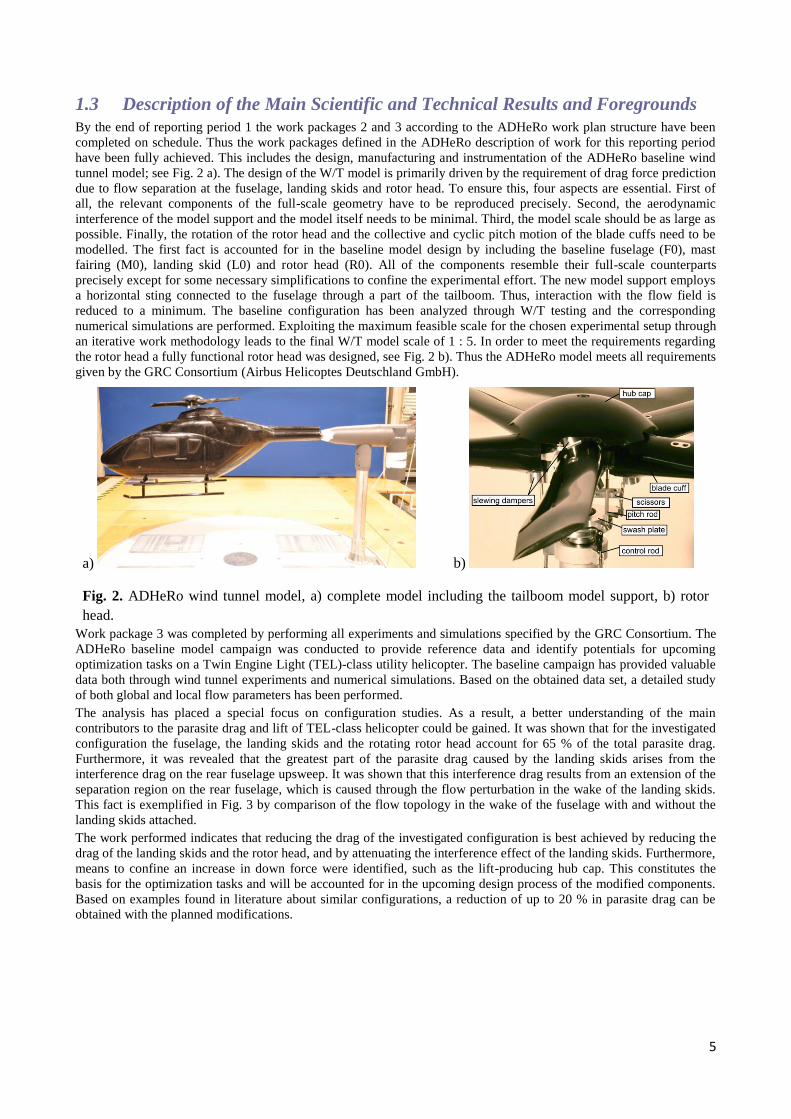
By the end of reporting period 1 the work packages 2 and 3 according to the ADHeRo work plan structure have been
completed on schedule. Thus the work packages defined in the ADHeRo description of work for this reporting period
have been fully achieved. This includes the design, manufacturing and instrumentation of the ADHeRo baseline wind
tunnel model; see Fig. 2 a). The design of the W/T model is primarily driven by the requirement of drag force prediction
due to flow separation at the fuselage, landing skids and rotor head. To ensure this, four aspects are essential. First of
all, the relevant components of the full-scale geometry have to be reproduced precisely. Second, the aerodynamic
interference of the model support and the model itself needs to be minimal. Third, the model scale should be as large as
possible. Finally, the rotation of the rotor head and the collective and cyclic pitch motion of the blade cuffs need to be
modelled. The first fact is accounted for in the baseline model design by including the baseline fuselage (F0), mast
fairing (M0), landing skid (L0) and rotor head (R0). All of the components resemble their full-scale counterparts
precisely except for some necessary simplifications to confine the experimental effort. The new model support employs
a horizontal sting connected to the fuselage through a part of the tailboom. Thus, interaction with the flow field is
reduced to a minimum. The baseline configuration has been analyzed through W/T testing and the corresponding
numerical simulations are performed. Exploiting the maximum feasible scale for the chosen experimental setup through
an iterative work methodology leads to the final W/T model scale of 1 : 5. In order to meet the requirements regarding
the rotor head a fully functional rotor head was designed, see Fig. 2 b). Thus the ADHeRo model meets all requirements
given by the GRC Consortium (Airbus Helicoptes Deutschland GmbH).
a) b)
Fig. 2. ADHeRo wind tunnel model, a) complete model including the tailboom model support, b) rotor
head.
Work package 3 was completed by performing all experiments and simulations specified by the GRC Consortium. The
ADHeRo baseline model campaign was conducted to provide reference data and identify potentials for upcoming
optimization tasks on a Twin Engine Light (TEL)-class utility helicopter. The baseline campaign has provided valuable
data both through wind tunnel experiments and numerical simulations. Based on the obtained data set, a detailed study
of both global and local flow parameters has been performed.
The analysis has placed a special focus on configuration studies. As a result, a better understanding of the main
contributors to the parasite drag and lift of TEL-class helicopter could be gained. It was shown that for the investigated
configuration the fuselage, the landing skids and the rotating rotor head account for 65 % of the total parasite drag.
Furthermore, it was revealed that the greatest part of the parasite drag caused by the landing skids arises from the
interference drag on the rear fuselage upsweep. It was shown that this interference drag results from an extension of the
separation region on the rear fuselage, which is caused through the flow perturbation in the wake of the landing skids.
This fact is exemplified in Fig. 3 by comparison of the flow topology in the wake of the fuselage with and without the
landing skids attached.
The work performed indicates that reducing the drag of the investigated configuration is best achieved by reducing the
drag of the landing skids and the rotor head, and by attenuating the interference effect of the landing skids. Furthermore,
means to confine an increase in down force were identified, such as the lift-producing hub cap. This constitutes the
basis for the optimization tasks and will be accounted for in the upcoming design process of the modified components.
Based on examples found in literature about similar configurations, a reduction of up to 20 % in parasite drag can be
obtained with the planned modifications.

6
a) b)
Fig. 3. Iso-surface of the Q-Criterion colored by non-dimensional axial vorticity in the wake of the fuselage
obtained from numerical simulations without a) and with b) landing skids attached.
By the end of reporting period 2 work package 4 has been completed and initial work on task 6.2 of work package 6 has
been carried out according to the ADHeRo work plan structure. As defined in the ADHeRo description of work for this
reporting period all experiments and simulations specified by GRC Consortium for WP 4 have been performed. This
includes the design and manufacturing of two modified landing gear variants (see Fig. 4 a), b)), wind tunnel testing of
configurations with these variants, and accompanying numerical simulations. The design of the landing gear variant L1
is based on input from Airbus Helicopters Deutschland GmbH (AHD) and evolved from numerical investigations and
optimizations carried out at the Institute of Aerodynamics and Fluid Mechanics at the Technische Universität München
(TUM-AER). Modification L1 provided by TUM-AER is designed as a retrofit variant for existing helicopter
configurations. Variant L2 provided by AHD is a total redesign for future helicopter configurations. For both variants a
refined underbody forming fuselage F1 was modelled. All of the components resemble possible full-scale counterparts
precisely except for some necessary simplifications to confine the experimental effort. The modifications of the
ADHeRo model meet all requirements given by the GRC Consortium (Airbus Helicopters Deutschland GmbH).
a)
b)
Fig. 4. ADHeRo wind tunnel model, a) landing gear variant L1, b) landing gear variant L2.
The aim of the ADHeRo landing gear modification campaign was to optimize landing gear geometries with respect to
drag reduction of the total parasite drag of a Twin Engine Light (TEL)-class utility helicopter. The landing gear
modification campaign has provided valuable data both through wind tunnel experiments and numerical simulations.
Based on the obtained data set, a detailed study of both global and local flow parameters has been performed.

7
Fig. 5. Drag coefficient CD as function of angle of attack α for configuration variants with rotating rotor
head F1M0R0 (without landing gear), F0M0L0R0 (with baseline landing gear L0), F1M0L1R0 (with
landing gear variant L1) and F1M0L2R0 (with landing gear variant L2) at symmetric free stream (sidelip β
= 0°).
The analysis has placed a special focus on the effects of the landing gear on configuration studies. It was shown that for
the investigated configuration including a rotating rotor head the modified landing gear variants allow for a reduction of
up to 21% for L1 and 23% for L2 of the total parasite drag of current production utility helicopter, see Fig. 5.
Furthermore, it was revealed that both modified landing gear variants generate a flow topology on the rear fuselage
upsweep closely resembling that of configurations without (or with fully retracted) landing gear. This fact is
exemplified in Fig. 6 by comparison of the surface pressure distributions (numerical result) of the rear fuselage without
landing gear, with baseline landing gear, and with landing gear variant L2 attached.
Fig. 6. Surface pressure coefficient distribution on the rear fuselage of configurations without landing gear
(left), baseline landing gear (middle), and modified landing gear L2 (right), superimposed with near-
surface stream lines.
By the end of reporting period 3 work packages 5 and 6 have been completed according to the ADHeRo work plan
structure. As defined in the ADHeRo description of work for this reporting period all experiments and simulations
specified by GRC Consortium for WP 5 and 6 have been performed. This includes the design and manufacturing of
several strake variants and vortex generators as well as two modified mast fairings, wind tunnel testing of
configurations with these variants, and accompanying numerical simulations. The achieved completion of all tasks
within reporting period 3 also marks the end of the ADHeRo project in full agreement with the project description.
The aim of the mast fairing and hubcap wind tunnel campaign was the optimization of the mast fairing and hubcap of a
5-bladed Twin Engine Light (TEL) - class utility helicopter. Based on the obtained data set, a detailed study of the
aerodynamic coefficients and flow characteristics has been performed. Different combinations of new mast fairing and
hub cap designs have been investigated. The analysis showed that introducing a new slender mast fairing yields
desirable drag savings. The selected modified mast fairing and the baseline mast fairing are presented in Fig. 7. The

8
performed analysis demonstrated that the new slender mast fairing design can lead to a drag reduction of about 1.5 %
measured in total parasite drag of the real production type helicopter.
a) b) Fig. 7. ADHeRo wind tunnel model with a) baseline mast fairing and b) modified mast fairing M1.
One of the distinct flow features associated to the mast fairing is the generation of a pair of contour-rotating vortices.
Through the performed numerical simulations the formation of these vortices could be studied both on the baseline as
well as on the modified mast fairing geometry,. see Fig. 8. Thus the numerical data are valuable for better understanding
the source of the observed modification of the wake provided by the new mast fairing designs. This is valuable
information since the “surfboard” has proved its potential for mitigating the risk of tail shake in the past.
a) b) Fig. 8. Formation of counter rotating mast fairing vortices analysed through numerical simulation, a)
baseline mast fairing and b) modified mast fairing M1.
The separation at the rear fuselage upsweep provides additional drag reduction potential. However, the requested
specifications often include a rear loading capability. In consequence, it is not feasible reducing parasite drag in the aft-
body region by streamlined surfaces. Thus WP6 addresses these drag sources through the application of passive flow
control devices. The selected devices (strakes and vortex generators) are applied to the rear fuselage upsweep region.
For WP6, counter-rotating vortex generators, straight type strakes (sheet-metal) and contoured strakes are considered.
Fig. 9 Achieved relative drag reductions for the employed passive flow control devices in comparison to the
reference without rotor head and faired skid-landing-gear F1M0L1. Results are shown for angles of attack
equal to 0° (blue) and -1.5° (red). Results for configurations with an increased drag level are blanked.

9
This includes a wide experimental analysis of the devices optimal position and their combination, see Fig. 9. Two
different combinations of flow control devices were identified, out of 20 configurations, as the most promising solutions
for reducing the aft-body drag and the remaining interference effects. Those configurations combine strakes with vortex
generators. One configuration includes straight type strakes (sheet-metal) whereas the other configuration features
contoured strakes, see Fig. 10 a) and b), respectively.
Compared to current production type TEL utility helicopter, the parasite drag could be reduced by another 1.4 - 1.6% in
addition to the previous drag savings obtained with the faired skid-landing-gear and modified mast fairing (22.5 %).
a)
b)
Fig. 10. ADHeRo wind tunnel model with retrofittable skid-landing-gear and a) vortex generators
combined with straight type strakes (sheet-metal), b) vortex generators combined with contoured strakes.
Fig. 11 depicts the near surface streamline pattern in the aft-body region obtained through numerical simulation.
Comparing the near surface flow pattern of configuration F1M0L1 against the one observed for the configuration also
including the contoured strakes and vortex generators, shows a significant impact of the flow control devices on the aft-
body flow topology. In the presence of the vortex generators and contoured strakes the separation at the rear fuselage
upsweep is almost fully suppressed and the separation at the lateral tapering is delayed. Thus the observed drag
reduction can be associated to those local flow phenomena.
a) b)
Fig. 11 Near surface streamlines on the rear fuselage of configurations a) F1M0L1 and b) F1M0L1 with
vortex generators and strakes.

10
1.4 Description of the Potential Impact, the Main Dissemination Activities and
the Exploitation of Results
The achieved scientific and technical progress, fostered by the ADHeRo project, has well been disseminated through a
variety of dissemination streams. First ADHeRo representative attended all GRC Annual Review Meetings during the
project period presenting technical presentations in the course of the GRC2 presentation. Furthermore, technical
progress has been presented at several GRC2 Management and Work Package Meetings.
On industry level, ADHeRo representative promoted the benefits of the investigated components through regular
progress meetings. Furthermore, the partner supported the project leader Airbus Helicopters Deutschland GmbH in the
preparation and execution of preliminary and critical design review meetings. This lead to the successful achievement
of technical readiness level 4 for all selected modifications investigated through wind tunnel experiments in the course
of the project (TRL4, i.e. component and/or breadboard validation in laboratory environment). Considering the planned
flight tests on the technology demonstrator in 2015, even technology readiness level 6 will be reached (TRL 6, i.e.
system/subsystem model or prototype demonstration in a relevant environment).
The scientific community has been addressed through the attendance of ADHeRo representatives at numerous
workshops and conferences at national and international level. This work is also documented through the publication of
conference and peer reviewed journal papers. The list below summarises these efforts.
STAB 2011 M. Grawunder, R. Reß, Z. Babosek, C. Breitsamter, N. A. Adams:
Numerische Simulation der Umströmung eines 5–Blatt-Rotorkopfes.
STAB-Workshop, Göttingen, 10.-11. Nov. 2011.
DGLR 2012 R. Reß, M. Grawunder, C. Breitsamter, and N. A. Adams:
Windkanaluntersuchung einer Hubschrauberzelle einschließlich eines rotierenden Rotorkopfs.
In: DGLRK2012–281310, German Aerospace Congress, Berlin, 9.-10. Sept. 2012, pp. 1-9.
ICAS 2012 M. Grawunder, R. Reß, C. Breitsamter, and N. A. Adams:
Flow Characteristics of a Helicopter Fuselage Configuration Including a
Rotating Rotor Head.
In: ICAS Proc., 28th Congress of the International Council of the Aeronautical Sciences,
ICAS–2012–2.7.3, Brisbane, Australia, Sept. 23-28, 2012, pp. 273.1– 273.14.
STAB 2012 M. Grawunder, R. Reß, V. Stein, C. Breitsamter, N. A. Adams:
Flow Characteristics of a Five Bladed Rotor Head..
STAB-Symposium, Stuttgart, 10.-11. Nov. 2012. Published in NNFM (Springer-Verlag).
EUCASS
2013
R. Reß, M. Grawunder, and C. Breitsamter:
Aerodynamic Analysis of a Helicopter Fuselage with Rotating Rotor Head.
In: Proc. 5th European Conference for Aeronautics and Space Sciences, Munich, July 1-5, 2013.
ERF 2013 M. Grawunder, R. Reß, C. Breitsamter, and N. A. Adams:
Optimized Skid-Landing-Gears for Twin-Engine-Light Utility Helicopter.
39th European Rotorcraft Forum, Moscow, Russia, Sept. 3-6, 2013.
ERF 2014 M. Grawunder, R. Reß, and C. Breitsamter:
Helicopter Aft Body Drag Reduction by Passive Flow Control.
40th European Rotorcraft Forum, Southampton, UK, Sept. 2-5, 2014.
ICAS 2014 C. Breitsamter, M. Grawunder, and R. Reß:
Aerodynamic Design Optimization for a Helicopter Configuration Including
a Rotating Rotor Head.
In: ICAS Proc., 29th Congress of the International Council of the Aeronautical Sciences,
ICAS–2014–4.9ST, St. Petersburg, Russia, Sept. 7-12, 2014, pp. 491.1– 491.11.
DGLR 2014 R. Reß, M. Grawunder, C. Breitsamter, and N. A. Adams:
Aerodynamic Design Optimization of a Light-Weight Helicopter Configuration.
In: DGLRK2014–0046, German Aerospace Congress, Augsburg, 16.-18. Sept. 2014, pp. 1-9.
11
STAB 2014 M. Grawunder, R. Reß, V. Stein, C. Breitsamter, and N. A. Adams:
Validation of the numerical simulation of a five bladed rotor head configuration. STAB-
Symposium, München, 4.-5. Nov. 2014. Published in NNFM (Springer-Verlag).
The general public was informed about the objectives and achievements through the project website
(www.ADHeRo.de) and on the occasion of open house presentations. Furthermore, ADHeRo representatives presented
the project at fairs such as the International Aerospace Exhibition (ILA) in Berlin.
The achieved drag reduction of about 24 % on aggregate could result in a reduction in fuel consumption in the order of
10 % and more. Thus the expected drag reduction expectations of about 20 % have clearly been exceeded. Considering
the achieved technology readiness level, the prospective benefits could enter market within a short period after project
completion.
Entering the market with a light weight helicopter of such an increased efficiency provides potential for several
economic and social benefits. This new generation of helicopter could either fly faster or further with the same amount
of fuel. This is beneficial for a number of missions. Being able to fly faster is especially important when economy of
time is crucial, e.g. helicopter emergency medical services (HEMS). Extending the range of a helicopter is beneficial for
example for search and rescue (SAR) missions or for supplying remote areas. Finally, the achieved efficiency gains can
lead to reduced costs of a given mission. Thus the achieved improvements of light weight helicopter increase the
mission compatibility for all key mission of this helicopter class. In consequence the European original equipment
manufacturer could be able to extend the versatility of their products. This could help securing existing and gaining new
market shares. Hence, ADHeRo contributed to reducing the environmental impact and improving the quality of services
provided by light weight utility helicopters. Overall, this could further improve the societal implication of helicopter
services as a beneficiary means both for society and industry.