project manual daytona state college building 2 … 11-2010.pdfproject manual daytona state college...
TRANSCRIPT

November 2010
PROJECT MANUAL
DAYTONA STATE COLLEGE BUILDING 2 RENOVATION PALM COAST, FLORIDA
CONSTRUCTION DOCUMENTS
Daytona State College Flagler/Palm Coast Campus
3000 Palm Coast Pkwy Palm Coast, FL 32137
Project #02092.53 Prepared By:
DJDESIGN SERVICES, INC. ARCHITECTS AND PLANNERS
913 North Nova Road (386) 255-6987 Phone Holly Hill, Florida 32117 (386) 255-6989 Fax AA 26000567

!"#$%&"'($"$)'*%++),)-'."+/'*%"0$'*"/120'3'425+65&,'7'8)&%9"$5%&'!!!!!!!!!!!!!!!!!!!!!!!!!!!!!!!!!!!"#$%&'%('7:;:'' '
<=4>?'@A'*@B<?B<(
(?*<C@BD <C<>?D .=E?(D
;F:;:' 4=(C*'G?*H=BC*=>'8?IJC8?G?B<(' K'
;F:F:' 4=(C*'G?*H=BC*=>'G=<?8C=>('=B!'G?<H@!(' 7'
;F:LF' =**?(('!@@8(' F'
;F:M:' CB(J>=<C@B' ';N'
;FKOM' (.>C<3(P(<?G'=C83*@B!C<C@BCBE'JBC<(' F'
;FM)*' G?<=>'!J*<( ;7'
;FM+,' !J*<'=**?((@8C?(' ''L
;FMN:' =C8'<?8GCB=>'JBC<(' K'
;FMFF' !CAAJ(?8(-'8?EC(<?8(-'=B!'E8C>>?(' F'
;FQ::' HR=*'CB(<8JG?B<=<C@B'=B!'*@B<8@>('' 7L'
;FQF:' <?(<CBE-'=!SJ(<CBE-'=B!'4=>=B*CBE'' ;N'
'
5'

Daytona State College, Palm Coast Campus - Building 2 Renovation Aug 2010
SECTION 15010 – BASIC MECHANICAL REQUIREMENTS
PART 1 - GENERAL
1.1 RELATED DOCUMENTS
A. Drawings and general provisions of Contract, including General and Supplementary Conditions
and Division 1 Specification Sections, apply to this and the other sections of Division 15.
1.2 SUMMARY
A. This Section includes general administrative and procedural requirements for mechanical instal-
lations. The following administrative and procedural requirements are included in this Section
to expand the requirements specified in Division 1:
1. Submittals.
2. Coordination drawings.
3. Record documents.
4. Maintenance manuals.
5. Installation instructions and manuals.
6. Quality Assurance.
7. Product Selection.
8. Rough-ins.
9. Mechanical installations.
1.3 SUBMITTALS
A. Submittals: Submit each copy in a three-ring loose-leaf binder or binders, sized to hold all sub-
mittal data, future as well as present.
1. Label each binder with clear identification.
2. Provide index tabs for each specification section for which data is being submitted.
3. Provide a table contents identifying each tab.
4. Clearly identify material and equipment being submitted when more than one item is in-
cluded on data sheets.
5. Prepare schedules in the same format as the basis of design equipment schedules, listing
the same parameters identified in the project manual.
6. Identify like kinds of equipment in same manner as contract documents.
1.4 COORDINATION DRAWINGS
A. Prepare coordination drawings to a scale of 1/4"=1'-0" or larger; detailing major elements, com-
ponents, and systems of mechanical equipment and materials in relationship with other systems,
installations, and building components. Indicate locations where space is limited for installation
and access and where sequencing and coordination of installations are of importance to the effi-
cient flow of the Work, including (but not necessarily limited to) the following:
BASIC MECHANICAL REQUIREMENTS 15010 - 1

Daytona State College, Palm Coast Campus - Building 2 Renovation Aug 2010
1. Indicate the proposed locations of piping, ductwork, equipment, and materials including:
a. Clearances for installing and maintaining insulation.
b. Clearances for servicing and maintaining equipment, including tube removal, filter
removal, and space for equipment disassembly required for periodic maintenance.
c. Equipment connections and support details.
d. Exterior wall and foundation penetrations.
e. Fire-rated wall and floor penetrations.
f. Sizes and location of required concrete pads and bases.
g. Valve stem movement.
2. Indicate scheduling, sequencing, movement, and positioning of large equipment into the
building during construction.
3. Prepare floor plans, elevations, and details to indicate equipment installation and penetra-
tions in floors, walls, and ceilings and their relationship to other installations.
4. Prepare reflected ceiling plans to coordinate installations, air outlets and inlets, light fix-
tures, communication systems components, sprinklers, and other ceiling-mounted items.
B. The contractor is responsible for all means, methods, sequencing, and coordination of construc-
tion. The contractor remains responsible for confirming all quantities and dimensions, assuring
required clearances, and coordinating installation conflicts.
1.5 RECORD DOCUMENTS
A. Prepare record documents in accordance with the requirements in Division 1 Section
"PROJECT CLOSEOUT." In addition to the requirements specified in Division 1, indicate the
following installed conditions:
1. Ductwork mains and branches, size and location, for both exterior and interior; locations
of dampers and other control devices; filters, boxes, and terminal units requiring periodic
maintenance or repair.
2. Mains and branches of piping systems, with valves and control devices located and num-
bered, concealed unions located, and with items requiring maintenance located (i.e.,
traps, strainers, tanks, etc.). Valve location diagrams, complete with valve tag chart. In-
dicate actual inverts and horizontal locations of underground piping.
3. Equipment locations (exposed and concealed), dimensioned from prominent building
lines.
4. Approved substitutions, Contract Modifications, and actual equipment and materials in-
stalled.
5. Contract Modifications, actual equipment and materials installed.
B. Engage the services of a Land Surveyor registered in the state in which the project is located to
record the locations and invert elevations of underground installations.
1.6 MAINTENANCE MANUALS
A. Prepare maintenance manuals in accordance with Division 1 Section "PROJECT CLOSEOUT."
In addition to the requirements specified in Division 1, include the following information for
equipment items:
BASIC MECHANICAL REQUIREMENTS 15010 - 2

Daytona State College, Palm Coast Campus - Building 2 Renovation Aug 2010
1. Description of function, normal operating characteristics and limitations, performance
curves, engineering data and tests, and complete nomenclature and commercial numbers
of replacement parts.
2. Manufacturer's printed operating procedures to include start-up, break-in, and routine and
normal operating instructions; regulation, control, stopping, shutdown, and emergency
instructions; and summer and winter operating instructions.
3. Maintenance procedures for routine preventative maintenance and troubleshooting; disas-
sembly, repair, and reassembly; aligning and adjusting instructions.
4. Servicing instructions and lubrication charts and schedules.
5. Copy of approved submittal data.
1.7 INSTALLATION INSTRUCTIONS AND MANUALS
A. Provide manufacturers’ standard published installation instructions for mechanical equipment,
devices and assemblies to be used on this project.
B. Manufacturer's printed installation instructions to include installation of main equipment, com-
ponents, accessory devices, and firestop systems. Include the following:
1. Clearances for servicing and maintaining equipment, accessories, and specialties.
2. Piping and accessory assembly and connections, including valves, ducts, and specialties.
3. Equipment and accessory service connections and details.
1.8 QUALITY ASSURANCE
A. Comply with governing laws, ordinances, and regulations of authority having jurisdiction.
B. Refer to individual specification sections for specific codes and standards not listed below.
C. Comply with the following codes and standards:
1. Florida Building Code, 2007, Building, with 2009 Supplements.
2. Florida Building Code, 2007, Mechanical, with 2009 Supplements.
3. Florida Building Code, 2007, Plumbing, with 2009 Supplements.
D. Energy Efficiency Requirements: Comply with requirements of Florida Building Code, 2007,
Chapter 13 Florida Energy Efficiency for Building Construction."
E. Accessibility Requirements: Comply with requirements of Florida Building Code, 2007, Chap-
ter 11 “Florida Accessibility Code for Building Construction.”
F. If compliance with two or more standards is specified and the standards establish different or
conflicting requirements for minimum quantities or quality levels, comply with the most
stringent requirement. Refer uncertainties and requirements that are different, but apparently
equal, to Architect for a decision before proceeding.
G. Factory-Authorized Service Representative Qualifications: An authorized representative of
manufacturer who is trained and approved by manufacturer to inspect installation of
BASIC MECHANICAL REQUIREMENTS 15010 - 3

Daytona State College, Palm Coast Campus - Building 2 Renovation Aug 2010
manufacturer's products that are similar in material, design, and extent to those indicated for this
Project.
H. Refer conflicts between requirements to Architect for resolution.
PART 2 - PRODUCTS
2.1 PRODUCTS
A. General Product Requirements: Provide products that comply with the Contract Documents,
that are undamaged and, unless otherwise indicated, that are new at time of installation.
1. Provide products complete with accessories, trim, finish, fasteners, and other items
needed for a complete installation and indicated use and effect.
2. Standard Products: If available, and unless custom products or nonstandard options are
specified, provide standard products of types that have been produced and used
successfully in similar situations on other projects.
3. Descriptive, performance, and reference standard requirements in the Specifications
establish "salient characteristics" of products.
B. Basis-of-Design Product Specification: A specific manufacturer's product is named, including
make or model number or other designation, to establish the significant qualities related to type,
function, dimension, in-service performance, physical properties, appearance, and other
characteristics for purposes of evaluating comparable products of other named manufacturers.
1. The types and capacities of equipment and accessories and are based on specific descrip-
tions and manufacturers indicated. Equipment having equal performance characteristics
by manufacturers may be considered provided that deviations in capacities, dimensions,
operation, or other characteristics are minor and do not change the design concept or in-
tended performance as judged by the Architect. Significant variations must be clearly in-
dicated in appropriate coordination drawings and must be attached to the pertinent
equipment submittal. Burden of proof for equality of equipment is on the Proposer.
2. Equipment with different operating criteria, electrical parameters, power, dimensions, ca-
pacities, and ratings may be furnished provided such proposed equipment is approved in
writing and connecting mechanical and electrical services, circuit breakers, conduit, mo-
tors, bases, piping, ductwork, and equipment spaces are modified to accept the proposed
equipment. Additional costs must be approved in advance by Architect or Owner. Oth-
erwise, additional costs shall be the responsibility of the Subcontractor. The proposed
equipment must meet the energy ratings, efficiencies, design, and commissioning re-
quirements of the basis of design equipment.
C. Manufacturers: Manufacturers listed in the Products Section under: Manufacturers; Available
Manufacturers; or Basis of Design Product may use other equipment manufacturer’s (OEM)
product in order to comply with the material and performance criteria specified when their stan-
dard or custom product cannot meet these criteria, provided they have a standard OEM agree-
ment with the other manufacturer to finish and place their name on that product.
BASIC MECHANICAL REQUIREMENTS 15010 - 4

Daytona State College, Palm Coast Campus - Building 2 Renovation Aug 2010
PART 3 - EXECUTION
3.1 EXAMINATION
A. Existing Utilities: The existence and location of underground and other utilities and
construction indicated as existing are not guaranteed. Before beginning work, investigate and
verify the existence and location of utilities and other construction affecting the Work.
1. Before construction, verify the location and invert elevation at points of connection of
sanitary sewer, storm sewer, and water-service piping; and electrical services.
2. Furnish location data for work related to Project that must be performed by public
utilities serving Project site.
B. Acceptance of Conditions: Examine substrates, areas, and conditions, with Installer or
Applicator present where indicated, for compliance with requirements for installation tolerances
and other conditions affecting performance. Record observations.
1. Written Report: Prepare a written report listing conditions detrimental to performance of
the Work, include the following:
a. Description of the Work.
b. List of detrimental conditions, including substrates.
c. List of unacceptable installation tolerances.
d. Recommended corrections.
2. Verify compatibility with and suitability of substrates, including compatibility with
existing finishes or primers.
3. Examine roughing-in for mechanical and electrical systems to verify actual locations of
connections before equipment and fixture installation.
4. Examine walls, floors, and roofs for suitable conditions where products and systems are
to be installed.
5. Proceed with installation only after unsatisfactory conditions have been corrected.
Proceeding with the Work indicates acceptance of surfaces and conditions.
3.2 EXISTING UTILITY SERVICES AND MECHANICAL SYSTEMS
A. Existing Services/Systems: Maintain services/systems to remain and protect them against
damage during selective demolition operations.
B. Service/System Requirements: Locate, identify, disconnect, and seal or cap off indicated utility
services and mechanical/electrical systems serving areas to be selectively demolished.
1. Owner will arrange to shut off indicated services/systems when requested by Contractor.
2. Arrange to shut off utilities with utility companies.
3. If services/systems are required to be removed, relocated, or abandoned, before
proceeding with selective demolition provide temporary services/systems that bypass
area of selective demolition and that maintain continuity of services/systems to other
parts of building.
BASIC MECHANICAL REQUIREMENTS 15010 - 5

Daytona State College, Palm Coast Campus - Building 2 Renovation Aug 2010
4. Cut off pipe or conduit in walls or partitions to be removed. Cap, valve, or plug and seal
remaining portion of pipe or conduit after bypassing.
3.3 INSTALLATION
A. General: Sequence, coordinate, and integrate the various elements of mechanical systems, ma-
terials, and equipment.
1. Coordinate mechanical systems, equipment, and materials installation with other building
components.
2. Verify all dimensions by field measurements.
3. Install systems, materials, and equipment to conform with approved submittal data, in-
cluding coordination drawings. Conform to arrangements indicated by the Contract
Documents, to greatest extent possible, recognizing that portions of the Work are shown
only in diagrammatic form.
B. Locate the Work and components of the Work accurately, in correct alignment and elevation.
1. Make vertical work plumb and make horizontal work level.
2. Where space is limited, install components to maximize space available for maintenance
and ease of removal for replacement.
3. Conceal pipes, ducts, and wiring in finished areas, unless otherwise indicated.
4. Maintain minimum headroom clearance of 8 feet in spaces without a suspended ceiling.
C. Verify final locations for rough-ins with field measurements and with the requirements of the
actual equipment to be connected.
D. Comply with manufacturer's written instructions and recommendations for installing products in
applications indicated.
E. Install products at the time and under conditions that will ensure the best possible results.
Maintain conditions required for product performance until Substantial Completion.
F. Conduct construction operations so no part of the Work is subjected to damaging operations or
loading in excess of that expected during normal conditions of occupancy.
G. Tools and Equipment: Do not use tools or equipment that produce harmful noise levels.
H. Templates: Obtain and distribute to the parties involved templates for work specified to be
factory prepared and field installed. Check Shop Drawings of other work to confirm that
adequate provisions are made for locating and installing products to comply with indicated
requirements.
I. Anchors and Fasteners: Provide anchors and fasteners as required to anchor each component
securely in place, accurately located and aligned with other portions of the Work.
1. Mounting Heights: Where mounting heights are not indicated, mount components at
heights directed by Architect.
2. Allow for building movement, including thermal expansion and contraction.
BASIC MECHANICAL REQUIREMENTS 15010 - 6

Daytona State College, Palm Coast Campus - Building 2 Renovation Aug 2010
3. Coordinate installation of anchorages. Furnish setting drawings, templates, and
directions for installing anchorages, including sleeves, concrete inserts, anchor bolts, and
items with integral anchors, that are to be embedded in concrete or masonry. Deliver
such items to Project site in time for installation.
J. Hazardous Materials: Use products, cleaners, and installation materials that are not considered
hazardous.
3.4 INSTALLATION INSTRUCTIONS AND MANUALS
A. Store manufacturers’ published instructions and manuals at project site so that they may be ref-
erenced at any time during normal working hours.
END OF SECTION 15010
BASIC MECHANICAL REQUIREMENTS 15010 - 7

Daytona State College, Palm Coast Campus - Building 2 Renovation Aug 2010
SECTION 15050 - BASIC MECHANICAL MATERIALS AND METHODS
PART 1 - GENERAL
1.1 RELATED DOCUMENTS
A. Drawings and general provisions of the Contract, including General and Supplementary
Conditions and Division 1 Specification Sections, apply to this Section.
1.2 SUMMARY
A. This Section includes the following:
1. Sleeves.
2. Equipment installation requirements common to equipment sections.
3. Painting and finishing.
4. Supports and anchorages.
1.3 DEFINITIONS
A. Finished Spaces: Spaces other than mechanical and electrical equipment rooms, furred spaces,
pipe and duct shafts, unheated spaces immediately below roof, spaces above ceilings,
unexcavated spaces, crawlspaces, and tunnels.
B. Exposed, Interior Installations: Exposed to view indoors. Examples include finished occupied
spaces and mechanical equipment rooms.
C. Exposed, Exterior Installations: Exposed to view outdoors or subject to outdoor ambient
temperatures and weather conditions. Examples include rooftop locations.
D. Concealed, Interior Installations: Concealed from view and protected from physical contact by
building occupants. Examples include above ceilings and in duct shafts.
E. Concealed, Exterior Installations: Concealed from view and protected from weather conditions
and physical contact by building occupants but subject to outdoor ambient temperatures.
Examples include installations within unheated shelters.
1.4 QUALITY ASSURANCE
A. Electrical Characteristics for Mechanical Equipment: Equipment of higher electrical
characteristics may be furnished provided such proposed equipment is approved in writing and
connecting electrical services, circuit breakers, and conduit sizes are appropriately modified. If
minimum energy ratings or efficiencies are specified, equipment shall comply with
requirements.
BASIC MECHANICAL MATERIALS AND METHODS 15050 - 1
Daytona State College, Palm Coast Campus - Building 2 Renovation Aug 2010
1.5 COORDINATION
A. Coordinate requirements for access panels and doors for mechanical items requiring access that
are concealed behind finished surfaces.
PART 2 - PRODUCTS
2.1 SLEEVES
A. Galvanized-Steel Sheet: 0.0239-inch minimum thickness; round tube closed with welded
longitudinal joint.
PART 3 - EXECUTION
3.1 EQUIPMENT INSTALLATION - COMMON REQUIREMENTS
A. Install equipment to allow maximum possible headroom unless specific mounting heights are
not indicated.
B. Install equipment level and plumb, parallel and perpendicular to other building systems and
components in exposed interior spaces, unless otherwise indicated.
C. Install mechanical equipment to facilitate service, maintenance, and repair or replacement of
components. Connect equipment for ease of disconnecting, with minimum interference to other
installations. Extend grease fittings to accessible locations.
D. Install equipment to allow right of way for piping installed at required slope.
3.2 PAINTING
A. Damage and Touchup: Repair marred and damaged factory-painted finishes with materials and
procedures to match original factory finish.
3.3 ERECTION OF METAL SUPPORTS AND ANCHORAGES
A. Cut, fit, and place miscellaneous metal supports accurately in location, alignment, and elevation
to support and anchor mechanical materials and equipment.
END OF SECTION 15050
BASIC MECHANICAL MATERIALS AND METHODS 15050 - 2

Daytona State College, Palm Coast Campus - Building 2 Renovation Aug 2010
SECTION 15065 - ACCESS DOORS AND FRAMES
PART 1 - GENERAL
1.1 RELATED DOCUMENTS
A. Drawings and general provisions of the Contract, including General and Supplementary
Conditions and Division 1 Specification Sections, apply to this Section.
1.2 SUMMARY
A. This Section includes the following:
1. Access doors and frames for walls and ceilings.
B. Related Sections include the following:
1. Division 15 Section “Plumbing Specialties” for pipe cleanouts
2. Division 15 Section "Duct Accessories" for heating and air-conditioning duct access
doors.
1.3 SUBMITTALS
A. Product Data: For each type of access door and frame indicated. Include construction details,
fire ratings, materials, individual components and profiles, and finishes.
B. Shop Drawings: Show fabrication and installation details of access doors and frames for each
type of substrate. Include plans, elevations, sections, details, and attachments to other work.
C. Access Door and Frame Schedule: Provide complete access door and frame schedule, including
types, locations, sizes, latching or locking provisions, and other data pertinent to installation.
D. Ceiling Coordination Drawings: Reflected ceiling plans, drawn to scale, on which ceiling-
mounted items including access doors and frames, lighting fixtures, diffusers, grilles, speakers,
sprinklers, and special trim are shown and coordinated with each other.
1.4 QUALITY ASSURANCE
A. Source Limitations: Obtain access door(s) and frame(s) through one source from a single
manufacturer.
B. Fire-Rated Access Doors and Frames: Units complying with NFPA 80 that are identical to
access door and frame assemblies tested for fire-test-response characteristics per the following
test method and that are listed and labeled by UL or another testing and inspecting agency
acceptable to authorities having jurisdiction:
ACCESS DOORS AND FRAMES 15065 - 1
Daytona State College, Palm Coast Campus - Building 2 Renovation Aug 2010
1. NFPA 252 or UL 10B for vertical access doors and frames.
2. ASTM E 119 or UL 263 for horizontal access doors and frames.
1.5 COORDINATION
A. Verification: Determine specific locations and sizes for access doors needed to gain access to
concealed plumbing, mechanical, or other concealed work, and indicate in the schedule
specified in "Submittals" Article.
PART 2 - PRODUCTS
2.1 STEEL MATERIALS
A. Steel Plates, Shapes, and Bars: ASTM A 36/A 36M.
1. ASTM A 123/A 123M, for galvanizing steel and iron products.
2. ASTM A 153/A 153M, for galvanizing steel and iron hardware.
B. Steel Sheet: Uncoated or electrolytic zinc-coated, ASTM A 591/A 591M with cold-rolled steel
sheet substrate complying with ASTM A 1008/A 1008M, Commercial Steel (CS), exposed.
C. Metallic-Coated Steel Sheet: ASTM A 653/A 653M, Commercial Steel (CS) with A60 zinc-
iron-alloy (galvannealed) coating or G60 mill-phosphatized zinc coating; stretcher-leveled
standard of flatness; with minimum thickness indicated representing specified thickness
according to ASTM A 924/A 924M.
D. Steel Finishes: Comply with NAAMM's "Metal Finishes Manual for Architectural and Metal
Products" for recommendations for applying and designating finishes.
1. Surface Preparation for Steel Sheet: Clean surfaces to comply with SSPC-SP 1, "Solvent
Cleaning," to remove dirt, oil, grease, or other contaminants that could impair paint bond.
Remove mill scale and rust, if present, from uncoated steel, complying with SSPC-
SP 5/NACE No. 1, "White Metal Blast Cleaning," or SSPC-SP 8, "Pickling."
2. Surface Preparation for Metallic-Coated Steel Sheet: Clean surfaces with nonpetroleum
solvent so surfaces are free of oil and other contaminants. After cleaning, apply a
conversion coating suited to the organic coating to be applied over it. Clean welds,
mechanical connections, and abraded areas, and apply galvanizing repair paint specified
below to comply with ASTM A 780.
a. Galvanizing Repair Paint: High-zinc-dust-content paint for regalvanizing welds in
steel, complying with SSPC-Paint 20.
E. Drywall Beads: Edge trim formed from 0.0299-inch zinc-coated steel sheet formed to receive
joint compound and in size to suit thickness of gypsum board.
F. Plaster Beads: Casing bead formed from 0.0299-inch zinc-coated steel sheet with flange
formed out of expanded metal lath and in size to suit thickness of plaster.
ACCESS DOORS AND FRAMES 15065 - 2

Daytona State College, Palm Coast Campus - Building 2 Renovation Aug 2010
2.2 STAINLESS-STEEL MATERIALS
A. Rolled-Stainless-Steel Floor Plate: ASTM A 793, manufacturer's standard finish.
B. Stainless-Steel Sheet, Strip, Plate, and Flat Bars: ASTM A 666, Type 304 or 316. Remove tool
and die marks and stretch lines or blend into finish.
1. Finish: Directional Satin Finish, No. 4.
2.3 ACCESS DOORS AND FRAMES FOR WALLS AND CEILINGS
A. Available Manufacturers: Subject to compliance with requirements, manufacturers offering
products that may be incorporated into the Work include, but are not limited to, the following:
1. Acudor Products, Inc.
2. Karp Associates, Inc.
3. Larsen's Manufacturing Company.
4. MIFAB, Inc.
5. Milcor Inc.
6. Nystrom, Inc.
B. Flush Access Doors and Frames with Exposed Trim: Fabricated from stainless-steel sheet.
1. Locations: Wall and ceiling surfaces.
2. Door: Minimum 0.060-inch thick sheet metal, set flush with exposed face flange of
frame.
3. Frame: Minimum 0.060-inch thick sheet metal with 1-1/4-inch wide, surface-mounted
trim.
4. Hinges: Continuous piano.
5. Lock: Cylinder or mortise cylinder.
C. Flush Access Doors and Trimless Frames: Fabricated from stainless-steel sheet.
1. Locations: Wall and ceiling surfaces.
2. Door: Minimum 0.060-inch thick sheet metal, set flush with surrounding finish surfaces.
3. Frame: Minimum 0.060-inch thick sheet metal with drywall or plaster bead flange, as
applicable for substrate.
4. Hinges: Continuous piano.
5. Lock: Cylinder or mortise cylinder.
D. Exterior Flush Access Doors and Frames with Exposed Trim: Weatherproof with extruded door
gasket.
1. Locations: Wall and ceiling surfaces.
2. Door: Minimum 0.040-inch thick, stainless-steel sheet; flush panel construction with
manufacturer's standard 2-inch- thick fiberglass insulation.
3. Frame: Minimum 0.060-inch thick stainless-steel sheet.
4. Hinges: Continuous piano, zinc plated.
5. Lock: Dual-action handles with key lock.
ACCESS DOORS AND FRAMES 15065 - 3

Daytona State College, Palm Coast Campus - Building 2 Renovation Aug 2010
E. Fire-Rated, Insulated, Flush Access Doors and Frames with Exposed Trim: Fabricated from
stainless-steel sheet.
1. Locations: Wall and ceiling surfaces.
2. Fire-Resistance Rating: Not less than 1-1/2 hours.
3. Temperature Rise Rating: 250 deg F at the end of 30 minutes.
4. Door: Flush panel with a core of mineral-fiber insulation enclosed in sheet metal with a
minimum thickness of 0.036 inch.
5. Frame: Minimum 0.060-inch thick sheet metal with 1-inch wide, surface-mounted trim.
6. Hinges: Continuous piano.
7. Automatic Closer: Spring type.
8. Lock: Self-latching device with cylinder or mortise cylinder lock.
F. Fire-Rated, Insulated, Flush Access Doors and Trimless Frames: Fabricated from stainless-steel
sheet.
1. Locations: Wall and ceiling surfaces.
2. Fire-Resistance Rating: Not less than 1-1/2 hours.
3. Temperature Rise Rating: 250 deg F at the end of 30 minutes.
4. Door: Flush panel with a core of mineral-fiber insulation enclosed in sheet metal with a
minimum thickness of 0.036 inch.
5. Frame: Minimum 0.060-inch thick sheet metal with drywall or plaster bead, as
applicable for substrate.
6. Hinges: Continuous piano.
7. Automatic Closer: Spring type.
8. Lock: Self-latching device with cylinder or mortise cylinder lock.
2.4 FABRICATION
A. General: Provide access door and frame assemblies manufactured as integral units ready for
installation.
B. Metal Surfaces: For metal surfaces exposed to view in the completed Work, provide materials
with smooth, flat surfaces without blemishes. Do not use materials with exposed pitting, seam
marks, roller marks, rolled trade names, or roughness.
C. Doors and Frames: Grind exposed welds smooth and flush with adjacent surfaces. Furnish
attachment devices and fasteners of type required to secure access panels to types of supports
indicated.
1. Exposed Flanges: Nominal 1 to 1-1/2 inches wide around perimeter of frame.
2. For trimless frames with drywall bead, provide edge trim for gypsum board and gypsum
base securely attached to perimeter of frames.
3. For trimless frames with plaster bead for full-bed plaster applications, provide zinc-
coated expanded metal lath and exposed casing bead welded to perimeter of frames.
4. Provide mounting holes in frames for attachment of units to metal or wood framing.
5. Provide mounting holes in frame for attachment of masonry anchors.
D. Latching Mechanisms: Furnish number required to hold doors in flush, smooth plane when
closed.
ACCESS DOORS AND FRAMES 15065 - 4

Daytona State College, Palm Coast Campus - Building 2 Renovation Aug 2010
1. For cylinder lock, furnish two keys per lock and key all locks alike.
2. For recessed panel doors, provide access sleeves for each locking device. Furnish plastic
grommets and install in holes cut through finish.
PART 3 - EXECUTION
3.1 ACCESS DOOR APPLICATIONS
A. Provide access doors when mechanical piping, equipment, control devices, and accessories
requiring periodic maintenance are located within walls, partitions, or ceilings and would
otherwise be inaccessible. Provide the types of doors indicated for the following applications:
1. Conditioned, non-fire-rated locations: Stainless steel.
2. Unconditioned, non-fire-rated locations: Stainless steel.
3. Unconditioned, fire-rated locations: Stainless steel fire-rated.
4. Conditioned, fire-rated locations: Stainless Steel fire-rated.
5. Exterior locations: Weatherproof, Stainless steel.
B. Frames: Provide trimless frames in drywall and plaster substrates and exposed trim frames in
wood and masonry substrates.
C. Provide access doors of adequate size to allow maintenance functions to be performed, but not
less than 12” x 12”.
3.2 INSTALLATION
A. Comply with manufacturer's written instructions for installing access doors and frames.
B. Set frames accurately in position and attach securely to supports with plane of face panels
aligned with adjacent finish surfaces.
C. Install doors flush with adjacent finish surfaces or recessed to receive finish material.
3.3 ADJUSTING AND CLEANING
A. Adjust doors and hardware after installation for proper operation.
B. Remove and replace doors and frames that are warped, bowed, or otherwise damaged.
END OF SECTION 15065
ACCESS DOORS AND FRAMES 15065 - 5

Daytona State College, Palm Coast Campus - Building 2 Renovation Aug 2010
SECTION 15080 - MECHANICAL INSULATION
PART 1 - GENERAL
1.1 RELATED DOCUMENTS
A. Drawings and general provisions of the Contract, including General and Supplementary
Conditions and Division 1 Specification Sections, apply to this Section.
1.2 SUMMARY
A. This Section includes mechanical insulation for boiler breeching, duct, equipment, and pipe,
including the following:
1. Insulation Materials:
a. Flexible elastomeric.
b. Mineral fiber.
2. Fire-rated insulation systems.
3. Insulating cements.
4. Adhesives.
5. Mastics.
6. Lagging adhesives.
7. Sealants.
8. Factory-applied jackets.
9. Field-applied fabric-reinforcing mesh.
10. Field-applied cloths.
11. Field-applied jackets.
12. Tapes.
13. Securements.
14. Corner angles.
1.3 DEFINITIONS
A. ASJ: All-service jacket.
B. FSK: Foil, scrim, kraft paper.
C. FSP: Foil, scrim, polyethylene.
D. SSL: Self-sealing lap.
MECHANICAL INSULATION 15080 - 1

Daytona State College, Palm Coast Campus - Building 2 Renovation Aug 2010
1.4 SUBMITTALS
A. Product Data: For each type of product indicated, identify thermal conductivity, thickness, and
jackets (both factory and field applied, if any).
B. Shop Drawings: Show details for the following:
1. Removable insulation at, equipment connections, and access panels.
2. Application of field-applied jackets.
3. Application at linkages of control devices.
4. Field application for each equipment type.
C. Field quality-control inspection reports.
1.5 QUALITY ASSURANCE
A. Fire-Test-Response Characteristics: Insulation and related materials shall have fire-test-
response characteristics indicated, as determined by testing identical products per ASTM E 84,
by a testing and inspecting agency acceptable to authorities having jurisdiction. Factory label
insulation and jacket materials and adhesive, mastic, and cement material containers, with
appropriate markings of applicable testing and inspecting agency.
1. Insulation Installed Indoors: Flame-spread index of 25 or less, and smoke-developed
index of 50 or less.
2. Insulation Installed Outdoors: Flame-spread index of 75 or less, and smoke-developed
index of 150 or less.
1.6 DELIVERY, STORAGE, AND HANDLING
A. Packaging: Insulation material containers shall be marked by manufacturer with appropriate
ASTM standard designation, type and grade, and maximum use temperature.
1.7 COORDINATION
A. Coordinate clearance requirements with duct Installer for duct insulation application, and
equipment Installer for equipment insulation application. Before preparing ductwork Shop
Drawings, establish and maintain clearance requirements for installation of insulation and field-
applied jackets and finishes and for space required for maintenance.
1.8 SCHEDULING
A. Schedule insulation application after pressure testing systems. Insulation application may begin
on segments that have satisfactory test results.
MECHANICAL INSULATION 15080 - 2
Daytona State College, Palm Coast Campus - Building 2 Renovation Aug 2010
PART 2 - PRODUCTS
2.1 MANUFACTURERS
A. In other Part 2 articles where titles below introduce lists, the following requirements apply to
product selection:
1. Available Products: Subject to compliance with requirements, products that may be
incorporated into the Work include, but are not limited to, products specified.
2. Products: Subject to compliance with requirements, provide one of the products
specified.
3. Available Manufacturers: Subject to compliance with requirements, manufacturers
offering products that may be incorporated into the Work include, but are not limited to,
manufacturers specified.
2.2 INSULATION MATERIALS
A. Refer to Part 3 schedule articles for requirements about where insulating materials shall be
applied.
B. Products shall not contain asbestos, lead, mercury, or mercury compounds.
C. Products that come in contact with stainless steel shall have a leachable chloride content of less
than 50 ppm when tested according to ASTM C 871.
D. Insulation materials for use on austenitic stainless steel shall be qualified as acceptable
according to ASTM C 795.
E. Mineral-Fiber Blanket Insulation: Mineral or glass fibers bonded with a thermosetting resin.
Comply with ASTM C 1290, andASTM C 553, Type I, Type 75 and Type II, Type 150 with
factory-applied FSK jacket.
1. Available Products:
a. CertainTeed Corp.; Duct Wrap.
b. Johns Manville; Microlite.
c. Knauf Insulation; Duct Wrap.
d. Owens Corning; All-Service Duct Wrap.
2. Density: 0.75 pounds per cubic foot.
3. R-Values (h*ft2*deg F)/Btu:
a. 2-inch, Type II, Type 150: 8.3 R and 6.4 R installed;
b. 3-inch, Type I, Type 75: 9.6 R and 8.0 R installed;
c. 4-inch, Type I, Type 75: 13.5 R and 11.0 R installed.
MECHANICAL INSULATION 15080 - 3

Daytona State College, Palm Coast Campus - Building 2 Renovation Aug 2010
2.3 INSULATING CEMENTS
A. Mineral-Fiber Insulating Cement: Comply with ASTM C 195.
1. Available Products:
a. Insulco, Division of MFS, Inc.; Triple I.
b. P. K. Insulation Mfg. Co., Inc.; Super-Stik.
B. Expanded or Exfoliated Vermiculite Insulating Cement: Comply with ASTM C 196.
1. Available Products:
a. P. K. Insulation Mfg. Co., Inc.; Thermal-V-Kote.
C. Mineral-Fiber, Hydraulic-Setting Insulating and Finishing Cement: Comply with
ASTM C 449/C 449M.
1. Available Products:
a. Insulco, Division of MFS, Inc.; SmoothKote.
b. P. K. Insulation Mfg. Co., Inc.; PK No. 127, and Quik-Cote.
c. Rock Wool Manufacturing Company; Delta One Shot.
2.4 ADHESIVES
A. Materials shall be compatible with insulation materials, jackets, and substrates and for bonding
insulation to itself and to surfaces to be insulated, unless otherwise indicated.
B. Mineral-Fiber Adhesive: Comply with MIL-A-3316C, Class 2, Grade A.
1. Available Products:
a. Childers Products, Division of ITW; CP-82.
b. Foster Products Corporation, H. B. Fuller Company; 85-20.
c. ITW TACC, Division of Illinois Tool Works; S-90/80.
d. Marathon Industries, Inc.; 225.
e. Mon-Eco Industries, Inc.; 22-25.
C. ASJ and FSK Adhesive: Comply with MIL-A-3316C, Class 2, Grade A for bonding insulation
jacket lap seams and joints.
1. Available Products:
a. Childers Products, Division of ITW; CP-82.
b. Foster Products Corporation, H. B. Fuller Company; 85-20.
c. ITW TACC, Division of Illinois Tool Works; S-90/80.
d. Marathon Industries, Inc.; 225.
e. Mon-Eco Industries, Inc.; 22-25.
MECHANICAL INSULATION 15080 - 4
Daytona State College, Palm Coast Campus - Building 2 Renovation Aug 2010
2.5 MASTICS
A. Materials shall be compatible with insulation materials, jackets, and substrates; comply with
MIL-C-19565C, Type II.
B. Vapor-Barrier Mastic: Water based; suitable for indoor and outdoor use on below ambient
services.
1. Available Products:
a. Childers Products, Division of ITW; CP-35.
b. Foster Products Corporation, H. B. Fuller Company; 30-90.
c. ITW TACC, Division of Illinois Tool Works; CB-50.
d. Marathon Industries, Inc.; 590.
e. Mon-Eco Industries, Inc.; 55-40.
f. Vimasco Corporation; 749.
2. Water-Vapor Permeance: ASTM E 96, Procedure B, 0.013 perm at 43-mil dry film
thickness.
3. Service Temperature Range: Minus 20 to plus 180 deg F.
4. Solids Content: ASTM D 1644, 59 percent by volume and 71 percent by weight.
5. Color: White.
2.6 LAGGING ADHESIVES
A. Description: Comply with MIL-A-3316C Class I, Grade A and shall be compatible with
insulation materials, jackets, and substrates.
1. Available Products:
a. Childers Products, Division of ITW; CP-52.
b. Foster Products Corporation, H. B. Fuller Company; 81-42.
c. Marathon Industries, Inc.; 130.
d. Mon-Eco Industries, Inc.; 11-30.
e. Vimasco Corporation; 136.
2. Fire-resistant, water-based lagging adhesive and coating for use indoors to adhere fire-
resistant lagging cloths over duct, equipment, and pipe insulation.
3. Service Temperature Range: Minus 50 to plus 180 deg F.
4. Color: White.
2.7 SEALANTS
A. FSK and Metal Jacket Flashing Sealants:
1. Available Products:
a. Childers Products, Division of ITW; CP-76-8.
b. Foster Products Corporation, H. B. Fuller Company; 95-44.
MECHANICAL INSULATION 15080 - 5

Daytona State College, Palm Coast Campus - Building 2 Renovation Aug 2010
c. Marathon Industries, Inc.; 405.
d. Mon-Eco Industries, Inc.; 44-05.
e. Vimasco Corporation; 750.
2. Materials shall be compatible with insulation materials, jackets, and substrates.
3. Fire- and water-resistant, flexible, elastomeric sealant.
4. Service Temperature Range: Minus 40 to plus 250 deg F.
5. Color: Aluminum.
2.8 FIELD-APPLIED FABRIC-REINFORCING MESH
A. Woven Glass-Fiber Fabric for Duct and Equipment Insulation: Approximately 6 oz./sq. yd.
with a thread count of 5 strands by 5 strands/sq. inch for covering equipment.
1. Available Products:
a. Childers Products, Division of ITW; Chil-Glas No. 5.
B. Woven Polyester Fabric: Approximately 1 oz./sq. yd. with a thread count of 10 strands by 10
strands/sq. inch, in a Leno weave, for duct, equipment, and pipe.
1. Available Products:
a. Foster Products Corporation, H. B. Fuller Company; Mast-A-Fab.
b. Vimasco Corporation; Elastafab 894.
2.9 TAPES
A. FSK Tape: Foil-face, vapor-retarder tape matching factory-applied jacket with acrylic adhesive;
complying with ASTM C 1136 and UL listed.
1. Available Products:
a. Avery Dennison Corporation, Specialty Tapes Division; Fasson 0827.
b. Compac Corp.; 110 and 111.
c. Ideal Tape Co., Inc., an American Biltrite Company; 491 AWF FSK.
d. Venture Tape; 1525 CW, 1528 CW, and 1528 CW/SQ.
2. Width: 3 inches.
3. Thickness: 6.5 mils.
4. Adhesion: 90 ounces force/inch in width.
5. Elongation: 2 percent.
6. Tensile Strength: 40 lbf/inch in width.
7. FSK Tape Disks and Squares: Precut disks or squares of FSK tape.
B. Aluminum-Foil Tape: Vapor-retarder tape with acrylic adhesive and UL listed.
1. Available Products:
MECHANICAL INSULATION 15080 - 6
Daytona State College, Palm Coast Campus - Building 2 Renovation Aug 2010
a. Avery Dennison Corporation, Specialty Tapes Division; Fasson 0800.
b. Compac Corp.; 120.
c. Ideal Tape Co., Inc., an American Biltrite Company; 488 AWF.
d. Venture Tape; 3520 CW.
2. Width: 2 inches.
3. Thickness: 3.7 mils.
4. Adhesion: 100 ounces force/inch in width.
5. Elongation: 5 percent.
6. Tensile Strength: 34 lbf/inch in width.
2.10 SECUREMENTS
A. Bands:
1. Available Products:
a. Childers Products; Bands.
b. PABCO Metals Corporation; Bands.
c. RPR Products, Inc.; Bands.
2. Stainless Steel: ASTM A 167 or ASTM A 240/A 240M, Type 304 or Type 316] 0.015
inch thick, 3/4 inch wide with wing seal.
3. Aluminum: ASTM B 209, Alloy 3003, 3005, 3105, or 5005; Temper H-14, 0.020 inch
thick, 3/4 inch wide with wing seal.
B. Insulation Pins and Hangers:
1. Capacitor-Discharge-Weld Pins: Copper- or zinc-coated steel pin, fully annealed for
capacitor-discharge welding, 0.135-inch-diameter shank, length to suit depth of insulation
indicated.
a. Available Products:
1) AGM Industries, Inc.; CWP-1.
2) GEMCO; CD.
3) Midwest Fasteners, Inc.; CD.
4) Nelson Stud Welding; TPA, TPC, and TPS.
2. Cupped-Head, Capacitor-Discharge-Weld Pins: Copper- or zinc-coated steel pin, fully
annealed for capacitor-discharge welding, 0.135-inch-diameter shank, length to suit depth
of insulation indicated with integral 1-1/2-inch galvanized carbon-steel washer.
a. Available Products:
1) AGM Industries, Inc.; CWP-1.
2) GEMCO; Cupped Head Weld Pin.
3) Midwest Fasteners, Inc.; Cupped Head.
4) Nelson Stud Welding; CHP.
MECHANICAL INSULATION 15080 - 7

Daytona State College, Palm Coast Campus - Building 2 Renovation Aug 2010
3. Nonmetal, Adhesively Attached, Perforated-Base Insulation Hangers: Baseplate fastened
to projecting spindle that is capable of holding insulation, of thickness indicated, securely
in position indicated when self-locking washer is in place. Comply with the following
requirements:
a. Available Products:
1) GEMCO; Nylon Hangers.
2) Midwest Fasteners, Inc.; Nylon Insulation Hangers.
b. Baseplate: Perforated, nylon sheet, 0.030 inch thick by 1-1/2 inches in diameter.
c. Spindle: Nylon, 0.106-inch- diameter shank, length to suit depth of insulation
indicated, up to 2-1/2 inches.
d. Adhesive: Recommended by hanger manufacturer. Product with demonstrated
capability to bond insulation hanger securely to substrates indicated without
damaging insulation, hangers, and substrates.
4. Self-Sticking-Base Insulation Hangers: Baseplate welded to projecting spindle that is
capable of holding insulation, of thickness indicated, securely in position indicated when
self-locking washer is in place. Comply with the following requirements:
a. Available Products:
1) AGM Industries, Inc.; Tactoo Insul-Hangers, Series TSA.
2) GEMCO; Press and Peel.
3) Midwest Fasteners, Inc.; Self Stick.
b. Baseplate: Galvanized carbon-steel sheet, 0.030 inch thick by 2 inches square.
c. Spindle: Stainless steel, fully annealed, 0.106-inch- diameter shank, length to suit
depth of insulation indicated.
d. Adhesive-backed base with a peel-off protective cover.
5. Insulation-Retaining Washers: Self-locking washers formed from 0.016-inch- thick,
stainless-steel sheet, with beveled edge sized as required to hold insulation securely in
place but not less than 1-1/2 inches in diameter.
a. Available Products:
1) AGM Industries, Inc.; RC-150.
2) GEMCO; R-150.
3) Midwest Fasteners, Inc.; WA-150.
4) Nelson Stud Welding; Speed Clips.
b. Protect ends with capped self-locking washers incorporating a spring steel insert to
ensure permanent retention of cap in exposed locations.
6. Nonmetal Insulation-Retaining Washers: Self-locking washers formed from 0.016-inch-
thick nylon sheet, with beveled edge sized as required to hold insulation securely in place
but not less than 1-1/2 inches in diameter.
a. Available Manufacturers:
MECHANICAL INSULATION 15080 - 8

Daytona State College, Palm Coast Campus - Building 2 Renovation Aug 2010
1) GEMCO.
2) Midwest Fasteners, Inc.
C. Staples: Outward-clinching insulation staples, nominal 3/4-inch- wide, stainless steel or Monel.
D. Wire: 0.080-inch nickel-copper alloy or 0.062-inch soft-annealed, stainless steel.
1. Available Manufacturers:
a. ACS Industries, Inc.
b. C & F Wire.
c. Childers Products.
d. PABCO Metals Corporation.
e. RPR Products, Inc.
2.11 CORNER ANGLES
A. Aluminum Corner Angles: 0.040 inch thick, minimum 1 by 1 inch, aluminum according to
ASTM B 209, Alloy 3003, 3005, 3105 or 5005; Temper H-14.
PART 3 - EXECUTION
3.1 EXAMINATION
A. Examine substrates and conditions for compliance with requirements for installation and other
conditions affecting performance of insulation application.
1. Verify that systems and equipment to be insulated have been tested and are free of
defects.
2. Verify that surfaces to be insulated are clean and dry.
3. Proceed with installation only after unsatisfactory conditions have been corrected.
3.2 PREPARATION
A. Surface Preparation: Clean and dry surfaces to receive insulation. Remove materials that will
adversely affect insulation application.
B. Mix insulating cements with clean potable water; if insulating cements are to be in contact with
stainless-steel surfaces, use demineralized water.
3.3 COMMON INSTALLATION REQUIREMENTS
A. Install insulation materials, accessories, and finishes with smooth, straight, and even surfaces;
free of voids throughout the length of equipment, ducts and fittings.
MECHANICAL INSULATION 15080 - 9

Daytona State College, Palm Coast Campus - Building 2 Renovation Aug 2010
B. Install insulation materials, forms, vapor barriers or retarders, jackets, and thicknesses required
for each item of equipment, duct system, and pipe system as specified in insulation system
schedules.
C. Install accessories compatible with insulation materials and suitable for the service. Install
accessories that do not corrode, soften, or otherwise attack insulation or jacket in either wet or
dry state.
D. Install insulation with longitudinal seams at top and bottom of horizontal runs.
E. Install multiple layers of insulation with longitudinal and end seams staggered.
F. Do not weld brackets, clips, or other attachment devices to piping, fittings, and specialties.
G. Keep insulation materials dry during application and finishing.
H. Install insulation with tight longitudinal seams and end joints. Bond seams and joints with
adhesive recommended by insulation material manufacturer.
I. Install insulation with least number of joints practical.
J. Where vapor barrier is indicated, seal joints, seams, and penetrations in insulation at hangers,
supports, anchors, and other projections with vapor-barrier mastic.
1. Install insulation continuously through hangers and around anchor attachments.
2. For insulation application where vapor barriers are indicated, extend insulation on anchor
legs from point of attachment to supported item to point of attachment to structure. Taper
and seal ends at attachment to structure with vapor-barrier mastic.
K. Apply adhesives, mastics, and sealants at manufacturer's recommended coverage rate and wet
and dry film thicknesses.
L. Install insulation with factory-applied jackets as follows:
1. Draw jacket tight and smooth.
2. Cover circumferential joints with 3-inch- wide strips, of same material as insulation
jacket. Secure strips with adhesive and outward clinching staples along both edges of
strip, spaced 4 inches o.c.
3. Overlap jacket longitudinal seams at least 1-1/2 inches. Install insulation with
longitudinal seams at bottom of pipe. Clean and dry surface to receive self-sealing lap.
Staple laps with outward clinching staples along edge at 2 inches o.c.
a. For below ambient services, apply vapor-barrier mastic over staples.
4. Cover joints and seams with tape as recommended by insulation material manufacturer to
maintain vapor seal.
5. Where vapor barriers are indicated, apply vapor-barrier mastic on seams and joints and at
ends adjacent to duct and pipe flanges and fittings.
M. Cut insulation in a manner to avoid compressing insulation more than 75 percent of its nominal
thickness.
MECHANICAL INSULATION 15080 - 10

Daytona State College, Palm Coast Campus - Building 2 Renovation Aug 2010
N. Finish installation with systems at operating conditions. Repair joint separations and cracking
due to thermal movement.
O. Repair damaged insulation facings by applying same facing material over damaged areas.
Extend patches at least 4 inches beyond damaged areas. Adhere, staple, and seal patches similar
to butt joints.
3.4 PENETRATIONS
A. Insulation Installation at Aboveground Exterior Wall Penetrations: Install insulation
continuously through wall penetrations.
1. Seal penetrations with flashing sealant.
2. For applications requiring only indoor insulation, terminate insulation inside wall surface
and seal with joint sealant. For applications requiring indoor and outdoor insulation,
install insulation for outdoor applications tightly joined to indoor insulation ends. Seal
joint with joint sealant.
3. Extend jacket of outdoor insulation outside wall flashing and overlap wall flashing at
least 2 inches.
4. Seal jacket to wall flashing with flashing sealant.
B. Insulation Installation at Interior Wall and Partition Penetrations (That Are Not Fire Rated):
Install insulation continuously through walls and partitions.
C. Insulation Installation at Fire-Rated Wall and Partition Penetrations: Install insulation
continuously through penetrations of fire-rated walls and partitions. Terminate insulation at fire
damper sleeves for fire-rated wall and partition penetrations. Externally insulate damper
sleeves to match adjacent insulation and overlap duct insulation at least 2 inches.
1. Firestopping and fire-resistive joint sealers are specified in Division 15 Section
"Through-Penetration Firestop Systems."
3.5 DUCT INSULATION INSTALLATION
A. Blanket Insulation Installation on Ducts: Secure with adhesive and insulation pins.
1. Apply adhesives according to manufacturer's recommended coverage rates per unit area,
for 100 percent coverage of duct and plenum surfaces.
2. Apply adhesive to entire circumference of ducts and to all surfaces of fittings and
transitions.
3. Install either capacitor-discharge-weld pins and speed washers or cupped-head, capacitor-
discharge-weld pins on sides and bottom of horizontal ducts and sides of vertical ducts as
follows:
a. On duct sides with dimensions 18 inches and smaller, place pins along longitudinal
centerline of duct. Space 3 inches maximum from insulation end joints, and 16
inches o.c.
MECHANICAL INSULATION 15080 - 11

Daytona State College, Palm Coast Campus - Building 2 Renovation Aug 2010
b. On duct sides with dimensions larger than 18 inches, place pins 16 inches o.c. each
way, and 3 inches maximum from insulation joints. Install additional pins to hold
insulation tightly against surface at cross bracing.
3.6 MINERAL-FIBER INSULATION INSTALLATION
A. Blanket Insulation Installation on Ducts: Secure with adhesive and insulation pins.
1. Apply adhesives according to manufacturer's recommended coverage rates per unit area,
for 100 percent coverage of duct and plenum surfaces.
2. Apply adhesive to entire circumference of ducts and to all surfaces of fittings and
transitions.
3. Install either capacitor-discharge-weld pins and speed washers or cupped-head, capacitor-
discharge-weld pins on sides and bottom of horizontal ducts and sides of vertical ducts as
follows:
a. On duct sides with dimensions 18 inches and smaller, place pins along longitudinal
centerline of duct. Space 3 inches maximum from insulation end joints, and 16
inches o.c.
b. On duct sides with dimensions larger than 18 inches, place pins 16 inches o.c. each
way, and 3 inches maximum from insulation joints. Install additional pins to hold
insulation tightly against surface at cross bracing.
c. Pins may be omitted from top surface of horizontal, rectangular ducts and plenums.
d. Do not overcompress insulation during installation.
e. Impale insulation over pins and attach speed washers.
f. Cut excess portion of pins extending beyond speed washers or bend parallel with
insulation surface. Cover exposed pins and washers with tape matching insulation
facing.
4. For ducts with surface temperatures below ambient, install a continuous unbroken vapor
barrier. Create a facing lap for longitudinal seams and end joints with insulation by
removing 2 inches (50 mm) from 1 edge and 1 end of insulation segment. Secure laps to
adjacent insulation section with 1/2-inch (13-mm) outward-clinching staples, 1 inch (25
mm) o.c. Install vapor barrier consisting of factory- or field-applied jacket, adhesive,
vapor-barrier mastic, and sealant at joints, seams, and protrusions.
a. Repair punctures, tears, and penetrations with tape or mastic to maintain vapor-
barrier seal.
b. Install vapor stops for ductwork and plenums operating below 50 deg F (10 deg C)
at 18-foot (5.5-m) intervals. Vapor stops shall consist of vapor-barrier mastic
applied in a Z-shaped pattern over insulation face, along butt end of insulation, and
over the surface. Cover insulation face and surface to be insulated a width equal to
2 times the insulation thickness but not less than 3 inches (75 mm).
5. Overlap unfaced blankets a minimum of 2 inches on longitudinal seams and end joints.
At end joints, secure with steel bands spaced a maximum of 18 inches o.c.
6. Install insulation on rectangular duct elbows and transitions with a full insulation section
for each surface. Install insulation on round and flat-oval duct elbows with individually
mitered gores cut to fit the elbow.
MECHANICAL INSULATION 15080 - 12

Daytona State College, Palm Coast Campus - Building 2 Renovation Aug 2010
7. Insulate duct stiffeners, hangers, and flanges that protrude beyond insulation surface with
6-inch- wide strips of same material used to insulate duct. Secure on alternating sides of
stiffener, hanger, and flange with pins spaced 6 inches o.c.
3.7 FIELD QUALITY CONTROL
A. Perform the following field tests and inspections and prepare test reports:
1. Inspect ductwork, randomly selected by Architect, by removing field-applied jacket and
insulation in layers in reverse order of their installation. Extent of inspection shall be
limited to one location for each duct system defined in the "Duct Insulation Schedule,
General" Article.
B. All insulation applications will be considered defective Work if sample inspection reveals
noncompliance with requirements. Remove defective Work.
C. Install new insulation and jackets to replace insulation and jackets removed for inspection.
Repeat inspection procedures after new materials are installed.
3.8 DUCT INSULATION SCHEDULE, GENERAL
A. Plenums and Ducts Requiring Insulation:
1. Indoor, concealed and exposed supply air.
2. Indoor, concealed and exposed return located in nonconditioned space.
B. Items Not Insulated:
1. Factory-insulated flexible ducts.
2. Factory-insulated plenums and casings.
3. Vibration-control devices.
4. Factory-insulated access panels and doors.
3.9 INDOOR DUCT INSULATION SCHEDULE
A. Concealed, medium-pressure round and rectangular, supply-air duct insulation between air-
handling unit and air terminals shall be any of the following:
1. Mineral-Fiber Blanket: R-9.6/8.0, 3 inches thick and 0.75-lb/cu. ft nominal density.
B. Concealed, low-pressure round and rectangular, supply- and return-air duct insulation
downstream of air terminals shall be any of the following:
1. Mineral-Fiber Blanket: R-8.3/6.4. 2 inches thick and 1.5-lb/cu. ft nominal density.
MECHANICAL INSULATION 15080 - 13

Daytona State College, Palm Coast Campus - Building 2 Renovation Aug 2010
3.10 OUTDOOR DUCT INSULATION SCHEDULE
A. Concealed, medium-pressure round and rectangular, supply-air duct insulation between air-
handling unit and air terminals shall be any of the following:
1. Mineral-Fiber Blanket: R-13.5/11.0, 4 inches thick and 0.75-lb/cu. ft nominal density.
B. Concealed, return-air duct insulation shall be any of the following:
1. Mineral-Fiber Blanket: R-13.5/11.0, 4 inches thick and 0.75-lb/cu. ft nominal density.
END OF SECTION 15080
MECHANICAL INSULATION 15080 - 14

Daytona State College, Palm Coast Campus - Building 2 Renovation Aug 2010
SECTION 15738 - SPLIT-SYSTEM AIR-CONDITIONING UNITS
PART 1 - GENERAL
1.1 RELATED DOCUMENTS
A. Drawings and general provisions of the Contract, including General and Supplementary Condi-
tions and Division 1 Specification Sections, apply to this Section.
1.2 SUMMARY
A. This Section includes split-system air-conditioning and heat pump units consisting of separate
evaporator-fan and compressor-condenser components. Units are designed for concealed
mounting, and may be connected to ducts.
1.3 SUBMITTALS
A. Product Data: Include rated capacities; shipping, installed, and operating weights; furnished
specialties; and accessories for each type of product indicated. Include performance data in
terms of capacities, outlet velocities, static pressures, sound power characteristics, motor re-
quirements, and electrical characteristics.
B. Shop Drawings: Diagram power, signal, and control wiring and differentiate between manufac-
turer-installed and field-installed wiring.
C. Maintenance Data: For split-system air-conditioning units to include in maintenance manuals
specified in Division 1.
1.4 QUALITY ASSURANCE
A. Product Options: Drawings indicate size, profiles, and dimensional requirements of split-system
units and are based on the specific system indicated. Other manufacturers' systems with equal
performance characteristics may be considered. Refer to Division 1 Section "Substitutions."
B. Energy Efficiency Ratio: Equal to or greater than prescribed by Florida "Energy Efficiency
Code for Building Construction", 2007.
C. Coefficient of Performance: Equal to or greater than prescribed by Florida "Energy Efficiency
Code for Building Construction", 2007.
D. Electrical Components, Devices, and Accessories: Listed and labeled as defined in NFPA 70,
Article 100, by a testing agency acceptable to authorities having jurisdiction, and marked for in-
tended use.
SPLIT-SYSTEM AIR-CONDITIONING UNITS 15738 - 1
Daytona State College, Palm Coast Campus - Building 2 Renovation Aug 2010
1.5 COORDINATION
A. Coordinate size and location of concrete bases for units. Cast anchor-bolt inserts into bases.
1.6 WARRANTY
A. General Warranty: Special warranty specified in this Article shall not deprive Owner of other
rights Owner may have under other provisions of the Contract Documents and shall be in addi-
tion to, and run concurrent with, other warranties made by Contractor under requirements of the
Contract Documents.
B. Special Warranty: Written warranty, executed by manufacturer agreeing to repair or replace
components of split-system air-conditioning units that fail in materials or workmanship within
specified warranty period.
C. Warranty Period: Five years from date of substantial completion.
PART 2 - PRODUCTS
2.1 MANUFACTURERS
A. Air Conditioning Systems Basis-of-Design Product: Subject to compliance with requirements,
provide Carrier Models defined in the Schedules at the back of this Section or comparable
products by one of the following:
1. Carrier Air Conditioning; Div. of Carrier Corp.
2. Trane Co. (The); Unitary Products Group.
3. York International Corp.
2.2 FLOOR-MOUNTED, EVAPORATOR-FAN COMPONENTS
A. Cabinet: Enameled steel with removable panels on front and ends.
1. Insulation: Faced, glass-fiber, duct liner.
2. Drain Pans: Galvanized steel, with connection for drain; insulated.
B. Refrigerant Coil: Copper tube, with mechanically bonded aluminum fins, complying with
ARI 210/240, and with thermal-expansion valve.
C. Electric Coil: Helical, nickel-chrome, resistance-wire heating elements with refractory ceramic
support bushings; automatic-reset thermal cutout; built-in magnetic contactors; manual-reset
thermal cutout; airflow proving device; and one-time fuses in terminal box for overcurrent pro-
tection.
D. Fan and Motor: Centrifugal fan, directly driven by electric motor with integral overload protec-
tion; resiliently mounted.
1. Electronically commutating motor with solid-state control on units 2-tons and above.
SPLIT-SYSTEM AIR-CONDITIONING UNITS 15738 - 2
Daytona State College, Palm Coast Campus - Building 2 Renovation Aug 2010
2.3 AIR-COOLED, COMPRESSOR-CONDENSER COMPONENTS
A. Casing: Steel, finished with baked enamel, with removable panels for access to controls, weep
holes for water drainage, and mounting holes in base. Provide brass service valves, fittings, and
gage ports on exterior of casing.
B. Compressor: Two-stage, hermetically sealed with crankcase heater and mounted on vibration
isolation. Compressor motor shall have thermal- and current-sensitive overload devices, start
capacitor, relay, and contactor.
1. Compressor Type: Scroll.
C. Refrigerant Coil: Copper or aluminum tube, with mechanically bonded aluminum fins, comply-
ing with ARI 210/240, and with liquid subcooler.
D. Fan: Aluminum-propeller type, directly connected to motor.
E. Motor: Permanently lubricated, with integral thermal-overload protection.
F. Low Ambient Kit: Permits operation down to 30 deg F.
2.4 THERMIDISTATS
A. Manufacture’s User Interface with fan speed control, temperature, and relative humidity control.
2.5 ACCESSORIES
A. General: Provide accessories recommended by manufacturer for the location of equipment in
regards to relative position and distance the outdoor unit is to the indoor unit, and ambient and
operational conditions encountered during operation.
PART 3 - EXECUTION
3.1 INSTALLATION
A. Install units level and plumb.
B. Install evaporator-fan components using manufacturer's standard mounting devices securely fas-
tened to building structure.
C. Install ground-mounted, compressor-condenser components on 4-inch- thick, reinforced con-
crete base; 4 inches larger on each side than unit. Coordinate tie-down installation with con-
crete base.
3.2 CONNECTIONS
SPLIT-SYSTEM AIR-CONDITIONING UNITS 15738 - 3

Daytona State College, Palm Coast Campus - Building 2 Renovation Aug 2010
A. Piping installation requirements are specified in other Division 15 Sections. Drawings indicate
general arrangement of piping, fittings, and specialties.
B. Install piping adjacent to unit to allow service and maintenance.
C. Ground equipment.
1. Tighten electrical connectors and terminals according to manufacturer's published torque-
tightening values. If manufacturer's torque values are not indicated, use those specified
in UL 486A and UL 486B.
3.3 FIELD QUALITY CONTROL
A. Installation Inspection: Engage a factory-authorized service representative to inspect field-
assembled components and equipment installation, including piping and electrical connections,
and to prepare a written report of inspection.
B. Leak Test: After installation, charge system and test for leaks. Repair leaks and retest until no
leaks exist.
C. Operational Test: After electrical circuitry has been energized, start units to confirm proper mo-
tor rotation and unit operation. Remove malfunctioning units, replace with new components,
and retest.
D. Test and adjust controls and safeties. Replace damaged and malfunctioning controls and
equipment.
3.4 COMMISSIONING
A. Perform manufacture’s recommended startup service.
B. Verify that units are installed and connected according to the Contract Documents.
C. Perform startup checks according to manufacturer's written instructions and do the following:
1. Fill out manufacturer's checklists.
2. Change filters.
3. Check for unobstructed airflow over coils.
4. Check operation of condenser capacity-control device.
5. Verify that flexible connectors dampen vibration transmission to structure.
3.5 DEMONSTRATION
A. Train Owner's maintenance personnel to adjust, operate, and maintain units.
1. Train Owner's maintenance personnel on procedures and schedules for starting and stop-
ping, troubleshooting, servicing, and maintaining units.
2. Review data in maintenance manuals. Refer to Division 1 Section "Contract Closeout."
SPLIT-SYSTEM AIR-CONDITIONING UNITS 15738 - 4

Daytona State College, Palm Coast Campus - Building 2 Renovation Aug 2010
3. Schedule training with Owner, through Architect, with at least seven days' advance no-
tice.
3.6 SCHEDULES
A. Schedules: Refer to the following schedules for additional basis of design criteria.
BASIS OF DESIGN AIR CONDITIONING UNIT – SCHEDULE
PLAN IDENTIFICATION: ACU/AHU-1
LOCATION: DATA ROOM
TYPE/ARRANGEMENT: SC/V
MANUFACTURER: CARRIER
ACU MOD. NO.: 24ANA160A30
AHU MOD. NO.: FE4ANB006
CLG. CAP. - TONS/STGS (HIGH STG): 5.0 / 2
TOT/SENS – MBH @ 80/67 (52%): 59.3 / 44.0
TOT/SENS – MBH @ 75/63 (52%): 55.19 / 34.13
TOT/SENS – MBH @ 75/62 (48%): 54.25 / 44.03
CLG. CAP. - TONS (LOW STG): 3.5
TOT/SENS – MBH @ 80/67 (52%): 41.06 / 28.64
TOT/SENS – MBH @ 75/63 (52%): 38.07 / 22.65
TOT/SENS – MBH @ 75/62 (48%): 37.22 / 28.87
SEER (EER): 16.0 (12.2)
AIR FLOW – CFM @ SP IN WG: 1980 @ 0.6 (1750 @ 1.0)
FAN BHP / HP / DRIVE / TYPE: - / 0.75 / D / ECM
REFRIGERANT: R-410A
WEIGHTS - LBS ACU/AHU: 350 / 207
ACU - VOLTS/PHASE/Hz: 208-230 / 1 / 60
MCA/MOCP: 34.8 / 50
AHU - VOLTS/PHASE/Hz/: 208-230 / 1 / 60
HEATER KW/PHASE/STGS: 7.5 – 10.0 / 1 / 1
MCA/MOCP @ 208-230/CB/CONN: 53.8-58.5/60-60/Y/SP
ACCESSORIES/REMARKS: T-H, F
ACCESSORIES/REMARKS
F FIRESTAT IN RETURN - FAN SHUTDOWN
T-H THERMIDISTAT, ELECTRONIC PROGRAMMABLE
END OF SECTION 15738
SPLIT-SYSTEM AIR-CONDITIONING UNITS 15738 - 5

Daytona State College, Palm Coast Campus - Building 2 Renovation Aug 2010
SECTION 15815 - METAL DUCTS
PART 1 - GENERAL
1.1 RELATED DOCUMENTS
A. Drawings and general provisions of the Contract, including General and Supplementary
Conditions and Division 1 Specification Sections, apply to this Section.
1.2 SUMMARY
A. Section Includes:
1. Single-wall rectangular ducts and fittings.
2. Single-wall round ducts and fittings.
3. Sheet metal materials.
4. Sealants and gaskets.
5. Hangers and supports.
B. Related Sections:
1. Division 15 Section "Duct Accessories" for dampers, sound-control devices, duct-
mounting access doors and panels, turning vanes, and flexible ducts.
2. Division 15 Section "Testing, Adjusting, and Balancing" for testing, adjusting, and
balancing requirements for metal ducts.
1.3 PERFORMANCE REQUIREMENTS
A. Delegated Duct Design: Duct construction, including sheet metal thicknesses, seam and joint
construction, reinforcements, and hangers and supports, shall comply with SMACNA's "HVAC
Duct Construction Standards - Metal and Flexible" and performance requirements and design
criteria indicated in "Duct Schedule" Article.
B. Structural Performance: Duct hangers and supports shall withstand the effects of gravity loads
and stresses within limits and under conditions described in SMACNA's "HVAC Duct
Construction Standards - Metal and Flexible".
1.4 SUBMITTALS
A. Product Data: For each type of the following products:
1. Adhesives.
2. Sealants and gaskets.
B. Shop Drawings:
METAL DUCTS 15815 - 1
Daytona State College, Palm Coast Campus - Building 2 Renovation Aug 2010
1. Fabrication, assembly, and installation, including plans, elevations, sections, components,
and attachments to other work.
2. Factory- and shop-fabricated ducts and fittings.
3. Duct layout indicating sizes, configuration, liner material, and static-pressure classes.
4. Elevation of top of ducts.
5. Dimensions of main duct runs from building grid lines.
6. Fittings.
7. Reinforcement and spacing.
8. Seam and joint construction.
9. Penetrations through fire-rated and other partitions.
10. Equipment installation based on equipment being used on Project.
11. Locations for duct accessories, including dampers, turning vanes, and access doors and
panels.
12. Hangers and supports, including methods for duct and building attachment and vibration
isolation.
C. Delegated-Design Submittal:
1. Sheet metal thicknesses.
2. Joint and seam construction and sealing.
3. Reinforcement details and spacing.
4. Materials, fabrication, assembly, and spacing of hangers and supports.
D. Coordination Drawings: Plans, drawn to scale, on which the following items are shown and
coordinated with each other, using input from installers of the items involved:
1. Duct installation in congested spaces, indicating coordination with general construction,
building components, and other building services. Indicate proposed changes to duct
layout.
2. Suspended ceiling components.
3. Structural members to which duct will be attached.
4. Size and location of initial access modules for acoustical tile.
5. Penetrations of smoke barriers and fire-rated construction.
6. Items penetrating finished ceiling including the following:
a. Lighting fixtures.
b. Air outlets and inlets.
c. Speakers.
d. Sprinklers.
e. Access panels.
f. Perimeter moldings.
E. Welding certificates.
F. Field quality-control reports.
METAL DUCTS 15815 - 2
Daytona State College, Palm Coast Campus - Building 2 Renovation Aug 2010
1.5 QUALITY ASSURANCE
A. Welding Qualifications: Qualify procedures and personnel according to AWS D1.1/D1.1M,
"Structural Welding Code - Steel," for hangers and supports. AWS D9.1M/D9.1, "Sheet Metal
Welding Code," for duct joint and seam welding.
B. Welding Qualifications: Qualify procedures and personnel according to the following:
1. AWS D1.1/D1.1M, "Structural Welding Code - Steel," for hangers and supports.
2. AWS D9.1M/D9.1, "Sheet Metal Welding Code," for duct joint and seam welding.
C. ASHRAE Compliance: Applicable requirements in ASHRAE 62.1, Section 5 - "Systems and
Equipment" and Section 7 - "Construction and System Start-Up."
D. ASHRAE/IESNA Compliance: Applicable requirements in ASHRAE/IESNA 90.1, Section
6.4.4 - "HVAC System Construction and Insulation."
PART 2 - PRODUCTS
2.1 SINGLE-WALL RECTANGULAR DUCTS AND FITTINGS
A. General Fabrication Requirements: Comply with SMACNA's "HVAC Duct Construction
Standards - Metal and Flexible" based on indicated static-pressure class unless otherwise
indicated.
B. Transverse Joints: Select joint types and fabricate according to SMACNA's "HVAC Duct
Construction Standards - Metal and Flexible," Figure 2-1, "Rectangular Duct/Transverse
Joints," for static-pressure class, applicable sealing requirements, materials involved, duct-
support intervals, and other provisions in SMACNA's "HVAC Duct Construction Standards -
Metal and Flexible."
C. Longitudinal Seams: Select seam types and fabricate according to SMACNA's "HVAC Duct
Construction Standards - Metal and Flexible," Figure 2-2, "Rectangular Duct/Longitudinal
Seams," for static-pressure class, applicable sealing requirements, materials involved, duct-
support intervals, and other provisions in SMACNA's "HVAC Duct Construction Standards -
Metal and Flexible."
D. Elbows, Transitions, Offsets, Branch Connections, and Other Duct Construction: Select types
and fabricate according to SMACNA's "HVAC Duct Construction Standards - Metal and
Flexible," Chapter 4, "Fittings and Other Construction," for static-pressure class, applicable
sealing requirements, materials involved, duct-support intervals, and other provisions in
SMACNA's "HVAC Duct Construction Standards - Metal and Flexible."
2.2 SINGLE-WALL ROUND DUCTS AND FITTINGS
A. General Fabrication Requirements: Comply with SMACNA's "HVAC Duct Construction
Standards - Metal and Flexible," Chapter 3, "Round, Oval, and Flexible Duct," based on
indicated static-pressure class unless otherwise indicated.
METAL DUCTS 15815 - 3

Daytona State College, Palm Coast Campus - Building 2 Renovation Aug 2010
1. Manufacturers: Subject to compliance with requirements, available manufacturers
offering products that may be incorporated into the Work include, but are not limited to,
the following:
a. Lindab Inc.
b. McGill AirFlow LLC.
c. SEMCO Incorporated.
d. Sheet Metal Connectors, Inc.
e. Spiral Manufacturing Co., Inc.
B. Transverse Joints: Select joint types and fabricate according to SMACNA's "HVAC Duct
Construction Standards - Metal and Flexible," Figure 3-1, "Round Duct Transverse Joints," for
static-pressure class, applicable sealing requirements, materials involved, duct-support intervals,
and other provisions in SMACNA's "HVAC Duct Construction Standards - Metal and
Flexible."
C. Longitudinal Seams: Select seam types and fabricate according to SMACNA's "HVAC Duct
Construction Standards - Metal and Flexible," Figure 3-2, "Round Duct Longitudinal Seams,"
for static-pressure class, applicable sealing requirements, materials involved, duct-support
intervals, and other provisions in SMACNA's "HVAC Duct Construction Standards - Metal and
Flexible."
D. Tees and Laterals: Select types and fabricate according to SMACNA's "HVAC Duct
Construction Standards - Metal and Flexible," Figure 3-5, "90 Degree Tees and Laterals," and
Figure 3-6, "Conical Tees," for static-pressure class, applicable sealing requirements, materials
involved, duct-support intervals, and other provisions in SMACNA's "HVAC Duct
Construction Standards - Metal and Flexible."
2.3 SHEET METAL MATERIALS
A. General Material Requirements: Comply with SMACNA's "HVAC Duct Construction
Standards - Metal and Flexible" for acceptable materials, material thicknesses, and duct
construction methods unless otherwise indicated. Sheet metal materials shall be free of pitting,
seam marks, roller marks, stains, discolorations, and other imperfections.
B. Galvanized Sheet Steel: Comply with ASTM A 653/A 653M.
1. Galvanized Coating Designation: [G60] [G90].
2. Finishes for Surfaces Exposed to View: Mill phosphatized.
C. Carbon-Steel Sheets: Comply with ASTM A 1008/A 1008M, with oiled, matte finish for
exposed ducts.
D. Stainless-Steel Sheets: Comply with ASTM A 480/A 480M, Type 304 or 316, as indicated in
the "Duct Schedule" Article; cold rolled, annealed, sheet. Exposed surface finish shall be
No. 2B, No. 2D, No. 3, or No. 4 as indicated in the "Duct Schedule" Article.
E. Aluminum Sheets: Comply with ASTM B 209 Alloy 3003, H14 temper; with mill finish for
concealed ducts, and standard, one-side bright finish for duct surfaces exposed to view.
METAL DUCTS 15815 - 4
Daytona State College, Palm Coast Campus - Building 2 Renovation Aug 2010
F. Factory- or Shop-Applied Antimicrobial Coating:
1. Apply to the surface of sheet metal that will form the interior surface of the duct. An
untreated clear coating shall be applied to the exterior surface.
2. Antimicrobial compound shall be tested for efficacy by an NRTL and registered by the
EPA for use in HVAC systems.
3. Coating containing the antimicrobial compound shall have a hardness of 2H, minimum,
when tested according to ASTM D 3363.
4. Surface-Burning Characteristics: Maximum flame-spread index of 25 and maximum
smoke-developed index of 50 when tested according to UL 723; certified by an NRTL.
5. Shop-Applied Coating Color: White.
6. Antimicrobial coating on sheet metal is not required for duct containing liner treated with
antimicrobial coating.
G. Reinforcement Shapes and Plates: ASTM A 36/A 36M, steel plates, shapes, and bars; black and
galvanized.
1. Where black- and galvanized-steel shapes and plates are used to reinforce aluminum
ducts, isolate the different metals with butyl rubber, neoprene, or EPDM gasket materials.
H. Tie Rods: Galvanized steel, 1/4-inch minimum diameter for lengths 36 inches or less; 3/8-inch
minimum diameter for lengths longer than 36 inches.
2.4 SEALANT AND GASKETS
A. General Sealant and Gasket Requirements: Surface-burning characteristics for sealants and
gaskets shall be a maximum flame-spread index of 25 and a maximum smoke-developed index
of 50 when tested according to UL 723; certified by an NRTL.
B. Two-Part Tape Sealing System:
1. Tape: Woven cotton fiber impregnated with mineral gypsum and modified
acrylic/silicone activator to react exothermically with tape to form hard, durable, airtight
seal.
2. Tape Width: [3 inches] [4 inches] [6 inches].
3. Sealant: Modified styrene acrylic.
4. Water resistant.
5. Mold and mildew resistant.
6. Maximum Static-Pressure Class: 10-inch wg, positive and negative.
7. Service: Indoor and outdoor.
8. Service Temperature: Minus 40 to plus 200 deg F.
9. Substrate: Compatible with galvanized sheet steel (both PVC coated and bare), stainless
steel, or aluminum.
C. Water-Based Joint and Seam Sealant:
1. Application Method: Brush on.
2. Solids Content: Minimum 65 percent.
3. Shore A Hardness: Minimum 20.
4. Water resistant.
METAL DUCTS 15815 - 5
Daytona State College, Palm Coast Campus - Building 2 Renovation Aug 2010
5. Mold and mildew resistant.
6. VOC: Maximum 75 g/L (less water).
7. Maximum Static-Pressure Class: 10-inch wg, positive and negative.
8. Service: Indoor or outdoor.
9. Substrate: Compatible with galvanized sheet steel (both PVC coated and bare), stainless
steel, or aluminum sheets.
D. Flanged Joint Sealant: Comply with ASTM C 920.
1. General: Single-component, acid-curing, silicone, elastomeric.
2. Type: S.
3. Grade: NS.
4. Class: 25.
5. Use: O.
E. Flange Gaskets: Butyl rubber, neoprene, or EPDM polymer with polyisobutylene plasticizer.
F. Round Duct Joint O-Ring Seals:
1. Seal shall provide maximum leakage class of 3 cfm/100 sq. ft. at 1-inch wg and shall be
rated for 10-inch wg static-pressure class, positive or negative.
2. EPDM O-ring to seal in concave bead in coupling or fitting spigot.
3. Double-lipped, EPDM O-ring seal, mechanically fastened to factory-fabricated couplings
and fitting spigots.
2.5 HANGERS AND SUPPORTS
A. Hanger Rods for Noncorrosive Environments: Cadmium-plated steel rods and nuts.
B. Hanger Rods for Corrosive Environments: Electrogalvanized, all-thread rods or galvanized
rods with threads painted with zinc-chromate primer after installation.
C. Strap and Rod Sizes: Comply with SMACNA's "HVAC Duct Construction Standards - Metal
and Flexible," Table 5-1, "Rectangular Duct Hangers Minimum Size," and Table 5-2,
"Minimum Hanger Sizes for Round Duct."
D. Steel Cables for Galvanized-Steel Ducts: Galvanized steel complying with ASTM A 603.
E. Steel Cables for Stainless-Steel Ducts: Stainless steel complying with ASTM A 492.
F. Steel Cable End Connections: Cadmium-plated steel assemblies with brackets, swivel, and
bolts designed for duct hanger service; with an automatic-locking and clamping device.
G. Duct Attachments: Sheet metal screws, blind rivets, or self-tapping metal screws; compatible
with duct materials.
H. Trapeze and Riser Supports:
1. Supports for Galvanized-Steel Ducts: Galvanized-steel shapes and plates.
2. Supports for Stainless-Steel Ducts: Stainless-steel shapes and plates.
METAL DUCTS 15815 - 6
Daytona State College, Palm Coast Campus - Building 2 Renovation Aug 2010
3. Supports for Aluminum Ducts: Aluminum or galvanized steel coated with zinc
chromate.
PART 3 - EXECUTION
3.1 DUCT INSTALLATION
A. Drawing plans, schematics, and diagrams indicate general location and arrangement of duct
system. Indicated duct locations, configurations, and arrangements were used to size ducts and
calculate friction loss for air-handling equipment sizing and for other design considerations.
Install duct systems as indicated unless deviations to layout are approved on Shop Drawings and
Coordination Drawings.
B. Install ducts according to SMACNA's "HVAC Duct Construction Standards - Metal and
Flexible" unless otherwise indicated.
C. Install round ducts in maximum practical lengths.
D. Install ducts with fewest possible joints.
E. Install factory- or shop-fabricated fittings for changes in direction, size, and shape and for
branch connections.
F. Unless otherwise indicated, install ducts vertically and horizontally, and parallel and
perpendicular to building lines.
G. Install ducts close to walls, overhead construction, columns, and other structural and permanent
enclosure elements of building.
H. Install ducts with a clearance of 1 inch, plus allowance for insulation thickness.
I. Route ducts to avoid passing through transformer vaults and electrical equipment rooms and
enclosures.
J. Where ducts pass through non-fire-rated interior partitions and exterior walls and are exposed to
view, cover the opening between the partition and duct or duct insulation with sheet metal
flanges of same metal thickness as the duct. Overlap openings on four sides by at least 1-1/2
inches.
K. Where ducts pass through fire-rated interior partitions and exterior walls, install fire dampers.
Comply with requirements in Division 15 Section "Duct Accessories" for fire and smoke
dampers.
L. Protect duct interiors from moisture, construction debris and dust, and other foreign
materials. Comply with SMACNA's "IAQ Guidelines for Occupied Buildings Under
Construction," Appendix G, "Duct Cleanliness for New Construction Guidelines."
METAL DUCTS 15815 - 7

Daytona State College, Palm Coast Campus - Building 2 Renovation Aug 2010
3.2 DUCT SEALING
A. Seal ducts for duct static-pressure, seal classes, and leakage classes specified in "Duct
Schedule" Article according to SMACNA's "HVAC Duct Construction Standards - Metal and
Flexible."
3.3 HANGER AND SUPPORT INSTALLATION
A. Comply with SMACNA's "HVAC Duct Construction Standards - Metal and Flexible,"
Chapter 5, "Hangers and Supports."
B. Building Attachments: Concrete inserts, powder-actuated fasteners, or structural-steel fasteners
appropriate for construction materials to which hangers are being attached.
1. Where practical, install concrete inserts before placing concrete.
2. Install powder-actuated concrete fasteners after concrete is placed and completely cured.
3. Use powder-actuated concrete fasteners for standard-weight aggregate concretes or for
slabs more than 4 inches thick.
4. Do not use powder-actuated concrete fasteners for lightweight-aggregate concretes or for
slabs less than 4 inches thick.
C. Hanger Spacing: Comply with SMACNA's "HVAC Duct Construction Standards - Metal and
Flexible," Table 5-1, "Rectangular Duct Hangers Minimum Size," and Table 5-2, "Minimum
Hanger Sizes for Round Duct," for maximum hanger spacing; install hangers and supports
within 24 inches of each elbow and within 48 inches of each branch intersection.
D. Hangers Exposed to View: Threaded rod and angle or channel supports.
E. Support vertical ducts with steel angles or channel secured to the sides of the duct with welds,
bolts, sheet metal screws, or blind rivets; support at each floor and at a maximum intervals of 16
feet.
F. Install upper attachments to structures. Select and size upper attachments with pull-out, tension,
and shear capacities appropriate for supported loads and building materials where used.
3.4 CONNECTIONS
A. Make connections to equipment with flexible connectors complying with Division 15 Section
"Duct Accessories."
B. Comply with SMACNA's "HVAC Duct Construction Standards - Metal and Flexible" for
branch, outlet and inlet, and terminal unit connections.
3.5 PAINTING
A. Paint interior of metal ducts that are visible through registers and grilles and that do not have
duct liner. Apply one coat of flat, black, latex paint over a compatible galvanized-steel primer.
METAL DUCTS 15815 - 8
Daytona State College, Palm Coast Campus - Building 2 Renovation Aug 2010
3.6 FIELD QUALITY CONTROL
A. Perform tests and inspections.
B. Duct System Cleanliness Tests:
1. Visually inspect duct system to ensure that no visible contaminants are present.
2. Test sections of metal duct system, chosen randomly by Owner, for cleanliness according
to "Vacuum Test" in NADCA ACR, "Assessment, Cleaning and Restoration of HVAC
Systems."
a. Acceptable Cleanliness Level: Net weight of debris collected on the filter media
shall not exceed 0.75 mg/100 sq. cm.
C. Duct system will be considered defective if it does not pass tests and inspections.
D. Prepare test and inspection reports.
3.7 DUCT CLEANING
A. Clean new duct system(s) before testing, adjusting, and balancing.
B. Use service openings for entry and inspection.
1. Create new openings and install access panels appropriate for duct static-pressure class if
required for cleaning access. Provide insulated panels for insulated or lined duct. Patch
insulation and liner as recommended by duct liner manufacturer. Comply with
Division 15 Section "Duct Accessories" for access panels and doors.
2. Disconnect and reconnect flexible ducts as needed for cleaning and inspection.
3. Remove and reinstall ceiling to gain access during the cleaning process.
C. Particulate Collection and Odor Control:
1. When venting vacuuming system inside the building, use HEPA filtration with 99.97
percent collection efficiency for 0.3-micron-size (or larger) particles.
2. When venting vacuuming system to outdoors, use filter to collect debris removed from
HVAC system, and locate exhaust downwind and away from air intakes and other points
of entry into building.
D. Clean the following components by removing surface contaminants and deposits:
1. Air outlets and inlets (registers, grilles, and diffusers).
2. Supply, return, and exhaust fans including fan housings, plenums (except ceiling supply
and return plenums), scrolls, blades or vanes, shafts, baffles, dampers, and drive
assemblies.
3. Air-handling unit internal surfaces and components including mixing box, coil section,
air wash systems, spray eliminators, condensate drain pans, humidifiers and
dehumidifiers, filters and filter sections, and condensate collectors and drains.
4. Coils and related components.
METAL DUCTS 15815 - 9

Daytona State College, Palm Coast Campus - Building 2 Renovation Aug 2010
5. Return-air ducts, dampers, actuators, and turning vanes except in ceiling plenums and
mechanical equipment rooms.
6. Supply-air ducts, dampers, actuators, and turning vanes.
7. Dedicated exhaust and ventilation components and makeup air systems.
E. Mechanical Cleaning Methodology:
1. Clean metal duct systems using mechanical cleaning methods that extract contaminants
from within duct systems and remove contaminants from building.
2. Use vacuum-collection devices that are operated continuously during cleaning. Connect
vacuum device to downstream end of duct sections so areas being cleaned are under
negative pressure.
3. Use mechanical agitation to dislodge debris adhered to interior duct surfaces without
damaging integrity of metal ducts, duct liner, or duct accessories.
4. Clean fibrous-glass duct liner with HEPA vacuuming equipment; do not permit duct liner
to get wet. Replace fibrous-glass duct liner that is damaged, deteriorated, or delaminated
or that has friable material, mold, or fungus growth.
5. Clean coils and coil drain pans according to NADCA 1992. Keep drain pan operational.
Rinse coils with clean water to remove latent residues and cleaning materials; comb and
straighten fins.
6. Provide drainage and cleanup for wash-down procedures.
7. Antimicrobial Agents and Coatings: Apply EPA-registered antimicrobial agents if
fungus is present. Apply antimicrobial agents according to manufacturer's written
instructions after removal of surface deposits and debris.
3.8 START UP
A. Air Balance: Comply with requirements in Division 15 Section "Testing, Adjusting, and
Balancing."
3.9 DUCT SCHEDULE
A. Fabricate ducts with galvanized sheet steel except as otherwise indicated and as follows:
B. Supply Ducts:
1. Ducts Connected to Constant-Volume Air-Handling Units:
a. Pressure Class: Positive 2-inch wg.
b. Minimum SMACNA Seal Class: A.
c. SMACNA Leakage Class for Rectangular: 12.
d. SMACNA Leakage Class for Round: 12.
2. Ducts Connected to Equipment Not Listed Above:
a. Pressure Class: Positive 2-inch wg.
b. Minimum SMACNA Seal Class: A.
c. SMACNA Leakage Class for Rectangular: 12.
d. SMACNA Leakage Class for Round: 12.
METAL DUCTS 15815 - 10

Daytona State College, Palm Coast Campus - Building 2 Renovation Aug 2010
C. Return Ducts:
1. Ducts Connected to Air-Handling Units:
a. Pressure Class: Positive or negative 2-inch wg.
b. Minimum SMACNA Seal Class: A.
c. SMACNA Leakage Class for Rectangular: 12.
d. SMACNA Leakage Class for Round: 12.
2. Ducts Connected to Equipment Not Listed Above:
a. Pressure Class: Positive or negative 2-inch wg.
b. Minimum SMACNA Seal Class: A.
c. SMACNA Leakage Class for Rectangular 12.
d. SMACNA Leakage Class for Round: 12.
D. Intermediate Reinforcement:
1. Galvanized-Steel Ducts: Galvanized steel.
E. Elbow Configuration:
1. Rectangular Duct: Comply with SMACNA's "HVAC Duct Construction Standards -
Metal and Flexible," Figure 4-2, "Rectangular Elbows."
a. Radius Type RE 1 with minimum 1.5 radius-to-diameter ratio.
b. Radius Type RE 3 with minimum 1.0 radius-to-diameter ratio and two vanes.
c. Mitered Type RE 2 with vanes complying with SMACNA's "HVAC Duct
Construction Standards - Metal and Flexible," Figure 4-3, "Vanes and Vane
Runners," and Figure 4-4, "Vane Support in Elbows."
2. Round Duct: Comply with SMACNA's "HVAC Duct Construction Standards - Metal
and Flexible," Figure 3-4, "Round Duct Elbows."
a. Minimum Radius-to-Diameter Ratio and Elbow Segments: Comply with
SMACNA's "HVAC Duct Construction Standards - Metal and Flexible," Table 3-
1, "Mitered Elbows." Elbows with less than 90-degree change of direction have
proportionately fewer segments.
1) Velocity 1000 fpm or Lower: 0.5 radius-to-diameter ratio and three
segments for 90-degree elbow.
2) Velocity 1000 to 1500 fpm: 1.0 radius-to-diameter ratio and four segments
for 90-degree elbow.
3) Velocity 1500 fpm or Higher: 1.5 radius-to-diameter ratio and five
segments for 90-degree elbow.
b. Round Elbows, 12 Inches and Smaller in Diameter: Stamped or pleated.
c. Round Elbows, 14 Inches and Larger in Diameter: Standing seam or Welded.
F. Branch Configuration:
METAL DUCTS 15815 - 11

Daytona State College, Palm Coast Campus - Building 2 Renovation Aug 2010
1. Rectangular Duct: Comply with SMACNA's "HVAC Duct Construction Standards -
Metal and Flexible," Figure 4-6, "Branch Connection."
a. Rectangular Main to Rectangular Branch: 45-degree entry.
b. Rectangular Main to Round Branch: Spin in with damper.
2. Round: Comply with SMACNA's "HVAC Duct Construction Standards - Metal and
Flexible," Figure 3-5, "90 Degree Tees and Laterals," and Figure 3-6, "Conical Tees."
Saddle taps are permitted in existing duct. Provide balancing dampers.
a. Velocity 1500 fpm or Lower: Conical tap.
b. Velocity 1501 fpm or Higher: 45-degree lateral.
END OF SECTION 15815
METAL DUCTS 15815 - 12

Daytona State College, Palm Coast Campus - Building 2 Renovation Aug 2010
SECTION 15820 - DUCT ACCESSORIES
PART 1 - GENERAL
1.1 RELATED DOCUMENTS
A. Drawings and general provisions of the Contract, including General and Supplementary
Conditions and Division 1 Specification Sections, apply to this Section.
1.2 SUMMARY
A. This Section includes the following:
1. Backdraft dampers.
2. Volume dampers.
3. Duct-mounting access doors.
4. Flexible connectors.
5. Flexible ducts.
6. Duct accessory hardware.
B. Related Sections include the following:
1. Division 13 Section "Fire Alarm" for duct-mounting fire and smoke detectors.
1.3 SUBMITTALS
A. Product Data: For the following:
1. Backdraft dampers.
2. Volume dampers.
3. Fire dampers.
4. Turning vanes.
5. Duct-mounting access doors.
6. Flexible connectors.
7. Flexible ducts.
B. Shop Drawings: Detail equipment assemblies and indicate dimensions, weights, loads, required
clearances, method of field assembly, components, and location and size of each field
connection.
1. Special fittings.
2. Manual-volume damper installations.
C. Coordination Drawings: Reflected ceiling plans, drawn to scale and coordinating penetrations
and ceiling-mounting items. Show ceiling-mounting access panels and access doors required
for access to duct accessories.
DUCT ACCESSORIES 15820 - 1
Daytona State College, Palm Coast Campus - Building 2 Renovation Aug 2010
1.4 QUALITY ASSURANCE
A. Comply with NFPA 90A, "Installation of Air Conditioning and Ventilating Systems," and
NFPA 90B, "Installation of Warm Air Heating and Air Conditioning Systems."
PART 2 - PRODUCTS
2.1 MANUFACTURERS
A. In other Part 2 articles where titles below introduce lists, the following requirements apply to
product selection:
1. Available Manufacturers: Subject to compliance with requirements, manufacturers
offering products that may be incorporated into the Work include, but are not limited to,
manufacturers specified.
2. Manufacturers: Subject to compliance with requirements, provide products by one of the
manufacturers specified.
2.2 SHEET METAL MATERIALS
A. Comply with SMACNA's "HVAC Duct Construction Standards--Metal and Flexible" for
acceptable materials, material thicknesses, and duct construction methods, unless otherwise
indicated.
B. Galvanized Sheet Steel: Lock-forming quality; complying with ASTM A 653/A 653M and
having G90 coating designation; ducts shall have mill-phosphatized finish for surfaces exposed
to view.
C. Stainless Steel: ASTM A 480/A 480M.
D. Aluminum Sheets: ASTM B 209, alloy 3003, temper H14; with mill finish for concealed ducts
and standard, 1-side bright finish for exposed ducts.
E. Extruded Aluminum: ASTM B 221, alloy 6063, temper T6.
F. Reinforcement Shapes and Plates: Galvanized-steel reinforcement where installed on
galvanized sheet metal ducts; compatible materials for aluminum and stainless-steel ducts.
G. Tie Rods: Galvanized steel, 1/4-inch minimum diameter for lengths 36 inches or less; 3/8-inch
minimum diameter for lengths longer than 36 inches.
2.3 VOLUME DAMPERS
A. Available Manufacturers:
1. Air Balance, Inc.
2. METALAIRE, Inc.
3. Nailor Industries Inc.
DUCT ACCESSORIES 15820 - 2
Daytona State College, Palm Coast Campus - Building 2 Renovation Aug 2010
4. Penn Ventilation Company, Inc.
5. Ruskin Company.
B. General Description: Factory fabricated, with required hardware and accessories. Stiffen
damper blades for stability. Include locking device to hold single-blade dampers in a fixed
position without vibration. Close duct penetrations for damper components to seal duct
consistent with pressure class.
1. Pressure Classes of 3-Inch wg or Higher: End bearings or other seals for ducts with axles
full length of damper blades and bearings at both ends of operating shaft.
C. Low-Leakage Volume Dampers: Multiple- or single-blade, opposed-blade design, low-leakage
rating and suitable for horizontal or vertical applications.
1. Steel Frames: Angle-shaped, galvanized sheet steel channels, minimum of 0.064 inch
thick, with mitered and welded corners; frames with flanges where indicated for attaching
to walls and flangeless frames where indicated for installing in ducts.
2. Roll-Formed Steel Blades: 0.064-inch- thick, galvanized sheet steel.
3. Blade Axles: Galvanized steel.
4. Bearings: Oil-impregnated bronze or molded synthetic thrust or ball.
5. Blade Seals: Vinyl or Neoprene.
6. Jamb Seals: Cambered stainless steel.
7. Tie Bars and Brackets: Galvanized steel.
D. Jackshaft: 1-inch- diameter, galvanized-steel pipe rotating within pipe-bearing assembly
mounted on supports at each mullion and at each end of multiple-damper assemblies.
1. Length and Number of Mountings: Appropriate to connect linkage of each damper in
multiple-damper assembly.
E. Damper Hardware: Zinc-plated, die-cast core with dial and handle made of 3/32-inch- thick
zinc-plated steel, and a 3/4-inch hexagon locking nut. Include center hole to suit damper
operating-rod size. Include elevated platform for insulated duct mounting.
2.4 DUCT-MOUNTING ACCESS DOORS
A. General Description: Fabricate doors airtight and suitable for duct pressure class.
B. Door: Double wall, duct mounting, and rectangular; fabricated of galvanized sheet metal with
insulation fill and thickness as indicated for duct pressure class. Include vision panel where
indicated. Include 1-by-1-inch butt or piano hinge and cam latches.
1. Available Manufacturers:
a. American Warming and Ventilating.
b. CESCO Products.
c. Ductmate Industries, Inc.
d. McGill AirFlow Corporation.
2. Frame: Galvanized sheet steel, with bend-over tabs and foam gaskets.
DUCT ACCESSORIES 15820 - 3
Daytona State College, Palm Coast Campus - Building 2 Renovation Aug 2010
3. Provide number of hinges and locks as follows:
a. Less Than 12 Inches Square: Secure with two sash locks.
b. Up to 18 Inches Square: Two hinges and two sash locks.
c. Up to 24 by 48 Inches: Three hinges and two compression latches with outside
and inside handles.
d. Sizes 24 by 48 Inches and Larger: One additional hinge.
C. Door: Double wall, duct mounting, and round; fabricated of galvanized sheet metal with
insulation fill and 1-inch thickness. Include cam latches.
1. Available Manufacturers:
a. Ductmate Industries, Inc.
b. Flexmaster U.S.A., Inc.
2. Frame: Galvanized sheet steel, with spin-in notched frame.
D. Seal around frame attachment to duct and door to frame with neoprene or foam rubber.
E. Insulation: 1-inch- thick, fibrous-glass or polystyrene-foam board.
2.5 FLEXIBLE CONNECTORS
A. Available Manufacturers:
1. Ductmate Industries, Inc.
2. Duro Dyne Corp.
3. Ventfabrics, Inc.
4. Ward Industries, Inc.
B. General Description: Flame-retardant or noncombustible fabrics, coatings, and adhesives
complying with UL 181, Class 1.
C. Metal-Edged Connectors: Factory fabricated with a fabric strip 5-3/4 inches wide attached to
two strips of 2-3/4-inch- wide, 0.028-inch- thick, galvanized sheet steel or 0.032-inch- thick
aluminum sheets. Select metal compatible with ducts.
D. Indoor System, Flexible Connector Fabric: Glass fabric double coated with neoprene.
1. Minimum Weight: 26 oz./sq. yd..
2. Tensile Strength: 480 lbf/inch in the warp and 360 lbf/inch in the filling.
3. Service Temperature: Minus 40 to plus 200 deg F.
2.6 FLEXIBLE DUCTS
A. Available Manufacturers:
1. Flexmaster U.S.A., Inc.
2. Hart & Cooley, Inc.
DUCT ACCESSORIES 15820 - 4
Daytona State College, Palm Coast Campus - Building 2 Renovation Aug 2010
3. McGill AirFlow Corporation.
B. Insulated-Duct Connectors: UL 181, Class 1, 2-ply vinyl film supported by helically wound,
spring-steel wire; fibrous-glass insulation; polyethylene vapor barrier film.
1. Pressure Rating: 10-inch wg positive and 1.0-inch wg negative.
2. Maximum Air Velocity: 4000 fpm.
3. Temperature Range: Minus 10 to plus 160 deg F.
C. Flexible Duct Clamps: Stainless-steel band with cadmium-plated hex screw to tighten band
with a worm-gear action, in sizes 3 through 18 inches to suit duct size.
2.7 DUCT ACCESSORY HARDWARE
A. Instrument Test Holes: Cast iron or cast aluminum to suit duct material, including screw cap
and gasket. Size to allow insertion of pitot tube and other testing instruments and of length to
suit duct insulation thickness.
B. Adhesives: High strength, quick setting, neoprene based, waterproof, and resistant to gasoline
and grease.
PART 3 - EXECUTION
3.1 APPLICATION AND INSTALLATION
A. Install duct accessories according to applicable details in SMACNA's "HVAC Duct
Construction Standards--Metal and Flexible" for metal ducts.
B. Provide duct accessories of materials suited to duct materials; use galvanized-steel accessories
in galvanized-steel, stainless-steel accessories in stainless-steel ducts, and aluminum accessories
in aluminum ducts.
C. Provide balancing dampers at points on supply, return, and exhaust systems where branches
lead from larger ducts as required for air balancing. Install at a minimum of two duct widths
from branch takeoff.
D. Provide test holes at fan inlets and outlets and elsewhere as indicated.
E. Install duct access doors to allow for inspecting, adjusting, and maintaining accessories and
terminal units as follows:
1. Downstream from volume dampers, turning vanes, and equipment.
2. To interior of ducts for cleaning; before and after each change in direction, at maximum
50-foot spacing.
3. On sides of ducts where adequate clearance is available.
F. Install the following sizes for duct-mounting, rectangular access doors:
1. One-Hand or Inspection Access: 8 by 5 inches.
DUCT ACCESSORIES 15820 - 5

Daytona State College, Palm Coast Campus - Building 2 Renovation Aug 2010
2. Two-Hand Access: 12 by 6 inches.
3. Head and Hand Access: 18 by 10 inches.
4. Head and Shoulders Access: 21 by 14 inches.
5. Body Access: 25 by 14 inches.
6. Body Plus Ladder Access: 25 by 17 inches.
G. Install the following sizes for duct-mounting, round access doors:
1. One-Hand or Inspection Access: 8 inches in diameter.
2. Two-Hand Access: 10 inches in diameter.
3. Head and Hand Access: 12 inches in diameter.
4. Head and Shoulders Access: 18 inches in diameter.
5. Body Access: 24 inches in diameter.
H. Label access doors according to Division 15 Section "Mechanical Identification."
I. Install flexible connectors immediately adjacent to equipment in ducts associated with fans and
motorized equipment supported by vibration isolators.
J. Connect terminal units to supply ducts with maximum 12-inch lengths of flexible duct. Do not
use flexible ducts to change directions.
K. Connect diffusers to low pressure ducts with maximum 60-inch lengths of flexible duct clamped
or strapped in place.
L. Connect flexible ducts to metal ducts with adhesive plus sheet metal screws.
M. Install duct test holes where indicated and required for testing and balancing purposes.
3.2 ADJUSTING
A. Adjust duct accessories for proper settings.
B. Final positioning of manual-volume dampers is specified in Division 15 Section "Testing,
Adjusting, and Balancing."
END OF SECTION 15820
DUCT ACCESSORIES 15820 - 6

Daytona State College, Palm Coast Campus - Building 2 Renovation Aug 2010
SECTION 15840 - AIR TERMINAL UNITS
PART 1 - GENERAL
1.1 RELATED DOCUMENTS
A. Drawings and general provisions of the Contract, including General and Supplementary
Conditions and Division 1 Specification Sections, apply to this Section.
1.2 SUMMARY
A. Section Includes:
1. Fan-powered air terminal units.
1.3 PERFORMANCE REQUIREMENTS
A. Thermal Performance: Air terminal construction designed to operate with low temperature (40
deg F) inlet air without condensation.
1.4 SUBMITTALS
A. Product Data: For each type of the following products, including rated capacities, furnished
specialties, sound-power ratings, and accessories.
1. Air terminal units.
2. Liners and adhesives.
3. Sealants and gaskets.
B. Shop Drawings: For air terminal units. Include plans, elevations, sections, details, and
attachments to other work.
1. Detail equipment assemblies and indicate dimensions, weights, loads, required
clearances, method of field assembly, components, and location and size of each field
connection.
2. Wiring Diagrams: For power, signal, and control wiring.
3. Hangers and supports, including methods for duct and building attachment and vibration
isolation.
C. Coordination Drawings: Reflected ceiling plans, drawn to scale, on which the following items
are shown and coordinated with each other, using input from Installers of the items involved:
1. Ceiling suspension assembly members.
2. Size and location of initial access modules for acoustic tile.
3. Ceiling-mounted items including lighting fixtures, diffusers, grilles, speakers, sprinklers,
access panels, and special moldings.
AIR TERMINAL UNITS 15840 - 1
Daytona State College, Palm Coast Campus - Building 2 Renovation Aug 2010
D. Field quality-control reports.
E. Operation and Maintenance Data: For air terminal units to include in emergency, operation, and
maintenance manuals. In addition to items specified in Division 1 Section "Operation and
Maintenance Data," include the following:
1. Instructions for resetting minimum and maximum air volumes.
2. Instructions for adjusting software set points.
1.5 QUALITY ASSURANCE
A. Electrical Components, Devices, and Accessories: Listed and labeled as defined in NFPA 70,
by a qualified testing agency, and marked for intended location and application.
PART 2 - PRODUCTS
2.1 SERIES FAN-POWERED AIR TERMINAL UNITS
A. Basis-of-Design Product: Subject to compliance with requirements, provide Price FDC5000
Series with Low-Temperature Construction products indicated in the Schedules at the back of
this Section or comparable product by one of the following:
1. Environmental Technologies, Inc.
2. Krueger.
3. METALAIRE, Inc.
4. Price Industries.
5. Titus.
6. Trane; a business of American Standard Companies.
B. Configuration: Volume-damper assembly and fan in series arrangement inside unit casing with
control components inside a protective metal shroud for installation above a ceiling.
C. Casing: 0.034-inch steel wall.
1. Casing Lining: Adhesive attached, 3/4-inch-thick, 1.5# density, coated, fibrous-glass
duct liner complying with ASTM C 1071, and having a maximum flame-spread index of
25 and a maximum smoke-developed index of 50, for both insulation and adhesive, when
tested according to ASTM E 84.
a. Cover liner with nonporous foil.
2. Alternate Casing Lining: Adhesive attached, 5/8-inch-thick, 4.0# density, rigid board,
fibrous-glass duct liner with foil face, complying with ASTM C 1071, and having a
maximum flame-spread index of 25 and a maximum smoke-developed index of 50, for
both insulation and adhesive, when tested according to ASTM E 84.
3. Air Inlets: Double-wall, round stub connections or S-slip and drive connections for duct
attachment.
AIR TERMINAL UNITS 15840 - 2

Daytona State College, Palm Coast Campus - Building 2 Renovation Aug 2010
a. Insulated primary air inlet duct, double wall construction, thermally isolated from
casing.
4. Air Outlet: S-slip and drive connections.
5. Access: Removable panels for access to parts requiring service, adjustment, or
maintenance; with airtight gasket and quarter-turn latches.
6. Fan: Forward-curved centrifugal.
D. Volume Damper: Insulated galvanized steel with flow-sensing ring and peripheral gasket and
self-lubricating bearings.
1. Insulated primary air damper to thermally isolate damper axle.
2. Maximum Damper Leakage: ARI 880 rated, 2 percent of nominal airflow at 3-inch wg
inlet static pressure.
3. Damper Position: Normally closed.
E. Velocity Sensors: Multipoint array with velocity sensors in cold-deck air inlet.
F. Internal Mixing Baffle: 0.034-inch steel baffle, configured to positively mix inlet air with
plenum air to prevent cold spots and condensation.
G. Motor:
1. Comply with NEMA designation, temperature rating, service factor, enclosure type, and
efficiency requirements for motors specified in Division 15 Section "Common Motor
Requirements for HVAC Equipment."
2. Type: Permanent-split capacitor with SCR for speed adjustment.
3. Fan-Motor Assembly Isolation: Rubber isolators.
4. Enclosure: Open dripproof.
5. Efficiency: Premium efficient.
H. Filters: Minimum arrestance according to ASHRAE 52.1 and a minimum efficiency reporting
value (MERV) according to ASHRAE 52.2.
1. Material: Glass fiber treated with adhesive; having 80 percent arrestance and 5 MERV.
2. Thickness: 1 inch.
I. Attenuator Section: 0.034-inch steel sheet.
1. Lining: Adhesive attached, 2-inch thick, coated, fibrous-glass duct liner complying with
ASTM C 1071, and having a maximum flame-spread index of 25 and a maximum
smoke-developed index of 50, for both insulation and adhesive, when tested according to
ASTM E 84.
a. Cover liner with nonporous foil.
J. Electric-Resistance Heating Coils: Nickel-chromium heating wire, free of expansion noise and
hum, mounted in ceramic inserts in a galvanized-steel housing; with primary automatic, and
secondary manual, reset thermal cutouts. Terminate elements in stainless-steel, machine-staked
terminals secured with stainless-steel hardware.
AIR TERMINAL UNITS 15840 - 3
Daytona State College, Palm Coast Campus - Building 2 Renovation Aug 2010
1. Stage(s): as scheduled.
2. Access door interlocked disconnect switch.
3. Downstream air temperature sensor with local connection to override discharge-air
temperature to not exceed a maximum temperature set point (adjustable.)
4. Nickel chrome 80/20 heating elements.
5. Fan interlock contacts.
6. Mercury contactors.
K. Factory-Mounted and -Wired Controls: Electrical components mounted in control box with
removable cover. Incorporate single-point electrical connection to power source.
1. Control Transformer: Factory mounted for control voltage on electric and electronic
control units with terminal strip in control box for field wiring of thermostat and power
source.
2. Wiring Terminations: Fan and controls to terminal strip. Terminal lugs to match
quantities, sizes, and materials of branch-circuit conductors. Enclose terminal lugs in
terminal box that is sized according to NFPA 70.
3. Disconnect Switch: Factory-mounted, fuse type.
L. Control Panel Enclosure: NEMA 250, Type 1, with access panel sealed from airflow and
mounted on side of unit.
M. Electronic Controls: Bidirectional damper operator and microprocessor-based controller with
integral airflow transducer and room sensor. Control devices shall be compatible with
temperature controls specified in Division 15 Section "HVAC Instrumentation and Controls"
and shall have the following features:
1. Occupied and unoccupied operating mode.
2. Remote reset of airflow or temperature set points.
3. Adjusting and monitoring with portable terminal.
4. Communication with temperature-control system specified in Division 15 Section
"HVAC Instrumentation and Controls."
N. Control Sequence:
1. Occupied (Primary Airflow On):
a. When pressure at inlet is at least 1.2-inch wg.
b. As cooling requirement decreases, control valve throttles toward minimum airflow.
2. Unoccupied (Primary Airflow Off):
a. When pressure at primary inlet is zero or less, fan is de-energized.
2.2 HANGERS AND SUPPORTS
A. Hanger Rods for Noncorrosive Environments: Cadmium-plated steel rods and nuts.
B. Air Terminal Unit Attachments: Sheet metal screws, blind rivets, or self-tapping metal screws;
compatible with duct materials.
AIR TERMINAL UNITS 15840 - 4

Daytona State College, Palm Coast Campus - Building 2 Renovation Aug 2010
C. Trapeze and Riser Supports: Steel shapes and plates for units with steel casings; aluminum for
units with aluminum casings.
2.3 SOURCE QUALITY CONTROL
A. Factory Tests: Test assembled air terminal units according to ARI 880.
1. Label each air terminal unit with plan number, nominal airflow, maximum and minimum
factory-set airflows, coil type, and ARI certification seal.
PART 3 - EXECUTION
3.1 INSTALLATION
A. Install air terminal units according to NFPA 90A, "Standard for the Installation of Air
Conditioning and Ventilating Systems."
B. Install air terminal units level and plumb. Maintain sufficient clearance for normal service and
maintenance.
C. Install wall-mounted thermostats.
3.2 HANGER AND SUPPORT INSTALLATION
A. Comply with SMACNA's "HVAC Duct Construction Standards - Metal and Flexible,"
Chapter 5, "Hangers and Supports."
B. Building Attachments: Concrete inserts, powder-actuated fasteners, or structural-steel fasteners
appropriate for construction materials to which hangers are being attached.
1. Where practical, install concrete inserts before placing concrete.
2. Install powder-actuated concrete fasteners after concrete is placed and completely cured.
3. Use powder-actuated concrete fasteners for standard-weight aggregate concretes and for
slabs more than 4 inches thick.
4. Do not use powder-actuated concrete fasteners for lightweight-aggregate concretes and
for slabs less than 4 inches thick.
5. Do not use powder-actuated concrete fasteners for seismic restraints.
C. Hangers Exposed to View: Threaded rod and angle or channel supports.
D. Install upper attachments to structures. Select and size upper attachments with pull-out, tension,
and shear capacities appropriate for supported loads and building materials where used.
3.3 CONNECTIONS
A. Install piping adjacent to air terminal unit to allow service and maintenance.
AIR TERMINAL UNITS 15840 - 5

Daytona State College, Palm Coast Campus - Building 2 Renovation Aug 2010
B. Connect ducts to air terminal units according to Division 15 Section "Metal Ducts."
C. Make connections to air terminal units with flexible connectors complying with requirements in
Division 15 Section "Duct Accessories."
3.4 IDENTIFICATION
A. Label each air terminal unit with plan number, nominal airflow, and maximum and minimum
factory-set airflows.
3.5 FIELD QUALITY CONTROL
A. Perform tests and inspections.
1. Manufacturer's Field Service: Engage a factory-authorized service representative to
inspect components, assemblies, and equipment installations, including connections, and
to assist in testing.
B. Tests and Inspections:
1. After installing air terminal units and after electrical circuitry has been energized, test for
compliance with requirements.
2. Leak Test: After installation, fill water coils and test for leaks. Repair leaks and retest
until no leaks exist.
3. Operational Test: After electrical circuitry has been energized, start units to confirm
proper motor rotation and unit operation.
4. Test and adjust controls and safeties. Replace damaged and malfunctioning controls and
equipment.
C. Air terminal unit will be considered defective if it does not pass tests and inspections.
D. Prepare test and inspection reports.
3.6 STARTUP SERVICE
A. Perform startup service.
1. Complete installation and startup checks according to manufacturer's written instructions.
2. Verify that inlet duct connections are as recommended by air terminal unit manufacturer
to achieve proper performance.
3. Verify that controls and control enclosure are accessible.
4. Verify that control connections are complete.
5. Verify that nameplate and identification tag are visible.
6. Verify that controls respond to inputs as specified.
3.7 DEMONSTRATION
A. Train Owner's maintenance personnel to adjust, operate, and maintain air terminal units.
AIR TERMINAL UNITS 15840 - 6

Daytona State College, Palm Coast Campus - Building 2 Renovation Aug 2010
3.8 EQUIPMENT SCHEDULES
A. Refer to these equipment schedules for additional performance criteria. Based on Price
FDC5000 Series with Low-Temperature Construction for operation with 40 deg F supply air
without condensation.
B.
ID VAV-1 VAV-2 VAV-3
Price FDC5 FDC5 FDC5
Location W Offices 1 & 2 S Offices 3,4, & 5 Security Office
Quantity 1 1 1
Unit Size 2 2 2
Inlet Size 6 6 6
Primary Airflow Max (CFM) 175.0 173.0 199.0
Primary Airflow Min (CFM) 90.0 90.0 90.0
Fan Airflow (CFM) 290.0 430.0 290.0
Altitude (ft) 30.0 30.0 30.0
Inlet Static Pressure (in wg) 1.0 1.0 0.7
Discharge SP (in wg) 0.2 0.2 0.2
Min Unit Ps (in wg) 0.02 0.05 0.02
Rad Fan Prim NC (dB) 31 37 31
Disc Fan Prim NC (dB) 13 21 13
Coil Type Electric Electric Electric
Heating Capacity (MBH) 6.83 10.24 6.83
Heating Airflow (CFM) 290.0 430.0 290.0
Induced Air Flow (CFM) 200.0 340.0 200.0
Coil EAT (°F) 59.93 62.56 63.97
Induced Air Temp (°F) 68.0 68.0 68.0
Heating Prim Air Temp (°F) 42.0 42.0 55.0
Leaving Air Temp (°F) 81.72 84.61 85.76
Air Pressure Drop (in wg) 0.02 0.05 0.02
kW (kW) [Amps] 2.0 [9.62] 3.0 [14.032] 2.0 [9.62]
Voltage 208V /1Ph 208V /1Ph 208V /1Ph
Steps 2 2 2
Primary Attenuation Airflow (CFM) 175.0 273.0 199.0
Fan Attenuation Airflow (CFM) 290.0 430.0 290.0
Fan External Static Pressure (in wg) 0.2 0.2 0.2
Fan Horsepower 1/10 1/10 1/10
END OF SECTION 15840
AIR TERMINAL UNITS 15840 - 7

Daytona State College, Palm Coast Campus - Building 2 Renovation Aug 2010
SECTION 15855 - DIFFUSERS, REGISTERS, AND GRILLES
PART 1 - GENERAL
1.1 SUMMARY
A. This Section includes ceiling- and wall-mounted diffusers, registers, and grilles.
B. Related Sections include the following:
1. Division 15 Section "Duct Accessories" for volume-control dampers not integral to
diffusers, registers, and grilles.
1.2 SUBMITTALS
A. Product Data: For each product indicated, include the following:
1. Data Sheet: Indicate materials of construction, finish, and mounting details; and
performance data including throw and drop, static-pressure drop, and noise ratings.
2. Diffuser, Register, and Grille Schedule: Indicate Drawing designation, room location,
quantity, model number, size, and accessories furnished.
B. Coordination Drawings: Reflected ceiling plans, drawn to scale, on which the following items
are shown and coordinated with each other, based on input from installers of the items involved:
1. Ceiling suspension assembly members.
2. Method of attaching hangers to building structure.
3. Size and location of initial access modules for acoustical tile.
4. Ceiling-mounted items including lighting fixtures, diffusers, grilles, speakers, sprinklers,
access panels, and special moldings.
5. Duct access panels.
PART 2 - PRODUCTS
2.1 GRILLES AND REGISTERS
A. Adjustable Round Duct Bar Register:
1. Basis-of-Design Product: Subject to compliance with requirements, provide Titus
S300FS units of sizes indicated on Drawings or comparable product by one of the
following:
a. METALAIRE, Inc.; Metal Industries Inc.
b. Price Industries.
c. Titus.
DIFFUSERS, REGISTERS, AND GRILLES 15855 - 1
Daytona State College, Palm Coast Campus - Building 2 Renovation Aug 2010
2. Material: Aluminum.
3. Finish: Baked enamel, white.
4. Face Blade Arrangement: Adjustable vertical spaced 3/4 inch apart.
5. Rear Blade Arrangement: Adjustable horizontal spaced 3/4 inch apart.
6. Frame: 1-3/8 inches wide, radius endcaps.
7. Mounting: Countersunk screw.
8. Damper Type: Adjustable air scoop damper/extractor assembly.
B. Adjustable Wall Bar Register:
1. Basis-of-Design Product: Subject to compliance with requirements, provide Titus
300FL units of sizes indicated on Drawings or comparable product by one of the
following:
a. METALAIRE, Inc.; Metal Industries Inc.
b. Price Industries.
c. Titus.
2. Material: Aluminum.
3. Finish: Baked enamel, white.
4. Face Blade Arrangement: Adjustable vertical spaced 3/4 inch apart.
5. Rear Blade Arrangement: Adjustable horizontal spaced 3/4 inch apart.
6. Frame: 1-1/4 inches wide.
7. Mounting: Countersunk screw.
8. Damper Type: Adjustable opposed-blade assembly.
C. Fixed Face Grille:
1. Basis-of-Design Product: Subject to compliance with requirements, provide Titus 350FL
units of sizes indicated on Drawings or comparable product by one of the following:
a. METALAIRE, Inc.; Metal Industries Inc.
b. Price Industries.
c. Titus.
2. Material: Aluminum.
3. Finish: Baked enamel, white.
4. Face Arrangement: Fixed horizontal spaced 3/4" inch apart.
5. Frame: 1-1/4 inches wide.
6. Mounting: Countersunk screw.
7. Damper Type: Adjustable opposed-blade.
2.2 CEILING DIFFUSER OUTLETS
A. Louver Face Diffuser:
1. Basis-of-Design Product: Subject to compliance with requirements, provide Titus TDC-
AA units of sizes indicated on Drawings or comparable product by one of the following:
a. METALAIRE, Inc.; Metal Industries Inc.
DIFFUSERS, REGISTERS, AND GRILLES 15855 - 2

Daytona State College, Palm Coast Campus - Building 2 Renovation Aug 2010
b. Price Industries.
c. Titus.
d. Tuttle & Bailey.
2. Material: Aluminum.
3. Finish: Baked enamel, white.
4. Face Size: As indicated on the Drawings.
5. Mounting: Surface with flush mounting and T-bar with panel lay-in mounting.
6. Pattern: One-, Two-, Two-way corner, Three-, or Four-way core style, as indicated on
the Drawings.
7. Dampers: Opposed blade.
8. Accessories: operating key and as indicated and scheduled.
2.3 SOURCE QUALITY CONTROL
A. Verification of Performance: Rate diffusers, registers, and grilles according to ASHRAE 70,
"Method of Testing for Rating the Performance of Air Outlets and Inlets."
PART 3 - EXECUTION
3.1 EXAMINATION
A. Examine areas where diffusers, registers, and grilles are to be installed for compliance with
requirements for installation tolerances and other conditions affecting performance of
equipment.
B. Proceed with installation only after unsatisfactory conditions have been corrected.
3.2 INSTALLATION
A. Install diffusers, registers, and grilles level and plumb.
B. Outlets and Inlets: Drawings indicate general arrangement of ducts, fittings, and accessories.
Air outlet and inlet locations have been indicated to achieve design requirements for air volume,
noise criteria, airflow pattern, throw, and pressure drop. Make final locations where indicated,
as much as practicable. For units installed in lay-in ceiling panels, locate units in the center of
panel. Where architectural features or other items conflict with installation, notify Architect for
a determination of final location.
C. Install diffusers, registers, and grilles with airtight connections to ducts and to allow service and
maintenance of dampers, air extractors, and fire dampers.
D. Install diffusion outlet suspension system in accordance with the requirements of the
manufacturer’s written instructions.
DIFFUSERS, REGISTERS, AND GRILLES 15855 - 3
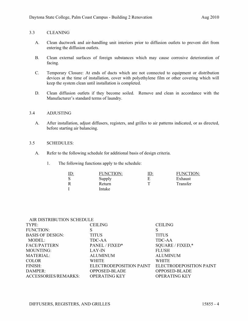
Daytona State College, Palm Coast Campus - Building 2 Renovation Aug 2010
3.3 CLEANING
A. Clean ductwork and air-handling unit interiors prior to diffusion outlets to prevent dirt from
entering the diffusion outlets.
B. Clean external surfaces of foreign substances which may cause corrosive deterioration of
facing.
C. Temporary Closure: At ends of ducts which are not connected to equipment or distribution
devices at the time of installation, cover with polyethylene film or other covering which will
keep the system clean until installation is completed.
D. Clean diffusion outlets if they become soiled. Remove and clean in accordance with the
Manufacturer’s standard terms of laundry.
3.4 ADJUSTING
A. After installation, adjust diffusers, registers, and grilles to air patterns indicated, or as directed,
before starting air balancing.
3.5 SCHEDULES:
A. Refer to the following schedule for additional basis of design criteria.
1. The following functions apply to the schedule:
ID: FUNCTION: ID: FUNCTION:
S Supply E Exhaust
R Return T Transfer
I Intake
AIR DISTRIBUTION SCHEDULE
TYPE: CEILING CEILING
FUNCTION: S S
BASIS OF DESIGN: TITUS TITUS
MODEL: TDC-AA TDC-AA
FACE/PATTERN PANEL / FIXED* SQUARE / FIXED,*
MOUNTING: LAY-IN FLUSH
MATERIAL: ALUMINUM ALUMINUM
COLOR WHITE WHITE
FINISH: ELECTRODEPOSITION PAINT ELECTRODEPOSITION PAINT
DAMPER: OPPOSED-BLADE OPPOSED-BLADE
ACCESSORIES/REMARKS: OPERATING KEY OPERATING KEY
DIFFUSERS, REGISTERS, AND GRILLES 15855 - 4
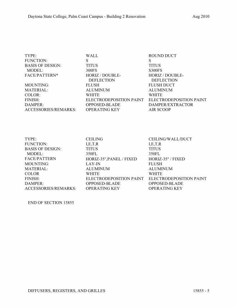
Daytona State College, Palm Coast Campus - Building 2 Renovation Aug 2010
TYPE: WALL ROUND DUCT
FUNCTION: S S
BASIS OF DESIGN: TITUS TITUS
MODEL: 300FS S300FS
FACE/PATTERN* HORIZ / DOUBLE-
DEFLECTION
HORIZ / DOUBLE-
DEFLECTION
MOUNTING: FLUSH FLUSH DUCT
MATERIAL: ALUMINUM ALUMINUM
COLOR: WHITE WHITE
FINISH: ELECTRODEPOSITION PAINT ELECTRODEPOSITION PAINT
DAMPER: OPPOSED-BLADE DAMPER/EXTRACTOR
ACCESSORIES/REMARKS: OPERATING KEY AIR SCOOP
TYPE: CEILING CEILING/WALL/DUCT
FUNCTION: I,E,T,R I,E,T,R
BASIS OF DESIGN: TITUS TITUS
MODEL: 350FL 350FL
FACE/PATTERN HORIZ-35!,PANEL / FIXED HORIZ-35! / FIXED
MOUNTING: LAY-IN FLUSH
MATERIAL: ALUMINUM ALUMINUM
COLOR WHITE WHITE
FINISH: ELECTRODEPOSITION PAINT ELECTRODEPOSITION PAINT
DAMPER: OPPOSED-BLADE OPPOSED-BLADE
ACCESSORIES/REMARKS: OPERATING KEY OPERATING KEY
END OF SECTION 15855
DIFFUSERS, REGISTERS, AND GRILLES 15855 - 5

Daytona State College, Palm Coast Campus - Building 2 Renovation Aug 2010
SECTION 15900 – HVAC INSTRUMENTATION AND CONTROLS
PART 1 - GENERAL
1.1 Products Furnished (and Wired) And Installed Under This Section.
A. JCI NEA Network Automation Engine.
1.2 Products Not Furnished or Installed but integrated with the Work of this Section.
A. Air Terminal & Duct accessories:
1. Terminal unit controls
B. General:
1. Coordination Meeting: The Installer furnishing the DDC network shall meet with the In-
staller(s) furnishing each of the following products to coordinate details of the interface
between these products and the DDC network. The Owner or his designated representa-
tive shall be present at this meeting. Each Installer shall provide the Owner and all other
Installers with details of the proposed interface including PICS for BACnet equipment,
hardware and software identifiers for the interface points, network identifiers, wiring re-
quirements, communication speeds, and required network accessories. The purpose of
this meeting shall be to insure there are no unresolved issues regarding the integration of
these products into the DDC network. Submittals for these products shall not be approved
prior to the completion of this meeting.
1.3 Related Sections
A. The General Conditions of the Contract, Supplementary Conditions, and General Requirements
are part of this specification and shall be used in conjunction with this section as part of the con-
tract documents.
1.4 Description
A. General: The control system shall consist of a high-speed, peer-to-peer network of DDC con-
trollers and a web-based operator interface. Depict each mechanical system and building floor
plan by a point-and-click graphic. A web server with a network interface card shall gather data
from this system and generate web pages accessible through a conventional web browser on
each PC connected to the network. Operators shall be able to perform all normal operator func-
tions through the web browser interface.
B. The system shall directly control HVAC equipment as specified in Section 15900 Appendix A
(Sequences of Operation). Each zone controller shall provide occupied and unoccupied modes
of operation by individual zone. Furnish energy conservation features such as optimal start and
HVAC INSTRUMENTATION AND CONTROLS 15900 - 1

Daytona State College, Palm Coast Campus - Building 2 Renovation Aug 2010
stop, night setback, request-based logic, and demand level adjustment of setpoints as specified
in Appendix A.
C. Provide for future system expansion to include monitoring of occupant card access, fire alarm,
and lighting control systems.
D. System shall use the BACnet protocol for communication to the operator workstation or web
server and for communication between control modules. Schedules, setpoints, trends, and
alarms specified in Section 15900 Appendix A (Sequences of Operation) shall be BACnet ob-
jects.
1.5 Approved Control Systems
A. The following are approved control system suppliers, manufacturers, and product lines:
1. Johnson Controls, Inc. (JCI).
B. Control systems shall comply with the terms of this specification.
1. The Contractor shall use only operator workstation software, controller software, custom
application programming language, and controllers from the corresponding manufacturer
and product line unless Owner approves use of multiple manufacturers.
2. Other products specified herein (such as sensors, valves, dampers, and actuators) need
not be manufactured by the above manufacturers.
1.6 Quality Assurance
A. Installer and Manufacturer Qualifications
1. Installer shall have an established working relationship with Control System Manufac-
turer.
2. Installer shall have successfully completed Control System Manufacturer's control system
training. Upon request, Installer shall present record of completed training including
course outlines.
1.7 Codes And Standards
A. Work, materials, and equipment shall comply with the most restrictive of local, state, and fed-
eral authorities' codes and ordinances or these plans and specifications. As a minimum, the in-
stallation shall comply with current editions in effect 30 days prior to receipt of bids of the fol-
lowing codes:
1. National Electric Code (NEC)
2. ANSI/ASHRAE 135-2004: Data Communication Protocol for Building Automation and
Control Systems (BACNET)
1.8 System Performance
HVAC INSTRUMENTATION AND CONTROLS 15900 - 2

Daytona State College, Palm Coast Campus - Building 2 Renovation Aug 2010
A. Performance Standards. System shall be compatible with Owner’s interface equipment and pro-
vide a seamless transition.
1.9 Submittals
A. Product Submittal Requirements: Provide six copies of shop drawings and other submittals on
hardware, software, and equipment to be installed or furnished. Begin no work until submittals
have been approved for conformity with design intent. Provide drawings as AutoCAD 2006 (or
newer) compatible files on magnetic or optical disk (file format: .DWG, .DXF, .VSD, or com-
parable) and 3 prints of each drawing on 11" x 17" paper. When manufacturer's cutsheets apply
to a product series rather than a specific product, clearly indicate applicable data by highlighting
or by other means. Clearly reference covered specification and drawing on each submittal. Gen-
eral catalogs shall not be accepted as cutsheets to fulfill submittal requirements. Select and
show submittal quantities appropriate to scope of work. Submittal approval does not relieve
Contractor of responsibility to supply sufficient quantities to complete work. Provide submittals
within 12 weeks of contract award on the following:
1. Direct Digital Control System Hardware
a. Complete bill of materials indicating quantity, manufacturer, model number, and
relevant technical data of equipment to be used.
b. Manufacturer's description and technical data such as performance curves, product
specifications, and installation and maintenance instructions for items listed below
and for relevant items not listed below:
1) Direct digital controllers (controller panels)
2) Transducers and transmitters
3) Sensors (include accuracy data)
4) Relays and switches
5) Control panels
6) Power supplies
7) Batteries
8) Operator interface equipment
9) Wiring
c. Wiring diagrams and layouts for each control panel. Show termination numbers.
d. Floor plan schematic diagrams indicating field sensor and controller locations.
e. Riser diagrams showing control network layout, communication protocol, and wire
types.
2. Central System Hardware and Software
a. Utilize Owner’s existing equipment and software except as indicated and provide
ancillary equipment as required for seamless integration.
b. Complete bill of material indicating quantity, manufacturer, model number, and
relevant technical data of equipment used.
c. Manufacturer's description and technical data such as product specifications and
installation and maintenance instructions for items listed below and for relevant
items furnished under this contract not listed below:
HVAC INSTRUMENTATION AND CONTROLS 15900 - 3

Daytona State College, Palm Coast Campus - Building 2 Renovation Aug 2010
d. Schematic diagrams of control, communication, and power wiring for central sys-
tem installation. Show interface wiring to control system.
e. Network riser diagrams of wiring between central control unit and control panels.
3. Controlled Systems
a. Riser diagrams showing control network layout, communication protocol, and wire
types.
b. Schematic diagram of each controlled system. Label control points with point
names. Graphically show locations of control elements.
c. Schematic wiring diagram of each controlled system. Label control elements and
terminals. Where a control element is also shown on control system schematic, use
the same name.
d. Complete description of control system operation including sequences of opera-
tion. Include and reference schematic diagram of controlled system. List I/O points
and software points specified in Section 15900 Appendix A. Indicate alarmed and
trended points.
4. BACnet Protocol Implemetation Conformance Statement (PICS) for each submitted type
of controller and operator interface.
B. Schedules
1. Schedule of work provided within one month of contract award, indicating:
a. Intended sequence of work items
b. Start date of each work item
c. Duration of each work item
d. Planned delivery dates for ordered material and equipment and expected lead times
e. Milestones indicating possible restraints on work by other trades or situations
2. Monthly written status reports indicating work completed and revisions to expected de-
livery dates. Include updated schedule of work.
C. Project Record Documents. Submit three copies of record (as-built) documents upon completion
of installation for approval prior to final completion. Submittal shall consist of:
1. Project Record Drawings. As-built versions of submittal shop drawings provided as
AutoCAD 2006 (or newer) compatible files on magnetic or optical disk (file format:
.DWG, .DXF, .VSD, or comparable) and 6 prints of each drawing on 11" x 17" paper.
2. Testing and Commissioning Reports and Checklists. Completed versions of reports,
checklists, and trend logs used to meet requirements of Section 15900 Article 3.16 (Con-
trol System Demonstration and Acceptance).
3. Operation and Maintenance (O&M) Manual. Printed, electronic, or online help documen-
tation of the following:
a. As-built versions of submittal product data.
b. Names, addresses, and telephone numbers of installing contractors and service rep-
resentatives for equipment and control systems.
HVAC INSTRUMENTATION AND CONTROLS 15900 - 4

Daytona State College, Palm Coast Campus - Building 2 Renovation Aug 2010
c. Operator's manual with procedures for operating control systems: logging on and
off, handling alarms, producing point reports, trending data, overriding computer
control, and changing setpoints and variables.
d. Programming manual or set of manuals with description of programming language
and syntax, of statements for algorithms and calculations used, of point database
creation and modification, of program creation and modification, and of editor use.
e. Engineering, installation, and maintenance manual or set of manuals that explains
how to design and install new points, panels, and other hardware; how to perform
preventive maintenance and calibration; how to debug hardware problems; and
how to repair or replace hardware.
f. Documentation of programs created using custom programming language includ-
ing setpoints, tuning parameters, and object database. Electronic copies of pro-
grams shall meet this requirement if control logic, setpoints, tuning parameters,
and objects can be viewed using furnished programming tools.
g. Graphic files, programs, and database on magnetic or optical media.
h. List of recommended spare parts with part numbers and suppliers.
i. Complete original-issue documentation, installation, and maintenance information
for furnished third-party hardware including computer equipment and sensors.
j. Complete original-issue copies of furnished software, including operating systems,
custom programming language, operator workstation or web server software, and
graphics software.
k. Licenses, guarantees, and warranty documents for equipment and systems.
l. Recommended preventive maintenance procedures for system components, includ-
ing schedule of tasks such as inspection, cleaning, and calibration; time between
tasks; and task descriptions.
D. Training Materials: Provide course outline and materials for each class at least six weeks before
first class. Training shall be furnished via instructor-led sessions, computer-based training, or
web-based training. Owner will modify course outlines and materials if necessary to meet
Owner's needs. Owner will review and approve course outlines and materials at least three
weeks before first class.
1.10 Warranty
A. Warrant work as follows:
1. Warrant labor and materials for specified control system free from defects for a period of
12 months after final acceptance. Control system failures during warranty period shall be
adjusted, repaired, or replaced at no additional cost or reduction in service to Owner. Re-
spond during normal business hours within 24 hours of Owner's warranty service request.
2. Work shall have a single warranty date, even if Owner receives beneficial use due to
early system start-up. If specified work is split into multiple contracts or a multi-phase
contract, each contract or phase shall have a separate warranty start date and period.
3. If Engineer determines that equipment and systems operate satisfactorily at the end of fi-
nal start-up, testing, and commissioning phase, Engineer will certify in writing that con-
trol system operation has been tested and accepted in accordance with the terms of this
specification. Date of acceptance shall begin warranty period.
4. Provide updates to operator workstation or web server software, project-specific soft-
ware, graphic software, database software, and firmware that resolve Contractor-
identified software deficiencies at no charge during warranty period. If available, Owner
HVAC INSTRUMENTATION AND CONTROLS 15900 - 5

Daytona State College, Palm Coast Campus - Building 2 Renovation Aug 2010
can purchase in-warranty service agreement to receive upgrades for functional enhance-
ments associated with above-mentioned items. Do not install updates or upgrades without
Owner's written authorization.
5. Exception: Contractor shall not be required to warrant reused devices except those that
have been rebuilt or repaired. Installation labor and materials shall be warranted. Demon-
strate operable condition of reused devices at time of Engineer's acceptance.
1.11 Ownership Of Proprietary Material
A. Project-specific software and documentation shall become Owner's property. This includes, but
is not limited to:
1. Graphics
2. Record drawings
3. Database
4. Application programming code
5. Documentation
PART 2 - PRODUCTS
2.1 General: All products shall be compatible with Owner’s existing product, assemblies, software,
and systems and shall comply with Owner’s current standards and requirements..
2.2 Materials
A. Use new products the manufacturer is currently manufacturing and selling for use in new instal-
lations. Do not use this installation as a product test site unless explicitly approved in writing by
Owner. Spare parts shall be available for at least five years after completion of this contract.
2.3 Communication
A. Control products, communication media, connectors, repeaters, hubs, and routers shall comprise
a unified control network compatible with Owner’s existing system shall comply with Owner’s
current standards and requirements.
B. Install new wiring and network devices as required to provide a complete and workable control
network. Use existing Ethernet backbone where available with Owner’s consent.
C. Each controller shall have a communication port for temporary connection to a laptop computer
or other operator interface. Connection shall support memory downloads and other commission-
ing and troubleshooting operations.
D. Internetwork operator interface and value passing shall be transparent to internetwork architec-
ture.
1. An operator interface connected to a controller shall allow the operator to interface with
each internetwork controller as if directly connected. Controller information such as data,
HVAC INSTRUMENTATION AND CONTROLS 15900 - 6

Daytona State College, Palm Coast Campus - Building 2 Renovation Aug 2010
status, and control algorithms shall be viewable and editable from each internetwork con-
troller.
2. Inputs, outputs, and control variables used to integrate control strategies across multiple
controllers shall be readable by each controller on the internetwork. Program and test all
cross-controller links required to execute control strategies. An authorized operator shall
be able to edit cross-controller links by typing a standard object address or by using a
point-and-click interface.
E. Controllers with real-time clocks shall use the BACnet Time Synchronization service. System
shall automatically synchronize system clocks daily from an operator-designated controller via
the internetwork. If applicable, system shall automatically adjust for daylight saving and stan-
dard time.
F. System shall be expandable to at least twice the required input and output objects with addi-
tional controllers, associated devices, and wiring.
G. System shall support Web services data exchange with any other system that complies with
XML (extensible markup language) and SOAP (simple object access protocol) standards speci-
fied by the Web Services Interoperability Organization (WS-I) Basic Profile 1.0 or higher. Web
services support shall as a minimum be provided at the workstation or web server level and
shall enable data to be read from or written to the system.
1. System shall support Web services read data requests by retrieving requested trend data
or point values (I/O hardware points, analog value software points, or binary value soft-
ware points) from any system controller or from the trend history database.
2. System shall support Web services write data request to each analog and binary object
that can be edited through the system operator interface by downloading a numeric value
to the specified object.
3. For read or write requests, the system shall require user name and password authentica-
tion and shall support SSL (Secure Socket Layer) or equivalent data encryption.
4. System shall support discovery through a Web services connection or shall provide a tool
available through the Operator Interface that will reveal the path/identifier needed to al-
low a third party Web services device to read data from or write data to any object in the
system which supports this service.
2.4 Operator Interface
A. Operator Interface. The operator interface shall be compatible with Owner’s existing system.
Hardware shall be compatible with Owner’s existing systems and shall comply with Owner’s
current standards and requirements.
B. Communication. Communication shall be compatible with Owner’s existing systems and shall
comply with Owner’s current standards and requirements. Web server and controllers shall
communicate using N2 protocol. .
C. Hardware. Hardware shall be compatible with Owner’s existing systems and shall comply with
Owner’s current standards and requirements.
D. Operator Functions. Operator interface shall be compatible with Owner’s existing systems and
shall comply with Owner’s current standards and requirements.
HVAC INSTRUMENTATION AND CONTROLS 15900 - 7

Daytona State College, Palm Coast Campus - Building 2 Renovation Aug 2010
E. System Software.
1. Utilize Owner’s current standards and requirements.
F. System Tools. System shall be compatible with Owner’s existing system and shall comply with
Owner’s current standards and requirements. If furnished as part of the interface, the tool shall
be available from each workstation or web browser interface. If furnished as a stand-alone pro-
gram, software shall be installable on standard IBM-compatible PCs with no limit on the num-
ber of copies that can be installed under the system license.
G. Portable Operator's Terminal. Provide all necessary software to configure an IBM-compatible
laptop computer for use as a Portable Operator's Terminal. Operator shall be able to connect
configured Terminal to the system network or directly to each controller for programming, set-
ting up, and troubleshooting.
H. Operator Workstation: Configure Owner’s Web server shall conform to BACnet Operator
Workstation (B-OWS) device profile or BACnet Advanced Workstation (B-AWS) as specified
in ANSI/ASHRAE 135, BACnet Annex L and shall be listed as a certified B-OWS or B-AWS
in the BACnet Testing Laboratories (BTL) Product Listing.
2.5 Controller Software
A. Building and energy management application software shall be compatible with Owner’s exist-
ing system and shall reside and operate in system controllers. Applications shall be editable
through operator workstation, web browser interface, or engineering workstation.
B. System Security. Security shall be compatible with Owner’s existing and shall comply with
Owner’s current standards and requirements.
C. Scheduling. Utilized Owner’s current standards and requirements.
D. System Coordination. Operator shall be able to group related equipment based on function and
location and to use these groups for scheduling and other applications.
E. Binary and Analog Alarms. Utilize Owner’s current standards and requirements.
F. Alarm Reporting. Utilize Owner’s current standards and requirements.
G. Remote Communication. System shall automatically contact operator workstation or server on
receipt of critical alarms. If no network connection is available, system shall use a modem con-
nection.
H. Demand Limiting: Utilize Owner’s current standards and requirements.
I. Maintenance Management: Utilize Owner’s current standards and requirements.
J. Sequencing: Utilize Owner’s current standards and requirements.
K. PID Control. System shall provide direct- and reverse-acting PID (proportional-integral-
derivative) algorithms. Each algorithm shall have anti-windup and selectable controlled vari-
HVAC INSTRUMENTATION AND CONTROLS 15900 - 8

Daytona State College, Palm Coast Campus - Building 2 Renovation Aug 2010
able, setpoint, and PID gains. Each algorithm shall calculate a time-varying analog value that
can be used to position an output or to stage a series of outputs.
L. Staggered Start. System shall stagger controlled equipment restart after power outage. Operator
shall be able to adjust equipment restart order and time delay between equipment restarts.
M. Energy Calculations: Utilize Owner’s current standards and requirements.
N. Anti-Short Cycling. Binary output objects shall be protected from short cycling by means of ad-
justable minimum on-time and off-time settings.
O. On and Off Control with Differential. System shall provide direct- and reverse-acting on and off
algorithms with adjustable differential to cycle a binary output based on a controlled variable
and setpoint.
P. Runtime Totalization. System shall provide an algorithm that can totalize runtime for each bi-
nary input and output. Operator shall be able to enable runtime alarm based on exceeded adjust-
able runtime limit. Utilize Owner’s current standards and requirements.
2.6 Controllers
A. General. Provide Building Controllers (BC), Advanced Application Controllers (AAC), Appli-
cation Specific Controllers (ASC), Smart Actuators (SA), and Smart Sensors (SS) as required to
achieve performance specified in Section 15900 Article 1.9 (System Performance) and shall be
compatible with Owner’s existing system. Utilize Owner’s current standards and requirements.
B. BACnet Communication shall be compatible with Owner’s existing system. Utilize Owner’s
current standards and requirements.
1. Each BC shall reside on or be connected to a BACnet network using ISO 8802-3
(Ethernet) Data Link/Physical layer protocol and BACnet/IP addressing.
2. BACnet routing shall be performed by BCs or other BACnet device routers as necessary
to connect BCs to networks of AACs and ASCs.
3. Each AAC shall reside on a BACnet network using ISO 8802-3 (Ethernet) Data
Link/Physical layer protocol with BACnet/IP addressing, or it shall reside on a BACnet
network using the ARCNET or MS/TP Data Link/Physical layer protocol.
4. Each ASC shall reside on a BACnet network using the ARCNET or MS/TP Data
Link/Physical layer protocol.
5. Each SA shall reside on a BACnet network using the ARCNET or MS/TP Data
Link/Physical layer protocol.
6. Each SS shall reside on a BACnet network using ISO 8802-3 (Ethernet) Data
Link/Physical layer protocol with BACnet/IP addressing, or it shall reside on a BACnet
network using ARCNET or MS/TP Data Link/Physical layer protocol.
C. Communication shall be compatible with Owner’s existing system. Utilize Owner’s current
standards and requirements.
D. Environment. Controller hardware shall be suitable for anticipated ambient conditions.
HVAC INSTRUMENTATION AND CONTROLS 15900 - 9

Daytona State College, Palm Coast Campus - Building 2 Renovation Aug 2010
1. Controllers used outdoors or in wet ambient conditions shall be mounted in waterproof
enclosures and shall be rated for operation at -20°F to 140°F.
2. Controllers used in conditioned space shall be mounted in dust-protective enclosures and
shall be rated for operation 32°F to 120°F.
E. Keypad. Provide a local keypad and display for each BC and AAC. Operator shall be able to
use keypad to view and edit data. Keypad and display shall require password to prevent unau-
thorized use. If the manufacturer does not normally provide a keypad and display for each BC
and AAC, provide the software and any interface cabling needed to use a laptop computer as a
Portable Operator's Terminal for the system.
F. Real-Time Clock. Controllers that perform scheduling shall have a real-time clock.
G. Serviceability.
1. Controllers shall have diagnostic LEDs for power, communication, and processor.
2. Wires shall be connected to a field-removable modular terminal strip or to a termination
card connected by a ribbon cable.
3. Each BC and AAC shall continually check its processor and memory circuit status and
shall generate an alarm on abnormal operation. System shall continuously check control-
ler network and generate alarm for each controller that fails to respond.
H. Memory.
1. Controller memory shall support operating system, database, and programming require-
ments.
2. Each BC and AAC shall retain BIOS and application programming for at least 72 hours
in the event of power loss.
3. Each ASC and SA shall use nonvolatile memory and shall retain BIOS and application
programming in the event of power loss. System shall automatically download dynamic
control parameters following power loss.
I. Immunity to Power and Noise. Controllers shall be able to operate at 90% to 110% of nominal
voltage rating and shall perform an orderly shutdown below 80% nominal voltage. Operation
shall be protected against electrical noise of 5 to 120 Hz and from keyed radios up to 5 W at 1
m (3 ft).
J. Transformer. ASC power supply shall be fused or current limiting and shall be rated at a mini-
mum of 125% of ASC power consumption.
2.7 Input and Output Interface shall be compatible with Owner’s existing system. Utilize Owner’s
current standards and requirements.
A. General. Hard-wire input and output points to BCs, AACs, ASCs, or SAs.
B. Protection. Shorting an input or output point to itself, to another point, or to ground shall cause
no controller damage. Input or output point contact with up to 24 V for any duration shall cause
no controller damage.
HVAC INSTRUMENTATION AND CONTROLS 15900 - 10
Daytona State College, Palm Coast Campus - Building 2 Renovation Aug 2010
C. Binary Inputs. Binary inputs shall monitor the on and off signal from a remote device. Binary
inputs shall provide a wetting current of at least 12 mA and shall be protected against contact
bounce and noise. Binary inputs shall sense dry contact closure without application of power
external to the controller.
D. Pulse Accumulation Inputs. Pulse accumulation inputs shall conform to binary input require-
ments and shall accumulate up to 10 pulses per second.
E. Analog Inputs. Analog inputs shall monitor low-voltage (0-10 Vdc), current (4-20 mA), or re-
sistance (thermistor or RTD) signals. Analog inputs shall be compatible with and field configur-
able to commonly available sensing devices.
F. Binary Outputs. Binary outputs shall send an on-or-off signal for on and off control. Building
Controller binary outputs shall have three-position (on-off-auto) override switches and status
lights. Outputs shall be selectable for normally open or normally closed operation.
G. Analog Outputs. Analog outputs shall send a modulating 0-10 Vdc or 4-20 mA signal as re-
quired to properly control output devices. Each Building Controller analog output shall have a
two-position (auto-manual) switch, a manually adjustable potentiometer, and status lights. Ana-
log outputs shall not drift more than 0.4% of range annually.
H. Tri-State Outputs. Control three-point floating electronic actuators without feedback with tri-
state outputs (two coordinated binary outputs). Tri-State outputs may be used to provide analog
output control in zone control and terminal unit control applications such as VAV terminal
units, duct-mounted heating coils, and zone dampers.
I. Universal Inputs and Outputs. Inputs and outputs that can be designated as either binary or ana-
log in software shall conform to the provisions of this section that are appropriate for their des-
ignated use.
2.8 Power Supplies and Line Filtering shall be compatible with Owner’s existing system. Utilized
Owner’s current standards and requirements.
A. Power Supplies. Control transformers shall be UL listed. Furnish Class 2 current-limiting type
or furnish over-current protection in primary and secondary circuits for Class 2 service in ac-
cordance with NEC requirements. Limit connected loads to 80% of rated capacity.
1. DC power supply output shall match output current and voltage requirements. Unit shall
be full-wave rectifier type with output ripple of 5.0 mV maximum peak-to-peak. Regula-
tion shall be 1.0% line and load combined, with 100-microsecond response time for 50%
load changes. Unit shall have built-in over-voltage and over-current protection and shall
be able to withstand 150% current overload for at least three seconds without trip-out or
failure.
a. Unit shall operate between 0°C and 50°C (32°F and 120°F). EM/RF shall meet
FCC Class B and VDE 0871 for Class B and MILSTD 810C for shock and vibra-
tion.
b. Line voltage units shall be UL recognized and CSA listed.
B. Power Line Filtering.
HVAC INSTRUMENTATION AND CONTROLS 15900 - 11
Daytona State College, Palm Coast Campus - Building 2 Renovation Aug 2010
1. Provide internal or external transient voltage and surge suppression for workstations and
controllers. Surge protection shall have:
2. Dielectric strength of 1000 V minimum
3. Response time of 10 nanoseconds or less
4. Transverse mode noise attenuation of 65 dB or greater
5. Common mode noise attenuation of 150 dB or greater at 40-100 Hz
C. Auxiliary Control Devices: Auxiliary Control Devices shall be compatible with Owner’s exist-
ing system. Utilize Owner’s current standards and requirements.
D. Temperature Sensors.
1. Type. Temperature sensors shall be Resistance Temperature Device (RTD) or thermistor.
2. Duct Sensors. Duct sensors shall be single point or averaging as shown. Averaging sen-
sors shall be a minimum of 1.5 m (5 ft) in length per 1 m2(10 ft2) of duct cross-section.
3. Space Sensors. Space sensors shall have setpoint adjustment, override switch, display,
and communication port as shown.
E. Relays.
1. Control Relays. Control relays shall be plug-in type, UL listed, and shall have dust cover
and LED "energized" indicator. Contact rating, configuration, and coil voltage shall be
suitable for application.
2. Time Delay Relays. Time delay relays shall be solid-state plug-in type, UL listed, and
shall have adjustable time delay. Delay shall be adjustable ±100% from setpoint shown.
Contact rating, configuration, and coil voltage shall be suitable for application. Provide
NEMA 1 enclosure for relays not installed in local control panel.
F. Override Timers.
1. Unless implemented in control software, override timers shall be spring-wound line volt-
age, UL Listed, with contact rating and configuration required by application. Provide 0-
6 hour calibrated dial unless otherwise specified. Flush mount timer on local control
panel face or where shown.
G. Current Transmitters.
1. AC current transmitters shall be self-powered, combination split-core current transformer
type with built-in rectifier and high-gain servo amplifier with 4-20 mA two-wire output.
Full-scale unit ranges shall be 10 A, 20 A, 50 A, 100 A, 150 A, and 200 A, with internal
zero and span adjustment. Unit accuracy shall be ±1% full-scale at 500 ohm maximum
burden.
2. Transmitter shall meet or exceed ANSI/ISA S50.1 requirements and shall be UL/CSA
recognized.
3. Unit shall be split-core type for clamp-on installation on existing wiring.
H. Current Transformers.
1. AC current transformers shall be UL/CSA recognized and shall be completely encased
(except for terminals) in approved plastic material.
HVAC INSTRUMENTATION AND CONTROLS 15900 - 12

Daytona State College, Palm Coast Campus - Building 2 Renovation Aug 2010
2. Transformers shall be available in various current ratios and shall be selected for ±1% ac-
curacy at 5 A full-scale output.
3. Use fixed-core transformers for new wiring installation and split-core transformers for
existing wiring installation.
I. Voltage Transmitters.
1. AC voltage transmitters shall be self-powered single-loop (two-wire) type, 4-20 mA out-
put with zero and span adjustment.
2. Adjustable full-scale unit ranges shall be 100-130 Vac, 200-250 Vac, 250-330 Vac, and
400-600 Vac. Unit accuracy shall be ±1% full-scale at 500 ohm maximum burden.
3. Transmitters shall meet or exceed ANSI/ISA S50.1 requirements and shall be UL/CSA
recognized at 600 Vac rating.
J. Voltage Transformers.
1. AC voltage transformers shall be UL/CSA recognized, 600 Vac rated, and shall have
built-in fuse protection.
2. Transformers shall be suitable for ambient temperatures of 4°C-55°C (40°F-130°F) and
shall provide ±0.5% accuracy at 24 Vac and 5 VA load.
3. Windings (except for terminals) shall be completely enclosed with metal or plastic.
K. Power Monitors.
1. Power monitors shall be three-phase type and shall have three-phase disconnect and
shorting switch assembly, UL listed voltage transformers, and UL listed split-core current
transformers.
2. Power monitors shall provide selectable output: rate pulse for kWh reading or 4-20 mA
for kW reading. Power monitors shall operate with 5 A current inputs and maximum er-
ror of ±2% at 1.0 power factor or ±2.5% at 0.5 power factor.
L. Current Switches.
1. Current-operated switches shall be self-powered, solid-state with adjustable trip current.
Select switches to match application current and DDC system output requirements.
M. Differential Pressure Switches. Differential pressure switches (air or water service) shall be UL
listed, SPDT snap-acting, pilot duty rated (125 VA minimum) and shall have scale range and
differential suitable for intended application and NEMA 1 enclosure unless otherwise specified.
N. Local Control Panels.
1. Indoor control panels shall be fully enclosed NEMA 1 construction with hinged door
key-lock latch and removable sub-panels. A common key shall open each control panel
and sub-panel.
2. Prewire internal and face-mounted device connections with color-coded stranded conduc-
tors tie-wrapped or neatly installed in plastic troughs. Field connection terminals shall be
UL listed for 600 V service, individually identified per control and interlock drawings,
with adequate clearance for field wiring.
3. Each local panel shall have a control power source power switch (on-off) with overcur-
rent protection.
HVAC INSTRUMENTATION AND CONTROLS 15900 - 13
Daytona State College, Palm Coast Campus - Building 2 Renovation Aug 2010
2.9 Wiring And Raceways
A. General. Provide copper wiring, plenum cable, and raceways as specified in applicable sections
of Division 16.
B. Insulated wire shall use copper conductors and shall be UL listed for 200°F minimum service.
2.10 Fiber Optic Cable System
A. Optical Cable. Optical cables shall be duplex 900 mm tight-buffer construction designed for in-
tra-building environments. Sheath shall be UL listed OFNP in accordance with NEC Article
770. Optical fiber shall meet the requirements of FDDI, ANSI X3T9.5 PMD for 62.5/125mm.
B. Connectors. Field terminate optical fibers with ST type connectors. Connectors shall have ce-
ramic ferrules and metal bayonet latching bodies.
PART 3 - EXECUTION
3.1 Examination
A. Thoroughly examine project plans for control device and equipment locations. Report discrep-
ancies, conflicts, or omissions to Architect or Engineer for resolution before starting rough-in
work.
B. Inspect site to verify that equipment can be installed as shown. Report discrepancies, conflicts,
or omissions to Engineer for resolution before starting rough-in work.
C. Examine drawings and specifications for work of others. Report inadequate headroom or space
conditions or other discrepancies to Engineer and obtain written instructions for changes neces-
sary to accommodate Section 15900 work with work of others. Controls Contractor shall per-
form at his expense necessary changes in specified work caused by failure or neglect to report
discrepancies.
3.2 Protection
A. Controls Contractor shall protect against and be liable for damage to work and to material
caused by Contractor's work or employees.
B. Controls Contractor shall be responsible for work and equipment until inspected, tested, and ac-
cepted. Protect material not immediately installed. Close open ends of work with temporary
covers or plugs during storage and construction to prevent entry of foreign objects.
3.3 Coordination
A. Site.
HVAC INSTRUMENTATION AND CONTROLS 15900 - 14

Daytona State College, Palm Coast Campus - Building 2 Renovation Aug 2010
1. Assist in coordinating space conditions to accommodate the work of each trade where
work will be installed near or will interfere with work of other trades. If installation with-
out coordination causes interference with work of other trades, Contractor shall correct
conditions without extra charge.
2. Coordinate and schedule work with other work in the same area and with work dependent
upon other work to facilitate mutual progress.
B. Submittals. See Section 15900 Article 1.10 (Submittals).
C. Test and Balance.
1. Provide Test and Balance Contractor a single set of necessary tools to interface to control
system for testing and balancing.
2. Train Test and Balance Contractor to use control system interface tools.
3. Provide a qualified technician to assist with testing and balancing the first 20 terminal
units.
4. Test and Balance Contractor shall return tools undamaged and in working condition at
completion of testing and balancing.
D. Life Safety.
1. Signal from Fire Alarm Control Panel Fire shall be sent to shutdown the air handling
units upon fire alarm control panel trouble.
2. Supply and exhaust fans: Interlock supply and exhaust fans to air handling units to shut-
down upon air handling unit shutdown, except Flt Ops Atrium Exhaust Fan.
3. Signal form Fire Alarm Control Panel shall be sent to open Atrium doors and then ener-
gize Atrium fan.
E. Coordination with Other Controls. Integrate with and coordinate controls and control devices
furnished or installed by others as follows.
1. Communication media and equipment shall be provided as specified in Section 15900
Article 2.2 (Communication).
2. Each supplier of a controls product shall configure, program, start up, and test that prod-
uct to meet the sequences of operation described in Section 15900 Appendix A regardless
of where within the contract documents those products are described.
3. Coordinate and resolve incompatibility issues that arise between control products pro-
vided under this section and those provided under other sections or divisions of this
specification.
4. Controls Contractor shall be responsible for integration of control products provided by
multiple suppliers regardless of where integration is described within the contract docu-
ments.
3.4 General Workmanship
A. Install equipment, piping, and wiring or raceway horizontally, vertically, and parallel to walls
wherever possible.
B. Provide sufficient slack and flexible connections to allow for piping and equipment vibration
isolation.
HVAC INSTRUMENTATION AND CONTROLS 15900 - 15

Daytona State College, Palm Coast Campus - Building 2 Renovation Aug 2010
C. Install equipment in readily accessible locations as defined by National Electrical Code (NEC)
Chapter 1 Article 100 Part A.
D. Verify wiring integrity to ensure continuity and freedom from shorts and ground faults.
E. Equipment, installation, and wiring shall comply with industry specifications and standards and
local codes for performance, reliability, and compatibility.
3.5 Field Quality Control
A. Work, materials, and equipment shall comply with rules and regulations of applicable local,
state, and federal codes and ordinances as identified in Section 15900 Article 1.8 (Codes and
Standards).
B. Continually monitor field installation for code compliance and workmanship quality.
C. Contractor shall arrange for work inspection by local or state authorities having jurisdiction
over the work.
3.6 Existing Equipment
A. Wiring. Abandoned wires may be reused. Check wire integrity and ensure proper application to
installation. Identify and test reused wires according to this specification. Properly identify un-
used or redundant wiring.
B. Local Control Panels. Existing local control panels may be used to locate new equipment. Re-
move and deliver redundant and unused equipment to Owner. Patch panel face cover to fill
holes caused by removal of unused equipment. Relocate panels as shown.
C. Repair. Unless otherwise directed, Contractor is not responsible for repair or replacement of ex-
isting energy equipment and systems, valves, dampers, or actuators. Notify Engineer in writing
immediately of existing equipment that requires maintenance.
D. Electronic Sensors and Transmitters. Existing sensors and transmitters may be reused unless
specifically noted otherwise. Remove and deliver unnecessary sensors and transmitters to
Owner.
E. Controllers and Auxiliary Electronic Devices. Existing controllers and auxiliary electronic de-
vices may be reused unless specifically noted otherwise. Remove unnecessary sensors and
transmitters.
F. Existing System Operating Schedule. Existing mechanical system may be disabled during this
work.
G. Maintain fan scheduling using existing or temporary time clocks or control systems throughout
the control system installation.
H. Modify existing starter control circuits if necessary to provide hand-off-auto control of each
controlled starter. Furnish new starters or starter control packages as required.
HVAC INSTRUMENTATION AND CONTROLS 15900 - 16

Daytona State College, Palm Coast Campus - Building 2 Renovation Aug 2010
I. Patch holes and finish to match existing walls.
J. At Owner's request, items to be delivered to Owner shall instead be properly disposed of. Haz-
ardous materials shall be disposed of under Division 0
3.7 Wiring
A. Control and interlock wiring, and power wiring from limits of electrical installer’s work to con-
trol devices, and installation shall comply with national and local electrical codes, Division 16,
and manufacturer's recommendations. Where the requirements of Section 15900 differ from Di-
vision 16, Section 15900 shall take precedence.
B. NEC Class 1 (line voltage) wiring shall be UL listed in approved raceway as specified by NEC
and Division 16.
C. Low-voltage wiring shall meet NEC Class 2 requirements. Subfuse low-voltage power circuits
as required to meet Class 2 current limit.
D. NEC Class 2 (current-limited) wires not in raceway but in concealed and accessible locations
such as return air plenums shall be UL listed for the intended application.
E. Install wiring in raceway where subject to mechanical damage and at levels below 3 m (10ft) in
mechanical, electrical, or service rooms.
F. Install Class 1 and Class 2 wiring in separate raceways. Boxes and panels containing high-
voltage wiring and equipment shall not be used for low-voltage wiring except for the purpose of
interfacing the two through relays and transformers.
G. Do not install wiring in raceway containing tubing.
H. Run exposed Class 2 wiring parallel to a surface or perpendicular to it and tie neatly at 3 m (10
ft) intervals.
I. Use structural members to support or anchor plenum cables without raceway. Do not use duct-
work, electrical raceways, piping, or ceiling suspension systems to support or anchor cables.
J. Secure raceways with raceway clamps fastened to structure and spaced according to code re-
quirements. Raceways and pull boxes shall not be hung on or attached to ductwork, electrical
raceways, piping, or ceiling suspension systems.
K. Size raceway and select wire size and type in accordance with manufacturer's recommendations
and NEC requirements.
L. Include one pull string in each raceway 2.5 cm (1 in.) or larger.
M. Use color-coded conductors throughout.
N. Locate control and status relays in designated enclosures only. Do not install control and status
relays in packaged equipment control panel enclosures containing Class 1 starters.
HVAC INSTRUMENTATION AND CONTROLS 15900 - 17
Daytona State College, Palm Coast Campus - Building 2 Renovation Aug 2010
O. Conceal raceways except within mechanical, electrical, or service rooms. Maintain minimum
clearance of 15 cm (6 in.) between raceway and high-temperature equipment such as steam
pipes or flues.
P. Adhere to requirements in Division 16 where raceway crosses building expansion joints.
Q. Install insulated bushings on raceway ends and enclosure openings. Seal top ends of vertical
raceways.
R. Terminate control and interlock wiring related to the work of this section. Maintain at the job
site updated (as-built) wiring diagrams that identify terminations.
S. Flexible metal raceways and liquid-tight flexible metal raceways shall not exceed 1 m (3 ft) in
length and shall be supported at each end. Do not use flexible metal raceway less than ½ in.
electrical trade size. Use liquid-tight flexible metal raceways in areas exposed to moisture in-
cluding chiller and boiler rooms.
T. Install raceway rigidly, support adequately, ream at both ends, and leave clean and free of ob-
structions. Join raceway sections with couplings and according to code. Make terminations in
boxes with fittings. Make terminations not in boxes with bushings.
3.8 Communication Wiring
A. Communication wiring shall be low-voltage Class 2 wiring and shall comply with Article 3.7
(Wiring).
B. Install communication wiring in separate raceways and enclosures from other Class 2 wiring.
C. During installation do not exceed maximum cable pulling, tension, or bend radius specified by
the cable manufacturer.
D. Verify entire network's integrity following cable installation using appropriate tests for each ca-
ble.
E. Install lightning arrestor according to manufacturer's recommendations between cable and
ground where a cable enters or exits a building.
F. Each run of communication wiring shall be a continuous length without splices when that length
is commercially available. Runs longer than commercially available lengths shall have as few
splices as possible using commercially available lengths.
G. Label communication wiring to indicate origination and destination.
H. Ground coaxial cable according to NEC regulations article on "Communications Circuits, Ca-
ble, and Protector Grounding."
3.9 Fiber Optic Cable
A. During installation do not exceed maximum pulling tensions specified by cable manufacturer.
Post-installation residual cable tension shall be within cable manufacturer's specifications.
HVAC INSTRUMENTATION AND CONTROLS 15900 - 18
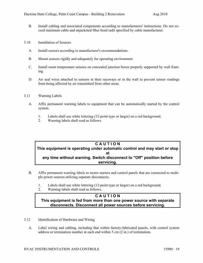
Daytona State College, Palm Coast Campus - Building 2 Renovation Aug 2010
B. Install cabling and associated components according to manufacturers' instructions. Do not ex-
ceed minimum cable and unjacketed fiber bend radii specified by cable manufacturer.
3.10 Installation of Sensors
A. Install sensors according to manufacturer's recommendations.
B. Mount sensors rigidly and adequately for operating environment.
C. Install room temperature sensors on concealed junction boxes properly supported by wall fram-
ing.
D. Air seal wires attached to sensors in their raceways or in the wall to prevent sensor readings
from being affected by air transmitted from other areas.
3.11 Warning Labels
A. Affix permanent warning labels to equipment that can be automatically started by the control
system.
1. Labels shall use white lettering (12-point type or larger) on a red background.
2. Warning labels shall read as follows.
C A U T I O NThis equipment is operating under automatic control and may start or stop
atany time without warning. Switch disconnect to "Off" position before
servicing.
B. Affix permanent warning labels to motor starters and control panels that are connected to multi-
ple power sources utilizing separate disconnects.
1. Labels shall use white lettering (12-point type or larger) on a red background.
2. Warning labels shall read as follows.
C A U T I O NThis equipment is fed from more than one power source with separate
disconnects. Disconnect all power sources before servicing.
3.12 Identification of Hardware and Wiring
A. Label wiring and cabling, including that within factory-fabricated panels, with control system
address or termination number at each end within 5 cm (2 in.) of termination.
HVAC INSTRUMENTATION AND CONTROLS 15900 - 19

Daytona State College, Palm Coast Campus - Building 2 Renovation Aug 2010
B. Label pneumatic tubing at each end within 5 cm (2 in.) of termination with a descriptive identi-
fier.
C. Permanently label or code each point of field terminal strips to show instrument or item served.
D. Label control panels with minimum 1 cm (½ in.) letters on laminated plastic nameplates.
E. Label each control component with a permanent label. Label plug-in components such that label
remains stationary during component replacement.
F. Label room sensors related to terminal boxes or valves with nameplates.
G. Manufacturers' nameplates and UL or CSA labels shall be visible and legible after equipment is
installed.
H. Label identifiers shall match record documents.
3.13 Programming
A. Point Naming. Name points as shown on the equipment points list provided with each sequence
of operation. See Section 15900 Appendix A (Sequences of Operation). If character limitations
or space restrictions make it advisable to shorten the name, the abbreviations given in Appendix
C may be used.
B. Software Programming. Programming shall provide actions for each possible situation.
Graphic- or parameter-based programs shall be documented. Text-based programs shall be
modular, structured, and commented to clearly describe each section of the program.
1. Application Programming. Provide application programming that adheres to sequences of
operation specified in Section 15900 Appendix A. Program documentation or comment
statements shall reflect language used in sequences of operation.
2. System Programming. Provide system programming necessary for system operation.
C. Operator Interface.
1. Standard Graphics. Provide graphics as specified in Section 15900 Article 2.3 Paragraph
E.2 (System Graphics). Show on each equipment graphic input and output points and
relevant calculated points such as indicated on the applicable Points List in Section 15900
Appendix A. Point information on graphics shall dynamically update.
2. Install, initialize, start up, and troubleshoot operator interface software and functions (in-
cluding operating system software, operator interface database, and third-party software
installation and integration required for successful operator interface operation) as de-
scribed in Section 15900.
3.14 Control System Checkout and Testing
A. Startup Testing. Complete startup testing to verify operational control system before notifying
Owner of system demonstration. Provide Owner with schedule for startup testing. Owner may
have representative present during any or all startup testing.
HVAC INSTRUMENTATION AND CONTROLS 15900 - 20

Daytona State College, Palm Coast Campus - Building 2 Renovation Aug 2010
1. Calibrate and prepare for service each instrument, control, and accessory equipment fur-
nished under Section 15900.
2. Verify that control wiring is properly connected and free of shorts and ground faults. Ver-
ify that terminations are tight.
3. Enable control systems and verify each input device's calibration. Calibrate each device
according to manufacturer's recommendations.
4. Verify that binary output devices such as relays, solenoid valves, two-position actuators
and control valves, and magnetic starters, operate properly and that normal positions are
correct.
5. Verify that analog output devices such as I/Ps and actuators are functional, that start and
span are correct, and that direction and normal positions are correct. Check control valves
and automatic dampers to ensure proper action and closure. Make necessary adjustments
to valve stem and damper blade travel.
6. Prepare a log documenting startup testing of each input and output device, with techni-
cian's initials certifying each device has been tested and calibrated.
7. Verify that system operates according to sequences of operation. Simulate and observe
each operational mode by overriding and varying inputs and schedules. Tune PID loops
and each control routine that requires tuning.
8. Alarms and Interlocks.
a. Check each alarm with an appropriate signal at a value that will trip the alarm.
b. Trip interlocks using field contacts to check logic and to ensure that actuators fail
in the proper direction.
c. Test interlock actions by simulating alarm conditions to check initiating value of
variable and interlock action.
3.15 Control System Demonstration and Acceptance
A. Demonstration. Prior to acceptance, perform the following performance tests to demonstrate
system operation and compliance with specification after and in addition to tests specified in
Article 3.17 (Control System Checkout and Testing). Provide Owner with log documenting
completion of startup tests.
1. Owner will be present to observe and review system demonstration. Notify Engineer at
least 10 days before system demonstration begins.
2. Demonstration shall follow process submitted and approved under Section 15900 Article
1.10 (Submittals). Complete approved checklists and forms for each system as part of
system demonstration.
3. Demonstrate actual field operation of each sequence of operation as specified in Section
15900 Appendix A. Provide at least two persons equipped with two-way communication.
Demonstrate calibration and response of any input and output points requested by Engi-
neer. Provide and operate test equipment required to prove proper system operation.
4. Demonstrate compliance with Section 15900 Part 1 (System Performance).
5. Demonstrate compliance with sequences of operation through each operational mode.
6. Demonstrate complete operation of operator interface.
7. Demonstrate each of the following.
a. DDC loop response. Supply graphical trend data output showing each DDC loop's
response to a setpoint change representing an actuator position change of at least
25% of full range. Trend sampling rate shall be from 10 seconds to 3 minutes, de-
HVAC INSTRUMENTATION AND CONTROLS 15900 - 21

Daytona State College, Palm Coast Campus - Building 2 Renovation Aug 2010
pending on loop speed. Each sample's trend data shall show setpoint, actuator posi-
tion, and controlled variable values. Engineer will require further tuning of each
loop that displays unreasonably under- or over-damped control.
b. Demand limiting. Supply trend data output showing demand-limiting algorithm ac-
tion. Trend data shall document action sampled each minute over at least a 30-
minute period and shall show building kW, demand-limiting setpoint, and status of
setpoints and other affected equipment parameters.
c. Building fire alarm system interface.
d. Trend logs for each system. Trend data shall indicate setpoints, operating points,
valve positions, and other data as specified in the points list provided with each se-
quence of operation in Section 15900 Appendix A. Each log shall cover three 48-
hour periods and shall have a sample frequency not less than 10 minutes or as
specified on its points list. Logs shall be accessible through system's operator inter-
face and shall be retrievable for use in other software programs as specified in Sec-
tion 15900 Article 2.3 Paragraph E.11 (Trend Configuration).
8. Tests that fail to demonstrate proper system operation shall be repeated after Contractor
makes necessary repairs or revisions to hardware or software to successfully complete
each test.
B. Acceptance.
1. After tests described in this specification are performed to the satisfaction of both Engi-
neer and Owner, Engineer will accept control system as meeting completion require-
ments. Engineer may exempt tests from completion requirements that cannot be per-
formed due to circumstances beyond Contractor's control. Engineer will provide written
statement of each exempted test. Exempted tests shall be performed as part of warranty.
2. System shall not be accepted until completed demonstration forms and checklists are
submitted and approved as required in Section 15900 Article 1.10 (Submittals).
3.16 Cleaning
A. Each day clean up debris resulting from work. Remove packaging material as soon as its con-
tents have been removed. Collect waste and place in designated location.
B. On completion of work in each area, clean work debris and equipment. Keep areas free from
dust, dirt, and debris.
C. On completion of work, check equipment furnished under this section for paint damage. Repair
damaged factory-finished paint to match adjacent areas. Replace deformed cabinets and enclo-
sures with new material and repaint to match adjacent areas.
3.17 Training
A. Provide training for a designated staff of Owner's representatives. Training shall be provided via
self-paced training, web-based or computer-based training, classroom training, or a combination
of training methods.
HVAC INSTRUMENTATION AND CONTROLS 15900 - 22
Daytona State College, Palm Coast Campus - Building 2 Renovation Aug 2010
B. Provide course outline and materials according to Section 15900 Article 1.10 (Submittals). Pro-
vide one copy of training material per student.
C. Instructors shall be factory-trained and experienced in presenting this material.
D. Perform classroom training using a network of working controllers representative of installed
hardware.
3.18 Sequence of Operation
A. See Section 15900 Appendix A (Sequences of Operation).
3.19 3.20 Points List
A. Points lists are integrated into Section 15900 Appendix A (Sequences of Operation).
APPENDIX A: Sequences of Operation
1. Variable Air Volume - Terminal Unit
Run Conditions - Scheduled:The unit shall run according to a user definable time schedule in the following modes:
! Occupied Mode: The unit shall maintain
! A 74°F (adj.) cooling setpoint
! A 70°F (adj.) heating setpoint.
! Unoccupied Mode (night setback): The unit shall maintain
! A 85°F (adj.) cooling setpoint.
! A 55°F (adj.) heating setpoint.
Alarms shall be provided as follows:
! High Zone Temp: If the zone temperature is greater than the cooling setpoint by a user definable amount (adj.).
! Low Zone Temp: If the zone temperature is less than the heating setpoint by a user definable amount (adj.).
Zone Setpoint Adjust: The occupant shall be able to adjust the zone temperature heating and cooling setpoints at the zone sensor.
Zone Unoccupied Override:A timed local override control shall allow an occupant to override the schedule
HVAC INSTRUMENTATION AND CONTROLS 15900 - 23

Daytona State College, Palm Coast Campus - Building 2 Renovation Aug 2010
and place the unit into an occupied mode for an adjustable period of time. At the expiration of this time, control of the unit shall automatically return to the sched-ule.
Variable Volume Terminal Unit - Flow Control:The unit shall maintain zone setpoints by controlling the airflow through one of the following:
Occupied:
! When zone temperature is greater than its cooling setpoint, the zone dampershall modulate between the minimum occupied airflow (adj.) and the maximumcooling airflow (adj.) until the zone is satisfied.
! When the zone temperature is less than the cooling setpoint, the zone dampershall maintain the minimum required zone ventilation (adj.).
Unoccupied:
! When the zone is unoccupied the zone damper shall control to its minimum un-occupied airflow (adj.).
! When the zone temperature is greater than its cooling setpoint, the zone damper shall modulate between the minimum unoccupied airflow (adj.) and the maximumcooling airflow (adj.) until the zone is satisfied.
Fan Control - Series:The fan shall run anytime the unit is commanded to run. The fan shall run for a minimum user definable time (adj.). The zone damper will close completely before the fan starts toprevent air from the AHU from causing the fan to spin backward. The zone damper will return to automatic control after the fan starts.
Electric Reheating Stages:The controller shall measure the zone temperature and stage the reheating to maintain its setpoint. To prevent short cycling, there shall be a user defin-able (adj.) delay between stages, and each stage shall have a user definable (adj.) minimum runtime.
The reheating shall be enabled whenever:
! Outside air temperature is less than 65°F (adj.).
! AND the zone temperature is below setpoint.
! AND sufficient airflow is provided.
Reheating - High Discharge Air Temperature Limit:The controller shall measure the discharge air temperature and limit reheating if the discharge air temperature is more than 15°F (adj.) above the zone tempera-ture.
Discharge Air Temperature:The controller shall monitor the discharge air temperature.
HVAC INSTRUMENTATION AND CONTROLS 15900 - 24

Daytona State College, Palm Coast Campus - Building 2 Renovation Aug 2010
Alarms shall be provided as follows:
! High Discharge Air Temp: If the discharge air temperature is greater than 120°F (adj.).
! Low Discharge Air Temp: If the discharge air temperature is less than 40°F (adj.).
Fan Status:The controller shall monitor the fan status.
Alarms shall be provided as follows:
! Fan Failure: Commanded on, but the status is off.
! Fan in Hand: Commanded off, but the status is on.
! Fan Runtime Exceeded: Fan status runtime exceeds a user definable limit (adj.).
Filter Hours:The controller shall monitor the fan runtime.
Alarms shall be provided as follows:
! Filter Change Required: Filter has been in use for more than 2200 hrs (adj.).
Environmental Index:When the zone is occupied, the controller will monitor the deviation of the zone temperature from the heating or cooling setpoint and calculate a 0 - 100% Envi-
ronmental Index which gives an indication of how well the zone is maintaining comfort. The controller will also calculate the percentage of time since occu-pancy began that the Environmental Index is 70% or higher. Optionally, a weight-ing factor can be configured to adjust the contribution of the zone to the rollup average index based upon the floor area of the zone, importance of the zone, or other static criteria.
Hardware Points Software Points
Point Name AI AO BI BO AV BV Sched Trend Alarm Show On Graphic
Zone Temp × × ×
Zone Setpoint Adjust × ×
Airflow × × ×
Discharge Air Temp × × ×
Zone Damper × ×
Zone Override × × ×
Fan Status × × ×
Fan Start/Stop × ×
Reheating Stage 1 × × ×
Reheating Stage 2 × × ×
Airflow Setpoint × × ×
HVAC INSTRUMENTATION AND CONTROLS 15900 - 25

Daytona State College, Palm Coast Campus - Building 2 Renovation Aug 2010
Hardware Points Software Points
Point Name AI AO BI BO AV BV Sched Trend Alarm Show On Graphic
Environmental Index × ×
Percent of Time Satisfied × ×
Schedule ×
Heating Setpoint × ×
Cooling Setpoint × ×
High Zone Temp ×
Low Zone Temp ×
High Discharge Air Temp ×
Low Discharge Air Temp ×
Fan Failure ×
Fan in Hand ×
Fan Runtime Exceeded ×
Filter Change Required × ×
END OF SECTION 15900
HVAC INSTRUMENTATION AND CONTROLS 15900 - 26

Daytona State College, Palm Coast Campus - Building 2 Renovation Aug 2010
SECTION 15950 - TESTING, ADJUSTING, AND BALANCING
PART 1 - GENERAL
1.1 RELATED DOCUMENTS
A. Drawings and general provisions of the Contract, including General and Supplementary
Conditions and Division 1 Specification Sections, apply to this Section.
1.2 SUMMARY
A. This Section includes TAB to produce design objectives for the following:
1. Air Systems:
a. Constant-volume air systems.
b. Variable-air-volume systems.
2. HVAC equipment quantitative-performance settings.
3. Verifying that automatic control devices are functioning properly.
4. Reporting results of activities and procedures specified in this Section.
1.3 DEFINITIONS
A. Adjust: To regulate fluid flow rate and air patterns at the terminal equipment, such as to reduce
fan speed or adjust a damper.
B. Balance: To proportion flows within the distribution system, including submains, branches, and
terminals, according to indicated quantities.
C. Barrier or Boundary: Construction, either vertical or horizontal, such as walls, floors, and
ceilings that are designed and constructed to restrict the movement of airflow, smoke, odors,
and other pollutants.
D. Draft: A current of air, when referring to localized effect caused by one or more factors of high
air velocity, low ambient temperature, or direction of airflow, whereby more heat is withdrawn
from a person's skin than is normally dissipated.
E. NC: Noise criteria.
F. Procedure: An approach to and execution of a sequence of work operations to yield repeatable
results.
G. RC: Room criteria.
H. Report Forms: Test data sheets for recording test data in logical order.
TESTING, ADJUSTING, AND BALANCING 15950 - 1
Daytona State College, Palm Coast Campus - Building 2 Renovation Aug 2010
I. System Effect: A phenomenon that can create undesired or unpredicted conditions that cause
reduced capacities in all or part of a system.
J. System Effect Factors: Allowances used to calculate a reduction of the performance ratings of a
fan when installed under conditions different from those presented when the fan was
performance tested.
K. TAB: Testing, adjusting, and balancing.
L. Terminal: A point where the controlled medium, such as fluid or energy, enters or leaves the
distribution system.
M. Test: A procedure to determine quantitative performance of systems or equipment.
N. Testing, Adjusting, and Balancing (TAB) Firm: The entity responsible for performing and
reporting TAB procedures.
1.4 SUBMITTALS
A. Qualification Data: Within 15 days from Contractor's Notice to Proceed, submit 4 copies of
evidence that TAB firm and this Project's TAB team members meet the qualifications specified
in "Quality Assurance" Article.
B. Contract Documents Examination Report: Within 15 days from Contractor's Notice to Proceed,
submit 4 copies of the Contract Documents review report as specified in Part 3.
C. Strategies and Procedures Plan: Within 30 days from Contractor's Notice to Proceed, submit 4
copies of TAB strategies and step-by-step procedures as specified in Part 3 "Preparation"
Article. Include a complete set of report forms intended for use on this Project.
D. Certified TAB Reports: Submit two copies of reports prepared, as specified in this Section, on
approved forms certified by TAB firm.
E. Warranties specified in this Section.
1.5 QUALITY ASSURANCE
A. TAB Firm Qualifications: Engage a TAB firm certified by either AABC or NEBB.
B. TAB Conference: Meet with Owner's and Architect's representatives on approval of TAB
strategies and procedures plan to develop a mutual understanding of the details. Ensure the
participation of TAB team members, equipment manufacturers' authorized service
representatives, HVAC controls installers, and other support personnel. Provide seven days'
advance notice of scheduled meeting time and location.
1. Agenda Items: Include at least the following:
a. Submittal distribution requirements.
b. The Contract Documents examination report.
c. TAB plan.
TESTING, ADJUSTING, AND BALANCING 15950 - 2
Daytona State College, Palm Coast Campus - Building 2 Renovation Aug 2010
d. Work schedule and Project-site access requirements.
e. Coordination and cooperation of trades and subcontractors.
f. Coordination of documentation and communication flow.
C. Certification of TAB Reports: Certify TAB field data reports. This certification includes the
following:
1. Review field data reports to validate accuracy of data and to prepare certified TAB
reports.
2. Certify that TAB team complied with approved TAB plan and the procedures specified
and referenced in this Specification.
D. TAB Report Forms: Use standard forms from AABC's "National Standards for Testing and
Balancing Heating, Ventilating, and Air Conditioning Systems" or NEBB's "Procedural
Standards for Testing, Adjusting, and Balancing of Environmental Systems."
E. Instrumentation Type, Quantity, and Accuracy: As described in [AABC's "National Standards
for Testing and Balancing Heating, Ventilating, and Air Conditioning Systems or NEBB's
"Procedural Standards for Testing, Adjusting, and Balancing of Environmental Systems,"
Section II, "Required Instrumentation for NEBB Certification."
F. Instrumentation Calibration: Calibrate instruments at least every six months or more frequently
if required by instrument manufacturer.
1. Keep an updated record of instrument calibration that indicates date of calibration and the
name of party performing instrument calibration.
1.6 PROJECT CONDITIONS
A. Owner Occupancy: Owner may occupy completed areas of building before Substantial
Completion. Cooperate with Owner during TAB operations to minimize conflicts with Owner's
operations.
1.7 COORDINATION
A. Coordinate the efforts of factory-authorized service representatives for systems and equipment,
HVAC controls installers, and other mechanics to operate HVAC systems and equipment to
support and assist TAB activities.
B. Notice: Provide seven days' advance notice for each test. Include scheduled test dates and
times.
C. Perform TAB after leakage and pressure tests on air and water distribution systems have been
satisfactorily completed.
1.8 WARRANTY
A. National Project Performance Guarantee: Provide a guarantee on AABC's "National Standards
for Testing and Balancing Heating, Ventilating, and Air Conditioning Systems" forms stating
TESTING, ADJUSTING, AND BALANCING 15950 - 3

Daytona State College, Palm Coast Campus - Building 2 Renovation Aug 2010
that AABC will assist in completing requirements of the Contract Documents if TAB firm fails
to comply with the Contract Documents. Guarantee includes the following provisions:
B. Special Guarantee: Provide a guarantee on NEBB forms stating that NEBB will assist in
completing requirements of the Contract Documents if TAB firm fails to comply with the
Contract Documents. Guarantee shall include the following provisions:
1. The certified TAB firm has tested and balanced systems according to the Contract
Documents.
2. Systems are balanced to optimum performance capabilities within design and installation
limits.
PART 2 - PRODUCTS (Not Applicable)
PART 3 - EXECUTION
3.1 EXAMINATION
A. Examine the Contract Documents to become familiar with Project requirements and to discover
conditions in systems' designs that may preclude proper TAB of systems and equipment.
1. Contract Documents are defined in the General and Supplementary Conditions of
Contract.
2. Verify that balancing devices, such as test ports and manual volume dampers are required
by the Contract Documents. Verify that quantities and locations of these balancing
devices are accessible and appropriate for effective balancing and for efficient system and
equipment operation.
B. Examine approved submittal data of HVAC systems and equipment.
C. Examine Project Record Documents described in Division 1 Section "Project Record
Documents."
D. Examine design data, including HVAC system descriptions, statements of design assumptions
for environmental conditions and systems' output, and statements of philosophies and
assumptions about HVAC system and equipment controls.
E. Examine equipment performance data including fan curves. Relate performance data to Project
conditions and requirements, including system effects that can create undesired or unpredicted
conditions that cause reduced capacities in all or part of a system. Calculate system effect
factors to reduce performance ratings of HVAC equipment when installed under conditions
different from those presented when the equipment was performance tested at the factory. To
calculate system effects for air systems, use tables and charts found in AMCA 201, "Fans and
Systems," Sections 7 through 10; or in SMACNA's "HVAC Systems--Duct Design," Sections 5
and 6. Compare this data with the design data and installed conditions.
F. Examine system and equipment installations to verify that they are complete and that testing,
cleaning, adjusting, and commissioning specified in individual Sections have been performed.
TESTING, ADJUSTING, AND BALANCING 15950 - 4

Daytona State College, Palm Coast Campus - Building 2 Renovation Aug 2010
G. Examine system and equipment test reports.
H. Examine HVAC system and equipment installations to verify that indicated balancing devices,
such as test ports and manual volume dampers, are properly installed, and that their locations
are accessible and appropriate for effective balancing and for efficient system and equipment
operation.
I. Examine systems for functional deficiencies that cannot be corrected by adjusting and
balancing.
J. Examine HVAC equipment to ensure that clean filters have been installed, bearings are greased,
belts are aligned and tight, and equipment with functioning controls is ready for operation.
K. Examine terminal units, such as variable-air-volume boxes, to verify that they are accessible
and their controls are connected and functioning.
L. Examine equipment for installation and for properly operating safety interlocks and controls.
M. Examine automatic temperature system components to verify the following:
1. Dampers and other controlled devices are operated by the intended controller.
2. Dampers are in the position indicated by the controller.
3. Integrity of dampers for free and full operation and for tightness of fully closed and fully
open positions. This includes dampers in mixing boxes, and variable-air-volume
terminals.
4. Sensors are located to sense only the intended conditions.
5. Sequence of operation for control modes is according to the Contract Documents.
6. Controller set points are set at indicated values.
7. Interlocked systems are operating.
8. Changeover from heating to cooling mode occurs according to indicated values.
N. Report deficiencies discovered before and during performance of TAB procedures. Observe
and record system reactions to changes in conditions. Record default set points if different from
indicated values.
3.2 PREPARATION
A. Prepare a TAB plan that includes strategies and step-by-step procedures.
B. Complete system readiness checks and prepare system readiness reports. Verify the following:
1. Permanent electrical power wiring is complete.
2. Automatic temperature-control systems are operational.
3. Equipment and duct access doors are securely closed.
4. Balance, smoke, and fire dampers are open.
5. Isolating and balancing valves are open and control valves are operational.
6. Ceilings are installed in critical areas where air-pattern adjustments are required and
access to balancing devices is provided.
7. Windows and doors can be closed so indicated conditions for system operations can be
met.
TESTING, ADJUSTING, AND BALANCING 15950 - 5

Daytona State College, Palm Coast Campus - Building 2 Renovation Aug 2010
3.3 GENERAL PROCEDURES FOR TESTING AND BALANCING
A. Perform testing and balancing procedures on each system according to the procedures contained
in AABC's "National Standards for Testing and Balancing Heating, Ventilating, and Air
Conditioning Systems" or NEBB's "Procedural Standards for Testing, Adjusting, and Balancing
of Environmental Systems and this Section.
B. Cut insulation, ducts equipment cabinets for installation of test probes to the minimum extent
necessary to allow adequate performance of procedures. After testing and balancing, close
probe holes and patch insulation with new materials identical to those removed. Restore vapor
barrier and finish according to insulation Specifications for this Project.
C. Mark equipment and balancing device settings with paint or other suitable, permanent
identification material, including damper-control positions, valve position indicators, fan-speed-
control levers, and similar controls and devices, to show final settings.
D. Take and report testing and balancing measurements in inch-pound (IP) units.
3.4 GENERAL PROCEDURES FOR BALANCING AIR SYSTEMS
A. Prepare test reports for both fans and outlets. Obtain manufacturer's outlet factors and
recommended testing procedures. Crosscheck the summation of required outlet volumes with
required fan volumes.
B. Prepare schematic diagrams of systems' "as-built" duct layouts.
C. For variable-air-volume systems, develop a plan to simulate diversity.
D. Determine the best locations in main and branch ducts for accurate duct airflow measurements.
E. Check airflow patterns from the outside-air louvers and dampers and the return- and exhaust-air
dampers, through the supply-fan discharge and mixing dampers.
F. Locate start-stop and disconnect switches, electrical interlocks, and motor starters.
G. Verify that motor starters are equipped with properly sized thermal protection.
H. Check dampers for proper position to achieve desired airflow path.
I. Check for airflow blockages.
J. Check for proper sealing of air-handling unit components.
K. Check for proper sealing of air duct system.
3.5 PROCEDURES FOR CONSTANT-VOLUME AIR SYSTEMS
A. Adjust fans to deliver total indicated airflows within the maximum allowable fan speed listed by
fan manufacturer.
TESTING, ADJUSTING, AND BALANCING 15950 - 6

Daytona State College, Palm Coast Campus - Building 2 Renovation Aug 2010
1. Measure fan static pressures to determine actual static pressure as follows:
a. Measure outlet static pressure as far downstream from the fan as practicable and
upstream from restrictions in ducts such as elbows and transitions.
b. Measure static pressure directly at the fan outlet or through the flexible connection.
c. Measure inlet static pressure of single-inlet fans in the inlet duct as near the fan as
possible, upstream from flexible connection and downstream from duct
restrictions.
d. Measure inlet static pressure of double-inlet fans through the wall of the plenum
that houses the fan.
2. Measure static pressure across each component that makes up an air-handling unit,
rooftop unit, and other air-handling and -treating equipment.
a. Simulate dirty filter operation and record the point at which maintenance personnel
must change filters.
3. Measure static pressures entering and leaving other devices such as sound traps, heat
recovery equipment, and air washers, under final balanced conditions.
4. Compare design data with installed conditions to determine variations in design static
pressures versus actual static pressures. Compare actual system effect factors with
calculated system effect factors to identify where variations occur. Recommend
corrective action to align design and actual conditions.
5. Obtain approval from Architect for adjustment of fan speed higher or lower than
indicated speed. Make required adjustments to pulley sizes, motor sizes, and electrical
connections to accommodate fan-speed changes.
6. Do not make fan-speed adjustments that result in motor overload. Consult equipment
manufacturers about fan-speed safety factors. Modulate dampers and measure fan-motor
amperage to ensure that no overload will occur. Measure amperage in full cooling, full
heating, economizer, and any other operating modes to determine the maximum required
brake horsepower.
B. Adjust volume dampers for main duct, submain ducts, and major branch ducts to indicated
airflows within specified tolerances.
1. Measure static pressure at a point downstream from the balancing damper and adjust
volume dampers until the proper static pressure is achieved.
a. Where sufficient space in submain and branch ducts is unavailable for Pitot-tube
traverse measurements, measure airflow at terminal outlets and inlets and calculate
the total airflow for that zone.
2. Remeasure each submain and branch duct after all have been adjusted. Continue to
adjust submain and branch ducts to indicated airflows within specified tolerances.
C. Measure terminal outlets and inlets without making adjustments.
1. Measure terminal outlets using a direct-reading hood or outlet manufacturer's written
instructions and calculating factors.
TESTING, ADJUSTING, AND BALANCING 15950 - 7
Daytona State College, Palm Coast Campus - Building 2 Renovation Aug 2010
D. Adjust terminal outlets and inlets for each space to indicated airflows within specified
tolerances of indicated values. Make adjustments using volume dampers rather than extractors
and the dampers at air terminals.
1. Adjust each outlet in same room or space to within specified tolerances of indicated
quantities without generating noise levels above the limitations prescribed by the
Contract Documents.
2. Adjust patterns of adjustable outlets for proper distribution without drafts.
3.6 PROCEDURES FOR VARIABLE-AIR-VOLUME SYSTEMS
A. Compensating for Diversity: When the total airflow of all terminal units is more than the
indicated airflow of the fan, place a selected number of terminal units at a maximum set-point
airflow condition until the total airflow of the terminal units equals the indicated airflow of the
fan. Select the reduced airflow terminal units so they are distributed evenly among the branch
ducts.
B. Variable-Air-Volume Systems: After the fan systems have been adjusted, adjust the variable-
air-volume systems as follows:
1. Set outside-air dampers at a position that simulates full-load.
2. Select the terminal unit that is most critical to the supply-fan airflow and static pressure.
Measure static pressure. Adjust system static pressure so the entering static pressure for
the critical terminal unit is not less than the sum of minimum inlet static pressure plus the
static pressure needed to overcome terminal-unit discharge system losses.
3. Measure total system airflow. Adjust to within indicated airflow.
4. Set terminal units at maximum airflow and adjust controller or regulator to deliver the
designed maximum airflow. When total airflow is correct, balance the air outlets
downstream from terminal units as described for constant-volume air systems.
5. Set terminal units at minimum airflow and adjust controller or regulator to deliver the
designed minimum airflow. Check air outlets for a proportional reduction in airflow as
described for constant-volume air systems.
a. If air outlets are out of balance at minimum airflow, report the condition but leave
outlets balanced for maximum airflow.
6. Remeasure the return airflow to the fan while operating at maximum return airflow and
minimum outside airflow. Adjust the fan and balance the return-air ducts and inlets as
described for constant-volume air systems.
7. Measure static pressure at the most critical terminal unit and adjust the static-pressure
controller at the main supply-air sensing station to ensure that adequate static pressure is
maintained at the most critical unit.
8. Record the final fan performance data.
3.7 GENERAL PROCEDURES FOR HYDRONIC SYSTEMS
A. Prepare test reports with pertinent design data and number in sequence starting at pump to end
of system. Check the sum of branch-circuit flows against approved pump flow rate. Correct
variations that exceed plus or minus 5 percent.
TESTING, ADJUSTING, AND BALANCING 15950 - 8

Daytona State College, Palm Coast Campus - Building 2 Renovation Aug 2010
B. Prepare schematic diagrams of systems' "as-built" piping layouts.
C. Prepare hydronic systems for testing and balancing according to the following, in addition to the
general preparation procedures specified above:
1. Open all manual valves for maximum flow.
2. Check flow-control valves for specified sequence of operation and set at indicated flow.
3. Set differential-pressure control valves at the specified differential pressure. Do not set at
fully closed position when pump is positive-displacement type unless several terminal
valves are kept open.
4. Set system controls so automatic valves are wide open to heat exchangers.
5. Check air vents for a forceful liquid flow exiting from vents when manually operated.
3.8 PROCEDURES FOR MOTORS
A. Motors, 1/2 HP and Larger: Test at final balanced conditions and record the following data:
1. Manufacturer, model, and serial numbers.
2. Motor horsepower rating.
3. Motor rpm.
4. Efficiency rating.
5. Nameplate and measured voltage, each phase.
6. Nameplate and measured amperage, each phase.
7. Starter thermal-protection-element rating.
B. Motors Driven by Variable-Frequency Controllers: Test for proper operation at speeds varying
from minimum to maximum. Test the manual bypass for the controller to prove proper
operation. Record observations, including controller manufacturer, model and serial numbers,
and nameplate data.
3.9 PROCEDURES FOR TEMPERATURE MEASUREMENTS
A. During TAB, report the need for adjustment in temperature regulation within the automatic
temperature-control system.
B. Measure indoor wet- and dry-bulb temperatures every other hour for a period of two successive
eight-hour days, in each separately controlled zone, to prove correctness of final temperature
settings. Measure when the building or zone is occupied.
C. Measure outside-air, wet- and dry-bulb temperatures.
3.10 TEMPERATURE-CONTROL VERIFICATION
A. Verify that controllers are calibrated and commissioned.
B. Check transmitter and controller locations and note conditions that would adversely affect
control functions.
C. Record controller settings and note variances between set points and actual measurements.
TESTING, ADJUSTING, AND BALANCING 15950 - 9
Daytona State College, Palm Coast Campus - Building 2 Renovation Aug 2010
D. Check the operation of limiting controllers (i.e., high- and low-temperature controllers).
E. Check free travel and proper operation of control devices such as damper and valve operators.
F. Check the sequence of operation of control devices. Note air pressures and device positions and
correlate with airflow and water flow measurements. Note the speed of response to input
changes.
G. Check the interaction of electrically operated switch transducers.
H. Check the interaction of interlock and lockout systems.
I. Check main control supply-air pressure and observe compressor and dryer operations.
J. Record voltages of power supply and controller output. Determine whether the system operates
on a grounded or nongrounded power supply.
K. Note operation of electric actuators using spring return for proper fail-safe operations.
3.11 TOLERANCES
A. Set HVAC system airflow and water flow rates within the following tolerances:
1. Exhaust Fans and Equipment with Fans: Plus 5 to plus 10 percent.
2. Air Outlets and Inlets: 0 to minus 10 percent.
3. Cooling-Water Flow Rate: 0 to minus 5 percent.
3.12 REPORTING
A. Initial Construction-Phase Report: Based on examination of the Contract Documents as
specified in "Examination" Article, prepare a report on the adequacy of design for systems'
balancing devices. Recommend changes and additions to systems' balancing devices to
facilitate proper performance measuring and balancing. Recommend changes and additions to
HVAC systems and general construction to allow access for performance measuring and
balancing devices.
B. Status Reports: As Work progresses, prepare reports to describe completed procedures,
procedures in progress, and scheduled procedures. Include a list of deficiencies and problems
found in systems being tested and balanced. Prepare a separate report for each system and each
building floor for systems serving multiple floors.
3.13 FINAL REPORT
A. General: Typewritten, or computer printout in letter-quality font, on standard bond paper, in
three-ring binder, tabulated and divided into sections by tested and balanced systems.
B. Include a certification sheet in front of binder signed and sealed by the certified testing and
balancing engineer.
TESTING, ADJUSTING, AND BALANCING 15950 - 10
Daytona State College, Palm Coast Campus - Building 2 Renovation Aug 2010
1. Include a list of instruments used for procedures, along with proof of calibration.
C. Final Report Contents: In addition to certified field report data, include the following:
1. Fan curves.
2. Manufacturers' test data.
3. Field test reports prepared by system and equipment installers.
4. Other information relative to equipment performance, but do not include Shop Drawings
and Product Data.
D. General Report Data: In addition to form titles and entries, include the following data in the
final report, as applicable:
1. Title page.
2. Name and address of TAB firm.
3. Project name.
4. Project location.
5. Engineer's name and address.
6. Contractor's name and address.
7. Report date.
8. Signature of TAB firm who certifies the report.
9. Table of Contents with the total number of pages defined for each section of the report.
Number each page in the report.
10. Summary of contents including the following:
a. Indicated versus final performance.
b. Notable characteristics of systems.
c. Description of system operation sequence.
11. Nomenclature sheets for each item of equipment.
12. Data for terminal units.
13. Notes to explain why certain final data in the body of reports varies from indicated
values.
14. Test conditions for fans performance forms including the following:
a. Settings for outside air dampers.
b. Conditions of filters.
c. Cooling coil, wet- and dry-bulb conditions.
d. Fan drive settings including settings and percentage of maximum pitch diameter.
e. Inlet vane settings for variable-air-volume systems.
f. Settings for supply-air, static-pressure controller.
g. Other system operating conditions that affect performance.
E. System Diagrams: Include schematic layouts of air and hydronic distribution systems. Present
each system with single-line diagram and include the following:
1. Quantities of outside, supply, return, and exhaust airflows.
2. Water flow rates.
3. Duct, outlet, and inlet sizes.
4. Pipe and valve sizes and locations.
5. Terminal units.
TESTING, ADJUSTING, AND BALANCING 15950 - 11

Daytona State College, Palm Coast Campus - Building 2 Renovation Aug 2010
6. Position of balancing devices.
F. Fan Test Reports: For supply and exhaust fans, include the following:
1. Fan Data:
a. System identification.
b. Location.
c. Make and type.
d. Model number and size.
e. Manufacturer's serial number.
f. Arrangement and class.
g. Sheave make, size in inches, and bore.
h. Sheave dimensions, center-to-center, and amount of adjustments in inches.
2. Motor Data:
a. Make and frame type and size.
b. Horsepower and rpm.
c. Volts, phase, and hertz.
d. Full-load amperage and service factor.
e. Sheave make, size in inches, and bore.
f. Sheave dimensions, center-to-center, and amount of adjustments in inches.
g. Number of belts, make, and size.
3. Test Data (Indicated and Actual Values):
a. Total airflow rate in cfm.
b. Total system static pressure in inches wg.
c. Fan rpm.
d. Discharge static pressure in inches wg.
e. Suction static pressure in inches wg.
G. Rectangular Duct Traverse Reports: Include a diagram with a grid representing the duct cross-
section and record the following:
1. Report Data:
a. System and air-handling unit number.
b. Location and zone.
c. Traverse air temperature in deg F.
d. Duct static pressure in inches wg.
e. Duct size in inches.
f. Duct area in sq. ft..
g. Indicated airflow rate in cfm.
h. Indicated velocity in fpm.
i. Actual airflow rate in cfm.
j. Actual average velocity in fpm.
k. Barometric pressure in psig.
H. Air-Terminal-Device Reports:
TESTING, ADJUSTING, AND BALANCING 15950 - 12

Daytona State College, Palm Coast Campus - Building 2 Renovation Aug 2010
1. Unit Data:
a. System and air-handling unit identification.
b. Location and zone.
c. Test apparatus used.
d. Area served.
e. Air-terminal-device size.
f. Air-terminal-device effective area in sq. ft..
2. Test Data (Indicated and Actual Values):
a. Airflow rate in cfm.
b. Air velocity in fpm.
c. Preliminary airflow rate as needed in cfm.
d. Preliminary velocity as needed in fpm.
e. Final airflow rate in cfm.
f. Final velocity in fpm.
g. Space temperature in deg F.
I. Instrument Calibration Reports:
1. Report Data:
a. Instrument type and make.
b. Serial number.
c. Application.
d. Dates of use.
e. Dates of calibration.
3.14 INSPECTIONS
A. Initial Inspection:
1. After testing and balancing are complete, operate each system and randomly check
measurements to verify that the system is operating according to the final test and balance
readings documented in the Final Report.
2. Randomly check the following for each system:
a. Measure airflow of at least 10 percent of air outlets.
b. Measure water flow of at least 5 percent of terminals.
c. Measure room temperature at each thermostat/temperature sensor. Compare the
reading to the set point.
d. Measure sound levels at two locations.
e. Measure space pressure of at least 10 percent of locations.
f. Verify that balancing devices are marked with final balance position.
g. Note deviations to the Contract Documents in the Final Report.
B. Final Inspection:
TESTING, ADJUSTING, AND BALANCING 15950 - 13

Daytona State College, Palm Coast Campus - Building 2 Renovation Aug 2010
1. After initial inspection is complete and evidence by random checks verifies that testing
and balancing are complete and accurately documented in the final report, request that a
final inspection be made by Owner.
2. TAB firm test and balance engineer shall conduct the inspection in the presence of
Owner.
3. Owner shall randomly select measurements documented in the final report to be
rechecked. The rechecking shall be limited to either 10 percent of the total measurements
recorded, or the extent of measurements that can be accomplished in a normal 8-hour
business day.
4. If the rechecks yield measurements that differ from the measurements documented in the
final report by more than the tolerances allowed, the measurements shall be noted as
"FAILED."
5. If the number of "FAILED" measurements is greater than 10 percent of the total
measurements checked during the final inspection, the testing and balancing shall be
considered incomplete and shall be rejected.
6. TAB firm shall recheck all measurements and make adjustments. Revise the final report
and balancing device settings to include all changes and resubmit the final report.
7. Request a second final inspection. If the second final inspection also fails, Owner shall
contract the services of another TAB firm to complete the testing and balancing in
accordance with the Contract Documents and deduct the cost of the services from the
final payment.
3.15 ADDITIONAL TESTS
A. Within 90 days of completing TAB, perform additional testing and balancing to verify that
balanced conditions are being maintained throughout and to correct unusual conditions.
B. Seasonal Periods: If initial TAB procedures were not performed during near-peak summer and
winter conditions, perform additional testing, inspecting, and adjusting during near-peak
summer and winter conditions.
END OF SECTION 15950
TESTING, ADJUSTING, AND BALANCING 15950 - 14