project manual - spokane transit authority
TRANSCRIPT

SPOKANE TRANSIT AUTHORITY
BOONE FACILITY TENANT
IMPROVEMENTS
PROJECT #14-STA-490
PROJECT MANUAL
SEPTEMBER 09, 2015

Spokane Transit Authority TABLE OF CONTENTS STA Boone Facility TI Page 1 Section Title DIVISION 0: SPECIAL SECTIONS 001100 Advertisement 002100 STA Instructions to Bidders 003100 Project Description and Scope of Work 004200 Bid Submittal Checklist 004213 Bid Proposal Form 004215 STA Bid Response 005000 STA Form of Contract Between Owner and Contractor 006211.F Submittal Transmittal Form 006313.F Request for Information 006324.F Substitution Request (During Bidding) 006325.F Substitution Request (After Bidding) 006336.F Field Authorization, Change Order Proposal, Change Order 007200 General Conditions for Spokane Transit Authority Facility Construction 007300 Special Conditions For Spokane Transit Authority Facility Construction 007346 State Prevailing Wage (Spokane County) DIVISION 1: GENERAL REQUIREMENTS 010100 Summary of Work 013100 Project Management and Coordination 013200 Construction Progress Documentation 014000 Quality Requirements 015000 Temporary Facilities and Controls 016000 Product Requirements 017300 Execution DIVISION 2: DEMOLITION 024119 Selective Structure Demolition DIVISION 5: Metals 055000 Metal Fabrication DIVISION 6: WOOD, PLASTICS AND COMPOSITS 061053 Miscellaneous Rough Carpentry 064116 Plastic-Laminate-Faced Architectural Cabinates DIVISION 7: THERMAL AND MOISTURE PROTECTION 072100 Thermo Insulation 079200 Joint Sealants
Spokane Transit Authority TABLE OF CONTENTS STA Boone Facility TI Page 2 DIVISION 8: OPENINGS 081113 Hollow Metal Doors and Frames 081416 Flush Wood Doors 081433 Stile and Rail Wood Doors 083113 Access Doors and Frames 087113 Door Hardware 088000 Glazing 080113 Decorative Glass Glazing 088733 Decorative Window Films 088853 Security Glazing DIVISION 9: FINISHES 092216 Non-strurctural Metal Framing 092900 Gypsum Board 093000 Tiling 095113 Acoustical Panel Ceilings 096513 Resilient Base and Accessories 096516 Resilient Sheet Flooring 096813 Tile Carpeting 096500 Resilient Flooring 097730 Pre-Finished Woodd-Veneer Wall Panels 099123 Interior Painting DIVISION 10: SPECIALTIES 101419 Dimensionsal Letter Signage 101423 Panel Signage 102600 Wall Protection DIVISION 12: FURNISHINGS 122113 Horizontal Louver Blinds 123661 Simulated Stone Countertops DIVISION 22: PLUMBING 220500 Common Work Results for Plumbing DIVISION 23: HEATING VENTILATING AND AIR CONDITION
230500 Common Work Results for HVAC
230590 Testing Adjusting and Balancing
230700 Insulation Systems
233100 Metal Ducts and Casings
233300 Air Duct Accessories
233700 Air Inlets and Outlets DIVISION 26: ELECTRICAL See sheet specifications

Spokane Transit Authority TABLE OF CONTENTS STA Boone Facility TI Page 3
END OF TABLE OF CONTENTS
September 09, 2015
ADVERTISEMENT FOR BIDS
Sealed bid proposals will be accepted for the following project:
PROJECT NO.: 14-STA-490
TITLE: Boone Facility Tenant Improvements
AGENCY: Spokane Transit Authority
PROJECT MANAGER: Jessica Charlton, Project Manager
PUBLIC BID OPENING: 3:00 P.M., Wednesday September 30, 2015
Spokane Transit Authority (Owner)
Sunroom, located at 1229 W Boone Avenue, Spokane,
WA 99201
PRE-BID WALK-THROUGH: 10:00 A.M., Tuesday, September 15, 2015
Spokane Transit Authority (Owner)
Project Site, Located at 1229 & 1230 W Boone Avenue,
Spokane, WA 99201
Contractors may obtain electronic copies of plans and specifications from the Project Manager, Jessica
Charlton by phone at (509)325-6049 or email at [email protected].
Plans and specifications may also be viewed at local and regional plan centers.
Use of MWBE contractors and suppliers is encouraged but not mandatory. Contractors submitting bids may
contact the Washington State Office of Minority and Women's Business Enterprise to obtain information on
certified firms.
The minimum prevailing wage provisions of Washington state law apply to this project.
The Owner reserves the right to reject or accept any or all bids and to waive minor informalities in the
process.
No contractor submitting may withdraw their bids after hour set for opening thereof unless contract award is
delayed for a period exceeding ninety (90) days.
STA is an Equal Employment Opportunity (EEO) organization which does not discriminate against any
prospective supplier on the basis of race, color, creed, national origin, sex, sexual orientation, gender identity,
or presence of any sensory, mental, or physical disability in the consideration of contract award. The
successful proposer will be required to comply with all EEO federal, state, and local laws and regulations.
Spokane Transit assures nondiscrimination in accordance with Title VI of the Civil Rights Act of 1964. For
more information, see www.spokanetransit.com.

Spokane Transit Authority Section 002100 STA Boone Facility TI STA Instructions to Contractors Submitting Bids
July 31, 2015 002100-1
SECTION 002100 – STA INSTRUCTIONS TO CONTRACTORS SUBMITTING BIDS
DEFINITIONS A. Addenda are written or graphic instruments, approved and issued by the Owner prior to the time
designated for Opening of Bids, which amend, modify or interpret the Bidding Documents by additions, deletions, clarifications, or corrections.
B. An Alternate Bid (or Alternate) is the amount stated in the Bid to be added or deducted from the
amount of the Base Bid if the corresponding change in project scope or materials or methods of construction described in the Bidding Documents is accepted.
C. A Bid is the submission of a complete and properly signed authorized solicitation form (Bid Proposal
Form) together with Bid Bond, if applicable, and the certifications and representations required to comply with the Invitation for Bid.
D. Base Bid is the sum stated in the Bid for which the Bidder offers to perform the work described as the
Base, to which work may be added or deducted from sums stated in Alternate Bids (if any). E. Bidder is one who submits a Bid for a prime contract with the Owner for the Work described in the
Construction Documents. F. A Non-responsive Bid is any Bid which fails to conform in all respects to the material requirements of
the Bidding Documents or imposes conditions which would modify requirements of the Bidding Documents or would limit a bidder's liability to the Spokane Transit Authority so as to give the bidder an advantage over the Bidders as determined by the Spokane Transit Authority.
G. Responsible Bidder means a contractor who meets the criteria listed in RCW 39.04.350. H. Unit Price is an amount stated in the Bid as a price per unit of measurement or materials or services as
described in the Construction documents as defined in the General Conditions of the Contract between STA, as Owner, and the Contractor.
Spokane Transit Authority Section 002100 STA Boone Facility TI STA Instructions to Contractors Submitting Bids
July 31, 2015 002100-2
PART 1 - GENERAL
1.1 EXPLANATION TO PROSPECTIVE CONTRACTORS SUBMITTING BIDS
A. Materials submitted in response to this competitive procurement shall become the property of Spokane Transit Authority. All received Proposals shall be deemed public records as defined in Ch. 42.56RCW “Public Records Act.” Any information in the Bid that the Contractor desires to claim as proprietary and exempt from discloser under the provisions of state law shall be clearly designated. Each page claimed to be exempt from disclosure must be clearly identified by the word “Confidential” printed on it. Marking the entire Bid exempt from discloser will not be honored. STA will consider a Contractor’s request for exemption from disclosure; however, the agency will make a decision predicated upon state law and regulations. If any information is marked as proprietary in the Bid, it will not be made available until the affected Contractor has been given an opportunity to seek a court injunction against the requested disclosure. STA assumes no liability for disclosure of proprietary material submitted by Contractors. Bid submittals shall be considered public documents under applicable Washington state law and shall be available for inspection and copying by the public, except to the extent portions of the submittals are otherwise protected under applicable law. Each Contractor will be responsible for protecting any disclosure of its submittal under applicable law.
B. Any prospective contractor submitting bids desiring an explanation or interpretation of the solicitation, drawings, specifications, etc., must submit a request in writing to the Architect/Engineer (A/E) seven (7) calendar days before the bid due date. Oral explanations or instructions given before the award of a contract will not be binding. Any information given a prospective contractor submitting bids concerning a solicitation will be furnished promptly to all other prospective contractors submitting bids by addendum to the solicitation, if that information is necessary in submitting bids or if the lack of it would be prejudicial to other prospective contractors submitting bids.
C. STA is committed to ensuring that all firms regardless of race, color, sex or national origin have equal opportunity to participate in STA contracts. Therefore, STA has established an annual agency goal for Disadvantaged Business Enterprise (DBE) participation in its contracting opportunities. In accordance with the legislative findings and policies set forth in Chapter 39.19 RCW STA encourages participation in all of its contracts by Minority Business Enterprises (MBE), Women Owned Business Enterprise (WBE, and Minority Women Owned Business Enterprise (MWBE) firms certified by the Office of Minority and Women’s Business Enterprises (OMWBE). Participation may be either on a direct basis in response to this invitation or as a subcontractor to a contractor submitting bids. However, unless required by federal statutes, regulations, grants, or contract terms referenced in the contract documents, no preference will be included in the evaluation of bids, no minimum level of DBE/MBE/WBE/MWBE participation shall be required as a condition for receiving an award, and bids will not be rejected or considered non-responsive on that basis. Any affirmative action requirements set forth in federal regulations or statutes included or referenced in the contract documents will apply.
D. On applicable projects the bid advertisement and Bid Proposal form shall establish a minimum required percentage of apprentice labor hours compared to the total labor hours. Contractors submitting bids may contact the Department of Labor and Industries, Specialty Compliance Services Division, Apprenticeship Section, P.O. Box 44530, Olympia, WA 98504-4530, by phone (360) 902-5320, and e-mail at [email protected], to obtain information on available apprenticeship programs.

Spokane Transit Authority Section 002100 STA Boone Facility TI STA Instructions to Contractors Submitting Bids
July 31, 2015 002100-3
E. In addition to the payment and performance bond required by work law the Contractor shall purchase and maintain in a company or companies lawfully authorized and admitted to do business in the State of Washington possessing a Best’s policyholder’s rating of A- or better and a financial rating of no less than VII, and reasonably acceptable to STA, an occurrence-based Commercial General Liability Insurance Policy which shall provide bodily injury and property damage liability on its own operations and vehicles on Work the Contractor may subcontract or sublet to others, in no less than the amounts specified in Part 2 of the attached STA General Conditions.
F. The general description and scope of work for the project can be found in Section 003100 of this document.
1.2 PREPARATION OF BIDS – CONSTRUCTION
A. Bids must be: (1) submitted on the bid proposal forms, or copies of forms, furnished by the Owner or the Owner’s agent, and (2) signed in ink. The person signing a bid must initial each change appearing on any bid form. If the bid is made by a corporation, it shall be signed by the corporation’s authorized designee. The address of the contractor submitting bids shall be typed or printed on the bid form in the space provided.
B. The bid form may require contractors submitting bids to submit bid prices for one or more items on various bases, including: (1) lump sum base bid; (2) lump sum bid alternate prices; (3) unit prices; or (4) any combination of items 1 through 3 above.
C. If the solicitation includes alternate bid items, failure to provide a bid on the alternates may disqualify the bid. If quoting on all items is not required, contractors submitting bids should insert the words “no bid” in the space provided for any item on which no price is submitted.
D. Substitute bid proposals will not be considered unless this solicitation authorizes their submission.
1.3 BID GUARANTEE
A. When the sum of the base bid plus all additive bid alternates is $35,000.00 or less, bid security is not required. When the sum of the base bid plus all additive alternates is greater than $35,000.00, a bid guarantee in the amount of 5% of the base bid amount is required. Failure of the contractor submitting bids to provide bid guarantee when required shall render the bid non-responsive.
B. Acceptable forms of bid guarantee are: A bid bond or postal money order, or certified check or cashier’s check made payable to Spokane Transit Authority. The Owner will return bid guarantees (other than bid bond) to unsuccessful contractors submitting bids as soon as practicable, but not sooner than the execution of a contract with the successful contractor submitting bids. The bid guarantee of the successful contractor submitting bids will be returned to the successful contractor submitting bids with its official notice to proceed with the work of the contract.
C. The contractor submitting bids will allow 90 days from bid opening date for acceptance of its bid by the Owner. The contractor submitting bids will return to the Owner a signed contract, insurance certificate and bond or bond waiver within 15 days after receipt of the contract. If the apparent successful contractor submitting bids fails to sign all contractual documents or provide the bond and insurance as required or return the documents within 15 days after receipt of the contract, the Owner may terminate the award of the contract.

Spokane Transit Authority Section 002100 STA Boone Facility TI STA Instructions to Contractors Submitting Bids
July 31, 2015 002100-4
D. In the event a contractor submitting bids discovers an error in its bid following the bid opening, the contractor submitting bids may request to withdraw its bid under the following conditions:
1. Written notification is received by the Owner within 24 hours following bid opening. 2. The contractor submitting bids provides written documentation of the claimed error to the
satisfaction of the Owner within 72 hours following the bid opening.
The Owner will approve or disapprove the request for withdrawal of the bid in writing. If the contractor’s request for withdrawal of its bid is approved, the contractor submitting bids will be released from further obligation to the Owner without penalty. If it is disapproved, the Owner may retain the contractor’s bid guarantee.
1.4 ADDITIVE OR DEDUCTIVE BID ITEMS
A. The low contractor submitting bids, for purposes of award, shall be the responsive contractor submitting bids offering the low aggregate amount for the base bid item, plus additive or deductive bid alternates selected by the Owner, and within funds available for the project.
B. The contractor submitting bids agrees to hold all bid alternate prices for ninety (90) days from date of bid opening.
1.5 ACKNOWLEDGEMENT OF ADDENDA
A. Contractors submitting bids shall acknowledge receipt of all addenda to this solicitation by identifying the addenda numbers in the space provided for this purpose on the bid proposal form. Failure to do so may result in the bid being declared non-responsive.
1.6 SITE INVESTIGATION AND CONDITIONS AFFECTING THE WORK
A. The contractor submitting bids acknowledges that it has taken steps necessary to ascertain the nature and location of the work, and that it has investigated and satisfied itself as to the general and local conditions which can affect the work or its cost, including but not limited to (1) conditions bearing upon transportation, disposal, handling, and storage of materials; (2) the availability of labor, water, electric power, and road; (3) uncertainties of weather, river stages, tides, or similar physical conditions at the site; (4) the conformation and conditions of the ground; and (5) the character of equipment and facilities needed preliminary to and during the work. The contractor submitting bids also acknowledges that it has satisfied itself as to character, quality, and quantity of surface and subsurface materials or obstacles to be encountered insofar as this information is reasonably ascertainable from an inspection of the site, including exploratory work done by the Owner, as well as from the drawings and specifications made a part of this contract. Any failure of the contractor submitting bids to take the actions described and acknowledged in this paragraph will not relieve the contractor submitting bids from responsibility for estimating properly the difficulty and cost of successfully performing the work.
B. If Bidder is unable to attend the scheduled Pre-Bid meeting, please contact STA to arrange a separate site visit. Bids submitted by contractors that have not either attended a pre-bid
meeting or inspected the site in the presence of STA staff will be considered non-responsive.

Spokane Transit Authority Section 002100 STA Boone Facility TI STA Instructions to Contractors Submitting Bids
July 31, 2015 002100-5
1.7 TIME OF COMPLETION
A. Work may begin when the Contractor receives a formal “Notice to Proceed.” Contractor shall proceed with promptness and dispatch and shall complete the project within ninety (90) calendar days beginning on the day of commencement as stated in a Notice to Proceed.
1.8 LIQUIDATED DAMAGES
A. The Contractor agrees to pay to STA liquidated damages in the amount of $100.00 for each day the Contractor fails to provide services or respond to an STA request for services hereinafter provided. These liquidated damages are for the purpose of any delay or impact caused to STA by virtue of the Contractor’s acts or omissions and do not cover any other actual or consequential damages other than delay. STA and the Contractor agree that such damage cannot be reasonably determined at this time. Such damages are very difficult to accurately estimate because of numerous factors, including, but not limited to inconvenience to STA. Further, the parties agree this is a reasonable forecast of all factors now known and available for consideration relating to the delay caused by failure to perform. Liquidated damages shall be deducted from the contract by change order.
1.9 WAGE RATE SCHEDULES
A. The Scope of Work for this project constitutes a public work under state law and therefore the Contractor shall pay the highest prevailing wage rate by trade or occupation as specified by the State of Washington, Department of Labor and Industries. The Prevailing Wage rates for the State of Washington are current at the time of submission and are available through websites provide in Section 007346 of this document. It is the responsibility of the prospective bidder to verify these publications are current at the time of bidding 1. Certified Payrolls for the prime and all subcontractors must accompany all applications for
payment. 2. An approved Intent to Pay Prevailing wage form must be received by STA for the contractor
and any subcontractors prior to commencement of any work.
B. Any disputes as to wage rates will be referred to the US Secretary of Labor and the Director of Labor and Industries for the State of Washington who will determine the prevailing local wage rate for the trade in dispute.
1.10 TAXES
A. NOTE: Contractor must bond for total contract amount plus WSST.
1.11 BID AMOUNTS
A. The bid prices shown for each item on the bid proposal shall include all labor, material, equipment, overhead and compensation to complete all of the work for that item.
B. The actual cost of building permit (only) and the public utility hookup fees will be a direct reimbursement to the Contractor or paid directly to the permitting agency by the Owner. Fees for these permits should not be included by the Contractor submitting bids in the bid amount.
Spokane Transit Authority Section 002100 STA Boone Facility TI STA Instructions to Contractors Submitting Bids
July 31, 2015 002100-6
B. The actual cost of building permit (only) and the public utility hookup fees will be a direct reimbursement to the Contractor or paid directly to the permitting agency by the Owner. Fees for these permits should not be included by the Contractor submitting bids in the bid amount.
C. The Contractor submitting bids agrees to hold the base bid prices for ninety (90) days from date of bid opening.
1.12 SUBMISSION OF BIDS
A. Bid Proposals must be submitted on or before the time specified in the Advertisement for Bids or as extended in Contract Documents.
B. If the base bid and the sum of the additive alternates is one million dollars or more, the Bid Proposal shall comply with the following requirements: 1. Pursuant to RCW 39.30.060, if the base bid and the sum of the additive alternates is one
million dollars or more, the Contractor submitting bids shall provide names of the Subcontractors with whom the Contractor submitting bids will subcontract for performance of heating, ventilation and air conditioning (HVAC), plumbing, and electrical.
2. The Contractor submitting bids can name itself for the performance of the work. 3. The Contractor submitting bids shall not list more than one Subcontractor for each category
of work identified UNLESS Subcontractors vary with bid alternates, in which case the Contractor submitting bids must indicate which Subcontractor will be used for which alternate.
4. Failure of the Contractor submitting bids to submit as part of the bid the NAMES of such Subcontractors or to name itself to perform such work shall render the contractor’s bid nonresponsive and, therefore, void.
C. The Bid Proposal shall be submitted in a sealed envelope addressed to the office specified in the Advertisement for Bids. Oral, telephonic, electronic, for facsimile bids are invalid and will not receive consideration. The envelope shall have printed on the outside:
1. The project number and description. 2. The name and address of the contractor submitting bids. 3. Identification as Bid Proposal.
D. Prior to the bid opening, the Owner’s representative will designate the official bid clock. Any part of the bid proposal or bid modification not received prior to the times specified, per the designated bid clock, will not be considered and the bid will be returned to the contractor unopened.
E. A bid may be withdrawn in person by the authorized representative of the contractor submitting bids before the opening of the bids. The representative of the contractor submitting bids will be required to show ID and sign on bid summary sheet before it will be released.
F. People with disabilities who wish to request special accommodation, (e.g., sign language interpreters, Braille, etc.) need to contact the Owner ten (10) working days prior to the scheduled bid opening.
1.13 CONSIDERATION OF BIDS
A. Spokane Transit Authority shall have the right to reject any or all bids and to reject bids considered non-responsive including but not limited to Bids not accompanied by any required bid security,

Spokane Transit Authority Section 002100 STA Boone Facility TI STA Instructions to Contractors Submitting Bids
July 31, 2015 002100-7
certifications, or data required by the Bidding Documents or a Bid not signed by the authorized legal representative.
B. The Owner shall have the right to waive any informality or irregularity in any Bid received.
C. In the event that a single bid is received, Spokane Transit will conduct a cost/price analysis of the bid. This analysis will compare the price and quality of the proposed equipment with that involved in recent similar purchases with similar specifications made by this or other governmental agencies in an attempt to determine the competitive integrity of the submitted bid.
1.14 BID RESULTS
A. After the Bid Opening, Contractors submitting bids may obtain bid results from the Owner. Bid results may also be obtained from the A/E.
1.15 LOW RESPONSIBLE
A. Mandatory Responsibility Criteria: Before award of a public works contract, a contractor submitting bids must meet the following mandatory responsibility criteria under RCW 39.04.350 (1) to be considered a responsible contractor submitting bids and qualified to be awarded a public works project. The contractor submitting bids must:
1. At the time of bid submittal, have a certificate of registration of contractor in compliance with
Chapter 18.27 RCW; 2. Have a current state unified business identifier number; 3. If applicable, have industrial insurance coverage for the employees of the contractor
submitting bids working in Washington as required in Title 51 RCW; an employment security department number as required in Title 50 RCW; and a state excise tax registration number as required in Title 82 RCW;
4. Not be disqualified from quoting on any public works contract under RCW 39.06.010 or 39.12.065(3); and
5. If quoting on a public works project subject to the apprenticeship utilization requirements in RCW 39.04.320, not have been found out of compliance by the Washington state apprenticeship and training council for working apprentices out of ratio, without appropriate supervision, or outside their approved work processes as outlined in their standards of apprenticeship under chapter 49.04 RCW for the one-year period immediately preceding the date of the bid solicitation.
6. Until December 31, 2013, not have violated the “Off-site Prefabrication” reporting requirement more than one time as determined by the Department of Labor and Industries.
B. Supplemental Responsibility Criteria: In addition to the mandatory contractor submitting bids responsibility, the Owner may adopt relevant supplemental criteria for determining contractor submitting bids responsibility applicable to a particular project which the contractor submitting bids must meet (RCW 39.04.350 (2)). 1. If applicable, the Owner shall consider an overall accounting of the attached supplemental
criteria for determining contractor submitting bids responsibility “DIVISION 00 RESPONSIBILITY CRITERIA”.
2. At least seven (7) days prior to the bid submittal deadline, a potential contractor submitting bids may request that the Owner modify the supplemental responsibility criteria. The Owner will evaluate the information submitted by the potential contractor submitting bids and

Spokane Transit Authority Section 002100 STA Boone Facility TI STA Instructions to Contractors Submitting Bids
July 31, 2015 002100-8
respond before the bid submittal deadline. If the evaluation results in a change of the criteria, the Owner will issue an addendum to the quoting documents identifying the new criteria.
3. Upon Owner’s request, the apparent low contractor submitting bids must supply the requested responsibility information within two (2) business days of request by Owner. Withholding information or failure to submit all the information requested within the time provided may render the bid non-responsive.
4. Upon request of the Owner, a Bidder whose proposal is under consideration for award of Contract shall submit promptly satisfactory evidence of his/her financial resources, experience, organization, and equipment available for performance of the Contract on AIA Form A305 “contractor’s Qualification Statement” or similar form approved by the Owner.
5. If the Owner determines that the apparent low contractor submitting bids is not responsible, the Owner will notify the contractor submitting bids of its preliminary determination in writing.
6. Within three (3) days after receipt of the preliminary determination, the contractor submitting bids may withdraw its bid or request a hearing where the contractor submitting bids may appeal the preliminary determination and present additional information to the Owner.
7. The Owner will schedule a hearing within three (3) working days of receipt of the contractor’s request. The hearing members will include a STA Executive or designee, and Project Manager.
8. The Owner will issue a Final Determination after reviewing information presented at the hearing.
9. If the Owner determines a contractor submitting bids to be not responsible, the Owner will provide, in writing, the reasons for the determination. If the final determination affirms that the contractor submitting bids is not responsible, the Owner will not execute a contract with any other contractor submitting bids until two (2) business days after the contractor submitting bids determined to be not responsible has received the final determination.
10. The Owner’s Final Determination is specific to this project, and will have no effect on other or future projects.
1.16 CONTRACT AWARD
A. The Owner will evaluate bids responsiveness and responsibility. 1. A bid will be considered responsive if it meets the following requirements:
a. It is received at the proper time and place. b. It meets the stated requirements of the bid proposal. c. It is accompanied by a bid guarantee, if required.
2. A bid will be considered responsible if it meets the following requirements: a. It is submitted by a licensed/registered contractor within the state of Washington at the
time of bid opening and is not banned from quoting by the Department of Labor and Industries.
b. It meets the mandatory responsibility criteria established in RCW 39.04.350 for Prime and Subs and an overall accounting of the supplemental responsibility criteria established for the project.
B. The Owner reserves the right to accept or reject any or all bid proposals and to waive informalities.
C. The Owner may negotiate bid price adjustments with the low responsive contractor submitting bids, including changes in the contract documents, to bring the bid within the available funding per RCW 39.04.015.
Spokane Transit Authority Section 002100 STA Boone Facility TI STA Instructions to Contractors Submitting Bids
July 31, 2015 002100-9
D. The apparent low contractor submitting bids, for purpose of award, shall be the responsive and responsible contractor submitting bids offering the low aggregate amount for the base bid plus selected additive or deductive bid alternates and meeting all other bid submittal requirements.
E. The Contract will only become effective when signed by the Owner. Prior to the Owner’s signature, any and all costs incurred shall be the sole responsibility of the contractor submitting bids.
F. The Contractor must purchase and maintain insurance coverage as stated in Part 2 of Spokane Transit Authority’s Public Works Construction Project General Conditions.
G. Note: AIA Payment Bond and Performance Bond forms (A312) are required. These forms will not be provided by the Owner.
1.17 CONTRACT DOCUMENTS
A. The Contract Documents under which it is proposed to execute this work consists of all material bound herein, plus any addenda incorporated into the documents.
B. These Contract Documents are intended to be mutually cooperative and to provide all details reasonably required for the execution of the proposed work. Any person contemplating the submission of a proposal shall have thoroughly examined all of the various parts of these documents, and should there be any doubt as to the meaning or intent of said Contract Documents, the Bidder should request the Architect/Engineer, in writing (at least six (6) working days prior to bid opening), and interpretation thereof. Any interpretation or change in said Contract Documents will be made only in writing, in the form of addenda to the documents and will be furnished to all Bidders receiving a set of documents, who shall indicate receipt of same in the space provided on the proposal form. The Owner will not be responsible for any other explanation or interpretation of said documents.
1.18 DISCREPANCIES & CONTRACT DOCUMENT REVIEW
A. The intent of Spokane Transit Authority and Federal Funded Project Contract Documents is to describe a complete Project. These Contract Documents are complimentary. What is required by one part of the Contract Documents shall be binding as if required by all.
B. In the event of a discrepancy between Spokane Transit Authority and Federal Funded Project Contract Documents, the Contractor will use the Contract Document that imparts the highest cost to their bid and/or longest delay in their schedule. It is the responsibility of the Contractor to bring these discrepancies to the attention of the Architect as soon as they are discovered.
1.19 PROTEST PROCEDURES
A. STA maintains a set of protest procedures. If any bidder desires this information, it may be obtained by calling the Office of the Purchasing Manager, Jacqueline Tjards at (509) 325-6032.

Spokane Transit Authority Section 002100 STA Boone Facility TI STA Instructions to Contractors Submitting Bids
July 31, 2015 002100-10
PART 2 - PRODUCTS (Not used)
PART 3 - EXECUTION (Not used)
END OF SECTION 002100

Spokane Transit Authority Section 003100
STA Boone Facility TI STA Project Description and Scope of Work
July 31, 2015 003100-1
SECTION 003100 – STA PROJECT DESCRIPTION AND SCOPE OF WORK
PROJECT DESCRIPTION
Spokane Transit Authority (STA) wishes to make tenant improvements to its facilities located at 1229 and
1230 W Boone Avenue in Spokane Washington.
Time Line: The Contractor agrees to coordinate the completion of all construction and finish work within
ninety (90) calendar days beginning on the day of commencement as stated in a Notice to Proceed. Refer to
STA Instructions to Bidders, Section 002100.
Liquidated Damages: Refer to STA Instructions to Bidders, Section 002100.
PROJECT GENERAL SCOPE OF WORK
The work shall generally consist of:
1. Obtain and pay for all required fees and permitting.
2. Reconfigure public entry with central reception and security.
3. Demolition and installation of new gypsum board partition walls, doors and hardware.
4. Relocation of fire annunciation panels (see alternate on E-111, keyed note 10).
5. Updated floor, wall and ceiling finishes throughout work areas.
6. Record all “as-built” information for delivery to Owner as required for final closeout
7. Provide O&M manuals to Owner as required for final closeout
8. All work to be completed as shown and specified on the associated plan and specifications for the
project.
All work shall meet/exceed all codes, utility locating, rules and regulations, as set forth by the City, County
and State of Washington.
Contractor is responsible for the supply of all equipment, materials, and labor necessary to complete the pro-
ject.
Contractor shall perform work in accordance with the Washington State Department of Labor and Industries
Safety Standards.
Contractor shall be responsible for any and all damage and cleanup costs. Contractor negligence shall be re-
paired immediately at no cost to STA.
All work will be subject to inspection and acceptance by STA’s project manager or designee prior to payment.
STA reserves the right to increase or decrease the amount of related services listed in the scope of work for a
fairly negotiated price.
END OF SECTION 003100

Spokane Transit Authority Section 004200
STA Boone Facility TI STA Bid Submittal Checklist
July 31, 2015 004200-1
SECTION 004200 STA BID SUBMITTAL CHECKLIST
BID CHECKLIST- BOONE FACILITY TENANT IMPROVEMENTS 14-STA-490
To be included with Bid Proposal Form when you submit your Bid. Failure of the contractor submitting a bid
to submit these forms with the bid shall render the bid non-responsive and shall be grounds for rejection of
said bid.
Check off each of the following as completed, and included with this proposal:
� Section 004200 - STA Bid Submittal Checklist - Statement of Compliance, signed and dated below.
� Section 004213 - Bid Proposal Form: Submitted on appropriate form, filled out legibly and completely.
� Section 004215 - Bid Response: Submitted on appropriate form, filled out legibly and completely.
� Section 004512 – STA Responsibility Criteria: Submit filled out legibly and completely.
� Bid Security attached in the Amount of 5% of Total Bid (Base Bid including applicable WSST), see
instructions to contractors.
� Work Plan: The Contractor submitting a bid must provide the following required information with the bid
form. Failure to submit such information to the satisfaction of the Owner may render the bid non-
responsive.
The Contractor’s work plan is to include with description the following minimum elements:
a. Installation of safety barriers
b. Phasing
c. Final cleanup
d. Final closeout
� Bid is submitted in a sealed opaque envelope, identified with the following:
Project Name: Boone Facility Tenant Improvements
Project Number: 14-STA-490
Contractor’s Name:
Contractor’s Address:
NOTE: If mailed, enclose sealed bid in a separate mailing envelope with the notation “Sealed Bid Enclosed”.
STATEMENT OF COMPLIANCE
The undersigned has reviewed, read and fully understands these Bid Documents and this checklist, fully
complies therein, and certifies that all required elements, as marked herein and contained within the
specification are included in this Bid Proposal.
Authorized Signature: Date:
END OF SECTION 004200

Spokane Transit Authority Section 004200
STA Boone Facility TI STA Bid Submittal Checklist
July 31, 2015 004200-2
This page intentionally left blank

Spokane Transit Authority Section 004213 STA Boone Facility TI Bid Proposal Form
July 31, 2015 004213-1
SPOKANE TRANSIT AUTHORITY
1230 W. BOONE AVE
SPOKANE, WASHINGTON 99205
BID PROPOSAL – BOONE FACILITY TENANT IMPROVEMENTS
Name of Firm (Contractor submitting bid): ______________________________________
Each bid shall constitute an offer to STA as outlined herein and no bidder may withdraw his/her bid after the hour set for the bid opening thereof except under the conditions explained in the Instructions to Contractors Section. In compliance with the contract documents, the following bid proposal is submitted:
Base Bid
$
(Please print dollar amount in space above) (Total for all work, including
Washington State Sales Tax)
Bid Alternate - Relocate Fire Alarm Control Panel to RM 306, See E-111 (Specify whether additive or deductive)
$
(Please print dollar amount in space above) (Total for all work, including
Washington State Sales Tax)
Unit Prices (Specify whether additive or deductive)
{There are no unit prices on this project}
$ N/A
The unit price shall include full compensation for the cost of labor, materials, equipment, overhead, profit and any additional cost associated with the unit bid.
(Total for all work, including
Washington State Sales Tax)
Basis of Award: The lowest bid shall be the lowest Base Bid price. If the Owner awards a contract it will go to the responsive and responsible bidder who submitted the lowest bid as determined by this basis of award.
The Owner reserves the right to accept or reject any or all bid prices within ninety (90) days of the bid date. Bidder agrees and understands that any additional taxes, permits, bonds, prevailing wage certifications, etc. Applicable to this project, have been included in the above Bid Amounts.
PRODUCTS/BRANDS OTHER THAN SPECIFIED IN BID DOCUMENT TO BE USED:
NOTE: Any deviation from technical specifications provided in bid document must be approved in advance by Owner.
Bidder Name & Signature:
END OF BID PROPOSAL FORM

Spokane Transit Authority Section 004215
STA Boone Facility TI Bid Response
July 31, 2015 004215-1
TO: SPOKANE TRANSIT
PLANNING DEPARTMENT
1230 West Boone Avenue
Spokane, Washington 99201-2686
RE: Project Number: 14-STA-490 BOONE FACILITY TENANT IMPROVEMENT
NAME OF FIRM SUBMITTING BID:
Each bid shall constitute an offer to STA as outlined herein and no bidder may withdraw his bid after the hour
set for the bid opening thereof except under the conditions explained in the Instructions to Bidders Section.
EXAMINATION OF DOCUMENTS:
A. Having carefully examined all Bidding Documents entitled “Boone Facility Tenant Improvements”
by the Spokane Transit Authority, as well as the site and local conditions affecting the work, the
undersigned proposes to perform all work in accordance with the Contract Documents for compensation
to be computed from the enclosed bid amounts.
B. Receipt of the following Addenda to the Specifications and Drawings is hereby acknowledged:
Addendum No. Date_______________
Addendum No. Date_______________
Addendum No. Date_______________
REJECTION: STA reserves the right to reject any or all bid proposals, portions or parts
thereof and to waive minor irregularities in bidding. Special attention will be directed to the
qualifications of the bidders when considering an award of contract.
TIME FOR COMPLETION: The Contractor agrees to coordinate the completion of all construction work
within ninety (90) calendar days after the date of Notice to Proceed.
LIQUIDATED DAMAGES: Per the STA Instructions to Contractors Submitting Bids
SUBMITTAL: The “Bid Response Documents”, “Bid Proposal Form”, and “Responsibility Criteria” constitute
the Bid Proposal when completed and submitted. Please do not submit the entire Invitation for Bid manual.
PRICES: Each bid item will be priced unless stated otherwise.
UNIT PRICE: Unit prices, if requested, shall govern in case of extension error.

Spokane Transit Authority Section 004215
STA Boone Facility TI Bid Response
July 31, 2015 004215-2
Bidder Name:
FREIGHT: Bid price(s) to include all freight costs to the project site.
COMPLETION OF BID PROPOSAL FORM:
All bidding procedures and other requirements of Instructions to Bidders and all Contract Documents have
been followed.
ATTACHMENTS:
A. Bid security as required by the Bidding Documents in the amount of 5% of the Base Bid.
B. Detailed Work Plan based on project plans, pre-bid walk-through, project summary and
specifications.
AWARD OF CONTRACT:
A. If written notice of acceptance of all or part of this submittal is mailed, sent electronically, or
delivered to undersigned within ninety (90) days after opening of proposals, the undersigned will,
within fifteen (15) days after date of such notice, execute and deliver the Form of Agreement as
specified and furnish Insurance Certificates, Performance Bonds, and Labor and Material Payment
Bonds as required.
B. If the undersigned fails to complete the above requirements, amount of Bid Security shall be
forfeited to the Owner.

Spokane Transit Authority Section 004215
STA Boone Facility TI Bid Response
July 31, 2015 004215-3
Bidder Name:
I CERTIFY that no final determination of violation of RCW 50.12.070(1)(b), or 82.32.070(1)(b) has been made
by the Washington State Departments of Employment Security, Labor and Industries or Revenue respectively
dated within two (2) years of the date of the opening of this bid. I understand further that no bid may be
submitted, considered or contract awarded for a public work to any person or entity that has a determination of
violation of the above reference statutes within two (2) years from the date that a violation is finally determined
and the date of this bid opening.
ANTI-KICKBACK: No officer or employee of STA, having the power or duty to perform an official act or
action related to this submittal, shall have or acquire any interest in this submittal, or have solicited, accepted
or granted a present or future gift, favor, service, or other thing of value from or to any person involved in this
submittal.
DEBARRED BIDDERS: The undersigned represents that the Bidder and all officers with a controlling interest
herein are not currently and have not previously been on any debarred bidders list maintained by the United
States Government.
I CERTIFY that to the best of my knowledge, the information contained in this proposal is accurate and
complete and that I have the legal authority to commit this Firm to a contractual agreement. I realize the final
funding for any service is based upon budget levels and the approval of the Spokane Transit Authority’s Board
of Directors.
SUBMITTED BY:
BIDDER NAME
(As registered with the State of Washington)
BY (Signature)
PRINTED NAME & TITLE
DATE:

Spokane Transit Authority Section 004215
STA Boone Facility TI Bid Response
July 31, 2015 004215-4
BIDDER ADMINISTRATIVE INFORMATION
BIDDER NAME:
(as registered with the State of Washington)
PHYSICAL ADDRESS:
MAILING ADDRESS:
CITY, STATE, ZIP:
TELEPHONE and FAX NUMBERS, including area code:
WASHINGTON STATE CONTRACTORS REGISTRATION NUMBER:
WASHINGTON STATE ELECTRICAL CONTRACTOR’S LICENSE NUMBER:
FEDERAL TAX IDENTIFICATION NUMBER:
WASHINGTON STATE UBI NUMBER:
STATE INDUSTRIAL ACCOUNT IDENTIFICATION NUMBER:
** NOTE: If a corporation, write State of Incorporation under signature. If a partnership, give full names of all
partners.
INSURANCE COMPANY:
Name of company:
Mailing Address including zip code:
Name of Insurance Agent:
Telephone number including area code:
Fax number including zip code:
BONDING COMPANY:
Name of Surety:
Mailing Address including zip code:
Name of Bonding Agent:
Telephone number including area code:

Spokane Transit Authority Section 004215
STA Boone Facility TI Bid Response
July 31, 2015 004215-5
BIDDER QUALIFICATION STATEMENT
The following statements of experience, personnel, equipment, and general qualifications of the Bidder are
submitted with the assurance that the owner can rely on its accuracy and truthfulness. If more space is required
for your answers, please attach a continuation sheet(s) to the corresponding bid response page referencing the
item number.
1. The company has been in business continuously from (month and year) .
2. The company has had experience comparable to that required under the proposed contract:
a. As a prime contractor for years.
b. As a subcontractor for years.
3. The following is a partial list of work completed that was on an order of magnitude equal to or greater in
scope and complexity to that required under the proposed contract.
Year Owner & Contact Person Phone No. Location Contract Value
4. A list of supervisory personnel and/or the project manager currently employed by the Bidder that will be
responsible for work on this project. Please attach a brief (1 page maximum) resume for each person listed.
If a resume(s) is not included in the bid documents, the bidder agrees to furnish a resume(s) within 24
hours of notice by STA.
Name Title Years of Experience
5. Following is a listing of all projects the company has undertaken in the last five (5) years which have
resulted in:
a. Arbitration or litigation.
b. Claims or violations being filed by the Federal Government or the Washington State Departments
of L&I, Employment Security, or Revenue.
c. Liens being filed by suppliers or subcontractors.
Person/Entity Name: Signature of Bidder:

Spokane Transit Authority Section 004215
STA Boone Facility TI Bid Response
July 31, 2015 004215-6
BIDDER COMPLIANCE CERTIFICATION
PROJECT COMPLIANCE
In compliance with the Invitation for Bid, bidder hereby proposes to perform all work for this project in strict
accordance with the contract documents, within the time set forth therein, and at the prices bid.
SPECIFICATION COMPLIANCE
The bidder certifies below that his bid complies in all respects with the attached specification documents,
including the minimum specifications.
YES NO
If NO, list below, in detail, any and all deviations.
LIST DEVIATIONS:
Person/Entity Name: Signature of Bidder

Spokane Transit Authority Section 004215
STA Boone Facility TI Bid Response
July 31, 2015 004215-7
SUBCONTRACTOR LIST
Project Number: 14-STA-490
The Bidder will provide a list of all subcontractors anticipated to be used on this project.
Use a copy of this page as a master for attachment if necessary.
If no subcontractors are listed, it will be considered the bidder’s affirmation that it does not intend to use any
subcontractors on this project.
Type of work -
Name of Firm (please print):
(as registered with the State of Washington)
Physical Address:
City, State, Zip:
Telephone/Fax Numbers:
Washington State Contractors Registration Number:
Washington State Electrical or Plumbers License Number:
Federal Tax Identification Number:
Washington State UBI Number:
State Industrial Account Identification Number:
**Note: If a corporation, write State of Incorporation under signature. If a partnership, give full names of all
partners.
Person/Entity Name: Signature of Bidder

Spokane Transit Authority Section 004215
STA Boone Facility TI Bid Response
July 31, 2015 004215-8
RESPONSIBLE BIDDER CRITERIA
In accordance with RCW 39.04, before award of a public works contract, a Bidder must meet the following
responsibility criteria to be considered a responsible bidder and qualified to be awarded a public works project.
The Bidder must:
1. At the time of bid submittal, have a certificate of registration in compliance with chapter 18.27 RCW;
2. Have a current state unified business identifier (UBI) number;
3. If applicable, have industrial insurance coverage for the Bidder’s employees working in Washington as
required in Title 51 RCW;
4. If applicable, have an employment security department number as required in Title 50 RCW;
5. If applicable, have a state excise tax registration number as required in Title 82 RCW; and
6. Not be disqualified from bidding on any public works contract under RCW 39.06.010 or 39.12.065(3).
In accordance with RCW 39.06, a public works contractor must verify responsibility criteria for each first tier
subcontractor, and a subcontractor of any tier that hires other subcontractors must verify responsibility criteria
for each of its subcontractors. Verification shall include that each subcontractor, at the time of subcontract
execution, meets the responsibility criteria and possesses an electrical contractor license, if required by RCW
19.28, or an elevator contractor license, if required by RCW 70.87. This verification requirement, as well as the
responsibility criteria, must be included in every public works contract and subcontract of every tier.
Providing the following information is MANDATORY in order to meet “Responsible Bidder” requirements.
Failure to provide this information may disqualify your bid as being “Non-Responsive”. If your business is not
required to have one of the following numbers, provide an explanation.
1. State of Washington Contractor Registration No.
2. State of Washington Unified Business Identifier No.
3. Employment Security Department No.
4. State Excise Tax Registration No.
5. Is the payment of Worker’s Comp (Industrial Insurance) Premiums current? If your business does not
have a Worker’s Comp account with the WA State Dept of L&I, please explain why.
[ ] Yes
[ ] No (If No, you are not eligible to bid on this project)
[ ] No Account – Explain why:
6. Are you disqualified from bidding on public works projects in the State of Washington?
[ ] Yes (If Yes, you are not eligible to bid on this project)
[ ] No

Spokane Transit Authority Section 004215
STA Boone Facility TI Bid Response
July 31, 2015 004215-9
The contractor submitting a bid must provide the following-required information with the bid form. Failure
to submit such information to the satisfaction of the Owner may render the bid non-responsive.
Low Responsible Contractor Submitting Bid
It is the intent of the Owner to award a contract to the low responsible contractor submitting a bid.
In determining the contractor’s responsibility, the Owner shall consider an overall accounting of the
items listed below. The contractor submitting a bid must submit the following information,
demonstrating they meet the listed criteria:
Category Required Information / Criteria Checklist
Experience: Compliant with
Relevant Projects
(Similar Size & Scope)
Contractor is to demonstrate a minimum of five (5) consecutive
years with primary experience as a prime contractor with
experience running publicly funded construction projects of
similar size and complexity.
�
Experience: Project
Manager/Superintendent
Submit resume and references of the person proposed by the
contractor submitting a bid to manage the project and
superintend the work. This person shall have managed projects
of similar complexity and similar size, and successfully
completed the project(s) within the last five (5) years.
�
References from Owners of
Previous Projects
Owner may check references by contacting owners and
architects of previous projects on contractor’s performance over
the past three (3) years. On average, such references shall be
satisfactory or better on a five-category scale with “satisfactory”
at mid-scale. A reference score sheet will be utilized for rating
completed projects of similar scope and value.
�
Public Agency Debarment Contractor submitting bid shall not have been debarred by any
Public agency within the past two (2) years.
�

Spokane Transit Authority Section 004215
STA Boone Facility TI Bid Response
July 31, 2015 004215-10
FEDERALLY REQUIRED CERTIFICATE
CERTIFICATION REGARDING DEBARMENT, SUSPENSION, INELIGIBILITY AND
VOLUNTARY EXCLUSION IN A LOWER
TIER COVERED TRANSACTION
The prospective lower tier participant (bidder/Respondent) in an FTA-financed procurement certifies, by
submission of this bid/proposal, that neither it nor its “principals” [as defined at 49 CFR, Part 29.995] are
presently debarred, suspended, proposed for debarment, declared ineligible, or voluntarily excluded from
participation in this transaction by any Federal department or agency.
The prospective lower tier participant agrees by submitting this bid/proposal that, should the proposed covered
transaction be entered into, it shall not knowingly enter into any lower tier covered transaction with a person
who is debarred, suspended, declared ineligible, or voluntarily excluded from participation in the covered
transaction, unless authorized in writing by STA. The prospective lower tier participant further agrees by
submitting this bid/proposal that it will include this certification, without modification, in all lower tier covered
transactions and in all solicitations for lower tier covered transactions.
When the prospective lower tier participant is unable to certify to the statements in this certification, such
prospective participant shall attach an explanation to this bid/proposal.
THE LOWER TIER PARTICIPANT CERTIFIES OR AFFIRMS THE TRUTHFULNESS AND ACCURACY
OF THE CONTENTS OF THE STATEMENTS SUBMITTED ON OR WITH THIS CERTIFICATION AND
UNDERSTANDS THAT THE PROVISIONS OF 31 U.S.C. #6101 ET SEQ. ARE APPLICABLE THERETO.
Company Name of Respondent:
Company Address:
Telephone Number:
Fax Number:
Email Address:
Authorized Signature:
Printed Name and Title:
Date Signed:

Spokane Transit Authority Section 004215
STA Boone Facility TI Bid Response
July 31, 2015 004215-11
DETAILED WORK PLAN
Boone Facility Tenant Improvement
Upon Receipt of Notice to Proceed:
*Reference: Bid Checklist “Work Plan” parts a through d.
Person/Entity Name: Signature of Bidder
Spokane Transit Authority Section 004215
STA Boone Facility TI Bid Response
July 31, 2015 004215-12
This page intentionally blank

Spokane Transit Authority Section 005200
STA Boone Facility TI STA Form of Contract Between Owner and Contractor
July 31, 2015 005200-1
Form of Contract Between Owner and Contractor
For Spokane Transit Authority Public Works Construction Projects
Agreement is made as of the day of in the year 2015.
Between the Owner: Spokane Transit Authority, a public agency,
Located at: 1230 West Boone Avenue,
Spokane, Washington, 99201-2686
And the Contractor:
Located at: (address)
State Contractor Registration Number:
UBI Number:
For the following project: (project name, location, and description)
The design professional: (architect or engineer)
Located at: (address)

Spokane Transit Authority Section 005200
STA Boone Facility TI STA Form of Contract Between Owner and Contractor
July 31, 2015 005200-2
The owner and contractor agree as follows:
1. The Contract Documents include:
A. This agreement signed by the Owner and the Contractor
B. The Advertisement for Bids and all Bid Documents
C. The General Conditions, Supplemental Conditions [and Special Conditions]
D. The drawings and specifications prepared by the design professional
(list the drawing number range from page 1 to ___ and the date[s]
(list the specifications number range from page 1 to ___ and the date)
E. The Invitation for Bid (IFB)
F. The addenda: (list any/all addenda by number, date and quantity of pages)
Number Date Quantity of pages
G. Changes in the work issued after execution of the agreement
H. Other documents identified as follows:
Spokane Transit Authority Section 005200
STA Boone Facility TI STA Form of Contract Between Owner and Contractor
July 31, 2015 005200-3
2. Contract sum: (list base individually the bid amount plus any/all alternates taken)
3. Unit prices: (list items by description, the units and limits and the price per unit)
Item(s) Units/limits Price per unit
4. Allowances included in contract sum: (list any allowances included in the contract sum)
Item Price
5. Other terms or conditions not otherwise covered in the noted previous documents.
Spokane Transit Authority Section 005200
STA Boone Facility TI STA Form of Contract Between Owner and Contractor
July 31, 2015 005200-4
6. In cases where communication is required between the Contractor and STA, such as further
information, furnishing of specifications, or obtaining approval of proposed work, such
communications from the Contractor shall be forwarded directly to:
Jessica Charlton
Project Manager
Spokane Transit Authority
1230 W. Boone Ave.
Spokane, WA 99201
(509) 325-6049
7. If any provision of this contract is held invalid, the remainder of this contract shall not be
affected thereby, if such remainder would then continue to conform to the terms and
requirements of applicable law.
8. This Agreement may be executed in one or more counterparts, each of which shall constitute an
original Agreement but all of which together shall constitute one and the same instrument.
Owner: Contractor:
_______________________________________ ________________________________________
(signature and title of authorized agent) (signature and title of authorized agent)
_______________________________________ ________________________________________
(printed name) (printed name)
_______________________________________ ________________________________________
(title) (title)

Spokane Transit Authority Section 005200
STA Boone Facility TI STA Form of Contract Between Owner and Contractor
July 31, 2015 005200-5
Disadvantaged Business Enterprise
Review and Approval:
_______________________________________
(signature and title of authorized agent)
_______________________________________
(printed name)
DBE Liaison Officer
_______________________________________________________
(title)

Spokane Transit Authority Section 005200
STA Boone Facility TI STA Form of Contract Between Owner and Contractor
July 31, 2015 005200-6
This page intentionally blank

Spokane Transit Authority Section 006211.F
STA Boone Facility TI Submittal Transmittal Form
July 31, 2015 006211.F-1
SECTION 006211.F – SUBMITTAL TRANSMITTAL FORM
Spec Section No.: Description:
Note: Complete one submittal transmittal form for each specification section.
Transmittal A (Supplier/Subcontractor) � Resubmittal
Date Transmitted: Qty:
From: (Supplier/Sub)
(Company/Manufacturer)
Contact Name:
Email: Phone:
To: (GC)
� Submitted for review and approval � Product(s) are available to meet construction schedule
Transmittal B (General Contractor) � Resubmittal
Date Received by GC: Qty:
Date Transmitted to Architect: Qty: Contractor’s Stamp:
Transmittal C (Engineer) � Not Applicable
Date Received by Architect: Qty:
Date Transmitted to Subconsultant: Qty:
To: (Subconsultant)
Engineer’s Stamp:
� Review Comments Attached
Transmittal D (Architect)
Date Received by Architect: Qty:
Date Transmitted to GC: Qty:
Architect’s Stamp:
� Review Comments Attached ___ Qty Retained by Arch

Spokane Transit Authority Section 006313.F
STA Boone Facility TI Request for Information
July 31, 2015 006313.F -1
Project: To: Re:
R.F.I. Number: RFI - From: Date: A/E Project Number: Contract For:
Specification Section: Paragraph: Drawing Reference: Detail:
Request: Signed by: Date: Response:
Attachments Response From: To: Date Rec’d: Date Ret’d: Signed by: Date: Cc: Owner Consultants File

Spokane Transit Authority Section 006324.F
STA Boone Facility TI Substitution Request (During the Bidding Phase)
July 31, 2015 006324.F-1
Section 006324.F – Substitution Request (During the Bidding Phase) Project:
To:
Re:
Substitution Request Number:
From:
Date:
A/E Project Number:
Contract For:
Specification Title: Description:
Section: Page: Article/Paragraph: Proposed Substitution: Manufacturer: Address: Phone: Trade Name: Model No.: Attached data includes product description, specifications, drawings, photographs, and performance and test data adequate for evaluation of the request; applicable portions of the data are clearly identified. Attached data also includes a description of changes to the Contract Documents that the proposed substitution will require for its proper installation. The Undersigned certifies:
• Proposed substitution has been fully investigated and determined to be equal or superior in all respects to specified product.
• Same warranty will be furnished for proposed substitution as for specified product.
• Same maintenance service and source of replacement parts, as applicable, is available.
• Proposed substitution will have no adverse effect on other trades and will not affect or delay progress schedule.
• Proposed substitution does not affect dimensions and functional clearances.
• Payment will be made for changes to building design, including A/E design, detailing, and construction costs caused by the substitution.
Submitted by: Signed by: Firm: Address:
Telephone: A/E’s REVIEW AND ACTION
Substitution approved - Make submittals in accordance with STA General Conditions. Substitution approved as noted - Make submittals in accordance with STA General Conditions. Substitution rejected - Use specified materials. Substitution Request received too late - Use specified materials.
Signed by: Date:
Supporting Data Attached: Drawings Product Data Samples Tests Reports

Spokane Transit Authority Section 006325.F STA Boone Facility TI Substitution Request (After the Bidding Phase)
July 31, 2015 006325.F -1
Section 006325.F – Substitution Request (After the Bidding Phase)
Project:
To:
Re:
Substitution Request Number: From: Date: A/E Project Number: Contract For:
Specification Title: Description:
Section: Page: Article/Paragraph: Proposed Substitution: Manufacturer: Address: Phone: Trade Name: Model No.: Installer: Address: Phone:
History: � New Product � 1-4 years old � 5-10 years old � More than 10 years old Differences between proposed substitution and specified product:
� Point-by-point comparative data attached – REQUIRED BY A/E Reason for not providing specified item: Similar Installation: Project: Address:
Architect: Owner: Date Installed:
Proposed substitution affects other parts of Work: � No � Yes; explain: Savings to Owner for accepting substitution: ($ ) Proposed substitution changes Contract Time: � No � Yes [ADD] [Deduct] Days Supporting Data Attached: Drawings Product Data Samples Tests Reports

Spokane Transit Authority Section 006325.F STA Boone Facility TI Substitution Request (After the Bidding Phase)
July 31, 2015 006325.F -2
The Undersigned certifies:
• Proposed substitution has been fully investigated and determined to be equal or superior in all respects to specified product.
• Same warranty will be furnished for proposed substitution as for specified product.
• Same maintenance service and source of replacement parts, as applicable, is available.
• Proposed substitution will have no adverse effect on other trades and will not affect or delay progress schedule.
• Proposed substitution does not affect dimensions and functional clearances.
• Payment will be made for changes to building design, including A/E design, detailing, and construction costs caused by the substitution.
Submitted by: Signed by: Firm: Address:
Telephone: Attachments: A/E’s REVIEW AND ACTION
Substitution approved - Make submittals in accordance with STA General Conditions. Substitution approved as noted - Make submittals in accordance with STA General Conditions. Substitution rejected - Use specified materials. Substitution Request received too late - Use specified materials.
Signed by: Date:
Additional comments: � Contractor � Subcontractor � Supplier � Manufacturer � A/E �

Spokane Transit Authority
STA Boone facility TISection 006336.F
Field Authorization Form
Contract No.
FAAGENCY
CONSTRUCTION FIELD AUTHORIZATIONPROJECT TITLE
TO: DATE
When authorized by Owner, you are directed to proceed with work as described below and/or detailed on the attachments referred hereto:
REASON FOR CHANGE
CHANGE ORIGINATED BY
(name) (company)
It is our opinion that this work will result in a change to the contract. You are authorized as follows:
INCREASE TO THE CONTRACT AMOUNT WITHIN THE MAXIMUM COST OF:
NO CHANGE
DECREASE $
CONTRACT COMPLETION DATE: INCREASE NO CHANGE DECREASE OF CALENDAR DAYS
Payment for work authorized by this FA will not be made prior to incorporation of this FA into a Change Order.
DATE COST DATA REQUIRED BY (DATE).
Cost data required by one of the following methods in accordance with the General and Supplemental Conditions.
UNIT PRICE
(Method of Measurement)
DETAILED COST BREAKDOWN
ACTUAL COST: T&M with daily work sheets that list the name, trade, firm, hours, itemized materials, equipment and other job
related costs. Contractor must obtain verification of hours from
within days from the day work was performed. (Owner's Rep.)
The above amount covers the maximum amount required in connection with the change.
ACCEPTED BY CONTRACTOR DATE
We have carefully examined this proposal and find the maximum cost to be reasonable.
APPROVED BY A/E DATE
FUNDING VERIFICATION BY PM DATE
AUTHORIZED BY Owner DATE
The final cost breakdown has been examined and is reasonable.
COST VERIFICATION PM DATE
FORM GEN-EA-001 (Revised 12/97)
WO
RK
DE
SC
RIP
TIO
N A
ND
MA
XIM
UM
CO
ST
CO
ST
CO
LLE
CT
ION
DIR
EC
TIO
N T
O P
RO
CE
ED

Spokane Transit Authority
STA Boone Facility TI
Section 006336.F
Change Order / Change Order Proposal Form
CONTRACT NO.
AGENCY
CONTRACT CHANGE ORDER COCOP No.
PROJECT TITLE
TO: CONTRACTOR PROPOSAL REQUEST DATE
You are directed to prepare a cost proposal for the work described below and/or detailed on the attachments referred to:
REASON FOR CHANGE
DATE PROPOSAL REQUIRED CHANGE ORIGINATED BY
PROPOSAL REQUESTED BY
WE PROPOSE TO PERFORM ALL CHANGES DESCRIBED IN THE PROPOSAL REQUEST FOR:
TO: (A/E) TO: PM (E&AS)
CONTRACT PRICE CHANGE: NO CHANGE INCREASE DECREASE
OF
(Washington State Sales Tax Not Included)
In accordance with the General Conditions, Cost Estimate Detail Sheet(s) are attached hereto
CONTRACT COMPLETION DATE: NO CHANGE INCREASE DECREASE OF CALENDAR DAYS
The foregoing amount covers everything required in connection with the change. All other provisions of the contract remain in full force and effect.
We understand that work shall not begin prior to authorization.
CONTRACTOR BY DATE
TO:
We have carefully examined this proposal and find the cost to be reasonable. Therefore, we recommend acceptance.
A/E DATE PM DATE
CONTRACT SUMMARY (BY E&AS)
ORIGINAL CONTRACT SUM PREVIOUS TOTAL
PREVIOUS ADDITIONS CHANGE AMOUNT
PREVIOUS DEDUCTIONS NEW TOTAL
NEW CONTRACT COMPLETION DATE DAYS PERCENT CHANGE FROM ORIGINAL CONTRACT AMOUNT
The final amount of this change order differs from the cost proposal. Invoices incorporating this change order constitutes acceptance by the
contractor as total reimbursement due in connection with this change order.
The State of Washington hereby accepts the foregoing proposal and authorizes the performance of the changes specified. This constitutes a
change order to the contract only when authorizing signature is affixed.
AUTHORIZING SIGNATURE DATE
FORM GEN-EA-099 (Revised 12/97)
P
RO
PO
SA
L R
EQ
UE
ST
C
ON
TR
AC
TO
R P
RO
PO
SA
L R
EC
OM
ME
ND
A
UT
HO
RIZ
AT
ION
July 31, 2015 006336.F-2

Spokane Transit Authority
STA Boone Facility TI
Section 006363.F
Change Order / Change Order Proposal Form
July 31, 2015

Spokane Transit Authority Section 007200.1 STA Boone Facility TI General Conditions for Spokane Transit Authority Facility Construction
July 31, 2015 007200.1-1
SECTION 007200 – General Conditions for Spokane Transit Authority Facility Construction
Contract # 14-STA-490
The following is adopted and incorporated as STA General Conditions applicable to facilities construction. Although these conditions are organized consistent with the General Conditions for Washington State Facility Construction, the provisions herein are not identical to the Washington State provisions. Please review these General Conditions carefully.
TABLE OF CONTENTS Page
Part 1 - GENERAL PROVISIONS ..................................... 2 1.01 DEFINITIONS ...................................................2 1.02 ORDER OF PRECEDENCE ..............................3 1.03 EXECUTION AND INTENT ............................3
Part 2 - INSURANCE AND BONDS ................................. 4 2.01 CONTRACTOR’S LIABILITY INSURANCE ..4 2.02 COVERAGE LIMITS.........................................4 2.03 INSURANCE COVERAGE CERTIFICATES ...5 2.04 PAYMENT AND PERFORMANCE BONDS ...5 2.05 ALTERNATIVE SURETY ................................5 2.06 BUILDER’S RISK ..............................................5
Part 3 - TIME AND SCHEDULE....................................... 5 3.01 PROGRESS AND COMPLETION .....................5 3.02 CONSTRUCTION SCHEDULE .........................5 3.03 OWNER’S RIGHT TO SUSPEND THE WORK
FOR CONVENIENCE ........................................6 3.04 OWNER’S RIGHT TO STOP THE WORK FOR
CAUSE ................................................................7 3.05 DELAY ...............................................................7 3.06 NOTICE TO OWNER OF LABOR DISPUTES .8 3.07 DAMAGES FOR FAILURE TO ACHIEVE
TIMELY COMPLETION ...................................8
Part 4 - SPECIFICATIONS, DRAWINGS, AND OTHER DOCUMENTS .................................................... 9
4.01 DISCREPANCIES AND CONTRACT DOCUMENT REVIEW .....................................9
4.02 PROJECT RECORD ..........................................9 4.03 SHOP DRAWINGS .......................................... 10 4.04 ORGANIZATION OF SPECIFICATIONS ...... 10 4.05 OWNERSHIP AND USE OF DRAWINGS,
SPECIFICATIONS, AND OTHER DOCUMENTS .................................................. 10
Part 5 - PERFORMANCE ................................................ 11 5.01 CONTRACTOR CONTROL AND
SUPERVISION ................................................ 11 5.02 PERMITS, FEES, AND NOTICES .................. 12 5.03 PATENTS AND ROYALTIES ........................ 12 5.04 PREVAILING WAGES ................................... 12 5.05 HOURS OF LABOR ........................................ 13 5.06 NONDISCRIMINATION ................................. 13 5.07 SAFETY PRECAUTIONS ............................... 14 5.08 OPERATIONS, MATERIAL HANDLING,
AND STORAGE AREAS ................................ 15 5.09 PRIOR NOTICE OF EXCAVATION .............. 16 5.10 UNFORESEEN PHYSICAL CONDITIONS ... 16 5.11 PROTECTION OF EXISTING STRUCTURES,
EQUIPMENT, VEGETATION, UTILITIES, AND IMPROVEMENTS ................................. 16
5.12 LAYOUT OF WORK ....................................... 16 5.13 MATERIAL AND EQUIPMENT .................... 16
5.14 AVAILABILITY AND USE OF PREMISES AND UTILITY SERVICES ............................. 17
5.15 TESTS AND INSPECTION ............................ 17 5.16 CORRECTION OF NONCONFORMING
WORK ............................................................. 18 5.17 CLEAN UP ...................................................... 19 5.18 ACCESS TO WORK AND
COMMUNICATIONS REGARDING PROJECT STATUS ......................................... 19
5.19 OTHER CONTRACTS .................................... 20 5.20 SUBCONTRACTORS AND SUPPLIERS ...... 20 5.21 WARRANTY OF CONSTRUCTION ............. 21 5.22 INDEMNIFICATION ...................................... 21
Part 6 - PAYMENTS AND COMPLETION ................... 22 6.01 CONTRACT SUM ........................................... 22 6.02 SCHEDULE OF VALUES .............................. 22 6.03 APPLICATION FOR PAYMENT ................... 22 6.04 PROGRESS PAYMENTS ............................... 23 6.05 PAYMENTS WITHHELD .............................. 24 6.06 RETAINAGE AND BOND CLAIM RIGHTS 24 6.07 SUBSTANTIAL COMPLETION .................... 24 6.08 PRIOR OCCUPANCY .................................... 24 6.09 FINAL INSPECTION, FINAL COMPLETION,
ACCEPTANCE, AND PAYMENT (PROJECT CLOSE-OUT) .................................................. 25
Part 7 - CHANGES .......................................................... 26 7.01 CHANGE IN THE WORK .............................. 26 7.02 CHANGE IN THE CONTRACT SUM ........... 27 7.03 CHANGE IN THE CONTRACT TIME .......... 33
Part 8 - CLAIMS AND DISPUTE RESOLUTION ......... 35 8.03 CLAIMS AUDITS ........................................... 37
Part 9 - TERMINATION OF THE WORK ..................... 37 9.01 TERMINATION BY OWNER FOR CAUSE . 37 9.02 TERMINATION BY OWNER FOR
CONVENIENCE ............................................. 38
Part 10 MISCELLANEOUS PROVISIONS .................... 39 10.01 GOVERNING LAW ........................................ 39 10.02 SUCCESSORS AND ASSIGNS ...................... 39 10.03 MEANING OF WORDS.................................. 39 10.04 RIGHTS AND REMEDIES ............................. 39 10.05 CONTRACTOR REGISTRATION ................. 39 10.06 TIME COMPUTATIONS ................................ 40 10.07 RECORDS RETENTION ................................ 40 10.08 THIRD-PARTY AGREEMENTS .................... 40 10.09 ANTITRUST ASSIGNMENT ......................... 40

Spokane Transit Authority Section 007200.1 STA Boone Facility TI General Conditions for Spokane Transit Authority Facility Construction
July 31, 2015 007200.1-2
- GENERAL PROVISIONS 1.01 DEFINITIONS
A. “Application for Payment” means a written request submitted by Contractor to Owner or, if applicable, A/E for payment of Work completed in accordance with the Contract Documents and approved Schedule of Values, supported by such substantiating data as Owner or, if applicable, A/E may require.
B. “Architect,” “Engineer,” or “A/E” means a person or entity lawfully entitled to practice architecture or engineering, representing Owner within the limits of its delegated authority.
C. “Award” means the formal decision by the Owner notifying a responsible Bidder with the lowest responsive bid of the Owner’s acceptance of the bid and intent to enter into a contract with the Bidder.
D. “Change Order” means a written instrument signed by Owner and Contractor stating their agreement upon all of the following: (1) a change in the Work; (2) the amount of the adjustment in the Contract Sum, if any, and (3) the extent of the adjustment in the Contract Time, if any.
E. “Claim” means Contractor’s exclusive remedy for resolving disputes with Owner regarding the terms of a Change Order or a request for equitable adjustment, as more fully set forth in Part 8.
F. “Contract Award Amount” is the sum of the Base Bid and any accepted Alternates.
G. “Contract Documents” means the Advertisement for Bids, Instructions for Bidders, completed Bid Form, General Conditions, Modifications to the General Conditions, Supplemental Conditions, Special Conditions, Contract, other Special Forms, Drawings and Specifications, and all addenda and modifications thereof.
H. “Contract Sum” is the total amount payable by Owner to Contractor for performance of the Work in accordance with the Contract Document. Except as described below, the Contract Sum includes all taxes imposed by law and properly chargeable to the Work. The Contract Sum does not include Washington State sales tax.
I. “Contract Time” is the number of calendar days allotted in the Contract Documents for achieving Substantial Completion of the Work.
J. “Contractor” means the person or entity who has agreed with Owner to perform the Work in accordance with the Contract Documents. Contractor’s duties and obligations flow down and become duties and obligations of Subcontractors.
K. “Day(s)”: Unless otherwise specified, day(s) shall mean calendar day(s).
L. “Drawings” are the graphic and pictorial portions of the Contract Documents showing the design, location, and dimensions of the Work, and may include plans, elevations, sections, details, schedules, and diagrams.
M. “Final Acceptance” means the written acceptance issued to Contractor by Owner after Contractor has completed the requirements of the Contract Documents, as more fully set forth in Section 6.09E.
N. “Final Completion” means that the Work is fully and finally complete in accordance with the Contract Documents, as more fully set forth in Section 6.09D.
O. “Force Majeure” means those acts entitling Contractor to request an equitable adjustment in the Contract Time, as more fully set forth in Section 3.05A.
P. “Notice” means a written notice which has been delivered in person to the individual or a member of the firm or entity or to an officer of the corporation for which it was intended or, if delivered or sent by registered or certified mail, to the last business address known to the party giving notice.
Q. ‘‘Notice to Proceed” means a notice from Owner to Contractor that defines the date on which the Contract Time begins to run.
R. “Owner” means the Spokane Transit Authority (“STA”) or its authorized representative with the authority to enter into, administer, and/or terminate the Work in accordance with the Contract Documents and make related determinations and findings.

Spokane Transit Authority Section 007200.1 STA Boone Facility TI General Conditions for Spokane Transit Authority Facility Construction
July 31, 2015 007200.1-3
S. “Person” means a corporation, partnership, business association of any kind, trust, company, or individual.
T. “Prior Occupancy” means Owner’s use of all or parts of the Project before Substantial Completion, as more fully set forth in Section 6.08A.
U. “Progress Schedule” means a schedule of the Work, in a form satisfactory to Owner, as further set forth in Section 3.02B.
V. “Project” means the total construction of which the Work performed in accordance with the Contract Documents may be the whole or a part and which may include construction by Owner or by separate contractors.
W. “Project Manual” means the volume usually assembled for the Work which may include the bidding requirements, sample forms, and other Contract Documents
X. “Project Record” means the separate set of Drawings and Specifications as further set forth in Section 4.02A.
Y. “Schedule of Values” means a written breakdown allocating the total Contract Sum to each principal category of Work, in such detail as requested by Owner.
Z. “Specifications” are that portion of the Contract Documents consisting of the written requirements for materials, equipment, construction systems, standards and workmanship for the Work, and performance of related services.
AA. “Subcontract” means a contract entered into by Subcontractor for the purpose of obtaining supplies, materials, equipment, or services of any kind for or in connection with the Work.
BB. “Subcontractor” means any person, other than Contractor, who agrees to furnish or furnishes any supplies, materials, equipment, or services of any kind in connection with the Work.
CC. “Substantial Completion” means that stage in the progress of the Work when the construction is sufficiently complete, as more fully set forth in Section 6.07.
DD. “Work” means the construction and services required by the Contract Documents, and includes,
but is not limited to, labor, materials, supplies, equipment, services, permits, and the manufacture and fabrication of components, performed, furnished, or provided in accordance with the Contract Documents.
1.02 ORDER OF PRECEDENCE
Any conflict or inconsistency in the Contract Documents shall be resolved by giving the documents precedence in the following order.
1. FTA Regulations and Requirements..
2. Signed Contract, including any Change Orders.
2. Supplemental Conditions.
3. Modifications to the General Conditions.
4. General Conditions.
5. Specifications – Provisions in Division 1 shall take precedence over provisions of any other Division.
6. Drawings -- In case of conflict within the Drawings, large scale drawings shall take precedence over small scale drawings.
7. Signed and Completed Bid Form.
8. Instructions to Bidders.
9. Advertisement for Bids.
1.03 EXECUTION AND INTENT
Contractor Representations: Contractor makes the following representations to Owner:
1. Contract Sum reasonable: The Contract Sum is reasonable compensation for the Work and the Contract Time is adequate for the performance of the Work, as represented by the Contract Documents;
2. Contractor familiar with project: Contractor has carefully reviewed the Bid Documents, Contract Documents, visited and examined the Project site, become familiar with the local conditions in which the Work is to be performed, and satisfied itself as to the nature, location, character, quality and quantity of the Work, the labor, materials, equipment, goods, supplies, work, services and other items to be furnished and all other requirements of the Contract
Spokane Transit Authority Section 007200.1 STA Boone Facility TI General Conditions for Spokane Transit Authority Facility Construction
July 31, 2015 007200.1-4
Documents, as well as the surface and subsurface conditions and other matters that may be encountered at the Project site or affect performance of the Work or the cost or difficulty thereof;
3. Contractor financially capable: Contractor is financially solvent, able to pay its debts as they mature, and possesses sufficient working capital to complete the Work and perform Contractor’s obligations required by the Contract Documents; and
4. Contractor can complete Work: Contractor is able to furnish the plant, tools, materials, supplies, equipment and labor required to complete the Work and perform the obligations required by the Contract Documents and has sufficient experience and competence to do so.
Part 2 - INSURANCE AND BONDS
2.01 CONTRACTOR’S LIABILITY INSURANCE
General Insurance Requirements: Prior to commencement of the Work, Contractor shall obtain all the insurance required by the Contract Documents and provide evidence satisfactory to Owner that such insurance has been procured. Review of the Contractor’s insurance by Owner shall not relieve or decrease the liability of Contractor. Companies writing the insurance to be obtained by this part shall be licensed to do business under Chapter 48 RCW or comply with the Surplus Lines Law of the State of Washington. Contractor shall include in its bid the cost of all insurance and bond costs required to complete the base bid work and accepted alternates. Insurance carriers providing insurance in accordance with the Contract Documents shall be acceptable to Owner, and its A. M. Best rating shall be indicated on the insurance certificates.
A. Term of Insurance Coverage: Contractor shall maintain the following insurance coverage during the Work and for one year after Final Acceptance. Contractor shall also maintain the following insurance coverage during the performance of any corrective Work required by Section 5.16.
1. General Liability Insurance: Commercial General Liability (CGL) on an Occurrence Form. Coverage shall include, but not be limited to:
a. Completed operations/products liability;
b. Explosion, collapse*, and underground; and
c. Employer’s liability coverage.
2. Automobile Liability Insurance: Automobile liability.
B. Industrial Insurance compliance: Contractor shall comply with the Washington State Industrial Insurance Act and, if applicable, the Federal Longshoremen’s and Harbor Workers’ Act and the Jones Act.
C. Insurance to protect for the following: All insurance coverages shall protect against claims for damages for personal and bodily injury or death, as well as claims for property damage, which may arise from operations in connection with the Work whether such operations are by Contractor or any Subcontractor. D. Owner as Additional Insured: All insurance coverages shall be endorsed to include Owner as an additional named insured for Work performed in accordance with the Contract Documents, and all insurance certificates shall evidence the Owner as an additional insured.
2.02 COVERAGE LIMITS
Insurance Amounts: The coverage limits shall be as follows:
A. Limits of Liability shall not be less than $1,000,000 Combined Single Limit for Bodily Injury and Property Damage (other than Automobile Liability) Each Occurrence; Personal Injury and Advertising Liability Each Occurrence.
B. $2,000,000 Combined Single Limit Annual General Aggregate.
C. $2,000,000 Annual Aggregate for Products and
Completed Operations Liability.
D. $1,000,000 Combined Single Limit for Automobile
Bodily Injury and Property Damage Liability, Each Accident or Loss.

Spokane Transit Authority Section 007200.1 STA Boone Facility TI General Conditions for Spokane Transit Authority Facility Construction
July 31, 2015 007200.1-5
2.03 INSURANCE COVERAGE CERTIFICATES
A. Certificate required: Prior to commencement of the Work, Contractor shall furnish to Owner a completed certificate of insurance coverage.
B. List Project information: All insurance certificates shall name Owner’s Project number and Project title.
C. Cancellation provisions: All insurance certificates shall specifically require 45 Days prior notice to Owner of cancellation or any material change, except 30 Days for surplus line insurance.
2.04 PAYMENT AND PERFORMANCE BONDS
Conditions for bonds: Payment and performance bonds for 100% of the Contract Award Amount plus state sales tax, shall be furnished for the Work, using the Payment Bond and Performance Bond form published by and available from the American Institute of Architects (AIA) – form A312 (or current version of the same). Prior to execution of a Change Order that, cumulatively with previous Change Orders, increases the Contract Award Amount by 15% or more, the Contractor shall provide either new payment and performance bonds for the revised Contract Sum, or riders to the existing payment and performance bonds increasing the amount of the bonds. The Contractor shall likewise provide additional bonds or riders when subsequent Change Orders increase the Contract Sum by 15% or more. No payment or performance bond is required if the contract Sum is $35,000 or less and Contractor agrees that Owner may, in lieu of the bond, retain 50% of the Contract Sum for the period allowed by RCW 39.08.010.
2.05 ALTERNATIVE SURETY
When alternative surety required: Contractor shall promptly furnish payment and performance bonds from an alternative surety as required to protect Owner and persons supplying labor or materials required by the Contract Documents if:
A. Owner has a reasonable objection to the surety; or
B. Any surety fails to furnish reports on its financial condition if requested by Owner.
2.06 BUILDER’S RISK
A. Contractor to buy Property Insurance: Contractor shall purchase and maintain property insurance in the amount of the Contract Sum including all Change Orders for the Work on a
replacement cost basis until Substantial Completion. For projects not involving New Building Construction, “Installation Floater” is an acceptable substitute for the Builder’s Risk Insurance. The insurance shall cover the interest of Owner, Contractor, and any Subcontractors, as their interests may appear.
B. Losses covered: Contractor property insurance shall be placed on an “all risk” basis and insure against the perils of fire and extended coverage and physical loss or damage including theft, vandalism, malicious mischief, collapse, false work, temporary buildings, debris removal including demolition occasioned by enforcement of any applicable legal requirements, and shall cover reasonable compensation for Owner’s and, if applicable, A/E’s services and expenses required as a result of an insured loss.
C. Waiver of subrogation rights: Owner and Contractor waive all subrogation rights against each other, any Subcontractors, A/E, A/E’s subconsultants, separate contractors, if any, and any of their subcontractors, for damages caused by fire or other perils to the extent covered by property insurance obtained pursuant to this section or other property insurance applicable to the Work, except such rights as they have to proceeds of such insurance held by Owner as fiduciary. The policies shall provide such waivers of subrogation by endorsement or otherwise. A waiver of subrogation shall be effective to a person or entity even though that person or entity would otherwise have a duty of indemnification, contractual or otherwise, did not pay the insurance premium directly or indirectly, and whether or not the person or entity had an insurable interest in the property damaged.
Part 3 - TIME AND SCHEDULE
3.01 PROGRESS AND COMPLETION
Contractor to meet schedule: Contractor shall diligently prosecute the Work, with adequate forces, achieve Substantial Completion within the Contract Time, and achieve Final Completion within a reasonable period thereafter.
3.02 CONSTRUCTION SCHEDULE
A. Preliminary Progress Schedule: Unless otherwise provided in the Contract, supplemental conditions, or modifications to these General Conditions, Contractor shall, within 14 Days after issuance of the Notice to Proceed, submit a preliminary Progress

Spokane Transit Authority Section 007200.1 STA Boone Facility TI General Conditions for Spokane Transit Authority Facility Construction
July 31, 2015 007200.1-6
Schedule. The Progress Schedule shall show the sequence in which Contractor proposes to perform the Work, and the dates on which Contractor plans to start and finish major portions of the Work, including dates for shop drawings and other submittals, and for acquiring materials and equipment.
B. Form of Progress Schedule: The Progress Schedule shall be created, maintained and edited using MS Project software or similar software identified and agreed to by and between the parties. The scheduling of construction is the responsibility of the Contractor and is included in the contract to assure adequate planning and execution of the work. The schedule will be used to evaluate progress of the work for payment based on the Schedule of Values. The schedule shall show the Contractor’s planned order and interdependence of activities, and sequence of work. As a minimum the schedule shall include:
• Date of Notice to Proceed;
• Activities (resources, durations, individual responsible for activity, early starts, late starts, early finishes, late finishes, etc.);
• Utility Shutdowns;
• Interrelationships and dependence of activities;
• Planned vs. actual status for each activity;
• Substantial completion;
• Punch list;
• Final inspection;
• Final completion, and
• Float time
The Schedule Duration shall be based on the Contract Time of Completion listed on the Bid Proposal form. The Owner shall not be obligated to accept any Early Completion Schedule suggested by the Contractor. The Contract Time for Completion shall establish the Schedule Completion Date.
If the Contractor feels that the work can be completed in less than the Specified Contract Time, then the Surplus Time shall be considered Project Float. This Float time shall be shown on the Project Schedule. It shall be available to accommodate changes in the work and unforeseen conditions.
Neither the Contractor nor the Owner have exclusive right to this Float Time. It belongs to the project.
C. Owner comments on Progress Schedule: Owner shall return comments on the preliminary Progress Schedule to Contractor within 14 Days of receipt. Review by Owner of Contractor’s schedule does not constitute an approval or acceptance of Contractor’s construction means, methods, or sequencing, or its ability to complete the Work within the Contract Time. Contractor shall revise and resubmit its schedule, as necessary. Owner may withhold a portion of progress payments until a Progress Schedule has been submitted which meets the requirements of this section.
D. Monthly updates and compliance with Progress
Schedule: Contractor shall utilize and comply with the Progress Schedule. On a monthly basis, or as otherwise directed by Owner, Contractor shall submit an updated Progress Schedule at its own expense to Owner indicating actual progress. If, in the opinion of Owner, Contractor is not in conformance with the Progress Schedule for reasons other than acts of Force Majeure as identified in Section 3.05, Contractor shall take such steps as are necessary to bring the actual completion dates of its work activities into conformance with the Progress Schedule, and if directed by Owner, Contractor shall submit a corrective action plan or revise the Progress Schedule to reconcile with the actual progress of the Work.
E. Contractor to notify Owner of delays: Contractor shall promptly notify Owner in writing of any actual or anticipated event which is delaying or could delay achievement of any milestone or performance of any critical path activity of the Work. Contractor shall indicate the expected duration of the delay, the anticipated effect of the delay on the Progress Schedule, and the action being or to be taken to correct the problem. Provision of such notice does not relieve Contractor of its obligation to complete the Work within the Contract Time.
3.03 OWNER’S RIGHT TO SUSPEND THE WORK FOR CONVENIENCE
A. Owner may suspend Work: Owner may, at its sole discretion, order Contractor, in writing, to suspend all or any part of the Work for up to 90 Days, or for such longer period as mutually agreed.

Spokane Transit Authority Section 007200.1 STA Boone Facility TI General Conditions for Spokane Transit Authority Facility Construction
July 31, 2015 007200.1-7
B. Compliance with suspension; Owner’s options: Upon receipt of a written notice suspending the Work, Contractor shall immediately comply with its terms and take all reasonable steps to minimize the incurrence of cost of performance directly attributable to such suspension. Within a period up to 90 Days after the notice is delivered to Contractor, or within any extension of that period to which the parties shall have agreed, Owner shall either:
1. Cancel the written notice suspending the Work; or
2. Terminate the Work covered by the notice as provided in the termination provisions of Part 9.
C. Resumption of Work: If a written notice suspending the Work is cancelled or the period of the notice or any extension thereof expires, Contractor shall resume Work.
D. Equitable Adjustment for suspensions: Contractor shall be entitled to an equitable adjustment in the Contract Time, or Contract Sum, or both, for increases in the time or cost of performance directly attributable to such suspension, provided Contractor complies with all requirements set forth in Part 7.
3.04 OWNER’S RIGHT TO STOP THE WORK FOR CAUSE
A. Owner may stop Work for Contractor’s failure to
perform: If Contractor fails or refuses to perform its obligations in accordance with the Contract Documents, Owner may order Contractor, in writing, to stop the Work, or any portion thereof, until satisfactory corrective action has been taken.
B. No Equitable Adjustment for Contractor’s failure
to perform: Contractor shall not be entitled to an equitable adjustment in the Contract Time or Contract Sum for any increased cost or time of performance attributable to Contractor’s failure or refusal to perform or from any reasonable remedial action taken by Owner based upon such failure.
C. Opportunity to Cure: STA in its sole discretion may, in the case of termination for breach or default, allow the Contractor an appropriate period of time, as determined by STA, in which to cure the defect of goods or service. In such case, the notice of termination will state the nature of the breach or default, the time period in which cure is permitted and other appropriate conditions. If the Contractor
fails to remedy to STA’s satisfaction the breach or default of any of the terms, covenants, or conditions of this contract within the stated period of time for remedy, STA shall have the right to terminate the contract without any further obligation to the Contractor. Any such termination for default shall not in any way operate to preclude STA from also pursuing all available legal remedies against the Contractor and its sureties for said breach or default.
D. Waiver of Remedies for any Breach. In the event that STA elects to waive its remedies for any breach by the Contractor of any covenant, term or condition of this contract, such waiver by STA shall not limit STA’s legal remedies for any succeeding breach of that or of any other term, covenant, or condition of this contract.
3.05 DELAY
A. Force Majeure actions not a default; Force
Majeure defined: Any delay in or failure of performance by Owner or Contractor, other than the payment of money, shall not constitute a default hereunder if and to the extent the cause for such delay or failure of performance was unforeseeable and beyond the control of the party (“Force Majeure”). Acts of Force Majeure include, but are not limited to:
1. Acts of God or the public enemy;
2. Acts or omissions of any government entity;
3. Fire or other casualty for which Contractor is not responsible;
4. Quarantine or epidemic;
5. Strike or defensive lockout;
6. Unusually severe weather, in excess of weather conditions experienced within the area any time in the preceding ten years:
A. Monthly rainfall in excess of the highest monthly rainfall experienced for the same month.
B. Annual rainfall in excess of the highest annual rainfall experienced.
C. Monthly snowfall in excess of the highest monthly snowfall experienced for the same month.

Spokane Transit Authority Section 007200.1 STA Boone Facility TI General Conditions for Spokane Transit Authority Facility Construction
July 31, 2015 007200.1-8
D. Annual snowfall in excess of the highest annual snowfall experienced.
E. Average high temperatures, for the summer months, in excess of the highest temperatures experienced.
F. Average low temperatures for the winter months, lower than the lowest average temperatures experienced.
7. Unusual delay in receipt of supplies or
products which were ordered and expedited and for which no substitute reasonably acceptable to Owner was available.
B. Contract Time adjustment for Force Majeure: Contractor shall be entitled to an equitable adjustment in the Contract Time for changes in the time of performance directly attributable to an act of Force Majeure, provided it makes a request for equitable adjustment according to Section 7.03. Contractor shall not be entitled to an adjustment in the Contract Sum resulting from an act of Force Majeure.
C. Contract Time or Contract Sum adjustment if
Owner at fault: STA reserves the right, in its sole discretion, to extend the time for performance of the services contemplated by this Agreement.
D. No Contract Time or Contract Sum adjustment if
Contractor at fault: Contractor shall not be entitled to an adjustment in Contract Time or in the Contract Sum for any delay or failure of performance to the extent such delay or failure was caused by Contractor or anyone for whose acts Contractor is responsible.
E. Contract Time adjustment only for concurrent
fault: To the extent any delay or failure of performance was concurrently caused by the Owner and Contractor, Contractor shall be entitled to an adjustment in the Contract Time for that portion of the delay or failure of performance that was concurrently caused, provided it makes a request for equitable adjustment according to Section 7.03, but shall not be entitled to an adjustment in Contract Sum.
F. Contractor to mitigate delay impacts: Contractor shall make all reasonable efforts to prevent and mitigate the effects of any delay, whether occasioned by an act of Force Majeure or otherwise.
3.06 NOTICE TO OWNER OF LABOR DISPUTES
A. Contractor to notify Owner of labor disputes: If Contractor has knowledge that any actual or potential labor dispute is delaying or threatens to delay timely performance in accordance with the Contract Documents, Contractor shall immediately give notice, including all relevant information, to Owner.
B. Pass through notification provisions to
Subcontractors: Contractor agrees to insert a provision in its Subcontracts and to require insertion in all sub-subcontracts, that in the event timely performance of any such contract is delayed or threatened by delay by any actual or potential labor dispute, the Subcontractor or Sub-subcontractor shall immediately notify the next higher tier Subcontractor or Contractor, as the case may be, of all relevant information concerning the dispute.
3.07 DAMAGES FOR FAILURE TO ACHIEVE TIMELY COMPLETION
A. Liquidated Damages
1. Reason for Liquidated Damages: Timely performance and completion of the Work is essential to Owner and time limits stated in the Contract Documents are of the essence. Owner will incur serious and substantial damages if Substantial Completion of the Work does not occur within the Contract Time. However, it would be difficult if not impossible to determine the exact amount of such damages. Consequently, provisions for liquidated damages are included in the Contract Documents.
2. Calculation of Liquidated Damages
amount: The liquidated damage amounts set forth in the Contract Documents will be assessed not as a penalty, but as liquidated damages for breach of the Contract Documents. This amount is fixed and agreed upon by and between the Contractor and Owner because of the impracticability and extreme difficulty of fixing and ascertaining the actual damages the Owner would in such event sustain. This amount shall be construed as the actual amount of damages sustained by the Owner, and may be retained by the Owner and deducted from periodic payments to the Contractor.

Spokane Transit Authority Section 007200.1 STA Boone Facility TI General Conditions for Spokane Transit Authority Facility Construction
July 31, 2015 007200.1-9
3. Contractor responsible even if Liquidated
Damages assessed: Assessment of liquidated damages shall not release Contractor from any further obligations or liabilities pursuant to the Contract Documents.
B. Actual Damages
Calculation of Actual Damages: Actual damages will be assessed for failure to achieve Final Completion within the time provided. Actual damages will be calculated on the basis of direct architectural, administrative, and other related costs attributable to the Project from the date when Final Completion should have been achieved, based on the date Substantial Completion is actually achieved, to the date Final Completion is actually achieved. Owner may offset these costs against any payment due Contractor.
Part 4 - SPECIFICATIONS, DRAWINGS, AND OTHER DOCUMENTS
4.01 DISCREPANCIES AND CONTRACT DOCUMENT REVIEW
A. Specifications and Drawings are basis of the
Work: The intent of the Specifications and Drawings is to describe a complete Project to be constructed in accordance with the Contract Documents. Contractor shall furnish all labor, materials, equipment, tools, transportation, permits, and supplies, and perform the Work required in accordance with the Drawings, Specifications, and other provisions of the Contract Documents.
B. Parts of the Contract Documents are
complementary: The Contract Documents are complementary. What is required by one part of the Contract Documents shall be binding as if required by all. Anything mentioned in the Specifications and not shown on the Drawings, or shown on the Drawings and not mentioned in the Specifications, shall be of like effect as if shown or mentioned in both.
C. Contractor to report discrepancies in Contract
Documents: Contractor shall carefully study and compare the Contract Documents with each other and with information furnished by Owner. If, during the performance of the Work, Contractor finds a conflict, error, inconsistency, or omission in the Contract Documents, it shall promptly and before proceeding with the Work affected thereby, report such conflict, error, inconsistency, or omission to Owner and, if applicable, A/E in writing.
D. Contractor knowledge of discrepancy in
documents – responsibility: Contractor shall do no Work without applicable Drawings, Specifications, or written modifications, or Shop Drawings where required, unless instructed to do so in writing by Owner. If Contractor performs any construction activity, and it knows or reasonably should have known that any of the Contract Documents contain a conflict, error, inconsistency, or omission, Contractor shall be responsible for the performance and shall bear the cost for its correction.
E. Contractor to perform Work implied by Contract
Documents: Contractor shall provide any work or materials the provision of which is clearly implied and is within the scope of the Contract Documents even if the Contract Documents do not mention them specifically.
F. Interpretation questions referred to Owner: Questions regarding interpretation of the requirements of the Contract Documents shall be referred to the Owner and, if applicable, the A/E.
4.02 PROJECT RECORD
A. Contractor to maintain Project Record Drawings
and Specifications: Contractor shall legibly mark in ink on a separate set of the Drawings and Specifications all actual construction, including depths of foundations, horizontal and vertical locations of internal and underground utilities and appurtenances referenced to permanent visible and accessible surface improvements, field changes of dimensions and details, actual suppliers, manufacturers and trade names, models of installed equipment, and Change Order Proposals (“COP”). This separate set of Drawings and Specifications shall be the “Project Record.”
B. Update Project Record weekly and keep on site: The Project Record shall be maintained on the project site throughout the construction and shall be clearly labeled “PROJECT RECORD.” The Project Record shall be updated at least weekly noting all changes and shall be available to Owner at all times.
C. Final Project Record to Owner before Final
Acceptance: Contractor shall submit the completed and finalized Project Record to Owner prior to Final Acceptance.
Spokane Transit Authority Section 007200.1 STA Boone Facility TI General Conditions for Spokane Transit Authority Facility Construction
July 31, 2015 007200.1-10
4.03 SHOP DRAWINGS
A. Definition of Shop Drawings: “Shop Drawings” means documents and other information required to be submitted to Owner and by Contractor pursuant to the Contract Documents, showing in detail: the proposed fabrication and assembly of structural elements; and the installation (i.e. form, fit, and attachment details) of materials and equipment. Shop Drawings include, but are not limited to, drawings, diagrams, layouts, schematics, descriptive literature, illustrations, schedules, performance and test data, samples, and similar materials furnished by Contractor to explain in detail specific portions of the Work required by the Contract Documents. For materials and equipment to be incorporated into the Work, Contractor submittal shall include the name of the manufacturer, the model number, and other information concerning the performance, capacity, nature, and rating of the item. When directed, Contractor shall submit all samples at its own expense. Owner may duplicate, use, and disclose Shop Drawings provided in accordance with the Contract Documents.
B. Approval of Shop Drawings by Contractor and
Owner: Contractor shall coordinate all Shop Drawings, and review them for accuracy, completeness, and compliance with the Contract Documents and shall indicate its approval thereon as evidence of such coordination and review. Where required by law, Shop Drawings shall be stamped by an appropriate professional licensed by the state of Washington. Shop Drawings submitted to Owner without evidence of Contractor’s approval shall be returned for resubmission. Contractor shall review, approve, and submit Shop Drawings with reasonable promptness and in such sequence as to cause no delay in the Work or in the activities of Owner or separate contractors. Contractor’s submittal schedule shall allow a reasonable time for Owner and, if applicable, A/E review. Owner and, if applicable, A/E will review, approve, or take other appropriate action on the Shop Drawings. Contractor shall perform no portion of the Work requiring submittal and review of Shop Drawings until the respective submittal has been reviewed and the Owner and, if applicable, A/E has approved or taken other appropriate action. Owner and, if applicable, A/E shall respond to Shop Drawing submittals with reasonable promptness. Any Work by Contractor shall be in accordance with reviewed Shop Drawings. Submittals made by Contractor which are not required by the Contract Documents may be returned without action.
C. Contractor not relieved of responsibility when
Shop Drawings approved: Approval, or other appropriate action with regard to Shop Drawings, by Owner and, if applicable, A/E shall not relieve Contractor of responsibility for any errors or omissions in such Shop Drawings, nor from responsibility for compliance with the requirements of the Contract Documents. Unless specified in the Contract Documents, review by Owner and, if applicable, A/E shall not constitute an approval of the safety precautions employed by Contractor during construction, or constitute an approval of Contractor’s means or methods of construction. If Contractor fails to obtain approval before installation, and the item or work is subsequently rejected, Contractor shall be responsible for all costs of correction.
D. Variations between Shop Drawings and Contract
Drawings: If Shop Drawings show variations from the requirements of the Contract Documents, Contractor shall describe such variations in writing, separate from the Shop Drawings, at the time it submits the Shop Drawings containing such variations. If Owner and, if applicable, A/E approves any such variation, an appropriate Change Order will be issued. If the variation is minor and does not involve an adjustment in the Contract Sum or Contract Time, a Change Order need not be issued; however, the modification shall be recorded upon the Project Record.
E. Contractor to submit 5 copies of Shop Drawings: Unless otherwise provided in Division I, Contractor shall submit to Owner and, if applicable, A/E for approval 5 copies of all Shop Drawings. Unless otherwise indicated, 3 sets of all Shop Drawings shall be retained by Owner and 2 sets shall be returned to Contractor.
4.04 ORGANIZATION OF SPECIFICATIONS
Specification organization by trade: Specifications are prepared in sections which conform generally with trade practices. These sections are for Owner and Contractor convenience and shall not control Contractor in dividing the Work among the Subcontractors or in establishing the extent of the Work to be performed by any trade.
4.05 OWNERSHIP AND USE OF DRAWINGS, SPECIFICATIONS, AND OTHER DOCUMENTS
A. Owner or, if applicable, A/E, not Contractor,
owns Copyright of Drawings and Specifications: The Drawings, Specifications, and other documents

Spokane Transit Authority Section 007200.1 STA Boone Facility TI General Conditions for Spokane Transit Authority Facility Construction
July 31, 2015 007200.1-11
prepared by Owner or, if applicable, A/E (the “Preparer”) are instruments of Preparer’s service through which the Work to be executed by Contractor is described. Neither Contractor nor any Subcontractor shall own or claim a copyright in the Drawings, Specifications, and other documents prepared by Preparer, and Preparer shall be deemed the author of them and will, along with any rights of Owner, retain all common law, statutory, and other reserved rights, in addition to the copyright. All copies of these documents, except Contractor’s set, shall be returned or suitably accounted for to Owner or, if applicable, A/E, on request, upon completion of the Work.
B. Drawings and Specifications to be used only for
this Project: The Drawings, Specifications, and other documents prepared by the Owner or, if applicable, A/E, and copies thereof furnished to Contractor, are for use solely with respect to this Project. They are not to be used by Contractor or any Subcontractor on other projects or for additions to this Project outside the scope of the Work without the specific written consent of Owner and, if applicable, A/E. Contractor and Subcontractors are granted a limited license to use and reproduce applicable portions of the Drawings, Specifications, and other documents prepared by Owner or, if applicable, A/E appropriate to and for use in the execution of their Work.
C. Shop Drawing license granted to Owner: Contractor and all Subcontractors grant a non-exclusive license to Owner, without additional cost or royalty, to use for its own purposes (including reproduction) all Shop Drawings, together with the information and diagrams contained therein, prepared by Contractor or any Subcontractor. In providing Shop Drawings, Contractor and all Subcontractors warrant that they have authority to grant to Owner a license to use the Shop Drawings, and that such license is not in violation of any copyright or other intellectual property right. Contractor agrees to defend and indemnify Owner pursuant to the indemnity provisions in Sections 5.03 and 5.22 from any violations of copyright or other intellectual property rights arising out of Owner’s use of the Shop Drawings hereunder, or to secure for Owner, at Contractor’s own cost, licenses in conformity with this section.
D. Shop Drawings to be used only for this Project: The Shop Drawings and other submittals prepared by Contractor, Subcontractors of any tier, or its or their equipment or material suppliers, and copies thereof furnished to Contractor, are for use solely with
respect to this Project. They are not to be used by Contractor or any Subcontractor of any tier, or material or equipment supplier, on other projects or for additions to this Project outside the scope of the Work without the specific written consent of Owner. The Contractor, Subcontractors of any tier, and material or equipment suppliers are granted a limited license to use and reproduce applicable portions of the Shop Drawings and other submittals appropriate to and for use in the execution of their Work under the Contract Documents.
Part 5 - PERFORMANCE
5.01 CONTRACTOR CONTROL AND SUPERVISION
A. Contractor responsible for Means and Methods of
construction: Contractor shall supervise and direct the Work, using its best skill and attention, and shall perform the Work in a skillful manner. Contractor shall be solely responsible for and have control over construction means, methods, techniques, sequences, and procedures and for coordinating all portions of the Work, unless the Contract Documents give other specific instructions concerning these matters. Contractor shall disclose its means and methods of construction when requested by Owner.
B. Competent Superintendence required: Performance of the Work shall be directly supervised by a competent superintendent who has authority to act for Contractor. The superintendent must be satisfactory to the Owner and shall not be changed without the prior written consent of Owner. Owner may require Contractor to remove the superintendent from the Work or Project site, if Owner reasonably deems the superintendent incompetent, careless, or otherwise objectionable, provided Owner has first notified Contractor in writing and allowed a reasonable period for transition.
C. Contractor responsible for acts and omissions of
self and agents: Contractor shall be responsible to Owner for acts and omissions of Contractor, Subcontractors, and their employees and agents.
D. Contractor to employ competent and disciplined
workforce: Contractor shall enforce strict discipline and good order among all of the Contractor’s employees and other persons performing the Work. Contractor shall not permit employment of persons not skilled in tasks assigned to them. Contractor’s employees shall at all times conduct business in a manner which assures fair, equal, and nondiscriminatory treatment of all persons. Owner

Spokane Transit Authority Section 007200.1 STA Boone Facility TI General Conditions for Spokane Transit Authority Facility Construction
July 31, 2015 007200.1-12
may, by written notice, request Contractor to remove from the Work or Project site any employee Owner reasonably deems incompetent, careless, or otherwise objectionable.
E. Contractor to keep project documents on site: Contractor shall keep on the Project site a copy of the Drawings, Specifications, addenda, reviewed Shop Drawings, and permits and permit drawings.
F. Contractor to comply with ethical standards: Contractor shall ensure that its owner(s) and employees, and those of its Subcontractors, comply with the Ethics in Public Service Act RCW 42.52, which, among other things, prohibits state employees from having an economic interest in any public works contract that was made by, or supervised by, that employee. Contractor shall remove, at its sole cost and expense, any of its, or its Subcontractors’, employees, if they are in violation of this act.
5.02 PERMITS, FEES, AND NOTICES
A. Contractor to obtain and pay for permits: Unless otherwise provided in the Contract Documents, Contractor shall pay for and obtain all permits, licenses, and inspections necessary for proper execution and completion of the Work. Prior to Final Acceptance, the approved, signed permits shall be delivered to Owner.
B. Allowances for permit fees: If allowances for permits or utility fees are called for in the Contract Documents and set forth in Contractor’s bid, and the actual costs of those permits or fees differ from the allowances in the Contract Documents, the difference shall be adjusted by Change Order.
C. Contractor to comply with all applicable laws: Contractor shall comply with and give notices required by all federal, state, and local laws, ordinances, rules, regulations, and lawful orders of public authorities applicable to performance of the Work.
5.03 PATENTS AND ROYALTIES
Payment, indemnification, and notice: Contractor is responsible for, and shall pay, all royalties and license fees. Contractor shall defend, indemnify, and hold Owner harmless from any costs, expenses, and liabilities arising out of the infringement by Contractor of any patent, copyright, or other intellectual property right used in the Work; however, provided that Contractor gives prompt notice, Contractor shall not be responsible for such
defense or indemnity when a particular design, process, or product of a particular manufacturer or manufacturers is required by the Contract Documents. If Contractor has reason to believe that use of the required design, process, or product constitutes an infringement of a patent or copyright, it shall promptly notify Owner of such potential infringement.
5.04 PREVAILING WAGES
A. Contractor to pay Prevailing Wages: Contractor and Subcontractors shall pay the prevailing rate of wages to all workers, laborers, or mechanics employed in the performance of any part of the Work in accordance with the Davis-Bacon and Related Acts, where applicable, RCW 39.12 and the rules and regulations of the Department of Labor and Industries. The schedule of prevailing wage rates for the locality or localities of the Work, is determined by the Industrial Statistician of the Department of Labor and Industries. It is the Contractor’s responsibility to verify the applicable prevailing wage rate.
B. Statement of Intent to Pay Prevailing Wage: Before payment is made by the Owner to the Contractor for any work performed by the Contractor and subcontractors whose work is included in the application for payment, the Contractor shall submit, or shall have previously submitted to the Owner for the Project, a Statement of Intent to Pay Prevailing Wages, approved by the Department of Labor and Industries, certifying the rate of hourly wage paid and to be paid each classification of laborers, workers, or mechanics employed upon the Work by Contractor and Subcontractors. Such rates of hourly wage shall not be less than the prevailing wage rate.
C. Affidavit of Wages Paid: Prior to release of retainage or, where applicable, bond, the Contractor shall submit to the Owner an Affidavit of Wages Paid, approved by the Department of Labor and Industries, for the Contractor and every subcontractor, of any tier, that performed work on the Project.
D. Statement with pay application; Post Statements
of Intent at job site: Each Application for Payment submitted by Contractor shall state that prevailing wages have been paid in accordance with the prefiled statement(s) of intent, as approved. Copies of the approved intent statement(s) shall be posted on the job site with the address and telephone number of the Industrial Statistician of the Department of Labor

Spokane Transit Authority Section 007200.1 STA Boone Facility TI General Conditions for Spokane Transit Authority Facility Construction
July 31, 2015 007200.1-13
and Industries where a complaint or inquiry concerning prevailing wages may be made.
E. Contractor to pay for Statements of Intent and
Affidavits: In compliance with chapter 296-127 WAC, Contractor shall pay to the Department of Labor and Industries the currently established fee(s) for each statement of intent and/or affidavit of wages paid submitted to the Department of Labor and Industries for certification.
F. Certified Payrolls: Consistent with WAC 296-127-320, the Contractor and any subcontractor shall submit a certified copy of payroll records if requested.
5.05 HOURS OF LABOR
A. Overtime: Contractor shall comply with all applicable provisions of RCW 49.28 and they are incorporated herein by reference. Pursuant to that statute, no laborer, worker, or mechanic employed by Contractor, any Subcontractor, or any other person performing or contracting to do the whole or any part of the Work, shall be permitted or required to work more than eight hours in any one calendar day, provided, that in cases of extraordinary emergency, such as danger to life or property, the hours of work may be extended, but in such cases the rate of pay for time employed in excess of eight hours of each calendar day shall be not less than one and one-half times the rate allowed for this same amount of time during eight hours of service.
B. 4-10 Agreements: Notwithstanding the preceding paragraph, RCW 49.28 permits a contractor or subcontractor in any public works contract subject to those provisions, to enter into an agreement with its employees in which the employees work up to ten hours in a calendar day. No such agreement may provide that the employees work ten-hour days for more than four calendar days a week. Any such agreement is subject to approval by the employees. The overtime provisions of RCW 49.28 shall not apply to the hours, up to forty hours per week, worked pursuant to any such agreement.
5.06 NONDISCRIMINATION
A. Discrimination prohibited by applicable laws: Discrimination in all phases of employment is prohibited by, among other laws and regulations, Title VI of the Civil Rights Act, Title VII of the Civil Rights Act of 1964, the Vietnam Era Veterans Readjustment Act of 1974, Sections 503 and 504 of
the Vocational Rehabilitation Act of 1973, the Equal Employment Act of 1972, the Age Discrimination Act of 1975, section 202 of the Americans with Disabilities Act of 1990, the Civil Rights Act of 1991, Presidential Executive Order 11246, Executive Order 11375, Executive Order 13672, Federal transit law at 49 U.S.C. § 5332, the Washington State Law Against Discrimination, RCW 49.60, and Gubernatorial Executive Order 85-09. These laws and regulations establish minimum requirements for affirmative action and fair employment practices which Contractor and Subcontractors must meet.
B. During performance of the Work:
1. Protected Classes: Contractor shall not discriminate against any employee or applicant for employment because of race, creed, religion, color, national origin, sex, age, marital status, sexual orientation, gender identity, or the presence of any physical, sensory, or mental disability, Vietnam era veteran status, or disabled veteran status, nor commit any other unfair practices as defined in RCW 49.60 and prohibited under state and federal law.
2. Advertisements to state
nondiscrimination: Contractor shall, in all solicitations or advertisements for employees placed by or for it, state that all qualified applicants will be considered for employment, without regard to race, creed, religion, color, national origin, sex, age, marital status, sexual orientation, gender identity, or the presence of any physical, sensory, or mental disability.
3. Contractor to notify unions and others
of nondiscrimination: Contractor shall send to each labor union, employment agency, or representative of workers with which it has a collective bargaining agreement or other contract or understanding, a notice advising the labor union, employment agency, or workers’ representative of Contractor’s obligations according to the Contract Documents, RCW 49.60, and state and federal prohibitions against discrimination.
4. Owner and government access to
Contractor records: Contractor shall permit access to its books, records, and accounts, and to its premises by Owner,

Spokane Transit Authority Section 007200.1 STA Boone Facility TI General Conditions for Spokane Transit Authority Facility Construction
July 31, 2015 007200.1-14
by the Equal Employment Opportunity Commission, and by the Washington State Human Rights Commission, for the purpose of investigation to ascertain compliance with this section of the Contract Documents.
5. Pass through provisions to
Subcontractors: Contractor shall include the provisions of this section in every Subcontract and shall require Subcontractors to include the provisions of this section in all contracts for the Project
5.07 SAFETY PRECAUTIONS
A. Contractor responsible for safety: Contractor shall be responsible for initiating, maintaining, and supervising all safety precautions and programs in connection with the performance of the Work.
B. Contractor safety responsibilities: In carrying out its responsibilities according to the Contract Documents, Contractor shall protect the lives and health of employees performing the Work and other persons who may be affected by the Work; prevent damage to materials, supplies, and equipment whether on site or stored off-site; and prevent damage to other property at the site or adjacent thereto. Contractor shall comply with all applicable laws, ordinances, rules, regulations, and orders of any public
body having jurisdiction for the safety of persons or property or to protect them from damage, injury, or loss; shall erect and maintain all necessary safeguards for such safety and protection; and shall notify owners of adjacent property and utilities when prosecution of the Work may affect them.
C. Contractor to maintain safety records: Contractor
shall maintain an accurate record of exposure data on all incidents relating to the Work resulting in death, traumatic injury, occupational disease, or damage to property, materials, supplies, or equipment. Contractor shall immediately report any such incident to Owner. Owner shall, at all times, have a right of access to all records of exposure.
D. Contractor to provide HazMat information and
training: Contractor shall provide all persons working on the Project site with information and training on hazardous chemicals in their work at the
time of their initial assignment, and whenever a new hazard is introduced into their work area.
1. Information. At a minimum, Contractor shall inform persons working on the Project site of:
a. WAC Requirements: the requirements of chapter 296-62 WAC, General Occupational Health Standards;
b. Presence of Hazardous Chemicals: Any operations in their work area where hazardous chemicals are present; and
c. Hazard communications program: The location and availability of written hazard communication programs, including the required list(s) of hazardous chemicals and material safety data sheets required by chapter 296-62 WAC.
2. Training. At a minimum, Contractor shall provide training for persons working on the Project site which includes:
a. Detecting hazardous chemicals: Methods and observations that may be used to detect the presence or release of a hazardous chemical in the work area (such as monitoring conducted by the employer, continuous monitoring devices, visual appearance or odor of hazardous chemicals when being released, etc.);
b. Hazards of chemicals: The physical and health hazards of the chemicals in the work area;
c. Protection from hazards: The measures such persons can take to protect themselves from these hazards, including specific procedures Contractor, or its Subcontractors, or others have implemented to protect those on the Project site from exposure to hazardous chemicals, such as appropriate work practices, emergency procedures, and personal protective equipment to be used; and
d. Hazard communications program: The details of the hazard communications program developed by Contractor, or its Subcontractors, including an explanation of the labeling system and the material safety data sheet, and how employees can obtain and use the appropriate hazard information.
E. Hazardous, toxic or harmful substances: Contractor’s responsibility for hazardous, toxic, or harmful substances shall include the following duties:
Spokane Transit Authority Section 007200.1 STA Boone Facility TI General Conditions for Spokane Transit Authority Facility Construction
July 31, 2015 007200.1-15
1. Illegal use of dangerous substances: Contractor shall not keep, use, dispose, transport, generate, or sell on or about the Project site, any substances now or hereafter designated as, or which are subject to regulation as, hazardous, toxic, dangerous, or harmful by any federal, state or local law, regulation, statute or ordinance (hereinafter collectively referred to as “hazardous substances”) in violation of any such law, regulation, statute, or ordinance, but in no case shall any such hazardous substance be stored more than 90 Days on the Project site.
2. Contractor notifications of spills, failures,
inspections, citations, and fines: Contractor shall promptly notify Owner of all spills or releases of any hazardous substances which are otherwise required to be reported to any regulatory agency and pay the cost of cleanup. Contractor shall promptly notify Owner of all failures to comply with any federal, state, or local law, regulation, or ordinance; all inspections of the Project site by any regulatory entity concerning the same; any citation, all regulatory orders or fines; and all responses or interim cleanup actions taken by or proposed to be taken by any government entity or private party on the Project site. F. Public safety and traffic: All Work shall be
performed with due regard for the safety of the public. Contractor shall perform the Work so as to cause a minimum of interruption of vehicular traffic or inconvenience to pedestrians. All arrangements to care for such traffic shall be Contractor’s responsibilities. All expenses involved in the maintenance of traffic by way of detours shall be borne by Contractor.
G. Contractor to act in an emergency: In an emergency affecting the safety of life or the Work or of adjoining property, Contractor is permitted to act, at its discretion, to prevent such threatened loss or injury, and Contractor shall so act if so authorized or instructed.
H. No duty of safety by Owner or A/E: Nothing provided in this section shall be construed as imposing any duty upon Owner and, if applicable, A/E with regard to, or as constituting any express or implied assumption of control or responsibility over, Project site safety, or over any other safety conditions relating to employees or agents of Contractor or any of its Subcontractors, or the public.
5.08 OPERATIONS, MATERIAL HANDLING, AND STORAGE AREAS
A. Limited storage areas: Contractor shall confine all operations, including storage of materials, to Owner-approved areas.
B. Temporary buildings and utilities at Contractor
expense: Temporary buildings (e.g., storage sheds, shops, offices) and utilities may be provided by Contractor only with the consent of Owner and without expense to Owner. The temporary buildings and utilities shall be removed by Contractor at its expense upon completion of the Work.
C. Roads and vehicle loads: Contractor shall use only established roadways or temporary roadways authorized by Owner. When materials are transported in prosecuting the Work, vehicles shall not be loaded beyond the loading capacity recommended by the manufacturer of the vehicle or prescribed by federal, state, or local law or regulation.
D. Ownership and reporting by Contractor of
demolished materials: Ownership and control of all materials or facility components to be demolished or removed from the Project site by Contractor shall immediately vest in Contractor upon severance of the component from the facility or severance of the material from the Project site. Contractor shall be responsible for compliance with all laws governing the storage and ultimate disposal. Contractor shall provide Owner with a copy of all manifests and receipts evidencing proper disposal when required by Owner or applicable law.
E. Contractor responsible for care of materials and
equipment on-site: Contractor shall be responsible for the proper care and protection of its materials and equipment delivered to the Project site. Materials and equipment may be stored on the premises subject to approval of Owner. When Contractor uses any portion of the Project site as a shop, Contractor shall be responsible for any repairs, patching, or cleaning arising from such use.
F. Contractor responsible for loss of materials and
equipment: Contractor shall protect and be responsible for any damage or loss to the Work, or to the materials or equipment until the date of Substantial Completion, and shall repair or replace without cost to Owner any damage or loss that may occur, except damages or loss caused by the acts or omissions of Owner. Contractor shall also protect

Spokane Transit Authority Section 007200.1 STA Boone Facility TI General Conditions for Spokane Transit Authority Facility Construction
July 31, 2015 007200.1-16
and be responsible for any damage or loss to the Work, or to the materials or equipment, after the date of Substantial Completion, and shall repair or replace without cost to Owner any such damage or loss that might occur, to the extent such damages or loss are caused by the acts or omissions of Contractor, or any Subcontractor.
5.09 PRIOR NOTICE OF EXCAVATION
A. Excavation defined: Use of locator services: “Excavation” means an operation in which earth, rock, or other material on or below the ground is moved or otherwise displaced by any means, except the tilling of soil less than 12 inches in depth for agricultural purposes, or road ditch maintenance that does not change the original road grade or ditch flow line. Before commencing any excavation, Contractor shall provide notice of the scheduled commencement of excavation to all owners of underground facilities or utilities, through locator services.
5.10 UNFORESEEN PHYSICAL CONDITIONS
A. Notice requirement for concealed or unknown
conditions: If Contractor encounters conditions at the site which are subsurface or otherwise concealed physical conditions which differ materially from those indicated in the Contract Documents, or unknown physical conditions of an unusual nature which differ materially from those ordinarily found to exist and generally recognized as inherent in construction activities of the character provided for in the Contract Documents, then Contractor shall give written notice to Owner promptly and in no event later than 7 Days after the first observance of the conditions. Conditions shall not be disturbed prior to such notice.
B. Adjustment in Contract Time and Contract Sum: If such conditions differ materially and cause a change in Contractor’s cost of, or time required for, performance of any part of the Work, the Contractor may be entitled to an equitable adjustment in the Contract Time or Contract Sum, or both, provided it makes a request therefore as provided in Part 7.
5.11 PROTECTION OF EXISTING STRUCTURES, EQUIPMENT, VEGETATION, UTILITIES, AND IMPROVEMENTS
A. Contractor to protect and repair property: Contractor shall protect from damage all existing structures, equipment, improvements, utilities, and
vegetation: at or near the Project site; and on adjacent property of a third party, the locations of which are made known to or should be known by Contractor. Contractor shall repair any damage, including that to the property of a third party, resulting from failure to comply with the requirements of the Contract Documents or failure to exercise reasonable care in performing the Work. If Contractor fails or refuses to repair the damage promptly, Owner may have the necessary work performed and charge the cost to Contractor.
B. Tree and vegetation protection: Contractor shall only remove trees when specifically authorized to do so, and shall protect vegetation that will remain in place.
5.12 LAYOUT OF WORK
A. Advanced planning of the Work: Contractor shall plan and lay out the Work in advance of operations so as to coordinate all work without delay or revision.
B. Layout responsibilities: Contractor shall lay out the Work from Owner-established baselines and bench marks indicated on the Drawings, and shall be responsible for all field measurements in connection with the layout. Contractor shall furnish, at its own expense, all stakes, templates, platforms, equipment, tools, materials, and labor required to lay out any part of the Work. Contractor shall be responsible for executing the Work to the lines and grades that may be established. Contractor shall be responsible for maintaining or restoring all stakes and other marks established.
5.13 MATERIAL AND EQUIPMENT
A. Contractor to provide new and equivalent
equipment and materials: All equipment, material, and articles incorporated into the Work shall be new and of the most suitable grade for the purpose intended, unless otherwise specifically provided in the Contract Documents. References in the Specifications to equipment, material, articles, or patented processes by trade name, make, or catalog number, shall be regarded as establishing a standard quality and shall not be construed as limiting competition. Contractor may, at its option, use any equipment, material, article, or process that, in the judgment of A/E, is equal to that named in the specifications, unless otherwise specifically provided in the Contract Documents.

Spokane Transit Authority Section 007200.1 STA Boone Facility TI General Conditions for Spokane Transit Authority Facility Construction
July 31, 2015 007200.1-17
B. Contractor responsible for fitting parts together: Contractor shall do all cutting, fitting, or patching that may be required to make its several parts fit together properly, or receive or be received by work of others set forth in, or reasonably implied by, the Contract Documents. Contractor shall not endanger any work by cutting, excavating, or otherwise altering the Work and shall not cut or alter the work of any other contractor unless approved in advance by Owner.
C. Owner may reject defective Work: Should any of the Work be found defective, or in any way not in accordance with the Contract Documents, this work, in whatever stage of completion, may be rejected by Owner.
5.14 AVAILABILITY AND USE OF PREMISES AND UTILITY SERVICES
A. Use of Premises: Contractor’s use of Owner’s premises is limited to Project activities within the areas identified.
B. Owner’s Occupation of Site: The Owner may occupy the site and existing building(s) during the entire work period. Contractor agrees to cooperate with Owner during operation to minimize conflicts and facilitate Owner usage. Contractor agrees to perform the work so as not to interfere with the Owner’s operations.
C. Contractor must allow Owner access: Contractor must at all times provide for and allow Owner access. Contractor shall not store or stage vehicles or materials on driveways or at entrances and must keep these access points serving the premises clear and available to the Owner at all times.
D. Owner to provide and charge for utilities: Owner shall make all reasonable utilities available to Contractor from existing outlets and supplies, as specified in the Contract Documents. Unless otherwise provided in the Contract Documents, the utility service consumed shall be charged to or paid for by Contractor at prevailing rates charged to Owner or, where the utility is produced by Owner, at reasonable rates determined by Owner. Contractor will carefully conserve any utilities furnished.
E. Contractor to install temporary connections and
meters: Contractor shall, at its expense and in a skillful manner satisfactory to Owner, install and maintain all necessary temporary connections and distribution lines, together with appropriate
protective devices, and all meters required to measure the amount of each utility used for the purpose of determining charges. Prior to the date of Final Acceptance, Contractor shall remove all temporary connections, distribution lines, meters, and associated equipment and materials.
5.15 TESTS AND INSPECTION
A. Owner to provide for all testing and inspection of
Work: Owner shall maintain an adequate testing and inspection program and perform such tests and inspections as are necessary or required to ensure that the Work conforms to the requirements of the Contract Documents. Contractor shall be responsible for quality surveillance of all its Work and all Work performed by any Subcontractor. Unless otherwise provided, Owner shall make arrangements for such tests, inspections, and approvals with an independent testing laboratory or entity acceptable to Owner, or with the appropriate public authority, and shall bear all related costs of tests, inspections, and approvals. Contractor shall give Owner timely notice of when and where tests and inspections are to be made. Contractor shall maintain complete inspection records and make them available to Owner.
B. Owner may conduct tests and inspections: Owner may, at any reasonable time, conduct such inspections and tests as it deems necessary to ensure that the Work is in accordance with the Contract Documents. Owner shall promptly notify Contractor if an inspection or test reveals that the Work is not in accordance with the Contract Documents. Unless the subject items are expressly accepted by Owner, such Owner inspection and tests are for the sole benefit of Owner and do not:
1. Constitute or imply acceptance;
2. Relieve Contractor of responsibility for providing adequate quality control measures;
3. Relieve Contractor of responsibility for risk of loss or damage to the Work, materials, or equipment;
4. Relieve Contractor of its responsibility to comply with the requirements of the Contract Documents; or
5. Impair Owner’s right to reject defective or nonconforming items, or to avail itself of

Spokane Transit Authority Section 007200.1 STA Boone Facility TI General Conditions for Spokane Transit Authority Facility Construction
July 31, 2015 007200.1-18
any other remedy to which it may be entitled.
C. Inspections or inspectors do not modify Contract
Documents: Neither observations by an inspector retained by Owner, the presence or absence of such inspector on the site, nor inspections, tests, or approvals by others, shall relieve Contractor from any requirement of the Contract Documents, nor is any such inspector authorized to change any term or condition of the Contract Documents.
D. Contractor responsibilities on inspections: Contractor shall promptly furnish, without additional charge, all facilities, labor, material and equipment reasonably needed for performing such safe and convenient inspections and tests as may be required by Owner. Owner may charge Contractor any additional cost of inspection or testing when Work is not ready at the time specified by Contractor for inspection or testing, or when prior rejection makes reinspection or retest necessary. Owner shall perform its inspections and tests in a manner that will cause no undue delay in the Work.
5.16 CORRECTION OF NONCONFORMING WORK
A. Work covered by Contractor without inspection: If a portion of the Work is covered contrary to the requirements in the Contract Documents, it must, if required in writing by Owner, be uncovered for Owner’s observation and be replaced at the Contractor’s expense and without change in the Contract Time.
B. Payment provisions for uncovering covered
Work: If, at any time prior to Final Completion, Owner desires to examine the Work, or any portion of it, which has been covered, Owner may request to see such Work and it shall be uncovered by Contractor. If such Work is in accordance with the Contract Documents, the Contractor shall be entitled to an adjustment in the Contract Sum for the costs of uncovering and replacement, and, if completion of the Work is thereby delayed, an adjustment in the Contract Time, provided it makes such a request as provided in Part 7. If such Work is not in accordance with the Contract Documents, the Contractor shall pay the costs of examination and reconstruction.
C. Contractor to correct and pay for non-
conforming Work: Contractor shall promptly correct Work found by Owner not to conform to the requirements of the Contract Documents, whether
observed before or after Substantial Completion and whether or not fabricated, installed, or completed. Contractor shall bear all costs of correcting such nonconforming Work, including additional testing and inspections.
D. Contractor’s compliance with warranty
provisions: If, within one year after the date of Substantial Completion of the Work or designated portion thereof, or within one year after the date for commencement of any system warranties established under Section 5.16D, 5.21, 6.08B, or within the terms of any applicable special warranty required by the Contract Documents, any of the Work is found to be not in accordance with the requirements of the Contract Documents, Contractor shall correct it promptly after receipt of written notice from Owner to do so. Owner shall give such notice promptly after discovery of the condition. This period of one year shall be extended, with respect to portions of Work first performed after Substantial Completion, by the period of time between Substantial Completion and the actual performance of the Work. Contractor’s duty to correct with respect to Work repaired or replaced shall run for one year from the date of repair or replacement. Obligations under this paragraph shall survive Final Acceptance.
E. Contractor to remove non-conforming Work: Contractor shall remove from the Project site portions of the Work which are not in accordance with the requirements of the Contract Documents and are neither corrected by Contractor nor accepted by Owner.
F. Owner may charge Contractor for non-
conforming Work: If Contractor fails to correct nonconforming Work within a reasonable time after written notice to do so, Owner may replace, correct, or remove the nonconforming Work and charge the cost thereof to the Contractor.
G. Contractor to pay for damaged Work during
correction: Contractor shall bear the cost of correcting destroyed or damaged Work, whether completed or partially completed, caused by Contractor’s correction or removal of Work which is not in accordance with the requirements of the Contract Documents.
H. No period of limitation on other requirements: Nothing contained in this section shall be construed to establish a period of limitation with respect to other obligations which Contractor might have according to the Contract Documents. Establishment

Spokane Transit Authority Section 007200.1 STA Boone Facility TI General Conditions for Spokane Transit Authority Facility Construction
July 31, 2015 007200.1-19
of the time period of one year as described in Section 5.16D relates only to the specific obligation of Contractor to correct the Work, and has no relationship to the time within which the Contractor’s obligation to comply with the Contract Documents may be sought to be enforced, including the time within which such proceedings may be commenced.
I. Owner may accept non-conforming Work and
charge Contractor: If Owner prefers to accept Work which is not in accordance with the requirements of the Contract Documents, Owner may do so instead of requiring its removal and correction, in which case the Contract Sum may be reduced as appropriate and equitable.
5.17 CLEAN UP
Contractor to keep site clean and leave it clean: Contractor shall at all times keep the Project site, including hauling routes, infrastructures, utilities, and storage areas, free from accumulations of waste materials. Before completing the Work, Contractor shall remove from the premises its rubbish, tools, scaffolding, equipment, and materials. Upon completing the Work, Contractor shall leave the Project site in a clean, neat, and orderly condition satisfactory to Owner. If Contractor fails to clean up as provided herein, and after reasonable notice from Owner, Owner may do so and the cost thereof shall be charged to Contractor. Contractor further agrees:
A. To comply with regulations of authorities having jurisdiction and safety standards for cleaning;
B. To not burn waste materials;
C. To not bury debris or excess materials on the Owner’s property;
D. To not discharge volatile, harmful, or dangerous materials into drainage systems; and
E. To remove waste materials from the site and dispose of in a lawful manner.
F. Where extra materials of value remaining after completion of associated work have become the Owner’s property, arrange for disposition of these materials as directed.
5.18 ACCESS TO WORK AND COMMUNICATIONS REGARDING PROJECT STATUS
A. Owner and A/E access to Work site: Contractor shall provide Owner and, if applicable, A/E access to the Work in progress wherever located.
B. Pre-Project Conference: Owner shall conduct a pre-project conference after execution of the Agreement and prior to commencement of Contractor’s performance. The parties to the Agreement shall review their respective responsibilities and personnel assignments.
C. Attendees - The Owner, the Contractor and its superintendent, subcontractors, suppliers, manufacturers, and other concerned parties shall be represented by persons authorized to conclude matters relating to the Work.
D. Agenda - Discuss significant items that could affect progress, including the tentative project progress schedule, critical sequencing, use of the premises, and procedures for processing Change Orders and equipment deliveries.
E. A/E shall record significant discussions, agreements and disagreements at each conference, along with the approved schedule. Distribute the meeting record to everyone concerned, promptly, including the Owner. Contractor is required to distribute recordings of significant discussions and/or agreements to affected subcontractors and prime suppliers.
F. Do not proceed if the conference cannot be successfully concluded. Initiate necessary actions to resolve impediments and reconvene the conference at the earliest feasible date.
G. A/E or Owner shall conduct Progress Meetings at regular intervals. Contractor should attempt to coordinate meeting dates with preparation of payment requests.
H. Agenda - Review minutes of the previous progress meeting. Review significant items that could affect progress. Include topics appropriate to the current status of the Project.
I. Review project progress schedule since the last meeting. Determine where each activity is in relation to the schedule, whether on time or ahead of, or behind, the schedule. Determine how areas

Spokane Transit Authority Section 007200.1 STA Boone Facility TI General Conditions for Spokane Transit Authority Facility Construction
July 31, 2015 007200.1-20
that are behind schedule will be expedited; secure commitments from parties involved to do so. Discuss whether revisions are required to ensure that current and subsequent activities will be completed within the Contract time.
J. Reporting - No later than 3 days after each meeting, distribute copies of minutes of the meeting to each party present and to parties who should have been present. Include a summary, in narrative form, of progress since the previous meeting.
5.19 OTHER CONTRACTS
Owner may award other contracts; Contractor to
cooperate: Owner may undertake or award other contracts for additional work at or near the Project site. Contractor shall reasonably cooperate with the other contractors and with Owner’s employees and shall carefully adapt scheduling and perform the Work in accordance with these Contract Documents to reasonably accommodate the other work.
5.20 SUBCONTRACTORS AND SUPPLIERS
A. Subcontractor Responsibilities: The Contractor shall include the language of this paragraph in each of its first tier subcontracts and shall require each of its subcontracts to include the same language of this section in each of their subcontracts, adjusting only as necessary the terms used for the contracting parties. Upon request of the Owner, the Contractor shall promptly provide documentation to the Owner demonstrating that the subcontractor meets the subcontractor responsibility criteria below. The requirements of this paragraph apply to all subcontractors regardless of tier. At the time of subcontract execution the Contractor shall verify that each of its first tier subcontracts meets the following bidder responsibility criteria.
1. Have a current certificate of registration as a contractor in compliance with chapter 18.27 RCW, which must have been in effect at the time of subcontract bid submittal;
2. Have a current Washington Unified Business Identifier (UBI) number;
3. If applicable, have
a. Industrial Insurance (workers’ compensation coverage for the subcontractor’s employees working in Washington, as required in Title 51 RCW;
b. A Washington Employment Security Department number, as required in Title 50 RCW;
c. A Washington Department of Revenue state excise tax registration number, as required in Title 82, RCW;
d. An electrical contractor license, if required by Chapter 19.28 RCW;
e. An elevator contractor license, if required by Chapter 19.28, RCW;
4. Not be disqualified from bidding on any public works contract under RCW 39.06.010 or 39.12.065(3).
5. On a project subject to the apprenticeship utilization requirements in RCW 39.04.320, not have been found out of compliance by the Washington state apprenticeship and training council for working apprentices out of ration without appropriate supervision, or outside their approved work process as outlined in their standards of apprenticeship under chapter 49.04 RCW for the one-year period immediately preceding the date of the Owner’s first advertisement of the project.
B. Provide names of Subcontractors and use qualified
firms: Before submitting the first Application for Payment, Contractor shall furnish in writing to Owner the names, addresses, and telephone numbers of all Subcontractors, as well as suppliers providing materials in excess of $2,500. Contractor shall utilize Subcontractors and suppliers which are experienced and qualified, and meet the requirements of the Contract Documents, if any. Contractor shall not utilize any Subcontractor or supplier to whom the Owner has a reasonable objection, and shall obtain Owner’s written consent before making any substitutions or additions. C. Subcontracts in writing and pass through
provision: All Subcontracts must be in writing. By appropriate written agreement, Contractor shall require each Subcontractor, so far as applicable to the Work to be performed by the Subcontractor, to be bound to Contractor by terms of the Contract Documents, and to assume toward Contractor all the obligations and responsibilities which Contractor assumes toward Owner in accordance with the Contract Documents. Each Subcontract shall preserve and protect the rights of Owner in accordance with the Contract Documents with respect to the Work to be performed by the Subcontractor so that subcontracting thereof will not prejudice such rights. Where appropriate, Contractor shall require each Subcontractor to enter into similar agreements with Sub-subcontractors. However,
Spokane Transit Authority Section 007200.1 STA Boone Facility TI General Conditions for Spokane Transit Authority Facility Construction
July 31, 2015 007200.1-21
nothing in this paragraph shall be construed to alter the contractual relations between Contractor and its Subcontractors with respect to insurance or bonds. D. Coordination of Subcontractors; Contractor
responsible for Work: Contractor shall schedule, supervise, and coordinate the operations of all Subcontractors. No Subcontracting of any of the Work shall relieve Contractor from its responsibility for the performance of the Work in accordance with the Contract Documents or any other obligations of the Contract Documents. E. Automatic assignment of subcontracts: Each subcontract agreement for a portion of the Work is hereby assigned by Contractor to Owner provided that: 1. Effective only after termination and Owner
approval: The assignment is effective only after termination by Owner for cause pursuant to Section 9.01 and only for those Subcontracts which Owner accepts by notifying the Subcontractor in writing; and 2. Owner assumes Contractor’s responsibilities:
After the assignment is effective, Owner will assume all future duties and obligations toward the Subcontractor which Contractor assumed in the Subcontract. 3. Impact of bond: The assignment is subject to the prior rights of the surety, if any, obligated under any bond provided in accordance with the Contract Documents.
5.21 WARRANTY OF CONSTRUCTION
A. Contractor warranty of Work: In addition to any special warranties provided elsewhere in the Contract Documents, Contractor warrants that all Work conforms to the requirements of the Contract Documents and is free of any defect in equipment, material, or design furnished, or workmanship performed by Contractor.
B. Contractor responsibilities: With respect to all warranties, express or implied, for Work performed or materials furnished according to the Contract Documents, Contractor shall:
1. Obtain warranties: Obtain all warranties that would be given in normal commercial practice;
2. Warranties for benefit of Owner: Require all warranties to be executed, in writing, for the benefit of Owner;
3. Enforcement of warranties: Enforce all warranties for the benefit of Owner, if directed by Owner; and
4. Contractor responsibility for
subcontractor warranties: Be responsible to enforce any subcontractor’s, manufacturer’s, or supplier’s warranties should they extend beyond the period specified in the Contract Documents.
C. Warranties beyond Final Acceptance: The obligations under this section shall survive Final Acceptance.
5.22 INDEMNIFICATION
A. In performing work and services hereunder, the Contractor, its employees, agents, and representatives, shall be acting as independent contractors, and shall not be deemed or construed to be employees or agents of STA in any manner whatsoever. The Contractor shall not hold itself out as, nor claim to be, an officer or employee of STA by reason hereof, and will not make any claim, demand, or application to or for any right or privilege applicable to an officer or employee of STA. The Contractor shall be solely responsible for any claims for wages or compensation by the Contractor’s employees, agents, and representatives, and shall save and hold STA harmless therefrom.
B. To the maximum extent permitted by law, the Contractor shall indemnify and hold harmless STA and all of STA’s officers, employees, and agents from and against all claims, demands, suits, penalties and liability of any kind, including injuries to persons or damages to property, which arise out of or are due to any acts, errors, or omissions of the Contractor, or the Contractor’s employees, agents, and representatives in performing work and services under this Agreement. In the event that any claims, investigations, demands, suits, actions, and lawsuits arise out of any of the aforesaid acts, errors, or omissions, the Contractor shall assume all costs of defending such claims, suits, actions, or lawsuits, including legal fees incurred by STA, any penalties imposed on STA or the Contractor, and all judgments that may be obtained against STA, or any of its officers, agents, or employees in such suits. Further, the Contractor waives immunity under the Industrial Insurance Act and assumes all liability for actions brought by him or his employees against STA for injuries in the performance of this

Spokane Transit Authority Section 007200.1 STA Boone Facility TI General Conditions for Spokane Transit Authority Facility Construction
July 31, 2015 007200.1-22
Agreement. The Contractor represents this provision has been negotiated with STA.
C. To the maximum extent permitted by law, STA shall indemnify and hold harmless the Contractor and all of Contractor’s officers, employees, and agents from and against all claims, demands, suits, penalties and liability of any kind, including injuries to persons or damages to property, which arise out of or are due to any acts, errors, or omissions of STA, or STA’s employees, agents, and representatives while engaged in the business of public transportation and with respect to its duties and obligations as fee owner of the real property which Contractor has been engaged to manage. In the event that any claims, investigations, demands, suits, actions, and lawsuits arise out of any of the aforesaid acts, errors, or omissions, STA shall assume all costs of defending such claims, suits, actions, or lawsuits, including legal fees incurred by Contractor, any penalties imposed on Contractor or STA, and all judgments that may be obtained against Contractor, or any of its officers, agents, or employees in such suits. STA represents this provision has been negotiated with Contractor.
Part 6- PAYMENTS AND COMPLETION
6.01 CONTRACT SUM
Owner shall pay Contract Sum: Owner shall pay Contractor the Contract Sum plus state sales tax for performance of the Work, in accordance with the Contract Documents.
6.02 SCHEDULE OF VALUES
Contractor to submit Schedule of Values: Before submitting its first Application for Payment, Contractor shall submit to Owner for approval a breakdown allocating the total Contract Sum to each principal category of work, in such detail as requested by Owner (“Schedule of Values”). The approved Schedule of Values shall include appropriate amounts for mobilization and demobilization, record drawings, O&M manuals, and any other requirements for Project closeout, and shall be used by Owner as the basis for progress payments. Project closeout costs should be scheduled independent of any retainage amount. Payment for Work shall be made only for and in accordance with those items included in the Schedule of Values.
6.03 APPLICATION FOR PAYMENT
A. Statement of Intent to Pay Prevailing Wages: The Statement of Intent to Pay Prevailing Wages for the Contractor and each Subcontractor must be on file with the Owner before commencement of work and before the first payment can be made.
B. Monthly Application for Payment with
substantiation: At monthly intervals, unless determined otherwise by Owner, Contractor shall submit to Owner an itemized Application for Payment for Work completed in accordance with the Contract Documents and the approved Schedule of Values.
• Each Application for Payment must include a statement that prevailing wages have been paid by the contractor in accordance with the pre-filed statement or statements of Intent to Pay prevailing wages on file.
• If federally funded, certified weekly payrolls must be submitted with Application for Payment.
• Each Application for Payment shall be consistent with previous applications and payments as certified and paid for by the Owner.
• Payment Application Times - Progress payments will be made only for actual work performed or materials delivered.
• Payment Application Forms - Use the Form for Applications for Payment included in the addenda or preapproved format.
• Include amounts of Change Orders and Construction Change Directives issued prior to the last day of the construction period covered by the application.
• Transmittal- Submit three (3) executed copies of each Application for Payment to the Owner by means ensuring receipt within twenty-four (24) hours; one (1) copy shall be complete, including waivers of lien and similar attachments, when required.
• Transmit each copy with a transmittal form listing attachments, and recording appropriate information related to the

Spokane Transit Authority Section 007200.1 STA Boone Facility TI General Conditions for Spokane Transit Authority Facility Construction
July 31, 2015 007200.1-23
application in a manner acceptable to the Owner.
• Waivers of Mechanics Lien: With each Application for Payment, submit waivers of lien from every entity who may lawfully be entitled to file a lien arising out of the Contract, and related to the work covered by the payment.
• The Contractor shall be paid, upon the submission of proper applications for payment, within thirty (30) days after STA’s approval of the Contractor’s application.
C. Contractor certifies Subcontractors paid: By submitting an Application for Payment, Contractor is certifying that all Subcontractors have been paid, less earned retainage in accordance with RCW 60.28.011, as their interests appeared in the last preceding certificate of payment. By submitting an Application for Payment, Contractor is recertifying that the representations set forth in Section 1.03 are true and correct, to the best of Contractor’s knowledge, as of the date of the Application for Payment.
D. Reconciliation of Work with Progress Schedule: At the time it submits an Application for Payment, Contractor shall analyze and reconcile, to the satisfaction of Owner, the actual progress of the Work with the Progress Schedule.
E. Payment for material delivered to site or stored
off-site: If authorized by Owner, the Application for Payment may include request for payment for material delivered to the Project site and suitably stored, or for completed preparatory work. Payment may similarly be requested for material stored off the Project site, provided Contractor complies with or furnishes satisfactory evidence of the following:
1. Suitable facility or location: The material will be placed in a facility or location that is structurally sound, dry, lighted and suitable for the materials to be stored;
2. Facility or location within 10 miles of
Project: The facility or location is located within a 10-mile radius of the Project. Other locations may be utilized, if approved in writing, by Owner;
3. Facility or location exclusive to
Project’s materials: Only materials for the Project are stored within the facility or location (or a secure portion of a facility or location set aside for the Project);
4. Insurance provided on materials in
facility or location: Contractor furnishes Owner a certificate of insurance extending Contractor’s insurance coverage for damage, fire, and theft to cover the full value of all materials stored, or in transit;
5. Facility or location locked and secure: The facility or location (or secure portion thereof) is continuously under lock and key, and only Contractor’s authorized personnel shall have access;
6. Owner right of access to facility or
location: Owner shall at all times have the right of access in company of Contractor;
7. Contractor assumes total responsibility
for stored materials: Contractor and its surety assume total responsibility for the stored materials; and
8. Contractor provides documentation
and Notice when materials moved to
site: Contractor furnishes to Owner certified lists of materials stored, bills of lading, invoices, and other information as may be required, and shall also furnish Notice to Owner when materials are moved from storage to the Project site.
6.04 PROGRESS PAYMENTS
A. Owner to pay within 30 Days: Owner shall make progress payments, in such amounts as Owner determines are properly due, within 30 Days after receipt of a properly executed Application for
Payment. Owner shall notify Contractor in accordance with chapter 39.76 RCW if the Application for Payment does not comply with the requirements of the Contract Documents.
B. Withholding retainage; Options for retainage: When allowed by law, Owner shall retain 5% of the amount of each progress payment until 45 Days after Final Acceptance and receipt of all documents required by law or the Contract Documents, including, at Owner’s request, consent of surety to

Spokane Transit Authority Section 007200.1 STA Boone Facility TI General Conditions for Spokane Transit Authority Facility Construction
July 31, 2015 007200.1-24
release of the retainage. In accordance with chapter 60.28 RCW, Contractor may request that monies reserved be retained in a fund by Owner, deposited by Owner in a bank or savings and loan, or placed in escrow with a bank or trust company to be converted into bonds and securities to be held in escrow with interest to be paid to Contractor. Owner may permit Contractor to provide an appropriate bond in lieu of the retained funds.
C. Title passes to Owner upon payment: Title to all Work and materials covered by a progress payment shall pass to Owner at the time of such payment free and clear of all liens, claims, security interests, and encumbrances. Passage of title shall not, however, relieve Contractor from any of its duties and responsibilities for the Work or materials, or waive any rights of Owner to insist on full compliance by Contractor with the Contract Documents.
D. Interest on unpaid balances: Payments due and unpaid in accordance with the Contract Documents may bear interest as specified in chapter. 39.76 RCW.
6.05 PAYMENTS WITHHELD
A. Owner’s right to withhold payment: Owner may withhold or, on account of subsequently discovered evidence, nullify the whole or part of any payment to such extent as may be necessary to protect Owner from loss or damage for reasons including but not limited to:
1. Non-compliant Work: Work not in accordance with the Contract Documents;
2. Remaining Work to cost more than
unpaid balance: Reasonable evidence that the Work required by the Contract Documents cannot be completed for the unpaid balance of the Contract Sum;
3. Owner correction or completion Work: Work by Owner to correct defective Work or complete the Work in accordance with Section 5.16;
4. Contractor’s failure to perform: Contractor’s failure to perform in accordance with the Contract Documents; or
5. Contractor’s negligent acts or
omissions: Cost or liability that may occur to Owner as the result of
Contractor’s fault or negligent acts or omissions.
B. Owner to notify Contractor of withholding for
unsatisfactory performance: In any case where part or all of a payment is going to be withheld for unsatisfactory performance, Owner shall notify Contractor in accordance with chapter 39.76, RCW.
6.06 RETAINAGE AND BOND CLAIM RIGHTS
Chapters 39.08 RCW and 60.28 RCW incorporated by
reference: chapters 39.08 and 60.28 RCW, concerning the rights and responsibilities of Contractor and Owner with regard to the performance and payment bonds and retainage, are made a part of the Contract Documents by reference as though fully set forth herein.
6.07 SUBSTANTIAL COMPLETION
Substantial Completion defined: Substantial Completion is the stage in the progress of the Work (or portion thereof designated and approved by Owner) when the construction is sufficiently complete, in accordance with the Contract Documents, so Owner has full and unrestricted use and benefit of the facilities (or portion thereof designated and approved by Owner) for the use for which it is intended. All Work other than incidental corrective or punch list work shall be completed. Substantial Completion shall not have been achieved if all systems and parts are not functional, if utilities are not connected and operating normally, if all required occupancy permits have not been issued, or if the Work is not accessible by normal vehicular and pedestrian traffic routes. The date Substantial Completion is achieved shall be established in writing by Owner. Contractor may request an early date of Substantial Completion which must be approved by Change Order. Owner’s occupancy of the Work or designated portion thereof does not necessarily indicate that Substantial Completion has been achieved.
6.08 PRIOR OCCUPANCY
A. Prior Occupancy defined; Restrictions: Owner may, upon written notice thereof to Contractor, take possession of or use any completed or partially completed portion of the Work (“Prior Occupancy”) at any time prior to Substantial Completion. Unless otherwise agreed in writing, Prior Occupancy shall not: be deemed an acceptance of any portion of the Work; accelerate the time for any payment to Contractor; prejudice any rights of Owner provided by any insurance, bond, guaranty, or the Contract Documents; relieve Contractor of the risk of loss or any of the obligations established by the Contract

Spokane Transit Authority Section 007200.1 STA Boone Facility TI General Conditions for Spokane Transit Authority Facility Construction
July 31, 2015 007200.1-25
Documents; establish a date for termination or partial termination of the assessment of liquidated damages; or constitute a waiver of claims.
B. Damage; Duty to repair and warranties: Notwithstanding anything in the preceding paragraph, Owner shall be responsible for loss of or damage to the Work resulting from Prior Occupancy. Contractor’s one year duty to repair any system warranties shall begin on building systems activated and used by Owner as agreed in writing by Owner and Contractor.
6.09 FINAL INSPECTION, FINAL COMPLETION, ACCEPTANCE, AND PAYMENT (PROJECT CLOSE-OUT)
A. Final Inspection. On receipt of a request for inspection, the Owner will either proceed with inspection or advise the Contractor of unfilled requirements. The Owner will prepare the Certificate of Substantial Completion following inspection, or advise the Contractor of construction that must be completed or corrected before the certificate will be issued.
B. The Owner will repeat the inspection once when requested and assured that the work has been substantially completed. Subsequent inspections necessary to assure that the work has been substantially completed will be charged at the Owner representative’s normal billing rate and a Construction Change Directive will be prepared to deduct the representative’s charges from the Contract Sum.
1. The Owner will reinspect the work upon receipt of notice that the work, including inspection list items from earlier inspections, has been completed, except items whose completion has been delayed because of circumstances acceptable to the Owner.
2. Upon completion of reinspection, the Owner will prepare a certificate of final acceptance, or advise the Contractor of work that is incomplete or of obligations that have not been fulfilled but are required for final acceptance.
C. Before requesting final inspection for certification of final acceptance and final payment, Contractor must complete the following:
1. Submit the final payment request with releases and supporting documentation
not previously submitted and accepted. Include certificates of insurance for products and completed operations where required.
2. Submit an updated final statement, accounting for final additional changes, if applicable, to the Contract Sum.
3. Submit a certified copy of the Owner’s final inspection list of items to be completed or corrected, stating that each item has been completed or otherwise resolved for acceptance and the list has been endorsed and dated by the Owner.
4. Submit a consent of surety to final payment.
5. Submit a final liquidated damages settlement statement, if applicable.
6. Submit evidence of final, continuing insurance coverage complying with insurance requirements.
7. Closeout and final payment of this project may be contingent upon completion and resolution of a Davis-Bacon Prevailing Wage audit.
8. Remove temporary protection and facilities installed for protection of the work during construction.
9. Assurance that unsettled claims will be settled
10. Assurance that work not complete and accepted will be completed without undue delay
11. Transmittal of required project construction records to Owner
12. Proof that taxes, fees, and similar obligations have been paid
13. Removal of surplus materials (not belonging to STA), rubbish and similar elements
14. Affidavit of Wages Paid certification
15. If federally funded, submit final certified weekly payrolls.
16. All required warranties have been written and submitted
D. Final Completion defined: Final Completion shall be achieved when the Work is fully and finally complete in accordance with the Contract

Spokane Transit Authority Section 007200.1 STA Boone Facility TI General Conditions for Spokane Transit Authority Facility Construction
July 31, 2015 007200.1-26
Documents. The date Final Completion is achieved shall be established by Owner in writing, but in no case shall constitute Final Acceptance which is a subsequent, separate, and distinct action.
E. Final Acceptance defined: Final Acceptance shall be achieved when the Contractor has completed the requirements of the Contract Documents. The date Final Acceptance is achieved shall be established by Owner in writing. Prior to Final Acceptance, Contractor shall, in addition to all other requirements in the Contract Documents, submit to Owner a written notice of any outstanding disputes or claims between Contractor and any of its Subcontractors, including the amounts and other details thereof. Neither Final Acceptance, nor final payment, shall release Contractor or its sureties from any obligations of these Contract Documents or the payment and performance, or constitute a waiver of any claims by Owner arising from Contractor’s failure to perform the Work in accordance with the Contract Documents.
1. Final payment (retainage or release of bond where applicable) cannot be made until Release of Lien Notices have been received from the Washington State Department of Revenue, Employment Security Department, and the Department of Labor and Industries, if applicable.
F. Final payment waives Claim rights: Acceptance of final payment by Contractor, or any Subcontractor, shall constitute a waiver and release to Owner of all claims by Contractor, or any such Subcontractor, for an increase in the Contract Sum or the Contract Time, and for every act or omission of Owner relating to or arising out of the Work, except for those Claims made in accordance with the procedures, including the time limits identified in the Contract Documents..
D. Prior to and/or contemporaneous with, Final Acceptance the following must be complete:
1. Contractor must submit specific warranties, workmanship bonds, maintenance agreements, final certifications, and similar documents;
2. Contractor must obtain and submit releases enabling the Owner unrestricted use of the work and access to services and utilities; include occupancy permits,
operating certificates, and similar releases as applicable;
3. Contractor must complete final clean up requirements;
4. Contractor must arrange for each installer of equipment that requires regular maintenance to meet with the Owner’s personnel to provide instruction in proper operation and maintenance. If installers are not experienced in procedures, provide instruction by manufacturer’s representatives;
Part 7 - CHANGES
7.01 CHANGE IN THE WORK
A. Changes in Work, Contract Sum, and Contract
Time by Change Order: Owner may, at any time and without notice to Contractor’s surety, order additions, deletions, revisions, or other changes in the Work. These changes in the Work shall be incorporated into the Contract Documents through the execution of Change Orders. If any change in the Work ordered by Owner causes an increase or decrease in the Contract Sum or the Contract Time, an equitable adjustment shall be made as provided in Section 7.02 or 7.03, respectively, and such adjustment(s) shall be incorporated into a Change Order.
B. Owner may request COP from Contractor: If Owner desires to order a change in the Work, it may request a written Change Order Proposal (COP) from Contractor. Contractor shall submit a Change Order Proposal within 14 Days of the request from Owner, or within such other period as mutually agreed. Contractor’s Change Order Proposal shall be full compensation for implementing the proposed change in the Work, including any adjustment in the Contract Sum or Contract Time, and including compensation for all delays in connection with such change in the Work and for any expense or inconvenience, disruption of schedule, or loss of efficiency or productivity occasioned by the change in the Work.
C. COP Negotiations: Upon receipt of the Change Order Proposal, or a request for equitable adjustment in the Contract Sum or Contract Time, or both, as provided in Sections 7.02 and 7.03, Owner may accept or reject the proposal, request further
Spokane Transit Authority Section 007200.1 STA Boone Facility TI General Conditions for Spokane Transit Authority Facility Construction
July 31, 2015 007200.1-27
documentation, or negotiate acceptable terms with Contractor. Pending agreement on the terms of the Change Order, Owner may direct Contractor to proceed immediately with the Change Order Work. Contractor shall not proceed with any change in the Work until it has obtained Owner’s approval. All Work done pursuant to any Owner-directed change in the Work shall be executed in accordance with the Contract Documents.
D. Change Order as full payment and final
settlement: If Owner and Contractor reach agreement on the terms of any change in the Work, including any adjustment in the Contract Sum or Contract Time, such agreement shall be incorporated in a Change Order. The Change Order shall constitute full payment and final settlement of all claims for time and for direct, indirect, and consequential costs, including costs of delays, inconvenience, disruption of schedule, or loss of efficiency or productivity, related to any Work either covered or affected by the Change Order, or related to the events giving rise to the request for equitable adjustment.
E. Failure to agree upon terms of Change Order;
Final offer and Claims: If Owner and Contractor are unable to reach agreement on the terms of any change in the Work, including any adjustment in the Contract Sum or Contract Time, Contractor may at any time in writing, request a final offer from Owner. Owner shall provide Contractor with its written response within 30 Days of Contractor’s request. Owner may also provide Contractor with a final offer at any time. If Contractor rejects Owner’s final offer, or the parties are otherwise unable to reach agreement, Contractor’s only remedy shall be to file a Claim as provided in Part 8.
F. Field Authorizations: The Owner may direct the Contractor to proceed with a change in the work through a written Field Authorization (also referred to as a Field Order) when the time required to price and execute a Change Order would impact the Project.
The Field Authorization shall describe and include the following:
1. The Scope of work 2. An agreed upon maximum not-to-exceed amount. 3. Any estimated change to the Contract Time
4. The method of final cost determination in accordance with the requirements of Part 7 of the General Conditions 5. The supporting cost data to be submitted in accordance with the requirements of Part 7 of the General Conditions Upon satisfactory submittal by the Contractor and approval by the Owner of supporting cost data a Change Order will be executed. The Owner will not make payment to the Contractor for Field Authorization Work until that work has been incorporated into an executed Change Order. 7.02 CHANGE IN THE CONTRACT SUM
A. General Application
1. Contract Sum changes only by Change
Order: The Contract Sum shall only be changed by a Change Order. Contractor shall include any request for a change in the Contract Sum in its Change Order Proposal.
2. Owner fault or negligence as basis for
change in Contract Sum: If the cost of Contractor’s performance is changed due to the fault or negligence of Owner, or anyone for whose acts Owner is responsible, Contractor shall be entitled to make a request for an equitable adjustment in the Contract Sum in accordance with the following procedure. No change in the Contract Sum shall be allowed to the extent: Contractor’s changed cost of performance is due to the fault or negligence of Contractor, or anyone for whose acts Contractor is responsible; the change is concurrently caused by Contractor and Owner; or the change is caused by an act of Force Majeure as defined in Section 3.05.
a. Notice and record keeping for
equitable adjustment: A request for an equitable adjustment in the Contract Sum shall be based on written notice delivered to Owner within 7 Days of the occurrence of the event giving rise to the request. For purposes of this part, “occurrence” means when Contractor knew, or in its diligent prosecution of the Work should have
Spokane Transit Authority Section 007200.1 STA Boone Facility TI General Conditions for Spokane Transit Authority Facility Construction
July 31, 2015 007200.1-28
known, of the event giving rise to the request. If Contractor believes it is entitled to an adjustment in the Contract Sum, Contractor shall immediately notify Owner and begin to keep and maintain complete, accurate, and specific daily records. Contractor shall give Owner access to any such records and, if requested
shall promptly furnish copies of such records to Owner.
b. Content of notice for equitable
adjustment; Failure to comply: Contractor shall not be entitled to any adjustment in the Contract Sum for any occurrence of events or costs that occurred more than 7 Days before Contractor’s written notice to Owner. The written notice shall set forth, at a minimum, a description of: the event giving rise to the request for an equitable adjustment in the Contract Sum; the nature of the impacts to Contractor and its Subcontractors of any tier, if any; and to the extent possible the amount of the adjustment in Contract Sum requested. Failure to properly give such written notice shall, to the extent Owner’s interests are prejudiced, constitute a waiver of Contractor’s right to an equitable adjustment.
c. Contractor to provide
supplemental information: Within 30 Days of the occurrence of the event giving rise to the request, unless Owner agrees in writing to allow an additional period of time to ascertain more accurate data, Contractor shall supplement the written notice provided in accordance with subparagraph a. above with additional supporting data. Such additional data shall include, at a minimum: the amount of compensation requested, itemized in accordance with the procedure set forth herein; specific facts, circumstances, and analysis that confirms not only that Contractor suffered the damages claimed, but that the damages claimed were actually a result of the act, event, or
condition complained of and that the Contract Documents provide entitlement to an equitable adjustment to Contractor for such act, event, or condition; and documentation sufficiently detailed to permit an informed analysis of the request by Owner. When the request for compensation relates to a delay, or other change in Contract Time, Contractor shall demonstrate the impact on the critical path, in accordance with Section 7.03C. Failure to provide such additional information and documentation within the time allowed or within the format required shall, to the extent Owner’s interests are-prejudiced, constitute a waiver of Contractor’s right to an equitable adjustment.
d. Contractor to proceed with Work
as directed: Pending final resolution of any request made in accordance with this paragraph, unless otherwise agreed in writing, Contractor shall proceed diligently with performance of the Work.
e. Contractor to combine requests
for same event together: Any requests by Contractor for an equitable adjustment in the Contract Sum and in the Contract Time that arise out of the same event(s) shall be submitted together.
3. Methods for calculating Change Order
amount: The value of any Work covered by a Change Order, or of any request for an equitable adjustment in the Contract Sum, shall be determined by one of the following methods:
a. Fixed Price: On the basis of a fixed price as determined in paragraph 7.02B.
b. Unit Prices: By application of unit prices to the quantities of the items involved as determined in paragraph 7.02C.

Spokane Transit Authority Section 007200.1 STA Boone Facility TI General Conditions for Spokane Transit Authority Facility Construction
July 31, 2015 007200.1-29
c. Time and Materials: On the basis of time and material as determined in paragraph 7.02D.
4. Fixed price method is default; Owner
may direct otherwise: When Owner has requested Contractor to submit a Change Order Proposal, Owner may direct Contractor as to which method in subparagraph 3 above to use when submitting its proposal. Otherwise, Contractor shall determine the value of the Work, or of a request for an equitable adjustment, on the basis of the fixed price method.
B. Change Order Pricing -- Fixed Price
Procedures: When the fixed price method is used to determine the value of any Work covered by a Change Order, or of a request for an equitable adjustment in the Contract Sum, the following procedures shall apply:
1. Breakdown and itemization of details
on COP: Contractor’s Change Order Proposal, or request for adjustment in the Contract Sum, shall be accompanied by a complete itemization of the costs, including labor, material, subcontractor costs, and overhead and profit. The costs shall be itemized in the manner set forth below, and shall be submitted on breakdown sheets in a form approved by Owner.
2. Use of industry standards in calculating
costs: All costs shall be calculated based upon appropriate industry standard methods of calculating labor, material quantities, and equipment costs.
3. Costs contingent on Owner’s actions: If any of Contractor’s pricing assumptions are contingent upon anticipated actions of Owner, Contractor shall clearly state them in the proposal or request for an equitable adjustment.
4. Markups on additive and deductive
Work: The cost of any additive or deductive changes in the Work shall be calculated as set forth below, except that overhead and profit shall not be included on deductive changes in the Work. Where
a change in the Work involves additive and deductive work by the same Contractor or Subcontractor, small tools, overhead, profit, bond and insurance markups will apply to the net difference.
5. Breakdown not required if change less
than $1,000: If the total cost of the change in the Work or request for equitable adjustment does not exceed $1,000, Contractor shall not be required to submit a breakdown if the description of the change in the Work or request for equitable adjustment is sufficiently definitive for Owner to determine fair value.
6. Breakdown required if change between
$1,000 and $2,500: If the total cost of the change in the Work or request for equitable adjustment is between $1,000 and $2,500, Contractor may submit a breakdown in the following level of detail if the description of the change in the Work or if the request for equitable adjustment is sufficiently definitive to permit the Owner to determine fair value:
a. lump sum labor;
b. lump sum material;
c. lump sum equipment usage;
d. overhead and profit as set forth below; and
e. insurance and bond costs as set forth below.
7. Components of increased cost: Any request for adjustment of Contract Sum based upon the fixed price method shall include only the following items:
a. Craft labor costs: These are the labor costs determined by multiplying the estimated or actual additional number of craft hours needed to perform the change in the Work by the hourly labor costs. Craft hours should cover direct labor, as well as indirect labor due to trade inefficiencies. The hourly costs shall be based on the following:

Spokane Transit Authority Section 007200.1 STA Boone Facility TI General Conditions for Spokane Transit Authority Facility Construction
July 31, 2015 007200.1-30
(1) Basic wages and benefits: Hourly rates and benefits as stated on the Department of Labor and Industries approved “statement of intent to pay prevailing wages” or a higher amount if approved by the Owner. Direct supervision shall be a reasonable percentage not to exceed 15% of the cost of direct labor. No supervision markup shall be allowed for a working supervisor’s hours.
(2) Worker’s insurance: Direct contributions to the state of Washington for industrial insurance; medical aid; and supplemental pension, by the class and rates established by the Department of Labor and Industries.
(3) Federal insurance: Direct contributions required by the Federal Insurance Compensation Act; Federal Unemployment Tax Act; and the State Unemployment Compensation Act.
(4) Travel allowance: Travel allowance and/or subsistence, if applicable, shall be consistent with Owner’s policy allowing reimbursement or allotment of amounts actual, reasonable, and necessary. Owner’s full policy regarding Travel is available on request.
(5) Safety: Cost incurred due to the Washington Industrial Safety and Health Act, which shall be a reasonable percentage not to exceed 2% of the sum of the amounts calculated in (1), (2), and (3) above.
b. Material costs: This is an itemization of the quantity and cost of materials needed to perform the change in the Work. Material costs
shall be developed first from actual known costs, second from supplier quotations or if these are not available, from standard industry pricing guides. Material costs shall consider all available discounts. Freight costs, express charges, or special delivery charges, shall be itemized.
c. Equipment costs: This is an itemization of the type of equipment and the estimated or actual length of time the construction equipment appropriate for the Work is or will be used on the change in the Work. Costs will be allowed for construction equipment only if used solely for the changed Work, or for additional rental costs actually incurred by the Contractor. Equipment charges shall be computed on the basis of actual invoice costs or if owned, from the current edition of one of the following sources:
(1) Associated General Contractors - Washington State Department of Transportation (AGC WSDOT) Equipment Rental Agreement current edition, on the Contract execution date.
(2) The state of Washington Utilities and Transportation Commission for trucks used on highways.
(3) The National Electrical Contractors Association for equipment used on electrical work.
(4) The Mechanical Contractors Association of America for equipment used on mechanical work.
The EuipmentWatch Rental Rate (Blue Book) shall be used as a basis for establishing rental rates of equipment not listed in the above sources. The maximum rate for standby equipment shall not exceed

Spokane Transit Authority Section 007200.1 STA Boone Facility TI General Conditions for Spokane Transit Authority Facility Construction
July 31, 2015 007200.1-31
that shown in the AGC WSDOT Equipment Rental Agreement, current edition on the Contract execution date.
d. Allowance for small tools, expendables & consumable supplies: Small tools consist of tools which cost $250 or less and are normally furnished by the performing contractor. The maximum rate for small tools shall not exceed the following:
(1) 3% for contractor: For Contractor, 3% of direct labor costs.
(2) 5% for Subcontractors: For Subcontractors, 5% of direct labor costs.
Expendables and consumables supplies directly associated with the change in Work must be itemized.
e. Subcontractor costs: This is defined as payments Contractor makes to Subcontractors for changed Work performed by Subcontractors of any tier. The Subcontractors’ cost of Work shall be calculated and itemized in the same manner as prescribed herein for Contractor.
f. Allowance for overhead: This is defined as costs of any kind attributable to direct and indirect delay, acceleration, or impact, added to the total cost to Owner of any change in the Contract Sum. If the Contractor is compensated under Section 7.03D, the amount of such compensation shall be reduced by the amount Contractor is otherwise entitled to under this subsection (f). This allowance shall compensate Contractor for all noncraft labor, temporary construction facilities, field engineering, schedule updating, as-built drawings, home office cost, B&O taxes, office engineering, estimating costs, additional overhead because of extended time, and any other cost incidental to the change in
the Work. It shall be strictly limited in all cases to a reasonable amount, mutually acceptable, or if none can be agreed upon to an amount not to exceed the rates below:
(1) Projects less than $3 million: For
projects where the Contract
Award Amount is under
$3 million, the following shall
apply:
(a) Contractor markup on Contractor Work: For Contractor, for any Work actually performed by Contractor’s own forces, shall not exceed 16% of the first $50,000 of the cost, and 4% of the remaining cost, if any.
(b) Subcontractor markup for Subcontractor
Work: For each Subcontractor (including lower tier subcontractors), for any Work actually performed by its own forces, shall not exceed 16% of the first $50,000 of the cost, and 4% of the remaining cost, if any.
(c) Contractor markup for Subcontractor Work: For Contractor, for any work performed by its Subcontractor(s), shall not exceed 6% of the first $50,000 of the amount due each Subcontractor, and 4% of the remaining amount if any.
(d) Subcontractor markup for lower tier
Subcontractor Work: For each Subcontractor, for any Work performed by its Subcontractor(s) of any lower tier, shall not exceed 4% of the first $50,000 of the amount due the sub-Subcontractor, and 2% of the remaining amount if any.
(e) Basis of cost applicable for markup: The cost to which overhead is to be applied shall be developed in accordance with Section 7.02B 7a.-e.
(2) Projects more than $3 million:
For projects where the Contract
Award Amount is equal to or
exceeds $3 million, the following
shall apply:
(a) Contractor markup on Contractor Work: For Contractor, for any Work actually performed by Contractor’s own forces, shall not exceed 12% of the first $50,000 of the cost, and 4% of the remaining cost, if any.
(b) Subcontractor markup for Subcontractor
Work: For each Subcontractor (including lower tier subcontractors), for any Work actually performed by its

Spokane Transit Authority Section 007200.1 STA Boone Facility TI General Conditions for Spokane Transit Authority Facility Construction
July 31, 2015 007200.1-32
own forces, shall not exceed 12% of the first $50,000 of the cost, and 4% of the remaining cost, if any.
(c) Contractor markup for Subcontractor Work: For Contractor, for any Work performed by its Subcontractor(s), shall not exceed 4% of the first $50,000 of the amount due each Subcontractor, and 2% of the remaining amount if any.
(d) Subcontractor markup for lower tier
Subcontractor Work: For each Subcontractor, for any Work performed by its Subcontractor(s) of any lower tier, shall not exceed 4% of the first $50,000 of the amount due the sub-Subcontractor, and 2% of the remaining amount if any.
(e) Basis of cost applicable for markup: The cost to which overhead is to be applied shall be developed in accordance with Section 7.02B 7a.-e.
g. Allowance for profit: This Allowance for profit is an amount to be added to the cost of any change in contract sum, but not to the cost of change in Contract Time for which contractor has been compensated pursuant to the conditions set forth in Section 7.03. It shall be limited to a reasonable amount, mutually acceptable, or if none can be agreed upon, to an amount not to exceed the rates below:
(1) Contractor/Subcontractor
markup for self-performed
Work: For Contractor or Subcontractor of any tier for work performed by their forces, 6% of the cost developed in accordance with 7.02B 7a.-e.
(2) Contractor / Subcontractor
markup for Work performed
at lower tier: For Contractor or Subcontractor of any tier for work performed by a subcontractor of a lower tier, shall not exceed 4% of the subcontract cost developed in accordance with 7.02B 7a. - h.
h. Insurance and bond premiums: Cost of change in insurance or bond premium: This is defined as:
(1) Contractor’s liability
insurance: The cost of any changes in Contractor’s liability insurance arising directly from execution of the Change Order; and
(2) Payment and Performance
Bond: The cost of the additional premium for Contractor’s bond arising directly from the changed Work.
The cost of any change in insurance or bond premium shall be added after overhead and allowance for profit are calculated in accordance with subparagraph f. and g. above.
C. Change Order Pricing -- Unit Prices
1. Content of Owner authorization: Whenever Owner authorizes Contractor to perform Work on a unit-price basis, Owner’s authorization shall clearly state:
a. Scope: Scope of work to be performed;
b. Reimbursement basis: Type of reimbursement including pre-agreed rates for material quantities; and
c. Reimbursement limit: Cost limit of reimbursement.
2. Contractor responsibilities: Contractor shall:
a. Cooperate with Owner and assist in monitoring the Work being performed. As requested by Owner, Contractor shall identify workers assigned to the Change Order Work and areas in which they are working;
b. Leave access as appropriate for quantity measurement; and
c. Not exceed any cost limit(s) without Owner’s prior written approval.
3. Cost breakdown consistent with Fixed
Price requirements: Contractor shall submit costs in accordance with Section 7.02B. and satisfy the following requirements:

Spokane Transit Authority Section 007200.1 STA Boone Facility TI General Conditions for Spokane Transit Authority Facility Construction
July 31, 2015 007200.1-33
a. Unit prices must include overhead,
profit, bond and insurance
premiums: Unit prices shall include reimbursement for all direct and indirect costs of the Work, including overhead, profit, bond, and insurance costs; and
b. Owner verification of quantities: Quantities must be supported by field measurement statements signed by Owner.
D. Change Order Pricing -- Time-and-Material Prices
1. Content of Owner authorization: Whenever Owner authorizes Contractor to perform Work on a time-and-material basis, Owner’s authorization shall clearly state:
a. Scope: Scope of Work to be performed;
b. Reimbursement basis: Type of reimbursement including pre-agreed rates, if any, for material quantities or labor; and
c. Reimbursement limit: Cost limit of reimbursement.
2. Contractor responsibilities: Contractor shall:
a. Identify workers assigned: Cooperate with Owner and assist in monitoring the Work being performed. As requested by Owner, identify workers assigned to the Change Order Work and areas in which they are working;
b. Provide daily timesheets: Identify on daily time sheets all labor performed in accordance with this authorization. Submit copies of daily time sheets within 2 working days for Owner’s review;
c. Allow Owner to measure
quantities: Leave access as appropriate for quantity measurement;
d. Perform Work efficiently: Perform all Work in accordance with this section as efficiently as possible; and
e. Not exceed Owner’s cost limit: Not exceed any cost limit(s) without Owner’s prior written approval.
3. Cost breakdown consistent with Fixed
Price requirements: Contractor shall submit costs in accordance with paragraph 7.02B and additional verification supported by:
a. Timesheets: Labor detailed on daily time sheets; and
b. Invoices: Invoices for material.
7.03 CHANGE IN THE CONTRACT TIME
A. COP requests for Contract Time: The Contract Time shall only be changed by a Change Order. Contractor shall include any request for a change in the Contract Time in its Change Order Proposal.
B. Time extension permitted if not Contractor’s
fault: If the time of Contractor’s performance is changed due to an act of Force Majeure, or due to the fault or negligence of Owner or anyone for whose acts Owner is responsible, Contractor shall be entitled to make a request for an equitable adjustment in the Contract Time in accordance with the following procedure. No adjustment in the Contract Time shall be allowed to the extent Contractor’s changed time of performance is due to the fault or negligence of Contractor, or anyone for whose acts Contractor is responsible.
1. Notice and record keeping for Contract
Time request: A request for an equitable adjustment in the Contract Time shall be based on written notice delivered within 7 Days of the occurrence of the event giving rise to the request. If Contractor believes it is entitled to adjustment of Contract Time, Contractor shall immediately notify Owner and begin to keep and maintain complete, accurate, and specific daily records. Contractor shall give Owner access to any such record and if requested, shall promptly furnish copies of such record to Owner.
2. Timing and content of Contractor’s
Notice: Contractor shall not be entitled to an adjustment in the Contract Time for any events that occurred more than 7 Days before Contractor’s written notice to

Spokane Transit Authority Section 007200.1 STA Boone Facility TI General Conditions for Spokane Transit Authority Facility Construction
July 31, 2015 007200.1-34
Owner. The written notice shall set forth, at a minimum, a description of: the event giving rise to the request for an equitable adjustment in the Contract Time; the nature of the impacts to Contractor and its Subcontractors of any tier, if any; and to the extent possible the amount of the adjustment in Contract Time requested. Failure to properly give such written notice shall, to the extent Owner’s interests are prejudiced, constitute a waiver of Contractor’s right to an equitable adjustment.
3. Contractor to provide supplemental
information: Within 30 Days of the occurrence of the event giving rise to the request, unless Owner agrees in writing to allow an additional period of time to ascertain more accurate data, Contractor shall supplement the written notice provided in accordance with subparagraph 7.03B.2 with additional supporting data. Such additional data shall include, at a minimum: the amount of delay claimed, itemized in accordance with the procedure set forth herein; specific facts, circumstances, and analysis that confirms not only that Contractor suffered the delay claimed, but that the delay claimed was actually a result of the act, event, or condition complained of, and that the Contract Documents provide entitlement to an equitable adjustment in Contract Time for such act, event, or condition; and supporting documentation sufficiently detailed to permit an informed analysis of the request by Owner. Failure to provide such additional information and documentation within the time allowed or within the format required shall, to the extent Owner’s interests are prejudiced, constitute a waiver of Contractor’s right to an equitable adjustment.
4. Contractor to proceed with Work as
directed: Pending final resolution of any request in accordance with this paragraph, unless otherwise agreed in writing, Contractor shall proceed diligently with performance of the Work.
C. Contractor to demonstrate impact on critical path
of schedule: Any change in the Contract Time covered by a Change Order, or based on a request for an equitable adjustment in the Contract Time, shall
be limited to the change in the critical path of Contractor’s schedule attributable to the change of Work or event(s) giving rise to the request for equitable adjustment. Any Change Order Proposal or request for an adjustment in the Contract Time shall demonstrate the impact on the critical path of the schedule. Contractor shall be responsible for showing clearly on the Progress Schedule that the change or event: had a specific impact on the critical path, and except in case of concurrent delay, was the sole cause of such impact; and could not have been avoided by resequencing of the Work or other reasonable alternatives.
D. Cost of change in Contract Time: Contractor may request compensation for the cost of a change in Contract Time in accordance with this paragraph, 7.03D, subject to the following conditions:
1. Must be solely fault of Owner or A/E: The change in Contract Time shall solely be caused by the fault or negligence of Owner or A/E;
2. Procedures: Contractor shall follow the procedure set forth in paragraph 7.03B;
3. Demonstrate impact on critical path: Contractor shall establish the extent of the change in Contract Time in accordance with paragraph 7.03C; and:
4. Limitations on daily costs: The daily cost of any change in Contract Time shall be limited to the items below, less the amount of any change in the Contract Sum the Contractor may otherwise be entitled to pursuant to Section 7.02B 7f for any change in the Work that contributed to this change in Contract Time:
a. Non-productive supervision of
labor: cost of nonproductive field supervision or labor extended because of the delay;
b. Weekly meetings and indirect
activities: cost of weekly meetings or similar indirect activities extended because of the delay;
c. Temporary facilities or equipment
rental: cost of temporary facilities

Spokane Transit Authority Section 007200.1 STA Boone Facility TI General Conditions for Spokane Transit Authority Facility Construction
July 31, 2015 007200.1-35
or equipment rental extended because of the delay;
d. Insurance premiums: cost of insurance extended because of the delay;
e. Overhead: general and administrative overhead in an amount to be agreed upon, but not to exceed 3% of the Contract Award Amount divided by the originally specified Contract Time for each Day of the delay.
Part 8 - CLAIMS AND DISPUTE RESOLUTION
8.01 CLAIMS
A. A Claim is Contractor’s remedy: If the parties fail to reach agreement on the terms of any Change Order for Owner-directed Work as provided in Section 7.01, on the resolution of any request for an equitable adjustment in the Contract Sum as provided in Section 7.02, the Contract Time as provided in Section 7.03, or any dispute interpretation of the parties respective obligations and duties under the Contract documents Contractor’s only remedy shall be to file a Claim with Owner as provided in this section.
B. Claim filing deadline for Contractor: Contractor shall file its Claim within 120 Days from Owner’s final offer made in accordance with Section 7.01E or by the date of Final Acceptance, whichever occurs first.
C. Claim must cover all costs and be documented: The Claim shall be deemed to cover all changes in cost and time (including direct, indirect, impact, and consequential) to which Contractor may be entitled. It shall be fully substantiated and documented. At a minimum, the Claim shall contain the following information:
1. Factual statement of Claim: A detailed factual statement of the Claim for additional compensation and time, if any, providing all necessary dates, locations, and items of Work affected by the Claim.
2. Dates: The date on which facts arose that gave rise to the claim.
3. Owner and A/E employee’s
knowledgeable about Claim: The name
of each employee of Owner or A/E knowledgeable about the Claim;
4. Support from Contract Documents: The specific provisions of the Contract Documents which support the Claim;
5. Identification of other supporting
information: The identification of any documents and the substance of any oral communications that support the Claim;
6. Copies of supporting documentation: Copies of any identified documents, other than the Contract Documents, that support the Claim;
7. Details on Claim for Contract Time: If an adjustment in the Contract Time is sought: the specific days and dates for which it is sought; the specific reasons Contractor believes an extension in the Contract Time should be granted; and Contractor’s analysis of its Progress Schedule to demonstrate the reason for the extension in Contract Time;
8. Details on Claim: for adjustment of Contract Sum: If an adjustment in the Contract Sum is sought, the exact amount sought and a breakdown of that amount into the categories set forth in, and in the detail as required by Section 7.02; and
9. Statement certifying Claim: A statement certifying, under penalty of perjury, that the Claim is made in good faith, that the supporting cost and pricing data are true and accurate to the best of Contractor’s knowledge and belief, that the Claim is fully supported by the accompanying data, and that the amount requested accurately reflects the adjustment in the Contract Sum or Contract Time for which Contractor believes Owner is liable.
D. Owner’s Contracting Officer’s response to Claim
filed: After Contractor has submitted a fully documented Claim that complies with all applicable provisions of Parts 7 and 8, Owner’s Contracting Officer shall respond, in writing, to Contractor as follows:
1. Response time for Claim less than $50,000: If the Claim amount is less than $50,000, with a decision within 60 Days from the date the Claim is received; or 2. Response time for Claim of $50,000 or more: If the

Spokane Transit Authority Section 007200.1 STA Boone Facility TI General Conditions for Spokane Transit Authority Facility Construction
July 31, 2015 007200.1-36
Claim amount is $50,000 or more, with a decision within 60 Days from the date the Claim is received, or with notice to Contractor of the date by which it will render its decision. Owner will then respond with a written decision in such additional time.
E. Contracting Officer’s review of Claim and finality
of decision: To assist in the review of Contractor’s Claim, Owner’s Contracting Officer may visit the Project site, or request additional information, in order to fully evaluate the issues raised by the Claim. Contractor shall proceed with performance of the Work pending final resolution of any Claim. Owner’s Contracting Officer’s written decision as set forth above shall be final and conclusive as to all matters set forth in the Claim, unless Contractor follows the procedure set forth in Section 8.02.
F. Waiver of Contractor rights for failure to comply
with this Section: Any Claim of the Contractor against the Owner for damages, additional compensation, or additional time, shall be conclusively deemed to have been waived by the Contractor unless made in accordance with the requirements of this Section.
G. Finality of Owner’s Contracting Officer’s
Decision: This decision shall be final and conclusive unless within ten (10) calendar days from the date of receipt of its copy, the Contractor mails or otherwise furnishes a written appeal to the Chief Executive Officer (“CEO”) of STA. STA CEO review of the Contracting Officer’s decision is limited to a review and decision issued on the same record presented to the Contracting Officer.
H. Appeal procedure: In connection with appeal to CEO, the Contractor shall be afforded an opportunity to be heard and to offer evidence in support of its position. Pending final decision of a dispute hereunder, the Contractor shall proceed diligently with the performance of this Contract while matters in dispute are being resolved. The final decision of the CEO shall be binding upon the Contractor and the Contractor shall abide by the decision. The only available review is by an arbitrator as provided below and the applicable standard of review is whether the CEO’s decision was arbitrary and capricious.
8.02 ARBITRATION A. Timing of Contractor’s demand for review of
CEO’s decision by third-party neutral (arbitration): If Contractor disagrees with STA’s CEO’s decision rendered
in accordance with paragraph H above, Contractor shall provide Owner with a written demand for review by a third-party neutral (arbitration). No demand for arbitration of any such Claim shall be made later than 30 Days after the date of the CEO’s decision on such Claim; failure to demand arbitration within said 30 Days period shall result in the CEO’s decision being final and binding upon Contractor and its Subcontractors. B. Selection of the third-party neutral (Arbitrator):
The parties shall mutually select a third-party neutral to review the parties’ claims within the confines of the decision issued by the CEO. If the parties are unable to mutually select a third-party neutral, they shall each appoint a neutral and the two appointed neutrals shall agree to the appointment of the third-party neutral who will preside over the matter. C. Standard of review: The arbitrator’s review shall be limited to determining whether the CEO acted arbitrarily and capriciously in issuing its decision. Decisions issued under the Administrative Procedures Act may guide the arbitrator in determining whether the CEO acted arbitrarily and capriciously. D. Costs of Arbitration: The costs of arbitration will be borne by the party against whom judgment is issued. To the extent neither party substantially prevails at arbitration, the parties will split equally the costs associated with the arbitration. E. Arbitration is forum for resolving Claims other
than those identified under Part 8 above: All Claims arising out of the Work shall be resolved by arbitration. The judgment upon the arbitration award may be entered, or review of the award may occur, in the superior court having jurisdiction thereof. No independent legal action relating to or arising from the Work shall be maintained. F. Owner may combine Claims into same arbitration:
Claims between Owner and Contractor, Contractor and its Subcontractors, Contractor and A/E, and Owner and A/E shall, upon demand by Owner, be submitted in the same arbitration or mediation. G. Settlement outside of arbitration to be documented
in Change Order: If the parties resolve the Claim prior to arbitration judgment, the terms of the resolution shall be incorporated in a Change Order. The Change Order shall constitute full payment and final settlement of the Claim, including all claims for time and for direct, indirect, or consequential costs, including costs of delays, inconvenience, disruption of schedule, or loss of efficiency or productivity.

Spokane Transit Authority Section 007200.1 STA Boone Facility TI General Conditions for Spokane Transit Authority Facility Construction
July 31, 2015 007200.1-37
8.03 CLAIMS AUDITS
A. Owner may audit Claims: All Claims filed against Owner shall be subject to audit at any time following the filing of the Claim. Failure of Contractor, or Subcontractors of any tier, to maintain and retain sufficient records to allow Owner to verify all or a portion of the Claim or to permit Owner access to the books and records of Contractor, or Subcontractors of any tier, shall constitute a waiver of the Claim and shall bar any recovery.
B. Contractor to make documents available: In support of Owner audit of any Claim, Contractor shall, upon request, promptly make available to Owner the following documents:
1. Daily time sheets and supervisor’s daily reports;
2. Collective bargaining agreements;
3. Insurance, welfare, and benefits records;
4. Payroll registers;
5. Earnings records;
6. Payroll tax forms;
7. Material invoices, requisitions, and delivery confirmations;
8. Material cost distribution worksheet;
9. Equipment records (list of company equipment, rates, etc.);
10. Vendors’, rental agencies’, Subcontractors’, and agents’ invoices;
11. Contracts between Contractor and each of its Subcontractors, and all lower-tier Subcontractor contracts and supplier contracts;
12. Subcontractors’ and agents’ payment certificates;
13. Cancelled checks (payroll and vendors);
14. Job cost report, including monthly totals;
15. Job payroll ledger;
16. Planned resource loading schedules and summaries;
17. General ledger;
18. Cash disbursements journal;
19. Financial statements for all years reflecting the operations on the Work. In
addition, the Owner may require, if it deems it appropriate, additional financial statements for 3 years preceding execution of the Work;
20. Depreciation records on all company equipment whether these records are maintained by the company involved, its accountant, or others;
21. If a source other than depreciation records is used to develop costs for Contractor’s internal purposes in establishing the actual cost of owning and operating equipment, all such other source documents;
22. All nonprivileged documents which relate to each and every Claim together with all documents which support the amount of any adjustment in Contract Sum or Contract Time sought by each Claim;
23. Work sheets or software used to prepare the Claim establishing the cost components for items of the Claim including but not limited to labor, benefits and insurance, materials, equipment, Subcontractors, all documents which establish the time periods, individuals involved, the hours for the individuals, and the rates for the individuals; and
24. Work sheets, software, and all other documents used by Contractor to prepare its bid.
C. Contractor to provide facilities for audit and shall
cooperate: The audit may be performed by employees of Owner or a representative of Owner. Contractor, and its Subcontractors, shall provide adequate facilities acceptable to Owner, for the audit during normal business hours. Contractor, and all Subcontractors, shall make a good faith effort to cooperate with Owner’s auditors.
Part 9 - TERMINATION OF THE WORK
9.01 TERMINATION BY OWNER FOR CAUSE
A. 7 Day Notice to Terminate for Cause: Owner may, upon 7 Days written notice to Contractor and to its surety, terminate (without prejudice to any right or remedy of Owner) the Work, or any part of it, for cause upon the occurrence of any one or more of the following events:

Spokane Transit Authority Section 007200.1 STA Boone Facility TI General Conditions for Spokane Transit Authority Facility Construction
July 31, 2015 007200.1-38
1. Contractor fails to prosecute Work: Contractor fails to prosecute the Work or any portion thereof with sufficient diligence to ensure Substantial Completion of the Work within the Contract Time;
2. Contractor bankrupt: Contractor is adjudged bankrupt, makes a general assignment for the benefit of its creditors, or a receiver is appointed on account of its insolvency;
3. Contractor fails to correct Work: Contractor fails in a material way to replace or correct Work not in conformance with the Contract Documents;
4. Contractor fails to supply workers or
materials: Contractor repeatedly fails to supply skilled workers or proper materials or equipment;
5. Contractor failure to pay Subcontractors or
labor: Contractor repeatedly fails to make prompt payment due to Subcontractors or for labor;
6. Contractor violates laws: Contractor materially disregards or fails to comply with laws, ordinances, rules, regulations, or orders of any public authority having jurisdiction; or
7. Contractor in material breach of Contract: Contractor is otherwise in material breach of any provision of the Contract Documents.
B. Owner’s actions upon termination: Upon termination, Owner may at its option:
1. Take possession of Project site: Take possession of the Project site and take possession of or use all materials, equipment, tools, and construction equipment and machinery thereon owned by Contractor to maintain the orderly progress of, and to finish, the Work;
2. Accept assignment of Subcontracts: Accept assignment of subcontracts pursuant to Section 5.20; and
3. Finish the Work: Finish the Work by whatever other reasonable method it deems expedient.
C. Surety’s role: Owner’s rights and duties upon termination are subject to the prior rights and duties of the surety, if any, obligated under any bond provided in accordance with the Contract Documents.
D. Contractor’s required actions: When Owner terminates the Work in accordance with this section, Contractor shall take the actions set forth in paragraph 9.02B, and shall not be entitled to receive further payment until the Work is accepted.
E. Contractor to pay for unfinished Work: If the unpaid balance of the Contract Sum exceeds the cost of finishing the Work, including compensation for A/E’s services and expenses made necessary thereby and any other extra costs or damages incurred by Owner in completing the Work, or as a result of Contractor’s actions, such excess shall be paid to Contractor. If such costs exceed the unpaid balance, Contractor shall pay the difference to Owner. These obligations for payment shall survive termination.
F. Contractor and Surety still responsible for Work
performed: Termination of the Work in accordance with this section shall not relieve Contractor or its surety of any responsibilities for Work performed.
G. Conversion of “Termination for Cause” to
“Termination for Convenience”: If Owner terminates Contractor for cause, and it is later determined that none of the circumstances set forth in paragraph 9.01A exist, then such termination shall be deemed a termination for convenience pursuant to Section 9.02.
9.02 TERMINATION BY OWNER FOR CONVENIENCE
A. Owner Notice of Termination for Convenience: Owner may, upon written notice, terminate (without prejudice to any right or remedy of Owner) the Work, or any part of it, for the convenience of Owner.
B. Contractor response to termination Notice: Unless Owner directs otherwise, after receipt of a written notice of termination for either cause or convenience, Contractor shall promptly:
1. Cease Work: Stop performing Work on the date and as specified in the notice of termination;
2. No further orders or Subcontracts: Place no further orders or subcontracts for materials, equipment, services or facilities, except as may be necessary for completion of such portion of the Work as is not terminated;

Spokane Transit Authority Section 007200.1 STA Boone Facility TI General Conditions for Spokane Transit Authority Facility Construction
July 31, 2015 007200.1-39
3. Cancel orders and Subcontracts: Cancel all orders and subcontracts, upon terms acceptable to Owner, to the extent that they relate to the performance of Work terminated;
4. Assign orders and Subcontracts to
Owner: Assign to Owner all of the right, title, and interest of Contractor in all orders and subcontracts;
5. Take action to protect the Work: Take such action as may be necessary or as directed by Owner to preserve and protect the Work, Project site, and any other property related to this Project in the possession of Contractor in which Owner has an interest; and
6. Continue performance not terminated: Continue performance only to the extent not terminated.
7. Owner’s Property. If the Contractor has any property in its possession belonging to STA, the Contractor will account for the same, and return it to STA or dispose of it in the manner STA directs.
C. Terms of adjustment in Contract Sum if Contract
Terminated: If Owner terminates the Work or any portion thereof for convenience, Contractor shall be entitled to make a request for an equitable adjustment for its reasonable direct costs incurred prior to the effective date of the termination, plus a reasonable allowance for overhead and profit on Work performed prior to termination, plus the reasonable administrative costs of the termination, but shall not be entitled to any other costs or damages, whatsoever, provided however, the total sum payable upon termination shall not exceed the Contract Sum reduced by prior payments. Contractor shall be required to make its request in accordance with the provisions of Part 7.
D. Owner to determine whether to adjust Contract
Time: If Owner terminates the Work or any portion thereof for convenience, the Contract Time shall be adjusted as determined by Owner.
Part 10 MISCELLANEOUS PROVISIONS
10.01 GOVERNING LAW
Applicable law and venue: The Contract Documents and the rights of the parties herein shall be governed by the laws of the state of Washington. Venue shall be in the Superior Court of Spokane County, Washington.
10.02 SUCCESSORS AND ASSIGNS
Bound to successors; Assignment of Contract: Owner and Contractor respectively bind themselves, their partners, successors, assigns, and legal representatives to the other party hereto and to partners, successors, assigns, and legal representatives of such other party in respect to covenants, agreements, and obligations contained in the Contract Documents. Neither party shall assign the Work without written consent of the other. If either party attempts to make such an assignment without such consent, that party shall nevertheless remain legally responsible for all obligations set forth in the Contract Documents.
10.03 MEANING OF WORDS
Meaning of words used in Specifications: Unless otherwise stated in the Contract Documents, words which have well-known technical or construction industry meanings are used in the Contract Documents in accordance with such recognized meanings. Reference to standard specifications, manuals, or codes of any technical society, organization, or association, or to the code of any governmental authority, whether such reference be specific or by implication, shall be to the latest standard specification, manual, or code in effect on the date for submission of bids, except as may be otherwise specifically stated. Wherever in these Drawings and Specifications an article, device, or piece of equipment is referred to in the singular manner, such reference shall apply to as many such articles as are shown on the drawings, or required to complete the installation.
10.04 RIGHTS AND REMEDIES
No waiver of rights: No action or failure to act by Owner or A/E shall constitute a waiver of a right or duty afforded them under the Contract Documents, nor shall action or failure to act constitute approval or an acquiescence in a breach therein, except as may be specifically agreed in writing.
10.05 CONTRACTOR REGISTRATION
Contractor must be registered or licensed: Pursuant to RCW 39.06, Contractor shall be registered or licensed as

Spokane Transit Authority Section 007200.1 STA Boone Facility TI General Conditions for Spokane Transit Authority Facility Construction
July 31, 2015 007200.1-40
required by the laws of the State of Washington, including but not limited to RCW 18.27.
10.06 TIME COMPUTATIONS
Computing time: When computing any period of time, the day of the event from which the period of time begins shall not be counted. The last day is counted unless it falls on a weekend or legal holiday, in which event the period runs until the end of the next day that is not a weekend or holiday.
10.07 RECORDS RETENTION
Six year records retention period: The wage, payroll, and cost records of Contractor, and its Subcontractors created or used for the Project, shall be retained for a period of not less than 6 years after the date of Final Acceptance.
10.08 THIRD-PARTY AGREEMENTS
No third party relationships created: The Contract Documents shall not be construed to create a contractual relationship of any kind between: A/E and Contractor; Owner and any Subcontractor, or any persons other than Owner and Contractor.
10.09 ANTITRUST ASSIGNMENT
Contractor assigns overcharge amounts to Owner: Owner and Contractor recognize that in actual economic practice, overcharges resulting from antitrust violations are in fact usually borne by the purchaser. Therefore, Contractor hereby assigns to Owner any and all claims for such overcharges as to goods, materials, and equipment purchased in connection with the Work performed in accordance with the Contract Documents, except as to overcharges which result from antitrust violations commencing after the Contract Sum is established and which are not passed on to Owner under a Change Order. Contractor shall put a similar clause in its Subcontracts, and require a similar clause in its sub-Subcontracts, such that all claims for such overcharges on the Work are passed to Owner by Contractor. 10.10 HEADINGS AND CAPTIONS Headings for convenience only: All headings and captions used in these General Conditions are only for convenience of reference, and shall not be used in any way in connection with the meaning, effect, interpretation, construction, or enforcement of the General Conditions, and do not define the limit or describe the scope or intent of any provision of these General Conditions.

Spokane Transit Authority Section 007300 STA Boone Facility TI Special Conditions for STA Facility Construction
July 31, 2015 007300-1
SECTION 007300 - Special Conditions for Spokane Transit Authority Facility Construction
Contract # 14-STA-490
1. LABOR PROVISIONS - NONCONSTRUCTION CONTRACTS
A. Overtime Requirements. No Contractor or subcontractor contracting for any part of the contract work which may require or involve the employment of laborers or mechanics shall require or permit any such laborer or mechanic in any work week in which they are employed on such work to work in excess of forty hours per week unless such laborer or mechanic receives compensation at a rate not less than one and one-half times the basic rate of pay for all hours worked in excess of forty hours in such work week.
B. Liability for Unpaid Wages and Liquidated Damages. In the event of any violation of the clause set forth in subparagraph (b)(1) of 29 CFR § 5.5, the Contractor and any subcontractor responsible therefore shall be liable for the unpaid wages and applicable liquidated damages. Such liquidated damages shall be computed with respect to each individual laborer or mechanic, including watchmen and guards, employed in violation of the clause set forth in subparagraph (b)(1) of 29 CFR § 5.5 in the sum of $10 each for each calendar day on which such individual was required or permitted to work in excess of eight hours or in excess of the standard work week of forty hours without payment of the overtime wages required by the clause set forth in subparagraph (b)(1) of 29 CFR § 5.5.
C. Withholding for Unpaid Wages and Liquidated Damages. The U.S. Department of Transportation (DOT) or STA shall, upon its own action or upon written request of an authorized representative of the DOT, withhold or cause to be withheld, from any monies payable on account of work performed by the Contractor or subcontractor under this contract or any other federally-assisted contract subject to the Contract Work Hours and Safety Standards Act, which is held by the same prime contractor, such sums as may be determined to be necessary to satisfy any liabilities of such Contractor or subcontractor for unpaid wages and liquidated damages as provided in the clause set forth in subparagraph (b)(2) of 29 CFR § 5.5.
D. Nonconstruction Grants. The Contractor or subcontractor shall maintain payrolls and basic payroll records during the course of the work and shall preserve them for a period of three years from the completion of the contract for all laborers and mechanics, including guards and watchmen, working on the contract. Such records shall contain the name and address of each such employee, social security number, correct classifications, hourly rates of wages paid, daily and weekly number of hours worked, deductions made, and actual wages paid.
E. Subcontracts. The Contractor or subcontractor shall insert in any subcontract the clauses set forth in subparagraphs A through E of this section, and also a clause requiring the subcontractors to include these clauses in any lower tier subcontracts. The Contractor shall be responsible for compliance by any subcontractor or lower tier subcontractor with the clauses set forth in subparagraphs A through E of this section.

Spokane Transit Authority Section 007300 STA Boone Facility TI Special Conditions for STA Facility Construction
July 31, 2015 007300-2
2. CONFLICT OF INTEREST
No employee, officer, or agent of STA shall participate in selection, or in the award or administration of a contract if a conflict of interest, real or apparent, would be involved. Such a conflict would arise when:
A. the employee, officer, or agent;
B. any member of his immediate family;
C. his or her partner; or
D. an organization which employs, or is about to employ an employee, officer, or agent of STA
has a financial or other interest in the firm, Contractor or subcontractor selected for award.
3. EMPLOYEE SOLICITATION
Vendor, without the consent of STA, shall not directly or indirectly solicit, influence, entice or hire or attempt to solicit, influence, entice or hire any employee of STA to: (a) cease employment with STA; or (b) do business related to a business connected with the Vendor’s business during this Agreement and for a period of three (3) years from the date on which the Agreement terminates, or the work is accepted by STA, whichever is earlier. STA’s employee shall be deemed to be related to or connected with a Vendor if such STA employee becomes (a) a partner in a general or limited partnership or employee of a partnership, (b) a shareholder, officer, employee or director of a corporation, member, consultant or agent for the Vendor or any of Vendor’s affiliates, subsidiaries or connected business. This subparagraph shall survive the termination of this Agreement. This Agreement is not restricted to any geographical area.
Vendor recognizes and acknowledges that STA’s employees may receive training and other benefits from the contractual relationship with STA because of STA’s assignment of employees to work in connection with Vendor’s contract. Vendor agrees the restrictions on soliciting, influencing, enticing or hiring STA employees are reasonable.
4. “MOST FAVORED NATION” STATUS
The Vendor represents and warrants that the cost of goods and services provided and the hourly and overhead rates that it will charge to STA are no greater than the costs and rates charged to any other public entity for a Federally funded project for similar services.
END OF SECTION 007300

Spokane Transit Authority Section 007346
STA Boone Facility TI Prevailing Wage Rages for Spokane County
July 31, 2015 007346-1
Washington State Prevailing Wages
For Spokane County
In the preparation of its bid, based on these specifications, the bidder is solely responsible to:
1. use the prevailing wage schedule in effect at the bid opening date and time; and
2. determine the appropriate labor classification(s); and utilize the appropriate and correct prevailing
wage and benefit rate(s).
The State of Washington Department of Labor and Industries issues revised wage schedules twice per year
(every 6 months) which become effective approximately the first of March and the last of August. The wage
schedule that will apply to this bid will be the schedule in effect at the time and date of the actual bid opening
(the published date including any changes made through the issue of addenda). Therefore the bidder is cau-
tioned to be mindful that addendum changing the bid opening date could make the enclosed schedule obso-
lete. The bidder is solely responsible to determine what schedule is applicable to the bid and to use that
schedule in the preparation of its bid.
The Prevailing Wage Documents for Public Works from the Washington State Department of Labor and In-
dustries for Spokane County may be found on the Department of Labor and Industries website located at:
http://www.lni.wa.gov/TradesLicensing/PrevWage/WageRates/default.asp
Questions should be referred to the State of Washington Department of Labor & Industries, 901 North Mon-
roe, Suite 100, Spokane, Washington, phone (509) 324-2600 or to PO Box 44540, Olympia WA 98504-4540,
phone (360) 902-5335 or Fax (360) 902-5300. Printed copies of the current prevailing wage forms are availa-
ble upon request.
It is the responsibility of the bidder to insure that the appropriate labor classification(s) are identified
and that the applicable wage and benefit rates are taken into consideration when preparing their bid
according to these specifications.

Spokane Transit Authority Section 007346
STA Boone Facility TI Prevailing Wage Rages for Spokane County
July 31, 2015 007346-2
This page intentionally blank

Spokane Transit Authority Section 011000 STA Boone Facility TI Summary
July 31, 2015 011000 - 1
SECTION 011000 - SUMMARY
PART 1 - GENERAL
1.1 RELATED DOCUMENTS
A. Drawings and general provisions of the Contract, including General and Supplementary
Conditions and other Division 00 and 01 Specification Sections, apply to this Section. In the
event of a conflict Division 00 shall take precedence.
1.2 SUMMARY
A. Section Includes:
1. Project information.
2. Work covered by Contract Documents.
3. Work by Owner.
4. Purchase contracts.
5. Owner-furnished products.
6. Contractor-furnished, Owner-installed products.
7. Access to site.
8. Coordination with occupants.
9. Work restrictions.
10. Specification and drawing conventions.
11. Miscellaneous provisions.
B. Related Requirements:
1. Division 01 Section "Temporary Facilities and Controls" for limitations and procedures
governing temporary use of Owner's facilities.
1.3 PROJECT INFORMATION
A. Project Identification: Boone Facility Tenant Improvements
1. Project Location: 1229 and 1230 W. Boone Avenue, Spokane, WA.
B. Agency: Spokane Transit Authority.
1. Owner's Representative: Jessica Charlton.
C. Engineer: Coffman Engineers, 10 N. Post Street, Suite 500, Spokane WA 99201.
D. Architect: Cortner Architectural Company, 1903 West 3rd Ave, Spokane WA 99201.

Spokane Transit Authority Section 011000 STA Boone Facility TI Summary
July 31, 2015 011000 - 2
1.4 WORK COVERED BY CONTRACT DOCUMENTS
A. The Work of Project is defined by the Contract Documents and consists of the following:
1. Reconfiguration of public entry with a central reception and security, including but not
limited to demolition and installation of new gypsum board partition walls, doors and
hardware with updated floor, wall and ceiling finishes throughout the work areas.
B. Type of Contract:
1. Project will be constructed under a single prime contract.
1.5 WORK BY AGENCY
A. General: Cooperate fully with Agency so work may be carried out smoothly, without
interfering with or delaying work under this Contract or work by Agency. Coordinate the Work
of this Contract with work performed by Agency.
B. Owner designated items as stated on the contract drawings.
1.6 AGENCY-FURNISHED PRODUCTS
A. Agency will furnish products indicated. The Work includes receiving, unloading, handling,
storing, protecting, and installing Agency-furnished products.
B. Agency-Furnished Products:
1. None.
1.7 ACCESS TO SITE
A. General: Contractor shall have limited use of Project site for construction operations as
indicated on Drawings by the Contract limits and as indicated by requirements of this Section.
B. Use of Site: Limit use of Project site to areas within the Contract limits indicated. Do not
disturb portions of Project site beyond areas in which the Work is indicated.
1. Limits: Confine construction work operations to areas indicated in the drawings.
Schedule deliveries to minimize STA operations.
1.8 COORDINATION WITH OCCUPANTS
A. Partial Agency Occupancy: Cooperate with Agency during construction operations to minimize
conflicts and facilitate Agency usage. Perform the Work so as not to interfere with Agency's
operations.

Spokane Transit Authority Section 011000 STA Boone Facility TI Summary
July 31, 2015 011000 - 3
1. Maintain access to existing walkways, parking and driveways. Do not close or obstruct
walkways without written permission from Agency and authorities having jurisdiction.
2. Provide not less than 72 hours' notice to Agency of activities that will affect Owner's
operations.
1.9 WORK RESTRICTIONS
A. Work Restrictions, General: Comply with restrictions on construction operations.
1. Comply with limitations on use of public streets and with other requirements of
authorities having jurisdiction.
B. On-Site Work Hours: Limit work in the existing building to normal business working hours of
8:00 a.m. to 3:00 p.m., Monday through Friday, unless otherwise indicated.
1. Weekend and After Hours Work: Contractor to coordinate weekend and after hours work
with the Owner.
C. Existing Utility Interruptions: Do not interrupt utilities serving facilities occupied by Owner or
others unless permitted under the following conditions and then only after providing temporary
utility services according to requirements indicated:
1. Notify Owner not less than ten days in advance of proposed utility interruptions.
D. Noise, Vibration, and Odors: Coordinate operations that may result in high levels of noise and
vibration, odors, or other disruption to Owner occupancy with Owner.
1. Notify Owner not less than ten days in advance of proposed disruptive operations.
1.10 SPECIFICATION AND DRAWING CONVENTIONS
A. Specification Content: The Specifications use certain conventions for the style of language and
the intended meaning of certain terms, words, and phrases when used in particular situations.
These conventions are as follows:
1. Imperative mood and streamlined language are generally used in the Specifications. The
words "shall," "shall be," or "shall comply with," depending on the context, are implied
where a colon (:) is used within a sentence or phrase.
2. Specification requirements are to be performed by Contractor unless specifically stated
otherwise.
B. Division 01 General Requirements: Requirements of Sections in Division 01 apply to the Work
of all Sections in the Specifications.
C. Drawing Coordination: Requirements for materials and products identified on Drawings are
described in detail in the Specifications. One or more of the following are used on Drawings to
identify materials and products:
1. Terminology: Materials and products are identified by the typical generic terms used in
the individual Specifications Sections.

Spokane Transit Authority Section 011000 STA Boone Facility TI Summary
July 31, 2015 011000 - 4
2. Abbreviations: Materials and products are identified by abbreviations published as part
of the U.S. National CAD Standard and scheduled on Drawings.
3. Keynoting: Materials and products are identified by reference keynotes referencing
Specification Section numbers found in this Project Manual.
PART 2 - PRODUCTS (Not Used)
PART 3 - EXECUTION (Not Used)
END OF SECTION 011000

Spokane Transit Authority Section 013100 STA Boone Facility TI Project Management and Coordination
July 31, 2015 013100 - 1
SECTION 013100 - PROJECT MANAGEMENT AND COORDINATION
PART 1 - GENERAL
1.1 RELATED DOCUMENTS
A. Drawings and general provisions of the Contract, including General and Supplementary
Conditions and other Divisions 00 and 01 Specification Sections, apply to this Section. In the
event of a conflict Division 00 shall take precedence.
1.2 SUMMARY
A. Section includes administrative provisions for coordinating construction operations on Project
including, but not limited to, the following:
1. General coordination procedures.
2. Coordination drawings.
3. Requests for Information (RFIs).
4. Project meetings.
B. Each contractor shall participate in coordination requirements. Certain areas of responsibility
are assigned to a specific contractor.
C. Related Requirements: See STA General Conditions
1.3 DEFINITIONS
A. RFI: Request from Agency, Engineer, or Contractor seeking information required by or
clarifications of the Contract Documents.
1.4 GENERAL COORDINATION PROCEDURES
A. Coordination: Coordinate construction operations included in different Sections of the
Specifications to ensure efficient and orderly installation of each part of the Work. Coordinate
construction operations, included in different Sections, that depend on each other for proper
installation, connection, and operation.
1. Schedule construction operations in sequence required to obtain the best results where
installation of one part of the Work depends on installation of other components, before
or after its own installation.
2. Coordinate installation of different components to ensure maximum performance and
accessibility for required maintenance, service, and repair.
3. Make adequate provisions to accommodate items scheduled for later installation.

Spokane Transit Authority Section 013100 STA Boone Facility TI Project Management and Coordination
July 31, 2015 013100 - 2
B. Prepare memoranda for distribution to each party involved, outlining special procedures
required for coordination. Include such items as required notices, reports, and list of attendees
at meetings.
1. Prepare similar memoranda for Owner and separate contractors if coordination of their
Work is required.
C. Administrative Procedures: Coordinate scheduling and timing of required administrative
procedures with other construction activities to avoid conflicts and to ensure orderly progress of
the Work. Such administrative activities include, but are not limited to, the following:
1. Preparation of Contractor's construction schedule.
2. Preparation of the schedule of values.
3. Installation and removal of temporary facilities and controls.
4. Delivery and processing of submittals.
5. Progress meetings.
6. Project closeout activities.
D. Conservation: Coordinate construction activities to ensure that operations are carried out with
consideration given to conservation of energy, water, and materials. Coordinate use of
temporary utilities to minimize waste.
1. Salvage materials and equipment involved in performance of, but not actually
incorporated into, the Work. See other Sections for disposition of salvaged materials that
are designated as Owner's property.
1.5 REQUESTS FOR INFORMATION (RFIs)
A. General: Immediately on discovery of the need for additional information or interpretation of
the Contract Documents, Contractor shall prepare and submit an RFI in the form specified.
1. Engineer will return RFIs submitted to Engineer by other entities controlled by
Contractor with no response.
2. Coordinate and submit RFIs in a prompt manner so as to avoid delays in Contractor's
work or work of subcontractors.
B. Content of the RFI: Include a detailed, legible description of item needing information or
interpretation and the following:
1. Project name.
2. Project number.
3. Date.
4. Name of Contractor.
5. Name of Engineer and Construction Manager.
6. RFI number, numbered sequentially.
7. RFI subject.
8. Specification Section number and title and related paragraphs, as appropriate.
9. Drawing number and detail references, as appropriate.
10. Field dimensions and conditions, as appropriate.

Spokane Transit Authority Section 013100 STA Boone Facility TI Project Management and Coordination
July 31, 2015 013100 - 3
11. Contractor's suggested resolution. If Contractor's suggested resolution impacts the
Contract Time or the Contract Sum, Contractor shall state impact in the RFI.
12. Contractor's signature.
13. Attachments: Include sketches, descriptions, measurements, photos, Product Data, Shop
Drawings, coordination drawings, and other information necessary to fully describe items
needing interpretation.
a. Include dimensions, thicknesses, structural grid references, and details of affected
materials, assemblies, and attachments on attached sketches.
C. RFI Forms: Use Owner’s form.
D. Engineer's Action: Engineer will review each RFI, determine action required, and respond.
Allow seven working days for Engineer's response for each RFI. RFIs received by Engineer
after 1:00 p.m. will be considered as received the following working day.
1. The following Contractor-generated RFIs will be returned without action:
a. Requests for approval of submittals.
b. Requests for approval of substitutions.
c. Requests for approval of Contractor's means and methods.
d. Requests for coordination information already indicated in the Contract
Documents.
e. Requests for adjustments in the Contract Time or the Contract Sum.
f. Requests for interpretation of Engineer’s actions on submittals.
g. Incomplete RFIs or inaccurately prepared RFIs.
2. Engineer's action may include a request for additional information, in which case
Engineer’s time for response will date from time of receipt of additional information.
3. Engineer's action on RFIs that may result in a change to the Contract Time or the
Contract Sum may be eligible for Contractor to submit Change Proposal according to
Division 01.
a. If Contractor believes the RFI response warrants change in the Contract Time or
the Contract Sum, notify Engineer in writing within 10 days of receipt of the RFI
response.
E. RFI Log: Prepare, maintain, and submit a tabular log of RFIs organized by the RFI number.
Submit log weekly. Use CSI Log Form 13.2B or form approved by the Engineer. Include the
following:
1. Project name.
2. Name and address of Contractor.
3. Name and address of Engineer.
4. RFI number including RFIs that were returned without action or withdrawn.
5. RFI description.
6. Date the RFI was submitted.
7. Date Engineer’s response was received.

Spokane Transit Authority Section 013100 STA Boone Facility TI Project Management and Coordination
July 31, 2015 013100 - 4
F. On receipt of Engineer's action, update the RFI log and immediately distribute the RFI response
to affected parties. Review response and notify Engineer within seven days if Contractor
disagrees with response.
1.6 PROJECT MEETINGS
A. General: Schedule and conduct meetings and conferences at Project site unless otherwise
indicated.
1. Attendees: Inform participants and others involved, and individuals whose presence is
required, of date and time of each meeting. Notify Agency and Engineer of scheduled
meeting dates and times.
2. Agenda: Prepare the meeting agenda. Distribute the agenda to all invited attendees.
3. Minutes: Entity responsible for conducting meeting will record significant discussions
and agreements achieved. Distribute the meeting minutes to everyone concerned,
including Agency, Construction Manager, and Engineer, within three days of the
meeting.
B. Preconstruction Conference: Schedule and conduct a preconstruction conference before starting
construction, at a time convenient to Agency and Engineer, but no later than 15 days after
execution of the Agreement.
1. Conduct the conference to review responsibilities and personnel assignments.
2. Attendees: Authorized representatives of Agency, Engineer, and their consultants;
Contractor and its superintendent; major subcontractors; suppliers; and other concerned
parties shall attend the conference. Participants at the conference shall be familiar with
Project and authorized to conclude matters relating to the Work.
3. Agenda: Discuss items of significance that could affect progress, including the
following:
a. Tentative construction schedule.
b. Phasing.
c. Critical work sequencing and long-lead items.
d. Designation of key personnel and their duties.
e. Lines of communications.
f. Procedures for processing field decisions and Change Orders.
g. Procedures for RFIs.
h. Procedures for testing and inspecting.
i. Procedures for processing Applications for Payment.
j. Distribution of the Contract Documents.
k. Submittal procedures.
l. Preparation of record documents.
m. Use of the premises.
n. Work restrictions.
o. Working hours.
p. Agency's occupancy requirements.
q. Responsibility for temporary facilities and controls.
r. Procedures for disruptions and shutdowns.
s. Construction waste management and recycling.
t. Parking availability.

Spokane Transit Authority Section 013100 STA Boone Facility TI Project Management and Coordination
July 31, 2015 013100 - 5
u. Work and storage areas.
v. Equipment deliveries and priorities.
w. First aid.
x. Security.
y. Progress cleaning.
4. Minutes: Entity responsible for conducting meeting will record and distribute meeting
minutes.
C. Progress Meetings: Owner may conduct progress meetings.
1. Coordinate dates of meetings with preparation of payment requests.
2. Attendees: In addition to representatives of Agency and Engineer, each contractor,
subcontractor, supplier, and other entity concerned with current progress or involved in
planning, coordination, or performance of future activities shall be represented at these
meetings. All participants at the meeting shall be familiar with Project and authorized to
conclude matters relating to the Work.
3. Agenda: Review and correct or approve minutes of previous progress meeting. Review
other items of significance that could affect progress. Include topics for discussion as
appropriate to status of Project.
a. Contractor's Construction Schedule: Review progress since the last meeting.
Determine whether each activity is on time, ahead of schedule, or behind schedule,
in relation to Contractor's construction schedule. Determine how construction
behind schedule will be expedited; secure commitments from parties involved to
do so. Discuss whether schedule revisions are required to ensure that current and
subsequent activities will be completed within the Contract Time.
1) Review schedule for next period.
b. Review present and future needs of each entity present, including the following:
1) Interface requirements.
2) Sequence of operations.
3) Status of submittals.
4) Deliveries.
5) Access.
6) Site utilization.
7) Temporary facilities and controls.
8) Progress cleaning.
9) Quality and work standards.
10) Status of correction of deficient items.
11) Field observations.
12) Status of RFIs.
13) Status of proposal requests.
14) Pending changes.
15) Status of Change Orders.
16) Pending claims and disputes.
17) Documentation of information for payment requests.

Spokane Transit Authority Section 013100 STA Boone Facility TI Project Management and Coordination
July 31, 2015 013100 - 6
4. Minutes: Entity responsible for conducting the meeting will record and distribute the
meeting minutes to each party present and to parties requiring information.
a. Schedule Updating: Revise Contractor's construction schedule after each progress
meeting where revisions to the schedule have been made or recognized. Issue
revised schedule concurrently with the report of each meeting.
D. Coordination Meetings: The Pre-construction Conference, the Monthly Progress Meetings, Pre-
Installation Conferences and Weekly Project Meetings are intended to facilitate communication
between the Contractor, Owner and design team. The responsibility for coordination of the
work and communications between the Contractor and subcontractors is strictly a Contractor
responsibility. It is expected that the Contractor will convene coordination meetings on a
regular basis and as required to facilitate the work. Contractor coordination meetings are to be
separate from the Owner, design team and other listed meetings and conferences.
PART 2 - PRODUCTS (Not Used)
PART 3 - EXECUTION (Not Used)
END OF SECTION 013100

Spokane Transit Authority Section 013200 South Hill Park & Ride Alterations Progress Documentation
July 17, 2015 013200 - 1
SECTION 013200 - CONSTRUCTION PROGRESS DOCUMENTATION
PART 1 - GENERAL
1.1 RELATED DOCUMENTS
A. Drawings and general provisions of the Contract, including General and Supplementary
Conditions and other Division 01 Specification Sections, apply to this Section.
1.2 SUMMARY
A. Section includes administrative and procedural requirements for documenting the progress of
construction during performance of the Work, including the following:
1. Startup construction schedule.
2. Contractor's construction schedule.
3. Construction schedule updating reports.
4. Daily construction reports.
5. Site condition reports.
6. Special reports.
B. Related Requirements:
1. Division 01 Section "Quality Requirements" for submitting a schedule of tests and
inspections.
1.3 DEFINITIONS
A. Activity: A discrete part of a project that can be identified for planning, scheduling, monitoring,
and controlling the construction project. Activities included in a construction schedule consume
time and resources.
1. Critical Activity: An activity on the critical path that must start and finish on the planned
early start and finish times.
2. Predecessor Activity: An activity that precedes another activity in the network.
3. Successor Activity: An activity that follows another activity in the network.
B. Cost Loading: The allocation of the schedule of values for the completion of an activity as
scheduled. The sum of costs for all activities must equal the total Contract Sum unless
otherwise approved by Engineer.
C. CPM: Critical path method, which is a method of planning and scheduling a construction
project where activities are arranged based on activity relationships. Network calculations
determine when activities can be performed and the critical path of Project.

Spokane Transit Authority Section 013200 South Hill Park & Ride Alterations Progress Documentation
July 17, 2015 013200 - 2
D. Critical Path: The longest connected chain of interdependent activities through the network
schedule that establishes the minimum overall Project duration and contains no float.
E. Event: The starting or ending point of an activity.
F. Float: The measure of leeway in starting and completing an activity.
1. Float time is not for the exclusive use or benefit of either Owner or Contractor, but is a
jointly owned, expiring Project resource available to both parties as needed to meet
schedule milestones and Contract completion date.
2. Free float is the amount of time an activity can be delayed without adversely affecting the
early start of the successor activity.
3. Total float is the measure of leeway in starting or completing an activity without
adversely affecting the planned Project completion date.
G. Fragnet: A partial or fragmentary network that breaks down activities into smaller activities for
greater detail.
H. Major Areas: A story of construction, a separate building, or a similar significant construction
element.
I. Milestone: A key or critical point in time for reference or measurement.
J. Network Diagram: A graphic diagram of a network schedule, showing activities and activity
relationships.
K. Resource Loading: The allocation of manpower and equipment necessary for the completion of
an activity as scheduled.
1.4 SUBMITTALS
A. Format for Submittals: Submit required submittals in the following format:
1. PDF electronic file.
2. Two paper copies.
B. Startup construction schedule.
1. Approval of cost-loaded, startup construction schedule will not constitute approval of
schedule of values for cost-loaded activities.
C. Contractor's Construction Schedule: Initial schedule, of size required to display entire schedule
for entire construction period.
1. Submit a working electronic copy of schedule, using software indicated, and labeled to
comply with requirements for submittals. Include type of schedule (initial or updated)
and date on label.

Spokane Transit Authority Section 013200 South Hill Park & Ride Alterations Progress Documentation
July 17, 2015 013200 - 3
D. CPM Reports: Concurrent with CPM schedule, submit each of the following reports. Format
for each activity in reports shall contain activity number, activity description, original duration,
remaining duration, early start date, early finish date, late start date, late finish date, and total
float in calendar days.
1. Activity Report: List of all activities sorted by activity number and then early start date,
or actual start date if known.
2. Logic Report: List of preceding and succeeding activities for all activities, sorted in
ascending order by activity number and then early start date, or actual start date if known.
3. Total Float Report: List of all activities sorted in ascending order of total float.
E. Construction Schedule Updating Reports: Submit with Applications for Payment.
F. Daily Construction Reports: Submit at weekly intervals.
G. Site Condition Reports: Submit at time of discovery of differing conditions.
H. Special Reports: Submit at time of unusual event.
I. Qualification Data: For scheduling consultant.
1.5 QUALITY ASSURANCE
A. Scheduling Consultant Qualifications: An experienced specialist in CPM scheduling and
reporting, with capability of producing CPM reports and diagrams within 72 hours of Engineer's
request.
B. Prescheduling Conference: Conduct conference at Project site to comply with requirements in
Division 01 Section "Project Management and Coordination." Review methods and procedures
related to the preliminary construction schedule and Contractor's construction schedule,
including, but not limited to, the following:
1. Verify availability of qualified personnel needed to develop and update schedule.
2. Discuss constraints, including phasing work stages area separations interim milestones
and partial Owner occupancy.
3. Review submittal requirements and procedures.
4. Review time required for review of submittals and resubmittals.
5. Review requirements for tests and inspections by independent testing and inspecting
agencies.
6. Review time required for Project closeout and Owner startup procedures, including
commissioning activities.
7. Review and finalize list of construction activities to be included in schedule.
8. Review procedures for updating schedule.
1.6 COORDINATION
A. Coordinate preparation and processing of schedules and reports with performance of
construction activities and with scheduling and reporting of separate contractors.

Spokane Transit Authority Section 013200 South Hill Park & Ride Alterations Progress Documentation
July 17, 2015 013200 - 4
B. Coordinate Contractor's construction schedule with the schedule of values, list of subcontracts,
submittal schedule, progress reports, payment requests, and other required schedules and
reports.
1. Secure time commitments for performing critical elements of the Work from entities
involved.
2. Coordinate each construction activity in the network with other activities and schedule
them in proper sequence.
PART 2 - PRODUCTS
2.1 CONTRACTOR'S CONSTRUCTION SCHEDULE, GENERAL
A. Procedures: Comply with procedures contained in AGC’s “Construction Planning and
Scheduling”.
B. Time Frame: Extend schedule from date established for the Notice to Proceed to date of
Substantial Completion.
1. Contract completion date shall not be changed by submission of a schedule that shows an
early completion date, unless specifically authorized by Change Order.
C. Activities: Treat each story or separate area as a separate numbered activity for each main
element of the Work. Comply with the following:
1. Activity Duration: Define activities so no activity is longer than 60 days, unless
specifically allowed by Engineer.
2. Procurement Activities: Include procurement process activities for the following long
lead items and major items, requiring a cycle of more than 60 days, as separate activities
in schedule. Procurement cycle activities include, but are not limited to, submittals,
approvals, purchasing, fabrication, and delivery.
3. Submittal Review Time: Include review and resubmittal times indicated in Division 01
Section "Submittal Procedures" in schedule. Coordinate submittal review times in
Contractor's construction schedule with submittal schedule.
4. Startup and Testing Time: Include no fewer than 7 days for startup and testing.
5. Substantial Completion: Indicate completion in advance of date established for
Substantial Completion, and allow time for Engineer's and Construction Manager's
administrative procedures necessary for certification of Substantial Completion.
6. Punch List and Final Completion: Include not more than 5 days for completion of punch
list items and final completion.
D. Constraints: Include constraints and work restrictions indicated in the Contract Documents and
as follows in schedule, and show how the sequence of the Work is affected.
1. Phasing: Arrange list of activities on schedule by phase.
2. Products Ordered in Advance: Include a separate activity for each product. Include
delivery date indicated in Division 01 Section "Summary." Delivery dates indicated
stipulate the earliest possible delivery date.
3. Work Restrictions: Show the effect of the following items on the schedule:

Spokane Transit Authority Section 013200 South Hill Park & Ride Alterations Progress Documentation
July 17, 2015 013200 - 5
a. Coordination with existing construction.
b. Uninterruptible services.
c. Use of premises restrictions.
d. Seasonal variations.
e. Environmental control.
4. Work Stages: Indicate important stages of construction for each major portion of the
Work, including, but not limited to, the following:
a. Submittals.
b. Deliveries.
c. Installation.
d. Tests and inspections
e. Adjusting.
f. Curing.
g. Startup and placement into final use and operation.
5. Construction Areas: Identify each major area of construction for each major portion of
the Work. Indicate where each construction activity within a major area must be
sequenced or integrated with other construction activities to provide for the following:
a. Substantial Completion.
E. Milestones: Include milestones indicated in the Contract Documents in schedule, including, but
not limited to, the Notice to Proceed, Substantial Completion, and final completion.
F. Upcoming Work Summary: Prepare summary report indicating activities scheduled to occur or
commence prior to submittal of next schedule update. Summarize the following issues:
1. Unresolved issues.
2. Unanswered Requests for Information.
3. Rejected or unreturned submittals.
4. Notations on returned submittals.
5. Pending modifications affecting the Work and Contract Time.
G. Recovery Schedule: When periodic update indicates the Work is 7 or more calendar days
behind the current approved schedule, submit a separate recovery schedule indicating means by
which Contractor intends to regain compliance with the schedule. Indicate changes to working
hours, working days, crew sizes, and equipment required to achieve compliance, and date by
which recovery will be accomplished.
2.2 STARTUP CONSTRUCTION SCHEDULE
A. Bar-Chart Schedule: Submit startup, horizontal, bar-chart-type construction schedule within
seven days of date established for the Notice to Proceed.
B. Preparation: Indicate each significant construction activity separately. Identify first workday of
each week with a continuous vertical line. Outline significant construction activities for first 60
days of construction. Include skeleton diagram for the remainder of the Work and a cash
requirement prediction based on indicated activities.

Spokane Transit Authority Section 013200 South Hill Park & Ride Alterations Progress Documentation
July 17, 2015 013200 - 6
2.3 CONTRACTOR'S CONSTRUCTION SCHEDULE (CPM SCHEDULE)
A. General: Prepare network diagrams using AON (activity-on-node) format.
B. Startup Network Diagram: Submit diagram within 14 days of date established for the Notice to
Proceed. Outline significant construction activities for the first 60 days of construction. Include
skeleton diagram for the remainder of the Work and a cash requirement prediction based on
indicated activities.
C. CPM Schedule: Prepare Contractor's construction schedule using a time-scaled CPM network
analysis diagram for the Work.
1. Develop network diagram in sufficient time to submit CPM schedule so it can be
accepted for use no later than 30 days after date established for the Notice to Proceed.
a. Failure to include any work item required for performance of this Contract shall
not excuse Contractor from completing all work within applicable completion
dates, regardless of Engineer's approval of the schedule.
2. Conduct educational workshops to train and inform key Project personnel, including
subcontractors' personnel, in proper methods of providing data and using CPM schedule
information.
3. Establish procedures for monitoring and updating CPM schedule and for reporting
progress. Coordinate procedures with progress meeting and payment request dates.
4. Use "one workday" as the unit of time for individual activities. Indicate nonworking
days and holidays incorporated into the schedule in order to coordinate with the Contract
Time.
D. CPM Schedule Preparation: Prepare a list of all activities required to complete the Work.
Using the startup network diagram, prepare a skeleton network to identify probable critical
paths.
1. Activities: Indicate the estimated time duration, sequence requirements, and relationship
of each activity in relation to other activities. Include estimated time frames for the
following activities:
a. Preparation and processing of submittals.
b. Mobilization and demobilization.
c. Delivery.
d. Installation.
e. Work by Owner that may affect or be affected by Contractor's activities.
f. Testing
g. Punch list and final completion.
h. Activities occurring following final completion.
2. Critical Path Activities: Identify critical path activities, including those for interim
completion dates. Scheduled start and completion dates shall be consistent with Contract
milestone dates.
3. Processing: Process data to produce output data on a computer-drawn, time-scaled
network. Revise data, reorganize activity sequences, and reproduce as often as necessary
to produce the CPM schedule within the limitations of the Contract Time.
Spokane Transit Authority Section 013200 South Hill Park & Ride Alterations Progress Documentation
July 17, 2015 013200 - 7
4. Format: Mark the critical path. Locate the critical path near center of network; locate
paths with most float near the edges.
a. Subnetworks on separate sheets are permissible for activities clearly off the critical
path.
E. Contract Modifications: For each proposed contract modification and concurrent with its
submission, prepare a time-impact analysis using a network fragment to demonstrate the effect
of the proposed change on the overall project schedule.
F. Initial Issue of Schedule: Prepare initial network diagram from a sorted activity list indicating
straight "early start-total float." Identify critical activities. Prepare tabulated reports showing
the following:
1. Contractor or subcontractor and the Work or activity.
2. Description of activity.
3. Main events of activity.
4. Immediate preceding and succeeding activities.
5. Early and late start dates.
6. Early and late finish dates.
7. Activity duration in workdays.
8. Total float or slack time.
9. Dollar value of activity (coordinated with the schedule of values).
G. Schedule Updating: Concurrent with making revisions to schedule, prepare tabulated reports
showing the following:
1. Identification of activities that have changed.
2. Changes in early and late start dates.
3. Changes in early and late finish dates.
4. Changes in activity durations in workdays.
5. Changes in the critical path.
6. Changes in total float or slack time.
7. Changes in the Contract Time.
2.4 REPORTS
A. Daily Construction Reports: Prepare a daily construction report recording the following
information concerning events at Project site:
1. List of subcontractors at Project site.
2. List of separate contractors at Project site.
3. Approximate count of personnel at Project site.
4. Equipment at Project site.
5. Material deliveries.
6. High and low temperatures and general weather conditions, including presence of rain or
snow.
7. Accidents.
8. Meetings and significant decisions.
9. Unusual events (see special reports).

Spokane Transit Authority Section 013200 South Hill Park & Ride Alterations Progress Documentation
July 17, 2015 013200 - 8
10. Stoppages, delays, shortages, and losses.
11. Emergency procedures.
12. Orders and requests of authorities having jurisdiction.
13. Change Orders received and implemented.
14. Construction Change Authorizations received and implemented.
15. Services connected and disconnected.
16. Equipment or system tests and startups.
17. Partial completions and occupancies.
18. Substantial Completions authorized.
B. Site Condition Reports: Immediately on discovery of a difference between site conditions and
the Contract Documents, prepare and submit a detailed report. Submit with a Request for
Information. Include a detailed description of the differing conditions, together with
recommendations for changing the Contract Documents.
2.5 SPECIAL REPORTS
A. General: Submit special reports directly to Owner within one day(s) of an occurrence.
Distribute copies of report to parties affected by the occurrence.
B. Reporting Unusual Events: When an event of an unusual and significant nature occurs at
Project site, whether or not related directly to the Work, prepare and submit a special report.
List chain of events, persons participating, response by Contractor's personnel, evaluation of
results or effects, and similar pertinent information. Advise Owner in advance when these
events are known or predictable.
PART 3 - EXECUTION
3.1 CONTRACTOR'S CONSTRUCTION SCHEDULE
A. Contractor's Construction Schedule Updating: At monthly intervals, update schedule to reflect
actual construction progress and activities. Issue schedule one week before each regularly
scheduled progress meeting.
1. Revise schedule immediately after each meeting or other activity where revisions have
been recognized or made. Issue updated schedule concurrently with the report of each
such meeting.
2. Include a report with updated schedule that indicates every change, including, but not
limited to, changes in logic, durations, actual starts and finishes, and activity durations.
3. As the Work progresses, indicate final completion percentage for each activity.
B. Distribution: Distribute copies of approved schedule to Engineer, Construction Manager,
Owner, separate contractors, testing and inspecting agencies, and other parties identified by
Contractor with a need-to-know schedule responsibility.
1. Post copies in Project meeting rooms and temporary field offices.

Spokane Transit Authority Section 013200 South Hill Park & Ride Alterations Progress Documentation
July 17, 2015 013200 - 9
2. When revisions are made, distribute updated schedules to the same parties and post in the
same locations. Delete parties from distribution when they have completed their assigned
portion of the Work and are no longer involved in performance of construction activities.
END OF SECTION 013200

Spokane Transit Authority Section 014000 STA Boone Facility TI Quality Requirements
July 31, 2015 014000 - 1
SECTION 014000 - QUALITY REQUIREMENTS
PART 1 - GENERAL
1.1 RELATED DOCUMENTS
A. Drawings and general provisions of the Contract, including General and Supplementary
Conditions and other Division 00 and 01 Specification Sections, apply to this Section. In the
event of a conflict, Division 00 shall take precedence.
1.2 SUMMARY
A. Section includes administrative and procedural requirements for quality assurance and quality
control.
B. Testing and inspecting services are required to verify compliance with requirements specified or
indicated. These services do not relieve Contractor of responsibility for compliance with the
Contract Document requirements.
1. Specific quality-assurance and -control requirements for individual construction activities
are specified in the Sections that specify those activities. Requirements in those Sections
may also cover production of standard products.
2. Specified tests, inspections, and related actions do not limit Contractor's other quality-
assurance and -control procedures that facilitate compliance with the Contract Document
requirements.
3. Requirements for Contractor to provide quality-assurance and -control services required
by Engineer, Owner, or authorities having jurisdiction are not limited by provisions of
this Section.
C. Related Requirements:
1. Divisions 02 through 33 Sections for specific test and inspection requirements.
1.3 DEFINITIONS
A. Quality-Assurance Services: Activities, actions, and procedures performed before and during
execution of the Work to guard against defects and deficiencies and substantiate that proposed
construction will comply with requirements.
B. Quality-Control Services: Tests, inspections, procedures, and related actions during and after
execution of the Work to evaluate that actual products incorporated into the Work and
completed construction comply with requirements. Services do not include contract
enforcement activities performed by Engineer.

Spokane Transit Authority Section 014000 STA Boone Facility TI Quality Requirements
July 31, 2015 014000 - 2
C. Mockups: Full-size physical assemblies that are constructed on-site. Mockups are constructed
to verify selections made under Sample submittals; to demonstrate aesthetic effects and, where
indicated, qualities of materials and execution; to review coordination, testing, or operation; to
show interface between dissimilar materials; and to demonstrate compliance with specified
installation tolerances. Mockups are not Samples. Unless otherwise indicated, approved
mockups establish the standard by which the Work will be judged.
1. Laboratory Mockups: Full-size physical assemblies constructed at testing facility to
verify performance characteristics.
2. Integrated Exterior Mockups: Mockups of the exterior envelope erected separately from
the building but on Project site, consisting of multiple products, assemblies, and
subassemblies.
3. Room Mockups: Mockups of typical interior spaces complete with wall, floor, and
ceiling finishes, doors, windows, millwork, casework, specialties, furnishings and
equipment, and lighting.
D. Preconstruction Testing: Tests and inspections performed specifically for Project before
products and materials are incorporated into the Work, to verify performance or compliance
with specified criteria.
E. Product Testing: Tests and inspections that are performed by an NRTL, an NVLAP, or a testing
agency qualified to conduct product testing and acceptable to authorities having jurisdiction, to
establish product performance and compliance with specified requirements.
F. Source Quality-Control Testing: Tests and inspections that are performed at the source, e.g.,
plant, mill, factory, or shop.
G. Field Quality-Control Testing: Tests and inspections that are performed on-site for installation
of the Work and for completed Work.
H. Testing Agency: An entity engaged to perform specific tests, inspections, or both. Testing
laboratory shall mean the same as testing agency.
I. Installer/Applicator/Erector: Contractor or another entity engaged by Contractor as an
employee, Subcontractor, or Sub-subcontractor, to perform a particular construction operation,
including installation, erection, application, and similar operations.
1. Use of trade-specific terminology in referring to a trade or entity does not require that
certain construction activities be performed by accredited or unionized individuals, or
that requirements specified apply exclusively to specific trade(s).
J. Experienced: When used with an entity or individual, "experienced" means having successfully
completed a minimum of five previous projects similar in nature, size, and extent to this Project;
being familiar with special requirements indicated; and having complied with requirements of
authorities having jurisdiction.

Spokane Transit Authority Section 014000 STA Boone Facility TI Quality Requirements
July 31, 2015 014000 - 3
1.4 CONFLICTING REQUIREMENTS
A. Referenced Standards: If compliance with two or more standards is specified and the standards
establish different or conflicting requirements for minimum quantities or quality levels, comply
with the most stringent requirement. Refer conflicting requirements that are different, but
apparently equal, to Engineer for a decision before proceeding.
B. Minimum Quantity or Quality Levels: The quantity or quality level shown or specified shall be
the minimum provided or performed. The actual installation may comply exactly with the
minimum quantity or quality specified, or it may exceed the minimum within reasonable limits.
To comply with these requirements, indicated numeric values are minimum or maximum, as
appropriate, for the context of requirements. Refer uncertainties to Engineer for a decision
before proceeding.
1.5 ACTION SUBMITTALS
A. Shop Drawings: For mockups, provide plans, sections, and elevations, indicating materials and
size of mockup construction.
1. Indicate manufacturer and model number of individual components.
2. Provide axonometric drawings for conditions difficult to illustrate in two dimensions.
1.6 INFORMATIONAL SUBMITTALS
A. Contractor's Quality-Control Plan: For quality-assurance and quality-control activities and
responsibilities.
B. Testing Agency Qualifications: For testing agencies specified in "Quality Assurance" Article to
demonstrate their capabilities and experience. Include proof of qualifications in the form of a
recent report on the inspection of the testing agency by a recognized authority.
C. Schedule of Tests and Inspections: Prepare in tabular form and include the following:
1. Specification Section number and title.
2. Entity responsible for performing tests and inspections.
3. Description of test and inspection.
4. Identification of applicable standards.
5. Identification of test and inspection methods.
6. Number of tests and inspections required.
7. Time schedule or time span for tests and inspections.
8. Requirements for obtaining samples.
9. Unique characteristics of each quality-control service.

Spokane Transit Authority Section 014000 STA Boone Facility TI Quality Requirements
July 31, 2015 014000 - 4
1.7 CONTRACTOR'S QUALITY-CONTROL PLAN
A. Quality-Control Plan, General: Submit quality-control plan within 10 days of Notice to
Proceed, and not less than five days prior to preconstruction conference. Submit in format
acceptable to Engineer. Identify personnel, procedures, controls, instructions, tests, records, and
forms to be used to carry out Contractor's quality-assurance and quality-control responsibilities.
Coordinate with Contractor's construction schedule.
B. Quality-Control Personnel Qualifications: Engage qualified full-time personnel trained and
experienced in managing and executing quality-assurance and quality-control procedures
similar in nature and extent to those required for Project.
1. Project quality-control manager may also serve as Project superintendent.
C. Submittal Procedure: Describe procedures for ensuring compliance with requirements through
review and management of submittal process. Indicate qualifications of personnel responsible
for submittal review.
D. Testing and Inspection: In quality-control plan, include a comprehensive schedule of Work
requiring testing or inspection, including the following:
1. Contractor-performed tests and inspections including subcontractor-performed tests and
inspections. Include required tests and inspections and Contractor-elected tests and
inspections.
2. Special inspections required by authorities having jurisdiction and indicated on the
"Statement of Special Inspections."
3. Owner-performed tests and inspections indicated in the Contract Documents.
E. Continuous Inspection of Workmanship: Describe process for continuous inspection during
construction to identify and correct deficiencies in workmanship in addition to testing and
inspection specified. Indicate types of corrective actions to be required to bring work into
compliance with standards of workmanship established by Contract requirements and approved
mockups.
F. Monitoring and Documentation: Maintain testing and inspection reports including log of
approved and rejected results. Include work Engineer has indicated as nonconforming or
defective. Indicate corrective actions taken to bring nonconforming work into compliance with
requirements. Comply with requirements of authorities having jurisdiction.
1.8 REPORTS AND DOCUMENTS
A. Test and Inspection Reports: Prepare and submit certified written reports specified in other
Sections. Include the following:
1. Date of issue.
2. Project title and number.
3. Name, address, and telephone number of testing agency.
4. Dates and locations of samples and tests or inspections.
5. Names of individuals making tests and inspections.
6. Description of the Work and test and inspection method.

Spokane Transit Authority Section 014000 STA Boone Facility TI Quality Requirements
July 31, 2015 014000 - 5
7. Identification of product and Specification Section.
8. Complete test or inspection data.
9. Test and inspection results and an interpretation of test results.
10. Record of temperature and weather conditions at time of sample taking and testing and
inspecting.
11. Comments or professional opinion on whether tested or inspected Work complies with
the Contract Document requirements.
12. Name and signature of laboratory inspector.
13. Recommendations on retesting and reinspecting.
B. Manufacturer's Technical Representative's Field Reports: Prepare written information
documenting manufacturer's technical representative's tests and inspections specified in other
Sections. Include the following:
1. Name, address, and telephone number of technical representative making report.
2. Statement on condition of substrates and their acceptability for installation of product.
3. Statement that products at Project site comply with requirements.
4. Summary of installation procedures being followed, whether they comply with
requirements and, if not, what corrective action was taken.
5. Results of operational and other tests and a statement of whether observed performance
complies with requirements.
6. Statement whether conditions, products, and installation will affect warranty.
7. Other required items indicated in individual Specification Sections.
C. Factory-Authorized Service Representative's Reports: Prepare written information documenting
manufacturer's factory-authorized service representative's tests and inspections specified in
other Sections. Include the following:
1. Name, address, and telephone number of factory-authorized service representative
making report.
2. Statement that equipment complies with requirements.
3. Results of operational and other tests and a statement of whether observed performance
complies with requirements.
4. Statement whether conditions, products, and installation will affect warranty.
5. Other required items indicated in individual Specification Sections.
D. Permits, Licenses, and Certificates: For Owner's records, submit copies of permits, licenses,
certifications, inspection reports, releases, jurisdictional settlements, notices, receipts for fee
payments, judgments, correspondence, records, and similar documents, established for
compliance with standards and regulations bearing on performance of the Work.
1.9 QUALITY ASSURANCE
A. General: Qualifications paragraphs in this article establish the minimum qualification levels
required; individual Specification Sections specify additional requirements.
B. Manufacturer Qualifications: A firm experienced in manufacturing products or systems similar
to those indicated for this Project and with a record of successful in-service performance, as
well as sufficient production capacity to produce required units.

Spokane Transit Authority Section 014000 STA Boone Facility TI Quality Requirements
July 31, 2015 014000 - 6
C. Fabricator Qualifications: A firm experienced in producing products similar to those indicated
for this Project and with a record of successful in-service performance, as well as sufficient
production capacity to produce required units.
D. Installer Qualifications: A firm or individual experienced in installing, erecting, or assembling
work similar in material, design, and extent to that indicated for this Project, whose work has
resulted in construction with a record of successful in-service performance.
E. Professional Engineer Qualifications: A professional engineer who is legally qualified to
practice in jurisdiction where Project is located and who is experienced in providing
engineering services of the kind indicated. Engineering services are defined as those performed
for installations of the system, assembly, or product that are similar in material, design, and
extent to those indicated for this Project.
F. Specialists: Certain Specification Sections require that specific construction activities shall be
performed by entities who are recognized experts in those operations. Specialists shall satisfy
qualification requirements indicated and shall be engaged for the activities indicated.
1. Requirements of authorities having jurisdiction shall supersede requirements for
specialists.
G. Testing Agency Qualifications: An NRTL, an NVLAP, or an independent agency with the
experience and capability to conduct testing and inspecting indicated, as documented according
to ASTM E 329; and with additional qualifications specified in individual Sections; and, where
required by authorities having jurisdiction, that is acceptable to authorities.
1. NRTL: A nationally recognized testing laboratory according to 29 CFR 1910.7.
2. NVLAP: A testing agency accredited according to NIST's National Voluntary
Laboratory Accreditation Program.
H. Manufacturer's Technical Representative Qualifications: An authorized representative of
manufacturer who is trained and approved by manufacturer to observe and inspect installation
of manufacturer's products that are similar in material, design, and extent to those indicated for
this Project.
I. Factory-Authorized Service Representative Qualifications: An authorized representative of
manufacturer who is trained and approved by manufacturer to inspect installation of
manufacturer's products that are similar in material, design, and extent to those indicated for this
Project.
J. Preconstruction Testing: Where testing agency is indicated to perform preconstruction testing
for compliance with specified requirements for performance and test methods, comply with the
following:
1. Contractor responsibilities include the following:
a. Provide test specimens representative of proposed products and construction.
b. Submit specimens in a timely manner with sufficient time for testing and analyzing
results to prevent delaying the Work.

Spokane Transit Authority Section 014000 STA Boone Facility TI Quality Requirements
July 31, 2015 014000 - 7
c. Provide sizes and configurations of test assemblies, mockups, and laboratory
mockups to adequately demonstrate capability of products to comply with
performance requirements.
d. Build site-assembled test assemblies and mockups using installers who will
perform same tasks for Project.
e. Build laboratory mockups at testing facility using personnel, products, and
methods of construction indicated for the completed Work.
f. When testing is complete, remove test specimens, assemblies, and mockups; do
not reuse products on Project.
2. Testing Agency Responsibilities: Submit a certified written report of each test,
inspection, and similar quality-assurance service to Engineer, through Construction
Manager, with copy to Contractor. Interpret tests and inspections and state in each report
whether tested and inspected work complies with or deviates from the Contract
Documents.
1.10 QUALITY CONTROL
A. Owner Responsibilities: Where quality-control services are indicated as Owner's responsibility,
Owner will engage a qualified testing agency to perform these services.
1. Owner will furnish Contractor with names, addresses, and telephone numbers of testing
agencies engaged and a description of types of testing and inspecting they are engaged to
perform.
2. Costs for retesting and reinspecting construction that replaces or is necessitated by work
that failed to comply with the Contract Documents will be charged to Contractor, and the
Contract Sum will be adjusted by Change Order.
B. Contractor Responsibilities: Tests and inspections not explicitly assigned to Owner are
Contractor's responsibility. Perform additional quality-control activities required to verify that
the Work complies with requirements, whether specified or not.
1. Unless otherwise indicated, provide quality-control services specified and those required
by authorities having jurisdiction. Perform quality-control services required of
Contractor by authorities having jurisdiction, whether specified or not.
2. Where services are indicated as Contractor's responsibility, engage a qualified testing
agency to perform these quality-control services.
a. Contractor shall not employ same entity engaged by Owner, unless agreed to in
writing by Owner.
3. Notify testing agencies at least 24 hours in advance of time when Work that requires
testing or inspecting will be performed.
4. Where quality-control services are indicated as Contractor's responsibility, submit a
certified written report, in duplicate, of each quality-control service.
5. Testing and inspecting requested by Contractor and not required by the Contract
Documents are Contractor's responsibility.
6. Submit additional copies of each written report directly to authorities having jurisdiction,
when they so direct.

Spokane Transit Authority Section 014000 STA Boone Facility TI Quality Requirements
July 31, 2015 014000 - 8
C. Manufacturer's Field Services: Where indicated, engage a factory-authorized service
representative to inspect field-assembled components and equipment installation, including
service connections. Report results in writing as specified in Division 01 Section "Submittal
Procedures."
D. Manufacturer's Technical Services: Where indicated, engage a manufacturer's technical
representative to observe and inspect the Work. Manufacturer's technical representative's
services include participation in preinstallation conferences, examination of substrates and
conditions, verification of materials, observation of Installer activities, inspection of completed
portions of the Work, and submittal of written reports.
E. Retesting/Reinspecting: Regardless of whether original tests or inspections were Contractor's
responsibility, provide quality-control services, including retesting and reinspecting, for
construction that replaced Work that failed to comply with the Contract Documents.
F. Testing Agency Responsibilities: Cooperate with Engineer and Contractor in performance of
duties. Provide qualified personnel to perform required tests and inspections.
1. Notify Engineer and Contractor promptly of irregularities or deficiencies observed in the
Work during performance of its services.
2. Determine the location from which test samples will be taken and in which in-situ tests
are conducted.
3. Conduct and interpret tests and inspections and state in each report whether tested and
inspected work complies with or deviates from requirements.
4. Submit a certified written report, in duplicate, of each test, inspection, and similar
quality-control service through Contractor.
5. Do not release, revoke, alter, or increase the Contract Document requirements or approve
or accept any portion of the Work.
6. Do not perform any duties of Contractor.
G. Associated Services: Cooperate with agencies performing required tests, inspections, and
similar quality-control services, and provide reasonable auxiliary services as requested. Notify
agency sufficiently in advance of operations to permit assignment of personnel. Provide the
following:
1. Access to the Work.
2. Incidental labor and facilities necessary to facilitate tests and inspections.
3. Adequate quantities of representative samples of materials that require testing and
inspecting. Assist agency in obtaining samples.
4. Facilities for storage and field curing of test samples.
5. Delivery of samples to testing agencies.
6. Preliminary design mix proposed for use for material mixes that require control by testing
agency.
7. Security and protection for samples and for testing and inspecting equipment at Project
site.
H. Coordination: Coordinate sequence of activities to accommodate required quality-assurance
and -control services with a minimum of delay and to avoid necessity of removing and
replacing construction to accommodate testing and inspecting.
1. Schedule times for tests, inspections, obtaining samples, and similar activities.

Spokane Transit Authority Section 014000 STA Boone Facility TI Quality Requirements
July 31, 2015 014000 - 9
I. Schedule of Tests and Inspections: Prepare a schedule of tests, inspections, and similar quality-
control services required by the Contract Documents as a component of Contractor's quality-
control plan. Coordinate and submit concurrently with Contractor's construction schedule.
Update as the Work progresses.
1. Distribution: Distribute schedule to Owner, Engineer, testing agencies, and each party
involved in performance of portions of the Work where tests and inspections are required.
1.11 SPECIAL TESTS AND INSPECTIONS
A. Special Tests and Inspections: Owner will engage a qualified testing agency special inspector
to conduct special tests and inspections required by the International Building Code Section
1701. The testing agency is responsible for:
1. Verifying that manufacturer maintains detailed fabrication and quality-control procedures
and reviews the completeness and adequacy of those procedures to perform the Work.
2. Notifying Engineer and Contractor promptly of irregularities and deficiencies observed in
the Work during performance of its services.
3. Submitting a certified written report of each test, inspection, and similar quality-control
service to Engineer with copy to Contractor and to authorities having jurisdiction.
4. Submitting a final report of special tests and inspections at Substantial Completion,
which includes a list of unresolved deficiencies.
5. Interpreting tests and inspections and stating in each report whether tested and inspected
work complies with or deviates from the Contract Documents.
6. Retesting and reinspecting corrected work.
PART 2 - PRODUCTS (Not Used)
PART 3 - EXECUTION
3.1 TEST AND INSPECTION LOG
A. Test and Inspection Log: Prepare a record of tests and inspections. Include the following:
1. Date test or inspection was conducted.
2. Description of the Work tested or inspected.
3. Date test or inspection results were transmitted to Engineer.
4. Identification of testing agency or special inspector conducting test or inspection.
B. Maintain log at Project site. Post changes and revisions as they occur. Provide access to test
and inspection log for Engineer’s reference during normal working hours.
3.2 REPAIR AND PROTECTION
A. General: On completion of testing, inspecting, sample taking, and similar services, repair
damaged construction and restore substrates and finishes.

Spokane Transit Authority Section 014000 STA Boone Facility TI Quality Requirements
July 31, 2015 014000 - 10
1. Provide materials and comply with installation requirements specified in other
Specification Sections or matching existing substrates and finishes. Restore patched
areas and extend restoration into adjoining areas with durable seams that are as invisible
as possible. Comply with the Contract Document requirements for cutting and patching
in Division 01 Section "Execution."
B. Protect construction exposed by or for quality-control service activities.
C. Repair and protection are Contractor's responsibility, regardless of the assignment of
responsibility for quality-control services.
END OF SECTION 014000

Spokane Transit Authority Section 015000
STA Boone Facility TI Temporary Facilities and Controls
July 31, 2015 015000 - 1
SECTION 015000 - TEMPORARY FACILITIES AND CONTROLS
PART 1 - GENERAL
1.1 RELATED DOCUMENTS
A. Drawings and general provisions of the Contract, including General and Supplementary
Conditions and other Division 00 and 01 Specification Sections, apply to this Section. Division
00 Specifications take precedence in the event of a conflict.
1.2 SUMMARY
A. This Section includes requirements for temporary utilities, support facilities, and security and
protection facilities.
B. Related Sections include the following:
1. Division 01 Section "Summary" for limitations on utility interruptions and other work
restrictions.
2. Division 00 Sections
3. Divisions 02 through 49 Sections for temporary heat, ventilation, and humidity
requirements for products in those Sections.
1.3 DEFINITIONS
A. Permanent Enclosure: As determined by Architect, permanent or temporary roofing is
complete, insulated, and weathertight; exterior walls are insulated and weathertight; and all
openings are closed with permanent construction or substantial temporary closures.
1.4 USE CHARGES
A. General: Cost or use charges for temporary facilities shall be included in the Contract Sum.
Allow other entities to use temporary services and facilities without cost, including, but not
limited to, Architect, Construction Manager, testing agencies, and authorities having
jurisdiction.
B. Water Service: Water from Owner's existing water system is available for use without metering
and without payment of use charges. Provide connections and extensions of services as
required for construction operations.
C. Electric Power Service: Electric power from Owner's existing system is available for use
without metering and without payment of use charges. Provide connections and extensions of
services as required for construction operations.

Spokane Transit Authority Section 015000
STA Boone Facility TI Temporary Facilities and Controls
July 31, 2015 015000 - 2
1.5 SUBMITTALS
A. Site Plan: Show temporary facilities, utility hookups, staging areas, and parking areas for
construction personnel.
1.6 QUALITY ASSURANCE
A. Electric Service: Comply with NECA, NEMA, and UL standards and regulations for temporary
electric service. Install service to comply with NFPA 70.
B. Tests and Inspections: Arrange for authorities having jurisdiction to test and inspect each
temporary utility before use. Obtain required certifications and permits.
1.7 PROJECT CONDITIONS
A. Temporary Use of Permanent Facilities: Installer of each permanent service shall assume
responsibility for operation, maintenance, and protection of each permanent service during its
use as a construction facility before Owner's acceptance, regardless of previously assigned
responsibilities.
PART 2 - PRODUCTS
2.1 MATERIALS
A. Portable Chain-Link Fencing: Minimum 2-inch (50-mm), 9-gage, galvanized steel, chain-link
fabric fencing; minimum 6 feet (1.8 m) high with galvanized steel pipe posts; minimum 2-3/8-
inch- (60-mm-) OD line posts and 2-7/8-inch- (73-mm-) OD corner and pull posts, with 1-5/8-
inch- (42-mm-) OD top and bottom rails. Provide concrete or galvanized steel bases for
supporting posts.
B. Lumber and Plywood: Comply with requirements in Division 06 Section "[Rough Carpentry
and Miscellaneous Rough Carpentry." Paint temporary demising walls white. The Owner
reserves the right to post communications materials on the demising walls at any time during
the project.
C. Gypsum Board: Minimum 1/2 inch (12.7 mm) thick by 48 inches (1219 mm) wide by
maximum available lengths; regular-type panels with tapered edges. Comply with
ASTM C 36/C 36M. Paint temporary demising walls white. The Owner reserves the right to
post communications materials on the demising walls at any time during the project.
D. Insulation: Unfaced mineral-fiber blanket, manufactured from glass, slag wool, or rock wool;
with maximum flame-spread and smoke-developed indexes of 25 and 50, respectively.
E. Paint: Comply with requirements in Division 09 painting Sections.

Spokane Transit Authority Section 015000
STA Boone Facility TI Temporary Facilities and Controls
July 31, 2015 015000 - 3
2.2 TEMPORARY FACILITIES
A. Field Offices, General: Prefabricated or mobile units with serviceable finishes, temperature
controls, and foundations adequate for normal loading.
B. Common-Use Field Office: Of sufficient size to accommodate needs of construction personnel.
Keep office clean and orderly. Coordinate paragraph and subparagraph below with Owner for
use of existing building for storage and protection of materials to be incorporated into Project.
C. Storage and Fabrication Sheds: Provide sheds sized, furnished, and equipped to accommodate
materials and equipment for construction operations.
1. Store combustible materials apart from building.
2.3 EQUIPMENT
A. Fire Extinguishers: Portable, UL rated; with class and extinguishing agent as required by
locations and classes of fire exposures.
B. HVAC Equipment: Unless Owner authorizes use of permanent HVAC system, provide vented,
self-contained, liquid-propane-gas or fuel-oil heaters with individual space thermostatic control.
1. Use of gasoline-burning space heaters, open-flame heaters, or salamander-type heating
units is prohibited.
2. Heating Units: Listed and labeled for type of fuel being consumed, by a testing agency
acceptable to authorities having jurisdiction, and marked for intended use.
3. Permanent HVAC System: If Owner authorizes use of permanent HVAC system for
temporary use during construction, provide filter with MERV of 8 at each return air grille
in system and remove at end of construction.
PART 3 - EXECUTION
3.1 INSTALLATION, GENERAL
A. Locate facilities where they will serve Project adequately and result in minimum interference
with performance of the Work. Relocate and modify facilities as required by progress of the
Work.
B. Provide each facility ready for use when needed to avoid delay. Do not remove until facilities
are no longer needed or are replaced by authorized use of completed permanent facilities.
3.2 TEMPORARY UTILITY INSTALLATION
A. General: Install temporary service or connect to existing service.
1. Arrange with utility company, Owner, and existing users for time when service can be
interrupted, if necessary, to make connections for temporary services.

Spokane Transit Authority Section 015000
STA Boone Facility TI Temporary Facilities and Controls
July 31, 2015 015000 - 4
B. Water Service: Use of Owner's existing water service facilities will be permitted, as long as
facilities are cleaned and maintained in a condition acceptable to Owner. At Substantial
Completion, restore these facilities to condition existing before initial use.
1. Where installations below an outlet might be damaged by spillage or leakage, provide a
drip pan of suitable size to minimize water damage. Drain accumulated water promptly
from pans.
C. Sanitary Facilities: Provide temporary toilets, wash facilities, and drinking water for use of
construction personnel. Comply with authorities having jurisdiction for type, number, location,
operation, and maintenance of fixtures and facilities.
1. Toilets: Use of Owner's existing toilet facilities will be permitted, as long as facilities are
cleaned and maintained in a condition acceptable to Owner. At Substantial Completion,
restore these facilities to condition existing before initial use.
D. Heating and Cooling: Provide temporary heating and cooling required by construction activities
for curing or drying of completed installations or for protecting installed construction from
adverse effects of low temperatures or high humidity. Select equipment that will not have a
harmful effect on completed installations or elements being installed.
E. Ventilation and Humidity Control: Provide temporary ventilation required by construction
activities for curing or drying of completed installations or for protecting installed construction
from adverse effects of high humidity. Select equipment that will not have a harmful effect on
completed installations or elements being installed. Coordinate ventilation requirements to
produce ambient condition required and minimize energy consumption.
F. Electric Power Service: Use of Owner's existing electric power service will be permitted, as
long as equipment is maintained in a condition acceptable to Owner.
G. Lighting: Provide temporary lighting with local switching that provides adequate illumination
for construction operations, observations, inspections, and traffic conditions.
1. Install and operate temporary lighting that fulfills security and protection requirements
without operating entire system.
2. Install lighting for Project identification sign.
H. Telephone Service: Provide temporary telephone service in common-use facilities for use by all
construction personnel.
1. Provide superintendent with cellular telephone or portable two-way radio for use when
away from field office.
3.3 SUPPORT FACILITIES INSTALLATION
A. General: Comply with the following:
1. Provide incombustible construction for offices, shops, and sheds located within
construction area or within 30 feet (9 m) of building lines. Comply with NFPA 241.

Spokane Transit Authority Section 015000
STA Boone Facility TI Temporary Facilities and Controls
July 31, 2015 015000 - 5
2. Maintain support facilities until near Substantial Completion. Remove before Substantial
Completion. Personnel remaining after Substantial Completion will be permitted to use
permanent facilities, under conditions acceptable to Owner.
B. Parking: Use designated limited areas of Owner's existing parking areas for construction
personnel.
C. Dewatering Facilities and Drains: Comply with requirements of authorities having jurisdiction.
Maintain Project site, excavations, and construction free of water.
1. Dispose of rainwater in a lawful manner that will not result in flooding Project or
adjoining properties nor endanger permanent Work or temporary facilities.
2. Remove snow and ice as required to minimize accumulations.
D. Project Identification and Temporary Signs: Provide Project identification and other signs as
approved by the Owner. Install signs where indicated to inform public and individuals seeking
entrance to Project. Unauthorized signs are not permitted.
1. Provide temporary, directional signs for construction personnel and visitors.
2. Maintain and touchup signs so they are legible at all times.
E. Waste Disposal Facilities: See Division 00.
F. Lifts and Hoists: Provide facilities necessary for hoisting materials and personnel. Engineer
must approve use of any such equipment within the building prior equipment mobilization.
Submit equipment
1. Truck cranes and similar devices used for hoisting materials are considered "tools and
equipment" and not temporary facilities.
G. Existing Elevator Use: Use of Owner's existing elevators will be permitted, as long as elevators
are cleaned and maintained in a condition acceptable to Owner. At Substantial Completion,
restore elevators to condition existing before initial use, including replacing worn cables, guide
shoes, and similar items of limited life.
1. Do not load elevators beyond their rated weight capacity.
2. Provide protective coverings, barriers, devices, signs, or other procedures to protect
elevator car and entrance doors and frame. If, despite such protection, elevators become
damaged, engage elevator Installer to restore damaged work so no evidence remains of
correction work. Return items that cannot be refinished in field to the shop, make
required repairs and refinish entire unit, or provide new units as required.
H. Existing Stair Usage: Use of Owner's existing stairs will be permitted, as long as stairs are
cleaned and maintained in a condition acceptable to Owner. At Substantial Completion, restore
stairs to condition existing before initial use.
1. Provide protective coverings, barriers, devices, signs, or other procedures to protect stairs
and to maintain means of egress. If, despite such protection, stairs become damaged,
restore damaged areas so no evidence remains of correction work.

Spokane Transit Authority Section 015000
STA Boone Facility TI Temporary Facilities and Controls
July 31, 2015 015000 - 6
I. Temporary Use of Permanent Stairs: Cover finished, permanent stairs with protective covering
of plywood or similar material so finishes will be undamaged at time of acceptance.
3.4 SECURITY AND PROTECTION FACILITIES INSTALLATION
A. Environmental Protection: Provide protection, operate temporary facilities, and conduct
construction in ways and by methods that comply with environmental regulations and that
minimize possible air, waterway, and subsoil contamination or pollution or other undesirable
effects.
1. Comply with work restrictions specified in Division 00 Sections and Division 01 Section
"Summary."
B. Pest Control: Engage pest-control service to recommend practices to minimize attraction and
harboring of rodents, roaches, and other pests and to perform extermination and control
procedures at regular intervals so Project will be free of pests and their residues at Substantial
Completion. Obtain extended warranty for Owner. Perform control operations lawfully, using
environmentally safe materials.
C. Security Enclosure and Lockup: Install substantial temporary enclosure around partially
completed areas of construction. Provide lockable entrances to prevent unauthorized entrance,
vandalism, theft, and similar violations of security.
D. Barricades, Warning Signs, and Lights: Comply with requirements of authorities having
jurisdiction for erecting structurally adequate barricades, including warning signs and lighting.
E. Covered Walkway: Erect structurally adequate, protective, covered walkway for passage of
individuals along adjacent public street(s). Coordinate with entrance gates, other facilities, and
obstructions. Comply with regulations of authorities having jurisdiction.
1. Construct covered walkways using scaffold or shoring framing.
2. Provide wood-plank overhead decking, protective plywood enclosure walls, handrails,
barricades, warning signs, lights, safe and well-drained walkways, and similar provisions
for protection and safe passage.
3. Extend back wall beyond the structure to complete enclosure fence.
4. Paint and maintain in a manner approved by Owner and Architect.
F. Temporary Enclosures: Provide temporary enclosures for protection of construction, in
progress and completed, from exposure, foul weather, other construction operations, and similar
activities. Provide temporary weathertight enclosure for building exterior.
1. Where heating or cooling is needed and permanent enclosure is not complete, insulate
temporary enclosures.
G. Temporary Partitions: Provide floor-to-ceiling dustproof partitions to limit dust and dirt
migration and to separate areas occupied by Owner and tenants from fumes and noise.
1. Construct dustproof partitions with gypsum wallboard with joints taped on occupied side,
and fire-retardant plywood on construction operations side. Paint occupied side white, the
owner reserves the right to display communications material on the partitions at any time.

Spokane Transit Authority Section 015000
STA Boone Facility TI Temporary Facilities and Controls
July 31, 2015 015000 - 7
2. Construct dustproof partitions with 2 layers of 3-mil (0.07-mm) polyethylene sheet on
each side. Cover floor with 2 layers of 3-mil (0.07-mm) polyethylene sheet, extending
sheets 18 inches (460 mm) up the sidewalls. Overlap and tape full length of joints.
Cover floor with fire-retardant plywood.
a. Construct vestibule and airlock at each entrance through temporary partition with
not less than 48 inches (1219 mm) between doors. Maintain water-dampened foot
mats in vestibule.
3. Insulate partitions to provide noise protection to occupied areas.
4. Seal joints and perimeter. Equip partitions with dustproof doors and security locks.
5. Protect air-handling equipment.
6. Weather strip openings.
7. Provide walk-off mats at each entrance through temporary partition.
H. Temporary Fire Protection: Install and maintain temporary fire-protection facilities of types
needed to protect against reasonably predictable and controllable fire losses. Comply with
NFPA 241.
1. Prohibit smoking at project site, see Division 00 for additional information.
2. Supervise welding operations, combustion-type temporary heating units, and similar
sources of fire ignition according to requirements of authorities having jurisdiction.
3. Develop and supervise an overall fire-prevention and -protection program for personnel
at Project site. Review needs with local fire department and establish procedures to be
followed. Instruct personnel in methods and procedures. Post warnings and information.
4. Provide temporary standpipes and hoses for fire protection. Hang hoses with a warning
sign stating that hoses are for fire-protection purposes only and are not to be removed.
Match hose size with outlet size and equip with suitable nozzles.
3.5 OPERATION, TERMINATION, AND REMOVAL
A. Supervision: Enforce strict discipline in use of temporary facilities. To minimize waste and
abuse, limit availability of temporary facilities to essential and intended uses.
B. Maintenance: Maintain facilities in good operating condition until removal.
1. Maintain operation of temporary enclosures, heating, cooling, humidity control,
ventilation, and similar facilities on a 24-hour basis where required to achieve indicated
results and to avoid possibility of damage.
C. Operate Project-identification-sign lighting daily from dusk until 12:00 midnight.
D. Temporary Facility Changeover: Do not change over from using temporary security and
protection facilities to permanent facilities until Substantial Completion.
E. Termination and Removal: Remove each temporary facility when need for its service has
ended, when it has been replaced by authorized use of a permanent facility, or no later than
Substantial Completion. Complete or, if necessary, restore permanent construction that may
have been delayed because of interference with temporary facility. Repair damaged Work,
clean exposed surfaces, and replace construction that cannot be satisfactorily repaired.

Spokane Transit Authority Section 015000
STA Boone Facility TI Temporary Facilities and Controls
July 31, 2015 015000 - 8
1. Materials and facilities that constitute temporary facilities are property of Contractor.
Owner reserves right to take possession of Project identification signs.
2. At Substantial Completion, clean and renovate permanent facilities used during
construction period. Comply with final cleaning requirements specified in Division 00
Closeout Procedures.
END OF SECTION 015000

Spokane Transit Authority Section 016000 STA Boone Facility TI Product Requirements
July 31, 2015 016000 - 1
SECTION 016000 - PRODUCT REQUIREMENTS
PART 1 - GENERAL
1.1 RELATED DOCUMENTS
A. Drawings and general provisions of the Contract, including General and Supplementary
Conditions and other Divisions 00and 01 Specification Sections, apply to this Section. In the
event of a conflict, Division 00 shall take precedence.
1.2 SUMMARY
A. This Section includes administrative and procedural requirements for selection of products for
use in Project; product delivery, storage, and handling; manufacturers' standard warranties on
products; special warranties; product substitutions; and comparable products.
B. Related Sections include the following:
1. Division 01 Section "References" for applicable industry standards for products
specified.
2. Divisions 02 through 49 Sections for specific requirements for warranties on products
and installations specified to be warranted.
1.3 DEFINITIONS
A. Products: Items purchased for incorporating into the Work, whether purchased for Project or
taken from previously purchased stock. The term "product" includes the terms "material,"
"equipment," "system," and terms of similar intent.
1. Named Products: Items identified by manufacturer's product name, including make or
model number or other designation shown or listed in manufacturer's published product
literature, that is current as of date of the Contract Documents.
2. New Products: Items that have not previously been incorporated into another project or
facility, unless explicitly stated otherwise. Products salvaged or recycled from other
projects are not considered new products.
3. Comparable Product: Product that is demonstrated and approved through submittal
process, or where indicated as a product substitution, to have the indicated qualities
related to type, function, dimension, in-service performance, physical properties,
appearance, and other characteristics that equal or exceed those of specified product.
B. Substitutions: Changes in products, materials, equipment, and methods of construction from
those required by the Contract Documents and proposed by Contractor.
C. Basis-of-Design Product Specification: Where a specific manufacturer's product is named and
accompanied by the words "basis of design," including make or model number or other
designation, to establish the significant qualities related to type, function, dimension, in-service

Spokane Transit Authority Section 016000 STA Boone Facility TI Product Requirements
July 31, 2015 016000 - 2
performance, physical properties, appearance, and other characteristics for purposes of
evaluating comparable products of other named manufacturers.
1.4 SUBMITTALS
A. Product List: Submit a list, in tabular from, showing specified products. Include generic names
of products required. Include manufacturer's name and proprietary product names for each
product.
1. Coordinate product list with Contractor's Construction Schedule and the Submittals
Schedule.
2. Form: Tabulate information for each product under the following column headings:
a. Specification Section number and title.
b. Generic name used in the Contract Documents.
c. Proprietary name, model number, and similar designations.
d. Manufacturer's name and address.
e. Supplier's name and address.
f. Installer's name and address.
g. Projected delivery date or time span of delivery period.
h. Identification of items that require early submittal approval for scheduled delivery
date.
3. Initial Submittal: Within 30 days after date of commencement of the Work, submit 1
paper copy and electronic pdf of initial product list. Include a written explanation for
omissions of data and for variations from Contract requirements.
a. At Contractor's option, initial submittal may be limited to product selections and
designations that must be established early in Contract period.
4. Completed List: Within 60 days after date of commencement of the Work, submit 1
paper copy and electronic pdf of completed product list. Include a written explanation
for omissions of data and for variations from Contract requirements.
5. Architect's Action: Architect will respond in writing to Contractor within 15 days of
receipt of completed product list. Architect's response will include a list of unacceptable
product selections and a brief explanation of reasons for this action. Architect's response,
or lack of response, does not constitute a waiver of requirement to comply with the
Contract Documents.
B. Substitution Requests: Submit three copies of each request for consideration. Identify product
or fabrication or installation method to be replaced. Include Specification Section number and
title and Drawing numbers and titles.
1. Substitution Request Form: Use form provided by Owner.
2. Documentation: Show compliance with requirements for substitutions and the following,
as applicable:
a. Statement indicating why specified material or product cannot be provided.

Spokane Transit Authority Section 016000 STA Boone Facility TI Product Requirements
July 31, 2015 016000 - 3
b. Coordination information, including a list of changes or modifications needed to
other parts of the Work and to construction performed by Owner and separate
contractors, that will be necessary to accommodate proposed substitution.
c. Detailed comparison of significant qualities of proposed substitution with those of
the Work specified. Significant qualities may include attributes such as
performance, weight, size, durability, visual effect, and specific features and
requirements indicated.
d. Product Data, including drawings and descriptions of products and fabrication and
installation procedures.
e. Samples, where applicable or requested.
f. List of similar installations for completed projects with project names and
addresses and names and addresses of architects and owners.
g. Material test reports from a qualified testing agency indicating and interpreting test
results for compliance with requirements indicated.
h. Research/evaluation reports evidencing compliance with building code in effect for
Project, from a model code organization acceptable to authorities having
jurisdiction.
i. Detailed comparison of Contractor's Construction Schedule using proposed
substitution with products specified for the Work, including effect on the overall
Contract Time. If specified product or method of construction cannot be provided
within the Contract Time, include letter from manufacturer, on manufacturer's
letterhead, stating lack of availability or delays in delivery.
j. Cost information, including a proposal of change, if any, in the Contract Sum.
k. Contractor's certification that proposed substitution complies with requirements in
the Contract Documents and is appropriate for applications indicated.
l. Contractor's waiver of rights to additional payment or time that may subsequently
become necessary because of failure of proposed substitution to produce indicated
results.
3. Architect's Action: If necessary, Architect will request additional information or
documentation for evaluation within 7 days of receipt of a request for substitution.
Architect will notify Contractor through Construction Manager of acceptance or rejection
of proposed substitution within 15 days of receipt of request, or 7 days of receipt of
additional information or documentation, whichever is later.
a. Form of Acceptance: Change Order.
b. Use product specified if Architect cannot make a decision on use of a proposed
substitution within time allocated.
C. Comparable Product Requests: Submit three copies of each request for consideration. Identify
product or fabrication or installation method to be replaced. Include Specification Section
number and title and Drawing numbers and titles.
1. Architect's Action: If necessary, Architect will request additional information or
documentation for evaluation within one week of receipt of a comparable product
request. Architect will notify Contractor through Construction Manager of approval or
rejection of proposed comparable product request within 15 days of receipt of request, or
7 days of receipt of additional information or documentation, whichever is later.
a. Form of Approval: As specified in Division 00

Spokane Transit Authority Section 016000 STA Boone Facility TI Product Requirements
July 31, 2015 016000 - 4
b. Use product specified if Architect cannot make a decision on use of a comparable
product request within time allocated.
D. Basis-of-Design Product Specification Submittal: Comply with requirements in Division 01
Section "Submittal Procedures." Show compliance with requirements.
1.5 QUALITY ASSURANCE
A. Compatibility of Options: If Contractor is given option of selecting between two or more
products for use on Project, product selected shall be compatible with products previously
selected, even if previously selected products were also options.
1. Each contractor is responsible for providing products and construction methods
compatible with products and construction methods of other contractors.
2. If a dispute arises between contractors over concurrently selectable but incompatible
products, Architect will determine which products shall be used.
1.6 PRODUCT DELIVERY, STORAGE, AND HANDLING
A. Deliver, store, and handle products using means and methods that will prevent damage,
deterioration, and loss, including theft. Comply with manufacturer's written instructions.
B. Delivery and Handling:
1. Schedule delivery to minimize long-term storage at Project site and to prevent
overcrowding of construction spaces.
2. Coordinate delivery with installation time to ensure minimum holding time for items that
are flammable, hazardous, easily damaged, or sensitive to deterioration, theft, and other
losses.
3. Deliver products to Project site in an undamaged condition in manufacturer's original
sealed container or other packaging system, complete with labels and instructions for
handling, storing, unpacking, protecting, and installing.
4. Inspect products on delivery to ensure compliance with the Contract Documents and to
ensure that products are undamaged and properly protected.
C. Storage:
1. Store products to allow for inspection and measurement of quantity or counting of units.
2. Store materials in a manner that will not endanger Project structure.
3. Store products that are subject to damage by the elements, under cover in a weathertight
enclosure above ground, with ventilation adequate to prevent condensation.
4. Store cementitious products and materials on elevated platforms.
5. Store foam plastic from exposure to sunlight, except to extent necessary for period of
installation and concealment.
6. Comply with product manufacturer's written instructions for temperature, humidity,
ventilation, and weather-protection requirements for storage.
7. Protect stored products from damage and liquids from freezing.
8. Provide a secure location and enclosure at Project site for storage of materials and
equipment by Owner's construction forces. Coordinate location with Owner.

Spokane Transit Authority Section 016000 STA Boone Facility TI Product Requirements
July 31, 2015 016000 - 5
1.7 PRODUCT WARRANTIES
A. Warranties specified in other Sections shall be in addition to, and run concurrent with, other
warranties required by the Contract Documents. Manufacturer's disclaimers and limitations on
product warranties do not relieve Contractor of obligations under requirements of the Contract
Documents.
1. Manufacturer's Warranty: Preprinted written warranty published by individual
manufacturer for a particular product and specifically endorsed by manufacturer to
Owner.
2. Special Warranty: Written warranty required by or incorporated into the Contract
Documents, either to extend time limit provided by manufacturer's warranty or to provide
more rights for Owner.
B. Special Warranties: Prepare a written document that contains appropriate terms and
identification, ready for execution. Submit a draft for approval before final execution.
1. Manufacturer's Standard Form: Modified to include Project-specific information and
properly executed.
2. Specified Form: When specified forms are included with the Specifications, prepare a
written document using appropriate form properly executed.
3. Refer to Divisions 02 through 49 Sections for specific content requirements and
particular requirements for submitting special warranties.
C. Submittal Time: Comply with requirements in Division 01 Section "Closeout Procedures."
PART 2 - PRODUCTS
2.1 PRODUCT SELECTION PROCEDURES
A. General Product Requirements: Provide products that comply with the Contract Documents,
that are undamaged and, unless otherwise indicated, that are new at time of installation.
1. Provide products complete with accessories, trim, finish, fasteners, and other items
needed for a complete installation and indicated use and effect.
2. Standard Products: If available, and unless custom products or nonstandard options are
specified, provide standard products of types that have been produced and used
successfully in similar situations on other projects.
3. Owner reserves the right to limit selection to products with warranties not in conflict with
requirements of the Contract Documents.
4. Where products are accompanied by the term "as selected," Architect will make
selection.
5. Where products are accompanied by the term "match sample," sample to be matched is
Architect's.
6. Descriptive, performance, and reference standard requirements in the Specifications
establish "salient characteristics" of products.
7. Or Equal: Where products are specified by name and accompanied by the term "or
equal" or "or approved equal" or "or approved," comply with provisions in Part 2
"Comparable Products" Article to obtain approval for use of an unnamed product.

Spokane Transit Authority Section 016000 STA Boone Facility TI Product Requirements
July 31, 2015 016000 - 6
B. Product Selection Procedures:
1. Product: Where Specifications name a single product and manufacturer, provide the
named product that complies with requirements.
2. Manufacturer/Source: Where Specifications name a single manufacturer or source,
provide a product by the named manufacturer or source that complies with requirements.
3. Products: Where Specifications include a list of names of both products and
manufacturers, provide one of the products listed that complies with requirements.
4. Manufacturers: Where Specifications include a list of manufacturers' names, provide a
product by one of the manufacturers listed that complies with requirements.
5. Available Products: Where Specifications include a list of names of both products and
manufacturers, provide one of the products listed, or an unnamed product, that complies
with requirements. Comply with provisions in Part 2 "Comparable Products" Article for
consideration of an unnamed product.
6. Available Manufacturers: Where Specifications include a list of manufacturers, provide a
product by one of the manufacturers listed, or an unnamed manufacturer, that complies
with requirements. Comply with provisions in Part 2 "Comparable Products" Article for
consideration of an unnamed product.
7. Product Options: Where Specifications indicate that sizes, profiles, and dimensional
requirements on Drawings are based on a specific product or system, provide the
specified product or system. Comply with provisions in Part 2 "Product Substitutions"
Article for consideration of an unnamed product or system.
8. Basis-of-Design Product: Where Specifications name a product and include a list of
manufacturers, provide the specified product or a comparable product by one of the other
named manufacturers. Drawings and Specifications indicate sizes, profiles, dimensions,
and other characteristics that are based on the product named. Comply with provisions in
Part 2 "Comparable Products" Article for consideration of an unnamed product by the
other named manufacturers.
9. Visual Matching Specification: Where Specifications require matching an established
Sample, select a product that complies with requirements and matches Architect's sample.
Architect's decision will be final on whether a proposed product matches.
a. If no product available within specified category matches and complies with other
specified requirements, comply with provisions in Part 2 "Product Substitutions"
Article for proposal of product.
10. Visual Selection Specification: Where Specifications include the phrase "as selected
from manufacturer's colors, patterns, textures" or a similar phrase, select a product that
complies with other specified requirements.
a. Standard Range: Where Specifications include the phrase "standard range of
colors, patterns, textures" or similar phrase, Architect will select color, pattern,
density, or texture from manufacturer's product line that does not include premium
items.
b. Full Range: Where Specifications include the phrase "full range of colors,
patterns, textures" or similar phrase, Architect will select color, pattern, density, or
texture from manufacturer's product line that includes both standard and premium
items.
Spokane Transit Authority Section 016000 STA Boone Facility TI Product Requirements
July 31, 2015 016000 - 7
2.2 PRODUCT SUBSTITUTIONS
A. Timing: Architect will consider requests for substitution if received within 60 days after the
Notice of Award. Requests received after that time may be considered or rejected at discretion
of Architect.
B. Conditions: Architect will consider Contractor's request for substitution when the following
conditions are satisfied. If the following conditions are not satisfied, Architect will return
requests without action, except to record noncompliance with these requirements:
1. Requested substitution offers Owner a substantial advantage in cost, time, energy
conservation, or other considerations, after deducting additional responsibilities Owner
must assume. Owner's additional responsibilities may include compensation to Architect
for redesign and evaluation services, increased cost of other construction by Owner, and
similar considerations.
2. Requested substitution does not require extensive revisions to the Contract Documents.
3. Requested substitution is consistent with the Contract Documents and will produce
indicated results.
4. Substitution request is fully documented and properly submitted.
5. Requested substitution will not adversely affect Contractor's Construction Schedule.
6. Requested substitution has received necessary approvals of authorities having
jurisdiction.
7. Requested substitution is compatible with other portions of the Work.
8. Requested substitution has been coordinated with other portions of the Work.
9. Requested substitution provides specified warranty.
10. If requested substitution involves more than one contractor, requested substitution has
been coordinated with other portions of the Work, is uniform and consistent, is
compatible with other products, and is acceptable to all contractors involved.
2.3 COMPARABLE PRODUCTS
A. Conditions: Architect will consider Contractor's request for comparable product when the
following conditions are satisfied. If the following conditions are not satisfied, Architect will
return requests without action, except to record noncompliance with these requirements:
1. Evidence that the proposed product does not require extensive revisions to the Contract
Documents, that it is consistent with the Contract Documents and will produce the
indicated results, and that it is compatible with other portions of the Work.
2. Detailed comparison of significant qualities of proposed product with those named in the
Specifications. Significant qualities include attributes such as performance, weight, size,
durability, visual effect, and specific features and requirements indicated.
3. Evidence that proposed product provides specified warranty.
4. List of similar installations for completed projects with project names and addresses and
names and addresses of architects and owners, if requested.
5. Samples, if requested.

Spokane Transit Authority Section 016000 STA Boone Facility TI Product Requirements
July 31, 2015 016000 - 8
PART 3 - EXECUTION (Not Used)
END OF SECTION 016000

Spokane Transit Authority Section 017300 STA Boone Facility TI Execution
July 31, 2015 017300 - 1
SECTION 017300 - EXECUTION
PART 1 - GENERAL
1.1 RELATED DOCUMENTS
A. Drawings and general provisions of the Contract, including General and Supplementary
Conditions and other Divisions 00 and 01 Specification Sections, apply to this Section. In the
event of a conflict, Division 00 takes precedence.
1.2 SUMMARY
A. Section includes general administrative and procedural requirements governing execution of the
Work including, but not limited to, the following:
1. Construction layout.
2. Field engineering and surveying.
3. Installation of the Work.
4. Cutting and patching.
5. Progress cleaning.
6. Starting and adjusting.
7. Protection of installed construction.
8. Correction of the Work.
B. Related Requirements:
1. Division 01 Section "Summary" for limits on use of Project site.
2. Division 01 Section "Submittal Procedures" for submitting surveys.
3. Division 01 Section "Closeout Procedures" for submitting final property survey with
Project Record Documents, recording of Owner-accepted deviations from indicated lines
and levels, and final cleaning.
1.3 DEFINITIONS
A. Cutting: Removal of in-place construction necessary to permit installation or performance of
other work.
B. Patching: Fitting and repair work required to restore construction to original conditions after
installation of other work.
1.4 INFORMATIONAL SUBMITTALS
A. Cutting and Patching Plan: Submit plan describing procedures at least 10 days prior to the time
cutting and patching will be performed. Include the following information:

Spokane Transit Authority Section 017300 STA Boone Facility TI Execution
July 31, 2015 017300 - 2
1. Extent: Describe reason for and extent of each occurrence of cutting and patching.
2. Changes to In-Place Construction: Describe anticipated results. Include changes to
structural elements and operating components as well as changes in building appearance
and other significant visual elements.
3. Products: List products to be used for patching and firms or entities that will perform
patching work.
4. Dates: Indicate when cutting and patching will be performed.
B. Landfill Receipts: Submit copy of receipts issued by a landfill facility, licensed to accept
hazardous materials, for hazardous waste disposal.
1.5 QUALITY ASSURANCE
A. Land Surveyor Qualifications: A professional land surveyor who is legally qualified to practice
in jurisdiction where Project is located and who is experienced in providing land-surveying
services of the kind indicated.
B. Cutting and Patching: Comply with requirements for and limitations on cutting and patching of
construction elements.
C. Manufacturer's Installation Instructions: Obtain and maintain on-site manufacturer's written
recommendations and instructions for installation of products and equipment.
PART 2 - PRODUCTS
2.1 MATERIALS
A. General: Comply with requirements specified in other Sections.
1. For projects requiring compliance with sustainable design and construction practices and
procedures, use products for patching that comply with requirements in Division 01
sustainable design requirements Section.
B. In-Place Materials: Use materials for patching identical to in-place materials. For exposed
surfaces, use materials that visually match in-place adjacent surfaces to the fullest extent
possible.
1. If identical materials are unavailable or cannot be used, use materials that, when installed,
will provide a match acceptable to Engineer for the visual and functional performance of
in-place materials.
PART 3 - EXECUTION
3.1 EXAMINATION
A. Existing Conditions: The existence and location of underground and other utilities and
construction indicated as existing are not guaranteed. Before beginning sitework, investigate
Spokane Transit Authority Section 017300 STA Boone Facility TI Execution
July 31, 2015 017300 - 3
and verify the existence and location of underground utilities, mechanical and electrical
systems, and other construction affecting the Work.
1. Before construction, verify the location and invert elevation at points of connection of
sanitary sewer, storm sewer, and water-service piping; underground electrical services,
and other utilities.
2. Furnish location data for work related to Project that must be performed by public
utilities serving Project site.
B. Examination and Acceptance of Conditions: Before proceeding with each component of the
Work, examine substrates, areas, and conditions, with Installer or Applicator present where
indicated, for compliance with requirements for installation tolerances and other conditions
affecting performance. Record observations.
C. Written Report: Where a written report listing conditions detrimental to performance of the
Work is required by other Sections, include the following:
1. Description of the Work.
2. List of detrimental conditions, including substrates.
3. List of unacceptable installation tolerances.
4. Recommended corrections.
D. Proceed with installation only after unsatisfactory conditions have been corrected. Proceeding
with the Work indicates acceptance of surfaces and conditions.
3.2 PREPARATION
A. Existing Utility Information: Furnish information to Owner that is necessary to adjust, move, or
relocate existing utility structures, utility poles, lines, services, or other utility appurtenances
located in or affected by construction. Coordinate with authorities having jurisdiction.
B. Field Measurements: Take field measurements as required to fit the Work properly. Recheck
measurements before installing each product. Where portions of the Work are indicated to fit to
other construction, verify dimensions of other construction by field measurements before
fabrication. Coordinate fabrication schedule with construction progress to avoid delaying the
Work.
C. Review of Contract Documents and Field Conditions: Immediately on discovery of the need for
clarification of the Contract Documents caused by differing field conditions outside the control
of Contractor, submit a request for information to Engineer according to requirements in
Division 01 Section "Project Management and Coordination."
3.3 CONSTRUCTION LAYOUT
A. Verification: Before proceeding to lay out the Work, verify layout information shown on
Drawings. If discrepancies are discovered, notify Engineer promptly.
1. Establish benchmarks and control points to set lines and levels at each story of
construction and elsewhere as needed to locate each element of Project.
Spokane Transit Authority Section 017300 STA Boone Facility TI Execution
July 31, 2015 017300 - 4
2. Establish limits on use of Project site.
3. Establish dimensions within tolerances indicated. Do not scale Drawings to obtain
required dimensions.
4. Inform installers of lines and levels to which they must comply.
5. Check the location, level and plumb, of every major element as the Work progresses.
6. Notify Engineer when deviations from required lines and levels exceed allowable
tolerances.
7. Close site surveys with an error of closure equal to or less than the standard established
by authorities having jurisdiction.
3.4 FIELD ENGINEERING
A. Reference Points: Locate existing permanent benchmarks, control points, and similar reference
points before beginning the Work. Preserve and protect permanent benchmarks and control
points during construction operations.
1. Do not change or relocate existing benchmarks or control points without prior written
approval of Engineer. Report lost or destroyed permanent benchmarks or control points
promptly. Report the need to relocate permanent benchmarks or control points to
Engineer before proceeding.
2. Replace lost or destroyed permanent benchmarks and control points promptly. Base
replacements on the original survey control points.
B. Benchmarks: Establish and maintain a minimum of two permanent benchmarks on Project site,
referenced to data established by survey control points. Comply with authorities having
jurisdiction for type and size of benchmark.
1. Record benchmark locations, with horizontal and vertical data, on Project Record
Documents.
2. Where the actual location or elevation of layout points cannot be marked, provide
temporary reference points sufficient to locate the Work.
3. Remove temporary reference points when no longer needed. Restore marked
construction to its original condition.
3.5 INSTALLATION
A. General: Locate the Work and components of the Work accurately, in correct alignment and
elevation, as indicated.
1. Make vertical work plumb and make horizontal work level.
2. Where space is limited, install components to maximize space available for maintenance
and ease of removal for replacement.
B. Comply with manufacturer's written instructions and recommendations for installing products in
applications indicated.
C. Install products at the time and under conditions that will ensure the best possible results.
Maintain conditions required for product performance until Substantial Completion.

Spokane Transit Authority Section 017300 STA Boone Facility TI Execution
July 31, 2015 017300 - 5
D. Conduct construction operations so no part of the Work is subjected to damaging operations or
loading in excess of that expected during normal conditions of occupancy.
E. Sequence the Work and allow adequate clearances to accommodate movement of construction
items on site and placement in permanent locations.
F. Tools and Equipment: Do not use tools or equipment that produce harmful noise levels.
G. Hazardous Materials: Use products, cleaners, and installation materials that are not considered
hazardous.
3.6 CUTTING AND PATCHING
A. Cutting and Patching, General: Employ skilled workers to perform cutting and patching.
Proceed with cutting and patching at the earliest feasible time, and complete without delay.
1. Cut in-place construction to provide for installation of other components or performance
of other construction, and subsequently patch as required to restore surfaces to their
original condition.
B. Protection: Protect in-place construction during cutting and patching to prevent damage.
Provide protection from adverse weather conditions for portions of Project that might be
exposed during cutting and patching operations.
3.7 OWNER-INSTALLED PRODUCTS
A. Owner installed items are designated on the construction drawings as such.
3.8 PROGRESS CLEANING
A. General: Clean Project site and work areas daily, including common areas. Enforce
requirements strictly. Dispose of materials lawfully.
1. Comply with requirements in NFPA 241 for removal of combustible waste materials and
debris.
2. Do not hold waste materials more than seven days during normal weather or three days if
the temperature is expected to rise above 80 deg F (27 deg C).
3. Containerize hazardous and unsanitary waste materials separately from other waste.
Mark containers appropriately and dispose of legally, according to regulations.
a. Use containers intended for holding waste materials of type to be stored.
4. Coordinate progress cleaning for joint-use areas where Contractor and other contractors
are working concurrently.
B. Site: Maintain Project site free of waste materials and debris.
C. Installed Work: Keep installed work clean. Clean installed surfaces according to written
instructions of manufacturer or fabricator of product installed, using only cleaning materials
Spokane Transit Authority Section 017300 STA Boone Facility TI Execution
July 31, 2015 017300 - 6
specifically recommended. If specific cleaning materials are not recommended, use cleaning
materials that are not hazardous to health or property and that will not damage exposed surfaces.
D. Waste Disposal: Do not bury or burn waste materials on-site. Do not wash waste materials
down sewers or into waterways. Comply with waste disposal requirements in Division 01
Section "Construction Waste Management and Disposal."
E. During handling and installation, clean and protect construction in progress and adjoining
materials already in place. Apply protective covering where required to ensure protection from
damage or deterioration at Substantial Completion.
F. Clean and provide maintenance on completed construction as frequently as necessary through
the remainder of the construction period. Adjust and lubricate operable components to ensure
operability without damaging effects.
G. Limiting Exposures: Supervise construction operations to assure that no part of the
construction, completed or in progress, is subject to harmful, dangerous, damaging, or otherwise
deleterious exposure during the construction period.
3.9 STARTING AND ADJUSTING
A. Start equipment and operating components to confirm proper operation. Remove
malfunctioning units, replace with new units, and retest.
B. Test each piece of equipment to verify proper operation. Test and adjust controls and safeties.
Replace damaged and malfunctioning controls and equipment.
C. Coordinate with factory-authorized representative for commissioning of restroom facility.
3.10 PROTECTION OF INSTALLED CONSTRUCTION
A. Provide final protection and maintain conditions that ensure installed Work is without damage
or deterioration at time of Substantial Completion.
END OF SECTION 017300

Spokane Transit Authority Section 024119 STA Boone Facility TI Selective Structure Demolition
July 31, 2015 024119 - 1
SECTION 024119 - SELECTIVE STRUCTURE DEMOLITION
PART 1 - GENERAL
1.1 RELATED DOCUMENTS
A. Drawings and general provisions of the Contract, including General and Supplementary Conditions and Division 01 Specification Sections, apply to this Section.
1.2 SUMMARY
A. Section Includes: 1. Demolition and removal of selected building elements.
1.3 DEFINITIONS
A. Remove: Detach items from existing construction and legally dispose of them off-site unless indicated to be removed and salvaged or removed and reinstalled.
B. Existing to Remain: Existing items of construction that are not to be permanently removed and that are not otherwise indicated to be removed, removed and salvaged, or removed and reinstalled.
1.4 MATERIALS OWNERSHIP
A. Unless otherwise indicated, demolition waste becomes property of Contractor.
1.5 PEFORMANCE REQUIREMENTS
A. Regulatory Requirements: Comply with governing EPA notification regulations before beginning selective demolition. Comply with hauling and disposal regulations of authorities having jurisdiction.
PART 2 - PRODUCTS (Not Applicable)
PART 3 - EXECUTION
3.1 EXAMINATION
A. Survey existing conditions and correlate with requirements indicated to determine extent of selective demolition required.
B. When unanticipated mechanical, electrical, or structural elements that conflict with intended function or design are encountered, investigate and measure the nature and extent of conflict. Promptly submit a written report to Architect.

Spokane Transit Authority Section 024119 STA Boone Facility TI Selective Structure Demolition
July 31, 2015 024119 - 2
3.2 PREPARATION
A. Site Access and Temporary Controls: Conduct selective demolition and debris-removal operations to ensure minimum interference with roads, streets, walks, walkways, and other adjacent occupied and used facilities.
3.3 SELECTIVE DEMOLITION, GENERAL
A. General: Demolish and remove existing construction only to the extent required by new construction and as indicated. Use methods required to complete the Work within limitations of governing regulations and as follows:
B. Maintain services/systems indicated to remain and protect them against damage during selective demolition operations. Before proceeding with demolition, provide temporary services/systems that bypass area of selective demolition and that maintain continuity of services/systems to other parts of the building.
C. Locate, identify, shut off, disconnect, and seal or cap off indicated utility services and mechanical/electrical systems serving areas to be selectively demolished.
D. Provide temporary barricades and other protection required to prevent injury to people and damage to adjacent buildings and facilities to remain.
E. Provide and maintain shoring, bracing, and structural supports as required to preserve stability and prevent movement, settlement, or collapse of construction and finishes to remain, and to prevent unexpected or uncontrolled movement or collapse of construction being demolished.
F. Provide temporary weather protection to prevent water leakage and damage to structure and interior areas.
G. Protect walls, ceilings, floors, and other existing finish work that are to remain. Erect and maintain dustproof partitions. Cover and protect furniture, furnishings, and equipment that have not been removed.
H. Neatly cut openings and holes plumb, square, and true to dimensions required. Use cutting methods least likely to damage construction to remain or adjoining construction.
I. Promptly remove demolition waste materials from Project site and legally dispose of them. Do not burn demolished materials.
3.4 SELECTIVE DEMOLITION PROCEDURES FOR SPECIFIC MATERIALS
A. Concrete: Demolish in sections. Cut concrete full depth at junctures with construction to remain and at regular intervals using power-driven saw, then remove concrete between saw cuts.
B. Concrete Slabs-on-Grade: Saw-cut perimeter of area to be demolished, then break up and remove.

Spokane Transit Authority Section 024119 STA Boone Facility TI Selective Structure Demolition
July 31, 2015 024119 - 3
3.5 DISPOSAL OF DEMOLISHED MATERIALS
A. General: Except for items or materials indicated to be reused, salvaged, reinstalled, or otherwise indicated to remain Owner's property, remove demolished materials from Project site and legally dispose of them off-site. 1. Do not allow demolished materials to accumulate on-site. 2. Remove and transport debris in a manner that will prevent spillage on adjacent surfaces
and areas.
B. Burning: Do not burn demolished materials.
3.6 CLEANING
A. Clean adjacent structures and improvements of dust, dirt, and debris caused by selective demolition operations. Return adjacent areas to condition existing before selective demolition operations began.
END OF SECTION 024119

Spokane Transit Authority STA Boone Facility TI
July 31, 2015
Intentionally Blank Page

STA Boone Facility TI Section 035416 Spokane Transit Authority Hydraulic Cement Underlayment
July 31, 2015 035416-1
SECTION 035416 - HYDRAULIC CEMENT UNDERLAYMENT
PART 1 - GENERAL
1.1 RELATED DOCUMENTS
A. Drawings and general provisions of the Contract, including General and Supplementary Conditions and Division 01 Specification Sections, apply to this Section.
1.2 SUMMARY
A. Section includes hydraulic-cement-based, polymer-modified, self-leveling underlayment for application below interior floor coverings.
1.3 SUBMITTALS
A. Product Data: For each type of product indicated.
1.4 DELIVERY, STORAGE, AND HANDLING
A. Store materials to comply with manufacturer's written instructions to prevent deterioration from moisture or other detrimental effects.
1.5 PROJECT CONDITIONS
A. Environmental Limitations: Comply with manufacturer's written instructions for substrate temperature, ventilation, ambient temperature and humidity, and other conditions affecting underlayment performance. 1. Place hydraulic-cement-based underlayments only when ambient temperature and
temperature of substrates are between 50 and 80 deg F.
1.6 COORDINATION
A. Coordinate application of underlayment with requirements of floor-covering products and adhesives, to ensure compatibility of products.
PART 2 - PRODUCTS
2.1 HYDRAULIC-CEMENT-BASED UNDERLAYMENTS
A. Patching Underlayment: Hydraulic-cement-based, polymer-modified, self-leveling product that can be applied in minimum uniform thickness of 1/4 inch and that can be feathered at edges to match adjacent floor elevations. 1. Products: Subject to compliance with requirements, provide one of the following:
a. Ardex; Feather Finish b. Euclid Chemical Company (The); TAMMS Thin Patch. c. Maxxon Corporation; Level-Right Featheredge
2. Cement Binder: ASTM C 150, Portland cement, or hydraulic or blended hydraulic cement as defined by ASTM C 219.
3. Compressive Strength: Not less than 4000 psi at 28 days when tested according to ASTM C 109/C 109M.
STA Boone Facility TI Section 035416 Spokane Transit Authority Hydraulic Cement Underlayment
July 31, 2015 035416-2
B. Aggregate: Well-graded, washed gravel, 1/8 to 1/4 inch; or coarse sand as recommended by underlayment manufacturer. 1. Provide aggregate when recommended in writing by underlayment manufacturer for
underlayment thickness required.
C. Water: Potable and at a temperature of not more than 70 deg F.
D. Primer: Product of underlayment manufacturer recommended in writing for substrate, conditions, and application indicated.
1. Primer shall have a VOC content of 200 g/L or less when calculated according to 40 CFR 59, Subpart D.
PART 3 - EXECUTION
3.1 EXAMINATION
A. Examine substrates, with Installer present, for conditions affecting performance.
1. Proceed with application only after unsatisfactory conditions have been corrected.
3.2 PREPARATION
A. General: Prepare and clean substrate according to manufacturer's written instructions.
1. Treat nonmoving substrate cracks according to manufacturer's written instructions to prevent cracks from telegraphing (reflecting) through underlayment.
2. Fill substrate voids to prevent underlayment from leaking.
B. Concrete Substrates: Mechanically remove, according to manufacturer's written instructions, laitance, glaze, efflorescence, curing compounds, form-release agents, dust, dirt, grease, oil, and other contaminants that might impair underlayment bond.
C. Nonporous Substrates: For ceramic tile, quarry tile, and terrazzo substrates, remove waxes, sealants, and other contaminants that might impair underlayment bond, and prepare surfaces according to manufacturer's written instructions.
3.3 APPLICATION
A. General: Mix and apply underlayment components according to manufacturer's written instructions. 1. Close areas to traffic during underlayment application and for time period after
application recommended in writing by manufacturer. 2. Coordinate application of components to provide optimum underlayment-to-substrate and
intercoat adhesion.
B. Apply primer over prepared substrate at manufacturer's recommended spreading rate.
C. Apply underlayment to produce uniform, level surface. 1. Feather edges to match adjacent floor elevations.
D. Cure underlayment according to manufacturer's written instructions. Prevent contamination during application and curing processes.
E. Do not install floor coverings over underlayment until after time period recommended in writing by underlayment manufacturer.
STA Boone Facility TI Section 035416 Spokane Transit Authority Hydraulic Cement Underlayment
July 31, 2015 035416-3
F. Remove and replace underlayment areas that evidence lack of bond with substrate, including areas that emit a "hollow" sound when tapped.
3.4 PROTECTION
A. Protect underlayment from concentrated and rolling loads for remainder of construction period.
END OF SECTION 035416

Spokane Transit Authority STA Boone Facility TI
July 31, 2015
Intentionally Blank Page

Spokane Transit Authority Section 055000 STA Boone Facility TI Metal Fabrications
July 31, 2015 055000 - 1
SECTION 055000 - METAL FABRICATIONS
PART 1 - GENERAL
1.1 RELATED DOCUMENTS
A. Drawings and general provisions of the Contract, including General and Supplementary Conditions and Division 01 Specification Sections, apply to this Section.
1.2 SUMMARY
A. Section Includes: 1. Steel framing and supports for mechanical and electrical equipment. 2. Steel framing and supports for applications where framing and supports are not specified
in other Sections.
B. Products furnished, but not installed, under this Section include the following: 1. Loose steel lintels. 2. Anchor bolts, steel pipe sleeves, slotted-channel inserts, and wedge-type inserts indicated
to be cast into concrete or built into unit masonry. 3. Steel weld plates and angles for casting into concrete for applications where they are not
specified in other Sections.
1.3 FIELD CONDITIONS
A. Field Measurements: Verify actual locations of walls and other construction contiguous with metal fabrications by field measurements before fabrication.
PART 2 - PRODUCTS
2.1 METALS
A. Metal Surfaces, General: Provide materials with smooth, flat surfaces unless otherwise indicated. For metal fabrications exposed to view in the completed Work, provide materials without seam marks, roller marks, rolled trade names, or blemishes.
B. Steel Plates, Shapes, and Bars: ASTM A 36/A 36M.
C. Steel Pipe: ASTM A 53/A 53M, Standard Weight (Schedule 40) unless otherwise indicated.

Spokane Transit Authority Section 055000 STA Boone Facility TI Metal Fabrications
July 31, 2015 055000 - 2
2.2 FASTENERS
A. General: Unless otherwise indicated, provide Type 304 stainless-steel fasteners for exterior use and zinc-plated fasteners with coating complying with ASTM B 633 or ASTM F 1941, Class Fe/Zn 5, at exterior walls. Select fasteners for type, grade, and class required.
B. Steel Bolts and Nuts: Regular hexagon-head bolts, ASTM A 307, Grade A; with hex nuts, ASTM A 563; and, where indicated, flat washers.
C. Anchor Bolts: ASTM F 1554, Grade 36, of dimensions indicated; with nuts, ASTM A 563; and, where indicated, flat washers. 1. Hot-dip galvanize or provide mechanically deposited, zinc coating where item being
fastened is indicated to be galvanized.
D. Anchors, General: Anchors capable of sustaining, without failure, a load equal to six times the load imposed when installed in unit masonry and four times the load imposed when installed in concrete, as determined by testing according to ASTM E 488/E 488M, conducted by a qualified independent testing agency.
E. Post-Installed Anchors: Torque-controlled expansion anchors]. 1. Material for Interior Locations: Carbon-steel components zinc plated to comply with
ASTM B 633 or ASTM F 1941, Class Fe/Zn 5, unless otherwise indicated.
2.3 MISCELLANEOUS MATERIALS
A. Universal Shop Primer: Fast-curing, lead- and chromate-free, universal modified-alkyd primer complying with MPI#79 and compatible with topcoat.
B. Bituminous Paint: Cold-applied asphalt emulsion complying with ASTM D 1187/D 1187M.
2.4 FABRICATION, GENERAL
A. Shop Assembly: Preassemble items in the shop to greatest extent possible. Disassemble units only as necessary for shipping and handling limitations. Use connections that maintain structural value of joined pieces. Clearly mark units for reassembly and coordinated installation.
B. Cut, drill, and punch metals cleanly and accurately. Remove burrs and ease edges to a radius of approximately 1/32 inch unless otherwise indicated. Remove sharp or rough areas on exposed surfaces.
C. Form bent-metal corners to smallest radius possible without causing grain separation or otherwise impairing work.
D. Form exposed work with accurate angles and surfaces and straight edges.
E. Weld corners and seams continuously to comply with the following: 1. Use materials and methods that minimize distortion and develop strength and corrosion
resistance of base metals. 2. Obtain fusion without undercut or overlap. 3. At exposed connections, finish exposed welds and surfaces smooth and blended so no
roughness shows after finishing.
Spokane Transit Authority Section 055000 STA Boone Facility TI Metal Fabrications
July 31, 2015 055000 - 3
F. Form exposed connections with hairline joints, flush and smooth, using concealed fasteners or welds where possible. Where exposed fasteners are required, use Phillips flat-head (countersunk) fasteners unless otherwise indicated. Locate joints where least conspicuous.
G. Fabricate seams and other connections that will be exposed to weather in a manner to exclude water. Provide weep holes where water may accumulate.
H. Cut, reinforce, drill, and tap metal fabrications as indicated to receive finish hardware, screws, and similar items.
I. Provide for anchorage of type indicated; coordinate with supporting structure. Space anchoring devices to secure metal fabrications rigidly in place and to support indicated loads.
2.5 MISCELLANEOUS FRAMING AND SUPPORTS
A. General: Provide steel framing and supports not specified in other Sections as needed to complete the Work.
B. Fabricate units from steel shapes, plates, and bars of welded construction unless otherwise indicated. Fabricate to sizes, shapes, and profiles indicated and as necessary to receive adjacent construction. See drawings for location of framing of metal deck support angles and decking.
C. Prime miscellaneous framing and supports with zinc-rich primer where indicated.
2.6 LOOSE STEEL LINTELS
A. Fabricate loose steel lintels from steel angles and shapes of size indicated for openings and recesses in masonry walls and partitions at locations indicated. Fabricate in single lengths for each opening unless otherwise indicated. Weld adjoining members together to form a single unit where indicated.
B. Size loose lintels to provide bearing length at each side of openings equal to 1/12 of clear span, but not less than 8 inches unless otherwise indicated.
C. Galvanize loose steel lintels located in exterior walls.
2.7 FINISHES, GENERAL
A. Finish metal fabrications after assembly.
B. Finish exposed surfaces to remove tool and die marks and stretch lines, and to blend into surrounding surface.
2.8 STEEL AND IRON FINISHES
A. Galvanizing: Hot-dip galvanize items as indicated to comply with ASTM A 153/A 153M for steel and iron hardware and with ASTM A 123/A 123M for other steel and iron products.
B. Shop prime iron and steel items not indicated to be galvanized unless they are to be embedded in concrete, sprayed-on fireproofing, or masonry, or unless otherwise indicated.
C. Shop Priming: Apply shop primer to comply with SSPC-PA 1, "Paint Application Specification No. 1: Shop, Field, and Maintenance Painting of Steel," for shop painting. 1. Stripe paint corners, crevices, bolts, welds, and sharp edges.

Spokane Transit Authority Section 055000 STA Boone Facility TI Metal Fabrications
July 31, 2015 055000 - 4
PART 3 - EXECUTION
3.1 INSTALLATION, GENERAL
A. Cutting, Fitting, and Placement: Perform cutting, drilling, and fitting required for installing metal fabrications. Set metal fabrications accurately in location, alignment, and elevation; with edges and surfaces level, plumb, true, and free of rack; and measured from established lines and levels.
B. Fit exposed connections accurately together to form hairline joints. Weld connections that are not to be left as exposed joints but cannot be shop welded because of shipping size limitations. Do not weld, cut, or abrade surfaces of exterior units that have been hot-dip galvanized after fabrication and are for bolted or screwed field connections.
C. Fastening to In-Place Construction: Provide anchorage devices and fasteners where metal fabrications are required to be fastened to in-place construction. Provide threaded fasteners for use with concrete and masonry inserts, toggle bolts, through bolts, lag screws, wood screws, and other connectors.
D. Provide temporary bracing or anchors in formwork for items that are to be built into concrete, masonry, or similar construction.
END OF SECTION 055000

Spokane Transit Authority Section 061053 STA Boone Facility TI Miscellaneous Rough Carpentry
July 31, 2015 061053 - 1
SECTION 061053 - MISCELLANEOUS ROUGH CARPENTRY
PART 1 - GENERAL
1.1 RELATED DOCUMENTS
A. Drawings and general provisions of the Contract, including General and Supplementary Conditions and Division 01 Specification Sections, apply to this Section.
1.2 SUMMARY
A. Section Includes: 1. Wood blocking and nailers.
1.3 DEFINITIONS
A. Dimension Lumber: Lumber of 2 inches nominal or greater but less than 5 inches nominal in least dimension.
B. Lumber grading agencies, and the abbreviations used to reference them, include the following: 1. NLGA: National Lumber Grades Authority. 2. WWPA: Western Wood Products Association.
PART 2 - PRODUCTS
2.1 WOOD PRODUCTS, GENERAL
A. Lumber: DOC PS 20 and applicable rules of grading agencies indicated. If no grading agency is indicated, provide lumber that complies with the applicable rules of any rules-writing agency certified by the ALSC Board of Review. Provide lumber graded by an agency certified by the ALSC Board of Review to inspect and grade lumber under the rules indicated. 1. Factory mark each piece of lumber with grade stamp of grading agency. 2. Where nominal sizes are indicated, provide actual sizes required by DOC PS 20 for
moisture content specified. Where actual sizes are indicated, they are minimum dressed sizes for dry lumber.
3. Provide dressed lumber, S4S, unless otherwise indicated.
B. Maximum Moisture Content of Lumber: 15 percent unless otherwise indicated.

Spokane Transit Authority Section 061053 STA Boone Facility TI Miscellaneous Rough Carpentry
July 31, 2015 061053 - 2
2.2 MISCELLANEOUS LUMBER
A. General: Provide miscellaneous lumber indicated and lumber for support or attachment of other construction, including the following: 1. Blocking 2. Nailers. 3. Furring.
B. For concealed boards and items of dimensional size, provide lumber with 15 percent maximum moisture content and any of the following species and grades: 1. Hem-fir or hem-fir (north), Construction or No. 2 Common grade; NLGA or WWPA. 2. Spruce-pine-fir, Construction or No. 2 Common grade; NLGA or WWPA. 3. Northern species, No. 2 Common grade; NLGA. 4. Western woods, Construction or No. 2 Common grade; WWPA.
C. For blocking not used for attachment of other construction, Utility, Stud, or No. 3 grade lumber of any species may be used provided that it is cut and selected to eliminate defects that will interfere with its attachment and purpose.
D. For blocking and nailers used for attachment of other construction, select and cut lumber to eliminate knots and other defects that will interfere with attachment of other work.
E. For furring strips for installing plywood or hardboard paneling, select boards with no knots capable of producing bent-over nails and damage to paneling.
2.3 FASTENERS
A. General: Provide fasteners of size and type indicated that comply with requirements specified in this article for material and manufacture.
B. Nails, Brads, and Staples: ASTM F 1667.
C. Power-Driven Fasteners: NES NER-272.
D. Wood Screws: ASME B18.6.1.
E. Screws for Fastening to Metal Framing: ASTM C 1002, length as recommended by screw manufacturer for material being fastened.
F. Lag Bolts: ASME B18.2.1.
G. Bolts: Steel bolts complying with ASTM A 307, Grade A; with ASTM A 563 hex nuts and, where indicated, flat washers.
Spokane Transit Authority Section 061053 STA Boone Facility TI Miscellaneous Rough Carpentry
July 31, 2015 061053 - 3
2.4 METAL FRAMING ANCHORS
A. Manufacturers: Subject to compliance with requirements, provide products by one of the following:
B. Basis-of-Design Product: Subject to compliance with requirements, provide product indicated on Drawings or comparable product by one of the following: 1. KC Metals Products, Inc. 2. Phoenix Metal Products, Inc. 3. Simpson Strong-Tie Co., Inc. 4. USP Structural Connectors.
C. Galvanized-Steel Sheet: Hot-dip, zinc-coated steel sheet complying with ASTM A 653/A 653M, G60 coating designation. 1. Use for interior locations unless otherwise indicated.
PART 3 - EXECUTION
3.1 INSTALLATION, GENERAL
A. Set carpentry to required levels and lines, with members plumb, true to line, cut, and fitted. Fit carpentry to other construction; scribe and cope as needed for accurate fit. Locate furring, nailers, blocking and similar supports to comply with requirements for attaching other construction.
B. Metal Framing Anchors: Install metal framing anchors to comply with manufacturer's written instructions. Install fasteners through each fastener hole.
C. Provide blocking and framing as indicated and as required to support facing materials, fixtures, specialty items, and trim. 1. Provide metal clips for fastening gypsum board or lath at corners and intersections where
framing or blocking does not provide a surface for fastening edges of panels. Space clips not more than 16 inches o.c.
D. Provide fire blocking in furred spaces, stud spaces, and other concealed cavities as indicated and as follows: 1. Fire block furred spaces of walls, at floor level, at ceiling, and at not more than 96 inches
o.c. with solid wood blocking or noncombustible materials accurately fitted to close furred spaces.
2. Fire block concealed spaces of wood-framed walls and partitions at floor level, at ceiling line of top story, and at not more than 96 inches o.c. Where fire blocking is not inherent in framing system used, provide closely fitted solid wood blocks of same width as framing members and 2-inch nominal thickness.

Spokane Transit Authority Section 061053 STA Boone Facility TI Miscellaneous Rough Carpentry
July 31, 2015 061053 - 4
E. Sort and select lumber so that natural characteristics will not interfere with installation or with fastening other materials to lumber. Do not use materials with defects that interfere with function of member or pieces that are too small to use with minimum number of joints or optimum joint arrangement.
F. Securely attach carpentry work to substrate by anchoring and fastening as indicated, complying with the following: 1. NES NER-272 for power-driven fasteners. 2. Table 2304.9.1, "Fastening Schedule," in ICC's International Building Code.
G. Use steel common nails unless otherwise indicated. Select fasteners of size that will not fully penetrate members where opposite side will be exposed to view or will receive finish materials. Make tight connections between members. Install fasteners without splitting wood. Drive nails snug but do not countersink nail heads unless otherwise indicated.
3.2 WOOD BLOCKING AND NAILER INSTALLATION
A. Install where indicated and where required for attaching other work. Form to shapes indicated and cut as required for true line and level of attached work. Coordinate locations with other work involved.
B. Attach items to substrates to support applied loading. Recess bolts and nuts flush with surfaces unless otherwise indicated.
END OF SECTION 061053

Spokane Transit Authority Section 064116 STA Boone Facility TI Plastic-Laminate-Faced Architectural Cabinets
July 31, 2015 064116 - 1
SECTION 064116 - PLASTIC-LAMINATE-FACED ARCHITECTURAL CABINETS
PART 1 - GENERAL
1.1 RELATED DOCUMENTS
A. Drawings and general provisions of the Contract, including General and Supplementary Conditions and Division 01 Specification Sections, apply to this Section.
1.2 SUMMARY
A. Section Includes: 1. Plastic-laminate-faced architectural cabinets. 2. Wood furring, blocking, shims, and hanging strips for installing plastic-laminate-faced
architectural cabinets unless concealed within other construction before cabinet installation.
1.3 SUBMITTALS
A. Product Data: For each type of product, including panel products, high-pressure decorative laminate, and cabinet hardware and accessories. 1. Include data for fire-retardant treatment from chemical-treatment manufacturer and
certification by treating plant that treated materials comply with requirements.
B. Shop Drawings: Show location of each item, dimensioned plans and elevations, large-scale details, attachment devices, and other components. 1. Show locations and sizes of furring, blocking, and hanging strips, including concealed
blocking and reinforcement specified in other Sections. 2. Show locations and sizes of cutouts and holes for electrical switches and outlets and other
items installed in architectural plastic-laminate cabinets.
C. Samples for Initial Selection: 1. Plastic laminates. 2. PVC edge material.
D. Qualification Data: For Installer and fabricator.
1.4 QUALITY ASSURANCE
A. Fabricator Qualifications: Shop that employs skilled workers who custom fabricate products similar to those required for this Project and whose products have a record of successful in-service performance. Fabricator to have a minimum of 5 years of recent, continuous experience.
B. Installer Qualifications: Installer to have a minimum of 5 years of recent, continuous experience.

Spokane Transit Authority Section 064116 STA Boone Facility TI Plastic-Laminate-Faced Architectural Cabinets
July 31, 2015 064116 - 2
1.5 DELIVERY, STORAGE, AND HANDLING
A. Do not deliver cabinets until painting and similar operations that could damage woodwork have been completed in installation areas.
1.6 FIELD CONDITIONS
A. Field Measurements: Where cabinets are indicated to fit to other construction, verify dimensions of other construction by field measurements before fabrication, and indicate measurements on Shop Drawings. Coordinate fabrication schedule with construction progress to avoid delaying the Work. 1. Locate concealed framing, blocking, and reinforcements that support cabinets by field
measurements before being enclosed, and indicate measurements on Shop Drawings.
B. Established Dimensions: Where cabinets are indicated to fit to other construction, establish dimensions for areas where cabinets are to fit. Provide allowance for trimming at site, and coordinate construction to ensure that actual dimensions correspond to established dimensions.
1.7 COORDINATION
A. Coordinate sizes and locations of framing, blocking, furring, reinforcements, and other related units of Work specified in other Sections to ensure that cabinets can be supported and installed as indicated.
PART 2 - PRODUCTS
2.1 PLASTIC-LAMINATE-FACED ARCHITECTURAL CABINETS
A. Quality Standard: Unless otherwise indicated, comply with the "Architectural Woodwork Standards" for grades of architectural plastic-laminate cabinets indicated for construction, finishes, installation, and other requirements.
B. Grade: Custom.
C. Type of Construction: Frameless.
D. Cabinet, Door, and Drawer Front Interface Style: Flush overlay.
E. Reveal Dimension: As indicated.
F. High-Pressure Decorative Laminate (HPDL): NEMA LD 3, grades as indicated or if not indicated, as required by woodwork quality standard. 1. Manufacturers: Subject to compliance with requirements, provide products by one of the
following: a. Formica Corporation. b. Panolam Industries International, Inc. c. Wilsonart International
G. Laminate Cladding for Exposed Surfaces: 1. Horizontal Surfaces: Grade HGS. 2. Postformed Surfaces: Grade HGP. 3. Vertical Surfaces: Grade HGS. 4. Edges: PVC T-mold, 0.12 inch thick, matching laminate in color, pattern, & finish. 5. Pattern Direction: Vertically for drawer fronts, doors, and fixed panels.

Spokane Transit Authority Section 064116 STA Boone Facility TI Plastic-Laminate-Faced Architectural Cabinets
July 31, 2015 064116 - 3
H. Materials for Semiexposed Surfaces: 1. Surfaces Other Than Drawer Bodies: Thermoset decorative panels.
a. Edges of Thermoset Decorative Panel Shelves: PVC or polyester edge banding. 2. Drawer Sides and Backs: Solid-hardwood lumber, Thermoset decorative panels with
PVC or polyester edge banding. 3. Drawer Bottoms: Hardwood plywood, Thermoset decorative panels.
I. Drawer Construction: Fabricate with exposed fronts fastened to subfront with mounting screws from interior of body. 1. Join subfronts, backs, and sides with glued rabbeted joints supplemented by mechanical
fasteners.
J. Colors, Patterns, and Finishes: Provide materials and products that result in colors and textures of exposed laminate surfaces complying with the following requirements: 1. HPDL-1: Wilsonart, 7057-60 Wild Cherry
2.2 WOOD MATERIALS
A. Wood Products: Provide materials that comply with requirements of referenced quality standard for each type of woodwork and quality grade specified unless otherwise indicated. 1. Wood Moisture Content: 5 to 10 percent.
B. Composite Wood Products: Provide materials that comply with requirements of referenced quality standard for each type of woodwork and quality grade specified unless otherwise indicated. 1. Medium-Density Fiberboard: ANSI A208.2, Grade 130. 2. Particleboard: ANSI A208.1, Grade M-2. 3. Thermoset Decorative Panels: Particleboard or medium-density fiberboard finished with
thermally fused, melamine-impregnated decorative paper and complying with requirements of NEMA LD 3, Grade VGL, for test methods 3.3, 3.4, 3.6, 3.8, and 3.10.
2.3 CABINET HARDWARE AND ACCESSORIES
A. Frameless Concealed Hinges (European Type): BHMA A156.9, B01602, 170 degrees of opening, full-overlay; self-closing. 1. Subject to compliance with requirements, provide one of the following products:
a. Salice; Series 200, 165°
B. Wire Pulls: Back mounted, solid metal, 4 inches long, 5/16 inch in diameter
C. Catches: Magnetic catches, BHMA A156.9, B03141. 1. Subject to compliance with requirements, provide one of the following products:
a. Amerock; Functional Collection, Catch (Allison) 144, Finish: Tan
D. Shelf Pin: BHMA A156.9, B04013; metal; 1/4 inch pin, 1. Subject to compliance with requirements, provide one of the following products:
a. Epco, 520; Finish: Bright Nickel

Spokane Transit Authority Section 064116 STA Boone Facility TI Plastic-Laminate-Faced Architectural Cabinets
July 31, 2015 064116 - 4
E. Drawer Slides: BHMA A156.9. Side mounted; full-extension type; stainless steel with polymer rollers 1. Subject to compliance with requirements, provide one of the following products:
a. Accuride; #3832EC (easy-close)
F. Door and Drawer Silencers: BHMA A156.16, L03011. 1. Subject to compliance with requirements, provide one of the following products:
a. Ives; SR66 (brown) b. Rockwood; 608CA (brown)
G. Concealed Counter Support Brackets. 1. Subject to compliance with requirements, provide one of the following products:
a. Rakks
H. Exposed Hardware Finishes: For exposed hardware, provide finish that complies with BHMA A156.18 for BHMA finish number indicated. 1. Satin Chromium Plated: BHMA 626 for brass or bronze base; BHMA 652 for steel base.
I. For concealed hardware, provide manufacturer's standard finish that complies with product class requirements in BHMA A156.9.
2.4 MISCELLANEOUS MATERIALS
A. Furring, Blocking, Shims, and Hanging Strips: Fire-retardant-treated softwood lumber, kiln dried to less than 15 percent moisture content.
B. Anchors: Select material, type, size, and finish required for each substrate for secure anchorage. Provide metal expansion sleeves or expansion bolts for post-installed anchors. Use nonferrous-metal or hot-dip galvanized anchors and inserts at inside face of exterior walls and at floors.
C. Adhesive for Bonding Plastic Laminate: Contact cement. 1. Adhesive for Bonding Edges: Hot-melt adhesive.
2.5 FABRICATION
A. Fabricate cabinets to dimensions, profiles, and details indicated.
B. Complete fabrication, including assembly and hardware application, to maximum extent possible before shipment to Project site. Disassemble components only as necessary for shipment and installation. Where necessary for fitting at site, provide ample allowance for scribing, trimming, and fitting.
C. Shop-cut openings to maximum extent possible to receive hardware, appliances, electrical work, and similar items. Locate openings accurately and use templates or roughing-in diagrams to produce accurately sized and shaped openings. Sand edges of cutouts to remove splinters and burrs.

Spokane Transit Authority Section 064116 STA Boone Facility TI Plastic-Laminate-Faced Architectural Cabinets
July 31, 2015 064116 - 5
PART 3 - EXECUTION
3.1 PREPARATION
A. Before installation, condition cabinets to average prevailing humidity conditions in installation areas.
B. Before installing cabinets, examine shop-fabricated work for completion and complete work as required.
3.2 INSTALLATION
A. Assemble cabinets and complete fabrication at Project site to the extent that it was not completed in the shop.
B. Install cabinets level, plumb, true, and straight. Shim as required with concealed shims. Install level and plumb to a tolerance of 1/8 inch in 96 inches.
C. Scribe and cut cabinets to fit adjoining work, refinish cut surfaces, and repair damaged finish at cuts.
D. Anchor cabinets to anchors or blocking built in or directly attached to substrates. Secure with countersunk, concealed fasteners and blind nailing. Use fine finishing nails or finishing screws for exposed fastening, countersunk and filled flush with woodwork. 1. Use filler matching finish of items being installed.
Cabinets: Install without distortion so doors and drawers fit openings properly and are accurately aligned. Adjust hardware to center doors and drawers in openings and to provide unencumbered operation. Complete installation of hardware and accessory items as indicated. 2. Install cabinets with no more than 1/8 inch in 96-inch sag, bow, or other variation from a
straight line. 3. Fasten wall cabinets through back, near top and bottom, and at ends not more than 16
inches o.c. with No. 10 wafer-head screws sized for not less than 1-1/2-inch penetration into wood framing, blocking, or hanging strips.
3.3 ADJUSTING AND CLEANING
A. Repair damaged and defective cabinets, where possible, to eliminate functional and visual defects; where not possible to repair, replace woodwork. Adjust joinery for uniform appearance.
B. Clean, lubricate, and adjust hardware.
C. Clean cabinets on exposed and semiexposed surfaces.
END OF SECTION 064116

Spokane Transit Authority STA Boone Facility TI
July 31, 2015
Intentionally Blank Page

Spokane Transit Authority Section 072100 STA Boone Facility TI Thermal Insulation
July 31, 2015 072100 - 1
SECTION 072100 - THERMAL INSULATION
PART 1 - GENERAL
1.1 RELATED DOCUMENTS
A. Drawings and general provisions of the Contract, including General and Supplementary Conditions and Division 01 Specification Sections, apply to this Section.
1.2 SUMMARY
A. Section Includes: 1. Mineral-wool blanket insulation
1.3 QUALITY ASSURANCE
A. Surface-Burning Characteristics: As determined by testing identical products according to ASTM E 84 by a qualified testing agency. Identify products with appropriate markings of applicable testing agency.
1.4 SUBMITTALS
A. Product Data: For each type of product indicated.
1.5 DELIVERY, STORAGE, AND HANDLING
A. Protect insulation materials from physical damage and from deterioration due to moisture, soiling, and other sources. Store inside and in a dry location. Comply with manufacturer's written instructions for handling, storing, and protecting during installation.
PART 2 - PRODUCTS
2.1 MINERAL-WOOL BLANKET INSULATION
A. Manufacturers: Subject to compliance with requirements, provide Roxul Acoustical Fire Batts (AFB) or approved equal by one of the following: 1. Fibrex Insulations Inc. 2. Owens Corning. 3. Roxul Inc. 4. Thermafiber.
B. Unfaced, Mineral-Wool Blanket Insulation: ASTM C 665, Type I (blankets without membrane facing); consisting of fibers; with maximum flame-spread and smoke-developed indexes of 25 and 50, respectively, per ASTM E 84; passing ASTM E 136 for combustion characteristics. 1. Density: 2.8 lbs/cf (minimum) 2. Thickness: 3 inches

Spokane Transit Authority Section 072100 STA Boone Facility TI Thermal Insulation
July 31, 2015 072100 - 2
PART 3 - EXECUTION
3.1 PREPARATION
A. Clean substrates of substances that are harmful to insulation or vapor retarders, including removing projections capable of puncturing vapor retarders, or that interfere with insulation attachment.
3.2 INSTALLATION, GENERAL
A. Comply with insulation manufacturer's written instructions applicable to products and applications indicated.
B. Install insulation that is undamaged, dry, and unsoiled and that has not been left exposed to ice, rain, or snow at any time.
C. Extend insulation to envelop entire area to be insulated. Cut and fit tightly around obstructions and fill voids with insulation. Remove projections that interfere with placement.
D. Provide sizes to fit applications indicated and selected from manufacturer's standard thicknesses, widths, and lengths. Apply single layer of insulation units to produce thickness indicated unless multiple layers are otherwise shown or required to make up total thickness.
3.3 INSTALLATION OF INSULATION FOR FRAMED CONSTRUCTION
A. Apply insulation units to substrates by method indicated, complying with manufacturer's written instructions. If no specific method is indicated, bond units to substrate with adhesive or use mechanical anchorage to provide permanent placement and support of units.
B. Mineral-Wool Blanket Insulation: Install in cavities formed by framing members according to the following requirements: 1. Use insulation widths and lengths that fill the cavities formed by framing members. If
more than one length is required to fill the cavities, provide lengths that will produce a snug fit between ends.
2. Place insulation in cavities formed by framing members to produce a friction fit between edges of insulation and adjoining framing members.
3. Maintain 3-inch clearance of insulation around recessed lighting fixtures not rated for or protected from contact with insulation.
4. Install eave ventilation troughs between roof framing members in insulated attic spaces at vented eaves.
5. For metal-framed wall cavities where cavity heights exceed 96 inches, support unfaced blankets mechanically and support faced blankets by taping flanges of insulation to flanges of metal studs.
C. Miscellaneous Voids: Install insulation in miscellaneous voids and cavity spaces where required to prevent gaps in insulation using the following materials: 1. Mineral-wool blanket insulation
3.4 INSTALLATION OF INSULATION IN CEILINGS FOR SOUND ATTENUATION
A. Where mineral-wool blankets are indicated for sound attenuation above ceilings, install blanket insulation 48 inches on both-side of partitions.

Spokane Transit Authority Section 072100 STA Boone Facility TI Thermal Insulation
July 31, 2015 072100 - 3
3.5 PROTECTION
A. Protect installed insulation and vapor retarders from damage due to harmful weather exposures, physical abuse, and other causes. Provide temporary coverings or enclosures where insulation is subject to abuse and cannot be concealed and protected by permanent construction immediately after installation.
END OF SECTION 072100

Spokane Transit Authority STA Boone Facility TI
July 31, 2015
Intentionally Blank Page

Spokane Transit Authority Section 079200 STA Boone Facility TI Joint Sealants
July 31, 2015 079200 - 1
SECTION 079200 - JOINT SEALANTS
PART 1 - GENERAL
1.2 RELATED DOCUMENTS
A. Drawings and general provisions of the Contract, including General and Supplementary Conditions and Division 01 Specification Sections, apply to this Section.
1.3 SUMMARY
A. Section Includes: 1. Silicone joint sealants. 2. Latex joint sealants.
1.4 SUBMITTALS
A. Product Data: For each joint-sealant product indicated. 1. Product Data for sealants and sealant primers used inside the weatherproofing system,
documentation including printed statement of VOC content.
B. Samples for Verification: For each kind and color of joint sealant required, provide Samples with joint sealants in 1/2-inch- wide joints formed between two 6-inch- long strips of material matching the appearance of exposed surfaces adjacent to joint sealants.
1.5 QUALITY ASSURANCE
A. Source Limitations: Obtain each kind of joint sealant from single source from single manufacturer.
1.6 PROJECT CONDITIONS
A. Do not proceed with installation of joint sealants under the following conditions: 1. When ambient and substrate temperature conditions are outside limits permitted by joint-
sealant manufacturer or are below 40 deg F. 2. When joint substrates are wet. 3. Where joint widths are less than those allowed by joint-sealant manufacturer for
applications indicated. 4. Where contaminants capable of interfering with adhesion have not yet been removed
from joint substrates.

Spokane Transit Authority Section 079200 STA Boone Facility TI Joint Sealants
July 31, 2015 079200 - 2
PART 2 - PRODUCTS
2.1 SCHEDULED JOINT SEALANT SYSTEMS
A. Provide joint sealant systems as scheduled in Part 3 "Joint Sealant Schedule" and as indicated on drawings to comply with requirements in this Section.
2.2 MATERIALS, GENERAL
A. Compatibility: Provide joint sealants, backings, and other related materials that are compatible with one another and with joint substrates under conditions of service and application, as demonstrated by joint-sealant manufacturer, based on testing and field experience.
2.3 SILICONE JOINT SEALANTS
A. Mildew-Resistant, Single-Component, Acid-Curing Silicone Joint Sealant: ASTM C 920, Type S, Grade NS, Class 25, for Use NT. 1. Products: Subject to compliance with requirements, provide one of the following:
a. BASF Building Systems; Omniplus. b. Dow Corning Corporation; 786 Mildew Resistant. c. GE Advanced Materials - Silicones; Sanitary SCS1700. d. May National Associates, Inc.; Bondaflex Sil 100 WF. e. Tremco Incorporated; Tremsil 200 Sanitary.
2. Color: Translucent
2.4 LATEX JOINT SEALANTS
A. Latex Joint Sealant: Siliconized acrylic latex, ASTM C 834, Type OP, Grade NF. 1. Products: Subject to compliance with requirements, provide one of the following:
a. BASF Building Systems; Sonolac. b. May National Associates, Inc.; Bondaflex Sil-A 700. c. Pecora Corporation; AC-20+.
2. Color: White
2.5 JOINT SEALANT BACKING
A. General: Provide sealant backings of material that are nonstaining; are compatible with joint substrates, sealants, primers, and other joint fillers; and are approved for applications indicated by sealant manufacturer based on field experience and laboratory testing.
B. Cylindrical Sealant Backings: ASTM C 1330, Type C (closed-cell material with a surface skin), and of size and density to control sealant depth and otherwise contribute to producing optimum sealant performance.
C. Bond-Breaker Tape: Polyethylene tape or other plastic tape recommended by sealant manufacturer for preventing sealant from adhering to rigid, inflexible joint-filler materials or joint surfaces at back of joint. Provide self-adhesive tape where applicable.

Spokane Transit Authority Section 079200 STA Boone Facility TI Joint Sealants
July 31, 2015 079200 - 3
2.6 MISCELLANEOUS MATERIALS
A. Primer: Material recommended by joint-sealant manufacturer where required for adhesion of sealant to joint substrates indicated, as determined from preconstruction joint-sealant-substrate tests and field tests.
B. Cleaners for Nonporous Surfaces: Chemical cleaners acceptable to manufacturers of sealants and sealant backing materials, free of oily residues or other substances capable of staining or harming joint substrates and adjacent nonporous surfaces in any way, and formulated to promote optimum adhesion of sealants to joint substrates.
C. Masking Tape: Nonstaining, nonabsorbent material compatible with joint sealants and surfaces adjacent to joints.
PART 3 - EXECUTION
3.1 EXAMINATION
A. Examine joints indicated to receive joint sealants, with Installer present, for compliance with requirements for joint configuration, installation tolerances, and other conditions affecting joint-sealant performance.
B. Proceed with installation only after unsatisfactory conditions have been corrected.
3.2 PREPARATION
A. Surface Cleaning of Joints: Clean out joints immediately before installing joint sealants to comply with joint-sealant manufacturer's written instructions and the following requirements: 1. Remove all foreign material from joint substrates that could interfere with adhesion of
joint sealant, including dust, paints (except for permanent, protective coatings tested and approved for sealant adhesion and compatibility by sealant manufacturer), old joint sealants, oil, grease, waterproofing, water repellents, water, surface dirt, and frost.
2. Clean porous joint substrate surfaces by brushing, grinding, mechanical abrading, or a combination of these methods to produce a clean, sound substrate capable of developing optimum bond with joint sealants. Remove loose particles remaining after cleaning operations above by vacuuming or blowing out joints with oil-free compressed air. Porous joint substrates include the following: a. Concrete. b. Masonry. c. Unglazed surfaces of ceramic tile. d. Exterior insulation and finish systems.
3. Remove laitance and form-release agents from concrete. 4. Clean nonporous joint substrate surfaces with chemical cleaners or other means that do
not stain, harm substrates, or leave residues capable of interfering with adhesion of joint sealants. Nonporous joint substrates include the following: a. Metal. b. Glass. c. Porcelain enamel. d. Glazed surfaces of ceramic tile.
B. Joint Priming: Prime joint substrates where recommended by joint-sealant manufacturer or as indicated by preconstruction joint-sealant-substrate tests or prior experience. Apply primer to comply with joint-sealant manufacturer's written instructions. Confine primers to areas of joint-sealant bond; do not allow spillage or migration onto adjoining surfaces.

Spokane Transit Authority Section 079200 STA Boone Facility TI Joint Sealants
July 31, 2015 079200 - 4
C. Masking Tape: Use masking tape where required to prevent contact of sealant or primer with adjoining surfaces that otherwise would be permanently stained or damaged by such contact or by cleaning methods required to remove sealant smears. Remove tape immediately after tooling without disturbing joint seal.
3.3 INSTALLATION OF JOINT SEALANTS
A. General: Comply with joint-sealant manufacturer's written installation instructions for products and applications indicated, unless more stringent requirements apply.
B. Sealant Installation Standard: Comply with recommendations in ASTM C 1193 for use of joint sealants as applicable to materials, applications, and conditions indicated.
C. Install sealant backings of kind indicated to support sealants during application and at position required to produce cross-sectional shapes and depths of installed sealants relative to joint widths that allow optimum sealant movement capability. 1. Do not leave gaps between ends of sealant backings. 2. Do not stretch, twist, puncture, or tear sealant backings. 3. Remove absorbent sealant backings that have become wet before sealant application and
replace them with dry materials.
D. Install bond-breaker tape behind sealants where sealant backings are not used between sealants and backs of joints.
E. Install sealants using proven techniques that comply with the following and at the same time backings are installed: 1. Place sealants so they directly contact and fully wet joint substrates. 2. Completely fill recesses in each joint configuration. 3. Produce uniform, cross-sectional shapes and depths relative to joint widths that allow
optimum sealant movement capability.
F. Tooling of Nonsag Sealants: Immediately after sealant application and before skinning or curing begins, tool sealants according to requirements specified in subparagraphs below to form smooth, uniform beads of configuration indicated; to eliminate air pockets; and to ensure contact and adhesion of sealant with sides of joint. 1. Remove excess sealant from surfaces adjacent to joints. 2. Use tooling agents that are approved in writing by sealant manufacturer and that do not
discolor sealants or adjacent surfaces. 3. Provide concave joint profile per Figure 8A in ASTM C 1193, unless otherwise
indicated.
G. Acoustical Sealant Installation: At sound-rated assemblies and elsewhere as indicated, seal construction at perimeters, behind control joints, and at openings and penetrations with a continuous bead of acoustical sealant. Install acoustical sealant at both faces of partitions at perimeters and through penetrations. Comply with ASTM C 919 and with manufacturer's written recommendations.

Spokane Transit Authority Section 079200 STA Boone Facility TI Joint Sealants
July 31, 2015 079200 - 5
3.4 CLEANING
A. Clean off excess sealant or sealant smears adjacent to joints as the Work progresses by methods and with cleaning materials approved in writing by manufacturers of joint sealants and of products in which joints occur.
3.5 PROTECTION
A. Protect joint sealants during and after curing period from contact with contaminating substances and from damage resulting from construction operations or other causes so sealants are without deterioration or damage at time of Substantial Completion. If, despite such protection, damage or deterioration occurs, cut out and remove damaged or deteriorated joint sealants immediately so installations with repaired areas are indistinguishable from original work.

Spokane Transit Authority Section 079200 STA Boone Facility TI Joint Sealants
July 31, 2015 079200 - 6
3.6 JOINT-SEALANT SCHEDULE
A. Joint-Sealant Application (JS-1): Interior joints in vertical surfaces and horizontal non-traffic surfaces. 1. Joint Locations:
a. Control and expansion joints on exposed interior surfaces of exterior walls. b. Perimeter joints of exterior openings where indicated. c. Vertical joints on exposed surfaces of walls and partitions. d. Perimeter joints between interior wall surfaces and frames of interior doors &
windows. e. Joints between architectural casework (cabinets and countertops) and adjacent wall
surface, unless noted otherwise f. Other joints as indicated.
2. Joint-Sealant Product: Siliconized acrylic latex. 3. Joint-Sealant Color: As selected by Architect from manufacturer's full range of colors to
match existing surface.
B. Joint-Sealant Application (JS-2): Mildew-resistant interior joints in vertical surfaces and horizontal non-traffic surfaces. 1. Joint Sealant Location:
a. Joints between plumbing fixtures and adjoining walls, floors, and counters. b. Tile control and expansion joints where indicated. c. Joints between vanity casework (cabinet and countertop) and adjacent wall surface.
2. Joint-Sealant Product: Single component, nonsag, mildew resistant, acid curing, silicone. 3. Joint-Sealant Color: As selected by Architect from manufacturer's full range of colors to
match adjacent surface.
END OF SECTION 079200

Spokane Transit Authority Section 081113 STA Boone Facility TI Hollow Metal Doors and Frames
July 31, 2015 081113-1
SECTION 081113 - HOLLOW METAL DOORS AND FRAMES
PART 1 - GENERAL
1.1 RELATED DOCUMENTS
A. Drawings and general provisions of the Contract, including General and Supplementary Conditions and Division 01 Specification Sections, apply to this Section.
1.2 SUMMARY
A. Section includes 1. Interior hollow metal doors and frames 2. Vision Frames
B. Related Requirements: 1. Section 087100 "Door Hardware" for door hardware for hollow-metal doors.
1.3 COORDINATION
A. Coordinate anchorage installation for hollow-metal frames. Furnish setting drawings, templates, and directions for installing anchorages, including sleeves, concrete inserts, anchor bolts, and items with integral anchors. Deliver such items to Project site in time for installation.
1.4 SUBMITTALS
A. Product Data: For each type of product. 1. Include construction details, material descriptions, core descriptions, fire-resistance
ratings, and finishes.
B. Schedule: Provide a schedule of hollow-metal work prepared by or under the supervision of supplier, using same reference numbers for details and openings as those on Drawings. Coordinate with final Door Hardware Schedule.
1.5 DELIVERY, STORAGE, AND HANDLING
A. Deliver hollow-metal work palletized, packaged, or crated to provide protection during transit and Project-site storage. Do not use nonvented plastic. 1. Provide additional protection to prevent damage to factory-finished units.
B. Deliver welded frames with two removable spreader bars across bottom of frames, tack welded to jambs and mullions.
C. Store hollow-metal work vertically under cover at Project site with head up. Place on minimum 4-inch- high wood blocking. Provide minimum 1/4-inch space between each stacked door to permit air circulation.

Spokane Transit Authority Section 081113 STA Boone Facility TI Hollow Metal Doors and Frames
July 31, 2015 081113-2
PART 2 - PRODUCTS
2.1 MANUFACTURERS
A. Source Limitations: Obtain hollow-metal work from single source from single manufacturer.
2.2 DOORS AND FRAMES – GENERAL
A. Fabricate frames with mitered and faces only welded corners, re-prime at the welded areas. All welds to be flush with neatly mitered or butted material cuts.
B. All frames shall have minimum 7 gauge hinge reinforcements, 14-gauge lock strike reinforcing, and 12-gauge closer reinforcing.
C. Provide temporary shipping bars to be removed before setting frames.
D. Except on weatherstripped frames, drill stops to receive three (3) silencers on strike jambs of single frames and two (2) silencers on heads of double frames.
E. Provide minimum 0.0179” thick steel plaster guards or mortar boxes at back of hardware cutouts where mortar or other materials might obstruct hardware operation and to close off interior of openings.
2.3 INTERIOR DOORS AND FRAMES
A. Provide hollow metal frames for doors, transoms, sidelights, borrowed lights, and other openings, of types and styles as shown on the drawings and schedules. Conceal fastenings unless otherwise indicated.
B. Heavy-Duty Doors: SDI A250.8, Level 2. 1. Physical Performance: Level B according to SDI A250.4. 2. Basis of Design: Subject to compliance with requirements, provide one of the following:
a. Curries Company; an Assa Abloy Group company; 707 Series. b. Fleming Door Products; an Assa Abloy Group company; D-Series c. Steelcraft; an Allegion company; L-Series
3. Doors: a. Type: As indicated in the Door and Frame Schedule. b. Thickness: 1-3/4 inches. c. Face: Uncoated cold-rolled steel sheet, min. thickness of 0.042 inch (18 gauge). ( d. Edge Construction: Model 2, Seamless. e. Core: Kraft-paper honeycomb.

Spokane Transit Authority Section 081113 STA Boone Facility TI Hollow Metal Doors and Frames
July 31, 2015 081113-3
C. Heavy-Duty Frames: SDI A250.8, Level 2. 1. Physical Performance: Level B according to SDI A250.4. 2. Basis of Design: Subject to compliance with requirements, provide one of the following:
a. Curries Company; an Assa Abloy Group company; CM Series b. Fleming Door Products; an Assa Abloy Group company; c. Steelcraft; an Allegion company; MU-Series
3. Frames: a. Materials: Uncoated steel sheet, min thickness of 0.0540 inch (16 gauge). b. Construction: Full profile welded c. Return Profile: Double-return d. Face Width, Throat Opening and Rabbet Style: As indicated on drawings e. Pre-wired:
1) Provide all hollow metal frames with manufacturer’s through-frame wiring harness and concealed plug connectors at each end to accommodate up to twelve wires (such as CECO, ElectroLynx or approved equal.)
2) Coordinate manufacturer’s connectors at each end of the wiring harness to plug directly into electrified hardware.
D. Exposed Finish: Prime.
2.4 VISION FRAMES
A. Vision frame: Provide vision frame for interior doors, where indicated. 1. Manufacturer and Product: Provide the following product or approved equal:
a. Activar CPG, VSL b. Anemostat, A Mettek Company; LoPro
2. Fire Rating: As indicated on drawings 3. Material: 20 gauge cold rolled steel 4. Construction: 1” trim with mitered corner and countersunk mounting holes 5. Finish: Grey primer 6. Fasteners: #8 x 32 Torx head security binder bolt with blank head one side 7. Glass: see glazing specification section 088000.
2.5 FRAME ANCHORS
A. Jamb Anchors: 1. Masonry Type: Adjustable strap-and-stirrup or T-shaped anchors to suit frame size, not
less than 0.042 inch thick, with corrugated or perforated straps not less than 2 inches wide by 10 inches long; or wire anchors not less than 0.177 inch thick.
2. Stud-Wall Type: Designed to engage stud, welded to back of frames; not less than 0.042 inch thick.
3. Compression Type for Drywall Slip-on Frames: Adjustable compression anchors. 4. Postinstalled Expansion Type for In-Place Concrete or Masonry: Minimum 3/8-inch-
diameter bolts with expansion shields or inserts. Provide pipe spacer from frame to wall, with throat reinforcement plate, welded to frame at each anchor location.
B. Floor Anchors: Formed from same material as frames, minimum thickness of 0.042 inch, and as follows: 1. Monolithic Concrete Slabs: Clip-type anchors, with two holes to receive fasteners.

Spokane Transit Authority Section 081113 STA Boone Facility TI Hollow Metal Doors and Frames
July 31, 2015 081113-4
2.6 MATERIALS
A. Cold-Rolled Steel Sheet: ASTM A 1008/A 1008M, Commercial Steel (CS), Type B; suitable for exposed applications.
B. Hot-Rolled Steel Sheet: ASTM A 1011/A 1011M, Commercial Steel (CS), Type B; free of scale, pitting, or surface defects; pickled and oiled.
C. Metallic-Coated Steel Sheet: ASTM A 653/A 653M, Commercial Steel (CS), Type B.
D. Frame Anchors: ASTM A 879/A 879M, Commercial Steel (CS), 04Z coating designation; mill phosphatized. 1. For anchors built into exterior walls, steel sheet complying with ASTM A 1008/A 1008M
or ASTM A 1011/A 1011M, hot-dip galvanized according to ASTM A 153/A 153M, Class B.
E. Inserts, Bolts, and Fasteners: Hot-dip galvanized according to ASTM A 153/A 153M.
F. Power-Actuated Fasteners in Concrete: Fastener system of type suitable for application indicated, fabricated from corrosion-resistant materials, with clips or other accessory devices for attaching hollow-metal frames of type indicated.
G. Mineral-Fiber Insulation: ASTM C 665, Type I (blankets without membrane facing); consisting of fibers manufactured from slag or rock wool; with maximum flame-spread and smoke-developed indexes of 25 and 50, respectively; passing ASTM E 136 for combustion characteristics.
H. Glazing: Comply with requirements in Section 088000 "Glazing."
I. Bituminous Coating: Cold-applied asphalt mastic, compounded for 15-mil dry film thickness per coat. Provide inert-type noncorrosive compound free of asbestos fibers, sulfur components, and other deleterious impurities.
2.7 FABRICATION
A. Fabricate hollow-metal work to be rigid and free of defects, warp, or buckle. Accurately form metal to required sizes and profiles, with minimum radius for metal thickness. Where practical, fit and assemble units in manufacturer's plant. To ensure proper assembly at Project site, clearly identify work that cannot be permanently factory assembled before shipment.
B. Hollow-Metal Doors: 1. Vertical Edges for Single-Acting Doors: Bevel edges 1/8 inch in 2 inches. 2. Top Edge Closures: Close top edges of doors with inverted closures of same material as
face sheets. 3. Bottom Edge Closures: Close bottom edges of doors with end closures or channels of
same material as face sheets.
C. Hollow-Metal Frames: Where frames are fabricated in sections due to shipping or handling limitations, provide alignment plates or angles at each joint, fabricated of same thickness metal as frames.

Spokane Transit Authority Section 081113 STA Boone Facility TI Hollow Metal Doors and Frames
July 31, 2015 081113-5
1. Provide countersunk, flat- or oval-head exposed screws and bolts for exposed fasteners unless otherwise indicated.
2. Grout Guards: Weld guards to frame at back of hardware mortises in frames to be grouted.
3. Floor Anchors: Weld anchors to bottoms of jambs with at least four spot welds per anchor.
4. Jamb Anchors: Provide number and spacing of anchors as follows: a. Stud-Wall Type: Locate anchors not more than 18 inches from top and bottom of
frame. Space anchors not more than 32 inches o.c. and as follows: 1) Three anchors per jamb up to 60 inches high. 2) Four anchors per jamb from 60 to 90 inches high. 3) Five anchors per jamb from 90 to 96 inches high. 4) Five anchors per jamb plus one additional anchor per jamb for each 24
inches or fraction thereof above 96 inches high. b. Compression Type: Not less than two anchors in each frame. c. Postinstalled Expansion Type: Locate anchors not more than 6 inches from top
and bottom of frame. Space anchors not more than 26 inches o.c. 5. Head Anchors: Two anchors per head for frames more than 42 inches wide and mounted
in metal-stud partitions. 6. Door Silencers: Except on weather-stripped frames, drill stops to receive door silencers
as follows. Keep holes clear during construction. a. Single-Door Frames: Drill stop in strike jamb to receive three door silencers. b. Double-Door Frames: Drill stop in head jamb to receive two door silencers.
7. Terminated Stops: Terminate stops above finish floor with a 90-degree angle cut, and close open end of stop with steel sheet closure. Cover opening in extension of frame with welded-steel filler plate, with welds ground smooth and flush with frame.
D. Fabricate concealed stiffeners and edge channels from either cold- or hot-rolled steel sheet.
E. Hardware Preparation: Factory prepare hollow-metal work to receive templated mortised hardware; include cutouts, reinforcement, mortising, drilling, and tapping according to SDI A250.6, the Door Hardware Schedule, and templates. 1. Reinforce doors and frames to receive nontemplated, mortised, and surface-mounted door
hardware. 2. Comply with applicable requirements in SDI A250.6 and BHMA A156.115 for
preparation of hollow-metal work for hardware.
F. Stops and Moldings: Provide stops and moldings around glazed lites and louvers where indicated. Form corners of stops and moldings with mitered hairline joints. 1. Single Glazed Lites: Provide fixed stops and moldings welded on secure side of hollow-
metal work. 2. Provide fixed frame moldings on outside of exterior and on secure side of interior doors
and frames. 3. Provide loose stops and moldings on inside of hollow-metal work. 4. Coordinate rabbet width between fixed and removable stops with glazing and installation
types indicated.

Spokane Transit Authority Section 081113 STA Boone Facility TI Hollow Metal Doors and Frames
July 31, 2015 081113-6
2.8 STEEL FINISHES
A. Prime Finish: Clean, pretreat, and apply manufacturer's standard primer. 1. Shop Primer: Manufacturer's standard, fast-curing, lead- and chromate-free primer
complying with SDI A250.10; recommended by primer manufacturer for substrate; compatible with substrate and field-applied coatings despite prolonged exposure.
2.9 ACCESSORIES
A. Grout Guards: Formed from same material as frames, not less than 0.016 inch thick.
PART 3 - EXECUTION
3.1 EXAMINATION
A. Examine substrates, areas, and conditions, with Installer present, for compliance with requirements for installation tolerances and other conditions affecting performance of the Work.
B. Examine roughing-in for embedded and built-in anchors to verify actual locations before frame installation.
C. Proceed with installation only after unsatisfactory conditions have been corrected.
3.2 PREPARATION
A. Remove welded-in shipping spreaders installed at factory. Restore exposed finish by grinding, filling, and dressing, as required to make repaired area smooth, flush, and invisible on exposed faces.
B. Drill and tap doors and frames to receive non-templated, mortised, and surface-mounted door hardware.
3.3 INSTALLATION
A. General: Install hollow-metal work plumb, rigid, properly aligned, and securely fastened in place. Comply with Drawings and manufacturer's written instructions.
B. Hollow-Metal Frames: Install hollow-metal frames of size and profile indicated. Comply with SDI A250.11 or NAAMM-HMMA 840 as required by standards specified. 1. Set frames accurately in position; plumbed, aligned, and braced securely until permanent
anchors are set. After wall construction is complete, remove temporary braces, leaving surfaces smooth and undamaged. a. At fire-rated openings, install frames according to NFPA 80. b. Where frames are fabricated in sections because of shipping or handling
limitations, field splice at approved locations by welding face joint continuously; grind, fill, dress, and make splice smooth, flush, and invisible on exposed faces.
c. Install frames with removable stops located on secure side of opening. d. Install door silencers in frames before grouting.

Spokane Transit Authority Section 081113 STA Boone Facility TI Hollow Metal Doors and Frames
July 31, 2015 081113-7
e. Remove temporary braces necessary for installation only after frames have been properly set and secured.
f. Check plumb, square, and twist of frames as walls are constructed. Shim as necessary to comply with installation tolerances.
g. Field apply bituminous coating to backs of frames that will be filled with grout containing antifreezing agents.
2. Floor Anchors: Provide floor anchors for each jamb and mullion that extends to floor, and secure with postinstalled expansion anchors. a. Floor anchors may be set with power-actuated fasteners instead of postinstalled
expansion anchors if so indicated and approved on Shop Drawings. 3. Metal-Stud Partitions: Solidly pack mineral-fiber insulation inside frames. 4. Installation Tolerances: Adjust hollow-metal door frames for squareness, alignment,
twist, and plumb to the following tolerances: a. Squareness: Plus or minus 1/16 inch, measured at door rabbet on a line 90 degrees
from jamb perpendicular to frame head. b. Alignment: Plus or minus 1/16 inch, measured at jambs on a horizontal line
parallel to plane of wall. c. Twist: Plus or minus 1/16 inch, measured at opposite face corners of jambs on
parallel lines, and perpendicular to plane of wall. d. Plumbness: Plus or minus 1/16 inch, measured at jambs at floor.
C. Hollow-Metal Doors: Fit hollow-metal doors accurately in frames, within clearances specified below. Shim as necessary. 1. Non-Fire-Rated Steel Doors:
a. Between Door and Frame Jambs and Head: 1/8 inch plus or minus 1/32 inch . b. Between Edges of Pairs of Doors: 1/8 inch to 1/4 inch plus or minus 1/32 inch . c. At Bottom of Door: [3/4 inch ] [5/8 inch ] plus or minus 1/32 inch . d. Between Door Face and Stop: 1/16 inch to 1/8 inch plus or minus 1/32 inch .
2. Fire-Rated Doors: Install doors with clearances according to NFPA 80. 3. Smoke-Control Doors: Install doors and gaskets according to NFPA 105.
D. Glazing: Comply with installation requirements in Section 088000 "Glazing" and with hollow-metal manufacturer's written instructions. 1. Secure stops with countersunk flat- or oval-head machine screws spaced uniformly not
more than 9 inches o.c. and not more than 2 inches o.c. from each corner.
3.4 ADJUSTING AND CLEANING
A. Final Adjustments: Check and readjust operating hardware items immediately before final inspection. Leave work in complete and proper operating condition. Remove and replace defective work, including hollow-metal work that is warped, bowed, or otherwise unacceptable.
B. Remove grout and other bonding material from hollow-metal work immediately after installation.
C. Prime-Coat Touchup: Immediately after erection, sand smooth rusted or damaged areas of prime coat and apply touchup of compatible air-drying, rust-inhibitive primer.
D. Metallic-Coated Surface Touchup: Clean abraded areas and repair with galvanizing repair paint according to manufacturer's written instructions.

Spokane Transit Authority Section 081113 STA Boone Facility TI Hollow Metal Doors and Frames
July 31, 2015 081113-8
E. Factory-Finish Touchup: Clean abraded areas and repair with same material used for factory finish according to manufacturer's written instructions.
F. Touchup Painting: Cleaning and touchup painting of abraded areas of paint are specified in painting Sections.
END OF SECTION 081113
Spokane Transit Authority Section 081416 STA Boone Facility TI Flush Wood Doors
July 31, 2015 081416-1
SECTION 081416 - FLUSH WOOD DOORS
PART 1 - GENERAL
1.1 RELATED DOCUMENTS
A. Drawings and general provisions of the Contract, including General and Supplementary Conditions and Division 01 Specification Sections, apply to this Section.
1.2 SUMMARY
A. Section Includes: 1. Solid-core doors with wood-veneer faces. 2. Factory finishing flush wood doors.
B. Related Sections: 1. Section 081113 "Hollow Metal Frames". 2. Section 087100 "Door Hardware"
1.3 SUBMITTALS
A. Product Data: For each type of door indicated. Include details of core and edge construction, louvers, and trim for openings. Include factory-finishing specifications.
B. Shop Drawings: Indicate location, size, and hand of each door; elevation of each kind of door; construction details not covered in Product Data; location and extent of hardware blocking; and other pertinent data. 1. Indicate dimensions and locations of mortises and holes for hardware. 2. Indicate dimensions and locations of cutouts. 3. Indicate requirements for veneer matching. 4. Indicate doors to be factory finished and finish requirements. 5. Indicate fire-protection ratings for fire-rated doors.
C. Samples for Verification: 1. Factory finishes applied to actual door face materials, approximately 8 by 10 inches, for
each material and finish. For each wood species and transparent finish, provide set of three samples showing typical range of color and grain to be expected in the finished work.
1.4 DELIVERY, STORAGE, AND HANDLING
A. Comply with requirements of referenced standard and manufacturer's written instructions.
B. Package doors individually in cardboard cartons and wrap bundles of doors in plastic sheeting.
C. Mark each door on top and bottom rail with opening number used on Shop Drawings.

Spokane Transit Authority Section 081416 STA Boone Facility TI Flush Wood Doors
July 31, 2015 081416-2
PART 2 - PRODUCTS
2.1 MANUFACTURERS
A. Manufacturers: Subject to compliance with requirements, provide products by one of the following: 1. Lynden Door, Inc. 2. Mohawk Flush Doors, Inc.; a Masonite company. 3. Vancouver Door Company. 4. VT Industries Inc.
2.2 DOOR CONSTRUCTION, GENERAL
A. Low-Emitting Materials: Fabricate doors with adhesives and composite wood products that do not contain urea formaldehyde.
B. WDMA I.S.1-A Performance Grade: 1. Heavy Duty unless otherwise indicated. 2. Provide doors with glued-wood-stave cores.
2.3 VENEERED-FACED DOORS FOR TRANSPARENT FINISH
A. Interior Solid-Core Doors (SCWD-1): 1. Grade: Premium, with Grade A faces. 2. Species: oak (field verify) species to match existing STA ADMIN BLDG – SECOND
Floor interior doors. 3. Cut: Plain sliced (flat sliced). 4. Match between Veneer Leaves: Book match. 5. Assembly of Veneer Leaves on Door Faces: Balance match. 6. Pair and Set Match: Provide for doors hung in same opening. 7. Exposed Vertical Edges: Applied wood edges of same species as faces and covering
edges of crossbands. 8. Core: Glued wood stave. 9. Construction: Five plies. Stiles and rails are bonded to core, then entire unit abrasive
planed before veneering. Faces are bonded to core using a hot press. 10. WDMA I.S.1-A Performance Grade: Heavy Duty.
2.4 FABRICATION
A. Factory machine doors for hardware that is not surface applied. Locate hardware to comply with DHI-WDHS-3. Comply with final hardware schedules, door frame Shop Drawings, DHI A115-W series standards, and hardware templates. 1. Coordinate with hardware mortises in metal frames to verify dimensions and alignment
before factory machining.

Spokane Transit Authority Section 081416 STA Boone Facility TI Flush Wood Doors
July 31, 2015 081416-3
2.5 FACTORY FINISHING
A. General: Comply with referenced quality standard for factory finishing. Complete fabrication, including fitting doors for openings and machining for hardware that is not surface applied, before finishing. 1. Finish faces, all four edges, edges of cutouts, and mortises. Stains and fillers may be
omitted on top and bottom edges, edges of cutouts, and mortises.
B. Finish doors at factory; minimum process: 1. Sand (180 grit) 2. Stain 3. (2) coats sealer 4. Sand (240 grit) 5. Sealer 6. Top Coat
C. Transparent Finish 1. Grade: Custom. 2. Finish: WDMA TR-6 catalyzed polyurethane. 3. Staining: N/A (Clear) 4. Effect: Open-grain finish. 5. Sheen: Satin.
PART 3 - EXECUTION
3.1 EXAMINATION
A. Examine doors and installed door frames before hanging doors. 1. Verify that frames comply with indicated requirements for type, size, location, and swing
characteristics and have been installed with level heads and plumb jambs. 2. Reject doors with defects.
B. Proceed with installation only after unsatisfactory conditions have been corrected.
3.2 INSTALLATION
A. Hardware: For installation, see Section 087100 "Door Hardware"
B. Installation Instructions: Install doors to comply with manufacturer's written instructions and the referenced quality standard, and as indicated. 1. Install fire-rated doors in corresponding fire-rated frames according to NFPA 80.
C. Job-Fitted Doors: Align and fit doors in frames with uniform clearances and bevels as indicated below; do not trim stiles and rails in excess of limits set by manufacturer or permitted for fire-rated doors. Machine doors for hardware. Seal edges of doors, edges of cutouts, and mortises after fitting and machining. 1. Clearances: Provide 1/8 inch at heads, jambs, and between pairs of doors. Provide 1/8
inch from bottom of door to top of decorative floor finish or covering unless otherwise indicated. Where threshold is shown or scheduled, provide 1/4 inch from bottom of door to top of threshold unless otherwise indicated. a. Comply with NFPA 80 for fire-rated doors.

Spokane Transit Authority Section 081416 STA Boone Facility TI Flush Wood Doors
July 31, 2015 081416-4
2. Bevel non-fire-rated doors 1/8 inch in 2 inches at lock and hinge edges. 3. Bevel fire-rated doors 1/8 inch in 2 inches at lock edge; trim stiles and rails only to extent
permitted by labeling agency.
D. Factory-Fitted Doors: Align in frames for uniform clearance at each edge.
E. Factory-Finished Doors: Restore finish before installation if fitting or machining is required at Project site.
3.3 ADJUSTING
A. Operation: Rehang or replace doors that do not swing or operate freely.
B. Finished Doors: Replace doors that are damaged or that do not comply with requirements. Doors may be repaired or refinished if work complies with requirements and shows no evidence of repair or refinishing.
END OF SECTION 081416

Spokane Transit Authority Section 081433 STA Boone Facility TI Stile and Rail Wood Doors
July 31, 2015 081433-1
SECTION 081433 - STILE AND RAIL WOOD DOORS
PART 1 - GENERAL
1.1 RELATED DOCUMENTS
A. Drawings and general provisions of the Contract, including General and Supplementary Conditions and Division 01 Specification Sections, apply to this Section.
1.2 SUMMARY
A. Section Includes: 1. Interior stile and rail wood doors. 2. Finishing stile and rail wood doors.
1.3 SUBMITTALS
A. Product Data: For each type of product. 1. Include details of construction 2. Include factory-finishing specifications.
B. Samples for Initial Selection: For factory-finished doors.
C. Warranty: For each type of door, from manufacturer.
1.4 DELIVERY, STORAGE, AND HANDLING
A. Comply with requirements of referenced standard and manufacturer's written instructions.
B. Package doors individually in opaque plastic bags or cardboard cartons.
1.5 WARRANTY
A. Warrant interior doors for 5 years in interior use against warpage, delamination, and defects in materials and workmanship
B. Defects noted during warranty period shall be corrected at no cost to Owner. Corrective work shall include labor and material for repair, replacement, refinishing, and rehanging as required.
PART 2 - PRODUCTS
2.1 MATERIALS
A. General: Use only materials that comply with referenced standards and other requirements specified. 1. Assemble interior doors, including components, with either dry-use or wet-use adhesives
complying with ASTM D 5572 for finger joints and with ASTM D 5751 for joints other than finger joints.

Spokane Transit Authority Section 081433 STA Boone Facility TI Stile and Rail Wood Doors
July 31, 2015 081433-2
B. Low-Emitting Materials: Fabricate doors with adhesives and composite wood products that do not contain urea formaldehyde.
C. Panel Products: Any of the following unless otherwise indicated: 1. Veneer-MDF, made with adhesive containing no urea-formaldehyde.
2.2 INTERIOR STILE AND RAIL WOOD DOORS
A. Interior Stile and Rail Wood Doors [SRWD-1]: Interior doors complying with WDMA I.S.6, "Industry Standard for Wood Stile and Rail Doors, and with other requirements specified. 1. Basis-of-Design Product: Subject to compliance with requirements, provide VT
Industries, Artistry Collection (interior stile and rail wood doors), or comparable product by one of the following: a. International Door and Latch. b. VT Industries, Inc.
2. Finish and Grade: Transparent and Premium. 3. Stile and Rail Construction: Veneered, structural composite lumber.
a. Dimensions (as indicated on drawings) 4. Flat-Panel Construction: Veneered MDF panel product 5. Flat-Panel Thickness: 1/2-inch 6. Molding Profile (Sticking): Ovolo. 7. Wood Species: Select White Birch 8. Color: Onyx (to be verified with owner before ordering)
2.3 STILE AND RAIL WOOD DOOR FABRICATION
A. Factory fit doors to suit frame-opening sizes indicated, with the following uniform clearances and bevels unless otherwise indicated: 1. Clearances: Provide 1/8 inch at heads, jambs, and between pairs of doors. Provide 1/2
inch from bottom of door to top of decorative floor finish or covering. Where threshold is shown or scheduled, provide not more than 3/8 inch from bottom of door to top of threshold.
2. Bevel non-fire-rated doors 1/8 inch in 2 inches at lock and hinge edges. 3. Provide hardware that complies with Section 087100 "Door Hardware."
2.4 FINISHING
A. Finish wood doors at factory.
B. Transparent Finish: 1. Grade: Premium. 2. Finish: AWS System 2, lacquer, precatalyzed. Finish faces and all four edges of doors,
including mortises and cutouts. a. Stain coat b. Sealer coat c. Top coat (2 coats)
3. Staining: As selected by Architect from manufacturer's full range a. Color: N/A (Clear)
4. Effect: Filled finish 5. Sheen: Semigloss.
Spokane Transit Authority Section 081433 STA Boone Facility TI Stile and Rail Wood Doors
July 31, 2015 081433-3
PART 3 - EXECUTION
3.1 EXAMINATION
A. Examine doors and installed door frames, with Installer present, before hanging doors. 1. Verify that installed frames comply with indicated requirements for type, size, location,
and swing characteristics and have been installed with level heads and plumb jambs. 2. Reject doors with defects.
B. Proceed with installation only after unsatisfactory conditions have been corrected.
3.2 INSTALLATION
A. Hardware: For installation, see Section 087100 "Door Hardware
B. Installation Instructions: Install doors to comply with manufacturer's written instructions and referenced quality standard, and as indicated
C. Install doors plumb, level and square.
D. Job-Fitted Doors: Align and fit doors in frames with uniform clearances and bevels as indicated below; do not trim stiles and rails in excess of limits set by manufacturer or permitted with fire-rated doors. Machine doors for hardware. Seal edges of doors, edges of cutouts, and mortises after fitting and machining. 1. Clearances: Provide 1/8 inch at heads, jambs, and between pairs of doors. Provide 1/4
inch from bottom of door to top of decorative floor finish or covering unless otherwise indicated. Where threshold is shown or scheduled, provide 1/4 inch from bottom of door to top of threshold unless otherwise indicated. a. Comply with NFPA 80 for fire-rated doors.
2. Bevel non-fire-rated doors 1/8 inch in 2 inches at lock and hinge edges.
E. Factory Finished Doors: Restore finish before installation if fitting or machining is required at Project site.
3.3 ADJUSTING
A. Operation: Rehang or replace doors that do not swing or operate freely.
B. Finished Doors: Replace doors that are damaged or do not comply with requirements. Doors may be repaired or refinished if Work complies with requirements and shows no evidence of repair or refinishing.
END OF SECTION 081433

Spokane Transit Authority STA Boone Facility TI
July 31, 2015
Intentionally Blank Page

STA Boone Facility TI Section 083113 Spokane Transit Authority Access Doors and Frames
July 31, 2015 083113-1
SECTION 083113 - ACCESS DOORS AND FRAMES
PART 1 - GENERAL
1.1 RELATED DOCUMENTS
A. Drawings and general provisions of the Contract, including General and Supplementary Conditions and Division 01 Specification Sections, apply to this Section.
1.2 SUMMARY
A. Section Includes: 1. Access doors and frames for walls and ceilings.
B. Related Requirements: 1. Section 233300 "Air Duct Accessories" for heating and air-conditioning duct access
doors.
1.3 SUBMITTALS
A. Product Data: For each type of product. 1. Include construction details, materials, individual components and profiles, and finishes.
PART 2 - PRODUCTS
2.1 ACCESS DOORS AND FRAMES FOR WALLS AND CEILINGS
A. Manufacturers: Subject to compliance with requirements, provide products one of the following: 1. Babcock-Davis. 2. J. L. Industries, Inc.; Div. of Activar Construction Products Group. 3. Larsen's Manufacturing Company. 4. Milcor Inc.
B. Source Limitations: Obtain each type of access door and frame from single source from single manufacturer.
C. Flush Access Doors with Concealed Flanges (AD-1): 1. Basis-of-Design Product: J.L. Industries, WB Series. 2. Assembly Description: Fabricate door to fit flush to frame. Provide frame with gypsum
board beads for concealed flange installation. 3. Locations: Wall 4. Size: As indicated on drawings 5. Uncoated Steel Sheet for Door: Nominal 0.060 inch, 16 gauge.
a. Finish: Factory prime.
6. Frame Material: Same material as door, 16 gauge steel with 1-inch flange. 7. Hinges: Continuous.

STA Boone Facility TI Section 083113 Spokane Transit Authority Access Doors and Frames
July 31, 2015 083113-2
8. Hardware: flush screwdriver operated cam.
2.2 MATERIALS
A. Steel Sheet: Uncoated or electrolytic zinc coated, ASTM A 879/A 879M, with cold-rolled steel sheet substrate complying with ASTM A 1008/A 1008M, Commercial Steel (CS), exposed.
B. Metallic-Coated Steel Sheet: ASTM A 653/A 653M, Commercial Steel (CS), Type B; with minimum G60 or A60 metallic coating.
C. Rolled-Stainless-Steel Floor Plate: ASTM A 793, manufacturer's standard finish.
D. Frame Anchors: Same type as door face.
E. Inserts, Bolts, and Anchor Fasteners: Hot-dip galvanized steel according to ASTM A 153/A 153M or ASTM F 2329.
2.3 FABRICATION
A. General: Provide access door and frame assemblies manufactured as integral units ready for installation.
B. Metal Surfaces: For metal surfaces exposed to view in the completed Work, provide materials with smooth, flat surfaces without blemishes. Do not use materials with exposed pitting, seam marks, roller marks, rolled trade names, or roughness.
C. Doors and Frames: Grind exposed welds smooth and flush with adjacent surfaces. Furnish attachment devices and fasteners of type required to secure access doors to types of supports indicated. 1. For concealed flanges with drywall bead, provide edge trim for gypsum board securely
attached to perimeter of frames. 2. Provide mounting holes in frames for attachment of units to metal or wood framing. 3. Provide mounting holes in frame for attachment of masonry anchors.
D. Latching Mechanisms: Furnish number required to hold doors in flush, smooth plane when closed.
2.4 FINISHES
A. Comply with NAAMM's "Metal Finishes Manual for Architectural and Metal Products" for recommendations for applying and designating finishes.
B. Protect mechanical finishes on exposed surfaces from damage by applying a strippable, temporary protective covering before shipping.
C. Appearance of Finished Work: Noticeable variations in same piece are not acceptable. Variations in appearance of adjoining components are acceptable if they are within the range of approved Samples and are assembled or installed to minimize contrast.
STA Boone Facility TI Section 083113 Spokane Transit Authority Access Doors and Frames
July 31, 2015 083113-3
D. Steel and Metallic-Coated-Steel Finishes: 1. Factory Prime: Apply manufacturer's standard, fast-curing, lead- and chromate-free,
universal primer immediately after surface preparation and pretreatment.
PART 3 - EXECUTION
3.1 EXAMINATION
A. Examine substrates for compliance with requirements for installation tolerances and other conditions affecting performance of the Work.
B. Proceed with installation only after unsatisfactory conditions have been corrected.
3.2 INSTALLATION
A. Comply with manufacturer's written instructions for installing access doors and frames.
B. Install doors flush with adjacent finish surfaces or recessed to receive finish material.
3.3 ADJUSTING
A. Adjust doors and hardware, after installation, for proper operation.
B. Remove and replace doors and frames that are warped, bowed, or otherwise damaged.
END OF SECTION 083113

Spokane Transit Authority STA Boone Facility TI
July 31, 2015
Intentionally Blank Page

Spokane Transit Authority Section 087100 STA Boone Facility TI Door Hardware
July 31, 2015 087100 - 1
SECTION 087100 - DOOR HARDWARE
PART 1 - GENERAL
1.1 RELATED DOCUMENTS
A. Drawings and general provisions of the Contract, including General and Supplementary Conditions and Division 01 Specification Sections, apply to this Section.
1.2 SUMMARY
A. Section includes: 1. Mechanical door hardware for the following:
a. Swinging doors. b. Barn-style doors
2. Cylinders for door hardware specified in other Sections. 3. Electrified door hardware.
B. Related Sections: 1. Section 081113 "Hollow Metal Doors and Frames" 2. Section 081416 "Flush Wood Doors" 3. Section 087113 “Automatic Door Operators” 4. Section 281300 "Access Control" for access control devices installed at door openings
and provided as part of a security system.
1.3 SUBMITTALS
A. Product Data: For each type of product indicated. Include construction and installation details, material descriptions, dimensions of individual components and profiles, and finishes.
B. Shop Drawings: Details of electrified door hardware, indicating the following: 1. Wiring Diagrams: For power, signal, and control wiring and including the following:
a. Details of interface of electrified door hardware and building safety and security systems.
b. Schematic diagram of systems that interface with electrified door hardware.
2. Operation Narrative: Describe the operation of doors controlled by electrified door hardware.
C. Other Submittals: 1. Door Hardware Schedule: Prepared by or under the supervision of Installer, detailing
fabrication and assembly of door hardware, as well as installation procedures and diagrams. Coordinate final door hardware schedule with doors, frames, and related work to ensure proper size, thickness, hand, function, and finish of door hardware. a. Submittal Sequence: Submit door hardware schedule concurrent with submissions
of Product Data, Samples, and Shop Drawings. Coordinate submission of door hardware schedule with scheduling requirements of other work to facilitate the fabrication of other work that is critical in Project construction schedule.
b. Format: Comply with scheduling sequence and vertical format in DHI's "Sequence and Format for the Hardware Schedule." Double space entries, and number and date each page.
Spokane Transit Authority Section 087100 STA Boone Facility TI Door Hardware
July 31, 2015 087100 - 2
2. Keying Schedule: Prepared by or under the supervision of Installer, detailing Owner's final keying instructions for locks. Include schematic keying diagram and index each key set to unique door designations that are coordinated with the Contract Documents. a. Contractor to verify the following keying schedule with STA:
1 = master (all doors) 2= semi-master (office doors, storage rooms, etc.) 3= individual office door (office doors)
D. Qualification Data: For Installer.
E. Maintenance Data: For each type of door hardware to include in maintenance manuals. Include final hardware and keying schedule.
1.4 QUALITY ASSURANCE
A. Installer Qualifications: Supplier of products and an employer of workers trained and approved by product manufacturers and an Architectural Hardware Consultant who is available during the course of the Work to consult with Contractor, Architect, and Owner about door hardware and keying. 1. Warehousing Facilities: In Project's vicinity. 2. Scheduling Responsibility: Preparation of door hardware and keying schedules. 3. Engineering Responsibility: Preparation of data for electrified door hardware, including
Shop Drawings, based on testing and engineering analysis of manufacturer's standard units in assemblies similar to those indicated for this Project.
B. Source Limitations: Obtain each type of door hardware from a single manufacturer. 1. Provide electrified door hardware from same manufacturer as mechanical door hardware,
unless otherwise indicated. Manufacturers that perform electrical modifications and that are listed by a testing and inspecting agency acceptable to authorities having jurisdiction are acceptable.
C. Electrified Door Hardware: Listed and labeled as defined in NFPA 70, Article 100, by a testing agency acceptable to authorities having jurisdiction.
D. Accessibility Requirements: For door hardware on doors in an accessible route, comply with the U.S. Architectural & Transportation Barriers Compliance Board's ADA-ABA Accessibility Guidelines and ICC/ANSI A117.1 and HUD's "Fair Housing Accessibility Guidelines. 1. Provide operating devices that do not require tight grasping, pinching, or twisting of the
wrist and that operate with a force of not more than 5 lbf. 2. Comply with the following maximum opening-force requirements:
a. Interior, Non-Fire-Rated Hinged Doors: 5 lbf applied perpendicular to door. b. Fire Doors: Minimum opening force allowable by authorities having jurisdiction.
3. Bevel raised thresholds with a slope of not more than 1:2. Provide thresholds not more than 1/2 inch high.
4. Adjust door closer sweep periods so that, from an open position of 70 degrees, the door will take at least 3 seconds to move to a point 3 inches from the latch, measured to the leading edge of the door.
1.5 DELIVERY, STORAGE, AND HANDLING
A. Inventory door hardware on receipt and provide secure lock-up for door hardware delivered to Project site.
Spokane Transit Authority Section 087100 STA Boone Facility TI Door Hardware
July 31, 2015 087100 - 3
B. Tag each item or package separately with identification coordinated with the final door hardware schedule, and include installation instructions, templates, and necessary fasteners with each item or package.
C. Deliver keys to manufacturer of key control system for subsequent delivery to Owner.
1.6 COORDINATION
A. Installation Templates: Distribute for doors, frames, and other work specified to be factory prepared. Check Shop Drawings of other work to confirm that adequate provisions are made for locating and installing door hardware to comply with indicated requirements.
B. Security: Coordinate installation of door hardware, keying, and access control with Owner's security consultant.
C. Electrical System Roughing-In: Coordinate layout and installation of electrified door hardware with connections to power supplies and building safety and security systems.
D. Existing Openings: Where hardware components are scheduled for application to existing construction or where modifications to existing door hardware are required, field verify existing conditions and coordinate installation of door hardware to suit opening conditions and to provide proper door operation.
PART 2 - PRODUCTS
2.1 SCHEDULED DOOR HARDWARE
A. Provide door hardware for each door as scheduled in Part 3 "Door Hardware Schedule" Article to comply with requirements in this Section. 1. Door Hardware Sets: Provide quantity, item, size, finish or color indicated, and products
complying with BHMA designations referenced. 2. Sequence of Operation: Provide electrified door hardware function, sequence of
operation, and interface with other building control systems indicated.
B. Designations: Requirements for design, grade, function, finish, size, and other distinctive qualities of each type of door hardware are indicated in Part 3 "Door Hardware Schedule" Article. Products are identified by using door hardware designations, as follows: 1. Named Manufacturers' Products: Manufacturer and product designation are listed for
each door hardware type required for the purpose of establishing minimum requirements. Manufacturers' names are abbreviated in Part 3 "Door Hardware Schedule" Article.
2.2 HINGES
A. Hinges: BHMA A156.1. Provide template-produced hinges for hinges installed on hollow-metal doors and hollow-metal frames. 1. Manufacturer and Product: Subject to compliance with requirements, provide one of the
following: steel, fully-mortised, anti-friction bearing, heavy-duty Grade 1 (BHMA/ANSI #A8111), size: 4-1/2 inch x4-1/2 inch, with non-removable pins (NRP) a. Hager Companies; ............................................................................. #BB1168 NRP b. McKinney Products Company; an ASSA ABLOY Group; ............ #T4A3786 NRP c. Stanley Commercial Hardware; Div. of The Stanley Works. ........... #FBB168 NRP

Spokane Transit Authority Section 087100 STA Boone Facility TI Door Hardware
July 31, 2015 087100 - 4
2.3 MECHANICAL LOCKS AND LATCHES
A. Lock Throw: Comply with testing requirements for length of bolts required for labeled fire doors, and as follows: 1. Bored Locks: Minimum 1/2-inch latchbolt throw. 2. Deadbolts: Minimum 1.0-inch bolt throw.
B. Lock Backset: 2-3/4 inches, unless otherwise indicated.
C. Lock Trim: 1. Description: Heavy-Duty Lock-Lever conforming to accessibility standards. 2. Levers: Cast
a. Style: Contour angle return 1) Best Access Systems; Div. of Stanley Security Solutions, Inc.; ............... #15 2) Sargent Manufacturing Co, ASSA ABLOY; ............................................... L 3) Schlage Commercial Lock Division; an Ingersoll-Rand company; “Rhodes”
3. Escutcheons (Roses): Wrought a. Style: 3-1/2” convex.
4. Dummy Trim: Match lever lock trim and escutcheons (roses). 5. Operating Device: Lever with escutcheons (roses).
D. Lock Cylinders; BHMA A156.5; Grade 1 permanent cores; face-finished to match lockset. 1. Core housing: tumbler type 7-pin 2. Permanent Core: interchangeable (IC) core
a. Provide construction cores that are replaceable by permanent cores.
E. Strikes: Provide manufacturer's standard strike for each lock bolt or latchbolt complying with requirements indicated for applicable lock or latch and with strike box and curved lip extended to protect frame; finished to match lock or latch.
F. Mortise Locks: BHMA A156.13; Operational Grade 1; stamped steel case with steel or brass parts; Series 1000. Subject to compliance with requirements, provide one of the following: 1. ANSI #F05 – Classroom
a. Best Access Systems; Div. of Stanley; #45H_R b. Sargent Manufacturing Co, ASSA ABLOY c. Schlage Commercial; Ingersoll-Rand; #LV9070
2. ANSI #F07 – Storeroom a. Best Access Systems; Div. of Stanley; #45H_D b. Sargent Manufacturing Co, ASSA ABLOY c. Schlage Commercial; Ingersoll-Rand; #LV9080
2.4 ELECTRIC STRIKES
A. Electric Strikes: BHMA A156.31; Grade 1; with faceplate to suit lock and frame. Subject to compliance with requirements, provide one of the following:
1. Electric Strike for cylinder and mortise locksets (recessed mounted, UL rated, fail secure, electric strike) with latch bolt monitor (LBM) a. HES, Inc. an ASSA ABLOY Group; .................................................... #4500-LBM b. Von Duprin; an Ingersoll-Rand company; ................................... there are no equals

Spokane Transit Authority Section 087100 STA Boone Facility TI Door Hardware
July 31, 2015 087100 - 5
2.5 EXIT DEVICES AND AUXILIARY ITEMS
A. Exit Devices and Auxiliary Items: BHMA A156.3; Grade 1.
1. Manufacturer and Product: Subject to compliance with requirements, provide one of the following: Rim Panic ANSI #F01/#F08 (interior/exterior function with breakaway trim, lock, classroom lever and cylinder dogging with night-latch trim). Include request to exit and electric lock options. a. DORMA Architectural Hardware; ..................................................................... 9300 b. SARGENT Manufacturing, ASSA ABLOY; ............................................ 8813xETL c. Von Duprin; an Ingersoll-Rand; ......................................................... #99NL/996NL
2.6 KEYING
A. Keying System: Factory registered, complying with guidelines in BHMA A156.28, Appendix A. Incorporate decisions made in keying conference. 1. Existing System:
a. Master key or grand master key locks to Owner's existing system.
B. Keys: Nickel silver. 1. Stamping: Permanently inscribe each key with a visual key control number and include
the following notation: a. Notation: Information to be furnished by Owner.
2. Quantity: In addition to one extra key blank for each lock, provide the following:
a. Cylinder Change Keys: Three.
2.7 SURFACE CLOSERS
A. Surface Closers: BHMA A156.4; rack-and-pinion hydraulic type with adjustable sweep and latch speeds controlled by key-operated valves and forged-steel main arm. Comply with manufacturer's written recommendations for size of door closers depending on size of door, exposure to weather, and anticipated frequency of use. Provide factory-sized closers, adjustable to meet field conditions and requirements for opening force.
1. Manufacturer and Product: Subject to compliance with requirements, provide one of the following: Surface closure, modern type with cover, heavy-duty Grade 1 (BHMA/ANSI #C02061) [hinge (pull) side mount] a. LCN Closers; an Ingersoll-Rand Co; #4011T with metal cover b. Norton Door Controls; ASSA ABLOY; #7500ST with metal cover c. Yale Security Inc.; ASSA ABLOY; #4410ST with metal cover
2.8 MECHANICAL STOPS AND HOLDERS
1. Mechanical stops, holders and silencers: BHMA A156.16; Manufacturer and Product: Subject to compliance with requirements, provide one of the following:
2. Wall mounted stops, concave; (BHMA/ANSI #L02251) a. Hager Companies; ........................................................................................... 234W b. IVES Hardware; an Ingersoll-Rand company; .............................................. WS401 c. Rockwood Manufacturing Company; ................................................................. 404

Spokane Transit Authority Section 087100 STA Boone Facility TI Door Hardware
July 31, 2015 087100 - 6
2.9 DOOR GASKETING AND SILENCERS
A. Door Silencers 1. Door Silencers, HM frame; (BHMA/ANSI #L03011) full range of mgfr’s standard finish
a. Hager Companies; ............................................................................................ 307D b. IVES Hardware; an Ingersoll-Rand company; ................................................. SR64 c. Rockwood Manufacturing Company; ................................................................. 608
2.10 THRESHOLDS
A. Thresholds: 1. Manufacturer and Product: Subject to compliance with requirements, provide one of the
following: Bevel raised thresholds with a slope of not more than 1:2. Provide thresholds not more than one-half inch high. a. Hager Companies ............................................................................................... 430S b. National Guard Products (NGP). .......................................................................... 426 c. Pemko Manufacturing Co.; an ASSA ABLOY Group. ..................................... 276A d. Sealese. ............................................................................................................... T612
2.11 BARN-STYLE DOOR HARDWARE
A. Pocket Door Privacy Latch 1. Manufacturer and Product: Subject to compliance with requirements, provide the
following complete pocket door privacy mortise set, including site plate with thumb turn, site plate with emergency release turn piece, mortise lock body, faceplate, stripe plate and all necessary mounting hardware: a. Emtek; an ASSA ABLOY Group.(thehardwarehut.com) ...... EMT-2105-PRIVACY
B. Concealed Floor Door Guide 1. Manufacturer and Product: Subject to compliance with requirements, provide the
following rattle-free, floor-mounted, concealed door guide and all necessary mounting hardware: a. Hafele Hardware Technology.(thehardwarehut.com) .................... HAF-940-40-031
C. Flat Track Hardware System 1. Manufacturer and Product: Subject to compliance with requirements, provide the
following flat-track hardware system including track, wheel carriers, standoffs, end stops, anti-jump blocks, and alternate end stop location kit. a. Agave Ironworks (619) 708-9127; agaveiron.com ................................ Kit #RH-001
2.12 FABRICATION
A. Manufacturer's Nameplate: Do not provide products that have manufacturer's name or trade name displayed in a visible location except in conjunction with required fire-rated labels and as otherwise approved by Architect. 1. Manufacturer's identification is permitted on rim of lock cylinders only.

Spokane Transit Authority Section 087100 STA Boone Facility TI Door Hardware
July 31, 2015 087100 - 7
B. Base Metals: Produce door hardware units of base metal indicated, fabricated by forming method indicated, using manufacturer's standard metal alloy, composition, temper, and hardness. Furnish metals of a quality equal to or greater than that of specified door hardware units and BHMA A156.18.
C. Fasteners: Provide door hardware manufactured to comply with published templates prepared for machine, wood, and sheet metal screws. Provide screws that comply with commercially recognized industry standards for application intended, except aluminum fasteners are not permitted. Provide Phillips flat-head screws with finished heads to match surface of door hardware, unless otherwise indicated. 1. Concealed Fasteners: For door hardware units that are exposed when door is closed,
except for units already specified with concealed fasteners. Do not use through bolts for installation where bolt head or nut on opposite face is exposed unless it is the only means of securely attaching the door hardware. Where through bolts are used on hollow door and frame construction, provide sleeves for each through bolt.
2. Fire-Rated Applications:
a. Wood or Machine Screws: For the following: 1) Hinges mortised to doors or frames[; use threaded-to-the-head wood screws
for wood doors and frames]. 2) Strike plates to frames. 3) Closers to doors and frames.
b. Steel Through Bolts: For the following unless door blocking is provided: 1) Surface hinges to doors. 2) Closers to doors and frames. 3) Surface-mounted exit devices.
3. Spacers or Sex Bolts: For through bolting of hollow-metal doors. 4. Fasteners for Wood Doors: Comply with requirements in DHI WDHS.2, "Recommended
Fasteners for Wood Doors." 5. Gasketing Fasteners: Provide noncorrosive fasteners for exterior applications and
elsewhere as indicated.
2.13 FINISHES
A. Provide finishes complying with BHMA A156.18 as indicated in door hardware schedule.
B. Protect mechanical finishes on exposed surfaces from damage by applying a strippable, temporary protective covering before shipping.
C. Appearance of Finished Work: Variations in appearance of abutting or adjacent pieces are acceptable if they are within one-half of the range of approved Samples. Noticeable variations in the same piece are not acceptable. Variations in appearance of other components are acceptable if they are within the range of approved Samples and are assembled or installed to minimize contrast.

Spokane Transit Authority Section 087100 STA Boone Facility TI Door Hardware
July 31, 2015 087100 - 8
PART 3 - EXECUTION
3.1 EXAMINATION
A. Examine doors and frames, with Installer present, for compliance with requirements for installation tolerances, labeled fire-rated door assembly construction, wall and floor construction, and other conditions affecting performance.
B. Examine roughing-in for electrical power systems to verify actual locations of wiring connections before electrified door hardware installation.
C. Proceed with installation only after unsatisfactory conditions have been corrected.
3.2 PREPARATION
A. Steel Doors and Frames: For surface applied door hardware, drill and tap doors and frames according to ANSI/SDI A250.6.
B. Wood Doors: Comply with DHI WDHS.5 "Recommended Hardware Reinforcement Locations for Mineral Core Wood Flush Doors."
3.3 INSTALLATION
A. Mounting Heights: Mount door hardware units at heights to comply with the following unless otherwise indicated or required to comply with governing regulations. 1. Standard Steel Doors and Frames: ANSI/SDI A250.8. 2. Custom Steel Doors and Frames: HMMA 831. 3. Wood Doors: DHI WDHS.3, "Recommended Locations for Architectural Hardware for
Wood Flush Doors."
B. Install each door hardware item to comply with manufacturer's written instructions. Where cutting and fitting are required to install door hardware onto or into surfaces that are later to be painted or finished in another way, coordinate removal, storage, and reinstallation of surface protective trim units with finishing. Do not install surface-mounted items until finishes have been completed on substrates involved. 1. Set units level, plumb, and true to line and location. Adjust and reinforce attachment
substrates as necessary for proper installation and operation. 2. Drill and countersink units that are not factory prepared for anchorage fasteners. Space
fasteners and anchors according to industry standards.
C. Hinges: Install types and in quantities indicated in door hardware schedule but not fewer than the number recommended by manufacturer for application indicated or one hinge for every 30 inches of door height, whichever is more stringent, unless other equivalent means of support for door, such as spring hinges or pivots, are provided.
D. Intermediate Offset Pivots: Where offset pivots are indicated, provide intermediate offset pivots in quantities indicated in door hardware schedule but not fewer than one intermediate offset pivot per door and one additional intermediate offset pivot for every 30 inches of door height greater than 90 inches.

Spokane Transit Authority Section 087100 STA Boone Facility TI Door Hardware
July 31, 2015 087100 - 9
E. Lock Cylinders: Install construction cores to secure building and areas during construction period. 1. Replace construction cores with permanent cores as directed by Owner. 2. Furnish permanent cores to Owner for installation.
F. Key Control System: Tag keys and place them on markers and hooks in key control system cabinet, as determined by final keying schedule.
G. Boxed Power Supplies: Locate power supplies as indicated or, if not indicated, above accessible ceilings. Verify location with Architect. 1. Configuration: Provide one power supply for each door opening with electrified door
hardware.
H. Thresholds: Set thresholds for exterior doors and other doors indicated in full bed of sealant complying with requirements specified in Section 079200 "Joint Sealants."
I. Stops: Provide floor stops for doors unless wall or other type stops are indicated in door hardware schedule. Do not mount floor stops where they will impede traffic.
J. Perimeter Gasketing: Apply to head and jamb, forming seal between door and frame.
K. Meeting Stile Gasketing: Fasten to meeting stiles, forming seal when doors are closed.
L. Door Bottoms: Apply to bottom of door, forming seal with threshold when door is closed.
3.4 FIELD QUALITY CONTROL
A. Independent Architectural Hardware Consultant: Owner will engage a qualified independent Architectural Hardware Consultant to perform inspections and to prepare inspection reports.
1. Independent Architectural Hardware Consultant will inspect door hardware and state in each report whether installed work complies with or deviates from requirements, including whether door hardware is properly installed and adjusted.
3.5 ADJUSTING
A. Initial Adjustment: Adjust and check each operating item of door hardware and each door to ensure proper operation or function of every unit. Replace units that cannot be adjusted to operate as intended. Adjust door control devices to compensate for final operation of heating and ventilating equipment and to comply with referenced accessibility requirements.
1. Spring Hinges: Adjust to achieve positive latching when door is allowed to close freely from an open position of 30 degrees.
2. Electric Strikes: Adjust horizontal and vertical alignment of keeper to properly engage lock bolt.
3. Door Closers: Adjust sweep period to comply with accessibility requirements and requirements of authorities having jurisdiction.

Spokane Transit Authority Section 087100 STA Boone Facility TI Door Hardware
July 31, 2015 087100 - 10
B. Occupancy Adjustment: Approximately three months after date of Substantial Completion, Installer's Architectural Hardware Consultant shall examine and readjust each item of door hardware, including adjusting operating forces, as necessary to ensure function of doors, door hardware, and electrified door hardware.
3.6 CLEANING AND PROTECTION
A. Clean adjacent surfaces soiled by door hardware installation.
B. Clean operating items as necessary to restore proper function and finish.
C. Provide final protection and maintain conditions that ensure that door hardware is without damage or deterioration at time of Substantial Completion.
3.7 DEMONSTRATION
A. Engage a factory-authorized service representative to train Owner's maintenance personnel to adjust, operate, and maintain door hardware and door hardware finishes. Refer to Section 017900 "Demonstration and Training."

Spokane Transit Authority Section 087100 STA Boone Facility TI Door Hardware
July 31, 2015 087100 - 11
3.8 DOOR HARDWARE SCHEDULE Qnty Item (see Spec Part 2) ANSI/BHMA Product Designation BHMA Finish Number Hardware Group #1 – Single Door, Entry from Garage (access controlled by relocated card reader) 1 Electric Strike BHMA A156.31 630 1 plug in AC to DC bridge rectifier (HES #2001 M or appoved equal) Provide and install associated hardware to tie into existing Lennell Access Controller located in Janitor’s closet (Room 311). This includes concealed j-boxes, power source, DC rectifier, and associated conduit and wiring to access controller. Hardware Group #2 – Single Door, Storage (access controlled by relocated card reader) 3 Hinges A8111 626 1 Mortised Lockset ANSI #F07 - Storeroom 626 1 Electric Strike BHMA A156.31 630 1 plug in AC to DC bridge rectifier (HES #2001 M or appoved equal) 1 Surface Closure C02061 (pull side) 626 3 Silencers L03011 grey 1 Wall Stop L02251 626 Provide and install associated hardware to tie into existing Lennell Access Controller located in Janitor’s closet (Room 311). This includes concealed j-boxes, power source, DC rectifier, and associated conduit and wiring to access controller. Hardware Group #3 – Single Door, Office 3 Hinges A8111 626 1 Mortised Lockset ANSI #F05 - Classroom 626 3 Silencers L03011 grey 1 Wall Stop L02251 626 Hardware Group #4 – Single Door, Entry (access controlled by new card reader and automatic closer) 3 Hinges A8111 626 1 Mortised Lockset ANSI #F07 - Storeroom 626 1 Electric Strike BHMA A156.31 630 1 plug in AC to DC bridge rectifier (HES #2001 M or appoved equal) 1 Automatic Closer* BHMA A156.19 (push side) 628 2 Auto Closer Operators* - 630 3 Silencers L03011 grey 1 Wall Stop L02251 626 * see Automatic Door Operators specification section 087113 Provide and install associated hardware to tie into existing Lennell Access Controller located in Janitor’s closet (Room 311). This includes concealed j-boxes, power source, DC rectifier, and associated conduit and wiring to access controller.

Spokane Transit Authority Section 087100 STA Boone Facility TI Door Hardware
July 31, 2015 087100 - 12
Hardware Group #5 – Single Door, Entry (access controlled by new card reader and automatic closer) 4 Hinges A8111 626 1 Mortised Lockset ANSI #F07 - Storeroom 630 1 plug in AC to DC bridge rectifier (HES #2001 M or appoved equal) 1 Automatic Closer* BHMA A156.19 (push side) 628 2 Auto Closer Operators* 630 3 Silencers L03011 grey 1 Wall Stop L02251 626
* see Automatic Door Operators specification section 087113 Provide and install associated hardware to tie into existing Lennell Access Controller located in Janitor’s closet (Room 311). This includes concealed j-boxes, power source, DC rectifier, and associated conduit and wiring to access controller. Hardware Group #6 – Double Door, (interior vestibule) with pair of automatic closers This is an existing double-door entry with a pair of pneumatic door closers that are at the end of their functional life. Remove automatic door closers and automatic door controllers. Patch holes in dark bronze anodized frame with dark bronze anodized cover plates.
Provide and install the following new electromechanical hardware to east swing door: 1 Automatic Closer* BHMA A156.19 (pull side) 628 2 Auto Closer Operators* 630 Replace all weather-stripping, sill and astragal brush sweeps * see Automatic Door Operator specification section 087113 Provide and install associated hardware to tie into existing Lennell Access Controller located in Janitor’s closet (Room 311). This includes concealed j-boxes, power source, DC rectifier, and associated conduit and wiring to access controller.

Spokane Transit Authority Section 087100 STA Boone Facility TI Door Hardware
July 31, 2015 087100 - 13
Hardware Group #7 – Double Door, (interior vestibule) with pair of automatic closers This is an existing double-door entry with a pair of pneumatic door closers that are at the end of their functional life. Remove automatic door closers and automatic door controllers. Remove existing pair of rim panic exit devices and replace with electric lock request to exit rim panic devices. Patch holes in dark bronze anodized frame with dark bronze anodized cover plates. Verify compressor above door 317B is abandoned, safe up electrical and remove.
Provide and install the following new electromechanical hardware to the east swing door: 1 Automatic Closer* BHMA A156.19 (push side) 628 2 Auto Closer Operators* 630 Provide and install the following new electromechanical hardware to the pair of swing doors: 2 Exit Device Rim Panic ANSI #F01/F08 710 (dark bronze anozided) 2 Surface mount magnetic contacts with leads [compatible with Lennell Access Control Replace all weather-stripping, sill and astragal brush sweeps * see Automatic Door Operator specification section 087113 Provide and install associated hardware to tie into existing Lennell Access Controller located in Janitor’s closet (Room 311). This includes concealed j-boxes, power source, DC rectifier, and associated conduit and wiring to access controller.

Spokane Transit Authority Section 087100 STA Boone Facility TI Door Hardware
July 31, 2015 087100 - 14
Hardware Group #8 – Single Door, Barn-Style Sliding 1 Flat Track Hardware System - Flat Black 1 Pocket Door Privacy Latch - 613 1 Concealed Floor Door Guide - Black 1 Threshold - 710 (dark bronze anodized) END OF SECTION 087100

Spokane Transit Authority Section 087113 STA Boone Facility TI Automatic Door Operators
July 31, 2015 087113 - 1
SECTION 087113 - AUTOMATIC DOOR OPERATORS
PART 1 - GENERAL
1.1 RELATED DOCUMENTS
A. Drawings and general provisions of the Contract, including General and Supplementary Conditions and Division 01 Specification Sections, apply to this Section.
1.2 SUMMARY
A. Section Includes: 1. Low-energy door operators for swinging doors.
1.3 SUBMITTALS
A. Product Data: For each type of product indicated. Include construction details, material descriptions, dimensions of individual components and profiles, and finishes for automatic door operators, including activation and safety devices. Include operating characteristics, electrical characteristics, and furnished accessories.
B. Shop Drawings: For automatic door operators. Include plans, elevations, sections, details, and attachments to other work. 1. Wiring Diagrams: For power, signal, and activation- and safety-device wiring.
C. Qualification Data: For qualified Installer.
D. Maintenance Data: For automatic door operators, including activation and safety devices, to include in maintenance manuals.
1.4 QUALITY ASSURANCE
A. Installer Qualifications: Manufacturer's authorized representative who is trained and approved for installation and maintenance of units required for this Project.
1. Maintenance Proximity: Not more than two hours' normal travel time from Installer's place of business to Project site
B. Source Limitations: Obtain automatic door operators, including activation and safety devices, from single source from single manufacturer.
C. Electrical Components, Devices, and Accessories: Listed and labeled as defined in NFPA 70, by a testing agency, and marked for intended location and application.
D. Exit-Door Requirements: Comply with requirements of authorities having jurisdiction for doors with automatic door operators serving as a component of a required means of egress.
E. Means of Egress Doors: Latches do not require more than 15 lbf to release the latch. Locks do not require use of a key, tool, or special knowledge for operation.

Spokane Transit Authority Section 087113 STA Boone Facility TI Automatic Door Operators
July 31, 2015 087113 - 2
F. Accessibility Requirements: For door hardware on doors in an accessible route, comply with the U.S. Architectural & Transportation Barriers Compliance Board's ADA-ABA Accessibility Guidelines and ICC/ANSI A117.1. 1. Provide operating devices that do not require tight grasping, pinching, or twisting of the
wrist and that operate with a force of not more than 5 lbf. 2. Comply with the following maximum opening-force requirements:
a. Interior, Non-Fire-Rated Hinged Doors: 5 lbf applied perpendicular to door. b. Fire Doors: Minimum opening force allowable by authorities having jurisdiction.
1.5 PROJECT CONDITIONS
A. Field Measurements: Verify actual dimensions of door frames by field measurements before fabrication of exposed covers for automatic door operators.
1.6 COORDINATION
A. Templates: Obtain and distribute, to the parties involved, templates for doors, frames, operators, and other work specified to be factory prepared and reinforced for installing automatic door operators. Check Shop Drawings of other work to confirm that adequate provisions are made for locating and installing automatic door operators to comply with indicated requirements.
B. Electrical System Roughing-in: Coordinate layout and installation of automatic door operators, including activation and safety devices, with connections to power supplies and to access-control system.
1.7 WARRANTY
A. Special Warranty: Manufacturer agrees to repair or replace components of automatic door operators that fail in materials or workmanship within specified warranty period. 1. Failures include, but are not limited to, the following:
a. Faulty or sporadic operation of automatic door operator, including controls. b. Deterioration of metals, metal finishes, and other materials beyond normal
weathering or use. 2. Warranty Period: Two years from date of Substantial Completion.
PART 2 - PRODUCTS
2.1 MANUFACTURERS
A. Manufacturers: Subject to compliance with requirements, provide products by one of the following: 1. LCN Closers; an Ingersoll-Rand company. 2. DORMA Architectural Hardware. 3. SARGENT Manufacturing Company; an ASSA ABLOY Group company.
B. Source Limitations: Obtain automatic door operators, including activation and safety devices, from single source from single manufacturer

Spokane Transit Authority Section 087113 STA Boone Facility TI Automatic Door Operators
July 31, 2015 087113 - 3
2.2 AUTOMATIC DOOR OPERATORS, GENERAL
A. General: Provide operators of size recommended by manufacturer for door size, weight, and movement; for condition of exposure; and for long-term, maintenance-free operation under normal traffic load for occupancy type indicated; and according to UL 325. Coordinate operator mechanisms with door operation, hinges, and activation and safety devices. 1. Emergency Breakaway: Where indicated for center-pivoted doors, provide emergency
breakaway feature for reverse swing of doors. Equip system to discontinue power to automatic door operator when door is in emergency breakaway position, to return door to closed position after breakaway, and to automatically reset.
2. Fire-Rated Doors: Provide door operators for fire-rated door assemblies that comply with NFPA 80 for fire-rated door components and are listed and labeled by a qualified testing agency.
3. Wind Load: Provide door operators on exterior doors that will open and close doors and maintain them in fully closed position when subjected to wind load of 85 mph (3 sec gust).
B. Electromechanical Operating System: Self-contained unit powered by permanent-magnet dc motor; with closing speed controlled mechanically by gear train and dynamically by braking action of electric motor, connections for power and activation- and safety-device wiring, and manual operation including spring closing when power is off.
C. Cover for Surface-Mounted Operators: Fabricated from 0.125-inch- thick, extruded or formed aluminum; continuous over full width of door opening including door jambs; with enclosed end caps, provision for maintenance access, and fasteners concealed when door is in closed position.
D. Brackets and Reinforcements: Fabricated from aluminum with non-staining, nonferrous shims for aligning system components.
E. Fire-Door Package: Consisting of UL-listed latch mechanism, power-reset box, and caution signage for fire-rated doors. Latch mechanism shall allow door to swing free during automatic operation; when fire is detected, latch actuator shall cause exit hardware to latch when door closes. Provide latch actuators with fail-secure design.
F. Electrical Components, Devices, and Accessories: Listed and labeled as defined in NFPA 70, by a qualified testing agency, and marked for intended location and application.
2.3 POWER-ASSIST AND LOW ENERGY DOOR OPERATORS
A. Basis-of-Design Product: Subject to compliance with requirements, provide LCN Closers; ADA door operator (single-door actuator) with mounting plate ........................ LCN #9540 alum
B. Standard: BHMA A156.19.
C. Performance Requirements: 1. Opening Force if Power Fails: Not more than 15 lbf required to release latch if provided,
not more than 30 lbf required to manually set door in motion, and not more than 15 lbf required to fully open door.
2. Entrapment-Prevention Force: Not more than 15 lbf required to prevent stopped door from closing or opening.
D. Configuration: Operator to control single swinging door. 1. Traffic Pattern: Two way 2. Operator Mounting: Surface
Spokane Transit Authority Section 087113 STA Boone Facility TI Automatic Door Operators
July 31, 2015 087113 - 4
E. Operation: Power opening and power-assisted spring closing. Provide time delay for door to remain open before initiating closing cycle as required by BHMA A156.19. When not in automatic mode, door operator shall function as manual door closer, with or without electrical power.
F. Operating System: Electromechanical.
G. Microprocessor Control Unit: Solid-state controller.
H. Features: 1. Adjustable opening and closing speed. 2. Adjustable opening and closing force. 3. Adjustable backcheck. 4. Adjustable hold-open time from zero to 30 seconds. 5. Adjustable time delay. 6. Adjustable acceleration. 7. Obstruction recycle. 8. On-off/hold-open switch to control electric power to operator
I. Activation Device: Push-plate switch to activate door operator.
J. Exposed Finish: Class II, clear anodic finish.
2.4 CONTROLS
A. General: Provide controls, including activation and safety devices, according to BHMA standards; for condition of exposure; and for long-term, maintenance-free operation under normal traffic load for occupancy type indicated. Coordinate activation and safety devices with door operation and door operator mechanisms.
B. Door 318 & 319: Basis-of-Design Product: Subject to compliance with requirements, provide LCN Closers; “Automatic Operator Actuators and Accessories, 8310 Series 4.75 Square” or equivalent product 1. Mounts:
a. New and Existing Framed Walls: Flush mount, square 4-by-4-inch junction box b. Existing CMU walls: Surface mount, square 4-by-4-inch junction box
2. Push-Plate Switch: Momentary-contact door control switch with push-plate actuator 3. Push-Plate Configuration: flat, square push-plate with contrasting-colored, engraved
message. 4. Push-Plate Message: International symbol of accessibility and "Push to Open" text 5. Push-Plate Material: Stainless steel as selected by Architect from manufacturer's full
range.
C. Door 317A and 317B: Basis-of-Design Product: Subject to compliance with requirements, provide LCN Closers; “Automatic Operator Actuators and Accessories, 8310 Series or equivalent product 1. Mounts:
a. Aluminum frame (Door 317B) : Flush mount, 1.5-by-4.75 junction box b. Existing Concrete walls: Surface mount, square 4-by-4-inch junction box
2. Push-Plate Switch: Momentary-contact door control switch with push-plate actuator 3. Push-Plate Configuration (exterior side of door 317A): flat, square push-plate with
contrasting-colored, engraved message. 4. Push-Plate Configuration (between 317A and 317B): flat, dual wall-mounted actuator
push-plate with contrasting-colored, engraved message.

Spokane Transit Authority Section 087113 STA Boone Facility TI Automatic Door Operators
July 31, 2015 087113 - 5
5. Push-Plate Configuration (interior side of door 317B): jamb mounted actuator push-plate with contrasting-colored, engraved message.
6. Push-Plate Message: International symbol of accessibility and "Push to Open" text 7. Push-Plate Material: Stainless steel as selected by Architect from manufacturer's full
range. 8. Accessories:
a. Weather Ring (for exterior or wet applications)
D. Electrical Interlocks: Unless units are equipped with self-protecting devices or circuits, provide electrical interlocks to prevent activation of operator when door is locked, latched, or bolted.
E. Coordinate controls with Section 281300 “Access Control” requirements.
2.5 ACCESSORIES
A. Signage: As required by cited BHMA standard for the type of operator. 1. Application Process: Decals. 2. Provide sign materials with instructions for field application when operators are installed.
2.6 MATERIALS
A. Aluminum: Alloy and temper recommended by manufacturer for type of use and finish indicated. 1. Extrusions: ASTM B 221. 2. Sheet: ASTM B 209.
B. Stainless-Steel Sheet: ASTM A 240/A 240M or ASTM A 666, Type 304, stretcher-leveled standard of flatness, in manufacturer's standard thickness.
C. Fasteners and Accessories: Corrosion-resistant, nonstaining, nonbleeding fasteners and accessories compatible with adjacent materials.
2.7 FABRICATION
A. Factory fabricate automatic door operators to comply with indicated standards.
B. Form aluminum shapes before finishing.
C. Fabricate exterior components to drain condensation and water passing joints within operator enclosure to the exterior.
D. Use concealed fasteners to greatest extent possible. Where exposed fasteners are required, use countersunk Phillips flat-head machine screws, finished to match operator.
E. Provide metal cladding, completely covering visible surfaces before shipment to Project site. Fabricate cladding with concealed fasteners and connection devices, with accurately fitted joints with ends coped or mitered to produce hairline joints free of burrs and distortion, and with allowance for thermal expansion at exterior doors.
2.8 GENERAL FINISH REQUIREMENTS
A. Comply with NAAMM's "Metal Finishes Manual for Architectural and Metal Products" for recommendations for applying and designating finishes.

Spokane Transit Authority Section 087113 STA Boone Facility TI Automatic Door Operators
July 31, 2015 087113 - 6
B. Protect mechanical finishes on exposed surfaces from damage by applying a strippable, temporary protective covering before shipping.
C. Apply organic and anodic finishes to formed metal after fabrication unless otherwise indicated.
D. Appearance of Finished Work: Noticeable variations in same piece are not acceptable. Variations in appearance of adjoining components are acceptable if they are within the range of approved Samples and are assembled or installed to minimize contrast.
2.9 ALUMINUM FINISHES
A. Clear Anodic Finish: AAMA 611, AA-M12C22A31, Class II, 0.010 mm or thicker.
PART 3 - EXECUTION
3.1 EXAMINATION
A. Examine conditions, with Installer present, for compliance with requirements for installation tolerances, door and frame preparation and reinforcements, and other conditions affecting performance of automatic door operators.
B. Examine roughing-in for electrical systems to verify actual locations of power connections before automatic door operator installation.
C. Proceed with installation only after unsatisfactory conditions have been corrected.
3.2 INSTALLATION
A. General: Install complete automatic door operators according to manufacturer's written instructions, including activation and safety devices, control wiring, and remote power units if any; connection to the building's power supply; and signage. 1. Do not install damaged components. Fit joints to produce hairline joints free of burrs and
distortion. 2. Install operators true in alignment with established lines and door geometry without warp
or rack. Anchor securely in place. 3. Power Door Operator Installation Standard: BHMA A156.10. 4. Low-Energy Door Operator Installation Standard: BHMA A156.19.
B. Access-Control System: Connect operators to access-control system as specified in Section 281300 "Access Control."
C. Signage: Apply on both sides of each door as required by cited BHMA standard for type of door operator and direction of pedestrian travel.
3.3 ADJUSTING
A. Adjust automatic door operators to function smoothly, and lubricate as recommended by manufacturer; comply with requirements of applicable BHMA standards. 1. Adjust operators on exterior doors for weathertight closure.
B. After completing installation of exposed, factory-finished automatic door operators, inspect exposed finishes on doors and operators. Repair damaged finish to match original finish.
C. Readjust automatic door operators after repeated operation of completed installation equivalent to three days' use by normal traffic (100 to 300 cycles).
Spokane Transit Authority Section 087113 STA Boone Facility TI Automatic Door Operators
July 31, 2015 087113 - 7
D. Occupancy Adjustment: When requested within 12 months of date of Substantial Completion, provide on-site assistance in adjusting system to suit actual occupied conditions. Provide up to two visits to Project during other-than-normal occupancy hours for this purpose.
3.4 DEMONSTRATION
A. Engage a certified inspector to train Owner's maintenance personnel to adjust, operate, and maintain automatic door operators.
END OF SECTION 087113

Spokane Transit Authority STA Boone Facility TI
July 31, 2015
Intentionally Blank Page

Spokane Transit Authority Section 088000 STA Boone Facility TI Glazing
July 31, 2015 088000 - 1
SECTION 088000 - GLAZING
PART 1 - GENERAL
1.1 RELATED DOCUMENTS
A. Drawings and general provisions of the Contract, including General and Supplementary Conditions and Division 01 Specification Sections, apply to this Section.
1.2 SUMMARY
A. Section includes glazing for the following products and applications, including those specified in other Sections where glazing requirements are specified by reference to this Section: 1. Windows. 2. Doors.
1.3 SUBMITTALS
A. Product Data: For each glass product and glazing material indicated.
B. Glazing Schedule: List glass types and thicknesses for each size opening and location. Use same designations indicated on Drawings.
C. Qualification Data: For installers
D. Product Certificates: For glass and glazing products, from manufacturer.
E. Warranties: Sample of special warranties.
1.4 QUALITY ASSURANCE
A. Installer Qualifications: A qualified installer who employs glass installers for this Project who are certified under the National Glass Association's Certified Glass Installer Program.
B. Source Limitations for Glass and Glazing Accessories: Obtain from single source from single manufacturer for each glass type.
C. Glazing Publications: Comply with published recommendations of glass product manufacturers and organizations below, unless more stringent requirements are indicated. Refer to these publications for glazing terms not otherwise defined in this Section or in referenced standards. 1. GANA Publications: GANA's "Laminated Glazing Reference Manual" and GANA's
"Glazing Manual." 2. IGMA Publication for Insulating Glass: SIGMA TM-3000, "North American Glazing
Guidelines for Sealed Insulating Glass Units for Commercial and Residential Use."
D. Safety Glazing Labeling: Where safety glazing labeling is indicated, permanently mark glazing with certification label of the SGCC or the manufacturer. Label shall indicate manufacturer's name, type of glass, thickness, and safety glazing standard with which glass complies.

Spokane Transit Authority Section 088000 STA Boone Facility TI Glazing
July 31, 2015 088000 - 2
1.5 DELIVERY, STORAGE, AND HANDLING
A. Protect glazing materials according to manufacturer's written instructions. Prevent damage to glass and glazing materials from condensation, temperature changes, direct exposure to sun, or other causes.
1.6 WARRANTY
A. Manufacturer's Special Warranty on Laminated Glass: Manufacturer's standard form in which laminated-glass manufacturer agrees to replace laminated-glass units that deteriorate within specified warranty period. Deterioration of laminated glass is defined as defects developed from normal use that are not attributed to glass breakage or to maintaining and cleaning laminated glass contrary to manufacturer's written instructions. Defects include edge separation, delamination materially obstructing vision through glass, and blemishes exceeding those allowed by referenced laminated-glass standard. 1. Warranty Period: Five years from date of Substantial Completion.
PART 2 - PRODUCTS
2.1 GLASS PRODUCTS
A. Float Glass: ASTM C 1036, Type I, Quality-Q3, Class I (clear) unless otherwise indicated.
B. Heat-Strengthened Float Glass: ASTM C 1048 (Kind HS); Type I; Quality-Q3; Class I (clear) unless otherwise indicated; of kind and condition indicated. 1. Fabrication Process: By horizontal (roller-hearth) process with roll-wave distortion
parallel to bottom edge of glass as installed unless otherwise indicated. 2. For uncoated glass, comply with requirements for Condition A. 3. For coated vision glass, comply with requirements for Condition C (other coated glass).
C. Fully-Tempered Float Glass: ASTM C 1048 (Kind FT); CPSC 16CFR-1201; ANSI Z97.1, Type I; Quality-Q3; Class I (clear) unless otherwise indicated; of kind and condition indicated. 1. Fabrication Process: By horizontal (roller-hearth) process with roll-wave distortion
parallel to bottom edge of glass as installed unless otherwise indicated. 2. For uncoated glass, comply with requirements for Condition A. 3. For coated vision glass, comply with requirements for Condition C (other coated glass).
2.2 MONOLITHIC-GLASS TYPES
A. Glass Type, GL-HS: Clear heat-strengthened float glass. 1. Thickness: 6.0 mm. 2. Provide safety glazing labeling.
2.3 LAMINATED GLASS TYPES
A. Laminated Glass: ASTM C 1172, and complying with testing requirements in 16 CFR 1201 for Category II materials, and with other requirements specified. Use materials that have a proven record of no tendency to bubble, discolor, or lose physical and mechanical properties after fabrication and installation. Laminate glass with polyvinyl butyral interlayer (PVB) to comply with interlayer manufacturer's written recommendations.

Spokane Transit Authority Section 088000 STA Boone Facility TI Glazing
July 31, 2015 088000 - 3
B. Basis of Design: Subject to compliance with requirements, provide PPG Clear Glass or equivalent product by one of the following:
a. Guardian Industries Corp. b. Pilkington North America c. PPG Industries, Inc.
C. Glass Type, GL-LT: Clear laminated glass with two plies of fully tempered float glass. 1. Thickness of Each Glass Ply: 4.0 mm (5/32. 2. Interlayer Thickness: 0.060 inch (clear) 3. Provide safety glazing labeling.
2.4 GLAZING SEALANTS
A. Glazing Sealant: Neutral-curing silicone glazing sealant complying with ASTM C 920, Type S, Grade NS, Class 50, Use NT.
1. Products: Subject to compliance with requirements, provide one of the following: a. Dow Corning Corporation; 795. b. GE Advanced Materials - Silicones; SilPruf SCS2000. c. May National Associates, Inc.; Bondaflex Sil 295 d. Tremco Incorporated; Spectrem 2
2. Applications: Seat exterior vision frames in continuous bed of clear silicone sealant.
2.5 GLAZING TAPES
A. Back-Bedding Mastic Glazing Tapes: Preformed, butyl-based, 100 percent solids elastomeric tape; nonstaining and nonmigrating in contact with nonporous surfaces; with or without spacer rod as recommended in writing by tape and glass manufacturers for application indicated; and complying with ASTM C 1281 and AAMA 800.
2.6 MISCELLANEOUS GLAZING MATERIALS
A. General: Provide products of material, size, and shape complying with referenced glazing standard, requirements of manufacturers of glass and other glazing materials for application indicated, and with a proven record of compatibility with surfaces contacted in installation.
B. Cleaners, Primers, and Sealers: Types recommended by sealant or gasket manufacturer.
C. Setting Blocks: Elastomeric material with a Shore, Type A durometer hardness of 85, plus or minus 5.
D. Spacers: Elastomeric blocks or continuous extrusions of hardness required by glass manufacturer to maintain glass lites in place for installation indicated.
E. Edge Blocks: Elastomeric material of hardness needed to limit glass lateral movement (side walking).

Spokane Transit Authority Section 088000 STA Boone Facility TI Glazing
July 31, 2015 088000 - 4
PART 3 - EXECUTION
3.1 EXAMINATION
A. Examine framing, glazing channels, and stops, with Installer present, for compliance with the following: 1. Manufacturing and installation tolerances, including those for size, squareness, and
offsets at corners. 2. Presence and functioning of weep systems. 3. Minimum required face and edge clearances. 4. Effective sealing between joints of glass-framing members.
B. Proceed with installation only after unsatisfactory conditions have been corrected.
3.2 PREPARATION
A. Clean glazing channels and other framing members receiving glass immediately before glazing. Remove coatings not firmly bonded to substrates.
B. Examine glazing units to locate exterior and interior surfaces. Label or mark units as needed so that exterior and interior surfaces are readily identifiable. Do not use materials that will leave visible marks in the completed work.
3.3 GLAZING, GENERAL
A. Comply with combined written instructions of manufacturers of glass, sealants, gaskets, and other glazing materials, unless more stringent requirements are indicated, including those in referenced glazing publications.
B. Adjust glazing channel dimensions as required by Project conditions during installation to provide necessary bite on glass, minimum edge and face clearances, and adequate sealant thicknesses, with reasonable tolerances.
C. Protect glass edges from damage during handling and installation. Remove damaged glass from Project site and legally dispose of off Project site. Damaged glass is glass with edge damage or other imperfections that, when installed, could weaken glass and impair performance and appearance.
D. Apply primers to joint surfaces where required for adhesion of sealants, as determined by preconstruction testing.
E. Install setting blocks in sill rabbets, sized and located to comply with referenced glazing publications, unless otherwise required by glass manufacturer. Set blocks in thin course of compatible sealant suitable for heel bead.
F. Do not exceed edge pressures stipulated by glass manufacturers for installing glass lites.
G. Provide spacers for glass lites where length plus width is larger than 50 inches. 1. Locate spacers directly opposite each other on both inside and outside faces of glass.
Install correct size and spacing to preserve required face clearances, unless gaskets and

Spokane Transit Authority Section 088000 STA Boone Facility TI Glazing
July 31, 2015 088000 - 5
glazing tapes are used that have demonstrated ability to maintain required face clearances and to comply with system performance requirements.
2. Provide 1/8-inch minimum bite of spacers on glass and use thickness equal to sealant width. With glazing tape, use thickness slightly less than final compressed thickness of tape.
H. Provide edge blocking where indicated or needed to prevent glass lites from moving sideways in glazing channel, as recommended in writing by glass manufacturer and according to requirements in referenced glazing publications.
I. Set glass lites in each series with uniform pattern, draw, bow, and similar characteristics.
J. Set glass lites with proper orientation so that coatings face exterior or interior as specified.
3.4 TAPE GLAZING
A. Position tapes on fixed stops so that, when compressed by glass, their exposed edges are flush with or protrude slightly above sightline of stops.
B. Install tapes continuously, but not necessarily in one continuous length. Do not stretch tapes to make them fit opening.
C. Cover vertical framing joints by applying tapes to heads and sills first and then to jambs. Cover horizontal framing joints by applying tapes to jambs and then to heads and sills.
D. Place joints in tapes at corners of opening with adjoining lengths butted together, not lapped. Seal joints in tapes with compatible sealant approved by tape manufacturer.
E. Do not remove release paper from tape until right before each glazing unit is installed.
F. Center glass lites in openings on setting blocks and press firmly against tape by inserting dense compression gaskets formed and installed to lock in place against faces of removable stops. Start gasket applications at corners and work toward centers of openings.
3.5 FABRICATION OF GLAZING UNITS
A. Fabricate glazing units in sizes required to fit openings indicated for Project, with edge and face clearances, edge and surface conditions, and bite complying with written instructions of product manufacturer and referenced glazing publications, to comply with system performance requirements.
3.6 CLEANING AND PROTECTION
A. Protect exterior glass from damage immediately after installation by attaching crossed streamers to framing held away from glass. Do not apply markers to glass surface. Remove nonpermanent labels and clean surfaces.
B. Protect glass from contact with contaminating substances resulting from construction operations. If, despite such protection, contaminating substances do come into contact with glass, remove substances immediately as recommended in writing by glass manufacturer.

Spokane Transit Authority Section 088000 STA Boone Facility TI Glazing
July 31, 2015 088000 - 6
C. Examine glass surfaces adjacent to or below exterior concrete and other masonry surfaces at frequent intervals during construction, but not less than once a month, for buildup of dirt, scum, alkaline deposits, or stains; remove as recommended in writing by glass manufacturer.
D. Remove and replace glass that is broken, chipped, cracked, or abraded or that is damaged from natural causes, accidents, and vandalism, during construction period.
END OF SECTION 088000
Spokane Transit Authority Section 088113 STA Boone Facility TI Decorative Glass Glazing
\July 31, 2015 088113 - 1
SECTION 088113 - DECORATIVE GLASS GLAZING
PART 1 - GENERAL
1.1 RELATED DOCUMENTS
A. Drawings and general provisions of the Contract, including General and Supplementary Conditions and Division 01 Specification Sections, apply to this Section.
1.2 SUMMARY
A. Section includes the following decorative glass for interior applications: 1. Sandblasted.
1.3 DEFINITION
A. Glass Thickness: Indicated by thickness designations in millimeters according to ASTM C 1036.
1.4 SUBMITTALS
A. Product Data: For each decorative-glass and glazing product indicated.
B. Shop Drawings: For decorative glass. Show fabrication and installation details.
C. Product Schedule: For decorative glass. Use same designations indicated on Drawings.
D. Qualification Data: For qualified fabricator.
1.5 QUALITY ASSURANCE
A. Installer Qualifications: A qualified installer who employs glass installers for this Project who are certified under NGA's Certified Glass Installer Program.
B. Source Limitations for Glass: Obtain each type of decorative glass from single source from single manufacturer.
C. Source Limitations for Glazing Accessories: Obtain from single source from single manufacturer, for each product and installation method.
D. Glazing Publications: Comply with published recommendations in GANA's "Laminated Glazing Reference Manual" and GANA's "Glazing Manual" unless more stringent requirements are indicated. See these publications for glazing terms not otherwise defined in this Section or in referenced standards.
1.6 DELIVERY, STORAGE, AND HANDLING
A. Protect decorative glass and glazing materials according to manufacturer's written instructions and as needed to prevent damage to surfaces and edges.
B. Retain packaging and sequencing numbers for decorative-glass units.

Spokane Transit Authority Section 088113 STA Boone Facility TI Decorative Glass Glazing
\July 31, 2015 088113 - 2
1.7 WARRANTY
A. Special Warranty on Laminated Glass: Manufacturer's standard form in which laminated-glass manufacturer agrees to replace laminated-glass units that deteriorate within specified warranty period. Deterioration of laminated glass is defined as defects developed from normal use that are not attributed to glass breakage or to maintaining and cleaning laminated glass contrary to manufacturer's written instructions. Defects include edge separation, delamination materially obstructing vision through glass, and blemishes exceeding those allowed by referenced laminated-glass standard. 1. Warranty Period: Five years from date of Substantial Completion.
PART 2 - PRODUCTS
2.1 GLASS PRODUCTS
A. Float Glass: ASTM C 1036, Type I, Quality-Q3, Class I (clear) unless otherwise indicated.
2.2 DECORATIVE GLASS TYPES
A. Decorative Glass, Type DG-SE: Sandblasted glass with decorative pattern applied uniformly, with abrasive particles forced through a high-pressure air nozzle, according to manufacturer's standard process.
A. Basis of Design: Subject to compliance with requirements, provide PPG Clear Glass or equivalent product by one of the following:
a. Guardian Industries Corp. b. Pilkington North America c. PPG Industries, Inc.
2. Glass Type: Clear float glass. 3. Glass Thickness: 12.0 mm (0.5 inches). 4. Antifingerprint Coating: Protective coating recommended and provided by glass
fabricator. 5. Acid-Etched Finish: Acid etch glass with hydrofluoric and hydrochloric acids, evenly
applied and maintaining detail of sandblasted pattern, according to manufacturer's standard process.
2.3 HARDWARE FOR GLASS INSTALLATION
A. Hardware: Stand-off display system with caps. 1. Basis of Design Products: Subject to compliance with requirements, provide 1-inch
diameter, MBS –Standoff “SBLS25-30” or equivalent product by one of the following: a. CHMI Custom Hardware Manufacturing, Inc. b. Laurence, C. R. Co., Inc. c. MBS-Standoffs, #SBLS25-30
2. Description: 1-inch diameter, brushed stainless steel, 1-inch standoffs with head cap, nylon washers and stainless steel fastener
3.

Spokane Transit Authority Section 088113 STA Boone Facility TI Decorative Glass Glazing
\July 31, 2015 088113 - 3
2.4 DECORATIVE-GLASS FABRICATION
A. Edge Finishing: Fabricate finished edges to produce smooth, polished edges without chips, scratches, or warps.
1. Finished Edge: Rounded (pencil-shaped), polished.
B. Lite Treatment: Drilled as indicated on Drawings with smooth, uniform edge.
PART 3 - EXECUTION
3.1 EXAMINATION
A. Examine decorative-glass framing members, with Installer present, for compliance with the following:
1. Manufacturing and installation tolerances, including those for size, squareness, and offsets at corners.
2. Minimum required face or edge clearances. 3. Effective sealing between joints of decorative-glass framing members.
B. Proceed with installation only after unsatisfactory conditions have been corrected.
3.2 PREPARATION
A. Clean glazing channels and other framing members receiving glass immediately before glazing. Remove coatings not firmly bonded to substrates.
B. Examine glazing units to locate orientation of outer surfaces as indicated on Drawings. Label or mark units as needed so that surface orientation is readily identifiable. Do not use materials that leave visible marks in the completed Work.
3.3 INSTALLATION
A. Set decorative-glass units in each series true in line with uniform orientation, pattern, draw, bow, and similar characteristics.
B. Set glass lites with proper orientation so that each outer surface faces the direction.
C. Set decorative glass in locations indicated on Drawings. Install glass with hardware and accessories according to hardware manufacturer's written instructions. Attach hardware securely to mounting surfaces.

Spokane Transit Authority Section 088113 STA Boone Facility TI Decorative Glass Glazing
\July 31, 2015 088113 - 4
3.4 GLAZING, GENERAL
A. Protect glass edges from damage during handling and installation. Remove damaged glass from Project site and legally dispose of off Project site. Damaged glass is glass with edge damage or other imperfections that, when installed, could weaken glass and impair performance and appearance.
3.5 CLEANING AND PROTECTION
A. Protect decorative glass from damage immediately after installation by attaching crossed streamers to framing and held away from glass. Do not apply markers to glass surface. Remove nonpermanent labels, and clean surfaces.
B. Protect glass from contact with contaminating substances resulting from construction operations. If, despite such protection, contaminating substances do come into contact with glass, remove substances immediately as recommended in writing by glass manufacturer.
C. Remove and replace glass that is broken, chipped, cracked, or abraded or that is damaged from natural causes, accidents, and vandalism, during construction period.
D. Wash glass on both exposed surfaces in each area of Project not more than four days before date scheduled for inspections that establish date of Substantial Completion. Wash glass as recommended in writing by glass manufacturer.
END OF SECTION 088113
Spokane Transit Authority Section 088733 STA Boone Facility TI Decorative Window Films
July 31, 2015 088733-1
SECTION 088733 – DECORATIVE WINDOW FILMS
PART 1 - GENERAL
1.1 RELATED DOCUMENTS
A. Drawings and general provisions of the Contract, including General and Supplementary Conditions and Division 01 Specification Sections, apply to this Section.
1.2 SUMMARY
A. Section includes glazing for the following products and applications, including those specified in other Sections where glazing requirements are specified by reference to this Section: 1. Decorative Window Films
1.3 SUBMITTALS
A. Submittals: Manufacturer’s product data sheets on each product to be used, including: 1. Preparation instruction and recommendations 2. Storage and handling requirements and recommendations 3. Installation methods
B. Samples for Verification: For each product specified, two complete sets of color chips representing manufacturer’s full range of available colors and patterns.
C. Source Limitations: Obtain decorative window films and accessories from single source from single manufacturer for each glazing film type.
1.4 PERFORMANCE REQUIREMENTS
A. Fire Performance: Surface burning characteristics when tested in accordance ASTM E 84: 1. 1. Flame Spread: 25, maximum. 2. 2. Smoke Developed: 450, maximum.
B. Abrasion Resistance: Film must have a surface coating that is resistant to abrasion such that, less than 5 percent increase of transmitted light haze will result in accordance with ASTM D 1044 using 50 cycles, 500 grams weight, and the CS10F Calbrase Wheel.
1.5 QUALITY ASSURANCE
A. Manufacturer Qualifications: All primary products specified in this section will be supplied by a single manufacturer with a minimum of five (5) years experience.
B. Installer Qualifications: All products listed in this section are to be installed by a single installer with a minimum of five (5) years demonstrated experience in installing products of the same type and scope as specified.

Spokane Transit Authority Section 088733 STA Boone Facility TI Decorative Window Films
July 31, 2015 088733-2
1.6 DELIVERY, STORAGE, AND HANDLING
A. Store products in manufacturer's unopened packaging until ready for installation.
1.7 PROJECT CONDITIONS
A. Maintain environmental conditions (temperature, humidity, and ventilation) within limits recommended by manufacturer for optimum results. Do not install products under environmental conditions outside manufacturer's absolute limits.
PART 2 - PRODUCTS
2.1 SUN-CONTROL WINDOW FILM (WF-1)
A. Manufacturer: Subject to compliance with requirements, provide 3M “Fasara, SH2FGAT Altair” Decorative Window Film, or approved equal by one of the following: 1. 3M Window Film, Toll Free Tel: 800-480-1704; Web: www.3m.com/windowfilm 2. Llumar Solar Control by Solutia Performance Films, Toll Free Tel: 800-255-8627; Web:
www.llumar.com 3. Saint-Gobain Solar Gard, Toll Free Tel: 877-273-4364; Web: www.solargard.com
B. Description: 1. Translucent rice-paper
C. Uniformity: No noticeable pin holes, streaks, thin spots, scratches, banding or other optical defects.
D. Variation in Total Transmission Across the Width: Less than 2 percent over the average at any portion along the length.
E. Identification: Labeled as to Manufacturer as listed in this Section.

Spokane Transit Authority Section 088733 STA Boone Facility TI Decorative Window Films
July 31, 2015 088733-3
PART 3 - EXECUTION
3.1 EXAMINATION
A. Do not begin installation until substrates have been properly prepared.
B. If substrate preparation is the responsibility of another installer, notify Architect of unsatisfactory preparation before proceeding.
3.2 PREPARATION
A. Clean surfaces thoroughly prior to installation.
B. Prepare surfaces using the methods recommended by the manufacturer for achieving the best result for the substrate under the project conditions.
3.3 INSTALLATION
A. Install in accordance with manufacturer's instructions.
B. Cut film edges neatly and square at a uniform distance of 1/8 inch to 1/16 inch of window sealant. Use new blade tips after 3 to 4 cuts.
C. Spray the slip solution, composed of one capful of baby shampoo or dishwashing liquid to 1 gallon of water, on window glass and adhesive to facilitate proper positioning of film.
D. Apply film to glass and lightly spray film with slip solution.
E. Squeegee from top to bottom of window. Spray slip solution to film and squeegee a second time.
F. Bump film edge with lint-free towel wrapped around edge of a 5-way tool.
G. Upon completion of film application, allow 30 days for moisture from film installation to dry thoroughly, and to allow film to dry flat with no moisture dimples when viewed under normal viewing conditions.
3.4 CLEANING AND PROTECTION
A. Remove left over material and debris from Work area. Use necessary means to protect film before, during, and after installation.
B. Touch-up, repair or replace damaged products before Substantial Completion.
C. After application of film, wash film using common window cleaning solutions, including ammonia solutions, 30 days after application. Do not use abrasive type cleaning agents and bristle brushes to avoid scratching film. Use synthetic sponges or soft cloths.
END OF SECTION 088733

Spokane Transit Authority STA Boone Facility TI
July 31, 2015
Intentionally Blank Page

Spokane Transit Authority Section 088853 STA Boone Facility TI Security Glazing
July 31, 2015 088853-1
SECTION 088853 - SECURITY GLAZING
PART 1 - GENERAL
1.1 RELATED DOCUMENTS
A. Drawings and general provisions of the Contract, including General and Supplementary Conditions and Division 01 Specification Sections, apply to this Section.
1.2 SUMMARY
A. Section includes glazing for the following products and applications and of the following types: 1. Security Glazing Types:
a. Laminated polycarbonate.
1.3 SUBMITTALS
A. Product Data: For each type of product indicated.
B. Product Certificates: For each type of product indicated, from manufacturer.
C. Warranties: Sample of special warranties.
1.4 QUALITY ASSURANCE
A. Source Limitations for Security Glazing: Obtain security glazing from single source from single manufacturer using the same type of lites, plies, interlayers, and spacers for each security glazing type indicated.
B. Source Limitations for Glazing Sealants and Gaskets: Obtain from single source from single manufacturer for each product and installation method.
C. Glazing Publications: Comply with published recommendations of security glazing and glazing material manufacturers and organizations below, unless more stringent requirements are indicated. Refer to these publications for glazing terms not otherwise defined in this Section or in referenced standards. 1. GANA Publications: GANA's "Laminated Glazing Reference Manual" and
GANA's "Glazing Manual."
1.5 DELIVERY, STORAGE, AND HANDLING
A. Protect security glazing and glazing materials according to manufacturer's written instructions. Prevent damage from condensation, temperature changes, direct exposure to sun, or other causes.

Spokane Transit Authority Section 088853 STA Boone Facility TI Security Glazing
July 31, 2015 088853-2
1.6 PROJECT CONDITIONS
A. Environmental Limitations: Do not proceed with glazing when ambient and substrate temperature conditions are outside limits permitted by glazing material manufacturers and when glazing channel substrates are wet from rain, frost, condensation, or other causes. 1. Do not install glazing sealants when ambient and substrate temperature conditions are
outside limits permitted by sealant manufacturer or below 40 deg F.
1.7 COORDINATION
A. Coordinate dimensions, including thickness, of security glazing with dimensions of construction that receives security glazing.
1.8 WARRANTY
A. Manufacturer's Special Warranty for Laminated Polycarbonate: Manufacturer's standard form in which laminated polycarbonate manufacturer agrees to replace laminated polycarbonate that deteriorates within specified warranty period. Deterioration is defined as defects developed from normal use that are not attributed to maintaining and cleaning laminated polycarbonate contrary to manufacturer's written instructions. Defects include edge separation, delamination materially obstructing vision through glazing, blemishes exceeding those allowed by referenced standard, yellowing, and loss of light transmission. 1. Warranty Period: Seven years (minimum) from date of Substantial Completion.
PART 2 - PRODUCTS
2.1 LAMINATED-POLYCARBONATE SECURITY GLAZING TYPES
A. Security Glazing Type SG-1: Laminated polycarbonate. Polycarbonate sheets laminated with clear urethane interlayer that complies with ASTM C 1349, Appendix X2, and has a proven record of no tendency to bubble, discolor, or lose physical and mechanical properties after fabrication and installation. Provide laminated units that comply with requirements of ASTM C 1349 for maximum allowable laminating process blemishes and haze. 1. Basis of Design Products: Subject to compliance with requirements, provide Bayer
Material Science, Hygard BR1250 laminated polycarbonate sheet or one of the following: a. Bayer Material Science, Hygard BR1250 b. Global Security Glazing, Lexgard SP1250
2. Performance Requirements: a. Ballistic Resistance: Level 3 per UL 752 [.44 magnum, 3 shots]. b. Forced-Entry and Containment: Class V per ASTM F 1233.08 (Body Passage). c. Number of Plies: Four. d. Manufacturer’s abrasion resistant coating applied to exposed faces e. Overall Unit Thickness: 1.250-inch. f. Smoke-developed index of 450 or less (ASTM E 84 g. Combustibility Class: CC1 - burning extent of < 1 inch (ASTM D 635) at a
nominal thickness of 0.060 inch or thickness indicated for the Work.

Spokane Transit Authority Section 088853 STA Boone Facility TI Security Glazing
July 31, 2015 088853-3
2.2 GLAZING SEALANTS
A. General:
1. Compatibility: Provide glazing sealants that are compatible with one another and with other materials they will contact, including security glazing, seals of insulating security glazing and air-gap security glazing, and glazing channel substrates, under conditions of service and application, as demonstrated by sealant manufacturer based on testing and field experience.
2. Suitability: Comply with sealant and security glazing manufacturers' written instructions for selecting glazing sealants suitable for applications indicated and for conditions existing at time of installation.
B. Glazing Sealant: Single-component, nonsag, neutral-curing silicone glazing sealant complying with ASTM C 920, Type S, Grade NS, Class 50, Use NT.
1. Products: Subject to compliance with requirements, provide one of the following: a. BASF Building SystemsDow Corning Corporation; 795 c. GE Advanced Materials - Silicones; SilPruf SCS2000. d. May National Associates, Inc.; Bondaflex Sil 295. e. Tremco Incorporated; Spectrem 2
2. Colors of Exposed Glazing Sealants: Translucent, Black
2.3 MISCELLANEOUS GLAZING MATERIALS
A. General: Provide products of material, size, and shape complying with referenced glazing standard, requirements of manufacturers of security glazing and other glazing materials for application indicated, and with a proven record of compatibility with surfaces contacted in installation.
B. Cleaners, Primers, and Sealers: Types recommended by sealant or gasket manufacturer.
C. Setting Blocks: Elastomeric material with a Shore, Type A durometer hardness of 85, plus or minus 5.
D. Spacers: Elastomeric blocks or continuous extrusions of hardness required by security glazing manufacturer to maintain security glazing lites in place for installation indicated.
E. Edge Blocks: Elastomeric material of hardness needed to limit security glazing lateral movement (side walking).
2.4 FABRICATION OF SECURITY GLAZING
A. Fabricate security glazing in sizes required to fit openings indicated for Project, with edge and face clearances, edge and surface conditions, and bite complying with written instructions of product manufacturer and referenced glazing publications, to comply with system performance requirements.

Spokane Transit Authority Section 088853 STA Boone Facility TI Security Glazing
July 31, 2015 088853-4
PART 3 - EXECUTION
3.1 EXAMINATION
A. Examine framing for security glazing, with Installer present, for compliance with the following: 1. Manufacturing and installation tolerances, including those for size, squareness, and
offsets at corners. 2. Minimum required face or edge clearances. 3. Effective sealing between joints of framing members.
B. Proceed with installation only after unsatisfactory conditions have been corrected.
3.2 PREPARATION
A. Clean glazing channels and other framing members receiving security glazing immediately before glazing. Remove coatings not firmly bonded to substrates.
3.3 GLAZING, GENERAL
A. Comply with combined written instructions of manufacturers of security glazing, sealants, gaskets, and other glazing materials, unless more stringent requirements are indicated, including those in referenced glazing publications.
B. Protect edges of security glazing from damage during handling and installation. Remove damaged security glazing from Project site and legally dispose of off Project site. Damaged security glazing includes units with edge or face damage or other imperfections that, when installed, could weaken security glazing, impair performance, or impair appearance.
C. Apply primers to joint surfaces where required for adhesion of sealants, as determined by preconstruction testing.
D. Install setting blocks in sill rabbets, sized and located to comply with referenced glazing publications unless otherwise required by glazing unit manufacturer. Set blocks in thin course of compatible sealant suitable for heel bead.
E. Do not exceed edge pressures stipulated by security glazing manufacturers for installing lites.
F. Provide spacers for security glazing lites where the length plus width is larger than 50 inches. 1. Locate spacers directly opposite each other on both inside and outside faces of security
glazing. Install correct size and spacing to preserve required face clearances unless gaskets and glazing tapes are used that have demonstrated ability to maintain required face clearances and to comply with performance requirements.
2. Provide 1/8-inch minimum bite of spacers on glazing lites and use thickness equal to sealant width. With glazing tape, use thickness slightly less than final compressed thickness of tape.

Spokane Transit Authority Section 088853 STA Boone Facility TI Security Glazing
July 31, 2015 088853-5
G. Provide edge blocking where indicated or needed to prevent security glazing from moving sideways in glazing channel, as recommended in writing by security glazing manufacturer and according to requirements in referenced glazing publications.
H. Set security glazing in each series with uniform pattern, draw, bow, and similar characteristics.
I. Set coated security glazing with proper orientation so that coatings face exterior or interior as specified.
3.4 SEALANT GLAZING (WET)
A. Install continuous spacers, or spacers combined with cylindrical sealant backing, between security glazing and glazing stops to maintain face clearances and to prevent sealant from extruding into glazing channel and blocking weep systems. Secure spacers or spacers and backings in place and in position to control depth of installed sealant relative to edge clearance for optimum sealant performance.
B. Force sealants into glazing channels to eliminate voids and to ensure complete wetting or bond of sealant to security glazing and channel surfaces.
C. Tool exposed surfaces of sealants to provide a substantial wash away from security glazing.
3.5 PROTECTION
A. Protect exterior security glazing from damage immediately after installation by attaching crossed streamers to framing held away from glazing unit. Do not apply markers to security glazing surfaces. Remove nonpermanent labels, and clean surfaces.
B. Protect security glazing from contact with contaminating substances resulting from construction operations, including weld splatter. If, despite such protection, contaminating substances do come into contact with security glazing, remove substances immediately as recommended in writing by security glazing manufacturer.
C. Examine security glazing surfaces adjacent to or below exterior concrete and other masonry surfaces at frequent intervals during construction, but not less than once a month, for buildup of dirt, scum, alkaline deposits, or stains; remove as recommended in writing by security glazing manufacturer.
D. Remove and replace security glazing that is broken, chipped, cracked, or abraded or that is damaged from natural causes, accidents, or vandalism during construction period.
3.6 CLEANING
A. Follow manufacturer’s recommendations for general and period cleaning and maintenance. The following are based on industry practices: 1. General Cleaning
a. Thoroughly pre-rinse with warm water to loosen and wash away surface material, grit and grime.

Spokane Transit Authority Section 088853 STA Boone Facility TI Security Glazing
July 31, 2015 088853-6
b. Using a soft microfiber cloth or moist non-abrasive sponge, gently wash with a mild diluted soap or detergent.
c. Rinse thoroughly with lukewarm clean water. To prevent water spots, thoroughly dry the glazing with a dry soft cloth.
2. Removing Adhesive backed Labels: a. Isopropyl Alcohol, Naphtha VM&P grade or Kerosene will help lift stickers and
adhesives. b. Immediately rinse thoroughly with lukewarm clean water. To prevent water spots,
thoroughly dry the glazing with a dry soft cloth. 3. Compatible Cleaners The following cleaning agents are compatible with Polycarbonate
Sheet products when used according to the manufacturer's recommendations: a. Top Job b. Joy • Palmolive Liquid c. Windex Ammonia free
4. Points to Remember a. Do not use abrasive cleaners. b. Do not use high alkaline cleaners (high pH or ammoniated). c. Do not leave cleaners sitting on polycarbonate for periods of time; wash off
immediately. d. Do not apply cleaners under direct sunlight or at elevated temperatures. e. Do not clean your polycarbonate with any unapproved cleaners. When in doubt,
seek guidance. f. Using scrapers, squeegees, razors or other sharp instruments may permanently
scratch your polycarbonate. g. Always avoid dry rubbing/cleaning your polycarbonate, as sand and dust particles
clinging to the exterior of the glazing may scratch its surface. An Anti-Static Canned-Air Ionizer can reduce electrostatic charge buildup on polycarbonate, consequently reducing dirt and dust buildup that would hinder cleaning.
h. The edges of your polycarbonate sheet are not protected with an abrasion and chemical resistance hard coating. Do not allow cleaning solutions and solvents to pool along the edges for any length of time. Always rinse edges thoroughly with generous amounts of lukewarm clean water.
5. Removing scratches from polycarbonate sheet/window a. Deep scratches and gouges made by sharp objects such as keys, screwdrivers, and
knives cannot be repaired. Fine scratches may be reduced in severity or cosmetically hidden by using a buffing compound such as NOVUS 2 Plastic Fine Scratch Remover, followed by a cleaning and polishing agent like NOVUS 1. However, for abrasion resistant coated products buffing their abrasion resistant coated surface is not recommended because doing so further damages the coating and these scratched sites worsen the condition. Once removed, the coating cannot be repaired and buffing sites may optically distort the window
END OF SECTION 088853

Spokane Transit Authority Section 092216 STA Boone Facility TI Non-Structural Metal Framing
July 31, 2015 092216 - 1
SECTION 092216 - NON-STRUCTURAL METAL FRAMING
PART 1 - GENERAL
1.1 RELATED DOCUMENTS
A. Drawings and general provisions of the Contract, including General and Supplementary Conditions and Division 01 Specification Sections, apply to this Section.
1.2 SUMMARY
A. Section Includes: 1. Non-load-bearing steel framing systems for interior gypsum board assemblies. 2. Suspension systems for interior gypsum ceilings, soffits, and grid systems.
1.3 SUBMITTALS
A. Product Data: For each type of product.
PART 2 - PRODUCTS
2.1 FRAMING SYSTEMS
A. Framing Members, General: Comply with ASTM C 754 for conditions indicated. 1. Steel Sheet Components: Comply with ASTM C 645 requirements for metal unless
otherwise indicated. 2. Protective Coating: ASTM A 653/A 653M, G40, hot-dip galvanized unless otherwise
indicated.
B. Studs and Runners: ASTM C 645. 1. Steel Studs and Runners:
a. Minimum Base-Metal Thickness: 0.033 inch. b. Depth: 3-1/2 inches.
C. Slip-Type Head Joints: Where indicated, provide the following: 1. Deflection Track: Steel sheet top runner manufactured to prevent cracking of finishes
applied to interior partition framing resulting from deflection of structure above; in thickness not less than indicated for studs and in width to accommodate depth of studs. a. Products: Subject to compliance with requirements, provide one of the following:
1) Dietrich Metal Framing; SLP-TRK Slotted Deflection Track. 2) Scafco Steel Stud Mfg. Co Slotted Track Series. 3) Steel Network Inc. (The); VertiTrack VTD and VertiClip SLD Series.
D. Curved wall track: Where indicated, provide the following: a. Products: Subject to compliance with requirements, provide the following or
approved equal: 1) Scafco Steel Stud Mfg. Co Priceless “perfect curve”Curved Wall Track.
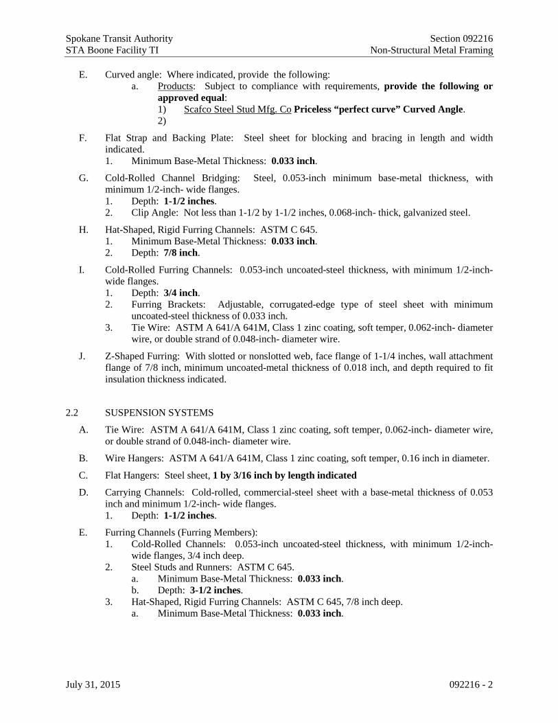
Spokane Transit Authority Section 092216 STA Boone Facility TI Non-Structural Metal Framing
July 31, 2015 092216 - 2
E. Curved angle: Where indicated, provide the following: a. Products: Subject to compliance with requirements, provide the following or
approved equal: 1) Scafco Steel Stud Mfg. Co Priceless “perfect curve” Curved Angle. 2)
F. Flat Strap and Backing Plate: Steel sheet for blocking and bracing in length and width indicated. 1. Minimum Base-Metal Thickness: 0.033 inch.
G. Cold-Rolled Channel Bridging: Steel, 0.053-inch minimum base-metal thickness, with minimum 1/2-inch- wide flanges. 1. Depth: 1-1/2 inches. 2. Clip Angle: Not less than 1-1/2 by 1-1/2 inches, 0.068-inch- thick, galvanized steel.
H. Hat-Shaped, Rigid Furring Channels: ASTM C 645. 1. Minimum Base-Metal Thickness: 0.033 inch. 2. Depth: 7/8 inch.
I. Cold-Rolled Furring Channels: 0.053-inch uncoated-steel thickness, with minimum 1/2-inch- wide flanges. 1. Depth: 3/4 inch. 2. Furring Brackets: Adjustable, corrugated-edge type of steel sheet with minimum
uncoated-steel thickness of 0.033 inch. 3. Tie Wire: ASTM A 641/A 641M, Class 1 zinc coating, soft temper, 0.062-inch- diameter
wire, or double strand of 0.048-inch- diameter wire.
J. Z-Shaped Furring: With slotted or nonslotted web, face flange of 1-1/4 inches, wall attachment flange of 7/8 inch, minimum uncoated-metal thickness of 0.018 inch, and depth required to fit insulation thickness indicated.
2.2 SUSPENSION SYSTEMS
A. Tie Wire: ASTM A 641/A 641M, Class 1 zinc coating, soft temper, 0.062-inch- diameter wire, or double strand of 0.048-inch- diameter wire.
B. Wire Hangers: ASTM A 641/A 641M, Class 1 zinc coating, soft temper, 0.16 inch in diameter.
C. Flat Hangers: Steel sheet, 1 by 3/16 inch by length indicated
D. Carrying Channels: Cold-rolled, commercial-steel sheet with a base-metal thickness of 0.053 inch and minimum 1/2-inch- wide flanges. 1. Depth: 1-1/2 inches.
E. Furring Channels (Furring Members): 1. Cold-Rolled Channels: 0.053-inch uncoated-steel thickness, with minimum 1/2-inch-
wide flanges, 3/4 inch deep. 2. Steel Studs and Runners: ASTM C 645.
a. Minimum Base-Metal Thickness: 0.033 inch. b. Depth: 3-1/2 inches.
3. Hat-Shaped, Rigid Furring Channels: ASTM C 645, 7/8 inch deep. a. Minimum Base-Metal Thickness: 0.033 inch.

Spokane Transit Authority Section 092216 STA Boone Facility TI Non-Structural Metal Framing
July 31, 2015 092216 - 3
F. Grid Suspension System for Gypsum Board Soffits: ASTM C 645, direct-hung system composed of main beams and cross-furring members that interlock. 1. Products: Subject to compliance with requirements, provide one of the following:
a. Armstrong World Industries, Inc.; Drywall Grid Systems. b. Chicago Metallic Corporation; Drywall Grid System. c. USG Corporation; Drywall Suspension System.
2.3 AUXILIARY MATERIALS
A. General: Provide auxiliary materials that comply with referenced installation standards. 1. Fasteners for Metal Framing: Of type, material, size, corrosion resistance, holding
power, and other properties required to fasten steel members to substrates.
B. Isolation Strip at Exterior Walls: Provide the following: 1. Foam Gasket: Adhesive-backed, closed-cell vinyl foam strips that allow fastener
penetration without foam displacement, 1/8 inch thick, in width to suit steel stud size.
PART 3 - EXECUTION
3.1 EXAMINATION
A. Examine areas and substrates, with Installer present, and including welded hollow-metal frames, cast-in anchors, and structural framing, for compliance with requirements and other conditions affecting performance of the Work.
B. Proceed with installation only after unsatisfactory conditions have been corrected.
3.2 INSTALLATION, GENERAL
A. Installation Standard: ASTM C 754. 1. Gypsum Board Assemblies: Also comply with requirements in ASTM C 840 that apply
to framing installation.
B. Install supplementary framing, and blocking to support fixtures, equipment services, heavy trim, grab bars, toilet accessories, furnishings, or similar construction.
C. Install bracing at terminations in assemblies.
D. Do not bridge building control and expansion joints with non-load-bearing steel framing members. Frame both sides of joints independently.
3.3 INSTALLING FRAMED ASSEMBLIES
A. Install framing system components according to spacings indicated, but not greater than spacings required by referenced installation standards for assembly types. 1. Single-Layer Application: 16 inches o.c. unless otherwise indicated. 2. Multilayer Application: 16 inches o.c. unless otherwise indicated. 3. Tile Backing Panels: 16 inches o.c. unless otherwise indicated.

Spokane Transit Authority Section 092216 STA Boone Facility TI Non-Structural Metal Framing
July 31, 2015 092216 - 4
B. Where studs are installed directly against exterior masonry walls or dissimilar metals at exterior walls, install isolation strip between studs and exterior wall.
C. Install studs so flanges within framing system point in same direction.
D. Install tracks (runners) at floors and overhead supports. Extend framing full height to structural supports or substrates above suspended ceilings except where partitions are indicated to terminate at suspended ceilings. Continue framing around ducts penetrating partitions above ceiling. 1. Slip-Type Head Joints: Where framing extends to overhead structural supports, install to
produce joints at tops of framing systems that prevent axial loading of finished assemblies.
2. Door Openings: Screw vertical studs at jambs to jamb anchor clips on door frames; install runner track section (for cripple studs) at head and secure to jamb studs. a. Install two studs at each jamb unless otherwise indicated. b. Install cripple studs at head adjacent to each jamb stud, with a minimum 1/2-inch
clearance from jamb stud to allow for installation of control joint in finished assembly.
3. Other Framed Openings: Frame openings other than door openings the same as required for door openings unless otherwise indicated. Install framing below sills of openings to match framing required above door heads.
4. At exterior corners, attach wide flange of furring members to wall with short flange extending beyond corner; on adjacent wall surface, screw-attach short flange of furring channel to web of attached channel. At interior corners, space second member no more than 12 inches from corner and cut insulation to fit.
E. Installation Tolerance: Install each framing member so fastening surfaces vary not more than 1/8 inch from the plane formed by faces of adjacent framing.
3.4 INSTALLING SUSPENSION SYSTEMS
A. Install suspension system components according to spacings indicated, but not greater than spacings required by referenced installation standards for assembly types. 1. Hangers: 48 inches o.c. 2. Carrying Channels (Main Runners): 48 inches o.c. 3. Furring Channels (Furring Members): 16 inches o.c.
B. Isolate suspension systems from building structure where they abut or are penetrated by building structure to prevent transfer of loading imposed by structural movement.
C. Suspend hangers from building structure as follows: 1. Install hangers plumb and free from contact with insulation or other objects within ceiling
plenum that are not part of supporting structural or suspension system. a. Splay hangers only where required to miss obstructions and offset resulting
horizontal forces by bracing, countersplaying, or other equally effective means.
2. Where width of ducts and other construction within ceiling plenum produces hanger spacings that interfere with locations of hangers required to support standard suspension

Spokane Transit Authority Section 092216 STA Boone Facility TI Non-Structural Metal Framing
July 31, 2015 092216 - 5
system members, install supplemental suspension members and hangers in the form of trapezes or equivalent devices.
3. Wire Hangers: Secure by looping and wire tying, either directly to structures or to inserts, eye screws, or other devices and fasteners that are secure and appropriate for substrate, and in a manner that will not cause hangers to deteriorate or otherwise fail.
4. Flat Hangers: Secure to structure, including intermediate framing members, by attaching to inserts, eye screws, or other devices and fasteners that are secure and appropriate for structure and hanger, and in a manner that will not cause hangers to deteriorate or otherwise fail.
5. Do not connect or suspend steel framing from ducts, pipes, or conduit.
D. Seismic Bracing: Sway-brace suspension systems with hangers used for support.
E. Grid Suspension Systems: Attach perimeter wall track or angle where grid suspension systems meet vertical surfaces. Mechanically join main beam and cross-furring members to each other and butt-cut to fit into wall track.
F. Installation Tolerances: Install suspension systems that are level to within 1/8 inch in 12 feet measured lengthwise on each member that will receive finishes and transversely between parallel members that will receive finishes.
END OF SECTION 092216

Spokane Transit Authority STA Boone Facility TI
July 31, 2015
Intentionally Blank Page
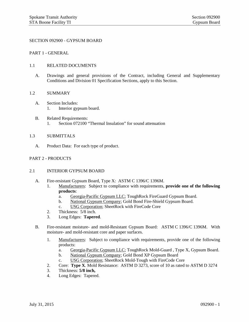
Spokane Transit Authority Section 092900 STA Boone Facility TI Gypsum Board
July 31, 2015 092900 - 1
SECTION 092900 - GYPSUM BOARD
PART 1 - GENERAL
1.1 RELATED DOCUMENTS
A. Drawings and general provisions of the Contract, including General and Supplementary Conditions and Division 01 Specification Sections, apply to this Section.
1.2 SUMMARY
A. Section Includes: 1. Interior gypsum board.
B. Related Requirements: 1. Section 072100 “Thermal Insulation” for sound attenuation
1.3 SUBMITTALS
A. Product Data: For each type of product.
PART 2 - PRODUCTS
2.1 INTERIOR GYPSUM BOARD
A. Fire-resistant Gypsum Board, Type X: ASTM C 1396/C 1396M. 1. Manufacturers: Subject to compliance with requirements, provide one of the following
products: a. Georgia-Pacific Gypsum LLC; ToughRock FireGuard Gypsum Board. b. National Gypsum Company; Gold Bond Fire-Shield Gypsum Board. c. USG Corporation; SheetRock with FireCode Core
2. Thickness: 5/8 inch. 3. Long Edges: Tapered.
B. Fire-resistant moisture- and mold-Resistant Gypsum Board: ASTM C 1396/C 1396M. With moisture- and mold-resistant core and paper surfaces.
1. Manufacturers: Subject to compliance with requirements, provide one of the following products: a. Georgia-Pacific Gypsum LLC; ToughRock Mold-Guard , Type X, Gypsum Board. b. National Gypsum Company; Gold Bond XP Gypsum Board c. USG Corporation; SheetRock Mold-Tough with FireCode Core
2. Core: Type X. Mold Resistance: ASTM D 3273, score of 10 as rated to ASTM D 3274 3. Thickness: 5/8 inch, 4. Long Edges: Tapered.

Spokane Transit Authority Section 092900 STA Boone Facility TI Gypsum Board
July 31, 2015 092900 - 2
C. Abuse-Resistant, fire-resistant, moisture and mold resistant Gypsum Board: ASTM C 1629/C 1629M.
1. Manufacturers: Subject to compliance with requirements, provide one of the following products: a. National Gypsum Company; Gold Bond Hi-Impact XP Gypsum Board b. USG Corporation; SheetRock Mold-Tough AR with FireCode Core
2. Core: Type X. Mold Resistance: ASTM D 3273, score of 10 as rated to ASTM D 3274 3. Thickness: 5/8 inch 4. Long Edges: Tapered.
2.2 ACCESSORIES
A. Trim Accessories: ASTM C 1047, formed from galvanized or aluminum-coated steel sheet, rolled zinc, plastic, or paper-faced galvanized-steel sheet. Provide cornerbead at outside corners unless otherwise indicated. 1. Cornerbead. 2. Provide LC-bead (J-bead) at exposed panel edges. 3. Expansion (control) joint.
B. Aluminum Trim: Extruded accessories of profiles and dimensions indicated. 1. Available Manufacturers: Subject to compliance with requirements, manufacturers
offering products that may be incorporated into the Work include, but are not limited to, the following:
2. Manufacturers: Subject to compliance with requirements, provide products by one of the following: a. Fry Reglet Corp. b. Gordon, Inc. c. Pittcon Industries.
3. Aluminum: Alloy and temper with not less than the strength and durability properties of ASTM B 221, Alloy 6063-T5. a. Finish: Corrosion-resistant primer compatible with joint compound and finish
materials specified.
C. Joint-Treatment Materials: ASTM C 475/C 475M. 1. Joint Tape:
a. Interior Gypsum Board: Paper. b. Tile Backing Panels: As recommended by panel manufacturer.
2. Joint Compound for Interior Gypsum Board: For each coat use formulation that is compatible with other compounds applied on previous or for successive coats. a. Prefilling: At open joints and damaged surface areas, use setting-type taping
compound. b. Embedding and First Coat: For embedding tape and first coat on joints, fasteners,
and trim flanges, use drying-type, all-purpose compound. c. Fill Coat: For second coat, use drying-type, all-purpose compound. d. Finish Coat: For third coat, use drying-type, all-purpose compound.
3. Cementitious Backer Unit Joint-Treatment Materials: Products recommended by cementitious backer unit manufacturer.
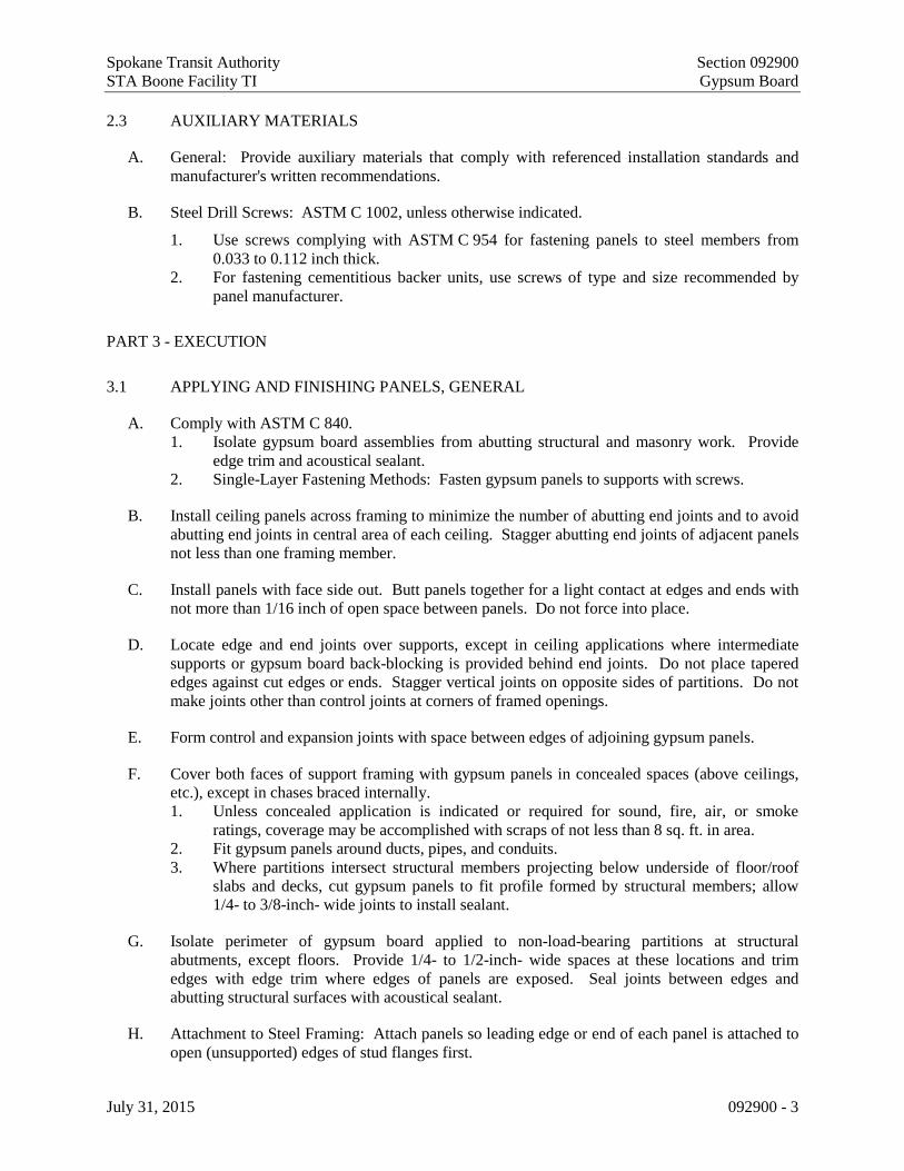
Spokane Transit Authority Section 092900 STA Boone Facility TI Gypsum Board
July 31, 2015 092900 - 3
2.3 AUXILIARY MATERIALS
A. General: Provide auxiliary materials that comply with referenced installation standards and manufacturer's written recommendations.
B. Steel Drill Screws: ASTM C 1002, unless otherwise indicated.
1. Use screws complying with ASTM C 954 for fastening panels to steel members from 0.033 to 0.112 inch thick.
2. For fastening cementitious backer units, use screws of type and size recommended by panel manufacturer.
PART 3 - EXECUTION
3.1 APPLYING AND FINISHING PANELS, GENERAL
A. Comply with ASTM C 840. 1. Isolate gypsum board assemblies from abutting structural and masonry work. Provide
edge trim and acoustical sealant. 2. Single-Layer Fastening Methods: Fasten gypsum panels to supports with screws.
B. Install ceiling panels across framing to minimize the number of abutting end joints and to avoid abutting end joints in central area of each ceiling. Stagger abutting end joints of adjacent panels not less than one framing member.
C. Install panels with face side out. Butt panels together for a light contact at edges and ends with not more than 1/16 inch of open space between panels. Do not force into place.
D. Locate edge and end joints over supports, except in ceiling applications where intermediate supports or gypsum board back-blocking is provided behind end joints. Do not place tapered edges against cut edges or ends. Stagger vertical joints on opposite sides of partitions. Do not make joints other than control joints at corners of framed openings.
E. Form control and expansion joints with space between edges of adjoining gypsum panels.
F. Cover both faces of support framing with gypsum panels in concealed spaces (above ceilings, etc.), except in chases braced internally. 1. Unless concealed application is indicated or required for sound, fire, air, or smoke
ratings, coverage may be accomplished with scraps of not less than 8 sq. ft. in area. 2. Fit gypsum panels around ducts, pipes, and conduits. 3. Where partitions intersect structural members projecting below underside of floor/roof
slabs and decks, cut gypsum panels to fit profile formed by structural members; allow 1/4- to 3/8-inch- wide joints to install sealant.
G. Isolate perimeter of gypsum board applied to non-load-bearing partitions at structural abutments, except floors. Provide 1/4- to 1/2-inch- wide spaces at these locations and trim edges with edge trim where edges of panels are exposed. Seal joints between edges and abutting structural surfaces with acoustical sealant.
H. Attachment to Steel Framing: Attach panels so leading edge or end of each panel is attached to open (unsupported) edges of stud flanges first.

Spokane Transit Authority Section 092900 STA Boone Facility TI Gypsum Board
July 31, 2015 092900 - 4
3.2 APPLYING INTERIOR GYPSUM BOARD
A. Install interior gypsum board in the following locations: 1. Type X:
a. Vertical surfaces, unless otherwise indicated. b. Ceiling surfaces, as indicated on drawings.
2. Moisture- and Mold-Resistant Type: Behind all water fixtures (water closets, vanity, sinks) and tub and shower surrounds, unless indicated otherwise.
B. Single-Layer Application: 1. On ceilings, apply gypsum panels before wall/partition board application to greatest
extent possible and at right angles to framing unless otherwise indicated. 2. On partitions/walls, apply gypsum panels vertically (parallel to framing) unless
otherwise indicated or required by fire-resistance-rated assembly, and minimize end joints. a. Stagger abutting end joints not less than one framing member in alternate courses
of panels.
3. On Z-furring members, apply gypsum panels vertically (parallel to framing) with no end joints. Locate edge joints over furring members.
4. Fastening Methods: Apply gypsum panels to supports with steel drill screws.
3.3 INSTALLING TRIM ACCESSORIES
A. General: For trim with back flanges intended for fasteners, attach to framing with same fasteners used for panels. Otherwise, attach trim according to manufacturer's written instructions.
B. Control Joints: Install control joints at locations indicated on Drawings.
C. Interior Trim: Install in the following locations: 1. Cornerbead: Use at outside corners unless otherwise indicated. 2. LC-Bead: Use at exposed panel edges.
D. Aluminum Trim: Install in locations indicated on Drawings.
3.4 FINISHING GYPSUM BOARD
A. General: Treat gypsum board joints, interior angles, edge trim, control joints, penetrations, fastener heads, surface defects, and elsewhere as required to prepare gypsum board surfaces for decoration. Promptly remove residual joint compound from adjacent surfaces.
B. Prefill open joints and damaged surface areas.
C. Apply joint tape over gypsum board joints, except for trim products specifically indicated as not intended to receive tape.
D. Gypsum Board Finish Levels: Finish panels to levels indicated below and according to ASTM C 840: 1. At concealed areas, unless a higher level of finish is required for fire-resistance-rated
assemblies, provide Level 1 finish: Embed tape at joints. 2. Unless otherwise indicated, provide Level 4 finish: Embed tape and apply separate
first, fill, and finish coats of joint compound to tape, fasteners, and trim flanges.

Spokane Transit Authority Section 092900 STA Boone Facility TI Gypsum Board
July 31, 2015 092900 - 5
3.5 PROTECTION
A. Protect adjacent surfaces from drywall compound and promptly remove from floors and other non-drywall surfaces. Repair surfaces stained, marred, or otherwise damaged during drywall application.
B. Protect installed products from damage from weather, condensation, direct sunlight, construction, and other causes during remainder of the construction period.
C. Remove and replace panels that are wet, moisture damaged, and mold damaged. 1. Indications that panels are wet or moisture damaged include, but are not limited to,
discoloration, sagging, or irregular shape. 2. Indications that panels are mold damaged include, but are not limited to, fuzzy or
splotchy surface contamination and discoloration.
END OF SECTION 092900

Spokane Transit Authority STA Boone Facility TI
July 31, 2015
Intentionally Blank Page

Spokane Transit Authority Section 093000 STA Boone Facility TI Tiling
July 31, 2015 093000-1
SECTION 093000 - TILING
PART 1 - GENERAL
1.1 RELATED DOCUMENTS
A. Drawings and general provisions of the Contract, including General and Supplementary Conditions and Division 01 Specification Sections, apply to this Section.
1.2 SUMMARY
A. Section Includes: 1. Ceramic tile. 2. Crack isolation membrane. 3. Metal edge strips.
1.3 DEFINITIONS
A. General: Definitions in the ANSI A108 series of tile installation standards and in ANSI A137.1 apply to Work of this Section unless otherwise specified.
B. ANSI A108 Series: ANSI A108.01, ANSI A108.02, ANSI A108.1A, ANSI A108.1B, ANSI A108.1C, ANSI A108.4, ANSI A108.5, ANSI A108.6, ANSI A108.8, ANSI A108.9, ANSI A108.10, ANSI A108.11, ANSI A108.12, ANSI A108.13, ANSI A108.14, ANSI A108.15, ANSI A108.16, and ANSI A108.17, which are contained in "American National Standard Specifications for Installation of Ceramic Tile."
C. Module Size: Actual tile size plus joint width indicated.
D. Face Size: Actual tile size, excluding spacer lugs.
1.4 SUBMITTALS
A. Product Data: For each type of product indicated.
B. Product Data for adhesives and grouts, documentation including printed statement of VOC content.
C. Samples for Verification: 1. Full-size units of each type and composition of tile and for each color and finish required. 2. Full-size units of each type of trim and accessory. 3. Metal edge strips in 6-inch lengths.
D. Qualification Data: For qualified Installer.

Spokane Transit Authority Section 093000 STA Boone Facility TI Tiling
July 31, 2015 093000-2
1.5 MAINTENANCE MATERIAL SUBMITTALS
A. Furnish extra materials that match and are from same production runs as products installed and that are packaged with protective covering for storage and identified with labels describing contents. 1. Tile and Trim Units: Furnish quantity of full-size units equal to 3 percent of amount
installed for each type, composition, color, pattern, and size indicated.
1.6 QUALITY ASSURANCE
A. Source Limitations for Tile: Obtain tile of each type and color or finish from one source or producer. 1. Obtain tile of each type and color or finish from same production run and of consistent
quality in appearance and physical properties for each contiguous area.
B. Source Limitations for Setting and Grouting Materials: Obtain ingredients of a uniform quality for each mortar, adhesive, and grout component from one manufacturer and each aggregate from one source or producer.
C. Source Limitations for Other Products: Obtain each of the following products specified in this Section from a single manufacturer for each product: 1. Ceramic Tiles 2. Crack isolation membrane. 3. Metal edge strips.
1.7 DELIVERY, STORAGE, AND HANDLING
A. Deliver and store packaged materials in original containers with seals unbroken and labels intact until time of use. Comply with requirements in ANSI A137.1 for labeling tile packages.
B. Store tile and cementitious materials on elevated platforms, under cover, and in a dry location.
C. Store liquid materials in unopened containers and protected from freezing.
D. Handle tile that has temporary protective coating on exposed surfaces to prevent coated surfaces from contacting backs or edges of other units. If coating does contact bonding surfaces of tile, remove coating from bonding surfaces before setting tile.
1.8 PROJECT CONDITIONS
A. Environmental Limitations: Do not install tile until construction in spaces is complete and ambient temperature and humidity conditions are maintained at the levels indicated in referenced standards and manufacturer's written instructions.

Spokane Transit Authority Section 093000 STA Boone Facility TI Tiling
July 31, 2015 093000-3
PART 2 - PRODUCTS
2.1 PRODUCTS, GENERAL
A. ANSI Ceramic Tile Standard: Provide tile that complies with ANSI A137.1 for types, compositions, and other characteristics indicated.
B. ANSI Standards for Tile Installation Materials: Provide materials complying with ANSI A108.02, ANSI standards referenced in other Part 2 articles, ANSI standards referenced by TCA installation methods specified in tile installation schedules, and other requirements specified.
2.2 TILE PRODUCTS
A. Tile Type CT-1 (Field); CT-2 (Trim): Factory-mounted glazed ceramic mosaic tile. 1. Manufacturers: Subject to compliance with requirements, provide the following product:
a. Iris, US 2. Tile Color and Pattern (CT-1):
a. Pattern: Porcelainwood b. Edges: Rectified c. Variation: V2 d. Color: Greywood e. Module Size: 6-inch x 24-inch f. Thickness: 3/8-inch g. Grout Color: As selected by architect from manufacturer’s full range
of standard colors 3. Trim Units (CT-2): Coordinated with sizes and coursing of adjoining flat tile where
applicable and matching characteristics of adjoining flat tile. Provide shapes as follows, selected from manufacturer's standard shapes: a. Base: bullnose top edge, face size 6 by 24 inches. b. Grout Color: match grout for field tile
4. Physical Properties a. Composition: Porcelain. b. Face: Pattern of design indicated, with cushion edges. c. Surface: Smooth, without abrasive admixture. d. Slip Resistance: Wet: > 0.62; Dry: > 0..99 as tested by TCNA
5. Internal Corners: Field-butted square corners.
2.3 CRACK ISOLATION MEMBRANE
A. Fabric-Reinforced, Fluid-Applied Membrane: System consisting of liquid-latex rubber or elastomeric polymer and continuous fabric reinforcement. 1. Products: Subject to compliance with requirements, provide one of the following:
a. Bostik, Inc.; Hydroment Blacktop 90210. b. Custom Building Products; 9240 Waterproofing and Anti-Fracture Membrane. c. Laticrete International, Inc.; Laticrete 9235 Waterproof Membrane.

Spokane Transit Authority Section 093000 STA Boone Facility TI Tiling
July 31, 2015 093000-4
2.4 SETTING MATERIALS
A. Latex-Portland Cement Mortar (Thin Set): ANSI A118.4. 1. Basis-of-Design Product: Subject to compliance with requirements, provide Laticrete
International, Inc.; 253 Gold or comparable product by one of the following: a. Bonsal American; an Oldcastle company. b. Bostik, Inc. c. Custom Building Products. d. Laticrete International, Inc. e. TEC; a subsidiary of H. B. Fuller Company.
2.5 GROUT MATERIALS
A. Water-Cleanable Epoxy Grout (GE-1): ANSI A118.3, with a VOC content of 65 g/L or less when calculated according to 40 CFR 59, Subpart D. 1. Basis-of-Design Product: Subject to compliance with requirements, provide Laticrete
International, Inc.; SpectraLOCK PRO or comparable product by one of the following: a. Bonsal American; an Oldcastle company. b. Bostik, Inc. c. Custom Building Products. d. Laticrete International, Inc. e. TEC; a subsidiary of H. B. Fuller Company
2. Color: Laticrete, #78 Sterling Silver
2.6 MISCELLANEOUS MATERIALS
A. Trowelable Underlayments and Patching Compounds: Latex-modified, portland cement-based formulation provided or approved by manufacturer of tile-setting materials for installations indicated. See section 035416 – hydraulic cement underlay.
B. Metal Edge Strips: Angle or L-shape, height to match tile and setting-bed thickness, metallic or combination of metal and PVC or neoprene base, designed specifically for flooring applications; stainless-steel, ASTM A 666, 300 Series exposed-edge material 1. Provide the following product or approved equal, sized to match the application
a. Tile-to-tile transitions: Schluter Systems; Schiene
C. Temporary Protective Coating: Product indicated below that is formulated to protect exposed surfaces of tile against adherence of mortar and grout; compatible with tile, mortar, and grout products; and easily removable after grouting is completed without damaging grout or tile. 1. Grout release in form of manufacturer's standard proprietary liquid coating that is
specially formulated and recommended for use as temporary protective coating for tile.
D. Tile Cleaner: A neutral cleaner capable of removing soil and residue without harming tile and grout surfaces, specifically approved for materials and installations indicated by tile and grout manufacturers.
E. Temporary tile-joint spacers, sized for joint widths indicated.

Spokane Transit Authority Section 093000 STA Boone Facility TI Tiling
July 31, 2015 093000-5
2.7 MIXING MORTARS AND GROUT
A. Mix mortars and grouts to comply with referenced standards and mortar and grout manufacturers' written instructions.
B. Add materials, water, and additives in accurate proportions.
C. Obtain and use type of mixing equipment, mixer speeds, mixing containers, mixing time, and other procedures to produce mortars and grouts of uniform quality with optimum performance characteristics for installations indicated.
PART 3 - EXECUTION
3.1 EXAMINATION
A. Examine substrates, areas, and conditions where tile will be installed, with Installer present, for compliance with requirements for installation tolerances and other conditions affecting performance of installed tile. 1. Verify that substrates for setting tile are firm, dry, clean, free of coatings that are
incompatible with tile-setting materials including curing compounds and other substances that contain soap, wax, oil, or silicone; and comply with flatness tolerances required by ANSI A108.01 for installations indicated.
2. Verify that concrete substrates for tile floors installed with bonded mortar bed or thin-set mortar comply with surface finish requirements in ANSI A108.01 for installations indicated. a. Verify that surfaces that received a steel trowel finish have been mechanically
scarified. b. Verify that protrusions, bumps, and ridges have been removed by sanding or
grinding. 3. Verify that installation of grounds, anchors, recessed frames, electrical and mechanical
units of work, and similar items located in or behind tile has been completed. 4. Verify that joints and cracks in tile substrates are coordinated with tile joint locations; if
not coordinated, adjust joint locations in consultation with Architect.
B. Proceed with installation only after unsatisfactory conditions have been corrected.
3.2 PREPARATION
A. Fill cracks, holes, and depressions in concrete substrates for tile floors installed with trowelable leveling and patching compound specifically recommended by tile-setting material manufacturer.
B. Where indicated, prepare substrates to receive waterproofing by applying a reinforced mortar bed that complies with ANSI A108.1A and is sloped 1/4 inch per foot toward drains.
C. Blending: For tile exhibiting color variations, verify that tile has been factory blended and packaged so tile units taken from one package show same range of colors as those taken from other packages and match approved Samples. If not factory blended, either return to manufacturer or blend tiles at Project site before installing.

Spokane Transit Authority Section 093000 STA Boone Facility TI Tiling
July 31, 2015 093000-6
3.3 TILE INSTALLATION
A. Comply with TCA's "Handbook for Ceramic Tile Installation" for TCA installation methods specified in tile installation schedules. Comply with parts of the ANSI A108 Series "Specifications for Installation of Ceramic Tile" that are referenced in TCA installation methods, specified in tile installation schedules, and apply to types of setting and grouting materials used. 1. For the following installations, follow procedures in the ANSI A108 Series of tile
installation standards for providing 95 percent mortar coverage: a. Tile floors in wet areas. b. Tile floors composed of tiles 8 by 8 inches or larger.
B. Extend tile work into recesses and under or behind equipment and fixtures to form complete covering without interruptions unless otherwise indicated. Terminate work neatly at obstructions, edges, and corners without disrupting pattern or joint alignments.
C. Accurately form intersections and returns. Perform cutting and drilling of tile without marring visible surfaces. Carefully grind cut edges of tile abutting trim, finish, or built-in items for straight aligned joints. Fit tile closely to electrical outlets, piping, fixtures, and other penetrations so plates, collars, or covers overlap tile.
D. Provide manufacturer's standard trim shapes where necessary to eliminate exposed tile edges.
E. Jointing Pattern: Lay tile in grid pattern unless otherwise indicated. Lay out tile work and center tile fields in both directions in each space or on each wall area. Lay out tile work to minimize the use of pieces that are less than half of a tile. Provide uniform joint widths unless otherwise indicated. 1. For tile mounted in sheets, make joints between tile sheets same width as joints within
tile sheets so joints between sheets are not apparent in finished work. 2. Where adjoining tiles on floor, base, walls, or trim are specified or indicated to be same
size, align joints. 3. Where tiles are specified or indicated to be whole integer multiples of adjoining tiles on
floor, base, walls, or trim, align joints unless otherwise indicated.
F. Joint Widths: Unless otherwise indicated, install tile with the following joint widths:
G. Lay out tile wainscots to dimensions indicated or to next full tile beyond dimensions indicated.
H. Expansion Joints: Provide expansion joints and other sealant-filled joints, including control, contraction, and isolation joints, where indicated. Form joints during installation of setting materials, mortar beds, and tile. Do not saw-cut joints after installing tiles. 1. Where joints occur in concrete substrates, locate joints in tile surfaces directly above
them.
I. Metal Edge Strips: Install at locations indicated on tile installation schedule: 1. Tile-to-tile transitions
3.4 CRACK ISOLATION MEMBRANE INSTALLATION
A. Install crack isolation membrane to comply with ANSI A108.17 and manufacturer's written instructions to produce membrane of uniform thickness and bonded securely to substrate.
B. Do not install tile or setting materials over crack isolation membrane until membrane has cured.

Spokane Transit Authority Section 093000 STA Boone Facility TI Tiling
July 31, 2015 093000-7
3.5 CLEANING AND PROTECTING
A. Cleaning: On completion of placement and grouting, clean all ceramic tile surfaces so they are free of foreign matter. 1. Remove epoxy grout residue from tile as soon as possible. 2. Clean grout smears and haze from tile according to tile and grout manufacturer's written
instructions but no sooner than 10 days after installation. Use only cleaners recommended by tile and grout manufacturers and only after determining that cleaners are safe to use by testing on samples of tile and other surfaces to be cleaned. Protect metal surfaces and plumbing fixtures from effects of cleaning. Flush surfaces with clean water before and after cleaning.
3. Remove temporary protective coating by method recommended by coating manufacturer and that is acceptable to tile and grout manufacturer. Trap and remove coating to prevent drain clogging.
B. Protect installed tile work with kraft paper or other heavy covering during construction period to prevent staining, damage, and wear. If recommended by tile manufacturer, apply coat of neutral protective cleaner to completed tile walls and floors.
C. Prohibit foot and wheel traffic from tiled floors for at least seven days after grouting is completed.
D. Before final inspection, remove protective coverings and rinse neutral protective cleaner from tile surfaces.
3.6 INTERIOR TILE INSTALLATION SCHEDULE
A. Concrete Floors 1. Tile Installation F113: Thin-set mortar on slab-on-grade; TCA F113.
a. Tile Type: CT-1 (Field) b. Thin-Set Mortar: Latex portland cement mortar. c. Grout: GE-1 (Water-cleanable epoxy grout). d. Joint Width: 1/8 inch
2. Tile Installation F125A: Thin-set mortar on slab-on-grade with partial crack isolation membrane coverage; TCA F125A. a. Tile Type: CT-1 (Field) b. Thin-Set Mortar: Latex portland cement mortar. c. Grout: GE-1 (Water-cleanable epoxy grout). d. Joint Width: 1/8 inch
B. Masonry or Concrete Walls: 1. Tile Installation W202I: Thin-set mortar, TCA W202I.
a. Tile Type: CT-2 (Trim) b. Thin-Set Mortar: Latex portland cement mortar. c. Grout: GE-1 (Water-cleanable epoxy grout). d. Joint Width: 1/8 inch
END OF SECTION 093000

Spokane Transit Authority STA Boone Facility TI
July 31, 2015
Intentionally Blank Page

Spokane Transit Authority Section 095113 STA Boone Facility TI Acoustical Panel Ceilings
July 31, 2015 095113 - 1
SECTION 095113 - ACOUSTICAL PANEL CEILINGS
PART 1 - GENERAL
1.1 RELATED DOCUMENTS
A. Drawings and general provisions of the Contract, including General and Supplementary Conditions and Division 01 Specification Sections, apply to this Section.
1.2 SUMMARY
A. Section includes acoustical panels and exposed suspension systems for ceilings.
B. Products furnished, but not installed under this Section, include anchors, clips, and other ceiling attachment devices to be cast in concrete.
1.3 SUBMITTALS
A. Product Data: For each type of product.
B. Samples for Initial Selection: For components with factory-applied color finishes.
C. Maintenance Data: For finishes to include in maintenance manuals.
1.4 MAINTENANCE MATERIAL SUBMITTALS
A. Furnish extra materials that match products installed and that are packaged with protective covering for storage and identified with labels describing contents. 1. Acoustical Ceiling Panels: Full-size panels equal to 2 percent of quantity installed.
1.5 DELIVERY, STORAGE, AND HANDLING
A. Deliver acoustical panels, suspension-system components, and accessories to Project site in original, unopened packages and store them in a fully enclosed, conditioned space where they will be protected against damage from moisture, humidity, temperature extremes, direct sunlight, surface contamination, and other causes.
B. Before installing acoustical panels, permit them to reach room temperature and a stabilized moisture content.
C. Handle acoustical panels carefully to avoid chipping edges or damaging units in any way.
1.6 FIELD CONDITIONS
A. Environmental Limitations: Do not install acoustical panel ceilings until spaces are enclosed and weatherproof, wet work in spaces is complete and dry, work above ceilings is complete, and
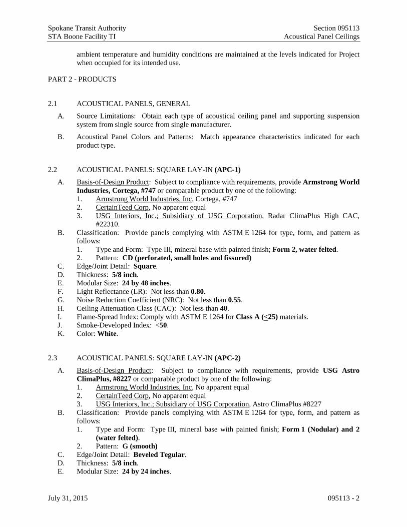
Spokane Transit Authority Section 095113 STA Boone Facility TI Acoustical Panel Ceilings
July 31, 2015 095113 - 2
ambient temperature and humidity conditions are maintained at the levels indicated for Project when occupied for its intended use.
PART 2 - PRODUCTS
2.1 ACOUSTICAL PANELS, GENERAL
A. Source Limitations: Obtain each type of acoustical ceiling panel and supporting suspension system from single source from single manufacturer.
B. Acoustical Panel Colors and Patterns: Match appearance characteristics indicated for each product type.
2.2 ACOUSTICAL PANELS: SQUARE LAY-IN (APC-1)
A. Basis-of-Design Product: Subject to compliance with requirements, provide Armstrong World Industries, Cortega, #747 or comparable product by one of the following: 1. Armstrong World Industries, Inc, Cortega, #747 2. CertainTeed Corp, No apparent equal 3. USG Interiors, Inc.; Subsidiary of USG Corporation, Radar ClimaPlus High CAC,
#22310. B. Classification: Provide panels complying with ASTM E 1264 for type, form, and pattern as
follows: 1. Type and Form: Type III, mineral base with painted finish; Form 2, water felted. 2. Pattern: CD (perforated, small holes and fissured)
C. Edge/Joint Detail: Square. D. Thickness: 5/8 inch. E. Modular Size: 24 by 48 inches. F. Light Reflectance (LR): Not less than 0.80. G. Noise Reduction Coefficient (NRC): Not less than 0.55. H. Ceiling Attenuation Class (CAC): Not less than 40. I. Flame-Spread Index: Comply with ASTM E 1264 for Class A (<25) materials. J. Smoke-Developed Index: <50. K. Color: White.
2.3 ACOUSTICAL PANELS: SQUARE LAY-IN (APC-2)
A. Basis-of-Design Product: Subject to compliance with requirements, provide USG Astro ClimaPlus, #8227 or comparable product by one of the following: 1. Armstrong World Industries, Inc, No apparent equal 2. CertainTeed Corp, No apparent equal 3. USG Interiors, Inc.; Subsidiary of USG Corporation, Astro ClimaPlus #8227
B. Classification: Provide panels complying with ASTM E 1264 for type, form, and pattern as follows: 1. Type and Form: Type III, mineral base with painted finish; Form 1 (Nodular) and 2
(water felted). 2. Pattern: G (smooth)
C. Edge/Joint Detail: Beveled Tegular. D. Thickness: 5/8 inch. E. Modular Size: 24 by 24 inches.

Spokane Transit Authority Section 095113 STA Boone Facility TI Acoustical Panel Ceilings
July 31, 2015 095113 - 3
F. Light Reflectance (LR): Not less than 0.86. G. Noise Reduction Coefficient (NRC): Not less than 0.55. H. Ceiling Attenuation Class (CAC): Not less than 35. I. Flame-Spread Index: Comply with ASTM E 1264 for Class A (<25) materials. J. Smoke-Developed Index: <50. K. Color: White.
2.4 CEILING SUSPENSION SYSTEM: WIDE-FACE, DIRECT HUNG (for APC-1)
A. Basis-of-Design Product: Subject to compliance with requirements, provide Armstrong World Industries, Prelude or comparable product by one of the following: 1. Armstrong World Industries, Inc., Prelude XL / Prelude XL Fireguard 2. CertainTeed Corp. No apparent equal 3. USG Interiors, Inc.; Subsidiary of USG Corporation, Donn DX/DXL.
B. Product Standard: ASTM C 635 C. Base Material: roll-formed cold-rolled steel sheet, electrolytically zinc coated, or hot-dip
galvanized according to ASTM A 653/A 653M, not less than G30 coating designation D. Face Dimension: 15/16-inch E. Profile: Exposed Tee F. Cross Tee/Main Beam Interface: Flush fit G. End Detail:
1. Main Beam: staked-on clip 2. Cross-Tee: staked-on hook clip
H. Duty Classification: Intermediate I. Surface Finish: baked polyester paint
1. Color: White J. Wall Moldings: Manufacturer's standard hemmed, pre-finished angle molding K. Attachment Devices: Size for five times the design load indicated in ASTM C 635/C 635M,
Table 1, "Direct Hung," for Seismic Design Category C L. Wire Hangers, Braces, and Ties: Provide wires complying with the following requirements:
1. Zinc-Coated, Carbon-Steel Wire: ASTM A 641/A 641M, Class 1 zinc coating, soft temper.
2. Size: Select wire diameter so its stress at three times hanger design load (ASTM C 635/C 635M, Table 1, "Direct Hung") will be less than yield stress of wire, but provide not less than 0.106-inch diameter wire.
M. Seismic Stabilizer Bars: Manufacturer's standard perimeter stabilizers designed to accommodate seismic forces.
N. Hold-Down Clips: Where indicated, provide manufacturer's standard hold-down clips spaced 24 inches o.c. on all cross tees.
2.5 CEILING SUSPENSION SYSTEM: NARROW-FACE, DIRECT HUNG (for APC-2)
A. Basis-of-Design Product: Subject to compliance with requirements, provide USG, Centricitee DXT or comparable product by one of the following: 1. Armstrong World Industries, Inc., Suprafine XL / Suprafine XL Fireguard 2. CertainTeed Corp. No apparent equal 3. USG Interiors, Inc.; Subsidiary of USG Corporation, Centricitee DXT
B. Product Standard: ASTM C 635 C. Base Material: roll-formed cold-rolled steel sheet, electrolytically zinc coated, or hot-dip
galvanized according to ASTM A 653/A 653M, not less than G30 coating designation

Spokane Transit Authority Section 095113 STA Boone Facility TI Acoustical Panel Ceilings
July 31, 2015 095113 - 4
D. Face Dimension: 9/16-inch E. Profile: Exposed Tee F. Cross Tee/Main Beam Interface: Flush fit G. End Detail:
1. Main Beam: staked-on clip 2. Cross-Tee: staked-on hook clip
H. Duty Classification: Intermediate I. Surface Finish: baked polyester paint
1. Color: White J. Wall Moldings: Manufacturer's standard hemmed, pre-finished angle molding K. Attachment Devices: Size for five times the design load indicated in ASTM C 635/C 635M,
Table 1, "Direct Hung," for Seismic Design Category C L. Wire Hangers, Braces, and Ties: Provide wires complying with the following requirements:
1. Zinc-Coated, Carbon-Steel Wire: ASTM A 641/A 641M, Class 1 zinc coating, soft temper.
2. Size: Select wire diameter so its stress at three times hanger design load (ASTM C 635/C 635M, Table 1, "Direct Hung") will be less than yield stress of wire, but provide not less than 0.106-inch diameter wire.
M. Seismic Stabilizer Bars: Manufacturer's standard perimeter stabilizers designed to accommodate seismic forces.
N. Hold-Down Clips: Where indicated, provide manufacturer's standard hold-down clips spaced 24 inches o.c. on all cross tees.
PART 3 - EXECUTION
3.1 EXAMINATION
A. Examine substrates, areas, and conditions, including structural framing to which acoustical panel ceilings attach or abut, with Installer present, for compliance with requirements specified in this and other Sections that affect ceiling installation and anchorage and with requirements for installation tolerances and other conditions affecting performance of acoustical panel ceilings.
B. Examine acoustical panels before installation. Reject acoustical panels that are wet, moisture damaged, or mold damaged.
C. Proceed with installation only after unsatisfactory conditions have been corrected.
3.2 PREPARATION
A. Measure each ceiling area and establish layout of acoustical panels to balance border widths at opposite edges of each ceiling. Avoid using less-than-half-width panels at borders, and comply with layout shown on reflected ceiling plans.
3.3 INSTALLATION
A. General: Install acoustical panel ceilings to comply with ASTM C 636/C 636M and according to manufacturer's written instructions and CISCA's "Ceiling Systems Handbook." 1. Fire-Rated Assembly: Install fire-rated ceiling systems according to tested fire-rated
design.

Spokane Transit Authority Section 095113 STA Boone Facility TI Acoustical Panel Ceilings
July 31, 2015 095113 - 5
B. Install acoustical panel ceilings to comply with additional seismic design requirements indicated: 1. ASCE 7-05 Seismic Design Category: C (for Spokane, WA)
NOTE: Requirements for essential use facilities may be different) a. Minimum 7/8″ wall molding b. Grid must not be attached to the wall molding c. Minimum 3/8″ clearance on all sides d. Minimum 3/8″ overlap of grid on the wall molding e. Ends of main beams and cross tees must be tied together to prevent their spreading f. Safety wires required on light fixtures
C. Suspend ceiling hangers from building's structural members and as follows: 1. Install hangers plumb and free from contact with insulation or other objects within ceiling
plenum that are not part of supporting structure or of ceiling suspension system. 2. Splay hangers only where required and, if permitted with fire-resistance-rated
ceilings, to miss obstructions; offset resulting horizontal forces by bracing, countersplaying, or other equally effective means.
3. Secure wire hangers to ceiling-suspension members and to supports above with a minimum of three tight turns. Connect hangers directly either to structures or to inserts, eye screws, or other devices that are secure and appropriate for substrate and that will not deteriorate or otherwise fail due to age, corrosion, or elevated temperatures.
4. Secure flat, angle, channel, and rod hangers to structure, including intermediate framing members, by attaching to inserts, eye screws, or other devices that are secure and appropriate for both the structure to which hangers are attached and the type of hanger involved. Install hangers in a manner that will not cause them to deteriorate or fail due to age, corrosion, or elevated temperatures.
5. Attach hangers to structural members. Do not support ceilings directly from permanent floor or roof deck.
6. When framing does not permit installation of hanger wires at spacing required, install carrying channels or other supplemental support for attachment of hanger wires.
7. Space hangers not more than 48 inches o.c. along each member supported directly from hangers unless otherwise indicated; provide hangers not more than 8 inches from ends of each member.
8. Size supplemental suspension members and hangers to support ceiling loads within performance limits established by referenced standards and publications.
D. Install edge moldings and trim of type indicated at perimeter of acoustical ceiling area and where necessary to conceal edges of acoustical panels. 1. Screw attach moldings to substrate at intervals not more than 16 inches o.c. and not more
than 3 inches from ends, leveling with ceiling suspension system to a tolerance of 1/8 inch in 12 feet. Miter corners accurately and connect securely.
2. Do not use exposed fasteners, including pop rivets, on moldings and trim.
E. Install suspension-system runners so they are square and securely interlocked with one another. Remove and replace dented, bent, or kinked members.
F. Install acoustical panels with undamaged edges and fit accurately into suspension-system runners and edge moldings. Scribe and cut panels at borders and penetrations to provide a neat, precise fit. 1. Arrange directionally patterned acoustical panels as follows:
a. As indicated on reflected ceiling plans. 2. For square-edged panels, install panels with edges fully hidden from view by flanges of
suspension-system runners and moldings.

Spokane Transit Authority Section 095113 STA Boone Facility TI Acoustical Panel Ceilings
July 31, 2015 095113 - 6
3. Paint cut edges of panel remaining exposed after installation; match color of exposed panel surfaces using coating recommended in writing for this purpose by acoustical panel manufacturer.
4. Install hold-down clips in areas indicated, in areas required by authorities having jurisdiction, and for fire-resistance ratings; space as recommended by panel manufacturer's written instructions unless otherwise indicated.
5. Protect lighting fixtures and air ducts to comply with requirements indicated for fire-resistance-rated assembly.
3.4 ADJUSTING AND CLEANING
A. Clean exposed surfaces of acoustical panel ceilings, including trim, edge moldings, and suspension-system members. Comply with manufacturer's written instructions for cleaning and touchup of minor finish damage.
B. Remove and replace ceiling components that cannot be successfully cleaned and repaired to permanently eliminate evidence of damage.
END OF SECTION 095113

Spokane Transit Authority Section 096513 STA Boone Facility TI Resilient Base and Accessories
July 31, 2015 096513 - 1
SECTION 096513 - RESILIENT BASE AND ACCESSORIES
PART 1 - GENERAL
1.1 RELATED DOCUMENTS
A. Drawings and general provisions of the Contract, including General and Supplementary Conditions and Division 01 Specification Sections, apply to this Section.
1.2 SUMMARY
A. Section Includes: 1. Resilient base. 2. Resilient molding accessories.
B. Related Sections: 1. Section 096516 "Resilient Sheet Flooring" for resilient sheet floor coverings. 2. Section 096813 "Tile Carpeting" for modular, tufted carpet tile.
1.3 SUBMITTALS
A. Product Data: For each type of product indicated.
B. Product Data for adhesives, documentation including printed statement of VOC content.
C. Samples for Verification: For each type of product indicated, in manufacturer's standard-size Samples but not less than 12 inches long, of each resilient product color, texture, and pattern required.
1.4 DELIVERY, STORAGE, AND HANDLING
A. Store resilient products and installation materials in dry spaces protected from the weather, with ambient temperatures maintained within range recommended by manufacturer, but not less than 50 deg F or more than 90 deg F.
1.5 PROJECT CONDITIONS
A. Maintain ambient temperatures within range recommended by manufacturer, but not less than 70 deg F or more than 95 deg F, in spaces to receive resilient products during the following time periods: 1. 48 hours before installation. 2. During installation. 3. 48 hours after installation.
B. Until Substantial Completion, maintain ambient temperatures within range recommended by manufacturer, but not less than 55 deg F or more than 95 deg F.
C. Install resilient products after other finishing operations, including painting, have been completed.
PART 2 - PRODUCTS
2.1 RESILIENT BASE
A. Resilient Base:

Spokane Transit Authority Section 096513 STA Boone Facility TI Resilient Base and Accessories
July 31, 2015 096513 - 2
1. Manufacturers: Subject to compliance with requirements, provide products by one of the following: a. Flexco, Inc. b. Johnsonite. c. Roppe Corporation, USA.
B. Resilient Base Standard: ASTM F 1861. 1. Material Requirement: Type TS (rubber, vulcanized thermoset). 2. Manufacturing Method: Group I (solid, homogeneous). 3. Style: Cove (base with toe).
C. Minimum Thickness: 0.125 inch. D. Height: 4 inches. E. Lengths: Coils in manufacturer's standard length. F. Outside Corners: Pre-formed. G. Inside Corners: Job-formed. H. Finish: As selected by Architect from manufacturer's full range. I. Colors and Patterns:
1. Color RB-1: As selected by Architect from manufacturer’s standard colors.
2.2 RESILIENT MOLDING ACCESSORY
A. Reducer, 1/8-inch resilient flooring (RA-1): 1. Description: Binder-bar edging for resilient flooring with a 1/8-inch undercut 2. Manufacturers: Subject to compliance with requirements, provide product and profiles
by one of the following: a. Flexco, Inc; profile #156 b. Johnsonite; profile #SSR-XX-A c. Roppe Corporation, USA; profile #168
3. Material: Rubber. 4. Colors and Patterns: To match rubber base of associated carpet.
B. Reducer, 1/4-inch carpet (RA-2): 1. Description: Bevel-edge reducer with undercut for 1/4-inch (0.25-inch) carpet to
concrete 2. Manufacturers: Subject to compliance with requirements, provide product and profiles
by one of the following: a. Flexco, Inc; profile #183 b. Johnsonite; profile #EG-XX-K c. Roppe Corporation, USA; profile #38
3. Material: Rubber. 4. Colors and Patterns: To match rubber base of associated carpet.
C. Transition, carpet to resilient flooring (RA-3): 1. Description: Transition for 1/8-inch resilient flooring to 1/4-inch carpet 2. Manufacturers: Subject to compliance with requirements, provide product and profiles
by one of the following: a. Flexco, Inc; profile #167 b. Johnsonite; profile #CTA-XX-A c. Roppe Corporation, USA; profile #50
3. Material: Rubber. 4. Colors and Patterns: To match rubber base of associated carpet.

Spokane Transit Authority Section 096513 STA Boone Facility TI Resilient Base and Accessories
July 31, 2015 096513 - 3
2.3 INSTALLATION MATERIALS
A. Trowelable Leveling and Patching Compounds: Blended hydraulic-cement-based formulation provided or approved by manufacturer for applications indicated.
B. Adhesives: Water-resistant type recommended by manufacturer to suit resilient products and substrate conditions indicated. 1. Adhesives shall have a VOC content of 50 g/L or less when calculated according to
40 CFR 59, Subpart D (EPA Method 24), except that adhesive for rubber stair treads shall have a VOC content of 60 g/L or less.
C. Metal Edge Strips: Extruded aluminum with mill finish of width shown, of height required to protect exposed edges of tiles, and in maximum available lengths to minimize running joints.
D. Floor Polish: Provide protective liquid floor polish products as recommended by resilient stair tread manufacturer.
PART 3 - EXECUTION
3.1 EXAMINATION
A. Examine substrates, with Installer present, for compliance with requirements for maximum moisture content and other conditions affecting performance of the Work. 1. Verify that finishes of substrates comply with tolerances and other requirements specified
in other Sections and that substrates are free of cracks, ridges, depressions, scale, and foreign deposits that might interfere with adhesion of resilient products.
B. Proceed with installation only after unsatisfactory conditions have been corrected. 1. Installation of resilient products indicates acceptance of surfaces and conditions.
3.2 PREPARATION
A. Prepare substrates according to manufacturer's written instructions to ensure adhesion of resilient products.
B. Concrete Substrates for Resilient Stair Treads and Accessories: Prepare according to ASTM F 710. 1. Verify that substrates are dry and free of curing compounds, sealers, and hardeners. 2. Remove substrate coatings and other substances that are incompatible with adhesives and
that contain soap, wax, oil, or silicone, using mechanical methods recommended by manufacturer. Do not use solvents.
3. Alkalinity and Adhesion Testing: Perform tests recommended by manufacturer. 4. Moisture Testing: Perform tests recommended by manufacturer and as follows. Proceed
with installation only after substrates pass testing. a. Perform anhydrous calcium chloride test, ASTM F 1869. Proceed with installation
only after substrates have maximum moisture-vapor-emission rate of 3 lb of water/1000 sq. ft. in 24 hours.
b. Perform relative humidity test using in situ probes, ASTM F 2170. Proceed with installation only after substrates have maximum 75 percent relative humidity level measurement.

Spokane Transit Authority Section 096513 STA Boone Facility TI Resilient Base and Accessories
July 31, 2015 096513 - 4
C. Fill cracks, holes, and depressions in substrates with trowelable leveling and patching compound and remove bumps and ridges to produce a uniform and smooth substrate.
D. Do not install resilient products until they are same temperature as the space where they are to be installed. 1. Move resilient products and installation materials into spaces where they will be installed
at least 48 hours in advance of installation.
E. Sweep and vacuum clean substrates to be covered by resilient products immediately before installation.
3.3 RESILIENT BASE INSTALLATION
A. Comply with manufacturer's written instructions for installing resilient base.
B. Apply resilient base to walls, columns, pilasters, casework and cabinets in toe spaces, and other permanent fixtures in rooms and areas where base is required.
C. Install resilient base in lengths as long as practicable without gaps at seams and with tops of adjacent pieces aligned.
D. Tightly adhere resilient base to substrate throughout length of each piece, with base in continuous contact with horizontal and vertical substrates.
E. Do not stretch resilient base during installation.
F. On masonry surfaces or other similar irregular substrates, fill voids along top edge of resilient base with manufacturer's recommended adhesive filler material.
G. Preformed Corners: Install preformed corners before installing straight pieces. 1. Outside Corners: Pre-formed
H. Job-Formed Corners: 1. Inside Corners: Use straight pieces of maximum lengths possible.
3.4 RESILIENT ACCESSORY INSTALLATION
A. Comply with manufacturer's written instructions for installing resilient accessories.
B. Resilient Molding Accessories: Butt to adjacent materials and tightly adhere to substrates throughout length of each piece. Install reducer strips at edges of carpet and resilient floor covering that would otherwise be exposed.
3.5 CLEANING AND PROTECTION
A. Comply with manufacturer's written instructions for cleaning and protection of resilient products.
B. Perform the following operations immediately after completing resilient product installation: 1. Remove adhesive and other blemishes from exposed surfaces.

Spokane Transit Authority Section 096513 STA Boone Facility TI Resilient Base and Accessories
July 31, 2015 096513 - 5
2. Sweep and vacuum surfaces thoroughly. 3. Damp-mop surfaces to remove marks and soil.
C. Protect resilient products from mars, marks, indentations, and other damage from construction operations and placement of equipment and fixtures during remainder of construction period.
D. Cover resilient products until Substantial Completion.
END OF SECTION 096513

Spokane Transit Authority STA Boone Facility TI
July 31, 2015
Intentionally Blank Page

Spokane Transit Authority Section 096516 STA Boone Facility TI Resilient Sheet Flooring
July 31, 2015 096516 - 1
SECTION 096516 - RESILIENT SHEET FLOORING
PART 1 - GENERAL
1.1 RELATED DOCUMENTS
A. Drawings and general provisions of the Contract, including General and Supplementary Conditions and Division 01 Specification Sections, apply to this Section.
1.2 SUMMARY
A. Section includes vinyl sheet flooring.
1.3 SUBMITTALS
A. Product Data: For each type of product.
B. Samples for Initial Selection: For each type of resilient sheet flooring indicated.
C. Welded-Seam Samples: For seamless-installation technique indicated and for each resilient sheet flooring product, color, and pattern required; with seam running lengthwise and in center of 6-by-9-inch
D. Qualification Data: For Installer.
E. Maintenance Data: For each type of resilient sheet flooring to include in maintenance manuals.
1.4 QUALITY ASSURANCE
A. Installer Qualifications: A qualified installer who employs workers for this Project who are competent in techniques required by manufacturer for resilient sheet flooring installation and seaming method indicated.
1.5 DELIVERY, STORAGE, AND HANDLING
A. Store resilient sheet flooring and installation materials in dry spaces protected from the weather, with ambient temperatures maintained within range recommended by manufacturer, but not less than 50 deg F or more than 90 deg F. Store rolls upright.
1.6 FIELD CONDITIONS
A. Maintain ambient temperatures within range recommended by manufacturer, but not less than 65 deg F or more than 85 deg F, in spaces to receive resilient sheet flooring during the following time periods: 1. 48 hours before installation. 2. During installation. 3. 48 hours after installation.

Spokane Transit Authority Section 096516 STA Boone Facility TI Resilient Sheet Flooring
July 31, 2015 096516 - 2
B. After installation and until Substantial Completion, maintain ambient temperatures within range recommended by manufacturer, but not less than 55 deg F or more than 95 deg F.
C. Close spaces to traffic during resilient sheet flooring installation.
D. Close spaces to traffic for 48 hours after resilient sheet flooring installation.
E. Install resilient sheet flooring after other finishing operations, including painting, have been completed.
PART 2 - PRODUCTS
2.1 UNBACKED VINYL SHEET FLOORING (RSV-1)
A. Products: Subject to compliance with requirements, provide Mannington Mills, Assurance II or comparable product by one of the following: 1. Armstrong World Industries, Inc; No apparent equal 2. Gerflor; No apparent equal. 3. Johnsonite; A Tarkett Company; Melodia 2.0 4. Mannington Mills, Inc; Assurance II.
B. Product Standard: ASTM F 1913.
C. Thickness: 1. Wearlayer: 0.125 inch. 2. Overall: 0.125 inch.
D. Sheet Width: As standard with manufacturer.
E. Seamless-Installation Method: Heat welded.
F. Static Coefficient of Friction: > 0.6
G. Flame Spread: ASTM E 648, >0.45 watt/cm2, Class I
H. Smoke Density: ASTM E 662 , <450
I. Warranty: 5 year manufacturer’s standard warranty
J. Colors and Patterns: #16307, Putty
2.2 INSTALLATION MATERIALS
A. Trowelable Leveling and Patching Compounds: Latex-modified, portland cement based or blended hydraulic-cement-based formulation provided or approved by resilient sheet flooring manufacturer for applications indicated.
B. Adhesives: Water-resistant type recommended by flooring and adhesive manufacturers to suit resilient sheet flooring and substrate conditions indicated.
C. Seamless-Installation Accessories: 1. Heat-Welding Bead: Manufacturer's solid-strand product for heat welding seams.
a. Color: manufacturer’s recommended color match to sheet flooring.

Spokane Transit Authority Section 096516 STA Boone Facility TI Resilient Sheet Flooring
July 31, 2015 096516 - 3
PART 3 - EXECUTION
3.1 EXAMINATION
A. Examine substrates, with Installer present, for compliance with requirements for maximum moisture content and other conditions affecting performance of the Work. 1. Verify that finishes of substrates comply with tolerances and other requirements specified
in other Sections and that substrates are free of cracks, ridges, depressions, scale, and foreign deposits that might interfere with adhesion of resilient sheet flooring.
B. Proceed with installation only after unsatisfactory conditions have been corrected.
3.2 PREPARATION
A. Prepare substrates according to resilient sheet flooring manufacturer's written instructions to ensure adhesion of resilient sheet flooring.
B. Concrete Substrates: Prepare according to ASTM F 710. 1. Verify that substrates are dry and free of curing compounds, sealers, and hardeners. 2. Remove substrate coatings and other substances that are incompatible with adhesives and
that contain soap, wax, oil, or silicone, using mechanical methods recommended by resilient sheet flooring manufacturer. Do not use solvents.
3. Alkalinity and Adhesion Testing: Perform tests recommended by resilient sheet flooring manufacturer. Proceed with installation only after substrate alkalinity falls within range on pH scale recommended by manufacturer in writing
4. Moisture Testing: Proceed with installation only after substrates pass testing according to resilient sheet flooring manufacturer's written recommendations, but not less stringent than the following: a. Perform anhydrous calcium chloride test according to ASTM F 1869. Proceed
with installation only after substrates have maximum moisture-vapor-emission rate of 3 lb of water/1000 sq. ft. in 24 hours.
b. Perform relative humidity test using in situ probes according to ASTM F 2170. Proceed with installation only after substrates have a maximum 75 percent relative humidity level.
C. Fill cracks, holes, and depressions in substrates with trowelable leveling and patching compound; remove bumps and ridges to produce a uniform and smooth substrate.
D. Do not install resilient sheet flooring until it is the same temperature as the space where it is to be installed. 1. At least 48 hours in advance of installation, move flooring and installation materials into
spaces where they will be installed.
E. Immediately before installation, sweep and vacuum clean substrates to be covered by resilient sheet flooring.
3.3 RESILIENT SHEET FLOORING INSTALLATION
A. Comply with manufacturer's written instructions for installing resilient sheet flooring.

Spokane Transit Authority Section 096516 STA Boone Facility TI Resilient Sheet Flooring
July 31, 2015 096516 - 4
B. Unroll resilient sheet flooring and allow it to stabilize before cutting and fitting.
C. Lay out resilient sheet flooring as follows: 1. Maintain uniformity of flooring direction. 2. Minimize number of seams; place seams in inconspicuous and low-traffic areas, at least 6
inches away from parallel joints in flooring substrates. 3. Match edges of flooring for color shading at seams. 4. Avoid cross seams.
D. Scribe and cut resilient sheet flooring to butt neatly and tightly to vertical surfaces, permanent fixtures, and built-in furniture including cabinets, pipes, outlets, and door frames.
E. Extend resilient sheet flooring into toe spaces, door reveals, closets, and similar openings.
F. Maintain reference markers, holes, and openings that are in place or marked for future cutting by repeating on resilient sheet flooring as marked on substrates. Use chalk or other nonpermanent marking device.
G. Install resilient sheet flooring on covers for telephone and electrical ducts and similar items in installation areas. Maintain overall continuity of color and pattern between pieces of flooring installed on covers and adjoining flooring. Tightly adhere flooring edges to substrates that abut covers and to cover perimeters.
H. Adhere resilient sheet flooring to substrates using a full spread of adhesive applied to substrate to produce a completed installation without open cracks, voids, raising and puckering at joints, telegraphing of adhesive spreader marks, and other surface imperfections.
I. Seamless Installation: 1. Heat-Welded Seams: Comply with ASTM F 1516. Rout joints and heat weld with
welding bead to permanently fuse sections into a seamless flooring. Prepare, weld, and finish seams to produce surfaces flush with adjoining flooring surfaces.
3.4 CLEANING AND PROTECTION
A. Comply with manufacturer's written instructions for cleaning and protecting resilient sheet flooring.
B. Perform the following operations immediately after completing resilient sheet flooring installation: 1. Remove adhesive and other blemishes from surfaces. 2. Sweep and vacuum surfaces thoroughly. 3. Damp-mop surfaces to remove marks and soil.
C. Protect resilient sheet flooring from mars, marks, indentations, and other damage from construction operations and placement of equipment and fixtures during remainder of construction period.
D. Cover resilient sheet flooring until Substantial Completion.
END OF SECTION 096516

Spokane Transit Authority Section 096813 STA Boone Facility TI Tile Carpeting
July 31, 2015 096813 - 1
SECTION 096813 - TILE CARPETING
PART 1 - GENERAL
1.1 RELATED DOCUMENTS
A. Drawings and general provisions of the Contract, including General and Supplementary Conditions and Division 01 Specification Sections, apply to this Section.
1.2 SUMMARY
A. Section includes 1. modular, tufted carpet tile 2. modular, walk-off
B. Related Requirements: 1. Section 096513 "Resilient Base and Accessories" for resilient wall base and accessories
installed with carpet tile.
1.3 SUBMITTALS
A. Product Data: For each type of product. 1. Include manufacturer's written data on physical characteristics, durability, and fade
resistance. 2. Include installation recommendations for each type of substrate.
B. Qualification Data: For Installer.
C. Maintenance Data: For carpet tiles to include in maintenance manuals. Include the following: 1. Methods for maintaining carpet tile, including cleaning and stain-removal products and
procedures and manufacturer's recommended maintenance schedule. 2. Precautions for cleaning materials and methods that could be detrimental to carpet tile.
1.4 QUALITY ASSURANCE
A. Installer Qualifications: An experienced installer who is certified by the International Certified Floorcovering Installers Association at the Commercial II certification level.
1.5 DELIVERY, STORAGE, AND HANDLING
A. Storage – Store carpet and related materials in a climate-controlled, dry space. Protect carpet from soil, dust, moisture and other contaminants and store on a flat surface. Stacking heavy objects on top of carpet rolls or stacking more than three rolls is prohibited.
B. Handling – Transport carpet in a manner that prevents damage and distortion. Bending or folding individual carpet rolls or cuts from rolls is not recommended. When bending or folding is unavoidable for delivery purposes, the carpet is required to be unrolled and allowed to lie flat immediately upon arrival at the installation site.

Spokane Transit Authority Section 096813 STA Boone Facility TI Tile Carpeting
July 31, 2015 096813 - 2
1.6 FIELD CONDITIONS
A. Substrate Conditions – The contractor is responsible for providing an acceptable substrate for the specified installation.
B. Ambient Temperature and Humidity – The installation is not to begin until the HVAC system is operational and the following conditions are maintained for at least 48 hours before, during and 72 hours after completion. The carpet is to be installed when the indoor temperature is between 65-95ºF (18-35ºC) with a maximum relative humidity of 65%. The substrate surface temperature should not be less than 65°F (18°C) at time of installation. Do not allow the temperature of indoor carpeted areas to fall below 50o F (10o C), regardless of the age of the installation. If these conditions are not attainable, contact flooring manufacturer for applications to warranty.
C. Floor Preparation - Carpet is required to be installed over properly prepared substrates that are suitable for the specific product and installation method selected. All cracks, holes and flooring irregularities are required to be repaired to ensure a smooth, finished appearance, prevent accelerated wear and telegraphing substrate irregularities. Substrates are required to be structurally sound and free of foreign substances that will compromise the carpet or its installation. Patching compounds are required to be suitable for the use application. Select polymer-fortified patching compounds according to the carpet manufacturer’s instructions. (Refer to ASTM E1155-96 (2008).
D. Environmental Limitations: Do not deliver or install carpet tiles until spaces are enclosed and weathertight, wet work in spaces is complete and dry, and ambient temperature and humidity conditions are maintained at occupancy levels during the remainder of the construction period.
E. Do not install carpet tiles over concrete slabs until slabs have cured and are sufficiently dry to bond with adhesive and concrete slabs have pH range recommended by carpet tile manufacturer.
F. Where demountable partitions or other items are indicated for installation on top of carpet tiles, install carpet tiles before installing these items.
1.7 WARRANTY
A. Warranty for Carpet Tiles: Manufacturer agrees to repair or replace components of carpet tile installation that fail in materials or workmanship within specified warranty period. 1. Warranty does not include deterioration or failure of carpet tile due to unusual traffic,
failure of substrate, vandalism, or abuse. 2. Warranty includes:
a. Wear – lifetime of carpet. No more than 10% face yarn loss by weight in normal use
b. Static – lifetime of carpet. c. Edge Ravel – Lifetime of carpet. Guaranteed no edge ravel in normal use (no seam
sealer required) d. Delamination – Lifetime of carpet. Guaranteed no delamination in normal use. e. Turf bind – Lifetime of carpet. Guaranteed not to zipper, wet or dry. f. Adhesive.- Lifetime of carpet g. Stain Resistance – Lifetime of carpet; and 10 year light fastness and atmospheric
contaminant warranty on all Duracolor carpets.

Spokane Transit Authority Section 096813 STA Boone Facility TI Tile Carpeting
July 31, 2015 096813 - 3
PART 2 - PRODUCTS
2.1 CARPET TILE (CPT-1) A. Basis-of-Design Product: Subject to compliance with requirements, provide
Mannington Commercial; Gametime III 20 – Infinity Modular: B. Color: Cobb C. Construction: Tufted Texture-Twist Loop D. Face Fiber: Type 6,6 Four Hole, Hollow Filament Nylon E. Dye Method: Solution/Yarn F. Gauge: 1/10 G. Stitches per inch: 6.33 H. Pile thickness: 0.086 inches I. Tufted Yarn Weight: 20 ounces per square yard J. Density: Average density = 8,372 / Weight density = 167,441 K. Primary backing: 100% woven synthetic L. Secondary backing: Infinity Modular Reinforced Composite Closed Cell Polymer M. Standard Size: 24-in x 24-in N. Installation format: Monolithic O. Performance Characteristics: As follows:
1. Electrostatic Propensity: 3.0 kV or less, according to AATCC 134. 2. Flammability: Passes DOC-FF-1-70 Pill Test 3. Smoke Density: NBS Smoke Chamber NFPA-258: Less than 450 Flaming Mode 4. CRI Green Label Plus Certified: Y
2.2 CARPET TILE (CPT-2) A. Basis-of-Design Product: Subject to compliance with requirements, provide
Lees, Tuff Stuff, Tile-Walk Off B. Color: #955 Cobalt C. Construction: Tufted Texture Patterned Cut and Loop D. Face Fiber: Fortis Type 6,6 Nylon with Sentry Soil Protection E. Dye Method: Yarn F. Gauge: 1/12 G. Stitches per inch: 10 H. Pile thickness: 0.129 inches I. Tufted Yarn Weight: 32 ounces per square yard J. Density: Average density = 8,930 / Weight density = 321,488 K. backing: 100% woven synthetic (EcoFlex ICT) L. Standard Size: 24-in x 24-in M. Installation format: Quarter-Turn N. Performance Characteristics: As follows:
1. Electrostatic Propensity: 3.0 kV or less, according to AATCC 134. 2. Flammability: Passes DOC-FF-1-70 Pill Test 3. Smoke Density: NBS Smoke Chamber NFPA-258: Less than 450 Flaming Mode 4. CRI Green Label Plus Certified: Y
Spokane Transit Authority Section 096813 STA Boone Facility TI Tile Carpeting
July 31, 2015 096813 - 4
2.3 INSTALLATION ACCESSORIES
A. Trowelable Leveling and Patching Compounds: Latex-modified, hydraulic-cement-based formulation provided or recommended by carpet tile manufacturer.
B. Adhesives: Water-resistant, mildew-resistant, nonstaining, pressure-sensitive type to suit products and subfloor conditions indicated, that complies with flammability requirements for installed carpet tile and is recommended by carpet tile manufacturer for releasable installation. 1. Adhesives shall have a VOC content of 50 g/L or less when calculated according to
40 CFR 59, Subpart D (EPA Method 24).
PART 3 - EXECUTION
3.1 EXAMINATION
A. Examine substrates, areas, and conditions, with Installer present, for compliance with requirements for maximum moisture content, alkalinity range, installation tolerances, and other conditions affecting carpet tile performance. Examine carpet tile for type, color, pattern, and potential defects.
B. Concrete Floors: Verify that concrete slabs comply with ASTM F 710 and the following: 1. Slab substrates are dry and free of curing compounds, sealers, hardeners, and other
materials that may interfere with adhesive bond. Determine adhesion and dryness characteristics by performing bond and moisture tests recommended by carpet tile manufacturer.
2. Subfloor finishes comply with requirements specified in Section 033000 "Cast-in-Place Concrete" for slabs receiving carpet tile.
3. Subfloors are free of cracks, ridges, depressions, scale, and foreign deposits. 4. Existing vinyl flooring (if left in place) is to have finish abrayed to assure bonding of
adhesive.
3.2 PREPARATION
A. General: Comply with CRI 104, Section 6.2, "Site Conditions; Floor Preparation," and with carpet tile manufacturer's written installation instructions for preparing substrates indicated to receive carpet tile installation.
B. Use trowelable leveling and patching compounds, according to manufacturer's written instructions, to fill cracks, holes, depressions, and protrusions in substrates. Fill or level cracks, holes and depressions 1/8 inch wide or wider and protrusions more than 1/32 inch unless more stringent requirements are required by manufacturer's written instructions.
C. Remove coatings, including curing compounds, and other substances that are incompatible with adhesives and that contain soap, wax, oil, or silicone, without using solvents. Use mechanical methods recommended in writing by carpet tile manufacturer.
D. Broom and vacuum clean substrates to be covered immediately before installing carpet tile.

Spokane Transit Authority Section 096813 STA Boone Facility TI Tile Carpeting
July 31, 2015 096813 - 5
3.3 INSTALLATION
A. General: Comply with CRI 104, Section 14, "Carpet Modules," and with carpet tile manufacturer's written installation instructions.
B. Installation Method: point-to-point monolithic, direct glue down, per manufacturer’s recommendations.
C. Maintain dye lot integrity. Do not mix dye lots in same area.
D. Cut and fit carpet tile to butt tightly to vertical surfaces, permanent fixtures, and built-in furniture including cabinets, pipes, outlets, edgings, thresholds, and nosings. Bind or seal cut edges as recommended by carpet tile manufacturer.
E. Extend carpet tile into toe spaces, door reveals, closets, open-bottomed obstructions, removable flanges, alcoves, and similar openings.
F. Maintain reference markers, holes, and openings that are in place or marked for future cutting by repeating on finish flooring as marked on subfloor. Use nonpermanent, nonstaining marking device.
G. Install pattern parallel to walls and borders.
3.4 CLEANING AND PROTECTION
A. Perform the following operations immediately after installing carpet tile: 1. Remove excess adhesive, seam sealer, and other surface blemishes using cleaner
recommended by carpet tile manufacturer. 2. Remove yarns that protrude from carpet tile surface. 3. Vacuum carpet tile using commercial machine with face-beater element.
B. Protect installed carpet tile to comply with CRI 104, Section 16, "Protecting Indoor Installations."
C. Protect carpet tile against damage from construction operations and placement of equipment and fixtures during the remainder of construction period. Use protection methods indicated or recommended in writing by carpet tile manufacturer.
END OF SECTION 096813

Spokane Transit Authority STA Boone Facility TI
July 31, 2015
Intentionally Blank Page

Spokane Transit Authority Section 097730 STA Boone Facility TI Pre-Finished Wood-Veneer Wall Panels
July 31, 2015 097730 - 1
SECTION 097730 – PRE-FINISHED WOOD-VENEER WALL PANELS
PART 1 - GENERAL
1.1 RELATED DOCUMENTS
A. Drawings and general provisions of the Contract, including General and Supplementary Conditions and Division 01 Specification Sections, apply to this Section.
1.2 SUMMARY
A. Section includes pre-finished wood-veneer wall panels.
1.3 SUBMITTALS
A. Product Data: 1. For each type of wall panel, core material, and mounting indicated. 2. For installation adhesives, documentation including printed statement of VOC content.
B. Samples for Verification 1. Wood Veneers: Submit sample sets of wood veneer with stain color and finish required.
Sample size approximately 6” by 10”.
C. Maintenance Data: For fabric-wrapped wall panels to include in maintenance manuals. Include fabric manufacturers' written cleaning and stain-removal recommendations.
1.4 DELIVERY, STORAGE, AND HANDLING
A. Comply with wall panel manufacturers' written instructions for minimum and maximum temperature and humidity requirements for shipment, storage, and handling.
B. Deliver materials and panels in unopened bundles and store in a temperature-controlled dry place with adequate air circulation.
1.5 PROJECT CONDITIONS
A. Field Measurements: Verify locations of pre-finished wood-veneer wall panels and actual dimensions of openings and penetrations by field measurements before fabrication.
PART 2 - PRODUCTS
2.1 MANUFACTURERS
A. Manufacturers: Subject to compliance with requirements, provide products the following, or approved equal: 1. Marlite Designer Wall Systems, 202 Harger Street, Dover, OH phone: (330) 343-6621

Spokane Transit Authority Section 097730 STA Boone Facility TI Pre-Finished Wood-Veneer Wall Panels
July 31, 2015 097730 - 2
2.2 MATERIALS
A. Marlite, Surface Systems (WWP-1), Mechanically Attached Panels “MAP” composed of the following:
1. Panels: a. Shall consist of 3/4-inch panels with square cut edges, installed utilizing an
exposed horizontal main rail and exposed vertical cross spline, for proper panel alignment.
b. Catalyzed finish: (approx thickness: 0.003-inch) c. Hardwood veneer (thickness: 0.010-inch to 0.015 inch) on MDF backing
1) Species and Cut: #8113 Makore (Fiddleback) 2) Grain Direction: vertical
d. Substrate: ASTM E-84 rated MDF wood fiber, Class-A rated 1) Flame Spread: 20 2) Smoke Developed: 130
2. Horizontal Main Rail (extruded aluminum 6063-T5 alloy prefinished at the factory): a. 1/2-inch channel reveal
3. Vertical cross spline (extruded aluminum 6063-T5 alloy prefinished at the factory): a. 1/2-inch channel reveal cross spline
4. Trims (extruded aluminum 6063-T5 alloy prefinished at the factory): a. NL-770 Edge Trim and Inside Corner Trim
5. Adhesive: C109 Construction Adhesive 6. All exposed application hardware shall be provided to make a complete & functional
system. 7. Location: As indicated on drawings 8. Sizes: As indicted on drawings
a. Rails and splines: Clear Satin Anodized Aluminum
2.3 FABRICATION
A. All Surface Systems panels, hardware and accessories shall be factory finished and ready to install. Field fabrication will be required at perimeter conditions.
B. Panel edges must be refinished per manufacturer’s instruction after field cutting, before installation.
PART 3 - EXECUTION
3.1 EXAMINATION
A. Many Surface Systems panels are man-made wood fiber products and are subject to the effects of humidity and temperature. Do not use in high humidity areas.
B. Open cartons and carefully inspect all panels.

Spokane Transit Authority Section 097730 STA Boone Facility TI Pre-Finished Wood-Veneer Wall Panels
July 31, 2015 097730 - 3
C. For the most pleasing appearance, arrange panels on each wall to achieve the best combination of color, texture and grain, before installing.
3.2 PREPARATION
A. Structural walls should be finished, with building completely closed. Walls shall be thoroughly dry before starting installation. A vapor barrier should be used on exterior walls behind backing to discourage warping.
B. Panels must be applied over a smooth, solid, flat backing such as plywood or drywall. All drywall joints should be taped and finished. Walls should be primed before installation begins.
C. Protect existing surfaces with drop cloths.
3.3 CONDITIONING
A. All panels shall be allowed to equalize to the moisture and temperature in the room environment prior to installation. To ensure product performance, a temperature range of 60°-80°F and a humidity range of 35-55% must be maintained during storage, installation and product life cycle.
3.4 INSTALLATION
A. Install all materials in strict accordance with the manufacturer’s installation instructions.
B. C-109 Marlite Construction adhesive is the adhesive recommended for installation of ¾-inch Surface Systems. C-109 adhesive is a solvent based material. Any adhesive substitution must have the manufacturer’s approval.
C. C-702 Marlite Premium Adhesive is the adhesive recommended for installation of ¼-inch architectural Surface Systems. C-702 adhesive is a solvent based material. Any adhesive substitution must have the manufacturer’s approval.
D. Avoid contamination of the panel faces with adhesives, solvents or cleaners during installation.
3.5 CLEANING
A. Clean panels, trim and hardware according to the manufacturer’s recommendations.
END OF SECTION 097730

Spokane Transit Authority STA Boone Facility TI
July 31, 2015
Intentionally Blank Page

Spokane Transit Authority Section 099123 STA Boone Facility TI Interior Painting
July 31, 2015 099123 - 1
SECTION 099123 - INTERIOR PAINTING
PART 1 - GENERAL
1.1 RELATED DOCUMENTS
A. Drawings and general provisions of the Contract, including General and Supplementary Conditions and Division 01 Specification Sections, apply to this Section.
1.2 SUMMARY
A. Section includes surface preparation and the application of paint systems on interior substrates: 1. Concrete (pavement marking) 2. Steel. 3. Gypsum board
1.3 DEFINITIONS (According to ASTM D 523)
A. Gloss Level 1: Not more than 5 units at 60 degrees and 10 units at 85 degrees.
B. Gloss Level 3: 10 to 25 units at 60 degrees and 10 to 35 units at 85 degrees
C. Gloss Level 5: 35 to 70 units at 60 degrees. Gloss Level 6: 70 to 85 units at 60 degrees
1.4 SUBMITTALS
A. Product Data: For each type of product. Include preparation requirements and application instructions. 1. Product Data for paints and coatings, including printed statement of VOC content.
B. Samples for Verification: For each type of paint system and in each color and gloss of topcoat. 1. Submit Samples on rigid backing, 8 inches square.
1.5 MAINTENANCE MATERIAL SUBMITTALS
A. Furnish extra materials that match products installed and that are packaged with protective covering for storage and identified with labels describing contents. 1. Paint: 1 gal. of each material and color applied.
1.6 DELIVERY, STORAGE, AND HANDLING
A. Store materials not in use in tightly covered containers in well-ventilated areas with ambient temperatures continuously maintained at not less than 45 deg F. 1. Maintain containers in clean condition, free of foreign materials and residue. 2. Remove rags and waste from storage areas daily.

Spokane Transit Authority Section 099123 STA Boone Facility TI Interior Painting
July 31, 2015 099123 - 2
1.7 FIELD CONDITIONS
A. Apply paints only when temperature of surfaces to be painted and ambient air temperatures are between 50 and 95 deg F.
B. Do not apply paints when relative humidity exceeds 85 percent; at temperatures less than 5 deg F above the dew point; or to damp or wet surfaces.
PART 2 - PRODUCTS
2.1 MANUFACTURERS
A. Manufacturers: Subject to compliance with requirements, provide products by the following: 1. Benjamin Moore & Co. 2. PPG Architectural. 3. Sherwin-Williams Company (The).
B. Products: Subject to compliance with requirements, provide product listed in other Part 2 articles for the paint category indicated.
C. Source Limitations: Obtain paints from single manufacturer.
2.2 PAINT, GENERAL
A. MPI Standards: Provide products that comply with MPI standards indicated and that are listed in its "MPI Approved Products List."
B. Material Compatibility: 1. Provide materials for use within each paint system that are compatible with one another
and substrates indicated, under conditions of service and application as demonstrated by manufacturer, based on testing and field experience.
2. For each coat in a paint system, provide products recommended in writing by manufacturers of topcoat for use in paint system and on substrate indicated.
2.3 PRIMERS
A. Latex Primer (for interior wood): MPI #39. 1. Benjamin Moore; Fresh Start, Multi-Purpose Latex Primer, #N023/F023 2. PPG Architectural; Olympic, Int/Ext Acrylic Stain Blocking Primer/Sealer, #76320 3. Sherwin-Williams; Multi-Purpose, Multipurpose Latex Primer/Sealer, #B51W00450
B. Rust-Inhibitive Primer (for interior steel), Water Based: MPI #107. 1. Benjamin Moore; Super Spec High Performance, Acrylic Metal Primer, #P04/KP04 2. PPG Architectural; Pitt-Tech Plus, Int/Ext DTM Industrial Primer, #90-908/909/912 3. Sherwin-Williams; Pro-Industrial, Pro-Cryl Universal Primer, #B66W310
C. Primer, Sealer (for interior gypsum board): MPI #149. 1. Subject to compliance with requirements, provide one of the following products:
a. ICI Paints; Dulux, Lifemaster Int. Acrylic Primer Sealer, #59113 b. Rodda Paint; Horizon, Interior Latex Sealer, #503501x c. Sherwin-Williams, Harmony, Interior Latex Primer, #B11W00900

Spokane Transit Authority Section 099123 STA Boone Facility TI Interior Painting
July 31, 2015 099123 - 3
2.4 PAINTS
A. Latex Low VOC – Flat (Gloss Level 1 - Matte): MPI #143 1. Subject to compliance with requirements, provide one of the following products:
a. ICI Paints; Dulux, Lifemaster Flat Int. Latex Enamel, #9100-0100 b. Rodda Paint; Horizon, Flax Interior Latex, #513501x c. Sherwin-Williams; Harmony, Interior Latex Flat, #B5W951
2. Location: As indicated on drawings and room finish schedule. 3. Color: As selected by Architect from manufacturer’s range of standard colors
a. PT-3
B. Latex Low VOC – Egg Shell (Gloss Level 2 - Velvet): MPI #144. 1. Subject to compliance with requirements, provide one of the following products:
a. ICI Paints; Dulux, Lifemaster EggShell Int. Latex Enamel, #9300-0100 b. Rodda Paint; Horizon, Interior Satin, #523501x c. Sherwin-Williams; Harmony, Interior Latex Eg-Shel, #B09W00951
2. Location: As indicated on drawings and room finish schedule. 3. Color: As selected by Architect from manufacturer’s range of standard colors
a. PT-1, PT-2
C. Latex Low VOC - Semi-Gloss (Gloss Level 5 - Gloss): MPI #147 1. Subject to compliance with requirements, provide one of the following products:
a. Benjamin Moore; Aura, Waterborne Interior Paint Semi-gloss Finish, #528/K528 b. PPG Architectural; Devoe Paint, Wonder Pure Semi-gloss Interior Latex Enamel,
#DRN33XX c. Sherwin-Williams; All Surface Enamel, All Surface Enamel HP Semi-Gloss,
#A41WQ8051 2. Location: As indicated on drawings and room finish schedule. 3. Color: As selected by Architect from manufacturer’s range of standard colors
a. PT-4, PT-5
PART 3 - EXECUTION
3.1 EXAMINATION
A. Examine substrates and conditions, with Applicator present, for compliance with requirements for maximum moisture content and other conditions affecting performance of the Work.
B. Maximum Moisture Content of Substrates: When measured with an electronic moisture meter as follows: 1. Wood: 15 percent. 2. Gypsum Board: 12 percent.
C. Gypsum Board Substrates: Verify that finishing compound is sanded smooth.
D. Verify suitability of substrates, including surface conditions and compatibility with existing finishes and primers.
E. Proceed with coating application only after unsatisfactory conditions have been corrected. 1. Application of coating indicates acceptance of surfaces and conditions.

Spokane Transit Authority Section 099123 STA Boone Facility TI Interior Painting
July 31, 2015 099123 - 4
3.2 PREPARATION
A. Comply with manufacturer's written instructions and recommendations in "MPI Manual" applicable to substrates indicated.
B. Erect barriers or screens adequate to contain dust, dirt and debris generated during preparation work and paint during execution of work within work-area. Post signs to warn, limit or direct traffic away or around work area as required.
C. Remove hardware, covers, plates, and similar items already in place that are removable and are not to be painted. If removal is impractical or impossible because of size or weight of item, provide surface-applied protection before surface preparation and painting. 1. After completing painting operations, use workers skilled in the trades involved to
reinstall items that were removed. Remove surface-applied protection if any.
D. Clean substrates of substances that could impair bond of paints, including dust, dirt, oil, grease, and incompatible paints and encapsulants.
E. Steel Substrates: Remove rust, loose mill scale, and shop primer if any. Clean using Society for Protective Coatings (SSPC) methods surface preparation standards SP3 and methods recommended in writing by paint manufacturer. 1. SSPC-SP 3, "Power Tool Cleaning." Removes all loose mill scale, loose rust, loose paint,
and other loose detrimental foreign matter by power wire brushing, power sanding, power grinding, power tool chipping, and power tool descaling.
F. Galvanized-Metal Substrates: Remove grease and oil residue from galvanized sheet metal fabricated from coil stock by mechanical methods to produce clean, lightly etched surfaces that promote adhesion of subsequently applied paints.
G. Shop-Primed Steel Substrates: Clean field welds, bolted connections, and abraded areas of shop paint, and paint exposed areas with the same material as used for shop priming to comply with SSPC-PA 1 for touching up shop-primed surfaces.
H. Wood Substrates: 1. Scrape and clean knots, and apply coat of knot sealer before applying primer. 2. Sand surfaces that will be exposed to view, and dust off. 3. Prime edges, ends, faces, undersides, and backsides of wood. 4. After priming, fill holes and imperfections in the finish surfaces with putty or plastic
wood filler. Sand smooth when dried.
I. Previously Painted Substrates: Sand paint feather edges and remove visible defects in existing paint evident when viewed from a distance of 39-inches.
3.3 APPLICATION
A. Apply paints according to manufacturer's written instructions and to recommendations in "MPI Manual." 1. Use applicators and techniques suited for paint and substrate indicated. Back-roll all
sprayed on applications.

Spokane Transit Authority Section 099123 STA Boone Facility TI Interior Painting
July 31, 2015 099123 - 5
2. Paint surfaces behind movable equipment and furniture same as similar exposed surfaces. Before final installation, paint surfaces behind permanently fixed equipment or furniture with prime coat only.
3. Paint front and backsides of access panels, removable or hinged covers, and similar hinged items to match exposed surfaces.
4. Do not paint over labels of independent testing agencies or equipment name, identification, performance rating, or nomenclature plates.
5. Primers specified in painting schedules may be omitted on items that are factory primed or factory finished if acceptable to topcoat manufacturers.
B. If undercoats or other conditions show through topcoat, apply additional coats until cured film has a uniform paint finish, color, and appearance.
C. Apply paints to produce surface films without cloudiness, spotting, holidays, laps, brush marks, roller tracking, runs, sags, ropiness, or other surface imperfections. Cut in sharp lines and color breaks.
D. Painting Fire Suppression, Plumbing, HVAC, Electrical, Communication, and Electronic Safety and Security Work: 1. Paint the following work where exposed in occupied spaces:
a. Uninsulated metal piping. b. Metal conduit. c. Plastic conduit. d. Duct. e. Hangers and other items as directed.
3.4 FIELD QUALITY CONTROL
A. Repainted interior surfaces shall be considered to lack uniformity and soundness if any of the following defects are apparent to the Architect’s inspector: 1. Brush / roller marks, streaks, laps, runs, sags, drips, heavy stippling, hiding or shadowing
by inefficient application methods, skipped or missed areas, and foreign materials in paint coatings.
2. Evidence of poor coverage at rivet heads, plate edges, lap joints, crevices, pockets, corners and re-entrant angles.
3. Damage due to touching before paint is sufficiently dry or any other contributory cause 4. Damage and/or contamination of paint due to contaminants (dust, etc.).
B. Repainted interior surfaces shall be considered unacceptable if any of the following are evident under natural lighting conditions: 1. Visible defects are evident on vertical surfaces when viewed at 90 degrees to the surface
from a distance of 39-inches. 2. Visible defects are evident on horizontal surfaces when viewed at 45 degrees to the
surface from a distance of 39-inches. 3. Visible defects are evident on soffit and other overhead surfaces when viewed at 45
degrees to the surface 4. When the final coat on any surface exhibits a lack of uniformity of sheen across full
surface area
C. Repainted surfaces rejected by the inspector shall be made good at the expense of the Contractor. Small affected areas may be touched up; large affected areas or areas without

Spokane Transit Authority Section 099123 STA Boone Facility TI Interior Painting
July 31, 2015 099123 - 6
sufficient dry film thickness of paint shall be repainted. Runs, sags of damaged paint shall be removed by scraper or by sanding prior to application of paint.
3.5 CLEANING AND PROTECTION
A. At end of each workday, remove rubbish, empty cans, rags, and other discarded materials from Project site.
B. After completing paint application, clean spattered surfaces. Remove spattered paints by washing, scraping, or other methods. Do not scratch or damage adjacent finished surfaces.
C. Protect work of other trades against damage from paint application. Correct damage to work of other trades by cleaning, repairing, replacing, and refinishing, as approved by architect, and leave in an undamaged condition.
D. At completion of construction activities of other trades, touch up and restore damaged or defaced painted surfaces.

Spokane Transit Authority Section 099123 STA Boone Facility TI Interior Painting
July 31, 2015 099123 - 7
3.6 INTERIOR PAINTING SCHEDULE
A. Steel Substrates (MPI System – INT 5.1S, Institutional Low Odor/VOC
1. Institutional Low-Odor/VOC Latex System: a. Prime Coat: Primer, rust-inhibitive, water based, MPI #107. b. Intermediate Coat: Latex, interior, matching topcoat. c. Topcoat: Latex, interior, semi-gloss (Gloss Level 5), MPI #147.
B. Dimensional Lumber (MPI System – INT 6.2L, Institutional Low Odor/VOC):
1. Institutional Low-Odor/VOC Latex System: a. Prime Coat: Latex Primer, MPI #39. b. Intermediate Coat: Latex, interior, matching topcoat. c. Topcoat: Latex, interior, flat (Gloss Level 1), MPI #143.
C. Wood Paneling [ie. partitions, plywood] (MPI System – INT 6.4T, Institutional Low Odor/VOC):
1. Institutional Low-Odor/VOC Latex System: a. Prime Coat: Latex Primer, MPI #39. b. Intermediate Coat: Latex, interior, matching topcoat. c. Topcoat: Latex, interior, egg-shell (Gloss Level 2), MPI #144.
D. Gypsum Board Substrates (MPI System - INT 9.2M, Institutional Low Odor/VOC):
1. Institutional Low-Odor/VOC Latex System: a. Prime Coat: Primer sealer, interior, MPI #149. b. Intermediate Coat: Latex, interior, matching topcoat. c. Topcoat: Latex, interior, flat (Gloss Level 1), MPI #143.
2. Institutional Low-Odor/VOC Latex System: a. Prime Coat: Primer sealer, interior, MI #149. b. Intermediate Coat: Latex, interior, matching topcoat. c. Topcoat: Latex, interior, egg-shell (Gloss Level 2), MPI #144.
END OF SECTION 099123

Spokane Transit Authority STA Boone Facility TI
July 31, 2015
Intentionally Blank Page

Spokane Transit Authority Section 101419 STA Boone Facility TI Dimensional Letter Signage
July 31, 2015 101419 - 1
SECTION 101419 - DIMENSIONAL LETTER SIGNAGE
PART 1 - GENERAL
1.1 RELATED DOCUMENTS
A. Drawings and general provisions of the Contract, including General and Supplementary Conditions and Division 01 Specification Sections, apply to this Section.
1.2 SUMMARY
A. Section Includes: 1. Cast dimensional characters.
1.3 SUBMITTALS
A. Product Data: For each type of product.
B. Sign Schedule: Use same designations specified or indicated on Drawings or in a sign schedule.
1.4 WARRANTY
A. Special Warranty: Manufacturer agrees to repair or replace components of signs that fail in materials or workmanship within specified warranty period. 1. Failures include, but are not limited to, the following:
a. Deterioration of finishes beyond normal weathering. b. Separation or delamination of sheet materials and components.
2. Warranty Period: Five years from date of Substantial Completion.
PART 2 - PRODUCTS
2.1 DIMENSIONAL CHARACTERS
A. Cast Characters: Characters with uniform faces, sharp corners, and precisely formed lines and profiles, and as follows: 1. Basis-of-Design Product: Subject to compliance with requirements, provide Gemini
Incorporated, Cast Metal Letters or comparable product by one of the following: a. ASI Sign Systems, Inc. b. Gemini Incorporated. c. Metal Arts; Division of L & H Mfg. Co.
2. Character Material: Cast aluminum. 3. Character Height: As indicated. 4. Thickness: Manufacturer's standard for size of character. 5. Finishes:
a. Integral Aluminum Finish: Clear anodized. 6. Mounting: Concealed studs, Flush. 7. Typeface: Helvetica

Spokane Transit Authority Section 101419 STA Boone Facility TI Dimensional Letter Signage
July 31, 2015 101419 - 2
2.2 DIMENSIONAL CHARACTER MATERIALS
A. Aluminum Castings: ASTM B 26/B 26M, alloy and temper recommended by sign manufacturer for casting process used and for type of use and finish indicated.
2.3 ACCESSORIES
A. Fasteners and Anchors: Manufacturer's standard as required for secure anchorage of signage, noncorrosive and compatible with each material joined, and complying with the following: 1. Use concealed fasteners and anchors unless indicated to be exposed. 2. Sign Mounting Fasteners:
a. Concealed Studs: Concealed (blind), threaded studs welded or brazed to back of sign material, screwed into back of sign assembly, or screwed into tapped lugs cast integrally into back of cast sign material, unless otherwise indicated.
2.4 FABRICATION
A. General: Provide manufacturer's standard sign assemblies according to requirements indicated. 1. Castings: Fabricate castings free of warp, cracks, blowholes, pits, scale, sand holes, and
other defects that impair appearance or strength. Grind, wire brush, sandblast, and buff castings to remove seams, gate marks, casting flash, and other casting marks before finishing.
2.5 GENERAL FINISH REQUIREMENTS
A. Protect mechanical finishes on exposed surfaces from damage by applying a strippable, temporary protective covering before shipping.
B. Appearance of Finished Work: Noticeable variations in same piece are not acceptable. Variations in appearance of adjoining components are acceptable if they are within the range of approved Samples and are assembled or installed to minimize contrast.
C. Organic, Anodic, and Chemically Produced Finishes: Apply to formed metal after fabrication but before applying contrasting polished finishes on raised features unless otherwise indicated.
2.6 ALUMINUM FINISHES
A. Clear Anodic Finish: AAMA 611, [Class I, 0.018 mm] [Class II, 0.010 mm] or thicker.

Spokane Transit Authority Section 101419 STA Boone Facility TI Dimensional Letter Signage
July 31, 2015 101419 - 3
PART 3 - EXECUTION
3.1 EXAMINATION
A. Examine substrates, areas, and conditions, with Installer present, for compliance with requirements for installation tolerances and other conditions affecting performance of signage work.
B. Verify that sign-support surfaces are within tolerances to accommodate signs without gaps or irregularities between backs of signs and support surfaces unless otherwise indicated.
C. Proceed with installation only after unsatisfactory conditions have been corrected.
3.2 INSTALLATION
A. General: Install signs using mounting methods indicated and according to manufacturer's written instructions.
1. Install signs level, plumb, true to line, and at locations and heights indicated, with sign surfaces free of distortion and other defects in appearance.
2. Before installation, verify that sign surfaces are clean and free of materials or debris that would impair installation.
B. Mounting Methods:
1. Concealed Studs: Using a template, drill holes in substrate aligning with studs on back of sign. Remove loose debris from hole and substrate surface.
3.3 ADJUSTING AND CLEANING
A. Remove and replace damaged or deformed characters and signs that do not comply with specified requirements. Replace characters with damaged or deteriorated finishes or components that cannot be successfully repaired by finish touchup or similar minor repair procedures.
B. Remove temporary protective coverings and strippable films as signs are installed.
C. On completion of installation, clean exposed surfaces of signs according to manufacturer's written instructions, and touch up minor nicks and abrasions in finish. Maintain signs in a clean condition during construction and protect from damage until acceptance by Owner.

Spokane Transit Authority Section 101419 STA Boone Facility TI Dimensional Letter Signage
July 31, 2015 101419 - 4
3.4 DIMENSIONAL LETTER SIGNAGE SCHEDULE
A. Signage Schedule. The following sign schedule, including all text, is to be reviewed and accepted by the Owner before to placing the sign order. All locations are interior applications, unless noted otherwise. Location Room, R# / Door, D# Character String Remarks
ADMIN Bldg Room 318 Spokane Transit Authority
upper & lower case characters installed on soffit
END OF SECTION 101419

Spokane Transit Authority Section 101423 STA Boone Facility TI Panel Signage
July 31, 2015 101423 - 1
SECTION 101423 - PANEL SIGNAGE
PART 1 - GENERAL
1.1 RELATED DOCUMENTS
A. Drawings and general provisions of the Contract, including General and Supplementary Conditions and Division 01 Specification Sections, apply to this Section.
1.2 SUMMARY
A. Section Includes: 1. Room-identification signs. 2. ADA signs
1.3 SUBMITTALS
A. Product Data: For each type of product.
B. Shop Drawings: For panel signs. 1. Include fabrication and installation details and attachments to other work. 2. Show sign mounting heights, locations of supplementary supports to be provided by
others, and accessories. 3. Show message list, typestyles, graphic elements and layout for each sign.
C. Samples for Initial Selection: For each type of sign assembly, exposed component, and exposed finish.
D. Sign Schedule: Use same designations specified or indicated on Drawings or in a sign schedule.
E. Maintenance Data: For signs to include in maintenance manuals.
1.4 QUALITY ASSURANCE
A. Single Source Responsibility: Each sign product shall be manufactured and provided as complete units, including necessary mounting accessories, fittings and fasteners by the same source.
PART 2 - PRODUCTS
2.1 ROOM IDENTIFICATION SIGNS
A. Basis-of-Design Product: Subject to compliance with requirements, provide sign with smooth, uniform surfaces; with message and characters having uniform faces, sharp corners, and precisely formed lines and profiles; by Kroy, ADA Signs-Photopolymer or comparable product by one of the following:
Spokane Transit Authority Section 101423 STA Boone Facility TI Panel Signage
July 31, 2015 101423 - 2
1. ASI Signage Innovations, InTouch 2 2. Kroy Sign Systems, LLC, - Photopolymer 3. Mohawk Sign Systems.1000 ADA System
B. Laminated-Sheet Sign: Photopolymer or sandblasted polymer face sheet with raised graphics laminated to non-glare, clear ultraviolet (UV) resistant polyethylene terephthalate (PETG) backing sheet to produce composite sheet.
C. Composite-Sheet Thickness: 0.125 inch.
D. Sign-Panel Perimeter: Finish edges smooth. 1. Edge Condition: Square cut 2. Corner Condition in Elevation Rounded to radius of 1/2-inch.
E. Frame condition: Frameless
F. Mounting: Surface mounted to wall with manufacturer’s recommended adhesive or two-face tape.
G. Text and Typeface: 1. Tactile characters shall be raised 1/32-inch above sign face. Glue-on letters are not
acceptable. 2. All text shall be accompanied by Grade 2 braille. Braille shall be raised 1/32-inch above
sign face and separated 1/2-inch from the corresponding raised characters or symbols. Grade 2 braille translation to be provided by signage manufacturer.
3. Perimeter borders shall be 3/8-inch. 4. All letters, numbers and symbols shall contrast with their background, light characters on
dark background. Characters and background shall have a non-glare finish. 5. Size of letters and numbers shall be as indicated on drawings.
H. Color 1. As selected by Architect from manufacturers standard colors.
I. Sign Types 1. As indicted on drawings in in schedule
2.2 ACCESSORIES
A. Adhesives: As recommended by sign manufacturer and with a VOC content of 70 g/L or less for adhesives used inside the weatherproofing system and applied on-site when calculated according to 40 CFR 59, Subpart D (EPA Method 24).
B. Two-Face Tape: Manufacturer's standard high-bond, foam-core tape, 0.045 inch thick, with adhesive on both sides.

Spokane Transit Authority Section 101423 STA Boone Facility TI Panel Signage
July 31, 2015 101423 - 3
PART 3 - EXECUTION
3.1 EXAMINATION
A. Examine substrates, areas, and conditions, with Installer present, for compliance with requirements for installation tolerances and other conditions affecting performance of signage work.
B. Proceed with installation only after unsatisfactory conditions have been corrected.
3.2 INSTALLATION
A. General: Install signs using mounting methods indicated and according to manufacturer's written instructions.
1. Install signs level, plumb, true to line, and at locations and heights indicated, with sign surfaces free of distortion and other defects in appearance.
2. Install signs so they do not protrude or obstruct according to the accessibility standard. 3. Before installation, verify that sign surfaces are clean and free of materials or debris that
would impair installation.
B. Room-Identification Signs: Install in locations on walls as indicated.
C. Mounting Methods: 1. Adhesive: Clean bond-breaking materials from substrate surface and remove loose
debris. Apply linear beads or spots of adhesive symmetrically to back of sign and of suitable quantity to support weight of sign after cure without slippage. Keep adhesive away from edges to prevent adhesive extrusion as sign is applied and to prevent visibility of cured adhesive at sign edges. Place sign in position, and push to engage adhesive. Temporarily support sign in position until adhesive fully sets.
2. Two-Face Tape: Clean bond-breaking materials from substrate surface and remove loose debris. Apply tape strips symmetrically to back of sign and of suitable quantity to support weight of sign without slippage. Keep strips away from edges to prevent visibility at sign edges. Place sign in position, and push to engage tape adhesive.
3.3 ADJUSTING AND CLEANING
A. Remove and replace damaged or deformed signs and signs that do not comply with specified requirements. Replace signs with damaged or deteriorated finishes or components that cannot be successfully repaired by finish touchup or similar minor repair procedures.
B. Remove temporary protective coverings and strippable films as signs are installed.
C. On completion of installation, clean exposed surfaces of signs according to manufacturer's written instructions, and touch up minor nicks and abrasions in finish. Maintain signs in a clean condition during construction and protect from damage until acceptance by Owner.

Spokane Transit Authority Section 101423 STA Boone Facility TI Panel Signage
July 31, 2015 101423 - 4
3.4 Signage Schedule. The following sign schedule, including all text, is to be reviewed and accepted by the Owner before to placing the sign order. All locations are interior applications, unless noted otherwise. Location Room, R# / Door, D#
Sign Type Tactile Copy
Graphic Symbols Remarks
R300/D315 A 315 Human Resources -
-
R309/D308 B 308 Office -
Strip insert: Sandy Wentz
R312B/D309 A 309 Multi-Purpose -
-
R312B/D312 B 312 Office -
Strip insert: Jenni Knoll
R312B/D313 A 313 Conference -
-
R315/D314 B 314 Office -
Strip Insert: Diana Broach
R315/D316 B 316 Office -
Strip insert: Steve Doolittle
R315/D330 A 330 Motor Room -
-
R315/D331 A 331 Work Room -
-
R319/D319 A 315 Human Resources -
-
R336/D333 A 333 File Storage -
-
R412/D308 B 308 Office -
Strip insert: Sandy Wentz
Sign Types A – Room function sign (8-3/4 inch x 8-3/4 inch) B – Office/Classroom Sign (8-3/4 inch x 8-3/4 inch) END OF SECTION 101423

Spokane Transit Authority Section 102600 STA Boone Facility TI Wall Protection
July 31, 2015 102600 - 1
SECTION 102600 - WALL PROTECTION
PART 1 - GENERAL
1.1 RELATED DOCUMENTS
A. Drawings and general provisions of the Contract, including General and Supplementary Conditions and Division 01 Specification Sections, apply to this Section.
1.2 SUMMARY
A. Section Includes: 1. Chair Rails. 2. Corner guards.
1.3 SUBMITTALS
A. Product Data: Include construction details, material descriptions, impact strength, dimensions of individual components and profiles, and finishes for each impact-resistant wall protection unit.
B. Samples for Initial Selection: For each type of impact-resistant wall protection unit indicated. 1. Include similar Samples of accent strips and accessories involving color selection.
C. Maintenance Data: For each impact-resistant wall protection unit to include in maintenance manuals. 1. Include recommended methods and frequency of maintenance for maintaining optimum
condition of plastic covers under anticipated traffic and use conditions. Include precautions against using cleaning materials and methods that may be detrimental to plastic finishes and performance.
1.4 QUALITY ASSURANCE
A. Installer Qualifications: An employer of workers trained and approved by manufacturer.
B. Source Limitations: Obtain impact-resistant wall protection units from single source from single manufacturer.
1.5 DELIVERY, STORAGE, AND HANDLING
A. Store impact-resistant wall protection units in original undamaged packages and containers inside well-ventilated area protected from weather, moisture, soiling, extreme temperatures, and humidity. 1. Maintain room temperature within storage area at not less than 70 deg F during the period
plastic materials are stored. 2. Keep plastic sheet material out of direct sunlight.

Spokane Transit Authority Section 102600 STA Boone Facility TI Wall Protection
July 31, 2015 102600 - 2
3. Store plastic wall protection components for a minimum of 72 hours, or until plastic material attains a minimum room temperature of 70 deg F. a. Store corner-guard covers in a vertical position. b. Store wall-guard covers in a horizontal position.
1.6 PROJECT CONDITIONS
A. Environmental Limitations: Do not deliver or install impact-resistant wall protection units until building is enclosed and weatherproof, wet work is complete and dry, and HVAC system is operating and maintaining temperature at 70 deg F for not less than 72 hours before beginning installation and for the remainder of the construction period.
1.7 WARRANTY
A. Special Warranty: Manufacturer's standard form in which manufacturer agrees to repair or replace components of impact-resistant wall protection units that fail in materials or workmanship within specified warranty period. 1. Failures include, but are not limited to, the following:
a. Structural failures. b. Deterioration of plastic and other materials beyond normal use.
PART 2 - PRODUCTS
2.1 MATERIALS
A. Polycarbonate Plastic Sheet: ASTM D 6098, S-PC01, Class 1 or 2, abrasion resistant; with a minimum impact-resistance rating of 15 ft-lbf/in. of notch when tested according to ASTM D 256, Test Method A.
B. Solid Wood: Clear hardwood lumber of species indicated, free of appearance defects, and selected for compatible grain and color.
C. Fasteners: Aluminum, nonmagnetic stainless-steel, or other noncorrosive metal screws, bolts, and other fasteners compatible with items being fastened. Use security-type fasteners where exposed to view.
2.2 WALL GUARDS
A. Wood Chair Rail: Assembly consisting of continuous sculpted, solid-wood rail.
1. Basis-of-Design Product: Subject to compliance with requirements, provide Acrovyn, FRW-225 Series chair rail or comparable product by one of the following:
a. Construction Specialties, Inc. b. IPC Door and Wall Protection Systems; Division of InPro Corporation.
Pawling Corporation.

Spokane Transit Authority Section 102600 STA Boone Facility TI Wall Protection
July 31, 2015 102600 - 3
2. Rail (CR-1): 2-1/4” high by 7/8 inch deep. a. Wood Species: Maple. b. Finish: Stained. c. Color: As selected by Architect from manufacturer's full range.
3. Accessories: Concealed splices and mounting hardware. 4. Mounting: Surface mounted directly to wall into continuous blocking.
2.3 CORNER GUARDS
A. Surface-Mounted, Metal Corner Guards (CG-1): Fabricated from one-piece, formed or extruded metal with formed edges; with 90- or 135-degree turn to match wall condition. 1. Basis-of-Design Product: Subject to compliance with requirements, provide
Construction Specialties, CO-8 or comparable product by one of the following: a. Construction Specialties, Inc., CO-8 b. JL Industries, ., CGSS c. Hiawatha, CGSS
2. Material: Stainless steel, Type 304. a. Thickness: 0.0625 inch (16-guage). b. Finish: Directional satin, No. 4
3. Wing Size: Nominal 3-1/2 by 3-1/2 inches. 4. Corner Radius: 1/8 inch. 5. Mounting: manufacturer’s recommended Structural adhesive/sealant.
2.4 FABRICATION
A. Fabricate impact-resistant wall protection units to comply with requirements indicated for design, dimensions, and member sizes, including thicknesses of components.
B. Assemble components in factory to greatest extent possible to minimize field assembly. Disassemble only as necessary for shipping and handling.
C. Fabricate components with tight seams and joints with exposed edges rolled. Provide surfaces free of wrinkles, chips, dents, uneven coloration, and other imperfections. Fabricate members and fittings to produce flush, smooth, and rigid hairline joints.
D. Miter corners and ends of wood handrails for returns.
PART 3 - EXECUTION
3.1 EXAMINATION
A. Examine substrates and wall areas, with Installer present, for compliance with requirements for installation tolerances and other conditions affecting performance of work.

Spokane Transit Authority Section 102600 STA Boone Facility TI Wall Protection
July 31, 2015 102600 - 4
B. Examine walls to which impact-resistant wall protection will be attached for blocking, grounds, and other solid backing that have been installed in the locations required for secure attachment of support fasteners.
1. For impact-resistant wall protection units attached with adhesive or foam tape, verify compatibility with and suitability of substrates, including compatibility with existing finishes or primers.
C. Proceed with installation only after unsatisfactory conditions have been corrected.
3.2 PREPARATION
A. Complete finishing operations, including painting, before installing impact-resistant wall protection system components.
B. Before installation, clean substrate to remove dust, debris, and loose particles.
3.3 INSTALLATION
A. General: Install impact-resistant wall protection units level, plumb, and true to line without distortions. Do not use materials with chips, cracks, voids, stains, or other defects that might be visible in the finished Work.
1. Install impact-resistant wall protection units in locations and at mounting heights indicated on Drawings or, if not indicated, at heights indicated below: a. Chair Rails: centerline of rail is 32 inches above finished floor.
2. Provide splices, mounting hardware, anchors, and other accessories required for a complete installation.
a. Provide anchoring devices to withstand imposed loads. b. Where splices occur in horizontal runs of more than 20 feet, splice aluminum
retainers and plastic covers at different locations along the run, but no closer than 12 inches.
c. Adjust end and top caps as required to ensure tight seams.
B. Impact-Resistant Wall Covering: Install top and edge moldings, corners, and divider bars as required for a complete installation.
3.4 CLEANING
A. Immediately after completion of installation, clean plastic covers and accessories using a standard, ammonia-based, household cleaning agent.
B. Remove excess adhesive using methods and materials recommended in writing by manufacturer.
END OF SECTION 102600

Spokane Transit Authority Section 122113 STA Boone Facility TI Horizontal Louver Blinds
July 31, 2015 122113-1
SECTION 122113 - HORIZONTAL LOUVER BLINDS
PART 1 - GENERAL
1.1 SUMMARY
A. Section Includes:
1. Horizontal louver blinds with aluminum slats.
1.2 SUBMITTALS
A. Product Data: For each type of product.
B. Samples for verification of Selection: For each type and color of horizontal louver blind.
1. Include similar Samples of accessories involving color selection.
C. Window-Treatment Schedule: For horizontal louver blinds. Use same designations indicated on Drawings.
D. Maintenance Data: For horizontal louver blinds to include in maintenance manuals.
1.3 DELIVERY, STORAGE, AND HANDLING
A. Deliver horizontal louver blinds in factory packages, marked with manufacturer, product name, and location of installation using same designations indicated on Drawings.
1.4 FIELD CONDITIONS
A. Environmental Limitations: Do not install horizontal louver blinds until construction and wet and finish work in spaces, including painting, is complete and dry and ambient temperature and humidity conditions are maintained at the levels indicated for Project when occupied for its intended use.
B. Field Measurements: Where horizontal louver blinds are indicated to fit to other construction, verify dimensions of other construction by field measurements before fabrication and indicate measurements on Shop Drawings. Allow clearances for operating hardware of operable glazed units through entire operating range. Notify Architect of installation conditions that vary from Drawings. Coordinate fabrication schedule with construction progress to avoid delaying the Work.
PART 2 - PRODUCTS
2.1 MANUFACTURERS
A. Source Limitations: Obtain horizontal louver blinds from single source from single manufacturer.
2.2 HORIZONTAL LOUVER BLINDS, ALUMINUM SLATS (HLB-1)
A. Basis-of-Design Product: Subject to compliance with requirements, provide Levolor, Mark I 1” Blind or comparable product by one of the following: 1. Hunter Douglas Contract. 2. Levolor Contract; a Newell Rubbermaid company. 3. Springs Window Fashions.

Spokane Transit Authority Section 122113 STA Boone Facility TI Horizontal Louver Blinds
July 31, 2015 122113-2
B. Slats: Aluminum; alloy and temper recommended by producer for type of use and finish indicated; with crowned profile and radius corners.
1. Width: 1 inch 2. Thickness: Not less than 0.008 inch
C. Headrail: Formed steel or extruded aluminum; long edges returned or rolled. Headrails fully enclose operating mechanisms on three sides. Valence-free design
1. Capacity: One blind per headrail unless otherwise indicated. 2. Ends: Manufacturer's standard. 3. Manual Lift Mechanism:
a. Lift-Cord Lock: Variable; stops lift cord at user-selected position within blind full operating range.
b. Operator: Extension of lift cord(s) through lift-cord lock mechanism to form cord pull.
4. Manual Tilt Mechanism: Enclosed worm-gear mechanism and linkage rod that adjusts ladders. a. Tilt: Full. b. Operator: Clear-plastic wand. c. Over-Rotation Protection: Manufacturer's detachable operator or slip clutch to prevent
over rotation of gear.
5. Manual Lift-Operator and Tilt-Operator Lengths: Length required to extend to 48 inches above floor level when blind is fully closed.
6. Manual Lift-Operator and Tilt-Operator Locations: Right side and left side of headrail, respectively unless otherwise indicated.
D. Bottom Rail: Formed-steel or extruded-aluminum tube that secures and protects ends of ladders and lift cords and has plastic- or metal-capped ends.
1. Type: Manufacturer's standard. Minimum requirements: Top contoured to match crowned shape of slat, bottom contoured to minimize light gaps
E. Lift Cords: Manufacturer's standard braided cord.
F. Ladders: Evenly spaced across headrail at spacing that prevents long-term slat sag.
1. Type: Braided cord.
G. Valance: Valence-free design
H. Mounting Brackets: With spacers and shims required for blind placement and alignment indicated.
1. Type: End 2. Intermediate Support: Provide intermediate support brackets to produce support spacing
recommended by blind manufacturer for weight and size of blind.
I. Chord Cleats: Provide two cord cleats for every blind
J. Colors, Textures, Patterns, and Gloss:
1. Slats: As selected by Architect from manufacturer's full range.

Spokane Transit Authority Section 122113 STA Boone Facility TI Horizontal Louver Blinds
July 31, 2015 122113-3
2. Components: Provide rails, cords, ladders, and materials exposed to view matching or coordinating with slat color unless otherwise indicated.
2.3 HORIZONTAL LOUVER BLIND FABRICATION
A. Product Safety Standard: Fabricate horizontal louver blinds to comply with WCMA A 100.1 including requirements for corded, flexible, looped devices; lead content of components; and warning labels.
B. Unit Sizes: Fabricate units in sizes to fill window and other openings as follows, measured at 74 deg F:
1. Between (Inside) Jamb Installation: Width equal to jamb-to-jamb dimension of opening in which blind is installed less 1/4 inch per side or 1/2 inch total, plus or minus 1/8 inch. Length equal to head-to-sill dimension of opening in which blind is installed less 1/4 inch, plus or minus 1/8 inch.
C. Concealed Components: Noncorrodible or corrosion-resistant-coated materials.
1. Lift-and-Tilt Mechanisms: With permanently lubricated moving parts.
D. Mounting and Intermediate Brackets: Designed for removal and reinstallation of blind without damaging blind and adjacent surfaces, for supporting blind components, and for bracket positions and blind placement indicated.
E. Installation Fasteners: No fewer than two fasteners per bracket, fabricated from metal noncorrosive to brackets and adjoining construction; type designed for securing to supporting substrate; and supporting blinds and accessories under conditions of normal use.
F. Color-Coated Finish:
1. Metal: For components exposed to view, apply manufacturer's standard baked finish complying with manufacturer's written instructions for surface preparation including pretreatment, application, baking, and minimum dry film thickness.
PART 3 - EXECUTION
3.1 EXAMINATION
A. Examine substrates, areas, and conditions, with Installer present, for compliance with requirements for installation tolerances, operational clearances, and other conditions affecting performance.
1. Proceed with installation only after unsatisfactory conditions have been corrected.
3.2 INSTALLATION
A. Install horizontal louver blinds level and plumb, aligned and centered on openings, and aligned with adjacent units according to manufacturer's written instructions.
1. Locate so exterior slat edges are not closer than 2 inches from interior faces of glass and not closer than 1/4 inch from interior faces of glazing frames through full operating ranges of blinds.
2. Install mounting and intermediate brackets to prevent deflection of headrails.

Spokane Transit Authority Section 122113 STA Boone Facility TI Horizontal Louver Blinds
July 31, 2015 122113-4
3. Install with clearances that prevent interference with adjacent blinds, adjacent construction, and operating hardware of glazed openings, other window treatments, and similar building components and furnishings.
3.3 ADJUSTING
A. Adjust horizontal louver blinds to operate free of binding or malfunction through full operating ranges.
3.4 CLEANING AND PROTECTION
A. Clean horizontal louver blind surfaces after installation according to manufacturer's written instructions.
B. Provide final protection and maintain conditions in a manner acceptable to manufacturer and Installer and that ensures that horizontal louver blinds are without damage or deterioration at time of Substantial Completion.
C. Replace damaged horizontal louver blinds that cannot be repaired in a manner approved by Architect before time of Substantial Completion.
END OF SECTION 122113

Spokane Transit Authority Section 123661 STA Boone Facility TI Simulated Stone Countertops
July 31, 2015 123661 - 1
SECTION 123661 - SIMULATED STONE COUNTERTOPS
PART 1 - GENERAL
1.1 RELATED DOCUMENTS
A. Drawings and general provisions of the Contract, including General and Supplementary Conditions and Division 01 Specification Sections, apply to this Section.
1.2 SUMMARY
A. Section Includes: 1. Quartz agglomerate countertops and backsplashes.
1.3 SUBMITTALS
A. Product Data: For countertop materials.
B. Shop Drawings: For countertops. Show materials, finishes, edge and backsplash profiles, methods of joining, and cutouts for plumbing fixtures.
C. Samples for Verification: For the following products: 1. Countertop material, 6 inches square.
1.4 PROJECT CONDITIONS
A. Field Measurements: Verify dimensions of countertops by field measurements after base cabinets are installed but before countertop fabrication is complete.
1.5 COORDINATION
A. Coordinate locations of utilities that will penetrate countertops or backsplashes.

Spokane Transit Authority Section 123661 STA Boone Facility TI Simulated Stone Countertops
July 31, 2015 123661 - 2
PART 2 - PRODUCTS
2.1 QUARTZ AGGLOMERATE COUNTERTOPS
A. Quartz Agglomerate (QAC-1): Solid sheets consisting of quartz aggregates bound together with a matrix of filled plastic resin and complying with the "Physical Characteristics of Materials" Article of ANSI SS1. 1. Manufacturers: Subject to compliance with requirements, provide one of the following:
a. Cosentino USA.; Silestone b. E. I. du Pont de Nemours and Company; Zodiaq. c. Samsung Chemical USA, Inc.; Staron
2. Countertops: 3/4-inch thick, quartz agglomerate with front edge built up with same material.
3. Backsplashes: 3/4-inch thick, quartz agglomerate.
4. Colors and Patterns: Zirconium
B. Configuration: Provide countertops with the following front and backsplash style:
1. Front: 1-1/2-inch laminated, square – eased edge top and bottom. 2. Backsplash: Straight, slightly eased at corner. 3. Endsplash: Matching backsplash.
C. Fabrication: Fabricate tops in one piece with shop-applied edges and backsplashes unless otherwise indicated. Comply with quartz agglomerate manufacturer's written instructions for adhesives, sealers, fabrication, and finishing.
D. Adhesives: Adhesives shall not contain urea formaldehyde.
PART 3 - EXECUTION
3.1 INSTALLATION
A. Install countertops level to a tolerance of 1/8 inch in 8 feet.
B. Fasten countertops by screwing through corner blocks of base units into underside of countertop. Pre-drill holes for screws as recommended by manufacturer. Align adjacent surfaces and, using adhesive in color to match countertop, form seams to comply with manufacturer's written instructions. Carefully dress joints smooth, remove surface scratches, and clean entire surface. 1. Install backsplashes and endsplashes to comply with manufacturer's written instructions
for adhesives, sealers, fabrication, and finishing.
END OF SECTION 123661
Spokane Transit Authority Section 220500
STA Boone Facility TI Common Work for Plumbing
July 31, 2015 220500- 1
SECTION 220500 – COMMON WORK FOR PLUMBING
PART 1 - GENERAL
1.1 RELATED DOCUMENTS
A. Drawings and general provisions of the Contract, including General and Supplementary
Conditions and Division 01 specification sections, apply to this section.
1.2 SUMMARY
A. Requirements under this section include required work that is common to multiple sections in
Division 22 and shall be complied with by all suppliers and subcontractors.
B. This Section includes the following:
1. Escutcheons.
2. Plumbing demolition.
3. Equipment Labels.
4. Pipe Labels.
1.3 DEFINITIONS
A. A/E: Prime design consultant responsible for preparation of these specifications.
B. Finished Spaces: Spaces other than mechanical and electrical equipment rooms, furred spaces,
pipe chases, unheated spaces immediately below roof, spaces above ceilings, unexcavated
spaces, crawlspaces, and tunnels.
C. Exposed, Interior Installations: Exposed to view indoors. Examples include finished occupied
spaces and mechanical equipment rooms.
D. Concealed, Interior Installations: Concealed from view and protected from physical contact by
building occupants. Examples include above ceilings and in chases.
1.4 SUBMITTALS
A. Provide submittals per Division 01, Section 013300, “Submittal Procedures.”
B. Product Data: Submit product data for each type of product indicated herein. Include
construction details, material descriptions, dimensions of individual components and profiles,
and finishes. Include rated capacities, operating characteristics, electrical characteristics, and
furnished specialties and accessories.

Spokane Transit Authority Section 220500
STA Boone Facility TI Common Work for Plumbing
July 31, 2015 220500- 2
C. Provide for the following:
1. Dielectric fittings.
2. Escutcheons.
3. Equipment Labels.
4. Pipe Labels.
D. Operation and Maintenance Data:
1. All valves and specialty valves,
2. All equipment that includes an electrical connection and/or has recommended
maintenance, along with all related accessories.
1.5 PROJECT CONDITIONS
A. Do not install products or materials that are wet, moisture damaged, or mold damaged.
B. Field Measurements: Verify actual dimensions of site conditions by field measurements before
fabrication.
1.6 DELIVERY, STORAGE, AND HANDLING
A. Deliver pipes and tubes with factory-applied end caps. Maintain end caps through shipping,
storage, and handling to prevent pipe end damage and to prevent entrance of dirt, debris, and
moisture.
1.7 COORDINATION
A. Arrange for pipe spaces, chases, slots, and openings in building structure during progress of
construction, to allow for plumbing installations.
B. Coordinate requirements for access panels and doors for plumbing items requiring access that
are concealed behind finished surfaces. Access panels and doors are specified in Division 08,
Section 083113, "Access Doors and Frames."
C. Coordinate installation of identifying devices with completion of covering and painting of
surfaces where devices are to be applied.
D. Coordinate installation of identifying devices with locations of access panels and doors.
E. Install identifying devices before installing acoustical ceilings and similar concealment.

Spokane Transit Authority Section 220500
STA Boone Facility TI Common Work for Plumbing
July 31, 2015 220500- 3
PART 2 - PRODUCTS
2.1 ESCUTCHEONS
A. General: Provide all steel manufactured wall and ceiling escutcheons and floor plates, with an
ID to closely fit around pipe, tube, and insulation of insulated piping and an OD that completely
covers opening. All escutcheons shall have polished chrome plated finish. Provide deep
pattern escutcheons where needed to conceal couplings and fittings that protrude beyond the
wall surface. No split ring escutcheons, no plastic eschucheons.
2.2 IDENTIFICATION FOR PLUMBING PIPING AND EQUIPMENT
A. Plastic Labels for Equipment:
1. Material and Thickness: Multilayer, multicolor, plastic labels for mechanical engraving,
1/8 inch thick, and having predrilled holes for attachment hardware.
2. Letter Color: White.
3. Background Color: Black.
4. Maximum Temperature: Able to withstand temperatures up to 160 degree F.
5. Minimum Label Size: Length and width vary for required label content, but not less than
2-1/2 by 3/4 inch.
6. Minimum Letter Size: 1/4 inch for name of units if viewing distance is less than 24
inches, 1/2 inch for viewing distances up to 72 inches, and proportionately larger
lettering for greater viewing distances. Include secondary lettering two-thirds to three-
fourths the size of principal lettering.
7. Fasteners: Stainless-steel rivets or self-tapping screws.
8. Adhesive: Contact-type permanent adhesive, compatible with label and with substrate.
B. Label Content: Include equipment's Drawing designation or unique equipment number.
C. General Requirements for Manufactured Pipe Labels: Preprinted, color-coded, with lettering
indicating service, and showing flow direction.
D. Self-Adhesive Pipe Labels: Printed plastic with contact-type, permanent-adhesive backing.
E. Pipe Label Contents: Include identification of piping service using same designations or
abbreviations as used on Drawings, pipe size, and an arrow indicating flow direction.
1. Flow-Direction Arrows: Integral with piping system service lettering to accommodate
both directions, or as separate unit on each pipe label to indicate flow direction.
2. Lettering Size: At least 1-1/2 inches high.
2.3 STEEL PIPE HANGERS AND EQUIPMENT SUPPORTS
A. Description: MSS SP-58-2009; “Pipe Hangers and support– Materials, Design, Manufacture,
Selection, Application and Installation”: Types 1 through 59, factory-fabricated components.

Spokane Transit Authority Section 220500
STA Boone Facility TI Common Work for Plumbing
July 31, 2015 220500- 4
Refer to Part 3 "Hanger and Support Applications" Article for where to use specific hanger and
support types.
1. Manufacturers:
a. Anvil.
b. B-Line Systems, Inc.
c. ERICO/Michigan Hanger Co.
d. Hubbard Enterprises/HOLDRITE®
e. PHD Manufacturing, Inc.
B. Galvanized, Metallic Coatings: Pregalvanized or hot dipped.
C. Nonmetallic Coatings: Plastic coating, jacket, or liner.
2.4 METAL FRAMING SYSTEMS
A. Description: MFMA-3, shop- or field-fabricated pipe-support assembly made of steel channels
and other components.
1. Manufacturers:
a. B-Line Systems, Inc.; a division of Cooper Industries.
b. ERICO/Michigan Hanger Co.; ERISTRUT Div.
c. Hubbard Enterprises/HOLDRITE®
d. PHD Manufacturing, Inc.
e. Unistrut Corp.; Tyco International, Ltd.
B. Coatings: Manufacturer's standard finish unless bare metal surfaces are indicated.
C. Nonmetallic Coatings: Plastic coating, jacket, or liner.
PART 3 - EXECUTION
3.1 PLUMBING DEMOLITION
A. Refer to Division 01, Section 017329, "Cutting and Patching" and Division 02, Section 024119,
"Selective Structure Demolition" for general demolition requirements and procedures.
B. Disconnect, demolish, and remove plumbing systems, equipment, and components indicated to
be removed.
1. Piping to Be Removed: Remove portion of piping indicated to be removed and cap or
plug remaining piping with same or compatible piping material.
2. Equipment and Fixtures to Be Removed: Disconnect and cap services and remove
equipment.

Spokane Transit Authority Section 220500
STA Boone Facility TI Common Work for Plumbing
July 31, 2015 220500- 5
C. If pipe, insulation, or equipment to remain is damaged in appearance or is unserviceable,
remove damaged or unserviceable portions and replace with new products of equal capacity
and quality.
3.2 PIPING SYSTEMS - COMMON REQUIREMENTS
A. Install piping according to the following requirements and Division 22 Sections specifying
piping systems.
B. Drawing plans, schematics, and diagrams indicate general location and arrangement of piping
systems. Indicated locations and arrangements were used to size pipe and calculate friction
loss, expansion, pump sizing, and other design considerations. Install piping as indicated
unless deviations to layout are approved on Coordination Drawings.
C. Install piping in concealed locations, unless otherwise indicated and except in equipment rooms
and service areas.
D. Install piping indicated to be exposed and piping in equipment rooms and service areas at right
angles or parallel to building walls. Diagonal runs are prohibited unless specifically indicated
otherwise.
E. Install piping above accessible ceilings to allow sufficient space for ceiling panel removal.
F. Install piping to permit valve servicing.
G. Install piping at indicated and/or code-required slopes.
H. Install piping free of sags and bends.
I. Install fittings for changes in direction and branch connections.
J. Install piping to allow application of insulation.
K. Select system components with pressure rating equal to or greater than system operating
pressure.
L. Install escutcheons for penetrations of walls, ceilings, and floors where exposed to view from
any location in a finished space and in stairways.
M. Install sleeves for pipes passing through concrete and masonry walls, gypsum-board partitions,
and concrete floor and roof slabs.
1. Cut sleeves to length for mounting flush with both surfaces.
2. Install sleeves in new walls and slabs as new walls and slabs are constructed.
a. Steel Pipe Sleeves: For pipes smaller than NPS 6.

Spokane Transit Authority Section 220500
STA Boone Facility TI Common Work for Plumbing
July 31, 2015 220500- 6
3. Except for underground wall penetrations, seal annular space between sleeve and pipe or
pipe insulation, using joint sealants appropriate for size, depth, and location of joint.
Refer to Division 07 for materials and installation.
N. Verify final equipment locations for roughing-in.
O. Refer to equipment specifications in other Sections of these Specifications for roughing-in
requirements.
3.3 PIPING JOINT CONSTRUCTION
A. Join pipe and fittings according to the following requirements and Division 22 Sections
specifying piping systems.
B. Ream ends of pipes and tubes and remove burrs. Bevel plain ends of steel pipe.
C. Remove scale, slag, dirt, and debris from inside and outside of pipe and fittings before
assembly.
D. Soldered Joints: Apply ASTM B 813, water-flushable flux, unless otherwise indicated, to tube
end. Construct joints according to ASTM B 828 or CDA's "Copper Tube Handbook," using
lead-free solder alloy complying with ASTM B 32.
E. Threaded Joints: Thread pipe with tapered pipe threads according to ASME B1.20.1. Cut
threads full and clean using sharp dies. Ream threaded pipe ends to remove burrs and restore
full ID. Join pipe fittings and valves as follows:
1. Apply appropriate tape or thread compound to external pipe threads unless dry seal
threading is specified.
2. Damaged Threads: Do not use pipe or pipe fittings with threads that are corroded or
damaged. Do not use pipe sections that have cracked or open welds.
3.4 PIPING CONNECTIONS
A. Make connections according to the following, unless otherwise indicated:
1. Install unions, in piping one to two-inch in size, adjacent to each valve (unless valve
construction facilitates disassembly) and at final connection to each piece of equipment.
2. Install dielectric coupling and nipple fittings to connect piping materials of dissimilar
metals in wet piping systems.
3.5 EQUIPMENT LABEL INSTALLATION
A. Install or permanently fasten labels on each major item of mechanical equipment.
B. Locate equipment labels where accessible and visible.
Spokane Transit Authority Section 220500
STA Boone Facility TI Common Work for Plumbing
July 31, 2015 220500- 7
3.6 PIPE LABEL INSTALLATION
A. Label color-coding shall be ANSI standards.
B. Locate pipe labels where piping is exposed or above accessible ceilings in finished spaces;
machine rooms; accessible maintenance spaces such as shafts, tunnels, and plenums; and
exterior exposed locations as follows:
1. Near each valve and control device.
2. Near each branch connection, excluding short takeoffs for fixtures and terminal units.
Where flow pattern is not obvious, mark each pipe at branch.
3. Near penetrations through walls, floors, ceilings, and inaccessible enclosures.
4. Near major equipment items and other points of origination and termination.
5. Spaced at maximum intervals of 50 feet along each run. Reduce intervals to 25 feet in
areas of congested piping and equipment.
6. On piping above removable acoustical ceilings. Omit intermediately spaced labels.
3.7 HANGER AND SUPPORT APPLICATIONS
A. Specific hanger and support requirements are specified in Sections specifying piping systems
and equipment.
B. Comply with MSS SP-69 for pipe hanger selections and applications that are not specified in
piping system Sections.
C. Use hangers and supports with galvanized, metallic coatings for piping and equipment that will
not have field-applied finish.
D. Use nonmetallic coatings on attachments for electrolytic protection where attachments are in
direct contact with copper tubing.
E. Horizontal-Piping Hangers and Supports: Unless otherwise indicated and except as specified in
piping system Sections, install the following types:
1. Adjustable, Steel Clevis Hangers (MSS Type 1): For suspension of noninsulated or
insulated stationary pipes, NPS 1/2 to NPS 30.
2. Carbon- or Alloy-Steel, Double-Bolt Pipe Clamps (MSS Type 3): For suspension of
pipes, NPS 3/4 to NPS 24, requiring clamp flexibility and up to 4 inches of insulation.
3. Steel Pipe Clamps (MSS Type 4): For suspension of cold and hot pipes, NPS 1/2 to
NPS 24, if little or no insulation is required.
4. Pipe Hangers (MSS Type 5): For suspension of pipes, NPS 1/2 to NPS 4, to allow off-
center closure for hanger installation before pipe erection.
5. Adjustable, Swivel Split- or Solid-Ring Hangers (MSS Type 6): For suspension of
noninsulated stationary pipes, NPS 3/4 to NPS 8.
6. Adjustable, Steel Band Hangers (MSS Type 7): For suspension of noninsulated
stationary pipes, NPS 1/2 to NPS 8.
7. Adjustable Band Hangers (MSS Type 9): For suspension of noninsulated stationary
pipes, NPS 1/2 to NPS 8.

Spokane Transit Authority Section 220500
STA Boone Facility TI Common Work for Plumbing
July 31, 2015 220500- 8
8. Adjustable, Swivel-Ring Band Hangers (MSS Type 10): For suspension of noninsulated
stationary pipes, NPS 1/2 to NPS 2.
a. Split Pipe-Ring with or without Turnbuckle-Adjustment Hangers (MSS Type 11):
For suspension of noninsulated stationary pipes, NPS 3/8 to NPS 8.
b. Extension Hinged or 2-Bolt Split Pipe Clamps (MSS Type 12): For suspension of
noninsulated stationary pipes, NPS 3/8 to NPS 3.
c. Clips (MSS Type 26): For support of insulated pipes not subject to expansion or
contraction.
9. Vertical-Piping Clamps: Unless otherwise indicated and except as specified in piping
system Sections, install the following types:
a. Extension Pipe or Riser Clamps (MSS Type 8): For support of pipe risers, NPS 3/4
to NPS 20.
b. Carbon- or Alloy-Steel Riser Clamps (MSS Type 42): For support of pipe risers,
NPS 3/4 to NPS 20, if longer ends are required for riser clamps.
10. Hanger-Rod Attachments: Unless otherwise indicated and except as specified in piping
system Sections, install the following types:
a. Steel Turnbuckles (MSS Type 13): For adjustment up to 6 inches for heavy loads.
b. Steel Clevises (MSS Type 14): For 120 to 450 deg F piping installations.
c. Swivel Turnbuckles (MSS Type 15): For use with MSS Type 11, split pipe rings.
d. Malleable-Iron Sockets (MSS Type 16): For attaching hanger rods to various types
of building attachments.
e. Steel Weldless Eye Nuts (MSS Type 17): For 120 to 450 deg F piping
installations.
11. Building Attachments: Unless otherwise indicated and except as specified in piping
system Sections, install the following types:
a. Steel or Malleable Concrete Inserts (MSS Type 18): For upper attachment to
suspend pipe hangers from concrete ceiling.
b. Top-Beam C-Clamps (MSS Type 19): For use under roof installations with bar-
joist construction to attach to top flange of structural shape.
c. Side-Beam or Channel Clamps (MSS Type 20): For attaching to bottom flange of
beams, channels, or angles.
d. Center-Beam Clamps (MSS Type 21): For attaching to center of bottom flange of
beams.
e. Welded Beam Attachments (MSS Type 22): For attaching to bottom of beams if
loads are considerable and rod sizes are large.
f. C-Clamps (MSS Type 23): For structural shapes.
g. Top-Beam Clamps (MSS Type 25): For top of beams if hanger rod is required
tangent to flange edge.
h. Side-Beam Clamps (MSS Type 27): For bottom of steel I-beams.
i. Steel-Beam Clamps with Eye Nuts (MSS Type 28): For attaching to bottom of
steel I-beams for heavy loads.
j. Linked-Steel Clamps with Eye Nuts (MSS Type 29): For attaching to bottom of
steel I-beams for heavy loads, with link extensions.

Spokane Transit Authority Section 220500
STA Boone Facility TI Common Work for Plumbing
July 31, 2015 220500- 9
k. Malleable Beam Clamps with Extension Pieces (MSS Type 30): For attaching to
structural steel.
l. Side-Beam Brackets (MSS Type 34): For sides of steel or wooden beams.
m. Plate Lugs (MSS Type 57): For attaching to steel beams if flexibility at beam is
required.
n. Saddles and Shields: Unless otherwise indicated and except as specified in piping
system Sections, install the following types:
1) Steel Pipe-Covering Protection Saddles (MSS Type 39): To fill interior
voids with insulation that matches adjoining insulation.
2) Protection Shields (MSS Type 40): Of length recommended in writing by
manufacturer to prevent crushing insulation.
o. Comply with MFMA-102 for metal framing system selections and applications that
are not specified in piping system Sections.
p. Use pipe positioning systems in pipe spaces behind plumbing fixtures to support
supply and waste piping for plumbing fixtures.
3.8 HANGER AND SUPPORT INSTALLATION
1. Steel Pipe Hanger Installation: Comply with MSS SP-69 and MSS SP-89. Install
hangers, supports, clamps, and attachments as required to properly support piping from
building structure.
a. Metal Framing System Installation: Arrange for grouping of parallel runs of piping
and support together on field-assembled metal framing systems.
b. Pipe Positioning System Installation: Install support devices to make rigid supply
and waste piping connections to each plumbing fixture. Refer to Division 22
Section "Plumbing Fixtures" for plumbing fixtures.
c. Install hangers and supports complete with necessary inserts, bolts, rods, nuts,
washers, and other accessories.
d. Install lateral bracing with pipe hangers and supports to prevent swaying.
e. Load Distribution: Install hangers and supports so piping live and dead loads and
stresses from movement will not be transmitted to connected equipment.
f. Pipe Slopes: Install hangers and supports to provide indicated pipe slopes and so
maximum pipe deflections allowed by ASME B31.9 (for building services piping)
are not exceeded.
g. Insulated Piping: Comply with the following:Specify parts as galvanized or
painted, as required, in first three subparagraphs and associated subparagraphs
below. Other materials are available in place of wooden blocks.
1) Attach clamps and spacers to piping.
a) Piping Operating above Ambient Air Temperature: Clamp may project
through insulation.
b) Piping Operating below Ambient Air Temperature: Use thermal-
hanger shield insert with clamp sized to match OD of insert.
c) Do not exceed pipe stress limits according to ASME B31.9 for
building services piping.

Spokane Transit Authority Section 220500
STA Boone Facility TI Common Work for Plumbing
July 31, 2015 220500- 10
2) Install MSS SP-58, Type 39, protection saddles if insulation without vapor
barrier is indicated. Fill interior voids with insulation that matches adjoining
insulation.
a) Option: Thermal-hanger shield inserts may be used.
3) Install MSS SP-58, Type 40, protective shields on cold piping with vapor
barrier. Shields shall span an arc of 180 degrees.
a) Option: Thermal-hanger shield inserts may be used.
4) Shield Dimensions for Pipe: Not less than the following:
a) NPS 1/4 to NPS 3-1/2: 12 inches long and 0.048 inch thick.
5) Insert Material: Length at least as long as protective shield.
6) Thermal-Hanger Shields: Install with insulation same thickness as piping
insulation.
3.9 ADJUSTING
A. Hanger Adjustments: Adjust hangers to distribute loads equally on attachments and to achieve
indicated slope of pipe.
B. Trim excess length of continuous-thread hanger and support rods to 1-1/2 inches.
END OF SECTION 220500

Spokane Transit Authority Section 230500
STA Boone Facility TI Common Work Results for HVAC
July 31, 2015 230500- 1
SECTION 230500 – COMMON WORK RESULTS FOR HVAC
PART 1 - GENERAL
1.1 RELATED DOCUMENTS
A. Drawings and general provisions of the Contract, including General and Supplementary
Conditions and Division 01 specification sections, apply to this section.
1.2 SUMMARY
A. Requirements under this section includes required work that is common to multiple sections in
Division 23 and shall be complied with by all suppliers and subcontractors
1.3 DEFINITIONS
A. A/E: Prime design consultant responsible for preparation of these specifications.
B. Finished Spaces: Spaces other than mechanical and electrical equipment rooms, furred spaces,
pipe and duct chases, unheated spaces immediately below roof, spaces above ceilings,
unexcavated spaces, crawlspaces, and tunnels.
C. Exposed, Interior Installations: Exposed to view indoors. Examples include finished occupied
spaces and mechanical equipment rooms.
D. Concealed, Interior Installations: Concealed from view and protected from physical contact by
building occupants. Examples include above ceilings and chases.
1.4 SUBMITTALS
A. Provide submittals per Division 01, Section 013300, “Submittal Procedures.”
B. Product Data: Submit product data for each type of product indicated herein. Include
construction details, material descriptions, dimensions of individual components and profiles,
and finishes. Include rated capacities, operating characteristics, electrical characteristics, and
furnished specialties and accessories.
C. Operation and Maintenance Data:
1. Ductwork system accessories including, but not limited to; fire and smoke dampers,
backdraft dampers, terminal units, etc.
2. All equipment that includes an electrical connection and/or has recommended
maintenance, along with all related accessories.
3. All controls.

Spokane Transit Authority Section 230500
STA Boone Facility TI Common Work Results for HVAC
July 31, 2015 230500- 2
1.5 QUALITY ASSURANCE
A. Surface-Burning Characteristics: As determined by testing identical products according to
ASTM E 84 by a qualified testing agency. Identify products with appropriate markings of
applicable testing agency.
1. Flame-Spread Index: 25 or less.
2. Smoke-Developed Index: 50 or less.
1.6 PROJECT CONDITIONS
A. Do not install products or materials that are wet, moisture damaged, or mold damaged.
B. Field Measurements: Verify actual dimensions of site conditions by field measurements before
fabrication.
1.7 DELIVERY, STORAGE, AND HANDLING
A. Deliver pipes and tubes with factory-applied end caps. Maintain end caps through shipping,
storage, and handling to prevent pipe end damage and to prevent entrance of dirt, debris, and
moisture.
1.8 TRANSITIONS AND OFFSETS BEYOND THE SCOPE OF WORK
A. Check drawings of other trades to verify spaces in which work will be installed. Establish
exact locations of piping and ducts in such a manner as to conform to structure, avoid
obstructions, and keep openings and passageways clear. Lines that must pitch, or that must
have a constant elevation, shall have the right-of-way over lines not so restricted. Maintain
maximum headroom. If space conditions appear inadequate, notify the A/E before proceeding
with the work. Make reasonable modifications in the work without extra cost as needed to
prevent conflict with work of other trades and for proper execution of the work.
PART 2 - PRODUCTS
2.1 MATERIALS FOR ANCHORS
A. Indicate alignment-guide length and maximum spider travel on Drawings.
B. Description: Steel, factory fabricated, with bolted two-section outer cylinder and base for
alignment of piping and two-section guiding spider for bolting to pipe.
C. Steel Shapes and Plates: ASTM A 36/A 36M.
D. Bolts and Nuts: ASME B18.10 or ASTM A 183, steel, hex head.

Spokane Transit Authority Section 230500
STA Boone Facility TI Common Work Results for HVAC
July 31, 2015 230500- 3
E. Washers: ASTM F 844, steel, plain, flat washers.
F. Mechanical Fasteners: Insert-wedge-type stud with expansion plug anchor for use in hardened
portland cement concrete, and tension and shear capacities appropriate for application.
1. Stud: Threaded, zinc-coated carbon steel.
2. Expansion Plug: Zinc-coated steel.
3. Washer and Nut: Zinc-coated steel.
PART 3 - EXECUTION
3.1 DEMOLITION
A. Refer to Division 01, Section 017329, "Cutting and Patching" and Division 02, Section 024119,
"Selective Structure Demolition" for general demolition requirements and procedures.
B. Disconnect, demolish, and remove HVAC systems, equipment, and components indicated to be
removed.
1. Ducts to Be Removed: Remove portion of ducts indicated to be removed and plug
remaining ducts with same or compatible ductwork material.
C. If ducts, insulation, or equipment to remain is damaged in appearance or is unserviceable,
remove damaged or unserviceable portions and replace with new products of equal capacity
and quality.
END OF SECTION 230500
Spokane Transit Authority Section 230590
STA Boone Facility TI Testing Adjusting and Balancing
July 31, 2015 230590- 1
SECTION 230590 – TESTING ADJUSTING AND BALANCING
PART 1 - GENERAL
1.1 RELATED DOCUMENTS
A. Drawings and general provisions of the Contract, including General and Supplementary
Conditions and Division 01 specification sections, apply to this section.
B. Division 23, Section 230500 is directly related. Other sections are indirectly related and shall
be reviewed.
1.2 SUMMARY
A. Work under this section shall include furnishing all labor, materials, tools, and equipment
necessary for testing, adjusting, and balancing (TAB) necessary to place all systems and items
of equipment, specified in Division 23, in proper operating condition. All work shall be
completely tested as required by this section and applicable city, county, and state codes and
ordinances.
B. Submit copies of all testing, adjusting, and balancing data to A/E.
C. TAB shall include the following:
1. Air Systems:
a. Constant-volume air systems.
2. HVAC equipment quantitative-performance settings.
3. Existing systems TAB.
4. Verifying that automatic control devices are functioning properly.
5. Reporting results of activities and procedures specified in this Section.
1.3 DEFINITIONS
A. Adjust: To regulate fluid flow rate and air patterns at the terminal equipment, such as to reduce
fan speed or adjust a damper.
B. Air Systems: Includes all outside air, supply air, return air, transfer air, exhaust air, relief air
and make-up air systems.
C. Balance: To proportion flows within the distribution system, including submains, branches,
and terminals, according to indicated quantities.
Spokane Transit Authority Section 230590
STA Boone Facility TI Testing Adjusting and Balancing
July 31, 2015 230590- 2
D. Barrier or Boundary: Construction, either vertical or horizontal, such as walls, floors, and
ceilings that are designed and constructed to restrict the movement of airflow, smoke, odors,
and other pollutants.
E. Procedure: An approach to and execution of a sequence of work operations to yield repeatable
results.
F. Report Forms: Test data sheets for recording test data in logical order.
G. TAB: Testing, adjusting, and balancing.
H. Terminal: A point where the controlled medium, such as fluid or energy, enters or leaves the
distribution system.
I. Test: A procedure to determine quantitative performance of systems or equipment.
J. Testing, Adjusting, and Balancing (TAB) Firm: The entity responsible for performing and
reporting TAB procedures.
K. Zone: The space that is controlled by a terminal unit or other temperature controlling device.
1.4 SUBMITTALS
A. Qualification Data: Within 30 days from Contractor's Notice to Proceed, submit two copies of
evidence that TAB firm and this Project's TAB team members meet the qualifications specified
in "Quality Assurance" Article.
B. Certified TAB Reports: Submit two copies of reports prepared, as specified in this Section, on
approved forms certified by TAB firm.
C. Warranties specified in this Section.
1.5 QUALITY ASSURANCE
A. Contracting: The TAB agency shall be a subcontractor of the General Contractor and shall
report to and be paid by the General Contractor.
B. TAB Firm Qualifications:
1. The TAB agency shall be either a certified member of AABC or certified by the NEBB to
perform TAB service for HVAC, water balancing and vibrations and sound testing of
equipment. The certification shall be maintained for the entire duration of duties
specified herein. If, for any reason, the agency loses subject certification during this
period, the General Contractor shall immediately notify the A/E and submit another TAB
firm for approval. Any agency that has been the subject of disciplinary action by either
the AABC or the NEBB within the five years preceding Contract Award shall not be
eligible to perform any work related to the TAB. All work performed in this Section and
in other related Sections by the TAB agency shall be considered invalid if the TAB

Spokane Transit Authority Section 230590
STA Boone Facility TI Testing Adjusting and Balancing
July 31, 2015 230590- 3
agency loses its certification prior to Contract completion, and the successor agency’s
review shows unsatisfactory work performed by the predecessor agency.
2. TAB Specialist: The TAB specialist shall be either a member of AABC or an experienced
technician of the Agency certified by NEBB. The certification shall be maintained for
the entire duration of duties specified herein. If, for any reason, the Specialist loses
subject certification during this period, the General Contractor shall immediately notify
the A/E and submit another TAB Specialist for approval. Any individual that has been
the subject of disciplinary action by either the AABC or the NEBB within the five years
preceding Contract Award shall not be eligible to perform any duties related to the
HVAC systems, including TAB. All work specified in this Section and in other related
Sections performed by the TAB specialist shall be considered invalid if the TAB
Specialist loses its certification prior to Contract completion and must be performed by
an approved successor.
3. TAB Specialist Responsibilities:
a. The General Contractor, within 60 days after the notice to proceed, shall identify
TAB specialist who would be responsible for supervising, coordinating, scheduling
and reporting all TAB work and related activities and provide necessary
information as required by the A/E.
b. All TAB work shall be performed under the direct supervision of the TAB
specialist.
c. The reports shall be accompanied by report forms and schematic drawings required
by the TAB standard, AABC or NEBB. The reports shall be signed by the TAB
specialist and shall bear the seal of the TAB standard.
d. The TAB Specialist would follow all TAB work through its satisfactory
completion.
e. Final markings of settings of all HVAC adjustment devices.
f. Permanently mark location of duct test ports.
4. All TAB technicians performing actual TAB work shall be experienced and must have
done satisfactory work on a minimum of three projects comparable in size and
complexity of this project and must be certified so by the TAB agency in writing.
C. Tab Criteria:
1. One or more of the applicable AABC or NEBB publications, supplemented by ASHRAE
Handbook "HVAC Applications" Chapter 36, and requirements stated herein shall be the
basis for planning, procedures, and reports.
2. Flow rate tolerance: Following tolerances are allowed. For tolerances not mentioned
herein follow ASHRAE Handbook "HVAC Applications", Chapter 36 as a guideline.
D. TAB Conference: Meet with Owner's and Architect's representatives on approval of TAB
strategies and procedures plan to develop a mutual understanding of the details. Ensure the
participation of TAB team members, equipment manufacturers' authorized service
representatives, HVAC controls installers, and other support personnel. Provide seven days'
advance notice of scheduled meeting time and location. Agenda Items: Include at least the
following:
1. Submittal distribution requirements.
2. The Contract Documents examination report.

Spokane Transit Authority Section 230590
STA Boone Facility TI Testing Adjusting and Balancing
July 31, 2015 230590- 4
3. TAB plan.
4. Work schedule and Project-site access requirements.
5. Coordination and cooperation of trades and subcontractors.
6. Coordination of documentation and communication flow.
E. Certification of TAB Reports: Certify TAB field data reports. This certification includes the
following:
1. Review field data reports to validate accuracy of data and to prepare certified TAB
reports.
2. Certify that TAB team complied with approved TAB plan and the procedures specified
and referenced in this Specification.
F. TAB Report Forms: Use standard forms from AABC’s "National Standards for Testing and
Balancing Heating, Ventilating, and Air Conditioning Systems" or NEBB’s "Procedural
Standards for Testing, Adjusting, and Balancing of Environmental Systems."
G. Instrumentation Type, Quantity, and Accuracy: As described in AABC's "National Standards
for Testing and Balancing Heating, Ventilating, and Air Conditioning Systems or NEBB's "
Procedural Standards for Testing, Adjusting, and Balancing of Environmental Systems, "
Section II, " Required Instrumentation for NEBB Certification."
H. Instrumentation Calibration: Calibrate instruments at least every six months or more frequently
if required by instrument manufacturer. Keep an updated record of instrument calibration that
indicates date of calibration and the name of party performing instrument calibration.
1.6 PROJECT CONDITIONS
A. Partial Owner Occupancy: Owner may occupy completed areas of building before Substantial
Completion. Cooperate with Owner during TAB operations to minimize conflicts with Owner's
operations.
1.7 COORDINATION
A. Coordinate the efforts of factory-authorized service representatives for systems and equipment,
HVAC controls installers, and other mechanics to operate HVAC systems and equipment to
support and assist TAB activities.
B. Notice: Provide seven days' advance notice for each test. Include scheduled test dates and
times.
1.8 WARRANTY
A. National Project Performance Guarantee: Provide a guarantee on AABC's "National Standards
for Testing and Balancing Heating, Ventilating, and Air Conditioning Systems" forms stating
that AABC will assist in completing requirements of the Contract Documents if TAB firm fails
to comply with the Contract Documents. Guarantee includes the following provisions:

Spokane Transit Authority Section 230590
STA Boone Facility TI Testing Adjusting and Balancing
July 31, 2015 230590- 5
1. The certified TAB firm has tested and balanced systems according to the Contract
Documents.
2. Systems are balanced to optimum performance capabilities within design and installation
limits.
1.9 APPLICABLE PUBLICATIONS
A. The following publications form a part of this specification to the extent indicated by the
reference thereto. In text, the publications are referenced to by the initials of the organization.
B. American Society of Heating, Refrigerating and Air Conditioning Engineers, Inc. (ASHRAE):
2003 HVAC Applications ASHRAE Handbook, Chapter 37, Testing, Adjusting, and Balancing
and Chapter 47, Sound and Vibration Control
C. Associated Air Balance Council (AABC): 2002 6th Edition AABC National Standards for
Total System Balance
D. National Environmental Balancing Bureau (NEBB):
1. 2005 7th Edition Procedural Standards for Testing, Adjusting, Balancing of
Environmental Systems
2. 1994 1st Edition Procedural Standards for the Measurement and Assessment of Sound
and Vibration
E. Sheet Metal and Air Conditioning Contractors National Association (SMACNA): 2002 3rd
Edition HVAC SYSTEMS-Testing, Adjusting and Balancing.
PART 2 - PRODUCTS
2.1 PLUGS
A. Provide plastic plugs to seal holes drilled in ductwork for test purposes.
2.2 INSULATION REPAIR MATERIAL
A. See Division 23, Section 23070, "Mechanical Insulation". Provide for repair of insulation
removed or damaged for TAB work.
PART 3 - EXECUTION
3.1 EXAMINATION
A. Examine the Contract Documents to become familiar with Project requirements and to discover
conditions in systems' designs that may preclude proper TAB of systems and equipment.

Spokane Transit Authority Section 230590
STA Boone Facility TI Testing Adjusting and Balancing
July 31, 2015 230590- 6
1. Contract Documents are defined in the General and Supplementary Conditions of
Contract.
B. Examine Project Record Documents described in Division 01,017839, Section "Project Record
Documents."
C. Examine system and equipment installations to verify that they are complete and that testing,
cleaning, adjusting, and commissioning specified in individual Sections have been performed.
D. Examine system and equipment test reports.
E. Examine HVAC system installations to verify that indicated balancing devices, such as manual
volume dampers, are properly installed, and that their locations are accessible and appropriate
for effective balancing and for efficient system and equipment operation.
F. Examine systems for functional deficiencies that cannot be corrected by adjusting and
balancing.
G. Report deficiencies discovered before and during performance of TAB procedures. Observe
and record system reactions to changes in conditions. Record default set points if different
from indicated values.
3.2 SYSTEMS INSPECTION REPORT
A. Inspect equipment and installation for conformance with design.
B. The inspection and report is to be done after air distribution equipment is on site and duct
installation has begun, but well in advance of performance testing and balancing work. The
purpose of the inspection is to identify and report deviations from design and ensure that
systems will be ready for TAB at the appropriate time.
C. Reports: Follow check list format developed by AABC or NEBB supplemented by narrative
comments, with emphasis on air handling units and fans. Check for conformance with
submittals. Verify that diffuser and register sizes are correct. Check air terminal unit
installation including flexible duct sizes and routing.
3.3 GENERAL PROCEDURES FOR TESTING AND BALANCING
A. General: During TAB all related system components shall be in full operation.
B. Coordinate TAB procedures with any phased construction completion requirements for the
project. Provide TAB reports for each phase of the project prior to partial final inspections of
each phase of the project.
C. Allow sufficient time in construction schedule for TAB and submission of all reports for an
organized and timely correction of deficiencies.

Spokane Transit Authority Section 230590
STA Boone Facility TI Testing Adjusting and Balancing
July 31, 2015 230590- 7
D. Perform testing and balancing procedures on each system according to the procedures
contained in AABC's "National Standards for Testing and Balancing Heating, Ventilating, and
Air Conditioning Systems" or NEBB's "Procedural Standards for Testing, Adjusting, and
Balancing of Environmental Systems" and this Section.
E. Mark equipment and balancing device settings with paint or other suitable, permanent
identification material, including damper-control positions, and similar controls and devices, to
show final settings.
3.4 GENERAL PROCEDURES FOR BALANCING AIR SYSTEMS
A. Check dampers for proper position to achieve desired airflow path.
B. Check for airflow blockages.
C. Check for proper sealing of air duct system.
3.5 PROCEDURES FOR CONSTANT-VOLUME AIR SYSTEMS
A. Measure terminal outlets and inlets without making adjustments. Measure terminal outlets
using a direct-reading hood or outlet manufacturer's written instructions and calculating factors.
B. Adjust terminal outlets and inlets for each space to indicated airflows within specified
tolerances of indicated values. Make adjustments using volume dampers rather than extractors
and the dampers at air terminals.
1. Adjust each outlet in same room or space to within specified tolerances of indicated
quantities without generating noise levels above the limitations prescribed by the
Contract Documents.
2. Adjust patterns of adjustable outlets for proper distribution without drafts.
3.6 PROCEDURES FOR TESTING, ADJUSTING, AND BALANCING EXISTING SYSTEMS
A. Perform a preconstruction inspection of existing equipment that is to remain and be reused.
1. Check the condition of filters.
2. Check the condition of coils.
3. Report on the operating condition of the equipment and the results of the measurements
taken. Report deficiencies.
B. Before performing testing and balancing of existing systems, inspect existing equipment that is
to remain and be reused to verify that existing equipment has been cleaned and refurbished.
1. New filters are installed.
2. Coils are clean and fins combed.
3. Deficiencies noted in the preconstruction report are corrected.

Spokane Transit Authority Section 230590
STA Boone Facility TI Testing Adjusting and Balancing
July 31, 2015 230590- 8
C. Perform testing and balancing of existing systems to the extent that existing systems are
affected by the renovation work.
1. Compare the indicated airflow of the renovated work to the measured airflows.
2. Air balance each air outlet.
3.7 TOLERANCES
A. Set HVAC system airflow rates within the following tolerances:
1. Air Outlets and Inlets: 0 to minus 10 percent.
3.8 REPORTING
A. Initial Construction-Phase Report: Based on examination of the Contract Documents as
specified in "Examination" Article, prepare a report on the adequacy of design for systems'
balancing devices. Recommend changes and additions to systems' balancing devices to
facilitate proper performance measuring and balancing. Recommend changes and additions to
HVAC systems and general construction to allow access for performance measuring and
balancing devices.
3.9 FINAL REPORT
A. General: Computer printout in letter-quality font, on standard bond paper, tabulated and
divided into sections by tested and balanced systems.
B. Include a certification sheet signed and sealed by the certified testing and balancing engineer.
Include a list of instruments used for procedures, along with proof of calibration.
C. Final Report Contents: In addition to certified field report data, include the following:
1. Manufacturers' test data.
2. Field test reports prepared by system and equipment installers.
3. Other information relative to equipment performance, but do not include Shop Drawings
and Product Data.
D. General Report Data: In addition to form titles and entries, include the following data in the
final report, as applicable:
1. Title page.
2. Name and address of TAB firm.
3. Project name.
4. Project location.
5. Architect's name and address.
6. Engineer's name and address.
7. Contractor's name and address.
8. Report date.

Spokane Transit Authority Section 230590
STA Boone Facility TI Testing Adjusting and Balancing
July 31, 2015 230590- 9
9. Signature of TAB firm who certifies the report.
10. Table of Contents with the total number of pages defined for each section of the report.
Number each page in the report.
11. Summary of contents including the following:
a. Indicated versus final performance.
b. Notable characteristics of systems.
c. Description of system operation sequence if it varies from the Contract Documents.
12. Nomenclature sheets for each item of equipment.
13. Notes to explain why certain final data in the body of reports varies from indicated
values.
E. Electric-Coil Test Reports: For duct coils include the following:
1. Unit Data:
a. System identification.
b. Location.
c. Coil identification.
d. Capacity in Btuh (kW).
e. Number of stages.
f. Connected volts, phase, and hertz.
g. Rated amperage.
h. Airflow rate in cfm.
i. Face area in square feet.
j. Minimum face velocity in fpm.
2. Test Data (Indicated and Actual Values):
a. Heat output in Btuh (kW).
b. Airflow rate in cfm.
c. Air velocity in fpm.
d. Entering-air temperature in degree F.
e. Leaving-air temperature in degree F.
f. Voltage at each connection.
g. Amperage for each phase.
3.10 INSPECTIONS
A. Final Inspection:
1. Owner or Engineer may randomly select measurements documented in the final report to
be rechecked. The rechecking shall be limited to either 10 percent of the total
measurements recorded, or the extent of measurements that can be accomplished in a
normal eight-hour business day.
2. If the rechecks yield measurements that differ from the measurements documented in the
final report by more than the tolerances allowed, the measurements shall be noted as
"FAILED."

Spokane Transit Authority Section 230590
STA Boone Facility TI Testing Adjusting and Balancing
July 31, 2015 230590- 10
3. If the number of "FAILED" measurements is greater than 10 percent of the total
measurements checked during the final inspection, the testing and balancing shall be
considered incomplete and shall be rejected.
4. TAB firm shall recheck all measurements and make adjustments. Revise the final report
and balancing device settings to include all changes and resubmit the final report.
5. Request a second final inspection. If the second final inspection also fails, Owner shall
contract the services of another TAB firm to complete the testing and balancing in
accordance with the Contract Documents and deduct the cost of the services from the
final payment.
END OF SECTION 230590
Spokane Transit Authority Section 230700
STA Boone Facility TI Insulation Systems
July 31, 2015 230700- 1
SECTION 230700 – INSULATION SYSTEMS
PART 1 - GENERAL
1.1 RELATED DOCUMENTS
A. Drawings and general provisions of the Contract, including General and Supplementary
Conditions and Division 01 specification sections, apply to this section.
1.2 SUMMARY
A. Section Includes: Insulation materials and accessories.
B. New Work: Completely insulate all new work as specified and scheduled.
C. Existing Work:
1. Insulate all existing piping and ductwork where existing insulation is damaged, as if it is
new piping or ductwork.
2. Insulate all existing piping and ductwork that is currently not insulated, as if it is new
piping or ductwork.
D. Coordination:
1. Coordinate size and location of supports, hangers, and insulation shields specified in
other sections.
2. Coordinate clearance requirements with piping installer for piping insulation application,
duct installer for duct insulation application, and equipment installer for equipment
insulation application. Before preparing piping and ductwork Shop Drawings, establish
and maintain clearance requirements for installation of insulation and field-applied
jackets and finishes and for space required for maintenance.
1.3 SUBMITTALS
A. Product Data: Submit for each type of product indicated. Include thermal conductivity,
thickness, and jackets (both factory and field applied, if any).
1.4 QUALITY ASSURANCE
A. Fire-Test-Response Characteristics: Insulation and related materials shall have fire-test-
response characteristics indicated, as determined by testing identical products per ASTM E 84,
by a testing and inspecting agency acceptable to authorities having jurisdiction. Factory label
insulation and jacket materials and adhesive, mastic, tapes, and cement material containers,
with appropriate markings of applicable testing and inspecting agency.

Spokane Transit Authority Section 230700
STA Boone Facility TI Insulation Systems
July 31, 2015 230700- 2
1. Insulation Installed Indoors: Flame-spread index of 25 or less, and smoke-developed
index of 50 or less.
2. Insulation Installed Outdoors: Flame-spread index of 75 or less, and smoke-developed
index of 150 or less.
1.5 COORDINATION
A. Coordinate size and location of supports, hangers, and insulation shields specified in
Division 23, Section 230500, “Common Work Results for HVAC."
B. Coordinate clearance requirements with piping Installer for piping insulation application and
equipment Installer for equipment insulation application. Before preparing piping Shop
Drawings, establish and maintain clearance requirements for installation of insulation and field-
applied jackets and finishes and for space required for maintenance.
PART 2 - PRODUCTS
2.1 INSULATION MATERIALS
A. Comply with requirements in Part 3 schedule articles for where insulating materials shall be
applied.
B. Thermal Requirements for all Insulation: Insulation thickness, conductivity (k) value and/or R-
value shall be as required by the local energy code or as indicated, whichever is greater.
2.2 EQUIPMENT AND DUCTWORK INSULATION
A. Thermal Requirements for all Equipment Insulation: Insulation thickness and/or R-value shall
be as required by the local energy code or as indicated, whichever is greater.
B. Glass or Mineral-Fiber Blanket Insulation: Mineral or glass fibers bonded with a thermosetting
resin. Comply with ASTM C 553, Type II and ASTM C 1290, Type III with factory-applied
FSK jacket. Factory-applied jacket requirements are specified in "Factory-Applied Jackets"
Article.
1. Manufacturers:
a. CertainTeed Corp.; SoftTouch Duct Wrap.
b. Johns Manville; Microlite XG.
c. Knauf Insulation; Duct Wrap.
d. Manson Insulation Inc.; Alley Wrap.
e. Owens Corning; Softr Duct Wrap FRK.
C. Glass or Mineral-Fiber Board Insulation: Mineral or glass fibers bonded with a thermosetting
resin. Comply with ASTM C 612, Type IA or Type IB. For duct and plenum applications,
provide insulation with factory-applied FSK jacket. For equipment applications, provide

Spokane Transit Authority Section 230700
STA Boone Facility TI Insulation Systems
July 31, 2015 230700- 3
insulation with factory-applied ASJ. Factory-applied jacket requirements are specified in
"Factory-Applied Jackets" Article.
1. Manufacturers:
a. CertainTeed Corp.; CertaPro Commercial Board.
b. Johns Manville; 1000 Series Spin-Glas.
c. Knauf Insulation; Insulation Board.
d. Owens Corning; Fiberglas 700 Series.
2.3 INSULATING CEMENTS
A. Mineral-Fiber Insulating Cement: Comply with ASTM C 195.
1. Manufacturers:
a. Insulco, Division of MFS, Inc.; "Triple I"
b. P. K. Insulation Mfg. Co., Inc.; "Super-Stik".
c. Ramco Insulation, Inc.; "Supertemp 1900".
B. Mineral-Fiber, Hydraulic-Setting Insulating and Finishing Cement 100 to 1200 degree:
Comply with ASTM C 449/C 449M.
1. Manufacturers:
a. Insulco, Division of MFS, Inc.; "SmoothKote".
b. P. K. Insulation Mfg. Co., Inc.; "Quik-Cote".
c. Ramco Insulation, Inc.; "Ramcote 1200".
d. Rock Wool Manufacturing Company; "Delta One Shot".
2.4 ADHESIVES AND MASTICS
A. Materials shall be compatible with insulation materials, jackets, and substrates and for bonding
insulation to itself and to surfaces to be insulated, unless otherwise indicated. Obtain insulation
and/or jacket manufacturer approval for all adhesives and mastics used. Obtain A/E approval
for all locations where mastics will be used.
1. Adhesives shall not be considered an acceptable alternative to specified mechanical
fastening methods without prior A/E approval.
2. All adhesives and mastics shall be suitable for the moisture conditions and temperatures
that will be encountered.
B. Mineral-Fiber Adhesive: Comply with MIL-A-3316C, Class 2, Grade A.
1. Manufacturers:
a. Childers Products, Division of ITW; CP-82.
b. Foster Products Corporation, H. B. Fuller Company; 85-20.
c. Marathon Industries, Inc.; 225.

Spokane Transit Authority Section 230700
STA Boone Facility TI Insulation Systems
July 31, 2015 230700- 4
d. Mon-Eco Industries, Inc.; 22-25.
C. Breather Mastic: Water based; suitable for indoor and outdoor use on above ambient services.
1. Manufacturers:
a. Childers Products, Division of ITW; CP-10, CP-11.
b. Foster Products Corporation, H. B. Fuller Company; 35-00.
c. Marathon Industries, Inc.; 550.
d. Mon-Eco Industries, Inc.; 55-50.
2.5 SEALANTS
A. ASJ Flashing Sealants. Materials shall be compatible with insulation materials, jackets, and
substrates. Fire- and water-resistant, flexible, elastomeric sealant. Minus 40 to plus 250
degree F service temperature range. Color shall be white.
1. Manufacturer:
a. Childers Products, Division of ITW; "CP-76".
b. Foster Products Corporation"95-44”.
c. Marathon Industries, Inc.; 405.
d. Mon-Eco Industries, Inc. "44-05".
B. FSK and Metal Jacket Flashing Sealants: Materials shall be compatible with insulation
materials, jackets, and substrates. Fire- and water-resistant, flexible, elastomeric sealant.
Minus 40 to plus 250 degree F service temperature range. Color shall be aluminum.
1. Manufacturers:
a. Childers Products, Division of ITW; "CP-76-8".
b. Foster Products Corporation"95-44”.
c. Mon-Eco Industries, Inc. "44-05".
2.6 TAPES
A. ASJ Tape: White, 3-inch wide, vapor-retarder tape matching factory-applied jacket with
acrylic adhesive, complying with ASTM C 1136.
1. Manufacturers:
a. Avery Dennison Corporation, Specialty Tapes Division "FT 2150".
b. Compac Corp. "104 and 105".
c. Ideal Tape Co., Inc., an American Biltrite Company; "428 AWF ASJ".
d. Venture Tape; "1540 CW Plus, 1542 CW Plus", and "1542 CW Plus/SQ".
B. FSK Tape: Foil-face, three-inch wide, vapor-retarder tape matching factory-applied jacket with
acrylic adhesive; complying with ASTM C 1136.

Spokane Transit Authority Section 230700
STA Boone Facility TI Insulation Systems
July 31, 2015 230700- 5
1. Manufacturers:
a. Avery Dennison Corporation, Specialty Tapes Division "Fasson 0827".
b. Compac Corp. "110 and 111".
c. Ideal Tape Co., Inc., an American Biltrite Company; "491 AWF FSK".
d. Venture Tape; "1525 CW Plus, 1528 CW Plus", and "1542 CW Plus/SQ".
2.7 SECUREMENTS
A. Bands:
1. Manufacturers:
a. Childers Products.
b. Gerrard & Co.
c. PABCO Metals Corporation.
d. RPR Products, Inc.
PART 3 - EXECUTION
3.1 MINIMUM INSULATION SCHEDULE
A. Fiberglass insulation shall not be used outdoors.
B. Duct insulation:
1. Supply within unconditioned spaces (above ceilings, within shafts and within mechanical
rooms): R-6.
a. 2” thick, 0.75 lb/cu.ft. mineral or glass fiber blanket.
b. 1-1/2” thick, 2.25 lb/cu.ft. mineral or glass fiber board.
2. Return, relief, and exhaust within the building envelope, upstream of shut-off dampers:
none required.
3.2 PREPARATION
A. Surface Preparation: Clean and dry surfaces to receive insulation. Remove materials that will
adversely affect insulation application.
B. Mix insulating cements with clean potable water.
3.3 INSULATION WORK IN GENERAL
A. General: Except as specified, material shall be installed in accordance with the
recommendations of the manufacturer.

Spokane Transit Authority Section 230700
STA Boone Facility TI Insulation Systems
July 31, 2015 230700- 6
1. Install insulation materials, accessories, and finishes with smooth, straight, and even
surfaces; free of voids throughout the length of equipment, ducts and fittings, and piping
including fittings, valves, and specialties.
2. Install insulation materials, forms, vapor barriers or retarders, jackets, and thicknesses
required for each item of equipment, duct system, and pipe system.
3. Install accessories compatible with insulation materials and suitable for the service.
Install accessories that do not corrode, soften, or otherwise attack insulation or jacket in
either wet or dry state.
4. Install insulation with tight longitudinal seams and end joints. Bond seams and joints
with adhesive recommended by insulation material manufacturer.
5. Install insulation with least number of joints practical.
6. Install insulation with longitudinal seams at top and bottom of horizontal runs.
7. Do not apply insulation until surfaces to be covered have been leak tested, have had rust
and scale removed, and have been cleaned, dried and inspected.
8. Insulation shall be kept dry and clean at all times.
9. Do not weld brackets, clips, or other attachment devices to piping, fittings, and
specialties.
10. Where vapor barrier is indicated, seal joints, seams, and penetrations in insulation at
hangers, supports, anchors, and other projections with vapor-barrier mastic.
a. Install insulation continuously through hangers and around anchor attachments.
b. For insulation application where vapor barriers are indicated, extend insulation on
anchor legs from point of attachment to supported item to point of attachment to
structure. Taper and seal ends at attachment to structure with vapor-barrier mastic.
c. Continue insulation vapor barrier through penetrations except where prohibited by
code.
11. All work shall be performed at ambient and equivalent temperatures as recommended by
the manufacturers.
12. Apply adhesives, mastics, and sealants at manufacturer's recommended coverage rate and
wet and dry film thicknesses.
13. Joints shall be staggered on multi-layer insulation.
14. Cut insulation in a manner to avoid compressing insulation more than 75 percent of its
nominal thickness.
3.4 DUCTWORK AND PLENUM INSULATION INSTALLATION
A. Apply adhesives according to manufacturer's recommended coverage rates per unit area, for
100 percent coverage of duct and plenum surfaces.
B. Apply adhesive to entire circumference of ducts and to all surfaces of fittings and transitions.
C. Install either capacitor-discharge-weld pins and speed washers or cupped-head, capacitor-
discharge-weld pins on sides and bottom of horizontal ducts and sides of vertical ducts as
follows:
1. On duct sides with dimensions 18 inches and smaller, place pins along longitudinal
centerline of duct. Space three inches maximum from insulation end joints, and 16
inches o.c.

Spokane Transit Authority Section 230700
STA Boone Facility TI Insulation Systems
July 31, 2015 230700- 7
2. On duct sides with dimensions larger than 18 inches, place pins 16 inches o.c. each way,
and three inches maximum from insulation joints. Install additional pins to hold
insulation tightly against surface at cross bracing.
3. Pins may be omitted from top surface of horizontal, rectangular ducts and plenums.
4. Do not over-compress insulation during installation.
5. Impale insulation over pins and attach speed washers.
6. Cut excess portion of pins extending beyond speed washers or bend parallel with
insulation surface. Cover exposed pins and washers with tape matching insulation
facing.
D. For ducts and plenums with surface temperatures below ambient, install a continuous unbroken
vapor barrier. Create a facing lap for longitudinal seams and end joints with insulation by
removing two inches from one edge and one end of insulation segment. Secure laps to adjacent
insulation section with 1/2-inch outward-clinching staples, one inch o.c. Install vapor barrier
consisting of factory- or field-applied jacket, adhesive, vapor-barrier mastic, and sealant at
joints, seams, and protrusions.
1. Repair punctures, tears, and penetrations with tape or mastic to maintain vapor-barrier
seal.
E. Overlap unfaced blankets a minimum of two inches on longitudinal seams and end joints. At
end joints, secure with steel bands spaced a maximum of 18 inches o.c.
F. Install insulation on rectangular duct elbows and transitions with a full insulation section for
each surface. Install insulation on round duct elbows with individually mitered gores cut to fit
the elbow.
G. Insulate duct stiffeners, hangers, and flanges that protrude beyond insulation surface with six-
inch- wide strips of same material used to insulate duct. Secure on alternating sides of stiffener,
hanger, and flange with pins spaced six inches o.c.
3.5 PENETRATIONS
A. Insulation Installation at Interior Wall and Partition Penetrations (That Are Not Fire Rated):
Install insulation continuously through walls and partitions.
END OF SECTION 230700
Spokane Transit Authority Section 233100
STA Boone Facility TI Metal Ducts and Casings
July 31, 2015 233100 - 1
SECTION 233100 - METAL DUCTS AND CASINGS
PART 1 - GENERAL
1.1 RELATED DOCUMENTS
A. Drawings and general provisions of the Contract, including General and Supplementary
Conditions and Division 01 Specification Sections, apply to this Section.
B. Related Sections include the following:
1. Division 23 Section "Air Duct Accessories" for dampers, duct-mounting access doors and
panels, and flexible ducts.
1.2 SUBMITTALS
A. Submit shop standard for ductwork construction utilized on this project. Include proposed duct
gage, reinforcement interval, seam and joint construction for all sizes and pressure classes of
rectangular and round ductwork.
1.3 QUALITY ASSURANCE
A. NFPA Compliance:
1. NFPA 90A, "Installation of Air Conditioning and Ventilating Systems."
2. NFPA 90B, "Installation of Warm Air Heating and Air Conditioning Systems."
B. Duct Protection, Cleaning, and Cleanliness Testing: Comply with requirements in Part 3 of this
specification for protection, cleaning, and cleanliness testing of ductwork.
PART 2 - PRODUCTS
2.1 GENERAL REQUIREMENTS –DUCTWORK AND PLENUMS
A. Construction: Primary air duct construction, fittings, reinforcements, pressure and seal
classifications and metal gauges shall conform to SMACNA HVAC/DCS, 2005 Edition
including Addendum No. 1, 2005 SMACNA Duct Construction Standards and NFPA90A
unless noted otherwise.
B. Ducts and accessories shall not pulsate or vibrate when in operation.
C. Test Ports: Provide instrument test holes with screw cap and gasket. Instrument test holes shall
be attached to ducts and plenums with bolts. Seal around bolt head with duct sealant. Provide
gasket to fit duct shape (rectangular or round) as needed. Provide all such test holes in ducts

Spokane Transit Authority Section 233100
STA Boone Facility TI Metal Ducts and Casings
July 31, 2015 233100 - 2
with instrument adapter as required for static pressure readings; exact location to be coordinated
with air balancing contractor.
1. Available Manufacturer: Ventfabrics No. 699
D. Stuffing Boxes: Provide airtight stuffing boxes at all penetrations for instrumentation, such as
sensors, thermostats, thermometers, pipes, etc.; use rubber grommets or U-channel rubber
extrusions to create airtight seal.
1. Available Manufacturer: “Rubbercraft”.
E. At connections to building construction, use steel angles fastened to the sheet metal by sheet
metal screws, attached using anchor bolts embedded in the wall or slab, with sealant under the
angle, angles 2"x2"x3/16" minimum.
2.2 SHEETMETAL DUCTWORK
A. General: All ductwork shall be of sheet metal construction.
B. Pressure and Seal Classification: Unless otherwise indicated, construct ducts according to the
following:
1. Supply ducts from outlet of air handlers and fans to terminal units: +1 in wg. Seal Class
A.
2. Return ducts: Negative 1 in wg. Seal class A.
C. Material schedule:
1. All ducts shall be galvanized steel unless otherwise specified.
D. Galvanized Steel: Steel sheets, G-60 zinc-coated (galvanized) or zinc-iron alloy coated
(galvannealed) by the hot dip process, conforming ASTM A653 unless noted otherwise.
E. Round Elbow Construction: Round or oval segmented or mitered elbows shall be minimum 3-
gore for 45°, 4-gore for 60°, and 5-gore for 90°. Adjustable round elbows are not permitted.
F. Bellmouth transitions shall be used on connections to air handling units and plenums.
G. Rectangular Elbows shall be radius or short radius with vanes, type RE 1 and RE 3 in the
SMACNA manual. Mitered elbows with turning vanes and other types shall not be used, use
short radius elbows with vanes where space is limited. Construct vanes per pages 4.5 and 4.6
(Figures 4-3 and 4-4) of the SMACNA manual.
H. Turning vanes for rectangular elbows:
1. All sheet metal duct pressure classes and velocities: Airfoil Turning Vane is acceptable.
Non-adjustable, double wall 26-gauge hot dipped galvanized steel, true airfoil type air
turning vanes at square duct elbows. Factory runner, 24-gauge, with vanes 2.4”o.c.
Available Manufacturer: “Aero Dyne Company”, Model HEP.

Spokane Transit Authority Section 233100
STA Boone Facility TI Metal Ducts and Casings
July 31, 2015 233100 - 3
2. 2” wg. Pressure Class ducts or lower with velocities at or below 1500 fpm: 2” single
width vanes, spaced 1.5”o.c. may be used when spanned lengths are 36” or less. Non-
adjustable, single wall 24-gauge vane per SMACNA Fig. 4-3 & 4-4. Rail shall be 24-
gauge. Available Manufacturer: “Duro Dyne”, “Ductmate” Monorail.
I. Seams: All seams shall conform to SMACNA standards for the corresponding pressure and seal
class and to the requirements in this specification.
1. Round duct seams shall be spiral seam or continuous butt weld construction only.
2. Rectangular seams for 2-in wg pressure class or lower shall be continuous butt weld,
SMACNA L-1 Pittsburgh Lock, or SMACNA L-2 Button Punch Snap Lock.
3. Do not use standing seams for ducts other than plenums
J. Joints: All joints shall conform to SMACNA standards for the corresponding pressure and seal
class and to the requirements in this specification.
K. Rectangular Joints: Provide prefabricated slide-on transverse duct connectors and components.
Install per manufacturer guidelines for sheet gauge, intermediate reinforcement size and
spacing, and joint reinforcement(s). Formed-on SMACNA flanges T-25a (T.D.C.) or T-25b
(T.D.F.) will not be accepted.
1. Acceptable Manufacturers:
a. “Ductmate Industries” 25, 35, and 45
b. “Nexus” G and J
c. “W.D.C.I.” J and H
2. Rectangular joints for 2-in wg pressure class or lower may also be SMACNA
a. T-24 flanged with gasket
b. T-1 Drive Slip with T-5, T-6, T-10, T-11, or T-12 S Slip
L. Round Joints: Factory fabricated transverse spiral and round duct joints conforming to
SMACNA standards RT-1 through RT-6 are acceptable for ducts 20” in diameter and under.
Prefabricated connectors for duct joints are permitted as noted below. Install per manufacturer
guidelines for sheet gauge, intermediate reinforcement size and spacing, and joint
reinforcement(s).
1. 3”-14” Diameter: Install duct with a one piece round duct connector that includes a
polyethylene gasket liner and single bolt closure. “Ductmate Industries” Quick-Sleeve
Round Duct Connector, “Ward Industries” Quick Connect Model QCC (up to 12” only),
or approved equal.
2. 6”-60” Diameter: Install duct with a one-piece round duct connector that includes a
polyethylene gasket on each side of the connector and a single bolt closure that expands
the connector to the interior of the round duct. “Ductmate Industries” Bullet Band
Connector or approved equal.
M. See Duct Fitting Requirements detail on drawings for acceptable configurations for offsets,
transitions, and take-offs.
N. Water-Based Joint and Seam Sealant:

Spokane Transit Authority Section 233100
STA Boone Facility TI Metal Ducts and Casings
July 31, 2015 233100 - 4
1. Application Method: Brush on.
2. Solids Content: Minimum 65 percent.
3. Shore A Hardness: Minimum 20.
4. Water resistant.
5. Mold and mildew resistant.
6. VOC: Maximum 75 g/L (less water).
7. Maximum Static-Pressure Class: 10-inch wg, positive and negative.
8. Service: Indoor or outdoor.
9. Substrate: Compatible with galvanized sheet steel (both PVC coated and bare), stainless
steel, or aluminum sheets.
O. Flanged Joint Sealant: Comply with ASTM C 920.
1. General: Single-component, acid-curing, silicone, elastomeric.
2. Characteristics: Type S, Grade NS, Class 25, Use O.
P. Gaskets in Flanged Ducts: Use soft neoprene or extruded butyl.
2.3 SHEETMETAL MATERIALS
A. Galvanized Steel: Steel sheets, G-60 zinc-coated (galvanized) or zinc-iron alloy coated
(galvannealed) by the hot dip process, conforming ASTM A653 unless noted otherwise.
PART 3 - EXECUTION
3.1 DUCT INSTALLATION
A. Fabricate and install ductwork and accessories in accordance with SMACNA Duct Construction
Standards, Metal and Flexible.
1. Drawings show the general layout of ductwork and accessories but do not show all
required fittings and offsets that may be necessary to connect ducts to equipment,
terminal units, diffusers, grilles, etc., and to coordinate with other trades. Fabricate
ductwork based on field measurements. Provide necessary fittings and offsets at no
additional cost to the owner. Coordinate with other trades for space available and relative
location of HVAC equipment and accessories on ceiling grid. Duct sizes on the drawings
are inside dimensions, which shall be altered by the contractor to other dimensions with
the same air handling characteristics (not less than same free area and pressure drop)
where necessary to avoid interferences and clearance difficulties.
B. Provide Duct transitions, offsets and connections to dampers, coils, and other equipment in
accordance with SMACNA Duct Construction Standards, Metal and Flexible and with Duct
Fitting Requirements detail on drawings.
1. When an obstruction cannot be avoided and must be taken in by the duct, comply with
SMACNA “Obstructions". Repair galvanized areas with galvanizing repair compound.
C. Install ducts with fewest possible joints.

Spokane Transit Authority Section 233100
STA Boone Facility TI Metal Ducts and Casings
July 31, 2015 233100 - 5
D. Install fabricated fittings for changes in directions, size, and shape and for connections.
E. Install couplings tight to duct wall surface with a minimum of projections into duct. Secure
couplings with sheet metal screws. Install screws at intervals of 12 inches, with a minimum of
3 screws in each coupling.
F. Install ducts with a clearance of 1 inch, plus allowance for insulation thickness.
G. Conceal ducts from view in finished spaces. Do not encase horizontal runs in solid partitions
unless specifically indicated.
H. Coordinate layout with suspended ceiling lighting layouts, and similar finished work.
I. Seal all joints and seams. Apply sealant to male end connectors before insertion, and afterward
to cover entire joint and sheet metal screws.
J. Non-Fire-Rated Partition Penetrations: Where ducts pass through interior partitions and
exterior walls and are exposed to view, conceal spaces between construction openings and ducts
or duct insulation with sheet metal flanges of same metal thickness as ducts. Overlap openings
on 4 sides by at least 1-1/2 inches.
K. New Ductwork Protection and Cleaning:
1. Each piece of shop-fabricated ductwork shall be cleaned of contaminants and oil residue.
2. Each piece of field-fabricated ductwork shall be cleaned of contaminants and oil residue.
It shall then either be promptly installed or sealed with visqueen or “Ductcap Products
Inc” caps and stored.
3. All ductwork shall be protected from moisture at all times.
3.2 SEAM AND JOINT SEALING
A. Seal duct seams and joints according to SMACNA's "HVAC Duct Construction Standards--
Metal and Flexible" for duct pressure and seal class indicated in Part 2 of this specification
section.
B. Seal ducts before external insulation is applied.
C. Adhesive-backed cloth or metallic furnace tape will not be acceptable.
END OF SECTION 233100

Spokane Transit Authority Section 233300
STA Boone Facility TI Air Duct Accessories
July 31, 2015 233300- 1
SECTION 233300 – AIR DUCT ACCESSORIES
PART 1 - GENERAL
1.1 RELATED DOCUMENTS
A. Drawings and general provisions of the Contract, including General and Supplementary
Conditions and Division 01 specification sections, apply to this section.
1.2 SUMMARY
A. This Section includes the following:
1. Volume dampers.
2. Duct-mounted access doors.
3. Flexible ducts.
4. Duct Heaters.
B. Related Sections include the following:
1. Division 23, Section “HVAC Ductwork and Casings” for test ports, stuffing boxes,
turning vanes, and joint sealant.
1.3 SUBMITTALS
A. Product Data: Submit for the following:
1. Volume dampers.
2. Duct-mounted access doors.
3. Flexible ducts.
4. Duct Heaters.
1.4 QUALITY ASSURANCE
A. Comply with NFPA 90A, "Installation of Air Conditioning and Ventilating Systems," and
NFPA 90B, "Installation of Warm Air Heating and Air Conditioning Systems."
PART 2 - PRODUCTS
2.1 SHEETMETAL MATERIALS
A. Galvanized Steel: Steel sheets, G-60 zinc-coated (galvanized) or zinc-iron alloy coated
(galvannealed) by the hot dip process, conforming ASTM A653 unless noted otherwise.

Spokane Transit Authority Section 233300
STA Boone Facility TI Air Duct Accessories
July 31, 2015 233300- 2
2.2 VOLUME DAMPERS
A. General Description: All volume dampers shall be factory fabricated with hardware and
accessories. Stiffen damper blades for stability and include locking device to hold single-blade
dampers in a fixed position without vibration. Dampers shall be free from any sharp edges that
would produce excessive turbulence. Dampers must be rated for the service pressure drop,
velocity, and temperature.
B. Damper and Accessory Material: Same as metal duct.
C. Single Blade Volume Dampers:
1. Permitted only for rectangular ducts up to 36” wide and 12” high or round ducts up to
12” diameter.
2. Use the Opposed-Blade dampers, orifice plates, or a high-pressure drop fitting in lieu of
this damper for higher velocity and pressure-drop applications (for example, upstream of
a terminal box that is close to the fan).
3. Rated for velocities up to 1500 fpm and pressure drops across damper of 1 in. wg. or less.
4. Damper blade shall be minimum 22 gauge steel and shall be as close to full size as
possible without binding. Both leading and leaving edges hemmed; side edges flanged
1/2"; placed so air strikes the smooth face.
5. Damper shaft shall be minimum 3/8” square rod. Shafts shall be full length.
6. Frame shall be min. 20 gauge steel channels with mitered and welded corners.
7. Basis of Design: McGill AirFlow Corporation Models UVC8 and UVC9.
8. Manufacturers:
a. McGill AirFlow Corporation Models UVC8 and UVC9.Greenheck Models MBD-
10 and MBDR-50
b. Young Regulator Company
D. Quadrants:
1. Provided with a dial regulator, heavy gauge handle, and locking nut. Size to match shaft
size.
2. Provide elevated stand-off for use on all externally insulated ductwork.
3. Basis of Design: Ventfabrics Ventline Quadrant.
4. Manufacturer:
a. Ventfabrics Ventline Quadrant
b. Young Regulator Company
2.3 DUCT-MOUNTED ACCESS DOORS
A. General Description: Fabricate doors airtight and suitable for duct pressure class.
B. Rectangular Duct Door: Double wall, duct mounting, and rectangular; fabricated of galvanized
sheet metal with insulation fill and thickness as indicated for duct pressure class. Include 1-by-
1-inch butt or piano hinge and cam latches.

Spokane Transit Authority Section 233300
STA Boone Facility TI Air Duct Accessories
July 31, 2015 233300- 3
1. Basis of Design: Ductmate Industries, Inc. “Square Framed Access Doors, Hinged and
Cammed Model”.
2. Manufacturers:
a. Ductmate Industries, Inc. “Square Framed Access Doors, Hinged and Cammed
Model”.
b. Air Balance Inc. “Series FSA”
c. Greenheck
d. McGill AirFlow Corporation Model ARB
e. Ruskin “SMACNA Standard”
3. Frame: Galvanized sheet steel, with bend-over tabs and foam gaskets.
4. Provide number of hinges and locks as follows:
a. Less Than 12 Inches Square: Secure with two sash locks.
b. Up to 18 Inches Square: Two hinges and two sash locks.
C. Seal around frame attachment to duct and door to frame with neoprene or foam rubber.
D. Insulation: One-inch- thick, fibrous-glass or polystyrene-foam board.
2.4 FLEXIBLE DUCTS
A. Manufacturers:
1. Flexmaster U.S.A., Inc. 1M or approved.
B. General: Flexible duct, including connectors, shall comply with UL181, Class I, and NFPA
90A and shall have acoustical performance acceptable to the Engineer. Installed duct shall not
erode, delaminate or impart loose fibers or odors into the air stream. Internal positive working
pressure shall be +10 in. w.g. Internal negative working pressure shall be -5 in. w.g. through
16" diameter and –1 in. wg. at 18" and 20" diameter.
C. Materials: Flexible duct assembly shall consist of a strong and puncture resistant polyethylene
inner liner and a high strength duct wall, mechanically locked together with a corrosive
resistant galvanized helix to form a solid performing UL-181, Class 1 flexible duct, without the
use of glue or adhesives.
D. Insulation and Vapor Barrier: The factory-fabricated flexible duct shall have blanket-type
insulation, having a C Factor of not more than 0.23. The insulation shall be sheathed with a
reinforced metallized vapor barrier having a maximum permeability of 0.05 perm per ASTM
E96, Procedure A. The vapor barrier jacket on the flexible duct shall be sealed to vapor barrier
on the connecting sheet metal ducts. Joints shall be airtight slip joints sealed and secured with a
clamp.
E. Clamps: 175-lb test 6/6 nylon locking draw band at each end.
1. Manufacturer: Panduit SLT10-LH-L, Ideal "Snaplock" or Ventlock "Suretite" No. 670.

Spokane Transit Authority Section 233300
STA Boone Facility TI Air Duct Accessories
July 31, 2015 233300- 4
F. Acoustical Performance: Test reports from an independent laboratory showing that flexible
ducts meet the performance specifications stated below. If manufacturer other than that
specified is submitted, provide acoustical performance ratings for each size flexible duct.
Acoustical performance testing shall be performed by an independent laboratory. The specified
insertion loss and radiated noise reduction of flexible duct should be met when tested with a 6
foot length of straight duct less than 500 feet per minute velocity.
Type 1M INSERTION LOSS (dB)
Duct
Dia. In
Air Veloc-
ity
Octave Band Center Frequency (Hz)
125 250 500 1000 2000 4000
6 <500 fpm 7.4 15.2 31.3 40.4 33.5 20.7
8 <500 fpm 5.6 10.6 23.9 34 22.5 17
12 <500 fpm 6.6 27.8 22.8 29.0 18.7 10.9
2.5 DUCT HEATERS
A. Manufacturers:
1. Greenheck, or approved equal.
B. General: Duct heaters shall be either flange-type or slip-in-type frame. Unit shall have 24V
controls. Thermostat shall be adjustable space temperature room stat.
C. Electrical: Heater shall have single point electrical connection. Transformer shall be provided
by manufacturer for control voltage.
D. Heating Element: Standard heater element shall be 60% Ni grade C wire. Elements shall be
supported with a wire rack system to reduce element sag and pressure drop.
E. Disconnect Switch: A door interlocking disconnect switch shall be used to prevent the control
door from being opened until power to heater is disconnected.
F. Control Panel: Construction shall be dust tight with gasketed cover and sealed seams. Panel
must have a vapor barrier.

Spokane Transit Authority Section 233300
STA Boone Facility TI Air Duct Accessories
July 31, 2015 233300- 5
PART 3 - EXECUTION
3.1 APPLICATION AND INSTALLATION
A. Install duct accessories according to applicable details in SMACNA's "HVAC Duct
Construction Standards--Metal and Flexible".
B. Provide duct accessories of materials suited to duct materials; use galvanized-steel accessories
in galvanized-steel except when another material is specifically specified.
C. Volume Dampers:
1. Contractor shall set and lock all dampers in the "Full Open" position prior to balancing
work.
2. Mount volume damper quadrants and end bearings so that the fasteners do not limit full
damper travel.
3. Provide volume dampers at points on supply, return, and exhaust systems where branches
lead from larger ducts as required for air balancing.
4. Install volume dampers as far from the outlet as possible while maintaining at a minimum
of two duct widths from branch takeoff. Install at a point where the duct is accessible, if
possible; axis of the blade the long dimension.
D. Access doors are required, but not typically shown on the drawings.
1. Install duct access doors on side of duct to allow for inspecting, adjusting, and
maintaining accessories and terminal units as follows:
a. Upstream of duct mounted coils.
Sizes below are from one manufacturer's literature. SMACNA lists only three sizes, 12 by 12 inches (300
by 300 mm), 16 by 20 inches (400 by 500 mm), and 24 by 24 inches (600 by 600 mm), but makes no
recommendations for applications.
2. Install the following sizes for duct-mounting, rectangular access doors:
a. One-Hand or Inspection Access: 8 by 5 inches.
b. Two-Hand Access: 12 by 6 inches.
c. Head and Hand Access: 18 by 10 inches.
3. Label access doors according to Division 23, Section 230553, "Identification for HVAC
Piping and Equipment."
E. Flexible Ducts:
1. Refer to SMACNA 2005 Standards, Chapter 3. Ducts shall be continuous, single piece at
least 6 and no more than 8 feet long. Ducts shall have at least one, but not more than
two, 90° elbows. Centerline radius of bends shall be not less than two duct diameters.
Clamp per SMACNA with one clamp on the core duct and one on the insulation jacket.
Flexible ducts shall not penetrate floors, or any chase or partition designated as a fire or
smoke barrier, including corridor penetrations fire rated one hour or two hour.
2. Comply with SMACNA support standards and the requirements below.

Spokane Transit Authority Section 233300
STA Boone Facility TI Air Duct Accessories
July 31, 2015 233300- 6
a. Provide 2" wide sheet metal or "Saddle-Strap" non-metallic strap hangers
maximum four feet on center. More frequent supports may be required to meet sag
limitation.
b. Maximum permissible sag is 1/2" per foot of spacing.
c. Hangers shall be adequately attached to the building structure. Do not attach
hangers to piping, ducts, or conduit.
3.2 EQUIPMENT AND MATERIALS PROTECTION
A. Adequately protect equipment and materials against physical damage. Place equipment and
materials in first class operating condition, or return to source of supply for repair or
replacement, as determined by the engineer. Protect all equipment and materials from moisture
at all times. Protect during construction against entry of foreign matter to the inside and clean
both inside and outside before operation and painting.
3.3 ADJUSTING
A. Adjust duct accessories for proper settings.
B. Final positioning of manual-volume dampers is specified in Division 23, Section 230593,
"Testing, Adjusting, and Balancing for HVAC."
END OF SECTION 233300
Spokane Transit Authority Section 233700
STA Boone Facility TI Air Inlets and Outlets
July 31, 2015 233700 - 1
SECTION 233700 – AIR INLETS AND OUTLETS
PART 1 - GENERAL
1.1 RELATED DOCUMENTS
A. Drawings and general provisions of the Contract, including General and Supplementary
Conditions and Division 01 Specification Sections, apply to this Section.
1.2 SUMMARY
A. This Section includes ceiling- and wall-mounted diffusers, registers, and grilles.
B. Related Sections include the following:
1. Division 23 Section "Air Duct Accessories" for volume-control dampers not integral to
diffusers, registers, and grilles.
1.3 SUBMITTALS
A. Product Data: For each product indicated, include the following:
1. Data Sheet: Indicate materials of construction, finish, and mounting details; and
performance data including throw and drop, static-pressure drop, and noise ratings.
2. Diffuser, Register, and Grille Schedule: Indicate Drawing designation, room location,
quantity, model number, size, and accessories furnished.
1.4 SOURCE QUALITY CONTROL
A. Verification of Performance: Rate diffusers, registers, and grilles according to ASHRAE 70,
"Method of Testing for Rating the Performance of Air Outlets and Inlets."
PART 2 - PRODUCTS
2.1 DIFFUSERS
A. General: Diffusers shall be sizes and mounting types shown on drawings and as scheduled.
B. Square Face Modular Core Adjustable Diffusers:
1. 1, 2, 3, or 4-way adjustable discharge pattern, steel construction, square or rectangular
neck.

Spokane Transit Authority Section 233700
STA Boone Facility TI Air Inlets and Outlets
July 31, 2015 233700 - 2
2. Back pan shall be one-piece stamped heavy gauge steel. Diffuser neck shall have 1-inch
minimum depth to facilitate duct connection.
3. Diffuser core shall consist of fixed louver directional modules, which can be easily
repositioned without tools in the field for 1, 2, 3, or 4-way discharge. Each module shall
be easily removable to adjust the dampers in neck of the diffuser.
4. Manufacturers: Titus Model MCD, Anemostat, Krueger, Price
2.2 GRILLES AND REGISTERS
A. General: Grilles and registers shall be sizes and mounting types shown on drawings and as
scheduled.
B. Ceiling-mounted Steel Return and Exhaust Grilles:
1. Grilles in lay-in ceilings shall not have screw holes in the border.
2. Grilles shall have fixed deflection blades, which shall be perpendicular to the line of sight
when viewed from the center of the room.
3. Borders of grilles shall be suitable for installation surface and materials. Border type
shall be surface mount, snap-in, or lay-in type as indicated or required for the associated
surface. Verify border requirements.
PART 3 - EXECUTION
3.1 EXAMINATION
A. Examine areas where diffusers, registers, and grilles are to be installed for compliance with
requirements for installation tolerances and other conditions affecting performance of
equipment.
3.2 EQUIPMENT AND MATERIALS PROTECTION: Adequately protect equipment and
materials against physical damage. Place equipment and materials in first class operating
condition, or return to source of supply for repair or replacement, as determined by A/E.
Protect all equipment and materials from moisture at all times. Protect during construction
against entry of foreign matter to the inside and clean both inside and outside before operation
and painting.
3.3 INSTALLATION
A. Install diffusers, registers, and grilles level and plumb in accordance with the details and notes
indicated and the recommendations and printed instructions of the manufacturer for each item.
B. Ceiling-Mounted Outlets and Inlets: Drawings indicate general arrangement of ducts, fittings,
and accessories. Air outlet and inlet locations have been indicated to achieve design
requirements for air volume, noise criteria, airflow pattern, throw, and pressure drop. Make
final locations where indicated, as much as practicable. For units installed in lay-in ceiling

Spokane Transit Authority Section 233700
STA Boone Facility TI Air Inlets and Outlets
July 31, 2015 233700 - 3
panels, locate units in the center of panel. Where architectural features or other items conflict
with installation, notify Architect for a determination of final location.
C. Install diffusers, registers, and grilles with airtight connections to ducts and to allow service and
maintenance of dampers, air extractors, and fire dampers.
D. Frames and Borders:
1. Diffusers and grilles shall have border or margins for tight fit to ceilings for optimum
ceiling appearance, designed to cover ceiling openings and minimize dirt development on
ceiling. All diffusers and grilles shall be provided with duct rings secured to diffuser or
grille outer shell with concealed fasteners.
2. Square Diffusers and Grilles for Exposed "Tee" Grid Ceilings: Square diffusers and
grilles that fit well within the framing grid shall be flanged. Where dimension
corresponds to the grid dimension, diffuser or grille shall be the same pattern as specified
above except margins shall be 5/8" wide with outside dimensions for "lay-in" installation
in the standard tee spacing required by the architectural drawings.
E. Ceiling Grille Orientation: Return and exhaust grilles and registers shall be installed in ceilings
such that the blade angle blocks line-of-sight into the duct from the center of the room. If the
best orientation still allows the ductwork interior to be seen through the grille from any point in
the room that is more than 3 feet from a wall, the visible portion of the interior shall be painted
with flat-black paint.
3.4 ADJUSTING
A. After installation, adjust diffusers, registers, and grilles to air patterns indicated, or as directed,
before starting air balancing. Set throw direction at all linear diffusers and modular core
diffusers. In general, air shall be directed away from adjacent walls, unless indicated otherwise
on the drawings. Request engineer direction if proper arrangement is not readily apparent.
END OF SECTION 233713