project manual - the mcp group
TRANSCRIPT

Project Manual
for
Laurel Flats Apartment Complex Tyler, Texas
August 26, 2020
Project No. 20-3069
Set No. _____
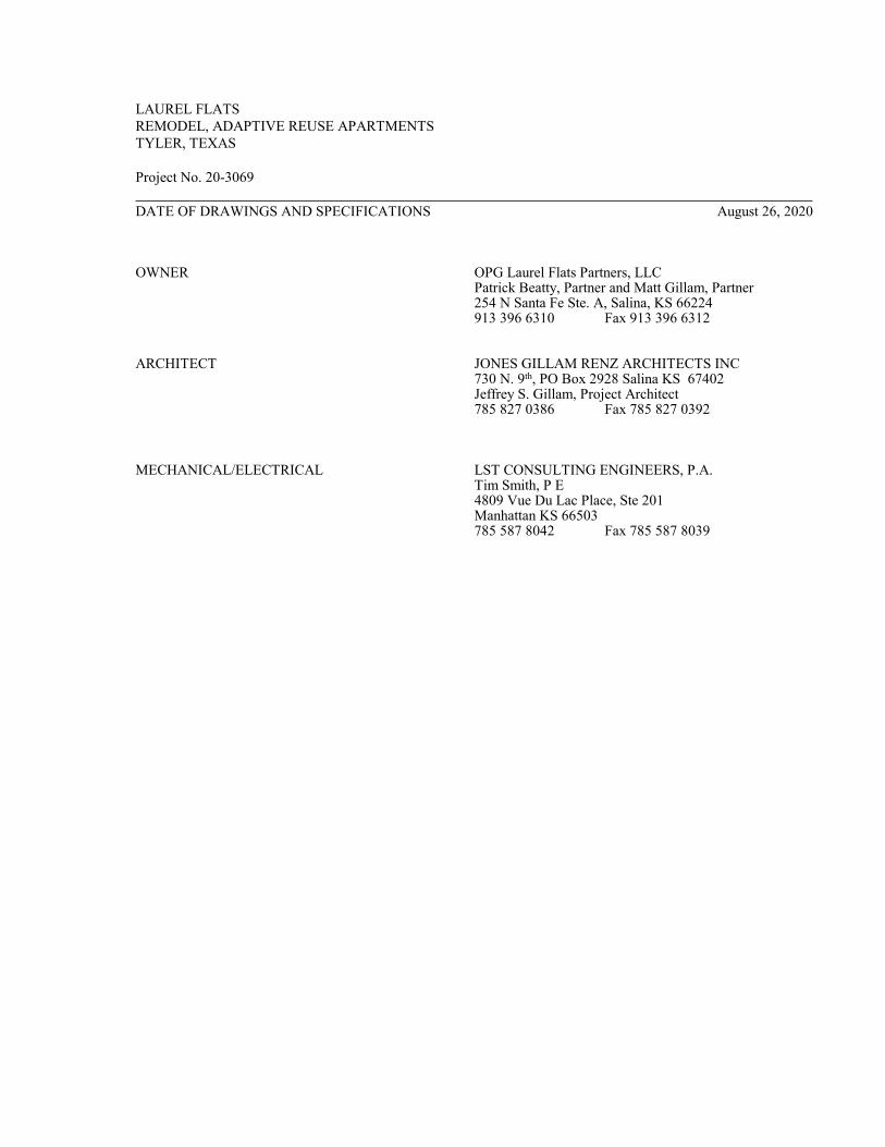
LAUREL FLATS
REMODEL, ADAPTIVE REUSE APARTMENTS
TYLER, TEXAS
Project No. 20-3069
DATE OF DRAWINGS AND SPECIFICATIONS August 26, 2020
OWNER OPG Laurel Flats Partners, LLC Patrick Beatty, Partner and Matt Gillam, Partner 254 N Santa Fe Ste. A, Salina, KS 66224913 396 6310 Fax 913 396 6312
ARCHITECT JONES GILLAM RENZ ARCHITECTS INC730 N. 9th, PO Box 2928 Salina KS 67402Jeffrey S. Gillam, Project Architect785 827 0386 Fax 785 827 0392
MECHANICAL/ELECTRICAL LST CONSULTING ENGINEERS, P.A.Tim Smith, P E 4809 Vue Du Lac Place, Ste 201 Manhattan KS 66503 785 587 8042 Fax 785 587 8039

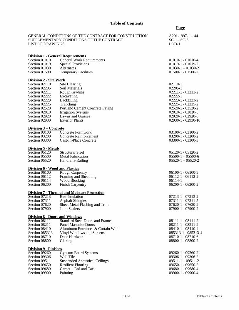
TC-1 Table of Contents
Table of Contents Page GENERAL CONDITIONS OF THE CONTRACT FOR CONSTRUCTION A201-1997-1 – 44 SUPPLEMENTARY CONDITIONS OF THE CONTRACT SC-1 - SC-3 LIST OF DRAWINGS LOD-1 Division 1 - General Requirements Section 01010 General Work Requirements 01010-1 - 01010-4 Section 01019 Special Provisions 01019-1 - 01019-2 Section 01030 Alternates 01030-1 – 01030-2 Section 01500 Temporary Facilities 01500-1 - 01500-2 Division 2 - Site Work Section 02110 Site Clearing 02110-1 Section 02205 Soil Materials 02205-1 Section 02211 Rough Grading 02211-1 - 02211-2 Section 02222 Excavating 02222-1 Section 02223 Backfilling 02223-1 - 02223-2 Section 02225 Trenching 02225-1 - 02225-2 Section 02520 Portland Cement Concrete Paving 02520-1 - 02520-2 Section 02810 Irrigation Systems 02810-1 - 02810-5 Section 02920 Lawns and Grasses 02920-1 - 02920-6 Section 02930 Exterior Plants 02930-1 - 02930-10 Division 3 – Concrete Section 03100 Concrete Formwork 03100-1 - 03100-2 Section 03200 Concrete Reinforcement 03200-1 - 03200-2 Section 03300 Cast-In-Place Concrete 03300-1 - 03300-3 Division 5 - Metals Section 05120 Structural Steel 05120-1 - 05120-2 Section 05500 Metal Fabrication 05500-1 – 05500-6 Section 05520 Handrails-Railing 05520-1 – 05520-2 Division 6 - Wood and Plastics Section 06100 Rough Carpentry 06100-1 - 06100-9 Section 06112 Framing and Sheathing 06112-1 - 06112-2 Section 06114 Wood Blocking 06114-1 Section 06200 Finish Carpentry 06200-1 - 06200-2 Division 7 - Thermal and Moisture Protection Section 07213 Batt Insulation 07213-1 - 07213-2 Section 07311 Asphalt Shingles 07311-1 - 07311-5 Section 07620 Sheet Metal Flashing and Trim 07620-1 - 07620-2 Section 07900 Joint Sealers 07900-1 - 07900-2 Division 8 - Doors and Windows Section 08111 Standard Steel Doors and Frames 08111-1 - 08111-2 Section 08211 Panel Masonite Doors 08211-1 - 08211-2 Section 08410 Aluminum Entrances & Curtain Wall 08410-1 - 08410-4 Section 085313 Vinyl Windows and Screens 085313-1 - 085313-4 Section 08710 Door Hardware 08710-1 - 08710-6 Section 08800 Glazing 08800-1 - 08800-2 Division 9 - Finishes Section 09260 Gypsum Board Systems 09260-1 - 09260-2 Section 09306 Wall Tile 09306-1 - 09306-2 Section 09511 Suspended Acoustical Ceilings 09511-1 – 09511-2 Section 09650 Resilient Flooring 09650-1 - 09650-2 Section 09680 Carpet – Pad and Tack 09680-1 - 09680-4 Section 09900 Painting 09900-1 - 09900-4

TC-2 Table of Contents
Division 10 - Specialties Section 10431 Signage 10431-1 – 10431-4 Section 10522 Fire Extinguishers & Accessories 10522-1 Section 10800 Toilet and Bath Accessories 10800-1 Section 10850 Building Specialties 10850-1 Division 11 Section 11451 Residential Appliances 11451-1 - 11451-4 Division 12 Section 12356 Kitchen Casework 12356-1 - 12356-5 Section 12491 Horizontal Louver Blinds 12491-1 - 12491-3
Division 21- Fire Suppression
Reference Drawings
Division 22- Plumbing
Reference Drawings
Division 23- Heating, Ventilating, and Air Conditioning (HVAC)
Reference Drawings
Division 26- Electrical Reference Drawings
Division 28- Electronic Safety and Security
Reference Drawings


SC-1
SUPPLEMENTARY CONDITIONS OF THE CONTRACT
1. DEFINITIONS - Supplement Paragraph 1.1 as follows:
a. When words such as approved, proper, satisfactory, equal, and as directed are used, they imply such reference to the Architect’s specific approval and directions.
b. Provide means to furnish and install.
c. The provisions of the Agreement take precedence over all other Contract Documents.
2. WARRANTY - Supplement Paragraph 3.5.1 as follows:
a. Contractor warrants to Owner and Architect that on receipt of notice from either of them, within the period of one (1) year following date of Substantial Completion, that defects in materials and/or workmanship have appeared in the Work, Contractor will promptly correct such defects to the state of condition originally required by the Contract Documents at Contractor’s expense.
3. SHOP DRAWINGS - Supplement Paragraph 3.12 as follows:
a. The Contractor shall submit one (1) electronic copy of all Shop or Setting Drawings and Schedules required for the work of the various trades, after same have been checked and compared with the Contract Document Requirements, and after checking with field conditions at the job and so certified on the Drawings by the Contractor. Above Drawings will not be checked by Architect unless same bear certification.
b. Architect’s approval is subject to notations on Drawings, Compliance with Drawings and Specifications, and conditions and measurements at project. Measurements and quantity not checked or approved.
4. SAMPLES - Supplement Subparagraph 3.12.3 as follows:
a. All samples as called for in the various Sections of this Specification and any other samples, as directed, shall be furnished by the Contractor for approval.
b. All samples of materials that require approval as to color, texture, finish and type shall be furnished at the same time, so that an intelligent selection of colors and textures may be made by the Architect.
5. COLOR SELECTIONS a. The Contractor shall provide for and coordinate into the project construction schedule, a 6-week time
frame for the Architect/Designer to make final color selections from Contractor's submittals, obtain approval from the Owner and to submit a color schedule, indicating what colors go where, to the Contractor. Time frame begins when Architect has received 100% of submittals listed below.
b. Submittals, i.e., actual samples, manufacturers' literature, full color line options, etc., shall include as a minimum, but not limited to:
Carpet TypesSheet Vinyl Flooring Vinyl Composition Tile FlooringVinyl BaseCeramic Wall TileCeiling TypesPaint Corner GuardsPlastic Laminate (Manufacturer)Wood Stain for Doors and WoodworkAluminum Storefront System
6. CLEAN UP - Supplement Paragraph 3.15 as follows:a. Each Contractor shall, at all times, remove any and all of his rubbish from the buildings and grounds
and keep the building site clean.
SC-2
b. In addition to the general broom cleaning, the General Contractor shall do the following special cleaning for all trades at the completion of the work:1) Glass. Remove putty, stains and paint from all glass and wash and polish same. Care shall be
taken not to scratch the glass.
2) Painted, Decorated, and Stained Work. Remove all marks, stains, fingerprints and other soil or dirt from all painted, decorated, and stained work.
3) Temporary Protection. Remove all temporary protections; clean and polish all floors at completion.
4) Woodwork. Clean and polish all woodwork upon completion.
5) Hardware. Clean and polish all hardware for all trades. This shall include removal of all stains, dust, dirt, paint, etc., upon completion.
6) Tile Work. Remove all spots, soil, and paint from all tile work, wash same upon completion.
7) Fixtures and Equipment. Clean all fixtures and equipment, removing all stains, paint, dirt, and dust.
c. All combustible rubbish, and all debris and other rubbish shall be removed entirely from the premises.
7. MUTUAL RESPONSIBILITY OF CONTRACTORS - Supplement Paragraph 6.2 as follows:
a. General Contractor shall assume general coordination and direction of the project. General Contractor shall cooperate with Mechanical and Electrical Contractors and other subcontractors and/or suppliers on the Work and install their work in sequence to facilitate and not delay the completion of the project. The Architect is not the coordinator or expeditor of the work of the contractors and/or subcontractors referred to hereinbefore.
8. CHANGES IN THE WORK
Refer to Paragraph 7.2 and insert the following:a. Whenever a Change Order involves net cost decrease, the CREDIT to the Owner shall be such net cost
decrease. Whenever a Change Order involves a summary net increase, the Contract shall be increased by the amount of such net cost increase plus 10% of such net cost for overhead and profit. The General Contractor will furnish supervision and coordination for 10% of the cost of additional Mechanical and Electrical work ordered by the Owner.
b. The Contractor shall furnish the Owner an itemized accounting with supporting data used in computing the value of any change that might be ordered.
c. Change Orders must state a number of added days or days to be deleted from completion time. If no change in days is required by the change order, write NONE. Failure to comply with above voids any later request for extra time.
9. APPLICATION FOR PROGRESS PAYMENTS AND CERTIFICATION FOR PAYMENT
a. Amend Subparagraph 9.3.1 and insert the following: On or before the 25th day of each month, the Contractor shall submit to the Architect an itemized Application for Payment supported by such data substantiating the Contractor’s right to payment as the Owner or Architect may require.
b. Amend Subparagraph 9.4.1 and insert: If the Contractor has made application for payment as above, the Architect will, with reasonable promptness and within seven (7) days after receipt of the application, issue an application for payment to the Owner, with a copy to the Contractor in the amount of 90% of the value of the Contract the Architect determines has been completed to the date of application, thus a 10% retainage, less any amount paid to the Contractor, or state in writing his reason for withholding an application as provided in Subparagraph 9.5.1.
c. Date of payment of the Application for Payment by the Owner is hereby defined as the earliest possible date that the Owner can prepare vouchers after receipt of Application for Payment from the Architect and approval of same by any governing body of the Owner and issuance of vouchers to cover Application for Payment.

SC-3
10. CONTRACTOR’S LIABILITY INSURANCE
a. Workers’ Compensation and Employers Liability Insurance - Refer to Subparagraph 11.1.1.
b. Bodily Injury and Property Damage - Refer to Subparagraph 11.1.2. Limits shall be as follows:(1) Limits of liability coverage shall be $2,000,000.00 Combined Single Limit for Bodily Injury
and Property Damage.
c. Owner’s Protective Liability Insurance - Refer to Paragraph 11.2 - Owner’s Option.
11. PERFORMANCE AND PAYMENT BONDS - Supplement Subparagraph 11.4.1 as follows:
a. Bond shall be equivalent to AIA Form A311, two part Performance Bond and Labor and Materials Bond with amount shown on each part equal to 100% of the total amount payable by the terms of the Contract. Surety shall be company licensed to do business at the place of building and shall be acceptable to the Owner.
END OF SECTION


LOD List of Drawings
List of Drawings
GENERAL
Cover SheetSurvey
UFAS1 Uniform Federal Accessibility StandardsUFAS2 Uniform Federal Accessibility StandardsUFAS3 Uniform Federal Accessibility StandardsFH Fair Housing DiagramsTAS1 Texas Accessibility StandardsTAS2 Texas Accessibility StandardsL1.1 Buildings 3, 1 & 7 Landscape PlansL1.2 Buildings 11 & 12 Landscape Plans
Architectural A1.1 Site Plan A1.2 Site DetailsA1.3 Site DetailsA1.4 Site DetailsA1.5 Site DetailsA1.6 Site DetailsA1.7 Site DetailsA1.8 Site DetailsA2.1 Buildings 1,3,4,5,6,7,8,9,10 & 16 First and Second Floor
Plans A2.2 Buildings 2, 13, 14, & 15 First and Second PlansA2.3 Buildings 11 & 12 First and Second Floor PlansA2.4 Accessible Unit Plans and DetailsA2.5 Accessible Unit Plans and DetailsA2.6 Standard Efficiency Unit Plans and DetailsA2.7 Standard 1-Bedroom Unit Plans and DetailsA2.8 Standard (Small) 1-Bedroom & 2-Bedroom Unit Plans
and DetailsA2.9 Live-in Office/1-Bedroom Unit Plans and DetailsA2.10 Entry Stair DetailsA2.11 Laundry, Maintenance & Stair Plans and Details A3.1 Exterior ElevationsA3.2 Exterior ElevationsA3.3 Exterior ElevationsA3.4 Exterior Elevations
A9.1 Standard & Accessible Kitchen Elevations and DetailsA9.2 Standard Bathroom Elevations and DetailsA9.3 Accessible Bathroom Plans, Elevations, and DetailsA10.1 Door & Window Schedules
Mechanical & ElectricalME0.1 Symbols and LegendME1.1 MEP Site PlanME2.1 Buildings 1,3,4,5,6,7,8,9,10 & 16 First and Second Floor
MEP PlansME2.2 Buildings 2, 13, 14, & 15 First and Second Power PlansME2.3 Buildings 11 & 12 First and Second Floor Power PlansME2.4 Laundry and Leasing Office MEP PlansM0.1 Mechanical SpecificationsM2.4 Accessible Units, Mechanical PlansM2.5 Standard Efficiency Units, Mechanical PlansM2.6 Standard 1-Bedroom Units, Mechanical PlansM2.7 Standard (Small) 1-Bedroom Unit & 2-Bedroom Units,
Mechanical PlansE0.1 Electrical SpecificationsE2.4 Accessible Units, Electrical PlansE2.5 Standard Efficiency Units, Electrical PlansE2.6 Standard 1-Bedroom Units, Electrical PlansE2.7 Standard (Small) 1-Bedroom & 2-Bedroom Units,
Electrical Plans


01010-1 General Work Requirements
SECTION 01010
GENERAL WORK REQUIREMENTS
1. GENERAL
Should conflict occur between these General Work Requirements and the General Conditions, the requirements of this Section take precedence.
2. INTENT OF DOCUMENTS
The Contract Drawings are complementary and what is called for by anyone shall be as binding as if called by all. The intention of the documents is to include all labor and materials, equipment and transportation necessary for the proper execution of the work.
3. MANUFACTURERS’ DIRECTIONS
All manufactured articles, materials and equipment shall be applied, installed, connected, erected, used, cleaned and conditioned as directed by the manufacturers, unless herein specified to the contrary.
4. COOPERATION - CONTRACTOR WITH OWNER
It shall be clearly understood that the Owner reserves the right to install various equipment in the building prior to completion and acceptance, and it shall be the duty of the Contractor to cooperate with the Owner’s employees rendering such assistance and so arranging his work that the entire project will be delivered complete in the best possible condition when required.
5. BUILDING PERMIT
As stated in Subparagraph 4.7.1, AIA DOCUMENT A201, General Conditions, the General Contractor shall secure and pay for the building permit.
6. CONSTRUCTION COORDINATION
Before starting construction, a meeting shall be held with Contractor(s), Architect, and Consulting Engineers in attendance to plan and coordinate the schedule of construction and to review intent of Contract Documents. Contractor(s) shall follow instructions received at meeting in prosecuting the Work.
7. MATERIALS - EQUIPMENT - SUBSTITUTIONa. In general, these Specifications identify the required materials and equipment by naming one
or more manufacturers, brand, model, catalog number, and/or other identification; the first-named manufacturer’s product used as a basis for design; the other named brands considered equivalent. Equivalent brand manufacturers named must furnish products consistent with the Specifications for the first-named product, as determined by the Architect. Base Bid shall include only those brands named and must be used on the project, except as hereinafter provided.
b. Materials or equipment specified exclusively, Base Bid shall be based on same and used on project, except as hereinafter provided.
c. Prior to receipt of bids, should Contractor wish to incorporate in Base Bid, brands or products other than those named in the Specifications, he shall submit written request for substitution to Architect not later than seven (7) days prior to date bids are due. Architect will consider request and items approved will be listed in an addendum issued to all bidders.
d. After execution of Contract, substitution of product brands for those named in the Specifications will be considered, only if request is received within thirty (30) days after Contract Date and request includes showing credit due Owner.

01010-2 General Work Requirements
e. Materials specified equivalent and those proposed for substitution must be equal or better than first-named material in construction, efficiency, utility, aesthetic design, and physical size shall not be larger than space provided for it. Request for substitution by full description and technical data in two (2) copies, including manufacturer’s name, model, catalog number, photographs or cuts, physical dimensions, operating characteristics, and any other information for comparison.
f. Owner reserves the right:1) To require any or all bidders, before execution of Contract, to state what materials they
will use.2) To require “if bound with the Bid Form,” the Contractor to fill out a BID SUPPLEMENT
listing the BASE BID and “ADD” or “DEDUCT” for other materials he proposes to use.
8. APPROVAL OF SUBCONTRACTORS - MATERIALSa. The Contractor, if requested, must submit for approval before signing Agreement, list of
Subcontractors and material suppliers enumerating items of work to be performed, name of materials, equipment, etc., to be furnished and/or installed. Refer to Paragraph - MATERIALS - EQUIPMENT - SUBSTITUTION.
b. If the list is not requested prior to signing of Agreement, list, as described in previous paragraph, shall be furnished within ten (10) days of signing Agreement.
9. PROTECTION - Supplement, ARTICLE 10, AIA GENERAL CONDITIONSa. Refer to Paragraph - WEATHER CONDITIONS.
b. Each Contractor shall assume responsibility for his materials stored on the premises.
c. General Contractor shall take charge and assume general responsibility for proper protection of project during construction.
d. The General Contractor shall protect trees, shrubs, lawns and all landscape from damage, providing guards and covering. Damaged work shall be repaired or replaced at his expense. Protect streets and sidewalks and make repairs at his expense.1) Water Protection. The General Contractor shall, at all times, protect the excavation,
trenches, and/or the building from damage by rain water, spring water, ground water, backing up of drains or sewers and all other water. He shall provide all pumps and equipment and enclosures to provide this protection.
2) Temporary Drainage. The General Contractor shall construct and maintain all necessary temporary drainage and do all pumping necessary to keep the excavation free of water.
3) Snow and Ice. The General Contractor shall remove all snow and ice from public sidewalks and from the building, as may be required for the proper protection and/or prosecution of the Work.
4) Bracing, Shoring, and Sheeting. The General Contractor shall provide all shoring, bracing and sheeting as required for safety and for the proper execution of the work and have same removed when the work is completed.
5) Guard Lights. The General Contractor shall provide and maintain guard lights at all barricades, railings, obstructions in the streets, roads or sidewalks and at all trenches or pits adjacent to public walks or roads.
6) Weather Conditions. The General Contractor shall, at all times, provide protection against weather; rain, winds, storms, frost, or heat, so as to maintain all work, materials, apparatus, and fixtures, free from injury or damage. At the end of the day’s work, all new work likely to be damaged shall be covered.
10. WEATHER CONDITIONSThe Contractor shall protect all portions of his work and all materials, at all times from damage by water, freezing, frost and is to repair, replace and make good to the satisfaction of the Architect, any portion of same which may in the Architect’s opinion, have been damaged by the elements.

01010-3 General Work Requirements
11. GRADES, LINES, LEVELS, AND SURVEYSThe Owner will establish the lot lines, restrictions and a bench mark. All other grades, lines, levels, and bench marks shall be established and maintained by the General Contractor, who shall be responsible for same. The General Contractor shall verify all grades, lines, levels, and dimensions as shown on the Drawings and he shall report all errors or inconsistencies in the above to the Architect before commencing work.a. The General Contractor shall provide and maintain well-built batter boards at all corners. He shall
establish bench marks in not less than two (2) widely separated places. As the work progresses, he shall establish bench marks at each floor, giving exact levels of the various floors.
b. As the work progresses, the General Contractor shall lay out in the forms and the rough flooring the exact location of all partitions as a guide to all trades.
c. The General Contractor shall verify all grades, lines, levels, and dimensions as shown on the Drawings and he shall report any errors or inconsistencies in the above to the Architect before commencing work.
12. USE OF COMPLETED PORTIONSThe Owner reserves the right to take possession of and use any completed or partially completed portions of the building, and further reserves the right to install equipment and facilities which are not a part of the Contract, notwithstanding the fact that the time of completion of entire work or portions thereof may not have expired; but such taking possession or installation of facilities shall not be deemed an acceptance of any work not completed in accordance with the Contract Documents. The Owner, in taking possession of completed portions or installing such equipment, and facilities, shall do so at his own expense any damage which may occur either directly or indirectly by reason of such action.a. Building Completion-Occupancy. Owner reserves the right to occupy building when the time
for completion of work as stipulated in Contract has been reached, even though all parts of the work have not been completed and accepted by Owner. All work, including heating, electrical, and water service, will be discontinued only to Owner schedule.
b. Limit of Contract is not confined to any particular area of the site, but includes any area required to perform work shown on the Drawings and/or specified in these Specifications.
13. REQUIREMENTS IMMEDIATELY AFTER EXECUTION OF CONTRACTImmediately after execution of the Contract, the Contractor shall deliver to the Architect the following items which are described more fully in following Articles:
Schedule of ValuesSchedule of OperationsProgress ChartsSamplesSuperintendent’s name and resume of experienceList of Subcontractors and Material Suppliers
a. Schedule of Values on AIA Form G702, or other form approved by the Architect, a detailed breakdown of the Contract Sum indicating the amounts allotted to the various divisions of the work for labor and material. The schedule will serve as a guide to the Architect in determining the amounts due each month as the work progresses. The schedule shall be broken down as directed by the Architect.
b. Schedule of Operations based on the above Schedule of Values and indicating the progress of the work up to the first day of each month shall be prepared by the Contractor in a form approved by the Architect and shall be delivered to the Architect in duplicate with each application for payment.
c. Progress Charts based on the above specified schedule of operations and indicating the progress of the work up to the first day of each month shall be prepared by the Contractor in a form approved by the Architect and shall be delivered to the Architect in duplicate with each application for payment. Progress charts shall be in the form of a bar graph. Along with progress charts the Contractor shall provide an estimated monthly cash flow chart.
01010-4 General Work Requirements
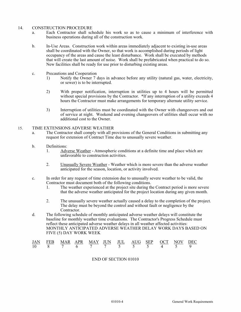
14. CONSTRUCTION PROCEDUREa. Each Contractor shall schedule his work so as to cause a minimum of interference with
business operations during all of the construction work.
b. In-Use Areas. Construction work within areas immediately adjacent to existing in-use areas shall be coordinated with the Owner, so that work is accomplished during periods of light occupancy of the areas and cause the least disturbance. Work shall be executed by methods that will create the last amount of noise. Work shall be prefabricated when practical to do so. New facilities shall be ready for use prior to disturbing existing areas.
c. Precautions and Cooperation1) Notify the Owner 7 days in advance before any utility (natural gas, water, electricity,
or sewer) is to be interrupted.
2) With proper notification, interruption in utilities up to 4 hours will be permitted without special provisions by the Contractor. *If any interruption of a utility exceeds 4 hours the Contractor must make arrangements for temporary alternate utility service.
3) Interruption of utilities must be coordinated with the Owner with changeovers and out of service at night. Weekend and evening changeovers of utilities shall occur with no additional cost to the Owner.
15. TIME EXTENSIONS ADVERSE WEATHERa. The Contractor shall comply with all provisions of the General Conditions in submitting any
request for extension of Contract Time due to unusually severe weather.
b. Definitions:1. Adverse Weather - Atmospheric conditions at a definite time and place which are
unfavorable to construction activities.
2. Unusually Severe Weather - Weather which is more severe than the adverse weather anticipated for the season, location, or activity involved.
c. In order for any request of time extension due to unusually severe weather to be valid, the Contractor must document both of the following conditions.1. The weather experienced at the project site during the Contract period is more severe
that the adverse weather anticipated for the project location during any given month.
2. The unusually severe weather actually caused a delay to the completion of the project. The delay must be beyond the control and without fault or negligence by the Contractor.
d. The following schedule of monthly anticipated adverse weather delays will constitute the baseline for monthly weather time evaluations. The Contractor's Progress Schedule must reflect these anticipated adverse weather delays in all weather affected activities:MONTHLY ANTICIPATED ADVERSE WEATHER DELAY WORK DAYS BASED ON FIVE (5) DAY WORK WEEK
JAN FEB MAR APR MAY JUN JUL AUG SEP OCT NOV DEC10 8 7 6 7 7 5 5 5 4 5 9
END OF SECTION 01010

01019-1 Special Provisions
SECTION 01019
SPECIAL PROVISIONS
1. GENERAL Should conflict occur between these Special Provisions and the General Conditions, the requirements of the Special Provisions shall take precedence.
2. TIME OF CONSTRUCTION - LIQUIDATED DAMAGES a. Time of Construction - The Contractor will commence the work within ten (10) days after the
Architect shall have given the Contractor written notice to commence construction to the satisfaction of the Owner within the calendar days as Contractor so stated in his Bid Form. The time for completion herein set forth shall be extended for the period of any reasonable delay which is due exclusively to causes beyond the control and without the fault of the Contractor, including acts of God, fires, floods, and direction by the Architect. It is impractical to perform any operation of construction and acts of omissions of the Owner with respect to matters for which Owner is solely responsible; provided, however, that no such extension of time for completion shall be granted the Contractor, unless within ten (10) days after the happening of any event relied upon by the Contractor for such extension of time, the Contractor shall have made a request, therefore, in writing to the Architect. Extended time will be submitted with pay request for Owner’s approval.
b. Liquidated Damages - The time of completion of the construction of the project is of the essence of this Contract. Should the Contractor neglect, refuse, or fail to complete the project within the time herein agreed upon, after giving effect to extensions of time, if any, herein provided; then in that event and in view of the difficulty of estimating with exactness damages caused by such delay, the Owner shall have the right to deduct from and retain out of such money, which may then be due or which may become due and payable to the Contractor, the sum of THREE HUNDRED DOLLARS ($300.00) per day for each and every day that such construction is delayed in its completion beyond the specified time, as liquidated damages and not as a penalty. If the amount due and to become due from the Contractor to the Owner is insufficient to pay in full any such liquidated damages, the Contractor shall pay to the Owner the amount necessary to effect such payment in full; provided, however, that the Owner shall promptly notify the Contractor in writing of the manner in which the amount retained, deducted or claimed as liquidated damages was computed.
c. Joint Responsibility - The General Contractor and/or Subcontractors causing the delay in completion of the project shall be responsible for payment of liquidated damages. In no case shall the total liquidated damages for all contracts exceed the sum of daily liquidated damages multiplied by the number of days of delay in completion.
3. ALTERNATES - Refer to Alternate Schedule, Section 01030a. Alternates specified are not a part of Base Bid, but are Alternates to same, their acceptance
being at option of Owner.
4. ENUMERATION OF DRAWINGS AND SPECIFICATIONSa. Correlation. Accompanying these Specifications are the Drawings, which jointly with these
Specifications, are intended to explain each other and describe and coordinate the work to be performed under the Contract.
b. Verification of Documents. Before submitting his bid, each Bidder shall check his set(s) of Drawings and Specifications and advise the Architect if any sheets are missing.
c. Specifications Explanations. For convenience of reference, the Specifications are separated into Titled Divisions and Sections. Such separation shall not, however, operate to make the Architect an arbiter to establish limits between the Contractor and Subcontractor or Sub-Subcontractor.
d. Drawings. Refer to LIST OF DRAWINGS.
e. Specifications. Refer to TABLE OF CONTENTS.
01019-2 Special Provisions
5. WARRANTIES
Before being eligible for final payment, Contractor shall deliver to Owner, through Architect, all special warranties specified for materials, equipment and installation.
6. OPERATING INSTRUCTIONS
Before being eligible for final payment, Contractor shall deliver to Owner, through Architect, three (3) copies of manufacturer’s operating instructions, one (1) complete set of shop drawings on each piece of equipment, and such framed instructions as instructed.
7. AS-BUILT DRAWINGS
Before being eligible for final payment, the Electrical and Mechanical Contractors shall prepare and deliver to Owner, through Architect, one (1) set of AS-BUILT DRAWINGS. These drawings may consist of marked-up prints, if the Contractor so chooses, but shall show the correct location of every item of equipment, piping, conduit, panel boards, ductwork, switches, valves, etc. If marked-up prints are used, they shall be new white prints.
8. CERTIFICATE OF COMPLIANCE
Upon completion of project, Contractor is to furnish written Certification to the Architect that he has complied with every paragraph of the Specifications and Drawings.
9. CONTRACTOR’S MONTHLY APPLICATION FOR PAYMENT FORM
Contractor’s monthly Application for Payment shall be submitted as per General Conditions. AIA Document G702, Application and Certificate for Payment is approved and acceptable.
10. FILING AND RECORDING OF BONDS
In addition to furnishing the number of combination Performance Bond and Labor and Materials Payment Bond, and Statutory Bond, if required, the Contractor shall file copies of such bonds with Clerk of the District Court and furnish Architect with receipt furnished by Clerk of the District Court, covering charges for filing and recording of said bonds.
11. STATUTORY BONDS
In addition to furnishing the combination Performance and Labor and Materials Payment Bond specified in General Conditions, the Contractor shall furnish Statutory Bond in an amount not less than 100% of the Agreement in such numbers and form stated in Sample Copy bound in the Specifications. Statutory Bond shall be filed and recorded with Clerk of the District Court, as specified in Paragraph - FILING AND RECORDING OF BONDS.
12. DOCUMENTS FURNISHED CONTRACTORS
The General Contractor will be furnished, free of charge, the following working drawings and specifications, including modifications for construction of the project - 20 sets. The General Contractor will be responsible for distribution of these sets to the Subcontractors and suppliers. The Contractor shall pay the actual cost of reproduction and postage for all additional sets requested by him.
13. SALES TAX EXEMPTIONSa. Materials, labor and equipment incorporated into this project are not exempt from the
payment of sales tax under the laws of the State of Kansas and such sales tax shall be
included in the Bid of the Bidder.
END OF SECTION 01019

01030-1 Alternates
SECTION 01030
ALTERNATES
PART 1 – GENERAL 1.1 RELATED DOCUMENTS
A. Drawings and general provisions of the Contract, including General and Supplementary Conditions and other Division 1 Specification Sections, apply to this Section.
1.2 SUMMARY
A. This Section includes administrative and procedural requirements for alternates.
1.3 GENERAL 1. The General Contractor shall state in his Bid Form the amount of dollars to be ADDED or
DEDUCTED from his Base Bid for the following Alternates. 2. Alternates are not in order of acceptance. 3. It shall be the responsibility of the General Contractor to advise all necessary personnel and
suppliers as to the nature and extent of all alternates selected by the owner. 4. Circle Add or Deduct to indicate that the alternate price is to be added or subtracted from the
base bid.
1.4 DEFINITIONS A. Alternate: An amount proposed by bidders and stated on the Bid Form for certain work defined in the
Bidding Requirements that may be added to or deducted from the Base Bid amount if Owner decides to accept a corresponding change either in the amount of construction to be completed or in the products, materials, equipment, systems, or installation methods described in the Contract Documents.
1. The cost or credit for each alternate is the net addition to or deduction from the Contract Sum to incorporate alternate into the Work. No other adjustments are made to the Contract Sum.
1.5 PROCEDURES
A. Coordination: Modify or adjust affected adjacent work as necessary to completely integrate work of the alternate into Project.
1. Include as part of each alternate, miscellaneous devices, accessory objects, and similar items incidental to or required for a complete installation whether or not indicated as part of alternate.
B. Notification: Immediately following award of the Contract, notify each party involved, in writing, of the
status of each alternate. Indicate if alternates have been accepted, rejected, or deferred for later consideration. Include a complete description of negotiated modifications to alternates.
C. Execute accepted alternates under the same conditions as other work of the Contract.
D. Schedule: A Schedule of Alternates is included at the end of this Section. Specification Sections
referenced in schedule contain requirements for materials necessary to achieve the work described under each alternate.
PART 2 - PRODUCTS (Not Used)

01030-2 Alternates
PART 3 - EXECUTION 3.1 SCHEDULE OF ALTERNATES 1. ALTERNATE NO. 1 FURNACES & A/C
Contractor shall state the amount of dollars to be added to the Base Bid to provide all labor and materials associated with the replacement of the Furnaces and Air conditioning equipment. Reference Mechanical drawings, details, & specifications.
Add/Deduct $ 2. ALTERNATE NO. 2 BATHROOM VENT FANS
Contractor shall state the amount of dollars to be added to the Base Bid to provide all labor and materials associated with the replacement of all existing bathroom exhaust fans Reference Mechanical drawings, details & specifications.
Add/Deduct $ 4. ALTERNATE NO. 3 WINDOWS
Contractor shall state the amount of dollars to be added to the base bid to provide all labor and materials to replace the existing Windows, Reference Architectural drawings, details, & specifications.
Add/Deduct$ 5. ALTERNATE NO. 4 ENTRY & STOREFRONT
Contractor shall state the amount of dollars to be added to the base bid to provide all labor and materials to remove and replace the glass block with storefront windows, paint brick, provide and install new railing above entry roof, Reference Architectural drawings, details, & specifications; G-A3.2 and elevations A3.1 – A3.2.
Add/Deduct$
END OF SECTION 01030

01500-1 Temporary Facilities
SECTION 01500
TEMPORARY FACILITIES
1. GENERAL
Should conflict occur between the Temporary Facilities and the General Conditions, the requirements of this Section take precedence.
2. TEMPORARY HEAT
a. The General Contractor shall provide heat, fuel and services as necessary to protect all work and materials against injury from dampness and cold until final acceptance of all work and material in the Contract, unless the building or buildings are fully occupied by the Owner prior to such acceptance, in which case, the Owner shall assume all expenses of heating from date of occupancy. The General Contractor shall provide heat as follows:
1) At all times during the placing, setting and curing of concrete, provide sufficient heat to insure the heating of the spaces involved to not less than 50° F.
2) From the beginning of the application of gypsum board taping and during the setting and curing period, provide sufficient heat to produce a temperature in the spaces involved of not less than 50° F.
3) For a period of ten (10) days previous to the placing of interior wood finish and throughout the placing of this and other interior finishing, varnishing, painting, etc., and until final acceptance of the work or until full occupancy by the Owner, provide sufficient heat to produce a temperature of not less than 70° F. Heating Subcontractor shall set such necessary temporary radiation as may be required.
4) Mechanical Subcontractor shall, as soon as possible, provide temporary heating facilities through the installed heating equipment.
3. SIGN AND ADVERTISING
a. The General Contractor shall furnish and erect one (1) banner sign, 4’-0” x 10’-0” in size, as shown on the last page of this Section and placed where directed. Sign shall have the following:1) Name of Project2) Name and Address of Architect3) Name and Address of General Contractor4) Name of Mechanical Subcontractor5) Name of Electrical Subcontractor6) Picture of Project (coordinate with Architect)
b. Post entire construction with DANGER and NO TRESPASSING signs to comply with safety and insurance regulations.
c. Keep premises clear and free from other signs or posters.
4. TEMPORARY FIELD OFFICES
a. General Contractor shall provide and maintain in good condition, a painted weatherproof field office (adequate size trailer acceptable) for use of General Contractor and Architect’s representative. Provide such building with heat, electric lights, telephone, locked doors, windows, table, and rack for Drawings. Building to remain property of General Contractor.
b. Electrical and Mechanical Subcontractors shall maintain similar field office, meeting requirements of previous paragraph, except provisions for Architect’s representative not needed.

01500-2 Temporary Facilities
5. TEMPORARY ENCLOSURES
General Contractor to provide:a. Temporary weathertight enclosures for all exterior openings as soon as possible as walls and roofs
are built to protect work from weather. Temporary exterior doors equipped with padlocks.
b. In cold weather, provide additional precautions necessary, including heat at such openings to protect building and contents.
6. TEMPORARY SHEDS
The Contractor shall provide and maintain on the premises watertight storage sheds for storage of all materials which may be damaged by weather. These sheds shall have wood floors raised above the ground.
7. TEMPORARY CONSTRUCTION ITEMS
General Contractor shall furnish necessary temporary stairs, chutes, runways, scaffolds, ladders, and hoist.
8. TEMPORARY TOILET ACCOMMODATIONS
a. The General Contractor shall provide for the use of all workmen, in accordance with local ordinances, ample temporary sanitary toilet accommodations and keep such clean and free from flies. Prior to completion of the Contract, all connections and appliances connected with same will be removed and the premises left perfectly clean.
b. The Mechanical Subcontractor shall, as soon as conditions of the work will allow, install inside building a temporary toilet with connections to the sewer.
9. TEMPORARY TELEPHONE
The General Contractor shall install at his own expense, a job telephone, and shall pay for all local calls. All long distance calls shall be paid by party making the call.
10. TEMPORARY LIGHT AND POWER
a. For new construction, the General Contractor shall arrange for temporary service, pay for all expenses therewith and bring services to building and run extensions to locations necessary for operations.
b. Permit other Subcontractors to use same. Other Subcontractors requiring additional extensions, make and remove same at their expense. General Contractor shall pay for all electricity consumed.
11. WATER FOR CONSTRUCTION
The Owner will furnish all water for construction. The General Contractor will be responsible for necessary water connections to existing source.
END OF SECTION 01500
02110-1 Site Clearing
SECTION 02110
SITE CLEARING
PART 1 GENERAL
1.01 SECTION INCLUDESA. Remove surface debris at areas of construction.C. Clear site of plant life and grass, at areas of construction.D. Remove trees and shrubs as indicated or at areas of construction.E. Remove root system of trees and shrubs indicated to be removed. F. Topsoil excavation as required and indicated areas of construction.
1.02 REGULATORY REQUIREMENTS A. Conform to applicable local codes and ordinances for disposal of debris, burning debris on site, use of
herbicides, etc.B. Coordinate clearing Work with utility companies as required.
PART 2 PRODUCTS
Not Used
PART 3 EXECUTION
3.01 PREPARATIONA. Verify that existing plant life designated to remain, is tagged, or identified.
3.02 PROTECTIONA. Locate, identify, and protect utilities that remain, from damage.B. Protect trees, plant growth, and features designated to remain, as final landscaping.C. Protect bench marks and existing structures from damage or displacement.
3.03 CLEARINGA. Clear areas required for access to site and execution of Work.B. Remove paving, curbs, and improvements designated.C. Remove trees and shrubs indicated. Remove stumps, root system, surface rock, and other areas
indicated or implied for completion of the project.D. Clear undergrowth and deadwood, without disturbing subsoil. Strip and clear vegetation from areas
designated to be filled, excavated, regraded, or landscaped.
3.04 REMOVALA. Remove debris, rock, and extracted plant life from site.
3.05 TOPSOIL EXCAVATIONA. Excavate clean topsoil from areas to be further excavated, filled, re-landscaped, or regraded.B. Stockpile in area designated on site to depth not exceeding 8 feet. Protect from erosion. Remove
excess topsoil not being reused, from site.
END OF SECTION 02110


02205-1 Soil Materials
SECTION 02205
SOIL MATERIALS
PART 1 GENERAL
1.01 SECTION INCLUDESA. Subsoil and topsoil materials.
1.03 REFERENCESA. ANSI/ASTM D698 - Test Methods for Moisture-Density Relations of Soils and Soil-Aggregate
Mixtures, Using 5.5 lb (2.49 Kg) Rammer and 12 inch (304.8 mm) Drop. B. ASTM D2487 - Classification of Soils for Engineering Purposes.
PART 2 PRODUCTS
2.01 SOIL MATERIALSA. Fill Material: Under slabs and within the zone of influence of foundation elements must be a material
approved by the geotechnical engineer for standard compaction and loading. B. Fill and Backfill Material: Other areas, foundation backfill, site grading, and pavement, should be clean
site material or similar borrow material.
2.02 SOURCE QUALITY CONTROL A. Inspection and testing of foundation bearing material and compaction, shall be performed by an
independent laboratory, Contractor shall bear all related costs under provisions of General Requirements.
B. Tests and analysis of soil material will be performed in accordance with ANSI/ASTM D698.C. If tests indicate materials do not meet specified requirements, change material and retest at no cost to
Owner.
PART 3 EXECUTION
3.01 STOCKPILINGA. Stockpile materials on site at locations indicated or in areas that will not impact project completion.B. Stockpile in sufficient quantities to meet project schedule and requirements.C. Separate differing materials with dividers or stockpile apart to prevent mixing.D. Direct surface water away from stockpile site to prevent erosion or deterioration of materials.
3.02 STOCKPILE CLEANUPA. Remove stockpile, leave area in a clean and neat condition. Grade site surface to prevent free-standing
surface water.
END OF SECTION 02205

02211-1 Rough Grading
SECTION 02211
ROUGH GRADING
PART 1 GENERAL
1.01 SECTION INCLUDESA. Removal of topsoil and subsoil.B. Cutting, grading, filling, and rough contouring the site for site structures and paving.
PART 2 PRODUCTS
2.01 MATERIALS A. Topsoil, Fill, and Structural Fill: As specified in Section 02205.
PART 3 EXECUTION
3.01 EXAMINATIONA. Verify that survey bench mark and intended elevations for the Work are as indicated.
3.02 PREPARATIONA. Identify required lines, levels, contours, and datum.B. Stake and flag locations of known utilities. Locate, identify, and protect utilities that remain, from
damage. Notify utility company to remove and relocate utilities.C. Protect above and below grade utilities that remain.D. Protect plant life, lawns, rock outcropping and other features remaining as a portion of final
landscaping.E. Protect bench marks, existing structures, fences, sidewalks, paving, and curbs from excavating
equipment and vehicular traffic.
3.03 SUBSOIL EXCAVATION A. Excavate subsoil from areas to be further excavated, relandscaped, or regraded.B. Stockpile in area designated on site to depth not exceeding 8 feet. Protect from erosion. Remove
subsoil not being reused, from site.C. When excavating through roots, perform work by hand and cut roots with sharp axe.
3.04 FILLINGA. Fill areas to contours and elevations with unfrozen materials.B. Place fill materials on continuous layers and compact in accordance with Schedule at end of Section.C. Maintain optimum moisture content of fill materials to attain required compaction density.D. Slope grade away from building minimum 2 inches in 10 ft. unless noted otherwise.E. Make grade changes gradual. Blend slope into level areas.F. Remove surplus fill materials from site.
3.05 TOLERANCESA. Top Surface of Subgrade: Plus or minus 1/10 foot.
3.06 FIELD QUALITY CONTROLA. Field inspection and testing will be performed under provisions of the General Requirements.B. Compaction testing will be performed in accordance with ANSI/ASTM D698.C. If tests indicate work does not meet specified requirements, remove work, replace, and retest at no
additional cost to the Owner.
3.07 SCHEDULESA. Structural Fill: (Structures and Paving)
1. Fill Maximum 8 inches compacted depth.2. Compact to minimum 95 percent of maximum density.

02211-2 Rough Grading
B. Subsoil Fill:1. Fill Maximum 8 inches compacted depth.2. Compact to minimum 90 percent of maximum density.
C. Topsoil Fill:1. Fill Maximum 8 inches depth.
END OF SECTION 02211

02222-1 Excavating
SECTION 02222
EXCAVATING
PART 1 GENERAL
1.01 SECTION INCLUDESA. Excavating for foundations and footings. B. Excavating for slabs-on-grade, paving, landscaping. C. Excavating for site structures.
PART 2 PRODUCTS
Not Used
PART 3 EXECUTION
3.01 PREPARATIONA. Identify required lines, levels, contours, and datum.B. Locate, identify, and protect utilities that remain, from damage. C. Notify utility company to remove and relocate utilities.D. Protect plant life, lawns, rock outcropping and other features remaining as a portion of final
landscaping.E. Protect bench marks, existing structures, fences, sidewalks, paving and curbs from excavation
equipment and vehicular traffic.
3.02 EXCAVATIONA. Underpin adjacent structures which may be damaged by excavation work.B. Excavate subsoil required to accommodate building foundations, slabs-on-grade, paving and site
structures, construction operations.C. Machine slope banks to angle of repose or less, until shored.D. Do not interfere with 45 degree bearing splay of foundation.E. Grade top perimeter of excavation to prevent surface water from draining into excavation.F. Hand trim excavation. Remove loose matter.G. Remove lumped subsoil, boulders, and rock up to 1/3 cu yd measured by volume. H. Notify Architect/Engineer of unexpected subsurface conditions and discontinue affected Work in area
until notified to resume work.I. Correct areas over-excavated in accordance with Section 02223.J. Stockpile excavated material in area designated on site and remove excess material not being reused,
from site.
3.03 FIELD QUALITY CONTROL A. Field inspection will be performed under provisions of the General Requirements.B. Provide for visual inspection of bearing surfaces.
3.04 PROTECTIONA. Protect excavations by methods required to prevent cave-in or loose soil from falling into excavation.B. Protect bottom of excavations and soil adjacent to and beneath foundation, from freezing.
END OF SECTION 02222


02223-1 Backfilling
SECTION 02223
BACKFILLING
PART 1 GENERAL 1.01 SECTION INCLUDES
A. Site structures backfilling to subgrade elevations. B. Site filling and backfilling.C. Fill under slabs-on-grade, paving.D. Consolidation and compaction as scheduled.E. Fill for over-excavation.
1.02 REFERENCES A. ANSI/ASTM D698 - Test Methods for Moisture-Density Relations of Soils and Soil-Aggregate
Mixtures, Using 5.5 lb (2.49 Kg) Rammer and 12 inch (304.8 mm) Drop.
PART 2 PRODUCTS
2.01 FILL MATERIALSA. Fill: As specified in Section 02205.
PART 3 EXECUTION
3.01 EXAMINATIONA. Verify subdrainage, dampproofing, or waterproofing installation has been inspected and completed.
3.02 PREPARATIONA. Compact subgrade to density requirements for subsequent backfill materials.B. Cut out soft areas of subgrade not capable of in situ compaction. Backfill with fill and compact to
density equal to or greater than requirements for subsequent fill material.C. Scarify and proof roll subgrade surface to a depth of 4 inches to identify soft spots; fill and compact to
density equal to or greater than requirements for subsequent fill material.
3.03 BACKFILLINGA. Backfill areas to contours and elevations with unfrozen materials.B. Systematically backfill to allow maximum time for natural settlement. Do not backfill over porous,
wet, frozen, or spongy subgrade surfaces.C. Fill, place and compact materials in continuous layers not exceeding 8 inches compacted depth.D. Employ a placement method that does not disturb or damage other work.E. Maintain optimum moisture content of backfill materials to attain required compaction density.
Backfill against supported foundation walls. Do not backfill against unsupported foundation walls.F. Backfill simultaneously on each side of unsupported foundation walls until supports are in place.G. Slope grade away from building minimum 2 inches in 10 ft. unless noted otherwise.H. Make gradual grade changes. Blend slope into level areas.I. Remove surplus backfill materials from site.J. Leave fill material stockpile areas free of excess fill materials.
3.04 TOLERANCESA. Top Surface of Backfilling Under paved Areas: Plus or minus 1 inch from required elevations.B. Top Surface of General Backfilling: Plus or minus 1 inch from required elevations.
3.05 FIELD QUALITY CONTROLA. Field inspection and testing will be performed under provisions of the General Requirements.B. Compaction testing will be performed in accordance with ANSI/ASTM D698.C. If tests indicate Work does not meet specified requirements, remove work, replace, and retest at no
additional cost to the Owner.D. Proof roll compacted fill surfaces under slabs-on-grade, and paving.

02223-2 Backfilling
3.06 PROTECTION OF FINISHED WORKA. Protect finished Work under provisions of the General Requirements.B. Reshape and re-compact fills subjected to vehicular traffic.
3.07 SCHEDULE
A. Exterior Side of Foundation Walls Retaining Walls and Over Granular Filter Material and Foundation Perimeter Drainage:1. Fill to subgrade elevation, each lift, compacted to 90 percent.
B. Fill Under Grass Areas:1. Fill to 4 inches below finish grade.
C. Fill Under Asphalt or Concrete Paving:1. Compact subsoil to 95 percent of its maximum dry density.
D. Fill to Correct Overexcavation: 1. Lean concrete to minimum compressive strength of 1000 psi.2. Compact approved fill to 95 percent of its maximum dry density.
END OF SECTION 02223

02225-1 Trenching
SECTION 02225
TRENCHING
PART 1 GENERAL
1.01 SECTION INCLUDES A. Excavating trenches for utilities from 5 feet outside building to municipal utilities.B. Compacted fill from top of utility bedding to subgrade elevations.C. Backfilling and compaction.
1.02 REFERENCES A. ANSI/ASTM D698 - Test Methods for Moisture-Density Relations of Soils and Soil-Aggregate
Mixtures, Using 5.5 lb (2.49 Kg) Rammer and 12 inch (304.8 mm) Drop.
1.03 FIELD MEASUREMENTS A. Verify that survey bench mark and intended elevations for the Work are as shown on drawings.
1.04 COORDINATIONA. Coordinate all work as required.B. Verify work associated with lower elevation utilities are complete before placing higher elevation
utilities.
PART 2 PRODUCTS
2.01 FILL MATERIALSA. Fill: As specified in Section 02205.
PART 3 EXECUTION
3.01 PREPARATIONA. Identify required lines, levels, contours, and datum.B. Protect plant life, lawns, rock outcropping and other features remaining as a portion of final
landscaping.C. Protect bench marks, existing structures, fences, sidewalks, paving, and curbs from excavation
equipment and vehicular traffic.D. Maintain and protect above and below grade utilities which are to remain.E. Cut out soft areas of subgrade not capable of in situ compaction. Backfill with fill and compact to
density equal to or greater than requirements for subsequent backfill material.
3.02 EXCAVATIONA. Excavate subsoil required for utilities to municipal utilities.B. Cut trenches sufficiently wide to enable installation and allow inspection.C. Do not interfere with 45 degree bearing splay of foundations.D. Hand trim excavation. Remove loose matter. E. Remove lumped subsoil, boulders, and rock up to 1/3 cu yd measured by volume.F. Correct areas over excavated in accordance with Section 02222.G. Stockpile excavated material in area designated on site and remove excess material not being used,
from site.
3.03 BACKFILLINGA. Backfill trenches to contours and elevations with unfrozen materials.B. Systematically backfill to allow maximum time for natural settlement. Do not backfill over porous,
wet, frozen, or spongy subgrade surfaces.C. Granular Fill: Place and compact materials in continuous layers not exceeding 8 inches compacted
depth.D. Soil Fill: Place and compact material in continuous layers not exceeding 8 inches compacted depth.E. Employ a placement method that does not disturb or damage foundation perimeter drainage, conduit, or
pipes in trench.F. Maintain optimum moisture content of fill materials to attain required compaction density.
02225-2 Trenching
G. Remove surplus fill materials from site.H. Leave fill material stockpile areas completely free of excess fill materials.
3.04 TOLERANCESA. Top Surface of Backfilling: Plus or minus 1 inch from required elevations.
3.05 FIELD QUALITY CONTROLA. Field inspection and testing will be performed under provisions of the General Requirements.B. Compaction testing will be performed in accordance with ANSI/ASTM D698.C. If tests indicate Work does not meet specified requirements, remove Work, replace, compact, and retest
at no additional cost to the owner.
3.06 PROTECTION OF FINISHED WORKA. Protect or reshape and recompact fills subjected to vehicular traffic during construction.
END OF SECTION 02225

02520-1 Portland Cement Concrete Paving
SECTION 02520
PORTLAND CEMENT CONCRETE PAVING
PART 1 GENERAL
1.01 SECTION INCLUDES A. Concrete sidewalks and stair steps, integral curbs, gutters, driveways and parking areas.
1.02 PERFORMANCE REQUIREMENTSA. Paving: Designed for parking and light duty commercial vehicles.
1.03 QUALITY ASSURANCEA. Perform work in accordance with ACI 301, requirements of Sections 03100, 03200 and 03300.B. Obtain cementitious materials from same source throughout.
1.04 ENVIRONMENTAL REQUIREMENTS A. Do not place concrete when base surface temperature is less than 40 degrees F, or surface is wet or
frozen.
PART 2 PRODUCTS
2.01 FORM MATERIALSA. Wood or Steel form material, profiled to suit conditions. B. Joint Filler: ANSI/ASTM D1751 type; 3/4 inch thick.
2.02 REINFORCEMENTA. Welded Steel Wire Fabric: Plain type, ANSI/ASTM A185; 6x6 - 6x6 in flat sheets or coiled rolls.B. Reinforcing Steel: ASTM A615; 40 ksi yield grade; deformed billet steel bars; unfinished.
2.03 CONCRETE MATERIALS A. Cement: ASTM C150 Air Entraining - Type IA Portland type, natural color. B. Fine and Coarse Mix Aggregates: ASTM C33.C. Water: Potable, not detrimental to concrete.D. Air Entrainment: ASTM C260.E. Chemical Admixture: ASTM C494, as approved by Architect.
2.04 CONCRETE MIX - BY PERFORMANCE CRITERIAA. Mix concrete in accordance with, ACI 304. Deliver concrete in accordance with ASTM C94.B. Provide concrete to the following criteria:
1. Compressive Strength: Reference schedule below.2. Slump: 1 to 2 inches.3. Minimum Water/Cement Ratio: 6.5 gallon/5.5 sack.4. Air Entrained: 5 percent.
C. Use accelerating admixtures in cold weather only when approved by Architect/Engineer. Use of admixtures will not relax cold weather placement requirements.
D. Use calcium chloride only when approved by Architect/Engineer.E. Use set retarding admixtures during hot weather only when approved by Architect/Engineer.
2.05 SOURCE QUALITY CONTROLA. Submit proposed mix design of each class of concrete to the architect and appointed testing laboratory
firm for review prior to commencement of work.B. Tests on cement and aggregates shall be performed to ensure conformance with specified requirements.
PART 3 EXECUTION
3.01 EXAMINATIONA. Verify compacted subgrade, granular base and stabilized soil is acceptable and ready to support paving
and imposed loads.B. Verify gradients and elevations of base are correct.

02520-2 Portland Cement Concrete Paving
3.02 PREPARATIONA. Moisten base to minimize absorption of water from fresh concrete.B. Coat surfaces of manholes, catch basins, and frames with oil to prevent bond with concrete pavement.C. Notify Architect/Engineer minimum 24 hours prior to commencement of concreting operations.
3.03 FORMINGA. Place and secure forms to correct location, dimension, and profile.B. Assemble formwork to permit easy stripping and dismantling without damaging concrete.C. Place joint filler vertical in position, in straight lines. Secure to formwork during concrete placement.
3.04 REINFORCEMENTA. Place reinforcement at mid-height of slabs-on-grade.B. Interrupt reinforcement at expansion joints.C. Place dowels and reinforcement to achieve pavement and curb alignment as detailed.D. Provide doweled joints 12 inch o.c. at interruptions of concrete.
3.05 PLACING CONCRETEA. Place concrete in accordance with ACI 301.B. Ensure reinforcement, inserts, and embedded parts, are not disturbed during concrete placement.C. Place concrete continuously between predetermined construction joints. Do not break or interrupt
successive pours such that cold joints occur.D. Place concrete to indicated pattern.
3.06 JOINTSA. Place 1/2 inch expansion joints at 60 foot intervals. Align curb, gutter, and sidewalk joints.B. Place joint filler between paving components and building or other appurtenances. Recess top of filler
1/4 inch for sealant placement by Section 07900.C. Provide scored or sawn joints at 4 feet intervals U.N.O. at sidewalks and curbs and 15 feet at pavement.D. Saw cut contraction joints 3/16 inch wide at an optimum time after finishing. Cut 1/3 into depth of
slab.
3.07 FINISHINGA. Parking: Light broom.B. Sidewalk Paving: Light broom, radius to 1/4 inch and trowel joint edges.C. Handicapped Ramps: Reference ADA.D. Curbs and Gutters: Trowel finish.E. Inclined Vehicular Ramps: Broom perpendicular to slope.F. Place curing compound on exposed concrete surfaces immediately after finishing. Apply in accordance
with manufacturer’s instructions.
3.08 FIELD QUALITY CONTROLA. Three concrete test cylinders shall be taken for every 100 or less cu yds of each class of concrete placed
each day.B. One additional test cylinder shall be taken during cold weather and cured on site under same conditions
as concrete it represents.C. One slump test shall be taken for each set of test cylinders taken.
3.09 PROTECTIONA. Immediately after placement, protect pavement from premature drying, excessive hot or cold
temperatures, and mechanical injury. 3.10 SCHEDULES
A. Concrete Sidewalks, Ramps, Stairs, and Retaining Walls: 3,000 psi 28 day concrete, 4 inches thick, 6x6 - 10x10 inch mesh reinforcement, natural color Portland cement, broom finish, detectable warnings per ADA at ramps and curb cuts.
B. Concrete Aprons and Driveways: 4,000 psi 28 day concrete, 6 inches thick, 6x6 - 6x6 W.W.F. reinforced, natural color Portland cement, broom finish.
END OF SECTION 02520

02810-1 Irrigation Systems
SECTION 02810
IRRIGATION SYSTEMS
PART 1 - GENERAL
1.1 RELATED DOCUMENTS A. Drawings and general provisions of the Contract, including General and Supplementary Conditions and
Division 1 Specification Sections, apply to this Section.
1.2 SUMMARYA. This Section includes inspection, testing, changes, repair, and replacement of existing irrigation
systems, required due to scope of work and proposed areas of construction, this contract. B. Bid Unit Pricing for Repair and Replacement of irrigation system, determined to be existing
issues, NOT required or caused by areas of construction, including but not limited to; controls, piping, valves, sprinkler heads, controls, and wiring.
C. Include all submittals, permits, and requirements associated with federal, state, and local requirements and regulations.
1.3 SUBMITTALSA. Product Data: Include pressure ratings, rated capacities, and settings of selected models for the
following:1. Water wells, pumps, regulators.2. Water hammer arresters.3. General-duty valves.4. Specialty valves.5. Control-valve boxes.6. Sprinklers.7. Irrigation specialties.8. Controllers. Include wiring diagrams.9. Control cables. Include splice kits and conduit.
1.4 QUALITY ASSURANCEA. Electrical Components, Devices, and Accessories: Listed and labeled as defined in NFPA 70,
Article 100, by a testing agency acceptable to authorities having jurisdiction, and marked for intended use.
1.5 DELIVERY, STORAGE, AND HANDLINGA. Deliver piping with factory-applied end caps. Maintain end caps through shipping, storage, and
handling to prevent pipe-end damage and to prevent entrance of dirt, debris, and moisture.B. Store plastic piping protected from direct sunlight. Support to prevent sagging and bending.
1.6 COORDINATIONA. Coordinate size and location of concrete bases. Cast anchor-bolt inserts into bases. Concrete,
reinforcement, and formwork requirements are specified in Division 3.
PART 2 - PRODUCTS
2.1 MANUFACTURERSA. In other Part 2 articles where titles below introduce lists, the following requirements apply to product
selection:1. Available Manufacturers: Subject to compliance with requirements, manufacturers offering
products that may be incorporated into the Work include, but are not limited to, manufacturers specified.
2. Manufacturers: Subject to compliance with requirements, provide products by one of the manufacturers specified.
2.2 PIPES, TUBES, AND FITTINGSA. PVC Pipe: ASTM D 1785, PVC 1120 compound, Schedule 40.
1. PVC Socket Fittings, Schedule 40: ASTM D 2466.B. Transition Fittings: Refer to Division 2 Section "Piped Utilities -- Basic Materials and Methods" for
transition fittings.
02810-2 Irrigation Systems
C. Dielectric Fittings: Refer to Division 2 Section "Piped Utilities -- Basic Materials and Methods" for dielectric fittings.
2.3 JOINING MATERIALSA. Refer to Division 2 Section "Piped Utilities -- Basic Materials and Methods" for commonly used joining
materials.
2.4 GENERAL-DUTY VALVESA. AWWA, Cast-Iron Gate Valves, nonrising-stem, gray- or ductile-iron body, and bonnet gate valve; with
bronze stem and stem nut.1. Minimum Working Pressure: 200 psig.2. End Connections: Mechanical joint.3. Interior Coating: Complying with AWWA C550.
B. Valve Boxes: Comply with AWWA M44 for cast-iron valve boxes. Include top section, adjustable extension of length required for depth of burial of valve, plug with lettering "WATER," bottom section with base of size to fit over valve, and approximately 5-inch diameter barrel.1. Operating Wrenches: Furnish total of two steel, tee-handle operating wrench (es) with one pointed
end, stem of length to operate deepest buried valve, and socket matching valve operating nut.C. MSS, Cast-Iron, Nonrising-Stem Gate Valves: MSS SP-70, Type I, Class 125, with solid wedge and
flanged ends. Include all bronze trim, cast-iron body, and handwheel.D. MSS, Cast-Iron, Rising-Stem Gate Valves: MSS SP-70, Type I, Class 125, with solid wedge and
flanged ends. Include all bronze trim, cast-iron body, and handwheel.E. Curb Valves: AWWA C800. Include bronze body, ball or ground-key plug, and wide tee head, with
inlet and outlet matching piping material.
2.5 SERVICE BOXES FOR CURB VALVES: Similar to AWWA M44 requirements for cast-iron valve boxes. Include cast-iron telescoping top section of length required for depth of burial of valve, plug with lettering "WATER," bottom section with base of size to fit over curb valve, and approximately 3-inch- diameter barrel.1. Shutoff Rods: Furnish total of two steel, tee-handle shutoff rod(s) with one pointed end, stem of
length to operate deepest buried valve, and slotted end matching curb valve.
B. COPPER-ALLOY BALL VALVES: MSS SP-110, one-piece brass or bronze body with chrome-plated bronze ball, PTFE or TFE seats, and 400-psig minimum CWP rating.
C. PVC BALL VALVES: MSS SP-122, union type, with full-port ball detachable end connectors, and pressure rating not less than 150 psig.1. Material Option: MSS SP-122, of plastic other than PVC and suitable for potable water. Include
threaded ends and pressure rating not less than 150 psig, unless otherwise indicated.
2.6 CONTROL-VALVE BOXESA. Plastic Control-Valve Boxes: Box and cover, with open bottom and openings for piping; designed for
installing flush with grade. Include size as required for valves and service. B. Drainage Backfill: Cleaned gravel or crushed stone, graded from 3/4 inch minimum to 3 inches
maximum.
2.7 PIPING SPECIALTIESA. Water Regulators: ASSE 1003, single-seated, direct-operated, water-pressure regulators, rated for 150-
psig minimum initial-inlet working pressure, with size, flow rate, and inlet and outlet pressures indicated. Include integral factory-installed or separate field-installed Y-pattern strainer that is compatible with unit for size and capacity.
B. Water Hammer Arresters: ASSE 1010 or PDI WH 201, with bellows or piston-type pressurized cushioning chamber and in sizes complying with PDI WH 201, Sizes A to F.
C. Pressure Gages: ASME B40.1. Include 4-1/2-inch- diameter dial, dial range of 2 times system operating pressure, and bottom outlet.
2.8 SPRINKLERS A. Description: Brass or plastic housing and corrosion-resistant interior parts designed for uniform
coverage over entire spray area indicated, at available water pressure.1. Flush, Surface Sprinklers: Fixed pattern, with screw-type flow adjustment.2. Bubblers: Fixed pattern, with screw-type flow adjustment.

02810-3 Irrigation Systems
3. Shrubbery Sprinklers: Fixed pattern, with screw-type flow adjustment. 4. Pop-up, Spray Sprinklers: Fixed pattern, with screw-type flow adjustment and stainless-steel
retraction spring.5. Pop-up, Rotary, Spray Sprinklers: Gear drive, full-circle and adjustable part-circle types.6. Pop-up, Rotary, Impact Sprinklers: Impact drive, full-circle, and part-circle types.7. Aboveground, Rotary, Impact Sprinklers: Impact drive, full-circle, and part-circle types.
2.9 AUTOMATIC-CONTROL SYSTEMA. Exterior Control Enclosures: NEMA 250, Type 4, weatherproof, with locking cover and two matching
keys; include provision for grounding.B. Control Transformer: 24-V secondary, with primary fuse.C. Controller Stations for Automatic Control Valves: Each station is variable from approximately 5 to 60
minutes. Include switch for manual or automatic operation of each station.D. Timing Device: Adjustable, 24-hour, 14-day clock, with automatic operations to skip operation any day
in timer period, to operate every other day, or to operate 2 or more times daily.1. Manual or Semiautomatic Operation: Allows this mode without disturbing preset automatic
operation.2. Nickel-Cadmium Battery and Trickle Charger: Automatically powers timing device during
power outages.3. Surge Protection: Metal-oxide-varistor type on each station and primary power.
E. Wiring: UL 493, Type UF-B multiconductor, with solid-copper conductors and insulated cable; suitable for direct burial.1. Feeder-Circuit Cables: No. 12 AWG minimum, between building and controllers.2. Low-Voltage, Branch-Circuit Cables: No. 14 AWG minimum, between controllers and
automatic control valves; color-coded different from feeder-circuit-cable jacket color; with jackets of different colors for multiple-cable installation in same trench.
3. Splicing Materials: Manufacturer's packaged kit consisting of insulating, spring-type connector or crimped joint and epoxy resin moisture seal; suitable for direct burial.
F. Concrete Base: Reinforced precast concrete with opening for wiring.
PART 3 - EXECUTION
3.1 EARTHWORKA. Refer to Division 2 Section "Earthwork" for excavating, trenching, and backfilling.B. Install warning tape directly above pressure piping, 12 inches below finished grades, except 6 inches
below subgrade under pavement and slabs.C. Install piping and wiring in sleeves under sidewalks, roadways, parking lots, and railroads.
1. Install piping sleeves by boring or jacking under existing paving if possible.D. Drain Pockets: Excavate to sizes indicated. Backfill with cleaned gravel or crushed stone, graded from
3/4 to 3 inches, to 12 inches below grade. Cover gravel or crushed stone with sheet of asphalt-saturated felt and backfill remainder with excavated material.
E. Provide minimum cover over top of underground piping according to the following:1. Irrigation Main Piping: Minimum depth of 36 inches below finished grade, or not less than 18
inches below average local frost depth, whichever is deeper.2. Circuit Piping: 12 inches. 3. Drain Piping: 12 inches.4. Sleeves: 24 inches.
3.2 PREPARATIONA. Set stakes to identify locations of proposed irrigation system. Obtain Architect's approval before
excavation.
3.3 PIPING INSTALLATIONA. Location and Arrangement: Drawings indicate location and arrangement of piping systems. Install
piping as indicated unless deviations are approved on Coordination Drawings.B. Install piping at minimum uniform slope of 0.5 percent down toward drain valves.C. Install piping free of sags and bends.D. Install groups of pipes parallel to each other, spaced to permit valve servicing.E. Install fittings for changes in direction and branch connections.F. Install unions adjacent to valves and to final connections to other components with NPS 2 or smaller
pipe connection.

02810-4 Irrigation Systems
G. Install flanges adjacent to valves and to final connections to other components with NPS 2-1/2 or larger pipe connection.
H. Install dielectric fittings to connect piping of dissimilar metals.I. Install underground thermoplastic piping according to ASTM D 2774.J. Lay piping on solid subbase, uniformly sloped without humps or depressions.K. Install ductile-iron piping according to AWWA C600.L. Install PVC piping in dry weather when temperature is above 40 deg F 5 deg C. Allow joints to cure at
least 24 hours at temperatures above 40 deg F 5 deg C before testing unless otherwise recommended by manufacturer.
M. Install water regulators with shutoff valve and strainer on inlet and pressure gage on outlet. Install shutoff valve on outlet.
N. Water Hammer Arresters: Install between connection to building main and circuit valves in valve box.
3.4 JOINT CONSTRUCTIONA. Refer to Division 2 Section "Piped Utilities -- Basic Materials and Methods" for basic pipe joint
construction.
3.5 VALVE INSTALLATIONA. Underground Gate Valves: Install in valve box with top flush with grade.
1. Install valves and PVC pipe with restrained, gasketed joints.B. Underground Curb Stops: Install in service box with top flush with grade.C. Underground, Manual Control Valves: Install in manual control-valve box.D. Control Valves: Install in control-valve box.E. Drain Valves: Install in control-valve box.
3.6 SPRINKLER INSTALLATIONA. Flush circuit piping with full head of water and install sprinklers after hydrostatic test is completed.B. Install sprinklers at manufacturer's recommended heights.C. Locate part-circle sprinklers to maintain a minimum distance of 4 inches from walls and 2 inches from
other boundaries, unless otherwise indicated.
3.7 AUTOMATIC-CONTROL SYSTEM INSTALLATIONA. Install freestanding controllers on precast concrete bases not less than 36 by 24 by 4 inches thick, and
not less than 6 inches greater in each direction than overall dimensions of controller.B. Install control cable in same trench as irrigation piping and at least 2 inches below piping. Provide
conductors of size not smaller than recommended by controller manufacturer. Install cable in separate sleeve under paved areas if irrigation piping is installed in sleeve.
3.8 CONNECTIONSA. Drawings indicate general arrangement of piping, fittings, and specialties.B. Ground equipment according to Division 16 Section "Grounding and Bonding."C. Connect wiring according to Division 16 Section "Conductors and Cables."D. Tighten electrical connectors and terminals according to manufacturer's published torque-tightening
values. If manufacturer's torque values are not indicated, use those specified in UL 486A and UL 486B.
3.9 LABELING AND IDENTIFYINGA. Equipment Nameplates and Signs: Install engraved plastic-laminate equipment nameplates and signs on
each automatic controller.1. Text: In addition to identifying unit, distinguish between multiple units, inform operator of
operational requirements, indicate safety and emergency precautions, and warn of hazards and improper operations.
B. Refer to Division 2 Section "Piped Utilities -- Basic Materials and Methods" for equipment nameplates and signs.
C. Warning Tapes: Arrange for installation of continuous, underground, detectable warning tape over underground piping, during backfilling of trenches.
D. Refer to Division 2 Section "Earthwork" for warning tapes.
02810-5 Irrigation Systems
3.10 FIELD QUALITY CONTROLA. Manufacturer's Field Service: Engage a factory-authorized service representative to inspect, test, and
adjust field-assembled components and equipment installation, including connection, and to assist in field testing. Report results in writing.
B. Perform the following field tests and inspections and prepare test reports:1. Leak Test: After installation, charge system and test for leaks. Repair leaks and retest until no
leaks exist.2. Operational Test: After electrical circuitry has been energized, operate controllers and automatic
control valves to confirm proper system operation.3. Test and adjust controls and safeties. Replace damaged and malfunctioning controls and
equipment.C. Remove and replace units and [retest / reinspect as specified above.
3.11 STARTUP SERVICEA. Engage a factory-authorized service representative to perform startup service.B. Verify that controllers are installed and connected according to the Contract Documents.C. Verify that electrical wiring installation complies with manufacturer's submittal and installation
requirements in Division 16 Sections.D. Complete startup checks according to manufacturer's written instructions.
3.12 ADJUSTINGA. Adjust settings of controllers.B. Adjust automatic control valves to provide flow rate of rated operating pressure required for each
sprinkler circuit.C. Adjust sprinklers so they will be flush with, or not more than 1/2 inch above, finish grade.
3.13 CLEANINGA. Flush dirt and debris from piping before installing sprinklers and other devices.
3.14 DEMONSTRATION A. Engage a factory-authorized service representative to train Owner's maintenance personnel to adjust,
operate, and maintain controller and automatic control valves.
END OF SECTION 02810


02920-1 Lawns and Grasses
SECTION 02920
LAWNS AND GRASSES
PART 1 - GENERAL
1.1 RELATED DOCUMENTS
A. Drawings and general provisions of the Contract, including General and Supplementary Conditions and Division 1 Specification Sections, apply to this Section.
1.2 SUMMARYA. This Section includes the following:
1. Seeding and prep at all construction areas.2. Sod and prep at areas indicated at street frontage Houston & Baxter.
B. Related Sections include the following:1. Division 2 Section "Site Clearing" for topsoil stripping and stockpiling.2. Division 2 Section "Earthwork" for excavation, filling and backfilling, and rough grading.3. Division 2 Section "Subdrainage" for subsurface drainage.
1.3 DEFINITIONS
A. Finish Grade: Elevation of finished surface of planting soil.
B. Manufactured Soil: Soil produced off-site by homogeneously blending mineral soils or sand with stabilized organic soil amendments to produce topsoil or planting soil.
C. Planting Soil: Native or imported topsoil, manufactured topsoil, or surface soil modified to become topsoil; mixed with soil amendments.
D. Subgrade: Surface or elevation of subsoil remaining after completing excavation, or top surface of a fill or backfill immediately beneath planting soil.
1.4 SUBMITTALS
A. Product Data: For each type of product indicated.
B. Certification of Grass Seed: From seed vendor for each grass-seed monostand or mixture stating the botanical and common name and percentage by weight of each species and variety, and percentage of purity, germination, and weed seed. Include the year of production and date of packaging.
C. Qualification Data: For landscape Installer.
D. Planting Schedule: Indicating anticipated planting dates for each type of planting.
E. Maintenance Instructions: Recommended procedures to be established by Owner for maintenance of lawns during a calendar year. Submit before expiration of required maintenance periods.
1.5 QUALITY ASSURANCE
A. Installer Qualifications: A qualified landscape installer whose work has resulted in successful lawn establishment.1. Installer's Field Supervision: Require Installer to maintain an experienced full-time supervisor
on Project site when planting is in progress.
02920-2 Lawns and Grasses
B. Soil-Testing Laboratory Qualifications: An independent laboratory, recognized by the State Department of Agriculture, with the experience and capability to conduct the testing indicated and that specializes in types of tests to be performed.
C. Topsoil Analysis: Furnish soil analysis by a qualified soil-testing laboratory stating percentages of organic matter; gradation of sand, silt, and clay content; cation exchange capacity; deleterious material; pH; and mineral and plant-nutrient content of topsoil.
1. Report suitability of topsoil for lawn growth. State recommended quantities of nitrogen, phosphorus, and potash nutrients and soil amendments to be added to produce a satisfactory topsoil.
D. Preinstallation Conference: Conduct conference at Project site to comply with requirements in Division 1 Section "Project Management and Coordination."
1.6 DELIVERY, STORAGE, AND HANDLING
A. Seed: Deliver seed in original sealed, labeled, and undamaged containers.
B. Sod: Harvest, deliver, store, and handle sod according to requirements in TPI's "Specifications for Turfgrass Sod Materials" and "Specifications for Turfgrass Sod Transplanting and Installation" in its "Guideline Specifications to Turfgrass Sodding."
1.7 SCHEDULING
A. Planting Restrictions: Plant according to manufacturer’s recommendations. Coordinate planting periods with maintenance periods to provide required maintenance from date of Substantial Completion.
B. Weather Limitations: Proceed with planting only when existing and forecasted weather conditions permit.
1.8 LAWN MAINTENANCE
A. Begin maintenance immediately after each area is planted and continue until acceptable lawn is established, but for not less than the following periods:1. Seeded & Sodded Lawns: 1 Year from date of Substantial Completion.
B. Maintain and establish lawn by watering, fertilizing, weeding, mowing, trimming, replanting, and other operations. Roll, regrade, and replant bare or eroded areas and remulch to produce a uniformly smooth lawn.1. In areas where mulch has been disturbed by wind or maintenance operations, add new mulch.
Anchor as required to prevent displacement.
C. Watering: Provide and maintain temporary piping, hoses, and lawn-watering equipment to convey water from sources and to keep lawn uniformly moist to a depth of 4 inches.1. Schedule watering to prevent wilting, puddling, erosion, and displacement of seed or mulch.
Lay out temporary watering system to avoid walking over muddy or newly planted areas.2. Water lawn at a minimum rate of 1 inch per week.

02920-3 Lawns and Grasses
D. Mow lawn as soon as top growth is tall enough to cut. Repeat mowing to maintain specified height without cutting more than 40 percent of grass height. Remove no more than 40 percent of grass-leaf growth in initial or subsequent mowing. Do not delay mowing until grass blades bend over and become matted. Do not mow when grass is wet.
E. Lawn Post fertilization: Apply fertilizer after initial mowing and when grass is dry.1. Use fertilizer that will provide actual nitrogen of at least 1 lb/1000 sq. ft. to lawn area.
PART 2 - PRODUCTS
2.1 SEED
A. Grass Seed: Fresh, clean, dry, new-crop seed complying with AOSA's "Journal of Seed Technology; Rules for Testing Seeds" for purity and germination tolerances.
B. Seed Species: Seed of grass species as follows, with not less than 95 percent germination, not less than 85 percent pure seed, and not more than 0.5 percent weed seed:1. Full Sun: Recommended species for area, soil, and climate. 2. Sun and Partial Shade: Recommended species for area, soil, and climate3. Shade: Recommended species for area, soil, and climate.
2.2 TOPSOIL
A. Topsoil: ASTM D 5268, pH range of 5.5 to 7, a minimum of 2 percent organic material content; free of stones 1/2 inch or larger in any dimension and other extraneous materials harmful to plant growth.
1. Topsoil Source: Reuse surface soil stockpiled on-site. Verify suitability of stockpiled surface soil to produce topsoil. Clean surface soil of roots, plants, sod, stones, clay lumps, and other extraneous materials harmful to plant growth.
a. Supplement with imported or manufactured topsoil from off-site sources when quantities are insufficient. Obtain topsoil displaced from naturally well-drained construction or mining sites where topsoil occurs at least 4 inches deep; do not obtain from agricultural land, bogs, or marshes.
2. Topsoil Source: Import topsoil or manufactured topsoil from off-site sources. Obtain topsoil displaced from naturally well-drained construction or mining sites where topsoil occurs at least 4 inches deep; do not obtain from agricultural land, bogs, or marshes.
3. Topsoil Source: Amend existing in-place surface soil to produce topsoil. Verify suitability of surface soil to produce topsoil. Clean surface soil of roots, plants, sod, stones, clay lumps, and other extraneous materials harmful to plant growth.
a. Surface soil may be supplemented with imported or manufactured topsoil from off-site sources. Obtain topsoil displaced from naturally well-drained construction or mining sites where topsoil occurs at least 4 inches deep; do not obtain from agricultural land, bogs, or marshes.
2.3 PLANTING ACCESSORIES
A. Selective Herbicides: EPA registered and approved, of type recommended by manufacturer for application.
02920-4 Lawns and Grasses
2.4 FERTILIZER
A. Bonemeal: Commercial, raw or steamed, finely ground; a minimum of 4 percent nitrogen and 10 percent phosphoric acid.
B. Superphosphate: Commercial, phosphate mixture, soluble; a minimum of 20 percent available phosphoric acid.
C. Commercial Fertilizer: Commercial-grade complete fertilizer of neutral character, consisting of fast- and slow-release nitrogen, 50 percent derived from natural organic sources of urea formaldehyde, phosphorous, and potassium in the following composition:
1. Composition: 1 lb/1000 sq. ft. of actual nitrogen, 4 percent phosphorous, and 2 percent potassium, by weight.
2. Composition: Nitrogen, phosphorous, and potassium in amounts recommended in soil reports from a qualified soil-testing agency.
D. Slow-Release Fertilizer: Granular or pelleted fertilizer consisting of 50 percent water-insoluble nitrogen, phosphorus, and potassium in the following composition:
1. Composition: 20 percent nitrogen, 10 percent phosphorous, and 10 percent potassium, by weight.
2. Composition: Nitrogen, phosphorous, and potassium in amounts recommended in soil reports from a qualified soil-testing agency.
2.5 MULCHES
A. Straw Mulch: Provide air-dry, clean, mildew- and seed-free, salt hay or threshed straw of wheat, rye, oats, or barley.
B. Peat Mulch: Sphagnum peat moss, partially decomposed, finely divided, or granular texture, with a pH range of 3.4 to 4.8.
C. Peat Mulch: Finely divided or granular texture, with a pH range of 6 to 7.5, containing partially decomposed moss peat, native peat, or reed-sedge peat and having a water-absorbing capacity of 1100 to 2000 percent.
D. Compost Mulch: Well-composted, stable, and weed-free organic matter, pH range of 5.5 to 8; moisture content 35 to 55 percent by weight; 100 percent passing through 1-inch sieve; soluble salt content of 5 to 10 decisiemens/m; not exceeding 0.5 percent inert contaminants and free of substances toxic to plantings; and as follows:
1. Organic Matter Content: 50 to 60 percent of dry weight.2. Feedstock: Agricultural, food, or industrial residuals; biosolids; yard trimmings; or source-
separated or compostable mixed solid waste.
E. Fiber Mulch: Biodegradable, dyed-wood, cellulose-fiber mulch; nontoxic; free of plant-growth or germination inhibitors; with maximum moisture content of 15 percent and a pH range of 4.5 to 6.5.
F. Nonasphaltic Tackifier: Colloidal tackifier recommended by fiber-mulch manufacturer for slurry application; nontoxic and free of plant-growth or germination inhibitors.
G. Asphalt Emulsion: ASTM D 977, Grade SS-1; nontoxic and free of plant-growth or germination inhibitors.

02920-5 Lawns and Grasses
PART 3 - EXECUTION
3.1 EXAMINATION
A. Examine areas to receive lawns and grass for compliance with requirements and other conditions affecting performance. Proceed with installation only after unsatisfactory conditions have been corrected.
3.2 PREPARATION
A. Protect structures, utilities, sidewalks, pavements, and other facilities, trees, shrubs, and plantings from damage caused by planting operations.1. Protect adjacent and adjoining areas from hydroseeding overspray.
B. Provide erosion-control measures to prevent erosion or displacement of soils and discharge of soil-bearing water runoff or airborne dust to adjacent properties and walkways.
3.3 LAWN PREPARATION
A. Limit lawn subgrade preparation to areas to be planted.
B. Newly Graded Subgrades: Loosen subgrade to a minimum depth of 4 inches Remove stones larger than 1/2 inch in any dimension and sticks, roots, rubbish, and other extraneous matter and legally dispose of them off Owner's property.1. Apply fertilizer directly to subgrade before loosening.
2. Thoroughly blend planting soil mix off-site before spreading or spread topsoil, apply soil amendments and fertilizer on surface, and thoroughly blend planting soil mix.
a. Delay mixing fertilizer with planting soil if planting will not proceed within a few days.b. Mix lime with dry soil before mixing fertilizer.
3. Spread planting soil mix to a depth of 4 inches but not less than required to meet finish grades after light rolling and natural settlement. Do not spread if planting soil or subgrade is frozen, muddy, or excessively wet.
a. Spread approximately one-half the thickness of planting soil mix over loosened subgrade. Mix thoroughly into top 2 inches of subgrade. Spread remainder of planting soil mix.
b. Reduce elevation of planting soil to allow for soil thickness of sod.
C. Unchanged Subgrades: If lawns are to be planted in areas unaltered or undisturbed by excavating, grading, or surface soil stripping operations, prepare surface soil as follows:
1. Remove existing grass, vegetation, and turf. Do not mix into surface soil.2. Loosen surface soil to a depth of at least of 6 inches. Apply soil amendments and fertilizers
according to planting soil mix proportions and mix thoroughly into top 4 inches of soil. Till soil to a homogeneous mixture of fine texture.
3. Remove stones larger than 1/2 inch in any dimension and sticks, roots, trash, and other extraneous matter.
4. Legally dispose of waste material, including grass, vegetation, and turf, off Owner's property.
D. Finish Grading: Grade planting areas to a smooth, uniform surface plane with loose, uniformly fine texture. Grade to within plus or minus 1/2 inch of finish elevation. Roll and rake, remove ridges, and fill depressions to meet finish grades. Limit fine grading to areas that can be planted in the immediate future.
E. Moisten prepared lawn areas before planting if soil is dry. Water thoroughly and allow surface to dry before planting. Do not create muddy soil.
F. Restore areas if eroded or otherwise disturbed after finish grading and before planting.

02920-6 Lawns and Grasses
3.4 SEEDING
A. Sow seed with spreader or seeding machine. Do not broadcast or drop seed when wind velocity exceeds 5 mph. Evenly distribute seed by sowing equal quantities in two directions at right angles to each other.
1. Do not use wet seed or seed that is moldy or otherwise damaged.
B. Sow seed at the rate of 3 to 4 lb/1000 sq. ft..
C. Rake seed lightly into top 1/8 inch of topsoil, roll lightly, and water with fine spray.
D. Protect seeded areas with slopes exceeding 1:6 with erosion-control fiber mesh and 1:4 with erosion-control blankets installed and stapled according to manufacturer's written instructions.
E. Protect seeded areas with slopes not exceeding 1:6 by spreading straw mulch. Spread uniformly at a minimum rate of 2 tons/acre to form a continuous blanket 1-1/2 inches in loose depth over seeded areas. Spread by hand, blower, or other suitable equipment.
1. Anchor straw mulch by crimping into topsoil with suitable mechanical equipment.2. Bond straw mulch by spraying with asphalt emulsion at the rate of 10 to 13 gal./1000 sq. ft..
Take precautions to prevent damage or staining of structures or other plantings adjacent to mulched areas. Immediately clean damaged or stained areas.
F. Protect seeded areas from hot, dry weather or drying winds by applying any compost mulch, peat mulch, planting soil, or topsoil within 24 hours after completing seeding operations. Soak and scatter uniformly to a depth of 3/16 inch and roll to a smooth surface.
3.5 SATISFACTORY LAWNS
A. Satisfactory Seeded Lawn: At end of maintenance period, a healthy, uniform, close stand of grass has been established, free of weeds and surface irregularities, with coverage exceeding 90 percent over any 10 sq. ft. and bare spots not exceeding 5 by 5 inches.
B. Satisfactory Sodded Lawn: At end of maintenance period, a healthy, well-rooted, even-colored, viable lawn has been established, free of weeds, open joints, bare areas, and surface irregularities.
C. Satisfactory Plugged Lawn: At end of maintenance period, the required number of plugs has been established as well-rooted, viable patches of grass; and areas between plugs are free of weeds and other undesirable vegetation.
D. Satisfactory Sprigged Lawn: At end of maintenance period, the required number of sprigs has been established as well-rooted, viable plants; and areas between sprigs are free of weeds and other undesirable vegetation.
E. Reestablish lawns that do not comply with requirements and continue maintenance until lawns are satisfactory.
3.6 CLEANUP AND PROTECTION
A. Promptly remove soil and debris created by lawn work from paved areas. Clean wheels of vehicles before leaving site to avoid tracking soil onto roads, walks, or other paved areas.
B. Erect barricades and warning signs as required to protect newly planted areas from traffic. Maintain barricades throughout maintenance period and remove after lawn is established.
C. Remove erosion-control measures after grass establishment period.
END OF SECTION 02920

02930-1 Exterior Plants
SECTION 02930
EXTERIOR PLANTS
PART 1 - GENERAL
1.1 RELATED DOCUMENTS
A. Drawings and general provisions of the Contract, including General and Supplementary Conditions and Division 1 Specification Sections, apply to this Section.
1.2 SUMMARY
A. This Section includes providing and installing the following:
1. Trees.2. Shrubs.3. Ground cover.4. Plants.5. Edgings.6. Planters.
B. This Section also includes, Tree Trimming of all existing trees on site.
1.3 DEFINITIONS
A. Balled and Burlapped Stock: Exterior plants dug with firm, natural balls of earth in which they are grown, wrapped, tied, rigidly supported, and drum-laced as recommended by ANSI Z60.1.
B. Balled and Potted Stock: Exterior plants dug with firm, natural balls of earth in which they are grown and placed, unbroken, in a container.
C. Bare-Root Stock: Exterior plants with a well-branched, fibrous-root system developed by transplanting or root pruning, with soil or growing medium removed, and with not less than minimum root spread according to ANSI Z60.1 for kind and size of exterior plant required.
D. Container-Grown Stock: Healthy, vigorous, well-rooted exterior plants grown in a container with well-established root system reaching sides of container and maintaining a firm ball when removed from container. Container shall be rigid enough to hold ball shape and protect root mass during shipping and be sized according to ANSI Z60.1 for kind, type, and size of exterior plant required.
E. Fabric Bag-Grown Stock: Healthy, vigorous, well-rooted exterior plants established and grown in-ground in a porous fabric bag with well-established root system reaching sides of fabric bag. Fabric bag size is not less than diameter, depth, and volume required by ANSI Z60.1 for type and size of exterior plant.
F. Finish Grade: Elevation of finished surface of planting soil.
G. Manufactured Topsoil: Soil produced off-site by homogeneously blending mineral soils or sand with stabilized organic soil amendments to produce topsoil or planting soil.
H. Planting Soil: Native or imported topsoil, manufactured topsoil, or surface soil modified to become topsoil; mixed with soil amendments.
I. Subgrade: Surface or elevation of subsoil remaining after completing excavation, or top surface of a fill or backfill, before placing planting soil.

02930-2 Exterior Plants
1.4 SUBMITTALS
A. Product Data: For each type of product indicated.
B. Samples for Verification: For each of the following:
1. 5 lb of mineral mulch for each color and texture of stone required, in labeled plastic bags.2. Edging materials and accessories, of manufacturer's standard size, to verify color selected.
C. Product Certificates: For each type of manufactured product, signed by product manufacturer, and complying with the following:
1. Manufacturer's certified analysis for standard products.2. Analysis of other materials by a recognized laboratory made according to methods established by
the Association of Official Analytical Chemists, where applicable.
D. Qualification Data: For landscape Installer.
E. Material Test Reports: For existing surface soil and imported topsoil.
F. Planting Schedule: Indicating anticipated planting dates for exterior plants.
G. Maintenance Instructions: Recommended procedures to be established by Owner for maintenance of exterior plants during a calendar year. Submit before expiration of required maintenance periods.
1.5 QUALITY ASSURANCE
A. Installer Qualifications: A qualified landscape installer whose work has resulted in successful establishment of exterior plants.1. Installer's Field Supervision: Require Installer to maintain an experienced full-time supervisor on
Project site when exterior planting is in progress.
B. Soil-Testing Laboratory Qualifications: An independent laboratory, recognized by the State Department of Agriculture, with the experience and capability to conduct the testing indicated and that specializes in types of tests to be performed.
C. Topsoil Analysis: Furnish soil analysis by a qualified soil-testing laboratory stating percentages of organic matter; gradation of sand, silt, and clay content; cation exchange capacity; deleterious material; pH; and mineral and plant-nutrient content of topsoil.1. Report suitability of topsoil for plant growth. State recommended quantities of nitrogen,
phosphorus, and potash nutrients and soil amendments to be added to produce a satisfactory topsoil.
D. Provide quality, size, genus, species, and variety of exterior plants indicated, complying with applicable requirements in ANSI Z60.1, "American Standard for Nursery Stock."1. Selection of exterior plants purchased under allowances will be made by Architect, who will tag
plants at their place of growth before they are prepared for transplanting.
E. Tree and Shrub Measurements: Measure according to ANSI Z60.1 with branches and trunks or canes in their normal position. Do not prune to obtain required sizes. Take caliper measurements 6 inches above ground for trees up to 4-inch caliper size, and 12 inches above ground for larger sizes. Measure main body of tree or shrub for height and spread; do not measure branches or roots tip-to-tip.
F. Observation: Architect may observe trees and shrubs either at place of growth or at site before planting for compliance with requirements for genus, species, variety, size, and quality. Architect retains right to observe trees and shrubs further for size and condition of balls and root systems, insects, injuries, and latent defects and to reject unsatisfactory or defective material at any time during progress of work. Remove rejected trees or shrubs immediately from Project site.1. Notify Architect of sources of planting materials seven days in advance of delivery to site.
02930-3 Exterior Plants
G. Preinstallation Conference: Conduct conference at Project site to comply with requirements in Division 1 Section "Project Management and Coordination."
1.6 DELIVERY, STORAGE, AND HANDLING
A. Deliver exterior plants freshly dug.1. Immediately after digging up bare-root stock, pack root system in wet straw, hay, or other
suitable material to keep root system moist until planting.
B. Do not prune trees and shrubs before delivery, except as approved by Architect. Protect bark, branches, and root systems from sun scald, drying, sweating, whipping, and other handling and tying damage. Do not bend or bind-tie trees or shrubs in such a manner as to destroy their natural shape. Provide protective covering of exterior plants during delivery. Do not drop exterior plants during delivery.
C. Handle planting stock by root ball.
D. Deliver exterior plants after preparations for planting have been completed and install immediately. If planting is delayed more than six hours after delivery, set exterior plants trees in shade, protect from weather and mechanical damage, and keep roots moist.1. Heel-in bare-root stock. Soak roots in water for two hours if dried out.2. Set balled stock on ground and cover ball with soil, peat moss, sawdust, or other acceptable
material.3. Do not remove container-grown stock from containers before time of planting.4. Water root systems of exterior plants stored on-site with a fine-mist spray. Water as often as
necessary to maintain root systems in a moist condition.
1.7 COORDINATIONA. Planting Restrictions: Plant during one of the following periods. Coordinate planting periods with
maintenance periods to provide required maintenance from date of Substantial Completion.1. Spring Planting: As recommended for area, soil, and climate.2. Fall Planting: As recommended for area, soil, and climate.
B. Weather Limitations: Proceed with planting only when existing and forecasted weather conditions permit.
C. Coordination with Lawns: Plant trees and shrubs after finish grades are established and before planting lawns, unless otherwise acceptable to Architect.1. When planting trees and shrubs after lawns, protect lawn areas and promptly repair damage
caused by planting operations.
1.8 WARRANTY
A. Special Warranty: Warrant the following exterior plants, for the warranty period indicated, against defects including death and unsatisfactory growth, except for defects resulting from lack of adequate maintenance, neglect, or abuse by Owner, or incidents that are beyond Contractor's control.1. Warranty Period for Trees and Shrubs: One year from date of Substantial Completion.2. Warranty Period for Ground Cover and Plants: Six months from date of Substantial Completion.3. Remove dead exterior plants immediately. Replace immediately unless required to plant in the
succeeding planting season.4. Replace exterior plants that are more than 25 percent dead or in an unhealthy condition at end of
warranty period.5. A limit of one replacement of each exterior plant will be required, except for losses or
replacements due to failure to comply with requirements.
1.9 MAINTENANCE
A. Trees and Shrubs: Maintain for the following maintenance period by pruning, cultivating, watering, weeding, fertilizing, restoring planting saucers, tightening and repairing stakes and guy supports, and resetting to proper grades or vertical position, as required to establish healthy, viable plantings. Spray as required to keep trees and shrubs free of insects and disease. Restore or replace damaged tree wrappings.

02930-4 Exterior Plants
1. Maintenance Period: Six months from date of Substantial Completion.
B. Ground Cover and Plants: Maintain for the following maintenance period by watering, weeding, fertilizing, and other operations as required to establish healthy, viable plantings:1. Maintenance Period: Six months from date of Substantial Completion.
PART 2 - PRODUCTS
2.1 TREE AND SHRUB MATERIAL
A. General: Furnish nursery-grown trees and shrubs complying with ANSI Z60.1, with healthy root systems developed by transplanting or root pruning. Provide well-shaped, fully branched, healthy, vigorous stock free of disease, insects, eggs, larvae, and defects such as knots, sun scald, injuries, abrasions, and disfigurement.
B. Grade: Provide trees and shrubs of sizes and grades complying with ANSI Z60.1 for type of trees and shrubs required. Trees and shrubs of a larger size may be used if acceptable to Architect, with a proportionate increase in size of roots or balls.
C. Label each tree and shrub with securely attached, waterproof tag bearing legible designation of botanical and common name.
D. Label at least one tree and one shrub of each variety and caliper with a securely attached, waterproof tag bearing legible designation of botanical and common name.
E. If formal arrangements or consecutive order of trees or shrubs is shown, select stock for uniform height and spread, and number label to assure symmetry in planting.
2.2 SHADE AND FLOWERING TREES
A. Small Trees: Branched or pruned naturally according to species and type, with relationship of caliper, height, and branching according to ANSI Z60.1.
B. Multistem Trees: Branched or pruned naturally according to species and type, with relationship of caliper, height, and branching according to ANSI Z60.1.
2.3 DECIDUOUS SHRUBS
A. Form and Size: Deciduous shrubs with not less than the minimum number of canes required by and measured according to ANSI Z60.1 for type, shape, and height of shrub.
2.4 CONIFEROUS EVERGREENS
A. Form and Size: Normal-quality, well-balanced, coniferous evergreens, of type, height, spread, and shape required, complying with ANSI Z60.1.
2.5 BROADLEAF EVERGREENS
A. Form and Size: Normal-quality, well-balanced, broadleaf evergreens, of type, height, spread, and shape required, complying with ANSI Z60.1.
2.6 GROUND COVER PLANTS
A. Ground Cover: Provide ground cover of species indicated, established and well rooted in pots or similar containers, and complying with ANSI Z60.1.
B. Dichondra: Provide dichondra seed with 99 percent minimum pure seed, not less than 85 percent germination, and not more than 0.25 percent weed seed.
C. Dichondra: Provide dichondra plants grown in flats and suitable for cutting into plugs.

02930-5 Exterior Plants
2.7 PLANTS
A. Annuals: Provide healthy, disease-free plants of species and variety shown or listed. Provide only plants that are acclimated to outdoor conditions before delivery and that are in bud but not yet in bloom.
B. Perennials: Provide healthy, field-grown plants from a commercial nursery, of species and variety shown or listed.
C. Fast-Growing Vines: Provide vines of species indicated complying with requirements in ANSI Z60.1 as follows: 1. Two-year plants with heavy, well-branched tops, with not less than 3 runners 18 inches or more
in length, and with a vigorous well-developed root system.2. Provide field-grown vines. Vines grown in pots or other containers of adequate size and
acclimated to outside conditions will also be acceptable.
2.8 TOPSOIL
A. Topsoil: ASTM D 5268, pH range of 5.5 to 7, a minimum of 4 percent organic material content; free of stones 1/2 inch or larger in any dimension and other extraneous materials harmful to plant growth.
1. Topsoil Source: Reuse surface soil stockpiled on-site. Verify suitability of stockpiled surface soil to produce topsoil. Clean surface soil of roots, plants, sod, stones, clay lumps, and other extraneous materials harmful to plant growth.a. Supplement with imported or manufactured topsoil from off-site sources when quantities are
insufficient. Obtain topsoil displaced from naturally well-drained construction or mining sites where topsoil occurs at least 4 inches deep; do not obtain from agricultural land, bogs or marshes.
2. Topsoil Source: Import topsoil or manufactured topsoil from off-site sources. Obtain topsoil displaced from naturally well-drained construction or mining sites where topsoil occurs at least 4 inches deep; do not obtain from agricultural land, bogs, or marshes.
3. Topsoil Source: Amend existing in-place surface soil to produce topsoil. Verify suitability of surface soil to produce topsoil. Clean surface soil of roots, plants, sod, stones, clay lumps, and other extraneous materials harmful to plant growth.a. Surface soil may be supplemented with imported or manufactured topsoil from off-site
sources. Obtain topsoil displaced from naturally well-drained construction or mining sites where topsoil occurs at least 4 inches deep; do not obtain from agricultural land, bogs or marshes.
2.9 ORGANIC SOIL AMENDMENTS
A. Compost: Well-composted, stable, and weed-free organic matter, pH range of 5.5 to 8; moisture content 35 to 55 percent by weight; 100 percent passing through 1-inch sieve; soluble salt content of 5 to 10 decisiemens/m; not exceeding 0.5 percent inert contaminants and free of substances toxic to plantings.
B. Peat: Sphagnum peat moss, partially decomposed, finely divided, or granular texture, with a pH range of 3.4 to 4.8.
C. Peat: Finely divided or granular texture, with a pH range of 6 to 7.5, containing partially decomposed moss peat, native peat, or reed-sedge peat and having a water-absorbing capacity of 1100 to 2000 percent.
D. Wood Derivatives: Decomposed, nitrogen-treated sawdust, ground bark, or wood waste; of uniform texture, free of chips, stones, sticks, soil, or toxic materials.
E. Manure: Well-rotted, unleached, stable or cattle manure containing not more than 25 percent by volume of straw, sawdust, or other bedding materials; free of toxic substances, stones, sticks, soil, weed seed, and material harmful to plant growth.

02930-6 Exterior Plants
2.10 FERTILIZER
A. Bonemeal: Commercial, raw or steamed, finely ground; a minimum of 4 percent nitrogen and 10 percent phosphoric acid.
B. Superphosphate: Commercial, phosphate mixture, soluble; a minimum of 20 percent available phosphoric acid.
C. Commercial Fertilizer: Commercial-grade complete fertilizer of neutral character, consisting of fast- and slow-release nitrogen, 50 percent derived from natural organic sources of urea formaldehyde, phosphorous, and potassium in the following composition:1. Composition: 1 lb/1000 sq. ft of actual nitrogen, 4 percent phosphorous, and 2 percent
potassium, by weight.2. Composition: Nitrogen, phosphorous, and potassium in amounts recommended in soil reports
from a qualified soil-testing agency.
D. Slow-Release Fertilizer: Granular or pelleted fertilizer consisting of 50 percent water-insoluble nitrogen, phosphorus, and potassium in the following composition:1. Composition: 20 percent nitrogen, 10 percent phosphorous, and 10 percent potassium, by weight.2. Composition: Nitrogen, phosphorous, and potassium in amounts recommended in soil reports
from a qualified soil-testing agency.
2.11 MULCHES
A. Organic Mulch: Free from deleterious materials and suitable as a top dressing of trees and shrubs.
B. Compost Mulch: Well-composted, stable, and weed-free organic matter, pH range of 5.5 to 8; moisture content 35 to 55 percent by weight; 100 percent passing through 1-inch sieve; soluble salt content of 5 to 10 decisiemens/m; not exceeding 0.5 percent inert contaminants and free of substances toxic to plantings.
2.12 WEED-CONTROL BARRIERS
A. Polyethylene Sheeting: ASTM D 4397, black, 0.006-inch- minimum thickness.
B. Nonwoven Fabric: Polypropylene or polyester fabric, 3 oz./sq. yd. minimum.
C. Composite Fabric: Woven, needle-punched polypropylene substrate bonded to a nonwoven polypropylene fabric, 4.8 oz./sq. yd.
2.13 STAKES AND GUYS
A. Upright and Guy Stakes: Rough-sawn, sound, new hardwood, redwood, or pressure-preservative-treated softwood, free of knots, holes, cross grain, and other defects, 2 by 2 inches by length indicated, pointed at one end.
B. Guy and Tie Wire: ASTM A 641/A 641M, Class 1, galvanized-steel wire, 2-strand, twisted, 0.106 inch in diameter.
C. Guy Cable: 5-strand, 3/16-inch- diameter, galvanized-steel cable, with zinc-coated turnbuckles, a minimum of 3 inches long, with two 3/8-inch galvanized eyebolts.
D. Hose Chafing Guard: Reinforced rubber or plastic hose at least 1/2 inch in diameter, black, cut to lengths required to protect tree trunks from damage.
E. Flags: Standard surveyor's plastic flagging tape, white, 6 inches long.
2.14 LANDSCAPE EDGINGS
A. Wood Edging: Of sizes shown, and wood stakes.

02930-7 Exterior Plants
B. Steel Edging: Standard commercial-steel edging, rolled edge, fabricated in sections of standard lengths, with loops stamped from, or welded to face of sections to receive stakes.
C. Aluminum Edging: Standard-profile extruded-aluminum edging, ASTM B 221, alloy 6063-T6, fabricated in standard lengths with interlocking sections with loops stamped from face of sections to receive stakes.
D. Polyethylene Edging: Standard black polyethylene edging, V-lipped bottom, extruded in standard lengths, with 9-inch steel angle stakes.
PART 3 - EXECUTION
3.1 EXAMINATION
A. Examine areas to receive exterior plants for compliance with requirements and conditions affecting installation and performance. Proceed with installation only after unsatisfactory conditions have been corrected.
3.2 PREPARATION
A. Protect structures, utilities, sidewalks, pavements, and other facilities, and lawns and existing exterior plants from damage caused by planting operations.
B. Provide erosion-control measures to prevent erosion or displacement of soils and discharge of soil-bearing water runoff or airborne dust to adjacent properties and walkways.
C. Lay out individual tree and shrub locations and areas for multiple exterior plantings. Stake locations, outline areas, adjust locations when requested, and obtain Architect's acceptance of layout before planting. Make minor adjustments as required.
D. Lay out exterior plants at locations directed by Architect. Stake locations of individual trees and shrubs and outline areas for multiple plantings.
E. Apply antidesiccant to trees and shrubs using power spray to provide an adequate film over trunks, branches, stems, twigs, and foliage to protect during digging, handling, and transportation.1. If deciduous trees or shrubs are moved in full leaf, spray with antidesiccant at nursery before
moving and again two weeks after planting.
3.3 PLANTING BED ESTABLISHMENT
A. Loosen subgrade of planting beds to a minimum depth of 4 inches. Remove stones larger than 1/2 inch in any dimension and sticks, roots, rubbish, and other extraneous matter and legally dispose of them off Owner's property.
B. Finish Grading: Grade planting beds to a smooth, uniform surface plane with loose, uniformly fine texture. Roll and rake, remove ridges, and fill depressions to meet finish grades.
C. Restore planting beds if eroded or otherwise disturbed after finish grading and before planting.
3.4 TREE AND SHRUB EXCAVATION
A. Pits and Trenches: Excavate circular pits with sides sloped inward. Trim base leaving center area raised slightly to support root ball and assist in drainage. Do not further disturb base. Scarify sides of plant pit smeared or smoothed during excavation.1. Excavate approximately three times as wide as ball diameter for balled and burlapped stock.2. Excavate at least 12 inches wider than root spread and deep enough to accommodate vertical
roots for bare-root stock.3. If drain tile is shown or required under planted areas, excavate to top of porous backfill over tile.
B. Subsoil removed from excavations may be used as backfill.
C. Obstructions: Notify Architect if unexpected rock or obstructions detrimental to trees or shrubs are encountered in excavations.

02930-8 Exterior Plants
1. Hardpan Layer: Drill 6-inch diameter holes into free-draining strata or to a depth of 10 feet, whichever is less, and backfill with free-draining material.
D. Drainage: Notify Architect if subsoil conditions evidence unexpected water seepage or retention in tree or shrub pits.
E. Fill excavations with water and allow to percolate away before positioning trees and shrubs.
3.5 TREE AND SHRUB PLANTING
A. Set balled and burlapped stock plumb and in center of pit or trench with top of root ball flush with adjacent finish grades.
1. Remove burlap and wire baskets from tops of root balls and partially from sides, but do not remove from under root balls. Remove pallets, if any, before setting. Do not use planting stock if root ball is cracked or broken before or during planting operation.
2. Place planting soil mix around root ball in layers, tamping to settle mix and eliminate voids and air pockets. When pit is approximately one-half backfilled, water thoroughly before placing remainder of backfill. Repeat watering until no more water is absorbed. Water again after placing and tamping final layer of planting soil mix.
B. Set balled and potted stock plumb and in center of pit or trench with top of root ball flush with adjacent finish grades.
1. Carefully remove root ball from container without damaging root ball or plant.2. Place planting soil mix around root ball in layers, tamping to settle mix and eliminate voids and
air pockets. When pit is approximately one-half backfilled, water thoroughly before placing remainder of backfill. Repeat watering until no more water is absorbed. Water again after placing and tamping final layer of planting soil mix.
C. Set fabric bag-grown stock plumb and in center of pit or trench with top of root ball flush with adjacent finish grades.1. Carefully remove root ball from fabric bag without damaging root ball or plant. Do not use
planting stock if root ball is cracked or broken before or during planting operation.2. Place planting soil mix around root ball in layers, tamping to settle mix and eliminate voids and
air pockets. When pit is approximately one-half backfilled, water thoroughly before placing remainder of backfill. Repeat watering until no more water is absorbed. Water again after placing and tamping final layer of planting soil mix.
D. Set and support bare-root stock in center of pit or trench with root collar or trunk flare, flush with adjacent finish grade. Spread roots without tangling or turning toward surface, and carefully work backfill around roots by hand. Puddle with water until backfill layers are completely saturated. Plumb before backfilling, and maintain plumb while working backfill around roots and placing layers above roots. Tamp final layer of backfill. Remove injured roots by cutting cleanly; do not break.
E. Organic Mulching: Apply 2-inch average thickness of organic mulch extending 12 inches beyond edge of planting pit or trench. Do not place mulch within 3 inches of trunks or stems.
F. Wrap trees of 2-inch caliper and larger with trunk-wrap tape. Start at base of trunk and spiral cover trunk to height of first branches. Overlap wrap, exposing half the width, and securely attach without causing girdling. Inspect tree trunks for injury, improper pruning, and insect infestation; take corrective measures required before wrapping.
3.6 TREE AND SHRUB PRUNING
A. Prune, thin, and shape trees and shrubs as directed by Architect.
B. Prune, thin, and shape trees and shrubs according to standard horticultural practice. Prune trees to retain required height and spread. Unless otherwise indicated by Architect, do not cut tree leaders; remove only injured or dead branches from flowering trees. Prune shrubs to retain natural character. Shrub sizes indicated are sizes after pruning.

02930-9 Exterior Plants
3.7 GUYING AND STAKING
A. Upright Staking and Tying: Stake trees of 2- through 5-inch caliper. Stake trees of less than 2-inch caliper only as required to prevent wind tip-out. Use a minimum of 2 stakes of length required to penetrate at least 18 inches below bottom of backfilled excavation and to extend at least 72 inches above grade. Set vertical stakes and space to avoid penetrating root balls or root masses. Support trees with two strands of tie wire encased in hose sections at contact points with tree trunk. Allow enough slack to avoid rigid restraint of tree. Use the number of stakes as follows:1. Use 2 stakes for trees up to 12 feet high and 2-1/2 inches or less in caliper; 3 stakes for trees less
than 14 feet high and up to 4 inches in caliper. Space stakes equally around trees.
B. Guying and Staking: Guy and stake trees exceeding 14 feet in height and more than 3 inches in caliper, unless otherwise indicated. Securely attach no fewer than 3 guys to stakes 30 inches long, driven to grade.1. For trees more than 6 inches in caliper, anchor guys to pressure-preservative-treated deadmen 8
inches in diameter and 48 incheslong buried at least 36 inches below grade. Provide turnbuckles for each guy wire and tighten securely.
2. Attach flags to each guy wire, 30 inches above finish grade.3. Paint turnbuckles with luminescent white paint.
3.8 PLANTERS
A. Planters: Place a layer of gravel at least 4 inches thick in bottom of planters, cover with nonwoven fabric, and fill with planter soil mix. Place soil in lightly compacted layers to an elevation of 1-1/2 inches below top of planter, allowing natural settlement. 1. Planter Soil Mix: One part topsoil, one part coarse sand, one part peat, and 3 lb of dolomitic
limestone per cubic yard of mix.
3.9 GROUND COVER AND PLANT PLANTING
A. Set out and space ground cover and plants as indicated or recommended.
B. Dig holes large enough to allow spreading of roots, and backfill with planting soil.
C. Work soil around roots to eliminate air pockets and leave a slight saucer indentation around plants to hold water.
D. Water thoroughly after planting, taking care not to cover plant crowns with wet soil.
E. Protect plants from hot sun and wind; remove protection if plants show evidence of recovery from transplanting shock.
3.10 PLANTING BED MULCHING
A. Install weed-control barriers before mulching according to manufacturer's written instructions. Completely cover area to be mulched, overlapping edges a minimum of 6 inches.
B. Mulch backfilled surfaces of planting beds and other areas indicated.1. Organic Mulch: Apply 2-inch average thickness of organic mulch, and finish level with adjacent
finish grades. Do not place mulch against plant stems.2. Mineral Mulch: Apply 2-inch average thickness of mineral mulch, and finish level with adjacent
finish grades. Do not place mulch against plant stems.
3.11 EDGING INSTALLATION
A. Wood Edgings: Install wood headers or edgings where indicated. Anchor with wood stakes spaced up to 36 inches apart, driven at least 1 inch below top elevation of header or edging. Use 2 galvanized nails per stake to fasten headers and edging; length as needed to penetrate both members and provide 1/2-inch clinch at point. Predrill stakes if needed to avoid splitting.

02930-10 Exterior Plants
B. Steel Edging: Install steel edging where indicated according to manufacturer's written instructions. Anchor with steel stakes spaced approximately 30 inches apart, driven below top elevation of edging.
C. Aluminum Edging: Install aluminum edging where indicated according to manufacturer's written instructions. Anchor with aluminum stakes spaced approximately 36 inches apart, driven below top elevation of edging.
D. Plastic Edging: Install plastic edging where indicated according to manufacturer's written instructions. Anchor with steel stakes spaced approximately 36 inches apart, driven through upper base grooves or V-lip of edging.
3.12 TREE GRATE INSTALLATION
A. Tree Grates: Set grate segments flush with adjoining surfaces as shown on Drawings. Shim from supporting substrate with soil-resistant plastic. Maintain a 3-inch- (75-mm-) minimum growth radius around base of tree; break away units of casting, if necessary, according to manufacturer's written instructions.
3.13 CLEANUP AND PROTECTION
A. During exterior planting, keep adjacent pavings and construction clean and work area in an orderly condition.
B. Protect exterior plants from damage due to landscape operations, operations by other contractors and trades, and others. Maintain protection during installation and maintenance periods. Treat, repair, or replace damaged exterior planting.
3.14 DISPOSAL
A. Disposal: Remove surplus soil and waste material, including excess subsoil, unsuitable soil, trash, and debris, and legally dispose of them off Owner's property.
END OF SECTION 02930

03100-1 Concrete Formwork
SECTION 03100 CONCRETE FORMWORK
PART 1 GENERAL
1.01 SECTION INCLUDESA. Formwork for cast-in place concrete, with shoring, bracing, and anchorage. B. Openings for other work.C. Form accessories.D. Form stripping.
1.02 DELIVERY, STORAGE, AND HANDLINGA. Deliver, store, protect, and handle products to site per the suppliers and/or manufacturer’s
recommendations.B. Store off ground in ventilated and protected manner to prevent deterioration from moisture.
1.03 COORDINATIONA. Coordinate this Section with other Sections of work which require attachment of components to formwork.B. If formwork is placed after reinforcement resulting in insufficient concrete cover over reinforcement before
proceeding, request instructions from Architect/Engineer.
PART 2 PRODUCTS
2.01 WOOD FORM MATERIALSA. Form Materials: At the discretion of the Contractor.
2.02 PREFABRICATED FORMSA. Preformed Steel Forms: Minimum gage matched, tight fitting, stiffened to support weight of concrete
without deflection detrimental to tolerances and appearance of finished surfaces.B. Glass Fiber Fabric Reinforced Plastic Forms: Matched, tight fitting, stiffened to support weight of concrete
without deflection detrimental to tolerances and appearance of finished concrete surfaces.
2.03 FORMWORK ACCESSORIESA. Form Ties: Removable or Snap-off type, metal, size and shape to minimize filling, waterproofing, and
refinishing concrete surfaces.B. Form Release Agent: Colorless mineral oil which will not stain concrete, or absorb moisture, or impair
natural bonding or color characteristics of coating intended for use on concrete.C. Corners: Chamfer, exposed edges 1/2 inch unless otherwise noted or detailed on the drawings.D. Dovetail Anchor Slot: Galvanized steel, 22 gage thick, release tape sealed slots, anchors for securing to
concrete formwork.E. Flashing Reglets: Galvanized steel 22 gage thick, longest possible lengths, with alignment splines for
joints, release tape sealed slots, anchors for securing to concrete formwork.F. Nails, Spikes, Lag Bolts, Through Bolts, Anchorages: Sized as required, of sufficient strength and
character to maintain formwork in place while placing concrete.G. Waterstops: Rubber Polyvinyl chloride, minimum 1,750 psi tensile strength, minimum 50 degrees F to plus
175 degrees F working temperature range, maximum possible lengths, ribbed profile, preformed corner sections, heat welded jointing.
PART 3 EXECUTION
3.01 EXAMINATIONA. Verify lines, levels, and centers before proceeding with formwork. Ensure that dimensions agree with
drawings.
3.02 EARTH FORMSA. Earth forms if permitted, hand trim sides and bottom of earth forms. Remove loose soil prior to placing
concrete.
3.03 ERECTION - FORMWORKA. Erect formwork, shoring, and bracing to achieve design requirements, in accordance with requirements of
ACI 301.
03100-2 Concrete Formwork
B. Provide bracing to ensure stability of formwork. Shore or strengthen formwork subject to over stressing by construction loads.
C. Arrange and assemble formwork to permit dismantling and stripping. Do not damage concrete during stripping. Permit removal of remaining principal shores.
D. Align joints and make watertight. Keep form joints to a minimum.E. Obtain approval before framing openings in structural members which are not indicated on Drawings.F. Provide chamfer strips on external corners of beams joists columns and exposed decorative concrete edges.G. Install void forms in accordance with manufacturer’s recommendations. Protect forms from moisture or
crushing.
3.04 APPLICATION - FORM RELEASE AGENTA. Apply form release agent on formwork in accordance with manufacturer’s recommendations.B. Apply prior to placement of reinforcing steel, anchoring devices, and embedded items.C. Do not apply form release agent where concrete surfaces will receive special finishes or applied coverings
which are effected by agent. Soak inside surfaces of untreated forms with clean water. Keep surfaces coated prior to placement of concrete.
3.05 INSERTS, EMBEDDED PARTS, AND OPENINGSA. Provide formed openings where required for items to be embedded in passing through concrete work.B. Locate and set in place items which will be cast directly into concrete.C. Coordinate with work of other sections in forming and placing openings, slots, reglets, recesses, sleeves,
bolts, anchors, other inserts, and components of other Work.D. Position recessed reglets for brick veneer masonry anchors to spacing and intervals specified in Section
04300.E. Install accessories in accordance with manufacturer’s instructions, straight, level, and plumb. Ensure items
are not disturbed during concrete placement.F. Install waterstops continuous without displacing reinforcement. Heat seal joints watertight.G. Provide temporary ports or openings in formwork where required to facilitate cleaning and inspection.
Locate openings at bottom of forms to allow flushing water to drain.H. Close temporary openings with tight fitting panels, flush with inside face of forms, and neatly fitted so
joints will not be apparent in exposed concrete surfaces.
3.06 FORM CLEANINGA. Clean forms as erection proceeds, to remove foreign matter within forms.B. Clean formed cavities of debris prior to placing concrete.C. Flush with water or use compressed air to remove remaining foreign matter. Ensure that water and debris
drain to exterior through clean-out ports.D. During cold weather, remove ice and snow from within forms. Do not use de-icing salts. Do not use water
to clean out forms, unless formwork and concrete construction proceed within heated enclosure. Use compressed air or other means to remove foreign matter.
3.07 FORMWORK TOLERANCESA. Construct formwork to maintain tolerances required by ACI 301. Construct and align formwork for
elevator hoistway in accordance with ANSI/ASME A17.1.
3.08 FIELD QUALITY CONTROLA. Inspect erected formwork, shoring, and bracing to ensure that work is in accordance with formwork design,
and that supports, fastenings, wedges, ties, and items are secure.B. Do not reuse wood formwork more than 2 times for concrete surfaces to be exposed to view. Do not patch
formwork.
3.09 FORM REMOVAL A. Do not remove forms or bracing until concrete has gained sufficient strength to carry its own weight andB. Loosen forms carefully. Do not wedge pry bars, hammers, or tools against finish concrete surfaces
scheduled for exposure to view.C. Store removed forms in manner that surfaces to be in contact with fresh concrete will not be damaged.
Discard damaged forms.
END OF SECTION 03100

03200-1 Concrete Reinforcement
SECTION 03200
CONCRETE REINFORCEMENT
PART 1 GENERAL
1.01 SECTION INCLUDESA. Reinforcing steel bars, wire fabric, and accessories for cast-in-place concrete.
1.02 SUBMITTALS A. Submit under provisions of the General Requirements.B. Shop Drawings: Indicate bar sizes, spacings, locations, and quantities of reinforcing steel and wire
fabric, bending and cutting schedules, and supporting and spacing devices. 1.03 QUALITY ASSURANCE
A. Perform Work in accordance with CRSI - Manual of Standard Practice and ACI 301.
1.04 QUALIFICATIONSA. Design reinforcement under direct supervision of a Professional Structural Engineer experienced in
design of this work and licensed in the State of Kansas.
1.05 COORDINATIONA. Coordinate with placement of formwork, formed openings and other Work.
PART 2 PRODUCTS
2.01 REINFORCEMENTA. Reinforcing Steel: ASTM A615, 40, 60, or 75 ksi yield grade as indicated on the drawings; deformed
billet steel bars, unfinished.B. Reinforcing Steel Plain Bar and Rod Mats: ASTM A704, ASTM A615, Grade 40 or 60 as indicated on
the drawings; steel bars or rods, unfinished.C. Stirrup Steel: ANSI/ASTM A82, unfinished.D. Welded Steel Wire Fabric: ASTM A815; in flat sheets or coiled rolls; unfinished.
2.02 ACCESSORY MATERIALSA. Tie Wire: Minimum 16 gage annealed type.B. Chairs, Bolsters, Bar Supports, Spacers: Sized and shaped for strength and support of reinforcement
during concrete placement conditions including load bearing pad on bottom to prevent vapor barrier puncture.
C. Special Chairs, Bolsters, Bar Supports, Spacers Adjacent to Weather Exposed Concrete Surfaces: Plastic coated steel type; size and shape as required.
2.03 FABRICATIONA. Fabricate concrete reinforcing in accordance with CRSI Manual of Practice.B. Weld reinforcement in accordance with ANSI/AWS D1.4.C. Locate reinforcing splices not indicated on drawings, at point of minimum stress.
PART 3 EXECUTION
3.01 PLACEMENTA. Place, support and secure reinforcement against displacement. Do not deviate from required position.B. Do not displace or damage vapor barrier.C. Accommodate placement of formed openings.

03200-2 Concrete Reinforcement
D. Maintain concrete cover around reinforcing as indicated on the drawings or if not indicated as follows:
Item CoverageBeams 1 1/2 inch Column Ties 1 1/2 inch Walls (exposed to weather or backfill) 2 inch Footings and Concrete Formed Against Earth 3 inch Slabs on Fill 3/4 inch
END OF SECTION 03200

03300-1 Cast-in-Place Concrete
SECTION 03300
CAST-IN-PLACE CONCRETE
PART 1 GENERAL
1.01 SECTION INCLUDESA. Cast-in-place concrete floors, foundation walls, retaining walls, steps and ramps.B. Floors and slabs on grade.C. Control, expansion, and contraction joint devices associated with concrete work, including joint
sealants.D. Equipment pads, light pole base and flagpole base.
1.02 SUBMITTALS A. Submit under provisions of the General Requirements. B. Product Data: Provide data on joint devices, attachment accessories.C. Samples: Submit 2-inch long samples of expansion/contraction joint.D. Manufacturer’s Installation Instructions: Indicate installation procedures and interface required with
adjacent Work.
1.03 PROJECT RECORD DOCUMENTS A. Accurately record actual locations of embedded utilities and components which are concealed from
view.
1.04 QUALITY ASSURANCEA. Perform Work in accordance with ACI 301.B. Acquire cement and aggregate from same source for all work.C. Conform to ACI 305R when concreting during hot weather.D. Conform to ACI 306R when concreting during cold weather.
1.05 COORDINATION A. Coordinate the placement of joint devices with erection of concrete formwork and placement of form
accessories.
PART 2 PRODUCTS
2.01 CONCRETE MATERIALSA. Cement: ASTM C150, Type I - Normal or Type III - High Early Strength Type V - Sulfate Resistant as
required Portland type.B. Fine and Coarse Aggregates: ASTM C33.C. Water: Clean and not detrimental to concrete.
2.02 ADMIXTURESA. Air Entrainment: ASTM C260.B. Chemical: ASTM C494 Type A - Water Reducing, Type B - Retarding, Type C - Accelerating, Type D
- Water Reducing and Retarding, Type E - Water Reducing and Accelerating.
2.03 ACCESSORIESA. Bonding Agent: Polymer resin emulsion, polyvinyl acetate, Latex emulsion, two component modified
epoxy resin, non-solvent two component polysulfide epoxy, mineral filled polysulfide polymer epoxy, mineral filled polysulfide polymer epoxy resin, or Polyamid cured epoxy as approved.
B. Vapor Barrier: 6 mil thick clear polyethylene film, type recommended for below grade application.C. Non-Shrink Grout: Premixed compound consisting of nonmetallic aggregate, cement, water reducing
and plasticizing agents; capable of developing minimum compressive strength of 2,400 psi in 48 hours and 7,000 psi in 28 days.
2.04 JOINT DEVICES AND FILLER MATERIALSA. Joint Filler:
1. Joint Filler Type A: ASTM D1751; Asphalt impregnated fiberboard or felt, 1/4 inch thick.2. Joint Filler Type B: ASTM D1752; Closed cell polyvinyl chloride foam, resiliency recovery of
95 percent if not compressed more than 50 percent of original thickness.

03300-2 Cast-in-Place Concrete
B. Expansion and Contraction Joint Devices: ASTM B221 alloy, extruded aluminum; resilient elastomeric, vinyl, or neoprene, filler strip with a Shore A hardness of 35 to permit plus or minus 25 percent joint movement with full recovery; extruded aluminum or vinyl cover plate, of longest manufactured length at each location, recess mounted; color as selected.
C. Sealant: Rubber or synthetic rubber compound.
2.05 CONCRETE MIXA. Mix concrete in accordance with ACI 304. Deliver concrete in accordance with ASTM C94.B. Select proportions for normal weight concrete in accordance with ACI 301.C. Provide concrete with compressive strength of 3,500 psi at 28 days.D. Use accelerating admixtures in cold weather only when approved by Architect/Engineer. Use of
admixtures will not relax cold weather placement requirements.E. Use calcium chloride only when approved by Architect/Engineer.F. Use set retarding admixtures during hot weather only when approved by Architect/Engineer.G. Add air entraining agent to normal weight concrete mix for work exposed to exterior.
PART 3 EXECUTION
3.01 EXAMINATIONA. Verify requirements for concrete cover over reinforcement.B. Verify that anchors, seats, plates, reinforcement and other items to be cast into concrete are accurately
placed, positioned securely, and will not cause hardship in placing concrete.
3.02 PREPARATIONA. Prepare previously placed concrete by cleaning with steel brush and applying bonding agent in
accordance with manufacturer’s instructions.B. In locations where new concrete is dowelled to existing work, drill holes in existing concrete, insert
steel dowels and pack solid with non-shrink grout.
3.03 PLACING CONCRETEA. Place concrete in accordance with ACI 301.B. Notify Architect/Engineer minimum 24 hours prior to commencement of operations.C. Ensure reinforcement, inserts, embedded parts, formed expansion, and contraction joints are not
disturbed during concrete placement.D. Install vapor barrier under interior slabs on grade. Lap joints minimum 6 inches and seal watertight by
sealant applied between overlapping edges and ends or taping edges and ends.E. Repair vapor barrier damaged during placement of concrete reinforcing. Repair with vapor barrier
material; lap over damaged areas minimum 6 inches and seal watertight.F. Separate slabs on grade from vertical surfaces with 1/2 inch thick joint filler.G. Place joint filler in floor slab pattern placement sequence. Set top to required elevations. Secure to
resist movement by wet concrete.H. Extend joint filler from bottom of slab to within 1/2 inch of finished slab surface. Conform to Section
07900 for finish joint sealer requirements.I. Install joint devices in accordance with manufacturer’s instructions.J. Install construction joint devices in coordination with floor slab pattern placement sequence. Set top to
required elevations. Secure to resist movement by wet concrete.K. Install joint device anchors. Maintain correct position to allow joint cover to be flush with floor and
wall finish.L. Install joint covers in longest practical length, when adjacent construction activity is complete.M. Apply sealants in joint devices in accordance with Section 07900.N. Maintain records of concrete placement. Record date, location, quantity, air temperature, and test
samples taken.O. Place concrete continuously between predetermined expansion, control, and construction joints.P. Do not interrupt successive placement; do not permit cold joints to occur where possible.Q. Place floor slabs in checkerboard or saw cut pattern indicated.R. Saw cut joints within 24 hours after placing. Use 3/16 inch thick blade, cut into 1/4 depth of slab
thickness.S. Screed floors and slabs on grade level, maintaining surface flatness of maximum 1/4 inch in 10 ft.

03300-3 Cast-in-Place Concrete
3.04 CONCRETE FINISHING A. Provide formed concrete surfaces to be left exposed concrete walls columns beams joists with smooth
rubbed finish. B. Finish concrete floor surfaces in accordance with ACI 301.C. Wood float surfaces which will receive quarry tile, ceramic tile, or terrazzo with full bed setting system.D. Steel trowel surfaces which will receive carpeting, resilient flooring, seamless flooring, thin set quarry
tile, or thin set ceramic tile.E. Steel trowel surfaces which are scheduled to be exposed.F. In areas with floor drains, maintain floor elevation at walls; pitch surfaces uniformly to drains at 1/4
inch per foot or as indicated on drawings.
3.05 CURING AND PROTECTIONA. Immediately after placement, protect concrete from premature drying, excessively hot or cold
temperatures, and mechanical injury.B. Maintain concrete with minimal moisture loss at relatively constant temperature for period necessary
for hydration of cement and hardening of concrete.C. Cure floor surfaces in accordance with ACI 308.D. Ponding: Maintain 100 percent coverage of water over floor slab areas continuously for 4 days.E. Spraying: Spray water over floor slab areas and maintain wet for 7 days.
3.06 FIELD QUALITY CONTROLA. Field inspection and testing will be performed in accordance with ACI 301 and under provisions of the
General Requirements.B. Provide free access to Work and cooperate with appointed firm.C. Submit proposed mix design of each class of concrete to inspection and testing firm for review prior to
commencement of Work.D. Tests of cement and aggregates may be performed to ensure conformance with specified requirements.E. Three concrete test cylinders will be taken for every 75 or less cu yds of each class of concrete placed.F. One additional test cylinder will be taken during cold weather concreting, cured on job site under same
conditions as concrete it represents.G. One slump test will be taken for each set of test cylinders taken.
3.07 PATCHINGA. Allow Architect/Engineer to inspect concrete surfaces immediately upon removal of forms.B. Excessive honeycomb or embedded debris in concrete is not acceptable. Notify Architect/Engineer
upon discovery.C. Patch imperfections as directed or in accordance with ACI 301.
3.08 DEFECTIVE CONCRETEA. Defective Concrete: Concrete not conforming to required lines, details, dimensions, tolerances or
specified requirements.B. Repair or replacement of defective concrete will be determined by the Architect/Engineer.C. Do not patch, fill, touch-up, repair, or replace exposed concrete except upon express direction of
Architect/Engineer for each individual area.
END OF SECTION 03300


05120-1 Structural Steel
SECTION 05120
STRUCTURAL STEEL
PART 1 GENERAL
1.01 SECTION INCLUDES A. Structural steel framing members and support members.B. Base plates.C. Grouting under base plates.
1.02 GENERALA. All notes or specifications on structural drawings shall override any discrepancies listed.
1.03 SUBMITTALS A. Submit under provisions of the General Requirements.B. Shop Drawings:
1. Indicate profiles, sizes, spacing, and locations of structural members, openings, attachments, and fasteners.
2. Connections and Connections not detailed.3. Cambers, and loads.4. Indicate welded connections with AWS A2.0 welding symbols. Indicate net weld lengths.
C. Welders Certificates: Certify welders employed on the Work, verifying AWS qualification within the previous 12 months.
1.04 QUALITY ASSURANCEA. Fabricate structural steel members in accordance with AISC - Specification for the Design, Fabrication
and Erection of Structural Steel for Buildings.B. Perform Work in accordance with AISC - Specification for Architectural Exposed Structural Steel.
1.05 QUALIFICATIONSA. Fabricator: Company specializing in performing the work of this Section with minimum 5 years’
documented experience.B. Erector: Company specializing in performing the work of this Section with minimum 5 years’
documented experience.C. Design connections not detailed on the Drawings under direct supervision of a Professional Structural
Engineer experienced in design of this work and licensed in the State of Kansas.
1.06 FIELD MEASUREMENTSA. Verify that field measurements are as shown on shop drawings and/or as instructed by the
manufacturer.
1.07 MISCELLANEOUS ITEMS A. All miscellaneous items required to complete the work in accordance with the intent of the Drawings
and Specifications, shall be furnished and installed, regardless of whether or not specifically shown or described. Such items include masonry anchors, dovetail slots, dowels and cramps, loose or embedded items of structural shapes, plates, bars, shield, and other fastening devices which may or may not be provided with the indicated or specified items shall also be furnished and installed as required for attachment and support.
PART 2 PRODUCTS
2.01 MATERIALSA. Reference drawings and notes on the drawings.
2.02 FINISHA. Prepare structural component surfaces in accordance with SSPC SP 2.B. Shop prime structural steel members. Do not prime surfaces that will be fireproofed, field welded, in
contact with concrete or high strength bolts.

05120-2 Structural Steel
PART 3 EXECUTION
3.01 EXAMINATIONA. Verify that field conditions are acceptable and are ready to receive work.
3.02 ERECTIONA. Allow for erection loads, and for sufficient temporary bracing to maintain structure safe, plumb, and in
true alignment until completion of erection and installation of permanent bracing.B. Field weld components and shear studs indicated on Drawings and/or shop drawings.C. Do not field cut or alter structural members without approval of Architect/Engineer.D. After erection, prime welds, abrasions, and surfaces not shop primed or galvanized, except surfaces to
be in contact with concrete. E. Grout under base plates as indicated.
3.03 ERECTION TOLERANCESA. Maximum Variation from Plumb: 1/4 inch per story, non-cumulative. B. Maximum Offset from True Alignment: 1/4 inch.
END OF SECTION 05120
05500-1 Metal Fabrication
SECTION 05500
METAL FABRICATIONS
PART 1 GENERAL
1.01 SUMMARY
A. Section Includes:
1. Rough Hardware
2. Loose Bearing and Leveling Plates
3. Loose Steel Lintels
4. Ladders:
a. Elevator Pit Ladder
b. Attic & Roof Ladder
5. Support Angles for Elevator Door Sills
6. Elevator Sump Pit Cover
7. Pipe Bollards
8. Miscellaneous Metal Trim
9. Steel Framing and Supports for Applications where framing and supports are not specified in
other Sections
B. Related Sections:
1. Section 02820 - Fences and Gates
2. Section 09900 - Paints and Coatings
3. Section 09960 - High Performance Coatings
4. Section 14240 - Hydraulic Elevators
1.02 SUBMITTALS
A. General: Submit the following in accordance with Conditions of Contract and Division 1
Specification Sections.
B. Submit “Letter of Conformance” in accordance with Section 01330.
1. Include supporting product data for products used in miscellaneous metal fabrications,
including paint products and grout.
C. Submit Shop Drawings detailing fabrication and erection of each metal fabrication indicated.
Include plans, elevations, sections, and details of metal fabrications and their connections. Show
anchorage and accessory items. Provide templates for anchors and bolts specified for installation
under other sections.
D. Submit samples representative of materials and finished products as may be requested by
Owner’s Representative.
1.03 QUALITY ASSURANCE
A. Fabricator Qualifications: Firm experienced in successfully producing metal fabrications similar
to that indicated for this Project, with sufficient production capacity to produce required units
without causing delay in the Work.
B. Installer Qualifications: Arrange for installation of metal fabrications specified in this Section by
same firm that fabricated them.
C. Quality welding processes and welding operators in accordance with the following:
1. AWS D1.1 "Structural Welding Code - Steel"
2. D1.3 "Structural Welding Code - Sheet Steel"
3. D1.2 "Structural Welding Code - Aluminum"
D. Certify that each welder has satisfactorily passed AWS qualification tests for welding processes
involved and, if pertinent, has undergone recertification.
1.04 PROJECT/SITE CONDITIONS
A. Field Measurements: Check actual locations of walls and other construction to which metal
fabrications must fit, by accurate field measurements before fabrication; show recorded
measurements on final shop drawings. Coordinate fabrication schedule with construction
progress to avoid delay of Work.

05500-2 Metal Fabrication
1.05 COORDINATION
A. Coordinate installation of anchorages for metal fabrications. Furnish setting drawings, templates,
and directions for installing anchorages, including sleeves, concrete inserts, anchor bolts, and
items with integral anchors, that are to be embedded in concrete or masonry. Deliver such items
to Project site in time for installation.
PART 2 PRODUCTS
2.01 FERROUS METALS
A. Metal Surfaces, General: For metal fabrications exposed to view upon completion of the Work,
provide materials selected for their surface flatness, smoothness, and freedom from surface
blemishes. Do not use materials whose exposed surfaces exhibit pitting, seam marks, roller
marks, rolled trade names, roughness, and, for steel sheet, variations in flatness exceeding those
permitted by reference standards for stretcher-leveled sheet.
B. Steel Plates, Shapes, and Bars: ASTM A 36
C. Steel Pipe: ASTM A53
1. Black finish, unless otherwise indicated.
2. Galvanized finish for exterior installations, unless shown to receive special coatings.
3. Type E, OR S, Grade B, Fy = 35 KSI, unless otherwise indicated, or another weight, type,
and grade required by structural loads.
D. Gray Iron Castings: ASTM A 48, Class 30
E. Malleable Iron Castings: ASTM A 47, Grade 32510
F. Brackets, Flanges and Anchors: Cast or formed metal of the same type material and finish as
supported rails, unless otherwise indicated.
G. Concrete Inserts: Threaded or wedge type; galvanized ferrous castings, either malleable iron,
ASTM A 47, or cast steel, ASTM A 27. Provide bolts, washers, and shims as required, hot-dip
galvanized per ASTM A 153.
H. Welding Rods: Select in accordance with AWS Specifications for the metal alloy to be welded.
2.02 FASTENERS
A. General: Provide zinc-coated fasteners for exterior use or where built into exterior walls. Select
fasteners for the type, grade, and class required for each application and complying with
applicable standards.
1. Bolts and Nuts: Regular hexagon head bolts, ASTM A-307, Grade A with hex nuts ASTM
A 563; and, where indicated, flat washers.
2. Anchor Bolts: ASTM F 1554, Grade30
3. Lag Bolts: Square head type, ASME B18.2.1
4. Machine Screws: Cadmium plated steel, ASME B18.6.3
5. Wood Screws: Flat head carbon steel, ASME B18.6.1
6. Plain Washers: Round, carbon steel, ASME B18.22.1
7. Lock Washers: Helical, spring type, carbon steel, ASME B18.21.1
8. Expansion Anchors: Anchor bolt and sleeve assembly of material indicated below with
capability to sustain, without failure, a load equal to six times the load imposed when
installed in unit masonry and equal to four times the load imposed when installed in
concrete, as determined by testing per ASTM E 488, conducted by a qualified independent
testing agency.
a. Interior Use - Material: Carbon-steel components zinc-plated to comply with ASTM B
633, Class Fe/Zn 5.
b. Exterior and Swimming Pool Use - Material: Alloy Group 1 or 2 stainless-steel bolts
complying with ASTM F 593 and nuts complying with ASTM F 594.
9. Toggle Bolts: FS FF-B-588, tumble-wing type, class, and style as needed.

05500-3 Metal Fabrication
2.03 GROUT AND ANCHORING CEMENT
A. Nonshrink Nonmetallic Grout: Premixed, factory-packaged, nonstaining, noncorrosive,
nongaseous grout complying with ASTM C 1107. Provide grout specifically recommended by
manufacturer for interior and exterior heavy-duty loading applications of type specified in this
Section.
B. Interior Anchoring Cement: Factory-prepackaged, nonshrink, nonstaining, hydraulic controlled
expansion cement formulation for mixing with water at Project site to create pourable anchoring,
patching, and grouting compound. Use for interior applications only.
C. Erosion-Resistant Anchoring Cement: Factory-prepackaged, nonshrink, nonstaining, hydraulic
controlled expansion cement formulation for mixing with water at Project site to create pourable
anchoring, patching, and grouting compound. Provide formulation that is resistant to erosion
from water exposure without need for protection by a sealer or waterproof coating and is
recommended for exterior use by manufacturer.
2.04 CONCRETE FILL AND REINFORCING MATERIALS
A. Concrete Materials and Properties: Comply with requirements of Section 03300, and as shown
on Drawings, with minimum 28-day compressive strength of 3,000 PSI, unless otherwise
indicated.
B. Non-slip Aggregate Finish: Factory-graded, packaged material containing fused aluminum oxide
grits or crushed emery as abrasive aggregate; rustproof and non-glazing; unaffected by freezing,
moisture, or cleaning materials.
C. Reinforcing Bars: ASTM A-615, Grade 60, unless noted otherwise.
2.05 PAINT
A. Shop Primer for Ferrous Metal: Manufacturer's or fabricator's standard, fast-curing, lead and
chromate-free, universal modified alkyd primer selected for good resistance to normal
atmospheric corrosion, for compatibility with finish paint systems indicated, and for capability to
provide a sound foundation for field-applied topcoats despite prolonged exposure complying with
performance requirements of FS TT-P-664.
B. Galvanizing Repair Paint: High zinc dust content paint for regalvanizing welds in galvanized
steel, with dry film containing not less than 94 percent zinc dust by weight, and complying with
DOD-P-21035 or SSPC-Paint-20.
C. Bituminous Paint: Cold-applied asphalt mastic complying with SSPC-Paint 12 except containing
no asbestos fibers.
2.06 FABRICATION - GENERAL
A. Form metal fabrications from materials of size, thickness, and shapes indicated but not less than
that needed to comply with performance requirements indicated. Work to dimensions indicated
or accepted on shop drawings, using proven details of fabrication and support. Use type of
materials indicated or specified for various components of each metal fabrication.
B. Allow for thermal movement resulting from the following maximum change (range) of exterior
metalwork in ambient temperature in the design, fabrication, and installation of installed metal
assemblies to prevent buckling, opening up of joints, and overstressing of welds and fasteners.
Base design calculations on actual surface temperatures of metals due to both solar heat gain and
nighttime sky heat loss. Temperature Change (Range): 120 Degrees F., ambient; 130 degrees F.,
material surfaces.
C. Form exposed work true to line and level with accurate angles and surfaces and straight sharp
edges. Ease exposed edges to a radius of approximately 1/32 inch, unless otherwise indicated.
Form bent-metal corners to smallest radius possible without causing grain separation or otherwise
impairing work. Form exposed connections with hairline joints, flush and smooth, using
concealed fasteners wherever possible. Use exposed fasteners of type indicated or, if not
indicated, Phillips flathead (countersunk) screws or bolts. Locate joints where least conspicuous.
D. Weld corners and seams continuously to comply with AWS recommendations and the following:
1. Use materials and methods that minimize distortion and develop strength and corrosion
resistance of base metals.
05500-4 Metal Fabrication
2. Obtain fusion without undercut or overlap.
3. Remove welding flux immediately.
4. At exposed connections, finish exposed welds and surfaces smooth and blended so that no
roughness shows after finishing and contour
E. Provide for anchorage of type indicated; coordinate with supporting structure. Fabricate and
space anchoring devices to provide adequate support for intended use.
F. Shop Assembly: Preassemble items in shop to greatest extent possible to minimize field splicing
and assembly. Disassemble units only as necessary for shipping and handling limitations. Use
connections that maintain structural value of joined pieces. Clearly mark units for reassembly
and coordinated installation. Cut, reinforce, drill, and tap miscellaneous metal work as indicated
to receive finish hardware, screws, and similar items.
G. Fabricate joints that will be exposed to weather in a manner to exclude water, or provide weep
holes where water may accumulate.
2.07 ROUGH HARDWARE
A. Furnish bent or otherwise custom fabricated bolts, plates, anchors, hangers, dowels, and other
miscellaneous steel and iron shapes as required for framing and supporting woodwork, and for
anchoring or securing woodwork to concrete or other structures. Fabricate items to sizes, shapes,
and dimensions required. Furnish malleable-iron washers for heads and nuts which bear on wood
structural connections; elsewhere, furnish steel washers.
2.08 STEEL LADDERS
A. General: Fabricate ladders for the locations shown, with dimensions, spacings, and anchorages as
indicated. Comply with requirements of ANSI A14.3.
B. Siderails: Continuous, steel, 1/2" x 2-1/2" flat bars, with eased edges, space 18" apart.
C. Bar Rungs: 3/4" diameter steel bars, spaced 12" o.c.
D. Fit rungs in centerline of side rails, plug weld and grind smooth on outer rail faces.
E. Support each ladder at top and bottom and at intermediate point’s space not more than 5' o.c. with
welded or bolted steel brackets.
F. Provide nonslip surfaces on top of each rung, either by coating the rung with aluminum-oxide
granules set in epoxy-resin adhesive, or by using a type of manufacture rung that is filled with
aluminum-oxide grout.
G. Provide ladder safety cages where required by local codes, to comply with ANSI A14.3.
2.09 LOOSE BEARING AND LEVELING PLATES
A. Provide loose bearing and leveling plates for steel items bearing on masonry or concrete
construction, made flat, free from warps or twists, and of required thickness and bearing area.
Drill plates to receive anchor bolts and for grouting as required. Galvanize after fabrication.
2.10 LOOSE STEEL LINTELS
A. Fabricate loose structural steel lintels from steel angles and shapes of size indicated for openings
and recesses in masonry walls and partitions at locations indicated. Weld adjoining members
together to form a single unit where indicated.
B. Hot-dipped galvanize loose steel lintels located in exterior walls.
C. Size loose lintels for equal bearing of one inch per foot of clear span but not less than 8 inches
bearing at each side of openings, if not indicated on Drawings.
2.11 MISCELLANEOUS FRAMING AND SUPPORTS
A. General: Provide steel framing and supports for applications indicated or which are not a part of
structural steel framework, as required to complete work.
B. Fabricate units to sizes, shapes, and profiles indicated and required to receive adjacent other
construction retained by framing and supports. Fabricate from structural steel shapes, plates, and
steel bars of welded construction using mitered joints for field connection. Cut, drill, and tap
units to receive hardware, hangers, and similar items.
05500-5 Metal Fabrication
1. Equip units with integrally welded anchors for casting into concrete or building into
masonry. Furnish inserts if units must be installed after concrete is placed. Spacing of
anchors shall not be more than 24" o.c.
2.12 PIPE BOLLARDS
A. ASTM A153 galvanized schedule 40 steel pipe with concrete fill, as detailed on Drawings. Provide
smooth radius for concrete top to prevent accumulation of rainwater. Provide field painted finish.
2.13 MISCELLANEOUS STEEL TRIM
A. Provide shapes and sizes indicated for profiles shown. Unless otherwise indicated, fabricate units
from structural steel shapes, plates, and steel bars, with continuously welded joints and smooth
exposed edges. Use concealed field splices wherever possible. Provide cutouts, fittings, and
anchorages as required for coordination of assembly and installation with other work.
1. Galvanize miscellaneous framing and supports in exterior locations and where shown to be
painted.
2.14 FINISHES, GENERAL
A. Comply with NAAMM "Metal Finishes Manual" for “Architectural and Metal Products” for
recommendations relative to application and designations of finishes. Finish metal fabrications
after assembly.
2.15 STEEL AND IRON FINISHES
A. Galvanizing: For those items indicated for galvanizing, apply zinc-coating by the hot-dip process
in compliance with the following requirements:
1. ASTM A-153 for galvanizing iron and steel hardware.
2. ASTM A-123 for galvanizing both fabricated and unfabricated iron and steel products made
of uncoated rolled, pressed, and forged shapes, plates, bars, and strip 0.0299 inch thick and
heavier.
B. Preparation for Shop Priming: Prepare uncoated ferrous metal surfaces to comply with minimum
requirements indicated below for SSPC surface preparation specifications and environmental
exposure conditions of installed metal fabrications: Interiors (SSPC Zone 1A): SSPC-SP3
"Power Tool Cleaning".
C. Apply shop primer to uncoated surfaces of metal fabrications, except those with galvanized finish
or to be embedded in concrete, sprayed-on fireproofing, or masonry, unless otherwise indicated.
Comply with requirements of SSPC-PA1 "Paint Application Specification No. 1" for shop
painting. Stripe paint all edges, corners, crevices, bolts, welds, and sharp edges.
PART 3 EXECUTION
3.01 PREPARATION
A. Coordinate and furnish anchorages, setting drawings, diagrams, templates, instructions, and
directions for installation of anchorages, including concrete inserts, sleeves, anchor bolts, and
miscellaneous items having integral anchors that are to be embedded in concrete or masonry
construction. Coordinate delivery of such items to project site.
B. Set sleeves in concrete with tops flush with finish surface elevations; protect sleeves from water
and concrete entry.
3.02 INSTALLATION
A. Fastening to In-Place Construction: Provide anchorage devices and fasteners where necessary for
securing miscellaneous metal fabrications to in-place construction; include threaded fasteners for
concrete and masonry inserts, toggle bolts, through-bolts, lag bolts, wood screws, and other
connectors as required.
B. Cutting, Fitting, and Placement: Perform cutting, drilling, and fitting required for installation of
miscellaneous metal fabrications. Set metal fabrication accurately in location, alignment, and
elevation; with edges and surfaces level, plumb, true, and free of rack; and measured from
established lines and levels.
05500-6 Metal Fabrication
C. Provide temporary bracing or anchors in formwork for items that are to be built into concrete
masonry or similar construction.
D. Field Welding: Comply with AWS Code for procedures of manual shielded metal-arc welding,
appearance and quality of welds made, methods used in correctly welding work, and the
following:
1. Use materials and methods that minimize distortion and develop strength and corrosion
resistance of base metals.
2. Obtain fusion without undercut or overlap.
3. Remove welding flux immediately.
4. At exposed connections, finish exposed welds and surfaces smooth and blended so that no
roughness shows after finishing and contour of welded surface matches those adjacent.
3.03 SETTING BEARING AND LEVELING PLATES
A. Clean concrete and masonry bearing surfaces of any bond-reducing materials, and roughen to
improve bond to surfaces. Clean bottom surface of plates.
B. Set leveling and bearing plates on wedges, shims, or leveling nuts. After the bearing members
have been positioned and plumbed, tighten the anchor bolts. Do not remove wedges or shims, but
if protruding, cut off flush with the edge of the bearing plate before packing with grout.
1. Use nonmetallic nonshrink grout, unless otherwise indicated.
2. Pack grout solidly between bearing surfaces and plates to ensure that no voids remain.
3.04 INSTALLING PIPE BOLLARDS
A. Anchor bollards in concrete with pipe sleeves preset and anchored into concrete. After bollards
have been inserted into sleeves, fill annular space between bollard and sleeve solidly with
nonshrink, nonmetallic grout, mixed and placed to comply with grout manufacturer’s written
instructions. Slope group up approximately 1/8” toward bollard.
B. Paint bollards yellow in front of dumpsters.
3.05 TOUCH-UP PAINTING: Immediately after erection, clean field welds, bolted connections, and
abraded areas of shop paint, and paint exposed areas with same material as used for shop painting to
comply with SSPC-PA1 requirements for touch-up of field painted surfaces.
A. Apply by brush or spray to provide a minimum dry film thickness of 2.0 mils.
B. For galvanized surfaces clean welds, bolted connections and abraded areas and apply galvanizing
repair paint to comply with ASTM A 780.
END OF SECTION 05500

05520-1 Handrails and Railings
SECTION 05520
HANDRAILS AND RAILINGS
PART 1 GENERAL
1.01 SECTION INCLUDES A. Steel pipe, tube handrails, balusters, and fittings.
1.02 DESIGN REQUIREMENTSA. Railing assembly, wall rails, and attachments to resist lateral force of 75 lbs. at any point without
damage or permanent set.
1.03 SUBMITTALSA. Shop Drawings: Indicate profiles, sizes, connection attachments, anchorage, size, and type of
fasteners, and accessories.
1.04 FIELD MEASUREMENTSA. Verify that field measurements are as indicated on shop drawings.
PART 2 PRODUCTS
2.01 STEEL RAILING SYSTEM A. Rails and Posts: As detailed and indicated on the drawings.B. Fittings: Elbows, T-shapes, wall brackets, escutcheons; machined steel.C. Mounting: Adjustable brackets and flanges, with steel inserts for casting in concrete and/or steel
brackets for embedding in masonry. Prepare backing plate for mounting in wall construction.D. Exposed Fasteners: Flush countersunk screws or bolts; consistent with design of railing.E. Splice Connectors: Steel concealed spigots, welding collars.
2.02 FABRICATIONA. Fit and shop assemble components in largest practical sizes, for delivery to site.B. Fabricate components with joints tightly fitted and secured.C. Exposed Mechanical Fastenings: Flush countersunk screws or bolts; unobtrusively located;
consistent with design of component, except where specifically noted otherwise.D. Supply components required for anchorage of fabrications. Fabricate anchors and related
components of same material and finish as fabrication, except where specifically noted otherwise.E. Continuously seal joined pieces by continuous welds.F. Grind exposed joints flush and smooth with adjacent finish surface. Make exposed joints butt tight,
flush, and hairline. Ease exposed edges to small uniform radius.G. Accurately form components to suit stairs and landings, to each other and to building structure.
PART 3 EXECUTION
3.01 EXAMINATIONA. Verify that field conditions are acceptable and are ready to receive work.B. Beginning of installation means erector accepts existing conditions.
3.02 PREPARATIONA. Clean and strip primed steel items to bare metal where site welding is required.B. Supply items required to be cast into concrete and/or embedded in masonry, placed in partitions
with setting templates, to appropriate Sections.
3.03 INSTALLATIONA. Install in accordance with manufacturer's instructions. B. Install components plumb and level, accurately fitted, free from distortion or defects.C. Provide anchors, plates angles required for connecting railings to structure. Anchor railing to
structure. D. Field weld anchors as indicated on Drawings. Touch-up welds with primer. Grind welds smooth.

05520-2 Handrails and Railings
E. Conceal bolts and screws whenever possible. Where not concealed, use flush countersunk fastenings.
3.04 ERECTION TOLERANCES A. Maximum Variation from Plumb: 1/4 inch per story, non-cumulative. B. Maximum Offset from True Alignment: 1/4 inch.
END OF SECTION 05520

06100-1 Rough Carpentry
SECTION 06100
ROUGH CARPENTRY
PART 1 - GENERAL
1.1 RELATED DOCUMENTS
A. Drawings and general provisions of the Contract, including General and Supplementary Conditions and Division 1 Specification Sections, apply to this Section.
1.2 SUMMARY
A. This Section includes the following:
1. Framing with dimension lumber.2. Framing with timber.3. Framing with engineered wood products. 4. Wood blocking, canta, and nailers.5. Utility shelving.6. Wood furring.7. Sheathing.8. Subflooring and underlayment. 9. Plywood backing panels.10. Building wrap.
1.3 QUALITY ASSURANCE
A. Testing Agency Qualifications: An independent testing agency, acceptable to authorities having jurisdiction, with the experience and capability to conduct the testing indicated, as documented according to ASTM E 548.
B. Source Limitations for Engineered Wood Products: Obtain each type of engineered wood product through one source from a single manufacturer.
C. Source Limitations for Fire-Retardant-Treated Wood: Obtain each type of fire-retardant-treated wood product through one source from a single producer.
1.4 DELIVERY, STORAGE, AND HANDLING
A. Stack lumber, plywood, and other panels; place spacers between each bundle to provide air circulation. Provide for air circulation around stacks and under coverings.
PART 2 - PRODUCTS
2.1 WOOD PRODUCTS, GENERAL
A. Lumber: DOC PS 20 and applicable rules of lumber grading agencies certified by the American Lumber Standards Committee Board of Review.
1. Factory mark each piece of lumber with grade stamp of grading agency.2. For exposed lumber indicated to receive a stained or natural finish, mark grade stamp on end or
back of each piece.3. Where nominal sizes are indicated, provide actual sizes required by DOC PS 20 for moisture
content specified. Where actual sizes are indicated, they are minimum dressed sizes for dry lumber.
4. Provide dressed lumber, S4S, unless otherwise indicated.5. Provide dry lumber with 19 percent maximum moisture content at time of dressing for 2-inch
nominal thickness or less, unless otherwise indicated.6. Provide dry lumber with 15 percent maximum moisture content at time of dressing for 2-inch
nominal thickness or less, unless otherwise indicated.
06100-2 Rough Carpentry
B. Engineered Wood Products: Provide engineered wood products acceptable to authorities having jurisdiction and for which current model code research or evaluation reports exist that show compliance with building code in effect for Project.
1. Allowable Design Stresses: Provide engineered wood products with allowable design stresses, as published by manufacturer that meet or exceed those indicated. Manufacturer's published values shall be determined from empirical data or by rational engineering analysis and demonstrated by comprehensive testing performed by a qualified independent testing agency.
C. Wood Structural Panels:
1. Plywood: DOC PS 1.2. Oriented Strand Board: DOC PS 2.3. Thickness: As needed to comply with requirements specified but not less than thickness
indicated.4. Comply with "Code Plus" provisions in APA Form No. E30K, "APA Design/Construction
Guide: Residential & Commercial."5. Factory mark panels according to indicated standard.
2.2 WOOD-PRESERVATIVE-TREATED MATERIALS
A. Preservative Treatment by Pressure Process: AWPA C2 lumber except that lumber that is not in contact with the ground and is continuously protected from liquid water may be treated according to AWPA C31 with inorganic boron (SBX).
1. Preservative Chemicals: Acceptable to authorities having jurisdiction and one of the following:a. Chromated copper arsenate (CCA).b. Ammoniacal copper zinc arsenate (ACZA).c. Ammoniacal, or amine, copper quat (ACQ).d. Copper bis (dimethyldithiocarbamate) (CDDC).e. Ammoniacal copper citrate (CC).f. Copper azole, Type A (CBA-A).g. Oxine copper (copper-8-quinolinolate) in a light petroleum solvent.
2. For exposed items indicated to receive a stained or natural finish, use chemical formulations that do not require incising, contain colorants, bleed through, or otherwise adversely affect finishes.
B. Kiln-dry material after treatment to a maximum moisture content of 19 percent for lumber and 15 percent for plywood. Do not use material that is warped or does not comply with requirements for untreated material.
C. Mark each treated item with the treatment quality mark of an inspection agency approved by the American Lumber Standards Committee Board of Review.
D. Application: Treat items indicated on Drawings, and the following:1. Wood cants, nailers, curbs, equipment support bases, blocking, stripping, and similar members
in connection with roofing, flashing, vapor barriers, and waterproofing.2. Wood sills, sleepers, blocking, furring, stripping, and similar concealed members in contact
with masonry or concrete.3. Wood framing members less than 18 inches above grade.4. Wood floor plates that are installed over concrete slabs directly in contact with earth.
2.3 FIRE-RETARDANT-TREATED MATERIALS
A. General: Where fire-retardant-treated materials are indicated, provide materials that comply with performance requirements in AWPA C20 lumber and AWPA C27 plywood. Identify fire-retardant-treated wood with appropriate classification marking of UL, U.S. Testing, Timber Products Inspection, or another testing and inspecting agency acceptable to authorities having jurisdiction.
1. Use treatment for which chemical manufacturer publishes physical properties of treated wood after exposure to elevated temperatures, when tested by a qualified independent testing agency according to ASTM D 5664, for lumber and ASTM D 5516, for plywood

06100-3 Rough Carpentry
2. Use treatment that does not promote corrosion of metal fasteners.3. Use Exterior type for exterior locations and where indicated.4. Use Interior Type A High Temperature (HT), unless otherwise indicated.
B. For exposed items indicated to receive a stained or natural finish, use chemical formulations that do not bleed through, contain colorants, or otherwise adversely affect finishes.
2.4 DIMENSION LUMBER
A. General: Provide dimension lumber of grades indicated according to the American Lumber Standards Committee National Grading Rule provisions of the grading agency indicated.
B. Non-Load-Bearing Interior Partitions: Construction, Stud, or No. 2 grade.
C. Exterior and Load-Bearing Walls Construction or No. 2 grade.
D. Ceiling Joists (Non-Load-Bearing): Construction or No. 2 grade.
E. Joists, Rafters, and Other Framing Not Listed Above: Construction or No. 1 grade.
2.5 MISCELLANEOUS LUMBER
A. General: Provide lumber for support or attachment of other construction, including the following:
1. Rooftop equipment bases and support curbs.2. Blocking.3. Cants.4. Nailers.5. Furring.6. Grounds.
B. For items of dimension lumber size, provide Construction, Stud, or No. 2 grade lumber with 15 percent maximum moisture content.
C. For exposed boards, provide lumber with 15 percent maximum moisture content.
D. For concealed boards, provide lumber with 15 percent maximum moisture content.
E. For furring strips for installing plywood or hardboard paneling, select boards with no knots capable of producing bent-over nails and damage to paneling.
2.6 ENGINEERED WOOD PRODUCTS
A. Veneer Lumber: A composite of wood veneers with grain primarily parallel to member lengths,
manufactured with an exterior-type adhesive complying with ASTM D 2559.
B. Parallel-Strand Lumber: A composite of wood strand elements with grain primarily parallel to member lengths, manufactured with an exterior-type adhesive complying with ASTM D 2559.
C. Wood I-Joists: Prefabricated units complying with APA PRI-400; depths and performance ratings not less than those indicated.
D. Rim Boards: Performance-rated product complying with APA PRR-401.
2.7 SHEATHING
A. Reference drawings, the following are minimums where sheathing is not noted on drawings.
06100-4 Rough Carpentry
B. Plywood Wall Sheathing: Exposure 1, Structural I sheathing.1. Span Rating: Not less than 24/0.2. Thickness: Not less than 1/2 inch.
C. Oriented-Strand-Board Wall Sheathing: Exposure 1, Structural I sheathing.1. Span Rating: Not less than 24/0.2. Thickness: Not less than 1/2 inch.
D. Glass-Mat Gypsum Wall Sheathing: ASTM C 1177/1177M.1. Product: Subject to compliance with requirements, provide "Dens-Glass Gold" by G-P Gypsum
Corp.2. Type and Thickness: Regular, 5/8 inch thick.3. Size: 48 by 96 inches for vertical installation.
E. Plywood Roof Sheathing: Exterior, Structural I sheathing.1. Span Rating: Not less than 32/16.2. Thickness: Not less than 5/8 inch.
F. Oriented-Strand-Board Roof Sheathing: Exposure 1, Structural I sheathing.1. Span Rating: Not less than 32/16.2. Thickness: Not less than 5/8 inch.
2.8 PLYWOOD BACKING PANELS
A. Telephone and Electrical Equipment Backing Panels: DOC PS 1, Exposure 1, C-D Plugged, fire-retardant treated, in thickness indicated or, if not indicated, not less than 1/2 inch thick.
2.9 FASTENERS
A. General: Provide fasteners of size and type indicated that comply with requirements specified in this Article for material and manufacture.1. Where rough carpentry is exposed to weather, in ground contact, or in area of high relative
humidity, provide fasteners with hot-dip zinc coating complying with ASTM A 153/A 153M.
B. Nails, Brads, and Staples: ASTM F 1667.
C. Power-Driven Fasteners: CABO NER-272.
D. Wood Screws: ASME B18.6.1.
E. Screws for Fastening to Cold-Formed Metal Framing: ASTM C 954, except with wafer heads and reamer wings, length as recommended by screw manufacturer for material being fastened.
F. Lag Bolts: ASME B18.2.1.
G. Bolts: Steel bolts complying with ASTM A 307, Grade A with ASTM A 563 hex nuts and, where indicated, flat washers.
H. Expansion Anchors: Anchor bolt and sleeve assembly of material indicated below with capability to sustain, without failure, a load equal to 6 times the load imposed when installed in unit masonry assemblies and equal to 4 times the load imposed when installed in concrete as determined by testing per ASTM E 488 conducted by a qualified independent testing and inspecting agency.1. Material: Carbon-steel components, zinc plated to comply with ASTM B 633, Class Fe/Zn 5.2. Material: Stainless steel with bolts and nuts complying with ASTM F 593 and ASTM F 594,
Alloy Group 1 or 2.
2.10 METAL FRAMING ANCHORS
A. General: Provide framing anchors made from metal indicated, of structural capacity, type, and size indicated, and as follows:
06100-5 Rough Carpentry
1. Research/Evaluation Reports: Provide products acceptable to authorities having jurisdiction and for which model code research/evaluation reports exist that show compliance of metal framing anchors, for application indicated, with building code in effect for Project.
2. Allowable Design Loads: Provide products with allowable design loads, as published by manufacturer that meet or exceed those indicated. Manufacturer's published values shall be determined from empirical data or by rational engineering analysis and demonstrated by comprehensive testing performed by a qualified independent testing agency.
B. Galvanized Steel Sheet: Hot-dip, zinc-coated steel sheet complying with ASTM A 653/A 653M, G60 coating designation.
C. Stainless-Steel Sheet: ASTM A 666, Type 304.1. Use for exterior locations and where indicated.
D. Joist Hangers: U-shaped joist hangers with 2-inch- long seat and 1-1/4-inch- wide nailing flanges at least 85 percent of joist depth.1. Thickness: 0.050 inch.
E. I-Joist Hangers: U-shaped joist hangers with 2-inch- long seat and 1-1/4-inch- wide nailing flanges full depth of joist. Nailing flanges provide lateral support at joist top chord.1. Thickness: 0.050 inch.
F. Top Flange Hangers: U-shaped joist hangers, full depth of joist, formed from metal strap with tabs bent to extend over and be fastened to supporting member.1. Strap Width: 1-1/2 inches.2. Thickness: 0.050 inch.
G. Bridging: Rigid, V-section, nailless type, 0.062 inch thick, length to suit joist size and spacing.
H. Post Bases: Adjustable-socket type for bolting in place with standoff plate to raise post 1 inch above base and with 2-inch- minimum side cover, socket 0.062 inch thick, and standoff and adjustment plates 0.108 inch thick.
I. Joist Ties: Flat straps, with holes for fasteners, for tying joists together over supports.1. Width: 3/4 inch.2. Thickness: 0.050 inch.3. Length: 16 inches.
J. Rafter Tie-Downs: Bent strap tie for fastening rafters or roof trusses to wall studs below, 1-1/2 inches wide by 0.050 inch thick. Tie fastens to side of rafter or truss, face of top plates, and side of stud below.
K. Rafter Tie-Downs (Hurricane or Seismic Ties): Bent strap tie for fastening rafters or roof trusses to wall studs below, 2-1/4 inches wide by 0.062 inch thick. Tie fits over top of rafter or truss and fastens to both sides of rafter or truss, face of top plates, and side of stud below.
L. Floor-to-Floor Ties: Flat straps, with holes for fasteners, for tying upper floor wall studs to band joists and lower floor studs, 1-1/4 inches wide by 0.050 inch thick by 36 inches long.
M. Hold-Downs: Brackets for bolting to wall studs and securing to foundation walls with anchor bolts or to other hold-downs with threaded rods and designed with first of two bolts placed seven bolt diameters from reinforced base.
N. Wall Bracing: T-shaped bracing made for letting into studs in saw kerf, 1-1/8 inches wide by 9/16 inch deep by 0.034 inch thick with hemmed edges.
O. Wall Bracing: Angle bracing made for letting into studs in saw kerf, 15/16 by 15/16 by 0.040 inch thick with hemmed edges.
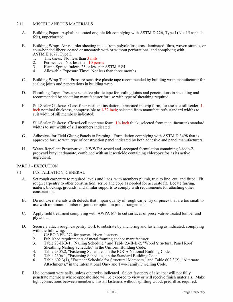
06100-6 Rough Carpentry
2.11 MISCELLANEOUS MATERIALS
A. Building Paper: Asphalt-saturated organic felt complying with ASTM D 226, Type I (No. 15 asphalt felt), unperforated.
B. Building Wrap: Air-retarder sheeting made from polyolefins; cross-laminated films, woven strands, or spun-bonded fibers; coated or uncoated; with or without perforations; and complying with ASTM E 1677, Type I.1. Thickness: Not less than 3 mils 2. Permeance: Not less than 10 perms 3. Flame-Spread Index: 25 or less per ASTM E 84.4. Allowable Exposure Time: Not less than three months.
C. Building Wrap Tape: Pressure-sensitive plastic tape recommended by building wrap manufacturer for sealing joints and penetrations in building wrap.
D. Sheathing Tape: Pressure-sensitive plastic tape for sealing joints and penetrations in sheathing and recommended by sheathing manufacturer for use with type of sheathing required.
E. Sill-Sealer Gaskets: Glass-fiber-resilient insulation, fabricated in strip form, for use as a sill sealer; 1-inch nominal thickness, compressible to 1/32 inch; selected from manufacturer's standard widths to suit width of sill members indicated.
F. Sill-Sealer Gaskets: Closed-cell neoprene foam, 1/4 inch thick, selected from manufacturer's standard widths to suit width of sill members indicated.
G. Adhesives for Field Gluing Panels to Framing: Formulation complying with ASTM D 3498 that is approved for use with type of construction panel indicated by both adhesive and panel manufacturers.
H. Water-Repellent Preservative: NWWDA-tested and -accepted formulation containing 3-iodo-2-propynyl butyl carbamate, combined with an insecticide containing chloropyrifos as its active ingredient.
PART 3 - EXECUTION
3.1 INSTALLATION, GENERAL
A. Set rough carpentry to required levels and lines, with members plumb, true to line, cut, and fitted. Fit rough carpentry to other construction; scribe and cope as needed for accurate fit. Locate furring, nailers, blocking, grounds, and similar supports to comply with requirements for attaching other construction.
B. Do not use materials with defects that impair quality of rough carpentry or pieces that are too small to use with minimum number of joints or optimum joint arrangement.
C. Apply field treatment complying with AWPA M4 to cut surfaces of preservative-treated lumber and plywood.
D. Securely attach rough carpentry work to substrate by anchoring and fastening as indicated, complying with the following:1. CABO NER-272 for power-driven fasteners.2. Published requirements of metal framing anchor manufacturer.3. Table 23-II-B-1, "Nailing Schedule," and Table 23-II-B-2, "Wood Structural Panel Roof
Sheathing Nailing Schedule," in the Uniform Building Code.4. Table 2305.2, "Fastening Schedule," in the BOCA National Building Code. 5. Table 2306.1, "Fastening Schedule," in the Standard Building Code.6. Table 602.3(1), "Fastener Schedule for Structural Members," and Table 602.3(2), "Alternate
Attachments," in the International One- and Two-Family Dwelling Code.
E. Use common wire nails, unless otherwise indicated. Select fasteners of size that will not fully penetrate members where opposite side will be exposed to view or will receive finish materials. Make tight connections between members. Install fasteners without splitting wood; predrill as required.
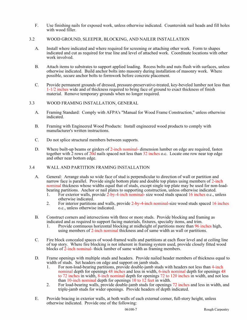
06100-7 Rough Carpentry
F. Use finishing nails for exposed work, unless otherwise indicated. Countersink nail heads and fill holes with wood filler.
3.2 WOOD GROUND, SLEEPER, BLOCKING, AND NAILER INSTALLATION
A. Install where indicated and where required for screening or attaching other work. Form to shapes indicated and cut as required for true line and level of attached work. Coordinate locations with other work involved.
B. Attach items to substrates to support applied loading. Recess bolts and nuts flush with surfaces, unless otherwise indicated. Build anchor bolts into masonry during installation of masonry work. Where possible, secure anchor bolts to formwork before concrete placement.
C. Provide permanent grounds of dressed, pressure-preservative-treated, key-beveled lumber not less than 1-1/2 inches wide and of thickness required to bring face of ground to exact thickness of finish material. Remove temporary grounds when no longer required.
3.3 WOOD FRAMING INSTALLATION, GENERAL
A. Framing Standard: Comply with AFPA's "Manual for Wood Frame Construction," unless otherwise indicated.
B. Framing with Engineered Wood Products: Install engineered wood products to comply with manufacturer's written instructions.
C. Do not splice structural members between supports.
D. Where built-up beams or girders of 2-inch nominal- dimension lumber on edge are required, fasten together with 2 rows of 20d nails spaced not less than 32 inches o.c. Locate one row near top edge and other near bottom edge.
3.4 WALL AND PARTITION FRAMING INSTALLATION
A. General: Arrange studs so wide face of stud is perpendicular to direction of wall or partition and narrow face is parallel. Provide single bottom plate and double top plates using members of 2-inch nominal thickness whose widths equal that of studs, except single top plate may be used for non-load-bearing partitions. Anchor or nail plates to supporting construction, unless otherwise indicated.1. For exterior walls, provide 2-by-4-inch nominal- size wood studs spaced 16 inches o.c., unless
otherwise indicated.2. For interior partitions and walls, provide 2-by-4-inch nominal-size wood studs spaced 16 inches
o.c., unless otherwise indicated.
B. Construct corners and intersections with three or more studs. Provide blocking and framing as indicated and as required to support facing materials, fixtures, specialty items, and trim.1. Provide continuous horizontal blocking at midheight of partitions more than 96 inches high,
using members of 2-inch nominal thickness and of same width as wall or partitions.
C. Fire block concealed spaces of wood-framed walls and partitions at each floor level and at ceiling line of top story. Where fire blocking is not inherent in framing system used, provide closely fitted wood blocks of 2-inch nominal- thick lumber of same width as framing members.
D. Frame openings with multiple studs and headers. Provide nailed header members of thickness equal to width of studs. Set headers on edge and support on jamb studs.1. For non-load-bearing partitions, provide double-jamb studs with headers not less than 4-inch
nominal depth for openings 48 inches and less in width, 6-inch nominal depth for openings 48 to 72 inches in width, 8-inch nominal depth for openings 72 to 120 inches in width, and not less than 10-inch nominal depth for openings 10 to 12 feet in width.
2. For load-bearing walls, provide double-jamb studs for openings 72 inches and less in width, and triple-jamb studs for wider openings. Provide headers of depth indicated.
E. Provide bracing in exterior walls, at both walls of each external corner, full-story height, unless otherwise indicated. Provide one of the following:
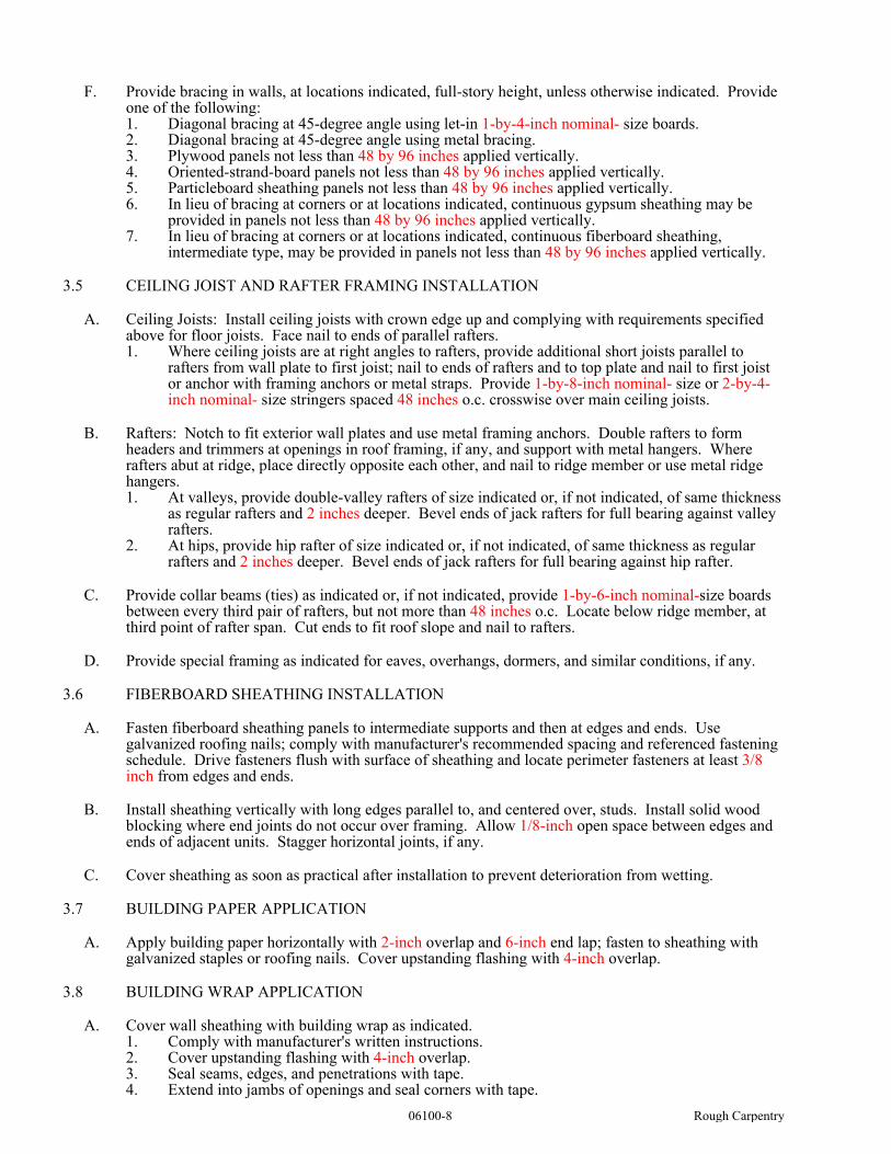
06100-8 Rough Carpentry
F. Provide bracing in walls, at locations indicated, full-story height, unless otherwise indicated. Provide one of the following:1. Diagonal bracing at 45-degree angle using let-in 1-by-4-inch nominal- size boards. 2. Diagonal bracing at 45-degree angle using metal bracing.3. Plywood panels not less than 48 by 96 inches applied vertically.4. Oriented-strand-board panels not less than 48 by 96 inches applied vertically.5. Particleboard sheathing panels not less than 48 by 96 inches applied vertically.6. In lieu of bracing at corners or at locations indicated, continuous gypsum sheathing may be
provided in panels not less than 48 by 96 inches applied vertically.7. In lieu of bracing at corners or at locations indicated, continuous fiberboard sheathing,
intermediate type, may be provided in panels not less than 48 by 96 inches applied vertically.
3.5 CEILING JOIST AND RAFTER FRAMING INSTALLATION
A. Ceiling Joists: Install ceiling joists with crown edge up and complying with requirements specified above for floor joists. Face nail to ends of parallel rafters.1. Where ceiling joists are at right angles to rafters, provide additional short joists parallel to
rafters from wall plate to first joist; nail to ends of rafters and to top plate and nail to first joist or anchor with framing anchors or metal straps. Provide 1-by-8-inch nominal- size or 2-by-4-inch nominal- size stringers spaced 48 inches o.c. crosswise over main ceiling joists.
B. Rafters: Notch to fit exterior wall plates and use metal framing anchors. Double rafters to form headers and trimmers at openings in roof framing, if any, and support with metal hangers. Where rafters abut at ridge, place directly opposite each other, and nail to ridge member or use metal ridge hangers.1. At valleys, provide double-valley rafters of size indicated or, if not indicated, of same thickness
as regular rafters and 2 inches deeper. Bevel ends of jack rafters for full bearing against valley rafters.
2. At hips, provide hip rafter of size indicated or, if not indicated, of same thickness as regular rafters and 2 inches deeper. Bevel ends of jack rafters for full bearing against hip rafter.
C. Provide collar beams (ties) as indicated or, if not indicated, provide 1-by-6-inch nominal-size boards between every third pair of rafters, but not more than 48 inches o.c. Locate below ridge member, at third point of rafter span. Cut ends to fit roof slope and nail to rafters.
D. Provide special framing as indicated for eaves, overhangs, dormers, and similar conditions, if any.
3.6 FIBERBOARD SHEATHING INSTALLATION
A. Fasten fiberboard sheathing panels to intermediate supports and then at edges and ends. Use galvanized roofing nails; comply with manufacturer's recommended spacing and referenced fastening schedule. Drive fasteners flush with surface of sheathing and locate perimeter fasteners at least 3/8 inch from edges and ends.
B. Install sheathing vertically with long edges parallel to, and centered over, studs. Install solid wood blocking where end joints do not occur over framing. Allow 1/8-inch open space between edges and ends of adjacent units. Stagger horizontal joints, if any.
C. Cover sheathing as soon as practical after installation to prevent deterioration from wetting.
3.7 BUILDING PAPER APPLICATION
A. Apply building paper horizontally with 2-inch overlap and 6-inch end lap; fasten to sheathing with galvanized staples or roofing nails. Cover upstanding flashing with 4-inch overlap.
3.8 BUILDING WRAP APPLICATION
A. Cover wall sheathing with building wrap as indicated.1. Comply with manufacturer's written instructions.2. Cover upstanding flashing with 4-inch overlap.3. Seal seams, edges, and penetrations with tape.4. Extend into jambs of openings and seal corners with tape.

06100-9 Rough Carpentry
3.9 SHEATHING TAPE APPLICATION
A. Apply sheathing tape to joints between sheathing panels and at items penetrating sheathing. Apply at upstanding flashing to overlap both flashing and sheathing.
END OF SECTION 06100

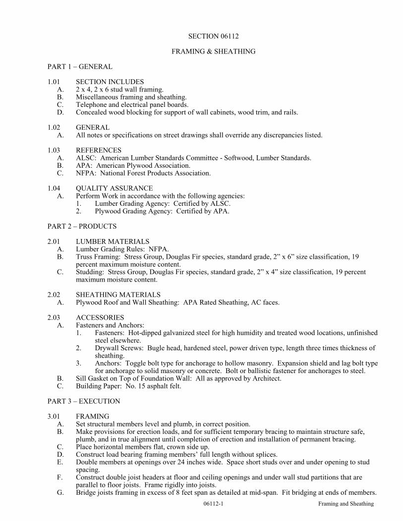
06112-1 Framing and Sheathing
SECTION 06112
FRAMING & SHEATHING
PART 1 – GENERAL
1.01 SECTION INCLUDESA. 2 x 4, 2 x 6 stud wall framing.B. Miscellaneous framing and sheathing.C. Telephone and electrical panel boards.D. Concealed wood blocking for support of wall cabinets, wood trim, and rails.
1.02 GENERALA. All notes or specifications on street drawings shall override any discrepancies listed.
1.03 REFERENCESA. ALSC: American Lumber Standards Committee - Softwood, Lumber Standards.B. APA: American Plywood Association.C. NFPA: National Forest Products Association.
1.04 QUALITY ASSURANCEA. Perform Work in accordance with the following agencies:
1. Lumber Grading Agency: Certified by ALSC.2. Plywood Grading Agency: Certified by APA.
PART 2 – PRODUCTS
2.01 LUMBER MATERIALSA. Lumber Grading Rules: NFPA.B. Truss Framing: Stress Group, Douglas Fir species, standard grade, 2” x 6” size classification, 19
percent maximum moisture content.C. Studding: Stress Group, Douglas Fir species, standard grade, 2” x 4” size classification, 19 percent
maximum moisture content.
2.02 SHEATHING MATERIALSA. Plywood Roof and Wall Sheathing: APA Rated Sheathing, AC faces.
2.03 ACCESSORIESA. Fasteners and Anchors:
1. Fasteners: Hot-dipped galvanized steel for high humidity and treated wood locations, unfinished steel elsewhere.
2. Drywall Screws: Bugle head, hardened steel, power driven type, length three times thickness of sheathing.
3. Anchors: Toggle bolt type for anchorage to hollow masonry. Expansion shield and lag bolt type for anchorage to solid masonry or concrete. Bolt or ballistic fastener for anchorages to steel.
B. Sill Gasket on Top of Foundation Wall: All as approved by Architect.C. Building Paper: No. 15 asphalt felt.
PART 3 – EXECUTION
3.01 FRAMING A. Set structural members level and plumb, in correct position.B. Make provisions for erection loads, and for sufficient temporary bracing to maintain structure safe,
plumb, and in true alignment until completion of erection and installation of permanent bracing.C. Place horizontal members flat, crown side up.D. Construct load bearing framing members’ full length without splices.E. Double members at openings over 24 inches wide. Space short studs over and under opening to stud
spacing.F. Construct double joist headers at floor and ceiling openings and under wall stud partitions that are
parallel to floor joists. Frame rigidly into joists.G. Bridge joists framing in excess of 8 feet span as detailed at mid-span. Fit bridging at ends of members.
06112-2 Framing and Sheathing
H. Place full width continuous sill flashings under framed walls on cementitious foundations. Lap flashing joint 4 inches.
I. Place sill gasket directly on sill flashing. Puncture gasket clean and fit tight to protruding foundation anchor bolts.
3.02 SHEATHINGA. Install telephone and electrical panel boards with plywood sheathing material where required. Over
size the panel by 12 inches on all sides.
3.03 TOLERANCESA. Framing Members: 1/4 inch from true position, maximum.
3.04 SCHEDULES A. Above Grade Truss, Rafter, and Stud Framing: S/P/F species, 19 percent maximum moisture content,
unless noted otherwise on drawings. B. Blocking: S/P/F species, pressure preservative treatment.
END OF SECTION 06112

06114-1 Wood Blocking
SECTION 06114
WOOD BLOCKING
PART 1 GENERAL
1.01 SECTION INCLUDESA. Roof curbs and cants.B. Blocking in wall and roof openings.C. Wood furring and grounds.D. Concealed wood blocking for support of toilet and bath accessories, wall cabinets, and wood trim.E. Telephone and electrical panel boards.
PART 2 PRODUCTS
2.01 MATERIALSA. Miscellaneous Blocking: Minimum stud grade.B. Plywood: APA Rated Sheathing, Grade C-D; Exposure Durability 1; sanded.
2.02 ACCESSORIESA. Fasteners and Anchors:
1. Fasteners: Hot-dipped galvanized steel for high humidity and treated wood locations, unfinished steel elsewhere.
2. Anchors: Toggle bolt type for anchorage to hollow masonry. Expansion shield and lag bolt type for anchorage to solid masonry or concrete. Bolt or ballistic fastener for anchorages to steel.
PART 3 EXECUTION
3.01 FRAMINGA. Set members level and plumb, in correct position.B. Place horizontal members flat, crown side up. C. Space framing and furring 16 inches o.c.
3.02 SHEATHING A. Secure sheathing to framing members with ends over firm bearing and staggered.B. Install telephone and electrical panel boards with plywood sheathing material where required. Over
size the panel by 12 inches on all sides.
END OF SECTION 06114


06200-1 Finish Carpentry
SECTION 06200
FINISH CARPENTRY
PART 1 GENERAL
1.01 SECTION INCLUDESA. Finish carpentry items, other than shop prefabricated casework.B. Hardware and attachment accessories.
1.02 QUALITY ASSURANCEA. Perform work in accordance with AWI Custom.
1.03 DELIVERY, STORAGE, AND HANDLINGA. Deliver, store, protect, and handle products to site under provisions of the General Requirements.B. Protect work from moisture damage.
1.04 FIELD MEASUREMENTS A. Verify that field measurements are as indicated on shop drawings and as instructed by the
manufacturer.
1.05 COORDINATIONA. Coordinate the work with plumbing and electrical rough-in, and installation of associated and adjacent
components.
PART 2 PRODUCTS
2.01 LUMBER MATERIALSA. Softwood Lumber: PS 20; Graded in accordance with AWI Custom; maximum moisture content of 6
percent; suitable for prime and paint.B. Hardwood Lumber: Graded in accordance with AWI prime and paint.
2.02 SHEET MATERIALSA. Exterior Plywood: Exposed to weather shall be group 1, Exterior type, Grade A-B or A-C as required
for exposure.B. Interior Plywood: Interior or Exterior type, Group 1 or 2, Grade B-D where concealed, Grade A-C one
side exposed and Grade A-A two sides exposed.C. Wood Particleboard: ANSI A208.1 Type 1; AWI standard, composed of wood chips, medium density,
made with high waterproof resin binders; of grade to suit application; sanded faces.
2.03 FASTENERS A. Fasteners: Of size and type to suit application; galvanized finish in concealed locations and brass or
chrome finish in exposed locations.
2.04 FABRICATION A. Fabricate to AWI Custom standards.B. Shop assemble work for delivery to site, permitting passage through building openings.C. Fit exposed sheet material edges with 3/8 inch matching hardwood edging. Use one piece for full
length only.D. When necessary to cut and fit on site, provide materials with ample allowance for cutting. Provide trim
for scribing and site cutting.
2.05 SHOP FINISHINGA. Sand work smooth and set exposed nails and screws.B. Apply wood filler in exposed nail and screw indentations.C. On items to receive transparent finishes, use wood filler which matches surrounding surfaces and of
types recommended for applied finishes.D. Seal, stain, and varnish exposed to view surfaces. Brush apply only.E. Prime paint. Seal surfaces in contact with cementitious materials.
06200-2 Finish Carpentry
PART 3 EXECUTION
3.01 EXAMINATIONA. Verify adequacy of backing and support framing.B. Verify mechanical, electrical, and building items affecting work of this section are placed and ready to
receive this work.
3.02 INSTALLATIONA. Install work in accordance with AWI Custom Quality Standard.B. Set and secure materials and components in place, plumb, and level.C. Carefully scribe work abutting other components, with maximum gaps of 1/32 inch. Do not use
additional overlay trim to conceal larger gaps.D. Install components trim with nails, screws, bolts with blind fasteners or wall adhesive by gun
application.E. Install hardware in accordance with manufacturer’s instructions.
3.03 SITE APPLIED WOOD TREATMENTA. Apply preservative treatment in accordance with manufacturer’s instructions.B. Brush apply two coats of preservative treatment on wood in contact with cementitious materials,
roofing and related metal flashings. Treat site-sawn cuts.C. Allow preservative to dry prior to erecting members.
3.04 PREPARATION FOR SITE FINISHINGA. Site Finishing: Refer to Section 09900.B. Before installation, prime paint surfaces of items or assemblies to be in contact with cementitious
materials.
3.05 SCHEDULE A. Interior:
1. Trim: Primed and painted.2. Loose Shelving: Melamine finished, color to be selected.3. Window Sills: Primed and painted.4. Wood Base: Primed and painted.5. Wood Light Valance, primed and painted.
END OF SECTION 06200

07213-1 Batt Insulation
SECTION 07213
BATT INSULATION
PART 1 GENERAL
1.01 SECTION INCLUDESA. Batt insulation at exterior stud walls.B. Batt insulation at attic space.C. Batt insulation for filling perimeter window and door shim spaces, crevices in exterior wall and roof.D. Sound batt insulation.E. Vapor retarder.
1.02 REFERENCES A. ASTM C665 - Mineral Fiber Blanket Thermal Insulation for Light Frame Construction and
Manufactured Housing.B. ASTM E84 - Test Method for Surface Burning Characteristics of Building Materials.
1.03 SYSTEM DESCRIPTIONA. Materials of This Section: Provide continuity of thermal barrier at building enclosure with thermal
insulating materials in attic and walls.. Overlap insulations to ensure complete thermal envelope at all exterior surfaces.
1.04 COORDINATIONA. Coordinate the work with all related Sections for installation of vapor retarder and other forms of
insulation.
PART 2 PRODUCTS
2.01 MANUFACTURERS - INSULATION MATERIALSA. OWENS-CORNING FIBERGLASS Product - thermal batt insulation.B. Substitutions: Under provisions of the General Requirements.
2.02 MATERIALSA. Batt Insulation, Walls: ASTM C665; preformed glass fiber batts; loose laid and taped, conforming to
the following:1. Thermal Resistance: Exterior Walls R-13, with added board insulation, reference drawings.2. Other areas as indicated in the drawings - R-19, & R-11.3. Batt Size: 5-1/2” & 3-1/2”.4. Facing: Kraft or Foil as required to meet R values and code requirements.
B. Blown Insulation, Attic: ASTM C739; Cellulose Fiber or Fiberglass type. 1. Therm. Res. R-382. Bulk for pneumatic placement
C. Sound Batt Insulation: 1. Batt size: 5-1/2” & 3-1/2”.2. Facing: Unfaced.
D. Tape: Self-adhering type as recommended by the manufacturer, mesh reinforced, 2 inches wide.
PART 3 EXECUTION
3.01 EXAMINATIONA. Verify site conditions.B. Verify that substrate, adjacent materials, and insulation are dry and ready to be installed.

07213-2 Batt Insulation
3.02 INSTALLATIONA. Install insulation and vapor retarder in accordance with manufacturer’s instructions.B. Trim insulation neatly to fit spaces. Insulate miscellaneous gaps and voids.C. Fit insulation tight in spaces and tight to exterior side of mechanical and electrical services within the
plane of insulation.D. Install with applied vapor retarder membrane facing warm side of building spaces. Lap ends and side
flanges of membrane, caulk, or tape.E. Tape seal butt ends, lapped flanges, and tears or cuts in membrane.F. Place loose-fill insulation into spaces and onto surfaces as shown, either by pouring or by machine
blowing to comply with ASTM C 1015. Level horizontal applications to uniform thickness as indicated, lightly settle to uniform density, but do not compact excessively.
1. For cellulosic loose-fill insulation, comply with the Cellulose Insulation Manufacturers
Association's Special Report #3, "Standard Practice for Installing Cellulose Insulation."
END OF SECTION 07213

07311-1 Asphalt Shingles
SECTION 07311
ASPHALT SHINGLES PART 1 - GENERAL
1.1 RELATED DOCUMENTSA. Drawings and general provisions of the Contract, including General and Supplementary Conditions
and Division 1 Specification Sections, apply to this Section.
1.2 SUMMARY
A. This Section includes the following:
1. Asphalt shingles.2. Felt underlayment.3. Self-adhering sheet underlayment. 4. Ridge vents.
1.3 DEFINITIONSA. Roofing Terminology: Refer to ASTM D 1079 and glossary of NRCA's "The NRCA Roofing and
Waterproofing Manual" for definitions of terms related to roofing work in this Section.
1.4 SUBMITTALSA. Product Data: For each type of product indicated.
B. Samples for Initial Selection: For each type of asphalt shingle, ridge and hip cap shingles, ridge vent and exposed valley lining indicated.
1. Include similar Samples of trim and accessories involving color selection.
C. Samples for Verification: For the following products, of sizes indicated, to verify color selected.1. Asphalt Shingle: Full-size asphalt shingle strip.2. Ridge and Hip Cap Shingles: Full-size ridge and hip cap asphalt shingle.3. Ridge Vent: 12-inch- (300-mm-) long Sample.4. Exposed Valley Lining: 12 inches (300 mm) square.5. Self-Adhering Underlayment: 12 inches (300 mm) square.
D. Qualification Data: For Installer, including certificate signed by asphalt shingle manufacturer stating that Installer is approved, authorized, or licensed to install roofing system indicated.
E. Product Test Reports: Based on evaluation of comprehensive tests performed by a qualified testing agency or by manufacturer and witnessed by a qualified testing agency, for asphalt shingles.
F. Research/Evaluation Reports: For asphalt shingles.
G. Maintenance Data: For asphalt shingles to include in maintenance manuals.
H. Warranties: Special warranties specified in this Section.
1.5 QUALITY ASSURANCEA. Installer Qualifications: A firm or individual that is approved, authorized, or licensed by asphalt
shingle roofing system manufacturer to install roofing system indicated.
B. Source Limitations: Obtain ridge and hip cap shingles ridge vents, felt underlayment, and self-adhering sheet underlayment through one source from a single asphalt shingle manufacturer.
C. Fire-Test-Response Characteristics: Provide asphalt shingle and related roofing materials with the fire-test-response characteristics indicated, as determined by testing identical products per test method below by UL or another testing and inspecting agency acceptable to authorities having jurisdiction. Identify materials with appropriate markings of applicable testing and inspecting agency.

07311-2 Asphalt Shingles
1. Exterior Fire-Test Exposure: Class C; ASTM E 108 or UL 790, for application and roof slopes indicated.
1.6 DELIVERY, STORAGE, AND HANDLINGA. Store roofing materials in a dry, well-ventilated, weathertight location according to asphalt shingle
manufacturer's written instructions. Store underlayment rolls on end on pallets or other raised surfaces. Do not double-stack rolls.1. Handle, store, and place roofing materials in a manner to avoid significant or permanent damage
to roof deck or structural supporting members.
B. Protect unused underlayment from weather, sunlight, and moisture when left overnight or when roofing work is not in progress.
1.7 PROJECT CONDITIONSA. Weather Limitations: Proceed with installation only when existing and forecasted weather conditions
permit asphalt shingle roofing to be performed according to manufacturer's written instructions and warranty requirements.
1. Install self-adhering sheet underlayment within the range of ambient and substrate temperatures recommended by manufacturer.
1.8 WARRANTYA. Special Project Warranty: Roofing Installer's warranty, on warranty form at end of this Section,
signed by roofing Installer, covering Work of this Section, in which roofing Installer agrees to repair or replace components of asphalt shingle roofing that fail in materials or workmanship within the following warranty period:1. Installation Warranty Period: Two years from date of Substantial Completion.2. Product Warranty Period: Forty-year product warranty.
1.9 EXTRA MATERIALSA. Furnish extra materials described below that match products installed and that are packaged with
protective covering for storage and identified with labels describing contents.
1. Asphalt Shingles: 100 sq. ft (9.3 sq. m) of each type, in unbroken bundles.
PART 2 - PRODUCTS
2.1 MANUFACTURERSA. In other Part 2 articles where titles below introduce lists, the following requirements apply to product
selection:1. Available Products: Subject to compliance with requirements, products that may be
incorporated into the Work include, but are not limited to, products specified.2. Products: Subject to compliance with requirements, provide one of the products specified.
2.2 GLASS-FIBER-REINFORCED ASPHALT SHINGLESA. Laminated-Strip Asphalt Shingles: Class A, ASTM D 3462, laminated, multi-ply overlay
construction, glass-fiber reinforced, mineral-granule surfaced, and self-sealing. GAF – Timberline 40 or approved equal, minimum 30-year Material Warranty. 1. Butt Edge: Straight or Notched cut.2. Strip Size: Manufacturer's standard.3. Algae Resistance: Granules treated to resist algae discoloration.4. Color and Blends As selected by Architect from manufacturer's full range.
B. Hip and Ridge Shingles: Manufacturer's standard units to match asphalt shingles.
2.3 UNDERLAYMENT MATERIALSA. Felts: ASTM D 4869, Type I, asphalt-saturated organic felts, nonperforated.
B. Self-Adhering Sheet Underlayment, Granular Surfaced: ASTM D 1970, minimum of 55-mil- thick sheet; glass-fiber-mat-reinforced, SBS-modified asphalt; mineral-granule surfaced; with release paper backing; cold applied

07311-3 Asphalt Shingles
2.4 RIDGE VENTSA. Rigid Ridge Vent: Manufacturer's standard rigid section high-density polypropylene or other UV-
stabilized plastic ridge vent with nonwoven geotextile filter strips and with external deflector baffles; for use under ridge shingles.
2.5 ACCESSORIESA. Asphalt Roofing Cement: ASTM D 4586, Type II, asbestos free.
B. Roofing Nails: ASTM F 1667; aluminum, stainless-steel, copper, or hot-dip galvanized steel wire shingle nails, minimum 0.120-inch- (3-mm-) diameter, barbed shank, sharp-pointed, with a minimum 3/8-inch- (9.5-mm-) diameter flat head and of sufficient length to penetrate 3/4 inch (19 mm) into solid wood decking or extend at least 1/8 inch (3 mm) through OSB or plywood sheathing.1. Where nails are in contact with metal flashing, use nails made from same metal as flashing.
C. Felt Underlayment Nails: Aluminum, stainless-steel, or hot-dip galvanized steel wire with low profile capped heads or disc caps, 1-inch (25-mm) minimum diameter.
2.6 METAL FLASHING AND TRIMA. Sheet Metal Flashing and Trim: Comply with requirements in Division 7 Section "Sheet Metal
Flashing and Trim."1. Sheet Metal: Zinc-coated (galvanized) steel or Prepainted, metallic-coated steel.
B. Fabricate sheet metal flashing and trim to comply with recommendations in SMACNA's "Architectural Sheet Metal Manual" that apply to design, dimensions, metal, and other characteristics of item.1. Apron Flashings: Fabricate with lower flange a minimum of 4 inches (100 mm) over and 4
inches (100 mm) beyond each side of down slope asphalt shingles and 6 inches (150 mm)] up the vertical surface.
2. Step Flashings: Fabricate with a headlap of 2 inches (50 mm) and a minimum extension of 4 inches (100 mm) over the underlying asphalt shingle and up the vertical surface.
3. Cricket Flashings: Fabricate with concealed flange extending a minimum of 18 inches (450 mm) beneath upslope asphalt shingles and 6 inches (150 mm) beyond each side of chimney, skylight, and 6 inches (150 mm) above the roof plane.
4. Open Valley Flashings: Fabricate in lengths not exceeding 10 feet (3 m) with 1-inch- (25-mm-) high inverted-V profile at center of valley and equal flange widths of 12 inches (300 mm).
5. Drip Edges: Fabricate in lengths not exceeding 10 feet (3 m) with 2-inch (50-mm) roof deck flange and 1-1/2-inch (38-mm) fascia flange with 3/8-inch (9.6-mm) drip at lower edge.
C. Vent Pipe Flashings: ASTM B 749, Type L51121, at least 1/16 inch (1.6 mm) thick. Provide lead sleeve sized to slip over and turn down into pipe, soldered to skirt at slope of roof and extending at least 4 inches (100 mm) from pipe onto roof.
PART 3 - EXECUTION
3.1 EXAMINATIONA. Examine substrates, areas, and conditions, with Installer present, for compliance with requirements for
installation tolerances and other conditions affecting performance of work.1. Examine roof sheathing to verify that sheathing joints are supported by framing and blocking or
metal clips and that installation is within flatness tolerances.2. Verify that substrate is sound, dry, smooth, clean, sloped for drainage, and completely
anchored; and that provision has been made for flashings and penetrations through asphalt shingles.
3. For the record, prepare written report, endorsed by Installer, listing conditions detrimental to performance of work.
B. Proceed with installation only after unsatisfactory conditions have been corrected.
07311-4 Asphalt Shingles
3.2 UNDERLAYMENT INSTALLATIONA. Double-Layer Felt Underlayment: Install double layers of felt underlayment on roof deck
perpendicular to roof slope in parallel courses. Install a 19-inch- (485-mm-) wide starter course at eaves and completely cover with full-width second course. Install succeeding courses lapping previous courses 19 inches (485 mm) in shingle fashion. Lap ends a minimum of 6 inches (150 mm). Stagger end laps between succeeding courses at least 72 inches (1830 mm). Fasten with felt underlayment roofing nails.
1. Apply a continuous layer of asphalt roofing cement over starter course and on felt underlayment surface to be concealed by succeeding courses as each felt course is installed.
2. Install felt underlayment on roof sheathing not covered by self-adhering sheet underlayment. Lap edges over self-adhering sheet underlayment not less than 3 inches (75 mm) in direction to shed water.
3. Terminate felt underlayment extended up not less than 4 inches (100 mm)] against sidewalls, curbs, chimneys and other roof projections.
B. Self-Adhering Sheet Underlayment: Install self-adhering sheet underlayment, wrinkle free, on roof deck. Comply with low-temperature installation restrictions of underlayment manufacturer if applicable. Install at locations indicated below, lapped in direction to shed water. Lap sides not less than 3-1/2 inches (89 mm). Lap ends not less than 6 inches (150 mm) staggered 24 inches (600 mm) between courses. Roll laps with roller. Cover underlayment within seven days.
1. Prime concrete and masonry surfaces to receive self-adhering sheet underlayment.2. Eaves: Extend from edges of eaves 24 inches (600 mm) beyond interior face of exterior wall.
Rakes: Extend from edges of rake 24 inches (600 mm) beyond interior face of exterior wall. Valleys: Extend from lowest to highest point 18 inches (450 mm) on each side. Hips: Extend 18 inches (450 mm on each side. Ridges: Extend 36 inches (914 mm) on each side without obstructing continuous ridge vent slot.
3. Sidewalls: Extend beyond sidewall 18 inches (450 mm) and return vertically against sidewall not less than 4 inches (100 mm).
4. Dormers, Chimneys, Skylights, and other Roof-Penetrating Elements: Extend beyond penetrating element 18 inches (450 mm) and return vertically against penetrating element not less than 4 inches (100 mm).
5. Roof Slope Transitions: Extend 18 inches (450 mm) on each roof slope.
C. Metal-Flashed Open Valley Underlayment: Install two layers of 36-inch- (914-mm-) wide felt underlayment centered in valley. Stagger end laps between layers at least 72 inches (1830 mm). Lap ends of each layer at least 12 inches (300 mm) in direction to shed water, and seal with asphalt roofing cement. Fasten each layer to roof deck with felt underlayment roofing nails.
1. Lap roof deck felt underlayment over first layer of valley felt underlayment at least 6 inches (150 mm).
3.3 METAL FLASHING INSTALLATIONA. General: Install metal flashings and other sheet metal to comply with requirements in Division 7
Section "Sheet Metal Flashing and Trim."
1. Install metal flashings according to recommendations in ARMA's "Residential Asphalt Roofing Manual" and asphalt shingle recommendations in NRCA's "The NRCA Roofing and Waterproofing Manual."
B. Apron Flashings: Extend lower flange over and beyond each side of downslope asphalt shingles and up the vertical surface.
C. Step Flashings: Install with a head lap of 2 inches (50 mm) and extend over the underlying asphalt shingle and up the vertical surface. Fasten to roof deck only.
D. Cricket or Backer Flashings: Install against the roof-penetrating element extending concealed flange beneath upslope asphalt shingles and beyond each side.
E. Open Valley Flashings: Install centrally in valleys, lapping ends at least 8 inches (200 mm) in direction to shed water. Fasten upper end of each length to roof deck beneath overlap.

07311-5 Asphalt Shingles
1. Secure hemmed flange edges into metal cleats spaced 12 inches apart and fastened to roof deck.2. Adhere 9-inch- (225-mm-) wide strip of self-adhering sheet to metal flanges and to self-
adhering sheet underlayment.
F. Rake Drip Edges: Install rake drip edge flashings over underlayment and fasten to roof deck.
G. Eave Drip Edges: Install eave drip edge flashings below underlayment and fasten to roof sheathing.
H. Pipe Flashings: Form flashing around pipe penetrations and asphalt shingles. Fasten and seal to asphalt shingles as recommended by manufacturer.
3.4 ASPHALT SHINGLE INSTALLATIONA. Install asphalt shingles according to manufacturer's written instructions, recommendations in ARMA's
"Residential Asphalt Roofing Manual," and asphalt shingle recommendations in NRCA's "The NRCA Roofing and Waterproofing Manual."
B. Install starter strip along lowest roof edge, consisting of an asphalt shingle strip with tabs removed with self-sealing strip face up at roof edge.
1. Extend asphalt shingles 1/2 inch (13 mm) over fascia at eaves and rakes.2. Install starter strip along rake edge.
C. Install first and remaining courses of asphalt shingles stair-stepping diagonally across roof deck with manufacturer's recommended offset pattern at succeeding courses, maintaining uniform exposure.
D. Install first and remaining courses of asphalt shingles stair-stepping diagonally across roof deck with manufacturer's recommended offset pattern at succeeding courses, maintaining uniform exposure.
E. Install asphalt shingles by single-strip column or racking method, maintaining uniform exposure. Install full length first course followed by cut second course, repeating alternating pattern in succeeding courses.
F. Fasten asphalt shingle strips with a minimum of six roofing nails located according to manufacturer's written instructions.
1. Where roof slope exceeds 20:12, seal asphalt shingles with asphalt roofing cement spots.2. Where roof slope is less than 4:12, seal asphalt shingles with asphalt roofing cement spots.3. When ambient temperature during installation is below 50 deg F (10 deg C), seal asphalt
shingles with asphalt roofing cement spots.
G. Open Valleys: Cut and fit asphalt shingles at open valleys, trimming upper concealed corners of shingle strips. Maintain uniform width of exposed open valley from highest to lowest point.
1. Set valley edge of asphalt shingles in a 3-inch- (75-mm-) wide bed of asphalt roofing cement.2. Do not nail asphalt shingles to metal open valley flashings.
H. Ridge Vents: Install continuous ridge vents over asphalt shingles according to manufacturer's written instructions. Fasten with roofing nails of sufficient length to penetrate sheathing.
I. Ridge and Hip Cap Shingles: Maintain same exposure of cap shingles as roofing shingle exposure. Lap cap shingles at ridges to shed water away from direction of prevailing winds. Fasten with roofing nails of sufficient length to penetrate sheathing.
END OF SECTION 07311


07620-1 Sheet Metal Flashing and Trim
SECTION 07620
SHEET METAL FLASHING AND TRIM
PART 1 GENERAL
1.01 SECTION INCLUDESA. Cap and sill flashings.B. Gutters and down spouts.C. Counterflashings at roof mounted equipment and vent stacks.D. Fascias.E. Miscellaneous flashings and closure pieces.
1.02 SUBMITTALSA. Shop Drawings: Indicate material profile, jointing pattern, jointing details, fastening methods,
flashings, terminations, and installation details.
1.03 QUALITY ASSURANCE A. Perform work in accordance with SMACNA standard details and requirements.
1.04 QUALIFICATIONSA. Fabricator and Installer: Company specializing in sheet metal flashing work with three years
documented experience.
1.05 DELIVERY, STORAGE, AND HANDLING A. Deliver, store, protect, and handle products to site under provisions of the General Requirements.B. Stack preformed and prefinished material to prevent twisting, bending, or abrasion, and to provide
ventilation. Slope metal sheets to ensure drainage.C. Prevent contact with materials which may cause discoloration or staining.
PART 2 PRODUCTS
2.01 SHEET MATERIALS A. Pre-Coated Galvanized Steel: ASTM A446, Grade A, G90 zinc coating; 24 gage core steel, exposed
flashings shall be shop prefinished with KYNAR coating of color as selected.
2.02 ACCESSORIESA. Fasteners: Galvanized steel with soft neoprene washers.B. Underlayment: ASTM D2178, No. 30 asphalt saturated roofing felt.C. Slip Sheet: Rosin sized building paper.D. Primer: Zinc chromate type.E. Sealant: Polyurethane type, specified in Section 07900. F. Bedding Compound: Rubber-asphalt type.G. Plastic Cement: ASTM D4586, Type II.H. Reglets: Recessed type, galvanized steel; face and ends covered with plastic tape.I. Gutter and Downspout Anchorage Devices: SMACNA requirements. Type recommended by
fabricator.
2.03 COMPONENTSA. Gutters: Size and shape per drawings.B. Downspouts: Rectangular profile.C. Accessories: Profiled to suit gutters and downspouts.D. Downspout Boots: Flexible plastic or metal.
2.04 FABRICATIONA. Form sections true to shape, accurate in size, square, and free from distortion or defects.B. Fabricate cleats of metal, same material as sheet, interlockable with sheet.C. Form pieces in longest possible lengths. Hem exposed edges on underside 1/2 inch; miter and seam
corners.

07620-2 Sheet Metal Flashing and Trim
D. Form material with flat lock seams.E. Fabricate corners from one piece with minimum 18 inch long legs; seam and/or solder for rigidity, seal
with sealant.F. Fabricate vertical faces with bottom edge formed outward 1/4 inch and hemmed to form drip.G. Fabricate flashings to allow toe to extend 2 inches over roofing. Return and brake edges.
2.05 FINISHA. Exposed metal shall pre-finished with Kynar finish color to be selected.
PART 3 EXECUTION
3.01 EXAMINATIONA. Verify roof openings, curbs, pipes, sleeves, ducts, or vents through roof are solidly set, reglets in place,
and nailing strips located.B. Verify roofing termination and base flashings are in place, sealed, and secure.
3.02 PREPARATIONA. Install starter and edge strips, and cleats before starting installation.B. Install surface mounted reglets true to lines and levels. Seal top of reglets with sealant.
3.03 INSTALLATIONA. Conform to drawing details included in the SMACNA manual unless otherwise indicated on the
drawings.B. Insert flashings into reglets to form tight fit. Secure in place with lead wedges. Pack remaining spaces
with lead wool. Seal flashings into reglets with sealant.C. Apply plastic cement compound between metal flashings and felt flashings.D. Fit flashings tight in place. Make corners square, surfaces true and straight in planes, and lines accurate
to profiles.E. Seal metal joints watertight. Secure gutters and downspouts in place using fasteners. Set splash pans
under downspouts. Seal metal joints watertight.
END OF SECTION 07620

07900-1 Joint Sealers
SECTION 07900
JOINT SEALERS
PART 1 GENERAL
1.01 SECTION INCLUDES A. Preparing substrate surfaces. B. Sealant and joint backing.
1.02 QUALITY ASSURANCEA. Perform work in accordance with sealant manufacturer’s requirements for preparation of surfaces and
material installation instructions.B. Perform acoustical sealant application work in accordance with ASTM C919.
1.03 QUALIFICATIONSA. Manufacturer: Company specializing in manufacturing the Products specified in this section with
minimum three years documented experience.B. Applicator: Company specializing in performing the work of this section with minimum years
documented experience.
1.04 WARRANTYA. Provide five year warranty.B. Warranty: Include coverage for installed sealants and accessories which fail to achieve air tight seal,
water tight seal, and exhibit loss of adhesion or cohesion, or do not cure.
PART 2 PRODUCTS
2.01 SEALANTSA. Acrylic Latex (Interior Minor Movement): ASTM C920, Single component, non-staining,
non-bleeding, non-sagging; white color paintable; manufactured by Pecora AC 20 + silicone.B. Butyl Sealant (Interior Minor Movement): ASTM C920 single component, solvent release, non-
skinning, non-sagging, white, paintable, and manufactured by Pecora BC 158.C. Silicone Sealant (Exterior, Interior Major Movement, and Water Resistant Areas): Single component,
solvent curing, non-sagging, non-staining, fungus resistant, non-bleeding; color as selected or to match adjacent materials; manufactured by Pecora 895 silicone.
D. Bituminous Based (Paving): Single component, asphalt compound, elongation capability of 0 to 2 percent of joint width.
2.02 ACCESSORIESA. Primer: Non-staining type, recommended by sealant manufacturer to suit application.B. Joint Cleaner: Non-corrosive and non-staining type, recommended by sealant manufacturer;
compatible with joint forming materials.C. Joint Backing: ASTM D1056; round, closed or open cell polyethylene foam rod; oversized 30 to 50
percent larger than joint width.D. Bond Breaker: Pressure sensitive tape recommended by sealant manufacturer to suit application.
PART 3 EXECUTION
3.01 EXAMINATION A. Verify that substrate surfaces and joint openings are ready to receive work.B. Verify that joint backing and release tapes are compatible with sealant.
3.02 PREPARATIONA. Remove loose materials and foreign matter which might impair adhesion of sealant.B. Clean and prime joints in accordance with manufacturer’s instructions.C. Perform preparation in accordance with manufacturer’s instructions.D. Protect elements surrounding the work of this section from damage or disfiguration.

07900-2 Joint Sealers
3.03 INSTALLATIONA. Install sealant in accordance with manufacturer’s instructions.B. Measure joint dimensions and size materials to achieve required 2:1 width/depth ratios.C. Install joint backing to achieve a neck dimension no greater than 1/3 of the joint width.D. Install bond breaker where joint backing is not used.E. Install sealant free of air pockets, foreign embedded matter, ridges, and sags.F. Apply sealant within recommended application temperature ranges. Consult manufacturer when
sealant cannot be applied within these temperature ranges.
3.04 SCHEDULEA. Interior: Caulk around all frames, windows, doors, openings, trim, etc., as required to seal or fill gaps,
cracks, to make material transitions watertight and/or visually tight and finished.B. Exterior: Caulk around all frames, windows, doors, openings, trim, material transitions etc., as required
to seal or fill gaps, cracks, to make material transitions watertight and/or visually tight finished.C. Paving: Caulk as required to seal or fill gaps, expansion joints, and cracks to make transitions
watertight and/or visually tight.
END OF SECTION 07900

08111-1 Standard Steel Doors and Frames
SECTION 08111
STANDARD STEEL DOORS AND FRAMES
PART 1 GENERAL
1.01 SECTION INCLUDESA. Exterior Doors, Non-rated, and thermally insulated Masonite HD Wood Edge panel doors with steel facing
and metal frames.
1.02 REFERENCESA. ANSI A117.1 - Specifications for Making Buildings and Facilities Accessible to and Usable by Physically
Handicapped People.B. NFPA 80 - Fire Doors and Windows.C. NFPA 252 - Fire Tests for Door Assemblies.D. UL 10B - Fire Tests of Door Assemblies.
1.03 DELIVERY, STORAGE, AND HANDLINGA. Deliver, store, protect, and handle products to site.B. Accept doors and frames on site in manufacturer’s packaging. Inspect for damage.
1.04 FIELD MEASUREMENTS A. Verify that field measurements are as indicated on shop drawings.
PART 2 PRODUCTS
2.01 DOOR MANUFACTURERSA. Masonite Int. CorpB. Substitutions: Under provisions of the General Requirements.
2.02 DOORSA. Exterior Insulated Doors Non-thermally Broken: SDI-100 Grade III. Thermo-pane insulated windows where
indicated.
2.03 DOOR CONSTRUCTIONA. Face: Galvanized Steel facing, .0215” min. with protective chemical coatings and primer. B. Core: Polyurethane or styrene foam.C. Thermal Insulated Door. Total insulation R value of 7.7, measured in accordance with ASTM C236.
2.04 FRAMESA. Exterior Frames: 16 gage thick material, base metal thickness.
2.05 ACCESSORIESA. Removable Stops: Rolled steel channel shape, mitered corners; prepared for countersink style screws.B. Primer: Zinc chromate type.C. Silencers: Resilient rubber, fitted into drilled hole.
2.06 FABRICATIONA. Fabricate doors with hardware reinforcement welded in place.B. Attach fire rated label to each door unit.C. Close top and bottom edge of exterior doors with flush end closure. Seal joints watertight.D. Configure exterior doors with special profile to receive recessed weatherstripping.F. Fabricate frames as welded unit.G. Transom Bars for Glazed Lights: Fixed type, of same profiles as jamb and head.H. Prepare frame for silencers. Provide three single silencers for single doors and mullions of double doors on
strike side. Provide two single silencers on frame head at double doors without mullions.L. Configure exterior frames with special profile to receive recessed weathersripping.M. Fabricate frames to suit masonry wall coursing with 4 or 2 inch head member.
2.07 FINISHA. Steel Sheet: Galvanized and chemically coated and primed.

08111-2 Standard Steel Doors and Frames
B. Primer: Baked.C. Coat inside of frame profile with bituminous coating to a thickness of 1/16 inch.
PART 3 EXECUTION
3.01 EXAMINATIONA. Verify that opening sizes and tolerances are acceptable.
3.02 INSTALLATIONA. Install doors and frames in accordance with ANSI/SDI-100 and DHI.B. Coordinate installation of glass and glazing.C. Install door louvers, plumb, and level.D. Coordinate installation of doors and frames with installation of frames and hardware. E. Coordinate with masonry and wallboard wall construction for anchor placement.F. Install roll-formed steel reinforcement channels between two abutting frames. Anchor to structure and floor.
3.03 ERECTION TOLERANCESA. Maximum Diagonal Distortion: 1/16 inch measured with straight edge, corner to corner.
3.04 ADJUSTINGA. Adjust door for smooth and balanced door movement.
END OF SECTION 08111
08211-1 Panel Masonite Doors
SECTION 08211
PANEL MASONITE DOORS
PART 1 GENERAL
1.01 SECTION INCLUDESA. Interior Masonite Panel doors; Panel Masonite doors as indicated on the drawings; fire rated and
non-rated as scheduled.
1.03 QUALIFICATIONSA. Manufacturer: Company specializing in manufacturing the Products specified in this section with
minimum three years documented experience.
1.04 DELIVERY, STORAGE, AND HANDLINGA. Deliver, store, protect, and handle products to siteB. Accept doors on site in manufacturer’s packaging. Inspect for damage. Do not store in damp or wet
areas; or in areas where sunlight might bleach veneer. Seal top and bottom edges if stored more than one week. Break seal on-site to permit ventilation.
1.05 FIELD MEASUREMENTS A. Verify that field measurements are as indicated on shop drawings.
1.06 COORDINATIONA. Coordinate the work with door opening construction, door frame and door hardware installation.
1.07 WARRANTYA. Provide warranty to the following term:
1. Interior Doors: 1 yearB. Include coverage for delamination of veneer, warping beyond specified installation tolerances,
defective materials, telegraphing core construction.
PART 2 PRODUCTS
2.01 MANUFACTURERSA. Masonite Int CorpB. Substitutions: Under provisions of the General Requirements.
2.02 DOOR TYPESA. Panel Interior Doors: 1-3/4 inches thick
2.03 DOOR CONSTRUCTIONA. Core (Solid, Non-Rated), as scheduled.B. Core (Solid, Fire Rated), as scheduled.
2.04 ACCESSORIESA. Glazing Stops: Masonite, of same species as door facing Masonite with metal clips for rated doors,
mitered corners; prepared for countersink style screws.
2.05 FABRICATIONA. Fabricate non-rated doors in accordance with Standard requirements.B. Fabricate fire rated doors in accordance with Standards and to UL requirements. Attach fire rating
label to door.D. Provide lock blocks at lock edge and top of door for closer hardware reinforcement.F. Fit door edge trim to edge of stiles after applying veneer facing.G. Bond edge banding to cores.H. Factory machine doors for finish hardware in accordance with hardware requirements and dimensions.
Do not machine for surface hardware. Provide solid blocking for through bolted hardware.I. Factory pre-fit doors for frame opening dimensions identified on shop drawings.J. Cut and configure exterior door edge to receive recessed weather stripping devices.
08211-2 Panel Masonite Doors
PART 3 EXECUTION
3.01 EXAMINATIONA. Verify that opening sizes and tolerances are acceptable.B. Do not install doors in frame openings that are not plumb or are out-of-tolerance for size or alignment.
3.02 INSTALLATIONA. Install fire rated and non-rated doors in accordance with Standards requirements.B. Trim non-rated door width by cutting equally on both jamb edges.C. Trim door height by cutting bottom edges to a maximum of 3/4 inch (19 mm). Trim fire door height at
bottom edge only, in accordance with fire rating requirements.D. Pilot drill screw and bolt holes. Use threaded through bolts for half surface hinges.E. Machine cut for hardware. Core for handsets and cylinders.F. Coordinate installation of glass and glazing.
3.03 INSTALLATION TOLERANCESA. Maximum Diagonal Distortion (Warp): 1/8 inch measured with straight edge or taught string, corner to
corner, over an imaginary 36 x 84 inch surface area.B. Maximum Vertical Distortion (Bow): 1/8 inch measured with straight edge or taught string, top to
bottom, over an imaginary 36 x 84 inch surface area.C. Maximum Width Distortion (Cup): 1/8 inch measured with straight edge or taught string, edge to edge,
over an imaginary 36 x 84 inch surface area.
3.04 ADJUSTINGA. Adjust door for smooth and balanced door movement.
END OF SECTION 08211
08410-1 Aluminum Entrances and Curtain Wall
SECTION 08410
ALUMINUM ENTRANCES AND CURTAIN WALL PART 1 GENERAL 1.01 SECTION INCLUDES A. Aluminum doors and frames. B. Curtain Wall frame and glass, (Assemblies over 12’-0” HGT) C. Door hardware including power operator system. D. IECC 2015 energy requirements U-Value .60 Min., SHGC .25 Min. E. Integral air and vapor barrier. F. Perimeter sealant. 1.02 SYSTEM DESCRIPTION A. Aluminum entrances, storefront system and curtain wall system includes tubular aluminum
sections with supplementary internal support framing, shop fabricated, factory prefinished, vision glass, related flashings, anchorage and attachment devices.
1.03 PERFORMANCE REQUIREMENTS A. Design and size components to withstand dead and live loads caused by positive and negative wind
pressure acting normal to plane of wall as calculated in accordance with codes. B. Limit mullion deflection to flexure limit of glass; with full recovery of glazing materials. C. System to accommodate, without damage to components or deterioration of seals, movement
within system, movement between system and peripheral construction, dynamic loading and release of loads, deflection of structural support framing.
D. Limit air leakage through assembly to 0.06 cfm/min/sq. ft. of wall area, measured at a reference differential pressure across assembly of psf as measured in accordance with AAMA 501.
E. Water Leakage: None, when measured in accordance with AAMA 501 with a test pressure difference of 2.86 lbs/sq. ft.
F. Maintain continuous air and vapor barrier throughout assembly, primarily in line with inside pane of glass and heel bead of glazing compound.
G. System to provide for expansion and contraction within system components caused by a cycling temperature range of 170 degrees F over a 12 hour period without causing detrimental affect to system components.
H. Drain water entering joints, condensation occurring in glazing channels, or migrating moisture occurring within system, to the exterior by a weep drainage network.
1.04 SUBMITTALS A. Shop Drawings: Indicate system dimensions, framed opening requirements and tolerances,
affected related Work and expansion and contraction joint location and details. 1.05 DELIVERY, STORAGE, AND HANDLING A. Deliver, store, protect and handle products to site. B. Protect pre-finished aluminum surfaces. Do not use adhesive papers or sprayed coatings which
bond when exposed to sunlight or weather. 1.06 ENVIRONMENTAL REQUIREMENTS A. Do not install sealants when ambient temperature is less than 40 degrees F during and 48 hours
after installation. 1.07 FIELD MEASUREMENTS A. Verify that field measurements are as indicated on shop drawings. 1.08 WARRANTY A. Provide three year warranty. B. Warranty: Include coverage for complete system for failure to meet specified requirements.

08410-2 Aluminum Entrances and Curtain Wall
PART 2 PRODUCTS 2.01 MANUFACTURERS A. Storefront System 1. Manko – 2450 series, Door series 150 H Wide Style. All windows to have sub-sill, head
and jamb receptors. 2. Other acceptable manufacturers offering equivalent Products. a. Kawneer. b. Amarlite. c. EFCO. 3. Substitutions: Under provisions of the General Requirements. B. Curtain Wall System, At all storefront assemblies over 12’-0” tall. 1. Manko – Curtain Wall series 250, Door series 150 H Wide Style. 2. Other acceptable manufacturers offering equivalent Products. a. Kawneer. b. Amarlite. c. EFCO. 3. Substitutions: Under provisions of the General Requirements. 2.02 MATERIALS A. Extruded Aluminum: ANSI/ASTM B221; 6063 alloy, T5 temper. Color: Dark Bronze. B. Steel Sections: ANSI/ASTM A36; shaped to suit mullion sections. C. Fasteners: Galvanized steel. 2.03 COMPONENTS A. Curtain Wall Frame: 5-5/8 x 2 ½ and 4 3/8 inch nominal dimension; glazing stops; drainage holes;
internal weep drainage system. B. Storefront Frame: 4 1/2 x 2 inch nominal dimension; glazing stops; drainage holes; internal weep
drainage system. Subsill with end dams are required. C. Doors: 2 inches thick, 5-inch wide top rail, 5-inch wide vertical stiles, 10-inch wide bottom rail;
square glazing stops. D. Flashings: Aluminum, finish to match mullion sections where exposed. 2.04 GLASS AND GLAZING MATERIALS A. Glass and Glazing Materials: As specified in Section 08800 of types described below: 1. Glass at Exterior and several Interior Lights (reference drawings): 1-inch insulated type
(outer pane of ¼ inch tinted medium bronze at exterior, inner pane of ¼ inch clear). Tempered where required. Low-E coating, third surface. U-Value .35 Min., SHGC .25 Min.
2. Glass at some Interior Lights (reference drawings): ¼ inch clear. Tempered where required.
3. Spandrel Glass at some Exterior Lights (reference drawings): 1-inch insulated type, fully colored or tinted to match other, although non-visual or see-through.
2.05 SEALANT MATERIALS A. Sealant and Backing Materials: As specified in Section 07900. 2.06 HARDWARE A. Weather Stripping, Sill Sweep Strips, Thresholds, Hinges, Tubular Pull Handles, Panic Device,
Closer: Manufacturers’ standard type to suit application, and finish, all provided by storefront manufacturer / supplier.
B. Handicap Power Door Operator 1.Norton 6670 Powermatic Series or Equal
1. Units shall be mounted at Entry Door. 2. Features shall include
a. Adjustable door opening speed b. Adjustable hold-open time. c. Adjustable sweep, latch, and back check. d. Meet requirements of ANSI A117.1 and A156.19 for access by handicapped.
08410-3 Aluminum Entrances and Curtain Wall
e. Include all switches and sensors for two-way traffic. f. Remote control operators (hard wired). 1) Interior remote controls, wall mounted. Six-total. Reference plans for locations. 2) Exterior remote control, recessed mounted on exterior wall. Four-total. Reference plans
for location. 3. Equivalent product by Stanley Magic Door shall be acceptable.
C. Cylinder locks by hardware supplier. D. Motorized Roller Shades at Curtain Walls – Reference Section 12413. 2.07 FABRICATION A. Fabricate components with minimum clearances and shim spacing around perimeter of assembly,
yet enabling installation and dynamic movement of perimeter seal. B. Accurately fit and secure joints and corners. Make joints flush, hairline, and weatherproof. C. Prepare components to receive anchor devices. Fabricate anchors. D. Arrange fasteners and attachments to conceal from view. E. Prepare components with internal reinforcement for door hardware and door operator hinge
hardware. F. Reinforce framing members for imposed loads. 2.08 FINISHES A. Finish coatings to conform to AAMA B. Exposed Aluminum Surfaces: Dark Bronze. PART 3 EXECUTION 3.01 EXAMINATION A. Verify site opening conditions. B. Verify dimensions, tolerances, and method of attachment with other work. C. Verify wall openings and adjoining air and vapor seal materials are ready to receive work of this
Section. 3.02 INSTALLATION A. Install wall system in accordance with manufacturer’s instructions and AAMA - Metal Curtain
Wall, Window, Store Front and Entrance - Guide Specifications Manual. B. Attach to structure to permit sufficient adjustment to accommodate construction tolerances and
other irregularities. C. Provide alignment attachments and shims to permanently fasten system to building structure. D. Align assembly plumb and level, free of warp or twist. Maintain assembly dimensional tolerances,
aligning with adjacent work. E. Provide thermal isolation where components penetrate or disrupt building insulation. F. Install sill flashings and manufacturer’s standard subsill, head and jamb systems. G. Coordinate attachment and seal of perimeter air and vapor barrier materials. H. Pack fibrous insulation in shim spaces at perimeter of assembly to maintain continuity of thermal
barrier. I. Set thresholds in bed of mastic and secure. J. Install hardware using templates provided. K. Install glass in accordance with Section 08800, to glazing method required to achieve performance
criteria. L. Install perimeter sealant to method required to achieve performance criteria, backing materials, and
installation criteria in accordance with Section 07900. 3.03 TOLERANCES A. Maximum Variation from Plumb: 0.06 inches every 3 ft non-cumulative or 1/16 inches per 10
feet, whichever is less. B. Maximum Misalignment of Two Adjoining Members Abutting in Plane: 1/32 inch. 3.04 ADJUSTING A. Adjust operating hardware and sash for smooth operation.

08410-4 Aluminum Entrances and Curtain Wall
3.05 CLEANING A. Remove protective material from prefinished aluminum surfaces. B. Wash down surfaces with a solution of mild detergent in warm water, applied with soft, clean
wiping cloths. Take care to remove dirt from corners. Wipe surfaces clean. C. Remove excess sealant by method acceptable to sealant manufacturer. 3.06 PROTECTION OF FINISHED WORK A. Protect finished Work from damage.
END OF SECTION 08410
085313-1 Vinyl Windows and Screens
SECTION 085313
VINYL WINDOWS & SCREENS (ALTERNATE #3 & BASE BID)
PART 1 - GENERAL
1.1 RELATED DOCUMENTSA. Drawings and general provisions of the Contract, including General and Supplementary Conditions and
Division 01 Specification Sections, apply to this Section.
1.2 SUMMARYA. This Section includes:
1. Fixed and Casement vinyl-framed windows - ALTERNATE BID.
2. Insect screens, damaged & missing - BASE BID.
1.3 PERFORMANCE REQUIREMENTS A. General: Provide vinyl windows capable of complying with performance requirements indicated, based on
testing manufacturer's windows that are representative of those specified, and that are of test size indicated below:1. Size required by AAMA/WDMA 101/I.S.2/NAFS 2. Size indicated on Drawings.
B. Structural Performance: Provide vinyl windows capable of withstanding the effects of the following loads, based on testing units representative of those indicated for Project that pass AAMA/WDMA 101/I.S.2/NAFS, Uniform Load Structural Test:1. Design Wind Loads: Determine design wind loads applicable to Project from basic wind speed
indicated in miles per hour (meters per second) at 33 feet (10 m) above grade, according to ASCE 7, Section 6.5, "Method 2-Analytical Procedure," based on mean roof heights above grade indicated on Drawings.a. Basic Wind Speed: 85 mph (38 m/s).b. Exposure Category: B.
C. Energy Star compliant and Approved or Rated for the Project Zone or Area.
1.4 QUALITY ASSURANCE A. Installer Qualifications: An installer acceptable to vinyl window manufacturer for installation of units
required for this Project.
1. Installer's responsibilities include providing professional engineering services needed to assume engineering responsibility.
2. Engineering Responsibility: Preparation of data for vinyl windows, including Shop Drawings, based on testing and engineering analysis of manufacturer's standard units in assemblies similar to those indicated for this Project.
B. Manufacturer Qualifications: A manufacturer capable of fabricating vinyl windows that meet or exceed performance requirements indicated and of documenting this performance by inclusion in lists and by labels, test reports, and calculations.
C. Source Limitations: Obtain vinyl windows through one source from a single manufacturer.Product Options: Information on Drawings and in Specifications establishes requirements for vinyl windows' aesthetic effects and performance characteristics. Aesthetic effects are indicated by dimensions, arrangements, alignment, and profiles of components and assemblies as they relate to sightlines, to one another, and to adjoining construction. Performance characteristics are indicated by criteria, subject to verification by one or more methods including preconstruction testing, field testing, and in-service performance
1.5 PROJECT CONDITIONSA. Field Measurements: Verify existing window openings by field measurements before fabrication and
indicate measurements on Shop Drawings.
1.6 WARRANTYA. Coordinate with Division 01 Section "Product Requirements."B. Special Warranty: Manufacturer's standard form in which manufacturer agrees to repair or replace vinyl
windows that fail in materials or workmanship within specified warranty period.

085313-2 Vinyl Windows and Screens
1. Failures include, but are not limited to, the following:a. Failure to meet performance requirements.b. Structural failures including excessive deflection, water leakage, air infiltration, or
condensation.c. Faulty operation of movable sash and hardware.d. Deterioration of vinyl, other materials, and finishes beyond normal weathering.e. Failure of insulating glass.
2. Warranty Period:a. Window: Two years from date of Substantial Completion.b. Glazing: Five years from date of Substantial Completion.c. Vinyl Finish: Five years from date of Substantial Completion.
PART 2 - PRODUCTS
2.1 MANUFACTURERSA. Manufacturer and Product: Andersen, or approved equal Subject to compliance with requirements. Energy
Star Rated, 2015 IECC compliance for Texas, U-Value - .35 Min., SHGC - .25 Min.B. Andersen – Series 100 Fibrex windows, Casement, and fixed window types. Must abide by performance
specs within this spec section and submit for approval.
2.2 MATERIALSA. Vinyl Extrusions: Rigid (unplasticized) hollow PVC extrusions, formulated and extruded for exterior
applications, complying with AAMA/WDMA 101/I.S.2/NAFS.B. Vinyl Trim and Glazing Stops: Material and finish to match frame members.C. Fasteners: Aluminum, nonmagnetic stainless steel, epoxy adhesive, or other materials warranted by
manufacturer to be noncorrosive and compatible with vinyl window members, cladding, trim, hardware, anchors, and other components.1. Exposed Fasteners: Unless unavoidable for applying hardware, do not use exposed fasteners. For
application of hardware, use fasteners that match finish of member or hardware being fastened, as appropriate.
D. Anchors, Clips, and Accessories: Aluminum, nonmagnetic stainless steel, or zinc-coated steel or iron complying with ASTM B 633 for SC 3 severe service conditions; provide sufficient strength to withstand design pressure indicated.
E. Reinforcing Members: Aluminum, or nonmagnetic stainless steel, or nickel/chrome-plated steel complying with ASTM B 456 for Type SC 3 severe service conditions, or zinc-coated steel or iron complying with ASTM B 633 for SC 3 severe service conditions; provide sufficient strength to withstand design pressure indicated.
F. Compression-Type Weather Stripping: Provide compressible weather stripping designed for permanently resilient sealing under bumper or wiper action, and for complete concealment when vinyl window is closed. 1. Weather-Stripping Material: Elastomeric cellular preformed gaskets complying with ASTM C 509.2. Weather-Stripping Material: Dense elastomeric gaskets complying with ASTM C 864.3. Weather-Stripping Material: Manufacturer's standard system and materials complying with
AAMA/WDMA 101/I.S.2/NAFS.G. Weather Stripping: Provide woven-pile weather stripping of wool, polypropylene, or nylon pile and resin-
impregnated backing fabric. Comply with AAMA 701/702.1. Weather Seals: Provide weather stripping with integral barrier fin or fins of semirigid, polypropylene
sheet or polypropylene-coated material. Comply with AAMA 701/702.H. Replaceable Weather Seals: Comply with AAMA 701/702.
2.3 WINDOWS (per alternate bid)A. Window Type: Casement & Fixed as indicated on Drawings.B. AAMA/WDMA Performance Requirements: Provide vinyl windows of performance indicated that comply
with AAMA/WDMA 101/I.S.2/NAFS.C. Condensation-Resistance Factor (CRF): Provide vinyl windows tested for thermal performance according to
AAMA 1503, showing a CRF of [45] .D. Thermal Transmittance: Provide vinyl windows with a whole-window, U-factor maximum indicated at 15-
mph (24-km/h) exterior wind velocity and winter condition temperatures when tested according to [AAMA 1503]. U-Value - .35 Min., SHGC - .25 Min.
2.4 GLAZINGA. Glass and Glazing Materials: Refer to Division 08 Section "Glazing" for glass units and glazing
requirements applicable to glazed vinyl window units.B. Glass: Clear, insulating-glass units.
085313-3 Vinyl Windows and Screens
2.5 HARDWAREA. General: Provide manufacturer's standard hardware fabricated from aluminum, stainless steel, carbon steel
complying with AAMA 907, or other corrosion-resistant material compatible with vinyl; designed to smoothly operate, tightly close, and securely lock vinyl windows, and sized to accommodate sash or ventilator weight and dimensions. Do not use aluminum in frictional contact with other metals.
B. Sill Cap/Track: of thickness, dimensions, and profile indicated; designed to comply with performance requirements indicated and to drain to the exterior.
C. Locks and Latches: Designed to allow unobstructed movement of the sash across adjacent sash in direction indicated and operated from the inside only.
D. Roller Assemblies: Low-friction design.E. Windows at second floor and windows with the sill opening 6’-0” above grade shall be provided with
Window Opening Control Device; device shall meet the ASTM F 2090 - Standard specification for window fall prevention devices with emergency escape (egress) release mechanisms.
2.6 INSECT SCREENS (base bid)A. New screens located at all operable window sashes. Charcoal mesh. All accessories, clips, retainers, and
fasteners per manufacturer’s recommendations for retrofit (base bid) or new (alternate bid). B. Located at interior of window sash. Windows open out. C. General: Design windows and hardware to accommodate screens in a tight-fitting, removable arrangement,
with a minimum of exposed fasteners and latches. Fabricate insect screens to fully integrate with window frame.
PART 3 - EXECUTION
3.1 EXAMINATIONA. Examine openings, substrates, structural support, anchorage, and conditions, with Installer present, for
compliance with requirements for installation tolerances and other conditions affecting performance of work. Verify rough opening dimensions, levelness of sill plate, and operational clearances. Examine wall flashings, vapor retarders, water and weather barriers, and other built-in components to ensure a coordinated, weathertight window installation.1. Masonry Surfaces: Visibly dry and free of excess mortar, sand, and other construction debris.2. Wood Frame Walls: Dry, clean, sound, well nailed, free of voids, and without offsets at joints.
Ensure nail heads are driven flush with surfaces in opening and within 3 inches (76 mm) of opening.3. Metal Surfaces: Dry; clean; free of grease, oil, dirt, rust, corrosion, and welding slag; without sharp
edges or offsets at joints.4. Proceed with installation only after unsatisfactory conditions have been corrected.
3.2 INSTALLATION A. Comply with Drawings, Shop Drawings, and manufacturer's written instructions for installing windows,
hardware, accessories, and other components.B. Install windows level, plumb, square, true to line, without distortion or impeding thermal movement,
anchored securely in place to structural support, and in proper relation to wall flashing and other adjacent construction.
C. Set sill members in bed of sealant or with gaskets, as indicated, for weathertight construction.D. Separate aluminum and other corrodible surfaces from sources of corrosion or electrolytic action at points of
contact with other materials.
3.3 ADJUSTING, CLEANING, AND PROTECTIONA. Adjust operating sashes and ventilators, screens, hardware, and accessories for a tight fit at contact points and
weather stripping for smooth operation and weathertight closure. Lubricate hardware and moving parts.B. Clean exposed surfaces immediately after installing windows. Avoid damaging protective coatings and
finishes. Remove excess sealants, glazing materials, dirt, and other substances.C. Clean factory-glazed glass immediately after installing windows. Comply with manufacturer's written
recommendations for final cleaning and maintenance. Remove nonpermanent labels, and clean surfaces.D. Remove and replace glass that has been broken, chipped, cracked, abraded, or damaged during construction
period.E. Protect window surfaces from contact with contaminating substances resulting from construction operations.
In addition, monitor window surfaces adjacent to and below exterior concrete and masonry surfaces during construction for presence of dirt, scum, alkaline deposits, stains, or other contaminants. If contaminating substances do contact window surfaces, remove contaminants immediately according to manufacturer's written recommendations.
END OF SECTION 085313

085313-4 Vinyl Windows and Screens

08710-1 Door Hardware
SECTION 08710
DOOR HARDWARE
PART 1 GENERAL
1.01 SECTION INCLUDESA. Replace and provide complete sets of New Door Hardware; for all doors; wood, metal insulated and
aluminum.B. Reference Drawings, Door Schedules and notes on Sheets A2.4 – A2.11.
1.03 REFERENCESA. ANSI A117.1 - Specifications for Making Buildings and Facilities Accessible to and Usable by Physically
Handicapped People.
1.04 OPERATION AND MAINTENANCE DATA A. Maintenance Data: Include data on operating hardware, lubrication requirements, and inspection
procedures related to preventative maintenance.
1.05 QUALIFICATIONSA. Manufacturer: Company specializing in manufacturing the Products specified in this section with minimum
3 years’ documented experience.B. Hardware Supplier: Company specializing in supplying commercial door hardware with 3 years’
documented experience approved by manufacturer.
1.06 DELIVERY, STORAGE, AND HANDLING A. Deliver, store, protect, and handle products to site.B. Package hardware items individually; label and identify each package with door opening code to match
hardware schedule.C. Deliver keys to Owner by security shipment direct from hardware supplier.
1.07 WARRANTYA. Provide five year warranty.
1.08 MAINTENANCE MATERIALSA. Provide special wrenches and tools applicable to each different or special hardware component.B. Provide maintenance tools and accessories supplied by hardware component manufacturer.
PART 2 PRODUCTS
2.01 KEYINGA. Door Locks: Master keyed. Include construction keying, and key to existing keying system.
2.02 HNGESA. Butts and Hinges: BHMA A156.1.B. Template Hinge Dimensions: BHMA A156.7.C. Manufacturers:
1. Baldwin Hardware Corporation (BH).2. Bommer Industries, Inc. (BI).3. Cal-Royal Products, Inc. (CRP).4. Hager Companies (HAG).5. Lawrence Brothers, Inc. (LB).6. McKinney Products Company; an ASSA ABLOY Group company (MCK).7. PBB, Inc. (PBB).8. Stanley Commercial Hardware; Div. of The Stanley Works (STH).
2.03 LOCKS AND LATCHES, GENERAL
A. Accessibility Requirements: Comply with accessibility requirements, comply with the U.S. Architectural & Transportation Barriers Compliance Board's "Americans with Disabilities Act (ADA), Accessibility Guidelines for Buildings and Facilities (ADAAG)." ANSI A117.1. FED-STD-795, "Uniform Federal Accessibility Standards."1. Provide operating devices that do not require tight grasping, pinching, or twisting of the wrist and that
operate with a force of not more than 5 lbf (22 N).

08710-2 Door Hardware
B. Latches and Locks for Means of Egress Doors: Comply with NFPA 101. Latches shall not require more than 15 lbf (67 N) to release the latch. Locks shall not require use of a key, tool, or special knowledge for operation.
2.04 MECHANICAL LOCKS AND LATCHESA. Lock Functions: Function numbers and descriptions indicated in door hardware sets comply with the
following:1. Bored Locks: BHMA A156.2.2. Mortise Locks: BHMA A156.13.3. Interconnected Locks: BHMA A156.12.
B. Bored Locks: 1. Manufacturers:
a. Best Access Systems; Div. of The Stanley Works (BAS).b. Corbin Russwin Architectural Hardware; an ASSA ABLOY Group company (CR).c. SARGENT Manufacturing Company; an ASSA ABLOY Group company (SGT).d. Schlage Commercial Lock Division; an Ingersoll-Rand Company (SCH).e. Yale Commercial Locks and Hardware; an ASSA ABLOY Group company (YAL).
C. Unit Entry Doors, Shall have; Lever Hardware latch sets, keyed outside with release inside. Deadbolt with thumb-turn inside and no key outside with 1” min. throw. Peep Holes with 180 degree range, installed at 60” AFF at all Accessible, Standard & Adaptable units, additional peep holes installed at 43” AFF, at all accessible units, per TDHCA standards & requirements.
D. Manufacturers:a. Best Access Systems; Div. of The Stanley Works (BAS).b. Corbin Russwin Architectural Hardware; an ASSA ABLOY Group company (CR).c. SARGENT Manufacturing Company; an ASSA ABLOY Group company (SGT).d. Schlage Commercial Lock Division; an Ingersoll-Rand Company (SCH).e. Yale Commercial Locks and Hardware; an ASSA ABLOY Group company (YAL).
2.05 KEYINGA. Keying System: Factory registered, complying with guidelines in BHMA A156.28, Appendix A.
Incorporate decisions made in keying conference, and as follows:1. Master Key System: Cylinders are operated by a change key and a master key.
B. Keys: Nickel silver.1. Quantity: In addition to one extra key blank for each lock, provide the following:
a. Cylinder Change Keys: Three.b. Master Keys: Five.c. Grand Master Keys: Five.d. Great-Grand Master Keys: Five.
2.06 CLOSERS
A. Accessibility Requirements: Where handles, pulls, latches, locks, and other operating devices are indicated to comply with accessibility requirements, comply with [the U.S. Architectural & Transportation Barriers Compliance Board's "Americans with Disabilities Act (ADA), Accessibility Guidelines for Buildings and Facilities (ADAAG).", ANSI A117.1., FED-STD-795, "Uniform Federal Accessibility Standards."
1. Comply with the following maximum opening-force requirements:a. Interior, Non-Fire-Rated Hinged Doors: 5 lbf (22.2 N) applied perpendicular to door.b. Sliding or Folding Doors: 5 lbf (22.2 N) applied parallel to door at latch.c. Fire Doors: Minimum opening force allowable by authorities having jurisdiction.
B. Door Closers for Means of Egress Doors: Comply with NFPA 101. Door closers shall not require more than 30 lbf (133 N) to set door in motion and not more than 15 lbf (67 N) to open door to minimum required width.
C. Hold-Open Closers/Detectors: Coordinate and interface integral smoke detector and closer device with fire alarm system.
D. Flush Floor Plates: Provide finish cover plates for floor closers unless thresholds are indicated. Match door hardware finish, unless otherwise indicated.

08710-3 Door Hardware
E. Recessed Floor Plates: Provide recessed floor plates with insert of floor finish material for floor closers unless thresholds are indicated. Provide extended closer spindle to accommodate thickness of floor finish.
F. Power-Assist Closers: As specified in Division 8 Section "Automatic Door Operators" for access doors for people with disabilities or where listed in the door hardware sets.
G. Size of Units: Unless otherwise indicated, comply with manufacturer's written recommendations for size of door closers depending on size of door, exposure to weather, and anticipated frequency of use. Provide factory-sized closers, adjustable to meet field conditions and requirements for opening force.
H. Surface Closers: Provide type of arm required for closer to be located on non-public side of door, unless otherwise indicated. 1. Manufacturers:
a. Corbin Russwin Architectural Hardware; an ASSA ABLOY Group company (CR).b. LCN Closers; an Ingersoll-Rand Company (LCN).c. Norton Door Controls; an ASSA ABLOY Group company (NDC).d. SARGENT Manufacturing Company; an ASSA ABLOY Group company (SGT).e. Yale Commercial Locks and Hardware; an ASSA ABLOY Group company (YAL).
I. Concealed Closers:
1. Manufacturers:a. LCN Closers; an Ingersoll-Rand Company (LCN).b. Norton Door Controls; an ASSA ABLOY Group company (NDC).c. SARGENT Manufacturing Company; an ASSA ABLOY Group company (SGT).
2.07 STOPS AND HOLDERSA. Stops and Bumpers:
1. Provide floor stops for doors unless wall or other type stops are scheduled or indicated. Do not mount floor stops where they will impede traffic. Where floor or wall stops are not appropriate, provide overhead holders.
B. Silencers for Wood Door Frames: BHMA A156.16, Grade 1; neoprene or rubber, minimum 5/8 by 3/4 inch (16 by 19 mm); fabricated for drilled-in application to frame.
C. Silencers for Metal Door Frames: BHMA A156.16, Grade 1; neoprene or rubber, minimum diameter 1/2 inch (13 mm); fabricated for drilled-in application to frame.
D. Manufacturers:1. Baldwin Hardware Corporation (BH).2. Cal-Royal Products, Inc. (CRP).3. Glynn-Johnson; an Ingersoll-Rand Company (GJ).4. Hager Companies (HAG).5. Hiawatha, Inc. (HIA).6. IVES Hardware; an Ingersoll-Rand Company (IVS).7. Rockwood Manufacturing Company (RM).8. SARGENT Manufacturing Company; an ASSA ABLOY Group company (SGT).9. Stanley Commercial Hardware; Div. of The Stanley Works (STH).
2.08 DOOR GASKETINGA. General: Provide continuous weather-strip gasketing on exterior doors and provide smoke, light, or sound
gasketing on interior doors where indicated or scheduled. Provide noncorrosive fasteners for exterior applications and elsewhere as indicated.1. Perimeter Gasketing: Apply to head and jamb, forming seal between door and frame.2. Meeting Stile Gasketing: Fasten to meeting stiles, forming seal when doors are closed.3. Door Bottoms: Apply to bottom of door, forming seal with threshold when door is closed.
B. Air Leakage: Not to exceed 0.50 cfm per foot (0.000774 cu. m/s per m) of crack length for gasketing other than for smoke control, as tested according to ASTM E 283.
C. Smoke-Labeled Gasketing: Assemblies complying with NFPA 105 that are listed and labeled by a testing and inspecting agency acceptable to authorities having jurisdiction, for smoke-control ratings indicated, based on testing according to UL 1784.1. Provide smoke-labeled gasketing on 20-minute-rated doors and on smoke-labeled doors.
08710-4 Door Hardware
D. Sound-Rated Gasketing: Assemblies that are listed and labeled by a testing and inspecting agency, for sound ratings indicated, based on testing according to ASTM E 1408.
E. Replaceable Seal Strips: Provide only those units where resilient or flexible seal strips are easily replaceable and readily available from stocks maintained by manufacturer.
F. Gasketing Materials: ASTM D 2000 and AAMA 701/702.
G. Manufacturers:1. Hager Companies (HAG).2. National Guard Products (NGP).3. Pemko Manufacturing Co. (PEM).4. Zero International (ZRO).
2.09 THRESHOLDSA. Accessibility Requirements: Where thresholds are indicated to comply with accessibility requirements,
comply with [the U.S. Architectural & Transportation Barriers Compliance Board's "Americans with Disabilities Act (ADA), Accessibility Guidelines for Buildings and Facilities (ADAAG).", ANSI A117.1., FED-STD-795, "Uniform Federal Accessibility Standards."
B. Thresholds for Means of Egress Doors: Comply with NFPA 101. Maximum 1/2 inch (13 mm) high.
C. Manufacturers:1. Hager Companies (HAG).2. National Guard Products (NGP).3. Pemko Manufacturing Co. (PEM).4. Zero International (ZRO).
2.10 FABRICATION
A. Base Metals: Produce door hardware units of base metal, fabricated by forming method indicated, using manufacturer's standard metal alloy, composition, temper, and hardness. Furnish metals of a quality equal to or greater than that of specified door hardware units and BHMA A156.18. Do not furnish manufacturer's standard materials or forming methods if different from specified standard.
B. Fasteners: Provide door hardware manufactured to comply with published templates generally prepared for machine, wood, and sheet metal screws. Provide screws according to commercially recognized industry standards for application intended, except aluminum fasteners are not permitted. Provide Phillips flat-head screws with finished heads to match surface of door hardware, unless otherwise indicated.1. Concealed Fasteners: For door hardware units that are exposed when door is closed, except for units
already specified with concealed fasteners. Do not use through bolts for installation where bolt head or nut on opposite face is exposed unless it is the only means of securely attaching the door hardware. Where through bolts are used on hollow door and frame construction, provide sleeves for each through bolt.
2. Steel Machine or Wood Screws: For the following fire-rated applications:a. Mortise hinges to doors.b. Strike plates to frames.c. Closers to doors and frames.
3. Steel Through Bolts: For the following fire-rated applications unless door blocking is provided:a. Surface hinges to doors.b. Closers to doors and frames.c. Surface-mounted exit devices.
4. Spacers or Hex Bolts: For through bolting of hollow-metal doors. 5. Fasteners for Wood Doors: Comply with requirements in DHI WDHS.2, "Recommended Fasteners
for Wood Doors."
2.11 FINISHESA. Standard: BHMA A156.18, as indicated in door hardware sets.
B. Protect mechanical finishes on exposed surfaces from damage by applying a strippable, temporary protective covering before shipping.
C. Appearance of Finished Work: Variations in appearance of abutting or adjacent pieces are acceptable if they are within one-half of the range of approved Samples. Noticeable variations in the same piece are not

08710-5 Door Hardware
acceptable. Variations in appearance of other components are acceptable if they are within the range of approved Samples and are assembled or installed to minimize contrast.
PART 3 EXECUTION
3.01 EXAMINATIONA. Verify that doors and frames are ready to receive work and dimensions are as indicated on shop drawings.B. Verify that electric power is available to power operated devices and of the correct characteristics. C. Examine doors and frames, with Installer present, for compliance with requirements for installation
tolerances, labeled fire door assembly construction, wall and floor construction, and other conditions affecting performance.
D. Examine roughing-in for electrical power systems to verify actual locations of wiring connections before electrified door hardware installation.
E. Proceed with installation only after unsatisfactory conditions have been corrected.
3.02 INSTALLATIONA. Install hardware in accordance with manufacturer’s instructions.
B. Use templates provided by hardware item manufacturer.
C. Mounting heights for hardware from finished floor to center line of hardware item:1. Locksets: 40”2. Push/Pulls: 45”3. Dead Locks: 54”4. Exit Devices: 42”
D. Install each door hardware item to comply with manufacturer's written instructions. Where cutting and fitting are required to install door hardware onto or into surfaces that are later to be painted or finished in another way, coordinate removal, storage, and reinstallation of surface protective trim units with finishing work specified in Division 9 Sections. Do not install surface-mounted items until finishes have been completed on substrates involved.1. Set units level, plumb, and true to line and location. Adjust and reinforce attachment substrates as
necessary for proper installation and operation.2. Drill and countersink units that are not factory prepared for anchorage fasteners. Space fasteners
and anchors according to industry standards.
E. Thresholds: Set thresholds for exterior and acoustical doors in full bed of sealant complying with requirements specified in Division 7 Section "Joint Sealants."
3.03 ADJUSTING
A. Initial Adjustment: Adjust and check each operating item of door hardware and each door to ensure proper operation or function of every unit. Replace units that cannot be adjusted to operate as intended. Adjust door control devices to compensate for final operation of heating and ventilating equipment and to comply with referenced accessibility requirements.
1. Spring Hinges: Adjust to achieve positive latching when door is allowed to close freely from an open position of 30 degrees.
2. Electric Strikes: Adjust horizontal and vertical alignment of keeper to properly engage lock bolt.3. Door Closers: Unless otherwise required by authorities having jurisdiction, adjust sweep period so
that, from an open position of 70 degrees, the door will take at least 3 seconds to move to a point 3 inches (75 mm) from the latch, measured to the leading edge of the door. Requirements in paragraph below increase cost but are recommended as a good investment on substantial projects even though they may be difficult to monitor.
Occupancy Adjustment: Approximately three months after date of Substantial Completion, Installer's Architectural Hardware Consultant shall examine and readjust, including adjusting operating forces, each item of door hardware as necessary to ensure function of doors, door hardware, and electrified door hardware.
END OF SECTION 08710
08800-1 Glazing
SECTION 08800
GLAZING
PART 1 GENERAL
1.01 SECTION INCLUDES A. Glass and glazing for Sections referencing this Section for products and installation.
1.02 PERFORMANCE REQUIREMENTSA. Glass and glazing materials of this Section shall provide continuity of building enclosure vapor and
air barrier:1. To utilize the inner pane of multiple pane sealed units for the continuity of the air and vapor
seal.2. Maintain continuous air and vapor barrier throughout glazed assembly from glass pane to heel
bead of glazing sealant.B. Size glass to withstand dead loads and positive and negative live loads acting normal to plane of glass
as calculated in accordance with UBC 91 code.C. Limit glass deflection to 1/200 flexure limit of glass with full recovery of glazing materials,
whichever is less.D. All Exterior glass and glazing must comply with IECC 2015 requirement of a minimum SHGC of
.25
1.03 ENVIRONMENTAL REQUIREMENTS A. Do not install glazing when ambient temperature is less than 50 degrees F.B. Maintain minimum ambient temperature before, during and 24 hours after installation of glazing
compounds.
1.04 FIELD MEASUREMENTSA. Verify that field measurements are as indicated on shop drawings.
1.05 COORDINATIONA. Coordinate the Work with glazing frames, wall openings, and perimeter air and vapor seal to adjacent
Work.
1.06 WARRANTYA. Provide five year manufacturer’s warranty.B. Warranty: Include coverage for sealed glass units from seal failure, interpane dusting, or misting,
reflective coating on mirrors, delamination of laminated glass and replacement of same.
PART 2 PRODUCTS
2.01 FLAT GLASS MATERIALS A. Float Glass (Type FG): Clear, 1/4 inch thick minimum.B. Safety Glass (Type SG): Clear; fully tempered with horizontal tempering 1/4 inch thick minimum at
all locations where glass is less than 18 inches above finished floor.C. Tinted Glass (Type TG): Float type, heat strengthened, light reducing, color (to be selected); 1/4 inch
thick minimum.D. Mirror Glass (Type MG): Clear with copper and silver coating, organic overcoating, beveled edges,
1/4 inch thick minimum, sizes as indicated.
2.02 SEALED INSULATING GLASS MATERIALSA. Insulated Glass Units (Type IG): ASTM E774 and E773; double pane with edge seal; outer pane of
1/4 inch glass tinted at exterior, inner pane of 1/4 inch glass.
2.03 GLAZING COMPOUNDSA. Exterior windows not shop installed shall be glazed with vinyl or neoprene gaskets, extruded elastic
polybutene tape sealant, a combination of polysulphide base compound and elastic glazing compound,

08800-2 Glazing
or a combination of extruded polysulphide tape, polysulphide base compound elastic glazing compound.
B. Doors and interior stopped -in glass shall be glazed using putty or elastic glazing compound and stop beads.
C. Exterior glazing of steel sash shall be DAP Metal Glaze. Interior glazing of steel sash shall be DAP Steel Sash Putty.
2.04 GLAZING ACCESSORIESA. Setting Blocks: Neoprene or Silicone, 80 - 90 Shore A durometer hardness, length of 0.1 inch for
each square foot of glazing or minimum 4 inch x width of glazing rabbet space minus 1/16 inch x height to suit glazing method and pane weight and area.
B. Spacer Shims: Neoprene or Silicone, 50 - 60 Shore A durometer hardness, minimum 3 inch long x one half the height of the glazing stop x thickness to suit application, self adhesive on one face.
C. Glazing Tape: Preformed butyl compound with integral resilient tube spacing device; 10 - 15 Shore A durometer hardness; coiled on release paper.
D. Glazing Clips: Manufacturer’s standard type.E. Mirror Attachment Accessories: Mirror adhesive, chemically compatible with mirror coating and
wall substrate.
PART 3 EXECUTION
3.01 EXAMINATIONA. Verify that openings for glazing are correctly sized and within tolerance.B. Verify that surfaces of glazing channels or recesses are clean, free of obstructions, and ready to
receive glazing.
3.02 PREPARATIONA. Clean contact surfaces with solvent and wipe dry.B. Seal porous glazing channels or recesses with substrate compatible primer or sealer.C. Prime surfaces scheduled to receive sealant.D. Install glazing in accordance with Flat Jobbers Association Glazing Manual.
3.03 INSTALLATION - MIRRORSA. Set mirrors with adhesive, applied in accordance with adhesive manufacturer’s instructions.B. Place plumb and level.
3.04 CLEANINGA. Remove glazing materials from finish surfaces. Remove labels after work is complete. Clean glass
and mirrors.
3.05 PROTECTION OF FINISHED WORKA. After installation, mark pane with an “X” by using removable plastic tape or paste. Do not mark heat
absorbing or reflective glass units.
END OF SECTION 08800
09260-1 Gypsum Board Systems
SECTION 09260
GYPSUM BOARD SYSTEMS
PART 1 GENERAL
1.01 SECTION INCLUDES A. Acoustical insulation.B. Gypsum board.D. Taped and sanded joint treatment.E. Texture finish.
1.02 REFERENCESA. ASTM C36 - Gypsum Wallboard.B. ASTM C475 - Joint Treatment Materials for Gypsum Wallboard Construction.C. ASTM C630 - Water Resistant Gypsum Backing Board.
PART 2 PRODUCTS
2.01 MANUFACTURERS - GYPSUM BOARD SYSTEMA. United States Gypsum.B. Other acceptable manufacturers offering equivalent products.C. Substitutions: Under provisions of the General Requirements.
2.02 FRAMING MATERIALSA. Studs and Tracks: Wood 2x4 and 2x6 framing. Refer to Section 06112 unless noted otherwise.B. Furring, Framing, and Accessories: ASTM C645. Galvanized sheet steel, 25 gage thick, unless noted
otherwise.C. Anchorage to Substrate: Tie wire, nails, screws and other metal supports, of type and size to suit
application; to rigidly secure materials in place.D. Adhesive: ASTM C557.
2.03 GYPSUM BOARD MATERIALS A. Fire Rated Gypsum Board: ASTM C36; fire resistive type, UL rated; 5/8 inch thick, maximum
permissible length; ends square cut, tapered edges.B. Moisture Resistant Gypsum Board: (At all wet areas) ASTM C630; 5/8 inch thick, maximum
permissible length; ends square cut, tapered edges.
2.04 ACCESSORIESA. Acoustical Insulation: ASTM C665; preformed glass fiber, friction fit type, unfaced, 3-1/2 inch thick.B. Corner Beads: Metal.C. Edge Trim: GA 201 and GA 216; Type L bead.D. Joint Materials: ASTM C475; reinforcing tape, joint compound, adhesive, and water.E. Fasteners: ASTM C1002, Type S12, W, and GA-216.F. Resilient channel: USG, RC-1 or equal.
PART 3 EXECUTION
3.01 EXAMINATIONA. Verify that site conditions are ready to receive work and opening dimensions are as indicated on shop
drawings.
3.02 WOOD STUD INSTALLATIONA Stud Spacing: 16 inches on center, unless noted otherwise.B. Refer to Drawings for indication of partitions, extend stud framing through the ceiling to the structure
above, unless noted otherwise. Maintain clearance under structural building members to avoid deflection transfer to studs. Provide extended leg ceiling runners.
C Door Opening Framing: Install double studs at door frame jambs. D. Blocking: Nail wood blocking to studs or Bolt or screw steel channels to studs. Install blocking for
support of plumbing fixtures, toilet partitions, wall cabinets, toilet accessories, and hardware.
09260-2 Gypsum Board Systems
3.03 WALL FURRING INSTALLATIONA. Erect wall furring for direct attachment to concrete walls.B. Erect furring channels vertically; space maximum 16 inches on center, not more than 4 inches from
floor and ceiling lines, abutting walls.C. Install thermal insulation between furring channels directly attached to concrete masonry walls in
accordance with manufacturer’s instructions.
3.04 FURRING FOR FIRE RATINGS A. Install furring as required for fire resistance ratings indicated.
3.05 CEILING FRAMING INSTALLATIONA. Coordinate location of hangers with other work.B. Install ceiling framing independent of walls, columns, and above ceiling work.C. Reinforce openings in ceiling suspension system which interrupt main carrying channels or furring
channels, with lateral channel bracing. Extend bracing minimum 24 inches past each end of openings.D. Laterally brace entire suspension system.
3.06 ACOUSTICAL ACCESSORIES INSTALLATIONA. Install resilient channels at maximum 24 inches on center. Locate joints over framing members.B. Place acoustical insulation in partitions tight within spaces, around cut openings, behind and around
electrical and mechanical items within or behind partitions, and tight to items passing through partitions.
3.07 GYPSUM BOARD INSTALLATIONA. Install gypsum board in accordance with manufacturer’s instructions.B. Erect single layer standard gypsum board vertical, with ends and edges occurring over firm bearing.C. Erect single layer fire rated gypsum board vertically, with edges and ends occurring over firm bearing.D. Use screws when fastening gypsum board to metal furring or framing.E. Place second layer perpendicular to first layer. Offset joints of second layer from joints of first layer.F. Erect exterior gypsum soffit board perpendicular to supports, with staggered end joints over supports.G. Treat cut edges and holes in moisture resistant gypsum board and exterior gypsum soffit board with
sealant.H. Place control joints consistent with lines of building spaces as directed.I. Place corner beads at external corners as indicated. Use longest practical length. Place edge trim
where gypsum board abuts dissimilar materials as indicated. J. Caulk at sound walls.
3.08 JOINT TREATMENT A. Tape, fill, and sand exposed joints, edges, and corners to produce smooth surface ready to receive
finishes.B. Feather coats onto adjoining surfaces so that camber is maximum 1/32.C. Taping, filling, and sanding is not required at surfaces behind adhesive applied ceramic tile.D. Tape joints and corners of cementitious backing board.
3.09 TOLERANCES A. Maximum Variation of Finished Gypsum Board Surface from True Flatness: 1/8 inch in 10 feet in
any direction.
END OF SECTION 09260
09306-1 Floor and Wall Tile
SECTION 09306
WALL & FLOOR TILE
PART 1 GENERAL
1.01 SECTION INCLUDES A. Ceramic tile wall & floor finish as indicated using the thinset application method.
1.02 SUBMITTALSA. Submit under provisions of the General Requirements. B. Product Data: Provide instructions for using adhesives and grouts.C. Samples: Submit two samples illustrating pattern, color variations, and grout color.
1.03 DELIVERY, STORAGE, AND HANDLINGA. Deliver, store, protect, and handle products to site.B. Protect adhesives from freezing or overheating in accordance with manufacturer’s instructions.
1.04 ENVIRONMENTAL REQUIREMENTSA. Do not install adhesives in an unventilated environment.B. Maintain 50 degrees F during installation of mortar materials.
PART 2 PRODUCTS
2.01 TILE MANUFACTURERSA. WALL: Ceramic Tile – Products 4x4, 6x 6, as selected by owner.B. Substitutions: Under provisions of the General Requirements as equal or better.
2.02 CERAMIC TILE MATERIALSA. Glazed Wall Tile: Flat tile as follows:
1. Module Size: 4-1/4 by 4-1/4 inches, 6 by 4-1/4 inches, 6 by 6 inches, as indicated and selected. 2. Thickness: 5/16 inch.3. Finish: Bright, opaque, Bright, clear, Mat, opaque, Mat, clear, Crystalline glaze. As Selected
B. Glazed floor Tile: Flat tile as follows:
1. Module Size: 6 by 6 inches, 8 by 8 inches, as indicated and selected. 2. Thickness: 5/16 inch.3. Finish: Bright, opaque, Bright, clear, Mat, opaque, Mat, clear, Crystalline glaze. As Selected
2.03 ADHESIVE MATERIALSA. Adhesives: thinset bond type as recommended and/or manufactured by the tile manufacturer.
2.04 MORTAR MATERIALSA. Mortar Materials: Portland cement, sand, latex additive, and water as recommended and/or
manufactured by the tile manufacturer, color to be selected.
2.05 GROUT MIXA. Mix and proportion pre-mix grout materials in accordance with manufacturer’s instructions.
PART 3 EXECUTION
3.01 EXAMINATIONA. Verify that surfaces are ready to receive work.
3.02 PREPARATIONA. Protect surrounding work from damage or disfiguration.B. Vacuum clean surfaces and damp clean.C. Seal substrate surface cracks with filler. Level existing substrate surfaces to acceptable flatness
tolerances.D. Apply sealer conditioner to substrate surfaces in accordance with adhesive manufacturer’s
instructions.

09306-2 Floor and Wall Tile
3.03 INSTALLATION - THINSET METHODA. Install adhesive tile, thresholds, and grout in accordance with manufacturer’s instructions and/or the
TCA Handbook.B. Lay tile to pattern indicated. Do not interrupt tile pattern through openings.C. Place edge strips at exposed tile edges.D. Cut and fit tile tight to penetrations through tile. Form corners and bases neatly. Align floor, base,
and wall joints.E. Place tile joints uniform in width, subject to variance in tolerance allowed in tile size. Make joints
watertight, without voids, cracks, excess mortar, or excess grout.F. Sound tile after setting. Replace hollow sounding units.G. Keep expansion, control joints free of adhesive or grout. Apply sealant to joints.H. Allow tile to set for a minimum of 48 hours prior to grouting.I. Grout tile joints.J. Apply sealant to junction of tile and dissimilar materials and junction of dissimilar planes.K. Install shower pan per manufacturer’s instructions.
3.04 CLEANING A. Clean tile and grout surfaces.
3.05 PROTECTION OF FINISHED WORKA. Do not permit traffic over finished floor surface for 4 days after installation.
END OF SECTION 09306

09511-1 Suspended Acoustical Ceilings
SECTION 09511
ACOUSTICAL CEILINGS
PART 1 GENERAL
1.01 SECTION INCLUDESA. Suspended metal grid ceiling system and perimeter trim. B. Acoustical Lay-in TilesC. Glue-up tiles with edge trim.
1.02 SYSTEM DESCRIPTIONA. Installed System: Conform to Fed. Spec. SS-S-118B flame spread 25 or under UL Labeled for ceiling
assembly.B. Suspension system to rigidly secure acoustical ceiling system including integral mechanical and electrical
components with maximum deflection of 1/360.
1.03 SUBMITTALSA. Product Data: Provide data on metal grid system components, and acoustical units.B. Samples: Submit two samples illustrating material and finish of acoustical units.C. Samples: Submit two samples each, of suspension system main runner, cross runner, and edge trim.
1.04 QUALIFICATIONS A. Grid and Tile Manufacturer: Company specializing in manufacturing the Products specified in this section
with minimum three years documented experience.B. Conform to applicable code for combustibility requirements for materials.
1.05 ENVIRONMENTAL REQUIREMENTSA. Maintain uniform temperature of minimum 60 degrees F, and maximum humidity of 40 percent prior to,
during, and after acoustical unit installation.
1.06 EXTRA MATERIALSA. Provide 40 sq. ft. of extra tile to Owner. (Each type.)
PART 2 PRODUCTS
2.01 MANUFACTURERS - SUSPENSION SYSTEMA. Armstrong Contract Interiors:
1. Type 1 (Occurs at dropped Bathroom). Clean Room 15/16” aluminum exposed tee grid, 2’x2’, white.B. Substitutions: Under provisions of the General Requirements.
2.02 SUSPENSION SYSTEM MATERIALSA. Grid Materials: Commercial quality cold rolled steel with galvanized coating.B. Exposed Grid Surface Width: 15/16 inch and 9/16 inch.C. Accessories: Stabilizer bars, clips, splices, edge moldings, hold down clips, and light protection hoods
required for rated suspended grid systems.D. Support Channels and Hangers: Galvanized steel; size and type to suit application and ceiling system
flatness requirement specified.E. Glue-up tile - provide edge trim at all exposed edges as indicated.
2.03 MANUFACTURERS - ACOUSTICAL UNITSA. Armstrong Contract Interiors, Type 1. Optima, cleanable ceiling tile #3150, Flat, 24x24x1”, White.
B. Substitutions: Under provisions of the General Requirements.
2.04 ACCESSORIESA. Touch-up Paint: Type and color to match acoustical and grid units. B. Manufacturers accessories for complete and finished assembly.
PART 3 EXECUTION
3.01 EXAMINATION

09511-2 Suspended Acoustical Ceilings
A. Verify that layout of hangers will not interfere with other work.
3.02 INSTALLATION - LAY-IN GRID SUSPENSION SYSTEMA. Install suspension system in accordance with ASTM C636 and manufacturer's instructions and as
supplemented in this section.B. Install system capable of supporting imposed loads to a deflection of 1/360 maximum.C. Lay out system to a balanced grid design with edge units no less than 50 percent of acoustical unit size.D. Locate system on room axis according to reflected plan.E. Install after major above ceiling work is complete. Coordinate the location of hangers with other work.F. Supply hangers or inserts for installation to Section with instructions for their correct placement.G. Hang suspension system independent of walls, columns, ducts, pipes and conduit. Where carrying
members are spliced, avoid visible displacement of face plane of adjacent members.H. Where ducts or other equipment prevent the regular spacing of hangers, reinforce the nearest affected
hangers and related carrying channels to span the extra distance.I. Do not support components on main runners or cross runners if weight causes total dead load to exceed
deflection capability. Support fixture loads by supplementary hangers located within 6 inches of each corner; or support components independently.
J. Do not eccentrically load system, or produce rotation of runners.K. Install edge molding at intersection of ceiling and vertical surfaces, using longest practical lengths. Miter
corners. Provide edge moldings at junctions with other interruptions.L. Form expansion joints as required or detailed. Form to accommodate plus or minus 1 inch movement.
Maintain visual closure.M. Install light fixture boxes constructed of gypsum board above light fixtures in accordance with UL assembly
requirements.N. Install additional hangers at fire rated ceiling assemblies, per manufacturer’s instruction or UL tested
assembly.O. Coordinate installation of suspension system with (but not limited too): fire sprinkler heads,
mechanical grilles/louvers, light fixtures.
3.03 INSTALLATION - ACOUSTICAL UNITSA. Install acoustical units in accordance with manufacturer's instructions.B. Fit acoustical units in place, free from damaged edges or other defects detrimental to appearance and
function.C. Lay directional patterned units one way with pattern parallel to shortest room axis. Fit border trim neatly
against abutting surfaces.D. Install units after above ceiling work is complete.E. Install acoustical units’ level, in uniform plane, and free from twist, warp, and dents.F. Cut tile to fit irregular grid and perimeter edge trim. Field rabbet tile edge. Double cut and field paint
exposed edges of tegular units.G. Lay acoustical insulation for a distance of 48 inches either side of acoustical partitions.H. Install hold-down clips to retain panels tight to grid system as required for to meet ratings.I. Coordinate installation of acoustical units with (but not limited too): fire sprinkler heads,
mechanical grilles/louvers, light fixtures.
3.04 ERECTION TOLERANCESA. Maximum Variation from Flat and Level Surface: 1/8 inch in 10 feet.
END OF SECTION 09511

09650-1 Resilient Flooring
SECTION 09650
RESILIENT FLOORING
PART 1 GENERAL
1.01 SECTION INCLUDES A. Vinyl Plank FlooringB. Resilient Base
1.02 SUBMITTALSA. Product Data: Provide data on specified products, describing physical characteristics; sizes, patterns
and colors available.B. Samples: Submit one sample, illustrating color and pattern for each floor material.C. Manufacturer’s Installation Instructions: Indicate special procedures, perimeter conditions requiring
special attention, and seaming recommendations.
1.03 DELIVERY, STORAGE, AND HANDLINGA. Deliver, store, protect, and handle products to site under provisions of the General Requirements.B. Protect roll materials from damage.
1.04 ENVIRONMENTAL REQUIREMENTSA. Store materials for three days prior to installation in area of installation to achieve temperature stability.B. Maintain ambient temperature required by adhesive manufacturer three days prior to, during, and 24 hours
after installation of materials.
1.05 MAINTENANCE DATAA. Maintenance Data: Include maintenance procedures, recommended maintenance materials, and suggested
schedule for cleaning, stripping, and re-waxing.
1.06 EXTRA MATERIALSA. Provide 60 sq ft of flooring, 10 lineal feet of base, and stair materials of each material specified.
1.07 WARRANTYA. 3 year light commercial warranty
PART 2 PRODUCTS
2.01 MATERIALS – VINYL PLANK FLOORINGA. Plank Flooring: J&J LVT Timeless, full range of colors (or approved equal)
1. Size: 9” wide x 48” long2. Wear layer: 20 mil3. Thickness: 5.0 mm4. Color to be selected by owner from full range of colors. Pattern: 1/3 drop4. Manufacturers:
a) Timeless Designsb) Tarkett, Armstrongc) Or as approved equal.
5. Color & pattern per drawings or finish schedule.
2.02 MATERIALS – BASEA. Base: FS SS-W-40. Rubber; coved wall base; pre-molded external corners; textured;
1. Height: 4”2. Thickness: 1/8” thick3. Length: Rolling. Strips are not acceptable.4. Manufacturers:
a) Roppeb) Johnsonitec) Or as approved equal
5. Color to be determined.
09650-2 Resilient Flooring
2.03 STAIR COVERINGA. Stair Treads: FS RR-T-650, Type B, Class 2; full width and depth of stair tread in one piece; return
down edge of tread 3/4 inch with tapered thickness. Stair landing of same material, approximately 2’ x 2’ square tile.1. Manufacturer: Roppe (or approved equal)
a. Material: Rubberb. Thickness: 3/16 inchc. Profile: #95 hammered design with riser, color to be selected from full rangee. Or as approved equal.
B. Stair Risers: Maintain height and length in one piece:1. Manufacturer: Roppe
a. Sheet Material: Rubberb. Thickness: .125 inchc. Or as approved equal.
2.04 ACCESSORIESA. Subfloor Filler: White premix latex; type recommended by adhesive material manufacturer.B. Primers and Adhesives: Waterproof; types recommended by flooring manufacturer.C. Edge Strips: Flooring material as approved.D. Sealer and Wax: Types recommended by flooring manufacturer.
PART 3 EXECUTION
3.01 EXAMINATIONA. Verify concrete floors are dry to a maximum moisture content of 7 percent, and exhibit negative alkalinity,
carbonization, or dusting.B. Verify floor and lower wall surfaces are free of substances that may impair adhesion of new adhesive and
finish materials.
3.02 PREPARATIONA. Remove sub-floor ridges and bumps. Fill minor or local low spots, cracks, joints, holes, and other defects
with sub-floor filler to achieve smooth, flat, hard surface.B. Prohibit traffic until filler is cured.C. Vacuum clean substrate.D. Apply primer as recommended by manufacturer.
3.05 INSTALLATION – RESILIENT TILE FLOORING A. Install in accordance with manufacturer’s instructions.B. Spread only enough adhesive to permit installation of materials before initial set.C. Set flooring in place, press with heavy roller to attain full adhesion. D. Lay flooring with joints and seams parallel to building lines to produce symmetrical tile pattern.G. Terminate flooring at centerline of door openings where adjacent floor finish is dissimilar.H. Install resilient edge strips at unprotected or exposed edges, and where flooring terminates.G. Scribe flooring to walls, columns, cabinets, floor outlets, and other appurtenances to produce tight joints.
3.06 CLEANINGA. Clean all work as described in the General Requirements.B. Remove access adhesive from floor, base, and wall surfaces without damage.C. Clean, seal, and wax floor and base surfaces in accordance with manufacturer’s instructions.
3.07 PROTECTION OF FINISHED WORKA. Protect finished Work.B. Prohibit traffic on floor finish for 48 hours after installation.
END OF SECTION 09650

09680-1 Carpet – Pad and Tack
SECTION 09680
CARPET – PAD AND TACK
PART 1 - GENERAL
1.1 RELATED DOCUMENTSA. Drawings and general provisions of the Contract, including General and Supplementary Conditions
and Division 1 Specification Sections, apply to this Section.
1.2 SUMMARYA. This Section includes the following:
1. Cut Pile carpet with Pad or Integral backing
1.3 SUBMITTALSA. Product Data: For the following, including installation recommendations for each type of substrate:
1. Carpet: For each type indicated. Include manufacturer's written data on physical characteristics, durability, and fade resistance.
2. Carpet Cushion: For each type indicated. Include manufacturer's written data on physical characteristics and durability.
B. Samples: For each of the following products and for each color and texture required. Label each Sample with manufacturer's name, material description, color, pattern, and designation indicated on Drawings and in schedules.1. Carpet: 12-inch- (300-mm-) square Sample.2. Exposed Edge, Transition, and other Accessory Stripping: 12-inch- (300-mm-) long Samples.3. Carpet Cushion: 6-inch- (150-mm-) square Sample.4. Carpet Seam: 6-inch (150-mm) Sample.5. Mitered Carpet Border Seam: 12-inch- (300-mm-) square Sample. Show carpet pattern
alignment.C. Product Schedule: For carpet and carpet cushion. Use same designations indicated on Drawings.D. Qualification Data: For Installer.E. Product Test Reports: Based on evaluation of comprehensive tests performed by a qualified testing
agency.F. Maintenance Data: For carpet to include in maintenance manuals. Include the following:
1. Methods for maintaining carpet, including cleaning and stain-removal products and procedures and manufacturer's recommended maintenance schedule.
2. Precautions for cleaning materials and methods that could be detrimental to carpet and carpet cushion.
G. Warranties: Special warranties specified in this Section.
1.4 QUALITY ASSURANCEA. Installer Qualifications: An experienced installer who is certified by the Floor Covering Installation
Board or who can demonstrate compliance with its certification program requirements.B. Fire-Test-Response Characteristics: Provide products with the critical radiant flux classification
indicated in Part 2, as determined by testing identical products per ASTM E 648 by an independent testing and inspecting agency acceptable to authorities having jurisdiction.
C. Mockups: Before installing carpet, build mockups to verify selections made under sample submittals and to demonstrate aesthetic effects and set quality standards for materials and execution.1. Approved mockups may become part of the completed Work if undisturbed at time of
Substantial Completion.
1.5 DELIVERY, STORAGE, AND HANDLING A. Comply with CRI 104, Section 5, "Storage and Handling."

09680-2 Carpet – Pad and Tack
1.6 PROJECT CONDITIONSA. Comply with CRI 104, Section 7.2, "Site Conditions; Temperature and Humidity" and Section 7.12,
"Ventilation."B. Environmental Limitations: Do not install carpet and carpet cushion until wet work in spaces is
complete and dry, and ambient temperature and humidity conditions are maintained at the levels indicated for Project when occupied for its intended use.
C. Do not install carpet and carpet cushion over concrete slabs until slabs have cured, are sufficiently dry to bond with adhesive, and have pH range recommended by carpet manufacturer.
D. Where demountable partitions or other items are indicated for installation on top of carpet, install carpet before installing these items.
1.7 WARRANTYA. Special Warranty for Carpet: Manufacturer's standard form in which manufacturer agrees to repair or
replace components of carpet installation that fail in materials or workmanship within specified warranty period.1. Warranty does not include deterioration or failure of carpet due to unusual traffic, failure of
substrate, vandalism, or abuse.2. Failures include, but are not limited to, more than 10 percent loss of face fiber, edge raveling,
snags, runs, and delamination.3. Warranty Period: 5 years from date of Substantial Completion.
B. Special Warranty for Carpet Cushion: Manufacturer's standard form in which manufacturer agrees to repair or replace components of carpet cushion installation that fail in materials or workmanship within specified warranty period.1. Warranty includes consequent removal and replacement of carpet and accessories.2. Warranty does not include deterioration or failure of carpet cushion due to unusual traffic,
failure of substrate, vandalism, or abuse.3. Failure includes, but is not limited to, permanent indentation or compression.4. Warranty Period: 5 years from date of Substantial Completion.
1.8 EXTRA MATERIALS A. Furnish extra materials described below, before installation begins, that match products installed and
that are packaged with protective covering for storage and identified with labels describing contents.1. Carpet: Full-width rolls equal to 5 percent of amount installed for each type indicated, but not
less than 10 sq. yd. (8.3 sq. m).
PART 2 - PRODUCTS
2.1 CUT PILE CARPET A. Available Products: Subject to compliance with requirements, products that may be incorporated into
the Work include, but are not limited to, the following:B. Products: Subject to compliance with requirements, provide one of the following:
1. To be selected by owner/developerC. Pile Characteristic: Cut pile.D. Pile Thickness: 0.16 inch for finished carpet.E. Face Weight: 25 oz./Sq. Yd. F. Total Weight: 40 oz./Sq. Yd. for finished carpet.G. Primary Backing: Manufacturer's standard material.H. Secondary Backing: Manufacturer's standard material.I. Applied Soil-Resistance Treatment: Manufacturer's standard materialJ. Antimicrobial Treatment: Manufacturer's standard material.
2.2 CARPET CUSHION A. Available Products: Subject to compliance with requirements, products that may be incorporated into
the Work include, but are not limited to, the following:B. Products: Subject to compliance with requirements, provide one of the following:
1. Thickness: 3/8 inch. Min.

09680-3 Carpet – Pad and Tack
2. Density: 6 lbs/cu. ft. Min.
2.3 INSTALLATION ACCESSORIESA. Trowelable Leveling and Patching Compounds: Latex-modified, hydraulic-cement-based formulation
provided or recommended by carpet cushion manufacturer.B. Adhesives: Water-resistant, mildew-resistant, nonstaining type to suit products and subfloor
conditions indicated, that complies with flammability requirements for installed carpet and is recommended or provided by carpet manufacturer carpet and carpet cushion manufacturers.1. VOC Limits: Provide adhesives that comply with the following limits for VOC content when
tested according to ASTM D 5116:a. Total VOCs: 10.00 mg/sq. m x h.b. Formaldehyde: 0.05 mg/sq. m x h.c. 2-Ethyl-1-Hexanol: 3.00 mg/sq. m x h.
C. Tackless Carpet Stripping: Water-resistant plywood, in strips as required to match cushion thickness and that comply with CRI 104, Section 12.2.
D. Seam Adhesive: Hot-melt adhesive tape or similar product recommended by carpet manufacturer for sealing and taping seams and butting cut edges at backing to form secure seams and to prevent pile loss at seams.
E. Metal Edge Strips: Extruded aluminum with mill finish of width shown, of height required to protect exposed edge of carpet, and of maximum lengths to minimize running joints.
PART 3 - EXECUTION
3.1 EXAMINATIONA. Examine substrates, areas, and conditions, with Installer present, for compliance with requirements for
maximum moisture content, alkalinity range, installation tolerances, and other conditions affecting carpet performance. Examine carpet for type, color, pattern, and potential defects.
B. Concrete Subfloors: Verify that concrete slabs comply with ASTM F 710 and the following:1. Slab substrates are dry and free of curing compounds, sealers, hardeners, and other materials
that may interfere with adhesive bond. Determine adhesion and dryness characteristics by performing bond and moisture tests recommended by carpet cushion manufacturer.
2. Subfloor finishes comply with requirements specified in Division 3 Section "Cast-in-Place Concrete" for slabs receiving carpet.
3. Subfloors are free of cracks, ridges, depressions, scale, and foreign deposits.C. For wood subfloors, verify the following:
1. Underlayment over subfloor complies with requirements specified in Division 6 Section "Rough Carpentry."
2. Underlayment surface is free of irregularities and substances that may interfere with adhesive bond or show through surface.
D. Proceed with installation only after unsatisfactory conditions have been corrected.
3.2 PREPARATIONA. General: Comply with CRI 104, Section 7.3, "Site Conditions; Floor Preparation," and with carpet
manufacturer's written installation instructions for preparing substrates.B. Use trowelable leveling and patching compounds, according to manufacturer's written instructions, to
fill cracks, holes, depressions, and protrusions in substrates. Fill or level cracks, holes and depressions 1/8 inch (3 mm) wide or wider, and protrusions more than 1/32 inch (0.8 mm), unless more stringent requirements are required by manufacturer's written instructions.
C. Remove coatings, including curing compounds, and other substances that are incompatible with adhesives and that contain soap, wax, oil, or silicone, without using solvents. Use mechanical methods recommended in writing by carpet cushion manufacturer.
D. Broom and vacuum clean substrates to be covered immediately before installing carpet.
3.3 INSTALLATION A. Comply with CRI 104 and carpet manufacturer's carpet and carpet cushion manufacturers' written
installation instructions for the following:1. Direct-Glue-Down Installation: Comply with CRI 104, Section 9, "Direct Glue-Down
Installation."

09680-4 Carpet – Pad and Tack
2. Double-Glue-Down Installation: Comply with CRI 104, Section 10, "Double Glue-Down Installation."
3. Carpet with Attached-Cushion Installation: Comply with CRI 104, Section 11, "Attached-Cushion Installations."
4. Stretch-in Installation: Comply with CRI 104, Section 12, "Stretch-in Installation."5. Stair Installation: Comply with CRI 104, Section 13, "Carpet on Stairs" for stretch-in glue-
down installation.B. Comply with carpet manufacturer's written recommendations and Shop Drawings for seam locations
and direction of carpet; maintain uniformity of carpet direction and lay of pile. At doorways, center seams under the door in closed position.
C. Do not bridge building expansion joints with carpet.D. Cut and fit carpet to butt tightly to vertical surfaces, permanent fixtures, and built-in furniture
including cabinets, pipes, outlets, edgings, thresholds, and nosings. Bind or seal cut edges as recommended by carpet manufacturer.
E. Extend carpet into toe spaces, door reveals, closets, open-bottomed obstructions, removable flanges, alcoves, and similar openings.
F. Maintain reference markers, holes, and openings that are in place or marked for future cutting by repeating on finish flooring as marked on subfloor. Use nonpermanent, nonstaining marking device.
G. Install pattern parallel to walls and borders to comply with CRI 104, Section 15, "Patterned Carpet Installations" and with carpet manufacturer's written recommendations.
H. Comply with carpet cushion manufacturer's written recommendations. Install carpet cushion seams at 90-degree angle with carpet seams.
3.4 CLEANING AND PROTECTINGA. Perform the following operations immediately after installing carpet:
1. Remove excess adhesive, seam sealer, and other surface blemishes using cleaner recommended by carpet manufacturer.
2. Remove yarns that protrude from carpet surface.3. Vacuum carpet using commercial machine with face-beater element.
B. Protect installed carpet to comply with CRI 104, Section 16, "Protection of Indoor Installations."C. Protect carpet against damage from construction operations and placement of equipment and fixtures
during the remainder of construction period. Use protection methods indicated or recommended in writing by carpet manufacturer and carpet cushion manufacturer.
END OF SECTION 09680

09900-1 Painting
SECTION 09900 PAINTING
PART 1 GENERAL
1.01 SECTION INCLUDES A. Surface preparation and field application of paints and coatings.
1.02 QUALIFICATIONSA. Manufacturer: Company specializing in manufacturing the Products specified in this section with minimum
three years documented experience.B. Applicator: Company specializing in performing the work of this section with minimum years documented
experience and approved by manufacturer.
1.03 DELIVERY, STORAGE, AND HANDLING A. Deliver, store, protect, and handle products to site.B. Deliver products to site in sealed and labeled containers; inspect to verify acceptability.C. Container label to include manufacturer’s name, type of paint, brand name, lot number, brand code,
coverage, surface preparation, drying time, cleanup requirements, color designation, and instructions for mixing and reducing.
D. Store paint materials at minimum ambient temperature of 45 degrees F and a maximum of 90 degrees F, in ventilated area, and as required by manufacturer’s instructions.
1.04 ENVIRONMENTAL REQUIREMENTSA. Do not apply materials when surface and ambient temperatures are outside the temperature ranges required
by the paint product manufacturer.B. Do not apply exterior coatings during rain or snow, or when relative humidity is outside the humidity ranges
required by the paint product manufacturer.C. Minimum Application Temperatures for Latex Paints: 45 degrees F for interiors; 50 degrees F for exterior;
unless required otherwise by manufacturer’s instructions. D. Minimum Application Temperature for Varnish and Finishes: 65 degrees F for interior or exterior, unless
required otherwise by manufacturer’s instructions.E. Provide lighting level of 80 foot candles measured mid-height at substrate surface.
PART 2 PRODUCTS
2.01 MANUFACTURERSA. Manufacturer - Paint, Transparent Finishes, Stain, Primer Sealers, and Block Filler by SHERWIN-
WILLIAMS or as approved equal.
2.02 MATERIALSA. Coatings: Ready mixed, except field catalyzed coatings. Process pigments to a soft paste consistency,
capable of being readily and uniformly dispersed to a homogeneous coating; good flow and brushing properties; capable of drying or curing free of streaks or sags.
B. Accessory Materials: Linseed oil, shellac, turpentine, paint thinners, and other materials not specifically indicated but required to achieve the finishes specified, of commercial quality.
C. Patching Materials: Latex filler.D. Fastener Head Cover Materials: Latex filler.E. All interior paints and primers shall comply with Green Seal standards for low VOC limits.
2.03 FINISHESA. Refer to schedule at end of section for surface finish schedule.
PART 3 EXECUTION
3.01 EXAMINATIONA. Verify that surfaces and substrate conditions are ready to receive work as instructed by the product
manufacturer.B. Examine surfaces scheduled to be finished prior to commencement of work. Report any condition that may
potentially affect proper application.C. Test shop applied primer for compatibility with subsequent cover materials.

09900-2 Painting
3.02 PREPARATIONA. Remove or mask electrical plates, hardware, light fixture trim, escutcheons, and fittings prior to preparing
surfaces or finishing.B. Correct defects and clean surfaces which affect work of this section. Remove existing coatings that exhibit
loose surface defects.C. Seal with shellac and seal marks which may bleed through surface finishes.D. Impervious Surfaces: Remove mildew by scrubbing with solution of trisodium phosphate and bleach. Rinse
with clean water and allow surface to dry.E. Aluminum Surfaces Scheduled for Paint Finish: Remove surface contamination by steam or high pressure
water. Remove oxidation with acid etch and solvent washing. Apply etching primer immediately following cleaning.
F. Asphalt, Creosote, or Bituminous Surfaces Scheduled for Paint Finish: Remove foreign particles to permit adhesion of finishing materials. Apply compatible sealer or primer.
G. Insulated Coverings: Remove dirt, grease, and oil from canvas and cotton.H. Concrete Floors: Remove contamination, acid etch, and rinse floors with clear water. Verify required acid-
alkali balance is achieved. Allow to dry.I. Copper Surfaces Scheduled for a Paint Finish: Remove contamination by steam, high pressure water, or
solvent washing. Apply vinyl etch primer immediately following cleaning.J. Copper Surfaces Scheduled for a Natural Oxidized Finish: Remove contamination by applying oxidizing
solution of copper acetate and ammonium chloride in acetic acid. Rub on repeatedly for required effect. Once attained, rinse surfaces with clear water and allow to dry.
K. Gypsum Board Surfaces: Fill minor defects with filler compound. Spot prime defects after repair.L. Galvanized Surfaces: Remove surface contamination and oils and wash with solvent. Apply coat of etching
primer.M. Concrete and Unit Masonry Surfaces Scheduled to Receive Paint Finish: Remove dirt, loose mortar, scale,
salt or alkali powder, and other foreign matter. Remove oil and grease with a solution of trisodium phosphate; rinse well and allow to dry. Remove stains caused by weathering of corroding metals with a solution of sodium metasilicate after thoroughly wetting with water. Allow to dry.
N. Plaster Surfaces: Fill hairline cracks, small holes, and imperfections with latex patching plaster. Make smooth and flush with adjacent surfaces. Wash and neutralize high alkali surfaces.
O. Uncoated Steel and Iron Surfaces: Remove grease, mill scale, weld splatter, dirt, and rust. Where heavy coatings of scale are evident, remove by hand, power tool wire brushing, or sandblasting; clean by washing with solvent. Apply a treatment of phosphoric acid solution, ensuring weld joints, bolts, and nuts are similarly cleaned. Spot prime paint after repairs.
P. Shop Primed Steel Surfaces: Sand and scrape to remove loose primer and rust. Feather edges to make touch-up patches inconspicuous. Clean surfaces with solvent. Prime bare steel surfaces.
Q. Interior Wood Items Scheduled to Receive Paint Finish: Wipe off dust and grit prior to priming. Seal knots, pitch streaks, and sappy sections with sealer. Fill nail holes and cracks after primer has dried; sand between coats.
R. Interior Wood Items Scheduled to Receive Transparent Finish: Wipe off dust and grit prior to sealing, seal knots, pitch streaks, and sappy sections with sealer. Fill nail holes and cracks after sealer has dried; sand lightly between coats.
S. Exterior Wood Scheduled to Receive Paint Finish: Remove dust, grit, and foreign matter. Seal knots, pitch streaks, and sappy sections. Fill nail holes with tinted exterior caulking compound after prime coat has been applied.
T. Exterior Wood Scheduled to Receive Transparent Finish: Remove dust, grit, and foreign matter; seal knots, pitch streaks, and sappy sections with sealer. Fill nail holes with tinted exterior caulking compound after sealer has been applied.
U. Glue-Laminated Beams: Prior to finishing, wash surfaces with solvent, remove grease, and dirt.V. Wood and Metal Doors Scheduled for Painting: Seal top and bottom edges with primer.
3.03 APPLICATIONA. Apply products in accordance with manufacturer’s instructions.B. Do not apply finishes to surfaces that are not dry.C. Apply each coat to uniform finish.D. Apply each coat of paint slightly darker than preceding coat unless otherwise approved.E. Sand wood and metal lightly between coats to achieve required finish.F. Vacuum clean surfaces free of loose particles. Use tack cloth just prior to applying next coat.G. Allow applied coat to dry before next coat is applied.H. Where clear finishes are required, tint fillers to match wood. Work fillers into the grain before set. Wipe
excess from surface.I. Prime concealed surfaces of interior and exterior woodwork with primer paint.J. Prime concealed surfaces of interior woodwork scheduled to receive stain or varnish finish with gloss varnish
reduced 25 percent with mineral spirits.

09900-3 Painting
3.04 FINISHING MECHANICAL AND ELECTRICAL EQUIPMENTA. Remove unfinished louvers, grilles, covers, and access panels on mechanical and electrical components and
paint separately.B. Prime and paint insulated and exposed pipes, conduit, boxes, insulated and exposed ducts, hangers, brackets,
collars, and supports except where items are prefinished.C. Paint interior surfaces of air ducts, and convector and baseboard heating cabinets that are visible through
grilles and louvers with one coat of flat black paint, to visible surfaces. Paint dampers exposed behind louvers, grilles, and convector and baseboard cabinets to match face panels.
D. Paint exposed conduit and electrical equipment occurring in finished areas.E. Paint both sides and edges of plywood backboards for electrical and telephone equipment before installing
equipment.F. Reinstall electrical cover plates, hardware, light fixture trim, escutcheons, and fittings removed prior to
finishing.
3.05 CLEANINGA. Collect waste material which may constitute a fire hazard, place in closed metal containers, and remove daily
from site.
3.06 SCHEDULEThe following are for exterior and interior surfaces, and are all products of Sherwin-Williams.EXTERIOR SURFACES
1. WOOD (Excluding Plywood)A. Satin Finish/Latex Base
1st Coat: Exterior Oil Based Wood Primer 2nd Coat: Duration, Satin3rd Coat: Duration, Satin
2. PLYWOOD & SIDINGA. Satin Finish/Latex Base
1st Coat: Exterior Oil Based Wood Primer 2nd Coat: Duration, Satin3rd Coat: Duration, Satin
3. FERROUS METAL (Handrails)A. Painted (Gloss Finish/Alkyd Base)
1st Coat: Kem Kromik Primer, B50N2/B50W12nd Coat: Industrial Enamel, B54 Series3rd Coat: Industrial Enamel, B54 Series
B. Finish on these items shall be applied to achieve polished or car finish.
4. GALVANIZED METALA. Painted (Satin Finish/Latex Base)
1st Coat: Duration, Satin2nd Coat: Duration, Satin
5. ALUMINUMA. Painted (Satin Finish/Latex Base)
1st Coat: Duration, Satin2nd Coat: Duration, Satin
6. CONCRETE MASONRY UNITS A. Painted (Satin Finish/Latex Base)
1st Coat: Loxon Primer/Sealer2nd Coat: Duration, Satin3rd Coat: Duration, Satin
7. CONCRETE, STUCCO, BRICKA. Painted (Satin Finish/Latex Base)
1st Coat: Loxon Primer/Sealer2nd Coat: Duration, Satin3rd Coat: Duration, Satin
8. TRAFFIC AND PARKING LINE MARKINGA. Painted (ProMar Traffic Marking Paint)

09900-4 Painting
1st Coat: B29W1-WHITE, or B29Y2-YELLOW
INTERIOR SURFACES 1. WOOD AND PLYWOOD
A. Painted (Eg-Shel Finish/Alkyd Base)1st Coat: ProMar 200 Latex Primer, B49W22nd Coat: ProMar 200 Latex Eg-Shel, B20W200 3rd Coat: ProMar 200 Eg-Shel, B20W200
B. Stained and Varnished (Clear Finish) Opened Grained Wood1st Coat: Interior Wood Stain, A482nd Coat: Sherwood 100 Fast Dri Semi-Paste Filler D70T13rd Coat: Oil Base Gloss Varnish, A66V914th Coat: Oil Base Gloss Varnish, A66V91 or Oil Base Satin Varnish, A66F90
2. CONCRETE MASONRY UNITSA. Painted (Eg-Shel Finish/Latex Base)
1st Coat: ProMar Block Filler, B25W12nd Coat: ProMar 200 Latex Eg-Shel, B20W200 3rd Coat: ProMar 200 Latex Eg-Shel, B20W200
3. CONCRETE, MASONRY EPOXY SYSTEM (SOLVENT BASE)A. Painted (Gloss Finish)
1st Coat: Tile-Clad II Epoxy, B62W100 Series2nd Coat: Tile-Clad II Epoxy, B62W100 Series
(9 mils wet, 4 mils dry per coat)
4. GYPSUM WALLBOARDA. Painted (Eg-Shel Finish/Latex Base)
1st Coat: ProMar 200 Latex Wall Primer, B28W2002nd Coat: ProMar 200 Alkyd Eg-Shel Enamel, B33W200 3rd Coat: ProMar 200 Alkyd Eg-Shel Enamel, B33W200
5. FERROUS METAL (Gloss, Handrails)A. Painted (Gloss Finish/Alkyd Base)
1st Coat: Kem Kromik Metal Primer, B50N2/B50W12nd Coat: Industrial Enamel, B54 Series3rd Coat: Industrial Enamel, B54 Series
6. GALVANIZED METALA. Painted (Flat Finish/Latex Base)
1st Coat: ProMar 200 Latex Flat Wall Paint, B30W200 2nd Coat: ProMar 200 Latex Flat Wall Paint, B30W200
7. ALUMINUMA. Painted (Flat Finish/Latex Base)
1st Coat: ProMar 200 Latex Flat Wall Paint, B30W200 2nd Coat: ProMar 200 Latex Flat Wall Paint, B30W200
8. CONCRETE FLOORS (SEALED)A. Painted (Clear Acrylic Floor Finish)
1st Coat: Concrete and Terrazzo Sealer B44V22 or W.R. Meadows – TIAH
END OF SECTION 09900

10431-1 Signage
SECTION 10431
SIGNAGE
PART 1 - GENERAL
1.1 RELATED DOCUMENTS
A. Drawings and general provisions of the Contract, including General and Supplementary Conditions and Division 1 Specification Sections, apply to this Section.
1.2 SUMMARYA. This Section includes the following:
1. Exterior ADA Parking Signs.2. Existing Ground Sign: Replacement of the existing plastic covering with complex name. (Both
sides). Sign manufacturer to work with owner on final design.3. Allowance for new interior and room signage: Unit numbers, laundry, mechanical, and storage
room.4. Allowance for new building signage.
1.3 ALLOWANCESA. Cash Allowance: This contractor shall allow the sum of $12,000.00 for the purchase and delivery of
Tactile and Braille Signage for unit numbers, laundry, mechanical and storage rooms 1. Allowance includes purchase and delivery of Signage only. Installation of such signage shall
be included in the Contractor’s Bid price, not the allowance. Any differential in the allowance
listed and the original invoices from suppliers will be adjusted in the contract price.B. Cash Allowance: This contractor shall allow the sum of $3,000.00 for the purchase and delivery of
Building Signage, indicating building number and associated unit numbers.1. Allowance includes purchase and delivery of Signage only. Installation of such signage shall
be included in the Contractor’s Bid price, not the allowance. Any differential in the allowance
listed and the original invoices from suppliers will be adjusted in the contract price.
1.4 DEFINITIONS
A. ADA-ABA Accessibility Guidelines: U.S. Architectural & Transportation Barriers Compliance Board's "Americans with Disabilities Act (ADA) Accessibility Guidelines for Buildings and Facilities; Architectural Barriers Act (ABA) Accessibility Guidelines."
1.5 SUBMITTALS
A. Product Data: For each type of product indicated.
B. Shop Drawings: Show fabrication and installation details for signs.1. Show sign mounting heights, locations of supplementary supports to be provided by others,
and accessories.2. Provide message list, typestyles, and graphic elements, including tactile characters and Braille,
and layout for each sign.
C. Samples for Initial Selection: Manufacturer's color charts consisting of actual units or sections of units showing the full range of colors.
D. Samples for Verification: For each of the following products and for the full range of color, texture, and sign material indicated, of sizes indicated:1. Plaque Casting: 6 inches (150 mm) square including border.2. Dimensional Characters: Full-size Samples of each type of dimensional character letter,
number, and graphic element.3. Aluminum: For each form, finish, and color, on 6-inch- (150-mm-) long sections of extrusions
and squares of sheet at least 4 by 4 inches (100 by 100 mm).
E. Sign Schedule: Use same building and unit designations indicated on Drawings.

10431-2 Signage
F. Maintenance Data: For signs to include in maintenance manuals.
G. Warranty: Special warranty specified in this Section.
1.6 QUALITY ASSURANCE
A. Fabricator Qualifications: Shop that employs skilled workers who custom-fabricate products similar to those required for this Project and whose products have a record of successful in-service performance.
B. Source Limitations for Signs: Obtain each sign type indicated from one source from a single manufacturer.
C. Regulatory Requirements: Comply with applicable provisions in ADA-ABA Accessibility Guidelines and ICC/ANSI A117.1.
1.7 PROJECT CONDITIONS
A. Weather Limitations: Proceed with installation only when existing and forecasted weather conditions permit installation of signs in exterior locations to be performed according to manufacturers' written instructions and warranty requirements.
B. Field Measurements: Verify recess openings by field measurements before fabrication and indicate measurements on Shop Drawings.
1.8 COORDINATION
A. Coordinate placement of anchorage devices with templates for installing signs.
1.9 WARRANTY
A. Special Warranty: Manufacturer's standard form in which manufacturer agrees to repair or replace components of signs that fail in materials or workmanship within specified warranty period.1. Failures include, but are not limited to, the following:
a. Deterioration of metal and polymer finishes beyond normal weathering.b. Deterioration of embedded graphic image colors and sign lamination.
2. Warranty Period: Five years from date of Substantial Completion.
PART 2 - PRODUCTS
2.1 MATERIALS
A. Aluminum Sheet and Plate: ASTM B 209 (ASTM B 209M), alloy and temper recommended by aluminum producer and finisher for type of use and finish indicated, and with at least the strength and durability properties of Alloy 5005-H32.
B. Unit Numbers, Laundry, Mechanical & Storage Rooms - Tactile and Braille Signage: Per Allowance, Manufacturer's standard process for producing text and symbols complying with ADA-ABA Accessibility Guidelines and with ICC/ANSI A117.1. Text shall be accompanied by Grade 2 Braille. Produce precisely formed characters with square-cut edges free from burrs and cut marks; Braille dots with domed or rounded shape.1. Panel Material: Opaque acrylic sheet.2. Raised-Copy Thickness: Not less than 1/32 inch (0.8 mm).
2.2 ACCESSORIES
A. Anchors and Inserts: Provide nonferrous-metal or hot-dip galvanized anchors and inserts for exterior installations and elsewhere as required for corrosion resistance. Use toothed steel or lead expansion-

10431-3 Signage
bolt devices for drilled-in-place anchors. Furnish inserts, as required, to be set into concrete or masonry work.
2.3 FABRICATION
A. General: Provide manufacturer's standard signs of configurations indicated.1. Welded Connections: Comply with AWS standards for recommended practices in shop
welding. Provide welds behind finished surfaces without distortion or discoloration of exposed side. Clean exposed welded surfaces of welding flux and dress exposed and contact surfaces.
2. Mill joints to tight, hairline fit. Form joints exposed to weather to exclude water penetration.3. Preassemble signs in the shop to greatest extent possible. Disassemble signs only as necessary
for shipping and handling limitations. Clearly mark units for reassembly and installation, in location not exposed to view after final assembly.
4. Conceal fasteners if possible; otherwise, locate fasteners where they will be inconspicuous.
2.4 FINISHES, GENERAL
A. Comply with NAAMM's "Metal Finishes Manual for Architectural and Metal Products" for recommendations for applying and designating finishes.
B. Protect mechanical finishes on exposed surfaces from damage by applying a strippable, temporary protective covering before shipping.
C. Appearance of Finished Work: Variations in appearance of abutting or adjacent pieces are acceptable if they are within one-half of the range of approved Samples. Noticeable variations in the same piece are not acceptable. Variations in appearance of other components are acceptable if they are within the range of approved Samples and are assembled or installed to minimize contrast.
2.5 ACRYLIC SHEET FINISHES
A. Colored Coatings for Acrylic Sheet: For copy and background colors, provide colored coatings, including inks, dyes, and paints, that are recommended by acrylic manufacturers for optimum adherence to acrylic surface and that are UV and water resistant for three years for application intended.
PART 3 - EXECUTION
3.1 EXAMINATION
A. Examine substrates, areas, and conditions, with Installer present, for compliance with requirements for installation tolerances and other conditions affecting performance of work.
B. Verify that items, including anchor inserts are sized and located to accommodate signs.
C. Proceed with installation only after unsatisfactory conditions have been corrected.
3.2 INSTALLATION
A. Locate signs and accessories where indicated, using mounting methods of types described and complying with manufacturer's written instructions.1. Install signs level, plumb, and at heights indicated, with sign surfaces free of distortion and
other defects in appearance.2. Interior Wall Signs: Install signs on walls adjacent to latch side of door where applicable.
Where not indicated or possible, such as double doors, install signs on nearest adjacent walls. Locate to allow approach within 3 inches (75 mm) of sign without encountering protruding objects or standing within swing of door.

10431-4 Signage
3.3 CLEANING AND PROTECTION
A. After installation, clean soiled sign surfaces according to manufacturer's written instructions. Protect signs from damage until acceptance by Owner.
END OF SECTION 10431
10522-1 Fire Extinguishers and Accessories
SECTION 10522
FIRE EXTINGUISHERS AND ACCESSORIES
PART 1 GENERAL
1.01 SECTION INCLUDESA. Fire extinguishers; Reference drawingsB. Wall Mounted Extinguishers, 1 at each unit. 1 each Laundry Room
1.02 SUBMITTALS
A. Product Data: Provide extinguisher operational features, color and finish, and anchorage details.
PART 2 PRODUCTS
2.01 EXTINGUISHERS A. Dry Chemical Type: Larsen’s MP series MP5, Cast steel tank, with pressure gage.B. Standard Brackets and accessories per manufacturer.
PART 3 EXECUTION
3.01 INSTALLATIONA. Install in accordance with manufacturer’s instructions.B. Secure rigidly in place.C. Location and Quantity: reference drawings and verify with architect.
END OF SECTION 10522


10800-1 Toilet and Bath Accessories
SECTION 10800
TOILET AND BATH ACCESSORIES
PART 1 GENERAL
1.01 SECTION INCLUDESA. Toilet and washroom accessories. B. Grab bars, Towel barsC. Medicine CabinetsD. Toilet Paper HoldersE. Attachment hardware
PART 2 PRODUCTS
2.01 MANUFACTURERS A. BOBRICK WASHROOM EQUIPMENT INC., or BRADLEY CORPORATION.B. Substitutions: Under provisions of the General Requirements.
2.02 FABRICATIONA. Weld and grind joints of fabricated components, smooth.B. Form exposed surfaces from single sheet of stock, free of joints. Form surfaces flat without distortion.
Maintain surfaces without scratches or dents.C. Fabricate grab bars of tubing, free of visible joints, return to wall with end attachment flanges. Form bar with
1 1/2 inches clear of wall surface. Knurl grip surfaces.D. Shop assemble components and package complete with anchors and fittings.E. Provide steel anchor plates, adapters, and anchor components for installation.
2.03 FINISHESA. Galvanizing: ASTM A123 to 1.25 oz./sq. yd. Galvanize ferrous metal and fastening devices.B. Chrome/Nickel Plating: ASTM B456, satin finish.C. Stainless Steel: No. 4 satin luster finish.D. Back paint components where contact is made with building finishes to prevent electrolysis.
PART 3 EXECUTION
3.01 EXAMINATIONA. Verify that site conditions are ready to receive work and dimensions are as indicated on shop drawings and
instructed by the manufacturer.B. Verify exact location of accessories for installation. Coordinate with ADA requirements.
3.02 PREPARATIONA. Deliver inserts and rough-in frames to site for timely installation. Provide templates and rough-in
measurements as required.
3.03 INSTALLATIONA. Install accessories in accordance with manufacturer’s instructions and Americans with Disabilities Act. Also
reference ANSI A117.1.B. Install plumb and level, securely and rigidly anchored to substrate.
3.04 SCHEDULEA. Reference drawings for all required accessories and submit for approval including but not limited to:B. Toilet Paper Holders: Bobrick.C. Towel Bars: (2 per bathroom) 24” & 18” with concealed wall bracket. Reference drawings for location and
sizes.D. Grab Bars as indicated on the drawings, Bobrick.E. Medicine Cabinet: Bobrick B-398 Recessed or Bobrick-299 Surface-Mounted. Several units will require
modification to walls for larger rough opening, Contractor to verify existing conditions and construction at existing units prior to ordering new cabinets.
F. Shower Curtain Rod: Stainless Steel Tube, 1 inch O.D., concealed attachment.
END OF SECTION 10800


10850-1 Building Specialties
SECTION 10850
BUILDING SPECIALTIES
PART 1 GENERAL
1.01 SECTION INCLUDES
A. Building specialties shall be furnished and installed as shown and herein specified. Installation shall be in accordance with the respective manufacturer’s instructions. Certain manufacturer’s products have been selected as a basic standard, and reference to these products has been made. Other manufacturers’ products of equal capacities and design characteristics may be used, if approved by the Architect prior to the Bidding. The Contractor shall submit for approval shop drawings or standard cuts and illustrations or a combination thereof showing all items he proposes to use.
1.02 SITE AMENITIESA. Mailboxes:
1. Manufacturer – National Mailboxes, Cluster Box Units F-Series High Security – USPS approved
2. 12 and 16 tenant door style high security CBU mailbox, pedestal included3. Quantity and Location: Reference Site Plans
B. Benches:1. Manufacturer – Polywood, Traditional Garden 60” Bench GB60. 2. Color to be determined by owner3. Quantity and Location: Reference Site Plans
C. Playgrounds:1. Manufacturer – Pro Playgrounds, Arlington Playground Structure2. Quantity and Location: Reference Site Plans
D. Bike Racks:1. Manufacturer – Saris Cycling Group, 2103 – 5 Bike FM Wave Rack2. Color to be determined by owner3. Quantity and Location: Reference Site Plans
E. BBQ Grills:1. Manufacturer – BBQ Guys, MHP Natural Gas Grill with Stainless Steel Shelves and Stainless
Grids on in-ground post (www.bbqguys.com). Item no. 1516309 model no. JNR4DD-N2. Quantity and Location: Reference Site Plans
F. Picnic Tables:1. Manufacturer – The Park Catalog, Everest Series 8’-0” heavy duty ADA single sided picnic
table (www.theparkcatalog.com) Item no. 398-60072. Color to be determined by owner3. Quantity and Location: Reference Site Plans
1.03 SHELVINGA. Manufacturers
1. Wire Shelving – ClosetMaid, Totalslide Shelving 5918 16” wide a. Standard Units – Install top of shelf @ 70” a.f.f. b. Accessible Units – Install top of shelf @ 48” a.f.f. max.2. Fixed Shelving – ClosetMaid, White Laminate Shelf Kit, 10” wide, cut to fit - width varies
B. Components and accessories per manufacturer including, but not limited to wall clips, end brackets,support brackets, and poles.
C. Quantity and Location: reference plans
END OF SECTION 10850

11451-1 Residential Appliances
SECTION 11451
RESIDENTIAL APPLIANCES
PART 1 - GENERAL
1.1 RELATED DOCUMENTSA. Drawings and general provisions of the Contract, including General and Supplementary Conditions and
Division 1 Specification Sections, apply to this Section.
1.2 SUMMARY A. This Section includes the following:
1. Cooking equipment including: Electric ranges, and Microwave ovens.2. Ventilation range hoods.3. Refrigerator/freezers, Energy Star Compliant.4. Dishwashers, Energy Star Compliant 5. Clothes Washers/Dryers – Provided by others
1.3 SUBMITTALS A. Product Data: For each type of product indicated. Include operating characteristics, dimensions of
individual appliances, and finishes for each appliance. All appliances must be submitted and approved by the Owner/Developer prior to ordering.
B. Samples for Verification: factory-applied color finishes.C. Appliance Schedule: For appliances; use same designations indicated on Drawings.D. Manufacturer Certificates: Signed by manufacturers certifying that products comply with requirements.E. Product Test Reports: Based on evaluation of comprehensive tests performed by manufacturer and
witnessed by a qualified testing agency, for each product.F. Maintenance Data: For each product to include in maintenance manuals.G. Warranties: Special warranties specified in this Section.
1.4 QUALITY ASSURANCE A. Manufacturer Qualifications: A qualified manufacturer with a service center capable of providing
training, parts, and emergency maintenance repairs.B. Product Options: Information on Drawings and in Specifications establishes requirements for product's
aesthetic effects and performance characteristics. Aesthetic effects are indicated by dimensions, arrangements, alignment, and profiles of components and assemblies as they relate to sightlines, to one another, and to adjoining construction. Performance characteristics are indicated by criteria subject to verification by one or more methods including preconstruction testing, field testing, and in-service performance.
C. Regulatory Requirements: Comply with provisions of the following product certifications:1. NFPA: Provide electrical appliances listed and labeled as defined in NFPA 70, Article 100, by a
testing agency acceptable to authorities having jurisdiction, and marked for intended use.2. UL and NEMA: Provide electrical components required as part of residential appliances that are
listed and labeled by UL and that comply with applicable NEMA standards.3. ANSI: Provide gas-burning appliances that comply with ANSI Z21 Series standards.4. NAECA: Provide residential appliances that comply with NAECA standards.
D. Regulatory Requirements, Accessibility: Where residential appliances are indicated to comply with accessibility requirements, comply with the U.S. Architectural & Transportation Barriers Compliance Board's "Americans with Disabilities Act (ADA), Accessibility Guidelines for Buildings and Facilities (ADAAG)." ANSI A117.1. FED-STD-795, "Uniform Federal Accessibility Standards."
1. Operable Parts: Provide controls with forward reach no higher than 48 inches (1219 mm) above the floor, horizontal front reach no more than 25 inches (635 mm), horizontal side reach no more than 24 inches (610 mm), and that do not require tight grasping, pinching, or twisting of the wrist and that operate with a force of not more than 5 lbf (22.2 N).
2. Range or Cooktop: Provide parallel approach of 30 x 48 clear floor space. Provide top surface 34 inches (865 mm) above the floor, with controls that do not require reaching across burners.
3. Refrigerator/Freezer: Provide 50 percent of freezer space within 54 inches (1370 mm) of the floor.

11451-2 Residential Appliances
E. AHAM Standards: Provide appliances that comply with the following AHAM standards:1. Dishwashers: AHAM DW-DW1.2. Electric Ranges: AHAM ER-1.3. Clothes Dryers: AHAM HLD-1.4. Household Refrigerators: AHAM HRF-1.5. Household Freezers: AHAM HRF-1.6. Trash Compactors: AHAM TC-1.
F. Energy Ratings: Provide residential appliances that carry labels indicating energy-cost analysis (estimated annual operating costs) and efficiency information as required by the FTC Appliance Labeling Rule.
1. Provide appliances that qualify for the EPA/DOE ENERGY STAR product labeling program.
G. Preinstallation Conference: Conduct conference at Project site to comply with requirements in Division 1 Section "Project Management and Coordination."
1.5 WARRANTYA. Special Warranties: Manufacturer's standard form in which manufacturer of each appliance specified
agrees to repair or replace residential appliances or components that fail in materials or workmanship within specified warranty period.
1. Electric Range: One-year limited warranty for surface-burner elements.2. Microwave Oven: One-year limited warranty fordefects in the magnetron tube.3. Refrigerator/Freezer: One-year limited warranty for in-home service on the sealed refrigeration
system.4. Freezer: One-year limited warranty for in-home service on the sealed refrigeration system.5. Dishwasher: One-year warranty for in-home service against deterioration of tub and door liner.6. Clothes Washer: One-year limited warranty for the inner wash basket and outer tub, and one-year
limited warranty for the balance suspension system and drive transmission.
PART 2 - PRODUCTS
2.1 MANUFACTURERSA. In other Part 2 articles where titles below introduce lists, the following requirements apply to product
selection:1. Available Products: Subject to compliance with requirements, products that may be incorporated
into the Work include, but are not limited to, products specified.2. Products: Subject to compliance with requirements, provide one of the products specified.3. Basis-of-Design Product: The design for each residential appliance is based on the product
named. Subject to compliance with requirements, provide either the named product or a comparable product by one of the other manufacturers specified.
2.2 COOKING APPLIANCES, provide one at each unit and clubhouse as indicated. A. Range (RGA) Accessible Units, Front Controls, Black
1. Products: GE, 30” Free Standing with Front Controls Model # JS760DLBB2. Acceptable manufacturers, submit equals for approval.
a. Amana Appliances, General Electric Company; Hotpoint; KitchenAid, Maytag
B. Range (RG), Black1. Products: GE, 30” Free Standing Range. Model # JBS60DKBB2. Acceptable manufacturers, submit equals for approval.
a. Amana Appliances, General Electric Company; Hotpoint; KitchenAid, Maytag
C. Microwave Oven (MO) Over Range, Black1. Products: Over Range Microwave Oven GE, 1.6 cf, 950 watt, Model # JNM3163DJBB2. Acceptable manufacturers, submit equals for approval.
a. Amana Appliances; General Electric Company; Hotpoint; KitchenAid; Maytag;
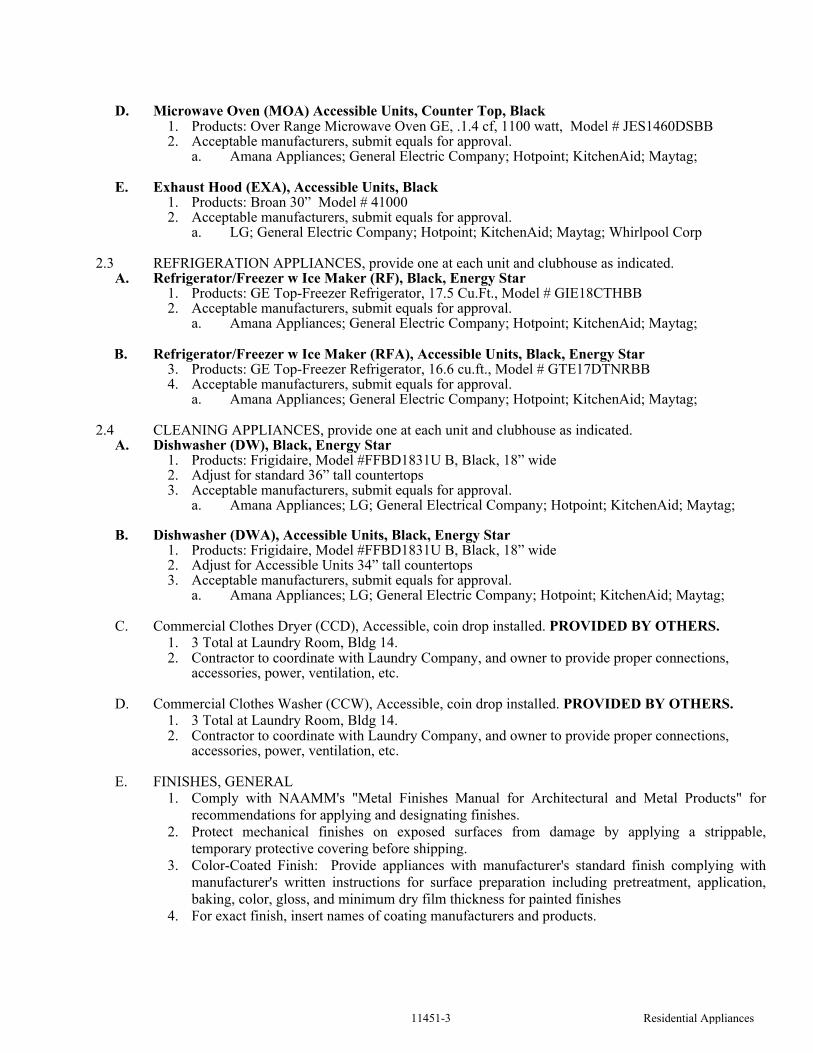
11451-3 Residential Appliances
D. Microwave Oven (MOA) Accessible Units, Counter Top, Black1. Products: Over Range Microwave Oven GE, .1.4 cf, 1100 watt, Model # JES1460DSBB2. Acceptable manufacturers, submit equals for approval.
a. Amana Appliances; General Electric Company; Hotpoint; KitchenAid; Maytag;
E. Exhaust Hood (EXA), Accessible Units, Black1. Products: Broan 30” Model # 410002. Acceptable manufacturers, submit equals for approval.
a. LG; General Electric Company; Hotpoint; KitchenAid; Maytag; Whirlpool Corp
2.3 REFRIGERATION APPLIANCES, provide one at each unit and clubhouse as indicated. A. Refrigerator/Freezer w Ice Maker (RF), Black, Energy Star
1. Products: GE Top-Freezer Refrigerator, 17.5 Cu.Ft., Model # GIE18CTHBB2. Acceptable manufacturers, submit equals for approval.
a. Amana Appliances; General Electric Company; Hotpoint; KitchenAid; Maytag;
B. Refrigerator/Freezer w Ice Maker (RFA), Accessible Units, Black, Energy Star3. Products: GE Top-Freezer Refrigerator, 16.6 cu.ft., Model # GTE17DTNRBB4. Acceptable manufacturers, submit equals for approval.
a. Amana Appliances; General Electric Company; Hotpoint; KitchenAid; Maytag;
2.4 CLEANING APPLIANCES, provide one at each unit and clubhouse as indicated. A. Dishwasher (DW), Black, Energy Star
1. Products: Frigidaire, Model #FFBD1831U B, Black, 18” wide2. Adjust for standard 36” tall countertops3. Acceptable manufacturers, submit equals for approval.
a. Amana Appliances; LG; General Electrical Company; Hotpoint; KitchenAid; Maytag;
B. Dishwasher (DWA), Accessible Units, Black, Energy Star1. Products: Frigidaire, Model #FFBD1831U B, Black, 18” wide 2. Adjust for Accessible Units 34” tall countertops3. Acceptable manufacturers, submit equals for approval.
a. Amana Appliances; LG; General Electric Company; Hotpoint; KitchenAid; Maytag;
C. Commercial Clothes Dryer (CCD), Accessible, coin drop installed. PROVIDED BY OTHERS.
1. 3 Total at Laundry Room, Bldg 14. 2. Contractor to coordinate with Laundry Company, and owner to provide proper connections,
accessories, power, ventilation, etc.
D. Commercial Clothes Washer (CCW), Accessible, coin drop installed. PROVIDED BY OTHERS.
1. 3 Total at Laundry Room, Bldg 14. 2. Contractor to coordinate with Laundry Company, and owner to provide proper connections,
accessories, power, ventilation, etc.
E. FINISHES, GENERAL1. Comply with NAAMM's "Metal Finishes Manual for Architectural and Metal Products" for
recommendations for applying and designating finishes.
2. Protect mechanical finishes on exposed surfaces from damage by applying a strippable,
temporary protective covering before shipping.
3. Color-Coated Finish: Provide appliances with manufacturer's standard finish complying with
manufacturer's written instructions for surface preparation including pretreatment, application,
baking, color, gloss, and minimum dry film thickness for painted finishes
4. For exact finish, insert names of coating manufacturers and products.

11451-4 Residential Appliances
PART 3 - EXECUTION
3.1 EXAMINATIONA. Examine roughing-in for piping systems to verify actual locations of piping connections before
equipment installation.B. Proceed with installation only after unsatisfactory conditions have been corrected.
3.2 INSTALLATION, GENERALA. General: Comply with manufacturer's written instructions.B. Built-in Equipment: Securely anchor units to supporting cabinets or countertops with concealed
fasteners. Verify that clearances are adequate for proper functioning and rough openings are completely concealed.
C. Freestanding Equipment: Place units in final locations after finishes have been completed in each area. Verify that clearances are adequate to properly operate equipment.
D. Utilities: Refer to Divisions 15 and 16 for plumbing and electrical requirements.
3.3 CLEANING AND PROTECTIONA. Test each item of residential appliances to verify proper operation. Make necessary adjustments.B. Verify that accessories required have been furnished and installed.C. Remove packing material from residential appliances and leave units in clean condition, ready for
operation.
3.4 DEMONSTRATION A. Engage a factory-authorized service representative to train Owner's maintenance personnel to adjust,
operate, and maintain residential appliances. Refer to Division 1 Section "Demonstration and Training."
END OF SECTION 11451

12356-1 Kitchen Casework
SECTION 12356
KITCHEN CASEWORK
PART 1 - GENERAL
1.1 RELATED DOCUMENTS
A. Drawings and general provisions of the Contract, including General and Supplementary Conditions and Division 1 Specification Sections, apply to this Section.
1.2 SUMMARY
A. This Section includes the following:1. Wood-faced kitchen cabinets.2. Wood-faced vanity cabinets.3. Plastic-laminate countertops.
B. Related Sections include the following:1. Division 11 Section "Residential Appliances" for appliances mounted in kitchen casework.2. Division 15 Section "Plumbing Fixtures" for sink units mounted in countertops.
1.3 DEFINIITIONS
A. Exposed Surfaces of Casework: Surfaces visible when doors and drawers are closed, including visible surfaces in open cabinets or behind glass doors.
B. Semi-exposed Surfaces of Casework: Surfaces behind opaque doors or drawer fronts, including interior faces of doors and interiors and sides of drawers. Bottoms of wall cabinets are defined as "semi-exposed."
C. Concealed Surfaces of Casework: Surfaces not usually visible after installation, including sleepers, web frames, dust panels, bottoms of drawers, and ends of cabinets installed directly against and completely concealed by walls or other cabinets. Tops of wall cabinets and utility cabinets are defined as "concealed."
1.4 SUBMITTALS
A. Product Data: For the following:
Samples and Submittals must be approved by Owner/Developer prior to ordering or production. 1. Cabinets.2. Plastic-laminate countertops.3. Cabinet hardware.
B. Shop Drawings: For cabinets and countertops. Include plans, elevations, details, and attachments to other work. Show materials, finishes, filler panels, hardware, edge and backsplash profiles, cutouts for plumbing fixtures, and methods of joining countertops.
C. Samples for Initial Selection: Manufacturer's color samples consisting of units or sections of units showing the full range of colors, textures, and patterns available for each type of material exposed to view.
D. Samples for Verification: For the following materials; in sets showing the full range of color, texture, and pattern variations expected:1. Wood-veneered panels with transparent finish, 8 by 10 inches (200 by 250 mm), for each
species.2. Solid wood with transparent finish, 50 sq. in. (300 sq. cm), for each species.3. Plastic laminate for countertops, 8 by 10 inches (200 by 250 mm).4. One unit of each type of exposed hardware.

12356-2 Kitchen Casework
E. Product Certificates: Signed by manufacturers of casework certifying that products furnished comply
with requirements. Samples and Submittals must be approved by Owner/Developer prior to
ordering or production.
1.5 QUALITY ASSURANCE
A. Source Limitations for Cabinets: Obtain cabinets through one source from a single manufacturer.
B. Product Designations: Drawings indicate size, configurations, and finish material of casework by referencing designated manufacturer's catalog numbers. Other manufacturers' casework of similar sizes, similar door and drawer configurations, same finish material, and complying with the Specifications may be considered. Refer to Division 1 Section "Substitutions."
C. Quality Standards: Unless otherwise indicated, comply with the following standards:1. Cabinets: KCMA A161.1.
a. KCMA Certification: Provide cabinets with KCMA's "Certified Cabinet" seal affixed in a semi exposed location of each unit and showing compliance with the above standard.
2. Plastic-Laminate Countertops: KCMA A161.2.
1.6 PROJECT CONDITIONS
A. Environmental Limitations: Do not deliver or install kitchen casework until building is enclosed, wet-work is complete, and HVAC system is operating and will maintain temperature and relative humidity at occupancy levels during the remainder of the construction period.
B. Established Dimensions: Where kitchen casework is indicated to fit to other construction, establish dimensions for areas where casework is to fit. Coordinate construction to ensure that actual dimensions correspond to established dimensions. Provide fillers and scribes to allow for trimming and fitting.
C. Field Measurements: Where kitchen casework is indicated to fit to existing construction, verify dimensions of existing construction by field measurements before fabrication and indicate measurements on Shop Drawings. Provide fillers and scribes if necessary.
D. Field Measurements for Countertops: Verify dimensions of countertops by field measurements after base cabinets are installed but before countertop fabrication is complete. Coordinate fabrication schedule with construction progress to avoid delaying the Work.
1.7 COORDINATION
A. Coordinate layout and installation of blocking and reinforcement in partitions for support of kitchen casework.
PART 2 - PRODUCTS
2.1 MANUFACTURERS
A. Available Manufacturers: Subject to compliance with requirements, manufacturers offering products that may be incorporated into the Work include, but are not limited to, the following:
B. Manufacturers: Subject to compliance with requirements, provide products by one of the following:
1. Cabinets:a. Mid America Cabinets, “Vista”, Concord
b. As submitted and approved Equal

12356-3 Kitchen Casework
2. Plastic Laminate for Countertops:a. Formica Corp.b. Nevamar Corp.c. Pionite Plastics Corp.d. WilsonArt
C. Product: Subject to compliance with requirements, provide "Vista" Concord, by Mid America Cabinets or Equivalent.
2.2 COLORS, TEXTURES, AND PATTERNS
A. Colors, Textures, and Patterns: As listed, or selected by Architect from manufacturer's full range for these characteristics.
2.3 CABINET MATERIALS
A. Exposed Materials: Comply with the following:
1. Exposed Wood Species: As follows. Do not use two adjacent exposed faces that are noticeably dissimilar in color, grain, figure, or natural character markings.a. Knotty Alder, or as selected by Owner/Developer
2. Solid Wood: Clear hardwood lumber of species indicated, free of defects, selected for compatible grain and color, and kiln dried to 7 percent moisture content.
3. Plywood: Hardwood plywood complying with HPVA HP-1 with face veneer of species indicated, selected for compatible color and grain with Grade A faces and Grade C backs of same species as faces.
a. Edge band exposed edges with minimum 1/8-inch- (3-mm-) thick, solid-wood edging of same species as face veneer.
B. Semi exposed Materials: Unless otherwise indicated, provide the following:
1. Plywood: Hardwood plywood complying with HPVA HP-1 with Grade C faces stained to be compatible with exposed surfaces and Grade 3 backs of same species as faces.
2. Thermoset Decorative Panels: Medium-density particleboard complying with ANSI A208.1, Grade M-2; with surface of thermally fused, melamine-impregnated decorative paper complying with LMA SAT-1.b. Provide thermoset decorative overlay on both sides of shelves, dividers, drawer bodies,
and other components with two semiexposed surfaces.c. Provide PVC or polyester edge banding complying with LMA EDG-1 on components
with semiexposed edges.3. Vinyl-Faced Particleboard: Medium-density particleboard complying with ANSI A208.1,
Grade M-2 with an embossed, wood-grain-patterned vinyl film adhesively bonded to particleboard.d. Provide vinyl film on both sides of shelves, dividers, drawer bodies, and other
components with two semi exposed surfaces and on semi exposed edges.
C. Concealed Materials: Comply with the following:1. Particleboard: ANSI A208.1, Grade M-2.3. Medium-Density Fiberboard: ANSI A208.2.4. Hardboard: AHA A135.4, Class 1 Tempered.
2.4 COUNTERTOP MATERIALS
A. Plastic Laminate: High-pressure decorative laminate complying with NEMA LD 3.1. Grade: HGS.2. Grade: HGP.3. Provide through-color plastic laminate.4. Grade for Backer Sheet: BKL.
12356-4 Kitchen Casework
B. Particleboard: ANSI A208.1, Grade M-2.
C. Plywood: Exterior softwood plywood complying with PS 1, Grade C-C Plugged, touch sanded.
D. Solid Wood Edges and Trim: Clear hardwood lumber of species indicated, free of defects, selected for compatible grain and color, and kiln dried.
2.5 CASEWORK HARDWARE
A. General: Manufacturer's standard units complying with BHMA A156.9, of type, material, size, and finish as selected from manufacturer's standard choices.
B. Hinges: Semi-concealed, self-closing hinges.
D. Drawer Guides: 100 lb. rated epoxy-coated-metal, self-closing drawer guides; designed to prevent rebound when drawers are closed; with nylon-tired, ball-bearing rollers; and complying with BHMA A156.9, Type B05091.
E. Cabinet Pulls: Submit Samples, Selected by Architect/Owner from manufacturers Standard range.
2.6 CABINET CONSTRUCTION
A. Face Style: Reveal overlay; door and drawer faces partially cover cabinet body or face frames.
B. Face Frames: 3/4-inch solid wood with glued mortise and tenon or doweled joints.
C. Door and Drawer Fronts: 2 inch wide by 3/4 inch thick perimeter assembled around a 1/4 inch veneer panel.
D. Cabinet Ends: 1/2 inch industrial-grade particle board fastened to face frame with tongue-and-groove. Exposed end panels are finished with wood veneer to match face frame finish.
E. Cabinet Tops and Bottoms: Wall cabinets constructed of 1/4 inch hardboard dadoed into end panels and interlocked into hanging rails for strength. Base bottoms constructed similarly of 1/2 inch industrial-grade particle board.
F. Hanging Rails: 3/4 inch by 2-1/2 inch hardwood on upper cabinets. 3/4 inch by 1 inch hardwood on base cabinets.
G. Drawers: 7/16 inch industrial-grade particle board using full box construction with 1/8 inch hardboard bottoms. Drawer fronts constructed to match cabinet door material and style.
H. Shelves: 1/2 inch industrial-grade particle board. Wall shelving adjustable up to 24” wide. Base cabinets feature 11 inch deep half-shelf.
I. Toe Kick: 1/2 inch industrial-grade particle board fastened between end panels.
J. Joinery: Rabbet backs flush into end panels and secure with concealed mechanical fasteners. Connect tops and bottoms of wall cabinets and bottoms and stretchers of base cabinets to ends and dividers with mechanical fasteners. Rabbet tops, bottoms, and backs into end panels.
K. Factory Finishing: To greatest extent possible, finish casework at factory. Defer only final touchup until after installation.
2.7 PLASTIC-LAMINATE COUNTERTOPS
A. Configuration: Provide countertops with the following front, cove (intersection of top with backsplash), backsplash, and end-splash style:1. Front: Rolled.2. Cove: Cove molding (one-piece postformed laminate supported at junction of top and
backsplash by wood cove molding).
12356-5 Kitchen Casework
3. Backsplash: Curved or waterfall shape with scribe.
B. Plastic-Laminate Substrate: Particleboard not less than 3/4 inch (19 mm) thick.1. For countertops at sinks and lavatories, use phenolic-resin particleboard or exterior-grade
plywood.2. Build up countertop thickness to 1-1/2 inches (38 mm) at front, back, and ends with additional
layers of particleboard laminated to top.
C. Backer Sheet: Provide plastic-laminate backer sheet on underside of countertop substrate.
D. Paper Backing: Provide paper backing on underside of countertop substrate.
PART 3 - EXECUTION
3.1 INSTALLATION
A. Install casework with no variations in flushness of adjoining surfaces; use concealed shims. Where casework abuts other finished work, scribe and cut for accurate fit. Provide filler strips, scribe strips, and moldings in finish to match casework face.
B. Install casework without distortion so doors and drawers fit openings and are aligned. Complete installation of hardware and accessories as indicated.
C. Install casework and countertop level and plumb to a tolerance of 1/8 inch in 8 feet (3 mm in 2.4 m).
D. Fasten cabinets to adjacent units and to backing.1. Fasten wall cabinets through back, near top and bottom, at ends and not less than 24 inches (600
mm) o.c. with No. 10 wafer-head screws sized for 1-inch (25-mm) penetration into wood framing, blocking, or hanging strips.
2. Fasten wall cabinets through back, near top and bottom, at ends and not less than 24 inches (600 mm) o.c., with toggle bolts through metal backing behind gypsum board.
E. Fasten plastic-laminate countertops by screwing through corner blocks of base units into underside of countertop. Form seams using splines to align adjacent surfaces, and secure with glue and concealed clamping devices designed for this purpose.
F. Fasten solid-surfacing-material countertops by screwing through corner blocks of base units into underside of countertop. Align adjacent surfaces, and form seams to comply with manufacturer's written instructions using adhesive in color to match countertop. Carefully dress joints smooth, remove surface scratches, and clean entire surface.
3.2 ADJUSTING AND CLEANING
A. Adjust casework and hardware so doors and drawers are centered in openings and operate smoothly without warp or bind. Lubricate operating hardware as recommended by manufacturer.
B. Clean casework on exposed and semi-exposed surfaces. Touch up factory-applied finishes to restore damaged or soiled areas.
END OF SECTION 12356


12491-1 Horizontal Louver Blinds
SECTION 12491
HORIZONTAL LOUVER BLINDS
PART 1 - GENERAL
1.1 SUMMARY
A. This Section includes the following types of venetian blinds and accessories: 1. Miniblinds, Cordless, with Aluminum louver slats.
1.2 SUBMITTALS
A. Product Data: For each type of product indicated. Include styles, material descriptions, construction details, dimensions of individual components and profiles, features, finishes, and operating instructions.
B. Shop Drawings: Show location and extent of horizontal louver blinds. Include elevations, sections, details, and dimensions not shown in Product Data. Show installation details, mountings, attachments to other Work, operational clearances, and relationship to adjoining work.
C. Samples for Initial Selection: For each colored component of each type of horizontal louver blind indicated. 1. Include similar Samples of accessories involving color selection.
D. Window Treatment Schedule: Include horizontal louver blinds in schedule using same room designations indicated on Drawings.
E. Product Certificates: For each type of horizontal louver blind product, signed by product manufacturer.
F. Product Test Reports: For each type of horizontal louver blind product.
G. Maintenance Data: For horizontal louver blinds to include in maintenance manuals. Include the following: 1. Methods for maintaining horizontal louver blinds and finishes. 2. Precautions about cleaning materials and methods that could be detrimental to finishes and
performance. 3. Operating hardware.
1.3 QUALITY ASSURANCE
A. Source Limitations: Obtain horizontal louver blinds through one source from a single manufacturer.
B. Fire-Test-Response Characteristics: Provide horizontal louver blinds with the fire-test-response characteristics indicated, as determined by testing identical products per test method indicated below by UL or another testing and inspecting agency acceptable to authorities having jurisdiction:
1. Flame-Resistance Ratings: Passes NFPA 701.
C. Electrical Components, Devices, and Accessories: Listed and labeled as defined in NFPA 70, Article 100, by a testing agency acceptable to authorities having jurisdiction, and marked for intended use.
D. Year 2000 Compliant: Computer hardware and software shall be capable of accurately processing, providing, and receiving date data from, into, and between the twentieth and twenty-first centuries, including leap year calculations.

12491-2 Horizontal Louver Blinds
E. Mockups: Build mockups to verify selections made under sample Submittals and to demonstrate aesthetic effects and qualities of materials and execution. 1. Build mockups in the location and of the size indicated or, if not indicated, as directed by
Architect. 2. Approved mockups may become part of the completed Work if undisturbed at time of
Substantial Completion.
1.4 DELIVERY, STORAGE, AND HANDLING
A. Deliver blinds in factory packages, marked with manufacturer and product name, and location of installation using same room designations indicated on Drawings and in a window treatment schedule.
1.5 PROJECT CONDITIONS
A. Environmental Limitations: Do not install horizontal louver blinds until construction and wet and dirty finish work in spaces, including painting, is complete and ambient temperature and humidity conditions are maintained at the levels indicated for Project when occupied for its intended use.
B. Field Measurements: Where horizontal louver blinds are indicated to fit to other construction, verify dimensions of other construction by field measurements before fabrication and indicate measurements on Shop Drawings. Allow clearances for operable glazed units' operation hardware throughout the entire operating range. Notify Architect of discrepancies. Coordinate fabrication schedule with construction progress to avoid delaying the Work.
PART 2 - PRODUCTS
2.1 MANUFACTURERS
A. Available Manufacturers: Subject to compliance with requirements, manufacturers offering products that may be incorporated into the Work include, but are not limited to, the following:
B. Manufacturers: Subject to compliance with requirements, provide products by one of the following: 1. Horizontal Louver Blinds, Aluminum Louver Slats:
a. Comfortex Window Fashions. b. Hunter Douglas Window Fashions. c. Levolor Contract; a Newell Company; Levolor. d. Springs Window Fashions Division, Inc.; Bali. e. Springs Window Fashions Division, Inc.; Graber. f. Verosol USA, Inc.
2.2 HORIZONTAL LOUVER BLINDS, VINYL LOUVER SLATS
A. Available Products: Subject to compliance with requirements, products that may be incorporated into the Work include, but are not limited to, the following:
B. Louver Slats: Vinyl recommended by producer for type of use and finish indicated; with crowned profile and radiused corners. 1. Verify availability of louver widths with manufacturers. 2. Nominal Slat Width: 1 inch (25 mm) for miniblinds. 3. Nominal Slat Thickness: Not less than 0.006 inch (0.15 mm). 4. Slat Finish: White
C. Headrail/Valance: Decorative, integrated headrail/valance not requiring a separate valance or end brackets for finished appearance; formed steel or extruded aluminum; long edges returned or rolled; fully enclosing operating mechanisms.
D. Bottom Rail: Formed-steel or extruded-aluminum tube, sealed with plastic or metal capped ends with enclosed and protected ladders and tapes to prevent their contact with sill.
12491-3 Horizontal Louver Blinds
E. Tilt Control: Consisting of enclosed worm gear mechanism and linkage rod, for the following operation:
F. Lift Operation: Manual & cordless; holds at any position in ascending or descending travel.
PART 3 - EXECUTION
3.1 EXAMINATION
A. Examine substrates, areas, and conditions, with Installer present, for compliance with requirements for installation tolerances, operational clearances, and other conditions affecting performance. Proceed with installation only after unsatisfactory conditions have been corrected.
3.2 HORIZONTAL LOUVER BLIND INSTALLATION
A. Install blinds level and plumb and aligned with adjacent units according to manufacturer's written instructions, and located so exterior louver edges in any position are not closer than 1 inch to interior face of glass. Install intermediate support as required to prevent deflection in headrail. Allow clearances between adjacent blinds and for operating glazed opening's operation hardware, if any.
B. Flush Mounted: Install blinds with louver edges flush with finish face of opening if slats are tilted open.
C. Jamb Mounted: Install headrail flush with face of opening jamb and head.
D. Head Mounted: Install headrail on face of opening head.
E. Recessed: Install headrail concealed within blind pocket.
3.3 ADJUSTING
A. Adjust horizontal louver blinds to operate smoothly, easily, safely, and free from binding or malfunction throughout entire operational range.
3.4 CLEANING AND PROTECTION
A. Clean blind surfaces after installation, according to manufacturer's written instructions.
B. Provide final protection and maintain conditions, in a manner acceptable to manufacturer and installer that ensure that horizontal louver blinds are without damage or deterioration at time of Substantial Completion.
C. Replace damaged blinds that cannot be repaired, in a manner approved by Architect, before time of Substantial Completion.
END OF SECTION 12491
