project no: project title: penndot technical advisor
TRANSCRIPT

Project No:
Research Contractor: Project Cost:
Project Title:
Principal Investigator:
Project Purpose:
PennDOT Technical Advisor: Project Duration:
Anticipated Outcome(s):
Proposed Implementation Plan:
ATLSS is a National Center for Engineering Research
on Advanced Technology for Large Structural Systems
117 ATLSS Drive
Bethlehem, PA 18015-4729
Phone: (610)758-3525 www.atlss.lehigh.edu
Fax: (610)758-5902 Email: [email protected]
PennDOT Agreement E03134
EXAMPLE CONFIGURATIONS
OF THE
PA FLEXBEAM BRIDGE SYSTEM
By
Clay Naito, Ph.D., P.E.
Robin Hendricks
Richard Sause, Ph.D., P.E.
December 2018
Revised: January 2020
ATLSS REPORT NO. 18-05
ATLSS Report 18-05 Page 2 FlexBeam Example Configuration Summary
ABSTRACT
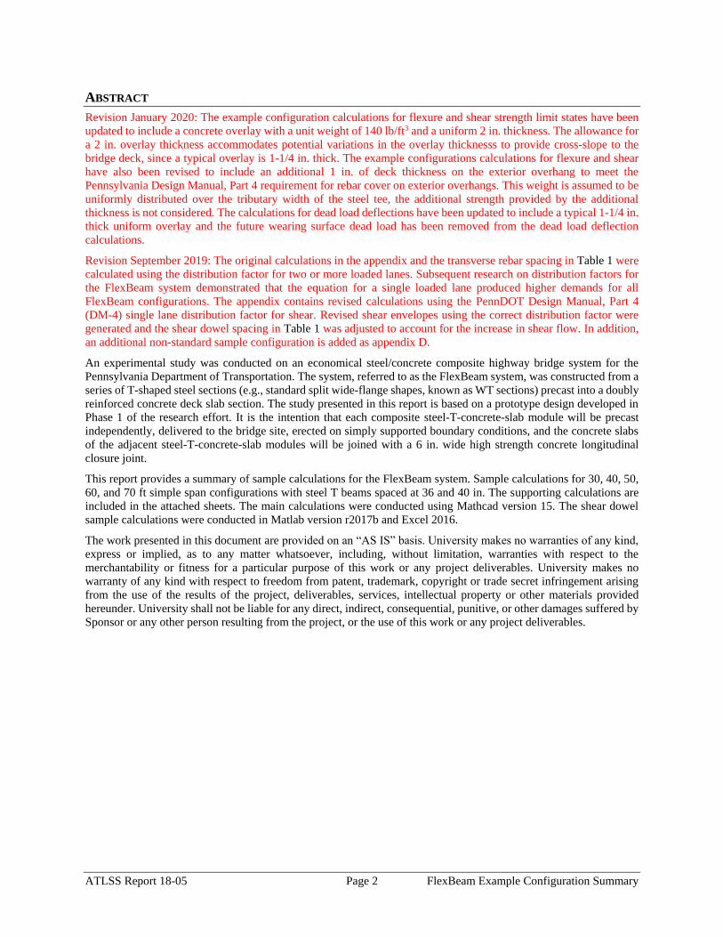
Revision January 2020: The example configuration calculations for flexure and shear strength limit states have been
updated to include a concrete overlay with a unit weight of 140 lb/ft3 and a uniform 2 in. thickness. The allowance for
a 2 in. overlay thickness accommodates potential variations in the overlay thicknesss to provide cross-slope to the
bridge deck, since a typical overlay is 1-1/4 in. thick. The example configurations calculations for flexure and shear
have also been revised to include an additional 1 in. of deck thickness on the exterior overhang to meet the
Pennsylvania Design Manual, Part 4 requirement for rebar cover on exterior overhangs. This weight is assumed to be
uniformly distributed over the tributary width of the steel tee, the additional strength provided by the additional
thickness is not considered. The calculations for dead load deflections have been updated to include a typical 1-1/4 in.
thick uniform overlay and the future wearing surface dead load has been removed from the dead load deflection
calculations.
Revision September 2019: The original calculations in the appendix and the transverse rebar spacing in Table 1 were
calculated using the distribution factor for two or more loaded lanes. Subsequent research on distribution factors for
the FlexBeam system demonstrated that the equation for a single loaded lane produced higher demands for all
FlexBeam configurations. The appendix contains revised calculations using the PennDOT Design Manual, Part 4
(DM-4) single lane distribution factor for shear. Revised shear envelopes using the correct distribution factor were
generated and the shear dowel spacing in Table 1 was adjusted to account for the increase in shear flow. In addition,
an additional non-standard sample configuration is added as appendix D.
An experimental study was conducted on an economical steel/concrete composite highway bridge system for the
Pennsylvania Department of Transportation. The system, referred to as the FlexBeam system, was constructed from a
series of T-shaped steel sections (e.g., standard split wide-flange shapes, known as WT sections) precast into a doubly
reinforced concrete deck slab section. The study presented in this report is based on a prototype design developed in
Phase 1 of the research effort. It is the intention that each composite steel-T-concrete-slab module will be precast
independently, delivered to the bridge site, erected on simply supported boundary conditions, and the concrete slabs
of the adjacent steel-T-concrete-slab modules will be joined with a 6 in. wide high strength concrete longitudinal
closure joint.
This report provides a summary of sample calculations for the FlexBeam system. Sample calculations for 30, 40, 50,
60, and 70 ft simple span configurations with steel T beams spaced at 36 and 40 in. The supporting calculations are
included in the attached sheets. The main calculations were conducted using Mathcad version 15. The shear dowel
sample calculations were conducted in Matlab version r2017b and Excel 2016.
The work presented in this document are provided on an “AS IS” basis. University makes no warranties of any kind,
express or implied, as to any matter whatsoever, including, without limitation, warranties with respect to the
merchantability or fitness for a particular purpose of this work or any project deliverables. University makes no
warranty of any kind with respect to freedom from patent, trademark, copyright or trade secret infringement arising
from the use of the results of the project, deliverables, services, intellectual property or other materials provided
hereunder. University shall not be liable for any direct, indirect, consequential, punitive, or other damages suffered by
Sponsor or any other person resulting from the project, or the use of this work or any project deliverables.
ATLSS Report 18-05 Page 3 FlexBeam Example Configuration Summary
TABLE OF CONTENTS
1. Background ................................................................................................................................................................ 4
1.1. Disclaimer ........................................................................................................................................................... 4
1.2. Example Configuration Assumptions ................................................................................................................. 4
1.3. Example Configurations ..................................................................................................................................... 5
2. Appendix A – Example Configuration Calculations ............................................................................................. 2-1
3. Appendix B – Example Configuration – Shear Calculations ................................................................................. 3-1
4. Appendix C – Example Configuration – Deflection Calculations ......................................................................... 4-1
5. Appendix D – Superstructure Replacement ........................................................................................................... 5-1
6. Appendix E – Matlab Load Case Script ................................................................................................................ 6-1
ATLSS Report 18-05 Page 4 FlexBeam Example Configuration Summary
1. BACKGROUND
This report summarizes example configurations for the PA FlexBeam system. Included in this report are examples of
30, 40, 50, 60, and 70 ft simple span configurations with steel T beams spaced at 36 and 40 in. The example dimensions
are included below in Table 1. The supporting calculations are included in the attached sheets. The main calculations
were conducted using Mathcad version 15. The shear dowel sample calculations were conducted in Matlab version
r2017b and Excel 2016.
1.1. DISCLAIMER
The work presented in this document are provided on an “AS IS” basis. University makes no warranties of any kind,
express or implied, as to any matter whatsoever, including, without limitation, warranties with respect to the
merchantability or fitness for a particular purpose of this work or any project deliverables. University makes no
warranty of any kind with respect to freedom from patent, trademark, copyright or trade secret infringement arising
from the use of the results of the project, deliverables, services, intellectual property or other materials provided
hereunder. University shall not be liable for any direct, indirect, consequential, punitive, or other damages suffered by
Sponsor or any other person resulting from the project, or the use of this work or any project deliverables.
1.2. EXAMPLE CONFIGURATION ASSUMPTIONS
The following assumptions are used in the example configurations of the PA FlexBeam system.
Design Specifications
o AASHTO LRFD Bridge Design Specifications 7th Edition with 2016 Interim Revisions
o PennDOT Design Manual, Part 4 (DM-4) June 30, 2015
Material Properties
o Structural steel: ASTM A709 Grade 50
o Concrete reinforcement: ASTM A615 or A706 Grade 60, fy = 60 ksi
o Concrete deck f’c = 4 ksi (Class AAAP Concrete)
o Concrete barriers, f’c = 3.5 ksi (Class AA Concrete)
Loads and Distribution
o Normal weight concrete = 150 lb/ft3
o Future wearing surface = 30 lb/ft2 (evenly distributed to all beams)
o 45 in. tall F-shape barrier, weight = 700 lb/ft (distributed to exterior two beams)
o Live load distribution factor assumed to be 0.3 for flexure limit states and using DM-4 equation for shear
limit states
Bridge Dimensions
o Minimum clear widths including 24, 28, 32, 36, and 40 ft
o Spans including 30, 40, 50, 60, 70 ft
o Configurations are double T modules (i.e., precast deck with two steel T beams embedded) with a 6 in. UHPC
closure joint.
The beams are evaluated for the following cases:
1. Strength I (flexure and shear design due to design truck or design tandem)
2. Strength II (flexure of shear design due to Permit Load)
3. Service II (stress check due to design truck or design tandem)
4. Strength V (combined flexural demand from wind and vehicle loading)
5. Optional L/800 Live Load Deflection Check (in accordance with AASHTO 3.6.1.3.2)
The supporting research for the PA FlexBeam example configurations are summarized in ATLSS Report 15-01
and ATLSS Report 16-01, and ATLSS Report 18-04.
Cercone, C., Naito, C., Sause, R., “PA Flex Beam Shear Strength Evaluation and Construction
Methods,” ATLSS Report No. 16-01, ATLSS Center, Lehigh University, February 2016, 84 pages.
ATLSS Report 18-05 Page 5 FlexBeam Example Configuration Summary
Aghl, P. P., Naito, C., Sause, R., “PA Flex Beam Preliminary Analysis,” ATLSS Report No. 15-01,
ATLSS Center, Lehigh University, January 2015, 26 pages.
Naito, C., Hendricks, R., Sause, R., “Full-Scale Evaluation of the PA FlexBeam Bridge System,”
ATLSS Report No. 18-04, ATLSS Center, Lehigh University, December 2018.
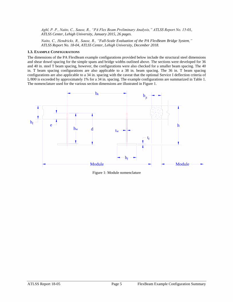
1.3. EXAMPLE CONFIGURATIONS
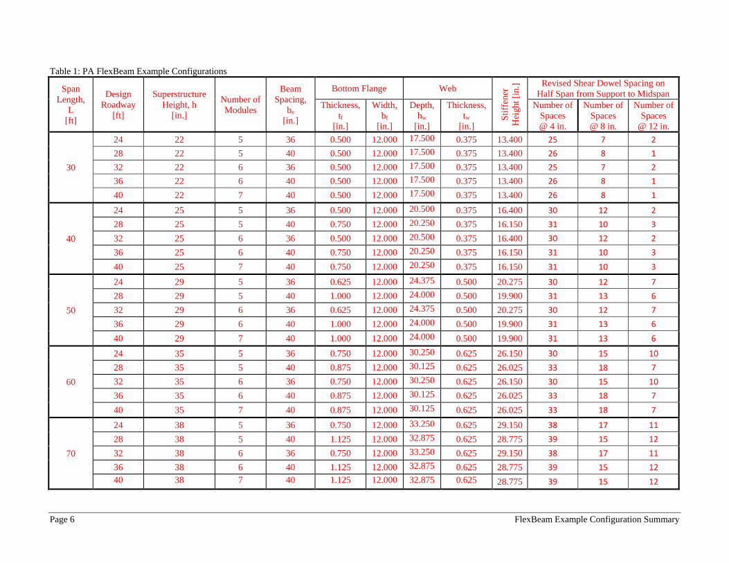
The dimensions of the PA FlexBeam example configurations provided below include the structural steel dimensions
and shear dowel spacing for the simple spans and bridge widths outlined above. The sections were developed for 36
and 40 in. steel T beam spacing, however, the configurations were also checked for a smaller beam spacing. The 40
in. T beam spacing configurations are also applicable to a 38 in. beam spacing. The 36 in. T beam spacing
configurations are also applicable to a 34 in. spacing with the caveat that the optional Service I deflection criteria of
L/800 is exceeded by approximately 1% for a 34 in. spacing. The example configurations are summarized in Table 1.
The nomenclature used for the various section dimensions are illustrated in Figure 1.
Figure 1: Module nomenclature
hf
tf
bf
tw
hd
bjt
be
e
Module Module
hw
Page 6 FlexBeam Example Configuration Summary
Table 1: PA FlexBeam Example Configurations
Span
Length,
L
[ft]
Design
Roadway
[ft]
Superstructure
Height, h
[in.]
Number of
Modules
Beam
Spacing,
be
[in.]
Bottom Flange Web
Sti
ffen
er
Hei
gh
t [i
n.]
Revised Shear Dowel Spacing on
Half Span from Support to Midspan
Thickness,
tf
[in.]
Width,
bf
[in.]
Depth,
hw
[in.]
Thickness,
tw
[in.]
Number of
Spaces
@ 4 in.
Number of
Spaces
@ 8 in.
Number of
Spaces
@ 12 in.
30
24 22 5 36 0.500 12.000 17.500 0.375 13.400 25 7 2
28 22 5 40 0.500 12.000 17.500 0.375 13.400 26 8 1
32 22 6 36 0.500 12.000 17.500 0.375 13.400 25 7 2
36 22 6 40 0.500 12.000 17.500 0.375 13.400 26 8 1
40 22 7 40 0.500 12.000 17.500 0.375 13.400 26 8 1
40
24 25 5 36 0.500 12.000 20.500 0.375 16.400 30 12 2
28 25 5 40 0.750 12.000 20.250 0.375 16.150 31 10 3
32 25 6 36 0.500 12.000 20.500 0.375 16.400 30 12 2
36 25 6 40 0.750 12.000 20.250 0.375 16.150 31 10 3
40 25 7 40 0.750 12.000 20.250 0.375 16.150 31 10 3
50
24 29 5 36 0.625 12.000 24.375 0.500 20.275 30 12 7
28 29 5 40 1.000 12.000 24.000 0.500 19.900 31 13 6
32 29 6 36 0.625 12.000 24.375 0.500 20.275 30 12 7
36 29 6 40 1.000 12.000 24.000 0.500 19.900 31 13 6
40 29 7 40 1.000 12.000 24.000 0.500 19.900 31 13 6
60
24 35 5 36 0.750 12.000 30.250 0.625 26.150 30 15 10
28 35 5 40 0.875 12.000 30.125 0.625 26.025 33 18 7
32 35 6 36 0.750 12.000 30.250 0.625 26.150 30 15 10
36 35 6 40 0.875 12.000 30.125 0.625 26.025 33 18 7
40 35 7 40 0.875 12.000 30.125 0.625 26.025 33 18 7
70
24 38 5 36 0.750 12.000 33.250 0.625 29.150 38 17 11
28 38 5 40 1.125 12.000 32.875 0.625 28.775 39 15 12
32 38 6 36 0.750 12.000 33.250 0.625 29.150 38 17 11
36 38 6 40 1.125 12.000 32.875 0.625 28.775 39 15 12
40 38 7 40 1.125 12.000 32.875 0.625 28.775 39 15 12
ATLSS Report 18-05 2-1 FlexBeam Example Configuration Summary
2. APPENDIX A – EXAMPLE CONFIGURATION CALCULATIONS
The example configuration calculations are included in this section. The calculations were conducted with Mathcad
version 15. Calculations include checks on Service II, Strength I, and Strength II limit states as well as the optional
check on live load deflections meeting the L/800 criteria for non-pedestrian bridges.

PA Flex Beam Example Configuration Calculations
Flexbeam Example Configuration Calculations
Summary of Calculations:
Input section dimensions and material properties for steel WT and the concrete deck1.Calculate demands (dead load, superimposed dead, and Live load demands for Strength I and Strength II2.Calculate composite section properties for the given section3.Check Strength I, Strength II, and Service II stresses 4.Check Strength I, Strength II, and Strength V moment demands 5.Perform live load deflection check6.Determine maximum shear demand and capacity7.Note: Shear envelope data was obtained from Matlab script (FlexBeam_Moment_ShearEnvelope.m).8.Shear envelope calculations are summarized separately for each design (Shear Design *.xlsx).
Design Assumptions:Design Specifications Used:
AASHTO LRFD Bridge Design Specifications 7th Edition with 2016 Interim RevisionsPennDOT Design Manual, Part 4 (DM-4) June 30, 2015
Example configurations are determined for two girder spacings, 36" and 40".The deck thickness is 7.5" and is assumed to have a non-structural wearing surface added after installation.Section properties are calculated using the full 7.5" deck thickness.The WT sections are embedded 3.5" into the concrete deck. The steel section spacing used is outside the scope of the AASHTO and PennDOT distribution factorequations. The Fflexural distribution factor is assumed to be 0.3 which was shown to tbe conservativeaccording to refined analysisThe shear distribution factor is calculated using the DM-4 shear distribution factor equation which wasshown to be conservative using refined analysis.Refined analysis is presented in: Zihan Ma, "Distribution Factors for Composite Steel Tee Concrete DeckBridge System," M.S. Thesis, Deparement of Civil and Environmental Engineering, Lehigh University,Bethlehem, 2019Shear and moment demands for the PL82 permit load vehicle are determined by Matlab script(FlexBeam_Moment_ShearEnvelope.m) and are manually input into this calculation sheet.All fabrication will occur as double modules, i.e. each module contains two WT sections. The number ofmodules is half the number of beams, N. A 45 in. tall F-Shape barrier is used, Weight = 700 lb/ft (Distributed to exterior two beams).
The work presented in this document are provided on an “AS IS” basis. University makes no warranties of anykind, express or implied, as to any matter whatsoever, including, without limitation, warranties with respect tothe merchantability or fitness for a particular purpose of this work or any project deliverables. Universitymakes no warranty of any kind with respect to freedom from patent, trademark, copyright or trade secretinfringement arising from the use of the results of the project, deliverables, services, intellectual property orother materials provided hereunder. University shall not be liable for any direct, indirect, consequential,punitive, or other damages suffered by Sponsor or any other person resulting from the project, or the use ofthis work or any project deliverables.
Page 1 1/15/2020

PA Flex Beam Example Configuration Calculations
hf
tf
bf
twh
d
bjtbe
e
Variable Definitions:
Number of beams N 10 modulesN
25
L 30ft Span length
be 34in Effective width of Flexbeamassuming constructed bridge width(i.e. closure joints cast)
Built Up Section Properties
tw 0.375in tf 0.5in bf 12in
h 22in Overall Height of section
hf 7.5in Total thickness of deck
e 3.5in Deck/Steel overlap
d h hf e 18 in depth of built up steel section
hw d tf 17.5 in height of web of built up steel
Moment and shear for permit load PL82 obtained from Matlab script: FlexBeam_Moment_ShearEnvelope
MLL_IM_PL82 215.136kip ft Moment due to PL82 with distribution factor and impact factor!!
VPL82span 86.04kip Shear due to PL82 WITHOUT distribution factor and impact factor!!
Check web and flange dimensions in sections 6.10.2.1 and 6.10.2.2
(Ignore 6.10.2.2-4 since no compression flange)
equation 6.10.2.1.1-1d
tw150 1 equation 6.10.2.2-1
bf
2 tf12 1
equation 6.10.2.2-2 bfh
6 1 equation 6.10.2.2-3 tf 1.1 tw 1
y_bar
tf bftf
2 hw tw tf
hw
2
tf bf hw tw4.951 in Center of gravity of steel section
Istl
bf tf3
12bf tf y_bar
tf
2
2
tw hw
3
12 tw hw tf
hw
2 y_bar
2
421.486 in4
MOI of steel
Astl tf bf hw tw 12.562 in2
Area of the WT steel section
Page 2 1/15/2020

PA Flex Beam Example Configuration Calculations
Material Properties
Elastic Modulus of Steel Es 29000ksi
Yield Strength of Steel Fy 50ksi
Yield Strength of Reinforcement fy 60ksi
Compressive Strength of Concrete fc 4000psi AAAP PennDOT Concrete
Concrete Modular Ratio n 8 modular ratio for 4ksi concrete per AASHTO
Unit weight of concrete slab wc 0.150kip
ft3
Unit weight of concrete
Section Properties
Width of UHPC Joint: bjt 6in
Parapet width: bpar 20.25in Parapet width per PennDOT F-shape barrier
Width of the bridge W be N bjt 334 in W 27.833 ft
Clear width of roadway Wlane W 2 bpar 24.458 ft
Dc wc hf W 2.609kip
ft DL due to slab
Db .700kip
ft DL due to each 45" F-Shape Barrier (per email 11/1/18)
DFWS 30lbf
ft2
W 2 bpar 0.734kip
ft DL due to Future Wearing Surface (FWS)
Ds Astl 490lbf
ft3
0.043kip
ft Selfweight of the steel section
DLself
Dc N
Ds 0.304kip
ft Self-weight per WT
Total weight of each precast FlexBeam for transportation:
Weight of C12x25 Diaphragms Wend_diaphragms 25lbf
ft32 in 0.067 kip
2be bjt hf wc 2Ds L 2 Wend_diaphragms 17.229 kip
Determine number of design lane (AASHTO Section 3.6.1.1.1)
Take the integer part of the ratio of W/12 ft. Number of lanes in bridge: Nl floorWlane
12ft
2
Page 3 1/15/2020
PA Flex Beam Example Configuration Calculations
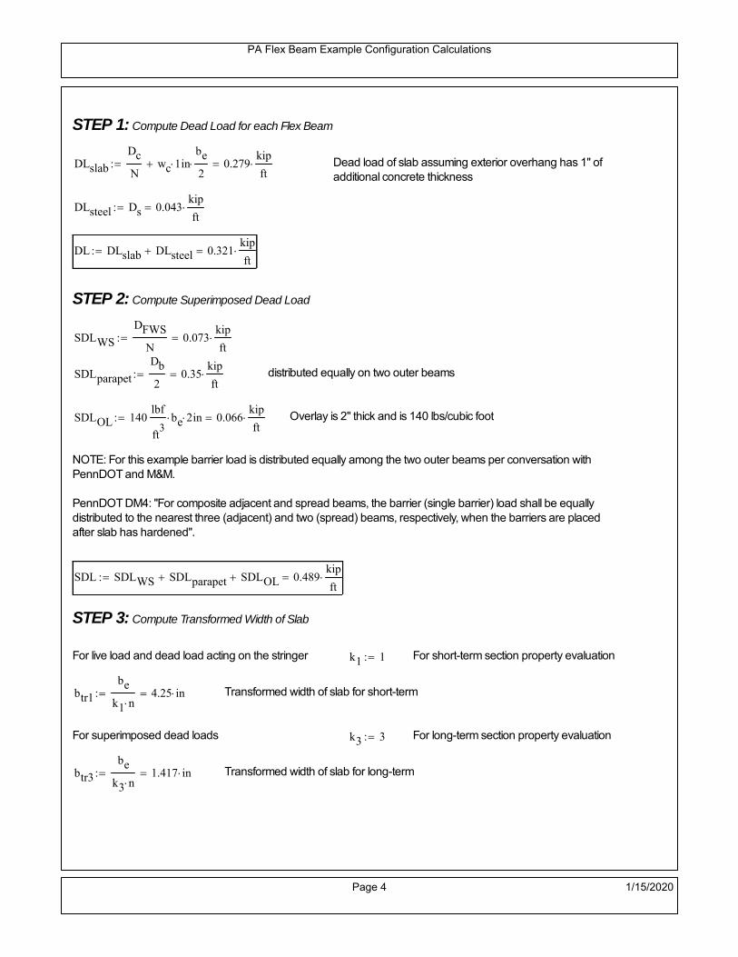
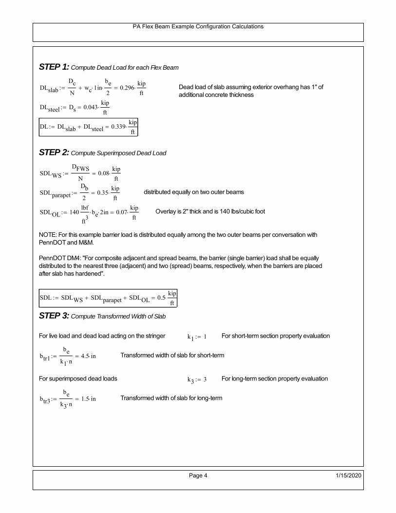
STEP 1: Compute Dead Load for each Flex Beam
DLslab
Dc
Nwc 1 in
be
2 0.279
kip
ft Dead load of slab assuming exterior overhang has 1" of
additional concrete thickness
DLsteel Ds 0.043kip
ft
DL DLslab DLsteel 0.321kip
ft
STEP 2: Compute Superimposed Dead Load
SDLWS
DFWS
N0.073
kip
ft
SDLparapet
Db
20.35
kip
ft distributed equally on two outer beams
SDLOL 140lbf
ft3be 2 in 0.066
kip
ft Overlay is 2" thick and is 140 lbs/cubic foot
NOTE: For this example barrier load is distributed equally among the two outer beams per conversation withPennDOT and M&M.
PennDOT DM4: "For composite adjacent and spread beams, the barrier (single barrier) load shall be equallydistributed to the nearest three (adjacent) and two (spread) beams, respectively, when the barriers are placedafter slab has hardened".
SDL SDLWS SDLparapet SDLOL 0.489kip
ft
STEP 3: Compute Transformed Width of Slab
For live load and dead load acting on the stringer k1 1 For short-term section property evaluation
btr1
be
k1 n4.25 in Transformed width of slab for short-term
For superimposed dead loads k3 3 For long-term section property evaluation
btr3
be
k3 n1.417 in Transformed width of slab for long-term
Page 4 1/15/2020
PA Flex Beam Example Configuration Calculations
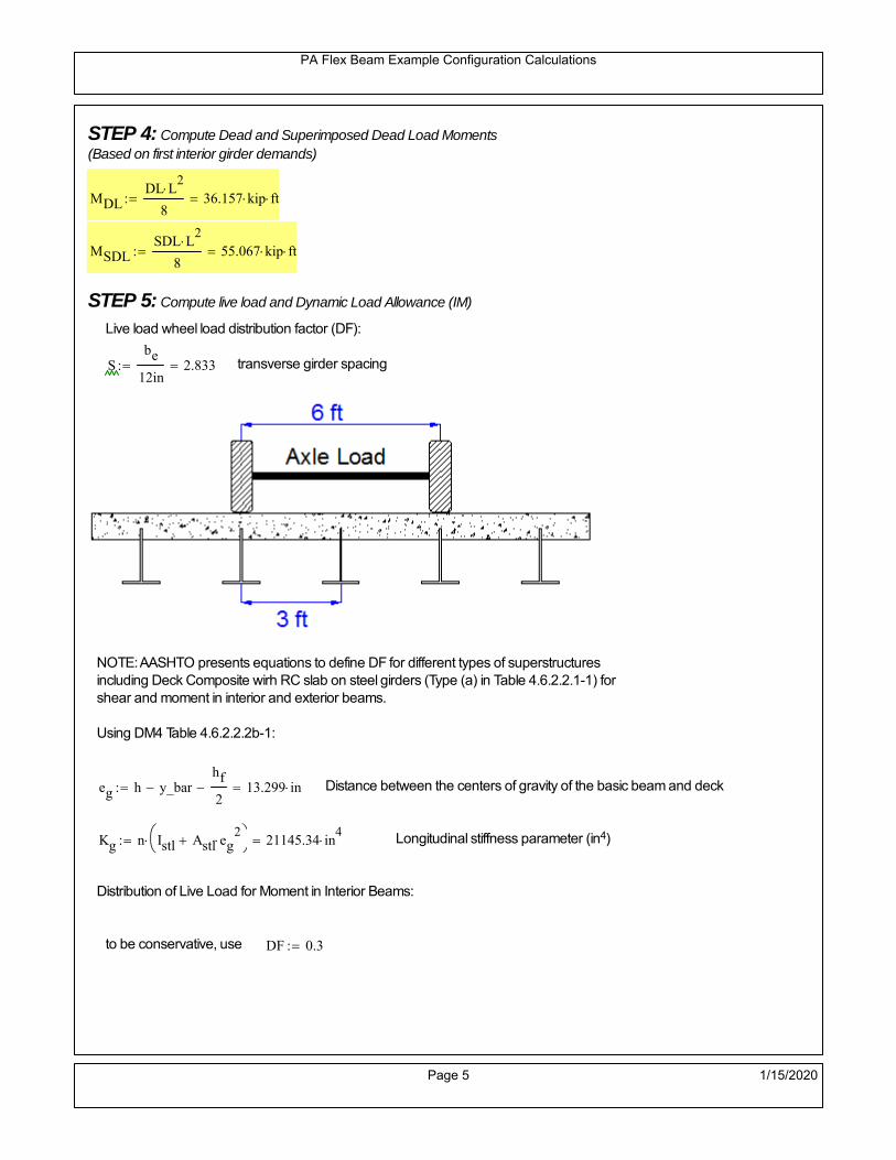
STEP 4: Compute Dead and Superimposed Dead Load Moments(Based on first interior girder demands)
MDLDL L
2
836.157 kip ft
MSDLSDL L
2
855.067 kip ft
STEP 5: Compute live load and Dynamic Load Allowance (IM)
Live load wheel load distribution factor (DF):
Sbe
12in2.833 transverse girder spacing
NOTE: AASHTO presents equations to define DF for different types of superstructuresincluding Deck Composite wirh RC slab on steel girders (Type (a) in Table 4.6.2.2.1-1) forshear and moment in interior and exterior beams.
Using DM4 Table 4.6.2.2.2b-1:
eg h y_barhf
2 13.299 in Distance between the centers of gravity of the basic beam and deck
Kg n Istl Astl eg2
21145.34 in
4 Longitudinal stiffness parameter (in4)
Distribution of Live Load for Moment in Interior Beams:
to be conservative, use DF 0.3
Page 5 1/15/2020

PA Flex Beam Example Configuration Calculations
Dynamic Load Allowance (Section 3.6.2 DM4)
Static effects of the design truck or tandem, shall be increased by the impact factor.
NOTE: The dynamic load allowance shall not be applied to the design lane load (Section 3.6.2.1 DM4)
I 0.33 Impact factor for moment
Note: PennDOT requires that the impact for decks be increased from 33% to 50%, the deck is not beingdesigned here. Instrad the deck design is based on the BD recommendations.
Dynamic load allowance for the Permit Load P-82 shall be less than 20%. (Section 3.6.2.1DM4)
IPL 0.20 Impact factor for moment on Strength II
Design Wind Loading for Exterior Girder
Vw 80 Wind speed for Strength V load case
CD 1.3 Gust factor for windard side of I-Girder and Box Girder Superstructures (Table 3.8.1.2.1-2)
G 1.0 Gus effect factor is 1.0 for all structures other than sound barriers (Table 3.8.1.2.1-1)
Kz 1.0 Pressure coefficient taken as 1 for Strength V (3.8.1.2.1)
Pz 2.56 106
Vw 2 Kz G CDkip
ft2
0.021kip
ft2
Wind pressure on exterior girder
hexp h hf 14.5 in Exposed height of exterior girder
Moment due to wind loading on exterior girderMWL
Pz hexp L2
82.895 kip ft
Iyy
bf3tf
1272 in
4 Transverse moment of intertia
Flange lateral bending stressfl
MWL
bf
2
Iyy2.895 ksi
Page 6 1/15/2020

PA Flex Beam Example Configuration Calculations
Design Vehicular Live Load
PHL-93 and P-82 are examined herein.
PHL-93 (A3.6.1.2.1)
PHL-93 consists of a combination of (design truck or design tandem) + (design lane load)
Design Truck
PennDOT defines the design truck in accordance with AASTHO 3.6.1.2
Design truck load in AASHTO (HS20 Truck) is used for this example.
NOTE : MAX moment occurs when the center line of the span is midway between the center ofgravity of the loads and the nearest concentrated load.
P1 8kip P2 32kip P3 32kip Axle loads (AASHTO 3.6.1.2.2)
XASr 14ft Rear Axle spacing for truck (14ft - 30ft)
XASf 14ft Front Axle spacing for truck
Page 7 1/15/2020

PA Flex Beam Example Configuration Calculations
Center of gravity (CG) of loads:
X'P1 XASr XASf P2 XASr
P1 P2 P39.333 ft Datum is the rear axle
X XASr X' 4.667 ft Spacing btw CG and nearest load
Find bridge reaction
Truck movestoward Support ARA
P1L
2XASf
X
2
P2L
2
X
2
P3L
2X'
X
2
L30.4 kip
Max live load moment (at the location of P2):
MLL_truck RAL
2
X
2
P1 XASf 273.067 kip ft
NOTE: Find the worst case by varying XASr
Page 8 1/15/2020

PA Flex Beam Example Configuration Calculations
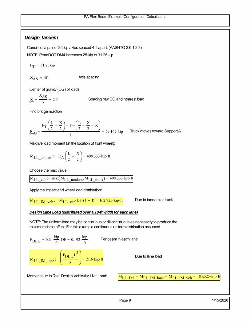
Design Tandem
Consist of a pair of 25-kip axles spaced 4-ft apart. (AASHTO 3.6.1.2.3)
NOTE: PennDOT DM4 increases 25-kip to 31.25-kip.
FT 31.25kip
XAS 4ft Axle spacing
Center of gravity (CG) of loads:
XXAS
22 ft Spacing btw CG and nearest load
Find bridge reaction
RA
FTL
2
X
2
FTL
2
X
2 X
L29.167 kip Truck moves toward Support A
Max live load moment (at the location of front wheel):
MLL_tandem RAL
2
X
2
408.333 kip ft
Choose the max value:
MLL_veh max MLL_tandem MLL_truck 408.333 kip ft
Apply the impact and wheel load distribution:
MLL_IM_veh MLL_veh DF 1 I( ) 162.925 kip ft Due to tandem or truck
Design Lane Load (distributed over a 10-ft width for each lane)
NOTE: The uniform load may be continuous or discontinuous as necessary to produce themaximum force effect. For this example continuous uniform distribution assumed.
FDLL 0.64kip
ftDF 0.192
kip
ft Per beam in each lane
Due to lane loadMLL_IM_lane
FDLL L2
8
21.6 kip ft
Moment due to Total Design Vehicular Live Load: MLL_IM MLL_IM_lane MLL_IM_veh 184.525 kip ft
Page 9 1/15/2020

PA Flex Beam Example Configuration Calculations
Design Permit Load P-82 (Section 3.6.1.2.7 DM4)
P1 P2 P3 P4 P5 P6 P7
NOTE: The moment for the permit load is defined at the beginning of the sheetand is obtained from MATLab File FlexBeam_Moment_ShearEnvelope.m
STEP 6: Compute Moment of Inertia (Note: rebar neglected!)
1) Moment of Inertia resisting dead load only:
a) Acting on the non-composite section (before the deck has hardened - DC1)
Use steel section only
Inc Istl 421.486 in4
Non-composite section modulus
Y'nc y_bar S.G. of the steel section of Flex Beam (Datum is bottom)
b) Acting on the composite section (after the deck has hardened - DC2)
Use Ic_short as defined below.
Page 10 1/15/2020

PA Flex Beam Example Configuration Calculations
2) Moment of Inertia resisting live load plus impact:
Using transformed slab with k1=1 (short-term composite).
Actr1 hf btr1 31.875 in2
Itr1
btr1 hf3
12149.414 in
4
Y'
Actr1 hhf
2
Astl Y'nc
Astl Actr114.491 in S.G. of the total flex beam (Datum is bottom)
Compositesection modulus(short-term)
Ic_short Istl Astl Y'nc Y' 2 Itr1 Actr1 hhf
2
Y'
2
2165 in4
Y'c_short Y' 14.491 in N.A. of the short-term composite section
3) Moment of Inertia resisting superimposed dead load:
Using transformed slab with k3=3.
Actr3 hf btr3 10.625 in2
Itr3
btr3 hf3
1249.805 in
4
Y'
Actr3 hhf
2
Astl Y'nc
Astl Actr311.045 in S.G. of the total flex beam (Datum is bottom)
Compositesection modulus(long-term)
Ic_long Istl Astl Y'nc Y' 2 Itr3 Actr3 hhf
2
Y'
2
1489 in4
Y'c_long Y' 11.045 in N.A. of the long-term composite section
Page 11 1/15/2020

PA Flex Beam Example Configuration Calculations
STEP 6.5 Check Ductility RequirementIn accordance with AASHTO Article 6.10.7.3 check ductility requirement. Assume compressionblock of concrete is at 0.85 f'c and that the concrete supports no tension. Steel section isassumed to be fully plastic at Fy.
Case 1 : Assuming PNA is in Concreteh d 4 inAssuming (h-d) < Dp < hf
Fp Dp 0.85 fc be Dp Fy tw Dp h d( ) Fy Astl tw Dp h d( )
Dp 7.5in 0.42 h 9.24 in
Dp1 root Fp Dp Dp 5.082 in Must be less than hf 7.5 inDp1
h0.231 must be < 0.42
Mn1check Dp1 hf h d( ) Dp1[ ] Dp1 0.42 h( ) 1 Dp1 0.42 h 1
Mp1 0.85 fc be Dp1Dp1
2
Fy tw Dp1 h d( )[ ] Dp1 h d( )[ ]
2
Fy bf tf h Dp1tf
2
Fy tw h Dp1 tf h Dp1 tf
2
Mp1 9031.2 kip in Mn1 Mp1 1.07 0.7Dp1
h
8202.9 kip in
Case 2 : Assuming PNA is NOT in Concrete
Assuming hf < Dp
Fp2 Dp 0.85 fc be hf Fy tw Dp h d( ) Fy Astl tw Dp h d( )
Dp 2.5in
Dp2 root Fp2 Dp Dp 2.37 in Must be more than hf 7.5 inDp2
h0.1077 must be < 0.42
Mn2check Dp2 hf Dp2 h( ) Dp2 0.42 h( ) 0 Dp2 0.42 h 1
Mp2 0.85 fc be hf Dp2hf
2
Fy tw Dp2 h d( )[ ] Dp2 h d( )[ ]
2
Fy bf tf h Dp2tf
2
Fy tw h Dp2 tf h Dp2 tf
2
Mp2 7652.03 kip inMn2 Mp2 1.07 0.7
Dp2
h
8764.7 kip in
Mn max Mn1 Mn1check Mn2 Mn2check 683.6 kip ft Mn 8202.9 kip in
Page 12 1/15/2020

PA Flex Beam Example Configuration Calculations
Check Composite Compact Section Criteria (6.10.6.2)
Dcpd
2
Fy tf bf 0.85 fc be hf
Fy hw tw1
6.552 in Dcp0 Dcp 0 0
Dcp Dcp Dcp0 0 in2 Dcp
tw3.76
Es
Fy 1 Check if section is compact
STEP 7: Load Combinations (Table 3.4.1-1)
The following load combinations will be considered herein. Only the maximum load factors forpermanent-loads are used in the following load combinations (uplift is not an issue for this typeof bridge).STRENGTH I 1.25DL + 1.5SDL + 1.75 (LL+IM)
SERVICE II: DL+SDL+1.3(LL+IM)
STEP 8: Compute and Check Stresses
Stress at bottom fiber of steel section
fDL
MDL Y'c_long
Ic_long3.218 ksi
fLL_I
MLL_IM Y'c_short
Ic_short14.824 ksi fPL
MLL_IM_PL82 Y'c_short
Ic_short17.283 ksi
fSDL
MSDL Y'c_long
Ic_long4.901 ksi
STRENGTH I fbot_str1 1.25fDL 1.5 fSDL 1.75 fLL_I 37.315 ksi
STRENGTH II fbot_str2 1.25fDL 1.5 fSDL 1.35 fPL 34.705 ksi
SERVICE II fbot_svc2 fDL fSDL 1.3fLL_I 27.39 ksi
Allowable Stress is based on Section 6.10.4.2.2-2
Flange stress due to service load II without consideration of flange lateral bending: ff fbot_svc2
Flange lateral bending stress due to service II: flSII 0ksi
Hybrid Factor: Rh 1.0 For rolled and homogenous built-up sections
ff
flSII
2 27.389 ksi 0.95 Rh Fy 47.5 ksi ff
fl
2 0.95Rh Fy 1
Page 13 1/15/2020

PA Flex Beam Example Configuration Calculations
Stress at top fiber of concrete
Note: For calculating longitudinal flexural stresses in the concrete deck due to allpermanent and transient loads, the short-term modular ratio shall be used.
fDL
MDL h Y'c_short
k1 n Ic_short0.188 ksi
fLL_I
MLL_IM h Y'c_short
k1 n Ic_short0.96 ksi fPL
MLL_IM_PL82 h Y'c_short
k1 n Ic_short1.12 ksi
fSDL
MSDL h Y'c_short
k1 n Ic_short0.287 ksi
STRENGTH I fc_str1 1.25fDL 1.5 fSDL 1.75 fLL_I 2.346 ksi
Mstr1 1.25 MDL 1.5 MSDL 1.75 MLL_IM 450.7 kip ft Mstr1 Mn 1
STRENGTH II fc_str2 1.25fDL 1.5 fSDL 1.35 fPL 2.176 ksi
Mstr2 1.25 MDL 1.5 MSDL 1.35 MLL_IM_PL82 418 kip ft Mstr2 Mn 1
SERVICE II
Allowable Stress in concrete - AASHTO 6.10.4.2.2For compact composite sections in positive flexure utilized in shored construction, the longitudinalcompressive stress in the concrete deck due to the Service II loads, determined as specified in Article6.10.1.1.1d, shall not exceed 0.6f́ c.
fallow 0.6 fc 2400 psi
fc_2 1.3fLL_I fSDL fDL 1723.1 psi This assumes short term compositesection for all calculations
fc_2 fallow 1
SERVICE II with Long Term Composite for dead loads
fDL
MDL h Y'c_long
k3 n Ic_long0.133 ksi
fLL_I
MLL_IM h Y'c_short
k1 n Ic_short0.96 ksi
fSDL
MSDL h Y'c_long
k3 n Ic_long0.203 ksi
fc_2 1.3fLL_I fSDL fDL 1583.87 psi fc_2 fallow 1
Page 14 1/15/2020

PA Flex Beam Example Configuration Calculations
Strength V Moment Check
Strength V is related to normal vehicular use of the bridge with an 80 mph wind gust
Note: that Strength V is checked for an exterior girder under wind load with the interior girder distribution factor forflexure used. If Strength V controls design, then this approach should be modified
Design vertical moment is: 1.25DL + 1.5SDL + 1.35 (LL+IM)
SLT
Ic_long
Y'c_long134.839 in
3 SST
Ic_short
Y'c_short149.374 in
3 short and long term section
modulus
Section D6.2.2 Find the moment required to cause yieldling of the flange. The approach is laid out in D6.2.2
MD2 1.25 MDL 1.5 MSDL 127.797 kip ft From D6.2.2-1 (all dead loads are in MD2 due to shoredconstruction
MAD Fy
MD2
SLT
SST 480.82 kip ft Additional moment to cause nominal yielding of steel flange
My MD2 MAD 608.617 kip ft D6.2.2-2: Moment to cause yielding of flange
6.10.7.1 Compact Section Check at Strength V limit state
Section Modulus for yielding of the flange (My/Fy) for equation 6.10.7.1.1-1Sxt
My
Fy146.068 in
3
Mu 1.25 MDL 1.5MSDL 1.35MLL_IM 376.905 kip ft Moment due to Strength V limit state
Mu1
3fl Sxt 388.653 kip ft Equation 6.10.7.1.7-1 Mn 683.575 kip ft Mu
1
3fl Sxt Mn 1
Page 15 1/15/2020
PA Flex Beam Example Configuration Calculations
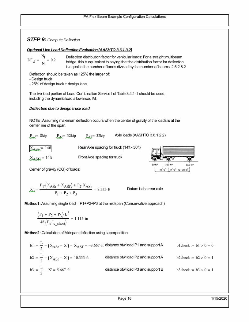
STEP 9: Compute Deflection
Optional Live Load Deflection Evaluation (AASHTO 3.6.1.3.2)
Deflection distribution factor for vehicular loads: For a straight multibeambridge, this is equivalent to saying that the distribution factor for deflectionis equal to the number of lanes divided by the number of beams. 2.5.2.6.2
DFd
Nl
N0.2
Deflection should be taken as 125% the larger of:- Design truck- 25% of design truck + design lane
The live load portion of Load Combination Service I of Table 3.4.1-1 should be used,including the dynamic load allowance, IM;
Deflection due to design truck load
NOTE : Assuming maximum deflection occurs when the center of gravity of the loads is at thecenter line of the span.
P1 8kip P2 32kip P3 32kip Axle loads (AASHTO 3.6.1.2.2)
XASr 14ft Rear Axle spacing for truck (14ft - 30ft)
XASf 14ft Front Axle spacing for truck
Center of gravity (CG) of loads:
X'P1 XASr XASf P2 XASr
P1 P2 P39.333 ft Datum is the rear axle
Method1: Assuming single load = P1+P2+P3 at the midspan (Conservative approach)
P1 P2 P3 L3
48 Es Ic_short 1.115 in
Method2: Calculation of Midspan deflection using superposition
b1L
2XASr X' XASf 3.667 ft distance btw load P1 and support A b1check b1 0 0
b2L
2XASr X' 10.333 ft distance btw load P2 and support A b2check b2 0 1
b3L
2X' 5.667 ft distance btw load P3 and support B b3check b3 0 1
Page 16 1/15/2020

PA Flex Beam Example Configuration Calculations
Deflection of the beam at midspan due to P1: P P1
xL
2 at midspan b b1 b1check The smallest distance btw load P1 and support
Δ1P b x
6 Es Ic_short LL2
b2
x2
0 in
Deflection of the beam at midspan due to P2: P P2
xL
2 at midspan b b2 b2check The smallest distance btw load P2 and support
Δ2P b x
6 Es Ic_short LL2
b2
x2
0.431 in
Deflection of the beam at midspan due to P3: P P3
xL
2 at midspan b b3 b3check The smallest distance btw load P3 and support
Δ3P b x
6 Es Ic_short LL2
b2
x2
0.267 in
Total Deflection at midspan:
Δtruck Δ1 Δ2 Δ3( ) DFd 1 I( ) 0.186 in (Considering IM)
Deflection due to tandem (Note: this calculation is not required according to Article3.6.1.3.2 which denotes only the design truck for deflection calculation)
Page 17 1/15/2020

PA Flex Beam Example Configuration Calculations
FT 31.25 kip Per axle
XAS 4ft Axle spacing
Δtandem
FTL
2
XAS
2
24 Es Ic_short3 L
2 4
L
2
XAS
2
2
DFd 1 I( ) 0.251 in (Considering IM)
Deflection due to lane load
FDLLd 640lbf
ft DFd 128
lbf
ft
Δlane
5 FDLLd L4
384 Es Ic_short0.037 in
Live Load Deflection:
ΔLL 1.25max Δtruck 0.25Δtruck Δlane 1.25 0.290 in ΔLLL
800 1
Deflection Limit
For steel or concrete vehicular bridges:
Vehicular load = Span/800L
8000.45 in
L
10000.36 in
Evaluation of Deflection at the Service Limit State (AASHTO 3.4.2.2)
The associated permitted deflections shall be included in the contract documents.
Page 18 1/15/2020

PA Flex Beam Example Configuration Calculations
Shear demands:
Determination of the distribution factor
Using DM4 Table 4.6.2.2.3a-1
Sbe
12in2.833 transverse girder spacing (ft)
Distribution of live loads per lane for shear in interior beams:
For one design lane loaded, 3.5' <= S =< 16', number of beam >= 4DFs 0.36
S
25 0.473
Q Actr1 h Y'c_shorthf
2
119.834 in3
first moment of deck slab for interface shear
Method 1: Range of shear based on Strength I Limit
STRENGTH I 1.25DL + 1.5SDL + 1.75 (LL+IM)
Computation of the range of shear in the beam
Dead Load:DL 0.321
kip
ft
Superimposed Dead Load: SDL 0.489kip
ft
Design Lane Load: 0.64kip
ft
Design Truck:
XASr 14ft Rear Axle spacing for truck (14ft - 30ft)
XASf 14ft Front Axle spacing for truck
P1 8 kip P2 32 kip P3 32 kip Wheel loads (AASHTO 3.6.1.2.2)
Design Tandem:
Consist of a pair of 25-kip axles spaced 4-ft apart. (AASHTO 3.6.1.2.3)
NOTE: PennDOT DM4 increases 25-kip to 31.25-kip.
FT 31.25kip
XAS 4ft Axle spacing
Page 19 1/15/2020

PA Flex Beam Example Configuration Calculations
Maximum positive shear at various points along the FlexBeam are examined.
At x=0 (at left support) (Truck is moving from left to right)
Truck
Max Positive Shear (when P3 is at x = 0):
x1 L XASr XASf 2 ft Distance between P1 and right support
x2 L XASr 16 ft Distance between P2 and right support
x3 L 30 ft Distance between P3 and right support
V1 P3
x3
L P2
x2
L P1
x1
L 49.6 kip
Total Vertical Shear Force for each FlexBeam (considering dynamic loads):
Vtruck1 V1 DFs 1 I( ) 31.225 kip
Tandem:
V1 FT FT
L XAS L
58.333 kip
Total Vertical Shear Force for each FlexBeam (considering dynamic loads):
Vtandem1 V1 DFs 1 I( ) 36.723 kip
Lane Load
V1 0.64kip
ft
L
2 9.6 kip
Total Vertical Shear Force for each FlexBeam (considering dynamic loads):
Vlane1 V1 DFs 4.544 kip
Dead Load
Vdl1 DLL
2 4.821 kip
Superimposed Dead Load
Vsdl1 SDLL
2 7.342 kip
Strength I Max Positive Shear:
Vstr1 1.25 Vdl1 1.5 Vsdl1 1.75 Vlane1 max Vtruck1 Vtandem1 89.256 kip
Page 20 1/15/2020

PA Flex Beam Example Configuration Calculations
Design Permit Load P-82
Shear at x=0
Strength II Max Positive Shear:
VPL82 VPL82span DFs 1 IPL 48.871 kip
STRENGTH II 1.25DL + 1.5SDL + 1.35 (LL+IM)
VstrII_PL 1.25 Vdl1 1.5 Vsdl1 1.35 VPL82 83.015 kip
Max Shear Demand Vu max Vstr1 VstrII_PL 89.256 kip
Determine the Shear Strength of the Web
Shear Strength of Unstiffened web from AASHTO section 6.10.9.2
Depth of Web D d 18 in Thickness of web tw 0.375 in
Transverse Stiffener Spacing d0 0in Shear Buckling Coefficient k 5 6.10.9.3.2-7
Plastic Shear Force Vp 0.58 Fy D tw 195.75 kip Equation 6.10.9.3.2-3
Ratio of Shear-Buckling resistance to shear yield, C
D
tw48 1.12
Es k
Fy 60.314 Ccheck
D
tw1.12
Es k
Fy 1 Equation 6.10.9.3.2-4
C 1.0 Ccheck 1 C=1 for most cases, if the criteria are not met, then C will go to zero and the actualcoefficients should be determined
Nominal Shear Resistance of Web Vn C Vp 195.75 kip equation 6.10.9.3.3-1
Shear Resistance Factor φv 1.0
φv Vn 195.75 kip φv Vn Vu 1Reduced Shear Strength
Page 21 1/15/2020

PA Flex Beam Example Configuration Calculations
Check Bearing Stiffeners
FYs 50ksi Yield strength of stiffener
tp 0.75in Thickness of stiffener
bt
bf tw
21.5in 4.312 in Effective width of stiffener
Dst hw 4.1in 13.4 in Depth of stiffeners
Apn 2 tp bt 6.469 in2
Projected area of stiffeners
bt 0.48 tpEs
FYs 1Check that effective width of stiffener meets requirements
Rsbn 1.4 Apn FYs 452.812 kip Bearing capacity of stiffener (phi=1 for bearing per AASHTO 6.5.4.2)
Rsbn Vu 1 Bearing capacity check
Qs 1.0 Q factor for bearing stiffner, taken as 1 (AASHTO 6.9.4.1.1)
Is
18 tw tw3
tp 2 bt 3
1240.131 in
4 Moment of inertia of stiffener and web (9*tw is used on each side)
AASHTO 6.10.11.2.4b
Ag 18 tw tw 2 bt tp 9 in2
Gross area of stiffener and web (AASHTO 6.10.11.2.4b)
rs
Is
Ag2.112 in Radius of gyration of stiffener/web
Po Qs FYs Apn 323.437 kip Nominal yeild resistance of stiffener (AASHTO 6.9.4.1.1)
Peπ2Es
0.75 Dst
rs
2Ag 1.137 10
5 kip Elastic critical buckling stress of stiffener (AASHTO 6.9.4.1.2-1)
Check that Pe/Po is great than 0.44 (AASHTO 6.9.4.1.1) PePoPe
Po0.44 1
Pn PePo 0.658
Po
Pe Po 323.053 kip Nominal compressive resistance of stiffener for Pe/Po>0.44
(AASHTO 6.9.4.1.1-1)
φcr 0.95 phi factor for axial compression (AASHTO 6.5.4.2)
Pr φcr Pn 306.9 kip Compressive capacity of bearing stiffener Pr Vu 1
Page 22 1/15/2020

PA Flex Beam Example Configuration Calculations
Flexbeam Example Configuration Calculations
Summary of Calculations:
Input section dimensions and material properties for steel WT and the concrete deck1.Calculate demands (dead load, superimposed dead, and Live load demands for Strength I and Strength II2.Calculate composite section properties for the given section3.Check Strength I, Strength II, and Service II stresses 4.Check Strength I, Strength II, and Strength V moment demands 5.Perform live load deflection check6.Determine maximum shear demand and capacity7.Note: Shear envelope data was obtained from Matlab script (FlexBeam_Moment_ShearEnvelope.m).8.Shear envelope calculations are summarized separately for each design (Shear Design *.xlsx).
Design Assumptions:Design Specifications Used:
AASHTO LRFD Bridge Design Specifications 7th Edition with 2016 Interim RevisionsPennDOT Design Manual, Part 4 (DM-4) June 30, 2015
Example configurations are determined for two girder spacings, 36" and 40".The deck thickness is 7.5" and is assumed to have a non-structural wearing surface added after installation.Section properties are calculated using the full 7.5" deck thickness.The WT sections are embedded 3.5" into the concrete deck. The steel section spacing used is outside the scope of the AASHTO and PennDOT distribution factorequations. The Fflexural distribution factor is assumed to be 0.3 which was shown to tbe conservativeaccording to refined analysisThe shear distribution factor is calculated using the DM-4 shear distribution factor equation which wasshown to be conservative using refined analysis.Refined analysis is presented in: Zihan Ma, "Distribution Factors for Composite Steel Tee Concrete DeckBridge System," M.S. Thesis, Deparement of Civil and Environmental Engineering, Lehigh University,Bethlehem, 2019Shear and moment demands for the PL82 permit load vehicle are determined by Matlab script(FlexBeam_Moment_ShearEnvelope.m) and are manually input into this calculation sheet.All fabrication will occur as double modules, i.e. each module contains two WT sections. The number ofmodules is half the number of beams, N. A 45 in. tall F-Shape barrier is used, Weight = 700 lb/ft (Distributed to exterior two beams).
The work presented in this document are provided on an “AS IS” basis. University makes no warranties of anykind, express or implied, as to any matter whatsoever, including, without limitation, warranties with respect tothe merchantability or fitness for a particular purpose of this work or any project deliverables. Universitymakes no warranty of any kind with respect to freedom from patent, trademark, copyright or trade secretinfringement arising from the use of the results of the project, deliverables, services, intellectual property orother materials provided hereunder. University shall not be liable for any direct, indirect, consequential,punitive, or other damages suffered by Sponsor or any other person resulting from the project, or the use ofthis work or any project deliverables.
Page 1 1/15/2020

PA Flex Beam Example Configuration Calculations
hf
tf
bf
twh
d
bjtbe
e
Variable Definitions:
Number of beams N 10 modulesN
25
L 30ft Span length
be 36in Effective width of Flexbeamassuming constructed bridge width(i.e. closure joints cast)
Built Up Section Properties
tw 0.375in tf 0.5in bf 12in
h 22in Overall Height of section
hf 7.5in Total thickness of deck
e 3.5in Deck/Steel overlap
d h hf e 18 in depth of built up steel section
hw d tf 17.5 in height of web of built up steel
Moment and shear for permit load PL82 obtained from Matlab script: FlexBeam_Moment_ShearEnvelope
MLL_IM_PL82 215.136kip ft Moment due to PL82 with distribution factor and impact factor!!
VPL82span 86.04kip Shear due to PL82 WITHOUT distribution factor and impact factor!!
Check web and flange dimensions in sections 6.10.2.1 and 6.10.2.2
(Ignore 6.10.2.2-4 since no compression flange)
equation 6.10.2.1.1-1d
tw150 1 equation 6.10.2.2-1
bf
2 tf12 1
equation 6.10.2.2-2 bfh
6 1 equation 6.10.2.2-3 tf 1.1 tw 1
y_bar
tf bftf
2 hw tw tf
hw
2
tf bf hw tw4.951 in Center of gravity of steel section
Istl
bf tf3
12bf tf y_bar
tf
2
2
tw hw
3
12 tw hw tf
hw
2 y_bar
2
421.486 in4
MOI of steel
Astl tf bf hw tw 12.562 in2
Area of the WT steel section
Page 2 1/15/2020

PA Flex Beam Example Configuration Calculations
Material Properties
Elastic Modulus of Steel Es 29000ksi
Yield Strength of Steel Fy 50ksi
Yield Strength of Reinforcement fy 60ksi
Compressive Strength of Concrete fc 4000psi AAAP PennDOT Concrete
Concrete Modular Ratio n 8 modular ratio for 4ksi concrete per AASHTO
Unit weight of concrete slab wc 0.150kip
ft3
Unit weight of concrete
Section Properties
Width of UHPC Joint: bjt 6in
Parapet width: bpar 20.25in Parapet width per PennDOT F-shape barrier
Width of the bridge W be N bjt 354 in W 29.5 ft
Clear width of roadway Wlane W 2 bpar 26.125 ft
Dc wc hf W 2.766kip
ft DL due to slab
Db .700kip
ft DL due to each 45" F-Shape Barrier (per email 11/1/18)
DFWS 30lbf
ft2
W 2 bpar 0.784kip
ft DL due to Future Wearing Surface (FWS)
Ds Astl 490lbf
ft3
0.043kip
ft Selfweight of the steel section
DLself
Dc N
Ds 0.319kip
ft Self-weight per WT
Total weight of each precast FlexBeam for transportation:
Weight of C12x25 Diaphragms Wend_diaphragms 25lbf
ft32 in 0.067 kip
2be bjt hf wc 2Ds L 2 Wend_diaphragms 18.167 kip
Determine number of design lane (AASHTO Section 3.6.1.1.1)
Take the integer part of the ratio of W/12 ft. Number of lanes in bridge: Nl floorWlane
12ft
2
Page 3 1/15/2020

PA Flex Beam Example Configuration Calculations
STEP 1: Compute Dead Load for each Flex Beam
DLslab
Dc
Nwc 1 in
be
2 0.295
kip
ft Dead load of slab assuming exterior overhang has 1" of
additional concrete thickness
DLsteel Ds 0.043kip
ft
DL DLslab DLsteel 0.338kip
ft
STEP 2: Compute Superimposed Dead Load
SDLWS
DFWS
N0.078
kip
ft
SDLparapet
Db
20.35
kip
ft distributed equally on two outer beams
SDLOL 140lbf
ft3be 2 in 0.07
kip
ft Overlay is 2" thick and is 140 lbs/cubic foot
NOTE: For this example barrier load is distributed equally among the two outer beams per conversation withPennDOT and M&M.
PennDOT DM4: "For composite adjacent and spread beams, the barrier (single barrier) load shall be equallydistributed to the nearest three (adjacent) and two (spread) beams, respectively, when the barriers are placedafter slab has hardened".
SDL SDLWS SDLparapet SDLOL 0.498kip
ft
STEP 3: Compute Transformed Width of Slab
For live load and dead load acting on the stringer k1 1 For short-term section property evaluation
btr1
be
k1 n4.5 in Transformed width of slab for short-term
For superimposed dead loads k3 3 For long-term section property evaluation
btr3
be
k3 n1.5 in Transformed width of slab for long-term
Page 4 1/15/2020

PA Flex Beam Example Configuration Calculations
STEP 4: Compute Dead and Superimposed Dead Load Moments(Based on first interior girder demands)
MDLDL L
2
838.032 kip ft
MSDLSDL L
2
856.067 kip ft
STEP 5: Compute live load and Dynamic Load Allowance (IM)
Live load wheel load distribution factor (DF):
Sbe
12in3 transverse girder spacing
NOTE: AASHTO presents equations to define DF for different types of superstructuresincluding Deck Composite wirh RC slab on steel girders (Type (a) in Table 4.6.2.2.1-1) forshear and moment in interior and exterior beams.
Using DM4 Table 4.6.2.2.2b-1:
eg h y_barhf
2 13.299 in Distance between the centers of gravity of the basic beam and deck
Kg n Istl Astl eg2
21145.34 in
4 Longitudinal stiffness parameter (in4)
Distribution of Live Load Per Lane for Moment in Interior Beams:
to be conservative, use DF 0.3
Page 5 1/15/2020

PA Flex Beam Example Configuration Calculations
Dynamic Load Allowance (Section 3.6.2 DM4)
Static effects of the design truck or tandem, shall be increased by the impact factor.
NOTE: The dynamic load allowance shall not be applied to the design lane load (Section 3.6.2.1 DM4)
I 0.33 Impact factor for moment
Note: PennDOT requires that the impact for decks be increased from 33% to 50%, the deck is not beingdesigned here. Instrad the deck design is based on the BD recommendations.
Dynamic load allowance for the Permit Load P-82 shall be less than 20%. (Section 3.6.2.1DM4)
IPL 0.20 Impact factor for moment on Strength II
Design Wind Loading for Exterior Girder
Vw 80 Wind speed for Strength V load case
CD 1.3 Gust factor for windard side of I-Girder and Box Girder Superstructures (Table 3.8.1.2.1-2)
G 1.0 Gus effect factor is 1.0 for all structures other than sound barriers (Table 3.8.1.2.1-1)
Kz 1.0 Pressure coefficient taken as 1 for Strength V (3.8.1.2.1)
Pz 2.56 106
Vw 2 Kz G CDkip
ft2
0.021kip
ft2
Wind pressure on exterior girder
hexp h hf 14.5 in Exposed height of exterior girder
Moment due to wind loading on exterior girderMWL
Pz hexp L2
82.895 kip ft
Iyy
bf3tf
1272 in
4 Transverse moment of intertia
Flange lateral bending stressfl
MWL
bf
2
Iyy2.895 ksi
Page 6 1/15/2020

PA Flex Beam Example Configuration Calculations
Design Vehicular Live Load
PHL-93 and P-82 are examined herein.
PHL-93 (A3.6.1.2.1)
PHL-93 consists of a combination of (design truck or design tandem) + (design lane load)
Design Truck
PennDOT defines the design truck in accordance with AASTHO 3.6.1.2
Design truck load in AASHTO (HS20 Truck) is used for this example.
NOTE : MAX moment occurs when the center line of the span is midway between the center ofgravity of the loads and the nearest concentrated load.
P1 8kip P2 32kip P3 32kip Axle loads (AASHTO 3.6.1.2.2)
XASr 14ft Rear Axle spacing for truck (14ft - 30ft)
XASf 14ft Front Axle spacing for truck
Page 7 1/15/2020

PA Flex Beam Example Configuration Calculations
Center of gravity (CG) of loads:
X'P1 XASr XASf P2 XASr
P1 P2 P39.333 ft Datum is the rear axle
X XASr X' 4.667 ft Spacing btw CG and nearest load
Find bridge reaction
Truck movestoward Support ARA
P1L
2XASf
X
2
P2L
2
X
2
P3L
2X'
X
2
L30.4 kip
Max live load moment (at the location of P2):
MLL_truck RAL
2
X
2
P1 XASf 273.067 kip ft
NOTE: Find the worst case by varying XASr
Page 8 1/15/2020
PA Flex Beam Example Configuration Calculations
Design Tandem
Consist of a pair of 25-kip axles spaced 4-ft apart. (AASHTO 3.6.1.2.3)
NOTE: PennDOT DM4 increases 25-kip to 31.25-kip.
FT 31.25kip
XAS 4ft Axle spacing
Center of gravity (CG) of loads:
XXAS
22 ft Spacing btw CG and nearest load
Find bridge reaction
RA
FTL
2
X
2
FTL
2
X
2 X
L29.167 kip Truck moves toward Support A
Max live load moment (at the location of front wheel):
MLL_tandem RAL
2
X
2
408.333 kip ft
Choose the max value:
MLL_veh max MLL_tandem MLL_truck 408.333 kip ft
Apply the impact and wheel load distribution:
MLL_IM_veh MLL_veh DF 1 I( ) 162.925 kip ft Due to tandem or truck
Design Lane Load (distributed over a 10-ft width for each lane)
NOTE: The uniform load may be continuous or discontinuous as necessary to produce themaximum force effect. For this example continuous uniform distribution assumed.
FDLL 0.64kip
ftDF 0.192
kip
ft Per beam in each lane
Due to lane loadMLL_IM_lane
FDLL L2
8
21.6 kip ft
Moment due to Total Design Vehicular Live Load: MLL_IM MLL_IM_lane MLL_IM_veh 184.525 kip ft
Page 9 1/15/2020

PA Flex Beam Example Configuration Calculations
Design Permit Load P-82 (Section 3.6.1.2.7 DM4)
P1 P2 P3 P4 P5 P6 P7
NOTE: The moment for the permit load is defined at the beginning of the sheetand is obtained from MATLab File FlexBeam_Moment_ShearEnvelope.m
STEP 6: Compute Moment of Inertia (Note: rebar neglected!)
1) Moment of Inertia resisting dead load only:
a) Acting on the non-composite section (before the deck has hardened - DC1)
Use steel section only
Inc Istl 421.486 in4
Non-composite section modulus
Y'nc y_bar S.G. of the steel section of Flex Beam (Datum is bottom)
b) Acting on the composite section (after the deck has hardened - DC2)
Use Ic_short as defined below.
Page 10 1/15/2020

PA Flex Beam Example Configuration Calculations
2) Moment of Inertia resisting live load plus impact:
Using transformed slab with k1=1 (short-term composite).
Actr1 hf btr1 33.75 in2
Itr1
btr1 hf3
12158.203 in
4
Y'
Actr1 hhf
2
Astl Y'nc
Astl Actr114.643 in S.G. of the total flex beam (Datum is bottom)
Compositesection modulus(short-term)
Ic_short Istl Astl Y'nc Y' 2 Itr1 Actr1 hhf
2
Y'
2
2199 in4
Y'c_short Y' 14.643 in N.A. of the short-term composite section
3) Moment of Inertia resisting superimposed dead load:
Using transformed slab with k3=3.
Actr3 hf btr3 11.25 in2
Itr3
btr3 hf3
1252.734 in
4
Y'
Actr3 hhf
2
Astl Y'nc
Astl Actr311.234 in S.G. of the total flex beam (Datum is bottom)
Compositesection modulus(long-term)
Ic_long Istl Astl Y'nc Y' 2 Itr3 Actr3 hhf
2
Y'
2
1524 in4
Y'c_long Y' 11.234 in N.A. of the long-term composite section
Page 11 1/15/2020

PA Flex Beam Example Configuration Calculations
STEP 6.5 Check Ductility RequirementIn accordance with AASHTO Article 6.10.7.3 check ductility requirement. Assume compressionblock of concrete is at 0.85 f'c and that the concrete supports no tension. Steel section isassumed to be fully plastic at Fy.
Case 1 : Assuming PNA is in Concreteh d 4 inAssuming (h-d) < Dp < hf
Fp Dp 0.85 fc be Dp Fy tw Dp h d( ) Fy Astl tw Dp h d( )
Dp 7.5in 0.42 h 9.24 in
Dp1 root Fp Dp Dp 4.866 in Must be less than hf 7.5 inDp1
h0.221 must be < 0.42
Mn1check Dp1 hf h d( ) Dp1[ ] Dp1 0.42 h( ) 1 Dp1 0.42 h 1
Mp1 0.85 fc be Dp1Dp1
2
Fy tw Dp1 h d( )[ ] Dp1 h d( )[ ]
2
Fy bf tf h Dp1tf
2
Fy tw h Dp1 tf h Dp1 tf
2
Mp1 9115.29 kip in Mn1 Mp1 1.07 0.7Dp1
h
8342 kip in
Case 2 : Assuming PNA is NOT in Concrete
Assuming hf < Dp
Fp2 Dp 0.85 fc be hf Fy tw Dp h d( ) Fy Astl tw Dp h d( )
Dp 2.5in
Dp2 root Fp2 Dp Dp 3.73 in Must be more than hf 7.5 inDp2
h0.1695 must be < 0.42
Mn2check Dp2 hf Dp2 h( ) Dp2 0.42 h( ) 0 Dp2 0.42 h 1
Mp2 0.85 fc be hf Dp2hf
2
Fy tw Dp2 h d( )[ ] Dp2 h d( )[ ]
2
Fy bf tf h Dp2tf
2
Fy tw h Dp2 tf h Dp2 tf
2
Mp2 7305.23 kip inMn2 Mp2 1.07 0.7
Dp2
h
8683.6 kip in
Mn max Mn1 Mn1check Mn2 Mn2check 695.2 kip ft Mn 8342 kip in
Page 12 1/15/2020

PA Flex Beam Example Configuration Calculations
Check Composite Compact Section Criteria (6.10.6.2)
Dcpd
2
Fy tf bf 0.85 fc be hf
Fy hw tw1
7.951 in Dcp0 Dcp 0 0
Dcp Dcp Dcp0 0 in2 Dcp
tw3.76
Es
Fy 1 Check if section is compact
STEP 7: Load Combinations (Table 3.4.1-1)
The following load combinations will be considered herein. Only the maximum load factors forpermanent-loads are used in the following load combinations (uplift is not an issue for this typeof bridge).STRENGTH I 1.25DL + 1.5SDL + 1.75 (LL+IM)
SERVICE II: DL+SDL+1.3(LL+IM)
STEP 8: Compute and Check Stresses
Stress at bottom fiber of steel section
fDL
MDL Y'c_long
Ic_long3.365 ksi
fLL_I
MLL_IM Y'c_short
Ic_short14.746 ksi fPL
MLL_IM_PL82 Y'c_short
Ic_short17.193 ksi
fSDL
MSDL Y'c_long
Ic_long4.96 ksi
STRENGTH I fbot_str1 1.25fDL 1.5 fSDL 1.75 fLL_I 37.452 ksi
STRENGTH II fbot_str2 1.25fDL 1.5 fSDL 1.35 fPL 34.856 ksi
SERVICE II fbot_svc2 fDL fSDL 1.3fLL_I 27.5 ksi
Allowable Stress is based on Section 6.10.4.2.2-2
Flange stress due to service load II without consideration of flange lateral bending: ff fbot_svc2
Flange lateral bending stress due to service II: flSII 0ksi
Hybrid Factor: Rh 1.0 For rolled and homogenous built-up sections
ff
flSII
2 27.495 ksi 0.95 Rh Fy 47.5 ksi ff
fl
2 0.95Rh Fy 1
Page 13 1/15/2020

PA Flex Beam Example Configuration Calculations
Stress at top fiber of concrete
Note: For calculating longitudinal flexural stresses in the concrete deck due to allpermanent and transient loads, the short-term modular ratio shall be used.
fDL
MDL h Y'c_short
k1 n Ic_short0.191 ksi
fLL_I
MLL_IM h Y'c_short
k1 n Ic_short0.926 ksi fPL
MLL_IM_PL82 h Y'c_short
k1 n Ic_short1.08 ksi
fSDL
MSDL h Y'c_short
k1 n Ic_short0.281 ksi
STRENGTH I fc_str1 1.25fDL 1.5 fSDL 1.75 fLL_I 2.282 ksi
Mstr1 1.25 MDL 1.5 MSDL 1.75 MLL_IM 454.6 kip ft Mstr1 Mn 1
STRENGTH II fc_str2 1.25fDL 1.5 fSDL 1.35 fPL 2.118 ksi
Mstr2 1.25 MDL 1.5 MSDL 1.35 MLL_IM_PL82 422 kip ft Mstr2 Mn 1
SERVICE II
Allowable Stress in concrete - AASHTO 6.10.4.2.2For compact composite sections in positive flexure utilized in shored construction, the longitudinalcompressive stress in the concrete deck due to the Service II loads, determined as specified in Article6.10.1.1.1d, shall not exceed 0.6f́ c.
fallow 0.6 fc 2400 psi
fc_2 1.3fLL_I fSDL fDL 1676.33 psi This assumes short term compositesection for all calculations
fc_2 fallow 1
SERVICE II with Long Term Composite for dead loads
fDL
MDL h Y'c_long
k3 n Ic_long0.134 ksi
fLL_I
MLL_IM h Y'c_short
k1 n Ic_short0.926 ksi
fSDL
MSDL h Y'c_long
k3 n Ic_long0.198 ksi
fc_2 1.3fLL_I fSDL fDL 1536.43 psi fc_2 fallow 1
Page 14 1/15/2020

PA Flex Beam Example Configuration Calculations
Strength V Moment Check
Strength V is related to normal vehicular use of the bridge with an 80 mph wind gust
Note: that Strength V is checked for an exterior girder under wind load with the interior girder distribution factor forflexure used. If Strength V controls design, then this approach should be modified
Design vertical moment is: 1.25DL + 1.5SDL + 1.35 (LL+IM)
SLT
Ic_long
Y'c_long135.642 in
3 SST
Ic_short
Y'c_short150.159 in
3 short and long term section
modulus
Section D6.2.2 Find the moment required to cause yieldling of the flange. The approach is laid out in D6.2.2
MD2 1.25 MDL 1.5 MSDL 131.64 kip ft From D6.2.2-1 (all dead loads are in MD2 due to shoredconstruction
MAD Fy
MD2
SLT
SST 479.932 kip ft Additional moment to cause nominal yielding of steel flange
My MD2 MAD 611.572 kip ft D6.2.2-2: Moment to cause yielding of flange
6.10.7.1 Compact Section Check at Strength V limit state
Section Modulus for yielding of the flange (My/Fy) for equation 6.10.7.1.1-1Sxt
My
Fy146.777 in
3
Mu 1.25 MDL 1.5MSDL 1.35MLL_IM 380.749 kip ft Moment due to Strength V limit state
Mu1
3fl Sxt 392.554 kip ft Equation 6.10.7.1.7-1 Mn 695.164 kip ft Mu
1
3fl Sxt Mn 1
Page 15 1/15/2020

PA Flex Beam Example Configuration Calculations
STEP 9: Compute Deflection
Optional Live Load Deflection Evaluation (AASHTO 3.6.1.3.2)
Deflection distribution factor for vehicular loads: For a straight multibeambridge, this is equivalent to saying that the distribution factor for deflectionis equal to the number of lanes divided by the number of beams. 2.5.2.6.2
DFd
Nl
N0.2
Deflection should be taken as 125% the larger of:- Design truck- 25% of design truck + design lane
The live load portion of Load Combination Service I of Table 3.4.1-1 should be used,including the dynamic load allowance, IM;
Deflection due to design truck load
NOTE : Assuming maximum deflection occurs when the center of gravity of the loads is at thecenter line of the span.
P1 8kip P2 32kip P3 32kip Axle loads (AASHTO 3.6.1.2.2)
XASr 14ft Rear Axle spacing for truck (14ft - 30ft)
XASf 14ft Front Axle spacing for truck
Center of gravity (CG) of loads:
X'P1 XASr XASf P2 XASr
P1 P2 P39.333 ft Datum is the rear axle
Method1: Assuming single load = P1+P2+P3 at the midspan (Conservative approach)
P1 P2 P3 L3
48 Es Ic_short 1.098 in
Method2: Calculation of Midspan deflection using superposition
b1L
2XASr X' XASf 3.667 ft distance btw load P1 and support A b1check b1 0 0
b2L
2XASr X' 10.333 ft distance btw load P2 and support A b2check b2 0 1
b3L
2X' 5.667 ft distance btw load P3 and support B b3check b3 0 1
Page 16 1/15/2020

PA Flex Beam Example Configuration Calculations
Deflection of the beam at midspan due to P1: P P1
xL
2 at midspan b b1 b1check The smallest distance btw load P1 and support
Δ1P b x
6 Es Ic_short LL2
b2
x2
0 in
Deflection of the beam at midspan due to P2: P P2
xL
2 at midspan b b2 b2check The smallest distance btw load P2 and support
Δ2P b x
6 Es Ic_short LL2
b2
x2
0.424 in
Deflection of the beam at midspan due to P3: P P3
xL
2 at midspan b b3 b3check The smallest distance btw load P3 and support
Δ3P b x
6 Es Ic_short LL2
b2
x2
0.263 in
Total Deflection at midspan:
Δtruck Δ1 Δ2 Δ3( ) DFd 1 I( ) 0.183 in (Considering IM)
Deflection due to tandem (Note: this calculation is not required according to Article3.6.1.3.2 which denotes only the design truck for deflection calculation)
Page 17 1/15/2020

PA Flex Beam Example Configuration Calculations
FT 31.25 kip Per axle
XAS 4ft Axle spacing
Δtandem
FTL
2
XAS
2
24 Es Ic_short3 L
2 4
L
2
XAS
2
2
DFd 1 I( ) 0.247 in (Considering IM)
Deflection due to lane load
FDLLd 640lbf
ft DFd 128
lbf
ft
Δlane
5 FDLLd L4
384 Es Ic_short0.037 in
Live Load Deflection:
ΔLL 1.25max Δtruck 0.25Δtruck Δlane 1.25 0.286 in ΔLLL
800 1
Deflection Limit
For steel or concrete vehicular bridges:
Vehicular load = Span/800L
8000.45 in
L
10000.36 in
Evaluation of Deflection at the Service Limit State (AASHTO 3.4.2.2)
The associated permitted deflections shall be included in the contract documents.
Page 18 1/15/2020

PA Flex Beam Example Configuration Calculations
Shear demands:
Determination of the distribution factor
Using DM4 Table 4.6.2.2.3a-1
Sbe
12in3 transverse girder spacing (ft)
Distribution of live loads per lane for shear in interior beams:
For two design lanes loaded, 3.5' <= S =< 16', number of beam >= 4DFs 0.36
S
25 0.48
Q Actr1 h Y'c_shorthf
2
121.746 in3
first moment of deck slab for interface shear
Method 1: Range of shear based on Strength I Limit
STRENGTH I 1.25DL + 1.5SDL + 1.75 (LL+IM)
Computation of the range of shear in the beam
Dead Load:DL 0.338
kip
ft
Superimposed Dead Load: SDL 0.498kip
ft
Design Lane Load: 0.64kip
ft
Design Truck:
XASr 14ft Rear Axle spacing for truck (14ft - 30ft)
XASf 14ft Front Axle spacing for truck
P1 8 kip P2 32 kip P3 32 kip Wheel loads (AASHTO 3.6.1.2.2)
Design Tandem:
Consist of a pair of 25-kip axles spaced 4-ft apart. (AASHTO 3.6.1.2.3)
NOTE: PennDOT DM4 increases 25-kip to 31.25-kip.
FT 31.25kip
XAS 4ft Axle spacing
Page 19 1/15/2020

PA Flex Beam Example Configuration Calculations
Maximum positive shear at various points along the FlexBeam are examined.
At x=0 (at left support) (Truck is moving from left to right)
Truck
Max Positive Shear (when P3 is at x = 0):
x1 L XASr XASf 2 ft Distance between P1 and right support
x2 L XASr 16 ft Distance between P2 and right support
x3 L 30 ft Distance between P3 and right support
V1 P3
x3
L P2
x2
L P1
x1
L 49.6 kip
Total Vertical Shear Force for each FlexBeam (considering dynamic loads):
Vtruck1 V1 DFs 1 I( ) 31.665 kip
Tandem:
V1 FT FT
L XAS L
58.333 kip
Total Vertical Shear Force for each FlexBeam (considering dynamic loads):
Vtandem1 V1 DFs 1 I( ) 37.24 kip
Lane Load
V1 0.64kip
ft
L
2 9.6 kip
Total Vertical Shear Force for each FlexBeam (considering dynamic loads):
Vlane1 V1 DFs 4.608 kip
Dead Load
Vdl1 DLL
2 5.071 kip
Superimposed Dead Load
Vsdl1 SDLL
2 7.476 kip
Strength I Max Positive Shear:
Vstr1 1.25 Vdl1 1.5 Vsdl1 1.75 Vlane1 max Vtruck1 Vtandem1 90.786 kip
Page 20 1/15/2020

PA Flex Beam Example Configuration Calculations
Design Permit Load P-82
Shear at x=0
Strength II Max Positive Shear:
VPL82 VPL82span DFs 1 IPL 49.559 kip
STRENGTH II 1.25DL + 1.5SDL + 1.35 (LL+IM)
VstrII_PL 1.25 Vdl1 1.5 Vsdl1 1.35 VPL82 84.457 kip
Max Shear Demand Vu max Vstr1 VstrII_PL 90.786 kip
Determine the Shear Strength of the Web
Shear Strength of Unstiffened web from AASHTO section 6.10.9.2
Depth of Web D d 18 in Thickness of web tw 0.375 in
Transverse Stiffener Spacing d0 0in Shear Buckling Coefficient k 5 6.10.9.3.2-7
Plastic Shear Force Vp 0.58 Fy D tw 195.75 kip Equation 6.10.9.3.2-3
Ratio of Shear-Buckling resistance to shear yield, C
D
tw48 1.12
Es k
Fy 60.314 Ccheck
D
tw1.12
Es k
Fy 1 Equation 6.10.9.3.2-4
C 1.0 Ccheck 1 C=1 for most cases, if the criteria are not met, then C will go to zero and the actualcoefficients should be determined
Nominal Shear Resistance of Web Vn C Vp 195.75 kip equation 6.10.9.3.3-1
Shear Resistance Factor φv 1.0
φv Vn 195.75 kip φv Vn Vu 1Reduced Shear Strength
Page 21 1/15/2020

PA Flex Beam Example Configuration Calculations
Check Bearing Stiffeners
FYs 50ksi Yield strength of stiffener
tp 0.75in Thickness of stiffener
bt
bf tw
21.5in 4.312 in Effective width of stiffener
Dst hw 4.1in 13.4 in Depth of stiffeners
Apn 2 tp bt 6.469 in2
Projected area of stiffeners
bt 0.48 tpEs
FYs 1Check that effective width of stiffener meets requirements
Rsbn 1.4 Apn FYs 452.812 kip Bearing capacity of stiffener (phi=1 for bearing per AASHTO 6.5.4.2)
Rsbn Vu 1 Bearing capacity check
Qs 1.0 Q factor for bearing stiffner, taken as 1 (AASHTO 6.9.4.1.1)
Is
18 tw tw3
tp 2 bt 3
1240.131 in
4 Moment of inertia of stiffener and web (9*tw is used on each side)
AASHTO 6.10.11.2.4b
Ag 18 tw tw 2 bt tp 9 in2
Gross area of stiffener and web (AASHTO 6.10.11.2.4b)
rs
Is
Ag2.112 in Radius of gyration of stiffener/web
Po Qs FYs Apn 323.437 kip Nominal yeild resistance of stiffener (AASHTO 6.9.4.1.1)
Peπ2Es
0.75 Dst
rs
2Ag 1.137 10
5 kip Elastic critical buckling stress of stiffener (AASHTO 6.9.4.1.2-1)
Check that Pe/Po is great than 0.44 (AASHTO 6.9.4.1.1) PePoPe
Po0.44 1
Pn PePo 0.658
Po
Pe Po 323.053 kip Nominal compressive resistance of stiffener for Pe/Po>0.44
(AASHTO 6.9.4.1.1-1)
φcr 0.95 phi factor for axial compression (AASHTO 6.5.4.2)
Pr φcr Pn 306.9 kip Compressive capacity of bearing stiffener Pr Vu 1
Page 22 1/15/2020

PA Flex Beam Example Configuration Calculations
Flexbeam Example Configuration Calculations
Summary of Calculations:
Input section dimensions and material properties for steel WT and the concrete deck1.Calculate demands (dead load, superimposed dead, and Live load demands for Strength I and Strength II2.Calculate composite section properties for the given section3.Check Strength I, Strength II, and Service II stresses 4.Check Strength I, Strength II, and Strength V moment demands 5.Perform live load deflection check6.Determine maximum shear demand and capacity7.Note: Shear envelope data was obtained from Matlab script (FlexBeam_Moment_ShearEnvelope.m).8.Shear envelope calculations are summarized separately for each design (Shear Design *.xlsx).
Design Assumptions:Design Specifications Used:
AASHTO LRFD Bridge Design Specifications 7th Edition with 2016 Interim RevisionsPennDOT Design Manual, Part 4 (DM-4) June 30, 2015
Example configurations are determined for two girder spacings, 36" and 40".The deck thickness is 7.5" and is assumed to have a non-structural wearing surface added after installation.Section properties are calculated using the full 7.5" deck thickness.The WT sections are embedded 3.5" into the concrete deck. The steel section spacing used is outside the scope of the AASHTO and PennDOT distribution factorequations. The Fflexural distribution factor is assumed to be 0.3 which was shown to tbe conservativeaccording to refined analysisThe shear distribution factor is calculated using the DM-4 shear distribution factor equation which wasshown to be conservative using refined analysis.Refined analysis is presented in: Zihan Ma, "Distribution Factors for Composite Steel Tee Concrete DeckBridge System," M.S. Thesis, Deparement of Civil and Environmental Engineering, Lehigh University,Bethlehem, 2019Shear and moment demands for the PL82 permit load vehicle are determined by Matlab script(FlexBeam_Moment_ShearEnvelope.m) and are manually input into this calculation sheet.All fabrication will occur as double modules, i.e. each module contains two WT sections. The number ofmodules is half the number of beams, N. A 45 in. tall F-Shape barrier is used, Weight = 700 lb/ft (Distributed to exterior two beams).
The work presented in this document are provided on an “AS IS” basis. University makes no warranties of anykind, express or implied, as to any matter whatsoever, including, without limitation, warranties with respect tothe merchantability or fitness for a particular purpose of this work or any project deliverables. Universitymakes no warranty of any kind with respect to freedom from patent, trademark, copyright or trade secretinfringement arising from the use of the results of the project, deliverables, services, intellectual property orother materials provided hereunder. University shall not be liable for any direct, indirect, consequential,punitive, or other damages suffered by Sponsor or any other person resulting from the project, or the use ofthis work or any project deliverables.
Page 1 1/15/2020

PA Flex Beam Example Configuration Calculations
hf
tf
bf
twh
d
bjtbe
e
Variable Definitions:
Number of beams N 12 modulesN
26
L 30ft Span length
be 36in Effective width of Flexbeamassuming constructed bridge width(i.e. closure joints cast)
Built Up Section Properties
tw 0.375in tf 0.5in bf 12in
h 22in Overall Height of section
hf 7.5in Total thickness of deck
e 3.5in Deck/Steel overlap
d h hf e 18 in depth of built up steel section
hw d tf 17.5 in height of web of built up steel
Moment and shear for permit load PL82 obtained from Matlab script: FlexBeam_Moment_ShearEnvelope
MLL_IM_PL82 215.136kip ft Moment due to PL82 with distribution factor and impact factor!!
VPL82span 86.04kip Shear due to PL82 WITHOUT distribution factor and impact factor!!
Check web and flange dimensions in sections 6.10.2.1 and 6.10.2.2
(Ignore 6.10.2.2-4 since no compression flange)
equation 6.10.2.1.1-1d
tw150 1 equation 6.10.2.2-1
bf
2 tf12 1
equation 6.10.2.2-2 bfh
6 1 equation 6.10.2.2-3 tf 1.1 tw 1
y_bar
tf bftf
2 hw tw tf
hw
2
tf bf hw tw4.951 in Center of gravity of steel section
Istl
bf tf3
12bf tf y_bar
tf
2
2
tw hw
3
12 tw hw tf
hw
2 y_bar
2
421.486 in4
MOI of steel
Astl tf bf hw tw 12.562 in2
Area of the WT steel section
Page 2 1/15/2020

PA Flex Beam Example Configuration Calculations
Material Properties
Elastic Modulus of Steel Es 29000ksi
Yield Strength of Steel Fy 50ksi
Yield Strength of Reinforcement fy 60ksi
Compressive Strength of Concrete fc 4000psi AAAP PennDOT Concrete
Concrete Modular Ratio n 8 modular ratio for 4ksi concrete per AASHTO
Unit weight of concrete slab wc 0.150kip
ft3
Unit weight of concrete
Section Properties
Width of UHPC Joint: bjt 6in
Parapet width: bpar 20.25in Parapet width per PennDOT F-shape barrier
Width of the bridge W be N bjt 426 in W 35.5 ft
Clear width of roadway Wlane W 2 bpar 32.125 ft
Dc wc hf W 3.328kip
ft DL due to slab
Db .700kip
ft DL due to each 45" F-Shape Barrier (per email 11/1/18)
DFWS 30lbf
ft2
W 2 bpar 0.964kip
ft DL due to Future Wearing Surface (FWS)
Ds Astl 490lbf
ft3
0.043kip
ft Selfweight of the steel section
DLself
Dc N
Ds 0.32kip
ft Self-weight per WT
Total weight of each precast FlexBeam for transportation:
Weight of C12x25 Diaphragms Wend_diaphragms 25lbf
ft32 in 0.067 kip
2be bjt hf wc 2Ds L 2 Wend_diaphragms 18.167 kip
Determine number of design lane (AASHTO Section 3.6.1.1.1)
Take the integer part of the ratio of W/12 ft. Number of lanes in bridge: Nl floorWlane
12ft
2
Page 3 1/15/2020
PA Flex Beam Example Configuration Calculations
STEP 1: Compute Dead Load for each Flex Beam
DLslab
Dc
Nwc 1 in
be
2 0.296
kip
ft Dead load of slab assuming exterior overhang has 1" of
additional concrete thickness
DLsteel Ds 0.043kip
ft
DL DLslab DLsteel 0.339kip
ft
STEP 2: Compute Superimposed Dead Load
SDLWS
DFWS
N0.08
kip
ft
SDLparapet
Db
20.35
kip
ft distributed equally on two outer beams
SDLOL 140lbf
ft3be 2 in 0.07
kip
ft Overlay is 2" thick and is 140 lbs/cubic foot
NOTE: For this example barrier load is distributed equally among the two outer beams per conversation withPennDOT and M&M.
PennDOT DM4: "For composite adjacent and spread beams, the barrier (single barrier) load shall be equallydistributed to the nearest three (adjacent) and two (spread) beams, respectively, when the barriers are placedafter slab has hardened".
SDL SDLWS SDLparapet SDLOL 0.5kip
ft
STEP 3: Compute Transformed Width of Slab
For live load and dead load acting on the stringer k1 1 For short-term section property evaluation
btr1
be
k1 n4.5 in Transformed width of slab for short-term
For superimposed dead loads k3 3 For long-term section property evaluation
btr3
be
k3 n1.5 in Transformed width of slab for long-term
Page 4 1/15/2020
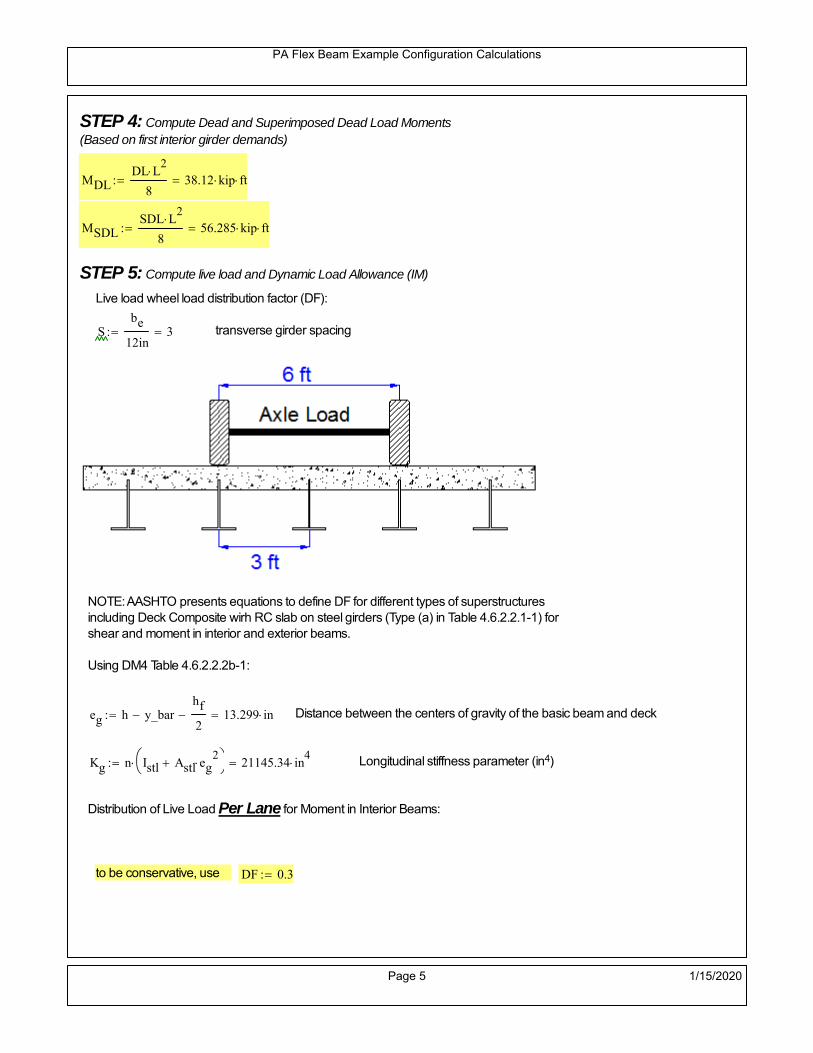
PA Flex Beam Example Configuration Calculations
STEP 4: Compute Dead and Superimposed Dead Load Moments(Based on first interior girder demands)
MDLDL L
2
838.12 kip ft
MSDLSDL L
2
856.285 kip ft
STEP 5: Compute live load and Dynamic Load Allowance (IM)
Live load wheel load distribution factor (DF):
Sbe
12in3 transverse girder spacing
NOTE: AASHTO presents equations to define DF for different types of superstructuresincluding Deck Composite wirh RC slab on steel girders (Type (a) in Table 4.6.2.2.1-1) forshear and moment in interior and exterior beams.
Using DM4 Table 4.6.2.2.2b-1:
eg h y_barhf
2 13.299 in Distance between the centers of gravity of the basic beam and deck
Kg n Istl Astl eg2
21145.34 in
4 Longitudinal stiffness parameter (in4)
Distribution of Live Load Per Lane for Moment in Interior Beams:
to be conservative, use DF 0.3
Page 5 1/15/2020

PA Flex Beam Example Configuration Calculations
Dynamic Load Allowance (Section 3.6.2 DM4)
Static effects of the design truck or tandem, shall be increased by the impact factor.
NOTE: The dynamic load allowance shall not be applied to the design lane load (Section 3.6.2.1 DM4)
I 0.33 Impact factor for moment
Note: PennDOT requires that the impact for decks be increased from 33% to 50%, the deck is not beingdesigned here. Instrad the deck design is based on the BD recommendations.
Dynamic load allowance for the Permit Load P-82 shall be less than 20%. (Section 3.6.2.1DM4)
IPL 0.20 Impact factor for moment on Strength II
Design Wind Loading for Exterior Girder
Vw 80 Wind speed for Strength V load case
CD 1.3 Gust factor for windard side of I-Girder and Box Girder Superstructures (Table 3.8.1.2.1-2)
G 1.0 Gus effect factor is 1.0 for all structures other than sound barriers (Table 3.8.1.2.1-1)
Kz 1.0 Pressure coefficient taken as 1 for Strength V (3.8.1.2.1)
Pz 2.56 106
Vw 2 Kz G CDkip
ft2
0.021kip
ft2
Wind pressure on exterior girder
hexp h hf 14.5 in Exposed height of exterior girder
Moment due to wind loading on exterior girderMWL
Pz hexp L2
82.895 kip ft
Iyy
bf3tf
1272 in
4 Transverse moment of intertia
Flange lateral bending stressfl
MWL
bf
2
Iyy2.895 ksi
Page 6 1/15/2020

PA Flex Beam Example Configuration Calculations
Design Vehicular Live Load
PHL-93 and P-82 are examined herein.
PHL-93 (A3.6.1.2.1)
PHL-93 consists of a combination of (design truck or design tandem) + (design lane load)
Design Truck
PennDOT defines the design truck in accordance with AASTHO 3.6.1.2
Design truck load in AASHTO (HS20 Truck) is used for this example.
NOTE : MAX moment occurs when the center line of the span is midway between the center ofgravity of the loads and the nearest concentrated load.
P1 8kip P2 32kip P3 32kip Axle loads (AASHTO 3.6.1.2.2)
XASr 14ft Rear Axle spacing for truck (14ft - 30ft)
XASf 14ft Front Axle spacing for truck
Page 7 1/15/2020

PA Flex Beam Example Configuration Calculations
Center of gravity (CG) of loads:
X'P1 XASr XASf P2 XASr
P1 P2 P39.333 ft Datum is the rear axle
X XASr X' 4.667 ft Spacing btw CG and nearest load
Find bridge reaction
Truck movestoward Support ARA
P1L
2XASf
X
2
P2L
2
X
2
P3L
2X'
X
2
L30.4 kip
Max live load moment (at the location of P2):
MLL_truck RAL
2
X
2
P1 XASf 273.067 kip ft
NOTE: Find the worst case by varying XASr
Page 8 1/15/2020

PA Flex Beam Example Configuration Calculations
Design Tandem
Consist of a pair of 25-kip axles spaced 4-ft apart. (AASHTO 3.6.1.2.3)
NOTE: PennDOT DM4 increases 25-kip to 31.25-kip.
FT 31.25kip
XAS 4ft Axle spacing
Center of gravity (CG) of loads:
XXAS
22 ft Spacing btw CG and nearest load
Find bridge reaction
RA
FTL
2
X
2
FTL
2
X
2 X
L29.167 kip Truck moves toward Support A
Max live load moment (at the location of front wheel):
MLL_tandem RAL
2
X
2
408.333 kip ft
Choose the max value:
MLL_veh max MLL_tandem MLL_truck 408.333 kip ft
Apply the impact and wheel load distribution:
MLL_IM_veh MLL_veh DF 1 I( ) 162.925 kip ft Due to tandem or truck
Design Lane Load (distributed over a 10-ft width for each lane)
NOTE: The uniform load may be continuous or discontinuous as necessary to produce themaximum force effect. For this example continuous uniform distribution assumed.
FDLL 0.64kip
ftDF 0.192
kip
ft Per beam in each lane
Due to lane loadMLL_IM_lane
FDLL L2
8
21.6 kip ft
Moment due to Total Design Vehicular Live Load: MLL_IM MLL_IM_lane MLL_IM_veh 184.525 kip ft
Page 9 1/15/2020

PA Flex Beam Example Configuration Calculations
Design Permit Load P-82 (Section 3.6.1.2.7 DM4)
P1 P2 P3 P4 P5 P6 P7
NOTE: The moment for the permit load is defined at the beginning of the sheetand is obtained from MATLab File FlexBeam_Moment_ShearEnvelope.m
STEP 6: Compute Moment of Inertia (Note: rebar neglected!)
1) Moment of Inertia resisting dead load only:
a) Acting on the non-composite section (before the deck has hardened - DC1)
Use steel section only
Inc Istl 421.486 in4
Non-composite section modulus
Y'nc y_bar S.G. of the steel section of Flex Beam (Datum is bottom)
b) Acting on the composite section (after the deck has hardened - DC2)
Use Ic_short as defined below.
Page 10 1/15/2020

PA Flex Beam Example Configuration Calculations
2) Moment of Inertia resisting live load plus impact:
Using transformed slab with k1=1 (short-term composite).
Actr1 hf btr1 33.75 in2
Itr1
btr1 hf3
12158.203 in
4
Y'
Actr1 hhf
2
Astl Y'nc
Astl Actr114.643 in S.G. of the total flex beam (Datum is bottom)
Compositesection modulus(short-term)
Ic_short Istl Astl Y'nc Y' 2 Itr1 Actr1 hhf
2
Y'
2
2199 in4
Y'c_short Y' 14.643 in N.A. of the short-term composite section
3) Moment of Inertia resisting superimposed dead load:
Using transformed slab with k3=3.
Actr3 hf btr3 11.25 in2
Itr3
btr3 hf3
1252.734 in
4
Y'
Actr3 hhf
2
Astl Y'nc
Astl Actr311.234 in S.G. of the total flex beam (Datum is bottom)
Compositesection modulus(long-term)
Ic_long Istl Astl Y'nc Y' 2 Itr3 Actr3 hhf
2
Y'
2
1524 in4
Y'c_long Y' 11.234 in N.A. of the long-term composite section
Page 11 1/15/2020

PA Flex Beam Example Configuration Calculations
STEP 6.5 Check Ductility RequirementIn accordance with AASHTO Article 6.10.7.3 check ductility requirement. Assume compressionblock of concrete is at 0.85 f'c and that the concrete supports no tension. Steel section isassumed to be fully plastic at Fy.
Case 1 : Assuming PNA is in Concreteh d 4 inAssuming (h-d) < Dp < hf
Fp Dp 0.85 fc be Dp Fy tw Dp h d( ) Fy Astl tw Dp h d( )
Dp 7.5in 0.42 h 9.24 in
Dp1 root Fp Dp Dp 4.866 in Must be less than hf 7.5 inDp1
h0.221 must be < 0.42
Mn1check Dp1 hf h d( ) Dp1[ ] Dp1 0.42 h( ) 1 Dp1 0.42 h 1
Mp1 0.85 fc be Dp1Dp1
2
Fy tw Dp1 h d( )[ ] Dp1 h d( )[ ]
2
Fy bf tf h Dp1tf
2
Fy tw h Dp1 tf h Dp1 tf
2
Mp1 9115.29 kip in Mn1 Mp1 1.07 0.7Dp1
h
8342 kip in
Case 2 : Assuming PNA is NOT in Concrete
Assuming hf < Dp
Fp2 Dp 0.85 fc be hf Fy tw Dp h d( ) Fy Astl tw Dp h d( )
Dp 2.5in
Dp2 root Fp2 Dp Dp 3.73 in Must be more than hf 7.5 inDp2
h0.1695 must be < 0.42
Mn2check Dp2 hf Dp2 h( ) Dp2 0.42 h( ) 0 Dp2 0.42 h 1
Mp2 0.85 fc be hf Dp2hf
2
Fy tw Dp2 h d( )[ ] Dp2 h d( )[ ]
2
Fy bf tf h Dp2tf
2
Fy tw h Dp2 tf h Dp2 tf
2
Mp2 7305.23 kip inMn2 Mp2 1.07 0.7
Dp2
h
8683.6 kip in
Mn max Mn1 Mn1check Mn2 Mn2check 695.2 kip ft Mn 8342 kip in
Page 12 1/15/2020

PA Flex Beam Example Configuration Calculations
Check Composite Compact Section Criteria (6.10.6.2)
Dcpd
2
Fy tf bf 0.85 fc be hf
Fy hw tw1
7.951 in Dcp0 Dcp 0 0
Dcp Dcp Dcp0 0 in2 Dcp
tw3.76
Es
Fy 1 Check if section is compact
STEP 7: Load Combinations (Table 3.4.1-1)
The following load combinations will be considered herein. Only the maximum load factors forpermanent-loads are used in the following load combinations (uplift is not an issue for this typeof bridge).STRENGTH I 1.25DL + 1.5SDL + 1.75 (LL+IM)
SERVICE II: DL+SDL+1.3(LL+IM)
STEP 8: Compute and Check Stresses
Stress at bottom fiber of steel section
fDL
MDL Y'c_long
Ic_long3.372 ksi
fLL_I
MLL_IM Y'c_short
Ic_short14.746 ksi fPL
MLL_IM_PL82 Y'c_short
Ic_short17.193 ksi
fSDL
MSDL Y'c_long
Ic_long4.979 ksi
STRENGTH I fbot_str1 1.25fDL 1.5 fSDL 1.75 fLL_I 37.491 ksi
STRENGTH II fbot_str2 1.25fDL 1.5 fSDL 1.35 fPL 34.895 ksi
SERVICE II fbot_svc2 fDL fSDL 1.3fLL_I 27.52 ksi
Allowable Stress is based on Section 6.10.4.2.2-2
Flange stress due to service load II without consideration of flange lateral bending: ff fbot_svc2
Flange lateral bending stress due to service II: flSII 0ksi
Hybrid Factor: Rh 1.0 For rolled and homogenous built-up sections
ff
flSII
2 27.522 ksi 0.95 Rh Fy 47.5 ksi ff
fl
2 0.95Rh Fy 1
Page 13 1/15/2020

PA Flex Beam Example Configuration Calculations
Stress at top fiber of concrete
Note: For calculating longitudinal flexural stresses in the concrete deck due to allpermanent and transient loads, the short-term modular ratio shall be used.
fDL
MDL h Y'c_short
k1 n Ic_short0.191 ksi
fLL_I
MLL_IM h Y'c_short
k1 n Ic_short0.926 ksi fPL
MLL_IM_PL82 h Y'c_short
k1 n Ic_short1.08 ksi
fSDL
MSDL h Y'c_short
k1 n Ic_short0.283 ksi
STRENGTH I fc_str1 1.25fDL 1.5 fSDL 1.75 fLL_I 2.284 ksi
Mstr1 1.25 MDL 1.5 MSDL 1.75 MLL_IM 455 kip ft Mstr1 Mn 1
STRENGTH II fc_str2 1.25fDL 1.5 fSDL 1.35 fPL 2.121 ksi
Mstr2 1.25 MDL 1.5 MSDL 1.35 MLL_IM_PL82 423 kip ft Mstr2 Mn 1
SERVICE II
Allowable Stress in concrete - AASHTO 6.10.4.2.2For compact composite sections in positive flexure utilized in shored construction, the longitudinalcompressive stress in the concrete deck due to the Service II loads, determined as specified in Article6.10.1.1.1d, shall not exceed 0.6f́ c.
fallow 0.6 fc 2400 psi
fc_2 1.3fLL_I fSDL fDL 1677.87 psi This assumes short term compositesection for all calculations
fc_2 fallow 1
SERVICE II with Long Term Composite for dead loads
fDL
MDL h Y'c_long
k3 n Ic_long0.135 ksi
fLL_I
MLL_IM h Y'c_short
k1 n Ic_short0.926 ksi
fSDL
MSDL h Y'c_long
k3 n Ic_long0.199 ksi
fc_2 1.3fLL_I fSDL fDL 1537.51 psi fc_2 fallow 1
Page 14 1/15/2020

PA Flex Beam Example Configuration Calculations
Strength V Moment Check
Strength V is related to normal vehicular use of the bridge with an 80 mph wind gust
Note: that Strength V is checked for an exterior girder under wind load with the interior girder distribution factor forflexure used. If Strength V controls design, then this approach should be modified
Design vertical moment is: 1.25DL + 1.5SDL + 1.35 (LL+IM)
SLT
Ic_long
Y'c_long135.642 in
3 SST
Ic_short
Y'c_short150.159 in
3 short and long term section
modulus
Section D6.2.2 Find the moment required to cause yieldling of the flange. The approach is laid out in D6.2.2
MD2 1.25 MDL 1.5 MSDL 132.077 kip ft From D6.2.2-1 (all dead loads are in MD2 due to shoredconstruction
MAD Fy
MD2
SLT
SST 479.448 kip ft Additional moment to cause nominal yielding of steel flange
My MD2 MAD 611.525 kip ft D6.2.2-2: Moment to cause yielding of flange
6.10.7.1 Compact Section Check at Strength V limit state
Section Modulus for yielding of the flange (My/Fy) for equation 6.10.7.1.1-1Sxt
My
Fy146.766 in
3
Mu 1.25 MDL 1.5MSDL 1.35MLL_IM 381.186 kip ft Moment due to Strength V limit state
Mu1
3fl Sxt 392.99 kip ft Equation 6.10.7.1.7-1 Mn 695.164 kip ft Mu
1
3fl Sxt Mn 1
Page 15 1/15/2020

PA Flex Beam Example Configuration Calculations
STEP 9: Compute Deflection
Optional Live Load Deflection Evaluation (AASHTO 3.6.1.3.2)
Deflection distribution factor for vehicular loads: For a straight multibeambridge, this is equivalent to saying that the distribution factor for deflectionis equal to the number of lanes divided by the number of beams. 2.5.2.6.2
DFd
Nl
N0.167
Deflection should be taken as 125% the larger of:- Design truck- 25% of design truck + design lane
The live load portion of Load Combination Service I of Table 3.4.1-1 should be used,including the dynamic load allowance, IM;
Deflection due to design truck load
NOTE : Assuming maximum deflection occurs when the center of gravity of the loads is at thecenter line of the span.
P1 8kip P2 32kip P3 32kip Axle loads (AASHTO 3.6.1.2.2)
XASr 14ft Rear Axle spacing for truck (14ft - 30ft)
XASf 14ft Front Axle spacing for truck
Center of gravity (CG) of loads:
X'P1 XASr XASf P2 XASr
P1 P2 P39.333 ft Datum is the rear axle
Method1: Assuming single load = P1+P2+P3 at the midspan (Conservative approach)
P1 P2 P3 L3
48 Es Ic_short 1.098 in
Method2: Calculation of Midspan deflection using superposition
b1L
2XASr X' XASf 3.667 ft distance btw load P1 and support A b1check b1 0 0
b2L
2XASr X' 10.333 ft distance btw load P2 and support A b2check b2 0 1
b3L
2X' 5.667 ft distance btw load P3 and support B b3check b3 0 1
Page 16 1/15/2020

PA Flex Beam Example Configuration Calculations
Deflection of the beam at midspan due to P1: P P1
xL
2 at midspan b b1 b1check The smallest distance btw load P1 and support
Δ1P b x
6 Es Ic_short LL2
b2
x2
0 in
Deflection of the beam at midspan due to P2: P P2
xL
2 at midspan b b2 b2check The smallest distance btw load P2 and support
Δ2P b x
6 Es Ic_short LL2
b2
x2
0.424 in
Deflection of the beam at midspan due to P3: P P3
xL
2 at midspan b b3 b3check The smallest distance btw load P3 and support
Δ3P b x
6 Es Ic_short LL2
b2
x2
0.263 in
Total Deflection at midspan:
Δtruck Δ1 Δ2 Δ3( ) DFd 1 I( ) 0.152 in (Considering IM)
Deflection due to tandem (Note: this calculation is not required according to Article3.6.1.3.2 which denotes only the design truck for deflection calculation)
Page 17 1/15/2020

PA Flex Beam Example Configuration Calculations
FT 31.25 kip Per axle
XAS 4ft Axle spacing
Δtandem
FTL
2
XAS
2
24 Es Ic_short3 L
2 4
L
2
XAS
2
2
DFd 1 I( ) 0.206 in (Considering IM)
Deflection due to lane load
FDLLd 640lbf
ft DFd 106.667
lbf
ft
Δlane
5 FDLLd L4
384 Es Ic_short0.03 in
Live Load Deflection:
ΔLL 1.25max Δtruck 0.25Δtruck Δlane 1.25 0.238 in ΔLLL
800 1
Deflection Limit
For steel or concrete vehicular bridges:
Vehicular load = Span/800L
8000.45 in
L
10000.36 in
Evaluation of Deflection at the Service Limit State (AASHTO 3.4.2.2)
The associated permitted deflections shall be included in the contract documents.
Page 18 1/15/2020

PA Flex Beam Example Configuration Calculations
Shear demands:
Determination of the distribution factor
Using DM4 Table 4.6.2.2.3a-1
Sbe
12in3 transverse girder spacing (ft)
Distribution of live loads per lane for shear in interior beams:
For two design lanes loaded, 3.5' <= S =< 16', number of beam >= 4DFs 0.36
S
25 0.48
Q Actr1 h Y'c_shorthf
2
121.746 in3
first moment of deck slab for interface shear
Method 1: Range of shear based on Strength I Limit
STRENGTH I 1.25DL + 1.5SDL + 1.75 (LL+IM)
Computation of the range of shear in the beam
Dead Load:DL 0.339
kip
ft
Superimposed Dead Load: SDL 0.5kip
ft
Design Lane Load: 0.64kip
ft
Design Truck:
XASr 14ft Rear Axle spacing for truck (14ft - 30ft)
XASf 14ft Front Axle spacing for truck
P1 8 kip P2 32 kip P3 32 kip Wheel loads (AASHTO 3.6.1.2.2)
Design Tandem:
Consist of a pair of 25-kip axles spaced 4-ft apart. (AASHTO 3.6.1.2.3)
NOTE: PennDOT DM4 increases 25-kip to 31.25-kip.
FT 31.25kip
XAS 4ft Axle spacing
Page 19 1/15/2020

PA Flex Beam Example Configuration Calculations
Maximum positive shear at various points along the FlexBeam are examined.
At x=0 (at left support) (Truck is moving from left to right)
Truck
Max Positive Shear (when P3 is at x = 0):
x1 L XASr XASf 2 ft Distance between P1 and right support
x2 L XASr 16 ft Distance between P2 and right support
x3 L 30 ft Distance between P3 and right support
V1 P3
x3
L P2
x2
L P1
x1
L 49.6 kip
Total Vertical Shear Force for each FlexBeam (considering dynamic loads):
Vtruck1 V1 DFs 1 I( ) 31.665 kip
Tandem:
V1 FT FT
L XAS L
58.333 kip
Total Vertical Shear Force for each FlexBeam (considering dynamic loads):
Vtandem1 V1 DFs 1 I( ) 37.24 kip
Lane Load
V1 0.64kip
ft
L
2 9.6 kip
Total Vertical Shear Force for each FlexBeam (considering dynamic loads):
Vlane1 V1 DFs 4.608 kip
Dead Load
Vdl1 DLL
2 5.083 kip
Superimposed Dead Load
Vsdl1 SDLL
2 7.505 kip
Strength I Max Positive Shear:
Vstr1 1.25 Vdl1 1.5 Vsdl1 1.75 Vlane1 max Vtruck1 Vtandem1 90.844 kip
Page 20 1/15/2020

PA Flex Beam Example Configuration Calculations
Design Permit Load P-82
Shear at x=0
Strength II Max Positive Shear:
VPL82 VPL82span DFs 1 IPL 49.559 kip
STRENGTH II 1.25DL + 1.5SDL + 1.35 (LL+IM)
VstrII_PL 1.25 Vdl1 1.5 Vsdl1 1.35 VPL82 84.515 kip
Max Shear Demand Vu max Vstr1 VstrII_PL 90.844 kip
Determine the Shear Strength of the Web
Shear Strength of Unstiffened web from AASHTO section 6.10.9.2
Depth of Web D d 18 in Thickness of web tw 0.375 in
Transverse Stiffener Spacing d0 0in Shear Buckling Coefficient k 5 6.10.9.3.2-7
Plastic Shear Force Vp 0.58 Fy D tw 195.75 kip Equation 6.10.9.3.2-3
Ratio of Shear-Buckling resistance to shear yield, C
D
tw48 1.12
Es k
Fy 60.314 Ccheck
D
tw1.12
Es k
Fy 1 Equation 6.10.9.3.2-4
C 1.0 Ccheck 1 C=1 for most cases, if the criteria are not met, then C will go to zero and the actualcoefficients should be determined
Nominal Shear Resistance of Web Vn C Vp 195.75 kip equation 6.10.9.3.3-1
Shear Resistance Factor φv 1.0
φv Vn 195.75 kip φv Vn Vu 1Reduced Shear Strength
Page 21 1/15/2020

PA Flex Beam Example Configuration Calculations
Check Bearing Stiffeners
FYs 50ksi Yield strength of stiffener
tp 0.75in Thickness of stiffener
bt
bf tw
21.5in 4.312 in Effective width of stiffener
Dst hw 4.1in 13.4 in Depth of stiffeners
Apn 2 tp bt 6.469 in2
Projected area of stiffeners
bt 0.48 tpEs
FYs 1Check that effective width of stiffener meets requirements
Rsbn 1.4 Apn FYs 452.812 kip Bearing capacity of stiffener (phi=1 for bearing per AASHTO 6.5.4.2)
Rsbn Vu 1 Bearing capacity check
Qs 1.0 Q factor for bearing stiffner, taken as 1 (AASHTO 6.9.4.1.1)
Is
18 tw tw3
tp 2 bt 3
1240.131 in
4 Moment of inertia of stiffener and web (9*tw is used on each side)
AASHTO 6.10.11.2.4b
Ag 18 tw tw 2 bt tp 9 in2
Gross area of stiffener and web (AASHTO 6.10.11.2.4b)
rs
Is
Ag2.112 in Radius of gyration of stiffener/web
Po Qs FYs Apn 323.437 kip Nominal yeild resistance of stiffener (AASHTO 6.9.4.1.1)
Peπ2Es
0.75 Dst
rs
2Ag 1.137 10
5 kip Elastic critical buckling stress of stiffener (AASHTO 6.9.4.1.2-1)
Check that Pe/Po is great than 0.44 (AASHTO 6.9.4.1.1) PePoPe
Po0.44 1
Pn PePo 0.658
Po
Pe Po 323.053 kip Nominal compressive resistance of stiffener for Pe/Po>0.44
(AASHTO 6.9.4.1.1-1)
φcr 0.95 phi factor for axial compression (AASHTO 6.5.4.2)
Pr φcr Pn 306.9 kip Compressive capacity of bearing stiffener Pr Vu 1
Page 22 1/15/2020

PA Flex Beam Example Configuration Calculations
Flexbeam Example Configuration Calculations
Summary of Calculations:
Input section dimensions and material properties for steel WT and the concrete deck1.Calculate demands (dead load, superimposed dead, and Live load demands for Strength I and Strength II2.Calculate composite section properties for the given section3.Check Strength I, Strength II, and Service II stresses 4.Check Strength I, Strength II, and Strength V moment demands 5.Perform live load deflection check6.Determine maximum shear demand and capacity7.Note: Shear envelope data was obtained from Matlab script (FlexBeam_Moment_ShearEnvelope.m).8.Shear envelope calculations are summarized separately for each design (Shear Design *.xlsx).
Design Assumptions:Design Specifications Used:
AASHTO LRFD Bridge Design Specifications 7th Edition with 2016 Interim RevisionsPennDOT Design Manual, Part 4 (DM-4) June 30, 2015
Example configurations are determined for two girder spacings, 36" and 40".The deck thickness is 7.5" and is assumed to have a non-structural wearing surface added after installation.Section properties are calculated using the full 7.5" deck thickness.The WT sections are embedded 3.5" into the concrete deck. The steel section spacing used is outside the scope of the AASHTO and PennDOT distribution factorequations. The Fflexural distribution factor is assumed to be 0.3 which was shown to tbe conservativeaccording to refined analysisThe shear distribution factor is calculated using the DM-4 shear distribution factor equation which wasshown to be conservative using refined analysis.Refined analysis is presented in: Zihan Ma, "Distribution Factors for Composite Steel Tee Concrete DeckBridge System," M.S. Thesis, Deparement of Civil and Environmental Engineering, Lehigh University,Bethlehem, 2019Shear and moment demands for the PL82 permit load vehicle are determined by Matlab script(FlexBeam_Moment_ShearEnvelope.m) and are manually input into this calculation sheet.All fabrication will occur as double modules, i.e. each module contains two WT sections. The number ofmodules is half the number of beams, N. A 45 in. tall F-Shape barrier is used, Weight = 700 lb/ft (Distributed to exterior two beams).
The work presented in this document are provided on an “AS IS” basis. University makes no warranties of anykind, express or implied, as to any matter whatsoever, including, without limitation, warranties with respect tothe merchantability or fitness for a particular purpose of this work or any project deliverables. Universitymakes no warranty of any kind with respect to freedom from patent, trademark, copyright or trade secretinfringement arising from the use of the results of the project, deliverables, services, intellectual property orother materials provided hereunder. University shall not be liable for any direct, indirect, consequential,punitive, or other damages suffered by Sponsor or any other person resulting from the project, or the use ofthis work or any project deliverables.
Page 1 1/15/2020

PA Flex Beam Example Configuration Calculations
hf
tf
bf
twh
d
bjtbe
e
Variable Definitions:
Number of beams N 10 modulesN
25
L 30ft Span length
be 38in Effective width of Flexbeamassuming constructed bridge width(i.e. closure joints cast)
Built Up Section Properties
tw 0.375in tf 0.5in bf 12in
h 22in Overall Height of section
hf 7.5in Total thickness of deck
e 3.5in Deck/Steel overlap
d h hf e 18 in depth of built up steel section
hw d tf 17.5 in height of web of built up steel
Moment and shear for permit load PL82 obtained from Matlab script: FlexBeam_Moment_ShearEnvelope
MLL_IM_PL82 215.136kip ft Moment due to PL82 with distribution factor and impact factor!!
VPL82span 86.04kip Shear due to PL82 WITHOUT distribution factor and impact factor!!
Check web and flange dimensions in sections 6.10.2.1 and 6.10.2.2
(Ignore 6.10.2.2-4 since no compression flange)
equation 6.10.2.1.1-1d
tw150 1 equation 6.10.2.2-1
bf
2 tf12 1
equation 6.10.2.2-2 bfh
6 1 equation 6.10.2.2-3 tf 1.1 tw 1
y_bar
tf bftf
2 hw tw tf
hw
2
tf bf hw tw4.951 in Center of gravity of steel section
Istl
bf tf3
12bf tf y_bar
tf
2
2
tw hw
3
12 tw hw tf
hw
2 y_bar
2
421.486 in4
MOI of steel
Astl tf bf hw tw 12.562 in2
Area of the WT steel section
Page 2 1/15/2020

PA Flex Beam Example Configuration Calculations
Material Properties
Elastic Modulus of Steel Es 29000ksi
Yield Strength of Steel Fy 50ksi
Yield Strength of Reinforcement fy 60ksi
Compressive Strength of Concrete fc 4000psi AAAP PennDOT Concrete
Concrete Modular Ratio n 8 modular ratio for 4ksi concrete per AASHTO
Unit weight of concrete slab wc 0.150kip
ft3
Unit weight of concrete
Section Properties
Width of UHPC Joint: bjt 6in
Parapet width: bpar 20.25in Parapet width per PennDOT F-shape barrier
Width of the bridge W be N bjt 374 in W 31.167 ft
Clear width of roadway Wlane W 2 bpar 27.792 ft
Dc wc hf W 2.922kip
ft DL due to slab
Db .700kip
ft DL due to each 45" F-Shape Barrier (per email 11/1/18)
DFWS 30lbf
ft2
W 2 bpar 0.834kip
ft DL due to Future Wearing Surface (FWS)
Ds Astl 490lbf
ft3
0.043kip
ft Selfweight of the steel section
DLself
Dc N
Ds 0.335kip
ft Self-weight per WT
Total weight of each precast FlexBeam for transportation:
Weight of C12x25 Diaphragms Wend_diaphragms 25lbf
ft32 in 0.067 kip
2be bjt hf wc 2Ds L 2 Wend_diaphragms 19.104 kip
Determine number of design lane (AASHTO Section 3.6.1.1.1)
Take the integer part of the ratio of W/12 ft. Number of lanes in bridge: Nl floorWlane
12ft
2
Page 3 1/15/2020

PA Flex Beam Example Configuration Calculations
STEP 1: Compute Dead Load for each Flex Beam
DLslab
Dc
Nwc 1 in
be
2 0.312
kip
ft Dead load of slab assuming exterior overhang has 1" of
additional concrete thickness
DLsteel Dskip
ttt
DLsteel Ds 0.043kip
ft
DL DLslab DLsteel 0.355kip
ft
STEP 2: Compute Superimposed Dead Load
SDLWS
DFWS
N0.083
kip
ft
SDLparapet
Db
20.35
kip
ft distributed equally on two outer beams
SDLOL 140lbf
ft3be 2 in 0.074
kip
ft Overlay is 2" thick and is 140 lbs/cubic foot
NOTE: For this example barrier load is distributed equally among the two outer beams per conversation withPennDOT and M&M.
PennDOT DM4: "For composite adjacent and spread beams, the barrier (single barrier) load shall be equallydistributed to the nearest three (adjacent) and two (spread) beams, respectively, when the barriers are placedafter slab has hardened".
SDL SDLWS SDLparapet SDLOL 0.507kip
ft
STEP 3: Compute Transformed Width of Slab
For live load and dead load acting on the stringer k1 1 For short-term section property evaluation
btr1
be
k1 n4.75 in Transformed width of slab for short-term
For superimposed dead loads k3 3 For long-term section property evaluation
btr3
be
k3 n1.583 in Transformed width of slab for long-term
Page 4 1/15/2020

PA Flex Beam Example Configuration Calculations
STEP 4: Compute Dead and Superimposed Dead Load Moments(Based on first interior girder demands)
MDLDL L
2
839.907 kip ft
MSDLSDL L
2
857.067 kip ft
STEP 5: Compute live load and Dynamic Load Allowance (IM)
Live load wheel load distribution factor (DF):
Sbe
12in3.167 transverse girder spacing
NOTE: AASHTO presents equations to define DF for different types of superstructuresincluding Deck Composite wirh RC slab on steel girders (Type (a) in Table 4.6.2.2.1-1) forshear and moment in interior and exterior beams.
Using DM4 Table 4.6.2.2.2b-1:
eg h y_barhf
2 13.299 in Distance between the centers of gravity of the basic beam and deck
Kg n Istl Astl eg2
21145.34 in
4 Longitudinal stiffness parameter (in4)
Distribution of Live Load Per Lane for Moment in Interior Beams:
to be conservative, use DF 0.3
Page 5 1/15/2020

PA Flex Beam Example Configuration Calculations
Dynamic Load Allowance (Section 3.6.2 DM4)
Static effects of the design truck or tandem, shall be increased by the impact factor.
NOTE: The dynamic load allowance shall not be applied to the design lane load (Section 3.6.2.1 DM4)
I 0.33 Impact factor for moment
Note: PennDOT requires that the impact for decks be increased from 33% to 50%, the deck is not beingdesigned here. Instrad the deck design is based on the BD recommendations.
Dynamic load allowance for the Permit Load P-82 shall be less than 20%. (Section 3.6.2.1DM4)
IPL 0.20 Impact factor for moment on Strength II
Design Wind Loading for Exterior Girder
Vw 80 Wind speed for Strength V load case
CD 1.3 Gust factor for windard side of I-Girder and Box Girder Superstructures (Table 3.8.1.2.1-2)
G 1.0 Gus effect factor is 1.0 for all structures other than sound barriers (Table 3.8.1.2.1-1)
Kz 1.0 Pressure coefficient taken as 1 for Strength V (3.8.1.2.1)
Pz 2.56 106
Vw 2 Kz G CDkip
ft2
0.021kip
ft2
Wind pressure on exterior girder
hexp h hf 14.5 in Exposed height of exterior girder
Moment due to wind loading on exterior girderMWL
Pz hexp L2
82.895 kip ft
Iyy
bf3tf
1272 in
4 Transverse moment of intertia
Flange lateral bending stressfl
MWL
bf
2
Iyy2.895 ksi
Page 6 1/15/2020

PA Flex Beam Example Configuration Calculations
Design Vehicular Live Load
PHL-93 and P-82 are examined herein.
PHL-93 (A3.6.1.2.1)
PHL-93 consists of a combination of (design truck or design tandem) + (design lane load)
Design Truck
PennDOT defines the design truck in accordance with AASTHO 3.6.1.2
Design truck load in AASHTO (HS20 Truck) is used for this example.
NOTE : MAX moment occurs when the center line of the span is midway between the center ofgravity of the loads and the nearest concentrated load.
P1 8kip P2 32kip P3 32kip Axle loads (AASHTO 3.6.1.2.2)
XASr 14ft Rear Axle spacing for truck (14ft - 30ft)
XASf 14ft Front Axle spacing for truck
Page 7 1/15/2020

PA Flex Beam Example Configuration Calculations
Center of gravity (CG) of loads:
X'P1 XASr XASf P2 XASr
P1 P2 P39.333 ft Datum is the rear axle
X XASr X' 4.667 ft Spacing btw CG and nearest load
Find bridge reaction
Truck movestoward Support ARA
P1L
2XASf
X
2
P2L
2
X
2
P3L
2X'
X
2
L30.4 kip
Max live load moment (at the location of P2):
MLL_truck RAL
2
X
2
P1 XASf 273.067 kip ft
NOTE: Find the worst case by varying XASr
Page 8 1/15/2020

PA Flex Beam Example Configuration Calculations
Design Tandem
Consist of a pair of 25-kip axles spaced 4-ft apart. (AASHTO 3.6.1.2.3)
NOTE: PennDOT DM4 increases 25-kip to 31.25-kip.
FT 31.25kip
XAS 4ft Axle spacing
Center of gravity (CG) of loads:
XXAS
22 ft Spacing btw CG and nearest load
Find bridge reaction
RA
FTL
2
X
2
FTL
2
X
2 X
L29.167 kip Truck moves toward Support A
Max live load moment (at the location of front wheel):
MLL_tandem RAL
2
X
2
408.333 kip ft
Choose the max value:
MLL_veh max MLL_tandem MLL_truck 408.333 kip ft
Apply the impact and wheel load distribution:
MLL_IM_veh MLL_veh DF 1 I( ) 162.925 kip ft Due to tandem or truck
Design Lane Load (distributed over a 10-ft width for each lane)
NOTE: The uniform load may be continuous or discontinuous as necessary to produce themaximum force effect. For this example continuous uniform distribution assumed.
FDLL 0.64kip
ftDF 0.192
kip
ft Per beam in each lane
Due to lane loadMLL_IM_lane
FDLL L2
8
21.6 kip ft
Moment due to Total Design Vehicular Live Load: MLL_IM MLL_IM_lane MLL_IM_veh 184.525 kip ft
Page 9 1/15/2020

PA Flex Beam Example Configuration Calculations
Design Permit Load P-82 (Section 3.6.1.2.7 DM4)
P1 P2 P3 P4 P5 P6 P7
NOTE: The moment for the permit load is defined at the beginning of the sheetand is obtained from MATLab File FlexBeam_Moment_ShearEnvelope.m
STEP 6: Compute Moment of Inertia (Note: rebar neglected!)
1) Moment of Inertia resisting dead load only:
a) Acting on the non-composite section (before the deck has hardened - DC1)
Use steel section only
Inc Istl 421.486 in4
Non-composite section modulus
Y'nc y_bar S.G. of the steel section of Flex Beam (Datum is bottom)
b) Acting on the composite section (after the deck has hardened - DC2)
Use Ic_short as defined below.
Page 10 1/15/2020

PA Flex Beam Example Configuration Calculations
2) Moment of Inertia resisting live load plus impact:
Using transformed slab with k1=1 (short-term composite).
Actr1 hf btr1 35.625 in2
Itr1
btr1 hf3
12166.992 in
4
Y'
Actr1 hhf
2
Astl Y'nc
Astl Actr114.783 in S.G. of the total flex beam (Datum is bottom)
Compositesection modulus(short-term)
Ic_short Istl Astl Y'nc Y' 2 Itr1 Actr1 hhf
2
Y'
2
2231 in4
Y'c_short Y' 14.783 in N.A. of the short-term composite section
3) Moment of Inertia resisting superimposed dead load:
Using transformed slab with k3=3.
Actr3 hf btr3 11.875 in2
Itr3
btr3 hf3
1255.664 in
4
Y'
Actr3 hhf
2
Astl Y'nc
Astl Actr311.414 in S.G. of the total flex beam (Datum is bottom)
Compositesection modulus(long-term)
Ic_long Istl Astl Y'nc Y' 2 Itr3 Actr3 hhf
2
Y'
2
1557 in4
Y'c_long Y' 11.414 in N.A. of the long-term composite section
Page 11 1/15/2020

PA Flex Beam Example Configuration Calculations
STEP 6.5 Check Ductility RequirementIn accordance with AASHTO Article 6.10.7.3 check ductility requirement. Assume compressionblock of concrete is at 0.85 f'c and that the concrete supports no tension. Steel section isassumed to be fully plastic at Fy.
Case 1 : Assuming PNA is in Concreteh d 4 inAssuming (h-d) < Dp < hf
Fp Dp 0.85 fc be Dp Fy tw Dp h d( ) Fy Astl tw Dp h d( )
Dp 7.5in 0.42 h 9.24 in
Dp1 root Fp Dp Dp 4.668 in Must be less than hf 7.5 inDp1
h0.212 must be < 0.42
Mn1check Dp1 hf h d( ) Dp1[ ] Dp1 0.42 h( ) 1 Dp1 0.42 h 1
Mp1 0.85 fc be Dp1Dp1
2
Fy tw Dp1 h d( )[ ] Dp1 h d( )[ ]
2
Fy bf tf h Dp1tf
2
Fy tw h Dp1 tf h Dp1 tf
2
Mp1 9192.52 kip in Mn1 Mp1 1.07 0.7Dp1
h
8470.7 kip in
Case 2 : Assuming PNA is NOT in Concrete
Assuming hf < Dp
Fp2 Dp 0.85 fc be hf Fy tw Dp h d( ) Fy Astl tw Dp h d( )
Dp 2.5in
Dp2 root Fp2 Dp Dp 5.09 in Must be more than hf 7.5 inDp2
h0.2314 must be < 0.42
Mn2check Dp2 hf Dp2 h( ) Dp2 0.42 h( ) 0 Dp2 0.42 h 1
Mp2 0.85 fc be hf Dp2hf
2
Fy tw Dp2 h d( )[ ] Dp2 h d( )[ ]
2
Fy bf tf h Dp2tf
2
Fy tw h Dp2 tf h Dp2 tf
2
Mp2 6889.07 kip inMn2 Mp2 1.07 0.7
Dp2
h
8487 kip in
Mn max Mn1 Mn1check Mn2 Mn2check 705.9 kip ft Mn 8470.7 kip in
Page 12 1/15/2020

PA Flex Beam Example Configuration Calculations
Check Composite Compact Section Criteria (6.10.6.2)
Dcpd
2
Fy tf bf 0.85 fc be hf
Fy hw tw1
9.35 in Dcp0 Dcp 0 0
Dcp Dcp Dcp0 0 in2 Dcp
tw3.76
Es
Fy 1 Check if section is compact
STEP 7: Load Combinations (Table 3.4.1-1)
The following load combinations will be considered herein. Only the maximum load factors forpermanent-loads are used in the following load combinations (uplift is not an issue for this typeof bridge).STRENGTH I 1.25DL + 1.5SDL + 1.75 (LL+IM)
SERVICE II: DL+SDL+1.3(LL+IM)
STEP 8: Compute and Check Stresses
Stress at bottom fiber of steel section
fDL
MDL Y'c_long
Ic_long3.511 ksi
fLL_I
MLL_IM Y'c_short
Ic_short14.673 ksi fPL
MLL_IM_PL82 Y'c_short
Ic_short17.107 ksi
fSDL
MSDL Y'c_long
Ic_long5.021 ksi
STRENGTH I fbot_str1 1.25fDL 1.5 fSDL 1.75 fLL_I 37.597 ksi
STRENGTH II fbot_str2 1.25fDL 1.5 fSDL 1.35 fPL 35.014 ksi
SERVICE II fbot_svc2 fDL fSDL 1.3fLL_I 27.61 ksi
Allowable Stress is based on Section 6.10.4.2.2-2
Flange stress due to service load II without consideration of flange lateral bending: ff fbot_svc2
Flange lateral bending stress due to service II: flSII 0ksi
Hybrid Factor: Rh 1.0 For rolled and homogenous built-up sections
ff
flSII
2 27.606 ksi 0.95 Rh Fy 47.5 ksi ff
fl
2 0.95Rh Fy 1
Page 13 1/15/2020

PA Flex Beam Example Configuration Calculations
Stress at top fiber of concrete
Note: For calculating longitudinal flexural stresses in the concrete deck due to allpermanent and transient loads, the short-term modular ratio shall be used.
fDL
MDL h Y'c_short
k1 n Ic_short0.194 ksi
fLL_I
MLL_IM h Y'c_short
k1 n Ic_short0.895 ksi fPL
MLL_IM_PL82 h Y'c_short
k1 n Ic_short1.044 ksi
fSDL
MSDL h Y'c_short
k1 n Ic_short0.277 ksi
STRENGTH I fc_str1 1.25fDL 1.5 fSDL 1.75 fLL_I 2.224 ksi
Mstr1 1.25 MDL 1.5 MSDL 1.75 MLL_IM 458.4 kip ft Mstr1 Mn 1
STRENGTH II fc_str2 1.25fDL 1.5 fSDL 1.35 fPL 2.067 ksi
Mstr2 1.25 MDL 1.5 MSDL 1.35 MLL_IM_PL82 426 kip ft Mstr2 Mn 1
SERVICE II
Allowable Stress in concrete - AASHTO 6.10.4.2.2For compact composite sections in positive flexure utilized in shored construction, the longitudinalcompressive stress in the concrete deck due to the Service II loads, determined as specified in Article6.10.1.1.1d, shall not exceed 0.6f́ c.
fallow 0.6 fc 2400 psi
fc_2 1.3fLL_I fSDL fDL 1634.54 psi This assumes short term compositesection for all calculations
fc_2 fallow 1
SERVICE II with Long Term Composite for dead loads
fDL
MDL h Y'c_long
k3 n Ic_long0.136 ksi
fLL_I
MLL_IM h Y'c_short
k1 n Ic_short0.895 ksi
fSDL
MSDL h Y'c_long
k3 n Ic_long0.194 ksi
fc_2 1.3fLL_I fSDL fDL 1493.72 psi fc_2 fallow 1
Page 14 1/15/2020

PA Flex Beam Example Configuration Calculations
Strength V Moment Check
Strength V is related to normal vehicular use of the bridge with an 80 mph wind gust
Note: that Strength V is checked for an exterior girder under wind load with the interior girder distribution factor forflexure used. If Strength V controls design, then this approach should be modified
Design vertical moment is: 1.25DL + 1.5SDL + 1.35 (LL+IM)
SLT
Ic_long
Y'c_long136.392 in
3 SST
Ic_short
Y'c_short150.914 in
3 short and long term section
modulus
Section D6.2.2 Find the moment required to cause yieldling of the flange. The approach is laid out in D6.2.2
MD2 1.25 MDL 1.5 MSDL 135.484 kip ft From D6.2.2-1 (all dead loads are in MD2 due to shoredconstruction
MAD Fy
MD2
SLT
SST 478.898 kip ft Additional moment to cause nominal yielding of steel flange
My MD2 MAD 614.382 kip ft D6.2.2-2: Moment to cause yielding of flange
6.10.7.1 Compact Section Check at Strength V limit state
Section Modulus for yielding of the flange (My/Fy) for equation 6.10.7.1.1-1Sxt
My
Fy147.452 in
3
Mu 1.25 MDL 1.5MSDL 1.35MLL_IM 384.593 kip ft Moment due to Strength V limit state
Mu1
3fl Sxt 396.452 kip ft Equation 6.10.7.1.7-1 Mn 705.893 kip ft Mu
1
3fl Sxt Mn 1
Page 15 1/15/2020

PA Flex Beam Example Configuration Calculations
STEP 9: Compute Deflection
Optional Live Load Deflection Evaluation (AASHTO 3.6.1.3.2)
Deflection distribution factor for vehicular loads: For a straight multibeambridge, this is equivalent to saying that the distribution factor for deflectionis equal to the number of lanes divided by the number of beams. 2.5.2.6.2
DFd
Nl
N0.2
Deflection should be taken as 125% the larger of:- Design truck- 25% of design truck + design lane
The live load portion of Load Combination Service I of Table 3.4.1-1 should be used,including the dynamic load allowance, IM;
Deflection due to design truck load
NOTE : Assuming maximum deflection occurs when the center of gravity of the loads is at thecenter line of the span.
P1 8kip P2 32kip P3 32kip Axle loads (AASHTO 3.6.1.2.2)
XASr 14ft Rear Axle spacing for truck (14ft - 30ft)
XASf 14ft Front Axle spacing for truck
Center of gravity (CG) of loads:
X'P1 XASr XASf P2 XASr
P1 P2 P39.333 ft Datum is the rear axle
Method1: Assuming single load = P1+P2+P3 at the midspan (Conservative approach)
P1 P2 P3 L3
48 Es Ic_short 1.082 in
Method2: Calculation of Midspan deflection using superposition
b1L
2XASr X' XASf 3.667 ft distance btw load P1 and support A b1check b1 0 0
b2L
2XASr X' 10.333 ft distance btw load P2 and support A b2check b2 0 1
b3L
2X' 5.667 ft distance btw load P3 and support B b3check b3 0 1
Page 16 1/15/2020

PA Flex Beam Example Configuration Calculations
Deflection of the beam at midspan due to P1: P P1
xL
2 at midspan b b1 b1check The smallest distance btw load P1 and support
Δ1P b x
6 Es Ic_short LL2
b2
x2
0 in
Deflection of the beam at midspan due to P2: P P2
xL
2 at midspan b b2 b2check The smallest distance btw load P2 and support
Δ2P b x
6 Es Ic_short LL2
b2
x2
0.418 in
Deflection of the beam at midspan due to P3: P P3
xL
2 at midspan b b3 b3check The smallest distance btw load P3 and support
Δ3P b x
6 Es Ic_short LL2
b2
x2
0.259 in
Total Deflection at midspan:
Δtruck Δ1 Δ2 Δ3( ) DFd 1 I( ) 0.18 in (Considering IM)
Deflection due to tandem (Note: this calculation is not required according to Article3.6.1.3.2 which denotes only the design truck for deflection calculation)
Page 17 1/15/2020

PA Flex Beam Example Configuration Calculations
FT 31.25 kip Per axle
XAS 4ft Axle spacing
Δtandem
FTL
2
XAS
2
24 Es Ic_short3 L
2 4
L
2
XAS
2
2
DFd 1 I( ) 0.243 in (Considering IM)
Deflection due to lane load
FDLLd 640lbf
ft DFd 128
lbf
ft
Δlane
5 FDLLd L4
384 Es Ic_short0.036 in
Live Load Deflection:
ΔLL 1.25max Δtruck 0.25Δtruck Δlane 1.25 0.282 in ΔLLL
800 1
Deflection Limit
For steel or concrete vehicular bridges:
Vehicular load = Span/800L
8000.45 in
L
10000.36 in
Evaluation of Deflection at the Service Limit State (AASHTO 3.4.2.2)
The associated permitted deflections shall be included in the contract documents.
Page 18 1/15/2020

PA Flex Beam Example Configuration Calculations
Shear demands:
Determination of the distribution factor
Using DM4 Table 4.6.2.2.3a-1
Sbe
12in3.167 transverse girder spacing (ft)
Distribution of live loads per lane for shear in interior beams:
For two design lanes loaded, 3.5' <= S =< 16', number of beam >= 4DFs 0.36
S
25 0.487
Q Actr1 h Y'c_shorthf
2
123.509 in3
first moment of deck slab for interface shear
Method 1: Range of shear based on Strength I Limit
STRENGTH I 1.25DL + 1.5SDL + 1.75 (LL+IM)
Computation of the range of shear in the beam
Dead Load:DL 0.355
kip
ft
Superimposed Dead Load: SDL 0.507kip
ft
Design Lane Load: 0.64kip
ft
Design Truck:
XASr 14ft Rear Axle spacing for truck (14ft - 30ft)
XASf 14ft Front Axle spacing for truck
P1 8 kip P2 32 kip P3 32 kip Wheel loads (AASHTO 3.6.1.2.2)
Design Tandem:
Consist of a pair of 25-kip axles spaced 4-ft apart. (AASHTO 3.6.1.2.3)
NOTE: PennDOT DM4 increases 25-kip to 31.25-kip.
FT 31.25kip
XAS 4ft Axle spacing
Page 19 1/15/2020

PA Flex Beam Example Configuration Calculations
Maximum positive shear at various points along the FlexBeam are examined.
At x=0 (at left support) (Truck is moving from left to right)
Truck
Max Positive Shear (when P3 is at x = 0):
x1 L XASr XASf 2 ft Distance between P1 and right support
x2 L XASr 16 ft Distance between P2 and right support
x3 L 30 ft Distance between P3 and right support
V1 P3
x3
L P2
x2
L P1
x1
L 49.6 kip
Total Vertical Shear Force for each FlexBeam (considering dynamic loads):
Vtruck1 V1 DFs 1 I( ) 32.104 kip
Tandem:
V1 FT FT
L XAS L
58.333 kip
Total Vertical Shear Force for each FlexBeam (considering dynamic loads):
Vtandem1 V1 DFs 1 I( ) 37.757 kip
Lane Load
V1 0.64kip
ft
L
2 9.6 kip
Total Vertical Shear Force for each FlexBeam (considering dynamic loads):
Vlane1 V1 DFs 4.672 kip
Dead Load
Vdl1 DLL
2 5.321 kip
Superimposed Dead Load
Vsdl1 SDLL
2 7.609 kip
Strength I Max Positive Shear:
Vstr1 1.25 Vdl1 1.5 Vsdl1 1.75 Vlane1 max Vtruck1 Vtandem1 92.316 kip
Page 20 1/15/2020

PA Flex Beam Example Configuration Calculations
Design Permit Load P-82
Shear at x=0
Strength II Max Positive Shear:
VPL82 VPL82span DFs 1 IPL 50.247 kip
STRENGTH II 1.25DL + 1.5SDL + 1.35 (LL+IM)
VstrII_PL 1.25 Vdl1 1.5 Vsdl1 1.35 VPL82 85.898 kip
Max Shear Demand Vu max Vstr1 VstrII_PL 92.316 kip
Determine the Shear Strength of the Web
Shear Strength of Unstiffened web from AASHTO section 6.10.9.2
Depth of Web D d 18 in Thickness of web tw 0.375 in
Transverse Stiffener Spacing d0 0in Shear Buckling Coefficient k 5 6.10.9.3.2-7
Plastic Shear Force Vp 0.58 Fy D tw 195.75 kip Equation 6.10.9.3.2-3
Ratio of Shear-Buckling resistance to shear yield, C
D
tw48 1.12
Es k
Fy 60.314 Ccheck
D
tw1.12
Es k
Fy 1 Equation 6.10.9.3.2-4
C 1.0 Ccheck 1 C=1 for most cases, if the criteria are not met, then C will go to zero and the actualcoefficients should be determined
Nominal Shear Resistance of Web Vn C Vp 195.75 kip equation 6.10.9.3.3-1
Shear Resistance Factor φv 1.0
φv Vn 195.75 kip φv Vn Vu 1Reduced Shear Strength
Page 21 1/15/2020

PA Flex Beam Example Configuration Calculations
Check Bearing Stiffeners
FYs 50ksi Yield strength of stiffener
tp 0.75in Thickness of stiffener
bt
bf tw
21.5in 4.312 in Effective width of stiffener
Dst hw 4.1in 13.4 in Depth of stiffeners
Apn 2 tp bt 6.469 in2
Projected area of stiffeners
bt 0.48 tpEs
FYs 1Check that effective width of stiffener meets requirements
Rsbn 1.4 Apn FYs 452.812 kip Bearing capacity of stiffener (phi=1 for bearing per AASHTO 6.5.4.2)
Rsbn Vu 1 Bearing capacity check
Qs 1.0 Q factor for bearing stiffner, taken as 1 (AASHTO 6.9.4.1.1)
Is
18 tw tw3
tp 2 bt 3
1240.131 in
4 Moment of inertia of stiffener and web (9*tw is used on each side)
AASHTO 6.10.11.2.4b
Ag 18 tw tw 2 bt tp 9 in2
Gross area of stiffener and web (AASHTO 6.10.11.2.4b)
rs
Is
Ag2.112 in Radius of gyration of stiffener/web
Po Qs FYs Apn 323.437 kip Nominal yeild resistance of stiffener (AASHTO 6.9.4.1.1)
Peπ2Es
0.75 Dst
rs
2Ag 1.137 10
5 kip Elastic critical buckling stress of stiffener (AASHTO 6.9.4.1.2-1)
Check that Pe/Po is great than 0.44 (AASHTO 6.9.4.1.1) PePoPe
Po0.44 1
Pn PePo 0.658
Po
Pe Po 323.053 kip Nominal compressive resistance of stiffener for Pe/Po>0.44
(AASHTO 6.9.4.1.1-1)
φcr 0.95 phi factor for axial compression (AASHTO 6.5.4.2)
Pr φcr Pn 306.9 kip Compressive capacity of bearing stiffener Pr Vu 1
Page 22 1/15/2020

PA Flex Beam Example Configuration Calculations
Flexbeam Example Configuration Calculations
Summary of Calculations:
Input section dimensions and material properties for steel WT and the concrete deck1.Calculate demands (dead load, superimposed dead, and Live load demands for Strength I and Strength II2.Calculate composite section properties for the given section3.Check Strength I, Strength II, and Service II stresses 4.Check Strength I, Strength II, and Strength V moment demands 5.Perform live load deflection check6.Determine maximum shear demand and capacity7.Note: Shear envelope data was obtained from Matlab script (FlexBeam_Moment_ShearEnvelope.m).8.Shear envelope calculations are summarized separately for each design (Shear Design *.xlsx).
Design Assumptions:Design Specifications Used:
AASHTO LRFD Bridge Design Specifications 7th Edition with 2016 Interim RevisionsPennDOT Design Manual, Part 4 (DM-4) June 30, 2015
Example configurations are determined for two girder spacings, 36" and 40".The deck thickness is 7.5" and is assumed to have a non-structural wearing surface added after installation.Section properties are calculated using the full 7.5" deck thickness.The WT sections are embedded 3.5" into the concrete deck. The steel section spacing used is outside the scope of the AASHTO and PennDOT distribution factorequations. The flexural distribution factor is assumed to be 0.3 which was shown to tbe conservativeaccording to refined analysisThe shear distribution factor is calculated using the DM-4 shear distribution factor equation which wasshown to be conservative using refined analysis.Refined analysis is presented in: Zihan Ma, "Distribution Factors for Composite Steel Tee Concrete DeckBridge System," M.S. Thesis, Deparement of Civil and Environmental Engineering, Lehigh University,Bethlehem, 2019Shear and moment demands for the PL82 permit load vehicle are determined by Matlab script(FlexBeam_Moment_ShearEnvelope.m) and are manually input into this calculation sheet.All fabrication will occur as double modules, i.e. each module contains two WT sections. The number ofmodules is half the number of beams, N. A 45 in. tall F-Shape barrier is used, Weight = 700 lb/ft (Distributed to exterior two beams).
The work presented in this document are provided on an “AS IS” basis. University makes no warranties of anykind, express or implied, as to any matter whatsoever, including, without limitation, warranties with respect tothe merchantability or fitness for a particular purpose of this work or any project deliverables. Universitymakes no warranty of any kind with respect to freedom from patent, trademark, copyright or trade secretinfringement arising from the use of the results of the project, deliverables, services, intellectual property orother materials provided hereunder. University shall not be liable for any direct, indirect, consequential,punitive, or other damages suffered by Sponsor or any other person resulting from the project, or the use ofthis work or any project deliverables.
Page 1 1/15/2020

PA Flex Beam Example Configuration Calculations
hf
tf
bf
twh
d
bjtbe
e
Variable Definitions:
Number of beams N 14 modulesN
27
L 30ft Span length
be 38in Effective width of Flexbeamassuming constructed bridge width(i.e. closure joints cast)
Built Up Section Properties
tw 0.375in tf 0.5in bf 12in
h 22in Overall Height of section
hf 7.5in Total thickness of deck
e 3.5in Deck/Steel overlap
d h hf e 18 in depth of built up steel section
hw d tf 17.5 in height of web of built up steel
Moment and shear for permit load PL82 obtained from Matlab script: FlexBeam_Moment_ShearEnvelope
MLL_IM_PL82 215.136kip ft Moment due to PL82 with distribution factor and impact factor!!
VPL82span 86.04kip Shear due to PL82 WITHOUT distribution factor and impact factor!!
Check web and flange dimensions in sections 6.10.2.1 and 6.10.2.2
(Ignore 6.10.2.2-4 since no compression flange)
equation 6.10.2.1.1-1d
tw150 1 equation 6.10.2.2-1
bf
2 tf12 1
equation 6.10.2.2-2 bfh
6 1 equation 6.10.2.2-3 tf 1.1 tw 1
y_bar
tf bftf
2 hw tw tf
hw
2
tf bf hw tw4.951 in Center of gravity of steel section
Istl
bf tf3
12bf tf y_bar
tf
2
2
tw hw
3
12 tw hw tf
hw
2 y_bar
2
421.486 in4
MOI of steel
Astl tf bf hw tw 12.562 in2
Area of the WT steel section
Page 2 1/15/2020

PA Flex Beam Example Configuration Calculations
Material Properties
Elastic Modulus of Steel Es 29000ksi
Yield Strength of Steel Fy 50ksi
Yield Strength of Reinforcement fy 60ksi
Compressive Strength of Concrete fc 4000psi AAAP PennDOT Concrete
Concrete Modular Ratio n 8 modular ratio for 4ksi concrete per AASHTO
Unit weight of concrete slab wc 0.150kip
ft3
Unit weight of concrete
Section Properties
Width of UHPC Joint: bjt 6in
Parapet width: bpar 20.25in Parapet width per PennDOT F-shape barrier
Width of the bridge W be N bjt 526 in W 43.833 ft
Clear width of roadway Wlane W 2 bpar 40.458 ft
Dc wc hf W 4.109kip
ft DL due to slab
Db .700kip
ft DL due to each 45" F-Shape Barrier (per email 11/1/18)
DFWS 30lbf
ft2
W 2 bpar 1.214kip
ft DL due to Future Wearing Surface (FWS)
Ds Astl 490lbf
ft3
0.043kip
ft Selfweight of the steel section
DLself
Dc N
Ds 0.336kip
ft Self-weight per WT
Total weight of each precast FlexBeam for transportation:
Weight of C12x25 Diaphragms Wend_diaphragms 25lbf
ft32 in 0.067 kip
2be bjt hf wc 2Ds L 2 Wend_diaphragms 19.104 kip
Determine number of design lane (AASHTO Section 3.6.1.1.1)
Take the integer part of the ratio of W/12 ft. Number of lanes in bridge: Nl floorWlane
12ft
3
Page 3 1/15/2020

PA Flex Beam Example Configuration Calculations
STEP 1: Compute Dead Load for each Flex Beam
DLslab
Dc
Nwc 1 in
be
2 0.313
kip
ft Dead load of slab assuming exterior overhang has 1" of
additional concrete thickness
DLsteel Ds 0.043kip
ft
DL DLslab DLsteel 0.356kip
ft
STEP 2: Compute Superimposed Dead Load
SDLWS
DFWS
N0.087
kip
ft
SDLparapet
Db
20.35
kip
ft distributed equally on two outer beams
SDLOL 140lbf
ft3be 2 in 0.074
kip
ft Overlay is 2" thick and is 140 lbs/cubic foot
NOTE: For this example barrier load is distributed equally among the two outer beams per conversation withPennDOT and M&M.
PennDOT DM4: "For composite adjacent and spread beams, the barrier (single barrier) load shall be equallydistributed to the nearest three (adjacent) and two (spread) beams, respectively, when the barriers are placedafter slab has hardened".
SDL SDLWS SDLparapet SDLOL 0.511kip
ft
STEP 3: Compute Transformed Width of Slab
For live load and dead load acting on the stringer k1 1 For short-term section property evaluation
btr1
be
k1 n4.75 in Transformed width of slab for short-term
For superimposed dead loads k3 3 For long-term section property evaluation
btr3
be
k3 n1.583 in Transformed width of slab for long-term
Page 4 1/15/2020

PA Flex Beam Example Configuration Calculations
STEP 4: Compute Dead and Superimposed Dead Load Moments(Based on first interior girder demands)
MDLDL L
2
840.057 kip ft
MSDLSDL L
2
857.441 kip ft
STEP 5: Compute live load and Dynamic Load Allowance (IM)
Live load wheel load distribution factor (DF):
Sbe
12in3.167 transverse girder spacing
NOTE: AASHTO presents equations to define DF for different types of superstructuresincluding Deck Composite wirh RC slab on steel girders (Type (a) in Table 4.6.2.2.1-1) forshear and moment in interior and exterior beams.
Using DM4 Table 4.6.2.2.2b-1:
eg h y_barhf
2 13.299 in Distance between the centers of gravity of the basic beam and deck
Kg n Istl Astl eg2
21145.34 in
4 Longitudinal stiffness parameter (in4)
Distribution of Live Load Per Lane for Moment in Interior Beams:
to be conservative, use DF 0.3
Page 5 1/15/2020

PA Flex Beam Example Configuration Calculations
Dynamic Load Allowance (Section 3.6.2 DM4)
Static effects of the design truck or tandem, shall be increased by the impact factor.
NOTE: The dynamic load allowance shall not be applied to the design lane load (Section 3.6.2.1 DM4)
I 0.33 Impact factor for moment
Note: PennDOT requires that the impact for decks be increased from 33% to 50%, the deck is not beingdesigned here. Instrad the deck design is based on the BD recommendations.
Dynamic load allowance for the Permit Load P-82 shall be less than 20%. (Section 3.6.2.1DM4)
IPL 0.20 Impact factor for moment on Strength II
Design Wind Loading for Exterior Girder
Vw 80 Wind speed for Strength V load case
CD 1.3 Gust factor for windard side of I-Girder and Box Girder Superstructures (Table 3.8.1.2.1-2)
G 1.0 Gus effect factor is 1.0 for all structures other than sound barriers (Table 3.8.1.2.1-1)
Kz 1.0 Pressure coefficient taken as 1 for Strength V (3.8.1.2.1)
Pz 2.56 106
Vw 2 Kz G CDkip
ft2
0.021kip
ft2
Wind pressure on exterior girder
hexp h hf 14.5 in Exposed height of exterior girder
Moment due to wind loading on exterior girderMWL
Pz hexp L2
82.895 kip ft
Iyy
bf3tf
1272 in
4 Transverse moment of intertia
Flange lateral bending stressfl
MWL
bf
2
Iyy2.895 ksi
Page 6 1/15/2020

PA Flex Beam Example Configuration Calculations
Design Vehicular Live Load
PHL-93 and P-82 are examined herein.
PHL-93 (A3.6.1.2.1)
PHL-93 consists of a combination of (design truck or design tandem) + (design lane load)
Design Truck
PennDOT defines the design truck in accordance with AASTHO 3.6.1.2
Design truck load in AASHTO (HS20 Truck) is used for this example.
NOTE : MAX moment occurs when the center line of the span is midway between the center ofgravity of the loads and the nearest concentrated load.
P1 8kip P2 32kip P3 32kip Axle loads (AASHTO 3.6.1.2.2)
XASr 14ft Rear Axle spacing for truck (14ft - 30ft)
XASf 14ft Front Axle spacing for truck
Page 7 1/15/2020

PA Flex Beam Example Configuration Calculations
Center of gravity (CG) of loads:
X'P1 XASr XASf P2 XASr
P1 P2 P39.333 ft Datum is the rear axle
X XASr X' 4.667 ft Spacing btw CG and nearest load
Find bridge reaction
Truck movestoward Support ARA
P1L
2XASf
X
2
P2L
2
X
2
P3L
2X'
X
2
L30.4 kip
Max live load moment (at the location of P2):
MLL_truck RAL
2
X
2
P1 XASf 273.067 kip ft
NOTE: Find the worst case by varying XASr
Page 8 1/15/2020

PA Flex Beam Example Configuration Calculations
Design Tandem
Consist of a pair of 25-kip axles spaced 4-ft apart. (AASHTO 3.6.1.2.3)
NOTE: PennDOT DM4 increases 25-kip to 31.25-kip.
FT 31.25kip
XAS 4ft Axle spacing
Center of gravity (CG) of loads:
XXAS
22 ft Spacing btw CG and nearest load
Find bridge reaction
RA
FTL
2
X
2
FTL
2
X
2 X
L29.167 kip Truck moves toward Support A
Max live load moment (at the location of front wheel):
MLL_tandem RAL
2
X
2
408.333 kip ft
Choose the max value:
MLL_veh max MLL_tandem MLL_truck 408.333 kip ft
Apply the impact and wheel load distribution:
MLL_IM_veh MLL_veh DF 1 I( ) 162.925 kip ft Due to tandem or truck
Design Lane Load (distributed over a 10-ft width for each lane)
NOTE: The uniform load may be continuous or discontinuous as necessary to produce themaximum force effect. For this example continuous uniform distribution assumed.
FDLL 0.64kip
ftDF 0.192
kip
ft Per beam in each lane
Due to lane loadMLL_IM_lane
FDLL L2
8
21.6 kip ft
Moment due to Total Design Vehicular Live Load: MLL_IM MLL_IM_lane MLL_IM_veh 184.525 kip ft
Page 9 1/15/2020

PA Flex Beam Example Configuration Calculations
Design Permit Load P-82 (Section 3.6.1.2.7 DM4)
P1 P2 P3 P4 P5 P6 P7
NOTE: The moment for the permit load is defined at the beginning of the sheetand is obtained from MATLab File FlexBeam_Moment_ShearEnvelope.m
STEP 6: Compute Moment of Inertia (Note: rebar neglected!)
1) Moment of Inertia resisting dead load only:
a) Acting on the non-composite section (before the deck has hardened - DC1)
Use steel section only
Inc Istl 421.486 in4
Non-composite section modulus
Y'nc y_bar S.G. of the steel section of Flex Beam (Datum is bottom)
b) Acting on the composite section (after the deck has hardened - DC2)
Use Ic_short as defined below.
Page 10 1/15/2020
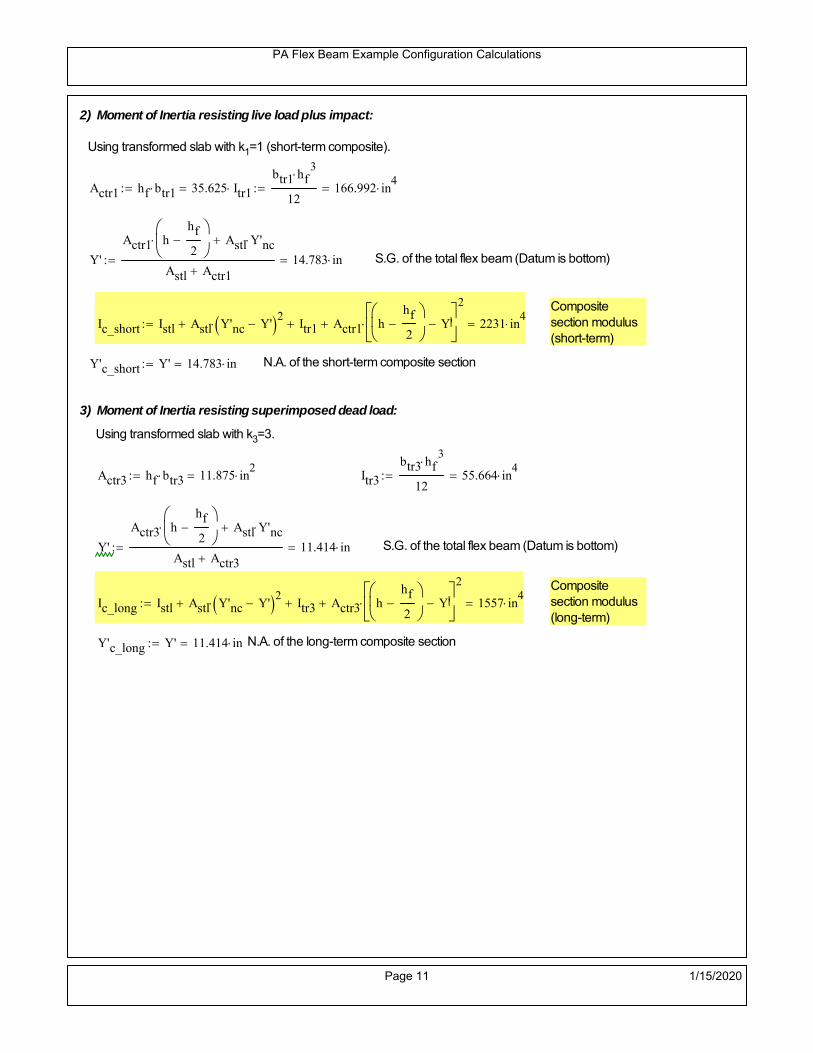
PA Flex Beam Example Configuration Calculations
2) Moment of Inertia resisting live load plus impact:
Using transformed slab with k1=1 (short-term composite).
Actr1 hf btr1 35.625 in2
Itr1
btr1 hf3
12166.992 in
4
Y'
Actr1 hhf
2
Astl Y'nc
Astl Actr114.783 in S.G. of the total flex beam (Datum is bottom)
Compositesection modulus(short-term)
Ic_short Istl Astl Y'nc Y' 2 Itr1 Actr1 hhf
2
Y'
2
2231 in4
Y'c_short Y' 14.783 in N.A. of the short-term composite section
3) Moment of Inertia resisting superimposed dead load:
Using transformed slab with k3=3.
Actr3 hf btr3 11.875 in2
Itr3
btr3 hf3
1255.664 in
4
Y'
Actr3 hhf
2
Astl Y'nc
Astl Actr311.414 in S.G. of the total flex beam (Datum is bottom)
Compositesection modulus(long-term)
Ic_long Istl Astl Y'nc Y' 2 Itr3 Actr3 hhf
2
Y'
2
1557 in4
Y'c_long Y' 11.414 in N.A. of the long-term composite section
Page 11 1/15/2020

PA Flex Beam Example Configuration Calculations
STEP 6.5 Check Ductility RequirementIn accordance with AASHTO Article 6.10.7.3 check ductility requirement. Assume compressionblock of concrete is at 0.85 f'c and that the concrete supports no tension. Steel section isassumed to be fully plastic at Fy.
Case 1 : Assuming PNA is in Concreteh d 4 inAssuming (h-d) < Dp < hf
Fp Dp 0.85 fc be Dp Fy tw Dp h d( ) Fy Astl tw Dp h d( )
Dp 7.5in 0.42 h 9.24 in
Dp1 root Fp Dp Dp 4.668 in Must be less than hf 7.5 inDp1
h0.212 must be < 0.42
Mn1check Dp1 hf h d( ) Dp1[ ] Dp1 0.42 h( ) 1 Dp1 0.42 h 1
Mp1 0.85 fc be Dp1Dp1
2
Fy tw Dp1 h d( )[ ] Dp1 h d( )[ ]
2
Fy bf tf h Dp1tf
2
Fy tw h Dp1 tf h Dp1 tf
2
Mp1 9192.52 kip in Mn1 Mp1 1.07 0.7Dp1
h
8470.7 kip in
Case 2 : Assuming PNA is NOT in Concrete
Assuming hf < Dp
Fp2 Dp 0.85 fc be hf Fy tw Dp h d( ) Fy Astl tw Dp h d( )
Dp 2.5in
Dp2 root Fp2 Dp Dp 5.09 in Must be more than hf 7.5 inDp2
h0.2314 must be < 0.42
Mn2check Dp2 hf Dp2 h( ) Dp2 0.42 h( ) 0 Dp2 0.42 h 1
Mp2 0.85 fc be hf Dp2hf
2
Fy tw Dp2 h d( )[ ] Dp2 h d( )[ ]
2
Fy bf tf h Dp2tf
2
Fy tw h Dp2 tf h Dp2 tf
2
Mp2 6889.07 kip inMn2 Mp2 1.07 0.7
Dp2
h
8487 kip in
Mn max Mn1 Mn1check Mn2 Mn2check 705.9 kip ft Mn 8470.7 kip in
Page 12 1/15/2020

PA Flex Beam Example Configuration Calculations
Check Composite Compact Section Criteria (6.10.6.2)
Dcpd
2
Fy tf bf 0.85 fc be hf
Fy hw tw1
9.35 in Dcp0 Dcp 0 0
Dcp Dcp Dcp0 0 in2 Dcp
tw3.76
Es
Fy 1 Check if section is compact
STEP 7: Load Combinations (Table 3.4.1-1)
The following load combinations will be considered herein. Only the maximum load factors forpermanent-loads are used in the following load combinations (uplift is not an issue for this typeof bridge).STRENGTH I 1.25DL + 1.5SDL + 1.75 (LL+IM)
SERVICE II: DL+SDL+1.3(LL+IM)
STEP 8: Compute and Check Stresses
Stress at bottom fiber of steel section
fDL
MDL Y'c_long
Ic_long3.524 ksi
fLL_I
MLL_IM Y'c_short
Ic_short14.673 ksi fPL
MLL_IM_PL82 Y'c_short
Ic_short17.107 ksi
fSDL
MSDL Y'c_long
Ic_long5.054 ksi
STRENGTH I fbot_str1 1.25fDL 1.5 fSDL 1.75 fLL_I 37.663 ksi
STRENGTH II fbot_str2 1.25fDL 1.5 fSDL 1.35 fPL 35.08 ksi
SERVICE II fbot_svc2 fDL fSDL 1.3fLL_I 27.65 ksi
Allowable Stress is based on Section 6.10.4.2.2-2
Flange stress due to service load II without consideration of flange lateral bending: ff fbot_svc2
Flange lateral bending stress due to service II: flSII 0ksi
Hybrid Factor: Rh 1.0 For rolled and homogenous built-up sections
ff
flSII
2 27.652 ksi 0.95 Rh Fy 47.5 ksi ff
fl
2 0.95Rh Fy 1
Page 13 1/15/2020

PA Flex Beam Example Configuration Calculations
Stress at top fiber of concrete
Note: For calculating longitudinal flexural stresses in the concrete deck due to allpermanent and transient loads, the short-term modular ratio shall be used.
fDL
MDL h Y'c_short
k1 n Ic_short0.194 ksi
fLL_I
MLL_IM h Y'c_short
k1 n Ic_short0.895 ksi fPL
MLL_IM_PL82 h Y'c_short
k1 n Ic_short1.044 ksi
fSDL
MSDL h Y'c_short
k1 n Ic_short0.279 ksi
STRENGTH I fc_str1 1.25fDL 1.5 fSDL 1.75 fLL_I 2.228 ksi
Mstr1 1.25 MDL 1.5 MSDL 1.75 MLL_IM 459.2 kip ft Mstr1 Mn 1
STRENGTH II fc_str2 1.25fDL 1.5 fSDL 1.35 fPL 2.07 ksi
Mstr2 1.25 MDL 1.5 MSDL 1.35 MLL_IM_PL82 427 kip ft Mstr2 Mn 1
SERVICE II
Allowable Stress in concrete - AASHTO 6.10.4.2.2For compact composite sections in positive flexure utilized in shored construction, the longitudinalcompressive stress in the concrete deck due to the Service II loads, determined as specified in Article6.10.1.1.1d, shall not exceed 0.6f́ c.
fallow 0.6 fc 2400 psi
fc_2 1.3fLL_I fSDL fDL 1637.08 psi This assumes short term compositesection for all calculations
fc_2 fallow 1
SERVICE II with Long Term Composite for dead loads
fDL
MDL h Y'c_long
k3 n Ic_long0.136 ksi
fLL_I
MLL_IM h Y'c_short
k1 n Ic_short0.895 ksi
fSDL
MSDL h Y'c_long
k3 n Ic_long0.195 ksi
fc_2 1.3fLL_I fSDL fDL 1495.5 psi fc_2 fallow 1
Page 14 1/15/2020

PA Flex Beam Example Configuration Calculations
Strength V Moment Check
Strength V is related to normal vehicular use of the bridge with an 80 mph wind gust
Note: that Strength V is checked for an exterior girder under wind load with the interior girder distribution factor forflexure used. If Strength V controls design, then this approach should be modified
Design vertical moment is: 1.25DL + 1.5SDL + 1.35 (LL+IM)
SLT
Ic_long
Y'c_long136.392 in
3 SST
Ic_short
Y'c_short150.914 in
3 short and long term section
modulus
Section D6.2.2 Find the moment required to cause yieldling of the flange. The approach is laid out in D6.2.2
MD2 1.25 MDL 1.5 MSDL 136.233 kip ft From D6.2.2-1 (all dead loads are in MD2 due to shoredconstruction
MAD Fy
MD2
SLT
SST 478.069 kip ft Additional moment to cause nominal yielding of steel flange
My MD2 MAD 614.302 kip ft D6.2.2-2: Moment to cause yielding of flange
6.10.7.1 Compact Section Check at Strength V limit state
Section Modulus for yielding of the flange (My/Fy) for equation 6.10.7.1.1-1Sxt
My
Fy147.433 in
3
Mu 1.25 MDL 1.5MSDL 1.35MLL_IM 385.342 kip ft Moment due to Strength V limit state
Mu1
3fl Sxt 397.199 kip ft Equation 6.10.7.1.7-1 Mn 705.893 kip ft Mu
1
3fl Sxt Mn 1
Page 15 1/15/2020

PA Flex Beam Example Configuration Calculations
STEP 9: Compute Deflection
Optional Live Load Deflection Evaluation (AASHTO 3.6.1.3.2)
Deflection distribution factor for vehicular loads: For a straight multibeambridge, this is equivalent to saying that the distribution factor for deflectionis equal to the number of lanes divided by the number of beams. 2.5.2.6.2
DFd
Nl
N0.214
Deflection should be taken as 125% the larger of:- Design truck- 25% of design truck + design lane
The live load portion of Load Combination Service I of Table 3.4.1-1 should be used,including the dynamic load allowance, IM;
Deflection due to design truck load
NOTE : Assuming maximum deflection occurs when the center of gravity of the loads is at thecenter line of the span.
P1 8kip P2 32kip P3 32kip Axle loads (AASHTO 3.6.1.2.2)
XASr 14ft Rear Axle spacing for truck (14ft - 30ft)
XASf 14ft Front Axle spacing for truck
Center of gravity (CG) of loads:
X'P1 XASr XASf P2 XASr
P1 P2 P39.333 ft Datum is the rear axle
Method1: Assuming single load = P1+P2+P3 at the midspan (Conservative approach)
P1 P2 P3 L3
48 Es Ic_short 1.082 in
Method2: Calculation of Midspan deflection using superposition
b1L
2XASr X' XASf 3.667 ft distance btw load P1 and support A b1check b1 0 0
b2L
2XASr X' 10.333 ft distance btw load P2 and support A b2check b2 0 1
b3L
2X' 5.667 ft distance btw load P3 and support B b3check b3 0 1
Page 16 1/15/2020

PA Flex Beam Example Configuration Calculations
Deflection of the beam at midspan due to P1: P P1
xL
2 at midspan b b1 b1check The smallest distance btw load P1 and support
Δ1P b x
6 Es Ic_short LL2
b2
x2
0 in
Deflection of the beam at midspan due to P2: P P2
xL
2 at midspan b b2 b2check The smallest distance btw load P2 and support
Δ2P b x
6 Es Ic_short LL2
b2
x2
0.418 in
Deflection of the beam at midspan due to P3: P P3
xL
2 at midspan b b3 b3check The smallest distance btw load P3 and support
Δ3P b x
6 Es Ic_short LL2
b2
x2
0.259 in
Total Deflection at midspan:
Δtruck Δ1 Δ2 Δ3( ) DFd 1 I( ) 0.193 in (Considering IM)
Deflection due to tandem (Note: this calculation is not required according to Article3.6.1.3.2 which denotes only the design truck for deflection calculation)
Page 17 1/15/2020

PA Flex Beam Example Configuration Calculations
FT 31.25 kip Per axle
XAS 4ft Axle spacing
Δtandem
FTL
2
XAS
2
24 Es Ic_short3 L
2 4
L
2
XAS
2
2
DFd 1 I( ) 0.261 in (Considering IM)
Deflection due to lane load
FDLLd 640lbf
ft DFd 137.143
lbf
ft
Δlane
5 FDLLd L4
384 Es Ic_short0.039 in
Live Load Deflection:
ΔLL 1.25max Δtruck 0.25Δtruck Δlane 1.25 0.302 in ΔLLL
800 1
Deflection Limit
For steel or concrete vehicular bridges:
Vehicular load = Span/800L
8000.45 in
L
10000.36 in
Evaluation of Deflection at the Service Limit State (AASHTO 3.4.2.2)
The associated permitted deflections shall be included in the contract documents.
Page 18 1/15/2020
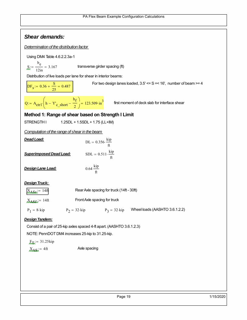
PA Flex Beam Example Configuration Calculations
Shear demands:
Determination of the distribution factor
Using DM4 Table 4.6.2.2.3a-1
Sbe
12in3.167 transverse girder spacing (ft)
Distribution of live loads per lane for shear in interior beams:
For two design lanes loaded, 3.5' <= S =< 16', number of beam >= 4DFs 0.36
S
25 0.487
Q Actr1 h Y'c_shorthf
2
123.509 in3
first moment of deck slab for interface shear
Method 1: Range of shear based on Strength I Limit
STRENGTH I 1.25DL + 1.5SDL + 1.75 (LL+IM)
Computation of the range of shear in the beam
Dead Load:DL 0.356
kip
ft
Superimposed Dead Load: SDL 0.511kip
ft
Design Lane Load: 0.64kip
ft
Design Truck:
XASr 14ft Rear Axle spacing for truck (14ft - 30ft)
XASf 14ft Front Axle spacing for truck
P1 8 kip P2 32 kip P3 32 kip Wheel loads (AASHTO 3.6.1.2.2)
Design Tandem:
Consist of a pair of 25-kip axles spaced 4-ft apart. (AASHTO 3.6.1.2.3)
NOTE: PennDOT DM4 increases 25-kip to 31.25-kip.
FT 31.25kip
XAS 4ft Axle spacing
Page 19 1/15/2020

PA Flex Beam Example Configuration Calculations
Maximum positive shear at various points along the FlexBeam are examined.
At x=0 (at left support) (Truck is moving from left to right)
Truck
Max Positive Shear (when P3 is at x = 0):
x1 L XASr XASf 2 ft Distance between P1 and right support
x2 L XASr 16 ft Distance between P2 and right support
x3 L 30 ft Distance between P3 and right support
V1 P3
x3
L P2
x2
L P1
x1
L 49.6 kip
Total Vertical Shear Force for each FlexBeam (considering dynamic loads):
Vtruck1 V1 DFs 1 I( ) 32.104 kip
Tandem:
V1 FT FT
L XAS L
58.333 kip
Total Vertical Shear Force for each FlexBeam (considering dynamic loads):
Vtandem1 V1 DFs 1 I( ) 37.757 kip
Lane Load
V1 0.64kip
ft
L
2 9.6 kip
Total Vertical Shear Force for each FlexBeam (considering dynamic loads):
Vlane1 V1 DFs 4.672 kip
Dead Load
Vdl1 DLL
2 5.341 kip
Superimposed Dead Load
Vsdl1 SDLL
2 7.659 kip
Strength I Max Positive Shear:
Vstr1 1.25 Vdl1 1.5 Vsdl1 1.75 Vlane1 max Vtruck1 Vtandem1 92.416 kip
Page 20 1/15/2020

PA Flex Beam Example Configuration Calculations
Design Permit Load P-82
Shear at x=0
Strength II Max Positive Shear:
VPL82 VPL82span DFs 1 IPL 50.247 kip
STRENGTH II 1.25DL + 1.5SDL + 1.35 (LL+IM)
VstrII_PL 1.25 Vdl1 1.5 Vsdl1 1.35 VPL82 85.998 kip
Max Shear Demand Vu max Vstr1 VstrII_PL 92.416 kip
Determine the Shear Strength of the Web
Shear Strength of Unstiffened web from AASHTO section 6.10.9.2
Depth of Web D d 18 in Thickness of web tw 0.375 in
Transverse Stiffener Spacing d0 0in Shear Buckling Coefficient k 5 6.10.9.3.2-7
Plastic Shear Force Vp 0.58 Fy D tw 195.75 kip Equation 6.10.9.3.2-3
Ratio of Shear-Buckling resistance to shear yield, C
D
tw48 1.12
Es k
Fy 60.314 Ccheck
D
tw1.12
Es k
Fy 1 Equation 6.10.9.3.2-4
C 1.0 Ccheck 1 C=1 for most cases, if the criteria are not met, then C will go to zero and the actualcoefficients should be determined
Nominal Shear Resistance of Web Vn C Vp 195.75 kip equation 6.10.9.3.3-1
Shear Resistance Factor φv 1.0
φv Vn 195.75 kip φv Vn Vu 1Reduced Shear Strength
Page 21 1/15/2020

PA Flex Beam Example Configuration Calculations
Check Bearing Stiffeners
FYs 50ksi Yield strength of stiffener
tp 0.75in Thickness of stiffener
bt
bf tw
21.5in 4.312 in Effective width of stiffener
Dst hw 4.1in 13.4 in Depth of stiffeners
Apn 2 tp bt 6.469 in2
Projected area of stiffeners
bt 0.48 tpEs
FYs 1Check that effective width of stiffener meets requirements
Rsbn 1.4 Apn FYs 452.812 kip Bearing capacity of stiffener (phi=1 for bearing per AASHTO 6.5.4.2)
Rsbn Vu 1 Bearing capacity check
Qs 1.0 Q factor for bearing stiffner, taken as 1 (AASHTO 6.9.4.1.1)
Is
18 tw tw3
tp 2 bt 3
1240.131 in
4 Moment of inertia of stiffener and web (9*tw is used on each side)
AASHTO 6.10.11.2.4b
Ag 18 tw tw 2 bt tp 9 in2
Gross area of stiffener and web (AASHTO 6.10.11.2.4b)
rs
Is
Ag2.112 in Radius of gyration of stiffener/web
Po Qs FYs Apn 323.437 kip Nominal yeild resistance of stiffener (AASHTO 6.9.4.1.1)
Peπ2Es
0.75 Dst
rs
2Ag 1.137 10
5 kip Elastic critical buckling stress of stiffener (AASHTO 6.9.4.1.2-1)
Check that Pe/Po is great than 0.44 (AASHTO 6.9.4.1.1) PePoPe
Po0.44 1
Pn PePo 0.658
Po
Pe Po 323.053 kip Nominal compressive resistance of stiffener for Pe/Po>0.44
(AASHTO 6.9.4.1.1-1)
φcr 0.95 phi factor for axial compression (AASHTO 6.5.4.2)
Pr φcr Pn 306.9 kip Compressive capacity of bearing stiffener Pr Vu 1
Page 22 1/15/2020

PA Flex Beam Example Configuration Calculations
Flexbeam Example Configuration Calculations
Summary of Calculations:
Input section dimensions and material properties for steel WT and the concrete deck1.Calculate demands (dead load, superimposed dead, and Live load demands for Strength I and Strength II2.Calculate composite section properties for the given section3.Check Strength I, Strength II, and Service II stresses 4.Check Strength I, Strength II, and Strength V moment demands 5.Perform live load deflection check6.Determine maximum shear demand and capacity7.Note: Shear envelope data was obtained from Matlab script (FlexBeam_Moment_ShearEnvelope.m).8.Shear envelope calculations are summarized separately for each design (Shear Design *.xlsx).
Design Assumptions:Design Specifications Used:
AASHTO LRFD Bridge Design Specifications 7th Edition with 2016 Interim RevisionsPennDOT Design Manual, Part 4 (DM-4) June 30, 2015
Example configurations are determined for two girder spacings, 36" and 40".The deck thickness is 7.5" and is assumed to have a non-structural wearing surface added after installation.Section properties are calculated using the full 7.5" deck thickness.The WT sections are embedded 3.5" into the concrete deck. The steel section spacing used is outside the scope of the AASHTO and PennDOT distribution factorequations. The flexural distribution factor is assumed to be 0.3 which was shown to tbe conservativeaccording to refined analysisThe shear distribution factor is calculated using the DM-4 shear distribution factor equation which wasshown to be conservative using refined analysis.Refined analysis is presented in: Zihan Ma, "Distribution Factors for Composite Steel Tee Concrete DeckBridge System," M.S. Thesis, Deparement of Civil and Environmental Engineering, Lehigh University,Bethlehem, 2019Shear and moment demands for the PL82 permit load vehicle are determined by Matlab script(FlexBeam_Moment_ShearEnvelope.m) and are manually input into this calculation sheet.All fabrication will occur as double modules, i.e. each module contains two WT sections. The number ofmodules is half the number of beams, N. A 45 in. tall F-Shape barrier is used, Weight = 700 lb/ft (Distributed to exterior two beams).
The work presented in this document are provided on an “AS IS” basis. University makes no warranties of anykind, express or implied, as to any matter whatsoever, including, without limitation, warranties with respect tothe merchantability or fitness for a particular purpose of this work or any project deliverables. Universitymakes no warranty of any kind with respect to freedom from patent, trademark, copyright or trade secretinfringement arising from the use of the results of the project, deliverables, services, intellectual property orother materials provided hereunder. University shall not be liable for any direct, indirect, consequential,punitive, or other damages suffered by Sponsor or any other person resulting from the project, or the use ofthis work or any project deliverables.
Page 1 1/15/2020

PA Flex Beam Example Configuration Calculations
hf
tf
bf
twh
d
bjtbe
e
Variable Definitions:
Number of beams N 10 modulesN
25
L 30ft Span length
be 40in Effective width of Flexbeamassuming constructed bridge width(i.e. closure joints cast)
Built Up Section Properties
tw 0.375in tf 0.5in bf 12in
h 22in Overall Height of section
hf 7.5in Total thickness of deck
e 3.5in Deck/Steel overlap
d h hf e 18 in depth of built up steel section
hw d tf 17.5 in height of web of built up steel
Moment and shear for permit load PL82 obtained from Matlab script: FlexBeam_Moment_ShearEnvelope
MLL_IM_PL82 215.136kip ft Moment due to PL82 with distribution factor and impact factor!!
VPL82span 86.04kip Shear due to PL82 WITHOUT distribution factor and impact factor!!
Check web and flange dimensions in sections 6.10.2.1 and 6.10.2.2
(Ignore 6.10.2.2-4 since no compression flange)
equation 6.10.2.1.1-1d
tw150 1 equation 6.10.2.2-1
bf
2 tf12 1
equation 6.10.2.2-2 bfh
6 1 equation 6.10.2.2-3 tf 1.1 tw 1
y_bar
tf bftf
2 hw tw tf
hw
2
tf bf hw tw4.951 in Center of gravity of steel section
Istl
bf tf3
12bf tf y_bar
tf
2
2
tw hw
3
12 tw hw tf
hw
2 y_bar
2
421.486 in4
MOI of steel
Astl tf bf hw tw 12.562 in2
Area of the WT steel section
Page 2 1/15/2020

PA Flex Beam Example Configuration Calculations
Material Properties
Elastic Modulus of Steel Es 29000ksi
Yield Strength of Steel Fy 50ksi
Yield Strength of Reinforcement fy 60ksi
Compressive Strength of Concrete fc 4000psi AAAP PennDOT Concrete
Concrete Modular Ratio n 8 modular ratio for 4ksi concrete per AASHTO
Unit weight of concrete slab wc 0.150kip
ft3
Unit weight of concrete
Section Properties
Width of UHPC Joint: bjt 6in
Parapet width: bpar 20.25in Parapet width per PennDOT F-shape barrier
Width of the bridge W be N bjt 394 in W 32.833 ft
Clear width of roadway Wlane W 2 bpar 29.458 ft
Dc wc hf W 3.078kip
ft DL due to slab
Db .700kip
ft DL due to each 45" F-Shape Barrier (per email 11/1/18)
DFWS 30lbf
ft2
W 2 bpar 0.884kip
ft DL due to Future Wearing Surface (FWS)
Ds Astl 490lbf
ft3
0.043kip
ft Selfweight of the steel section
DLself
Dc N
Ds 0.351kip
ft Self-weight per WT
Total weight of each precast FlexBeam for transportation:
Weight of C12x25 Diaphragms Wend_diaphragms 25lbf
ft32 in 0.067 kip
2be bjt hf wc 2Ds L 2 Wend_diaphragms 20.042 kip
Determine number of design lane (AASHTO Section 3.6.1.1.1)
Take the integer part of the ratio of W/12 ft. Number of lanes in bridge: Nl floorWlane
12ft
2
Page 3 1/15/2020

PA Flex Beam Example Configuration Calculations
STEP 1: Compute Dead Load for each Flex Beam
DLslab
Dc
Nwc 1 in
be
2 0.329
kip
ft Dead load of slab assuming exterior overhang has 1" of
additional concrete thickness
DLsteel Ds 0.043kip
ft
DL DLslab DLsteel 0.371kip
ft
STEP 2: Compute Superimposed Dead Load
SDLWS
DFWS
N0.088
kip
ft
SDLparapet
Db
20.35
kip
ft distributed equally on two outer beams
SDLOL 140lbf
ft3be 2 in 0.078
kip
ft Overlay is 2" thick and is 140 lbs/cubic foot
NOTE: For this example barrier load is distributed equally among the two outer beams per conversation withPennDOT and M&M.
PennDOT DM4: "For composite adjacent and spread beams, the barrier (single barrier) load shall be equallydistributed to the nearest three (adjacent) and two (spread) beams, respectively, when the barriers are placedafter slab has hardened".
SDL SDLWS SDLparapet SDLOL 0.516kip
ft
STEP 3: Compute Transformed Width of Slab
For live load and dead load acting on the stringer k1 1 For short-term section property evaluation
btr1
be
k1 n5 in Transformed width of slab for short-term
For superimposed dead loads k3 3 For long-term section property evaluation
btr3
be
k3 n1.667 in Transformed width of slab for long-term
Page 4 1/15/2020

PA Flex Beam Example Configuration Calculations
STEP 4: Compute Dead and Superimposed Dead Load Moments(Based on first interior girder demands)
MDLDL L
2
841.782 kip ft
MSDLSDL L
2
858.067 kip ft
STEP 5: Compute live load and Dynamic Load Allowance (IM)
Live load wheel load distribution factor (DF):
Sbe
12in3.333 transverse girder spacing
NOTE: AASHTO presents equations to define DF for different types of superstructuresincluding Deck Composite wirh RC slab on steel girders (Type (a) in Table 4.6.2.2.1-1) forshear and moment in interior and exterior beams.
Using DM4 Table 4.6.2.2.2b-1:
eg h y_barhf
2 13.299 in Distance between the centers of gravity of the basic beam and deck
Kg n Istl Astl eg2
21145.34 in
4 Longitudinal stiffness parameter (in4)
Distribution of Live Load Per Lane for Moment in Interior Beams:
to be conservative, use DF 0.3
Page 5 1/15/2020

PA Flex Beam Example Configuration Calculations
Dynamic Load Allowance (Section 3.6.2 DM4)
Static effects of the design truck or tandem, shall be increased by the impact factor.
NOTE: The dynamic load allowance shall not be applied to the design lane load (Section 3.6.2.1 DM4)
I 0.33 Impact factor for moment
Note: PennDOT requires that the impact for decks be increased from 33% to 50%, the deck is not beingdesigned here. Instrad the deck design is based on the BD recommendations.
Dynamic load allowance for the Permit Load P-82 shall be less than 20%. (Section 3.6.2.1DM4)
IPL 0.20 Impact factor for moment on Strength II
Design Wind Loading for Exterior Girder
Vw 80 Wind speed for Strength V load case
CD 1.3 Gust factor for windard side of I-Girder and Box Girder Superstructures (Table 3.8.1.2.1-2)
G 1.0 Gus effect factor is 1.0 for all structures other than sound barriers (Table 3.8.1.2.1-1)
Kz 1.0 Pressure coefficient taken as 1 for Strength V (3.8.1.2.1)
Pz 2.56 106
Vw 2 Kz G CDkip
ft2
0.021kip
ft2
Wind pressure on exterior girder
hexp h hf 14.5 in Exposed height of exterior girder
Moment due to wind loading on exterior girderMWL
Pz hexp L2
82.895 kip ft
Iyy
bf3tf
1272 in
4 Transverse moment of intertia
Flange lateral bending stressfl
MWL
bf
2
Iyy2.895 ksi
Page 6 1/15/2020

PA Flex Beam Example Configuration Calculations
Design Vehicular Live Load
PHL-93 and P-82 are examined herein.
PHL-93 (A3.6.1.2.1)
PHL-93 consists of a combination of (design truck or design tandem) + (design lane load)
Design Truck
PennDOT defines the design truck in accordance with AASTHO 3.6.1.2
Design truck load in AASHTO (HS20 Truck) is used for this example.
NOTE : MAX moment occurs when the center line of the span is midway between the center ofgravity of the loads and the nearest concentrated load.
P1 8kip P2 32kip P3 32kip Axle loads (AASHTO 3.6.1.2.2)
XASr 14ft Rear Axle spacing for truck (14ft - 30ft)
XASf 14ft Front Axle spacing for truck
Page 7 1/15/2020

PA Flex Beam Example Configuration Calculations
Center of gravity (CG) of loads:
X'P1 XASr XASf P2 XASr
P1 P2 P39.333 ft Datum is the rear axle
X XASr X' 4.667 ft Spacing btw CG and nearest load
Find bridge reaction
Truck movestoward Support ARA
P1L
2XASf
X
2
P2L
2
X
2
P3L
2X'
X
2
L30.4 kip
Max live load moment (at the location of P2):
MLL_truck RAL
2
X
2
P1 XASf 273.067 kip ft
NOTE: Find the worst case by varying XASr
Page 8 1/15/2020

PA Flex Beam Example Configuration Calculations
Design Tandem
Consist of a pair of 25-kip axles spaced 4-ft apart. (AASHTO 3.6.1.2.3)
NOTE: PennDOT DM4 increases 25-kip to 31.25-kip.
FT 31.25kip
XAS 4ft Axle spacing
Center of gravity (CG) of loads:
XXAS
22 ft Spacing btw CG and nearest load
Find bridge reaction
RA
FTL
2
X
2
FTL
2
X
2 X
L29.167 kip Truck moves toward Support A
Max live load moment (at the location of front wheel):
MLL_tandem RAL
2
X
2
408.333 kip ft
Choose the max value:
MLL_veh max MLL_tandem MLL_truck 408.333 kip ft
Apply the impact and wheel load distribution:
MLL_IM_veh MLL_veh DF 1 I( ) 162.925 kip ft Due to tandem or truck
Design Lane Load (distributed over a 10-ft width for each lane)
NOTE: The uniform load may be continuous or discontinuous as necessary to produce themaximum force effect. For this example continuous uniform distribution assumed.
FDLL 0.64kip
ftDF 0.192
kip
ft Per beam in each lane
Due to lane loadMLL_IM_lane
FDLL L2
8
21.6 kip ft
Moment due to Total Design Vehicular Live Load: MLL_IM MLL_IM_lane MLL_IM_veh 184.525 kip ft
Page 9 1/15/2020

PA Flex Beam Example Configuration Calculations
Design Permit Load P-82 (Section 3.6.1.2.7 DM4)
P1 P2 P3 P4 P5 P6 P7
NOTE: The moment for the permit load is defined at the beginning of the sheetand is obtained from MATLab File FlexBeam_Moment_ShearEnvelope.m
STEP 6: Compute Moment of Inertia (Note: rebar neglected!)
1) Moment of Inertia resisting dead load only:
a) Acting on the non-composite section (before the deck has hardened - DC1)
Use steel section only
Inc Istl 421.486 in4
Non-composite section modulus
Y'nc y_bar S.G. of the steel section of Flex Beam (Datum is bottom)
b) Acting on the composite section (after the deck has hardened - DC2)
Use Ic_short as defined below.
Page 10 1/15/2020

PA Flex Beam Example Configuration Calculations
2) Moment of Inertia resisting live load plus impact:
Using transformed slab with k1=1 (short-term composite).
Actr1 hf btr1 37.5 in2
Itr1
btr1 hf3
12175.781 in
4
Y'
Actr1 hhf
2
Astl Y'nc
Astl Actr114.913 in S.G. of the total flex beam (Datum is bottom)
Compositesection modulus(short-term)
Ic_short Istl Astl Y'nc Y' 2 Itr1 Actr1 hhf
2
Y'
2
2261 in4
Y'c_short Y' 14.913 in N.A. of the short-term composite section
3) Moment of Inertia resisting superimposed dead load:
Using transformed slab with k3=3.
Actr3 hf btr3 12.5 in2
Itr3
btr3 hf3
1258.594 in
4
Y'
Actr3 hhf
2
Astl Y'nc
Astl Actr311.584 in S.G. of the total flex beam (Datum is bottom)
Compositesection modulus(long-term)
Ic_long Istl Astl Y'nc Y' 2 Itr3 Actr3 hhf
2
Y'
2
1588 in4
Y'c_long Y' 11.584 in N.A. of the long-term composite section
Page 11 1/15/2020

PA Flex Beam Example Configuration Calculations
STEP 6.5 Check Ductility RequirementIn accordance with AASHTO Article 6.10.7.3 check ductility requirement. Assume compressionblock of concrete is at 0.85 f'c and that the concrete supports no tension. Steel section isassumed to be fully plastic at Fy.
Case 1 : Assuming PNA is in Concreteh d 4 inAssuming (h-d) < Dp < hf
Fp Dp 0.85 fc be Dp Fy tw Dp h d( ) Fy Astl tw Dp h d( )
Dp 7.5in 0.42 h 9.24 in
Dp1 root Fp Dp Dp 4.485 in Must be less than hf 7.5 inDp1
h0.204 must be < 0.42
Mn1check Dp1 hf h d( ) Dp1[ ] Dp1 0.42 h( ) 1 Dp1 0.42 h 1
Mp1 0.85 fc be Dp1Dp1
2
Fy tw Dp1 h d( )[ ] Dp1 h d( )[ ]
2
Fy bf tf h Dp1tf
2
Fy tw h Dp1 tf h Dp1 tf
2
Mp1 9263.7 kip in Mn1 Mp1 1.07 0.7Dp1
h
8590.2 kip in
Case 2 : Assuming PNA is NOT in Concrete
Assuming hf < Dp
Fp2 Dp 0.85 fc be hf Fy tw Dp h d( ) Fy Astl tw Dp h d( )
Dp 2.5in
Dp2 root Fp2 Dp Dp 6.45 in Must be more than hf 7.5 inDp2
h0.2932 must be < 0.42
Mn2check Dp2 hf Dp2 h( ) Dp2 0.42 h( ) 0 Dp2 0.42 h 1
Mp2 0.85 fc be hf Dp2hf
2
Fy tw Dp2 h d( )[ ] Dp2 h d( )[ ]
2
Fy bf tf h Dp2tf
2
Fy tw h Dp2 tf h Dp2 tf
2
Mp2 6403.55 kip inMn2 Mp2 1.07 0.7
Dp2
h
8166 kip in
Mn max Mn1 Mn1check Mn2 Mn2check 715.9 kip ft Mn 8590.2 kip in
Page 12 1/15/2020

PA Flex Beam Example Configuration Calculations
Check Composite Compact Section Criteria (6.10.6.2)
Dcpd
2
Fy tf bf 0.85 fc be hf
Fy hw tw1
10.749 in Dcp0 Dcp 0 0
Dcp Dcp Dcp0 0 in2 Dcp
tw3.76
Es
Fy 1 Check if section is compact
STEP 7: Load Combinations (Table 3.4.1-1)
The following load combinations will be considered herein. Only the maximum load factors forpermanent-loads are used in the following load combinations (uplift is not an issue for this typeof bridge).STRENGTH I 1.25DL + 1.5SDL + 1.75 (LL+IM)
SERVICE II: DL+SDL+1.3(LL+IM)
STEP 8: Compute and Check Stresses
Stress at bottom fiber of steel section
fDL
MDL Y'c_long
Ic_long3.657 ksi
fLL_I
MLL_IM Y'c_short
Ic_short14.602 ksi fPL
MLL_IM_PL82 Y'c_short
Ic_short17.024 ksi
fSDL
MSDL Y'c_long
Ic_long5.083 ksi
STRENGTH I fbot_str1 1.25fDL 1.5 fSDL 1.75 fLL_I 37.749 ksi
STRENGTH II fbot_str2 1.25fDL 1.5 fSDL 1.35 fPL 35.178 ksi
SERVICE II fbot_svc2 fDL fSDL 1.3fLL_I 27.72 ksi
Allowable Stress is based on Section 6.10.4.2.2-2
Flange stress due to service load II without consideration of flange lateral bending: ff fbot_svc2
Flange lateral bending stress due to service II: flSII 0ksi
Hybrid Factor: Rh 1.0 For rolled and homogenous built-up sections
ff
flSII
2 27.722 ksi 0.95 Rh Fy 47.5 ksi ff
fl
2 0.95Rh Fy 1
Page 13 1/15/2020

PA Flex Beam Example Configuration Calculations
Stress at top fiber of concrete
Note: For calculating longitudinal flexural stresses in the concrete deck due to allpermanent and transient loads, the short-term modular ratio shall be used.
fDL
MDL h Y'c_short
k1 n Ic_short0.196 ksi
fLL_I
MLL_IM h Y'c_short
k1 n Ic_short0.867 ksi fPL
MLL_IM_PL82 h Y'c_short
k1 n Ic_short1.011 ksi
fSDL
MSDL h Y'c_short
k1 n Ic_short0.273 ksi
STRENGTH I fc_str1 1.25fDL 1.5 fSDL 1.75 fLL_I 2.173 ksi
Mstr1 1.25 MDL 1.5 MSDL 1.75 MLL_IM 462.2 kip ft Mstr1 Mn 1
STRENGTH II fc_str2 1.25fDL 1.5 fSDL 1.35 fPL 2.02 ksi
Mstr2 1.25 MDL 1.5 MSDL 1.35 MLL_IM_PL82 430 kip ft Mstr2 Mn 1
SERVICE II
Allowable Stress in concrete - AASHTO 6.10.4.2.2For compact composite sections in positive flexure utilized in shored construction, the longitudinalcompressive stress in the concrete deck due to the Service II loads, determined as specified in Article6.10.1.1.1d, shall not exceed 0.6f́ c.
fallow 0.6 fc 2400 psi
fc_2 1.3fLL_I fSDL fDL 1597.01 psi This assumes short term compositesection for all calculations
fc_2 fallow 1
SERVICE II with Long Term Composite for dead loads
fDL
MDL h Y'c_long
k3 n Ic_long0.137 ksi
fLL_I
MLL_IM h Y'c_short
k1 n Ic_short0.867 ksi
fSDL
MSDL h Y'c_long
k3 n Ic_long0.19 ksi
fc_2 1.3fLL_I fSDL fDL 1455.07 psi fc_2 fallow 1
Page 14 1/15/2020

PA Flex Beam Example Configuration Calculations
Strength V Moment Check
Strength V is related to normal vehicular use of the bridge with an 80 mph wind gust
Note: that Strength V is checked for an exterior girder under wind load with the interior girder distribution factor forflexure used. If Strength V controls design, then this approach should be modified
Design vertical moment is: 1.25DL + 1.5SDL + 1.35 (LL+IM)
SLT
Ic_long
Y'c_long137.097 in
3 SST
Ic_short
Y'c_short151.644 in
3 short and long term section
modulus
Section D6.2.2 Find the moment required to cause yieldling of the flange. The approach is laid out in D6.2.2
MD2 1.25 MDL 1.5 MSDL 139.328 kip ft From D6.2.2-1 (all dead loads are in MD2 due to shoredconstruction
MAD Fy
MD2
SLT
SST 477.737 kip ft Additional moment to cause nominal yielding of steel flange
My MD2 MAD 617.065 kip ft D6.2.2-2: Moment to cause yielding of flange
6.10.7.1 Compact Section Check at Strength V limit state
Section Modulus for yielding of the flange (My/Fy) for equation 6.10.7.1.1-1Sxt
My
Fy148.095 in
3
Mu 1.25 MDL 1.5MSDL 1.35MLL_IM 388.437 kip ft Moment due to Strength V limit state
Mu1
3fl Sxt 400.348 kip ft Equation 6.10.7.1.7-1 Mn 715.852 kip ft Mu
1
3fl Sxt Mn 1
Page 15 1/15/2020

PA Flex Beam Example Configuration Calculations
STEP 9: Compute Deflection
Optional Live Load Deflection Evaluation (AASHTO 3.6.1.3.2)
Deflection distribution factor for vehicular loads: For a straight multibeambridge, this is equivalent to saying that the distribution factor for deflectionis equal to the number of lanes divided by the number of beams. 2.5.2.6.2
DFd
Nl
N0.2
Deflection should be taken as 125% the larger of:- Design truck- 25% of design truck + design lane
The live load portion of Load Combination Service I of Table 3.4.1-1 should be used,including the dynamic load allowance, IM;
Deflection due to design truck load
NOTE : Assuming maximum deflection occurs when the center of gravity of the loads is at thecenter line of the span.
P1 8kip P2 32kip P3 32kip Axle loads (AASHTO 3.6.1.2.2)
XASr 14ft Rear Axle spacing for truck (14ft - 30ft)
XASf 14ft Front Axle spacing for truck
Center of gravity (CG) of loads:
X'P1 XASr XASf P2 XASr
P1 P2 P39.333 ft Datum is the rear axle
Method1: Assuming single load = P1+P2+P3 at the midspan (Conservative approach)
P1 P2 P3 L3
48 Es Ic_short 1.067 in
Method2: Calculation of Midspan deflection using superposition
b1L
2XASr X' XASf 3.667 ft distance btw load P1 and support A b1check b1 0 0
b2L
2XASr X' 10.333 ft distance btw load P2 and support A b2check b2 0 1
b3L
2X' 5.667 ft distance btw load P3 and support B b3check b3 0 1
Page 16 1/15/2020

PA Flex Beam Example Configuration Calculations
Deflection of the beam at midspan due to P1: P P1
xL
2 at midspan b b1 b1check The smallest distance btw load P1 and support
Δ1P b x
6 Es Ic_short LL2
b2
x2
0 in
Deflection of the beam at midspan due to P2: P P2
xL
2 at midspan b b2 b2check The smallest distance btw load P2 and support
Δ2P b x
6 Es Ic_short LL2
b2
x2
0.413 in
Deflection of the beam at midspan due to P3: P P3
xL
2 at midspan b b3 b3check The smallest distance btw load P3 and support
Δ3P b x
6 Es Ic_short LL2
b2
x2
0.256 in
Total Deflection at midspan:
Δtruck Δ1 Δ2 Δ3( ) DFd 1 I( ) 0.178 in (Considering IM)
Deflection due to tandem (Note: this calculation is not required according to Article3.6.1.3.2 which denotes only the design truck for deflection calculation)
Page 17 1/15/2020

PA Flex Beam Example Configuration Calculations
FT 31.25 kip Per axle
XAS 4ft Axle spacing
Δtandem
FTL
2
XAS
2
24 Es Ic_short3 L
2 4
L
2
XAS
2
2
DFd 1 I( ) 0.24 in (Considering IM)
Deflection due to lane load
FDLLd 640lbf
ft DFd 128
lbf
ft
Δlane
5 FDLLd L4
384 Es Ic_short0.036 in
Live Load Deflection:
ΔLL 1.25max Δtruck 0.25Δtruck Δlane 1.25 0.278 in ΔLLL
800 1
Deflection Limit
For steel or concrete vehicular bridges:
Vehicular load = Span/800L
8000.45 in
L
10000.36 in
Evaluation of Deflection at the Service Limit State (AASHTO 3.4.2.2)
The associated permitted deflections shall be included in the contract documents.
Page 18 1/15/2020

PA Flex Beam Example Configuration Calculations
Shear demands:
Determination of the distribution factor
Using DM4 Table 4.6.2.2.3a-1
Sbe
12in3.333 transverse girder spacing (ft)
Distribution of live loads per lane for shear in interior beams:
For two design lanes loaded, 3.5' <= S =< 16', number of beam >= 4DFs 0.36
S
25 0.493
Q Actr1 h Y'c_shorthf
2
125.14 in3
first moment of deck slab for interface shear
Method 1: Range of shear based on Strength I Limit
STRENGTH I 1.25DL + 1.5SDL + 1.75 (LL+IM)
Computation of the range of shear in the beam
Dead Load:DL 0.371
kip
ft
Superimposed Dead Load: SDL 0.516kip
ft
Design Lane Load: 0.64kip
ft
Design Truck:
XASr 14ft Rear Axle spacing for truck (14ft - 30ft)
XASf 14ft Front Axle spacing for truck
P1 8 kip P2 32 kip P3 32 kip Wheel loads (AASHTO 3.6.1.2.2)
Design Tandem:
Consist of a pair of 25-kip axles spaced 4-ft apart. (AASHTO 3.6.1.2.3)
NOTE: PennDOT DM4 increases 25-kip to 31.25-kip.
FT 31.25kip
XAS 4ft Axle spacing
Page 19 1/15/2020

PA Flex Beam Example Configuration Calculations
Maximum positive shear at various points along the FlexBeam are examined.
At x=0 (at left support) (Truck is moving from left to right)
Truck
Max Positive Shear (when P3 is at x = 0):
x1 L XASr XASf 2 ft Distance between P1 and right support
x2 L XASr 16 ft Distance between P2 and right support
x3 L 30 ft Distance between P3 and right support
V1 P3
x3
L P2
x2
L P1
x1
L 49.6 kip
Total Vertical Shear Force for each FlexBeam (considering dynamic loads):
Vtruck1 V1 DFs 1 I( ) 32.544 kip
Tandem:
V1 FT FT
L XAS L
58.333 kip
Total Vertical Shear Force for each FlexBeam (considering dynamic loads):
Vtandem1 V1 DFs 1 I( ) 38.274 kip
Lane Load
V1 0.64kip
ft
L
2 9.6 kip
Total Vertical Shear Force for each FlexBeam (considering dynamic loads):
Vlane1 V1 DFs 4.736 kip
Dead Load
Vdl1 DLL
2 5.571 kip
Superimposed Dead Load
Vsdl1 SDLL
2 7.742 kip
Strength I Max Positive Shear:
Vstr1 1.25 Vdl1 1.5 Vsdl1 1.75 Vlane1 max Vtruck1 Vtandem1 93.845 kip
Page 20 1/15/2020

PA Flex Beam Example Configuration Calculations
Design Permit Load P-82
Shear at x=0
Strength II Max Positive Shear:
VPL82 VPL82span DFs 1 IPL 50.936 kip
STRENGTH II 1.25DL + 1.5SDL + 1.35 (LL+IM)
VstrII_PL 1.25 Vdl1 1.5 Vsdl1 1.35 VPL82 87.34 kip
Max Shear Demand Vu max Vstr1 VstrII_PL 93.845 kip
Determine the Shear Strength of the Web
Shear Strength of Unstiffened web from AASHTO section 6.10.9.2
Depth of Web D d 18 in Thickness of web tw 0.375 in
Transverse Stiffener Spacing d0 0in Shear Buckling Coefficient k 5 6.10.9.3.2-7
Plastic Shear Force Vp 0.58 Fy D tw 195.75 kip Equation 6.10.9.3.2-3
Ratio of Shear-Buckling resistance to shear yield, C
D
tw48 1.12
Es k
Fy 60.314 Ccheck
D
tw1.12
Es k
Fy 1 Equation 6.10.9.3.2-4
C 1.0 Ccheck 1 C=1 for most cases, if the criteria are not met, then C will go to zero and the actualcoefficients should be determined
Nominal Shear Resistance of Web Vn C Vp 195.75 kip equation 6.10.9.3.3-1
Shear Resistance Factor φv 1.0
φv Vn 195.75 kip φv Vn Vu 1Reduced Shear Strength
Page 21 1/15/2020

PA Flex Beam Example Configuration Calculations
Check Bearing Stiffeners
FYs 50ksi Yield strength of stiffener
tp 0.75in Thickness of stiffener
bt
bf tw
21.5in 4.312 in Effective width of stiffener
Dst hw 4.1in 13.4 in Depth of stiffeners
Apn 2 tp bt 6.469 in2
Projected area of stiffeners
bt 0.48 tpEs
FYs 1Check that effective width of stiffener meets requirements
Rsbn 1.4 Apn FYs 452.812 kip Bearing capacity of stiffener (phi=1 for bearing per AASHTO 6.5.4.2)
Rsbn Vu 1 Bearing capacity check
Qs 1.0 Q factor for bearing stiffner, taken as 1 (AASHTO 6.9.4.1.1)
Is
18 tw tw3
tp 2 bt 3
1240.131 in
4 Moment of inertia of stiffener and web (9*tw is used on each side)
AASHTO 6.10.11.2.4b
Ag 18 tw tw 2 bt tp 9 in2
Gross area of stiffener and web (AASHTO 6.10.11.2.4b)
rs
Is
Ag2.112 in Radius of gyration of stiffener/web
Po Qs FYs Apn 323.437 kip Nominal yeild resistance of stiffener (AASHTO 6.9.4.1.1)
Peπ2Es
0.75 Dst
rs
2Ag 1.137 10
5 kip Elastic critical buckling stress of stiffener (AASHTO 6.9.4.1.2-1)
Check that Pe/Po is great than 0.44 (AASHTO 6.9.4.1.1) PePoPe
Po0.44 1
Pn PePo 0.658
Po
Pe Po 323.053 kip Nominal compressive resistance of stiffener for Pe/Po>0.44
(AASHTO 6.9.4.1.1-1)
φcr 0.95 phi factor for axial compression (AASHTO 6.5.4.2)
Pr φcr Pn 306.9 kip Compressive capacity of bearing stiffener Pr Vu 1
Page 22 1/15/2020

PA Flex Beam Example Configuration Calculations
Flexbeam Example Configuration Calculations
Summary of Calculations:
Input section dimensions and material properties for steel WT and the concrete deck1.Calculate demands (dead load, superimposed dead, and Live load demands for Strength I and Strength II2.Calculate composite section properties for the given section3.Check Strength I, Strength II, and Service II stresses 4.Check Strength I, Strength II, and Strength V moment demands 5.Perform live load deflection check6.Determine maximum shear demand and capacity7.Note: Shear envelope data was obtained from Matlab script (FlexBeam_Moment_ShearEnvelope.m).8.Shear envelope calculations are summarized separately for each design (Shear Design *.xlsx).
Design Assumptions:Design Specifications Used:
AASHTO LRFD Bridge Design Specifications 7th Edition with 2016 Interim RevisionsPennDOT Design Manual, Part 4 (DM-4) June 30, 2015
Example configurations are determined for two girder spacings, 36" and 40".The deck thickness is 7.5" and is assumed to have a non-structural wearing surface added after installation.Section properties are calculated using the full 7.5" deck thickness.The WT sections are embedded 3.5" into the concrete deck. The steel section spacing used is outside the scope of the AASHTO and PennDOT distribution factorequations. The flexural distribution factor is assumed to be 0.3 which was shown to tbe conservativeaccording to refined analysisThe shear distribution factor is calculated using the DM-4 shear distribution factor equation which wasshown to be conservative using refined analysis.Refined analysis is presented in: Zihan Ma, "Distribution Factors for Composite Steel Tee Concrete DeckBridge System," M.S. Thesis, Deparement of Civil and Environmental Engineering, Lehigh University,Bethlehem, 2019Shear and moment demands for the PL82 permit load vehicle are determined by Matlab script(FlexBeam_Moment_ShearEnvelope.m) and are manually input into this calculation sheet.All fabrication will occur as double modules, i.e. each module contains two WT sections. The number ofmodules is half the number of beams, N. A 45 in. tall F-Shape barrier is used, Weight = 700 lb/ft (Distributed to exterior two beams).
The work presented in this document are provided on an “AS IS” basis. University makes no warranties of anykind, express or implied, as to any matter whatsoever, including, without limitation, warranties with respect tothe merchantability or fitness for a particular purpose of this work or any project deliverables. Universitymakes no warranty of any kind with respect to freedom from patent, trademark, copyright or trade secretinfringement arising from the use of the results of the project, deliverables, services, intellectual property orother materials provided hereunder. University shall not be liable for any direct, indirect, consequential,punitive, or other damages suffered by Sponsor or any other person resulting from the project, or the use ofthis work or any project deliverables.
Page 1 1/15/2020

PA Flex Beam Example Configuration Calculations
hf
tf
bf
twh
d
bjtbe
e
Variable Definitions:
Number of beams N 12 modulesN
26
L 30ft Span length
be 40in Effective width of Flexbeamassuming constructed bridge width(i.e. closure joints cast)
Built Up Section Properties
tw 0.375in tf 0.5in bf 12in
h 22in Overall Height of section
hf 7.5in Total thickness of deck
e 3.5in Deck/Steel overlap
d h hf e 18 in depth of built up steel section
hw d tf 17.5 in height of web of built up steel
Moment and shear for permit load PL82 obtained from Matlab script: FlexBeam_Moment_ShearEnvelope
MLL_IM_PL82 215.136kip ft Moment due to PL82 with distribution factor and impact factor!!
VPL82span 86.04kip Shear due to PL82 WITHOUT distribution factor and impact factor!!
Check web and flange dimensions in sections 6.10.2.1 and 6.10.2.2
(Ignore 6.10.2.2-4 since no compression flange)
equation 6.10.2.1.1-1d
tw150 1 equation 6.10.2.2-1
bf
2 tf12 1
equation 6.10.2.2-2 bfh
6 1 equation 6.10.2.2-3 tf 1.1 tw 1
y_bar
tf bftf
2 hw tw tf
hw
2
tf bf hw tw4.951 in Center of gravity of steel section
Istl
bf tf3
12bf tf y_bar
tf
2
2
tw hw
3
12 tw hw tf
hw
2 y_bar
2
421.486 in4
MOI of steel
Astl tf bf hw tw 12.562 in2
Area of the WT steel section
Page 2 1/15/2020

PA Flex Beam Example Configuration Calculations
Material Properties
Elastic Modulus of Steel Es 29000ksi
Yield Strength of Steel Fy 50ksi
Yield Strength of Reinforcement fy 60ksi
Compressive Strength of Concrete fc 4000psi AAAP PennDOT Concrete
Concrete Modular Ratio n 8 modular ratio for 4ksi concrete per AASHTO
Unit weight of concrete slab wc 0.150kip
ft3
Unit weight of concrete
Section Properties
Width of UHPC Joint: bjt 6in
Parapet width: bpar 20.25in Parapet width per PennDOT F-shape barrier
Width of the bridge W be N bjt 474 in W 39.5 ft
Clear width of roadway Wlane W 2 bpar 36.125 ft
Dc wc hf W 3.703kip
ft DL due to slab
Db .700kip
ft DL due to each 45" F-Shape Barrier (per email 11/1/18)
DFWS 30lbf
ft2
W 2 bpar 1.084kip
ft DL due to Future Wearing Surface (FWS)
Ds Astl 490lbf
ft3
0.043kip
ft Selfweight of the steel section
DLself
Dc N
Ds 0.351kip
ft Self-weight per WT
Total weight of each precast FlexBeam for transportation:
Weight of C12x25 Diaphragms Wend_diaphragms 25lbf
ft32 in 0.067 kip
2be bjt hf wc 2Ds L 2 Wend_diaphragms 20.042 kip
Determine number of design lane (AASHTO Section 3.6.1.1.1)
Take the integer part of the ratio of W/12 ft. Number of lanes in bridge: Nl floorWlane
12ft
3
Page 3 1/15/2020

PA Flex Beam Example Configuration Calculations
STEP 1: Compute Dead Load for each Flex Beam
DLslab
Dc
Nwc 1 in
be
2 0.329
kip
ft Dead load of slab assuming exterior overhang has 1" of
additional concrete thickness
DLsteel Ds 0.043kip
ft
DL DLslab DLsteel 0.372kip
ft
STEP 2: Compute Superimposed Dead Load
SDLWS
DFWS
N0.09
kip
ft
SDLparapet
Db
20.35
kip
ft distributed equally on two outer beams
SDLOL 140lbf
ft3be 2 in 0.078
kip
ft Overlay is 2" thick and is 140 lbs/cubic foot
NOTE: For this example barrier load is distributed equally among the two outer beams per conversation withPennDOT and M&M.
PennDOT DM4: "For composite adjacent and spread beams, the barrier (single barrier) load shall be equallydistributed to the nearest three (adjacent) and two (spread) beams, respectively, when the barriers are placedafter slab has hardened".
SDL SDLWS SDLparapet SDLOL 0.518kip
ft
STEP 3: Compute Transformed Width of Slab
For live load and dead load acting on the stringer k1 1 For short-term section property evaluation
btr1
be
k1 n5 in Transformed width of slab for short-term
For superimposed dead loads k3 3 For long-term section property evaluation
btr3
be
k3 n1.667 in Transformed width of slab for long-term
Page 4 1/15/2020

PA Flex Beam Example Configuration Calculations
STEP 4: Compute Dead and Superimposed Dead Load Moments(Based on first interior girder demands)
MDLDL L
2
841.87 kip ft
MSDLSDL L
2
858.285 kip ft
STEP 5: Compute live load and Dynamic Load Allowance (IM)
Live load wheel load distribution factor (DF):
Sbe
12in3.333 transverse girder spacing
NOTE: AASHTO presents equations to define DF for different types of superstructuresincluding Deck Composite wirh RC slab on steel girders (Type (a) in Table 4.6.2.2.1-1) forshear and moment in interior and exterior beams.
Using DM4 Table 4.6.2.2.2b-1:
eg h y_barhf
2 13.299 in Distance between the centers of gravity of the basic beam and deck
Kg n Istl Astl eg2
21145.34 in
4 Longitudinal stiffness parameter (in4)
Distribution of Live Load Per Lane for Moment in Interior Beams:
to be conservative, use DF 0.3
Page 5 1/15/2020

PA Flex Beam Example Configuration Calculations
Dynamic Load Allowance (Section 3.6.2 DM4)
Static effects of the design truck or tandem, shall be increased by the impact factor.
NOTE: The dynamic load allowance shall not be applied to the design lane load (Section 3.6.2.1 DM4)
I 0.33 Impact factor for moment
Note: PennDOT requires that the impact for decks be increased from 33% to 50%, the deck is not beingdesigned here. Instrad the deck design is based on the BD recommendations.
Dynamic load allowance for the Permit Load P-82 shall be less than 20%. (Section 3.6.2.1DM4)
IPL 0.20 Impact factor for moment on Strength II
Design Wind Loading for Exterior Girder
Vw 80 Wind speed for Strength V load case
CD 1.3 Gust factor for windard side of I-Girder and Box Girder Superstructures (Table 3.8.1.2.1-2)
G 1.0 Gus effect factor is 1.0 for all structures other than sound barriers (Table 3.8.1.2.1-1)
Kz 1.0 Pressure coefficient taken as 1 for Strength V (3.8.1.2.1)
Pz 2.56 106
Vw 2 Kz G CDkip
ft2
0.021kip
ft2
Wind pressure on exterior girder
hexp h hf 14.5 in Exposed height of exterior girder
Moment due to wind loading on exterior girderMWL
Pz hexp L2
82.895 kip ft
Iyy
bf3tf
1272 in
4 Transverse moment of intertia
Flange lateral bending stressfl
MWL
bf
2
Iyy2.895 ksi
Page 6 1/15/2020

PA Flex Beam Example Configuration Calculations
Design Vehicular Live Load
PHL-93 and P-82 are examined herein.
PHL-93 (A3.6.1.2.1)
PHL-93 consists of a combination of (design truck or design tandem) + (design lane load)
Design Truck
PennDOT defines the design truck in accordance with AASTHO 3.6.1.2
Design truck load in AASHTO (HS20 Truck) is used for this example.
NOTE : MAX moment occurs when the center line of the span is midway between the center ofgravity of the loads and the nearest concentrated load.
P1 8kip P2 32kip P3 32kip Axle loads (AASHTO 3.6.1.2.2)
XASr 14ft Rear Axle spacing for truck (14ft - 30ft)
XASf 14ft Front Axle spacing for truck
Page 7 1/15/2020

PA Flex Beam Example Configuration Calculations
Center of gravity (CG) of loads:
X'P1 XASr XASf P2 XASr
P1 P2 P39.333 ft Datum is the rear axle
X XASr X' 4.667 ft Spacing btw CG and nearest load
Find bridge reaction
Truck movestoward Support ARA
P1L
2XASf
X
2
P2L
2
X
2
P3L
2X'
X
2
L30.4 kip
Max live load moment (at the location of P2):
MLL_truck RAL
2
X
2
P1 XASf 273.067 kip ft
NOTE: Find the worst case by varying XASr
Page 8 1/15/2020

PA Flex Beam Example Configuration Calculations
Design Tandem
Consist of a pair of 25-kip axles spaced 4-ft apart. (AASHTO 3.6.1.2.3)
NOTE: PennDOT DM4 increases 25-kip to 31.25-kip.
FT 31.25kip
XAS 4ft Axle spacing
Center of gravity (CG) of loads:
XXAS
22 ft Spacing btw CG and nearest load
Find bridge reaction
RA
FTL
2
X
2
FTL
2
X
2 X
L29.167 kip Truck moves toward Support A
Max live load moment (at the location of front wheel):
MLL_tandem RAL
2
X
2
408.333 kip ft
Choose the max value:
MLL_veh max MLL_tandem MLL_truck 408.333 kip ft
Apply the impact and wheel load distribution:
MLL_IM_veh MLL_veh DF 1 I( ) 162.925 kip ft Due to tandem or truck
Design Lane Load (distributed over a 10-ft width for each lane)
NOTE: The uniform load may be continuous or discontinuous as necessary to produce themaximum force effect. For this example continuous uniform distribution assumed.
FDLL 0.64kip
ftDF 0.192
kip
ft Per beam in each lane
Due to lane loadMLL_IM_lane
FDLL L2
8
21.6 kip ft
Moment due to Total Design Vehicular Live Load: MLL_IM MLL_IM_lane MLL_IM_veh 184.525 kip ft
Page 9 1/15/2020
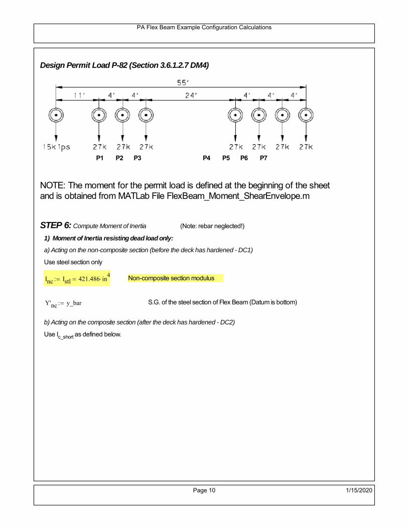
PA Flex Beam Example Configuration Calculations
Design Permit Load P-82 (Section 3.6.1.2.7 DM4)
P1 P2 P3 P4 P5 P6 P7
NOTE: The moment for the permit load is defined at the beginning of the sheetand is obtained from MATLab File FlexBeam_Moment_ShearEnvelope.m
STEP 6: Compute Moment of Inertia (Note: rebar neglected!)
1) Moment of Inertia resisting dead load only:
a) Acting on the non-composite section (before the deck has hardened - DC1)
Use steel section only
Inc Istl 421.486 in4
Non-composite section modulus
Y'nc y_bar S.G. of the steel section of Flex Beam (Datum is bottom)
b) Acting on the composite section (after the deck has hardened - DC2)
Use Ic_short as defined below.
Page 10 1/15/2020

PA Flex Beam Example Configuration Calculations
2) Moment of Inertia resisting live load plus impact:
Using transformed slab with k1=1 (short-term composite).
Actr1 hf btr1 37.5 in2
Itr1
btr1 hf3
12175.781 in
4
Y'
Actr1 hhf
2
Astl Y'nc
Astl Actr114.913 in S.G. of the total flex beam (Datum is bottom)
Compositesection modulus(short-term)
Ic_short Istl Astl Y'nc Y' 2 Itr1 Actr1 hhf
2
Y'
2
2261 in4
Y'c_short Y' 14.913 in N.A. of the short-term composite section
3) Moment of Inertia resisting superimposed dead load:
Using transformed slab with k3=3.
Actr3 hf btr3 12.5 in2
Itr3
btr3 hf3
1258.594 in
4
Y'
Actr3 hhf
2
Astl Y'nc
Astl Actr311.584 in S.G. of the total flex beam (Datum is bottom)
Compositesection modulus(long-term)
Ic_long Istl Astl Y'nc Y' 2 Itr3 Actr3 hhf
2
Y'
2
1588 in4
Y'c_long Y' 11.584 in N.A. of the long-term composite section
Page 11 1/15/2020
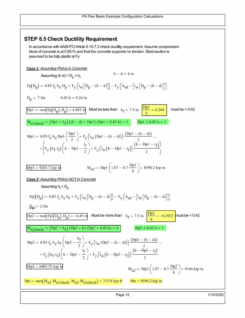
PA Flex Beam Example Configuration Calculations
STEP 6.5 Check Ductility RequirementIn accordance with AASHTO Article 6.10.7.3 check ductility requirement. Assume compressionblock of concrete is at 0.85 f'c and that the concrete supports no tension. Steel section isassumed to be fully plastic at Fy.
Case 1 : Assuming PNA is in Concreteh d 4 inAssuming (h-d) < Dp < hf
Fp Dp 0.85 fc be Dp Fy tw Dp h d( ) Fy Astl tw Dp h d( )
Dp 7.5in 0.42 h 9.24 in
Dp1 root Fp Dp Dp 4.485 in Must be less than hf 7.5 inDp1
h0.204 must be < 0.42
Mn1check Dp1 hf h d( ) Dp1[ ] Dp1 0.42 h( ) 1 Dp1 0.42 h 1
Mp1 0.85 fc be Dp1Dp1
2
Fy tw Dp1 h d( )[ ] Dp1 h d( )[ ]
2
Fy bf tf h Dp1tf
2
Fy tw h Dp1 tf h Dp1 tf
2
Mp1 9263.7 kip in Mn1 Mp1 1.07 0.7Dp1
h
8590.2 kip in
Case 2 : Assuming PNA is NOT in Concrete
Assuming hf < Dp
Fp2 Dp 0.85 fc be hf Fy tw Dp h d( ) Fy Astl tw Dp h d( )
Dp 2.5in
Dp2 root Fp2 Dp Dp 6.45 in Must be more than hf 7.5 inDp2
h0.2932 must be < 0.42
Mn2check Dp2 hf Dp2 h( ) Dp2 0.42 h( ) 0 Dp2 0.42 h 1
Mp2 0.85 fc be hf Dp2hf
2
Fy tw Dp2 h d( )[ ] Dp2 h d( )[ ]
2
Fy bf tf h Dp2tf
2
Fy tw h Dp2 tf h Dp2 tf
2
Mp2 6403.55 kip inMn2 Mp2 1.07 0.7
Dp2
h
8166 kip in
Mn max Mn1 Mn1check Mn2 Mn2check 715.9 kip ft Mn 8590.2 kip in
Page 12 1/15/2020

PA Flex Beam Example Configuration Calculations
Check Composite Compact Section Criteria (6.10.6.2)
Dcpd
2
Fy tf bf 0.85 fc be hf
Fy hw tw1
10.749 in Dcp0 Dcp 0 0
Dcp Dcp Dcp0 0 in2 Dcp
tw3.76
Es
Fy 1 Check if section is compact
STEP 7: Load Combinations (Table 3.4.1-1)
The following load combinations will be considered herein. Only the maximum load factors forpermanent-loads are used in the following load combinations (uplift is not an issue for this typeof bridge).STRENGTH I 1.25DL + 1.5SDL + 1.75 (LL+IM)
SERVICE II: DL+SDL+1.3(LL+IM)
STEP 8: Compute and Check Stresses
Stress at bottom fiber of steel section
fDL
MDL Y'c_long
Ic_long3.665 ksi
fLL_I
MLL_IM Y'c_short
Ic_short14.602 ksi fPL
MLL_IM_PL82 Y'c_short
Ic_short17.024 ksi
fSDL
MSDL Y'c_long
Ic_long5.102 ksi
STRENGTH I fbot_str1 1.25fDL 1.5 fSDL 1.75 fLL_I 37.787 ksi
STRENGTH II fbot_str2 1.25fDL 1.5 fSDL 1.35 fPL 35.216 ksi
SERVICE II fbot_svc2 fDL fSDL 1.3fLL_I 27.75 ksi
Allowable Stress is based on Section 6.10.4.2.2-2
Flange stress due to service load II without consideration of flange lateral bending: ff fbot_svc2
Flange lateral bending stress due to service II: flSII 0ksi
Hybrid Factor: Rh 1.0 For rolled and homogenous built-up sections
ff
flSII
2 27.749 ksi 0.95 Rh Fy 47.5 ksi ff
fl
2 0.95Rh Fy 1
Page 13 1/15/2020

PA Flex Beam Example Configuration Calculations
Stress at top fiber of concrete
Note: For calculating longitudinal flexural stresses in the concrete deck due to allpermanent and transient loads, the short-term modular ratio shall be used.
fDL
MDL h Y'c_short
k1 n Ic_short0.197 ksi
fLL_I
MLL_IM h Y'c_short
k1 n Ic_short0.867 ksi fPL
MLL_IM_PL82 h Y'c_short
k1 n Ic_short1.011 ksi
fSDL
MSDL h Y'c_short
k1 n Ic_short0.274 ksi
STRENGTH I fc_str1 1.25fDL 1.5 fSDL 1.75 fLL_I 2.175 ksi
Mstr1 1.25 MDL 1.5 MSDL 1.75 MLL_IM 462.7 kip ft Mstr1 Mn 1
STRENGTH II fc_str2 1.25fDL 1.5 fSDL 1.35 fPL 2.022 ksi
Mstr2 1.25 MDL 1.5 MSDL 1.35 MLL_IM_PL82 430 kip ft Mstr2 Mn 1
SERVICE II
Allowable Stress in concrete - AASHTO 6.10.4.2.2For compact composite sections in positive flexure utilized in shored construction, the longitudinalcompressive stress in the concrete deck due to the Service II loads, determined as specified in Article6.10.1.1.1d, shall not exceed 0.6f́ c.
fallow 0.6 fc 2400 psi
fc_2 1.3fLL_I fSDL fDL 1598.45 psi This assumes short term compositesection for all calculations
fc_2 fallow 1
SERVICE II with Long Term Composite for dead loads
fDL
MDL h Y'c_long
k3 n Ic_long0.137 ksi
fLL_I
MLL_IM h Y'c_short
k1 n Ic_short0.867 ksi
fSDL
MSDL h Y'c_long
k3 n Ic_long0.191 ksi
fc_2 1.3fLL_I fSDL fDL 1456.07 psi fc_2 fallow 1
Page 14 1/15/2020

PA Flex Beam Example Configuration Calculations
Strength V Moment Check
Strength V is related to normal vehicular use of the bridge with an 80 mph wind gust
Note: that Strength V is checked for an exterior girder under wind load with the interior girder distribution factor forflexure used. If Strength V controls design, then this approach should be modified
Design vertical moment is: 1.25DL + 1.5SDL + 1.35 (LL+IM)
SLT
Ic_long
Y'c_long137.097 in
3 SST
Ic_short
Y'c_short151.644 in
3 short and long term section
modulus
Section D6.2.2 Find the moment required to cause yieldling of the flange. The approach is laid out in D6.2.2
MD2 1.25 MDL 1.5 MSDL 139.765 kip ft From D6.2.2-1 (all dead loads are in MD2 due to shoredconstruction
MAD Fy
MD2
SLT
SST 477.253 kip ft Additional moment to cause nominal yielding of steel flange
My MD2 MAD 617.018 kip ft D6.2.2-2: Moment to cause yielding of flange
6.10.7.1 Compact Section Check at Strength V limit state
Section Modulus for yielding of the flange (My/Fy) for equation 6.10.7.1.1-1Sxt
My
Fy148.084 in
3
Mu 1.25 MDL 1.5MSDL 1.35MLL_IM 388.874 kip ft Moment due to Strength V limit state
Mu1
3fl Sxt 400.783 kip ft Equation 6.10.7.1.7-1 Mn 715.852 kip ft Mu
1
3fl Sxt Mn 1
Page 15 1/15/2020

PA Flex Beam Example Configuration Calculations
STEP 9: Compute Deflection
Optional Live Load Deflection Evaluation (AASHTO 3.6.1.3.2)
Deflection distribution factor for vehicular loads: For a straight multibeambridge, this is equivalent to saying that the distribution factor for deflectionis equal to the number of lanes divided by the number of beams. 2.5.2.6.2
DFd
Nl
N0.25
Deflection should be taken as 125% the larger of:- Design truck- 25% of design truck + design lane
The live load portion of Load Combination Service I of Table 3.4.1-1 should be used,including the dynamic load allowance, IM;
Deflection due to design truck load
NOTE : Assuming maximum deflection occurs when the center of gravity of the loads is at thecenter line of the span.
P1 8kip P2 32kip P3 32kip Axle loads (AASHTO 3.6.1.2.2)
XASr 14ft Rear Axle spacing for truck (14ft - 30ft)
XASf 14ft Front Axle spacing for truck
Center of gravity (CG) of loads:
X'P1 XASr XASf P2 XASr
P1 P2 P39.333 ft Datum is the rear axle
Method1: Assuming single load = P1+P2+P3 at the midspan (Conservative approach)
P1 P2 P3 L3
48 Es Ic_short 1.067 in
Method2: Calculation of Midspan deflection using superposition
b1L
2XASr X' XASf 3.667 ft distance btw load P1 and support A b1check b1 0 0
b2L
2XASr X' 10.333 ft distance btw load P2 and support A b2check b2 0 1
b3L
2X' 5.667 ft distance btw load P3 and support B b3check b3 0 1
Page 16 1/15/2020

PA Flex Beam Example Configuration Calculations
Deflection of the beam at midspan due to P1: P P1
xL
2 at midspan b b1 b1check The smallest distance btw load P1 and support
Δ1P b x
6 Es Ic_short LL2
b2
x2
0 in
Deflection of the beam at midspan due to P2: P P2
xL
2 at midspan b b2 b2check The smallest distance btw load P2 and support
Δ2P b x
6 Es Ic_short LL2
b2
x2
0.413 in
Deflection of the beam at midspan due to P3: P P3
xL
2 at midspan b b3 b3check The smallest distance btw load P3 and support
Δ3P b x
6 Es Ic_short LL2
b2
x2
0.256 in
Total Deflection at midspan:
Δtruck Δ1 Δ2 Δ3( ) DFd 1 I( ) 0.222 in (Considering IM)
Deflection due to tandem (Note: this calculation is not required according to Article3.6.1.3.2 which denotes only the design truck for deflection calculation)
Page 17 1/15/2020

PA Flex Beam Example Configuration Calculations
FT 31.25 kip Per axle
XAS 4ft Axle spacing
Δtandem
FTL
2
XAS
2
24 Es Ic_short3 L
2 4
L
2
XAS
2
2
DFd 1 I( ) 0.3 in (Considering IM)
Deflection due to lane load
FDLLd 640lbf
ft DFd 160
lbf
ft
Δlane
5 FDLLd L4
384 Es Ic_short0.044 in
Live Load Deflection:
ΔLL 1.25max Δtruck 0.25Δtruck Δlane 1.25 0.347 in ΔLLL
800 1
Deflection Limit
For steel or concrete vehicular bridges:
Vehicular load = Span/800L
8000.45 in
L
10000.36 in
Evaluation of Deflection at the Service Limit State (AASHTO 3.4.2.2)
The associated permitted deflections shall be included in the contract documents.
Page 18 1/15/2020

PA Flex Beam Example Configuration Calculations
Shear demands:
Determination of the distribution factor
Using DM4 Table 4.6.2.2.3a-1
Sbe
12in3.333 transverse girder spacing (ft)
Distribution of live loads per lane for shear in interior beams:
For two design lanes loaded, 3.5' <= S =< 16', number of beam >= 4DFs 0.36
S
25 0.493
Q Actr1 h Y'c_shorthf
2
125.14 in3
first moment of deck slab for interface shear
Method 1: Range of shear based on Strength I Limit
STRENGTH I 1.25DL + 1.5SDL + 1.75 (LL+IM)
Computation of the range of shear in the beam
Dead Load:DL 0.372
kip
ft
Superimposed Dead Load: SDL 0.518kip
ft
Design Lane Load: 0.64kip
ft
Design Truck:
XASr 14ft Rear Axle spacing for truck (14ft - 30ft)
XASf 14ft Front Axle spacing for truck
P1 8 kip P2 32 kip P3 32 kip Wheel loads (AASHTO 3.6.1.2.2)
Design Tandem:
Consist of a pair of 25-kip axles spaced 4-ft apart. (AASHTO 3.6.1.2.3)
NOTE: PennDOT DM4 increases 25-kip to 31.25-kip.
FT 31.25kip
XAS 4ft Axle spacing
Page 19 1/15/2020

PA Flex Beam Example Configuration Calculations
Maximum positive shear at various points along the FlexBeam are examined.
At x=0 (at left support) (Truck is moving from left to right)
Truck
Max Positive Shear (when P3 is at x = 0):
x1 L XASr XASf 2 ft Distance between P1 and right support
x2 L XASr 16 ft Distance between P2 and right support
x3 L 30 ft Distance between P3 and right support
V1 P3
x3
L P2
x2
L P1
x1
L 49.6 kip
Total Vertical Shear Force for each FlexBeam (considering dynamic loads):
Vtruck1 V1 DFs 1 I( ) 32.544 kip
Tandem:
V1 FT FT
L XAS L
58.333 kip
Total Vertical Shear Force for each FlexBeam (considering dynamic loads):
Vtandem1 V1 DFs 1 I( ) 38.274 kip
Lane Load
V1 0.64kip
ft
L
2 9.6 kip
Total Vertical Shear Force for each FlexBeam (considering dynamic loads):
Vlane1 V1 DFs 4.736 kip
Dead Load
Vdl1 DLL
2 5.583 kip
Superimposed Dead Load
Vsdl1 SDLL
2 7.771 kip
Strength I Max Positive Shear:
Vstr1 1.25 Vdl1 1.5 Vsdl1 1.75 Vlane1 max Vtruck1 Vtandem1 93.904 kip
Page 20 1/15/2020

PA Flex Beam Example Configuration Calculations
Design Permit Load P-82
Shear at x=0
Strength II Max Positive Shear:
VPL82 VPL82span DFs 1 IPL 50.936 kip
STRENGTH II 1.25DL + 1.5SDL + 1.35 (LL+IM)
VstrII_PL 1.25 Vdl1 1.5 Vsdl1 1.35 VPL82 87.398 kip
Max Shear Demand Vu max Vstr1 VstrII_PL 93.904 kip
Determine the Shear Strength of the Web
Shear Strength of Unstiffened web from AASHTO section 6.10.9.2
Depth of Web D d 18 in Thickness of web tw 0.375 in
Transverse Stiffener Spacing d0 0in Shear Buckling Coefficient k 5 6.10.9.3.2-7
Plastic Shear Force Vp 0.58 Fy D tw 195.75 kip Equation 6.10.9.3.2-3
Ratio of Shear-Buckling resistance to shear yield, C
D
tw48 1.12
Es k
Fy 60.314 Ccheck
D
tw1.12
Es k
Fy 1 Equation 6.10.9.3.2-4
C 1.0 Ccheck 1 C=1 for most cases, if the criteria are not met, then C will go to zero and the actualcoefficients should be determined
Nominal Shear Resistance of Web Vn C Vp 195.75 kip equation 6.10.9.3.3-1
Shear Resistance Factor φv 1.0
φv Vn 195.75 kip φv Vn Vu 1Reduced Shear Strength
Page 21 1/15/2020

PA Flex Beam Example Configuration Calculations
Check Bearing Stiffeners
FYs 50ksi Yield strength of stiffener
tp 0.75in Thickness of stiffener
bt
bf tw
21.5in 4.312 in Effective width of stiffener
Dst hw 4.1in 13.4 in Depth of stiffeners
Apn 2 tp bt 6.469 in2
Projected area of stiffeners
bt 0.48 tpEs
FYs 1Check that effective width of stiffener meets requirements
Rsbn 1.4 Apn FYs 452.812 kip Bearing capacity of stiffener (phi=1 for bearing per AASHTO 6.5.4.2)
Rsbn Vu 1 Bearing capacity check
Qs 1.0 Q factor for bearing stiffner, taken as 1 (AASHTO 6.9.4.1.1)
Is
18 tw tw3
tp 2 bt 3
1240.131 in
4 Moment of inertia of stiffener and web (9*tw is used on each side)
AASHTO 6.10.11.2.4b
Ag 18 tw tw 2 bt tp 9 in2
Gross area of stiffener and web (AASHTO 6.10.11.2.4b)
rs
Is
Ag2.112 in Radius of gyration of stiffener/web
Po Qs FYs Apn 323.437 kip Nominal yeild resistance of stiffener (AASHTO 6.9.4.1.1)
Peπ2Es
0.75 Dst
rs
2Ag 1.137 10
5 kip Elastic critical buckling stress of stiffener (AASHTO 6.9.4.1.2-1)
Check that Pe/Po is great than 0.44 (AASHTO 6.9.4.1.1) PePoPe
Po0.44 1
Pn PePo 0.658
Po
Pe Po 323.053 kip Nominal compressive resistance of stiffener for Pe/Po>0.44
(AASHTO 6.9.4.1.1-1)
φcr 0.95 phi factor for axial compression (AASHTO 6.5.4.2)
Pr φcr Pn 306.9 kip Compressive capacity of bearing stiffener Pr Vu 1
Page 22 1/15/2020

PA Flex Beam Example Configuration Calculations
Flexbeam Example Configuration Calculations
Summary of Calculations:
Input section dimensions and material properties for steel WT and the concrete deck1.Calculate demands (dead load, superimposed dead, and Live load demands for Strength I and Strength II2.Calculate composite section properties for the given section3.Check Strength I, Strength II, and Service II stresses 4.Check Strength I, Strength II, and Strength V moment demands 5.Perform live load deflection check6.Determine maximum shear demand and capacity7.Note: Shear envelope data was obtained from Matlab script (FlexBeam_Moment_ShearEnvelope.m).8.Shear envelope calculations are summarized separately for each design (Shear Design *.xlsx).
Design Assumptions:Design Specifications Used:
AASHTO LRFD Bridge Design Specifications 7th Edition with 2016 Interim RevisionsPennDOT Design Manual, Part 4 (DM-4) June 30, 2015
Example configurations are determined for two girder spacings, 36" and 40".The deck thickness is 7.5" and is assumed to have a non-structural wearing surface added after installation.Section properties are calculated using the full 7.5" deck thickness.The WT sections are embedded 3.5" into the concrete deck. The steel section spacing used is outside the scope of the AASHTO and PennDOT distribution factorequations. The flexural distribution factor is assumed to be 0.3 which was shown to tbe conservativeaccording to refined analysisThe shear distribution factor is calculated using the DM-4 shear distribution factor equation which wasshown to be conservative using refined analysis.Refined analysis is presented in: Zihan Ma, "Distribution Factors for Composite Steel Tee Concrete DeckBridge System," M.S. Thesis, Deparement of Civil and Environmental Engineering, Lehigh University,Bethlehem, 2019Shear and moment demands for the PL82 permit load vehicle are determined by Matlab script(FlexBeam_Moment_ShearEnvelope.m) and are manually input into this calculation sheet.All fabrication will occur as double modules, i.e. each module contains two WT sections. The number ofmodules is half the number of beams, N. A 45 in. tall F-Shape barrier is used, Weight = 700 lb/ft (Distributed to exterior two beams).
The work presented in this document are provided on an “AS IS” basis. University makes no warranties of anykind, express or implied, as to any matter whatsoever, including, without limitation, warranties with respect tothe merchantability or fitness for a particular purpose of this work or any project deliverables. Universitymakes no warranty of any kind with respect to freedom from patent, trademark, copyright or trade secretinfringement arising from the use of the results of the project, deliverables, services, intellectual property orother materials provided hereunder. University shall not be liable for any direct, indirect, consequential,punitive, or other damages suffered by Sponsor or any other person resulting from the project, or the use ofthis work or any project deliverables.
Page 1 1/15/2020

PA Flex Beam Example Configuration Calculations
hf
tf
bf
twh
d
bjtbe
e
Variable Definitions:
Number of beams N 14 modulesN
27
L 30ft Span length
be 40in Effective width of Flexbeamassuming constructed bridge width(i.e. closure joints cast)
Built Up Section Properties
tw 0.375in tf 0.5in bf 12in
h 22in Overall Height of section
hf 7.5in Total thickness of deck
e 3.5in Deck/Steel overlap
d h hf e 18 in depth of built up steel section
hw d tf 17.5 in height of web of built up steel
Moment and shear for permit load PL82 obtained from Matlab script: FlexBeam_Moment_ShearEnvelope
MLL_IM_PL82 215.136kip ft Moment due to PL82 with distribution factor and impact factor!!
VPL82span 86.04kip Shear due to PL82 WITHOUT distribution factor and impact factor!!
Check web and flange dimensions in sections 6.10.2.1 and 6.10.2.2
(Ignore 6.10.2.2-4 since no compression flange)
equation 6.10.2.1.1-1d
tw150 1 equation 6.10.2.2-1
bf
2 tf12 1
equation 6.10.2.2-2 bfh
6 1 equation 6.10.2.2-3 tf 1.1 tw 1
y_bar
tf bftf
2 hw tw tf
hw
2
tf bf hw tw4.951 in Center of gravity of steel section
Istl
bf tf3
12bf tf y_bar
tf
2
2
tw hw
3
12 tw hw tf
hw
2 y_bar
2
421.486 in4
MOI of steel
Astl tf bf hw tw 12.562 in2
Area of the WT steel section
Page 2 1/15/2020

PA Flex Beam Example Configuration Calculations
Material Properties
Elastic Modulus of Steel Es 29000ksi
Yield Strength of Steel Fy 50ksi
Yield Strength of Reinforcement fy 60ksi
Compressive Strength of Concrete fc 4000psi AAAP PennDOT Concrete
Concrete Modular Ratio n 8 modular ratio for 4ksi concrete per AASHTO
Unit weight of concrete slab wc 0.150kip
ft3
Unit weight of concrete
Section Properties
Width of UHPC Joint: bjt 6in
Parapet width: bpar 20.25in Parapet width per PennDOT F-shape barrier
Width of the bridge W be N bjt 554 in W 46.167 ft
Clear width of roadway Wlane W 2 bpar 42.792 ft
Dc wc hf W 4.328kip
ft DL due to slab
Db .700kip
ft DL due to each 45" F-Shape Barrier (per email 11/1/18)
DFWS 30lbf
ft2
W 2 bpar 1.284kip
ft DL due to Future Wearing Surface (FWS)
Ds Astl 490lbf
ft3
0.043kip
ft Selfweight of the steel section
DLself
Dc N
Ds 0.352kip
ft Self-weight per WT
Total weight of each precast FlexBeam for transportation:
Weight of C12x25 Diaphragms Wend_diaphragms 25lbf
ft32 in 0.067 kip
2be bjt hf wc 2Ds L 2 Wend_diaphragms 20.042 kip
Determine number of design lane (AASHTO Section 3.6.1.1.1)
Take the integer part of the ratio of W/12 ft. Number of lanes in bridge: Nl floorWlane
12ft
3
Page 3 1/15/2020

PA Flex Beam Example Configuration Calculations
STEP 1: Compute Dead Load for each Flex Beam
DLslab
Dc
Nwc 1 in
be
2 0.33
kip
ft Dead load of slab assuming exterior overhang has 1" of
additional concrete thickness
DLsteel Ds 0.043kip
ft
DL DLslab DLsteel 0.373kip
ft
STEP 2: Compute Superimposed Dead Load
SDLWS
DFWS
N0.092
kip
ft
SDLparapet
Db
20.35
kip
ft distributed equally on two outer beams
SDLOL 140lbf
ft3be 2 in 0.078
kip
ft Overlay is 2" thick and is 140 lbs/cubic foot
NOTE: For this example barrier load is distributed equally among the two outer beams per conversation withPennDOT and M&M.
PennDOT DM4: "For composite adjacent and spread beams, the barrier (single barrier) load shall be equallydistributed to the nearest three (adjacent) and two (spread) beams, respectively, when the barriers are placedafter slab has hardened".
SDL SDLWS SDLparapet SDLOL 0.519kip
ft
STEP 3: Compute Transformed Width of Slab
For live load and dead load acting on the stringer k1 1 For short-term section property evaluation
btr1
be
k1 n5 in Transformed width of slab for short-term
For superimposed dead loads k3 3 For long-term section property evaluation
btr3
be
k3 n1.667 in Transformed width of slab for long-term
Page 4 1/15/2020

PA Flex Beam Example Configuration Calculations
STEP 4: Compute Dead and Superimposed Dead Load Moments(Based on first interior girder demands)
MDLDL L
2
841.932 kip ft
MSDLSDL L
2
858.441 kip ft
STEP 5: Compute live load and Dynamic Load Allowance (IM)
Live load wheel load distribution factor (DF):
Sbe
12in3.333 transverse girder spacing
NOTE: AASHTO presents equations to define DF for different types of superstructuresincluding Deck Composite wirh RC slab on steel girders (Type (a) in Table 4.6.2.2.1-1) forshear and moment in interior and exterior beams.
Using DM4 Table 4.6.2.2.2b-1:
eg h y_barhf
2 13.299 in Distance between the centers of gravity of the basic beam and deck
Kg n Istl Astl eg2
21145.34 in
4 Longitudinal stiffness parameter (in4)
Distribution of Live Load Per Lane for Moment in Interior Beams:
to be conservative, use DF 0.3
Page 5 1/15/2020

PA Flex Beam Example Configuration Calculations
Dynamic Load Allowance (Section 3.6.2 DM4)
Static effects of the design truck or tandem, shall be increased by the impact factor.
NOTE: The dynamic load allowance shall not be applied to the design lane load (Section 3.6.2.1 DM4)
I 0.33 Impact factor for moment
Note: PennDOT requires that the impact for decks be increased from 33% to 50%, the deck is not beingdesigned here. Instrad the deck design is based on the BD recommendations.
Dynamic load allowance for the Permit Load P-82 shall be less than 20%. (Section 3.6.2.1DM4)
IPL 0.20 Impact factor for moment on Strength II
Design Wind Loading for Exterior Girder
Vw 80 Wind speed for Strength V load case
CD 1.3 Gust factor for windard side of I-Girder and Box Girder Superstructures (Table 3.8.1.2.1-2)
G 1.0 Gus effect factor is 1.0 for all structures other than sound barriers (Table 3.8.1.2.1-1)
Kz 1.0 Pressure coefficient taken as 1 for Strength V (3.8.1.2.1)
Pz 2.56 106
Vw 2 Kz G CDkip
ft2
0.021kip
ft2
Wind pressure on exterior girder
hexp h hf 14.5 in Exposed height of exterior girder
Moment due to wind loading on exterior girderMWL
Pz hexp L2
82.895 kip ft
Iyy
bf3tf
1272 in
4 Transverse moment of intertia
Flange lateral bending stressfl
MWL
bf
2
Iyy2.895 ksi
Page 6 1/15/2020

PA Flex Beam Example Configuration Calculations
Design Vehicular Live Load
PHL-93 and P-82 are examined herein.
PHL-93 (A3.6.1.2.1)
PHL-93 consists of a combination of (design truck or design tandem) + (design lane load)
Design Truck
PennDOT defines the design truck in accordance with AASTHO 3.6.1.2
Design truck load in AASHTO (HS20 Truck) is used for this example.
NOTE : MAX moment occurs when the center line of the span is midway between the center ofgravity of the loads and the nearest concentrated load.
P1 8kip P2 32kip P3 32kip Axle loads (AASHTO 3.6.1.2.2)
XASr 14ft Rear Axle spacing for truck (14ft - 30ft)
XASf 14ft Front Axle spacing for truck
Page 7 1/15/2020

PA Flex Beam Example Configuration Calculations
Center of gravity (CG) of loads:
X'P1 XASr XASf P2 XASr
P1 P2 P39.333 ft Datum is the rear axle
X XASr X' 4.667 ft Spacing btw CG and nearest load
Find bridge reaction
Truck movestoward Support ARA
P1L
2XASf
X
2
P2L
2
X
2
P3L
2X'
X
2
L30.4 kip
Max live load moment (at the location of P2):
MLL_truck RAL
2
X
2
P1 XASf 273.067 kip ft
NOTE: Find the worst case by varying XASr
Page 8 1/15/2020

PA Flex Beam Example Configuration Calculations
Design Tandem
Consist of a pair of 25-kip axles spaced 4-ft apart. (AASHTO 3.6.1.2.3)
NOTE: PennDOT DM4 increases 25-kip to 31.25-kip.
FT 31.25kip
XAS 4ft Axle spacing
Center of gravity (CG) of loads:
XXAS
22 ft Spacing btw CG and nearest load
Find bridge reaction
RA
FTL
2
X
2
FTL
2
X
2 X
L29.167 kip Truck moves toward Support A
Max live load moment (at the location of front wheel):
MLL_tandem RAL
2
X
2
408.333 kip ft
Choose the max value:
MLL_veh max MLL_tandem MLL_truck 408.333 kip ft
Apply the impact and wheel load distribution:
MLL_IM_veh MLL_veh DF 1 I( ) 162.925 kip ft Due to tandem or truck
Design Lane Load (distributed over a 10-ft width for each lane)
NOTE: The uniform load may be continuous or discontinuous as necessary to produce themaximum force effect. For this example continuous uniform distribution assumed.
FDLL 0.64kip
ftDF 0.192
kip
ft Per beam in each lane
Due to lane loadMLL_IM_lane
FDLL L2
8
21.6 kip ft
Moment due to Total Design Vehicular Live Load: MLL_IM MLL_IM_lane MLL_IM_veh 184.525 kip ft
Page 9 1/15/2020

PA Flex Beam Example Configuration Calculations
Design Permit Load P-82 (Section 3.6.1.2.7 DM4)
P1 P2 P3 P4 P5 P6 P7
NOTE: The moment for the permit load is defined at the beginning of the sheetand is obtained from MATLab File FlexBeam_Moment_ShearEnvelope.m
STEP 6: Compute Moment of Inertia (Note: rebar neglected!)
1) Moment of Inertia resisting dead load only:
a) Acting on the non-composite section (before the deck has hardened - DC1)
Use steel section only
Inc Istl 421.486 in4
Non-composite section modulus
Y'nc y_bar S.G. of the steel section of Flex Beam (Datum is bottom)
b) Acting on the composite section (after the deck has hardened - DC2)
Use Ic_short as defined below.
Page 10 1/15/2020

PA Flex Beam Example Configuration Calculations
2) Moment of Inertia resisting live load plus impact:
Using transformed slab with k1=1 (short-term composite).
Actr1 hf btr1 37.5 in2
Itr1
btr1 hf3
12175.781 in
4
Y'
Actr1 hhf
2
Astl Y'nc
Astl Actr114.913 in S.G. of the total flex beam (Datum is bottom)
Compositesection modulus(short-term)
Ic_short Istl Astl Y'nc Y' 2 Itr1 Actr1 hhf
2
Y'
2
2261 in4
Y'c_short Y' 14.913 in N.A. of the short-term composite section
3) Moment of Inertia resisting superimposed dead load:
Using transformed slab with k3=3.
Actr3 hf btr3 12.5 in2
Itr3
btr3 hf3
1258.594 in
4
Y'
Actr3 hhf
2
Astl Y'nc
Astl Actr311.584 in S.G. of the total flex beam (Datum is bottom)
Compositesection modulus(long-term)
Ic_long Istl Astl Y'nc Y' 2 Itr3 Actr3 hhf
2
Y'
2
1588 in4
Y'c_long Y' 11.584 in N.A. of the long-term composite section
Page 11 1/15/2020

PA Flex Beam Example Configuration Calculations
STEP 6.5 Check Ductility RequirementIn accordance with AASHTO Article 6.10.7.3 check ductility requirement. Assume compressionblock of concrete is at 0.85 f'c and that the concrete supports no tension. Steel section isassumed to be fully plastic at Fy.
Case 1 : Assuming PNA is in Concreteh d 4 inAssuming (h-d) < Dp < hf
Fp Dp 0.85 fc be Dp Fy tw Dp h d( ) Fy Astl tw Dp h d( )
Dp 7.5in 0.42 h 9.24 in
Dp1 root Fp Dp Dp 4.485 in Must be less than hf 7.5 inDp1
h0.204 must be < 0.42
Mn1check Dp1 hf h d( ) Dp1[ ] Dp1 0.42 h( ) 1 Dp1 0.42 h 1
Mp1 0.85 fc be Dp1Dp1
2
Fy tw Dp1 h d( )[ ] Dp1 h d( )[ ]
2
Fy bf tf h Dp1tf
2
Fy tw h Dp1 tf h Dp1 tf
2
Mp1 9263.7 kip in Mn1 Mp1 1.07 0.7Dp1
h
8590.2 kip in
Case 2 : Assuming PNA is NOT in Concrete
Assuming hf < Dp
Fp2 Dp 0.85 fc be hf Fy tw Dp h d( ) Fy Astl tw Dp h d( )
Dp 2.5in
Dp2 root Fp2 Dp Dp 6.45 in Must be more than hf 7.5 inDp2
h0.2932 must be < 0.42
Mn2check Dp2 hf Dp2 h( ) Dp2 0.42 h( ) 0 Dp2 0.42 h 1
Mp2 0.85 fc be hf Dp2hf
2
Fy tw Dp2 h d( )[ ] Dp2 h d( )[ ]
2
Fy bf tf h Dp2tf
2
Fy tw h Dp2 tf h Dp2 tf
2
Mp2 6403.55 kip inMn2 Mp2 1.07 0.7
Dp2
h
8166 kip in
Mn max Mn1 Mn1check Mn2 Mn2check 715.9 kip ft Mn 8590.2 kip in
Page 12 1/15/2020

PA Flex Beam Example Configuration Calculations
Check Composite Compact Section Criteria (6.10.6.2)
Dcpd
2
Fy tf bf 0.85 fc be hf
Fy hw tw1
10.749 in Dcp0 Dcp 0 0
Dcp Dcp Dcp0 0 in2 Dcp
tw3.76
Es
Fy 1 Check if section is compact
STEP 7: Load Combinations (Table 3.4.1-1)
The following load combinations will be considered herein. Only the maximum load factors forpermanent-loads are used in the following load combinations (uplift is not an issue for this typeof bridge).STRENGTH I 1.25DL + 1.5SDL + 1.75 (LL+IM)
SERVICE II: DL+SDL+1.3(LL+IM)
STEP 8: Compute and Check Stresses
Stress at bottom fiber of steel section
fDL
MDL Y'c_long
Ic_long3.67 ksi
fLL_I
MLL_IM Y'c_short
Ic_short14.602 ksi fPL
MLL_IM_PL82 Y'c_short
Ic_short17.024 ksi
fSDL
MSDL Y'c_long
Ic_long5.115 ksi
STRENGTH I fbot_str1 1.25fDL 1.5 fSDL 1.75 fLL_I 37.814 ksi
STRENGTH II fbot_str2 1.25fDL 1.5 fSDL 1.35 fPL 35.244 ksi
SERVICE II fbot_svc2 fDL fSDL 1.3fLL_I 27.77 ksi
Allowable Stress is based on Section 6.10.4.2.2-2
Flange stress due to service load II without consideration of flange lateral bending: ff fbot_svc2
Flange lateral bending stress due to service II: flSII 0ksi
Hybrid Factor: Rh 1.0 For rolled and homogenous built-up sections
ff
flSII
2 27.768 ksi 0.95 Rh Fy 47.5 ksi ff
fl
2 0.95Rh Fy 1
Page 13 1/15/2020

PA Flex Beam Example Configuration Calculations
Stress at top fiber of concrete
Note: For calculating longitudinal flexural stresses in the concrete deck due to allpermanent and transient loads, the short-term modular ratio shall be used.
fDL
MDL h Y'c_short
k1 n Ic_short0.197 ksi
fLL_I
MLL_IM h Y'c_short
k1 n Ic_short0.867 ksi fPL
MLL_IM_PL82 h Y'c_short
k1 n Ic_short1.011 ksi
fSDL
MSDL h Y'c_short
k1 n Ic_short0.275 ksi
STRENGTH I fc_str1 1.25fDL 1.5 fSDL 1.75 fLL_I 2.176 ksi
Mstr1 1.25 MDL 1.5 MSDL 1.75 MLL_IM 463 kip ft Mstr1 Mn 1
STRENGTH II fc_str2 1.25fDL 1.5 fSDL 1.35 fPL 2.024 ksi
Mstr2 1.25 MDL 1.5 MSDL 1.35 MLL_IM_PL82 431 kip ft Mstr2 Mn 1
SERVICE II
Allowable Stress in concrete - AASHTO 6.10.4.2.2For compact composite sections in positive flexure utilized in shored construction, the longitudinalcompressive stress in the concrete deck due to the Service II loads, determined as specified in Article6.10.1.1.1d, shall not exceed 0.6f́ c.
fallow 0.6 fc 2400 psi
fc_2 1.3fLL_I fSDL fDL 1599.47 psi This assumes short term compositesection for all calculations
fc_2 fallow 1
SERVICE II with Long Term Composite for dead loads
fDL
MDL h Y'c_long
k3 n Ic_long0.138 ksi
fLL_I
MLL_IM h Y'c_short
k1 n Ic_short0.867 ksi
fSDL
MSDL h Y'c_long
k3 n Ic_long0.192 ksi
fc_2 1.3fLL_I fSDL fDL 1456.79 psi fc_2 fallow 1
Page 14 1/15/2020

PA Flex Beam Example Configuration Calculations
Strength V Moment Check
Strength V is related to normal vehicular use of the bridge with an 80 mph wind gust
Note: that Strength V is checked for an exterior girder under wind load with the interior girder distribution factor forflexure used. If Strength V controls design, then this approach should be modified
Design vertical moment is: 1.25DL + 1.5SDL + 1.35 (LL+IM)
SLT
Ic_long
Y'c_long137.097 in
3 SST
Ic_short
Y'c_short151.644 in
3 short and long term section
modulus
Section D6.2.2 Find the moment required to cause yieldling of the flange. The approach is laid out in D6.2.2
MD2 1.25 MDL 1.5 MSDL 140.077 kip ft From D6.2.2-1 (all dead loads are in MD2 due to shoredconstruction
MAD Fy
MD2
SLT
SST 476.908 kip ft Additional moment to cause nominal yielding of steel flange
My MD2 MAD 616.985 kip ft D6.2.2-2: Moment to cause yielding of flange
6.10.7.1 Compact Section Check at Strength V limit state
Section Modulus for yielding of the flange (My/Fy) for equation 6.10.7.1.1-1Sxt
My
Fy148.076 in
3
Mu 1.25 MDL 1.5MSDL 1.35MLL_IM 389.186 kip ft Moment due to Strength V limit state
Mu1
3fl Sxt 401.095 kip ft Equation 6.10.7.1.7-1 Mn 715.852 kip ft Mu
1
3fl Sxt Mn 1
Page 15 1/15/2020

PA Flex Beam Example Configuration Calculations
STEP 9: Compute Deflection
Optional Live Load Deflection Evaluation (AASHTO 3.6.1.3.2)
Deflection distribution factor for vehicular loads: For a straight multibeambridge, this is equivalent to saying that the distribution factor for deflectionis equal to the number of lanes divided by the number of beams. 2.5.2.6.2
DFd
Nl
N0.214
Deflection should be taken as 125% the larger of:- Design truck- 25% of design truck + design lane
The live load portion of Load Combination Service I of Table 3.4.1-1 should be used,including the dynamic load allowance, IM;
Deflection due to design truck load
NOTE : Assuming maximum deflection occurs when the center of gravity of the loads is at thecenter line of the span.
P1 8kip P2 32kip P3 32kip Axle loads (AASHTO 3.6.1.2.2)
XASr 14ft Rear Axle spacing for truck (14ft - 30ft)
XASf 14ft Front Axle spacing for truck
Center of gravity (CG) of loads:
X'P1 XASr XASf P2 XASr
P1 P2 P39.333 ft Datum is the rear axle
Method1: Assuming single load = P1+P2+P3 at the midspan (Conservative approach)
P1 P2 P3 L3
48 Es Ic_short 1.067 in
Method2: Calculation of Midspan deflection using superposition
b1L
2XASr X' XASf 3.667 ft distance btw load P1 and support A b1check b1 0 0
b2L
2XASr X' 10.333 ft distance btw load P2 and support A b2check b2 0 1
b3L
2X' 5.667 ft distance btw load P3 and support B b3check b3 0 1
Page 16 1/15/2020
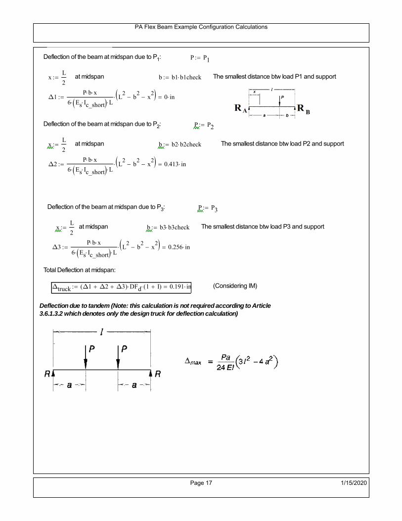
PA Flex Beam Example Configuration Calculations
Deflection of the beam at midspan due to P1: P P1
xL
2 at midspan b b1 b1check The smallest distance btw load P1 and support
Δ1P b x
6 Es Ic_short LL2
b2
x2
0 in
Deflection of the beam at midspan due to P2: P P2
xL
2 at midspan b b2 b2check The smallest distance btw load P2 and support
Δ2P b x
6 Es Ic_short LL2
b2
x2
0.413 in
Deflection of the beam at midspan due to P3: P P3
xL
2 at midspan b b3 b3check The smallest distance btw load P3 and support
Δ3P b x
6 Es Ic_short LL2
b2
x2
0.256 in
Total Deflection at midspan:
Δtruck Δ1 Δ2 Δ3( ) DFd 1 I( ) 0.191 in (Considering IM)
Deflection due to tandem (Note: this calculation is not required according to Article3.6.1.3.2 which denotes only the design truck for deflection calculation)
Page 17 1/15/2020

PA Flex Beam Example Configuration Calculations
FT 31.25 kip Per axle
XAS 4ft Axle spacing
Δtandem
FTL
2
XAS
2
24 Es Ic_short3 L
2 4
L
2
XAS
2
2
DFd 1 I( ) 0.257 in (Considering IM)
Deflection due to lane load
FDLLd 640lbf
ft DFd 137.143
lbf
ft
Δlane
5 FDLLd L4
384 Es Ic_short0.038 in
Live Load Deflection:
ΔLL 1.25max Δtruck 0.25Δtruck Δlane 1.25 0.298 in ΔLLL
800 1
Deflection Limit
For steel or concrete vehicular bridges:
Vehicular load = Span/800L
8000.45 in
L
10000.36 in
Evaluation of Deflection at the Service Limit State (AASHTO 3.4.2.2)
The associated permitted deflections shall be included in the contract documents.
Page 18 1/15/2020

PA Flex Beam Example Configuration Calculations
Shear demands:
Determination of the distribution factor
Using DM4 Table 4.6.2.2.3a-1
Sbe
12in3.333 transverse girder spacing (ft)
Distribution of live loads per lane for shear in interior beams:
DFs 0.36S
25 0.493 For ONE design lanes loaded, 3.5' <= S =< 16', number of beam >= 4
Q Actr1 h Y'c_shorthf
2
125.14 in3
first moment of deck slab for interface shear
Method 1: Range of shear based on Strength I Limit
STRENGTH I 1.25DL + 1.5SDL + 1.75 (LL+IM)
Computation of the range of shear in the beam
Dead Load:DL 0.373
kip
ft
Superimposed Dead Load: SDL 0.519kip
ft
Design Lane Load: 0.64kip
ft
Design Truck:
XASr 14ft Rear Axle spacing for truck (14ft - 30ft)
XASf 14ft Front Axle spacing for truck
P1 8 kip P2 32 kip P3 32 kip Wheel loads (AASHTO 3.6.1.2.2)
Design Tandem:
Consist of a pair of 25-kip axles spaced 4-ft apart. (AASHTO 3.6.1.2.3)
NOTE: PennDOT DM4 increases 25-kip to 31.25-kip.
FT 31.25kip
XAS 4ft Axle spacing
Page 19 1/15/2020

PA Flex Beam Example Configuration Calculations
Maximum positive shear at various points along the FlexBeam are examined.
At x=0 (at left support) (Truck is moving from left to right)
Truck
Max Positive Shear (when P3 is at x = 0):
x1 L XASr XASf 2 ft Distance between P1 and right support
x2 L XASr 16 ft Distance between P2 and right support
x3 L 30 ft Distance between P3 and right support
V1 P3
x3
L P2
x2
L P1
x1
L 49.6 kip
Total Vertical Shear Force for each FlexBeam (considering dynamic loads):
Vtruck1 V1 DFs 1 I( ) 32.544 kip
Tandem:
V1 FT FT
L XAS L
58.333 kip
Total Vertical Shear Force for each FlexBeam (considering dynamic loads):
Vtandem1 V1 DFs 1 I( ) 38.274 kip
Lane Load
V1 0.64kip
ft
L
2 9.6 kip
Total Vertical Shear Force for each FlexBeam (considering dynamic loads):
Vlane1 V1 DFs 4.736 kip
Dead Load
Vdl1 DLL
2 5.591 kip
Superimposed Dead Load
Vsdl1 SDLL
2 7.792 kip
Strength I Max Positive Shear:
Vstr1 1.25 Vdl1 1.5 Vsdl1 1.75 Vlane1 max Vtruck1 Vtandem1 93.945 kip
Page 20 1/15/2020

PA Flex Beam Example Configuration Calculations
Design Permit Load P-82
Shear at x=0
Strength II Max Positive Shear:
VPL82 VPL82span DFs 1 IPL 50.936 kip
STRENGTH II 1.25DL + 1.5SDL + 1.35 (LL+IM)
VstrII_PL 1.25 Vdl1 1.5 Vsdl1 1.35 VPL82 87.44 kip
Max Shear Demand Vu max Vstr1 VstrII_PL 93.945 kip
Determine the Shear Strength of the Web
Shear Strength of Unstiffened web from AASHTO section 6.10.9.2
Depth of Web D d 18 in Thickness of web tw 0.375 in
Transverse Stiffener Spacing d0 0in Shear Buckling Coefficient k 5 6.10.9.3.2-7
Plastic Shear Force Vp 0.58 Fy D tw 195.75 kip Equation 6.10.9.3.2-3
Ratio of Shear-Buckling resistance to shear yield, C
D
tw48 1.12
Es k
Fy 60.314 Ccheck
D
tw1.12
Es k
Fy 1 Equation 6.10.9.3.2-4
C 1.0 Ccheck 1 C=1 for most cases, if the criteria are not met, then C will go to zero and the actualcoefficients should be determined
Nominal Shear Resistance of Web Vn C Vp 195.75 kip equation 6.10.9.3.3-1
Shear Resistance Factor φv 1.0
φv Vn 195.75 kip φv Vn Vu 1Reduced Shear Strength
Page 21 1/15/2020

PA Flex Beam Example Configuration Calculations
Check Bearing Stiffeners
FYs 50ksi Yield strength of stiffener
tp 0.75in Thickness of stiffener
bt
bf tw
21.5in 4.312 in Effective width of stiffener
Dst hw 4.1in 13.4 in Depth of stiffeners
Apn 2 tp bt 6.469 in2
Projected area of stiffeners
bt 0.48 tpEs
FYs 1Check that effective width of stiffener meets requirements
Rsbn 1.4 Apn FYs 452.812 kip Bearing capacity of stiffener (phi=1 for bearing per AASHTO 6.5.4.2)
Rsbn Vu 1 Bearing capacity check
Qs 1.0 Q factor for bearing stiffner, taken as 1 (AASHTO 6.9.4.1.1)
Is
18 tw tw3
tp 2 bt 3
1240.131 in
4 Moment of inertia of stiffener and web (9*tw is used on each side)
AASHTO 6.10.11.2.4b
Ag 18 tw tw 2 bt tp 9 in2
Gross area of stiffener and web (AASHTO 6.10.11.2.4b)
rs
Is
Ag2.112 in Radius of gyration of stiffener/web
Po Qs FYs Apn 323.437 kip Nominal yeild resistance of stiffener (AASHTO 6.9.4.1.1)
Peπ2Es
0.75 Dst
rs
2Ag 1.137 10
5 kip Elastic critical buckling stress of stiffener (AASHTO 6.9.4.1.2-1)
Check that Pe/Po is great than 0.44 (AASHTO 6.9.4.1.1) PePoPe
Po0.44 1
Pn PePo 0.658
Po
Pe Po 323.053 kip Nominal compressive resistance of stiffener for Pe/Po>0.44
(AASHTO 6.9.4.1.1-1)
φcr 0.95 phi factor for axial compression (AASHTO 6.5.4.2)
Pr φcr Pn 306.9 kip Compressive capacity of bearing stiffener Pr Vu 1
Page 22 1/15/2020

PA Flex Beam Example Configuration Calculations
Flexbeam Example Configuration Calculations
Summary of Calculations:
Input section dimensions and material properties for steel WT and the concrete deck1.Calculate demands (dead load, superimposed dead, and Live load demands for Strength I and Strength II2.Calculate composite section properties for the given section3.Check Strength I, Strength II, and Service II stresses 4.Check Strength I, Strength II, and Strength V moment demands 5.Perform live load deflection check6.Determine maximum shear demand and capacity7.Note: Shear envelope data was obtained from Matlab script (FlexBeam_Moment_ShearEnvelope.m).8.Shear envelope calculations are summarized separately for each design (Shear Design *.xlsx).
Design Assumptions:Design Specifications Used:
AASHTO LRFD Bridge Design Specifications 7th Edition with 2016 Interim RevisionsPennDOT Design Manual, Part 4 (DM-4) June 30, 2015
Example configurations are determined for two girder spacings, 36" and 40".The deck thickness is 7.5" and is assumed to have a non-structural wearing surface added after installation.Section properties are calculated using the full 7.5" deck thickness.The WT sections are embedded 3.5" into the concrete deck. The steel section spacing used is outside the scope of the AASHTO and PennDOT distribution factorequations. The flexural distribution factor is assumed to be 0.3 which was shown to tbe conservativeaccording to refined analysisThe shear distribution factor is calculated using the DM-4 shear distribution factor equation which wasshown to be conservative using refined analysis.Refined analysis is presented in: Zihan Ma, "Distribution Factors for Composite Steel Tee Concrete DeckBridge System," M.S. Thesis, Deparement of Civil and Environmental Engineering, Lehigh University,Bethlehem, 2019Shear and moment demands for the PL82 permit load vehicle are determined by Matlab script(FlexBeam_Moment_ShearEnvelope.m) and are manually input into this calculation sheet.All fabrication will occur as double modules, i.e. each module contains two WT sections. The number ofmodules is half the number of beams, N. A 45 in. tall F-Shape barrier is used, Weight = 700 lb/ft (Distributed to exterior two beams).
The work presented in this document are provided on an “AS IS” basis. University makes no warranties of anykind, express or implied, as to any matter whatsoever, including, without limitation, warranties with respect tothe merchantability or fitness for a particular purpose of this work or any project deliverables. Universitymakes no warranty of any kind with respect to freedom from patent, trademark, copyright or trade secretinfringement arising from the use of the results of the project, deliverables, services, intellectual property orother materials provided hereunder. University shall not be liable for any direct, indirect, consequential,punitive, or other damages suffered by Sponsor or any other person resulting from the project, or the use ofthis work or any project deliverables.
Page 1 1/15/2020

PA Flex Beam Example Configuration Calculations
hf
tf
bf
twh
d
bjtbe
e
Variable Definitions:
Number of beams N 10 modulesN
25
L 40ft Span length
be 34in Effective width of Flexbeamassuming constructed bridge width(i.e. closure joints cast)
Built Up Section Properties
tw 0.375in tf 0.5in bf 12in
h 25in Overall Height of section
hf 7.5in Total thickness of deck
e 3.5in Deck/Steel overlap
d h hf e 21 in depth of built up steel section
hw d tf 20.5 in height of web of built up steel
Moment and shear for permit load PL82 obtained from Matlab script: FlexBeam_Moment_ShearEnvelope
MLL_IM_PL82 312.012kip ft Moment due to PL82 with distribution factor and impact factor!!
VPL82span 94.1625kip Shear due to PL82 WITHOUT distribution factor and impact factor!!
Check web and flange dimensions in sections 6.10.2.1 and 6.10.2.2
(Ignore 6.10.2.2-4 since no compression flange)
equation 6.10.2.1.1-1d
tw150 1 equation 6.10.2.2-1
bf
2 tf12 1
equation 6.10.2.2-2 bfh
6 1 equation 6.10.2.2-3 tf 1.1 tw 1
y_bar
tf bftf
2 hw tw tf
hw
2
tf bf hw tw6.147 in Center of gravity of steel section
Istl
bf tf3
12bf tf y_bar
tf
2
2
tw hw
3
12 tw hw tf
hw
2 y_bar
2
640.875 in4
MOI of steel
Astl tf bf hw tw 13.687 in2
Area of the WT steel section
Page 2 1/15/2020

PA Flex Beam Example Configuration Calculations
Material Properties
Elastic Modulus of Steel Es 29000ksi
Yield Strength of Steel Fy 50ksi
Yield Strength of Reinforcement fy 60ksi
Compressive Strength of Concrete fc 4000psi AAAP PennDOT Concrete
Concrete Modular Ratio n 8 modular ratio for 4ksi concrete per AASHTO
Unit weight of concrete slab wc 0.150kip
ft3
Unit weight of concrete
Section Properties
Width of UHPC Joint: bjt 6in
Parapet width: bpar 20.25in Parapet width per PennDOT F-shape barrier
Width of the bridge W be N bjt 334 in W 27.833 ft
Clear width of roadway Wlane W 2 bpar 24.458 ft
Dc wc hf W 2.609kip
ft DL due to slab
Db .700kip
ft DL due to each 45" F-Shape Barrier (per email 11/1/18)
DFWS 30lbf
ft2
W 2 bpar 0.734kip
ft DL due to Future Wearing Surface (FWS)
Ds Astl 490lbf
ft3
0.047kip
ft Selfweight of the steel section
DLself
Dc N
Ds 0.308kip
ft Self-weight per WT
Total weight of each precast FlexBeam for transportation:
Weight of C12x25 Diaphragms Wend_diaphragms 25lbf
ft32 in 0.067 kip
2be bjt hf wc 2Ds L 2 Wend_diaphragms 23.234 kip
Determine number of design lane (AASHTO Section 3.6.1.1.1)
Take the integer part of the ratio of W/12 ft. Number of lanes in bridge: Nl floorWlane
12ft
2
Page 3 1/15/2020

PA Flex Beam Example Configuration Calculations
STEP 1: Compute Dead Load for each Flex Beam
DLslab
Dc
Nwc 1 in
be
2 0.279
kip
ft Dead load of slab assuming exterior overhang has 1" of
additional concrete thickness
DLsteel Ds 0.047kip
ft
DL DLslab DLsteel 0.325kip
ft
STEP 2: Compute Superimposed Dead Load
SDLWS
DFWS
N0.073
kip
ft
SDLparapet
Db
20.35
kip
ft distributed equally on two outer beams
SDLOL 140lbf
ft3be 2 in 0.066
kip
ft Overlay is 2" thick and is 140 lbs/cubic foot
NOTE: For this example barrier load is distributed equally among the two outer beams per conversation withPennDOT and M&M.
PennDOT DM4: "For composite adjacent and spread beams, the barrier (single barrier) load shall be equallydistributed to the nearest three (adjacent) and two (spread) beams, respectively, when the barriers are placedafter slab has hardened".
SDL SDLWS SDLparapet SDLOL 0.489kip
ft
STEP 3: Compute Transformed Width of Slab
For live load and dead load acting on the stringer k1 1 For short-term section property evaluation
btr1
be
k1 n4.25 in Transformed width of slab for short-term
For superimposed dead loads k3 3 For long-term section property evaluation
btr3
be
k3 n1.417 in Transformed width of slab for long-term
Page 4 1/15/2020
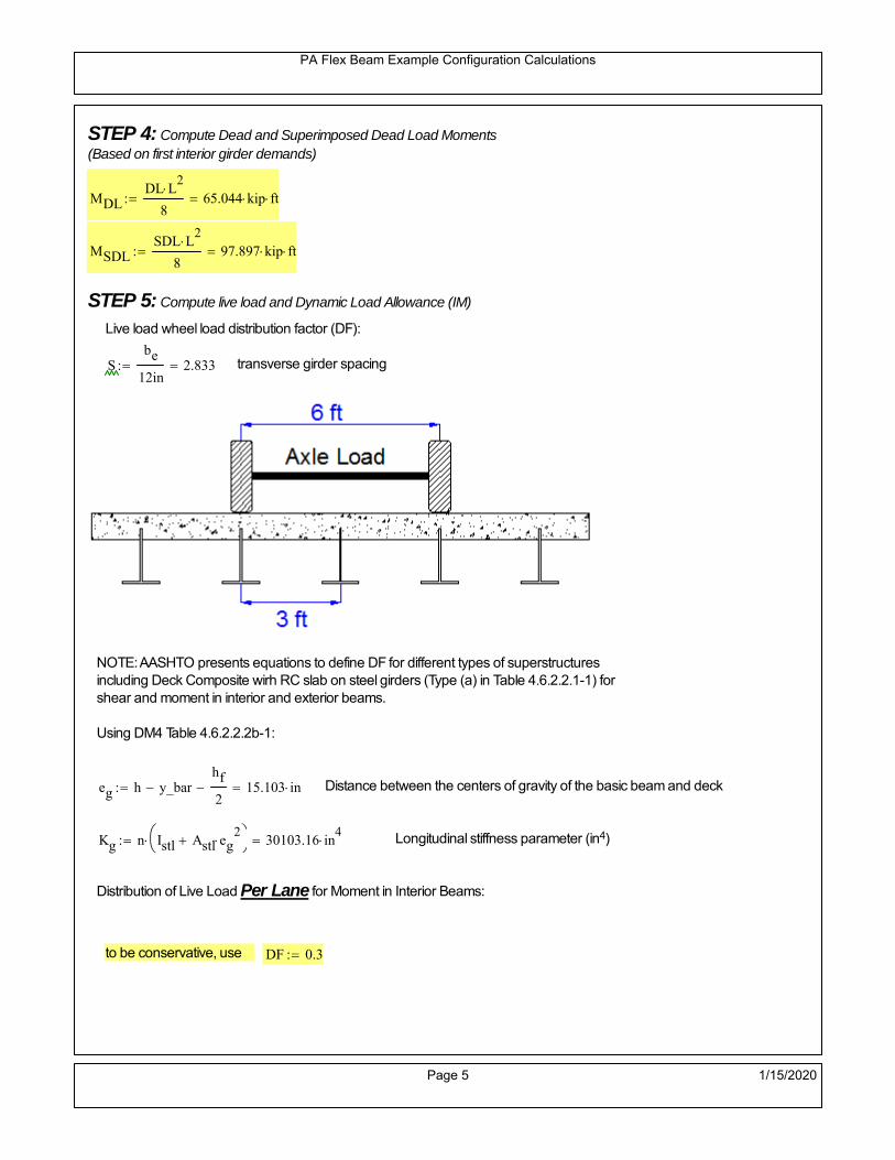
PA Flex Beam Example Configuration Calculations
STEP 4: Compute Dead and Superimposed Dead Load Moments(Based on first interior girder demands)
MDLDL L
2
865.044 kip ft
MSDLSDL L
2
897.897 kip ft
STEP 5: Compute live load and Dynamic Load Allowance (IM)
Live load wheel load distribution factor (DF):
Sbe
12in2.833 transverse girder spacing
NOTE: AASHTO presents equations to define DF for different types of superstructuresincluding Deck Composite wirh RC slab on steel girders (Type (a) in Table 4.6.2.2.1-1) forshear and moment in interior and exterior beams.
Using DM4 Table 4.6.2.2.2b-1:
eg h y_barhf
2 15.103 in Distance between the centers of gravity of the basic beam and deck
Kg n Istl Astl eg2
30103.16 in
4 Longitudinal stiffness parameter (in4)
Distribution of Live Load Per Lane for Moment in Interior Beams:
to be conservative, use DF 0.3
Page 5 1/15/2020

PA Flex Beam Example Configuration Calculations
Dynamic Load Allowance (Section 3.6.2 DM4)
Static effects of the design truck or tandem, shall be increased by the impact factor.
NOTE: The dynamic load allowance shall not be applied to the design lane load (Section 3.6.2.1 DM4)
I 0.33 Impact factor for moment
Note: PennDOT requires that the impact for decks be increased from 33% to 50%, the deck is not beingdesigned here. Instrad the deck design is based on the BD recommendations.
Dynamic load allowance for the Permit Load P-82 shall be less than 20%. (Section 3.6.2.1DM4)
IPL 0.20 Impact factor for moment on Strength II
Design Wind Loading for Exterior Girder
Vw 80 Wind speed for Strength V load case
CD 1.3 Gust factor for windard side of I-Girder and Box Girder Superstructures (Table 3.8.1.2.1-2)
G 1.0 Gus effect factor is 1.0 for all structures other than sound barriers (Table 3.8.1.2.1-1)
Kz 1.0 Pressure coefficient taken as 1 for Strength V (3.8.1.2.1)
Pz 2.56 106
Vw 2 Kz G CDkip
ft2
0.021kip
ft2
Wind pressure on exterior girder
hexp h hf 17.5 in Exposed height of exterior girder
Moment due to wind loading on exterior girderMWL
Pz hexp L2
86.212 kip ft
Iyy
bf3tf
1272 in
4 Transverse moment of intertia
Flange lateral bending stressfl
MWL
bf
2
Iyy6.212 ksi
Page 6 1/15/2020

PA Flex Beam Example Configuration Calculations
Design Vehicular Live Load
PHL-93 and P-82 are examined herein.
PHL-93 (A3.6.1.2.1)
PHL-93 consists of a combination of (design truck or design tandem) + (design lane load)
Design Truck
PennDOT defines the design truck in accordance with AASTHO 3.6.1.2
Design truck load in AASHTO (HS20 Truck) is used for this example.
NOTE : MAX moment occurs when the center line of the span is midway between the center ofgravity of the loads and the nearest concentrated load.
P1 8kip P2 32kip P3 32kip Axle loads (AASHTO 3.6.1.2.2)
XASr 14ft Rear Axle spacing for truck (14ft - 30ft)
XASf 14ft Front Axle spacing for truck
Page 7 1/15/2020

PA Flex Beam Example Configuration Calculations
Center of gravity (CG) of loads:
X'P1 XASr XASf P2 XASr
P1 P2 P39.333 ft Datum is the rear axle
X XASr X' 4.667 ft Spacing btw CG and nearest load
Find bridge reaction
Truck movestoward Support ARA
P1L
2XASf
X
2
P2L
2
X
2
P3L
2X'
X
2
L31.8 kip
Max live load moment (at the location of P2):
MLL_truck RAL
2
X
2
P1 XASf 449.8 kip ft
NOTE: Find the worst case by varying XASr
Page 8 1/15/2020

PA Flex Beam Example Configuration Calculations
Design Tandem
Consist of a pair of 25-kip axles spaced 4-ft apart. (AASHTO 3.6.1.2.3)
NOTE: PennDOT DM4 increases 25-kip to 31.25-kip.
FT 31.25kip
XAS 4ft Axle spacing
Center of gravity (CG) of loads:
XXAS
22 ft Spacing btw CG and nearest load
Find bridge reaction
RA
FTL
2
X
2
FTL
2
X
2 X
L29.688 kip Truck moves toward Support A
Max live load moment (at the location of front wheel):
MLL_tandem RAL
2
X
2
564.063 kip ft
Choose the max value:
MLL_veh max MLL_tandem MLL_truck 564.063 kip ft
Apply the impact and wheel load distribution:
MLL_IM_veh MLL_veh DF 1 I( ) 225.061 kip ft Due to tandem or truck
Design Lane Load (distributed over a 10-ft width for each lane)
NOTE: The uniform load may be continuous or discontinuous as necessary to produce themaximum force effect. For this example continuous uniform distribution assumed.
FDLL 0.64kip
ftDF 0.192
kip
ft Per beam in each lane
Due to lane loadMLL_IM_lane
FDLL L2
8
38.4 kip ft
Moment due to Total Design Vehicular Live Load: MLL_IM MLL_IM_lane MLL_IM_veh 263.461 kip ft
Page 9 1/15/2020

PA Flex Beam Example Configuration Calculations
Design Permit Load P-82 (Section 3.6.1.2.7 DM4)
P1 P2 P3 P4 P5 P6 P7
NOTE: The moment for the permit load is defined at the beginning of the sheetand is obtained from MATLab File FlexBeam_Moment_ShearEnvelope.m
STEP 6: Compute Moment of Inertia (Note: rebar neglected!)
1) Moment of Inertia resisting dead load only:
a) Acting on the non-composite section (before the deck has hardened - DC1)
Use steel section only
Inc Istl 640.875 in4
Non-composite section modulus
Y'nc y_bar S.G. of the steel section of Flex Beam (Datum is bottom)
b) Acting on the composite section (after the deck has hardened - DC2)
Use Ic_short as defined below.
Page 10 1/15/2020

PA Flex Beam Example Configuration Calculations
2) Moment of Inertia resisting live load plus impact:
Using transformed slab with k1=1 (short-term composite).
Actr1 hf btr1 31.875 in2
Itr1
btr1 hf3
12149.414 in
4
Y'
Actr1 hhf
2
Astl Y'nc
Astl Actr116.713 in S.G. of the total flex beam (Datum is bottom)
Compositesection modulus(short-term)
Ic_short Istl Astl Y'nc Y' 2 Itr1 Actr1 hhf
2
Y'
2
2974 in4
Y'c_short Y' 16.713 in N.A. of the short-term composite section
3) Moment of Inertia resisting superimposed dead load:
Using transformed slab with k3=3.
Actr3 hf btr3 10.625 in2
Itr3
btr3 hf3
1249.805 in
4
Y'
Actr3 hhf
2
Astl Y'nc
Astl Actr312.747 in S.G. of the total flex beam (Datum is bottom)
Compositesection modulus(long-term)
Ic_long Istl Astl Y'nc Y' 2 Itr3 Actr3 hhf
2
Y'
2
2055 in4
Y'c_long Y' 12.747 in N.A. of the long-term composite section
Page 11 1/15/2020

PA Flex Beam Example Configuration Calculations
STEP 6.5 Check Ductility RequirementIn accordance with AASHTO Article 6.10.7.3 check ductility requirement. Assume compressionblock of concrete is at 0.85 f'c and that the concrete supports no tension. Steel section isassumed to be fully plastic at Fy.
Case 1 : Assuming PNA is in Concreteh d 4 inAssuming (h-d) < Dp < hf
Fp Dp 0.85 fc be Dp Fy tw Dp h d( ) Fy Astl tw Dp h d( )
Dp 7.5in 0.42 h 10.5 in
Dp1 root Fp Dp Dp 5.45 in Must be less than hf 7.5 inDp1
h0.218 must be < 0.42
Mn1check Dp1 hf h d( ) Dp1[ ] Dp1 0.42 h( ) 1 Dp1 0.42 h 1
Mp1 0.85 fc be Dp1Dp1
2
Fy tw Dp1 h d( )[ ] Dp1 h d( )[ ]
2
Fy bf tf h Dp1tf
2
Fy tw h Dp1 tf h Dp1 tf
2
Mp1 10928.73 kip in Mn1 Mp1 1.07 0.7Dp1
h
10026.1 kip in
Case 2 : Assuming PNA is NOT in Concrete
Assuming hf < Dp
Fp2 Dp 0.85 fc be hf Fy tw Dp h d( ) Fy Astl tw Dp h d( )
Dp 2.5in
Dp2 root Fp2 Dp Dp 0.87 in Must be more than hf 7.5 inDp2
h0.0348 must be < 0.42
Mn2check Dp2 hf Dp2 h( ) Dp2 0.42 h( ) 0 Dp2 0.42 h 1
Mp2 0.85 fc be hf Dp2hf
2
Fy tw Dp2 h d( )[ ] Dp2 h d( )[ ]
2
Fy bf tf h Dp2tf
2
Fy tw h Dp2 tf h Dp2 tf
2
Mp2 9936.9 kip inMn2 Mp2 1.07 0.7
Dp2
h
10874.5 kip in
Mn max Mn1 Mn1check Mn2 Mn2check 835.5 kip ft Mn 10026.1 kip in
Page 12 1/15/2020

PA Flex Beam Example Configuration Calculations
Check Composite Compact Section Criteria (6.10.6.2)
Dcpd
2
Fy tf bf 0.85 fc be hf
Fy hw tw1
4.989 in Dcp0 Dcp 0 0
Dcp Dcp Dcp0 0 in2 Dcp
tw3.76
Es
Fy 1 Check if section is compact
STEP 7: Load Combinations (Table 3.4.1-1)
The following load combinations will be considered herein. Only the maximum load factors forpermanent-loads are used in the following load combinations (uplift is not an issue for this typeof bridge).STRENGTH I 1.25DL + 1.5SDL + 1.75 (LL+IM)
SERVICE II: DL+SDL+1.3(LL+IM)
STEP 8: Compute and Check Stresses
Stress at bottom fiber of steel section
fDL
MDL Y'c_long
Ic_long4.842 ksi
fLL_I
MLL_IM Y'c_short
Ic_short17.764 ksi fPL
MLL_IM_PL82 Y'c_short
Ic_short21.038 ksi
fSDL
MSDL Y'c_long
Ic_long7.287 ksi
STRENGTH I fbot_str1 1.25fDL 1.5 fSDL 1.75 fLL_I 48.07 ksi
STRENGTH II fbot_str2 1.25fDL 1.5 fSDL 1.35 fPL 45.384 ksi
SERVICE II fbot_svc2 fDL fSDL 1.3fLL_I 35.22 ksi
Allowable Stress is based on Section 6.10.4.2.2-2
Flange stress due to service load II without consideration of flange lateral bending: ff fbot_svc2
Flange lateral bending stress due to service II: flSII 0ksi
Hybrid Factor: Rh 1.0 For rolled and homogenous built-up sections
ff
flSII
2 35.222 ksi 0.95 Rh Fy 47.5 ksi ff
fl
2 0.95Rh Fy 1
Page 13 1/15/2020

PA Flex Beam Example Configuration Calculations
Stress at top fiber of concrete
Note: For calculating longitudinal flexural stresses in the concrete deck due to allpermanent and transient loads, the short-term modular ratio shall be used.
fDL
MDL h Y'c_short
k1 n Ic_short0.272 ksi
fLL_I
MLL_IM h Y'c_short
k1 n Ic_short1.101 ksi fPL
MLL_IM_PL82 h Y'c_short
k1 n Ic_short1.304 ksi
fSDL
MSDL h Y'c_short
k1 n Ic_short0.409 ksi
STRENGTH I fc_str1 1.25fDL 1.5 fSDL 1.75 fLL_I 2.88 ksi
Mstr1 1.25 MDL 1.5 MSDL 1.75 MLL_IM 689.2 kip ft Mstr1 Mn 1
STRENGTH II fc_str2 1.25fDL 1.5 fSDL 1.35 fPL 2.714 ksi
Mstr2 1.25 MDL 1.5 MSDL 1.35 MLL_IM_PL82 649 kip ft Mstr2 Mn 1
SERVICE II
Allowable Stress in concrete - AASHTO 6.10.4.2.2For compact composite sections in positive flexure utilized in shored construction, the longitudinalcompressive stress in the concrete deck due to the Service II loads, determined as specified in Article6.10.1.1.1d, shall not exceed 0.6f́ c.
fallow 0.6 fc 2400 psi
fc_2 1.3fLL_I fSDL fDL 2112.32 psi This assumes short term compositesection for all calculations
fc_2 fallow 1
SERVICE II with Long Term Composite for dead loads
fDL
MDL h Y'c_long
k3 n Ic_long0.194 ksi
fLL_I
MLL_IM h Y'c_short
k1 n Ic_short1.101 ksi
fSDL
MSDL h Y'c_long
k3 n Ic_long0.292 ksi
fc_2 1.3fLL_I fSDL fDL 1917.1 psi fc_2 fallow 1
Page 14 1/15/2020

PA Flex Beam Example Configuration Calculations
Strength V Moment Check
Strength V is related to normal vehicular use of the bridge with an 80 mph wind gust
Note: that Strength V is checked for an exterior girder under wind load with the interior girder distribution factor forflexure used. If Strength V controls design, then this approach should be modified
Design vertical moment is: 1.25DL + 1.5SDL + 1.35 (LL+IM)
SLT
Ic_long
Y'c_long161.214 in
3 SST
Ic_short
Y'c_short177.971 in
3 short and long term section
modulus
Section D6.2.2 Find the moment required to cause yieldling of the flange. The approach is laid out in D6.2.2
MD2 1.25 MDL 1.5 MSDL 228.151 kip ft From D6.2.2-1 (all dead loads are in MD2 due to shoredconstruction
MAD Fy
MD2
SLT
SST 489.679 kip ft Additional moment to cause nominal yielding of steel flange
My MD2 MAD 717.83 kip ft D6.2.2-2: Moment to cause yielding of flange
6.10.7.1 Compact Section Check at Strength V limit state
Section Modulus for yielding of the flange (My/Fy) for equation 6.10.7.1.1-1Sxt
My
Fy172.279 in
3
Mu 1.25 MDL 1.5MSDL 1.35MLL_IM 583.823 kip ft Moment due to Strength V limit state
Mu1
3fl Sxt 613.552 kip ft Equation 6.10.7.1.7-1 Mn 835.504 kip ft Mu
1
3fl Sxt Mn 1
Page 15 1/15/2020

PA Flex Beam Example Configuration Calculations
STEP 9: Compute Deflection
Optional Live Load Deflection Evaluation (AASHTO 3.6.1.3.2)
Deflection distribution factor for vehicular loads: For a straight multibeambridge, this is equivalent to saying that the distribution factor for deflectionis equal to the number of lanes divided by the number of beams. 2.5.2.6.2
DFd
Nl
N0.2
Deflection should be taken as 125% the larger of:- Design truck- 25% of design truck + design lane
The live load portion of Load Combination Service I of Table 3.4.1-1 should be used,including the dynamic load allowance, IM;
Deflection due to design truck load
NOTE : Assuming maximum deflection occurs when the center of gravity of the loads is at thecenter line of the span.
P1 8kip P2 32kip P3 32kip Axle loads (AASHTO 3.6.1.2.2)
XASr 14ft Rear Axle spacing for truck (14ft - 30ft)
XASf 14ft Front Axle spacing for truck
Center of gravity (CG) of loads:
X'P1 XASr XASf P2 XASr
P1 P2 P39.333 ft Datum is the rear axle
Method1: Assuming single load = P1+P2+P3 at the midspan (Conservative approach)
P1 P2 P3 L3
48 Es Ic_short 1.923 in
Method2: Calculation of Midspan deflection using superposition
b1L
2XASr X' XASf 1.333 ft distance btw load P1 and support A b1check b1 0 1
b2L
2XASr X' 15.333 ft distance btw load P2 and support A b2check b2 0 1
b3L
2X' 10.667 ft distance btw load P3 and support B b3check b3 0 1
Page 16 1/15/2020

PA Flex Beam Example Configuration Calculations
Deflection of the beam at midspan due to P1: P P1
xL
2 at midspan b b1 b1check The smallest distance btw load P1 and support
Δ1P b x
6 Es Ic_short LL2
b2
x2
0.021 in
Deflection of the beam at midspan due to P2: P P2
xL
2 at midspan b b2 b2check The smallest distance btw load P2 and support
Δ2P b x
6 Es Ic_short LL2
b2
x2
0.79 in
Deflection of the beam at midspan due to P3: P P3
xL
2 at midspan b b3 b3check The smallest distance btw load P3 and support
Δ3P b x
6 Es Ic_short LL2
b2
x2
0.619 in
Total Deflection at midspan:
Δtruck Δ1 Δ2 Δ3( ) DFd 1 I( ) 0.381 in (Considering IM)
Deflection due to tandem (Note: this calculation is not required according to Article3.6.1.3.2 which denotes only the design truck for deflection calculation)
Page 17 1/15/2020

PA Flex Beam Example Configuration Calculations
FT 31.25 kip Per axle
XAS 4ft Axle spacing
Δtandem
FTL
2
XAS
2
24 Es Ic_short3 L
2 4
L
2
XAS
2
2
DFd 1 I( ) 0.438 in (Considering IM)
Deflection due to lane load
FDLLd 640lbf
ft DFd 128
lbf
ft
Δlane
5 FDLLd L4
384 Es Ic_short0.085 in
Live Load Deflection:
ΔLL 1.25max Δtruck 0.25Δtruck Δlane 1.25 0.595 in ΔLLL
800 1
Deflection Limit
For steel or concrete vehicular bridges:
Vehicular load = Span/800L
8000.6 in
L
10000.48 in
Evaluation of Deflection at the Service Limit State (AASHTO 3.4.2.2)
The associated permitted deflections shall be included in the contract documents.
Page 18 1/15/2020

PA Flex Beam Example Configuration Calculations
Shear demands:
Determination of the distribution factor
Using DM4 Table 4.6.2.2.3a-1
Sbe
12in2.833 transverse girder spacing (ft)
Distribution of live loads per lane for shear in interior beams:
For two design lanes loaded, 3.5' <= S =< 16', number of beam >= 4DFs 0.36
S
25 0.473
Q Actr1 h Y'c_shorthf
2
144.618 in3
first moment of deck slab for interface shear
Method 1: Range of shear based on Strength I Limit
STRENGTH I 1.25DL + 1.5SDL + 1.75 (LL+IM)
Computation of the range of shear in the beam
Dead Load:DL 0.325
kip
ft
Superimposed Dead Load: SDL 0.489kip
ft
Design Lane Load: 0.64kip
ft
Design Truck:
XASr 14ft Rear Axle spacing for truck (14ft - 30ft)
XASf 14ft Front Axle spacing for truck
P1 8 kip P2 32 kip P3 32 kip Wheel loads (AASHTO 3.6.1.2.2)
Design Tandem:
Consist of a pair of 25-kip axles spaced 4-ft apart. (AASHTO 3.6.1.2.3)
NOTE: PennDOT DM4 increases 25-kip to 31.25-kip.
FT 31.25kip
XAS 4ft Axle spacing
Page 19 1/15/2020
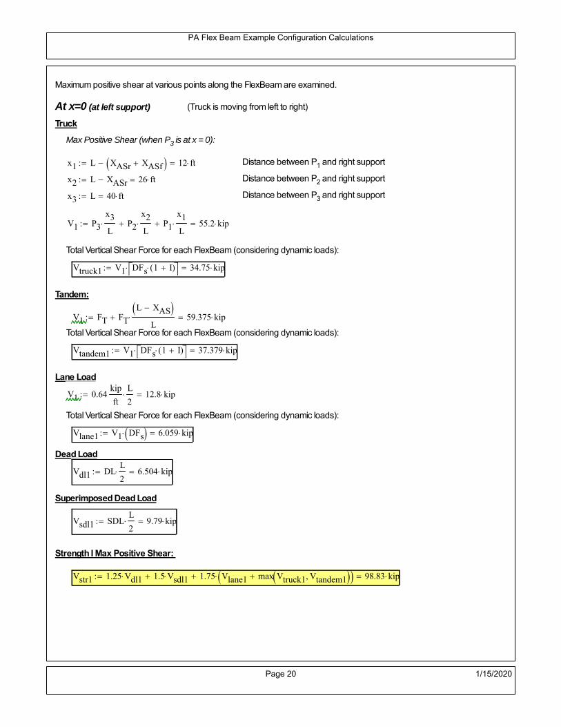
PA Flex Beam Example Configuration Calculations
Maximum positive shear at various points along the FlexBeam are examined.
At x=0 (at left support) (Truck is moving from left to right)
Truck
Max Positive Shear (when P3 is at x = 0):
x1 L XASr XASf 12 ft Distance between P1 and right support
x2 L XASr 26 ft Distance between P2 and right support
x3 L 40 ft Distance between P3 and right support
V1 P3
x3
L P2
x2
L P1
x1
L 55.2 kip
Total Vertical Shear Force for each FlexBeam (considering dynamic loads):
Vtruck1 V1 DFs 1 I( ) 34.75 kip
Tandem:
V1 FT FT
L XAS L
59.375 kip
Total Vertical Shear Force for each FlexBeam (considering dynamic loads):
Vtandem1 V1 DFs 1 I( ) 37.379 kip
Lane Load
V1 0.64kip
ft
L
2 12.8 kip
Total Vertical Shear Force for each FlexBeam (considering dynamic loads):
Vlane1 V1 DFs 6.059 kip
Dead Load
Vdl1 DLL
2 6.504 kip
Superimposed Dead Load
Vsdl1 SDLL
2 9.79 kip
Strength I Max Positive Shear:
Vstr1 1.25 Vdl1 1.5 Vsdl1 1.75 Vlane1 max Vtruck1 Vtandem1 98.83 kip
Page 20 1/15/2020

PA Flex Beam Example Configuration Calculations
Design Permit Load P-82
Shear at x=0
Strength II Max Positive Shear:
VPL82 VPL82span DFs 1 IPL 53.484 kip
STRENGTH II 1.25DL + 1.5SDL + 1.35 (LL+IM)
VstrII_PL 1.25 Vdl1 1.5 Vsdl1 1.35 VPL82 95.019 kip
Max Shear Demand Vu max Vstr1 VstrII_PL 98.83 kip
Determine the Shear Strength of the Web
Shear Strength of Unstiffened web from AASHTO section 6.10.9.2
Depth of Web D d 21 in Thickness of web tw 0.375 in
Transverse Stiffener Spacing d0 0in Shear Buckling Coefficient k 5 6.10.9.3.2-7
Plastic Shear Force Vp 0.58 Fy D tw 228.375 kip Equation 6.10.9.3.2-3
Ratio of Shear-Buckling resistance to shear yield, C
D
tw56 1.12
Es k
Fy 60.314 Ccheck
D
tw1.12
Es k
Fy 1 Equation 6.10.9.3.2-4
C 1.0 Ccheck 1 C=1 for most cases, if the criteria are not met, then C will go to zero and the actualcoefficients should be determined
Nominal Shear Resistance of Web Vn C Vp 228.375 kip equation 6.10.9.3.3-1
Shear Resistance Factor φv 1.0
φv Vn 228.375 kip φv Vn Vu 1Reduced Shear Strength
Page 21 1/15/2020

PA Flex Beam Example Configuration Calculations
Check Bearing Stiffeners
FYs 50ksi Yield strength of stiffener
tp 0.75in Thickness of stiffener
bt
bf tw
21.5in 4.312 in Effective width of stiffener
Dst hw 4.1in 16.4 in Depth of stiffeners
Apn 2 tp bt 6.469 in2
Projected area of stiffeners
bt 0.48 tpEs
FYs 1Check that effective width of stiffener meets requirements
Rsbn 1.4 Apn FYs 452.812 kip Bearing capacity of stiffener (phi=1 for bearing per AASHTO 6.5.4.2)
Rsbn Vu 1 Bearing capacity check
Qs 1.0 Q factor for bearing stiffner, taken as 1 (AASHTO 6.9.4.1.1)
Is
18 tw tw3
tp 2 bt 3
1240.131 in
4 Moment of inertia of stiffener and web (9*tw is used on each side)
AASHTO 6.10.11.2.4b
Ag 18 tw tw 2 bt tp 9 in2
Gross area of stiffener and web (AASHTO 6.10.11.2.4b)
rs
Is
Ag2.112 in Radius of gyration of stiffener/web
Po Qs FYs Apn 323.437 kip Nominal yeild resistance of stiffener (AASHTO 6.9.4.1.1)
Peπ2Es
0.75 Dst
rs
2Ag 7.592 10
4 kip Elastic critical buckling stress of stiffener (AASHTO 6.9.4.1.2-1)
Check that Pe/Po is great than 0.44 (AASHTO 6.9.4.1.1) PePoPe
Po0.44 1
Pn PePo 0.658
Po
Pe Po 322.861 kip Nominal compressive resistance of stiffener for Pe/Po>0.44
(AASHTO 6.9.4.1.1-1)
φcr 0.95 phi factor for axial compression (AASHTO 6.5.4.2)
Pr φcr Pn 306.718 kip Compressive capacity of bearing stiffener Pr Vu 1
Page 22 1/15/2020

PA Flex Beam Example Configuration Calculations
Flexbeam Example Configuration Calculations
Summary of Calculations:
Input section dimensions and material properties for steel WT and the concrete deck1.Calculate demands (dead load, superimposed dead, and Live load demands for Strength I and Strength II2.Calculate composite section properties for the given section3.Check Strength I, Strength II, and Service II stresses 4.Check Strength I, Strength II, and Strength V moment demands 5.Perform live load deflection check6.Determine maximum shear demand and capacity7.Note: Shear envelope data was obtained from Matlab script (FlexBeam_Moment_ShearEnvelope.m).8.Shear envelope calculations are summarized separately for each design (Shear Design *.xlsx).
Design Assumptions:Design Specifications Used:
AASHTO LRFD Bridge Design Specifications 7th Edition with 2016 Interim RevisionsPennDOT Design Manual, Part 4 (DM-4) June 30, 2015
Example configurations are determined for two girder spacings, 36" and 40".The deck thickness is 7.5" and is assumed to have a non-structural wearing surface added after installation.Section properties are calculated using the full 7.5" deck thickness.The WT sections are embedded 3.5" into the concrete deck. The steel section spacing used is outside the scope of the AASHTO and PennDOT distribution factorequations. The flexural distribution factor is assumed to be 0.3 which was shown to tbe conservativeaccording to refined analysisThe shear distribution factor is calculated using the DM-4 shear distribution factor equation which wasshown to be conservative using refined analysis.Refined analysis is presented in: Zihan Ma, "Distribution Factors for Composite Steel Tee Concrete DeckBridge System," M.S. Thesis, Deparement of Civil and Environmental Engineering, Lehigh University,Bethlehem, 2019Shear and moment demands for the PL82 permit load vehicle are determined by Matlab script(FlexBeam_Moment_ShearEnvelope.m) and are manually input into this calculation sheet.All fabrication will occur as double modules, i.e. each module contains two WT sections. The number ofmodules is half the number of beams, N. A 45 in. tall F-Shape barrier is used, Weight = 700 lb/ft (Distributed to exterior two beams).
The work presented in this document are provided on an “AS IS” basis. University makes no warranties of anykind, express or implied, as to any matter whatsoever, including, without limitation, warranties with respect tothe merchantability or fitness for a particular purpose of this work or any project deliverables. Universitymakes no warranty of any kind with respect to freedom from patent, trademark, copyright or trade secretinfringement arising from the use of the results of the project, deliverables, services, intellectual property orother materials provided hereunder. University shall not be liable for any direct, indirect, consequential,punitive, or other damages suffered by Sponsor or any other person resulting from the project, or the use ofthis work or any project deliverables.
Page 1 1/15/2020

PA Flex Beam Example Configuration Calculations
hf
tf
bf
twh
d
bjtbe
e
Variable Definitions:
Number of beams N 10 modulesN
25
L 40ft Span length
be 36in Effective width of Flexbeamassuming constructed bridge width(i.e. closure joints cast)
Built Up Section Properties
tw 0.375in tf 0.5in bf 12in
h 25in Overall Height of section
hf 7.5in Total thickness of deck
e 3.5in Deck/Steel overlap
d h hf e 21 in depth of built up steel section
hw d tf 20.5 in height of web of built up steel
Moment and shear for permit load PL82 obtained from Matlab script: FlexBeam_Moment_ShearEnvelope
MLL_IM_PL82 312.012kip ft Moment due to PL82 with distribution factor and impact factor!!
VPL82span 94.1625kip Shear due to PL82 WITHOUT distribution factor and impact factor!!
Check web and flange dimensions in sections 6.10.2.1 and 6.10.2.2
(Ignore 6.10.2.2-4 since no compression flange)
equation 6.10.2.1.1-1d
tw150 1 equation 6.10.2.2-1
bf
2 tf12 1
equation 6.10.2.2-2 bfh
6 1 equation 6.10.2.2-3 tf 1.1 tw 1
y_bar
tf bftf
2 hw tw tf
hw
2
tf bf hw tw6.147 in Center of gravity of steel section
Istl
bf tf3
12bf tf y_bar
tf
2
2
tw hw
3
12 tw hw tf
hw
2 y_bar
2
640.875 in4
MOI of steel
Astl tf bf hw tw 13.687 in2
Area of the WT steel section
Page 2 1/15/2020

PA Flex Beam Example Configuration Calculations
Material Properties
Elastic Modulus of Steel Es 29000ksi
Yield Strength of Steel Fy 50ksi
Yield Strength of Reinforcement fy 60ksi
Compressive Strength of Concrete fc 4000psi AAAP PennDOT Concrete
Concrete Modular Ratio n 8 modular ratio for 4ksi concrete per AASHTO
Unit weight of concrete slab wc 0.150kip
ft3
Unit weight of concrete
Section Properties
Width of UHPC Joint: bjt 6in
Parapet width: bpar 20.25in Parapet width per PennDOT F-shape barrier
Width of the bridge W be N bjt 354 in W 29.5 ft
Clear width of roadway Wlane W 2 bpar 26.125 ft
Dc wc hf W 2.766kip
ft DL due to slab
Db .700kip
ft DL due to each 45" F-Shape Barrier (per email 11/1/18)
DFWS 30lbf
ft2
W 2 bpar 0.784kip
ft DL due to Future Wearing Surface (FWS)
Ds Astl 490lbf
ft3
0.047kip
ft Selfweight of the steel section
DLself
Dc N
Ds 0.323kip
ft Self-weight per WT
Total weight of each precast FlexBeam for transportation:
Weight of C12x25 Diaphragms Wend_diaphragms 25lbf
ft32 in 0.067 kip
2be bjt hf wc 2Ds L 2 Wend_diaphragms 24.484 kip
Determine number of design lane (AASHTO Section 3.6.1.1.1)
Take the integer part of the ratio of W/12 ft. Number of lanes in bridge: Nl floorWlane
12ft
2
Page 3 1/15/2020

PA Flex Beam Example Configuration Calculations
STEP 1: Compute Dead Load for each Flex Beam
DLslab
Dc
Nwc 1 in
be
2 0.295
kip
ft Dead load of slab assuming exterior overhang has 1" of
additional concrete thickness
DLsteel Ds 0.047kip
ft
DL DLslab DLsteel 0.342kip
ft
STEP 2: Compute Superimposed Dead Load
SDLWS
DFWS
N0.078
kip
ft
SDLparapet
Db
20.35
kip
ft distributed equally on two outer beams
SDLOL 140lbf
ft3be 2 in 0.07
kip
ft Overlay is 2" thick and is 140 lbs/cubic foot
NOTE: For this example barrier load is distributed equally among the two outer beams per conversation withPennDOT and M&M.
PennDOT DM4: "For composite adjacent and spread beams, the barrier (single barrier) load shall be equallydistributed to the nearest three (adjacent) and two (spread) beams, respectively, when the barriers are placedafter slab has hardened".
SDL SDLWS SDLparapet SDLOL 0.498kip
ft
STEP 3: Compute Transformed Width of Slab
For live load and dead load acting on the stringer k1 1 For short-term section property evaluation
btr1
be
k1 n4.5 in Transformed width of slab for short-term
For superimposed dead loads k3 3 For long-term section property evaluation
btr3
be
k3 n1.5 in Transformed width of slab for long-term
Page 4 1/15/2020

PA Flex Beam Example Configuration Calculations
STEP 4: Compute Dead and Superimposed Dead Load Moments(Based on first interior girder demands)
MDLDL L
2
868.378 kip ft
MSDLSDL L
2
899.675 kip ft
STEP 5: Compute live load and Dynamic Load Allowance (IM)
Live load wheel load distribution factor (DF):
Sbe
12in3 transverse girder spacing
NOTE: AASHTO presents equations to define DF for different types of superstructuresincluding Deck Composite wirh RC slab on steel girders (Type (a) in Table 4.6.2.2.1-1) forshear and moment in interior and exterior beams.
Using DM4 Table 4.6.2.2.2b-1:
eg h y_barhf
2 15.103 in Distance between the centers of gravity of the basic beam and deck
Kg n Istl Astl eg2
30103.16 in
4 Longitudinal stiffness parameter (in4)
Distribution of Live Load Per Lane for Moment in Interior Beams:
to be conservative, use DF 0.3
Page 5 1/15/2020

PA Flex Beam Example Configuration Calculations
Dynamic Load Allowance (Section 3.6.2 DM4)
Static effects of the design truck or tandem, shall be increased by the impact factor.
NOTE: The dynamic load allowance shall not be applied to the design lane load (Section 3.6.2.1 DM4)
I 0.33 Impact factor for moment
Note: PennDOT requires that the impact for decks be increased from 33% to 50%, the deck is not beingdesigned here. Instrad the deck design is based on the BD recommendations.
Dynamic load allowance for the Permit Load P-82 shall be less than 20%. (Section 3.6.2.1DM4)
IPL 0.20 Impact factor for moment on Strength II
Design Wind Loading for Exterior Girder
Vw 80 Wind speed for Strength V load case
CD 1.3 Gust factor for windard side of I-Girder and Box Girder Superstructures (Table 3.8.1.2.1-2)
G 1.0 Gus effect factor is 1.0 for all structures other than sound barriers (Table 3.8.1.2.1-1)
Kz 1.0 Pressure coefficient taken as 1 for Strength V (3.8.1.2.1)
Pz 2.56 106
Vw 2 Kz G CDkip
ft2
0.021kip
ft2
Wind pressure on exterior girder
hexp h hf 17.5 in Exposed height of exterior girder
Moment due to wind loading on exterior girderMWL
Pz hexp L2
86.212 kip ft
Iyy
bf3tf
1272 in
4 Transverse moment of intertia
Flange lateral bending stressfl
MWL
bf
2
Iyy6.212 ksi
Page 6 1/15/2020

PA Flex Beam Example Configuration Calculations
Design Vehicular Live Load
PHL-93 and P-82 are examined herein.
PHL-93 (A3.6.1.2.1)
PHL-93 consists of a combination of (design truck or design tandem) + (design lane load)
Design Truck
PennDOT defines the design truck in accordance with AASTHO 3.6.1.2
Design truck load in AASHTO (HS20 Truck) is used for this example.
NOTE : MAX moment occurs when the center line of the span is midway between the center ofgravity of the loads and the nearest concentrated load.
P1 8kip P2 32kip P3 32kip Axle loads (AASHTO 3.6.1.2.2)
XASr 14ft Rear Axle spacing for truck (14ft - 30ft)
XASf 14ft Front Axle spacing for truck
Page 7 1/15/2020

PA Flex Beam Example Configuration Calculations
Center of gravity (CG) of loads:
X'P1 XASr XASf P2 XASr
P1 P2 P39.333 ft Datum is the rear axle
X XASr X' 4.667 ft Spacing btw CG and nearest load
Find bridge reaction
Truck movestoward Support ARA
P1L
2XASf
X
2
P2L
2
X
2
P3L
2X'
X
2
L31.8 kip
Max live load moment (at the location of P2):
MLL_truck RAL
2
X
2
P1 XASf 449.8 kip ft
NOTE: Find the worst case by varying XASr
Page 8 1/15/2020

PA Flex Beam Example Configuration Calculations
Design Tandem
Consist of a pair of 25-kip axles spaced 4-ft apart. (AASHTO 3.6.1.2.3)
NOTE: PennDOT DM4 increases 25-kip to 31.25-kip.
FT 31.25kip
XAS 4ft Axle spacing
Center of gravity (CG) of loads:
XXAS
22 ft Spacing btw CG and nearest load
Find bridge reaction
RA
FTL
2
X
2
FTL
2
X
2 X
L29.688 kip Truck moves toward Support A
Max live load moment (at the location of front wheel):
MLL_tandem RAL
2
X
2
564.063 kip ft
Choose the max value:
MLL_veh max MLL_tandem MLL_truck 564.063 kip ft
Apply the impact and wheel load distribution:
MLL_IM_veh MLL_veh DF 1 I( ) 225.061 kip ft Due to tandem or truck
Design Lane Load (distributed over a 10-ft width for each lane)
NOTE: The uniform load may be continuous or discontinuous as necessary to produce themaximum force effect. For this example continuous uniform distribution assumed.
FDLL 0.64kip
ftDF 0.192
kip
ft Per beam in each lane
Due to lane loadMLL_IM_lane
FDLL L2
8
38.4 kip ft
Moment due to Total Design Vehicular Live Load: MLL_IM MLL_IM_lane MLL_IM_veh 263.461 kip ft
Page 9 1/15/2020

PA Flex Beam Example Configuration Calculations
Design Permit Load P-82 (Section 3.6.1.2.7 DM4)
P1 P2 P3 P4 P5 P6 P7
NOTE: The moment for the permit load is defined at the beginning of the sheetand is obtained from MATLab File FlexBeam_Moment_ShearEnvelope.m
STEP 6: Compute Moment of Inertia (Note: rebar neglected!)
1) Moment of Inertia resisting dead load only:
a) Acting on the non-composite section (before the deck has hardened - DC1)
Use steel section only
Inc Istl 640.875 in4
Non-composite section modulus
Y'nc y_bar S.G. of the steel section of Flex Beam (Datum is bottom)
b) Acting on the composite section (after the deck has hardened - DC2)
Use Ic_short as defined below.
Page 10 1/15/2020

PA Flex Beam Example Configuration Calculations
2) Moment of Inertia resisting live load plus impact:
Using transformed slab with k1=1 (short-term composite).
Actr1 hf btr1 33.75 in2
Itr1
btr1 hf3
12158.203 in
4
Y'
Actr1 hhf
2
Astl Y'nc
Astl Actr116.892 in S.G. of the total flex beam (Datum is bottom)
Compositesection modulus(short-term)
Ic_short Istl Astl Y'nc Y' 2 Itr1 Actr1 hhf
2
Y'
2
3020 in4
Y'c_short Y' 16.892 in N.A. of the short-term composite section
3) Moment of Inertia resisting superimposed dead load:
Using transformed slab with k3=3.
Actr3 hf btr3 11.25 in2
Itr3
btr3 hf3
1252.734 in
4
Y'
Actr3 hhf
2
Astl Y'nc
Astl Actr312.961 in S.G. of the total flex beam (Datum is bottom)
Compositesection modulus(long-term)
Ic_long Istl Astl Y'nc Y' 2 Itr3 Actr3 hhf
2
Y'
2
2102 in4
Y'c_long Y' 12.961 in N.A. of the long-term composite section
Page 11 1/15/2020

PA Flex Beam Example Configuration Calculations
STEP 6.5 Check Ductility RequirementIn accordance with AASHTO Article 6.10.7.3 check ductility requirement. Assume compressionblock of concrete is at 0.85 f'c and that the concrete supports no tension. Steel section isassumed to be fully plastic at Fy.
Case 1 : Assuming PNA is in Concreteh d 4 inAssuming (h-d) < Dp < hf
Fp Dp 0.85 fc be Dp Fy tw Dp h d( ) Fy Astl tw Dp h d( )
Dp 7.5in 0.42 h 10.5 in
Dp1 root Fp Dp Dp 5.218 in Must be less than hf 7.5 inDp1
h0.209 must be < 0.42
Mn1check Dp1 hf h d( ) Dp1[ ] Dp1 0.42 h( ) 1 Dp1 0.42 h 1
Mp1 0.85 fc be Dp1Dp1
2
Fy tw Dp1 h d( )[ ] Dp1 h d( )[ ]
2
Fy bf tf h Dp1tf
2
Fy tw h Dp1 tf h Dp1 tf
2
Mp1 11025.42 kip in Mn1 Mp1 1.07 0.7Dp1
h
10186.3 kip in
Case 2 : Assuming PNA is NOT in Concrete
Assuming hf < Dp
Fp2 Dp 0.85 fc be hf Fy tw Dp h d( ) Fy Astl tw Dp h d( )
Dp 2.5in
Dp2 root Fp2 Dp Dp 2.23 in Must be more than hf 7.5 inDp2
h0.0892 must be < 0.42
Mn2check Dp2 hf Dp2 h( ) Dp2 0.42 h( ) 0 Dp2 0.42 h 1
Mp2 0.85 fc be hf Dp2hf
2
Fy tw Dp2 h d( )[ ] Dp2 h d( )[ ]
2
Fy bf tf h Dp2tf
2
Fy tw h Dp2 tf h Dp2 tf
2
Mp2 9666.6 kip inMn2 Mp2 1.07 0.7
Dp2
h
10946.8 kip in
Mn max Mn1 Mn1check Mn2 Mn2check 848.9 kip ft Mn 10186.3 kip in
Page 12 1/15/2020

PA Flex Beam Example Configuration Calculations
Check Composite Compact Section Criteria (6.10.6.2)
Dcpd
2
Fy tf bf 0.85 fc be hf
Fy hw tw1
6.382 in Dcp0 Dcp 0 0
Dcp Dcp Dcp0 0 in2 Dcp
tw3.76
Es
Fy 1 Check if section is compact
STEP 7: Load Combinations (Table 3.4.1-1)
The following load combinations will be considered herein. Only the maximum load factors forpermanent-loads are used in the following load combinations (uplift is not an issue for this typeof bridge).STRENGTH I 1.25DL + 1.5SDL + 1.75 (LL+IM)
SERVICE II: DL+SDL+1.3(LL+IM)
STEP 8: Compute and Check Stresses
Stress at bottom fiber of steel section
fDL
MDL Y'c_long
Ic_long5.059 ksi
fLL_I
MLL_IM Y'c_short
Ic_short17.682 ksi fPL
MLL_IM_PL82 Y'c_short
Ic_short20.941 ksi
fSDL
MSDL Y'c_long
Ic_long7.375 ksi
STRENGTH I fbot_str1 1.25fDL 1.5 fSDL 1.75 fLL_I 48.33 ksi
STRENGTH II fbot_str2 1.25fDL 1.5 fSDL 1.35 fPL 45.656 ksi
SERVICE II fbot_svc2 fDL fSDL 1.3fLL_I 35.42 ksi
Allowable Stress is based on Section 6.10.4.2.2-2
Flange stress due to service load II without consideration of flange lateral bending: ff fbot_svc2
Flange lateral bending stress due to service II: flSII 0ksi
Hybrid Factor: Rh 1.0 For rolled and homogenous built-up sections
ff
flSII
2 35.421 ksi 0.95 Rh Fy 47.5 ksi ff
fl
2 0.95Rh Fy 1
Page 13 1/15/2020

PA Flex Beam Example Configuration Calculations
Stress at top fiber of concrete
Note: For calculating longitudinal flexural stresses in the concrete deck due to allpermanent and transient loads, the short-term modular ratio shall be used.
fDL
MDL h Y'c_short
k1 n Ic_short0.275 ksi
fLL_I
MLL_IM h Y'c_short
k1 n Ic_short1.061 ksi fPL
MLL_IM_PL82 h Y'c_short
k1 n Ic_short1.256 ksi
fSDL
MSDL h Y'c_short
k1 n Ic_short0.401 ksi
STRENGTH I fc_str1 1.25fDL 1.5 fSDL 1.75 fLL_I 2.803 ksi
Mstr1 1.25 MDL 1.5 MSDL 1.75 MLL_IM 696 kip ft Mstr1 Mn 1
STRENGTH II fc_str2 1.25fDL 1.5 fSDL 1.35 fPL 2.642 ksi
Mstr2 1.25 MDL 1.5 MSDL 1.35 MLL_IM_PL82 656 kip ft Mstr2 Mn 1
SERVICE II
Allowable Stress in concrete - AASHTO 6.10.4.2.2For compact composite sections in positive flexure utilized in shored construction, the longitudinalcompressive stress in the concrete deck due to the Service II loads, determined as specified in Article6.10.1.1.1d, shall not exceed 0.6f́ c.
fallow 0.6 fc 2400 psi
fc_2 1.3fLL_I fSDL fDL 2055.81 psi This assumes short term compositesection for all calculations
fc_2 fallow 1
SERVICE II with Long Term Composite for dead loads
fDL
MDL h Y'c_long
k3 n Ic_long0.196 ksi
fLL_I
MLL_IM h Y'c_short
k1 n Ic_short1.061 ksi
fSDL
MSDL h Y'c_long
k3 n Ic_long0.285 ksi
fc_2 1.3fLL_I fSDL fDL 1860.38 psi fc_2 fallow 1
Page 14 1/15/2020
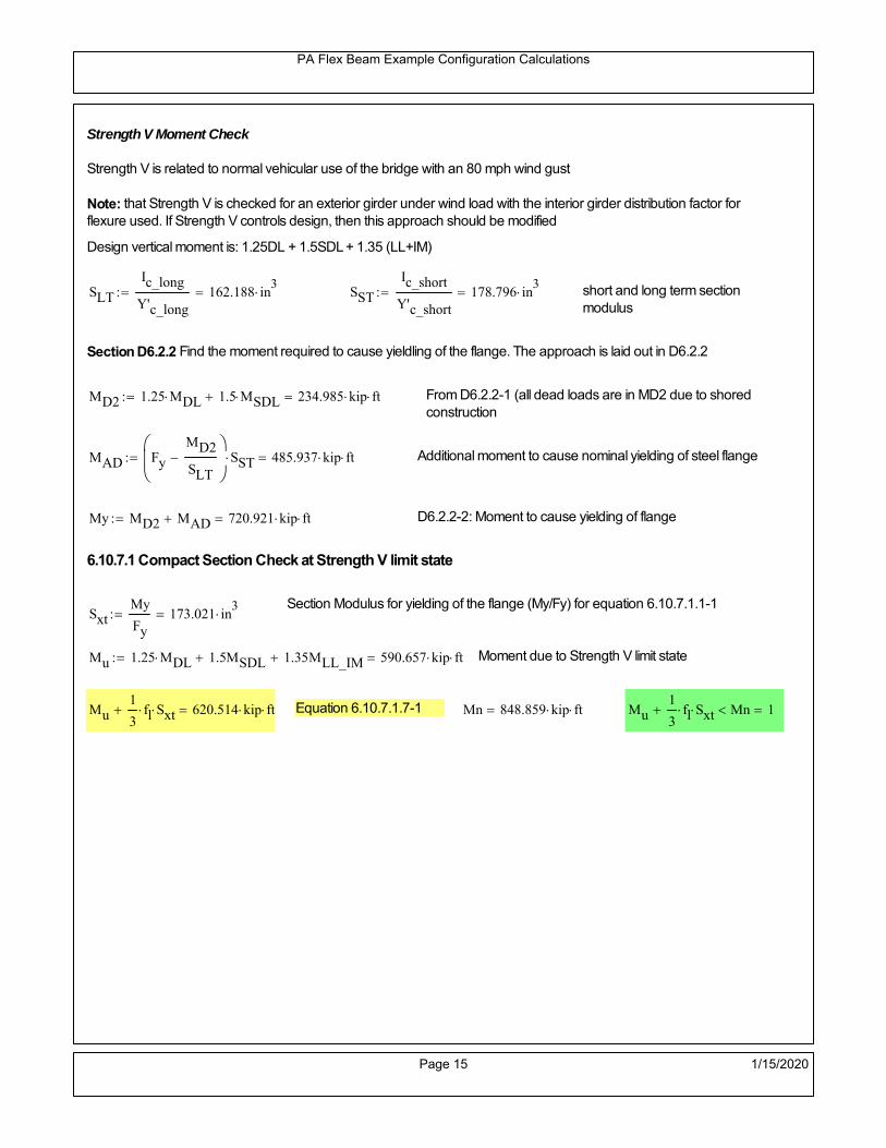
PA Flex Beam Example Configuration Calculations
Strength V Moment Check
Strength V is related to normal vehicular use of the bridge with an 80 mph wind gust
Note: that Strength V is checked for an exterior girder under wind load with the interior girder distribution factor forflexure used. If Strength V controls design, then this approach should be modified
Design vertical moment is: 1.25DL + 1.5SDL + 1.35 (LL+IM)
SLT
Ic_long
Y'c_long162.188 in
3 SST
Ic_short
Y'c_short178.796 in
3 short and long term section
modulus
Section D6.2.2 Find the moment required to cause yieldling of the flange. The approach is laid out in D6.2.2
MD2 1.25 MDL 1.5 MSDL 234.985 kip ft From D6.2.2-1 (all dead loads are in MD2 due to shoredconstruction
MAD Fy
MD2
SLT
SST 485.937 kip ft Additional moment to cause nominal yielding of steel flange
My MD2 MAD 720.921 kip ft D6.2.2-2: Moment to cause yielding of flange
6.10.7.1 Compact Section Check at Strength V limit state
Section Modulus for yielding of the flange (My/Fy) for equation 6.10.7.1.1-1Sxt
My
Fy173.021 in
3
Mu 1.25 MDL 1.5MSDL 1.35MLL_IM 590.657 kip ft Moment due to Strength V limit state
Mu1
3fl Sxt 620.514 kip ft Equation 6.10.7.1.7-1 Mn 848.859 kip ft Mu
1
3fl Sxt Mn 1
Page 15 1/15/2020

PA Flex Beam Example Configuration Calculations
STEP 9: Compute Deflection
Optional Live Load Deflection Evaluation (AASHTO 3.6.1.3.2)
Deflection distribution factor for vehicular loads: For a straight multibeambridge, this is equivalent to saying that the distribution factor for deflectionis equal to the number of lanes divided by the number of beams. 2.5.2.6.2
DFd
Nl
N0.2
Deflection should be taken as 125% the larger of:- Design truck- 25% of design truck + design lane
The live load portion of Load Combination Service I of Table 3.4.1-1 should be used,including the dynamic load allowance, IM;
Deflection due to design truck load
NOTE : Assuming maximum deflection occurs when the center of gravity of the loads is at thecenter line of the span.
P1 8kip P2 32kip P3 32kip Axle loads (AASHTO 3.6.1.2.2)
XASr 14ft Rear Axle spacing for truck (14ft - 30ft)
XASf 14ft Front Axle spacing for truck
Center of gravity (CG) of loads:
X'P1 XASr XASf P2 XASr
P1 P2 P39.333 ft Datum is the rear axle
Method1: Assuming single load = P1+P2+P3 at the midspan (Conservative approach)
P1 P2 P3 L3
48 Es Ic_short 1.894 in
Method2: Calculation of Midspan deflection using superposition
b1L
2XASr X' XASf 1.333 ft distance btw load P1 and support A b1check b1 0 1
b2L
2XASr X' 15.333 ft distance btw load P2 and support A b2check b2 0 1
b3L
2X' 10.667 ft distance btw load P3 and support B b3check b3 0 1
Page 16 1/15/2020

PA Flex Beam Example Configuration Calculations
Deflection of the beam at midspan due to P1: P P1
xL
2 at midspan b b1 b1check The smallest distance btw load P1 and support
Δ1P b x
6 Es Ic_short LL2
b2
x2
0.021 in
Deflection of the beam at midspan due to P2: P P2
xL
2 at midspan b b2 b2check The smallest distance btw load P2 and support
Δ2P b x
6 Es Ic_short LL2
b2
x2
0.778 in
Deflection of the beam at midspan due to P3: P P3
xL
2 at midspan b b3 b3check The smallest distance btw load P3 and support
Δ3P b x
6 Es Ic_short LL2
b2
x2
0.61 in
Total Deflection at midspan:
Δtruck Δ1 Δ2 Δ3( ) DFd 1 I( ) 0.375 in (Considering IM)
Deflection due to tandem (Note: this calculation is not required according to Article3.6.1.3.2 which denotes only the design truck for deflection calculation)
Page 17 1/15/2020

PA Flex Beam Example Configuration Calculations
FT 31.25 kip Per axle
XAS 4ft Axle spacing
Δtandem
FTL
2
XAS
2
24 Es Ic_short3 L
2 4
L
2
XAS
2
2
DFd 1 I( ) 0.431 in (Considering IM)
Deflection due to lane load
FDLLd 640lbf
ft DFd 128
lbf
ft
Δlane
5 FDLLd L4
384 Es Ic_short0.084 in
Live Load Deflection:
ΔLL 1.25max Δtruck 0.25Δtruck Δlane 1.25 0.586 in ΔLLL
800 1
Deflection Limit
For steel or concrete vehicular bridges:
Vehicular load = Span/800L
8000.6 in
L
10000.48 in
Evaluation of Deflection at the Service Limit State (AASHTO 3.4.2.2)
The associated permitted deflections shall be included in the contract documents.
Page 18 1/15/2020

PA Flex Beam Example Configuration Calculations
Shear demands:
Determination of the distribution factor
Using DM4 Table 4.6.2.2.3a-1
Sbe
12in3 transverse girder spacing (ft)
Distribution of live loads per lane for shear in interior beams:
For two design lanes loaded, 3.5' <= S =< 16', number of beam >= 4DFs 0.36
S
25 0.48
Q Actr1 h Y'c_shorthf
2
147.073 in3
first moment of deck slab for interface shear
Method 1: Range of shear based on Strength I Limit
STRENGTH I 1.25DL + 1.5SDL + 1.75 (LL+IM)
Computation of the range of shear in the beam
Dead Load:DL 0.342
kip
ft
Superimposed Dead Load: SDL 0.498kip
ft
Design Lane Load: 0.64kip
ft
Design Truck:
XASr 14ft Rear Axle spacing for truck (14ft - 30ft)
XASf 14ft Front Axle spacing for truck
P1 8 kip P2 32 kip P3 32 kip Wheel loads (AASHTO 3.6.1.2.2)
Design Tandem:
Consist of a pair of 25-kip axles spaced 4-ft apart. (AASHTO 3.6.1.2.3)
NOTE: PennDOT DM4 increases 25-kip to 31.25-kip.
FT 31.25kip
XAS 4ft Axle spacing
Page 19 1/15/2020

PA Flex Beam Example Configuration Calculations
Maximum positive shear at various points along the FlexBeam are examined.
At x=0 (at left support) (Truck is moving from left to right)
Truck
Max Positive Shear (when P3 is at x = 0):
x1 L XASr XASf 12 ft Distance between P1 and right support
x2 L XASr 26 ft Distance between P2 and right support
x3 L 40 ft Distance between P3 and right support
V1 P3
x3
L P2
x2
L P1
x1
L 55.2 kip
Total Vertical Shear Force for each FlexBeam (considering dynamic loads):
Vtruck1 V1 DFs 1 I( ) 35.24 kip
Tandem:
V1 FT FT
L XAS L
59.375 kip
Total Vertical Shear Force for each FlexBeam (considering dynamic loads):
Vtandem1 V1 DFs 1 I( ) 37.905 kip
Lane Load
V1 0.64kip
ft
L
2 12.8 kip
Total Vertical Shear Force for each FlexBeam (considering dynamic loads):
Vlane1 V1 DFs 6.144 kip
Dead Load
Vdl1 DLL
2 6.838 kip
Superimposed Dead Load
Vsdl1 SDLL
2 9.967 kip
Strength I Max Positive Shear:
Vstr1 1.25 Vdl1 1.5 Vsdl1 1.75 Vlane1 max Vtruck1 Vtandem1 100.584 kip
Page 20 1/15/2020
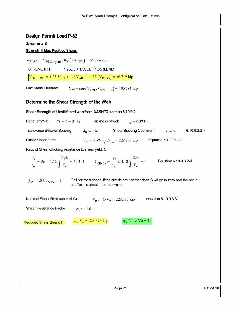
PA Flex Beam Example Configuration Calculations
Design Permit Load P-82
Shear at x=0
Strength II Max Positive Shear:
VPL82 VPL82span DFs 1 IPL 54.238 kip
STRENGTH II 1.25DL + 1.5SDL + 1.35 (LL+IM)
VstrII_PL 1.25 Vdl1 1.5 Vsdl1 1.35 VPL82 96.719 kip
Max Shear Demand Vu max Vstr1 VstrII_PL 100.584 kip
Determine the Shear Strength of the Web
Shear Strength of Unstiffened web from AASHTO section 6.10.9.2
Depth of Web D d 21 in Thickness of web tw 0.375 in
Transverse Stiffener Spacing d0 0in Shear Buckling Coefficient k 5 6.10.9.3.2-7
Plastic Shear Force Vp 0.58 Fy D tw 228.375 kip Equation 6.10.9.3.2-3
Ratio of Shear-Buckling resistance to shear yield, C
D
tw56 1.12
Es k
Fy 60.314 Ccheck
D
tw1.12
Es k
Fy 1 Equation 6.10.9.3.2-4
C 1.0 Ccheck 1 C=1 for most cases, if the criteria are not met, then C will go to zero and the actualcoefficients should be determined
Nominal Shear Resistance of Web Vn C Vp 228.375 kip equation 6.10.9.3.3-1
Shear Resistance Factor φv 1.0
φv Vn 228.375 kip φv Vn Vu 1Reduced Shear Strength
Page 21 1/15/2020

PA Flex Beam Example Configuration Calculations
Check Bearing Stiffeners
FYs 50ksi Yield strength of stiffener
tp 0.75in Thickness of stiffener
bt
bf tw
21.5in 4.312 in Effective width of stiffener
Dst hw 4.1in 16.4 in Depth of stiffeners
Apn 2 tp bt 6.469 in2
Projected area of stiffeners
bt 0.48 tpEs
FYs 1Check that effective width of stiffener meets requirements
Rsbn 1.4 Apn FYs 452.812 kip Bearing capacity of stiffener (phi=1 for bearing per AASHTO 6.5.4.2)
Rsbn Vu 1 Bearing capacity check
Qs 1.0 Q factor for bearing stiffner, taken as 1 (AASHTO 6.9.4.1.1)
Is
18 tw tw3
tp 2 bt 3
1240.131 in
4 Moment of inertia of stiffener and web (9*tw is used on each side)
AASHTO 6.10.11.2.4b
Ag 18 tw tw 2 bt tp 9 in2
Gross area of stiffener and web (AASHTO 6.10.11.2.4b)
rs
Is
Ag2.112 in Radius of gyration of stiffener/web
Po Qs FYs Apn 323.437 kip Nominal yeild resistance of stiffener (AASHTO 6.9.4.1.1)
Peπ2Es
0.75 Dst
rs
2Ag 7.592 10
4 kip Elastic critical buckling stress of stiffener (AASHTO 6.9.4.1.2-1)
Check that Pe/Po is great than 0.44 (AASHTO 6.9.4.1.1) PePoPe
Po0.44 1
Pn PePo 0.658
Po
Pe Po 322.861 kip Nominal compressive resistance of stiffener for Pe/Po>0.44
(AASHTO 6.9.4.1.1-1)
φcr 0.95 phi factor for axial compression (AASHTO 6.5.4.2)
Pr φcr Pn 306.718 kip Compressive capacity of bearing stiffener Pr Vu 1
Page 22 1/15/2020

PA Flex Beam Example Configuration Calculations
Flexbeam Example Configuration Calculations
Summary of Calculations:
Input section dimensions and material properties for steel WT and the concrete deck1.Calculate demands (dead load, superimposed dead, and Live load demands for Strength I and Strength II2.Calculate composite section properties for the given section3.Check Strength I, Strength II, and Service II stresses 4.Check Strength I, Strength II, and Strength V moment demands 5.Perform live load deflection check6.Determine maximum shear demand and capacity7.Note: Shear envelope data was obtained from Matlab script (FlexBeam_Moment_ShearEnvelope.m).8.Shear envelope calculations are summarized separately for each design (Shear Design *.xlsx).
Design Assumptions:Design Specifications Used:
AASHTO LRFD Bridge Design Specifications 7th Edition with 2016 Interim RevisionsPennDOT Design Manual, Part 4 (DM-4) June 30, 2015
Example configurations are determined for two girder spacings, 36" and 40".The deck thickness is 7.5" and is assumed to have a non-structural wearing surface added after installation.Section properties are calculated using the full 7.5" deck thickness.The WT sections are embedded 3.5" into the concrete deck. The steel section spacing used is outside the scope of the AASHTO and PennDOT distribution factorequations. The flexural distribution factor is assumed to be 0.3 which was shown to tbe conservativeaccording to refined analysisThe shear distribution factor is calculated using the DM-4 shear distribution factor equation which wasshown to be conservative using refined analysis.Refined analysis is presented in: Zihan Ma, "Distribution Factors for Composite Steel Tee Concrete DeckBridge System," M.S. Thesis, Deparement of Civil and Environmental Engineering, Lehigh University,Bethlehem, 2019Shear and moment demands for the PL82 permit load vehicle are determined by Matlab script(FlexBeam_Moment_ShearEnvelope.m) and are manually input into this calculation sheet.All fabrication will occur as double modules, i.e. each module contains two WT sections. The number ofmodules is half the number of beams, N. A 45 in. tall F-Shape barrier is used, Weight = 700 lb/ft (Distributed to exterior two beams).
The work presented in this document are provided on an “AS IS” basis. University makes no warranties of anykind, express or implied, as to any matter whatsoever, including, without limitation, warranties with respect tothe merchantability or fitness for a particular purpose of this work or any project deliverables. Universitymakes no warranty of any kind with respect to freedom from patent, trademark, copyright or trade secretinfringement arising from the use of the results of the project, deliverables, services, intellectual property orother materials provided hereunder. University shall not be liable for any direct, indirect, consequential,punitive, or other damages suffered by Sponsor or any other person resulting from the project, or the use ofthis work or any project deliverables.
Page 1 1/15/2020

PA Flex Beam Example Configuration Calculations
hf
tf
bf
twh
d
bjtbe
e
Variable Definitions:
Number of beams N 12 modulesN
26
L 40ft Span length
be 36in Effective width of Flexbeamassuming constructed bridge width(i.e. closure joints cast)
Built Up Section Properties
tw 0.375in tf 0.5in bf 12in
h 25in Overall Height of section
hf 7.5in Total thickness of deck
e 3.5in Deck/Steel overlap
d h hf e 21 in depth of built up steel section
hw d tf 20.5 in height of web of built up steel
Moment and shear for permit load PL82 obtained from Matlab script: FlexBeam_Moment_ShearEnvelope
MLL_IM_PL82 312.012kip ft Moment due to PL82 with distribution factor and impact factor!!
VPL82span 94.1625kip Shear due to PL82 WITHOUT distribution factor and impact factor!!
Check web and flange dimensions in sections 6.10.2.1 and 6.10.2.2
(Ignore 6.10.2.2-4 since no compression flange)
equation 6.10.2.1.1-1d
tw150 1 equation 6.10.2.2-1
bf
2 tf12 1
equation 6.10.2.2-2 bfh
6 1 equation 6.10.2.2-3 tf 1.1 tw 1
y_bar
tf bftf
2 hw tw tf
hw
2
tf bf hw tw6.147 in Center of gravity of steel section
Istl
bf tf3
12bf tf y_bar
tf
2
2
tw hw
3
12 tw hw tf
hw
2 y_bar
2
640.875 in4
MOI of steel
Astl tf bf hw tw 13.687 in2
Area of the WT steel section
Page 2 1/15/2020

PA Flex Beam Example Configuration Calculations
Material Properties
Elastic Modulus of Steel Es 29000ksi
Yield Strength of Steel Fy 50ksi
Yield Strength of Reinforcement fy 60ksi
Compressive Strength of Concrete fc 4000psi AAAP PennDOT Concrete
Concrete Modular Ratio n 8 modular ratio for 4ksi concrete per AASHTO
Unit weight of concrete slab wc 0.150kip
ft3
Unit weight of concrete
Section Properties
Width of UHPC Joint: bjt 6in
Parapet width: bpar 20.25in Parapet width per PennDOT F-shape barrier
Width of the bridge W be N bjt 426 in W 35.5 ft
Clear width of roadway Wlane W 2 bpar 32.125 ft
Dc wc hf W 3.328kip
ft DL due to slab
Db .700kip
ft DL due to each 45" F-Shape Barrier (per email 11/1/18)
DFWS 30lbf
ft2
W 2 bpar 0.964kip
ft DL due to Future Wearing Surface (FWS)
Ds Astl 490lbf
ft3
0.047kip
ft Selfweight of the steel section
DLself
Dc N
Ds 0.324kip
ft Self-weight per WT
Total weight of each precast FlexBeam for transportation:
Weight of C12x25 Diaphragms Wend_diaphragms 25lbf
ft32 in 0.067 kip
2be bjt hf wc 2Ds L 2 Wend_diaphragms 24.484 kip
Determine number of design lane (AASHTO Section 3.6.1.1.1)
Take the integer part of the ratio of W/12 ft. Number of lanes in bridge: Nl floorWlane
12ft
2
Page 3 1/15/2020
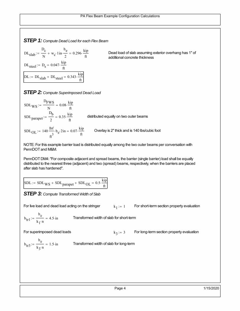
PA Flex Beam Example Configuration Calculations
STEP 1: Compute Dead Load for each Flex Beam
DLslab
Dc
Nwc 1 in
be
2 0.296
kip
ft Dead load of slab assuming exterior overhang has 1" of
additional concrete thickness
DLsteel Ds 0.047kip
ft
DL DLslab DLsteel 0.343kip
ft
STEP 2: Compute Superimposed Dead Load
SDLWS
DFWS
N0.08
kip
ft
SDLparapet
Db
20.35
kip
ft distributed equally on two outer beams
SDLOL 140lbf
ft3be 2 in 0.07
kip
ft Overlay is 2" thick and is 140 lbs/cubic foot
NOTE: For this example barrier load is distributed equally among the two outer beams per conversation withPennDOT and M&M.
PennDOT DM4: "For composite adjacent and spread beams, the barrier (single barrier) load shall be equallydistributed to the nearest three (adjacent) and two (spread) beams, respectively, when the barriers are placedafter slab has hardened".
SDL SDLWS SDLparapet SDLOL 0.5kip
ft
STEP 3: Compute Transformed Width of Slab
For live load and dead load acting on the stringer k1 1 For short-term section property evaluation
btr1
be
k1 n4.5 in Transformed width of slab for short-term
For superimposed dead loads k3 3 For long-term section property evaluation
btr3
be
k3 n1.5 in Transformed width of slab for long-term
Page 4 1/15/2020

PA Flex Beam Example Configuration Calculations
STEP 4: Compute Dead and Superimposed Dead Load Moments(Based on first interior girder demands)
MDLDL L
2
868.534 kip ft
MSDLSDL L
2
8100.062 kip ft
STEP 5: Compute live load and Dynamic Load Allowance (IM)
Live load wheel load distribution factor (DF):
Sbe
12in3 transverse girder spacing
NOTE: AASHTO presents equations to define DF for different types of superstructuresincluding Deck Composite wirh RC slab on steel girders (Type (a) in Table 4.6.2.2.1-1) forshear and moment in interior and exterior beams.
Using DM4 Table 4.6.2.2.2b-1:
eg h y_barhf
2 15.103 in Distance between the centers of gravity of the basic beam and deck
Kg n Istl Astl eg2
30103.16 in
4 Longitudinal stiffness parameter (in4)
Distribution of Live Load Per Lane for Moment in Interior Beams:
to be conservative, use DF 0.3
Page 5 1/15/2020

PA Flex Beam Example Configuration Calculations
Dynamic Load Allowance (Section 3.6.2 DM4)
Static effects of the design truck or tandem, shall be increased by the impact factor.
NOTE: The dynamic load allowance shall not be applied to the design lane load (Section 3.6.2.1 DM4)
I 0.33 Impact factor for moment
Note: PennDOT requires that the impact for decks be increased from 33% to 50%, the deck is not beingdesigned here. Instrad the deck design is based on the BD recommendations.
Dynamic load allowance for the Permit Load P-82 shall be less than 20%. (Section 3.6.2.1DM4)
IPL 0.20 Impact factor for moment on Strength II
Design Wind Loading for Exterior Girder
Vw 80 Wind speed for Strength V load case
CD 1.3 Gust factor for windard side of I-Girder and Box Girder Superstructures (Table 3.8.1.2.1-2)
G 1.0 Gus effect factor is 1.0 for all structures other than sound barriers (Table 3.8.1.2.1-1)
Kz 1.0 Pressure coefficient taken as 1 for Strength V (3.8.1.2.1)
Pz 2.56 106
Vw 2 Kz G CDkip
ft2
0.021kip
ft2
Wind pressure on exterior girder
hexp h hf 17.5 in Exposed height of exterior girder
Moment due to wind loading on exterior girderMWL
Pz hexp L2
86.212 kip ft
Iyy
bf3tf
1272 in
4 Transverse moment of intertia
Flange lateral bending stressfl
MWL
bf
2
Iyy6.212 ksi
Page 6 1/15/2020

PA Flex Beam Example Configuration Calculations
Design Vehicular Live Load
PHL-93 and P-82 are examined herein.
PHL-93 (A3.6.1.2.1)
PHL-93 consists of a combination of (design truck or design tandem) + (design lane load)
Design Truck
PennDOT defines the design truck in accordance with AASTHO 3.6.1.2
Design truck load in AASHTO (HS20 Truck) is used for this example.
NOTE : MAX moment occurs when the center line of the span is midway between the center ofgravity of the loads and the nearest concentrated load.
P1 8kip P2 32kip P3 32kip Axle loads (AASHTO 3.6.1.2.2)
XASr 14ft Rear Axle spacing for truck (14ft - 30ft)
XASf 14ft Front Axle spacing for truck
Page 7 1/15/2020

PA Flex Beam Example Configuration Calculations
Center of gravity (CG) of loads:
X'P1 XASr XASf P2 XASr
P1 P2 P39.333 ft Datum is the rear axle
X XASr X' 4.667 ft Spacing btw CG and nearest load
Find bridge reaction
Truck movestoward Support ARA
P1L
2XASf
X
2
P2L
2
X
2
P3L
2X'
X
2
L31.8 kip
Max live load moment (at the location of P2):
MLL_truck RAL
2
X
2
P1 XASf 449.8 kip ft
NOTE: Find the worst case by varying XASr
Page 8 1/15/2020

PA Flex Beam Example Configuration Calculations
Design Tandem
Consist of a pair of 25-kip axles spaced 4-ft apart. (AASHTO 3.6.1.2.3)
NOTE: PennDOT DM4 increases 25-kip to 31.25-kip.
FT 31.25kip
XAS 4ft Axle spacing
Center of gravity (CG) of loads:
XXAS
22 ft Spacing btw CG and nearest load
Find bridge reaction
RA
FTL
2
X
2
FTL
2
X
2 X
L29.688 kip Truck moves toward Support A
Max live load moment (at the location of front wheel):
MLL_tandem RAL
2
X
2
564.063 kip ft
Choose the max value:
MLL_veh max MLL_tandem MLL_truck 564.063 kip ft
Apply the impact and wheel load distribution:
MLL_IM_veh MLL_veh DF 1 I( ) 225.061 kip ft Due to tandem or truck
Design Lane Load (distributed over a 10-ft width for each lane)
NOTE: The uniform load may be continuous or discontinuous as necessary to produce themaximum force effect. For this example continuous uniform distribution assumed.
FDLL 0.64kip
ftDF 0.192
kip
ft Per beam in each lane
Due to lane loadMLL_IM_lane
FDLL L2
8
38.4 kip ft
Moment due to Total Design Vehicular Live Load: MLL_IM MLL_IM_lane MLL_IM_veh 263.461 kip ft
Page 9 1/15/2020

PA Flex Beam Example Configuration Calculations
Design Permit Load P-82 (Section 3.6.1.2.7 DM4)
P1 P2 P3 P4 P5 P6 P7
NOTE: The moment for the permit load is defined at the beginning of the sheetand is obtained from MATLab File FlexBeam_Moment_ShearEnvelope.m
STEP 6: Compute Moment of Inertia (Note: rebar neglected!)
1) Moment of Inertia resisting dead load only:
a) Acting on the non-composite section (before the deck has hardened - DC1)
Use steel section only
Inc Istl 640.875 in4
Non-composite section modulus
Y'nc y_bar S.G. of the steel section of Flex Beam (Datum is bottom)
b) Acting on the composite section (after the deck has hardened - DC2)
Use Ic_short as defined below.
Page 10 1/15/2020

PA Flex Beam Example Configuration Calculations
2) Moment of Inertia resisting live load plus impact:
Using transformed slab with k1=1 (short-term composite).
Actr1 hf btr1 33.75 in2
Itr1
btr1 hf3
12158.203 in
4
Y'
Actr1 hhf
2
Astl Y'nc
Astl Actr116.892 in S.G. of the total flex beam (Datum is bottom)
Compositesection modulus(short-term)
Ic_short Istl Astl Y'nc Y' 2 Itr1 Actr1 hhf
2
Y'
2
3020 in4
Y'c_short Y' 16.892 in N.A. of the short-term composite section
3) Moment of Inertia resisting superimposed dead load:
Using transformed slab with k3=3.
Actr3 hf btr3 11.25 in2
Itr3
btr3 hf3
1252.734 in
4
Y'
Actr3 hhf
2
Astl Y'nc
Astl Actr312.961 in S.G. of the total flex beam (Datum is bottom)
Compositesection modulus(long-term)
Ic_long Istl Astl Y'nc Y' 2 Itr3 Actr3 hhf
2
Y'
2
2102 in4
Y'c_long Y' 12.961 in N.A. of the long-term composite section
Page 11 1/15/2020

PA Flex Beam Example Configuration Calculations
STEP 6.5 Check Ductility RequirementIn accordance with AASHTO Article 6.10.7.3 check ductility requirement. Assume compressionblock of concrete is at 0.85 f'c and that the concrete supports no tension. Steel section isassumed to be fully plastic at Fy.
Case 1 : Assuming PNA is in Concreteh d 4 inAssuming (h-d) < Dp < hf
Fp Dp 0.85 fc be Dp Fy tw Dp h d( ) Fy Astl tw Dp h d( )
Dp 7.5in 0.42 h 10.5 in
Dp1 root Fp Dp Dp 5.218 in Must be less than hf 7.5 inDp1
h0.209 must be < 0.42
Mn1check Dp1 hf h d( ) Dp1[ ] Dp1 0.42 h( ) 1 Dp1 0.42 h 1
Mp1 0.85 fc be Dp1Dp1
2
Fy tw Dp1 h d( )[ ] Dp1 h d( )[ ]
2
Fy bf tf h Dp1tf
2
Fy tw h Dp1 tf h Dp1 tf
2
Mp1 11025.42 kip in Mn1 Mp1 1.07 0.7Dp1
h
10186.3 kip in
Case 2 : Assuming PNA is NOT in Concrete
Assuming hf < Dp
Fp2 Dp 0.85 fc be hf Fy tw Dp h d( ) Fy Astl tw Dp h d( )
Dp 2.5in
Dp2 root Fp2 Dp Dp 2.23 in Must be more than hf 7.5 inDp2
h0.0892 must be < 0.42
Mn2check Dp2 hf Dp2 h( ) Dp2 0.42 h( ) 0 Dp2 0.42 h 1
Mp2 0.85 fc be hf Dp2hf
2
Fy tw Dp2 h d( )[ ] Dp2 h d( )[ ]
2
Fy bf tf h Dp2tf
2
Fy tw h Dp2 tf h Dp2 tf
2
Mp2 9666.6 kip inMn2 Mp2 1.07 0.7
Dp2
h
10946.8 kip in
Mn max Mn1 Mn1check Mn2 Mn2check 848.9 kip ft Mn 10186.3 kip in
Page 12 1/15/2020

PA Flex Beam Example Configuration Calculations
Check Composite Compact Section Criteria (6.10.6.2)
Dcpd
2
Fy tf bf 0.85 fc be hf
Fy hw tw1
6.382 in Dcp0 Dcp 0 0
Dcp Dcp Dcp0 0 in2 Dcp
tw3.76
Es
Fy 1 Check if section is compact
STEP 7: Load Combinations (Table 3.4.1-1)
The following load combinations will be considered herein. Only the maximum load factors forpermanent-loads are used in the following load combinations (uplift is not an issue for this typeof bridge).STRENGTH I 1.25DL + 1.5SDL + 1.75 (LL+IM)
SERVICE II: DL+SDL+1.3(LL+IM)
STEP 8: Compute and Check Stresses
Stress at bottom fiber of steel section
fDL
MDL Y'c_long
Ic_long5.071 ksi
fLL_I
MLL_IM Y'c_short
Ic_short17.682 ksi fPL
MLL_IM_PL82 Y'c_short
Ic_short20.941 ksi
fSDL
MSDL Y'c_long
Ic_long7.403 ksi
STRENGTH I fbot_str1 1.25fDL 1.5 fSDL 1.75 fLL_I 48.388 ksi
STRENGTH II fbot_str2 1.25fDL 1.5 fSDL 1.35 fPL 45.714 ksi
SERVICE II fbot_svc2 fDL fSDL 1.3fLL_I 35.46 ksi
Allowable Stress is based on Section 6.10.4.2.2-2
Flange stress due to service load II without consideration of flange lateral bending: ff fbot_svc2
Flange lateral bending stress due to service II: flSII 0ksi
Hybrid Factor: Rh 1.0 For rolled and homogenous built-up sections
ff
flSII
2 35.461 ksi 0.95 Rh Fy 47.5 ksi ff
fl
2 0.95Rh Fy 1
Page 13 1/15/2020
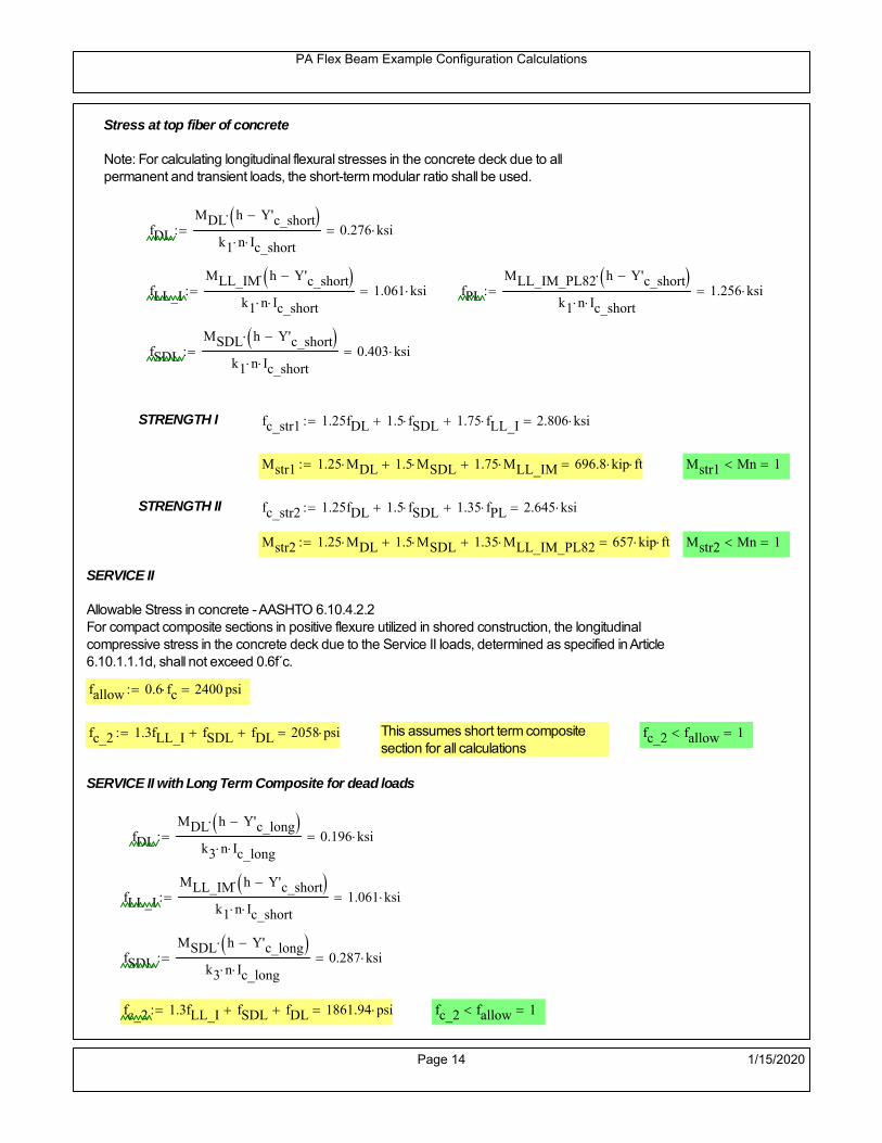
PA Flex Beam Example Configuration Calculations
Stress at top fiber of concrete
Note: For calculating longitudinal flexural stresses in the concrete deck due to allpermanent and transient loads, the short-term modular ratio shall be used.
fDL
MDL h Y'c_short
k1 n Ic_short0.276 ksi
fLL_I
MLL_IM h Y'c_short
k1 n Ic_short1.061 ksi fPL
MLL_IM_PL82 h Y'c_short
k1 n Ic_short1.256 ksi
fSDL
MSDL h Y'c_short
k1 n Ic_short0.403 ksi
STRENGTH I fc_str1 1.25fDL 1.5 fSDL 1.75 fLL_I 2.806 ksi
Mstr1 1.25 MDL 1.5 MSDL 1.75 MLL_IM 696.8 kip ft Mstr1 Mn 1
STRENGTH II fc_str2 1.25fDL 1.5 fSDL 1.35 fPL 2.645 ksi
Mstr2 1.25 MDL 1.5 MSDL 1.35 MLL_IM_PL82 657 kip ft Mstr2 Mn 1
SERVICE II
Allowable Stress in concrete - AASHTO 6.10.4.2.2For compact composite sections in positive flexure utilized in shored construction, the longitudinalcompressive stress in the concrete deck due to the Service II loads, determined as specified in Article6.10.1.1.1d, shall not exceed 0.6f́ c.
fallow 0.6 fc 2400 psi
fc_2 1.3fLL_I fSDL fDL 2058 psi This assumes short term compositesection for all calculations
fc_2 fallow 1
SERVICE II with Long Term Composite for dead loads
fDL
MDL h Y'c_long
k3 n Ic_long0.196 ksi
fLL_I
MLL_IM h Y'c_short
k1 n Ic_short1.061 ksi
fSDL
MSDL h Y'c_long
k3 n Ic_long0.287 ksi
fc_2 1.3fLL_I fSDL fDL 1861.94 psi fc_2 fallow 1
Page 14 1/15/2020

PA Flex Beam Example Configuration Calculations
Strength V Moment Check
Strength V is related to normal vehicular use of the bridge with an 80 mph wind gust
Note: that Strength V is checked for an exterior girder under wind load with the interior girder distribution factor forflexure used. If Strength V controls design, then this approach should be modified
Design vertical moment is: 1.25DL + 1.5SDL + 1.35 (LL+IM)
SLT
Ic_long
Y'c_long162.188 in
3 SST
Ic_short
Y'c_short178.796 in
3 short and long term section
modulus
Section D6.2.2 Find the moment required to cause yieldling of the flange. The approach is laid out in D6.2.2
MD2 1.25 MDL 1.5 MSDL 235.761 kip ft From D6.2.2-1 (all dead loads are in MD2 due to shoredconstruction
MAD Fy
MD2
SLT
SST 485.081 kip ft Additional moment to cause nominal yielding of steel flange
My MD2 MAD 720.842 kip ft D6.2.2-2: Moment to cause yielding of flange
6.10.7.1 Compact Section Check at Strength V limit state
Section Modulus for yielding of the flange (My/Fy) for equation 6.10.7.1.1-1Sxt
My
Fy173.002 in
3
Mu 1.25 MDL 1.5MSDL 1.35MLL_IM 591.433 kip ft Moment due to Strength V limit state
Mu1
3fl Sxt 621.287 kip ft Equation 6.10.7.1.7-1 Mn 848.859 kip ft Mu
1
3fl Sxt Mn 1
Page 15 1/15/2020

PA Flex Beam Example Configuration Calculations
STEP 9: Compute Deflection
Optional Live Load Deflection Evaluation (AASHTO 3.6.1.3.2)
Deflection distribution factor for vehicular loads: For a straight multibeambridge, this is equivalent to saying that the distribution factor for deflectionis equal to the number of lanes divided by the number of beams. 2.5.2.6.2
DFd
Nl
N0.167
Deflection should be taken as 125% the larger of:- Design truck- 25% of design truck + design lane
The live load portion of Load Combination Service I of Table 3.4.1-1 should be used,including the dynamic load allowance, IM;
Deflection due to design truck load
NOTE : Assuming maximum deflection occurs when the center of gravity of the loads is at thecenter line of the span.
P1 8kip P2 32kip P3 32kip Axle loads (AASHTO 3.6.1.2.2)
XASr 14ft Rear Axle spacing for truck (14ft - 30ft)
XASf 14ft Front Axle spacing for truck
Center of gravity (CG) of loads:
X'P1 XASr XASf P2 XASr
P1 P2 P39.333 ft Datum is the rear axle
Method1: Assuming single load = P1+P2+P3 at the midspan (Conservative approach)
P1 P2 P3 L3
48 Es Ic_short 1.894 in
Method2: Calculation of Midspan deflection using superposition
b1L
2XASr X' XASf 1.333 ft distance btw load P1 and support A b1check b1 0 1
b2L
2XASr X' 15.333 ft distance btw load P2 and support A b2check b2 0 1
b3L
2X' 10.667 ft distance btw load P3 and support B b3check b3 0 1
Page 16 1/15/2020

PA Flex Beam Example Configuration Calculations
Deflection of the beam at midspan due to P1: P P1
xL
2 at midspan b b1 b1check The smallest distance btw load P1 and support
Δ1P b x
6 Es Ic_short LL2
b2
x2
0.021 in
Deflection of the beam at midspan due to P2: P P2
xL
2 at midspan b b2 b2check The smallest distance btw load P2 and support
Δ2P b x
6 Es Ic_short LL2
b2
x2
0.778 in
Deflection of the beam at midspan due to P3: P P3
xL
2 at midspan b b3 b3check The smallest distance btw load P3 and support
Δ3P b x
6 Es Ic_short LL2
b2
x2
0.61 in
Total Deflection at midspan:
Δtruck Δ1 Δ2 Δ3( ) DFd 1 I( ) 0.312 in (Considering IM)
Deflection due to tandem (Note: this calculation is not required according to Article3.6.1.3.2 which denotes only the design truck for deflection calculation)
Page 17 1/15/2020

PA Flex Beam Example Configuration Calculations
FT 31.25 kip Per axle
XAS 4ft Axle spacing
Δtandem
FTL
2
XAS
2
24 Es Ic_short3 L
2 4
L
2
XAS
2
2
DFd 1 I( ) 0.359 in (Considering IM)
Deflection due to lane load
FDLLd 640lbf
ft DFd 106.667
lbf
ft
Δlane
5 FDLLd L4
384 Es Ic_short0.07 in
Live Load Deflection:
ΔLL 1.25max Δtruck 0.25Δtruck Δlane 1.25 0.488 in ΔLLL
800 1
Deflection Limit
For steel or concrete vehicular bridges:
Vehicular load = Span/800L
8000.6 in
L
10000.48 in
Evaluation of Deflection at the Service Limit State (AASHTO 3.4.2.2)
The associated permitted deflections shall be included in the contract documents.
Page 18 1/15/2020

PA Flex Beam Example Configuration Calculations
Shear demands:
Determination of the distribution factor
Using DM4 Table 4.6.2.2.3a-1
Sbe
12in3 transverse girder spacing (ft)
Distribution of live loads per lane for shear in interior beams:
For two design lanes loaded, 3.5' <= S =< 16', number of beam >= 4DFs 0.36
S
25 0.48
Q Actr1 h Y'c_shorthf
2
147.073 in3
first moment of deck slab for interface shear
Method 1: Range of shear based on Strength I Limit
STRENGTH I 1.25DL + 1.5SDL + 1.75 (LL+IM)
Computation of the range of shear in the beam
Dead Load:DL 0.343
kip
ft
Superimposed Dead Load: SDL 0.5kip
ft
Design Lane Load: 0.64kip
ft
Design Truck:
XASr 14ft Rear Axle spacing for truck (14ft - 30ft)
XASf 14ft Front Axle spacing for truck
P1 8 kip P2 32 kip P3 32 kip Wheel loads (AASHTO 3.6.1.2.2)
Design Tandem:
Consist of a pair of 25-kip axles spaced 4-ft apart. (AASHTO 3.6.1.2.3)
NOTE: PennDOT DM4 increases 25-kip to 31.25-kip.
FT 31.25kip
XAS 4ft Axle spacing
Page 19 1/15/2020

PA Flex Beam Example Configuration Calculations
Maximum positive shear at various points along the FlexBeam are examined.
At x=0 (at left support) (Truck is moving from left to right)
Truck
Max Positive Shear (when P3 is at x = 0):
x1 L XASr XASf 12 ft Distance between P1 and right support
x2 L XASr 26 ft Distance between P2 and right support
x3 L 40 ft Distance between P3 and right support
V1 P3
x3
L P2
x2
L P1
x1
L 55.2 kip
Total Vertical Shear Force for each FlexBeam (considering dynamic loads):
Vtruck1 V1 DFs 1 I( ) 35.24 kip
Tandem:
V1 FT FT
L XAS L
59.375 kip
Total Vertical Shear Force for each FlexBeam (considering dynamic loads):
Vtandem1 V1 DFs 1 I( ) 37.905 kip
Lane Load
V1 0.64kip
ft
L
2 12.8 kip
Total Vertical Shear Force for each FlexBeam (considering dynamic loads):
Vlane1 V1 DFs 6.144 kip
Dead Load
Vdl1 DLL
2 6.853 kip
Superimposed Dead Load
Vsdl1 SDLL
2 10.006 kip
Strength I Max Positive Shear:
Vstr1 1.25 Vdl1 1.5 Vsdl1 1.75 Vlane1 max Vtruck1 Vtandem1 100.662 kip
Page 20 1/15/2020

PA Flex Beam Example Configuration Calculations
Design Permit Load P-82
Shear at x=0
Strength II Max Positive Shear:
VPL82 VPL82span DFs 1 IPL 54.238 kip
STRENGTH II 1.25DL + 1.5SDL + 1.35 (LL+IM)
VstrII_PL 1.25 Vdl1 1.5 Vsdl1 1.35 VPL82 96.797 kip
Max Shear Demand Vu max Vstr1 VstrII_PL 100.662 kip
Determine the Shear Strength of the Web
Shear Strength of Unstiffened web from AASHTO section 6.10.9.2
Depth of Web D d 21 in Thickness of web tw 0.375 in
Transverse Stiffener Spacing d0 0in Shear Buckling Coefficient k 5 6.10.9.3.2-7
Plastic Shear Force Vp 0.58 Fy D tw 228.375 kip Equation 6.10.9.3.2-3
Ratio of Shear-Buckling resistance to shear yield, C
D
tw56 1.12
Es k
Fy 60.314 Ccheck
D
tw1.12
Es k
Fy 1 Equation 6.10.9.3.2-4
C 1.0 Ccheck 1 C=1 for most cases, if the criteria are not met, then C will go to zero and the actualcoefficients should be determined
Nominal Shear Resistance of Web Vn C Vp 228.375 kip equation 6.10.9.3.3-1
Shear Resistance Factor φv 1.0
φv Vn 228.375 kip φv Vn Vu 1Reduced Shear Strength
Page 21 1/15/2020

PA Flex Beam Example Configuration Calculations
Check Bearing Stiffeners
FYs 50ksi Yield strength of stiffener
tp 0.75in Thickness of stiffener
bt
bf tw
21.5in 4.312 in Effective width of stiffener
Dst hw 4.1in 16.4 in Depth of stiffeners
Apn 2 tp bt 6.469 in2
Projected area of stiffeners
bt 0.48 tpEs
FYs 1Check that effective width of stiffener meets requirements
Rsbn 1.4 Apn FYs 452.812 kip Bearing capacity of stiffener (phi=1 for bearing per AASHTO 6.5.4.2)
Rsbn Vu 1 Bearing capacity check
Qs 1.0 Q factor for bearing stiffner, taken as 1 (AASHTO 6.9.4.1.1)
Is
18 tw tw3
tp 2 bt 3
1240.131 in
4 Moment of inertia of stiffener and web (9*tw is used on each side)
AASHTO 6.10.11.2.4b
Ag 18 tw tw 2 bt tp 9 in2
Gross area of stiffener and web (AASHTO 6.10.11.2.4b)
rs
Is
Ag2.112 in Radius of gyration of stiffener/web
Po Qs FYs Apn 323.437 kip Nominal yeild resistance of stiffener (AASHTO 6.9.4.1.1)
Peπ2Es
0.75 Dst
rs
2Ag 7.592 10
4 kip Elastic critical buckling stress of stiffener (AASHTO 6.9.4.1.2-1)
Check that Pe/Po is great than 0.44 (AASHTO 6.9.4.1.1) PePoPe
Po0.44 1
Pn PePo 0.658
Po
Pe Po 322.861 kip Nominal compressive resistance of stiffener for Pe/Po>0.44
(AASHTO 6.9.4.1.1-1)
φcr 0.95 phi factor for axial compression (AASHTO 6.5.4.2)
Pr φcr Pn 306.718 kip Compressive capacity of bearing stiffener Pr Vu 1
Page 22 1/15/2020

PA Flex Beam Example Configuration Calculations
Flexbeam Example Configuration Calculations
Summary of Calculations:
Input section dimensions and material properties for steel WT and the concrete deck1.Calculate demands (dead load, superimposed dead, and Live load demands for Strength I and Strength II2.Calculate composite section properties for the given section3.Check Strength I, Strength II, and Service II stresses 4.Check Strength I, Strength II, and Strength V moment demands 5.Perform live load deflection check6.Determine maximum shear demand and capacity7.Note: Shear envelope data was obtained from Matlab script (FlexBeam_Moment_ShearEnvelope.m).8.Shear envelope calculations are summarized separately for each design (Shear Design *.xlsx).
Design Assumptions:Design Specifications Used:
AASHTO LRFD Bridge Design Specifications 7th Edition with 2016 Interim RevisionsPennDOT Design Manual, Part 4 (DM-4) June 30, 2015
Example configurations are determined for two girder spacings, 36" and 40".The deck thickness is 7.5" and is assumed to have a non-structural wearing surface added after installation.Section properties are calculated using the full 7.5" deck thickness.The WT sections are embedded 3.5" into the concrete deck. The steel section spacing used is outside the scope of the AASHTO and PennDOT distribution factorequations. The flexural distribution factor is assumed to be 0.3 which was shown to tbe conservativeaccording to refined analysisThe shear distribution factor is calculated using the DM-4 shear distribution factor equation which wasshown to be conservative using refined analysis.Refined analysis is presented in: Zihan Ma, "Distribution Factors for Composite Steel Tee Concrete DeckBridge System," M.S. Thesis, Deparement of Civil and Environmental Engineering, Lehigh University,Bethlehem, 2019Shear and moment demands for the PL82 permit load vehicle are determined by Matlab script(FlexBeam_Moment_ShearEnvelope.m) and are manually input into this calculation sheet.All fabrication will occur as double modules, i.e. each module contains two WT sections. The number ofmodules is half the number of beams, N. A 45 in. tall F-Shape barrier is used, Weight = 700 lb/ft (Distributed to exterior two beams).
The work presented in this document are provided on an “AS IS” basis. University makes no warranties of anykind, express or implied, as to any matter whatsoever, including, without limitation, warranties with respect tothe merchantability or fitness for a particular purpose of this work or any project deliverables. Universitymakes no warranty of any kind with respect to freedom from patent, trademark, copyright or trade secretinfringement arising from the use of the results of the project, deliverables, services, intellectual property orother materials provided hereunder. University shall not be liable for any direct, indirect, consequential,punitive, or other damages suffered by Sponsor or any other person resulting from the project, or the use ofthis work or any project deliverables.
Page 1 1/15/2020

PA Flex Beam Example Configuration Calculations
hf
tf
bf
twh
d
bjtbe
e
Variable Definitions:
Number of beams N 10 modulesN
25
L 40ft Span length
be 38in Effective width of Flexbeamassuming constructed bridge width(i.e. closure joints cast)
Built Up Section Properties
tw 0.375in tf 0.75in bf 12in
h 25in Overall Height of section
hf 7.5in Total thickness of deck
e 3.5in Deck/Steel overlap
d h hf e 21 in depth of built up steel section
hw d tf 20.25 in height of web of built up steel
Moment and shear for permit load PL82 obtained from Matlab script: FlexBeam_Moment_ShearEnvelope
MLL_IM_PL82 312.012kip ft Moment due to PL82 with distribution factor and impact factor!!
VPL82span 94.1625kip Shear due to PL82 WITHOUT distribution factor and impact factor!!
Check web and flange dimensions in sections 6.10.2.1 and 6.10.2.2
(Ignore 6.10.2.2-4 since no compression flange)
equation 6.10.2.1.1-1d
tw150 1 equation 6.10.2.2-1
bf
2 tf12 1
equation 6.10.2.2-2 bfh
6 1 equation 6.10.2.2-3 tf 1.1 tw 1
y_bar
tf bftf
2 hw tw tf
hw
2
tf bf hw tw5.18 in Center of gravity of steel section
Istl
bf tf3
12bf tf y_bar
tf
2
2
tw hw
3
12 tw hw tf
hw
2 y_bar
2
713.995 in4
MOI of steel
Astl tf bf hw tw 16.594 in2
Area of the WT steel section
Page 2 1/15/2020

PA Flex Beam Example Configuration Calculations
Material Properties
Elastic Modulus of Steel Es 29000ksi
Yield Strength of Steel Fy 50ksi
Yield Strength of Reinforcement fy 60ksi
Compressive Strength of Concrete fc 4000psi AAAP PennDOT Concrete
Concrete Modular Ratio n 8 modular ratio for 4ksi concrete per AASHTO
Unit weight of concrete slab wc 0.150kip
ft3
Unit weight of concrete
Section Properties
Width of UHPC Joint: bjt 6in
Parapet width: bpar 20.25in Parapet width per PennDOT F-shape barrier
Width of the bridge W be N bjt 374 in W 31.167 ft
Clear width of roadway Wlane W 2 bpar 27.792 ft
Dc wc hf W 2.922kip
ft DL due to slab
Db .700kip
ft DL due to each 45" F-Shape Barrier (per email 11/1/18)
DFWS 30lbf
ft2
W 2 bpar 0.834kip
ft DL due to Future Wearing Surface (FWS)
Ds Astl 490lbf
ft3
0.056kip
ft Selfweight of the steel section
DLself
Dc N
Ds 0.349kip
ft Self-weight per WT
Total weight of each precast FlexBeam for transportation:
Weight of C12x25 Diaphragms Wend_diaphragms 25lbf
ft32 in 0.067 kip
2be bjt hf wc 2Ds L 2 Wend_diaphragms 26.526 kip
Determine number of design lane (AASHTO Section 3.6.1.1.1)
Take the integer part of the ratio of W/12 ft. Number of lanes in bridge: Nl floorWlane
12ft
2
Page 3 1/15/2020
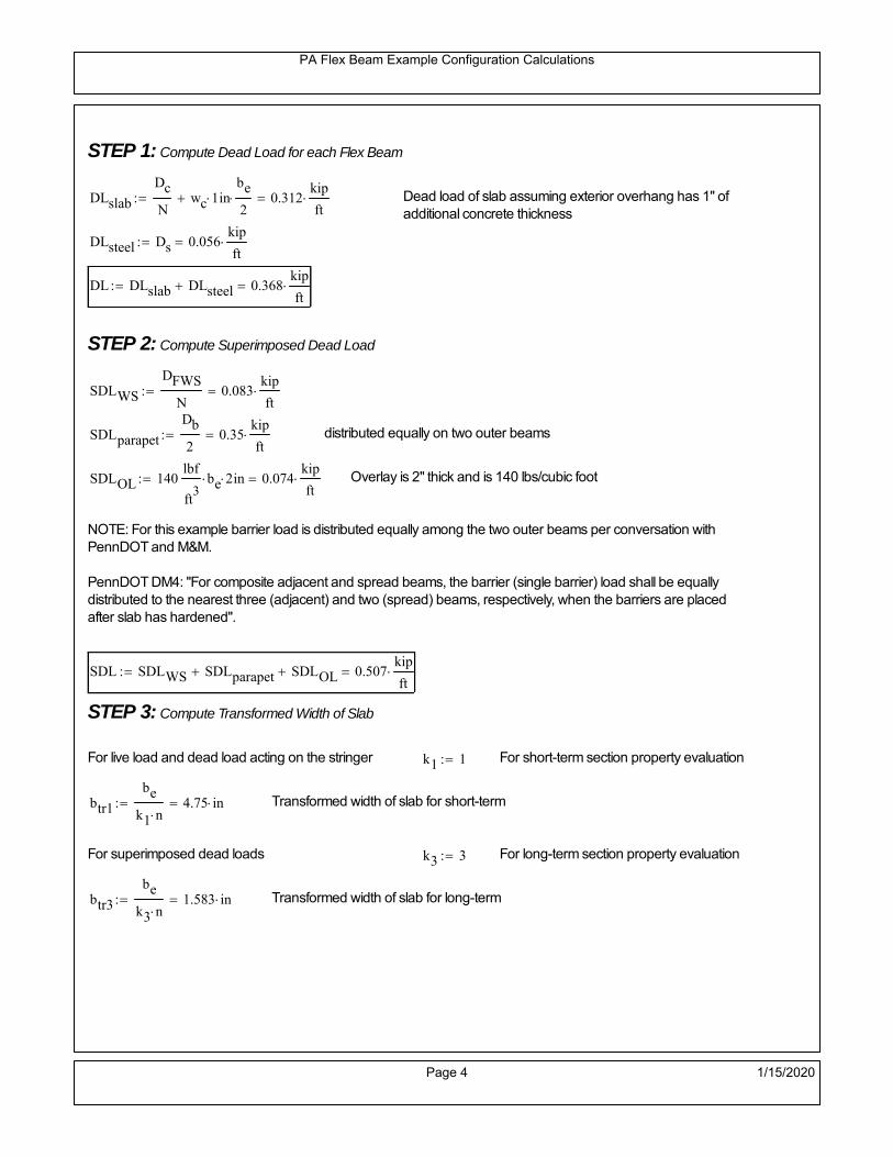
PA Flex Beam Example Configuration Calculations
STEP 1: Compute Dead Load for each Flex Beam
DLslab
Dc
Nwc 1 in
be
2 0.312
kip
ft Dead load of slab assuming exterior overhang has 1" of
additional concrete thickness
DLsteel Ds 0.056kip
ft
DL DLslab DLsteel 0.368kip
ft
STEP 2: Compute Superimposed Dead Load
SDLWS
DFWS
N0.083
kip
ft
SDLparapet
Db
20.35
kip
ft distributed equally on two outer beams
SDLOL 140lbf
ft3be 2 in 0.074
kip
ft Overlay is 2" thick and is 140 lbs/cubic foot
NOTE: For this example barrier load is distributed equally among the two outer beams per conversation withPennDOT and M&M.
PennDOT DM4: "For composite adjacent and spread beams, the barrier (single barrier) load shall be equallydistributed to the nearest three (adjacent) and two (spread) beams, respectively, when the barriers are placedafter slab has hardened".
SDL SDLWS SDLparapet SDLOL 0.507kip
ft
STEP 3: Compute Transformed Width of Slab
For live load and dead load acting on the stringer k1 1 For short-term section property evaluation
btr1
be
k1 n4.75 in Transformed width of slab for short-term
For superimposed dead loads k3 3 For long-term section property evaluation
btr3
be
k3 n1.583 in Transformed width of slab for long-term
Page 4 1/15/2020

PA Flex Beam Example Configuration Calculations
STEP 4: Compute Dead and Superimposed Dead Load Moments(Based on first interior girder demands)
MDLDL L
2
873.689 kip ft
MSDLSDL L
2
8101.453 kip ft
STEP 5: Compute live load and Dynamic Load Allowance (IM)
Live load wheel load distribution factor (DF):
Sbe
12in3.167 transverse girder spacing
NOTE: AASHTO presents equations to define DF for different types of superstructuresincluding Deck Composite wirh RC slab on steel girders (Type (a) in Table 4.6.2.2.1-1) forshear and moment in interior and exterior beams.
Using DM4 Table 4.6.2.2.2b-1:
eg h y_barhf
2 16.07 in Distance between the centers of gravity of the basic beam and deck
Kg n Istl Astl eg2
39993.61 in
4 Longitudinal stiffness parameter (in4)
Distribution of Live Load Per Lane for Moment in Interior Beams:
to be conservative, use DF 0.3
Page 5 1/15/2020
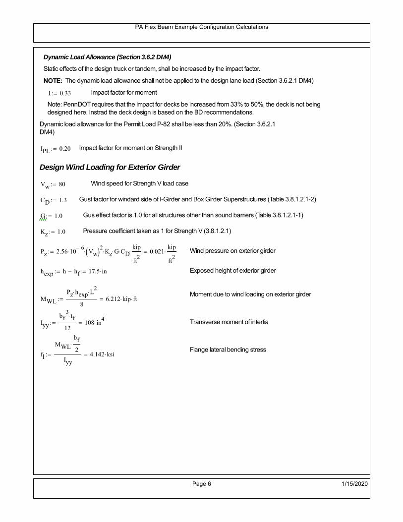
PA Flex Beam Example Configuration Calculations
Dynamic Load Allowance (Section 3.6.2 DM4)
Static effects of the design truck or tandem, shall be increased by the impact factor.
NOTE: The dynamic load allowance shall not be applied to the design lane load (Section 3.6.2.1 DM4)
I 0.33 Impact factor for moment
Note: PennDOT requires that the impact for decks be increased from 33% to 50%, the deck is not beingdesigned here. Instrad the deck design is based on the BD recommendations.
Dynamic load allowance for the Permit Load P-82 shall be less than 20%. (Section 3.6.2.1DM4)
IPL 0.20 Impact factor for moment on Strength II
Design Wind Loading for Exterior Girder
Vw 80 Wind speed for Strength V load case
CD 1.3 Gust factor for windard side of I-Girder and Box Girder Superstructures (Table 3.8.1.2.1-2)
G 1.0 Gus effect factor is 1.0 for all structures other than sound barriers (Table 3.8.1.2.1-1)
Kz 1.0 Pressure coefficient taken as 1 for Strength V (3.8.1.2.1)
Pz 2.56 106
Vw 2 Kz G CDkip
ft2
0.021kip
ft2
Wind pressure on exterior girder
hexp h hf 17.5 in Exposed height of exterior girder
Moment due to wind loading on exterior girderMWL
Pz hexp L2
86.212 kip ft
Iyy
bf3tf
12108 in
4 Transverse moment of intertia
Flange lateral bending stressfl
MWL
bf
2
Iyy4.142 ksi
Page 6 1/15/2020

PA Flex Beam Example Configuration Calculations
Design Vehicular Live Load
PHL-93 and P-82 are examined herein.
PHL-93 (A3.6.1.2.1)
PHL-93 consists of a combination of (design truck or design tandem) + (design lane load)
Design Truck
PennDOT defines the design truck in accordance with AASTHO 3.6.1.2
Design truck load in AASHTO (HS20 Truck) is used for this example.
NOTE : MAX moment occurs when the center line of the span is midway between the center ofgravity of the loads and the nearest concentrated load.
P1 8kip P2 32kip P3 32kip Axle loads (AASHTO 3.6.1.2.2)
XASr 14ft Rear Axle spacing for truck (14ft - 30ft)
XASf 14ft Front Axle spacing for truck
Page 7 1/15/2020

PA Flex Beam Example Configuration Calculations
Center of gravity (CG) of loads:
X'P1 XASr XASf P2 XASr
P1 P2 P39.333 ft Datum is the rear axle
X XASr X' 4.667 ft Spacing btw CG and nearest load
Find bridge reaction
Truck movestoward Support ARA
P1L
2XASf
X
2
P2L
2
X
2
P3L
2X'
X
2
L31.8 kip
Max live load moment (at the location of P2):
MLL_truck RAL
2
X
2
P1 XASf 449.8 kip ft
NOTE: Find the worst case by varying XASr
Page 8 1/15/2020

PA Flex Beam Example Configuration Calculations
Design Tandem
Consist of a pair of 25-kip axles spaced 4-ft apart. (AASHTO 3.6.1.2.3)
NOTE: PennDOT DM4 increases 25-kip to 31.25-kip.
FT 31.25kip
XAS 4ft Axle spacing
Center of gravity (CG) of loads:
XXAS
22 ft Spacing btw CG and nearest load
Find bridge reaction
RA
FTL
2
X
2
FTL
2
X
2 X
L29.688 kip Truck moves toward Support A
Max live load moment (at the location of front wheel):
MLL_tandem RAL
2
X
2
564.063 kip ft
Choose the max value:
MLL_veh max MLL_tandem MLL_truck 564.063 kip ft
Apply the impact and wheel load distribution:
MLL_IM_veh MLL_veh DF 1 I( ) 225.061 kip ft Due to tandem or truck
Design Lane Load (distributed over a 10-ft width for each lane)
NOTE: The uniform load may be continuous or discontinuous as necessary to produce themaximum force effect. For this example continuous uniform distribution assumed.
FDLL 0.64kip
ftDF 0.192
kip
ft Per beam in each lane
Due to lane loadMLL_IM_lane
FDLL L2
8
38.4 kip ft
Moment due to Total Design Vehicular Live Load: MLL_IM MLL_IM_lane MLL_IM_veh 263.461 kip ft
Page 9 1/15/2020

PA Flex Beam Example Configuration Calculations
Design Permit Load P-82 (Section 3.6.1.2.7 DM4)
P1 P2 P3 P4 P5 P6 P7
NOTE: The moment for the permit load is defined at the beginning of the sheetand is obtained from MATLab File FlexBeam_Moment_ShearEnvelope.m
STEP 6: Compute Moment of Inertia (Note: rebar neglected!)
1) Moment of Inertia resisting dead load only:
a) Acting on the non-composite section (before the deck has hardened - DC1)
Use steel section only
Inc Istl 713.995 in4
Non-composite section modulus
Y'nc y_bar S.G. of the steel section of Flex Beam (Datum is bottom)
b) Acting on the composite section (after the deck has hardened - DC2)
Use Ic_short as defined below.
Page 10 1/15/2020

PA Flex Beam Example Configuration Calculations
2) Moment of Inertia resisting live load plus impact:
Using transformed slab with k1=1 (short-term composite).
Actr1 hf btr1 35.625 in2
Itr1
btr1 hf3
12166.992 in
4
Y'
Actr1 hhf
2
Astl Y'nc
Astl Actr116.143 in S.G. of the total flex beam (Datum is bottom)
Compositesection modulus(short-term)
Ic_short Istl Astl Y'nc Y' 2 Itr1 Actr1 hhf
2
Y'
2
3804 in4
Y'c_short Y' 16.143 in N.A. of the short-term composite section
3) Moment of Inertia resisting superimposed dead load:
Using transformed slab with k3=3.
Actr3 hf btr3 11.875 in2
Itr3
btr3 hf3
1255.664 in
4
Y'
Actr3 hhf
2
Astl Y'nc
Astl Actr311.883 in S.G. of the total flex beam (Datum is bottom)
Compositesection modulus(long-term)
Ic_long Istl Astl Y'nc Y' 2 Itr3 Actr3 hhf
2
Y'
2
2557 in4
Y'c_long Y' 11.883 in N.A. of the long-term composite section
Page 11 1/15/2020

PA Flex Beam Example Configuration Calculations
STEP 6.5 Check Ductility RequirementIn accordance with AASHTO Article 6.10.7.3 check ductility requirement. Assume compressionblock of concrete is at 0.85 f'c and that the concrete supports no tension. Steel section isassumed to be fully plastic at Fy.
Case 1 : Assuming PNA is in Concreteh d 4 inAssuming (h-d) < Dp < hf
Fp Dp 0.85 fc be Dp Fy tw Dp h d( ) Fy Astl tw Dp h d( )
Dp 7.5in 0.42 h 10.5 in
Dp1 root Fp Dp Dp 5.877 in Must be less than hf 7.5 inDp1
h0.235 must be < 0.42
Mn1check Dp1 hf h d( ) Dp1[ ] Dp1 0.42 h( ) 1 Dp1 0.42 h 1
Mp1 0.85 fc be Dp1Dp1
2
Fy tw Dp1 h d( )[ ] Dp1 h d( )[ ]
2
Fy bf tf h Dp1tf
2
Fy tw h Dp1 tf h Dp1 tf
2
Mp1 13865.55 kip in Mn1 Mp1 1.07 0.7Dp1
h
12554.5 kip in
Case 2 : Assuming PNA is NOT in Concrete
Assuming hf < Dp
Fp2 Dp 0.85 fc be hf Fy tw Dp h d( ) Fy Astl tw Dp h d( )
Dp 2.5in
Dp2 root Fp2 Dp Dp 0.285 in Must be more than hf 7.5 inDp2
h0.0114 must be < 0.42
Mn2check Dp2 hf Dp2 h( ) Dp2 0.42 h( ) 0 Dp2 0.42 h 1
Mp2 0.85 fc be hf Dp2hf
2
Fy tw Dp2 h d( )[ ] Dp2 h d( )[ ]
2
Fy bf tf h Dp2tf
2
Fy tw h Dp2 tf h Dp2 tf
2
Mp2 13109.06 kip inMn2 Mp2 1.07 0.7
Dp2
h
13922.1 kip in
Mn max Mn1 Mn1check Mn2 Mn2check 1046.2 kip ft Mn 12554.5 kip in
Page 12 1/15/2020

PA Flex Beam Example Configuration Calculations
Check Composite Compact Section Criteria (6.10.6.2)
Dcpd
2
Fy tf bf 0.85 fc be hf
Fy hw tw1
3.853 in Dcp0 Dcp 0 0
Dcp Dcp Dcp0 0 in2 Dcp
tw3.76
Es
Fy 1 Check if section is compact
STEP 7: Load Combinations (Table 3.4.1-1)
The following load combinations will be considered herein. Only the maximum load factors forpermanent-loads are used in the following load combinations (uplift is not an issue for this typeof bridge).STRENGTH I 1.25DL + 1.5SDL + 1.75 (LL+IM)
SERVICE II: DL+SDL+1.3(LL+IM)
STEP 8: Compute and Check Stresses
Stress at bottom fiber of steel section
fDL
MDL Y'c_long
Ic_long4.109 ksi
fLL_I
MLL_IM Y'c_short
Ic_short13.415 ksi fPL
MLL_IM_PL82 Y'c_short
Ic_short15.887 ksi
fSDL
MSDL Y'c_long
Ic_long5.658 ksi
STRENGTH I fbot_str1 1.25fDL 1.5 fSDL 1.75 fLL_I 37.1 ksi
STRENGTH II fbot_str2 1.25fDL 1.5 fSDL 1.35 fPL 35.071 ksi
SERVICE II fbot_svc2 fDL fSDL 1.3fLL_I 27.21 ksi
Allowable Stress is based on Section 6.10.4.2.2-2
Flange stress due to service load II without consideration of flange lateral bending: ff fbot_svc2
Flange lateral bending stress due to service II: flSII 0ksi
Hybrid Factor: Rh 1.0 For rolled and homogenous built-up sections
ff
flSII
2 27.207 ksi 0.95 Rh Fy 47.5 ksi ff
fl
2 0.95Rh Fy 1
Page 13 1/15/2020

PA Flex Beam Example Configuration Calculations
Stress at top fiber of concrete
Note: For calculating longitudinal flexural stresses in the concrete deck due to allpermanent and transient loads, the short-term modular ratio shall be used.
fDL
MDL h Y'c_short
k1 n Ic_short0.257 ksi
fLL_I
MLL_IM h Y'c_short
k1 n Ic_short0.92 ksi fPL
MLL_IM_PL82 h Y'c_short
k1 n Ic_short1.09 ksi
fSDL
MSDL h Y'c_short
k1 n Ic_short0.354 ksi
STRENGTH I fc_str1 1.25fDL 1.5 fSDL 1.75 fLL_I 2.463 ksi
Mstr1 1.25 MDL 1.5 MSDL 1.75 MLL_IM 705.3 kip ft Mstr1 Mn 1
STRENGTH II fc_str2 1.25fDL 1.5 fSDL 1.35 fPL 2.324 ksi
Mstr2 1.25 MDL 1.5 MSDL 1.35 MLL_IM_PL82 666 kip ft Mstr2 Mn 1
SERVICE II
Allowable Stress in concrete - AASHTO 6.10.4.2.2For compact composite sections in positive flexure utilized in shored construction, the longitudinalcompressive stress in the concrete deck due to the Service II loads, determined as specified in Article6.10.1.1.1d, shall not exceed 0.6f́ c.
fallow 0.6 fc 2400 psi
fc_2 1.3fLL_I fSDL fDL 1807.56 psi This assumes short term compositesection for all calculations
fc_2 fallow 1
SERVICE II with Long Term Composite for dead loads
fDL
MDL h Y'c_long
k3 n Ic_long0.189 ksi
fLL_I
MLL_IM h Y'c_short
k1 n Ic_short0.92 ksi
fSDL
MSDL h Y'c_long
k3 n Ic_long0.26 ksi
fc_2 1.3fLL_I fSDL fDL 1645.17 psi fc_2 fallow 1
Page 14 1/15/2020

PA Flex Beam Example Configuration Calculations
Strength V Moment Check
Strength V is related to normal vehicular use of the bridge with an 80 mph wind gust
Note: that Strength V is checked for an exterior girder under wind load with the interior girder distribution factor forflexure used. If Strength V controls design, then this approach should be modified
Design vertical moment is: 1.25DL + 1.5SDL + 1.35 (LL+IM)
SLT
Ic_long
Y'c_long215.187 in
3 SST
Ic_short
Y'c_short235.667 in
3 short and long term section
modulus
Section D6.2.2 Find the moment required to cause yieldling of the flange. The approach is laid out in D6.2.2
MD2 1.25 MDL 1.5 MSDL 244.29 kip ft From D6.2.2-1 (all dead loads are in MD2 due to shoredconstruction
MAD Fy
MD2
SLT
SST 714.406 kip ft Additional moment to cause nominal yielding of steel flange
My MD2 MAD 958.696 kip ft D6.2.2-2: Moment to cause yielding of flange
6.10.7.1 Compact Section Check at Strength V limit state
Section Modulus for yielding of the flange (My/Fy) for equation 6.10.7.1.1-1Sxt
My
Fy230.087 in
3
Mu 1.25 MDL 1.5MSDL 1.35MLL_IM 599.962 kip ft Moment due to Strength V limit state
Mu1
3fl Sxt 626.432 kip ft Equation 6.10.7.1.7-1 Mn 1.046 10
3 kip ft Mu
1
3fl Sxt Mn 1
Page 15 1/15/2020

PA Flex Beam Example Configuration Calculations
STEP 9: Compute Deflection
Optional Live Load Deflection Evaluation (AASHTO 3.6.1.3.2)
Deflection distribution factor for vehicular loads: For a straight multibeambridge, this is equivalent to saying that the distribution factor for deflectionis equal to the number of lanes divided by the number of beams. 2.5.2.6.2
DFd
Nl
N0.2
Deflection should be taken as 125% the larger of:- Design truck- 25% of design truck + design lane
The live load portion of Load Combination Service I of Table 3.4.1-1 should be used,including the dynamic load allowance, IM;
Deflection due to design truck load
NOTE : Assuming maximum deflection occurs when the center of gravity of the loads is at thecenter line of the span.
P1 8kip P2 32kip P3 32kip Axle loads (AASHTO 3.6.1.2.2)
XASr 14ft Rear Axle spacing for truck (14ft - 30ft)
XASf 14ft Front Axle spacing for truck
Center of gravity (CG) of loads:
X'P1 XASr XASf P2 XASr
P1 P2 P39.333 ft Datum is the rear axle
Method1: Assuming single load = P1+P2+P3 at the midspan (Conservative approach)
P1 P2 P3 L3
48 Es Ic_short 1.504 in
Method2: Calculation of Midspan deflection using superposition
b1L
2XASr X' XASf 1.333 ft distance btw load P1 and support A b1check b1 0 1
b2L
2XASr X' 15.333 ft distance btw load P2 and support A b2check b2 0 1
b3L
2X' 10.667 ft distance btw load P3 and support B b3check b3 0 1
Page 16 1/15/2020

PA Flex Beam Example Configuration Calculations
Deflection of the beam at midspan due to P1: P P1
xL
2 at midspan b b1 b1check The smallest distance btw load P1 and support
Δ1P b x
6 Es Ic_short LL2
b2
x2
0.017 in
Deflection of the beam at midspan due to P2: P P2
xL
2 at midspan b b2 b2check The smallest distance btw load P2 and support
Δ2P b x
6 Es Ic_short LL2
b2
x2
0.618 in
Deflection of the beam at midspan due to P3: P P3
xL
2 at midspan b b3 b3check The smallest distance btw load P3 and support
Δ3P b x
6 Es Ic_short LL2
b2
x2
0.484 in
Total Deflection at midspan:
Δtruck Δ1 Δ2 Δ3( ) DFd 1 I( ) 0.298 in (Considering IM)
Deflection due to tandem (Note: this calculation is not required according to Article3.6.1.3.2 which denotes only the design truck for deflection calculation)
Page 17 1/15/2020

PA Flex Beam Example Configuration Calculations
FT 31.25 kip Per axle
XAS 4ft Axle spacing
Δtandem
FTL
2
XAS
2
24 Es Ic_short3 L
2 4
L
2
XAS
2
2
DFd 1 I( ) 0.342 in (Considering IM)
Deflection due to lane load
FDLLd 640lbf
ft DFd 128
lbf
ft
Δlane
5 FDLLd L4
384 Es Ic_short0.067 in
Live Load Deflection:
ΔLL 1.25max Δtruck 0.25Δtruck Δlane 1.25 0.465 in ΔLLL
800 1
Deflection Limit
For steel or concrete vehicular bridges:
Vehicular load = Span/800L
8000.6 in
L
10000.48 in
Evaluation of Deflection at the Service Limit State (AASHTO 3.4.2.2)
The associated permitted deflections shall be included in the contract documents.
Page 18 1/15/2020

PA Flex Beam Example Configuration Calculations
Shear demands:
Determination of the distribution factor
Using DM4 Table 4.6.2.2.3a-1
Sbe
12in3.167 transverse girder spacing (ft)
Distribution of live loads per lane for shear in interior beams:
For two design lanes loaded, 3.5' <= S =< 16', number of beam >= 4DFs 0.36
S
25 0.487
Q Actr1 h Y'c_shorthf
2
181.923 in3
first moment of deck slab for interface shear
Method 1: Range of shear based on Strength I Limit
STRENGTH I 1.25DL + 1.5SDL + 1.75 (LL+IM)
Computation of the range of shear in the beam
Dead Load:DL 0.368
kip
ft
Superimposed Dead Load: SDL 0.507kip
ft
Design Lane Load: 0.64kip
ft
Design Truck:
XASr 14ft Rear Axle spacing for truck (14ft - 30ft)
XASf 14ft Front Axle spacing for truck
P1 8 kip P2 32 kip P3 32 kip Wheel loads (AASHTO 3.6.1.2.2)
Design Tandem:
Consist of a pair of 25-kip axles spaced 4-ft apart. (AASHTO 3.6.1.2.3)
NOTE: PennDOT DM4 increases 25-kip to 31.25-kip.
FT 31.25kip
XAS 4ft Axle spacing
Page 19 1/15/2020

PA Flex Beam Example Configuration Calculations
Maximum positive shear at various points along the FlexBeam are examined.
At x=0 (at left support) (Truck is moving from left to right)
Truck
Max Positive Shear (when P3 is at x = 0):
x1 L XASr XASf 12 ft Distance between P1 and right support
x2 L XASr 26 ft Distance between P2 and right support
x3 L 40 ft Distance between P3 and right support
V1 P3
x3
L P2
x2
L P1
x1
L 55.2 kip
Total Vertical Shear Force for each FlexBeam (considering dynamic loads):
Vtruck1 V1 DFs 1 I( ) 35.729 kip
Tandem:
V1 FT FT
L XAS L
59.375 kip
Total Vertical Shear Force for each FlexBeam (considering dynamic loads):
Vtandem1 V1 DFs 1 I( ) 38.431 kip
Lane Load
V1 0.64kip
ft
L
2 12.8 kip
Total Vertical Shear Force for each FlexBeam (considering dynamic loads):
Vlane1 V1 DFs 6.229 kip
Dead Load
Vdl1 DLL
2 7.369 kip
Superimposed Dead Load
Vsdl1 SDLL
2 10.145 kip
Strength I Max Positive Shear:
Vstr1 1.25 Vdl1 1.5 Vsdl1 1.75 Vlane1 max Vtruck1 Vtandem1 102.585 kip
Page 20 1/15/2020

PA Flex Beam Example Configuration Calculations
Design Permit Load P-82
Shear at x=0
Strength II Max Positive Shear:
VPL82 VPL82span DFs 1 IPL 54.991 kip
STRENGTH II 1.25DL + 1.5SDL + 1.35 (LL+IM)
VstrII_PL 1.25 Vdl1 1.5 Vsdl1 1.35 VPL82 98.667 kip
Max Shear Demand Vu max Vstr1 VstrII_PL 102.585 kip
Determine the Shear Strength of the Web
Shear Strength of Unstiffened web from AASHTO section 6.10.9.2
Depth of Web D d 21 in Thickness of web tw 0.375 in
Transverse Stiffener Spacing d0 0in Shear Buckling Coefficient k 5 6.10.9.3.2-7
Plastic Shear Force Vp 0.58 Fy D tw 228.375 kip Equation 6.10.9.3.2-3
Ratio of Shear-Buckling resistance to shear yield, C
D
tw56 1.12
Es k
Fy 60.314 Ccheck
D
tw1.12
Es k
Fy 1 Equation 6.10.9.3.2-4
C 1.0 Ccheck 1 C=1 for most cases, if the criteria are not met, then C will go to zero and the actualcoefficients should be determined
Nominal Shear Resistance of Web Vn C Vp 228.375 kip equation 6.10.9.3.3-1
Shear Resistance Factor φv 1.0
φv Vn 228.375 kip φv Vn Vu 1Reduced Shear Strength
Page 21 1/15/2020

PA Flex Beam Example Configuration Calculations
Check Bearing Stiffeners
FYs 50ksi Yield strength of stiffener
tp 0.75in Thickness of stiffener
bt
bf tw
21.5in 4.312 in Effective width of stiffener
Dst hw 4.1in 16.15 in Depth of stiffeners
Apn 2 tp bt 6.469 in2
Projected area of stiffeners
bt 0.48 tpEs
FYs 1Check that effective width of stiffener meets requirements
Rsbn 1.4 Apn FYs 452.812 kip Bearing capacity of stiffener (phi=1 for bearing per AASHTO 6.5.4.2)
Rsbn Vu 1 Bearing capacity check
Qs 1.0 Q factor for bearing stiffner, taken as 1 (AASHTO 6.9.4.1.1)
Is
18 tw tw3
tp 2 bt 3
1240.131 in
4 Moment of inertia of stiffener and web (9*tw is used on each side)
AASHTO 6.10.11.2.4b
Ag 18 tw tw 2 bt tp 9 in2
Gross area of stiffener and web (AASHTO 6.10.11.2.4b)
rs
Is
Ag2.112 in Radius of gyration of stiffener/web
Po Qs FYs Apn 323.437 kip Nominal yeild resistance of stiffener (AASHTO 6.9.4.1.1)
Peπ2Es
0.75 Dst
rs
2Ag 7.829 10
4 kip Elastic critical buckling stress of stiffener (AASHTO 6.9.4.1.2-1)
Check that Pe/Po is great than 0.44 (AASHTO 6.9.4.1.1) PePoPe
Po0.44 1
Pn PePo 0.658
Po
Pe Po 322.879 kip Nominal compressive resistance of stiffener for Pe/Po>0.44
(AASHTO 6.9.4.1.1-1)
φcr 0.95 phi factor for axial compression (AASHTO 6.5.4.2)
Pr φcr Pn 306.735 kip Compressive capacity of bearing stiffener Pr Vu 1
Page 22 1/15/2020

PA Flex Beam Example Configuration Calculations
Flexbeam Example Configuration Calculations
Summary of Calculations:
Input section dimensions and material properties for steel WT and the concrete deck1.Calculate demands (dead load, superimposed dead, and Live load demands for Strength I and Strength II2.Calculate composite section properties for the given section3.Check Strength I, Strength II, and Service II stresses 4.Check Strength I, Strength II, and Strength V moment demands 5.Perform live load deflection check6.Determine maximum shear demand and capacity7.Note: Shear envelope data was obtained from Matlab script (FlexBeam_Moment_ShearEnvelope.m).8.Shear envelope calculations are summarized separately for each design (Shear Design *.xlsx).
Design Assumptions:Design Specifications Used:
AASHTO LRFD Bridge Design Specifications 7th Edition with 2016 Interim RevisionsPennDOT Design Manual, Part 4 (DM-4) June 30, 2015
Example configurations are determined for two girder spacings, 36" and 40".The deck thickness is 7.5" and is assumed to have a non-structural wearing surface added after installation.Section properties are calculated using the full 7.5" deck thickness.The WT sections are embedded 3.5" into the concrete deck. The steel section spacing used is outside the scope of the AASHTO and PennDOT distribution factorequations. The flexural distribution factor is assumed to be 0.3 which was shown to tbe conservativeaccording to refined analysisThe shear distribution factor is calculated using the DM-4 shear distribution factor equation which wasshown to be conservative using refined analysis.Refined analysis is presented in: Zihan Ma, "Distribution Factors for Composite Steel Tee Concrete DeckBridge System," M.S. Thesis, Deparement of Civil and Environmental Engineering, Lehigh University,Bethlehem, 2019Shear and moment demands for the PL82 permit load vehicle are determined by Matlab script(FlexBeam_Moment_ShearEnvelope.m) and are manually input into this calculation sheet.All fabrication will occur as double modules, i.e. each module contains two WT sections. The number ofmodules is half the number of beams, N. A 45 in. tall F-Shape barrier is used, Weight = 700 lb/ft (Distributed to exterior two beams).
The work presented in this document are provided on an “AS IS” basis. University makes no warranties of anykind, express or implied, as to any matter whatsoever, including, without limitation, warranties with respect tothe merchantability or fitness for a particular purpose of this work or any project deliverables. Universitymakes no warranty of any kind with respect to freedom from patent, trademark, copyright or trade secretinfringement arising from the use of the results of the project, deliverables, services, intellectual property orother materials provided hereunder. University shall not be liable for any direct, indirect, consequential,punitive, or other damages suffered by Sponsor or any other person resulting from the project, or the use ofthis work or any project deliverables.
Page 1 1/15/2020

PA Flex Beam Example Configuration Calculations
hf
tf
bf
twh
d
bjtbe
e
Variable Definitions:
Number of beams N 14 modulesN
27
L 40ft Span length
be 38in Effective width of Flexbeamassuming constructed bridge width(i.e. closure joints cast)
Built Up Section Properties
tw 0.375in tf 0.75in bf 12in
h 25in Overall Height of section
hf 7.5in Total thickness of deck
e 3.5in Deck/Steel overlap
d h hf e 21 in depth of built up steel section
hw d tf 20.25 in height of web of built up steel
Moment and shear for permit load PL82 obtained from Matlab script: FlexBeam_Moment_ShearEnvelope
MLL_IM_PL82 312.012kip ft Moment due to PL82 with distribution factor and impact factor!!
VPL82span 94.1625kip Shear due to PL82 WITHOUT distribution factor and impact factor!!
Check web and flange dimensions in sections 6.10.2.1 and 6.10.2.2
(Ignore 6.10.2.2-4 since no compression flange)
equation 6.10.2.1.1-1d
tw150 1 equation 6.10.2.2-1
bf
2 tf12 1
equation 6.10.2.2-2 bfh
6 1 equation 6.10.2.2-3 tf 1.1 tw 1
y_bar
tf bftf
2 hw tw tf
hw
2
tf bf hw tw5.18 in Center of gravity of steel section
Istl
bf tf3
12bf tf y_bar
tf
2
2
tw hw
3
12 tw hw tf
hw
2 y_bar
2
713.995 in4
MOI of steel
Astl tf bf hw tw 16.594 in2
Area of the WT steel section
Page 2 1/15/2020

PA Flex Beam Example Configuration Calculations
Material Properties
Elastic Modulus of Steel Es 29000ksi
Yield Strength of Steel Fy 50ksi
Yield Strength of Reinforcement fy 60ksi
Compressive Strength of Concrete fc 4000psi AAAP PennDOT Concrete
Concrete Modular Ratio n 8 modular ratio for 4ksi concrete per AASHTO
Unit weight of concrete slab wc 0.150kip
ft3
Unit weight of concrete
Section Properties
Width of UHPC Joint: bjt 6in
Parapet width: bpar 20.25in Parapet width per PennDOT F-shape barrier
Width of the bridge W be N bjt 526 in W 43.833 ft
Clear width of roadway Wlane W 2 bpar 40.458 ft
Dc wc hf W 4.109kip
ft DL due to slab
Db .700kip
ft DL due to each 45" F-Shape Barrier (per email 11/1/18)
DFWS 30lbf
ft2
W 2 bpar 1.214kip
ft DL due to Future Wearing Surface (FWS)
Ds Astl 490lbf
ft3
0.056kip
ft Selfweight of the steel section
DLself
Dc N
Ds 0.35kip
ft Self-weight per WT
Total weight of each precast FlexBeam for transportation:
Weight of C12x25 Diaphragms Wend_diaphragms 25lbf
ft32 in 0.067 kip
2be bjt hf wc 2Ds L 2 Wend_diaphragms 26.526 kip
Determine number of design lane (AASHTO Section 3.6.1.1.1)
Take the integer part of the ratio of W/12 ft. Number of lanes in bridge: Nl floorWlane
12ft
3
Page 3 1/15/2020

PA Flex Beam Example Configuration Calculations
STEP 1: Compute Dead Load for each Flex Beam
DLslab
Dc
Nwc 1 in
be
2 0.313
kip
ft Dead load of slab assuming exterior overhang has 1" of
additional concrete thickness
DLsteel Ds 0.056kip
ft
DL DLslab DLsteel 0.37kip
ft
STEP 2: Compute Superimposed Dead Load
SDLWS
DFWS
N0.087
kip
ft
SDLparapet
Db
20.35
kip
ft distributed equally on two outer beams
SDLOL 140lbf
ft3be 2 in 0.074
kip
ft Overlay is 2" thick and is 140 lbs/cubic foot
NOTE: For this example barrier load is distributed equally among the two outer beams per conversation withPennDOT and M&M.
PennDOT DM4: "For composite adjacent and spread beams, the barrier (single barrier) load shall be equallydistributed to the nearest three (adjacent) and two (spread) beams, respectively, when the barriers are placedafter slab has hardened".
SDL SDLWS SDLparapet SDLOL 0.511kip
ft
STEP 3: Compute Transformed Width of Slab
For live load and dead load acting on the stringer k1 1 For short-term section property evaluation
btr1
be
k1 n4.75 in Transformed width of slab for short-term
For superimposed dead loads k3 3 For long-term section property evaluation
btr3
be
k3 n1.583 in Transformed width of slab for long-term
Page 4 1/15/2020

PA Flex Beam Example Configuration Calculations
STEP 4: Compute Dead and Superimposed Dead Load Moments(Based on first interior girder demands)
MDLDL L
2
873.957 kip ft
MSDLSDL L
2
8102.117 kip ft
STEP 5: Compute live load and Dynamic Load Allowance (IM)
Live load wheel load distribution factor (DF):
Sbe
12in3.167 transverse girder spacing
NOTE: AASHTO presents equations to define DF for different types of superstructuresincluding Deck Composite wirh RC slab on steel girders (Type (a) in Table 4.6.2.2.1-1) forshear and moment in interior and exterior beams.
Using DM4 Table 4.6.2.2.2b-1:
eg h y_barhf
2 16.07 in Distance between the centers of gravity of the basic beam and deck
Kg n Istl Astl eg2
39993.61 in
4 Longitudinal stiffness parameter (in4)
Distribution of Live Load Per Lane for Moment in Interior Beams:
to be conservative, use DF 0.3
Page 5 1/15/2020

PA Flex Beam Example Configuration Calculations
Dynamic Load Allowance (Section 3.6.2 DM4)
Static effects of the design truck or tandem, shall be increased by the impact factor.
NOTE: The dynamic load allowance shall not be applied to the design lane load (Section 3.6.2.1 DM4)
I 0.33 Impact factor for moment
Note: PennDOT requires that the impact for decks be increased from 33% to 50%, the deck is not beingdesigned here. Instrad the deck design is based on the BD recommendations.
Dynamic load allowance for the Permit Load P-82 shall be less than 20%. (Section 3.6.2.1DM4)
IPL 0.20 Impact factor for moment on Strength II
Design Wind Loading for Exterior Girder
Vw 80 Wind speed for Strength V load case
CD 1.3 Gust factor for windard side of I-Girder and Box Girder Superstructures (Table 3.8.1.2.1-2)
G 1.0 Gus effect factor is 1.0 for all structures other than sound barriers (Table 3.8.1.2.1-1)
Kz 1.0 Pressure coefficient taken as 1 for Strength V (3.8.1.2.1)
Pz 2.56 106
Vw 2 Kz G CDkip
ft2
0.021kip
ft2
Wind pressure on exterior girder
hexp h hf 17.5 in Exposed height of exterior girder
Moment due to wind loading on exterior girderMWL
Pz hexp L2
86.212 kip ft
Iyy
bf3tf
12108 in
4 Transverse moment of intertia
Flange lateral bending stressfl
MWL
bf
2
Iyy4.142 ksi
Page 6 1/15/2020

PA Flex Beam Example Configuration Calculations
Design Vehicular Live Load
PHL-93 and P-82 are examined herein.
PHL-93 (A3.6.1.2.1)
PHL-93 consists of a combination of (design truck or design tandem) + (design lane load)
Design Truck
PennDOT defines the design truck in accordance with AASTHO 3.6.1.2
Design truck load in AASHTO (HS20 Truck) is used for this example.
NOTE : MAX moment occurs when the center line of the span is midway between the center ofgravity of the loads and the nearest concentrated load.
P1 8kip P2 32kip P3 32kip Axle loads (AASHTO 3.6.1.2.2)
XASr 14ft Rear Axle spacing for truck (14ft - 30ft)
XASf 14ft Front Axle spacing for truck
Page 7 1/15/2020

PA Flex Beam Example Configuration Calculations
Center of gravity (CG) of loads:
X'P1 XASr XASf P2 XASr
P1 P2 P39.333 ft Datum is the rear axle
X XASr X' 4.667 ft Spacing btw CG and nearest load
Find bridge reaction
Truck movestoward Support ARA
P1L
2XASf
X
2
P2L
2
X
2
P3L
2X'
X
2
L31.8 kip
Max live load moment (at the location of P2):
MLL_truck RAL
2
X
2
P1 XASf 449.8 kip ft
NOTE: Find the worst case by varying XASr
Page 8 1/15/2020

PA Flex Beam Example Configuration Calculations
Design Tandem
Consist of a pair of 25-kip axles spaced 4-ft apart. (AASHTO 3.6.1.2.3)
NOTE: PennDOT DM4 increases 25-kip to 31.25-kip.
FT 31.25kip
XAS 4ft Axle spacing
Center of gravity (CG) of loads:
XXAS
22 ft Spacing btw CG and nearest load
Find bridge reaction
RA
FTL
2
X
2
FTL
2
X
2 X
L29.688 kip Truck moves toward Support A
Max live load moment (at the location of front wheel):
MLL_tandem RAL
2
X
2
564.063 kip ft
Choose the max value:
MLL_veh max MLL_tandem MLL_truck 564.063 kip ft
Apply the impact and wheel load distribution:
MLL_IM_veh MLL_veh DF 1 I( ) 225.061 kip ft Due to tandem or truck
Design Lane Load (distributed over a 10-ft width for each lane)
NOTE: The uniform load may be continuous or discontinuous as necessary to produce themaximum force effect. For this example continuous uniform distribution assumed.
FDLL 0.64kip
ftDF 0.192
kip
ft Per beam in each lane
Due to lane loadMLL_IM_lane
FDLL L2
8
38.4 kip ft
Moment due to Total Design Vehicular Live Load: MLL_IM MLL_IM_lane MLL_IM_veh 263.461 kip ft
Page 9 1/15/2020

PA Flex Beam Example Configuration Calculations
Design Permit Load P-82 (Section 3.6.1.2.7 DM4)
P1 P2 P3 P4 P5 P6 P7
NOTE: The moment for the permit load is defined at the beginning of the sheetand is obtained from MATLab File FlexBeam_Moment_ShearEnvelope.m
STEP 6: Compute Moment of Inertia (Note: rebar neglected!)
1) Moment of Inertia resisting dead load only:
a) Acting on the non-composite section (before the deck has hardened - DC1)
Use steel section only
Inc Istl 713.995 in4
Non-composite section modulus
Y'nc y_bar S.G. of the steel section of Flex Beam (Datum is bottom)
b) Acting on the composite section (after the deck has hardened - DC2)
Use Ic_short as defined below.
Page 10 1/15/2020

PA Flex Beam Example Configuration Calculations
2) Moment of Inertia resisting live load plus impact:
Using transformed slab with k1=1 (short-term composite).
Actr1 hf btr1 35.625 in2
Itr1
btr1 hf3
12166.992 in
4
Y'
Actr1 hhf
2
Astl Y'nc
Astl Actr116.143 in S.G. of the total flex beam (Datum is bottom)
Compositesection modulus(short-term)
Ic_short Istl Astl Y'nc Y' 2 Itr1 Actr1 hhf
2
Y'
2
3804 in4
Y'c_short Y' 16.143 in N.A. of the short-term composite section
3) Moment of Inertia resisting superimposed dead load:
Using transformed slab with k3=3.
Actr3 hf btr3 11.875 in2
Itr3
btr3 hf3
1255.664 in
4
Y'
Actr3 hhf
2
Astl Y'nc
Astl Actr311.883 in S.G. of the total flex beam (Datum is bottom)
Compositesection modulus(long-term)
Ic_long Istl Astl Y'nc Y' 2 Itr3 Actr3 hhf
2
Y'
2
2557 in4
Y'c_long Y' 11.883 in N.A. of the long-term composite section
Page 11 1/15/2020

PA Flex Beam Example Configuration Calculations
STEP 6.5 Check Ductility RequirementIn accordance with AASHTO Article 6.10.7.3 check ductility requirement. Assume compressionblock of concrete is at 0.85 f'c and that the concrete supports no tension. Steel section isassumed to be fully plastic at Fy.
Case 1 : Assuming PNA is in Concreteh d 4 inAssuming (h-d) < Dp < hf
Fp Dp 0.85 fc be Dp Fy tw Dp h d( ) Fy Astl tw Dp h d( )
Dp 7.5in 0.42 h 10.5 in
Dp1 root Fp Dp Dp 5.877 in Must be less than hf 7.5 inDp1
h0.235 must be < 0.42
Mn1check Dp1 hf h d( ) Dp1[ ] Dp1 0.42 h( ) 1 Dp1 0.42 h 1
Mp1 0.85 fc be Dp1Dp1
2
Fy tw Dp1 h d( )[ ] Dp1 h d( )[ ]
2
Fy bf tf h Dp1tf
2
Fy tw h Dp1 tf h Dp1 tf
2
Mp1 13865.55 kip in Mn1 Mp1 1.07 0.7Dp1
h
12554.5 kip in
Case 2 : Assuming PNA is NOT in Concrete
Assuming hf < Dp
Fp2 Dp 0.85 fc be hf Fy tw Dp h d( ) Fy Astl tw Dp h d( )
Dp 2.5in
Dp2 root Fp2 Dp Dp 0.285 in Must be more than hf 7.5 inDp2
h0.0114 must be < 0.42
Mn2check Dp2 hf Dp2 h( ) Dp2 0.42 h( ) 0 Dp2 0.42 h 1
Mp2 0.85 fc be hf Dp2hf
2
Fy tw Dp2 h d( )[ ] Dp2 h d( )[ ]
2
Fy bf tf h Dp2tf
2
Fy tw h Dp2 tf h Dp2 tf
2
Mp2 13109.06 kip inMn2 Mp2 1.07 0.7
Dp2
h
13922.1 kip in
Mn max Mn1 Mn1check Mn2 Mn2check 1046.2 kip ft Mn 12554.5 kip in
Page 12 1/15/2020

PA Flex Beam Example Configuration Calculations
Check Composite Compact Section Criteria (6.10.6.2)
Dcpd
2
Fy tf bf 0.85 fc be hf
Fy hw tw1
3.853 in Dcp0 Dcp 0 0
Dcp Dcp Dcp0 0 in2 Dcp
tw3.76
Es
Fy 1 Check if section is compact
STEP 7: Load Combinations (Table 3.4.1-1)
The following load combinations will be considered herein. Only the maximum load factors forpermanent-loads are used in the following load combinations (uplift is not an issue for this typeof bridge).STRENGTH I 1.25DL + 1.5SDL + 1.75 (LL+IM)
SERVICE II: DL+SDL+1.3(LL+IM)
STEP 8: Compute and Check Stresses
Stress at bottom fiber of steel section
fDL
MDL Y'c_long
Ic_long4.124 ksi
fLL_I
MLL_IM Y'c_short
Ic_short13.415 ksi fPL
MLL_IM_PL82 Y'c_short
Ic_short15.887 ksi
fSDL
MSDL Y'c_long
Ic_long5.695 ksi
STRENGTH I fbot_str1 1.25fDL 1.5 fSDL 1.75 fLL_I 37.174 ksi
STRENGTH II fbot_str2 1.25fDL 1.5 fSDL 1.35 fPL 35.145 ksi
SERVICE II fbot_svc2 fDL fSDL 1.3fLL_I 27.26 ksi
Allowable Stress is based on Section 6.10.4.2.2-2
Flange stress due to service load II without consideration of flange lateral bending: ff fbot_svc2
Flange lateral bending stress due to service II: flSII 0ksi
Hybrid Factor: Rh 1.0 For rolled and homogenous built-up sections
ff
flSII
2 27.259 ksi 0.95 Rh Fy 47.5 ksi ff
fl
2 0.95Rh Fy 1
Page 13 1/15/2020

PA Flex Beam Example Configuration Calculations
Stress at top fiber of concrete
Note: For calculating longitudinal flexural stresses in the concrete deck due to allpermanent and transient loads, the short-term modular ratio shall be used.
fDL
MDL h Y'c_short
k1 n Ic_short0.258 ksi
fLL_I
MLL_IM h Y'c_short
k1 n Ic_short0.92 ksi fPL
MLL_IM_PL82 h Y'c_short
k1 n Ic_short1.09 ksi
fSDL
MSDL h Y'c_short
k1 n Ic_short0.357 ksi
STRENGTH I fc_str1 1.25fDL 1.5 fSDL 1.75 fLL_I 2.468 ksi
Mstr1 1.25 MDL 1.5 MSDL 1.75 MLL_IM 706.7 kip ft Mstr1 Mn 1
STRENGTH II fc_str2 1.25fDL 1.5 fSDL 1.35 fPL 2.329 ksi
Mstr2 1.25 MDL 1.5 MSDL 1.35 MLL_IM_PL82 667 kip ft Mstr2 Mn 1
SERVICE II
Allowable Stress in concrete - AASHTO 6.10.4.2.2For compact composite sections in positive flexure utilized in shored construction, the longitudinalcompressive stress in the concrete deck due to the Service II loads, determined as specified in Article6.10.1.1.1d, shall not exceed 0.6f́ c.
fallow 0.6 fc 2400 psi
fc_2 1.3fLL_I fSDL fDL 1810.82 psi This assumes short term compositesection for all calculations
fc_2 fallow 1
SERVICE II with Long Term Composite for dead loads
fDL
MDL h Y'c_long
k3 n Ic_long0.19 ksi
fLL_I
MLL_IM h Y'c_short
k1 n Ic_short0.92 ksi
fSDL
MSDL h Y'c_long
k3 n Ic_long0.262 ksi
fc_2 1.3fLL_I fSDL fDL 1647.57 psi fc_2 fallow 1
Page 14 1/15/2020

PA Flex Beam Example Configuration Calculations
Strength V Moment Check
Strength V is related to normal vehicular use of the bridge with an 80 mph wind gust
Note: that Strength V is checked for an exterior girder under wind load with the interior girder distribution factor forflexure used. If Strength V controls design, then this approach should be modified
Design vertical moment is: 1.25DL + 1.5SDL + 1.35 (LL+IM)
SLT
Ic_long
Y'c_long215.187 in
3 SST
Ic_short
Y'c_short235.667 in
3 short and long term section
modulus
Section D6.2.2 Find the moment required to cause yieldling of the flange. The approach is laid out in D6.2.2
MD2 1.25 MDL 1.5 MSDL 245.621 kip ft From D6.2.2-1 (all dead loads are in MD2 due to shoredconstruction
MAD Fy
MD2
SLT
SST 712.948 kip ft Additional moment to cause nominal yielding of steel flange
My MD2 MAD 958.57 kip ft D6.2.2-2: Moment to cause yielding of flange
6.10.7.1 Compact Section Check at Strength V limit state
Section Modulus for yielding of the flange (My/Fy) for equation 6.10.7.1.1-1Sxt
My
Fy230.057 in
3
Mu 1.25 MDL 1.5MSDL 1.35MLL_IM 601.294 kip ft Moment due to Strength V limit state
Mu1
3fl Sxt 627.76 kip ft Equation 6.10.7.1.7-1 Mn 1.046 10
3 kip ft Mu
1
3fl Sxt Mn 1
Page 15 1/15/2020

PA Flex Beam Example Configuration Calculations
STEP 9: Compute Deflection
Optional Live Load Deflection Evaluation (AASHTO 3.6.1.3.2)
Deflection distribution factor for vehicular loads: For a straight multibeambridge, this is equivalent to saying that the distribution factor for deflectionis equal to the number of lanes divided by the number of beams. 2.5.2.6.2
DFd
Nl
N0.214
Deflection should be taken as 125% the larger of:- Design truck- 25% of design truck + design lane
The live load portion of Load Combination Service I of Table 3.4.1-1 should be used,including the dynamic load allowance, IM;
Deflection due to design truck load
NOTE : Assuming maximum deflection occurs when the center of gravity of the loads is at thecenter line of the span.
P1 8kip P2 32kip P3 32kip Axle loads (AASHTO 3.6.1.2.2)
XASr 14ft Rear Axle spacing for truck (14ft - 30ft)
XASf 14ft Front Axle spacing for truck
Center of gravity (CG) of loads:
X'P1 XASr XASf P2 XASr
P1 P2 P39.333 ft Datum is the rear axle
Method1: Assuming single load = P1+P2+P3 at the midspan (Conservative approach)
P1 P2 P3 L3
48 Es Ic_short 1.504 in
Method2: Calculation of Midspan deflection using superposition
b1L
2XASr X' XASf 1.333 ft distance btw load P1 and support A b1check b1 0 1
b2L
2XASr X' 15.333 ft distance btw load P2 and support A b2check b2 0 1
b3L
2X' 10.667 ft distance btw load P3 and support B b3check b3 0 1
Page 16 1/15/2020

PA Flex Beam Example Configuration Calculations
Deflection of the beam at midspan due to P1: P P1
xL
2 at midspan b b1 b1check The smallest distance btw load P1 and support
Δ1P b x
6 Es Ic_short LL2
b2
x2
0.017 in
Deflection of the beam at midspan due to P2: P P2
xL
2 at midspan b b2 b2check The smallest distance btw load P2 and support
Δ2P b x
6 Es Ic_short LL2
b2
x2
0.618 in
Deflection of the beam at midspan due to P3: P P3
xL
2 at midspan b b3 b3check The smallest distance btw load P3 and support
Δ3P b x
6 Es Ic_short LL2
b2
x2
0.484 in
Total Deflection at midspan:
Δtruck Δ1 Δ2 Δ3( ) DFd 1 I( ) 0.319 in (Considering IM)
Deflection due to tandem (Note: this calculation is not required according to Article3.6.1.3.2 which denotes only the design truck for deflection calculation)
Page 17 1/15/2020

PA Flex Beam Example Configuration Calculations
FT 31.25 kip Per axle
XAS 4ft Axle spacing
Δtandem
FTL
2
XAS
2
24 Es Ic_short3 L
2 4
L
2
XAS
2
2
DFd 1 I( ) 0.367 in (Considering IM)
Deflection due to lane load
FDLLd 640lbf
ft DFd 137.143
lbf
ft
Δlane
5 FDLLd L4
384 Es Ic_short0.072 in
Live Load Deflection:
ΔLL 1.25max Δtruck 0.25Δtruck Δlane 1.25 0.498 in ΔLLL
800 1
Deflection Limit
For steel or concrete vehicular bridges:
Vehicular load = Span/800L
8000.6 in
L
10000.48 in
Evaluation of Deflection at the Service Limit State (AASHTO 3.4.2.2)
The associated permitted deflections shall be included in the contract documents.
Page 18 1/15/2020

PA Flex Beam Example Configuration Calculations
Shear demands:
Determination of the distribution factor
Using DM4 Table 4.6.2.2.3a-1
Sbe
12in3.167 transverse girder spacing (ft)
Distribution of live loads per lane for shear in interior beams:
For two design lanes loaded, 3.5' <= S =< 16', number of beam >= 4DFs 0.36
S
25 0.487
Q Actr1 h Y'c_shorthf
2
181.923 in3
first moment of deck slab for interface shear
Method 1: Range of shear based on Strength I Limit
STRENGTH I 1.25DL + 1.5SDL + 1.75 (LL+IM)
Computation of the range of shear in the beam
Dead Load:DL 0.37
kip
ft
Superimposed Dead Load: SDL 0.511kip
ft
Design Lane Load: 0.64kip
ft
Design Truck:
XASr 14ft Rear Axle spacing for truck (14ft - 30ft)
XASf 14ft Front Axle spacing for truck
P1 8 kip P2 32 kip P3 32 kip Wheel loads (AASHTO 3.6.1.2.2)
Design Tandem:
Consist of a pair of 25-kip axles spaced 4-ft apart. (AASHTO 3.6.1.2.3)
NOTE: PennDOT DM4 increases 25-kip to 31.25-kip.
FT 31.25kip
XAS 4ft Axle spacing
Page 19 1/15/2020

PA Flex Beam Example Configuration Calculations
Maximum positive shear at various points along the FlexBeam are examined.
At x=0 (at left support) (Truck is moving from left to right)
Truck
Max Positive Shear (when P3 is at x = 0):
x1 L XASr XASf 12 ft Distance between P1 and right support
x2 L XASr 26 ft Distance between P2 and right support
x3 L 40 ft Distance between P3 and right support
V1 P3
x3
L P2
x2
L P1
x1
L 55.2 kip
Total Vertical Shear Force for each FlexBeam (considering dynamic loads):
Vtruck1 V1 DFs 1 I( ) 35.729 kip
Tandem:
V1 FT FT
L XAS L
59.375 kip
Total Vertical Shear Force for each FlexBeam (considering dynamic loads):
Vtandem1 V1 DFs 1 I( ) 38.431 kip
Lane Load
V1 0.64kip
ft
L
2 12.8 kip
Total Vertical Shear Force for each FlexBeam (considering dynamic loads):
Vlane1 V1 DFs 6.229 kip
Dead Load
Vdl1 DLL
2 7.396 kip
Superimposed Dead Load
Vsdl1 SDLL
2 10.212 kip
Strength I Max Positive Shear:
Vstr1 1.25 Vdl1 1.5 Vsdl1 1.75 Vlane1 max Vtruck1 Vtandem1 102.719 kip
Page 20 1/15/2020
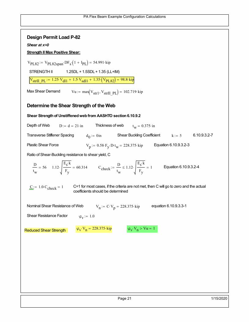
PA Flex Beam Example Configuration Calculations
Design Permit Load P-82
Shear at x=0
Strength II Max Positive Shear:
VPL82 VPL82span DFs 1 IPL 54.991 kip
STRENGTH II 1.25DL + 1.5SDL + 1.35 (LL+IM)
VstrII_PL 1.25 Vdl1 1.5 Vsdl1 1.35 VPL82 98.8 kip
Max Shear Demand Vu max Vstr1 VstrII_PL 102.719 kip
Determine the Shear Strength of the Web
Shear Strength of Unstiffened web from AASHTO section 6.10.9.2
Depth of Web D d 21 in Thickness of web tw 0.375 in
Transverse Stiffener Spacing d0 0in Shear Buckling Coefficient k 5 6.10.9.3.2-7
Plastic Shear Force Vp 0.58 Fy D tw 228.375 kip Equation 6.10.9.3.2-3
Ratio of Shear-Buckling resistance to shear yield, C
D
tw56 1.12
Es k
Fy 60.314 Ccheck
D
tw1.12
Es k
Fy 1 Equation 6.10.9.3.2-4
C 1.0 Ccheck 1 C=1 for most cases, if the criteria are not met, then C will go to zero and the actualcoefficients should be determined
Nominal Shear Resistance of Web Vn C Vp 228.375 kip equation 6.10.9.3.3-1
Shear Resistance Factor φv 1.0
φv Vn 228.375 kip φv Vn Vu 1Reduced Shear Strength
Page 21 1/15/2020

PA Flex Beam Example Configuration Calculations
Check Bearing Stiffeners
FYs 50ksi Yield strength of stiffener
tp 0.75in Thickness of stiffener
bt
bf tw
21.5in 4.312 in Effective width of stiffener
Dst hw 4.1in 16.15 in Depth of stiffeners
Apn 2 tp bt 6.469 in2
Projected area of stiffeners
bt 0.48 tpEs
FYs 1Check that effective width of stiffener meets requirements
Rsbn 1.4 Apn FYs 452.812 kip Bearing capacity of stiffener (phi=1 for bearing per AASHTO 6.5.4.2)
Rsbn Vu 1 Bearing capacity check
Qs 1.0 Q factor for bearing stiffner, taken as 1 (AASHTO 6.9.4.1.1)
Is
18 tw tw3
tp 2 bt 3
1240.131 in
4 Moment of inertia of stiffener and web (9*tw is used on each side)
AASHTO 6.10.11.2.4b
Ag 18 tw tw 2 bt tp 9 in2
Gross area of stiffener and web (AASHTO 6.10.11.2.4b)
rs
Is
Ag2.112 in Radius of gyration of stiffener/web
Po Qs FYs Apn 323.437 kip Nominal yeild resistance of stiffener (AASHTO 6.9.4.1.1)
Peπ2Es
0.75 Dst
rs
2Ag 7.829 10
4 kip Elastic critical buckling stress of stiffener (AASHTO 6.9.4.1.2-1)
Check that Pe/Po is great than 0.44 (AASHTO 6.9.4.1.1) PePoPe
Po0.44 1
Pn PePo 0.658
Po
Pe Po 322.879 kip Nominal compressive resistance of stiffener for Pe/Po>0.44
(AASHTO 6.9.4.1.1-1)
φcr 0.95 phi factor for axial compression (AASHTO 6.5.4.2)
Pr φcr Pn 306.735 kip Compressive capacity of bearing stiffener Pr Vu 1
Page 22 1/15/2020

PA Flex Beam Example Configuration Calculations
Flexbeam Example Configuration Calculations
Summary of Calculations:
Input section dimensions and material properties for steel WT and the concrete deck1.Calculate demands (dead load, superimposed dead, and Live load demands for Strength I and Strength II2.Calculate composite section properties for the given section3.Check Strength I, Strength II, and Service II stresses 4.Check Strength I, Strength II, and Strength V moment demands 5.Perform live load deflection check6.Determine maximum shear demand and capacity7.Note: Shear envelope data was obtained from Matlab script (FlexBeam_Moment_ShearEnvelope.m).8.Shear envelope calculations are summarized separately for each design (Shear Design *.xlsx).
Design Assumptions:Design Specifications Used:
AASHTO LRFD Bridge Design Specifications 7th Edition with 2016 Interim RevisionsPennDOT Design Manual, Part 4 (DM-4) June 30, 2015
Example configurations are determined for two girder spacings, 36" and 40".The deck thickness is 7.5" and is assumed to have a non-structural wearing surface added after installation.Section properties are calculated using the full 7.5" deck thickness.The WT sections are embedded 3.5" into the concrete deck. The steel section spacing used is outside the scope of the AASHTO and PennDOT distribution factorequations. The flexural distribution factor is assumed to be 0.3 which was shown to tbe conservativeaccording to refined analysisThe shear distribution factor is calculated using the DM-4 shear distribution factor equation which wasshown to be conservative using refined analysis.Refined analysis is presented in: Zihan Ma, "Distribution Factors for Composite Steel Tee Concrete DeckBridge System," M.S. Thesis, Deparement of Civil and Environmental Engineering, Lehigh University,Bethlehem, 2019Shear and moment demands for the PL82 permit load vehicle are determined by Matlab script(FlexBeam_Moment_ShearEnvelope.m) and are manually input into this calculation sheet.All fabrication will occur as double modules, i.e. each module contains two WT sections. The number ofmodules is half the number of beams, N. A 45 in. tall F-Shape barrier is used, Weight = 700 lb/ft (Distributed to exterior two beams).
The work presented in this document are provided on an “AS IS” basis. University makes no warranties of anykind, express or implied, as to any matter whatsoever, including, without limitation, warranties with respect tothe merchantability or fitness for a particular purpose of this work or any project deliverables. Universitymakes no warranty of any kind with respect to freedom from patent, trademark, copyright or trade secretinfringement arising from the use of the results of the project, deliverables, services, intellectual property orother materials provided hereunder. University shall not be liable for any direct, indirect, consequential,punitive, or other damages suffered by Sponsor or any other person resulting from the project, or the use ofthis work or any project deliverables.
Page 1 1/15/2020

PA Flex Beam Example Configuration Calculations
hf
tf
bf
twh
d
bjtbe
e
Variable Definitions:
Number of beams N 10 modulesN
25
L 40ft Span length
be 40in Effective width of Flexbeamassuming constructed bridge width(i.e. closure joints cast)
Built Up Section Properties
tw 0.375in tf 0.75in bf 12in
h 25in Overall Height of section
hf 7.5in Total thickness of deck
e 3.5in Deck/Steel overlap
d h hf e 21 in depth of built up steel section
hw d tf 20.25 in height of web of built up steel
Moment and shear for permit load PL82 obtained from Matlab script: FlexBeam_Moment_ShearEnvelope
MLL_IM_PL82 312.012kip ft Moment due to PL82 with distribution factor and impact factor!!
VPL82span 94.1625kip Shear due to PL82 WITHOUT distribution factor and impact factor!!
Check web and flange dimensions in sections 6.10.2.1 and 6.10.2.2
(Ignore 6.10.2.2-4 since no compression flange)
equation 6.10.2.1.1-1d
tw150 1 equation 6.10.2.2-1
bf
2 tf12 1
equation 6.10.2.2-2 bfh
6 1 equation 6.10.2.2-3 tf 1.1 tw 1
y_bar
tf bftf
2 hw tw tf
hw
2
tf bf hw tw5.18 in Center of gravity of steel section
Istl
bf tf3
12bf tf y_bar
tf
2
2
tw hw
3
12 tw hw tf
hw
2 y_bar
2
713.995 in4
MOI of steel
Astl tf bf hw tw 16.594 in2
Area of the WT steel section
Page 2 1/15/2020

PA Flex Beam Example Configuration Calculations
Material Properties
Elastic Modulus of Steel Es 29000ksi
Yield Strength of Steel Fy 50ksi
Yield Strength of Reinforcement fy 60ksi
Compressive Strength of Concrete fc 4000psi AAAP PennDOT Concrete
Concrete Modular Ratio n 8 modular ratio for 4ksi concrete per AASHTO
Unit weight of concrete slab wc 0.150kip
ft3
Unit weight of concrete
Section Properties
Width of UHPC Joint: bjt 6in
Parapet width: bpar 20.25in Parapet width per PennDOT F-shape barrier
Width of the bridge W be N bjt 394 in W 32.833 ft
Clear width of roadway Wlane W 2 bpar 29.458 ft
Dc wc hf W 3.078kip
ft DL due to slab
Db .700kip
ft DL due to each 45" F-Shape Barrier (per email 11/1/18)
DFWS 30lbf
ft2
W 2 bpar 0.884kip
ft DL due to Future Wearing Surface (FWS)
Ds Astl 490lbf
ft3
0.056kip
ft Selfweight of the steel section
DLself
Dc N
Ds 0.364kip
ft Self-weight per WT
Total weight of each precast FlexBeam for transportation:
Weight of C12x25 Diaphragms Wend_diaphragms 25lbf
ft32 in 0.067 kip
2be bjt hf wc 2Ds L 2 Wend_diaphragms 27.776 kip
Determine number of design lane (AASHTO Section 3.6.1.1.1)
Take the integer part of the ratio of W/12 ft. Number of lanes in bridge: Nl floorWlane
12ft
2
Page 3 1/15/2020
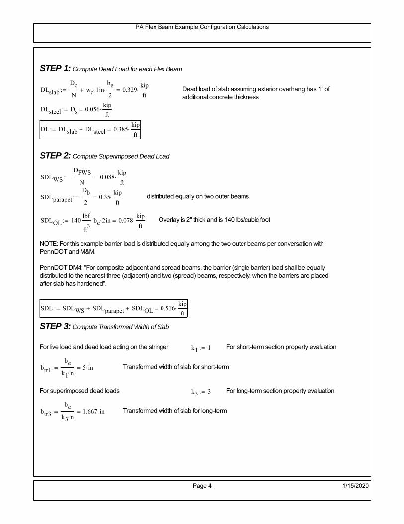
PA Flex Beam Example Configuration Calculations
STEP 1: Compute Dead Load for each Flex Beam
DLslab
Dc
Nwc 1 in
be
2 0.329
kip
ft Dead load of slab assuming exterior overhang has 1" of
additional concrete thickness
DLsteel Ds 0.056kip
ft
DL DLslab DLsteel 0.385kip
ft
STEP 2: Compute Superimposed Dead Load
SDLWS
DFWS
N0.088
kip
ft
SDLparapet
Db
20.35
kip
ft distributed equally on two outer beams
SDLOL 140lbf
ft3be 2 in 0.078
kip
ft Overlay is 2" thick and is 140 lbs/cubic foot
NOTE: For this example barrier load is distributed equally among the two outer beams per conversation withPennDOT and M&M.
PennDOT DM4: "For composite adjacent and spread beams, the barrier (single barrier) load shall be equallydistributed to the nearest three (adjacent) and two (spread) beams, respectively, when the barriers are placedafter slab has hardened".
SDL SDLWS SDLparapet SDLOL 0.516kip
ft
STEP 3: Compute Transformed Width of Slab
For live load and dead load acting on the stringer k1 1 For short-term section property evaluation
btr1
be
k1 n5 in Transformed width of slab for short-term
For superimposed dead loads k3 3 For long-term section property evaluation
btr3
be
k3 n1.667 in Transformed width of slab for long-term
Page 4 1/15/2020

PA Flex Beam Example Configuration Calculations
STEP 4: Compute Dead and Superimposed Dead Load Moments(Based on first interior girder demands)
MDLDL L
2
877.022 kip ft
MSDLSDL L
2
8103.231 kip ft
STEP 5: Compute live load and Dynamic Load Allowance (IM)
Live load wheel load distribution factor (DF):
Sbe
12in3.333 transverse girder spacing
NOTE: AASHTO presents equations to define DF for different types of superstructuresincluding Deck Composite wirh RC slab on steel girders (Type (a) in Table 4.6.2.2.1-1) forshear and moment in interior and exterior beams.
Using DM4 Table 4.6.2.2.2b-1:
eg h y_barhf
2 16.07 in Distance between the centers of gravity of the basic beam and deck
Kg n Istl Astl eg2
39993.61 in
4 Longitudinal stiffness parameter (in4)
Distribution of Live Load Per Lane for Moment in Interior Beams:
to be conservative, use DF 0.3
Page 5 1/15/2020

PA Flex Beam Example Configuration Calculations
Dynamic Load Allowance (Section 3.6.2 DM4)
Static effects of the design truck or tandem, shall be increased by the impact factor.
NOTE: The dynamic load allowance shall not be applied to the design lane load (Section 3.6.2.1 DM4)
I 0.33 Impact factor for moment
Note: PennDOT requires that the impact for decks be increased from 33% to 50%, the deck is not beingdesigned here. Instrad the deck design is based on the BD recommendations.
Dynamic load allowance for the Permit Load P-82 shall be less than 20%. (Section 3.6.2.1DM4)
IPL 0.20 Impact factor for moment on Strength II
Design Wind Loading for Exterior Girder
Vw 80 Wind speed for Strength V load case
CD 1.3 Gust factor for windard side of I-Girder and Box Girder Superstructures (Table 3.8.1.2.1-2)
G 1.0 Gus effect factor is 1.0 for all structures other than sound barriers (Table 3.8.1.2.1-1)
Kz 1.0 Pressure coefficient taken as 1 for Strength V (3.8.1.2.1)
Pz 2.56 106
Vw 2 Kz G CDkip
ft2
0.021kip
ft2
Wind pressure on exterior girder
hexp h hf 17.5 in Exposed height of exterior girder
Moment due to wind loading on exterior girderMWL
Pz hexp L2
86.212 kip ft
Iyy
bf3tf
12108 in
4 Transverse moment of intertia
Flange lateral bending stressfl
MWL
bf
2
Iyy4.142 ksi
Page 6 1/15/2020

PA Flex Beam Example Configuration Calculations
Design Vehicular Live Load
PHL-93 and P-82 are examined herein.
PHL-93 (A3.6.1.2.1)
PHL-93 consists of a combination of (design truck or design tandem) + (design lane load)
Design Truck
PennDOT defines the design truck in accordance with AASTHO 3.6.1.2
Design truck load in AASHTO (HS20 Truck) is used for this example.
NOTE : MAX moment occurs when the center line of the span is midway between the center ofgravity of the loads and the nearest concentrated load.
P1 8kip P2 32kip P3 32kip Axle loads (AASHTO 3.6.1.2.2)
XASr 14ft Rear Axle spacing for truck (14ft - 30ft)
XASf 14ft Front Axle spacing for truck
Page 7 1/15/2020

PA Flex Beam Example Configuration Calculations
Center of gravity (CG) of loads:
X'P1 XASr XASf P2 XASr
P1 P2 P39.333 ft Datum is the rear axle
X XASr X' 4.667 ft Spacing btw CG and nearest load
Find bridge reaction
Truck movestoward Support ARA
P1L
2XASf
X
2
P2L
2
X
2
P3L
2X'
X
2
L31.8 kip
Max live load moment (at the location of P2):
MLL_truck RAL
2
X
2
P1 XASf 449.8 kip ft
NOTE: Find the worst case by varying XASr
Page 8 1/15/2020

PA Flex Beam Example Configuration Calculations
Design Tandem
Consist of a pair of 25-kip axles spaced 4-ft apart. (AASHTO 3.6.1.2.3)
NOTE: PennDOT DM4 increases 25-kip to 31.25-kip.
FT 31.25kip
XAS 4ft Axle spacing
Center of gravity (CG) of loads:
XXAS
22 ft Spacing btw CG and nearest load
Find bridge reaction
RA
FTL
2
X
2
FTL
2
X
2 X
L29.688 kip Truck moves toward Support A
Max live load moment (at the location of front wheel):
MLL_tandem RAL
2
X
2
564.063 kip ft
Choose the max value:
MLL_veh max MLL_tandem MLL_truck 564.063 kip ft
Apply the impact and wheel load distribution:
MLL_IM_veh MLL_veh DF 1 I( ) 225.061 kip ft Due to tandem or truck
Design Lane Load (distributed over a 10-ft width for each lane)
NOTE: The uniform load may be continuous or discontinuous as necessary to produce themaximum force effect. For this example continuous uniform distribution assumed.
FDLL 0.64kip
ftDF 0.192
kip
ft Per beam in each lane
Due to lane loadMLL_IM_lane
FDLL L2
8
38.4 kip ft
Moment due to Total Design Vehicular Live Load: MLL_IM MLL_IM_lane MLL_IM_veh 263.461 kip ft
Page 9 1/15/2020

PA Flex Beam Example Configuration Calculations
Design Permit Load P-82 (Section 3.6.1.2.7 DM4)
P1 P2 P3 P4 P5 P6 P7
NOTE: The moment for the permit load is defined at the beginning of the sheetand is obtained from MATLab File FlexBeam_Moment_ShearEnvelope.m
STEP 6: Compute Moment of Inertia (Note: rebar neglected!)
1) Moment of Inertia resisting dead load only:
a) Acting on the non-composite section (before the deck has hardened - DC1)
Use steel section only
Inc Istl 713.995 in4
Non-composite section modulus
Y'nc y_bar S.G. of the steel section of Flex Beam (Datum is bottom)
b) Acting on the composite section (after the deck has hardened - DC2)
Use Ic_short as defined below.
Page 10 1/15/2020

PA Flex Beam Example Configuration Calculations
2) Moment of Inertia resisting live load plus impact:
Using transformed slab with k1=1 (short-term composite).
Actr1 hf btr1 37.5 in2
Itr1
btr1 hf3
12175.781 in
4
Y'
Actr1 hhf
2
Astl Y'nc
Astl Actr116.32 in S.G. of the total flex beam (Datum is bottom)
Compositesection modulus(short-term)
Ic_short Istl Astl Y'nc Y' 2 Itr1 Actr1 hhf
2
Y'
2
3860 in4
Y'c_short Y' 16.32 in N.A. of the short-term composite section
3) Moment of Inertia resisting superimposed dead load:
Using transformed slab with k3=3.
Actr3 hf btr3 12.5 in2
Itr3
btr3 hf3
1258.594 in
4
Y'
Actr3 hhf
2
Astl Y'nc
Astl Actr312.084 in S.G. of the total flex beam (Datum is bottom)
Compositesection modulus(long-term)
Ic_long Istl Astl Y'nc Y' 2 Itr3 Actr3 hhf
2
Y'
2
2614 in4
Y'c_long Y' 12.084 in N.A. of the long-term composite section
Page 11 1/15/2020

PA Flex Beam Example Configuration Calculations
STEP 6.5 Check Ductility RequirementIn accordance with AASHTO Article 6.10.7.3 check ductility requirement. Assume compressionblock of concrete is at 0.85 f'c and that the concrete supports no tension. Steel section isassumed to be fully plastic at Fy.
Case 1 : Assuming PNA is in Concreteh d 4 inAssuming (h-d) < Dp < hf
Fp Dp 0.85 fc be Dp Fy tw Dp h d( ) Fy Astl tw Dp h d( )
Dp 7.5in 0.42 h 10.5 in
Dp1 root Fp Dp Dp 5.647 in Must be less than hf 7.5 inDp1
h0.226 must be < 0.42
Mn1check Dp1 hf h d( ) Dp1[ ] Dp1 0.42 h( ) 1 Dp1 0.42 h 1
Mp1 0.85 fc be Dp1Dp1
2
Fy tw Dp1 h d( )[ ] Dp1 h d( )[ ]
2
Fy bf tf h Dp1tf
2
Fy tw h Dp1 tf h Dp1 tf
2
Mp1 13978.38 kip in Mn1 Mp1 1.07 0.7Dp1
h
12746.8 kip in
Case 2 : Assuming PNA is NOT in Concrete
Assuming hf < Dp
Fp2 Dp 0.85 fc be hf Fy tw Dp h d( ) Fy Astl tw Dp h d( )
Dp 2.5in
Dp2 root Fp2 Dp Dp 1.075 in Must be more than hf 7.5 inDp2
h0.043 must be < 0.42
Mn2check Dp2 hf Dp2 h( ) Dp2 0.42 h( ) 0 Dp2 0.42 h 1
Mp2 0.85 fc be hf Dp2hf
2
Fy tw Dp2 h d( )[ ] Dp2 h d( )[ ]
2
Fy bf tf h Dp2tf
2
Fy tw h Dp2 tf h Dp2 tf
2
Mp2 12897.67 kip inMn2 Mp2 1.07 0.7
Dp2
h
14188.7 kip in
Mn max Mn1 Mn1check Mn2 Mn2check 1062.2 kip ft Mn 12746.8 kip in
Page 12 1/15/2020

PA Flex Beam Example Configuration Calculations
Check Composite Compact Section Criteria (6.10.6.2)
Dcpd
2
Fy tf bf 0.85 fc be hf
Fy hw tw1
5.263 in Dcp0 Dcp 0 0
Dcp Dcp Dcp0 0 in2 Dcp
tw3.76
Es
Fy 1 Check if section is compact
STEP 7: Load Combinations (Table 3.4.1-1)
The following load combinations will be considered herein. Only the maximum load factors forpermanent-loads are used in the following load combinations (uplift is not an issue for this typeof bridge).STRENGTH I 1.25DL + 1.5SDL + 1.75 (LL+IM)
SERVICE II: DL+SDL+1.3(LL+IM)
STEP 8: Compute and Check Stresses
Stress at bottom fiber of steel section
fDL
MDL Y'c_long
Ic_long4.273 ksi
fLL_I
MLL_IM Y'c_short
Ic_short13.366 ksi fPL
MLL_IM_PL82 Y'c_short
Ic_short15.829 ksi
fSDL
MSDL Y'c_long
Ic_long5.727 ksi
STRENGTH I fbot_str1 1.25fDL 1.5 fSDL 1.75 fLL_I 37.323 ksi
STRENGTH II fbot_str2 1.25fDL 1.5 fSDL 1.35 fPL 35.302 ksi
SERVICE II fbot_svc2 fDL fSDL 1.3fLL_I 27.38 ksi
Allowable Stress is based on Section 6.10.4.2.2-2
Flange stress due to service load II without consideration of flange lateral bending: ff fbot_svc2
Flange lateral bending stress due to service II: flSII 0ksi
Hybrid Factor: Rh 1.0 For rolled and homogenous built-up sections
ff
flSII
2 27.376 ksi 0.95 Rh Fy 47.5 ksi ff
fl
2 0.95Rh Fy 1
Page 13 1/15/2020

PA Flex Beam Example Configuration Calculations
Stress at top fiber of concrete
Note: For calculating longitudinal flexural stresses in the concrete deck due to allpermanent and transient loads, the short-term modular ratio shall be used.
fDL
MDL h Y'c_short
k1 n Ic_short0.26 ksi
fLL_I
MLL_IM h Y'c_short
k1 n Ic_short0.889 ksi fPL
MLL_IM_PL82 h Y'c_short
k1 n Ic_short1.052 ksi
fSDL
MSDL h Y'c_short
k1 n Ic_short0.348 ksi
STRENGTH I fc_str1 1.25fDL 1.5 fSDL 1.75 fLL_I 2.402 ksi
Mstr1 1.25 MDL 1.5 MSDL 1.75 MLL_IM 712.2 kip ft Mstr1 Mn 1
STRENGTH II fc_str2 1.25fDL 1.5 fSDL 1.35 fPL 2.267 ksi
Mstr2 1.25 MDL 1.5 MSDL 1.35 MLL_IM_PL82 672 kip ft Mstr2 Mn 1
SERVICE II
Allowable Stress in concrete - AASHTO 6.10.4.2.2For compact composite sections in positive flexure utilized in shored construction, the longitudinalcompressive stress in the concrete deck due to the Service II loads, determined as specified in Article6.10.1.1.1d, shall not exceed 0.6f́ c.
fallow 0.6 fc 2400 psi
fc_2 1.3fLL_I fSDL fDL 1762.98 psi This assumes short term compositesection for all calculations
fc_2 fallow 1
SERVICE II with Long Term Composite for dead loads
fDL
MDL h Y'c_long
k3 n Ic_long0.19 ksi
fLL_I
MLL_IM h Y'c_short
k1 n Ic_short0.889 ksi
fSDL
MSDL h Y'c_long
k3 n Ic_long0.255 ksi
fc_2 1.3fLL_I fSDL fDL 1600.43 psi fc_2 fallow 1
Page 14 1/15/2020

PA Flex Beam Example Configuration Calculations
Strength V Moment Check
Strength V is related to normal vehicular use of the bridge with an 80 mph wind gust
Note: that Strength V is checked for an exterior girder under wind load with the interior girder distribution factor forflexure used. If Strength V controls design, then this approach should be modified
Design vertical moment is: 1.25DL + 1.5SDL + 1.35 (LL+IM)
SLT
Ic_long
Y'c_long216.287 in
3 SST
Ic_short
Y'c_short236.542 in
3 short and long term section
modulus
Section D6.2.2 Find the moment required to cause yieldling of the flange. The approach is laid out in D6.2.2
MD2 1.25 MDL 1.5 MSDL 251.124 kip ft From D6.2.2-1 (all dead loads are in MD2 due to shoredconstruction
MAD Fy
MD2
SLT
SST 710.95 kip ft Additional moment to cause nominal yielding of steel flange
My MD2 MAD 962.073 kip ft D6.2.2-2: Moment to cause yielding of flange
6.10.7.1 Compact Section Check at Strength V limit state
Section Modulus for yielding of the flange (My/Fy) for equation 6.10.7.1.1-1Sxt
My
Fy230.898 in
3
Mu 1.25 MDL 1.5MSDL 1.35MLL_IM 606.796 kip ft Moment due to Strength V limit state
Mu1
3fl Sxt 633.359 kip ft Equation 6.10.7.1.7-1 Mn 1.062 10
3 kip ft Mu
1
3fl Sxt Mn 1
Page 15 1/15/2020

PA Flex Beam Example Configuration Calculations
STEP 9: Compute Deflection
Optional Live Load Deflection Evaluation (AASHTO 3.6.1.3.2)
Deflection distribution factor for vehicular loads: For a straight multibeambridge, this is equivalent to saying that the distribution factor for deflectionis equal to the number of lanes divided by the number of beams. 2.5.2.6.2
DFd
Nl
N0.2
Deflection should be taken as 125% the larger of:- Design truck- 25% of design truck + design lane
The live load portion of Load Combination Service I of Table 3.4.1-1 should be used,including the dynamic load allowance, IM;
Deflection due to design truck load
NOTE : Assuming maximum deflection occurs when the center of gravity of the loads is at thecenter line of the span.
P1 8kip P2 32kip P3 32kip Axle loads (AASHTO 3.6.1.2.2)
XASr 14ft Rear Axle spacing for truck (14ft - 30ft)
XASf 14ft Front Axle spacing for truck
Center of gravity (CG) of loads:
X'P1 XASr XASf P2 XASr
P1 P2 P39.333 ft Datum is the rear axle
Method1: Assuming single load = P1+P2+P3 at the midspan (Conservative approach)
P1 P2 P3 L3
48 Es Ic_short 1.482 in
Method2: Calculation of Midspan deflection using superposition
b1L
2XASr X' XASf 1.333 ft distance btw load P1 and support A b1check b1 0 1
b2L
2XASr X' 15.333 ft distance btw load P2 and support A b2check b2 0 1
b3L
2X' 10.667 ft distance btw load P3 and support B b3check b3 0 1
Page 16 1/15/2020

PA Flex Beam Example Configuration Calculations
Deflection of the beam at midspan due to P1: P P1
xL
2 at midspan b b1 b1check The smallest distance btw load P1 and support
Δ1P b x
6 Es Ic_short LL2
b2
x2
0.016 in
Deflection of the beam at midspan due to P2: P P2
xL
2 at midspan b b2 b2check The smallest distance btw load P2 and support
Δ2P b x
6 Es Ic_short LL2
b2
x2
0.609 in
Deflection of the beam at midspan due to P3: P P3
xL
2 at midspan b b3 b3check The smallest distance btw load P3 and support
Δ3P b x
6 Es Ic_short LL2
b2
x2
0.477 in
Total Deflection at midspan:
Δtruck Δ1 Δ2 Δ3( ) DFd 1 I( ) 0.293 in (Considering IM)
Deflection due to tandem (Note: this calculation is not required according to Article3.6.1.3.2 which denotes only the design truck for deflection calculation)
Page 17 1/15/2020

PA Flex Beam Example Configuration Calculations
FT 31.25 kip Per axle
XAS 4ft Axle spacing
Δtandem
FTL
2
XAS
2
24 Es Ic_short3 L
2 4
L
2
XAS
2
2
DFd 1 I( ) 0.337 in (Considering IM)
Deflection due to lane load
FDLLd 640lbf
ft DFd 128
lbf
ft
Δlane
5 FDLLd L4
384 Es Ic_short0.066 in
Live Load Deflection:
ΔLL 1.25max Δtruck 0.25Δtruck Δlane 1.25 0.458 in ΔLLL
800 1
Deflection Limit
For steel or concrete vehicular bridges:
Vehicular load = Span/800L
8000.6 in
L
10000.48 in
Evaluation of Deflection at the Service Limit State (AASHTO 3.4.2.2)
The associated permitted deflections shall be included in the contract documents.
Page 18 1/15/2020

PA Flex Beam Example Configuration Calculations
Shear demands:
Determination of the distribution factor
Using DM4 Table 4.6.2.2.3a-1
Sbe
12in3.333 transverse girder spacing (ft)
Distribution of live loads per lane for shear in interior beams:
For two design lanes loaded, 3.5' <= S =< 16', number of beam >= 4DFs 0.36
S
25 0.493
Q Actr1 h Y'c_shorthf
2
184.86 in3
first moment of deck slab for interface shear
Method 1: Range of shear based on Strength I Limit
STRENGTH I 1.25DL + 1.5SDL + 1.75 (LL+IM)
Computation of the range of shear in the beam
Dead Load:DL 0.385
kip
ft
Superimposed Dead Load: SDL 0.516kip
ft
Design Lane Load: 0.64kip
ft
Design Truck:
XASr 14ft Rear Axle spacing for truck (14ft - 30ft)
XASf 14ft Front Axle spacing for truck
P1 8 kip P2 32 kip P3 32 kip Wheel loads (AASHTO 3.6.1.2.2)
Design Tandem:
Consist of a pair of 25-kip axles spaced 4-ft apart. (AASHTO 3.6.1.2.3)
NOTE: PennDOT DM4 increases 25-kip to 31.25-kip.
FT 31.25kip
XAS 4ft Axle spacing
Page 19 1/15/2020

PA Flex Beam Example Configuration Calculations
Maximum positive shear at various points along the FlexBeam are examined.
At x=0 (at left support) (Truck is moving from left to right)
Truck
Max Positive Shear (when P3 is at x = 0):
x1 L XASr XASf 12 ft Distance between P1 and right support
x2 L XASr 26 ft Distance between P2 and right support
x3 L 40 ft Distance between P3 and right support
V1 P3
x3
L P2
x2
L P1
x1
L 55.2 kip
Total Vertical Shear Force for each FlexBeam (considering dynamic loads):
Vtruck1 V1 DFs 1 I( ) 36.219 kip
Tandem:
V1 FT FT
L XAS L
59.375 kip
Total Vertical Shear Force for each FlexBeam (considering dynamic loads):
Vtandem1 V1 DFs 1 I( ) 38.958 kip
Lane Load
V1 0.64kip
ft
L
2 12.8 kip
Total Vertical Shear Force for each FlexBeam (considering dynamic loads):
Vlane1 V1 DFs 6.315 kip
Dead Load
Vdl1 DLL
2 7.702 kip
Superimposed Dead Load
Vsdl1 SDLL
2 10.323 kip
Strength I Max Positive Shear:
Vstr1 1.25 Vdl1 1.5 Vsdl1 1.75 Vlane1 max Vtruck1 Vtandem1 104.339 kip
Page 20 1/15/2020
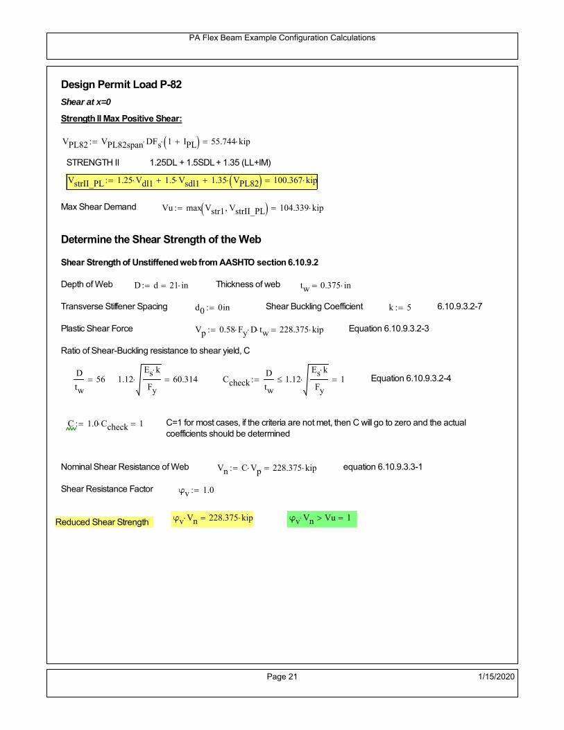
PA Flex Beam Example Configuration Calculations
Design Permit Load P-82
Shear at x=0
Strength II Max Positive Shear:
VPL82 VPL82span DFs 1 IPL 55.744 kip
STRENGTH II 1.25DL + 1.5SDL + 1.35 (LL+IM)
VstrII_PL 1.25 Vdl1 1.5 Vsdl1 1.35 VPL82 100.367 kip
Max Shear Demand Vu max Vstr1 VstrII_PL 104.339 kip
Determine the Shear Strength of the Web
Shear Strength of Unstiffened web from AASHTO section 6.10.9.2
Depth of Web D d 21 in Thickness of web tw 0.375 in
Transverse Stiffener Spacing d0 0in Shear Buckling Coefficient k 5 6.10.9.3.2-7
Plastic Shear Force Vp 0.58 Fy D tw 228.375 kip Equation 6.10.9.3.2-3
Ratio of Shear-Buckling resistance to shear yield, C
D
tw56 1.12
Es k
Fy 60.314 Ccheck
D
tw1.12
Es k
Fy 1 Equation 6.10.9.3.2-4
C 1.0 Ccheck 1 C=1 for most cases, if the criteria are not met, then C will go to zero and the actualcoefficients should be determined
Nominal Shear Resistance of Web Vn C Vp 228.375 kip equation 6.10.9.3.3-1
Shear Resistance Factor φv 1.0
φv Vn 228.375 kip φv Vn Vu 1Reduced Shear Strength
Page 21 1/15/2020

PA Flex Beam Example Configuration Calculations
Check Bearing Stiffeners
FYs 50ksi Yield strength of stiffener
tp 0.75in Thickness of stiffener
bt
bf tw
21.5in 4.312 in Effective width of stiffener
Dst hw 4.1in 16.15 in Depth of stiffeners
Apn 2 tp bt 6.469 in2
Projected area of stiffeners
bt 0.48 tpEs
FYs 1Check that effective width of stiffener meets requirements
Rsbn 1.4 Apn FYs 452.812 kip Bearing capacity of stiffener (phi=1 for bearing per AASHTO 6.5.4.2)
Rsbn Vu 1 Bearing capacity check
Qs 1.0 Q factor for bearing stiffner, taken as 1 (AASHTO 6.9.4.1.1)
Is
18 tw tw3
tp 2 bt 3
1240.131 in
4 Moment of inertia of stiffener and web (9*tw is used on each side)
AASHTO 6.10.11.2.4b
Ag 18 tw tw 2 bt tp 9 in2
Gross area of stiffener and web (AASHTO 6.10.11.2.4b)
rs
Is
Ag2.112 in Radius of gyration of stiffener/web
Po Qs FYs Apn 323.437 kip Nominal yeild resistance of stiffener (AASHTO 6.9.4.1.1)
Peπ2Es
0.75 Dst
rs
2Ag 7.829 10
4 kip Elastic critical buckling stress of stiffener (AASHTO 6.9.4.1.2-1)
Check that Pe/Po is great than 0.44 (AASHTO 6.9.4.1.1) PePoPe
Po0.44 1
Pn PePo 0.658
Po
Pe Po 322.879 kip Nominal compressive resistance of stiffener for Pe/Po>0.44
(AASHTO 6.9.4.1.1-1)
φcr 0.95 phi factor for axial compression (AASHTO 6.5.4.2)
Pr φcr Pn 306.735 kip Compressive capacity of bearing stiffener Pr Vu 1
Page 22 1/15/2020

PA Flex Beam Example Configuration Calculations
Flexbeam Example Configuration Calculations
Summary of Calculations:
Input section dimensions and material properties for steel WT and the concrete deck1.Calculate demands (dead load, superimposed dead, and Live load demands for Strength I and Strength II2.Calculate composite section properties for the given section3.Check Strength I, Strength II, and Service II stresses 4.Check Strength I, Strength II, and Strength V moment demands 5.Perform live load deflection check6.Determine maximum shear demand and capacity7.Note: Shear envelope data was obtained from Matlab script (FlexBeam_Moment_ShearEnvelope.m).8.Shear envelope calculations are summarized separately for each design (Shear Design *.xlsx).
Design Assumptions:Design Specifications Used:
AASHTO LRFD Bridge Design Specifications 7th Edition with 2016 Interim RevisionsPennDOT Design Manual, Part 4 (DM-4) June 30, 2015
Example configurations are determined for two girder spacings, 36" and 40".The deck thickness is 7.5" and is assumed to have a non-structural wearing surface added after installation.Section properties are calculated using the full 7.5" deck thickness.The WT sections are embedded 3.5" into the concrete deck. The steel section spacing used is outside the scope of the AASHTO and PennDOT distribution factorequations. The flexural distribution factor is assumed to be 0.3 which was shown to tbe conservativeaccording to refined analysisThe shear distribution factor is calculated using the DM-4 shear distribution factor equation which wasshown to be conservative using refined analysis.Refined analysis is presented in: Zihan Ma, "Distribution Factors for Composite Steel Tee Concrete DeckBridge System," M.S. Thesis, Deparement of Civil and Environmental Engineering, Lehigh University,Bethlehem, 2019Shear and moment demands for the PL82 permit load vehicle are determined by Matlab script(FlexBeam_Moment_ShearEnvelope.m) and are manually input into this calculation sheet.All fabrication will occur as double modules, i.e. each module contains two WT sections. The number ofmodules is half the number of beams, N. A 45 in. tall F-Shape barrier is used, Weight = 700 lb/ft (Distributed to exterior two beams).
The work presented in this document are provided on an “AS IS” basis. University makes no warranties of anykind, express or implied, as to any matter whatsoever, including, without limitation, warranties with respect tothe merchantability or fitness for a particular purpose of this work or any project deliverables. Universitymakes no warranty of any kind with respect to freedom from patent, trademark, copyright or trade secretinfringement arising from the use of the results of the project, deliverables, services, intellectual property orother materials provided hereunder. University shall not be liable for any direct, indirect, consequential,punitive, or other damages suffered by Sponsor or any other person resulting from the project, or the use ofthis work or any project deliverables.
Page 1 1/15/2020

PA Flex Beam Example Configuration Calculations
hf
tf
bf
twh
d
bjtbe
e
Variable Definitions:
Number of beams N 12 modulesN
26
L 40ft Span length
be 40in Effective width of Flexbeamassuming constructed bridge width(i.e. closure joints cast)
Built Up Section Properties
tw 0.375in tf 0.75in bf 12in
h 25in Overall Height of section
hf 7.5in Total thickness of deck
e 3.5in Deck/Steel overlap
d h hf e 21 in depth of built up steel section
hw d tf 20.25 in height of web of built up steel
Moment and shear for permit load PL82 obtained from Matlab script: FlexBeam_Moment_ShearEnvelope
MLL_IM_PL82 312.012kip ft Moment due to PL82 with distribution factor and impact factor!!
VPL82span 94.1625kip Shear due to PL82 WITHOUT distribution factor and impact factor!!
Check web and flange dimensions in sections 6.10.2.1 and 6.10.2.2
(Ignore 6.10.2.2-4 since no compression flange)
equation 6.10.2.1.1-1d
tw150 1 equation 6.10.2.2-1
bf
2 tf12 1
equation 6.10.2.2-2 bfh
6 1 equation 6.10.2.2-3 tf 1.1 tw 1
y_bar
tf bftf
2 hw tw tf
hw
2
tf bf hw tw5.18 in Center of gravity of steel section
Istl
bf tf3
12bf tf y_bar
tf
2
2
tw hw
3
12 tw hw tf
hw
2 y_bar
2
713.995 in4
MOI of steel
Astl tf bf hw tw 16.594 in2
Area of the WT steel section
Page 2 1/15/2020

PA Flex Beam Example Configuration Calculations
Material Properties
Elastic Modulus of Steel Es 29000ksi
Yield Strength of Steel Fy 50ksi
Yield Strength of Reinforcement fy 60ksi
Compressive Strength of Concrete fc 4000psi AAAP PennDOT Concrete
Concrete Modular Ratio n 8 modular ratio for 4ksi concrete per AASHTO
Unit weight of concrete slab wc 0.150kip
ft3
Unit weight of concrete
Section Properties
Width of UHPC Joint: bjt 6in
Parapet width: bpar 20.25in Parapet width per PennDOT F-shape barrier
Width of the bridge W be N bjt 474 in W 39.5 ft
Clear width of roadway Wlane W 2 bpar 36.125 ft
Dc wc hf W 3.703kip
ft DL due to slab
Db .700kip
ft DL due to each 45" F-Shape Barrier (per email 11/1/18)
DFWS 30lbf
ft2
W 2 bpar 1.084kip
ft DL due to Future Wearing Surface (FWS)
Ds Astl 490lbf
ft3
0.056kip
ft Selfweight of the steel section
DLself
Dc N
Ds 0.365kip
ft Self-weight per WT
Total weight of each precast FlexBeam for transportation:
Weight of C12x25 Diaphragms Wend_diaphragms 25lbf
ft32 in 0.067 kip
2be bjt hf wc 2Ds L 2 Wend_diaphragms 27.776 kip
Determine number of design lane (AASHTO Section 3.6.1.1.1)
Take the integer part of the ratio of W/12 ft. Number of lanes in bridge: Nl floorWlane
12ft
3
Page 3 1/15/2020

PA Flex Beam Example Configuration Calculations
STEP 1: Compute Dead Load for each Flex Beam
DLslab
Dc
Nwc 1 in
be
2 0.329
kip
ft Dead load of slab assuming exterior overhang has 1" of
additional concrete thickness
DLsteel Ds 0.056kip
ft
DL DLslab DLsteel 0.386kip
ft
STEP 2: Compute Superimposed Dead Load
SDLWS
DFWS
N0.09
kip
ft
SDLparapet
Db
20.35
kip
ft distributed equally on two outer beams
SDLOL 140lbf
ft3be 2 in 0.078
kip
ft Overlay is 2" thick and is 140 lbs/cubic foot
NOTE: For this example barrier load is distributed equally among the two outer beams per conversation withPennDOT and M&M.
PennDOT DM4: "For composite adjacent and spread beams, the barrier (single barrier) load shall be equallydistributed to the nearest three (adjacent) and two (spread) beams, respectively, when the barriers are placedafter slab has hardened".
SDL SDLWS SDLparapet SDLOL 0.518kip
ft
STEP 3: Compute Transformed Width of Slab
For live load and dead load acting on the stringer k1 1 For short-term section property evaluation
btr1
be
k1 n5 in Transformed width of slab for short-term
For superimposed dead loads k3 3 For long-term section property evaluation
btr3
be
k3 n1.667 in Transformed width of slab for long-term
Page 4 1/15/2020

PA Flex Beam Example Configuration Calculations
STEP 4: Compute Dead and Superimposed Dead Load Moments(Based on first interior girder demands)
MDLDL L
2
877.178 kip ft
MSDLSDL L
2
8103.618 kip ft
STEP 5: Compute live load and Dynamic Load Allowance (IM)
Live load wheel load distribution factor (DF):
Sbe
12in3.333 transverse girder spacing
NOTE: AASHTO presents equations to define DF for different types of superstructuresincluding Deck Composite wirh RC slab on steel girders (Type (a) in Table 4.6.2.2.1-1) forshear and moment in interior and exterior beams.
Using DM4 Table 4.6.2.2.2b-1:
eg h y_barhf
2 16.07 in Distance between the centers of gravity of the basic beam and deck
Kg n Istl Astl eg2
39993.61 in
4 Longitudinal stiffness parameter (in4)
Distribution of Live Load Per Lane for Moment in Interior Beams:
to be conservative, use DF 0.3
Page 5 1/15/2020

PA Flex Beam Example Configuration Calculations
Dynamic Load Allowance (Section 3.6.2 DM4)
Static effects of the design truck or tandem, shall be increased by the impact factor.
NOTE: The dynamic load allowance shall not be applied to the design lane load (Section 3.6.2.1 DM4)
I 0.33 Impact factor for moment
Note: PennDOT requires that the impact for decks be increased from 33% to 50%, the deck is not beingdesigned here. Instrad the deck design is based on the BD recommendations.
Dynamic load allowance for the Permit Load P-82 shall be less than 20%. (Section 3.6.2.1DM4)
IPL 0.20 Impact factor for moment on Strength II
Design Wind Loading for Exterior Girder
Vw 80 Wind speed for Strength V load case
CD 1.3 Gust factor for windard side of I-Girder and Box Girder Superstructures (Table 3.8.1.2.1-2)
G 1.0 Gus effect factor is 1.0 for all structures other than sound barriers (Table 3.8.1.2.1-1)
Kz 1.0 Pressure coefficient taken as 1 for Strength V (3.8.1.2.1)
Pz 2.56 106
Vw 2 Kz G CDkip
ft2
0.021kip
ft2
Wind pressure on exterior girder
hexp h hf 17.5 in Exposed height of exterior girder
Moment due to wind loading on exterior girderMWL
Pz hexp L2
86.212 kip ft
Iyy
bf3tf
12108 in
4 Transverse moment of intertia
Flange lateral bending stressfl
MWL
bf
2
Iyy4.142 ksi
Page 6 1/15/2020

PA Flex Beam Example Configuration Calculations
Design Vehicular Live Load
PHL-93 and P-82 are examined herein.
PHL-93 (A3.6.1.2.1)
PHL-93 consists of a combination of (design truck or design tandem) + (design lane load)
Design Truck
PennDOT defines the design truck in accordance with AASTHO 3.6.1.2
Design truck load in AASHTO (HS20 Truck) is used for this example.
NOTE : MAX moment occurs when the center line of the span is midway between the center ofgravity of the loads and the nearest concentrated load.
P1 8kip P2 32kip P3 32kip Axle loads (AASHTO 3.6.1.2.2)
XASr 14ft Rear Axle spacing for truck (14ft - 30ft)
XASf 14ft Front Axle spacing for truck
Page 7 1/15/2020

PA Flex Beam Example Configuration Calculations
Center of gravity (CG) of loads:
X'P1 XASr XASf P2 XASr
P1 P2 P39.333 ft Datum is the rear axle
X XASr X' 4.667 ft Spacing btw CG and nearest load
Find bridge reaction
Truck movestoward Support ARA
P1L
2XASf
X
2
P2L
2
X
2
P3L
2X'
X
2
L31.8 kip
Max live load moment (at the location of P2):
MLL_truck RAL
2
X
2
P1 XASf 449.8 kip ft
NOTE: Find the worst case by varying XASr
Page 8 1/15/2020
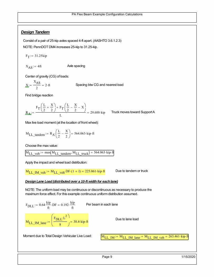
PA Flex Beam Example Configuration Calculations
Design Tandem
Consist of a pair of 25-kip axles spaced 4-ft apart. (AASHTO 3.6.1.2.3)
NOTE: PennDOT DM4 increases 25-kip to 31.25-kip.
FT 31.25kip
XAS 4ft Axle spacing
Center of gravity (CG) of loads:
XXAS
22 ft Spacing btw CG and nearest load
Find bridge reaction
RA
FTL
2
X
2
FTL
2
X
2 X
L29.688 kip Truck moves toward Support A
Max live load moment (at the location of front wheel):
MLL_tandem RAL
2
X
2
564.063 kip ft
Choose the max value:
MLL_veh max MLL_tandem MLL_truck 564.063 kip ft
Apply the impact and wheel load distribution:
MLL_IM_veh MLL_veh DF 1 I( ) 225.061 kip ft Due to tandem or truck
Design Lane Load (distributed over a 10-ft width for each lane)
NOTE: The uniform load may be continuous or discontinuous as necessary to produce themaximum force effect. For this example continuous uniform distribution assumed.
FDLL 0.64kip
ftDF 0.192
kip
ft Per beam in each lane
Due to lane loadMLL_IM_lane
FDLL L2
8
38.4 kip ft
Moment due to Total Design Vehicular Live Load: MLL_IM MLL_IM_lane MLL_IM_veh 263.461 kip ft
Page 9 1/15/2020

PA Flex Beam Example Configuration Calculations
Design Permit Load P-82 (Section 3.6.1.2.7 DM4)
P1 P2 P3 P4 P5 P6 P7
NOTE: The moment for the permit load is defined at the beginning of the sheetand is obtained from MATLab File FlexBeam_Moment_ShearEnvelope.m
STEP 6: Compute Moment of Inertia (Note: rebar neglected!)
1) Moment of Inertia resisting dead load only:
a) Acting on the non-composite section (before the deck has hardened - DC1)
Use steel section only
Inc Istl 713.995 in4
Non-composite section modulus
Y'nc y_bar S.G. of the steel section of Flex Beam (Datum is bottom)
b) Acting on the composite section (after the deck has hardened - DC2)
Use Ic_short as defined below.
Page 10 1/15/2020

PA Flex Beam Example Configuration Calculations
2) Moment of Inertia resisting live load plus impact:
Using transformed slab with k1=1 (short-term composite).
Actr1 hf btr1 37.5 in2
Itr1
btr1 hf3
12175.781 in
4
Y'
Actr1 hhf
2
Astl Y'nc
Astl Actr116.32 in S.G. of the total flex beam (Datum is bottom)
Compositesection modulus(short-term)
Ic_short Istl Astl Y'nc Y' 2 Itr1 Actr1 hhf
2
Y'
2
3860 in4
Y'c_short Y' 16.32 in N.A. of the short-term composite section
3) Moment of Inertia resisting superimposed dead load:
Using transformed slab with k3=3.
Actr3 hf btr3 12.5 in2
Itr3
btr3 hf3
1258.594 in
4
Y'
Actr3 hhf
2
Astl Y'nc
Astl Actr312.084 in S.G. of the total flex beam (Datum is bottom)
Compositesection modulus(long-term)
Ic_long Istl Astl Y'nc Y' 2 Itr3 Actr3 hhf
2
Y'
2
2614 in4
Y'c_long Y' 12.084 in N.A. of the long-term composite section
Page 11 1/15/2020

PA Flex Beam Example Configuration Calculations
STEP 6.5 Check Ductility RequirementIn accordance with AASHTO Article 6.10.7.3 check ductility requirement. Assume compressionblock of concrete is at 0.85 f'c and that the concrete supports no tension. Steel section isassumed to be fully plastic at Fy.
Case 1 : Assuming PNA is in Concreteh d 4 inAssuming (h-d) < Dp < hf
Fp Dp 0.85 fc be Dp Fy tw Dp h d( ) Fy Astl tw Dp h d( )
Dp 7.5in 0.42 h 10.5 in
Dp1 root Fp Dp Dp 5.647 in Must be less than hf 7.5 inDp1
h0.226 must be < 0.42
Mn1check Dp1 hf h d( ) Dp1[ ] Dp1 0.42 h( ) 1 Dp1 0.42 h 1
Mp1 0.85 fc be Dp1Dp1
2
Fy tw Dp1 h d( )[ ] Dp1 h d( )[ ]
2
Fy bf tf h Dp1tf
2
Fy tw h Dp1 tf h Dp1 tf
2
Mp1 13978.38 kip in Mn1 Mp1 1.07 0.7Dp1
h
12746.8 kip in
Case 2 : Assuming PNA is NOT in Concrete
Assuming hf < Dp
Fp2 Dp 0.85 fc be hf Fy tw Dp h d( ) Fy Astl tw Dp h d( )
Dp 2.5in
Dp2 root Fp2 Dp Dp 1.075 in Must be more than hf 7.5 inDp2
h0.043 must be < 0.42
Mn2check Dp2 hf Dp2 h( ) Dp2 0.42 h( ) 0 Dp2 0.42 h 1
Mp2 0.85 fc be hf Dp2hf
2
Fy tw Dp2 h d( )[ ] Dp2 h d( )[ ]
2
Fy bf tf h Dp2tf
2
Fy tw h Dp2 tf h Dp2 tf
2
Mp2 12897.67 kip inMn2 Mp2 1.07 0.7
Dp2
h
14188.7 kip in
Mn max Mn1 Mn1check Mn2 Mn2check 1062.2 kip ft Mn 12746.8 kip in
Page 12 1/15/2020

PA Flex Beam Example Configuration Calculations
Check Composite Compact Section Criteria (6.10.6.2)
Dcpd
2
Fy tf bf 0.85 fc be hf
Fy hw tw1
5.263 in Dcp0 Dcp 0 0
Dcp Dcp Dcp0 0 in2 Dcp
tw3.76
Es
Fy 1 Check if section is compact
STEP 7: Load Combinations (Table 3.4.1-1)
The following load combinations will be considered herein. Only the maximum load factors forpermanent-loads are used in the following load combinations (uplift is not an issue for this typeof bridge).STRENGTH I 1.25DL + 1.5SDL + 1.75 (LL+IM)
SERVICE II: DL+SDL+1.3(LL+IM)
STEP 8: Compute and Check Stresses
Stress at bottom fiber of steel section
fDL
MDL Y'c_long
Ic_long4.282 ksi
fLL_I
MLL_IM Y'c_short
Ic_short13.366 ksi fPL
MLL_IM_PL82 Y'c_short
Ic_short15.829 ksi
fSDL
MSDL Y'c_long
Ic_long5.749 ksi
STRENGTH I fbot_str1 1.25fDL 1.5 fSDL 1.75 fLL_I 37.366 ksi
STRENGTH II fbot_str2 1.25fDL 1.5 fSDL 1.35 fPL 35.345 ksi
SERVICE II fbot_svc2 fDL fSDL 1.3fLL_I 27.41 ksi
Allowable Stress is based on Section 6.10.4.2.2-2
Flange stress due to service load II without consideration of flange lateral bending: ff fbot_svc2
Flange lateral bending stress due to service II: flSII 0ksi
Hybrid Factor: Rh 1.0 For rolled and homogenous built-up sections
ff
flSII
2 27.406 ksi 0.95 Rh Fy 47.5 ksi ff
fl
2 0.95Rh Fy 1
Page 13 1/15/2020

PA Flex Beam Example Configuration Calculations
Stress at top fiber of concrete
Note: For calculating longitudinal flexural stresses in the concrete deck due to allpermanent and transient loads, the short-term modular ratio shall be used.
fDL
MDL h Y'c_short
k1 n Ic_short0.26 ksi
fLL_I
MLL_IM h Y'c_short
k1 n Ic_short0.889 ksi fPL
MLL_IM_PL82 h Y'c_short
k1 n Ic_short1.052 ksi
fSDL
MSDL h Y'c_short
k1 n Ic_short0.349 ksi
STRENGTH I fc_str1 1.25fDL 1.5 fSDL 1.75 fLL_I 2.404 ksi
Mstr1 1.25 MDL 1.5 MSDL 1.75 MLL_IM 713 kip ft Mstr1 Mn 1
STRENGTH II fc_str2 1.25fDL 1.5 fSDL 1.35 fPL 2.27 ksi
Mstr2 1.25 MDL 1.5 MSDL 1.35 MLL_IM_PL82 673 kip ft Mstr2 Mn 1
SERVICE II
Allowable Stress in concrete - AASHTO 6.10.4.2.2For compact composite sections in positive flexure utilized in shored construction, the longitudinalcompressive stress in the concrete deck due to the Service II loads, determined as specified in Article6.10.1.1.1d, shall not exceed 0.6f́ c.
fallow 0.6 fc 2400 psi
fc_2 1.3fLL_I fSDL fDL 1764.81 psi This assumes short term compositesection for all calculations
fc_2 fallow 1
SERVICE II with Long Term Composite for dead loads
fDL
MDL h Y'c_long
k3 n Ic_long0.191 ksi
fLL_I
MLL_IM h Y'c_short
k1 n Ic_short0.889 ksi
fSDL
MSDL h Y'c_long
k3 n Ic_long0.256 ksi
fc_2 1.3fLL_I fSDL fDL 1601.78 psi fc_2 fallow 1
Page 14 1/15/2020

PA Flex Beam Example Configuration Calculations
Strength V Moment Check
Strength V is related to normal vehicular use of the bridge with an 80 mph wind gust
Note: that Strength V is checked for an exterior girder under wind load with the interior girder distribution factor forflexure used. If Strength V controls design, then this approach should be modified
Design vertical moment is: 1.25DL + 1.5SDL + 1.35 (LL+IM)
SLT
Ic_long
Y'c_long216.287 in
3 SST
Ic_short
Y'c_short236.542 in
3 short and long term section
modulus
Section D6.2.2 Find the moment required to cause yieldling of the flange. The approach is laid out in D6.2.2
MD2 1.25 MDL 1.5 MSDL 251.9 kip ft From D6.2.2-1 (all dead loads are in MD2 due to shoredconstruction
MAD Fy
MD2
SLT
SST 710.1 kip ft Additional moment to cause nominal yielding of steel flange
My MD2 MAD 962 kip ft D6.2.2-2: Moment to cause yielding of flange
6.10.7.1 Compact Section Check at Strength V limit state
Section Modulus for yielding of the flange (My/Fy) for equation 6.10.7.1.1-1Sxt
My
Fy230.88 in
3
Mu 1.25 MDL 1.5MSDL 1.35MLL_IM 607.572 kip ft Moment due to Strength V limit state
Mu1
3fl Sxt 634.133 kip ft Equation 6.10.7.1.7-1 Mn 1.062 10
3 kip ft Mu
1
3fl Sxt Mn 1
Page 15 1/15/2020

PA Flex Beam Example Configuration Calculations
STEP 9: Compute Deflection
Optional Live Load Deflection Evaluation (AASHTO 3.6.1.3.2)
Deflection distribution factor for vehicular loads: For a straight multibeambridge, this is equivalent to saying that the distribution factor for deflectionis equal to the number of lanes divided by the number of beams. 2.5.2.6.2
DFd
Nl
N0.25
Deflection should be taken as 125% the larger of:- Design truck- 25% of design truck + design lane
The live load portion of Load Combination Service I of Table 3.4.1-1 should be used,including the dynamic load allowance, IM;
Deflection due to design truck load
NOTE : Assuming maximum deflection occurs when the center of gravity of the loads is at thecenter line of the span.
P1 8kip P2 32kip P3 32kip Axle loads (AASHTO 3.6.1.2.2)
XASr 14ft Rear Axle spacing for truck (14ft - 30ft)
XASf 14ft Front Axle spacing for truck
Center of gravity (CG) of loads:
X'P1 XASr XASf P2 XASr
P1 P2 P39.333 ft Datum is the rear axle
Method1: Assuming single load = P1+P2+P3 at the midspan (Conservative approach)
P1 P2 P3 L3
48 Es Ic_short 1.482 in
Method2: Calculation of Midspan deflection using superposition
b1L
2XASr X' XASf 1.333 ft distance btw load P1 and support A b1check b1 0 1
b2L
2XASr X' 15.333 ft distance btw load P2 and support A b2check b2 0 1
b3L
2X' 10.667 ft distance btw load P3 and support B b3check b3 0 1
Page 16 1/15/2020

PA Flex Beam Example Configuration Calculations
Deflection of the beam at midspan due to P1: P P1
xL
2 at midspan b b1 b1check The smallest distance btw load P1 and support
Δ1P b x
6 Es Ic_short LL2
b2
x2
0.016 in
Deflection of the beam at midspan due to P2: P P2
xL
2 at midspan b b2 b2check The smallest distance btw load P2 and support
Δ2P b x
6 Es Ic_short LL2
b2
x2
0.609 in
Deflection of the beam at midspan due to P3: P P3
xL
2 at midspan b b3 b3check The smallest distance btw load P3 and support
Δ3P b x
6 Es Ic_short LL2
b2
x2
0.477 in
Total Deflection at midspan:
Δtruck Δ1 Δ2 Δ3( ) DFd 1 I( ) 0.367 in (Considering IM)
Deflection due to tandem (Note: this calculation is not required according to Article3.6.1.3.2 which denotes only the design truck for deflection calculation)
Page 17 1/15/2020

PA Flex Beam Example Configuration Calculations
FT 31.25 kip Per axle
XAS 4ft Axle spacing
Δtandem
FTL
2
XAS
2
24 Es Ic_short3 L
2 4
L
2
XAS
2
2
DFd 1 I( ) 0.421 in (Considering IM)
Deflection due to lane load
FDLLd 640lbf
ft DFd 160
lbf
ft
Δlane
5 FDLLd L4
384 Es Ic_short0.082 in
Live Load Deflection:
ΔLL 1.25max Δtruck 0.25Δtruck Δlane 1.25 0.573 in ΔLLL
800 1
Deflection Limit
For steel or concrete vehicular bridges:
Vehicular load = Span/800L
8000.6 in
L
10000.48 in
Evaluation of Deflection at the Service Limit State (AASHTO 3.4.2.2)
The associated permitted deflections shall be included in the contract documents.
Page 18 1/15/2020

PA Flex Beam Example Configuration Calculations
Shear demands:
Determination of the distribution factor
Using DM4 Table 4.6.2.2.3a-1
Sbe
12in3.333 transverse girder spacing (ft)
Distribution of live loads per lane for shear in interior beams:
For two design lanes loaded, 3.5' <= S =< 16', number of beam >= 4DFs 0.36
S
25 0.493
Q Actr1 h Y'c_shorthf
2
184.86 in3
first moment of deck slab for interface shear
Method 1: Range of shear based on Strength I Limit
STRENGTH I 1.25DL + 1.5SDL + 1.75 (LL+IM)
Computation of the range of shear in the beam
Dead Load:DL 0.386
kip
ft
Superimposed Dead Load: SDL 0.518kip
ft
Design Lane Load: 0.64kip
ft
Design Truck:
XASr 14ft Rear Axle spacing for truck (14ft - 30ft)
XASf 14ft Front Axle spacing for truck
P1 8 kip P2 32 kip P3 32 kip Wheel loads (AASHTO 3.6.1.2.2)
Design Tandem:
Consist of a pair of 25-kip axles spaced 4-ft apart. (AASHTO 3.6.1.2.3)
NOTE: PennDOT DM4 increases 25-kip to 31.25-kip.
FT 31.25kip
XAS 4ft Axle spacing
Page 19 1/15/2020

PA Flex Beam Example Configuration Calculations
Maximum positive shear at various points along the FlexBeam are examined.
At x=0 (at left support) (Truck is moving from left to right)
Truck
Max Positive Shear (when P3 is at x = 0):
x1 L XASr XASf 12 ft Distance between P1 and right support
x2 L XASr 26 ft Distance between P2 and right support
x3 L 40 ft Distance between P3 and right support
V1 P3
x3
L P2
x2
L P1
x1
L 55.2 kip
Total Vertical Shear Force for each FlexBeam (considering dynamic loads):
Vtruck1 V1 DFs 1 I( ) 36.219 kip
Tandem:
V1 FT FT
L XAS L
59.375 kip
Total Vertical Shear Force for each FlexBeam (considering dynamic loads):
Vtandem1 V1 DFs 1 I( ) 38.958 kip
Lane Load
V1 0.64kip
ft
L
2 12.8 kip
Total Vertical Shear Force for each FlexBeam (considering dynamic loads):
Vlane1 V1 DFs 6.315 kip
Dead Load
Vdl1 DLL
2 7.718 kip
Superimposed Dead Load
Vsdl1 SDLL
2 10.362 kip
Strength I Max Positive Shear:
Vstr1 1.25 Vdl1 1.5 Vsdl1 1.75 Vlane1 max Vtruck1 Vtandem1 104.417 kip
Page 20 1/15/2020

PA Flex Beam Example Configuration Calculations
Design Permit Load P-82
Shear at x=0
Strength II Max Positive Shear:
VPL82 VPL82span DFs 1 IPL 55.744 kip
STRENGTH II 1.25DL + 1.5SDL + 1.35 (LL+IM)
VstrII_PL 1.25 Vdl1 1.5 Vsdl1 1.35 VPL82 100.445 kip
Max Shear Demand Vu max Vstr1 VstrII_PL 104.417 kip
Determine the Shear Strength of the Web
Shear Strength of Unstiffened web from AASHTO section 6.10.9.2
Depth of Web D d 21 in Thickness of web tw 0.375 in
Transverse Stiffener Spacing d0 0in Shear Buckling Coefficient k 5 6.10.9.3.2-7
Plastic Shear Force Vp 0.58 Fy D tw 228.375 kip Equation 6.10.9.3.2-3
Ratio of Shear-Buckling resistance to shear yield, C
D
tw56 1.12
Es k
Fy 60.314 Ccheck
D
tw1.12
Es k
Fy 1 Equation 6.10.9.3.2-4
C 1.0 Ccheck 1 C=1 for most cases, if the criteria are not met, then C will go to zero and the actualcoefficients should be determined
Nominal Shear Resistance of Web Vn C Vp 228.375 kip equation 6.10.9.3.3-1
Shear Resistance Factor φv 1.0
φv Vn 228.375 kip φv Vn Vu 1Reduced Shear Strength
Page 21 1/15/2020

PA Flex Beam Example Configuration Calculations
Check Bearing Stiffeners
FYs 50ksi Yield strength of stiffener
tp 0.75in Thickness of stiffener
bt
bf tw
21.5in 4.312 in Effective width of stiffener
Dst hw 4.1in 16.15 in Depth of stiffeners
Apn 2 tp bt 6.469 in2
Projected area of stiffeners
bt 0.48 tpEs
FYs 1Check that effective width of stiffener meets requirements
Rsbn 1.4 Apn FYs 452.812 kip Bearing capacity of stiffener (phi=1 for bearing per AASHTO 6.5.4.2)
Rsbn Vu 1 Bearing capacity check
Qs 1.0 Q factor for bearing stiffner, taken as 1 (AASHTO 6.9.4.1.1)
Is
18 tw tw3
tp 2 bt 3
1240.131 in
4 Moment of inertia of stiffener and web (9*tw is used on each side)
AASHTO 6.10.11.2.4b
Ag 18 tw tw 2 bt tp 9 in2
Gross area of stiffener and web (AASHTO 6.10.11.2.4b)
rs
Is
Ag2.112 in Radius of gyration of stiffener/web
Po Qs FYs Apn 323.437 kip Nominal yeild resistance of stiffener (AASHTO 6.9.4.1.1)
Peπ2Es
0.75 Dst
rs
2Ag 7.829 10
4 kip Elastic critical buckling stress of stiffener (AASHTO 6.9.4.1.2-1)
Check that Pe/Po is great than 0.44 (AASHTO 6.9.4.1.1) PePoPe
Po0.44 1
Pn PePo 0.658
Po
Pe Po 322.879 kip Nominal compressive resistance of stiffener for Pe/Po>0.44
(AASHTO 6.9.4.1.1-1)
φcr 0.95 phi factor for axial compression (AASHTO 6.5.4.2)
Pr φcr Pn 306.735 kip Compressive capacity of bearing stiffener Pr Vu 1
Page 22 1/15/2020

PA Flex Beam Example Configuration Calculations
Flexbeam Example Configuration Calculations
Summary of Calculations:
Input section dimensions and material properties for steel WT and the concrete deck1.Calculate demands (dead load, superimposed dead, and Live load demands for Strength I and Strength II2.Calculate composite section properties for the given section3.Check Strength I, Strength II, and Service II stresses 4.Check Strength I, Strength II, and Strength V moment demands 5.Perform live load deflection check6.Determine maximum shear demand and capacity7.Note: Shear envelope data was obtained from Matlab script (FlexBeam_Moment_ShearEnvelope.m).8.Shear envelope calculations are summarized separately for each design (Shear Design *.xlsx).
Design Assumptions:Design Specifications Used:
AASHTO LRFD Bridge Design Specifications 7th Edition with 2016 Interim RevisionsPennDOT Design Manual, Part 4 (DM-4) June 30, 2015
Example configurations are determined for two girder spacings, 36" and 40".The deck thickness is 7.5" and is assumed to have a non-structural wearing surface added after installation.Section properties are calculated using the full 7.5" deck thickness.The WT sections are embedded 3.5" into the concrete deck. The steel section spacing used is outside the scope of the AASHTO and PennDOT distribution factorequations. The flexural distribution factor is assumed to be 0.3 which was shown to tbe conservativeaccording to refined analysisThe shear distribution factor is calculated using the DM-4 shear distribution factor equation which wasshown to be conservative using refined analysis.Refined analysis is presented in: Zihan Ma, "Distribution Factors for Composite Steel Tee Concrete DeckBridge System," M.S. Thesis, Deparement of Civil and Environmental Engineering, Lehigh University,Bethlehem, 2019Shear and moment demands for the PL82 permit load vehicle are determined by Matlab script(FlexBeam_Moment_ShearEnvelope.m) and are manually input into this calculation sheet.All fabrication will occur as double modules, i.e. each module contains two WT sections. The number ofmodules is half the number of beams, N. A 45 in. tall F-Shape barrier is used, Weight = 700 lb/ft (Distributed to exterior two beams).
The work presented in this document are provided on an “AS IS” basis. University makes no warranties of anykind, express or implied, as to any matter whatsoever, including, without limitation, warranties with respect tothe merchantability or fitness for a particular purpose of this work or any project deliverables. Universitymakes no warranty of any kind with respect to freedom from patent, trademark, copyright or trade secretinfringement arising from the use of the results of the project, deliverables, services, intellectual property orother materials provided hereunder. University shall not be liable for any direct, indirect, consequential,punitive, or other damages suffered by Sponsor or any other person resulting from the project, or the use ofthis work or any project deliverables.
Page 1 1/15/2020

PA Flex Beam Example Configuration Calculations
hf
tf
bf
twh
d
bjtbe
e
Variable Definitions:
Number of beams N 14 modulesN
27
L 40ft Span length
be 40in Effective width of Flexbeamassuming constructed bridge width(i.e. closure joints cast)
Built Up Section Properties
tw 0.375in tf 0.75in bf 12in
h 25in Overall Height of section
hf 7.5in Total thickness of deck
e 3.5in Deck/Steel overlap
d h hf e 21 in depth of built up steel section
hw d tf 20.25 in height of web of built up steel
Moment and shear for permit load PL82 obtained from Matlab script: FlexBeam_Moment_ShearEnvelope
MLL_IM_PL82 312.012kip ft Moment due to PL82 with distribution factor and impact factor!!
VPL82span 94.1625kip Shear due to PL82 WITHOUT distribution factor and impact factor!!
Check web and flange dimensions in sections 6.10.2.1 and 6.10.2.2
(Ignore 6.10.2.2-4 since no compression flange)
equation 6.10.2.1.1-1d
tw150 1 equation 6.10.2.2-1
bf
2 tf12 1
equation 6.10.2.2-2 bfh
6 1 equation 6.10.2.2-3 tf 1.1 tw 1
y_bar
tf bftf
2 hw tw tf
hw
2
tf bf hw tw5.18 in Center of gravity of steel section
Istl
bf tf3
12bf tf y_bar
tf
2
2
tw hw
3
12 tw hw tf
hw
2 y_bar
2
713.995 in4
MOI of steel
Astl tf bf hw tw 16.594 in2
Area of the WT steel section
Page 2 1/15/2020
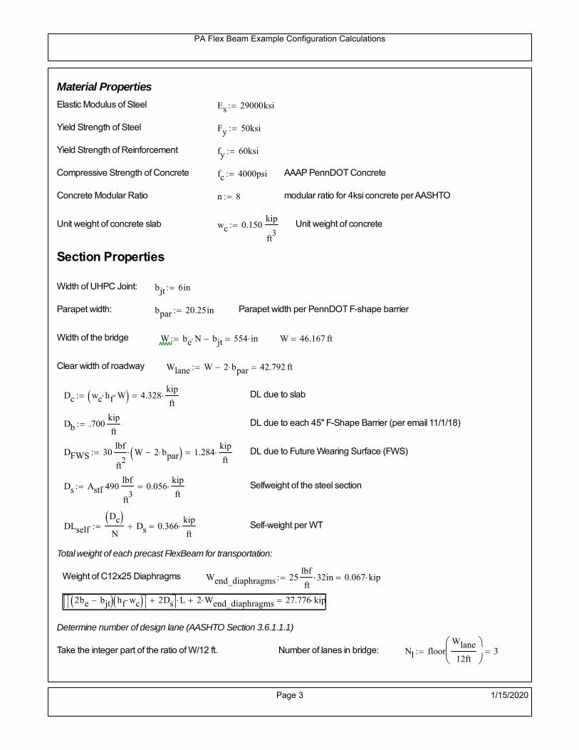
PA Flex Beam Example Configuration Calculations
Material Properties
Elastic Modulus of Steel Es 29000ksi
Yield Strength of Steel Fy 50ksi
Yield Strength of Reinforcement fy 60ksi
Compressive Strength of Concrete fc 4000psi AAAP PennDOT Concrete
Concrete Modular Ratio n 8 modular ratio for 4ksi concrete per AASHTO
Unit weight of concrete slab wc 0.150kip
ft3
Unit weight of concrete
Section Properties
Width of UHPC Joint: bjt 6in
Parapet width: bpar 20.25in Parapet width per PennDOT F-shape barrier
Width of the bridge W be N bjt 554 in W 46.167 ft
Clear width of roadway Wlane W 2 bpar 42.792 ft
Dc wc hf W 4.328kip
ft DL due to slab
Db .700kip
ft DL due to each 45" F-Shape Barrier (per email 11/1/18)
DFWS 30lbf
ft2
W 2 bpar 1.284kip
ft DL due to Future Wearing Surface (FWS)
Ds Astl 490lbf
ft3
0.056kip
ft Selfweight of the steel section
DLself
Dc N
Ds 0.366kip
ft Self-weight per WT
Total weight of each precast FlexBeam for transportation:
Weight of C12x25 Diaphragms Wend_diaphragms 25lbf
ft32 in 0.067 kip
2be bjt hf wc 2Ds L 2 Wend_diaphragms 27.776 kip
Determine number of design lane (AASHTO Section 3.6.1.1.1)
Take the integer part of the ratio of W/12 ft. Number of lanes in bridge: Nl floorWlane
12ft
3
Page 3 1/15/2020

PA Flex Beam Example Configuration Calculations
STEP 1: Compute Dead Load for each Flex Beam
DLslab
Dc
Nwc 1 in
be
2 0.33
kip
ft Dead load of slab assuming exterior overhang has 1" of
additional concrete thickness
DLsteel Ds 0.056kip
ft
DL DLslab DLsteel 0.386kip
ft
STEP 2: Compute Superimposed Dead Load
SDLWS
DFWS
N0.092
kip
ft
SDLparapet
Db
20.35
kip
ft distributed equally on two outer beams
SDLOL 140lbf
ft3be 2 in 0.078
kip
ft Overlay is 2" thick and is 140 lbs/cubic foot
NOTE: For this example barrier load is distributed equally among the two outer beams per conversation withPennDOT and M&M.
PennDOT DM4: "For composite adjacent and spread beams, the barrier (single barrier) load shall be equallydistributed to the nearest three (adjacent) and two (spread) beams, respectively, when the barriers are placedafter slab has hardened".
SDL SDLWS SDLparapet SDLOL 0.519kip
ft
STEP 3: Compute Transformed Width of Slab
For live load and dead load acting on the stringer k1 1 For short-term section property evaluation
btr1
be
k1 n5 in Transformed width of slab for short-term
For superimposed dead loads k3 3 For long-term section property evaluation
btr3
be
k3 n1.667 in Transformed width of slab for long-term
Page 4 1/15/2020

PA Flex Beam Example Configuration Calculations
STEP 4: Compute Dead and Superimposed Dead Load Moments(Based on first interior girder demands)
MDLDL L
2
877.29 kip ft
MSDLSDL L
2
8103.895 kip ft
STEP 5: Compute live load and Dynamic Load Allowance (IM)
Live load wheel load distribution factor (DF):
Sbe
12in3.333 transverse girder spacing
NOTE: AASHTO presents equations to define DF for different types of superstructuresincluding Deck Composite wirh RC slab on steel girders (Type (a) in Table 4.6.2.2.1-1) forshear and moment in interior and exterior beams.
Using DM4 Table 4.6.2.2.2b-1:
eg h y_barhf
2 16.07 in Distance between the centers of gravity of the basic beam and deck
Kg n Istl Astl eg2
39993.61 in
4 Longitudinal stiffness parameter (in4)
Distribution of Live Load Per Lane for Moment in Interior Beams:
to be conservative, use DF 0.3
Page 5 1/15/2020

PA Flex Beam Example Configuration Calculations
Dynamic Load Allowance (Section 3.6.2 DM4)
Static effects of the design truck or tandem, shall be increased by the impact factor.
NOTE: The dynamic load allowance shall not be applied to the design lane load (Section 3.6.2.1 DM4)
I 0.33 Impact factor for moment
Note: PennDOT requires that the impact for decks be increased from 33% to 50%, the deck is not beingdesigned here. Instrad the deck design is based on the BD recommendations.
Dynamic load allowance for the Permit Load P-82 shall be less than 20%. (Section 3.6.2.1DM4)
IPL 0.20 Impact factor for moment on Strength II
Design Wind Loading for Exterior Girder
Vw 80 Wind speed for Strength V load case
CD 1.3 Gust factor for windard side of I-Girder and Box Girder Superstructures (Table 3.8.1.2.1-2)
G 1.0 Gus effect factor is 1.0 for all structures other than sound barriers (Table 3.8.1.2.1-1)
Kz 1.0 Pressure coefficient taken as 1 for Strength V (3.8.1.2.1)
Pz 2.56 106
Vw 2 Kz G CDkip
ft2
0.021kip
ft2
Wind pressure on exterior girder
hexp h hf 17.5 in Exposed height of exterior girder
Moment due to wind loading on exterior girderMWL
Pz hexp L2
86.212 kip ft
Iyy
bf3tf
12108 in
4 Transverse moment of intertia
Flange lateral bending stressfl
MWL
bf
2
Iyy4.142 ksi
Page 6 1/15/2020

PA Flex Beam Example Configuration Calculations
Design Vehicular Live Load
PHL-93 and P-82 are examined herein.
PHL-93 (A3.6.1.2.1)
PHL-93 consists of a combination of (design truck or design tandem) + (design lane load)
Design Truck
PennDOT defines the design truck in accordance with AASTHO 3.6.1.2
Design truck load in AASHTO (HS20 Truck) is used for this example.
NOTE : MAX moment occurs when the center line of the span is midway between the center ofgravity of the loads and the nearest concentrated load.
P1 8kip P2 32kip P3 32kip Axle loads (AASHTO 3.6.1.2.2)
XASr 14ft Rear Axle spacing for truck (14ft - 30ft)
XASf 14ft Front Axle spacing for truck
Page 7 1/15/2020

PA Flex Beam Example Configuration Calculations
Center of gravity (CG) of loads:
X'P1 XASr XASf P2 XASr
P1 P2 P39.333 ft Datum is the rear axle
X XASr X' 4.667 ft Spacing btw CG and nearest load
Find bridge reaction
Truck movestoward Support ARA
P1L
2XASf
X
2
P2L
2
X
2
P3L
2X'
X
2
L31.8 kip
Max live load moment (at the location of P2):
MLL_truck RAL
2
X
2
P1 XASf 449.8 kip ft
NOTE: Find the worst case by varying XASr
Page 8 1/15/2020

PA Flex Beam Example Configuration Calculations
Design Tandem
Consist of a pair of 25-kip axles spaced 4-ft apart. (AASHTO 3.6.1.2.3)
NOTE: PennDOT DM4 increases 25-kip to 31.25-kip.
FT 31.25kip
XAS 4ft Axle spacing
Center of gravity (CG) of loads:
XXAS
22 ft Spacing btw CG and nearest load
Find bridge reaction
RA
FTL
2
X
2
FTL
2
X
2 X
L29.688 kip Truck moves toward Support A
Max live load moment (at the location of front wheel):
MLL_tandem RAL
2
X
2
564.063 kip ft
Choose the max value:
MLL_veh max MLL_tandem MLL_truck 564.063 kip ft
Apply the impact and wheel load distribution:
MLL_IM_veh MLL_veh DF 1 I( ) 225.061 kip ft Due to tandem or truck
Design Lane Load (distributed over a 10-ft width for each lane)
NOTE: The uniform load may be continuous or discontinuous as necessary to produce themaximum force effect. For this example continuous uniform distribution assumed.
FDLL 0.64kip
ftDF 0.192
kip
ft Per beam in each lane
Due to lane loadMLL_IM_lane
FDLL L2
8
38.4 kip ft
Moment due to Total Design Vehicular Live Load: MLL_IM MLL_IM_lane MLL_IM_veh 263.461 kip ft
Page 9 1/15/2020

PA Flex Beam Example Configuration Calculations
Design Permit Load P-82 (Section 3.6.1.2.7 DM4)
P1 P2 P3 P4 P5 P6 P7
NOTE: The moment for the permit load is defined at the beginning of the sheetand is obtained from MATLab File FlexBeam_Moment_ShearEnvelope.m
STEP 6: Compute Moment of Inertia (Note: rebar neglected!)
1) Moment of Inertia resisting dead load only:
a) Acting on the non-composite section (before the deck has hardened - DC1)
Use steel section only
Inc Istl 713.995 in4
Non-composite section modulus
Y'nc y_bar S.G. of the steel section of Flex Beam (Datum is bottom)
b) Acting on the composite section (after the deck has hardened - DC2)
Use Ic_short as defined below.
Page 10 1/15/2020

PA Flex Beam Example Configuration Calculations
2) Moment of Inertia resisting live load plus impact:
Using transformed slab with k1=1 (short-term composite).
Actr1 hf btr1 37.5 in2
Itr1
btr1 hf3
12175.781 in
4
Y'
Actr1 hhf
2
Astl Y'nc
Astl Actr116.32 in S.G. of the total flex beam (Datum is bottom)
Compositesection modulus(short-term)
Ic_short Istl Astl Y'nc Y' 2 Itr1 Actr1 hhf
2
Y'
2
3860 in4
Y'c_short Y' 16.32 in N.A. of the short-term composite section
3) Moment of Inertia resisting superimposed dead load:
Using transformed slab with k3=3.
Actr3 hf btr3 12.5 in2
Itr3
btr3 hf3
1258.594 in
4
Y'
Actr3 hhf
2
Astl Y'nc
Astl Actr312.084 in S.G. of the total flex beam (Datum is bottom)
Compositesection modulus(long-term)
Ic_long Istl Astl Y'nc Y' 2 Itr3 Actr3 hhf
2
Y'
2
2614 in4
Y'c_long Y' 12.084 in N.A. of the long-term composite section
Page 11 1/15/2020

PA Flex Beam Example Configuration Calculations
STEP 6.5 Check Ductility RequirementIn accordance with AASHTO Article 6.10.7.3 check ductility requirement. Assume compressionblock of concrete is at 0.85 f'c and that the concrete supports no tension. Steel section isassumed to be fully plastic at Fy.
Case 1 : Assuming PNA is in Concreteh d 4 inAssuming (h-d) < Dp < hf
Fp Dp 0.85 fc be Dp Fy tw Dp h d( ) Fy Astl tw Dp h d( )
Dp 7.5in 0.42 h 10.5 in
Dp1 root Fp Dp Dp 5.647 in Must be less than hf 7.5 inDp1
h0.226 must be < 0.42
Mn1check Dp1 hf h d( ) Dp1[ ] Dp1 0.42 h( ) 1 Dp1 0.42 h 1
Mp1 0.85 fc be Dp1Dp1
2
Fy tw Dp1 h d( )[ ] Dp1 h d( )[ ]
2
Fy bf tf h Dp1tf
2
Fy tw h Dp1 tf h Dp1 tf
2
Mp1 13978.38 kip in Mn1 Mp1 1.07 0.7Dp1
h
12746.8 kip in
Case 2 : Assuming PNA is NOT in Concrete
Assuming hf < Dp
Fp2 Dp 0.85 fc be hf Fy tw Dp h d( ) Fy Astl tw Dp h d( )
Dp 2.5in
Dp2 root Fp2 Dp Dp 1.075 in Must be more than hf 7.5 inDp2
h0.043 must be < 0.42
Mn2check Dp2 hf Dp2 h( ) Dp2 0.42 h( ) 0 Dp2 0.42 h 1
Mp2 0.85 fc be hf Dp2hf
2
Fy tw Dp2 h d( )[ ] Dp2 h d( )[ ]
2
Fy bf tf h Dp2tf
2
Fy tw h Dp2 tf h Dp2 tf
2
Mp2 12897.67 kip inMn2 Mp2 1.07 0.7
Dp2
h
14188.7 kip in
Mn max Mn1 Mn1check Mn2 Mn2check 1062.2 kip ft Mn 12746.8 kip in
Page 12 1/15/2020

PA Flex Beam Example Configuration Calculations
Check Composite Compact Section Criteria (6.10.6.2)
Dcpd
2
Fy tf bf 0.85 fc be hf
Fy hw tw1
5.263 in Dcp0 Dcp 0 0
Dcp Dcp Dcp0 0 in2 Dcp
tw3.76
Es
Fy 1 Check if section is compact
STEP 7: Load Combinations (Table 3.4.1-1)
The following load combinations will be considered herein. Only the maximum load factors forpermanent-loads are used in the following load combinations (uplift is not an issue for this typeof bridge).STRENGTH I 1.25DL + 1.5SDL + 1.75 (LL+IM)
SERVICE II: DL+SDL+1.3(LL+IM)
STEP 8: Compute and Check Stresses
Stress at bottom fiber of steel section
fDL
MDL Y'c_long
Ic_long4.288 ksi
fLL_I
MLL_IM Y'c_short
Ic_short13.366 ksi fPL
MLL_IM_PL82 Y'c_short
Ic_short15.829 ksi
fSDL
MSDL Y'c_long
Ic_long5.764 ksi
STRENGTH I fbot_str1 1.25fDL 1.5 fSDL 1.75 fLL_I 37.397 ksi
STRENGTH II fbot_str2 1.25fDL 1.5 fSDL 1.35 fPL 35.375 ksi
SERVICE II fbot_svc2 fDL fSDL 1.3fLL_I 27.43 ksi
Allowable Stress is based on Section 6.10.4.2.2-2
Flange stress due to service load II without consideration of flange lateral bending: ff fbot_svc2
Flange lateral bending stress due to service II: flSII 0ksi
Hybrid Factor: Rh 1.0 For rolled and homogenous built-up sections
ff
flSII
2 27.428 ksi 0.95 Rh Fy 47.5 ksi ff
fl
2 0.95Rh Fy 1
Page 13 1/15/2020

PA Flex Beam Example Configuration Calculations
Stress at top fiber of concrete
Note: For calculating longitudinal flexural stresses in the concrete deck due to allpermanent and transient loads, the short-term modular ratio shall be used.
fDL
MDL h Y'c_short
k1 n Ic_short0.261 ksi
fLL_I
MLL_IM h Y'c_short
k1 n Ic_short0.889 ksi fPL
MLL_IM_PL82 h Y'c_short
k1 n Ic_short1.052 ksi
fSDL
MSDL h Y'c_short
k1 n Ic_short0.35 ksi
STRENGTH I fc_str1 1.25fDL 1.5 fSDL 1.75 fLL_I 2.406 ksi
Mstr1 1.25 MDL 1.5 MSDL 1.75 MLL_IM 713.5 kip ft Mstr1 Mn 1
STRENGTH II fc_str2 1.25fDL 1.5 fSDL 1.35 fPL 2.272 ksi
Mstr2 1.25 MDL 1.5 MSDL 1.35 MLL_IM_PL82 674 kip ft Mstr2 Mn 1
SERVICE II
Allowable Stress in concrete - AASHTO 6.10.4.2.2For compact composite sections in positive flexure utilized in shored construction, the longitudinalcompressive stress in the concrete deck due to the Service II loads, determined as specified in Article6.10.1.1.1d, shall not exceed 0.6f́ c.
fallow 0.6 fc 2400 psi
fc_2 1.3fLL_I fSDL fDL 1766.12 psi This assumes short term compositesection for all calculations
fc_2 fallow 1
SERVICE II with Long Term Composite for dead loads
fDL
MDL h Y'c_long
k3 n Ic_long0.191 ksi
fLL_I
MLL_IM h Y'c_short
k1 n Ic_short0.889 ksi
fSDL
MSDL h Y'c_long
k3 n Ic_long0.257 ksi
fc_2 1.3fLL_I fSDL fDL 1602.74 psi fc_2 fallow 1
Page 14 1/15/2020

PA Flex Beam Example Configuration Calculations
Strength V Moment Check
Strength V is related to normal vehicular use of the bridge with an 80 mph wind gust
Note: that Strength V is checked for an exterior girder under wind load with the interior girder distribution factor forflexure used. If Strength V controls design, then this approach should be modified
Design vertical moment is: 1.25DL + 1.5SDL + 1.35 (LL+IM)
SLT
Ic_long
Y'c_long216.287 in
3 SST
Ic_short
Y'c_short236.542 in
3 short and long term section
modulus
Section D6.2.2 Find the moment required to cause yieldling of the flange. The approach is laid out in D6.2.2
MD2 1.25 MDL 1.5 MSDL 252.455 kip ft From D6.2.2-1 (all dead loads are in MD2 due to shoredconstruction
MAD Fy
MD2
SLT
SST 709.494 kip ft Additional moment to cause nominal yielding of steel flange
My MD2 MAD 961.948 kip ft D6.2.2-2: Moment to cause yielding of flange
6.10.7.1 Compact Section Check at Strength V limit state
Section Modulus for yielding of the flange (My/Fy) for equation 6.10.7.1.1-1Sxt
My
Fy230.868 in
3
Mu 1.25 MDL 1.5MSDL 1.35MLL_IM 608.127 kip ft Moment due to Strength V limit state
Mu1
3fl Sxt 634.686 kip ft Equation 6.10.7.1.7-1 Mn 1.062 10
3 kip ft Mu
1
3fl Sxt Mn 1
Page 15 1/15/2020

PA Flex Beam Example Configuration Calculations
STEP 9: Compute Deflection
Optional Live Load Deflection Evaluation (AASHTO 3.6.1.3.2)
Deflection distribution factor for vehicular loads: For a straight multibeambridge, this is equivalent to saying that the distribution factor for deflectionis equal to the number of lanes divided by the number of beams. 2.5.2.6.2
DFd
Nl
N0.214
Deflection should be taken as 125% the larger of:- Design truck- 25% of design truck + design lane
The live load portion of Load Combination Service I of Table 3.4.1-1 should be used,including the dynamic load allowance, IM;
Deflection due to design truck load
NOTE : Assuming maximum deflection occurs when the center of gravity of the loads is at thecenter line of the span.
P1 8kip P2 32kip P3 32kip Axle loads (AASHTO 3.6.1.2.2)
XASr 14ft Rear Axle spacing for truck (14ft - 30ft)
XASf 14ft Front Axle spacing for truck
Center of gravity (CG) of loads:
X'P1 XASr XASf P2 XASr
P1 P2 P39.333 ft Datum is the rear axle
Method1: Assuming single load = P1+P2+P3 at the midspan (Conservative approach)
P1 P2 P3 L3
48 Es Ic_short 1.482 in
Method2: Calculation of Midspan deflection using superposition
b1L
2XASr X' XASf 1.333 ft distance btw load P1 and support A b1check b1 0 1
b2L
2XASr X' 15.333 ft distance btw load P2 and support A b2check b2 0 1
b3L
2X' 10.667 ft distance btw load P3 and support B b3check b3 0 1
Page 16 1/15/2020

PA Flex Beam Example Configuration Calculations
Deflection of the beam at midspan due to P1: P P1
xL
2 at midspan b b1 b1check The smallest distance btw load P1 and support
Δ1P b x
6 Es Ic_short LL2
b2
x2
0.016 in
Deflection of the beam at midspan due to P2: P P2
xL
2 at midspan b b2 b2check The smallest distance btw load P2 and support
Δ2P b x
6 Es Ic_short LL2
b2
x2
0.609 in
Deflection of the beam at midspan due to P3: P P3
xL
2 at midspan b b3 b3check The smallest distance btw load P3 and support
Δ3P b x
6 Es Ic_short LL2
b2
x2
0.477 in
Total Deflection at midspan:
Δtruck Δ1 Δ2 Δ3( ) DFd 1 I( ) 0.314 in (Considering IM)
Deflection due to tandem (Note: this calculation is not required according to Article3.6.1.3.2 which denotes only the design truck for deflection calculation)
Page 17 1/15/2020

PA Flex Beam Example Configuration Calculations
FT 31.25 kip Per axle
XAS 4ft Axle spacing
Δtandem
FTL
2
XAS
2
24 Es Ic_short3 L
2 4
L
2
XAS
2
2
DFd 1 I( ) 0.361 in (Considering IM)
Deflection due to lane load
FDLLd 640lbf
ft DFd 137.143
lbf
ft
Δlane
5 FDLLd L4
384 Es Ic_short0.071 in
Live Load Deflection:
ΔLL 1.25max Δtruck 0.25Δtruck Δlane 1.25 0.491 in ΔLLL
800 1
Deflection Limit
For steel or concrete vehicular bridges:
Vehicular load = Span/800L
8000.6 in
L
10000.48 in
Evaluation of Deflection at the Service Limit State (AASHTO 3.4.2.2)
The associated permitted deflections shall be included in the contract documents.
Page 18 1/15/2020

PA Flex Beam Example Configuration Calculations
Shear demands:
Determination of the distribution factor
Using DM4 Table 4.6.2.2.3a-1
Sbe
12in3.333 transverse girder spacing (ft)
Distribution of live loads per lane for shear in interior beams:
For two design lanes loaded, 3.5' <= S =< 16', number of beam >= 4DFs 0.36
S
25 0.493
Q Actr1 h Y'c_shorthf
2
184.86 in3
first moment of deck slab for interface shear
Method 1: Range of shear based on Strength I Limit
STRENGTH I 1.25DL + 1.5SDL + 1.75 (LL+IM)
Computation of the range of shear in the beam
Dead Load:DL 0.386
kip
ft
Superimposed Dead Load: SDL 0.519kip
ft
Design Lane Load: 0.64kip
ft
Design Truck:
XASr 14ft Rear Axle spacing for truck (14ft - 30ft)
XASf 14ft Front Axle spacing for truck
P1 8 kip P2 32 kip P3 32 kip Wheel loads (AASHTO 3.6.1.2.2)
Design Tandem:
Consist of a pair of 25-kip axles spaced 4-ft apart. (AASHTO 3.6.1.2.3)
NOTE: PennDOT DM4 increases 25-kip to 31.25-kip.
FT 31.25kip
XAS 4ft Axle spacing
Page 19 1/15/2020

PA Flex Beam Example Configuration Calculations
Maximum positive shear at various points along the FlexBeam are examined.
At x=0 (at left support) (Truck is moving from left to right)
Truck
Max Positive Shear (when P3 is at x = 0):
x1 L XASr XASf 12 ft Distance between P1 and right support
x2 L XASr 26 ft Distance between P2 and right support
x3 L 40 ft Distance between P3 and right support
V1 P3
x3
L P2
x2
L P1
x1
L 55.2 kip
Total Vertical Shear Force for each FlexBeam (considering dynamic loads):
Vtruck1 V1 DFs 1 I( ) 36.219 kip
Tandem:
V1 FT FT
L XAS L
59.375 kip
Total Vertical Shear Force for each FlexBeam (considering dynamic loads):
Vtandem1 V1 DFs 1 I( ) 38.958 kip
Lane Load
V1 0.64kip
ft
L
2 12.8 kip
Total Vertical Shear Force for each FlexBeam (considering dynamic loads):
Vlane1 V1 DFs 6.315 kip
Dead Load
Vdl1 DLL
2 7.729 kip
Superimposed Dead Load
Vsdl1 SDLL
2 10.389 kip
Strength I Max Positive Shear:
Vstr1 1.25 Vdl1 1.5 Vsdl1 1.75 Vlane1 max Vtruck1 Vtandem1 104.472 kip
Page 20 1/15/2020

PA Flex Beam Example Configuration Calculations
Design Permit Load P-82
Shear at x=0
Strength II Max Positive Shear:
VPL82 VPL82span DFs 1 IPL 55.744 kip
STRENGTH II 1.25DL + 1.5SDL + 1.35 (LL+IM)
VstrII_PL 1.25 Vdl1 1.5 Vsdl1 1.35 VPL82 100.5 kip
Max Shear Demand Vu max Vstr1 VstrII_PL 104.472 kip
Determine the Shear Strength of the Web
Shear Strength of Unstiffened web from AASHTO section 6.10.9.2
Depth of Web D d 21 in Thickness of web tw 0.375 in
Transverse Stiffener Spacing d0 0in Shear Buckling Coefficient k 5 6.10.9.3.2-7
Plastic Shear Force Vp 0.58 Fy D tw 228.375 kip Equation 6.10.9.3.2-3
Ratio of Shear-Buckling resistance to shear yield, C
D
tw56 1.12
Es k
Fy 60.314 Ccheck
D
tw1.12
Es k
Fy 1 Equation 6.10.9.3.2-4
C 1.0 Ccheck 1 C=1 for most cases, if the criteria are not met, then C will go to zero and the actualcoefficients should be determined
Nominal Shear Resistance of Web Vn C Vp 228.375 kip equation 6.10.9.3.3-1
Shear Resistance Factor φv 1.0
φv Vn 228.375 kip φv Vn Vu 1Reduced Shear Strength
Page 21 1/15/2020

PA Flex Beam Example Configuration Calculations
Check Bearing Stiffeners
FYs 50ksi Yield strength of stiffener
tp 0.75in Thickness of stiffener
bt
bf tw
21.5in 4.312 in Effective width of stiffener
Dst hw 4.1in 16.15 in Depth of stiffeners
Apn 2 tp bt 6.469 in2
Projected area of stiffeners
bt 0.48 tpEs
FYs 1Check that effective width of stiffener meets requirements
Rsbn 1.4 Apn FYs 452.812 kip Bearing capacity of stiffener (phi=1 for bearing per AASHTO 6.5.4.2)
Rsbn Vu 1 Bearing capacity check
Qs 1.0 Q factor for bearing stiffner, taken as 1 (AASHTO 6.9.4.1.1)
Is
18 tw tw3
tp 2 bt 3
1240.131 in
4 Moment of inertia of stiffener and web (9*tw is used on each side)
AASHTO 6.10.11.2.4b
Ag 18 tw tw 2 bt tp 9 in2
Gross area of stiffener and web (AASHTO 6.10.11.2.4b)
rs
Is
Ag2.112 in Radius of gyration of stiffener/web
Po Qs FYs Apn 323.437 kip Nominal yeild resistance of stiffener (AASHTO 6.9.4.1.1)
Peπ2Es
0.75 Dst
rs
2Ag 7.829 10
4 kip Elastic critical buckling stress of stiffener (AASHTO 6.9.4.1.2-1)
Check that Pe/Po is great than 0.44 (AASHTO 6.9.4.1.1) PePoPe
Po0.44 1
Pn PePo 0.658
Po
Pe Po 322.879 kip Nominal compressive resistance of stiffener for Pe/Po>0.44
(AASHTO 6.9.4.1.1-1)
φcr 0.95 phi factor for axial compression (AASHTO 6.5.4.2)
Pr φcr Pn 306.735 kip Compressive capacity of bearing stiffener Pr Vu 1
Page 22 1/15/2020

PA Flex Beam Example Configuration Calculations
Flexbeam Example Configuration Calculations
Summary of Calculations:
Input section dimensions and material properties for steel WT and the concrete deck1.Calculate demands (dead load, superimposed dead, and Live load demands for Strength I and Strength II2.Calculate composite section properties for the given section3.Check Strength I, Strength II, and Service II stresses 4.Check Strength I, Strength II, and Strength V moment demands 5.Perform live load deflection check6.Determine maximum shear demand and capacity7.Note: Shear envelope data was obtained from Matlab script (FlexBeam_Moment_ShearEnvelope.m).8.Shear envelope calculations are summarized separately for each design (Shear Design *.xlsx).
Design Assumptions:Design Specifications Used:
AASHTO LRFD Bridge Design Specifications 7th Edition with 2016 Interim RevisionsPennDOT Design Manual, Part 4 (DM-4) June 30, 2015
Example configurations are determined for two girder spacings, 36" and 40".The deck thickness is 7.5" and is assumed to have a non-structural wearing surface added after installation.Section properties are calculated using the full 7.5" deck thickness.The WT sections are embedded 3.5" into the concrete deck. The steel section spacing used is outside the scope of the AASHTO and PennDOT distribution factorequations. The flexural distribution factor is assumed to be 0.3 which was shown to tbe conservativeaccording to refined analysisThe shear distribution factor is calculated using the DM-4 shear distribution factor equation which wasshown to be conservative using refined analysis.Refined analysis is presented in: Zihan Ma, "Distribution Factors for Composite Steel Tee Concrete DeckBridge System," M.S. Thesis, Deparement of Civil and Environmental Engineering, Lehigh University,Bethlehem, 2019Shear and moment demands for the PL82 permit load vehicle are determined by Matlab script(FlexBeam_Moment_ShearEnvelope.m) and are manually input into this calculation sheet.All fabrication will occur as double modules, i.e. each module contains two WT sections. The number ofmodules is half the number of beams, N. A 45 in. tall F-Shape barrier is used, Weight = 700 lb/ft (Distributed to exterior two beams).
The work presented in this document are provided on an “AS IS” basis. University makes no warranties of anykind, express or implied, as to any matter whatsoever, including, without limitation, warranties with respect tothe merchantability or fitness for a particular purpose of this work or any project deliverables. Universitymakes no warranty of any kind with respect to freedom from patent, trademark, copyright or trade secretinfringement arising from the use of the results of the project, deliverables, services, intellectual property orother materials provided hereunder. University shall not be liable for any direct, indirect, consequential,punitive, or other damages suffered by Sponsor or any other person resulting from the project, or the use ofthis work or any project deliverables.
Page 1 1/15/2020

PA Flex Beam Example Configuration Calculations
hf
tf
bf
twh
d
bjtbe
e
Variable Definitions:
Number of beams N 10 modulesN
25
L 50ft Span length
be 34in Effective width of Flexbeamassuming constructed bridge width(i.e. closure joints cast)
Built Up Section Properties
tw 0.500in tf 0.625in bf 12in
h 29in Overall Height of section
hf 7.5in Total thickness of deck
e 3.5in Deck/Steel overlap
d h hf e 25 in depth of built up steel section
hw d tf 24.375 in height of web of built up steel
Moment and shear for permit load PL82 obtained from Matlab script: FlexBeam_Moment_ShearEnvelope
MLL_IM_PL82 409.0176kip ft Moment due to PL82 with distribution factor and impact factor!!
VPL82span 110.862kip Shear due to PL82 WITHOUT distribution factor and impact factor!!
Check web and flange dimensions in sections 6.10.2.1 and 6.10.2.2
(Ignore 6.10.2.2-4 since no compression flange)
equation 6.10.2.1.1-1d
tw150 1 equation 6.10.2.2-1
bf
2 tf12 1
equation 6.10.2.2-2 bfh
6 1 equation 6.10.2.2-3 tf 1.1 tw 1
y_bar
tf bftf
2 hw tw tf
hw
2
tf bf hw tw8.051 in Center of gravity of steel section
Istl
bf tf3
12bf tf y_bar
tf
2
2
tw hw
3
12 tw hw tf
hw
2 y_bar
2
1.329 103
in4
MOI of steel
Astl tf bf hw tw 19.687 in2
Area of the WT steel section
Page 2 1/15/2020

PA Flex Beam Example Configuration Calculations
Material Properties
Elastic Modulus of Steel Es 29000ksi
Yield Strength of Steel Fy 50ksi
Yield Strength of Reinforcement fy 60ksi
Compressive Strength of Concrete fc 4000psi AAAP PennDOT Concrete
Concrete Modular Ratio n 8 modular ratio for 4ksi concrete per AASHTO
Unit weight of concrete slab wc 0.150kip
ft3
Unit weight of concrete
Section Properties
Width of UHPC Joint: bjt 6in
Parapet width: bpar 20.25in Parapet width per PennDOT F-shape barrier
Width of the bridge W be N bjt 334 in W 27.833 ft
Clear width of roadway Wlane W 2 bpar 24.458 ft
Dc wc hf W 2.609kip
ft DL due to slab
Db .700kip
ft DL due to each 45" F-Shape Barrier (per email 11/1/18)
DFWS 30lbf
ft2
W 2 bpar 0.734kip
ft DL due to Future Wearing Surface (FWS)
Ds Astl 490lbf
ft3
0.067kip
ft Selfweight of the steel section
DLself
Dc N
Ds 0.328kip
ft Self-weight per WT
Total weight of each precast FlexBeam for transportation:
Weight of C12x25 Diaphragms Wend_diaphragms 25lbf
ft32 in 0.067 kip
2be bjt hf wc 2Ds L 2 Wend_diaphragms 31.051 kip
Determine number of design lane (AASHTO Section 3.6.1.1.1)
Take the integer part of the ratio of W/12 ft. Number of lanes in bridge: Nl floorWlane
12ft
2
Page 3 1/15/2020

PA Flex Beam Example Configuration Calculations
STEP 1: Compute Dead Load for each Flex Beam
DLslab
Dc
Nwc 1 in
be
2 0.279
kip
ft Dead load of slab assuming exterior overhang has 1" of
additional concrete thickness
DLsteel Ds 0.067kip
ft
DL DLslab DLsteel 0.346kip
ft
STEP 2: Compute Superimposed Dead Load
SDLWS
DFWS
N0.073
kip
ft
SDLparapet
Db
20.35
kip
ft distributed equally on two outer beams
SDLOL 140lbf
ft3be 2 in 0.066
kip
ft Overlay is 2" thick and is 140 lbs/cubic foot
NOTE: For this example barrier load is distributed equally among the two outer beams per conversation withPennDOT and M&M.
PennDOT DM4: "For composite adjacent and spread beams, the barrier (single barrier) load shall be equallydistributed to the nearest three (adjacent) and two (spread) beams, respectively, when the barriers are placedafter slab has hardened".
SDL SDLWS SDLparapet SDLOL 0.489kip
ft
STEP 3: Compute Transformed Width of Slab
For live load and dead load acting on the stringer k1 1 For short-term section property evaluation
btr1
be
k1 n4.25 in Transformed width of slab for short-term
For superimposed dead loads k3 3 For long-term section property evaluation
btr3
be
k3 n1.417 in Transformed width of slab for long-term
Page 4 1/15/2020

PA Flex Beam Example Configuration Calculations
STEP 4: Compute Dead and Superimposed Dead Load Moments(Based on first interior girder demands)
MDLDL L
2
8108.012 kip ft
MSDLSDL L
2
8152.964 kip ft
STEP 5: Compute live load and Dynamic Load Allowance (IM)
Live load wheel load distribution factor (DF):
Sbe
12in2.833 transverse girder spacing
NOTE: AASHTO presents equations to define DF for different types of superstructuresincluding Deck Composite wirh RC slab on steel girders (Type (a) in Table 4.6.2.2.1-1) forshear and moment in interior and exterior beams.
Using DM4 Table 4.6.2.2.2b-1:
eg h y_barhf
2 17.199 in Distance between the centers of gravity of the basic beam and deck
Kg n Istl Astl eg2
57224.49 in
4 Longitudinal stiffness parameter (in4)
Distribution of Live Load Per Lane for Moment in Interior Beams:
to be conservative, use DF 0.3
Page 5 1/15/2020

PA Flex Beam Example Configuration Calculations
Dynamic Load Allowance (Section 3.6.2 DM4)
Static effects of the design truck or tandem, shall be increased by the impact factor.
NOTE: The dynamic load allowance shall not be applied to the design lane load (Section 3.6.2.1 DM4)
I 0.33 Impact factor for moment
Note: PennDOT requires that the impact for decks be increased from 33% to 50%, the deck is not beingdesigned here. Instrad the deck design is based on the BD recommendations.
Dynamic load allowance for the Permit Load P-82 shall be less than 20%. (Section 3.6.2.1DM4)
IPL 0.20 Impact factor for moment on Strength II
Design Wind Loading for Exterior Girder
Vw 80 Wind speed for Strength V load case
CD 1.3 Gust factor for windard side of I-Girder and Box Girder Superstructures (Table 3.8.1.2.1-2)
G 1.0 Gus effect factor is 1.0 for all structures other than sound barriers (Table 3.8.1.2.1-1)
Kz 1.0 Pressure coefficient taken as 1 for Strength V (3.8.1.2.1)
Pz 2.56 106
Vw 2 Kz G CDkip
ft2
0.021kip
ft2
Wind pressure on exterior girder
hexp h hf 21.5 in Exposed height of exterior girder
Moment due to wind loading on exterior girderMWL
Pz hexp L2
811.925 kip ft
Iyy
bf3tf
1290 in
4 Transverse moment of intertia
Flange lateral bending stressfl
MWL
bf
2
Iyy9.54 ksi
Page 6 1/15/2020

PA Flex Beam Example Configuration Calculations
Design Vehicular Live Load
PHL-93 and P-82 are examined herein.
PHL-93 (A3.6.1.2.1)
PHL-93 consists of a combination of (design truck or design tandem) + (design lane load)
Design Truck
PennDOT defines the design truck in accordance with AASTHO 3.6.1.2
Design truck load in AASHTO (HS20 Truck) is used for this example.
NOTE : MAX moment occurs when the center line of the span is midway between the center ofgravity of the loads and the nearest concentrated load.
P1 8kip P2 32kip P3 32kip Axle loads (AASHTO 3.6.1.2.2)
XASr 14ft Rear Axle spacing for truck (14ft - 30ft)
XASf 14ft Front Axle spacing for truck
Page 7 1/15/2020

PA Flex Beam Example Configuration Calculations
Center of gravity (CG) of loads:
X'P1 XASr XASf P2 XASr
P1 P2 P39.333 ft Datum is the rear axle
X XASr X' 4.667 ft Spacing btw CG and nearest load
Find bridge reaction
Truck movestoward Support ARA
P1L
2XASf
X
2
P2L
2
X
2
P3L
2X'
X
2
L32.64 kip
Max live load moment (at the location of P2):
MLL_truck RAL
2
X
2
P1 XASf 627.84 kip ft
NOTE: Find the worst case by varying XASr
Page 8 1/15/2020

PA Flex Beam Example Configuration Calculations
Design Tandem
Consist of a pair of 25-kip axles spaced 4-ft apart. (AASHTO 3.6.1.2.3)
NOTE: PennDOT DM4 increases 25-kip to 31.25-kip.
FT 31.25kip
XAS 4ft Axle spacing
Center of gravity (CG) of loads:
XXAS
22 ft Spacing btw CG and nearest load
Find bridge reaction
RA
FTL
2
X
2
FTL
2
X
2 X
L30 kip Truck moves toward Support A
Max live load moment (at the location of front wheel):
MLL_tandem RAL
2
X
2
720 kip ft
Choose the max value:
MLL_veh max MLL_tandem MLL_truck 720 kip ft
Apply the impact and wheel load distribution:
MLL_IM_veh MLL_veh DF 1 I( ) 287.28 kip ft Due to tandem or truck
Design Lane Load (distributed over a 10-ft width for each lane)
NOTE: The uniform load may be continuous or discontinuous as necessary to produce themaximum force effect. For this example continuous uniform distribution assumed.
FDLL 0.64kip
ftDF 0.192
kip
ft Per beam in each lane
Due to lane loadMLL_IM_lane
FDLL L2
8
60 kip ft
Moment due to Total Design Vehicular Live Load: MLL_IM MLL_IM_lane MLL_IM_veh 347.28 kip ft
Page 9 1/15/2020

PA Flex Beam Example Configuration Calculations
Design Permit Load P-82 (Section 3.6.1.2.7 DM4)
P1 P2 P3 P4 P5 P6 P7
NOTE: The moment for the permit load is defined at the beginning of the sheetand is obtained from MATLab File FlexBeam_Moment_ShearEnvelope.m
STEP 6: Compute Moment of Inertia (Note: rebar neglected!)
1) Moment of Inertia resisting dead load only:
a) Acting on the non-composite section (before the deck has hardened - DC1)
Use steel section only
Inc Istl 1.329 103
in4
Non-composite section modulus
Y'nc y_bar S.G. of the steel section of Flex Beam (Datum is bottom)
b) Acting on the composite section (after the deck has hardened - DC2)
Use Ic_short as defined below.
Page 10 1/15/2020

PA Flex Beam Example Configuration Calculations
2) Moment of Inertia resisting live load plus impact:
Using transformed slab with k1=1 (short-term composite).
Actr1 hf btr1 31.875 in2
Itr1
btr1 hf3
12149.414 in
4
Y'
Actr1 hhf
2
Astl Y'nc
Astl Actr118.683 in S.G. of the total flex beam (Datum is bottom)
Compositesection modulus(short-term)
Ic_short Istl Astl Y'nc Y' 2 Itr1 Actr1 hhf
2
Y'
2
5079 in4
Y'c_short Y' 18.683 in N.A. of the short-term composite section
3) Moment of Inertia resisting superimposed dead load:
Using transformed slab with k3=3.
Actr3 hf btr3 10.625 in2
Itr3
btr3 hf3
1249.805 in
4
Y'
Actr3 hhf
2
Astl Y'nc
Astl Actr314.079 in S.G. of the total flex beam (Datum is bottom)
Compositesection modulus(long-term)
Ic_long Istl Astl Y'nc Y' 2 Itr3 Actr3 hhf
2
Y'
2
3420 in4
Y'c_long Y' 14.079 in N.A. of the long-term composite section
Page 11 1/15/2020

PA Flex Beam Example Configuration Calculations
STEP 6.5 Check Ductility RequirementIn accordance with AASHTO Article 6.10.7.3 check ductility requirement. Assume compressionblock of concrete is at 0.85 f'c and that the concrete supports no tension. Steel section isassumed to be fully plastic at Fy.
Case 1 : Assuming PNA is in Concreteh d 4 inAssuming (h-d) < Dp < hf
Fp Dp 0.85 fc be Dp Fy tw Dp h d( ) Fy Astl tw Dp h d( )
Dp 7.5in 0.42 h 12.18 in
Dp1 root Fp Dp Dp 7.152 in Must be less than hf 7.5 inDp1
h0.247 must be < 0.42
Mn1check Dp1 hf h d( ) Dp1[ ] Dp1 0.42 h( ) 1 Dp1 0.42 h 1
Mp1 0.85 fc be Dp1Dp1
2
Fy tw Dp1 h d( )[ ] Dp1 h d( )[ ]
2
Fy bf tf h Dp1tf
2
Fy tw h Dp1 tf h Dp1 tf
2
Mp1 16786.73 kip in Mn1 Mp1 1.07 0.7Dp1
h
15063.8 kip in
Case 2 : Assuming PNA is NOT in Concrete
Assuming hf < Dp
Fp2 Dp 0.85 fc be hf Fy tw Dp h d( ) Fy Astl tw Dp h d( )
Dp 2.5in
Dp2 root Fp2 Dp Dp 6.348 in Must be more than hf 7.5 inDp2
h0.2189 must be < 0.42
Mn2check Dp2 hf Dp2 h( ) Dp2 0.42 h( ) 0 Dp2 0.42 h 1
Mp2 0.85 fc be hf Dp2hf
2
Fy tw Dp2 h d( )[ ] Dp2 h d( )[ ]
2
Fy bf tf h Dp2tf
2
Fy tw h Dp2 tf h Dp2 tf
2
Mp2 16763.55 kip inMn2 Mp2 1.07 0.7
Dp2
h
15368.6 kip in
Mn max Mn1 Mn1check Mn2 Mn2check 1255.3 kip ft Mn 15063.8 kip in
Page 12 1/15/2020

PA Flex Beam Example Configuration Calculations
Check Composite Compact Section Criteria (6.10.6.2)
Dcpd
2
Fy tf bf 0.85 fc be hf
Fy hw tw1
2.408 in Dcp0 Dcp 0 1
Dcp Dcp Dcp0 2.408 in2 Dcp
tw3.76
Es
Fy 1 Check if section is compact
STEP 7: Load Combinations (Table 3.4.1-1)
The following load combinations will be considered herein. Only the maximum load factors forpermanent-loads are used in the following load combinations (uplift is not an issue for this typeof bridge).STRENGTH I 1.25DL + 1.5SDL + 1.75 (LL+IM)
SERVICE II: DL+SDL+1.3(LL+IM)
STEP 8: Compute and Check Stresses
Stress at bottom fiber of steel section
fDL
MDL Y'c_long
Ic_long5.335 ksi
fLL_I
MLL_IM Y'c_short
Ic_short15.33 ksi fPL
MLL_IM_PL82 Y'c_short
Ic_short18.055 ksi
fSDL
MSDL Y'c_long
Ic_long7.556 ksi
STRENGTH I fbot_str1 1.25fDL 1.5 fSDL 1.75 fLL_I 44.831 ksi
STRENGTH II fbot_str2 1.25fDL 1.5 fSDL 1.35 fPL 42.378 ksi
SERVICE II fbot_svc2 fDL fSDL 1.3fLL_I 32.82 ksi
Allowable Stress is based on Section 6.10.4.2.2-2
Flange stress due to service load II without consideration of flange lateral bending: ff fbot_svc2
Flange lateral bending stress due to service II: flSII 0ksi
Hybrid Factor: Rh 1.0 For rolled and homogenous built-up sections
ff
flSII
2 32.821 ksi 0.95 Rh Fy 47.5 ksi ff
fl
2 0.95Rh Fy 1
Page 13 1/15/2020

PA Flex Beam Example Configuration Calculations
Stress at top fiber of concrete
Note: For calculating longitudinal flexural stresses in the concrete deck due to allpermanent and transient loads, the short-term modular ratio shall be used.
fDL
MDL h Y'c_short
k1 n Ic_short0.329 ksi
fLL_I
MLL_IM h Y'c_short
k1 n Ic_short1.058 ksi fPL
MLL_IM_PL82 h Y'c_short
k1 n Ic_short1.246 ksi
fSDL
MSDL h Y'c_short
k1 n Ic_short0.466 ksi
STRENGTH I fc_str1 1.25fDL 1.5 fSDL 1.75 fLL_I 2.962 ksi
Mstr1 1.25 MDL 1.5 MSDL 1.75 MLL_IM 972.2 kip ft Mstr1 Mn 1
STRENGTH II fc_str2 1.25fDL 1.5 fSDL 1.35 fPL 2.793 ksi
Mstr2 1.25 MDL 1.5 MSDL 1.35 MLL_IM_PL82 917 kip ft Mstr2 Mn 1
SERVICE II
Allowable Stress in concrete - AASHTO 6.10.4.2.2For compact composite sections in positive flexure utilized in shored construction, the longitudinalcompressive stress in the concrete deck due to the Service II loads, determined as specified in Article6.10.1.1.1d, shall not exceed 0.6f́ c.
fallow 0.6 fc 2400 psi
fc_2 1.3fLL_I fSDL fDL 2170.88 psi This assumes short term compositesection for all calculations
fc_2 fallow 1
SERVICE II with Long Term Composite for dead loads
fDL
MDL h Y'c_long
k3 n Ic_long0.236 ksi
fLL_I
MLL_IM h Y'c_short
k1 n Ic_short1.058 ksi
fSDL
MSDL h Y'c_long
k3 n Ic_long0.334 ksi
fc_2 1.3fLL_I fSDL fDL 1944.9 psi fc_2 fallow 1
Page 14 1/15/2020

PA Flex Beam Example Configuration Calculations
Strength V Moment Check
Strength V is related to normal vehicular use of the bridge with an 80 mph wind gust
Note: that Strength V is checked for an exterior girder under wind load with the interior girder distribution factor forflexure used. If Strength V controls design, then this approach should be modified
Design vertical moment is: 1.25DL + 1.5SDL + 1.35 (LL+IM)
SLT
Ic_long
Y'c_long242.932 in
3 SST
Ic_short
Y'c_short271.841 in
3 short and long term section
modulus
Section D6.2.2 Find the moment required to cause yieldling of the flange. The approach is laid out in D6.2.2
MD2 1.25 MDL 1.5 MSDL 364.461 kip ft From D6.2.2-1 (all dead loads are in MD2 due to shoredconstruction
MAD Fy
MD2
SLT
SST 724.838 kip ft Additional moment to cause nominal yielding of steel flange
My MD2 MAD 1.089 103
kip ft D6.2.2-2: Moment to cause yielding of flange
6.10.7.1 Compact Section Check at Strength V limit state
Section Modulus for yielding of the flange (My/Fy) for equation 6.10.7.1.1-1Sxt
My
Fy261.432 in
3
Mu 1.25 MDL 1.5MSDL 1.35MLL_IM 833.289 kip ft Moment due to Strength V limit state
Mu1
3fl Sxt 902.571 kip ft Equation 6.10.7.1.7-1 Mn 1.255 10
3 kip ft Mu
1
3fl Sxt Mn 1
Page 15 1/15/2020

PA Flex Beam Example Configuration Calculations
STEP 9: Compute Deflection
Optional Live Load Deflection Evaluation (AASHTO 3.6.1.3.2)
Deflection distribution factor for vehicular loads: For a straight multibeambridge, this is equivalent to saying that the distribution factor for deflectionis equal to the number of lanes divided by the number of beams. 2.5.2.6.2
DFd
Nl
N0.2
Deflection should be taken as 125% the larger of:- Design truck- 25% of design truck + design lane
The live load portion of Load Combination Service I of Table 3.4.1-1 should be used,including the dynamic load allowance, IM;
Deflection due to design truck load
NOTE : Assuming maximum deflection occurs when the center of gravity of the loads is at thecenter line of the span.
P1 8kip P2 32kip P3 32kip Axle loads (AASHTO 3.6.1.2.2)
XASr 14ft Rear Axle spacing for truck (14ft - 30ft)
XASf 14ft Front Axle spacing for truck
Center of gravity (CG) of loads:
X'P1 XASr XASf P2 XASr
P1 P2 P39.333 ft Datum is the rear axle
Method1: Assuming single load = P1+P2+P3 at the midspan (Conservative approach)
P1 P2 P3 L3
48 Es Ic_short 2.2 in
Method2: Calculation of Midspan deflection using superposition
b1L
2XASr X' XASf 6.333 ft distance btw load P1 and support A b1check b1 0 1
b2L
2XASr X' 20.333 ft distance btw load P2 and support A b2check b2 0 1
b3L
2X' 15.667 ft distance btw load P3 and support B b3check b3 0 1
Page 16 1/15/2020

PA Flex Beam Example Configuration Calculations
Deflection of the beam at midspan due to P1: P P1
xL
2 at midspan b b1 b1check The smallest distance btw load P1 and support
Δ1P b x
6 Es Ic_short LL2
b2
x2
0.091 in
Deflection of the beam at midspan due to P2: P P2
xL
2 at midspan b b2 b2check The smallest distance btw load P2 and support
Δ2P b x
6 Es Ic_short LL2
b2
x2
0.93 in
Deflection of the beam at midspan due to P3: P P3
xL
2 at midspan b b3 b3check The smallest distance btw load P3 and support
Δ3P b x
6 Es Ic_short LL2
b2
x2
0.799 in
Total Deflection at midspan:
Δtruck Δ1 Δ2 Δ3( ) DFd 1 I( ) 0.484 in (Considering IM)
Deflection due to tandem (Note: this calculation is not required according to Article3.6.1.3.2 which denotes only the design truck for deflection calculation)
Page 17 1/15/2020

PA Flex Beam Example Configuration Calculations
FT 31.25 kip Per axle
XAS 4ft Axle spacing
Δtandem
FTL
2
XAS
2
24 Es Ic_short3 L
2 4
L
2
XAS
2
2
DFd 1 I( ) 0.503 in (Considering IM)
Deflection due to lane load
FDLLd 640lbf
ft DFd 128
lbf
ft
Δlane
5 FDLLd L4
384 Es Ic_short0.122 in
Live Load Deflection:
ΔLL 1.25max Δtruck 0.25Δtruck Δlane 1.25 0.756 in ΔLLL
800 0
Deflection Limit
For steel or concrete vehicular bridges:
Vehicular load = Span/800L
8000.75 in
L
10000.6 in
Evaluation of Deflection at the Service Limit State (AASHTO 3.4.2.2)
The associated permitted deflections shall be included in the contract documents.
Page 18 1/15/2020

PA Flex Beam Example Configuration Calculations
Shear demands:
Determination of the distribution factor
Using DM4 Table 4.6.2.2.3a-1
Sbe
12in2.833 transverse girder spacing (ft)
Distribution of live loads per lane for shear in interior beams:
For two design lanes loaded, 3.5' <= S =< 16', number of beam >= 4DFs 0.36
S
25 0.473
Q Actr1 h Y'c_shorthf
2
209.325 in3
first moment of deck slab for interface shear
Method 1: Range of shear based on Strength I Limit
STRENGTH I 1.25DL + 1.5SDL + 1.75 (LL+IM)
Computation of the range of shear in the beam
Dead Load:DL 0.346
kip
ft
Superimposed Dead Load: SDL 0.489kip
ft
Design Lane Load: 0.64kip
ft
Design Truck:
XASr 14ft Rear Axle spacing for truck (14ft - 30ft)
XASf 14ft Front Axle spacing for truck
P1 8 kip P2 32 kip P3 32 kip Wheel loads (AASHTO 3.6.1.2.2)
Design Tandem:
Consist of a pair of 25-kip axles spaced 4-ft apart. (AASHTO 3.6.1.2.3)
NOTE: PennDOT DM4 increases 25-kip to 31.25-kip.
FT 31.25kip
XAS 4ft Axle spacing
Page 19 1/15/2020

PA Flex Beam Example Configuration Calculations
Maximum positive shear at various points along the FlexBeam are examined.
At x=0 (at left support) (Truck is moving from left to right)
Truck
Max Positive Shear (when P3 is at x = 0):
x1 L XASr XASf 22 ft Distance between P1 and right support
x2 L XASr 36 ft Distance between P2 and right support
x3 L 50 ft Distance between P3 and right support
V1 P3
x3
L P2
x2
L P1
x1
L 58.56 kip
Total Vertical Shear Force for each FlexBeam (considering dynamic loads):
Vtruck1 V1 DFs 1 I( ) 36.865 kip
Tandem:
V1 FT FT
L XAS L
60 kip
Total Vertical Shear Force for each FlexBeam (considering dynamic loads):
Vtandem1 V1 DFs 1 I( ) 37.772 kip
Lane Load
V1 0.64kip
ft
L
2 16 kip
Total Vertical Shear Force for each FlexBeam (considering dynamic loads):
Vlane1 V1 DFs 7.573 kip
Dead Load
Vdl1 DLL
2 8.641 kip
Superimposed Dead Load
Vsdl1 SDLL
2 12.237 kip
Strength I Max Positive Shear:
Vstr1 1.25 Vdl1 1.5 Vsdl1 1.75 Vlane1 max Vtruck1 Vtandem1 108.511 kip
Page 20 1/15/2020

PA Flex Beam Example Configuration Calculations
Design Permit Load P-82
Shear at x=0
Strength II Max Positive Shear:
VPL82 VPL82span DFs 1 IPL 62.97 kip
STRENGTH II 1.25DL + 1.5SDL + 1.35 (LL+IM)
VstrII_PL 1.25 Vdl1 1.5 Vsdl1 1.35 VPL82 114.166 kip
Max Shear Demand Vu max Vstr1 VstrII_PL 114.166 kip
Determine the Shear Strength of the Web
Shear Strength of Unstiffened web from AASHTO section 6.10.9.2
Depth of Web D d 25 in Thickness of web tw 0.5 in
Transverse Stiffener Spacing d0 0in Shear Buckling Coefficient k 5 6.10.9.3.2-7
Plastic Shear Force Vp 0.58 Fy D tw 362.5 kip Equation 6.10.9.3.2-3
Ratio of Shear-Buckling resistance to shear yield, C
D
tw50 1.12
Es k
Fy 60.314 Ccheck
D
tw1.12
Es k
Fy 1 Equation 6.10.9.3.2-4
C 1.0 Ccheck 1 C=1 for most cases, if the criteria are not met, then C will go to zero and the actualcoefficients should be determined
Nominal Shear Resistance of Web Vn C Vp 362.5 kip equation 6.10.9.3.3-1
Shear Resistance Factor φv 1.0
φv Vn 362.5 kip φv Vn Vu 1Reduced Shear Strength
Page 21 1/15/2020

PA Flex Beam Example Configuration Calculations
Check Bearing Stiffeners
FYs 50ksi Yield strength of stiffener
tp 0.75in Thickness of stiffener
bt
bf tw
21.5in 4.25 in Effective width of stiffener
Dst hw 4.1in 20.275 in Depth of stiffeners
Apn 2 tp bt 6.375 in2
Projected area of stiffeners
bt 0.48 tpEs
FYs 1Check that effective width of stiffener meets requirements
Rsbn 1.4 Apn FYs 446.25 kip Bearing capacity of stiffener (phi=1 for bearing per AASHTO 6.5.4.2)
Rsbn Vu 1 Bearing capacity check
Qs 1.0 Q factor for bearing stiffner, taken as 1 (AASHTO 6.9.4.1.1)
Is
18 tw tw3
tp 2 bt 3
1238.477 in
4 Moment of inertia of stiffener and web (9*tw is used on each side)
AASHTO 6.10.11.2.4b
Ag 18 tw tw 2 bt tp 10.875 in2
Gross area of stiffener and web (AASHTO 6.10.11.2.4b)
rs
Is
Ag1.881 in Radius of gyration of stiffener/web
Po Qs FYs Apn 318.75 kip Nominal yeild resistance of stiffener (AASHTO 6.9.4.1.1)
Peπ2Es
0.75 Dst
rs
2Ag 4.763 10
4 kip Elastic critical buckling stress of stiffener (AASHTO 6.9.4.1.2-1)
Check that Pe/Po is great than 0.44 (AASHTO 6.9.4.1.1) PePoPe
Po0.44 1
Pn PePo 0.658
Po
Pe Po 317.858 kip Nominal compressive resistance of stiffener for Pe/Po>0.44
(AASHTO 6.9.4.1.1-1)
φcr 0.95 phi factor for axial compression (AASHTO 6.5.4.2)
Pr φcr Pn 301.965 kip Compressive capacity of bearing stiffener Pr Vu 1
Page 22 1/15/2020

PA Flex Beam Example Configuration Calculations
Flexbeam Example Configuration Calculations
Summary of Calculations:
Input section dimensions and material properties for steel WT and the concrete deck1.Calculate demands (dead load, superimposed dead, and Live load demands for Strength I and Strength II2.Calculate composite section properties for the given section3.Check Strength I, Strength II, and Service II stresses 4.Check Strength I, Strength II, and Strength V moment demands 5.Perform live load deflection check6.Determine maximum shear demand and capacity7.Note: Shear envelope data was obtained from Matlab script (FlexBeam_Moment_ShearEnvelope.m).8.Shear envelope calculations are summarized separately for each design (Shear Design *.xlsx).
Design Assumptions:Design Specifications Used:
AASHTO LRFD Bridge Design Specifications 7th Edition with 2016 Interim RevisionsPennDOT Design Manual, Part 4 (DM-4) June 30, 2015
Example configurations are determined for two girder spacings, 36" and 40".The deck thickness is 7.5" and is assumed to have a non-structural wearing surface added after installation.Section properties are calculated using the full 7.5" deck thickness.The WT sections are embedded 3.5" into the concrete deck. The steel section spacing used is outside the scope of the AASHTO and PennDOT distribution factorequations. The flexural distribution factor is assumed to be 0.3 which was shown to tbe conservativeaccording to refined analysisThe shear distribution factor is calculated using the DM-4 shear distribution factor equation which wasshown to be conservative using refined analysis.Refined analysis is presented in: Zihan Ma, "Distribution Factors for Composite Steel Tee Concrete DeckBridge System," M.S. Thesis, Deparement of Civil and Environmental Engineering, Lehigh University,Bethlehem, 2019Shear and moment demands for the PL82 permit load vehicle are determined by Matlab script(FlexBeam_Moment_ShearEnvelope.m) and are manually input into this calculation sheet.All fabrication will occur as double modules, i.e. each module contains two WT sections. The number ofmodules is half the number of beams, N. A 45 in. tall F-Shape barrier is used, Weight = 700 lb/ft (Distributed to exterior two beams).
The work presented in this document are provided on an “AS IS” basis. University makes no warranties of anykind, express or implied, as to any matter whatsoever, including, without limitation, warranties with respect tothe merchantability or fitness for a particular purpose of this work or any project deliverables. Universitymakes no warranty of any kind with respect to freedom from patent, trademark, copyright or trade secretinfringement arising from the use of the results of the project, deliverables, services, intellectual property orother materials provided hereunder. University shall not be liable for any direct, indirect, consequential,punitive, or other damages suffered by Sponsor or any other person resulting from the project, or the use ofthis work or any project deliverables.
Page 1 1/15/2020

PA Flex Beam Example Configuration Calculations
hf
tf
bf
twh
d
bjtbe
e
Variable Definitions:
Number of beams N 10 modulesN
25
L 50ft Span length
be 36in Effective width of Flexbeamassuming constructed bridge width(i.e. closure joints cast)
Built Up Section Properties
tw 0.500in tf 0.625in bf 12in
h 29in Overall Height of section
hf 7.5in Total thickness of deck
e 3.5in Deck/Steel overlap
d h hf e 25 in depth of built up steel section
hw d tf 24.375 in height of web of built up steel
Moment and shear for permit load PL82 obtained from Matlab script: FlexBeam_Moment_ShearEnvelope
MLL_IM_PL82 409.0176kip ft Moment due to PL82 with distribution factor and impact factor!!
VPL82span 110.862kip Shear due to PL82 WITHOUT distribution factor and impact factor!!
Check web and flange dimensions in sections 6.10.2.1 and 6.10.2.2
(Ignore 6.10.2.2-4 since no compression flange)
equation 6.10.2.1.1-1d
tw150 1 equation 6.10.2.2-1
bf
2 tf12 1
equation 6.10.2.2-2 bfh
6 1 equation 6.10.2.2-3 tf 1.1 tw 1
y_bar
tf bftf
2 hw tw tf
hw
2
tf bf hw tw8.051 in Center of gravity of steel section
Istl
bf tf3
12bf tf y_bar
tf
2
2
tw hw
3
12 tw hw tf
hw
2 y_bar
2
1.329 103
in4
MOI of steel
Astl tf bf hw tw 19.687 in2
Area of the WT steel section
Page 2 1/15/2020

PA Flex Beam Example Configuration Calculations
Material Properties
Elastic Modulus of Steel Es 29000ksi
Yield Strength of Steel Fy 50ksi
Yield Strength of Reinforcement fy 60ksi
Compressive Strength of Concrete fc 4000psi AAAP PennDOT Concrete
Concrete Modular Ratio n 8 modular ratio for 4ksi concrete per AASHTO
Unit weight of concrete slab wc 0.150kip
ft3
Unit weight of concrete
Section Properties
Width of UHPC Joint: bjt 6in
Parapet width: bpar 20.25in Parapet width per PennDOT F-shape barrier
Width of the bridge W be N bjt 354 in W 29.5 ft
Clear width of roadway Wlane W 2 bpar 26.125 ft
Dc wc hf W 2.766kip
ft DL due to slab
Db .700kip
ft DL due to each 45" F-Shape Barrier (per email 11/1/18)
DFWS 30lbf
ft2
W 2 bpar 0.784kip
ft DL due to Future Wearing Surface (FWS)
Ds Astl 490lbf
ft3
0.067kip
ft Selfweight of the steel section
DLself
Dc N
Ds 0.344kip
ft Self-weight per WT
Total weight of each precast FlexBeam for transportation:
Weight of C12x25 Diaphragms Wend_diaphragms 25lbf
ft32 in 0.067 kip
2be bjt hf wc 2Ds L 2 Wend_diaphragms 32.614 kip
Determine number of design lane (AASHTO Section 3.6.1.1.1)
Take the integer part of the ratio of W/12 ft. Number of lanes in bridge: Nl floorWlane
12ft
2
Page 3 1/15/2020

PA Flex Beam Example Configuration Calculations
STEP 1: Compute Dead Load for each Flex Beam
DLslab
Dc
Nwc 1 in
be
2 0.295
kip
ft Dead load of slab assuming exterior overhang has 1" of
additional concrete thickness
DLsteel Ds 0.067kip
ft
DL DLslab DLsteel 0.362kip
ft
STEP 2: Compute Superimposed Dead Load
SDLWS
DFWS
N0.078
kip
ft
SDLparapet
Db
20.35
kip
ft distributed equally on two outer beams
SDLOL 140lbf
ft3be 2 in 0.07
kip
ft Overlay is 2" thick and is 140 lbs/cubic foot
NOTE: For this example barrier load is distributed equally among the two outer beams per conversation withPennDOT and M&M.
PennDOT DM4: "For composite adjacent and spread beams, the barrier (single barrier) load shall be equallydistributed to the nearest three (adjacent) and two (spread) beams, respectively, when the barriers are placedafter slab has hardened".
SDL SDLWS SDLparapet SDLOL 0.498kip
ft
STEP 3: Compute Transformed Width of Slab
For live load and dead load acting on the stringer k1 1 For short-term section property evaluation
btr1
be
k1 n4.5 in Transformed width of slab for short-term
For superimposed dead loads k3 3 For long-term section property evaluation
btr3
be
k3 n1.5 in Transformed width of slab for long-term
Page 4 1/15/2020

PA Flex Beam Example Configuration Calculations
STEP 4: Compute Dead and Superimposed Dead Load Moments(Based on first interior girder demands)
MDLDL L
2
8113.22 kip ft
MSDLSDL L
2
8155.742 kip ft
STEP 5: Compute live load and Dynamic Load Allowance (IM)
Live load wheel load distribution factor (DF):
Sbe
12in3 transverse girder spacing
NOTE: AASHTO presents equations to define DF for different types of superstructuresincluding Deck Composite wirh RC slab on steel girders (Type (a) in Table 4.6.2.2.1-1) forshear and moment in interior and exterior beams.
Using DM4 Table 4.6.2.2.2b-1:
eg h y_barhf
2 17.199 in Distance between the centers of gravity of the basic beam and deck
Kg n Istl Astl eg2
57224.49 in
4 Longitudinal stiffness parameter (in4)
Distribution of Live Load Per Lane for Moment in Interior Beams:
to be conservative, use DF 0.3
Page 5 1/15/2020

PA Flex Beam Example Configuration Calculations
Dynamic Load Allowance (Section 3.6.2 DM4)
Static effects of the design truck or tandem, shall be increased by the impact factor.
NOTE: The dynamic load allowance shall not be applied to the design lane load (Section 3.6.2.1 DM4)
I 0.33 Impact factor for moment
Note: PennDOT requires that the impact for decks be increased from 33% to 50%, the deck is not beingdesigned here. Instrad the deck design is based on the BD recommendations.
Dynamic load allowance for the Permit Load P-82 shall be less than 20%. (Section 3.6.2.1DM4)
IPL 0.20 Impact factor for moment on Strength II
Design Wind Loading for Exterior Girder
Vw 80 Wind speed for Strength V load case
CD 1.3 Gust factor for windard side of I-Girder and Box Girder Superstructures (Table 3.8.1.2.1-2)
G 1.0 Gus effect factor is 1.0 for all structures other than sound barriers (Table 3.8.1.2.1-1)
Kz 1.0 Pressure coefficient taken as 1 for Strength V (3.8.1.2.1)
Pz 2.56 106
Vw 2 Kz G CDkip
ft2
0.021kip
ft2
Wind pressure on exterior girder
hexp h hf 21.5 in Exposed height of exterior girder
Moment due to wind loading on exterior girderMWL
Pz hexp L2
811.925 kip ft
Iyy
bf3tf
1290 in
4 Transverse moment of intertia
Flange lateral bending stressfl
MWL
bf
2
Iyy9.54 ksi
Page 6 1/15/2020

PA Flex Beam Example Configuration Calculations
Design Vehicular Live Load
PHL-93 and P-82 are examined herein.
PHL-93 (A3.6.1.2.1)
PHL-93 consists of a combination of (design truck or design tandem) + (design lane load)
Design Truck
PennDOT defines the design truck in accordance with AASTHO 3.6.1.2
Design truck load in AASHTO (HS20 Truck) is used for this example.
NOTE : MAX moment occurs when the center line of the span is midway between the center ofgravity of the loads and the nearest concentrated load.
P1 8kip P2 32kip P3 32kip Axle loads (AASHTO 3.6.1.2.2)
XASr 14ft Rear Axle spacing for truck (14ft - 30ft)
XASf 14ft Front Axle spacing for truck
Page 7 1/15/2020

PA Flex Beam Example Configuration Calculations
Center of gravity (CG) of loads:
X'P1 XASr XASf P2 XASr
P1 P2 P39.333 ft Datum is the rear axle
X XASr X' 4.667 ft Spacing btw CG and nearest load
Find bridge reaction
Truck movestoward Support ARA
P1L
2XASf
X
2
P2L
2
X
2
P3L
2X'
X
2
L32.64 kip
Max live load moment (at the location of P2):
MLL_truck RAL
2
X
2
P1 XASf 627.84 kip ft
NOTE: Find the worst case by varying XASr
Page 8 1/15/2020
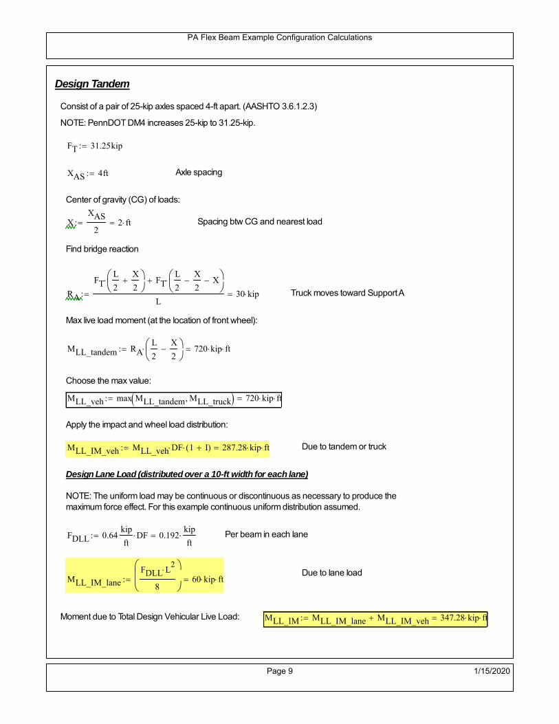
PA Flex Beam Example Configuration Calculations
Design Tandem
Consist of a pair of 25-kip axles spaced 4-ft apart. (AASHTO 3.6.1.2.3)
NOTE: PennDOT DM4 increases 25-kip to 31.25-kip.
FT 31.25kip
XAS 4ft Axle spacing
Center of gravity (CG) of loads:
XXAS
22 ft Spacing btw CG and nearest load
Find bridge reaction
RA
FTL
2
X
2
FTL
2
X
2 X
L30 kip Truck moves toward Support A
Max live load moment (at the location of front wheel):
MLL_tandem RAL
2
X
2
720 kip ft
Choose the max value:
MLL_veh max MLL_tandem MLL_truck 720 kip ft
Apply the impact and wheel load distribution:
MLL_IM_veh MLL_veh DF 1 I( ) 287.28 kip ft Due to tandem or truck
Design Lane Load (distributed over a 10-ft width for each lane)
NOTE: The uniform load may be continuous or discontinuous as necessary to produce themaximum force effect. For this example continuous uniform distribution assumed.
FDLL 0.64kip
ftDF 0.192
kip
ft Per beam in each lane
Due to lane loadMLL_IM_lane
FDLL L2
8
60 kip ft
Moment due to Total Design Vehicular Live Load: MLL_IM MLL_IM_lane MLL_IM_veh 347.28 kip ft
Page 9 1/15/2020

PA Flex Beam Example Configuration Calculations
Design Permit Load P-82 (Section 3.6.1.2.7 DM4)
P1 P2 P3 P4 P5 P6 P7
NOTE: The moment for the permit load is defined at the beginning of the sheetand is obtained from MATLab File FlexBeam_Moment_ShearEnvelope.m
STEP 6: Compute Moment of Inertia (Note: rebar neglected!)
1) Moment of Inertia resisting dead load only:
a) Acting on the non-composite section (before the deck has hardened - DC1)
Use steel section only
Inc Istl 1.329 103
in4
Non-composite section modulus
Y'nc y_bar S.G. of the steel section of Flex Beam (Datum is bottom)
b) Acting on the composite section (after the deck has hardened - DC2)
Use Ic_short as defined below.
Page 10 1/15/2020

PA Flex Beam Example Configuration Calculations
2) Moment of Inertia resisting live load plus impact:
Using transformed slab with k1=1 (short-term composite).
Actr1 hf btr1 33.75 in2
Itr1
btr1 hf3
12158.203 in
4
Y'
Actr1 hhf
2
Astl Y'nc
Astl Actr118.913 in S.G. of the total flex beam (Datum is bottom)
Compositesection modulus(short-term)
Ic_short Istl Astl Y'nc Y' 2 Itr1 Actr1 hhf
2
Y'
2
5166 in4
Y'c_short Y' 18.913 in N.A. of the short-term composite section
3) Moment of Inertia resisting superimposed dead load:
Using transformed slab with k3=3.
Actr3 hf btr3 11.25 in2
Itr3
btr3 hf3
1252.734 in
4
Y'
Actr3 hhf
2
Astl Y'nc
Astl Actr314.305 in S.G. of the total flex beam (Datum is bottom)
Compositesection modulus(long-term)
Ic_long Istl Astl Y'nc Y' 2 Itr3 Actr3 hhf
2
Y'
2
3500 in4
Y'c_long Y' 14.305 in N.A. of the long-term composite section
Page 11 1/15/2020

PA Flex Beam Example Configuration Calculations
STEP 6.5 Check Ductility RequirementIn accordance with AASHTO Article 6.10.7.3 check ductility requirement. Assume compressionblock of concrete is at 0.85 f'c and that the concrete supports no tension. Steel section isassumed to be fully plastic at Fy.
Case 1 : Assuming PNA is in Concreteh d 4 inAssuming (h-d) < Dp < hf
Fp Dp 0.85 fc be Dp Fy tw Dp h d( ) Fy Astl tw Dp h d( )
Dp 7.5in 0.42 h 12.18 in
Dp1 root Fp Dp Dp 6.87 in Must be less than hf 7.5 inDp1
h0.237 must be < 0.42
Mn1check Dp1 hf h d( ) Dp1[ ] Dp1 0.42 h( ) 1 Dp1 0.42 h 1
Mp1 0.85 fc be Dp1Dp1
2
Fy tw Dp1 h d( )[ ] Dp1 h d( )[ ]
2
Fy bf tf h Dp1tf
2
Fy tw h Dp1 tf h Dp1 tf
2
Mp1 16953.79 kip in Mn1 Mp1 1.07 0.7Dp1
h
15329.2 kip in
Case 2 : Assuming PNA is NOT in Concrete
Assuming hf < Dp
Fp2 Dp 0.85 fc be hf Fy tw Dp h d( ) Fy Astl tw Dp h d( )
Dp 2.5in
Dp2 root Fp2 Dp Dp 5.328 in Must be more than hf 7.5 inDp2
h0.1837 must be < 0.42
Mn2check Dp2 hf Dp2 h( ) Dp2 0.42 h( ) 0 Dp2 0.42 h 1
Mp2 0.85 fc be hf Dp2hf
2
Fy tw Dp2 h d( )[ ] Dp2 h d( )[ ]
2
Fy bf tf h Dp2tf
2
Fy tw h Dp2 tf h Dp2 tf
2
Mp2 16870.01 kip inMn2 Mp2 1.07 0.7
Dp2
h
15881.5 kip in
Mn max Mn1 Mn1check Mn2 Mn2check 1277.4 kip ft Mn 15329.2 kip in
Page 12 1/15/2020

PA Flex Beam Example Configuration Calculations
Check Composite Compact Section Criteria (6.10.6.2)
Dcpd
2
Fy tf bf 0.85 fc be hf
Fy hw tw1
1.362 in Dcp0 Dcp 0 1
Dcp Dcp Dcp0 1.362 in2 Dcp
tw3.76
Es
Fy 1 Check if section is compact
STEP 7: Load Combinations (Table 3.4.1-1)
The following load combinations will be considered herein. Only the maximum load factors forpermanent-loads are used in the following load combinations (uplift is not an issue for this typeof bridge).STRENGTH I 1.25DL + 1.5SDL + 1.75 (LL+IM)
SERVICE II: DL+SDL+1.3(LL+IM)
STEP 8: Compute and Check Stresses
Stress at bottom fiber of steel section
fDL
MDL Y'c_long
Ic_long5.553 ksi
fLL_I
MLL_IM Y'c_short
Ic_short15.258 ksi fPL
MLL_IM_PL82 Y'c_short
Ic_short17.971 ksi
fSDL
MSDL Y'c_long
Ic_long7.639 ksi
STRENGTH I fbot_str1 1.25fDL 1.5 fSDL 1.75 fLL_I 45.103 ksi
STRENGTH II fbot_str2 1.25fDL 1.5 fSDL 1.35 fPL 42.662 ksi
SERVICE II fbot_svc2 fDL fSDL 1.3fLL_I 33.03 ksi
Allowable Stress is based on Section 6.10.4.2.2-2
Flange stress due to service load II without consideration of flange lateral bending: ff fbot_svc2
Flange lateral bending stress due to service II: flSII 0ksi
Hybrid Factor: Rh 1.0 For rolled and homogenous built-up sections
ff
flSII
2 33.029 ksi 0.95 Rh Fy 47.5 ksi ff
fl
2 0.95Rh Fy 1
Page 13 1/15/2020

PA Flex Beam Example Configuration Calculations
Stress at top fiber of concrete
Note: For calculating longitudinal flexural stresses in the concrete deck due to allpermanent and transient loads, the short-term modular ratio shall be used.
fDL
MDL h Y'c_short
k1 n Ic_short0.332 ksi
fLL_I
MLL_IM h Y'c_short
k1 n Ic_short1.017 ksi fPL
MLL_IM_PL82 h Y'c_short
k1 n Ic_short1.198 ksi
fSDL
MSDL h Y'c_short
k1 n Ic_short0.456 ksi
STRENGTH I fc_str1 1.25fDL 1.5 fSDL 1.75 fLL_I 2.879 ksi
Mstr1 1.25 MDL 1.5 MSDL 1.75 MLL_IM 982.9 kip ft Mstr1 Mn 1
STRENGTH II fc_str2 1.25fDL 1.5 fSDL 1.35 fPL 2.716 ksi
Mstr2 1.25 MDL 1.5 MSDL 1.35 MLL_IM_PL82 927 kip ft Mstr2 Mn 1
SERVICE II
Allowable Stress in concrete - AASHTO 6.10.4.2.2For compact composite sections in positive flexure utilized in shored construction, the longitudinalcompressive stress in the concrete deck due to the Service II loads, determined as specified in Article6.10.1.1.1d, shall not exceed 0.6f́ c.
fallow 0.6 fc 2400 psi
fc_2 1.3fLL_I fSDL fDL 2110.11 psi This assumes short term compositesection for all calculations
fc_2 fallow 1
SERVICE II with Long Term Composite for dead loads
fDL
MDL h Y'c_long
k3 n Ic_long0.238 ksi
fLL_I
MLL_IM h Y'c_short
k1 n Ic_short1.017 ksi
fSDL
MSDL h Y'c_long
k3 n Ic_long0.327 ksi
fc_2 1.3fLL_I fSDL fDL 1887.02 psi fc_2 fallow 1
Page 14 1/15/2020

PA Flex Beam Example Configuration Calculations
Strength V Moment Check
Strength V is related to normal vehicular use of the bridge with an 80 mph wind gust
Note: that Strength V is checked for an exterior girder under wind load with the interior girder distribution factor forflexure used. If Strength V controls design, then this approach should be modified
Design vertical moment is: 1.25DL + 1.5SDL + 1.35 (LL+IM)
SLT
Ic_long
Y'c_long244.646 in
3 SST
Ic_short
Y'c_short273.119 in
3 short and long term section
modulus
Section D6.2.2 Find the moment required to cause yieldling of the flange. The approach is laid out in D6.2.2
MD2 1.25 MDL 1.5 MSDL 375.139 kip ft From D6.2.2-1 (all dead loads are in MD2 due to shoredconstruction
MAD Fy
MD2
SLT
SST 719.197 kip ft Additional moment to cause nominal yielding of steel flange
My MD2 MAD 1.094 103
kip ft D6.2.2-2: Moment to cause yielding of flange
6.10.7.1 Compact Section Check at Strength V limit state
Section Modulus for yielding of the flange (My/Fy) for equation 6.10.7.1.1-1Sxt
My
Fy262.641 in
3
Mu 1.25 MDL 1.5MSDL 1.35MLL_IM 843.967 kip ft Moment due to Strength V limit state
Mu1
3fl Sxt 913.568 kip ft Equation 6.10.7.1.7-1 Mn 1.277 10
3 kip ft Mu
1
3fl Sxt Mn 1
Page 15 1/15/2020

PA Flex Beam Example Configuration Calculations
STEP 9: Compute Deflection
Optional Live Load Deflection Evaluation (AASHTO 3.6.1.3.2)
Deflection distribution factor for vehicular loads: For a straight multibeambridge, this is equivalent to saying that the distribution factor for deflectionis equal to the number of lanes divided by the number of beams. 2.5.2.6.2
DFd
Nl
N0.2
Deflection should be taken as 125% the larger of:- Design truck- 25% of design truck + design lane
The live load portion of Load Combination Service I of Table 3.4.1-1 should be used,including the dynamic load allowance, IM;
Deflection due to design truck load
NOTE : Assuming maximum deflection occurs when the center of gravity of the loads is at thecenter line of the span.
P1 8kip P2 32kip P3 32kip Axle loads (AASHTO 3.6.1.2.2)
XASr 14ft Rear Axle spacing for truck (14ft - 30ft)
XASf 14ft Front Axle spacing for truck
Center of gravity (CG) of loads:
X'P1 XASr XASf P2 XASr
P1 P2 P39.333 ft Datum is the rear axle
Method1: Assuming single load = P1+P2+P3 at the midspan (Conservative approach)
P1 P2 P3 L3
48 Es Ic_short 2.163 in
Method2: Calculation of Midspan deflection using superposition
b1L
2XASr X' XASf 6.333 ft distance btw load P1 and support A b1check b1 0 1
b2L
2XASr X' 20.333 ft distance btw load P2 and support A b2check b2 0 1
b3L
2X' 15.667 ft distance btw load P3 and support B b3check b3 0 1
Page 16 1/15/2020

PA Flex Beam Example Configuration Calculations
Deflection of the beam at midspan due to P1: P P1
xL
2 at midspan b b1 b1check The smallest distance btw load P1 and support
Δ1P b x
6 Es Ic_short LL2
b2
x2
0.089 in
Deflection of the beam at midspan due to P2: P P2
xL
2 at midspan b b2 b2check The smallest distance btw load P2 and support
Δ2P b x
6 Es Ic_short LL2
b2
x2
0.914 in
Deflection of the beam at midspan due to P3: P P3
xL
2 at midspan b b3 b3check The smallest distance btw load P3 and support
Δ3P b x
6 Es Ic_short LL2
b2
x2
0.785 in
Total Deflection at midspan:
Δtruck Δ1 Δ2 Δ3( ) DFd 1 I( ) 0.476 in (Considering IM)
Deflection due to tandem (Note: this calculation is not required according to Article3.6.1.3.2 which denotes only the design truck for deflection calculation)
Page 17 1/15/2020

PA Flex Beam Example Configuration Calculations
FT 31.25 kip Per axle
XAS 4ft Axle spacing
Δtandem
FTL
2
XAS
2
24 Es Ic_short3 L
2 4
L
2
XAS
2
2
DFd 1 I( ) 0.495 in (Considering IM)
Deflection due to lane load
FDLLd 640lbf
ft DFd 128
lbf
ft
Δlane
5 FDLLd L4
384 Es Ic_short0.12 in
Live Load Deflection:
ΔLL 1.25max Δtruck 0.25Δtruck Δlane 1.25 0.743 in ΔLLL
800 1
Deflection Limit
For steel or concrete vehicular bridges:
Vehicular load = Span/800L
8000.75 in
L
10000.6 in
Evaluation of Deflection at the Service Limit State (AASHTO 3.4.2.2)
The associated permitted deflections shall be included in the contract documents.
Page 18 1/15/2020

PA Flex Beam Example Configuration Calculations
Shear demands:
Determination of the distribution factor
Using DM4 Table 4.6.2.2.3a-1
Sbe
12in3 transverse girder spacing (ft)
Distribution of live loads per lane for shear in interior beams:
For two design lanes loaded, 3.5' <= S =< 16', number of beam >= 4DFs 0.36
S
25 0.48
Q Actr1 h Y'c_shorthf
2
213.861 in3
first moment of deck slab for interface shear
Method 1: Range of shear based on Strength I Limit
STRENGTH I 1.25DL + 1.5SDL + 1.75 (LL+IM)
Computation of the range of shear in the beam
Dead Load:DL 0.362
kip
ft
Superimposed Dead Load: SDL 0.498kip
ft
Design Lane Load: 0.64kip
ft
Design Truck:
XASr 14ft Rear Axle spacing for truck (14ft - 30ft)
XASf 14ft Front Axle spacing for truck
P1 8 kip P2 32 kip P3 32 kip Wheel loads (AASHTO 3.6.1.2.2)
Design Tandem:
Consist of a pair of 25-kip axles spaced 4-ft apart. (AASHTO 3.6.1.2.3)
NOTE: PennDOT DM4 increases 25-kip to 31.25-kip.
FT 31.25kip
XAS 4ft Axle spacing
Page 19 1/15/2020

PA Flex Beam Example Configuration Calculations
Maximum positive shear at various points along the FlexBeam are examined.
At x=0 (at left support) (Truck is moving from left to right)
Truck
Max Positive Shear (when P3 is at x = 0):
x1 L XASr XASf 22 ft Distance between P1 and right support
x2 L XASr 36 ft Distance between P2 and right support
x3 L 50 ft Distance between P3 and right support
V1 P3
x3
L P2
x2
L P1
x1
L 58.56 kip
Total Vertical Shear Force for each FlexBeam (considering dynamic loads):
Vtruck1 V1 DFs 1 I( ) 37.385 kip
Tandem:
V1 FT FT
L XAS L
60 kip
Total Vertical Shear Force for each FlexBeam (considering dynamic loads):
Vtandem1 V1 DFs 1 I( ) 38.304 kip
Lane Load
V1 0.64kip
ft
L
2 16 kip
Total Vertical Shear Force for each FlexBeam (considering dynamic loads):
Vlane1 V1 DFs 7.68 kip
Dead Load
Vdl1 DLL
2 9.058 kip
Superimposed Dead Load
Vsdl1 SDLL
2 12.459 kip
Strength I Max Positive Shear:
Vstr1 1.25 Vdl1 1.5 Vsdl1 1.75 Vlane1 max Vtruck1 Vtandem1 110.483 kip
Page 20 1/15/2020
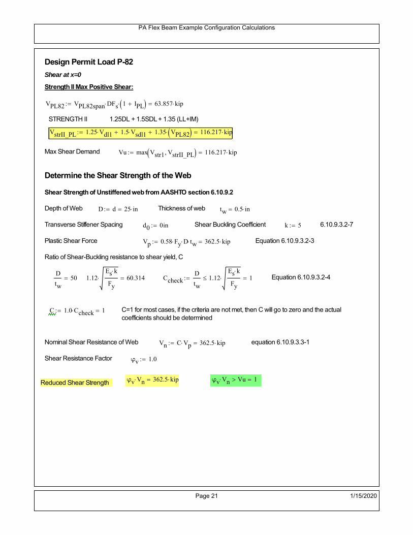
PA Flex Beam Example Configuration Calculations
Design Permit Load P-82
Shear at x=0
Strength II Max Positive Shear:
VPL82 VPL82span DFs 1 IPL 63.857 kip
STRENGTH II 1.25DL + 1.5SDL + 1.35 (LL+IM)
VstrII_PL 1.25 Vdl1 1.5 Vsdl1 1.35 VPL82 116.217 kip
Max Shear Demand Vu max Vstr1 VstrII_PL 116.217 kip
Determine the Shear Strength of the Web
Shear Strength of Unstiffened web from AASHTO section 6.10.9.2
Depth of Web D d 25 in Thickness of web tw 0.5 in
Transverse Stiffener Spacing d0 0in Shear Buckling Coefficient k 5 6.10.9.3.2-7
Plastic Shear Force Vp 0.58 Fy D tw 362.5 kip Equation 6.10.9.3.2-3
Ratio of Shear-Buckling resistance to shear yield, C
D
tw50 1.12
Es k
Fy 60.314 Ccheck
D
tw1.12
Es k
Fy 1 Equation 6.10.9.3.2-4
C 1.0 Ccheck 1 C=1 for most cases, if the criteria are not met, then C will go to zero and the actualcoefficients should be determined
Nominal Shear Resistance of Web Vn C Vp 362.5 kip equation 6.10.9.3.3-1
Shear Resistance Factor φv 1.0
φv Vn 362.5 kip φv Vn Vu 1Reduced Shear Strength
Page 21 1/15/2020

PA Flex Beam Example Configuration Calculations
Check Bearing Stiffeners
FYs 50ksi Yield strength of stiffener
tp 0.75in Thickness of stiffener
bt
bf tw
21.5in 4.25 in Effective width of stiffener
Dst hw 4.1in 20.275 in Depth of stiffeners
Apn 2 tp bt 6.375 in2
Projected area of stiffeners
bt 0.48 tpEs
FYs 1Check that effective width of stiffener meets requirements
Rsbn 1.4 Apn FYs 446.25 kip Bearing capacity of stiffener (phi=1 for bearing per AASHTO 6.5.4.2)
Rsbn Vu 1 Bearing capacity check
Qs 1.0 Q factor for bearing stiffner, taken as 1 (AASHTO 6.9.4.1.1)
Is
18 tw tw3
tp 2 bt 3
1238.477 in
4 Moment of inertia of stiffener and web (9*tw is used on each side)
AASHTO 6.10.11.2.4b
Ag 18 tw tw 2 bt tp 10.875 in2
Gross area of stiffener and web (AASHTO 6.10.11.2.4b)
rs
Is
Ag1.881 in Radius of gyration of stiffener/web
Po Qs FYs Apn 318.75 kip Nominal yeild resistance of stiffener (AASHTO 6.9.4.1.1)
Peπ2Es
0.75 Dst
rs
2Ag 4.763 10
4 kip Elastic critical buckling stress of stiffener (AASHTO 6.9.4.1.2-1)
Check that Pe/Po is great than 0.44 (AASHTO 6.9.4.1.1) PePoPe
Po0.44 1
Pn PePo 0.658
Po
Pe Po 317.858 kip Nominal compressive resistance of stiffener for Pe/Po>0.44
(AASHTO 6.9.4.1.1-1)
φcr 0.95 phi factor for axial compression (AASHTO 6.5.4.2)
Pr φcr Pn 301.965 kip Compressive capacity of bearing stiffener Pr Vu 1
Page 22 1/15/2020

PA Flex Beam Example Configuration Calculations
Flexbeam Example Configuration Calculations
Summary of Calculations:
Input section dimensions and material properties for steel WT and the concrete deck1.Calculate demands (dead load, superimposed dead, and Live load demands for Strength I and Strength II2.Calculate composite section properties for the given section3.Check Strength I, Strength II, and Service II stresses 4.Check Strength I, Strength II, and Strength V moment demands 5.Perform live load deflection check6.Determine maximum shear demand and capacity7.Note: Shear envelope data was obtained from Matlab script (FlexBeam_Moment_ShearEnvelope.m).8.Shear envelope calculations are summarized separately for each design (Shear Design *.xlsx).
Design Assumptions:Design Specifications Used:
AASHTO LRFD Bridge Design Specifications 7th Edition with 2016 Interim RevisionsPennDOT Design Manual, Part 4 (DM-4) June 30, 2015
Example configurations are determined for two girder spacings, 36" and 40".The deck thickness is 7.5" and is assumed to have a non-structural wearing surface added after installation.Section properties are calculated using the full 7.5" deck thickness.The WT sections are embedded 3.5" into the concrete deck. The steel section spacing used is outside the scope of the AASHTO and PennDOT distribution factorequations. The flexural distribution factor is assumed to be 0.3 which was shown to tbe conservativeaccording to refined analysisThe shear distribution factor is calculated using the DM-4 shear distribution factor equation which wasshown to be conservative using refined analysis.Refined analysis is presented in: Zihan Ma, "Distribution Factors for Composite Steel Tee Concrete DeckBridge System," M.S. Thesis, Deparement of Civil and Environmental Engineering, Lehigh University,Bethlehem, 2019Shear and moment demands for the PL82 permit load vehicle are determined by Matlab script(FlexBeam_Moment_ShearEnvelope.m) and are manually input into this calculation sheet.All fabrication will occur as double modules, i.e. each module contains two WT sections. The number ofmodules is half the number of beams, N. A 45 in. tall F-Shape barrier is used, Weight = 700 lb/ft (Distributed to exterior two beams).
The work presented in this document are provided on an “AS IS” basis. University makes no warranties of anykind, express or implied, as to any matter whatsoever, including, without limitation, warranties with respect tothe merchantability or fitness for a particular purpose of this work or any project deliverables. Universitymakes no warranty of any kind with respect to freedom from patent, trademark, copyright or trade secretinfringement arising from the use of the results of the project, deliverables, services, intellectual property orother materials provided hereunder. University shall not be liable for any direct, indirect, consequential,punitive, or other damages suffered by Sponsor or any other person resulting from the project, or the use ofthis work or any project deliverables.
Page 1 1/15/2020

PA Flex Beam Example Configuration Calculations
hf
tf
bf
twh
d
bjtbe
e
Variable Definitions:
Number of beams N 12 modulesN
26
L 50ft Span length
be 36in Effective width of Flexbeamassuming constructed bridge width(i.e. closure joints cast)
Built Up Section Properties
tw 0.500in tf 0.625in bf 12in
h 29in Overall Height of section
hf 7.5in Total thickness of deck
e 3.5in Deck/Steel overlap
d h hf e 25 in depth of built up steel section
hw d tf 24.375 in height of web of built up steel
Moment and shear for permit load PL82 obtained from Matlab script: FlexBeam_Moment_ShearEnvelope
MLL_IM_PL82 409.0176kip ft Moment due to PL82 with distribution factor and impact factor!!
VPL82span 110.862kip Shear due to PL82 WITHOUT distribution factor and impact factor!!
Check web and flange dimensions in sections 6.10.2.1 and 6.10.2.2
(Ignore 6.10.2.2-4 since no compression flange)
equation 6.10.2.1.1-1d
tw150 1 equation 6.10.2.2-1
bf
2 tf12 1
equation 6.10.2.2-2 bfh
6 1 equation 6.10.2.2-3 tf 1.1 tw 1
y_bar
tf bftf
2 hw tw tf
hw
2
tf bf hw tw8.051 in Center of gravity of steel section
Istl
bf tf3
12bf tf y_bar
tf
2
2
tw hw
3
12 tw hw tf
hw
2 y_bar
2
1.329 103
in4
MOI of steel
Astl tf bf hw tw 19.687 in2
Area of the WT steel section
Page 2 1/15/2020

PA Flex Beam Example Configuration Calculations
Material Properties
Elastic Modulus of Steel Es 29000ksi
Yield Strength of Steel Fy 50ksi
Yield Strength of Reinforcement fy 60ksi
Compressive Strength of Concrete fc 4000psi AAAP PennDOT Concrete
Concrete Modular Ratio n 8 modular ratio for 4ksi concrete per AASHTO
Unit weight of concrete slab wc 0.150kip
ft3
Unit weight of concrete
Section Properties
Width of UHPC Joint: bjt 6in
Parapet width: bpar 20.25in Parapet width per PennDOT F-shape barrier
Width of the bridge W be N bjt 426 in W 35.5 ft
Clear width of roadway Wlane W 2 bpar 32.125 ft
Dc wc hf W 3.328kip
ft DL due to slab
Db .700kip
ft DL due to each 45" F-Shape Barrier (per email 11/1/18)
DFWS 30lbf
ft2
W 2 bpar 0.964kip
ft DL due to Future Wearing Surface (FWS)
Ds Astl 490lbf
ft3
0.067kip
ft Selfweight of the steel section
DLself
Dc N
Ds 0.344kip
ft Self-weight per WT
Total weight of each precast FlexBeam for transportation:
Weight of C12x25 Diaphragms Wend_diaphragms 25lbf
ft32 in 0.067 kip
2be bjt hf wc 2Ds L 2 Wend_diaphragms 32.614 kip
Determine number of design lane (AASHTO Section 3.6.1.1.1)
Take the integer part of the ratio of W/12 ft. Number of lanes in bridge: Nl floorWlane
12ft
2
Page 3 1/15/2020

PA Flex Beam Example Configuration Calculations
STEP 1: Compute Dead Load for each Flex Beam
DLslab
Dc
Nwc 1 in
be
2 0.296
kip
ft Dead load of slab assuming exterior overhang has 1" of
additional concrete thickness
DLsteel Ds 0.067kip
ft
DL DLslab DLsteel 0.363kip
ft
STEP 2: Compute Superimposed Dead Load
SDLWS
DFWS
N0.08
kip
ft
SDLparapet
Db
20.35
kip
ft distributed equally on two outer beams
SDLOL 140lbf
ft3be 2 in 0.07
kip
ft Overlay is 2" thick and is 140 lbs/cubic foot
NOTE: For this example barrier load is distributed equally among the two outer beams per conversation withPennDOT and M&M.
PennDOT DM4: "For composite adjacent and spread beams, the barrier (single barrier) load shall be equallydistributed to the nearest three (adjacent) and two (spread) beams, respectively, when the barriers are placedafter slab has hardened".
SDL SDLWS SDLparapet SDLOL 0.5kip
ft
STEP 3: Compute Transformed Width of Slab
For live load and dead load acting on the stringer k1 1 For short-term section property evaluation
btr1
be
k1 n4.5 in Transformed width of slab for short-term
For superimposed dead loads k3 3 For long-term section property evaluation
btr3
be
k3 n1.5 in Transformed width of slab for long-term
Page 4 1/15/2020

PA Flex Beam Example Configuration Calculations
STEP 4: Compute Dead and Superimposed Dead Load Moments(Based on first interior girder demands)
MDLDL L
2
8113.464 kip ft
MSDLSDL L
2
8156.348 kip ft
STEP 5: Compute live load and Dynamic Load Allowance (IM)
Live load wheel load distribution factor (DF):
Sbe
12in3 transverse girder spacing
NOTE: AASHTO presents equations to define DF for different types of superstructuresincluding Deck Composite wirh RC slab on steel girders (Type (a) in Table 4.6.2.2.1-1) forshear and moment in interior and exterior beams.
Using DM4 Table 4.6.2.2.2b-1:
eg h y_barhf
2 17.199 in Distance between the centers of gravity of the basic beam and deck
Kg n Istl Astl eg2
57224.49 in
4 Longitudinal stiffness parameter (in4)
Distribution of Live Load Per Lane for Moment in Interior Beams:
to be conservative, use DF 0.3
Page 5 1/15/2020

PA Flex Beam Example Configuration Calculations
Dynamic Load Allowance (Section 3.6.2 DM4)
Static effects of the design truck or tandem, shall be increased by the impact factor.
NOTE: The dynamic load allowance shall not be applied to the design lane load (Section 3.6.2.1 DM4)
I 0.33 Impact factor for moment
Note: PennDOT requires that the impact for decks be increased from 33% to 50%, the deck is not beingdesigned here. Instrad the deck design is based on the BD recommendations.
Dynamic load allowance for the Permit Load P-82 shall be less than 20%. (Section 3.6.2.1DM4)
IPL 0.20 Impact factor for moment on Strength II
Design Wind Loading for Exterior Girder
Vw 80 Wind speed for Strength V load case
CD 1.3 Gust factor for windard side of I-Girder and Box Girder Superstructures (Table 3.8.1.2.1-2)
G 1.0 Gus effect factor is 1.0 for all structures other than sound barriers (Table 3.8.1.2.1-1)
Kz 1.0 Pressure coefficient taken as 1 for Strength V (3.8.1.2.1)
Pz 2.56 106
Vw 2 Kz G CDkip
ft2
0.021kip
ft2
Wind pressure on exterior girder
hexp h hf 21.5 in Exposed height of exterior girder
Moment due to wind loading on exterior girderMWL
Pz hexp L2
811.925 kip ft
Iyy
bf3tf
1290 in
4 Transverse moment of intertia
Flange lateral bending stressfl
MWL
bf
2
Iyy9.54 ksi
Page 6 1/15/2020

PA Flex Beam Example Configuration Calculations
Design Vehicular Live Load
PHL-93 and P-82 are examined herein.
PHL-93 (A3.6.1.2.1)
PHL-93 consists of a combination of (design truck or design tandem) + (design lane load)
Design Truck
PennDOT defines the design truck in accordance with AASTHO 3.6.1.2
Design truck load in AASHTO (HS20 Truck) is used for this example.
NOTE : MAX moment occurs when the center line of the span is midway between the center ofgravity of the loads and the nearest concentrated load.
P1 8kip P2 32kip P3 32kip Axle loads (AASHTO 3.6.1.2.2)
XASr 14ft Rear Axle spacing for truck (14ft - 30ft)
XASf 14ft Front Axle spacing for truck
Page 7 1/15/2020

PA Flex Beam Example Configuration Calculations
Center of gravity (CG) of loads:
X'P1 XASr XASf P2 XASr
P1 P2 P39.333 ft Datum is the rear axle
X XASr X' 4.667 ft Spacing btw CG and nearest load
Find bridge reaction
Truck movestoward Support ARA
P1L
2XASf
X
2
P2L
2
X
2
P3L
2X'
X
2
L32.64 kip
Max live load moment (at the location of P2):
MLL_truck RAL
2
X
2
P1 XASf 627.84 kip ft
NOTE: Find the worst case by varying XASr
Page 8 1/15/2020

PA Flex Beam Example Configuration Calculations
Design Tandem
Consist of a pair of 25-kip axles spaced 4-ft apart. (AASHTO 3.6.1.2.3)
NOTE: PennDOT DM4 increases 25-kip to 31.25-kip.
FT 31.25kip
XAS 4ft Axle spacing
Center of gravity (CG) of loads:
XXAS
22 ft Spacing btw CG and nearest load
Find bridge reaction
RA
FTL
2
X
2
FTL
2
X
2 X
L30 kip Truck moves toward Support A
Max live load moment (at the location of front wheel):
MLL_tandem RAL
2
X
2
720 kip ft
Choose the max value:
MLL_veh max MLL_tandem MLL_truck 720 kip ft
Apply the impact and wheel load distribution:
MLL_IM_veh MLL_veh DF 1 I( ) 287.28 kip ft Due to tandem or truck
Design Lane Load (distributed over a 10-ft width for each lane)
NOTE: The uniform load may be continuous or discontinuous as necessary to produce themaximum force effect. For this example continuous uniform distribution assumed.
FDLL 0.64kip
ftDF 0.192
kip
ft Per beam in each lane
Due to lane loadMLL_IM_lane
FDLL L2
8
60 kip ft
Moment due to Total Design Vehicular Live Load: MLL_IM MLL_IM_lane MLL_IM_veh 347.28 kip ft
Page 9 1/15/2020

PA Flex Beam Example Configuration Calculations
Design Permit Load P-82 (Section 3.6.1.2.7 DM4)
P1 P2 P3 P4 P5 P6 P7
NOTE: The moment for the permit load is defined at the beginning of the sheetand is obtained from MATLab File FlexBeam_Moment_ShearEnvelope.m
STEP 6: Compute Moment of Inertia (Note: rebar neglected!)
1) Moment of Inertia resisting dead load only:
a) Acting on the non-composite section (before the deck has hardened - DC1)
Use steel section only
Inc Istl 1.329 103
in4
Non-composite section modulus
Y'nc y_bar S.G. of the steel section of Flex Beam (Datum is bottom)
b) Acting on the composite section (after the deck has hardened - DC2)
Use Ic_short as defined below.
Page 10 1/15/2020

PA Flex Beam Example Configuration Calculations
2) Moment of Inertia resisting live load plus impact:
Using transformed slab with k1=1 (short-term composite).
Actr1 hf btr1 33.75 in2
Itr1
btr1 hf3
12158.203 in
4
Y'
Actr1 hhf
2
Astl Y'nc
Astl Actr118.913 in S.G. of the total flex beam (Datum is bottom)
Compositesection modulus(short-term)
Ic_short Istl Astl Y'nc Y' 2 Itr1 Actr1 hhf
2
Y'
2
5166 in4
Y'c_short Y' 18.913 in N.A. of the short-term composite section
3) Moment of Inertia resisting superimposed dead load:
Using transformed slab with k3=3.
Actr3 hf btr3 11.25 in2
Itr3
btr3 hf3
1252.734 in
4
Y'
Actr3 hhf
2
Astl Y'nc
Astl Actr314.305 in S.G. of the total flex beam (Datum is bottom)
Compositesection modulus(long-term)
Ic_long Istl Astl Y'nc Y' 2 Itr3 Actr3 hhf
2
Y'
2
3500 in4
Y'c_long Y' 14.305 in N.A. of the long-term composite section
Page 11 1/15/2020

PA Flex Beam Example Configuration Calculations
STEP 6.5 Check Ductility RequirementIn accordance with AASHTO Article 6.10.7.3 check ductility requirement. Assume compressionblock of concrete is at 0.85 f'c and that the concrete supports no tension. Steel section isassumed to be fully plastic at Fy.
Case 1 : Assuming PNA is in Concreteh d 4 inAssuming (h-d) < Dp < hf
Fp Dp 0.85 fc be Dp Fy tw Dp h d( ) Fy Astl tw Dp h d( )
Dp 7.5in 0.42 h 12.18 in
Dp1 root Fp Dp Dp 6.87 in Must be less than hf 7.5 inDp1
h0.237 must be < 0.42
Mn1check Dp1 hf h d( ) Dp1[ ] Dp1 0.42 h( ) 1 Dp1 0.42 h 1
Mp1 0.85 fc be Dp1Dp1
2
Fy tw Dp1 h d( )[ ] Dp1 h d( )[ ]
2
Fy bf tf h Dp1tf
2
Fy tw h Dp1 tf h Dp1 tf
2
Mp1 16953.79 kip in Mn1 Mp1 1.07 0.7Dp1
h
15329.2 kip in
Case 2 : Assuming PNA is NOT in Concrete
Assuming hf < Dp
Fp2 Dp 0.85 fc be hf Fy tw Dp h d( ) Fy Astl tw Dp h d( )
Dp 2.5in
Dp2 root Fp2 Dp Dp 5.328 in Must be more than hf 7.5 inDp2
h0.1837 must be < 0.42
Mn2check Dp2 hf Dp2 h( ) Dp2 0.42 h( ) 0 Dp2 0.42 h 1
Mp2 0.85 fc be hf Dp2hf
2
Fy tw Dp2 h d( )[ ] Dp2 h d( )[ ]
2
Fy bf tf h Dp2tf
2
Fy tw h Dp2 tf h Dp2 tf
2
Mp2 16870.01 kip inMn2 Mp2 1.07 0.7
Dp2
h
15881.5 kip in
Mn max Mn1 Mn1check Mn2 Mn2check 1277.4 kip ft Mn 15329.2 kip in
Page 12 1/15/2020

PA Flex Beam Example Configuration Calculations
Check Composite Compact Section Criteria (6.10.6.2)
Dcpd
2
Fy tf bf 0.85 fc be hf
Fy hw tw1
1.362 in Dcp0 Dcp 0 1
Dcp Dcp Dcp0 1.362 in2 Dcp
tw3.76
Es
Fy 1 Check if section is compact
STEP 7: Load Combinations (Table 3.4.1-1)
The following load combinations will be considered herein. Only the maximum load factors forpermanent-loads are used in the following load combinations (uplift is not an issue for this typeof bridge).STRENGTH I 1.25DL + 1.5SDL + 1.75 (LL+IM)
SERVICE II: DL+SDL+1.3(LL+IM)
STEP 8: Compute and Check Stresses
Stress at bottom fiber of steel section
fDL
MDL Y'c_long
Ic_long5.565 ksi
fLL_I
MLL_IM Y'c_short
Ic_short15.258 ksi fPL
MLL_IM_PL82 Y'c_short
Ic_short17.971 ksi
fSDL
MSDL Y'c_long
Ic_long7.669 ksi
STRENGTH I fbot_str1 1.25fDL 1.5 fSDL 1.75 fLL_I 45.162 ksi
STRENGTH II fbot_str2 1.25fDL 1.5 fSDL 1.35 fPL 42.721 ksi
SERVICE II fbot_svc2 fDL fSDL 1.3fLL_I 33.07 ksi
Allowable Stress is based on Section 6.10.4.2.2-2
Flange stress due to service load II without consideration of flange lateral bending: ff fbot_svc2
Flange lateral bending stress due to service II: flSII 0ksi
Hybrid Factor: Rh 1.0 For rolled and homogenous built-up sections
ff
flSII
2 33.07 ksi 0.95 Rh Fy 47.5 ksi ff
fl
2 0.95Rh Fy 1
Page 13 1/15/2020

PA Flex Beam Example Configuration Calculations
Stress at top fiber of concrete
Note: For calculating longitudinal flexural stresses in the concrete deck due to allpermanent and transient loads, the short-term modular ratio shall be used.
fDL
MDL h Y'c_short
k1 n Ic_short0.332 ksi
fLL_I
MLL_IM h Y'c_short
k1 n Ic_short1.017 ksi fPL
MLL_IM_PL82 h Y'c_short
k1 n Ic_short1.198 ksi
fSDL
MSDL h Y'c_short
k1 n Ic_short0.458 ksi
STRENGTH I fc_str1 1.25fDL 1.5 fSDL 1.75 fLL_I 2.882 ksi
Mstr1 1.25 MDL 1.5 MSDL 1.75 MLL_IM 984.1 kip ft Mstr1 Mn 1
STRENGTH II fc_str2 1.25fDL 1.5 fSDL 1.35 fPL 2.72 ksi
Mstr2 1.25 MDL 1.5 MSDL 1.35 MLL_IM_PL82 929 kip ft Mstr2 Mn 1
SERVICE II
Allowable Stress in concrete - AASHTO 6.10.4.2.2For compact composite sections in positive flexure utilized in shored construction, the longitudinalcompressive stress in the concrete deck due to the Service II loads, determined as specified in Article6.10.1.1.1d, shall not exceed 0.6f́ c.
fallow 0.6 fc 2400 psi
fc_2 1.3fLL_I fSDL fDL 2112.6 psi This assumes short term compositesection for all calculations
fc_2 fallow 1
SERVICE II with Long Term Composite for dead loads
fDL
MDL h Y'c_long
k3 n Ic_long0.238 ksi
fLL_I
MLL_IM h Y'c_short
k1 n Ic_short1.017 ksi
fSDL
MSDL h Y'c_long
k3 n Ic_long0.328 ksi
fc_2 1.3fLL_I fSDL fDL 1888.8 psi fc_2 fallow 1
Page 14 1/15/2020

PA Flex Beam Example Configuration Calculations
Strength V Moment Check
Strength V is related to normal vehicular use of the bridge with an 80 mph wind gust
Note: that Strength V is checked for an exterior girder under wind load with the interior girder distribution factor forflexure used. If Strength V controls design, then this approach should be modified
Design vertical moment is: 1.25DL + 1.5SDL + 1.35 (LL+IM)
SLT
Ic_long
Y'c_long244.646 in
3 SST
Ic_short
Y'c_short273.119 in
3 short and long term section
modulus
Section D6.2.2 Find the moment required to cause yieldling of the flange. The approach is laid out in D6.2.2
MD2 1.25 MDL 1.5 MSDL 376.352 kip ft From D6.2.2-1 (all dead loads are in MD2 due to shoredconstruction
MAD Fy
MD2
SLT
SST 717.843 kip ft Additional moment to cause nominal yielding of steel flange
My MD2 MAD 1.094 103
kip ft D6.2.2-2: Moment to cause yielding of flange
6.10.7.1 Compact Section Check at Strength V limit state
Section Modulus for yielding of the flange (My/Fy) for equation 6.10.7.1.1-1Sxt
My
Fy262.607 in
3
Mu 1.25 MDL 1.5MSDL 1.35MLL_IM 845.18 kip ft Moment due to Strength V limit state
Mu1
3fl Sxt 914.773 kip ft Equation 6.10.7.1.7-1 Mn 1.277 10
3 kip ft Mu
1
3fl Sxt Mn 1
Page 15 1/15/2020

PA Flex Beam Example Configuration Calculations
STEP 9: Compute Deflection
Optional Live Load Deflection Evaluation (AASHTO 3.6.1.3.2)
Deflection distribution factor for vehicular loads: For a straight multibeambridge, this is equivalent to saying that the distribution factor for deflectionis equal to the number of lanes divided by the number of beams. 2.5.2.6.2
DFd
Nl
N0.167
Deflection should be taken as 125% the larger of:- Design truck- 25% of design truck + design lane
The live load portion of Load Combination Service I of Table 3.4.1-1 should be used,including the dynamic load allowance, IM;
Deflection due to design truck load
NOTE : Assuming maximum deflection occurs when the center of gravity of the loads is at thecenter line of the span.
P1 8kip P2 32kip P3 32kip Axle loads (AASHTO 3.6.1.2.2)
XASr 14ft Rear Axle spacing for truck (14ft - 30ft)
XASf 14ft Front Axle spacing for truck
Center of gravity (CG) of loads:
X'P1 XASr XASf P2 XASr
P1 P2 P39.333 ft Datum is the rear axle
Method1: Assuming single load = P1+P2+P3 at the midspan (Conservative approach)
P1 P2 P3 L3
48 Es Ic_short 2.163 in
Method2: Calculation of Midspan deflection using superposition
b1L
2XASr X' XASf 6.333 ft distance btw load P1 and support A b1check b1 0 1
b2L
2XASr X' 20.333 ft distance btw load P2 and support A b2check b2 0 1
b3L
2X' 15.667 ft distance btw load P3 and support B b3check b3 0 1
Page 16 1/15/2020

PA Flex Beam Example Configuration Calculations
Deflection of the beam at midspan due to P1: P P1
xL
2 at midspan b b1 b1check The smallest distance btw load P1 and support
Δ1P b x
6 Es Ic_short LL2
b2
x2
0.089 in
Deflection of the beam at midspan due to P2: P P2
xL
2 at midspan b b2 b2check The smallest distance btw load P2 and support
Δ2P b x
6 Es Ic_short LL2
b2
x2
0.914 in
Deflection of the beam at midspan due to P3: P P3
xL
2 at midspan b b3 b3check The smallest distance btw load P3 and support
Δ3P b x
6 Es Ic_short LL2
b2
x2
0.785 in
Total Deflection at midspan:
Δtruck Δ1 Δ2 Δ3( ) DFd 1 I( ) 0.397 in (Considering IM)
Deflection due to tandem (Note: this calculation is not required according to Article3.6.1.3.2 which denotes only the design truck for deflection calculation)
Page 17 1/15/2020
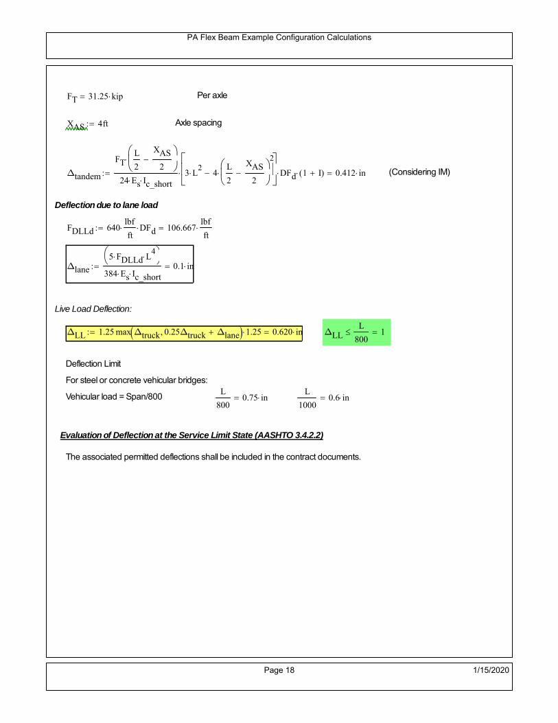
PA Flex Beam Example Configuration Calculations
FT 31.25 kip Per axle
XAS 4ft Axle spacing
Δtandem
FTL
2
XAS
2
24 Es Ic_short3 L
2 4
L
2
XAS
2
2
DFd 1 I( ) 0.412 in (Considering IM)
Deflection due to lane load
FDLLd 640lbf
ft DFd 106.667
lbf
ft
Δlane
5 FDLLd L4
384 Es Ic_short0.1 in
Live Load Deflection:
ΔLL 1.25max Δtruck 0.25Δtruck Δlane 1.25 0.620 in ΔLLL
800 1
Deflection Limit
For steel or concrete vehicular bridges:
Vehicular load = Span/800L
8000.75 in
L
10000.6 in
Evaluation of Deflection at the Service Limit State (AASHTO 3.4.2.2)
The associated permitted deflections shall be included in the contract documents.
Page 18 1/15/2020

PA Flex Beam Example Configuration Calculations
Shear demands:
Determination of the distribution factor
Using DM4 Table 4.6.2.2.3a-1
Sbe
12in3 transverse girder spacing (ft)
Distribution of live loads per lane for shear in interior beams:
For two design lanes loaded, 3.5' <= S =< 16', number of beam >= 4DFs 0.36
S
25 0.48
Q Actr1 h Y'c_shorthf
2
213.861 in3
first moment of deck slab for interface shear
Method 1: Range of shear based on Strength I Limit
STRENGTH I 1.25DL + 1.5SDL + 1.75 (LL+IM)
Computation of the range of shear in the beam
Dead Load:DL 0.363
kip
ft
Superimposed Dead Load: SDL 0.5kip
ft
Design Lane Load: 0.64kip
ft
Design Truck:
XASr 14ft Rear Axle spacing for truck (14ft - 30ft)
XASf 14ft Front Axle spacing for truck
P1 8 kip P2 32 kip P3 32 kip Wheel loads (AASHTO 3.6.1.2.2)
Design Tandem:
Consist of a pair of 25-kip axles spaced 4-ft apart. (AASHTO 3.6.1.2.3)
NOTE: PennDOT DM4 increases 25-kip to 31.25-kip.
FT 31.25kip
XAS 4ft Axle spacing
Page 19 1/15/2020

PA Flex Beam Example Configuration Calculations
Maximum positive shear at various points along the FlexBeam are examined.
At x=0 (at left support) (Truck is moving from left to right)
Truck
Max Positive Shear (when P3 is at x = 0):
x1 L XASr XASf 22 ft Distance between P1 and right support
x2 L XASr 36 ft Distance between P2 and right support
x3 L 50 ft Distance between P3 and right support
V1 P3
x3
L P2
x2
L P1
x1
L 58.56 kip
Total Vertical Shear Force for each FlexBeam (considering dynamic loads):
Vtruck1 V1 DFs 1 I( ) 37.385 kip
Tandem:
V1 FT FT
L XAS L
60 kip
Total Vertical Shear Force for each FlexBeam (considering dynamic loads):
Vtandem1 V1 DFs 1 I( ) 38.304 kip
Lane Load
V1 0.64kip
ft
L
2 16 kip
Total Vertical Shear Force for each FlexBeam (considering dynamic loads):
Vlane1 V1 DFs 7.68 kip
Dead Load
Vdl1 DLL
2 9.077 kip
Superimposed Dead Load
Vsdl1 SDLL
2 12.508 kip
Strength I Max Positive Shear:
Vstr1 1.25 Vdl1 1.5 Vsdl1 1.75 Vlane1 max Vtruck1 Vtandem1 110.58 kip
Page 20 1/15/2020

PA Flex Beam Example Configuration Calculations
Design Permit Load P-82
Shear at x=0
Strength II Max Positive Shear:
VPL82 VPL82span DFs 1 IPL 63.857 kip
STRENGTH II 1.25DL + 1.5SDL + 1.35 (LL+IM)
VstrII_PL 1.25 Vdl1 1.5 Vsdl1 1.35 VPL82 116.314 kip
Max Shear Demand Vu max Vstr1 VstrII_PL 116.314 kip
Determine the Shear Strength of the Web
Shear Strength of Unstiffened web from AASHTO section 6.10.9.2
Depth of Web D d 25 in Thickness of web tw 0.5 in
Transverse Stiffener Spacing d0 0in Shear Buckling Coefficient k 5 6.10.9.3.2-7
Plastic Shear Force Vp 0.58 Fy D tw 362.5 kip Equation 6.10.9.3.2-3
Ratio of Shear-Buckling resistance to shear yield, C
D
tw50 1.12
Es k
Fy 60.314 Ccheck
D
tw1.12
Es k
Fy 1 Equation 6.10.9.3.2-4
C 1.0 Ccheck 1 C=1 for most cases, if the criteria are not met, then C will go to zero and the actualcoefficients should be determined
Nominal Shear Resistance of Web Vn C Vp 362.5 kip equation 6.10.9.3.3-1
Shear Resistance Factor φv 1.0
φv Vn 362.5 kip φv Vn Vu 1Reduced Shear Strength
Page 21 1/15/2020

PA Flex Beam Example Configuration Calculations
Check Bearing Stiffeners
FYs 50ksi Yield strength of stiffener
tp 0.75in Thickness of stiffener
bt
bf tw
21.5in 4.25 in Effective width of stiffener
Dst hw 4.1in 20.275 in Depth of stiffeners
Apn 2 tp bt 6.375 in2
Projected area of stiffeners
bt 0.48 tpEs
FYs 1Check that effective width of stiffener meets requirements
Rsbn 1.4 Apn FYs 446.25 kip Bearing capacity of stiffener (phi=1 for bearing per AASHTO 6.5.4.2)
Rsbn Vu 1 Bearing capacity check
Qs 1.0 Q factor for bearing stiffner, taken as 1 (AASHTO 6.9.4.1.1)
Is
18 tw tw3
tp 2 bt 3
1238.477 in
4 Moment of inertia of stiffener and web (9*tw is used on each side)
AASHTO 6.10.11.2.4b
Ag 18 tw tw 2 bt tp 10.875 in2
Gross area of stiffener and web (AASHTO 6.10.11.2.4b)
rs
Is
Ag1.881 in Radius of gyration of stiffener/web
Po Qs FYs Apn 318.75 kip Nominal yeild resistance of stiffener (AASHTO 6.9.4.1.1)
Peπ2Es
0.75 Dst
rs
2Ag 4.763 10
4 kip Elastic critical buckling stress of stiffener (AASHTO 6.9.4.1.2-1)
Check that Pe/Po is great than 0.44 (AASHTO 6.9.4.1.1) PePoPe
Po0.44 1
Pn PePo 0.658
Po
Pe Po 317.858 kip Nominal compressive resistance of stiffener for Pe/Po>0.44
(AASHTO 6.9.4.1.1-1)
φcr 0.95 phi factor for axial compression (AASHTO 6.5.4.2)
Pr φcr Pn 301.965 kip Compressive capacity of bearing stiffener Pr Vu 1
Page 22 1/15/2020

PA Flex Beam Example Configuration Calculations
Flexbeam Example Configuration Calculations
Summary of Calculations:
Input section dimensions and material properties for steel WT and the concrete deck1.Calculate demands (dead load, superimposed dead, and Live load demands for Strength I and Strength II2.Calculate composite section properties for the given section3.Check Strength I, Strength II, and Service II stresses 4.Check Strength I, Strength II, and Strength V moment demands 5.Perform live load deflection check6.Determine maximum shear demand and capacity7.Note: Shear envelope data was obtained from Matlab script (FlexBeam_Moment_ShearEnvelope.m).8.Shear envelope calculations are summarized separately for each design (Shear Design *.xlsx).
Design Assumptions:Design Specifications Used:
AASHTO LRFD Bridge Design Specifications 7th Edition with 2016 Interim RevisionsPennDOT Design Manual, Part 4 (DM-4) June 30, 2015
Example configurations are determined for two girder spacings, 36" and 40".The deck thickness is 7.5" and is assumed to have a non-structural wearing surface added after installation.Section properties are calculated using the full 7.5" deck thickness.The WT sections are embedded 3.5" into the concrete deck. The steel section spacing used is outside the scope of the AASHTO and PennDOT distribution factorequations. The flexural distribution factor is assumed to be 0.3 which was shown to tbe conservativeaccording to refined analysisThe shear distribution factor is calculated using the DM-4 shear distribution factor equation which wasshown to be conservative using refined analysis.Refined analysis is presented in: Zihan Ma, "Distribution Factors for Composite Steel Tee Concrete DeckBridge System," M.S. Thesis, Deparement of Civil and Environmental Engineering, Lehigh University,Bethlehem, 2019Shear and moment demands for the PL82 permit load vehicle are determined by Matlab script(FlexBeam_Moment_ShearEnvelope.m) and are manually input into this calculation sheet.All fabrication will occur as double modules, i.e. each module contains two WT sections. The number ofmodules is half the number of beams, N. A 45 in. tall F-Shape barrier is used, Weight = 700 lb/ft (Distributed to exterior two beams).
The work presented in this document are provided on an “AS IS” basis. University makes no warranties of anykind, express or implied, as to any matter whatsoever, including, without limitation, warranties with respect tothe merchantability or fitness for a particular purpose of this work or any project deliverables. Universitymakes no warranty of any kind with respect to freedom from patent, trademark, copyright or trade secretinfringement arising from the use of the results of the project, deliverables, services, intellectual property orother materials provided hereunder. University shall not be liable for any direct, indirect, consequential,punitive, or other damages suffered by Sponsor or any other person resulting from the project, or the use ofthis work or any project deliverables.
Page 1 1/15/2020

PA Flex Beam Example Configuration Calculations
hf
tf
bf
twh
d
bjtbe
e
Variable Definitions:
Number of beams N 10 modulesN
25
L 50ft Span length
be 38in Effective width of Flexbeamassuming constructed bridge width(i.e. closure joints cast)
Built Up Section Properties
tw 0.500in tf 1.00in bf 12in
h 29in Overall Height of section
hf 7.5in Total thickness of deck
e 3.5in Deck/Steel overlap
d h hf e 25 in depth of built up steel section
hw d tf 24 in height of web of built up steel
Moment and shear for permit load PL82 obtained from Matlab script: FlexBeam_Moment_ShearEnvelope
MLL_IM_PL82 409.0176kip ft Moment due to PL82 with distribution factor and impact factor!!
VPL82span 110.862kip Shear due to PL82 WITHOUT distribution factor and impact factor!!
Check web and flange dimensions in sections 6.10.2.1 and 6.10.2.2
(Ignore 6.10.2.2-4 since no compression flange)
equation 6.10.2.1.1-1d
tw150 1 equation 6.10.2.2-1
bf
2 tf12 1
equation 6.10.2.2-2 bfh
6 1 equation 6.10.2.2-3 tf 1.1 tw 1
y_bar
tf bftf
2 hw tw tf
hw
2
tf bf hw tw6.75 in Center of gravity of steel section
Istl
bf tf3
12bf tf y_bar
tf
2
2
tw hw
3
12 tw hw tf
hw
2 y_bar
2
1.514 103
in4
MOI of steel
Astl tf bf hw tw 24 in2
Area of the WT steel section
Page 2 1/15/2020

PA Flex Beam Example Configuration Calculations
Material Properties
Elastic Modulus of Steel Es 29000ksi
Yield Strength of Steel Fy 50ksi
Yield Strength of Reinforcement fy 60ksi
Compressive Strength of Concrete fc 4000psi AAAP PennDOT Concrete
Concrete Modular Ratio n 8 modular ratio for 4ksi concrete per AASHTO
Unit weight of concrete slab wc 0.150kip
ft3
Unit weight of concrete
Section Properties
Width of UHPC Joint: bjt 6in
Parapet width: bpar 20.25in Parapet width per PennDOT F-shape barrier
Width of the bridge W be N bjt 374 in W 31.167 ft
Clear width of roadway Wlane W 2 bpar 27.792 ft
Dc wc hf W 2.922kip
ft DL due to slab
Db .700kip
ft DL due to each 45" F-Shape Barrier (per email 11/1/18)
DFWS 30lbf
ft2
W 2 bpar 0.834kip
ft DL due to Future Wearing Surface (FWS)
Ds Astl 490lbf
ft3
0.082kip
ft Selfweight of the steel section
DLself
Dc N
Ds 0.374kip
ft Self-weight per WT
Total weight of each precast FlexBeam for transportation:
Weight of C12x25 Diaphragms Wend_diaphragms 25lbf
ft32 in 0.067 kip
2be bjt hf wc 2Ds L 2 Wend_diaphragms 35.644 kip
Determine number of design lane (AASHTO Section 3.6.1.1.1)
Take the integer part of the ratio of W/12 ft. Number of lanes in bridge: Nl floorWlane
12ft
2
Page 3 1/15/2020

PA Flex Beam Example Configuration Calculations
STEP 1: Compute Dead Load for each Flex Beam
DLslab
Dc
Nwc 1 in
be
2 0.312
kip
ft Dead load of slab assuming exterior overhang has 1" of
additional concrete thickness
DLsteel Ds 0.082kip
ft
DL DLslab DLsteel 0.394kip
ft
STEP 2: Compute Superimposed Dead Load
SDLWS
DFWS
N0.083
kip
ft
SDLparapet
Db
20.35
kip
ft distributed equally on two outer beams
SDLOL 140lbf
ft3be 2 in 0.074
kip
ft Overlay is 2" thick and is 140 lbs/cubic foot
NOTE: For this example barrier load is distributed equally among the two outer beams per conversation withPennDOT and M&M.
PennDOT DM4: "For composite adjacent and spread beams, the barrier (single barrier) load shall be equallydistributed to the nearest three (adjacent) and two (spread) beams, respectively, when the barriers are placedafter slab has hardened".
SDL SDLWS SDLparapet SDLOL 0.507kip
ft
STEP 3: Compute Transformed Width of Slab
For live load and dead load acting on the stringer k1 1 For short-term section property evaluation
btr1
be
k1 n4.75 in Transformed width of slab for short-term
For superimposed dead loads k3 3 For long-term section property evaluation
btr3
be
k3 n1.583 in Transformed width of slab for long-term
Page 4 1/15/2020

PA Flex Beam Example Configuration Calculations
STEP 4: Compute Dead and Superimposed Dead Load Moments(Based on first interior girder demands)
MDLDL L
2
8123.014 kip ft
MSDLSDL L
2
8158.52 kip ft
STEP 5: Compute live load and Dynamic Load Allowance (IM)
Live load wheel load distribution factor (DF):
Sbe
12in3.167 transverse girder spacing
NOTE: AASHTO presents equations to define DF for different types of superstructuresincluding Deck Composite wirh RC slab on steel girders (Type (a) in Table 4.6.2.2.1-1) forshear and moment in interior and exterior beams.
Using DM4 Table 4.6.2.2.2b-1:
eg h y_barhf
2 18.5 in Distance between the centers of gravity of the basic beam and deck
Kg n Istl Astl eg2
77828 in
4 Longitudinal stiffness parameter (in4)
Distribution of Live Load Per Lane for Moment in Interior Beams:
to be conservative, use DF 0.3
Page 5 1/15/2020

PA Flex Beam Example Configuration Calculations
Dynamic Load Allowance (Section 3.6.2 DM4)
Static effects of the design truck or tandem, shall be increased by the impact factor.
NOTE: The dynamic load allowance shall not be applied to the design lane load (Section 3.6.2.1 DM4)
I 0.33 Impact factor for moment
Note: PennDOT requires that the impact for decks be increased from 33% to 50%, the deck is not beingdesigned here. Instrad the deck design is based on the BD recommendations.
Dynamic load allowance for the Permit Load P-82 shall be less than 20%. (Section 3.6.2.1DM4)
IPL 0.20 Impact factor for moment on Strength II
Design Wind Loading for Exterior Girder
Vw 80 Wind speed for Strength V load case
CD 1.3 Gust factor for windard side of I-Girder and Box Girder Superstructures (Table 3.8.1.2.1-2)
G 1.0 Gus effect factor is 1.0 for all structures other than sound barriers (Table 3.8.1.2.1-1)
Kz 1.0 Pressure coefficient taken as 1 for Strength V (3.8.1.2.1)
Pz 2.56 106
Vw 2 Kz G CDkip
ft2
0.021kip
ft2
Wind pressure on exterior girder
hexp h hf 21.5 in Exposed height of exterior girder
Moment due to wind loading on exterior girderMWL
Pz hexp L2
811.925 kip ft
Iyy
bf3tf
12144 in
4 Transverse moment of intertia
Flange lateral bending stressfl
MWL
bf
2
Iyy5.963 ksi
Page 6 1/15/2020

PA Flex Beam Example Configuration Calculations
Design Vehicular Live Load
PHL-93 and P-82 are examined herein.
PHL-93 (A3.6.1.2.1)
PHL-93 consists of a combination of (design truck or design tandem) + (design lane load)
Design Truck
PennDOT defines the design truck in accordance with AASTHO 3.6.1.2
Design truck load in AASHTO (HS20 Truck) is used for this example.
NOTE : MAX moment occurs when the center line of the span is midway between the center ofgravity of the loads and the nearest concentrated load.
P1 8kip P2 32kip P3 32kip Axle loads (AASHTO 3.6.1.2.2)
XASr 14ft Rear Axle spacing for truck (14ft - 30ft)
XASf 14ft Front Axle spacing for truck
Page 7 1/15/2020

PA Flex Beam Example Configuration Calculations
Center of gravity (CG) of loads:
X'P1 XASr XASf P2 XASr
P1 P2 P39.333 ft Datum is the rear axle
X XASr X' 4.667 ft Spacing btw CG and nearest load
Find bridge reaction
Truck movestoward Support ARA
P1L
2XASf
X
2
P2L
2
X
2
P3L
2X'
X
2
L32.64 kip
Max live load moment (at the location of P2):
MLL_truck RAL
2
X
2
P1 XASf 627.84 kip ft
NOTE: Find the worst case by varying XASr
Page 8 1/15/2020

PA Flex Beam Example Configuration Calculations
Design Tandem
Consist of a pair of 25-kip axles spaced 4-ft apart. (AASHTO 3.6.1.2.3)
NOTE: PennDOT DM4 increases 25-kip to 31.25-kip.
FT 31.25kip
XAS 4ft Axle spacing
Center of gravity (CG) of loads:
XXAS
22 ft Spacing btw CG and nearest load
Find bridge reaction
RA
FTL
2
X
2
FTL
2
X
2 X
L30 kip Truck moves toward Support A
Max live load moment (at the location of front wheel):
MLL_tandem RAL
2
X
2
720 kip ft
Choose the max value:
MLL_veh max MLL_tandem MLL_truck 720 kip ft
Apply the impact and wheel load distribution:
MLL_IM_veh MLL_veh DF 1 I( ) 287.28 kip ft Due to tandem or truck
Design Lane Load (distributed over a 10-ft width for each lane)
NOTE: The uniform load may be continuous or discontinuous as necessary to produce themaximum force effect. For this example continuous uniform distribution assumed.
FDLL 0.64kip
ftDF 0.192
kip
ft Per beam in each lane
Due to lane loadMLL_IM_lane
FDLL L2
8
60 kip ft
Moment due to Total Design Vehicular Live Load: MLL_IM MLL_IM_lane MLL_IM_veh 347.28 kip ft
Page 9 1/15/2020

PA Flex Beam Example Configuration Calculations
Design Permit Load P-82 (Section 3.6.1.2.7 DM4)
P1 P2 P3 P4 P5 P6 P7
NOTE: The moment for the permit load is defined at the beginning of the sheetand is obtained from MATLab File FlexBeam_Moment_ShearEnvelope.m
STEP 6: Compute Moment of Inertia (Note: rebar neglected!)
1) Moment of Inertia resisting dead load only:
a) Acting on the non-composite section (before the deck has hardened - DC1)
Use steel section only
Inc Istl 1.514 103
in4
Non-composite section modulus
Y'nc y_bar S.G. of the steel section of Flex Beam (Datum is bottom)
b) Acting on the composite section (after the deck has hardened - DC2)
Use Ic_short as defined below.
Page 10 1/15/2020

PA Flex Beam Example Configuration Calculations
2) Moment of Inertia resisting live load plus impact:
Using transformed slab with k1=1 (short-term composite).
Actr1 hf btr1 35.625 in2
Itr1
btr1 hf3
12166.992 in
4
Y'
Actr1 hhf
2
Astl Y'nc
Astl Actr117.803 in S.G. of the total flex beam (Datum is bottom)
Compositesection modulus(short-term)
Ic_short Istl Astl Y'nc Y' 2 Itr1 Actr1 hhf
2
Y'
2
6589 in4
Y'c_short Y' 17.803 in N.A. of the short-term composite section
3) Moment of Inertia resisting superimposed dead load:
Using transformed slab with k3=3.
Actr3 hf btr3 11.875 in2
Itr3
btr3 hf3
1255.664 in
4
Y'
Actr3 hhf
2
Astl Y'nc
Astl Actr312.874 in S.G. of the total flex beam (Datum is bottom)
Compositesection modulus(long-term)
Ic_long Istl Astl Y'nc Y' 2 Itr3 Actr3 hhf
2
Y'
2
4289 in4
Y'c_long Y' 12.874 in N.A. of the long-term composite section
Page 11 1/15/2020

PA Flex Beam Example Configuration Calculations
STEP 6.5 Check Ductility RequirementIn accordance with AASHTO Article 6.10.7.3 check ductility requirement. Assume compressionblock of concrete is at 0.85 f'c and that the concrete supports no tension. Steel section isassumed to be fully plastic at Fy.
Case 1 : Assuming PNA is in Concreteh d 4 inAssuming (h-d) < Dp < hf
Fp Dp 0.85 fc be Dp Fy tw Dp h d( ) Fy Astl tw Dp h d( )
Dp 7.5in 0.42 h 12.18 in
Dp1 root Fp Dp Dp 7.813 in Must be less than hf 7.5 inDp1
h0.269 must be < 0.42
Mn1check Dp1 hf h d( ) Dp1[ ] Dp1 0.42 h( ) 0 Dp1 0.42 h 1
Mp1 0.85 fc be Dp1Dp1
2
Fy tw Dp1 h d( )[ ] Dp1 h d( )[ ]
2
Fy bf tf h Dp1tf
2
Fy tw h Dp1 tf h Dp1 tf
2
Mp1 21631.25 kip in Mn1 Mp1 1.07 0.7Dp1
h
19066.3 kip in
Case 2 : Assuming PNA is NOT in Concrete
Assuming hf < Dp
Fp2 Dp 0.85 fc be hf Fy tw Dp h d( ) Fy Astl tw Dp h d( )
Dp 2.5in
Dp2 root Fp2 Dp Dp 8.62 in Must be more than hf 7.5 inDp2
h0.2972 must be < 0.42
Mn2check Dp2 hf Dp2 h( ) Dp2 0.42 h( ) 1 Dp2 0.42 h 1
Mp2 0.85 fc be hf Dp2hf
2
Fy tw Dp2 h d( )[ ] Dp2 h d( )[ ]
2
Fy bf tf h Dp2tf
2
Fy tw h Dp2 tf h Dp2 tf
2
Mp2 21608.64 kip inMn2 Mp2 1.07 0.7
Dp2
h
18625.2 kip in
Mn max Mn1 Mn1check Mn2 Mn2check 1552.1 kip ft Mn 18625.2 kip in
Page 12 1/15/2020

PA Flex Beam Example Configuration Calculations
Check Composite Compact Section Criteria (6.10.6.2)
Dcpd
2
Fy tf bf 0.85 fc be hf
Fy hw tw1
4.813 in Dcp0 Dcp 0 1
Dcp Dcp Dcp0 4.813 in2 Dcp
tw3.76
Es
Fy 1 Check if section is compact
STEP 7: Load Combinations (Table 3.4.1-1)
The following load combinations will be considered herein. Only the maximum load factors forpermanent-loads are used in the following load combinations (uplift is not an issue for this typeof bridge).STRENGTH I 1.25DL + 1.5SDL + 1.75 (LL+IM)
SERVICE II: DL+SDL+1.3(LL+IM)
STEP 8: Compute and Check Stresses
Stress at bottom fiber of steel section
fDL
MDL Y'c_long
Ic_long4.431 ksi
fLL_I
MLL_IM Y'c_short
Ic_short11.26 ksi fPL
MLL_IM_PL82 Y'c_short
Ic_short13.262 ksi
fSDL
MSDL Y'c_long
Ic_long5.71 ksi
STRENGTH I fbot_str1 1.25fDL 1.5 fSDL 1.75 fLL_I 33.807 ksi
STRENGTH II fbot_str2 1.25fDL 1.5 fSDL 1.35 fPL 32.006 ksi
SERVICE II fbot_svc2 fDL fSDL 1.3fLL_I 24.78 ksi
Allowable Stress is based on Section 6.10.4.2.2-2
Flange stress due to service load II without consideration of flange lateral bending: ff fbot_svc2
Flange lateral bending stress due to service II: flSII 0ksi
Hybrid Factor: Rh 1.0 For rolled and homogenous built-up sections
ff
flSII
2 24.778 ksi 0.95 Rh Fy 47.5 ksi ff
fl
2 0.95Rh Fy 1
Page 13 1/15/2020

PA Flex Beam Example Configuration Calculations
Stress at top fiber of concrete
Note: For calculating longitudinal flexural stresses in the concrete deck due to allpermanent and transient loads, the short-term modular ratio shall be used.
fDL
MDL h Y'c_short
k1 n Ic_short0.314 ksi
fLL_I
MLL_IM h Y'c_short
k1 n Ic_short0.885 ksi fPL
MLL_IM_PL82 h Y'c_short
k1 n Ic_short1.043 ksi
fSDL
MSDL h Y'c_short
k1 n Ic_short0.404 ksi
STRENGTH I fc_str1 1.25fDL 1.5 fSDL 1.75 fLL_I 2.547 ksi
Mstr1 1.25 MDL 1.5 MSDL 1.75 MLL_IM 999.3 kip ft Mstr1 Mn 1
STRENGTH II fc_str2 1.25fDL 1.5 fSDL 1.35 fPL 2.405 ksi
Mstr2 1.25 MDL 1.5 MSDL 1.35 MLL_IM_PL82 944 kip ft Mstr2 Mn 1
SERVICE II
Allowable Stress in concrete - AASHTO 6.10.4.2.2For compact composite sections in positive flexure utilized in shored construction, the longitudinalcompressive stress in the concrete deck due to the Service II loads, determined as specified in Article6.10.1.1.1d, shall not exceed 0.6f́ c.
fallow 0.6 fc 2400 psi
fc_2 1.3fLL_I fSDL fDL 1868.29 psi This assumes short term compositesection for all calculations
fc_2 fallow 1
SERVICE II with Long Term Composite for dead loads
fDL
MDL h Y'c_long
k3 n Ic_long0.231 ksi
fLL_I
MLL_IM h Y'c_short
k1 n Ic_short0.885 ksi
fSDL
MSDL h Y'c_long
k3 n Ic_long0.298 ksi
fc_2 1.3fLL_I fSDL fDL 1679.97 psi fc_2 fallow 1
Page 14 1/15/2020
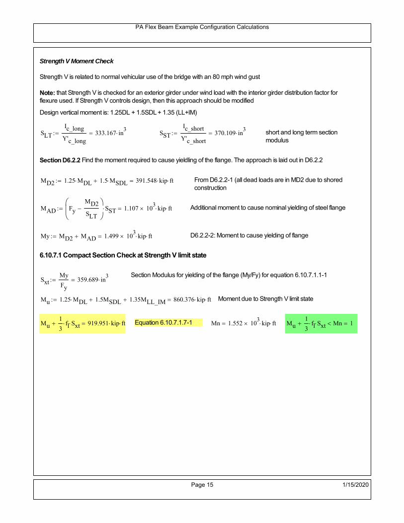
PA Flex Beam Example Configuration Calculations
Strength V Moment Check
Strength V is related to normal vehicular use of the bridge with an 80 mph wind gust
Note: that Strength V is checked for an exterior girder under wind load with the interior girder distribution factor forflexure used. If Strength V controls design, then this approach should be modified
Design vertical moment is: 1.25DL + 1.5SDL + 1.35 (LL+IM)
SLT
Ic_long
Y'c_long333.167 in
3 SST
Ic_short
Y'c_short370.109 in
3 short and long term section
modulus
Section D6.2.2 Find the moment required to cause yieldling of the flange. The approach is laid out in D6.2.2
MD2 1.25 MDL 1.5 MSDL 391.548 kip ft From D6.2.2-1 (all dead loads are in MD2 due to shoredconstruction
MAD Fy
MD2
SLT
SST 1.107 10
3 kip ft Additional moment to cause nominal yielding of steel flange
My MD2 MAD 1.499 103
kip ft D6.2.2-2: Moment to cause yielding of flange
6.10.7.1 Compact Section Check at Strength V limit state
Section Modulus for yielding of the flange (My/Fy) for equation 6.10.7.1.1-1Sxt
My
Fy359.689 in
3
Mu 1.25 MDL 1.5MSDL 1.35MLL_IM 860.376 kip ft Moment due to Strength V limit state
Mu1
3fl Sxt 919.951 kip ft Equation 6.10.7.1.7-1 Mn 1.552 10
3 kip ft Mu
1
3fl Sxt Mn 1
Page 15 1/15/2020

PA Flex Beam Example Configuration Calculations
STEP 9: Compute Deflection
Optional Live Load Deflection Evaluation (AASHTO 3.6.1.3.2)
Deflection distribution factor for vehicular loads: For a straight multibeambridge, this is equivalent to saying that the distribution factor for deflectionis equal to the number of lanes divided by the number of beams. 2.5.2.6.2
DFd
Nl
N0.2
Deflection should be taken as 125% the larger of:- Design truck- 25% of design truck + design lane
The live load portion of Load Combination Service I of Table 3.4.1-1 should be used,including the dynamic load allowance, IM;
Deflection due to design truck load
NOTE : Assuming maximum deflection occurs when the center of gravity of the loads is at thecenter line of the span.
P1 8kip P2 32kip P3 32kip Axle loads (AASHTO 3.6.1.2.2)
XASr 14ft Rear Axle spacing for truck (14ft - 30ft)
XASf 14ft Front Axle spacing for truck
Center of gravity (CG) of loads:
X'P1 XASr XASf P2 XASr
P1 P2 P39.333 ft Datum is the rear axle
Method1: Assuming single load = P1+P2+P3 at the midspan (Conservative approach)
P1 P2 P3 L3
48 Es Ic_short 1.696 in
Method2: Calculation of Midspan deflection using superposition
b1L
2XASr X' XASf 6.333 ft distance btw load P1 and support A b1check b1 0 1
b2L
2XASr X' 20.333 ft distance btw load P2 and support A b2check b2 0 1
b3L
2X' 15.667 ft distance btw load P3 and support B b3check b3 0 1
Page 16 1/15/2020

PA Flex Beam Example Configuration Calculations
Deflection of the beam at midspan due to P1: P P1
xL
2 at midspan b b1 b1check The smallest distance btw load P1 and support
Δ1P b x
6 Es Ic_short LL2
b2
x2
0.07 in
Deflection of the beam at midspan due to P2: P P2
xL
2 at midspan b b2 b2check The smallest distance btw load P2 and support
Δ2P b x
6 Es Ic_short LL2
b2
x2
0.717 in
Deflection of the beam at midspan due to P3: P P3
xL
2 at midspan b b3 b3check The smallest distance btw load P3 and support
Δ3P b x
6 Es Ic_short LL2
b2
x2
0.616 in
Total Deflection at midspan:
Δtruck Δ1 Δ2 Δ3( ) DFd 1 I( ) 0.373 in (Considering IM)
Deflection due to tandem (Note: this calculation is not required according to Article3.6.1.3.2 which denotes only the design truck for deflection calculation)
Page 17 1/15/2020

PA Flex Beam Example Configuration Calculations
FT 31.25 kip Per axle
XAS 4ft Axle spacing
Δtandem
FTL
2
XAS
2
24 Es Ic_short3 L
2 4
L
2
XAS
2
2
DFd 1 I( ) 0.388 in (Considering IM)
Deflection due to lane load
FDLLd 640lbf
ft DFd 128
lbf
ft
Δlane
5 FDLLd L4
384 Es Ic_short0.094 in
Live Load Deflection:
ΔLL 1.25max Δtruck 0.25Δtruck Δlane 1.25 0.583 in ΔLLL
800 1
Deflection Limit
For steel or concrete vehicular bridges:
Vehicular load = Span/800L
8000.75 in
L
10000.6 in
Evaluation of Deflection at the Service Limit State (AASHTO 3.4.2.2)
The associated permitted deflections shall be included in the contract documents.
Page 18 1/15/2020

PA Flex Beam Example Configuration Calculations
Shear demands:
Determination of the distribution factor
Using DM4 Table 4.6.2.2.3a-1
Sbe
12in3.167 transverse girder spacing (ft)
Distribution of live loads per lane for shear in interior beams:
For two design lanes loaded, 3.5' <= S =< 16', number of beam >= 4DFs 0.36
S
25 0.487
Q Actr1 h Y'c_shorthf
2
265.283 in3
first moment of deck slab for interface shear
Method 1: Range of shear based on Strength I Limit
STRENGTH I 1.25DL + 1.5SDL + 1.75 (LL+IM)
Computation of the range of shear in the beam
Dead Load:DL 0.394
kip
ft
Superimposed Dead Load: SDL 0.507kip
ft
Design Lane Load: 0.64kip
ft
Design Truck:
XASr 14ft Rear Axle spacing for truck (14ft - 30ft)
XASf 14ft Front Axle spacing for truck
P1 8 kip P2 32 kip P3 32 kip Wheel loads (AASHTO 3.6.1.2.2)
Design Tandem:
Consist of a pair of 25-kip axles spaced 4-ft apart. (AASHTO 3.6.1.2.3)
NOTE: PennDOT DM4 increases 25-kip to 31.25-kip.
FT 31.25kip
XAS 4ft Axle spacing
Page 19 1/15/2020

PA Flex Beam Example Configuration Calculations
Maximum positive shear at various points along the FlexBeam are examined.
At x=0 (at left support) (Truck is moving from left to right)
Truck
Max Positive Shear (when P3 is at x = 0):
x1 L XASr XASf 22 ft Distance between P1 and right support
x2 L XASr 36 ft Distance between P2 and right support
x3 L 50 ft Distance between P3 and right support
V1 P3
x3
L P2
x2
L P1
x1
L 58.56 kip
Total Vertical Shear Force for each FlexBeam (considering dynamic loads):
Vtruck1 V1 DFs 1 I( ) 37.904 kip
Tandem:
V1 FT FT
L XAS L
60 kip
Total Vertical Shear Force for each FlexBeam (considering dynamic loads):
Vtandem1 V1 DFs 1 I( ) 38.836 kip
Lane Load
V1 0.64kip
ft
L
2 16 kip
Total Vertical Shear Force for each FlexBeam (considering dynamic loads):
Vlane1 V1 DFs 7.787 kip
Dead Load
Vdl1 DLL
2 9.841 kip
Superimposed Dead Load
Vsdl1 SDLL
2 12.682 kip
Strength I Max Positive Shear:
Vstr1 1.25 Vdl1 1.5 Vsdl1 1.75 Vlane1 max Vtruck1 Vtandem1 112.913 kip
Page 20 1/15/2020

PA Flex Beam Example Configuration Calculations
Design Permit Load P-82
Shear at x=0
Strength II Max Positive Shear:
VPL82 VPL82span DFs 1 IPL 64.743 kip
STRENGTH II 1.25DL + 1.5SDL + 1.35 (LL+IM)
VstrII_PL 1.25 Vdl1 1.5 Vsdl1 1.35 VPL82 118.727 kip
Max Shear Demand Vu max Vstr1 VstrII_PL 118.727 kip
Determine the Shear Strength of the Web
Shear Strength of Unstiffened web from AASHTO section 6.10.9.2
Depth of Web D d 25 in Thickness of web tw 0.5 in
Transverse Stiffener Spacing d0 0in Shear Buckling Coefficient k 5 6.10.9.3.2-7
Plastic Shear Force Vp 0.58 Fy D tw 362.5 kip Equation 6.10.9.3.2-3
Ratio of Shear-Buckling resistance to shear yield, C
D
tw50 1.12
Es k
Fy 60.314 Ccheck
D
tw1.12
Es k
Fy 1 Equation 6.10.9.3.2-4
C 1.0 Ccheck 1 C=1 for most cases, if the criteria are not met, then C will go to zero and the actualcoefficients should be determined
Nominal Shear Resistance of Web Vn C Vp 362.5 kip equation 6.10.9.3.3-1
Shear Resistance Factor φv 1.0
φv Vn 362.5 kip φv Vn Vu 1Reduced Shear Strength
Page 21 1/15/2020

PA Flex Beam Example Configuration Calculations
Check Bearing Stiffeners
FYs 50ksi Yield strength of stiffener
tp 0.75in Thickness of stiffener
bt
bf tw
21.5in 4.25 in Effective width of stiffener
Dst hw 4.1in 19.9 in Depth of stiffeners
Apn 2 tp bt 6.375 in2
Projected area of stiffeners
bt 0.48 tpEs
FYs 1Check that effective width of stiffener meets requirements
Rsbn 1.4 Apn FYs 446.25 kip Bearing capacity of stiffener (phi=1 for bearing per AASHTO 6.5.4.2)
Rsbn Vu 1 Bearing capacity check
Qs 1.0 Q factor for bearing stiffner, taken as 1 (AASHTO 6.9.4.1.1)
Is
18 tw tw3
tp 2 bt 3
1238.477 in
4 Moment of inertia of stiffener and web (9*tw is used on each side)
AASHTO 6.10.11.2.4b
Ag 18 tw tw 2 bt tp 10.875 in2
Gross area of stiffener and web (AASHTO 6.10.11.2.4b)
rs
Is
Ag1.881 in Radius of gyration of stiffener/web
Po Qs FYs Apn 318.75 kip Nominal yeild resistance of stiffener (AASHTO 6.9.4.1.1)
Peπ2Es
0.75 Dst
rs
2Ag 4.944 10
4 kip Elastic critical buckling stress of stiffener (AASHTO 6.9.4.1.2-1)
Check that Pe/Po is great than 0.44 (AASHTO 6.9.4.1.1) PePoPe
Po0.44 1
Pn PePo 0.658
Po
Pe Po 317.891 kip Nominal compressive resistance of stiffener for Pe/Po>0.44
(AASHTO 6.9.4.1.1-1)
φcr 0.95 phi factor for axial compression (AASHTO 6.5.4.2)
Pr φcr Pn 301.996 kip Compressive capacity of bearing stiffener Pr Vu 1
Page 22 1/15/2020

PA Flex Beam Example Configuration Calculations
Flexbeam Example Configuration Calculations
Summary of Calculations:
Input section dimensions and material properties for steel WT and the concrete deck1.Calculate demands (dead load, superimposed dead, and Live load demands for Strength I and Strength II2.Calculate composite section properties for the given section3.Check Strength I, Strength II, and Service II stresses 4.Check Strength I, Strength II, and Strength V moment demands 5.Perform live load deflection check6.Determine maximum shear demand and capacity7.Note: Shear envelope data was obtained from Matlab script (FlexBeam_Moment_ShearEnvelope.m).8.Shear envelope calculations are summarized separately for each design (Shear Design *.xlsx).
Design Assumptions:Design Specifications Used:
AASHTO LRFD Bridge Design Specifications 7th Edition with 2016 Interim RevisionsPennDOT Design Manual, Part 4 (DM-4) June 30, 2015
Example configurations are determined for two girder spacings, 36" and 40".The deck thickness is 7.5" and is assumed to have a non-structural wearing surface added after installation.Section properties are calculated using the full 7.5" deck thickness.The WT sections are embedded 3.5" into the concrete deck. The steel section spacing used is outside the scope of the AASHTO and PennDOT distribution factorequations. The flexural distribution factor is assumed to be 0.3 which was shown to tbe conservativeaccording to refined analysisThe shear distribution factor is calculated using the DM-4 shear distribution factor equation which wasshown to be conservative using refined analysis.Refined analysis is presented in: Zihan Ma, "Distribution Factors for Composite Steel Tee Concrete DeckBridge System," M.S. Thesis, Deparement of Civil and Environmental Engineering, Lehigh University,Bethlehem, 2019Shear and moment demands for the PL82 permit load vehicle are determined by Matlab script(FlexBeam_Moment_ShearEnvelope.m) and are manually input into this calculation sheet.All fabrication will occur as double modules, i.e. each module contains two WT sections. The number ofmodules is half the number of beams, N. A 45 in. tall F-Shape barrier is used, Weight = 700 lb/ft (Distributed to exterior two beams).
The work presented in this document are provided on an “AS IS” basis. University makes no warranties of anykind, express or implied, as to any matter whatsoever, including, without limitation, warranties with respect tothe merchantability or fitness for a particular purpose of this work or any project deliverables. Universitymakes no warranty of any kind with respect to freedom from patent, trademark, copyright or trade secretinfringement arising from the use of the results of the project, deliverables, services, intellectual property orother materials provided hereunder. University shall not be liable for any direct, indirect, consequential,punitive, or other damages suffered by Sponsor or any other person resulting from the project, or the use ofthis work or any project deliverables.
Page 1 1/15/2020

PA Flex Beam Example Configuration Calculations
hf
tf
bf
twh
d
bjtbe
e
Variable Definitions:
Number of beams N 14 modulesN
27
L 50ft Span length
be 38in Effective width of Flexbeamassuming constructed bridge width(i.e. closure joints cast)
Built Up Section Properties
tw 0.500in tf 1.00in bf 12in
h 29in Overall Height of section
hf 7.5in Total thickness of deck
e 3.5in Deck/Steel overlap
d h hf e 25 in depth of built up steel section
hw d tf 24 in height of web of built up steel
Moment and shear for permit load PL82 obtained from Matlab script: FlexBeam_Moment_ShearEnvelope
MLL_IM_PL82 409.0176kip ft Moment due to PL82 with distribution factor and impact factor!!
VPL82span 110.862kip Shear due to PL82 WITHOUT distribution factor and impact factor!!
Check web and flange dimensions in sections 6.10.2.1 and 6.10.2.2
(Ignore 6.10.2.2-4 since no compression flange)
equation 6.10.2.1.1-1d
tw150 1 equation 6.10.2.2-1
bf
2 tf12 1
equation 6.10.2.2-2 bfh
6 1 equation 6.10.2.2-3 tf 1.1 tw 1
y_bar
tf bftf
2 hw tw tf
hw
2
tf bf hw tw6.75 in Center of gravity of steel section
Istl
bf tf3
12bf tf y_bar
tf
2
2
tw hw
3
12 tw hw tf
hw
2 y_bar
2
1.514 103
in4
MOI of steel
Astl tf bf hw tw 24 in2
Area of the WT steel section
Page 2 1/15/2020

PA Flex Beam Example Configuration Calculations
Material Properties
Elastic Modulus of Steel Es 29000ksi
Yield Strength of Steel Fy 50ksi
Yield Strength of Reinforcement fy 60ksi
Compressive Strength of Concrete fc 4000psi AAAP PennDOT Concrete
Concrete Modular Ratio n 8 modular ratio for 4ksi concrete per AASHTO
Unit weight of concrete slab wc 0.150kip
ft3
Unit weight of concrete
Section Properties
Width of UHPC Joint: bjt 6in
Parapet width: bpar 20.25in Parapet width per PennDOT F-shape barrier
Width of the bridge W be N bjt 526 in W 43.833 ft
Clear width of roadway Wlane W 2 bpar 40.458 ft
Dc wc hf W 4.109kip
ft DL due to slab
Db .700kip
ft DL due to each 45" F-Shape Barrier (per email 11/1/18)
DFWS 30lbf
ft2
W 2 bpar 1.214kip
ft DL due to Future Wearing Surface (FWS)
Ds Astl 490lbf
ft3
0.082kip
ft Selfweight of the steel section
DLself
Dc N
Ds 0.375kip
ft Self-weight per WT
Total weight of each precast FlexBeam for transportation:
Weight of C12x25 Diaphragms Wend_diaphragms 25lbf
ft32 in 0.067 kip
2be bjt hf wc 2Ds L 2 Wend_diaphragms 35.644 kip
Determine number of design lane (AASHTO Section 3.6.1.1.1)
Take the integer part of the ratio of W/12 ft. Number of lanes in bridge: Nl floorWlane
12ft
3
Page 3 1/15/2020

PA Flex Beam Example Configuration Calculations
STEP 1: Compute Dead Load for each Flex Beam
DLslab
Dc
Nwc 1 in
be
2 0.313
kip
ft Dead load of slab assuming exterior overhang has 1" of
additional concrete thickness
DLsteel Ds 0.082kip
ft
DL DLslab DLsteel 0.395kip
ft
STEP 2: Compute Superimposed Dead Load
SDLWS
DFWS
N0.087
kip
ft
SDLparapet
Db
20.35
kip
ft distributed equally on two outer beams
SDLOL 140lbf
ft3be 2 in 0.074
kip
ft Overlay is 2" thick and is 140 lbs/cubic foot
NOTE: For this example barrier load is distributed equally among the two outer beams per conversation withPennDOT and M&M.
PennDOT DM4: "For composite adjacent and spread beams, the barrier (single barrier) load shall be equallydistributed to the nearest three (adjacent) and two (spread) beams, respectively, when the barriers are placedafter slab has hardened".
SDL SDLWS SDLparapet SDLOL 0.511kip
ft
STEP 3: Compute Transformed Width of Slab
For live load and dead load acting on the stringer k1 1 For short-term section property evaluation
btr1
be
k1 n4.75 in Transformed width of slab for short-term
For superimposed dead loads k3 3 For long-term section property evaluation
btr3
be
k3 n1.583 in Transformed width of slab for long-term
Page 4 1/15/2020

PA Flex Beam Example Configuration Calculations
STEP 4: Compute Dead and Superimposed Dead Load Moments(Based on first interior girder demands)
MDLDL L
2
8123.433 kip ft
MSDLSDL L
2
8159.558 kip ft
STEP 5: Compute live load and Dynamic Load Allowance (IM)
Live load wheel load distribution factor (DF):
Sbe
12in3.167 transverse girder spacing
NOTE: AASHTO presents equations to define DF for different types of superstructuresincluding Deck Composite wirh RC slab on steel girders (Type (a) in Table 4.6.2.2.1-1) forshear and moment in interior and exterior beams.
Using DM4 Table 4.6.2.2.2b-1:
eg h y_barhf
2 18.5 in Distance between the centers of gravity of the basic beam and deck
Kg n Istl Astl eg2
77828 in
4 Longitudinal stiffness parameter (in4)
Distribution of Live Load Per Lane for Moment in Interior Beams:
to be conservative, use DF 0.3
Page 5 1/15/2020

PA Flex Beam Example Configuration Calculations
Dynamic Load Allowance (Section 3.6.2 DM4)
Static effects of the design truck or tandem, shall be increased by the impact factor.
NOTE: The dynamic load allowance shall not be applied to the design lane load (Section 3.6.2.1 DM4)
I 0.33 Impact factor for moment
Note: PennDOT requires that the impact for decks be increased from 33% to 50%, the deck is not beingdesigned here. Instrad the deck design is based on the BD recommendations.
Dynamic load allowance for the Permit Load P-82 shall be less than 20%. (Section 3.6.2.1DM4)
IPL 0.20 Impact factor for moment on Strength II
Design Wind Loading for Exterior Girder
Vw 80 Wind speed for Strength V load case
CD 1.3 Gust factor for windard side of I-Girder and Box Girder Superstructures (Table 3.8.1.2.1-2)
G 1.0 Gus effect factor is 1.0 for all structures other than sound barriers (Table 3.8.1.2.1-1)
Kz 1.0 Pressure coefficient taken as 1 for Strength V (3.8.1.2.1)
Pz 2.56 106
Vw 2 Kz G CDkip
ft2
0.021kip
ft2
Wind pressure on exterior girder
hexp h hf 21.5 in Exposed height of exterior girder
Moment due to wind loading on exterior girderMWL
Pz hexp L2
811.925 kip ft
Iyy
bf3tf
12144 in
4 Transverse moment of intertia
Flange lateral bending stressfl
MWL
bf
2
Iyy5.963 ksi
Page 6 1/15/2020
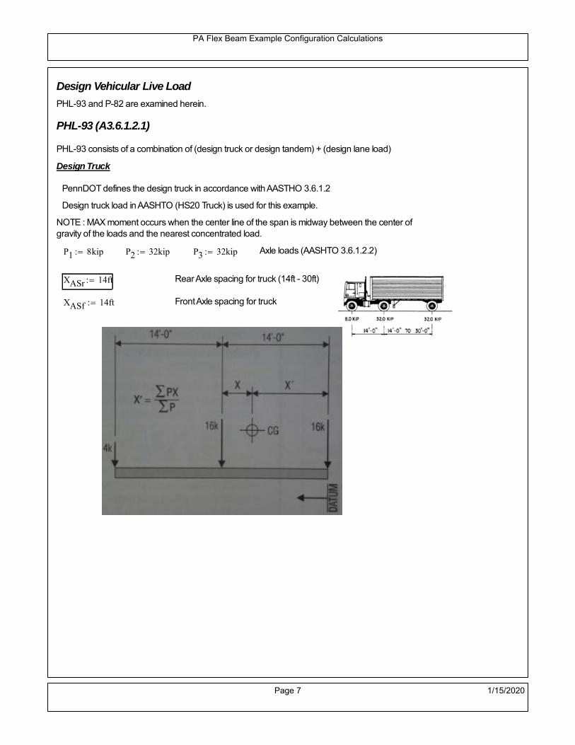
PA Flex Beam Example Configuration Calculations
Design Vehicular Live Load
PHL-93 and P-82 are examined herein.
PHL-93 (A3.6.1.2.1)
PHL-93 consists of a combination of (design truck or design tandem) + (design lane load)
Design Truck
PennDOT defines the design truck in accordance with AASTHO 3.6.1.2
Design truck load in AASHTO (HS20 Truck) is used for this example.
NOTE : MAX moment occurs when the center line of the span is midway between the center ofgravity of the loads and the nearest concentrated load.
P1 8kip P2 32kip P3 32kip Axle loads (AASHTO 3.6.1.2.2)
XASr 14ft Rear Axle spacing for truck (14ft - 30ft)
XASf 14ft Front Axle spacing for truck
Page 7 1/15/2020

PA Flex Beam Example Configuration Calculations
Center of gravity (CG) of loads:
X'P1 XASr XASf P2 XASr
P1 P2 P39.333 ft Datum is the rear axle
X XASr X' 4.667 ft Spacing btw CG and nearest load
Find bridge reaction
Truck movestoward Support ARA
P1L
2XASf
X
2
P2L
2
X
2
P3L
2X'
X
2
L32.64 kip
Max live load moment (at the location of P2):
MLL_truck RAL
2
X
2
P1 XASf 627.84 kip ft
NOTE: Find the worst case by varying XASr
Page 8 1/15/2020

PA Flex Beam Example Configuration Calculations
Design Tandem
Consist of a pair of 25-kip axles spaced 4-ft apart. (AASHTO 3.6.1.2.3)
NOTE: PennDOT DM4 increases 25-kip to 31.25-kip.
FT 31.25kip
XAS 4ft Axle spacing
Center of gravity (CG) of loads:
XXAS
22 ft Spacing btw CG and nearest load
Find bridge reaction
RA
FTL
2
X
2
FTL
2
X
2 X
L30 kip Truck moves toward Support A
Max live load moment (at the location of front wheel):
MLL_tandem RAL
2
X
2
720 kip ft
Choose the max value:
MLL_veh max MLL_tandem MLL_truck 720 kip ft
Apply the impact and wheel load distribution:
MLL_IM_veh MLL_veh DF 1 I( ) 287.28 kip ft Due to tandem or truck
Design Lane Load (distributed over a 10-ft width for each lane)
NOTE: The uniform load may be continuous or discontinuous as necessary to produce themaximum force effect. For this example continuous uniform distribution assumed.
FDLL 0.64kip
ftDF 0.192
kip
ft Per beam in each lane
Due to lane loadMLL_IM_lane
FDLL L2
8
60 kip ft
Moment due to Total Design Vehicular Live Load: MLL_IM MLL_IM_lane MLL_IM_veh 347.28 kip ft
Page 9 1/15/2020

PA Flex Beam Example Configuration Calculations
Design Permit Load P-82 (Section 3.6.1.2.7 DM4)
P1 P2 P3 P4 P5 P6 P7
NOTE: The moment for the permit load is defined at the beginning of the sheetand is obtained from MATLab File FlexBeam_Moment_ShearEnvelope.m
STEP 6: Compute Moment of Inertia (Note: rebar neglected!)
1) Moment of Inertia resisting dead load only:
a) Acting on the non-composite section (before the deck has hardened - DC1)
Use steel section only
Inc Istl 1.514 103
in4
Non-composite section modulus
Y'nc y_bar S.G. of the steel section of Flex Beam (Datum is bottom)
b) Acting on the composite section (after the deck has hardened - DC2)
Use Ic_short as defined below.
Page 10 1/15/2020

PA Flex Beam Example Configuration Calculations
2) Moment of Inertia resisting live load plus impact:
Using transformed slab with k1=1 (short-term composite).
Actr1 hf btr1 35.625 in2
Itr1
btr1 hf3
12166.992 in
4
Y'
Actr1 hhf
2
Astl Y'nc
Astl Actr117.803 in S.G. of the total flex beam (Datum is bottom)
Compositesection modulus(short-term)
Ic_short Istl Astl Y'nc Y' 2 Itr1 Actr1 hhf
2
Y'
2
6589 in4
Y'c_short Y' 17.803 in N.A. of the short-term composite section
3) Moment of Inertia resisting superimposed dead load:
Using transformed slab with k3=3.
Actr3 hf btr3 11.875 in2
Itr3
btr3 hf3
1255.664 in
4
Y'
Actr3 hhf
2
Astl Y'nc
Astl Actr312.874 in S.G. of the total flex beam (Datum is bottom)
Compositesection modulus(long-term)
Ic_long Istl Astl Y'nc Y' 2 Itr3 Actr3 hhf
2
Y'
2
4289 in4
Y'c_long Y' 12.874 in N.A. of the long-term composite section
Page 11 1/15/2020

PA Flex Beam Example Configuration Calculations
STEP 6.5 Check Ductility RequirementIn accordance with AASHTO Article 6.10.7.3 check ductility requirement. Assume compressionblock of concrete is at 0.85 f'c and that the concrete supports no tension. Steel section isassumed to be fully plastic at Fy.
Case 1 : Assuming PNA is in Concreteh d 4 inAssuming (h-d) < Dp < hf
Fp Dp 0.85 fc be Dp Fy tw Dp h d( ) Fy Astl tw Dp h d( )
Dp 7.5in 0.42 h 12.18 in
Dp1 root Fp Dp Dp 7.813 in Must be less than hf 7.5 inDp1
h0.269 must be < 0.42
Mn1check Dp1 hf h d( ) Dp1[ ] Dp1 0.42 h( ) 0 Dp1 0.42 h 1
Mp1 0.85 fc be Dp1Dp1
2
Fy tw Dp1 h d( )[ ] Dp1 h d( )[ ]
2
Fy bf tf h Dp1tf
2
Fy tw h Dp1 tf h Dp1 tf
2
Mp1 21631.25 kip in Mn1 Mp1 1.07 0.7Dp1
h
19066.3 kip in
Case 2 : Assuming PNA is NOT in Concrete
Assuming hf < Dp
Fp2 Dp 0.85 fc be hf Fy tw Dp h d( ) Fy Astl tw Dp h d( )
Dp 2.5in
Dp2 root Fp2 Dp Dp 8.62 in Must be more than hf 7.5 inDp2
h0.2972 must be < 0.42
Mn2check Dp2 hf Dp2 h( ) Dp2 0.42 h( ) 1 Dp2 0.42 h 1
Mp2 0.85 fc be hf Dp2hf
2
Fy tw Dp2 h d( )[ ] Dp2 h d( )[ ]
2
Fy bf tf h Dp2tf
2
Fy tw h Dp2 tf h Dp2 tf
2
Mp2 21608.64 kip inMn2 Mp2 1.07 0.7
Dp2
h
18625.2 kip in
Mn max Mn1 Mn1check Mn2 Mn2check 1552.1 kip ft Mn 18625.2 kip in
Page 12 1/15/2020

PA Flex Beam Example Configuration Calculations
Check Composite Compact Section Criteria (6.10.6.2)
Dcpd
2
Fy tf bf 0.85 fc be hf
Fy hw tw1
4.813 in Dcp0 Dcp 0 1
Dcp Dcp Dcp0 4.813 in2 Dcp
tw3.76
Es
Fy 1 Check if section is compact
STEP 7: Load Combinations (Table 3.4.1-1)
The following load combinations will be considered herein. Only the maximum load factors forpermanent-loads are used in the following load combinations (uplift is not an issue for this typeof bridge).STRENGTH I 1.25DL + 1.5SDL + 1.75 (LL+IM)
SERVICE II: DL+SDL+1.3(LL+IM)
STEP 8: Compute and Check Stresses
Stress at bottom fiber of steel section
fDL
MDL Y'c_long
Ic_long4.446 ksi
fLL_I
MLL_IM Y'c_short
Ic_short11.26 ksi fPL
MLL_IM_PL82 Y'c_short
Ic_short13.262 ksi
fSDL
MSDL Y'c_long
Ic_long5.747 ksi
STRENGTH I fbot_str1 1.25fDL 1.5 fSDL 1.75 fLL_I 33.882 ksi
STRENGTH II fbot_str2 1.25fDL 1.5 fSDL 1.35 fPL 32.081 ksi
SERVICE II fbot_svc2 fDL fSDL 1.3fLL_I 24.83 ksi
Allowable Stress is based on Section 6.10.4.2.2-2
Flange stress due to service load II without consideration of flange lateral bending: ff fbot_svc2
Flange lateral bending stress due to service II: flSII 0ksi
Hybrid Factor: Rh 1.0 For rolled and homogenous built-up sections
ff
flSII
2 24.831 ksi 0.95 Rh Fy 47.5 ksi ff
fl
2 0.95Rh Fy 1
Page 13 1/15/2020
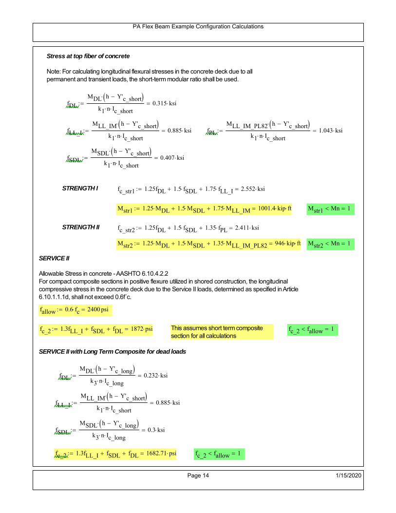
PA Flex Beam Example Configuration Calculations
Stress at top fiber of concrete
Note: For calculating longitudinal flexural stresses in the concrete deck due to allpermanent and transient loads, the short-term modular ratio shall be used.
fDL
MDL h Y'c_short
k1 n Ic_short0.315 ksi
fLL_I
MLL_IM h Y'c_short
k1 n Ic_short0.885 ksi fPL
MLL_IM_PL82 h Y'c_short
k1 n Ic_short1.043 ksi
fSDL
MSDL h Y'c_short
k1 n Ic_short0.407 ksi
STRENGTH I fc_str1 1.25fDL 1.5 fSDL 1.75 fLL_I 2.552 ksi
Mstr1 1.25 MDL 1.5 MSDL 1.75 MLL_IM 1001.4 kip ft Mstr1 Mn 1
STRENGTH II fc_str2 1.25fDL 1.5 fSDL 1.35 fPL 2.411 ksi
Mstr2 1.25 MDL 1.5 MSDL 1.35 MLL_IM_PL82 946 kip ft Mstr2 Mn 1
SERVICE II
Allowable Stress in concrete - AASHTO 6.10.4.2.2For compact composite sections in positive flexure utilized in shored construction, the longitudinalcompressive stress in the concrete deck due to the Service II loads, determined as specified in Article6.10.1.1.1d, shall not exceed 0.6f́ c.
fallow 0.6 fc 2400 psi
fc_2 1.3fLL_I fSDL fDL 1872 psi This assumes short term compositesection for all calculations
fc_2 fallow 1
SERVICE II with Long Term Composite for dead loads
fDL
MDL h Y'c_long
k3 n Ic_long0.232 ksi
fLL_I
MLL_IM h Y'c_short
k1 n Ic_short0.885 ksi
fSDL
MSDL h Y'c_long
k3 n Ic_long0.3 ksi
fc_2 1.3fLL_I fSDL fDL 1682.71 psi fc_2 fallow 1
Page 14 1/15/2020

PA Flex Beam Example Configuration Calculations
Strength V Moment Check
Strength V is related to normal vehicular use of the bridge with an 80 mph wind gust
Note: that Strength V is checked for an exterior girder under wind load with the interior girder distribution factor forflexure used. If Strength V controls design, then this approach should be modified
Design vertical moment is: 1.25DL + 1.5SDL + 1.35 (LL+IM)
SLT
Ic_long
Y'c_long333.167 in
3 SST
Ic_short
Y'c_short370.109 in
3 short and long term section
modulus
Section D6.2.2 Find the moment required to cause yieldling of the flange. The approach is laid out in D6.2.2
MD2 1.25 MDL 1.5 MSDL 393.628 kip ft From D6.2.2-1 (all dead loads are in MD2 due to shoredconstruction
MAD Fy
MD2
SLT
SST 1.105 10
3 kip ft Additional moment to cause nominal yielding of steel flange
My MD2 MAD 1.498 103
kip ft D6.2.2-2: Moment to cause yielding of flange
6.10.7.1 Compact Section Check at Strength V limit state
Section Modulus for yielding of the flange (My/Fy) for equation 6.10.7.1.1-1Sxt
My
Fy359.634 in
3
Mu 1.25 MDL 1.5MSDL 1.35MLL_IM 862.456 kip ft Moment due to Strength V limit state
Mu1
3fl Sxt 922.022 kip ft Equation 6.10.7.1.7-1 Mn 1.552 10
3 kip ft Mu
1
3fl Sxt Mn 1
Page 15 1/15/2020

PA Flex Beam Example Configuration Calculations
STEP 9: Compute Deflection
Optional Live Load Deflection Evaluation (AASHTO 3.6.1.3.2)
Deflection distribution factor for vehicular loads: For a straight multibeambridge, this is equivalent to saying that the distribution factor for deflectionis equal to the number of lanes divided by the number of beams. 2.5.2.6.2
DFd
Nl
N0.214
Deflection should be taken as 125% the larger of:- Design truck- 25% of design truck + design lane
The live load portion of Load Combination Service I of Table 3.4.1-1 should be used,including the dynamic load allowance, IM;
Deflection due to design truck load
NOTE : Assuming maximum deflection occurs when the center of gravity of the loads is at thecenter line of the span.
P1 8kip P2 32kip P3 32kip Axle loads (AASHTO 3.6.1.2.2)
XASr 14ft Rear Axle spacing for truck (14ft - 30ft)
XASf 14ft Front Axle spacing for truck
Center of gravity (CG) of loads:
X'P1 XASr XASf P2 XASr
P1 P2 P39.333 ft Datum is the rear axle
Method1: Assuming single load = P1+P2+P3 at the midspan (Conservative approach)
P1 P2 P3 L3
48 Es Ic_short 1.696 in
Method2: Calculation of Midspan deflection using superposition
b1L
2XASr X' XASf 6.333 ft distance btw load P1 and support A b1check b1 0 1
b2L
2XASr X' 20.333 ft distance btw load P2 and support A b2check b2 0 1
b3L
2X' 15.667 ft distance btw load P3 and support B b3check b3 0 1
Page 16 1/15/2020

PA Flex Beam Example Configuration Calculations
Deflection of the beam at midspan due to P1: P P1
xL
2 at midspan b b1 b1check The smallest distance btw load P1 and support
Δ1P b x
6 Es Ic_short LL2
b2
x2
0.07 in
Deflection of the beam at midspan due to P2: P P2
xL
2 at midspan b b2 b2check The smallest distance btw load P2 and support
Δ2P b x
6 Es Ic_short LL2
b2
x2
0.717 in
Deflection of the beam at midspan due to P3: P P3
xL
2 at midspan b b3 b3check The smallest distance btw load P3 and support
Δ3P b x
6 Es Ic_short LL2
b2
x2
0.616 in
Total Deflection at midspan:
Δtruck Δ1 Δ2 Δ3( ) DFd 1 I( ) 0.4 in (Considering IM)
Deflection due to tandem (Note: this calculation is not required according to Article3.6.1.3.2 which denotes only the design truck for deflection calculation)
Page 17 1/15/2020

PA Flex Beam Example Configuration Calculations
FT 31.25 kip Per axle
XAS 4ft Axle spacing
Δtandem
FTL
2
XAS
2
24 Es Ic_short3 L
2 4
L
2
XAS
2
2
DFd 1 I( ) 0.416 in (Considering IM)
Deflection due to lane load
FDLLd 640lbf
ft DFd 137.143
lbf
ft
Δlane
5 FDLLd L4
384 Es Ic_short0.101 in
Live Load Deflection:
ΔLL 1.25max Δtruck 0.25Δtruck Δlane 1.25 0.624 in ΔLLL
800 1
Deflection Limit
For steel or concrete vehicular bridges:
Vehicular load = Span/800L
8000.75 in
L
10000.6 in
Evaluation of Deflection at the Service Limit State (AASHTO 3.4.2.2)
The associated permitted deflections shall be included in the contract documents.
Page 18 1/15/2020

PA Flex Beam Example Configuration Calculations
Shear demands:
Determination of the distribution factor
Using DM4 Table 4.6.2.2.3a-1
Sbe
12in3.167 transverse girder spacing (ft)
Distribution of live loads per lane for shear in interior beams:
For two design lanes loaded, 3.5' <= S =< 16', number of beam >= 4DFs 0.36
S
25 0.487
Q Actr1 h Y'c_shorthf
2
265.283 in3
first moment of deck slab for interface shear
Method 1: Range of shear based on Strength I Limit
STRENGTH I 1.25DL + 1.5SDL + 1.75 (LL+IM)
Computation of the range of shear in the beam
Dead Load:DL 0.395
kip
ft
Superimposed Dead Load: SDL 0.511kip
ft
Design Lane Load: 0.64kip
ft
Design Truck:
XASr 14ft Rear Axle spacing for truck (14ft - 30ft)
XASf 14ft Front Axle spacing for truck
P1 8 kip P2 32 kip P3 32 kip Wheel loads (AASHTO 3.6.1.2.2)
Design Tandem:
Consist of a pair of 25-kip axles spaced 4-ft apart. (AASHTO 3.6.1.2.3)
NOTE: PennDOT DM4 increases 25-kip to 31.25-kip.
FT 31.25kip
XAS 4ft Axle spacing
Page 19 1/15/2020

PA Flex Beam Example Configuration Calculations
Maximum positive shear at various points along the FlexBeam are examined.
At x=0 (at left support) (Truck is moving from left to right)
Truck
Max Positive Shear (when P3 is at x = 0):
x1 L XASr XASf 22 ft Distance between P1 and right support
x2 L XASr 36 ft Distance between P2 and right support
x3 L 50 ft Distance between P3 and right support
V1 P3
x3
L P2
x2
L P1
x1
L 58.56 kip
Total Vertical Shear Force for each FlexBeam (considering dynamic loads):
Vtruck1 V1 DFs 1 I( ) 37.904 kip
Tandem:
V1 FT FT
L XAS L
60 kip
Total Vertical Shear Force for each FlexBeam (considering dynamic loads):
Vtandem1 V1 DFs 1 I( ) 38.836 kip
Lane Load
V1 0.64kip
ft
L
2 16 kip
Total Vertical Shear Force for each FlexBeam (considering dynamic loads):
Vlane1 V1 DFs 7.787 kip
Dead Load
Vdl1 DLL
2 9.875 kip
Superimposed Dead Load
Vsdl1 SDLL
2 12.765 kip
Strength I Max Positive Shear:
Vstr1 1.25 Vdl1 1.5 Vsdl1 1.75 Vlane1 max Vtruck1 Vtandem1 113.08 kip
Page 20 1/15/2020

PA Flex Beam Example Configuration Calculations
Design Permit Load P-82
Shear at x=0
Strength II Max Positive Shear:
VPL82 VPL82span DFs 1 IPL 64.743 kip
STRENGTH II 1.25DL + 1.5SDL + 1.35 (LL+IM)
VstrII_PL 1.25 Vdl1 1.5 Vsdl1 1.35 VPL82 118.894 kip
Max Shear Demand Vu max Vstr1 VstrII_PL 118.894 kip
Determine the Shear Strength of the Web
Shear Strength of Unstiffened web from AASHTO section 6.10.9.2
Depth of Web D d 25 in Thickness of web tw 0.5 in
Transverse Stiffener Spacing d0 0in Shear Buckling Coefficient k 5 6.10.9.3.2-7
Plastic Shear Force Vp 0.58 Fy D tw 362.5 kip Equation 6.10.9.3.2-3
Ratio of Shear-Buckling resistance to shear yield, C
D
tw50 1.12
Es k
Fy 60.314 Ccheck
D
tw1.12
Es k
Fy 1 Equation 6.10.9.3.2-4
C 1.0 Ccheck 1 C=1 for most cases, if the criteria are not met, then C will go to zero and the actualcoefficients should be determined
Nominal Shear Resistance of Web Vn C Vp 362.5 kip equation 6.10.9.3.3-1
Shear Resistance Factor φv 1.0
φv Vn 362.5 kip φv Vn Vu 1Reduced Shear Strength
Page 21 1/15/2020

PA Flex Beam Example Configuration Calculations
Check Bearing Stiffeners
FYs 50ksi Yield strength of stiffener
tp 0.75in Thickness of stiffener
bt
bf tw
21.5in 4.25 in Effective width of stiffener
Dst hw 4.1in 19.9 in Depth of stiffeners
Apn 2 tp bt 6.375 in2
Projected area of stiffeners
bt 0.48 tpEs
FYs 1Check that effective width of stiffener meets requirements
Rsbn 1.4 Apn FYs 446.25 kip Bearing capacity of stiffener (phi=1 for bearing per AASHTO 6.5.4.2)
Rsbn Vu 1 Bearing capacity check
Qs 1.0 Q factor for bearing stiffner, taken as 1 (AASHTO 6.9.4.1.1)
Is
18 tw tw3
tp 2 bt 3
1238.477 in
4 Moment of inertia of stiffener and web (9*tw is used on each side)
AASHTO 6.10.11.2.4b
Ag 18 tw tw 2 bt tp 10.875 in2
Gross area of stiffener and web (AASHTO 6.10.11.2.4b)
rs
Is
Ag1.881 in Radius of gyration of stiffener/web
Po Qs FYs Apn 318.75 kip Nominal yeild resistance of stiffener (AASHTO 6.9.4.1.1)
Peπ2Es
0.75 Dst
rs
2Ag 4.944 10
4 kip Elastic critical buckling stress of stiffener (AASHTO 6.9.4.1.2-1)
Check that Pe/Po is great than 0.44 (AASHTO 6.9.4.1.1) PePoPe
Po0.44 1
Pn PePo 0.658
Po
Pe Po 317.891 kip Nominal compressive resistance of stiffener for Pe/Po>0.44
(AASHTO 6.9.4.1.1-1)
φcr 0.95 phi factor for axial compression (AASHTO 6.5.4.2)
Pr φcr Pn 301.996 kip Compressive capacity of bearing stiffener Pr Vu 1
Page 22 1/15/2020

PA Flex Beam Example Configuration Calculations
Flexbeam Example Configuration Calculations
Summary of Calculations:
Input section dimensions and material properties for steel WT and the concrete deck1.Calculate demands (dead load, superimposed dead, and Live load demands for Strength I and Strength II2.Calculate composite section properties for the given section3.Check Strength I, Strength II, and Service II stresses 4.Check Strength I, Strength II, and Strength V moment demands 5.Perform live load deflection check6.Determine maximum shear demand and capacity7.Note: Shear envelope data was obtained from Matlab script (FlexBeam_Moment_ShearEnvelope.m).8.Shear envelope calculations are summarized separately for each design (Shear Design *.xlsx).
Design Assumptions:Design Specifications Used:
AASHTO LRFD Bridge Design Specifications 7th Edition with 2016 Interim RevisionsPennDOT Design Manual, Part 4 (DM-4) June 30, 2015
Example configurations are determined for two girder spacings, 36" and 40".The deck thickness is 7.5" and is assumed to have a non-structural wearing surface added after installation.Section properties are calculated using the full 7.5" deck thickness.The WT sections are embedded 3.5" into the concrete deck. The steel section spacing used is outside the scope of the AASHTO and PennDOT distribution factorequations. The flexural distribution factor is assumed to be 0.3 which was shown to tbe conservativeaccording to refined analysisThe shear distribution factor is calculated using the DM-4 shear distribution factor equation which wasshown to be conservative using refined analysis.Refined analysis is presented in: Zihan Ma, "Distribution Factors for Composite Steel Tee Concrete DeckBridge System," M.S. Thesis, Deparement of Civil and Environmental Engineering, Lehigh University,Bethlehem, 2019Shear and moment demands for the PL82 permit load vehicle are determined by Matlab script(FlexBeam_Moment_ShearEnvelope.m) and are manually input into this calculation sheet.All fabrication will occur as double modules, i.e. each module contains two WT sections. The number ofmodules is half the number of beams, N. A 45 in. tall F-Shape barrier is used, Weight = 700 lb/ft (Distributed to exterior two beams).
The work presented in this document are provided on an “AS IS” basis. University makes no warranties of anykind, express or implied, as to any matter whatsoever, including, without limitation, warranties with respect tothe merchantability or fitness for a particular purpose of this work or any project deliverables. Universitymakes no warranty of any kind with respect to freedom from patent, trademark, copyright or trade secretinfringement arising from the use of the results of the project, deliverables, services, intellectual property orother materials provided hereunder. University shall not be liable for any direct, indirect, consequential,punitive, or other damages suffered by Sponsor or any other person resulting from the project, or the use ofthis work or any project deliverables.
Page 1 1/15/2020

PA Flex Beam Example Configuration Calculations
hf
tf
bf
twh
d
bjtbe
e
Variable Definitions:
Number of beams N 10 modulesN
25
L 50ft Span length
be 40in Effective width of Flexbeamassuming constructed bridge width(i.e. closure joints cast)
Built Up Section Properties
tw 0.500in tf 1.00in bf 12in
h 29in Overall Height of section
hf 7.5in Total thickness of deck
e 3.5in Deck/Steel overlap
d h hf e 25 in depth of built up steel section
hw d tf 24 in height of web of built up steel
Moment and shear for permit load PL82 obtained from Matlab script: FlexBeam_Moment_ShearEnvelope
MLL_IM_PL82 409.0176kip ft Moment due to PL82 with distribution factor and impact factor!!
VPL82span 110.862kip Shear due to PL82 WITHOUT distribution factor and impact factor!!
Check web and flange dimensions in sections 6.10.2.1 and 6.10.2.2
(Ignore 6.10.2.2-4 since no compression flange)
equation 6.10.2.1.1-1d
tw150 1 equation 6.10.2.2-1
bf
2 tf12 1
equation 6.10.2.2-2 bfh
6 1 equation 6.10.2.2-3 tf 1.1 tw 1
y_bar
tf bftf
2 hw tw tf
hw
2
tf bf hw tw6.75 in Center of gravity of steel section
Istl
bf tf3
12bf tf y_bar
tf
2
2
tw hw
3
12 tw hw tf
hw
2 y_bar
2
1.514 103
in4
MOI of steel
Astl tf bf hw tw 24 in2
Area of the WT steel section
Page 2 1/15/2020

PA Flex Beam Example Configuration Calculations
Material Properties
Elastic Modulus of Steel Es 29000ksi
Yield Strength of Steel Fy 50ksi
Yield Strength of Reinforcement fy 60ksi
Compressive Strength of Concrete fc 4000psi AAAP PennDOT Concrete
Concrete Modular Ratio n 8 modular ratio for 4ksi concrete per AASHTO
Unit weight of concrete slab wc 0.150kip
ft3
Unit weight of concrete
Section Properties
Width of UHPC Joint: bjt 6in
Parapet width: bpar 20.25in Parapet width per PennDOT F-shape barrier
Width of the bridge W be N bjt 394 in W 32.833 ft
Clear width of roadway Wlane W 2 bpar 29.458 ft
Dc wc hf W 3.078kip
ft DL due to slab
Db .700kip
ft DL due to each 45" F-Shape Barrier (per email 11/1/18)
DFWS 30lbf
ft2
W 2 bpar 0.884kip
ft DL due to Future Wearing Surface (FWS)
Ds Astl 490lbf
ft3
0.082kip
ft Selfweight of the steel section
DLself
Dc N
Ds 0.389kip
ft Self-weight per WT
Total weight of each precast FlexBeam for transportation:
Weight of C12x25 Diaphragms Wend_diaphragms 25lbf
ft32 in 0.067 kip
2be bjt hf wc 2Ds L 2 Wend_diaphragms 37.206 kip
Determine number of design lane (AASHTO Section 3.6.1.1.1)
Take the integer part of the ratio of W/12 ft. Number of lanes in bridge: Nl floorWlane
12ft
2
Page 3 1/15/2020

PA Flex Beam Example Configuration Calculations
STEP 1: Compute Dead Load for each Flex Beam
DLslab
Dc
Nwc 1 in
be
2 0.329
kip
ft Dead load of slab assuming exterior overhang has 1" of
additional concrete thickness
DLsteel Ds 0.082kip
ft
DL DLslab DLsteel 0.41kip
ft
STEP 2: Compute Superimposed Dead Load
SDLWS
DFWS
N0.088
kip
ft
SDLparapet
Db
20.35
kip
ft distributed equally on two outer beams
SDLOL 140lbf
ft3be 2 in 0.078
kip
ft Overlay is 2" thick and is 140 lbs/cubic foot
NOTE: For this example barrier load is distributed equally among the two outer beams per conversation withPennDOT and M&M.
PennDOT DM4: "For composite adjacent and spread beams, the barrier (single barrier) load shall be equallydistributed to the nearest three (adjacent) and two (spread) beams, respectively, when the barriers are placedafter slab has hardened".
SDL SDLWS SDLparapet SDLOL 0.516kip
ft
STEP 3: Compute Transformed Width of Slab
For live load and dead load acting on the stringer k1 1 For short-term section property evaluation
btr1
be
k1 n5 in Transformed width of slab for short-term
For superimposed dead loads k3 3 For long-term section property evaluation
btr3
be
k3 n1.667 in Transformed width of slab for long-term
Page 4 1/15/2020

PA Flex Beam Example Configuration Calculations
STEP 4: Compute Dead and Superimposed Dead Load Moments(Based on first interior girder demands)
MDLDL L
2
8128.223 kip ft
MSDLSDL L
2
8161.298 kip ft
STEP 5: Compute live load and Dynamic Load Allowance (IM)
Live load wheel load distribution factor (DF):
Sbe
12in3.333 transverse girder spacing
NOTE: AASHTO presents equations to define DF for different types of superstructuresincluding Deck Composite wirh RC slab on steel girders (Type (a) in Table 4.6.2.2.1-1) forshear and moment in interior and exterior beams.
Using DM4 Table 4.6.2.2.2b-1:
eg h y_barhf
2 18.5 in Distance between the centers of gravity of the basic beam and deck
Kg n Istl Astl eg2
77828 in
4 Longitudinal stiffness parameter (in4)
Distribution of Live Load Per Lane for Moment in Interior Beams:
to be conservative, use DF 0.3
Page 5 1/15/2020

PA Flex Beam Example Configuration Calculations
Dynamic Load Allowance (Section 3.6.2 DM4)
Static effects of the design truck or tandem, shall be increased by the impact factor.
NOTE: The dynamic load allowance shall not be applied to the design lane load (Section 3.6.2.1 DM4)
I 0.33 Impact factor for moment
Note: PennDOT requires that the impact for decks be increased from 33% to 50%, the deck is not beingdesigned here. Instrad the deck design is based on the BD recommendations.
Dynamic load allowance for the Permit Load P-82 shall be less than 20%. (Section 3.6.2.1DM4)
IPL 0.20 Impact factor for moment on Strength II
Design Wind Loading for Exterior Girder
Vw 80 Wind speed for Strength V load case
CD 1.3 Gust factor for windard side of I-Girder and Box Girder Superstructures (Table 3.8.1.2.1-2)
G 1.0 Gus effect factor is 1.0 for all structures other than sound barriers (Table 3.8.1.2.1-1)
Kz 1.0 Pressure coefficient taken as 1 for Strength V (3.8.1.2.1)
Pz 2.56 106
Vw 2 Kz G CDkip
ft2
0.021kip
ft2
Wind pressure on exterior girder
hexp h hf 21.5 in Exposed height of exterior girder
Moment due to wind loading on exterior girderMWL
Pz hexp L2
811.925 kip ft
Iyy
bf3tf
12144 in
4 Transverse moment of intertia
Flange lateral bending stressfl
MWL
bf
2
Iyy5.963 ksi
Page 6 1/15/2020

PA Flex Beam Example Configuration Calculations
Design Vehicular Live Load
PHL-93 and P-82 are examined herein.
PHL-93 (A3.6.1.2.1)
PHL-93 consists of a combination of (design truck or design tandem) + (design lane load)
Design Truck
PennDOT defines the design truck in accordance with AASTHO 3.6.1.2
Design truck load in AASHTO (HS20 Truck) is used for this example.
NOTE : MAX moment occurs when the center line of the span is midway between the center ofgravity of the loads and the nearest concentrated load.
P1 8kip P2 32kip P3 32kip Axle loads (AASHTO 3.6.1.2.2)
XASr 14ft Rear Axle spacing for truck (14ft - 30ft)
XASf 14ft Front Axle spacing for truck
Page 7 1/15/2020

PA Flex Beam Example Configuration Calculations
Center of gravity (CG) of loads:
X'P1 XASr XASf P2 XASr
P1 P2 P39.333 ft Datum is the rear axle
X XASr X' 4.667 ft Spacing btw CG and nearest load
Find bridge reaction
Truck movestoward Support ARA
P1L
2XASf
X
2
P2L
2
X
2
P3L
2X'
X
2
L32.64 kip
Max live load moment (at the location of P2):
MLL_truck RAL
2
X
2
P1 XASf 627.84 kip ft
NOTE: Find the worst case by varying XASr
Page 8 1/15/2020

PA Flex Beam Example Configuration Calculations
Design Tandem
Consist of a pair of 25-kip axles spaced 4-ft apart. (AASHTO 3.6.1.2.3)
NOTE: PennDOT DM4 increases 25-kip to 31.25-kip.
FT 31.25kip
XAS 4ft Axle spacing
Center of gravity (CG) of loads:
XXAS
22 ft Spacing btw CG and nearest load
Find bridge reaction
RA
FTL
2
X
2
FTL
2
X
2 X
L30 kip Truck moves toward Support A
Max live load moment (at the location of front wheel):
MLL_tandem RAL
2
X
2
720 kip ft
Choose the max value:
MLL_veh max MLL_tandem MLL_truck 720 kip ft
Apply the impact and wheel load distribution:
MLL_IM_veh MLL_veh DF 1 I( ) 287.28 kip ft Due to tandem or truck
Design Lane Load (distributed over a 10-ft width for each lane)
NOTE: The uniform load may be continuous or discontinuous as necessary to produce themaximum force effect. For this example continuous uniform distribution assumed.
FDLL 0.64kip
ftDF 0.192
kip
ft Per beam in each lane
Due to lane loadMLL_IM_lane
FDLL L2
8
60 kip ft
Moment due to Total Design Vehicular Live Load: MLL_IM MLL_IM_lane MLL_IM_veh 347.28 kip ft
Page 9 1/15/2020

PA Flex Beam Example Configuration Calculations
Design Permit Load P-82 (Section 3.6.1.2.7 DM4)
P1 P2 P3 P4 P5 P6 P7
NOTE: The moment for the permit load is defined at the beginning of the sheetand is obtained from MATLab File FlexBeam_Moment_ShearEnvelope.m
STEP 6: Compute Moment of Inertia (Note: rebar neglected!)
1) Moment of Inertia resisting dead load only:
a) Acting on the non-composite section (before the deck has hardened - DC1)
Use steel section only
Inc Istl 1.514 103
in4
Non-composite section modulus
Y'nc y_bar S.G. of the steel section of Flex Beam (Datum is bottom)
b) Acting on the composite section (after the deck has hardened - DC2)
Use Ic_short as defined below.
Page 10 1/15/2020

PA Flex Beam Example Configuration Calculations
2) Moment of Inertia resisting live load plus impact:
Using transformed slab with k1=1 (short-term composite).
Actr1 hf btr1 37.5 in2
Itr1
btr1 hf3
12175.781 in
4
Y'
Actr1 hhf
2
Astl Y'nc
Astl Actr118.03 in S.G. of the total flex beam (Datum is bottom)
Compositesection modulus(short-term)
Ic_short Istl Astl Y'nc Y' 2 Itr1 Actr1 hhf
2
Y'
2
6699 in4
Y'c_short Y' 18.03 in N.A. of the short-term composite section
3) Moment of Inertia resisting superimposed dead load:
Using transformed slab with k3=3.
Actr3 hf btr3 12.5 in2
Itr3
btr3 hf3
1258.594 in
4
Y'
Actr3 hhf
2
Astl Y'nc
Astl Actr313.086 in S.G. of the total flex beam (Datum is bottom)
Compositesection modulus(long-term)
Ic_long Istl Astl Y'nc Y' 2 Itr3 Actr3 hhf
2
Y'
2
4386 in4
Y'c_long Y' 13.086 in N.A. of the long-term composite section
Page 11 1/15/2020

PA Flex Beam Example Configuration Calculations
STEP 6.5 Check Ductility RequirementIn accordance with AASHTO Article 6.10.7.3 check ductility requirement. Assume compressionblock of concrete is at 0.85 f'c and that the concrete supports no tension. Steel section isassumed to be fully plastic at Fy.
Case 1 : Assuming PNA is in Concreteh d 4 inAssuming (h-d) < Dp < hf
Fp Dp 0.85 fc be Dp Fy tw Dp h d( ) Fy Astl tw Dp h d( )
Dp 7.5in 0.42 h 12.18 in
Dp1 root Fp Dp Dp 7.527 in Must be less than hf 7.5 inDp1
h0.26 must be < 0.42
Mn1check Dp1 hf h d( ) Dp1[ ] Dp1 0.42 h( ) 0 Dp1 0.42 h 1
Mp1 0.85 fc be Dp1Dp1
2
Fy tw Dp1 h d( )[ ] Dp1 h d( )[ ]
2
Fy bf tf h Dp1tf
2
Fy tw h Dp1 tf h Dp1 tf
2
Mp1 21831.18 kip in Mn1 Mp1 1.07 0.7Dp1
h
19393 kip in
Case 2 : Assuming PNA is NOT in Concrete
Assuming hf < Dp
Fp2 Dp 0.85 fc be hf Fy tw Dp h d( ) Fy Astl tw Dp h d( )
Dp 2.5in
Dp2 root Fp2 Dp Dp 7.6 in Must be more than hf 7.5 inDp2
h0.2621 must be < 0.42
Mn2check Dp2 hf Dp2 h( ) Dp2 0.42 h( ) 1 Dp2 0.42 h 1
Mp2 0.85 fc be hf Dp2hf
2
Fy tw Dp2 h d( )[ ] Dp2 h d( )[ ]
2
Fy bf tf h Dp2tf
2
Fy tw h Dp2 tf h Dp2 tf
2
Mp2 21831 kip inMn2 Mp2 1.07 0.7
Dp2
h
19354.3 kip in
Mn max Mn1 Mn1check Mn2 Mn2check 1612.9 kip ft Mn 19354.3 kip in
Page 12 1/15/2020

PA Flex Beam Example Configuration Calculations
Check Composite Compact Section Criteria (6.10.6.2)
Dcpd
2
Fy tf bf 0.85 fc be hf
Fy hw tw1
3.75 in Dcp0 Dcp 0 1
Dcp Dcp Dcp0 3.75 in2 Dcp
tw3.76
Es
Fy 1 Check if section is compact
STEP 7: Load Combinations (Table 3.4.1-1)
The following load combinations will be considered herein. Only the maximum load factors forpermanent-loads are used in the following load combinations (uplift is not an issue for this typeof bridge).STRENGTH I 1.25DL + 1.5SDL + 1.75 (LL+IM)
SERVICE II: DL+SDL+1.3(LL+IM)
STEP 8: Compute and Check Stresses
Stress at bottom fiber of steel section
fDL
MDL Y'c_long
Ic_long4.591 ksi
fLL_I
MLL_IM Y'c_short
Ic_short11.217 ksi fPL
MLL_IM_PL82 Y'c_short
Ic_short13.211 ksi
fSDL
MSDL Y'c_long
Ic_long5.775 ksi
STRENGTH I fbot_str1 1.25fDL 1.5 fSDL 1.75 fLL_I 34.03 ksi
STRENGTH II fbot_str2 1.25fDL 1.5 fSDL 1.35 fPL 32.235 ksi
SERVICE II fbot_svc2 fDL fSDL 1.3fLL_I 24.95 ksi
Allowable Stress is based on Section 6.10.4.2.2-2
Flange stress due to service load II without consideration of flange lateral bending: ff fbot_svc2
Flange lateral bending stress due to service II: flSII 0ksi
Hybrid Factor: Rh 1.0 For rolled and homogenous built-up sections
ff
flSII
2 24.947 ksi 0.95 Rh Fy 47.5 ksi ff
fl
2 0.95Rh Fy 1
Page 13 1/15/2020

PA Flex Beam Example Configuration Calculations
Stress at top fiber of concrete
Note: For calculating longitudinal flexural stresses in the concrete deck due to allpermanent and transient loads, the short-term modular ratio shall be used.
fDL
MDL h Y'c_short
k1 n Ic_short0.315 ksi
fLL_I
MLL_IM h Y'c_short
k1 n Ic_short0.853 ksi fPL
MLL_IM_PL82 h Y'c_short
k1 n Ic_short1.005 ksi
fSDL
MSDL h Y'c_short
k1 n Ic_short0.396 ksi
STRENGTH I fc_str1 1.25fDL 1.5 fSDL 1.75 fLL_I 2.481 ksi
Mstr1 1.25 MDL 1.5 MSDL 1.75 MLL_IM 1010 kip ft Mstr1 Mn 1
STRENGTH II fc_str2 1.25fDL 1.5 fSDL 1.35 fPL 2.344 ksi
Mstr2 1.25 MDL 1.5 MSDL 1.35 MLL_IM_PL82 954 kip ft Mstr2 Mn 1
SERVICE II
Allowable Stress in concrete - AASHTO 6.10.4.2.2For compact composite sections in positive flexure utilized in shored construction, the longitudinalcompressive stress in the concrete deck due to the Service II loads, determined as specified in Article6.10.1.1.1d, shall not exceed 0.6f́ c.
fallow 0.6 fc 2400 psi
fc_2 1.3fLL_I fSDL fDL 1820.08 psi This assumes short term compositesection for all calculations
fc_2 fallow 1
SERVICE II with Long Term Composite for dead loads
fDL
MDL h Y'c_long
k3 n Ic_long0.233 ksi
fLL_I
MLL_IM h Y'c_short
k1 n Ic_short0.853 ksi
fSDL
MSDL h Y'c_long
k3 n Ic_long0.293 ksi
fc_2 1.3fLL_I fSDL fDL 1634.17 psi fc_2 fallow 1
Page 14 1/15/2020

PA Flex Beam Example Configuration Calculations
Strength V Moment Check
Strength V is related to normal vehicular use of the bridge with an 80 mph wind gust
Note: that Strength V is checked for an exterior girder under wind load with the interior girder distribution factor forflexure used. If Strength V controls design, then this approach should be modified
Design vertical moment is: 1.25DL + 1.5SDL + 1.35 (LL+IM)
SLT
Ic_long
Y'c_long335.185 in
3 SST
Ic_short
Y'c_short371.527 in
3 short and long term section
modulus
Section D6.2.2 Find the moment required to cause yieldling of the flange. The approach is laid out in D6.2.2
MD2 1.25 MDL 1.5 MSDL 402.225 kip ft From D6.2.2-1 (all dead loads are in MD2 due to shoredconstruction
MAD Fy
MD2
SLT
SST 1.102 10
3 kip ft Additional moment to cause nominal yielding of steel flange
My MD2 MAD 1.504 103
kip ft D6.2.2-2: Moment to cause yielding of flange
6.10.7.1 Compact Section Check at Strength V limit state
Section Modulus for yielding of the flange (My/Fy) for equation 6.10.7.1.1-1Sxt
My
Fy361.061 in
3
Mu 1.25 MDL 1.5MSDL 1.35MLL_IM 871.053 kip ft Moment due to Strength V limit state
Mu1
3fl Sxt 930.855 kip ft Equation 6.10.7.1.7-1 Mn 1.613 10
3 kip ft Mu
1
3fl Sxt Mn 1
Page 15 1/15/2020

PA Flex Beam Example Configuration Calculations
STEP 9: Compute Deflection
Optional Live Load Deflection Evaluation (AASHTO 3.6.1.3.2)
Deflection distribution factor for vehicular loads: For a straight multibeambridge, this is equivalent to saying that the distribution factor for deflectionis equal to the number of lanes divided by the number of beams. 2.5.2.6.2
DFd
Nl
N0.2
Deflection should be taken as 125% the larger of:- Design truck- 25% of design truck + design lane
The live load portion of Load Combination Service I of Table 3.4.1-1 should be used,including the dynamic load allowance, IM;
Deflection due to design truck load
NOTE : Assuming maximum deflection occurs when the center of gravity of the loads is at thecenter line of the span.
P1 8kip P2 32kip P3 32kip Axle loads (AASHTO 3.6.1.2.2)
XASr 14ft Rear Axle spacing for truck (14ft - 30ft)
XASf 14ft Front Axle spacing for truck
Center of gravity (CG) of loads:
X'P1 XASr XASf P2 XASr
P1 P2 P39.333 ft Datum is the rear axle
Method1: Assuming single load = P1+P2+P3 at the midspan (Conservative approach)
P1 P2 P3 L3
48 Es Ic_short 1.668 in
Method2: Calculation of Midspan deflection using superposition
b1L
2XASr X' XASf 6.333 ft distance btw load P1 and support A b1check b1 0 1
b2L
2XASr X' 20.333 ft distance btw load P2 and support A b2check b2 0 1
b3L
2X' 15.667 ft distance btw load P3 and support B b3check b3 0 1
Page 16 1/15/2020

PA Flex Beam Example Configuration Calculations
Deflection of the beam at midspan due to P1: P P1
xL
2 at midspan b b1 b1check The smallest distance btw load P1 and support
Δ1P b x
6 Es Ic_short LL2
b2
x2
0.069 in
Deflection of the beam at midspan due to P2: P P2
xL
2 at midspan b b2 b2check The smallest distance btw load P2 and support
Δ2P b x
6 Es Ic_short LL2
b2
x2
0.705 in
Deflection of the beam at midspan due to P3: P P3
xL
2 at midspan b b3 b3check The smallest distance btw load P3 and support
Δ3P b x
6 Es Ic_short LL2
b2
x2
0.606 in
Total Deflection at midspan:
Δtruck Δ1 Δ2 Δ3( ) DFd 1 I( ) 0.367 in (Considering IM)
Deflection due to tandem (Note: this calculation is not required according to Article3.6.1.3.2 which denotes only the design truck for deflection calculation)
Page 17 1/15/2020

PA Flex Beam Example Configuration Calculations
FT 31.25 kip Per axle
XAS 4ft Axle spacing
Δtandem
FTL
2
XAS
2
24 Es Ic_short3 L
2 4
L
2
XAS
2
2
DFd 1 I( ) 0.382 in (Considering IM)
Deflection due to lane load
FDLLd 640lbf
ft DFd 128
lbf
ft
Δlane
5 FDLLd L4
384 Es Ic_short0.093 in
Live Load Deflection:
ΔLL 1.25max Δtruck 0.25Δtruck Δlane 1.25 0.573 in ΔLLL
800 1
Deflection Limit
For steel or concrete vehicular bridges:
Vehicular load = Span/800L
8000.75 in
L
10000.6 in
Evaluation of Deflection at the Service Limit State (AASHTO 3.4.2.2)
The associated permitted deflections shall be included in the contract documents.
Page 18 1/15/2020

PA Flex Beam Example Configuration Calculations
Shear demands:
Determination of the distribution factor
Using DM4 Table 4.6.2.2.3a-1
Sbe
12in3.333 transverse girder spacing (ft)
Distribution of live loads per lane for shear in interior beams:
For two design lanes loaded, 3.5' <= S =< 16', number of beam >= 4DFs 0.36
S
25 0.493
Q Actr1 h Y'c_shorthf
2
270.732 in3
first moment of deck slab for interface shear
Method 1: Range of shear based on Strength I Limit
STRENGTH I 1.25DL + 1.5SDL + 1.75 (LL+IM)
Computation of the range of shear in the beam
Dead Load:DL 0.41
kip
ft
Superimposed Dead Load: SDL 0.516kip
ft
Design Lane Load: 0.64kip
ft
Design Truck:
XASr 14ft Rear Axle spacing for truck (14ft - 30ft)
XASf 14ft Front Axle spacing for truck
P1 8 kip P2 32 kip P3 32 kip Wheel loads (AASHTO 3.6.1.2.2)
Design Tandem:
Consist of a pair of 25-kip axles spaced 4-ft apart. (AASHTO 3.6.1.2.3)
NOTE: PennDOT DM4 increases 25-kip to 31.25-kip.
FT 31.25kip
XAS 4ft Axle spacing
Page 19 1/15/2020

PA Flex Beam Example Configuration Calculations
Maximum positive shear at various points along the FlexBeam are examined.
At x=0 (at left support) (Truck is moving from left to right)
Truck
Max Positive Shear (when P3 is at x = 0):
x1 L XASr XASf 22 ft Distance between P1 and right support
x2 L XASr 36 ft Distance between P2 and right support
x3 L 50 ft Distance between P3 and right support
V1 P3
x3
L P2
x2
L P1
x1
L 58.56 kip
Total Vertical Shear Force for each FlexBeam (considering dynamic loads):
Vtruck1 V1 DFs 1 I( ) 38.423 kip
Tandem:
V1 FT FT
L XAS L
60 kip
Total Vertical Shear Force for each FlexBeam (considering dynamic loads):
Vtandem1 V1 DFs 1 I( ) 39.368 kip
Lane Load
V1 0.64kip
ft
L
2 16 kip
Total Vertical Shear Force for each FlexBeam (considering dynamic loads):
Vlane1 V1 DFs 7.893 kip
Dead Load
Vdl1 DLL
2 10.258 kip
Superimposed Dead Load
Vsdl1 SDLL
2 12.904 kip
Strength I Max Positive Shear:
Vstr1 1.25 Vdl1 1.5 Vsdl1 1.75 Vlane1 max Vtruck1 Vtandem1 114.885 kip
Page 20 1/15/2020

PA Flex Beam Example Configuration Calculations
Design Permit Load P-82
Shear at x=0
Strength II Max Positive Shear:
VPL82 VPL82span DFs 1 IPL 65.63 kip
STRENGTH II 1.25DL + 1.5SDL + 1.35 (LL+IM)
VstrII_PL 1.25 Vdl1 1.5 Vsdl1 1.35 VPL82 120.779 kip
Max Shear Demand Vu max Vstr1 VstrII_PL 120.779 kip
Determine the Shear Strength of the Web
Shear Strength of Unstiffened web from AASHTO section 6.10.9.2
Depth of Web D d 25 in Thickness of web tw 0.5 in
Transverse Stiffener Spacing d0 0in Shear Buckling Coefficient k 5 6.10.9.3.2-7
Plastic Shear Force Vp 0.58 Fy D tw 362.5 kip Equation 6.10.9.3.2-3
Ratio of Shear-Buckling resistance to shear yield, C
D
tw50 1.12
Es k
Fy 60.314 Ccheck
D
tw1.12
Es k
Fy 1 Equation 6.10.9.3.2-4
C 1.0 Ccheck 1 C=1 for most cases, if the criteria are not met, then C will go to zero and the actualcoefficients should be determined
Nominal Shear Resistance of Web Vn C Vp 362.5 kip equation 6.10.9.3.3-1
Shear Resistance Factor φv 1.0
φv Vn 362.5 kip φv Vn Vu 1Reduced Shear Strength
Page 21 1/15/2020

PA Flex Beam Example Configuration Calculations
Check Bearing Stiffeners
FYs 50ksi Yield strength of stiffener
tp 0.75in Thickness of stiffener
bt
bf tw
21.5in 4.25 in Effective width of stiffener
Dst hw 4.1in 19.9 in Depth of stiffeners
Apn 2 tp bt 6.375 in2
Projected area of stiffeners
bt 0.48 tpEs
FYs 1Check that effective width of stiffener meets requirements
Rsbn 1.4 Apn FYs 446.25 kip Bearing capacity of stiffener (phi=1 for bearing per AASHTO 6.5.4.2)
Rsbn Vu 1 Bearing capacity check
Qs 1.0 Q factor for bearing stiffner, taken as 1 (AASHTO 6.9.4.1.1)
Is
18 tw tw3
tp 2 bt 3
1238.477 in
4 Moment of inertia of stiffener and web (9*tw is used on each side)
AASHTO 6.10.11.2.4b
Ag 18 tw tw 2 bt tp 10.875 in2
Gross area of stiffener and web (AASHTO 6.10.11.2.4b)
rs
Is
Ag1.881 in Radius of gyration of stiffener/web
Po Qs FYs Apn 318.75 kip Nominal yeild resistance of stiffener (AASHTO 6.9.4.1.1)
Peπ2Es
0.75 Dst
rs
2Ag 4.944 10
4 kip Elastic critical buckling stress of stiffener (AASHTO 6.9.4.1.2-1)
Check that Pe/Po is great than 0.44 (AASHTO 6.9.4.1.1) PePoPe
Po0.44 1
Pn PePo 0.658
Po
Pe Po 317.891 kip Nominal compressive resistance of stiffener for Pe/Po>0.44
(AASHTO 6.9.4.1.1-1)
φcr 0.95 phi factor for axial compression (AASHTO 6.5.4.2)
Pr φcr Pn 301.996 kip Compressive capacity of bearing stiffener Pr Vu 1
Page 22 1/15/2020

PA Flex Beam Example Configuration Calculations
Flexbeam Example Configuration Calculations
Summary of Calculations:
Input section dimensions and material properties for steel WT and the concrete deck1.Calculate demands (dead load, superimposed dead, and Live load demands for Strength I and Strength II2.Calculate composite section properties for the given section3.Check Strength I, Strength II, and Service II stresses 4.Check Strength I, Strength II, and Strength V moment demands 5.Perform live load deflection check6.Determine maximum shear demand and capacity7.Note: Shear envelope data was obtained from Matlab script (FlexBeam_Moment_ShearEnvelope.m).8.Shear envelope calculations are summarized separately for each design (Shear Design *.xlsx).
Design Assumptions:Design Specifications Used:
AASHTO LRFD Bridge Design Specifications 7th Edition with 2016 Interim RevisionsPennDOT Design Manual, Part 4 (DM-4) June 30, 2015
Example configurations are determined for two girder spacings, 36" and 40".The deck thickness is 7.5" and is assumed to have a non-structural wearing surface added after installation.Section properties are calculated using the full 7.5" deck thickness.The WT sections are embedded 3.5" into the concrete deck. The steel section spacing used is outside the scope of the AASHTO and PennDOT distribution factorequations. The flexural distribution factor is assumed to be 0.3 which was shown to tbe conservativeaccording to refined analysisThe shear distribution factor is calculated using the DM-4 shear distribution factor equation which wasshown to be conservative using refined analysis.Refined analysis is presented in: Zihan Ma, "Distribution Factors for Composite Steel Tee Concrete DeckBridge System," M.S. Thesis, Deparement of Civil and Environmental Engineering, Lehigh University,Bethlehem, 2019Shear and moment demands for the PL82 permit load vehicle are determined by Matlab script(FlexBeam_Moment_ShearEnvelope.m) and are manually input into this calculation sheet.All fabrication will occur as double modules, i.e. each module contains two WT sections. The number ofmodules is half the number of beams, N. A 45 in. tall F-Shape barrier is used, Weight = 700 lb/ft (Distributed to exterior two beams).
The work presented in this document are provided on an “AS IS” basis. University makes no warranties of anykind, express or implied, as to any matter whatsoever, including, without limitation, warranties with respect tothe merchantability or fitness for a particular purpose of this work or any project deliverables. Universitymakes no warranty of any kind with respect to freedom from patent, trademark, copyright or trade secretinfringement arising from the use of the results of the project, deliverables, services, intellectual property orother materials provided hereunder. University shall not be liable for any direct, indirect, consequential,punitive, or other damages suffered by Sponsor or any other person resulting from the project, or the use ofthis work or any project deliverables.
Page 1 1/15/2020

PA Flex Beam Example Configuration Calculations
hf
tf
bf
twh
d
bjtbe
e
Variable Definitions:
Number of beams N 12 modulesN
26
L 50ft Span length
be 40in Effective width of Flexbeamassuming constructed bridge width(i.e. closure joints cast)
Built Up Section Properties
tw 0.500in tf 1.00in bf 12in
h 29in Overall Height of section
hf 7.5in Total thickness of deck
e 3.5in Deck/Steel overlap
d h hf e 25 in depth of built up steel section
hw d tf 24 in height of web of built up steel
Moment and shear for permit load PL82 obtained from Matlab script: FlexBeam_Moment_ShearEnvelope
MLL_IM_PL82 409.0176kip ft Moment due to PL82 with distribution factor and impact factor!!
VPL82span 110.862kip Shear due to PL82 WITHOUT distribution factor and impact factor!!
Check web and flange dimensions in sections 6.10.2.1 and 6.10.2.2
(Ignore 6.10.2.2-4 since no compression flange)
equation 6.10.2.1.1-1d
tw150 1 equation 6.10.2.2-1
bf
2 tf12 1
equation 6.10.2.2-2 bfh
6 1 equation 6.10.2.2-3 tf 1.1 tw 1
y_bar
tf bftf
2 hw tw tf
hw
2
tf bf hw tw6.75 in Center of gravity of steel section
Istl
bf tf3
12bf tf y_bar
tf
2
2
tw hw
3
12 tw hw tf
hw
2 y_bar
2
1.514 103
in4
MOI of steel
Astl tf bf hw tw 24 in2
Area of the WT steel section
Page 2 1/15/2020
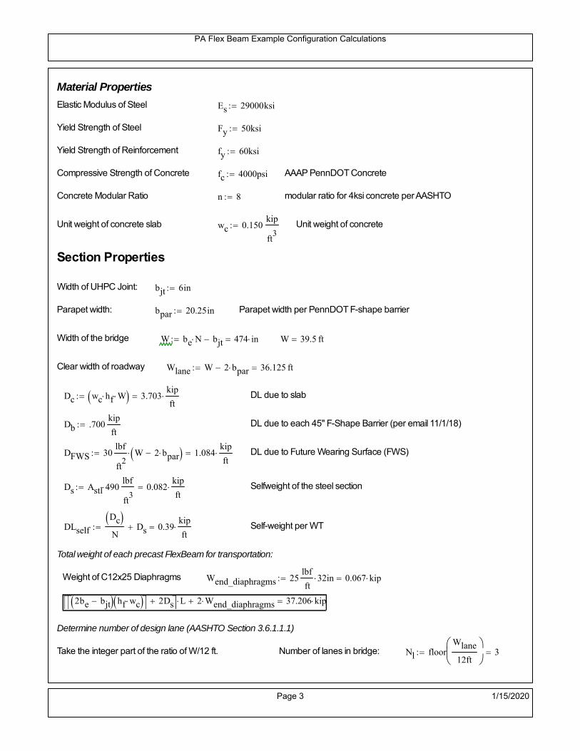
PA Flex Beam Example Configuration Calculations
Material Properties
Elastic Modulus of Steel Es 29000ksi
Yield Strength of Steel Fy 50ksi
Yield Strength of Reinforcement fy 60ksi
Compressive Strength of Concrete fc 4000psi AAAP PennDOT Concrete
Concrete Modular Ratio n 8 modular ratio for 4ksi concrete per AASHTO
Unit weight of concrete slab wc 0.150kip
ft3
Unit weight of concrete
Section Properties
Width of UHPC Joint: bjt 6in
Parapet width: bpar 20.25in Parapet width per PennDOT F-shape barrier
Width of the bridge W be N bjt 474 in W 39.5 ft
Clear width of roadway Wlane W 2 bpar 36.125 ft
Dc wc hf W 3.703kip
ft DL due to slab
Db .700kip
ft DL due to each 45" F-Shape Barrier (per email 11/1/18)
DFWS 30lbf
ft2
W 2 bpar 1.084kip
ft DL due to Future Wearing Surface (FWS)
Ds Astl 490lbf
ft3
0.082kip
ft Selfweight of the steel section
DLself
Dc N
Ds 0.39kip
ft Self-weight per WT
Total weight of each precast FlexBeam for transportation:
Weight of C12x25 Diaphragms Wend_diaphragms 25lbf
ft32 in 0.067 kip
2be bjt hf wc 2Ds L 2 Wend_diaphragms 37.206 kip
Determine number of design lane (AASHTO Section 3.6.1.1.1)
Take the integer part of the ratio of W/12 ft. Number of lanes in bridge: Nl floorWlane
12ft
3
Page 3 1/15/2020

PA Flex Beam Example Configuration Calculations
STEP 1: Compute Dead Load for each Flex Beam
DLslab
Dc
Nwc 1 in
be
2 0.329
kip
ft Dead load of slab assuming exterior overhang has 1" of
additional concrete thickness
DLsteel Ds 0.082kip
ft
DL DLslab DLsteel 0.411kip
ft
STEP 2: Compute Superimposed Dead Load
SDLWS
DFWS
N0.09
kip
ft
SDLparapet
Db
20.35
kip
ft distributed equally on two outer beams
SDLOL 140lbf
ft3be 2 in 0.078
kip
ft Overlay is 2" thick and is 140 lbs/cubic foot
NOTE: For this example barrier load is distributed equally among the two outer beams per conversation withPennDOT and M&M.
PennDOT DM4: "For composite adjacent and spread beams, the barrier (single barrier) load shall be equallydistributed to the nearest three (adjacent) and two (spread) beams, respectively, when the barriers are placedafter slab has hardened".
SDL SDLWS SDLparapet SDLOL 0.518kip
ft
STEP 3: Compute Transformed Width of Slab
For live load and dead load acting on the stringer k1 1 For short-term section property evaluation
btr1
be
k1 n5 in Transformed width of slab for short-term
For superimposed dead loads k3 3 For long-term section property evaluation
btr3
be
k3 n1.667 in Transformed width of slab for long-term
Page 4 1/15/2020

PA Flex Beam Example Configuration Calculations
STEP 4: Compute Dead and Superimposed Dead Load Moments(Based on first interior girder demands)
MDLDL L
2
8128.467 kip ft
MSDLSDL L
2
8161.903 kip ft
STEP 5: Compute live load and Dynamic Load Allowance (IM)
Live load wheel load distribution factor (DF):
Sbe
12in3.333 transverse girder spacing
NOTE: AASHTO presents equations to define DF for different types of superstructuresincluding Deck Composite wirh RC slab on steel girders (Type (a) in Table 4.6.2.2.1-1) forshear and moment in interior and exterior beams.
Using DM4 Table 4.6.2.2.2b-1:
eg h y_barhf
2 18.5 in Distance between the centers of gravity of the basic beam and deck
Kg n Istl Astl eg2
77828 in
4 Longitudinal stiffness parameter (in4)
Distribution of Live Load Per Lane for Moment in Interior Beams:
to be conservative, use DF 0.3
Page 5 1/15/2020

PA Flex Beam Example Configuration Calculations
Dynamic Load Allowance (Section 3.6.2 DM4)
Static effects of the design truck or tandem, shall be increased by the impact factor.
NOTE: The dynamic load allowance shall not be applied to the design lane load (Section 3.6.2.1 DM4)
I 0.33 Impact factor for moment
Note: PennDOT requires that the impact for decks be increased from 33% to 50%, the deck is not beingdesigned here. Instrad the deck design is based on the BD recommendations.
Dynamic load allowance for the Permit Load P-82 shall be less than 20%. (Section 3.6.2.1DM4)
IPL 0.20 Impact factor for moment on Strength II
Design Wind Loading for Exterior Girder
Vw 80 Wind speed for Strength V load case
CD 1.3 Gust factor for windard side of I-Girder and Box Girder Superstructures (Table 3.8.1.2.1-2)
G 1.0 Gus effect factor is 1.0 for all structures other than sound barriers (Table 3.8.1.2.1-1)
Kz 1.0 Pressure coefficient taken as 1 for Strength V (3.8.1.2.1)
Pz 2.56 106
Vw 2 Kz G CDkip
ft2
0.021kip
ft2
Wind pressure on exterior girder
hexp h hf 21.5 in Exposed height of exterior girder
Moment due to wind loading on exterior girderMWL
Pz hexp L2
811.925 kip ft
Iyy
bf3tf
12144 in
4 Transverse moment of intertia
Flange lateral bending stressfl
MWL
bf
2
Iyy5.963 ksi
Page 6 1/15/2020

PA Flex Beam Example Configuration Calculations
Design Vehicular Live Load
PHL-93 and P-82 are examined herein.
PHL-93 (A3.6.1.2.1)
PHL-93 consists of a combination of (design truck or design tandem) + (design lane load)
Design Truck
PennDOT defines the design truck in accordance with AASTHO 3.6.1.2
Design truck load in AASHTO (HS20 Truck) is used for this example.
NOTE : MAX moment occurs when the center line of the span is midway between the center ofgravity of the loads and the nearest concentrated load.
P1 8kip P2 32kip P3 32kip Axle loads (AASHTO 3.6.1.2.2)
XASr 14ft Rear Axle spacing for truck (14ft - 30ft)
XASf 14ft Front Axle spacing for truck
Page 7 1/15/2020

PA Flex Beam Example Configuration Calculations
Center of gravity (CG) of loads:
X'P1 XASr XASf P2 XASr
P1 P2 P39.333 ft Datum is the rear axle
X XASr X' 4.667 ft Spacing btw CG and nearest load
Find bridge reaction
Truck movestoward Support ARA
P1L
2XASf
X
2
P2L
2
X
2
P3L
2X'
X
2
L32.64 kip
Max live load moment (at the location of P2):
MLL_truck RAL
2
X
2
P1 XASf 627.84 kip ft
NOTE: Find the worst case by varying XASr
Page 8 1/15/2020

PA Flex Beam Example Configuration Calculations
Design Tandem
Consist of a pair of 25-kip axles spaced 4-ft apart. (AASHTO 3.6.1.2.3)
NOTE: PennDOT DM4 increases 25-kip to 31.25-kip.
FT 31.25kip
XAS 4ft Axle spacing
Center of gravity (CG) of loads:
XXAS
22 ft Spacing btw CG and nearest load
Find bridge reaction
RA
FTL
2
X
2
FTL
2
X
2 X
L30 kip Truck moves toward Support A
Max live load moment (at the location of front wheel):
MLL_tandem RAL
2
X
2
720 kip ft
Choose the max value:
MLL_veh max MLL_tandem MLL_truck 720 kip ft
Apply the impact and wheel load distribution:
MLL_IM_veh MLL_veh DF 1 I( ) 287.28 kip ft Due to tandem or truck
Design Lane Load (distributed over a 10-ft width for each lane)
NOTE: The uniform load may be continuous or discontinuous as necessary to produce themaximum force effect. For this example continuous uniform distribution assumed.
FDLL 0.64kip
ftDF 0.192
kip
ft Per beam in each lane
Due to lane loadMLL_IM_lane
FDLL L2
8
60 kip ft
Moment due to Total Design Vehicular Live Load: MLL_IM MLL_IM_lane MLL_IM_veh 347.28 kip ft
Page 9 1/15/2020

PA Flex Beam Example Configuration Calculations
Design Permit Load P-82 (Section 3.6.1.2.7 DM4)
P1 P2 P3 P4 P5 P6 P7
NOTE: The moment for the permit load is defined at the beginning of the sheetand is obtained from MATLab File FlexBeam_Moment_ShearEnvelope.m
STEP 6: Compute Moment of Inertia (Note: rebar neglected!)
1) Moment of Inertia resisting dead load only:
a) Acting on the non-composite section (before the deck has hardened - DC1)
Use steel section only
Inc Istl 1.514 103
in4
Non-composite section modulus
Y'nc y_bar S.G. of the steel section of Flex Beam (Datum is bottom)
b) Acting on the composite section (after the deck has hardened - DC2)
Use Ic_short as defined below.
Page 10 1/15/2020

PA Flex Beam Example Configuration Calculations
2) Moment of Inertia resisting live load plus impact:
Using transformed slab with k1=1 (short-term composite).
Actr1 hf btr1 37.5 in2
Itr1
btr1 hf3
12175.781 in
4
Y'
Actr1 hhf
2
Astl Y'nc
Astl Actr118.03 in S.G. of the total flex beam (Datum is bottom)
Compositesection modulus(short-term)
Ic_short Istl Astl Y'nc Y' 2 Itr1 Actr1 hhf
2
Y'
2
6699 in4
Y'c_short Y' 18.03 in N.A. of the short-term composite section
3) Moment of Inertia resisting superimposed dead load:
Using transformed slab with k3=3.
Actr3 hf btr3 12.5 in2
Itr3
btr3 hf3
1258.594 in
4
Y'
Actr3 hhf
2
Astl Y'nc
Astl Actr313.086 in S.G. of the total flex beam (Datum is bottom)
Compositesection modulus(long-term)
Ic_long Istl Astl Y'nc Y' 2 Itr3 Actr3 hhf
2
Y'
2
4386 in4
Y'c_long Y' 13.086 in N.A. of the long-term composite section
Page 11 1/15/2020
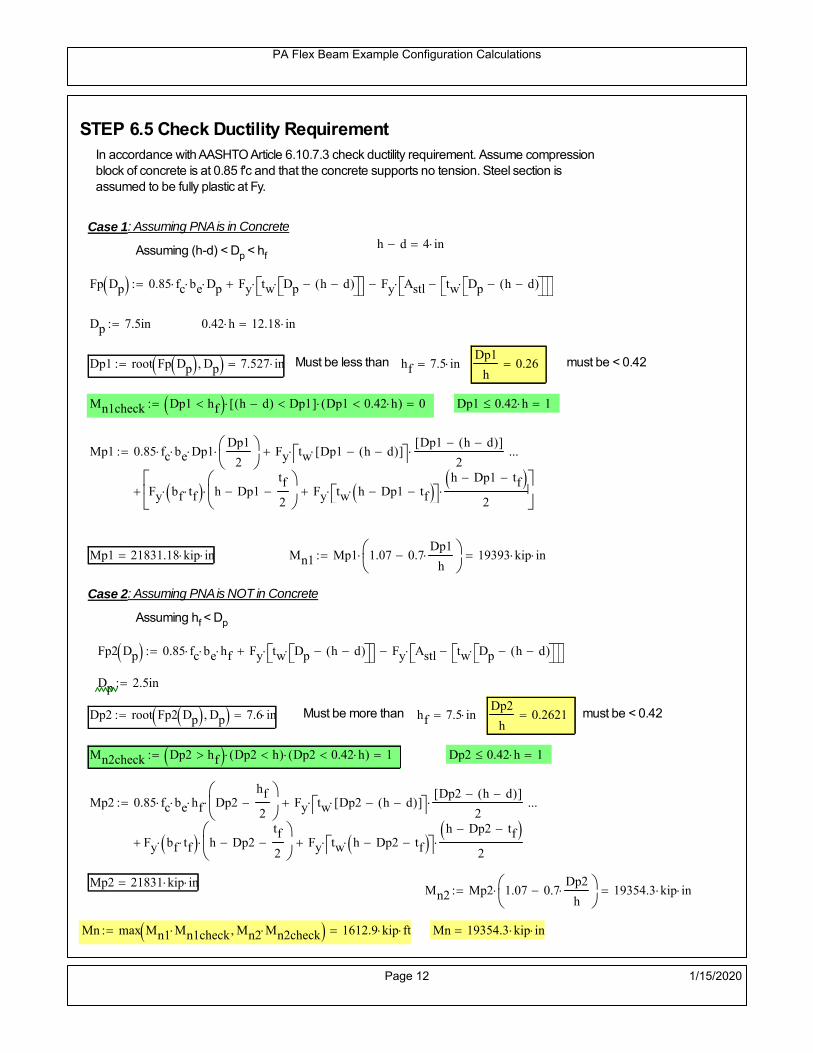
PA Flex Beam Example Configuration Calculations
STEP 6.5 Check Ductility RequirementIn accordance with AASHTO Article 6.10.7.3 check ductility requirement. Assume compressionblock of concrete is at 0.85 f'c and that the concrete supports no tension. Steel section isassumed to be fully plastic at Fy.
Case 1 : Assuming PNA is in Concreteh d 4 inAssuming (h-d) < Dp < hf
Fp Dp 0.85 fc be Dp Fy tw Dp h d( ) Fy Astl tw Dp h d( )
Dp 7.5in 0.42 h 12.18 in
Dp1 root Fp Dp Dp 7.527 in Must be less than hf 7.5 inDp1
h0.26 must be < 0.42
Mn1check Dp1 hf h d( ) Dp1[ ] Dp1 0.42 h( ) 0 Dp1 0.42 h 1
Mp1 0.85 fc be Dp1Dp1
2
Fy tw Dp1 h d( )[ ] Dp1 h d( )[ ]
2
Fy bf tf h Dp1tf
2
Fy tw h Dp1 tf h Dp1 tf
2
Mp1 21831.18 kip in Mn1 Mp1 1.07 0.7Dp1
h
19393 kip in
Case 2 : Assuming PNA is NOT in Concrete
Assuming hf < Dp
Fp2 Dp 0.85 fc be hf Fy tw Dp h d( ) Fy Astl tw Dp h d( )
Dp 2.5in
Dp2 root Fp2 Dp Dp 7.6 in Must be more than hf 7.5 inDp2
h0.2621 must be < 0.42
Mn2check Dp2 hf Dp2 h( ) Dp2 0.42 h( ) 1 Dp2 0.42 h 1
Mp2 0.85 fc be hf Dp2hf
2
Fy tw Dp2 h d( )[ ] Dp2 h d( )[ ]
2
Fy bf tf h Dp2tf
2
Fy tw h Dp2 tf h Dp2 tf
2
Mp2 21831 kip inMn2 Mp2 1.07 0.7
Dp2
h
19354.3 kip in
Mn max Mn1 Mn1check Mn2 Mn2check 1612.9 kip ft Mn 19354.3 kip in
Page 12 1/15/2020

PA Flex Beam Example Configuration Calculations
Check Composite Compact Section Criteria (6.10.6.2)
Dcpd
2
Fy tf bf 0.85 fc be hf
Fy hw tw1
3.75 in Dcp0 Dcp 0 1
Dcp Dcp Dcp0 3.75 in2 Dcp
tw3.76
Es
Fy 1 Check if section is compact
STEP 7: Load Combinations (Table 3.4.1-1)
The following load combinations will be considered herein. Only the maximum load factors forpermanent-loads are used in the following load combinations (uplift is not an issue for this typeof bridge).STRENGTH I 1.25DL + 1.5SDL + 1.75 (LL+IM)
SERVICE II: DL+SDL+1.3(LL+IM)
STEP 8: Compute and Check Stresses
Stress at bottom fiber of steel section
fDL
MDL Y'c_long
Ic_long4.599 ksi
fLL_I
MLL_IM Y'c_short
Ic_short11.217 ksi fPL
MLL_IM_PL82 Y'c_short
Ic_short13.211 ksi
fSDL
MSDL Y'c_long
Ic_long5.796 ksi
STRENGTH I fbot_str1 1.25fDL 1.5 fSDL 1.75 fLL_I 34.073 ksi
STRENGTH II fbot_str2 1.25fDL 1.5 fSDL 1.35 fPL 32.278 ksi
SERVICE II fbot_svc2 fDL fSDL 1.3fLL_I 24.98 ksi
Allowable Stress is based on Section 6.10.4.2.2-2
Flange stress due to service load II without consideration of flange lateral bending: ff fbot_svc2
Flange lateral bending stress due to service II: flSII 0ksi
Hybrid Factor: Rh 1.0 For rolled and homogenous built-up sections
ff
flSII
2 24.977 ksi 0.95 Rh Fy 47.5 ksi ff
fl
2 0.95Rh Fy 1
Page 13 1/15/2020

PA Flex Beam Example Configuration Calculations
Stress at top fiber of concrete
Note: For calculating longitudinal flexural stresses in the concrete deck due to allpermanent and transient loads, the short-term modular ratio shall be used.
fDL
MDL h Y'c_short
k1 n Ic_short0.316 ksi
fLL_I
MLL_IM h Y'c_short
k1 n Ic_short0.853 ksi fPL
MLL_IM_PL82 h Y'c_short
k1 n Ic_short1.005 ksi
fSDL
MSDL h Y'c_short
k1 n Ic_short0.398 ksi
STRENGTH I fc_str1 1.25fDL 1.5 fSDL 1.75 fLL_I 2.484 ksi
Mstr1 1.25 MDL 1.5 MSDL 1.75 MLL_IM 1011.2 kip ft Mstr1 Mn 1
STRENGTH II fc_str2 1.25fDL 1.5 fSDL 1.35 fPL 2.347 ksi
Mstr2 1.25 MDL 1.5 MSDL 1.35 MLL_IM_PL82 956 kip ft Mstr2 Mn 1
SERVICE II
Allowable Stress in concrete - AASHTO 6.10.4.2.2For compact composite sections in positive flexure utilized in shored construction, the longitudinalcompressive stress in the concrete deck due to the Service II loads, determined as specified in Article6.10.1.1.1d, shall not exceed 0.6f́ c.
fallow 0.6 fc 2400 psi
fc_2 1.3fLL_I fSDL fDL 1822.16 psi This assumes short term compositesection for all calculations
fc_2 fallow 1
SERVICE II with Long Term Composite for dead loads
fDL
MDL h Y'c_long
k3 n Ic_long0.233 ksi
fLL_I
MLL_IM h Y'c_short
k1 n Ic_short0.853 ksi
fSDL
MSDL h Y'c_long
k3 n Ic_long0.294 ksi
fc_2 1.3fLL_I fSDL fDL 1635.71 psi fc_2 fallow 1
Page 14 1/15/2020

PA Flex Beam Example Configuration Calculations
Strength V Moment Check
Strength V is related to normal vehicular use of the bridge with an 80 mph wind gust
Note: that Strength V is checked for an exterior girder under wind load with the interior girder distribution factor forflexure used. If Strength V controls design, then this approach should be modified
Design vertical moment is: 1.25DL + 1.5SDL + 1.35 (LL+IM)
SLT
Ic_long
Y'c_long335.185 in
3 SST
Ic_short
Y'c_short371.527 in
3 short and long term section
modulus
Section D6.2.2 Find the moment required to cause yieldling of the flange. The approach is laid out in D6.2.2
MD2 1.25 MDL 1.5 MSDL 403.438 kip ft From D6.2.2-1 (all dead loads are in MD2 due to shoredconstruction
MAD Fy
MD2
SLT
SST 1.101 10
3 kip ft Additional moment to cause nominal yielding of steel flange
My MD2 MAD 1.504 103
kip ft D6.2.2-2: Moment to cause yielding of flange
6.10.7.1 Compact Section Check at Strength V limit state
Section Modulus for yielding of the flange (My/Fy) for equation 6.10.7.1.1-1Sxt
My
Fy361.029 in
3
Mu 1.25 MDL 1.5MSDL 1.35MLL_IM 872.266 kip ft Moment due to Strength V limit state
Mu1
3fl Sxt 932.063 kip ft Equation 6.10.7.1.7-1 Mn 1.613 10
3 kip ft Mu
1
3fl Sxt Mn 1
Page 15 1/15/2020

PA Flex Beam Example Configuration Calculations
STEP 9: Compute Deflection
Optional Live Load Deflection Evaluation (AASHTO 3.6.1.3.2)
Deflection distribution factor for vehicular loads: For a straight multibeambridge, this is equivalent to saying that the distribution factor for deflectionis equal to the number of lanes divided by the number of beams. 2.5.2.6.2
DFd
Nl
N0.25
Deflection should be taken as 125% the larger of:- Design truck- 25% of design truck + design lane
The live load portion of Load Combination Service I of Table 3.4.1-1 should be used,including the dynamic load allowance, IM;
Deflection due to design truck load
NOTE : Assuming maximum deflection occurs when the center of gravity of the loads is at thecenter line of the span.
P1 8kip P2 32kip P3 32kip Axle loads (AASHTO 3.6.1.2.2)
XASr 14ft Rear Axle spacing for truck (14ft - 30ft)
XASf 14ft Front Axle spacing for truck
Center of gravity (CG) of loads:
X'P1 XASr XASf P2 XASr
P1 P2 P39.333 ft Datum is the rear axle
Method1: Assuming single load = P1+P2+P3 at the midspan (Conservative approach)
P1 P2 P3 L3
48 Es Ic_short 1.668 in
Method2: Calculation of Midspan deflection using superposition
b1L
2XASr X' XASf 6.333 ft distance btw load P1 and support A b1check b1 0 1
b2L
2XASr X' 20.333 ft distance btw load P2 and support A b2check b2 0 1
b3L
2X' 15.667 ft distance btw load P3 and support B b3check b3 0 1
Page 16 1/15/2020

PA Flex Beam Example Configuration Calculations
Deflection of the beam at midspan due to P1: P P1
xL
2 at midspan b b1 b1check The smallest distance btw load P1 and support
Δ1P b x
6 Es Ic_short LL2
b2
x2
0.069 in
Deflection of the beam at midspan due to P2: P P2
xL
2 at midspan b b2 b2check The smallest distance btw load P2 and support
Δ2P b x
6 Es Ic_short LL2
b2
x2
0.705 in
Deflection of the beam at midspan due to P3: P P3
xL
2 at midspan b b3 b3check The smallest distance btw load P3 and support
Δ3P b x
6 Es Ic_short LL2
b2
x2
0.606 in
Total Deflection at midspan:
Δtruck Δ1 Δ2 Δ3( ) DFd 1 I( ) 0.459 in (Considering IM)
Deflection due to tandem (Note: this calculation is not required according to Article3.6.1.3.2 which denotes only the design truck for deflection calculation)
Page 17 1/15/2020

PA Flex Beam Example Configuration Calculations
FT 31.25 kip Per axle
XAS 4ft Axle spacing
Δtandem
FTL
2
XAS
2
24 Es Ic_short3 L
2 4
L
2
XAS
2
2
DFd 1 I( ) 0.477 in (Considering IM)
Deflection due to lane load
FDLLd 640lbf
ft DFd 160
lbf
ft
Δlane
5 FDLLd L4
384 Es Ic_short0.116 in
Live Load Deflection:
ΔLL 1.25max Δtruck 0.25Δtruck Δlane 1.25 0.717 in ΔLLL
800 1
Deflection Limit
For steel or concrete vehicular bridges:
Vehicular load = Span/800L
8000.75 in
L
10000.6 in
Evaluation of Deflection at the Service Limit State (AASHTO 3.4.2.2)
The associated permitted deflections shall be included in the contract documents.
Page 18 1/15/2020

PA Flex Beam Example Configuration Calculations
Shear demands:
Determination of the distribution factor
Using DM4 Table 4.6.2.2.3a-1
Sbe
12in3.333 transverse girder spacing (ft)
Distribution of live loads per lane for shear in interior beams:
For two design lanes loaded, 3.5' <= S =< 16', number of beam >= 4DFs 0.36
S
25 0.493
Q Actr1 h Y'c_shorthf
2
270.732 in3
first moment of deck slab for interface shear
Method 1: Range of shear based on Strength I Limit
STRENGTH I 1.25DL + 1.5SDL + 1.75 (LL+IM)
Computation of the range of shear in the beam
Dead Load:DL 0.411
kip
ft
Superimposed Dead Load: SDL 0.518kip
ft
Design Lane Load: 0.64kip
ft
Design Truck:
XASr 14ft Rear Axle spacing for truck (14ft - 30ft)
XASf 14ft Front Axle spacing for truck
P1 8 kip P2 32 kip P3 32 kip Wheel loads (AASHTO 3.6.1.2.2)
Design Tandem:
Consist of a pair of 25-kip axles spaced 4-ft apart. (AASHTO 3.6.1.2.3)
NOTE: PennDOT DM4 increases 25-kip to 31.25-kip.
FT 31.25kip
XAS 4ft Axle spacing
Page 19 1/15/2020

PA Flex Beam Example Configuration Calculations
Maximum positive shear at various points along the FlexBeam are examined.
At x=0 (at left support) (Truck is moving from left to right)
Truck
Max Positive Shear (when P3 is at x = 0):
x1 L XASr XASf 22 ft Distance between P1 and right support
x2 L XASr 36 ft Distance between P2 and right support
x3 L 50 ft Distance between P3 and right support
V1 P3
x3
L P2
x2
L P1
x1
L 58.56 kip
Total Vertical Shear Force for each FlexBeam (considering dynamic loads):
Vtruck1 V1 DFs 1 I( ) 38.423 kip
Tandem:
V1 FT FT
L XAS L
60 kip
Total Vertical Shear Force for each FlexBeam (considering dynamic loads):
Vtandem1 V1 DFs 1 I( ) 39.368 kip
Lane Load
V1 0.64kip
ft
L
2 16 kip
Total Vertical Shear Force for each FlexBeam (considering dynamic loads):
Vlane1 V1 DFs 7.893 kip
Dead Load
Vdl1 DLL
2 10.277 kip
Superimposed Dead Load
Vsdl1 SDLL
2 12.952 kip
Strength I Max Positive Shear:
Vstr1 1.25 Vdl1 1.5 Vsdl1 1.75 Vlane1 max Vtruck1 Vtandem1 114.982 kip
Page 20 1/15/2020

PA Flex Beam Example Configuration Calculations
Design Permit Load P-82
Shear at x=0
Strength II Max Positive Shear:
VPL82 VPL82span DFs 1 IPL 65.63 kip
STRENGTH II 1.25DL + 1.5SDL + 1.35 (LL+IM)
VstrII_PL 1.25 Vdl1 1.5 Vsdl1 1.35 VPL82 120.876 kip
Max Shear Demand Vu max Vstr1 VstrII_PL 120.876 kip
Determine the Shear Strength of the Web
Shear Strength of Unstiffened web from AASHTO section 6.10.9.2
Depth of Web D d 25 in Thickness of web tw 0.5 in
Transverse Stiffener Spacing d0 0in Shear Buckling Coefficient k 5 6.10.9.3.2-7
Plastic Shear Force Vp 0.58 Fy D tw 362.5 kip Equation 6.10.9.3.2-3
Ratio of Shear-Buckling resistance to shear yield, C
D
tw50 1.12
Es k
Fy 60.314 Ccheck
D
tw1.12
Es k
Fy 1 Equation 6.10.9.3.2-4
C 1.0 Ccheck 1 C=1 for most cases, if the criteria are not met, then C will go to zero and the actualcoefficients should be determined
Nominal Shear Resistance of Web Vn C Vp 362.5 kip equation 6.10.9.3.3-1
Shear Resistance Factor φv 1.0
φv Vn 362.5 kip φv Vn Vu 1Reduced Shear Strength
Page 21 1/15/2020

PA Flex Beam Example Configuration Calculations
Check Bearing Stiffeners
FYs 50ksi Yield strength of stiffener
tp 0.75in Thickness of stiffener
bt
bf tw
21.5in 4.25 in Effective width of stiffener
Dst hw 4.1in 19.9 in Depth of stiffeners
Apn 2 tp bt 6.375 in2
Projected area of stiffeners
bt 0.48 tpEs
FYs 1Check that effective width of stiffener meets requirements
Rsbn 1.4 Apn FYs 446.25 kip Bearing capacity of stiffener (phi=1 for bearing per AASHTO 6.5.4.2)
Rsbn Vu 1 Bearing capacity check
Qs 1.0 Q factor for bearing stiffner, taken as 1 (AASHTO 6.9.4.1.1)
Is
18 tw tw3
tp 2 bt 3
1238.477 in
4 Moment of inertia of stiffener and web (9*tw is used on each side)
AASHTO 6.10.11.2.4b
Ag 18 tw tw 2 bt tp 10.875 in2
Gross area of stiffener and web (AASHTO 6.10.11.2.4b)
rs
Is
Ag1.881 in Radius of gyration of stiffener/web
Po Qs FYs Apn 318.75 kip Nominal yeild resistance of stiffener (AASHTO 6.9.4.1.1)
Peπ2Es
0.75 Dst
rs
2Ag 4.944 10
4 kip Elastic critical buckling stress of stiffener (AASHTO 6.9.4.1.2-1)
Check that Pe/Po is great than 0.44 (AASHTO 6.9.4.1.1) PePoPe
Po0.44 1
Pn PePo 0.658
Po
Pe Po 317.891 kip Nominal compressive resistance of stiffener for Pe/Po>0.44
(AASHTO 6.9.4.1.1-1)
φcr 0.95 phi factor for axial compression (AASHTO 6.5.4.2)
Pr φcr Pn 301.996 kip Compressive capacity of bearing stiffener Pr Vu 1
Page 22 1/15/2020

PA Flex Beam Example Configuration Calculations
Flexbeam Example Configuration Calculations
Summary of Calculations:
Input section dimensions and material properties for steel WT and the concrete deck1.Calculate demands (dead load, superimposed dead, and Live load demands for Strength I and Strength II2.Calculate composite section properties for the given section3.Check Strength I, Strength II, and Service II stresses 4.Check Strength I, Strength II, and Strength V moment demands 5.Perform live load deflection check6.Determine maximum shear demand and capacity7.Note: Shear envelope data was obtained from Matlab script (FlexBeam_Moment_ShearEnvelope.m).8.Shear envelope calculations are summarized separately for each design (Shear Design *.xlsx).
Design Assumptions:Design Specifications Used:
AASHTO LRFD Bridge Design Specifications 7th Edition with 2016 Interim RevisionsPennDOT Design Manual, Part 4 (DM-4) June 30, 2015
Example configurations are determined for two girder spacings, 36" and 40".The deck thickness is 7.5" and is assumed to have a non-structural wearing surface added after installation.Section properties are calculated using the full 7.5" deck thickness.The WT sections are embedded 3.5" into the concrete deck. The steel section spacing used is outside the scope of the AASHTO and PennDOT distribution factorequations. The flexural distribution factor is assumed to be 0.3 which was shown to tbe conservativeaccording to refined analysisThe shear distribution factor is calculated using the DM-4 shear distribution factor equation which wasshown to be conservative using refined analysis.Refined analysis is presented in: Zihan Ma, "Distribution Factors for Composite Steel Tee Concrete DeckBridge System," M.S. Thesis, Deparement of Civil and Environmental Engineering, Lehigh University,Bethlehem, 2019Shear and moment demands for the PL82 permit load vehicle are determined by Matlab script(FlexBeam_Moment_ShearEnvelope.m) and are manually input into this calculation sheet.All fabrication will occur as double modules, i.e. each module contains two WT sections. The number ofmodules is half the number of beams, N. A 45 in. tall F-Shape barrier is used, Weight = 700 lb/ft (Distributed to exterior two beams).
The work presented in this document are provided on an “AS IS” basis. University makes no warranties of anykind, express or implied, as to any matter whatsoever, including, without limitation, warranties with respect tothe merchantability or fitness for a particular purpose of this work or any project deliverables. Universitymakes no warranty of any kind with respect to freedom from patent, trademark, copyright or trade secretinfringement arising from the use of the results of the project, deliverables, services, intellectual property orother materials provided hereunder. University shall not be liable for any direct, indirect, consequential,punitive, or other damages suffered by Sponsor or any other person resulting from the project, or the use ofthis work or any project deliverables.
Page 1 1/15/2020

PA Flex Beam Example Configuration Calculations
hf
tf
bf
twh
d
bjtbe
e
Variable Definitions:
Number of beams N 14 modulesN
27
L 50ft Span length
be 40in Effective width of Flexbeamassuming constructed bridge width(i.e. closure joints cast)
Built Up Section Properties
tw 0.500in tf 1.00in bf 12in
h 29in Overall Height of section
hf 7.5in Total thickness of deck
e 3.5in Deck/Steel overlap
d h hf e 25 in depth of built up steel section
hw d tf 24 in height of web of built up steel
Moment and shear for permit load PL82 obtained from Matlab script: FlexBeam_Moment_ShearEnvelope
MLL_IM_PL82 409.0176kip ft Moment due to PL82 with distribution factor and impact factor!!
VPL82span 110.862kip Shear due to PL82 WITHOUT distribution factor and impact factor!!
Check web and flange dimensions in sections 6.10.2.1 and 6.10.2.2
(Ignore 6.10.2.2-4 since no compression flange)
equation 6.10.2.1.1-1d
tw150 1 equation 6.10.2.2-1
bf
2 tf12 1
equation 6.10.2.2-2 bfh
6 1 equation 6.10.2.2-3 tf 1.1 tw 1
y_bar
tf bftf
2 hw tw tf
hw
2
tf bf hw tw6.75 in Center of gravity of steel section
Istl
bf tf3
12bf tf y_bar
tf
2
2
tw hw
3
12 tw hw tf
hw
2 y_bar
2
1.514 103
in4
MOI of steel
Astl tf bf hw tw 24 in2
Area of the WT steel section
Page 2 1/15/2020

PA Flex Beam Example Configuration Calculations
Material Properties
Elastic Modulus of Steel Es 29000ksi
Yield Strength of Steel Fy 50ksi
Yield Strength of Reinforcement fy 60ksi
Compressive Strength of Concrete fc 4000psi AAAP PennDOT Concrete
Concrete Modular Ratio n 8 modular ratio for 4ksi concrete per AASHTO
Unit weight of concrete slab wc 0.150kip
ft3
Unit weight of concrete
Section Properties
Width of UHPC Joint: bjt 6in
Parapet width: bpar 20.25in Parapet width per PennDOT F-shape barrier
Width of the bridge W be N bjt 554 in W 46.167 ft
Clear width of roadway Wlane W 2 bpar 42.792 ft
Dc wc hf W 4.328kip
ft DL due to slab
Db .700kip
ft DL due to each 45" F-Shape Barrier (per email 11/1/18)
DFWS 30lbf
ft2
W 2 bpar 1.284kip
ft DL due to Future Wearing Surface (FWS)
Ds Astl 490lbf
ft3
0.082kip
ft Selfweight of the steel section
DLself
Dc N
Ds 0.391kip
ft Self-weight per WT
Total weight of each precast FlexBeam for transportation:
Weight of C12x25 Diaphragms Wend_diaphragms 25lbf
ft32 in 0.067 kip
2be bjt hf wc 2Ds L 2 Wend_diaphragms 37.206 kip
Determine number of design lane (AASHTO Section 3.6.1.1.1)
Take the integer part of the ratio of W/12 ft. Number of lanes in bridge: Nl floorWlane
12ft
3
Page 3 1/15/2020

PA Flex Beam Example Configuration Calculations
STEP 1: Compute Dead Load for each Flex Beam
DLslab
Dc
Nwc 1 in
be
2 0.33
kip
ft Dead load of slab assuming exterior overhang has 1" of
additional concrete thickness
DLsteel Ds 0.082kip
ft
DL DLslab DLsteel 0.412kip
ft
STEP 2: Compute Superimposed Dead Load
SDLWS
DFWS
N0.092
kip
ft
SDLparapet
Db
20.35
kip
ft distributed equally on two outer beams
SDLOL 140lbf
ft3be 2 in 0.078
kip
ft Overlay is 2" thick and is 140 lbs/cubic foot
NOTE: For this example barrier load is distributed equally among the two outer beams per conversation withPennDOT and M&M.
PennDOT DM4: "For composite adjacent and spread beams, the barrier (single barrier) load shall be equallydistributed to the nearest three (adjacent) and two (spread) beams, respectively, when the barriers are placedafter slab has hardened".
SDL SDLWS SDLparapet SDLOL 0.519kip
ft
STEP 3: Compute Transformed Width of Slab
For live load and dead load acting on the stringer k1 1 For short-term section property evaluation
btr1
be
k1 n5 in Transformed width of slab for short-term
For superimposed dead loads k3 3 For long-term section property evaluation
btr3
be
k3 n1.667 in Transformed width of slab for long-term
Page 4 1/15/2020

PA Flex Beam Example Configuration Calculations
STEP 4: Compute Dead and Superimposed Dead Load Moments(Based on first interior girder demands)
MDLDL L
2
8128.641 kip ft
MSDLSDL L
2
8162.336 kip ft
STEP 5: Compute live load and Dynamic Load Allowance (IM)
Live load wheel load distribution factor (DF):
Sbe
12in3.333 transverse girder spacing
NOTE: AASHTO presents equations to define DF for different types of superstructuresincluding Deck Composite wirh RC slab on steel girders (Type (a) in Table 4.6.2.2.1-1) forshear and moment in interior and exterior beams.
Using DM4 Table 4.6.2.2.2b-1:
eg h y_barhf
2 18.5 in Distance between the centers of gravity of the basic beam and deck
Kg n Istl Astl eg2
77828 in
4 Longitudinal stiffness parameter (in4)
Distribution of Live Load Per Lane for Moment in Interior Beams:
to be conservative, use DF 0.3
Page 5 1/15/2020
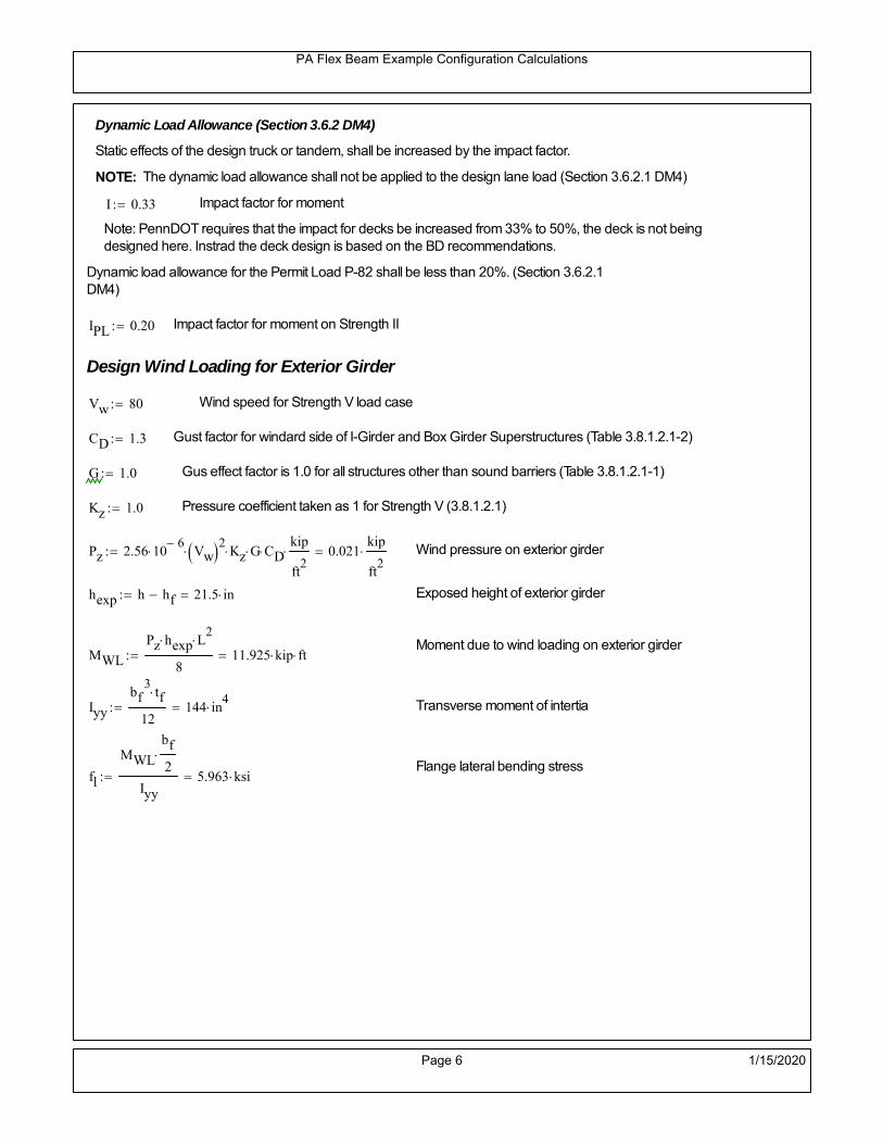
PA Flex Beam Example Configuration Calculations
Dynamic Load Allowance (Section 3.6.2 DM4)
Static effects of the design truck or tandem, shall be increased by the impact factor.
NOTE: The dynamic load allowance shall not be applied to the design lane load (Section 3.6.2.1 DM4)
I 0.33 Impact factor for moment
Note: PennDOT requires that the impact for decks be increased from 33% to 50%, the deck is not beingdesigned here. Instrad the deck design is based on the BD recommendations.
Dynamic load allowance for the Permit Load P-82 shall be less than 20%. (Section 3.6.2.1DM4)
IPL 0.20 Impact factor for moment on Strength II
Design Wind Loading for Exterior Girder
Vw 80 Wind speed for Strength V load case
CD 1.3 Gust factor for windard side of I-Girder and Box Girder Superstructures (Table 3.8.1.2.1-2)
G 1.0 Gus effect factor is 1.0 for all structures other than sound barriers (Table 3.8.1.2.1-1)
Kz 1.0 Pressure coefficient taken as 1 for Strength V (3.8.1.2.1)
Pz 2.56 106
Vw 2 Kz G CDkip
ft2
0.021kip
ft2
Wind pressure on exterior girder
hexp h hf 21.5 in Exposed height of exterior girder
Moment due to wind loading on exterior girderMWL
Pz hexp L2
811.925 kip ft
Iyy
bf3tf
12144 in
4 Transverse moment of intertia
Flange lateral bending stressfl
MWL
bf
2
Iyy5.963 ksi
Page 6 1/15/2020

PA Flex Beam Example Configuration Calculations
Design Vehicular Live Load
PHL-93 and P-82 are examined herein.
PHL-93 (A3.6.1.2.1)
PHL-93 consists of a combination of (design truck or design tandem) + (design lane load)
Design Truck
PennDOT defines the design truck in accordance with AASTHO 3.6.1.2
Design truck load in AASHTO (HS20 Truck) is used for this example.
NOTE : MAX moment occurs when the center line of the span is midway between the center ofgravity of the loads and the nearest concentrated load.
P1 8kip P2 32kip P3 32kip Axle loads (AASHTO 3.6.1.2.2)
XASr 14ft Rear Axle spacing for truck (14ft - 30ft)
XASf 14ft Front Axle spacing for truck
Page 7 1/15/2020

PA Flex Beam Example Configuration Calculations
Center of gravity (CG) of loads:
X'P1 XASr XASf P2 XASr
P1 P2 P39.333 ft Datum is the rear axle
X XASr X' 4.667 ft Spacing btw CG and nearest load
Find bridge reaction
Truck movestoward Support ARA
P1L
2XASf
X
2
P2L
2
X
2
P3L
2X'
X
2
L32.64 kip
Max live load moment (at the location of P2):
MLL_truck RAL
2
X
2
P1 XASf 627.84 kip ft
NOTE: Find the worst case by varying XASr
Page 8 1/15/2020

PA Flex Beam Example Configuration Calculations
Design Tandem
Consist of a pair of 25-kip axles spaced 4-ft apart. (AASHTO 3.6.1.2.3)
NOTE: PennDOT DM4 increases 25-kip to 31.25-kip.
FT 31.25kip
XAS 4ft Axle spacing
Center of gravity (CG) of loads:
XXAS
22 ft Spacing btw CG and nearest load
Find bridge reaction
RA
FTL
2
X
2
FTL
2
X
2 X
L30 kip Truck moves toward Support A
Max live load moment (at the location of front wheel):
MLL_tandem RAL
2
X
2
720 kip ft
Choose the max value:
MLL_veh max MLL_tandem MLL_truck 720 kip ft
Apply the impact and wheel load distribution:
MLL_IM_veh MLL_veh DF 1 I( ) 287.28 kip ft Due to tandem or truck
Design Lane Load (distributed over a 10-ft width for each lane)
NOTE: The uniform load may be continuous or discontinuous as necessary to produce themaximum force effect. For this example continuous uniform distribution assumed.
FDLL 0.64kip
ftDF 0.192
kip
ft Per beam in each lane
Due to lane loadMLL_IM_lane
FDLL L2
8
60 kip ft
Moment due to Total Design Vehicular Live Load: MLL_IM MLL_IM_lane MLL_IM_veh 347.28 kip ft
Page 9 1/15/2020

PA Flex Beam Example Configuration Calculations
Design Permit Load P-82 (Section 3.6.1.2.7 DM4)
P1 P2 P3 P4 P5 P6 P7
NOTE: The moment for the permit load is defined at the beginning of the sheetand is obtained from MATLab File FlexBeam_Moment_ShearEnvelope.m
STEP 6: Compute Moment of Inertia (Note: rebar neglected!)
1) Moment of Inertia resisting dead load only:
a) Acting on the non-composite section (before the deck has hardened - DC1)
Use steel section only
Inc Istl 1.514 103
in4
Non-composite section modulus
Y'nc y_bar S.G. of the steel section of Flex Beam (Datum is bottom)
b) Acting on the composite section (after the deck has hardened - DC2)
Use Ic_short as defined below.
Page 10 1/15/2020

PA Flex Beam Example Configuration Calculations
2) Moment of Inertia resisting live load plus impact:
Using transformed slab with k1=1 (short-term composite).
Actr1 hf btr1 37.5 in2
Itr1
btr1 hf3
12175.781 in
4
Y'
Actr1 hhf
2
Astl Y'nc
Astl Actr118.03 in S.G. of the total flex beam (Datum is bottom)
Compositesection modulus(short-term)
Ic_short Istl Astl Y'nc Y' 2 Itr1 Actr1 hhf
2
Y'
2
6699 in4
Y'c_short Y' 18.03 in N.A. of the short-term composite section
3) Moment of Inertia resisting superimposed dead load:
Using transformed slab with k3=3.
Actr3 hf btr3 12.5 in2
Itr3
btr3 hf3
1258.594 in
4
Y'
Actr3 hhf
2
Astl Y'nc
Astl Actr313.086 in S.G. of the total flex beam (Datum is bottom)
Compositesection modulus(long-term)
Ic_long Istl Astl Y'nc Y' 2 Itr3 Actr3 hhf
2
Y'
2
4386 in4
Y'c_long Y' 13.086 in N.A. of the long-term composite section
Page 11 1/15/2020

PA Flex Beam Example Configuration Calculations
STEP 6.5 Check Ductility RequirementIn accordance with AASHTO Article 6.10.7.3 check ductility requirement. Assume compressionblock of concrete is at 0.85 f'c and that the concrete supports no tension. Steel section isassumed to be fully plastic at Fy.
Case 1 : Assuming PNA is in Concreteh d 4 inAssuming (h-d) < Dp < hf
Fp Dp 0.85 fc be Dp Fy tw Dp h d( ) Fy Astl tw Dp h d( )
Dp 7.5in 0.42 h 12.18 in
Dp1 root Fp Dp Dp 7.527 in Must be less than hf 7.5 inDp1
h0.26 must be < 0.42
Mn1check Dp1 hf h d( ) Dp1[ ] Dp1 0.42 h( ) 0 Dp1 0.42 h 1
Mp1 0.85 fc be Dp1Dp1
2
Fy tw Dp1 h d( )[ ] Dp1 h d( )[ ]
2
Fy bf tf h Dp1tf
2
Fy tw h Dp1 tf h Dp1 tf
2
Mp1 21831.18 kip in Mn1 Mp1 1.07 0.7Dp1
h
19393 kip in
Case 2 : Assuming PNA is NOT in Concrete
Assuming hf < Dp
Fp2 Dp 0.85 fc be hf Fy tw Dp h d( ) Fy Astl tw Dp h d( )
Dp 2.5in
Dp2 root Fp2 Dp Dp 7.6 in Must be more than hf 7.5 inDp2
h0.2621 must be < 0.42
Mn2check Dp2 hf Dp2 h( ) Dp2 0.42 h( ) 1 Dp2 0.42 h 1
Mp2 0.85 fc be hf Dp2hf
2
Fy tw Dp2 h d( )[ ] Dp2 h d( )[ ]
2
Fy bf tf h Dp2tf
2
Fy tw h Dp2 tf h Dp2 tf
2
Mp2 21831 kip inMn2 Mp2 1.07 0.7
Dp2
h
19354.3 kip in
Mn max Mn1 Mn1check Mn2 Mn2check 1612.9 kip ft Mn 19354.3 kip in
Page 12 1/15/2020

PA Flex Beam Example Configuration Calculations
Check Composite Compact Section Criteria (6.10.6.2)
Dcpd
2
Fy tf bf 0.85 fc be hf
Fy hw tw1
3.75 in Dcp0 Dcp 0 1
Dcp Dcp Dcp0 3.75 in2 Dcp
tw3.76
Es
Fy 1 Check if section is compact
STEP 7: Load Combinations (Table 3.4.1-1)
The following load combinations will be considered herein. Only the maximum load factors forpermanent-loads are used in the following load combinations (uplift is not an issue for this typeof bridge).STRENGTH I 1.25DL + 1.5SDL + 1.75 (LL+IM)
SERVICE II: DL+SDL+1.3(LL+IM)
STEP 8: Compute and Check Stresses
Stress at bottom fiber of steel section
fDL
MDL Y'c_long
Ic_long4.605 ksi
fLL_I
MLL_IM Y'c_short
Ic_short11.217 ksi fPL
MLL_IM_PL82 Y'c_short
Ic_short13.211 ksi
fSDL
MSDL Y'c_long
Ic_long5.812 ksi
STRENGTH I fbot_str1 1.25fDL 1.5 fSDL 1.75 fLL_I 34.104 ksi
STRENGTH II fbot_str2 1.25fDL 1.5 fSDL 1.35 fPL 32.309 ksi
SERVICE II fbot_svc2 fDL fSDL 1.3fLL_I 25 ksi
Allowable Stress is based on Section 6.10.4.2.2-2
Flange stress due to service load II without consideration of flange lateral bending: ff fbot_svc2
Flange lateral bending stress due to service II: flSII 0ksi
Hybrid Factor: Rh 1.0 For rolled and homogenous built-up sections
ff
flSII
2 24.999 ksi 0.95 Rh Fy 47.5 ksi ff
fl
2 0.95Rh Fy 1
Page 13 1/15/2020

PA Flex Beam Example Configuration Calculations
Stress at top fiber of concrete
Note: For calculating longitudinal flexural stresses in the concrete deck due to allpermanent and transient loads, the short-term modular ratio shall be used.
fDL
MDL h Y'c_short
k1 n Ic_short0.316 ksi
fLL_I
MLL_IM h Y'c_short
k1 n Ic_short0.853 ksi fPL
MLL_IM_PL82 h Y'c_short
k1 n Ic_short1.005 ksi
fSDL
MSDL h Y'c_short
k1 n Ic_short0.399 ksi
STRENGTH I fc_str1 1.25fDL 1.5 fSDL 1.75 fLL_I 2.486 ksi
Mstr1 1.25 MDL 1.5 MSDL 1.75 MLL_IM 1012 kip ft Mstr1 Mn 1
STRENGTH II fc_str2 1.25fDL 1.5 fSDL 1.35 fPL 2.349 ksi
Mstr2 1.25 MDL 1.5 MSDL 1.35 MLL_IM_PL82 956 kip ft Mstr2 Mn 1
SERVICE II
Allowable Stress in concrete - AASHTO 6.10.4.2.2For compact composite sections in positive flexure utilized in shored construction, the longitudinalcompressive stress in the concrete deck due to the Service II loads, determined as specified in Article6.10.1.1.1d, shall not exceed 0.6f́ c.
fallow 0.6 fc 2400 psi
fc_2 1.3fLL_I fSDL fDL 1823.65 psi This assumes short term compositesection for all calculations
fc_2 fallow 1
SERVICE II with Long Term Composite for dead loads
fDL
MDL h Y'c_long
k3 n Ic_long0.233 ksi
fLL_I
MLL_IM h Y'c_short
k1 n Ic_short0.853 ksi
fSDL
MSDL h Y'c_long
k3 n Ic_long0.295 ksi
fc_2 1.3fLL_I fSDL fDL 1636.81 psi fc_2 fallow 1
Page 14 1/15/2020

PA Flex Beam Example Configuration Calculations
Strength V Moment Check
Strength V is related to normal vehicular use of the bridge with an 80 mph wind gust
Note: that Strength V is checked for an exterior girder under wind load with the interior girder distribution factor forflexure used. If Strength V controls design, then this approach should be modified
Design vertical moment is: 1.25DL + 1.5SDL + 1.35 (LL+IM)
SLT
Ic_long
Y'c_long335.185 in
3 SST
Ic_short
Y'c_short371.527 in
3 short and long term section
modulus
Section D6.2.2 Find the moment required to cause yieldling of the flange. The approach is laid out in D6.2.2
MD2 1.25 MDL 1.5 MSDL 404.305 kip ft From D6.2.2-1 (all dead loads are in MD2 due to shoredconstruction
MAD Fy
MD2
SLT
SST 1.1 10
3 kip ft Additional moment to cause nominal yielding of steel flange
My MD2 MAD 1.504 103
kip ft D6.2.2-2: Moment to cause yielding of flange
6.10.7.1 Compact Section Check at Strength V limit state
Section Modulus for yielding of the flange (My/Fy) for equation 6.10.7.1.1-1Sxt
My
Fy361.007 in
3
Mu 1.25 MDL 1.5MSDL 1.35MLL_IM 873.133 kip ft Moment due to Strength V limit state
Mu1
3fl Sxt 932.926 kip ft Equation 6.10.7.1.7-1 Mn 1.613 10
3 kip ft Mu
1
3fl Sxt Mn 1
Page 15 1/15/2020

PA Flex Beam Example Configuration Calculations
STEP 9: Compute Deflection
Optional Live Load Deflection Evaluation (AASHTO 3.6.1.3.2)
Deflection distribution factor for vehicular loads: For a straight multibeambridge, this is equivalent to saying that the distribution factor for deflectionis equal to the number of lanes divided by the number of beams. 2.5.2.6.2
DFd
Nl
N0.214
Deflection should be taken as 125% the larger of:- Design truck- 25% of design truck + design lane
The live load portion of Load Combination Service I of Table 3.4.1-1 should be used,including the dynamic load allowance, IM;
Deflection due to design truck load
NOTE : Assuming maximum deflection occurs when the center of gravity of the loads is at thecenter line of the span.
P1 8kip P2 32kip P3 32kip Axle loads (AASHTO 3.6.1.2.2)
XASr 14ft Rear Axle spacing for truck (14ft - 30ft)
XASf 14ft Front Axle spacing for truck
Center of gravity (CG) of loads:
X'P1 XASr XASf P2 XASr
P1 P2 P39.333 ft Datum is the rear axle
Method1: Assuming single load = P1+P2+P3 at the midspan (Conservative approach)
P1 P2 P3 L3
48 Es Ic_short 1.668 in
Method2: Calculation of Midspan deflection using superposition
b1L
2XASr X' XASf 6.333 ft distance btw load P1 and support A b1check b1 0 1
b2L
2XASr X' 20.333 ft distance btw load P2 and support A b2check b2 0 1
b3L
2X' 15.667 ft distance btw load P3 and support B b3check b3 0 1
Page 16 1/15/2020

PA Flex Beam Example Configuration Calculations
Deflection of the beam at midspan due to P1: P P1
xL
2 at midspan b b1 b1check The smallest distance btw load P1 and support
Δ1P b x
6 Es Ic_short LL2
b2
x2
0.069 in
Deflection of the beam at midspan due to P2: P P2
xL
2 at midspan b b2 b2check The smallest distance btw load P2 and support
Δ2P b x
6 Es Ic_short LL2
b2
x2
0.705 in
Deflection of the beam at midspan due to P3: P P3
xL
2 at midspan b b3 b3check The smallest distance btw load P3 and support
Δ3P b x
6 Es Ic_short LL2
b2
x2
0.606 in
Total Deflection at midspan:
Δtruck Δ1 Δ2 Δ3( ) DFd 1 I( ) 0.393 in (Considering IM)
Deflection due to tandem (Note: this calculation is not required according to Article3.6.1.3.2 which denotes only the design truck for deflection calculation)
Page 17 1/15/2020

PA Flex Beam Example Configuration Calculations
FT 31.25 kip Per axle
XAS 4ft Axle spacing
Δtandem
FTL
2
XAS
2
24 Es Ic_short3 L
2 4
L
2
XAS
2
2
DFd 1 I( ) 0.409 in (Considering IM)
Deflection due to lane load
FDLLd 640lbf
ft DFd 137.143
lbf
ft
Δlane
5 FDLLd L4
384 Es Ic_short0.099 in
Live Load Deflection:
ΔLL 1.25max Δtruck 0.25Δtruck Δlane 1.25 0.614 in ΔLLL
800 1
Deflection Limit
For steel or concrete vehicular bridges:
Vehicular load = Span/800L
8000.75 in
L
10000.6 in
Evaluation of Deflection at the Service Limit State (AASHTO 3.4.2.2)
The associated permitted deflections shall be included in the contract documents.
Page 18 1/15/2020

PA Flex Beam Example Configuration Calculations
Shear demands:
Determination of the distribution factor
Using DM4 Table 4.6.2.2.3a-1
Sbe
12in3.333 transverse girder spacing (ft)
Distribution of live loads per lane for shear in interior beams:
For two design lanes loaded, 3.5' <= S =< 16', number of beam >= 4DFs 0.36
S
25 0.493
Q Actr1 h Y'c_shorthf
2
270.732 in3
first moment of deck slab for interface shear
Method 1: Range of shear based on Strength I Limit
STRENGTH I 1.25DL + 1.5SDL + 1.75 (LL+IM)
Computation of the range of shear in the beam
Dead Load:DL 0.412
kip
ft
Superimposed Dead Load: SDL 0.519kip
ft
Design Lane Load: 0.64kip
ft
Design Truck:
XASr 14ft Rear Axle spacing for truck (14ft - 30ft)
XASf 14ft Front Axle spacing for truck
P1 8 kip P2 32 kip P3 32 kip Wheel loads (AASHTO 3.6.1.2.2)
Design Tandem:
Consist of a pair of 25-kip axles spaced 4-ft apart. (AASHTO 3.6.1.2.3)
NOTE: PennDOT DM4 increases 25-kip to 31.25-kip.
FT 31.25kip
XAS 4ft Axle spacing
Page 19 1/15/2020

PA Flex Beam Example Configuration Calculations
Maximum positive shear at various points along the FlexBeam are examined.
At x=0 (at left support) (Truck is moving from left to right)
Truck
Max Positive Shear (when P3 is at x = 0):
x1 L XASr XASf 22 ft Distance between P1 and right support
x2 L XASr 36 ft Distance between P2 and right support
x3 L 50 ft Distance between P3 and right support
V1 P3
x3
L P2
x2
L P1
x1
L 58.56 kip
Total Vertical Shear Force for each FlexBeam (considering dynamic loads):
Vtruck1 V1 DFs 1 I( ) 38.423 kip
Tandem:
V1 FT FT
L XAS L
60 kip
Total Vertical Shear Force for each FlexBeam (considering dynamic loads):
Vtandem1 V1 DFs 1 I( ) 39.368 kip
Lane Load
V1 0.64kip
ft
L
2 16 kip
Total Vertical Shear Force for each FlexBeam (considering dynamic loads):
Vlane1 V1 DFs 7.893 kip
Dead Load
Vdl1 DLL
2 10.291 kip
Superimposed Dead Load
Vsdl1 SDLL
2 12.987 kip
Strength I Max Positive Shear:
Vstr1 1.25 Vdl1 1.5 Vsdl1 1.75 Vlane1 max Vtruck1 Vtandem1 115.052 kip
Page 20 1/15/2020

PA Flex Beam Example Configuration Calculations
Design Permit Load P-82
Shear at x=0
Strength II Max Positive Shear:
VPL82 VPL82span DFs 1 IPL 65.63 kip
STRENGTH II 1.25DL + 1.5SDL + 1.35 (LL+IM)
VstrII_PL 1.25 Vdl1 1.5 Vsdl1 1.35 VPL82 120.945 kip
Max Shear Demand Vu max Vstr1 VstrII_PL 120.945 kip
Determine the Shear Strength of the Web
Shear Strength of Unstiffened web from AASHTO section 6.10.9.2
Depth of Web D d 25 in Thickness of web tw 0.5 in
Transverse Stiffener Spacing d0 0in Shear Buckling Coefficient k 5 6.10.9.3.2-7
Plastic Shear Force Vp 0.58 Fy D tw 362.5 kip Equation 6.10.9.3.2-3
Ratio of Shear-Buckling resistance to shear yield, C
D
tw50 1.12
Es k
Fy 60.314 Ccheck
D
tw1.12
Es k
Fy 1 Equation 6.10.9.3.2-4
C 1.0 Ccheck 1 C=1 for most cases, if the criteria are not met, then C will go to zero and the actualcoefficients should be determined
Nominal Shear Resistance of Web Vn C Vp 362.5 kip equation 6.10.9.3.3-1
Shear Resistance Factor φv 1.0
φv Vn 362.5 kip φv Vn Vu 1Reduced Shear Strength
Page 21 1/15/2020

PA Flex Beam Example Configuration Calculations
Check Bearing Stiffeners
FYs 50ksi Yield strength of stiffener
tp 0.75in Thickness of stiffener
bt
bf tw
21.5in 4.25 in Effective width of stiffener
Dst hw 4.1in 19.9 in Depth of stiffeners
Apn 2 tp bt 6.375 in2
Projected area of stiffeners
bt 0.48 tpEs
FYs 1Check that effective width of stiffener meets requirements
Rsbn 1.4 Apn FYs 446.25 kip Bearing capacity of stiffener (phi=1 for bearing per AASHTO 6.5.4.2)
Rsbn Vu 1 Bearing capacity check
Qs 1.0 Q factor for bearing stiffner, taken as 1 (AASHTO 6.9.4.1.1)
Is
18 tw tw3
tp 2 bt 3
1238.477 in
4 Moment of inertia of stiffener and web (9*tw is used on each side)
AASHTO 6.10.11.2.4b
Ag 18 tw tw 2 bt tp 10.875 in2
Gross area of stiffener and web (AASHTO 6.10.11.2.4b)
rs
Is
Ag1.881 in Radius of gyration of stiffener/web
Po Qs FYs Apn 318.75 kip Nominal yeild resistance of stiffener (AASHTO 6.9.4.1.1)
Peπ2Es
0.75 Dst
rs
2Ag 4.944 10
4 kip Elastic critical buckling stress of stiffener (AASHTO 6.9.4.1.2-1)
Check that Pe/Po is great than 0.44 (AASHTO 6.9.4.1.1) PePoPe
Po0.44 1
Pn PePo 0.658
Po
Pe Po 317.891 kip Nominal compressive resistance of stiffener for Pe/Po>0.44
(AASHTO 6.9.4.1.1-1)
φcr 0.95 phi factor for axial compression (AASHTO 6.5.4.2)
Pr φcr Pn 301.996 kip Compressive capacity of bearing stiffener Pr Vu 1
Page 22 1/15/2020

PA Flex Beam Example Configuration Calculations
Flexbeam Example Configuration Calculations
Summary of Calculations:
Input section dimensions and material properties for steel WT and the concrete deck1.Calculate demands (dead load, superimposed dead, and Live load demands for Strength I and Strength II2.Calculate composite section properties for the given section3.Check Strength I, Strength II, and Service II stresses 4.Check Strength I, Strength II, and Strength V moment demands 5.Perform live load deflection check6.Determine maximum shear demand and capacity7.Note: Shear envelope data was obtained from Matlab script (FlexBeam_Moment_ShearEnvelope.m).8.Shear envelope calculations are summarized separately for each design (Shear Design *.xlsx).
Design Assumptions:Design Specifications Used:
AASHTO LRFD Bridge Design Specifications 7th Edition with 2016 Interim RevisionsPennDOT Design Manual, Part 4 (DM-4) June 30, 2015
Example configurations are determined for two girder spacings, 36" and 40".The deck thickness is 7.5" and is assumed to have a non-structural wearing surface added after installation.Section properties are calculated using the full 7.5" deck thickness.The WT sections are embedded 3.5" into the concrete deck. The steel section spacing used is outside the scope of the AASHTO and PennDOT distribution factorequations. The flexural distribution factor is assumed to be 0.3 which was shown to tbe conservativeaccording to refined analysisThe shear distribution factor is calculated using the DM-4 shear distribution factor equation which wasshown to be conservative using refined analysis.Refined analysis is presented in: Zihan Ma, "Distribution Factors for Composite Steel Tee Concrete DeckBridge System," M.S. Thesis, Deparement of Civil and Environmental Engineering, Lehigh University,Bethlehem, 2019Shear and moment demands for the PL82 permit load vehicle are determined by Matlab script(FlexBeam_Moment_ShearEnvelope.m) and are manually input into this calculation sheet.All fabrication will occur as double modules, i.e. each module contains two WT sections. The number ofmodules is half the number of beams, N. A 45 in. tall F-Shape barrier is used, Weight = 700 lb/ft (Distributed to exterior two beams).
The work presented in this document are provided on an “AS IS” basis. University makes no warranties of anykind, express or implied, as to any matter whatsoever, including, without limitation, warranties with respect tothe merchantability or fitness for a particular purpose of this work or any project deliverables. Universitymakes no warranty of any kind with respect to freedom from patent, trademark, copyright or trade secretinfringement arising from the use of the results of the project, deliverables, services, intellectual property orother materials provided hereunder. University shall not be liable for any direct, indirect, consequential,punitive, or other damages suffered by Sponsor or any other person resulting from the project, or the use ofthis work or any project deliverables.
Page 1 1/15/2020

PA Flex Beam Example Configuration Calculations
hf
tf
bf
twh
d
bjtbe
e
Variable Definitions:
Number of beams N 10 modulesN
25
L 60ft Span length
be 34in Effective width of Flexbeamassuming constructed bridge width(i.e. closure joints cast)
Built Up Section Properties
tw 0.625in tf 0.750in bf 12in
h 35in Overall Height of section
hf 7.5in Total thickness of deck
e 3.5in Deck/Steel overlap
d h hf e 31 in depth of built up steel section
hw d tf 30.25 in height of web of built up steel
Moment and shear for permit load PL82 obtained from Matlab script: FlexBeam_Moment_ShearEnvelope
MLL_IM_PL82 523.6917kip ft Moment due to PL82 with distribution factor and impact factor!!
VPL82span 125.11kip Shear due to PL82 WITHOUT distribution factor and impact factor!!
Check web and flange dimensions in sections 6.10.2.1 and 6.10.2.2
(Ignore 6.10.2.2-4 since no compression flange)
equation 6.10.2.1.1-1d
tw150 1 equation 6.10.2.2-1
bf
2 tf12 1
equation 6.10.2.2-2 bfh
6 1 equation 6.10.2.2-3 tf 1.1 tw 1
y_bar
tf bftf
2 hw tw tf
hw
2
tf bf hw tw10.876 in Center of gravity of steel section
Istl
bf tf3
12bf tf y_bar
tf
2
2
tw hw
3
12 tw hw tf
hw
2 y_bar
2
2.907 103
in4
MOI of steel
Astl tf bf hw tw 27.906 in2
Area of the WT steel section
Page 2 1/15/2020
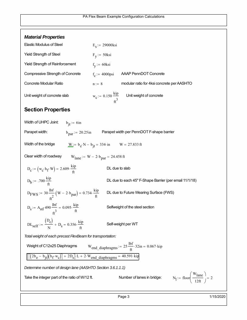
PA Flex Beam Example Configuration Calculations
Material Properties
Elastic Modulus of Steel Es 29000ksi
Yield Strength of Steel Fy 50ksi
Yield Strength of Reinforcement fy 60ksi
Compressive Strength of Concrete fc 4000psi AAAP PennDOT Concrete
Concrete Modular Ratio n 8 modular ratio for 4ksi concrete per AASHTO
Unit weight of concrete slab wc 0.150kip
ft3
Unit weight of concrete
Section Properties
Width of UHPC Joint: bjt 6in
Parapet width: bpar 20.25in Parapet width per PennDOT F-shape barrier
Width of the bridge W be N bjt 334 in W 27.833 ft
Clear width of roadway Wlane W 2 bpar 24.458 ft
Dc wc hf W 2.609kip
ft DL due to slab
Db .700kip
ft DL due to each 45" F-Shape Barrier (per email 11/1/18)
DFWS 30lbf
ft2
W 2 bpar 0.734kip
ft DL due to Future Wearing Surface (FWS)
Ds Astl 490lbf
ft3
0.095kip
ft Selfweight of the steel section
DLself
Dc N
Ds 0.356kip
ft Self-weight per WT
Total weight of each precast FlexBeam for transportation:
Weight of C12x25 Diaphragms Wend_diaphragms 25lbf
ft32 in 0.067 kip
2be bjt hf wc 2Ds L 2 Wend_diaphragms 40.591 kip
Determine number of design lane (AASHTO Section 3.6.1.1.1)
Take the integer part of the ratio of W/12 ft. Number of lanes in bridge: Nl floorWlane
12ft
2
Page 3 1/15/2020

PA Flex Beam Example Configuration Calculations
STEP 1: Compute Dead Load for each Flex Beam
DLslab
Dc
Nwc 1 in
be
2 0.279
kip
ft Dead load of slab assuming exterior overhang has 1" of
additional concrete thickness
DLsteel Ds 0.095kip
ft
DL DLslab DLsteel 0.374kip
ft
STEP 2: Compute Superimposed Dead Load
SDLWS
DFWS
N0.073
kip
ft
SDLparapet
Db
20.35
kip
ft distributed equally on two outer beams
SDLOL 140lbf
ft3be 2 in 0.066
kip
ft Overlay is 2" thick and is 140 lbs/cubic foot
NOTE: For this example barrier load is distributed equally among the two outer beams per conversation withPennDOT and M&M.
PennDOT DM4: "For composite adjacent and spread beams, the barrier (single barrier) load shall be equallydistributed to the nearest three (adjacent) and two (spread) beams, respectively, when the barriers are placedafter slab has hardened".
SDL SDLWS SDLparapet SDLOL 0.489kip
ft
STEP 3: Compute Transformed Width of Slab
For live load and dead load acting on the stringer k1 1 For short-term section property evaluation
btr1
be
k1 n4.25 in Transformed width of slab for short-term
For superimposed dead loads k3 3 For long-term section property evaluation
btr3
be
k3 n1.417 in Transformed width of slab for long-term
Page 4 1/15/2020

PA Flex Beam Example Configuration Calculations
STEP 4: Compute Dead and Superimposed Dead Load Moments(Based on first interior girder demands)
MDLDL L
2
8168.122 kip ft
MSDLSDL L
2
8220.269 kip ft
STEP 5: Compute live load and Dynamic Load Allowance (IM)
Live load wheel load distribution factor (DF):
Sbe
12in2.833 transverse girder spacing
NOTE: AASHTO presents equations to define DF for different types of superstructuresincluding Deck Composite wirh RC slab on steel girders (Type (a) in Table 4.6.2.2.1-1) forshear and moment in interior and exterior beams.
Using DM4 Table 4.6.2.2.2b-1:
eg h y_barhf
2 20.374 in Distance between the centers of gravity of the basic beam and deck
Kg n Istl Astl eg2
1.16 10
5 in
4 Longitudinal stiffness parameter (in4)
Distribution of Live Load Per Lane for Moment in Interior Beams:
to be conservative, use DF 0.3
Page 5 1/15/2020

PA Flex Beam Example Configuration Calculations
Dynamic Load Allowance (Section 3.6.2 DM4)
Static effects of the design truck or tandem, shall be increased by the impact factor.
NOTE: The dynamic load allowance shall not be applied to the design lane load (Section 3.6.2.1 DM4)
I 0.33 Impact factor for moment
Note: PennDOT requires that the impact for decks be increased from 33% to 50%, the deck is not beingdesigned here. Instrad the deck design is based on the BD recommendations.
Dynamic load allowance for the Permit Load P-82 shall be less than 20%. (Section 3.6.2.1DM4)
IPL 0.20 Impact factor for moment on Strength II
Design Wind Loading for Exterior Girder
Vw 80 Wind speed for Strength V load case
CD 1.3 Gust factor for windard side of I-Girder and Box Girder Superstructures (Table 3.8.1.2.1-2)
G 1.0 Gus effect factor is 1.0 for all structures other than sound barriers (Table 3.8.1.2.1-1)
Kz 1.0 Pressure coefficient taken as 1 for Strength V (3.8.1.2.1)
Pz 2.56 106
Vw 2 Kz G CDkip
ft2
0.021kip
ft2
Wind pressure on exterior girder
hexp h hf 27.5 in Exposed height of exterior girder
Moment due to wind loading on exterior girderMWL
Pz hexp L2
821.965 kip ft
Iyy
bf3tf
12108 in
4 Transverse moment of intertia
Flange lateral bending stressfl
MWL
bf
2
Iyy14.643 ksi
Page 6 1/15/2020

PA Flex Beam Example Configuration Calculations
Design Vehicular Live Load
PHL-93 and P-82 are examined herein.
PHL-93 (A3.6.1.2.1)
PHL-93 consists of a combination of (design truck or design tandem) + (design lane load)
Design Truck
PennDOT defines the design truck in accordance with AASTHO 3.6.1.2
Design truck load in AASHTO (HS20 Truck) is used for this example.
NOTE : MAX moment occurs when the center line of the span is midway between the center ofgravity of the loads and the nearest concentrated load.
P1 8kip P2 32kip P3 32kip Axle loads (AASHTO 3.6.1.2.2)
XASr 14ft Rear Axle spacing for truck (14ft - 30ft)
XASf 14ft Front Axle spacing for truck
Page 7 1/15/2020

PA Flex Beam Example Configuration Calculations
Center of gravity (CG) of loads:
X'P1 XASr XASf P2 XASr
P1 P2 P39.333 ft Datum is the rear axle
X XASr X' 4.667 ft Spacing btw CG and nearest load
Find bridge reaction
Truck movestoward Support ARA
P1L
2XASf
X
2
P2L
2
X
2
P3L
2X'
X
2
L33.2 kip
Max live load moment (at the location of P2):
MLL_truck RAL
2
X
2
P1 XASf 806.533 kip ft
NOTE: Find the worst case by varying XASr
Page 8 1/15/2020

PA Flex Beam Example Configuration Calculations
Design Tandem
Consist of a pair of 25-kip axles spaced 4-ft apart. (AASHTO 3.6.1.2.3)
NOTE: PennDOT DM4 increases 25-kip to 31.25-kip.
FT 31.25kip
XAS 4ft Axle spacing
Center of gravity (CG) of loads:
XXAS
22 ft Spacing btw CG and nearest load
Find bridge reaction
RA
FTL
2
X
2
FTL
2
X
2 X
L30.208 kip Truck moves toward Support A
Max live load moment (at the location of front wheel):
MLL_tandem RAL
2
X
2
876.042 kip ft
Choose the max value:
MLL_veh max MLL_tandem MLL_truck 876.042 kip ft
Apply the impact and wheel load distribution:
MLL_IM_veh MLL_veh DF 1 I( ) 349.541 kip ft Due to tandem or truck
Design Lane Load (distributed over a 10-ft width for each lane)
NOTE: The uniform load may be continuous or discontinuous as necessary to produce themaximum force effect. For this example continuous uniform distribution assumed.
FDLL 0.64kip
ftDF 0.192
kip
ft Per beam in each lane
Due to lane loadMLL_IM_lane
FDLL L2
8
86.4 kip ft
Moment due to Total Design Vehicular Live Load: MLL_IM MLL_IM_lane MLL_IM_veh 435.941 kip ft
Page 9 1/15/2020

PA Flex Beam Example Configuration Calculations
Design Permit Load P-82 (Section 3.6.1.2.7 DM4)
P1 P2 P3 P4 P5 P6 P7
NOTE: The moment for the permit load is defined at the beginning of the sheetand is obtained from MATLab File FlexBeam_Moment_ShearEnvelope.m
STEP 6: Compute Moment of Inertia (Note: rebar neglected!)
1) Moment of Inertia resisting dead load only:
a) Acting on the non-composite section (before the deck has hardened - DC1)
Use steel section only
Inc Istl 2.907 103
in4
Non-composite section modulus
Y'nc y_bar S.G. of the steel section of Flex Beam (Datum is bottom)
b) Acting on the composite section (after the deck has hardened - DC2)
Use Ic_short as defined below.
Page 10 1/15/2020

PA Flex Beam Example Configuration Calculations
2) Moment of Inertia resisting live load plus impact:
Using transformed slab with k1=1 (short-term composite).
Actr1 hf btr1 31.875 in2
Itr1
btr1 hf3
12149.414 in
4
Y'
Actr1 hhf
2
Astl Y'nc
Astl Actr121.739 in S.G. of the total flex beam (Datum is bottom)
Compositesection modulus(short-term)
Ic_short Istl Astl Y'nc Y' 2 Itr1 Actr1 hhf
2
Y'
2
9233 in4
Y'c_short Y' 21.739 in N.A. of the short-term composite section
3) Moment of Inertia resisting superimposed dead load:
Using transformed slab with k3=3.
Actr3 hf btr3 10.625 in2
Itr3
btr3 hf3
1249.805 in
4
Y'
Actr3 hhf
2
Astl Y'nc
Astl Actr316.494 in S.G. of the total flex beam (Datum is bottom)
Compositesection modulus(long-term)
Ic_long Istl Astl Y'nc Y' 2 Itr3 Actr3 hhf
2
Y'
2
6151 in4
Y'c_long Y' 16.494 in N.A. of the long-term composite section
Page 11 1/15/2020
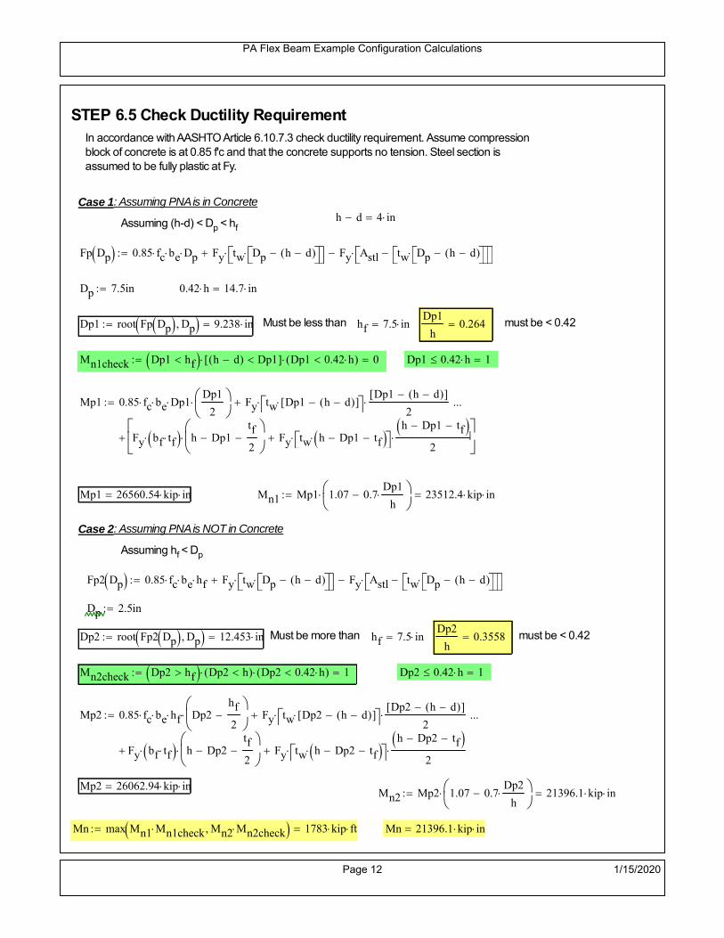
PA Flex Beam Example Configuration Calculations
STEP 6.5 Check Ductility RequirementIn accordance with AASHTO Article 6.10.7.3 check ductility requirement. Assume compressionblock of concrete is at 0.85 f'c and that the concrete supports no tension. Steel section isassumed to be fully plastic at Fy.
Case 1 : Assuming PNA is in Concreteh d 4 inAssuming (h-d) < Dp < hf
Fp Dp 0.85 fc be Dp Fy tw Dp h d( ) Fy Astl tw Dp h d( )
Dp 7.5in 0.42 h 14.7 in
Dp1 root Fp Dp Dp 9.238 in Must be less than hf 7.5 inDp1
h0.264 must be < 0.42
Mn1check Dp1 hf h d( ) Dp1[ ] Dp1 0.42 h( ) 0 Dp1 0.42 h 1
Mp1 0.85 fc be Dp1Dp1
2
Fy tw Dp1 h d( )[ ] Dp1 h d( )[ ]
2
Fy bf tf h Dp1tf
2
Fy tw h Dp1 tf h Dp1 tf
2
Mp1 26560.54 kip in Mn1 Mp1 1.07 0.7Dp1
h
23512.4 kip in
Case 2 : Assuming PNA is NOT in Concrete
Assuming hf < Dp
Fp2 Dp 0.85 fc be hf Fy tw Dp h d( ) Fy Astl tw Dp h d( )
Dp 2.5in
Dp2 root Fp2 Dp Dp 12.453 in Must be more than hf 7.5 inDp2
h0.3558 must be < 0.42
Mn2check Dp2 hf Dp2 h( ) Dp2 0.42 h( ) 1 Dp2 0.42 h 1
Mp2 0.85 fc be hf Dp2hf
2
Fy tw Dp2 h d( )[ ] Dp2 h d( )[ ]
2
Fy bf tf h Dp2tf
2
Fy tw h Dp2 tf h Dp2 tf
2
Mp2 26062.94 kip inMn2 Mp2 1.07 0.7
Dp2
h
21396.1 kip in
Mn max Mn1 Mn1check Mn2 Mn2check 1783 kip ft Mn 21396.1 kip in
Page 12 1/15/2020

PA Flex Beam Example Configuration Calculations
Check Composite Compact Section Criteria (6.10.6.2)
Dcpd
2
Fy tf bf 0.85 fc be hf
Fy hw tw1
8.663 in Dcp0 Dcp 0 1
Dcp Dcp Dcp0 8.663 in2 Dcp
tw3.76
Es
Fy 1 Check if section is compact
STEP 7: Load Combinations (Table 3.4.1-1)
The following load combinations will be considered herein. Only the maximum load factors forpermanent-loads are used in the following load combinations (uplift is not an issue for this typeof bridge).STRENGTH I 1.25DL + 1.5SDL + 1.75 (LL+IM)
SERVICE II: DL+SDL+1.3(LL+IM)
STEP 8: Compute and Check Stresses
Stress at bottom fiber of steel section
fDL
MDL Y'c_long
Ic_long5.41 ksi
fLL_I
MLL_IM Y'c_short
Ic_short12.317 ksi fPL
MLL_IM_PL82 Y'c_short
Ic_short14.797 ksi
fSDL
MSDL Y'c_long
Ic_long7.088 ksi
STRENGTH I fbot_str1 1.25fDL 1.5 fSDL 1.75 fLL_I 38.95 ksi
STRENGTH II fbot_str2 1.25fDL 1.5 fSDL 1.35 fPL 37.37 ksi
SERVICE II fbot_svc2 fDL fSDL 1.3fLL_I 28.51 ksi
Allowable Stress is based on Section 6.10.4.2.2-2
Flange stress due to service load II without consideration of flange lateral bending: ff fbot_svc2
Flange lateral bending stress due to service II: flSII 0ksi
Hybrid Factor: Rh 1.0 For rolled and homogenous built-up sections
ff
flSII
2 28.51 ksi 0.95 Rh Fy 47.5 ksi ff
fl
2 0.95Rh Fy 1
Page 13 1/15/2020

PA Flex Beam Example Configuration Calculations
Stress at top fiber of concrete
Note: For calculating longitudinal flexural stresses in the concrete deck due to allpermanent and transient loads, the short-term modular ratio shall be used.
fDL
MDL h Y'c_short
k1 n Ic_short0.362 ksi
fLL_I
MLL_IM h Y'c_short
k1 n Ic_short0.939 ksi fPL
MLL_IM_PL82 h Y'c_short
k1 n Ic_short1.128 ksi
fSDL
MSDL h Y'c_short
k1 n Ic_short0.475 ksi
STRENGTH I fc_str1 1.25fDL 1.5 fSDL 1.75 fLL_I 2.808 ksi
Mstr1 1.25 MDL 1.5 MSDL 1.75 MLL_IM 1303.5 kip ft Mstr1 Mn 1
STRENGTH II fc_str2 1.25fDL 1.5 fSDL 1.35 fPL 2.688 ksi
Mstr2 1.25 MDL 1.5 MSDL 1.35 MLL_IM_PL82 1248 kip ft Mstr2 Mn 1
SERVICE II
Allowable Stress in concrete - AASHTO 6.10.4.2.2For compact composite sections in positive flexure utilized in shored construction, the longitudinalcompressive stress in the concrete deck due to the Service II loads, determined as specified in Article6.10.1.1.1d, shall not exceed 0.6f́ c.
fallow 0.6 fc 2400 psi
fc_2 1.3fLL_I fSDL fDL 2057.67 psi This assumes short term compositesection for all calculations
fc_2 fallow 1
SERVICE II with Long Term Composite for dead loads
fDL
MDL h Y'c_long
k3 n Ic_long0.253 ksi
fLL_I
MLL_IM h Y'c_short
k1 n Ic_short0.939 ksi
fSDL
MSDL h Y'c_long
k3 n Ic_long0.331 ksi
fc_2 1.3fLL_I fSDL fDL 1805.18 psi fc_2 fallow 1
Page 14 1/15/2020

PA Flex Beam Example Configuration Calculations
Strength V Moment Check
Strength V is related to normal vehicular use of the bridge with an 80 mph wind gust
Note: that Strength V is checked for an exterior girder under wind load with the interior girder distribution factor forflexure used. If Strength V controls design, then this approach should be modified
Design vertical moment is: 1.25DL + 1.5SDL + 1.35 (LL+IM)
SLT
Ic_long
Y'c_long372.922 in
3 SST
Ic_short
Y'c_short424.706 in
3 short and long term section
modulus
Section D6.2.2 Find the moment required to cause yieldling of the flange. The approach is laid out in D6.2.2
MD2 1.25 MDL 1.5 MSDL 540.556 kip ft From D6.2.2-1 (all dead loads are in MD2 due to shoredconstruction
MAD Fy
MD2
SLT
SST 1.154 10
3 kip ft Additional moment to cause nominal yielding of steel flange
My MD2 MAD 1.695 103
kip ft D6.2.2-2: Moment to cause yielding of flange
6.10.7.1 Compact Section Check at Strength V limit state
Section Modulus for yielding of the flange (My/Fy) for equation 6.10.7.1.1-1Sxt
My
Fy406.691 in
3
Mu 1.25 MDL 1.5MSDL 1.35MLL_IM 1.129 103
kip ft Moment due to Strength V limit state
Mu1
3fl Sxt 1.294 10
3 kip ft Equation 6.10.7.1.7-1 Mn 1.783 10
3 kip ft Mu
1
3fl Sxt Mn 1
Page 15 1/15/2020

PA Flex Beam Example Configuration Calculations
STEP 9: Compute Deflection
Optional Live Load Deflection Evaluation (AASHTO 3.6.1.3.2)
Deflection distribution factor for vehicular loads: For a straight multibeambridge, this is equivalent to saying that the distribution factor for deflectionis equal to the number of lanes divided by the number of beams. 2.5.2.6.2
DFd
Nl
N0.2
Deflection should be taken as 125% the larger of:- Design truck- 25% of design truck + design lane
The live load portion of Load Combination Service I of Table 3.4.1-1 should be used,including the dynamic load allowance, IM;
Deflection due to design truck load
NOTE : Assuming maximum deflection occurs when the center of gravity of the loads is at thecenter line of the span.
P1 8kip P2 32kip P3 32kip Axle loads (AASHTO 3.6.1.2.2)
XASr 14ft Rear Axle spacing for truck (14ft - 30ft)
XASf 14ft Front Axle spacing for truck
Center of gravity (CG) of loads:
X'P1 XASr XASf P2 XASr
P1 P2 P39.333 ft Datum is the rear axle
Method1: Assuming single load = P1+P2+P3 at the midspan (Conservative approach)
P1 P2 P3 L3
48 Es Ic_short 2.091 in
Method2: Calculation of Midspan deflection using superposition
b1L
2XASr X' XASf 11.333 ft distance btw load P1 and support A b1check b1 0 1
b2L
2XASr X' 25.333 ft distance btw load P2 and support A b2check b2 0 1
b3L
2X' 20.667 ft distance btw load P3 and support B b3check b3 0 1
Page 16 1/15/2020

PA Flex Beam Example Configuration Calculations
Deflection of the beam at midspan due to P1: P P1
xL
2 at midspan b b1 b1check The smallest distance btw load P1 and support
Δ1P b x
6 Es Ic_short LL2
b2
x2
0.125 in
Deflection of the beam at midspan due to P2: P P2
xL
2 at midspan b b2 b2check The smallest distance btw load P2 and support
Δ2P b x
6 Es Ic_short LL2
b2
x2
0.897 in
Deflection of the beam at midspan due to P3: P P3
xL
2 at midspan b b3 b3check The smallest distance btw load P3 and support
Δ3P b x
6 Es Ic_short LL2
b2
x2
0.808 in
Total Deflection at midspan:
Δtruck Δ1 Δ2 Δ3( ) DFd 1 I( ) 0.487 in (Considering IM)
Deflection due to tandem (Note: this calculation is not required according to Article3.6.1.3.2 which denotes only the design truck for deflection calculation)
Page 17 1/15/2020

PA Flex Beam Example Configuration Calculations
FT 31.25 kip Per axle
XAS 4ft Axle spacing
Δtandem
FTL
2
XAS
2
24 Es Ic_short3 L
2 4
L
2
XAS
2
2
DFd 1 I( ) 0.48 in (Considering IM)
Deflection due to lane load
FDLLd 640lbf
ft DFd 128
lbf
ft
Δlane
5 FDLLd L4
384 Es Ic_short0.139 in
Live Load Deflection:
ΔLL 1.25max Δtruck 0.25Δtruck Δlane 1.25 0.761 in ΔLLL
800 1
Deflection Limit
For steel or concrete vehicular bridges:
Vehicular load = Span/800L
8000.9 in
L
10000.72 in
Evaluation of Deflection at the Service Limit State (AASHTO 3.4.2.2)
The associated permitted deflections shall be included in the contract documents.
Page 18 1/15/2020

PA Flex Beam Example Configuration Calculations
Shear demands:
Determination of the distribution factor
Using DM4 Table 4.6.2.2.3a-1
Sbe
12in2.833 transverse girder spacing (ft)
Distribution of live loads per lane for shear in interior beams:
For two design lanes loaded, 3.5' <= S =< 16', number of beam >= 4DFs 0.36
S
25 0.473
Q Actr1 h Y'c_shorthf
2
303.152 in3
first moment of deck slab for interface shear
Method 1: Range of shear based on Strength I Limit
STRENGTH I 1.25DL + 1.5SDL + 1.75 (LL+IM)
Computation of the range of shear in the beam
Dead Load:DL 0.374
kip
ft
Superimposed Dead Load: SDL 0.489kip
ft
Design Lane Load: 0.64kip
ft
Design Truck:
XASr 14ft Rear Axle spacing for truck (14ft - 30ft)
XASf 14ft Front Axle spacing for truck
P1 8 kip P2 32 kip P3 32 kip Wheel loads (AASHTO 3.6.1.2.2)
Design Tandem:
Consist of a pair of 25-kip axles spaced 4-ft apart. (AASHTO 3.6.1.2.3)
NOTE: PennDOT DM4 increases 25-kip to 31.25-kip.
FT 31.25kip
XAS 4ft Axle spacing
Page 19 1/15/2020

PA Flex Beam Example Configuration Calculations
Maximum positive shear at various points along the FlexBeam are examined.
At x=0 (at left support) (Truck is moving from left to right)
Truck
Max Positive Shear (when P3 is at x = 0):
x1 L XASr XASf 32 ft Distance between P1 and right support
x2 L XASr 46 ft Distance between P2 and right support
x3 L 60 ft Distance between P3 and right support
V1 P3
x3
L P2
x2
L P1
x1
L 60.8 kip
Total Vertical Shear Force for each FlexBeam (considering dynamic loads):
Vtruck1 V1 DFs 1 I( ) 38.276 kip
Tandem:
V1 FT FT
L XAS L
60.417 kip
Total Vertical Shear Force for each FlexBeam (considering dynamic loads):
Vtandem1 V1 DFs 1 I( ) 38.034 kip
Lane Load
V1 0.64kip
ft
L
2 19.2 kip
Total Vertical Shear Force for each FlexBeam (considering dynamic loads):
Vlane1 V1 DFs 9.088 kip
Dead Load
Vdl1 DLL
2 11.208 kip
Superimposed Dead Load
Vsdl1 SDLL
2 14.685 kip
Strength I Max Positive Shear:
Vstr1 1.25 Vdl1 1.5 Vsdl1 1.75 Vlane1 max Vtruck1 Vtandem1 118.923 kip
Page 20 1/15/2020

PA Flex Beam Example Configuration Calculations
Design Permit Load P-82
Shear at x=0
Strength II Max Positive Shear:
VPL82 VPL82span DFs 1 IPL 71.062 kip
STRENGTH II 1.25DL + 1.5SDL + 1.35 (LL+IM)
VstrII_PL 1.25 Vdl1 1.5 Vsdl1 1.35 VPL82 131.971 kip
Max Shear Demand Vu max Vstr1 VstrII_PL 131.971 kip
Determine the Shear Strength of the Web
Shear Strength of Unstiffened web from AASHTO section 6.10.9.2
Depth of Web D d 31 in Thickness of web tw 0.625 in
Transverse Stiffener Spacing d0 0in Shear Buckling Coefficient k 5 6.10.9.3.2-7
Plastic Shear Force Vp 0.58 Fy D tw 561.875 kip Equation 6.10.9.3.2-3
Ratio of Shear-Buckling resistance to shear yield, C
D
tw49.6 1.12
Es k
Fy 60.314 Ccheck
D
tw1.12
Es k
Fy 1 Equation 6.10.9.3.2-4
C 1.0 Ccheck 1 C=1 for most cases, if the criteria are not met, then C will go to zero and the actualcoefficients should be determined
Nominal Shear Resistance of Web Vn C Vp 561.875 kip equation 6.10.9.3.3-1
Shear Resistance Factor φv 1.0
φv Vn 561.875 kip φv Vn Vu 1Reduced Shear Strength
Page 21 1/15/2020

PA Flex Beam Example Configuration Calculations
Check Bearing Stiffeners
FYs 50ksi Yield strength of stiffener
tp 0.75in Thickness of stiffener
bt
bf tw
21.5in 4.188 in Effective width of stiffener
Dst hw 4.1in 26.15 in Depth of stiffeners
Apn 2 tp bt 6.281 in2
Projected area of stiffeners
bt 0.48 tpEs
FYs 1Check that effective width of stiffener meets requirements
Rsbn 1.4 Apn FYs 439.688 kip Bearing capacity of stiffener (phi=1 for bearing per AASHTO 6.5.4.2)
Rsbn Vu 1 Bearing capacity check
Qs 1.0 Q factor for bearing stiffner, taken as 1 (AASHTO 6.9.4.1.1)
Is
18 tw tw3
tp 2 bt 3
1236.943 in
4 Moment of inertia of stiffener and web (9*tw is used on each side)
AASHTO 6.10.11.2.4b
Ag 18 tw tw 2 bt tp 13.313 in2
Gross area of stiffener and web (AASHTO 6.10.11.2.4b)
rs
Is
Ag1.666 in Radius of gyration of stiffener/web
Po Qs FYs Apn 314.062 kip Nominal yeild resistance of stiffener (AASHTO 6.9.4.1.1)
Peπ2Es
0.75 Dst
rs
2Ag 2.749 10
4 kip Elastic critical buckling stress of stiffener (AASHTO 6.9.4.1.2-1)
Check that Pe/Po is great than 0.44 (AASHTO 6.9.4.1.1) PePoPe
Po0.44 1
Pn PePo 0.658
Po
Pe Po 312.564 kip Nominal compressive resistance of stiffener for Pe/Po>0.44
(AASHTO 6.9.4.1.1-1)
φcr 0.95 phi factor for axial compression (AASHTO 6.5.4.2)
Pr φcr Pn 296.936 kip Compressive capacity of bearing stiffener Pr Vu 1
Page 22 1/15/2020

PA Flex Beam Example Configuration Calculations
Flexbeam Example Configuration Calculations
Summary of Calculations:
Input section dimensions and material properties for steel WT and the concrete deck1.Calculate demands (dead load, superimposed dead, and Live load demands for Strength I and Strength II2.Calculate composite section properties for the given section3.Check Strength I, Strength II, and Service II stresses 4.Check Strength I, Strength II, and Strength V moment demands 5.Perform live load deflection check6.Determine maximum shear demand and capacity7.Note: Shear envelope data was obtained from Matlab script (FlexBeam_Moment_ShearEnvelope.m).8.Shear envelope calculations are summarized separately for each design (Shear Design *.xlsx).
Design Assumptions:Design Specifications Used:
AASHTO LRFD Bridge Design Specifications 7th Edition with 2016 Interim RevisionsPennDOT Design Manual, Part 4 (DM-4) June 30, 2015
Example configurations are determined for two girder spacings, 36" and 40".The deck thickness is 7.5" and is assumed to have a non-structural wearing surface added after installation.Section properties are calculated using the full 7.5" deck thickness.The WT sections are embedded 3.5" into the concrete deck. The steel section spacing used is outside the scope of the AASHTO and PennDOT distribution factorequations. The flexural distribution factor is assumed to be 0.3 which was shown to tbe conservativeaccording to refined analysisThe shear distribution factor is calculated using the DM-4 shear distribution factor equation which wasshown to be conservative using refined analysis.Refined analysis is presented in: Zihan Ma, "Distribution Factors for Composite Steel Tee Concrete DeckBridge System," M.S. Thesis, Deparement of Civil and Environmental Engineering, Lehigh University,Bethlehem, 2019Shear and moment demands for the PL82 permit load vehicle are determined by Matlab script(FlexBeam_Moment_ShearEnvelope.m) and are manually input into this calculation sheet.All fabrication will occur as double modules, i.e. each module contains two WT sections. The number ofmodules is half the number of beams, N. A 45 in. tall F-Shape barrier is used, Weight = 700 lb/ft (Distributed to exterior two beams).
The work presented in this document are provided on an “AS IS” basis. University makes no warranties of anykind, express or implied, as to any matter whatsoever, including, without limitation, warranties with respect tothe merchantability or fitness for a particular purpose of this work or any project deliverables. Universitymakes no warranty of any kind with respect to freedom from patent, trademark, copyright or trade secretinfringement arising from the use of the results of the project, deliverables, services, intellectual property orother materials provided hereunder. University shall not be liable for any direct, indirect, consequential,punitive, or other damages suffered by Sponsor or any other person resulting from the project, or the use ofthis work or any project deliverables.
Page 1 1/15/2020

PA Flex Beam Example Configuration Calculations
hf
tf
bf
twh
d
bjtbe
e
Variable Definitions:
Number of beams N 10 modulesN
25
L 60ft Span length
be 36in Effective width of Flexbeamassuming constructed bridge width(i.e. closure joints cast)
Built Up Section Properties
tw 0.625in tf 0.750in bf 12in
h 35in Overall Height of section
hf 7.5in Total thickness of deck
e 3.5in Deck/Steel overlap
d h hf e 31 in depth of built up steel section
hw d tf 30.25 in height of web of built up steel
Moment and shear for permit load PL82 obtained from Matlab script: FlexBeam_Moment_ShearEnvelope
MLL_IM_PL82 523.6917kip ft Moment due to PL82 with distribution factor and impact factor!!
VPL82span 125.11kip Shear due to PL82 WITHOUT distribution factor and impact factor!!
Check web and flange dimensions in sections 6.10.2.1 and 6.10.2.2
(Ignore 6.10.2.2-4 since no compression flange)
equation 6.10.2.1.1-1d
tw150 1 equation 6.10.2.2-1
bf
2 tf12 1
equation 6.10.2.2-2 bfh
6 1 equation 6.10.2.2-3 tf 1.1 tw 1
y_bar
tf bftf
2 hw tw tf
hw
2
tf bf hw tw10.876 in Center of gravity of steel section
Istl
bf tf3
12bf tf y_bar
tf
2
2
tw hw
3
12 tw hw tf
hw
2 y_bar
2
2.907 103
in4
MOI of steel
Astl tf bf hw tw 27.906 in2
Area of the WT steel section
Page 2 1/15/2020

PA Flex Beam Example Configuration Calculations
Material Properties
Elastic Modulus of Steel Es 29000ksi
Yield Strength of Steel Fy 50ksi
Yield Strength of Reinforcement fy 60ksi
Compressive Strength of Concrete fc 4000psi AAAP PennDOT Concrete
Concrete Modular Ratio n 8 modular ratio for 4ksi concrete per AASHTO
Unit weight of concrete slab wc 0.150kip
ft3
Unit weight of concrete
Section Properties
Width of UHPC Joint: bjt 6in
Parapet width: bpar 20.25in Parapet width per PennDOT F-shape barrier
Width of the bridge W be N bjt 354 in W 29.5 ft
Clear width of roadway Wlane W 2 bpar 26.125 ft
Dc wc hf W 2.766kip
ft DL due to slab
Db .700kip
ft DL due to each 45" F-Shape Barrier (per email 11/1/18)
DFWS 30lbf
ft2
W 2 bpar 0.784kip
ft DL due to Future Wearing Surface (FWS)
Ds Astl 490lbf
ft3
0.095kip
ft Selfweight of the steel section
DLself
Dc N
Ds 0.372kip
ft Self-weight per WT
Total weight of each precast FlexBeam for transportation:
Weight of C12x25 Diaphragms Wend_diaphragms 25lbf
ft32 in 0.067 kip
2be bjt hf wc 2Ds L 2 Wend_diaphragms 42.466 kip
Determine number of design lane (AASHTO Section 3.6.1.1.1)
Take the integer part of the ratio of W/12 ft. Number of lanes in bridge: Nl floorWlane
12ft
2
Page 3 1/15/2020

PA Flex Beam Example Configuration Calculations
STEP 1: Compute Dead Load for each Flex Beam
DLslab
Dc
Nwc 1 in
be
2 0.295
kip
ft Dead load of slab assuming exterior overhang has 1" of
additional concrete thickness
DLsteel Ds 0.095kip
ft
DL DLslab DLsteel 0.39kip
ft
STEP 2: Compute Superimposed Dead Load
SDLWS
DFWS
N0.078
kip
ft
SDLparapet
Db
20.35
kip
ft distributed equally on two outer beams
SDLOL 140lbf
ft3be 2 in 0.07
kip
ft Overlay is 2" thick and is 140 lbs/cubic foot
NOTE: For this example barrier load is distributed equally among the two outer beams per conversation withPennDOT and M&M.
PennDOT DM4: "For composite adjacent and spread beams, the barrier (single barrier) load shall be equallydistributed to the nearest three (adjacent) and two (spread) beams, respectively, when the barriers are placedafter slab has hardened".
SDL SDLWS SDLparapet SDLOL 0.498kip
ft
STEP 3: Compute Transformed Width of Slab
For live load and dead load acting on the stringer k1 1 For short-term section property evaluation
btr1
be
k1 n4.5 in Transformed width of slab for short-term
For superimposed dead loads k3 3 For long-term section property evaluation
btr3
be
k3 n1.5 in Transformed width of slab for long-term
Page 4 1/15/2020

PA Flex Beam Example Configuration Calculations
STEP 4: Compute Dead and Superimposed Dead Load Moments(Based on first interior girder demands)
MDLDL L
2
8175.622 kip ft
MSDLSDL L
2
8224.269 kip ft
STEP 5: Compute live load and Dynamic Load Allowance (IM)
Live load wheel load distribution factor (DF):
Sbe
12in3 transverse girder spacing
NOTE: AASHTO presents equations to define DF for different types of superstructuresincluding Deck Composite wirh RC slab on steel girders (Type (a) in Table 4.6.2.2.1-1) forshear and moment in interior and exterior beams.
Using DM4 Table 4.6.2.2.2b-1:
eg h y_barhf
2 20.374 in Distance between the centers of gravity of the basic beam and deck
Kg n Istl Astl eg2
1.16 10
5 in
4 Longitudinal stiffness parameter (in4)
Distribution of Live Load Per Lane for Moment in Interior Beams:
to be conservative, use DF 0.3
Page 5 1/15/2020
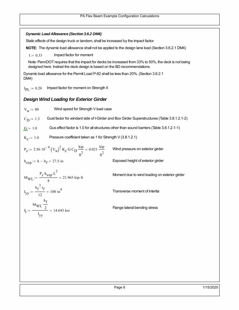
PA Flex Beam Example Configuration Calculations
Dynamic Load Allowance (Section 3.6.2 DM4)
Static effects of the design truck or tandem, shall be increased by the impact factor.
NOTE: The dynamic load allowance shall not be applied to the design lane load (Section 3.6.2.1 DM4)
I 0.33 Impact factor for moment
Note: PennDOT requires that the impact for decks be increased from 33% to 50%, the deck is not beingdesigned here. Instrad the deck design is based on the BD recommendations.
Dynamic load allowance for the Permit Load P-82 shall be less than 20%. (Section 3.6.2.1DM4)
IPL 0.20 Impact factor for moment on Strength II
Design Wind Loading for Exterior Girder
Vw 80 Wind speed for Strength V load case
CD 1.3 Gust factor for windard side of I-Girder and Box Girder Superstructures (Table 3.8.1.2.1-2)
G 1.0 Gus effect factor is 1.0 for all structures other than sound barriers (Table 3.8.1.2.1-1)
Kz 1.0 Pressure coefficient taken as 1 for Strength V (3.8.1.2.1)
Pz 2.56 106
Vw 2 Kz G CDkip
ft2
0.021kip
ft2
Wind pressure on exterior girder
hexp h hf 27.5 in Exposed height of exterior girder
Moment due to wind loading on exterior girderMWL
Pz hexp L2
821.965 kip ft
Iyy
bf3tf
12108 in
4 Transverse moment of intertia
Flange lateral bending stressfl
MWL
bf
2
Iyy14.643 ksi
Page 6 1/15/2020

PA Flex Beam Example Configuration Calculations
Design Vehicular Live Load
PHL-93 and P-82 are examined herein.
PHL-93 (A3.6.1.2.1)
PHL-93 consists of a combination of (design truck or design tandem) + (design lane load)
Design Truck
PennDOT defines the design truck in accordance with AASTHO 3.6.1.2
Design truck load in AASHTO (HS20 Truck) is used for this example.
NOTE : MAX moment occurs when the center line of the span is midway between the center ofgravity of the loads and the nearest concentrated load.
P1 8kip P2 32kip P3 32kip Axle loads (AASHTO 3.6.1.2.2)
XASr 14ft Rear Axle spacing for truck (14ft - 30ft)
XASf 14ft Front Axle spacing for truck
Page 7 1/15/2020

PA Flex Beam Example Configuration Calculations
Center of gravity (CG) of loads:
X'P1 XASr XASf P2 XASr
P1 P2 P39.333 ft Datum is the rear axle
X XASr X' 4.667 ft Spacing btw CG and nearest load
Find bridge reaction
Truck movestoward Support ARA
P1L
2XASf
X
2
P2L
2
X
2
P3L
2X'
X
2
L33.2 kip
Max live load moment (at the location of P2):
MLL_truck RAL
2
X
2
P1 XASf 806.533 kip ft
NOTE: Find the worst case by varying XASr
Page 8 1/15/2020

PA Flex Beam Example Configuration Calculations
Design Tandem
Consist of a pair of 25-kip axles spaced 4-ft apart. (AASHTO 3.6.1.2.3)
NOTE: PennDOT DM4 increases 25-kip to 31.25-kip.
FT 31.25kip
XAS 4ft Axle spacing
Center of gravity (CG) of loads:
XXAS
22 ft Spacing btw CG and nearest load
Find bridge reaction
RA
FTL
2
X
2
FTL
2
X
2 X
L30.208 kip Truck moves toward Support A
Max live load moment (at the location of front wheel):
MLL_tandem RAL
2
X
2
876.042 kip ft
Choose the max value:
MLL_veh max MLL_tandem MLL_truck 876.042 kip ft
Apply the impact and wheel load distribution:
MLL_IM_veh MLL_veh DF 1 I( ) 349.541 kip ft Due to tandem or truck
Design Lane Load (distributed over a 10-ft width for each lane)
NOTE: The uniform load may be continuous or discontinuous as necessary to produce themaximum force effect. For this example continuous uniform distribution assumed.
FDLL 0.64kip
ftDF 0.192
kip
ft Per beam in each lane
Due to lane loadMLL_IM_lane
FDLL L2
8
86.4 kip ft
Moment due to Total Design Vehicular Live Load: MLL_IM MLL_IM_lane MLL_IM_veh 435.941 kip ft
Page 9 1/15/2020

PA Flex Beam Example Configuration Calculations
Design Permit Load P-82 (Section 3.6.1.2.7 DM4)
P1 P2 P3 P4 P5 P6 P7
NOTE: The moment for the permit load is defined at the beginning of the sheetand is obtained from MATLab File FlexBeam_Moment_ShearEnvelope.m
STEP 6: Compute Moment of Inertia (Note: rebar neglected!)
1) Moment of Inertia resisting dead load only:
a) Acting on the non-composite section (before the deck has hardened - DC1)
Use steel section only
Inc Istl 2.907 103
in4
Non-composite section modulus
Y'nc y_bar S.G. of the steel section of Flex Beam (Datum is bottom)
b) Acting on the composite section (after the deck has hardened - DC2)
Use Ic_short as defined below.
Page 10 1/15/2020
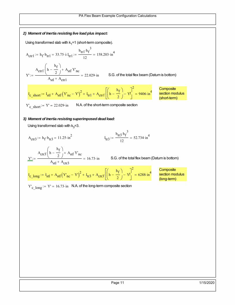
PA Flex Beam Example Configuration Calculations
2) Moment of Inertia resisting live load plus impact:
Using transformed slab with k1=1 (short-term composite).
Actr1 hf btr1 33.75 in2
Itr1
btr1 hf3
12158.203 in
4
Y'
Actr1 hhf
2
Astl Y'nc
Astl Actr122.029 in S.G. of the total flex beam (Datum is bottom)
Compositesection modulus(short-term)
Ic_short Istl Astl Y'nc Y' 2 Itr1 Actr1 hhf
2
Y'
2
9406 in4
Y'c_short Y' 22.029 in N.A. of the short-term composite section
3) Moment of Inertia resisting superimposed dead load:
Using transformed slab with k3=3.
Actr3 hf btr3 11.25 in2
Itr3
btr3 hf3
1252.734 in
4
Y'
Actr3 hhf
2
Astl Y'nc
Astl Actr316.73 in S.G. of the total flex beam (Datum is bottom)
Compositesection modulus(long-term)
Ic_long Istl Astl Y'nc Y' 2 Itr3 Actr3 hhf
2
Y'
2
6288 in4
Y'c_long Y' 16.73 in N.A. of the long-term composite section
Page 11 1/15/2020

PA Flex Beam Example Configuration Calculations
STEP 6.5 Check Ductility RequirementIn accordance with AASHTO Article 6.10.7.3 check ductility requirement. Assume compressionblock of concrete is at 0.85 f'c and that the concrete supports no tension. Steel section isassumed to be fully plastic at Fy.
Case 1 : Assuming PNA is in Concreteh d 4 inAssuming (h-d) < Dp < hf
Fp Dp 0.85 fc be Dp Fy tw Dp h d( ) Fy Astl tw Dp h d( )
Dp 7.5in 0.42 h 14.7 in
Dp1 root Fp Dp Dp 8.898 in Must be less than hf 7.5 inDp1
h0.254 must be < 0.42
Mn1check Dp1 hf h d( ) Dp1[ ] Dp1 0.42 h( ) 0 Dp1 0.42 h 1
Mp1 0.85 fc be Dp1Dp1
2
Fy tw Dp1 h d( )[ ] Dp1 h d( )[ ]
2
Fy bf tf h Dp1tf
2
Fy tw h Dp1 tf h Dp1 tf
2
Mp1 26840.03 kip in Mn1 Mp1 1.07 0.7Dp1
h
23942.2 kip in
Case 2 : Assuming PNA is NOT in Concrete
Assuming hf < Dp
Fp2 Dp 0.85 fc be hf Fy tw Dp h d( ) Fy Astl tw Dp h d( )
Dp 2.5in
Dp2 root Fp2 Dp Dp 11.637 in Must be more than hf 7.5 inDp2
h0.3325 must be < 0.42
Mn2check Dp2 hf Dp2 h( ) Dp2 0.42 h( ) 1 Dp2 0.42 h 1
Mp2 0.85 fc be hf Dp2hf
2
Fy tw Dp2 h d( )[ ] Dp2 h d( )[ ]
2
Fy bf tf h Dp2tf
2
Fy tw h Dp2 tf h Dp2 tf
2
Mp2 26485.98 kip inMn2 Mp2 1.07 0.7
Dp2
h
22175.7 kip in
Mn max Mn1 Mn1check Mn2 Mn2check 1848 kip ft Mn 22175.7 kip in
Page 12 1/15/2020

PA Flex Beam Example Configuration Calculations
Check Composite Compact Section Criteria (6.10.6.2)
Dcpd
2
Fy tf bf 0.85 fc be hf
Fy hw tw1
7.826 in Dcp0 Dcp 0 1
Dcp Dcp Dcp0 7.826 in2 Dcp
tw3.76
Es
Fy 1 Check if section is compact
STEP 7: Load Combinations (Table 3.4.1-1)
The following load combinations will be considered herein. Only the maximum load factors forpermanent-loads are used in the following load combinations (uplift is not an issue for this typeof bridge).STRENGTH I 1.25DL + 1.5SDL + 1.75 (LL+IM)
SERVICE II: DL+SDL+1.3(LL+IM)
STEP 8: Compute and Check Stresses
Stress at bottom fiber of steel section
fDL
MDL Y'c_long
Ic_long5.607 ksi
fLL_I
MLL_IM Y'c_short
Ic_short12.251 ksi fPL
MLL_IM_PL82 Y'c_short
Ic_short14.718 ksi
fSDL
MSDL Y'c_long
Ic_long7.16 ksi
STRENGTH I fbot_str1 1.25fDL 1.5 fSDL 1.75 fLL_I 39.19 ksi
STRENGTH II fbot_str2 1.25fDL 1.5 fSDL 1.35 fPL 37.618 ksi
SERVICE II fbot_svc2 fDL fSDL 1.3fLL_I 28.69 ksi
Allowable Stress is based on Section 6.10.4.2.2-2
Flange stress due to service load II without consideration of flange lateral bending: ff fbot_svc2
Flange lateral bending stress due to service II: flSII 0ksi
Hybrid Factor: Rh 1.0 For rolled and homogenous built-up sections
ff
flSII
2 28.694 ksi 0.95 Rh Fy 47.5 ksi ff
fl
2 0.95Rh Fy 1
Page 13 1/15/2020

PA Flex Beam Example Configuration Calculations
Stress at top fiber of concrete
Note: For calculating longitudinal flexural stresses in the concrete deck due to allpermanent and transient loads, the short-term modular ratio shall be used.
fDL
MDL h Y'c_short
k1 n Ic_short0.363 ksi
fLL_I
MLL_IM h Y'c_short
k1 n Ic_short0.902 ksi fPL
MLL_IM_PL82 h Y'c_short
k1 n Ic_short1.083 ksi
fSDL
MSDL h Y'c_short
k1 n Ic_short0.464 ksi
STRENGTH I fc_str1 1.25fDL 1.5 fSDL 1.75 fLL_I 2.728 ksi
Mstr1 1.25 MDL 1.5 MSDL 1.75 MLL_IM 1318.8 kip ft Mstr1 Mn 1
STRENGTH II fc_str2 1.25fDL 1.5 fSDL 1.35 fPL 2.612 ksi
Mstr2 1.25 MDL 1.5 MSDL 1.35 MLL_IM_PL82 1263 kip ft Mstr2 Mn 1
SERVICE II
Allowable Stress in concrete - AASHTO 6.10.4.2.2For compact composite sections in positive flexure utilized in shored construction, the longitudinalcompressive stress in the concrete deck due to the Service II loads, determined as specified in Article6.10.1.1.1d, shall not exceed 0.6f́ c.
fallow 0.6 fc 2400 psi
fc_2 1.3fLL_I fSDL fDL 1999.51 psi This assumes short term compositesection for all calculations
fc_2 fallow 1
SERVICE II with Long Term Composite for dead loads
fDL
MDL h Y'c_long
k3 n Ic_long0.255 ksi
fLL_I
MLL_IM h Y'c_short
k1 n Ic_short0.902 ksi
fSDL
MSDL h Y'c_long
k3 n Ic_long0.326 ksi
fc_2 1.3fLL_I fSDL fDL 1753.28 psi fc_2 fallow 1
Page 14 1/15/2020

PA Flex Beam Example Configuration Calculations
Strength V Moment Check
Strength V is related to normal vehicular use of the bridge with an 80 mph wind gust
Note: that Strength V is checked for an exterior girder under wind load with the interior girder distribution factor forflexure used. If Strength V controls design, then this approach should be modified
Design vertical moment is: 1.25DL + 1.5SDL + 1.35 (LL+IM)
SLT
Ic_long
Y'c_long375.851 in
3 SST
Ic_short
Y'c_short426.993 in
3 short and long term section
modulus
Section D6.2.2 Find the moment required to cause yieldling of the flange. The approach is laid out in D6.2.2
MD2 1.25 MDL 1.5 MSDL 555.931 kip ft From D6.2.2-1 (all dead loads are in MD2 due to shoredconstruction
MAD Fy
MD2
SLT
SST 1.148 10
3 kip ft Additional moment to cause nominal yielding of steel flange
My MD2 MAD 1.703 103
kip ft D6.2.2-2: Moment to cause yielding of flange
6.10.7.1 Compact Section Check at Strength V limit state
Section Modulus for yielding of the flange (My/Fy) for equation 6.10.7.1.1-1Sxt
My
Fy408.838 in
3
Mu 1.25 MDL 1.5MSDL 1.35MLL_IM 1.144 103
kip ft Moment due to Strength V limit state
Mu1
3fl Sxt 1.311 10
3 kip ft Equation 6.10.7.1.7-1 Mn 1.848 10
3 kip ft Mu
1
3fl Sxt Mn 1
Page 15 1/15/2020

PA Flex Beam Example Configuration Calculations
STEP 9: Compute Deflection
Optional Live Load Deflection Evaluation (AASHTO 3.6.1.3.2)
Deflection distribution factor for vehicular loads: For a straight multibeambridge, this is equivalent to saying that the distribution factor for deflectionis equal to the number of lanes divided by the number of beams. 2.5.2.6.2
DFd
Nl
N0.2
Deflection should be taken as 125% the larger of:- Design truck- 25% of design truck + design lane
The live load portion of Load Combination Service I of Table 3.4.1-1 should be used,including the dynamic load allowance, IM;
Deflection due to design truck load
NOTE : Assuming maximum deflection occurs when the center of gravity of the loads is at thecenter line of the span.
P1 8kip P2 32kip P3 32kip Axle loads (AASHTO 3.6.1.2.2)
XASr 14ft Rear Axle spacing for truck (14ft - 30ft)
XASf 14ft Front Axle spacing for truck
Center of gravity (CG) of loads:
X'P1 XASr XASf P2 XASr
P1 P2 P39.333 ft Datum is the rear axle
Method1: Assuming single load = P1+P2+P3 at the midspan (Conservative approach)
P1 P2 P3 L3
48 Es Ic_short 2.053 in
Method2: Calculation of Midspan deflection using superposition
b1L
2XASr X' XASf 11.333 ft distance btw load P1 and support A b1check b1 0 1
b2L
2XASr X' 25.333 ft distance btw load P2 and support A b2check b2 0 1
b3L
2X' 20.667 ft distance btw load P3 and support B b3check b3 0 1
Page 16 1/15/2020
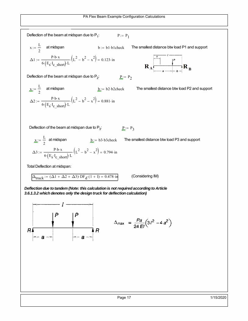
PA Flex Beam Example Configuration Calculations
Deflection of the beam at midspan due to P1: P P1
xL
2 at midspan b b1 b1check The smallest distance btw load P1 and support
Δ1P b x
6 Es Ic_short LL2
b2
x2
0.123 in
Deflection of the beam at midspan due to P2: P P2
xL
2 at midspan b b2 b2check The smallest distance btw load P2 and support
Δ2P b x
6 Es Ic_short LL2
b2
x2
0.881 in
Deflection of the beam at midspan due to P3: P P3
xL
2 at midspan b b3 b3check The smallest distance btw load P3 and support
Δ3P b x
6 Es Ic_short LL2
b2
x2
0.794 in
Total Deflection at midspan:
Δtruck Δ1 Δ2 Δ3( ) DFd 1 I( ) 0.478 in (Considering IM)
Deflection due to tandem (Note: this calculation is not required according to Article3.6.1.3.2 which denotes only the design truck for deflection calculation)
Page 17 1/15/2020

PA Flex Beam Example Configuration Calculations
FT 31.25 kip Per axle
XAS 4ft Axle spacing
Δtandem
FTL
2
XAS
2
24 Es Ic_short3 L
2 4
L
2
XAS
2
2
DFd 1 I( ) 0.471 in (Considering IM)
Deflection due to lane load
FDLLd 640lbf
ft DFd 128
lbf
ft
Δlane
5 FDLLd L4
384 Es Ic_short0.137 in
Live Load Deflection:
ΔLL 1.25max Δtruck 0.25Δtruck Δlane 1.25 0.747 in ΔLLL
800 1
Deflection Limit
For steel or concrete vehicular bridges:
Vehicular load = Span/800L
8000.9 in
L
10000.72 in
Evaluation of Deflection at the Service Limit State (AASHTO 3.4.2.2)
The associated permitted deflections shall be included in the contract documents.
Page 18 1/15/2020
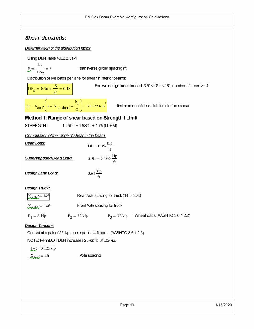
PA Flex Beam Example Configuration Calculations
Shear demands:
Determination of the distribution factor
Using DM4 Table 4.6.2.2.3a-1
Sbe
12in3 transverse girder spacing (ft)
Distribution of live loads per lane for shear in interior beams:
For two design lanes loaded, 3.5' <= S =< 16', number of beam >= 4DFs 0.36
S
25 0.48
Q Actr1 h Y'c_shorthf
2
311.223 in3
first moment of deck slab for interface shear
Method 1: Range of shear based on Strength I Limit
STRENGTH I 1.25DL + 1.5SDL + 1.75 (LL+IM)
Computation of the range of shear in the beam
Dead Load:DL 0.39
kip
ft
Superimposed Dead Load: SDL 0.498kip
ft
Design Lane Load: 0.64kip
ft
Design Truck:
XASr 14ft Rear Axle spacing for truck (14ft - 30ft)
XASf 14ft Front Axle spacing for truck
P1 8 kip P2 32 kip P3 32 kip Wheel loads (AASHTO 3.6.1.2.2)
Design Tandem:
Consist of a pair of 25-kip axles spaced 4-ft apart. (AASHTO 3.6.1.2.3)
NOTE: PennDOT DM4 increases 25-kip to 31.25-kip.
FT 31.25kip
XAS 4ft Axle spacing
Page 19 1/15/2020

PA Flex Beam Example Configuration Calculations
Maximum positive shear at various points along the FlexBeam are examined.
At x=0 (at left support) (Truck is moving from left to right)
Truck
Max Positive Shear (when P3 is at x = 0):
x1 L XASr XASf 32 ft Distance between P1 and right support
x2 L XASr 46 ft Distance between P2 and right support
x3 L 60 ft Distance between P3 and right support
V1 P3
x3
L P2
x2
L P1
x1
L 60.8 kip
Total Vertical Shear Force for each FlexBeam (considering dynamic loads):
Vtruck1 V1 DFs 1 I( ) 38.815 kip
Tandem:
V1 FT FT
L XAS L
60.417 kip
Total Vertical Shear Force for each FlexBeam (considering dynamic loads):
Vtandem1 V1 DFs 1 I( ) 38.57 kip
Lane Load
V1 0.64kip
ft
L
2 19.2 kip
Total Vertical Shear Force for each FlexBeam (considering dynamic loads):
Vlane1 V1 DFs 9.216 kip
Dead Load
Vdl1 DLL
2 11.708 kip
Superimposed Dead Load
Vsdl1 SDLL
2 14.951 kip
Strength I Max Positive Shear:
Vstr1 1.25 Vdl1 1.5 Vsdl1 1.75 Vlane1 max Vtruck1 Vtandem1 121.116 kip
Page 20 1/15/2020

PA Flex Beam Example Configuration Calculations
Design Permit Load P-82
Shear at x=0
Strength II Max Positive Shear:
VPL82 VPL82span DFs 1 IPL 72.063 kip
STRENGTH II 1.25DL + 1.5SDL + 1.35 (LL+IM)
VstrII_PL 1.25 Vdl1 1.5 Vsdl1 1.35 VPL82 134.348 kip
Max Shear Demand Vu max Vstr1 VstrII_PL 134.348 kip
Determine the Shear Strength of the Web
Shear Strength of Unstiffened web from AASHTO section 6.10.9.2
Depth of Web D d 31 in Thickness of web tw 0.625 in
Transverse Stiffener Spacing d0 0in Shear Buckling Coefficient k 5 6.10.9.3.2-7
Plastic Shear Force Vp 0.58 Fy D tw 561.875 kip Equation 6.10.9.3.2-3
Ratio of Shear-Buckling resistance to shear yield, C
D
tw49.6 1.12
Es k
Fy 60.314 Ccheck
D
tw1.12
Es k
Fy 1 Equation 6.10.9.3.2-4
C 1.0 Ccheck 1 C=1 for most cases, if the criteria are not met, then C will go to zero and the actualcoefficients should be determined
Nominal Shear Resistance of Web Vn C Vp 561.875 kip equation 6.10.9.3.3-1
Shear Resistance Factor φv 1.0
φv Vn 561.875 kip φv Vn Vu 1Reduced Shear Strength
Page 21 1/15/2020

PA Flex Beam Example Configuration Calculations
Check Bearing Stiffeners
FYs 50ksi Yield strength of stiffener
tp 0.75in Thickness of stiffener
bt
bf tw
21.5in 4.188 in Effective width of stiffener
Dst hw 4.1in 26.15 in Depth of stiffeners
Apn 2 tp bt 6.281 in2
Projected area of stiffeners
bt 0.48 tpEs
FYs 1Check that effective width of stiffener meets requirements
Rsbn 1.4 Apn FYs 439.688 kip Bearing capacity of stiffener (phi=1 for bearing per AASHTO 6.5.4.2)
Rsbn Vu 1 Bearing capacity check
Qs 1.0 Q factor for bearing stiffner, taken as 1 (AASHTO 6.9.4.1.1)
Is
18 tw tw3
tp 2 bt 3
1236.943 in
4 Moment of inertia of stiffener and web (9*tw is used on each side)
AASHTO 6.10.11.2.4b
Ag 18 tw tw 2 bt tp 13.313 in2
Gross area of stiffener and web (AASHTO 6.10.11.2.4b)
rs
Is
Ag1.666 in Radius of gyration of stiffener/web
Po Qs FYs Apn 314.062 kip Nominal yeild resistance of stiffener (AASHTO 6.9.4.1.1)
Peπ2Es
0.75 Dst
rs
2Ag 2.749 10
4 kip Elastic critical buckling stress of stiffener (AASHTO 6.9.4.1.2-1)
Check that Pe/Po is great than 0.44 (AASHTO 6.9.4.1.1) PePoPe
Po0.44 1
Pn PePo 0.658
Po
Pe Po 312.564 kip Nominal compressive resistance of stiffener for Pe/Po>0.44
(AASHTO 6.9.4.1.1-1)
φcr 0.95 phi factor for axial compression (AASHTO 6.5.4.2)
Pr φcr Pn 296.936 kip Compressive capacity of bearing stiffener Pr Vu 1
Page 22 1/15/2020

PA Flex Beam Example Configuration Calculations
Flexbeam Example Configuration Calculations
Summary of Calculations:
Input section dimensions and material properties for steel WT and the concrete deck1.Calculate demands (dead load, superimposed dead, and Live load demands for Strength I and Strength II2.Calculate composite section properties for the given section3.Check Strength I, Strength II, and Service II stresses 4.Check Strength I, Strength II, and Strength V moment demands 5.Perform live load deflection check6.Determine maximum shear demand and capacity7.Note: Shear envelope data was obtained from Matlab script (FlexBeam_Moment_ShearEnvelope.m).8.Shear envelope calculations are summarized separately for each design (Shear Design *.xlsx).
Design Assumptions:Design Specifications Used:
AASHTO LRFD Bridge Design Specifications 7th Edition with 2016 Interim RevisionsPennDOT Design Manual, Part 4 (DM-4) June 30, 2015
Example configurations are determined for two girder spacings, 36" and 40".The deck thickness is 7.5" and is assumed to have a non-structural wearing surface added after installation.Section properties are calculated using the full 7.5" deck thickness.The WT sections are embedded 3.5" into the concrete deck. The steel section spacing used is outside the scope of the AASHTO and PennDOT distribution factorequations. The flexural distribution factor is assumed to be 0.3 which was shown to tbe conservativeaccording to refined analysisThe shear distribution factor is calculated using the DM-4 shear distribution factor equation which wasshown to be conservative using refined analysis.Refined analysis is presented in: Zihan Ma, "Distribution Factors for Composite Steel Tee Concrete DeckBridge System," M.S. Thesis, Deparement of Civil and Environmental Engineering, Lehigh University,Bethlehem, 2019Shear and moment demands for the PL82 permit load vehicle are determined by Matlab script(FlexBeam_Moment_ShearEnvelope.m) and are manually input into this calculation sheet.All fabrication will occur as double modules, i.e. each module contains two WT sections. The number ofmodules is half the number of beams, N. A 45 in. tall F-Shape barrier is used, Weight = 700 lb/ft (Distributed to exterior two beams).
The work presented in this document are provided on an “AS IS” basis. University makes no warranties of anykind, express or implied, as to any matter whatsoever, including, without limitation, warranties with respect tothe merchantability or fitness for a particular purpose of this work or any project deliverables. Universitymakes no warranty of any kind with respect to freedom from patent, trademark, copyright or trade secretinfringement arising from the use of the results of the project, deliverables, services, intellectual property orother materials provided hereunder. University shall not be liable for any direct, indirect, consequential,punitive, or other damages suffered by Sponsor or any other person resulting from the project, or the use ofthis work or any project deliverables.
Page 1 1/15/2020

PA Flex Beam Example Configuration Calculations
hf
tf
bf
twh
d
bjtbe
e
Variable Definitions:
Number of beams N 12 modulesN
26
L 60ft Span length
be 36in Effective width of Flexbeamassuming constructed bridge width(i.e. closure joints cast)
Built Up Section Properties
tw 0.625in tf 0.750in bf 12in
h 35in Overall Height of section
hf 7.5in Total thickness of deck
e 3.5in Deck/Steel overlap
d h hf e 31 in depth of built up steel section
hw d tf 30.25 in height of web of built up steel
Moment and shear for permit load PL82 obtained from Matlab script: FlexBeam_Moment_ShearEnvelope
MLL_IM_PL82 523.6917kip ft Moment due to PL82 with distribution factor and impact factor!!
VPL82span 125.11kip Shear due to PL82 WITHOUT distribution factor and impact factor!!
Check web and flange dimensions in sections 6.10.2.1 and 6.10.2.2
(Ignore 6.10.2.2-4 since no compression flange)
equation 6.10.2.1.1-1d
tw150 1 equation 6.10.2.2-1
bf
2 tf12 1
equation 6.10.2.2-2 bfh
6 1 equation 6.10.2.2-3 tf 1.1 tw 1
y_bar
tf bftf
2 hw tw tf
hw
2
tf bf hw tw10.876 in Center of gravity of steel section
Istl
bf tf3
12bf tf y_bar
tf
2
2
tw hw
3
12 tw hw tf
hw
2 y_bar
2
2.907 103
in4
MOI of steel
Astl tf bf hw tw 27.906 in2
Area of the WT steel section
Page 2 1/15/2020

PA Flex Beam Example Configuration Calculations
Material Properties
Elastic Modulus of Steel Es 29000ksi
Yield Strength of Steel Fy 50ksi
Yield Strength of Reinforcement fy 60ksi
Compressive Strength of Concrete fc 4000psi AAAP PennDOT Concrete
Concrete Modular Ratio n 8 modular ratio for 4ksi concrete per AASHTO
Unit weight of concrete slab wc 0.150kip
ft3
Unit weight of concrete
Section Properties
Width of UHPC Joint: bjt 6in
Parapet width: bpar 20.25in Parapet width per PennDOT F-shape barrier
Width of the bridge W be N bjt 426 in W 35.5 ft
Clear width of roadway Wlane W 2 bpar 32.125 ft
Dc wc hf W 3.328kip
ft DL due to slab
Db .700kip
ft DL due to each 45" F-Shape Barrier (per email 11/1/18)
DFWS 30lbf
ft2
W 2 bpar 0.964kip
ft DL due to Future Wearing Surface (FWS)
Ds Astl 490lbf
ft3
0.095kip
ft Selfweight of the steel section
DLself
Dc N
Ds 0.372kip
ft Self-weight per WT
Total weight of each precast FlexBeam for transportation:
Weight of C12x25 Diaphragms Wend_diaphragms 25lbf
ft32 in 0.067 kip
2be bjt hf wc 2Ds L 2 Wend_diaphragms 42.466 kip
Determine number of design lane (AASHTO Section 3.6.1.1.1)
Take the integer part of the ratio of W/12 ft. Number of lanes in bridge: Nl floorWlane
12ft
2
Page 3 1/15/2020

PA Flex Beam Example Configuration Calculations
STEP 1: Compute Dead Load for each Flex Beam
DLslab
Dc
Nwc 1 in
be
2 0.296
kip
ft Dead load of slab assuming exterior overhang has 1" of
additional concrete thickness
DLsteel Ds 0.095kip
ft
DL DLslab DLsteel 0.391kip
ft
STEP 2: Compute Superimposed Dead Load
SDLWS
DFWS
N0.08
kip
ft
SDLparapet
Db
20.35
kip
ft distributed equally on two outer beams
SDLOL 140lbf
ft3be 2 in 0.07
kip
ft Overlay is 2" thick and is 140 lbs/cubic foot
NOTE: For this example barrier load is distributed equally among the two outer beams per conversation withPennDOT and M&M.
PennDOT DM4: "For composite adjacent and spread beams, the barrier (single barrier) load shall be equallydistributed to the nearest three (adjacent) and two (spread) beams, respectively, when the barriers are placedafter slab has hardened".
SDL SDLWS SDLparapet SDLOL 0.5kip
ft
STEP 3: Compute Transformed Width of Slab
For live load and dead load acting on the stringer k1 1 For short-term section property evaluation
btr1
be
k1 n4.5 in Transformed width of slab for short-term
For superimposed dead loads k3 3 For long-term section property evaluation
btr3
be
k3 n1.5 in Transformed width of slab for long-term
Page 4 1/15/2020

PA Flex Beam Example Configuration Calculations
STEP 4: Compute Dead and Superimposed Dead Load Moments(Based on first interior girder demands)
MDLDL L
2
8175.974 kip ft
MSDLSDL L
2
8225.141 kip ft
STEP 5: Compute live load and Dynamic Load Allowance (IM)
Live load wheel load distribution factor (DF):
Sbe
12in3 transverse girder spacing
NOTE: AASHTO presents equations to define DF for different types of superstructuresincluding Deck Composite wirh RC slab on steel girders (Type (a) in Table 4.6.2.2.1-1) forshear and moment in interior and exterior beams.
Using DM4 Table 4.6.2.2.2b-1:
eg h y_barhf
2 20.374 in Distance between the centers of gravity of the basic beam and deck
Kg n Istl Astl eg2
1.16 10
5 in
4 Longitudinal stiffness parameter (in4)
Distribution of Live Load Per Lane for Moment in Interior Beams:
to be conservative, use DF 0.3
Page 5 1/15/2020

PA Flex Beam Example Configuration Calculations
Dynamic Load Allowance (Section 3.6.2 DM4)
Static effects of the design truck or tandem, shall be increased by the impact factor.
NOTE: The dynamic load allowance shall not be applied to the design lane load (Section 3.6.2.1 DM4)
I 0.33 Impact factor for moment
Note: PennDOT requires that the impact for decks be increased from 33% to 50%, the deck is not beingdesigned here. Instrad the deck design is based on the BD recommendations.
Dynamic load allowance for the Permit Load P-82 shall be less than 20%. (Section 3.6.2.1DM4)
IPL 0.20 Impact factor for moment on Strength II
Design Wind Loading for Exterior Girder
Vw 80 Wind speed for Strength V load case
CD 1.3 Gust factor for windard side of I-Girder and Box Girder Superstructures (Table 3.8.1.2.1-2)
G 1.0 Gus effect factor is 1.0 for all structures other than sound barriers (Table 3.8.1.2.1-1)
Kz 1.0 Pressure coefficient taken as 1 for Strength V (3.8.1.2.1)
Pz 2.56 106
Vw 2 Kz G CDkip
ft2
0.021kip
ft2
Wind pressure on exterior girder
hexp h hf 27.5 in Exposed height of exterior girder
Moment due to wind loading on exterior girderMWL
Pz hexp L2
821.965 kip ft
Iyy
bf3tf
12108 in
4 Transverse moment of intertia
Flange lateral bending stressfl
MWL
bf
2
Iyy14.643 ksi
Page 6 1/15/2020

PA Flex Beam Example Configuration Calculations
Design Vehicular Live Load
PHL-93 and P-82 are examined herein.
PHL-93 (A3.6.1.2.1)
PHL-93 consists of a combination of (design truck or design tandem) + (design lane load)
Design Truck
PennDOT defines the design truck in accordance with AASTHO 3.6.1.2
Design truck load in AASHTO (HS20 Truck) is used for this example.
NOTE : MAX moment occurs when the center line of the span is midway between the center ofgravity of the loads and the nearest concentrated load.
P1 8kip P2 32kip P3 32kip Axle loads (AASHTO 3.6.1.2.2)
XASr 14ft Rear Axle spacing for truck (14ft - 30ft)
XASf 14ft Front Axle spacing for truck
Page 7 1/15/2020
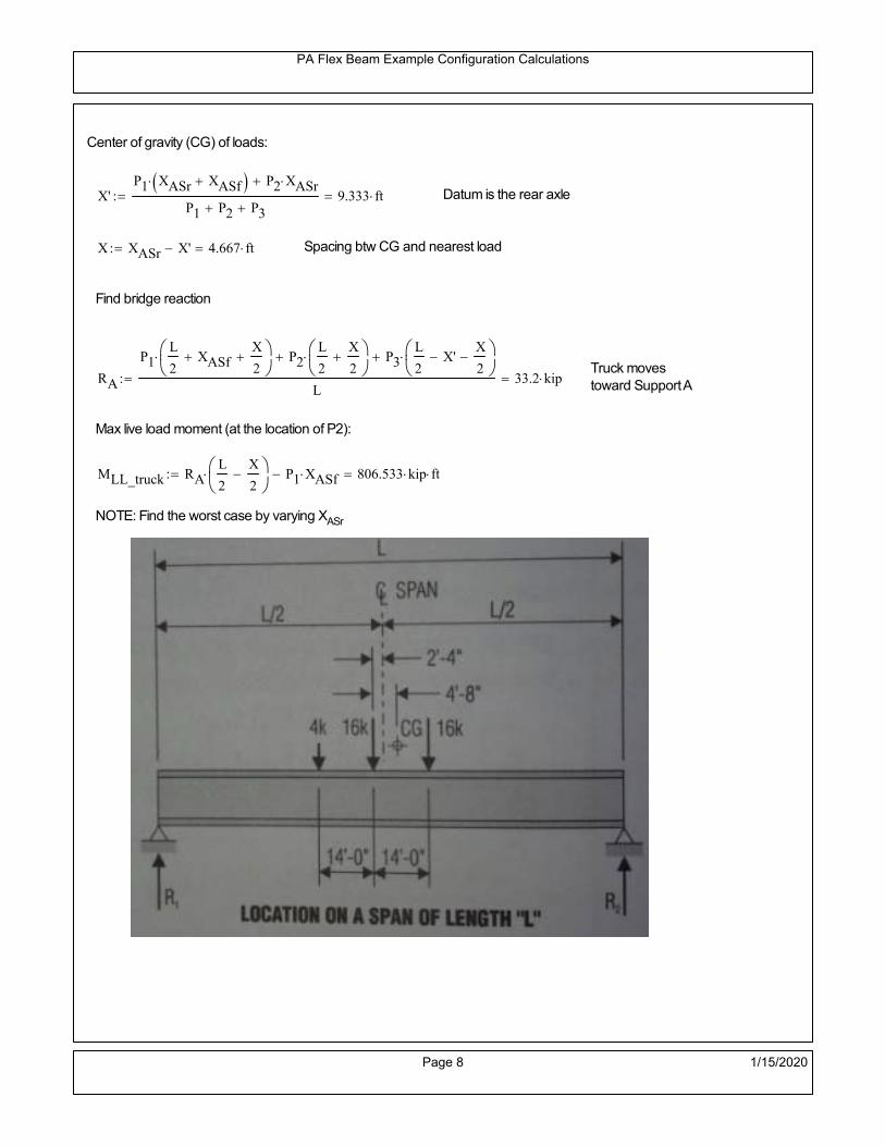
PA Flex Beam Example Configuration Calculations
Center of gravity (CG) of loads:
X'P1 XASr XASf P2 XASr
P1 P2 P39.333 ft Datum is the rear axle
X XASr X' 4.667 ft Spacing btw CG and nearest load
Find bridge reaction
Truck movestoward Support ARA
P1L
2XASf
X
2
P2L
2
X
2
P3L
2X'
X
2
L33.2 kip
Max live load moment (at the location of P2):
MLL_truck RAL
2
X
2
P1 XASf 806.533 kip ft
NOTE: Find the worst case by varying XASr
Page 8 1/15/2020

PA Flex Beam Example Configuration Calculations
Design Tandem
Consist of a pair of 25-kip axles spaced 4-ft apart. (AASHTO 3.6.1.2.3)
NOTE: PennDOT DM4 increases 25-kip to 31.25-kip.
FT 31.25kip
XAS 4ft Axle spacing
Center of gravity (CG) of loads:
XXAS
22 ft Spacing btw CG and nearest load
Find bridge reaction
RA
FTL
2
X
2
FTL
2
X
2 X
L30.208 kip Truck moves toward Support A
Max live load moment (at the location of front wheel):
MLL_tandem RAL
2
X
2
876.042 kip ft
Choose the max value:
MLL_veh max MLL_tandem MLL_truck 876.042 kip ft
Apply the impact and wheel load distribution:
MLL_IM_veh MLL_veh DF 1 I( ) 349.541 kip ft Due to tandem or truck
Design Lane Load (distributed over a 10-ft width for each lane)
NOTE: The uniform load may be continuous or discontinuous as necessary to produce themaximum force effect. For this example continuous uniform distribution assumed.
FDLL 0.64kip
ftDF 0.192
kip
ft Per beam in each lane
Due to lane loadMLL_IM_lane
FDLL L2
8
86.4 kip ft
Moment due to Total Design Vehicular Live Load: MLL_IM MLL_IM_lane MLL_IM_veh 435.941 kip ft
Page 9 1/15/2020

PA Flex Beam Example Configuration Calculations
Design Permit Load P-82 (Section 3.6.1.2.7 DM4)
P1 P2 P3 P4 P5 P6 P7
NOTE: The moment for the permit load is defined at the beginning of the sheetand is obtained from MATLab File FlexBeam_Moment_ShearEnvelope.m
STEP 6: Compute Moment of Inertia (Note: rebar neglected!)
1) Moment of Inertia resisting dead load only:
a) Acting on the non-composite section (before the deck has hardened - DC1)
Use steel section only
Inc Istl 2.907 103
in4
Non-composite section modulus
Y'nc y_bar S.G. of the steel section of Flex Beam (Datum is bottom)
b) Acting on the composite section (after the deck has hardened - DC2)
Use Ic_short as defined below.
Page 10 1/15/2020

PA Flex Beam Example Configuration Calculations
2) Moment of Inertia resisting live load plus impact:
Using transformed slab with k1=1 (short-term composite).
Actr1 hf btr1 33.75 in2
Itr1
btr1 hf3
12158.203 in
4
Y'
Actr1 hhf
2
Astl Y'nc
Astl Actr122.029 in S.G. of the total flex beam (Datum is bottom)
Compositesection modulus(short-term)
Ic_short Istl Astl Y'nc Y' 2 Itr1 Actr1 hhf
2
Y'
2
9406 in4
Y'c_short Y' 22.029 in N.A. of the short-term composite section
3) Moment of Inertia resisting superimposed dead load:
Using transformed slab with k3=3.
Actr3 hf btr3 11.25 in2
Itr3
btr3 hf3
1252.734 in
4
Y'
Actr3 hhf
2
Astl Y'nc
Astl Actr316.73 in S.G. of the total flex beam (Datum is bottom)
Compositesection modulus(long-term)
Ic_long Istl Astl Y'nc Y' 2 Itr3 Actr3 hhf
2
Y'
2
6288 in4
Y'c_long Y' 16.73 in N.A. of the long-term composite section
Page 11 1/15/2020

PA Flex Beam Example Configuration Calculations
STEP 6.5 Check Ductility RequirementIn accordance with AASHTO Article 6.10.7.3 check ductility requirement. Assume compressionblock of concrete is at 0.85 f'c and that the concrete supports no tension. Steel section isassumed to be fully plastic at Fy.
Case 1 : Assuming PNA is in Concreteh d 4 inAssuming (h-d) < Dp < hf
Fp Dp 0.85 fc be Dp Fy tw Dp h d( ) Fy Astl tw Dp h d( )
Dp 7.5in 0.42 h 14.7 in
Dp1 root Fp Dp Dp 8.898 in Must be less than hf 7.5 inDp1
h0.254 must be < 0.42
Mn1check Dp1 hf h d( ) Dp1[ ] Dp1 0.42 h( ) 0 Dp1 0.42 h 1
Mp1 0.85 fc be Dp1Dp1
2
Fy tw Dp1 h d( )[ ] Dp1 h d( )[ ]
2
Fy bf tf h Dp1tf
2
Fy tw h Dp1 tf h Dp1 tf
2
Mp1 26840.03 kip in Mn1 Mp1 1.07 0.7Dp1
h
23942.2 kip in
Case 2 : Assuming PNA is NOT in Concrete
Assuming hf < Dp
Fp2 Dp 0.85 fc be hf Fy tw Dp h d( ) Fy Astl tw Dp h d( )
Dp 2.5in
Dp2 root Fp2 Dp Dp 11.637 in Must be more than hf 7.5 inDp2
h0.3325 must be < 0.42
Mn2check Dp2 hf Dp2 h( ) Dp2 0.42 h( ) 1 Dp2 0.42 h 1
Mp2 0.85 fc be hf Dp2hf
2
Fy tw Dp2 h d( )[ ] Dp2 h d( )[ ]
2
Fy bf tf h Dp2tf
2
Fy tw h Dp2 tf h Dp2 tf
2
Mp2 26485.98 kip inMn2 Mp2 1.07 0.7
Dp2
h
22175.7 kip in
Mn max Mn1 Mn1check Mn2 Mn2check 1848 kip ft Mn 22175.7 kip in
Page 12 1/15/2020

PA Flex Beam Example Configuration Calculations
Check Composite Compact Section Criteria (6.10.6.2)
Dcpd
2
Fy tf bf 0.85 fc be hf
Fy hw tw1
7.826 in Dcp0 Dcp 0 1
Dcp Dcp Dcp0 7.826 in2 Dcp
tw3.76
Es
Fy 1 Check if section is compact
STEP 7: Load Combinations (Table 3.4.1-1)
The following load combinations will be considered herein. Only the maximum load factors forpermanent-loads are used in the following load combinations (uplift is not an issue for this typeof bridge).STRENGTH I 1.25DL + 1.5SDL + 1.75 (LL+IM)
SERVICE II: DL+SDL+1.3(LL+IM)
STEP 8: Compute and Check Stresses
Stress at bottom fiber of steel section
fDL
MDL Y'c_long
Ic_long5.618 ksi
fLL_I
MLL_IM Y'c_short
Ic_short12.251 ksi fPL
MLL_IM_PL82 Y'c_short
Ic_short14.718 ksi
fSDL
MSDL Y'c_long
Ic_long7.188 ksi
STRENGTH I fbot_str1 1.25fDL 1.5 fSDL 1.75 fLL_I 39.245 ksi
STRENGTH II fbot_str2 1.25fDL 1.5 fSDL 1.35 fPL 37.674 ksi
SERVICE II fbot_svc2 fDL fSDL 1.3fLL_I 28.73 ksi
Allowable Stress is based on Section 6.10.4.2.2-2
Flange stress due to service load II without consideration of flange lateral bending: ff fbot_svc2
Flange lateral bending stress due to service II: flSII 0ksi
Hybrid Factor: Rh 1.0 For rolled and homogenous built-up sections
ff
flSII
2 28.733 ksi 0.95 Rh Fy 47.5 ksi ff
fl
2 0.95Rh Fy 1
Page 13 1/15/2020

PA Flex Beam Example Configuration Calculations
Stress at top fiber of concrete
Note: For calculating longitudinal flexural stresses in the concrete deck due to allpermanent and transient loads, the short-term modular ratio shall be used.
fDL
MDL h Y'c_short
k1 n Ic_short0.364 ksi
fLL_I
MLL_IM h Y'c_short
k1 n Ic_short0.902 ksi fPL
MLL_IM_PL82 h Y'c_short
k1 n Ic_short1.083 ksi
fSDL
MSDL h Y'c_short
k1 n Ic_short0.466 ksi
STRENGTH I fc_str1 1.25fDL 1.5 fSDL 1.75 fLL_I 2.732 ksi
Mstr1 1.25 MDL 1.5 MSDL 1.75 MLL_IM 1320.6 kip ft Mstr1 Mn 1
STRENGTH II fc_str2 1.25fDL 1.5 fSDL 1.35 fPL 2.616 ksi
Mstr2 1.25 MDL 1.5 MSDL 1.35 MLL_IM_PL82 1265 kip ft Mstr2 Mn 1
SERVICE II
Allowable Stress in concrete - AASHTO 6.10.4.2.2For compact composite sections in positive flexure utilized in shored construction, the longitudinalcompressive stress in the concrete deck due to the Service II loads, determined as specified in Article6.10.1.1.1d, shall not exceed 0.6f́ c.
fallow 0.6 fc 2400 psi
fc_2 1.3fLL_I fSDL fDL 2002.04 psi This assumes short term compositesection for all calculations
fc_2 fallow 1
SERVICE II with Long Term Composite for dead loads
fDL
MDL h Y'c_long
k3 n Ic_long0.256 ksi
fLL_I
MLL_IM h Y'c_short
k1 n Ic_short0.902 ksi
fSDL
MSDL h Y'c_long
k3 n Ic_long0.327 ksi
fc_2 1.3fLL_I fSDL fDL 1755.05 psi fc_2 fallow 1
Page 14 1/15/2020

PA Flex Beam Example Configuration Calculations
Strength V Moment Check
Strength V is related to normal vehicular use of the bridge with an 80 mph wind gust
Note: that Strength V is checked for an exterior girder under wind load with the interior girder distribution factor forflexure used. If Strength V controls design, then this approach should be modified
Design vertical moment is: 1.25DL + 1.5SDL + 1.35 (LL+IM)
SLT
Ic_long
Y'c_long375.851 in
3 SST
Ic_short
Y'c_short426.993 in
3 short and long term section
modulus
Section D6.2.2 Find the moment required to cause yieldling of the flange. The approach is laid out in D6.2.2
MD2 1.25 MDL 1.5 MSDL 557.678 kip ft From D6.2.2-1 (all dead loads are in MD2 due to shoredconstruction
MAD Fy
MD2
SLT
SST 1.146 10
3 kip ft Additional moment to cause nominal yielding of steel flange
My MD2 MAD 1.703 103
kip ft D6.2.2-2: Moment to cause yielding of flange
6.10.7.1 Compact Section Check at Strength V limit state
Section Modulus for yielding of the flange (My/Fy) for equation 6.10.7.1.1-1Sxt
My
Fy408.781 in
3
Mu 1.25 MDL 1.5MSDL 1.35MLL_IM 1.146 103
kip ft Moment due to Strength V limit state
Mu1
3fl Sxt 1.312 10
3 kip ft Equation 6.10.7.1.7-1 Mn 1.848 10
3 kip ft Mu
1
3fl Sxt Mn 1
Page 15 1/15/2020

PA Flex Beam Example Configuration Calculations
STEP 9: Compute Deflection
Optional Live Load Deflection Evaluation (AASHTO 3.6.1.3.2)
Deflection distribution factor for vehicular loads: For a straight multibeambridge, this is equivalent to saying that the distribution factor for deflectionis equal to the number of lanes divided by the number of beams. 2.5.2.6.2
DFd
Nl
N0.167
Deflection should be taken as 125% the larger of:- Design truck- 25% of design truck + design lane
The live load portion of Load Combination Service I of Table 3.4.1-1 should be used,including the dynamic load allowance, IM;
Deflection due to design truck load
NOTE : Assuming maximum deflection occurs when the center of gravity of the loads is at thecenter line of the span.
P1 8kip P2 32kip P3 32kip Axle loads (AASHTO 3.6.1.2.2)
XASr 14ft Rear Axle spacing for truck (14ft - 30ft)
XASf 14ft Front Axle spacing for truck
Center of gravity (CG) of loads:
X'P1 XASr XASf P2 XASr
P1 P2 P39.333 ft Datum is the rear axle
Method1: Assuming single load = P1+P2+P3 at the midspan (Conservative approach)
P1 P2 P3 L3
48 Es Ic_short 2.053 in
Method2: Calculation of Midspan deflection using superposition
b1L
2XASr X' XASf 11.333 ft distance btw load P1 and support A b1check b1 0 1
b2L
2XASr X' 25.333 ft distance btw load P2 and support A b2check b2 0 1
b3L
2X' 20.667 ft distance btw load P3 and support B b3check b3 0 1
Page 16 1/15/2020

PA Flex Beam Example Configuration Calculations
Deflection of the beam at midspan due to P1: P P1
xL
2 at midspan b b1 b1check The smallest distance btw load P1 and support
Δ1P b x
6 Es Ic_short LL2
b2
x2
0.123 in
Deflection of the beam at midspan due to P2: P P2
xL
2 at midspan b b2 b2check The smallest distance btw load P2 and support
Δ2P b x
6 Es Ic_short LL2
b2
x2
0.881 in
Deflection of the beam at midspan due to P3: P P3
xL
2 at midspan b b3 b3check The smallest distance btw load P3 and support
Δ3P b x
6 Es Ic_short LL2
b2
x2
0.794 in
Total Deflection at midspan:
Δtruck Δ1 Δ2 Δ3( ) DFd 1 I( ) 0.398 in (Considering IM)
Deflection due to tandem (Note: this calculation is not required according to Article3.6.1.3.2 which denotes only the design truck for deflection calculation)
Page 17 1/15/2020

PA Flex Beam Example Configuration Calculations
FT 31.25 kip Per axle
XAS 4ft Axle spacing
Δtandem
FTL
2
XAS
2
24 Es Ic_short3 L
2 4
L
2
XAS
2
2
DFd 1 I( ) 0.392 in (Considering IM)
Deflection due to lane load
FDLLd 640lbf
ft DFd 106.667
lbf
ft
Δlane
5 FDLLd L4
384 Es Ic_short0.114 in
Live Load Deflection:
ΔLL 1.25max Δtruck 0.25Δtruck Δlane 1.25 0.623 in ΔLLL
800 1
Deflection Limit
For steel or concrete vehicular bridges:
Vehicular load = Span/800L
8000.9 in
L
10000.72 in
Evaluation of Deflection at the Service Limit State (AASHTO 3.4.2.2)
The associated permitted deflections shall be included in the contract documents.
Page 18 1/15/2020

PA Flex Beam Example Configuration Calculations
Shear demands:
Determination of the distribution factor
Using DM4 Table 4.6.2.2.3a-1
Sbe
12in3 transverse girder spacing (ft)
Distribution of live loads per lane for shear in interior beams:
For two design lanes loaded, 3.5' <= S =< 16', number of beam >= 4DFs 0.36
S
25 0.48
Q Actr1 h Y'c_shorthf
2
311.223 in3
first moment of deck slab for interface shear
Method 1: Range of shear based on Strength I Limit
STRENGTH I 1.25DL + 1.5SDL + 1.75 (LL+IM)
Computation of the range of shear in the beam
Dead Load:DL 0.391
kip
ft
Superimposed Dead Load: SDL 0.5kip
ft
Design Lane Load: 0.64kip
ft
Design Truck:
XASr 14ft Rear Axle spacing for truck (14ft - 30ft)
XASf 14ft Front Axle spacing for truck
P1 8 kip P2 32 kip P3 32 kip Wheel loads (AASHTO 3.6.1.2.2)
Design Tandem:
Consist of a pair of 25-kip axles spaced 4-ft apart. (AASHTO 3.6.1.2.3)
NOTE: PennDOT DM4 increases 25-kip to 31.25-kip.
FT 31.25kip
XAS 4ft Axle spacing
Page 19 1/15/2020

PA Flex Beam Example Configuration Calculations
Maximum positive shear at various points along the FlexBeam are examined.
At x=0 (at left support) (Truck is moving from left to right)
Truck
Max Positive Shear (when P3 is at x = 0):
x1 L XASr XASf 32 ft Distance between P1 and right support
x2 L XASr 46 ft Distance between P2 and right support
x3 L 60 ft Distance between P3 and right support
V1 P3
x3
L P2
x2
L P1
x1
L 60.8 kip
Total Vertical Shear Force for each FlexBeam (considering dynamic loads):
Vtruck1 V1 DFs 1 I( ) 38.815 kip
Tandem:
V1 FT FT
L XAS L
60.417 kip
Total Vertical Shear Force for each FlexBeam (considering dynamic loads):
Vtandem1 V1 DFs 1 I( ) 38.57 kip
Lane Load
V1 0.64kip
ft
L
2 19.2 kip
Total Vertical Shear Force for each FlexBeam (considering dynamic loads):
Vlane1 V1 DFs 9.216 kip
Dead Load
Vdl1 DLL
2 11.732 kip
Superimposed Dead Load
Vsdl1 SDLL
2 15.009 kip
Strength I Max Positive Shear:
Vstr1 1.25 Vdl1 1.5 Vsdl1 1.75 Vlane1 max Vtruck1 Vtandem1 121.232 kip
Page 20 1/15/2020

PA Flex Beam Example Configuration Calculations
Design Permit Load P-82
Shear at x=0
Strength II Max Positive Shear:
VPL82 VPL82span DFs 1 IPL 72.063 kip
STRENGTH II 1.25DL + 1.5SDL + 1.35 (LL+IM)
VstrII_PL 1.25 Vdl1 1.5 Vsdl1 1.35 VPL82 134.464 kip
Max Shear Demand Vu max Vstr1 VstrII_PL 134.464 kip
Determine the Shear Strength of the Web
Shear Strength of Unstiffened web from AASHTO section 6.10.9.2
Depth of Web D d 31 in Thickness of web tw 0.625 in
Transverse Stiffener Spacing d0 0in Shear Buckling Coefficient k 5 6.10.9.3.2-7
Plastic Shear Force Vp 0.58 Fy D tw 561.875 kip Equation 6.10.9.3.2-3
Ratio of Shear-Buckling resistance to shear yield, C
D
tw49.6 1.12
Es k
Fy 60.314 Ccheck
D
tw1.12
Es k
Fy 1 Equation 6.10.9.3.2-4
C 1.0 Ccheck 1 C=1 for most cases, if the criteria are not met, then C will go to zero and the actualcoefficients should be determined
Nominal Shear Resistance of Web Vn C Vp 561.875 kip equation 6.10.9.3.3-1
Shear Resistance Factor φv 1.0
φv Vn 561.875 kip φv Vn Vu 1Reduced Shear Strength
Page 21 1/15/2020

PA Flex Beam Example Configuration Calculations
Check Bearing Stiffeners
FYs 50ksi Yield strength of stiffener
tp 0.75in Thickness of stiffener
bt
bf tw
21.5in 4.188 in Effective width of stiffener
Dst hw 4.1in 26.15 in Depth of stiffeners
Apn 2 tp bt 6.281 in2
Projected area of stiffeners
bt 0.48 tpEs
FYs 1Check that effective width of stiffener meets requirements
Rsbn 1.4 Apn FYs 439.688 kip Bearing capacity of stiffener (phi=1 for bearing per AASHTO 6.5.4.2)
Rsbn Vu 1 Bearing capacity check
Qs 1.0 Q factor for bearing stiffner, taken as 1 (AASHTO 6.9.4.1.1)
Is
18 tw tw3
tp 2 bt 3
1236.943 in
4 Moment of inertia of stiffener and web (9*tw is used on each side)
AASHTO 6.10.11.2.4b
Ag 18 tw tw 2 bt tp 13.313 in2
Gross area of stiffener and web (AASHTO 6.10.11.2.4b)
rs
Is
Ag1.666 in Radius of gyration of stiffener/web
Po Qs FYs Apn 314.062 kip Nominal yeild resistance of stiffener (AASHTO 6.9.4.1.1)
Peπ2Es
0.75 Dst
rs
2Ag 2.749 10
4 kip Elastic critical buckling stress of stiffener (AASHTO 6.9.4.1.2-1)
Check that Pe/Po is great than 0.44 (AASHTO 6.9.4.1.1) PePoPe
Po0.44 1
Pn PePo 0.658
Po
Pe Po 312.564 kip Nominal compressive resistance of stiffener for Pe/Po>0.44
(AASHTO 6.9.4.1.1-1)
φcr 0.95 phi factor for axial compression (AASHTO 6.5.4.2)
Pr φcr Pn 296.936 kip Compressive capacity of bearing stiffener Pr Vu 1
Page 22 1/15/2020

PA Flex Beam Example Configuration Calculations
Flexbeam Example Configuration Calculations
Summary of Calculations:
Input section dimensions and material properties for steel WT and the concrete deck1.Calculate demands (dead load, superimposed dead, and Live load demands for Strength I and Strength II2.Calculate composite section properties for the given section3.Check Strength I, Strength II, and Service II stresses 4.Check Strength I, Strength II, and Strength V moment demands 5.Perform live load deflection check6.Determine maximum shear demand and capacity7.Note: Shear envelope data was obtained from Matlab script (FlexBeam_Moment_ShearEnvelope.m).8.Shear envelope calculations are summarized separately for each design (Shear Design *.xlsx).
Design Assumptions:Design Specifications Used:
AASHTO LRFD Bridge Design Specifications 7th Edition with 2016 Interim RevisionsPennDOT Design Manual, Part 4 (DM-4) June 30, 2015
Example configurations are determined for two girder spacings, 36" and 40".The deck thickness is 7.5" and is assumed to have a non-structural wearing surface added after installation.Section properties are calculated using the full 7.5" deck thickness.The WT sections are embedded 3.5" into the concrete deck. The steel section spacing used is outside the scope of the AASHTO and PennDOT distribution factorequations. The flexural distribution factor is assumed to be 0.3 which was shown to tbe conservativeaccording to refined analysisThe shear distribution factor is calculated using the DM-4 shear distribution factor equation which wasshown to be conservative using refined analysis.Refined analysis is presented in: Zihan Ma, "Distribution Factors for Composite Steel Tee Concrete DeckBridge System," M.S. Thesis, Deparement of Civil and Environmental Engineering, Lehigh University,Bethlehem, 2019Shear and moment demands for the PL82 permit load vehicle are determined by Matlab script(FlexBeam_Moment_ShearEnvelope.m) and are manually input into this calculation sheet.All fabrication will occur as double modules, i.e. each module contains two WT sections. The number ofmodules is half the number of beams, N. A 45 in. tall F-Shape barrier is used, Weight = 700 lb/ft (Distributed to exterior two beams).
The work presented in this document are provided on an “AS IS” basis. University makes no warranties of anykind, express or implied, as to any matter whatsoever, including, without limitation, warranties with respect tothe merchantability or fitness for a particular purpose of this work or any project deliverables. Universitymakes no warranty of any kind with respect to freedom from patent, trademark, copyright or trade secretinfringement arising from the use of the results of the project, deliverables, services, intellectual property orother materials provided hereunder. University shall not be liable for any direct, indirect, consequential,punitive, or other damages suffered by Sponsor or any other person resulting from the project, or the use ofthis work or any project deliverables.
Page 1 1/15/2020

PA Flex Beam Example Configuration Calculations
hf
tf
bf
twh
d
bjtbe
e
Variable Definitions:
Number of beams N 10 modulesN
25
L 60ft Span length
be 38in Effective width of Flexbeamassuming constructed bridge width(i.e. closure joints cast)
Built Up Section Properties
tw 0.625in tf 0.875in bf 12in
h 35in Overall Height of section
hf 7.5in Total thickness of deck
e 3.5in Deck/Steel overlap
d h hf e 31 in depth of built up steel section
hw d tf 30.125 in height of web of built up steel
Moment and shear for permit load PL82 obtained from Matlab script: FlexBeam_Moment_ShearEnvelope
MLL_IM_PL82 523.6917kip ft Moment due to PL82 with distribution factor and impact factor!!
VPL82span 125.11kip Shear due to PL82 WITHOUT distribution factor and impact factor!!
Check web and flange dimensions in sections 6.10.2.1 and 6.10.2.2
(Ignore 6.10.2.2-4 since no compression flange)
equation 6.10.2.1.1-1d
tw150 1 equation 6.10.2.2-1
bf
2 tf12 1
equation 6.10.2.2-2 bfh
6 1 equation 6.10.2.2-3 tf 1.1 tw 1
y_bar
tf bftf
2 hw tw tf
hw
2
tf bf hw tw10.388 in Center of gravity of steel section
Istl
bf tf3
12bf tf y_bar
tf
2
2
tw hw
3
12 tw hw tf
hw
2 y_bar
2
3.044 103
in4
MOI of steel
Astl tf bf hw tw 29.328 in2
Area of the WT steel section
Page 2 1/15/2020

PA Flex Beam Example Configuration Calculations
Material Properties
Elastic Modulus of Steel Es 29000ksi
Yield Strength of Steel Fy 50ksi
Yield Strength of Reinforcement fy 60ksi
Compressive Strength of Concrete fc 4000psi AAAP PennDOT Concrete
Concrete Modular Ratio n 8 modular ratio for 4ksi concrete per AASHTO
Unit weight of concrete slab wc 0.150kip
ft3
Unit weight of concrete
Section Properties
Width of UHPC Joint: bjt 6in
Parapet width: bpar 20.25in Parapet width per PennDOT F-shape barrier
Width of the bridge W be N bjt 374 in W 31.167 ft
Clear width of roadway Wlane W 2 bpar 27.792 ft
Dc wc hf W 2.922kip
ft DL due to slab
Db .700kip
ft DL due to each 45" F-Shape Barrier (per email 11/1/18)
DFWS 30lbf
ft2
W 2 bpar 0.834kip
ft DL due to Future Wearing Surface (FWS)
Ds Astl 490lbf
ft3
0.1kip
ft Selfweight of the steel section
DLself
Dc N
Ds 0.392kip
ft Self-weight per WT
Total weight of each precast FlexBeam for transportation:
Weight of C12x25 Diaphragms Wend_diaphragms 25lbf
ft32 in 0.067 kip
2be bjt hf wc 2Ds L 2 Wend_diaphragms 44.921 kip
Determine number of design lane (AASHTO Section 3.6.1.1.1)
Take the integer part of the ratio of W/12 ft. Number of lanes in bridge: Nl floorWlane
12ft
2
Page 3 1/15/2020

PA Flex Beam Example Configuration Calculations
STEP 1: Compute Dead Load for each Flex Beam
DLslab
Dc
Nwc 1 in
be
2 0.312
kip
ft Dead load of slab assuming exterior overhang has 1" of
additional concrete thickness
DLsteel Ds 0.1kip
ft
DL DLslab DLsteel 0.412kip
ft
STEP 2: Compute Superimposed Dead Load
SDLWS
DFWS
N0.083
kip
ft
SDLparapet
Db
20.35
kip
ft distributed equally on two outer beams
SDLOL 140lbf
ft3be 2 in 0.074
kip
ft Overlay is 2" thick and is 140 lbs/cubic foot
NOTE: For this example barrier load is distributed equally among the two outer beams per conversation withPennDOT and M&M.
PennDOT DM4: "For composite adjacent and spread beams, the barrier (single barrier) load shall be equallydistributed to the nearest three (adjacent) and two (spread) beams, respectively, when the barriers are placedafter slab has hardened".
SDL SDLWS SDLparapet SDLOL 0.507kip
ft
STEP 3: Compute Transformed Width of Slab
For live load and dead load acting on the stringer k1 1 For short-term section property evaluation
btr1
be
k1 n4.75 in Transformed width of slab for short-term
For superimposed dead loads k3 3 For long-term section property evaluation
btr3
be
k3 n1.583 in Transformed width of slab for long-term
Page 4 1/15/2020

PA Flex Beam Example Configuration Calculations
STEP 4: Compute Dead and Superimposed Dead Load Moments(Based on first interior girder demands)
MDLDL L
2
8185.299 kip ft
MSDLSDL L
2
8228.269 kip ft
STEP 5: Compute live load and Dynamic Load Allowance (IM)
Live load wheel load distribution factor (DF):
Sbe
12in3.167 transverse girder spacing
NOTE: AASHTO presents equations to define DF for different types of superstructuresincluding Deck Composite wirh RC slab on steel girders (Type (a) in Table 4.6.2.2.1-1) forshear and moment in interior and exterior beams.
Using DM4 Table 4.6.2.2.2b-1:
eg h y_barhf
2 20.862 in Distance between the centers of gravity of the basic beam and deck
Kg n Istl Astl eg2
1.26 10
5 in
4 Longitudinal stiffness parameter (in4)
Distribution of Live Load Per Lane for Moment in Interior Beams:
to be conservative, use DF 0.3
Page 5 1/15/2020

PA Flex Beam Example Configuration Calculations
Dynamic Load Allowance (Section 3.6.2 DM4)
Static effects of the design truck or tandem, shall be increased by the impact factor.
NOTE: The dynamic load allowance shall not be applied to the design lane load (Section 3.6.2.1 DM4)
I 0.33 Impact factor for moment
Note: PennDOT requires that the impact for decks be increased from 33% to 50%, the deck is not beingdesigned here. Instrad the deck design is based on the BD recommendations.
Dynamic load allowance for the Permit Load P-82 shall be less than 20%. (Section 3.6.2.1DM4)
IPL 0.20 Impact factor for moment on Strength II
Design Wind Loading for Exterior Girder
Vw 80 Wind speed for Strength V load case
CD 1.3 Gust factor for windard side of I-Girder and Box Girder Superstructures (Table 3.8.1.2.1-2)
G 1.0 Gus effect factor is 1.0 for all structures other than sound barriers (Table 3.8.1.2.1-1)
Kz 1.0 Pressure coefficient taken as 1 for Strength V (3.8.1.2.1)
Pz 2.56 106
Vw 2 Kz G CDkip
ft2
0.021kip
ft2
Wind pressure on exterior girder
hexp h hf 27.5 in Exposed height of exterior girder
Moment due to wind loading on exterior girderMWL
Pz hexp L2
821.965 kip ft
Iyy
bf3tf
12126 in
4 Transverse moment of intertia
Flange lateral bending stressfl
MWL
bf
2
Iyy12.551 ksi
Page 6 1/15/2020

PA Flex Beam Example Configuration Calculations
Design Vehicular Live Load
PHL-93 and P-82 are examined herein.
PHL-93 (A3.6.1.2.1)
PHL-93 consists of a combination of (design truck or design tandem) + (design lane load)
Design Truck
PennDOT defines the design truck in accordance with AASTHO 3.6.1.2
Design truck load in AASHTO (HS20 Truck) is used for this example.
NOTE : MAX moment occurs when the center line of the span is midway between the center ofgravity of the loads and the nearest concentrated load.
P1 8kip P2 32kip P3 32kip Axle loads (AASHTO 3.6.1.2.2)
XASr 14ft Rear Axle spacing for truck (14ft - 30ft)
XASf 14ft Front Axle spacing for truck
Page 7 1/15/2020

PA Flex Beam Example Configuration Calculations
Center of gravity (CG) of loads:
X'P1 XASr XASf P2 XASr
P1 P2 P39.333 ft Datum is the rear axle
X XASr X' 4.667 ft Spacing btw CG and nearest load
Find bridge reaction
Truck movestoward Support ARA
P1L
2XASf
X
2
P2L
2
X
2
P3L
2X'
X
2
L33.2 kip
Max live load moment (at the location of P2):
MLL_truck RAL
2
X
2
P1 XASf 806.533 kip ft
NOTE: Find the worst case by varying XASr
Page 8 1/15/2020

PA Flex Beam Example Configuration Calculations
Design Tandem
Consist of a pair of 25-kip axles spaced 4-ft apart. (AASHTO 3.6.1.2.3)
NOTE: PennDOT DM4 increases 25-kip to 31.25-kip.
FT 31.25kip
XAS 4ft Axle spacing
Center of gravity (CG) of loads:
XXAS
22 ft Spacing btw CG and nearest load
Find bridge reaction
RA
FTL
2
X
2
FTL
2
X
2 X
L30.208 kip Truck moves toward Support A
Max live load moment (at the location of front wheel):
MLL_tandem RAL
2
X
2
876.042 kip ft
Choose the max value:
MLL_veh max MLL_tandem MLL_truck 876.042 kip ft
Apply the impact and wheel load distribution:
MLL_IM_veh MLL_veh DF 1 I( ) 349.541 kip ft Due to tandem or truck
Design Lane Load (distributed over a 10-ft width for each lane)
NOTE: The uniform load may be continuous or discontinuous as necessary to produce themaximum force effect. For this example continuous uniform distribution assumed.
FDLL 0.64kip
ftDF 0.192
kip
ft Per beam in each lane
Due to lane loadMLL_IM_lane
FDLL L2
8
86.4 kip ft
Moment due to Total Design Vehicular Live Load: MLL_IM MLL_IM_lane MLL_IM_veh 435.941 kip ft
Page 9 1/15/2020

PA Flex Beam Example Configuration Calculations
Design Permit Load P-82 (Section 3.6.1.2.7 DM4)
P1 P2 P3 P4 P5 P6 P7
NOTE: The moment for the permit load is defined at the beginning of the sheetand is obtained from MATLab File FlexBeam_Moment_ShearEnvelope.m
STEP 6: Compute Moment of Inertia (Note: rebar neglected!)
1) Moment of Inertia resisting dead load only:
a) Acting on the non-composite section (before the deck has hardened - DC1)
Use steel section only
Inc Istl 3.044 103
in4
Non-composite section modulus
Y'nc y_bar S.G. of the steel section of Flex Beam (Datum is bottom)
b) Acting on the composite section (after the deck has hardened - DC2)
Use Ic_short as defined below.
Page 10 1/15/2020

PA Flex Beam Example Configuration Calculations
2) Moment of Inertia resisting live load plus impact:
Using transformed slab with k1=1 (short-term composite).
Actr1 hf btr1 35.625 in2
Itr1
btr1 hf3
12166.992 in
4
Y'
Actr1 hhf
2
Astl Y'nc
Astl Actr121.83 in S.G. of the total flex beam (Datum is bottom)
Compositesection modulus(short-term)
Ic_short Istl Astl Y'nc Y' 2 Itr1 Actr1 hhf
2
Y'
2
10212 in4
Y'c_short Y' 21.83 in N.A. of the short-term composite section
3) Moment of Inertia resisting superimposed dead load:
Using transformed slab with k3=3.
Actr3 hf btr3 11.875 in2
Itr3
btr3 hf3
1255.664 in
4
Y'
Actr3 hhf
2
Astl Y'nc
Astl Actr316.401 in S.G. of the total flex beam (Datum is bottom)
Compositesection modulus(long-term)
Ic_long Istl Astl Y'nc Y' 2 Itr3 Actr3 hhf
2
Y'
2
6778 in4
Y'c_long Y' 16.401 in N.A. of the long-term composite section
Page 11 1/15/2020

PA Flex Beam Example Configuration Calculations
STEP 6.5 Check Ductility RequirementIn accordance with AASHTO Article 6.10.7.3 check ductility requirement. Assume compressionblock of concrete is at 0.85 f'c and that the concrete supports no tension. Steel section isassumed to be fully plastic at Fy.
Case 1 : Assuming PNA is in Concreteh d 4 inAssuming (h-d) < Dp < hf
Fp Dp 0.85 fc be Dp Fy tw Dp h d( ) Fy Astl tw Dp h d( )
Dp 7.5in 0.42 h 14.7 in
Dp1 root Fp Dp Dp 8.954 in Must be less than hf 7.5 inDp1
h0.256 must be < 0.42
Mn1check Dp1 hf h d( ) Dp1[ ] Dp1 0.42 h( ) 0 Dp1 0.42 h 1
Mp1 0.85 fc be Dp1Dp1
2
Fy tw Dp1 h d( )[ ] Dp1 h d( )[ ]
2
Fy bf tf h Dp1tf
2
Fy tw h Dp1 tf h Dp1 tf
2
Mp1 28906.86 kip in Mn1 Mp1 1.07 0.7Dp1
h
25753.9 kip in
Case 2 : Assuming PNA is NOT in Concrete
Assuming hf < Dp
Fp2 Dp 0.85 fc be hf Fy tw Dp h d( ) Fy Astl tw Dp h d( )
Dp 2.5in
Dp2 root Fp2 Dp Dp 11.959 in Must be more than hf 7.5 inDp2
h0.3417 must be < 0.42
Mn2check Dp2 hf Dp2 h( ) Dp2 0.42 h( ) 1 Dp2 0.42 h 1
Mp2 0.85 fc be hf Dp2hf
2
Fy tw Dp2 h d( )[ ] Dp2 h d( )[ ]
2
Fy bf tf h Dp2tf
2
Fy tw h Dp2 tf h Dp2 tf
2
Mp2 28488.19 kip inMn2 Mp2 1.07 0.7
Dp2
h
23668.8 kip in
Mn max Mn1 Mn1check Mn2 Mn2check 1972.4 kip ft Mn 23668.8 kip in
Page 12 1/15/2020

PA Flex Beam Example Configuration Calculations
Check Composite Compact Section Criteria (6.10.6.2)
Dcpd
2
Fy tf bf 0.85 fc be hf
Fy hw tw1
8.19 in Dcp0 Dcp 0 1
Dcp Dcp Dcp0 8.19 in2 Dcp
tw3.76
Es
Fy 1 Check if section is compact
STEP 7: Load Combinations (Table 3.4.1-1)
The following load combinations will be considered herein. Only the maximum load factors forpermanent-loads are used in the following load combinations (uplift is not an issue for this typeof bridge).STRENGTH I 1.25DL + 1.5SDL + 1.75 (LL+IM)
SERVICE II: DL+SDL+1.3(LL+IM)
STEP 8: Compute and Check Stresses
Stress at bottom fiber of steel section
fDL
MDL Y'c_long
Ic_long5.38 ksi
fLL_I
MLL_IM Y'c_short
Ic_short11.183 ksi fPL
MLL_IM_PL82 Y'c_short
Ic_short13.434 ksi
fSDL
MSDL Y'c_long
Ic_long6.628 ksi
STRENGTH I fbot_str1 1.25fDL 1.5 fSDL 1.75 fLL_I 36.237 ksi
STRENGTH II fbot_str2 1.25fDL 1.5 fSDL 1.35 fPL 34.803 ksi
SERVICE II fbot_svc2 fDL fSDL 1.3fLL_I 26.55 ksi
Allowable Stress is based on Section 6.10.4.2.2-2
Flange stress due to service load II without consideration of flange lateral bending: ff fbot_svc2
Flange lateral bending stress due to service II: flSII 0ksi
Hybrid Factor: Rh 1.0 For rolled and homogenous built-up sections
ff
flSII
2 26.546 ksi 0.95 Rh Fy 47.5 ksi ff
fl
2 0.95Rh Fy 1
Page 13 1/15/2020

PA Flex Beam Example Configuration Calculations
Stress at top fiber of concrete
Note: For calculating longitudinal flexural stresses in the concrete deck due to allpermanent and transient loads, the short-term modular ratio shall be used.
fDL
MDL h Y'c_short
k1 n Ic_short0.358 ksi
fLL_I
MLL_IM h Y'c_short
k1 n Ic_short0.843 ksi fPL
MLL_IM_PL82 h Y'c_short
k1 n Ic_short1.013 ksi
fSDL
MSDL h Y'c_short
k1 n Ic_short0.442 ksi
STRENGTH I fc_str1 1.25fDL 1.5 fSDL 1.75 fLL_I 2.586 ksi
Mstr1 1.25 MDL 1.5 MSDL 1.75 MLL_IM 1336.9 kip ft Mstr1 Mn 1
STRENGTH II fc_str2 1.25fDL 1.5 fSDL 1.35 fPL 2.478 ksi
Mstr2 1.25 MDL 1.5 MSDL 1.35 MLL_IM_PL82 1281 kip ft Mstr2 Mn 1
SERVICE II
Allowable Stress in concrete - AASHTO 6.10.4.2.2For compact composite sections in positive flexure utilized in shored construction, the longitudinalcompressive stress in the concrete deck due to the Service II loads, determined as specified in Article6.10.1.1.1d, shall not exceed 0.6f́ c.
fallow 0.6 fc 2400 psi
fc_2 1.3fLL_I fSDL fDL 1896.36 psi This assumes short term compositesection for all calculations
fc_2 fallow 1
SERVICE II with Long Term Composite for dead loads
fDL
MDL h Y'c_long
k3 n Ic_long0.254 ksi
fLL_I
MLL_IM h Y'c_short
k1 n Ic_short0.843 ksi
fSDL
MSDL h Y'c_long
k3 n Ic_long0.313 ksi
fc_2 1.3fLL_I fSDL fDL 1663.72 psi fc_2 fallow 1
Page 14 1/15/2020

PA Flex Beam Example Configuration Calculations
Strength V Moment Check
Strength V is related to normal vehicular use of the bridge with an 80 mph wind gust
Note: that Strength V is checked for an exterior girder under wind load with the interior girder distribution factor forflexure used. If Strength V controls design, then this approach should be modified
Design vertical moment is: 1.25DL + 1.5SDL + 1.35 (LL+IM)
SLT
Ic_long
Y'c_long413.298 in
3 SST
Ic_short
Y'c_short467.778 in
3 short and long term section
modulus
Section D6.2.2 Find the moment required to cause yieldling of the flange. The approach is laid out in D6.2.2
MD2 1.25 MDL 1.5 MSDL 574.027 kip ft From D6.2.2-1 (all dead loads are in MD2 due to shoredconstruction
MAD Fy
MD2
SLT
SST 1.299 10
3 kip ft Additional moment to cause nominal yielding of steel flange
My MD2 MAD 1.873 103
kip ft D6.2.2-2: Moment to cause yielding of flange
6.10.7.1 Compact Section Check at Strength V limit state
Section Modulus for yielding of the flange (My/Fy) for equation 6.10.7.1.1-1Sxt
My
Fy449.618 in
3
Mu 1.25 MDL 1.5MSDL 1.35MLL_IM 1.163 103
kip ft Moment due to Strength V limit state
Mu1
3fl Sxt 1.319 10
3 kip ft Equation 6.10.7.1.7-1 Mn 1.972 10
3 kip ft Mu
1
3fl Sxt Mn 1
Page 15 1/15/2020

PA Flex Beam Example Configuration Calculations
STEP 9: Compute Deflection
Optional Live Load Deflection Evaluation (AASHTO 3.6.1.3.2)
Deflection distribution factor for vehicular loads: For a straight multibeambridge, this is equivalent to saying that the distribution factor for deflectionis equal to the number of lanes divided by the number of beams. 2.5.2.6.2
DFd
Nl
N0.2
Deflection should be taken as 125% the larger of:- Design truck- 25% of design truck + design lane
The live load portion of Load Combination Service I of Table 3.4.1-1 should be used,including the dynamic load allowance, IM;
Deflection due to design truck load
NOTE : Assuming maximum deflection occurs when the center of gravity of the loads is at thecenter line of the span.
P1 8kip P2 32kip P3 32kip Axle loads (AASHTO 3.6.1.2.2)
XASr 14ft Rear Axle spacing for truck (14ft - 30ft)
XASf 14ft Front Axle spacing for truck
Center of gravity (CG) of loads:
X'P1 XASr XASf P2 XASr
P1 P2 P39.333 ft Datum is the rear axle
Method1: Assuming single load = P1+P2+P3 at the midspan (Conservative approach)
P1 P2 P3 L3
48 Es Ic_short 1.891 in
Method2: Calculation of Midspan deflection using superposition
b1L
2XASr X' XASf 11.333 ft distance btw load P1 and support A b1check b1 0 1
b2L
2XASr X' 25.333 ft distance btw load P2 and support A b2check b2 0 1
b3L
2X' 20.667 ft distance btw load P3 and support B b3check b3 0 1
Page 16 1/15/2020

PA Flex Beam Example Configuration Calculations
Deflection of the beam at midspan due to P1: P P1
xL
2 at midspan b b1 b1check The smallest distance btw load P1 and support
Δ1P b x
6 Es Ic_short LL2
b2
x2
0.113 in
Deflection of the beam at midspan due to P2: P P2
xL
2 at midspan b b2 b2check The smallest distance btw load P2 and support
Δ2P b x
6 Es Ic_short LL2
b2
x2
0.811 in
Deflection of the beam at midspan due to P3: P P3
xL
2 at midspan b b3 b3check The smallest distance btw load P3 and support
Δ3P b x
6 Es Ic_short LL2
b2
x2
0.731 in
Total Deflection at midspan:
Δtruck Δ1 Δ2 Δ3( ) DFd 1 I( ) 0.44 in (Considering IM)
Deflection due to tandem (Note: this calculation is not required according to Article3.6.1.3.2 which denotes only the design truck for deflection calculation)
Page 17 1/15/2020

PA Flex Beam Example Configuration Calculations
FT 31.25 kip Per axle
XAS 4ft Axle spacing
Δtandem
FTL
2
XAS
2
24 Es Ic_short3 L
2 4
L
2
XAS
2
2
DFd 1 I( ) 0.434 in (Considering IM)
Deflection due to lane load
FDLLd 640lbf
ft DFd 128
lbf
ft
Δlane
5 FDLLd L4
384 Es Ic_short0.126 in
Live Load Deflection:
ΔLL 1.25max Δtruck 0.25Δtruck Δlane 1.25 0.688 in ΔLLL
800 1
Deflection Limit
For steel or concrete vehicular bridges:
Vehicular load = Span/800L
8000.9 in
L
10000.72 in
Evaluation of Deflection at the Service Limit State (AASHTO 3.4.2.2)
The associated permitted deflections shall be included in the contract documents.
Page 18 1/15/2020

PA Flex Beam Example Configuration Calculations
Shear demands:
Determination of the distribution factor
Using DM4 Table 4.6.2.2.3a-1
Sbe
12in3.167 transverse girder spacing (ft)
Distribution of live loads per lane for shear in interior beams:
For two design lanes loaded, 3.5' <= S =< 16', number of beam >= 4DFs 0.36
S
25 0.487
Q Actr1 h Y'c_shorthf
2
335.576 in3
first moment of deck slab for interface shear
Method 1: Range of shear based on Strength I Limit
STRENGTH I 1.25DL + 1.5SDL + 1.75 (LL+IM)
Computation of the range of shear in the beam
Dead Load:DL 0.412
kip
ft
Superimposed Dead Load: SDL 0.507kip
ft
Design Lane Load: 0.64kip
ft
Design Truck:
XASr 14ft Rear Axle spacing for truck (14ft - 30ft)
XASf 14ft Front Axle spacing for truck
P1 8 kip P2 32 kip P3 32 kip Wheel loads (AASHTO 3.6.1.2.2)
Design Tandem:
Consist of a pair of 25-kip axles spaced 4-ft apart. (AASHTO 3.6.1.2.3)
NOTE: PennDOT DM4 increases 25-kip to 31.25-kip.
FT 31.25kip
XAS 4ft Axle spacing
Page 19 1/15/2020
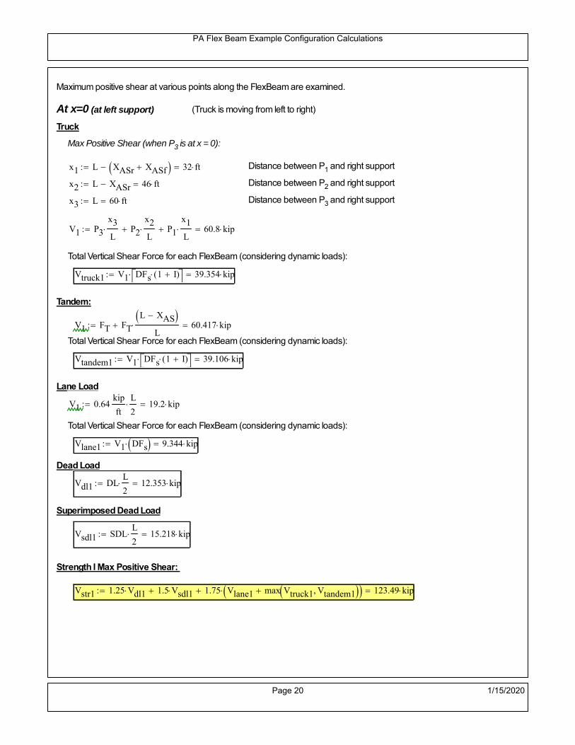
PA Flex Beam Example Configuration Calculations
Maximum positive shear at various points along the FlexBeam are examined.
At x=0 (at left support) (Truck is moving from left to right)
Truck
Max Positive Shear (when P3 is at x = 0):
x1 L XASr XASf 32 ft Distance between P1 and right support
x2 L XASr 46 ft Distance between P2 and right support
x3 L 60 ft Distance between P3 and right support
V1 P3
x3
L P2
x2
L P1
x1
L 60.8 kip
Total Vertical Shear Force for each FlexBeam (considering dynamic loads):
Vtruck1 V1 DFs 1 I( ) 39.354 kip
Tandem:
V1 FT FT
L XAS L
60.417 kip
Total Vertical Shear Force for each FlexBeam (considering dynamic loads):
Vtandem1 V1 DFs 1 I( ) 39.106 kip
Lane Load
V1 0.64kip
ft
L
2 19.2 kip
Total Vertical Shear Force for each FlexBeam (considering dynamic loads):
Vlane1 V1 DFs 9.344 kip
Dead Load
Vdl1 DLL
2 12.353 kip
Superimposed Dead Load
Vsdl1 SDLL
2 15.218 kip
Strength I Max Positive Shear:
Vstr1 1.25 Vdl1 1.5 Vsdl1 1.75 Vlane1 max Vtruck1 Vtandem1 123.49 kip
Page 20 1/15/2020

PA Flex Beam Example Configuration Calculations
Design Permit Load P-82
Shear at x=0
Strength II Max Positive Shear:
VPL82 VPL82span DFs 1 IPL 73.064 kip
STRENGTH II 1.25DL + 1.5SDL + 1.35 (LL+IM)
VstrII_PL 1.25 Vdl1 1.5 Vsdl1 1.35 VPL82 136.905 kip
Max Shear Demand Vu max Vstr1 VstrII_PL 136.905 kip
Determine the Shear Strength of the Web
Shear Strength of Unstiffened web from AASHTO section 6.10.9.2
Depth of Web D d 31 in Thickness of web tw 0.625 in
Transverse Stiffener Spacing d0 0in Shear Buckling Coefficient k 5 6.10.9.3.2-7
Plastic Shear Force Vp 0.58 Fy D tw 561.875 kip Equation 6.10.9.3.2-3
Ratio of Shear-Buckling resistance to shear yield, C
D
tw49.6 1.12
Es k
Fy 60.314 Ccheck
D
tw1.12
Es k
Fy 1 Equation 6.10.9.3.2-4
C 1.0 Ccheck 1 C=1 for most cases, if the criteria are not met, then C will go to zero and the actualcoefficients should be determined
Nominal Shear Resistance of Web Vn C Vp 561.875 kip equation 6.10.9.3.3-1
Shear Resistance Factor φv 1.0
φv Vn 561.875 kip φv Vn Vu 1Reduced Shear Strength
Page 21 1/15/2020

PA Flex Beam Example Configuration Calculations
Check Bearing Stiffeners
FYs 50ksi Yield strength of stiffener
tp 0.75in Thickness of stiffener
bt
bf tw
21.5in 4.188 in Effective width of stiffener
Dst hw 4.1in 26.025 in Depth of stiffeners
Apn 2 tp bt 6.281 in2
Projected area of stiffeners
bt 0.48 tpEs
FYs 1Check that effective width of stiffener meets requirements
Rsbn 1.4 Apn FYs 439.688 kip Bearing capacity of stiffener (phi=1 for bearing per AASHTO 6.5.4.2)
Rsbn Vu 1 Bearing capacity check
Qs 1.0 Q factor for bearing stiffner, taken as 1 (AASHTO 6.9.4.1.1)
Is
18 tw tw3
tp 2 bt 3
1236.943 in
4 Moment of inertia of stiffener and web (9*tw is used on each side)
AASHTO 6.10.11.2.4b
Ag 18 tw tw 2 bt tp 13.313 in2
Gross area of stiffener and web (AASHTO 6.10.11.2.4b)
rs
Is
Ag1.666 in Radius of gyration of stiffener/web
Po Qs FYs Apn 314.062 kip Nominal yeild resistance of stiffener (AASHTO 6.9.4.1.1)
Peπ2Es
0.75 Dst
rs
2Ag 2.775 10
4 kip Elastic critical buckling stress of stiffener (AASHTO 6.9.4.1.2-1)
Check that Pe/Po is great than 0.44 (AASHTO 6.9.4.1.1) PePoPe
Po0.44 1
Pn PePo 0.658
Po
Pe Po 312.579 kip Nominal compressive resistance of stiffener for Pe/Po>0.44
(AASHTO 6.9.4.1.1-1)
φcr 0.95 phi factor for axial compression (AASHTO 6.5.4.2)
Pr φcr Pn 296.95 kip Compressive capacity of bearing stiffener Pr Vu 1
Page 22 1/15/2020

PA Flex Beam Example Configuration Calculations
Flexbeam Example Configuration Calculations
Summary of Calculations:
Input section dimensions and material properties for steel WT and the concrete deck1.Calculate demands (dead load, superimposed dead, and Live load demands for Strength I and Strength II2.Calculate composite section properties for the given section3.Check Strength I, Strength II, and Service II stresses 4.Check Strength I, Strength II, and Strength V moment demands 5.Perform live load deflection check6.Determine maximum shear demand and capacity7.Note: Shear envelope data was obtained from Matlab script (FlexBeam_Moment_ShearEnvelope.m).8.Shear envelope calculations are summarized separately for each design (Shear Design *.xlsx).
Design Assumptions:Design Specifications Used:
AASHTO LRFD Bridge Design Specifications 7th Edition with 2016 Interim RevisionsPennDOT Design Manual, Part 4 (DM-4) June 30, 2015
Example configurations are determined for two girder spacings, 36" and 40".The deck thickness is 7.5" and is assumed to have a non-structural wearing surface added after installation.Section properties are calculated using the full 7.5" deck thickness.The WT sections are embedded 3.5" into the concrete deck. The steel section spacing used is outside the scope of the AASHTO and PennDOT distribution factorequations. The flexural distribution factor is assumed to be 0.3 which was shown to tbe conservativeaccording to refined analysisThe shear distribution factor is calculated using the DM-4 shear distribution factor equation which wasshown to be conservative using refined analysis.Refined analysis is presented in: Zihan Ma, "Distribution Factors for Composite Steel Tee Concrete DeckBridge System," M.S. Thesis, Deparement of Civil and Environmental Engineering, Lehigh University,Bethlehem, 2019Shear and moment demands for the PL82 permit load vehicle are determined by Matlab script(FlexBeam_Moment_ShearEnvelope.m) and are manually input into this calculation sheet.All fabrication will occur as double modules, i.e. each module contains two WT sections. The number ofmodules is half the number of beams, N. A 45 in. tall F-Shape barrier is used, Weight = 700 lb/ft (Distributed to exterior two beams).
The work presented in this document are provided on an “AS IS” basis. University makes no warranties of anykind, express or implied, as to any matter whatsoever, including, without limitation, warranties with respect tothe merchantability or fitness for a particular purpose of this work or any project deliverables. Universitymakes no warranty of any kind with respect to freedom from patent, trademark, copyright or trade secretinfringement arising from the use of the results of the project, deliverables, services, intellectual property orother materials provided hereunder. University shall not be liable for any direct, indirect, consequential,punitive, or other damages suffered by Sponsor or any other person resulting from the project, or the use ofthis work or any project deliverables.
Page 1 1/15/2020

PA Flex Beam Example Configuration Calculations
hf
tf
bf
twh
d
bjtbe
e
Variable Definitions:
Number of beams N 14 modulesN
27
L 60ft Span length
be 38in Effective width of Flexbeamassuming constructed bridge width(i.e. closure joints cast)
Built Up Section Properties
tw 0.625in tf 0.875in bf 12in
h 35in Overall Height of section
hf 7.5in Total thickness of deck
e 3.5in Deck/Steel overlap
d h hf e 31 in depth of built up steel section
hw d tf 30.125 in height of web of built up steel
Moment and shear for permit load PL82 obtained from Matlab script: FlexBeam_Moment_ShearEnvelope
MLL_IM_PL82 523.6917kip ft Moment due to PL82 with distribution factor and impact factor!!
VPL82span 125.11kip Shear due to PL82 WITHOUT distribution factor and impact factor!!
Check web and flange dimensions in sections 6.10.2.1 and 6.10.2.2
(Ignore 6.10.2.2-4 since no compression flange)
equation 6.10.2.1.1-1d
tw150 1 equation 6.10.2.2-1
bf
2 tf12 1
equation 6.10.2.2-2 bfh
6 1 equation 6.10.2.2-3 tf 1.1 tw 1
y_bar
tf bftf
2 hw tw tf
hw
2
tf bf hw tw10.388 in Center of gravity of steel section
Istl
bf tf3
12bf tf y_bar
tf
2
2
tw hw
3
12 tw hw tf
hw
2 y_bar
2
3.044 103
in4
MOI of steel
Astl tf bf hw tw 29.328 in2
Area of the WT steel section
Page 2 1/15/2020

PA Flex Beam Example Configuration Calculations
Material Properties
Elastic Modulus of Steel Es 29000ksi
Yield Strength of Steel Fy 50ksi
Yield Strength of Reinforcement fy 60ksi
Compressive Strength of Concrete fc 4000psi AAAP PennDOT Concrete
Concrete Modular Ratio n 8 modular ratio for 4ksi concrete per AASHTO
Unit weight of concrete slab wc 0.150kip
ft3
Unit weight of concrete
Section Properties
Width of UHPC Joint: bjt 6in
Parapet width: bpar 20.25in Parapet width per PennDOT F-shape barrier
Width of the bridge W be N bjt 526 in W 43.833 ft
Clear width of roadway Wlane W 2 bpar 40.458 ft
Dc wc hf W 4.109kip
ft DL due to slab
Db .700kip
ft DL due to each 45" F-Shape Barrier (per email 11/1/18)
DFWS 30lbf
ft2
W 2 bpar 1.214kip
ft DL due to Future Wearing Surface (FWS)
Ds Astl 490lbf
ft3
0.1kip
ft Selfweight of the steel section
DLself
Dc N
Ds 0.393kip
ft Self-weight per WT
Total weight of each precast FlexBeam for transportation:
Weight of C12x25 Diaphragms Wend_diaphragms 25lbf
ft32 in 0.067 kip
2be bjt hf wc 2Ds L 2 Wend_diaphragms 44.921 kip
Determine number of design lane (AASHTO Section 3.6.1.1.1)
Take the integer part of the ratio of W/12 ft. Number of lanes in bridge: Nl floorWlane
12ft
3
Page 3 1/15/2020

PA Flex Beam Example Configuration Calculations
STEP 1: Compute Dead Load for each Flex Beam
DLslab
Dc
Nwc 1 in
be
2 0.313
kip
ft Dead load of slab assuming exterior overhang has 1" of
additional concrete thickness
DLsteel Ds 0.1kip
ft
DL DLslab DLsteel 0.413kip
ft
STEP 2: Compute Superimposed Dead Load
SDLWS
DFWS
N0.087
kip
ft
SDLparapet
Db
20.35
kip
ft distributed equally on two outer beams
SDLOL 140lbf
ft3be 2 in 0.074
kip
ft Overlay is 2" thick and is 140 lbs/cubic foot
NOTE: For this example barrier load is distributed equally among the two outer beams per conversation withPennDOT and M&M.
PennDOT DM4: "For composite adjacent and spread beams, the barrier (single barrier) load shall be equallydistributed to the nearest three (adjacent) and two (spread) beams, respectively, when the barriers are placedafter slab has hardened".
SDL SDLWS SDLparapet SDLOL 0.511kip
ft
STEP 3: Compute Transformed Width of Slab
For live load and dead load acting on the stringer k1 1 For short-term section property evaluation
btr1
be
k1 n4.75 in Transformed width of slab for short-term
For superimposed dead loads k3 3 For long-term section property evaluation
btr3
be
k3 n1.583 in Transformed width of slab for long-term
Page 4 1/15/2020

PA Flex Beam Example Configuration Calculations
STEP 4: Compute Dead and Superimposed Dead Load Moments(Based on first interior girder demands)
MDLDL L
2
8185.902 kip ft
MSDLSDL L
2
8229.763 kip ft
STEP 5: Compute live load and Dynamic Load Allowance (IM)
Live load wheel load distribution factor (DF):
Sbe
12in3.167 transverse girder spacing
NOTE: AASHTO presents equations to define DF for different types of superstructuresincluding Deck Composite wirh RC slab on steel girders (Type (a) in Table 4.6.2.2.1-1) forshear and moment in interior and exterior beams.
Using DM4 Table 4.6.2.2.2b-1:
eg h y_barhf
2 20.862 in Distance between the centers of gravity of the basic beam and deck
Kg n Istl Astl eg2
1.26 10
5 in
4 Longitudinal stiffness parameter (in4)
Distribution of Live Load Per Lane for Moment in Interior Beams:
to be conservative, use DF 0.3
Page 5 1/15/2020

PA Flex Beam Example Configuration Calculations
Dynamic Load Allowance (Section 3.6.2 DM4)
Static effects of the design truck or tandem, shall be increased by the impact factor.
NOTE: The dynamic load allowance shall not be applied to the design lane load (Section 3.6.2.1 DM4)
I 0.33 Impact factor for moment
Note: PennDOT requires that the impact for decks be increased from 33% to 50%, the deck is not beingdesigned here. Instrad the deck design is based on the BD recommendations.
Dynamic load allowance for the Permit Load P-82 shall be less than 20%. (Section 3.6.2.1DM4)
IPL 0.20 Impact factor for moment on Strength II
Design Wind Loading for Exterior Girder
Vw 80 Wind speed for Strength V load case
CD 1.3 Gust factor for windard side of I-Girder and Box Girder Superstructures (Table 3.8.1.2.1-2)
G 1.0 Gus effect factor is 1.0 for all structures other than sound barriers (Table 3.8.1.2.1-1)
Kz 1.0 Pressure coefficient taken as 1 for Strength V (3.8.1.2.1)
Pz 2.56 106
Vw 2 Kz G CDkip
ft2
0.021kip
ft2
Wind pressure on exterior girder
hexp h hf 27.5 in Exposed height of exterior girder
Moment due to wind loading on exterior girderMWL
Pz hexp L2
821.965 kip ft
Iyy
bf3tf
12126 in
4 Transverse moment of intertia
Flange lateral bending stressfl
MWL
bf
2
Iyy12.551 ksi
Page 6 1/15/2020

PA Flex Beam Example Configuration Calculations
Design Vehicular Live Load
PHL-93 and P-82 are examined herein.
PHL-93 (A3.6.1.2.1)
PHL-93 consists of a combination of (design truck or design tandem) + (design lane load)
Design Truck
PennDOT defines the design truck in accordance with AASTHO 3.6.1.2
Design truck load in AASHTO (HS20 Truck) is used for this example.
NOTE : MAX moment occurs when the center line of the span is midway between the center ofgravity of the loads and the nearest concentrated load.
P1 8kip P2 32kip P3 32kip Axle loads (AASHTO 3.6.1.2.2)
XASr 14ft Rear Axle spacing for truck (14ft - 30ft)
XASf 14ft Front Axle spacing for truck
Page 7 1/15/2020

PA Flex Beam Example Configuration Calculations
Center of gravity (CG) of loads:
X'P1 XASr XASf P2 XASr
P1 P2 P39.333 ft Datum is the rear axle
X XASr X' 4.667 ft Spacing btw CG and nearest load
Find bridge reaction
Truck movestoward Support ARA
P1L
2XASf
X
2
P2L
2
X
2
P3L
2X'
X
2
L33.2 kip
Max live load moment (at the location of P2):
MLL_truck RAL
2
X
2
P1 XASf 806.533 kip ft
NOTE: Find the worst case by varying XASr
Page 8 1/15/2020

PA Flex Beam Example Configuration Calculations
Design Tandem
Consist of a pair of 25-kip axles spaced 4-ft apart. (AASHTO 3.6.1.2.3)
NOTE: PennDOT DM4 increases 25-kip to 31.25-kip.
FT 31.25kip
XAS 4ft Axle spacing
Center of gravity (CG) of loads:
XXAS
22 ft Spacing btw CG and nearest load
Find bridge reaction
RA
FTL
2
X
2
FTL
2
X
2 X
L30.208 kip Truck moves toward Support A
Max live load moment (at the location of front wheel):
MLL_tandem RAL
2
X
2
876.042 kip ft
Choose the max value:
MLL_veh max MLL_tandem MLL_truck 876.042 kip ft
Apply the impact and wheel load distribution:
MLL_IM_veh MLL_veh DF 1 I( ) 349.541 kip ft Due to tandem or truck
Design Lane Load (distributed over a 10-ft width for each lane)
NOTE: The uniform load may be continuous or discontinuous as necessary to produce themaximum force effect. For this example continuous uniform distribution assumed.
FDLL 0.64kip
ftDF 0.192
kip
ft Per beam in each lane
Due to lane loadMLL_IM_lane
FDLL L2
8
86.4 kip ft
Moment due to Total Design Vehicular Live Load: MLL_IM MLL_IM_lane MLL_IM_veh 435.941 kip ft
Page 9 1/15/2020

PA Flex Beam Example Configuration Calculations
Design Permit Load P-82 (Section 3.6.1.2.7 DM4)
P1 P2 P3 P4 P5 P6 P7
NOTE: The moment for the permit load is defined at the beginning of the sheetand is obtained from MATLab File FlexBeam_Moment_ShearEnvelope.m
STEP 6: Compute Moment of Inertia (Note: rebar neglected!)
1) Moment of Inertia resisting dead load only:
a) Acting on the non-composite section (before the deck has hardened - DC1)
Use steel section only
Inc Istl 3.044 103
in4
Non-composite section modulus
Y'nc y_bar S.G. of the steel section of Flex Beam (Datum is bottom)
b) Acting on the composite section (after the deck has hardened - DC2)
Use Ic_short as defined below.
Page 10 1/15/2020

PA Flex Beam Example Configuration Calculations
2) Moment of Inertia resisting live load plus impact:
Using transformed slab with k1=1 (short-term composite).
Actr1 hf btr1 35.625 in2
Itr1
btr1 hf3
12166.992 in
4
Y'
Actr1 hhf
2
Astl Y'nc
Astl Actr121.83 in S.G. of the total flex beam (Datum is bottom)
Compositesection modulus(short-term)
Ic_short Istl Astl Y'nc Y' 2 Itr1 Actr1 hhf
2
Y'
2
10212 in4
Y'c_short Y' 21.83 in N.A. of the short-term composite section
3) Moment of Inertia resisting superimposed dead load:
Using transformed slab with k3=3.
Actr3 hf btr3 11.875 in2
Itr3
btr3 hf3
1255.664 in
4
Y'
Actr3 hhf
2
Astl Y'nc
Astl Actr316.401 in S.G. of the total flex beam (Datum is bottom)
Compositesection modulus(long-term)
Ic_long Istl Astl Y'nc Y' 2 Itr3 Actr3 hhf
2
Y'
2
6778 in4
Y'c_long Y' 16.401 in N.A. of the long-term composite section
Page 11 1/15/2020

PA Flex Beam Example Configuration Calculations
STEP 6.5 Check Ductility RequirementIn accordance with AASHTO Article 6.10.7.3 check ductility requirement. Assume compressionblock of concrete is at 0.85 f'c and that the concrete supports no tension. Steel section isassumed to be fully plastic at Fy.
Case 1 : Assuming PNA is in Concreteh d 4 inAssuming (h-d) < Dp < hf
Fp Dp 0.85 fc be Dp Fy tw Dp h d( ) Fy Astl tw Dp h d( )
Dp 7.5in 0.42 h 14.7 in
Dp1 root Fp Dp Dp 8.954 in Must be less than hf 7.5 inDp1
h0.256 must be < 0.42
Mn1check Dp1 hf h d( ) Dp1[ ] Dp1 0.42 h( ) 0 Dp1 0.42 h 1
Mp1 0.85 fc be Dp1Dp1
2
Fy tw Dp1 h d( )[ ] Dp1 h d( )[ ]
2
Fy bf tf h Dp1tf
2
Fy tw h Dp1 tf h Dp1 tf
2
Mp1 28906.86 kip in Mn1 Mp1 1.07 0.7Dp1
h
25753.9 kip in
Case 2 : Assuming PNA is NOT in Concrete
Assuming hf < Dp
Fp2 Dp 0.85 fc be hf Fy tw Dp h d( ) Fy Astl tw Dp h d( )
Dp 2.5in
Dp2 root Fp2 Dp Dp 11.959 in Must be more than hf 7.5 inDp2
h0.3417 must be < 0.42
Mn2check Dp2 hf Dp2 h( ) Dp2 0.42 h( ) 1 Dp2 0.42 h 1
Mp2 0.85 fc be hf Dp2hf
2
Fy tw Dp2 h d( )[ ] Dp2 h d( )[ ]
2
Fy bf tf h Dp2tf
2
Fy tw h Dp2 tf h Dp2 tf
2
Mp2 28488.19 kip inMn2 Mp2 1.07 0.7
Dp2
h
23668.8 kip in
Mn max Mn1 Mn1check Mn2 Mn2check 1972.4 kip ft Mn 23668.8 kip in
Page 12 1/15/2020

PA Flex Beam Example Configuration Calculations
Check Composite Compact Section Criteria (6.10.6.2)
Dcpd
2
Fy tf bf 0.85 fc be hf
Fy hw tw1
8.19 in Dcp0 Dcp 0 1
Dcp Dcp Dcp0 8.19 in2 Dcp
tw3.76
Es
Fy 1 Check if section is compact
STEP 7: Load Combinations (Table 3.4.1-1)
The following load combinations will be considered herein. Only the maximum load factors forpermanent-loads are used in the following load combinations (uplift is not an issue for this typeof bridge).STRENGTH I 1.25DL + 1.5SDL + 1.75 (LL+IM)
SERVICE II: DL+SDL+1.3(LL+IM)
STEP 8: Compute and Check Stresses
Stress at bottom fiber of steel section
fDL
MDL Y'c_long
Ic_long5.398 ksi
fLL_I
MLL_IM Y'c_short
Ic_short11.183 ksi fPL
MLL_IM_PL82 Y'c_short
Ic_short13.434 ksi
fSDL
MSDL Y'c_long
Ic_long6.671 ksi
STRENGTH I fbot_str1 1.25fDL 1.5 fSDL 1.75 fLL_I 36.324 ksi
STRENGTH II fbot_str2 1.25fDL 1.5 fSDL 1.35 fPL 34.89 ksi
SERVICE II fbot_svc2 fDL fSDL 1.3fLL_I 26.61 ksi
Allowable Stress is based on Section 6.10.4.2.2-2
Flange stress due to service load II without consideration of flange lateral bending: ff fbot_svc2
Flange lateral bending stress due to service II: flSII 0ksi
Hybrid Factor: Rh 1.0 For rolled and homogenous built-up sections
ff
flSII
2 26.607 ksi 0.95 Rh Fy 47.5 ksi ff
fl
2 0.95Rh Fy 1
Page 13 1/15/2020

PA Flex Beam Example Configuration Calculations
Stress at top fiber of concrete
Note: For calculating longitudinal flexural stresses in the concrete deck due to allpermanent and transient loads, the short-term modular ratio shall be used.
fDL
MDL h Y'c_short
k1 n Ic_short0.36 ksi
fLL_I
MLL_IM h Y'c_short
k1 n Ic_short0.843 ksi fPL
MLL_IM_PL82 h Y'c_short
k1 n Ic_short1.013 ksi
fSDL
MSDL h Y'c_short
k1 n Ic_short0.444 ksi
STRENGTH I fc_str1 1.25fDL 1.5 fSDL 1.75 fLL_I 2.592 ksi
Mstr1 1.25 MDL 1.5 MSDL 1.75 MLL_IM 1339.9 kip ft Mstr1 Mn 1
STRENGTH II fc_str2 1.25fDL 1.5 fSDL 1.35 fPL 2.484 ksi
Mstr2 1.25 MDL 1.5 MSDL 1.35 MLL_IM_PL82 1284 kip ft Mstr2 Mn 1
SERVICE II
Allowable Stress in concrete - AASHTO 6.10.4.2.2For compact composite sections in positive flexure utilized in shored construction, the longitudinalcompressive stress in the concrete deck due to the Service II loads, determined as specified in Article6.10.1.1.1d, shall not exceed 0.6f́ c.
fallow 0.6 fc 2400 psi
fc_2 1.3fLL_I fSDL fDL 1900.42 psi This assumes short term compositesection for all calculations
fc_2 fallow 1
SERVICE II with Long Term Composite for dead loads
fDL
MDL h Y'c_long
k3 n Ic_long0.255 ksi
fLL_I
MLL_IM h Y'c_short
k1 n Ic_short0.843 ksi
fSDL
MSDL h Y'c_long
k3 n Ic_long0.315 ksi
fc_2 1.3fLL_I fSDL fDL 1666.59 psi fc_2 fallow 1
Page 14 1/15/2020
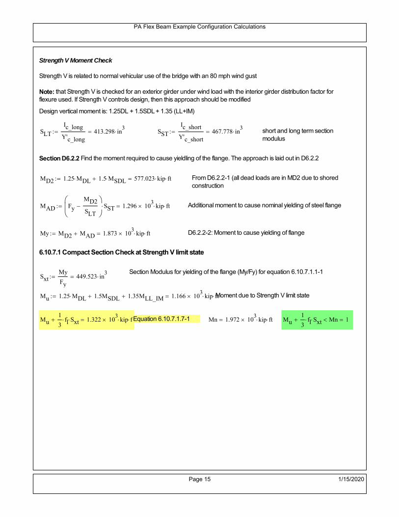
PA Flex Beam Example Configuration Calculations
Strength V Moment Check
Strength V is related to normal vehicular use of the bridge with an 80 mph wind gust
Note: that Strength V is checked for an exterior girder under wind load with the interior girder distribution factor forflexure used. If Strength V controls design, then this approach should be modified
Design vertical moment is: 1.25DL + 1.5SDL + 1.35 (LL+IM)
SLT
Ic_long
Y'c_long413.298 in
3 SST
Ic_short
Y'c_short467.778 in
3 short and long term section
modulus
Section D6.2.2 Find the moment required to cause yieldling of the flange. The approach is laid out in D6.2.2
MD2 1.25 MDL 1.5 MSDL 577.023 kip ft From D6.2.2-1 (all dead loads are in MD2 due to shoredconstruction
MAD Fy
MD2
SLT
SST 1.296 10
3 kip ft Additional moment to cause nominal yielding of steel flange
My MD2 MAD 1.873 103
kip ft D6.2.2-2: Moment to cause yielding of flange
6.10.7.1 Compact Section Check at Strength V limit state
Section Modulus for yielding of the flange (My/Fy) for equation 6.10.7.1.1-1Sxt
My
Fy449.523 in
3
Mu 1.25 MDL 1.5MSDL 1.35MLL_IM 1.166 103
kip ft Moment due to Strength V limit state
Mu1
3fl Sxt 1.322 10
3 kip ft Equation 6.10.7.1.7-1 Mn 1.972 10
3 kip ft Mu
1
3fl Sxt Mn 1
Page 15 1/15/2020

PA Flex Beam Example Configuration Calculations
STEP 9: Compute Deflection
Optional Live Load Deflection Evaluation (AASHTO 3.6.1.3.2)
Deflection distribution factor for vehicular loads: For a straight multibeambridge, this is equivalent to saying that the distribution factor for deflectionis equal to the number of lanes divided by the number of beams. 2.5.2.6.2
DFd
Nl
N0.214
Deflection should be taken as 125% the larger of:- Design truck- 25% of design truck + design lane
The live load portion of Load Combination Service I of Table 3.4.1-1 should be used,including the dynamic load allowance, IM;
Deflection due to design truck load
NOTE : Assuming maximum deflection occurs when the center of gravity of the loads is at thecenter line of the span.
P1 8kip P2 32kip P3 32kip Axle loads (AASHTO 3.6.1.2.2)
XASr 14ft Rear Axle spacing for truck (14ft - 30ft)
XASf 14ft Front Axle spacing for truck
Center of gravity (CG) of loads:
X'P1 XASr XASf P2 XASr
P1 P2 P39.333 ft Datum is the rear axle
Method1: Assuming single load = P1+P2+P3 at the midspan (Conservative approach)
P1 P2 P3 L3
48 Es Ic_short 1.891 in
Method2: Calculation of Midspan deflection using superposition
b1L
2XASr X' XASf 11.333 ft distance btw load P1 and support A b1check b1 0 1
b2L
2XASr X' 25.333 ft distance btw load P2 and support A b2check b2 0 1
b3L
2X' 20.667 ft distance btw load P3 and support B b3check b3 0 1
Page 16 1/15/2020

PA Flex Beam Example Configuration Calculations
Deflection of the beam at midspan due to P1: P P1
xL
2 at midspan b b1 b1check The smallest distance btw load P1 and support
Δ1P b x
6 Es Ic_short LL2
b2
x2
0.113 in
Deflection of the beam at midspan due to P2: P P2
xL
2 at midspan b b2 b2check The smallest distance btw load P2 and support
Δ2P b x
6 Es Ic_short LL2
b2
x2
0.811 in
Deflection of the beam at midspan due to P3: P P3
xL
2 at midspan b b3 b3check The smallest distance btw load P3 and support
Δ3P b x
6 Es Ic_short LL2
b2
x2
0.731 in
Total Deflection at midspan:
Δtruck Δ1 Δ2 Δ3( ) DFd 1 I( ) 0.472 in (Considering IM)
Deflection due to tandem (Note: this calculation is not required according to Article3.6.1.3.2 which denotes only the design truck for deflection calculation)
Page 17 1/15/2020

PA Flex Beam Example Configuration Calculations
FT 31.25 kip Per axle
XAS 4ft Axle spacing
Δtandem
FTL
2
XAS
2
24 Es Ic_short3 L
2 4
L
2
XAS
2
2
DFd 1 I( ) 0.465 in (Considering IM)
Deflection due to lane load
FDLLd 640lbf
ft DFd 137.143
lbf
ft
Δlane
5 FDLLd L4
384 Es Ic_short0.135 in
Live Load Deflection:
ΔLL 1.25max Δtruck 0.25Δtruck Δlane 1.25 0.737 in ΔLLL
800 1
Deflection Limit
For steel or concrete vehicular bridges:
Vehicular load = Span/800L
8000.9 in
L
10000.72 in
Evaluation of Deflection at the Service Limit State (AASHTO 3.4.2.2)
The associated permitted deflections shall be included in the contract documents.
Page 18 1/15/2020

PA Flex Beam Example Configuration Calculations
Shear demands:
Determination of the distribution factor
Using DM4 Table 4.6.2.2.3a-1
Sbe
12in3.167 transverse girder spacing (ft)
Distribution of live loads per lane for shear in interior beams:
For two design lanes loaded, 3.5' <= S =< 16', number of beam >= 4DFs 0.36
S
25 0.487
Q Actr1 h Y'c_shorthf
2
335.576 in3
first moment of deck slab for interface shear
Method 1: Range of shear based on Strength I Limit
STRENGTH I 1.25DL + 1.5SDL + 1.75 (LL+IM)
Computation of the range of shear in the beam
Dead Load:DL 0.413
kip
ft
Superimposed Dead Load: SDL 0.511kip
ft
Design Lane Load: 0.64kip
ft
Design Truck:
XASr 14ft Rear Axle spacing for truck (14ft - 30ft)
XASf 14ft Front Axle spacing for truck
P1 8 kip P2 32 kip P3 32 kip Wheel loads (AASHTO 3.6.1.2.2)
Design Tandem:
Consist of a pair of 25-kip axles spaced 4-ft apart. (AASHTO 3.6.1.2.3)
NOTE: PennDOT DM4 increases 25-kip to 31.25-kip.
FT 31.25kip
XAS 4ft Axle spacing
Page 19 1/15/2020

PA Flex Beam Example Configuration Calculations
Maximum positive shear at various points along the FlexBeam are examined.
At x=0 (at left support) (Truck is moving from left to right)
Truck
Max Positive Shear (when P3 is at x = 0):
x1 L XASr XASf 32 ft Distance between P1 and right support
x2 L XASr 46 ft Distance between P2 and right support
x3 L 60 ft Distance between P3 and right support
V1 P3
x3
L P2
x2
L P1
x1
L 60.8 kip
Total Vertical Shear Force for each FlexBeam (considering dynamic loads):
Vtruck1 V1 DFs 1 I( ) 39.354 kip
Tandem:
V1 FT FT
L XAS L
60.417 kip
Total Vertical Shear Force for each FlexBeam (considering dynamic loads):
Vtandem1 V1 DFs 1 I( ) 39.106 kip
Lane Load
V1 0.64kip
ft
L
2 19.2 kip
Total Vertical Shear Force for each FlexBeam (considering dynamic loads):
Vlane1 V1 DFs 9.344 kip
Dead Load
Vdl1 DLL
2 12.393 kip
Superimposed Dead Load
Vsdl1 SDLL
2 15.318 kip
Strength I Max Positive Shear:
Vstr1 1.25 Vdl1 1.5 Vsdl1 1.75 Vlane1 max Vtruck1 Vtandem1 123.689 kip
Page 20 1/15/2020

PA Flex Beam Example Configuration Calculations
Design Permit Load P-82
Shear at x=0
Strength II Max Positive Shear:
VPL82 VPL82span DFs 1 IPL 73.064 kip
STRENGTH II 1.25DL + 1.5SDL + 1.35 (LL+IM)
VstrII_PL 1.25 Vdl1 1.5 Vsdl1 1.35 VPL82 137.105 kip
Max Shear Demand Vu max Vstr1 VstrII_PL 137.105 kip
Determine the Shear Strength of the Web
Shear Strength of Unstiffened web from AASHTO section 6.10.9.2
Depth of Web D d 31 in Thickness of web tw 0.625 in
Transverse Stiffener Spacing d0 0in Shear Buckling Coefficient k 5 6.10.9.3.2-7
Plastic Shear Force Vp 0.58 Fy D tw 561.875 kip Equation 6.10.9.3.2-3
Ratio of Shear-Buckling resistance to shear yield, C
D
tw49.6 1.12
Es k
Fy 60.314 Ccheck
D
tw1.12
Es k
Fy 1 Equation 6.10.9.3.2-4
C 1.0 Ccheck 1 C=1 for most cases, if the criteria are not met, then C will go to zero and the actualcoefficients should be determined
Nominal Shear Resistance of Web Vn C Vp 561.875 kip equation 6.10.9.3.3-1
Shear Resistance Factor φv 1.0
φv Vn 561.875 kip φv Vn Vu 1Reduced Shear Strength
Page 21 1/15/2020

PA Flex Beam Example Configuration Calculations
Check Bearing Stiffeners
FYs 50ksi Yield strength of stiffener
tp 0.75in Thickness of stiffener
bt
bf tw
21.5in 4.188 in Effective width of stiffener
Dst hw 4.1in 26.025 in Depth of stiffeners
Apn 2 tp bt 6.281 in2
Projected area of stiffeners
bt 0.48 tpEs
FYs 1Check that effective width of stiffener meets requirements
Rsbn 1.4 Apn FYs 439.688 kip Bearing capacity of stiffener (phi=1 for bearing per AASHTO 6.5.4.2)
Rsbn Vu 1 Bearing capacity check
Qs 1.0 Q factor for bearing stiffner, taken as 1 (AASHTO 6.9.4.1.1)
Is
18 tw tw3
tp 2 bt 3
1236.943 in
4 Moment of inertia of stiffener and web (9*tw is used on each side)
AASHTO 6.10.11.2.4b
Ag 18 tw tw 2 bt tp 13.313 in2
Gross area of stiffener and web (AASHTO 6.10.11.2.4b)
rs
Is
Ag1.666 in Radius of gyration of stiffener/web
Po Qs FYs Apn 314.062 kip Nominal yeild resistance of stiffener (AASHTO 6.9.4.1.1)
Peπ2Es
0.75 Dst
rs
2Ag 2.775 10
4 kip Elastic critical buckling stress of stiffener (AASHTO 6.9.4.1.2-1)
Check that Pe/Po is great than 0.44 (AASHTO 6.9.4.1.1) PePoPe
Po0.44 1
Pn PePo 0.658
Po
Pe Po 312.579 kip Nominal compressive resistance of stiffener for Pe/Po>0.44
(AASHTO 6.9.4.1.1-1)
φcr 0.95 phi factor for axial compression (AASHTO 6.5.4.2)
Pr φcr Pn 296.95 kip Compressive capacity of bearing stiffener Pr Vu 1
Page 22 1/15/2020

PA Flex Beam Example Configuration Calculations
Flexbeam Example Configuration Calculations
Summary of Calculations:
Input section dimensions and material properties for steel WT and the concrete deck1.Calculate demands (dead load, superimposed dead, and Live load demands for Strength I and Strength II2.Calculate composite section properties for the given section3.Check Strength I, Strength II, and Service II stresses 4.Check Strength I, Strength II, and Strength V moment demands 5.Perform live load deflection check6.Determine maximum shear demand and capacity7.Note: Shear envelope data was obtained from Matlab script (FlexBeam_Moment_ShearEnvelope.m).8.Shear envelope calculations are summarized separately for each design (Shear Design *.xlsx).
Design Assumptions:Design Specifications Used:
AASHTO LRFD Bridge Design Specifications 7th Edition with 2016 Interim RevisionsPennDOT Design Manual, Part 4 (DM-4) June 30, 2015
Example configurations are determined for two girder spacings, 36" and 40".The deck thickness is 7.5" and is assumed to have a non-structural wearing surface added after installation.Section properties are calculated using the full 7.5" deck thickness.The WT sections are embedded 3.5" into the concrete deck. The steel section spacing used is outside the scope of the AASHTO and PennDOT distribution factorequations. The flexural distribution factor is assumed to be 0.3 which was shown to tbe conservativeaccording to refined analysisThe shear distribution factor is calculated using the DM-4 shear distribution factor equation which wasshown to be conservative using refined analysis.Refined analysis is presented in: Zihan Ma, "Distribution Factors for Composite Steel Tee Concrete DeckBridge System," M.S. Thesis, Deparement of Civil and Environmental Engineering, Lehigh University,Bethlehem, 2019Shear and moment demands for the PL82 permit load vehicle are determined by Matlab script(FlexBeam_Moment_ShearEnvelope.m) and are manually input into this calculation sheet.All fabrication will occur as double modules, i.e. each module contains two WT sections. The number ofmodules is half the number of beams, N. A 45 in. tall F-Shape barrier is used, Weight = 700 lb/ft (Distributed to exterior two beams).
The work presented in this document are provided on an “AS IS” basis. University makes no warranties of anykind, express or implied, as to any matter whatsoever, including, without limitation, warranties with respect tothe merchantability or fitness for a particular purpose of this work or any project deliverables. Universitymakes no warranty of any kind with respect to freedom from patent, trademark, copyright or trade secretinfringement arising from the use of the results of the project, deliverables, services, intellectual property orother materials provided hereunder. University shall not be liable for any direct, indirect, consequential,punitive, or other damages suffered by Sponsor or any other person resulting from the project, or the use ofthis work or any project deliverables.
Page 1 1/15/2020
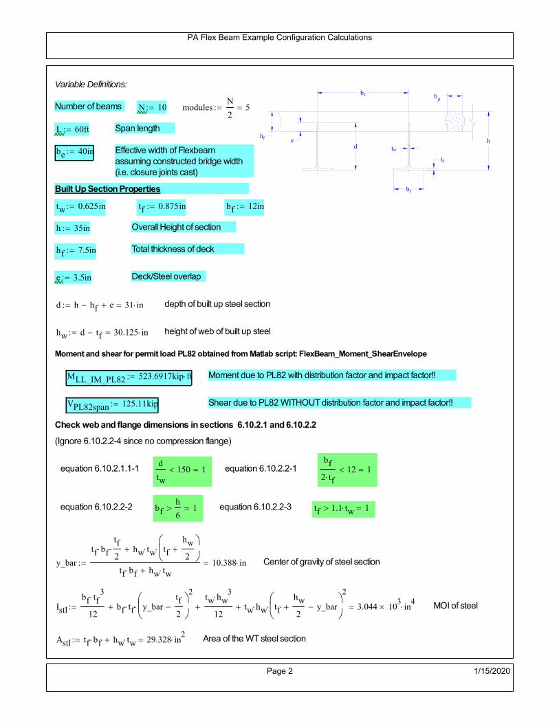
PA Flex Beam Example Configuration Calculations
hf
tf
bf
twh
d
bjtbe
e
Variable Definitions:
Number of beams N 10 modulesN
25
L 60ft Span length
be 40in Effective width of Flexbeamassuming constructed bridge width(i.e. closure joints cast)
Built Up Section Properties
tw 0.625in tf 0.875in bf 12in
h 35in Overall Height of section
hf 7.5in Total thickness of deck
e 3.5in Deck/Steel overlap
d h hf e 31 in depth of built up steel section
hw d tf 30.125 in height of web of built up steel
Moment and shear for permit load PL82 obtained from Matlab script: FlexBeam_Moment_ShearEnvelope
MLL_IM_PL82 523.6917kip ft Moment due to PL82 with distribution factor and impact factor!!
VPL82span 125.11kip Shear due to PL82 WITHOUT distribution factor and impact factor!!
Check web and flange dimensions in sections 6.10.2.1 and 6.10.2.2
(Ignore 6.10.2.2-4 since no compression flange)
equation 6.10.2.1.1-1d
tw150 1 equation 6.10.2.2-1
bf
2 tf12 1
equation 6.10.2.2-2 bfh
6 1 equation 6.10.2.2-3 tf 1.1 tw 1
y_bar
tf bftf
2 hw tw tf
hw
2
tf bf hw tw10.388 in Center of gravity of steel section
Istl
bf tf3
12bf tf y_bar
tf
2
2
tw hw
3
12 tw hw tf
hw
2 y_bar
2
3.044 103
in4
MOI of steel
Astl tf bf hw tw 29.328 in2
Area of the WT steel section
Page 2 1/15/2020

PA Flex Beam Example Configuration Calculations
Material Properties
Elastic Modulus of Steel Es 29000ksi
Yield Strength of Steel Fy 50ksi
Yield Strength of Reinforcement fy 60ksi
Compressive Strength of Concrete fc 4000psi AAAP PennDOT Concrete
Concrete Modular Ratio n 8 modular ratio for 4ksi concrete per AASHTO
Unit weight of concrete slab wc 0.150kip
ft3
Unit weight of concrete
Section Properties
Width of UHPC Joint: bjt 6in
Parapet width: bpar 20.25in Parapet width per PennDOT F-shape barrier
Width of the bridge W be N bjt 394 in W 32.833 ft
Clear width of roadway Wlane W 2 bpar 29.458 ft
Dc wc hf W 3.078kip
ft DL due to slab
Db .700kip
ft DL due to each 45" F-Shape Barrier (per email 11/1/18)
DFWS 30lbf
ft2
W 2 bpar 0.884kip
ft DL due to Future Wearing Surface (FWS)
Ds Astl 490lbf
ft3
0.1kip
ft Selfweight of the steel section
DLself
Dc N
Ds 0.408kip
ft Self-weight per WT
Total weight of each precast FlexBeam for transportation:
Weight of C12x25 Diaphragms Wend_diaphragms 25lbf
ft32 in 0.067 kip
2be bjt hf wc 2Ds L 2 Wend_diaphragms 46.796 kip
Determine number of design lane (AASHTO Section 3.6.1.1.1)
Take the integer part of the ratio of W/12 ft. Number of lanes in bridge: Nl floorWlane
12ft
2
Page 3 1/15/2020

PA Flex Beam Example Configuration Calculations
STEP 1: Compute Dead Load for each Flex Beam
DLslab
Dc
Nwc 1 in
be
2 0.329
kip
ft Dead load of slab assuming exterior overhang has 1" of
additional concrete thickness
DLsteel Ds 0.1kip
ft
DL DLslab DLsteel 0.428kip
ft
STEP 2: Compute Superimposed Dead Load
SDLWS
DFWS
N0.088
kip
ft
SDLparapet
Db
20.35
kip
ft distributed equally on two outer beams
SDLOL 140lbf
ft3be 2 in 0.078
kip
ft Overlay is 2" thick and is 140 lbs/cubic foot
NOTE: For this example barrier load is distributed equally among the two outer beams per conversation withPennDOT and M&M.
PennDOT DM4: "For composite adjacent and spread beams, the barrier (single barrier) load shall be equallydistributed to the nearest three (adjacent) and two (spread) beams, respectively, when the barriers are placedafter slab has hardened".
SDL SDLWS SDLparapet SDLOL 0.516kip
ft
STEP 3: Compute Transformed Width of Slab
For live load and dead load acting on the stringer k1 1 For short-term section property evaluation
btr1
be
k1 n5 in Transformed width of slab for short-term
For superimposed dead loads k3 3 For long-term section property evaluation
btr3
be
k3 n1.667 in Transformed width of slab for long-term
Page 4 1/15/2020

PA Flex Beam Example Configuration Calculations
STEP 4: Compute Dead and Superimposed Dead Load Moments(Based on first interior girder demands)
MDLDL L
2
8192.799 kip ft
MSDLSDL L
2
8232.269 kip ft
STEP 5: Compute live load and Dynamic Load Allowance (IM)
Live load wheel load distribution factor (DF):
Sbe
12in3.333 transverse girder spacing
NOTE: AASHTO presents equations to define DF for different types of superstructuresincluding Deck Composite wirh RC slab on steel girders (Type (a) in Table 4.6.2.2.1-1) forshear and moment in interior and exterior beams.
Using DM4 Table 4.6.2.2.2b-1:
eg h y_barhf
2 20.862 in Distance between the centers of gravity of the basic beam and deck
Kg n Istl Astl eg2
1.26 10
5 in
4 Longitudinal stiffness parameter (in4)
Distribution of Live Load Per Lane for Moment in Interior Beams:
to be conservative, use DF 0.3
Page 5 1/15/2020

PA Flex Beam Example Configuration Calculations
Dynamic Load Allowance (Section 3.6.2 DM4)
Static effects of the design truck or tandem, shall be increased by the impact factor.
NOTE: The dynamic load allowance shall not be applied to the design lane load (Section 3.6.2.1 DM4)
I 0.33 Impact factor for moment
Note: PennDOT requires that the impact for decks be increased from 33% to 50%, the deck is not beingdesigned here. Instrad the deck design is based on the BD recommendations.
Dynamic load allowance for the Permit Load P-82 shall be less than 20%. (Section 3.6.2.1DM4)
IPL 0.20 Impact factor for moment on Strength II
Design Wind Loading for Exterior Girder
Vw 80 Wind speed for Strength V load case
CD 1.3 Gust factor for windard side of I-Girder and Box Girder Superstructures (Table 3.8.1.2.1-2)
G 1.0 Gus effect factor is 1.0 for all structures other than sound barriers (Table 3.8.1.2.1-1)
Kz 1.0 Pressure coefficient taken as 1 for Strength V (3.8.1.2.1)
Pz 2.56 106
Vw 2 Kz G CDkip
ft2
0.021kip
ft2
Wind pressure on exterior girder
hexp h hf 27.5 in Exposed height of exterior girder
Moment due to wind loading on exterior girderMWL
Pz hexp L2
821.965 kip ft
Iyy
bf3tf
12126 in
4 Transverse moment of intertia
Flange lateral bending stressfl
MWL
bf
2
Iyy12.551 ksi
Page 6 1/15/2020

PA Flex Beam Example Configuration Calculations
Design Vehicular Live Load
PHL-93 and P-82 are examined herein.
PHL-93 (A3.6.1.2.1)
PHL-93 consists of a combination of (design truck or design tandem) + (design lane load)
Design Truck
PennDOT defines the design truck in accordance with AASTHO 3.6.1.2
Design truck load in AASHTO (HS20 Truck) is used for this example.
NOTE : MAX moment occurs when the center line of the span is midway between the center ofgravity of the loads and the nearest concentrated load.
P1 8kip P2 32kip P3 32kip Axle loads (AASHTO 3.6.1.2.2)
XASr 14ft Rear Axle spacing for truck (14ft - 30ft)
XASf 14ft Front Axle spacing for truck
Page 7 1/15/2020

PA Flex Beam Example Configuration Calculations
Center of gravity (CG) of loads:
X'P1 XASr XASf P2 XASr
P1 P2 P39.333 ft Datum is the rear axle
X XASr X' 4.667 ft Spacing btw CG and nearest load
Find bridge reaction
Truck movestoward Support ARA
P1L
2XASf
X
2
P2L
2
X
2
P3L
2X'
X
2
L33.2 kip
Max live load moment (at the location of P2):
MLL_truck RAL
2
X
2
P1 XASf 806.533 kip ft
NOTE: Find the worst case by varying XASr
Page 8 1/15/2020

PA Flex Beam Example Configuration Calculations
Design Tandem
Consist of a pair of 25-kip axles spaced 4-ft apart. (AASHTO 3.6.1.2.3)
NOTE: PennDOT DM4 increases 25-kip to 31.25-kip.
FT 31.25kip
XAS 4ft Axle spacing
Center of gravity (CG) of loads:
XXAS
22 ft Spacing btw CG and nearest load
Find bridge reaction
RA
FTL
2
X
2
FTL
2
X
2 X
L30.208 kip Truck moves toward Support A
Max live load moment (at the location of front wheel):
MLL_tandem RAL
2
X
2
876.042 kip ft
Choose the max value:
MLL_veh max MLL_tandem MLL_truck 876.042 kip ft
Apply the impact and wheel load distribution:
MLL_IM_veh MLL_veh DF 1 I( ) 349.541 kip ft Due to tandem or truck
Design Lane Load (distributed over a 10-ft width for each lane)
NOTE: The uniform load may be continuous or discontinuous as necessary to produce themaximum force effect. For this example continuous uniform distribution assumed.
FDLL 0.64kip
ftDF 0.192
kip
ft Per beam in each lane
Due to lane loadMLL_IM_lane
FDLL L2
8
86.4 kip ft
Moment due to Total Design Vehicular Live Load: MLL_IM MLL_IM_lane MLL_IM_veh 435.941 kip ft
Page 9 1/15/2020

PA Flex Beam Example Configuration Calculations
Design Permit Load P-82 (Section 3.6.1.2.7 DM4)
P1 P2 P3 P4 P5 P6 P7
NOTE: The moment for the permit load is defined at the beginning of the sheetand is obtained from MATLab File FlexBeam_Moment_ShearEnvelope.m
STEP 6: Compute Moment of Inertia (Note: rebar neglected!)
1) Moment of Inertia resisting dead load only:
a) Acting on the non-composite section (before the deck has hardened - DC1)
Use steel section only
Inc Istl 3.044 103
in4
Non-composite section modulus
Y'nc y_bar S.G. of the steel section of Flex Beam (Datum is bottom)
b) Acting on the composite section (after the deck has hardened - DC2)
Use Ic_short as defined below.
Page 10 1/15/2020

PA Flex Beam Example Configuration Calculations
2) Moment of Inertia resisting live load plus impact:
Using transformed slab with k1=1 (short-term composite).
Actr1 hf btr1 37.5 in2
Itr1
btr1 hf3
12175.781 in
4
Y'
Actr1 hhf
2
Astl Y'nc
Astl Actr122.095 in S.G. of the total flex beam (Datum is bottom)
Compositesection modulus(short-term)
Ic_short Istl Astl Y'nc Y' 2 Itr1 Actr1 hhf
2
Y'
2
10382 in4
Y'c_short Y' 22.095 in N.A. of the short-term composite section
3) Moment of Inertia resisting superimposed dead load:
Using transformed slab with k3=3.
Actr3 hf btr3 12.5 in2
Itr3
btr3 hf3
1258.594 in
4
Y'
Actr3 hhf
2
Astl Y'nc
Astl Actr316.623 in S.G. of the total flex beam (Datum is bottom)
Compositesection modulus(long-term)
Ic_long Istl Astl Y'nc Y' 2 Itr3 Actr3 hhf
2
Y'
2
6917 in4
Y'c_long Y' 16.623 in N.A. of the long-term composite section
Page 11 1/15/2020

PA Flex Beam Example Configuration Calculations
STEP 6.5 Check Ductility RequirementIn accordance with AASHTO Article 6.10.7.3 check ductility requirement. Assume compressionblock of concrete is at 0.85 f'c and that the concrete supports no tension. Steel section isassumed to be fully plastic at Fy.
Case 1 : Assuming PNA is in Concreteh d 4 inAssuming (h-d) < Dp < hf
Fp Dp 0.85 fc be Dp Fy tw Dp h d( ) Fy Astl tw Dp h d( )
Dp 7.5in 0.42 h 14.7 in
Dp1 root Fp Dp Dp 8.647 in Must be less than hf 7.5 inDp1
h0.247 must be < 0.42
Mn1check Dp1 hf h d( ) Dp1[ ] Dp1 0.42 h( ) 0 Dp1 0.42 h 1
Mp1 0.85 fc be Dp1Dp1
2
Fy tw Dp1 h d( )[ ] Dp1 h d( )[ ]
2
Fy bf tf h Dp1tf
2
Fy tw h Dp1 tf h Dp1 tf
2
Mp1 29170.09 kip in Mn1 Mp1 1.07 0.7Dp1
h
26167.4 kip in
Case 2 : Assuming PNA is NOT in Concrete
Assuming hf < Dp
Fp2 Dp 0.85 fc be hf Fy tw Dp h d( ) Fy Astl tw Dp h d( )
Dp 2.5in
Dp2 root Fp2 Dp Dp 11.143 in Must be more than hf 7.5 inDp2
h0.3184 must be < 0.42
Mn2check Dp2 hf Dp2 h( ) Dp2 0.42 h( ) 1 Dp2 0.42 h 1
Mp2 0.85 fc be hf Dp2hf
2
Fy tw Dp2 h d( )[ ] Dp2 h d( )[ ]
2
Fy bf tf h Dp2tf
2
Fy tw h Dp2 tf h Dp2 tf
2
Mp2 28886.02 kip inMn2 Mp2 1.07 0.7
Dp2
h
24470.8 kip in
Mn max Mn1 Mn1check Mn2 Mn2check 2039.2 kip ft Mn 24470.8 kip in
Page 12 1/15/2020

PA Flex Beam Example Configuration Calculations
Check Composite Compact Section Criteria (6.10.6.2)
Dcpd
2
Fy tf bf 0.85 fc be hf
Fy hw tw1
7.35 in Dcp0 Dcp 0 1
Dcp Dcp Dcp0 7.35 in2 Dcp
tw3.76
Es
Fy 1 Check if section is compact
STEP 7: Load Combinations (Table 3.4.1-1)
The following load combinations will be considered herein. Only the maximum load factors forpermanent-loads are used in the following load combinations (uplift is not an issue for this typeof bridge).STRENGTH I 1.25DL + 1.5SDL + 1.75 (LL+IM)
SERVICE II: DL+SDL+1.3(LL+IM)
STEP 8: Compute and Check Stresses
Stress at bottom fiber of steel section
fDL
MDL Y'c_long
Ic_long5.56 ksi
fLL_I
MLL_IM Y'c_short
Ic_short11.133 ksi fPL
MLL_IM_PL82 Y'c_short
Ic_short13.374 ksi
fSDL
MSDL Y'c_long
Ic_long6.698 ksi
STRENGTH I fbot_str1 1.25fDL 1.5 fSDL 1.75 fLL_I 36.479 ksi
STRENGTH II fbot_str2 1.25fDL 1.5 fSDL 1.35 fPL 35.051 ksi
SERVICE II fbot_svc2 fDL fSDL 1.3fLL_I 26.73 ksi
Allowable Stress is based on Section 6.10.4.2.2-2
Flange stress due to service load II without consideration of flange lateral bending: ff fbot_svc2
Flange lateral bending stress due to service II: flSII 0ksi
Hybrid Factor: Rh 1.0 For rolled and homogenous built-up sections
ff
flSII
2 26.731 ksi 0.95 Rh Fy 47.5 ksi ff
fl
2 0.95Rh Fy 1
Page 13 1/15/2020

PA Flex Beam Example Configuration Calculations
Stress at top fiber of concrete
Note: For calculating longitudinal flexural stresses in the concrete deck due to allpermanent and transient loads, the short-term modular ratio shall be used.
fDL
MDL h Y'c_short
k1 n Ic_short0.359 ksi
fLL_I
MLL_IM h Y'c_short
k1 n Ic_short0.813 ksi fPL
MLL_IM_PL82 h Y'c_short
k1 n Ic_short0.976 ksi
fSDL
MSDL h Y'c_short
k1 n Ic_short0.433 ksi
STRENGTH I fc_str1 1.25fDL 1.5 fSDL 1.75 fLL_I 2.521 ksi
Mstr1 1.25 MDL 1.5 MSDL 1.75 MLL_IM 1352.3 kip ft Mstr1 Mn 1
STRENGTH II fc_str2 1.25fDL 1.5 fSDL 1.35 fPL 2.417 ksi
Mstr2 1.25 MDL 1.5 MSDL 1.35 MLL_IM_PL82 1296 kip ft Mstr2 Mn 1
SERVICE II
Allowable Stress in concrete - AASHTO 6.10.4.2.2For compact composite sections in positive flexure utilized in shored construction, the longitudinalcompressive stress in the concrete deck due to the Service II loads, determined as specified in Article6.10.1.1.1d, shall not exceed 0.6f́ c.
fallow 0.6 fc 2400 psi
fc_2 1.3fLL_I fSDL fDL 1849.23 psi This assumes short term compositesection for all calculations
fc_2 fallow 1
SERVICE II with Long Term Composite for dead loads
fDL
MDL h Y'c_long
k3 n Ic_long0.256 ksi
fLL_I
MLL_IM h Y'c_short
k1 n Ic_short0.813 ksi
fSDL
MSDL h Y'c_long
k3 n Ic_long0.309 ksi
fc_2 1.3fLL_I fSDL fDL 1621.34 psi fc_2 fallow 1
Page 14 1/15/2020

PA Flex Beam Example Configuration Calculations
Strength V Moment Check
Strength V is related to normal vehicular use of the bridge with an 80 mph wind gust
Note: that Strength V is checked for an exterior girder under wind load with the interior girder distribution factor forflexure used. If Strength V controls design, then this approach should be modified
Design vertical moment is: 1.25DL + 1.5SDL + 1.35 (LL+IM)
SLT
Ic_long
Y'c_long416.124 in
3 SST
Ic_short
Y'c_short469.899 in
3 short and long term section
modulus
Section D6.2.2 Find the moment required to cause yieldling of the flange. The approach is laid out in D6.2.2
MD2 1.25 MDL 1.5 MSDL 589.402 kip ft From D6.2.2-1 (all dead loads are in MD2 due to shoredconstruction
MAD Fy
MD2
SLT
SST 1.292 10
3 kip ft Additional moment to cause nominal yielding of steel flange
My MD2 MAD 1.882 103
kip ft D6.2.2-2: Moment to cause yielding of flange
6.10.7.1 Compact Section Check at Strength V limit state
Section Modulus for yielding of the flange (My/Fy) for equation 6.10.7.1.1-1Sxt
My
Fy451.619 in
3
Mu 1.25 MDL 1.5MSDL 1.35MLL_IM 1.178 103
kip ft Moment due to Strength V limit state
Mu1
3fl Sxt 1.335 10
3 kip ft Equation 6.10.7.1.7-1 Mn 2.039 10
3 kip ft Mu
1
3fl Sxt Mn 1
Page 15 1/15/2020

PA Flex Beam Example Configuration Calculations
STEP 9: Compute Deflection
Optional Live Load Deflection Evaluation (AASHTO 3.6.1.3.2)
Deflection distribution factor for vehicular loads: For a straight multibeambridge, this is equivalent to saying that the distribution factor for deflectionis equal to the number of lanes divided by the number of beams. 2.5.2.6.2
DFd
Nl
N0.2
Deflection should be taken as 125% the larger of:- Design truck- 25% of design truck + design lane
The live load portion of Load Combination Service I of Table 3.4.1-1 should be used,including the dynamic load allowance, IM;
Deflection due to design truck load
NOTE : Assuming maximum deflection occurs when the center of gravity of the loads is at thecenter line of the span.
P1 8kip P2 32kip P3 32kip Axle loads (AASHTO 3.6.1.2.2)
XASr 14ft Rear Axle spacing for truck (14ft - 30ft)
XASf 14ft Front Axle spacing for truck
Center of gravity (CG) of loads:
X'P1 XASr XASf P2 XASr
P1 P2 P39.333 ft Datum is the rear axle
Method1: Assuming single load = P1+P2+P3 at the midspan (Conservative approach)
P1 P2 P3 L3
48 Es Ic_short 1.86 in
Method2: Calculation of Midspan deflection using superposition
b1L
2XASr X' XASf 11.333 ft distance btw load P1 and support A b1check b1 0 1
b2L
2XASr X' 25.333 ft distance btw load P2 and support A b2check b2 0 1
b3L
2X' 20.667 ft distance btw load P3 and support B b3check b3 0 1
Page 16 1/15/2020

PA Flex Beam Example Configuration Calculations
Deflection of the beam at midspan due to P1: P P1
xL
2 at midspan b b1 b1check The smallest distance btw load P1 and support
Δ1P b x
6 Es Ic_short LL2
b2
x2
0.112 in
Deflection of the beam at midspan due to P2: P P2
xL
2 at midspan b b2 b2check The smallest distance btw load P2 and support
Δ2P b x
6 Es Ic_short LL2
b2
x2
0.798 in
Deflection of the beam at midspan due to P3: P P3
xL
2 at midspan b b3 b3check The smallest distance btw load P3 and support
Δ3P b x
6 Es Ic_short LL2
b2
x2
0.719 in
Total Deflection at midspan:
Δtruck Δ1 Δ2 Δ3( ) DFd 1 I( ) 0.433 in (Considering IM)
Deflection due to tandem (Note: this calculation is not required according to Article3.6.1.3.2 which denotes only the design truck for deflection calculation)
Page 17 1/15/2020

PA Flex Beam Example Configuration Calculations
FT 31.25 kip Per axle
XAS 4ft Axle spacing
Δtandem
FTL
2
XAS
2
24 Es Ic_short3 L
2 4
L
2
XAS
2
2
DFd 1 I( ) 0.427 in (Considering IM)
Deflection due to lane load
FDLLd 640lbf
ft DFd 128
lbf
ft
Δlane
5 FDLLd L4
384 Es Ic_short0.124 in
Live Load Deflection:
ΔLL 1.25max Δtruck 0.25Δtruck Δlane 1.25 0.677 in ΔLLL
800 1
Deflection Limit
For steel or concrete vehicular bridges:
Vehicular load = Span/800L
8000.9 in
L
10000.72 in
Evaluation of Deflection at the Service Limit State (AASHTO 3.4.2.2)
The associated permitted deflections shall be included in the contract documents.
Page 18 1/15/2020

PA Flex Beam Example Configuration Calculations
Shear demands:
Determination of the distribution factor
Using DM4 Table 4.6.2.2.3a-1
Sbe
12in3.333 transverse girder spacing (ft)
Distribution of live loads per lane for shear in interior beams:
For two design lanes loaded, 3.5' <= S =< 16', number of beam >= 4DFs 0.36
S
25 0.493
Q Actr1 h Y'c_shorthf
2
343.327 in3
first moment of deck slab for interface shear
Method 1: Range of shear based on Strength I Limit
STRENGTH I 1.25DL + 1.5SDL + 1.75 (LL+IM)
Computation of the range of shear in the beam
Dead Load:DL 0.428
kip
ft
Superimposed Dead Load: SDL 0.516kip
ft
Design Lane Load: 0.64kip
ft
Design Truck:
XASr 14ft Rear Axle spacing for truck (14ft - 30ft)
XASf 14ft Front Axle spacing for truck
P1 8 kip P2 32 kip P3 32 kip Wheel loads (AASHTO 3.6.1.2.2)
Design Tandem:
Consist of a pair of 25-kip axles spaced 4-ft apart. (AASHTO 3.6.1.2.3)
NOTE: PennDOT DM4 increases 25-kip to 31.25-kip.
FT 31.25kip
XAS 4ft Axle spacing
Page 19 1/15/2020

PA Flex Beam Example Configuration Calculations
Maximum positive shear at various points along the FlexBeam are examined.
At x=0 (at left support) (Truck is moving from left to right)
Truck
Max Positive Shear (when P3 is at x = 0):
x1 L XASr XASf 32 ft Distance between P1 and right support
x2 L XASr 46 ft Distance between P2 and right support
x3 L 60 ft Distance between P3 and right support
V1 P3
x3
L P2
x2
L P1
x1
L 60.8 kip
Total Vertical Shear Force for each FlexBeam (considering dynamic loads):
Vtruck1 V1 DFs 1 I( ) 39.893 kip
Tandem:
V1 FT FT
L XAS L
60.417 kip
Total Vertical Shear Force for each FlexBeam (considering dynamic loads):
Vtandem1 V1 DFs 1 I( ) 39.641 kip
Lane Load
V1 0.64kip
ft
L
2 19.2 kip
Total Vertical Shear Force for each FlexBeam (considering dynamic loads):
Vlane1 V1 DFs 9.472 kip
Dead Load
Vdl1 DLL
2 12.853 kip
Superimposed Dead Load
Vsdl1 SDLL
2 15.485 kip
Strength I Max Positive Shear:
Vstr1 1.25 Vdl1 1.5 Vsdl1 1.75 Vlane1 max Vtruck1 Vtandem1 125.682 kip
Page 20 1/15/2020

PA Flex Beam Example Configuration Calculations
Design Permit Load P-82
Shear at x=0
Strength II Max Positive Shear:
VPL82 VPL82span DFs 1 IPL 74.065 kip
STRENGTH II 1.25DL + 1.5SDL + 1.35 (LL+IM)
VstrII_PL 1.25 Vdl1 1.5 Vsdl1 1.35 VPL82 139.281 kip
Max Shear Demand Vu max Vstr1 VstrII_PL 139.281 kip
Determine the Shear Strength of the Web
Shear Strength of Unstiffened web from AASHTO section 6.10.9.2
Depth of Web D d 31 in Thickness of web tw 0.625 in
Transverse Stiffener Spacing d0 0in Shear Buckling Coefficient k 5 6.10.9.3.2-7
Plastic Shear Force Vp 0.58 Fy D tw 561.875 kip Equation 6.10.9.3.2-3
Ratio of Shear-Buckling resistance to shear yield, C
D
tw49.6 1.12
Es k
Fy 60.314 Ccheck
D
tw1.12
Es k
Fy 1 Equation 6.10.9.3.2-4
C 1.0 Ccheck 1 C=1 for most cases, if the criteria are not met, then C will go to zero and the actualcoefficients should be determined
Nominal Shear Resistance of Web Vn C Vp 561.875 kip equation 6.10.9.3.3-1
Shear Resistance Factor φv 1.0
φv Vn 561.875 kip φv Vn Vu 1Reduced Shear Strength
Page 21 1/15/2020

PA Flex Beam Example Configuration Calculations
Check Bearing Stiffeners
FYs 50ksi Yield strength of stiffener
tp 0.75in Thickness of stiffener
bt
bf tw
21.5in 4.188 in Effective width of stiffener
Dst hw 4.1in 26.025 in Depth of stiffeners
Apn 2 tp bt 6.281 in2
Projected area of stiffeners
bt 0.48 tpEs
FYs 1Check that effective width of stiffener meets requirements
Rsbn 1.4 Apn FYs 439.688 kip Bearing capacity of stiffener (phi=1 for bearing per AASHTO 6.5.4.2)
Rsbn Vu 1 Bearing capacity check
Qs 1.0 Q factor for bearing stiffner, taken as 1 (AASHTO 6.9.4.1.1)
Is
18 tw tw3
tp 2 bt 3
1236.943 in
4 Moment of inertia of stiffener and web (9*tw is used on each side)
AASHTO 6.10.11.2.4b
Ag 18 tw tw 2 bt tp 13.313 in2
Gross area of stiffener and web (AASHTO 6.10.11.2.4b)
rs
Is
Ag1.666 in Radius of gyration of stiffener/web
Po Qs FYs Apn 314.062 kip Nominal yeild resistance of stiffener (AASHTO 6.9.4.1.1)
Peπ2Es
0.75 Dst
rs
2Ag 2.775 10
4 kip Elastic critical buckling stress of stiffener (AASHTO 6.9.4.1.2-1)
Check that Pe/Po is great than 0.44 (AASHTO 6.9.4.1.1) PePoPe
Po0.44 1
Pn PePo 0.658
Po
Pe Po 312.579 kip Nominal compressive resistance of stiffener for Pe/Po>0.44
(AASHTO 6.9.4.1.1-1)
φcr 0.95 phi factor for axial compression (AASHTO 6.5.4.2)
Pr φcr Pn 296.95 kip Compressive capacity of bearing stiffener Pr Vu 1
Page 22 1/15/2020

PA Flex Beam Example Configuration Calculations
Flexbeam Example Configuration Calculations
Summary of Calculations:
Input section dimensions and material properties for steel WT and the concrete deck1.Calculate demands (dead load, superimposed dead, and Live load demands for Strength I and Strength II2.Calculate composite section properties for the given section3.Check Strength I, Strength II, and Service II stresses 4.Check Strength I, Strength II, and Strength V moment demands 5.Perform live load deflection check6.Determine maximum shear demand and capacity7.Note: Shear envelope data was obtained from Matlab script (FlexBeam_Moment_ShearEnvelope.m).8.Shear envelope calculations are summarized separately for each design (Shear Design *.xlsx).
Design Assumptions:Design Specifications Used:
AASHTO LRFD Bridge Design Specifications 7th Edition with 2016 Interim RevisionsPennDOT Design Manual, Part 4 (DM-4) June 30, 2015
Example configurations are determined for two girder spacings, 36" and 40".The deck thickness is 7.5" and is assumed to have a non-structural wearing surface added after installation.Section properties are calculated using the full 7.5" deck thickness.The WT sections are embedded 3.5" into the concrete deck. The steel section spacing used is outside the scope of the AASHTO and PennDOT distribution factorequations. The flexural distribution factor is assumed to be 0.3 which was shown to tbe conservativeaccording to refined analysisThe shear distribution factor is calculated using the DM-4 shear distribution factor equation which wasshown to be conservative using refined analysis.Refined analysis is presented in: Zihan Ma, "Distribution Factors for Composite Steel Tee Concrete DeckBridge System," M.S. Thesis, Deparement of Civil and Environmental Engineering, Lehigh University,Bethlehem, 2019Shear and moment demands for the PL82 permit load vehicle are determined by Matlab script(FlexBeam_Moment_ShearEnvelope.m) and are manually input into this calculation sheet.All fabrication will occur as double modules, i.e. each module contains two WT sections. The number ofmodules is half the number of beams, N. A 45 in. tall F-Shape barrier is used, Weight = 700 lb/ft (Distributed to exterior two beams).
The work presented in this document are provided on an “AS IS” basis. University makes no warranties of anykind, express or implied, as to any matter whatsoever, including, without limitation, warranties with respect tothe merchantability or fitness for a particular purpose of this work or any project deliverables. Universitymakes no warranty of any kind with respect to freedom from patent, trademark, copyright or trade secretinfringement arising from the use of the results of the project, deliverables, services, intellectual property orother materials provided hereunder. University shall not be liable for any direct, indirect, consequential,punitive, or other damages suffered by Sponsor or any other person resulting from the project, or the use ofthis work or any project deliverables.
Page 1 1/15/2020

PA Flex Beam Example Configuration Calculations
hf
tf
bf
twh
d
bjtbe
e
Variable Definitions:
Number of beams N 12 modulesN
26
L 60ft Span length
be 40in Effective width of Flexbeamassuming constructed bridge width(i.e. closure joints cast)
Built Up Section Properties
tw 0.625in tf 0.875in bf 12in
h 35in Overall Height of section
hf 7.5in Total thickness of deck
e 3.5in Deck/Steel overlap
d h hf e 31 in depth of built up steel section
hw d tf 30.125 in height of web of built up steel
Moment and shear for permit load PL82 obtained from Matlab script: FlexBeam_Moment_ShearEnvelope
MLL_IM_PL82 523.6917kip ft Moment due to PL82 with distribution factor and impact factor!!
VPL82span 125.11kip Shear due to PL82 WITHOUT distribution factor and impact factor!!
Check web and flange dimensions in sections 6.10.2.1 and 6.10.2.2
(Ignore 6.10.2.2-4 since no compression flange)
equation 6.10.2.1.1-1d
tw150 1 equation 6.10.2.2-1
bf
2 tf12 1
equation 6.10.2.2-2 bfh
6 1 equation 6.10.2.2-3 tf 1.1 tw 1
y_bar
tf bftf
2 hw tw tf
hw
2
tf bf hw tw10.388 in Center of gravity of steel section
Istl
bf tf3
12bf tf y_bar
tf
2
2
tw hw
3
12 tw hw tf
hw
2 y_bar
2
3.044 103
in4
MOI of steel
Astl tf bf hw tw 29.328 in2
Area of the WT steel section
Page 2 1/15/2020

PA Flex Beam Example Configuration Calculations
Material Properties
Elastic Modulus of Steel Es 29000ksi
Yield Strength of Steel Fy 50ksi
Yield Strength of Reinforcement fy 60ksi
Compressive Strength of Concrete fc 4000psi AAAP PennDOT Concrete
Concrete Modular Ratio n 8 modular ratio for 4ksi concrete per AASHTO
Unit weight of concrete slab wc 0.150kip
ft3
Unit weight of concrete
Section Properties
Width of UHPC Joint: bjt 6in
Parapet width: bpar 20.25in Parapet width per PennDOT F-shape barrier
Width of the bridge W be N bjt 474 in W 39.5 ft
Clear width of roadway Wlane W 2 bpar 36.125 ft
Dc wc hf W 3.703kip
ft DL due to slab
Db .700kip
ft DL due to each 45" F-Shape Barrier (per email 11/1/18)
DFWS 30lbf
ft2
W 2 bpar 1.084kip
ft DL due to Future Wearing Surface (FWS)
Ds Astl 490lbf
ft3
0.1kip
ft Selfweight of the steel section
DLself
Dc N
Ds 0.408kip
ft Self-weight per WT
Total weight of each precast FlexBeam for transportation:
Weight of C12x25 Diaphragms Wend_diaphragms 25lbf
ft32 in 0.067 kip
2be bjt hf wc 2Ds L 2 Wend_diaphragms 46.796 kip
Determine number of design lane (AASHTO Section 3.6.1.1.1)
Take the integer part of the ratio of W/12 ft. Number of lanes in bridge: Nl floorWlane
12ft
3
Page 3 1/15/2020

PA Flex Beam Example Configuration Calculations
STEP 1: Compute Dead Load for each Flex Beam
DLslab
Dc
Nwc 1 in
be
2 0.329
kip
ft Dead load of slab assuming exterior overhang has 1" of
additional concrete thickness
DLsteel Ds 0.1kip
ft
DL DLslab DLsteel 0.429kip
ft
STEP 2: Compute Superimposed Dead Load
SDLWS
DFWS
N0.09
kip
ft
SDLparapet
Db
20.35
kip
ft distributed equally on two outer beams
SDLOL 140lbf
ft3be 2 in 0.078
kip
ft Overlay is 2" thick and is 140 lbs/cubic foot
NOTE: For this example barrier load is distributed equally among the two outer beams per conversation withPennDOT and M&M.
PennDOT DM4: "For composite adjacent and spread beams, the barrier (single barrier) load shall be equallydistributed to the nearest three (adjacent) and two (spread) beams, respectively, when the barriers are placedafter slab has hardened".
SDL SDLWS SDLparapet SDLOL 0.518kip
ft
STEP 3: Compute Transformed Width of Slab
For live load and dead load acting on the stringer k1 1 For short-term section property evaluation
btr1
be
k1 n5 in Transformed width of slab for short-term
For superimposed dead loads k3 3 For long-term section property evaluation
btr3
be
k3 n1.667 in Transformed width of slab for long-term
Page 4 1/15/2020
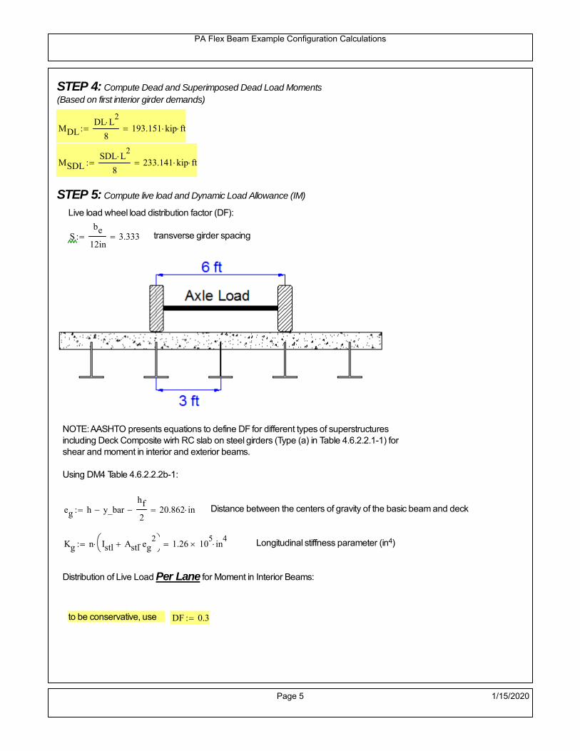
PA Flex Beam Example Configuration Calculations
STEP 4: Compute Dead and Superimposed Dead Load Moments(Based on first interior girder demands)
MDLDL L
2
8193.151 kip ft
MSDLSDL L
2
8233.141 kip ft
STEP 5: Compute live load and Dynamic Load Allowance (IM)
Live load wheel load distribution factor (DF):
Sbe
12in3.333 transverse girder spacing
NOTE: AASHTO presents equations to define DF for different types of superstructuresincluding Deck Composite wirh RC slab on steel girders (Type (a) in Table 4.6.2.2.1-1) forshear and moment in interior and exterior beams.
Using DM4 Table 4.6.2.2.2b-1:
eg h y_barhf
2 20.862 in Distance between the centers of gravity of the basic beam and deck
Kg n Istl Astl eg2
1.26 10
5 in
4 Longitudinal stiffness parameter (in4)
Distribution of Live Load Per Lane for Moment in Interior Beams:
to be conservative, use DF 0.3
Page 5 1/15/2020

PA Flex Beam Example Configuration Calculations
Dynamic Load Allowance (Section 3.6.2 DM4)
Static effects of the design truck or tandem, shall be increased by the impact factor.
NOTE: The dynamic load allowance shall not be applied to the design lane load (Section 3.6.2.1 DM4)
I 0.33 Impact factor for moment
Note: PennDOT requires that the impact for decks be increased from 33% to 50%, the deck is not beingdesigned here. Instrad the deck design is based on the BD recommendations.
Dynamic load allowance for the Permit Load P-82 shall be less than 20%. (Section 3.6.2.1DM4)
IPL 0.20 Impact factor for moment on Strength II
Design Wind Loading for Exterior Girder
Vw 80 Wind speed for Strength V load case
CD 1.3 Gust factor for windard side of I-Girder and Box Girder Superstructures (Table 3.8.1.2.1-2)
G 1.0 Gus effect factor is 1.0 for all structures other than sound barriers (Table 3.8.1.2.1-1)
Kz 1.0 Pressure coefficient taken as 1 for Strength V (3.8.1.2.1)
Pz 2.56 106
Vw 2 Kz G CDkip
ft2
0.021kip
ft2
Wind pressure on exterior girder
hexp h hf 27.5 in Exposed height of exterior girder
Moment due to wind loading on exterior girderMWL
Pz hexp L2
821.965 kip ft
Iyy
bf3tf
12126 in
4 Transverse moment of intertia
Flange lateral bending stressfl
MWL
bf
2
Iyy12.551 ksi
Page 6 1/15/2020

PA Flex Beam Example Configuration Calculations
Design Vehicular Live Load
PHL-93 and P-82 are examined herein.
PHL-93 (A3.6.1.2.1)
PHL-93 consists of a combination of (design truck or design tandem) + (design lane load)
Design Truck
PennDOT defines the design truck in accordance with AASTHO 3.6.1.2
Design truck load in AASHTO (HS20 Truck) is used for this example.
NOTE : MAX moment occurs when the center line of the span is midway between the center ofgravity of the loads and the nearest concentrated load.
P1 8kip P2 32kip P3 32kip Axle loads (AASHTO 3.6.1.2.2)
XASr 14ft Rear Axle spacing for truck (14ft - 30ft)
XASf 14ft Front Axle spacing for truck
Page 7 1/15/2020

PA Flex Beam Example Configuration Calculations
Center of gravity (CG) of loads:
X'P1 XASr XASf P2 XASr
P1 P2 P39.333 ft Datum is the rear axle
X XASr X' 4.667 ft Spacing btw CG and nearest load
Find bridge reaction
Truck movestoward Support ARA
P1L
2XASf
X
2
P2L
2
X
2
P3L
2X'
X
2
L33.2 kip
Max live load moment (at the location of P2):
MLL_truck RAL
2
X
2
P1 XASf 806.533 kip ft
NOTE: Find the worst case by varying XASr
Page 8 1/15/2020

PA Flex Beam Example Configuration Calculations
Design Tandem
Consist of a pair of 25-kip axles spaced 4-ft apart. (AASHTO 3.6.1.2.3)
NOTE: PennDOT DM4 increases 25-kip to 31.25-kip.
FT 31.25kip
XAS 4ft Axle spacing
Center of gravity (CG) of loads:
XXAS
22 ft Spacing btw CG and nearest load
Find bridge reaction
RA
FTL
2
X
2
FTL
2
X
2 X
L30.208 kip Truck moves toward Support A
Max live load moment (at the location of front wheel):
MLL_tandem RAL
2
X
2
876.042 kip ft
Choose the max value:
MLL_veh max MLL_tandem MLL_truck 876.042 kip ft
Apply the impact and wheel load distribution:
MLL_IM_veh MLL_veh DF 1 I( ) 349.541 kip ft Due to tandem or truck
Design Lane Load (distributed over a 10-ft width for each lane)
NOTE: The uniform load may be continuous or discontinuous as necessary to produce themaximum force effect. For this example continuous uniform distribution assumed.
FDLL 0.64kip
ftDF 0.192
kip
ft Per beam in each lane
Due to lane loadMLL_IM_lane
FDLL L2
8
86.4 kip ft
Moment due to Total Design Vehicular Live Load: MLL_IM MLL_IM_lane MLL_IM_veh 435.941 kip ft
Page 9 1/15/2020
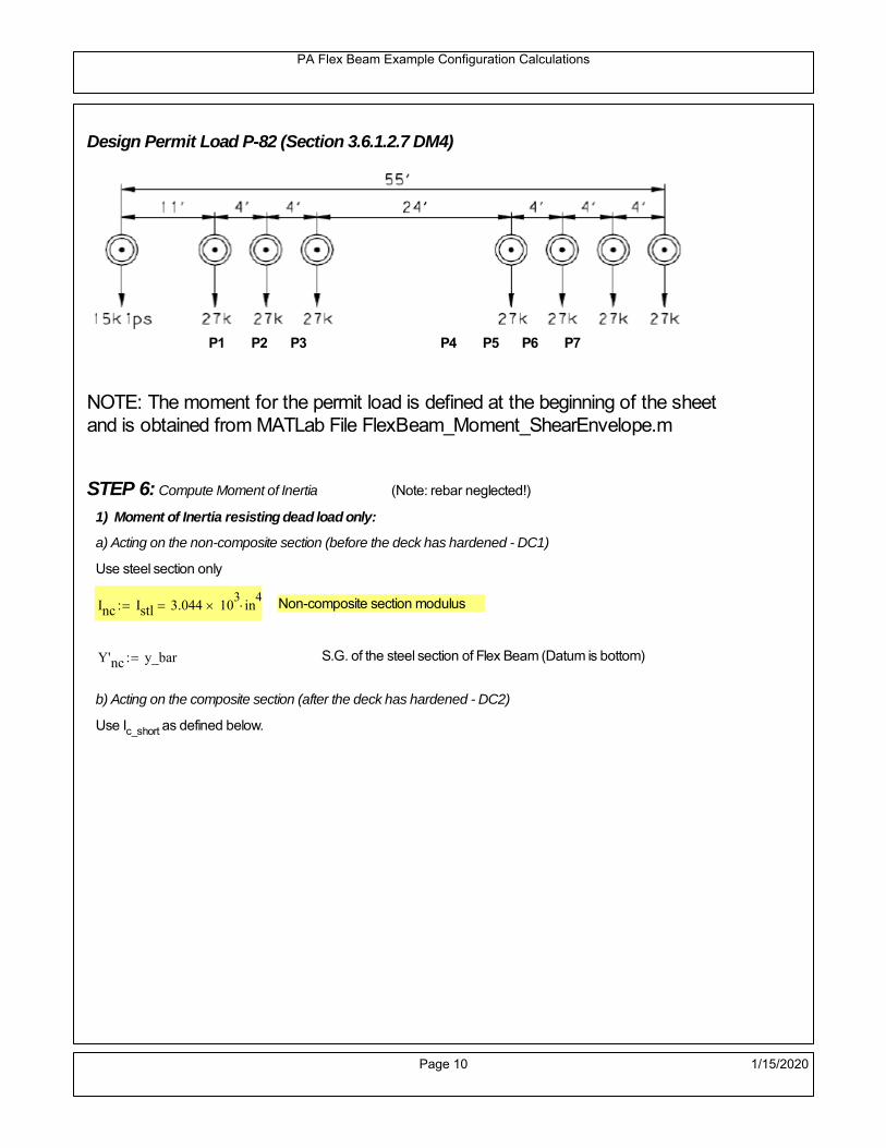
PA Flex Beam Example Configuration Calculations
Design Permit Load P-82 (Section 3.6.1.2.7 DM4)
P1 P2 P3 P4 P5 P6 P7
NOTE: The moment for the permit load is defined at the beginning of the sheetand is obtained from MATLab File FlexBeam_Moment_ShearEnvelope.m
STEP 6: Compute Moment of Inertia (Note: rebar neglected!)
1) Moment of Inertia resisting dead load only:
a) Acting on the non-composite section (before the deck has hardened - DC1)
Use steel section only
Inc Istl 3.044 103
in4
Non-composite section modulus
Y'nc y_bar S.G. of the steel section of Flex Beam (Datum is bottom)
b) Acting on the composite section (after the deck has hardened - DC2)
Use Ic_short as defined below.
Page 10 1/15/2020

PA Flex Beam Example Configuration Calculations
2) Moment of Inertia resisting live load plus impact:
Using transformed slab with k1=1 (short-term composite).
Actr1 hf btr1 37.5 in2
Itr1
btr1 hf3
12175.781 in
4
Y'
Actr1 hhf
2
Astl Y'nc
Astl Actr122.095 in S.G. of the total flex beam (Datum is bottom)
Compositesection modulus(short-term)
Ic_short Istl Astl Y'nc Y' 2 Itr1 Actr1 hhf
2
Y'
2
10382 in4
Y'c_short Y' 22.095 in N.A. of the short-term composite section
3) Moment of Inertia resisting superimposed dead load:
Using transformed slab with k3=3.
Actr3 hf btr3 12.5 in2
Itr3
btr3 hf3
1258.594 in
4
Y'
Actr3 hhf
2
Astl Y'nc
Astl Actr316.623 in S.G. of the total flex beam (Datum is bottom)
Compositesection modulus(long-term)
Ic_long Istl Astl Y'nc Y' 2 Itr3 Actr3 hhf
2
Y'
2
6917 in4
Y'c_long Y' 16.623 in N.A. of the long-term composite section
Page 11 1/15/2020

PA Flex Beam Example Configuration Calculations
STEP 6.5 Check Ductility RequirementIn accordance with AASHTO Article 6.10.7.3 check ductility requirement. Assume compressionblock of concrete is at 0.85 f'c and that the concrete supports no tension. Steel section isassumed to be fully plastic at Fy.
Case 1 : Assuming PNA is in Concreteh d 4 inAssuming (h-d) < Dp < hf
Fp Dp 0.85 fc be Dp Fy tw Dp h d( ) Fy Astl tw Dp h d( )
Dp 7.5in 0.42 h 14.7 in
Dp1 root Fp Dp Dp 8.647 in Must be less than hf 7.5 inDp1
h0.247 must be < 0.42
Mn1check Dp1 hf h d( ) Dp1[ ] Dp1 0.42 h( ) 0 Dp1 0.42 h 1
Mp1 0.85 fc be Dp1Dp1
2
Fy tw Dp1 h d( )[ ] Dp1 h d( )[ ]
2
Fy bf tf h Dp1tf
2
Fy tw h Dp1 tf h Dp1 tf
2
Mp1 29170.09 kip in Mn1 Mp1 1.07 0.7Dp1
h
26167.4 kip in
Case 2 : Assuming PNA is NOT in Concrete
Assuming hf < Dp
Fp2 Dp 0.85 fc be hf Fy tw Dp h d( ) Fy Astl tw Dp h d( )
Dp 2.5in
Dp2 root Fp2 Dp Dp 11.143 in Must be more than hf 7.5 inDp2
h0.3184 must be < 0.42
Mn2check Dp2 hf Dp2 h( ) Dp2 0.42 h( ) 1 Dp2 0.42 h 1
Mp2 0.85 fc be hf Dp2hf
2
Fy tw Dp2 h d( )[ ] Dp2 h d( )[ ]
2
Fy bf tf h Dp2tf
2
Fy tw h Dp2 tf h Dp2 tf
2
Mp2 28886.02 kip inMn2 Mp2 1.07 0.7
Dp2
h
24470.8 kip in
Mn max Mn1 Mn1check Mn2 Mn2check 2039.2 kip ft Mn 24470.8 kip in
Page 12 1/15/2020

PA Flex Beam Example Configuration Calculations
Check Composite Compact Section Criteria (6.10.6.2)
Dcpd
2
Fy tf bf 0.85 fc be hf
Fy hw tw1
7.35 in Dcp0 Dcp 0 1
Dcp Dcp Dcp0 7.35 in2 Dcp
tw3.76
Es
Fy 1 Check if section is compact
STEP 7: Load Combinations (Table 3.4.1-1)
The following load combinations will be considered herein. Only the maximum load factors forpermanent-loads are used in the following load combinations (uplift is not an issue for this typeof bridge).STRENGTH I 1.25DL + 1.5SDL + 1.75 (LL+IM)
SERVICE II: DL+SDL+1.3(LL+IM)
STEP 8: Compute and Check Stresses
Stress at bottom fiber of steel section
fDL
MDL Y'c_long
Ic_long5.57 ksi
fLL_I
MLL_IM Y'c_short
Ic_short11.133 ksi fPL
MLL_IM_PL82 Y'c_short
Ic_short13.374 ksi
fSDL
MSDL Y'c_long
Ic_long6.723 ksi
STRENGTH I fbot_str1 1.25fDL 1.5 fSDL 1.75 fLL_I 36.53 ksi
STRENGTH II fbot_str2 1.25fDL 1.5 fSDL 1.35 fPL 35.102 ksi
SERVICE II fbot_svc2 fDL fSDL 1.3fLL_I 26.77 ksi
Allowable Stress is based on Section 6.10.4.2.2-2
Flange stress due to service load II without consideration of flange lateral bending: ff fbot_svc2
Flange lateral bending stress due to service II: flSII 0ksi
Hybrid Factor: Rh 1.0 For rolled and homogenous built-up sections
ff
flSII
2 26.766 ksi 0.95 Rh Fy 47.5 ksi ff
fl
2 0.95Rh Fy 1
Page 13 1/15/2020

PA Flex Beam Example Configuration Calculations
Stress at top fiber of concrete
Note: For calculating longitudinal flexural stresses in the concrete deck due to allpermanent and transient loads, the short-term modular ratio shall be used.
fDL
MDL h Y'c_short
k1 n Ic_short0.36 ksi
fLL_I
MLL_IM h Y'c_short
k1 n Ic_short0.813 ksi fPL
MLL_IM_PL82 h Y'c_short
k1 n Ic_short0.976 ksi
fSDL
MSDL h Y'c_short
k1 n Ic_short0.435 ksi
STRENGTH I fc_str1 1.25fDL 1.5 fSDL 1.75 fLL_I 2.525 ksi
Mstr1 1.25 MDL 1.5 MSDL 1.75 MLL_IM 1354 kip ft Mstr1 Mn 1
STRENGTH II fc_str2 1.25fDL 1.5 fSDL 1.35 fPL 2.42 ksi
Mstr2 1.25 MDL 1.5 MSDL 1.35 MLL_IM_PL82 1298 kip ft Mstr2 Mn 1
SERVICE II
Allowable Stress in concrete - AASHTO 6.10.4.2.2For compact composite sections in positive flexure utilized in shored construction, the longitudinalcompressive stress in the concrete deck due to the Service II loads, determined as specified in Article6.10.1.1.1d, shall not exceed 0.6f́ c.
fallow 0.6 fc 2400 psi
fc_2 1.3fLL_I fSDL fDL 1851.51 psi This assumes short term compositesection for all calculations
fc_2 fallow 1
SERVICE II with Long Term Composite for dead loads
fDL
MDL h Y'c_long
k3 n Ic_long0.257 ksi
fLL_I
MLL_IM h Y'c_short
k1 n Ic_short0.813 ksi
fSDL
MSDL h Y'c_long
k3 n Ic_long0.31 ksi
fc_2 1.3fLL_I fSDL fDL 1622.97 psi fc_2 fallow 1
Page 14 1/15/2020

PA Flex Beam Example Configuration Calculations
Strength V Moment Check
Strength V is related to normal vehicular use of the bridge with an 80 mph wind gust
Note: that Strength V is checked for an exterior girder under wind load with the interior girder distribution factor forflexure used. If Strength V controls design, then this approach should be modified
Design vertical moment is: 1.25DL + 1.5SDL + 1.35 (LL+IM)
SLT
Ic_long
Y'c_long416.124 in
3 SST
Ic_short
Y'c_short469.899 in
3 short and long term section
modulus
Section D6.2.2 Find the moment required to cause yieldling of the flange. The approach is laid out in D6.2.2
MD2 1.25 MDL 1.5 MSDL 591.15 kip ft From D6.2.2-1 (all dead loads are in MD2 due to shoredconstruction
MAD Fy
MD2
SLT
SST 1.29 10
3 kip ft Additional moment to cause nominal yielding of steel flange
My MD2 MAD 1.882 103
kip ft D6.2.2-2: Moment to cause yielding of flange
6.10.7.1 Compact Section Check at Strength V limit state
Section Modulus for yielding of the flange (My/Fy) for equation 6.10.7.1.1-1Sxt
My
Fy451.565 in
3
Mu 1.25 MDL 1.5MSDL 1.35MLL_IM 1.18 103
kip ft Moment due to Strength V limit state
Mu1
3fl Sxt 1.337 10
3 kip ft Equation 6.10.7.1.7-1 Mn 2.039 10
3 kip ft Mu
1
3fl Sxt Mn 1
Page 15 1/15/2020

PA Flex Beam Example Configuration Calculations
STEP 9: Compute Deflection
Optional Live Load Deflection Evaluation (AASHTO 3.6.1.3.2)
Deflection distribution factor for vehicular loads: For a straight multibeambridge, this is equivalent to saying that the distribution factor for deflectionis equal to the number of lanes divided by the number of beams. 2.5.2.6.2
DFd
Nl
N0.25
Deflection should be taken as 125% the larger of:- Design truck- 25% of design truck + design lane
The live load portion of Load Combination Service I of Table 3.4.1-1 should be used,including the dynamic load allowance, IM;
Deflection due to design truck load
NOTE : Assuming maximum deflection occurs when the center of gravity of the loads is at thecenter line of the span.
P1 8kip P2 32kip P3 32kip Axle loads (AASHTO 3.6.1.2.2)
XASr 14ft Rear Axle spacing for truck (14ft - 30ft)
XASf 14ft Front Axle spacing for truck
Center of gravity (CG) of loads:
X'P1 XASr XASf P2 XASr
P1 P2 P39.333 ft Datum is the rear axle
Method1: Assuming single load = P1+P2+P3 at the midspan (Conservative approach)
P1 P2 P3 L3
48 Es Ic_short 1.86 in
Method2: Calculation of Midspan deflection using superposition
b1L
2XASr X' XASf 11.333 ft distance btw load P1 and support A b1check b1 0 1
b2L
2XASr X' 25.333 ft distance btw load P2 and support A b2check b2 0 1
b3L
2X' 20.667 ft distance btw load P3 and support B b3check b3 0 1
Page 16 1/15/2020

PA Flex Beam Example Configuration Calculations
Deflection of the beam at midspan due to P1: P P1
xL
2 at midspan b b1 b1check The smallest distance btw load P1 and support
Δ1P b x
6 Es Ic_short LL2
b2
x2
0.112 in
Deflection of the beam at midspan due to P2: P P2
xL
2 at midspan b b2 b2check The smallest distance btw load P2 and support
Δ2P b x
6 Es Ic_short LL2
b2
x2
0.798 in
Deflection of the beam at midspan due to P3: P P3
xL
2 at midspan b b3 b3check The smallest distance btw load P3 and support
Δ3P b x
6 Es Ic_short LL2
b2
x2
0.719 in
Total Deflection at midspan:
Δtruck Δ1 Δ2 Δ3( ) DFd 1 I( ) 0.541 in (Considering IM)
Deflection due to tandem (Note: this calculation is not required according to Article3.6.1.3.2 which denotes only the design truck for deflection calculation)
Page 17 1/15/2020

PA Flex Beam Example Configuration Calculations
FT 31.25 kip Per axle
XAS 4ft Axle spacing
Δtandem
FTL
2
XAS
2
24 Es Ic_short3 L
2 4
L
2
XAS
2
2
DFd 1 I( ) 0.533 in (Considering IM)
Deflection due to lane load
FDLLd 640lbf
ft DFd 160
lbf
ft
Δlane
5 FDLLd L4
384 Es Ic_short0.155 in
Live Load Deflection:
ΔLL 1.25max Δtruck 0.25Δtruck Δlane 1.25 0.846 in ΔLLL
800 1
Deflection Limit
For steel or concrete vehicular bridges:
Vehicular load = Span/800L
8000.9 in
L
10000.72 in
Evaluation of Deflection at the Service Limit State (AASHTO 3.4.2.2)
The associated permitted deflections shall be included in the contract documents.
Page 18 1/15/2020

PA Flex Beam Example Configuration Calculations
Shear demands:
Determination of the distribution factor
Using DM4 Table 4.6.2.2.3a-1
Sbe
12in3.333 transverse girder spacing (ft)
Distribution of live loads per lane for shear in interior beams:
For two design lanes loaded, 3.5' <= S =< 16', number of beam >= 4DFs 0.36
S
25 0.493
Q Actr1 h Y'c_shorthf
2
343.327 in3
first moment of deck slab for interface shear
Method 1: Range of shear based on Strength I Limit
STRENGTH I 1.25DL + 1.5SDL + 1.75 (LL+IM)
Computation of the range of shear in the beam
Dead Load:DL 0.429
kip
ft
Superimposed Dead Load: SDL 0.518kip
ft
Design Lane Load: 0.64kip
ft
Design Truck:
XASr 14ft Rear Axle spacing for truck (14ft - 30ft)
XASf 14ft Front Axle spacing for truck
P1 8 kip P2 32 kip P3 32 kip Wheel loads (AASHTO 3.6.1.2.2)
Design Tandem:
Consist of a pair of 25-kip axles spaced 4-ft apart. (AASHTO 3.6.1.2.3)
NOTE: PennDOT DM4 increases 25-kip to 31.25-kip.
FT 31.25kip
XAS 4ft Axle spacing
Page 19 1/15/2020

PA Flex Beam Example Configuration Calculations
Maximum positive shear at various points along the FlexBeam are examined.
At x=0 (at left support) (Truck is moving from left to right)
Truck
Max Positive Shear (when P3 is at x = 0):
x1 L XASr XASf 32 ft Distance between P1 and right support
x2 L XASr 46 ft Distance between P2 and right support
x3 L 60 ft Distance between P3 and right support
V1 P3
x3
L P2
x2
L P1
x1
L 60.8 kip
Total Vertical Shear Force for each FlexBeam (considering dynamic loads):
Vtruck1 V1 DFs 1 I( ) 39.893 kip
Tandem:
V1 FT FT
L XAS L
60.417 kip
Total Vertical Shear Force for each FlexBeam (considering dynamic loads):
Vtandem1 V1 DFs 1 I( ) 39.641 kip
Lane Load
V1 0.64kip
ft
L
2 19.2 kip
Total Vertical Shear Force for each FlexBeam (considering dynamic loads):
Vlane1 V1 DFs 9.472 kip
Dead Load
Vdl1 DLL
2 12.877 kip
Superimposed Dead Load
Vsdl1 SDLL
2 15.543 kip
Strength I Max Positive Shear:
Vstr1 1.25 Vdl1 1.5 Vsdl1 1.75 Vlane1 max Vtruck1 Vtandem1 125.799 kip
Page 20 1/15/2020

PA Flex Beam Example Configuration Calculations
Design Permit Load P-82
Shear at x=0
Strength II Max Positive Shear:
VPL82 VPL82span DFs 1 IPL 74.065 kip
STRENGTH II 1.25DL + 1.5SDL + 1.35 (LL+IM)
VstrII_PL 1.25 Vdl1 1.5 Vsdl1 1.35 VPL82 139.398 kip
Max Shear Demand Vu max Vstr1 VstrII_PL 139.398 kip
Determine the Shear Strength of the Web
Shear Strength of Unstiffened web from AASHTO section 6.10.9.2
Depth of Web D d 31 in Thickness of web tw 0.625 in
Transverse Stiffener Spacing d0 0in Shear Buckling Coefficient k 5 6.10.9.3.2-7
Plastic Shear Force Vp 0.58 Fy D tw 561.875 kip Equation 6.10.9.3.2-3
Ratio of Shear-Buckling resistance to shear yield, C
D
tw49.6 1.12
Es k
Fy 60.314 Ccheck
D
tw1.12
Es k
Fy 1 Equation 6.10.9.3.2-4
C 1.0 Ccheck 1 C=1 for most cases, if the criteria are not met, then C will go to zero and the actualcoefficients should be determined
Nominal Shear Resistance of Web Vn C Vp 561.875 kip equation 6.10.9.3.3-1
Shear Resistance Factor φv 1.0
φv Vn 561.875 kip φv Vn Vu 1Reduced Shear Strength
Page 21 1/15/2020

PA Flex Beam Example Configuration Calculations
Check Bearing Stiffeners
FYs 50ksi Yield strength of stiffener
tp 0.75in Thickness of stiffener
bt
bf tw
21.5in 4.188 in Effective width of stiffener
Dst hw 4.1in 26.025 in Depth of stiffeners
Apn 2 tp bt 6.281 in2
Projected area of stiffeners
bt 0.48 tpEs
FYs 1Check that effective width of stiffener meets requirements
Rsbn 1.4 Apn FYs 439.688 kip Bearing capacity of stiffener (phi=1 for bearing per AASHTO 6.5.4.2)
Rsbn Vu 1 Bearing capacity check
Qs 1.0 Q factor for bearing stiffner, taken as 1 (AASHTO 6.9.4.1.1)
Is
18 tw tw3
tp 2 bt 3
1236.943 in
4 Moment of inertia of stiffener and web (9*tw is used on each side)
AASHTO 6.10.11.2.4b
Ag 18 tw tw 2 bt tp 13.313 in2
Gross area of stiffener and web (AASHTO 6.10.11.2.4b)
rs
Is
Ag1.666 in Radius of gyration of stiffener/web
Po Qs FYs Apn 314.062 kip Nominal yeild resistance of stiffener (AASHTO 6.9.4.1.1)
Peπ2Es
0.75 Dst
rs
2Ag 2.775 10
4 kip Elastic critical buckling stress of stiffener (AASHTO 6.9.4.1.2-1)
Check that Pe/Po is great than 0.44 (AASHTO 6.9.4.1.1) PePoPe
Po0.44 1
Pn PePo 0.658
Po
Pe Po 312.579 kip Nominal compressive resistance of stiffener for Pe/Po>0.44
(AASHTO 6.9.4.1.1-1)
φcr 0.95 phi factor for axial compression (AASHTO 6.5.4.2)
Pr φcr Pn 296.95 kip Compressive capacity of bearing stiffener Pr Vu 1
Page 22 1/15/2020

PA Flex Beam Example Configuration Calculations
Flexbeam Example Configuration Calculations
Summary of Calculations:
Input section dimensions and material properties for steel WT and the concrete deck1.Calculate demands (dead load, superimposed dead, and Live load demands for Strength I and Strength II2.Calculate composite section properties for the given section3.Check Strength I, Strength II, and Service II stresses 4.Check Strength I, Strength II, and Strength V moment demands 5.Perform live load deflection check6.Determine maximum shear demand and capacity7.Note: Shear envelope data was obtained from Matlab script (FlexBeam_Moment_ShearEnvelope.m).8.Shear envelope calculations are summarized separately for each design (Shear Design *.xlsx).
Design Assumptions:Design Specifications Used:
AASHTO LRFD Bridge Design Specifications 7th Edition with 2016 Interim RevisionsPennDOT Design Manual, Part 4 (DM-4) June 30, 2015
Example configurations are determined for two girder spacings, 36" and 40".The deck thickness is 7.5" and is assumed to have a non-structural wearing surface added after installation.Section properties are calculated using the full 7.5" deck thickness.The WT sections are embedded 3.5" into the concrete deck. The steel section spacing used is outside the scope of the AASHTO and PennDOT distribution factorequations. The flexural distribution factor is assumed to be 0.3 which was shown to tbe conservativeaccording to refined analysisThe shear distribution factor is calculated using the DM-4 shear distribution factor equation which wasshown to be conservative using refined analysis.Refined analysis is presented in: Zihan Ma, "Distribution Factors for Composite Steel Tee Concrete DeckBridge System," M.S. Thesis, Deparement of Civil and Environmental Engineering, Lehigh University,Bethlehem, 2019Shear and moment demands for the PL82 permit load vehicle are determined by Matlab script(FlexBeam_Moment_ShearEnvelope.m) and are manually input into this calculation sheet.All fabrication will occur as double modules, i.e. each module contains two WT sections. The number ofmodules is half the number of beams, N. A 45 in. tall F-Shape barrier is used, Weight = 700 lb/ft (Distributed to exterior two beams).
The work presented in this document are provided on an “AS IS” basis. University makes no warranties of anykind, express or implied, as to any matter whatsoever, including, without limitation, warranties with respect tothe merchantability or fitness for a particular purpose of this work or any project deliverables. Universitymakes no warranty of any kind with respect to freedom from patent, trademark, copyright or trade secretinfringement arising from the use of the results of the project, deliverables, services, intellectual property orother materials provided hereunder. University shall not be liable for any direct, indirect, consequential,punitive, or other damages suffered by Sponsor or any other person resulting from the project, or the use ofthis work or any project deliverables.
Page 1 1/15/2020

PA Flex Beam Example Configuration Calculations
hf
tf
bf
twh
d
bjtbe
e
Variable Definitions:
Number of beams N 14 modulesN
27
L 60ft Span length
be 40in Effective width of Flexbeamassuming constructed bridge width(i.e. closure joints cast)
Built Up Section Properties
tw 0.625in tf 0.875in bf 12in
h 35in Overall Height of section
hf 7.5in Total thickness of deck
e 3.5in Deck/Steel overlap
d h hf e 31 in depth of built up steel section
hw d tf 30.125 in height of web of built up steel
Moment and shear for permit load PL82 obtained from Matlab script: FlexBeam_Moment_ShearEnvelope
MLL_IM_PL82 523.6917kip ft Moment due to PL82 with distribution factor and impact factor!!
VPL82span 125.11kip Shear due to PL82 WITHOUT distribution factor and impact factor!!
Check web and flange dimensions in sections 6.10.2.1 and 6.10.2.2
(Ignore 6.10.2.2-4 since no compression flange)
equation 6.10.2.1.1-1d
tw150 1 equation 6.10.2.2-1
bf
2 tf12 1
equation 6.10.2.2-2 bfh
6 1 equation 6.10.2.2-3 tf 1.1 tw 1
y_bar
tf bftf
2 hw tw tf
hw
2
tf bf hw tw10.388 in Center of gravity of steel section
Istl
bf tf3
12bf tf y_bar
tf
2
2
tw hw
3
12 tw hw tf
hw
2 y_bar
2
3.044 103
in4
MOI of steel
Astl tf bf hw tw 29.328 in2
Area of the WT steel section
Page 2 1/15/2020

PA Flex Beam Example Configuration Calculations
Material Properties
Elastic Modulus of Steel Es 29000ksi
Yield Strength of Steel Fy 50ksi
Yield Strength of Reinforcement fy 60ksi
Compressive Strength of Concrete fc 4000psi AAAP PennDOT Concrete
Concrete Modular Ratio n 8 modular ratio for 4ksi concrete per AASHTO
Unit weight of concrete slab wc 0.150kip
ft3
Unit weight of concrete
Section Properties
Width of UHPC Joint: bjt 6in
Parapet width: bpar 20.25in Parapet width per PennDOT F-shape barrier
Width of the bridge W be N bjt 554 in W 46.167 ft
Clear width of roadway Wlane W 2 bpar 42.792 ft
Dc wc hf W 4.328kip
ft DL due to slab
Db .700kip
ft DL due to each 45" F-Shape Barrier (per email 11/1/18)
DFWS 30lbf
ft2
W 2 bpar 1.284kip
ft DL due to Future Wearing Surface (FWS)
Ds Astl 490lbf
ft3
0.1kip
ft Selfweight of the steel section
DLself
Dc N
Ds 0.409kip
ft Self-weight per WT
Total weight of each precast FlexBeam for transportation:
Weight of C12x25 Diaphragms Wend_diaphragms 25lbf
ft32 in 0.067 kip
2be bjt hf wc 2Ds L 2 Wend_diaphragms 46.796 kip
Determine number of design lane (AASHTO Section 3.6.1.1.1)
Take the integer part of the ratio of W/12 ft. Number of lanes in bridge: Nl floorWlane
12ft
3
Page 3 1/15/2020

PA Flex Beam Example Configuration Calculations
STEP 1: Compute Dead Load for each Flex Beam
DLslab
Dc
Nwc 1 in
be
2 0.33
kip
ft Dead load of slab assuming exterior overhang has 1" of
additional concrete thickness
DLsteel Ds 0.1kip
ft
DL DLslab DLsteel 0.43kip
ft
STEP 2: Compute Superimposed Dead Load
SDLWS
DFWS
N0.092
kip
ft
SDLparapet
Db
20.35
kip
ft distributed equally on two outer beams
SDLOL 140lbf
ft3be 2 in 0.078
kip
ft Overlay is 2" thick and is 140 lbs/cubic foot
NOTE: For this example barrier load is distributed equally among the two outer beams per conversation withPennDOT and M&M.
PennDOT DM4: "For composite adjacent and spread beams, the barrier (single barrier) load shall be equallydistributed to the nearest three (adjacent) and two (spread) beams, respectively, when the barriers are placedafter slab has hardened".
SDL SDLWS SDLparapet SDLOL 0.519kip
ft
STEP 3: Compute Transformed Width of Slab
For live load and dead load acting on the stringer k1 1 For short-term section property evaluation
btr1
be
k1 n5 in Transformed width of slab for short-term
For superimposed dead loads k3 3 For long-term section property evaluation
btr3
be
k3 n1.667 in Transformed width of slab for long-term
Page 4 1/15/2020

PA Flex Beam Example Configuration Calculations
STEP 4: Compute Dead and Superimposed Dead Load Moments(Based on first interior girder demands)
MDLDL L
2
8193.402 kip ft
MSDLSDL L
2
8233.763 kip ft
STEP 5: Compute live load and Dynamic Load Allowance (IM)
Live load wheel load distribution factor (DF):
Sbe
12in3.333 transverse girder spacing
NOTE: AASHTO presents equations to define DF for different types of superstructuresincluding Deck Composite wirh RC slab on steel girders (Type (a) in Table 4.6.2.2.1-1) forshear and moment in interior and exterior beams.
Using DM4 Table 4.6.2.2.2b-1:
eg h y_barhf
2 20.862 in Distance between the centers of gravity of the basic beam and deck
Kg n Istl Astl eg2
1.26 10
5 in
4 Longitudinal stiffness parameter (in4)
Distribution of Live Load Per Lane for Moment in Interior Beams:
to be conservative, use DF 0.3
Page 5 1/15/2020

PA Flex Beam Example Configuration Calculations
Dynamic Load Allowance (Section 3.6.2 DM4)
Static effects of the design truck or tandem, shall be increased by the impact factor.
NOTE: The dynamic load allowance shall not be applied to the design lane load (Section 3.6.2.1 DM4)
I 0.33 Impact factor for moment
Note: PennDOT requires that the impact for decks be increased from 33% to 50%, the deck is not beingdesigned here. Instrad the deck design is based on the BD recommendations.
Dynamic load allowance for the Permit Load P-82 shall be less than 20%. (Section 3.6.2.1DM4)
IPL 0.20 Impact factor for moment on Strength II
Design Wind Loading for Exterior Girder
Vw 80 Wind speed for Strength V load case
CD 1.3 Gust factor for windard side of I-Girder and Box Girder Superstructures (Table 3.8.1.2.1-2)
G 1.0 Gus effect factor is 1.0 for all structures other than sound barriers (Table 3.8.1.2.1-1)
Kz 1.0 Pressure coefficient taken as 1 for Strength V (3.8.1.2.1)
Pz 2.56 106
Vw 2 Kz G CDkip
ft2
0.021kip
ft2
Wind pressure on exterior girder
hexp h hf 27.5 in Exposed height of exterior girder
Moment due to wind loading on exterior girderMWL
Pz hexp L2
821.965 kip ft
Iyy
bf3tf
12126 in
4 Transverse moment of intertia
Flange lateral bending stressfl
MWL
bf
2
Iyy12.551 ksi
Page 6 1/15/2020

PA Flex Beam Example Configuration Calculations
Design Vehicular Live Load
PHL-93 and P-82 are examined herein.
PHL-93 (A3.6.1.2.1)
PHL-93 consists of a combination of (design truck or design tandem) + (design lane load)
Design Truck
PennDOT defines the design truck in accordance with AASTHO 3.6.1.2
Design truck load in AASHTO (HS20 Truck) is used for this example.
NOTE : MAX moment occurs when the center line of the span is midway between the center ofgravity of the loads and the nearest concentrated load.
P1 8kip P2 32kip P3 32kip Axle loads (AASHTO 3.6.1.2.2)
XASr 14ft Rear Axle spacing for truck (14ft - 30ft)
XASf 14ft Front Axle spacing for truck
Page 7 1/15/2020

PA Flex Beam Example Configuration Calculations
Center of gravity (CG) of loads:
X'P1 XASr XASf P2 XASr
P1 P2 P39.333 ft Datum is the rear axle
X XASr X' 4.667 ft Spacing btw CG and nearest load
Find bridge reaction
Truck movestoward Support ARA
P1L
2XASf
X
2
P2L
2
X
2
P3L
2X'
X
2
L33.2 kip
Max live load moment (at the location of P2):
MLL_truck RAL
2
X
2
P1 XASf 806.533 kip ft
NOTE: Find the worst case by varying XASr
Page 8 1/15/2020
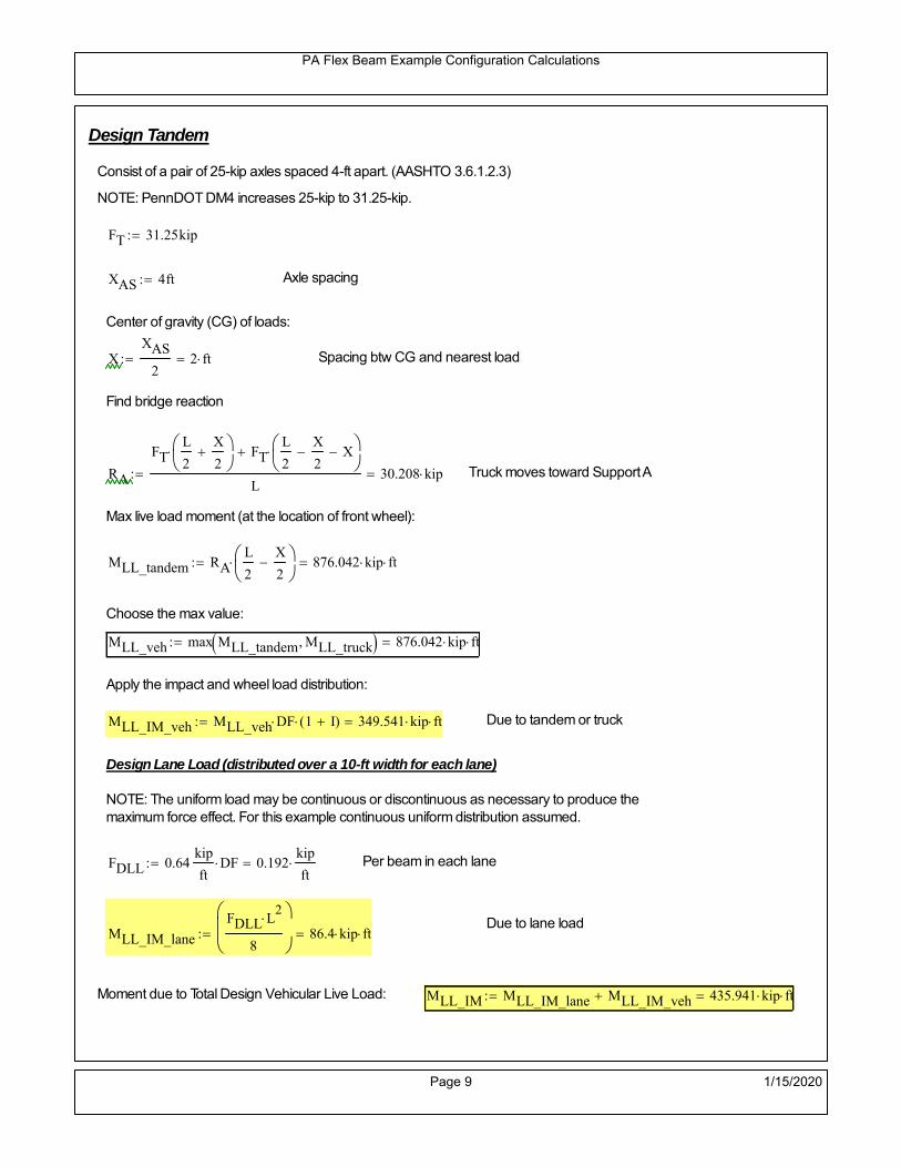
PA Flex Beam Example Configuration Calculations
Design Tandem
Consist of a pair of 25-kip axles spaced 4-ft apart. (AASHTO 3.6.1.2.3)
NOTE: PennDOT DM4 increases 25-kip to 31.25-kip.
FT 31.25kip
XAS 4ft Axle spacing
Center of gravity (CG) of loads:
XXAS
22 ft Spacing btw CG and nearest load
Find bridge reaction
RA
FTL
2
X
2
FTL
2
X
2 X
L30.208 kip Truck moves toward Support A
Max live load moment (at the location of front wheel):
MLL_tandem RAL
2
X
2
876.042 kip ft
Choose the max value:
MLL_veh max MLL_tandem MLL_truck 876.042 kip ft
Apply the impact and wheel load distribution:
MLL_IM_veh MLL_veh DF 1 I( ) 349.541 kip ft Due to tandem or truck
Design Lane Load (distributed over a 10-ft width for each lane)
NOTE: The uniform load may be continuous or discontinuous as necessary to produce themaximum force effect. For this example continuous uniform distribution assumed.
FDLL 0.64kip
ftDF 0.192
kip
ft Per beam in each lane
Due to lane loadMLL_IM_lane
FDLL L2
8
86.4 kip ft
Moment due to Total Design Vehicular Live Load: MLL_IM MLL_IM_lane MLL_IM_veh 435.941 kip ft
Page 9 1/15/2020

PA Flex Beam Example Configuration Calculations
Design Permit Load P-82 (Section 3.6.1.2.7 DM4)
P1 P2 P3 P4 P5 P6 P7
NOTE: The moment for the permit load is defined at the beginning of the sheetand is obtained from MATLab File FlexBeam_Moment_ShearEnvelope.m
STEP 6: Compute Moment of Inertia (Note: rebar neglected!)
1) Moment of Inertia resisting dead load only:
a) Acting on the non-composite section (before the deck has hardened - DC1)
Use steel section only
Inc Istl 3.044 103
in4
Non-composite section modulus
Y'nc y_bar S.G. of the steel section of Flex Beam (Datum is bottom)
b) Acting on the composite section (after the deck has hardened - DC2)
Use Ic_short as defined below.
Page 10 1/15/2020

PA Flex Beam Example Configuration Calculations
2) Moment of Inertia resisting live load plus impact:
Using transformed slab with k1=1 (short-term composite).
Actr1 hf btr1 37.5 in2
Itr1
btr1 hf3
12175.781 in
4
Y'
Actr1 hhf
2
Astl Y'nc
Astl Actr122.095 in S.G. of the total flex beam (Datum is bottom)
Compositesection modulus(short-term)
Ic_short Istl Astl Y'nc Y' 2 Itr1 Actr1 hhf
2
Y'
2
10382 in4
Y'c_short Y' 22.095 in N.A. of the short-term composite section
3) Moment of Inertia resisting superimposed dead load:
Using transformed slab with k3=3.
Actr3 hf btr3 12.5 in2
Itr3
btr3 hf3
1258.594 in
4
Y'
Actr3 hhf
2
Astl Y'nc
Astl Actr316.623 in S.G. of the total flex beam (Datum is bottom)
Compositesection modulus(long-term)
Ic_long Istl Astl Y'nc Y' 2 Itr3 Actr3 hhf
2
Y'
2
6917 in4
Y'c_long Y' 16.623 in N.A. of the long-term composite section
Page 11 1/15/2020

PA Flex Beam Example Configuration Calculations
STEP 6.5 Check Ductility RequirementIn accordance with AASHTO Article 6.10.7.3 check ductility requirement. Assume compressionblock of concrete is at 0.85 f'c and that the concrete supports no tension. Steel section isassumed to be fully plastic at Fy.
Case 1 : Assuming PNA is in Concreteh d 4 inAssuming (h-d) < Dp < hf
Fp Dp 0.85 fc be Dp Fy tw Dp h d( ) Fy Astl tw Dp h d( )
Dp 7.5in 0.42 h 14.7 in
Dp1 root Fp Dp Dp 8.647 in Must be less than hf 7.5 inDp1
h0.247 must be < 0.42
Mn1check Dp1 hf h d( ) Dp1[ ] Dp1 0.42 h( ) 0 Dp1 0.42 h 1
Mp1 0.85 fc be Dp1Dp1
2
Fy tw Dp1 h d( )[ ] Dp1 h d( )[ ]
2
Fy bf tf h Dp1tf
2
Fy tw h Dp1 tf h Dp1 tf
2
Mp1 29170.09 kip in Mn1 Mp1 1.07 0.7Dp1
h
26167.4 kip in
Case 2 : Assuming PNA is NOT in Concrete
Assuming hf < Dp
Fp2 Dp 0.85 fc be hf Fy tw Dp h d( ) Fy Astl tw Dp h d( )
Dp 2.5in
Dp2 root Fp2 Dp Dp 11.143 in Must be more than hf 7.5 inDp2
h0.3184 must be < 0.42
Mn2check Dp2 hf Dp2 h( ) Dp2 0.42 h( ) 1 Dp2 0.42 h 1
Mp2 0.85 fc be hf Dp2hf
2
Fy tw Dp2 h d( )[ ] Dp2 h d( )[ ]
2
Fy bf tf h Dp2tf
2
Fy tw h Dp2 tf h Dp2 tf
2
Mp2 28886.02 kip inMn2 Mp2 1.07 0.7
Dp2
h
24470.8 kip in
Mn max Mn1 Mn1check Mn2 Mn2check 2039.2 kip ft Mn 24470.8 kip in
Page 12 1/15/2020

PA Flex Beam Example Configuration Calculations
Check Composite Compact Section Criteria (6.10.6.2)
Dcpd
2
Fy tf bf 0.85 fc be hf
Fy hw tw1
7.35 in Dcp0 Dcp 0 1
Dcp Dcp Dcp0 7.35 in2 Dcp
tw3.76
Es
Fy 1 Check if section is compact
STEP 7: Load Combinations (Table 3.4.1-1)
The following load combinations will be considered herein. Only the maximum load factors forpermanent-loads are used in the following load combinations (uplift is not an issue for this typeof bridge).STRENGTH I 1.25DL + 1.5SDL + 1.75 (LL+IM)
SERVICE II: DL+SDL+1.3(LL+IM)
STEP 8: Compute and Check Stresses
Stress at bottom fiber of steel section
fDL
MDL Y'c_long
Ic_long5.577 ksi
fLL_I
MLL_IM Y'c_short
Ic_short11.133 ksi fPL
MLL_IM_PL82 Y'c_short
Ic_short13.374 ksi
fSDL
MSDL Y'c_long
Ic_long6.741 ksi
STRENGTH I fbot_str1 1.25fDL 1.5 fSDL 1.75 fLL_I 36.566 ksi
STRENGTH II fbot_str2 1.25fDL 1.5 fSDL 1.35 fPL 35.138 ksi
SERVICE II fbot_svc2 fDL fSDL 1.3fLL_I 26.79 ksi
Allowable Stress is based on Section 6.10.4.2.2-2
Flange stress due to service load II without consideration of flange lateral bending: ff fbot_svc2
Flange lateral bending stress due to service II: flSII 0ksi
Hybrid Factor: Rh 1.0 For rolled and homogenous built-up sections
ff
flSII
2 26.791 ksi 0.95 Rh Fy 47.5 ksi ff
fl
2 0.95Rh Fy 1
Page 13 1/15/2020
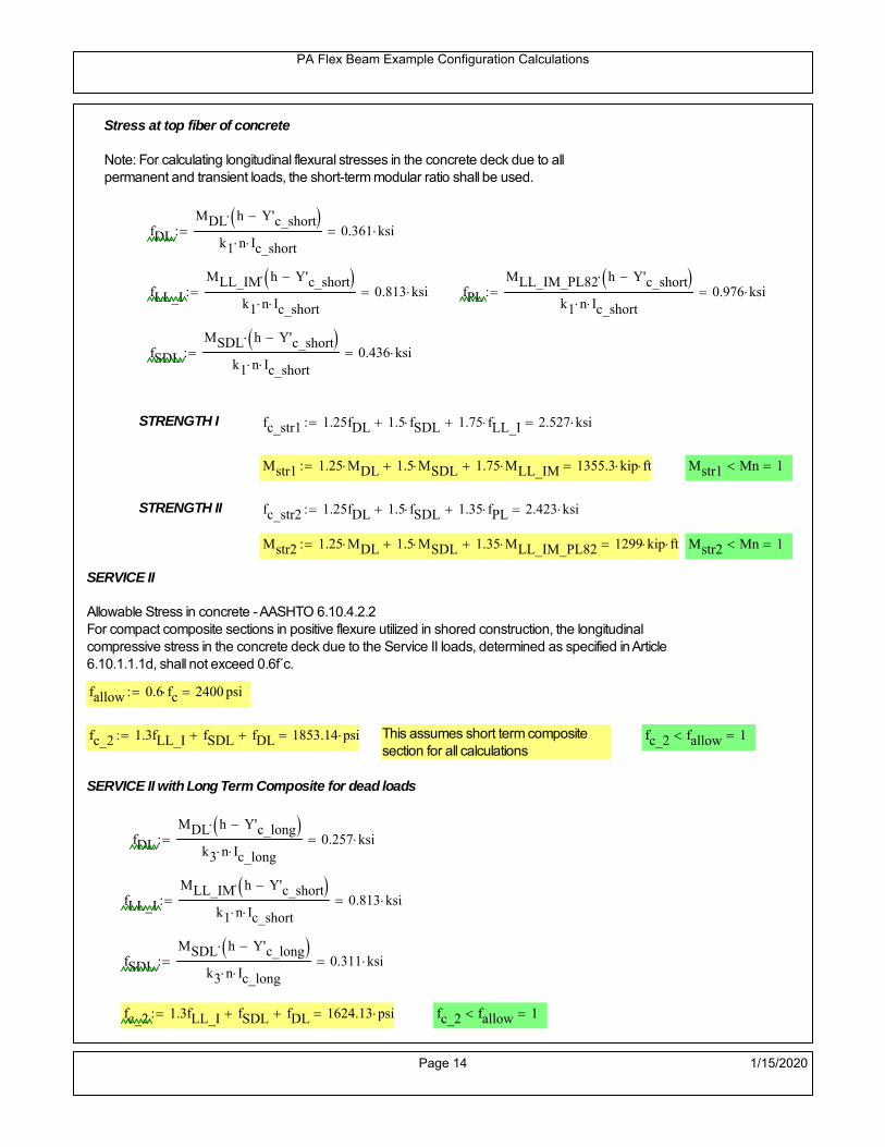
PA Flex Beam Example Configuration Calculations
Stress at top fiber of concrete
Note: For calculating longitudinal flexural stresses in the concrete deck due to allpermanent and transient loads, the short-term modular ratio shall be used.
fDL
MDL h Y'c_short
k1 n Ic_short0.361 ksi
fLL_I
MLL_IM h Y'c_short
k1 n Ic_short0.813 ksi fPL
MLL_IM_PL82 h Y'c_short
k1 n Ic_short0.976 ksi
fSDL
MSDL h Y'c_short
k1 n Ic_short0.436 ksi
STRENGTH I fc_str1 1.25fDL 1.5 fSDL 1.75 fLL_I 2.527 ksi
Mstr1 1.25 MDL 1.5 MSDL 1.75 MLL_IM 1355.3 kip ft Mstr1 Mn 1
STRENGTH II fc_str2 1.25fDL 1.5 fSDL 1.35 fPL 2.423 ksi
Mstr2 1.25 MDL 1.5 MSDL 1.35 MLL_IM_PL82 1299 kip ft Mstr2 Mn 1
SERVICE II
Allowable Stress in concrete - AASHTO 6.10.4.2.2For compact composite sections in positive flexure utilized in shored construction, the longitudinalcompressive stress in the concrete deck due to the Service II loads, determined as specified in Article6.10.1.1.1d, shall not exceed 0.6f́ c.
fallow 0.6 fc 2400 psi
fc_2 1.3fLL_I fSDL fDL 1853.14 psi This assumes short term compositesection for all calculations
fc_2 fallow 1
SERVICE II with Long Term Composite for dead loads
fDL
MDL h Y'c_long
k3 n Ic_long0.257 ksi
fLL_I
MLL_IM h Y'c_short
k1 n Ic_short0.813 ksi
fSDL
MSDL h Y'c_long
k3 n Ic_long0.311 ksi
fc_2 1.3fLL_I fSDL fDL 1624.13 psi fc_2 fallow 1
Page 14 1/15/2020

PA Flex Beam Example Configuration Calculations
Strength V Moment Check
Strength V is related to normal vehicular use of the bridge with an 80 mph wind gust
Note: that Strength V is checked for an exterior girder under wind load with the interior girder distribution factor forflexure used. If Strength V controls design, then this approach should be modified
Design vertical moment is: 1.25DL + 1.5SDL + 1.35 (LL+IM)
SLT
Ic_long
Y'c_long416.124 in
3 SST
Ic_short
Y'c_short469.899 in
3 short and long term section
modulus
Section D6.2.2 Find the moment required to cause yieldling of the flange. The approach is laid out in D6.2.2
MD2 1.25 MDL 1.5 MSDL 592.398 kip ft From D6.2.2-1 (all dead loads are in MD2 due to shoredconstruction
MAD Fy
MD2
SLT
SST 1.289 10
3 kip ft Additional moment to cause nominal yielding of steel flange
My MD2 MAD 1.881 103
kip ft D6.2.2-2: Moment to cause yielding of flange
6.10.7.1 Compact Section Check at Strength V limit state
Section Modulus for yielding of the flange (My/Fy) for equation 6.10.7.1.1-1Sxt
My
Fy451.526 in
3
Mu 1.25 MDL 1.5MSDL 1.35MLL_IM 1.181 103
kip ft Moment due to Strength V limit state
Mu1
3fl Sxt 1.338 10
3 kip ft Equation 6.10.7.1.7-1 Mn 2.039 10
3 kip ft Mu
1
3fl Sxt Mn 1
Page 15 1/15/2020

PA Flex Beam Example Configuration Calculations
STEP 9: Compute Deflection
Optional Live Load Deflection Evaluation (AASHTO 3.6.1.3.2)
Deflection distribution factor for vehicular loads: For a straight multibeambridge, this is equivalent to saying that the distribution factor for deflectionis equal to the number of lanes divided by the number of beams. 2.5.2.6.2
DFd
Nl
N0.214
Deflection should be taken as 125% the larger of:- Design truck- 25% of design truck + design lane
The live load portion of Load Combination Service I of Table 3.4.1-1 should be used,including the dynamic load allowance, IM;
Deflection due to design truck load
NOTE : Assuming maximum deflection occurs when the center of gravity of the loads is at thecenter line of the span.
P1 8kip P2 32kip P3 32kip Axle loads (AASHTO 3.6.1.2.2)
XASr 14ft Rear Axle spacing for truck (14ft - 30ft)
XASf 14ft Front Axle spacing for truck
Center of gravity (CG) of loads:
X'P1 XASr XASf P2 XASr
P1 P2 P39.333 ft Datum is the rear axle
Method1: Assuming single load = P1+P2+P3 at the midspan (Conservative approach)
P1 P2 P3 L3
48 Es Ic_short 1.86 in
Method2: Calculation of Midspan deflection using superposition
b1L
2XASr X' XASf 11.333 ft distance btw load P1 and support A b1check b1 0 1
b2L
2XASr X' 25.333 ft distance btw load P2 and support A b2check b2 0 1
b3L
2X' 20.667 ft distance btw load P3 and support B b3check b3 0 1
Page 16 1/15/2020

PA Flex Beam Example Configuration Calculations
Deflection of the beam at midspan due to P1: P P1
xL
2 at midspan b b1 b1check The smallest distance btw load P1 and support
Δ1P b x
6 Es Ic_short LL2
b2
x2
0.112 in
Deflection of the beam at midspan due to P2: P P2
xL
2 at midspan b b2 b2check The smallest distance btw load P2 and support
Δ2P b x
6 Es Ic_short LL2
b2
x2
0.798 in
Deflection of the beam at midspan due to P3: P P3
xL
2 at midspan b b3 b3check The smallest distance btw load P3 and support
Δ3P b x
6 Es Ic_short LL2
b2
x2
0.719 in
Total Deflection at midspan:
Δtruck Δ1 Δ2 Δ3( ) DFd 1 I( ) 0.464 in (Considering IM)
Deflection due to tandem (Note: this calculation is not required according to Article3.6.1.3.2 which denotes only the design truck for deflection calculation)
Page 17 1/15/2020

PA Flex Beam Example Configuration Calculations
FT 31.25 kip Per axle
XAS 4ft Axle spacing
Δtandem
FTL
2
XAS
2
24 Es Ic_short3 L
2 4
L
2
XAS
2
2
DFd 1 I( ) 0.457 in (Considering IM)
Deflection due to lane load
FDLLd 640lbf
ft DFd 137.143
lbf
ft
Δlane
5 FDLLd L4
384 Es Ic_short0.133 in
Live Load Deflection:
ΔLL 1.25max Δtruck 0.25Δtruck Δlane 1.25 0.725 in ΔLLL
800 1
Deflection Limit
For steel or concrete vehicular bridges:
Vehicular load = Span/800L
8000.9 in
L
10000.72 in
Evaluation of Deflection at the Service Limit State (AASHTO 3.4.2.2)
The associated permitted deflections shall be included in the contract documents.
Page 18 1/15/2020

PA Flex Beam Example Configuration Calculations
Shear demands:
Determination of the distribution factor
Using DM4 Table 4.6.2.2.3a-1
Sbe
12in3.333 transverse girder spacing (ft)
Distribution of live loads per lane for shear in interior beams:
For two design lanes loaded, 3.5' <= S =< 16', number of beam >= 4DFs 0.36
S
25 0.493
Q Actr1 h Y'c_shorthf
2
343.327 in3
first moment of deck slab for interface shear
Method 1: Range of shear based on Strength I Limit
STRENGTH I 1.25DL + 1.5SDL + 1.75 (LL+IM)
Computation of the range of shear in the beam
Dead Load:DL 0.43
kip
ft
Superimposed Dead Load: SDL 0.519kip
ft
Design Lane Load: 0.64kip
ft
Design Truck:
XASr 14ft Rear Axle spacing for truck (14ft - 30ft)
XASf 14ft Front Axle spacing for truck
P1 8 kip P2 32 kip P3 32 kip Wheel loads (AASHTO 3.6.1.2.2)
Design Tandem:
Consist of a pair of 25-kip axles spaced 4-ft apart. (AASHTO 3.6.1.2.3)
NOTE: PennDOT DM4 increases 25-kip to 31.25-kip.
FT 31.25kip
XAS 4ft Axle spacing
Page 19 1/15/2020

PA Flex Beam Example Configuration Calculations
Maximum positive shear at various points along the FlexBeam are examined.
At x=0 (at left support) (Truck is moving from left to right)
Truck
Max Positive Shear (when P3 is at x = 0):
x1 L XASr XASf 32 ft Distance between P1 and right support
x2 L XASr 46 ft Distance between P2 and right support
x3 L 60 ft Distance between P3 and right support
V1 P3
x3
L P2
x2
L P1
x1
L 60.8 kip
Total Vertical Shear Force for each FlexBeam (considering dynamic loads):
Vtruck1 V1 DFs 1 I( ) 39.893 kip
Tandem:
V1 FT FT
L XAS L
60.417 kip
Total Vertical Shear Force for each FlexBeam (considering dynamic loads):
Vtandem1 V1 DFs 1 I( ) 39.641 kip
Lane Load
V1 0.64kip
ft
L
2 19.2 kip
Total Vertical Shear Force for each FlexBeam (considering dynamic loads):
Vlane1 V1 DFs 9.472 kip
Dead Load
Vdl1 DLL
2 12.893 kip
Superimposed Dead Load
Vsdl1 SDLL
2 15.584 kip
Strength I Max Positive Shear:
Vstr1 1.25 Vdl1 1.5 Vsdl1 1.75 Vlane1 max Vtruck1 Vtandem1 125.882 kip
Page 20 1/15/2020

PA Flex Beam Example Configuration Calculations
Design Permit Load P-82
Shear at x=0
Strength II Max Positive Shear:
VPL82 VPL82span DFs 1 IPL 74.065 kip
STRENGTH II 1.25DL + 1.5SDL + 1.35 (LL+IM)
VstrII_PL 1.25 Vdl1 1.5 Vsdl1 1.35 VPL82 139.481 kip
Max Shear Demand Vu max Vstr1 VstrII_PL 139.481 kip
Determine the Shear Strength of the Web
Shear Strength of Unstiffened web from AASHTO section 6.10.9.2
Depth of Web D d 31 in Thickness of web tw 0.625 in
Transverse Stiffener Spacing d0 0in Shear Buckling Coefficient k 5 6.10.9.3.2-7
Plastic Shear Force Vp 0.58 Fy D tw 561.875 kip Equation 6.10.9.3.2-3
Ratio of Shear-Buckling resistance to shear yield, C
D
tw49.6 1.12
Es k
Fy 60.314 Ccheck
D
tw1.12
Es k
Fy 1 Equation 6.10.9.3.2-4
C 1.0 Ccheck 1 C=1 for most cases, if the criteria are not met, then C will go to zero and the actualcoefficients should be determined
Nominal Shear Resistance of Web Vn C Vp 561.875 kip equation 6.10.9.3.3-1
Shear Resistance Factor φv 1.0
φv Vn 561.875 kip φv Vn Vu 1Reduced Shear Strength
Page 21 1/15/2020

PA Flex Beam Example Configuration Calculations
Check Bearing Stiffeners
FYs 50ksi Yield strength of stiffener
tp 0.75in Thickness of stiffener
bt
bf tw
21.5in 4.188 in Effective width of stiffener
Dst hw 4.1in 26.025 in Depth of stiffeners
Apn 2 tp bt 6.281 in2
Projected area of stiffeners
bt 0.48 tpEs
FYs 1Check that effective width of stiffener meets requirements
Rsbn 1.4 Apn FYs 439.688 kip Bearing capacity of stiffener (phi=1 for bearing per AASHTO 6.5.4.2)
Rsbn Vu 1 Bearing capacity check
Qs 1.0 Q factor for bearing stiffner, taken as 1 (AASHTO 6.9.4.1.1)
Is
18 tw tw3
tp 2 bt 3
1236.943 in
4 Moment of inertia of stiffener and web (9*tw is used on each side)
AASHTO 6.10.11.2.4b
Ag 18 tw tw 2 bt tp 13.313 in2
Gross area of stiffener and web (AASHTO 6.10.11.2.4b)
rs
Is
Ag1.666 in Radius of gyration of stiffener/web
Po Qs FYs Apn 314.062 kip Nominal yeild resistance of stiffener (AASHTO 6.9.4.1.1)
Peπ2Es
0.75 Dst
rs
2Ag 2.775 10
4 kip Elastic critical buckling stress of stiffener (AASHTO 6.9.4.1.2-1)
Check that Pe/Po is great than 0.44 (AASHTO 6.9.4.1.1) PePoPe
Po0.44 1
Pn PePo 0.658
Po
Pe Po 312.579 kip Nominal compressive resistance of stiffener for Pe/Po>0.44
(AASHTO 6.9.4.1.1-1)
φcr 0.95 phi factor for axial compression (AASHTO 6.5.4.2)
Pr φcr Pn 296.95 kip Compressive capacity of bearing stiffener Pr Vu 1
Page 22 1/15/2020

PA Flex Beam Example Configuration Calculations
Flexbeam Example Configuration Calculations
Summary of Calculations:
Input section dimensions and material properties for steel WT and the concrete deck1.Calculate demands (dead load, superimposed dead, and Live load demands for Strength I and Strength II2.Calculate composite section properties for the given section3.Check Strength I, Strength II, and Service II stresses 4.Check Strength I, Strength II, and Strength V moment demands 5.Perform live load deflection check6.Determine maximum shear demand and capacity7.Note: Shear envelope data was obtained from Matlab script (FlexBeam_Moment_ShearEnvelope.m).8.Shear envelope calculations are summarized separately for each design (Shear Design *.xlsx).
Design Assumptions:Design Specifications Used:
AASHTO LRFD Bridge Design Specifications 7th Edition with 2016 Interim RevisionsPennDOT Design Manual, Part 4 (DM-4) June 30, 2015
Example configurations are determined for two girder spacings, 36" and 40".The deck thickness is 7.5" and is assumed to have a non-structural wearing surface added after installation.Section properties are calculated using the full 7.5" deck thickness.The WT sections are embedded 3.5" into the concrete deck. The steel section spacing used is outside the scope of the AASHTO and PennDOT distribution factorequations. The flexural distribution factor is assumed to be 0.3 which was shown to tbe conservativeaccording to refined analysisThe shear distribution factor is calculated using the DM-4 shear distribution factor equation which wasshown to be conservative using refined analysis.Refined analysis is presented in: Zihan Ma, "Distribution Factors for Composite Steel Tee Concrete DeckBridge System," M.S. Thesis, Deparement of Civil and Environmental Engineering, Lehigh University,Bethlehem, 2019Shear and moment demands for the PL82 permit load vehicle are determined by Matlab script(FlexBeam_Moment_ShearEnvelope.m) and are manually input into this calculation sheet.All fabrication will occur as double modules, i.e. each module contains two WT sections. The number ofmodules is half the number of beams, N. A 45 in. tall F-Shape barrier is used, Weight = 700 lb/ft (Distributed to exterior two beams).
The work presented in this document are provided on an “AS IS” basis. University makes no warranties of anykind, express or implied, as to any matter whatsoever, including, without limitation, warranties with respect tothe merchantability or fitness for a particular purpose of this work or any project deliverables. Universitymakes no warranty of any kind with respect to freedom from patent, trademark, copyright or trade secretinfringement arising from the use of the results of the project, deliverables, services, intellectual property orother materials provided hereunder. University shall not be liable for any direct, indirect, consequential,punitive, or other damages suffered by Sponsor or any other person resulting from the project, or the use ofthis work or any project deliverables.
Page 1 1/15/2020

PA Flex Beam Example Configuration Calculations
hf
tf
bf
twh
d
bjtbe
e
Variable Definitions:
Number of beams N 10 modulesN
25
L 70ft Span length
be 34in Effective width of Flexbeamassuming constructed bridge width(i.e. closure joints cast)
Built Up Section Properties
tw 0.625in tf 0.75in bf 12in
h 38in Overall Height of section
hf 7.5in Total thickness of deck
e 3.5in Deck/Steel overlap
d h hf e 34 in depth of built up steel section
hw d tf 33.25 in height of web of built up steel
Moment and shear for permit load PL82 obtained from Matlab script: FlexBeam_Moment_ShearEnvelope
MLL_IM_PL82 684.78kip ft Moment due to PL82 with distribution factor and impact factor!!
VPL82span 136.38kip Shear due to PL82 WITHOUT distribution factor and impact factor!!
Check web and flange dimensions in sections 6.10.2.1 and 6.10.2.2
(Ignore 6.10.2.2-4 since no compression flange)
equation 6.10.2.1.1-1d
tw150 1 equation 6.10.2.2-1
bf
2 tf12 1
equation 6.10.2.2-2 bfh
6 1 equation 6.10.2.2-3 tf 1.1 tw 1
y_bar
tf bftf
2 hw tw tf
hw
2
tf bf hw tw12.238 in Center of gravity of steel section
Istl
bf tf3
12bf tf y_bar
tf
2
2
tw hw
3
12 tw hw tf
hw
2 y_bar
2
3.73 103
in4
MOI of steel
Astl tf bf hw tw 29.781 in2
Area of the WT steel section
Page 2 1/15/2020

PA Flex Beam Example Configuration Calculations
Material Properties
Elastic Modulus of Steel Es 29000ksi
Yield Strength of Steel Fy 50ksi
Yield Strength of Reinforcement fy 60ksi
Compressive Strength of Concrete fc 4000psi AAAP PennDOT Concrete
Concrete Modular Ratio n 8 modular ratio for 4ksi concrete per AASHTO
Unit weight of concrete slab wc 0.150kip
ft3
Unit weight of concrete
Section Properties
Width of UHPC Joint: bjt 6in
Parapet width: bpar 20.25in Parapet width per PennDOT F-shape barrier
Width of the bridge W be N bjt 334 in W 27.833 ft
Clear width of roadway Wlane W 2 bpar 24.458 ft
Dc wc hf W 2.609kip
ft DL due to slab
Db .700kip
ft DL due to each 45" F-Shape Barrier (per email 11/1/18)
DFWS 30lbf
ft2
W 2 bpar 0.734kip
ft DL due to Future Wearing Surface (FWS)
Ds Astl 490lbf
ft3
0.101kip
ft Selfweight of the steel section
DLself
Dc N
Ds 0.362kip
ft Self-weight per WT
Total weight of each precast FlexBeam for transportation:
Weight of C12x25 Diaphragms Wend_diaphragms 25lbf
ft32 in 0.067 kip
2be bjt hf wc 2Ds L 2 Wend_diaphragms 48.227 kip
Determine number of design lane (AASHTO Section 3.6.1.1.1)
Take the integer part of the ratio of W/12 ft. Number of lanes in bridge: Nl floorWlane
12ft
2
Page 3 1/15/2020

PA Flex Beam Example Configuration Calculations
STEP 1: Compute Dead Load for each Flex Beam
DLslab
Dc
Nwc 1 in
be
2 0.279
kip
ft Dead load of slab assuming exterior overhang has 1" of
additional concrete thickness
DLsteel Ds 0.101kip
ft
DL DLslab DLsteel 0.38kip
ft
STEP 2: Compute Superimposed Dead Load
SDLWS
DFWS
N0.073
kip
ft
SDLparapet
Db
20.35
kip
ft distributed equally on two outer beams
SDLOL 140lbf
ft3be 2 in 0.066
kip
ft Overlay is 2" thick and is 140 lbs/cubic foot
NOTE: For this example barrier load is distributed equally among the two outer beams per conversation withPennDOT and M&M.
PennDOT DM4: "For composite adjacent and spread beams, the barrier (single barrier) load shall be equallydistributed to the nearest three (adjacent) and two (spread) beams, respectively, when the barriers are placedafter slab has hardened".
SDL SDLWS SDLparapet SDLOL 0.489kip
ft
STEP 3: Compute Transformed Width of Slab
For live load and dead load acting on the stringer k1 1 For short-term section property evaluation
btr1
be
k1 n4.25 in Transformed width of slab for short-term
For superimposed dead loads k3 3 For long-term section property evaluation
btr3
be
k3 n1.417 in Transformed width of slab for long-term
Page 4 1/15/2020

PA Flex Beam Example Configuration Calculations
STEP 4: Compute Dead and Superimposed Dead Load Moments(Based on first interior girder demands)
MDLDL L
2
8232.741 kip ft
MSDLSDL L
2
8299.81 kip ft
STEP 5: Compute live load and Dynamic Load Allowance (IM)
Live load wheel load distribution factor (DF):
Sbe
12in2.833 transverse girder spacing
NOTE: AASHTO presents equations to define DF for different types of superstructuresincluding Deck Composite wirh RC slab on steel girders (Type (a) in Table 4.6.2.2.1-1) forshear and moment in interior and exterior beams.
Using DM4 Table 4.6.2.2.2b-1:
eg h y_barhf
2 22.012 in Distance between the centers of gravity of the basic beam and deck
Kg n Istl Astl eg2
1.45 10
5 in
4 Longitudinal stiffness parameter (in4)
Distribution of Live Load Per Lane for Moment in Interior Beams:
to be conservative, use DF 0.3
Page 5 1/15/2020

PA Flex Beam Example Configuration Calculations
Dynamic Load Allowance (Section 3.6.2 DM4)
Static effects of the design truck or tandem, shall be increased by the impact factor.
NOTE: The dynamic load allowance shall not be applied to the design lane load (Section 3.6.2.1 DM4)
I 0.33 Impact factor for moment
Note: PennDOT requires that the impact for decks be increased from 33% to 50%, the deck is not beingdesigned here. Instrad the deck design is based on the BD recommendations.
Dynamic load allowance for the Permit Load P-82 shall be less than 20%. (Section 3.6.2.1DM4)
IPL 0.20 Impact factor for moment on Strength II
Design Wind Loading for Exterior Girder
Vw 80 Wind speed for Strength V load case
CD 1.3 Gust factor for windard side of I-Girder and Box Girder Superstructures (Table 3.8.1.2.1-2)
G 1.0 Gus effect factor is 1.0 for all structures other than sound barriers (Table 3.8.1.2.1-1)
Kz 1.0 Pressure coefficient taken as 1 for Strength V (3.8.1.2.1)
Pz 2.56 106
Vw 2 Kz G CDkip
ft2
0.021kip
ft2
Wind pressure on exterior girder
hexp h hf 30.5 in Exposed height of exterior girder
Moment due to wind loading on exterior girderMWL
Pz hexp L2
833.158 kip ft
Iyy
bf3tf
12108 in
4 Transverse moment of intertia
Flange lateral bending stressfl
MWL
bf
2
Iyy22.105 ksi
Page 6 1/15/2020

PA Flex Beam Example Configuration Calculations
Design Vehicular Live Load
PHL-93 and P-82 are examined herein.
PHL-93 (A3.6.1.2.1)
PHL-93 consists of a combination of (design truck or design tandem) + (design lane load)
Design Truck
PennDOT defines the design truck in accordance with AASTHO 3.6.1.2
Design truck load in AASHTO (HS20 Truck) is used for this example.
NOTE : MAX moment occurs when the center line of the span is midway between the center ofgravity of the loads and the nearest concentrated load.
P1 8kip P2 32kip P3 32kip Axle loads (AASHTO 3.6.1.2.2)
XASr 14ft Rear Axle spacing for truck (14ft - 30ft)
XASf 14ft Front Axle spacing for truck
Page 7 1/15/2020

PA Flex Beam Example Configuration Calculations
Center of gravity (CG) of loads:
X'P1 XASr XASf P2 XASr
P1 P2 P39.333 ft Datum is the rear axle
X XASr X' 4.667 ft Spacing btw CG and nearest load
Find bridge reaction
Truck movestoward Support ARA
P1L
2XASf
X
2
P2L
2
X
2
P3L
2X'
X
2
L33.6 kip
Max live load moment (at the location of P2):
MLL_truck RAL
2
X
2
P1 XASf 985.6 kip ft
NOTE: Find the worst case by varying XASr
Page 8 1/15/2020

PA Flex Beam Example Configuration Calculations
Design Tandem
Consist of a pair of 25-kip axles spaced 4-ft apart. (AASHTO 3.6.1.2.3)
NOTE: PennDOT DM4 increases 25-kip to 31.25-kip.
FT 31.25kip
XAS 4ft Axle spacing
Center of gravity (CG) of loads:
XXAS
22 ft Spacing btw CG and nearest load
Find bridge reaction
RA
FTL
2
X
2
FTL
2
X
2 X
L30.357 kip Truck moves toward Support A
Max live load moment (at the location of front wheel):
MLL_tandem RAL
2
X
2
1.032 103
kip ft
Choose the max value:
MLL_veh max MLL_tandem MLL_truck 1.032 103
kip ft
Apply the impact and wheel load distribution:
MLL_IM_veh MLL_veh DF 1 I( ) 411.825 kip ft Due to tandem or truck
Design Lane Load (distributed over a 10-ft width for each lane)
NOTE: The uniform load may be continuous or discontinuous as necessary to produce themaximum force effect. For this example continuous uniform distribution assumed.
FDLL 0.64kip
ftDF 0.192
kip
ft Per beam in each lane
Due to lane loadMLL_IM_lane
FDLL L2
8
117.6 kip ft
Moment due to Total Design Vehicular Live Load: MLL_IM MLL_IM_lane MLL_IM_veh 529.425 kip ft
Page 9 1/15/2020

PA Flex Beam Example Configuration Calculations
Design Permit Load P-82 (Section 3.6.1.2.7 DM4)
P1 P2 P3 P4 P5 P6 P7
NOTE: The moment for the permit load is defined at the beginning of the sheetand is obtained from MATLab File FlexBeam_Moment_ShearEnvelope.m
STEP 6: Compute Moment of Inertia (Note: rebar neglected!)
1) Moment of Inertia resisting dead load only:
a) Acting on the non-composite section (before the deck has hardened - DC1)
Use steel section only
Inc Istl 3.73 103
in4
Non-composite section modulus
Y'nc y_bar S.G. of the steel section of Flex Beam (Datum is bottom)
b) Acting on the composite section (after the deck has hardened - DC2)
Use Ic_short as defined below.
Page 10 1/15/2020
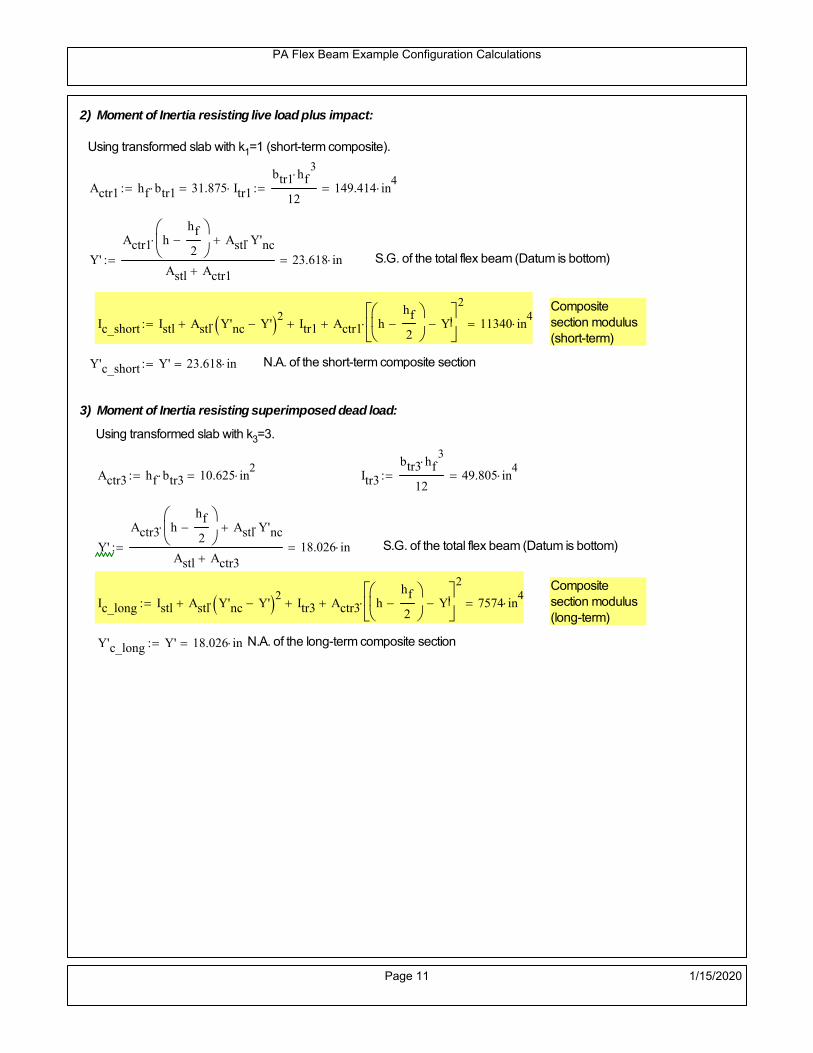
PA Flex Beam Example Configuration Calculations
2) Moment of Inertia resisting live load plus impact:
Using transformed slab with k1=1 (short-term composite).
Actr1 hf btr1 31.875 in2
Itr1
btr1 hf3
12149.414 in
4
Y'
Actr1 hhf
2
Astl Y'nc
Astl Actr123.618 in S.G. of the total flex beam (Datum is bottom)
Compositesection modulus(short-term)
Ic_short Istl Astl Y'nc Y' 2 Itr1 Actr1 hhf
2
Y'
2
11340 in4
Y'c_short Y' 23.618 in N.A. of the short-term composite section
3) Moment of Inertia resisting superimposed dead load:
Using transformed slab with k3=3.
Actr3 hf btr3 10.625 in2
Itr3
btr3 hf3
1249.805 in
4
Y'
Actr3 hhf
2
Astl Y'nc
Astl Actr318.026 in S.G. of the total flex beam (Datum is bottom)
Compositesection modulus(long-term)
Ic_long Istl Astl Y'nc Y' 2 Itr3 Actr3 hhf
2
Y'
2
7574 in4
Y'c_long Y' 18.026 in N.A. of the long-term composite section
Page 11 1/15/2020

PA Flex Beam Example Configuration Calculations
STEP 6.5 Check Ductility RequirementIn accordance with AASHTO Article 6.10.7.3 check ductility requirement. Assume compressionblock of concrete is at 0.85 f'c and that the concrete supports no tension. Steel section isassumed to be fully plastic at Fy.
Case 1 : Assuming PNA is in Concreteh d 4 inAssuming (h-d) < Dp < hf
Fp Dp 0.85 fc be Dp Fy tw Dp h d( ) Fy Astl tw Dp h d( )
Dp 7.5in 0.42 h 15.96 in
Dp1 root Fp Dp Dp 9.765 in Must be less than hf 7.5 inDp1
h0.257 must be < 0.42
Mn1check Dp1 hf h d( ) Dp1[ ] Dp1 0.42 h( ) 0 Dp1 0.42 h 1
Mp1 0.85 fc be Dp1Dp1
2
Fy tw Dp1 h d( )[ ] Dp1 h d( )[ ]
2
Fy bf tf h Dp1tf
2
Fy tw h Dp1 tf h Dp1 tf
2
Mp1 30371.35 kip in Mn1 Mp1 1.07 0.7Dp1
h
27034.4 kip in
Case 2 : Assuming PNA is NOT in Concrete
Assuming hf < Dp
Fp2 Dp 0.85 fc be hf Fy tw Dp h d( ) Fy Astl tw Dp h d( )
Dp 2.5in
Dp2 root Fp2 Dp Dp 13.953 in Must be more than hf 7.5 inDp2
h0.3672 must be < 0.42
Mn2check Dp2 hf Dp2 h( ) Dp2 0.42 h( ) 1 Dp2 0.42 h 1
Mp2 0.85 fc be hf Dp2hf
2
Fy tw Dp2 h d( )[ ] Dp2 h d( )[ ]
2
Fy bf tf h Dp2tf
2
Fy tw h Dp2 tf h Dp2 tf
2
Mp2 29526.72 kip inMn2 Mp2 1.07 0.7
Dp2
h
24004.4 kip in
Mn max Mn1 Mn1check Mn2 Mn2check 2000.4 kip ft Mn 24004.4 kip in
Page 12 1/15/2020
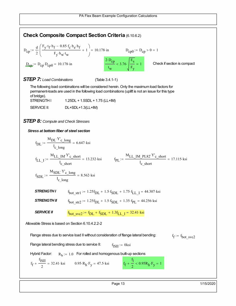
PA Flex Beam Example Configuration Calculations
Check Composite Compact Section Criteria (6.10.6.2)
Dcpd
2
Fy tf bf 0.85 fc be hf
Fy hw tw1
10.178 in Dcp0 Dcp 0 1
Dcp Dcp Dcp0 10.178 in2 Dcp
tw3.76
Es
Fy 1 Check if section is compact
STEP 7: Load Combinations (Table 3.4.1-1)
The following load combinations will be considered herein. Only the maximum load factors forpermanent-loads are used in the following load combinations (uplift is not an issue for this typeof bridge).STRENGTH I 1.25DL + 1.5SDL + 1.75 (LL+IM)
SERVICE II: DL+SDL+1.3(LL+IM)
STEP 8: Compute and Check Stresses
Stress at bottom fiber of steel section
fDL
MDL Y'c_long
Ic_long6.647 ksi
fLL_I
MLL_IM Y'c_short
Ic_short13.232 ksi fPL
MLL_IM_PL82 Y'c_short
Ic_short17.115 ksi
fSDL
MSDL Y'c_long
Ic_long8.562 ksi
STRENGTH I fbot_str1 1.25fDL 1.5 fSDL 1.75 fLL_I 44.307 ksi
STRENGTH II fbot_str2 1.25fDL 1.5 fSDL 1.35 fPL 44.256 ksi
SERVICE II fbot_svc2 fDL fSDL 1.3fLL_I 32.41 ksi
Allowable Stress is based on Section 6.10.4.2.2-2
Flange stress due to service load II without consideration of flange lateral bending: ff fbot_svc2
Flange lateral bending stress due to service II: flSII 0ksi
Hybrid Factor: Rh 1.0 For rolled and homogenous built-up sections
ff
flSII
2 32.41 ksi 0.95 Rh Fy 47.5 ksi ff
fl
2 0.95Rh Fy 1
Page 13 1/15/2020

PA Flex Beam Example Configuration Calculations
Stress at top fiber of concrete
Note: For calculating longitudinal flexural stresses in the concrete deck due to allpermanent and transient loads, the short-term modular ratio shall be used.
fDL
MDL h Y'c_short
k1 n Ic_short0.443 ksi
fLL_I
MLL_IM h Y'c_short
k1 n Ic_short1.007 ksi fPL
MLL_IM_PL82 h Y'c_short
k1 n Ic_short1.303 ksi
fSDL
MSDL h Y'c_short
k1 n Ic_short0.57 ksi
STRENGTH I fc_str1 1.25fDL 1.5 fSDL 1.75 fLL_I 3.172 ksi
Mstr1 1.25 MDL 1.5 MSDL 1.75 MLL_IM 1667.1 kip ft Mstr1 Mn 1
STRENGTH II fc_str2 1.25fDL 1.5 fSDL 1.35 fPL 3.168 ksi
Mstr2 1.25 MDL 1.5 MSDL 1.35 MLL_IM_PL82 1665 kip ft Mstr2 Mn 1
SERVICE II
Allowable Stress in concrete - AASHTO 6.10.4.2.2For compact composite sections in positive flexure utilized in shored construction, the longitudinalcompressive stress in the concrete deck due to the Service II loads, determined as specified in Article6.10.1.1.1d, shall not exceed 0.6f́ c.
fallow 0.6 fc 2400 psi
fc_2 1.3fLL_I fSDL fDL 2322.59 psi This assumes short term compositesection for all calculations
fc_2 fallow 1
SERVICE II with Long Term Composite for dead loads
fDL
MDL h Y'c_long
k3 n Ic_long0.307 ksi
fLL_I
MLL_IM h Y'c_short
k1 n Ic_short1.007 ksi
fSDL
MSDL h Y'c_long
k3 n Ic_long0.395 ksi
fc_2 1.3fLL_I fSDL fDL 2011.6 psi fc_2 fallow 1
Page 14 1/15/2020
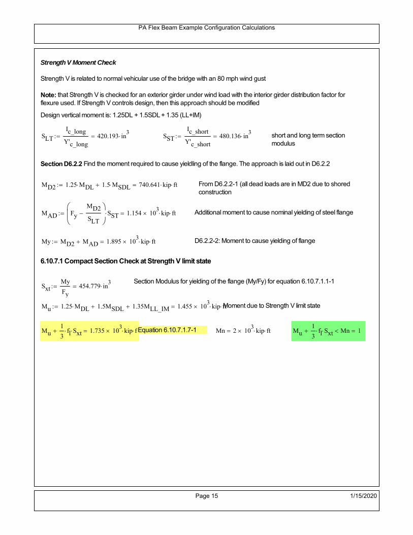
PA Flex Beam Example Configuration Calculations
Strength V Moment Check
Strength V is related to normal vehicular use of the bridge with an 80 mph wind gust
Note: that Strength V is checked for an exterior girder under wind load with the interior girder distribution factor forflexure used. If Strength V controls design, then this approach should be modified
Design vertical moment is: 1.25DL + 1.5SDL + 1.35 (LL+IM)
SLT
Ic_long
Y'c_long420.193 in
3 SST
Ic_short
Y'c_short480.136 in
3 short and long term section
modulus
Section D6.2.2 Find the moment required to cause yieldling of the flange. The approach is laid out in D6.2.2
MD2 1.25 MDL 1.5 MSDL 740.641 kip ft From D6.2.2-1 (all dead loads are in MD2 due to shoredconstruction
MAD Fy
MD2
SLT
SST 1.154 10
3 kip ft Additional moment to cause nominal yielding of steel flange
My MD2 MAD 1.895 103
kip ft D6.2.2-2: Moment to cause yielding of flange
6.10.7.1 Compact Section Check at Strength V limit state
Section Modulus for yielding of the flange (My/Fy) for equation 6.10.7.1.1-1Sxt
My
Fy454.779 in
3
Mu 1.25 MDL 1.5MSDL 1.35MLL_IM 1.455 103
kip ft Moment due to Strength V limit state
Mu1
3fl Sxt 1.735 10
3 kip ft Equation 6.10.7.1.7-1 Mn 2 10
3 kip ft Mu
1
3fl Sxt Mn 1
Page 15 1/15/2020

PA Flex Beam Example Configuration Calculations
STEP 9: Compute Deflection
Optional Live Load Deflection Evaluation (AASHTO 3.6.1.3.2)
Deflection distribution factor for vehicular loads: For a straight multibeambridge, this is equivalent to saying that the distribution factor for deflectionis equal to the number of lanes divided by the number of beams. 2.5.2.6.2
DFd
Nl
N0.2
Deflection should be taken as 125% the larger of:- Design truck- 25% of design truck + design lane
The live load portion of Load Combination Service I of Table 3.4.1-1 should be used,including the dynamic load allowance, IM;
Deflection due to design truck load
NOTE : Assuming maximum deflection occurs when the center of gravity of the loads is at thecenter line of the span.
P1 8kip P2 32kip P3 32kip Axle loads (AASHTO 3.6.1.2.2)
XASr 14ft Rear Axle spacing for truck (14ft - 30ft)
XASf 14ft Front Axle spacing for truck
Center of gravity (CG) of loads:
X'P1 XASr XASf P2 XASr
P1 P2 P39.333 ft Datum is the rear axle
Method1: Assuming single load = P1+P2+P3 at the midspan (Conservative approach)
P1 P2 P3 L3
48 Es Ic_short 2.704 in
Method2: Calculation of Midspan deflection using superposition
b1L
2XASr X' XASf 16.333 ft distance btw load P1 and support A b1check b1 0 1
b2L
2XASr X' 30.333 ft distance btw load P2 and support A b2check b2 0 1
b3L
2X' 25.667 ft distance btw load P3 and support B b3check b3 0 1
Page 16 1/15/2020

PA Flex Beam Example Configuration Calculations
Deflection of the beam at midspan due to P1: P P1
xL
2 at midspan b b1 b1check The smallest distance btw load P1 and support
Δ1P b x
6 Es Ic_short LL2
b2
x2
0.195 in
Deflection of the beam at midspan due to P2: P P2
xL
2 at midspan b b2 b2check The smallest distance btw load P2 and support
Δ2P b x
6 Es Ic_short LL2
b2
x2
1.171 in
Deflection of the beam at midspan due to P3: P P3
xL
2 at midspan b b3 b3check The smallest distance btw load P3 and support
Δ3P b x
6 Es Ic_short LL2
b2
x2
1.085 in
Total Deflection at midspan:
Δtruck Δ1 Δ2 Δ3( ) DFd 1 I( ) 0.652 in (Considering IM)
Deflection due to tandem (Note: this calculation is not required according to Article3.6.1.3.2 which denotes only the design truck for deflection calculation)
Page 17 1/15/2020

PA Flex Beam Example Configuration Calculations
FT 31.25 kip Per axle
XAS 4ft Axle spacing
Δtandem
FTL
2
XAS
2
24 Es Ic_short3 L
2 4
L
2
XAS
2
2
DFd 1 I( ) 0.621 in (Considering IM)
Deflection due to lane load
FDLLd 640lbf
ft DFd 128
lbf
ft
Δlane
5 FDLLd L4
384 Es Ic_short0.21 in
Live Load Deflection:
ΔLL 1.25max Δtruck 0.25Δtruck Δlane 1.25 1.019 in ΔLLL
800 1
Deflection Limit
For steel or concrete vehicular bridges:
Vehicular load = Span/800L
8001.05 in
L
10000.84 in
Evaluation of Deflection at the Service Limit State (AASHTO 3.4.2.2)
The associated permitted deflections shall be included in the contract documents.
Page 18 1/15/2020

PA Flex Beam Example Configuration Calculations
Shear demands:
Determination of the distribution factor
Using DM4 Table 4.6.2.2.3a-1
Sbe
12in2.833 transverse girder spacing (ft)
Distribution of live loads per lane for shear in interior beams:
For two design lanes loaded, 3.5' <= S =< 16', number of beam >= 4DFs 0.36
S
25 0.473
Q Actr1 h Y'c_shorthf
2
338.91 in3
first moment of deck slab for interface shear
Method 1: Range of shear based on Strength I Limit
STRENGTH I 1.25DL + 1.5SDL + 1.75 (LL+IM)
Computation of the range of shear in the beam
Dead Load:DL 0.38
kip
ft
Superimposed Dead Load: SDL 0.489kip
ft
Design Lane Load: 0.64kip
ft
Design Truck:
XASr 14ft Rear Axle spacing for truck (14ft - 30ft)
XASf 14ft Front Axle spacing for truck
P1 8 kip P2 32 kip P3 32 kip Wheel loads (AASHTO 3.6.1.2.2)
Design Tandem:
Consist of a pair of 25-kip axles spaced 4-ft apart. (AASHTO 3.6.1.2.3)
NOTE: PennDOT DM4 increases 25-kip to 31.25-kip.
FT 31.25kip
XAS 4ft Axle spacing
Page 19 1/15/2020

PA Flex Beam Example Configuration Calculations
Maximum positive shear at various points along the FlexBeam are examined.
At x=0 (at left support) (Truck is moving from left to right)
Truck
Max Positive Shear (when P3 is at x = 0):
x1 L XASr XASf 42 ft Distance between P1 and right support
x2 L XASr 56 ft Distance between P2 and right support
x3 L 70 ft Distance between P3 and right support
V1 P3
x3
L P2
x2
L P1
x1
L 62.4 kip
Total Vertical Shear Force for each FlexBeam (considering dynamic loads):
Vtruck1 V1 DFs 1 I( ) 39.283 kip
Tandem:
V1 FT FT
L XAS L
60.714 kip
Total Vertical Shear Force for each FlexBeam (considering dynamic loads):
Vtandem1 V1 DFs 1 I( ) 38.222 kip
Lane Load
V1 0.64kip
ft
L
2 22.4 kip
Total Vertical Shear Force for each FlexBeam (considering dynamic loads):
Vlane1 V1 DFs 10.603 kip
Dead Load
Vdl1 DLL
2 13.299 kip
Superimposed Dead Load
Vsdl1 SDLL
2 17.132 kip
Strength I Max Positive Shear:
Vstr1 1.25 Vdl1 1.5 Vsdl1 1.75 Vlane1 max Vtruck1 Vtandem1 129.622 kip
Page 20 1/15/2020

PA Flex Beam Example Configuration Calculations
Design Permit Load P-82
Shear at x=0
Strength II Max Positive Shear:
VPL82 VPL82span DFs 1 IPL 77.464 kip
STRENGTH II 1.25DL + 1.5SDL + 1.35 (LL+IM)
VstrII_PL 1.25 Vdl1 1.5 Vsdl1 1.35 VPL82 146.899 kip
Max Shear Demand Vu max Vstr1 VstrII_PL 146.899 kip
Determine the Shear Strength of the Web
Shear Strength of Unstiffened web from AASHTO section 6.10.9.2
Depth of Web D d 34 in Thickness of web tw 0.625 in
Transverse Stiffener Spacing d0 0in Shear Buckling Coefficient k 5 6.10.9.3.2-7
Plastic Shear Force Vp 0.58 Fy D tw 616.25 kip Equation 6.10.9.3.2-3
Ratio of Shear-Buckling resistance to shear yield, C
D
tw54.4 1.12
Es k
Fy 60.314 Ccheck
D
tw1.12
Es k
Fy 1 Equation 6.10.9.3.2-4
C 1.0 Ccheck 1 C=1 for most cases, if the criteria are not met, then C will go to zero and the actualcoefficients should be determined
Nominal Shear Resistance of Web Vn C Vp 616.25 kip equation 6.10.9.3.3-1
Shear Resistance Factor φv 1.0
φv Vn 616.25 kip φv Vn Vu 1Reduced Shear Strength
Page 21 1/15/2020

PA Flex Beam Example Configuration Calculations
Check Bearing Stiffeners
FYs 50ksi Yield strength of stiffener
tp 0.75in Thickness of stiffener
bt
bf tw
21.5in 4.188 in Effective width of stiffener
Dst hw 4.1in 29.15 in Depth of stiffeners
Apn 2 tp bt 6.281 in2
Projected area of stiffeners
bt 0.48 tpEs
FYs 1Check that effective width of stiffener meets requirements
Rsbn 1.4 Apn FYs 439.688 kip Bearing capacity of stiffener (phi=1 for bearing per AASHTO 6.5.4.2)
Rsbn Vu 1 Bearing capacity check
Qs 1.0 Q factor for bearing stiffner, taken as 1 (AASHTO 6.9.4.1.1)
Is
18 tw tw3
tp 2 bt 3
1236.943 in
4 Moment of inertia of stiffener and web (9*tw is used on each side)
AASHTO 6.10.11.2.4b
Ag 18 tw tw 2 bt tp 13.313 in2
Gross area of stiffener and web (AASHTO 6.10.11.2.4b)
rs
Is
Ag1.666 in Radius of gyration of stiffener/web
Po Qs FYs Apn 314.062 kip Nominal yeild resistance of stiffener (AASHTO 6.9.4.1.1)
Peπ2Es
0.75 Dst
rs
2Ag 2.212 10
4 kip Elastic critical buckling stress of stiffener (AASHTO 6.9.4.1.2-1)
Check that Pe/Po is great than 0.44 (AASHTO 6.9.4.1.1) PePoPe
Po0.44 1
Pn PePo 0.658
Po
Pe Po 312.202 kip Nominal compressive resistance of stiffener for Pe/Po>0.44
(AASHTO 6.9.4.1.1-1)
φcr 0.95 phi factor for axial compression (AASHTO 6.5.4.2)
Pr φcr Pn 296.592 kip Compressive capacity of bearing stiffener Pr Vu 1
Page 22 1/15/2020

PA Flex Beam Example Configuration Calculations
Flexbeam Example Configuration Calculations
Summary of Calculations:
Input section dimensions and material properties for steel WT and the concrete deck1.Calculate demands (dead load, superimposed dead, and Live load demands for Strength I and Strength II2.Calculate composite section properties for the given section3.Check Strength I, Strength II, and Service II stresses 4.Check Strength I, Strength II, and Strength V moment demands 5.Perform live load deflection check6.Determine maximum shear demand and capacity7.Note: Shear envelope data was obtained from Matlab script (FlexBeam_Moment_ShearEnvelope.m).8.Shear envelope calculations are summarized separately for each design (Shear Design *.xlsx).
Design Assumptions:Design Specifications Used:
AASHTO LRFD Bridge Design Specifications 7th Edition with 2016 Interim RevisionsPennDOT Design Manual, Part 4 (DM-4) June 30, 2015
Example configurations are determined for two girder spacings, 36" and 40".The deck thickness is 7.5" and is assumed to have a non-structural wearing surface added after installation.Section properties are calculated using the full 7.5" deck thickness.The WT sections are embedded 3.5" into the concrete deck. The steel section spacing used is outside the scope of the AASHTO and PennDOT distribution factorequations. The flexural distribution factor is assumed to be 0.3 which was shown to to be conservativeaccording to refined analysisThe shear distribution factor is calculated using the DM-4 shear distribution factor equation which wasshown to be conservative using refined analysis.Refined analysis is presented in: Zihan Ma, "Distribution Factors for Composite Steel Tee Concrete DeckBridge System," M.S. Thesis, Deparement of Civil and Environmental Engineering, Lehigh University,Bethlehem, 2019Shear and moment demands for the PL82 permit load vehicle are determined by Matlab script(FlexBeam_Moment_ShearEnvelope.m) and are manually input into this calculation sheet.All fabrication will occur as double modules, i.e. each module contains two WT sections. The number ofmodules is half the number of beams, N. A 45 in. tall F-Shape barrier is used, Weight = 700 lb/ft (Distributed to exterior two beams).
The work presented in this document are provided on an “AS IS” basis. University makes no warranties of anykind, express or implied, as to any matter whatsoever, including, without limitation, warranties with respect tothe merchantability or fitness for a particular purpose of this work or any project deliverables. Universitymakes no warranty of any kind with respect to freedom from patent, trademark, copyright or trade secretinfringement arising from the use of the results of the project, deliverables, services, intellectual property orother materials provided hereunder. University shall not be liable for any direct, indirect, consequential,punitive, or other damages suffered by Sponsor or any other person resulting from the project, or the use ofthis work or any project deliverables.
Page 1 1/15/2020

PA Flex Beam Example Configuration Calculations
hf
tf
bf
twh
d
bjtbe
e
Variable Definitions:
Number of beams N 10 modulesN
25
L 70ft Span length
be 36in Effective width of Flexbeamassuming constructed bridge width(i.e. closure joints cast)
Built Up Section Properties
tw 0.625in tf 0.75in bf 12in
h 38in Overall Height of section
hf 7.5in Total thickness of deck
e 3.5in Deck/Steel overlap
d h hf e 34 in depth of built up steel section
hw d tf 33.25 in height of web of built up steel
Moment and shear for permit load PL82 obtained from Matlab script: FlexBeam_Moment_ShearEnvelope
MLL_IM_PL82 684.78kip ft Moment due to PL82 with distribution factor and impact factor!!
VPL82span 136.38kip Shear due to PL82 WITHOUT distribution factor and impact factor!!
Check web and flange dimensions in sections 6.10.2.1 and 6.10.2.2
(Ignore 6.10.2.2-4 since no compression flange)
equation 6.10.2.1.1-1d
tw150 1 equation 6.10.2.2-1
bf
2 tf12 1
equation 6.10.2.2-2 bfh
6 1 equation 6.10.2.2-3 tf 1.1 tw 1
y_bar
tf bftf
2 hw tw tf
hw
2
tf bf hw tw12.238 in Center of gravity of steel section
Istl
bf tf3
12bf tf y_bar
tf
2
2
tw hw
3
12 tw hw tf
hw
2 y_bar
2
3.73 103
in4
MOI of steel
Astl tf bf hw tw 29.781 in2
Area of the WT steel section
Page 2 1/15/2020

PA Flex Beam Example Configuration Calculations
Material Properties
Elastic Modulus of Steel Es 29000ksi
Yield Strength of Steel Fy 50ksi
Yield Strength of Reinforcement fy 60ksi
Compressive Strength of Concrete fc 4000psi AAAP PennDOT Concrete
Concrete Modular Ratio n 8 modular ratio for 4ksi concrete per AASHTO
Unit weight of concrete slab wc 0.150kip
ft3
Unit weight of concrete
Section Properties
Width of UHPC Joint: bjt 6in
Parapet width: bpar 20.25in Parapet width per PennDOT F-shape barrier
Width of the bridge W be N bjt 354 in W 29.5 ft
Clear width of roadway Wlane W 2 bpar 26.125 ft
Dc wc hf W 2.766kip
ft DL due to slab
Db .700kip
ft DL due to each 45" F-Shape Barrier (per email 11/1/18)
DFWS 30lbf
ft2
W 2 bpar 0.784kip
ft DL due to Future Wearing Surface (FWS)
Ds Astl 490lbf
ft3
0.101kip
ft Selfweight of the steel section
DLself
Dc N
Ds 0.378kip
ft Self-weight per WT
Total weight of each precast FlexBeam for transportation:
Weight of C12x25 Diaphragms Wend_diaphragms 25lbf
ft32 in 0.067 kip
2be bjt hf wc 2Ds L 2 Wend_diaphragms 50.415 kip
Determine number of design lane (AASHTO Section 3.6.1.1.1)
Take the integer part of the ratio of W/12 ft. Number of lanes in bridge: Nl floorWlane
12ft
2
Page 3 1/15/2020

PA Flex Beam Example Configuration Calculations
STEP 1: Compute Dead Load for each Flex Beam
DLslab
Dc
Nwc 1 in
be
2 0.295
kip
ft Dead load of slab assuming exterior overhang has 1" of
additional concrete thickness
DLsteel Ds 0.101kip
ft
DL DLslab DLsteel 0.397kip
ft
STEP 2: Compute Superimposed Dead Load
SDLWS
DFWS
N0.078
kip
ft
SDLparapet
Db
20.35
kip
ft distributed equally on two outer beams
SDLOL 140lbf
ft3be 2 in 0.07
kip
ft Overlay is 2" thick and is 140 lbs/cubic foot
NOTE: For this example barrier load is distributed equally among the two outer beams per conversation withPennDOT and M&M.
PennDOT DM4: "For composite adjacent and spread beams, the barrier (single barrier) load shall be equallydistributed to the nearest three (adjacent) and two (spread) beams, respectively, when the barriers are placedafter slab has hardened".
SDL SDLWS SDLparapet SDLOL 0.498kip
ft
STEP 3: Compute Transformed Width of Slab
For live load and dead load acting on the stringer k1 1 For short-term section property evaluation
btr1
be
k1 n4.5 in Transformed width of slab for short-term
For superimposed dead loads k3 3 For long-term section property evaluation
btr3
be
k3 n1.5 in Transformed width of slab for long-term
Page 4 1/15/2020

PA Flex Beam Example Configuration Calculations
STEP 4: Compute Dead and Superimposed Dead Load Moments(Based on first interior girder demands)
MDLDL L
2
8242.949 kip ft
MSDLSDL L
2
8305.255 kip ft
STEP 5: Compute live load and Dynamic Load Allowance (IM)
Live load wheel load distribution factor (DF):
Sbe
12in3 transverse girder spacing
NOTE: AASHTO presents equations to define DF for different types of superstructuresincluding Deck Composite wirh RC slab on steel girders (Type (a) in Table 4.6.2.2.1-1) forshear and moment in interior and exterior beams.
Using DM4 Table 4.6.2.2.2b-1:
eg h y_barhf
2 22.012 in Distance between the centers of gravity of the basic beam and deck
Kg n Istl Astl eg2
1.45 10
5 in
4 Longitudinal stiffness parameter (in4)
Distribution of Live Load Per Lane for Moment in Interior Beams:
to be conservative, use DF 0.3
Page 5 1/15/2020

PA Flex Beam Example Configuration Calculations
Dynamic Load Allowance (Section 3.6.2 DM4)
Static effects of the design truck or tandem, shall be increased by the impact factor.
NOTE: The dynamic load allowance shall not be applied to the design lane load (Section 3.6.2.1 DM4)
I 0.33 Impact factor for moment
Note: PennDOT requires that the impact for decks be increased from 33% to 50%, the deck is not beingdesigned here. Instrad the deck design is based on the BD recommendations.
Dynamic load allowance for the Permit Load P-82 shall be less than 20%. (Section 3.6.2.1DM4)
IPL 0.20 Impact factor for moment on Strength II
Design Wind Loading for Exterior Girder
Vw 80 Wind speed for Strength V load case
CD 1.3 Gust factor for windard side of I-Girder and Box Girder Superstructures (Table 3.8.1.2.1-2)
G 1.0 Gus effect factor is 1.0 for all structures other than sound barriers (Table 3.8.1.2.1-1)
Kz 1.0 Pressure coefficient taken as 1 for Strength V (3.8.1.2.1)
Pz 2.56 106
Vw 2 Kz G CDkip
ft2
0.021kip
ft2
Wind pressure on exterior girder
hexp h hf 30.5 in Exposed height of exterior girder
Moment due to wind loading on exterior girderMWL
Pz hexp L2
833.158 kip ft
Iyy
bf3tf
12108 in
4 Transverse moment of intertia
Flange lateral bending stressfl
MWL
bf
2
Iyy22.105 ksi
Page 6 1/15/2020

PA Flex Beam Example Configuration Calculations
Design Vehicular Live Load
PHL-93 and P-82 are examined herein.
PHL-93 (A3.6.1.2.1)
PHL-93 consists of a combination of (design truck or design tandem) + (design lane load)
Design Truck
PennDOT defines the design truck in accordance with AASTHO 3.6.1.2
Design truck load in AASHTO (HS20 Truck) is used for this example.
NOTE : MAX moment occurs when the center line of the span is midway between the center ofgravity of the loads and the nearest concentrated load.
P1 8kip P2 32kip P3 32kip Axle loads (AASHTO 3.6.1.2.2)
XASr 14ft Rear Axle spacing for truck (14ft - 30ft)
XASf 14ft Front Axle spacing for truck
Page 7 1/15/2020

PA Flex Beam Example Configuration Calculations
Center of gravity (CG) of loads:
X'P1 XASr XASf P2 XASr
P1 P2 P39.333 ft Datum is the rear axle
X XASr X' 4.667 ft Spacing btw CG and nearest load
Find bridge reaction
Truck movestoward Support ARA
P1L
2XASf
X
2
P2L
2
X
2
P3L
2X'
X
2
L33.6 kip
Max live load moment (at the location of P2):
MLL_truck RAL
2
X
2
P1 XASf 985.6 kip ft
NOTE: Find the worst case by varying XASr
Page 8 1/15/2020

PA Flex Beam Example Configuration Calculations
Design Tandem
Consist of a pair of 25-kip axles spaced 4-ft apart. (AASHTO 3.6.1.2.3)
NOTE: PennDOT DM4 increases 25-kip to 31.25-kip.
FT 31.25kip
XAS 4ft Axle spacing
Center of gravity (CG) of loads:
XXAS
22 ft Spacing btw CG and nearest load
Find bridge reaction
RA
FTL
2
X
2
FTL
2
X
2 X
L30.357 kip Truck moves toward Support A
Max live load moment (at the location of front wheel):
MLL_tandem RAL
2
X
2
1.032 103
kip ft
Choose the max value:
MLL_veh max MLL_tandem MLL_truck 1.032 103
kip ft
Apply the impact and wheel load distribution:
MLL_IM_veh MLL_veh DF 1 I( ) 411.825 kip ft Due to tandem or truck
Design Lane Load (distributed over a 10-ft width for each lane)
NOTE: The uniform load may be continuous or discontinuous as necessary to produce themaximum force effect. For this example continuous uniform distribution assumed.
FDLL 0.64kip
ftDF 0.192
kip
ft Per beam in each lane
Due to lane loadMLL_IM_lane
FDLL L2
8
117.6 kip ft
Moment due to Total Design Vehicular Live Load: MLL_IM MLL_IM_lane MLL_IM_veh 529.425 kip ft
Page 9 1/15/2020

PA Flex Beam Example Configuration Calculations
Design Permit Load P-82 (Section 3.6.1.2.7 DM4)
P1 P2 P3 P4 P5 P6 P7
NOTE: The moment for the permit load is defined at the beginning of the sheetand is obtained from MATLab File FlexBeam_Moment_ShearEnvelope.m
STEP 6: Compute Moment of Inertia (Note: rebar neglected!)
1) Moment of Inertia resisting dead load only:
a) Acting on the non-composite section (before the deck has hardened - DC1)
Use steel section only
Inc Istl 3.73 103
in4
Non-composite section modulus
Y'nc y_bar S.G. of the steel section of Flex Beam (Datum is bottom)
b) Acting on the composite section (after the deck has hardened - DC2)
Use Ic_short as defined below.
Page 10 1/15/2020

PA Flex Beam Example Configuration Calculations
2) Moment of Inertia resisting live load plus impact:
Using transformed slab with k1=1 (short-term composite).
Actr1 hf btr1 33.75 in2
Itr1
btr1 hf3
12158.203 in
4
Y'
Actr1 hhf
2
Astl Y'nc
Astl Actr123.931 in S.G. of the total flex beam (Datum is bottom)
Compositesection modulus(short-term)
Ic_short Istl Astl Y'nc Y' 2 Itr1 Actr1 hhf
2
Y'
2
11554 in4
Y'c_short Y' 23.931 in N.A. of the short-term composite section
3) Moment of Inertia resisting superimposed dead load:
Using transformed slab with k3=3.
Actr3 hf btr3 11.25 in2
Itr3
btr3 hf3
1252.734 in
4
Y'
Actr3 hhf
2
Astl Y'nc
Astl Actr318.273 in S.G. of the total flex beam (Datum is bottom)
Compositesection modulus(long-term)
Ic_long Istl Astl Y'nc Y' 2 Itr3 Actr3 hhf
2
Y'
2
7739 in4
Y'c_long Y' 18.273 in N.A. of the long-term composite section
Page 11 1/15/2020
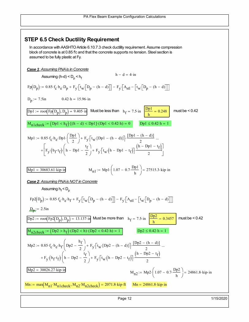
PA Flex Beam Example Configuration Calculations
STEP 6.5 Check Ductility RequirementIn accordance with AASHTO Article 6.10.7.3 check ductility requirement. Assume compressionblock of concrete is at 0.85 f'c and that the concrete supports no tension. Steel section isassumed to be fully plastic at Fy.
Case 1 : Assuming PNA is in Concreteh d 4 inAssuming (h-d) < Dp < hf
Fp Dp 0.85 fc be Dp Fy tw Dp h d( ) Fy Astl tw Dp h d( )
Dp 7.5in 0.42 h 15.96 in
Dp1 root Fp Dp Dp 9.405 in Must be less than hf 7.5 inDp1
h0.248 must be < 0.42
Mn1check Dp1 hf h d( ) Dp1[ ] Dp1 0.42 h( ) 0 Dp1 0.42 h 1
Mp1 0.85 fc be Dp1Dp1
2
Fy tw Dp1 h d( )[ ] Dp1 h d( )[ ]
2
Fy bf tf h Dp1tf
2
Fy tw h Dp1 tf h Dp1 tf
2
Mp1 30683.61 kip in Mn1 Mp1 1.07 0.7Dp1
h
27515.3 kip in
Case 2 : Assuming PNA is NOT in Concrete
Assuming hf < Dp
Fp2 Dp 0.85 fc be hf Fy tw Dp h d( ) Fy Astl tw Dp h d( )
Dp 2.5in
Dp2 root Fp2 Dp Dp 13.137 in Must be more than hf 7.5 inDp2
h0.3457 must be < 0.42
Mn2check Dp2 hf Dp2 h( ) Dp2 0.42 h( ) 1 Dp2 0.42 h 1
Mp2 0.85 fc be hf Dp2hf
2
Fy tw Dp2 h d( )[ ] Dp2 h d( )[ ]
2
Fy bf tf h Dp2tf
2
Fy tw h Dp2 tf h Dp2 tf
2
Mp2 30026.27 kip inMn2 Mp2 1.07 0.7
Dp2
h
24861.8 kip in
Mn max Mn1 Mn1check Mn2 Mn2check 2071.8 kip ft Mn 24861.8 kip in
Page 12 1/15/2020

PA Flex Beam Example Configuration Calculations
Check Composite Compact Section Criteria (6.10.6.2)
Dcpd
2
Fy tf bf 0.85 fc be hf
Fy hw tw1
9.343 in Dcp0 Dcp 0 1
Dcp Dcp Dcp0 9.343 in2 Dcp
tw3.76
Es
Fy 1 Check if section is compact
STEP 7: Load Combinations (Table 3.4.1-1)
The following load combinations will be considered herein. Only the maximum load factors forpermanent-loads are used in the following load combinations (uplift is not an issue for this typeof bridge).STRENGTH I 1.25DL + 1.5SDL + 1.75 (LL+IM)
SERVICE II: DL+SDL+1.3(LL+IM)
STEP 8: Compute and Check Stresses
Stress at bottom fiber of steel section
fDL
MDL Y'c_long
Ic_long6.883 ksi
fLL_I
MLL_IM Y'c_short
Ic_short13.159 ksi fPL
MLL_IM_PL82 Y'c_short
Ic_short17.02 ksi
fSDL
MSDL Y'c_long
Ic_long8.649 ksi
STRENGTH I fbot_str1 1.25fDL 1.5 fSDL 1.75 fLL_I 44.605 ksi
STRENGTH II fbot_str2 1.25fDL 1.5 fSDL 1.35 fPL 44.554 ksi
SERVICE II fbot_svc2 fDL fSDL 1.3fLL_I 32.64 ksi
Allowable Stress is based on Section 6.10.4.2.2-2
Flange stress due to service load II without consideration of flange lateral bending: ff fbot_svc2
Flange lateral bending stress due to service II: flSII 0ksi
Hybrid Factor: Rh 1.0 For rolled and homogenous built-up sections
ff
flSII
2 32.639 ksi 0.95 Rh Fy 47.5 ksi ff
fl
2 0.95Rh Fy 1
Page 13 1/15/2020

PA Flex Beam Example Configuration Calculations
Stress at top fiber of concrete
Note: For calculating longitudinal flexural stresses in the concrete deck due to allpermanent and transient loads, the short-term modular ratio shall be used.
fDL
MDL h Y'c_short
k1 n Ic_short0.444 ksi
fLL_I
MLL_IM h Y'c_short
k1 n Ic_short0.967 ksi fPL
MLL_IM_PL82 h Y'c_short
k1 n Ic_short1.251 ksi
fSDL
MSDL h Y'c_short
k1 n Ic_short0.558 ksi
STRENGTH I fc_str1 1.25fDL 1.5 fSDL 1.75 fLL_I 3.083 ksi
Mstr1 1.25 MDL 1.5 MSDL 1.75 MLL_IM 1688.1 kip ft Mstr1 Mn 1
STRENGTH II fc_str2 1.25fDL 1.5 fSDL 1.35 fPL 3.079 ksi
Mstr2 1.25 MDL 1.5 MSDL 1.35 MLL_IM_PL82 1686 kip ft Mstr2 Mn 1
SERVICE II
Allowable Stress in concrete - AASHTO 6.10.4.2.2For compact composite sections in positive flexure utilized in shored construction, the longitudinalcompressive stress in the concrete deck due to the Service II loads, determined as specified in Article6.10.1.1.1d, shall not exceed 0.6f́ c.
fallow 0.6 fc 2400 psi
fc_2 1.3fLL_I fSDL fDL 2258.32 psi This assumes short term compositesection for all calculations
fc_2 fallow 1
SERVICE II with Long Term Composite for dead loads
fDL
MDL h Y'c_long
k3 n Ic_long0.31 ksi
fLL_I
MLL_IM h Y'c_short
k1 n Ic_short0.967 ksi
fSDL
MSDL h Y'c_long
k3 n Ic_long0.389 ksi
fc_2 1.3fLL_I fSDL fDL 1955.73 psi fc_2 fallow 1
Page 14 1/15/2020

PA Flex Beam Example Configuration Calculations
Strength V Moment Check
Strength V is related to normal vehicular use of the bridge with an 80 mph wind gust
Note: that Strength V is checked for an exterior girder under wind load with the interior girder distribution factor forflexure used. If Strength V controls design, then this approach should be modified
Design vertical moment is: 1.25DL + 1.5SDL + 1.35 (LL+IM)
SLT
Ic_long
Y'c_long423.537 in
3 SST
Ic_short
Y'c_short482.804 in
3 short and long term section
modulus
Section D6.2.2 Find the moment required to cause yieldling of the flange. The approach is laid out in D6.2.2
MD2 1.25 MDL 1.5 MSDL 761.568 kip ft From D6.2.2-1 (all dead loads are in MD2 due to shoredconstruction
MAD Fy
MD2
SLT
SST 1.144 10
3 kip ft Additional moment to cause nominal yielding of steel flange
My MD2 MAD 1.905 103
kip ft D6.2.2-2: Moment to cause yielding of flange
6.10.7.1 Compact Section Check at Strength V limit state
Section Modulus for yielding of the flange (My/Fy) for equation 6.10.7.1.1-1Sxt
My
Fy457.227 in
3
Mu 1.25 MDL 1.5MSDL 1.35MLL_IM 1.476 103
kip ft Moment due to Strength V limit state
Mu1
3fl Sxt 1.757 10
3 kip ft Equation 6.10.7.1.7-1 Mn 2.072 10
3 kip ft Mu
1
3fl Sxt Mn 1
Page 15 1/15/2020

PA Flex Beam Example Configuration Calculations
STEP 9: Compute Deflection
Optional Live Load Deflection Evaluation (AASHTO 3.6.1.3.2)
Deflection distribution factor for vehicular loads: For a straight multibeambridge, this is equivalent to saying that the distribution factor for deflectionis equal to the number of lanes divided by the number of beams. 2.5.2.6.2
DFd
Nl
N0.2
Deflection should be taken as 125% the larger of:- Design truck- 25% of design truck + design lane
The live load portion of Load Combination Service I of Table 3.4.1-1 should be used,including the dynamic load allowance, IM;
Deflection due to design truck load
NOTE : Assuming maximum deflection occurs when the center of gravity of the loads is at thecenter line of the span.
P1 8kip P2 32kip P3 32kip Axle loads (AASHTO 3.6.1.2.2)
XASr 14ft Rear Axle spacing for truck (14ft - 30ft)
XASf 14ft Front Axle spacing for truck
Center of gravity (CG) of loads:
X'P1 XASr XASf P2 XASr
P1 P2 P39.333 ft Datum is the rear axle
Method1: Assuming single load = P1+P2+P3 at the midspan (Conservative approach)
P1 P2 P3 L3
48 Es Ic_short 2.653 in
Method2: Calculation of Midspan deflection using superposition
b1L
2XASr X' XASf 16.333 ft distance btw load P1 and support A b1check b1 0 1
b2L
2XASr X' 30.333 ft distance btw load P2 and support A b2check b2 0 1
b3L
2X' 25.667 ft distance btw load P3 and support B b3check b3 0 1
Page 16 1/15/2020

PA Flex Beam Example Configuration Calculations
Deflection of the beam at midspan due to P1: P P1
xL
2 at midspan b b1 b1check The smallest distance btw load P1 and support
Δ1P b x
6 Es Ic_short LL2
b2
x2
0.191 in
Deflection of the beam at midspan due to P2: P P2
xL
2 at midspan b b2 b2check The smallest distance btw load P2 and support
Δ2P b x
6 Es Ic_short LL2
b2
x2
1.149 in
Deflection of the beam at midspan due to P3: P P3
xL
2 at midspan b b3 b3check The smallest distance btw load P3 and support
Δ3P b x
6 Es Ic_short LL2
b2
x2
1.065 in
Total Deflection at midspan:
Δtruck Δ1 Δ2 Δ3( ) DFd 1 I( ) 0.64 in (Considering IM)
Deflection due to tandem (Note: this calculation is not required according to Article3.6.1.3.2 which denotes only the design truck for deflection calculation)
Page 17 1/15/2020

PA Flex Beam Example Configuration Calculations
FT 31.25 kip Per axle
XAS 4ft Axle spacing
Δtandem
FTL
2
XAS
2
24 Es Ic_short3 L
2 4
L
2
XAS
2
2
DFd 1 I( ) 0.61 in (Considering IM)
Deflection due to lane load
FDLLd 640lbf
ft DFd 128
lbf
ft
Δlane
5 FDLLd L4
384 Es Ic_short0.206 in
Live Load Deflection:
ΔLL 1.25max Δtruck 0.25Δtruck Δlane 1.25 1.000 in ΔLLL
800 1
Deflection Limit
For steel or concrete vehicular bridges:
Vehicular load = Span/800L
8001.05 in
L
10000.84 in
Evaluation of Deflection at the Service Limit State (AASHTO 3.4.2.2)
The associated permitted deflections shall be included in the contract documents.
Page 18 1/15/2020

PA Flex Beam Example Configuration Calculations
Shear demands:
Determination of the distribution factor
Using DM4 Table 4.6.2.2.3a-1
Sbe
12in3 transverse girder spacing (ft)
Distribution of live loads per lane for shear in interior beams:
For two design lanes loaded, 3.5' <= S =< 16', number of beam >= 4DFs 0.36
S
25 0.48
Q Actr1 h Y'c_shorthf
2
348.255 in3
first moment of deck slab for interface shear
Method 1: Range of shear based on Strength I Limit
STRENGTH I 1.25DL + 1.5SDL + 1.75 (LL+IM)
Computation of the range of shear in the beam
Dead Load:DL 0.397
kip
ft
Superimposed Dead Load: SDL 0.498kip
ft
Design Lane Load: 0.64kip
ft
Design Truck:
XASr 14ft Rear Axle spacing for truck (14ft - 30ft)
XASf 14ft Front Axle spacing for truck
P1 8 kip P2 32 kip P3 32 kip Wheel loads (AASHTO 3.6.1.2.2)
Design Tandem:
Consist of a pair of 25-kip axles spaced 4-ft apart. (AASHTO 3.6.1.2.3)
NOTE: PennDOT DM4 increases 25-kip to 31.25-kip.
FT 31.25kip
XAS 4ft Axle spacing
Page 19 1/15/2020

PA Flex Beam Example Configuration Calculations
Maximum positive shear at various points along the FlexBeam are examined.
At x=0 (at left support) (Truck is moving from left to right)
Truck
Max Positive Shear (when P3 is at x = 0):
x1 L XASr XASf 42 ft Distance between P1 and right support
x2 L XASr 56 ft Distance between P2 and right support
x3 L 70 ft Distance between P3 and right support
V1 P3
x3
L P2
x2
L P1
x1
L 62.4 kip
Total Vertical Shear Force for each FlexBeam (considering dynamic loads):
Vtruck1 V1 DFs 1 I( ) 39.836 kip
Tandem:
V1 FT FT
L XAS L
60.714 kip
Total Vertical Shear Force for each FlexBeam (considering dynamic loads):
Vtandem1 V1 DFs 1 I( ) 38.76 kip
Lane Load
V1 0.64kip
ft
L
2 22.4 kip
Total Vertical Shear Force for each FlexBeam (considering dynamic loads):
Vlane1 V1 DFs 10.752 kip
Dead Load
Vdl1 DLL
2 13.883 kip
Superimposed Dead Load
Vsdl1 SDLL
2 17.443 kip
Strength I Max Positive Shear:
Vstr1 1.25 Vdl1 1.5 Vsdl1 1.75 Vlane1 max Vtruck1 Vtandem1 132.047 kip
Page 20 1/15/2020

PA Flex Beam Example Configuration Calculations
Design Permit Load P-82
Shear at x=0
Strength II Max Positive Shear:
VPL82 VPL82span DFs 1 IPL 78.555 kip
STRENGTH II 1.25DL + 1.5SDL + 1.35 (LL+IM)
VstrII_PL 1.25 Vdl1 1.5 Vsdl1 1.35 VPL82 149.567 kip
Max Shear Demand Vu max Vstr1 VstrII_PL 149.567 kip
Determine the Shear Strength of the Web
Shear Strength of Unstiffened web from AASHTO section 6.10.9.2
Depth of Web D d 34 in Thickness of web tw 0.625 in
Transverse Stiffener Spacing d0 0in Shear Buckling Coefficient k 5 6.10.9.3.2-7
Plastic Shear Force Vp 0.58 Fy D tw 616.25 kip Equation 6.10.9.3.2-3
Ratio of Shear-Buckling resistance to shear yield, C
D
tw54.4 1.12
Es k
Fy 60.314 Ccheck
D
tw1.12
Es k
Fy 1 Equation 6.10.9.3.2-4
C 1.0 Ccheck 1 C=1 for most cases, if the criteria are not met, then C will go to zero and the actualcoefficients should be determined
Nominal Shear Resistance of Web Vn C Vp 616.25 kip equation 6.10.9.3.3-1
Shear Resistance Factor φv 1.0
φv Vn 616.25 kip φv Vn Vu 1Reduced Shear Strength
Page 21 1/15/2020

PA Flex Beam Example Configuration Calculations
Check Bearing Stiffeners
FYs 50ksi Yield strength of stiffener
tp 0.75in Thickness of stiffener
bt
bf tw
21.5in 4.188 in Effective width of stiffener
Dst hw 4.1in 29.15 in Depth of stiffeners
Apn 2 tp bt 6.281 in2
Projected area of stiffeners
bt 0.48 tpEs
FYs 1Check that effective width of stiffener meets requirements
Rsbn 1.4 Apn FYs 439.688 kip Bearing capacity of stiffener (phi=1 for bearing per AASHTO 6.5.4.2)
Rsbn Vu 1 Bearing capacity check
Qs 1.0 Q factor for bearing stiffner, taken as 1 (AASHTO 6.9.4.1.1)
Is
18 tw tw3
tp 2 bt 3
1236.943 in
4 Moment of inertia of stiffener and web (9*tw is used on each side)
AASHTO 6.10.11.2.4b
Ag 18 tw tw 2 bt tp 13.313 in2
Gross area of stiffener and web (AASHTO 6.10.11.2.4b)
rs
Is
Ag1.666 in Radius of gyration of stiffener/web
Po Qs FYs Apn 314.062 kip Nominal yeild resistance of stiffener (AASHTO 6.9.4.1.1)
Peπ2Es
0.75 Dst
rs
2Ag 2.212 10
4 kip Elastic critical buckling stress of stiffener (AASHTO 6.9.4.1.2-1)
Check that Pe/Po is great than 0.44 (AASHTO 6.9.4.1.1) PePoPe
Po0.44 1
Pn PePo 0.658
Po
Pe Po 312.202 kip Nominal compressive resistance of stiffener for Pe/Po>0.44
(AASHTO 6.9.4.1.1-1)
φcr 0.95 phi factor for axial compression (AASHTO 6.5.4.2)
Pr φcr Pn 296.592 kip Compressive capacity of bearing stiffener Pr Vu 1
Page 22 1/15/2020

PA Flex Beam Example Configuration Calculations
Flexbeam Example Configuration Calculations
Summary of Calculations:
Input section dimensions and material properties for steel WT and the concrete deck1.Calculate demands (dead load, superimposed dead, and Live load demands for Strength I and Strength II2.Calculate composite section properties for the given section3.Check Strength I, Strength II, and Service II stresses 4.Check Strength I, Strength II, and Strength V moment demands 5.Perform live load deflection check6.Determine maximum shear demand and capacity7.Note: Shear envelope data was obtained from Matlab script (FlexBeam_Moment_ShearEnvelope.m).8.Shear envelope calculations are summarized separately for each design (Shear Design *.xlsx).
Design Assumptions:Design Specifications Used:
AASHTO LRFD Bridge Design Specifications 7th Edition with 2016 Interim RevisionsPennDOT Design Manual, Part 4 (DM-4) June 30, 2015
Example configurations are determined for two girder spacings, 36" and 40".The deck thickness is 7.5" and is assumed to have a non-structural wearing surface added after installation.Section properties are calculated using the full 7.5" deck thickness.The WT sections are embedded 3.5" into the concrete deck. TThe steel section spacing used is outside the scope of the AASHTO and PennDOT distribution factorequations. The flexural distribution factor is assumed to be 0.3 which was shown to to be conservativeaccording to refined analysisThe shear distribution factor is calculated using the DM-4 shear distribution factor equation which wasshown to be conservative using refined analysis.Refined analysis is presented in: Zihan Ma, "Distribution Factors for Composite Steel Tee Concrete DeckBridge System," M.S. Thesis, Deparement of Civil and Environmental Engineering, Lehigh University,Bethlehem, 2019Shear and moment demands for the PL82 permit load vehicle are determined by Matlab script(FlexBeam_Moment_ShearEnvelope.m) and are manually input into this calculation sheet.All fabrication will occur as double modules, i.e. each module contains two WT sections. The number ofmodules is half the number of beams, N. A 45 in. tall F-Shape barrier is used, Weight = 700 lb/ft (Distributed to exterior two beams).
The work presented in this document are provided on an “AS IS” basis. University makes no warranties of anykind, express or implied, as to any matter whatsoever, including, without limitation, warranties with respect tothe merchantability or fitness for a particular purpose of this work or any project deliverables. Universitymakes no warranty of any kind with respect to freedom from patent, trademark, copyright or trade secretinfringement arising from the use of the results of the project, deliverables, services, intellectual property orother materials provided hereunder. University shall not be liable for any direct, indirect, consequential,punitive, or other damages suffered by Sponsor or any other person resulting from the project, or the use ofthis work or any project deliverables.
Page 1 1/15/2020

PA Flex Beam Example Configuration Calculations
hf
tf
bf
twh
d
bjtbe
e
Variable Definitions:
Number of beams N 12 modulesN
26
L 70ft Span length
be 36in Effective width of Flexbeamassuming constructed bridge width(i.e. closure joints cast)
Built Up Section Properties
tw 0.625in tf 0.75in bf 12in
h 38in Overall Height of section
hf 7.5in Total thickness of deck
e 3.5in Deck/Steel overlap
d h hf e 34 in depth of built up steel section
hw d tf 33.25 in height of web of built up steel
Moment and shear for permit load PL82 obtained from Matlab script: FlexBeam_Moment_ShearEnvelope
MLL_IM_PL82 684.78kip ft Moment due to PL82 with distribution factor and impact factor!!
VPL82span 136.38kip Shear due to PL82 WITHOUT distribution factor and impact factor!!
Check web and flange dimensions in sections 6.10.2.1 and 6.10.2.2
(Ignore 6.10.2.2-4 since no compression flange)
equation 6.10.2.1.1-1d
tw150 1 equation 6.10.2.2-1
bf
2 tf12 1
equation 6.10.2.2-2 bfh
6 1 equation 6.10.2.2-3 tf 1.1 tw 1
y_bar
tf bftf
2 hw tw tf
hw
2
tf bf hw tw12.238 in Center of gravity of steel section
Istl
bf tf3
12bf tf y_bar
tf
2
2
tw hw
3
12 tw hw tf
hw
2 y_bar
2
3.73 103
in4
MOI of steel
Astl tf bf hw tw 29.781 in2
Area of the WT steel section
Page 2 1/15/2020

PA Flex Beam Example Configuration Calculations
Material Properties
Elastic Modulus of Steel Es 29000ksi
Yield Strength of Steel Fy 50ksi
Yield Strength of Reinforcement fy 60ksi
Compressive Strength of Concrete fc 4000psi AAAP PennDOT Concrete
Concrete Modular Ratio n 8 modular ratio for 4ksi concrete per AASHTO
Unit weight of concrete slab wc 0.150kip
ft3
Unit weight of concrete
Section Properties
Width of UHPC Joint: bjt 6in
Parapet width: bpar 20.25in Parapet width per PennDOT F-shape barrier
Width of the bridge W be N bjt 426 in W 35.5 ft
Clear width of roadway Wlane W 2 bpar 32.125 ft
Dc wc hf W 3.328kip
ft DL due to slab
Db .700kip
ft DL due to each 45" F-Shape Barrier (per email 11/1/18)
DFWS 30lbf
ft2
W 2 bpar 0.964kip
ft DL due to Future Wearing Surface (FWS)
Ds Astl 490lbf
ft3
0.101kip
ft Selfweight of the steel section
DLself
Dc N
Ds 0.379kip
ft Self-weight per WT
Total weight of each precast FlexBeam for transportation:
Weight of C12x25 Diaphragms Wend_diaphragms 25lbf
ft32 in 0.067 kip
2be bjt hf wc 2Ds L 2 Wend_diaphragms 50.415 kip
Determine number of design lane (AASHTO Section 3.6.1.1.1)
Take the integer part of the ratio of W/12 ft. Number of lanes in bridge: Nl floorWlane
12ft
2
Page 3 1/15/2020

PA Flex Beam Example Configuration Calculations
STEP 1: Compute Dead Load for each Flex Beam
DLslab
Dc
Nwc 1 in
be
2 0.296
kip
ft Dead load of slab assuming exterior overhang has 1" of
additional concrete thickness
DLsteel Ds 0.101kip
ft
DL DLslab DLsteel 0.397kip
ft
STEP 2: Compute Superimposed Dead Load
SDLWS
DFWS
N0.08
kip
ft
SDLparapet
Db
20.35
kip
ft distributed equally on two outer beams
SDLOL 140lbf
ft3be 2 in 0.07
kip
ft Overlay is 2" thick and is 140 lbs/cubic foot
NOTE: For this example barrier load is distributed equally among the two outer beams per conversation withPennDOT and M&M.
PennDOT DM4: "For composite adjacent and spread beams, the barrier (single barrier) load shall be equallydistributed to the nearest three (adjacent) and two (spread) beams, respectively, when the barriers are placedafter slab has hardened".
SDL SDLWS SDLparapet SDLOL 0.5kip
ft
STEP 3: Compute Transformed Width of Slab
For live load and dead load acting on the stringer k1 1 For short-term section property evaluation
btr1
be
k1 n4.5 in Transformed width of slab for short-term
For superimposed dead loads k3 3 For long-term section property evaluation
btr3
be
k3 n1.5 in Transformed width of slab for long-term
Page 4 1/15/2020

PA Flex Beam Example Configuration Calculations
STEP 4: Compute Dead and Superimposed Dead Load Moments(Based on first interior girder demands)
MDLDL L
2
8243.428 kip ft
MSDLSDL L
2
8306.441 kip ft
STEP 5: Compute live load and Dynamic Load Allowance (IM)
Live load wheel load distribution factor (DF):
Sbe
12in3 transverse girder spacing
NOTE: AASHTO presents equations to define DF for different types of superstructuresincluding Deck Composite wirh RC slab on steel girders (Type (a) in Table 4.6.2.2.1-1) forshear and moment in interior and exterior beams.
Using DM4 Table 4.6.2.2.2b-1:
eg h y_barhf
2 22.012 in Distance between the centers of gravity of the basic beam and deck
Kg n Istl Astl eg2
1.45 10
5 in
4 Longitudinal stiffness parameter (in4)
Distribution of Live Load Per Lane for Moment in Interior Beams:
to be conservative, use DF 0.3
Page 5 1/15/2020

PA Flex Beam Example Configuration Calculations
Dynamic Load Allowance (Section 3.6.2 DM4)
Static effects of the design truck or tandem, shall be increased by the impact factor.
NOTE: The dynamic load allowance shall not be applied to the design lane load (Section 3.6.2.1 DM4)
I 0.33 Impact factor for moment
Note: PennDOT requires that the impact for decks be increased from 33% to 50%, the deck is not beingdesigned here. Instrad the deck design is based on the BD recommendations.
Dynamic load allowance for the Permit Load P-82 shall be less than 20%. (Section 3.6.2.1DM4)
IPL 0.20 Impact factor for moment on Strength II
Design Wind Loading for Exterior Girder
Vw 80 Wind speed for Strength V load case
CD 1.3 Gust factor for windard side of I-Girder and Box Girder Superstructures (Table 3.8.1.2.1-2)
G 1.0 Gus effect factor is 1.0 for all structures other than sound barriers (Table 3.8.1.2.1-1)
Kz 1.0 Pressure coefficient taken as 1 for Strength V (3.8.1.2.1)
Pz 2.56 106
Vw 2 Kz G CDkip
ft2
0.021kip
ft2
Wind pressure on exterior girder
hexp h hf 30.5 in Exposed height of exterior girder
Moment due to wind loading on exterior girderMWL
Pz hexp L2
833.158 kip ft
Iyy
bf3tf
12108 in
4 Transverse moment of intertia
Flange lateral bending stressfl
MWL
bf
2
Iyy22.105 ksi
Page 6 1/15/2020

PA Flex Beam Example Configuration Calculations
Design Vehicular Live Load
PHL-93 and P-82 are examined herein.
PHL-93 (A3.6.1.2.1)
PHL-93 consists of a combination of (design truck or design tandem) + (design lane load)
Design Truck
PennDOT defines the design truck in accordance with AASTHO 3.6.1.2
Design truck load in AASHTO (HS20 Truck) is used for this example.
NOTE : MAX moment occurs when the center line of the span is midway between the center ofgravity of the loads and the nearest concentrated load.
P1 8kip P2 32kip P3 32kip Axle loads (AASHTO 3.6.1.2.2)
XASr 14ft Rear Axle spacing for truck (14ft - 30ft)
XASf 14ft Front Axle spacing for truck
Page 7 1/15/2020

PA Flex Beam Example Configuration Calculations
Center of gravity (CG) of loads:
X'P1 XASr XASf P2 XASr
P1 P2 P39.333 ft Datum is the rear axle
X XASr X' 4.667 ft Spacing btw CG and nearest load
Find bridge reaction
Truck movestoward Support ARA
P1L
2XASf
X
2
P2L
2
X
2
P3L
2X'
X
2
L33.6 kip
Max live load moment (at the location of P2):
MLL_truck RAL
2
X
2
P1 XASf 985.6 kip ft
NOTE: Find the worst case by varying XASr
Page 8 1/15/2020

PA Flex Beam Example Configuration Calculations
Design Tandem
Consist of a pair of 25-kip axles spaced 4-ft apart. (AASHTO 3.6.1.2.3)
NOTE: PennDOT DM4 increases 25-kip to 31.25-kip.
FT 31.25kip
XAS 4ft Axle spacing
Center of gravity (CG) of loads:
XXAS
22 ft Spacing btw CG and nearest load
Find bridge reaction
RA
FTL
2
X
2
FTL
2
X
2 X
L30.357 kip Truck moves toward Support A
Max live load moment (at the location of front wheel):
MLL_tandem RAL
2
X
2
1.032 103
kip ft
Choose the max value:
MLL_veh max MLL_tandem MLL_truck 1.032 103
kip ft
Apply the impact and wheel load distribution:
MLL_IM_veh MLL_veh DF 1 I( ) 411.825 kip ft Due to tandem or truck
Design Lane Load (distributed over a 10-ft width for each lane)
NOTE: The uniform load may be continuous or discontinuous as necessary to produce themaximum force effect. For this example continuous uniform distribution assumed.
FDLL 0.64kip
ftDF 0.192
kip
ft Per beam in each lane
Due to lane loadMLL_IM_lane
FDLL L2
8
117.6 kip ft
Moment due to Total Design Vehicular Live Load: MLL_IM MLL_IM_lane MLL_IM_veh 529.425 kip ft
Page 9 1/15/2020

PA Flex Beam Example Configuration Calculations
Design Permit Load P-82 (Section 3.6.1.2.7 DM4)
P1 P2 P3 P4 P5 P6 P7
NOTE: The moment for the permit load is defined at the beginning of the sheetand is obtained from MATLab File FlexBeam_Moment_ShearEnvelope.m
STEP 6: Compute Moment of Inertia (Note: rebar neglected!)
1) Moment of Inertia resisting dead load only:
a) Acting on the non-composite section (before the deck has hardened - DC1)
Use steel section only
Inc Istl 3.73 103
in4
Non-composite section modulus
Y'nc y_bar S.G. of the steel section of Flex Beam (Datum is bottom)
b) Acting on the composite section (after the deck has hardened - DC2)
Use Ic_short as defined below.
Page 10 1/15/2020

PA Flex Beam Example Configuration Calculations
2) Moment of Inertia resisting live load plus impact:
Using transformed slab with k1=1 (short-term composite).
Actr1 hf btr1 33.75 in2
Itr1
btr1 hf3
12158.203 in
4
Y'
Actr1 hhf
2
Astl Y'nc
Astl Actr123.931 in S.G. of the total flex beam (Datum is bottom)
Compositesection modulus(short-term)
Ic_short Istl Astl Y'nc Y' 2 Itr1 Actr1 hhf
2
Y'
2
11554 in4
Y'c_short Y' 23.931 in N.A. of the short-term composite section
3) Moment of Inertia resisting superimposed dead load:
Using transformed slab with k3=3.
Actr3 hf btr3 11.25 in2
Itr3
btr3 hf3
1252.734 in
4
Y'
Actr3 hhf
2
Astl Y'nc
Astl Actr318.273 in S.G. of the total flex beam (Datum is bottom)
Compositesection modulus(long-term)
Ic_long Istl Astl Y'nc Y' 2 Itr3 Actr3 hhf
2
Y'
2
7739 in4
Y'c_long Y' 18.273 in N.A. of the long-term composite section
Page 11 1/15/2020

PA Flex Beam Example Configuration Calculations
STEP 6.5 Check Ductility RequirementIn accordance with AASHTO Article 6.10.7.3 check ductility requirement. Assume compressionblock of concrete is at 0.85 f'c and that the concrete supports no tension. Steel section isassumed to be fully plastic at Fy.
Case 1 : Assuming PNA is in Concreteh d 4 inAssuming (h-d) < Dp < hf
Fp Dp 0.85 fc be Dp Fy tw Dp h d( ) Fy Astl tw Dp h d( )
Dp 7.5in 0.42 h 15.96 in
Dp1 root Fp Dp Dp 9.405 in Must be less than hf 7.5 inDp1
h0.248 must be < 0.42
Mn1check Dp1 hf h d( ) Dp1[ ] Dp1 0.42 h( ) 0 Dp1 0.42 h 1
Mp1 0.85 fc be Dp1Dp1
2
Fy tw Dp1 h d( )[ ] Dp1 h d( )[ ]
2
Fy bf tf h Dp1tf
2
Fy tw h Dp1 tf h Dp1 tf
2
Mp1 30683.61 kip in Mn1 Mp1 1.07 0.7Dp1
h
27515.3 kip in
Case 2 : Assuming PNA is NOT in Concrete
Assuming hf < Dp
Fp2 Dp 0.85 fc be hf Fy tw Dp h d( ) Fy Astl tw Dp h d( )
Dp 2.5in
Dp2 root Fp2 Dp Dp 13.137 in Must be more than hf 7.5 inDp2
h0.3457 must be < 0.42
Mn2check Dp2 hf Dp2 h( ) Dp2 0.42 h( ) 1 Dp2 0.42 h 1
Mp2 0.85 fc be hf Dp2hf
2
Fy tw Dp2 h d( )[ ] Dp2 h d( )[ ]
2
Fy bf tf h Dp2tf
2
Fy tw h Dp2 tf h Dp2 tf
2
Mp2 30026.27 kip inMn2 Mp2 1.07 0.7
Dp2
h
24861.8 kip in
Mn max Mn1 Mn1check Mn2 Mn2check 2071.8 kip ft Mn 24861.8 kip in
Page 12 1/15/2020

PA Flex Beam Example Configuration Calculations
Check Composite Compact Section Criteria (6.10.6.2)
Dcpd
2
Fy tf bf 0.85 fc be hf
Fy hw tw1
9.343 in Dcp0 Dcp 0 1
Dcp Dcp Dcp0 9.343 in2 Dcp
tw3.76
Es
Fy 1 Check if section is compact
STEP 7: Load Combinations (Table 3.4.1-1)
The following load combinations will be considered herein. Only the maximum load factors forpermanent-loads are used in the following load combinations (uplift is not an issue for this typeof bridge).STRENGTH I 1.25DL + 1.5SDL + 1.75 (LL+IM)
SERVICE II: DL+SDL+1.3(LL+IM)
STEP 8: Compute and Check Stresses
Stress at bottom fiber of steel section
fDL
MDL Y'c_long
Ic_long6.897 ksi
fLL_I
MLL_IM Y'c_short
Ic_short13.159 ksi fPL
MLL_IM_PL82 Y'c_short
Ic_short17.02 ksi
fSDL
MSDL Y'c_long
Ic_long8.682 ksi
STRENGTH I fbot_str1 1.25fDL 1.5 fSDL 1.75 fLL_I 44.673 ksi
STRENGTH II fbot_str2 1.25fDL 1.5 fSDL 1.35 fPL 44.622 ksi
SERVICE II fbot_svc2 fDL fSDL 1.3fLL_I 32.69 ksi
Allowable Stress is based on Section 6.10.4.2.2-2
Flange stress due to service load II without consideration of flange lateral bending: ff fbot_svc2
Flange lateral bending stress due to service II: flSII 0ksi
Hybrid Factor: Rh 1.0 For rolled and homogenous built-up sections
ff
flSII
2 32.686 ksi 0.95 Rh Fy 47.5 ksi ff
fl
2 0.95Rh Fy 1
Page 13 1/15/2020

PA Flex Beam Example Configuration Calculations
Stress at top fiber of concrete
Note: For calculating longitudinal flexural stresses in the concrete deck due to allpermanent and transient loads, the short-term modular ratio shall be used.
fDL
MDL h Y'c_short
k1 n Ic_short0.445 ksi
fLL_I
MLL_IM h Y'c_short
k1 n Ic_short0.967 ksi fPL
MLL_IM_PL82 h Y'c_short
k1 n Ic_short1.251 ksi
fSDL
MSDL h Y'c_short
k1 n Ic_short0.56 ksi
STRENGTH I fc_str1 1.25fDL 1.5 fSDL 1.75 fLL_I 3.088 ksi
Mstr1 1.25 MDL 1.5 MSDL 1.75 MLL_IM 1690.4 kip ft Mstr1 Mn 1
STRENGTH II fc_str2 1.25fDL 1.5 fSDL 1.35 fPL 3.084 ksi
Mstr2 1.25 MDL 1.5 MSDL 1.35 MLL_IM_PL82 1688 kip ft Mstr2 Mn 1
SERVICE II
Allowable Stress in concrete - AASHTO 6.10.4.2.2For compact composite sections in positive flexure utilized in shored construction, the longitudinalcompressive stress in the concrete deck due to the Service II loads, determined as specified in Article6.10.1.1.1d, shall not exceed 0.6f́ c.
fallow 0.6 fc 2400 psi
fc_2 1.3fLL_I fSDL fDL 2261.36 psi This assumes short term compositesection for all calculations
fc_2 fallow 1
SERVICE II with Long Term Composite for dead loads
fDL
MDL h Y'c_long
k3 n Ic_long0.31 ksi
fLL_I
MLL_IM h Y'c_short
k1 n Ic_short0.967 ksi
fSDL
MSDL h Y'c_long
k3 n Ic_long0.391 ksi
fc_2 1.3fLL_I fSDL fDL 1957.85 psi fc_2 fallow 1
Page 14 1/15/2020

PA Flex Beam Example Configuration Calculations
Strength V Moment Check
Strength V is related to normal vehicular use of the bridge with an 80 mph wind gust
Note: that Strength V is checked for an exterior girder under wind load with the interior girder distribution factor forflexure used. If Strength V controls design, then this approach should be modified
Design vertical moment is: 1.25DL + 1.5SDL + 1.35 (LL+IM)
SLT
Ic_long
Y'c_long423.537 in
3 SST
Ic_short
Y'c_short482.804 in
3 short and long term section
modulus
Section D6.2.2 Find the moment required to cause yieldling of the flange. The approach is laid out in D6.2.2
MD2 1.25 MDL 1.5 MSDL 763.947 kip ft From D6.2.2-1 (all dead loads are in MD2 due to shoredconstruction
MAD Fy
MD2
SLT
SST 1.141 10
3 kip ft Additional moment to cause nominal yielding of steel flange
My MD2 MAD 1.905 103
kip ft D6.2.2-2: Moment to cause yielding of flange
6.10.7.1 Compact Section Check at Strength V limit state
Section Modulus for yielding of the flange (My/Fy) for equation 6.10.7.1.1-1Sxt
My
Fy457.147 in
3
Mu 1.25 MDL 1.5MSDL 1.35MLL_IM 1.479 103
kip ft Moment due to Strength V limit state
Mu1
3fl Sxt 1.759 10
3 kip ft Equation 6.10.7.1.7-1 Mn 2.072 10
3 kip ft Mu
1
3fl Sxt Mn 1
Page 15 1/15/2020

PA Flex Beam Example Configuration Calculations
STEP 9: Compute Deflection
Optional Live Load Deflection Evaluation (AASHTO 3.6.1.3.2)
Deflection distribution factor for vehicular loads: For a straight multibeambridge, this is equivalent to saying that the distribution factor for deflectionis equal to the number of lanes divided by the number of beams. 2.5.2.6.2
DFd
Nl
N0.167
Deflection should be taken as 125% the larger of:- Design truck- 25% of design truck + design lane
The live load portion of Load Combination Service I of Table 3.4.1-1 should be used,including the dynamic load allowance, IM;
Deflection due to design truck load
NOTE : Assuming maximum deflection occurs when the center of gravity of the loads is at thecenter line of the span.
P1 8kip P2 32kip P3 32kip Axle loads (AASHTO 3.6.1.2.2)
XASr 14ft Rear Axle spacing for truck (14ft - 30ft)
XASf 14ft Front Axle spacing for truck
Center of gravity (CG) of loads:
X'P1 XASr XASf P2 XASr
P1 P2 P39.333 ft Datum is the rear axle
Method1: Assuming single load = P1+P2+P3 at the midspan (Conservative approach)
P1 P2 P3 L3
48 Es Ic_short 2.653 in
Method2: Calculation of Midspan deflection using superposition
b1L
2XASr X' XASf 16.333 ft distance btw load P1 and support A b1check b1 0 1
b2L
2XASr X' 30.333 ft distance btw load P2 and support A b2check b2 0 1
b3L
2X' 25.667 ft distance btw load P3 and support B b3check b3 0 1
Page 16 1/15/2020

PA Flex Beam Example Configuration Calculations
Deflection of the beam at midspan due to P1: P P1
xL
2 at midspan b b1 b1check The smallest distance btw load P1 and support
Δ1P b x
6 Es Ic_short LL2
b2
x2
0.191 in
Deflection of the beam at midspan due to P2: P P2
xL
2 at midspan b b2 b2check The smallest distance btw load P2 and support
Δ2P b x
6 Es Ic_short LL2
b2
x2
1.149 in
Deflection of the beam at midspan due to P3: P P3
xL
2 at midspan b b3 b3check The smallest distance btw load P3 and support
Δ3P b x
6 Es Ic_short LL2
b2
x2
1.065 in
Total Deflection at midspan:
Δtruck Δ1 Δ2 Δ3( ) DFd 1 I( ) 0.533 in (Considering IM)
Deflection due to tandem (Note: this calculation is not required according to Article3.6.1.3.2 which denotes only the design truck for deflection calculation)
Page 17 1/15/2020

PA Flex Beam Example Configuration Calculations
FT 31.25 kip Per axle
XAS 4ft Axle spacing
Δtandem
FTL
2
XAS
2
24 Es Ic_short3 L
2 4
L
2
XAS
2
2
DFd 1 I( ) 0.508 in (Considering IM)
Deflection due to lane load
FDLLd 640lbf
ft DFd 106.667
lbf
ft
Δlane
5 FDLLd L4
384 Es Ic_short0.172 in
Live Load Deflection:
ΔLL 1.25max Δtruck 0.25Δtruck Δlane 1.25 0.833 in ΔLLL
800 1
Deflection Limit
For steel or concrete vehicular bridges:
Vehicular load = Span/800L
8001.05 in
L
10000.84 in
Evaluation of Deflection at the Service Limit State (AASHTO 3.4.2.2)
The associated permitted deflections shall be included in the contract documents.
Page 18 1/15/2020

PA Flex Beam Example Configuration Calculations
Shear demands:
Determination of the distribution factor
Using DM4 Table 4.6.2.2.3a-1
Sbe
12in3 transverse girder spacing (ft)
Distribution of live loads per lane for shear in interior beams:
For two design lanes loaded, 3.5' <= S =< 16', number of beam >= 4DFs 0.36
S
25 0.48
Q Actr1 h Y'c_shorthf
2
348.255 in3
first moment of deck slab for interface shear
Method 1: Range of shear based on Strength I Limit
STRENGTH I 1.25DL + 1.5SDL + 1.75 (LL+IM)
Computation of the range of shear in the beam
Dead Load:DL 0.397
kip
ft
Superimposed Dead Load: SDL 0.5kip
ft
Design Lane Load: 0.64kip
ft
Design Truck:
XASr 14ft Rear Axle spacing for truck (14ft - 30ft)
XASf 14ft Front Axle spacing for truck
P1 8 kip P2 32 kip P3 32 kip Wheel loads (AASHTO 3.6.1.2.2)
Design Tandem:
Consist of a pair of 25-kip axles spaced 4-ft apart. (AASHTO 3.6.1.2.3)
NOTE: PennDOT DM4 increases 25-kip to 31.25-kip.
FT 31.25kip
XAS 4ft Axle spacing
Page 19 1/15/2020

PA Flex Beam Example Configuration Calculations
Maximum positive shear at various points along the FlexBeam are examined.
At x=0 (at left support) (Truck is moving from left to right)
Truck
Max Positive Shear (when P3 is at x = 0):
x1 L XASr XASf 42 ft Distance between P1 and right support
x2 L XASr 56 ft Distance between P2 and right support
x3 L 70 ft Distance between P3 and right support
V1 P3
x3
L P2
x2
L P1
x1
L 62.4 kip
Total Vertical Shear Force for each FlexBeam (considering dynamic loads):
Vtruck1 V1 DFs 1 I( ) 39.836 kip
Tandem:
V1 FT FT
L XAS L
60.714 kip
Total Vertical Shear Force for each FlexBeam (considering dynamic loads):
Vtandem1 V1 DFs 1 I( ) 38.76 kip
Lane Load
V1 0.64kip
ft
L
2 22.4 kip
Total Vertical Shear Force for each FlexBeam (considering dynamic loads):
Vlane1 V1 DFs 10.752 kip
Dead Load
Vdl1 DLL
2 13.91 kip
Superimposed Dead Load
Vsdl1 SDLL
2 17.511 kip
Strength I Max Positive Shear:
Vstr1 1.25 Vdl1 1.5 Vsdl1 1.75 Vlane1 max Vtruck1 Vtandem1 132.183 kip
Page 20 1/15/2020

PA Flex Beam Example Configuration Calculations
Design Permit Load P-82
Shear at x=0
Strength II Max Positive Shear:
VPL82 VPL82span DFs 1 IPL 78.555 kip
STRENGTH II 1.25DL + 1.5SDL + 1.35 (LL+IM)
VstrII_PL 1.25 Vdl1 1.5 Vsdl1 1.35 VPL82 149.703 kip
Max Shear Demand Vu max Vstr1 VstrII_PL 149.703 kip
Determine the Shear Strength of the Web
Shear Strength of Unstiffened web from AASHTO section 6.10.9.2
Depth of Web D d 34 in Thickness of web tw 0.625 in
Transverse Stiffener Spacing d0 0in Shear Buckling Coefficient k 5 6.10.9.3.2-7
Plastic Shear Force Vp 0.58 Fy D tw 616.25 kip Equation 6.10.9.3.2-3
Ratio of Shear-Buckling resistance to shear yield, C
D
tw54.4 1.12
Es k
Fy 60.314 Ccheck
D
tw1.12
Es k
Fy 1 Equation 6.10.9.3.2-4
C 1.0 Ccheck 1 C=1 for most cases, if the criteria are not met, then C will go to zero and the actualcoefficients should be determined
Nominal Shear Resistance of Web Vn C Vp 616.25 kip equation 6.10.9.3.3-1
Shear Resistance Factor φv 1.0
φv Vn 616.25 kip φv Vn Vu 1Reduced Shear Strength
Page 21 1/15/2020

PA Flex Beam Example Configuration Calculations
Check Bearing Stiffeners
FYs 50ksi Yield strength of stiffener
tp 0.75in Thickness of stiffener
bt
bf tw
21.5in 4.188 in Effective width of stiffener
Dst hw 4.1in 29.15 in Depth of stiffeners
Apn 2 tp bt 6.281 in2
Projected area of stiffeners
bt 0.48 tpEs
FYs 1Check that effective width of stiffener meets requirements
Rsbn 1.4 Apn FYs 439.688 kip Bearing capacity of stiffener (phi=1 for bearing per AASHTO 6.5.4.2)
Rsbn Vu 1 Bearing capacity check
Qs 1.0 Q factor for bearing stiffner, taken as 1 (AASHTO 6.9.4.1.1)
Is
18 tw tw3
tp 2 bt 3
1236.943 in
4 Moment of inertia of stiffener and web (9*tw is used on each side)
AASHTO 6.10.11.2.4b
Ag 18 tw tw 2 bt tp 13.313 in2
Gross area of stiffener and web (AASHTO 6.10.11.2.4b)
rs
Is
Ag1.666 in Radius of gyration of stiffener/web
Po Qs FYs Apn 314.062 kip Nominal yeild resistance of stiffener (AASHTO 6.9.4.1.1)
Peπ2Es
0.75 Dst
rs
2Ag 2.212 10
4 kip Elastic critical buckling stress of stiffener (AASHTO 6.9.4.1.2-1)
Check that Pe/Po is great than 0.44 (AASHTO 6.9.4.1.1) PePoPe
Po0.44 1
Pn PePo 0.658
Po
Pe Po 312.202 kip Nominal compressive resistance of stiffener for Pe/Po>0.44
(AASHTO 6.9.4.1.1-1)
φcr 0.95 phi factor for axial compression (AASHTO 6.5.4.2)
Pr φcr Pn 296.592 kip Compressive capacity of bearing stiffener Pr Vu 1
Page 22 1/15/2020

PA Flex Beam Example Configuration Calculations
Flexbeam Example Configuration Calculations
Summary of Calculations:
Input section dimensions and material properties for steel WT and the concrete deck1.Calculate demands (dead load, superimposed dead, and Live load demands for Strength I and Strength II2.Calculate composite section properties for the given section3.Check Strength I, Strength II, and Service II stresses 4.Check Strength I, Strength II, and Strength V moment demands 5.Perform live load deflection check6.Determine maximum shear demand and capacity7.Note: Shear envelope data was obtained from Matlab script (FlexBeam_Moment_ShearEnvelope.m).8.Shear envelope calculations are summarized separately for each design (Shear Design *.xlsx).
Design Assumptions:Design Specifications Used:
AASHTO LRFD Bridge Design Specifications 7th Edition with 2016 Interim RevisionsPennDOT Design Manual, Part 4 (DM-4) June 30, 2015
Example configurations are determined for two girder spacings, 36" and 40".The deck thickness is 7.5" and is assumed to have a non-structural wearing surface added after installation.Section properties are calculated using the full 7.5" deck thickness.The WT sections are embedded 3.5" into the concrete deck. The steel section spacing used is outside the scope of the AASHTO and PennDOT distribution factorequations. The flexural distribution factor is assumed to be 0.3 which was shown to to be conservativeaccording to refined analysisThe shear distribution factor is calculated using the DM-4 shear distribution factor equation which wasshown to be conservative using refined analysis.Refined analysis is presented in: Zihan Ma, "Distribution Factors for Composite Steel Tee Concrete DeckBridge System," M.S. Thesis, Deparement of Civil and Environmental Engineering, Lehigh University,Bethlehem, 2019Shear and moment demands for the PL82 permit load vehicle are determined by Matlab script(FlexBeam_Moment_ShearEnvelope.m) and are manually input into this calculation sheet.All fabrication will occur as double modules, i.e. each module contains two WT sections. The number ofmodules is half the number of beams, N. A 45 in. tall F-Shape barrier is used, Weight = 700 lb/ft (Distributed to exterior two beams).
The work presented in this document are provided on an “AS IS” basis. University makes no warranties of anykind, express or implied, as to any matter whatsoever, including, without limitation, warranties with respect tothe merchantability or fitness for a particular purpose of this work or any project deliverables. Universitymakes no warranty of any kind with respect to freedom from patent, trademark, copyright or trade secretinfringement arising from the use of the results of the project, deliverables, services, intellectual property orother materials provided hereunder. University shall not be liable for any direct, indirect, consequential,punitive, or other damages suffered by Sponsor or any other person resulting from the project, or the use ofthis work or any project deliverables.
Page 1 1/15/2020

PA Flex Beam Example Configuration Calculations
hf
tf
bf
twh
d
bjtbe
e
Variable Definitions:
Number of beams N 10 modulesN
25
L 70ft Span length
be 38in Effective width of Flexbeamassuming constructed bridge width(i.e. closure joints cast)
Built Up Section Properties
tw 0.625in tf 1.125in bf 12in
h 38in Overall Height of section
hf 7.5in Total thickness of deck
e 3.5in Deck/Steel overlap
d h hf e 34 in depth of built up steel section
hw d tf 32.875 in height of web of built up steel
Moment and shear for permit load PL82 obtained from Matlab script: FlexBeam_Moment_ShearEnvelope
MLL_IM_PL82 684.78kip ft Moment due to PL82 with distribution factor and impact factor!!
VPL82span 136.38kip Shear due to PL82 WITHOUT distribution factor and impact factor!!
Check web and flange dimensions in sections 6.10.2.1 and 6.10.2.2
(Ignore 6.10.2.2-4 since no compression flange)
equation 6.10.2.1.1-1d
tw150 1 equation 6.10.2.2-1
bf
2 tf12 1
equation 6.10.2.2-2 bfh
6 1 equation 6.10.2.2-3 tf 1.1 tw 1
y_bar
tf bftf
2 hw tw tf
hw
2
tf bf hw tw10.822 in Center of gravity of steel section
Istl
bf tf3
12bf tf y_bar
tf
2
2
tw hw
3
12 tw hw tf
hw
2 y_bar
2
4.206 103
in4
MOI of steel
Astl tf bf hw tw 34.047 in2
Area of the WT steel section
Page 2 1/15/2020

PA Flex Beam Example Configuration Calculations
Material Properties
Elastic Modulus of Steel Es 29000ksi
Yield Strength of Steel Fy 50ksi
Yield Strength of Reinforcement fy 60ksi
Compressive Strength of Concrete fc 4000psi AAAP PennDOT Concrete
Concrete Modular Ratio n 8 modular ratio for 4ksi concrete per AASHTO
Unit weight of concrete slab wc 0.150kip
ft3
Unit weight of concrete
Section Properties
Width of UHPC Joint: bjt 6in
Parapet width: bpar 20.25in Parapet width per PennDOT F-shape barrier
Width of the bridge W be N bjt 374 in W 31.167 ft
Clear width of roadway Wlane W 2 bpar 27.792 ft
Dc wc hf W 2.922kip
ft DL due to slab
Db .700kip
ft DL due to each 45" F-Shape Barrier (per email 11/1/18)
DFWS 30lbf
ft2
W 2 bpar 0.834kip
ft DL due to Future Wearing Surface (FWS)
Ds Astl 490lbf
ft3
0.116kip
ft Selfweight of the steel section
DLself
Dc N
Ds 0.408kip
ft Self-weight per WT
Total weight of each precast FlexBeam for transportation:
Weight of C12x25 Diaphragms Wend_diaphragms 25lbf
ft32 in 0.067 kip
2be bjt hf wc 2Ds L 2 Wend_diaphragms 54.634 kip
Determine number of design lane (AASHTO Section 3.6.1.1.1)
Take the integer part of the ratio of W/12 ft. Number of lanes in bridge: Nl floorWlane
12ft
2
Page 3 1/15/2020

PA Flex Beam Example Configuration Calculations
STEP 1: Compute Dead Load for each Flex Beam
DLslab
Dc
Nwc 1 in
be
2 0.312
kip
ft Dead load of slab assuming exterior overhang has 1" of
additional concrete thickness
DLsteel Ds 0.116kip
ft
DL DLslab DLsteel 0.428kip
ft
STEP 2: Compute Superimposed Dead Load
SDLWS
DFWS
N0.083
kip
ft
SDLparapet
Db
20.35
kip
ft distributed equally on two outer beams
SDLOL 140lbf
ft3be 2 in 0.074
kip
ft Overlay is 2" thick and is 140 lbs/cubic foot
NOTE: For this example barrier load is distributed equally among the two outer beams per conversation withPennDOT and M&M.
PennDOT DM4: "For composite adjacent and spread beams, the barrier (single barrier) load shall be equallydistributed to the nearest three (adjacent) and two (spread) beams, respectively, when the barriers are placedafter slab has hardened".
SDL SDLWS SDLparapet SDLOL 0.507kip
ft
STEP 3: Compute Transformed Width of Slab
For live load and dead load acting on the stringer k1 1 For short-term section property evaluation
btr1
be
k1 n4.75 in Transformed width of slab for short-term
For superimposed dead loads k3 3 For long-term section property evaluation
btr3
be
k3 n1.583 in Transformed width of slab for long-term
Page 4 1/15/2020

PA Flex Beam Example Configuration Calculations
STEP 4: Compute Dead and Superimposed Dead Load Moments(Based on first interior girder demands)
MDLDL L
2
8262.048 kip ft
MSDLSDL L
2
8310.699 kip ft
STEP 5: Compute live load and Dynamic Load Allowance (IM)
Live load wheel load distribution factor (DF):
Sbe
12in3.167 transverse girder spacing
NOTE: AASHTO presents equations to define DF for different types of superstructuresincluding Deck Composite wirh RC slab on steel girders (Type (a) in Table 4.6.2.2.1-1) forshear and moment in interior and exterior beams.
Using DM4 Table 4.6.2.2.2b-1:
eg h y_barhf
2 23.428 in Distance between the centers of gravity of the basic beam and deck
Kg n Istl Astl eg2
1.83 10
5 in
4 Longitudinal stiffness parameter (in4)
Distribution of Live Load Per Lane for Moment in Interior Beams:
to be conservative, use DF 0.3
Page 5 1/15/2020

PA Flex Beam Example Configuration Calculations
Dynamic Load Allowance (Section 3.6.2 DM4)
Static effects of the design truck or tandem, shall be increased by the impact factor.
NOTE: The dynamic load allowance shall not be applied to the design lane load (Section 3.6.2.1 DM4)
I 0.33 Impact factor for moment
Note: PennDOT requires that the impact for decks be increased from 33% to 50%, the deck is not beingdesigned here. Instrad the deck design is based on the BD recommendations.
Dynamic load allowance for the Permit Load P-82 shall be less than 20%. (Section 3.6.2.1DM4)
IPL 0.20 Impact factor for moment on Strength II
Design Wind Loading for Exterior Girder
Vw 80 Wind speed for Strength V load case
CD 1.3 Gust factor for windard side of I-Girder and Box Girder Superstructures (Table 3.8.1.2.1-2)
G 1.0 Gus effect factor is 1.0 for all structures other than sound barriers (Table 3.8.1.2.1-1)
Kz 1.0 Pressure coefficient taken as 1 for Strength V (3.8.1.2.1)
Pz 2.56 106
Vw 2 Kz G CDkip
ft2
0.021kip
ft2
Wind pressure on exterior girder
hexp h hf 30.5 in Exposed height of exterior girder
Moment due to wind loading on exterior girderMWL
Pz hexp L2
833.158 kip ft
Iyy
bf3tf
12162 in
4 Transverse moment of intertia
Flange lateral bending stressfl
MWL
bf
2
Iyy14.737 ksi
Page 6 1/15/2020

PA Flex Beam Example Configuration Calculations
Design Vehicular Live Load
PHL-93 and P-82 are examined herein.
PHL-93 (A3.6.1.2.1)
PHL-93 consists of a combination of (design truck or design tandem) + (design lane load)
Design Truck
PennDOT defines the design truck in accordance with AASTHO 3.6.1.2
Design truck load in AASHTO (HS20 Truck) is used for this example.
NOTE : MAX moment occurs when the center line of the span is midway between the center ofgravity of the loads and the nearest concentrated load.
P1 8kip P2 32kip P3 32kip Axle loads (AASHTO 3.6.1.2.2)
XASr 14ft Rear Axle spacing for truck (14ft - 30ft)
XASf 14ft Front Axle spacing for truck
Page 7 1/15/2020

PA Flex Beam Example Configuration Calculations
Center of gravity (CG) of loads:
X'P1 XASr XASf P2 XASr
P1 P2 P39.333 ft Datum is the rear axle
X XASr X' 4.667 ft Spacing btw CG and nearest load
Find bridge reaction
Truck movestoward Support ARA
P1L
2XASf
X
2
P2L
2
X
2
P3L
2X'
X
2
L33.6 kip
Max live load moment (at the location of P2):
MLL_truck RAL
2
X
2
P1 XASf 985.6 kip ft
NOTE: Find the worst case by varying XASr
Page 8 1/15/2020

PA Flex Beam Example Configuration Calculations
Design Tandem
Consist of a pair of 25-kip axles spaced 4-ft apart. (AASHTO 3.6.1.2.3)
NOTE: PennDOT DM4 increases 25-kip to 31.25-kip.
FT 31.25kip
XAS 4ft Axle spacing
Center of gravity (CG) of loads:
XXAS
22 ft Spacing btw CG and nearest load
Find bridge reaction
RA
FTL
2
X
2
FTL
2
X
2 X
L30.357 kip Truck moves toward Support A
Max live load moment (at the location of front wheel):
MLL_tandem RAL
2
X
2
1.032 103
kip ft
Choose the max value:
MLL_veh max MLL_tandem MLL_truck 1.032 103
kip ft
Apply the impact and wheel load distribution:
MLL_IM_veh MLL_veh DF 1 I( ) 411.825 kip ft Due to tandem or truck
Design Lane Load (distributed over a 10-ft width for each lane)
NOTE: The uniform load may be continuous or discontinuous as necessary to produce themaximum force effect. For this example continuous uniform distribution assumed.
FDLL 0.64kip
ftDF 0.192
kip
ft Per beam in each lane
Due to lane loadMLL_IM_lane
FDLL L2
8
117.6 kip ft
Moment due to Total Design Vehicular Live Load: MLL_IM MLL_IM_lane MLL_IM_veh 529.425 kip ft
Page 9 1/15/2020

PA Flex Beam Example Configuration Calculations
Design Permit Load P-82 (Section 3.6.1.2.7 DM4)
P1 P2 P3 P4 P5 P6 P7
NOTE: The moment for the permit load is defined at the beginning of the sheetand is obtained from MATLab File FlexBeam_Moment_ShearEnvelope.m
STEP 6: Compute Moment of Inertia (Note: rebar neglected!)
1) Moment of Inertia resisting dead load only:
a) Acting on the non-composite section (before the deck has hardened - DC1)
Use steel section only
Inc Istl 4.206 103
in4
Non-composite section modulus
Y'nc y_bar S.G. of the steel section of Flex Beam (Datum is bottom)
b) Acting on the composite section (after the deck has hardened - DC2)
Use Ic_short as defined below.
Page 10 1/15/2020

PA Flex Beam Example Configuration Calculations
2) Moment of Inertia resisting live load plus impact:
Using transformed slab with k1=1 (short-term composite).
Actr1 hf btr1 35.625 in2
Itr1
btr1 hf3
12166.992 in
4
Y'
Actr1 hhf
2
Astl Y'nc
Astl Actr122.801 in S.G. of the total flex beam (Datum is bottom)
Compositesection modulus(short-term)
Ic_short Istl Astl Y'nc Y' 2 Itr1 Actr1 hhf
2
Y'
2
13929 in4
Y'c_short Y' 22.801 in N.A. of the short-term composite section
3) Moment of Inertia resisting superimposed dead load:
Using transformed slab with k3=3.
Actr3 hf btr3 11.875 in2
Itr3
btr3 hf3
1255.664 in
4
Y'
Actr3 hhf
2
Astl Y'nc
Astl Actr316.88 in S.G. of the total flex beam (Datum is bottom)
Compositesection modulus(long-term)
Ic_long Istl Astl Y'nc Y' 2 Itr3 Actr3 hhf
2
Y'
2
9095 in4
Y'c_long Y' 16.88 in N.A. of the long-term composite section
Page 11 1/15/2020
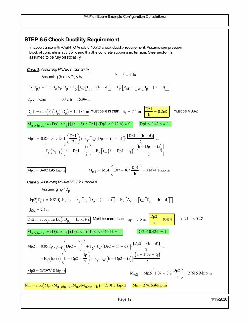
PA Flex Beam Example Configuration Calculations
STEP 6.5 Check Ductility RequirementIn accordance with AASHTO Article 6.10.7.3 check ductility requirement. Assume compressionblock of concrete is at 0.85 f'c and that the concrete supports no tension. Steel section isassumed to be fully plastic at Fy.
Case 1 : Assuming PNA is in Concreteh d 4 inAssuming (h-d) < Dp < hf
Fp Dp 0.85 fc be Dp Fy tw Dp h d( ) Fy Astl tw Dp h d( )
Dp 7.5in 0.42 h 15.96 in
Dp1 root Fp Dp Dp 10.184 in Must be less than hf 7.5 inDp1
h0.268 must be < 0.42
Mn1check Dp1 hf h d( ) Dp1[ ] Dp1 0.42 h( ) 0 Dp1 0.42 h 1
Mp1 0.85 fc be Dp1Dp1
2
Fy tw Dp1 h d( )[ ] Dp1 h d( )[ ]
2
Fy bf tf h Dp1tf
2
Fy tw h Dp1 tf h Dp1 tf
2
Mp1 36824.95 kip in Mn1 Mp1 1.07 0.7Dp1
h
32494.1 kip in
Case 2 : Assuming PNA is NOT in Concrete
Assuming hf < Dp
Fp2 Dp 0.85 fc be hf Fy tw Dp h d( ) Fy Astl tw Dp h d( )
Dp 2.5in
Dp2 root Fp2 Dp Dp 15.734 in Must be more than hf 7.5 inDp2
h0.414 must be < 0.42
Mn2check Dp2 hf Dp2 h( ) Dp2 0.42 h( ) 1 Dp2 0.42 h 1
Mp2 0.85 fc be hf Dp2hf
2
Fy tw Dp2 h d( )[ ] Dp2 h d( )[ ]
2
Fy bf tf h Dp2tf
2
Fy tw h Dp2 tf h Dp2 tf
2
Mp2 35397.18 kip inMn2 Mp2 1.07 0.7
Dp2
h
27615.9 kip in
Mn max Mn1 Mn1check Mn2 Mn2check 2301.3 kip ft Mn 27615.9 kip in
Page 12 1/15/2020
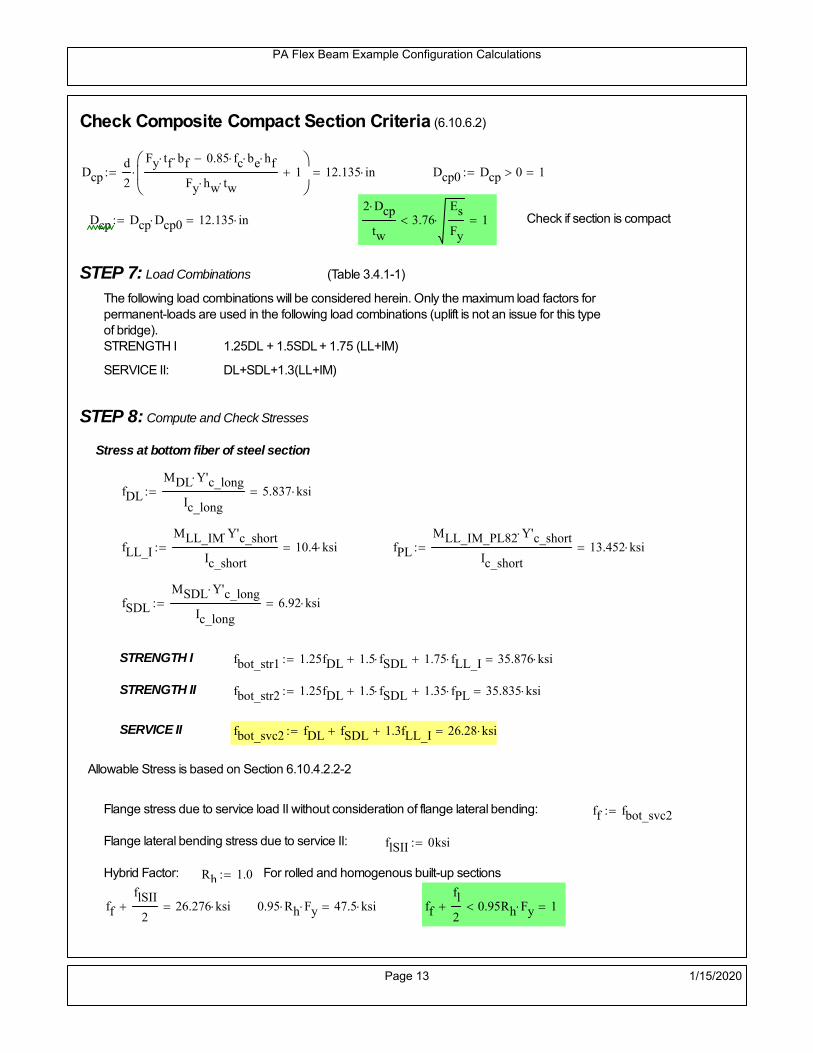
PA Flex Beam Example Configuration Calculations
Check Composite Compact Section Criteria (6.10.6.2)
Dcpd
2
Fy tf bf 0.85 fc be hf
Fy hw tw1
12.135 in Dcp0 Dcp 0 1
Dcp Dcp Dcp0 12.135 in2 Dcp
tw3.76
Es
Fy 1 Check if section is compact
STEP 7: Load Combinations (Table 3.4.1-1)
The following load combinations will be considered herein. Only the maximum load factors forpermanent-loads are used in the following load combinations (uplift is not an issue for this typeof bridge).STRENGTH I 1.25DL + 1.5SDL + 1.75 (LL+IM)
SERVICE II: DL+SDL+1.3(LL+IM)
STEP 8: Compute and Check Stresses
Stress at bottom fiber of steel section
fDL
MDL Y'c_long
Ic_long5.837 ksi
fLL_I
MLL_IM Y'c_short
Ic_short10.4 ksi fPL
MLL_IM_PL82 Y'c_short
Ic_short13.452 ksi
fSDL
MSDL Y'c_long
Ic_long6.92 ksi
STRENGTH I fbot_str1 1.25fDL 1.5 fSDL 1.75 fLL_I 35.876 ksi
STRENGTH II fbot_str2 1.25fDL 1.5 fSDL 1.35 fPL 35.835 ksi
SERVICE II fbot_svc2 fDL fSDL 1.3fLL_I 26.28 ksi
Allowable Stress is based on Section 6.10.4.2.2-2
Flange stress due to service load II without consideration of flange lateral bending: ff fbot_svc2
Flange lateral bending stress due to service II: flSII 0ksi
Hybrid Factor: Rh 1.0 For rolled and homogenous built-up sections
ff
flSII
2 26.276 ksi 0.95 Rh Fy 47.5 ksi ff
fl
2 0.95Rh Fy 1
Page 13 1/15/2020

PA Flex Beam Example Configuration Calculations
Stress at top fiber of concrete
Note: For calculating longitudinal flexural stresses in the concrete deck due to allpermanent and transient loads, the short-term modular ratio shall be used.
fDL
MDL h Y'c_short
k1 n Ic_short0.429 ksi
fLL_I
MLL_IM h Y'c_short
k1 n Ic_short0.867 ksi fPL
MLL_IM_PL82 h Y'c_short
k1 n Ic_short1.121 ksi
fSDL
MSDL h Y'c_short
k1 n Ic_short0.509 ksi
STRENGTH I fc_str1 1.25fDL 1.5 fSDL 1.75 fLL_I 2.815 ksi
Mstr1 1.25 MDL 1.5 MSDL 1.75 MLL_IM 1720.1 kip ft Mstr1 Mn 1
STRENGTH II fc_str2 1.25fDL 1.5 fSDL 1.35 fPL 2.812 ksi
Mstr2 1.25 MDL 1.5 MSDL 1.35 MLL_IM_PL82 1718 kip ft Mstr2 Mn 1
SERVICE II
Allowable Stress in concrete - AASHTO 6.10.4.2.2For compact composite sections in positive flexure utilized in shored construction, the longitudinalcompressive stress in the concrete deck due to the Service II loads, determined as specified in Article6.10.1.1.1d, shall not exceed 0.6f́ c.
fallow 0.6 fc 2400 psi
fc_2 1.3fLL_I fSDL fDL 2063.94 psi This assumes short term compositesection for all calculations
fc_2 fallow 1
SERVICE II with Long Term Composite for dead loads
fDL
MDL h Y'c_long
k3 n Ic_long0.304 ksi
fLL_I
MLL_IM h Y'c_short
k1 n Ic_short0.867 ksi
fSDL
MSDL h Y'c_long
k3 n Ic_long0.361 ksi
fc_2 1.3fLL_I fSDL fDL 1791.52 psi fc_2 fallow 1
Page 14 1/15/2020

PA Flex Beam Example Configuration Calculations
Strength V Moment Check
Strength V is related to normal vehicular use of the bridge with an 80 mph wind gust
Note: that Strength V is checked for an exterior girder under wind load with the interior girder distribution factor forflexure used. If Strength V controls design, then this approach should be modified
Design vertical moment is: 1.25DL + 1.5SDL + 1.35 (LL+IM)
SLT
Ic_long
Y'c_long538.775 in
3 SST
Ic_short
Y'c_short610.885 in
3 short and long term section
modulus
Section D6.2.2 Find the moment required to cause yieldling of the flange. The approach is laid out in D6.2.2
MD2 1.25 MDL 1.5 MSDL 793.608 kip ft From D6.2.2-1 (all dead loads are in MD2 due to shoredconstruction
MAD Fy
MD2
SLT
SST 1.646 10
3 kip ft Additional moment to cause nominal yielding of steel flange
My MD2 MAD 2.439 103
kip ft D6.2.2-2: Moment to cause yielding of flange
6.10.7.1 Compact Section Check at Strength V limit state
Section Modulus for yielding of the flange (My/Fy) for equation 6.10.7.1.1-1Sxt
My
Fy585.393 in
3
Mu 1.25 MDL 1.5MSDL 1.35MLL_IM 1.508 103
kip ft Moment due to Strength V limit state
Mu1
3fl Sxt 1.748 10
3 kip ft Equation 6.10.7.1.7-1 Mn 2.301 10
3 kip ft Mu
1
3fl Sxt Mn 1
Page 15 1/15/2020

PA Flex Beam Example Configuration Calculations
STEP 9: Compute Deflection
Optional Live Load Deflection Evaluation (AASHTO 3.6.1.3.2)
Deflection distribution factor for vehicular loads: For a straight multibeambridge, this is equivalent to saying that the distribution factor for deflectionis equal to the number of lanes divided by the number of beams. 2.5.2.6.2
DFd
Nl
N0.2
Deflection should be taken as 125% the larger of:- Design truck- 25% of design truck + design lane
The live load portion of Load Combination Service I of Table 3.4.1-1 should be used,including the dynamic load allowance, IM;
Deflection due to design truck load
NOTE : Assuming maximum deflection occurs when the center of gravity of the loads is at thecenter line of the span.
P1 8kip P2 32kip P3 32kip Axle loads (AASHTO 3.6.1.2.2)
XASr 14ft Rear Axle spacing for truck (14ft - 30ft)
XASf 14ft Front Axle spacing for truck
Center of gravity (CG) of loads:
X'P1 XASr XASf P2 XASr
P1 P2 P39.333 ft Datum is the rear axle
Method1: Assuming single load = P1+P2+P3 at the midspan (Conservative approach)
P1 P2 P3 L3
48 Es Ic_short 2.201 in
Method2: Calculation of Midspan deflection using superposition
b1L
2XASr X' XASf 16.333 ft distance btw load P1 and support A b1check b1 0 1
b2L
2XASr X' 30.333 ft distance btw load P2 and support A b2check b2 0 1
b3L
2X' 25.667 ft distance btw load P3 and support B b3check b3 0 1
Page 16 1/15/2020

PA Flex Beam Example Configuration Calculations
Deflection of the beam at midspan due to P1: P P1
xL
2 at midspan b b1 b1check The smallest distance btw load P1 and support
Δ1P b x
6 Es Ic_short LL2
b2
x2
0.159 in
Deflection of the beam at midspan due to P2: P P2
xL
2 at midspan b b2 b2check The smallest distance btw load P2 and support
Δ2P b x
6 Es Ic_short LL2
b2
x2
0.953 in
Deflection of the beam at midspan due to P3: P P3
xL
2 at midspan b b3 b3check The smallest distance btw load P3 and support
Δ3P b x
6 Es Ic_short LL2
b2
x2
0.883 in
Total Deflection at midspan:
Δtruck Δ1 Δ2 Δ3( ) DFd 1 I( ) 0.531 in (Considering IM)
Deflection due to tandem (Note: this calculation is not required according to Article3.6.1.3.2 which denotes only the design truck for deflection calculation)
Page 17 1/15/2020

PA Flex Beam Example Configuration Calculations
FT 31.25 kip Per axle
XAS 4ft Axle spacing
Δtandem
FTL
2
XAS
2
24 Es Ic_short3 L
2 4
L
2
XAS
2
2
DFd 1 I( ) 0.506 in (Considering IM)
Deflection due to lane load
FDLLd 640lbf
ft DFd 128
lbf
ft
Δlane
5 FDLLd L4
384 Es Ic_short0.171 in
Live Load Deflection:
ΔLL 1.25max Δtruck 0.25Δtruck Δlane 1.25 0.829 in ΔLLL
800 1
Deflection Limit
For steel or concrete vehicular bridges:
Vehicular load = Span/800L
8001.05 in
L
10000.84 in
Evaluation of Deflection at the Service Limit State (AASHTO 3.4.2.2)
The associated permitted deflections shall be included in the contract documents.
Page 18 1/15/2020

PA Flex Beam Example Configuration Calculations
Shear demands:
Determination of the distribution factor
Using DM4 Table 4.6.2.2.3a-1
Sbe
12in3.167 transverse girder spacing (ft)
Distribution of live loads per lane for shear in interior beams:
For two design lanes loaded, 3.5' <= S =< 16', number of beam >= 4DFs 0.36
S
25 0.487
Q Actr1 h Y'c_shorthf
2
407.862 in3
first moment of deck slab for interface shear
Method 1: Range of shear based on Strength I Limit
STRENGTH I 1.25DL + 1.5SDL + 1.75 (LL+IM)
Computation of the range of shear in the beam
Dead Load:DL 0.428
kip
ft
Superimposed Dead Load: SDL 0.507kip
ft
Design Lane Load: 0.64kip
ft
Design Truck:
XASr 14ft Rear Axle spacing for truck (14ft - 30ft)
XASf 14ft Front Axle spacing for truck
P1 8 kip P2 32 kip P3 32 kip Wheel loads (AASHTO 3.6.1.2.2)
Design Tandem:
Consist of a pair of 25-kip axles spaced 4-ft apart. (AASHTO 3.6.1.2.3)
NOTE: PennDOT DM4 increases 25-kip to 31.25-kip.
FT 31.25kip
XAS 4ft Axle spacing
Page 19 1/15/2020

PA Flex Beam Example Configuration Calculations
Maximum positive shear at various points along the FlexBeam are examined.
At x=0 (at left support) (Truck is moving from left to right)
Truck
Max Positive Shear (when P3 is at x = 0):
x1 L XASr XASf 42 ft Distance between P1 and right support
x2 L XASr 56 ft Distance between P2 and right support
x3 L 70 ft Distance between P3 and right support
V1 P3
x3
L P2
x2
L P1
x1
L 62.4 kip
Total Vertical Shear Force for each FlexBeam (considering dynamic loads):
Vtruck1 V1 DFs 1 I( ) 40.389 kip
Tandem:
V1 FT FT
L XAS L
60.714 kip
Total Vertical Shear Force for each FlexBeam (considering dynamic loads):
Vtandem1 V1 DFs 1 I( ) 39.298 kip
Lane Load
V1 0.64kip
ft
L
2 22.4 kip
Total Vertical Shear Force for each FlexBeam (considering dynamic loads):
Vlane1 V1 DFs 10.901 kip
Dead Load
Vdl1 DLL
2 14.974 kip
Superimposed Dead Load
Vsdl1 SDLL
2 17.754 kip
Strength I Max Positive Shear:
Vstr1 1.25 Vdl1 1.5 Vsdl1 1.75 Vlane1 max Vtruck1 Vtandem1 135.108 kip
Page 20 1/15/2020

PA Flex Beam Example Configuration Calculations
Design Permit Load P-82
Shear at x=0
Strength II Max Positive Shear:
VPL82 VPL82span DFs 1 IPL 79.646 kip
STRENGTH II 1.25DL + 1.5SDL + 1.35 (LL+IM)
VstrII_PL 1.25 Vdl1 1.5 Vsdl1 1.35 VPL82 152.871 kip
Max Shear Demand Vu max Vstr1 VstrII_PL 152.871 kip
Determine the Shear Strength of the Web
Shear Strength of Unstiffened web from AASHTO section 6.10.9.2
Depth of Web D d 34 in Thickness of web tw 0.625 in
Transverse Stiffener Spacing d0 0in Shear Buckling Coefficient k 5 6.10.9.3.2-7
Plastic Shear Force Vp 0.58 Fy D tw 616.25 kip Equation 6.10.9.3.2-3
Ratio of Shear-Buckling resistance to shear yield, C
D
tw54.4 1.12
Es k
Fy 60.314 Ccheck
D
tw1.12
Es k
Fy 1 Equation 6.10.9.3.2-4
C 1.0 Ccheck 1 C=1 for most cases, if the criteria are not met, then C will go to zero and the actualcoefficients should be determined
Nominal Shear Resistance of Web Vn C Vp 616.25 kip equation 6.10.9.3.3-1
Shear Resistance Factor φv 1.0
φv Vn 616.25 kip φv Vn Vu 1Reduced Shear Strength
Page 21 1/15/2020

PA Flex Beam Example Configuration Calculations
Check Bearing Stiffeners
FYs 50ksi Yield strength of stiffener
tp 0.75in Thickness of stiffener
bt
bf tw
21.5in 4.188 in Effective width of stiffener
Dst hw 4.1in 28.775 in Depth of stiffeners
Apn 2 tp bt 6.281 in2
Projected area of stiffeners
bt 0.48 tpEs
FYs 1Check that effective width of stiffener meets requirements
Rsbn 1.4 Apn FYs 439.688 kip Bearing capacity of stiffener (phi=1 for bearing per AASHTO 6.5.4.2)
Rsbn Vu 1 Bearing capacity check
Qs 1.0 Q factor for bearing stiffner, taken as 1 (AASHTO 6.9.4.1.1)
Is
18 tw tw3
tp 2 bt 3
1236.943 in
4 Moment of inertia of stiffener and web (9*tw is used on each side)
AASHTO 6.10.11.2.4b
Ag 18 tw tw 2 bt tp 13.313 in2
Gross area of stiffener and web (AASHTO 6.10.11.2.4b)
rs
Is
Ag1.666 in Radius of gyration of stiffener/web
Po Qs FYs Apn 314.062 kip Nominal yeild resistance of stiffener (AASHTO 6.9.4.1.1)
Peπ2Es
0.75 Dst
rs
2Ag 2.27 10
4 kip Elastic critical buckling stress of stiffener (AASHTO 6.9.4.1.2-1)
Check that Pe/Po is great than 0.44 (AASHTO 6.9.4.1.1) PePoPe
Po0.44 1
Pn PePo 0.658
Po
Pe Po 312.249 kip Nominal compressive resistance of stiffener for Pe/Po>0.44
(AASHTO 6.9.4.1.1-1)
φcr 0.95 phi factor for axial compression (AASHTO 6.5.4.2)
Pr φcr Pn 296.637 kip Compressive capacity of bearing stiffener Pr Vu 1
Page 22 1/15/2020

PA Flex Beam Example Configuration Calculations
Flexbeam Example Configuration Calculations
Summary of Calculations:
Input section dimensions and material properties for steel WT and the concrete deck1.Calculate demands (dead load, superimposed dead, and Live load demands for Strength I and Strength II2.Calculate composite section properties for the given section3.Check Strength I, Strength II, and Service II stresses 4.Check Strength I, Strength II, and Strength V moment demands 5.Perform live load deflection check6.Determine maximum shear demand and capacity7.Note: Shear envelope data was obtained from Matlab script (FlexBeam_Moment_ShearEnvelope.m).8.Shear envelope calculations are summarized separately for each design (Shear Design *.xlsx).
Design Assumptions:Design Specifications Used:
AASHTO LRFD Bridge Design Specifications 7th Edition with 2016 Interim RevisionsPennDOT Design Manual, Part 4 (DM-4) June 30, 2015
Example configurations are determined for two girder spacings, 36" and 40".The deck thickness is 7.5" and is assumed to have a non-structural wearing surface added after installation.Section properties are calculated using the full 7.5" deck thickness.The WT sections are embedded 3.5" into the concrete deck. The steel section spacing used is outside the scope of the AASHTO and PennDOT distribution factorequations. The flexural distribution factor is assumed to be 0.3 which was shown to to be conservativeaccording to refined analysisThe shear distribution factor is calculated using the DM-4 shear distribution factor equation which wasshown to be conservative using refined analysis.Refined analysis is presented in: Zihan Ma, "Distribution Factors for Composite Steel Tee Concrete DeckBridge System," M.S. Thesis, Deparement of Civil and Environmental Engineering, Lehigh University,Bethlehem, 2019Shear and moment demands for the PL82 permit load vehicle are determined by Matlab script(FlexBeam_Moment_ShearEnvelope.m) and are manually input into this calculation sheet.All fabrication will occur as double modules, i.e. each module contains two WT sections. The number ofmodules is half the number of beams, N. A 45 in. tall F-Shape barrier is used, Weight = 700 lb/ft (Distributed to exterior two beams).
The work presented in this document are provided on an “AS IS” basis. University makes no warranties of anykind, express or implied, as to any matter whatsoever, including, without limitation, warranties with respect tothe merchantability or fitness for a particular purpose of this work or any project deliverables. Universitymakes no warranty of any kind with respect to freedom from patent, trademark, copyright or trade secretinfringement arising from the use of the results of the project, deliverables, services, intellectual property orother materials provided hereunder. University shall not be liable for any direct, indirect, consequential,punitive, or other damages suffered by Sponsor or any other person resulting from the project, or the use ofthis work or any project deliverables.
Page 1 1/15/2020

PA Flex Beam Example Configuration Calculations
hf
tf
bf
twh
d
bjtbe
e
Variable Definitions:
Number of beams N 14 modulesN
27
L 70ft Span length
be 38in Effective width of Flexbeamassuming constructed bridge width(i.e. closure joints cast)
Built Up Section Properties
tw 0.625in tf 1.125in bf 12in
h 38in Overall Height of section
hf 7.5in Total thickness of deck
e 3.5in Deck/Steel overlap
d h hf e 34 in depth of built up steel section
hw d tf 32.875 in height of web of built up steel
Moment and shear for permit load PL82 obtained from Matlab script: FlexBeam_Moment_ShearEnvelope
MLL_IM_PL82 684.78kip ft Moment due to PL82 with distribution factor and impact factor!!
VPL82span 136.38kip Shear due to PL82 WITHOUT distribution factor and impact factor!!
Check web and flange dimensions in sections 6.10.2.1 and 6.10.2.2
(Ignore 6.10.2.2-4 since no compression flange)
equation 6.10.2.1.1-1d
tw150 1 equation 6.10.2.2-1
bf
2 tf12 1
equation 6.10.2.2-2 bfh
6 1 equation 6.10.2.2-3 tf 1.1 tw 1
y_bar
tf bftf
2 hw tw tf
hw
2
tf bf hw tw10.822 in Center of gravity of steel section
Istl
bf tf3
12bf tf y_bar
tf
2
2
tw hw
3
12 tw hw tf
hw
2 y_bar
2
4.206 103
in4
MOI of steel
Astl tf bf hw tw 34.047 in2
Area of the WT steel section
Page 2 1/15/2020

PA Flex Beam Example Configuration Calculations
Material Properties
Elastic Modulus of Steel Es 29000ksi
Yield Strength of Steel Fy 50ksi
Yield Strength of Reinforcement fy 60ksi
Compressive Strength of Concrete fc 4000psi AAAP PennDOT Concrete
Concrete Modular Ratio n 8 modular ratio for 4ksi concrete per AASHTO
Unit weight of concrete slab wc 0.150kip
ft3
Unit weight of concrete
Section Properties
Width of UHPC Joint: bjt 6in
Parapet width: bpar 20.25in Parapet width per PennDOT F-shape barrier
Width of the bridge W be N bjt 526 in W 43.833 ft
Clear width of roadway Wlane W 2 bpar 40.458 ft
Dc wc hf W 4.109kip
ft DL due to slab
Db .700kip
ft DL due to each 45" F-Shape Barrier (per email 11/1/18)
DFWS 30lbf
ft2
W 2 bpar 1.214kip
ft DL due to Future Wearing Surface (FWS)
Ds Astl 490lbf
ft3
0.116kip
ft Selfweight of the steel section
DLself
Dc N
Ds 0.409kip
ft Self-weight per WT
Total weight of each precast FlexBeam for transportation:
Weight of C12x25 Diaphragms Wend_diaphragms 25lbf
ft32 in 0.067 kip
2be bjt hf wc 2Ds L 2 Wend_diaphragms 54.634 kip
Determine number of design lane (AASHTO Section 3.6.1.1.1)
Take the integer part of the ratio of W/12 ft. Number of lanes in bridge: Nl floorWlane
12ft
3
Page 3 1/15/2020
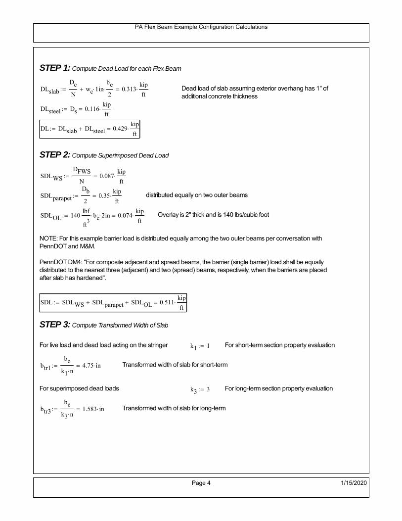
PA Flex Beam Example Configuration Calculations
STEP 1: Compute Dead Load for each Flex Beam
DLslab
Dc
Nwc 1 in
be
2 0.313
kip
ft Dead load of slab assuming exterior overhang has 1" of
additional concrete thickness
DLsteel Ds 0.116kip
ft
DL DLslab DLsteel 0.429kip
ft
STEP 2: Compute Superimposed Dead Load
SDLWS
DFWS
N0.087
kip
ft
SDLparapet
Db
20.35
kip
ft distributed equally on two outer beams
SDLOL 140lbf
ft3be 2 in 0.074
kip
ft Overlay is 2" thick and is 140 lbs/cubic foot
NOTE: For this example barrier load is distributed equally among the two outer beams per conversation withPennDOT and M&M.
PennDOT DM4: "For composite adjacent and spread beams, the barrier (single barrier) load shall be equallydistributed to the nearest three (adjacent) and two (spread) beams, respectively, when the barriers are placedafter slab has hardened".
SDL SDLWS SDLparapet SDLOL 0.511kip
ft
STEP 3: Compute Transformed Width of Slab
For live load and dead load acting on the stringer k1 1 For short-term section property evaluation
btr1
be
k1 n4.75 in Transformed width of slab for short-term
For superimposed dead loads k3 3 For long-term section property evaluation
btr3
be
k3 n1.583 in Transformed width of slab for long-term
Page 4 1/15/2020

PA Flex Beam Example Configuration Calculations
STEP 4: Compute Dead and Superimposed Dead Load Moments(Based on first interior girder demands)
MDLDL L
2
8262.868 kip ft
MSDLSDL L
2
8312.734 kip ft
STEP 5: Compute live load and Dynamic Load Allowance (IM)
Live load wheel load distribution factor (DF):
Sbe
12in3.167 transverse girder spacing
NOTE: AASHTO presents equations to define DF for different types of superstructuresincluding Deck Composite wirh RC slab on steel girders (Type (a) in Table 4.6.2.2.1-1) forshear and moment in interior and exterior beams.
Using DM4 Table 4.6.2.2.2b-1:
eg h y_barhf
2 23.428 in Distance between the centers of gravity of the basic beam and deck
Kg n Istl Astl eg2
1.83 10
5 in
4 Longitudinal stiffness parameter (in4)
Distribution of Live Load Per Lane for Moment in Interior Beams:
to be conservative, use DF 0.3
Page 5 1/15/2020

PA Flex Beam Example Configuration Calculations
Dynamic Load Allowance (Section 3.6.2 DM4)
Static effects of the design truck or tandem, shall be increased by the impact factor.
NOTE: The dynamic load allowance shall not be applied to the design lane load (Section 3.6.2.1 DM4)
I 0.33 Impact factor for moment
Note: PennDOT requires that the impact for decks be increased from 33% to 50%, the deck is not beingdesigned here. Instrad the deck design is based on the BD recommendations.
Dynamic load allowance for the Permit Load P-82 shall be less than 20%. (Section 3.6.2.1DM4)
IPL 0.20 Impact factor for moment on Strength II
Design Wind Loading for Exterior Girder
Vw 80 Wind speed for Strength V load case
CD 1.3 Gust factor for windard side of I-Girder and Box Girder Superstructures (Table 3.8.1.2.1-2)
G 1.0 Gus effect factor is 1.0 for all structures other than sound barriers (Table 3.8.1.2.1-1)
Kz 1.0 Pressure coefficient taken as 1 for Strength V (3.8.1.2.1)
Pz 2.56 106
Vw 2 Kz G CDkip
ft2
0.021kip
ft2
Wind pressure on exterior girder
hexp h hf 30.5 in Exposed height of exterior girder
Moment due to wind loading on exterior girderMWL
Pz hexp L2
833.158 kip ft
Iyy
bf3tf
12162 in
4 Transverse moment of intertia
Flange lateral bending stressfl
MWL
bf
2
Iyy14.737 ksi
Page 6 1/15/2020

PA Flex Beam Example Configuration Calculations
Design Vehicular Live Load
PHL-93 and P-82 are examined herein.
PHL-93 (A3.6.1.2.1)
PHL-93 consists of a combination of (design truck or design tandem) + (design lane load)
Design Truck
PennDOT defines the design truck in accordance with AASTHO 3.6.1.2
Design truck load in AASHTO (HS20 Truck) is used for this example.
NOTE : MAX moment occurs when the center line of the span is midway between the center ofgravity of the loads and the nearest concentrated load.
P1 8kip P2 32kip P3 32kip Axle loads (AASHTO 3.6.1.2.2)
XASr 14ft Rear Axle spacing for truck (14ft - 30ft)
XASf 14ft Front Axle spacing for truck
Page 7 1/15/2020

PA Flex Beam Example Configuration Calculations
Center of gravity (CG) of loads:
X'P1 XASr XASf P2 XASr
P1 P2 P39.333 ft Datum is the rear axle
X XASr X' 4.667 ft Spacing btw CG and nearest load
Find bridge reaction
Truck movestoward Support ARA
P1L
2XASf
X
2
P2L
2
X
2
P3L
2X'
X
2
L33.6 kip
Max live load moment (at the location of P2):
MLL_truck RAL
2
X
2
P1 XASf 985.6 kip ft
NOTE: Find the worst case by varying XASr
Page 8 1/15/2020

PA Flex Beam Example Configuration Calculations
Design Tandem
Consist of a pair of 25-kip axles spaced 4-ft apart. (AASHTO 3.6.1.2.3)
NOTE: PennDOT DM4 increases 25-kip to 31.25-kip.
FT 31.25kip
XAS 4ft Axle spacing
Center of gravity (CG) of loads:
XXAS
22 ft Spacing btw CG and nearest load
Find bridge reaction
RA
FTL
2
X
2
FTL
2
X
2 X
L30.357 kip Truck moves toward Support A
Max live load moment (at the location of front wheel):
MLL_tandem RAL
2
X
2
1.032 103
kip ft
Choose the max value:
MLL_veh max MLL_tandem MLL_truck 1.032 103
kip ft
Apply the impact and wheel load distribution:
MLL_IM_veh MLL_veh DF 1 I( ) 411.825 kip ft Due to tandem or truck
Design Lane Load (distributed over a 10-ft width for each lane)
NOTE: The uniform load may be continuous or discontinuous as necessary to produce themaximum force effect. For this example continuous uniform distribution assumed.
FDLL 0.64kip
ftDF 0.192
kip
ft Per beam in each lane
Due to lane loadMLL_IM_lane
FDLL L2
8
117.6 kip ft
Moment due to Total Design Vehicular Live Load: MLL_IM MLL_IM_lane MLL_IM_veh 529.425 kip ft
Page 9 1/15/2020

PA Flex Beam Example Configuration Calculations
Design Permit Load P-82 (Section 3.6.1.2.7 DM4)
P1 P2 P3 P4 P5 P6 P7
NOTE: The moment for the permit load is defined at the beginning of the sheetand is obtained from MATLab File FlexBeam_Moment_ShearEnvelope.m
STEP 6: Compute Moment of Inertia (Note: rebar neglected!)
1) Moment of Inertia resisting dead load only:
a) Acting on the non-composite section (before the deck has hardened - DC1)
Use steel section only
Inc Istl 4.206 103
in4
Non-composite section modulus
Y'nc y_bar S.G. of the steel section of Flex Beam (Datum is bottom)
b) Acting on the composite section (after the deck has hardened - DC2)
Use Ic_short as defined below.
Page 10 1/15/2020

PA Flex Beam Example Configuration Calculations
2) Moment of Inertia resisting live load plus impact:
Using transformed slab with k1=1 (short-term composite).
Actr1 hf btr1 35.625 in2
Itr1
btr1 hf3
12166.992 in
4
Y'
Actr1 hhf
2
Astl Y'nc
Astl Actr122.801 in S.G. of the total flex beam (Datum is bottom)
Compositesection modulus(short-term)
Ic_short Istl Astl Y'nc Y' 2 Itr1 Actr1 hhf
2
Y'
2
13929 in4
Y'c_short Y' 22.801 in N.A. of the short-term composite section
3) Moment of Inertia resisting superimposed dead load:
Using transformed slab with k3=3.
Actr3 hf btr3 11.875 in2
Itr3
btr3 hf3
1255.664 in
4
Y'
Actr3 hhf
2
Astl Y'nc
Astl Actr316.88 in S.G. of the total flex beam (Datum is bottom)
Compositesection modulus(long-term)
Ic_long Istl Astl Y'nc Y' 2 Itr3 Actr3 hhf
2
Y'
2
9095 in4
Y'c_long Y' 16.88 in N.A. of the long-term composite section
Page 11 1/15/2020

PA Flex Beam Example Configuration Calculations
STEP 6.5 Check Ductility RequirementIn accordance with AASHTO Article 6.10.7.3 check ductility requirement. Assume compressionblock of concrete is at 0.85 f'c and that the concrete supports no tension. Steel section isassumed to be fully plastic at Fy.
Case 1 : Assuming PNA is in Concreteh d 4 inAssuming (h-d) < Dp < hf
Fp Dp 0.85 fc be Dp Fy tw Dp h d( ) Fy Astl tw Dp h d( )
Dp 7.5in 0.42 h 15.96 in
Dp1 root Fp Dp Dp 10.184 in Must be less than hf 7.5 inDp1
h0.268 must be < 0.42
Mn1check Dp1 hf h d( ) Dp1[ ] Dp1 0.42 h( ) 0 Dp1 0.42 h 1
Mp1 0.85 fc be Dp1Dp1
2
Fy tw Dp1 h d( )[ ] Dp1 h d( )[ ]
2
Fy bf tf h Dp1tf
2
Fy tw h Dp1 tf h Dp1 tf
2
Mp1 36824.95 kip in Mn1 Mp1 1.07 0.7Dp1
h
32494.1 kip in
Case 2 : Assuming PNA is NOT in Concrete
Assuming hf < Dp
Fp2 Dp 0.85 fc be hf Fy tw Dp h d( ) Fy Astl tw Dp h d( )
Dp 2.5in
Dp2 root Fp2 Dp Dp 15.734 in Must be more than hf 7.5 inDp2
h0.414 must be < 0.42
Mn2check Dp2 hf Dp2 h( ) Dp2 0.42 h( ) 1 Dp2 0.42 h 1
Mp2 0.85 fc be hf Dp2hf
2
Fy tw Dp2 h d( )[ ] Dp2 h d( )[ ]
2
Fy bf tf h Dp2tf
2
Fy tw h Dp2 tf h Dp2 tf
2
Mp2 35397.18 kip inMn2 Mp2 1.07 0.7
Dp2
h
27615.9 kip in
Mn max Mn1 Mn1check Mn2 Mn2check 2301.3 kip ft Mn 27615.9 kip in
Page 12 1/15/2020

PA Flex Beam Example Configuration Calculations
Check Composite Compact Section Criteria (6.10.6.2)
Dcpd
2
Fy tf bf 0.85 fc be hf
Fy hw tw1
12.135 in Dcp0 Dcp 0 1
Dcp Dcp Dcp0 12.135 in2 Dcp
tw3.76
Es
Fy 1 Check if section is compact
STEP 7: Load Combinations (Table 3.4.1-1)
The following load combinations will be considered herein. Only the maximum load factors forpermanent-loads are used in the following load combinations (uplift is not an issue for this typeof bridge).STRENGTH I 1.25DL + 1.5SDL + 1.75 (LL+IM)
SERVICE II: DL+SDL+1.3(LL+IM)
STEP 8: Compute and Check Stresses
Stress at bottom fiber of steel section
fDL
MDL Y'c_long
Ic_long5.855 ksi
fLL_I
MLL_IM Y'c_short
Ic_short10.4 ksi fPL
MLL_IM_PL82 Y'c_short
Ic_short13.452 ksi
fSDL
MSDL Y'c_long
Ic_long6.965 ksi
STRENGTH I fbot_str1 1.25fDL 1.5 fSDL 1.75 fLL_I 35.966 ksi
STRENGTH II fbot_str2 1.25fDL 1.5 fSDL 1.35 fPL 35.926 ksi
SERVICE II fbot_svc2 fDL fSDL 1.3fLL_I 26.34 ksi
Allowable Stress is based on Section 6.10.4.2.2-2
Flange stress due to service load II without consideration of flange lateral bending: ff fbot_svc2
Flange lateral bending stress due to service II: flSII 0ksi
Hybrid Factor: Rh 1.0 For rolled and homogenous built-up sections
ff
flSII
2 26.34 ksi 0.95 Rh Fy 47.5 ksi ff
fl
2 0.95Rh Fy 1
Page 13 1/15/2020

PA Flex Beam Example Configuration Calculations
Stress at top fiber of concrete
Note: For calculating longitudinal flexural stresses in the concrete deck due to allpermanent and transient loads, the short-term modular ratio shall be used.
fDL
MDL h Y'c_short
k1 n Ic_short0.43 ksi
fLL_I
MLL_IM h Y'c_short
k1 n Ic_short0.867 ksi fPL
MLL_IM_PL82 h Y'c_short
k1 n Ic_short1.121 ksi
fSDL
MSDL h Y'c_short
k1 n Ic_short0.512 ksi
STRENGTH I fc_str1 1.25fDL 1.5 fSDL 1.75 fLL_I 2.822 ksi
Mstr1 1.25 MDL 1.5 MSDL 1.75 MLL_IM 1724.2 kip ft Mstr1 Mn 1
STRENGTH II fc_str2 1.25fDL 1.5 fSDL 1.35 fPL 2.819 ksi
Mstr2 1.25 MDL 1.5 MSDL 1.35 MLL_IM_PL82 1722 kip ft Mstr2 Mn 1
SERVICE II
Allowable Stress in concrete - AASHTO 6.10.4.2.2For compact composite sections in positive flexure utilized in shored construction, the longitudinalcompressive stress in the concrete deck due to the Service II loads, determined as specified in Article6.10.1.1.1d, shall not exceed 0.6f́ c.
fallow 0.6 fc 2400 psi
fc_2 1.3fLL_I fSDL fDL 2068.61 psi This assumes short term compositesection for all calculations
fc_2 fallow 1
SERVICE II with Long Term Composite for dead loads
fDL
MDL h Y'c_long
k3 n Ic_long0.305 ksi
fLL_I
MLL_IM h Y'c_short
k1 n Ic_short0.867 ksi
fSDL
MSDL h Y'c_long
k3 n Ic_long0.363 ksi
fc_2 1.3fLL_I fSDL fDL 1794.84 psi fc_2 fallow 1
Page 14 1/15/2020

PA Flex Beam Example Configuration Calculations
Strength V Moment Check
Strength V is related to normal vehicular use of the bridge with an 80 mph wind gust
Note: that Strength V is checked for an exterior girder under wind load with the interior girder distribution factor forflexure used. If Strength V controls design, then this approach should be modified
Design vertical moment is: 1.25DL + 1.5SDL + 1.35 (LL+IM)
SLT
Ic_long
Y'c_long538.775 in
3 SST
Ic_short
Y'c_short610.885 in
3 short and long term section
modulus
Section D6.2.2 Find the moment required to cause yieldling of the flange. The approach is laid out in D6.2.2
MD2 1.25 MDL 1.5 MSDL 797.685 kip ft From D6.2.2-1 (all dead loads are in MD2 due to shoredconstruction
MAD Fy
MD2
SLT
SST 1.641 10
3 kip ft Additional moment to cause nominal yielding of steel flange
My MD2 MAD 2.439 103
kip ft D6.2.2-2: Moment to cause yielding of flange
6.10.7.1 Compact Section Check at Strength V limit state
Section Modulus for yielding of the flange (My/Fy) for equation 6.10.7.1.1-1Sxt
My
Fy585.262 in
3
Mu 1.25 MDL 1.5MSDL 1.35MLL_IM 1.512 103
kip ft Moment due to Strength V limit state
Mu1
3fl Sxt 1.752 10
3 kip ft Equation 6.10.7.1.7-1 Mn 2.301 10
3 kip ft Mu
1
3fl Sxt Mn 1
Page 15 1/15/2020

PA Flex Beam Example Configuration Calculations
STEP 9: Compute Deflection
Optional Live Load Deflection Evaluation (AASHTO 3.6.1.3.2)
Deflection distribution factor for vehicular loads: For a straight multibeambridge, this is equivalent to saying that the distribution factor for deflectionis equal to the number of lanes divided by the number of beams. 2.5.2.6.2
DFd
Nl
N0.214
Deflection should be taken as 125% the larger of:- Design truck- 25% of design truck + design lane
The live load portion of Load Combination Service I of Table 3.4.1-1 should be used,including the dynamic load allowance, IM;
Deflection due to design truck load
NOTE : Assuming maximum deflection occurs when the center of gravity of the loads is at thecenter line of the span.
P1 8kip P2 32kip P3 32kip Axle loads (AASHTO 3.6.1.2.2)
XASr 14ft Rear Axle spacing for truck (14ft - 30ft)
XASf 14ft Front Axle spacing for truck
Center of gravity (CG) of loads:
X'P1 XASr XASf P2 XASr
P1 P2 P39.333 ft Datum is the rear axle
Method1: Assuming single load = P1+P2+P3 at the midspan (Conservative approach)
P1 P2 P3 L3
48 Es Ic_short 2.201 in
Method2: Calculation of Midspan deflection using superposition
b1L
2XASr X' XASf 16.333 ft distance btw load P1 and support A b1check b1 0 1
b2L
2XASr X' 30.333 ft distance btw load P2 and support A b2check b2 0 1
b3L
2X' 25.667 ft distance btw load P3 and support B b3check b3 0 1
Page 16 1/15/2020

PA Flex Beam Example Configuration Calculations
Deflection of the beam at midspan due to P1: P P1
xL
2 at midspan b b1 b1check The smallest distance btw load P1 and support
Δ1P b x
6 Es Ic_short LL2
b2
x2
0.159 in
Deflection of the beam at midspan due to P2: P P2
xL
2 at midspan b b2 b2check The smallest distance btw load P2 and support
Δ2P b x
6 Es Ic_short LL2
b2
x2
0.953 in
Deflection of the beam at midspan due to P3: P P3
xL
2 at midspan b b3 b3check The smallest distance btw load P3 and support
Δ3P b x
6 Es Ic_short LL2
b2
x2
0.883 in
Total Deflection at midspan:
Δtruck Δ1 Δ2 Δ3( ) DFd 1 I( ) 0.569 in (Considering IM)
Deflection due to tandem (Note: this calculation is not required according to Article3.6.1.3.2 which denotes only the design truck for deflection calculation)
Page 17 1/15/2020

PA Flex Beam Example Configuration Calculations
FT 31.25 kip Per axle
XAS 4ft Axle spacing
Δtandem
FTL
2
XAS
2
24 Es Ic_short3 L
2 4
L
2
XAS
2
2
DFd 1 I( ) 0.542 in (Considering IM)
Deflection due to lane load
FDLLd 640lbf
ft DFd 137.143
lbf
ft
Δlane
5 FDLLd L4
384 Es Ic_short0.183 in
Live Load Deflection:
ΔLL 1.25max Δtruck 0.25Δtruck Δlane 1.25 0.888 in ΔLLL
800 1
Deflection Limit
For steel or concrete vehicular bridges:
Vehicular load = Span/800L
8001.05 in
L
10000.84 in
Evaluation of Deflection at the Service Limit State (AASHTO 3.4.2.2)
The associated permitted deflections shall be included in the contract documents.
Page 18 1/15/2020

PA Flex Beam Example Configuration Calculations
Shear demands:
Determination of the distribution factor
Using DM4 Table 4.6.2.2.3a-1
Sbe
12in3.167 transverse girder spacing (ft)
Distribution of live loads per lane for shear in interior beams:
For two design lanes loaded, 3.5' <= S =< 16', number of beam >= 4DFs 0.36
S
25 0.487
Q Actr1 h Y'c_shorthf
2
407.862 in3
first moment of deck slab for interface shear
Method 1: Range of shear based on Strength I Limit
STRENGTH I 1.25DL + 1.5SDL + 1.75 (LL+IM)
Computation of the range of shear in the beam
Dead Load:DL 0.429
kip
ft
Superimposed Dead Load: SDL 0.511kip
ft
Design Lane Load: 0.64kip
ft
Design Truck:
XASr 14ft Rear Axle spacing for truck (14ft - 30ft)
XASf 14ft Front Axle spacing for truck
P1 8 kip P2 32 kip P3 32 kip Wheel loads (AASHTO 3.6.1.2.2)
Design Tandem:
Consist of a pair of 25-kip axles spaced 4-ft apart. (AASHTO 3.6.1.2.3)
NOTE: PennDOT DM4 increases 25-kip to 31.25-kip.
FT 31.25kip
XAS 4ft Axle spacing
Page 19 1/15/2020

PA Flex Beam Example Configuration Calculations
Maximum positive shear at various points along the FlexBeam are examined.
At x=0 (at left support) (Truck is moving from left to right)
Truck
Max Positive Shear (when P3 is at x = 0):
x1 L XASr XASf 42 ft Distance between P1 and right support
x2 L XASr 56 ft Distance between P2 and right support
x3 L 70 ft Distance between P3 and right support
V1 P3
x3
L P2
x2
L P1
x1
L 62.4 kip
Total Vertical Shear Force for each FlexBeam (considering dynamic loads):
Vtruck1 V1 DFs 1 I( ) 40.389 kip
Tandem:
V1 FT FT
L XAS L
60.714 kip
Total Vertical Shear Force for each FlexBeam (considering dynamic loads):
Vtandem1 V1 DFs 1 I( ) 39.298 kip
Lane Load
V1 0.64kip
ft
L
2 22.4 kip
Total Vertical Shear Force for each FlexBeam (considering dynamic loads):
Vlane1 V1 DFs 10.901 kip
Dead Load
Vdl1 DLL
2 15.021 kip
Superimposed Dead Load
Vsdl1 SDLL
2 17.87 kip
Strength I Max Positive Shear:
Vstr1 1.25 Vdl1 1.5 Vsdl1 1.75 Vlane1 max Vtruck1 Vtandem1 135.341 kip
Page 20 1/15/2020

PA Flex Beam Example Configuration Calculations
Design Permit Load P-82
Shear at x=0
Strength II Max Positive Shear:
VPL82 VPL82span DFs 1 IPL 79.646 kip
STRENGTH II 1.25DL + 1.5SDL + 1.35 (LL+IM)
VstrII_PL 1.25 Vdl1 1.5 Vsdl1 1.35 VPL82 153.104 kip
Max Shear Demand Vu max Vstr1 VstrII_PL 153.104 kip
Determine the Shear Strength of the Web
Shear Strength of Unstiffened web from AASHTO section 6.10.9.2
Depth of Web D d 34 in Thickness of web tw 0.625 in
Transverse Stiffener Spacing d0 0in Shear Buckling Coefficient k 5 6.10.9.3.2-7
Plastic Shear Force Vp 0.58 Fy D tw 616.25 kip Equation 6.10.9.3.2-3
Ratio of Shear-Buckling resistance to shear yield, C
D
tw54.4 1.12
Es k
Fy 60.314 Ccheck
D
tw1.12
Es k
Fy 1 Equation 6.10.9.3.2-4
C 1.0 Ccheck 1 C=1 for most cases, if the criteria are not met, then C will go to zero and the actualcoefficients should be determined
Nominal Shear Resistance of Web Vn C Vp 616.25 kip equation 6.10.9.3.3-1
Shear Resistance Factor φv 1.0
φv Vn 616.25 kip φv Vn Vu 1Reduced Shear Strength
Page 21 1/15/2020

PA Flex Beam Example Configuration Calculations
Check Bearing Stiffeners
FYs 50ksi Yield strength of stiffener
tp 0.75in Thickness of stiffener
bt
bf tw
21.5in 4.188 in Effective width of stiffener
Dst hw 4.1in 28.775 in Depth of stiffeners
Apn 2 tp bt 6.281 in2
Projected area of stiffeners
bt 0.48 tpEs
FYs 1Check that effective width of stiffener meets requirements
Rsbn 1.4 Apn FYs 439.688 kip Bearing capacity of stiffener (phi=1 for bearing per AASHTO 6.5.4.2)
Rsbn Vu 1 Bearing capacity check
Qs 1.0 Q factor for bearing stiffner, taken as 1 (AASHTO 6.9.4.1.1)
Is
18 tw tw3
tp 2 bt 3
1236.943 in
4 Moment of inertia of stiffener and web (9*tw is used on each side)
AASHTO 6.10.11.2.4b
Ag 18 tw tw 2 bt tp 13.313 in2
Gross area of stiffener and web (AASHTO 6.10.11.2.4b)
rs
Is
Ag1.666 in Radius of gyration of stiffener/web
Po Qs FYs Apn 314.062 kip Nominal yeild resistance of stiffener (AASHTO 6.9.4.1.1)
Peπ2Es
0.75 Dst
rs
2Ag 2.27 10
4 kip Elastic critical buckling stress of stiffener (AASHTO 6.9.4.1.2-1)
Check that Pe/Po is great than 0.44 (AASHTO 6.9.4.1.1) PePoPe
Po0.44 1
Pn PePo 0.658
Po
Pe Po 312.249 kip Nominal compressive resistance of stiffener for Pe/Po>0.44
(AASHTO 6.9.4.1.1-1)
φcr 0.95 phi factor for axial compression (AASHTO 6.5.4.2)
Pr φcr Pn 296.637 kip Compressive capacity of bearing stiffener Pr Vu 1
Page 22 1/15/2020
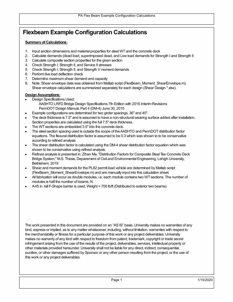
PA Flex Beam Example Configuration Calculations
Flexbeam Example Configuration Calculations
Summary of Calculations:
Input section dimensions and material properties for steel WT and the concrete deck1.Calculate demands (dead load, superimposed dead, and Live load demands for Strength I and Strength II2.Calculate composite section properties for the given section3.Check Strength I, Strength II, and Service II stresses 4.Check Strength I, Strength II, and Strength V moment demands 5.Perform live load deflection check6.Determine maximum shear demand and capacity7.Note: Shear envelope data was obtained from Matlab script (FlexBeam_Moment_ShearEnvelope.m).8.Shear envelope calculations are summarized separately for each design (Shear Design *.xlsx).
Design Assumptions:Design Specifications Used:
AASHTO LRFD Bridge Design Specifications 7th Edition with 2016 Interim RevisionsPennDOT Design Manual, Part 4 (DM-4) June 30, 2015
Example configurations are determined for two girder spacings, 36" and 40".The deck thickness is 7.5" and is assumed to have a non-structural wearing surface added after installation.Section properties are calculated using the full 7.5" deck thickness.The WT sections are embedded 3.5" into the concrete deck. The steel section spacing used is outside the scope of the AASHTO and PennDOT distribution factorequations. The flexural distribution factor is assumed to be 0.3 which was shown to to be conservativeaccording to refined analysisThe shear distribution factor is calculated using the DM-4 shear distribution factor equation which wasshown to be conservative using refined analysis.Refined analysis is presented in: Zihan Ma, "Distribution Factors for Composite Steel Tee Concrete DeckBridge System," M.S. Thesis, Deparement of Civil and Environmental Engineering, Lehigh University,Bethlehem, 2019Shear and moment demands for the PL82 permit load vehicle are determined by Matlab script(FlexBeam_Moment_ShearEnvelope.m) and are manually input into this calculation sheet.All fabrication will occur as double modules, i.e. each module contains two WT sections. The number ofmodules is half the number of beams, N. A 45 in. tall F-Shape barrier is used, Weight = 700 lb/ft (Distributed to exterior two beams).
The work presented in this document are provided on an “AS IS” basis. University makes no warranties of anykind, express or implied, as to any matter whatsoever, including, without limitation, warranties with respect tothe merchantability or fitness for a particular purpose of this work or any project deliverables. Universitymakes no warranty of any kind with respect to freedom from patent, trademark, copyright or trade secretinfringement arising from the use of the results of the project, deliverables, services, intellectual property orother materials provided hereunder. University shall not be liable for any direct, indirect, consequential,punitive, or other damages suffered by Sponsor or any other person resulting from the project, or the use ofthis work or any project deliverables.
Page 1 1/15/2020

PA Flex Beam Example Configuration Calculations
hf
tf
bf
twh
d
bjtbe
e
Variable Definitions:
Number of beams N 10 modulesN
25
L 70ft Span length
be 40in Effective width of Flexbeamassuming constructed bridge width(i.e. closure joints cast)
Built Up Section Properties
tw 0.625in tf 1.125in bf 12in
h 38in Overall Height of section
hf 7.5in Total thickness of deck
e 3.5in Deck/Steel overlap
d h hf e 34 in depth of built up steel section
hw d tf 32.875 in height of web of built up steel
Moment and shear for permit load PL82 obtained from Matlab script: FlexBeam_Moment_ShearEnvelope
MLL_IM_PL82 684.78kip ft Moment due to PL82 with distribution factor and impact factor!!
VPL82span 136.38kip Shear due to PL82 WITHOUT distribution factor and impact factor!!
Check web and flange dimensions in sections 6.10.2.1 and 6.10.2.2
(Ignore 6.10.2.2-4 since no compression flange)
equation 6.10.2.1.1-1d
tw150 1 equation 6.10.2.2-1
bf
2 tf12 1
equation 6.10.2.2-2 bfh
6 1 equation 6.10.2.2-3 tf 1.1 tw 1
y_bar
tf bftf
2 hw tw tf
hw
2
tf bf hw tw10.822 in Center of gravity of steel section
Istl
bf tf3
12bf tf y_bar
tf
2
2
tw hw
3
12 tw hw tf
hw
2 y_bar
2
4.206 103
in4
MOI of steel
Astl tf bf hw tw 34.047 in2
Area of the WT steel section
Page 2 1/15/2020

PA Flex Beam Example Configuration Calculations
Material Properties
Elastic Modulus of Steel Es 29000ksi
Yield Strength of Steel Fy 50ksi
Yield Strength of Reinforcement fy 60ksi
Compressive Strength of Concrete fc 4000psi AAAP PennDOT Concrete
Concrete Modular Ratio n 8 modular ratio for 4ksi concrete per AASHTO
Unit weight of concrete slab wc 0.150kip
ft3
Unit weight of concrete
Section Properties
Width of UHPC Joint: bjt 6in
Parapet width: bpar 20.25in Parapet width per PennDOT F-shape barrier
Width of the bridge W be N bjt 394 in W 32.833 ft
Clear width of roadway Wlane W 2 bpar 29.458 ft
Dc wc hf W 3.078kip
ft DL due to slab
Db .700kip
ft DL due to each 45" F-Shape Barrier (per email 11/1/18)
DFWS 30lbf
ft2
W 2 bpar 0.884kip
ft DL due to Future Wearing Surface (FWS)
Ds Astl 490lbf
ft3
0.116kip
ft Selfweight of the steel section
DLself
Dc N
Ds 0.424kip
ft Self-weight per WT
Total weight of each precast FlexBeam for transportation:
Weight of C12x25 Diaphragms Wend_diaphragms 25lbf
ft32 in 0.067 kip
2be bjt hf wc 2Ds L 2 Wend_diaphragms 56.822 kip
Determine number of design lane (AASHTO Section 3.6.1.1.1)
Take the integer part of the ratio of W/12 ft. Number of lanes in bridge: Nl floorWlane
12ft
2
Page 3 1/15/2020

PA Flex Beam Example Configuration Calculations
STEP 1: Compute Dead Load for each Flex Beam
DLslab
Dc
Nwc 1 in
be
2 0.329
kip
ft Dead load of slab assuming exterior overhang has 1" of
additional concrete thickness
DLsteel Ds 0.116kip
ft
DL DLslab DLsteel 0.444kip
ft
STEP 2: Compute Superimposed Dead Load
SDLWS
DFWS
N0.088
kip
ft
SDLparapet
Db
20.35
kip
ft distributed equally on two outer beams
SDLOL 140lbf
ft3be 2 in 0.078
kip
ft Overlay is 2" thick and is 140 lbs/cubic foot
NOTE: For this example barrier load is distributed equally among the two outer beams per conversation withPennDOT and M&M.
PennDOT DM4: "For composite adjacent and spread beams, the barrier (single barrier) load shall be equallydistributed to the nearest three (adjacent) and two (spread) beams, respectively, when the barriers are placedafter slab has hardened".
SDL SDLWS SDLparapet SDLOL 0.516kip
ft
STEP 3: Compute Transformed Width of Slab
For live load and dead load acting on the stringer k1 1 For short-term section property evaluation
btr1
be
k1 n5 in Transformed width of slab for short-term
For superimposed dead loads k3 3 For long-term section property evaluation
btr3
be
k3 n1.667 in Transformed width of slab for long-term
Page 4 1/15/2020

PA Flex Beam Example Configuration Calculations
STEP 4: Compute Dead and Superimposed Dead Load Moments(Based on first interior girder demands)
MDLDL L
2
8272.256 kip ft
MSDLSDL L
2
8316.144 kip ft
STEP 5: Compute live load and Dynamic Load Allowance (IM)
Live load wheel load distribution factor (DF):
Sbe
12in3.333 transverse girder spacing
NOTE: AASHTO presents equations to define DF for different types of superstructuresincluding Deck Composite wirh RC slab on steel girders (Type (a) in Table 4.6.2.2.1-1) forshear and moment in interior and exterior beams.
Using DM4 Table 4.6.2.2.2b-1:
eg h y_barhf
2 23.428 in Distance between the centers of gravity of the basic beam and deck
Kg n Istl Astl eg2
1.83 10
5 in
4 Longitudinal stiffness parameter (in4)
Distribution of Live Load Per Lane for Moment in Interior Beams:
to be conservative, use DF 0.3
Page 5 1/15/2020

PA Flex Beam Example Configuration Calculations
Dynamic Load Allowance (Section 3.6.2 DM4)
Static effects of the design truck or tandem, shall be increased by the impact factor.
NOTE: The dynamic load allowance shall not be applied to the design lane load (Section 3.6.2.1 DM4)
I 0.33 Impact factor for moment
Note: PennDOT requires that the impact for decks be increased from 33% to 50%, the deck is not beingdesigned here. Instrad the deck design is based on the BD recommendations.
Dynamic load allowance for the Permit Load P-82 shall be less than 20%. (Section 3.6.2.1DM4)
IPL 0.20 Impact factor for moment on Strength II
Design Wind Loading for Exterior Girder
Vw 80 Wind speed for Strength V load case
CD 1.3 Gust factor for windard side of I-Girder and Box Girder Superstructures (Table 3.8.1.2.1-2)
G 1.0 Gus effect factor is 1.0 for all structures other than sound barriers (Table 3.8.1.2.1-1)
Kz 1.0 Pressure coefficient taken as 1 for Strength V (3.8.1.2.1)
Pz 2.56 106
Vw 2 Kz G CDkip
ft2
0.021kip
ft2
Wind pressure on exterior girder
hexp h hf 30.5 in Exposed height of exterior girder
Moment due to wind loading on exterior girderMWL
Pz hexp L2
833.158 kip ft
Iyy
bf3tf
12162 in
4 Transverse moment of intertia
Flange lateral bending stressfl
MWL
bf
2
Iyy14.737 ksi
Page 6 1/15/2020

PA Flex Beam Example Configuration Calculations
Design Vehicular Live Load
PHL-93 and P-82 are examined herein.
PHL-93 (A3.6.1.2.1)
PHL-93 consists of a combination of (design truck or design tandem) + (design lane load)
Design Truck
PennDOT defines the design truck in accordance with AASTHO 3.6.1.2
Design truck load in AASHTO (HS20 Truck) is used for this example.
NOTE : MAX moment occurs when the center line of the span is midway between the center ofgravity of the loads and the nearest concentrated load.
P1 8kip P2 32kip P3 32kip Axle loads (AASHTO 3.6.1.2.2)
XASr 14ft Rear Axle spacing for truck (14ft - 30ft)
XASf 14ft Front Axle spacing for truck
Page 7 1/15/2020

PA Flex Beam Example Configuration Calculations
Center of gravity (CG) of loads:
X'P1 XASr XASf P2 XASr
P1 P2 P39.333 ft Datum is the rear axle
X XASr X' 4.667 ft Spacing btw CG and nearest load
Find bridge reaction
Truck movestoward Support ARA
P1L
2XASf
X
2
P2L
2
X
2
P3L
2X'
X
2
L33.6 kip
Max live load moment (at the location of P2):
MLL_truck RAL
2
X
2
P1 XASf 985.6 kip ft
NOTE: Find the worst case by varying XASr
Page 8 1/15/2020
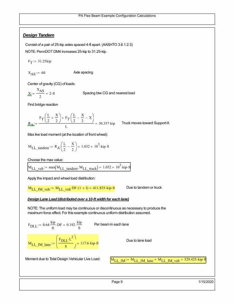
PA Flex Beam Example Configuration Calculations
Design Tandem
Consist of a pair of 25-kip axles spaced 4-ft apart. (AASHTO 3.6.1.2.3)
NOTE: PennDOT DM4 increases 25-kip to 31.25-kip.
FT 31.25kip
XAS 4ft Axle spacing
Center of gravity (CG) of loads:
XXAS
22 ft Spacing btw CG and nearest load
Find bridge reaction
RA
FTL
2
X
2
FTL
2
X
2 X
L30.357 kip Truck moves toward Support A
Max live load moment (at the location of front wheel):
MLL_tandem RAL
2
X
2
1.032 103
kip ft
Choose the max value:
MLL_veh max MLL_tandem MLL_truck 1.032 103
kip ft
Apply the impact and wheel load distribution:
MLL_IM_veh MLL_veh DF 1 I( ) 411.825 kip ft Due to tandem or truck
Design Lane Load (distributed over a 10-ft width for each lane)
NOTE: The uniform load may be continuous or discontinuous as necessary to produce themaximum force effect. For this example continuous uniform distribution assumed.
FDLL 0.64kip
ftDF 0.192
kip
ft Per beam in each lane
Due to lane loadMLL_IM_lane
FDLL L2
8
117.6 kip ft
Moment due to Total Design Vehicular Live Load: MLL_IM MLL_IM_lane MLL_IM_veh 529.425 kip ft
Page 9 1/15/2020

PA Flex Beam Example Configuration Calculations
Design Permit Load P-82 (Section 3.6.1.2.7 DM4)
P1 P2 P3 P4 P5 P6 P7
NOTE: The moment for the permit load is defined at the beginning of the sheetand is obtained from MATLab File FlexBeam_Moment_ShearEnvelope.m
STEP 6: Compute Moment of Inertia (Note: rebar neglected!)
1) Moment of Inertia resisting dead load only:
a) Acting on the non-composite section (before the deck has hardened - DC1)
Use steel section only
Inc Istl 4.206 103
in4
Non-composite section modulus
Y'nc y_bar S.G. of the steel section of Flex Beam (Datum is bottom)
b) Acting on the composite section (after the deck has hardened - DC2)
Use Ic_short as defined below.
Page 10 1/15/2020

PA Flex Beam Example Configuration Calculations
2) Moment of Inertia resisting live load plus impact:
Using transformed slab with k1=1 (short-term composite).
Actr1 hf btr1 37.5 in2
Itr1
btr1 hf3
12175.781 in
4
Y'
Actr1 hhf
2
Astl Y'nc
Astl Actr123.101 in S.G. of the total flex beam (Datum is bottom)
Compositesection modulus(short-term)
Ic_short Istl Astl Y'nc Y' 2 Itr1 Actr1 hhf
2
Y'
2
14177 in4
Y'c_short Y' 23.101 in N.A. of the short-term composite section
3) Moment of Inertia resisting superimposed dead load:
Using transformed slab with k3=3.
Actr3 hf btr3 12.5 in2
Itr3
btr3 hf3
1258.594 in
4
Y'
Actr3 hhf
2
Astl Y'nc
Astl Actr317.113 in S.G. of the total flex beam (Datum is bottom)
Compositesection modulus(long-term)
Ic_long Istl Astl Y'nc Y' 2 Itr3 Actr3 hhf
2
Y'
2
9284 in4
Y'c_long Y' 17.113 in N.A. of the long-term composite section
Page 11 1/15/2020

PA Flex Beam Example Configuration Calculations
STEP 6.5 Check Ductility RequirementIn accordance with AASHTO Article 6.10.7.3 check ductility requirement. Assume compressionblock of concrete is at 0.85 f'c and that the concrete supports no tension. Steel section isassumed to be fully plastic at Fy.
Case 1 : Assuming PNA is in Concreteh d 4 inAssuming (h-d) < Dp < hf
Fp Dp 0.85 fc be Dp Fy tw Dp h d( ) Fy Astl tw Dp h d( )
Dp 7.5in 0.42 h 15.96 in
Dp1 root Fp Dp Dp 9.835 in Must be less than hf 7.5 inDp1
h0.259 must be < 0.42
Mn1check Dp1 hf h d( ) Dp1[ ] Dp1 0.42 h( ) 0 Dp1 0.42 h 1
Mp1 0.85 fc be Dp1Dp1
2
Fy tw Dp1 h d( )[ ] Dp1 h d( )[ ]
2
Fy bf tf h Dp1tf
2
Fy tw h Dp1 tf h Dp1 tf
2
Mp1 37165.53 kip in Mn1 Mp1 1.07 0.7Dp1
h
33033.5 kip in
Case 2 : Assuming PNA is NOT in Concrete
Assuming hf < Dp
Fp2 Dp 0.85 fc be hf Fy tw Dp h d( ) Fy Astl tw Dp h d( )
Dp 2.5in
Dp2 root Fp2 Dp Dp 14.918 in Must be more than hf 7.5 inDp2
h0.3926 must be < 0.42
Mn2check Dp2 hf Dp2 h( ) Dp2 0.42 h( ) 1 Dp2 0.42 h 1
Mp2 0.85 fc be hf Dp2hf
2
Fy tw Dp2 h d( )[ ] Dp2 h d( )[ ]
2
Fy bf tf h Dp2tf
2
Fy tw h Dp2 tf h Dp2 tf
2
Mp2 35987.53 kip inMn2 Mp2 1.07 0.7
Dp2
h
28617.4 kip in
Mn max Mn1 Mn1check Mn2 Mn2check 2384.8 kip ft Mn 28617.4 kip in
Page 12 1/15/2020

PA Flex Beam Example Configuration Calculations
Check Composite Compact Section Criteria (6.10.6.2)
Dcpd
2
Fy tf bf 0.85 fc be hf
Fy hw tw1
11.291 in Dcp0 Dcp 0 1
Dcp Dcp Dcp0 11.291 in2 Dcp
tw3.76
Es
Fy 1 Check if section is compact
STEP 7: Load Combinations (Table 3.4.1-1)
The following load combinations will be considered herein. Only the maximum load factors forpermanent-loads are used in the following load combinations (uplift is not an issue for this typeof bridge).STRENGTH I 1.25DL + 1.5SDL + 1.75 (LL+IM)
SERVICE II: DL+SDL+1.3(LL+IM)
STEP 8: Compute and Check Stresses
Stress at bottom fiber of steel section
fDL
MDL Y'c_long
Ic_long6.023 ksi
fLL_I
MLL_IM Y'c_short
Ic_short10.352 ksi fPL
MLL_IM_PL82 Y'c_short
Ic_short13.39 ksi
fSDL
MSDL Y'c_long
Ic_long6.993 ksi
STRENGTH I fbot_str1 1.25fDL 1.5 fSDL 1.75 fLL_I 36.135 ksi
STRENGTH II fbot_str2 1.25fDL 1.5 fSDL 1.35 fPL 36.095 ksi
SERVICE II fbot_svc2 fDL fSDL 1.3fLL_I 26.47 ksi
Allowable Stress is based on Section 6.10.4.2.2-2
Flange stress due to service load II without consideration of flange lateral bending: ff fbot_svc2
Flange lateral bending stress due to service II: flSII 0ksi
Hybrid Factor: Rh 1.0 For rolled and homogenous built-up sections
ff
flSII
2 26.474 ksi 0.95 Rh Fy 47.5 ksi ff
fl
2 0.95Rh Fy 1
Page 13 1/15/2020

PA Flex Beam Example Configuration Calculations
Stress at top fiber of concrete
Note: For calculating longitudinal flexural stresses in the concrete deck due to allpermanent and transient loads, the short-term modular ratio shall be used.
fDL
MDL h Y'c_short
k1 n Ic_short0.429 ksi
fLL_I
MLL_IM h Y'c_short
k1 n Ic_short0.835 ksi fPL
MLL_IM_PL82 h Y'c_short
k1 n Ic_short1.079 ksi
fSDL
MSDL h Y'c_short
k1 n Ic_short0.498 ksi
STRENGTH I fc_str1 1.25fDL 1.5 fSDL 1.75 fLL_I 2.744 ksi
Mstr1 1.25 MDL 1.5 MSDL 1.75 MLL_IM 1741 kip ft Mstr1 Mn 1
STRENGTH II fc_str2 1.25fDL 1.5 fSDL 1.35 fPL 2.741 ksi
Mstr2 1.25 MDL 1.5 MSDL 1.35 MLL_IM_PL82 1739 kip ft Mstr2 Mn 1
SERVICE II
Allowable Stress in concrete - AASHTO 6.10.4.2.2For compact composite sections in positive flexure utilized in shored construction, the longitudinalcompressive stress in the concrete deck due to the Service II loads, determined as specified in Article6.10.1.1.1d, shall not exceed 0.6f́ c.
fallow 0.6 fc 2400 psi
fc_2 1.3fLL_I fSDL fDL 2012.46 psi This assumes short term compositesection for all calculations
fc_2 fallow 1
SERVICE II with Long Term Composite for dead loads
fDL
MDL h Y'c_long
k3 n Ic_long0.306 ksi
fLL_I
MLL_IM h Y'c_short
k1 n Ic_short0.835 ksi
fSDL
MSDL h Y'c_long
k3 n Ic_long0.356 ksi
fc_2 1.3fLL_I fSDL fDL 1746.84 psi fc_2 fallow 1
Page 14 1/15/2020

PA Flex Beam Example Configuration Calculations
Strength V Moment Check
Strength V is related to normal vehicular use of the bridge with an 80 mph wind gust
Note: that Strength V is checked for an exterior girder under wind load with the interior girder distribution factor forflexure used. If Strength V controls design, then this approach should be modified
Design vertical moment is: 1.25DL + 1.5SDL + 1.35 (LL+IM)
SLT
Ic_long
Y'c_long542.475 in
3 SST
Ic_short
Y'c_short613.692 in
3 short and long term section
modulus
Section D6.2.2 Find the moment required to cause yieldling of the flange. The approach is laid out in D6.2.2
MD2 1.25 MDL 1.5 MSDL 814.536 kip ft From D6.2.2-1 (all dead loads are in MD2 due to shoredconstruction
MAD Fy
MD2
SLT
SST 1.636 10
3 kip ft Additional moment to cause nominal yielding of steel flange
My MD2 MAD 2.45 103
kip ft D6.2.2-2: Moment to cause yielding of flange
6.10.7.1 Compact Section Check at Strength V limit state
Section Modulus for yielding of the flange (My/Fy) for equation 6.10.7.1.1-1Sxt
My
Fy588.028 in
3
Mu 1.25 MDL 1.5MSDL 1.35MLL_IM 1.529 103
kip ft Moment due to Strength V limit state
Mu1
3fl Sxt 1.77 10
3 kip ft Equation 6.10.7.1.7-1 Mn 2.385 10
3 kip ft Mu
1
3fl Sxt Mn 1
Page 15 1/15/2020
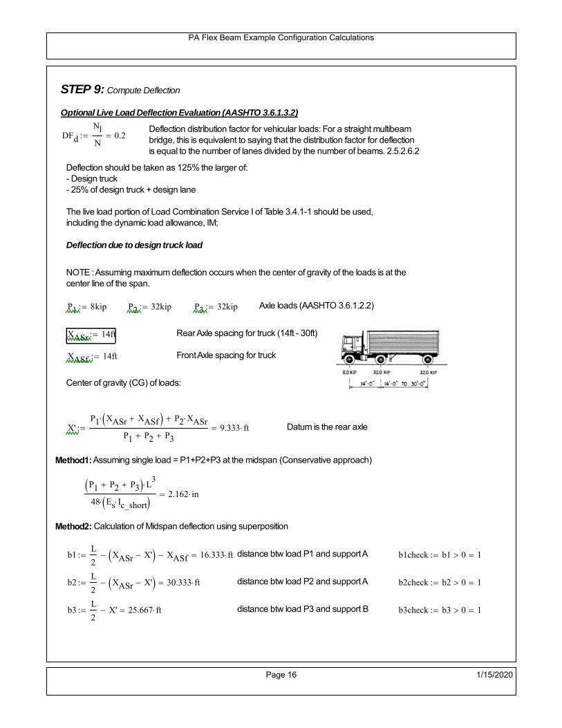
PA Flex Beam Example Configuration Calculations
STEP 9: Compute Deflection
Optional Live Load Deflection Evaluation (AASHTO 3.6.1.3.2)
Deflection distribution factor for vehicular loads: For a straight multibeambridge, this is equivalent to saying that the distribution factor for deflectionis equal to the number of lanes divided by the number of beams. 2.5.2.6.2
DFd
Nl
N0.2
Deflection should be taken as 125% the larger of:- Design truck- 25% of design truck + design lane
The live load portion of Load Combination Service I of Table 3.4.1-1 should be used,including the dynamic load allowance, IM;
Deflection due to design truck load
NOTE : Assuming maximum deflection occurs when the center of gravity of the loads is at thecenter line of the span.
P1 8kip P2 32kip P3 32kip Axle loads (AASHTO 3.6.1.2.2)
XASr 14ft Rear Axle spacing for truck (14ft - 30ft)
XASf 14ft Front Axle spacing for truck
Center of gravity (CG) of loads:
X'P1 XASr XASf P2 XASr
P1 P2 P39.333 ft Datum is the rear axle
Method1: Assuming single load = P1+P2+P3 at the midspan (Conservative approach)
P1 P2 P3 L3
48 Es Ic_short 2.162 in
Method2: Calculation of Midspan deflection using superposition
b1L
2XASr X' XASf 16.333 ft distance btw load P1 and support A b1check b1 0 1
b2L
2XASr X' 30.333 ft distance btw load P2 and support A b2check b2 0 1
b3L
2X' 25.667 ft distance btw load P3 and support B b3check b3 0 1
Page 16 1/15/2020

PA Flex Beam Example Configuration Calculations
Deflection of the beam at midspan due to P1: P P1
xL
2 at midspan b b1 b1check The smallest distance btw load P1 and support
Δ1P b x
6 Es Ic_short LL2
b2
x2
0.156 in
Deflection of the beam at midspan due to P2: P P2
xL
2 at midspan b b2 b2check The smallest distance btw load P2 and support
Δ2P b x
6 Es Ic_short LL2
b2
x2
0.937 in
Deflection of the beam at midspan due to P3: P P3
xL
2 at midspan b b3 b3check The smallest distance btw load P3 and support
Δ3P b x
6 Es Ic_short LL2
b2
x2
0.868 in
Total Deflection at midspan:
Δtruck Δ1 Δ2 Δ3( ) DFd 1 I( ) 0.521 in (Considering IM)
Deflection due to tandem (Note: this calculation is not required according to Article3.6.1.3.2 which denotes only the design truck for deflection calculation)
Page 17 1/15/2020

PA Flex Beam Example Configuration Calculations
FT 31.25 kip Per axle
XAS 4ft Axle spacing
Δtandem
FTL
2
XAS
2
24 Es Ic_short3 L
2 4
L
2
XAS
2
2
DFd 1 I( ) 0.497 in (Considering IM)
Deflection due to lane load
FDLLd 640lbf
ft DFd 128
lbf
ft
Δlane
5 FDLLd L4
384 Es Ic_short0.168 in
Live Load Deflection:
ΔLL 1.25max Δtruck 0.25Δtruck Δlane 1.25 0.815 in ΔLLL
800 1
Deflection Limit
For steel or concrete vehicular bridges:
Vehicular load = Span/800L
8001.05 in
L
10000.84 in
Evaluation of Deflection at the Service Limit State (AASHTO 3.4.2.2)
The associated permitted deflections shall be included in the contract documents.
Page 18 1/15/2020

PA Flex Beam Example Configuration Calculations
Shear demands:
Determination of the distribution factor
Using DM4 Table 4.6.2.2.3a-1
Sbe
12in3.333 transverse girder spacing (ft)
Distribution of live loads per lane for shear in interior beams:
For two design lanes loaded, 3.5' <= S =< 16', number of beam >= 4DFs 0.36
S
25 0.493
Q Actr1 h Y'c_shorthf
2
418.078 in3
first moment of deck slab for interface shear
Method 1: Range of shear based on Strength I Limit
STRENGTH I 1.25DL + 1.5SDL + 1.75 (LL+IM)
Computation of the range of shear in the beam
Dead Load:DL 0.444
kip
ft
Superimposed Dead Load: SDL 0.516kip
ft
Design Lane Load: 0.64kip
ft
Design Truck:
XASr 14ft Rear Axle spacing for truck (14ft - 30ft)
XASf 14ft Front Axle spacing for truck
P1 8 kip P2 32 kip P3 32 kip Wheel loads (AASHTO 3.6.1.2.2)
Design Tandem:
Consist of a pair of 25-kip axles spaced 4-ft apart. (AASHTO 3.6.1.2.3)
NOTE: PennDOT DM4 increases 25-kip to 31.25-kip.
FT 31.25kip
XAS 4ft Axle spacing
Page 19 1/15/2020

PA Flex Beam Example Configuration Calculations
Maximum positive shear at various points along the FlexBeam are examined.
At x=0 (at left support) (Truck is moving from left to right)
Truck
Max Positive Shear (when P3 is at x = 0):
x1 L XASr XASf 42 ft Distance between P1 and right support
x2 L XASr 56 ft Distance between P2 and right support
x3 L 70 ft Distance between P3 and right support
V1 P3
x3
L P2
x2
L P1
x1
L 62.4 kip
Total Vertical Shear Force for each FlexBeam (considering dynamic loads):
Vtruck1 V1 DFs 1 I( ) 40.943 kip
Tandem:
V1 FT FT
L XAS L
60.714 kip
Total Vertical Shear Force for each FlexBeam (considering dynamic loads):
Vtandem1 V1 DFs 1 I( ) 39.837 kip
Lane Load
V1 0.64kip
ft
L
2 22.4 kip
Total Vertical Shear Force for each FlexBeam (considering dynamic loads):
Vlane1 V1 DFs 11.051 kip
Dead Load
Vdl1 DLL
2 15.557 kip
Superimposed Dead Load
Vsdl1 SDLL
2 18.065 kip
Strength I Max Positive Shear:
Vstr1 1.25 Vdl1 1.5 Vsdl1 1.75 Vlane1 max Vtruck1 Vtandem1 137.533 kip
Page 20 1/15/2020

PA Flex Beam Example Configuration Calculations
Design Permit Load P-82
Shear at x=0
Strength II Max Positive Shear:
VPL82 VPL82span DFs 1 IPL 80.737 kip
STRENGTH II 1.25DL + 1.5SDL + 1.35 (LL+IM)
VstrII_PL 1.25 Vdl1 1.5 Vsdl1 1.35 VPL82 155.54 kip
Max Shear Demand Vu max Vstr1 VstrII_PL 155.54 kip
Determine the Shear Strength of the Web
Shear Strength of Unstiffened web from AASHTO section 6.10.9.2
Depth of Web D d 34 in Thickness of web tw 0.625 in
Transverse Stiffener Spacing d0 0in Shear Buckling Coefficient k 5 6.10.9.3.2-7
Plastic Shear Force Vp 0.58 Fy D tw 616.25 kip Equation 6.10.9.3.2-3
Ratio of Shear-Buckling resistance to shear yield, C
D
tw54.4 1.12
Es k
Fy 60.314 Ccheck
D
tw1.12
Es k
Fy 1 Equation 6.10.9.3.2-4
C 1.0 Ccheck 1 C=1 for most cases, if the criteria are not met, then C will go to zero and the actualcoefficients should be determined
Nominal Shear Resistance of Web Vn C Vp 616.25 kip equation 6.10.9.3.3-1
Shear Resistance Factor φv 1.0
φv Vn 616.25 kip φv Vn Vu 1Reduced Shear Strength
Page 21 1/15/2020

PA Flex Beam Example Configuration Calculations
Check Bearing Stiffeners
FYs 50ksi Yield strength of stiffener
tp 0.75in Thickness of stiffener
bt
bf tw
21.5in 4.188 in Effective width of stiffener
Dst hw 4.1in 28.775 in Depth of stiffeners
Apn 2 tp bt 6.281 in2
Projected area of stiffeners
bt 0.48 tpEs
FYs 1Check that effective width of stiffener meets requirements
Rsbn 1.4 Apn FYs 439.688 kip Bearing capacity of stiffener (phi=1 for bearing per AASHTO 6.5.4.2)
Rsbn Vu 1 Bearing capacity check
Qs 1.0 Q factor for bearing stiffner, taken as 1 (AASHTO 6.9.4.1.1)
Is
18 tw tw3
tp 2 bt 3
1236.943 in
4 Moment of inertia of stiffener and web (9*tw is used on each side)
AASHTO 6.10.11.2.4b
Ag 18 tw tw 2 bt tp 13.313 in2
Gross area of stiffener and web (AASHTO 6.10.11.2.4b)
rs
Is
Ag1.666 in Radius of gyration of stiffener/web
Po Qs FYs Apn 314.062 kip Nominal yeild resistance of stiffener (AASHTO 6.9.4.1.1)
Peπ2Es
0.75 Dst
rs
2Ag 2.27 10
4 kip Elastic critical buckling stress of stiffener (AASHTO 6.9.4.1.2-1)
Check that Pe/Po is great than 0.44 (AASHTO 6.9.4.1.1) PePoPe
Po0.44 1
Pn PePo 0.658
Po
Pe Po 312.249 kip Nominal compressive resistance of stiffener for Pe/Po>0.44
(AASHTO 6.9.4.1.1-1)
φcr 0.95 phi factor for axial compression (AASHTO 6.5.4.2)
Pr φcr Pn 296.637 kip Compressive capacity of bearing stiffener Pr Vu 1
Page 22 1/15/2020

PA Flex Beam Example Configuration Calculations
Flexbeam Example Configuration Calculations
Summary of Calculations:
Input section dimensions and material properties for steel WT and the concrete deck1.Calculate demands (dead load, superimposed dead, and Live load demands for Strength I and Strength II2.Calculate composite section properties for the given section3.Check Strength I, Strength II, and Service II stresses 4.Check Strength I, Strength II, and Strength V moment demands 5.Perform live load deflection check6.Determine maximum shear demand and capacity7.Note: Shear envelope data was obtained from Matlab script (FlexBeam_Moment_ShearEnvelope.m).8.Shear envelope calculations are summarized separately for each design (Shear Design *.xlsx).
Design Assumptions:Design Specifications Used:
AASHTO LRFD Bridge Design Specifications 7th Edition with 2016 Interim RevisionsPennDOT Design Manual, Part 4 (DM-4) June 30, 2015
Example configurations are determined for two girder spacings, 36" and 40".The deck thickness is 7.5" and is assumed to have a non-structural wearing surface added after installation.Section properties are calculated using the full 7.5" deck thickness.The WT sections are embedded 3.5" into the concrete deck. The steel section spacing used is outside the scope of the AASHTO and PennDOT distribution factorequations. The flexural distribution factor is assumed to be 0.3 which was shown to to be conservativeaccording to refined analysisThe shear distribution factor is calculated using the DM-4 shear distribution factor equation which wasshown to be conservative using refined analysis.Refined analysis is presented in: Zihan Ma, "Distribution Factors for Composite Steel Tee Concrete DeckBridge System," M.S. Thesis, Deparement of Civil and Environmental Engineering, Lehigh University,Bethlehem, 2019Shear and moment demands for the PL82 permit load vehicle are determined by Matlab script(FlexBeam_Moment_ShearEnvelope.m) and are manually input into this calculation sheet.All fabrication will occur as double modules, i.e. each module contains two WT sections. The number ofmodules is half the number of beams, N. A 45 in. tall F-Shape barrier is used, Weight = 700 lb/ft (Distributed to exterior two beams).
The work presented in this document are provided on an “AS IS” basis. University makes no warranties of anykind, express or implied, as to any matter whatsoever, including, without limitation, warranties with respect tothe merchantability or fitness for a particular purpose of this work or any project deliverables. Universitymakes no warranty of any kind with respect to freedom from patent, trademark, copyright or trade secretinfringement arising from the use of the results of the project, deliverables, services, intellectual property orother materials provided hereunder. University shall not be liable for any direct, indirect, consequential,punitive, or other damages suffered by Sponsor or any other person resulting from the project, or the use ofthis work or any project deliverables.
Page 1 1/15/2020

PA Flex Beam Example Configuration Calculations
hf
tf
bf
twh
d
bjtbe
e
Variable Definitions:
Number of beams N 12 modulesN
26
L 70ft Span length
be 40in Effective width of Flexbeamassuming constructed bridge width(i.e. closure joints cast)
Built Up Section Properties
tw 0.625in tf 1.125in bf 12in
h 38in Overall Height of section
hf 7.5in Total thickness of deck
e 3.5in Deck/Steel overlap
d h hf e 34 in depth of built up steel section
hw d tf 32.875 in height of web of built up steel
Moment and shear for permit load PL82 obtained from Matlab script: FlexBeam_Moment_ShearEnvelope
MLL_IM_PL82 684.78kip ft Moment due to PL82 with distribution factor and impact factor!!
VPL82span 136.38kip Shear due to PL82 WITHOUT distribution factor and impact factor!!
Check web and flange dimensions in sections 6.10.2.1 and 6.10.2.2
(Ignore 6.10.2.2-4 since no compression flange)
equation 6.10.2.1.1-1d
tw150 1 equation 6.10.2.2-1
bf
2 tf12 1
equation 6.10.2.2-2 bfh
6 1 equation 6.10.2.2-3 tf 1.1 tw 1
y_bar
tf bftf
2 hw tw tf
hw
2
tf bf hw tw10.822 in Center of gravity of steel section
Istl
bf tf3
12bf tf y_bar
tf
2
2
tw hw
3
12 tw hw tf
hw
2 y_bar
2
4.206 103
in4
MOI of steel
Astl tf bf hw tw 34.047 in2
Area of the WT steel section
Page 2 1/15/2020

PA Flex Beam Example Configuration Calculations
Material Properties
Elastic Modulus of Steel Es 29000ksi
Yield Strength of Steel Fy 50ksi
Yield Strength of Reinforcement fy 60ksi
Compressive Strength of Concrete fc 4000psi AAAP PennDOT Concrete
Concrete Modular Ratio n 8 modular ratio for 4ksi concrete per AASHTO
Unit weight of concrete slab wc 0.150kip
ft3
Unit weight of concrete
Section Properties
Width of UHPC Joint: bjt 6in
Parapet width: bpar 20.25in Parapet width per PennDOT F-shape barrier
Width of the bridge W be N bjt 474 in W 39.5 ft
Clear width of roadway Wlane W 2 bpar 36.125 ft
Dc wc hf W 3.703kip
ft DL due to slab
Db .700kip
ft DL due to each 45" F-Shape Barrier (per email 11/1/18)
DFWS 30lbf
ft2
W 2 bpar 1.084kip
ft DL due to Future Wearing Surface (FWS)
Ds Astl 490lbf
ft3
0.116kip
ft Selfweight of the steel section
DLself
Dc N
Ds 0.424kip
ft Self-weight per WT
Total weight of each precast FlexBeam for transportation:
Weight of C12x25 Diaphragms Wend_diaphragms 25lbf
ft32 in 0.067 kip
2be bjt hf wc 2Ds L 2 Wend_diaphragms 56.822 kip
Determine number of design lane (AASHTO Section 3.6.1.1.1)
Take the integer part of the ratio of W/12 ft. Number of lanes in bridge: Nl floorWlane
12ft
3
Page 3 1/15/2020
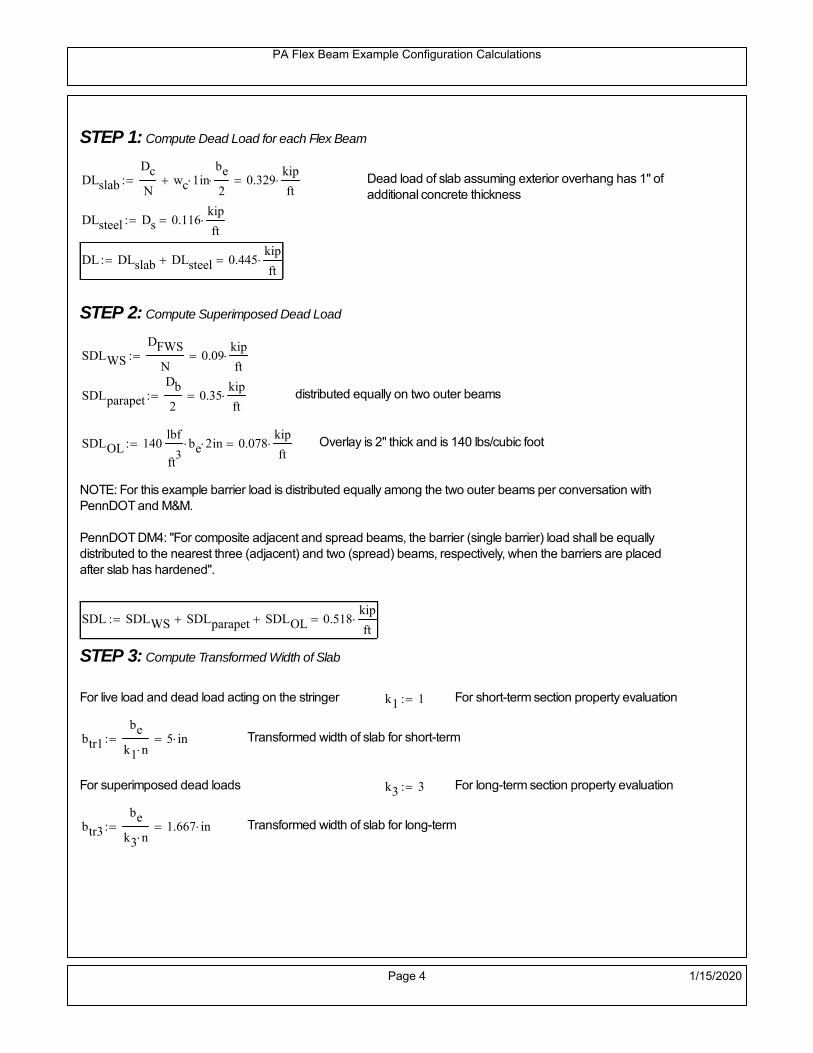
PA Flex Beam Example Configuration Calculations
STEP 1: Compute Dead Load for each Flex Beam
DLslab
Dc
Nwc 1 in
be
2 0.329
kip
ft Dead load of slab assuming exterior overhang has 1" of
additional concrete thickness
DLsteel Ds 0.116kip
ft
DL DLslab DLsteel 0.445kip
ft
STEP 2: Compute Superimposed Dead Load
SDLWS
DFWS
N0.09
kip
ft
SDLparapet
Db
20.35
kip
ft distributed equally on two outer beams
SDLOL 140lbf
ft3be 2 in 0.078
kip
ft Overlay is 2" thick and is 140 lbs/cubic foot
NOTE: For this example barrier load is distributed equally among the two outer beams per conversation withPennDOT and M&M.
PennDOT DM4: "For composite adjacent and spread beams, the barrier (single barrier) load shall be equallydistributed to the nearest three (adjacent) and two (spread) beams, respectively, when the barriers are placedafter slab has hardened".
SDL SDLWS SDLparapet SDLOL 0.518kip
ft
STEP 3: Compute Transformed Width of Slab
For live load and dead load acting on the stringer k1 1 For short-term section property evaluation
btr1
be
k1 n5 in Transformed width of slab for short-term
For superimposed dead loads k3 3 For long-term section property evaluation
btr3
be
k3 n1.667 in Transformed width of slab for long-term
Page 4 1/15/2020
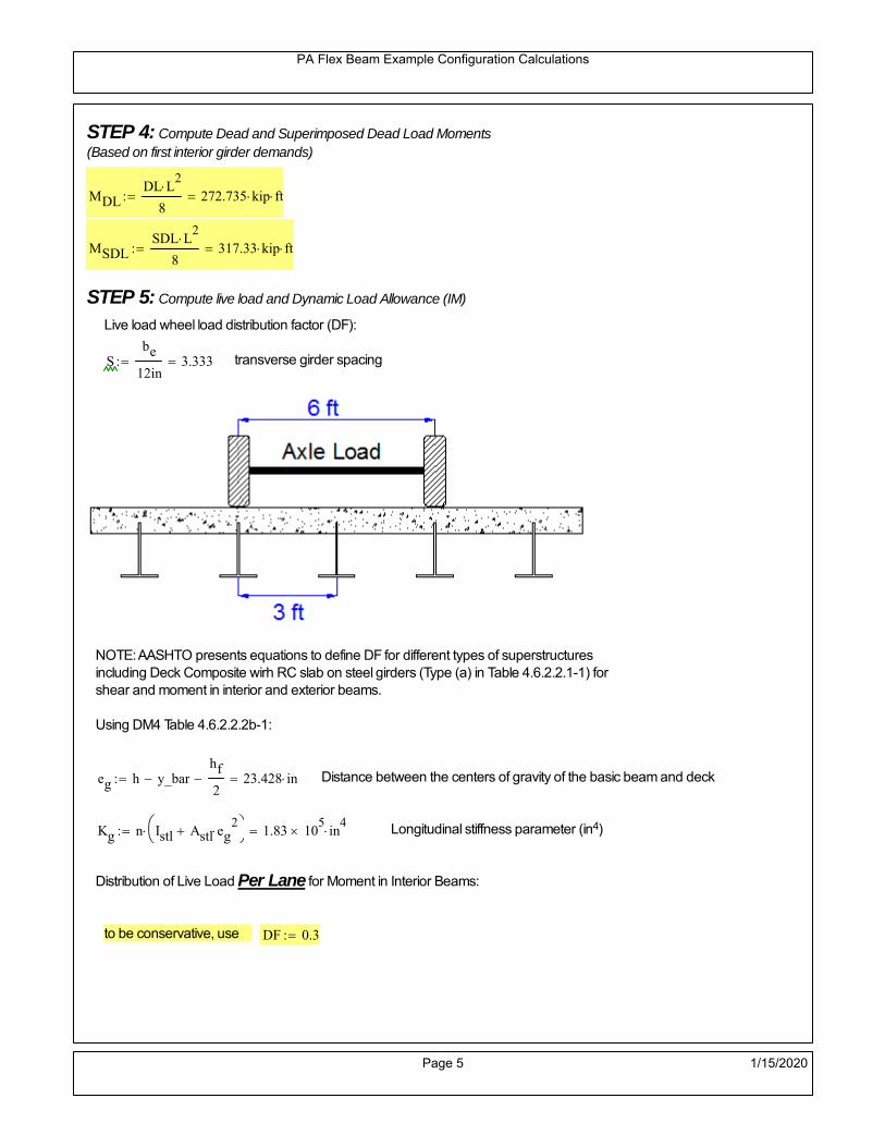
PA Flex Beam Example Configuration Calculations
STEP 4: Compute Dead and Superimposed Dead Load Moments(Based on first interior girder demands)
MDLDL L
2
8272.735 kip ft
MSDLSDL L
2
8317.33 kip ft
STEP 5: Compute live load and Dynamic Load Allowance (IM)
Live load wheel load distribution factor (DF):
Sbe
12in3.333 transverse girder spacing
NOTE: AASHTO presents equations to define DF for different types of superstructuresincluding Deck Composite wirh RC slab on steel girders (Type (a) in Table 4.6.2.2.1-1) forshear and moment in interior and exterior beams.
Using DM4 Table 4.6.2.2.2b-1:
eg h y_barhf
2 23.428 in Distance between the centers of gravity of the basic beam and deck
Kg n Istl Astl eg2
1.83 10
5 in
4 Longitudinal stiffness parameter (in4)
Distribution of Live Load Per Lane for Moment in Interior Beams:
to be conservative, use DF 0.3
Page 5 1/15/2020

PA Flex Beam Example Configuration Calculations
Dynamic Load Allowance (Section 3.6.2 DM4)
Static effects of the design truck or tandem, shall be increased by the impact factor.
NOTE: The dynamic load allowance shall not be applied to the design lane load (Section 3.6.2.1 DM4)
I 0.33 Impact factor for moment
Note: PennDOT requires that the impact for decks be increased from 33% to 50%, the deck is not beingdesigned here. Instrad the deck design is based on the BD recommendations.
Dynamic load allowance for the Permit Load P-82 shall be less than 20%. (Section 3.6.2.1DM4)
IPL 0.20 Impact factor for moment on Strength II
Design Wind Loading for Exterior Girder
Vw 80 Wind speed for Strength V load case
CD 1.3 Gust factor for windard side of I-Girder and Box Girder Superstructures (Table 3.8.1.2.1-2)
G 1.0 Gus effect factor is 1.0 for all structures other than sound barriers (Table 3.8.1.2.1-1)
Kz 1.0 Pressure coefficient taken as 1 for Strength V (3.8.1.2.1)
Pz 2.56 106
Vw 2 Kz G CDkip
ft2
0.021kip
ft2
Wind pressure on exterior girder
hexp h hf 30.5 in Exposed height of exterior girder
Moment due to wind loading on exterior girderMWL
Pz hexp L2
833.158 kip ft
Iyy
bf3tf
12162 in
4 Transverse moment of intertia
Flange lateral bending stressfl
MWL
bf
2
Iyy14.737 ksi
Page 6 1/15/2020

PA Flex Beam Example Configuration Calculations
Design Vehicular Live Load
PHL-93 and P-82 are examined herein.
PHL-93 (A3.6.1.2.1)
PHL-93 consists of a combination of (design truck or design tandem) + (design lane load)
Design Truck
PennDOT defines the design truck in accordance with AASTHO 3.6.1.2
Design truck load in AASHTO (HS20 Truck) is used for this example.
NOTE : MAX moment occurs when the center line of the span is midway between the center ofgravity of the loads and the nearest concentrated load.
P1 8kip P2 32kip P3 32kip Axle loads (AASHTO 3.6.1.2.2)
XASr 14ft Rear Axle spacing for truck (14ft - 30ft)
XASf 14ft Front Axle spacing for truck
Page 7 1/15/2020

PA Flex Beam Example Configuration Calculations
Center of gravity (CG) of loads:
X'P1 XASr XASf P2 XASr
P1 P2 P39.333 ft Datum is the rear axle
X XASr X' 4.667 ft Spacing btw CG and nearest load
Find bridge reaction
Truck movestoward Support ARA
P1L
2XASf
X
2
P2L
2
X
2
P3L
2X'
X
2
L33.6 kip
Max live load moment (at the location of P2):
MLL_truck RAL
2
X
2
P1 XASf 985.6 kip ft
NOTE: Find the worst case by varying XASr
Page 8 1/15/2020

PA Flex Beam Example Configuration Calculations
Design Tandem
Consist of a pair of 25-kip axles spaced 4-ft apart. (AASHTO 3.6.1.2.3)
NOTE: PennDOT DM4 increases 25-kip to 31.25-kip.
FT 31.25kip
XAS 4ft Axle spacing
Center of gravity (CG) of loads:
XXAS
22 ft Spacing btw CG and nearest load
Find bridge reaction
RA
FTL
2
X
2
FTL
2
X
2 X
L30.357 kip Truck moves toward Support A
Max live load moment (at the location of front wheel):
MLL_tandem RAL
2
X
2
1.032 103
kip ft
Choose the max value:
MLL_veh max MLL_tandem MLL_truck 1.032 103
kip ft
Apply the impact and wheel load distribution:
MLL_IM_veh MLL_veh DF 1 I( ) 411.825 kip ft Due to tandem or truck
Design Lane Load (distributed over a 10-ft width for each lane)
NOTE: The uniform load may be continuous or discontinuous as necessary to produce themaximum force effect. For this example continuous uniform distribution assumed.
FDLL 0.64kip
ftDF 0.192
kip
ft Per beam in each lane
Due to lane loadMLL_IM_lane
FDLL L2
8
117.6 kip ft
Moment due to Total Design Vehicular Live Load: MLL_IM MLL_IM_lane MLL_IM_veh 529.425 kip ft
Page 9 1/15/2020

PA Flex Beam Example Configuration Calculations
Design Permit Load P-82 (Section 3.6.1.2.7 DM4)
P1 P2 P3 P4 P5 P6 P7
NOTE: The moment for the permit load is defined at the beginning of the sheetand is obtained from MATLab File FlexBeam_Moment_ShearEnvelope.m
STEP 6: Compute Moment of Inertia (Note: rebar neglected!)
1) Moment of Inertia resisting dead load only:
a) Acting on the non-composite section (before the deck has hardened - DC1)
Use steel section only
Inc Istl 4.206 103
in4
Non-composite section modulus
Y'nc y_bar S.G. of the steel section of Flex Beam (Datum is bottom)
b) Acting on the composite section (after the deck has hardened - DC2)
Use Ic_short as defined below.
Page 10 1/15/2020

PA Flex Beam Example Configuration Calculations
2) Moment of Inertia resisting live load plus impact:
Using transformed slab with k1=1 (short-term composite).
Actr1 hf btr1 37.5 in2
Itr1
btr1 hf3
12175.781 in
4
Y'
Actr1 hhf
2
Astl Y'nc
Astl Actr123.101 in S.G. of the total flex beam (Datum is bottom)
Compositesection modulus(short-term)
Ic_short Istl Astl Y'nc Y' 2 Itr1 Actr1 hhf
2
Y'
2
14177 in4
Y'c_short Y' 23.101 in N.A. of the short-term composite section
3) Moment of Inertia resisting superimposed dead load:
Using transformed slab with k3=3.
Actr3 hf btr3 12.5 in2
Itr3
btr3 hf3
1258.594 in
4
Y'
Actr3 hhf
2
Astl Y'nc
Astl Actr317.113 in S.G. of the total flex beam (Datum is bottom)
Compositesection modulus(long-term)
Ic_long Istl Astl Y'nc Y' 2 Itr3 Actr3 hhf
2
Y'
2
9284 in4
Y'c_long Y' 17.113 in N.A. of the long-term composite section
Page 11 1/15/2020

PA Flex Beam Example Configuration Calculations
STEP 6.5 Check Ductility RequirementIn accordance with AASHTO Article 6.10.7.3 check ductility requirement. Assume compressionblock of concrete is at 0.85 f'c and that the concrete supports no tension. Steel section isassumed to be fully plastic at Fy.
Case 1 : Assuming PNA is in Concreteh d 4 inAssuming (h-d) < Dp < hf
Fp Dp 0.85 fc be Dp Fy tw Dp h d( ) Fy Astl tw Dp h d( )
Dp 7.5in 0.42 h 15.96 in
Dp1 root Fp Dp Dp 9.835 in Must be less than hf 7.5 inDp1
h0.259 must be < 0.42
Mn1check Dp1 hf h d( ) Dp1[ ] Dp1 0.42 h( ) 0 Dp1 0.42 h 1
Mp1 0.85 fc be Dp1Dp1
2
Fy tw Dp1 h d( )[ ] Dp1 h d( )[ ]
2
Fy bf tf h Dp1tf
2
Fy tw h Dp1 tf h Dp1 tf
2
Mp1 37165.53 kip in Mn1 Mp1 1.07 0.7Dp1
h
33033.5 kip in
Case 2 : Assuming PNA is NOT in Concrete
Assuming hf < Dp
Fp2 Dp 0.85 fc be hf Fy tw Dp h d( ) Fy Astl tw Dp h d( )
Dp 2.5in
Dp2 root Fp2 Dp Dp 14.918 in Must be more than hf 7.5 inDp2
h0.3926 must be < 0.42
Mn2check Dp2 hf Dp2 h( ) Dp2 0.42 h( ) 1 Dp2 0.42 h 1
Mp2 0.85 fc be hf Dp2hf
2
Fy tw Dp2 h d( )[ ] Dp2 h d( )[ ]
2
Fy bf tf h Dp2tf
2
Fy tw h Dp2 tf h Dp2 tf
2
Mp2 35987.53 kip inMn2 Mp2 1.07 0.7
Dp2
h
28617.4 kip in
Mn max Mn1 Mn1check Mn2 Mn2check 2384.8 kip ft Mn 28617.4 kip in
Page 12 1/15/2020

PA Flex Beam Example Configuration Calculations
Check Composite Compact Section Criteria (6.10.6.2)
Dcpd
2
Fy tf bf 0.85 fc be hf
Fy hw tw1
11.291 in Dcp0 Dcp 0 1
Dcp Dcp Dcp0 11.291 in2 Dcp
tw3.76
Es
Fy 1 Check if section is compact
STEP 7: Load Combinations (Table 3.4.1-1)
The following load combinations will be considered herein. Only the maximum load factors forpermanent-loads are used in the following load combinations (uplift is not an issue for this typeof bridge).STRENGTH I 1.25DL + 1.5SDL + 1.75 (LL+IM)
SERVICE II: DL+SDL+1.3(LL+IM)
STEP 8: Compute and Check Stresses
Stress at bottom fiber of steel section
fDL
MDL Y'c_long
Ic_long6.033 ksi
fLL_I
MLL_IM Y'c_short
Ic_short10.352 ksi fPL
MLL_IM_PL82 Y'c_short
Ic_short13.39 ksi
fSDL
MSDL Y'c_long
Ic_long7.02 ksi
STRENGTH I fbot_str1 1.25fDL 1.5 fSDL 1.75 fLL_I 36.187 ksi
STRENGTH II fbot_str2 1.25fDL 1.5 fSDL 1.35 fPL 36.147 ksi
SERVICE II fbot_svc2 fDL fSDL 1.3fLL_I 26.51 ksi
Allowable Stress is based on Section 6.10.4.2.2-2
Flange stress due to service load II without consideration of flange lateral bending: ff fbot_svc2
Flange lateral bending stress due to service II: flSII 0ksi
Hybrid Factor: Rh 1.0 For rolled and homogenous built-up sections
ff
flSII
2 26.511 ksi 0.95 Rh Fy 47.5 ksi ff
fl
2 0.95Rh Fy 1
Page 13 1/15/2020

PA Flex Beam Example Configuration Calculations
Stress at top fiber of concrete
Note: For calculating longitudinal flexural stresses in the concrete deck due to allpermanent and transient loads, the short-term modular ratio shall be used.
fDL
MDL h Y'c_short
k1 n Ic_short0.43 ksi
fLL_I
MLL_IM h Y'c_short
k1 n Ic_short0.835 ksi fPL
MLL_IM_PL82 h Y'c_short
k1 n Ic_short1.079 ksi
fSDL
MSDL h Y'c_short
k1 n Ic_short0.5 ksi
STRENGTH I fc_str1 1.25fDL 1.5 fSDL 1.75 fLL_I 2.748 ksi
Mstr1 1.25 MDL 1.5 MSDL 1.75 MLL_IM 1743.4 kip ft Mstr1 Mn 1
STRENGTH II fc_str2 1.25fDL 1.5 fSDL 1.35 fPL 2.745 ksi
Mstr2 1.25 MDL 1.5 MSDL 1.35 MLL_IM_PL82 1741 kip ft Mstr2 Mn 1
SERVICE II
Allowable Stress in concrete - AASHTO 6.10.4.2.2For compact composite sections in positive flexure utilized in shored construction, the longitudinalcompressive stress in the concrete deck due to the Service II loads, determined as specified in Article6.10.1.1.1d, shall not exceed 0.6f́ c.
fallow 0.6 fc 2400 psi
fc_2 1.3fLL_I fSDL fDL 2015.09 psi This assumes short term compositesection for all calculations
fc_2 fallow 1
SERVICE II with Long Term Composite for dead loads
fDL
MDL h Y'c_long
k3 n Ic_long0.307 ksi
fLL_I
MLL_IM h Y'c_short
k1 n Ic_short0.835 ksi
fSDL
MSDL h Y'c_long
k3 n Ic_long0.357 ksi
fc_2 1.3fLL_I fSDL fDL 1748.71 psi fc_2 fallow 1
Page 14 1/15/2020

PA Flex Beam Example Configuration Calculations
Strength V Moment Check
Strength V is related to normal vehicular use of the bridge with an 80 mph wind gust
Note: that Strength V is checked for an exterior girder under wind load with the interior girder distribution factor forflexure used. If Strength V controls design, then this approach should be modified
Design vertical moment is: 1.25DL + 1.5SDL + 1.35 (LL+IM)
SLT
Ic_long
Y'c_long542.475 in
3 SST
Ic_short
Y'c_short613.692 in
3 short and long term section
modulus
Section D6.2.2 Find the moment required to cause yieldling of the flange. The approach is laid out in D6.2.2
MD2 1.25 MDL 1.5 MSDL 816.914 kip ft From D6.2.2-1 (all dead loads are in MD2 due to shoredconstruction
MAD Fy
MD2
SLT
SST 1.633 10
3 kip ft Additional moment to cause nominal yielding of steel flange
My MD2 MAD 2.45 103
kip ft D6.2.2-2: Moment to cause yielding of flange
6.10.7.1 Compact Section Check at Strength V limit state
Section Modulus for yielding of the flange (My/Fy) for equation 6.10.7.1.1-1Sxt
My
Fy587.953 in
3
Mu 1.25 MDL 1.5MSDL 1.35MLL_IM 1.532 103
kip ft Moment due to Strength V limit state
Mu1
3fl Sxt 1.772 10
3 kip ft Equation 6.10.7.1.7-1 Mn 2.385 10
3 kip ft Mu
1
3fl Sxt Mn 1
Page 15 1/15/2020

PA Flex Beam Example Configuration Calculations
STEP 9: Compute Deflection
Optional Live Load Deflection Evaluation (AASHTO 3.6.1.3.2)
Deflection distribution factor for vehicular loads: For a straight multibeambridge, this is equivalent to saying that the distribution factor for deflectionis equal to the number of lanes divided by the number of beams. 2.5.2.6.2
DFd
Nl
N0.25
Deflection should be taken as 125% the larger of:- Design truck- 25% of design truck + design lane
The live load portion of Load Combination Service I of Table 3.4.1-1 should be used,including the dynamic load allowance, IM;
Deflection due to design truck load
NOTE : Assuming maximum deflection occurs when the center of gravity of the loads is at thecenter line of the span.
P1 8kip P2 32kip P3 32kip Axle loads (AASHTO 3.6.1.2.2)
XASr 14ft Rear Axle spacing for truck (14ft - 30ft)
XASf 14ft Front Axle spacing for truck
Center of gravity (CG) of loads:
X'P1 XASr XASf P2 XASr
P1 P2 P39.333 ft Datum is the rear axle
Method1: Assuming single load = P1+P2+P3 at the midspan (Conservative approach)
P1 P2 P3 L3
48 Es Ic_short 2.162 in
Method2: Calculation of Midspan deflection using superposition
b1L
2XASr X' XASf 16.333 ft distance btw load P1 and support A b1check b1 0 1
b2L
2XASr X' 30.333 ft distance btw load P2 and support A b2check b2 0 1
b3L
2X' 25.667 ft distance btw load P3 and support B b3check b3 0 1
Page 16 1/15/2020

PA Flex Beam Example Configuration Calculations
Deflection of the beam at midspan due to P1: P P1
xL
2 at midspan b b1 b1check The smallest distance btw load P1 and support
Δ1P b x
6 Es Ic_short LL2
b2
x2
0.156 in
Deflection of the beam at midspan due to P2: P P2
xL
2 at midspan b b2 b2check The smallest distance btw load P2 and support
Δ2P b x
6 Es Ic_short LL2
b2
x2
0.937 in
Deflection of the beam at midspan due to P3: P P3
xL
2 at midspan b b3 b3check The smallest distance btw load P3 and support
Δ3P b x
6 Es Ic_short LL2
b2
x2
0.868 in
Total Deflection at midspan:
Δtruck Δ1 Δ2 Δ3( ) DFd 1 I( ) 0.652 in (Considering IM)
Deflection due to tandem (Note: this calculation is not required according to Article3.6.1.3.2 which denotes only the design truck for deflection calculation)
Page 17 1/15/2020

PA Flex Beam Example Configuration Calculations
FT 31.25 kip Per axle
XAS 4ft Axle spacing
Δtandem
FTL
2
XAS
2
24 Es Ic_short3 L
2 4
L
2
XAS
2
2
DFd 1 I( ) 0.621 in (Considering IM)
Deflection due to lane load
FDLLd 640lbf
ft DFd 160
lbf
ft
Δlane
5 FDLLd L4
384 Es Ic_short0.21 in
Live Load Deflection:
ΔLL 1.25max Δtruck 0.25Δtruck Δlane 1.25 1.018 in ΔLLL
800 1
Deflection Limit
For steel or concrete vehicular bridges:
Vehicular load = Span/800L
8001.05 in
L
10000.84 in
Evaluation of Deflection at the Service Limit State (AASHTO 3.4.2.2)
The associated permitted deflections shall be included in the contract documents.
Page 18 1/15/2020

PA Flex Beam Example Configuration Calculations
Shear demands:
Determination of the distribution factor
Using DM4 Table 4.6.2.2.3a-1
Sbe
12in3.333 transverse girder spacing (ft)
Distribution of live loads per lane for shear in interior beams:
For two design lanes loaded, 3.5' <= S =< 16', number of beam >= 4DFs 0.36
S
25 0.493
Q Actr1 h Y'c_shorthf
2
418.078 in3
first moment of deck slab for interface shear
Method 1: Range of shear based on Strength I Limit
STRENGTH I 1.25DL + 1.5SDL + 1.75 (LL+IM)
Computation of the range of shear in the beam
Dead Load:DL 0.445
kip
ft
Superimposed Dead Load: SDL 0.518kip
ft
Design Lane Load: 0.64kip
ft
Design Truck:
XASr 14ft Rear Axle spacing for truck (14ft - 30ft)
XASf 14ft Front Axle spacing for truck
P1 8 kip P2 32 kip P3 32 kip Wheel loads (AASHTO 3.6.1.2.2)
Design Tandem:
Consist of a pair of 25-kip axles spaced 4-ft apart. (AASHTO 3.6.1.2.3)
NOTE: PennDOT DM4 increases 25-kip to 31.25-kip.
FT 31.25kip
XAS 4ft Axle spacing
Page 19 1/15/2020

PA Flex Beam Example Configuration Calculations
Maximum positive shear at various points along the FlexBeam are examined.
At x=0 (at left support) (Truck is moving from left to right)
Truck
Max Positive Shear (when P3 is at x = 0):
x1 L XASr XASf 42 ft Distance between P1 and right support
x2 L XASr 56 ft Distance between P2 and right support
x3 L 70 ft Distance between P3 and right support
V1 P3
x3
L P2
x2
L P1
x1
L 62.4 kip
Total Vertical Shear Force for each FlexBeam (considering dynamic loads):
Vtruck1 V1 DFs 1 I( ) 40.943 kip
Tandem:
V1 FT FT
L XAS L
60.714 kip
Total Vertical Shear Force for each FlexBeam (considering dynamic loads):
Vtandem1 V1 DFs 1 I( ) 39.837 kip
Lane Load
V1 0.64kip
ft
L
2 22.4 kip
Total Vertical Shear Force for each FlexBeam (considering dynamic loads):
Vlane1 V1 DFs 11.051 kip
Dead Load
Vdl1 DLL
2 15.585 kip
Superimposed Dead Load
Vsdl1 SDLL
2 18.133 kip
Strength I Max Positive Shear:
Vstr1 1.25 Vdl1 1.5 Vsdl1 1.75 Vlane1 max Vtruck1 Vtandem1 137.669 kip
Page 20 1/15/2020

PA Flex Beam Example Configuration Calculations
Design Permit Load P-82
Shear at x=0
Strength II Max Positive Shear:
VPL82 VPL82span DFs 1 IPL 80.737 kip
STRENGTH II 1.25DL + 1.5SDL + 1.35 (LL+IM)
VstrII_PL 1.25 Vdl1 1.5 Vsdl1 1.35 VPL82 155.676 kip
Max Shear Demand Vu max Vstr1 VstrII_PL 155.676 kip
Determine the Shear Strength of the Web
Shear Strength of Unstiffened web from AASHTO section 6.10.9.2
Depth of Web D d 34 in Thickness of web tw 0.625 in
Transverse Stiffener Spacing d0 0in Shear Buckling Coefficient k 5 6.10.9.3.2-7
Plastic Shear Force Vp 0.58 Fy D tw 616.25 kip Equation 6.10.9.3.2-3
Ratio of Shear-Buckling resistance to shear yield, C
D
tw54.4 1.12
Es k
Fy 60.314 Ccheck
D
tw1.12
Es k
Fy 1 Equation 6.10.9.3.2-4
C 1.0 Ccheck 1 C=1 for most cases, if the criteria are not met, then C will go to zero and the actualcoefficients should be determined
Nominal Shear Resistance of Web Vn C Vp 616.25 kip equation 6.10.9.3.3-1
Shear Resistance Factor φv 1.0
φv Vn 616.25 kip φv Vn Vu 1Reduced Shear Strength
Page 21 1/15/2020

PA Flex Beam Example Configuration Calculations
Check Bearing Stiffeners
FYs 50ksi Yield strength of stiffener
tp 0.75in Thickness of stiffener
bt
bf tw
21.5in 4.188 in Effective width of stiffener
Dst hw 4.1in 28.775 in Depth of stiffeners
Apn 2 tp bt 6.281 in2
Projected area of stiffeners
bt 0.48 tpEs
FYs 1Check that effective width of stiffener meets requirements
Rsbn 1.4 Apn FYs 439.688 kip Bearing capacity of stiffener (phi=1 for bearing per AASHTO 6.5.4.2)
Rsbn Vu 1 Bearing capacity check
Qs 1.0 Q factor for bearing stiffner, taken as 1 (AASHTO 6.9.4.1.1)
Is
18 tw tw3
tp 2 bt 3
1236.943 in
4 Moment of inertia of stiffener and web (9*tw is used on each side)
AASHTO 6.10.11.2.4b
Ag 18 tw tw 2 bt tp 13.313 in2
Gross area of stiffener and web (AASHTO 6.10.11.2.4b)
rs
Is
Ag1.666 in Radius of gyration of stiffener/web
Po Qs FYs Apn 314.062 kip Nominal yeild resistance of stiffener (AASHTO 6.9.4.1.1)
Peπ2Es
0.75 Dst
rs
2Ag 2.27 10
4 kip Elastic critical buckling stress of stiffener (AASHTO 6.9.4.1.2-1)
Check that Pe/Po is great than 0.44 (AASHTO 6.9.4.1.1) PePoPe
Po0.44 1
Pn PePo 0.658
Po
Pe Po 312.249 kip Nominal compressive resistance of stiffener for Pe/Po>0.44
(AASHTO 6.9.4.1.1-1)
φcr 0.95 phi factor for axial compression (AASHTO 6.5.4.2)
Pr φcr Pn 296.637 kip Compressive capacity of bearing stiffener Pr Vu 1
Page 22 1/15/2020

PA Flex Beam Example Configuration Calculations
Flexbeam Example Configuration Calculations
Summary of Calculations:
Input section dimensions and material properties for steel WT and the concrete deck1.Calculate demands (dead load, superimposed dead, and Live load demands for Strength I and Strength II2.Calculate composite section properties for the given section3.Check Strength I, Strength II, and Service II stresses 4.Check Strength I, Strength II, and Strength V moment demands 5.Perform live load deflection check6.Determine maximum shear demand and capacity7.Note: Shear envelope data was obtained from Matlab script (FlexBeam_Moment_ShearEnvelope.m).8.Shear envelope calculations are summarized separately for each design (Shear Design *.xlsx).
Design Assumptions:Design Specifications Used:
AASHTO LRFD Bridge Design Specifications 7th Edition with 2016 Interim RevisionsPennDOT Design Manual, Part 4 (DM-4) June 30, 2015
Example configurations are determined for two girder spacings, 36" and 40".The deck thickness is 7.5" and is assumed to have a non-structural wearing surface added after installation.Section properties are calculated using the full 7.5" deck thickness.The WT sections are embedded 3.5" into the concrete deck. The steel section spacing used is outside the scope of the AASHTO and PennDOT distribution factorequations. The flexural distribution factor is assumed to be 0.3 which was shown to to be conservativeaccording to refined analysisThe shear distribution factor is calculated using the DM-4 shear distribution factor equation which wasshown to be conservative using refined analysis.Refined analysis is presented in: Zihan Ma, "Distribution Factors for Composite Steel Tee Concrete DeckBridge System," M.S. Thesis, Deparement of Civil and Environmental Engineering, Lehigh University,Bethlehem, 2019Shear and moment demands for the PL82 permit load vehicle are determined by Matlab script(FlexBeam_Moment_ShearEnvelope.m) and are manually input into this calculation sheet.All fabrication will occur as double modules, i.e. each module contains two WT sections. The number ofmodules is half the number of beams, N. A 45 in. tall F-Shape barrier is used, Weight = 700 lb/ft (Distributed to exterior two beams).
The work presented in this document are provided on an “AS IS” basis. University makes no warranties of anykind, express or implied, as to any matter whatsoever, including, without limitation, warranties with respect tothe merchantability or fitness for a particular purpose of this work or any project deliverables. Universitymakes no warranty of any kind with respect to freedom from patent, trademark, copyright or trade secretinfringement arising from the use of the results of the project, deliverables, services, intellectual property orother materials provided hereunder. University shall not be liable for any direct, indirect, consequential,punitive, or other damages suffered by Sponsor or any other person resulting from the project, or the use ofthis work or any project deliverables.
Page 1 1/15/2020

PA Flex Beam Example Configuration Calculations
hf
tf
bf
twh
d
bjtbe
e
Variable Definitions:
Number of beams N 14 modulesN
27
L 70ft Span length
be 40in Effective width of Flexbeamassuming constructed bridge width(i.e. closure joints cast)
Built Up Section Properties
tw 0.625in tf 1.125in bf 12in
h 38in Overall Height of section
hf 7.5in Total thickness of deck
e 3.5in Deck/Steel overlap
d h hf e 34 in depth of built up steel section
hw d tf 32.875 in height of web of built up steel
Moment and shear for permit load PL82 obtained from Matlab script: FlexBeam_Moment_ShearEnvelope
MLL_IM_PL82 684.78kip ft Moment due to PL82 with distribution factor and impact factor!!
VPL82span 136.38kip Shear due to PL82 WITHOUT distribution factor and impact factor!!
Check web and flange dimensions in sections 6.10.2.1 and 6.10.2.2
(Ignore 6.10.2.2-4 since no compression flange)
equation 6.10.2.1.1-1d
tw150 1 equation 6.10.2.2-1
bf
2 tf12 1
equation 6.10.2.2-2 bfh
6 1 equation 6.10.2.2-3 tf 1.1 tw 1
y_bar
tf bftf
2 hw tw tf
hw
2
tf bf hw tw10.822 in Center of gravity of steel section
Istl
bf tf3
12bf tf y_bar
tf
2
2
tw hw
3
12 tw hw tf
hw
2 y_bar
2
4.206 103
in4
MOI of steel
Astl tf bf hw tw 34.047 in2
Area of the WT steel section
Page 2 1/15/2020

PA Flex Beam Example Configuration Calculations
Material Properties
Elastic Modulus of Steel Es 29000ksi
Yield Strength of Steel Fy 50ksi
Yield Strength of Reinforcement fy 60ksi
Compressive Strength of Concrete fc 4000psi AAAP PennDOT Concrete
Concrete Modular Ratio n 8 modular ratio for 4ksi concrete per AASHTO
Unit weight of concrete slab wc 0.150kip
ft3
Unit weight of concrete
Section Properties
Width of UHPC Joint: bjt 6in
Parapet width: bpar 20.25in Parapet width per PennDOT F-shape barrier
Width of the bridge W be N bjt 554 in W 46.167 ft
Clear width of roadway Wlane W 2 bpar 42.792 ft
Dc wc hf W 4.328kip
ft DL due to slab
Db .700kip
ft DL due to each 45" F-Shape Barrier (per email 11/1/18)
DFWS 30lbf
ft2
W 2 bpar 1.284kip
ft DL due to Future Wearing Surface (FWS)
Ds Astl 490lbf
ft3
0.116kip
ft Selfweight of the steel section
DLself
Dc N
Ds 0.425kip
ft Self-weight per WT
Total weight of each precast FlexBeam for transportation:
Weight of C12x25 Diaphragms Wend_diaphragms 25lbf
ft32 in 0.067 kip
2be bjt hf wc 2Ds L 2 Wend_diaphragms 56.822 kip
Determine number of design lane (AASHTO Section 3.6.1.1.1)
Take the integer part of the ratio of W/12 ft. Number of lanes in bridge: Nl floorWlane
12ft
3
Page 3 1/15/2020

PA Flex Beam Example Configuration Calculations
STEP 1: Compute Dead Load for each Flex Beam
DLslab
Dc
Nwc 1 in
be
2 0.33
kip
ft Dead load of slab assuming exterior overhang has 1" of
additional concrete thickness
DLsteel Ds 0.116kip
ft
DL DLslab DLsteel 0.446kip
ft
STEP 2: Compute Superimposed Dead Load
SDLWS
DFWS
N0.092
kip
ft
SDLparapet
Db
20.35
kip
ft distributed equally on two outer beams
SDLOL 140lbf
ft3be 2 in 0.078
kip
ft Overlay is 2" thick and is 140 lbs/cubic foot
NOTE: For this example barrier load is distributed equally among the two outer beams per conversation withPennDOT and M&M.
PennDOT DM4: "For composite adjacent and spread beams, the barrier (single barrier) load shall be equallydistributed to the nearest three (adjacent) and two (spread) beams, respectively, when the barriers are placedafter slab has hardened".
SDL SDLWS SDLparapet SDLOL 0.519kip
ft
STEP 3: Compute Transformed Width of Slab
For live load and dead load acting on the stringer k1 1 For short-term section property evaluation
btr1
be
k1 n5 in Transformed width of slab for short-term
For superimposed dead loads k3 3 For long-term section property evaluation
btr3
be
k3 n1.667 in Transformed width of slab for long-term
Page 4 1/15/2020

PA Flex Beam Example Configuration Calculations
STEP 4: Compute Dead and Superimposed Dead Load Moments(Based on first interior girder demands)
MDLDL L
2
8273.076 kip ft
MSDLSDL L
2
8318.178 kip ft
STEP 5: Compute live load and Dynamic Load Allowance (IM)
Live load wheel load distribution factor (DF):
Sbe
12in3.333 transverse girder spacing
NOTE: AASHTO presents equations to define DF for different types of superstructuresincluding Deck Composite wirh RC slab on steel girders (Type (a) in Table 4.6.2.2.1-1) forshear and moment in interior and exterior beams.
Using DM4 Table 4.6.2.2.2b-1:
eg h y_barhf
2 23.428 in Distance between the centers of gravity of the basic beam and deck
Kg n Istl Astl eg2
1.83 10
5 in
4 Longitudinal stiffness parameter (in4)
Distribution of Live Load Per Lane for Moment in Interior Beams:
to be conservative, use DF 0.3
Page 5 1/15/2020

PA Flex Beam Example Configuration Calculations
Dynamic Load Allowance (Section 3.6.2 DM4)
Static effects of the design truck or tandem, shall be increased by the impact factor.
NOTE: The dynamic load allowance shall not be applied to the design lane load (Section 3.6.2.1 DM4)
I 0.33 Impact factor for moment
Note: PennDOT requires that the impact for decks be increased from 33% to 50%, the deck is not beingdesigned here. Instrad the deck design is based on the BD recommendations.
Dynamic load allowance for the Permit Load P-82 shall be less than 20%. (Section 3.6.2.1DM4)
IPL 0.20 Impact factor for moment on Strength II
Design Wind Loading for Exterior Girder
Vw 80 Wind speed for Strength V load case
CD 1.3 Gust factor for windard side of I-Girder and Box Girder Superstructures (Table 3.8.1.2.1-2)
G 1.0 Gus effect factor is 1.0 for all structures other than sound barriers (Table 3.8.1.2.1-1)
Kz 1.0 Pressure coefficient taken as 1 for Strength V (3.8.1.2.1)
Pz 2.56 106
Vw 2 Kz G CDkip
ft2
0.021kip
ft2
Wind pressure on exterior girder
hexp h hf 30.5 in Exposed height of exterior girder
Moment due to wind loading on exterior girderMWL
Pz hexp L2
833.158 kip ft
Iyy
bf3tf
12162 in
4 Transverse moment of intertia
Flange lateral bending stressfl
MWL
bf
2
Iyy14.737 ksi
Page 6 1/15/2020

PA Flex Beam Example Configuration Calculations
Design Vehicular Live Load
PHL-93 and P-82 are examined herein.
PHL-93 (A3.6.1.2.1)
PHL-93 consists of a combination of (design truck or design tandem) + (design lane load)
Design Truck
PennDOT defines the design truck in accordance with AASTHO 3.6.1.2
Design truck load in AASHTO (HS20 Truck) is used for this example.
NOTE : MAX moment occurs when the center line of the span is midway between the center ofgravity of the loads and the nearest concentrated load.
P1 8kip P2 32kip P3 32kip Axle loads (AASHTO 3.6.1.2.2)
XASr 14ft Rear Axle spacing for truck (14ft - 30ft)
XASf 14ft Front Axle spacing for truck
Page 7 1/15/2020

PA Flex Beam Example Configuration Calculations
Center of gravity (CG) of loads:
X'P1 XASr XASf P2 XASr
P1 P2 P39.333 ft Datum is the rear axle
X XASr X' 4.667 ft Spacing btw CG and nearest load
Find bridge reaction
Truck movestoward Support ARA
P1L
2XASf
X
2
P2L
2
X
2
P3L
2X'
X
2
L33.6 kip
Max live load moment (at the location of P2):
MLL_truck RAL
2
X
2
P1 XASf 985.6 kip ft
NOTE: Find the worst case by varying XASr
Page 8 1/15/2020

PA Flex Beam Example Configuration Calculations
Design Tandem
Consist of a pair of 25-kip axles spaced 4-ft apart. (AASHTO 3.6.1.2.3)
NOTE: PennDOT DM4 increases 25-kip to 31.25-kip.
FT 31.25kip
XAS 4ft Axle spacing
Center of gravity (CG) of loads:
XXAS
22 ft Spacing btw CG and nearest load
Find bridge reaction
RA
FTL
2
X
2
FTL
2
X
2 X
L30.357 kip Truck moves toward Support A
Max live load moment (at the location of front wheel):
MLL_tandem RAL
2
X
2
1.032 103
kip ft
Choose the max value:
MLL_veh max MLL_tandem MLL_truck 1.032 103
kip ft
Apply the impact and wheel load distribution:
MLL_IM_veh MLL_veh DF 1 I( ) 411.825 kip ft Due to tandem or truck
Design Lane Load (distributed over a 10-ft width for each lane)
NOTE: The uniform load may be continuous or discontinuous as necessary to produce themaximum force effect. For this example continuous uniform distribution assumed.
FDLL 0.64kip
ftDF 0.192
kip
ft Per beam in each lane
Due to lane loadMLL_IM_lane
FDLL L2
8
117.6 kip ft
Moment due to Total Design Vehicular Live Load: MLL_IM MLL_IM_lane MLL_IM_veh 529.425 kip ft
Page 9 1/15/2020

PA Flex Beam Example Configuration Calculations
Design Permit Load P-82 (Section 3.6.1.2.7 DM4)
P1 P2 P3 P4 P5 P6 P7
NOTE: The moment for the permit load is defined at the beginning of the sheetand is obtained from MATLab File FlexBeam_Moment_ShearEnvelope.m
STEP 6: Compute Moment of Inertia (Note: rebar neglected!)
1) Moment of Inertia resisting dead load only:
a) Acting on the non-composite section (before the deck has hardened - DC1)
Use steel section only
Inc Istl 4.206 103
in4
Non-composite section modulus
Y'nc y_bar S.G. of the steel section of Flex Beam (Datum is bottom)
b) Acting on the composite section (after the deck has hardened - DC2)
Use Ic_short as defined below.
Page 10 1/15/2020

PA Flex Beam Example Configuration Calculations
2) Moment of Inertia resisting live load plus impact:
Using transformed slab with k1=1 (short-term composite).
Actr1 hf btr1 37.5 in2
Itr1
btr1 hf3
12175.781 in
4
Y'
Actr1 hhf
2
Astl Y'nc
Astl Actr123.101 in S.G. of the total flex beam (Datum is bottom)
Compositesection modulus(short-term)
Ic_short Istl Astl Y'nc Y' 2 Itr1 Actr1 hhf
2
Y'
2
14177 in4
Y'c_short Y' 23.101 in N.A. of the short-term composite section
3) Moment of Inertia resisting superimposed dead load:
Using transformed slab with k3=3.
Actr3 hf btr3 12.5 in2
Itr3
btr3 hf3
1258.594 in
4
Y'
Actr3 hhf
2
Astl Y'nc
Astl Actr317.113 in S.G. of the total flex beam (Datum is bottom)
Compositesection modulus(long-term)
Ic_long Istl Astl Y'nc Y' 2 Itr3 Actr3 hhf
2
Y'
2
9284 in4
Y'c_long Y' 17.113 in N.A. of the long-term composite section
Page 11 1/15/2020

PA Flex Beam Example Configuration Calculations
STEP 6.5 Check Ductility RequirementIn accordance with AASHTO Article 6.10.7.3 check ductility requirement. Assume compressionblock of concrete is at 0.85 f'c and that the concrete supports no tension. Steel section isassumed to be fully plastic at Fy.
Case 1 : Assuming PNA is in Concreteh d 4 inAssuming (h-d) < Dp < hf
Fp Dp 0.85 fc be Dp Fy tw Dp h d( ) Fy Astl tw Dp h d( )
Dp 7.5in 0.42 h 15.96 in
Dp1 root Fp Dp Dp 9.835 in Must be less than hf 7.5 inDp1
h0.259 must be < 0.42
Mn1check Dp1 hf h d( ) Dp1[ ] Dp1 0.42 h( ) 0 Dp1 0.42 h 1
Mp1 0.85 fc be Dp1Dp1
2
Fy tw Dp1 h d( )[ ] Dp1 h d( )[ ]
2
Fy bf tf h Dp1tf
2
Fy tw h Dp1 tf h Dp1 tf
2
Mp1 37165.53 kip in Mn1 Mp1 1.07 0.7Dp1
h
33033.5 kip in
Case 2 : Assuming PNA is NOT in Concrete
Assuming hf < Dp
Fp2 Dp 0.85 fc be hf Fy tw Dp h d( ) Fy Astl tw Dp h d( )
Dp 2.5in
Dp2 root Fp2 Dp Dp 14.918 in Must be more than hf 7.5 inDp2
h0.3926 must be < 0.42
Mn2check Dp2 hf Dp2 h( ) Dp2 0.42 h( ) 1 Dp2 0.42 h 1
Mp2 0.85 fc be hf Dp2hf
2
Fy tw Dp2 h d( )[ ] Dp2 h d( )[ ]
2
Fy bf tf h Dp2tf
2
Fy tw h Dp2 tf h Dp2 tf
2
Mp2 35987.53 kip inMn2 Mp2 1.07 0.7
Dp2
h
28617.4 kip in
Mn max Mn1 Mn1check Mn2 Mn2check 2384.8 kip ft Mn 28617.4 kip in
Page 12 1/15/2020

PA Flex Beam Example Configuration Calculations
Check Composite Compact Section Criteria (6.10.6.2)
Dcpd
2
Fy tf bf 0.85 fc be hf
Fy hw tw1
11.291 in Dcp0 Dcp 0 1
Dcp Dcp Dcp0 11.291 in2 Dcp
tw3.76
Es
Fy 1 Check if section is compact
STEP 7: Load Combinations (Table 3.4.1-1)
The following load combinations will be considered herein. Only the maximum load factors forpermanent-loads are used in the following load combinations (uplift is not an issue for this typeof bridge).STRENGTH I 1.25DL + 1.5SDL + 1.75 (LL+IM)
SERVICE II: DL+SDL+1.3(LL+IM)
STEP 8: Compute and Check Stresses
Stress at bottom fiber of steel section
fDL
MDL Y'c_long
Ic_long6.041 ksi
fLL_I
MLL_IM Y'c_short
Ic_short10.352 ksi fPL
MLL_IM_PL82 Y'c_short
Ic_short13.39 ksi
fSDL
MSDL Y'c_long
Ic_long7.038 ksi
STRENGTH I fbot_str1 1.25fDL 1.5 fSDL 1.75 fLL_I 36.225 ksi
STRENGTH II fbot_str2 1.25fDL 1.5 fSDL 1.35 fPL 36.185 ksi
SERVICE II fbot_svc2 fDL fSDL 1.3fLL_I 26.54 ksi
Allowable Stress is based on Section 6.10.4.2.2-2
Flange stress due to service load II without consideration of flange lateral bending: ff fbot_svc2
Flange lateral bending stress due to service II: flSII 0ksi
Hybrid Factor: Rh 1.0 For rolled and homogenous built-up sections
ff
flSII
2 26.537 ksi 0.95 Rh Fy 47.5 ksi ff
fl
2 0.95Rh Fy 1
Page 13 1/15/2020

PA Flex Beam Example Configuration Calculations
Stress at top fiber of concrete
Note: For calculating longitudinal flexural stresses in the concrete deck due to allpermanent and transient loads, the short-term modular ratio shall be used.
fDL
MDL h Y'c_short
k1 n Ic_short0.43 ksi
fLL_I
MLL_IM h Y'c_short
k1 n Ic_short0.835 ksi fPL
MLL_IM_PL82 h Y'c_short
k1 n Ic_short1.079 ksi
fSDL
MSDL h Y'c_short
k1 n Ic_short0.502 ksi
STRENGTH I fc_str1 1.25fDL 1.5 fSDL 1.75 fLL_I 2.751 ksi
Mstr1 1.25 MDL 1.5 MSDL 1.75 MLL_IM 1745.1 kip ft Mstr1 Mn 1
STRENGTH II fc_str2 1.25fDL 1.5 fSDL 1.35 fPL 2.748 ksi
Mstr2 1.25 MDL 1.5 MSDL 1.35 MLL_IM_PL82 1743 kip ft Mstr2 Mn 1
SERVICE II
Allowable Stress in concrete - AASHTO 6.10.4.2.2For compact composite sections in positive flexure utilized in shored construction, the longitudinalcompressive stress in the concrete deck due to the Service II loads, determined as specified in Article6.10.1.1.1d, shall not exceed 0.6f́ c.
fallow 0.6 fc 2400 psi
fc_2 1.3fLL_I fSDL fDL 2016.96 psi This assumes short term compositesection for all calculations
fc_2 fallow 1
SERVICE II with Long Term Composite for dead loads
fDL
MDL h Y'c_long
k3 n Ic_long0.307 ksi
fLL_I
MLL_IM h Y'c_short
k1 n Ic_short0.835 ksi
fSDL
MSDL h Y'c_long
k3 n Ic_long0.358 ksi
fc_2 1.3fLL_I fSDL fDL 1750.05 psi fc_2 fallow 1
Page 14 1/15/2020

PA Flex Beam Example Configuration Calculations
Strength V Moment Check
Strength V is related to normal vehicular use of the bridge with an 80 mph wind gust
Note: that Strength V is checked for an exterior girder under wind load with the interior girder distribution factor forflexure used. If Strength V controls design, then this approach should be modified
Design vertical moment is: 1.25DL + 1.5SDL + 1.35 (LL+IM)
SLT
Ic_long
Y'c_long542.475 in
3 SST
Ic_short
Y'c_short613.692 in
3 short and long term section
modulus
Section D6.2.2 Find the moment required to cause yieldling of the flange. The approach is laid out in D6.2.2
MD2 1.25 MDL 1.5 MSDL 818.612 kip ft From D6.2.2-1 (all dead loads are in MD2 due to shoredconstruction
MAD Fy
MD2
SLT
SST 1.631 10
3 kip ft Additional moment to cause nominal yielding of steel flange
My MD2 MAD 2.45 103
kip ft D6.2.2-2: Moment to cause yielding of flange
6.10.7.1 Compact Section Check at Strength V limit state
Section Modulus for yielding of the flange (My/Fy) for equation 6.10.7.1.1-1Sxt
My
Fy587.899 in
3
Mu 1.25 MDL 1.5MSDL 1.35MLL_IM 1.533 103
kip ft Moment due to Strength V limit state
Mu1
3fl Sxt 1.774 10
3 kip ft Equation 6.10.7.1.7-1 Mn 2.385 10
3 kip ft Mu
1
3fl Sxt Mn 1
Page 15 1/15/2020

PA Flex Beam Example Configuration Calculations
STEP 9: Compute Deflection
Optional Live Load Deflection Evaluation (AASHTO 3.6.1.3.2)
Deflection distribution factor for vehicular loads: For a straight multibeambridge, this is equivalent to saying that the distribution factor for deflectionis equal to the number of lanes divided by the number of beams. 2.5.2.6.2
DFd
Nl
N0.214
Deflection should be taken as 125% the larger of:- Design truck- 25% of design truck + design lane
The live load portion of Load Combination Service I of Table 3.4.1-1 should be used,including the dynamic load allowance, IM;
Deflection due to design truck load
NOTE : Assuming maximum deflection occurs when the center of gravity of the loads is at thecenter line of the span.
P1 8kip P2 32kip P3 32kip Axle loads (AASHTO 3.6.1.2.2)
XASr 14ft Rear Axle spacing for truck (14ft - 30ft)
XASf 14ft Front Axle spacing for truck
Center of gravity (CG) of loads:
X'P1 XASr XASf P2 XASr
P1 P2 P39.333 ft Datum is the rear axle
Method1: Assuming single load = P1+P2+P3 at the midspan (Conservative approach)
P1 P2 P3 L3
48 Es Ic_short 2.162 in
Method2: Calculation of Midspan deflection using superposition
b1L
2XASr X' XASf 16.333 ft distance btw load P1 and support A b1check b1 0 1
b2L
2XASr X' 30.333 ft distance btw load P2 and support A b2check b2 0 1
b3L
2X' 25.667 ft distance btw load P3 and support B b3check b3 0 1
Page 16 1/15/2020

PA Flex Beam Example Configuration Calculations
Deflection of the beam at midspan due to P1: P P1
xL
2 at midspan b b1 b1check The smallest distance btw load P1 and support
Δ1P b x
6 Es Ic_short LL2
b2
x2
0.156 in
Deflection of the beam at midspan due to P2: P P2
xL
2 at midspan b b2 b2check The smallest distance btw load P2 and support
Δ2P b x
6 Es Ic_short LL2
b2
x2
0.937 in
Deflection of the beam at midspan due to P3: P P3
xL
2 at midspan b b3 b3check The smallest distance btw load P3 and support
Δ3P b x
6 Es Ic_short LL2
b2
x2
0.868 in
Total Deflection at midspan:
Δtruck Δ1 Δ2 Δ3( ) DFd 1 I( ) 0.559 in (Considering IM)
Deflection due to tandem (Note: this calculation is not required according to Article3.6.1.3.2 which denotes only the design truck for deflection calculation)
Page 17 1/15/2020

PA Flex Beam Example Configuration Calculations
FT 31.25 kip Per axle
XAS 4ft Axle spacing
Δtandem
FTL
2
XAS
2
24 Es Ic_short3 L
2 4
L
2
XAS
2
2
DFd 1 I( ) 0.532 in (Considering IM)
Deflection due to lane load
FDLLd 640lbf
ft DFd 137.143
lbf
ft
Δlane
5 FDLLd L4
384 Es Ic_short0.18 in
Live Load Deflection:
ΔLL 1.25max Δtruck 0.25Δtruck Δlane 1.25 0.873 in ΔLLL
800 1
Deflection Limit
For steel or concrete vehicular bridges:
Vehicular load = Span/800L
8001.05 in
L
10000.84 in
Evaluation of Deflection at the Service Limit State (AASHTO 3.4.2.2)
The associated permitted deflections shall be included in the contract documents.
Page 18 1/15/2020

PA Flex Beam Example Configuration Calculations
Shear demands:
Determination of the distribution factor
Using DM4 Table 4.6.2.2.3a-1
Sbe
12in3.333 transverse girder spacing (ft)
Distribution of live loads per lane for shear in interior beams:
For two design lanes loaded, 3.5' <= S =< 16', number of beam >= 4DFs 0.36
S
25 0.493
Q Actr1 h Y'c_shorthf
2
418.078 in3
first moment of deck slab for interface shear
Method 1: Range of shear based on Strength I Limit
STRENGTH I 1.25DL + 1.5SDL + 1.75 (LL+IM)
Computation of the range of shear in the beam
Dead Load:DL 0.446
kip
ft
Superimposed Dead Load: SDL 0.519kip
ft
Design Lane Load: 0.64kip
ft
Design Truck:
XASr 14ft Rear Axle spacing for truck (14ft - 30ft)
XASf 14ft Front Axle spacing for truck
P1 8 kip P2 32 kip P3 32 kip Wheel loads (AASHTO 3.6.1.2.2)
Design Tandem:
Consist of a pair of 25-kip axles spaced 4-ft apart. (AASHTO 3.6.1.2.3)
NOTE: PennDOT DM4 increases 25-kip to 31.25-kip.
FT 31.25kip
XAS 4ft Axle spacing
Page 19 1/15/2020

PA Flex Beam Example Configuration Calculations
Maximum positive shear at various points along the FlexBeam are examined.
At x=0 (at left support) (Truck is moving from left to right)
Truck
Max Positive Shear (when P3 is at x = 0):
x1 L XASr XASf 42 ft Distance between P1 and right support
x2 L XASr 56 ft Distance between P2 and right support
x3 L 70 ft Distance between P3 and right support
V1 P3
x3
L P2
x2
L P1
x1
L 62.4 kip
Total Vertical Shear Force for each FlexBeam (considering dynamic loads):
Vtruck1 V1 DFs 1 I( ) 40.943 kip
Tandem:
V1 FT FT
L XAS L
60.714 kip
Total Vertical Shear Force for each FlexBeam (considering dynamic loads):
Vtandem1 V1 DFs 1 I( ) 39.837 kip
Lane Load
V1 0.64kip
ft
L
2 22.4 kip
Total Vertical Shear Force for each FlexBeam (considering dynamic loads):
Vlane1 V1 DFs 11.051 kip
Dead Load
Vdl1 DLL
2 15.604 kip
Superimposed Dead Load
Vsdl1 SDLL
2 18.182 kip
Strength I Max Positive Shear:
Vstr1 1.25 Vdl1 1.5 Vsdl1 1.75 Vlane1 max Vtruck1 Vtandem1 137.766 kip
Page 20 1/15/2020

PA Flex Beam Example Configuration Calculations
Design Permit Load P-82
Shear at x=0
Strength II Max Positive Shear:
VPL82 VPL82span DFs 1 IPL 80.737 kip
STRENGTH II 1.25DL + 1.5SDL + 1.35 (LL+IM)
VstrII_PL 1.25 Vdl1 1.5 Vsdl1 1.35 VPL82 155.773 kip
Max Shear Demand Vu max Vstr1 VstrII_PL 155.773 kip
Determine the Shear Strength of the Web
Shear Strength of Unstiffened web from AASHTO section 6.10.9.2
Depth of Web D d 34 in Thickness of web tw 0.625 in
Transverse Stiffener Spacing d0 0in Shear Buckling Coefficient k 5 6.10.9.3.2-7
Plastic Shear Force Vp 0.58 Fy D tw 616.25 kip Equation 6.10.9.3.2-3
Ratio of Shear-Buckling resistance to shear yield, C
D
tw54.4 1.12
Es k
Fy 60.314 Ccheck
D
tw1.12
Es k
Fy 1 Equation 6.10.9.3.2-4
C 1.0 Ccheck 1 C=1 for most cases, if the criteria are not met, then C will go to zero and the actualcoefficients should be determined
Nominal Shear Resistance of Web Vn C Vp 616.25 kip equation 6.10.9.3.3-1
Shear Resistance Factor φv 1.0
φv Vn 616.25 kip φv Vn Vu 1Reduced Shear Strength
Page 21 1/15/2020
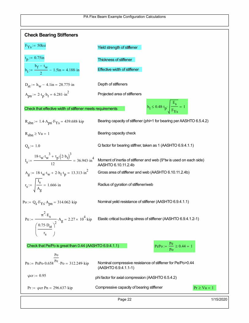
PA Flex Beam Example Configuration Calculations
Check Bearing Stiffeners
FYs 50ksi Yield strength of stiffener
tp 0.75in Thickness of stiffener
bt
bf tw
21.5in 4.188 in Effective width of stiffener
Dst hw 4.1in 28.775 in Depth of stiffeners
Apn 2 tp bt 6.281 in2
Projected area of stiffeners
bt 0.48 tpEs
FYs 1Check that effective width of stiffener meets requirements
Rsbn 1.4 Apn FYs 439.688 kip Bearing capacity of stiffener (phi=1 for bearing per AASHTO 6.5.4.2)
Rsbn Vu 1 Bearing capacity check
Qs 1.0 Q factor for bearing stiffner, taken as 1 (AASHTO 6.9.4.1.1)
Is
18 tw tw3
tp 2 bt 3
1236.943 in
4 Moment of inertia of stiffener and web (9*tw is used on each side)
AASHTO 6.10.11.2.4b
Ag 18 tw tw 2 bt tp 13.313 in2
Gross area of stiffener and web (AASHTO 6.10.11.2.4b)
rs
Is
Ag1.666 in Radius of gyration of stiffener/web
Po Qs FYs Apn 314.062 kip Nominal yeild resistance of stiffener (AASHTO 6.9.4.1.1)
Peπ2Es
0.75 Dst
rs
2Ag 2.27 10
4 kip Elastic critical buckling stress of stiffener (AASHTO 6.9.4.1.2-1)
Check that Pe/Po is great than 0.44 (AASHTO 6.9.4.1.1) PePoPe
Po0.44 1
Pn PePo 0.658
Po
Pe Po 312.249 kip Nominal compressive resistance of stiffener for Pe/Po>0.44
(AASHTO 6.9.4.1.1-1)
φcr 0.95 phi factor for axial compression (AASHTO 6.5.4.2)
Pr φcr Pn 296.637 kip Compressive capacity of bearing stiffener Pr Vu 1
Page 22 1/15/2020
ATLSS Report 18-05 3-1 FlexBeam Example Configuration Summary
3. APPENDIX B – EXAMPLE CONFIGURATION – SHEAR CALCULATIONS
The interface shear calculations are included in this section. Shear transfer rebar spacing is limited to 4, 8, and 12
inches. The spacing of the rebar is specified to transfer the entire horizontal shear force in the deck to the steel section.
The interface shear meets both the maximum discrete shear demands as well as the average shear demand due to the
plastic moment occurring at midspan.

Shear Spacing Analysis for PA Flex Beam Example Configuration
30 ft
36 in
121.75 in3
2199 in4
12.652 in2
0.375 in
65 ksi
270 in2
3.51 kip/in
0.80
Distance from
support
(ft)
Shear force
(kip)
Shear Flow
(kip/in)
Avg Shear Flow
(kip/in)
0 90.446 5.01 3.51
3 78.547 4.35 3.51
6 66.445 3.68 3.51
9 54.344 3.01 3.51
12 42.243 2.34 3.51
15 30.258 1.68 3.51
Distance from
support [in.]
Distance from
support [ft] Hole spacing (in.) Number of holes
Dowel shear
strength [kip/in.]
Web block shear
strength [kip/in.]
Average Shear
Capacity [kip/in.] Hole Dia. 1.5 in
0 0.0 4 6.534 7.3125 4.113 Yield Strength 60 ksi
100 8.3 4 6.534 7.3125 4.113 Bar Area 0.44 sq.in.
100 8.3 8 3.267 9.50625 4.113 Shear Factor 0.55
156 13.0 8 3.267 9.50625 4.113 Discrete f 0.9
156 13.0 12 2.178 10.2375 4.113 Average f 0.75
180 15.0 12 2.178 10.2375 4.113 Discrete Cap 26.136 kip/dowel
Total Number of Holes 34 holes on half span Avg. Capacity 21.78 kip/dowel
Total Force Capacity 740 kip
Average Shear Capacity 4.11 kip/in
Area of deck:
Shear Dowel Spacing Design
Avg. interface shear:
Block shear f:
Section Properties
Calculated Shear Demand Envelope from Matlab
Length:
Width of deck:
Qshort:
Ishort:
Area of steel:
Web thickness:
Web tensile:
Disclaimer: The work presented in this document are provided on an “AS IS” basis. University makes no warranties of any kind, express or implied, as to any matter
whatsoever, including, without limitation, warranties with respect to the merchantability or fitness for a particular purpose of this work or any project deliverables.
University makes no warranty of any kind with respect to freedom from patent, trademark, copyright or trade secret infringement arising from the use of the results of the
project, deliverables, services, intellectual property or other materials provided hereunder. University shall not be liable for any direct, indirect, consequential, punitive, or
other damages suffered by Sponsor or any other person resulting from the project, or the use of this work or any project deliverables.
25.0
7.0
2.0
Capacity of Dowel
0
2
4
6
8
10
12
0 5 10 15S
hea
r fl
ow
[kip
/in]
Distance from support [ft]
Average Interface Demand
Average Interface Capacity
Discrete Interface Demand
Discrete Interface Capacity
Web Block-Shear Capacity
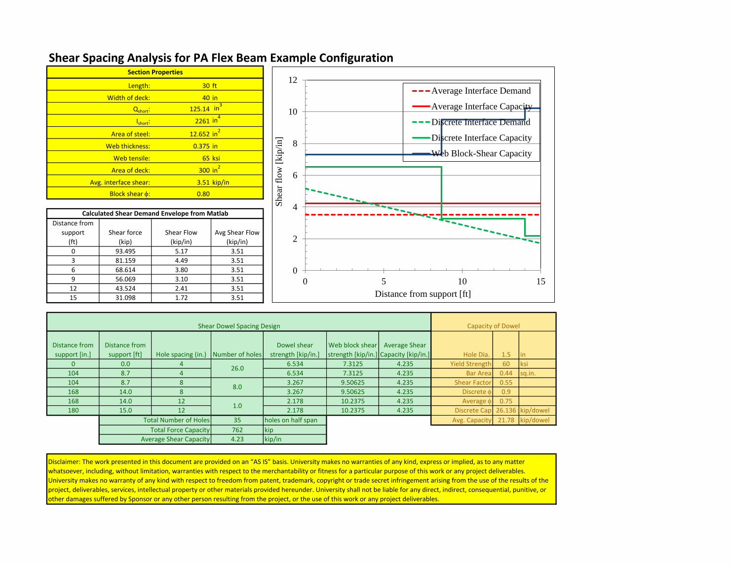
Shear Spacing Analysis for PA Flex Beam Example Configuration
30 ft
40 in
125.14 in3
2261 in4
12.652 in2
0.375 in
65 ksi
300 in2
3.51 kip/in
0.80
Distance from
support
(ft)
Shear force
(kip)
Shear Flow
(kip/in)
Avg Shear Flow
(kip/in)
0 93.495 5.17 3.51
3 81.159 4.49 3.51
6 68.614 3.80 3.51
9 56.069 3.10 3.51
12 43.524 2.41 3.51
15 31.098 1.72 3.51
Distance from
support [in.]
Distance from
support [ft] Hole spacing (in.) Number of holes
Dowel shear
strength [kip/in.]
Web block shear
strength [kip/in.]
Average Shear
Capacity [kip/in.] Hole Dia. 1.5 in
0 0.0 4 6.534 7.3125 4.235 Yield Strength 60 ksi
104 8.7 4 6.534 7.3125 4.235 Bar Area 0.44 sq.in.
104 8.7 8 3.267 9.50625 4.235 Shear Factor 0.55
168 14.0 8 3.267 9.50625 4.235 Discrete f 0.9
168 14.0 12 2.178 10.2375 4.235 Average f 0.75
180 15.0 12 2.178 10.2375 4.235 Discrete Cap 26.136 kip/dowel
Total Number of Holes 35 holes on half span Avg. Capacity 21.78 kip/dowel
Total Force Capacity 762 kip
Average Shear Capacity 4.23 kip/in
Area of steel:
Section Properties
Length:
Width of deck:
Qshort:
Ishort:
Disclaimer: The work presented in this document are provided on an “AS IS” basis. University makes no warranties of any kind, express or implied, as to any matter
whatsoever, including, without limitation, warranties with respect to the merchantability or fitness for a particular purpose of this work or any project deliverables.
University makes no warranty of any kind with respect to freedom from patent, trademark, copyright or trade secret infringement arising from the use of the results of the
project, deliverables, services, intellectual property or other materials provided hereunder. University shall not be liable for any direct, indirect, consequential, punitive, or
other damages suffered by Sponsor or any other person resulting from the project, or the use of this work or any project deliverables.
Web thickness:
Web tensile:
Area of deck:
Avg. interface shear:
Block shear f:
Calculated Shear Demand Envelope from Matlab
Shear Dowel Spacing Design Capacity of Dowel
26.0
8.0
1.0
0
2
4
6
8
10
12
0 5 10 15S
hea
r fl
ow
[kip
/in]
Distance from support [ft]
Average Interface Demand
Average Interface Capacity
Discrete Interface Demand
Discrete Interface Capacity
Web Block-Shear Capacity
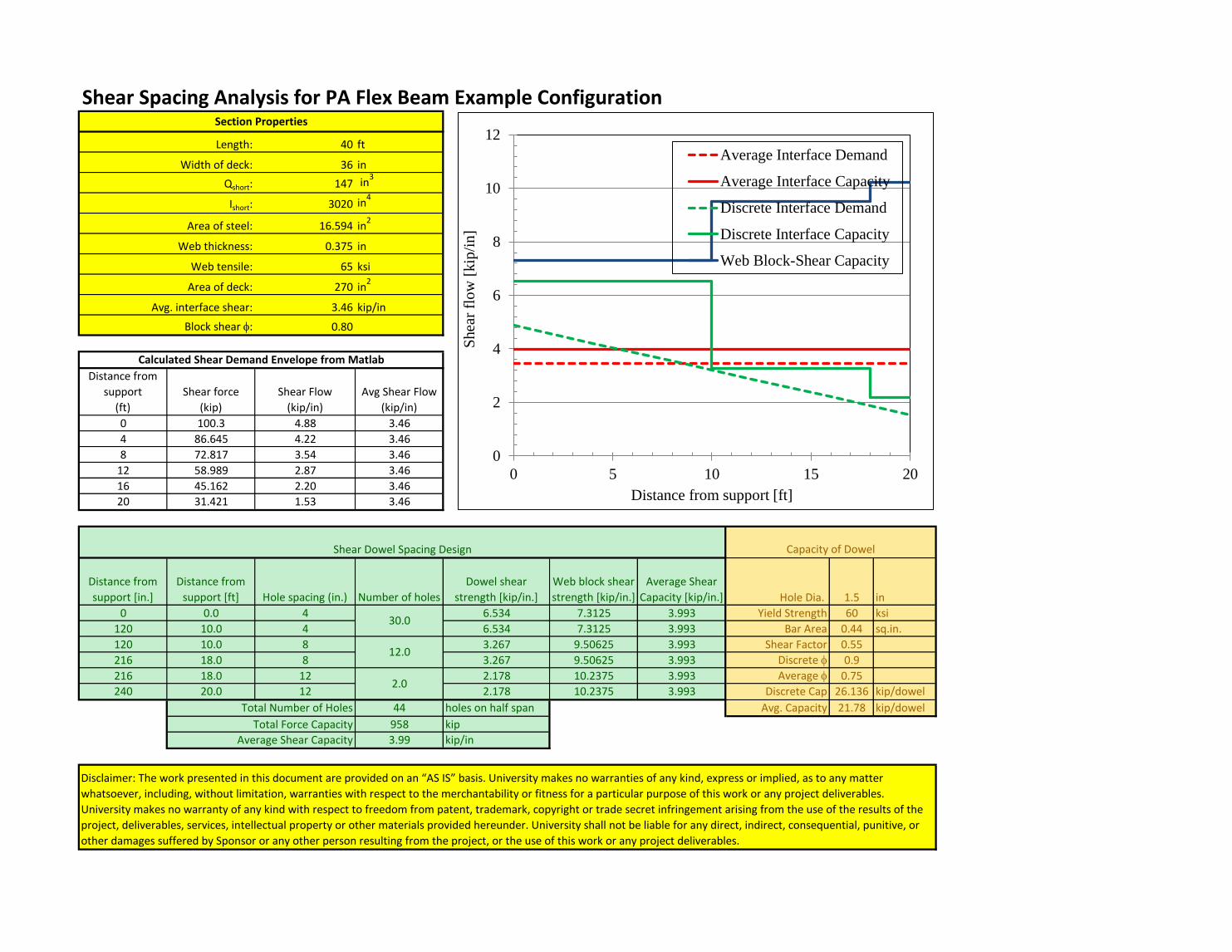
Shear Spacing Analysis for PA Flex Beam Example Configuration
40 ft
36 in
147 in3
3020 in4
16.594 in2
0.375 in
65 ksi
270 in2
3.46 kip/in
0.80
Distance from
support
(ft)
Shear force
(kip)
Shear Flow
(kip/in)
Avg Shear Flow
(kip/in)
0 100.3 4.88 3.46
4 86.645 4.22 3.46
8 72.817 3.54 3.46
12 58.989 2.87 3.46
16 45.162 2.20 3.46
20 31.421 1.53 3.46
Distance from
support [in.]
Distance from
support [ft] Hole spacing (in.) Number of holes
Dowel shear
strength [kip/in.]
Web block shear
strength [kip/in.]
Average Shear
Capacity [kip/in.] Hole Dia. 1.5 in
0 0.0 4 6.534 7.3125 3.993 Yield Strength 60 ksi
120 10.0 4 6.534 7.3125 3.993 Bar Area 0.44 sq.in.
120 10.0 8 3.267 9.50625 3.993 Shear Factor 0.55
216 18.0 8 3.267 9.50625 3.993 Discrete f 0.9
216 18.0 12 2.178 10.2375 3.993 Average f 0.75
240 20.0 12 2.178 10.2375 3.993 Discrete Cap 26.136 kip/dowel
Total Number of Holes 44 holes on half span Avg. Capacity 21.78 kip/dowel
Total Force Capacity 958 kip
Average Shear Capacity 3.99 kip/in
Area of steel:
Section Properties
Length:
Width of deck:
Qshort:
Ishort:
Disclaimer: The work presented in this document are provided on an “AS IS” basis. University makes no warranties of any kind, express or implied, as to any matter
whatsoever, including, without limitation, warranties with respect to the merchantability or fitness for a particular purpose of this work or any project deliverables.
University makes no warranty of any kind with respect to freedom from patent, trademark, copyright or trade secret infringement arising from the use of the results of the
project, deliverables, services, intellectual property or other materials provided hereunder. University shall not be liable for any direct, indirect, consequential, punitive, or
other damages suffered by Sponsor or any other person resulting from the project, or the use of this work or any project deliverables.
Web thickness:
Web tensile:
Area of deck:
Avg. interface shear:
Block shear f:
Calculated Shear Demand Envelope from Matlab
Shear Dowel Spacing Design Capacity of Dowel
30.0
12.0
2.0
0
2
4
6
8
10
12
0 5 10 15 20S
hea
r fl
ow
[kip
/in]
Distance from support [ft]
Average Interface Demand
Average Interface Capacity
Discrete Interface Demand
Discrete Interface Capacity
Web Block-Shear Capacity

Shear Spacing Analysis for PA Flex Beam Example Configuration
40 ft
40 in
184.86 in3
3860.5 in4
16.594 in2
0.375 in
65 ksi
300 in2
3.46 kip/in
0.80
Distance from
support
(ft)
Shear force
(kip)
Shear Flow
(kip/in)
Avg Shear Flow
(kip/in)
0 103.8 4.97 3.46
4 89.623 4.29 3.46
8 75.269 3.60 3.46
12 60.914 2.92 3.46
16 46.559 2.23 3.46
20 32.294 1.55 3.46
Distance from
support [in.]
Distance from
support [ft] Hole spacing (in.) Number of holes
Dowel shear
strength [kip/in.]
Web block shear
strength [kip/in.]
Average Shear
Capacity [kip/in.] Hole Dia. 1.5 in
0 0.0 4 6.534 7.3125 3.993 Yield Strength 60 ksi
124 10.3 4 6.534 7.3125 3.993 Bar Area 0.44 sq.in.
124 10.3 8 3.267 9.50625 3.993 Shear Factor 0.55
204 17.0 8 3.267 9.50625 3.993 Discrete f 0.9
204 17.0 12 2.178 10.2375 3.993 Average f 0.75
240 20.0 12 2.178 10.2375 3.993 Discrete Cap 26.136 kip/dowel
Total Number of Holes 44 holes on half span Avg. Capacity 21.78 kip/dowel
Total Force Capacity 958 kip
Average Shear Capacity 3.99 kip/in
Area of steel:
Section Properties
Length:
Width of deck:
Qshort:
Ishort:
Disclaimer: The work presented in this document are provided on an “AS IS” basis. University makes no warranties of any kind, express or implied, as to any matter
whatsoever, including, without limitation, warranties with respect to the merchantability or fitness for a particular purpose of this work or any project deliverables.
University makes no warranty of any kind with respect to freedom from patent, trademark, copyright or trade secret infringement arising from the use of the results of the
project, deliverables, services, intellectual property or other materials provided hereunder. University shall not be liable for any direct, indirect, consequential, punitive, or
other damages suffered by Sponsor or any other person resulting from the project, or the use of this work or any project deliverables.
Web thickness:
Web tensile:
Area of deck:
Avg. interface shear:
Block shear f:
Calculated Shear Demand Envelope from Matlab
Shear Dowel Spacing Design Capacity of Dowel
31.0
10.0
3.0
0
2
4
6
8
10
12
0 5 10 15 20S
hea
r fl
ow
[kip
/in]
Distance from support [ft]
Average Interface Demand
Average Interface Capacity
Discrete Interface Demand
Discrete Interface Capacity
Web Block-Shear Capacity
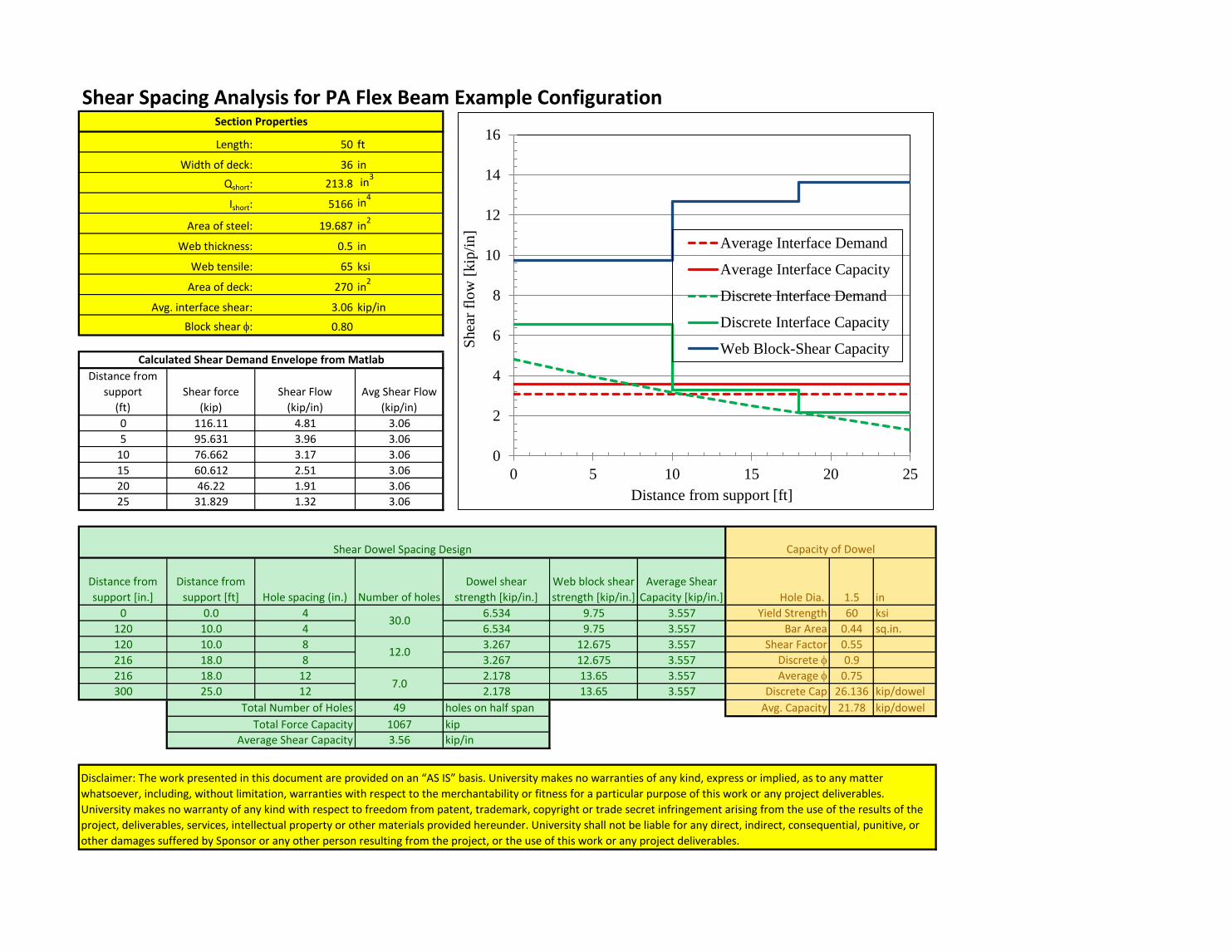
Shear Spacing Analysis for PA Flex Beam Example Configuration
50 ft
36 in
213.8 in3
5166 in4
19.687 in2
0.5 in
65 ksi
270 in2
3.06 kip/in
0.80
Distance from
support
(ft)
Shear force
(kip)
Shear Flow
(kip/in)
Avg Shear Flow
(kip/in)
0 116.11 4.81 3.06
5 95.631 3.96 3.06
10 76.662 3.17 3.06
15 60.612 2.51 3.06
20 46.22 1.91 3.06
25 31.829 1.32 3.06
Distance from
support [in.]
Distance from
support [ft] Hole spacing (in.) Number of holes
Dowel shear
strength [kip/in.]
Web block shear
strength [kip/in.]
Average Shear
Capacity [kip/in.] Hole Dia. 1.5 in
0 0.0 4 6.534 9.75 3.557 Yield Strength 60 ksi
120 10.0 4 6.534 9.75 3.557 Bar Area 0.44 sq.in.
120 10.0 8 3.267 12.675 3.557 Shear Factor 0.55
216 18.0 8 3.267 12.675 3.557 Discrete f 0.9
216 18.0 12 2.178 13.65 3.557 Average f 0.75
300 25.0 12 2.178 13.65 3.557 Discrete Cap 26.136 kip/dowel
Total Number of Holes 49 holes on half span Avg. Capacity 21.78 kip/dowel
Total Force Capacity 1067 kip
Average Shear Capacity 3.56 kip/in
Area of steel:
Section Properties
Length:
Width of deck:
Qshort:
Ishort:
Disclaimer: The work presented in this document are provided on an “AS IS” basis. University makes no warranties of any kind, express or implied, as to any matter
whatsoever, including, without limitation, warranties with respect to the merchantability or fitness for a particular purpose of this work or any project deliverables.
University makes no warranty of any kind with respect to freedom from patent, trademark, copyright or trade secret infringement arising from the use of the results of the
project, deliverables, services, intellectual property or other materials provided hereunder. University shall not be liable for any direct, indirect, consequential, punitive, or
other damages suffered by Sponsor or any other person resulting from the project, or the use of this work or any project deliverables.
Web thickness:
Web tensile:
Area of deck:
Avg. interface shear:
Block shear f:
Calculated Shear Demand Envelope from Matlab
Shear Dowel Spacing Design Capacity of Dowel
30.0
12.0
7.0
0
2
4
6
8
10
12
14
16
0 5 10 15 20 25S
hea
r fl
ow
[kip
/in]
Distance from support [ft]
Average Interface Demand
Average Interface Capacity
Discrete Interface Demand
Discrete Interface Capacity
Web Block-Shear Capacity
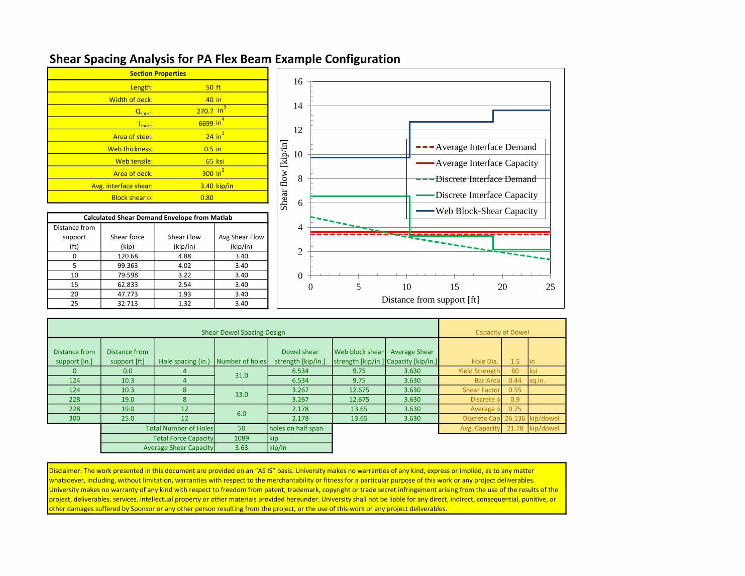
Shear Spacing Analysis for PA Flex Beam Example Configuration
50 ft
40 in
270.7 in3
6699 in4
24 in2
0.5 in
65 ksi
300 in2
3.40 kip/in
0.80
Distance from
support
(ft)
Shear force
(kip)
Shear Flow
(kip/in)
Avg Shear Flow
(kip/in)
0 120.68 4.88 3.40
5 99.363 4.02 3.40
10 79.598 3.22 3.40
15 62.833 2.54 3.40
20 47.773 1.93 3.40
25 32.713 1.32 3.40
Distance from
support [in.]
Distance from
support [ft] Hole spacing (in.) Number of holes
Dowel shear
strength [kip/in.]
Web block shear
strength [kip/in.]
Average Shear
Capacity [kip/in.] Hole Dia. 1.5 in
0 0.0 4 6.534 9.75 3.630 Yield Strength 60 ksi
124 10.3 4 6.534 9.75 3.630 Bar Area 0.44 sq.in.
124 10.3 8 3.267 12.675 3.630 Shear Factor 0.55
228 19.0 8 3.267 12.675 3.630 Discrete f 0.9
228 19.0 12 2.178 13.65 3.630 Average f 0.75
300 25.0 12 2.178 13.65 3.630 Discrete Cap 26.136 kip/dowel
Total Number of Holes 50 holes on half span Avg. Capacity 21.78 kip/dowel
Total Force Capacity 1089 kip
Average Shear Capacity 3.63 kip/in
Area of steel:
Section Properties
Length:
Width of deck:
Qshort:
Ishort:
Disclaimer: The work presented in this document are provided on an “AS IS” basis. University makes no warranties of any kind, express or implied, as to any matter
whatsoever, including, without limitation, warranties with respect to the merchantability or fitness for a particular purpose of this work or any project deliverables.
University makes no warranty of any kind with respect to freedom from patent, trademark, copyright or trade secret infringement arising from the use of the results of the
project, deliverables, services, intellectual property or other materials provided hereunder. University shall not be liable for any direct, indirect, consequential, punitive, or
other damages suffered by Sponsor or any other person resulting from the project, or the use of this work or any project deliverables.
Web thickness:
Web tensile:
Area of deck:
Avg. interface shear:
Block shear f:
Calculated Shear Demand Envelope from Matlab
Shear Dowel Spacing Design Capacity of Dowel
31.0
13.0
6.0
0
2
4
6
8
10
12
14
16
0 5 10 15 20 25S
hea
r fl
ow
[kip
/in]
Distance from support [ft]
Average Interface Demand
Average Interface Capacity
Discrete Interface Demand
Discrete Interface Capacity
Web Block-Shear Capacity

Shear Spacing Analysis for PA Flex Beam Example Configuration
60 ft
36 in
311.2 in3
9406 in4
27.906 in2
0.625 in
65 ksi
270 in2
2.55 kip/in
0.80
Distance from
support
(ft)
Shear force
(kip)
Shear Flow
(kip/in)
Avg Shear Flow
(kip/in)
0 134.23 4.44 2.55
6 111.37 3.68 2.55
12 89.269 2.95 2.55
18 67.887 2.25 2.55
24 49.323 1.63 2.55
30 33.522 1.11 2.55
Distance from
support [in.]
Distance from
support [ft] Hole spacing (in.) Number of holes
Dowel shear
strength [kip/in.]
Web block shear
strength [kip/in.]
Average Shear
Capacity [kip/in.] Hole Dia. 1.5 in
0 0.0 4 6.534 12.1875 3.328 Yield Strength 60 ksi
120 10.0 4 6.534 12.1875 3.328 Bar Area 0.44 sq.in.
120 10.0 8 3.267 15.84375 3.328 Shear Factor 0.55
240 20.0 8 3.267 15.84375 3.328 Discrete f 0.9
240 20.0 12 2.178 17.0625 3.328 Average f 0.75
360 30.0 12 2.178 17.0625 3.328 Discrete Cap 26.136 kip/dowel
Total Number of Holes 55 holes on half span Avg. Capacity 21.78 kip/dowel
Total Force Capacity 1198 kip
Average Shear Capacity 3.33 kip/in
Area of steel:
Section Properties
Length:
Width of deck:
Qshort:
Ishort:
Disclaimer: The work presented in this document are provided on an “AS IS” basis. University makes no warranties of any kind, express or implied, as to any matter
whatsoever, including, without limitation, warranties with respect to the merchantability or fitness for a particular purpose of this work or any project deliverables.
University makes no warranty of any kind with respect to freedom from patent, trademark, copyright or trade secret infringement arising from the use of the results of the
project, deliverables, services, intellectual property or other materials provided hereunder. University shall not be liable for any direct, indirect, consequential, punitive, or
other damages suffered by Sponsor or any other person resulting from the project, or the use of this work or any project deliverables.
Web thickness:
Web tensile:
Area of deck:
Avg. interface shear:
Block shear f:
Calculated Shear Demand Envelope from Matlab
Shear Dowel Spacing Design Capacity of Dowel
30.0
15.0
10.0
0
2
4
6
8
10
12
14
16
18
0 5 10 15 20 25 30S
hea
r fl
ow
[kip
/in]
Distance from support [ft]
Average Interface Demand
Average Interface Capacity
Discrete Interface Demand
Discrete Interface Capacity
Web Block-Shear Capacity
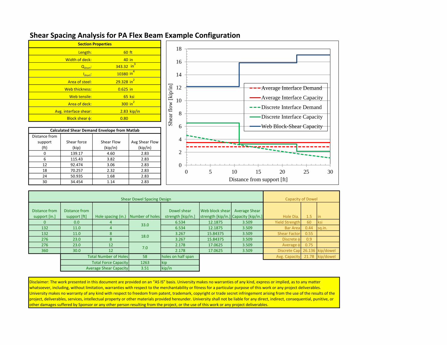
Shear Spacing Analysis for PA Flex Beam Example Configuration
60 ft
40 in
343.32 in3
10380 in4
29.328 in2
0.625 in
65 ksi
300 in2
2.83 kip/in
0.80
Distance from
support
(ft)
Shear force
(kip)
Shear Flow
(kip/in)
Avg Shear Flow
(kip/in)
0 139.17 4.60 2.83
6 115.43 3.82 2.83
12 92.474 3.06 2.83
18 70.257 2.32 2.83
24 50.935 1.68 2.83
30 34.454 1.14 2.83
Distance from
support [in.]
Distance from
support [ft] Hole spacing (in.) Number of holes
Dowel shear
strength [kip/in.]
Web block shear
strength [kip/in.]
Average Shear
Capacity [kip/in.] Hole Dia. 1.5 in
0 0.0 4 6.534 12.1875 3.509 Yield Strength 60 ksi
132 11.0 4 6.534 12.1875 3.509 Bar Area 0.44 sq.in.
132 11.0 8 3.267 15.84375 3.509 Shear Factor 0.55
276 23.0 8 3.267 15.84375 3.509 Discrete f 0.9
276 23.0 12 2.178 17.0625 3.509 Average f 0.75
360 30.0 12 2.178 17.0625 3.509 Discrete Cap 26.136 kip/dowel
Total Number of Holes 58 holes on half span Avg. Capacity 21.78 kip/dowel
Total Force Capacity 1263 kip
Average Shear Capacity 3.51 kip/in
Area of steel:
Section Properties
Length:
Width of deck:
Qshort:
Ishort:
Disclaimer: The work presented in this document are provided on an “AS IS” basis. University makes no warranties of any kind, express or implied, as to any matter
whatsoever, including, without limitation, warranties with respect to the merchantability or fitness for a particular purpose of this work or any project deliverables.
University makes no warranty of any kind with respect to freedom from patent, trademark, copyright or trade secret infringement arising from the use of the results of the
project, deliverables, services, intellectual property or other materials provided hereunder. University shall not be liable for any direct, indirect, consequential, punitive, or
other damages suffered by Sponsor or any other person resulting from the project, or the use of this work or any project deliverables.
Web thickness:
Web tensile:
Area of deck:
Avg. interface shear:
Block shear f:
Calculated Shear Demand Envelope from Matlab
Shear Dowel Spacing Design Capacity of Dowel
33.0
18.0
7.0
0
2
4
6
8
10
12
14
16
18
0 5 10 15 20 25 30S
hea
r fl
ow
[kip
/in]
Distance from support [ft]
Average Interface Demand
Average Interface Capacity
Discrete Interface Demand
Discrete Interface Capacity
Web Block-Shear Capacity

Shear Spacing Analysis for PA Flex Beam Example Configuration
70 ft
36 in
348.25 in3
11550 in4
29.781 in2
0.625 in
65 ksi
270 in2
2.19 kip/in
0.80
Distance from
support
(ft)
Shear force
(kip)
Shear Flow
(kip/in)
Avg Shear Flow
(kip/in)
0 149.43 4.51 2.19
7 125.05 3.77 2.19
14 100.5 3.03 2.19
21 76.958 2.32 2.19
28 54.188 1.63 2.19
35 34.732 1.05 2.19
Distance from
support [in.]
Distance from
support [ft] Hole spacing (in.) Number of holes
Dowel shear
strength [kip/in.]
Web block shear
strength [kip/in.]
Average Shear
Capacity [kip/in.] Hole Dia. 1.5 in
0 0.0 4 6.534 12.1875 3.423 Yield Strength 60 ksi
152 12.7 4 6.534 12.1875 3.423 Bar Area 0.44 sq.in.
152 12.7 8 3.267 15.84375 3.423 Shear Factor 0.55
288 24.0 8 3.267 15.84375 3.423 Discrete f 0.9
288 24.0 12 2.178 17.0625 3.423 Average f 0.75
420 35.0 12 2.178 17.0625 3.423 Discrete Cap 26.136 kip/dowel
Total Number of Holes 66 holes on half span Avg. Capacity 21.78 kip/dowel
Total Force Capacity 1437 kip
Average Shear Capacity 3.42 kip/in
Area of steel:
Section Properties
Length:
Width of deck:
Qshort:
Ishort:
Disclaimer: The work presented in this document are provided on an “AS IS” basis. University makes no warranties of any kind, express or implied, as to any matter
whatsoever, including, without limitation, warranties with respect to the merchantability or fitness for a particular purpose of this work or any project deliverables.
University makes no warranty of any kind with respect to freedom from patent, trademark, copyright or trade secret infringement arising from the use of the results of the
project, deliverables, services, intellectual property or other materials provided hereunder. University shall not be liable for any direct, indirect, consequential, punitive, or
other damages suffered by Sponsor or any other person resulting from the project, or the use of this work or any project deliverables.
Web thickness:
Web tensile:
Area of deck:
Avg. interface shear:
Block shear f:
Calculated Shear Demand Envelope from Matlab
Shear Dowel Spacing Design Capacity of Dowel
38.0
17.0
11.0
0
2
4
6
8
10
12
14
16
18
0 10 20 30S
hea
r fl
ow
[kip
/in]
Distance from support [ft]
Average Interface Demand
Average Interface Capacity
Discrete Interface Demand
Discrete Interface Capacity
Web Block-Shear Capacity
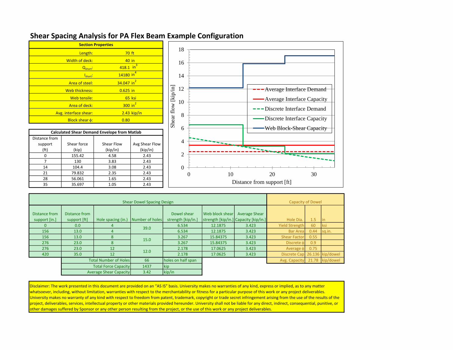
Shear Spacing Analysis for PA Flex Beam Example Configuration
70 ft
40 in
418.1 in3
14180 in4
34.047 in2
0.625 in
65 ksi
300 in2
2.43 kip/in
0.80
Distance from
support
(ft)
Shear force
(kip)
Shear Flow
(kip/in)
Avg Shear Flow
(kip/in)
0 155.42 4.58 2.43
7 130 3.83 2.43
14 104.4 3.08 2.43
21 79.832 2.35 2.43
28 56.061 1.65 2.43
35 35.697 1.05 2.43
Distance from
support [in.]
Distance from
support [ft] Hole spacing (in.) Number of holes
Dowel shear
strength [kip/in.]
Web block shear
strength [kip/in.]
Average Shear
Capacity [kip/in.] Hole Dia. 1.5 in
0 0.0 4 6.534 12.1875 3.423 Yield Strength 60 ksi
156 13.0 4 6.534 12.1875 3.423 Bar Area 0.44 sq.in.
156 13.0 8 3.267 15.84375 3.423 Shear Factor 0.55
276 23.0 8 3.267 15.84375 3.423 Discrete f 0.9
276 23.0 12 2.178 17.0625 3.423 Average f 0.75
420 35.0 12 2.178 17.0625 3.423 Discrete Cap 26.136 kip/dowel
Total Number of Holes 66 holes on half span Avg. Capacity 21.78 kip/dowel
Total Force Capacity 1437 kip
Average Shear Capacity 3.42 kip/in
Area of steel:
Section Properties
Length:
Width of deck:
Qshort:
Ishort:
Disclaimer: The work presented in this document are provided on an “AS IS” basis. University makes no warranties of any kind, express or implied, as to any matter
whatsoever, including, without limitation, warranties with respect to the merchantability or fitness for a particular purpose of this work or any project deliverables.
University makes no warranty of any kind with respect to freedom from patent, trademark, copyright or trade secret infringement arising from the use of the results of the
project, deliverables, services, intellectual property or other materials provided hereunder. University shall not be liable for any direct, indirect, consequential, punitive, or
other damages suffered by Sponsor or any other person resulting from the project, or the use of this work or any project deliverables.
Web thickness:
Web tensile:
Area of deck:
Avg. interface shear:
Block shear f:
Calculated Shear Demand Envelope from Matlab
Shear Dowel Spacing Design Capacity of Dowel
39.0
15.0
12.0
0
2
4
6
8
10
12
14
16
18
0 10 20 30S
hea
r fl
ow
[kip
/in]
Distance from support [ft]
Average Interface Demand
Average Interface Capacity
Discrete Interface Demand
Discrete Interface Capacity
Web Block-Shear Capacity
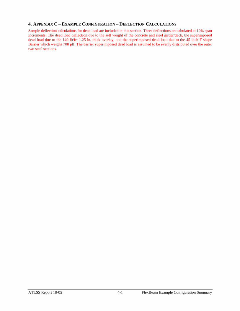
ATLSS Report 18-05 4-1 FlexBeam Example Configuration Summary
4. APPENDIX C – EXAMPLE CONFIGURATION – DEFLECTION CALCULATIONS
Sample deflection calculations for dead load are included in this section. Three deflections are tabulated at 10% span
increments: The dead load deflection due to the self weight of the concrete and steel girder/deck, the superimposed
dead load due to the 140 lb/ft3 1.25 in. thick overlay, and the superimposed dead load due to the 45 inch F-shape
Barrier which weighs 700 plf. The barrier superimposed dead load is assumed to be evenly distributed over the outer
two steel sections.

Lehigh University and ATLSS Center Disclaimer
The work presented in this document are provided on an “AS IS” basis. University makes no
warranties of any kind, express or implied, as to any matter whatsoever, including, without
limitation, warranties with respect to the merchantability or fitness for a particular purpose of this
work or any project deliverables. University makes no warranty of any kind with respect to freedom
from patent, trademark, copyright or trade secret infringement arising from the use of the results of
the project, deliverables, services, intellectual property or other materials provided hereunder.
University shall not be liable for any direct, indirect, consequential, punitive, or other damages
suffered by Sponsor or any other person resulting from the project, or the use of this work or any
project deliverables.
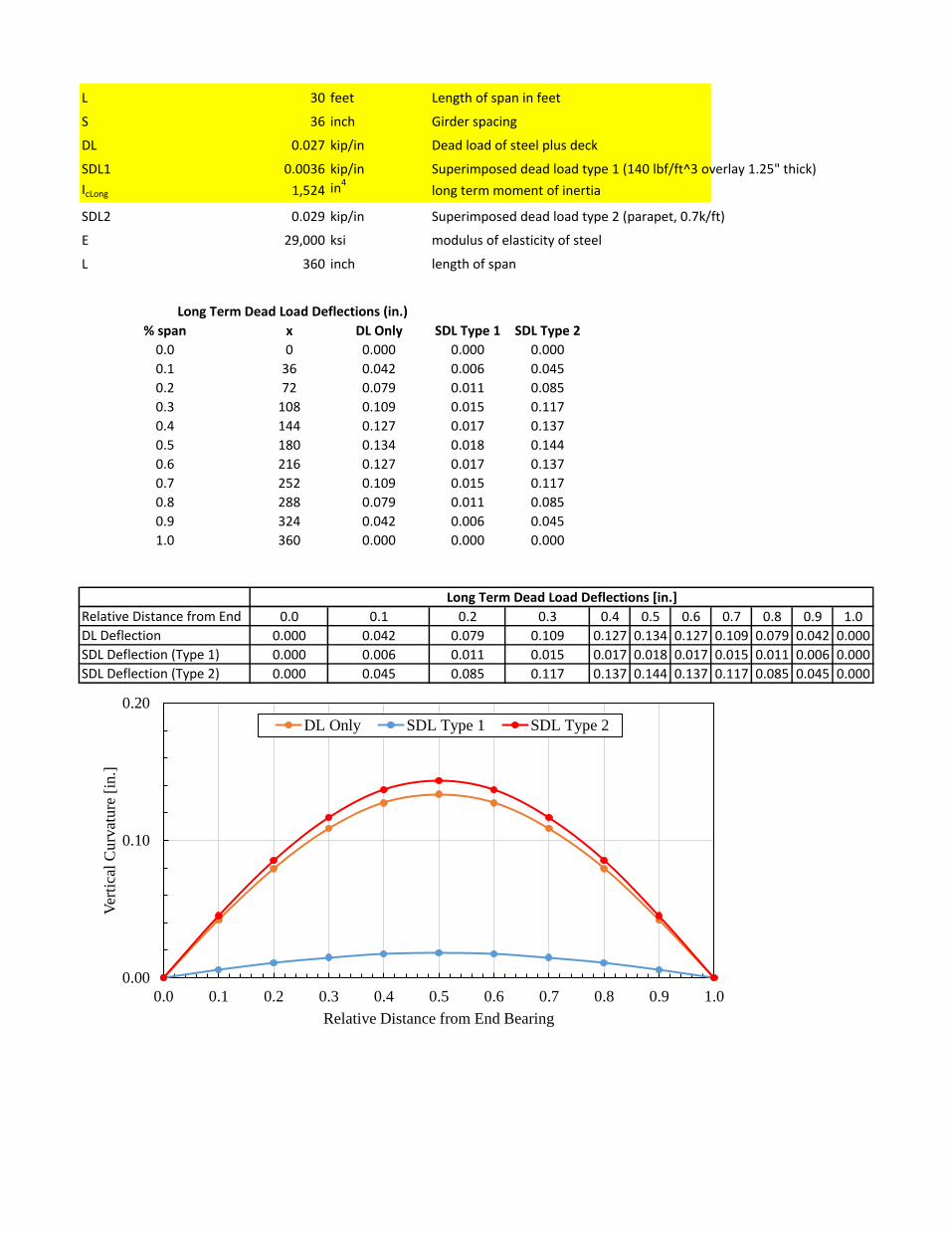
L 30 feet Length of span in feet
S 36 inch Girder spacing
DL 0.027 kip/in Dead load of steel plus deck
SDL1 0.0036 kip/in Superimposed dead load type 1 (140 lbf/ft^3 overlay 1.25" thick)
IcLong 1,524 in4
long term moment of inertia
SDL2 0.029 kip/in Superimposed dead load type 2 (parapet, 0.7k/ft)
E 29,000 ksi modulus of elasticity of steel
L 360 inch length of span
% span x DL Only SDL Type 1 SDL Type 2
0.0 0 0.000 0.000 0.000
0.1 36 0.042 0.006 0.045
0.2 72 0.079 0.011 0.085
0.3 108 0.109 0.015 0.117
0.4 144 0.127 0.017 0.137
0.5 180 0.134 0.018 0.144
0.6 216 0.127 0.017 0.137
0.7 252 0.109 0.015 0.117
0.8 288 0.079 0.011 0.085
0.9 324 0.042 0.006 0.045
1.0 360 0.000 0.000 0.000
Relative Distance from End 0.0 0.1 0.2 0.3 0.4 0.5 0.6 0.7 0.8 0.9 1.0
DL Deflection 0.000 0.042 0.079 0.109 0.127 0.134 0.127 0.109 0.079 0.042 0.000
SDL Deflection (Type 1) 0.000 0.006 0.011 0.015 0.017 0.018 0.017 0.015 0.011 0.006 0.000
SDL Deflection (Type 2) 0.000 0.045 0.085 0.117 0.137 0.144 0.137 0.117 0.085 0.045 0.000
Long Term Dead Load Deflections [in.]
Long Term Dead Load Deflections (in.)
0.00
0.10
0.20
0.0 0.1 0.2 0.3 0.4 0.5 0.6 0.7 0.8 0.9 1.0
Ver
tica
l C
urv
atu
re [
in.]
Relative Distance from End Bearing
DL Only SDL Type 1 SDL Type 2
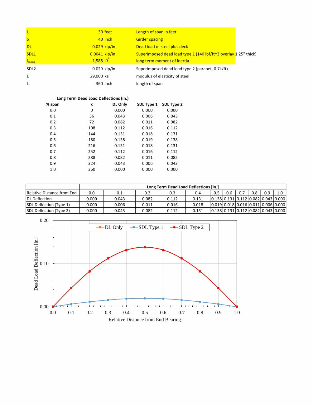
L 30 feet Length of span in feet
S 40 inch Girder spacing
DL 0.029 kip/in Dead load of steel plus deck
SDL1 0.0041 kip/in Superimposed dead load type 1 (140 lbf/ft^3 overlay 1.25" thick)
IcLong 1,588 in4long term moment of inertia
SDL2 0.029 kip/in Superimposed dead load type 2 (parapet, 0.7k/ft)
E 29,000 ksi modulus of elasticity of steel
L 360 inch length of span
% span x DL Only SDL Type 1 SDL Type 2
0.0 0 0.000 0.000 0.000
0.1 36 0.043 0.006 0.043
0.2 72 0.082 0.011 0.082
0.3 108 0.112 0.016 0.112
0.4 144 0.131 0.018 0.131
0.5 180 0.138 0.019 0.138
0.6 216 0.131 0.018 0.131
0.7 252 0.112 0.016 0.112
0.8 288 0.082 0.011 0.082
0.9 324 0.043 0.006 0.043
1.0 360 0.000 0.000 0.000
Relative Distance from End 0.0 0.1 0.2 0.3 0.4 0.5 0.6 0.7 0.8 0.9 1.0
DL Deflection 0.000 0.043 0.082 0.112 0.131 0.138 0.131 0.112 0.082 0.043 0.000
SDL Deflection (Type 1) 0.000 0.006 0.011 0.016 0.018 0.019 0.018 0.016 0.011 0.006 0.000
SDL Deflection (Type 2) 0.000 0.043 0.082 0.112 0.131 0.138 0.131 0.112 0.082 0.043 0.000
Long Term Dead Load Deflections [in.]
Long Term Dead Load Deflections (in.)
0.00
0.10
0.20
0.0 0.1 0.2 0.3 0.4 0.5 0.6 0.7 0.8 0.9 1.0
Dea
d L
oad
Def
lect
ion
[in
.]
Relative Distance from End Bearing
DL Only SDL Type 1 SDL Type 2
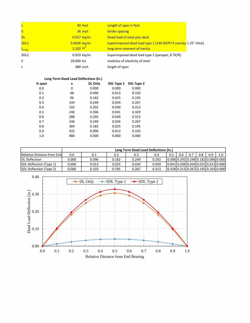
L 40 feet Length of span in feet
S 36 inch Girder spacing
DL 0.027 kip/in Dead load of steel plus deck
SDL1 0.0036 kip/in Superimposed dead load type 1 (140 lbf/ft^3 overlay 1.25" thick)
IcLong 2,102 in4long term moment of inertia
SDL2 0.029 kip/in Superimposed dead load type 2 (parapet, 0.7k/ft)
E 29,000 ksi modulus of elasticity of steel
L 480 inch length of span
% span x DL Only SDL Type 1 SDL Type 2
0.0 0 0.000 0.000 0.000
0.1 48 0.096 0.013 0.103
0.2 96 0.182 0.025 0.195
0.3 144 0.249 0.034 0.267
0.4 192 0.292 0.039 0.313
0.5 240 0.306 0.041 0.329
0.6 288 0.292 0.039 0.313
0.7 336 0.249 0.034 0.267
0.8 384 0.182 0.025 0.195
0.9 432 0.096 0.013 0.103
1.0 480 0.000 0.000 0.000
Relative Distance from End 0.0 0.1 0.2 0.3 0.4 0.5 0.6 0.7 0.8 0.9 1.0
DL Deflection 0.000 0.096 0.182 0.249 0.292 0.306 0.292 0.249 0.182 0.096 0.000
SDL Deflection (Type 1) 0.000 0.013 0.025 0.034 0.039 0.041 0.039 0.034 0.025 0.013 0.000
SDL Deflection (Type 2) 0.000 0.103 0.195 0.267 0.313 0.329 0.313 0.267 0.195 0.103 0.000
Long Term Dead Load Deflections [in.]
Long Term Dead Load Deflections (in.)
0.00
0.10
0.20
0.30
0.40
0.0 0.1 0.2 0.3 0.4 0.5 0.6 0.7 0.8 0.9 1.0
Dea
d L
oad
Def
lect
ion [
in.]
Relative Distance from End Bearing
DL Only SDL Type 1 SDL Type 2
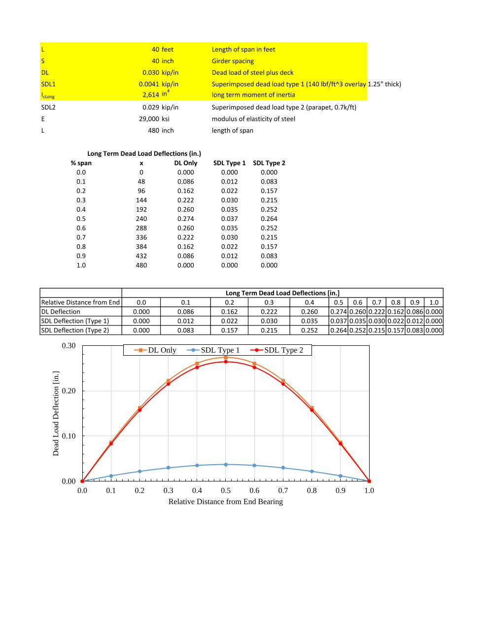
L 40 feet Length of span in feet
S 40 inch Girder spacing
DL 0.030 kip/in Dead load of steel plus deck
SDL1 0.0041 kip/in Superimposed dead load type 1 (140 lbf/ft^3 overlay 1.25" thick)
IcLong 2,614 in4long term moment of inertia
SDL2 0.029 kip/in Superimposed dead load type 2 (parapet, 0.7k/ft)
E 29,000 ksi modulus of elasticity of steel
L 480 inch length of span
% span x DL Only SDL Type 1 SDL Type 2
0.0 0 0.000 0.000 0.000
0.1 48 0.086 0.012 0.083
0.2 96 0.162 0.022 0.157
0.3 144 0.222 0.030 0.215
0.4 192 0.260 0.035 0.252
0.5 240 0.274 0.037 0.264
0.6 288 0.260 0.035 0.252
0.7 336 0.222 0.030 0.215
0.8 384 0.162 0.022 0.157
0.9 432 0.086 0.012 0.083
1.0 480 0.000 0.000 0.000
Relative Distance from End 0.0 0.1 0.2 0.3 0.4 0.5 0.6 0.7 0.8 0.9 1.0
DL Deflection 0.000 0.086 0.162 0.222 0.260 0.274 0.260 0.222 0.162 0.086 0.000
SDL Deflection (Type 1) 0.000 0.012 0.022 0.030 0.035 0.037 0.035 0.030 0.022 0.012 0.000
SDL Deflection (Type 2) 0.000 0.083 0.157 0.215 0.252 0.264 0.252 0.215 0.157 0.083 0.000
Long Term Dead Load Deflections [in.]
Long Term Dead Load Deflections (in.)
0.00
0.10
0.20
0.30
0.0 0.1 0.2 0.3 0.4 0.5 0.6 0.7 0.8 0.9 1.0
Dea
d L
oad
Def
lect
ion [
in.]
Relative Distance from End Bearing
DL Only SDL Type 1 SDL Type 2
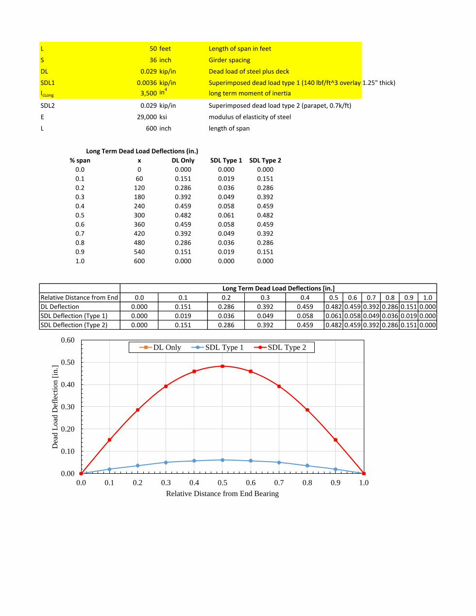
L 50 feet Length of span in feet
S 36 inch Girder spacing
DL 0.029 kip/in Dead load of steel plus deck
SDL1 0.0036 kip/in Superimposed dead load type 1 (140 lbf/ft^3 overlay 1.25" thick)
IcLong 3,500 in4long term moment of inertia
SDL2 0.029 kip/in Superimposed dead load type 2 (parapet, 0.7k/ft)
E 29,000 ksi modulus of elasticity of steel
L 600 inch length of span
% span x DL Only SDL Type 1 SDL Type 2
0.0 0 0.000 0.000 0.000
0.1 60 0.151 0.019 0.151
0.2 120 0.286 0.036 0.286
0.3 180 0.392 0.049 0.392
0.4 240 0.459 0.058 0.459
0.5 300 0.482 0.061 0.482
0.6 360 0.459 0.058 0.459
0.7 420 0.392 0.049 0.392
0.8 480 0.286 0.036 0.286
0.9 540 0.151 0.019 0.151
1.0 600 0.000 0.000 0.000
Relative Distance from End 0.0 0.1 0.2 0.3 0.4 0.5 0.6 0.7 0.8 0.9 1.0
DL Deflection 0.000 0.151 0.286 0.392 0.459 0.482 0.459 0.392 0.286 0.151 0.000
SDL Deflection (Type 1) 0.000 0.019 0.036 0.049 0.058 0.061 0.058 0.049 0.036 0.019 0.000
SDL Deflection (Type 2) 0.000 0.151 0.286 0.392 0.459 0.482 0.459 0.392 0.286 0.151 0.000
Long Term Dead Load Deflections [in.]
Long Term Dead Load Deflections (in.)
0.00
0.10
0.20
0.30
0.40
0.50
0.60
0.0 0.1 0.2 0.3 0.4 0.5 0.6 0.7 0.8 0.9 1.0
Dea
d L
oad
Def
lect
ion [
in.]
Relative Distance from End Bearing
DL Only SDL Type 1 SDL Type 2
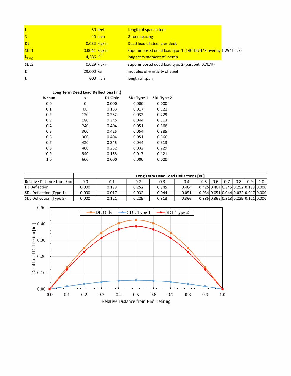
L 50 feet Length of span in feet
S 40 inch Girder spacing
DL 0.032 kip/in Dead load of steel plus deck
SDL1 0.0041 kip/in Superimposed dead load type 1 (140 lbf/ft^3 overlay 1.25" thick)
IcLong 4,386 in4long term moment of inertia
SDL2 0.029 kip/in Superimposed dead load type 2 (parapet, 0.7k/ft)
E 29,000 ksi modulus of elasticity of steel
L 600 inch length of span
% span x DL Only SDL Type 1 SDL Type 2
0.0 0 0.000 0.000 0.000
0.1 60 0.133 0.017 0.121
0.2 120 0.252 0.032 0.229
0.3 180 0.345 0.044 0.313
0.4 240 0.404 0.051 0.366
0.5 300 0.425 0.054 0.385
0.6 360 0.404 0.051 0.366
0.7 420 0.345 0.044 0.313
0.8 480 0.252 0.032 0.229
0.9 540 0.133 0.017 0.121
1.0 600 0.000 0.000 0.000
Relative Distance from End 0.0 0.1 0.2 0.3 0.4 0.5 0.6 0.7 0.8 0.9 1.0
DL Deflection 0.000 0.133 0.252 0.345 0.404 0.425 0.404 0.345 0.252 0.133 0.000
SDL Deflection (Type 1) 0.000 0.017 0.032 0.044 0.051 0.054 0.051 0.044 0.032 0.017 0.000
SDL Deflection (Type 2) 0.000 0.121 0.229 0.313 0.366 0.385 0.366 0.313 0.229 0.121 0.000
Long Term Dead Load Deflections [in.]
Long Term Dead Load Deflections (in.)
0.00
0.10
0.20
0.30
0.40
0.50
0.0 0.1 0.2 0.3 0.4 0.5 0.6 0.7 0.8 0.9 1.0
Dea
d L
oad
Def
lect
ion [
in.]
Relative Distance from End Bearing
DL Only SDL Type 1 SDL Type 2
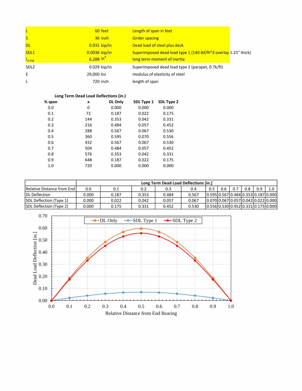
L 60 feet Length of span in feet
S 36 inch Girder spacing
DL 0.031 kip/in Dead load of steel plus deck
SDL1 0.0036 kip/in Superimposed dead load type 1 (140 lbf/ft^3 overlay 1.25" thick)
IcLong 6,288 in4long term moment of inertia
SDL2 0.029 kip/in Superimposed dead load type 2 (parapet, 0.7k/ft)
E 29,000 ksi modulus of elasticity of steel
L 720 inch length of span
% span x DL Only SDL Type 1 SDL Type 2
0.0 0 0.000 0.000 0.000
0.1 72 0.187 0.022 0.175
0.2 144 0.353 0.042 0.331
0.3 216 0.484 0.057 0.452
0.4 288 0.567 0.067 0.530
0.5 360 0.595 0.070 0.556
0.6 432 0.567 0.067 0.530
0.7 504 0.484 0.057 0.452
0.8 576 0.353 0.042 0.331
0.9 648 0.187 0.022 0.175
1.0 720 0.000 0.000 0.000
Relative Distance from End 0.0 0.1 0.2 0.3 0.4 0.5 0.6 0.7 0.8 0.9 1.0
DL Deflection 0.000 0.187 0.353 0.484 0.567 0.595 0.567 0.484 0.353 0.187 0.000
SDL Deflection (Type 1) 0.000 0.022 0.042 0.057 0.067 0.070 0.067 0.057 0.042 0.022 0.000
SDL Deflection (Type 2) 0.000 0.175 0.331 0.452 0.530 0.556 0.530 0.452 0.331 0.175 0.000
Long Term Dead Load Deflections [in.]
Long Term Dead Load Deflections (in.)
0.00
0.10
0.20
0.30
0.40
0.50
0.60
0.70
0.0 0.1 0.2 0.3 0.4 0.5 0.6 0.7 0.8 0.9 1.0
Dea
d L
oad
Def
lect
ion [
in.]
Relative Distance from End Bearing
DL Only SDL Type 1 SDL Type 2
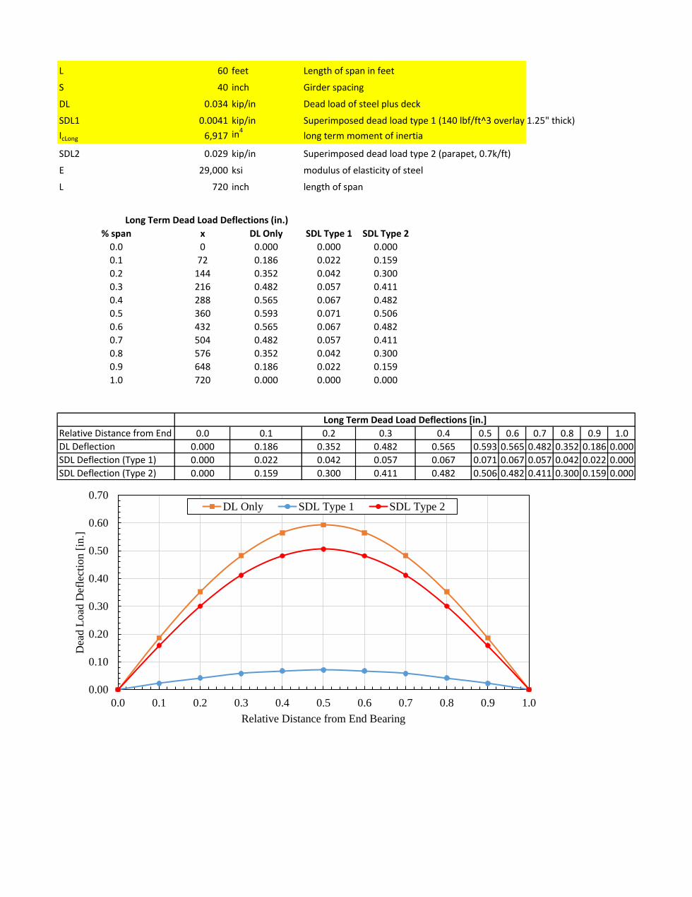
L 60 feet Length of span in feet
S 40 inch Girder spacing
DL 0.034 kip/in Dead load of steel plus deck
SDL1 0.0041 kip/in Superimposed dead load type 1 (140 lbf/ft^3 overlay 1.25" thick)
IcLong 6,917 in4long term moment of inertia
SDL2 0.029 kip/in Superimposed dead load type 2 (parapet, 0.7k/ft)
E 29,000 ksi modulus of elasticity of steel
L 720 inch length of span
% span x DL Only SDL Type 1 SDL Type 2
0.0 0 0.000 0.000 0.000
0.1 72 0.186 0.022 0.159
0.2 144 0.352 0.042 0.300
0.3 216 0.482 0.057 0.411
0.4 288 0.565 0.067 0.482
0.5 360 0.593 0.071 0.506
0.6 432 0.565 0.067 0.482
0.7 504 0.482 0.057 0.411
0.8 576 0.352 0.042 0.300
0.9 648 0.186 0.022 0.159
1.0 720 0.000 0.000 0.000
Relative Distance from End 0.0 0.1 0.2 0.3 0.4 0.5 0.6 0.7 0.8 0.9 1.0
DL Deflection 0.000 0.186 0.352 0.482 0.565 0.593 0.565 0.482 0.352 0.186 0.000
SDL Deflection (Type 1) 0.000 0.022 0.042 0.057 0.067 0.071 0.067 0.057 0.042 0.022 0.000
SDL Deflection (Type 2) 0.000 0.159 0.300 0.411 0.482 0.506 0.482 0.411 0.300 0.159 0.000
Long Term Dead Load Deflections [in.]
Long Term Dead Load Deflections (in.)
0.00
0.10
0.20
0.30
0.40
0.50
0.60
0.70
0.0 0.1 0.2 0.3 0.4 0.5 0.6 0.7 0.8 0.9 1.0
Dea
d L
oad
Def
lect
ion [
in.]
Relative Distance from End Bearing
DL Only SDL Type 1 SDL Type 2
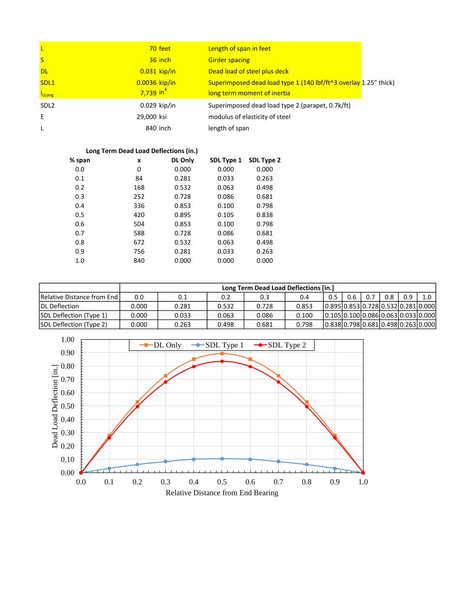
L 70 feet Length of span in feet
S 36 inch Girder spacing
DL 0.031 kip/in Dead load of steel plus deck
SDL1 0.0036 kip/in Superimposed dead load type 1 (140 lbf/ft^3 overlay 1.25" thick)
IcLong 7,739 in4long term moment of inertia
SDL2 0.029 kip/in Superimposed dead load type 2 (parapet, 0.7k/ft)
E 29,000 ksi modulus of elasticity of steel
L 840 inch length of span
% span x DL Only SDL Type 1 SDL Type 2
0.0 0 0.000 0.000 0.000
0.1 84 0.281 0.033 0.263
0.2 168 0.532 0.063 0.498
0.3 252 0.728 0.086 0.681
0.4 336 0.853 0.100 0.798
0.5 420 0.895 0.105 0.838
0.6 504 0.853 0.100 0.798
0.7 588 0.728 0.086 0.681
0.8 672 0.532 0.063 0.498
0.9 756 0.281 0.033 0.263
1.0 840 0.000 0.000 0.000
Relative Distance from End 0.0 0.1 0.2 0.3 0.4 0.5 0.6 0.7 0.8 0.9 1.0
DL Deflection 0.000 0.281 0.532 0.728 0.853 0.895 0.853 0.728 0.532 0.281 0.000
SDL Deflection (Type 1) 0.000 0.033 0.063 0.086 0.100 0.105 0.100 0.086 0.063 0.033 0.000
SDL Deflection (Type 2) 0.000 0.263 0.498 0.681 0.798 0.838 0.798 0.681 0.498 0.263 0.000
Long Term Dead Load Deflections [in.]
Long Term Dead Load Deflections (in.)
0.00
0.10
0.20
0.30
0.40
0.50
0.60
0.70
0.80
0.90
1.00
0.0 0.1 0.2 0.3 0.4 0.5 0.6 0.7 0.8 0.9 1.0
Dea
d L
oad
Def
lect
ion [
in.]
Relative Distance from End Bearing
DL Only SDL Type 1 SDL Type 2
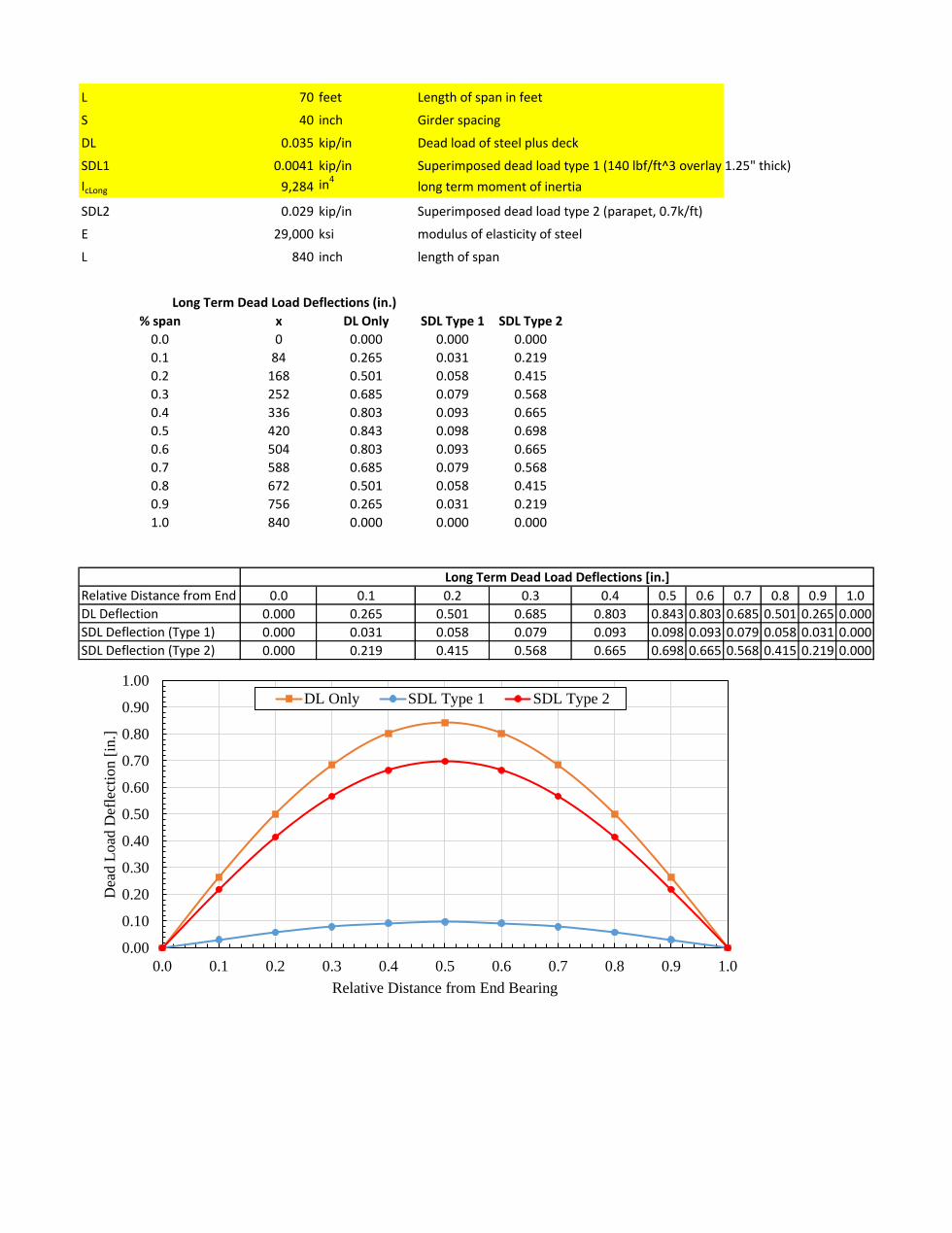
L 70 feet Length of span in feet
S 40 inch Girder spacing
DL 0.035 kip/in Dead load of steel plus deck
SDL1 0.0041 kip/in Superimposed dead load type 1 (140 lbf/ft^3 overlay 1.25" thick)
IcLong 9,284 in4long term moment of inertia
SDL2 0.029 kip/in Superimposed dead load type 2 (parapet, 0.7k/ft)
E 29,000 ksi modulus of elasticity of steel
L 840 inch length of span
% span x DL Only SDL Type 1 SDL Type 2
0.0 0 0.000 0.000 0.000
0.1 84 0.265 0.031 0.219
0.2 168 0.501 0.058 0.415
0.3 252 0.685 0.079 0.568
0.4 336 0.803 0.093 0.665
0.5 420 0.843 0.098 0.698
0.6 504 0.803 0.093 0.665
0.7 588 0.685 0.079 0.568
0.8 672 0.501 0.058 0.415
0.9 756 0.265 0.031 0.219
1.0 840 0.000 0.000 0.000
Relative Distance from End 0.0 0.1 0.2 0.3 0.4 0.5 0.6 0.7 0.8 0.9 1.0
DL Deflection 0.000 0.265 0.501 0.685 0.803 0.843 0.803 0.685 0.501 0.265 0.000
SDL Deflection (Type 1) 0.000 0.031 0.058 0.079 0.093 0.098 0.093 0.079 0.058 0.031 0.000
SDL Deflection (Type 2) 0.000 0.219 0.415 0.568 0.665 0.698 0.665 0.568 0.415 0.219 0.000
Long Term Dead Load Deflections [in.]
Long Term Dead Load Deflections (in.)
0.00
0.10
0.20
0.30
0.40
0.50
0.60
0.70
0.80
0.90
1.00
0.0 0.1 0.2 0.3 0.4 0.5 0.6 0.7 0.8 0.9 1.0
Dea
d L
oad
Def
lect
ion [
in.]
Relative Distance from End Bearing
DL Only SDL Type 1 SDL Type 2
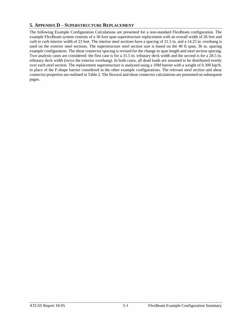
ATLSS Report 18-05 5-1 FlexBeam Example Configuration Summary
5. APPENDIX D – SUPERSTRUCTURE REPLACEMENT
The following Example Configuration Calculations are presented for a non-standard FlexBeam configuration. The
example FlexBeam system consists of a 36 foot span superstructure replacement with an overall width of 26 feet and
curb to curb interior width of 23 feet. The interior steel sections have a spacing of 31.5 in. and a 14.25 in. overhang is
used on the exterior steel sections. The superstructure steel section size is based on the 40 ft span, 36 in. spacing
example configuration. The shear connector spacing is revised for the change in span length and steel section spacing.
Two analysis cases are considered: the first case is for a 31.5 in. tributary deck width and the second is for a 28.5 in.
tributary deck width (twice the exterior overhang). In both cases, all dead loads are assumed to be distributed evenly
over each steel section. The replacement superstructure is analyzed using a 10M barrier with a weight of 0.300 kip/ft.
in place of the F-shape barrier considered in the other example configurations. The relevant steel section and shear
connector properties are outlined in Table 2. The flexural and shear connector calculations are presented on subsequent
pages.
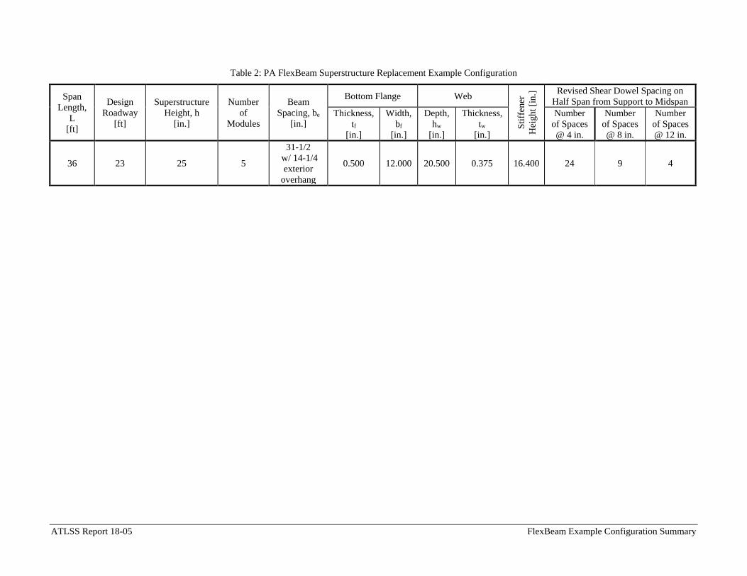
ATLSS Report 18-05 FlexBeam Example Configuration Summary
Table 2: PA FlexBeam Superstructure Replacement Example Configuration
Span
Length,
L
[ft]
Design
Roadway
[ft]
Superstructure
Height, h
[in.]
Number
of
Modules
Beam
Spacing, be
[in.]
Bottom Flange Web
Sti
ffen
er
Hei
gh
t [i
n.]
Revised Shear Dowel Spacing on
Half Span from Support to Midspan
Thickness,
tf
[in.]
Width,
bf
[in.]
Depth,
hw
[in.]
Thickness,
tw
[in.]
Number
of Spaces
@ 4 in.
Number
of Spaces
@ 8 in.
Number
of Spaces
@ 12 in.
36 23 25 5
31-1/2
w/ 14-1/4
exterior
overhang
0.500 12.000 20.500 0.375 16.400 24 9 4
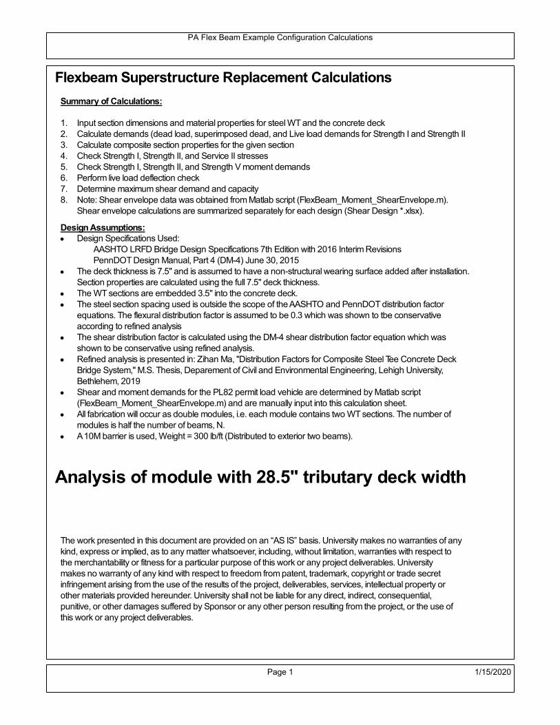
PA Flex Beam Example Configuration Calculations
Flexbeam Superstructure Replacement Calculations
Summary of Calculations:
Input section dimensions and material properties for steel WT and the concrete deck1.Calculate demands (dead load, superimposed dead, and Live load demands for Strength I and Strength II2.Calculate composite section properties for the given section3.Check Strength I, Strength II, and Service II stresses 4.Check Strength I, Strength II, and Strength V moment demands 5.Perform live load deflection check6.Determine maximum shear demand and capacity7.Note: Shear envelope data was obtained from Matlab script (FlexBeam_Moment_ShearEnvelope.m).8.Shear envelope calculations are summarized separately for each design (Shear Design *.xlsx).
Design Assumptions:Design Specifications Used:
AASHTO LRFD Bridge Design Specifications 7th Edition with 2016 Interim RevisionsPennDOT Design Manual, Part 4 (DM-4) June 30, 2015
The deck thickness is 7.5" and is assumed to have a non-structural wearing surface added after installation.Section properties are calculated using the full 7.5" deck thickness.The WT sections are embedded 3.5" into the concrete deck. The steel section spacing used is outside the scope of the AASHTO and PennDOT distribution factorequations. The flexural distribution factor is assumed to be 0.3 which was shown to tbe conservativeaccording to refined analysisThe shear distribution factor is calculated using the DM-4 shear distribution factor equation which wasshown to be conservative using refined analysis.Refined analysis is presented in: Zihan Ma, "Distribution Factors for Composite Steel Tee Concrete DeckBridge System," M.S. Thesis, Deparement of Civil and Environmental Engineering, Lehigh University,Bethlehem, 2019Shear and moment demands for the PL82 permit load vehicle are determined by Matlab script(FlexBeam_Moment_ShearEnvelope.m) and are manually input into this calculation sheet.All fabrication will occur as double modules, i.e. each module contains two WT sections. The number ofmodules is half the number of beams, N. A 10M barrier is used, Weight = 300 lb/ft (Distributed to exterior two beams).
Analysis of module with 28.5" tributary deck width
The work presented in this document are provided on an “AS IS” basis. University makes no warranties of anykind, express or implied, as to any matter whatsoever, including, without limitation, warranties with respect tothe merchantability or fitness for a particular purpose of this work or any project deliverables. Universitymakes no warranty of any kind with respect to freedom from patent, trademark, copyright or trade secretinfringement arising from the use of the results of the project, deliverables, services, intellectual property orother materials provided hereunder. University shall not be liable for any direct, indirect, consequential,punitive, or other damages suffered by Sponsor or any other person resulting from the project, or the use ofthis work or any project deliverables.
Page 1 1/15/2020

PA Flex Beam Example Configuration Calculations
hf
tf
bf
twh
d
bjtbe
e
Variable Definitions:
Number of beams N 10 modulesN
25
L 36ft Span length
be 28.5in Effective width of Flexbeamassuming constructed bridge width(i.e. closure joints cast)
Built Up Section Properties
tw 0.375in tf 0.5in bf 12in
h 25in Overall Height of section
hf 7.5in Total thickness of deck
e 3.5in Deck/Steel overlap
d h hf e 21 in depth of built up steel section
hw d tf 20.5 in height of web of built up steel
Moment and shear for permit load PL82 obtained from Matlab script: FlexBeam_Moment_ShearEnvelope
MLL_IM_PL82 273.24kip ft Moment due to PL82 with distribution factor and impact factor!!
VPL82span 89.7kip Shear due to PL82 WITHOUT distribution factor and impact factor!!
Check web and flange dimensions in sections 6.10.2.1 and 6.10.2.2
(Ignore 6.10.2.2-4 since no compression flange)
equation 6.10.2.1.1-1d
tw150 1 equation 6.10.2.2-1
bf
2 tf12 1
equation 6.10.2.2-2 bfh
6 1 equation 6.10.2.2-3 tf 1.1 tw 1
y_bar
tf bftf
2 hw tw tf
hw
2
tf bf hw tw6.147 in Center of gravity of steel section
Istl
bf tf3
12bf tf y_bar
tf
2
2
tw hw
3
12 tw hw tf
hw
2 y_bar
2
640.875 in4
MOI of steel
Astl tf bf hw tw 13.687 in2
Area of the WT steel section
Page 2 1/15/2020

PA Flex Beam Example Configuration Calculations
Material Properties
Elastic Modulus of Steel Es 29000ksi
Yield Strength of Steel Fy 50ksi
Yield Strength of Reinforcement fy 60ksi
Compressive Strength of Concrete fc 4000psi AAAP PennDOT Concrete
Concrete Modular Ratio n 8 modular ratio for 4ksi concrete per AASHTO
Unit weight of concrete slab wc 0.150kip
ft3
Unit weight of concrete
Section Properties
Width of UHPC Joint: bjt 8in
Parapet width: bpar 18in Parapet width (10M barrier)
Width of the bridge W 312in 312 in W 26 ft fix bridge width at 26 ft
Clear width of roadway Wlane W 2 bpar 23 ft
Dc wc hf W 2.437kip
ft DL due to slab
Db .300kip
ft DL due to each 10M barrier (BD-617M)
DFWS 30lbf
ft2
W 2 bpar 0.69kip
ft DL due to future wearing surface
Ds Astl 490lbf
ft3
0.047kip
ft Selfweight of the steel section
DLself
Dc N
Ds 0.29kip
ft Self-weight per WT
Total weight of each precast FlexBeam for transportation:
Weight of C12x25 Diaphragms Wend_diaphragms 25lbf
ft32 in 0.067 kip
2be bjt hf wc 2Ds L 2 Wend_diaphragms 17.268 kip
Determine number of design lane (AASHTO Section 3.6.1.1.1) Fix number of lanes at 2
Take the integer part of the ratio of W/12 ft. Number of lanes in bridge: Nl 2
Page 3 1/15/2020

PA Flex Beam Example Configuration Calculations
STEP 1: Compute Dead Load for each Flex Beam
DLslab
Dc
Nwc 1 in
be
2 0.259
kip
ft Dead load of slab assuming exterior overhang has 1" of
additional concrete thickness
DLsteel Ds 0.047kip
ft
DL DLslab DLsteel 0.305kip
ft
STEP 2: Compute Superimposed Dead Load
SDLWS
DFWS
N0.069
kip
ft
SDLparapet
Db
20.15
kip
ft distributed equally on two outer beams
SDLOL 140lbf
ft3be 2 in 0.055
kip
ft Overlay is 2" thick and is 140 lbs/cubic foot
NOTE: For this example barrier load is distributed equally among the two outer beams per conversation withPennDOT and M&M.
PennDOT DM4: "For composite adjacent and spread beams, the barrier (single barrier) load shall be equallydistributed to the nearest three (adjacent) and two (spread) beams, respectively, when the barriers are placedafter slab has hardened".
SDL SDLWS SDLparapet SDLOL 0.274kip
ft
STEP 3: Compute Transformed Width of Slab
For live load and dead load acting on the stringer k1 1 For short-term section property evaluation
btr1
be
k1 n3.563 in Transformed width of slab for short-term
For superimposed dead loads k3 3 For long-term section property evaluation
btr3
be
k3 n1.188 in Transformed width of slab for long-term
Page 4 1/15/2020

PA Flex Beam Example Configuration Calculations
STEP 4: Compute Dead and Superimposed Dead Load Moments(Based on first interior girder demands)
MDLDL L
2
849.437 kip ft
MSDLSDL L
2
844.456 kip ft
STEP 5: Compute live load and Dynamic Load Allowance (IM)
Live load wheel load distribution factor (DF):
Sbe
12in2.375 transverse girder spacing
NOTE: AASHTO presents equations to define DF for different types of superstructuresincluding Deck Composite wirh RC slab on steel girders (Type (a) in Table 4.6.2.2.1-1) forshear and moment in interior and exterior beams.
Using DM4 Table 4.6.2.2.2b-1:
eg h y_barhf
2 15.103 in Distance between the centers of gravity of the basic beam and deck
Kg n Istl Astl eg2
30103.16 in
4 Longitudinal stiffness parameter (in4)
Distribution of Live Load Per Lane for Moment in Interior Beams:
to be conservative, use DF 0.3
Page 5 1/15/2020

PA Flex Beam Example Configuration Calculations
Dynamic Load Allowance (Section 3.6.2 DM4)
Static effects of the design truck or tandem, shall be increased by the impact factor.
NOTE: The dynamic load allowance shall not be applied to the design lane load (Section 3.6.2.1 DM4)
I 0.33 Impact factor for moment
Note: PennDOT requires that the impact for decks be increased from 33% to 50%, the deck is not beingdesigned here. Instrad the deck design is based on the BD recommendations.
Dynamic load allowance for the Permit Load P-82 shall be less than 20%. (Section 3.6.2.1DM4)
IPL 0.20 Impact factor for moment on Strength II
Design Wind Loading for Exterior Girder
Vw 80 Wind speed for Strength V load case
CD 1.3 Gust factor for windard side of I-Girder and Box Girder Superstructures (Table 3.8.1.2.1-2)
G 1.0 Gus effect factor is 1.0 for all structures other than sound barriers (Table 3.8.1.2.1-1)
Kz 1.0 Pressure coefficient taken as 1 for Strength V (3.8.1.2.1)
Pz 2.56 106
Vw 2 Kz G CDkip
ft2
0.021kip
ft2
Wind pressure on exterior girder
hexp h hf 17.5 in Exposed height of exterior girder
Moment due to wind loading on exterior girderMWL
Pz hexp L2
85.032 kip ft
Iyy
bf3tf
1272 in
4 Transverse moment of intertia
Flange lateral bending stressfl
MWL
bf
2
Iyy5.032 ksi
Page 6 1/15/2020

PA Flex Beam Example Configuration Calculations
Design Vehicular Live Load
PHL-93 and P-82 are examined herein.
PHL-93 (A3.6.1.2.1)
PHL-93 consists of a combination of (design truck or design tandem) + (design lane load)
Design Truck
PennDOT defines the design truck in accordance with AASTHO 3.6.1.2
Design truck load in AASHTO (HS20 Truck) is used for this example.
NOTE : MAX moment occurs when the center line of the span is midway between the center ofgravity of the loads and the nearest concentrated load.
P1 8kip P2 32kip P3 32kip Axle loads (AASHTO 3.6.1.2.2)
XASr 14ft Rear Axle spacing for truck (14ft - 30ft)
XASf 14ft Front Axle spacing for truck
Page 7 1/15/2020

PA Flex Beam Example Configuration Calculations
Center of gravity (CG) of loads:
X'P1 XASr XASf P2 XASr
P1 P2 P39.333 ft Datum is the rear axle
X XASr X' 4.667 ft Spacing btw CG and nearest load
Find bridge reaction
Truck movestoward Support ARA
P1L
2XASf
X
2
P2L
2
X
2
P3L
2X'
X
2
L31.333 kip
Max live load moment (at the location of P2):
MLL_truck RAL
2
X
2
P1 XASf 378.889 kip ft
NOTE: Find the worst case by varying XASr
Page 8 1/15/2020

PA Flex Beam Example Configuration Calculations
Design Tandem
Consist of a pair of 25-kip axles spaced 4-ft apart. (AASHTO 3.6.1.2.3)
NOTE: PennDOT DM4 increases 25-kip to 31.25-kip.
FT 31.25kip
XAS 4ft Axle spacing
Center of gravity (CG) of loads:
XXAS
22 ft Spacing btw CG and nearest load
Find bridge reaction
RA
FTL
2
X
2
FTL
2
X
2 X
L29.514 kip Truck moves toward Support A
Max live load moment (at the location of front wheel):
MLL_tandem RAL
2
X
2
501.736 kip ft
Choose the max value:
MLL_veh max MLL_tandem MLL_truck 501.736 kip ft
Apply the impact and wheel load distribution:
MLL_IM_veh MLL_veh DF 1 I( ) 200.193 kip ft Due to tandem or truck
Design Lane Load (distributed over a 10-ft width for each lane)
NOTE: The uniform load may be continuous or discontinuous as necessary to produce themaximum force effect. For this example continuous uniform distribution assumed.
FDLL 0.64kip
ftDF 0.192
kip
ft Per beam in each lane
Due to lane loadMLL_IM_lane
FDLL L2
8
31.104 kip ft
Moment due to Total Design Vehicular Live Load: MLL_IM MLL_IM_lane MLL_IM_veh 231.297 kip ft
Page 9 1/15/2020

PA Flex Beam Example Configuration Calculations
Design Permit Load P-82 (Section 3.6.1.2.7 DM4)
P1 P2 P3 P4 P5 P6 P7
NOTE: The moment for the permit load is defined at the beginning of the sheetand is obtained from MATLab File FlexBeam_Moment_ShearEnvelope.m
STEP 6: Compute Moment of Inertia (Note: rebar neglected!)
1) Moment of Inertia resisting dead load only:
a) Acting on the non-composite section (before the deck has hardened - DC1)
Use steel section only
Inc Istl 640.875 in4
Non-composite section modulus
Y'nc y_bar S.G. of the steel section of Flex Beam (Datum is bottom)
b) Acting on the composite section (after the deck has hardened - DC2)
Use Ic_short as defined below.
Page 10 1/15/2020

PA Flex Beam Example Configuration Calculations
2) Moment of Inertia resisting live load plus impact:
Using transformed slab with k1=1 (short-term composite).
Actr1 hf btr1 26.719 in2
Itr1
btr1 hf3
12125.244 in
4
Y'
Actr1 hhf
2
Astl Y'nc
Astl Actr116.134 in S.G. of the total flex beam (Datum is bottom)
Compositesection modulus(short-term)
Ic_short Istl Astl Y'nc Y' 2 Itr1 Actr1 hhf
2
Y'
2
2831 in4
Y'c_short Y' 16.134 in N.A. of the short-term composite section
3) Moment of Inertia resisting superimposed dead load:
Using transformed slab with k3=3.
Actr3 hf btr3 8.906 in2
Itr3
btr3 hf3
1241.748 in
4
Y'
Actr3 hhf
2
Astl Y'nc
Astl Actr312.101 in S.G. of the total flex beam (Datum is bottom)
Compositesection modulus(long-term)
Ic_long Istl Astl Y'nc Y' 2 Itr3 Actr3 hhf
2
Y'
2
1913 in4
Y'c_long Y' 12.101 in N.A. of the long-term composite section
Page 11 1/15/2020

PA Flex Beam Example Configuration Calculations
STEP 6.5 Check Ductility RequirementIn accordance with AASHTO Article 6.10.7.3 check ductility requirement. Assume compressionblock of concrete is at 0.85 f'c and that the concrete supports no tension. Steel section isassumed to be fully plastic at Fy.
Case 1 : Assuming PNA is in Concreteh d 4 inAssuming (h-d) < Dp < hf
Fp Dp 0.85 fc be Dp Fy tw Dp h d( ) Fy Astl tw Dp h d( )
Dp 7.5in 0.42 h 10.5 in
Dp1 root Fp Dp Dp 6.208 in Must be less than hf 7.5 inDp1
h0.248 must be < 0.42
Mn1check Dp1 hf h d( ) Dp1[ ] Dp1 0.42 h( ) 1 Dp1 0.42 h 1
Mp1 0.85 fc be Dp1Dp1
2
Fy tw Dp1 h d( )[ ] Dp1 h d( )[ ]
2
Fy bf tf h Dp1tf
2
Fy tw h Dp1 tf h Dp1 tf
2
Mp1 10612.38 kip in Mn1 Mp1 1.07 0.7Dp1
h
9510.5 kip in
Case 2 : Assuming PNA is NOT in Concrete
Assuming hf < Dp
Fp2 Dp 0.85 fc be hf Fy tw Dp h d( ) Fy Astl tw Dp h d( )
Dp 2.5in
Dp2 root Fp2 Dp Dp 2.87 in Must be more than hf 7.5 inDp2
h0.1148 must be < 0.42
Mn2check Dp2 hf Dp2 h( ) Dp2 0.42 h( ) 0 Dp2 0.42 h 1
Mp2 0.85 fc be hf Dp2hf
2
Fy tw Dp2 h d( )[ ] Dp2 h d( )[ ]
2
Fy bf tf h Dp2tf
2
Fy tw h Dp2 tf h Dp2 tf
2
Mp2 10322.59 kip inMn2 Mp2 1.07 0.7
Dp2
h
10215.6 kip in
Mn max Mn1 Mn1check Mn2 Mn2check 792.5 kip ft Mn 9510.5 kip in
Page 12 1/15/2020

PA Flex Beam Example Configuration Calculations
Check Composite Compact Section Criteria (6.10.6.2)
Dcpd
2
Fy tf bf 0.85 fc be hf
Fy hw tw1
1.158 in Dcp0 Dcp 0 0
Dcp Dcp Dcp0 0 in2 Dcp
tw3.76
Es
Fy 1 Check if section is compact
STEP 7: Load Combinations (Table 3.4.1-1)
The following load combinations will be considered herein. Only the maximum load factors forpermanent-loads are used in the following load combinations (uplift is not an issue for this typeof bridge).STRENGTH I 1.25DL + 1.5SDL + 1.75 (LL+IM)
SERVICE II: DL+SDL+1.3(LL+IM)
STEP 8: Compute and Check Stresses
Stress at bottom fiber of steel section
fDL
MDL Y'c_long
Ic_long3.752 ksi
fLL_I
MLL_IM Y'c_short
Ic_short15.82 ksi fPL
MLL_IM_PL82 Y'c_short
Ic_short18.689 ksi
fSDL
MSDL Y'c_long
Ic_long3.374 ksi
STRENGTH I fbot_str1 1.25fDL 1.5 fSDL 1.75 fLL_I 37.437 ksi
STRENGTH II fbot_str2 1.25fDL 1.5 fSDL 1.35 fPL 34.981 ksi
SERVICE II fbot_svc2 fDL fSDL 1.3fLL_I 27.69 ksi
Allowable Stress is based on Section 6.10.4.2.2-2
Flange stress due to service load II without consideration of flange lateral bending: ff fbot_svc2
Flange lateral bending stress due to service II: flSII 0ksi
Hybrid Factor: Rh 1.0 For rolled and homogenous built-up sections
ff
flSII
2 27.693 ksi 0.95 Rh Fy 47.5 ksi ff
fl
2 0.95Rh Fy 1
Page 13 1/15/2020

PA Flex Beam Example Configuration Calculations
Stress at top fiber of concrete
Note: For calculating longitudinal flexural stresses in the concrete deck due to allpermanent and transient loads, the short-term modular ratio shall be used.
fDL
MDL h Y'c_short
k1 n Ic_short0.232 ksi
fLL_I
MLL_IM h Y'c_short
k1 n Ic_short1.087 ksi fPL
MLL_IM_PL82 h Y'c_short
k1 n Ic_short1.284 ksi
fSDL
MSDL h Y'c_short
k1 n Ic_short0.209 ksi
STRENGTH I fc_str1 1.25fDL 1.5 fSDL 1.75 fLL_I 2.505 ksi
Mstr1 1.25 MDL 1.5 MSDL 1.75 MLL_IM 533.2 kip ft Mstr1 Mn 1
STRENGTH II fc_str2 1.25fDL 1.5 fSDL 1.35 fPL 2.337 ksi
Mstr2 1.25 MDL 1.5 MSDL 1.35 MLL_IM_PL82 497 kip ft Mstr2 Mn 1
SERVICE II
Allowable Stress in concrete - AASHTO 6.10.4.2.2For compact composite sections in positive flexure utilized in shored construction, the longitudinalcompressive stress in the concrete deck due to the Service II loads, determined as specified in Article6.10.1.1.1d, shall not exceed 0.6f́ c.
fallow 0.6 fc 2400 psi
fc_2 1.3fLL_I fSDL fDL 1853.87 psi This assumes short term compositesection for all calculations
fc_2 fallow 1
SERVICE II with Long Term Composite for dead loads
fDL
MDL h Y'c_long
k3 n Ic_long0.167 ksi
fLL_I
MLL_IM h Y'c_short
k1 n Ic_short1.087 ksi
fSDL
MSDL h Y'c_long
k3 n Ic_long0.15 ksi
fc_2 1.3fLL_I fSDL fDL 1729.24 psi fc_2 fallow 1
Page 14 1/15/2020

PA Flex Beam Example Configuration Calculations
Strength V Moment Check
Strength V is related to normal vehicular use of the bridge with an 80 mph wind gust
Note: that Strength V is checked for an exterior girder under wind load with the interior girder distribution factor forflexure used. If Strength V controls design, then this approach should be modified
Design vertical moment is: 1.25DL + 1.5SDL + 1.35 (LL+IM)
SLT
Ic_long
Y'c_long158.115 in
3 SST
Ic_short
Y'c_short175.441 in
3 short and long term section
modulus
Section D6.2.2 Find the moment required to cause yieldling of the flange. The approach is laid out in D6.2.2
MD2 1.25 MDL 1.5 MSDL 128.48 kip ft From D6.2.2-1 (all dead loads are in MD2 due to shoredconstruction
MAD Fy
MD2
SLT
SST 588.446 kip ft Additional moment to cause nominal yielding of steel flange
My MD2 MAD 716.926 kip ft D6.2.2-2: Moment to cause yielding of flange
6.10.7.1 Compact Section Check at Strength V limit state
Section Modulus for yielding of the flange (My/Fy) for equation 6.10.7.1.1-1Sxt
My
Fy172.062 in
3
Mu 1.25 MDL 1.5MSDL 1.35MLL_IM 440.731 kip ft Moment due to Strength V limit state
Mu1
3fl Sxt 464.781 kip ft Equation 6.10.7.1.7-1 Mn 792.543 kip ft Mu
1
3fl Sxt Mn 1
Page 15 1/15/2020

PA Flex Beam Example Configuration Calculations
STEP 9: Compute Deflection
Optional Live Load Deflection Evaluation (AASHTO 3.6.1.3.2)
Deflection distribution factor for vehicular loads: For a straight multibeambridge, this is equivalent to saying that the distribution factor for deflectionis equal to the number of lanes divided by the number of beams. 2.5.2.6.2
DFd
Nl
N0.2
Deflection should be taken as 125% the larger of:- Design truck- 25% of design truck + design lane
The live load portion of Load Combination Service I of Table 3.4.1-1 should be used,including the dynamic load allowance, IM;
Deflection due to design truck load
NOTE : Assuming maximum deflection occurs when the center of gravity of the loads is at thecenter line of the span.
P1 8kip P2 32kip P3 32kip Axle loads (AASHTO 3.6.1.2.2)
XASr 14ft Rear Axle spacing for truck (14ft - 30ft)
XASf 14ft Front Axle spacing for truck
Center of gravity (CG) of loads:
X'P1 XASr XASf P2 XASr
P1 P2 P39.333 ft Datum is the rear axle
Method1: Assuming single load = P1+P2+P3 at the midspan (Conservative approach)
P1 P2 P3 L3
48 Es Ic_short 1.473 in
Method2: Calculation of Midspan deflection using superposition
b1L
2XASr X' XASf 0.667 ft distance btw load P1 and support A b1check b1 0 0
b2L
2XASr X' 13.333 ft distance btw load P2 and support A b2check b2 0 1
b3L
2X' 8.667 ft distance btw load P3 and support B b3check b3 0 1
Page 16 1/15/2020

PA Flex Beam Example Configuration Calculations
Deflection of the beam at midspan due to P1: P P1
xL
2 at midspan b b1 b1check The smallest distance btw load P1 and support
Δ1P b x
6 Es Ic_short LL2
b2
x2
0 in
Deflection of the beam at midspan due to P2: P P2
xL
2 at midspan b b2 b2check The smallest distance btw load P2 and support
Δ2P b x
6 Es Ic_short LL2
b2
x2
0.594 in
Deflection of the beam at midspan due to P3: P P3
xL
2 at midspan b b3 b3check The smallest distance btw load P3 and support
Δ3P b x
6 Es Ic_short LL2
b2
x2
0.436 in
Total Deflection at midspan:
Δtruck Δ1 Δ2 Δ3( ) DFd 1 I( ) 0.274 in (Considering IM)
Deflection due to tandem (Note: this calculation is not required according to Article3.6.1.3.2 which denotes only the design truck for deflection calculation)
Page 17 1/15/2020

PA Flex Beam Example Configuration Calculations
FT 31.25 kip Per axle
XAS 4ft Axle spacing
Δtandem
FTL
2
XAS
2
24 Es Ic_short3 L
2 4
L
2
XAS
2
2
DFd 1 I( ) 0.334 in (Considering IM)
Deflection due to lane load
FDLLd 640lbf
ft DFd 128
lbf
ft
Δlane
5 FDLLd L4
384 Es Ic_short0.059 in
Live Load Deflection:
ΔLL 1.25max Δtruck 0.25Δtruck Δlane 1.25 0.428 in ΔLLL
800 1
Deflection Limit
For steel or concrete vehicular bridges:
Vehicular load = Span/800L
8000.54 in
L
10000.432 in
Evaluation of Deflection at the Service Limit State (AASHTO 3.4.2.2)
The associated permitted deflections shall be included in the contract documents.
Page 18 1/15/2020

PA Flex Beam Example Configuration Calculations
Shear demands:
Determination of the distribution factor
Using DM4 Table 4.6.2.2.3a-1
Sbe
12in2.375 transverse girder spacing (ft)
Distribution of live loads per lane for shear in interior beams:
For two design lanes loaded, 3.5' <= S =< 16', number of beam >= 4DFs 0.36
S
25 0.455
Q Actr1 h Y'c_shorthf
2
136.693 in3
first moment of deck slab for interface shear
Method 1: Range of shear based on Strength I Limit
STRENGTH I 1.25DL + 1.5SDL + 1.75 (LL+IM)
Computation of the range of shear in the beam
Dead Load:DL 0.305
kip
ft
Superimposed Dead Load: SDL 0.274kip
ft
Design Lane Load: 0.64kip
ft
Design Truck:
XASr 14ft Rear Axle spacing for truck (14ft - 30ft)
XASf 14ft Front Axle spacing for truck
P1 8 kip P2 32 kip P3 32 kip Wheel loads (AASHTO 3.6.1.2.2)
Design Tandem:
Consist of a pair of 25-kip axles spaced 4-ft apart. (AASHTO 3.6.1.2.3)
NOTE: PennDOT DM4 increases 25-kip to 31.25-kip.
FT 31.25kip
XAS 4ft Axle spacing
Page 19 1/15/2020
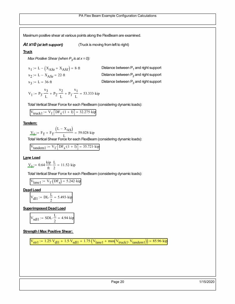
PA Flex Beam Example Configuration Calculations
Maximum positive shear at various points along the FlexBeam are examined.
At x=0 (at left support) (Truck is moving from left to right)
Truck
Max Positive Shear (when P3 is at x = 0):
x1 L XASr XASf 8 ft Distance between P1 and right support
x2 L XASr 22 ft Distance between P2 and right support
x3 L 36 ft Distance between P3 and right support
V1 P3
x3
L P2
x2
L P1
x1
L 53.333 kip
Total Vertical Shear Force for each FlexBeam (considering dynamic loads):
Vtruck1 V1 DFs 1 I( ) 32.275 kip
Tandem:
V1 FT FT
L XAS L
59.028 kip
Total Vertical Shear Force for each FlexBeam (considering dynamic loads):
Vtandem1 V1 DFs 1 I( ) 35.721 kip
Lane Load
V1 0.64kip
ft
L
2 11.52 kip
Total Vertical Shear Force for each FlexBeam (considering dynamic loads):
Vlane1 V1 DFs 5.242 kip
Dead Load
Vdl1 DLL
2 5.493 kip
Superimposed Dead Load
Vsdl1 SDLL
2 4.94 kip
Strength I Max Positive Shear:
Vstr1 1.25 Vdl1 1.5 Vsdl1 1.75 Vlane1 max Vtruck1 Vtandem1 85.96 kip
Page 20 1/15/2020

PA Flex Beam Example Configuration Calculations
Design Permit Load P-82
Shear at x=0
Strength II Max Positive Shear:
VPL82 VPL82span DFs 1 IPL 48.976 kip
STRENGTH II 1.25DL + 1.5SDL + 1.35 (LL+IM)
VstrII_PL 1.25 Vdl1 1.5 Vsdl1 1.35 VPL82 80.393 kip
Max Shear Demand Vu max Vstr1 VstrII_PL 85.96 kip
Determine the Shear Strength of the Web
Shear Strength of Unstiffened web from AASHTO section 6.10.9.2
Depth of Web D d 21 in Thickness of web tw 0.375 in
Transverse Stiffener Spacing d0 0in Shear Buckling Coefficient k 5 6.10.9.3.2-7
Plastic Shear Force Vp 0.58 Fy D tw 228.375 kip Equation 6.10.9.3.2-3
Ratio of Shear-Buckling resistance to shear yield, C
D
tw56 1.12
Es k
Fy 60.314 Ccheck
D
tw1.12
Es k
Fy 1 Equation 6.10.9.3.2-4
C 1.0 Ccheck 1 C=1 for most cases, if the criteria are not met, then C will go to zero and the actualcoefficients should be determined
Nominal Shear Resistance of Web Vn C Vp 228.375 kip equation 6.10.9.3.3-1
Shear Resistance Factor φv 1.0
φv Vn 228.375 kip φv Vn Vu 1Reduced Shear Strength
Page 21 1/15/2020

PA Flex Beam Example Configuration Calculations
Check Bearing Stiffeners
FYs 50ksi Yield strength of stiffener
tp 0.75in Thickness of stiffener
bt
bf tw
21.5in 4.312 in Effective width of stiffener
Dst hw 4.1in 16.4 in Depth of stiffeners
Apn 2 tp bt 6.469 in2
Projected area of stiffeners
bt 0.48 tpEs
FYs 1Check that effective width of stiffener meets requirements
Rsbn 1.4 Apn FYs 452.812 kip Bearing capacity of stiffener (phi=1 for bearing per AASHTO 6.5.4.2)
Rsbn Vu 1 Bearing capacity check
Qs 1.0 Q factor for bearing stiffner, taken as 1 (AASHTO 6.9.4.1.1)
Is
18 tw tw3
tp 2 bt 3
1240.131 in
4 Moment of inertia of stiffener and web (9*tw is used on each side)
AASHTO 6.10.11.2.4b
Ag 18 tw tw 2 bt tp 9 in2
Gross area of stiffener and web (AASHTO 6.10.11.2.4b)
rs
Is
Ag2.112 in Radius of gyration of stiffener/web
Po Qs FYs Apn 323.437 kip Nominal yeild resistance of stiffener (AASHTO 6.9.4.1.1)
Peπ2Es
0.75 Dst
rs
2Ag 7.592 10
4 kip Elastic critical buckling stress of stiffener (AASHTO 6.9.4.1.2-1)
Check that Pe/Po is great than 0.44 (AASHTO 6.9.4.1.1) PePoPe
Po0.44 1
Pn PePo 0.658
Po
Pe Po 322.861 kip Nominal compressive resistance of stiffener for Pe/Po>0.44
(AASHTO 6.9.4.1.1-1)
φcr 0.95 phi factor for axial compression (AASHTO 6.5.4.2)
Pr φcr Pn 306.718 kip Compressive capacity of bearing stiffener Pr Vu 1
Page 22 1/15/2020

PA Flex Beam Example Configuration Calculations
Flexbeam Superstructure Replacement Calculations
Summary of Calculations:
Input section dimensions and material properties for steel WT and the concrete deck1.Calculate demands (dead load, superimposed dead, and Live load demands for Strength I and Strength II2.Calculate composite section properties for the given section3.Check Strength I, Strength II, and Service II stresses 4.Check Strength I, Strength II, and Strength V moment demands 5.Perform live load deflection check6.Determine maximum shear demand and capacity7.Note: Shear envelope data was obtained from Matlab script (FlexBeam_Moment_ShearEnvelope.m).8.Shear envelope calculations are summarized separately for each design (Shear Design *.xlsx).
Design Assumptions:Design Specifications Used:
AASHTO LRFD Bridge Design Specifications 7th Edition with 2016 Interim RevisionsPennDOT Design Manual, Part 4 (DM-4) June 30, 2015
The deck thickness is 7.5" and is assumed to have a non-structural wearing surface added after installation.Section properties are calculated using the full 7.5" deck thickness.The WT sections are embedded 3.5" into the concrete deck. The steel section spacing used is outside the scope of the AASHTO and PennDOT distribution factorequations. The flexural distribution factor is assumed to be 0.3 which was shown to tbe conservativeaccording to refined analysisThe shear distribution factor is calculated using the DM-4 shear distribution factor equation which wasshown to be conservative using refined analysis.Refined analysis is presented in: Zihan Ma, "Distribution Factors for Composite Steel Tee Concrete DeckBridge System," M.S. Thesis, Deparement of Civil and Environmental Engineering, Lehigh University,Bethlehem, 2019Shear and moment demands for the PL82 permit load vehicle are determined by Matlab script(FlexBeam_Moment_ShearEnvelope.m) and are manually input into this calculation sheet.All fabrication will occur as double modules, i.e. each module contains two WT sections. The number ofmodules is half the number of beams, N. A 10M barrier is used, Weight = 300 lb/ft (Distributed to exterior two beams).
Analysis of module with 31.5" tributary deck width
The work presented in this document are provided on an “AS IS” basis. University makes no warranties of anykind, express or implied, as to any matter whatsoever, including, without limitation, warranties with respect tothe merchantability or fitness for a particular purpose of this work or any project deliverables. Universitymakes no warranty of any kind with respect to freedom from patent, trademark, copyright or trade secretinfringement arising from the use of the results of the project, deliverables, services, intellectual property orother materials provided hereunder. University shall not be liable for any direct, indirect, consequential,punitive, or other damages suffered by Sponsor or any other person resulting from the project, or the use ofthis work or any project deliverables.
Page 1 1/15/2020

PA Flex Beam Example Configuration Calculations
hf
tf
bf
twh
d
bjtbe
e
Variable Definitions:
Number of beams N 10 modulesN
25
L 36ft Span length
be 31.5in Effective width of Flexbeamassuming constructed bridge width(i.e. closure joints cast)
Built Up Section Properties
tw 0.375in tf 0.5in bf 12in
h 25in Overall Height of section
hf 7.5in Total thickness of deck
e 3.5in Deck/Steel overlap
d h hf e 21 in depth of built up steel section
hw d tf 20.5 in height of web of built up steel
Moment and shear for permit load PL82 obtained from Matlab script: FlexBeam_Moment_ShearEnvelope
MLL_IM_PL82 273.24kip ft Moment due to PL82 with distribution factor and impact factor!!
VPL82span 89.7kip Shear due to PL82 WITHOUT distribution factor and impact factor!!
Check web and flange dimensions in sections 6.10.2.1 and 6.10.2.2
(Ignore 6.10.2.2-4 since no compression flange)
equation 6.10.2.1.1-1d
tw150 1 equation 6.10.2.2-1
bf
2 tf12 1
equation 6.10.2.2-2 bfh
6 1 equation 6.10.2.2-3 tf 1.1 tw 1
y_bar
tf bftf
2 hw tw tf
hw
2
tf bf hw tw6.147 in Center of gravity of steel section
Istl
bf tf3
12bf tf y_bar
tf
2
2
tw hw
3
12 tw hw tf
hw
2 y_bar
2
640.875 in4
MOI of steel
Astl tf bf hw tw 13.687 in2
Area of the WT steel section
Page 2 1/15/2020
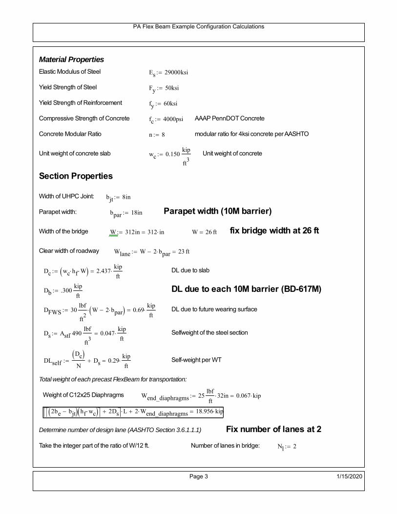
PA Flex Beam Example Configuration Calculations
Material Properties
Elastic Modulus of Steel Es 29000ksi
Yield Strength of Steel Fy 50ksi
Yield Strength of Reinforcement fy 60ksi
Compressive Strength of Concrete fc 4000psi AAAP PennDOT Concrete
Concrete Modular Ratio n 8 modular ratio for 4ksi concrete per AASHTO
Unit weight of concrete slab wc 0.150kip
ft3
Unit weight of concrete
Section Properties
Width of UHPC Joint: bjt 8in
Parapet width: bpar 18in Parapet width (10M barrier)
Width of the bridge W 312in 312 in W 26 ft fix bridge width at 26 ft
Clear width of roadway Wlane W 2 bpar 23 ft
Dc wc hf W 2.437kip
ft DL due to slab
Db .300kip
ft DL due to each 10M barrier (BD-617M)
DFWS 30lbf
ft2
W 2 bpar 0.69kip
ft DL due to future wearing surface
Ds Astl 490lbf
ft3
0.047kip
ft Selfweight of the steel section
DLself
Dc N
Ds 0.29kip
ft Self-weight per WT
Total weight of each precast FlexBeam for transportation:
Weight of C12x25 Diaphragms Wend_diaphragms 25lbf
ft32 in 0.067 kip
2be bjt hf wc 2Ds L 2 Wend_diaphragms 18.956 kip
Determine number of design lane (AASHTO Section 3.6.1.1.1) Fix number of lanes at 2
Take the integer part of the ratio of W/12 ft. Number of lanes in bridge: Nl 2
Page 3 1/15/2020

PA Flex Beam Example Configuration Calculations
STEP 1: Compute Dead Load for each Flex Beam
DLslab
Dc
Nwc 1 in
be
2 0.26
kip
ft Dead load of slab assuming exterior overhang has 1" of
additional concrete thickness
DLsteel Ds 0.047kip
ft
DL DLslab DLsteel 0.307kip
ft
STEP 2: Compute Superimposed Dead Load
SDLWS
DFWS
N0.069
kip
ft
SDLparapet
Db
20.15
kip
ft distributed equally on two outer beams
SDLOL 140lbf
ft3be 2 in 0.061
kip
ft Overlay is 2" thick and is 140 lbs/cubic foot
NOTE: For this example barrier load is distributed equally among the two outer beams per conversation withPennDOT and M&M.
PennDOT DM4: "For composite adjacent and spread beams, the barrier (single barrier) load shall be equallydistributed to the nearest three (adjacent) and two (spread) beams, respectively, when the barriers are placedafter slab has hardened".
SDL SDLWS SDLparapet SDLOL 0.28kip
ft
STEP 3: Compute Transformed Width of Slab
For live load and dead load acting on the stringer k1 1 For short-term section property evaluation
btr1
be
k1 n3.938 in Transformed width of slab for short-term
For superimposed dead loads k3 3 For long-term section property evaluation
btr3
be
k3 n1.313 in Transformed width of slab for long-term
Page 4 1/15/2020

PA Flex Beam Example Configuration Calculations
STEP 4: Compute Dead and Superimposed Dead Load Moments(Based on first interior girder demands)
MDLDL L
2
849.691 kip ft
MSDLSDL L
2
845.401 kip ft
STEP 5: Compute live load and Dynamic Load Allowance (IM)
Live load wheel load distribution factor (DF):
Sbe
12in2.625 transverse girder spacing
NOTE: AASHTO presents equations to define DF for different types of superstructuresincluding Deck Composite wirh RC slab on steel girders (Type (a) in Table 4.6.2.2.1-1) forshear and moment in interior and exterior beams.
Using DM4 Table 4.6.2.2.2b-1:
eg h y_barhf
2 15.103 in Distance between the centers of gravity of the basic beam and deck
Kg n Istl Astl eg2
30103.16 in
4 Longitudinal stiffness parameter (in4)
Distribution of Live Load Per Lane for Moment in Interior Beams:
to be conservative, use DF 0.3
Page 5 1/15/2020

PA Flex Beam Example Configuration Calculations
Dynamic Load Allowance (Section 3.6.2 DM4)
Static effects of the design truck or tandem, shall be increased by the impact factor.
NOTE: The dynamic load allowance shall not be applied to the design lane load (Section 3.6.2.1 DM4)
I 0.33 Impact factor for moment
Note: PennDOT requires that the impact for decks be increased from 33% to 50%, the deck is not beingdesigned here. Instrad the deck design is based on the BD recommendations.
Dynamic load allowance for the Permit Load P-82 shall be less than 20%. (Section 3.6.2.1DM4)
IPL 0.20 Impact factor for moment on Strength II
Design Wind Loading for Exterior Girder
Vw 80 Wind speed for Strength V load case
CD 1.3 Gust factor for windard side of I-Girder and Box Girder Superstructures (Table 3.8.1.2.1-2)
G 1.0 Gus effect factor is 1.0 for all structures other than sound barriers (Table 3.8.1.2.1-1)
Kz 1.0 Pressure coefficient taken as 1 for Strength V (3.8.1.2.1)
Pz 2.56 106
Vw 2 Kz G CDkip
ft2
0.021kip
ft2
Wind pressure on exterior girder
hexp h hf 17.5 in Exposed height of exterior girder
Moment due to wind loading on exterior girderMWL
Pz hexp L2
85.032 kip ft
Iyy
bf3tf
1272 in
4 Transverse moment of intertia
Flange lateral bending stressfl
MWL
bf
2
Iyy5.032 ksi
Page 6 1/15/2020

PA Flex Beam Example Configuration Calculations
Design Vehicular Live Load
PHL-93 and P-82 are examined herein.
PHL-93 (A3.6.1.2.1)
PHL-93 consists of a combination of (design truck or design tandem) + (design lane load)
Design Truck
PennDOT defines the design truck in accordance with AASTHO 3.6.1.2
Design truck load in AASHTO (HS20 Truck) is used for this example.
NOTE : MAX moment occurs when the center line of the span is midway between the center ofgravity of the loads and the nearest concentrated load.
P1 8kip P2 32kip P3 32kip Axle loads (AASHTO 3.6.1.2.2)
XASr 14ft Rear Axle spacing for truck (14ft - 30ft)
XASf 14ft Front Axle spacing for truck
Page 7 1/15/2020

PA Flex Beam Example Configuration Calculations
Center of gravity (CG) of loads:
X'P1 XASr XASf P2 XASr
P1 P2 P39.333 ft Datum is the rear axle
X XASr X' 4.667 ft Spacing btw CG and nearest load
Find bridge reaction
Truck movestoward Support ARA
P1L
2XASf
X
2
P2L
2
X
2
P3L
2X'
X
2
L31.333 kip
Max live load moment (at the location of P2):
MLL_truck RAL
2
X
2
P1 XASf 378.889 kip ft
NOTE: Find the worst case by varying XASr
Page 8 1/15/2020

PA Flex Beam Example Configuration Calculations
Design Tandem
Consist of a pair of 25-kip axles spaced 4-ft apart. (AASHTO 3.6.1.2.3)
NOTE: PennDOT DM4 increases 25-kip to 31.25-kip.
FT 31.25kip
XAS 4ft Axle spacing
Center of gravity (CG) of loads:
XXAS
22 ft Spacing btw CG and nearest load
Find bridge reaction
RA
FTL
2
X
2
FTL
2
X
2 X
L29.514 kip Truck moves toward Support A
Max live load moment (at the location of front wheel):
MLL_tandem RAL
2
X
2
501.736 kip ft
Choose the max value:
MLL_veh max MLL_tandem MLL_truck 501.736 kip ft
Apply the impact and wheel load distribution:
MLL_IM_veh MLL_veh DF 1 I( ) 200.193 kip ft Due to tandem or truck
Design Lane Load (distributed over a 10-ft width for each lane)
NOTE: The uniform load may be continuous or discontinuous as necessary to produce themaximum force effect. For this example continuous uniform distribution assumed.
FDLL 0.64kip
ftDF 0.192
kip
ft Per beam in each lane
Due to lane loadMLL_IM_lane
FDLL L2
8
31.104 kip ft
Moment due to Total Design Vehicular Live Load: MLL_IM MLL_IM_lane MLL_IM_veh 231.297 kip ft
Page 9 1/15/2020

PA Flex Beam Example Configuration Calculations
Design Permit Load P-82 (Section 3.6.1.2.7 DM4)
P1 P2 P3 P4 P5 P6 P7
NOTE: The moment for the permit load is defined at the beginning of the sheetand is obtained from MATLab File FlexBeam_Moment_ShearEnvelope.m
STEP 6: Compute Moment of Inertia (Note: rebar neglected!)
1) Moment of Inertia resisting dead load only:
a) Acting on the non-composite section (before the deck has hardened - DC1)
Use steel section only
Inc Istl 640.875 in4
Non-composite section modulus
Y'nc y_bar S.G. of the steel section of Flex Beam (Datum is bottom)
b) Acting on the composite section (after the deck has hardened - DC2)
Use Ic_short as defined below.
Page 10 1/15/2020

PA Flex Beam Example Configuration Calculations
2) Moment of Inertia resisting live load plus impact:
Using transformed slab with k1=1 (short-term composite).
Actr1 hf btr1 29.531 in2
Itr1
btr1 hf3
12138.428 in
4
Y'
Actr1 hhf
2
Astl Y'nc
Astl Actr116.467 in S.G. of the total flex beam (Datum is bottom)
Compositesection modulus(short-term)
Ic_short Istl Astl Y'nc Y' 2 Itr1 Actr1 hhf
2
Y'
2
2913 in4
Y'c_short Y' 16.467 in N.A. of the short-term composite section
3) Moment of Inertia resisting superimposed dead load:
Using transformed slab with k3=3.
Actr3 hf btr3 9.844 in2
Itr3
btr3 hf3
1246.143 in
4
Y'
Actr3 hhf
2
Astl Y'nc
Astl Actr312.465 in S.G. of the total flex beam (Datum is bottom)
Compositesection modulus(long-term)
Ic_long Istl Astl Y'nc Y' 2 Itr3 Actr3 hhf
2
Y'
2
1993 in4
Y'c_long Y' 12.465 in N.A. of the long-term composite section
Page 11 1/15/2020

PA Flex Beam Example Configuration Calculations
STEP 6.5 Check Ductility RequirementIn accordance with AASHTO Article 6.10.7.3 check ductility requirement. Assume compressionblock of concrete is at 0.85 f'c and that the concrete supports no tension. Steel section isassumed to be fully plastic at Fy.
Case 1 : Assuming PNA is in Concreteh d 4 inAssuming (h-d) < Dp < hf
Fp Dp 0.85 fc be Dp Fy tw Dp h d( ) Fy Astl tw Dp h d( )
Dp 7.5in 0.42 h 10.5 in
Dp1 root Fp Dp Dp 5.77 in Must be less than hf 7.5 inDp1
h0.231 must be < 0.42
Mn1check Dp1 hf h d( ) Dp1[ ] Dp1 0.42 h( ) 1 Dp1 0.42 h 1
Mp1 0.85 fc be Dp1Dp1
2
Fy tw Dp1 h d( )[ ] Dp1 h d( )[ ]
2
Fy bf tf h Dp1tf
2
Fy tw h Dp1 tf h Dp1 tf
2
Mp1 10795.08 kip in Mn1 Mp1 1.07 0.7Dp1
h
9806.6 kip in
Case 2 : Assuming PNA is NOT in Concrete
Assuming hf < Dp
Fp2 Dp 0.85 fc be hf Fy tw Dp h d( ) Fy Astl tw Dp h d( )
Dp 2.5in
Dp2 root Fp2 Dp Dp 0.83 in Must be more than hf 7.5 inDp2
h0.0332 must be < 0.42
Mn2check Dp2 hf Dp2 h( ) Dp2 0.42 h( ) 0 Dp2 0.42 h 1
Mp2 0.85 fc be hf Dp2hf
2
Fy tw Dp2 h d( )[ ] Dp2 h d( )[ ]
2
Fy bf tf h Dp2tf
2
Fy tw h Dp2 tf h Dp2 tf
2
Mp2 10177.24 kip inMn2 Mp2 1.07 0.7
Dp2
h
10653.1 kip in
Mn max Mn1 Mn1check Mn2 Mn2check 817.2 kip ft Mn 9806.6 kip in
Page 12 1/15/2020

PA Flex Beam Example Configuration Calculations
Check Composite Compact Section Criteria (6.10.6.2)
Dcpd
2
Fy tf bf 0.85 fc be hf
Fy hw tw1
3.247 in Dcp0 Dcp 0 0
Dcp Dcp Dcp0 0 in2 Dcp
tw3.76
Es
Fy 1 Check if section is compact
STEP 7: Load Combinations (Table 3.4.1-1)
The following load combinations will be considered herein. Only the maximum load factors forpermanent-loads are used in the following load combinations (uplift is not an issue for this typeof bridge).STRENGTH I 1.25DL + 1.5SDL + 1.75 (LL+IM)
SERVICE II: DL+SDL+1.3(LL+IM)
STEP 8: Compute and Check Stresses
Stress at bottom fiber of steel section
fDL
MDL Y'c_long
Ic_long3.729 ksi
fLL_I
MLL_IM Y'c_short
Ic_short15.692 ksi fPL
MLL_IM_PL82 Y'c_short
Ic_short18.538 ksi
fSDL
MSDL Y'c_long
Ic_long3.407 ksi
STRENGTH I fbot_str1 1.25fDL 1.5 fSDL 1.75 fLL_I 37.234 ksi
STRENGTH II fbot_str2 1.25fDL 1.5 fSDL 1.35 fPL 34.799 ksi
SERVICE II fbot_svc2 fDL fSDL 1.3fLL_I 27.54 ksi
Allowable Stress is based on Section 6.10.4.2.2-2
Flange stress due to service load II without consideration of flange lateral bending: ff fbot_svc2
Flange lateral bending stress due to service II: flSII 0ksi
Hybrid Factor: Rh 1.0 For rolled and homogenous built-up sections
ff
flSII
2 27.537 ksi 0.95 Rh Fy 47.5 ksi ff
fl
2 0.95Rh Fy 1
Page 13 1/15/2020

PA Flex Beam Example Configuration Calculations
Stress at top fiber of concrete
Note: For calculating longitudinal flexural stresses in the concrete deck due to allpermanent and transient loads, the short-term modular ratio shall be used.
fDL
MDL h Y'c_short
k1 n Ic_short0.218 ksi
fLL_I
MLL_IM h Y'c_short
k1 n Ic_short1.016 ksi fPL
MLL_IM_PL82 h Y'c_short
k1 n Ic_short1.201 ksi
fSDL
MSDL h Y'c_short
k1 n Ic_short0.2 ksi
STRENGTH I fc_str1 1.25fDL 1.5 fSDL 1.75 fLL_I 2.351 ksi
Mstr1 1.25 MDL 1.5 MSDL 1.75 MLL_IM 535 kip ft Mstr1 Mn 1
STRENGTH II fc_str2 1.25fDL 1.5 fSDL 1.35 fPL 2.193 ksi
Mstr2 1.25 MDL 1.5 MSDL 1.35 MLL_IM_PL82 499 kip ft Mstr2 Mn 1
SERVICE II
Allowable Stress in concrete - AASHTO 6.10.4.2.2For compact composite sections in positive flexure utilized in shored construction, the longitudinalcompressive stress in the concrete deck due to the Service II loads, determined as specified in Article6.10.1.1.1d, shall not exceed 0.6f́ c.
fallow 0.6 fc 2400 psi
fc_2 1.3fLL_I fSDL fDL 1739.29 psi This assumes short term compositesection for all calculations
fc_2 fallow 1
SERVICE II with Long Term Composite for dead loads
fDL
MDL h Y'c_long
k3 n Ic_long0.156 ksi
fLL_I
MLL_IM h Y'c_short
k1 n Ic_short1.016 ksi
fSDL
MSDL h Y'c_long
k3 n Ic_long0.143 ksi
fc_2 1.3fLL_I fSDL fDL 1620.43 psi fc_2 fallow 1
Page 14 1/15/2020

PA Flex Beam Example Configuration Calculations
Strength V Moment Check
Strength V is related to normal vehicular use of the bridge with an 80 mph wind gust
Note: that Strength V is checked for an exterior girder under wind load with the interior girder distribution factor forflexure used. If Strength V controls design, then this approach should be modified
Design vertical moment is: 1.25DL + 1.5SDL + 1.35 (LL+IM)
SLT
Ic_long
Y'c_long159.889 in
3 SST
Ic_short
Y'c_short176.874 in
3 short and long term section
modulus
Section D6.2.2 Find the moment required to cause yieldling of the flange. The approach is laid out in D6.2.2
MD2 1.25 MDL 1.5 MSDL 130.214 kip ft From D6.2.2-1 (all dead loads are in MD2 due to shoredconstruction
MAD Fy
MD2
SLT
SST 592.929 kip ft Additional moment to cause nominal yielding of steel flange
My MD2 MAD 723.143 kip ft D6.2.2-2: Moment to cause yielding of flange
6.10.7.1 Compact Section Check at Strength V limit state
Section Modulus for yielding of the flange (My/Fy) for equation 6.10.7.1.1-1Sxt
My
Fy173.554 in
3
Mu 1.25 MDL 1.5MSDL 1.35MLL_IM 442.464 kip ft Moment due to Strength V limit state
Mu1
3fl Sxt 466.723 kip ft Equation 6.10.7.1.7-1 Mn 817.218 kip ft Mu
1
3fl Sxt Mn 1
Page 15 1/15/2020

PA Flex Beam Example Configuration Calculations
STEP 9: Compute Deflection
Optional Live Load Deflection Evaluation (AASHTO 3.6.1.3.2)
Deflection distribution factor for vehicular loads: For a straight multibeambridge, this is equivalent to saying that the distribution factor for deflectionis equal to the number of lanes divided by the number of beams. 2.5.2.6.2
DFd
Nl
N0.2
Deflection should be taken as 125% the larger of:- Design truck- 25% of design truck + design lane
The live load portion of Load Combination Service I of Table 3.4.1-1 should be used,including the dynamic load allowance, IM;
Deflection due to design truck load
NOTE : Assuming maximum deflection occurs when the center of gravity of the loads is at thecenter line of the span.
P1 8kip P2 32kip P3 32kip Axle loads (AASHTO 3.6.1.2.2)
XASr 14ft Rear Axle spacing for truck (14ft - 30ft)
XASf 14ft Front Axle spacing for truck
Center of gravity (CG) of loads:
X'P1 XASr XASf P2 XASr
P1 P2 P39.333 ft Datum is the rear axle
Method1: Assuming single load = P1+P2+P3 at the midspan (Conservative approach)
P1 P2 P3 L3
48 Es Ic_short 1.432 in
Method2: Calculation of Midspan deflection using superposition
b1L
2XASr X' XASf 0.667 ft distance btw load P1 and support A b1check b1 0 0
b2L
2XASr X' 13.333 ft distance btw load P2 and support A b2check b2 0 1
b3L
2X' 8.667 ft distance btw load P3 and support B b3check b3 0 1
Page 16 1/15/2020
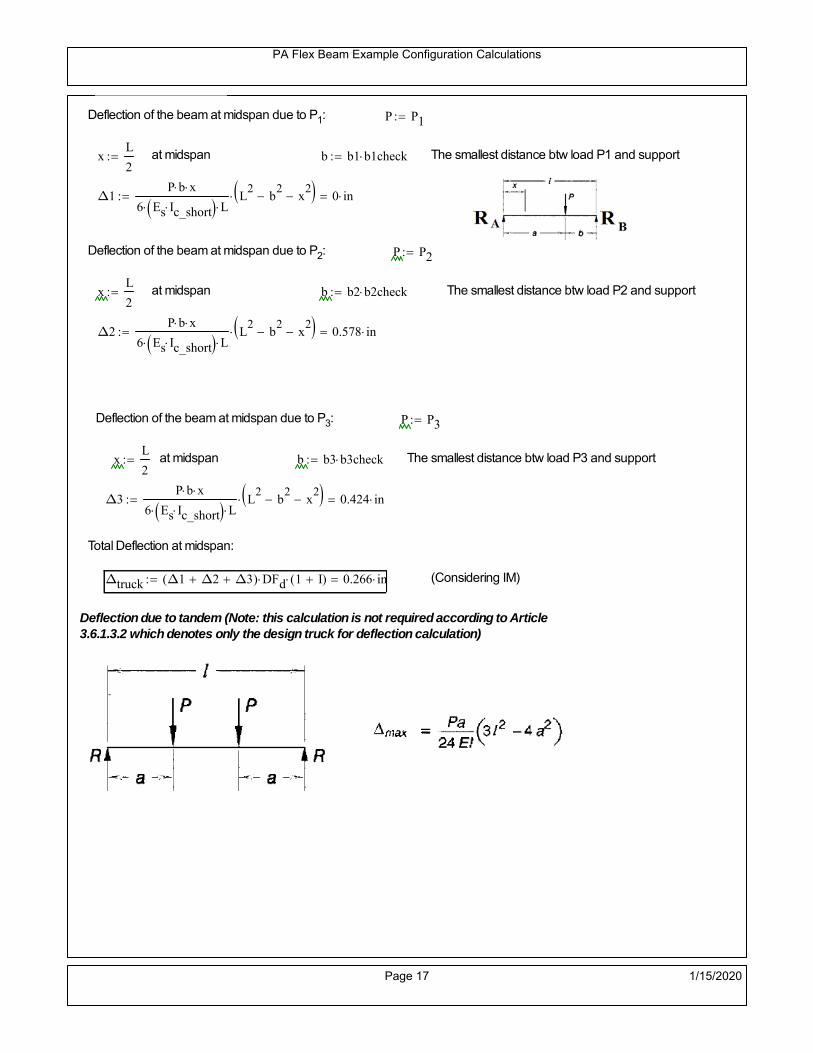
PA Flex Beam Example Configuration Calculations
Deflection of the beam at midspan due to P1: P P1
xL
2 at midspan b b1 b1check The smallest distance btw load P1 and support
Δ1P b x
6 Es Ic_short LL2
b2
x2
0 in
Deflection of the beam at midspan due to P2: P P2
xL
2 at midspan b b2 b2check The smallest distance btw load P2 and support
Δ2P b x
6 Es Ic_short LL2
b2
x2
0.578 in
Deflection of the beam at midspan due to P3: P P3
xL
2 at midspan b b3 b3check The smallest distance btw load P3 and support
Δ3P b x
6 Es Ic_short LL2
b2
x2
0.424 in
Total Deflection at midspan:
Δtruck Δ1 Δ2 Δ3( ) DFd 1 I( ) 0.266 in (Considering IM)
Deflection due to tandem (Note: this calculation is not required according to Article3.6.1.3.2 which denotes only the design truck for deflection calculation)
Page 17 1/15/2020

PA Flex Beam Example Configuration Calculations
FT 31.25 kip Per axle
XAS 4ft Axle spacing
Δtandem
FTL
2
XAS
2
24 Es Ic_short3 L
2 4
L
2
XAS
2
2
DFd 1 I( ) 0.325 in (Considering IM)
Deflection due to lane load
FDLLd 640lbf
ft DFd 128
lbf
ft
Δlane
5 FDLLd L4
384 Es Ic_short0.057 in
Live Load Deflection:
ΔLL 1.25max Δtruck 0.25Δtruck Δlane 1.25 0.416 in ΔLLL
800 1
Deflection Limit
For steel or concrete vehicular bridges:
Vehicular load = Span/800L
8000.54 in
L
10000.432 in
Evaluation of Deflection at the Service Limit State (AASHTO 3.4.2.2)
The associated permitted deflections shall be included in the contract documents.
Page 18 1/15/2020
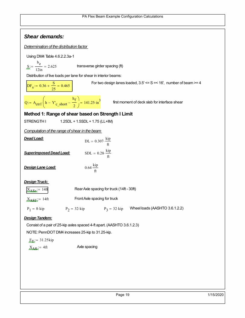
PA Flex Beam Example Configuration Calculations
Shear demands:
Determination of the distribution factor
Using DM4 Table 4.6.2.2.3a-1
Sbe
12in2.625 transverse girder spacing (ft)
Distribution of live loads per lane for shear in interior beams:
For two design lanes loaded, 3.5' <= S =< 16', number of beam >= 4DFs 0.36
S
25 0.465
Q Actr1 h Y'c_shorthf
2
141.25 in3
first moment of deck slab for interface shear
Method 1: Range of shear based on Strength I Limit
STRENGTH I 1.25DL + 1.5SDL + 1.75 (LL+IM)
Computation of the range of shear in the beam
Dead Load:DL 0.307
kip
ft
Superimposed Dead Load: SDL 0.28kip
ft
Design Lane Load: 0.64kip
ft
Design Truck:
XASr 14ft Rear Axle spacing for truck (14ft - 30ft)
XASf 14ft Front Axle spacing for truck
P1 8 kip P2 32 kip P3 32 kip Wheel loads (AASHTO 3.6.1.2.2)
Design Tandem:
Consist of a pair of 25-kip axles spaced 4-ft apart. (AASHTO 3.6.1.2.3)
NOTE: PennDOT DM4 increases 25-kip to 31.25-kip.
FT 31.25kip
XAS 4ft Axle spacing
Page 19 1/15/2020

PA Flex Beam Example Configuration Calculations
Maximum positive shear at various points along the FlexBeam are examined.
At x=0 (at left support) (Truck is moving from left to right)
Truck
Max Positive Shear (when P3 is at x = 0):
x1 L XASr XASf 8 ft Distance between P1 and right support
x2 L XASr 22 ft Distance between P2 and right support
x3 L 36 ft Distance between P3 and right support
V1 P3
x3
L P2
x2
L P1
x1
L 53.333 kip
Total Vertical Shear Force for each FlexBeam (considering dynamic loads):
Vtruck1 V1 DFs 1 I( ) 32.984 kip
Tandem:
V1 FT FT
L XAS L
59.028 kip
Total Vertical Shear Force for each FlexBeam (considering dynamic loads):
Vtandem1 V1 DFs 1 I( ) 36.506 kip
Lane Load
V1 0.64kip
ft
L
2 11.52 kip
Total Vertical Shear Force for each FlexBeam (considering dynamic loads):
Vlane1 V1 DFs 5.357 kip
Dead Load
Vdl1 DLL
2 5.521 kip
Superimposed Dead Load
Vsdl1 SDLL
2 5.045 kip
Strength I Max Positive Shear:
Vstr1 1.25 Vdl1 1.5 Vsdl1 1.75 Vlane1 max Vtruck1 Vtandem1 87.728 kip
Page 20 1/15/2020

PA Flex Beam Example Configuration Calculations
Design Permit Load P-82
Shear at x=0
Strength II Max Positive Shear:
VPL82 VPL82span DFs 1 IPL 50.053 kip
STRENGTH II 1.25DL + 1.5SDL + 1.35 (LL+IM)
VstrII_PL 1.25 Vdl1 1.5 Vsdl1 1.35 VPL82 82.039 kip
Max Shear Demand Vu max Vstr1 VstrII_PL 87.728 kip
Determine the Shear Strength of the Web
Shear Strength of Unstiffened web from AASHTO section 6.10.9.2
Depth of Web D d 21 in Thickness of web tw 0.375 in
Transverse Stiffener Spacing d0 0in Shear Buckling Coefficient k 5 6.10.9.3.2-7
Plastic Shear Force Vp 0.58 Fy D tw 228.375 kip Equation 6.10.9.3.2-3
Ratio of Shear-Buckling resistance to shear yield, C
D
tw56 1.12
Es k
Fy 60.314 Ccheck
D
tw1.12
Es k
Fy 1 Equation 6.10.9.3.2-4
C 1.0 Ccheck 1 C=1 for most cases, if the criteria are not met, then C will go to zero and the actualcoefficients should be determined
Nominal Shear Resistance of Web Vn C Vp 228.375 kip equation 6.10.9.3.3-1
Shear Resistance Factor φv 1.0
φv Vn 228.375 kip φv Vn Vu 1Reduced Shear Strength
Page 21 1/15/2020

PA Flex Beam Example Configuration Calculations
Check Bearing Stiffeners
FYs 50ksi Yield strength of stiffener
tp 0.75in Thickness of stiffener
bt
bf tw
21.5in 4.312 in Effective width of stiffener
Dst hw 4.1in 16.4 in Depth of stiffeners
Apn 2 tp bt 6.469 in2
Projected area of stiffeners
bt 0.48 tpEs
FYs 1Check that effective width of stiffener meets requirements
Rsbn 1.4 Apn FYs 452.812 kip Bearing capacity of stiffener (phi=1 for bearing per AASHTO 6.5.4.2)
Rsbn Vu 1 Bearing capacity check
Qs 1.0 Q factor for bearing stiffner, taken as 1 (AASHTO 6.9.4.1.1)
Is
18 tw tw3
tp 2 bt 3
1240.131 in
4 Moment of inertia of stiffener and web (9*tw is used on each side)
AASHTO 6.10.11.2.4b
Ag 18 tw tw 2 bt tp 9 in2
Gross area of stiffener and web (AASHTO 6.10.11.2.4b)
rs
Is
Ag2.112 in Radius of gyration of stiffener/web
Po Qs FYs Apn 323.437 kip Nominal yeild resistance of stiffener (AASHTO 6.9.4.1.1)
Peπ2Es
0.75 Dst
rs
2Ag 7.592 10
4 kip Elastic critical buckling stress of stiffener (AASHTO 6.9.4.1.2-1)
Check that Pe/Po is great than 0.44 (AASHTO 6.9.4.1.1) PePoPe
Po0.44 1
Pn PePo 0.658
Po
Pe Po 322.861 kip Nominal compressive resistance of stiffener for Pe/Po>0.44
(AASHTO 6.9.4.1.1-1)
φcr 0.95 phi factor for axial compression (AASHTO 6.5.4.2)
Pr φcr Pn 306.718 kip Compressive capacity of bearing stiffener Pr Vu 1
Page 22 1/15/2020
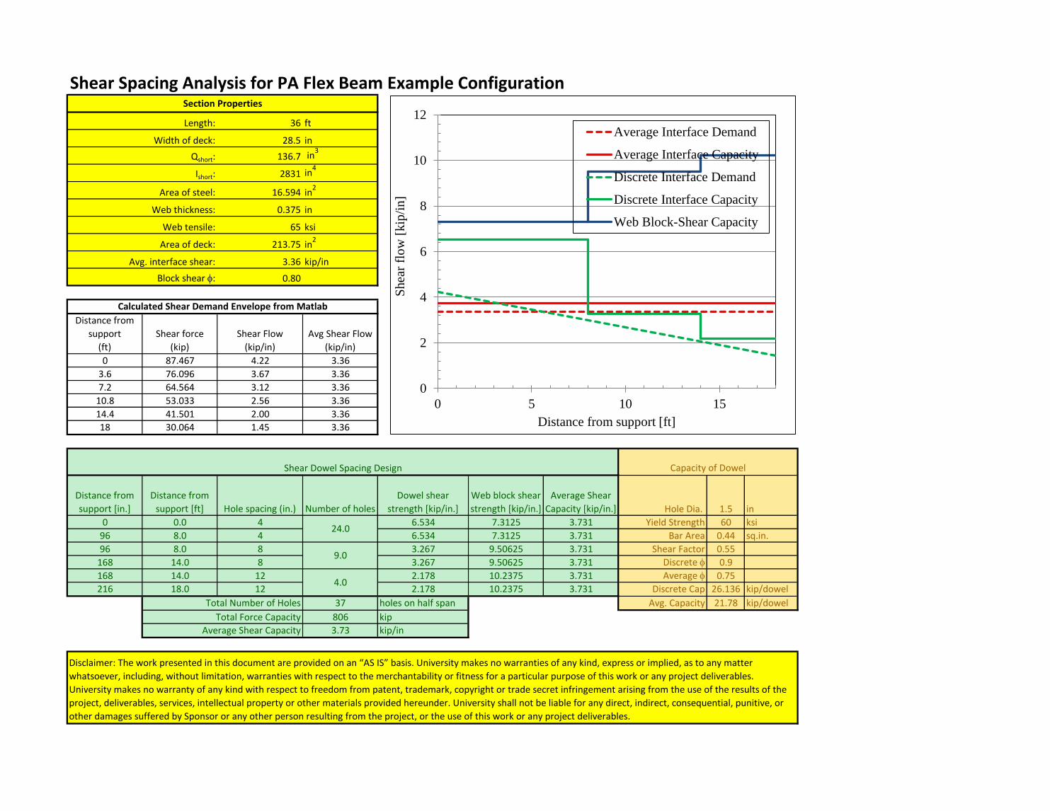
Shear Spacing Analysis for PA Flex Beam Example Configuration
36 ft
28.5 in
136.7 in3
2831 in4
16.594 in2
0.375 in
65 ksi
213.75 in2
3.36 kip/in
0.80
Distance from
support
(ft)
Shear force
(kip)
Shear Flow
(kip/in)
Avg Shear Flow
(kip/in)
0 87.467 4.22 3.36
3.6 76.096 3.67 3.36
7.2 64.564 3.12 3.36
10.8 53.033 2.56 3.36
14.4 41.501 2.00 3.36
18 30.064 1.45 3.36
Distance from
support [in.]
Distance from
support [ft] Hole spacing (in.) Number of holes
Dowel shear
strength [kip/in.]
Web block shear
strength [kip/in.]
Average Shear
Capacity [kip/in.] Hole Dia. 1.5 in
0 0.0 4 6.534 7.3125 3.731 Yield Strength 60 ksi
96 8.0 4 6.534 7.3125 3.731 Bar Area 0.44 sq.in.
96 8.0 8 3.267 9.50625 3.731 Shear Factor 0.55
168 14.0 8 3.267 9.50625 3.731 Discrete f 0.9
168 14.0 12 2.178 10.2375 3.731 Average f 0.75
216 18.0 12 2.178 10.2375 3.731 Discrete Cap 26.136 kip/dowel
Total Number of Holes 37 holes on half span Avg. Capacity 21.78 kip/dowel
Total Force Capacity 806 kip
Average Shear Capacity 3.73 kip/in
Area of steel:
Section Properties
Length:
Width of deck:
Qshort:
Ishort:
Disclaimer: The work presented in this document are provided on an “AS IS” basis. University makes no warranties of any kind, express or implied, as to any matter
whatsoever, including, without limitation, warranties with respect to the merchantability or fitness for a particular purpose of this work or any project deliverables.
University makes no warranty of any kind with respect to freedom from patent, trademark, copyright or trade secret infringement arising from the use of the results of the
project, deliverables, services, intellectual property or other materials provided hereunder. University shall not be liable for any direct, indirect, consequential, punitive, or
other damages suffered by Sponsor or any other person resulting from the project, or the use of this work or any project deliverables.
Web thickness:
Web tensile:
Area of deck:
Avg. interface shear:
Block shear f:
Calculated Shear Demand Envelope from Matlab
Shear Dowel Spacing Design Capacity of Dowel
24.0
9.0
4.0
0
2
4
6
8
10
12
0 5 10 15S
hea
r fl
ow
[kip
/in]
Distance from support [ft]
Average Interface Demand
Average Interface Capacity
Discrete Interface Demand
Discrete Interface Capacity
Web Block-Shear Capacity

Shear Spacing Analysis for PA Flex Beam Example Configuration
36 ft
28.5 in
141.25 in3
2913 in4
16.594 in2
0.375 in
65 ksi
213.75 in2
3.36 kip/in
0.80
Distance from
support
(ft)
Shear force
(kip)
Shear Flow
(kip/in)
Avg Shear Flow
(kip/in)
0 87.467 4.24 3.36
3.6 76.096 3.69 3.36
7.2 64.564 3.13 3.36
10.8 53.033 2.57 3.36
14.4 41.501 2.01 3.36
18 30.064 1.46 3.36
Distance from
support [in.]
Distance from
support [ft] Hole spacing (in.) Number of holes
Dowel shear
strength [kip/in.]
Web block shear
strength [kip/in.]
Average Shear
Capacity [kip/in.] Hole Dia. 1.5 in
0 0.0 4 6.534 7.3125 3.731 Yield Strength 60 ksi
96 8.0 4 6.534 7.3125 3.731 Bar Area 0.44 sq.in.
96 8.0 8 3.267 9.50625 3.731 Shear Factor 0.55
168 14.0 8 3.267 9.50625 3.731 Discrete f 0.9
168 14.0 12 2.178 10.2375 3.731 Average f 0.75
216 18.0 12 2.178 10.2375 3.731 Discrete Cap 26.136 kip/dowel
Total Number of Holes 37 holes on half span Avg. Capacity 21.78 kip/dowel
Total Force Capacity 806 kip
Average Shear Capacity 3.73 kip/in
Area of steel:
Section Properties
Length:
Width of deck:
Qshort:
Ishort:
Disclaimer: The work presented in this document are provided on an “AS IS” basis. University makes no warranties of any kind, express or implied, as to any matter
whatsoever, including, without limitation, warranties with respect to the merchantability or fitness for a particular purpose of this work or any project deliverables.
University makes no warranty of any kind with respect to freedom from patent, trademark, copyright or trade secret infringement arising from the use of the results of the
project, deliverables, services, intellectual property or other materials provided hereunder. University shall not be liable for any direct, indirect, consequential, punitive, or
other damages suffered by Sponsor or any other person resulting from the project, or the use of this work or any project deliverables.
Web thickness:
Web tensile:
Area of deck:
Avg. interface shear:
Block shear f:
Calculated Shear Demand Envelope from Matlab
Shear Dowel Spacing Design Capacity of Dowel
24.0
9.0
4.0
0
2
4
6
8
10
12
0 5 10 15S
hea
r fl
ow
[kip
/in]
Distance from support [ft]
Average Interface Demand
Average Interface Capacity
Discrete Interface Demand
Discrete Interface Capacity
Web Block-Shear Capacity
ATLSS Report 18-05 6-1 FlexBeam Example Configuration Summary
6. APPENDIX E – MATLAB LOAD CASE SCRIPT
The load cases are examined for the various bridge span using a Matlab m-file script. The program computes the
maximum moment distribution and shear envelope for the simply supported FlexBeam configurations in accordance
with PennDOT live load combinations and vehicles.
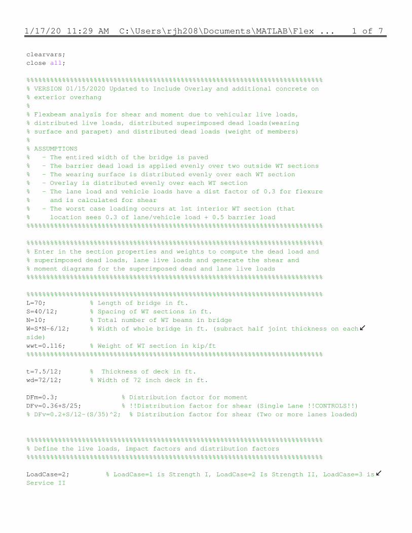
1/17/20 11:29 AM C:\Users\rjh208\Documents\MATLAB\Flex ... 1 of 7
clearvars;close all; %%%%%%%%%%%%%%%%%%%%%%%%%%%%%%%%%%%%%%%%%%%%%%%%%%%%%%%%%%%%%%%%%%%%%%%%%%%% VERSION 01/15/2020 Updated to Include Overlay and additional concrete on% exterior overhang%% Flexbeam analysis for shear and moment due to vehicular live loads, % distributed live loads, distributed superimposed dead loads(wearing% surface and parapet) and distributed dead loads (weight of members)%% ASSUMPTIONS% - The entired width of the bridge is paved% - The barrier dead load is applied evenly over two outside WT sections% - The wearing surface is distributed evenly over each WT section% - Overlay is distributed evenly over each WT section% - The lane load and vehicle loads have a dist factor of 0.3 for flexure% and is calculated for shear% - The worst case loading occurs at 1st interior WT section (that% location sees 0.3 of lane/vehicle load + 0.5 barrier load%%%%%%%%%%%%%%%%%%%%%%%%%%%%%%%%%%%%%%%%%%%%%%%%%%%%%%%%%%%%%%%%%%%%%%%%%%% %%%%%%%%%%%%%%%%%%%%%%%%%%%%%%%%%%%%%%%%%%%%%%%%%%%%%%%%%%%%%%%%%%%%%%%%%%%% Enter in the section properties and weights to compute the dead load and% superimposed dead loads, lane live loads and generate the shear and % moment diagrams for the superimposed dead and lane live loads%%%%%%%%%%%%%%%%%%%%%%%%%%%%%%%%%%%%%%%%%%%%%%%%%%%%%%%%%%%%%%%%%%%%%%%%%%% %%%%%%%%%%%%%%%%%%%%%%%%%%%%%%%%%%%%%%%%%%%%%%%%%%%%%%%%%%%%%%%%%%%%%%%%%%%L=70; % Length of bridge in ft.S=40/12; % Spacing of WT sections in ft. N=10; % Total number of WT beams in bridge W=S*N-6/12; % Width of whole bridge in ft. (subract half joint thickness on each side)wwt=0.116; % Weight of WT section in kip/ft%%%%%%%%%%%%%%%%%%%%%%%%%%%%%%%%%%%%%%%%%%%%%%%%%%%%%%%%%%%%%%%%%%%%%%%%%%% t=7.5/12; % Thickness of deck in ft.wd=72/12; % Width of 72 inch deck in ft. DFm=0.3; % Distribution factor for momentDFv=0.36+S/25; % !!Distribution factor for shear (Single Lane !!CONTROLS!!)% DFv=0.2+S/12-(S/35)^2; % Distribution factor for shear (Two or more lanes loaded) %%%%%%%%%%%%%%%%%%%%%%%%%%%%%%%%%%%%%%%%%%%%%%%%%%%%%%%%%%%%%%%%%%%%%%%%%%%% Define the live loads, impact factors and distribution factors %%%%%%%%%%%%%%%%%%%%%%%%%%%%%%%%%%%%%%%%%%%%%%%%%%%%%%%%%%%%%%%%%%%%%%%%%%% LoadCase=2; % LoadCase=1 is Strength I, LoadCase=2 Is Strength II, LoadCase=3 is Service II
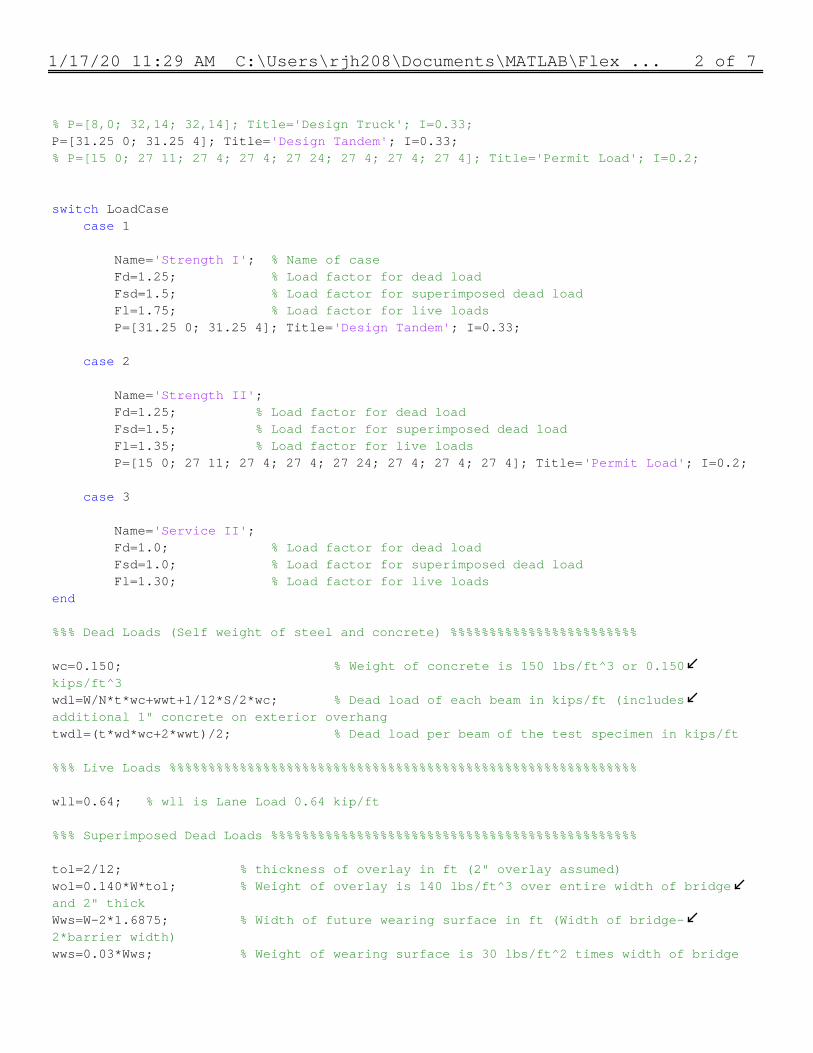
1/17/20 11:29 AM C:\Users\rjh208\Documents\MATLAB\Flex ... 2 of 7
% P=[8,0; 32,14; 32,14]; Title='Design Truck'; I=0.33;P=[31.25 0; 31.25 4]; Title='Design Tandem'; I=0.33;% P=[15 0; 27 11; 27 4; 27 4; 27 24; 27 4; 27 4; 27 4]; Title='Permit Load'; I=0.2; switch LoadCase case 1 Name='Strength I'; % Name of case Fd=1.25; % Load factor for dead load Fsd=1.5; % Load factor for superimposed dead load Fl=1.75; % Load factor for live loads P=[31.25 0; 31.25 4]; Title='Design Tandem'; I=0.33; case 2 Name='Strength II'; Fd=1.25; % Load factor for dead load Fsd=1.5; % Load factor for superimposed dead load Fl=1.35; % Load factor for live loads P=[15 0; 27 11; 27 4; 27 4; 27 24; 27 4; 27 4; 27 4]; Title='Permit Load'; I=0.2; case 3 Name='Service II'; Fd=1.0; % Load factor for dead load Fsd=1.0; % Load factor for superimposed dead load Fl=1.30; % Load factor for live loadsend %%% Dead Loads (Self weight of steel and concrete) %%%%%%%%%%%%%%%%%%%%%%%% wc=0.150; % Weight of concrete is 150 lbs/ft^3 or 0.150 kips/ft^3wdl=W/N*t*wc+wwt+1/12*S/2*wc; % Dead load of each beam in kips/ft (includes additional 1" concrete on exterior overhangtwdl=(t*wd*wc+2*wwt)/2; % Dead load per beam of the test specimen in kips/ft %%% Live Loads %%%%%%%%%%%%%%%%%%%%%%%%%%%%%%%%%%%%%%%%%%%%%%%%%%%%%%%%%%%% wll=0.64; % wll is Lane Load 0.64 kip/ft %%% Superimposed Dead Loads %%%%%%%%%%%%%%%%%%%%%%%%%%%%%%%%%%%%%%%%%%%%%%% tol=2/12; % thickness of overlay in ft (2" overlay assumed)wol=0.140*W*tol; % Weight of overlay is 140 lbs/ft^3 over entire width of bridge and 2" thickWws=W-2*1.6875; % Width of future wearing surface in ft (Width of bridge- 2*barrier width)wws=0.03*Wws; % Weight of wearing surface is 30 lbs/ft^2 times width of bridge
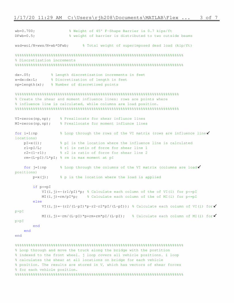
1/17/20 11:29 AM C:\Users\rjh208\Documents\MATLAB\Flex ... 3 of 7
wb=0.700; % Weight of 45" F-Shape Barrier is 0.7 kips/ftDFwb=0.5; % weight of barrier is distributed to two outside beams wsd=wol/N+wws/N+wb*DFwb; % Total weight of superimposed dead load (kip/ft) %%%%%%%%%%%%%%%%%%%%%%%%%%%%%%%%%%%%%%%%%%%%%%%%%%%%%%%%%%%%%%%%%%%%%%%%%%%% Discretization increments%%%%%%%%%%%%%%%%%%%%%%%%%%%%%%%%%%%%%%%%%%%%%%%%%%%%%%%%%%%%%%%%%%%%%%%%%%% dx=.05; % Length discretization increments in feetx=dx:dx:L; % Discretization of length in feetnp=length(x); % Number of discretized points %%%%%%%%%%%%%%%%%%%%%%%%%%%%%%%%%%%%%%%%%%%%%%%%%%%%%%%%%%%%%%%%%%%%%%%%%% Create the shear and moment influence lines: rows are points where % influence line is calculated, while columns are load position.%%%%%%%%%%%%%%%%%%%%%%%%%%%%%%%%%%%%%%%%%%%%%%%%%%%%%%%%%%%%%%%%%%%%%%%%% VI=zeros(np,np); % Preallocate for shear influnce linesMI=zeros(np,np); % Preallocate for moment influnce lines for i=1:np % Loop through the rows of the VI matrix (rows are influence line locations) pI=x(i); % pI is the location where the influence line is calculated r1=pI/L; % r1 is ratio of force for shear line 1 r2=(1-r1); % r2 is ratio of force for shear line 2 rm=(L-pI)/L*pI; % rm is max moment at pI for j=1:np % Loop through the columns of the VI matrix (columns are load positions) p=x(j); % p is the location where the load is applied if p<=pI VI(i,j)=-(r1/pI)*p; % Calculate each column of the of VI(i) for p<=pI MI(i,j)=rm/pI*p; % Calculate each column of the of MI(i) for p<=pI else VI(i,j)=-(r2/(L-pI)*p-r2-r2*pI/(L-pI)); % Calculate each column of VI(i) for p>pI MI(i,j)=-rm/(L-pI)*p+rm+rm*pI/(L-pI); % Calculate each column of MI(i) for p>pI end endend %%%%%%%%%%%%%%%%%%%%%%%%%%%%%%%%%%%%%%%%%%%%%%%%%%%%%%%%%%%%%%%%%%%%%%%%%%%% Loop through and move the truck along the bridge with the postition% indexed to the front wheel. j loop covers all vehicle positions. i loop% calculates the shear at all locations on bridge for each vehicle% position. The results are stored in V, which has vectors of shear forces% for each vehicle position. %%%%%%%%%%%%%%%%%%%%%%%%%%%%%%%%%%%%%%%%%%%%%%%%%%%%%%%%%%%%%%%%%%%%%%%%%%%
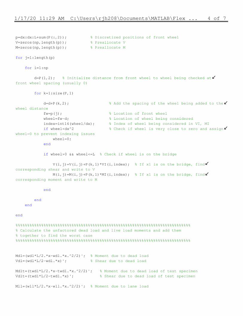
1/17/20 11:29 AM C:\Users\rjh208\Documents\MATLAB\Flex ... 4 of 7
p=dx:dx:L+sum(P(:,2)); % Discretized positions of front wheelV=zeros(np,length(p)); % Preallocate VM=zeros(np,length(p)); % Preallocate M for j=1:length(p) for i=1:np d=P(1,2); % Initialize distance from front wheel to wheel being checked at front wheel spacing (usually 0) for k=1:size(P,1) d=d+P(k,2); % Add the spacing of the wheel being added to the wheel distance fw=p(j); % Location of front wheel wheel=fw-d; % Location of wheel being considered index=int16(wheel/dx); % Index of wheel being considered in VI, MI if wheel<dx^2 % Check if wheel is very close to zero and assign wheel=0 to prevent indexing issues wheel=0; end if wheel>0 && wheel<=L % Check if wheel is on the bridge V(i,j)=V(i,j)+P(k,1)*VI(i,index); % If x1 is on the bridge, find corresponding shear and write to V M(i,j)=M(i,j)+P(k,1)*MI(i,index); % If x1 is on the bridge, find corresponding moment and write to M end end end end %%%%%%%%%%%%%%%%%%%%%%%%%%%%%%%%%%%%%%%%%%%%%%%%%%%%%%%%%%%%%%%%%%%%%%%%%%%% Calculate the unfactored dead load and live load moments and add them% together to find the worst case%%%%%%%%%%%%%%%%%%%%%%%%%%%%%%%%%%%%%%%%%%%%%%%%%%%%%%%%%%%%%%%%%%%%%%%%%%% Mdl=(wdl*L/2.*x-wdl.*x.^2/2)'; % Moment due to dead loadVdl=(wdl*L/2-wdl.*x)'; % Shear due to dead load Mdlt=(twdl*L/2.*x-twdl.*x.^2/2)'; % Moment due to dead load of test specimenVdlt=(twdl*L/2-twdl.*x)'; % Shear due to dead load of test specimen Mll=(wll*L/2.*x-wll.*x.^2/2)'; % Moment due to lane load
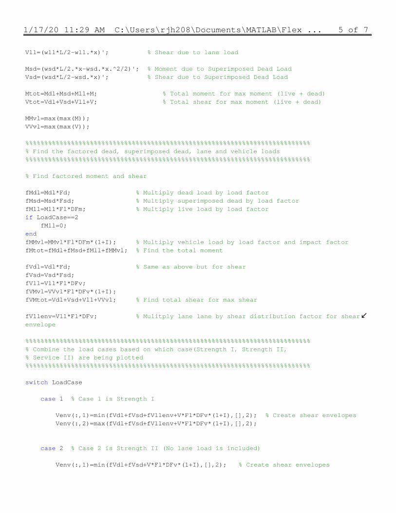
1/17/20 11:29 AM C:\Users\rjh208\Documents\MATLAB\Flex ... 5 of 7
Vll=(wll*L/2-wll.*x)'; % Shear due to lane load Msd=(wsd*L/2.*x-wsd.*x.^2/2)'; % Moment due to Superimposed Dead LoadVsd=(wsd*L/2-wsd.*x)'; % Shear due to Superimposed Dead Load Mtot=Mdl+Msd+Mll+M; % Total moment for max moment (live + dead)Vtot=Vdl+Vsd+Vll+V; % Total shear for max moment (live + dead) MMvl=max(max(M));VVvl=max(max(V)); %%%%%%%%%%%%%%%%%%%%%%%%%%%%%%%%%%%%%%%%%%%%%%%%%%%%%%%%%%%%%%%%%%%%%%%%%%%% Find the factored dead, superimposed dead, lane and vehicle loads%%%%%%%%%%%%%%%%%%%%%%%%%%%%%%%%%%%%%%%%%%%%%%%%%%%%%%%%%%%%%%%%%%%%%%%%%%% % Find factored moment and shear fMdl=Mdl*Fd; % Multiply dead load by load factor fMsd=Msd*Fsd; % Multiply superimposed dead by load factorfMll=Mll*Fl*DFm; % Multiply live load by load factorif LoadCase==2 fMll=0;endfMMvl=MMvl*Fl*DFm*(1+I); % Multiply vehicle load by load factor and impact factorfMtot=fMdl+fMsd+fMll+fMMvl; % Find the total moment fVdl=Vdl*Fd; % Same as above but for shearfVsd=Vsd*Fsd;fVll=Vll*Fl*DFv;fVMvl=VVvl*Fl*DFv*(1+I);fVMtot=Vdl+Vsd+Vll+VVvl; % Find total shear for max shear fVllenv=Vll*Fl*DFv; % Mulitply lane lane by shear distribution factor for shear envelope %%%%%%%%%%%%%%%%%%%%%%%%%%%%%%%%%%%%%%%%%%%%%%%%%%%%%%%%%%%%%%%%%%%%%%%%%%%% Combine the load cases based on which case(Strength I, Strength II,% Service II) are being plotted%%%%%%%%%%%%%%%%%%%%%%%%%%%%%%%%%%%%%%%%%%%%%%%%%%%%%%%%%%%%%%%%%%%%%%%%%%% switch LoadCase case 1 % Case 1 is Strength I Venv(:,1)=min(fVdl+fVsd+fVllenv+V*Fl*DFv*(1+I),[],2); % Create shear envelopes Venv(:,2)=max(fVdl+fVsd+fVllenv+V*Fl*DFv*(1+I),[],2); case 2 % Case 2 is Strength II (No lane load is included) Venv(:,1)=min(fVdl+fVsd+V*Fl*DFv*(1+I),[],2); % Create shear envelopes
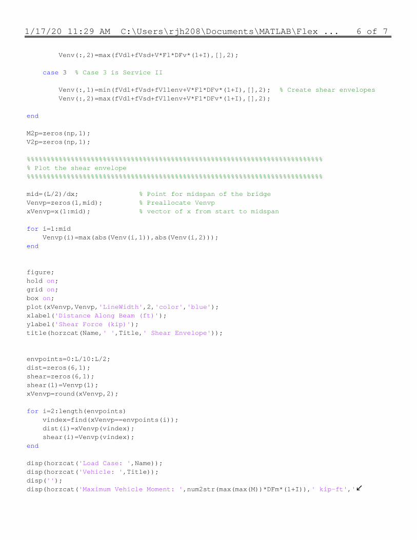
1/17/20 11:29 AM C:\Users\rjh208\Documents\MATLAB\Flex ... 6 of 7
Venv(:,2)=max(fVdl+fVsd+V*Fl*DFv*(1+I),[],2); case 3 % Case 3 is Service II Venv(:,1)=min(fVdl+fVsd+fVllenv+V*Fl*DFv*(1+I),[],2); % Create shear envelopes Venv(:,2)=max(fVdl+fVsd+fVllenv+V*Fl*DFv*(1+I),[],2); end M2p=zeros(np,1);V2p=zeros(np,1); %%%%%%%%%%%%%%%%%%%%%%%%%%%%%%%%%%%%%%%%%%%%%%%%%%%%%%%%%%%%%%%%%%%%%%%%%%% Plot the shear envelope%%%%%%%%%%%%%%%%%%%%%%%%%%%%%%%%%%%%%%%%%%%%%%%%%%%%%%%%%%%%%%%%%%%%%%%%%% mid=(L/2)/dx; % Point for midspan of the bridgeVenvp=zeros(1,mid); % Preallocate VenvpxVenvp=x(1:mid); % vector of x from start to midspan for i=1:mid Venvp(i)=max(abs(Venv(i,1)),abs(Venv(i,2)));end figure;hold on;grid on;box on;plot(xVenvp,Venvp,'LineWidth',2,'color','blue');xlabel('Distance Along Beam (ft)');ylabel('Shear Force (kip)');title(horzcat(Name,' ',Title,' Shear Envelope')); envpoints=0:L/10:L/2;dist=zeros(6,1);shear=zeros(6,1);shear(1)=Venvp(1);xVenvp=round(xVenvp,2); for i=2:length(envpoints) vindex=find(xVenvp==envpoints(i)); dist(i)=xVenvp(vindex); shear(i)=Venvp(vindex);end disp(horzcat('Load Case: ',Name));disp(horzcat('Vehicle: ',Title));disp('');disp(horzcat('Maximum Vehicle Moment: ',num2str(max(max(M))*DFm*(1+I)),' kip-ft','

1/17/20 11:29 AM C:\Users\rjh208\Documents\MATLAB\Flex ... 7 of 7
includes distribution and impact'));disp(horzcat('Maximum Vehicle Shear: ',num2str(max(max(V))),' kip',' does not include distribution and impact'));disp(table(dist,shear));