project-specific plan investigating subsurface material ... · project-specific plan for...
TRANSCRIPT

PROJECT-SPECIFIC PLAN FOR INVESTIGATING SUBSURFACE MATERIAL
FROM THE NORTHWESTERN PORTION OF WASTE PIT 3
FERNALD CLOSURE PROJECT FERNALD, OHIO
DECEMBER 2003
U.S. DEPARTMENT OF ENERGY
20600-PSP-0007 REVISION 0
FINAL

PROJECT-SPECIFIC PLAN FOR INVESTIGATING THE NORTHEWESTERN PORTION OF
WASTE PIT 3 SUBSURFACE MATERIAL
Document Number 20600-PSP-0007 Revision 0, Final
December 2003
APPROVAL:
+ /03 J.D. ‘Chiou, Projrct Manager Date Soil and_)isposal Facility Project
/&& Kopp, Acting Project Manager Date Waste Pits Project
&,L. I ZII 1/03 Cindy tabor, Project Data Oversight Soil and Disposal Facility Project
bate
&& 4, Lui&Lnd Leslie V#illiams, Quality Assurance Date Waste Pits Project
FERNALD CLOSURE PROJECT
Fluor Fernald P.O. Box 538704
Cincinnati, Ohio 45253-8704
000802

, 5 2 0 1 TABLE OF CONTENTS
Page
1.0 Introduction ..................................................................................................................................... 1-1 1.1 Purpose ..................................................................................................................................... 1-1 1.2 Background ............................. .. ................................................................................................ 1-1 1.3 Scope ........................................................................................................................................ 1-3 1.4 Key Project Personnel .............................................................................................................. 1-3
2.0 Physical Sampling Strategy ................................ . .... . .............................. . .......................................... 2-1 2.1 Selection of Constituents .......................................................................................................... 2-1 2.2 Selection of Sample Locations ................................................................................................. 2-3 2.3 Sample Collection Methods ..................................................................................................... 2-5 2.4 Sample Identification ................................................ . ............................................................... 2-7 2.5 Sample Analysis ....................................................................................................................... 2-7 2.6 Equipment Decontamination .................................................................................................... 2-9 2.7 Sampling Waste Disposition ............................................................................. ...................... 2-9 2.8 Borehole Abandonment ............................................................................................................ 2-9
3 .O Quality Assurance/Quality Control Requirements ... . ...... . .. . . .. . ...... ... . . .. .... . .. ..... . ..... ... . .. .... . .. .. ...... .... ... 3- 1 3.1 Field Quality Control Samples, Analytical Requirements, and Data Validation ...................... 3-1 3.2 Project-Specific Procedures, Manuals, and Documents ........................................................... 3-1 3.3 Project Requirements for Independent Assessments . . .. . ... . .. . .. ..... ... . .. ... . ... .. . ..... ... , .. . .. .. . . ... .. .. ... .3-2 3.4 Implementation of Field Changes ............................................................................................. 3-2
4.0 Health and Safety .............................................................................................................................. 4-1
5.0 Data Management .............................................................................................................................. 5-1
LIST OF APPENDICES
Appendix A Appendix B Appendix C Target Analyte Lists Appendix D
Data Quality Objectives SL-048, Revision 5 Waste Pit 3 Dioxin and Furan Information
Sample Locations and Identifiers
LIST OF TABLES
Table 1-1 Key Personnel Table 2-1
Table 2-2
OU1 RVFS Data for Waste Pit 3 and Associated Remediation Area 6 FRL and OSDF WAC Information Sampling and Analyhcal Requirements
LIST OF FIGURES
Figure 1-1 Figure 1-2 Figure 2-1 Figure 2-2 Figure 2-3
Location of OU1 Waste Pits at FCP Previous Boring Locations and Currently Excavated Area in Waste Pit 3 Proposed Sample Locations for the Northwestern Portion of Waste Pit 3 Sample Intervals for Waste Pit 3 Subsurface Investigation Analysis Sequence for Waste Pit 3 Subsurface Investigation
000003

LIST OF ACRONYMS AND ABBREVIATIONS
ASL BTV CERCLA COC DOE DQO EPA FACTS FCP FF FRL IEMP mCi/g mg/kg OEPA OSDF ou PAH PCB pCi pCi/g PID PPb PSP QA RIfFS RWP SCQ SDFP SED SEP SPL svoc TAL TEF
VRCN voc WAC WAO W P
analytical support level benchmark toxicity value Comprehensive Environmental Response, Compensation, and Liability Act Constituent of Concern U.S. Department of Energy Data Quality Objective U.S. Environmental Protection Agency Fernald Analytical Computerized Tracking System Fernald Closure Project Fluor Fernald final remediation level Integrated Environmental Monitoring Plan millicuries per gram milligram per kilogram Ohio Environmental Protection Agency On-Site Disposal Facility Operable Unit polynuclear aromatic hydrocarbon polychlorinated biphenyl picoCuries picocuries per gram photoionization detector parts per billion project-specific plan Quality Assurance Remedial InvestigatiodFeasibility Study Radiological Work Permit Sitewide CERCLA Quality Assurance Project Plan Soil and Disposal Facility Project Sitewide Environmental Database Sitewide Excavation Plan Sample Processing Laboratory semi-volatile organic compound target analyte list Toxicity Equivalence Factor micrograms per kilogram VarianceEield Change Notice volatile organic compound waste acceptance criteria Waste Acceptance Organization Waste Pits Project

5 2 0 1 FCP-WPP PIT LINER INVEST FINAL
20600-PSP-0007, Revision 0 December 2003
1 .O INTRODUCTION
1.1 PURPOSE
This project-specific plan (PSP) has been developed to gather information pertaining to the material
underlying the northwestern portion of Waste Pit 3 in the Fernald Closure Project (FCP) Waste Storage
Area. The resulting data from the Waste Pit 3 subsurface material (Le., liner and/or native material)
investigation will assist in:
0 Verifylng the general assumptions supporting overall schedule and management decisions associated with the remediation of the subsurface materials underlying the waste pits
0 Updatinghefining volume estimates and schedule for on-site disposal facility (OSDF) waste placement and Envirocare railcar shipments
0 Obtaining field experience and identifymg general statistical parameters necessary to support the development of a fbture predesign PSP for sampling subsurface material underlying all waste pits in the Waste Storage Area.
It is anticipated that waste pit subsurface sampling will be conducted in multiple phases as excavation of
the waste pits progresses. Sampling under this PSP specifically addresses the northwestern portion of
Waste Pit 3 where waste excavation has been completed to the extent that safe access to the pit floor is
possible. Sampling under this PSP will also be conducted in a manner that will prevent impact to the
Great Miami Aquifer.
1.2 BACKGROUND
The Waste Storage Area at the FCP covers approximately 38 acres and is located west of the former
production area (Figure 1-1). Designated as Operable Unit (OU) 1 during the Remedial
InvestigationReasibility Study (RVFS), this area consists of Waste Pits 1 through 6, the Bum Pit, and the
Clearwell. The various components of OU1 were constructed from 1952 (Waste Pit 1) through 1979
(Waste Pit 6 ) and were used to store waste products generated by the FCP uranium refinement process.

FCP-WPP PIT LINER INVEST FINAL 20600-PSP-0007, Revision 0
December 2003
The waste product sources were numerous production byproducts from chemical feed material extraction
and precipitation, filtering and settling operations, drying operations, chemical conversion, and heat
treatment. The waste pits were also used to dispose of other wastes generated in the refinement process
and site support activities, including pollution control products, flyash from the boiler plant, residues from
the process water treatment plant, construction debris, and discarded equipment, vessels, and containers.
These wastes were contaminated with numerous radiological and chemical constituents, including uranium
isotopes and their decay products, thorium isotopes and their decay products, fission products such as technetium-99, potentially hazardous metals (such as arsenic, chromium, nickel, and lead) extracted as
impurities from the uranium-bearing feedstock, and organic chemical constituents used in various plant
processes and maintenance operations.
Characterization of the physical, chemical, and radiological profiles of the contents of each waste pit,
supplemented by treatability studies, were completed in 1992 to meet the objectives of the OU1 RVFS. No
analytical information on the nature and extent of contaminants in the native clay material used to line
some of the waste pits, as well as the soils beneath the pits is available.
Because of the concem about maintaining the integrity of the waste pit liners to prevent environmental
migration of pit contaminants into the underlying Great Miami Aquifer, waste pit content characterization
borings were carefully conducted so as not to breach the pit lining material. The informational needs of
the RVFS were satisfied through the use of computer modeling that simulated the migration of
contaminants from the waste pits to the underlying soils.
Lining material used in the waste pits includes native clay (either from an existing in-situ clay lens, or dug
from the Bum Pit) used for Waste Pits 1 , 2,3,4, and the Clearwell. A 60-mil thick ethylene propylene
diene monomer elastomeric membrane underlain with native soil was used for Waste Pits 5 and 6, and
native soil is beneath the Bum Pit (which was created as the result of removal of clay for lining other pits).
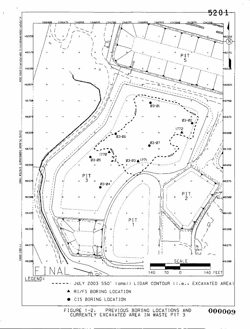
Figure 1-2 presents the OU1 RVFS sample locations associated with Waste Pit 3. The figure additionally
delineates the area where current excavation in Waste Pit 3 has reached the waste pit floor, which is
indicated by the 550 foot above mean sea level contour from the July 2003 topographical survey.
OOOOQ6
5 2 0 1
Title DOE Contact Soil and Disposal Facility Project (SDFP) - Project Manager Waste Pits Project (WPP) - Project Manager Characterization Lead
FCP-WPP PIT LINER INVEST FINAL 20600-PSP-0007, Revision 0
December 2003
Primary Alternate Dave Lojek Johnny Reising
Jyh-Dong Chiou Rich Abitz
Mike Kopp (Acting) Dennis Dalga Cindy Tabor Bill Westerman
1.3 SCOPE
Under this PSP, physical samples will be collected from the northwestern portion of Waste Pit 3 where
excavation has progressed to the pit floor (Figure 1-2), to meet the objectives stated in Section 1.1. The
analytical results of this investigation will be compiled to support overall schedule and management
Field Sampling Lead Project Geologista Surveying Lead Waste Acceptance Organization (WAO) Contact
decisions associated with remediation of the subsurface materials underlying the waste pits. All sampling
~~
Tom Buhrlage Jim Hey Hank Becker Jonathon Walters Jim Schwing Andy Clinton Joe Jacoboski Bob Bischoff
activities carried out under this PSP will be performed in accordance with the Sitewide Comprehensive
Environmental Response, Compensation, and Liability Act (CERCLA) Quality Assurance Project
Plan (SCQ), and Data Quality Objective (DQO) SL-048, Revision 5 (Appendix A). Further sampling of
Waste Pit 3 subsurface material along with the remaining waste pits’ subsurface material will be addressed
in a separate PSP.
Laboratory Contact Data Management Lead Field Data Validation Contact Data Validation Contact Fernald Analytical Computerized Tracking System (FACTS)/Sitewide Environmental Database (SED)
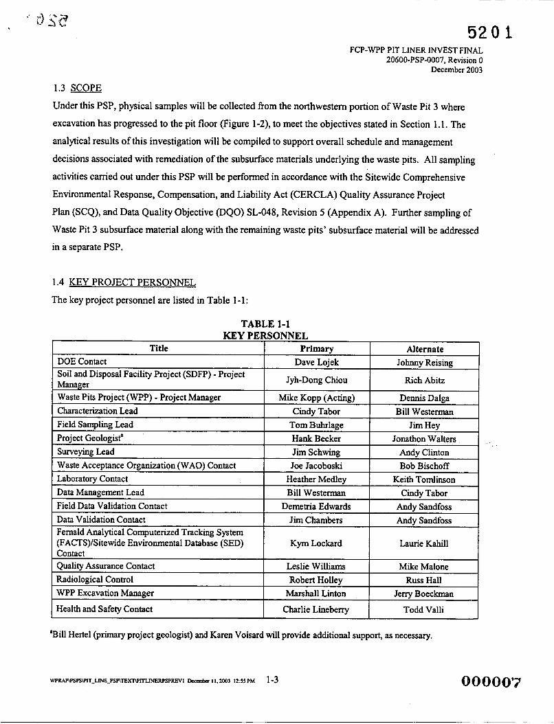
1.4 KEY PROJECT PERSONNEL
The key project personnel are listed in Table 1-1:
Heather Medley Keith Tomlinson Bill Westerman Cindy Tabor
Demetria Edwards Andy Sandfoss Jim Chambers Andy Sandfoss
Kym Lockard Laurie Kahill Contact Quality Assurance Contact Radiological Control
Leslie Williams Mike Malone Robert Hollev Russ Hall
WPP Excavation Manager
Health and Safety Contact
Marshall Linton Jerry B o e c L n
Charlie Lineberry Todd Valli
*Bill Hertel (primary project geologist) and Karen Voisard will provide additional support, as necessary.

LEGEND :
FCP BOUNDARY ---.-
I
4
SCALE
! 800 400 0 800 FEET
V:/SFGPl/DGN/WESTERMANO4.DCN FIGURE 1-1. L O C A T I O N OF OU1 WASTE P I T S AT FCP 02/04/02 S T A T E PLANAR CDORDINATE SYSTEM 1983
I
* RI/FS BORING LOCATION 0 CIS BORING LOCATION
FIGURE 1-2. PREVIOUS BORING LOCATIONS AND CURRENTLY EXCAVATED AREA I N WASTE P I T 3
000009

FCP-WPP PIT LINER INVEST FINAL 20600-PSP-0007, Revision 0
December 2003
2.0 PHYSICAL SAMPLING STRATEGY
2.1 SELECTION OF CONSTITUENTS
In order to determine the appropriate list of constituents to monitor in the northwestern portion of
Waste Pit 3, those constituents of concern (COCs) in the Sitewide Excavation Plan (SEP) for
Remediation Area 6 (i.e., Waste Storage Area) were reviewed. These COCs are listed below.
SEP Remediation Area 6 COC List
Primarv COCs Secondarv COCs Ecological COCs Radium-226 Fluoride Antimony Radium-228 Cadmium Thori~m-228 Thorium-232 Total Uranium
Arsenic Beryllium
Aroclor-1254 Aroclor- 1260 Dieldrin
Benzo(a)p yrene Benzo(b) fluoranthene Dibenzo(a,h)anthracene Indeno( lY2,3-cd)pyrene
Bromodichloromethane 1,l-Dichloroethene Tetrachloroethene
Heptachloradibenzo-p-dioxin Octochlorodibenzo-pdioxin
Cesium-1 37 Technetium-99 Thorium-230
Silver
Benzo( a)anthracene Benzo(k) fluoranthene Chrysene Benzo(g,h,i)perylenea Fluoranthenea Phenanthrenea Pyrenea
'Constituent has no associated final remediation level (FRL) or OSDF waste acceptance criteria (WAC) level.
Specifically, Remediation Area 6 COCs fiom Waste Pit 3 OU1 RVFS data (refer to Figure 1-2 for
monitoring locations) were evaluated against on-property FRLs and OSDF WAC levels. Table 2-1 lists
these COCs and identifies those constituents that have exceeded FRLs andor OSDF WAC levels in
Waste Pit 3. For each COC, this table additionally identifies the following information fiom Waste Pit 3
data:
0 Minimum and maximum concentrations 0
0
Number of locations and samples with exceedances Total number of samples and locations.
i

5201 '
FCP-WPP PIT LINER INVEST FINAL 20600-PSP-0007, Revision 0
December 2003
Of the 29 constituents identified in Table 2-1, 13 had concentrations that exceeded a FRL andor
OSDF WAC level. Note that benzo(g,h,i)perylene, fluoranthene, phenanthrene, and pyrene are not
included in Table 2-1. This is because these constituents have no associated FRL or OSDF WAC level.
For this investigation, samples will be collected for the 13 constituents that have had FRL or OSDF WAC
exceedances in Waste Pit 3. Additionally, the following constituent selection process was used to ensure
the appropriate target analyte lists (TALs) were defined for the northwestern portion of Waste Pit 3
subsurface sampling:
Determine if any Remediation Area 6 COCs have not been analyzed from Waste Pit 3 and evaluate the necessity for sampling.
Determine if FRL or OSDF WAC constituent exceedances in Waste Pit 3 have been widespread or isolated based on number of samplesflocations and evaluate iflwhere sampling should occur.
Determine if additional site information exists that might lead to the elimination or addition of constituents for Waste Pit 3 subsurface sampling.
Determine if the presence of volatile organic exceedances necessitates photoionization detector (PID) screening.
After analysis of the data presented in Table 2-1, the following statements can be made in response to the
four constituent selection criteria above:
1) All Remediation Area 6 COCs have been analyzed with respect to Waste Pit 3; therefore, no constituents will be added to the TALs based on this step.
2) 1,l -Dichloroethene was not detected in any samples; however, one sample had a non detected value slightly above the associated FRL (420 pgkg versus 410 pgkg). This constituent will not be add to the Waste Pit 3 TAL based on all results being non detects; however, will be added based on step 3)c below.
3) a) The latest guidance for evaluating the health-based risk of dioxins, in short, is to determine the concentration of each individual congener, multiply each concentration by the appropriate Toxicity Equivalence Factors (TEF), s u m the corrected concentrations, and compare the total contribution of all dioxin and furan congeners to an established limit of 1 part per billion (ppb). Appendix B presents these calculations for all samples of dioxins and furans for Waste Pit 3. Based on the results of these calculations, it is concluded that dioxins and furans are well within the acceptable risk level per U.S. Environmental Protection Agency (EPA) Guidelines. Therefore, the two dioxins listed in the SEP as Remediation Area 6 COCs, heptachlorodibenzo-p-dioxin and octochlorodibenzo-p- dioxin, do not require further evaluation and will not be included in the TALs associated with this PSP.

-520 1 FCP-WPP PIT LINER INVEST FINAL
20600-PSP-0007, Revision 0 December 2003
b) Although benzo(g,h,i)perlyene, fluoranthene , phenanthrene, and pyrene do not have associated FRLs or OSDF WAC levels, they have been identified as COCs for Remediation Area 6. These constituents will be added to the Waste Pit 3 TALs in order to collect information to support overall schedule and management decisions associated with remediation of the subsurface materials underlying the waste pits.
c) Volatile organic compounds (VOCs) sampling will be conducted to support the selection of future certification COCs. Analysis will include those typical solvents found in quantities around the site, based on process knowledge: 1 , 1 , 1 -Trichloroethane, 1 , 1 ,2-TrichloroethaneY 1 , 1 - Dichloroethene, cis- 1 ,2-DichloroetheneY trans- 1 ,2-DichloroetheneY Trichloroethene , Tetrachlorethene, and Vinyl Chloride.
4) Because there are volatile organics among the COCs for Waste Pit 3, PID screening will be necessary .
Through application of the constituent selection process, it was determined that 17 constituents, 13 with
FRL and/or OSDF WAC exceedances and four polynuclear aromatic hydrocarbons [step 3)b], will be
sampled in the northwestern portion of Waste Pit 3 subsurface investigation. Additionally, samples will be
collected for VOC analysis as identified in step 3)c above. The constituents to be sampled are listed below
and provided in Appendix C in five TALs (TAL A, TAL By TAL Cy TAL D, TAL E, and TAL F).
Division of the constituents into the different TALs is based on the various analytical methods used and
whether particular constituents will be analyzed on-site or at an off-site laboratory.
Waste Pit 3 Sampling List
Primarv COCs Secondarv COCs Ecoloeical COCs
Radium-226 Radium-228
Thorium-232 Thori~m-228
ggg$g~izi~
Arsenic Beryllium
Aroclor-1254 Aroclor-1260 Dieldrin
Benzo(g, h,l)perylene Fluoranthene Phenanthrene Pyrene
I, ....,. ... .~-. HijiigtitG Constituent concenbations from Waste Pit 3 OUI RVFS data have exceeded OSDF WAC levels. Itolicued
Note:
Although there are no associated FRLs, samples will be collected to support overall schedule and management decisions associated with the remediation of waste pits subsurface material. VOC samples to support future remediation certification efforts will be collected for 1 ,1 ,1 -Trichloroethane, 1.1,2-Trichloroethane, 1,l-Dichloroethene, cis-l,2-Dichloroethene, trans-1 2-Dichloroethene, Trichloroethene, Tetrachlorethene. and Vinyl Chloride.
2.2 SELECTION OF SAMPLE LOCATIONS
Sample locations will be placed to meet the objectives presented in Section 1.1, while taking into
consideration efforts to minimize cross-contamination. Because of the dynamic nature of excavation
activities in the various waste pits, final placement of borings will be determined during an area walk-down
008012 W P R A P \ P S P S W I T - ~ - P S P \ T E ~ ~ ~ ~ S P R I ~ccember 1 I . 2003 125s PM 2-3
5201 ' if c: FCP-WPP PIT LINER INVEST FINAL
20600-PSP-0007, Revision 0 December 2003
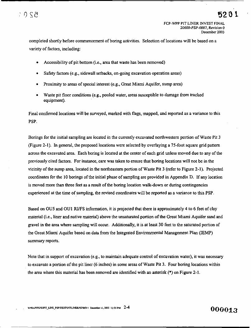
completed shortly before commencement of boring activities. Selection of locations will be based on a
variety of factors, including:
Accessibility of pit bottom (i.e., area that waste has been removed)
0 Safety factors (e.g., sidewall setbacks, on-going excavation operation areas)
Proximity to areas of special interest (e.g., Great Miami Aquifer, sump area)
0 Waste pit floor conditions (e.g., pooled water, areas susceptible to damage from tracked equipment).
Final confirmed locations will be surveyed, marked with flags, mapped, and reported as a variance to this
PSP.
Borings for the initial sampling are located in the currently excavated northwestern portion of Waste Pit 3
(Figure 2-1). In general, the proposed locations were selected by overlaying a 75-foot square grid pattern
across the excavated area. Each boring is located at the center of each grid unless moved due to any of the
previously cited factors. For instance, care was taken to ensure that boring locations will not be in the
vicinity of the sump area, located in the northeastern portion of Waste Pit 3 (refer to Figure 2-1). Projected
coordinates for the 10 borings of the initial phase of sampling are provided in Appendix D. If any location
is moved more than three feet as a result of the boring location walkdown or during contingencies
experienced at the time of sampling, the revised coordinates will be reported as a variance to this PSP.
Based on OU5 and OU1 RVFS information, it is projected that there is approximately 4 to 6 feet of clay
material (i.e., liner and native material) above the unsaturated portion of the Great Miami Aquifer sand and
gravel in the area where sampling will occur. Additionally, it is at least 30 feet to the saturated portion of
the Great Miami Aquifer based on data from the Integrated Environmental Management Plan (IEMP)
summary reports.
Note that in support of excavation (e.g., to maintain adequate control of excavation water), it was necessary
to excavate a portion of the pit liner (6 inches) in some areas of Waste Pit 3. Four boring locations within
the area where this material has been removed are identified with an asterisk (*) on Figure 2-1.

520 1 FCP-WPP PIT LINER INVEST FINAL
20600-PSP-0007, Revision 0 December 2003
Sampling within each boring core will be conducted at 6 six-inch intervals as shown on Figure 2-2. The
first six-inch interval of non-waste material (i.e., liner) will be included as part of the general pit
excavation effort, with the material presumed to be contaminated and shipped offsite for disposal.
Sampling for the targeted constituents will begin after the first six-inch interval of non-waste material is
removed (except for the four asterisked locations) and will be conducted at six-inch intervals to a depth of
3.5 feet (refer to Section 2.3). The six sample intervals collected from each of the 10 locations are
identified in Appendix D.
2.3 SAMPLE COLLECTION METHODS
Soil borings will be completed using the Geoprobe" core sampling assembly, in accordance with procedure
EQT-06, Geoprobe" Model 5400 and Model 6600 Operation and Maintenance Manual. Soil samples will
be collected in accordance with procedure SMPL-0 1, Solids Sampling. If refusal or resistance is
encountered during sample collection, the boring location may be relocated up to three feet away. Any
movement of the boring location by more than three feet will be documented on a variancelfield change
notice (V/FCN) form, as described in Section 3.4. Changes of less than three feet from the scheduled
location will be documented (distance and direction) in the Field Activity Log associated with that boring.
These activities will be coordinated with and authorized by the Characterization Lead and the WPP
Excavation Manager.
Prior to collection of the sample cores, any pit waste material overlying the pit floor within a 12-inch radius
from the point to be sampled will be removed. The Geoprobe" will then be driven to the appropriate depth
and, upon removal, each core will be laid out on clean plastic. The entire length of each boring will be
PID screened for volatile organics. The Geoprobe core liners will be opened for the PID screening and the
measurement for each six-inch interval will be recorded in the field documentation, along with the PID background reading. Additionally, the entire length of each soil core will be surveyed with a betdgamma
(Geiger-Mueller) survey meter. Following betdgamma screening, the appropriate six-inch sample
intervals, as designated for each of the 10 boring locations, will be collected. Note that a sample will be
collected from the interval with the highest betdgamma reading in each boring and submitted to the on-site
laboratory for alphaibeta analysis results for off-site shipping purposes. If all intervals from a boring
indicate no contamination above background, the alphaheta sample will be collected from the first six-
inch interval of non-waste material.

FCP-WPP PIT LINER INVEST FINAL 20600-PSP-0007, Revision 0
December 2003
Lithological descriptions of the cores will be completed by the project geologist. The project geologist will attempt to identify the interface between the constructed clay pit liner material and the material below the
constructed liner by evaluation of certain lithological characteristics. These characteristics will be recorded on a lithological log and will include, at minimum, material stratification; particle size; color; moisture
content; density; and related geotechnical properties. Additionally, any debris (e.g., wood not part of
undisturbed native till material, glass, metal) contained in the sample intervals will be removed and identified in a visual description of the sample core material.
Because of the propensity for contaminants to collect at interfaces of differing material, it has been determined that at conditions where there is a cleadmajor interface between material types (e.g., clay versus sand), the six-inch sample interval will be adjusted such that one six-inch interval will be collected
immediately above the material interface and one six-inch interval will be collected immediately below the interface. The six-inch interval spacing will proceed in both directions (up and down the core) starting from the interface. If there is less than six inches remaining that can’t provide the sufficient amount of soil
volume at the uppermost interval of the boring, that interval will only be analyzed for total uranium and
technetium-99. Any such interval adjustments must be noted in the Field Activity Log.
During this investigation, it is critical to prevent cross-contamination within the boreholes due to the proximity of the Great Miami Aquifer to the bottom of the waste pit liner. Therefore, a project geologist
from Aquifer Restoratioflater Management group will monitor all boring activities associated with this investigation to ensure that every effort is taken to protect the Great Miami Aquifer. No borehole will be
placed within ten feet of any liquid pooled on the waste pit floor. Weather forecasts will be monitored to prevent sampling during precipitation events. A containment barrier will be closely available to place
around a borehole in process in the case of unexpected rain. Boreholes in the pit liner will be plugged (as specified in Section 2.8) immediately upon completion and any partially completed borehole shall not be left unplugged overnight or left unattended during the .day of sampling.
Additionally, if the sand and gravel of the Great Miami Aquifer is encountered prior to the 3.5 foot depth
in a borehole, then adjacent borehole depths will be altered to a depth six inches below the depth from which the sand and gravel was encountered (e.g., encounter sand and gravel at 2.0 feet, then adjacent
borehole depths would be 2.5 feet). If in adjacent boreholes, sand and gravel is not encountered, then sample interval depths will proceed. Changes will be documented in the Field Activity Log associated for
borings of interest and activities will be coordinated with and authorized by the Characterization Lead and the WPP Excavation Manager. Note that monitoring of the Great Miami Aquifer will continue as part of
the groundwater remedy performance monitoring specified in the IEMP and Geoprobe activities in the

L
-- - 5 2 0 1 FCP-WPP PIT LINER INVEST FINAL
20600-PSP-0007, Revision 0 December 2003
Waste Storage Area are being planned for 2004 to ensure that there is no adverse impact to the aquifer .
and/or to determine if groundwater remedy design changes are necessary.
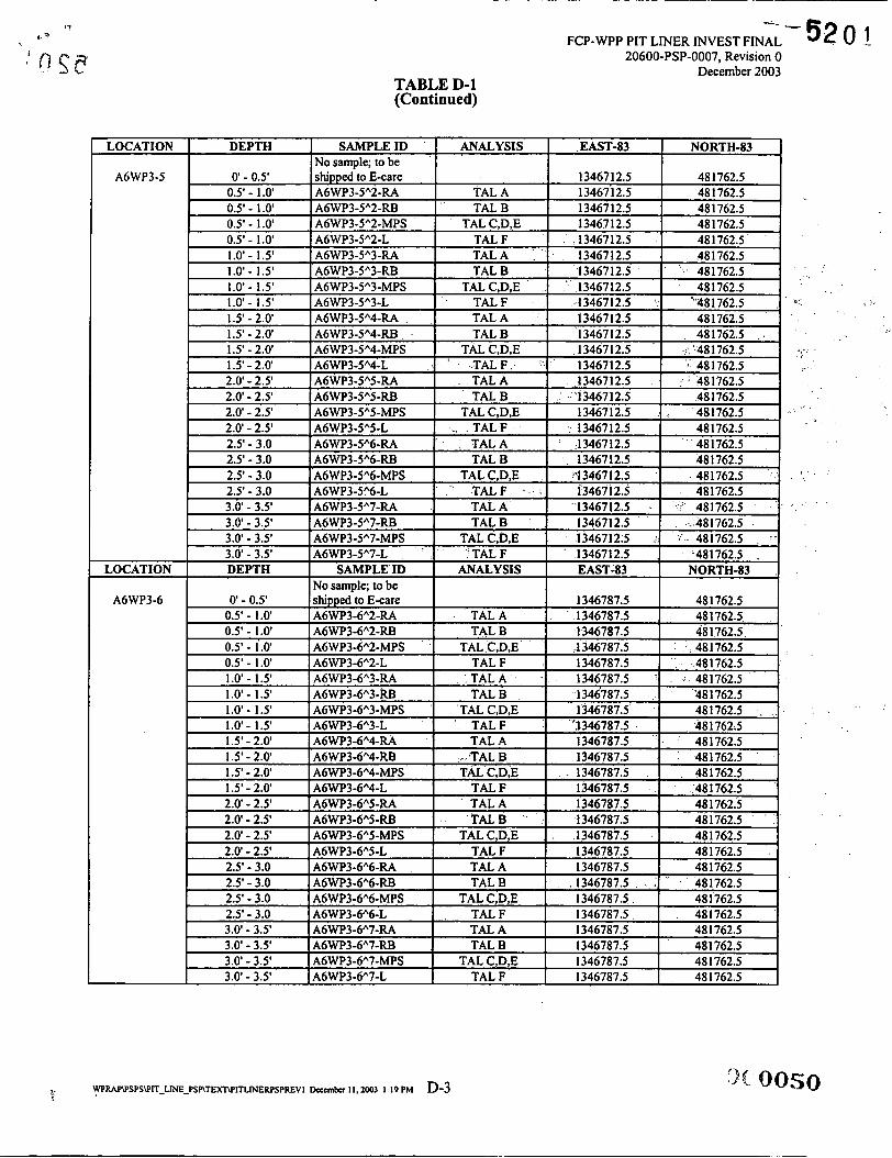
2.4 SAMPLE IDENTIFICATION
All physical samples collected for laboratory analysis will be assigned a unique$ sample identification
number as A6WP3-Location”Depth-Analysis, where:
A6WP3
Location
Depth Interval
Analysis
Sample collected from Remediation Area 6 Waste Pit 3
Sample Location number (1 through 10)
66 9,- 1 - 0 to 0.5 feet below the pit floor @e., where the overlying waste material
2 - 0.5 to 1 feet below the pit floor, etc. ends and the pit liner material begins)
(where depth interval indicator equals two times the bottom depth for the respective interval and is measured in feet, i.e., “1”= 2 x O S ’ , “2” = 2 x 1 ’, etc.)
66 Y3-
“RA” for radiological (total uranium and technetium-99), “RB” for all other radiological parameters, “M” for metals, “P” for pesticide/polychlorinated biphenyls (PCBs), “S” for polynuclear aromatic hydrocarbons, “L” for VOCs, and “AB” for alphaheta screening
For example:
Sample identifier A6WP3-lA3-RA is a sample collected from boring location A6WP3-1, at the 1 to 1.5 foot boring interval, for total uranium and technetium-99 radiological analysis.
0 Sample identifier A6WP3-7”4-RBMPS is a sample collected from boring location A6W3-7, at the 1.5 to 2 foot boring interval, for radiological, metals, pesticidePCB, and polynuclear aromatic hydrocarbon analysis.
Refer to Appendix D for a listing of sample identifiers for all samples from each boring location.
2.5 SAMPLE ANALYSIS
Sample volume, container, and preservation requirements for samples collected for the various TALs are
listed in Table 2-2. All samples will be delivered to the on-site Sample Processing Laboratory (SPL),
where samples to be analyzed offsite will be prepared for shipment to an approved off-site laboratory, in
accordance with procedure 9501 , Shipping Samples to Off-Site Laboratories. The alphaheta screening
samples will be analyzed onsite to provide radiological activity information for the off-site shipment.
Those samples to be analyzed onsite will be delivered to the appropriate on-site laboratory by SPL.
008016
*
FCP-WPP PIT LINER INVEST F M A i 20600-PSP-0007, Revision 0
December 2003
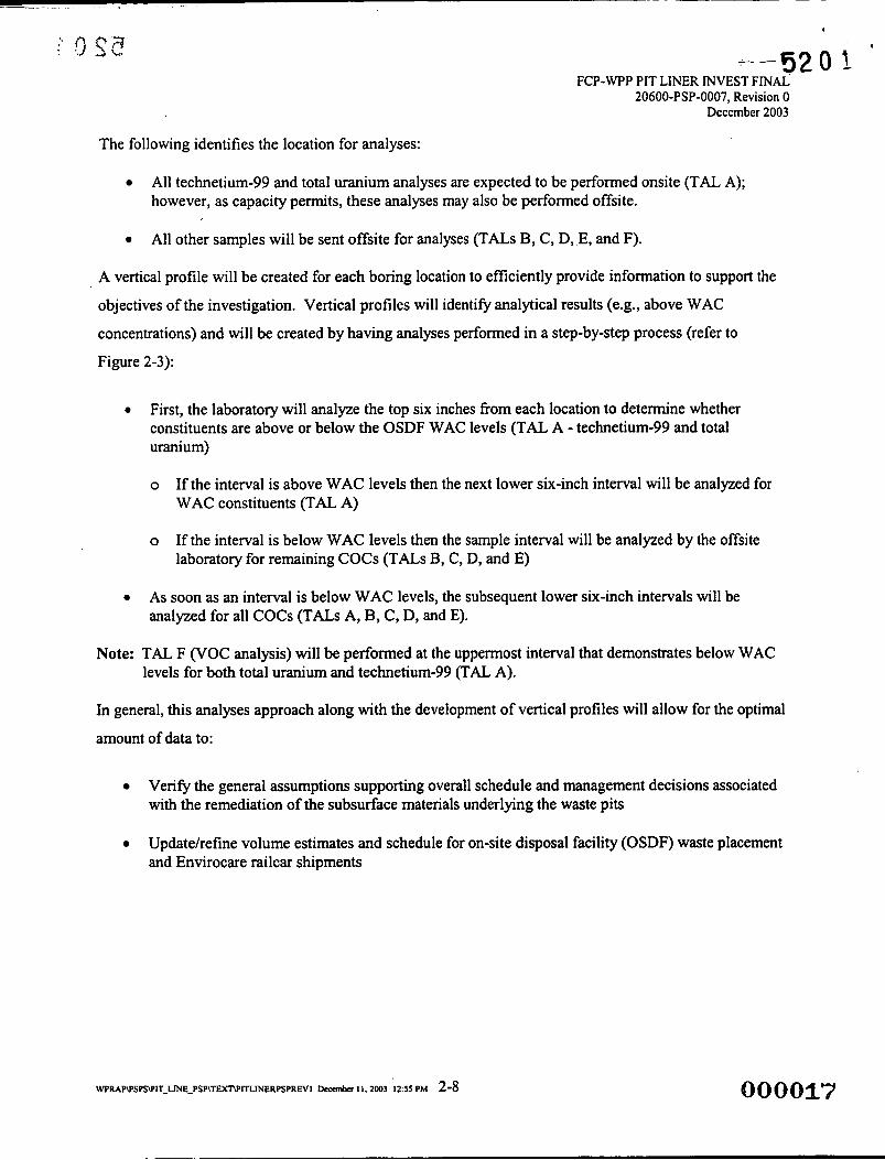
The following identifies the location for analyses:
All technetium-99 and total uranium analyses are expected to be performed onsite (TAL A); however, as capacity permits, these analyses may also be performed offsite.
All other samples will be sent offsite for analyses (TALs B, C, D, E, and F). 0
A vertical profile will be created for each boring location to efficiently provide information to support the
objectives of the investigation. Vertical profiles will identify analytical results (e.g., above WAC
concentrations) and will be created by having analyses performed in a step-by-step process (refer to
Figure 2-3):
0 First, the laboratory will analyze the top six inches from each location to determine whether constituents are above or below the OSDF WAC levels (TAL A - technetium-99 and total uranium)
o If the interval is above WAC levels then the next lower six-inch interval will be analyzed for WAC constituents (TAL A)
o If the interval is below WAC levels then the sample interval will be analyzed by the offsite laboratory for remaining COCs (TALs B, C, D, and E)
0 As soon as an interval is below WAC levels, the subsequent lower six-inch intervals will be analyzed for all COCs (TALs A, By C, D, and E).
Note: TAL F (VOC analysis) will be performed at the uppermost interval that demonstrates below WAC levels for both total uranium and technetium-99 (TAL A).
In general, this analyses approach along with the development of vertical profiles will allow for the optimal
amount of data to:
0 Verify the general assumptions supporting overall schedule and management decisions associated with the remediation of the subsurface materials underlying the waste pits
0 Updatehefine volume estimates and schedule for on-site disposal facility (OSDF) waste placement and Envirocare railcar shipments

5201 FCP-WPP PIT LINER INVEST FINAL
20600-PSP-0007, Revision 0 December 2003
2.6 EOUIPMENT DECONTAMINATION
Decontamination is performed on the sampling equipment to protect worker health and safety and to
prevent the introduction of contaminants into subsequent soil samples. Equipment that comes into contact
with sample material (i.e., cutting shoes, etc.) will be decontaminated at Level II (Section K. 11, SCQ) prior
to transport to the field site, between sample locations, and after sampling performed under this PSP is
completed. Other equipment that does not contact sample media may be decontaminated at Level I, or
wiped down using disposable towels. Clean disposable wipes may be used to replace air drylng of the
equipment.
Based on the Waste Pits isotope of concern (thorium-230) and due to the nature and extent of work to be
performed within the waste pit areas it may be necessary to incorporate additional radiological controls on
equipment or supplies to prevent or mitigate the potential spread of radiological contamination. Thus, in
an effort to reduce the decontamination effort prior to release fiom radiological areas, members of the
sampling team may be required to use plastic, herculite or other non-permeable materials on items that
come or are likely to come into direct contact with sample material.
2.7 SAMPLING WASTE DISPOSITION
Excess soil fiom the borings will be disposed of in the waste pit from which it was collected. Any water
(used decontamination water, flushed groundwater, etc.) generated during sampling will be disposed at the
wastewater discharge sump located in each waste pit.
2.8 BOREHOLE ABANDONMENT
Each borehole will be plugged using a bentonite grout slurry injected immediately after sampling is
completed. The bentonite grout slurry will have a density of at least 9.4 pounds per gallon. A Borehole
Abandonment Log will be completed for each borehole. Each plugged borehole will be checked 24 hours
after placement of the bentonite grout slurry and additional sealing material will be added if settling has
occurred.

TABLE 2-1
OU1 RI/FS DATA FOR WASTE PIT 3 AND ASSOCIATED REMEDIATION AREA 6 FRL AND OSDF WAC INFORMATION
Number of Number of Number of Samples Above Number of Locations Above Locations
Constituent WACFRL' Minimum4" Maximum4" WACFRL"" Samples4c WAC/FRL4Cnd Sampled General Chemistry: (mdkg) (mdkg) (mdkg) Fluoride - - 178,000 0.4 U 2,350 - - - IO 5 --IO 3 Inorganics: (wk) (mglkg) (mdkg) Antimony - - I96 2.6 U 63.5 - - - 10 IO --IO 7
- - 11.5 1 J 24 J - - I - - I 6 7 - - I82 2.2 - 38.6 J - - I - - io 7
Silver - - 129,000 2 u 41.8 - - - I O 10 - - I O 7 (Wkg) (Pdkg) (Pdkg) - - / I30 210 u 1,500 J - - I 7 - - I 7 - - I130 210 u 1,600 U - - I 10 - - I 7 - - I15 21 u 160 U - - I IO - - I 7
Semi-Volatile Organics: (Pdkg) (Pdkg) (Pdkg) Benzo(a)anthracene - - 120,000 510 u 60 J" - - I O 5 - - IO 5 Benzo(a)pyrene - - 12,000 510 U 960 U - - I O 5 - - IO 5 Benzo@)fluoranthene - - 120,000 510 U IlOF - - I O 5 - - IO 5
5 Benzo(k) fl uoranthene - - 1200,000 510 U 960 U - - IO 5 - - IO 5 Chrysene - - 12,000,000 510 u 75 J" - - I O 5 - - IO 5 Dibenzo(a,h)anthracene - - 12,000 510 u 960 UJ - - I O 5 - - IO Indeno( 1,2,3-cd)pyrene - - 120,000 510 u 960 U - - I O 5 - - I O 5 =d
Volatile Organics: (Pdkg) (Pdkg) (Pdkg) pJ Bromodichloromethane 903 14,000 6 U 420 U - - 10 14 01 0 7 8 r 1,1 -Dichloroethene' 11,4001410 6 U 420 U 011' 14 - - / I f 7 % p
a 0 2 Tetrachloroethene 1.28E+5 13,600 220 u 420 U 0 10 4 01 0 4 Dioxins: (Pdkg) (Pdkg) (ccdkg) Q "2 $ Heptachlorodi benzo-p-dioxinB - - 10.88 0.11 u 3.2 J - - 13' 6 - - 12B 3 Octachlorodi benzo-p-dioxinB - - 18.8 3.7 J 19.4 J - - / I 8 6 - - I 1 8 3 g 2. cr!
g 8' 2
1 l a r Q 0
--I12 6.9 J 37,200 J - - I - - I?. 7
5 5
3 gFl@ 0-a -I
= * 8 o r

TABLE 2-1
(Continued)
(PCi/g) - - 11.4 --I1.7 - -11 .8
29.1 130 --I1.7 - - I280 - - 11.5
1,030 /50
Note: BT@i3%x$ndicates constituent exceeded FRL. Note: lOutbox5dicates constituent exceeded OSDF WAC.
( P C W 0.2 UJ 1.41 J 1.5 J
1.2 UJ 3.7 u 3.28 J 1.5 u 399h J
( P C W 5 UJ 451 J 241 J
1,l IO - 554 -
1 1,370 J 396 -
5,190h -
- - I
- - I - - I
--I
- - I
- - I
81
IO 6 6 IO 9 10 9 10
- - I - - I
- - I
41 - - I
- - I
- - I
5 1
nu- -9, .
“U’’ indicates non-detected results, “-’’ indicates detected results, and ‘T’ indicates estimated detected results. ‘Rejected data qualified with either a R or Z were not included in the minimum, maximum, or counts. %e column is intended to focus on detected results. However, in the case where all the results are non-detects, the number in the column reflects the number of non-detected results above the WACERL or number of locations above the WACIFRL. This result represents the highest detected result. There were several non-detected results, with detection limits above the result. ‘Minimal non detected level above FRL (420 pgkg versus 410 pgkg) and only one occurrence indicates that it is not necessary to sample for this constituent. gExceedances are not considered to be warranted based on the commonly accepted practice of multiplying the highest conger concentration by the appropriate TEF, which indicates that the sum of the adjusted dioxin values are significantly less than the current limit of 1 pgkg and the proposed federal limit of 0.1 pgkg. hT’otal uranium results were calculated from uranium-238 results with a conversion factor of 2.98 pg total uranium per pCi of uranium-238.
indicates there is no defined WAC or FRL for that constituent.

52b I - .
0 ff-site
4 FCP-WPP PIT LINER INVEST FINAL
20600-PSP-0007, Revision 0 December 2003
B none one year Glassor 250grams Plastic
TABLE 2-2
SAMPLING AND ANALYTICAL REQUIREMENTS
Total Inorganics
Analyte 1 Method
ICP-AES,
Total U ~ C - 9 9 ICP-MS,
0 ff-site
Offsite
Offsite
Offsite
On-site
spectroscopy Radiological
B Cool2"-6"C 14days Glasswl 30gramsb Teflon cap
B Cool2"-6"C 14days Glasswl 30gramsb Teflon cap
B Cool2"-6"C 14days Glassw/ 30gramsb Teflon cap
B HzSO,,pH<2 14days Glassw/ 3-40 ml Cool 2"-6" C Teflon cap
B none NA' 10 grams
vocsc
(TAL F)
AlphalBeta screenc
iample Matrh
Solid
Solid
Solid
Solid
Solid
Solid
Water
Solid
Lab I ASL I Preservation I Holding Time I Container I Sample Mass
Off-site I B 1 Cool2"-6"C I 6months 1 YE; 1 30grams
"As capacity permits, TAL A analyses may be performed at an approved offsite laboratory. sample fkom each off-site sample shipment (which will be chosen by the field sampling lead) must have at least three times
the mass specified, for laboratory QC. 'VOC analysis will be conducted at the uppermost interval that demonstrates below WAC concentrations for both total uranium and technetium-99. %is VOC is for the trip blank, which will be taken at a rate of 1 per team per day. ?fall intervals indicate no contamination above background, the alphaheta sample will be collected fiom the first 6-inch interval of non-waste material. 'NA = not applicable
008021

48225
48217
4821e
48202
48195
48187
48180
48172
48165
48157
4815e
48142
4813:
48127
48121
LEGEND: J U L Y 2003 550 ' (amsl 1
A L L BORING L O C A T I O N S WILL BE PRECEDED BY "A6WP3-"
* AT THESE PROPOSED L O C A T I O N S - - - - - I L I D A R CONTOUR S I X INCHES OF L I N E R M A T E R I A L HAS . ( i . e. EXCAVATED A R E A )
PROPOSED L INER/SUBSURFACE BEEN EXCAVATED AND S H I P P E D T O * M A T E R I A L BORINGS ENVIROCARE FIGURE 2-1. PROPOSED SAMPLE LOCATIONS FOR O O o ( J z 2 . .
THE NORTHWESTERN PORTION OF WASTE P I T 3

520 1
FIGURE 2-2. SAMPLE INTERVALS FOR WASTE PIT 3 SUBSURFACE INVESTIGATION
Represents the pit waste interface to clay liner.
/ Ship to Envirocare
Contaminated Materials
Sample for targeted COCs in TALs
_------------- __--------- -
Note 1 : Where there is a clearlmajor interface between material types (e.g., clay versus sand), the six-inch sample interval will be adjusted such that one six-inch interval will be collected immediately above the material interface and one six-inch interval will be collected immediately below the surface. The six-inch interval spacing will proceed in both directions (up and down the core) starting from the interface.
Note 2: For those locations on Figure 2-1, the top interval (0 to 0.5 feet) has already been removed.
Note 3: If the sand and gravel of the Great Miami Aquifer is encountered prior to the 3.5 foot depth in the borehole, then adjacent borehole depths will be altered to a depth six inches below the depth from which the sand and gravel was encountered (e.g., encounter sand and gravel at 2.0 feet, then adjacent borehole depths would be 2.5 feet). If in adjacent boreholes, sand and gravel is not encountered, then sample interval depths will proceed.
F ER\WPRAP\PSPSWIT_LINE-PS~T~I~NERPSPREV l \ OQ0023

FIGURE 2-3. ANALYSIS SEQUENCE FOR WASTE PIT 3 SUBSURFACE INVESTIGATION
interface to clay liner. Represents the pit wast
* \ ------l-
0 to 0.5 ft
(analyze all intervals (obtain results) (analyze appropriately) in sequence)
WAC COCs (UTTc99)
1 WAC COCs (UTTc99)
I I
WAC COCs (UlTc99)
WAC COCs (UTTc99)
i WAC COCs (UITc99)
I WAC COCs (UITc99)
NOTANALYZED
If c WAC +
If WAC +
If WAC
IfCWAC
If WAC +
If WAC --+
Remainder of COCs (a)
Remainder of COCs (a)
Remainder of COCs (a)
Remainder of COCs (a)
Remainder of COCs (a)
Remainder of COCs (a)
(a) VOCs (TAL F) will be analyzed at the uppermost interval that demonstrates below WAC concentrations of both total uranium and technetium-99.
5 2 0 1
000024

5201 FCP-WPP PIT LINER INVEST FINAL
20600-PSP-0007, Revision 0 December 2003
3.0 QUALITY ASSURANCE/QUALITY CONTROL REQUIREMENTS
3.1 FIELD QUALITY CONTROL SAMPLEB. ANALYTICAL REOUIREMENTS, AND DATA VALIDATION
In accordance with the requirements of DQO SL-048, Revision 5 (see Appendix A), the field quality
control, analytical, and data validation requirements are as follows:
e All laboratory analyses will be performed at ASL B (ASLs are defined in the SCQ).
A sample selected for lab matrix spike and matrix spike duplicate analysis (requires additional sample mass per Table 2-2) will be designated by the Sampling Lead on the Chain of Custody form for each shipment of samples sent for off-site analysis.
e A trip blank water sample for VOCs (TAL F) analysis will be collected by each sample team for each day of sampling.
e All field data will be validated. Ten per cent of the analytical data will be validated to validation support level B and require a certificate of analysis and associated laboratory quality assurance/quality control results.
3.2 PROJECT-SPECIFIC PROCEDURES, MANUALS. AND DOCUMENTS
To assure consistency and data integrity, field actihties in support of this PSP will follow the requirements
and responsibilities outlined in controlled procedures and manufacturer operational manuals. Applicable
procedures, manuals, and documents include:
e
e
e
e
e
e
0
e
0
e
e
e
e
e
e
0
SMPL-0 1, Solids Sampling SMPL-02, Liquids and Sludge Sampling SMPL-2 1, Collection of Field Quality Control Samples EQT-04, Photoionization Detector EQT-06, GeoprobeQ Model 5400 and Model 6600 Operation and Maintenance Manual EW-0002, Chain of CustodyRequest for Analysis Record for Sample Control 5507, Drying and Grinding Solid Samples in Preparation for Laboratory Analysis 9503, Processing Samples through the Sample Processing Laboratory 9505, Using the FACTS Database to Process Samples 7532, Analytical Laboratory Services Internal Chain of Custody 950 1, Shipping Samples to Off-Site Laboratories RM-0020, Radiological Control Requirements Manual 10500-H1, Shaw Environmental and Infhstructure, Incorporated (Shaw) Health and Safety Program 10500-017, Shaw WRAP Excavation Plan Sitewide CERCLA Quality Assurance Project Plan (SCQ) Sitewide Excavation Plan (SEP)
FCP-WPP PIT LINER INVEST FINAL 20600-PSP-0007, Revision 0
December 2003
3.3 PROJECT REOUIREMENTS FOR INDEPENDENT ASSESSMENTS
Project management has ultimate responsibility for the quality of the work processes and the results of the
sampling activities covered by this PSP. The Quality Assurance (QA) organization may conduct
independent assessments of the work processes and operations to assure the quality of performance.
Assessments will encompass technical and procedural requirements of this PSP and the SCQ.
3.4 IMPLEMENTATION OF FIELD CHANGES
If field conditions require changes or variances, the project manager must prepare a VECN. The
completed VECN must contain the signatures of all affected organizations, which at a minimum includes
the Project Manager, Characterization Manager, and QA but may also include Field Sampling, or Sample
Management Office, as appropriate. A time-critical variance may be obtained in cases where expedited
approval is needed to avoid costly project delays. In the case of a time-critical variance, verbal or written
approval (electronic mail is acceptable) must be received from the Characterization Manager and from QA
prior to implementing the variance. The completed approved V/FCN form must be completed within five
working days after the time-critical variance is approved.

- -5201 FCP-WPP PIT LINER INVEST FINAL
20600-PSP-0007, Revision 0 December 2003
4.0 HEALTH AND SAFETY
The Fluor Fernald (FF) and Shaw Excavation Managers, Shaw Health and Safety Lead, Field Sampling
Leads, and team members will assess the safety of performing sampling activities in the Waste Storage
Area. This will include vehicle/equipment positioning limitations and fall hazards.
Sample technicians will conform to precautionary surveys performed by Radiological Control, Safety, and
Industrial Hygiene personnel. All work on this project will be performed in accordance with applicable
Environmental Monitoring procedures, RM-0020 (Radiological Control Requirements Manual),
Shaw Health and Safety Plan, FF work permit, Radiological Work Permit (RWP), penetration permit and
other applicable permits. Concurrence with applicable safety permits (as indicated by the signature of each
field team member assigned to this project) is required by each team member in the performance of their
assigned duties.
Sampling technicians will also comply with any specific requirements for activity conducted within the
waste pits area, including the Excavation Plan, the non-typical waste procedure, access restrictions,
respiratory requirements, and health and safety briefings that may be required by Shaw procedures. Any
access to the waste pits area must be authorized by a competent (i.e., certified in excavation activity)
excavation manager. Members of the sampling team are also required to be on the beryllium monitoring
list. Because waste pit excavation activities using heavy equipment may be ongoing during this sampling
activity, the sampling team and support personnel must pay special attention to such activities and maintain
a safe distance fiom the heavy equipment work zones, as well as, ensuring that the heavy equipment
operators are aware of their presence.
The Field Sampling Lead will ensure that each technician performing work related to this project has been
trained to the relevant sampling procedures including safety precautions. Technicians who do not sign
project safety and technical briefing forms will not participate in any activities related to the completion of
assigned project responsibilities. A copy of applicable safety permits/surveys issued for worker safety and
health will be posted in the affected area during field activities.
A daily safety briefing will be conducted prior to the initiation of field activities. All emergencies will be
reported immediately to the Shaw control room at 648-4496, the site communication center at 648-65 1 1 by
cell phone, 91 1 on-site phone, or by contacting “control” on the radio.
W P R A p W S P S W I T _ L ~ E - P S P \ T E ~ ~ L ~ ~ S P R I Dcccmbcr I I , 2003 1259 PM 4-1 000827

5201 FCP-WT'P PIT LINER INVEST FINAL
20600-PSP-0007, Revision 0 December 2003
5.0 DATA MANAGEMENT
A data management process will be implemented so information collected during the investigation will be
properly managed to satisfy data end use requirements after completion of the field activities. As specified
in Section 5.1 of the SCQ, sampling teams will describe daily activities on a Field Activity Log, which
should be sufficient for accurate reconstruction of the events at a later date without reliance on memory.
Sample Collection Logs will be completed according to protocol specified in Appendix B of the SCQ and
in applicable procedures. These forms will be maintained in loose-leaf form and uniquely numbered
following the field sampling event. At least weekly, a copy of all field logs will be sent to the Data
Management Lead.
All field measurements, observations, and sample collection information associated with physical sample
collection will be recorded, as applicable, on the Sample Collection Log, the Field Activity Log, the
Lithological Log, and the Chain of CustodyRequest for Analysis Form, as required. The method of
sample collection will be specified in the Field Activity Log. Borehole Abandonment Logs are required.
The PSP number will be on all documentation associated with these sampling activities.
Samples will be assigned a unique sample number as explained in Section 2.4. This unique sample
identifier will appear on the Sample Collection Log and Chain of CustodyRequest for Analysis and will be
used to identify the samples during analysis, data entry, and data management.
Technicians will review all field data for completeness and accuracy and then forward the data package to
the Field Data Validation Contact for final review. The field data package will be filed in the records of
the Sample and Data Management Group. Analytical data that is designated for data validation will be
forwarded to the Data Validation Group. The PSP requirements for analytical data validation are outlined
in Section 3.1.
APPENDIX A
DATA QUALITY OBJECTIVES SL-048, REVISION 5
5 2 0 1
000029

5201
1
9i’i 9/97 I 013t97
Control Number
i . 2 3 4 1 5 1 6
411 5/98 r;ii 7/90 7t 14/98 ” -- 2/26/99
FernaId Environmental Management Project
Data Quality Objectives
Title: Delineating the Extent of Constituents of Coiicern During Remediation Sampling
Number: SL-048
Revision: 5
Effective Date: February 26, 1999
Contact Name: Eric Kroger
Approval: (siqnature on file) James E. Chambers DQO Coordinator
Date: 2/25/99
Approval:(si_cnature o n file) Date: 2/26/99 J .D . Chiou SCEP Project Director
000034)
p r'i q -3 ' 5 2 0 1 .
DUO #: S1.-048, Rev. 5 Effective Date: 2/26/99
~ a g e . 2 of IO
DAIA QUALITY OBJECTIVES Delineating the Extent of Constituents of Concern During Remediation Sampling
- Niembers of Data Quality Objectives (DQOI S-inq Team The members o f the DQO team include a project lead, a project engineer, a field lead, a statistician, a lead chemist, a sampling sugervisor, and a data mariagemen: lead.
ConceDtual Model of t h e Site Media is considered contaminated if the concentration of B constituent of concern (COC) exceeds the final remediation levels (FRLs). The extent of specific media contamination was estimated and published in the Operable Unit 5 Feasibility Study (FS). These estimates were based on kriging analysis of available data for media collected during the Remedial Investigation (RI) effort and other FEMP environmental characterization studies. Maps outlining contaminated media boundaries were generated for the Operable Unit 5 FS by overlaying the results of the kriging analysis data with isoconcentration maps of the other constituents of concern (COCs), as presented in the Operable Unit 5 RI report, and further modified by spatial analysis of maps reflecting the most current media characterization data. A sequential remediation plan has been presented that subdivides the FEMP into seven construction areas. During the course of remediation, areas of specific rnedia may require additional characterization so remi diation can bc! carried out as ttloroughly and efficiently as possible. As a result, xldit ional sampling may be necessary t o accurately delineate a volume of specific media as exceeding a target level, such as the FRL or the Waste Attainment Criterion (WAC). Each individual Project-Specific Plan (PSP) wi l l identify and desciibe the particular media t o be sampled, This DQO covers all physical sampling activities associated with Pre- design Investigations, precertification sampling, WAC attainment sampling or regulatory monitoring that is required during site remediation.
1.0 Statement of Problem
If the extent (depth and/or area) of the media COC contamination is unknown, then it must b e defined wi th respect t o the appropriate target level (FRL, WAC, or other specified media concentration).
2.0 ldentifv the D e c i s b
Delineate the horizontal and/or vertical extent o f media COC contamination in an area with respect t o the appropriate target level.
3.0 Inputs That Affect the Decision
Informational Inputs - Historical data, process history knowledge, the modeled extent o f COC contamination, and the origins of contarnination will be required to
000031
DO0 #: SL-048, Rev. 5 Effective Date: 2/26/99
Page '3 of IO
establish a sampling plan to delinea-:e the extent of COC contamination. The desired precision of the delineation must be weighed against the cost 'of collecting and analyzing additional samples in order t o determine the optimal sampling density. The project-specific plan will identify the .optimal sampling density.
.
Action Levels - COCs must be delineated with respect t o a specific action level, such a s FRLs and On-Site 'Disposal Facility (OSDFI WAC conl.mtrations. Specific media FRLs are established in the OU2 and OU5 RODS, and the WAC concentrations are published in the OU5 ROD. delineation with respect to other action levels that act a s remediation drivers, such as Benchmark Toxicity Values (BTVs).
Media COCs may also require
4.0 The Boundaries of the Situation
Temporal 8oundaries - Sampling must be.completed within a time frame sufficient t o meet the remediation schedule. Time frames must allow for the scheduling of sampling and analytical activities, the collection of samples, analysis of samples and the processing of analytical data when received.
Scale of Decision Making - The decision made based upon the data collected in this investigation will b e the extent of COC contamination a t or above the appropriate action level. This delineation will result in media contaminaw concerltration informatio!l being incorporated into engineering design, and t he attainment of established remediation goals.
-I Parameters of Interest - The parameters of interest are the COCs tha t have been determined to require additional delineation before remediation design can be finalized with the optimal degree of accuracy.
5.0 Decision Rule
If existing data provide a n u!iacceptable level of uncertai!Ity in t h e COC delineation model, then additional sampling will take place to decrease the model uncertainty. When deciding what additional data is needed, the cos ts of additional sampling and analysis must be weighed against the benefit of reduced uncertainty in the delineation model, which will eventually be used for assigning excavation, or for other purposes.
6.0 urnits on Decision Errors
In order to be useful, data must be collected with sufficient areal and depth coverage, and a t sufficient density to ensure an accurate delineation of COC concentrations. Analytical sensitivity and reproducibility must be sufficient t o differentiate t h e COC concentrations below their respective target levels.
000032

5 2 0 1
DOC) #: SL-048, Rev. 5 Effective Date: 2/26/99
Page 4of IO
Types of Decision Errors and Conseauences
Decision Error 'i -,.This decision error occurs when the decision maker determines:.:. ..
that the extent oi media contaminated with COCs above action levels is not:as . ... . extensive as it actually is. This error can result in a remediation design that fails to incorporate media contaminated with COCis) above the action JevelIs). This could. result in t h e re-mobilization.of excavation equipment and delays in the remediation schedule, Also, this could result in media contaminated above 'action levels remaining after remediation is considered complete, posing a potential threat to human health and the environment.
- . Decision Error 2 - This decision error occurs when the decision.maker determines that the extent of media contaminated above COC action levels is more extensive than it actually is. This error could result in more excavation than necessary, and this excess volume of materials being transferred t o the OSDF, or.an oif-site disposal facility if Contamination levels exceed the OSDF WAC.
True State of Nature for the Decision Errors - The true state of nature for Decision Error 1 is that the maximum extent of contamination above the FRL is more extensive than was determined. The true state of nature for Decision Error 2 is that the maximum extent of contamination above the FRL is not as extensive as was determined. Decision Error 1 is the more severe error.
7.0 Glmizina Desicrn f o d s e a b l e Data
7.1 SamDle Collection
A sampling and analytical testing program will delineate the extent of COC contamination in a given area with respect t o the action level o f interest. Existing data, process knowledge, modeled concentration data, and the origins of contamination will be considered when determining the latera l and vertical extent of sample collection. The cost of collecting and analyzing additional samples will be weighed against the benefit of reduced uncertainty in the delineation model. This will determine the sampling density, Individual PSPs will identify t h e locations and depths t o be sampled, the sampling density necessary to obtain the desired accuracy of the delineation, and if samples will be analyzed by the oti-site or of f - site laboratory. The PSP will also identify the sampling increments t o be selectively analyzed for concentrations of the COC(s) of interest, along with field work requirements. Analytical requirements will be listed in the PSP. The chosen' analytical methodologies are able to achieve a detection limit capable of resolving the COC action level, Smpl ing of groundwater monitoring wells may require different purge requirements than those stated in the SCQ (i,e,, dry well definitions or small purge volumes). In order to accommodate sampling of wells that go dry prior t o completing the purge of the. necessary well volume, attempts t o sample the
.
000033
DO0 #: SL-048, Rev. 5 Effective Date: 2/26/99
Page 5 of 10
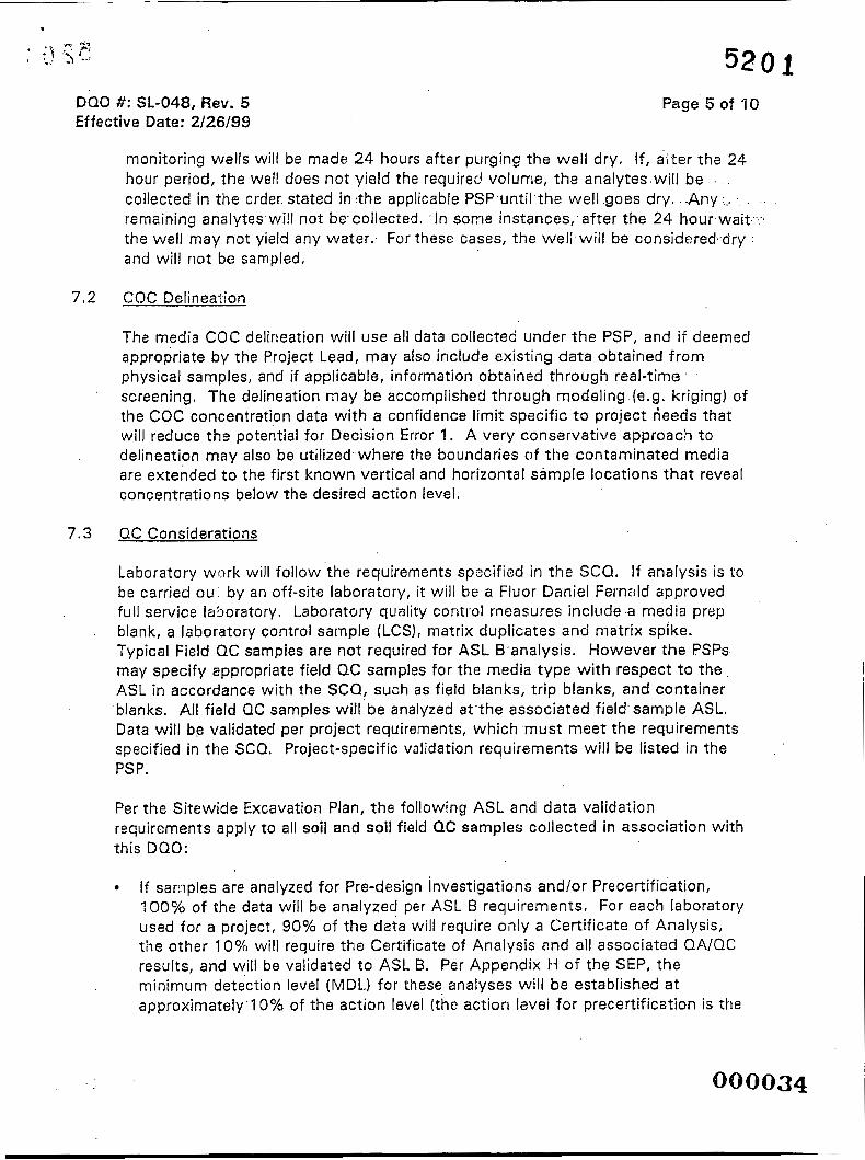
monitoring wells will be made 24 hours after purging the well dry. If, a?ter tha 24 hour period, the well does not yield the requirec! volume, the analytes.will be . . .
collected in the order. stated in :the applicable PSP.until'the well .goes dry. .-Any I... .. . .. .
remaining analytes.will not bccollected. . In some instances,, after the 24 hour.wait.-:.. the well may not yield any water.. For these cases, the well.wiil be considered,.dry : a n d will not be sampled.
7.2 COC Delineation
The media COC delineation will use all data collected under t h e PSP, and if deemed appropriate by the Project Lead, may also include existing da ta obtained from physical samples, and if applicable, information obtained through real-time screening. The delineation may be accomplished through modeling (e.g. kriging) of the COC concentration data with a confidence limit specific t o project deeds that will reduce the potential for Decision Error 1. A very conservative approach t o delineation may also be utilized where the boundaries of t he contaminated media are extended t o the first known vertical and horizontal sampJe locations tha t reveal concentrations below the desired action level,
QC Considerations
Laboratory work will follow the requirements spocified in the SCQ. If analysis is to be carried ou by an off-site laboratory, it will be a Fluor Daniel FernziId approved full service laboratory. Laboratory quality control measures include a media prep blank, a laboratory control sample (LCS), matrix duplicates and matrix spike. Typical Field QC samples are not required for ASL B analysis. However the PSPs may specify appropriate field QC samples for the media type with respect t o the ASL in accordance with the SCQ, such as field blanks, trip blanks, and container blanks. All field QC samples will be analyzed at the associated field sample ASL, Data will be validated per project requirements, which must meet the requirements specified in the SCQ. Project-specific validation requirements will be listed in the PSP.
Per the Sitewide Excavation Plan, t h e following ASL and data valida;ion requirements apply to all soil and soil field QC samples collected in association with this DQO:
If sarnples are analyzed for Pre-design Investigations and/or Precertific'ation, 100% of the data will be analyzed per ASL B requirements. For each laboratory used for a project, 90% of the deta will require only a Certificate of Analysis, the other 10%) will require the Certificate of Analysis and all associated QA/QC results, and will bo validated to ASL B. Per Appendix H of the SEP, the minimum dete'ction level (MDL.) for these analyses will be established a t approximateIy'10% of the action level (the action level for precertificztion is the

DQO #: SL-048, Rev. 5 Effective Date: 2/26/99
7.4
7.5
520 1
Page 6 of 10
FRL; the action level for pre-design investigations can bc: several different action levels, including the FRL; the WAC, .RCRA levels, ALARA levels,-etc.). ..If this MDL is different fro'm.the SCQ-.spec:ified..MDL, the. ASL will default t o ASL E,: . . .
though,other arialytical.requirements..will remain as,spec:ified for ASL 8. . .. . . ; .:.
If samples are analyzed for WAC Attainment and/or RCRA Characteristic .Areas Delineation, 100% of the data will. be analyzed and reported to ASL 8' with 10% validated. The ASL B package will include a Certificate of Analysis along with all associated QA/QC results. .Total uranium analyses using a higher detection limit than is required for ASL 8 (10 mg/kg) may be appropriate for WAC attainment purposes since the WAC limit for total uranium is 1,030 mg/kg. In this case, an ASL E designation will apply t o the analysis and 1
reporting to be performed under the. following conditions:
t all of the ASL 8 laboratory QA/QC methods and reporting criteria will apply .with.the exception.of the total uranium detection limit
t the detection limit will be ~ 1 0 % of the WAC limit (e.g., ~ 1 0 3 mg/kg for total uranium).
If delineation data are also to be used for certification, t h e data ViuSt meet the data quality objectives specified in the Certification D O 0 (SL-043).
Validation will include field volidation of field packages for ASL R or ASL D data.
All data will undergo an evaluation by the Project Team, including a comparison for consistency with historical data. Deviations from QC considerations resulting from evaluating inputs to the decision from Section 3;must be justified in the PSP. such that the objectives of the decision rule in Section 5 are met.
lndeoendent Assessment
Independent assessment shall be performed by the. FEMP QA organization by conducting surveillances. Surveillances will be planned and documented in accordance with Section 12.3 of the SCQ.
Data Mananement
Upon receipt from the laboratory, all results will be entered into the SED as qualified da ta using standard data entry protocol. The required ASL B, 'D or E data will undergo analytical validation by the FEMP validation team, as require::l (see Section 7.3). The Project Manager will be responsible t o determine data usability as it pertains t o supporting the DQO decision of determining delineation o f media
0 0 0 8 35

1 r q T ' : Ju-, -520 1
DQO #: SL-048, Rev. 5 Effective Date: 2/26/99
Page 7 of 10
COC'S.
7.6 Applicable Procedures
Sample collection will be described in the PSP with a listing of applicable procedures. Typical related plans and procedures are the following:
Sitewide Excavation Plan (SEP)
a Sitewide CERCLA Quality Assurance Project Plan (SCQ).
0 SMPL-01, Solids Sampling
0 SMPL-02, Liquids and Sludge Sampling
SMPL-21, Collection of Fie/d.Quality Control Samples
EQT-06, GeoprobeO Model 5400 Operation and Maintenance
0
EQT-23, Operation of High Purity Germanium Detectors
EQT-30, Operation of Iiadiation Tracking Vehicle Sodium lodide Detection System

-520 k DQO 0: SL-048, Rev. 5 Effective Date: 2/26/99
Page 8 of ' IO
Data Quality Objectives . . Delineatiiig the.Extent of Constituents of Concern.During Remediation Sampling . . . .
1 A. 'rask/Descrip?ion: Delineating t h e extent of. contamination above the FRLs .
1 .B. Project Phase: (Put .an X in the appropriate selection.)
1 .C. DQO No.: SL-04.8, Rev. 5 DQO Reference No.:
2. Media Characterization: (Put an X in the appropriate selection.)
Air Biological n Groundwater , Sediment Soil
Waste El Wastewater 0 Surface water 0 Other (specify)
3. Data Use with Analytical Support Level (A-E): [Put an X in t h e appropriate Analytical Support Level .selection(s) beside each applicable Data Use.)
Site Characterization Risk Assessment A13 BEI cCI DEI ~lv l AU SO CO DEI EU Evaluation of Alternatives Engineering Design A D BO c 0 DO EO AO B cCI DKIE!KI Monitoring during remediation Other AIX BEI c D DDEKI AD BOCCI D 0 EO
.. I -- 4.A. Drivers: Remedial Actioii Work Plans, Applicable or Relevant and Appropriate
Requirements (ARARs) and t h e OU2 andlor OU5 Record of Decision (ROD).
4.8. Objective: Delineate the extent of media contaminated with a COC (or COCsl with respect to the action level(s) of inxerest.
- 5, Site Information (Description):
-5201 DQO #: SL-048, Rev. 5 Effective Date: 2/26/99
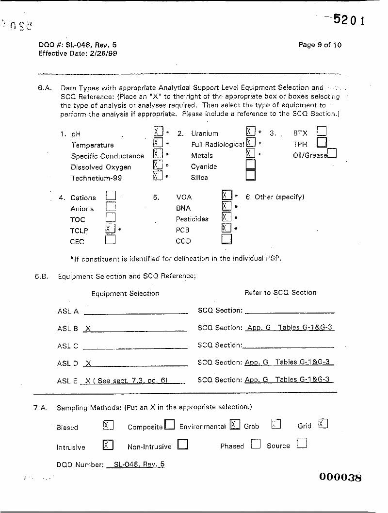
6.A. Data Types with appropriate Analytical Support Level Equipment Selection and SCQ Reference: (Place an "X" to the right of thr: appropriate box or boxes selectirg the type of analysis or analyses required. Then select t t i e type of equipment to perform the analysis if appropriate. Please include a reference to the SCU Section.)
1. pH E l * 2. Uranium D* 3, BTX a Temperature DI. Full Radiological a * TPH Specific Conductance El* Metals El* 0 il/G rea s e n Dissolved Oxygen a* Cyanide Technetium-99 El* Silica
4. Cations 17 5. VOA * 6. Other (specify)
Anions r] BNA El* TOC 0 Pes ticid es a* TCLP m* PCB Jx* CEC n COD
*If constituent is identified for delineation in the individual PSP.
6.B. Equipment Selection and SCQ Reference;
Equipment Selection Refer t o SCQ Section
ASL A SCQ Section:
A S L B X SCQ Section: APD. G T a b j C G - l &G-3
ASL C --. SCQ Section:
A S L D X SCQ Section: ADD. G lab les G - l & G - 3
ASL E SCQ Section: ARD. G Tables G-I &G-3 X ( See sect. 7.3, p a . 6)
7 .A . Sampling Methods: (Put an X in the appropriate selection.)
Biascd .m Composite Environmental G r a b Grid a Intrusive Non-Intrusive Phased 0 Source c1
(". . > . .
DQO Number: SL-048, Rev. 5
080038

DQO #: SL-048, Rev. 5 Effective Date: 2/26/99
7.8. Sample Work Plan Reference: This DQO is being written prior to the PSPs. .
Page 10 of 10
Background,samples: OU5 RI
7.C. Sample Collection Reference:
Sample Collection Reference: SMPL-01 , SMPL-02, EQT-06 . .
8.
8.A.
8.B.
9.
Quality Control Samples: (Place an "X" in the appropriate selection 'box.) .
Field Quality Control Samples:
Trip. Blanks w* Container Blanks D+ +
Field Blanks a+ Duplicate Samples (x*** Equipment Rinsate Samples E l * *+Split Samples (x* * Preservative Blanks 0 Performance Evaluation Samples Other (specify)
* For volatile organics only * * Split samples will be collected where required by EPA or OEPA. * + + If specified in PSP. + Collected at the discretion of the Project Manager (if warranted by field
conditions) + + One per Aiea and Phase Area per container type (i.e. stainless steel core
liner/plastic core liner/Geoprobe tube).
Laboratory Quality Control Samples: Method Blank .
Matrix Spike Ixl Surrogate Spikes Matrix Duplicate/Replicate El
0 Tracer Spike 0 Other (specify) Per SCQ
Other: Please provide any other germane information that may impact the data quality or gathering of this particular objective, task or data use.
000039

APPENDIX B
WASTE PIT 3 DIOXIN AND FURAN INFORMATION
000040

5 2 0 1 FCP-WPP PIT LINER INVEST FINAL
20600-PSP-0007, Revision 0 December 2003
APPENDIX B
Table B-1 provides the results for the evaluation of the health-based risk of dioxins and furans at
Waste Pit 3. Specifically, Table B-1 provides the analytical results of each dioxin and furan congener at
each location and depth within a location. The table also provides:
The Toxicity Equivalence Factor (TEF) for each constituent (dioxin and furan congener)
The result used for the calculation (i.e., for non-detected results, the result used for the calculation is set at half the detection limit).
The corrected concentration found by multiplying each dioxin and furan congener result by its applicable TEF
The sum of the corrected concentrations at each of the six locations/depths.
All six TEF calculations are below the limit of 1 pgkg as demonstrated by the last column of Table B-1.
The highest corrected calculation, at location 1770 and a depth of 24 to 39 inches, is less than 0.34 pgkg.
(PQQ041 . . I
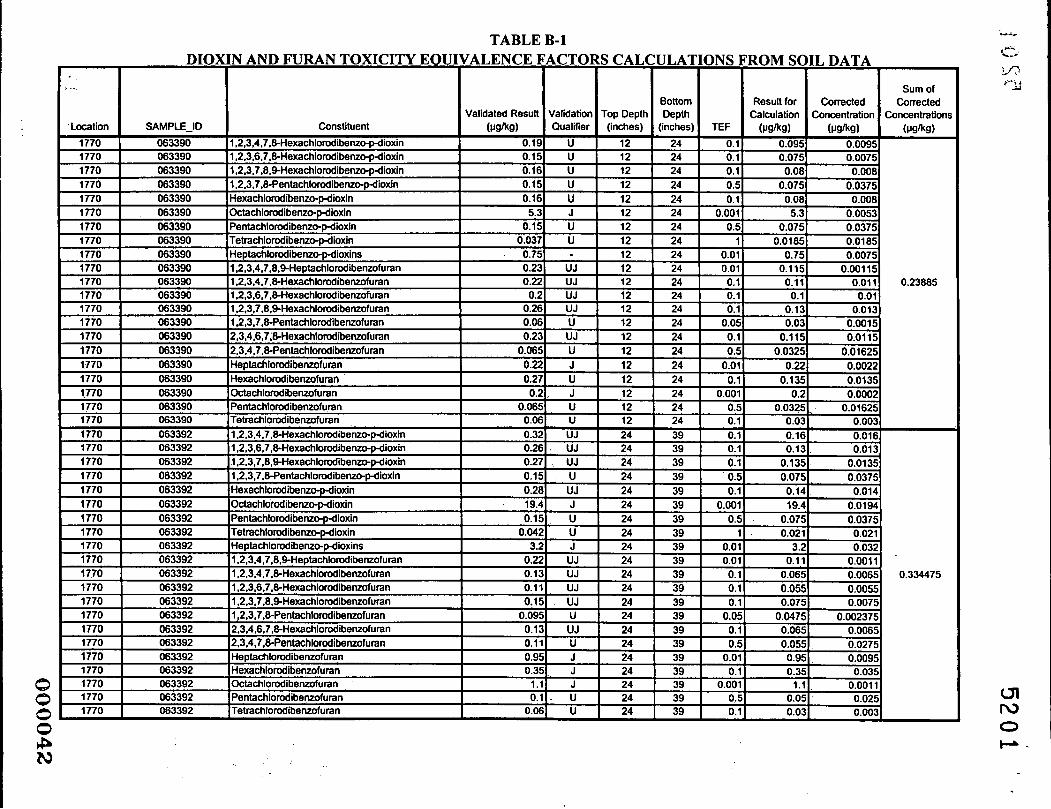
TABLE B-1
Validated Result
0.23885
0.334475

TABLE B-1
a c,
ONS
TEF - 0. 0. 0. 0. 0.
0.00 0.
0.0 0.0
0. 0. 0.
0.0 0. 0.
0.0 0.
0.00 0. 0. 0. 0. 0. 0. 0.
0.
- - - - - - - - - - - - - - - - - - - - - - - - - -
0.00
0.0 0.a
- - - - - 0. 0. 0.
0 0
0.
0. 0.
- - - 0.a
0.0
0.00
- - - - - - - -
ROM SOIL DATA
Sum of
0.065 0.0065 0.006
0.075 0.0075
0.2641 15
0.0475
0.55 0.045
4

Validated Result
. 0..
Sum of Bottom Result for Corrected Corrected
Validation Top Depth Depth Calculation Concentration Concentrations
0.0507455
0.254815
I
I UI tu 0 t-

\
APPENDIX C
TARGET ANALYTE LISTS
5 2 0 1

- 5 2 0 1
Soil Radiological Analysis, On-site, ASL B (WAC') Total Uranium 82 mgkg Technetium-99 29.1 pCi/g
FCP-WPP PIT LINER INVEST FINAL 20600-PSP-0007, Revision 0
December 2003
MDL 8.2 m a g 29 pCiIg
TAL A
Soil PAHs, Off site, ASL B B T V Benzo(g,h,i)perylene 1,000 pgikg Fluoranthene 10,000 pgkg Phenanthrene 5,000 pgkg Pyrene 10,000 Pgkg
On-Property FRL I 1
MDL 100 pgkg
1,000 pgikg 500 pgkg 1,000
Soil Volatile Organic Constituents, Off-site, ASL B 1,1,1 -Trichloroethane 4.3 mg/kgd 1 , I ,2-Trichloroethane 4.3 mgkg 1, I-Dichloroethene 0.41 m&e
On-Property FRL MDL'
0.43 m a g 0.43 mgkg
0.041 me/ke 1 -
cis- 1,2-DichIoroethene 0.16 mgkg trans- 1,2-DichIoroethene 0.16 mgkg Trichloroethene 25 m a g Tetrachloroethene 3.6 mgkg Vinyl Chloride 0.13 mgkg
0 -
0.01 mgkg 0.01 mgkg 2.5 mgkg
0.36 mgkg 0.013 mgkg
O O Q 0 4 6

r APPENDIX D
SAMPLE LOCATIONS AND IDENTIFIERS
5201
800847

FCP-WPP PIT LINER INVEST FINAL 20600-PSP-0007, Revision 0
December 2003
TABLE D-1
WASTE PIT 3 SAMPLE LOCATION AND IDENTIFIERS
, . - .
!., . c . . . .
000048

C.
FCP-WPP PIT LINER INVEST F I N A L 5 . 2 0 1: 20600-PSP-0007, Revision 0
3.0' - 3.5' 3.0' - 3.5' 3.0' - 3.5'
A6WP3aA7-RB TAL B 1346937.5 481837.5 A6WP3dA7-MPS TAL C,D,E 1346937.5 481837.5 A6WP3-4"7-L TAL F 1346937.5 481 837.5
17 *, ?
TABLE D-1 (Continued)
FCP-WPP PIT LINER INVEST FINAL -'-520 1-
' A6WP3 -6
-
20600-PSP-0007, Revision 0 December 2003

, 155 - I IJ .
I
TABLE D-1 (Continued)
A6WP3-7
LOCATION I I Removed previously; I I I I
A6WP3-8
r b FCP-WPP PIT LINER INVEST FINAL
5'2 0 i 20600-PSP-0007, Revision 0 December 2003
LOCATION I DEPTH I SAMPLE ID I ANALYSIS I EAST-83 I NORTH-83 I I Removed areviouslv: I I I
. . . . : .
,. .. t<. i .,
, .. <..
. .
. . . ..
. .

FCP-WPP PIT LINER INVEST FINAL 20600-PSP-0007, Revision 0
December 2003 +-,
c y 5 b..
TABLE D-1 (Continued) 52 01

n FCP-WPP PIT LINER INVEST FINAL ' JJ.
20600-PSP-0007, Revision 0 December 2003
TABLE D-1 -_ (Continued) -520 ?.
Note I : A sample for alphabeta Screening required for off-site shipment will be collected h m the boring core interval with the highest measurement during a field beta/gamma screen For brings that have no intenal exceeding the betalgama background level, the alphabeta shipping screen sample will be collected from the shallowest sample interval. Thus, if all field W g a m m a xreening results are background for Boring A M 3 - 1 , the alphabeta shipping screen sample would be collected h m the first interval and identified as A6WP3-lAl-AB.
Note 2: The entire length of each boring will be PID screened for volatile organics. The Geoprobe core liners will be opened for the PID screening and the measurement for each six-inch interval will be recorded in the field documentation, along with thePID background reading.
Note 3: Because of the propensity for contaminants to collect at interfaces of differing material, it has been determined that at conditions where there is a clear/major interface between material types (e.g., clay versus sand), thesix-inch sample interval will be adjusted such that one six-inch interval will be collected immediately above the material interface and one six-inch interval will be collected immediately below the interface. The six-inch interval spacing will proceed in both directions (up and down thecore) starting from the interface. I f there is less than six inches remaining that can't provide the sufficient amount of soil mlume at the uppermost interval of the boring, that intaval will only be analyzed for total uraniumand technetium-99. Any such interval adjustments must be noted in the Field Activity Log.
Note 4: If the sand and grawl of the Great Miami Aquifer is encountered prior to the 3.5 foot depth in the borehole, then adjacent borehole depths will be altered to a depth six inches below the depth from which the sand and gravel was encountered (e.g., encounter sand and g r a d at 2.0 feet, then adjacent borehole depths would be 2.5 feet). If in adjacent boreholes, sand and gravel is not encountered, then sample interval depths will proceed.
6 . ' WPR\P\PSPS\PIT-LINE-PSP\TEX"ITLMERPSPREVI Dccernbcr I1.2W3 4:22 PM D-6