propagation of fractures from an interface in a brazilian
TRANSCRIPT

~ ) Pergamon Int. J. Rock Mech. M#7. Sci. & Geomech. Ahstr. Vol. 31, No. 6. pp. 581 596, 1994
Copyright ,~" 1994 Elsevier Science Ltd 0148-9062(94)00013-1 Printed in Great Britain. All rights reserved
0148-9062/94 $7.00 + 0.00
Propagation of Fractures from an Interface in a Brazilian Test Specimen D. F. MALAN~" J. A. L. NAP I ERt B. P. WATSONt
The influence of an interface on the initiation and propagation of fractures was investigated using the Brazilian tensile test (diametral compression of a disc). Failure in the Brazilian test takes the form of an extension fracture in the loaded diameter. Various samples with an interface running perpendicular or nearly perpendicular to the diametral axis were tested. The properties of the interface determined the fracture pattern. Failure in the test specimens was simulated using a computer programme utilizing the displacement discontinuity method. The pattern of fractures predicted by the simulation is fairly consistent with that observed in the physical tests. It is shown that slip occurring on the interface is an important mechanism affecting the fracturing process.
INTRODUCTION
The fracture pattern surrounding stoping excavations in the South African gold mines has been of significant interest. Observation of this pattern is motivated by the need to understand the fundamental behaviour of the rock mass in the vicinity of mining activities. This knowledge can eventually lead to the design of effective support systems and a suitable rockburst control pro- gram.
Figure 1 represents a vertical section of the fracture pattern surrounding a stope in bedded strata where the stoping height is of the order of 1 m. This zone has been described by Adams et al. [1] and later by Joughin and Jager [2]. High angle fractures (Type II) are thought to form ahead of the stope face either by shear action or as extension fractures that are subsequently sheared. Type I fractures are extensional. It is important to note that these fractures are confined to the region between part- ing planes whereas Type II fractures pass through the parting planes. The main objective of this paper is to examine the effect of parting planes on the initiation and propagation of Type I fractures and thus to better understand the fracture pattern observed in the mines. No attempt is made in this paper to explain other fracture patterns observed near the stope. An indirect method that can be used to study this interaction is to use Brazilian test specimens with a horizontal slit cut in the sample beforehand. A detailed description of the Brazilian test and why it is possible to test the described
tDivision of Mining Technology, CSIR, P.O. Box 91230, Auckland Park, 2006, South Africa.
interaction in this manner is included below. Apart from the actual experimental tests, a special purpose computer programme, DIGS (discontinuity interaction and growth simulation), was used to model the failure occur- ring in the test specimens. Only the propagation of fractures from an interface is modelled. No attempt is made to model the problem of a fracture approaching an interface.
THEORY OF THE BRAZILIAN TEST In the Brazilian test a circular disc is compressed in a
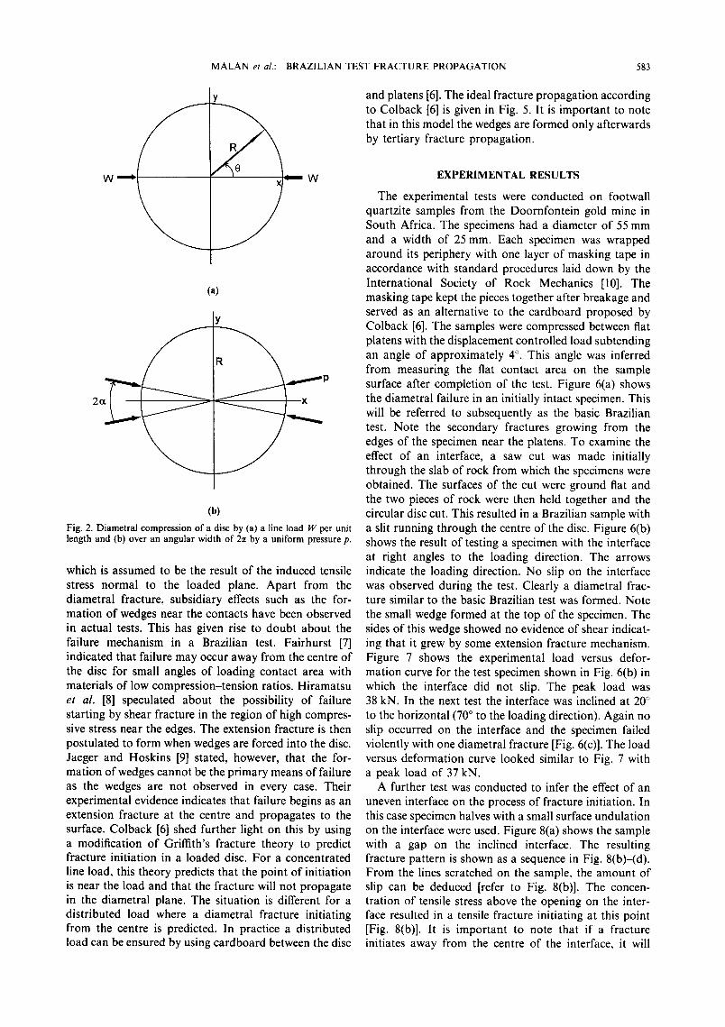
diametral plane between surfaces that apply concen- trated loads. This test was developed to overcome the difficulties associated with performing a direct uniaxial tensile test. It was used by Hondros [3] to determine the elastic properties of concrete and to determine the tensile strength of rock by Berenbaum and Brodie [4]. If a circular disc of radius R and unit thickness is compressed across a diameter by line loads W as shown in Fig. 2(a), the stresses on this diameter are given by Jaeger and Cook [5] as
W ~' ~R (1)
- W(3R z + x 2) a,. = (2)
~R (R 2 - x 2)
The convention of tension being positive is used. By symmetry these are the principal stresses. It appears that for line loading there is a constant tensile stress ¢r across the loaded diameter while a, increases from 3 W/~R at the centre to infinity at the loaded points. It must be kept
581

582 M A L A N et al.: B R A Z I L I A N TEST F R A C T U R E P R O P A G A T I O N
/ f
\
Type II ~ '/~ '~
1 m
Parting planes 1 /
Fig. 1. Schematic diagram of the major discontinuities adjacent to a typical stope in bedded strata (after Adams et al. [ll).
in mind that in practice a perfect line load is not possible due to the deformation of the sample and platens. Figure 2(b) gives a more general case where a radial pressure, p, is applied to the surface over the regions - ~ < 19 < and n - c~ < 19 < n + ~, where 19 is measured counter clockwise from the x axis. The stress distribution in this case can be expressed in polar co-ordinates r, 0 by the following equations [5]:
o r - 1 - I - - - - n n ,,=1 -R m
x ~ sin2me cos2m0 (3)
cr 0 - + 1 - 1 - - - 7~" m= I R m
x ~ sin2mc~ cos2m0 (4)
Tr0 -- ~' m = I
) J s in2me sin 2mO (5)
To assess the significance of applying the local pressure over the area 2e, these stresses were calculated for several values of r / R using an arc of 4 ~ (~ = 2 °) to verify the numerical solution given in this paper. The radius R was chosen for convenience to be equal to 14.33 m to ensure
that a single boundary element grid, on the circumfer- ence of the specimen, would subtend an angle of 4 ° . Applying the loading pressure p over a single grid (i m) gives a loading force, W = p (p was chosen to be 775 MPa). The results of the analytical solution are displayed in Fig. 3 where a double line denotes tension. A tension of 17.19 MPa arises close to the centre. Figure 4 gives an enlarged view of the region next to the loading contact. (A thick line on the boundary denotes the loading area.) It is clear from this figure that the infinite stress concentrations at the edges, corresponding to the line loading arrangement, are removed for finite values of ~. Small areas where both the major and minor principal stresses are compressive are formed next to the loading contacts. For small values of ~, the stress at other locations in the disc is not altered significantly compared to a disc where a line load is applied. This can be verified by using equation (1) to calculate the stress at the centre for a line load.
775 - - - 17.21 MPa
a , . - n 14.33
This value compares favourably with the 17.19MPa calculated when the load is distributed over an arc of 4 ° . According to Coiback [6] the load distribution can extend over as much as 10% of the diameter without affecting the stress at the centre of the disc.
In a Brazilian test, failure is usually in the form of an extension fracture along the loaded diametral plane
MALAN et al.: BRAZILIAN TEST FRACTURE PROPAGATION 583
Y
! W I W
(a)
Y
R
2 Z . .
I (b)
Fig. 2. Diametral compression of a disc by (a) a line load W per unit length and (b) over an angular width of 2c~ by a uniform pressure p.
which is assumed to be the result of the induced tensile stress normal to the loaded plane. Apart from the diametral fracture, subsidiary effects such as the for- mation of wedges near the contacts have been observed in actual tests. This has given rise to doubt about the failure mechanism in a Brazilian test. Fairhurst [7] indicated that failure may occur away from the centre of the disc for small angles of loading contact area with materials of low compression-tension ratios. Hiramatsu et al. [8] speculated about the possibility of failure starting by shear fracture in the region of high compres- sive stress near the edges. The extension fracture is then postulated to form when wedges are forced into the disc. Jaeger and Hoskins [9] stated, however, that the for- mation of wedges cannot be the primary means of failure as the wedges are not observed in every case. Their experimental evidence indicates that failure begins as an extension fracture at the centre and propagates to the surface. Colback [6] shed further light on this by using a modification of Griffith's fracture theory to predict fracture initiation in a loaded disc. For a concentrated line load, this theory predicts that the point of initiation is near the load and that the fracture will not propagate in the diametral plane. The situation is different for a distributed load where a diametral fracture initiating from the centre is predicted. In practice a distributed load can be ensured by using cardboard between the disc
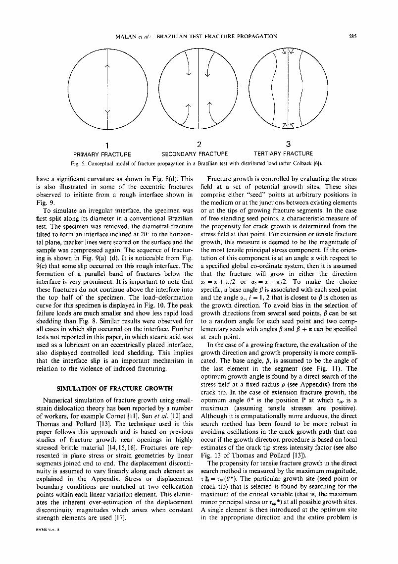
and platens [6]. The ideal fracture propagation according to Colback [6] is given in Fig. 5. It is important to note that in this model the wedges are formed only afterwards by tertiary fracture propagation.
EXPERIMENTAL RESULTS
The experimental tests were conducted on footwall quartzite samples from the Doornfontein gold mine in South Africa. The specimens had a diameter of 55 mm and a width of 25 ram. Each specimen was wrapped around its periphery with one layer of masking tape in accordance with standard procedures laid down by the International Society of Rock Mechanics [10]. The masking tape kept the pieces together after breakage and served as an alternative to the cardboard proposed by Colback [6]. The samples were compressed between fiat platens with the displacement controlled load subtending an angle of approximately 4 ° . This angle was inferred from measuring the fiat contact area on the sample surface after completion of the test. Figure 6(a) shows the diametral failure in an initially intact specimen. This will be referred to subsequently as the basic Brazilian test. Note the secondary fractures growing from the edges of the specimen near the platens. To examine the effect of an interface, a saw cut was made initially through the slab of rock from which the specimens were obtained. The surfaces of the cut were ground fiat and the two pieces of rock were then held together and the circular disc cut. This resulted in a Brazilian sample with a slit running through the centre of the disc. Figure 6(b) shows the result of testing a specimen with the interface at right angles to the loading direction. The arrows indicate the loading direction. No slip on the interface was observed during the test. Clearly a diametral frac- ture similar to the basic Brazilian test was formed. Note the small wedge formed at the top of the specimen. The sides of this wedge showed no evidence of shear indicat- ing that it grew by some extension fracture mechanism. Figure 7 shows the experimental load versus defor- mation curve for the test specimen shown in Fig. 6(b) in which the interface did not slip. The peak load was 38 kN. In the next test the interface was inclined at 20 ° to the horizontal (70 ° to the loading direction). Again no slip occurred on the interface and the specimen failed violently with one diametral fracture [Fig. 6(c)]. The load versus deformation curve looked similar to Fig. 7 with a peak load of 37 kN.
A further test was conducted to infer the effect of an uneven interface on the process of fracture initiation. In this case specimen halves with a small surface undulation on the interface were used. Figure 8(a) shows the sample with a gap on the inclined interface. The resulting fracture pattern is shown as a sequence in Fig. 8(b)-(d). From the lines scratched on the sample, the amount of slip can be deduced [refer to Fig. 8(b)]. The concen- tration of tensile stress above the opening on the inter- face resulted in a tensile fracture initiating at this point [Fig. 8(b)]. It is important to note that if a fracture initiates away from the centre of the interface, it will

584 MALAN et a/: BRAZILIAN TEST F R A C T U R E PROPAGATION
\ /
, ~ / ? \ \ ,
' ' / t ~ k x , '
, ~ + + + + + + ~ ,
' ' t k i t ' ' \ - \ \ / - ~
\ \ / / /
S T R E S S SCALE - - 70 MPa
Fig. 3. Analytic solution of the stresses in a disc compressed by a distributed load.
/
/
/ /
/
/
/
\
J
/ / / /
\
\ \ \
STRESS SCALE - - 80 MPa
Fig. 4. Analytic solution of the region next to the contact area.
\
\
\
\
MALAN et al.: BRAZILIAN TEST FRACTURE PROPAGATION 585
1 2 3 PRIMARY FRACTURE SECONDARY FRACTURE TERTIARY FRACTURE
Fig. 5. Conceptual model of fracture propagation in a Brazilian test with distributed load (after Colback [6]).
have a significant curvature as shown in Fig. 8(d). This is also illustrated in some of the eccentric fractures observed to initiate from a rough interface shown in Fig. 9.
To simulate an irregular interface, the specimen was first split along its diameter in a conventional Brazilian test. The specimen was removed, the diametral fracture tilted to form an interface inclined at 20 ° to the horizon- tal plane, marker lines were scored on the surface and the sample was compressed again. The sequence of fractur- ing is shown in Fig. 9(a)-(d). It is noticeable from Fig. 9(c) that some slip occurred on this rough interface. The formation of a parallel band of fractures below the interface is very prominent. It is important to note that these fractures do not continue above the interface into the top half of the specimen. The load~leformation curve for this specimen is displayed in Fig. 10. The peak failure loads are much smaller and show less rapid load shedding than Fig. 8. Similar results were observed for all cases in which slip occurred on the interface. Further tests not reported in this paper, in which stearic acid was used as a lubricant on an eccentrically placed interface, also displayed controlled load shedding. This implies that the interface slip is an important mechanism in relation to the violence of induced fracturing.
SIMULATION OF FRACTURE GROWTH
Numerical simulation of fracture growth using small- strain dislocation theory has been reported by a number of workers, for example Cornet [11], Sun et al. [12] and Thomas and Pollard [13]. The technique used in this paper follows this approach and is based on previous studies of fracture growth near openings in highly stressed brittle material [14, 15,16]. Fractures are rep- resented in plane stress or strain geometries by linear segments joined end to end. The displacement disconti- nuity is assumed to vary linearly along each element as explained in the Appendix. Stress or displacement boundary conditions are matched at two collocation points within each linear variation element. This elimin- ates the inherent over-estimation of the displacement discontinuity magnitudes which arises when constant strength elements are used [17].
Fracture growth is controlled by evaluating the stress field at a set of potential growth sites. These sites comprise either "seed" points at arbitrary positions in the medium or at the junctions between existing elements or at the tips of growing fracture segments. In the case of free standing seed points, a characteristic measure of the propensity for crack growth is determined from the stress field at that point. For extension or tensile fracture growth, this measure is deemed to be the magnitude of the most tensile principal stress component. If the orien- tation of this component is at an angle ct with respect to a specified global co-ordinate system, then it is assumed that the fracture will grow in either the direction cq = ~ +7r/2 or e t 2 = ~ - z r / 2 . To make the choice specific, a base angle fl is associated with each seed point and the angle ~i, i = 1, 2 that is closest to fl is chosen as the growth direction. To avoid bias in the selection of growth directions from several seed points, fl can be set to a random angle for each seed point and two comp- lementary seeds with angles fl and fl + n can be specified at each point.
In the case of a growing fracture, the evaluation of the growth direction and growth propensity is more compli- cated. The base angle, fl, is assumed to be the angle of the last element in the segment (see Fig. l 1). The optimum growth angle is found by a direct search of the stress field at a fixed radius p (see Appendix) from the crack tip. In the case of extension fracture growth, the optimum angle 0* is the position P at which zoo is a maximum (assuming tensile stresses are positive). Although it is computationally more arduous, the direct search method has been found to be more robust in avoiding oscillations in the crack growth path that can occur if the growth direction procedure is based on local estimates of the crack tip stress intensity factor (see also Fig. 13 of Thomas and Pollard [13]).
The propensity for tensile fracture growth in the direct search method is measured by the maximum magnitude, T*0 = r00(0*). The particular growth site (seed point or crack tip) that is selected is found by searching for the maximum of the critical variable (that is, the maximum minor principal stress or zoo*) at all possible growth sites. A single element is then introduced at the optimum site in the appropriate direction and the entire problem is
RMMS 3L6-- B

586 M A L A N et al.: BRAZILIAN TEST F R A C F U R E PROPAGATION
b c Fig. 6. Results for the Brazilian test for (a) an intact specimen, (b) a specimen with interface at right angles to the loaded
direction and (c) a specimen with interface inclined at 2 0 to the horizontal.
resolved with the additional element. The search pro- cedure is then repeated using the new problem solution. This process ceases when it is found that the element that would be introduced at the op t imum site would not be mobilized, according to a specified M o h r - C o u l o m b fail- ure criterion, evaluated at the chosen seed point or position P ahead of the crack tip. The M o h r - C o u l o m b criterion is assumed to be given by a linear relationship o f the form
0"t = -- 0"c + rn0"~ (6)
where
0"~ = uniaxial compressive strength 0"3 = minor principal stress componen t 0"~ = major principal stress component .
Note 0-1 < 03 for a negative compressive stress conven- tion. An additional tension cutoff parameter, To, can be specified to limit the maximum tensile strength o f the material.
Shear failure localisation is an inherently more com- plex process than extension fracture growth. At present

M A L A N et al.: BRAZILIAN TEST F RACTURE PROPAGATION 587
t-I
0 .._1
i
0
40
35
3O
25
20
15
10
5
0 0
J~
i i I i I
0 07 C) ~ 0 C) 0 0 0 Q 01 0
0 0
O I SPLACEMENT
Fig. 7. Typical load vs deformation curve for a test with no slip on the interface.
Fig. 8. (a)-(d) Sequence of fracturing in a Brazilian test with a gap on the inclined interface.

588 M A L A N ~,: al.: B R A Z I L I A N TEST t : R A ( ' T U R E P R O P A ( i A T I ( ) N
Fig. 9. (a) {d) Sequence of fracturing in a Brazilian test with an irregular interface.
40
r-~
0 _J
35
30
25
20
15
10
5
0 C3 CO ~ 0U "d CO ~
(3] CD (J] £D Oq C9 C9 rO C3 ED C3 C] C3 ED Oq CO
CD C]
DISPLACEMENT
Fig. 10. Typical load ,:s dcl'ormation curxc for a tcsl with slip on tile intcrthcc.

MALAN et al.: BRAZILIAN TEST FRACTURE PROPAGATION 589
P Fig. 11. Selection of crack growth angle from an existing crack tip, T, by direct evaluation of the stress field at point P a fixed radius p from
T.
this is simulated using the same seed and crack growth structure described for extension fracturing but with a different rule for determining the angle and propensity for fracture initiation and growth. Specifically, the shear growth direction is determined by finding the angle at which the difference, re, between shear stress and shear resistance is a maximum. The expression for z e depends on the internal angle of friction of the material and is given by
re = Izr01 + ~00 (7)
where
r = direction of proposed element 0 = direction normal to proposed element /~ = effective friction coefficient
Zr0 = shear stress on element r00 = normal stress across element.
Note that Zoo is assumed to be negative when a compres- sive stress acts across the element.
In specifying a fracture growth problem, shear frac- ture seeds must be distinguished from tension fracture seeds. Consequently, in the current version of the com- puter code there is no automatic choice of growth mode; this has to be explicitly associated with each seed point. Each seed point must also reference a constitutive defi- nition in which the failure properties of the material are specified in terms of the Mohr-Coulomb parameters a c, m and T¢ defined above. Once the crack element is emplaced at the seed point, a specified "post-failure" friction angle and cohesion is applied to the crack faces. Some judgement has to be exercised by the modeller about the selection of shear or extension fracture growth modes and in certain cases simulations must be restricted to only one mode. In the present paper fracture growth is almost exclusively restricted to extension fracturing with the exception of a brief explanation of shear fracturing near the specimen load points. Work is cur- rently being directed to improve the shear fracture rule and to allow for an automatic selection of shear or extension fracture growth. The use of the current shear fracture growth rule has been discussed by Napier and Hildyard [15].
The choice of the maximum tension criterion for determining the extension growth direction is motivated on intuitive grounds as well as following the apparent success of this criterion as reported by Erdogan and Sih
[18] and more recently by Thomas and Pollard [13] who used this criterion to synthesize an expression for the optimum growth direction in terms of the opening and sliding mode stress intensity factors at the crack tip. It would be straightforward to implement a strain energy density criterion such as proposed by Sih [19] but the application of this criterion does not seem to be war- ranted. There does not seem to be a strong justification for introducing an energy release criterion to control extension or tensile fracture growth. However. it is considered that energy release criteria, based on incre- mental crack extension in different directions may be appropriate for the simulation of shear fracture growth processes but these are not considered in this paper.
The simulation procedure for fracture growth has also been extended to allow growing fractures to intersect existing discontinuities, fractures or boundary surfaces. Numerical difficulties arise if the intersection angle is less than 30 ° or if nearly parallel elements arise that are closer than one fifth of the element length. In these cases the potential growth element is automatically blocked. This can lead to small artificial bridges remaining in the fractured material requiring some judgement on the part of the modeller. More robust intersection rules are being investigated.
SIMULATION OF THE BRAZILIAN TEST
The unstressed circumference of the Brazilian speci- men is specified by a series of crack elements, joined end to end, in which the crack faces are stress free. The bottom element was fixed and a displacement boundary condition was applied to the top element. Ninety el- ements of uniform size were used to describe the circum- ference of the specimen. With the element size chosen to be 1, the radius of the disc was 14.33. The load on the top element, subtending an angle of 4 ~', was set to a value of 775 MPa. This particular value was chosen to com- pare the numerical and analytical solutions. The tensile stress at the centre of the sample was 17 MPa (as shown previously, this is consistent with the analytical sol- ution). This was somewhat in excess of the nominal tensile strength of 14MPa observed in experimental Brazilian tests conducted on the footwall quartzite samples from the Doornfomein goldmine. It was as- sumed that the uniaxial compressive strength would be approximately ten times the tensile strength: ac= 140MPa. This corresponds to a cohesion So= 22.14MPa and a friction ~p =54 .9 ' for use in the Coulomb criterion for shear failure in a plane [5]. These values are considered to be appropriate for the failure surface in the region where the minor principal stress is tensile or minimally compressive. Other values assumed in the simulation are Young's modulus = 70,000 MPa and Poisson's ratio = 0.2.
Figure 12 shows the numerical solution of the stress distribution in the disc. This compares well with the analytical solution shown in Fig. 3. Extension fractures were allowed to initiate from 120 extension seed points distributed in the plane of the disc after the stresses had

590 MAL.AN ,'i ,#: tJR,'~ZILIAX, I f !S I I R..\¢ l l r R l ! I 'ROPA( i . ' \ I I~ ) t,
/ ; /
, t
' t
' t
, \
L
/
/" /
t t t t
\ \
+++
t
\ 1 / / ~
\
\
7 t t / /
\
\
\
t
t
t
t
/
S T R E S S S C A L E - - 70 M P a
Fig. 12. Numerical solution of the stresses in a disc compressed by a distributed load.
Fig. 13. Distribution o1" fracture seed points in the disc.

M AL AN et al.: BRAZILIAN TEST F R A C T U R E PROPAGATION 591
1
t
\ \
2
3 4 Fig. 14. Numerical simulation of the fracture propagation sequence in a Brazilian test.
been resolved for the particular top load being applied. The location of these nucleation points is shown in Fig. 13. The sequence in Fig. 14 shows the initiation and propagation of fractures from these seed points. It is clear from this figure that if the primary fracture is extensional, it initiates from the centre of the disc. The secondary fractures correspond to the fractures observed by Colback [6] (refer to Fig. 5). Although this result appeared to be very encouraging, the possibility of fractures starting next to the platens was investigated in greater detail. This was examined by allowing shear fractures to initiate from shear seeds next to the loaded area. The growth directions are shown in Fig. 15. Although the initial growth angle was selected inwards, the most favourable shear fracture directions were in the outward orientations shown in Fig. 15. This resulted in fractures similar to the curved shear fractures observed by Colback [6] for a line load (not shown in this paper). The fractures observed in the experimental tests reported in this paper were cleanly separated with no evidence of powdering between the surfaces indicating clearly the extensional nature of the fractures. The evidence of the numerical simulations indicates that an extension frac-
ture initiates first from the centre of the specimen and that wedges will not form initially in shear mode near the load points.
Further numerical investigations were carried out to determine the effect of element sizes and the sensitivity of the value assigned as a tension cutoff on the intersec- tion of the growing extension fracture with the top and bottom elements. The results shown in Fig. 16 were obtained with the growing element size reduced to 0.1 of the original size and using a 14 MPa tension cutoff. The fracture did not intersect the loaded boundary segment. It is clear from the figure that no tension exists in this region due to the confinement imposed by the applied load. The same results were obtained when using a stress loading arrangement derived from Hertzian contact logic and when the tension cutoff was set to zero. A prominent feature of the experimental tests was the formation of a small wedge next to the platens [see Fig. 6(b)]. A purely speculative explanation is that stress waves generated at the growing crack tip (which is not controlled in the experiment) might be reflected back from the surface of the specimen towards the approach- ing crack tip and cause it to bifurcate.
Fig. 15. Shear growth directions next to the platens.
5~,~2 M A I . A N ~'r,//.: B R , \ Z l t l A N I ' I~SI I ' R A ( ~ I L R I ~ I ~ R O P A ( k \ I I ( ) ~,
: z ¢
: y
; /
/ !
i / /
/
/
/ /
/ ,J r
I
I
STRESS SCALE - - 740 MPa
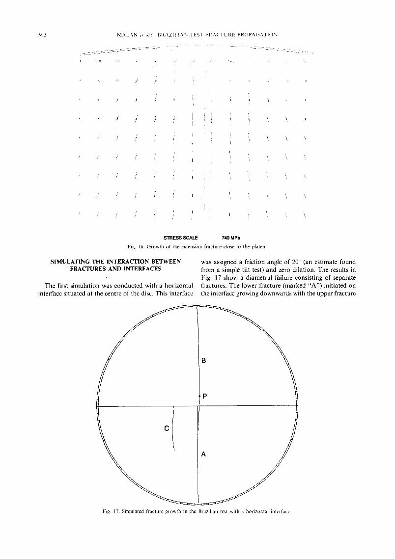
Fig. 16. Growth of the extension fracture close to the platen.
S I M U L A T I N G T H E I N T E R A C T I O N B E T W E E N F R A C T U R E S A N D I N T E R F A C E S
The first simulation was conducted with a horizontal interface situated at the centre of the disc. This interface
was assigned a friction angle of 2if' (an estimate found from a simple tilt test) and zero dilation. The results in Fig. 17 show a diametral failure consisting of separate fractures. The lower fracture (marked "A") initiated on the interface growing downwards with the upper fracture
P
Fig. 17. Simulated tTacture growth in the Brazilian test with a hor izontal interface.
M A L A N et al.: BRAZILIAN TEST F R A C T U R E PROPAGATION
\ /
593
" ~ / / ~ i \ \ \ "
" / / i ! ~ \ \ "
'"i '2" " \~' y / ' . \\ / / ,
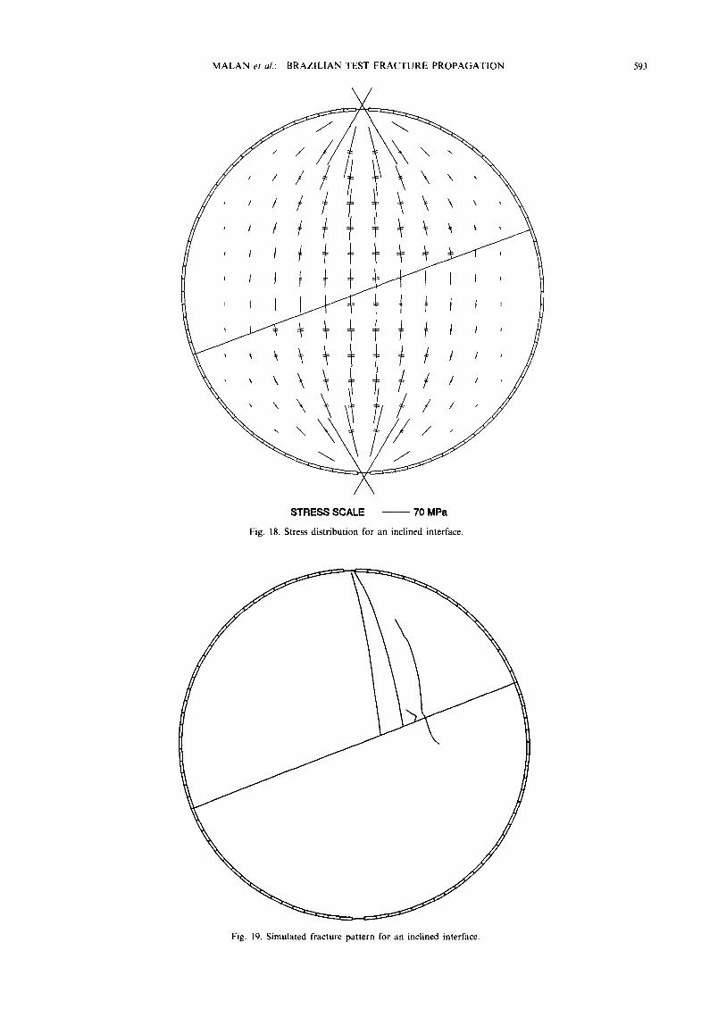
STRESS SCALE ~ 70 MPa
Fig. 18. Stress distribution for an inclined interface.
Fig. 19. Simulated fracture pattern for an inclined interface.

594 MALAN et al.: BRAZILIAN TEST FRACTURE PROPAGATION
t, t+ ~t t t t t Tt t t t+ tt ~ ~ + + ++÷+++ttttt~ttt tt+ttt t t t It+ t+ ttttt ~t ~~
STRESS SCALE - - 50 MPa
Fig. 20. Simulated stress distribution caused by an irregular interface slipping (elements with slip indicated by a thick line).
(marked "B") starting above the interface at point P. Compared to the basic Brazilian test (Fig. 14), this model differs in that the two vertical fractures do not join and that a secondary fracture "C" started on the inter- face and not on the boundary near the loading platens.
Subsequently the interface was inclined at 20 ° to the horizontal. The friction angle was kept at 20 ° . This resulted in slip on the interface with the stress distri-
bution shown in Fig. 18. As can be expected, a concen- tration of tensile stress on the upper right and lower left part of the interface is found. Fracture growth was simulated using the same seed point distribution as shown in Fig. 13, with additional seeds at the ends of every interface element, leading to the fracture pattern of Fig. 19. Apparently the interface slip can play a key role in the formation of fractures. With the friction angle
\
A
Fig, 21. Fracture pattern for an irregular interface with a 20 friction angle

MALAN et al.: BRAZILIAN TEST FRACTURE PROPAGATION 595
increased to 30 ° ( reducing the slip significantly), a frac- ture pa t te rn not d iss imilar to Fig. 17 was observed (the
hor izonta l interface in Fig. 17 did not slip). In the exper imenta l tests it was noted that when less slip occurred on the interface, the eventual f ractur ing was more violent with rapid load shedding.
I f slip occurs on a pa r t ing plane, local asperi t ies might form nuclea t ion centres for possible fracture ini t iat ion. This hypothes is was tested using a saw- tooth pa t te rn of e lements at the interface. This consis ted o f two kinds o f e lements inclined a l ternate ly at 25 ° and at 15 ° giving an overal l interface or ien ta t ion of 20 ° to the hor izonta l . It was found tha t the elements inclined at 25 ° s l ipped but not those inclined at 15 ° . F igure 20 shows the detai led stress d i s t r ibu t ion sur rounding a por t ion o f the interface for a 20 ° fr ict ion angle. It is clear that the poin t where a s l ipping and non-s l ipp ing element meet is a possible nuclea t ion centre. The stress pa t t e rn in o ther areas o f the disc is s imilar to Fig. 18. S imula t ion o f fracture growth using the i r regular interface results in the fracture pat- tern o f Fig. 21. An impor t an t observa t ion is the curva- ture o f the b o t t o m fracture marked " A " which is s imilar to the shape that was observed in pract ice [refer to Fig. 10(d)]. It can be expla ined as follows. The fracture init iates on the interface at an off-centre posi t ion " P " caused by local asperi t ies (see Fig. 21). Lower down in the disc the fracture is subjected to bo th shear and tension load ing result ing in the curvature towards the load ing point .
CONCLUSION
The Brazi l ian test was successfully model led using a d i sp lacement d i scont inu i ty approach . F rac tu re pa t te rns s imilar to the exper imenta l tests were observed. F rac tu r - ing in a Brazi l ian test with a d is t r ibuted load init iates at the centre o f the specimen in the form of an extension fracture.
The u l t imate goal o f the present work in relat ion to mining app l ica t ions is to enable var ious mining strat- egies to be evalua ted which might be used to "engineer" the s tope fracture zone, In the case o f extension fracture p r o p a g a t i o n f rom par t ing plane interfaces it is possible, in principle, to examine effects o f local suppor t units in the face area and the in t roduc t ion o f backfill mater ia l on the fo rma t ion o f fractures. In cer tain cases it may be conjec tured that suppor t s trategies which suppress regu- lar fracture fo rma t ion may lead to in termi t tent sudden stress f rac tur ing events which are manifes ted as rock- bursts.
When using the Brazil ian test to examine the inter- ac t ion between par t ing planes and fractures, two impor t - an t obse rva t ions were made. When slip occurs on the interface, a pe r tu rbed stress d is t r ibut ion is induced adja- cent to the interface causing a different fracture pa t te rn to that observed in specimens with no slip. It is observed exper imenta l ly that progressive slip on the interface reduces the a m o u n t o f s tored energy and the recorded stress d rop magni tudes . This has impor t an t impl ica t ions for the s tabi l i ty o f mining induced fractures ahead o f the
s tope face. F o r example , artificial loosening o f the
par t ing planes could const i tu te a form of precondi t ion- ing leading to improved s toping condi t ions . The impor t - ance of this po in t war ran ts fur ther exper imental testing and numerical modell ing.
The o ther impor t an t observa t ion is that when slip occurs on an interface, local asperi t ies can form nucle- a t ion centres for the ini t ia t ion of fractures. Extension fractures ini t iat ing in this manner usually p ropaga te on only one side of the interface. This is a possible reason why some fractures observed in pract ice do not extend beyond par t ing planes and may, in fact, ini t iate on the par t ing plane interfaces as indicated for the type I fractures shown in Fig. 1.
Acknowledgements--Grateful acknowledgement is made to Dr N. C. Gay and Dr J. A. Ryder for several useful comments and Mr M. L. Drummond for taking the excellent photographs. The authors would like to acknowledge the constructive and helpful comments of two anonymous referees of the paper.
Accepted for publication 28 April 1994.
REFERENCES
1. Adams G. R., Jager A. J. and Roering C. Investigation of rock fracture around deep-level gold mine stopes. Proc. 22nd U.S. Symp. Rock Mech., pp. 213-218 (1981).
2. Joughin N. C. and Jager A. J. Fracture of rock at stope faces in South African gold mines. In Rockbursts: Prediction and Control, pp. 53~6. Institution of Mining and Metallurgy, London (1983).
3. Hondros G. The evaluation of Poisson's ratio and the modulus of materials of a low tensile resistance by the Brazilian test with particular reference to concrete. Aust. J. Appl. Sci. 10, 243-264 (1959).
4. Berenbaum R. and Brodie I. Measurement of the tensile strength of brittle materials. Br. J. Appl. Phys. 10, 281--286 (1959).
5. Jaeger J. C. and Cook N. G. W. Fundamentals of Rock Mechanics, pp. 169-172, 258-259. Chapman & Hall, London (1976).
6. Colback P. S. B. An analysis of brittle fracture initiation and propagation in the Brazilian test. Proc. First Congress International Society of Rock Mechanics, pp. 385-391 (1967).
7. Fairhurst C. On the validity of the Brazilian test for brittle materials. Int. J. Rock Mech. Min. Sci. 1, 535-546 (1964).
8. Hiramatsu Y., Nishihara M. and Oka Y. A discussion of the methods of tension test of rock. J. Mining Met. Inst. Jap. 70, 285-289 (1954).
9. Jaeger J. C. and Hoskins E. R. Rock failure under the confined Brazilian test. J. Geophys. Res. 71, 2651 2659 (1966).
10. Suggested methods for determining tensile strength of rock ma- terials. International Society for Rock Mechanics commission on standardisation of laboratory and field tests. Int. J. Rock Mech. Min. Sci. & Geomech. Abstr. 15, 99-103 (1978).
11. Cornet F. H. Comparative analysis by the displacement disconti- nuity method of two energy criteria of failure. J. Appl. Mech. 46, 349-355 (1979).
12. Sun G. X., Whittaker B. N. and Reddish D. J. Computer simulation of crack propagation in proximity to a tunnel by the displacement discontinuity method. Trans. Inst. Min. Metall. 101, A114-AI22 (1992).
13. Thomas A. L. and Pollard D. D. The geometry of echelon fractures in rock: implications from laboratory and numerical experiments. J. Struct. Geol. 15, 323 334 (1993).
14. Napier J. A. L. Modelling of fracturing near deep level gold mine excavations using a displacement discontinuity approach. Proc. Int. Con[~ on Mechanics of Jointed and Faulted Rock (Edited by Rossmanith H. P.), pp. 709-715. Balkema, Rotterdam (1990).
15. Napier J. A. L. and Hildyard M. W. simulation of fracture growth around openings in highly stressed brittle rock. J. S. ,4[~. Inst. Min. Metall. 92, 159 168 (1992).
16. Napier J. A. L. and Ozbay M. U. Application of the displacement discontinuity method to the modelling of crack growth around openings in layered media. Proc. Assessment and Pret,ention ¢~["

596 MAI.AN eta/ . : BRAZILIAN TEST ERACI-I.!RE PROPAGATI()N
Failure Phenomena in Rock Engineering, pp. 947 956. Balkema, Rotterdam (1993).
17. Ryder J. A. and Napier J. A. L. Error analysis and design of a large-scale tabular mining stress analyser. Proc. F(lth Int. ConL Num. Meth. Geomeeh. Nagoya, pp. 1549 1555 (19851.
18. Erdogan F. and Sih G. C. On the crack extension in plates under plane loading and transverse shear. Trans. Am. Soc. Mech. En~rs 85, 519 527 (1963).
19. Sih G. C. Strain-energy-density factor applied to mixed mode crack problems. Int. J. Fracture 10, 305 321 (19741.
20. Crouch S. L. and Starfield A. M. Boundary Element Methods in Solid Mechanics, pp. 79 100. Allen & Unwin, London (1983).
21. Crawford A. M. and Curran J. H. Higher-order functional variation displacement discontinuity elements. Int. J. Rock Mech. Min. Sei. & Geomech. Abstr. 19, 143 148 (1982).
A P P E N D I X
The influence of distributions of dislocations or so called "'displace- ment discontinuities" [20] throughout the region of interest is com- puted using integral relationships of the form
(P) = - [" G (Q,, P~ )n:(Q)O~(Q) dS (Q) CA 1 ) U k d, ~B
rk~(P) = - - I 8J ' F(Q,,, P,w)n,(Q)O,(Q) dS (Q) (A2)
where
uk(P ) = k th component of the displacement vector at P rkj(P) = klth component of the stress tensor at point P hi(Q) = j t h component of an assigned normal to the surface ?B
at point Q Ds(Q) = ith component of the displacement vector jump across
surface 8B at point Q.
Specifically, the displacement discontinuity is defined to be
D,(Q) = u~ (Q) - u 7 (Q) (A31
where u + (Q) is the ith displacement vector component of the material in the region towards which the normal vector nJ(Q) is directed and u,- (Q) is the ith displacement vector component on the opposite side of the discontinuity. In an isotropic elastic medium, the influence tensors G(Q,2,Pk) and F(Q,j,Pkl) can be expressed in terms of the derivatives o f the harmonic functions log r e and 1/r, for two and three dimensional problems respectively, where r = IP - QI.
In the present case, it is assumed that plane strain conditions obtain and that each fracture can be represented as a set of connected straight line elements. The shear and normal components of the displacement discontinuity vector are assumed to vary linearly over each element according to
D, = ~, + fl:l (A4)
8 B
I -b
® X
- c ,[® [ni]
Q(O,q) :,, x I >y
Z
Fig. A1. Local co-ordinate system used to define the influence of a given element at a general point P.
where ~ and /)', are constants Ior component i of the displacement discontinuity vector and ;l is a local variable representing the position of point Q within the element (see Fig. AI ). Erecting a local co-ordi- nate system at the centre of an element of length 2h. as shown in Fig. A I. the incremental components of displacements and stress at point P can be shown to be given by the following expression when the material is isotropic with shear modulus G and Poisson's ratio ~'
1 u,(l'.7. =grr( I v) [2(I v)K, +.=A" --(I 2v)A cA" ] (A5)
I u ( y , z ) = 8 ~ . ( i - v ) [ ( l 2 v ) K , , - - - K , . , . + 2 ( I - - v ) K - -K.::] (A61
G q , ( Y . Z ) = 4 7 i i _ - i ; i [ 2 K , , = + z K ..... + K - ~- --K=.==I (A7)
G t . : (v , . : l= ~/(~ i Z-Vj I-.zK,.,:: + K:.::- zK=.:::] (AS)
(7 r,=(.v,z)= 4~tTi~r) [K,= + :K,.===- .zK= ::] IA91
where
and
ih E (y, z ) = - log[(y h
=, 'Y~I,I
K , = ~ , E +fl, F (AI0)
K. = ~:E + fl=F (Al l )
- q)z + z- '}dq
F ( y , z ) = - ~1 l o g [ ( y - q ) Z + z ' q d q h
, = ~l.~l ~{ ~ ( 2 v B - R z ) l ° g R z - 2 v B
(AI31
B = y - ~ b : ~ = - 1 or + I z R 2 - B 2 + = "-.
In equations (A5)~A9), subscripts following a comma denote derivatives with respect to the local directions y and z at the field point P. For example K ~ . , : ~ 2/?,y&[K,.]. The left handed co-ordinate system in Fig. AI and the definition (A4) implies that when slip is right lateral, the component D, is positive. The collocation distance, c, shown in Fig. AI is defined as the point at which stress or displacement boundary conditions are matched in each element. The collocation factor, c r is defined by
q = c (AI41 h
where b is the half-length of the element. The radius,/7, from the crack tip at which the stress field is evaluated to determine the crack growth path is given by
# = h ( l - G ) (AI5)
Following Crawford and Curran [21] and using additional argu- ments relating to the opening displacement of a single element [[4], c, is chosen to be 1/,,/2 for linear variation elements. At present there is no physical basis for the choice of the radius p and it can only be justified by a posteriori compatibility of observed and simulated fracture patterns. It may also be noted that numeric experiments, not reported in here, indicate that at the distance p from the crack tip the stress field generated by the linear variation elements described above is very similar to that generated by a single crack having constant shear and normal tractions applied to the crack faces. Further work is currently underway to examine the effect of cusp like crack tip shapes corresponding to a crack tip process zone.