propellant slosh analysis for the solar dynamics observatory - nasa
TRANSCRIPT

I!, 9
Propellant Slosh Analysis for the Solar Dynamics Observatory
Paul A. C. Mason and Scott R. Starin
Goddard Space Flight Center, Code 595, Greenbelt, AID, 20771
ABSTRACT
The Solar Dynamics Observatory (SDO) mission, part of the Living With a Star program, is a geosynchronous satellite with tight pointing requirements. Due to a large amount of liquid propellant, a detailed slosh analysis is required to ensure the tight pointing budget can be satisfied. Much of the high fidelity slosh analysis and simulation has been performed via computational fluid dynamics. Even though this method of simulation is very accurate, it requires significant computational effort and specialized knowledge, limiting the ability of the SDO project to access fluid dynamics simulations at will. Furthermore, it is very difficult to incorporate most of these models into simulations of the overall spacecraft and its environment.
Ultimately, the effects of the propellant slosh on the attitude stability and pointing performance of the entire spacecraft are of great interest to attitude control engineers. Equivalent mechanical models, such as models that approximate the fluid slosh effects by analogy to the movements of a point-mass pendulum, are important tools in simulating propellant slosh dynamics as part of the entire attitude determination and control system. This paper describes some of the current methods used to analyze and model slosh. It focuses on equivalent mechanical models and their incorporation into control-based analysis tools such as Simulink. The SDO mission is used as the case study for this work.
INTRODUCTION
SDO Overview The Solar Dynamics Observatory (SDO) is a large 2894 kg Sun-pointing geosynchronous satellite. Approximately 1205 kg of propellant is used during the geosynchronous transfer orbit (GTO) phase of the mission, and then several smaller maneuvers guide the spacecraft into a geosynchronous orbit (GEO). During this early phase of the mission, the effects of propellant slosh will be significant. During the observational phase of the mission, the amount of propellant is significantly smaller (263kg-73kg). However, the pointing and jitter budget is very tight, so we must still understand slosh dynamics to ensure that slosh will not cause significant jitter. SDO has six control modes: Science, Inertial, Sun Acquisition, DeltaH, DeltaV, and Safehold. Four of the six modes must account for the effects of slosh: Science, Inertial, DeltaH, and DeltaV. This work only examines the effects of slosh in the thruster modes. For more information on SDO and its control modes see [ 11.
https://ntrs.nasa.gov/search.jsp?R=20050243594 2019-04-12T01:51:24+00:00Z

e
modes could excite slosh dynamics. The attitude sensor suite on SDO includes 16 coarse Sun sensors (CSS), a digital Sun sensor, three two-axis inertial reference units (IRU), two star trackers, and four guide telescopes. The actuators include four reaction wheel assemblies (RWA), eight attitude thrusters, and a single main engine [ 11. The main engine, which nominally provides orbital velocity change (AV) only in the X direction, is located in the center of the ACS thruster suite. SDO only uses 4 attitude thrusters during nominal operations. All thrusters are canted 10 deg about the Z axis, with most of their force directed along the X axis to provide redundancy for AV delivery. The X axis is the bore sight of the spacecraft and is nominally pointed at the sun, the Y axis is along the solar arrays and the Z axis is along the High Gain Antenna. For slosh modeling purposes, the propulsive forces and torques on the spacecraft are based on a worst-case main engine bum. The worst-case disturbances, which are caused by thruster misalignments and uncertainty in thruster performance and spacecraft center-of-mass (CM) location, are incorporated in the simulation as external disturbances.
Literature Review Slosh dynamics has been studied for several decades. Even though most of the work has been in the aerospace industry, slosh dynamics is applicable to industrial/manufacturing applications (movement of fluid-filled containers), civil engineering (earthquakes), automotive engineering (he1 trucks), and ship dynamics. In the case of manufacturing, the transportation of liquids without spilling is a cost and efficiency driver. Much of the work in this field is based on slosh due to lateral motion in a 1-g environment. Many container manufacturers now utilize computational fluid dynamics (CFD) analysis to account for and mitigate the effects of slosh. Another area in which slosh is studied is earthquakes [2,3]. The ground motion of an earthquake can produce slosh motions in a liquid container such that it may be damaged or ruptured. On a large scale, earthquakes can also induce slosh motions in a lake, which can be very dangerous. In the automotive industry, slosh analysis is mandatory for large liquid tanks that transport gas, milk, chemicals, etc. [4,5]. Much of this work examines the lateral and roll effects of slosh based on cylindrical tanks. In maritime applications, ships transport large amounts of liquid and are therefore susceptible to the effects of slosh [6]. The slosh motion of large volumes of liquid can have a dramatic effect on ship stability and structural integrity.
The largest body of slosh dynamics and suppression work is found in the aerospace industry. Some of the earliest works in slosh were associated with vehicle stability for missiles and spacecraft [7]. As vehicle size and propellant capacity increase, the potential for slosh increases significantly. The interaction between the slosh dynamics and vehicle can lead to instability or poor performance. With the advent of larger aerospace vehicles and tighter pointing requirements, analyzing and controlling the slosh dynamics has become a standard component in the analysis of many aerospace vehicles.
Most of the work in slosh can be categorized into two areas, based on the modeling techniques used: fluid dynamics modeling and equivalent mechanical models. The fluid dynamics modeling can be broken into two sub-categories. The first is analytic solutions and the second is CFD. CFD is analogous to finite elements in structures. Analytic modeling of slosh dynamics uses fluid dynamic principles and partial differential equations to describe fluid behavior in a given environment. H. Norman Abramson, a distinguished researcher in the area of slosh dynamics, published a document. [SI, that describes the analvtic process for determining; the slosh dynamics

for a given container shape. As he states, “an exact solution to the general problem of fluid oscillations in a moving container is extremely difficult.” For this reason the initial step is to define any simplifying assumptions. Next, the fundamental fluid dynamics laws are used to define the basic partial differential equations (PDE). The boundary conditions, which are determined as a function of the container shape, are incorporated into the PDEs from the fundamental laws. In many cases, numerical PDE techniques must be utilized to obtain a solution. In fact, most analytic studies feed into the CFD slosh analysis.
In many applications, analytic solutions are prohibitively complex. Analytic methods are often unpractical for large problems, irregular shapes, and variable fluid compositions and properties. In these situations, numerical techniques such as CFD are usually employed. Since numerical methods are not exact, they may be less accurate than direct analysis of the PDEs. However, direct analysis may require more time to obtain solutions than CFD methods, and a direct solution may even be impossible. Due to the nature of numerical methods, most of the literature is associated with a particular application. As the complexity of the problem increases so does the computational expense. In some cases, the complexity reaches a point where a supercomputer must be used to solve the problem [9].
Equivalent mechanical slosh modeling, described in the next section, provides a simple and empirical, though lower-accuracy, alternative to fluid dynamics methods. Equivalent mechanical models (also called mechanical analogy models) are particularly useful when designing a control system or creating a model based on solid-body dynamics for stability or performance analyses. In the aerospace industry, equivalent slosh models have been used since the 1960’s. In many cases, these equivalent models are an assemblage of dampers or dashpots, springs, and masses. More complicated models incorporate camshafts, slides, and nonlinear elements [ 101 to simulate a desired motion. In 1964, Roberts, Basurto and Chen [ 1 13 compiled a slosh design handbook with many equivalent mechanical models, including some of their own design, and their parameters. The accuracy of an equivalent model is a function of the validity of the model for the given container shape, fluid properties (e.g. laminar flow, accelerations), and the model parameters. The equivalent mechanical model parameters can be derived from analytic expressions or from parameter estimation of flight or numerical data.
In general, choice of modeling technique is a tradeoff. Most analytic models provide accurate representations of the dynamics, but require a significant amount of formulation and are not applicable to all problems. Alternatively, CFD models provide high accuracy and require less formulation time. However, numerical techniques such as CFD are difficult to incorporate into a stability analysis or a simulation and require large computational resources. Equivalent mechanical models are simple and can be incorporated into stability analyses, controller design processes, and solid-body simulations, but their accuracy is a function of the parameters used and the experimentation by which they were developed. Also, these models usually only account for the dominant fluid dynamics, so that higher frequency behavior may not be captured.
EQUIVALENT MECHANICAL MODELS In applications other than spacecraft design, the mass-spring model is the most commonly used equivalent mechanical slosh model. This model is primarily used to represent lateral sloshing, which is when a wave moves from one side to another in a partially filled container. These
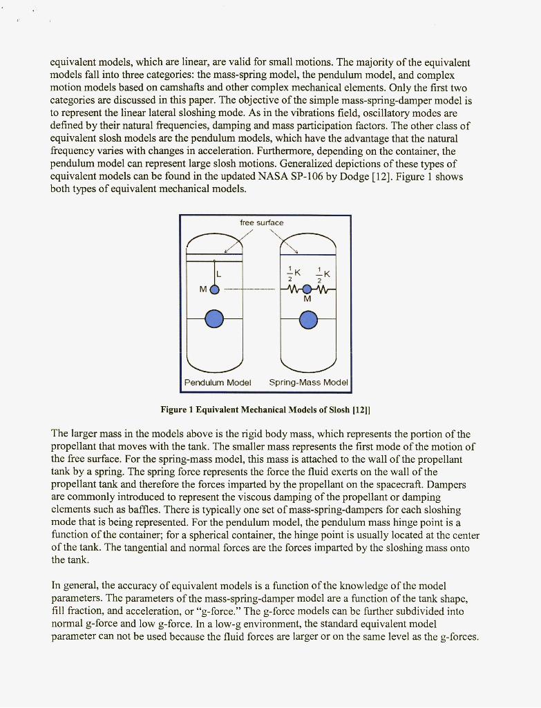
equivalent models, which are linear, are valid for small motions. The majority of the equivalent models fall into three categories: the mass-spring model, the pendulum model, and complex motion models based on camshafts and other complex mechanical elements. Only the first two categories are discussed in this paper. The objective of the simple mass-spring-damper model is to represent the linear lateral sloshing mode. As in the vibrations field, oscillatory modes are defined by their natural frequencies, damping and mass participation factors. The other class of equivalent slosh models are the pendulum models, which have the advantage that the natural fiequency varies with changes in acceleration. Furthermore, depending on the container, the pendulum model can represent large slosh motions. Generalized depictions of these types of equivalent models can be found in the updated NASA SP- 106 by Dodge [ 121. Figure 1 shows both types of equivalent mechanical models.
free surface
>endulum Model Spring-Mass Mode
Figure 1 Equivalent Mechanical Models of Slosh [12]]
The larger mass in the models above is the rigid body mass, which represents the portion of the propellant that moves with the tank. The smaller mass represents the first mode of the motion of the fiee surface. For the spring-mass model, this mass is attached to the wall of the propellant tank by a spring. The spring force represents the force the fluid exerts on the wall of the propellant tank and therefore the forces imparted by the propellant on the spacecraft. Dampers are commonly introduced to represent the viscous damping of the propellant or damping elements such as baffles. There is typically one set of mass-spring-dampers for each sloshing mode that is being represented. For the pendulum model, the pendulum mass hinge point is a h c t i o n of the container; for a spherical container, the hinge point is usually located at the center of the tank. The tangential and normal forces are the forces imparted by the sloshing mass onto the tank.
In general, the accuracy of equivalent models is a finction of the knowledge of the model parameters. The parameters of the mass-spring-damper model are a h c t i o n of the tank shape, fill fiaction, and acceleration, or “g-force.” The g-force models can be fi-u-ther subdivided into normal g-force and low g-force. In a low-g environment, the standard equivalent model parameter can not be used because the fluid forces are larger or on the same level as the g-forces.

The most important of these fluid forces is the surface tension. As described in [ 121, the Weber, Froude and Bond numbers are used to determine which forces dominate (gravitational, inertial, or capillary). A Bond number much less than 1 .O represents a regime where the gravitational force dominates and the fiee surface is flat. If the Bond number is much greater than 1.0, then the capillary forces of surface tension dominate and the free surface is curved. If the Weber number is much greater than 1 .O, the inertial forces dominate. If the Froude number is much greater than 1 .O, the inertial forces are dominant compared to the gravity forces. After determination of the appropriate regime, we can use analytic expressions or tables that are functions of Bond number, fill fraction, and tank shape to determine the appropriate parameters [ 121. Most of the literature provides models for selected tank shapes such as cylindrical, elliptical, rectangular, and ellipsoid. However, when the tank is of arbitrary shape, analytic techniques can be used to determine the appropriate parameters. In 1965, Loman [ 131 derived the pertinent hydrodynamic equations for a tank of arbitrary shape. This work provides researchers with an analytic method of determining the appropriate model for a tank of arbitrary shape.
Mass Spring Model Due to its simplicity and ability to be visualized, the most commonly used equivalent mechanical slosh model is the mass-spring model. A detailed derivation of the formulation of this model is available in Dodge [ 121. The basic mass-spring model is shown in F
i
gure 2.
Figure 2 Mechanical model with damping (Dodge p 49) [12]
The equation of motion for this model is
m,,(Xo + ;t, + H,,&,)+ ~ i , , + I+,, - mngaO = o The force exerted by the fluid on the tank (spacecraft) is

- F = moXo + c m , , ( 2 0 + x,,) The moment exerted by the fluid on the tank (spacecraft) is
From the equations above, it can be seen that this mode mainly describes the linear horizontal motion, which is perfect for many industrial and earth-based applications. In this model, g is any vertical acceleration acting on the tank (including gravity). If the container is vertical, the angular displacement is zero (ab = 0) and the modal masses are along the center line that this model predicts, not the line of slosh motion. As the states move away from this equilibrium point, the slosh motion grows. Since the stiffness is constant, a large enough force and perturbation from the equilibrium point can cause deflections that exceed the size of the container. These are situations for which this model becomes invalid, and other models, such as the pendulum model, will need to be used.
Pendulum Model One of the advantages of the pendulum model is that the slosh motion is constrained. In addition, the slosh motion is not confined to a given vertical location in the tank. In missile applications, the high-acceleration environment forces most of the propellant to settle in a location opposite the direction of the acceleration. This fixed propellant mass is represented by the rest mass, and the moving propellant mass is modeled by the pendulum. The resulting oscillations are usually small and well-defined. For this reason the pendulum model was the primary model in missileh-ocket applications. The inclusion of the damping and low-g parameter allows the pendulum model to be extended to spacecraft applications. Figure 3 provides a description of the pendulum slosh model
The equation of motion for the pendulum model with torsional damping, with aa denoting linear axial acceleration and aT denoting linear transverse acceleration, is
The transverse force exerted on the tank is
F,,, = m, (a - L,B’ cos e + L,B sin e)+ moa
The axial force exerted on the tank is
4ransverse = -m, ( ~ , 8 cos e + ~ , e ~ sin e) From the equations above, it can be seen that the pendulum provides a description of the angular motions of the slosh mass. This constrained motion makes it very applicable for a spherical tank. The transverse and axial force represents the tangential and normal forces for a given 6. The torsional damping is a finction of fluid properties, objects within the tank, tank shape, and fill fraction. It should also be noted that this model can be extended to three dimensions to incorporate a second angle. To provide linear translations and higher-order dynamics, several additions must be made to this model.

Figure 3 Pendulum model with torsional damping (Dodge p 49) [12]
Complex Mechanical Modeling In general, the equivalent mechanical models only provide information about the first-order dynamics. More complex models are required to capture some of the nonlinear and higher-order dynamics. Such models can also account for the coupling between propellant dynamics and spacecraft dynamics. London [ 161 presents a general, momentum-based, multibody dynamics model that allows for such coupling. This fdly coupled model consists of 3 degrees of freedom (DOF) of translation and 3 DOF of rotation. Even though the slosh-model component of this formulation does not capture some of the complex nonlinearity, the technique allows for the use of more complex models. Walchko [17] also utilized the momentum-based technique to couple both slosh and solar array dynamics with spacecraft dynamics. The slosh and the solar array dynamics were modeled with modal parameters such that the higher modes of the slosh could be incorporated into the model.
The authors of this paper are in the process of formulating a complex equivalent model, which will be published at a later time. The proposed model is briefly described but not formulated here. This model attempts to reproduce the dynamics associated with a "geyser" motion of the propellant while accounting for the coupling and first-order linear and rotational dynamics. The geyser mode, which is excited by an axial force, occurs when propellant flows down from the walls and pushes the propellant in the center up towards the top of the tank. To represent these dynamics, a hybrid penduldmass-spring model is being developed. During this initial development, parameters will be based on a simple equivalent model assuming small motions. It is expected that parameter determination will be a challenge.
Parameter Determination One of the difficulties in synthesizing an equivalent mechanical model is the determination of the appropriate parameters. For common tank shapes, model parameters can be obtained from parameter tables found in the literature [lo, 121. For arbitrary tank shapes, one can utilize algorithms such as Lomen's [ 131. These algorithms can be very complex and require a niFifir.Rnt Rmniint nfhnrkcpiint in flrid Axrnnm;np -, **-*AA--. - A n n t h e r ----a_-- nntin- 'r""" ;c I" t A I" >-en ..YW n n r n m a t n w r....-A."*"*

estimation techniques along with flight data [ 141. Once the data points are determined, one can employ a curve-fitting technique to determine the model parameters for a given regime or fill fraction [ 151. Finally, if the slosh frequencies are known, then an ad hoc method can be used to determine the other parameters. Individuals with experience can approximate the model parameters that will produce reasonable results.
RESULTS
System Description In this work a pendulum slosh model is used to study the effects of slosh during a simulated SDO orbit change (DeltaV) maneuver. The pendulum model used is two-dimensional; that is, it does not account for the second transverse axis dynamics and the second transverse force is set to zero. The coordinate system, thruster layout, and tank configuration of the SDO spacecraft are provided in Figure 4. The propulsion module contains two propellant tanks and two pressurant tanks, but only propellant tanks have the potential to produce a slosh disturbance torque. To reduce the effects of propellant slosh and CM migration, a propellant management device (PMD) is added to the fuel and oxidizer tanks. The propellant tanks are located along the center line of the spacecraft. In this work, fuel and oxidizer tanks are located on the X axis, with their beginning-of-life CMs approximately 1.9 m and 0.75 m above the launch vehicle interface plane.
MainEngine - - .
Figure 4 SDO spacecraft and propulsion module
Since 80% of the propellant is used during the main-engine GTO maneuvers, and since the main engine provides the most significant disturbance forces and torques, the effects of the slosh are examined during this phase of the mission. The low fidelity (LoFi) simulation of the DeltaV control mode, slosh dynamics and spacecraft dynamics are depicted by the Simulink block diagram shown in Figure 5.

Thluster Model
Tm-THR-Tnrel
For-THR-Tuel Tme
Pos-BcsF-ScCM1
ME-Toques 31
Slosh Model
- TW-SOS h
Sc-CM 4
*Chit1 In1 4 Cmd
Three Axis Controller
Figure 5 Simulink Block diagram of system
The Spacecraft Momentum Nonlinear dynamics block contains the nonlinear thruster model, Euler's equation, and a simple gyro model. The thruster model includes the algorithm for converting torque commands into individual thrust vector time sequences: a selection matrix, firing time scaling, and a quantizer. The firing time resolution is 0.05 seconds and the control cycle is 0.2 seconds. The gyro dynamics are
G, = W, =43.98% (7.0Hz) 5 = 0.707 s2 + 250,s + 0;
Model Parameters With the exception of the damping ratio, the pendulum model parameters were determined using Figure 6.7 in the SP-106 document (p 206) [ 121. The damping ratio was determined based on correspondence with the PMD designer. The justification and formulation of these parameters will be discussed in a later paper. In order to obtain a better intuitive range, the parameters were compared to parameters in other works. For example, the model stiffness and damping coefficients are the same order of magnitude as those used for the Triana spacecraft by Morgenstem [15]. Since the tank/PMD configuration in [ 151 is not the same as the SDO tank/PMD configuration, we do not expect an exact match.
Setup The results are divided into two cases-slosh dynamics with and without a PMD. The non-PMD case has a damping ratio of 0.2% whereas the PMD case has a damping ratio of 8.0%. Both cases will use scaled-mass properties associated with a 40% fill fraction. This fill fraction is expected to produce the largest disturbance torques and CM motion. The 40% fill fraction produced a large change in the CM which can lead to a large change in the disturbance torques due to a main engine firing. The main engine and ACS thruster misalignment disturbances are determined from a worst-case duty cycle analysis. The thrusters are fired for 1000 sec and then turned off. The mass properties used for this analysis is associated with the non-deployed High Gain Antenna case.

Case 1: LoFi without a PMD To isolate the effects of the slosh on the spacecraft, the control torques and external disturbances on the spacecraft are neglected. The only torques on the spacecraft are the slosh disturbance torques. The forces acting on the tanks are due to the main engine or ACS thrusters. The initial slosh angle is 90 deg, and model parameters are based on 40% fill fi-action and the acceleration levels. Figures 6 and 7 contain the results of the main engine burn.
ow
OM
0 0 1 -
Figure 6 Propellant slosh torques during a main engine maneuver without PMD
pj ~
The peak slosh torque is approximately 0.08 newton-meters (Nm), and the peak attitude and rate errors are 0.44 deg and 0.022 deg/sec. Even though the slosh disturbance torque has a large spike, the duration is small. It should also be noted that the slosh torques settle at approximately 500 sec, which is before the main engine is cut off at 1000 sec. The slosh angle, not shown here, settles to 180 deg in approximately the same time the slosh torques settle. It is expected that a non-main engine maneuver should yield smaller slosh disturbance torques because of lower forces and lesser overall effects fi-om misalignments. Figures 7 and 8 contain the results of a non- main engine maneuver (ie. an ACS thruster maneuver).
During the ACS thruster burn, the peak slosh torques are approximately 0.00055 Nm, which is two orders of magnitude smaller than during the main engine maneuver. However, the durations of the peaks are larger. The attitude and rate error peak at 0.4 deg and 0.0053 deg/sec. This slosh disturbance dies out just before the thrusters are turned off. Since the axial forces are smaller, the pendulum should approach the equilibrium point (8 = 180 deg) slower than the main engine burn. It should be noted that if the thruster force line of action is further perturbed away fi-om the CM, the resulting slosh torques will become larger. However, the dominant effects of the control torques and disturbance torques are significantly larger than those associated with the slosh. Next, we examine the effects of the slosh in the presence of control and external disturbances; refer to Figure 9 and 10 below.

3 A 4A L sm lok ldoo 1L isbp lsbp A Tinu (uc)
Figure 7: Propellant slosh torques during an ACS bum without PMD
Figure 9 Propellant slosh torques during a controlled main engine burn without PMD
4A 0 . k 0:l 0.16 02 0.25 0; O.$ O!+ (hg)
Figure(8): Phaseplane plot during an ACS bum without PMD
Figure 10 Phaseplane plot for a controlled main engine burn without PMD
As expected, the main engine disturbances and control torques dominate. The effects of the slosh can not be discerned. Examining the slosh torques, we see that the input dynamics are much faster than the bandwidth of the slosh mode. Therefore, during a main engine burn with ACS thruster control, the fuel slosh at 40% fill fiaction will not be a significant contributor to the attitude and rate errors. It should also be noted that any significant CM migration will increase the main engine, ACS thruster and slosh disturbance torques.
Case 2: LoFi with a PMD The SDO PMD is designed to hold propellant in reserve so that no pressurant enters the propellant lines, to increase the damping, and to reduce the CM migration due to propellant movement during wheel-based control. The damping is represented as an increase in the damping ratio of the slosh model. The damping value is selected based on discussion with the PMD designer. The next paper on this topic will provide more details on the determination of the slosh parameters with the SDO PMD. The results of the main engine burn maneuver without control are provided in the figures below.

Figure 11 Propellant slosh torques during a main engine burn with a PMD
0.05 0.1 0.(5 0.2 - (c*cll
Figure 12 Phase-plane plot for a main engine bum with a PMD
25
From the figures above, we can see that the slosh torques are more damped than for the non- PMD case. The slosh starts at 0.0002 Nm and decreases after one overshoot. A spike occurs in the slosh torques when the main engines are turned off. This is somewhat representative of a backlash effect. The attitude and rate error peak at approximately 0.225 deg and 0.00055 deg/sec.
The compared results of the PMD and the non-PMD cases show that the PMD reduces the slosh disturbance torques, and therefore the effects on the attitude and rate errors. Furthermore, the inclusion of the main engine disturbance torques and the control torques results in a performance that is dominated by the main engine disturbance. Therefore, we expect that the disturbances due to the slosh will be negligible compared to the main engine disturbance during a DeltaV maneuver.
Stability Now that we have examined the effect the slosh will have on the performance, the effects the slosh has on the stability of the closed-loop system must be examined. A DeltaV maneuver can excite the slosh dynamics to varying degrees depending on the thruster forces, CM locations, and fill fraction. Therefore, we must ensure that these dynamics will not lead to instabilities. A linear stability analysis, based on slosh dynamics without a PMD (for conservatism) is used to determine the stability margins of the SDO thruster-mode controllers in the presence of slosh dynamics. In simulation, the slosh is modeled as a damped pendulum attached to the spacecrafl at a point other than the CM. This model is nonlinear and cannot readily be incorporated in a linear stability analysis. Therefore, the slosh model is linearized and represented as a flexible structural mode. The flex model used for this analysis is the non-deployed High Gain Antenna case with a flex mode moved to the lowest requirement mode. Figure 13 contains a block diagram of the closed-loop system including slosh. The open loop is obtained by breaking the loop at the X.
The modal parameters are determined fiom the slosh parameters and the work of Boka [ 181. The modal parameters are the fuel slosh natural frequency, 0.233 radsec, the oxidizer slosh natural frequency, 0.213 radsec, the damping ratio, 0.2%, and the modal participation factor, 0.0001.

Since the modal participation factor is so small, a gain of order 1000 is required to yield a threat to ACS stability. The thruster stability margins for 0.2% damping are shown in Table 1.
Roll
1 'd PWM (Quant).
Gain margin (dB) Phase margin (deg) 11.6 41 -6
~
~ thruster model
Pitch Yaw
Scaling *
10.9 40.5- 10.1 35.3
Rigid Body, wheel dynamics & Flex Modes &Slosh
: \
e
35
Figure 13 Propellant Slosh torques during a ME burn with a PMD
i :
': ii ....................... , ' ..................... .-
Since the modal participation factors are so small, the stability margins should not change due to the addition of the slosh flexible mode. Figure 14 contains a representative Nichols plot of the slosWattitude dynamics model along with the quantizer represented using a describing function.
I ,
0 I i / c ...................... L.....................................................................
...................... I .......................
......
-25 ........................ A' ' I
CONCLUSION From the results above, we see that during a main engine bum at 40% fill fraction the slosh modes will hP inciyi5;rant ; r nmwrP? tn the &knn-wtcmr~ t c y ~ e s frnm thp !.!z -d )ACE

I
thrusters. The addition of the PMD reduces the effects of the slosh and allow for constrained center-of-mass migration. The stability analysis illustrates that since the modal participating factor is so low, the slosh mode does not have a considerable effect of the stability margins. Therefore slosh will not hinder the stability or performance of the SDO mission during a DeltaV with 40% fill fraction.
REFERENCES 1. S. Starin, K. Bourkland, K. Liu, P. Mason, M. Vess, S. Andrews, and W. Morgenstern.
Attitude Control System Design for the Solar Dynamics Observatory. Flight Mechanics Symposium, NASA CP-2005-XXxXXX, 2005.
2. M. Aslam, Godden and Scalise,, “Earthquake Sloshing in Annular and Cylindrical Tanks”, J. Eng. Mechanics ASCE, Vol. 105, No. 3, May/June 1979, pp. 371-389
3. M. Aslam, Finite Element Analysis of Earthquake-Induced Sloshing in Axisymmetric Tanks, International Journal of Numerical Methods in Engineering, Vol. 17, 198 1, pp. 159- 170.
4. G. Popov, G. H. Vatistas, S. Sankar and T. S. Sankar, “Dynamics of Liquid Sloshing in Horizontal Cylindrical Road Containers”, AIAA Journal 1993., Vol. 31 no.1 (10-1 1).
5. G. Popov, G. H. Vatistas, S . Sankar and T. S. Sankar, “Numerical Simulation of Viscous Liquid Sloshing in Arbitrarily Shaped Reserviors”, AIAA Journal 1993, Vol. 3 1 no.1 (10-1 1).
6. G. Gaillarde, A. Ledoux “Coupling Between Liquefied Gas and Vessel’s Motions for Partially Filled Tanks: Effect on Seakeeping”, RINA International Conference, Design & Operation of Gas Carriers,22 - 23 September 2004, London UK
7. H. Bauer “Stability boundaries of Liquid propellant Space Vehicles with Sloshing”, AIAA Journal 1963., Vol. 1 no.7.
8. H. Abramson “Dynamic Behavior of Liquids in Moving Containers”, NASA, 1966, NASA
9. R. Hung and H. Pan “Modelling of sloshing modulated angular momentum fluctuations actuated by gravity gradient associated with spacecraft slew motion”, Appl. Math, Modelling, 1996, Vol. 20 May, p. 399-409.
SP- 106.
10. R. Buseck and H. Benaroya, “Mechanical Models for Slosh of Liquid Fuel”, AIAA-93-1093 11. J. Roberts, E. Basurto, and P. Chen “Slosh Design Handbook I”, Northrop Space Lab, NASA
12. F. Dodge “The New Dynamic Behavior of Liquids in Moving Containers”, 2000, NASA SP-
13. D. Lomen, “Slosh Liquid Propellant Sloshing in mobile Tanks of arbitrary shape”, General
14. D. Kana, and F. Dodge,”Study of Liquid Slosh in the Tracking and Data Relay Satellite
15. W. Morgenstern ”Control of the Triana Spacecraft in the Presence of Fuel Slosh Dynamics”,
16. K. London “A fully coupled Multi-Rigid-Body Fuel Slosh Dynamics model applied to the
17. K. Walchko “Robust nonlinear attitude control with disturbance compensation”, Thesis (Ph.
18. J. Boka,“EOS-AM Slosh Dynamics Stability Analysis”, Design Note Summary - EOS-DN-
Technical Report No. 27, Contract NAS8-11111.
106 update.
DynamicsNASA Contract Report, 1965a NASA CR-222, Contract NAS8-11193
HydrazineTanks”, NASA CR 166745, November 1981.
December 1,1999.
TRIANA Stack”, 2001 Flight Mechanis Symposium, NASA GSFC
D.) Thesis University of Florida, 2003.
GN&C-056, August 23,1993.