propeller owner's manual - hartzell propeller · the design and manufacture of a propeller,...
TRANSCRIPT

Manual No. 14661-00-46 Revision 5November 2017
Propeller Owner's Manual and Logbook
Models: HC-B3MN-3 HC-B4MN-5AL HC-B4MP-3A
Hartzell Propeller Inc.One Propeller PlacePiqua, OH 45356 - 2634 U.S.A.Ph: 937- 778 - 4200 (Hartzell Propeller Inc.)Ph: 937-778-4379 (Product Support)Product Support Fax: 937-778-4215
Steel Hub Turbine Propellers with Composite Blades

Inside CoverRev. 5 Nov/17COVER
Propeller Owner's Manual146
© 1999, 2004, 2010, 2012, 2015, 2017 - Hartzell Propeller Inc.- All rights reserved

Page 1Rev. 2 Jul/10 61-00-46 MESSAGE
PropellerOwner'sManual146
As a fellow pilot, I urge you to read this Manual thoroughly. It contains a wealth of information about your new propeller.
The propeller is among the most reliable components of your airplane. It is also among the most critical to flight safety. It therefore deserves the care and maintenance called for in this Manual. Please give it your attention, especially the section dealing with Inspections and Checks.
Thank you for choosing a Hartzell propeller. Properly maintained it will give you many years of reliable service.
JIM BROWN Chairman, Hartzell Propeller Inc.

Page 2Rev. 2 Jul/10 61-00-46 MESSAGE
PropellerOwner'sManual146
People who fly should recognize that various types of risks are involved; and they should take all precautions to minimize them, since they cannot be eliminated entirely. The propeller is a vital component of the aircraft. A mechanical failure of the propeller could cause a forced landing or create vibrations sufficiently severe to damage the aircraft, possibly causing it to become uncontrollable.
Propellers are subject to constant vibration stresses from the engine and airstream, which are added to high bending and centrifugal stresses.
Before a propeller is certified as being safe to operate on an airplane, an adequate margin of safety must be demonstrated. Even though every precaution is taken in the design and manufacture of a propeller, history has revealed rare instances of failures, particularly of the fatigue type.
It is essential that the propeller is properly maintained according to the recommended service procedures and a close watch is exercised to detect impending problems before they become serious. Any grease or oil leakage, loss of air pressure, unusual vibration, or unusual operation should be investigated and repaired, as it could be a warning that something serious is wrong.
WARNING

Page 3Rev. 5 Nov/17 61-00-46 MESSAGE
Propeller Owner's Manual146
For operators of uncertified or experimental aircraft an even greater level of vigilance is required in the maintenance and inspection of the propeller. Experimental installations often use propeller-engine combinations that have not been tested and approved. In these cases, the stress on the propeller and, therefore, its safety margin is unknown. Failure could be as severe as loss of propeller or propeller blades and cause loss of propeller control and/or loss of aircraft control.
Hartzell Propeller Inc. follows FAA regulations for propeller certification on certificated aircraft. Experimental aircraft may operate with unapproved engines or propellers or engine modifications to increase horsepower, such as unapproved crankshaft damper configurations or high compression pistons. These issues affect the vibration output of the engine and the stress levels on the propeller. Significant propeller life reduction and failure are real possibilities.
Frequent inspections are strongly recommended if operating with a non-certificated installation; however, these inspections may not guarantee propeller reliability, as a failing device may be hidden from the view of the inspector. Propeller overhaul is strongly recommended to accomplish periodic internal inspection.
Visually examine composite blades for cracks. Inspect hubs, with particular emphasis on each blade arm for cracks. Eddy current equipment is recommended for hub inspection, since cracks are usually not apparent.

Page 4Rev. 5 Nov/17 61-00-46 MESSAGE
Propeller Owner's Manual146
(This page is intentionally blank.)

61-00-46REVISION HIGHLIGHTS
Propeller Owner's Manual146
Page 5Rev. 5 Nov/17
REVISION 5 HIGHLIGHTSRevision 5, dated November 2017, incorporates the following:
Front matter (Cover, Revision Highlights, etc.), has been revised to match this revision.
Minor language/format changes and renumbering, if applicable are marked with a revision bar, but are not listed below.
• INSTALLATION AND REMOVAL • Revised the section, "Spinner Dome Installation"
• INSPECTION AND CHECK • Removed the section, "Tachometer Inspection"
• MAINTENANCE PRACTICES • Revised the section "Lubrication Intervals" • Revised the section "Painting After Repair" • Revised the section "Placement of Balance Weights for Dynamic Balance" • Added the section, "Tachometer Calibration"
• DE-ICE SYSTEMS • Revised the section "Introduction" • Revised the section "System Description" • Revised the section "De-ice System Operational Checks" • Revised the section "Anti-ice System Operational/Functional Checks" • Revised the section "De-ice and Anti-ice Inspections" • Revised the section "De-ice and Anti-ice System Troubleshooting"

61-00-46REVISION HIGHLIGHTS
Propeller Owner's Manual146
Page 6Rev. 5 Nov/17
REVISION HIGHLIGHTS
1. IntroductionA. General
This is a list of current revisions that have been issued against this manual. Please compare it to the RECORD OF REVISIONS page to ensure that all revisions have been added to the manual.
B. Components(1) Revision No. indicates the revisions incorporated in this
manual.(2) Issue Date is the date of the revision.(3) Comments indicates the level of the revision.
(a) New Issue is a new manual distribution. The manual is distributed in its entirety. All the page revision dates are the same and no change bars are used.
(b) Reissue is a revision to an existing manual that includes major content and/or major format changes. The manual is distributed in its entirety. All the page revision dates are the same and no change bars are used.
(c) Major Revision is a revision to an existing manual that includes major content or minor content changes over a large portion of the manual. The manual is distributed in its entirety. All the page revision dates are the same, but change bars are used to indicate the changes incorporated in the latest revision of the manual.
(d) Minor Revision is a revision to an existing manual that includes minor content changes to the manual. Only the revised pages of the manual are distributed. Each page retains the date and the change bars associated with the last revision to that page.

61-00-46REVISION HIGHLIGHTS
Propeller Owner's Manual146
Page 7Rev. 5 Nov/17
Revision No. Issue Date Comments Original Oct/99 New Issue Rev. 1 Oct/04 Minor Revision Rev. 2 Jul/10 Minor Revision Rev. 3 Jun/12 Minor Revision Rev. 4 Jun/15 Minor Revision Rev. 5 Nov/17 Minor Revision

61-00-46REVISION HIGHLIGHTS
Propeller Owner's Manual146
Page 8Rev. 5 Nov/17
(This page is intentionally blank.)

RECORD OF REVISIONS
Rev. No. Issue Date Date Inserted Inserted By
Propeller Owner's Manual 146
Page 9 Rev. 5 Nov/17RECORD OF REVISIONS 61-00-46
1 Oct/04 Oct/04 HPI
2 Jul/10 Jul/10 HPI
3 Jun/12 Jun/12 HPI
4 Jun/15 Jun/15 HPI
5 Nov/17 Nov/17 HPI

Page 10 Rev. 5 Nov/17RECORD OF REVISIONS 61-00-46
RECORD OF REVISIONS
Rev. No. Issue Date Date Inserted Inserted By
Propeller Owner's Manual 146
Page 11Rev. 5 Nov/1761-00-46RECORD OF TEMPORARY REVISIONS
Propeller Owner's Manual146
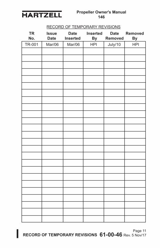
RECORD OF TEMPORARY REVISIONS TR Issue Date Inserted Date Removed No. Date Inserted By Removed By
TR-001 Mar/06 Mar/06 HPI July/10 HPI

61-00-46RECORD OF TEMPORARY REVISIONSPage 12
Rev. 5 Nov/17
Propeller Owner's Manual146
RECORD OF TEMPORARY REVISIONS TR Issue Date Inserted Date Removed No. Date Inserted By Removed By

61-00-46 SERVICE DOCUMENT LIST
Propeller Owner's Manual146
Page 13Rev. 5 Nov/17
SERVICE DOCUMENTS LIST
Service Document Number Incorporation Rev/Date
Service Bulletins:SB 169A Rev 2, Jul/10
CAUTION 1: DO NOT USE OBSOLETE OR OUTDATED INFORMATION. PERFORM ALL INSPECTIONS OR WORK IN ACCORDANCE WITH THE MOST RECENT REVISION OF A SERVICE DOCUMENT. INFORMATION CONTAINED IN A SERVICE DOCUMENT MAY BE SIGNIFICANTLY CHANGED FROM EARLIER REVISIONS. FAILURE TO COMPLY WITH INFORMATION CONTAINED IN A SERVICE DOCUMENT OR THE USE OF OBSOLETE INFORMATION MAY CREATE AN UNSAFE CONDITION THAT MAY RESULT IN DEATH, SERIOUS BODILY INJURY, AND/OR SUBSTANTIAL PROPERTY DAMAGE.
CAUTION 2: THE INFORMATION FOR THE DOCUMENTS LISTED INDICATES THE REVISION LEVEL AND DATE AT THE TIME THAT THE DOCUMENT WAS INITIALLY INCORPORATED INTO THIS MANUAL. INFORMATION CONTAINED IN A SERVICE DOCUMENT MAY BE SIGNIFICANTLY CHANGED FROM EARLIER REVISIONS. REFER TO THE APPLICABLE SERVICE DOCUMENT INDEX FOR THE MOST RECENT REVISION LEVEL OF THE SERVICE DOCUMENT.

61-00-46 SERVICE DOCUMENT LIST
Propeller Owner's Manual146
Page 14Rev. 5 Nov/17
SERVICE DOCUMENTS LIST
Service Document Number Incorporation Rev/Date
Service Letters:HC-SL-61-185 Rev 5, Nov/17

Page 15Rev. 5 Nov/17 61-00-46 AIRWORTHINESS LIMITATIONS
Propeller Owner's Manual146
Rev. No. Description of Revision
Rev. No.
Description of Revision
The Airworthiness Limitations section is FAA approved and specifies maintenance required under 43.16 and 91.403 of the Federal Aviation Regulations unless an alternative program has been approved.
AIRWORTHINESS LIMITATIONS

Propeller Owner's Manual146
Page 16Rev. 5 Nov/17 61-00-46 AIRWORTHINESS LIMITATIONS
1. The FAA establishes specific life limits for certain component parts, as well as the entire propeller. Such limits require replacement of the identified parts after a specified number of hours of use.
2. The following data summarizes all current information concerning Hartzell life limited parts as related to propeller models affected by this manual. These parts are not life limited on other installations; however, time accumulated toward life limit accrues when first operated on aircraft/engine/propeller combinations listed and continues regardless of subsequent installations (that may or may not be life limited).A. Propeller models affected by this manual currently do not
have any life limited parts.
AIRWORTHINESS LIMITATIONS

61-00-46LIST OF EFFECTIVE PAGES
Propeller Owner's Manual146
Page 17Rev. 5 Nov/17
LIST OF EFFECTIVE PAGES Chapter Page Revision Date
Cover Cover and Inside Cover Rev. 5 Nov/17Message 1 and 2 Rev. 2 Jul/10Message 3 and 4 Rev. 5 Nov/17Revision Highlights 5 thru 8 Rev. 5 Nov/17Record of Revisions 9 and 10 Rev. 5 Nov/17Record of Temporary Revisions 11 and 12 Rev. 5 Nov/17Service Documents List 13 and 14 Rev. 5 Nov/17Airworthiness Limitations 15 and 16 Rev. 5 Nov/17List of Effective Pages 17 and 18 Rev. 5 Nov/17Table of Contents 19 and 20 Rev. 5 Nov/17Introduction 1-1 thru 1-3 Rev. 3 Jun/12Introduction 1-4 Rev. 1 Oct/04Introduction 1-5 Rev. 4 Jun/15Introduction 1-6 Rev. 3 Jun/12Introduction 1-7 thru 1-13 Rev. 4 Jun/15Introduction 1-14 thru 1-16 Rev. 3 Jun/12Description and Operation 2-1 thru 2-24 Rev. 3 Jun/12Installation and Removal 3-1 Rev. 5 Nov/17Installation and Removal 3-2 Rev. 3 Jun/12Installation and Removal 3-3 Rev. 4 Jun/15Installation and Removal 3-4 Rev. 1 Oct/04Installation and Removal 3-5 Original Oct/99Installation and Removal 3-6 thru 3-11 Rev. 3 Jun/12Installation and Removal 3-12 Rev. 2 Jul/10Installation and Removal 3-13 Rev. 4 Jun/15Installation and Removal 3-14 thru 3-17 Rev. 3 Jun/12Installation and Removal 3-18 thru 3-20 Rev. 5 Nov/17Installation and Removal 3-21 thru 3-24 Rev. 3 Jun/12Testing and Troubleshooting 4-1 thru 4-3 Rev. 3 Jun/12Testing and Troubleshooting 4-4 and 4-5 Rev. 4 Jun/15Testing and Troubleshooting 4-6 Rev. 3 Jun/12Testing and Troubleshooting 4-7 and 4-8 Rev. 4 Jun/15Testing and Troubleshooting 4-9 Original Oct/99

Page 18Rev. 5 Nov/1761-00-46LIST OF EFFECTIVE PAGES
Propeller Owner's Manual146
LIST OF EFFECTIVE PAGES Chapter Page Revision Date
Testing and Troubleshooting 4-10 Rev. 3 Jun/12Inspection and Check 5-1 Rev. 5 Nov/17Inspection and Check 5-2 Rev. 2 Jul/10Inspection and Check 5-3 and 5-4 Rev. 3 Jun/12Inspection and Check 5-5 Rev. 4 Jun/15Inspection and Check 5-6 thru 5-8 Rev. 3 Jun/12Inspection and Check 5-9 and 5-10 Rev. 4 Jun/15Inspection and Check 5-11 Rev. 5 Nov/17Inspection and Check 5-12 Rev. 2 Jul/10Inspection and Check 5-13 and 5-14 Rev. 5 Nov/17Inspection and Check 5-15 Rev. 2 Jul/10Inspection and Check 5-16 Rev. 3 Jun/12Inspection and Check 5-17 Rev. 4 Jun/15Inspection and Check 5-18 and 5-19 Rev. 3 Jun/12Inspection and Check 5-20 and 5-21 Rev. 4 Jun/15Inspection and Check 5-22 and 5-23 Rev. 2 Jul/10Inspection and Check 5-24 Rev. 4 Jun/15Inspection and Check 5-25 and 5-26 Rev. 3 Jun/12Maintenance Practices 6-1 Rev. 5 Nov/17Maintenance Practices 6-2 Rev. 4 Jun/15Maintenance Practices 6-3 Rev. 3 Jun/12Maintenance Practices 6-4 Rev. 2 Jul/10Maintenance Practices 6-5 Rev. 3 Jun/12Maintenance Practices 6-6 Rev. 5 Nov/17Maintenance Practices 6-7 thru 6-11 Rev. 3 Jun/12Maintenance Practices 6-12 thru 6-22 Rev. 4 Jun/15Maintenance Practices 6-23 Rev. 5 Nov/17Maintenance Practices 6-24 thru 6-27 Rev. 4 Jun/15Maintenance Practices 6-28 thru 6-30 Rev. 5 Nov/17De-ice Systems 7-1 thru 7-8 Rev. 5 Nov/17Records 8-1 thru 8-16 Original Oct/99

61-00-46 TABLE OF CONTENTS
Propeller Owner's Manual146
Page 19Rev. 5 Nov/17
TABLE OF CONTENTS
MESSAGE ...................................................................................... 1
REVISION HIGHLIGHTS ............................................................... 5
RECORD OF REVISIONS ............................................................. 9
RECORD OF TEMPORARY REVISIONS .....................................11
SERVICE DOCUMENTS LIST ..................................................... 13
AIRWORTHINESS LIMITATIONS ................................................ 15
LIST OF EFFECTIVE PAGES ...................................................... 17
TABLE OF CONTENTS ................................................................ 19
INTRODUCTION ......................................................................... 1-1
DESCRIPTION AND OPERATION .............................................. 2-1
INSTALLATION AND REMOVAL ................................................. 3-1
TESTING AND TROUBLESHOOTING ....................................... 4-1
INSPECTION AND CHECK ......................................................... 5-1
MAINTENANCE PRACTICES ..................................................... 6-1
ANTI-ICE AND DE-ICE SYSTEMS ............................................. 7-1
RECORDS .................................................................................. 8-1

61-00-46 TABLE OF CONTENTS
Propeller Owner's Manual146
Page 20Rev. 5 Nov/17
(This page is intentionally blank.)

INTRODUCTION 61-00-46Page 1-1
Rev. 3 Jun/12
PropellerOwner’sManual146
CONTENTS Page
1. Purpose .................................................................................. 1-3
2. Airworthiness Limits ................................................................ 1-3
3. Airframe or Engine Modifications ............................................ 1-4
4. Restrictions and Placards ....................................................... 1-5
5. General ................................................................................... 1-5A. Personnel Requirements ................................................... 1-5B. Maintenance Practices ....................................................... 1-6C. Continued Airworthiness .................................................... 1-8D. Propeller Critical Parts ....................................................... 1-8
6. Reference Publications ........................................................... 1-9
7. Definitions ............................................................................. 1-10
8. Abbreviations ........................................................................ 1-14
9. Hartzell Propeller Inc. Product Support ................................ 1-15
10.Warranty Service .................................................................. 1-15
11. Hartzell Propeller Inc. Recommended Facilities ................... 1-16

INTRODUCTION 61-00-46Page 1-2
Rev. 3 Jun/12
PropellerOwner’sManual146
(This page is intentionally blank.)

INTRODUCTION 61-00-46Page 1-3
Rev. 3 Jun/12
PropellerOwner’sManual146
1. Purpose
CAUTION: KEEP THIS MANUAL WITH THE PROPELLER, OR WITH THE AIRCRAFT ON WHICH IT IS INSTALLED, AT ALL TIMES. THE LOGBOOK RECORD WITHIN THIS MANUAL MUST BE MAINTAINED, RETAINED CONCURRENTLY, AND BECOME A PART OF THE AIRCRAFT AND ENGINE SERVICE RECORDS.
A. This manual supports constant speed feathering and reversing steel hub turbine propellers with composite blades.
B. The purpose of this manual is to enable qualified personnel to install, operate, and maintain a Hartzell Propeller Inc. Constant Speed Feathering and Reversing Propeller with composite blades. Separate manuals are available concerning overhaul procedures and specifications for the propeller.
C. This manual covers different design types. (1) Sample hub and blade model numbers within each
design are covered in the Description and Operation chapter of this manual.NOTE: All propeller models included in this manual
use composite propeller blades. Identical propeller types that use aluminum blades are supported by Hartzell Propeller Inc. Manual 139 (61-00-39).
2. Airworthiness LimitsRefer to the Airworthiness Limitations chapter of this manual for information about airworthiness limits.

INTRODUCTION 61-00-46Page 1-4
Rev. 1 Oct/04
PropellerOwner’sManual146
3. Airframe or Engine ModificationsA. Propellers are approved vibrationwise on airframe and
engine combinations based on tests or analysis of similar installations. This data has demonstrated that propeller stress levels are affected by airframe configuration, airspeed, weight, power, engine configuration, and flight maneuvers. Aircraft modifications which can effect propeller stress include, but are not limited to: aerodynamic changes ahead of or behind the propeller, realignment of the thrust axis, increasing airspeed limits, decreasing stall speed, increasing or decreasing weight limits (less significant on piston engines), and the addition of approved flight maneuvers (utility and aerobatic).
B. Engine modifications can also affect the propeller. The two primary categories of engine modifications are those which affect structure and those which affect power. An example of a structural engine modification is the alteration of the crankshaft or damper of a piston engine. Any change to the weight, stiffness or tuning of rotating components could result in a potentially dangerous resonant condition which is not detectable by the pilot. Most common engine modifications affect the power during some phase of operation. Some increase the maximum power output, while others improve the power available during hot and high operation (flat rating) or at off-peak conditions. Examples of such engine modifications include, but are not limited to: changes to the compressor, power turbine or hot section of a turboprop engine; and on piston engines, the addition or alteration of a turbocharger or turbonormalizer, increased compression ratio, increased RPM, altered ignition timing, electronic ignition, full authority digital electronic controls (FADEC), or tuned induction or exhaust.
C. All such modifications must be reviewed and approved by the propeller manufacturer prior to obtaining approval on the aircraft.

INTRODUCTION 61-00-46Page 1-5
Rev. 4 Jun/15
Propeller Owner’s Manual146
4. RestrictionsandPlacardsA. Thepropellerscoveredbythismanualmayhavearestricted
operatingrangethatrequiresacockpitplacard.(1) Therestrictions,ifpresent,willvarydependingonthe
propeller,blade,engine,and/oraircraftmodel.(2) Reviewthepropellerandaircrafttypecertificatedata
sheet(TCDS),PilotOperatingHandbook(POH),andanyapplicableAirworthinessDirectivesforspecificinformation.
WARNING: STABILIZEDGROUNDOPERATIONWITHINTHEPROPELLERRESTRICTEDRPMRANGECANGENERATEHIGHPROPELLERSTRESSESANDRESULTINFATIGUEDAMAGETOTHEPROPELLER.THISDAMAGECANLEADTOAREDUCEDPROPELLERFATIGUELIFE,PROPELLERFAILURE,ANDLOSSOFCONTROLOFTHEAIRCRAFT.THEPROPELLERRESTRICTEDRPMRANGEISDEFINEDINTHEAIRPLANEFLIGHTMANUAL(AFM).
B. ThepropelleroperatingrestrictionsorlimitationsarefoundintheAirplaneFlightManual(AFM)orAirplaneFlightManualSupplement(AFMS).
C. IfapropellerRPMoperatingrestrictionorlimitationisviolated,refertotheSpecialInspectionssectionintheInspectionandCheckchapterofthismanualforcorrectiveactions.
5. GeneralA. PersonnelRequirements
(1) Inspection,Repair,andOverhaul(a) Compliancetotheapplicableregulatory
requirementsestablishedbytheFederalAviationAdministration(FAA)orforeignequivalentismandatoryforanyoneperformingoracceptingresponsibilityforanyinspectionand/orrepairand/oroverhaulofanyHartzellPropellerInc.product.
(2) Personnelperformingmaintenanceareexpectedtohavesufficienttrainingandcertifications(whenrequiredbythe applicableAviationAuthority)toaccomplishtheworkrequired in a safe and airworthy manner.

INTRODUCTION 61-00-46Page 1-6
Rev. 3 Jun/12
PropellerOwner’sManual146
B. Maintenance Practices(1) The propeller and its components are highly vulnerable
to damage while they are removed from the engine. Properly protect all components until they are reinstalled on the engine.
(2) Never attempt to move the aircraft by pulling on the propeller.
(3) Avoid the use of blade paddles. Do not place the blade paddle in the area of the de-ice boot when applying torque to a blade assembly. Place the blade paddle in the thickest area of the blade, just outside of the de-ice boot. Use one blade paddle per blade.
(4) Use only the approved consumables, e.g., cleaning agents, lubricants, etc.
(5) Safe Handling of Paints and Chemicals(a) Always use caution when handling or being exposed
to paints and/or chemicals during propeller overhaul and maintenance procedures.
(b) Before using paint or chemicals, always read the manufacturer’s label on the container and follow specified instructions and procedures.
(c) Refer to the product’s Material Safety Data Sheet (MSDS) for detailed information about physical properties, health, and physical hazards of any chemical.
(6) Observe applicable torque values during maintenance.

INTRODUCTION 61-00-46Page 1-7
Rev. 4 Jun/15
Propeller Owner’s Manual146
(7) Beforeinstallingthepropellerontheengine,thepropellermustbestaticallybalanced.NewpropellersarestaticallybalancedatHartzellPropellerInc.Overhauledpropellersmustbestaticallybalancedbyacertifiedpropellerrepairstationwiththeappropriateratingbeforereturntoservice.NOTE: Dynamicbalancingisrecommended,but
maybeaccomplishedatthediscretionoftheoperator,unlessspecificallyrequiredbytheairframeorenginemanufacturer.DynamicbalancingmustbeaccomplishedinaccordancewiththeproceduresandlimitationsintheMaintenancePracticeschapterofthismanual.Additionalproceduresmaybefoundintheaircraftmaintenancemanual.
(8) Asnecessary,useasoft,non-graphitepencilorcrayon tomakeidentifyingmarksoncomponents.
(9) Asapplicable,followmilitarystandardNASM33540for safetywireandcotterpingeneralpractices.Use 0.032inch(0.81mm)diameterstainlesssteelsafetywireunlessotherwiseindicated.
WARNING: DO NOT USE OBSOLETE OR OUTDATEDINFORMATION.PERFORMALLINSPECTIONSORWORKINACCORDANCEWITHTHEMOSTRECENTREVISIONOFTHISMANUAL.INFORMATIONCONTAINEDINTHISMANUALMAYBESIGNIFICANTLYCHANGEDFROMEARLIERREVISIONS.USEOFOBSOLETEINFORMATIONMAYRESULTINDEATH,SERIOUSBODILYINJURY,AND/ORSUBSTANTIALPROPERTYDAMAGE.FORTHEMOSTRECENTREVISIONLEVELOFTHISMANUAL,REFERTOTHEHARTZELLPROPELLERINC.WEBSITEAT WWW.HARTZELLPROP.COM.
(10)Theinformationinthismanualrevisionsupersedesdatainallpreviouspublishedrevisionsofthismanual.

INTRODUCTION 61-00-46Page 1-8
Rev. 4 Jun/15
Propeller Owner’s Manual146
(11)Theairframemanufacturer’smanualsshouldbeusedinadditiontotheinformationinthismanualduetopossiblespecialrequirementsforspecificaircraftapplications.
(12)IfthepropellerisequippedwithaniceprotectionsystemthatusescomponentssuppliedbyHartzellPropellerInc., applicableinstructionsandtechnicalinformationforthe componentssuppliedbyHartzellPropellerInc.canbe foundinthefollowingpublicationsavailableontheHartzellPropellerInc.websiteatwww.hartzellprop.com:(a) Manual180(30-61-80)-PropellerIceProtection
SystemManual(b) Manual181(30-60-81)-PropellerIceProtection
SystemComponentMaintenanceManual(c) Manual182(61-12-82)-PropellerElectricalDe-ice
BootRemovalandInstallationManual.(13)Propellericeprotectionsystemcomponentsnot
suppliedbyHartzellPropellerInc.arecontrolledbytheapplicableTCorSTCholder’sInstructionsforContinuedAirworthiness(ICA).
C. Continued AirworthinessOperatorsareurgedtokeepinformedofairworthinessinformationviaHartzellPropellerInc.ServiceBulletinsandServiceLetters,whichareavailablefromHartzellPropellerInc.distributorsorfromtheHartzellPropellerInc.factorybysubscription.SelectedinformationisalsoavailableontheHartzellPropellerInc.websiteatwww.hartzellprop.com.
D. PropellerCriticalParts(1) Thefollowingmaintenanceproceduresmayinvolve
propellercriticalparts.TheseprocedureshavebeensubstantiatedbasedonEngineeringanalysisthatexpectsthisproductwillbeoperatedandmaintainedusingtheproceduresandinspectionsprovidedintheInstructionsforContinuedAirworthiness(ICA)forthisproduct.RefertotheIllustratedPartsListchapteroftheapplicablemaintenancemanualfortheapplicablepropellermodelfortheidentificationofspecificCriticalParts.

INTRODUCTION 61-00-46Page 1-9
Rev. 4 Jun/15
Propeller Owner’s Manual146
(2) NumerouspropellersystempartscanproduceapropellerMajororHazardouseffect,eventhoughthosepartsmaynotbeconsideredasCriticalParts.TheoperatingandmaintenanceproceduresandinspectionsprovidedintheICAforthisproductare,therefore,expectedtobeaccomplishedforallpropellersystemparts.
6. ReferencePublications
Thefollowingpublicationsarereferencedwithinthismanual:ActiveHartzellPropellerInc.ServiceBulletins,ServiceLetters,ServiceInstructions,andServiceAdvisoriesHartzellPropellerInc.ManualNo.118F(61-10-18) - Three and Four-BladeSteelHubTurbinePropellerMaintenanceManualHartzellPropellerInc.ManualNo.127(61-16-27) - Spinner AssemblyMaintenanceManualHartzellPropellerInc.ManualNo.135F(61-13-35) - Composite PropellerBladeMaintenanceManualHartzellPropellerInc.ManualNo.159(61-02-59) - ApplicationGuide - AvailableontheHartzellPropellerInc.website at www.hartzellprop.comHartzellPropellerInc.ManualNo.165A(61-00-65)-IllustratedToolandEquipmentManual-AvailableontheHartzellwebsiteatwww.hartzellprop.comHartzellPropellerInc.ManualNo.170(61-13-70) - Composite PropellerBladeFieldMaintenanceandMinorRepairManual -AvailableontheHartzellPropellerInc.websiteatwww.hartzellprop.com
HartzellPropellerInc.ManualNo.180(30-61-80)-PropellerIceProtectionSystemManual-AvailableontheHartzellPropellerInc.websiteatwww.hartzellprop.comHartzellPropellerInc.ManualNo.181(30-60-81)-PropellerIceProtectionSystemComponentMaintenanceManual- AvailableontheHartzellPropellerInc.websiteat www.hartzellprop.com
HartzellPropellerInc.ManualNo.182(61-12-82)-PropellerElectricalDe-iceBootRemovalandInstallationManual- AvailableontheHartzellPropellerInc.websiteat www.hartzellprop.com

INTRODUCTION 61-00-46Page 1-10
Rev. 4 Jun/15
Propeller Owner’s Manual146
HartzellPropellerInc.ManualNo.202A(61-01-02) - Standard PracticesManual-Volumes1through11(Volume7,ConsumableMaterialsisavailableontheHartzellPropellerInc.websiteatwww.hartzellprop.com)HartzellPropellerInc.ServiceLetterHC-SL-61-61Y-PropellerOverhaulPeriodsandServiceLifeLimitsforHartzellPropellerInc.Aviation Components - Propellers,Governors,Accumulators,andPropellerDamperAssemblies-(AvailableontheHartzellPropellerInc.websiteatwww.hartzellprop.com)
7. DefinitionsAbasicunderstandingofthefollowingtermswillassistinmaintainingandoperatingHartzellPropellerInc.propellersystems.
Term Definition
Annealed ...................... Softeningofmaterialduetooverexposuretoheat.
BladeAngle .................. Measurementofbladeairfoillocationdescribedastheanglebetweenthebladeairfoilandthesurfacedescribedbypropellerrotation.
Brinelling ....................... Adepressioncausedbyfailureofthematerialincompression.
Chord Line .................... Astraightlinebetweentheleadingandtrailingedgesofanairfoil.
CompositeMaterial ....... Kevlar®(yellow)orgraphite(black)fibersboundtogetherwithorencapsulatedwithinanepoxyresin.
ConstantForce ............. Aforcethatisalwayspresentinsomedegreewhenthepropellerisoperating.
Constant Speed ............ ApropellersystemthatemploysagoverningdevicetomaintainaselectedengineRPM.
Corrosion ...................... Gradualmaterialremovalordeteriorationduetochemicalaction.

INTRODUCTION 61-00-46Page 1-11
Rev. 4 Jun/15
Propeller Owner’s Manual146
Crack ............................ Irregularlyshapedseparationwithinamaterial,sometimesvisibleasanarrowopeningatthesurface.
Debond ......................... Separationoftwomaterialsthatwereoriginallybondedtogetherinaseparate operation.
Delamination ................. Internalseparationbetweenthelayersofcompositematerial.
Depression ................... Surfaceareawherethematerialhasbeencompressedbutnotremoved.
Distortion ...................... Alterationoftheoriginalshapeorsizeofacomponent.
Erosion ......................... Gradualwearingawayordeteriorationduetoactionoftheelements.
Exposure ...................... Materialopentoactionoftheelements.
Feathering .................... Thecapabilityofbladestoberotatedparalleltotherelativewind,thusreducingaerodynamicdrag.
Fretting ......................... Damagethatdevelopswhenrelativemotionofsmalldisplacementtakesplacebetweencontactingparts,wearingawaythesurface.
Gouge ........................... Surfaceareawherematerialhasbeenremoved.
HazardousPropeller ..... ThehazardouspropellereffectsEffect aredefinedinTitle14CFRsection
35.15(g)(1).HorizontalBalance ....... Balancebetweenthebladetipand
thecenterofthehub.ImpactDamage ........... Damagethatoccurswhenthe
propellerbladeorhubassemblystrikes,orisstruckby,anobjectwhileinflightorontheground.
Term Definition

INTRODUCTION 61-00-46Page 1-12
Rev. 4 Jun/15
Propeller Owner’s Manual146
MajorPropellerEffect ... ThemajorpropellereffectsaredefinedinTitle14CFRsection35.15(g)(2).
Nick .............................. Removalofpaintandpossiblyasmallamountofmaterial.
Onspeed ....................... ConditioninwhichtheRPMselectedbythepilotthroughthepropellercontrolleverandtheactualengine(propeller)RPMareequal.
Overhaul ....................... Theperiodicdisassembly,inspection,repair,refinish,andreassemblyofapropellerassemblyto maintain airworthiness.
Overspeed .................... ConditioninwhichtheRPMofthepropellerorengineexceedspredeterminedmaximumlimits;theconditioninwhichtheengine(propeller)RPMishigherthantheRPMselectedbythepilotthroughthepropellercontrollever.
Overspeed Damage ..... Damagethatoccurswhenthepropellerhubassemblyrotatesataspeedgreaterthanthemaximumlimitforwhichitisdesigned.
Pitting ............................ Formationofanumberofsmall,irregularlyshapedcavitiesinsurfacematerialcausedbycorrosionorwear.
PropellerCriticalParts .. Apartonthepropellerwhoseprimaryfailurecanresultinahazardouspropellereffect,asdeterminedbythesafetyanalysisrequiredbyTitle14CFRsection35.15.
Reversing ..................... Thecapabilityofrotatingbladestoa position to generate reverse thrust toslowtheaircraftorbackup.
Term Definition

INTRODUCTION 61-00-46Page 1-13
Rev. 4 Jun/15
Propeller Owner’s Manual146
Scratch ......................... Sameas“Nick”.SingleActing ................. Hydraulicallyactuatedpropellerthat
usesasingleoilsupplyforpitchcontrol.
Split ............................... Delaminationofbladeextendingtothebladesurface,normallyfoundnearthetrailingedgeortip.
Synchronizing ............... AdjustingtheRPMofallthepropellersofamulti-engineaircraftto the same RPM.
Synchrophasing ............ AformofpropellersychronizationinwhichnotonlytheRPMoftheengines(propellers)areheldconstant,butalsothepositionofthepropellersinrelationtoeachother.
Track ............................. Inanassembledpropeller,ameasurementofthelocationofthebladetipwithrespecttotheplaneofrotation,usedtoverifyfacealignmentandtocomparebladetiplocationwithrespecttothelocationsoftheotherbladesintheassembly.
Underspeed .................. Theconditioninwhichtheactualengine(propeller)RPMislowerthantheRPMselectedbythepilotthroughthepropellercontrollever
VariableForce .............. Aforcethatmaybeappliedorremovedduringpropelleroperation.
Windmilling ................... Therotationofanaircraftpropellercausedbyairflowingthroughitwhiletheengineisnotproducingpower.
Term Definition

INTRODUCTION 61-00-46Page 1-14
Rev. 3 Jun/12
Propeller Owner’s Manual146
8. Abbreviations
Abbreviation Term
AMM ............................. AircraftMaintenanceManualAN ................................. AirForce-Navy(orArmy-Navy)AOG .............................. AircraftonGroundFAA ............................... FederalAviationAdministrationFt-Lb ............................. Foot-PoundICA ................................ InstructionsforContinued
AirworthinessID .................................. InsideDiameterIn-Lb ............................. Inch-PoundLbs ................................ PoundsMIL-X-XXX .................... MilitarySpecificationMPI ............................... MajorPeriodicInspection(Overhaul)MS ................................ MilitaryStandardMSDS ........................... MaterialSafetyDataSheetOD ................................ Outside DiameterNAS .............................. NationalAerospaceStandards N•m ............................... Newton-MetersPOH .............................. Pilot’sOperatingHandbookPSI ................................ PoundsperSquareInchRPM .............................. RevolutionsperMinuteTBO .............................. TimeBetweenOverhaulTSN .............................. TimeSinceNewTSO .............................. TimeSinceOverhaulNOTE: TSN/TSOisconsideredasthetimeaccumulated
betweenrotationandlanding,i.e.,flighttime.

INTRODUCTION 61-00-46Page 1-15
Rev. 3 Jun/12
PropellerOwner’sManual146
9. Hartzell Propeller Inc. Product SupportHartzell Propeller Inc. is ready to assist you with questions concerning your propeller system. Hartzell Propeller Inc. Product Support may be reached during business hours (8:00 a.m. through 5:00 p.m., United States Eastern Time) at (937) 778-4379 or at (800) 942-7767, toll free from the United States and Canada. Hartzell Propeller Inc. Product Support can also be reached by fax at (937) 778-4391, and by email at [email protected] business hours, you may leave a message on our 24 hour product support line at (937) 778-4376 or at (800) 942-7767, toll free from the United States and Canada. A technical representative will contact you during normal business hours. Urgent AOG support is also available 24 hours per day, seven days per week via this message service.Additional information is available on our website at www.hartzellprop.com.NOTE: When calling from outside the United States, dial (001)
before dialing the above telephone numbers.
10. Warranty ServiceIf you believe you have a warranty claim, it is necessary to contact Hartzell’s Warranty Administrator. Hartzell’s Warranty Administrator will provide you with a Warranty Application form. It is necessary to complete this form and return it to the Warranty Administrator for evaluation beforeproceedingwithrepairorinspectionwork. Upon receipt of this form, the Warranty Administrator will provide instructions on how to proceed. Hartzell Propeller Inc. Warranty may be reached during business hours (8:00 a.m. through 5:00 p.m., United States Eastern Time) at 937-778-4379, or toll free at (800) 942-7767. Hartzell Propeller Inc. Warranty Adminstration can also be reached by fax, at (937) 778-4391, or by email at [email protected]: When calling from outside the United States, dial (001)
before dialing the above telephone numbers.

INTRODUCTION 61-00-46Page 1-16
Rev. 3 Jun/12
PropellerOwner’sManual146
11. Hartzell Propeller Inc. Recommended FacilitiesA. Hartzell Propeller Inc. recommends using Hartzell Propeller
Inc. approved distributors and repair facilities for the purchase, repair and overhaul of Hartzell Propeller Inc. propeller assemblies or components.
B. Information about the Hartzell Propeller Inc. worldwide network of aftermarket distributors and approved repair facilities is available on the Hartzell Propeller Inc. website at www.hartzellprop.com.

DESCRIPTION AND OPERATION 61-00-46
Propeller Owner's Manual146
Page 2-1Rev. 3 Jun/12
CONTENTS Page 1. Functional Description of Constant Speed Propeller Types ... 2-5
A. Feathering and Reversing Propellers HC-B(3,4)( )( )-3( ) (External Beta System) ...................................................... 2-5B. Feathering and Reversing Propellers HC-B(3,4)( )( )-5( ) (Internal Beta System) ....................................................... 2-9
2. Overview of Composite Blade .............................................. 2-13A. Composite Blades ............................................................ 2-13
3. Model Designation ................................................................ 2-17A. Blade Model ..................................................................... 2-17B. Blade Shank Designs ....................................................... 2-17C.CompositeBladeModelIdentification .............................. 2-18D. Blade Type and Blade Model Designations ..................... 2-20
4. Governors ............................................................................. 2-23A. Theory of Operation ......................................................... 2-23
5. Propeller De-ice System ....................................................... 2-24A. Description ....................................................................... 2-24

DESCRIPTION AND OPERATION 61-00-46
Propeller Owner's Manual146
Page 2-2 Rev. 3 Jun/12
FIGURES Page
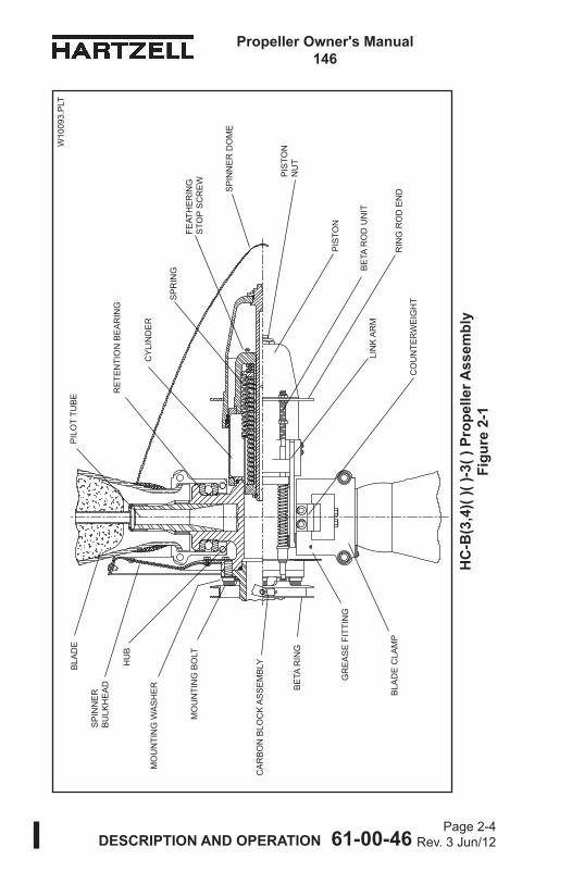
HC-B(3,4)( )( )-3( ) Propeller Assembly .. Figure 2-1 .................... 2-4
Steel Hub Unit ........................................ Figure 2-2 .................... 2-5
HC-B(3,4)( )( )-5( ) Propeller Assembly .. Figure 2-3 .................... 2-8
Section of Typical Composite Blade ....... Figure 2-4 .................. 2-12
Composite Blade Retention System for Steel Hub........................................... Figure 2-5 .................. 2-12
Basic Components of Composite Blade . Figure 2-6 .................. 2-14
Governor in Onspeed Condition ............. Figure 2-7 .................. 2-22
Governor in Underspeed Condition ........ Figure 2-8 .................. 2-22
Governor in Overspeed Condition .......... Figure 2-9 .................. 2-22
TABLES Page
Typical Composite Blade Model Number ................................................... Table 2-1 ................... 2-19
Blade Type and Blade Model Designations ........................................... Table 2-2 ................... 2-20

DESCRIPTION AND OPERATION 61-00-46
Propeller Owner's Manual146
Page 2-3Rev. 3 Jun/12
(This page is intentionally blank.)
DESCRIPTION AND OPERATION 61-00-46
Propeller Owner's Manual146
Page 2-4 Rev. 3 Jun/12
FEAT
HE
RIN
G
STO
P S
CR
EW
HC
-B(3
,4)(
)( )-3
( ) P
rope
ller A
ssem
bly
Figu
re 2
-1
W10
093.
PLT
HU
BR
ETE
NTI
ON
BE
AR
ING
CY
LIN
DE
R
PIS
TON
BLA
DE
PIL
OT
TUB
E
BLA
DE
CLA
MP
CO
UN
TER
WE
IGH
T
BE
TA R
OD
UN
IT
BE
TA R
ING
MO
UN
TIN
G B
OLT
GR
EA
SE
FIT
TIN
G
SP
INN
ER
DO
ME
SP
RIN
G
SP
INN
ER
B
ULK
HE
AD
MO
UN
TIN
G W
AS
HE
R
PIS
TON
N
UT
RIN
G R
OD
EN
D
LIN
K A
RM
CA
RB
ON
BLO
CK
AS
SE
MB
LY

DESCRIPTION AND OPERATION 61-00-46
Propeller Owner's Manual146
Page 2-5Rev. 3 Jun/12
1. Functional Description of Constant Speed Propeller TypesA. Feathering and Reversing Propellers HC-B(3,4)( )( )-3( )
(External Beta System) Refer to Figure 2-1. The propellers described in this section are constant speed, feathering and reversing. They use a single oil supply from a governing device to hydraulically actuate a change in blade angle. The propellers can have three or four blades, and they are used primarily on Pratt and Whitney turbine engines.Propeller blades and bearing assemblies are mounted on the arms of a steel hub unit (Figure 2-2) and are held in place by two-piece blade clamps. A cylinder is threaded onto the hub, and a feathering spring assembly is installed in the cylinder. A piston is placed over the cylinder and is connected by a link arm to each blade clamp. Propeller blade angle change is accomplished through the linear motion of the hydraulically actuated piston that is transmitted to each blade through the link arms and blade clamps.
Steel Hub UnitFigure 2-2
APS2063

DESCRIPTION AND OPERATION 61-00-46
Propeller Owner's Manual146
Page 2-6 Rev. 3 Jun/12
While the propeller is operating, the following forces are constantly present: 1) spring force, 2) counterweight force, 3) centrifugal twisting moment of each blade, and 4) blade aerodynamic twisting forces. The spring and counterweight forces attempt to rotate the blades to a higher blade angle, while the centrifugal twisting moment of each blade is generally acting toward lower blade angle. Blade aerodynamic twisting force is usually very small in relation to the other forces and can attempt to increase or decrease blade angle.The summation of the propeller forces is toward higher pitch (low RPM) and is opposed by a variable force toward lower pitch (high RPM). The variable force is oil under pressure from a governor with an internal pump, which is mounted on and driven by the engine. The oil from the governor is supplied to the propeller and hydraulic piston through a hollow engine shaft. Increasing the volume of oil within the piston and cylinder will decrease the blade angle and increase propeller RPM. Decreasing the volume of oil will increase blade angle and decrease propeller RPM. By changing the blade angle, the governor can vary the load on the engine and maintain constant engine RPM (within limits), independent of where the power lever is set. The governor uses engine speed sensing mechanisms that allow it to supply or drain oil as necessary to maintain constant engine speed (RPM).If governor supplied oil is lost during operation, the propeller will increase pitch and feather. Feathering occurs because the summation of internal propeller forces causes the oil to drain out of the propeller until the feather stop position is reached.Normalin-flightfeatheringisaccomplishedwhenthepilotretards the propeller condition lever past the feather detent. This allows control oil to drain from the propeller and return to the engine sump. Engine shutdown is normally accomplished during the feathering process.

DESCRIPTION AND OPERATION 61-00-46
Propeller Owner's Manual146
Page 2-7Rev. 3 Jun/12
Normalin-flightunfeatheringisaccomplishedwhenthepilotpositionsthepropellerconditionleverintothenormalflight(governing) range and restarts the engine. As engine speed increases, the governor supplies oil to the propeller, and the blade angle decreases.In reverse mode of operation, the governor operates in an underspeed condition to act strictly as a source of pressurized oil, without attempting to control RPM. The propeller blade angle in reverse is accomplished through the beta valve.NOTE: The beta valve is normally built into the base of the
governor.The propeller is reversed by manually repositioning the cockpit-control to cause the beta valve to supply oil from the governor pump to the propeller. An external propeller feedback mechanism, which includes a beta ring and carbon block assembly, communicates propeller blade angle position to the beta valve.When the propeller reaches the desired reverse position, movement of the beta ring and carbon block assembly, initiated by the propeller piston, causes the beta valve toshutofftheflowofoiltothepropeller.Anyadditionalunwanted movement of the propeller toward reverse, or any movement of the manually positioned beta valve control toward high pitch position will cause the beta valve to drain oil from the propeller to increase pitch.

DESCRIPTION AND OPERATION 61-00-46
Propeller Owner's Manual146
Page 2-8 Rev. 3 Jun/12
W10
094.
PLT
HC
-B(3
,4)(
)( )-5
( ) P
rope
ller A
ssem
bly
Figu
re 2
-3
HU
BR
ETE
NTI
ON
BE
AR
ING
CY
LIN
DE
R
FEAT
HE
RIN
G
STO
P S
CR
EW
BLA
DE
PIT
CH
CH
AN
GE
RO
D
SP
RIN
G
PIL
OT
TUB
E
BLA
DE
CLA
MP
MO
UN
TIN
G B
OLT
SP
INN
ER
DO
ME
AU
TO H
IGH
PIT
CH
S
TOP
UN
IT
BE
TA V
ALV
E T
UB
E (I
NS
IDE
PIT
CH
C
HA
NG
E R
OD
SU
PP
LIE
D W
ITH
E
NG
INE
)
CO
UN
TER
WE
IGH
T
GR
EA
SE
FIT
TIN
G
PIS
TON
PIS
TON
NU
T
MO
UN
TIN
G W
AS
HE
R
LIN
K A
RM

DESCRIPTION AND OPERATION 61-00-46
Propeller Owner's Manual146
Page 2-9Rev. 3 Jun/12
B. Feathering and Reversing Propeller HC-B(3,4)( )( )-5( ) (Internal Beta System)Refer to Figure 2-3. The propellers described in this section are constant speed, feathering and reversing. They use a single oil supply from a governing device to hydraulically actuate a change in blade angle. The propellers can have three or four blades, and are used primarily on Garrett (Allied Signal) turbine engines.Propeller blades and bearing assemblies are mounted on the arms of a steel hub unit (Figure 2-2) and are held in place by two-piece blade clamps. A cylinder is threaded onto the hub, and a feathering spring assembly is installed in the cylinder. A piston is placed over the cylinder and is connected by a link arm to each blade clamp. Propeller blade angle change is accomplished through the linear motion of the hydraulically actuated piston that is transmitted to each blade through the link arms and blade clamps.While the propeller is operating, the following forces are constantly present: 1) spring force, 2) counterweight force, 3) centrifugal twisting moment of each blade, and 4) blade aerodynamic twisting forces. The spring and counterweight forces attempt to rotate the blades to higher blade angle, while the centrifugal twisting moment of each blade is generally toward lower blade angle. Blade aerodynamic twisting force is usually very small in relation to the other forces and can attempt to increase or decrease blade angle.

DESCRIPTION AND OPERATION 61-00-46
Propeller Owner's Manual146
Page 2-10 Rev. 3 Jun/12
The summation of the propeller forces is toward higher pitch (low RPM) and is opposed by a variable force toward lower pitch (high RPM). The variable force is oil under pressure from a governor with an internal pump, which is driven by the engine. The oil from the governor is supplied to the propeller and hydraulic piston through a hollow engine shaft. Increasing the volume of oil within the piston and cylinder will decrease the blade angle and increase propeller RPM. Decreasing the volume of oil will increase blade angle and decrease propeller RPM. By changing the blade angle, the governor can vary the load on the engine and maintain constant engine RPM (within limits), independent of where the power lever is set. The governor uses engine speed sensing mechanisms that allow it to supply or drain oil as necessary to maintain constant engine speed (RPM).If governor supplied oil is lost during operation, the propeller will increase pitch and feather. Feathering occurs because the summation of internal propeller forces causes the oil to drain out of the propeller until the feather stop position is reached.Normalin-flightfeatheringisaccomplishedwhenthepilotplaces the propeller condition lever into feather position. This allows control oil to drain from the propeller and return to the engine sump. Engine shutdown is normally accomplished during the feathering process.Normalin-flightunfeatheringisaccomplishedwhenthepilotpositionsthepropellerconditionleverintothenormalflight(governing) range, activates the auxiliary pump to decrease blade pitch, and restarts the engine. As engine speed increases, the governor supplies oil to the propeller, and the blade angle decreases until it reaches an onspeed condition.In reverse mode of operation, the governor operates in an underspeed condition to act strictly as a source of pressurized oil, without attempting to control RPM. Propeller blade angle is then controlled by the pilot via the beta valve.NOTE: The beta valve is normally located on the side of
the reduction gearbox opposite the propeller.

DESCRIPTION AND OPERATION 61-00-46
Propeller Owner's Manual146
Page 2-11Rev. 3 Jun/12
The propeller is operated from ground idle to maximum reverse by manually repositioning the power lever within the beta range to cause the beta valve to supply oil from the governor pump to the propeller. A beta rod inserted into the front of the propeller communicates propeller blade angle position to the beta valve. When the propeller reaches the desired negative blade angle, movement of thebetarodcausesthebetavalvetoshutofftheflowofoilto the propeller. Any additional unwanted movement of the propeller toward reverse, or any movement of the manually positioned beta valve control toward high pitch position will cause the beta valve to drain oil from the propeller to increase pitch.It is undesirable to feather the propeller when the engine is stopped after landing the aircraft. This propeller type is normallyinstalledonafixedshaftenginethatcausesthepropeller to rotate during an engine start process. If the propeller is in feather position, an overload on the electric engine starter will occur.To prevent feathering during normal engine shutdown, the propeller incorporates spring-energized latch pins called start lock units. These units are installed either on a two-piece spinner mounting plate or on the spinner bulkhead, which isboltedtothepropellerhubflange.Ifpropellerrotationisapproximately 800 RPM or above, the auto high pitch stop units are disengaged from the blade clamp mounted plates by centrifugal force acting on the latch pins to compress the springs (within the units). When the RPM drops below 800, the springs overcome the centrifugal force and move the latch pins to engage the clamp-mounted plate, preventing blade angle movement to feather.Shortly after engine start-up, with the propeller RPM above 800, the latch pins in the auto high pitch stop units will still retain the blade angle. To release the latch pins, it is necessary to manually actuate the propeller slightly toward reverse. This will move the clamp-mounted plate, allowing the latch pins to slide freely. Centrifugal force will compress the springs and disengage the pins from the plate.

DESCRIPTION AND OPERATION 61-00-46
Propeller Owner's Manual146
Page 2-12 Rev. 3 Jun/12
Composite Blade Retention System for Steel HubFigure 2-5
Section of Typical Composite BladeFigure 2-4
CPS0051
Shear Webs inserted through cuts in foam (not
present in all designs)
Low-DensityFoam Core
Laminated Layers of
Composite Material
Erosion Shield
Laminated Layers of Composite
Material
Solid Unidirectional
Composite Material
Solid Unidirectional
Composite Material
Low-DensityFoam Core
CPS0043 Typical BladeRetentionWindings
Blade Cuff(optional)
SteelHub Unit
BladeO-ring
Blade RetentionSplit-Bearing
HubPilotTube Blade
Clamp
SmallBlade
AlignmentBearing
Low-DensityFoam Core
BladeBalance
Tube
Spacer
Large BladeAlignment Bearing
Metal BladePlug
RetentionComposite Materials

DESCRIPTION AND OPERATION 61-00-46
Propeller Owner's Manual146
Page 2-13Rev. 3 Jun/12
2. Overview of Composite BladesA. Composite Blades
(1) Composite blades are composed of a metal blade shank (plug) into which is molded a low-density foam core. (a) These internal components are covered by layers
of laminated composite materials that make up the outer shell of the blade.
(b) The laminated blade then undergoes compressive moldingthatprovidesthefinalairfoilshapeandbonds the composite materials to the blade plug.
(c) The foam core is used to support the layers of laminated composite materials during the manufacturing process.
(d) Refer to Figure 2-4 for the end view of a sectioned cord line.
NOTE: On some blade designs the original molded shape contains a recess on the leading edge for the de-ice boot and/or the erosion shield.
(2) The laminated composite materials that are an integral component of the blade provide a retention load path that extends directly under the clamp in steel hubs (or bearing in aluminum hubs) for blade retention. Refer to Figure 2-5.
(3) An electroformed nickel erosion shield is adhesively bonded over the leading edge of the blade to provide protection from impact and erosion damage. (a) The LM10585 blade was introduced with a stainless
steel erosion shield, but can only be replaced with a nickel shield.
(4) Some designs incorporate a stainless steel wire mesh into the fabrication to inhibit erosion in blade tip areas.

DESCRIPTION AND OPERATION 61-00-46
Propeller Owner's Manual146
Page 2-14 Rev. 3 Jun/12
(5) Some designs incorporate a non-structural blade cuff of low-density foam that is molded to the blade and covered with composite material. Refer to Figure 2-6.
(6) Filament windings of composite material provide additional retention of the blade composite materials to the internal metal plug. On some designs the windings also provide a machinable surface for the application of a blade/hub seal.
(7) Somedesignsuseafilamentwindingontheinboardendof the erosion shield to aid the retention of the erosion shield. (a) This winding is sometimes referred to as an erosion
shield winding and should not be confused with the blade retention winding that is used to attach the blade material to the internal metal plug.
Basic Components of the Composite BladeFigure 2-6
Blade Cuff(as applicable)
Low-DensityFoam Core
Shear Web Slots Cut into
Foam
APS0047B
Low-DensityFoam Core
Shank of Metal Blade
PlugComposite
MaterialRetention Laminates
Metal Blade Plug
Erosion Shield
Blade Retention Windings

DESCRIPTION AND OPERATION 61-00-46
Propeller Owner's Manual146
Page 2-15Rev. 3 Jun/12
(8) The composite blade is balanced in the horizontal plane during production by the addition of lead wool to a centrally located balance tube in the metal blade shank (that may protrude into the foam core of the blade).
(9) Afinishcoveringofpolyurethanepaintprotectstheentireblade from erosion and ultraviolet damage.
(10) For aircraft that require ice protection:(a) Most composite blade models use an external de-ice
boot.1 The A10460E blade model was introduced with
an internal heating element instead of a boot. A standard de-ice boot for this model is an option.

DESCRIPTION AND OPERATION 61-00-46
Propeller Owner's Manual146
Page 2-16 Rev. 3 Jun/12
(This page is intentionally blank.)

DESCRIPTION AND OPERATION 61-00-46
Propeller Owner's Manual146
Page 2-17Rev. 3 Jun/12
3. Model DesignationA. Blade Model - Refer to Table 2-1
(1) Hartzell Propeller Inc. uses a propeller model designationtoidentifyspecificpropellerandblade assemblies. Example: HC-B4MN-5( )/LM10585B+4. A slash mark separates the propeller and blade designations.
(2) The propeller model designation is permanently impression stamped on the propeller hub.
(3) The blade designation is permanently impression stamped on the butt end (internal to hub) of the blade. NOTE: N-shank blades are constructed of serialized
components. (4) The external surface of the blade (outside of the hub)
also has a label or ink stamping on the camber side that identifiestheblademodel,serialnumber,andrevisionlevel of the blade.
(5) Blade balance information is also included on the camber side of the blade on some designs.
B. Blade Shank Designs(1) Hartzell Propeller Inc. composite blade designs are often
referred to as an “A", "B", "E", “M", or "N" shank blade, in reference to the type of retention system incorporated on the blade. (a) Theshanktypemaybeidentifiedbytheprefixletter
of the blade model designation, such as the "M" in M10083(K). Refer to Table 2-1 for an explanation of shank designations.
(2) Somebladesthathavebeencertifieddonothavearetention system designation in the model number.
(3) Refer to the Overhaul chapter in the Hartzell Propeller Inc. Composite Blade Manual 135F (61-13-35) to verify the dimensions of applicable machined windings.

DESCRIPTION AND OPERATION 61-00-46
Propeller Owner's Manual146
Page 2-18 Rev. 3 Jun/12
HC - B 4 M N - 5 AL
MINOR MODIFICATIONS
3 - CONSTANT SPEED, FEATHERING, REVERSING, PT6-( ) ENGINE, EXTERNAL BETA SYSTEM
5 - CONSTANT SPEED, FEATHERING, REVERSING, INTERNAL BETA SYSTEM, START LOCK UNITS, TPE-331-( ) ENGINE
SPECIFIC DESIGN FEATURES
BOLT DOWELS NO. OF BOLTS CIRCLE NO. DIA. OR STUDS N 4.25 in. 2 1/2 8 (9/16") P 4.25 in. 4 1/2 8 (9/16") MOUNTING
FLANGE
NO. OF BLADES 3 or 4
B - SINGLE SHOULDER RETENTIONBASIC DESIGN
BASIC SHANK M - TWO NEEDLE BEARINGS IN BLADE, C-1977 CLAMP
HC - HARTZELL CONTROLLABLE
C. CompositeBladeModelIdentificationThe blade designation is impression-stamped on the blade butt end (internal) and is either on a decal, or ink-stamped on the blade camber side (external).
NOTE: Parentheses in the model designation system indicates that an option or modification may or may not be included in the blade assembly.
Typical Composite Blade Model NumberTable 2-1

DESCRIPTION AND OPERATION 61-00-46
Propeller Owner's Manual146
Page 2-19Rev. 3 Jun/12
MINOR MODIFICATIONS
prop model/LM10585ANK+4CHANGE FROM BASIC PROPELLER DIAMETER(inches plus or minus)
TYPE OF DE-ICE BOOT ** K tapered watt density (Foil elements) B constant watt density (Wire elements)
MINOR MODIFICATIONSe.g. *Nickel Erosion Shield
MINOR MODIFICATIONSe.g. Cuff Shape
INITIAL DESIGN DIAMETER (inches)(Not necessarily the actual propeller dia.)
BLADE RETENTION SYSTEM (Not applicable to all designs)
M shank: used with steel hub propellers, shank is similar to M shank aluminum blades, counterweights are attached to steel hub clamps.
DIRECTION OF ROTATION (L = Left hand Blade) (Right-hand rotation is not indicated)
*All other blades, as well as recent production LM10585( )( )+4, use a nickel erosion shield and do not have an “N” in the model designation.
** Applies to composite blades only.
ENGINEERING DESIGNATION forDESIGN CHARACTERISTICS
Typical Composite Blade Model Number, continuedTable 2-1
HC-B3MN-3(No Minor Modifications Apply)
HC-B4MN-5A - 834-13 STOP COLLAR, A-3495 STOP PLATE, 838-97L CLAMP ASSEMBLY, 832-44L PISTON ASSEMBLYL - LEFT HAND ROTATION
HC-B4MP-3A - D-4846P SPINNER ASSEMBLY. 838-109 CLAMP ASSEMBLY
MINOR MODIFICATIONS
HC - B 4 MN - 5 AL

DESCRIPTION AND OPERATION 61-00-46
Propeller Owner's Manual146
Page 2-20 Rev. 3 Jun/12
BLADE TYPE BLADE MODEL DESIGNATION
Kevlar® ( )7690( )7890K
B7421(K)E8190K
M10083(K)A10460(E)(K)
LM10585(A)(N)(B,K)M10877K
E10950P(C)(B,K)E11990KE12902K
Carbon E13890KE9193(B,K)
Blade Type and Blade Model Designations Table 2-2
D. Blade Type and Blade Model Designations(1) For blade types and the associated blade model
designation, refer to Table 2-2 in this chapter.

DESCRIPTION AND OPERATION 61-00-46
Propeller Owner's Manual146
Page 2-21Rev. 3 Jun/12
(This page is intentionally blank.)

DESCRIPTION AND OPERATION 61-00-46
Propeller Owner's Manual146
Page 2-22 Rev. 3 Jun/12
APS6151
APS6149
APS6150 Pilot Control
Speeder SpringFlyweights
Pilot Valve
Pilot Control
Speeder SpringFlyweights
Pilot Valve
Governor in Onspeed ConditionFigure 2-7
Governor in Underspeed ConditionFigure 2-8
Governor in Overspeed ConditionFigure 2-9
Speeder SpringFlyweights
Pilot Valve
Pilot Control

DESCRIPTION AND OPERATION 61-00-46
Propeller Owner's Manual146
Page 2-23Rev. 3 Jun/12
4. GovernorsA. Theory of Operation
(1) A governor is an engine RPM sensing device and high pressure oil pump. In a constant speed propeller system, the governor responds to a change in engine RPM by directing oil under pressure to the propeller hydraulic cylinder or by releasing oil from the hydraulic cylinder. The change in oil volume in the hydraulic cylinder changes the blade angle and maintains the propeller system RPM to the set value. The governor is set for aspecificRPMviathecockpitpropellercontrolthatcompresses or releases the governor speeder spring.
(2) When the engine is operating at the RPM set by the pilot using the cockpit control, the governor is operating onspeed. Refer to Figure 2-7. In an onspeed condition, thecentrifugalforceactingontheflyweightsisbalancedby the speeder spring, and the pilot valve is neither directing oil to nor from the propeller hydraulic cylinder.
(3) When the engine is operating below the RPM set by the pilot using the cockpit control, the governor is operating underspeed. Refer to Figure 2-8. In an underspeed condition,theflyweightstiltinwardbecausethereisnotenoughcentrifugalforceontheflyweightstoovercomethe force of the speeder spring. The pilot valve, forced downbythespeederspring,metersoilflowtodecreasepropeller pitch and raise engine RPM.
(4) When the engine is operating above the RPM set by the pilot using the cockpit control, the governor is operating overspeed. Refer to Figure 2-9. In an overspeed condition,thecentrifugalforceactingontheflyweightsisgreaterthanthespeederspringforce.Theflyweightstilt outward, and raise the pilot valve. The pilot valve thenmetersoilflowtoincreasepropellerpitchandlowerengine RPM.

DESCRIPTION AND OPERATION 61-00-46
Propeller Owner's Manual146
Page 2-24 Rev. 3 Jun/12
(5) Feathering governors allow oil to be pushed from the propeller to the engine drain to increase propeller pitch to feather.
(6) A synchronizing system can be employed in a multi-engine aircraft to keep the engines operating at the same RPM. A synchrophasing system not only keeps RPM of the engines consistent, but also keeps the propeller blades operating in phase with each other. Both synchronizing and synchrophasing systems serve to reduce noise and vibration.
5. Propeller De-ice System A Hartzell Propeller Inc. turbine propeller is sometimes equipped with a de-ice system. A. Description
A propeller de-ice system is a system that allows ice to form, and then removes it by electrically heating the de-ice boots. The ice partially melts and is thrown from the blade by centrifugal force.(1) A de-ice system consists of one or more on/off switches,
a timer or cycling unit, a slip ring, brush blocks, and de-ice boots. The pilot controls the operation of the de-ice system by turning on one or more switches. All de-ice systems have a master switch, and may have another toggle switch for each propeller. Some systems also have a selector switch to adjust for light or heavy icing conditions.
(2) The timer or cycling unit determines the sequence of which blades (or portion thereof) are currently being de-iced, and for what length of time. The cycling unit applies power to each de-ice boot or boot segment in a sequential order.
(3) A brush block, which is normally mounted on the engine just behind the propeller, is used to transfer electricity to the slip ring. The slip ring rotates with the propeller and provides a current path to the blade de-ice boots.
(4) De-ice boots contain internal heating elements. These boots are securely attached to the leading edge of each blade with adhesive.

INSTALLATION AND REMOVAL 61-00-46
Propeller Owner’s Manual146
Page 3-1Rev. 5 Nov/17
CONTENTS Page
1. Tools, Consumables, and Expendables ................................. 3-3A. Tooling ................................................................................ 3-3B. Consumables ..................................................................... 3-3C. Expendables ...................................................................... 3-3
2. Pre-Installation ........................................................................ 3-4A. Inspection of Shipping Package ......................................... 3-4B. Uncrating ............................................................................ 3-4C. Inspection after Shipment .................................................. 3-4D. Reassembly of a Propeller Disassembled for Shipment ... 3-4
3. Propeller Assembly Installation ............................................... 3-5A. Precautions ........................................................................ 3-5B. Installing the HC-B(3,4)( )( )-3( ) Propeller on the Aircraft Engine ......................................................... 3-7C. Installing the HC-B4MN-5AL Propeller on the Aircraft Engine ....................................................... 3-15
4. Spinner Dome Installation .................................................... 3-18
5. Post-Installation Checks ....................................................... 3-18
6. Spinner Dome Removal ....................................................... 3-19
7. Propeller Assembly Removal ................................................ 3-19A. Removal of HC-B(3,4)( )( )-3( ) Propellers ....................... 3-19B. Removal of HC-B4MN-5AL Propeller ............................... 3-21

Page 3-2Rev. 3 Jun/12 INSTALLATIONANDREMOVAL 61-00-46
PropellerOwner’sManual146
TABLES Page
Propeller/Engine Flange O-rings ............ Table 3-1 ..................... 3-9
Torque Values ......................................... Table 3-2 ................... 3-12
FIGURES Page
Beta System Puller for Decompressing HC-B(3,4)( )( )-3( ) External Beta System ............................. Figure 3-1 .................... 3-6
Installing Propeller on Engine Flange ..... Figure 3-2 .................... 3-8
Mounting Bolt and Washer ..................... Figure 3-3 .................... 3-8
Diagram of Torquing Sequence for Propeller Mounting Bolts ........................ Figure 3-4 .................... 3-9
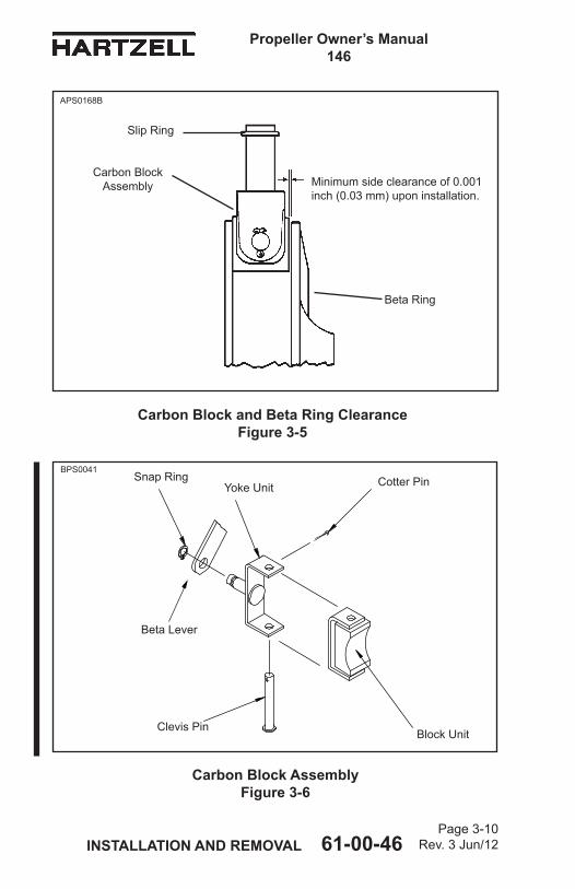
Carbon Block and Beta Ring Clearance ............................................... Figure 3-5 .................. 3-10
Carbon Block Assembly.......................... Figure 3-6 .................. 3-10
Determining Torque Value When Using Torquing Adaptor .......................... Figure 3-7 .................. 3-12

Page 3-3Rev. 4 Jun/15 INSTALLATION AND REMOVAL 61-00-46
Propeller Owner’s Manual146
1. Tools, Consumables, and ExpendablesThe following tools, consumables, and expendables will be required for propeller removal or installation:NOTE: The steel hub turbine propellers covered in this
manual are manufactured with two basic flange designs, flange types N and P. The flange type used on a particular propeller installation is indicated in the propeller model identification number stamped on the hub. For example, HC-B3MN-3 indicates an N flange. Refer to the Steel Hub Model Identification in the Description and Operation chapter of this manual for a description of each flange type.
A. ToolingN Flange • Safety wire pliers (Alternate: Safety cable tool) • Torque wrench • Torque wrench adapter (Hartzell Propeller Inc. P/N AST-2877) P Flange • Safety wire pliers (Alternate: Safety cable tool) • Torque wrench • Torque wrench adapter (Hartzell Propeller Inc. P/N AST-2877)
B. Consumables• Quick Dry Stoddard Solvent or Methyl-Ethyl-Ketone (MEK)
C. Expendables• 0.032 inch Stainless steel Aircraft Safety Wire (Alternate: 0.032 inch [0.81 mm] aircraft safety cable, and associated hardware) • O-ring, Propeller to engine seal (see Table 3-1)

Page 3-4 Rev.1 Oct/04
PropellerOwner’sManual146
INSTALLATIONANDREMOVAL 61-00-46
2. Pre-InstallationA. Inspection of Shipping Package
Examine the exterior of the shipping container for signs of shipping damage, especially the box ends around each blade. A hole, tear, or crushed appearance at the end of the box (blade tips) may indicate that the propeller was dropped during shipment, possibly damaging the blades.
B. Uncrating(1) Place the propeller on a firm support. (2) Remove the banding and any external wood bracing
from the shipping container. (3) Remove the cardboard from the hub and blades. Place
the propeller on a padded surface that supports the propeller over a large area. Never stand the propeller on a blade tip.
(4) Remove the plastic dust cover cup from the propeller mounting flange (if installed).
C. Inspection after ShipmentAfter removing the propeller from the shipping container, examine the propeller components for shipping damage.
CAUTION: TO FACILITATE BOXING AND SHIPPING OF PROPELLERS, THE PISTON NUT (A-880-1 OR A-880-2) ON STEEL HUB TURBINE PROPELLERS MAY BE REMOVED TO ALLOW ROTATING OF THE BLADES BEFORE PACKAGING (SEE FIGURES 2-1 AND 2-3).
D. Reassembly of a Propeller Disassembled for ShipmentIf a propeller was received disassembled for shipment, it must be reassembled by trained personnel in accordance with the applicable propeller maintenance manual.

Page 3-5 Oct/99
PropellerOwner’sManual146
INSTALLATIONANDREMOVAL 61-00-46
3. Propeller Assembly InstallationA. Precautions
WARNING 1: DURING ENGINE INSTALLATION OR REMOVAL, USING THE PROPELLER TO SUPPORT THE WEIGHT OF THE ENGINE IS NOT AUTHORIZED. UNAPPROVED INSTALLATION AND REMOVAL TECHNIQUES MAY CAUSE DAMAGE TO THE PROPELLER THAT MAY LEAD TO FAILURE RESULTING IN AN AIRCRAFT ACCIDENT.
WARNING 2: WHEN INSTALLING THE PROPELLER, FOLLOW THE AIRFRAME MANUFACTURER’S MANUALS AND PROCEDURES, AS THEY MAY CONTAIN ISSUES VITAL TO AIRCRAFT SAFETY THAT ARE NOT CONTAINED IN THIS OWNER’S MANUAL.
CAUTION: AVOID THE USE OF BLADE PADDLES. DO NOT PLACE THE BLADE PADDLE IN THE AREA OF THE DE-ICE BOOT WHEN APPLYING TORQUE TO A BLADE ASSEMBLY. PLACE THE BLADE PADDLE IN THE THICKEST AREA OF THE BLADE, JUST OUTSIDE OF THE DE-ICE BOOT. USE ONE BLADE PADDLE PER BLADE.
(1) Be sure the propeller is removed before the engine is removed or installed in the airframe.
(2) Follow the airframe manufacturer’s instructions for installing the propeller. If such instructions are not in the airframe manufacturer’s manual, then follow the instructions in this manual; however, mechanics must consider that this owner’s manual does not describe important procedures that are outside the scope of this manual. In addition to propeller installation procedures, items such as rigging and preflight testing of flight idle blade angle, installation and adjustment of de-ice equipment, and propeller synchronization devices are normally found in the airframe manufacturer’s manuals.

Page 3-6Rev. 3 Jun/12 INSTALLATIONANDREMOVAL 61-00-46
PropellerOwner’sManual146
BetaSy
stem
PullerforDecom
pressing
HC-B(3,4)()()-3
()ExternalB
etaSy
stem
Figu
re3-1
W10
084
Har
tzel
l Pro
pelle
r Inc
. P
/N C
ST-
2987

Page 3-7Rev. 3 Jun/12 INSTALLATIONANDREMOVAL 61-00-46
PropellerOwner’sManual146
B. Installing the HC-B(3,4)( )( )-3( ) Propeller on the Aircraft Engine(1) Use a beta system puller CST-2987 (Figure 3-1) to
compress the beta system and pull the beta ring forward to allow installation of the double hex head propeller mounting bolts.
WARNING: MAKE SURE THE SLING IS RATED UP TO 800 LBS (363 KG) TO SUPPORT THE WEIGHT OF THE PROPELLER ASSEMBLY DURING INSTALLATION.
CAUTION 1: INSTRUCTIONS AND PROCEDURES IN THIS SECTION MAY INVOLVE CRITICAL PARTS. REFER TO THE INTRODUCTION CHAPTER OF THIS MANUAL FOR INFORMATION ABOUT PROPELLER CRITICAL PARTS. REFER TO THE ILLUSTRATED PARTS LIST CHAPTER OF THE APPLICABLE OVERHAUL MANUAL(S) FOR THE IDENTIFICATION OF SPECIFIC PROPELLER CRITICAL PARTS.
CAUTION 2: WHEN INSTALLING THE PROPELLER ON THE AIRCRAFT, DO NOT DAMAGE THE ICE PROTECTION SYSTEM COMPONENTS, IF APPLICABLE.
(2) With a suitable crane hoist and sling, carefully move the propeller assembly to the aircraft engine mounting flange.

Page 3-8Rev. 3 Jun/12 INSTALLATIONANDREMOVAL 61-00-46
PropellerOwner’sManual146
O-ring
Propeller Flange
Engine Flange
Bolt
Torque Wrench
Washer
InstallingPropelleronEngineFlangeFigure3-2
*Note: If torque wrench adaptor is used, use the calculation in Figure 3-7 to determine correct torque wrench setting.
APS0279C
MountingBoltandWasherFigure3-3
NOTE: Size of chamfer can vary from washer to washer.
WasherWithout chamfer
WasherWith
chamfer
Chamfer of washer must face bolt head at installation. Washers without chamfer must be installed with rolled edges toward bolt head.
3040i
Torque Wrench Adapter*

Page 3-9Rev. 3 Jun/12 INSTALLATIONANDREMOVAL 61-00-46
PropellerOwner’sManual146
(3) Make sure the propeller hub flange and the engine flange mating surfaces are clean.
(4) Install the specified O-ring on the engine flange. Refer to Table 3-1.
(5) Align the mounting and dowel pin holes in the propeller hub flange with the mounting holes and dowel pins in the engine flange.
SEQUENCE A SEQUENCE BUsesequenceAforsteps1and2 UsesequenceBforstep3
Step1 - Torque all bolts to 40 Ft-Lbs (54 N•m). Step3 - Torque all bolts to Table 3-2. Step2 - Torque all bolts to 80 Ft-Lbs (108 N•m).
DiagramofTorquingSequenceforPropellerMountingBoltsFigure3-4
APS0272A APS0272B NorPFlange
HC-B3MN-3 B-3339 Bolt and A-2048-2 Washer
HC-B4MN-5AL B-3339 Bolt and A-2048-2 Washer
HC-B4MP-3A B-3339 Bolt and A-2048-2 Washer
“N” flange O-ring C-3317-230
“P” flange O-ring C-3317-230
Propeller/EngineFlangeO-ringsandMountingHardwareTable3-1
Propeller/EngineFlangeO-rings
PropellerMountingHardware
Page 3-10Rev. 3 Jun/12 INSTALLATIONANDREMOVAL 61-00-46
PropellerOwner’sManual146
CarbonBlockandBetaRingClearanceFigure3-5
Beta Ring
APS0168B
Minimum side clearance of 0.001 inch (0.03 mm) upon installation.
CarbonBlockAssemblyFigure3-6
BPS0041
Carbon Block Assembly
Cotter PinSnap Ring
Block UnitClevis Pin
Beta Lever
Yoke Unit
Slip Ring

Page 3-11Rev. 3 Jun/12 INSTALLATIONANDREMOVAL 61-00-46
PropellerOwner’sManual146
(6) Slide the propeller flange onto the engine flange.
CAUTION 1: MAKE SURE THAT COMPLETE AND TRUE SURFACE CONTACT IS ESTABLISHED BETWEEN THE PROPELLER HUB FLANGE AND THE ENGINE FLANGE.
CAUTION 2: NEW PROPELLER MOUNTING BOLTS MUST BE USED WHEN INITIALLY INSTALLING A NEW OR OVERHAULED PROPELLER.
(7) Apply MIL-PRF-83483 anti-seize compound to the threaded surfaces of the mounting bolts. Refer to Table 3-1 for the correct mounting hardware.NOTE: If the propeller is removed between overhaul
intervals, mounting bolts and washers may be reused if they are not damaged or corroded.
CAUTION: ID CHAMFER OF WASHER MUST BE FACING TOWARD THE BOLT HEAD. WASHERS WITHOUT CHAMFER MUST BE INSTALLED WITH ROLLED EDGES TOWARD THE BOLT HEAD. (REFER TO FIGURE 3-3).
(8) Install the mounting bolts through the engine flange and into the propeller hub flange. Refer to Figure 3-2.
(9) Use a torque wrench with a torque wrench adapter Hartzell Propeller Inc. P/N AST-2877 to torque all mounting bolts in sequences and steps shown in Figure 3-4. Refer to Table 3-2 and Figure 3-7 to determine the correct torque value.
(10) Safety all mounting bolts with 0.032 inch (0.81 mm) minimum diameter stainless steel wire. (Two bolts per safety).
(11) Decompress and remove the beta system puller.

Page 3-12 Rev. 2 Jul/10
PropellerOwner’sManual146
INSTALLATIONANDREMOVAL 61-00-46
N flange propeller mounting bolts 100-105 Ft-Lbs (136-142 N•m)
P flange propeller mounting bolts 100-105 Ft-Lbs (136-142 N•m)
Piston flexlock nut 120 Ft-Lbs (163 N•m)*
Guide rod jam nuts 10 Ft-Lbs (14 N•m)*
* Torque tolerance is ± 10 percent unless otherwise noted.
NOTE: Torque values are based on non-lubricated threads, except for the torque value of propeller mounting bolts, which is based on threads with approved anti-seize compound MIL-PRF-83483.
DeterminingTorqueValueWhenUsingTorquingAdaptorFigure3-7
TorqueValuesTable3-2
APS0212A
(actual torque required) X (torque wrench length) Torque wrench reading (torque wrench length) + (length of adapter) = to achieve required actual torque
= <
EXAMPLE:
Standard Torque Wrench
0.25 foot(76.2 mm)
1.00 foot(304.8 mm)
Torquing Adapter
100 Ft-Lb (136 N•m) x 1 ft (304.8 mm) 1 ft (304.8 mm) + 0..25 ft (76.2 mm)
80 Ft-Lb (108 N•m)
reading on torque wrench with 3-inch
(76.2 mm) adapter for actual torque of 100
Ft-Lb (136 N•m)

Page 3-13Rev. 4 Jun/15 INSTALLATION AND REMOVAL 61-00-46
Propeller Owner’s Manual146
CAUTION: THE BETA FEEDBACK COLLAR MUST NOT CONTACT ANY ENGINE COMPONENT OR MOUNTING BOLT SAFETY WIRE. THE BETA FEEDBACK MECHANISM COULD BE DAMAGED IF IT CONTACTED ANY STATIC ENGINE COMPONENT WHILE ROTATING.
(12) Examine the beta feedback collar to make sure that it is not in contact with any engine components or mounting bolt safety wire.(a) If there is contact between the beta feedback collar
and any engine components or mounting bolt safety wire, consult qualified personnel at a certified propeller repair station with the appropriate rating.
(13) Install the carbon block into the beta linkage lever per the airframe manufacturer’s instructions.
CAUTION: FIT THE BLOCK IN THE BETA RING WITH A MINIMUM SIDE CLEARANCE OF 0.001 INCH (0.025 mm). REFER TO FIGURE 3-5.
(14) Install the carbon block assembly (Figure 3-6) into the beta ring.
(15) Install, adjust and safety the beta linkage per the airframe manufacturer’s instructions.
CAUTION: TO FACILITATE BOXING AND SHIPPING OF PROPELLERS, THE PISTON NUT (A-880-1) ON HC-B(3,4)( )( )-3( ) STEEL HUB TURBINE PROPELLERS MAY BE REMOVED IN ORDER TO ALLOW ROTATING OF THE BLADES BEFORE PACKAGING.
NOTE: The ability to rotate the blades during propeller installation will allow easier access to the propeller mounting bolts.

Page 3-14Rev. 3 Jun/12 INSTALLATIONANDREMOVAL 61-00-46
PropellerOwner’sManual146
(16) Procedure for reinstallation of piston nut, if applicable.(a) Following the installation of the propeller, use a
breaker bar and a 5/8 inch deep well socket to hold the pitch change rod.
(b) Using 1-7/16 inch crowfoot wrench and torque wrench, torque the A-880-1 nut. Refer to Table 3-2 and Figure 3-7 for the correct torque value.NOTE: The removal and subsequent reinstallation
of the piston nut does not require that the propeller blade angles be rechecked.
(17) If the propeller is equipped with an ice protection system that uses components supplied by Hartzell Propeller Inc., applicable instructions and technical information for the components supplied by Hartzell Propeller Inc. can be found in the following publications available on the Hartzell Propeller Inc. website at www.hartzellprop.com.(a) Manual 180 (30-61-80) - Propeller Ice Protection
System Manual(b) Manual 181 (30-60-81) - Propeller Ice Protection
System Component Maintenance Manual(c) Manual 182 (61-12-82) - Propeller Electrical De-ice
Boot Removal and Installation Manual(18) Propeller ice protection system components not
supplied by Hartzell Propeller Inc. are controlled by the applicable TC or STC holder’s Instructions for Continued Airworthiness (ICA).

Page 3-15Rev. 3 Jun/12 INSTALLATIONANDREMOVAL 61-00-46
PropellerOwner’sManual146
C. Installing the HC-B4MN-5AL Propeller on the Aircraft Engine
WARNING: MAKE SURE THE SLING IS RATED UP TO 800 POUNDS (363 KG) TO SUPPORT THE WEIGHT OF THE PROPELLER ASSEMBLY DURING INSTALLATION.
CAUTION 1: INSTRUCTIONS AND PROCEDURES IN THIS SECTION MAY INVOLVE CRITICAL PARTS. REFER TO THE INTRODUCTION CHAPTER OF THIS MANUAL FOR INFORMATION ABOUT PROPELLER CRITICAL PARTS. REFER TO THE ILLUSTRATED PARTS LIST CHAPTER OF THE APPLICABLE OVERHAUL MANUAL(S) FOR THE IDENTIFICATION OF SPECIFIC PROPELLER CRITICAL PARTS.
CAUTION 2: WHEN INSTALLING THE PROPELLER ON THE AIRCRAFT, DO NOT DAMAGE THE ICE PROTECTION SYSTEM COMPONENTS, IF APPLICABLE.
(1) With a suitable crane hoist and sling, carefully move the propeller assembly to the aircraft engine mounting flange.
(2) Make sure that the propeller hub flange and engine flange are clean.
(3) Install the specified O-ring on the engine flange. Refer to Table 3-1.
(4) Align the mounting and dowel pin holes in the propeller hub flange with the mounting holes and dowel pins in the engine flange.
(5) Slide the propeller flange onto the engine flange.

Page 3-16Rev. 3 Jun/12 INSTALLATIONANDREMOVAL 61-00-46
PropellerOwner’sManual146
CAUTION 1: MAKE SURE THAT COMPLETE AND TRUE SURFACE CONTACT IS ESTABLISHED BETWEEN THE PROPELLER HUB FLANGE AND THE ENGINE FLANGE.
CAUTION 2: NEW PROPELLER MOUNTING BOLTS MUST BE USED WHEN INITIALLY INSTALLING A NEW OR OVERHAULED PROPELLER.
(6) Apply MIL-PRF-83483 anti-seize compound to the threaded surfaces of the mounting bolts. Refer to Table 3-1 for the correct mounting hardware.NOTE: If the propeller is removed between overhaul
intervals, mounting bolts and washers may be reused if they are not damaged or corroded.
CAUTION: ID CHAMFER OF WASHER MUST BE FACING TOWARD THE BOLT HEAD. WASHERS WITHOUT CHAMFER MUST BE INSTALLED WITH ROLLED EDGES TOWARD THE BOLT HEAD (FIGURE 3-3).
(7) Install the mounting bolts with washers through the engine flange and into the propeller hub flange. Refer to Figure 3-2.
(8) Use a torque wrench and a torque wrench adapter Hartzell Propeller Inc. P/N AST-2877 to torque all mounting bolts in sequences and steps shown in Figure 3-4. Refer to Table 3-2 and Figure 3-7 to determine the correct torque value.
(9) Safety all mounting bolts with 0.032 inch (0.81 mm) minimum diameter stainless steel wire (two bolts per safety).

Page 3-17Rev. 3 Jun/12 INSTALLATION AND REMOVAL 61-00-46
Propeller Owner’s Manual146
CAUTION: TO FACILITATE BOXING AND SHIPPING OF PROPELLERS, THE PISTON NUT (A-880-2) ON THE HC-B4MN-5AL STEEL HUB TURBINE PROPELLER MAY BE REMOVED IN ORDER TO ALLOW ROTATING OF THE BLADES BEFORE PACKAGING.
(10) Procedure for reinstallation of piston nut (if applicable).(a) Following the installation of the propeller, use a
breaker bar and a 5/8 inch deep well socket to hold the pitch change rod.
(b) Using a 1-13/16 inch crowfoot wrench and torque wrench, torque the A-880-2 nut. Refer to Table 3-2 and Figure 3-7 for the correct torque value.NOTE: The removal and subsequent reinstallation
of the piston nut does not require that the propeller blade angles be rechecked.
(11) Install the beta tube per the airframe and/or engine manufacturer’s instructions.NOTE 1: Follow the airframe manufacturer’s instructions
for adjusting the beta tube to obtain the correct low pitch (flight idle blade angle).
NOTE 2: Refer to the Aircraft Type Certificate Data Sheet for the low pitch blade angle setting.
(12) If the propeller is equipped with an ice protection system that uses components supplied by Hartzell Propeller Inc., applicable instructions and technical information for the components supplied by Hartzell Propeller Inc. can be found in the following publications available on the Hartzell Propeller Inc. website at www.hartzellprop.com.(a) Manual 180 (30-61-80) - Propeller Ice Protection
System Manual(b) Manual 181 (30-60-81) - Propeller Ice Protection
System Component Maintenance Manual(c) Manual 182 (61-12-82) - Propeller Electrical De-ice
Boot Removal and Installation Manual(13) Propeller ice protection system components not supplied by
Hartzell Propeller Inc. are controlled by the applicable TC or STC holder’s Instructions for Continued Airworthiness (ICA).

INSTALLATION AND REMOVAL 61-00-46
Propeller Owner’s Manual146
Page 3-18Rev. 5 Nov/17
4. Spinner Dome Installation
CAUTION 1: TO PREVENT DAMAGE TO THE BLADE AND BLADE PAINT, WRAP THE BLADE SHANKS IN SEVERAL LAYERS OF MASKING OR DUCT TAPE BEFORE INSTALLING THE SPINNER DOME. REMOVE THE TAPE AFTER THE SPINNER IS INSTALLED.
CAUTION 2: THE SPINNER DOME WILL WOBBLE IF NOT ALIGNED PROPERLY, AND MAY AFFECT DYNAMIC BALANCE OF THE PROPELLER.
A. Carefully slide the spinner dome over the reassembled propeller.
B. Using the supplied screws and washers, attach the spinner dome to the spinner bulkhead. (1) Install one or two screws in the hole(s) centered between
two blade cutouts.(2) Tighten the screw(s) until snug.(3) Install one or two screws in the hole(s) centered between
two blade cutouts on the opposite side of the spinner dome.
(4) Tighten the screw(s) until snug.(5) Repeat installation of screws in the holes centered
between two blade cutouts for the remaining areas.(6) Tighten screw(s) until snug.(7) Install the remaining screws in the remaining holes.(8) Tighten until snug.
5. Post-Installation ChecksA. Refer to the airframe manufacturer’s instructions for post-
installation checks.B. Perform a maximum RPM (Static) hydraulic low pitch stop
check in accordance with the Testing and Troubleshooting chapter of this manual.

INSTALLATION AND REMOVAL 61-00-46
Propeller Owner’s Manual146
Page 3-19Rev. 5 Nov/17
6. Spinner Dome Removal
CAUTION: TO PREVENT DAMAGE TO THE BLADE AND BLADE PAINT, WRAP THE BLADE SHANKS IN SEVERAL LAYERS OF MASKING OR DUCT TAPE BEFORE REMOVING THE SPINNER DOME.
A. Remove the screws and washers that secure the spinner to the spinner bulkhead.
B. Remove the spinner dome.
7. Propeller Assembly RemovalA. Removal of HC-B(3,4)( )( )-3( ) Propellers
WARNING: FOR SAFETY REASONS, THE PROPELLER MUST BE PLACED IN THE FEATHER POSITION BEFORE IT IS REMOVED FROM THE AIRCRAFT.
CAUTION: INSTRUCTIONS AND PROCEDURES IN THIS SECTION MAY INVOLVE CRITICAL PARTS. REFER TO THE INTRODUCTION CHAPTER OF THIS MANUAL FOR INFORMATION ABOUT PROPELLER CRITICAL PARTS. REFER TO THE ILLUSTRATED PARTS LIST CHAPTER OF THE APPLICABLE OVERHAUL MANUAL(S) FOR THE IDENTIFICATION OF SPECIFIC PROPELLER CRITICAL PARTS.
(1) Remove the spinner dome in accordance with the procedures in the Spinner Removal section of this chapter.
(2) Disconnect the engine beta linkage and carbon block assembly from the beta ring per the airframe manufacturer’s instructions. Refer to Figure 3-6.NOTE: If the propeller is equipped with a de-ice
system, follow the manufacturer’s instructions for removing whichever components are necessary for propeller removal.
(a) Remove the snap ring that retains the carbon block assembly to the beta linkage.
(b) Remove the carbon block assembly.

INSTALLATION AND REMOVAL 61-00-46
Propeller Owner’s Manual146
Page 3-20Rev. 5 Nov/17
(3) Use a beta system puller Hartzell Propeller Inc. P/N CST-2987 to compress the beta system spring and pull the beta ring forward to expose the propeller mounting bolts and washers.
WARNING 1: DURING ENGINE INSTALLATION OR REMOVAL, USING THE PROPELLER TO SUPPORT THE WEIGHT OF THE ENGINE IS NOT AUTHORIZED. UNAPPROVED INSTALLATION AND REMOVAL TECHNIQUES MAY CAUSE DAMAGE TO THE PROPELLER THAT MAY LEAD TO FAILURE AND RESULT IN AN AIRCRAFT ACCIDENT.
WARNING 2: DURING PROPELLER REMOVAL, AIRFRAME MANUFACTURER’S MANUALS AND PROCEDURES MUST BE FOLLOWED BECAUSE THEY MAY CONTAIN ISSUES VITAL TO AIRCRAFT SAFETY THAT ARE NOT CONTAINED IN THIS MANUAL OR THE HARTZELL PROPELLER INC. OVERHAUL MANUAL 118F.
WARNING 3: MAKE SURE THE SLING IS RATED UP TO 800 LBS (363 KG) TO SUPPORT THE WEIGHT OF THE PROPELLER ASSEMBLY DURING REMOVAL.
(4) Cut and remove the safety wire on the propeller mounting bolts.
(5) Support the propeller assembly with a sling.NOTE 1: Supporting the propeller with the sling may be
delayed until all but two mounting bolts and washers have been removed to allow rotating the propeller for ease of nut removal.
NOTE 2: If the propeller will be reinstalled, and it has been dynamically balanced, make an identifying mark on the propeller hub and a matching mark on the engine flange to make sure of the correct orientation during re-installation to prevent dynamic imbalance.

Page 3-21Rev. 3 Jun/12 INSTALLATIONANDREMOVAL 61-00-46
PropellerOwner’sManual146
CAUTION: DISCARD THE PROPELLER MOUNTING BOLTS IF THEY ARE DAMAGED OR CORRODED, OR WHEN THE PROPELLER IS REMOVED FOR OVERHAUL.
(6) Remove the propeller mounting bolts and washers.NOTE: If the propeller is removed between overhaul
intervals, mounting bolts and washers may be reused if they are not damaged or corroded.
CAUTION: USE ADEQUATE PRECAUTIONS TO PROTECT THE PROPELLER ASSEMBLY FROM DAMAGE WHEN IT IS REMOVED FROM THE AIRCRAFT ENGINE AND WHEN IT IS STORED.
(7) Using the support sling, lift the propeller from the mounting flange.
(8) Remove and discard the propeller mounting O-ring. (9) Decompress and remove the beta system puller.(10) Place the propeller on a suitable cart for transportation.
B. Removal of HC-B4MN-5AL Propeller
CAUTION: INSTRUCTIONS AND PROCEDURES IN THIS SECTION MAY INVOLVE CRITICAL PARTS. REFER TO THE INTRODUCTION CHAPTER OF THIS MANUAL FOR INFORMATION ABOUT PROPELLER CRITICAL PARTS. REFER TO THE ILLUSTRATED PARTS LIST CHAPTER OF THE APPLICABLE OVERHAUL MANUAL(S) FOR THE IDENTIFICATION OF SPECIFIC PROPELLER CRITICAL PARTS.
(1) Remove the spinner dome in accordance with the procedures in the Spinner Removal section of this chapter.NOTE: If the propeller is equipped with a de-ice
system, follow the manufacturer’s instructions for removing whichever components are necessary for propeller removal.

Page 3-22Rev. 3 Jun/12 INSTALLATIONANDREMOVAL 61-00-46
PropellerOwner’sManual146
WARNING 1: DURING ENGINE INSTALLATION OR REMOVAL, USING THE PROPELLER TO SUPPORT THE WEIGHT OF THE ENGINE IS NOT AUTHORIZED. UNAPPROVED INSTALLATION AND REMOVAL TECHNIQUES MAY CAUSE DAMAGE TO THE PROPELLER THAT MAY LEAD TO FAILURE AND RESULT IN AN AIRCRAFT ACCIDENT.
WARNING 2: DURING PROPELLER REMOVAL, AIRFRAME MANUFACTURER’S MANUALS AND PROCEDURES MUST BE FOLLOWED BECAUSE THEY MAY CONTAIN ISSUES VITAL TO AIRCRAFT SAFETY THAT ARE NOT CONTAINED IN THIS MANUAL OR THE HARTZELL PROPELLER INC. OVERHAUL MANUAL 118F.
WARNING 3: FOR SAFETY REASONS, THE PROPELLER MUST BE PLACED IN THE FEATHER POSITION BEFORE IT IS REMOVED FROM THE AIRCRAFT.
(2) Place the propeller in feather position.
CAUTION: THE BETA TUBE MUST BE REMOVED BEFORE THE PROPELLER ASSEMBLY IS REMOVED FROM THE AIRCRAFT. REFER TO THE AIRCRAFT MAINTENANCE INSTRUCTION MANUAL.
(3) Remove the beta tube.

Page 3-23Rev. 3 Jun/12 INSTALLATIONANDREMOVAL 61-00-46
PropellerOwner’sManual146
WARNING: MAKE SURE THE SLING IS RATED UP TO 800 LBS (363 KG) TO SUPPORT THE WEIGHT OF THE PROPELLER ASSEMBLY DURING REMOVAL.
CAUTION: USE ADEQUATE PRECAUTIONS TO PROTECT THE PROPELLER ASSEMBLY FROM DAMAGE WHEN IT IS REMOVED FROM THE AIRCRAFT ENGINE AND WHEN IT IS STORED.
(4) Cut and remove the safety wire (if installed) on the propeller mounting bolts.
(5) Support the propeller assembly with a sling.NOTE 1: Supporting the propeller with the sling may be
delayed until all but two mounting bolts and washers have been removed to allow rotating the propeller for ease of nut removal.
NOTE 2: If the propeller will be reinstalled, and it has been dynamically balanced, make an identifying mark on the propeller hub and a matching mark on the engine flange to make sure of the correct orientation during re-installation to prevent dynamic imbalance.
CAUTION: DISCARD THE PROPELLER MOUNTING BOLTS IF THEY ARE DAMAGED OR CORRODED, OR WHEN THE PROPELLER IS REMOVED FOR OVERHAUL.
(6) Remove the propeller mounting bolts and washers.NOTE: If the propeller is removed between overhaul
intervals, mounting bolts and washers may be reused if they are not damaged or corroded.
(7) Using the support sling, lift the propeller from the mounting flange.
(8) Remove and discard the propeller mounting O-ring.(9) Place the propeller on a suitable cart for transportation.

Page 3-24Rev. 3 Jun/12 INSTALLATIONANDREMOVAL 61-00-46
PropellerOwner’sManual146
(This page is intentionally blank.)

TESTINGANDTROUBLESHOOTING 61-00-46
PropellerOwner'sManual146
Page 4-1Rev. 3 Jun/12
CONTENTS Page
1. Operational Tests .................................................................... 4-3A. Initial Run-Up ..................................................................... 4-3B. Post-Run Check ................................................................. 4-3C. Maximum RPM (Static) Hydraulic Low Pitch Stop Check .. 4-4D. Feathering Pitch Stop Adjustment ...................................... 4-4E. Start Lock Unit Adjustment ................................................. 4-4F. Electric De-ice System ....................................................... 4-4
2. Troubleshooting ...................................................................... 4-5A. Hunting and Surging .......................................................... 4-5B. Engine Speed Varies With Flight Altitude (or Airspeed) ..... 4-6C. Loss of Propeller Control ................................................... 4-6D. Failure to Feather (or feathers slowly) ............................... 4-7E. Failure to Unfeather ........................................................... 4-7F. Start Lock Units Fail to Latch on Shutdown (HC-B4MN-5AL Model) ...................... 4-7G. Vibration ............................................................................. 4-8H. Propeller Overspeed .......................................................... 4-9I. Propeller Underspeed ........................................................ 4-9J. Oil or Grease Leakage ..................................................... 4-10

TESTINGANDTROUBLESHOOTING 61-00-46
PropellerOwner'sManual146
Page 4-2Rev. 3 Jun/12
This page intentionally blank

TESTINGANDTROUBLESHOOTING 61-00-46
PropellerOwner'sManual146
Page 4-3Rev. 3 Jun/12
1. Operational TestsFollowing propeller installation, the propeller hydraulic system must be purged of air, and correct operation verified.
WARNING: REFER TO THE AIRCRAFT MAINTENANCE MANUAL FOR ADDITIONAL PROCEDURES THAT MAY BE REQUIRED AFTER PROPELLER INSTALLATION.
CAUTION: INSTRUCTIONS AND PROCEDURES IN THIS SECTION MAY INVOLVE CRITICAL PARTS. REFER TO THE INTRODUCTION CHAPTER OF THIS MANUAL FOR INFORMATION ABOUT PROPELLER CRITICAL PARTS. REFER TO THE ILLUSTRATED PARTS LIST CHAPTER OF THE APPLICABLE OVERHAUL MANUAL(S) FOR THE IDENTIFICATION OF SPECIFIC PROPELLER CRITICAL PARTS.
A. Initial Run-Up(1) Perform engine start and warm-up per the Pilot's
Operating Handbook (POH).(2) Cycle the condition lever through its operating pitch
range from reverse to high (or as directed by the POH).(3) Repeat this procedure at least three times to purge air
from the propeller hydraulic system and to introduce warmed oil to the cylinder.
(4) Verify correct operation from reverse pitch to high pitch and throughout operating range.
(5) Shut down the engine in accordance with the POH.NOTE: Air trapped in the propeller hydraulic system
will cause the pitch control to be imprecise and may result in propeller surging.
B. Post-Run CheckAfter engine shutdown, check the propeller for signs of engine oil leakage.

TESTING AND TROUBLESHOOTING 61-00-46
Propeller Owner's Manual146
Page 4-4Rev. 4 Jun/15
C. Maximum RPM (Static) Hydraulic Low Pitch Stop CheckThe Maximum RPM (hydraulic low pitch stop) is normally set at the factory per the aircraft manufacturer's requirements, and should not require any additional adjustment. Adjustments may be required after maintenance or because of specific aircraft variances. Adjustments must be done in accordance with the airframe manufacturer's specifications found in the airframe manufacturer's manual.
D. Feathering Pitch Stop AdjustmentThe feathering pitch stop is set at the factory per the aircraft manufacturer's recommendations. This stop is adjustable only by a certified propeller repair station with the appropriate rating, aircraft manufacturer, or the Hartzell Propeller Inc. factory.
E. Start Lock Unit AdjustmentThe start lock units are set at the factory per the aircraft manufacturer's recommendations. These stops are adjustable only by a certified propeller repair station with the appropriate rating or at the Hartzell Propeller Inc. factory.
F. Electric De-ice SystemNOTE: The Pilot Operating Handbook (POH) must be
consulted regarding flight into conditions of known icing. The aircraft may not be certificated for flight in known icing conditions, even though propeller de-ice equipment is installed.
(1) Refer to the De-ice Systems chapter of this manual for functional tests of the De-ice system.

TESTING AND TROUBLESHOOTING 61-00-46
Propeller Owner's Manual146
Page 4-5Rev. 4 Jun/15
2. Troubleshooting
CAUTION: INSTRUCTIONS AND PROCEDURES IN THIS SECTION MAY INVOLVE CRITICAL PARTS. REFER TO THE INTRODUCTION CHAPTER OF THIS MANUAL FOR INFORMATION ABOUT PROPELLER CRITICAL PARTS. REFER TO THE ILLUSTRATED PARTS LIST CHAPTER OF THE APPLICABLE OVERHAUL MANUAL(S) FOR THE IDENTIFICATION OF SPECIFIC PROPELLER CRITICAL PARTS.
A. Hunting and SurgingHunting is characterized by a cyclic variation in engine speed above and below desired speed. Surging is characterized by a large increase/decrease in engine speed, followed by a return to set speed after one or two occurrences. (1) If the propeller is hunting, a certified propeller repair
station with the appropriate rating should check:(a) Governor(b) Fuel control(c) Synchrophaser or synchronizer
(2) If the propeller is surging:(a) Perform steps 1.A.(1) through 1.A.(5) in the
Operational Tests section of this chapter, to release trapped air from the propeller. If surging recurs, it is most likely due to a faulty governor.
(b) Hunting and/or surging may also be caused by friction or binding within the governor control, or by internal corrosion, which causes the propeller to react slower to governor commands.NOTE: The propeller must be tested on a test
bench at a certified propeller repair station with the appropriate rating to isolate these faults.

TESTINGANDTROUBLESHOOTING 61-00-46
PropellerOwner'sManual146
Page 4-6Rev. 3 Jun/12
B. Engine Speed Varies with Flight Altitude (or Airspeed)(1) Small variances in engine speed are normal and are no
cause for concern.(2) Increase in engine speed while descending or increasing
airspeed:(a) Governor is not reducing oil volume.(b) Friction in propeller.
(3) Decrease in engine speed while increasing airspeed:(a) Governor pilot valve is stuck and is excessively
decreasing oil volume.(b) Feathering command engaged on propeller pitch
control.(4) Increase in engine speed while decreasing airspeed:
(a) Governor pilot valve is stuck and is excessively increasing oil volume.
(5) Decrease in engine speed while decreasing airspeed:(a) Governor is not increasing oil volume in propeller.(b) Friction in propeller.
C. Loss of Propeller Control(1) Propeller goes to uncommanded high pitch (or feather)
(a) Loss of propeller oil pressure - check:1 Governor pressure relief valve.2 Governor drive.3 Engine oil supply.
(b) Start Lock Unit not engaging.(2) Propeller goes to uncommanded low pitch (high RPM)
(a) Governor pilot valve sticking.(3) RPM increases with power and airspeed, propeller RPM
control has little or no effect.(a) Excessive friction in blade bearings or pitch change
mechanism.(b) Broken feathering spring.
(4) RPM control sluggish (especially on reducing RPM).(a) Broken feathering spring.

TESTING AND TROUBLESHOOTING 61-00-46
Propeller Owner's Manual146
Page 4-7Rev. 4 Jun/15
D. Failure to Feather (or feathers slowly)(1) Broken feathering spring.(2) Check for correct function and rigging of propeller/
governor control linkage.(3) Check governor drain function.(4) Propeller must be checked for misadjustment or internal
corrosion (usually in blade bearings or pitch changing mechanism) that results in excessive friction. This must be accomplished at a certified propeller repair station with the appropriate rating.
E. Failure to Unfeather(1) Check for correct function and rigging of propeller control
linkage.(2) Check governor function.(3) Propeller must be checked for misadjustment or internal
corrosion (usually in blade bearings or pitch change mechanism) that results in excessive friction. This must be accomplished at a certified propeller repair station with the appropriate rating.
F. Start Lock Units Fail to Latch on Shutdown (HC-B4MN-5AL Model)(1) Propeller was feathered before shutdown.(2) Shutdown occurred at high RPM with propeller control
off the low pitch stop. The problem may be solved by using the engine auxiliary
pump to reposition the propeller on the start lock unit. (3) Excessive governor pump leakage. The problem should be referred to a certified propeller
repair station with the appropriate rating. (4) Broken start lock unit. The problem should be referred to a certified propeller
repair station with the appropriate rating.

TESTING AND TROUBLESHOOTING 61-00-46
Propeller Owner's Manual146
Page 4-8Rev. 4 Jun/15
G. Vibration
CAUTION: ANY VIBRATION THAT CAN BE DESCRIBED AS APPEARING SUDDENLY, OR IS ACCOMPANIED BY UNEXPLAINED GREASE LEAKAGE, SHOULD BE INVESTIGATED BY A CERTIFIED PROPELLER REPAIR STATION WITH THE APPROPRIATE RATING, BEFORE THE NEXT FLIGHT.
NOTE: Vibration problems due to propeller system imbalance are normally felt throughout the RPM range, with the intensity of vibration increasing with RPM. Vibration problems that occur in a narrow RPM range are a symptom of resonance, and are potentially harmful to the propeller. Avoid operation in that RPM range until the propeller can be checked by a certified propeller repair station with the appropriate rating.
(1) Check:(a) Control surfaces, exhaust system, landing gear
doors, etc. for excessive play that may be causing vibration unrelated to the propeller.
(b) Uneven lubrication of the propeller.(c) Correct engine/propeller flange mating. (d) Blade track. (Refer to the Inspection and Check
chapter of this manual for procedure.)(e) Blade angles: Blade angle must be within tolerance between
blades and on the propeller as a whole. Refer to the Hartzell Propeller Inc. Overhaul Manual 118F (61-10-18) for blade angle check procedure.
(f) Spinner for cracks, incorrect installation or "wobble" during operation.
(g) Static balance.(h) Airfoil profile identical between blades (after
overhaul or rework for nicks - verify at a certified propeller repair station with the appropriate rating).
(i) Hub, blade, or blade clamp for damage or cracking.(j) Grease or oil leakage from a seemingly solid surface
of the hub, blade clamp, or blade.

Page 4-9 Oct/99 TESTINGANDTROUBLESHOOTING 61-00-46
PropellerOwner'sManual146
(k) Blade deformation.NOTE: Dynamic balancing is recommended after
installing or performing maintenance on a propeller. While normally an optional task, it may be required by the engine or airframe manufacturer to make certain the propeller/engine combination is balanced within close tolerances before operation. Refer to the engine or airframe manuals, and the Maintenance Practices chapter of this manual.
H. Propeller Overspeed(1) Check:
(a) Low pitch stop adjustment.(b) Governor maximum RPM set too high.(c) Broken feathering spring.(d) Governor pilot valve jammed, supplying high
pressure only.(e) Tachometer error.
I. Propeller Underspeed(1) Check:
(a) Governor oil pressure low.(b) Governor oil passage clogged.(c) Tachometer error.

TESTINGANDTROUBLESHOOTING 61-00-46
PropellerOwner'sManual146
Page 4-10Rev. 3 Jun/12
J. Oil or Grease Leakage
CAUTION: GREASE LEAKAGE THAT CAN BE DESCRIBED AS EXCESSIVE AND APPEARING SUDDENLY, ESPECIALLY WHEN ACCOMPANIED BY VIBRATION, SHOULD BE INVESTIGATED IMMEDIATELY BEFORE NEXT FLIGHT.
(1) Grease Leakage - Probable Cause:(a) Incorrect torqued or loose lubrication fitting. (Tighten
the fitting).(b) Defective lubrication fitting. (Replace the fitting).(c) Incorrect or damaged O-ring between the blade
clamp and the propeller hub. (Refer to an authorized propeller service facility for replacement of the O-ring.)
(d) Grease leaks past the blade clamp seal gaskets. (Replace gaskets.) (Refer to an authorized propeller service facility for replacement of sealant.)
(e) Grease leaks from between the blade clamp and the blade. (Refer to an authorized propeller service facility for replacement of sealant.)
(f) Incorrect application of silicone sealant on the clamp radius of the bearing-to-clamp interface. (Refer to an authorized propeller service facility for reapplication of silicone sealant.)
(2) Oil Leakage - Probable Cause:(a) Faulty or missing O-ring seal between the hub and
the cylinder.(b) Faulty or missing O-ring seal between the piston and
the cylinder at the front of the piston.(c) Displaced felt seal between the piston and the
cylinder.(d) Faulty or missing O-ring between the propeller hub
and the engine flange.(e) Faulty or missing O-ring between the piston and the
pitch change rod.

INSPECTION AND CHECK 61-00-46Page 5-1
Rev. 5 Nov/17
Propeller Owner’s Manual146
INSPECTION AND CHECK - CONTENTS
1. Pre-Flight Checks ................................................................... 5-3
2. Operational Checks ................................................................ 5-5
3. Required Periodic Inspections and Maintenance ................... 5-5A. Periodic Inspections ........................................................... 5-5B. Airworthiness Limitations ................................................... 5-6C. Overhaul Periods ............................................................... 5-7D. Periodic Maintenance ........................................................ 5-7
4. Inspection Procedures ............................................................ 5-8A. Blade Damage ................................................................... 5-8B. Grease or Oil Leakage ....................................................... 5-9C. Vibration ........................................................................... 5-10D. Blade Track ...................................................................... 5-13E. Loose Blades ................................................................... 5-13F. Corrosion ......................................................................... 5-14G. Spinner Damage .............................................................. 5-14H. Electric De-ice System ..................................................... 5-14
5. Special Inspections ............................................................... 5-18A. Overspeed/Overtorque .................................................... 5-18B. Lightning Strike ................................................................ 5-19C. Foreign Object Strike/Ground Strike ................................ 5-22D. Fire Damage or Heat Damage ......................................... 5-24
6. Long Term Storage ............................................................... 5-25

Page 5-2Rev. 2 Jul/10 INSPECTION AND CHECK 61-00-46
Propeller Owner’s Manual146
FIGURES Page
Checking Blade Track............................. Figure 5-1 .................. 5-12
Blade Play .............................................. Figure 5-2 .................. 5-12
Turbine Engine Overspeed Limits .......... Figure 5-3 ................. 5-16
Turbine Engine Overtorque Limits .......... Figure 5-4 ................. 5-17
Evidence of Lightning Strike Damage to Composite Blade ................................ Figure 5-5 .................. 5-20

INSPECTIONANDCHECK61-00-46Page 5-3
Rev. 3 Jun/12
PropellerOwner’sManual146
1. Pre-Flight Checks
CAUTION: INSTRUCTIONS AND PROCEDURES IN THIS SECTION MAY INVOLVE CRITICAL PARTS. REFER TO THE INTRODUCTION CHAPTER OF THIS MANUAL FOR INFORMATION ABOUT PROPELLER CRITICAL PARTS. REFER TO THE ILLUSTRATED PARTS LIST CHAPTER OF THE APPLICABLE OVERHAUL MANUAL(S) FOR THE IDENTIFICATION OF SPECIFIC PROPELLER CRITICAL PARTS.
Follow propeller preflight inspection procedures as specified in the aircraft maintenance manual, air carrier’s operational specifications, or this manual. In addition, perform the following inspections:A. Blades
(1) Visually inspect the entire blade and the erosion shield (lead, trail, face, and camber sides) for nicks, gouges, looseness of material, erosion, cracks, and debonds. Refer to the Maintenance Practices chapter of this manual for composite blade airworthy damage limits.
(2) Visually inspect the blades for lightning strike. Refer to lightning strike damage information in the Special Inspections section of this chapter.
(3) Defects or damage discovered during preflight inspection must be evaluated in accordance with allowables outlined in the Maintenance Practices chapter of this manual to determine if repairs are required before further flight.
B. Inspect the spinner and visible blade retention components for damage or cracks. Repair or replace components, as required, before further flight.
C. Check for loose/missing hardware. Retighten or reinstall as necessary.

Page 5-4Rev. 3 Jun/12 INSPECTIONANDCHECK61-00-46
PropellerOwner’sManual146
WARNING: ABNORMAL GREASE LEAKAGE CAN BE AN INDICATION OF A FAILING PROPELLER BLADE OR BLADE RETENTION COMPONENT. AN IN-FLIGHT BLADE SEPARATION CAN RESULT IN A CATASTROPHIC AIRCRAFT ACCIDENT.
D. Inspect for grease and oil leakage, and determine the source.
E. Check blades for radial play or movement of blade tip (in and out, or back and forth). Refer to Loose Blades in the Inspection Procedures section of this chapter for blade play limits.
F. Inspect de-ice boots (if installed) for damage. Refer to the De-ice Systems chapter of this manual for inspection information.
G. Check the propeller speed control and operation from reverse or low pitch to high pitch, using the procedure specified in the Pilot Operating Handbook (POH) for the aircraft.
WARNING: ABNORMAL VIBRATION CAN BE AN INDICATION OF A FAILING PROPELLER BLADE OR BLADE RETENTION COMPONENT. AN IN-FLIGHT BLADE SEPARATION CAN RESULT IN A CATASTROPHIC AIRCRAFT ACCIDENT.
H. Perform initial run-up as outlined in Operational Tests 1.A.(1) through 1.A.(5) in the Testing and Troubleshooting chapter of this manual.
I. Check for any abnormal vibration during run-up. If vibration occurs, shut the engine down, determine the cause, and correct it before further flight. Refer to Vibration in the Testing and Troubleshooting chapter of this manual.
J. Refer to the Inspection Procedures section of this chapter for additional inspection information and possible corrections to any discrepancies discovered as a result of pre-flight checks.
INSPECTION AND CHECK 61-00-46Page 5-5
Rev. 4 Jun/15
Propeller Owner’s Manual146
2. Operational ChecksRefer to the airframe manufacturer’s manual for operational checks.
3. Required Periodic Inspections and Maintenance
CAUTION: INSTRUCTIONS AND PROCEDURES IN THIS SECTION MAY INVOLVE CRITICAL PARTS. REFER TO THE INTRODUCTION CHAPTER OF THIS MANUAL FOR INFORMATION ABOUT PROPELLER CRITICAL PARTS. REFER TO THE ILLUSTRATED PARTS LIST CHAPTER OF THE APPLICABLE OVERHAUL MANUAL(S) FOR THE IDENTIFICATION OF SPECIFIC PROPELLER CRITICAL PARTS.
A. Periodic Inspections Perform detailed inspection procedures at 400 hour intervals,
not to exceed twelve (12) calendar months.NOTE 1: Inspection and maintenance specified by an
airframe manufacturer’s maintenance program and approved by the applicable airworthiness agency may not coincide with the inspection time interval specified. In this situation the airframe manufacturer’s schedule may be applied with the exception that the calendar limit for the inspection interval may not exceed twelve (12) calendar months.
NOTE 2: Refer to Inspection Procedures in this chapter for additional inspection information and possible corrections to any discrepancies discovered as a result of the periodic inspection.
(1) Remove the spinner dome.(2) Visually inspect the entire blade and erosion shield
for nicks, cracks, looseness of material, erosion, and debonds. If any damage is discovered, refer to the Blade Repairs section in the Maintenance Practices chapter of this manual for additional information. A cracked blade must be referred to a certified propeller repair station with the appropriate rating.

Page 5-6Rev. 3 Jun/12 INSPECTIONANDCHECK61-00-46
PropellerOwner’sManual146
(3) Inspect all visible propeller parts for cracks, wear, or unsafe conditions.
(4) Check for oil and grease leaks. Refer to Oil and Grease Leakage in the Inspection Procedures section of this chapter.
(5) Make an entry in the propeller logbook verifying this inspection.
B. Airworthiness Limitations(1) Certain components, as well as the entire propeller,
may have specific life limits established as part of the certification by the FAA. Such limits call for mandatory replacement of specified parts after a defined number of hours and/or cycles of use.
(2) Life limited component times are provided in the Airworthiness Limitations section of this manual.
(3) Operators are urged to keep informed of airworthiness information via Hartzell Propeller Inc. Service Bulletins and Service Letters, which are available from Hartzell Propeller Inc. distributors or from the Hartzell Propeller Inc. factory by subscription. Selected information is also available on the Hartzell Propeller Inc. website at www.hartzellprop.com.

INSPECTIONANDCHECK61-00-46Page 5-7
Rev. 3 Jun/12
PropellerOwner’sManual146
C. Overhaul PeriodsIn flight, the propeller is constantly subjected to vibration from the engine and the airstream, as well as high centrifugal forces. The propeller is also subject to corrosion and general deterioration due to aging. Under these conditions, metal fatigue or mechanical failures can occur. To protect your safety and your investment, and to maximize the safe operating lifetime of your propeller, it is essential that the propeller be properly maintained and overhauled according to the recommended service procedures.
CAUTION 1: OVERHAUL PERIODS LISTED BELOW, ALTHOUGH CURRENT AT THE TIME OF PUBLICATION, ARE FOR REFERENCE PURPOSES ONLY. OVERHAUL PERIODS MAY BE INCREASED OR DECREASED AS A RESULT OF ENGINEERING EVALUATION.
CAUTION 2: CHECK THE LATEST REVISION OF HARTZELL PROPELLER INC. SERVICE LETTER HC-SL-61-61Y FOR THE MOST CURRENT INFORMATION.
(1) Hartzell Propeller Inc. steel hub propellers installed on turbine engine aircraft are to be overhauled at 3000 hours of operation or 60 calendar months, whichever occurs first.
(2) Agricultural aircraft are to be overhauled at 3000 hours of operation or 36 calendar months, whichever occurs first.(a) Once used on an agricultural aircraft, the 36 month
overhaul limit is to be maintained until an overhaul is accomplished, even if the propeller is later installed on other category airplanes.
D. Periodic MaintenanceLubricate the propeller assembly. Refer to the Lubrication section in the Maintenance Practices chapter of this manual for intervals and procedures.

Page 5-8Rev. 3 Jun/12 INSPECTIONANDCHECK61-00-46
PropellerOwner’sManual146
4. Inspection Procedures
CAUTION: INSTRUCTIONS AND PROCEDURES IN THIS SECTION MAY INVOLVE CRITICAL PARTS. REFER TO THE INTRODUCTION CHAPTER OF THIS MANUAL FOR INFORMATION ABOUT PROPELLER CRITICAL PARTS. REFER TO THE ILLUSTRATED PARTS LIST CHAPTER OF THE APPLICABLE OVERHAUL MANUAL(S) FOR THE IDENTIFICATION OF SPECIFIC PROPELLER CRITICAL PARTS.
The inspections detailed below are made on a regular basis, either before flight, during Periodic Inspections (described in this chapter), or if a problem is noted. Possible corrections to problems discovered during inspections, additional inspections, and limits are detailed in the following inspection procedures.A. Blade Damage
(1) Refer to the Composite Blade section in the Maintenance Practices chapter of this manual for information regarding blade damage.
(2) For composite blade model M10083( ) installed on a Hartzell Propeller Inc. model HC-B3MN-3 that is on a Cessna 208 series Caravan aircraft:(a) Inspect the blade at 250 hour intervals for cracks
in the filament windings and at the end of a layer of laminate. Refer to the Maintenance Practices chapter of this manual for inspection procedures.

INSPECTION AND CHECK 61-00-46Page 5-9
Rev. 4 Jun/15
Propeller Owner’s Manual146
B. Grease or Oil LeakageNOTE: A new or newly overhauled propeller may leak
slightly during the first several hours of operation. This leakage may be caused by the seating of seals and O-rings, and the slinging of lubricants used during assembly. Such leakage should cease within the first ten hours of operation.
Leakage that persists beyond the first ten hours of operation on a new or newly overhauled propeller, or that occurs on a propeller that has been in service for some time, will require repair. A determination should be made as to the source of the leak. The only leakage that is field repairable is the removal and replacement of the O-ring seal between the engine and propeller flange. All other leakage repairs should be referred to a certified propeller repair station with the appropriate rating. An instance of abnormal grease leakage should be inspected following the procedure below:(1) Remove the spinner dome.
CAUTION: PERFORM VISUAL INSPECTION WITHOUT CLEANING PARTS. A TIGHT CRACK IS OFTEN EVIDENT DUE TO TRACES OF GREASE EMANATING FROM THE CRACK. CLEANING CAN REMOVE SUCH EVIDENCE AND MAKE A CRACK VIRTUALLY IMPOSSIBLE TO SEE.
(2) Perform a visual inspection of the blade clamps to locate the origin of the leakage. If the origin of the grease leakage is determined to be a noncritical part, such as an O-ring, gasket, or sealant, repairs can be accomplished during scheduled maintenance.
(3) If cracks in the blade clamp are suspected, perform additional inspections before further flight (by qualified personnel at a certified propeller repair station with the appropriate rating) to verify the condition. Such inspections typically include disassembly of the propeller in accordance with published procedures.
(4) If cracks or failing components are found, these parts must be replaced before further flight. Report such occurrences to airworthiness authorities and to Hartzell Propeller Inc. Product Support.

Page 5-10Rev. 4 Jun/15 INSPECTION AND CHECK 61-00-46
Propeller Owner’s Manual146
C. VibrationInstances of abnormal vibration should be investigated immediately. If the cause of the vibration is not readily apparent, the propeller may be inspected following the procedure below:NOTE: It may sometimes be difficult to readily identify
the cause of abnormal vibration. Vibration may originate in the engine, propeller, or airframe. Troubleshooting procedures typically begin with an investigation of the engine. Airframe components, such as engine mounts or loose landing gear doors, can also be the source of vibration. When investigating an abnormal vibration, the possibility of a failing blade or blade retention component should be considered as a potential source of the problem.
(1) Perform troubleshooting and evaluation of possible sources of vibration in accordance with engine or airframe manufacturer’s instructions.
(2) Refer to the Vibration section in the Testing and Troubleshooting chapter of this manual. Perform the checks to determine possible cause of the vibration. If no cause is found, proceed with steps 4.C.(3) through 4.C.(8).
(3) Remove the spinner dome.(4) Perform a visual inspection for cracks in the hub and
blade clamps.(5) If cracks in the hub or the blade clamp are suspected,
additional inspections must be performed before further flight. These inspections must be performed by qualified personnel at a certified propeller repair station with the appropriate rating to verify the condition. Such inspections typically include disassembly of the propeller in accordance with published procedures in Hartzell Propeller Inc. Manual 118F (61-10-18).

INSPECTION AND CHECK 61-00-46Page 5-11
Rev. 5 Nov/17
Propeller Owner’s Manual146
(6) Check the blades and compare blade-to-blade differences:(a) Inspect the propeller blades for unusual looseness
or movement. Refer to Loose Blades in this section.(b) Check blade track. Refer to Blade Track in this
section.
CAUTION: DO NOT USE BLADE PADDLES TO TURN BLADES.
(c) Manually (by hand) attempt to turn the blades (change pitch). Do not use a blade paddles.
(d) Visually check for damaged blades.(7) If abnormal blade conditions or damage are found,
perform additional inspections (by qualified personnel at a certified propeller repair station with the appropriate rating) to evaluate the condition. Refer to the Composite Blades section in the Maintenance Practices chapter of this manual.
(8) If cracks or failing components are found, these parts must be replaced before further flight. Report such occurrences to airworthiness authorities and Hartzell Propeller Inc. Product Support.

Page 5-12Rev. 2 Jul/10 INSPECTION AND CHECK 61-00-46
Propeller Owner’s Manual146
Checking Blade Track Figure 5-1
W10144
Blade Play Figure 5-2
W10143
RADIAL PLAY
FORE AND AFT PLAY
BLADE END PLAY

INSPECTION AND CHECK 61-00-46Page 5-13
Rev. 5 Nov/17
Propeller Owner’s Manual146
D. Blade Track(1) Check blade track as follows:
(a) Chock aircraft wheels securely.(b) Refer to Figure 5-1. Place a fixed reference point
beneath the propeller, within 0.25 inch (6.4 mm) of the lowest point of the propeller arc.NOTE: This reference point may be a flat board
with a sheet of paper attached to it. The board may then be blocked up to within 0.25 inch (6.4 mm) of the propeller arc.
(c) Remove the piston nut and move the blades to low pitch blade angle.NOTE: An accurate blade track inspection can not
be accomplished with the blades in feather position.
(d) Rotate the propeller by hand in the direction of normal rotation until a blade points directly at the paper. Mark the position of the blade tip in relation to the paper.
(e) Repeat this procedure with the remaining blades.(f) Tracking tolerance is + 0.125 inch (3.18 mm) or
0.25 inch (6.4 mm) total.(g) Reinstall and torque the piston nut in accordance with
Torque Table 3-2.(2) Possible Correction
(a) Remove any foreign matter from the propeller mounting flange.
(b) If no foreign matter is present, refer to a certified propeller repair station with the appropriate rating.
E. Loose BladesRefer to Figure 5-2. Limits for blade looseness are as follows:End Play ± 0.06 inch (1.5 mm) Fore & Aft Movement ± 0.06 inch (1.5 mm) Radial Play (pitch change) ± 0.5 degree (1 degree total)
NOTE: Blades are intended to be tight in the propeller; however, movement less than the allowable limits is acceptable if the blade returns to its original position when released. Blades with movement greater than the allowable limits, or that do not return to their original position when released may indicate internal wear or damage that should be referred to a certified propeller repair station with the appropriate rating.

Page 5-14Rev. 5 Nov/17 INSPECTION AND CHECK 61-00-46
Propeller Owner’s Manual146
F. Corrosion
WARNING: REWORK THAT INVOLVES COLD WORKING THE METAL, RESULTING IN CONCEALMENT OF A DAMAGED AREA IS NOT PERMITTED.
Corrosion of any type on the hub or the blade clamp, or heavy corrosion on other parts that results in severe pitting, must be referred to a certified propeller repair station with the appropriate rating.
G Spinner DamageInspect the spinner for cracks, missing hardware, or other damage. Refer to Hartzell Propeller Inc. Metal Spinner Maintenance Manual 127 (61-16-27) or a certified propeller repair station with the appropriate rating for spinner damage acceptance and repair information.
H. Electric De-ice SystemRefer to the De-ice Systems chapter of this manual for inspection procedures.

INSPECTIONANDCHECK61-00-46Page 5-15
Rev. 2 Jul/10
PropellerOwner’sManual146
(This page is intentionally blank.)

Page 5-16Rev. 3 Jun/12 INSPECTIONANDCHECK61-00-46
PropellerOwner’sManual146
TurbineEn
gineOverspeedLimits
Figu
re5-3
110%
Dur
atio
n of
Ove
rspe
ed in
Sec
onds
Percent Overspeed -- Turbine Engines Only
115%
120%
106%
6030
0 3
60
125%
20
Req
uire
s ev
alua
tion
by a
n ap
prop
riate
ly
licen
sed
prop
elle
r ser
vice
faci
lity
Dur
atio
n of
Ove
rspe
ed (i
n se
cond
s)
No
Act
ion
Req
uire
d
W10
069

INSPECTION AND CHECK 61-00-46Page 5-17
Rev. 4 Jun/15
Propeller Owner’s Manual146
Con
tact
Har
tzel
l Pro
pelle
r Inc
. fo
r dis
posi
tion.
Tur
bine
Eng
ine
Ove
rtor
que
Lim
itsFi
gure
5-4
110%
115%
120%
300
20
102%
Dur
atio
n of
Ove
rtorq
ue in
Sec
onds
Percent Overtorque -- Turbine Engines Only
No
Act
ion
Req
uire
d
W10
070

Page 5-18Rev. 3 Jun/12 INSPECTIONANDCHECK61-00-46
PropellerOwner’sManual146
5. Special Inspections
CAUTION: INSTRUCTIONS AND PROCEDURES IN THIS SECTION MAY INVOLVE CRITICAL PARTS. REFER TO THE INTRODUCTION CHAPTER OF THIS MANUAL FOR INFORMATION ABOUT PROPELLER CRITICAL PARTS. REFER TO THE ILLUSTRATED PARTS LIST CHAPTER OF THE APPLICABLE OVERHAUL MANUAL(S) FOR THE IDENTIFICATION OF SPECIFIC PROPELLER CRITICAL PARTS.
A. Overspeed/OvertorqueAn overspeed has occurred when the propeller RPM has exceeded the maximum RPM stated in the applicable Aircraft Type Certificate Data Sheet. An overtorque condition occurs when the engine load exceeds the limits established by the engine, propeller, or airframe manufacturer. The duration of time at overspeed/overtorque for a single event determines the corrective action that must be taken to ensure that no damage to the propeller has occurred.The criteria for determining the required action after an overspeed are based on many factors. The additional centrifugal forces that occur during overspeed are not the only concern. Some applications have sharp increases in vibratory stresses at RPMs above the maximum rated for the airframe/engine/propeller combination.(1) When a propeller installed on a turbine engine has an
overspeed event, refer to the Turbine Engine Overspeed Limits (Figure 5-3) to determine the corrective action to be taken.
(2) When a propeller installed on a turbine engine has an overtorque event, refer to the Turbine Engine Overtorque Limits (Figure 5-4) to determine the corrective action to be taken.

INSPECTIONANDCHECK61-00-46Page 5-19
Rev. 3 Jun/12
PropellerOwner’sManual146
(3) Make an entry in the propeller logbook to document the overspeed/overtorque event.NOTE: Some aircraft installations have torque
indicator values indicating 100% torque that are less than the maximum certified torque for the specific propeller model as listed in the propeller type certificate data sheet. If an overtorque occurs that requires propeller repair station evaluation, contact Hartzell Propeller Inc. Product Support to confirm actual overtorque percentage.
B. Lightning Strike
CAUTION 1: CONSULT AIRFRAME MANUFACTURER’S MANUALS. THERE MAY BE ADDITIONAL REQUIREMENTS, SUCH AS DE-ICE SYSTEM CHECKS, TO PERFORM IN THE EVENT OF PROPELLER LIGHTNING STRIKE.
CAUTION 2: A COMPOSITE BLADE SUSPECTED OF LIGHTNING STRIKE MUST BE INSPECTED AND MAY REQUIRE OVERHAUL.
NOTE: Lightning usually enters the propeller through the metal erosion shield or the stainless steel mesh (if applicable) of a blade. The charge typically enters at the tip of the blade and travels through the erosion shield toward the hub. The charge exits the erosion shield at the inboard end and enters the next conductive element in the path.

Page 5-20Rev. 4 Jun/15 INSPECTION AND CHECK 61-00-46
Propeller Owner’s Manual146
(1) GeneralIn the event of a propeller lightning strike, an inspection is required before further flight. It may be permissible to operate a propeller for an additional ten (10) hours of operation if the propeller is not severely damaged and meets the requirements in Procedures for Temporary Operation in this section. Regardless of the outcome of the initial inspection, the propeller must eventually be removed from the aircraft, disassembled, evaluated, and/or repaired by a certified propeller repair station with the appropriate rating.
(2) Procedure for Temporary OperationIf temporary additional operation is desired before propeller removal and disassembly:(a) Remove spinner dome and perform visual inspection
of propeller, spinner, and de-ice system for evidence of significant damage that would require repair before flight (such as broken de-ice wires or arcing damage to the propeller hub or blade clamps).
Evidence of Lightning Strike Damage to Composite BladeFigure 5-5
APS0334A
Brown Burn Mark on Erosion Shield, From Lightning Strike

INSPECTION AND CHECK 61-00-46Page 5-21
Rev. 4 Jun/15
Propeller Owner’s Manual146
CAUTION: IF THE PROPELLER EXPERIENCES A LIGHTNING STRIKE, THE COMPOSITE BLADES MUST BE WITHIN AIRWORTHY LIMITS FOR ANY ADDITIONAL FLIGHT.
(b) Perform a thorough visual inspection of the blades, looking for the indications of a lightning strike. If lightning strike damage is present, a darkened area and possible pitting, usually in proximity to the tip and at the most inboard end of the metal erosion shield, will be noticeable (Figure 5-5). If the blade has a de-ice boot installed, it may be debonded from the erosion shield due to the strike. In any case, the de-ice system may be damaged. Lightning strikes may also cause one or all of the following: debonding, lifting and buckling of the metal erosion shield, and delamination and splitting of the laminate.
(c) Perform a coin-tap inspection of the composite blades that have indications of arcing. If the only evident damage is minor arcing and all other criteria do not exceed airworthy damage limits, stated in the Maintenance Practices chapter, then operation for ten (10) hours is acceptable before disassembly and inspection.
(d) Perform a functional check of the propeller de-ice system (if installed) in accordance with aircraft maintenance manual procedures.
(e) Regardless of the degree of damage, make a log book entry to document the lightning strike.
(f) The propeller must be removed from the aircraft, disassembled, evaluated, and/or repaired by a certified propeller repair station with the appropriate rating for flight beyond the temporary operation limits granted above.
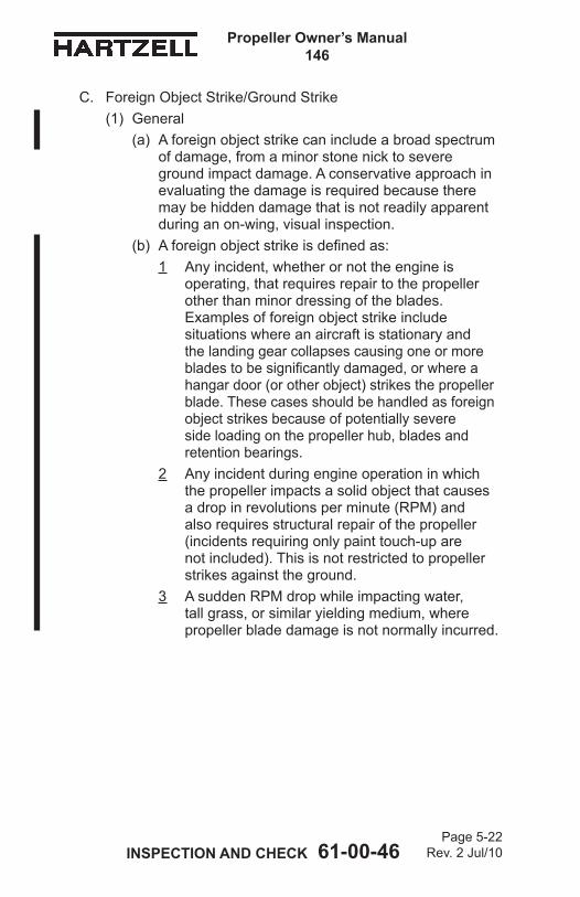
Page 5-22Rev. 2 Jul/10 INSPECTION AND CHECK 61-00-46
Propeller Owner’s Manual146
C. Foreign Object Strike/Ground Strike(1) General
(a) A foreign object strike can include a broad spectrum of damage, from a minor stone nick to severe ground impact damage. A conservative approach in evaluating the damage is required because there may be hidden damage that is not readily apparent during an on-wing, visual inspection.
(b) A foreign object strike is defined as:1 Any incident, whether or not the engine is
operating, that requires repair to the propeller other than minor dressing of the blades. Examples of foreign object strike include situations where an aircraft is stationary and the landing gear collapses causing one or more blades to be significantly damaged, or where a hangar door (or other object) strikes the propeller blade. These cases should be handled as foreign object strikes because of potentially severe side loading on the propeller hub, blades and retention bearings.
2 Any incident during engine operation in which the propeller impacts a solid object that causes a drop in revolutions per minute (RPM) and also requires structural repair of the propeller (incidents requiring only paint touch-up are not included). This is not restricted to propeller strikes against the ground.
3 A sudden RPM drop while impacting water, tall grass, or similar yielding medium, where propeller blade damage is not normally incurred.

INSPECTION AND CHECK 61-00-46Page 5-23
Rev. 2 Jul/10
Propeller Owner’s Manual146
(2) Procedure(a) In the event of a foreign object strike, an inspection
is required before further flight. If the inspection reveals one or more of the following indications, the propeller must be removed from the aircraft, disassembled, and overhauled in accordance with the applicable propeller and blade maintenance manuals.1 A blade rotated in the clamp.2 Any noticeable or suspected damage to the
pitch change mechanism. 3 A bent blade (out of track or angle).4 Any diameter reduction.5 Blade Damage.6 A bent, cracked, or failed engine shaft.7 A blade rotated in the clamp.8 Vibration during operation that was not present
before the event.(b) Unairworthy damage on composite blade surfaces
or on the leading and trailing edges must be repaired before flight. Refer to the Composite Blade Unairworthy Damage section in the Maintenance Practices chapter of this manual.
(c) Engine mounted components such as governors, pumps, etc. may be damaged by a foreign object strike/ground strike, especially if the strike resulted in a sudden stoppage of the engine. These components should be inspected, repaired, or overhauled as recommended by the applicable component maintenance manual.
(d) Make an entry in the propeller log book about the foreign object strike/ground strike incident and any corrective action(s) taken.

Page 5-24Rev. 4 Jun/15 INSPECTION AND CHECK 61-00-46
Propeller Owner’s Manual146
D. Fire Damage or Heat Damage
WARNING 1: EXPOSING COMPOSITE BLADES TO HIGH TEMPERATURES MAY LEAD TO FAILURE THAT MAY CAUSE PERSONAL INJURY AND DEATH. COMPOSITE BLADES ARE SUBJECT TO DELAMINATIONS DUE TO HIGH TEMPERATURES.
WARNING 2: HUBS AND CLAMPS ARE MANUFACTURED FROM HEAT TREATED FORGINGS AND ARE SHOT PEENED. EXPOSURE TO HIGH TEMPERATURES CAN DESTROY THE FATIGUE RESISTANCE BENEFITS OBTAINED FROM THESE PROCESSES.
On rare occasions propellers may be exposed to fire or heat damage, such as an engine or hangar fire. In the event of such an incident, an inspection by a certified propeller repair station with the appropriate rating is required before further flight.

INSPECTIONANDCHECK61-00-46Page 5-25
Rev. 3 Jun/12
PropellerOwner’sManual146
6. Long Term StorageA. Parts shipped from the Hartzell Propeller Inc. factory are not
shipped or packaged in a container that is designed for long term storage.
B. Long term storage procedures may be obtained by contacting a Hartzell Propeller Inc. distributor, or the Hartzell Propeller Inc. factory via the Product Support number listed in the Introduction chapter of this manual. Storage information is also detailed in Hartzell Propeller Inc. Standard Practices Manual 202A (61-01-02).
C. Information regarding the return of a propeller assembly to service after long term storage may be obtained by contacting a Hartzell Propeller Inc. distributor, or the Hartzell Propeller Inc. factory via the Product Support number listed in the Introduction chapter of this manual. This information is detailed in Hartzell Propeller Inc. Standard Practices Manual 202A (61-01-02).

Page 5-26Rev. 3 Jun/12 INSPECTIONANDCHECK61-00-46
PropellerOwner’sManual146
(This page is intentionally blank.)

MAINTENANCE PRACTICES 61-00-46
Propeller Owner's Manual146
Page 6-1Rev. 5 Nov/17
MAINTENANCE PRACTICES - CONTENTS
1. Cleaning ................................................................................. 6-3A. General Cleaning ............................................................... 6-3B. Spinner Cleaning and Polishing ......................................... 6-5
2. Lubrication .............................................................................. 6-6A. Lubrication Intervals ........................................................... 6-6B. Lubrication Procedure ........................................................ 6-7C. Approved Lubricants .......................................................... 6-9
3. Carbon Block Assemblies ..................................................... 6-10A. Inspection ......................................................................... 6-10B. Replacement of A-3026 Carbon Block Unit in the A-3044 Carbon Block Assembly ............................. 6-11C. Installation of the A-3044 Carbon Block Assembly .......... 6-11
4. Composite Blades ................................................................ 6-13A. General Description ......................................................... 6-13B. Component Life and Service ............................................ 6-14C. Damage Evaluation .......................................................... 6-15D. Repair Determination ....................................................... 6-16E. Personnel Requirements ................................................. 6-17F. Blade Inspection Requirements ....................................... 6-18
5. Painting After Repair ............................................................. 6-22A. General ............................................................................ 6-22B. Painting of Composite Blades .......................................... 6-23
6. Dynamic Balance .................................................................. 6-25A. Overview .......................................................................... 6-25B. Inspection Procedures Before Balancing ......................... 6-26C. Modifying Spinner Bulkhead to Accommodate Dynamic Balance Weights ............................................... 6-27D. Placement of Balance Weights for Dynamic Balance ...... 6-27
7. De-ice Systems .................................................................... 6-28
8. Tachometer Inspection .......................................................... 6-29

Page 6-2Rev. 4 Jun/15 MAINTENANCE PRACTICES 61-00-46
Propeller Owner's Manual146
Lubrication Fitting ..........................................Figure 6-1 ............ 6-4
Lubrication Label ...........................................Figure 6-2 ............. 6-8
Section of Typical Legacy Composite Blade ........................................Figure 6-3 ........... 6-12
Basic Components of a Legacy Composite Blade ........................................Figure 6-4 ........... 6-12
Blade Crack Location ....................................Figure 6-5 ........... 6-19
Blade Crack Outboard of the 5 Inch (127 mm) Area .................................Figure 6-6 ........... 6-19
LIST OF TABLES Page
Approved Paints ............................................Table 6-1 ............ 6-22
LIST OF FIGURES Page
Page 6-3Rev. 3 Jun/12 MAINTENANCEPRACTICES 61-00-46
PropellerOwner'sManual146
1. Cleaning
CAUTION 1: INSTRUCTIONS AND PROCEDURES IN THIS SECTION MAY INVOLVE CRITICAL PARTS. REFER TO THE INTRODUCTION CHAPTER OF THIS MANUAL FOR INFORMATION ABOUT PROPELLER CRITICAL PARTS. REFER TO THE ILLUSTRATED PARTS LIST CHAPTER OF THE APPLICABLE OVERHAUL MANUAL(S) FOR THE IDENTIFICATION OF SPECIFIC PROPELLER CRITICAL PARTS.
CAUTION 2: DO NOT USE PRESSURE WASHING EQUIPMENT TO CLEAN THE PROPELLER OR CONTROL COMPONENTS. PRESSURE WASHING CAN FORCE WATER AND/OR CLEANING SOLVENTS PAST SEALS, AND CAN LEAD TO INTERNAL CORROSION OF PROPELLER COMPONENTS.
A. General Cleaning
CAUTION 1: DO NOT CLEAN THE PROPELLER WITH CAUSTIC OR ACIDIC SOAP SOLUTIONS. IRREPARABLE CORROSION OF PROPELLER COMPONENTS MAY OCCUR.
CAUTION 2: WHEN CLEANING THE PROPELLER, DO NOT ALLOW SOAP OR SOLVENT SOLUTIONS TO RUN OR SPLASH INTO THE HUB AREA.
(1) Wash the propeller with a noncorrosive soap solution.

Page 6-4 Rev. 2 Jul/10 MAINTENANCEPRACTICES61-00-46
PropellerOwner'sManual146
LubricationFitting
Figu
re6-1
W10
094.
PLT
LUB
RIC
ATIO
N F
ITTI
NG
(O
NE
IN E
AC
H C
LAM
P H
ALF
)

Page 6-5Rev. 3 Jun/12 MAINTENANCE PRACTICES 61-00-46
Propeller Owner's Manual146
WARNING: CLEANING AGENTS (ACETONE, #700 LACQUER THINNER, AND MEK), ARE FLAMMABLE AND TOXIC TO THE SKIN, EYES AND RESPIRATORY TRACT. SKIN AND EYE PROTECTION ARE REQUIRED. AVOID PROLONGED CONTACT. USE IN WELL VENTILATED AREA.
CAUTION: DO NOT USE ANY SOLVENT DURING CLEANING THAT COULD SOFTEN OR DESTROY THE BOND BETWEEN CHEMICALLY ATTACHED PARTS.
(2) To remove grease or oil from propeller surfaces, apply Stoddard Solvent or equivalent to a clean cloth and wipe the part clean.
(3) Thoroughly rinse in water and allow the part to dry.B. Spinner Cleaning and Polishing
(1) Clean the spinner using the General Cleaning procedures in this section.
(2) Polish the dome (if required) with an automotive-type aluminum polish.

MAINTENANCE PRACTICES 61-00-46
Propeller Owner's Manual146
Page 6-6Rev. 5 Nov/17
2. Lubrication
CAUTION: INSTRUCTIONS AND PROCEDURES IN THIS SECTION MAY INVOLVE CRITICAL PARTS. REFER TO THE INTRODUCTION CHAPTER OF THIS MANUAL FOR INFORMATION ABOUT PROPELLER CRITICAL PARTS. REFER TO THE ILLUSTRATED PARTS LIST CHAPTER OF THE APPLICABLE OVERHAUL MANUAL(S) FOR THE IDENTIFICATION OF SPECIFIC PROPELLER CRITICAL PARTS.
A. Lubrication Intervals(1) The propeller is to be lubricated at intervals not to
exceed 200 hours or at 12 calendar months, whichever occurs first.(a) If propeller operation in a 6 month period from the
last lubrication interval is less than 50 hours, the propeller must be re-lubricated.
(b) If the aircraft is operated or stored under adverse atmospheric conditions, e.g., high humidity, salt air, calendar lubrication intervals should be reduced to 100 hours or six months.
(c) If the propeller is operated on a seaplane, the lubrication interval should be reduced to 100 hours or six months.
(d) If the propeller is leaking grease, the lubrication interval should be reduced to 100 hours until the grease leak issue is resolved.
(2) Owners of high use aircraft may wish to extend their lubrication intervals. Lubrication interval may be gradually extended after evaluation of previous propeller overhauls, with regard to bearing wear and internal corrosion.
(3) New or newly overhauled propellers should be lubricated after the first one or two hours of operation, because centrifugal loads will pack and redistribute grease. (a) Purchasers of new aircraft should check the
propeller logbook to verify whether the propeller was lubricated by the manufacturer during flight testing. If not, the propeller should be serviced at earliest convenience.

Page 6-7Rev. 3 Jun/12 MAINTENANCEPRACTICES 61-00-46
PropellerOwner'sManual146
B. Lubrication Procedure
CAUTION: FOLLOW LUBRICATION PROCEDURES CORRECTLY TO MAINTAIN AN ACCURATE BALANCE OF THE PROPELLER ASSEMBLY.
(1) Remove the propeller spinner.(2) Refer to Figure 6-1. Each blade clamp has two
lubrication fittings. Remove both lubrication fitting caps and one of the lubrication fittings from each blade clamp.
(3) Use a piece of safety wire to loosen any blockage or hardened grease in the threaded holes where the lubrication fitting was removed.
WARNING: WHEN MIXING AEROSHELL GREASES 5 AND 6, AEROSHELL GREASE 5 MUST BE INDICATED ON THE LABEL (HARTZELL PROPELLER INC. P/N A-3594) AND THE AIRCRAFT MUST BE PLACARDED TO INDICATE THAT FLIGHT IS PROHIBITED IF THE OUTSIDE AIR TEMPERATURE IS LESS THAN -40°F (-40°C).
CAUTION: USE HARTZELL PROPELLER INC. APPROVED GREASE ONLY. EXCEPT IN THE CASE OF AEROSHELL GREASES 5 AND 6, DO NOT MIX DIFFERENT SPECIFICATIONS AND/OR BRANDS OF GREASE.
(4) Aeroshell greases 5 and 6 both have a mineral oil base and have the same thickening agent; therefore, mixing of these two greases is acceptable in Hartzell Propeller Inc. propellers.

Page 6-8Rev. 3 Jun/12 MAINTENANCEPRACTICES 61-00-46
PropellerOwner'sManual146
(5) A label (Hartzell Propeller Inc. P/N A-3594) is normally applied to the propeller to indicate the type of grease previously used (Figure 6-2).(a) This grease type should be used during
re-lubrication, unless the propeller has been disassembled and the old grease removed.
(b) Purging of old grease through lubrication fittings is only about 30 percent effective.
(c) To completely replace one grease with another, the propeller must be disassembled in accordance with the applicable overhaul manual.
CAUTION 1: IF A PNEUMATIC GREASE GUN IS USED, EXTRA CARE MUST BE TAKEN TO AVOID EXCESSIVE PRESSURE BUILDUP.
CAUTION 2: GREASE MUST BE APPLIED TO ALL BLADES OF A PROPELLER ASSEMBLY AT THE TIME OF LUBRICATION.
(6) Pump grease into the blade clamp lubrication fitting until grease emerges from the hole of the removed lubrication fitting. NOTE: Lubrication is complete when grease emerges
in a steady flow with no air pockets or moisture, and has the color and texture of the new grease.
LubricationLabelFigure6-2
A-3594

Page 6-9Rev. 3 Jun/12 MAINTENANCEPRACTICES 61-00-46
PropellerOwner'sManual146
(7) Repeat step 2.B.4 for each blade clamp assembly.(8) Reinstall the removed lubrication fitting on each clamp.(9) Tighten each lubrication fitting until snug.
(a) Make sure the ball of each lubrication fitting is correctly seated.
(10) Install a new lubrication fitting cap on each lubrication fitting.
C. Approved Lubricants(1) The following lubricants are approved for use in Hartzell
Propeller Inc. propellers:Aeroshell 6 - Recommended"all purpose" grease. Used in most new production propellers since 1989. Higher leakage/oil separation than Aeroshell 5 at higher temperatures.Aeroshell 5 - Good high temperature qualities, very little oil separation or leakage. Cannot be used in temperatures colder than -40° F (-40° C). Aircraft serviced with this grease must be placarded to indicate that flight is prohibited if the outside air temperature is less than -40° F (-40° C). Aeroshell 7 - Good low temperature grease, but high leakage/oil separation at higher temperatures. This grease has been associated with sporadic problems involving seal swelling.Aeroshell 22 - Qualities similar to Aeroshell 7. Royco 22CF - Not widely used. Qualities similar to Aeroshell 22.(2) A label indicating the type of grease used for previous
lubrication (if used) is installed on the propeller piston or on the blade clamp. If the propeller must be lubricated with a different type of grease, the propeller must be disassembled and cleaned of old grease before relubricating.

Page 6-10Rev. 3 Jun/12 MAINTENANCEPRACTICES 61-00-46
PropellerOwner'sManual146
3. Carbon Block Assemblies
CAUTION: INSTRUCTIONS AND PROCEDURES IN THIS SECTION MAY INVOLVE CRITICAL PARTS. REFER TO THE INTRODUCTION CHAPTER OF THIS MANUAL FOR INFORMATION ABOUT PROPELLER CRITICAL PARTS. REFER TO THE ILLUSTRATED PARTS LIST CHAPTER OF THE APPLICABLE OVERHAUL MANUAL(S) FOR THE IDENTIFICATION OF SPECIFIC PROPELLER CRITICAL PARTS.
A. InspectionRefer to Figures 3-5 and 3-6.The clearance between the yoke pin and the corresponding linkage (beta lever bushing) can become too close due to a buildup of plating and foreign particles between the two pieces. This can cause a binding action, resulting in excessive wear to the carbon block, low stop collar, and beta linkage.(1) Inspect the beta lever and carbon block interface for free
movement. If there is binding, complete the following steps:(a) Disconnect the beta linkage and remove the carbon
block assemblies from the beta ring.(b) Polish the yoke pin to provide adequate clearance
and eliminate binding.(c) Reinstall the carbon block assembly into the beta
ring.(d) Install, adjust and safety the beta linkage per the
airframe manufacturer's instructions.

Page 6-11Rev. 3 Jun/12 MAINTENANCE PRACTICES 61-00-46
Propeller Owner's Manual146
B. Replacement of A-3026 Carbon Block Unit in the A-3044 Carbon Block AssemblyReplace an A-3026 carbon block unit if the side clearance between the beta ring and carbon block exceeds 0.010 inch (0.25 mm)(1) Remove the cotter pin from the end of the clevis pin.(2) Slide the pin from the assembly and remove and discard
the carbon block unit.(3) Inspect the yoke for wear or cracks. Replace the yoke if
necessary.(4) Install a new carbon block unit and slide a new clevis pin
into place.(5) Secure the clevis pin with a T-head cotter pin
(Figure 3-6).(6) Refit the carbon block (Figure 3-5).
(a) Establish the required clearance by sanding the sides of the carbon block as needed.
C. Installation of the A-3044 Carbon Block AssemblyRefer to the Installation and Removal chapter of this manual for installation instructions.

Page 6-12Rev. 4 Jun/15 MAINTENANCE PRACTICES 61-00-46
Propeller Owner's Manual146
Section of Typical Legacy Composite Blade Figure 6-3
CP
S00
51a
Solid Unidirectional Composite Material
Laminated Layers of
Composite Material
Solid Unidirectional Composite Material
Erosion Shield
Low-DensityFoam CoreLaminated Layers
of Composite Material
Basic Components of a Legacy Composite Blade Figure 6-4
AP
S00
47a,
A
PS
0665
a
Low-DensityFoam Core
Composite Material
Retention Laminates
Shank of Metal Blade
Plug
Metal Blade Plug
Erosion Shield
Low-DensityFoam Core
Blade Retention Windings

Page 6-13Rev. 4 Jun/15 MAINTENANCE PRACTICES 61-00-46
Propeller Owner's Manual146
4. Composite Blades
CAUTION: INSTRUCTIONS AND PROCEDURES IN THIS SECTION MAY INVOLVE CRITICAL PARTS. REFER TO THE INTRODUCTION CHAPTER OF THIS MANUAL FOR INFORMATION ABOUT PROPELLER CRITICAL PARTS. REFER TO THE ILLUSTRATED PARTS LIST CHAPTER OF THE APPLICABLE OVERHAUL MANUAL(S) FOR THE IDENTIFICATION OF SPECIFIC PROPELLER CRITICAL PARTS.
A. General Description(1) The Legacy composite blade is composed of a metal
blade shank (plug) that has a low-density foam core molded into the metal blade shank. (a) These internal components are covered by layers
of laminated composite materials that make up the outer shell of the blade.
(b) The laminated blade then undergoes compressive molding that provides the final airfoil shape and bonds the composite materials to the blade plug.
(c) The foam core is used to support the layers of laminated composite materials to the blade plug. Refer to Figure 6-3.
(2) The laminated composite materials that are an integral component of the blade provide a retention load path that extends directly under the bearing in aluminum hubs for blade retention.
(3) An electroformed nickel erosion shield is adhesively bonded over the leading edge of the blade to provide protection from impact and erosion damage.
(4) Filament windings of composite material provide additional retention of the blade composite materials to the internal metal plug. Refer to Figure 6-4.
(5) Some designs use a filament winding on the inboard end of the erosion shield to aid the retention of the erosion shield.

Page 6-14Rev. 4 Jun/15 MAINTENANCE PRACTICES 61-00-46
Propeller Owner's Manual146
(a) This winding is sometimes referred to as an erosion shield winding and should not be confused with the blade retention winding used to attach the blade material to the internal metal plug.
(6) The composite blade is balanced in the horizontal plane during production by the addition of lead wool to a centrally located balance tube in the metal blade shank. The balance tube may protrude into the foam core of the blade.
(7) A finish covering of polyurethane paint protects the entire blade from erosion and ultraviolet damage.
(8) Aircraft that require ice protection use an external de-ice or anti-icing boot.
B. Component Life and Service(1) Blade Life
Blade life is expressed in terms of total hours of service since new (TSN), time between overhauls (TBO) and in terms of service since overhaul (TSO). All references are necessary in defining the life of the propeller.
(2) Overhaul or Major Periodic Inspection (MPI)(a) Overhaul, or MPI, is the periodic disassembly,
inspection, repair, refinish, and reassembly of the composite blade assembly.NOTE: The term "overhaul" is used throughout
the text of this manual.(b) At such specified periods, the blade assemblies are
completely disassembled and inspected for cracks, wear, corrosion, and other unusual or abnormal conditions. As specified, some blades are refinished, and other blades are replaced. The blades can then be reassembled and balanced.
(c) Overhaul is to be accomplished in accordance with the latest revision of Hartzell Propeller Inc. Composite Propeller Blade Maintenance Manual 135F (61-13-35) and other applicable publications.

Page 6-15Rev. 4 Jun/15 MAINTENANCE PRACTICES 61-00-46
Propeller Owner's Manual146
(d) Any propeller repair station that is appropriately certified by their local aviation authority may perform composite blade overhaul and minor repair.
(e) Any propeller repair station that is appropriately certified by their local aviation authority may perform composite blade overhaul and minor repair, but ONLY those facilities that employ personnel that have certification by Hartzell Propeller Inc. for Composite Blade Major Repair and Composite Blade Erosion Shield Replacement are granted official Hartzell Propeller Inc. certification and are listed on the Hartzell Propeller Inc. website.
C. Damage EvaluationNOTE: Specific Hartzell Propeller Inc. manuals and
service documents are available on the Hartzell website at www.hartzellprop.com. Refer to the Required Publications section in the Introduction chapter of this manual for the identification of these publications.
(1) Airworthy Damage
CAUTION: ALTHOUGH A BLADE MAY CONTINUE IN SERVICE WITH AIRWORTHY DAMAGE, THIS TYPE OF DAMAGE SHOULD BE REPAIRED AT THE EARLIEST PRACTICAL TIME.
(a) Airworthy damage is a specific condition to a blade that does not affect the safety or flight characteristics of the propeller blade and conforms to its type design by meeting the condition inspection criteria limitations found in Hartzell Propeller Inc. Composite Propeller Blade Field Maintenance and Minor Repair Manual 170 (61-13-70).1 The maximum limits of airworthy damage are
specified in Hartzell Propeller Inc.Composite Propeller Blade Field Maintenance and Minor Repair Manual 170 (61-13-70).
2 Hartzell Propeller Inc. Composite Propeller Blade Field Maintenance and Minor Repair Manual 170 (61-13-70) provides inspection criteria and direction to evaluate damage to determine continued airworthiness.

Page 6-16Rev. 4 Jun/15 MAINTENANCE PRACTICES 61-00-46
Propeller Owner's Manual146
(b) Although a blade may continue in service with airworthy damage, this type of damage should be repaired at the earliest practical time to prevent the damage from progressing to a condition that could require more extensive repair to the blade.
(2) Unairworthy Damage
CAUTION: IN MOST CASES, UNAIRWORTHY DAMAGE MUST BE REPAIRED BEFORE THE NEXT FLIGHT.
(a) Unairworthy damage is damage that exceeds the airworthy damage limits as specified in Hartzell Propeller Inc. Composite Blade Field Maintenance and Minor Repair Manual 170 (61-13-70). 1 Unairworthy damage can affect the safety or
flight characteristics of the propeller blade and does not conform to its type design.
2 This condition deems the blade unairworthy, requiring appropriate corrective action to repair or remove it from service, as applicable.
D. Repair DeterminationNOTE: Specific Hartzell Propeller Inc. manuals and
service documents are available on the Hartzell website at www.hartzellprop.com. Refer to the Required Publications section in the Introduction chapter of this manual for the identification of these publications.
(1) Minor Repair(a) Minor repair is correction of damage that may
be safely performed in the field by elementary operations.
(b) For complete description of minor repair and allowable procedures, refer to Hartzell Propeller Inc. Composite Blade Field Maintenance and Minor Repair Manual 170 (61-13-70).

Page 6-17Rev. 4 Jun/15 MAINTENANCE PRACTICES 61-00-46
Propeller Owner's Manual146
(2) Major Repair(a) Major repair is correction of damage that cannot be
performed by elementary operations. (b) Major repair must be accepted by a certified aircraft
mechanic with an appropriate rating, preferably one that holds a Factory Training Certificate from Hartzell Propeller Inc.
(c) All major repairs must be performed by a propeller repair station that is certified by Hartzell Propeller Inc. and is an appropriately rated propeller repair station certified by the Federal Aviation Administration (FAA) or international equivalent.
E. Personnel RequirementsNOTE: Specific Hartzell Propeller Inc. manuals and
service documents are available on the Hartzell website at www.hartzellprop.com. Refer to the Required Publications section in the Introduction chapter of this manual for the identification of these publications.
(1) Anyone performing or accepting responsibility for an inspection, repair and/or overhaul of a Hartzell Propeller Inc. product must comply with the applicable regulatory requirements established by the appropriate Aviation Authority.
(2) Any person signing for or performing inspections and/or repairs to Hartzell Propeller Inc. composite parts should be familiar with the objectives and procedures associated with the inspection and/or repair of composite parts.
(3) For personnel requirements for repair of Hartzell Propeller Inc. composite blades, are specified in Hartzell Propeller Inc. Composite Propeller Blade Field Maintenance and Minor Repair Manual 170 (61-13-70).

Page 6-18Rev. 4 Jun/15 MAINTENANCE PRACTICES 61-00-46
Propeller Owner's Manual146
F. Blade Inspection Requirements
CAUTION: MAINTAINING A GOOD LOGBOOK RECORD IS PARTICULARLY IMPORTANT FOR COMPOSITE PROPELLER BLADES. DAMAGE AND/OR REPAIRS MAY SUFFER FURTHER DEGRADATION AFTER CONTINUED USE. SUCH DEGRADATION MAY BE EASILY OVERLOOKED. IT IS IMPORTANT FOR INSPECTORS TO HAVE ACCESS TO ACCURATE HISTORICAL DATA WHEN PERFORMING SUBSEQUENT INSPECTIONS.
NOTE: Specific Hartzell Propeller Inc. manuals and service documents are available on the Hartzell website at www.hartzellprop.com. Refer to the Required Publications section in the Introduction chapter of this manual for the identification of these publications.
(1) Required Record-Keeping(a) Composite blade damage and a description of the
repair must be recorded in the composite blade logbook.
(2) Preflight Inspection(a) Follow propeller preflight inspection procedures
as specified in the aircraft maintenance manual, or an air carrier’s operational specifications, or this manual. In addition, perform the following inspections:1 Visually inspect each entire blade for nicks,
gouges, loose material, erosion, cracks, and debonds.
2 Visually inspect each blade for lightning strike. Refer to “Lightning Strike Damage” in the Inspection and Check of this manual for a description of damage.
(b) Defects or damage discovered during preflight inspection must be evaluated in accordance with Hartzell Propeller Inc. Composite Propeller Blade Field Maintenance and Minor Repair Manual 170 (61-13-70).

Page 6-19Rev. 4 Jun/15 MAINTENANCE PRACTICES 61-00-46
Propeller Owner's Manual146
Blade Crack Location Figure 6-5
Typical crack indication
5 inches (127 mm)
Inspect within this area9 inches
(228.6 mm)
TI-1
46Fi
g.6-
11
Blade Crack Outboard of the 5 Inch (127 mm) AreaFigure 6-6
5 inches (127 mm)
TI-1
46Fi
g.6-
12

Page 6-20Rev. 4 Jun/15 MAINTENANCE PRACTICES 61-00-46
Propeller Owner's Manual146
(3) Maintenance Inspections(a) Inspection procedures must be performed in
accordance with this manual. 1 Perform a thorough visual inspection.2 Perform a coin-tap test to the exposed section
of the blade at intervals as required. For the required intervals, refer to the Periodic Inspections section of the Inspection and Check chapter of this manual.a Coin-tapping will indicate a delamination or
debond by an apparent audible change.b For the coin tap procedure for composite
blades, refer to Hartzell Propeller Inc. Composite Propeller Blade Field Maintenance and Minor Repair Manual 170 (61-13-70).
3 For M10083(K) blades - Erosion Screena The erosion screen is located on the tip of
the blade (face and camber sides) for the purpose of erosion protection.
b Although no specific airworthy limits exist for the erosion screen, if the screen or part of the screen becomes loose from the blade, remove the loose piece(s) to prevent possible blade damage from occurring.
c The limits of erosion screen damage that would require replacement at overhaul are given in Hartzell Propeller Inc. Composite Propeller Blade Field Maintenance and Minor Repair Manual 170 (61-13-70).
4 For M10083(K), LM10585( )( )+4 and M10877K - Blade Retention windingsa Cracks appearing in the paint over the
blade retention windings are airworthy. These cracks should be repaired as soon as practical.
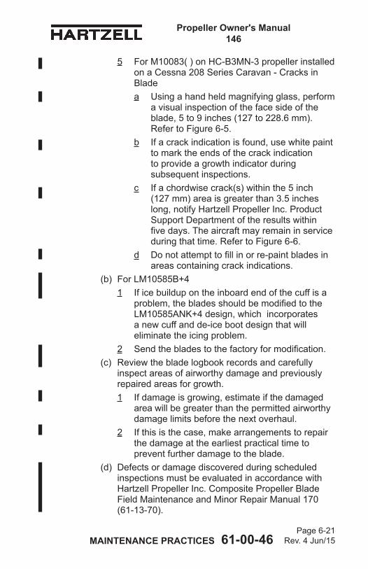
Page 6-21Rev. 4 Jun/15 MAINTENANCE PRACTICES 61-00-46
Propeller Owner's Manual146
5 For M10083( ) on HC-B3MN-3 propeller installed on a Cessna 208 Series Caravan - Cracks in Blade a Using a hand held magnifying glass, perform
a visual inspection of the face side of the blade, 5 to 9 inches (127 to 228.6 mm). Refer to Figure 6-5.
b If a crack indication is found, use white paint to mark the ends of the crack indication to provide a growth indicator during subsequent inspections.
c If a chordwise crack(s) within the 5 inch (127 mm) area is greater than 3.5 inches long, notify Hartzell Propeller Inc. Product Support Department of the results within five days. The aircraft may remain in service during that time. Refer to Figure 6-6.
d Do not attempt to fill in or re-paint blades in areas containing crack indications.
(b) For LM10585B+41 If ice buildup on the inboard end of the cuff is a
problem, the blades should be modified to the LM10585ANK+4 design, which incorporates a new cuff and de-ice boot design that will eliminate the icing problem.
2 Send the blades to the factory for modification.(c) Review the blade logbook records and carefully
inspect areas of airworthy damage and previously repaired areas for growth. 1 If damage is growing, estimate if the damaged
area will be greater than the permitted airworthy damage limits before the next overhaul.
2 If this is the case, make arrangements to repair the damage at the earliest practical time to prevent further damage to the blade.
(d) Defects or damage discovered during scheduled inspections must be evaluated in accordance with Hartzell Propeller Inc. Composite Propeller Blade Field Maintenance and Minor Repair Manual 170 (61-13-70).

Page 6-22Rev. 4 Jun/15 MAINTENANCE PRACTICES 61-00-46
Propeller Owner's Manual146
5. Painting After RepairA. General
(1) Propeller blades are painted with a durable specialized coating that is resistant to abrasion. If this coating becomes eroded over an area of more than 10 square inches (64.5 square cm), it is necessary to repaint the entire blade to provide proper corrosion and erosion protection. Painting should be performed a certified propeller repair station with the appropriate rating in accordance with Hartzell Propeller Inc. Standard Practices Manual 202A (61-01-02).
(2) For paint erosion over an area of less than 10 square inches (64.5 square cm) it is permissible to perform a blade touch-up with aerosol paint in accordance with the procedures in this section.
(3) Refer to Table 6-1 for paints that are approved for blade touch-up.
Approved PaintsTable 6-1
Vendor Color/Type VendorP/N
Hartzell Propeller Inc.
P/NTempo Epoxy Black A-150 n/aTempo Epoxy Gray A-151 n/aTempo Epoxy White (tip stripe) A-152 n/aTempo Epoxy Red (tip stripe) A-153 n/aTempo Epoxy Yellow (tip stripe) A-154 n/aSherwin-Williams Black F75KXB9958-4311 A-6741-145-1
Sherwin-Williams Gray F75KXA10445-4311 A-6741-146-1
Sherwin-Williams White (tip stripe) F75KXW10309-4311 A-6741-147-1
Sherwin-Williams
Gray Metallic (Raytheon Beech 1900D aircraft models only)
F75KXM9754-4311 A-6741-148-1
Sherwin-Williams Red (tip stripe) F75KXR12320-4311 A-6741-149-1
Sherwin-Williams Yellow (tip stripe) F75KXY11841-4311 A-6741-150-1

MAINTENANCE PRACTICES 61-00-46
Propeller Owner's Manual146
Page 6-23Rev. 5 Nov/17
(4) The paint manufacturers may be contacted as listed below:Tempo Products Co. Sherwin Williams Co. A plasti-kote Company Refer to the Sherwin Williams 1000 Lake Road Product Finishes Global Finishes Medina, OH 44256 Group website at Tel: 800.321.6300 http://oem.sherwin-williams.com Fax: 440.349.4241 to find the nearest location. Cage Code: 07708
B. Painting of Composite Blades
WARNING: CLEANING AGENTS (ACETONE, #700 LACQUER THINNER, AND MEK), ARE FLAMMABLE AND TOXIC TO THE SKIN, EYES AND RESPIRATORY TRACT. SKIN AND EYE PROTECTION ARE REQUIRED. AVOID PROLONGED CONTACT. USE IN A WELL VENTILATED AREA.
CAUTION 1: ANY REFINISHING PROCEDURE CAN ALTER PROPELLER BALANCE. PROPELLERS THAT ARE OUT OF BALANCE MAY EXPERIENCE EXCESSIVE VIBRATIONS WHILE IN OPERATION.
CAUTION 2: PAINT EROSION IS TYPICALLY VERY SIMILAR ON ALL BLADES IN A PROPELLER ASSEMBLY. ALL BLADES SHOULD BE PAINTED TO THE SAME THICKNESS TO MAINTAIN PROPER BALANCE AFTER REFINISHING.
(1) Using acetone, #700 lacquer thinner, or MEK, wipe the surface of the blade to remove any contaminants.

Page 6-24Rev. 4 Jun/15 MAINTENANCE PRACTICES 61-00-46
Propeller Owner's Manual146
CAUTION: EXCESSIVE SANDING WILL CAUSE "FUZZING" OF THE KEVLAR MATERIAL, RESULTING IN A ROUGH FINISH.
(2) Using 120 to 180 grit sandpaper, sand to feather the existing coatings away from the eroded or repaired area.(a) Erosion damage is typically very similar on all blades
in a propeller assembly. If one blade has more extensive damage, e.g., in the tip area, sand all the blades in the tip area to replicate the repair of the most severely damaged blade tip. This practice is essential in maintaining balance after refinishing.
(3) Using lacquer thinner #700 or MEK, wipe the surface of the blade, and permit the solvent to evaporate.
(4) Apply masking material for the erosion shield, de-ice boot and tip stripes, as needed.
WARNING: FINISH COATINGS ARE FLAMMABLE AND TOXIC TO THE SKIN, EYES AND RESPIRATORY TRACT. SKIN AND EYE PROTECTION ARE REQUIRED. AVOID PROLONGED CONTACT. USE IN WELL VENTILATED AREA.
CAUTION: APPLY FINISH COATING ONLY TO THE DEGREE REQUIRED TO UNIFORMLY COVER THE REPAIR/EROSION. AVOID EXCESSIVE PAINT BUILDUP ALONG THE TRAILING EDGE TO AVOID CHANGING BLADE PROFILE AND/OR P-STATIC CHARACTERISTICS.
(5) Apply sufficient finish coating to achieve 2 to 4 mil thickness when dry. (a) Re-coat before 30 minutes, or after 48 hours.(b) If the paint is permitted to dry longer than four (4)
hours, it must be lightly sanded before another coat is applied.
(6) Remove the masking material from the tip stripes and re-apply masking material for the tip stripe refinishing, if required.

Page 6-25Rev. 4 Jun/15 MAINTENANCE PRACTICES 61-00-46
Propeller Owner's Manual146
(7) Apply the sufficient tip stripe coating to achieve 2 to 4 mils thickness when dry. (a) Re-coat before 30 minutes, or after 48 hours.(b) If the paint is permitted to dry longer than
four (4) hours, it must be lightly sanded before another coat is applied.
(8) Remove the masking material immediately from the tip stripes and de-ice boot, if required.
(9) Optionally, perform dynamic balancing in accordance with the procedures and limitations specified in the Dynamic Balance section of this chapter.
6. Dynamic Balance
CAUTION: INSTRUCTIONS AND PROCEDURES IN THIS SECTION MAY INVOLVE CRITICAL PARTS. REFER TO THE INTRODUCTION CHAPTER OF THIS MANUAL FOR INFORMATION ABOUT PROPELLER CRITICAL PARTS. REFER TO THE ILLUSTRATED PARTS LIST CHAPTER OF THE APPLICABLE OVERHAUL MANUAL(S) FOR THE IDENTIFICATION OF SPECIFIC PROPELLER CRITICAL PARTS.
A. OverviewNOTE: Dynamic balance is recommended to reduce
vibrations that may be caused by a rotating system (propeller and engine) imbalance. Dynamic balancing can help prolong the life of the propeller, engine, airframe, and avionics.
(1) Static balancing is required when an overhaul or major repair is performed at an appropriately licensed propeller service facility. NOTE: If static balancing is not accomplished before
dynamic balancing, the propeller may be so severely unbalanced that dynamic balance may not be achieved.
(2) Dynamic balance is accomplished by using an accurate means of measuring the amount and location of the dynamic imbalance.

Page 6-26Rev. 4 Jun/15 MAINTENANCE PRACTICES 61-00-46
Propeller Owner's Manual146
(3) The number of balance weights installed must not exceed the limits specified in this chapter.
(4) Follow the dynamic balance equipment manufacturer’s instructions for dynamic balance, in addition to the specifications of this section.NOTE: Hartzell Propeller Inc. Standard Practices
Manual 202A (61-01-02), also contains information on weight placement and balancing.
(5) Unless otherwise specified by the engine or airframe manufacturer, Hartzell Propeller Inc. recommends that the propeller be dynamically balanced to a reading of 0.2 IPS, or less.
B. Inspection Procedures Before Balancing(1) Visually inspect the propeller assembly before dynamic
balancing.NOTE: The first run-up of a new or overhauled
propeller assembly may leave a small amount of grease on the blades and inner surface of the spinner dome.
(a) Use a mild solvent to completely remove any grease from the blades or inner surface of the spinner dome.
(b) Visually check each propeller blade assembly for evidence of grease leakage.
(c) Visually inspect the inner surface of the spinner dome for evidence of grease leakage.
(2) If there is no evidence of grease leakage, lubricate the propeller in accordance with the Maintenance Practices chapter in this manual. If grease leakage is evident, determine the location of the leak and correct before re-lubricating the propeller and dynamic balancing.
(3) Before dynamic balancing, record the number and location of all balance weights.

Page 6-27Rev. 4 Jun/15 MAINTENANCE PRACTICES 61-00-46
Propeller Owner's Manual146
C. Modifying Spinner Bulkhead to Accommodate Dynamic Balance Weights
CAUTION 1: ALL HOLE/BALANCE WEIGHT LOCATIONS MUST TAKE INTO CONSIDERATION AND MUST AVOID ANY POSSIBILITY OF INTERFERING WITH THE ADJACENT AIRFRAME, DE-ICE, AND ENGINE COMPONENTS.
CAUTION 2: DO NOT MODIFY A COMPOSITE SPINNER BULKHEAD TO ACCOMMODATE DYNAMIC BALANCE WEIGHTS.
(1) It is recommended that the placement of balance weights be in a radial location on the aluminum spinner bulkheads that have not been previously drilled.
(2) The radial location should be outboard of the de-ice slip ring or bulkhead doubler and inboard of the bend where the bulkhead creates the flange to attach the spinner dome.
(3) Twelve equally spaced locations for weight attachment are recommended.
(4) Installing nut plates (10-32 thread) of the type used to attach the spinner dome will allow convenient balance weight attachment on the engine side of the bulkhead.
(5) Alternatively, drilling holes for use with the AN3-( ) type bolts with self-locking nuts is acceptable.NOTE: Chadwick-Helmuth Manual AW-9511-2, “The
Smooth Propeller”, specifies several generic bulkhead rework procedures. These are acceptable, providing they comply with the conditions specified herein.
D. Placement of Balance Weights for Dynamic Balance(1) The preferred method of attachment of dynamic balance
weights is to add the weights to the spinner bulkhead.NOTE: Many spinner bulkheads have factory installed
self-locking nut plates provided for this purpose.

MAINTENANCE PRACTICES 61-00-46
Propeller Owner's Manual146
Page 6-28Rev. 5 Nov/17
(2) If the location of static balance weights has not been altered, subsequent removal of the dynamic balance weights will return the propeller to its original static balance condition.
(3) Use only stainless or plated steel washers as dynamic balance weights on the spinner bulkhead.
(4) A maximum of six AN970 style washers weighing up to approximately 1.0 oz (28.0 g) may be installed at any one location. NOTE: The dimensions of an AN970 style washer
are: ID 0.203 inch (5.16 mm), OD 0.875 inch (22.23 mm), and thickness 0.063 inch (1.59 mm).
(5) Install weights using aircraft quality #10-32 or AN-3( ) type screws or bolts.
(6) Balance weight screws attached to the spinner bulkhead must protrude through the self-locking nuts or nut plates a minimum of one thread and a maximum of four threads.NOTE: It may be necessary to alter the number and/
or location of static balance weights in order to achieve dynamic balance.
(7) Make a record in the propeller logbook of the number and location of dynamic balance weights and static balance weights, if they have been reconfigured, in the logbook.
7. De-ice SystemsA. Refer to the De-ice Systems chapter of this manual for
de-ice system maintenance information.

MAINTENANCE PRACTICES 61-00-46
Propeller Owner's Manual146
Page 6-29Rev. 5 Nov/17
8. Tachometer Calibration
WARNING: OPERATION WITH AN INACCURATE TACHOMETER CAN CAUSE RESTRICTED RPM OPERATION AND DAMAGING HIGH STRESSES. PROPELLER LIFE WILL BE SHORTENED AND COULD CAUSE CATASTROPHIC FAILURE.
A. All engine/propeller combinations have operating conditions at which the propeller blade stresses begin to reach design limits. (1) In most cases, these conditions occur above the
maximum rated RPM of the engine. (2) Some engine/propeller combinations have certain
ranges of RPM that are less than maximum engine speed, where stresses are at a level considered too high for continuous operation. This results in a restricted operating range where continuous operation is not permitted. A placard on the instrument panel or yellow arc on the tachometer will inform the pilot to avoid operation in this range.
(3) In other cases, the limiting condition occurs at an RPM only slightly above the maximum engine RPM.
(4) For these reasons, it is very important to accurately monitor engine speed.
B. The accuracy of the tachometer is critical to the safe operation of the aircraft. (1) Some tachometers have been found to be in error by as
much as 200 RPM. (2) Operating the aircraft with an inaccurate tachometer
could cause continued operation at unacceptably high stresses, including repeatedly exceeding the maximum engine RPM.
(3) Continuous operation in a restricted RPM range subjects the propeller to stresses that are higher than the design limits.
(4) Stresses that are higher than the design limits will shorten the life of the propeller and could cause a catastrophic failure.

MAINTENANCE PRACTICES 61-00-46
Propeller Owner's Manual146
Page 6-30Rev. 5 Nov/17
C. Tachometer Calibration(1) Hartzell Propeller Inc. recommends that propeller
owners/operators calibrate the engine tachometer in accordance with the National Institute of Standards and Technology (NIST) or similar national standard (traceable).
(2) Contact Hartzell Propeller Inc. if it is found that a propeller was operated in a restricted RPM range because of a tachometer error.

Page 7-1Rev. 5 Nov/17 ANTI-ICE AND DE-ICE SYSTEMS 61-00-46
Propeller Owner’s Manual146
ANTI-ICE AND DE-ICE SYSTEMS - CONTENTS
1. Introduction ............................................................................. 7-3A. Propeller De-ice System .................................................... 7-3B. Propeller Anti-ice System ................................................... 7-3
2. System Description ................................................................. 7-4A. De-ice System .................................................................... 7-4B. Anti-ice System .................................................................. 7-5
3. De-ice System Operational Checks ........................................ 7-6
4. Anti-ice System Operational/Functional Checks .................... 7-6
5. De-ice and Anti-ice System Inspections ................................. 7-7A. De-ice System Inspections ................................................ 7-7B. Anti-ice System Inspections ............................................... 7-7
6. De-ice and Anti-ice System Troubleshooting .......................... 7-8A. De-ice System Troubleshooting ......................................... 7-8B. Anti-ice System Troubleshooting ....................................... 7-8

Page 7-2Rev. 5 Nov/17 ANTI-ICE AND DE-ICE SYSTEMS 61-00-46
Propeller Owner’s Manual146
(This page is intentionally blank.)

Page 7-3Rev. 5 Nov/17 ANTI-ICE AND DE-ICE SYSTEMS 61-00-46
Propeller Owner’s Manual146
1. IntroductionA. Propeller De-ice System
(1) A propeller de-ice system is a system that removes ice after it forms on the propeller blades. A de-ice system uses electrical heating elements to melt the ice layer next to the blades, permitting the ice to be thrown from the blade by centrifugal force. Blades are alternately heated and permitted to cool as the current is applied and removed automatically by the de-ice system timer.
(2) System components include a timer or cycling unit, electrical slip ring(s), brush block assembly, and blade mounted de-ice boots.
B. Propeller Anti-ice System(1) A propeller anti-ice system is a system that prevents
formation of ice on propeller surfaces. An anti-ice system dispenses a fluid that mixes with, and reduces the freezing point of, moisture on the propeller blades. The mixture may then flow off the blades before it forms ice.
(2) System components include a fluid tank, pump, slinger ring, blade mounted fluid anti-icing boots, and a fluid dispensing tube that is found at each blade anti-icing boot.

Page 7-4Rev. 5 Nov/17 ANTI-ICE AND DE-ICE SYSTEMS 61-00-46
Propeller Owner’s Manual146
2. System DescriptionA. De-ice System
NOTE: Because of the wide variances of various de-ice systems, the following description is general in nature. Consult the airframe manufacturer’s manual for a description of your specific de-ice system and controls.
(1) The de-ice system is controlled by the pilot via a cockpit control switch. This switch applies electrical power to the de-ice system, that will operate as long as the switch is in the ON position. Depending upon the system, another set of cockpit controls may be available. One of these controls is a mode selector, that permits the pilot to select two cycling speeds, for heavy or light icing conditions. Some systems on twin engine aircraft have a switch that provides a full de-ice mode, that permits the pilot to de-ice both propellers simultaneously. This switch may only be used for short periods, and is used when ice builds up on the propeller before the system is turned on.
(2) An ammeter, that indicates current drawn by the system, is normally located near the de-ice system switches. This meter may indicate total system load, or a separate ammeter may be supplied for each propeller.
(3) A timer, that is turned off and on by the cockpit control, is used to sequence the de-ice system. This timer turns the de-ice system on and off in proper sequence, controlling the heating interval to each propeller for even de-icing.
(4) A brush block, that is mounted on the engine immediately behind the propeller, supplies electrical current to the de-ice boot on each propeller blade via a slip ring. The slip ring is normally mounted on the spinner bulkhead.
(5) When the pilot puts the de-ice system cockpit control switch in the ON position, the system timer begins to operate. As the timer sequences, power is delivered to a power relay. The power relay delivers high current to the brush block and the slip ring. Each propeller is de-iced in turn by the timer.

Page 7-5Rev. 5 Nov/17 ANTI-ICE AND DE-ICE SYSTEMS 61-00-46
Propeller Owner’s Manual146
B. Anti-ice System(1) The anti-ice system is controlled by the pilot via a cockpit
mounted rheostat. This rheostat operates a pump that pumps anti-ice fluid from the tank at a controlled rate.
(2) The anti-ice fluid is delivered through a filter, a check valve, and then through tubing to a slinger ring located at the rear of the spinner bulkhead. The anti-ice fluid is dispensed into the rotating slinger ring, that holds the fluid in a curved channel by centrifugal force. The fluid then flows out of the slinger ring through feed tubes that are welded to the slinger ring, and then out onto the blade anti-icing boots.
(3) The blade anti-icing boots are ridged rubber sheets that are glued to the leading edge of the blades. The ridges in the anti-icing boots direct the fluid out onto the blades and permit for an even distribution of the anti-ice fluid across the blades.

Page 7-6Rev. 5 Nov/17 ANTI-ICE AND DE-ICE SYSTEMS 61-00-46
Propeller Owner’s Manual146
3. De-ice System Operational ChecksA. Operational checks of the de-ice system should be
performed in accordance with the following Hartzell Propeller Inc. manuals that are available on the Hartzell Propeller Inc. website at www.hartzellprop.com:
(1) Hartzell Propeller Inc. Manual No. 181 (30-60-81) - Propeller Ice Protection System Component Maintenance Manual
(2) Hartzell Propeller Inc. Manual No. 182 (61-12-82) - Propeller Electrical De-ice Boot Removal and Installation Manual
B. Components supplied by Hartzell Propeller Inc. for use in de-ice systems are found in the following manuals that are available on the Hartzell website at www.hartzellprop.com:(1) Hartzell Propeller Inc. Manual 180 (30-61-80) - Propeller
Ice Protection System Manual(2) Hartzell Propeller Inc. Manual 182 (61-12-82) - Propeller
Electrical De-ice Boot Removal and Installation Manual
4. Anti-ice System Operational/Functional ChecksA. Operational/functional checks of the anti-ice system should
be performed in accordance with the Aircraft Maintenance Manual and the following Hartzell Propeller Inc. manual that is available on the Hartzell website at www.hartzellprop.com: (1) Hartzell Propeller Inc. Manual 181 (30-61-81) - Propeller
Ice Protection System Component Maintenance ManualB. Components supplied by Hartzell Propeller Inc. for use
in anti-ice systems are found in the following manuals that are available on the Hartzell website at www.hartzellprop.com:(1) Hartzell Propeller Inc. Manual 180 (30-61-80) - Propeller
Ice Protection System Manual(2) Hartzell Propeller Inc. Manual 183 (61-12-83) - Propeller
Anti-icing Boot Removal and Installation Manual

Page 7-7Rev. 5 Nov/17 ANTI-ICE AND DE-ICE SYSTEMS 61-00-46
Propeller Owner’s Manual146
5. De-ice and Anti-ice InspectionsThe inspections detailed below are made on a regular basis, either before flight, during the 100 hour inspection, or if a problem is noted. Possible corrections to problems discovered during inspections, additional inspections, and limits are detailed in the following Hartzell Propeller Inc. manuals. A. De-ice System Inspections
(1) Perform inspections in accordance with the following Hartzell Propeller Inc. manuals that are available on the Hartzell Propeller Inc. website at www.hartzellprop.com:
(a) Hartzell Propeller Inc. Manual No. 181 (30-60-81) - Propeller Ice Protection System Component Maintenance Manual
(b) Hartzell Propeller Inc. Manual No. 182 (61-12-82) - Propeller Electrical De-ice Boot Removal and Installation Manual
B. Anti-ice System Inspections(1) Perform inspections in accordance with the Aircraft
Maintenance Manual or the following Hartzell Propeller Inc. manuals that are available on the Hartzell website at www.hartzellprop.com:(a) Hartzell Propeller Inc. Manual 181 (30-60-81) -
Propeller Ice Protection System Component Maintenance Manual
(b) Hartzell Propeller Inc. Manual 183 (61-12-83) - Propeller Anti-icing Boot Removal and Installation Manual
Page 7-8Rev. 5 Nov/17 ANTI-ICE AND DE-ICE SYSTEMS 61-00-46
Propeller Owner’s Manual146
6. De-ice and Anti-ice System TroubleshootingA. De-ice System Troubleshooting
(1) Perform troubleshooting in accordance with the following Hartzell Propeller Inc. manuals that are available on the Hartzell Propeller Inc. website at www.hartzellprop.com:
(a) Hartzell Propeller Inc. Manual No. 181 (30-60-81) - Propeller Ice Protection System Component Maintenance Manual
(b) Hartzell Propeller Inc. Manual No. 182 (61-12-82) - Propeller Electrical De-ice Boot Removal and Installation Manual
B. Anti-ice System Troubleshooting(1) Perform troubleshooting in accordance with the
following Hartzell Propeller Inc. manuals that are available on the Hartzell website at www.hartzellprop.com:(a) Hartzell Propeller Inc. Manual 181 (30-60-81) -
Propeller Ice Protection System Component Maintenance Manual
(b) Hartzell Propeller Inc. Manual 183 (61-12-83) - Propeller Anti-icing Boot Removal and Installation Manual

Propeller Owner’s Manual 146
Page 8-1Oct/99 RECORDS 61-00-46
CONTENTS Page
1. Introduction ............................................................................. 8-3
2. Record Keeping ...................................................................... 8-3A. Information to be Recorded ............................................... 8-3B. Blade Damage Repair Sheets ........................................... 8-3 LM10585AN(B,K)+4 .......................................................... 8-5 M10083(K) ...................................................................... 8-10 M10877K .......................................................................... 8-13
Page 8-2Oct/99
Propeller Owner’s Manual 146
RECORDS 61-00-46
(This page is intentionally blank.)

Propeller Owner’s Manual 146
Page 8-3Oct/99 RECORDS 61-00-46
1. IntroductionFederal Aviation Regulations require that a record be kept of any repairs, adjustments, maintenance, or required inspections performed on a propeller or propeller system.This chapter provides a method for maintaining these records. It also provides a location for recording information that can aid the service technician in maintaining the propeller system.
2. Record KeepingA. Information to be Recorded
(1) Information that is required to be recorded is listed in Part 43 of the U.S. Federal Aviation Regulations.
(2) The log book may also be used to record:(a) Propeller position (on aircraft)(b) Propeller model (c) Propeller serial number(d) Blade design number(e) Blade serial numbers(f) Spinner assembly part number (g) Propeller pitch range(h) Aircraft information (aircraft type, model, serial
number and registration number) B. Blade Damage Repair Sheets
NOTE: The use of the Blade Damage Repair Sheets in this chapter is at the discretion of the user.

Page 8-4Oct/99
Propeller Owner’s Manual 146
RECORDS 61-00-46
(This page is intentionally blank.)

Propeller Owner’s Manual 146
Page 8-5Oct/99 RECORDS 61-00-46
Rec
ord
of L
M10
585A
N(B
,K)+
4 C
ompo
site
Bla
de D
amag
e R
epai
r
Bla
de S
eria
l No.
___
____
___
Sta
tions
AP
S09
14
Face
Cam
ber

Page 8-6Oct/99
Propeller Owner’s Manual 146
RECORDS 61-00-46
Rec
ord
of L
M10
585A
N(B
,K)+
4 C
ompo
site
Bla
de D
amag
e R
epai
r
Bla
de S
eria
l No.
___
____
___
Sta
tions
Face
Cam
berAP
S09
14

Propeller Owner’s Manual 146
Page 8-7Oct/99 RECORDS 61-00-46
Rec
ord
of L
M10
585A
N(B
,K)+
4 C
ompo
site
Bla
de D
amag
e R
epai
r
Bla
de S
eria
l No.
___
____
___
Sta
tions
Face
Cam
ber
AP
S09
14

Page 8-8Oct/99
Propeller Owner’s Manual 146
RECORDS 61-00-46
Rec
ord
of L
M10
585A
N(B
,K)+
4 C
ompo
site
Bla
de D
amag
e R
epai
r
Bla
de S
eria
l No.
___
____
___
Sta
tions
Face
AP
S09
14
Cam
ber

Propeller Owner’s Manual 146
Page 8-9Oct/99 RECORDS 61-00-46
(This page is intentionally blank.)
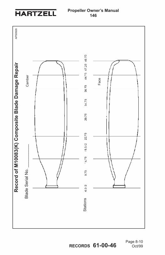
Page 8-10Oct/99
Propeller Owner’s Manual 146
RECORDS 61-00-46
Rec
ord
of M
1008
3(K
) Com
posi
te B
lade
Dam
age
Rep
air
Bla
de S
eria
l No.
___
____
___
Sta
tions
Face
Cam
ber
AP
S09
28

Propeller Owner’s Manual 146
Page 8-11Oct/99 RECORDS 61-00-46
Rec
ord
of M
1008
3(K
) Com
posi
te B
lade
Dam
age
Rep
air
Bla
de S
eria
l No.
___
____
___
Sta
tions
Face
Cam
ber
AP
S09
28

Page 8-12Oct/99
Propeller Owner’s Manual 146
RECORDS 61-00-46
Rec
ord
of M
1008
3(K
) Com
posi
te B
lade
Dam
age
Rep
air
Bla
de S
eria
l No.
___
____
___
Sta
tions
Face
Cam
ber
AP
S09
28

Propeller Owner’s Manual 146
Page 8-13Oct/99 RECORDS 61-00-46
Rec
ord
of M
1087
7K C
ompo
site
Bla
de D
amag
e R
epai
r
Bla
de S
eria
l No.
___
____
___
Sta
tions
Face
Cam
ber
AP
S09
13

Page 8-14Oct/99
Propeller Owner’s Manual 146
RECORDS 61-00-46
Rec
ord
of M
1087
7K C
ompo
site
Bla
de D
amag
e R
epai
r
Bla
de S
eria
l No.
___
____
___
Sta
tions
Face
Cam
ber
AP
S09
13

Propeller Owner’s Manual 146
Page 8-15Oct/99 RECORDS 61-00-46
Rec
ord
of M
1087
7K C
ompo
site
Bla
de D
amag
e R
epai
r
Bla
de S
eria
l No.
___
____
___
Sta
tions
Face
Cam
ber
AP
S09
13

Page 8-16Oct/99
Propeller Owner’s Manual 146
RECORDS 61-00-46
Rec
ord
of M
1087
7K C
ompo
site
Bla
de D
amag
e R
epai
r
Bla
de S
eria
l No.
___
____
___
Sta
tions
Face
Cam
ber
AP
S09
13