proposed multipurpose center - international … · architect's general conditions - uap doc....
TRANSCRIPT

TECHNICAL SPECIFICATIONS
FOR
ELECTRICAL WORKS
PROPOSED MULTIPURPOSE CENTERPILOT BUILDING, GUIUAN, EASTERN SAMAR
APRIL 6, 2015

PROPOSED MULTI-PURPOSE CENTERPilot Building, Guiuan, Eastern Samar
DIVISION 16 ELECTRICAL WORKS
TABLE OF CONTENTS
SECTION TITLE PAGE
16010 General Provisions 1 thru 6
16100 Basic Materials and Methods 1 thru 9
16134 Panelboards 1 thru 2
16140 Wiring Devices 1
16400 Power Distribution 1
16450 Grounding 1 and 2
16500 Lighting 1 thru 2
16610 Lightning Protection System 1 and 3
2k1404 Proposed Multi-Purpose Center

Division 16 Electrical
SECTION 16010 - GENERAL PROVISIONS
SECTION INDEX
1.0 General Conditions 12.0 General Description 13.0 Work Included 24.0 Codes, Inspection, Permits and Fees 35.0 Record Drawings 36.0 Shop Drawings, Samples and Other Submittals 47.0 Coordination 58.0 Minor Modifications 59.0 Guarantee 6
10.0 Approvals, Substitutions, Etc. 611.0 Acceptance Test 612.0 Subcontracts, Etc. 613.0 Workmanship 6
2K1404 – Proposed Multi-Purpose Center 16010 - i

Division 16 Electrical
SECTION 16010 - GENERAL PROVISIONS
1.0 GENERAL CONDITIONS:
All sections under this Division shall be subject to the requirements of theArchitect's General Conditions - UAP Doc. 301 and Section 16010 of theseSpecifications.
2.0 GENERAL DESCRIPTION:
A. The work to be done under this Division of the Specifications consists ofthe fabrication, complete in all details, of the Electrical Work, at thesubject premises, and all work and materials incidental to the propercompletion of the installation, except those portions of the work which areexpressly stated to be done by others. All work shall be in accordancewith the governing Codes and Regulations and with the Specifications,except where same shall conflict with such Codes, etc., in which case,latter shall then govern. The requirements in regard to materials andworkmanship specify the required standards for the furnishing of all labor,materials and appliances necessary for the complete installation of thework specified therein and indicated on the drawings. Thesespecifications are intended to provide a broad outline of the requiredinstallation, but are not intended to include all details of design andconstruction.
B. The CONTRACTOR before submitting his proposal, shall examine alldrawings relating to his work and verify all governing conditions at siteand shall become fully informed as to the extent and character of the workrequired. No consideration will be granted for any allegedmisunderstanding of the materials to be furnished or work to be done, itbeing understood that the submission of a proposal is an agreement to allitems and conditions referred to herein or indicated on the accompanyingdrawings and actual site conditions.
If specified equipment/instruments are not locally available,CONTRACTOR must immediately place an order as soon as project isawarded. Any exceptions, omission or substitutions shall be presented inwriting with the CONTRACTOR's bid.
C. The CONTRACTOR, before commencing work, shall examine alladjoining areas on which this work is in any way dependent for perfectworkmanship according to the intent of this specification and shall reportto the Owner's representative any condition which will prevent theCONTRACTOR from performing first class work. No waiver ofresponsibility for defective work will be considered unless notice has beenfiled at the time the CONTRACTOR submits his proposal.
2K1404 – Proposed Multi-Purpose Center 16010 - 1/6

Division 16 Electrical
SECTION 16010 - GENERAL PROVISIONS
D. It is the intention of these Specifications and drawings to call for furnishedwork tested and ready for operation. Whenever the word "provide" isused, it shall mean "furnish and install, complete and ready to use". Minordetails not usually shown or specified, but necessary for the properinstallation and operation, shall be included in the work, the same as ifherein specified or shown.
3.0 WORK INCLUDED:
Under this Division of the Specifications, provide all materials and equipment andperform all the work necessary for the complete execution of all the ElectricalWorks as shown on the Electrical Drawings, and on the General ConstructionDrawings, as herein specified, or both, except as otherwise excluded, and whichwithout excluding the generality of the foregoing, shall include but not be limitedto the following principal items of work:
A. Power distribution equipment including lighting panelboard and disconnectswitches.
B. A system of lighting and power wiring, switches and socket outletsincluding all feeders, branch circuits and connections to all lighting andpower outlets.
C. All general lighting fixtures and lamps.
D. Complete grounding system for electrical power system.
E. Lightning Protection System
F. Battery Operated Fire Detection and Alarm System
G. Complete testing and commissioning of all systems.
H. Painting of electrical work and equipment.
I. Grouting of openings in floors and walls after all conduits or pipes orducts are in place and sealing of all such openings.
J. Anything that has been omitted in any item of work or materials usuallyfurnished, which are necessary for the completion of the electrical work.
4.0 CODES, INSPECTION, PERMITS AND FEES:
A. The work under this contract is to be installed according to the latestrequirements of the following:
2K1404 – Proposed Multi-Purpose Center 16010 - 2/6

Division 16 Electrical
SECTION 16010 - GENERAL PROVISIONS
Philippine National Building Code Philippine Electrical CodeMunicipality of Guiuan, Eastern SamarLocal Electric Utility
Nothing contained in these specifications or shown on the drawings shallbe construed as to conflict with National and Local Ordinances or Lawsgoverning the installation of Electrical Works, and all such laws andordinances are hereby made part of these specifications. The Contractor isrequired to meet the requirements thereof.
B. All construction permits and fees including construction plans andspecifications required for this work shall be obtained by and at theexpense of the CONTRACTOR. The CONTRACTOR shall furnish theOWNER and the CONSULTANT final certificates of inspection andapproval from the proper government authorities after the completion ofthe work. The CONTRACTOR shall prepare all the shop or workingdrawings, as-built plans and all other paperwork required by the approvingauthorities.
C. Approval from authorities of all plans for construction shall be secured bythe CONTRACTOR.
5.0 RECORD DRAWINGS:
A. The CONTRACTOR shall, during the progress of the work, keep a recordof all deviations of the actual installation from that shown on the ContractDrawings and shall be available anytime upon request of theCONSULTANT.
B. The CONSULTANT will furnish the CONTRACTOR at cost a completeset of electronic files on which he shall indicate all changes and revisions.Copies of these electronic files, indicating such changes and revisions, shallbe submitted to the CONSULTANT together with the requests forprogress billings.
C. Upon completion of work, the CONTRACTOR shall submit three (3)copies of the as-built drawings, signed and dry-sealed by the Contractor'sregistered Professional Electrical Engineer, indicating the work as actuallyand finally installed, including new information not originally shown inContract Drawings, to the CONSULTANT for approval as to conformancewith the design concepts and compliance with pertinent Code provisions.The CONTRACTOR shall also submit three (3) sets of operating andmaintenance instructions, equipment and parts lists for approval.
2K1404 – Proposed Multi-Purpose Center 16010 - 3/6

Division 16 Electrical
SECTION 16010 - GENERAL PROVISIONS
After such approvals, the CONTRACTOR shall submit the CADD-generated as-built originals, three (3) sets of prints and two (2) sets ofelectronic files to the CONSULTANT, as well as three (3) sets of operatingand maintenance instructions, equipment and parts lists, includingaddresses of manufacturers or suppliers of major equipment and materials.
D. Approval of the as-built drawings by the CONSULTANT shall be arequirement for final acceptance of the completed works and of finalpayment.
6.0 SHOP DRAWINGS, SAMPLES AND OTHER SUBMITTALS:
A. CONTRACTOR shall prepare and submit to the CONSULTANT forapproval the following:
1. Dimensional layout and assembly drawings of all panelboards.Shop drawings shall contain bus bar sizes and spacing, lug sizes,circuit breaker arrangements, etc. of each of the panelboards.
2. Shop drawing and sample of wireways for power andcommunications.
3. Shop drawing of lightning protection mounting bracket.
4. Sample of lighting fixtures.
5. Samples and/or manufacturer's catalog sheets with completetechnical data marked as necessary to indicate materials, devicesand equipment being furnished for the following:
a. Circuit breakersb. Fire detection and alarm system devicesc. All lighting fixturesd. All wiring devices including plate coverse. Lightning Protection System
6. Detailed shop drawings for the following installations:a Lighting fixturesb. Main feederc. Mounting of panelboard, pullboxes and gutters.
7. Field test reports for the following: a. Insulation resistance testsb. Voltage level testsc. Continuity testd. Phase relationshipe. Earth-ground resistance tests
2K1404 – Proposed Multi-Purpose Center 16010 - 4/6

Division 16 Electrical
SECTION 16010 - GENERAL PROVISIONS
8. List of miscellaneous materials proposed, including conduits,conductors, and accessories, identifying manufacturer and type.
9. Such other shop drawings as indicated on the plans or as theCONSULTANT may require.
B. All drawings should be signed and dry sealed by the Contractor'sRegistered Professional Electrical Engineer.
C. All drawings, etc. shall be submitted sufficiently in advance of fieldrequirements to allow ample time for checking and no extension of thecontract time will be granted this CONTRACTOR, by reason of his failurein this respect.
All submittals shall be complete and shall contain all required and detailedinformation.
7.0 COORDINATION:
A. Coordinate timing of installation with work of other trades.
B. Systems provided shall be complete and operable, and shall includerequired accessories, fastenings, and supports.
C. Determine required location, arrangement, and quantities of equipmentand materials from drawings, schedules and specifications.
D. All equipment shall be installed in strict accordance with manufacturer'srecommendations.
E. Certain items of equipment specified in other contracts require electricalconnections. Contractor shall provide such connections as required.
8.0 MINOR MODIFICATIONS:
The plans as drawn are based upon architectural plans and details and showconditions as accurately as it is possible to indicate them in scale. The plans arediagrammatical and do not necessarily show all fittings, etc., necessary to fit thebuilding conditions. The location of outlets, apparatus and equipment shown onthe plans are approximate. This CONTRACTOR shall be responsible for theproper location in order to make them fit with architectural details andinstructions from the CONSULTANT''s representative at the site.
9.0 GUARANTEE:
A. The CONTRACTOR shall guarantee that the Electrical System is freefrom all grounds and from all defective workmanship and materials and
2K1404 – Proposed Multi-Purpose Center 16010 - 5/6
Division 16 Electrical
SECTION 16010 - GENERAL PROVISIONS
will remain so for a period of one (1) year from date of acceptance of thework. Any defects, appearing within the aforesaid period, shall beremedied by this CONTRACTOR at his own expense.
B. The CONTRACTOR shall indemnify and save harmless the OWNER andthe CONSULTANT from and against all liability for damages arising frominjuries or disabilities to persons or damage to property occasioned by anyact or omissions of the CONTRACTOR or any of his Subcontractors,including any and all expenses, legal or otherwise which may be incurredby the OWNER, or the CONSULTANT, in the defense of any claim,action or suit.
10.0 APPROVALS, SUBSTITUTIONS, ETC.:
Wherever hereinafter the words "for approval", or "approved" (make, type, size,arrangement, etc.) are used, especially in regard to manufactured specialties, etc.,or wherever it is desired to substitute a different make or type of apparatus forthat specified, all information pertinent to the adequacy and adaptability of theproposed apparatus, shall be submitted during the pre-bid conference(s) to theCONSULTANT and their approval secured before submitting the bid. Noapprovals or substitutions on specified items will be entertained unless requestedby the OWNER after the Contract Award or during construction.
11.0 ACCEPTANCE TEST:
Field tests and adjustments as laid out in Section 16100 shall be performed priorto approval of work.
12.0 SUBCONTRACTS, ETC.:
This CONTRACTOR shall be held fully responsible for the work of anySubcontractor or manufacturer performing work for or supplying materials tohim, as it is intended that the entire Electrical Work, when finally delivered to theOWNER, shall be ready in every respect for satisfactory and efficient operation.
13.0 WORKMANSHIP:
The work throughout shall be executed in the best and most thorough manner tothe satisfaction of the CONSULTANT, who will interpret the meaning of theDrawings and Specifications and shall have the authority to reject any work andmaterials which in their judgment, are not in full accordance therewith.
This CONTRACTOR shall assume unit responsibility and shall provide the serviceof a qualified Engineer to supervise the complete installation of equipment andsystems and who shall be available for conducting the final acceptance tests.
2K1404 – Proposed Multi-Purpose Center 16010 - 6/6
Division 16 Electrical
SECTION 16100 - BASIC MATERIALS AND METHODS
SECTION INDEX
1.0 Reference 12.0 General 13.0 Intermediate Metal Conduit (Alternate: Rigid Steel Conduit) 14.0 Polyvinylchloride (PVC) Conduit 15.0 Flexible galvanized Steel Conduit 26.0 Flexible Liquid Tight Conduit 27.0 Conduit Installation 38.0 Junction and Outlet Boxes 59.0 Wireway 5
10.0 Conductor 611.0 Conductor Installation 612.0 Nameplates 713.0 Field Tests and Adjustments 8
2K1404 – Proposed Multi-Purpose Center 16100 - i

Division 16 Electrical
SECTION 16100 - BASIC MATERIALS AND METHODS
1.0 REFERENCE:
Requirements of Section 16010 apply to all work under this Section.
2.0 GENERAL:
A. Furnish and install all conduits, joint and outlet boxes, conductor andmiscellaneous materials required for wiring, as specified herein and shownon drawings.
B. Furnish and install all power and control wiring to all equipment, except asotherwise specified. Equipment includes motor, motor starter, andmiscellaneous devices.
3.0 INTERMEDIATE METAL CONDUIT: (ALTERNATE: RIGID STEELCONDUIT)
A. General: NEMA Standard trade sizes, UL approved or equivalent toPittsburg Standard's SeAH, Robroy, Youngstown, Panasonic, Maruichi,Korea or approved equal.
B. Material: Mild steel, hot dipped galvanized.
C. Size: 15mm (½") minimum.
D. Couplings, unions and fittings: standard, threaded.
E. Use limitation: As specified in the latest edition of PEC and/or NEC.
F. Expansion fittings: Use for runs spanning expansion joints.
G. Paint field cuts and repair damaged protective coating with zinc chromate.Conduit threads shall not be painted.
4.0 POLYVINYLCHLORIDE (PVC) CONDUIT:
A. General: Standard trade sizes, heavy wall, manufactured to NEMA TC-2Type 40, rated for 90°C cable as manufactured by Neltex, Moldex andAtlanta or approved equal.
B. Material: Polyvinylchloride, extruded.
C. Nominal Size: 20mm (3/4")minimum.
D. Couplings and Fittings: Standard joint by solvent weld process.
2K1404 – Proposed Multi-Purpose Center 16100 - 1/9
Division 16 Electrical
SECTION 16100 - BASIC MATERIALS AND METHODS
E. Use Limitation:
1. As specified in the latest edition of PEC and/or NEC.
2. Not permitted where subject to mechanical damage.
3. As indicated in the drawings.
F. Pulling Hardwares: Flat fish tape with ball and flexible leader orpolyethylene or Manila rope. Use of steel pulling cable not permitted.
5.0 FLEXIBLE GALVANIZED STEEL CONDUIT:
A. General: Standard trade sizes, UL approved or equivalent.
B. Material: Steel, galvanized.
C. Size: 15mm (½") minimum.
D. Fittings: Standard.
E. Use Limitation:
1. Between motor terminal boxes, or vibration producing devices andrigid conduit.
2. Short lengths of concealed wiring to lighting fixtures (max. length -1800mm).
3. Other applications: only where approved or where shown on plans.
6.0 FLEXIBLE LIQUID TIGHT CONDUIT:
A. General: Standard trade sizes. UL approved or equivalent.
B. Material: Galvanized steel with outer liquid-tight plastic jacket.
C. Diameter: 15mm (½")
D. Fittings: Liquid-tight
E. Use limitation:
1. Short lengths to vibration producing devices situated in wet orpotentially wet locations.
2. Between motor terminal boxes or vibration producing devices andrigid conduit.
2K1404 – Proposed Multi-Purpose Center 16100 - 2/9

Division 16 Electrical
SECTION 16100 - BASIC MATERIALS AND METHODS
3. Other applications: Only where approved or where shown onplans.
7.0 CONDUIT INSTALLATION:
A. General: Install in accordance with applicable codes and recognizedstandards of good practice.
B. Location: Approximately as shown on drawings; actual routing subject toapproval.
C. Wall and floor sleeves:
1. General: Provide for passage of conduits through walls, floors, orpartitions. Set sleeves in masonry during construction; set sleevesthrough concrete before pouring begins.
2. Material: Galvanized pipe, securely fastened in position.
3. Sleeves through exterior building walls: Install conduit in center ofsleeve, fill annular space with loosely packed oakum. Seal interiorand exterior of packing with hot applied asphalt. Fit the conduiton each side of the wall with round galvanized steel flange fastenedto conduit by two set screws to retain sealing compound.
4. Sleeves through waterproof constructions: Flanged type.
5. Opening required after footings, walls, floors, or ceilings areconstructed shall be provided and patched at Contractor's expensein an approved manner.
D. Embedded Conduit:
1. General: Set before pouring of concrete begins. Route in asdirect a line as possible and where a bend is required, turn with along radius.
2. Underground installation: Encase conduits with concrete, 75mm(3") from outer face of conduits.
3. Conduit joints shall be half-wrapped with 3M Scotch Wrap #50PVC Tape or approved equivalent.
E. Joints: Make with approved couplings and unions to provide electricallycontinuous and moisture-tight system.
2K1404 – Proposed Multi-Purpose Center 16100 - 3/9
Division 16 Electrical
SECTION 16100 - BASIC MATERIALS AND METHODS
F. Expansion joints: Use expansion fittings and bonding jumpers whereverconduit spans building expansion joints.
G. Bends: Not more than the equivalent of three 90° bends between pullingjoints.
H. Wiring of fire related motors shall be embedded or encased in concrete.
I. Field cuts and threads:
1. Cut ends of conduit square with hand or power saw and ream toremove burrs and sharp edges. Do not use wheel cutter.
2. Threads cut on job shall have same effective lengths, threaddimensions, and taper as factory cut threads.
3. Carefully remove burrs from threads. Conduit threads shall not bepainted.
4. Apply coat of protective paint through conduits where protectivecoating is damaged.
J. Supports:
1. Manufacturer: Steel City, Unistrut or approved equal.
2. Hangers, supports, or fastenings: Provide at each elbow and atend of every straight run terminating in a box or cabinet. Rigidfastenings spaced in accordance with the PEC.
3. Clamps: Galvanized malleable iron one-hole straps, beam clamps,or other approved device with necessary bolts and expansionshields.
4. Adjustable hangers:
a. Use to support horizontal runs only.
b. Trapeze hangers: For parallel runs of conduits. Install pipeclamps every third intermediate hanger for each conduit.Paint hangers one prime coat of red lead or zinc chromate,one finish coat of approved color. Hangers are not detailedbut must be adequate to support the combined weights ofconduit, conductors, and hangers.
5. Submit shop drawings for approval.
2K1404 – Proposed Multi-Purpose Center 16100 - 4/9

Division 16 Electrical
SECTION 16100 - BASIC MATERIALS AND METHODS
K. Concealing: Conceal conduits in all areas except mechanical equipmentrooms and areas as specified. Run exposed conduits parallel with, or atright angle to, lines of buildings.
L. Conduit ends:
1. Cap conduit.
2. Open conduit ends terminating in panels for enclosures whereexposed to entrance of foreign material: Plug space around cableswith commercial duct sealing compound.
3. Cap conduit ends during construction to prevent entrance offoreign material.
M. Cleaning: Clean inside by mechanical means to remove all foreignmaterials and moisture before wires or cables are installed.
N. Conduit connections at panels and boxes: Double locknuts and bushings.
8.0 JUNCTION AND OUTLET BOXES:
A. General: Provide junction boxes for pulling and splicing wires, and outletboxes for installation of wiring devices as required, or as shown ondrawings. As a rule, provide junction boxes in all runs of greater than 30meters (100 ft.) in length. For other lengths, provide boxes as required forsplicing or pulling. Boxes shall be in accessible locations.
B. Construction: Welded sheet steel, galvanized finish. Provide removablecovers attached with round head machine screws, minimum of 1.6mmMSG (Ga. 16). Concentric knockouts are not allowed.
C. Support: Support boxes independently of conduits entering, by means ofmaterials decribed in Section 16100, sub-section 7.0. J.
D. Finish: Galvanized.
9.0 WIREWAY:
A. General: Furnish and install wireway as indicated on drawings or asrequired.
B. Size and arrangement: As indicated on drawings.
C. Construction: Minimum 1.519mm (#16 MSG) thick galvanized steel sheetmetal with snap-on cover or as shown on plans.
2K1404 – Proposed Multi-Purpose Center 16100 - 5/9

Division 16 Electrical
SECTION 16100 - BASIC MATERIALS AND METHODS
D. All screws installed towards the inside shall be guarded to prevent wireinsulation damage.
E. Provide all necessary supports, fittings and miscellaneous materials for acomplete installation.
10.0 CONDUCTOR:
A. Manufacturer: UL listed, Phelps Dodge or approved equal.
B. Material: Copper, annealed.
C. Stranding: Standard stranding for 3.5 sq.mm and larger.
D. Minimum sizes: 3.5 sq.mm THHN for lighting and power, 2.0 sq.mm forcontrol wiring.
E. Standards: ICEA or Philippine Electrical Code.
F. Color Code:
1. Color coding for all phase, ground and neutral conductors shall beas follows and in accordance with the Code:
Power Ground GreenNeutral WhitePhase Black
2. Color coding shall be maintained all throughout the installation.
G. 600-Volt Class Conductors: Insulation:
1. Feeders and general use conductors: THHN/THWN insulation.
2. Fixture wires: In accordance with Philippine Electrical Code.
11.0 CONDUCTOR INSTALLATION:
A. Place all wiring, in raceway of type or types indicated. Provide allrequired and indicated accessories for proper installation of all wiring.
B. Bending radii: Not less than permitted by Philippine Electrical Code
C. Supports in vertical runs: As prescribed by Philippine Electrical Code.
2K1404 – Proposed Multi-Purpose Center 16100 - 6/9

Division 16 Electrical
SECTION 16100 - BASIC MATERIALS AND METHODS
D. Splicing:
1. Permissible only in junction boxes or similar accessible locations.Number of splices held to absolute minimum.
2. Use solderless, compression-type wire terminators at devices. Usewire nuts with screws not bearing directly on the wires.
E. Insulation of splices or taps:
1. Three layers 20mm wide 3M Company "Scotch No. 33" or"Scotch No. 88", or approved equal, electrical tape, half lapped.
2. Use filler compound, "Scotchfil", or approved equal, at sharpedges to provide smooth surface before taping.
3. Use 3M #UG for .32/3C telephone.
4. Use 3M wire nut for splices in wireways.
F. Marking: Mark each end of every power or control cable with a plastictag securely fastened to it bearing circuit use identification. Also markcables in pull or junction boxes.
G. Connections:
1. Apparatus lugs: Solderless pressure-type lugs. Thoroughly cleanlug conductor and coat with suitable oxidation inhibitingcompound prior to connection.
2. Terminal blocks: Use retaining cup washers where solid wire isused. Use pressure type terminal lugs where stranded wire is used.
3. All feeder cable terminations shall be torqued and properly marked.
12.0 NAMEPLATES:
A. General: provide and install nameplates wherever indicated as required inthese specifications. Wording shall be approved prior to purchase ofnameplates.
B. Material: Red Bakelite engraving stock, white core.
C. Lettering: Engraved, approximately 5.0mm high. Wording shall identifyfunction of device to which nameplate is attached, or identify equipmentserved by device or as indicated in the plans.
2K1404 – Proposed Multi-Purpose Center 16100 - 7/9

Division 16 Electrical
SECTION 16100 - BASIC MATERIALS AND METHODS
D. Installation (except for factory-installed nameplates): Attach with sheetmetal screws after painting of equipment is completed.
E. All receptacle outlets/switches, plates shall be identified with circuit andpanel homerun numbers using tape labeller (do not use dymo).
13.0 FIELD TESTS AND ADJUSTMENTS:
A. Test reports: Typewritten, listing equipment used, person or personsperforming the tests, date tested, circuits tested, and results of tests.
B. Insulation resistance tests, general:
1. Perform insulation resistance tests on wires listed herein.
2. Test Equipment: Furnished by CONTRACTOR; equal to Megger"as manufactured by James G. Biddle Company, motor driven orrectifier type with ranges of 500, 1000, and 2500 volts d-c.
3. Resistance measured: Line to ground.
4. Disconnect all solid state equipment before making wire or cabletests. CONTRACTOR is responsible for damage to any suchequipment caused by these tests.
C. Insulation resistance tests, wires.
1. Test all 600 volt class power and lighting circuits at 1000-voltrating of "Megger" for one minute duration.
2. Spot test control circuits with "Megger" as directed.
D. Voltage level test:
1. When performed: After all equipment is installed, ready foroperation.
2. CONTRACTOR shall measure voltage at five points in the system,as directed.
3. Load conditions: No-load and full load, in so far as practicable.
4. Test report: Required, as specified under Item "A".
E. Continuity test: Test all socket outlet and control circuits to determinecontinuity of wiring and connections. Submit written statement that thistest has been performed.
2K1404 – Proposed Multi-Purpose Center 16100 - 8/9

Division 16 Electrical
SECTION 16100 - BASIC MATERIALS AND METHODS
F. Correction of defects:
1. If tests disclose any unsatisfactory workmanship, wiring orequipment furnished under this Contract, CONTRACTOR shallrepair or replace, at his expense, such defects in an approvedmanner.
2. If any wiring or equipment is damaged by tests, CONTRACTORshall repair or replace, at his expense, such wiring or equipment inan approved manner.
2K1404 – Proposed Multi-Purpose Center 16100 - 9/9
Division 16 Electrical
SECTION 16134 - PANELBOARDS
SECTION INDEX
1.0 Reference 12.0 General 13.0 Types and Ratings 14.0 Panel and Box 15.0 Molded Case Circuit Breakers 26.0 Warranty 27.0 Quantity and Identification 2
2K1404 – Proposed Multi-Purpose Center 16134 - i

Division 16 Electrical
SECTION 16134 - PANELBOARDS
1.0 REFERENCE:
Requirements of Section 16010 apply to all work under this Section.
2.0 GENERAL:
Furnish and install panelboards as listed in the "Panelboard Schedule" appended tothis section.
3.0 TYPES AND RATINGS:
A. Enclosure and internal elements shall be manufactured in accordance withNEMA Standards and PEC Rules and Regulations.
B. All panelboards shall have a NEMA type enclosure and contain a singlebrand of molded case circuit breakers. All current carrying parts shall bemade of electrical gage copper with non-corrosive protective coating onall contact surfaces. Terminal lugs shall be the same or equal to thosesupplied with the circuit breakers with sizes and type suitable for copperwires.
C. All insulating materials shall be non-combustible, high-impact, non-tracking and non-hygroscopic.
4.0 PANEL AND BOX:
B.I. 1.984mm (#14 MSG) minimum box, plain steel front for indoor usageenclosure, complete with corrosion free hardware such as hinged door, polishedmetal catch and lock. All panels shall be keyed alike.
Paint and corrosion proofing shall be per manufacturer's standards and finishes.Repair any damage to finish in manner acceptable to CONSULTANT.
A. Mounting: flush and surface as required.
B. Cardholder on inside of door, with clear plastic cover and completeprinted schedule of panel branch circuits. Leave "spare" circuits blank.
C. Nameplate: required for each panel.
D. Installation:
1. Location: As shown. Maximum distance from floor to center lineof highest breaker shall be 1.8m.
2K1404 – Proposed Multi-Purpose Center 16134 - 1/2
Division 16 Electrical
SECTION 16134 - PANELBOARDS
2. Provide required mounting materials; make connections specifiedor shown. Use collars around mounting bolts, or equivalentmeans, to provide air space between panels and wall for surface-mounted panels.
3. Provide extension troughs and pull boxes for column-type panels.
5.0 MOLDED CASE CIRCUIT BREAKERS:
A. Panelboard shall contain a single brand of industrial type circuit breakersmanufactured by General Electric/Fuji, Square D or approved equal.
B. Voltages and full load amperes shall be UL and/or NEMA rated. Projectrequirements shall be as shown in the Panelboard Schedule.
C. Breakers: "Plug-in" type molded case, thermal-magnetic protective,quick-make, quick-break, trip-free from handle, trip-indicating, numberand size as shown in Panelboard Schedule. Internal common trip for 2-and 3-pole breakers.
D. Breaker minimum interrupting capacities: based on NEMA and UL testprocedures shall be as follows unless otherwise noted in the panelboardschedule:
1. 230-volt breakers: 10,000 rms symmetrical amperes at 230VAC.
E. Time-current characteristic coordination curves of circuit breakers indistribution boards and the corresponding downstream breakers shall besubmitted prior to the purchase of subject breakers.
6.0 WARRANTY:
Warranty for a period of one (1) year shall be provided against failure ofcomponents resulting from normal use and/or factory defects.
7.0 QUANTITY AND IDENTIFICATION:
The Panelboard Schedule consisting of one (1) page appended to this sectioncomprises the entire requirement of this project for panelboards. Where "space" isindicated in the Schedule, this shall mean that complete bus, insulators, etc., shallbe included ready to accept future circuit breakers. Any inconsistency betweenthe Panelboard Schedule and the Single Line Schematic Diagram, the panelboardwith the greater number of branches and higher ampere ratings shall be considered.
2K1404 – Proposed Multi-Purpose Center 16134 - 2/2

PANELBOARD SCHEDULE
BUILDING FLOOR ROOM DESIGNATION ENCLOSURE TYPE
CB AMP TRIP
QTYAMPERE TRIPLUG-AMPACITY
P-PHASE WIRE SIZE
N-NEUTRAL WIRE SIZE 1P 2P 3P
LOWER LEVEL PP NEMA 1
230 V MAIN – 100 A 11 15 101-PHASE 3 20 10
2-WIRE2 60AF
VOLTS / PHASE / WIRE
MINIMUM PANEL &
BREAKERS (MAIN &
BRANCHES KAIC RATING)
GENSET ROOM
P – 1-22mm² THWNN – 1-22mm² THWNG – 1-8mm² THWN

Division 16 Electrical
SECTION 16140 - WIRING DEVICES
SECTION INDEX
1.0 Reference 12.0 General 13.0 Devices and Plates 14.0 Installation 15.0 Locations 16.0 Warranty 17.0 Wiring Device Schedule 1
2K1404 – Proposed Multi-Purpose Center 16140 - i
Division 16 Electrical
SECTION 16140 - WIRING DEVICES
1.0 REFERENCE:
Requirements of Section 16010 apply to all work under under this Section.
2.0 GENERAL:
Furnish and install wiring devices as listed in "Wiring Device Schedule", appendedto this Section.
3.0 DEVICES AND PLATES:
A. Wall Switches: Quiet type, spring operated. The type of switch shall be oftumbler operation. Rating as shown in wiring device schedule.
B. General Purpose Receptacles: Flush mounting, type and ratings as shownin wiring device schedule.
C. General Purpose Wall Plates: Type, color, plating and appearance of deviceplates shall be as selected by the CONSULTANT. Appropriate samplesshall be submitted prior to the purchase of faceplates.
D. Manufacturers: Panasonic, G.E., Bryant, Hubbel, AH & H, Slater, orapproved equal.
4.0 INSTALLATION:
Connect wiring devices ground terminal to circuit ground wire.
5.0 LOCATIONS:
Indicated locations are approximate. Determine exact locations at site byreference to building drawings and in coordination with work of other trades.Receptacles for appliances shall be so located as to be accessible, but, notprominently displayed and upon coordination with the CONSULTANT.
6.0 WARRANTY:
A warranty for a period of one (1) year shall be provided against failure ofcomponents resulting from normal use and/or factory defects.
7.0 WIRING DEVICE SCHEDULE:
The following "Wiring Device Schedule" consisting of one (1) page comprises theentire requirement of this project for wiring devices.
2K1404 – Proposed Multi-Purpose Center 16140 - 1/1

WIRING DEVICE SCHEDULE
ITEM NO. SYMBOL RATING CONFIGURATION DESIGNATION DESCRIPTION
1 10A, 250V
2 10A, 250V
3 S 15A, 300V
4 2S 15A, 300V
5 3S 15A, 300V
6 S3 15A, 300V SIMILAR TO ITEM #3, EXCEPT THAT THE SWITCH IS THREE-WAY.
DUPLEX CONVENIENCE OUTLET, PARALLEL SLOTS, GROUNDING TYPE, SIMILAR TO NATIONAL/PANASONIC BRAND WITH MODERN COVER PLATE OR APPROVED EQUAL. NOTE: WEATHERPROOF IF MARKED “WP”
SINGLE CONVENIENCE OUTLET, PARALLEL SLOTS, GROUNDING TYPE, SIMILAR TO NATIONAL/PANASONIC BRAND WITH MODERN COVER PLATE OR APPROVED EQUAL. NOTE: WEATHERPROOF IF MARKED “WP” ; EMERGENCY LIGHT IF MARKED “E”
SWITCH, STANDARD GRADE INTERCHANGEABLE LINE, 1-POLE ON-OFF QUIET TYPE SIMILAR TO NATIONAL WN5001-701 W/ MODERN COVER PLATE OR APPROVED EQUAL.
SIMILAR TO ITEM #3, EXCEPT WITH 2-LEVEL PLATE FOR TWO (2) SWITCHES.
SIMILAR TO ITEM #3, EXCEPT WITH 3-LEVEL PLATE FOR TWO (2) SWITCHES.
NOTE: ALL COVER PLATES ARE SUBJECT TO ARCHITECT'S APPROVAL.

Division 16 Electrical
SECTION 16400 - POWER DISTRIBUTION
SECTION INDEX
1.0 Reference 12.0 General 13.0 Individually Enclosed Circuit Breakers 14.0 Installation 15.0 Shop Drawing 16.0 Warranty 1
2K1404 – Proposed Multi-Purpose Center 16400 - i
Division 16 Electrical
SECTION 16400 - POWER DISTRIBUTION
1.0 REFERENCE:
Requirements of Section 16010 apply to all work under this section.
2.0 GENERAL:
A. Furnish and install all equipment and materials shown on drawings orspecified to provide complete and operable system.
B. Refer to Section 16100 for conduit, conductor, and nameplatespecifications and for field tests affecting equipment specified herein.
C. Provide all excavation and backfill required for installation of undergroundcircuits. Refer to Architectural/Structural Specifications for applicableexcavation, backfill and compaction specifications.
3.0 INDIVIDUALLY ENCLOSED CIRCUIT BREAKERS:
A. Ratings: 1, 2 or 3-pole, 230V, automatic or non-automatic, ampere ratings as shown on drawings. Requirements of Section 16134 shall be complied with. Lockable if indicated on drawings.
B. Enclosure: NEMA1, unless noted. Use NEMA 3R for outdoors.
C. Nameplates: Required to indicate equipment served or function of switch and voltage rating.
D. Color: Manufacturer's standard. Repair any damage to finish in manner acceptable to Consultant.
4.0 INSTALLATION:
Furnish and install as shown on drawings.
5.0 SHOP DRAWINGS:
Submit shop drawings for approval.
6.0 WARRANTY:
A warranty for a period of one (1) year shall be provided against failure of components resulting from normal use and/or factory defects.
2K1404 – Proposed Multi-Purpose Center 16400 - 1/1

Division 16 Electrical
SECTION 16450 - GROUNDING
SECTION INDEX
1.0 Reference 12.0 General 13.0 Materials 14.0 Installation 15.0 Tests 1
2K1404 – Proposed Multi-Purpose Center 16450 - i
Division 16 Electrical
SECTION 16450 - GROUNDING
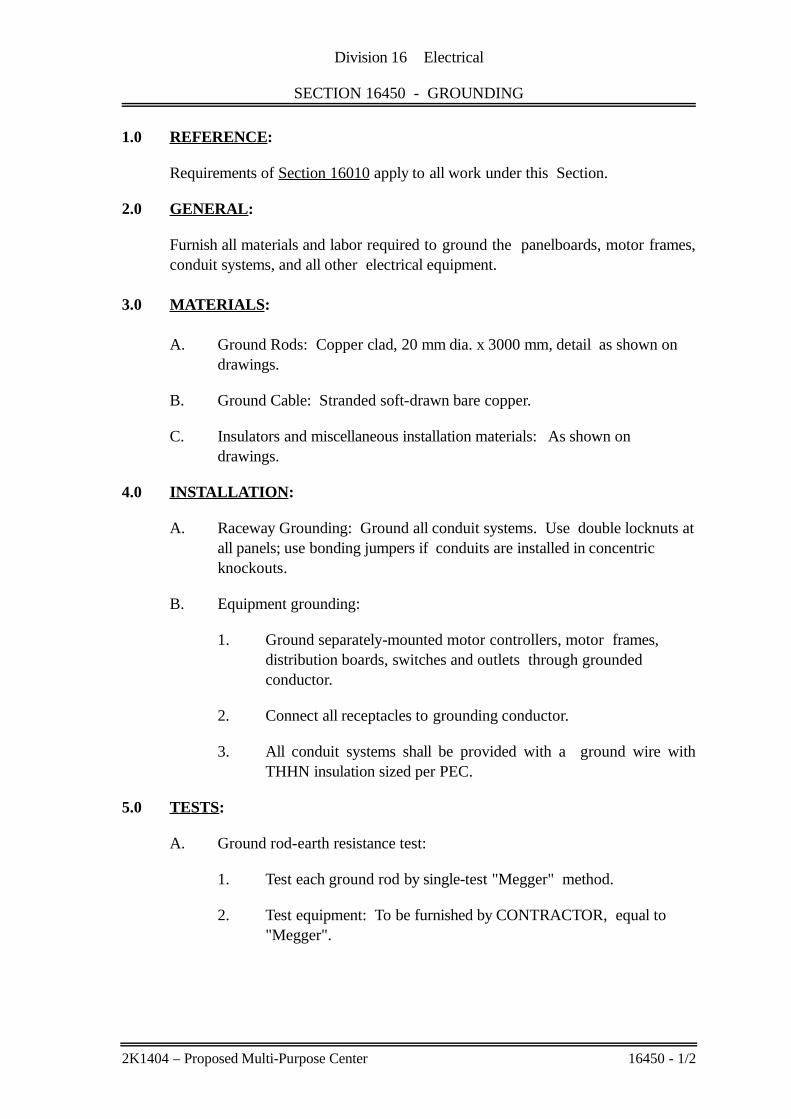
1.0 REFERENCE:
Requirements of Section 16010 apply to all work under this Section.
2.0 GENERAL:
Furnish all materials and labor required to ground the panelboards, motor frames,conduit systems, and all other electrical equipment.
3.0 MATERIALS:
A. Ground Rods: Copper clad, 20 mm dia. x 3000 mm, detail as shown on drawings.
B. Ground Cable: Stranded soft-drawn bare copper.
C. Insulators and miscellaneous installation materials: As shown on drawings.
4.0 INSTALLATION:
A. Raceway Grounding: Ground all conduit systems. Use double locknuts atall panels; use bonding jumpers if conduits are installed in concentric knockouts.
B. Equipment grounding:
1. Ground separately-mounted motor controllers, motor frames, distribution boards, switches and outlets through grounded conductor.
2. Connect all receptacles to grounding conductor.
3. All conduit systems shall be provided with a ground wire withTHHN insulation sized per PEC.
5.0 TESTS:
A. Ground rod-earth resistance test:
1. Test each ground rod by single-test "Megger" method.
2. Test equipment: To be furnished by CONTRACTOR, equal to "Megger".
2K1404 – Proposed Multi-Purpose Center 16450 - 1/2

Division 16 Electrical
SECTION 16450 - GROUNDING
B. Test report: submit typewritten report, listing equipment used, person or persons performing the tests, date tested, circuits or equipment tested, andresults of tests.
2K1404 – Proposed Multi-Purpose Center 16450 - 2/2

Division 16 Electrical
SECTION 16500 - LIGHTING
SECTION INDEX
1.0 Reference 12.0 General 13.0 Lighting Fixtures 14.0 Coordination 25.0 Shop Drawings and Samples 26.0 Warranty 27.0 Lighting Fixture Schedule 2
2K1404 – Proposed Multi-Purpose Center 16500 - i

Division 16 Electrical
SECTION 16500 - LIGHTING
1.0 REFERENCE:
Requirements of Section 16010 apply to all work under this Section.
2.0 GENERAL:
A. Furnish, install and wire all equipment and materials required for completelighting system, as specified and shown.
B. See Section 16100 for conduit, conductor, and nameplate specifications.
3.0 LIGHTING FIXTURES:
A. Lighting Fixtures: As designated in "Lighting Fixture Schedule" appendedto this section.
1. Housing: 22 gage, B.I. Sheet, Formed, screwed with machine orstove bolt and/or welded.
2. Finish: Use two (2) coat primer. Powder coat, white acrylic paint.
3. Lampholder: UL listed, locking type, springloaded bi-pin, push-inlead wire.
4. Diffusers: Prismatic acrylic 3.0mm thickness or as listed in the“Lighting Fixture Schedule”.
5. Others: Per details on the plans.
B. Provide fixtures complete with required accessories, including thefollowing:
1. Lamps:
a. General: Types and ratings as shown in "Lighting FixtureSchedule."
b. LED: as listed in "Lighting Fixture Schedule."
d. Manufacturer: Philips, G.E. or approved equal.
2. Mounting Hardware, including any steel required to supplementbuilding structure for support of fixtures.
3. Support fixtures independently of suspended ceiling or as shownon details.
2K1404 – Proposed Multi-Purpose Center 16500 - 1/2

Division 16 Electrical
SECTION 16500 - LIGHTING
C. Wiring:
1. General: Fixture wiring shall comply with fixture manufacturer'srecommendations and PEC requirements.
D. Location: Approximately as shown. Modify to avoid other equipment orstructural components. Provide necessary conduit, wire, fittings andmiscellaneous materials to locate fixtures in unobstructed locations.
4.0 COORDINATION:
A. Coordinate installation of all lighting fixtures with work of other trades.
B. Coordinate exact location of fixtures with respect to suspended ceilinglayout to achieve uniformity.
5.0 SHOP DRAWINGS AND SAMPLES:
Prepare and submit for approval before manufacturing the following:
A. Fabrication drawings.
B. Sample of each fixture.
6.0 WARRANTY:
All fixture components shall be covered with a warranty for a period of one (1)year against any failure resulting from normal use and/or factory defects.
7.0 LIGHTING FIXTURE SCHEDULE:
The following "Lighting Fixture Schedule" consisting of one (1) page comprise theentire requirement of this project for lighting fixtures.
2K1404 – Proposed Multi-Purpose Center 16500 - 2/2

LIGHTING FIXTURE SCHEDULE
ITEM NO. QUANTITY TYPE SYMBOL DETAIL DESCRIPTION
1
2 SAME AS ITEM NO. 1 EXCEPT WITH 2x16W LAMP.
3
4 SAME AS ITEM NO. 3 EXCEPT WITH 2x16W LAMP.
5 ES/M/W5100
6
7
NOTE: ALL LIGHTING FIXTURES ARE SUBJECT TO ARCHITECT'S APPROVAL
SURFACE MOUNTED SLIM BOX TYPE LINEAR LED LIGHTING FIXTURE (1200mm x 55mm), WITH 1x16W LAMP, 230 V, IP 20. ZINC PHOSPHATE STEEL SHEET HOUSING, WHITE POWDER COAT PAINT FINISH. FUMACO BRAND OR APPROVED EQUAL.
SURFACE MOUNTED LINEAR LED LIGHTING FIXTURE (1200mm x 300mm), WITH 1x16W LAMP, 230 V, IP 54. ZINC PHOSPHATE STEEL SHEET HOUSING, WHITE POWDER COAT PAINT FINISH. FUMACO BRAND OR APPROVED EQUAL.
SURFACE MOUNTED LED EXIT LIGHT SINGLE SIDED (375mm x 270mm), WITH 2W LED STRIP LAMP TYPE, 230 V, IP 30. HIGH TEMPERATURE NICKEL CADMIUM BATTERY FOR 2 HOURS DURATION. HOUSING MADE OF ELECTRO-GALVANIZED STEEL WITH EPOXY POWDER COATING. FUMACO BRAND OR APPROVED EQUAL.
MAXSPID MR203L
WALL OR CEILING MOUNTED LED EMERGENCY LIGHT, WITH 2x1W LED LAMP, IP 50 CLASS 2. INJECTION MOULDED THERMOPLASTIC ABS; UL 94V-0 FLAME RATING, TWO FULLY ADJUSTABLE GLARE-FREE ROUND SHAPED HEADS. HIGH TEMPERATURE NICKEL CADMIUM, 2 HOURS DURATION. FUMACO BRAND OR APPROVED EQUAL.
FUMACO LED 1571 50W
FLOODLIGHT
WALL MOUNTED 50W LED FLOODLIGHT WITH BUILT-IN LED DRIVER, 200-240V, IP 54, DAYLIGHT. DIE-CAST ALL ALUMINUM CONSTRUCTION, POWDER COAT FINISH HOUSING. HIGH PURITY ALUMINUM REFLECTOR WITH TEMPERED GLASS DIFFUSER. FUMACO BRAND OR APPROVED EQUAL.
WP
WP
EXIT

Division 16 Electrical
SECTION 16610 - LIGHTNING PROTECTION
SECTION INDEX
1.0 Reference 12.0 General 13.0 Materials 14.0 Manufacturer 35.0 Warranty 3
2K1404 – Proposed Multi-Purpose Center 16610 - i

Division 16 Electrical
SECTION 16610 - LIGHTNING PROTECTION
1.0 REFERENCE:
Requirements of Section 16010 apply to all work under this Section.
2.0 GENERAL:
Furnish and install one (1) set lightning protection system complete in everyrespect as indicated in the plans and as specified herein.
The lightning protection system shall be one which conveys a lightning dischargeto ground without electrification of its supporting mast or pole and nearbystructures. A set of protection system shall consist of electrode, down conductor,ground rods, masts, fasteners and other miscellaneous mounting hardwares.
3.0 MATERIALS:
A. Electrode (Air Terminal):
1. The electrode shall generate a current of free primary electronscoming from the air natural gradient, the potential of which rises inproportion with the approach of lightning and its charge.
2. It shall be non-radioactive and shall not require batteries or solarcells to perform its function. It shall have no moving parts.
3. The electrode shall be made of highly dielectric materials so that assoon as lightning strikes its tip, it enters into a sealed hole down toearth.
4. The construction of the electrode assembly shall be such as toprevent the occurrence of galvanic corrosion. Its down conductorterminal shall be insulated from the mast and support structure.
5. The electrode shall be mounted at least 3 meters above the highestpoint of the building. It shall provide a protective radius of 107meters at ground level.
B. Down Conductor:
1. The down conductor shall be a two conductor coaxial cable withoutside insulation; the insulation shall have basic impulse levelrating of 200 KV.
2K1404 – Proposed Multi-Purpose Center 16610 - 1/3

Division 16 Electrical
SECTION 16610 - LIGHTNING PROTECTION
2. Each conductor shall have a minimum cross sectional areaequivalent to 35 sq.mm of electrical grade copper.
3. The characteristic impedance of the coaxial cable shall not exceed16 ohms when determined by the following formula:
Z = (L/C) 1/2
Where:
Z = Characteristic impedance of coaxial cable.L = Inductance per meter of the inner conductor.C = Capacitance per meter between inner and outerconductor.
4. At the electrode end, the central conductor shall make a highcurrent connection to the electrode terminal while the outerconductor shall remain insulated.
5. At the earth end, the central and outer conductors of the coaxialcable shall both bond to the grounding system in such a manner asto allow subsequent removal for electrical testing. Groundingsystem of any nearby electrical or telecommunication systems shallnot be utilized.
6. The down conductor shall be secured in accordance with themanufacturer's instructions, and shall not be subject to bend lessthan 0.365 meter radius.
7. The coaxial cable, together with its accessories, shall be furnishedby the electrode assembly manufacturer.
C. Grounding and Ground Rods:
1. The grounding system shall not exceed 10 ohms of staticimpedance.
2. The ground resistance shall be measured with an approved 3-electrode type test instrument.
3. Ground rod shall be as shown in the plan and as specified inSection 16450. Additional ground rods shall be driven if resistanceexceeds 10 ohms.
2K1404 – Proposed Multi-Purpose Center 16610 - 2/3

Division 16 Electrical
SECTION 16610 - LIGHTNING PROTECTION
4. Where several ground rods are required, these shall beinterconnected by buried copper wire of 100 sq.mm minimumcross sectional area.
5. The ground rod shall be bonded to mast (or pole).
D. Mast (or Pole):
1. Mast shall be made of steel, round, plain body, with an all-weatherpaint over primer, complete with base plate and anchor bolts.
2. Mast shall be able to withstand a wind loading created by 320 kphwind velocity.
E. The top of the mast supporting the electrode shall be fiberglass pipe withan inside diameter of not less than 70mm diameter, 4mm thick, 2 metersminimum length with electrode assembly bracket.
4.0 MANUFACTURER:
Lightning protection system shall be EF Lightning Control System or approvedequal.
5.0 WARRANTY:
A warranty for a period of one (1) year shall be provided against failure ofcomponents resulting from normal use and/or factory defects.
2K1404 – Proposed Multi-Purpose Center 16610 - 3/3

TECHNICAL SPECIFICATIONS
FOR
SANITARY/PLUMBING WORKS
PROPOSED MULTIPURPOSE CENTERPILOT BUILDING, GUIUAN, EASTERN SAMAR
APRIL 6, 2015
PROPOSED MULTI-PURPOSE CENTERPilot Building, Guiuan, Eastern Samar
DIVISION 15A PLUMBING WORKS
TABLE OF CONTENTS
SECTION TITLE PAGE
15400 General Provisions 1 thru 5
15410 Basic Materials and Methods 1 thru 18
15410 Equipment 1 thru 5
15450 Plumbing Fixtures and Trim 1 and 2
2K1404 Proposed Multi-Purpose Center

Division 15A Plumbing
SECTION 15400 - GENERAL PROVISIONS
SECTION INDEX
1.0 General Conditions 12.0 General Description 13.0 Work Included 14.0 Work Not Included 25.0 Codes, Inspection, Permits and Fees 26.0 As-Built Drawings 27.0 Shop Drawings, Samples and Other Submittals 38.0 Coordination 49.0 Minor Modifications 410.0 Guarantee 511.0 Approval, Substitutions, Etc. 512.0 Acceptance Tests 513.0 Subcontracts, Etc. 514.0 Workmanship 5
2k1404 Proposed Multi-Purpose Center Page i

Division 15A Plumbing
SECTION 15400 - GENERAL PROVISIONS
1.0 GENERAL CONDITIONS:
All sections under this Division shall be subject to the requirements of the Architect'sGeneral Conditions - UAP Doc. 301 and Section 15400 of these specifications.
2.0 GENERAL DESCRIPTION:
The work to be done under this Division of the Specifications consist of the fabrication,complete in all details, of the Plumbing Works, at the subject premises, and all work andmaterials incidental to the proper completion of the installation, except those portions ofthe work which are expressly stated to be done by Others. All work shall be in accordancewith the governing Codes and Regulations and with the Specifications, except where sameshall conflict with such Codes, etc., which the latter shall then govern. The requirementsin regard to materials and workmanship specify the required standards for the furnishing ofall labor, materials and appliances necessary for the complete installation of the workspecified herein and indicated on the drawings. These specifications are intended toprovide a broad outline of the required installation, but are not intended to include alldetails of design and construction.
3.0 WORK INCLUDED:
Under this Division of the Specifications, provide all materials and equipment and performall the work necessary for the complete execution of all the Plumbing Works as shown onthe Plumbing Drawings, and on the General Construction Drawings, as herein specified, orboth, except as otherwise excluded, and which without excluding the generality of theforegoing, shall include but not be limited to the following principal items of work:
A. Roof and second floor drainage piping.
B. Soil, waste, drain and vent pipe systems within the building.
C. Septic tank, sanitary piping and connections to the septic tank and leaching pit.
D. Cistern, elevated tank, transfer pump and cold water supply and distribution pipes tofixtures, equipment and hosebibbs including all valves.
E. Deepwell system: bored hole, submersible pumps, controls and transmission pipes(including valves) to the cistern tank.
F. Supply and installation of all floor drains.
G. Pipe supports and hangers.
H. Leakage test for drains, waste and venting system.
I. Testing for pressure and leakage of all water pipelines.
J. Disinfection of all cold water distribution systems.
K. Painting of exposed piping and equipment.
L. Securing of and payment for all permits and licenses as required.
M. Preparation and submittal of as-built drawings.
2k1404 Proposed Multi-Purpose Center Page 1/5

Division 15A Plumbing
SECTION 15400 - GENERAL PROVISIONS
If anything has been omitted in any item of work or materials usually furnished, which arenecessary for the completion of the Plumbing Work as outlined herein before, then suchitems must be and are hereby included in this Division of the Work.
4.0 WORK NOT INCLUDED:
The following principal items of work will be done under other Divisions of thesespecifications or will be supplied and installed by others:
A. Pumping, shoring, general excavation and backfilling (General Contractor).
B. Painting, except as required by the Plumbing Code and these Specifications underSection 15410.
5.0 CODES, INSPECTION, PERMITS AND FEES:
A. The work under this contract is to be installed according to the latest codes, ordinancesand requirements of the following:
Uniform Plumbing CodeFire Code of the PhilippinesRequirements of Local Code
Nothing contained in these specifications or shown on the drawings shall be construedas to conflict with National and Local Ordinances or Laws governing the installationof Plumbing Work, and all such laws and ordinances are hereby made part of thesespecifications. The CONTRACTOR is required to meet the requirements thereof.
B. Codes and standards of following organizations other than mentioned above arereferenced in this Division:
1. American Society for Testing and Materials (ASTM)2. American Water Works Association (AWWA)3. U.S. Federal Specifications (FS)4. National Fire Protection Association (NFPA)5. National Electrical Manufacturers Association (NEMA)6. Underwriters' Laboratories (UL)7. International Organization for Standardization (ISO)8. American National Standards Institute (ANSI)9. Uniform Plumbing Code by IAPMO
C. All construction permits and fees required for this work shall be obtained by and at theexpense of the CONTRACTOR. The CONTRACTOR shall furnish theCONSULTANT and the Owner final certificates of inspection and approval from theproper government authorities after the completion of the work.
D. Approval from authorities of all plans for construction shall be secured by theCONTRACTOR.
6.0 AS-BUILT DRAWINGS:
A. The CONTRACTOR shall have an available set of contract plans and specificationsat the site for the accurate recording of works as actually installed during the progressof the work.
2k1404 Proposed Multi-Purpose Center Page 2/5
Division 15A Plumbing
SECTION 15400 - GENERAL PROVISIONS
B. The CONSULTANT will furnish the CONTRACTOR at cost a complete set ofelectronic files on which he shall indicate all changes and revisions. Copies of theseelectronic files, indicating such changes and revisions, shall be submitted to theCONSULTANT together with the requests for progress billings.
C. Upon completion of work, the CONTRACTOR shall submit three (3) copies of the as-built drawings, signed and dry-sealed by the Contractor's registered ProfessionalSanitary Engineer, indicating the work as actually and finally installed, including newinformation not originally shown in Contract Drawings, to the CONSULTANT forapproval as to conformance with the design concepts and compliance with pertinentCode provisions. The CONTRACTOR shall also submit three (3) sets of operatingand maintenance instructions, equipment and parts lists for approval.
After such approvals, the CONTRACTOR shall submit the CADD-generated as-builtoriginals, three (3) sets of prints and two (2) sets of electronic files to theCONSULTANT, as well as three (3) sets of operating and maintenance instructions,equipment and parts lists, including addresses of manufacturers or suppliers of majorequipment and materials.
D. Approval of the as-built drawings by the CONSULTANT shall be a requirement forfinal acceptance of the completed works and of final payment.
7.0 SHOP DRAWINGS, SAMPLES, AND OTHER SUBMITTALS:
A. The CONTRACTOR shall submit to the CONSULTANT, for approval, detailed shopdrawings of all equipment and all material required to complete the project, and nomaterial or equipment may be delivered to the jobsite or installed until theCONTRACTOR has in his possession the approved shop drawings for the particularmaterial or equipment. The shop drawings shall be complete as described herein. TheCONTRACTOR shall furnish five (5) copies of the submittals.
B. Prior to the delivery of any material to jobsite, and sufficiently in advance ofrequirements to allow ample time for checking, submit for approval detailed,dimensioned drawings or cuts, showing construction, size, arrangement, operatingclearances, performance characteristics and capacity. Each item of equipmentproposed shall be a standard catalog product of an established manufacturer and ofequal quality, finish, and durability to that specified.
C. Samples, drawings, specifications and catalogs, submitted for approval, shall beproperly labeled indicating specific service for which material or equipment is to beused, section and article number of specifications governing, CONTRACTOR's nameand name of job.
D. Catalogs, pamphlets, or other documents submitted to describe items in whichapproval is being requested, shall be specific and identification in catalog, pamphlet,etc. of item submitted shall be clearly made in ink. Data of general nature will not beaccepted. Approval rendered on shop drawings shall not be considered as a guaranteeof measurements of building conditions. Where drawings approved, said approval doesnot mean that drawings have been checked in detail; said approval does not in any wayrelieve the CONTRACTOR from his responsibility or necessity of furnishing materialor performing work as required by the contract drawings and specifications.
E. All drawings, etc. shall be submitted sufficiently in advance of field requirements toallow ample time for checking. Failure of the CONTRACTOR to submit shop
2k1404 Proposed Multi-Purpose Center Page 3/5

Division 15A Plumbing
SECTION 15400 - GENERAL PROVISIONS
drawings in ample time for checking shall not entitle him to an extension of contracttime and no claim for extension by reason of such default will be allowed.
F. The CONTRACTOR shall prepare and submit for approval the following:
1. Dimensional layout drawings of all pumping systems and tapping to existingsystems.
2. Plan and profile of storm drainage lines at the outside facilities showing the invertelevations of pipes and manholes and connection to existing utilities.
3. Dimensional drawings of any deviations of plumbing layout from the plans.
4. Manufacturer's catalog sheets, marked as necessary to indicate materials orequipment being furnished for the following items:
a. Pipe supports and sleevesb. Plumbing fixtures, trims and accessoriesc. Valves, all types supplied for the projectd. Drains: deck, roof and floore. Controls, magnetic starters, pressure switches, etc.f. Flexible couplingsg. All pumps including accessories complete with technical data
6. List of miscellaneous materials proposed, including pipe, fittings, valves, etc.,identifying manufacturer and type.
7. Field test reports
8. Such other similar information as the CONSULTANT may require.
8.0 COORDINATION:
A. Coordinate timing of installation with work of other trades.
B. Systems provided shall be complete and operable, and shall include requiredaccessories, fastenings, and supports. Provide one coat of red lead primer for allfastenings and supports.
C. Determine required location, arrangement and quantities of equipment and materialsfrom drawings, schedules and specifications.
D. All equipment shall be installed in strict accordance with manufacturers'recommendation.
E. Certain items of equipment specified in other contracts require plumbing connections.CONTRACTOR shall provide such connections as required.
9.0 MINOR MODIFICATIONS:
The plans as drawn are based upon architectural plans and details and show conditions asaccurately as it is possible to indicate them in scale. The plans are diagrammatic and donot necessarily show all fittings, etc., necessary to fit the building conditions. The locationsof valves, fittings and fixtures shown on the plans are approximate. The CONTRACTOR
2k1404 Proposed Multi-Purpose Center Page 4/5
Division 15A Plumbing
SECTION 15400 - GENERAL PROVISIONS
shall be responsible for the proper location in order to make them fit with architecturaldetails and instructions.
10.0 GUARANTEE:
A. The CONTRACTOR shall guarantee that the Plumbing System is free from alldefective workmanship and materials and will remain so for a period of one (1) yearfrom date of acceptance of the work. Any defects, appearing within one (1) year shallbe remedied by the CONTRACTOR at his own expense.
B. The CONTRACTOR shall indemnify and save harmless the OWNER, theCONSULTANT from and against all liability for damages arising from injuries ordisabilities to persons or damage to property occasioned by any act or omissions of theCONTRACTOR or any of his Subcontractors, including any and all expenses, legalor otherwise which may be incurred by the OWNER and the CONSULTANT, in thedefense of any claim, action or suit.
11.0 APPROVAL, SUBSTITUTIONS, ETC.:
Wherever hereinafter the words "for approval", or "approved" (make, type size,arrangement, etc.) are used, especially in regard to manufactured specialties, etc., orwherever it is desired to substitute a different make or type of apparatus for that specified,all information pertinent to the adequacy and adaptability of the proposed apparatus, shallbe submitted to the CONSULTANT, and their approval secured before the apparatus isordered or installed.
12.0 ACCEPTANCE TESTS:
A. Test requirements laid out in Section 15410 shall be performed prior to approval of thework.
B. Isolated Leak Tests or partial pre-test of areas may be performed prior to installationof ceiling materials or storage of materials in the area to preclude any damage threatduring total system final tests.
13.0 SUBCONTRACTS, ETC.:
The CONTRACTOR shall be held fully responsible for the work of any Subcontractor ormanufacturer performing work for or supplying materials from, as it is intended that theentire Plumbing Work, when finally delivered to the Owner, shall be ready in every respectfor satisfactory and efficient operation.
14.0 WORKMANSHIP:
The work throughout shall be executed in the best and most thorough manner to thesatisfaction of the Architect and the CONSULTANT who will jointly interpret the meaningof the Drawings and Specifications and shall have power to reject any work and materialswhich in their judgment are not in full accordance therewith.
The CONTRACTOR shall assume responsibility and shall provide the services of aqualified Engineer to supervise the complete installation of equipment who shall beavailable for conducting the final acceptance tests as stated under Section 15410 of thespecifications.
2k1404 Proposed Multi-Purpose Center Page 5/5

Division 15A Plumbing
SECTION 15410 - BASIC MATERIALS AND METHODS
SECTION INDEX
1.0 Reference 12.0 General 13.0 Excavation and Backfill 14.0 Piping - General 35.0 Piping Materials 46.0 Soil and Waste System 57.0 Fittings - General 58.0 Pipe Flanges 59.0 Unions 510.0 Valves - General 511.0 Valve Operators and Valve Accessories 712.0 Vent and Drain Valves 713.0 Plug Valves 714.0 Check Valves 715.0 Float Valves 816.0 Ball Valves 817.0 Drains 918.0 Manhole Cover 919.0 Flexible Connectors 920.0 Shock Absorbers 1021.0 Plumbing Work Supports 1022.0 Piping Installation 1123.0 Pipe Sleeves 1224.0 Valve Installation 1325.0 Pipe Joints and Joining Methods 1326.0 Painting and Equipment Identification 1427.0 Valve Identification 1628.0 Plumbing Work Testing 1629.0 Cleaning and Protection 1730.0 Disinfection 18
2k1404 Proposed Multi-Purpose Center Page i

Division 15A Plumbing
SECTION 15410 - BASIC MATERIALS AND METHODS
1.0 REFERENCE:
Requirements of Section 15400 apply to all work under this Section.
2.0 GENERAL:
A. Coordinate exact location of piping and equipment with CONSULTANT beforeinstallation.
B. Requirements as to pipe chases, etc., are as indicated on the drawings. Any variationof these, request the other Contractors to notify the CONSULTANT in writing beforework shall commence.
C. Where materials are not specifically described, they shall be of a kind best adapted tothe purpose for which they are used and shall be subject to the approval of theCONSULTANT.
D. The materials required for construction work shall be stored where directed, adjacentto construction work, and in such manner as not to interfere with storage of materialsof other Contractors.
E. The CONTRACTOR shall be responsible, before commencing work, for checking alldrainage levels and gradient shown on drawings and for relating them to siteconditions to ascertain that conditions on site permit execution of work as shown ondrawings.
F. The CONTRACTOR shall locate all valves, traps, and similar items where they areeasily accessible for operation, inspection, and repair.
G. The CONTRACTOR shall run all drain pipes with a minimum fall as indicated ondrawings and shall give horizontal antisyphon and ventilating pipes at correspondingupward gradient toward mains.
3.0 EXCAVATION AND BACKFILL:
A. Trench Excavation:
1. Excavate trenches for all underground pipe lines to the required depth and grades.
2. Pipe Bedding Material:
a. Clean gravel or crushed rock covered with sand cushion.
b. Compact by slicing with shovel.
c. Trench bottoms carried below required grade: backfill to proper elevationwith pea gravel or crushed rod before covering with sand cushion at noadditional expense to the Owner.
d. Where rock is encountered, excavation shall extend to a depth 152mm belowthe pipe bottom and before pipe is laid, the space between the trench bottomand the pipe should be filled with the approved bedding materials.
3. Remove all loose stones or other foreign materials from trench bottom.
2k1404 Proposed Multi-Purpose Center Page 1/18

Division 15A Plumbing
SECTION 15410 - BASIC MATERIALS AND METHODS
4. Maximum trench width at top of pipe: Outside diameter of pipe plus 609mmKeep entire trench width as narrow as possible.
5. Provide bell holes at each pipe joint so that pipe will rest on well tamped solidground for its entire length.
6. Provide suitable access completely around circumference of pipe for properjointing operations as required; excavate sides of trench, if necessary, to providesatisfactory access.
B. Underground Obstructions:
1. The CONTRACTOR shall verify and take cautions on known undergroundpiping, foundations, or other underground obstructions in the vicinity ofconstruction.
2. If objects not shown on plans are encountered in area of new construction,remove, relocate or perform extra work as directed by the CONSULTANT.
C. Dewatering:
1. Furnish, install, operate and move dewatering equipment necessary to drain andkeep excavation free of water under all circumstances.
2. Obtain CONSULTANT's approval on proposed method of dewatering.
3. Prevent surface water from flowing into excavations; promptly remove any wateraccumulated.
D. Shoring and Bracing:
1. Provide shoring and bracing where required to hold walls of excavation.
2. Remove shoring and bracing in manner to avoid damage or disturbance to work.
E. Backfill:
1. Material:
a. Backfill trench with selected material obtained from the excavation aftercompletion of work therein. Use best earth fill materials obtained fromexcavations approved by the CONSULTANT; provide additional fill materialas required for construction; match existing acceptance fill material.
b. Exclude debris, large stones, rock, roots or organic material, and otherdeleterious material.
2. Placing:
a. Place approved backfill material in successive horizontal layers not morethan 152mm in loose depth.
b. Place cohesive material at proper moisture content for obtaining density asspecified hereinafter.
2k1404 Proposed Multi-Purpose Center Page 2/18
Division 15A Plumbing
SECTION 15410 - BASIC MATERIALS AND METHODS
c. Place sandy material in completely dry or completely saturated condition toprevent bulking.
3. Compaction:
a. Compact backfill from trench bottom up to pipe centerline and all backfillwithin building outlines.
b. Use appropriate compaction methods as necessary to obtain requiredcompaction desired. Generally, compact cohesive material by rolling and/ormechanically tamping and granular material by flooding and/or mechanicallyvibrating. Obtain CONSULTANT's approval of proposed methods.
4. Backfilling Trenches:
a. Do not backfill until piping has been tested, inspected and approved by theCONSULTANT.
b. Backfill simultaneously on both sides of pipe to prevent displacement.
F. Disposal of Excess Material: Remove excess excavated material from site atCONTRACTOR's expense.
G. Surface Restorations:
1. Restore existing surface disturbed in performing work, including concrete/asphaltpavement, seal coat surfaces and gravel surfaces.
2. Restore surfaces to original condition using same type of materials.
4.0 PIPING, GENERAL:
A. Where American standards are not specified, other approved national or localstandards may be acceptable, provided copies of these standard specifications areforwarded to the CONSULTANT for his written approval.
B. Deviation from Piping Specifications:
1. If pipe wall thickness specified is not available, use next heavier wall thickness.
2. General: Specific deviations from the requirements of the drawings may berequested by the CONTRACTOR. Such requests may be accompanied by acomplete design analysis which demonstrates equivalent performancecharacteristics and compliance with the requirements of the plumbing or otherapplicable codes. All deviations shall be subject to review and approval by theCONSULTANT.
3. Submit to the CONSULTANT, for approval, design computations based upondesign conditions for pipings as stated on drawings.
2k1404 Proposed Multi-Purpose Center Page 3/18

Division 15A Plumbing
SECTION 15410 - BASIC MATERIALS AND METHODS
5.0 PIPING MATERIALS:
A. Soil, Waste and Vent Pipes:
1. Pipes: Unplastized Polyvinyl Chloride (uPVC) pipes conforming to ASTM D-2729 and/or ISO/DIS4435 and ISO/DIS3633.
2. Fittings: Moulded
3. Joints: Solvent cement conforming to ASTM D-2564 and/or elastomeric ringconfirming to ASTM F477.
B. Storm Drainage Pipes:
1. Downspouts and Condensate Drain Pipes: As described in Sub-section 5.0.A.
2. Concrete Pipes:
a. Re-inforced Pipes: ASTM C 76M, Class II, IV or ASTM c 655, D-Load
b. Non-reinforced Pipes: ASTM C 14M, Class [1] [2] [3]
c. Cast-in-Place Non-reinforced Pipes: ACI 346/346R, except that testing shallbe the responsibility of and at the expense of the CONTRACTOR. In caseof conflicts between ACI 346/346R and project specifications, requirementsof ACI 346/346R shall govern.
C. Cold Water Pipes:
1. For pipes running outside the buildings and exposed to weather:
a. Pipes: Galvanized iron pipes, Schedule 40, conforming to ASTM A120.When buried underground, apply two (2) coats of tar and wrap with jutecloth thoroughly soaked in tar or asphalt.
b. Fittings: Malleable iron
c. Joints:
1) Flanged: 64mm and larger2) Screwed with Teflon tape: 51mm and smaller
d. Pressure Rating: 1,034 kPa
e. Valves:
1) Screwed: Bronze ASTM B62, 862 kPa pressure class, screwed-inbonnet with bronze or composition internals.
2) Flanged: Cast iron ASTM A126, 862 kPa pressure class, bolted bonnet,renewable bronze internals and trim.
2k1404 Proposed Multi-Purpose Center Page 4/18
Division 15A Plumbing
SECTION 15410 - BASIC MATERIALS AND METHODS
2. For pipes running inside the buildings:
a. Pipes: Unplasticized Polyvinyl Chloride (uPVC) pressure pipes, Class 150,conforming to ASTM D-2241 and/or ISO/DIS 4422.
b Fittings: Moulded
c. Joints: Solvent cement conforming to ASTM D-2564 and/or elastomeric ringconforming to ASTM F477.
d. Pressure Rating: 1,034 kPa
e. Valves: As described in Subsection 5.0.D.1.e
6.0 SOIL AND WASTE SYSTEM:
A. Furnish and install cleanouts in following locations:
1. At point where sewer enter the building.
2. Near base of each vertical stack, at each change in direction, and at intervals notgreater than 15 meters in each horizontal run.
3. Where shown on drawings and where required to conform to applicable codes andto permit rodding or testing of the system.
B. Cleanouts: Soil and Waste Pipes
1. Drawing Designation: C. O.2. Manufacture: Same manufacturer for soil and waste pipes.
C. Cleanout Cover: Furnish and install covers for all floor and wall cleanouts suitable forthe floor and wall finishes.
7.0 FITTINGS - GENERAL:
Material, wall thickness and pressure class: As specified in "Piping Materials", thisSection.
8.0 PIPE FLANGES:
Steel flanges mating with cast iron flanges or steel equipment flanges shall have samefacing as mating flange.
9.0 UNIONS:
Unions shall be provided where required for disconnection. Unions shall be galvanizedmalleable iron zinc coated.
10.0 VALVES - GENERAL:
A. All valves shall be of same manufacture for each class of piping and insofar as possiblefor the entire project. Valves shall be of Crane, Kitz, Keystone or Nibco.
Adopt PPR valces for PPR piping system.
2k1404 Proposed Multi-Purpose Center Page 5/18
Division 15A Plumbing
SECTION 15410 - BASIC MATERIALS AND METHODS
B. Gate, globe and angle valves: Type permitting repacking under pressure when wideopen.
C. Provide special tools required for repacking and disassembling valves provided.
D. Globe valves may be used in place of gate valves where approved by CONSULTANT.
E. Valves shall bear manufacturer's permanently affixed stamp or tag indicatingmanufacturer, catalog number, pressure and temperature rating.
F. Valve ends:
1. Steel Valves: Welded, except where flanges are shown on drawings. Butt-weldedfor sizes 64mm and larger; socket weld for 51mm and smaller.
2. Cast Iron Valves: Flanged for sizes 64mm and larger; screwed for sizes 51mmand smaller.
3. Bronze Valves: Screwed
G. Furnish all valves and accessory materials necessary for piping not shown on drawingsas follows:
1. Vents and drains for equipment to which piping connections are made and toequipment installed under this contract.
2. Connections to metering instruments and controls including pressure gages,thermometers, controllers, traps and appurtenances required for properfunctioning of instruments and controls.
3. Temporary valves and accessories required for placing equipment into initialservice.
4. Piping 51mm and smaller required for proper operation of piping system andequipment, including drain valves required to drain all low points in piping; noadditional compensation will be allowed for drain valves 51mm and smaller andnot exceeding 2,067 kPa, 136.36 kg. pressure classification.
H. Stem Arrangements:
1. Steel valves and cast-iron valves: Outside screw and yoke with rising stem,except as noted otherwise in "Pipe Materials", this Section.
2. Bronze valves 51mm and smaller: Inside screw and rising stem, screwed bonnets.
3. Non-corrosive stem finish on all valves handling steam or water.
I. Gate Valve Discs: Solid or flexible single disc wedge type.
J. Valve Seats:
1. Globe valves: Renewable all sizes except forged steel and high pressure cast steelvalves where manufacturer's standard is integral seats.
2k1404 Proposed Multi-Purpose Center Page 6/18

Division 15A Plumbing
SECTION 15410 - BASIC MATERIALS AND METHODS
2. Gate valves: Renewable seats all valves 64mm and larger.
11.0 VALVE OPERATORS AND VALVE ACCESSORIES:
A. Provide (standard wheel) operators for globe and gate valves.
B. Provide floor stands and other special devices where specified or noted on drawingsfor proper operation. Floor stands shall have flanged faces for bolting to floor orplatforms.
C. Provide extension stems, universal joints, stem guide bearings, and other accessoriesrequired to locate floor stands in convenient location without interference with otherequipment, piping or building parts.
D. Provide supports as necessary to support floor stands mounted on grating platforms.
E. Where floor stand operates valve through reducing gears, floor stand indicator shall becoordinated with valve position for full valve travel.
12.0 VENT AND DRAIN VALVES:
A. Provide vents at high points and drains at low points of all water piping.
B. Vent valves: 6mm globe
C. Drain valves:
1. Concealed piping and exposed piping in finished spaces: 13mm hose bibb2. Piping 51mmand smaller: 13mm globe3. Piping 64mm through 127mm : 19mm globe4. Piping 152mm and larger: 32mm globe
D. Route discharge from vent and drain valves, except hose bibbs, to nearest floor orequipment drain.
13.0 PLUG VALVES:
A. Type: Gun-lubricated, tapered plug with wrench-operated shanks.
B. Provide one operating wrench for each valve.
C. Valves shall have visual indication of valve position.
D. Valve shall have cast-iron body, bronze plug with waterproof housing for buriedservice.
14.0 CHECK VALVES:
A. For Cold and Hot Water Distribution Systems:
1. 76mm and larger:
a. General: Guided spring, silent check, bronze mounted iron body.
2k1404 Proposed Multi-Purpose Center Page 7/18

Division 15A Plumbing
SECTION 15410 - BASIC MATERIALS AND METHODS
b. 76mm to 254mm: Wafer type
2. Smaller than 76mm: Swing check with hinged disc; bronze body and composition.
B. For Discharge Pipes of All Pumps:
1. Type: Ball check valve (Flygt HDL Type 2016 or approved equal).
2. Body: Cast-iron ASTM A159, Class 35
3. Flange Drilling: ANSI B16.1, Class 125 flat-faced bolt holes straddle centerline.
4. Ball: Hollow steel with vulcanized nitril rubber.
5. Sinking Type: SP.GR. greater than 1
6. Working Pressure: 1034 KPa (150 psig) maximum.
7. Temperature: 85°C (185°F) maximum
15.0 FLOAT VALVES:
A. Type: Non-modulating similar to Clayton Model 124-01.
B. Float Control Assembly: Brass housing and linkage with stainless steel and mobileworking parts. Steel bracket and counterweight.
C. Float: Non-corroding plastic, 136mm diameter.
D. Float Rod: Two (2) 305mm sections of stainless steel.
E. Main Valve:
1. Size: Globe or angle, 102mm dia. flanged
2. End Details: Flanged, cast-iron 125, ANSI B-16.1
3. Pressure Ratings: 125 Class, 1,207 kPa
4. Temperature Range: Water to 82°C maximum
5. Materials:
a. Main valve body and cover: Cast-iron ASTM A48b. Main valve trim: Stainless steel 303c. Pilot control system: Bronze ASTM B62 with stainless steel 303 trim.d. Rubber Parts: Buna N Synthetic rubber.
16.0 BALL VALVES:
A. May be used in place of gate or globe valves 76m and smaller indicated on serviceswith design pressures of 1,034 kPa or less and design temperatures of 104°C or less.
B. Bronze, brass or cast iron body with Buna-n seat or seal.
C. Bronze or stainless steel ball with full size port.
D. Provide lever operator with position dial indicator.
2k1404 Proposed Multi-Purpose Center Page 8/18

Division 15A Plumbing
SECTION 15410 - BASIC MATERIALS AND METHODS
17.0 DRAINS:
A. Floor Drains:
1. Designation on Drawings: F. D.
2. Manufacturer: Metma or approved equal
3. Model: M-200 with Type D Strainer
4. Type: Cast-iron body with chrome or brass- plated strainers for AHU, Machineand Pump Rooms. Cast-iron body with stainless steel or nickel plated strainer fortoilets, corridors and other areas.
5. Size: Noted on drawings; same size as connecting pipe.
6. Provide floor drains at toilets and pump rooms.
B. Roof Drains:
1. Drawing Designation: RD
2. Manufacturer: Metma or approved equal.
3. Model: Similar to Metma M-319-58
4. Type: Prefabricated stainless steel wire basket strainer. Strainer shall have anavailable inlet area above roof level of not less than 1-1/2 times the area of theconnecting pipe.
5. Size of Pipe: Drain size same as connecting pipe.
18.0 MANHOLE COVER:
A. Sewer Manhole:
1. Drawing Designation: S
2. Manufacturer: Metma
3. Model: M-469
B. Water Tank Manhole:
1. Drawing Designation: M
2. Manufacturer: Metma
3. Model: M-440
19.0 FLEXIBLE CONNECTORS:
A. Flexible couplings with flange ends shall be provided for riser pipes passing acrossseismic gap and pumps suction and discharge lines as indicated on the plans.
B. Flexible pipe grooved coupling shall have a rated working pressure of 1,207 kPa
C. Material:
1. Steel Piping: T321 stainless steel or high grade reinforced rubber constructionwith steel ring reinforced.
2. Copper Piping: Grade E phosphor bronze hose and signal bronze braid.
2k1404 Proposed Multi-Purpose Center Page 9/18

Division 15A Plumbing
SECTION 15410 - BASIC MATERIALS AND METHODS
D. Pressure and temperature rating: Same as connecting pipe unless otherwise noted ondrawings.
E. Location: Where shown on drawings.
F. Flanges: Same as connecting pipe; use split metal retaining rings between pipe flangeand rubber.
G. Manufacturer: Mercer Rubber Company, Flexonics Division of Calumet and Hecla orapproved equal.
H. Submit brochure or sample and installation drawing for approval.
20.0 SHOCK ABSORBERS:
Shock absorbers shall be air chambers, one size bigger than the size of supply pipe and notbe less than 305m long; install at fixture connections and other points necessary toeliminate water hammer.
21.0 PLUMBING WORK SUPPORTS:
A. Types required or acceptable:
1. As applicable for the service.
2. All parts in contact with copper piping shall be copper plated; parts in contactwith galvanized piping shall be galvanized or cadmium plated.
3. Hanger for all piping shall be selected and located by pipe hanger manufacturerexcept as detailed on drawings.
B. Maximum working loads: Not greater than manufacturer's ratings, based on safetyfactor of 5.
C. Spacing:
1. Limit sag of pipe between supports to permit draining.
2. Limit bending stress in pipe to maximum values allowed by ANSI "Code forPressure Piping"; provide additional supports at valves and other concentratedloads.
3. Horizontal runs of pipe shall be hung with adjustable hangers spaced not over 3meters apart, except hub-and-spigot pipes which shall have hangers spaced notover 152 meters apart and located near the hub. For polyvinyl chloride pipes,hangers shall be provided not over 152 meters apart.
D. Adjustment:
1. All hangers shall be arranged for adjustment of load and pipe elevation afterinstallation.
2. All adjustable member shall be provided with suitable locking features.
2k1404 Proposed Multi-Purpose Center Page 10/18

Division 15A Plumbing
SECTION 15410 - BASIC MATERIALS AND METHODS
E. Auxiliary Members:
1. Provide all auxiliary structural steel members required for supporting andanchoring pipe and accessories.
2. Perform all work required to fasten auxiliary members to building structure.
F. Provide dielectric isolation for copper piping hangers. Electric tape isolation will notbe allowed.
G. Hangers for piping to receive anti-sweat insulation shall be arranged to support pipingat outer surface of insulation.
1. Provide insulation shields at hanger points to distribute load on insulation:loading shall be not greater than 345 kPa on insulation, based on horizontalprojected area of shielded under pipe.
2. Install hangers with shields in place, with pipe held in position by temporaryblocking which will be removed by insulation trades.
H. Sway bracing:
1. Provide for all vertical runs of piping longer than 10 meters.
2. Provide at other locations as required to prevent excessive movement or vibration.
3. Bracing shall not interfere with thermal movement of piping.
I. Anchors:
1. Location, magnitude and direction of primary loads as shown.
2. Design to totally restrain piping; allow for lateral forces and cooling belowinstallation temperature.
3. Minimum safety factor of 5.
4. Arrangement and attachments subject to approval.
J. Submit marked set of piping drawing showing mark number and exact location ofspring hangers, anchors, guides and sway braces, and approximate location of randomhangers. Contractor shall submit copies of these drawings with individual hangerdrawings for CONSULTANT's review. Each drawing, when complete, shall showlocations of all pipe hangers in that area. Contractor shall be supplied with one set oftransparencies for this purpose.
K. Design hangers for as near zero reaction on equipment as possible.
L. Provide details or all anchors, guides, and sway braces required.
22.0 PIPING INSTALLATION:
A. General:
1. Parallel to building lines and other piping.
2k1404 Proposed Multi-Purpose Center Page 11/18

Division 15A Plumbing
SECTION 15410 - BASIC MATERIALS AND METHODS
2. Install essentially as shown; modify as required to clear building structure andopenings, lights, ducts, and other services.
3. Piping, including instrument tubing, shall not be run exposed in finished spacesexcept where shown otherwise.
4. Provide sufficient unions and flanged connections to permit dismantling andremoving equipment for maintenance, whether or not so shown on drawings.
B. Spacing: adequate to permit installing insulation, servicing valves and specialties, andreplacing sections of pipe.
C. Pipe Grade:
1. As shown on drawings.
2. Where not shown:a. Soil and waste pipes 102mm and larger: 1% minimum.b. Soil and waste pipes smaller than 102mm: 2% minimum.c. Storm drainage pipes: 0.5% minimum.
23.0 PIPE SLEEVES:
A. Provide sleeves for all piping passing through building structure, except whereotherwise shown on drawings.
B. Materials: Above grade: steel pipe, sheet steel not lighter than 16 US Standard gage,or fiber with 6mm minimum wall thickness.
C. Installation:
1. Clearance: sleeves through footings shall provide 13mm clearance between pipeand sleeve. Sleeves for other piping shall provide a minimum of 13mm clearancebetween sleeve and pipe or outer surface of insulated pipe. Sleeve sizes shall, inall cases, be adequate to accommodate pipe movement caused by thermalexpansion.
2. Install sleeves 6mm above finished floors, flush with walls and ceiling.
3. Coordinate sleeve installation with the works of other trades.
D. Sleeve closures and covers:
1. Exterior walls below grade and slabs on grade: caulked joint; oakum andminimum 25mm pipe jointing epoxy A and B compound.
2. Roofs and exterior walls above grade: flash in accordance with drawings.
3. Sleeve ends in finished spaces:a. Escutcheon, split type with concealed hinge, chromium plated.b. Size: completely cover sleeve.c. Fit closely to building surface; allow for raised end of floor sleeves.d. Allow free thermal movement of pipe.
2k1404 Proposed Multi-Purpose Center Page 12/18

Division 15A Plumbing
SECTION 15410 - BASIC MATERIALS AND METHODS
4. Finished spaces are considered to be any space not concealed by a ceiling orwithin a machine room space.
24.0 VALVE INSTALLATION:
A. Install all valves with stems horizontal or above.
B. Where possible, locate valves for convenient operation from floors.
C. Install as recommended by manufacturer to prevent distortion of body.
D. Remove bonnets from solder end valves during installation.
E. Tighten all valve glands as work is erected and again as required after placing inservice.
F. Replace any gland packing which is determined to be in deteriorated or unsatisfactorycondition.
25.0 PIPE JOINTS AND JOINING METHODS:
A. Welding:
1. Metallic arc process, in accordance with codes for pressure piping.
2. Shielded arc or coated electrodes specifically designed for pipe materials;standard ASTM A233 on carbon steel pipe.
3. Use only one welding operator on each joint.
4. Thoroughly grind or wire brush each weld pass and remove all welding slab anddefective material before next pass is applied.
5. Welds shall be neat; remove excessive spatter by chipping or grinding.
6. Welding operator shall stamp pipe adjacent to weld with his identifying symbol;submit list of symbols used on job with corresponding operator names.
B. Threaded Joints:
1. Thread type: ANSI B2.1 or applicable British Standard, where required, taperpipe thread.
2. Clean-out threads; ream pipe ends and remove all burrs.
3. Apply suitable lubricating, non-corrosive, flexible pipe joint compound to malethreads only.
C. Other joints and jointing methods: In connection with piping materials specifiedherein.
2k1404 Proposed Multi-Purpose Center Page 13/18

Division 15A Plumbing
SECTION 15410 - BASIC MATERIALS AND METHODS
D. Flanged joints:
1. Make up all flanges prior to completing last weld in connecting piping; alignmentof piping shall be correct without forcing or drifting except for cut shortindicated on drawings.
2. Coat all bolt threads with a suitable lubricant, Crand "Anti-Sieze" threadcompound, or approved equal.
3. Make-up joints having "Flexitallic" type gaskets by raking up bolts until flangefaces touch gage rings; re-tighten to same position after piping warm-up.
4. After piping has been heated to operating temperature for 48 hours, recheckbolting to restore initial bolt tension.
5. Flange gaskets: 1.7mm
26.0 PAINTING AND EQUIPMENT IDENTIFICATION:
A. Pipe painting shall be required after installation and test. Before the installations ofceiling fixtures or boards, all piping shall be painted with two coats of gloss quickdrying enamel. Color code shall comply with ANSI standards A13.1 or as required inthis Section or by the CONSULTANT.
B. Identify all piping and equipment as herein specified.
C. Contractor shall submit list of proposed wording for identifying pipe connections andequipment unless wording is specified herein. Add identification of nominalconditions (pressure, temperature, etc.).
D. Apply only after all insulating and painting is complete.
E. Markers:
1. Type: self-sticking markers indicating contents of pipe, or signboards which shallbe made of GA14 B.I. sheet with baked enamel finish paint and letter instructionsas shown on the plans. Additional signboards as may be required and notspecified herewith shall be furnished at no extra costs. Signboards shall bemounted on the equipment or wall nearest the equipment unobstructed for easyidentification and reading.
2. Lettering:
a. Size: use 51mm high letters for pipes with outer covering 76mm diameter orlarger; use 25mm high letters for pipes with outer covering smaller than76mm diameter.
b. Lettering subject to approval.
3. Color code: yellow with black lettering.
F. Directional arrows:
1. Same color as identification markers.
2. Locate at each identification marker.
2k1404 Proposed Multi-Purpose Center Page 14/18

Division 15A Plumbing
SECTION 15410 - BASIC MATERIALS AND METHODS
3. Point away from identification marker and in direction of flow.
G. Banding:
1. Type: self-sticking tape, 38mm wide.
2. Same color as background of identification markers when used.
3. Apply completely around pipe to anchor each end of each marker.
H. Location:
1. Use markers and directional flow arrows within equipment rooms and tunnels.
2. Use color coded banding on pipe concealed within ceiling.
3. Each 15m interval on long continuous lines.
4. Intersections with chases and shafts.
I. Banding color code:
Service Color Code
Cold Water Pipes Blue with white band at 1.00 O.C.Sewage Pipes Black with red band Vent Pipes GreenStorm Sewer Pipes Black with green band
J. Chart: provide chart of banding code listed above in frame and mounted undersuitable plastic cover. Chart shall be mounted where directed by the Engineer.
27.0 VALVE IDENTIFICATION:
A. Tag all valves with brass tags attached in a permanent and neat manner.
B. Tags shall not be less than 25mm in diameter, with black etched numbers 12mm high.
1. Valve numbers shall be in sequential order.2. Do not duplicate valve numbers.
C. Provide printed valve directory for piping systems; list the following:
1. Each valve number.2. The associated manufacturer names.3. Manufacturer's figure or model number.
28.0 PLUMBING WORK TESTING:
A. Field pressure test all pipe lines listed below, except refrigerant lines, at pressurespecified by pneumatic or hydrostatic means. The pipe ends may be valved orblanked off and the test pressure shall be maintained a sufficient length of time topermit an inspection of all joints and connections for any leaks or failures.
B. Provision must be made for completely draining a pipe line after hydrostatic testing iscompleted.
2k1404 Proposed Multi-Purpose Center Page 15/18

Division 15A Plumbing
SECTION 15410 - BASIC MATERIALS AND METHODS
C. Testing of nonferrous piping, plastics, fiberglass reinforced resin and other materialsshall be made within the recommended limits of the manufacturer.
D. Test pressures as follows:
Service Test Pressure Test TypeDomestic Water 1034KPa Hydrostatic
E. Provide all pumps, meters, gages, piping, fittings, and accessories, and all laborrequired to conduct tests.
F. Isolate all equipment which may be damaged by test pressure.
G. Conduct tests prior to insulating, painting and concealing underground or withinstructure.
H. Replace with new material all pipe, fittings, and equipment which do not pass test,except as specifically approved.
I. All systems shall be subject to inspection while under the test.
J. Test for Storm and Sanitary Drainage and Vent Systems:
1. Water test:
a. The water test shall be applied to the storm and sanitary drainage and ventsystems either in its entirety or in sections after rough piping has beeninstalled. If applied to the entire system, all openings in the piping shall betightly closed, except the highest opening, and the system filled with waterto point of overflow.
b. If the system is tested in sections, each opening shall be tightly pluggedexcept the highest opening of the section under test, each section shall betested with less than 3 meters head of water. In testing the successivesections at least the upper 3 meters of the next preceding section shall betested, so that no joints or pipe in the building (except the uppermost 3meters of the system) shall have been submitted to a test of less than a 3meters) head of water.
c. The water shall be kept in the system or in the portion under test for at least30 minutes during which time there shall be no drop greater than 102mm.
2. Air Test: The air test shall be made of attaching an air compressor testingapparatus to any suitable opening and after closing all other inlets and outlets tothe system, forcing air into the system until there is a uniform gauge pressure of 5pounds per square inch or sufficient to balance a column of mercury 250mmheight. This pressure shall be held without introduction of additional air for aperiod of at least 15 minutes.
3. Finished Plumbing: After the plumbing fixtures have been set and their trapsfilled with water, the entire drainage system shall be tested and proved gastight.The following test method shall be employed:
2k1404 Proposed Multi-Purpose Center Page 16/18

Division 15A Plumbing
SECTION 15410 - BASIC MATERIALS AND METHODS
a. Final test for gastightness: The final test of the completed drainage and ventsystem may be either a smoke test or a peppermint test. Where the smoketest is preferred, it shall be made by filling all traps with water and thenintroducing into entire system a pungent thick smoke produced by one ormore smoke machines. When the smoke appears at stack openings on theroof, they shall be closed and pressure, equivalent to 25mm water column,shall be built and maintained for the period of the inspection.
b. Where the peppermint test is preferred, two (2) ounces of oil of peppermintshall be introduced into the roof vent terminal or stack to be tested. The oilpeppermint shall be followed at once by ten quartz of hot 71°C or higherwater whereupon all roof vent terminals shall be sealed. A positive test,which reveal leakage, shall be the detection of the odor or peppermint at anytrap or other point on the system. Oil of peppermint or persons whoseclothes have come in contact with oil of peppermint shall be excluded fromthe test area.
K. The entire cold water distribution system shall be tested one and one-half (1-1/2) timesthe expected rated pressure or not less than 1035 KPa. The test shall be conductedfor a period of fifteen (15) minutes and no leaking will be allowed during and after thetest.
L. Drainage and Vent System:
Rough Plumbing: Except for the perforated or open- jointed underdrain tile, the pipingof storm and sanitary drainage and venting systems shall be tested upon completion ofthe rough piping installation by water test and proved watertight. The CONSULTANTmay require the removal of any cleanout plug to ascertain if the pressure has reachedall parts of the system.
M. After satisfactory completion of pressure tests, all traps, strainers, etc., shall bethoroughly cleansed and flushed before being permanently connected.
N. System shall be put into normal working condition after cleaning operation insofar aspossible. All repairs, alterations, adjustments, and readjustments shall be made tomeet specified test requirements and to obtain system approval by CONSULTANT.
O. CONTRACTOR shall furnish all tools, equipment, supplies, and labor necessary formaking prescribed tests, at his own expense. CONTRACTOR shall also pay all costsof all subsequent tests, until entire system is approved and accepted in writing by theCONSULTANT.
29.0 CLEANING AND PROTECTION:
A. General:
1. Before erection, remove all foreign material from pipe.
2. During construction:
a. Cap or otherwise protect all exposed finished pipe ends during storage anderection.
b. Close ends of all partially erected systems.
c. Remove all temporary preservative coatings from valves and accessories.
2k1404 Proposed Multi-Purpose Center Page 17/18
Division 15A Plumbing
SECTION 15410 - BASIC MATERIALS AND METHODS
B. Upon completion of construction, clean the entire water system using the followingprocedure in sequence.
1. Hydraulically flush entire system to remove construction debris.
2. Remove and clean all strainers in the system.
C. CONTRACTOR shall be responsible for malfunctioning of equipment due to presenceof foreign material in piping. CONTRACTOR shall clean, repair, or replace allmalfunctioning of damaged equipment without additional compensation.
30.0 DISINFECTION:
A. The entire system shall be thoroughly flushed and disinfected with chlorine before it isplaced in service.
B. Chlorine shall be liquid chlorine or hydrochloride (HTH) and shall be introduced intothe water lines in a manner approved by the CONSULTANT.
C. Chlorine dosage shall be provided not less than fifty parts per million (50 ppm) ofavailable chlorine and allowed to stand for 24 hours, after which the system shall beflushed with potable water until the residual chlorine content is about 0.2 parts permillion. All valves in the system shall be opened and closed several times during thechlorinating period.
D. The interior of the elevated and underground water tanks shall be thoroughly washedand swabbed with chlorine or hydrochloride solution containing two hundred parts permillion (200 ppm) available chlorine and allowed to stand for at least 16 hours, afterwhich the tank shall be flushed with potable water before placing in service.
Before washing and swabbing with chlorine solution, the tank shall be thoroughlycleaned of debris, dirt or dust to the satisfaction of the CONSULTANT.
E. The CONTRACTOR shall furnish and pay for all devices, chlorine materials, labor andpower required for disinfection purposes. Disinfection shall be made in the presence of theCONSULTANT.
2k1404 Proposed Multi-Purpose Center Page 18/18

Division 15A Plumbing
SECTION 15420 - EQUIPMENT
SECTION INDEX
1.0 Reference 12.0 General 13.0 Pumps 14.0 Motors 25.0 Motor Controllers 36.0 Warranty 37.0 Control Wiring 48.0 Pump Schedule 4
2k1404 Proposed Multi-Purpose Center Page i

Division 15A Plumbing
SECTION 15420 - EQUIPMENT
1.0 REFERENCE:
Requirements of Section 15400 apply to all works under this Section.
2.0 GENERAL:
A. Works included:
1. Supply, installation, testing, and commissioning of all water pumps includingmotor control centers and motor starters.
2. Supply and installation of power and control wires (including conduits andaccessories) from the motor control center or motor starters to the pumps andother monitoring points.
3. Construction and sealing of all civil penetrations.
B. Work not included: Supply and installation of power wires and conduits from thesource to the first disconnect, motor starters or motor control center.
3.0 PUMPS:
A. Transfer Pumps:
1. Designation on Drawings: TP-1and TP-2
2. Manufacturer: EIM, PACO or approved equal.
3. See Pump Schedule for details of units.
4. Type: Submersible, non-clog, simplex type.
5. Pump Construction:
a. The volute casing, impeller and motor enclosures shall be cast iron.
b. The motor shaft on which the impeller is mounted shall be stainless steel.
c. The impeller shall be slip-fit to the shaft, key-driven and attached withstainless steel fasteners.
d. All electrical parts shall be housed in an air-filled water-tight enclosure.
e. Tandem lapped-face seals shall be provided on the rotating motor shaft. Theinner seal shall operate in a sealed, oil-filled chamber containing twomoisture sensing probes, capable of detecting any influx of conductive liquidpast the outer seal. The probes shall be connected to a relay and signaldevice in the pump control panel, providing the operator with an indication ofimpending seal failure.
f. The pump supplier, with the assistance of the CONTRACTOR, shall check,test and start each pump.
2k1404 Proposed Multi-Purpose Center Page 1/5

Division 15A Plumbing
SECTION 15420 - EQUIPMENT
6. Accessories:
a. Liquid level control, electrode type to be located inside the undergroundwater tank respective to service.
b. Alternator, electrically operated for sequencing alternate operation of thepumps.
c. Combination circuit breaker and starter.
7. Mode of Operation: Two pumps shall be on duty operating alternately or onepump shall be a standby pump.
4.0 MOTOR:
A. General:
1. Motors shall be furnished with driven equipment to assure proper coordination ofmotor and control characteristics with requirements of driven equipment.Contractor is responsible for proper correlation of horsepower, starting torque,other characteristics of electrical equipment, with requirements of drivenequipment.
2. Conform with NEMA Standard No. MG1 entitled "Motors and Generators,Induction Machines in General and Universal Motors".
3. Conform with the latest ANSI Standard for Alternating-Current Induction Motors,Induction Machines in General and Universal Motors".
4. All necessary accessories essential to the proper operation of the motor and thedriven equipment shall be provided.
5. Torque and speed characteristics: Suited to requirements of driven equipment,including gear reducers if specified.
6. Maximum speed:
7. Horsepower:
a. Motor hp rating specified shall be nameplate rating without consideration ofmotor service factor.
b. Nameplate hp not less than hp required by driven equipment operated atmaximum conditions specified.
8. Duty: Continuous
9. Service factor: 1.15
10. Accessories: Lifting lugs as required
11. Motors: Specified as 230V, single-phase may be designed for single or dualvoltage in accordance with manufacturer's standard for horsepower and speedrequired.
2k1404 Proposed Multi-Purpose Center Page 2/5

Division 15A Plumbing
SECTION 15420 - EQUIPMENT
12. Frequency: 60 Hz.
B. Enclosures and Insulation: Open drip-proof 40°C ambient, continuous duty, 1.15service factor.
5.0 MOTOR CONTROLLERS:
A. Applications:
1. For motors above 20 hp: Combination circuit breaker, reduced-voltage, closed-circuit transition magnetic starter, NEMA 1A enclosure.
2. For 1/6 hp thru 20 hp motors: Combination circuit breaker and across-the-linemagnetic starter, NEMA 1A enclosure.
3. Motors below 1/6 hp, 230V, 1 phase: Manual type with overload protectionNEMA 1.
B. Starters:
1. Type:
a. Magnetic - 380V, 3-phase and 230V, 1 phase, provide separate control wiringat 24V.
b. Manual - 230V, 1 phase
2. All starters for separate mounting will be installed under Division 16 (by theElectrical Contractor).
3. Size and Rating: UL approved or listed and NEMA standards.
4. Overload Relays: One (1) per phase with heaters.
5. Auxiliary Contacts: Provide minimum of two (2) normally open contacts perstarter. Provide additional contacts as required by controls.
6. Enclosure: NEMA 1A for indoor use with dust protecting gaskets. Rustproofmetal with baked enamel finish, NEMA 3R for outdoor use.
C. Circuit Breakers: Provide each starter with molded case breaker complete with thermalmagnetic trip and external operating handle.
D. Pushbutton and Auxiliary Controls:
1. Type: Heavy duty control stations, start-stop pilot lights.
2. Enclosure: NEMA type 1A for indoor use with dust protecting gaskets.Rustproof metal with baked enamel finish, NEMA Type 3R for outdoor use.
6.0 WARRANTY:
A. A warranty for a period of one (1) year shall be provided against failure of componentsresulting from normal use and/or factory defects.
2k1404 Proposed Multi-Purpose Center Page 3/5

Division 15A Plumbing
SECTION 15420 - EQUIPMENT
B. The CONTRACTOR shall be able to furnish adequate replacement parts, service andengineering facilities to maintain satisfactory operation and maintenance at all times.
C. Complete operating, maintenance instructions, system components and layout in five(5) copies shall be furnished to the Owner at acceptance of the system.
7.0 CONTROL WIRING:
A. All wiring in connection with the control system shall be provided under this Sectionexcept as noted on the plans or specified otherwise.
B. The term "wiring" shall be construed to include furnishing of wires, conduits,miscellaneous materials, and labor as required for mounting and connecting theelectrical control devices.
C. Control wiring shall be installed in accordance with applicable requirements ofPhilippine Electrical Code.
D. All wires between equipment or devices shall be installed in conduit or other approvedraceway.
E. Conduit: UL approved or approved equivalent, mildsteel hot dipped with interior coatof enamel. Conduits shall conform to the requirements of Section 2151 of thePhilippine Electrical Code.
F. Conductor:
1. Construction: Plain annealed copper strand #18 AWG minimum complying withIPCEA Standards. Shielded if required.
2. Insulation: Colored THHN, 600V complying with the NEC.
3. Establish consistent color code throughout building insofar as practicable.Identify conductor by means of tape or printed tags or equal markers at equipmentand junction boxes.
4. Use no splices except as approved.
5. Pull wires into conduit using powdered soapstone or commercial wire lubrication;do not use soap solution.
G. Step-down transformers: Provide step-down transformers as required by controlsystem. Power supplies from distribution boards to transformers shall beprovided under Division 16 (by Electrical Contractor).
8.0 PUMP SCHEDULE:
The following "Pump Schedule" consisting of one (1) page comprises the entire requirementof this project for pumps.
2k1404 Proposed Multi-Purpose Center Page 4/5

Division 15A Plumbing
SECTION 15420 - EQUIPMENT
TRANSFER PUMP SCHEDULE
1. DESIGNATION TP-1 / TP-2
2. SERVICE For transferring PotableWater from Cistern to Overhead Tank
3. LOCATION As shown on drawings
4. TYPE Submersible Non-clog Type
5. MANUFACTURER “Paco”, “Aurora”,or approved equal
6. QUANTITY (UNIT) Two (2)
7. CAPACITY, LPS (GPM) 1.89 (30)
8. TOTAL DYNAMIC HEAD, M (FT.) 15.24 (50)
9. MOTOR DATA:A. MAXIMUM RATING, kW (hp) 0.37 (1/2)B. MAXIMUM SPEED, rpm 3600C. VOLTS/PHASE/HERTZ 230/1/60
10. REMARKS Pump shall operateautomatically.
Automatic shiftingfor standby pump.
2k1404 Proposed Multi-Purpose Center Page 5/5

Division 15A Plumbing
SECTION 15450 - PLUMBING FIXTURES AND TRIM
SECTION INDEX
PART 1 - GENERAL
1.01 General Requirements 11.02 Work Description 11.03 Guarantee 1
PART 2 - PRODUCTS
2.01 General 12.02 Plumbing Fixtures 1
PART 3 - EXECUTION
3.01 Installation 13.02 Plumbing Fixtures Schedule 2
2k1404 Proposed Multi-Purpose Center Page i

Division 15A Plumbing
SECTION 15450 - PLUMBING FIXTURES AND TRIM
PART 1 - GENERAL
1.01 GENERAL REQUIREMENTS
The Work specified under this Section shall be subject to Division 1 - General Requirementsand Section 15400 - General provision of these Specifications.
1.02 WORK DESCRIPTION
A. The CONTRACTOR shall furnish and install plumbing fixtures and fittings indicatedon the drawings complete with trimmings and accessories unless otherwise specified.
B. Generally, fixtures except water closets, shall have the water supply discharge belowthe rim, equipped with backflow preventors, angle stops, or straight stop. Stopsintegral with the faucets shall be furnished and installed with fixture. Exposed trapsand supply pipes for all fixtures and equipment shall be connected to the rough pipingsystem at the wall unless otherwise specified.
1.03 GUARANTEE
The Contract shall furnish guarantee to the Owner per requirement of the Contract for aperiod of one (1) year after date of Final Acceptance of the Work.
PART 2 - PRODUCTS
2.01 GENERAL
A. Except otherwise indicated, plumbing fixtures shall be vitreous china, brand and maketo be Saniwares. Fittings and accessories for fixtures shall be American Standard oras approved by the CONSULTANT and/or Owner.
B. Exposed piping and fittings shall be chromium plated brass with polished finish.
C. Mounting height as directed by the CONSULTANT.
D. Provide suitable carriers where required.
2.02 PLUMBING FIXTURES
Refer to Architectural specifications
PART 3 - EXECUTION
3.01 INSTALLATION
A. All plumbing fixtures shall be installed free and open in a manner to afford access forcleaning, and shall be furnished with all brackets, cleats, plates, and anchors requiredto support the fixtures rigidly in place.
B. After the installation of any or all of the plumbing fixtures of the building, same shallbe kept clean and in working order but shall not be used by anybody until the buildinghas been turned over and accepted by the Owner.
2k1404 Proposed Multi-Purpose Center Page 1/2

Division 15A Plumbing
SECTION 15450 - PLUMBING FIXTURES AND TRIM
C. Fixture trim, traps, faucets, escutcheons, and waste pipes that are exposed to view infinished spaces shall be brass with polished chromium plating or nickel finish, unlessotherwise specified.
D. The CONTRACTOR shall be responsible for providing those portions of the fixturefittings (as trims) which are not provided with the fixture but are required for thecomplete installation. All fixtures shall be carefully checked to determine the portionswhich must be provided to complete the installation.
E. All fixtures requiring hot water shall be provided with separate stop valves for hot andcold water so that each fixture may be separately controlled without affecting anyother fixture.
F. All flush valves shall be equipped with vacuum breaking devices.
3.02 PLUMBING FIXTURES SCHEDULE:
Refer to Architectural specifications
2k1404 Proposed Multi-Purpose Center Page 2/2