proposed obermeyer modifications to o’neill diversion … · u.s. department of the interior...
TRANSCRIPT
U.S. Department of the Interior Bureau of Reclamation Technical Service Center Denver, Colorado August 2004
Proposed Obermeyer Modifications to O’Neill Diversion Weir on Santa Margarita River, California

Obermeyer Modifications, Santa Margarita River, Bureau of Reclamation

1
Pre-Feasibility Level August 2004
Executive summary: Proposed is an inflatable (Obermeyer) style dam to replace an existing sheetpile diversion dam on the Santa Margarita River, Camp Pendleton Marine Corp Base, in California. The inflatable dam purpose is improved downstream sediment passage. Sediment accumulating behind the existing dam and then going into the O’Neill diversion channel is impeding groundwater recharge. Improved sediment passage would reduce operation and maintenance expenses and improve the groundwater recharge reliability. The dam could be installed in one single dropping section for lowering in large floods or in two sections that could have a smaller sub-section width section lowered for smaller floods. A pre-feasibility level cost estimate for installing a single section Obermeyer dam is $4,100,000 and is $4,100,000 for installing a two dropping section dam.
2
Pre-Feasibility Level August 2004
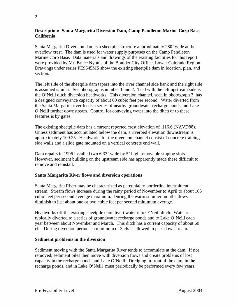
Description: Santa Margarita Diversion Dam, Camp Pendleton Marine Corp Base, California Santa Margarita Diversion dam is a sheetpile structure approximately 280’ wide at the overflow crest. The dam is used for water supply purposes on the Camp Pendleton Marine Corp Base. Data materials and drawings of the existing facilities for this report were provided by Mr. Bruce Nyhuis of the Boulder City Office, Lower Colorado Region. Drawings under series PE9645MS show the existing sheetpile dam in location, plan, and section. The left side of the sheetpile dam tapers into the river channel side bank and the right side is assumed similar. See photographs number 1 and 2. Tied with the left upstream side is the O’Neill ditch diversion headworks. This diversion channel, seen in photograph 3, has a designed conveyance capacity of about 60 cubic feet per second. Water diverted from the Santa Margarita river feeds a series of nearby groundwater recharge ponds and Lake O’Neill further downstream. Control for conveying water into the ditch or to these features is by gates. The existing sheetpile dam has a current reported crest elevation of 116.6 (NAVD88). Unless sediment has accumulated below the dam, a riverbed elevation downstream is approximately 109.25. Headworks for the diversion channel consist of concrete training side walls and a slide gate mounted on a vertical concrete end wall. Dam repairs in 1996 installed two 6.33’ wide by 5’ high removable stoplog slots. However, sediment building on the upstream side has apparently made these difficult to remove and reinstall. Santa Margarita River flows and diversion operations Santa Margarita River may be characterized as perennial to borderline intermittent stream. Stream flows increase during the rainy period of November to April to about 165 cubic feet per second average maximum. During the warm summer months flows diminish to just about one or two cubic feet per second minimum average. Headworks off the existing sheetpile dam divert water into O’Neill ditch. Water is typically diverted to a series of groundwater recharge ponds and to Lake O’Neill each year between about November and March. This ditch has a current capacity of about 60 cfs. During diversion periods, a minimum of 3 cfs is allowed to pass downstream. Sediment problems in the diversion Sediment moving with the Santa Margarita River tends to accumulate at the dam. If not removed, sediment piles then move with diversion flows and create problems of lost capacity in the recharge ponds and Lake O’Neill. Dredging in front of the dam, in the recharge ponds, and in Lake O’Neill must periodically be performed every few years.
3
Pre-Feasibility Level August 2004
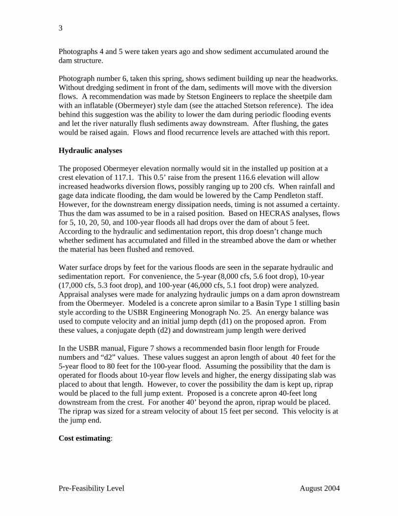
Photographs 4 and 5 were taken years ago and show sediment accumulated around the dam structure. Photograph number 6, taken this spring, shows sediment building up near the headworks. Without dredging sediment in front of the dam, sediments will move with the diversion flows. A recommendation was made by Stetson Engineers to replace the sheetpile dam with an inflatable (Obermeyer) style dam (see the attached Stetson reference). The idea behind this suggestion was the ability to lower the dam during periodic flooding events and let the river naturally flush sediments away downstream. After flushing, the gates would be raised again. Flows and flood recurrence levels are attached with this report. Hydraulic analyses The proposed Obermeyer elevation normally would sit in the installed up position at a crest elevation of 117.1. This 0.5’ raise from the present 116.6 elevation will allow increased headworks diversion flows, possibly ranging up to 200 cfs. When rainfall and gage data indicate flooding, the dam would be lowered by the Camp Pendleton staff. However, for the downstream energy dissipation needs, timing is not assumed a certainty. Thus the dam was assumed to be in a raised position. Based on HECRAS analyses, flows for 5, 10, 20, 50, and 100-year floods all had drops over the dam of about 5 feet. According to the hydraulic and sedimentation report, this drop doesn’t change much whether sediment has accumulated and filled in the streambed above the dam or whether the material has been flushed and removed. Water surface drops by feet for the various floods are seen in the separate hydraulic and sedimentation report. For convenience, the 5-year (8,000 cfs, 5.6 foot drop), 10-year (17,000 cfs, 5.3 foot drop), and 100-year (46,000 cfs, 5.1 foot drop) were analyzed. Appraisal analyses were made for analyzing hydraulic jumps on a dam apron downstream from the Obermeyer. Modeled is a concrete apron similar to a Basin Type 1 stilling basin style according to the USBR Engineering Monograph No. 25. An energy balance was used to compute velocity and an initial jump depth (d1) on the proposed apron. From these values, a conjugate depth (d2) and downstream jump length were derived In the USBR manual, Figure 7 shows a recommended basin floor length for Froude numbers and “d2” values. These values suggest an apron length of about 40 feet for the 5-year flood to 80 feet for the 100-year flood. Assuming the possibility that the dam is operated for floods about 10-year flow levels and higher, the energy dissipating slab was placed to about that length. However, to cover the possibility the dam is kept up, riprap would be placed to the full jump extent. Proposed is a concrete apron 40-feet long downstream from the crest. For another 40’ beyond the apron, riprap would be placed. The riprap was sized for a stream velocity of about 15 feet per second. This velocity is at the jump end. Cost estimating:
4
Pre-Feasibility Level August 2004
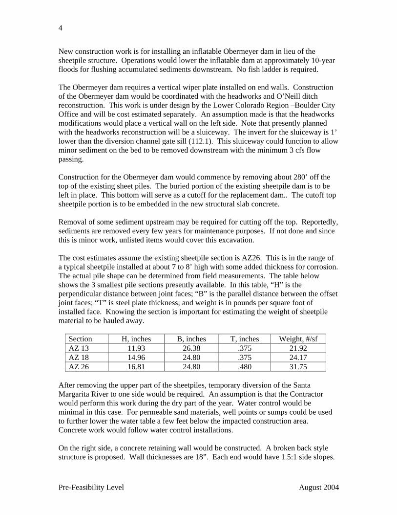
New construction work is for installing an inflatable Obermeyer dam in lieu of the sheetpile structure. Operations would lower the inflatable dam at approximately 10-year floods for flushing accumulated sediments downstream. No fish ladder is required. The Obermeyer dam requires a vertical wiper plate installed on end walls. Construction of the Obermeyer dam would be coordinated with the headworks and O’Neill ditch reconstruction. This work is under design by the Lower Colorado Region –Boulder City Office and will be cost estimated separately. An assumption made is that the headworks modifications would place a vertical wall on the left side. Note that presently planned with the headworks reconstruction will be a sluiceway. The invert for the sluiceway is 1’ lower than the diversion channel gate sill (112.1). This sluiceway could function to allow minor sediment on the bed to be removed downstream with the minimum 3 cfs flow passing. Construction for the Obermeyer dam would commence by removing about 280’ off the top of the existing sheet piles. The buried portion of the existing sheetpile dam is to be left in place. This bottom will serve as a cutoff for the replacement dam.. The cutoff top sheetpile portion is to be embedded in the new structural slab concrete. Removal of some sediment upstream may be required for cutting off the top. Reportedly, sediments are removed every few years for maintenance purposes. If not done and since this is minor work, unlisted items would cover this excavation. The cost estimates assume the existing sheetpile section is AZ26. This is in the range of a typical sheetpile installed at about 7 to 8’ high with some added thickness for corrosion. The actual pile shape can be determined from field measurements. The table below shows the 3 smallest pile sections presently available. In this table, “H” is the perpendicular distance between joint faces; “B” is the parallel distance between the offset joint faces; “T” is steel plate thickness; and weight is in pounds per square foot of installed face. Knowing the section is important for estimating the weight of sheetpile material to be hauled away.
Section H, inches B, inches T, inches Weight, #/sf AZ 13 11.93 26.38 .375 21.92 AZ 18 14.96 24.80 .375 24.17 AZ 26 16.81 24.80 .480 31.75
After removing the upper part of the sheetpiles, temporary diversion of the Santa Margarita River to one side would be required. An assumption is that the Contractor would perform this work during the dry part of the year. Water control would be minimal in this case. For permeable sand materials, well points or sumps could be used to further lower the water table a few feet below the impacted construction area. Concrete work would follow water control installations. On the right side, a concrete retaining wall would be constructed. A broken back style structure is proposed. Wall thicknesses are 18”. Each end would have 1.5:1 side slopes.

5
Pre-Feasibility Level August 2004
A concept to use a sheet pile wall on the right side was investigated. However, with large riprap that may be existing, sheetpile driving may be impossible. Note that the need for downstream riprap may allow some existing buried riprap to be salvaged from the site at Contractor’s option. The Type 1 basin assumed for downstream energy dissipation is longer than other basin types that employ dentate baffles to force a jump earlier. Use of one of the baffle style basins could decrease the length of concrete and riprap. However, a problem with baffles is they catch trash that will hang up on these protrusions. Thus, for this estimate the Type 1 flat slab apron was assumed. Slab thickness was selected as 24-inches. On the upstream side, this thickness accommodates the anchor bolts needed for mounting the Obermeyer dam. On the downstream side, the thickness includes several inches of wearing surface. Length upstream from the present dam centerline is about 20’ and the length downstream is about 40’. The upstream 20’ length provides resistance from overturning and extends about the typical upstream length of twice the dam height. Cutoff at each end are placed to allow for some possible streambed degradation. In some special cases the rubber bladders are impregnated with Kevlar as a protection against vandalism. This would increase the dam costs. However, Kevlar impregnated rubber was not assumed since the base is a government controlled facility and vandalism should not occur. A small building is required to house air compressors and system control equipment for the inflatable dam. Size of the proposed building is 12’ by 15’ maximum. The building would be prefabricated and installed on a concrete base. Location is on the left bank near the headworks. Air piping would cross the sluiceway and run in a channel in the concrete apron. Elevation for this building base slab is about 127. Note that this is about 2’ lower than the maximum upstream water surface for a 100-year flood and about 1.5’ higher than the downstream maximum water surface, assuming the gates are in the up position. If higher ground is available nearby, this should be investigated. If the gates are in the down position, the maximum upstream water surface is about elevation 125.8. See the hydraulic analyses worksheet for these water surface elevations. Based on the existing sheetpile configuration, preliminary hydraulics and sedimentation, and the construction assumptions listed above, two cost estimates for the Obermeyer dam were prepared. One estimate is to completely replace the dam with one operating Obermeyer section. Cost for a single 280’ Obermeyer is $4,100,000. The other estimate is for a split section installation. A split section would have a total length of 280’ but have two independently operating sections. The smaller section would be placed near the proposed headworks. This section could possibly be used for flushing sediment accumulations at less than the 10-year flood events. The estimate for the split section came out at the same price.

6
Pre-Feasibility Level August 2004
Item details are shown on the attached cost estimate worksheets. Drawings depicting a split section installation are also attached. A single section installation would be very similar. Attachments, enclosures, and references: Photos 1 through 6 with captions References:
1. Flood hydrology memo 2. Stetson report recommendation 3. Hydraulics and Sedimentation memos
Cost estimate worksheets Drawings
1. Existing sheetpile dam 2. Re-configured Obermeyer dam – PLAN and SECTIONS
7
PHOTO APPENDIX
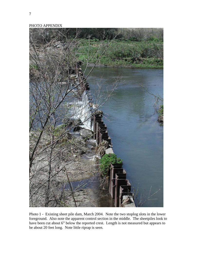
Photo 1 - Existing sheet pile dam, March 2004. Note the two stoplog slots in the lower foreground. Also note the apparent control section in the middle. The sheetpiles look to have been cut about 6” below the reported crest. Length is not measured but appears to be about 20 feet long. Note little riprap is seen.
8
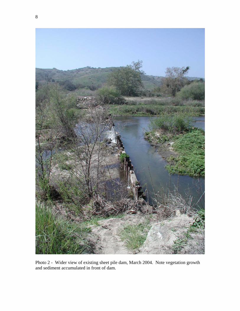
Photo 2 - Wider view of existing sheet pile dam, March 2004. Note vegetation growth and sediment accumulated in front of dam.
9
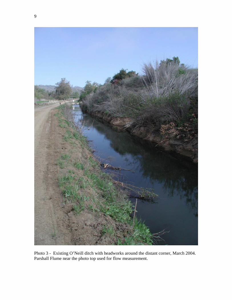
Photo 3 - Existing O’Neill ditch with headworks around the distant corner, March 2004. Parshall Flume near the photo top used for flow measurement.
10
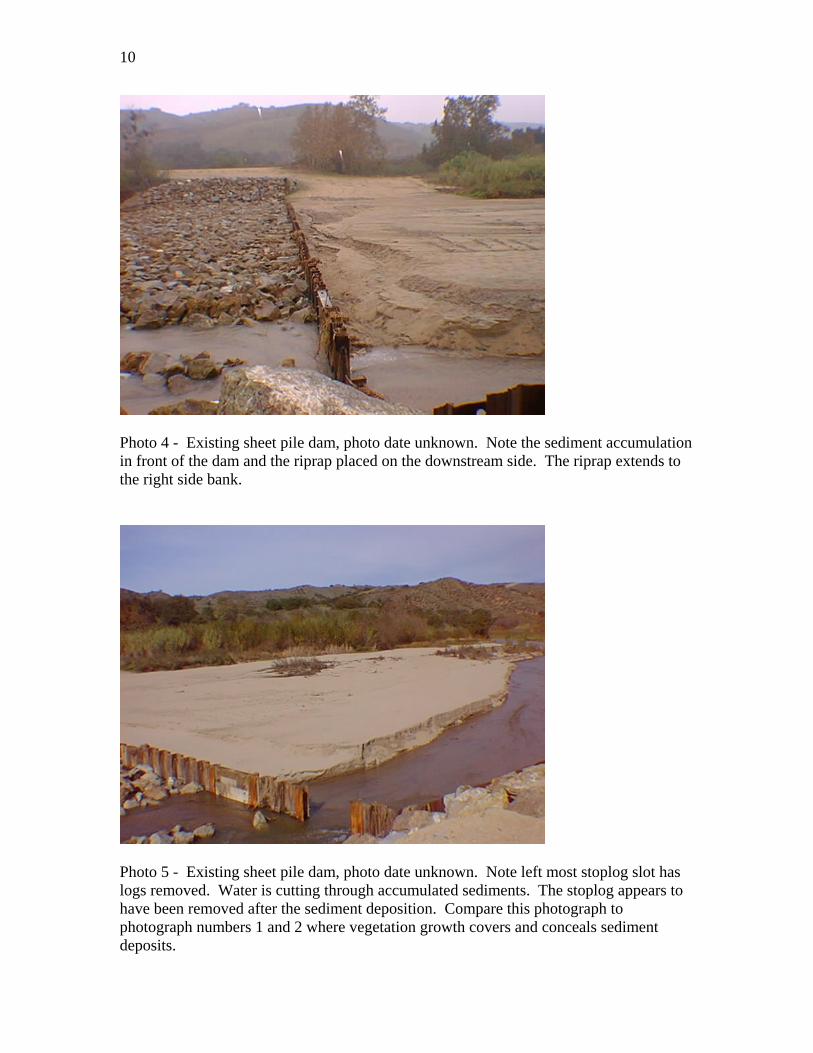
Photo 4 - Existing sheet pile dam, photo date unknown. Note the sediment accumulation in front of the dam and the riprap placed on the downstream side. The riprap extends to the right side bank.
Photo 5 - Existing sheet pile dam, photo date unknown. Note left most stoplog slot has logs removed. Water is cutting through accumulated sediments. The stoplog appears to have been removed after the sediment deposition. Compare this photograph to photograph numbers 1 and 2 where vegetation growth covers and conceals sediment deposits.
11
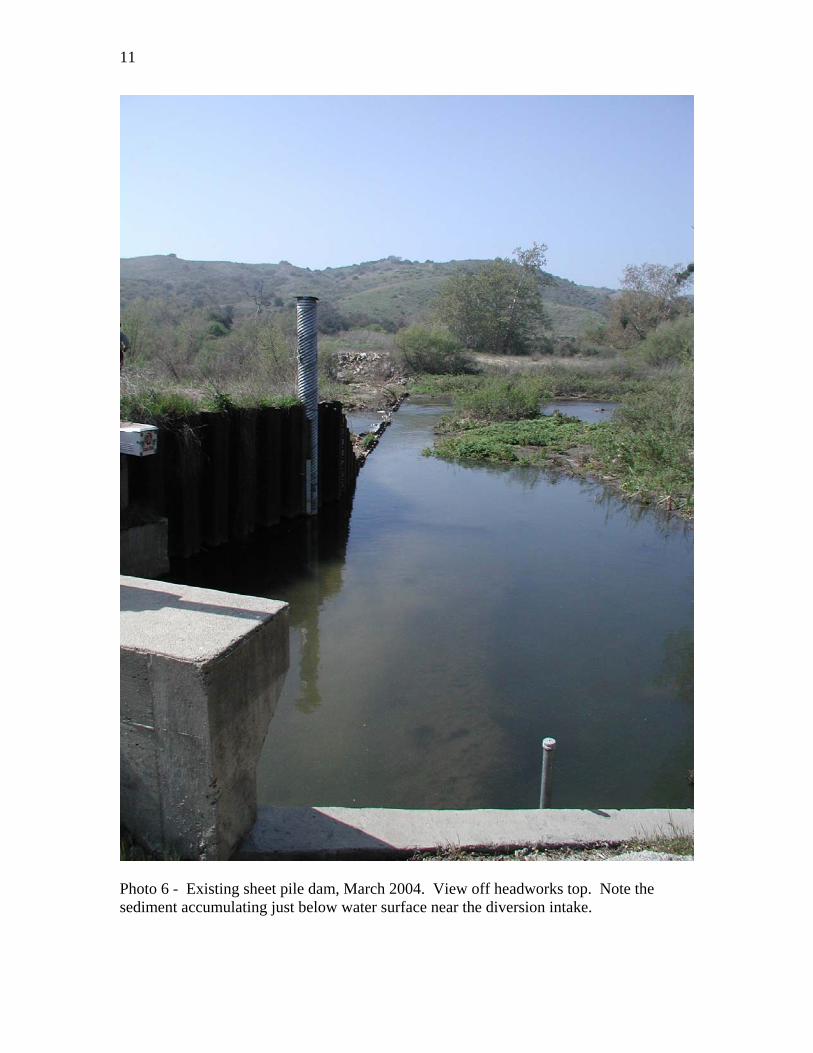
Photo 6 - Existing sheet pile dam, March 2004. View off headworks top. Note the sediment accumulating just below water surface near the diversion intake.
12
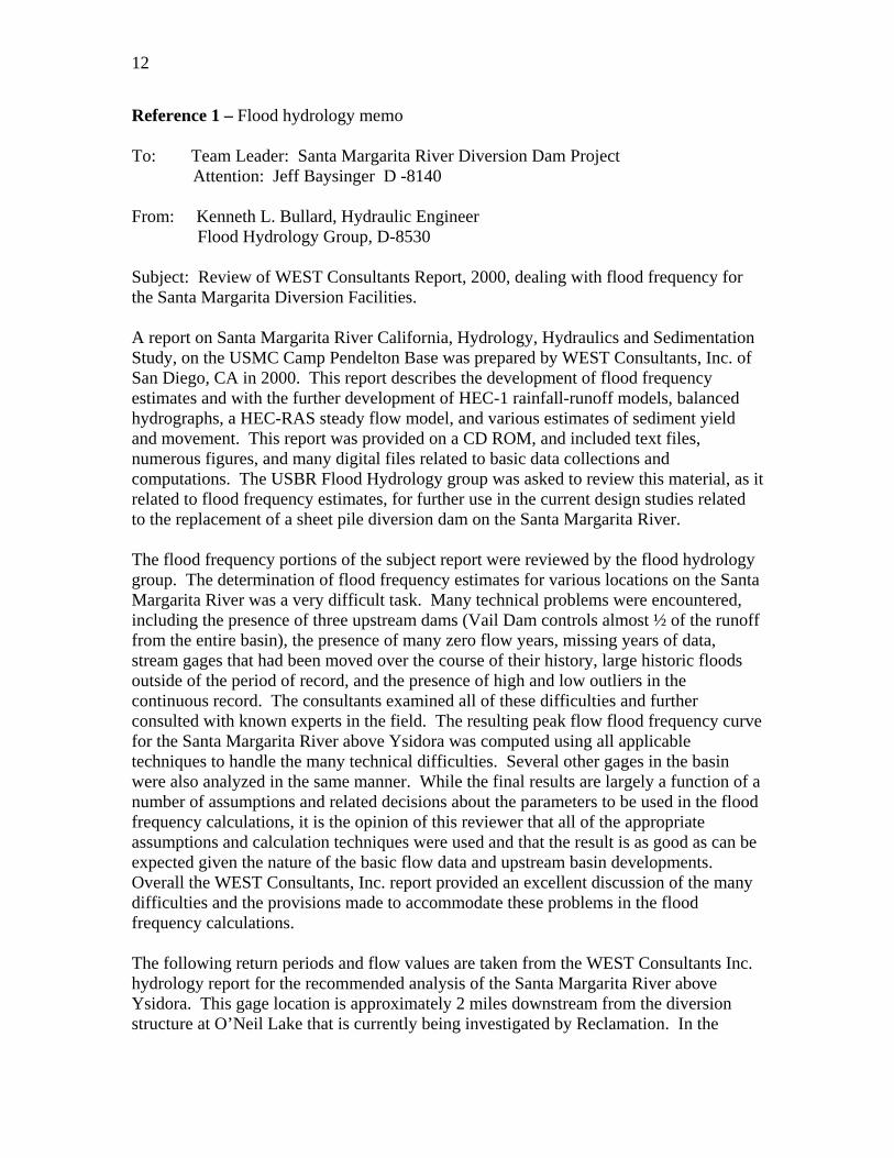
Reference 1 – Flood hydrology memo To: Team Leader: Santa Margarita River Diversion Dam Project Attention: Jeff Baysinger D -8140 From: Kenneth L. Bullard, Hydraulic Engineer Flood Hydrology Group, D-8530 Subject: Review of WEST Consultants Report, 2000, dealing with flood frequency for the Santa Margarita Diversion Facilities. A report on Santa Margarita River California, Hydrology, Hydraulics and Sedimentation Study, on the USMC Camp Pendelton Base was prepared by WEST Consultants, Inc. of San Diego, CA in 2000. This report describes the development of flood frequency estimates and with the further development of HEC-1 rainfall-runoff models, balanced hydrographs, a HEC-RAS steady flow model, and various estimates of sediment yield and movement. This report was provided on a CD ROM, and included text files, numerous figures, and many digital files related to basic data collections and computations. The USBR Flood Hydrology group was asked to review this material, as it related to flood frequency estimates, for further use in the current design studies related to the replacement of a sheet pile diversion dam on the Santa Margarita River. The flood frequency portions of the subject report were reviewed by the flood hydrology group. The determination of flood frequency estimates for various locations on the Santa Margarita River was a very difficult task. Many technical problems were encountered, including the presence of three upstream dams (Vail Dam controls almost ½ of the runoff from the entire basin), the presence of many zero flow years, missing years of data, stream gages that had been moved over the course of their history, large historic floods outside of the period of record, and the presence of high and low outliers in the continuous record. The consultants examined all of these difficulties and further consulted with known experts in the field. The resulting peak flow flood frequency curve for the Santa Margarita River above Ysidora was computed using all applicable techniques to handle the many technical difficulties. Several other gages in the basin were also analyzed in the same manner. While the final results are largely a function of a number of assumptions and related decisions about the parameters to be used in the flood frequency calculations, it is the opinion of this reviewer that all of the appropriate assumptions and calculation techniques were used and that the result is as good as can be expected given the nature of the basic flow data and upstream basin developments. Overall the WEST Consultants, Inc. report provided an excellent discussion of the many difficulties and the provisions made to accommodate these problems in the flood frequency calculations. The following return periods and flow values are taken from the WEST Consultants Inc. hydrology report for the recommended analysis of the Santa Margarita River above Ysidora. This gage location is approximately 2 miles downstream from the diversion structure at O’Neil Lake that is currently being investigated by Reclamation. In the

13
Consultants report a HEC-RAS model was also set up. The flow values for the 10-, 50-, and 100-year return periods at the location of the O’Neil Lake diversion structure are the same as the Santa Margarita River above Ysidora gage location flood frequency analysis. These values are recommended for further use in design studies related to the replacement of the diversion structure near the O’Neil Lake area. Recommended Flow values: Return Period Flow (Years) (ft3/s)
5 8,000 10 17,000 20 26,000 50 37,500 100 46,000
If you have questions about this review or the analysis provided in the WEST Consultants Report please contact me at 303-445-2539. Copy to (Bullard/Schreiner)
14
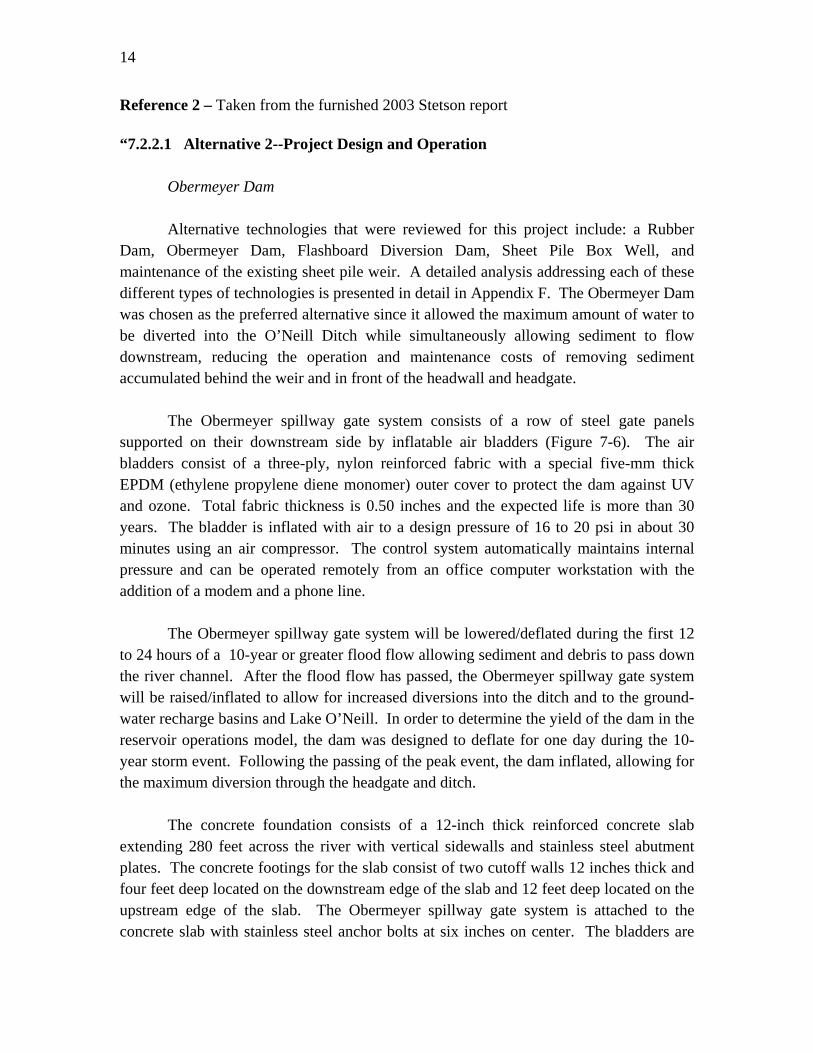
Reference 2 – Taken from the furnished 2003 Stetson report “7.2.2.1 Alternative 2--Project Design and Operation
Obermeyer Dam Alternative technologies that were reviewed for this project include: a Rubber
Dam, Obermeyer Dam, Flashboard Diversion Dam, Sheet Pile Box Well, and maintenance of the existing sheet pile weir. A detailed analysis addressing each of these different types of technologies is presented in detail in Appendix F. The Obermeyer Dam was chosen as the preferred alternative since it allowed the maximum amount of water to be diverted into the O’Neill Ditch while simultaneously allowing sediment to flow downstream, reducing the operation and maintenance costs of removing sediment accumulated behind the weir and in front of the headwall and headgate.
The Obermeyer spillway gate system consists of a row of steel gate panels
supported on their downstream side by inflatable air bladders (Figure 7-6). The air bladders consist of a three-ply, nylon reinforced fabric with a special five-mm thick EPDM (ethylene propylene diene monomer) outer cover to protect the dam against UV and ozone. Total fabric thickness is 0.50 inches and the expected life is more than 30 years. The bladder is inflated with air to a design pressure of 16 to 20 psi in about 30 minutes using an air compressor. The control system automatically maintains internal pressure and can be operated remotely from an office computer workstation with the addition of a modem and a phone line.
The Obermeyer spillway gate system will be lowered/deflated during the first 12
to 24 hours of a 10-year or greater flood flow allowing sediment and debris to pass down the river channel. After the flood flow has passed, the Obermeyer spillway gate system will be raised/inflated to allow for increased diversions into the ditch and to the ground-water recharge basins and Lake O’Neill. In order to determine the yield of the dam in the reservoir operations model, the dam was designed to deflate for one day during the 10-year storm event. Following the passing of the peak event, the dam inflated, allowing for the maximum diversion through the headgate and ditch.
The concrete foundation consists of a 12-inch thick reinforced concrete slab
extending 280 feet across the river with vertical sidewalls and stainless steel abutment plates. The concrete footings for the slab consist of two cutoff walls 12 inches thick and four feet deep located on the downstream edge of the slab and 12 feet deep located on the upstream edge of the slab. The Obermeyer spillway gate system is attached to the concrete slab with stainless steel anchor bolts at six inches on center. The bladders are
15
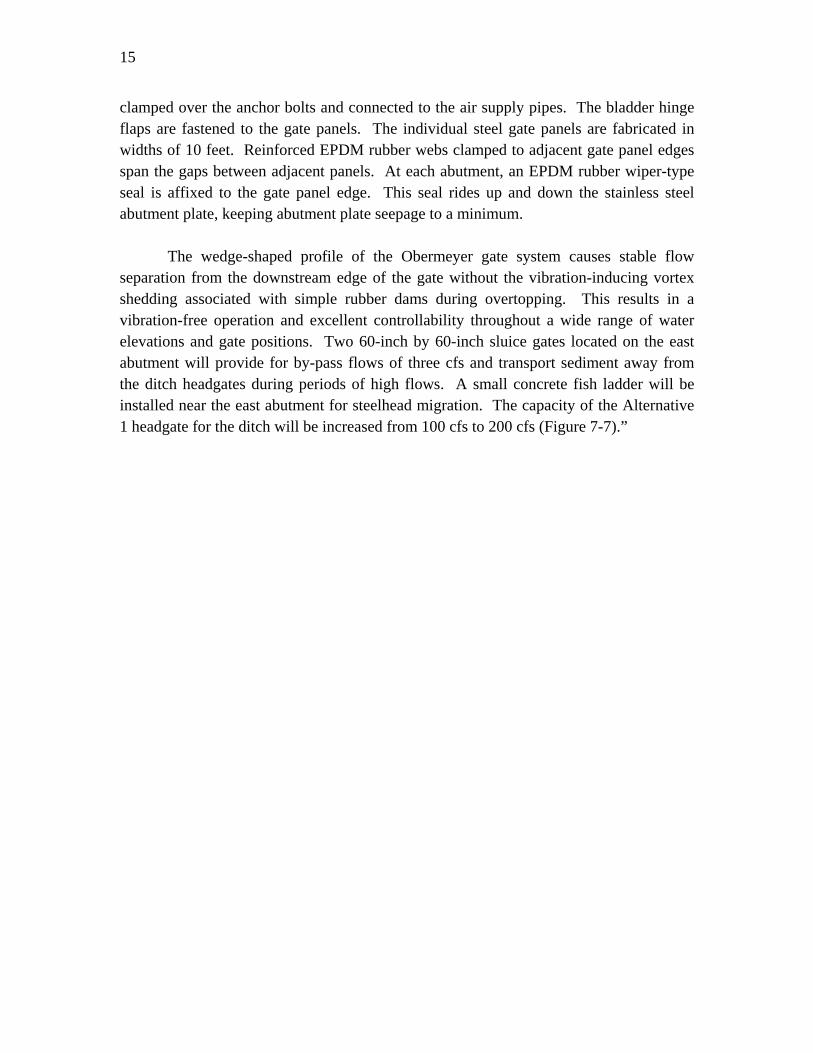
clamped over the anchor bolts and connected to the air supply pipes. The bladder hinge flaps are fastened to the gate panels. The individual steel gate panels are fabricated in widths of 10 feet. Reinforced EPDM rubber webs clamped to adjacent gate panel edges span the gaps between adjacent panels. At each abutment, an EPDM rubber wiper-type seal is affixed to the gate panel edge. This seal rides up and down the stainless steel abutment plate, keeping abutment plate seepage to a minimum.
The wedge-shaped profile of the Obermeyer gate system causes stable flow
separation from the downstream edge of the gate without the vibration-inducing vortex shedding associated with simple rubber dams during overtopping. This results in a vibration-free operation and excellent controllability throughout a wide range of water elevations and gate positions. Two 60-inch by 60-inch sluice gates located on the east abutment will provide for by-pass flows of three cfs and transport sediment away from the ditch headgates during periods of high flows. A small concrete fish ladder will be installed near the east abutment for steelhead migration. The capacity of the Alternative 1 headgate for the ditch will be increased from 100 cfs to 200 cfs (Figure 7-7).”