propulsion systems...various combinations of oxidizer- ... to this day, all chemical rocket...
TRANSCRIPT

472
PROPULSION SYSTEMSWith a few exceptions, propulsion systems for rockets and spacecraft today use chemical pro-
pellants. These propellants can be solid, semisolid, gelled or liquid, depending on whether they are pressurized. However, they are most often in solid or liquid form.
How rapidly a solid propellant burns depends on how much of its surface is exposed to burning at any one moment. Of course, this depends on the design or molding of the solid-propellant charge within its container. It is relatively easy to throttle or change the thrust of a liquid-propellant rocket, but it is very difficult to control the thrust of a solid-propellant type. Why and how these conditions exist will be examined in this chapter. We will look at special factors and conditions influencing the use of liquid propellants and examine rocket engine (or motor) design and function.
bjectivesExplain oxidation.State the difference between an oxidizer and a reducer.Define cryogenics, hydrocarbons and a self-reacting compound. State the difference between a propellant, a bipropellant and a monopropellant.List the four qualities of a good propellant.Explain why a rocket propellant does not need air.Explain the difference between an air-breathing engine and a rocket engine.Define hypergolic propellants, mass flow and low explosives.Identify a way to get more force from a load of propellant.Describe the purpose of the rocket engine.Describe the function of the rocket motor throat and nozzle.Compare the features of the liquid and solid-propellant chemical systems.Name two systems that use solid propellants.Describe the solid-propellant chemical system.Explain how the burning rate of solid propellants is controlled.State the purpose of a squib in a solid-propellant rocket. Describe a liquid-propellant engine system.Discuss the combustion chamber of a liquid-propellant system.Explain the function of the coupled valve in a combustion chamber.Explain the function of the injector in a liquid-propellant engine.Describe the hybrid propellant system.State the advantages of a hybrid propellant system.
Chapter 22- Propulsion Systems
473
Oxidation and Combustion
Combustion is nothing more than very rapid oxidation, but what is oxidation? Oxidation is the combination of oxygen with another substance. The time it takes for this combining process to take place determines whether the substance rusts or corrodes, burns as a fire or explodes violently.
A chunk of rusting iron and the heat, pressure and light of a functioning rocket engine are doing the same thing. It just takes one longer to become oxidized than it does the other. Another similarity between these two extremes of oxidation is that both require oxygen (oxidizer) and a substance to be oxidized. The substance to be oxidized, the fuel, is also known as the reducer. Thus, the iron in the example is the reducer and the oxygen in the air touching the iron is the oxidizer. For the rocket, one chemical compound is the reducer (fuel), while the oxidizer is either another chemical compound or perhaps liquid oxygen.
Oxidizers and Reducers
Various combinations of oxidizer-reducers can produce an almost endless variety of oxidation reactions. When it comes to rocketry, however, a few ele-ments occurring in a wider variety of compounds (molecular bonding of two or more elements) dominate the field.
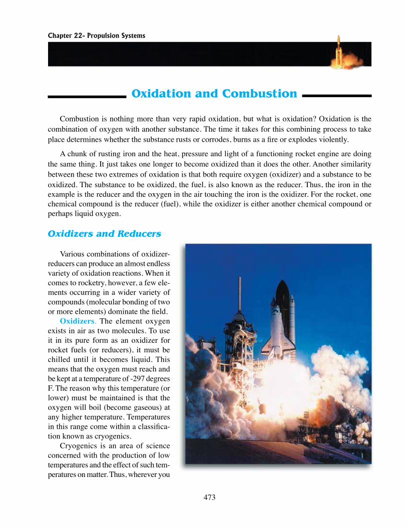
Oxidizers. The element oxygen exists in air as two molecules. To use it in its pure form as an oxidizer for rocket fuels (or reducers), it must be chilled until it becomes liquid. This means that the oxygen must reach and be kept at a temperature of -297 degrees F. The reason why this temperature (or lower) must be maintained is that the oxygen will boil (become gaseous) at any higher temperature. Tem peratures in this range come within a classifica-tion known as cryogenics.
Cryogenics is an area of science concerned with the production of low temperatures and the effect of such tem-peratures on matter. Thus, wherever you
474
see cryogenics used with reference to an oxidizer, fuel or propellant, you know that the substance is “super cold.”
There are other oxidiz-ers that do not have to be kept at as low a tempera-ture as pure oxygen. These are chemical compounds that contain oxygen atoms as part of their molecular structure.
Reducers. Any list of fuels (or reducers) must begin with the elements hydrogen, carbon and ni-trogen. Certain compounds
of hydrogen and carbon are called hydrocar-bons. As you probably know, the fuels we use for heating and transportation are usually hydrocarbons that include coal and products obtained from crude oil.
The first stage of the Saturn V rocket used the hydrocarbon kerosene as its fuel. The re-maining stages all used hydrogen. Pure hydro-gen is an excellent rocket fuel, but it is even more cryogenic than oxygen. Hydrogen must be chilled to -423 degrees F to liquefy it.
In the atmosphere, nitrogen is inert, but it is highly reactive in other forms. Nitrogen is very important to the manufacture of high explosives and other high-energy compounds and mixtures.
Propellant Combinations. Since it takes both an oxidizer and a reducer to propel a rocket, it is correct to call either of them a propellant, However, the term propellant is most often used as a single reference to the oxidizer and reducer. For example, we could say, “the rocket uses an oxygen-hydrogen propellant.” We could also say that a rocket uses 1,000 pounds of propellant. It is not necessary to say there are
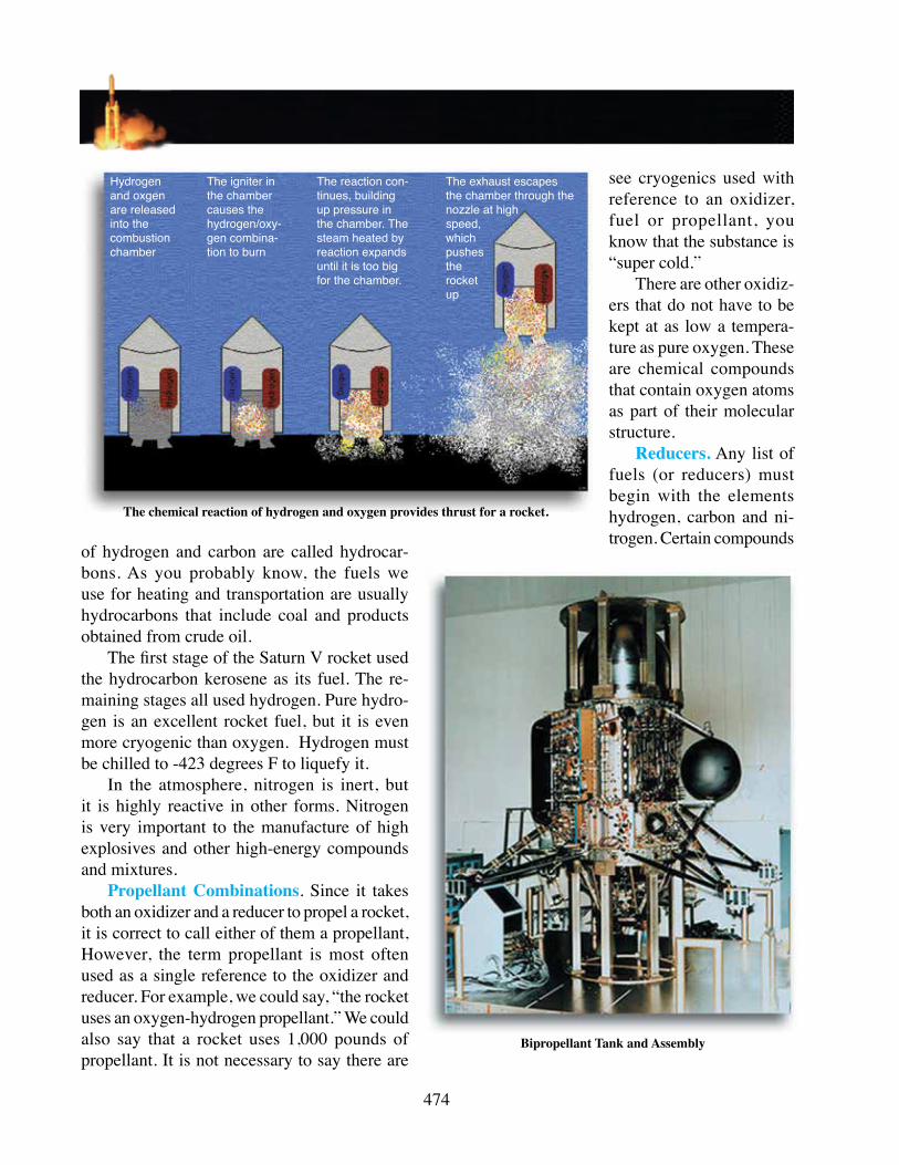
The chemical reaction of hydrogen and oxygen provides thrust for a rocket.
Bipropellant Tank and Assembly
Hydrogen and oxgen are released into the combustion chamber
The igniter in the chamber causes the hydrogen/oxy-gen combina-tion to burn
The reaction con-tinues, building up pressure in the chamber. The steam heated by reaction expands until it is too big for the chamber.
The exhaust escapes the chamber through the nozzle at high speed, which pushes the rocket up

Chapter 22- Propulsion Systems
475
500 pounds of oxidizer and 500 pounds of reducer, nor is it necessary to say that they are stored within the same container or in separate containers.
Speaking of propellant storage, other terms are used to describe the storage arrangement of a propellant’s oxidizer and reducer. If the oxidizer is stored in one container and the fuel (reducer) in another, the term bipropellant is used. Bipropellants are not mixed until they reach the engine’s combus tion chamber. Back to the Saturn V: the first-stage bipropellant was oxygen and kerosene; the second- and third-stage bipropellants were oxygen and hydrogen. For all three stages, the propellants were pumped into the combustion chamber of the engine where ignition and burning took place. The majority of liquid-propellant rockets use the bipropellant arrangement.
In some cases, the liquid oxidizer and fuel can exist together in the same storage tank. Here the propellant also is pumped into the combustion chamber of the rocket engine and ignited. However, the fact that separate storage tanks are not necessary qualifies the propellant to be called a monopropellant.
Chemically, when an oxidizer and a reducer occur in a mixture, they are considered to be two separate ingredients. There is such a thing as a self-reacting compound. In such a compound, one molecule contains atoms of both oxidizer and reducer and, upon ignition, reacts with itself, yielding energy as it breaks down or decomposes.
Combustion for Propulsion
The final objective in considering any combination of chemicals as a propellant is how much force can be obtained as the mixture oxidizes. However, there are other considerations that are recognized as the qualities of a good propellant: (1) the propellant must contain oxidizer and fuel, (2) it must ignite correctly every time, (3) it must produce energy in the form of force, and (4) the force produced must be controllable. Let’s consider these four qualities individually.
Need for Packaged Oxidizers. Aside from propulsion in space, where no free oxygen is available, there is another reason for putting oxidizer in a concentrated package. An oxidizer-reducer mixture will burn forcibly in a confined or semi-confined space in which an air-breathing fire would be smothered.
People knew this fact for centuries without knowing the reason why and used it long before air-breathing engines were ever imagined. Old-fashioned gunpowder or “black pow-der” needs no air to burn its carbon and sulfur fuel ingredients because it has an oxidizer built into a third ingredient, potassium nitrate or saltpeter.
The ability of this mix-ture to propel a rocket or hurl a cannonball out of an An Example of Rocket Thrust

476
iron tube was known and employed in warfare centuries before Lavoisier discovered oxygen and the principle of oxidation in the eighteenth century. To this day, all chemical rocket propellants, all gun munitions, and all chemi cal explosives contain an oxidizer, burn in confine ment and do their work by bursting out of confinement or rushing out of semi-confinement.
Rushing out of semi-confinement describes rocket-propellant action. In a rocket-propellant mixture, the oxidizer outweighs the fuel on the order of 6 to 1 (for oxygen/hydrogen propellant combinations). Because the packaged oxidizer is expensive and a rocket propellant needs so much of it, the air-breathing engine is much less expensive to operate than any type of rocket engine. Still, the air-breathing engine cannot operate within both the atmosphere and space as does the rocket engine.
Ignition Characteristics. How fast a mixture burns is not necessarily related to how easily it starts. What properties of a propellant should be considered? Since the starting time of the rocket engine is important to controlling it, the propellant must start every time in the same way.
Another factor that must be considered is a choice between a continuous or restartable propellant. Some propellants can be started, but continue burning until all of the propel lant is exhausted (a burnout). Others can be repeat edly started and stopped.
Safety is also a very important factor. This does not mean the propellant can stand up to any kind of rough or careless handling without igniting, but it does mean that its safety requirements should be known and feasible. Some propellants are ignitable the old-fashioned way with a match, flame or hot wire. Others require greater and more concentrated heat. Some require an explosive shock. Some are hypergolic; that is, under normal temperatures, the oxidizer and reducer burst into flame the instant they meet. The main safety requirement in this case is to keep the ingredients separated.
Energy for Force. Not light and not heat, but force is what we’re looking for from a propellant’s release of energy—the sheer mo-mentum of moving molecules. What is desired is mass flow of combustion exhaust, but this mass can be no greater or less than the mass of ingredients before combustion.
Although a designer might wish to lighten the propellant load aboard a vehicle, there must be a certain amount of propellant on board to produce the needed thrust. This load alone
Propellant Changes to a Gas
constitutes most of the initial weight of a launch vehicle. The only way to get more force per load is to increase the velocity of the mass flow—that is, to get more “speed” per molecule. Therefore, it is better not to increase mass flow by means of heavier molecules that are too sluggish. The ideal exhaust gas consists of plenty of lightweight molecules, which excel in energy and velocity.
Controllable Force. When a propellant burns, the speed of the combustion should not be exces-sive. Fast, but not too fast, is the rule of thumb. How is this combustion process regulated? If a liquid propellant is used, the task of controlling the force is basically easy. All that is necessary is to govern the amount of propellant reaching the combustion chamber. This is similar to governing the amount of fuel/air mixture reaching the cylinders of an auto mobile engine through actions of the throttle and
Mass and speed of gas governs maximum speed of rocket
Chapter 22- Propulsion Systems
477
carburetor.Controlling the force of a solid propellant is slightly more difficult. There are ways of controlling
the force desired from a solid-propellant rocket. Basically, a solid propel lant is selected (or developed) according to its ability to produce force without causing a massive, destructive explosion.
In fact, solid propellants sometimes are called “low explosives.” Modern solid propellants are considerably more energetic than the black-powder-type propellant used with very early rockets. Yet, they have the black powder’s property of burning so that each particle ignites its neighbor particle and the burning continues as a swiftly spreading reaction.
Pressure and Mass Flow
Adding pressure to a medium will increase its molecular activity and consequently, its temperature. Increase the temperature of a medium and its molecular activity and pressure will be increased— this is particularly true with a gaseous medium that is enclosed by a container. Thus, the purpose of the rocket motor or engine is to provide a container in which the temperature (of the oxidizing propellant) increases the pressure of the gaseous portion of the medium.
If some means were not provided to relieve the constantly building pressure of a burning propellant, the container would burst. Among the functions performed by the nozzle throat and nozzle of the rocket motor are to provide an exit for the burned propellant mass, reduce the pressure within the combustion area and direct the flow of the mass involved.
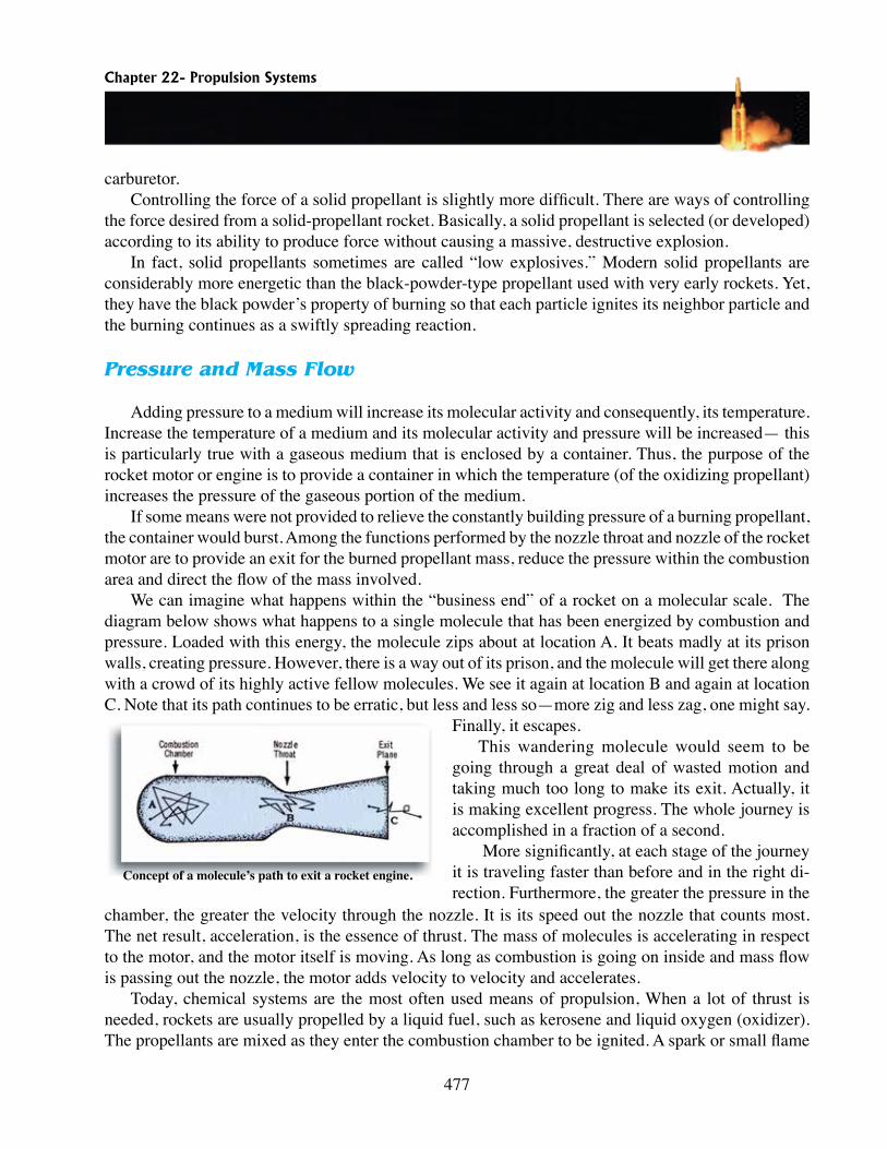
We can imagine what happens within the “business end” of a rocket on a molecular scale. The diagram below shows what happens to a single molecule that has been energized by combustion and pressure. Loaded with this energy, the molecule zips about at location A. It beats madly at its prison walls, creating pressure. However, there is a way out of its prison, and the molecule will get there along with a crowd of its highly active fellow molecules. We see it again at location B and again at location C. Note that its path continues to be erratic, but less and less so—more zig and less zag, one might say.
Finally, it escapes.This wandering molecule would seem to be
going through a great deal of wasted motion and taking much too long to make its exit. Actually, it is making excellent progress. The whole journey is accomplished in a fraction of a second.
More significantly, at each stage of the journey it is traveling faster than before and in the right di-rection. Furthermore, the greater the pressure in the
chamber, the greater the velocity through the nozzle. It is its speed out the nozzle that counts most. The net result, acceleration, is the essence of thrust. The mass of molecules is accelerating in respect to the motor, and the motor itself is moving. As long as combustion is going on inside and mass flow is passing out the nozzle, the motor adds velocity to velocity and accelerates.
Today, chemical systems are the most often used means of propulsion, When a lot of thrust is needed, rockets are usually propelled by a liquid fuel, such as kerosene and liquid oxygen (oxidizer). The propellants are mixed as they enter the com bustion chamber to be ignited. A spark or small flame
Concept of a molecule’s path to exit a rocket engine.
478
is used to start the ignition process. From then on, continuing combustion ignites the fuel and oxidizer as they enter the combustion chamber. The drawback to liquid chemical systems is that they require expensive plumbing, turbines, pumps, and engines.
Solid Propellants and the Solid Propellant Motor
Solid Propellants
The chemical system may have a solid rather than a liquid propellant. The fuel and oxidizer of a solid propellant are mixed together from the start. The skyrocket is a good example of a solid propel-lant; all it takes is ignition of the mixture. The combustion chamber and the propellant container are one and the same. This means that the solid-propellant chemical system is simple, much less costly than the liquid type and is very reliable. Today, solid propellants are used for our sub marine-launched ballistic missiles, the Minuteman intercontinental ballistic missiles, and many space launch vehicles. Solid propulsion was also used on the MX (Peacekeeper) missile as well as the Space Shuttle solid rocket boosters.
Fuels used in solid propellants include asphalts, waxes, oils, plastics, metals, rubbers and resins. The oxidizers for solid propellants come from two general sources: the organic (the source of nitrocel lulose and nitroglycerin) and the inorganic (the source of chemicals such as sodium nitrate and potassium perchlorate).
Chemical and Physical Properties
A look at the contents of a typical double-base propellant tells much about the requirements of a solid propellant. Typical of today’s solid propellants are composites in which the fuel and oxidizer are two different compounds. Usually the oxidizer is crystalline in form (like salt or sugar) and is embed-ded in the fuel base.
In a solid rocket motor (motor usually is associated with solid propellant whereas engine is associated with liquid propellants), the propellant substance is molded into its motor and casing as a single solid mass called a grain. The shape and consistency of the grain determine its burning properties.
The polyurethane fuel base of the most common solid-fuel mixture is a type of synthetic rubber. It maintains about the same consistency as that of tire rubber. Various other rocket propellants have similar plastic consistencies. It is very important that this consistency be even and free from internal bubbles or surface cracks. Exposure of more burning surface than intended could result in the danger of uncontrolled burning or an explosion. The casing into which the grain is molded must be tough and

Chapter 22- Propulsion Systems
479
heat resistant. A lining material is used as an insulator, and the case itself is made of various materials such as special steels, titanium and fiberglass.
Grain Design and Thrust Control
Once a solid propellant is ignited, it is going to burn. It can’t be turned off and then restarted as is done with liquid-propellant systems. Some solid propellants can be stopped from burning by dousing them with water, but others cannot be stopped. So, how does one control the burning rate of a solid propellant? How can the amount of thrust produced be controlled? The primary way of doing this is to mold the propellant into a shape that will provide the desired burning rate.
The flame front (where actual oxidation is taking place) of a solid propellant always eats its way into the mass in a direction that is perpendicular to the surface. The flame eats its way into a mass at a fixed rate depending on the contents of the propellant. For example, a typical double-base propellant’s burning rate is about 0.40 inch per second; a dense polyurethane composite burns at about 0.22 inches per second. Since these rates do not change, the only way to control the amount of force (or thrust) generated is to control the surface area exposed to the burning process.
The grain of a common skyrocket more than likely is a solidly packed propellant, with a space for ignition between the charge and the nozzle. Once ignited, this grain can burn only straightforward and the flame front is limited to the surface diameter. Thus, the burn rate (whatever it is) does not change until burnout. Since the burn rate doesn’t change and the flame-front area doesn’t change, the amount of thrust produced is
constant. When this type of situation exists, the grain design is neutral.What if a hole is bored the length of the grain, or charge, along its longitudinal axis? There will be
an instantaneous spread of the flame-front along the entire surface of the hole. This, of course, provides a larger surface area of flame and greater force. As the grain continues to burn, more and more surface area is exposed so more and more thrust is produced. This is called a progressive burn rate.
Suppose a considerable amount of thrust is needed, but the designers want the thrust to be neutral. The design shown above might be used. Ignition produces a large amount of thrust very quickly, but the design keeps the surface area constant. Remember, the flame eats its way into the mass perpendicular to the surface.
The third design is one for a regressive rate. With this design, the most thrust is produced shortly after ignition, and it diminishes thereafter. A similar approach was used for the space shuttle’s solid rocket boosters. The most thrust was produced upon ignition and during the first 55 seconds of the 2-minute burn. The grain of these boosters was shaped so that it then reduces thrust by approximately one-third until burnout.
There are other ways of controlling the amount of thrust or burn rate of a grain. The grain can be made up of different propellant mixtures that have different burn rates. Another method of control is
Grain Designs for Solid Propellants

480
to paint certain surfaces of the propellant with a heat resistant compound, leaving the other surfaces to burn at their regular rate.
Control of a solid rocket motor’s thrust depends primarily on the design and composition of the grain, as indicated earlier. It is also possible to stop thrust in a solid propellant by injecting a high-pres-sure inert (or neutral) gas into the chamber. A grain stopped in this manner could be restarted. However, such arrangements have not proven worth the effort. So, once the grain is ignited, it continues to burn and produce the amount of thrust for which it was designed. Control of the direction of thrust is another matter. Thrust directional control for the solid-propellant rocket can be obtained from the same type devices used with liquid-propellant rockets.
Igniters
Solid propellants are ignited by a composition that both heats the grain to ignition temperature and increases the pressure in the combustion chamber until propellant reaction is assured. The heat produced by an electrical wire could ignite a few of the older solid-propellant mixtures. Today, this type of ignition device is sometimes found in model-rocket launching devices, but the real rockets use devices like the squib. The squib consists of an enclosure filled with a combustible powder that is ignited electrically. The flame of the burning squib, in turn, ignites the grain.
Two igniter compositions frequently used are common gunpowder and a metal-oxidizer mixture such as magnesium and potassium perchlorate. Each of these has advantages over the other. Each also has certain disadvantages. Gunpowder is inexpensive, but it tends to absorb moisture, which can ad-versely affect its performance. Metal-oxidizer igniters are generally more efficient and ignition delays are shorter. However, they are more hazardous to handle than black-powder igniters. If magnesium is used in igniter composition, surface oxidation is likely to occur. Once oxidized, the igniter doesn’t work very well.
A critical part of an igniter is the case that contains the composition. Manufacturers of igniters have a variety of materials to choose from, ranging from paper to metal. The strength of the container must be sufficient for demands made upon it. For example, rapid ignition requires the container to be strong enough to remain intact, until all the composition has ignited. However, the container must be designed so that no part of it is large enough to block the exhaust nozzle. Such blocking could cause extremely high pressures and damage the motor. The location of the igniter depends upon the design of the grain.
Liquid Propellants and the Liquid-Propellant Engine
Liquid Propellants
You will remember that there are two general classifications of liquid propellants: bipropellant and monopropellant. When the oxidizers and fuels are separated, we refer to the two as a bipropellant. Any rocket that uses a bipropellant has a liquid-bipropellant propulsion system. However, it is not neces-

Chapter 22- Propulsion Systems
481
sary for all liquid propellants to have their oxidizers and fuels kept separate. When a liquid propellant contains its oxidizer and fuel in one solution, it is called a monopropellant.
Bipropellants have an advantage over monopropellants in that they are more stable and capable of better performance. Bipropellants consist of two types: the nonhypergolic (nonself-igniting) and the hypergolic (self-igniting). Each of the two types of bipropellants has advantages and disadvantages. Malfunctioning of equipment and accidents involving a system using either type of bipropellant can be disastrous.
An ignition delay, even a brief one, results in a sufficient accumulation of nonhypergolic fuel and oxidizers in the combustion cham-ber to cause a damaging explosion. The components of a hypergolic propellant catch fire when brought into contact one with the other.
The design of a liquid-mono-propellant system is much simpler than the design of a bipropellant system. A monopropellant system requires only half the storage, pumping and controlling equip-ment required by a bipropellant system. It doesn’t require metering to keep the fuel and oxidizer in correct proportion.
The drawback of a monopro-pellant is its sensitivity to tempera-ture and shock. This sensitivity results in instability and restricts its handling. Generally, monopropellants also require more heat for ignition and react more slowly than bipropellants. These factors mean that monopropellants require larger combustion chambers.
Just as there are two general types of bipropellants, there are two general types of monopropellants: those that obtain energy by combustion and those that obtain energy by dissociation reaction (decomposition). A catalyst initiates the dissociation reaction.
To ignite a liquid propellant, it is necessary to raise the temperature of a small part of the mixture to its ignition point. The flame will then spread throughout the total mixture. Mixtures that contain liquid oxygen have a high reaction rate, so these mixtures are easy to ignite. For example, an ordinary spark plug can be used to ignite a flow of oxygen and alcohol.
One method of igniting a liquid-propellant mixture is to inject a limited amount of hypergolic fuel into the combustion chamber along with the oxidizer just before the main fuel flow starts. Another method uses a pyrotechnic fired electrically from an external circuit. If repeated ignitions are required during flight, a small precombustion chamber makes the ignition of a small amount of the propellant possible by means of a spark plug. The flow into the main chamber is delayed until the propellant in the precombustion chamber is ignited. The flame from the precombustion chamber is then used to ignite
Comparison of Bipropellant and Monopropellant Propulsion Systems
LIQUID PROPULSION
482
the mixture in the main chamber.
The Liquid-Propellant Engine
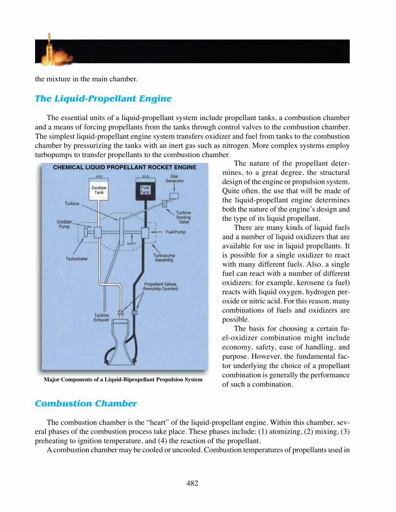
The essential units of a liquid-propellant system include propellant tanks, a combustion chamber and a means of forcing propellants from the tanks through control valves to the combustion chamber. The simplest liquid-propellant engine system transfers oxidizer and fuel from tanks to the combustion chamber by pressurizing the tanks with an inert gas such as nitrogen. More complex systems employ turbopumps to transfer propellants to the combustion chamber.
The nature of the propellant deter-mines, to a great degree, the structural design of the engine or propulsion system. Quite often, the use that will be made of the liquid-propellant engine determines both the nature of the engine’s design and the type of its liquid propellant.
There are many kinds of liquid fuels and a number of liquid oxidizers that are available for use in liquid propellants. It is possible for a single oxidizer to react with many different fuels. Also, a single fuel can react with a number of different oxidizers; for example, kerosene (a fuel) reacts with liquid oxygen, hydrogen per-oxide or nitric acid. For this reason, many combinations of fuels and oxidizers are possible.
The basis for choosing a certain fu-el-oxidizer combination might include economy, safety, ease of handling, and purpose. However, the fundamental fac-tor underlying the choice of a propellant combination is generally the performance of such a combination.
Combustion Chamber
The combustion chamber is the “heart” of the liquid-propellant engine. Within this chamber, sev-eral phases of the combustion process take place. These phases include: (1) atomizing, (2) mixing, (3) preheating to ignition temperature, and (4) the reaction of the propellant.
A combustion chamber may be cooled or un cooled. Combustion temperatures of propellants used in
Major Components of a Liquid-Bipropellant Propulsion System
CHEMICAL LIQUID PROPELLANt ROCKEt ENGINE
Chapter 22- Propulsion Systems
483
uncooled combustion chambers frequently are under 1,000° C. When it is desired to construct uncooled combustion chambers that will withstand relatively high temperatures over a comparatively long period of time, they are given an interior ceramic or carbon coating.
There are several methods of cooling a combustion chamber, but the most commonly used method is by regenerative cooling. In this method, fuel or oxidizer is circulated within small passageways between the inner and outer walls of the combustion chamber, throat and nozzle. As the propellant flows through the pas sageways, it absorbs heat, thereby cooling the combustion chamber. The absorbed heat also adds energy to the fuel or oxidizer before it enters the injector and increases the velocity of injection into the combustion chamber.
Valves
A propellant system’s tanks and plumbing must be constructed of materials that are not adversely affected by the nature of the fuel and oxidizer the system uses. The nature of the fluids a system uses also determines the kinds of materials used to make valves. The scope of both the operating temperatures and operating conditions to which they are subject makes it necessary to use high-precision techniques in valve manufacturing.
Valves used in propellant systems range in type and size according to their specific functions. Comparatively large valves, for example, are used to control the high flow of fuel and oxidizer. A coupled valve, consisting of two propellant valves opened by a single piston, operates through a crosshead, causing fuel and oxidizer to enter the combustion chamber at the same time.
Injector
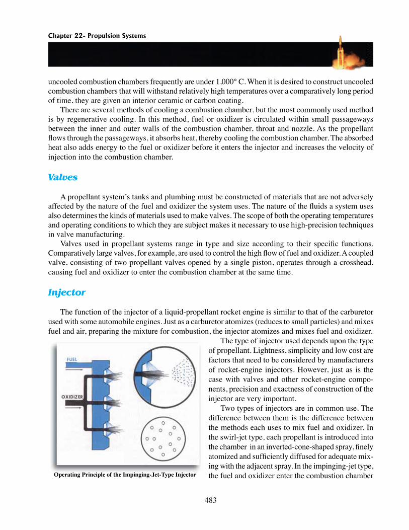
The function of the injector of a liquid-propellant rocket engine is similar to that of the carburetor used with some automobile engines. Just as a carburetor atomizes (reduces to small particles) and mixes fuel and air, preparing the mixture for combustion, the injector atomizes and mixes fuel and oxidizer.
The type of injector used depends upon the type of propellant. Lightness, simplicity and low cost are factors that need to be considered by manufacturers of rocket-engine injectors. However, just as is the case with valves and other rocket-engine compo-nents, precision and exactness of construction of the injector are very important.
Two types of injectors are in common use. The difference between them is the difference between the methods each uses to mix fuel and oxidizer. In the swirl-jet type, each propellant is introduced into the chamber in an inverted-cone-shaped spray, finely atomized and sufficiently diffused for adequate mix-ing with the adjacent spray. In the impinging-jet type, the fuel and oxidizer enter the combustion chamber Operating Principle of the Impinging-Jet-Type Injector
484
directly through openings arranged in such a way that the streams of fuel and oxidizer strike each other (impinge on one another). Their collision causes the required atomization and mixing.
Improved injection systems have contributed to the development of throttleable (variable control) liquid-propellant engines. One such system mixes, in a specially designed manifold, gas under high pressure with liquid fuel before it is injected into the combustion chamber. Depending on the ratio of gas to liquid fuel, the engine may be throttled from a low to a full thrust, and may be stopped and started in flight.
Hybrid Propellants
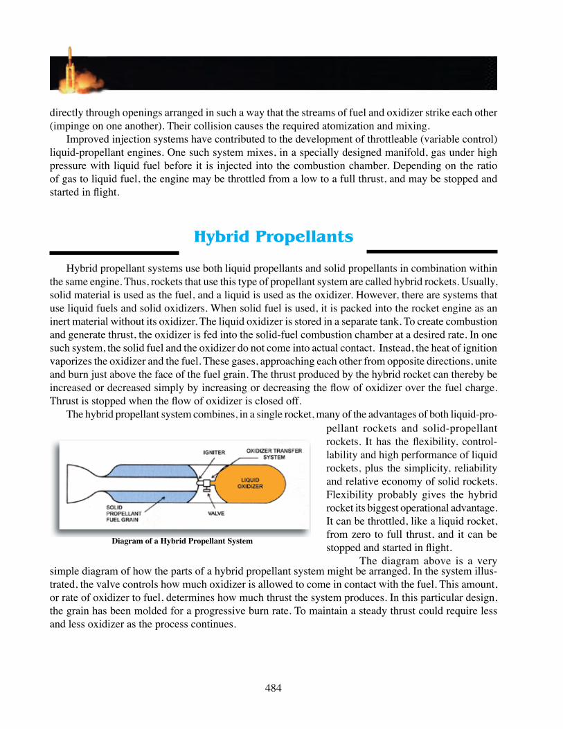
Hybrid propellant systems use both liquid pro pellants and solid propellants in combination within the same engine. Thus, rockets that use this type of propellant system are called hybrid rockets. Usually, solid material is used as the fuel, and a liquid is used as the oxidizer. However, there are systems that use liquid fuels and solid oxidizers. When solid fuel is used, it is packed into the rocket engine as an inert material without its oxidizer. The liquid oxidizer is stored in a separate tank. To create combustion and generate thrust, the oxidizer is fed into the solid-fuel combustion chamber at a desired rate. In one such system, the solid fuel and the oxidizer do not come into actual contact. Instead, the heat of ignition vaporizes the oxidizer and the fuel. These gases, approaching each other from opposite directions, unite and burn just above the face of the fuel grain. The thrust produced by the hybrid rocket can thereby be increased or decreased simply by increasing or decreasing the flow of oxidizer over the fuel charge. Thrust is stopped when the flow of oxidizer is closed off.
The hybrid propellant system combines, in a single rocket, many of the advantages of both liquid-pro-pellant rockets and solid-propellant rockets. It has the flexibility, control-lability and high perform ance of liquid rockets, plus the simplicity, reliability and relative economy of solid rockets. Flexibility probably gives the hybrid rocket its biggest opera tional advantage. It can be throttled, like a liquid rocket, from zero to full thrust, and it can be stopped and started in flight.
The diagram above is a very simple diagram of how the parts of a hybrid propellant system might be arranged. In the system illus-trated, the valve controls how much oxidizer is allowed to come in contact with the fuel. This amount, or rate of oxidizer to fuel, determines how much thrust the system produces. In this particular design, the grain has been molded for a progressive burn rate. To maintain a steady thrust could require less and less oxidizer as the process continues.
Diagram of a Hybrid Propellant System

Chapter 22- Propulsion Systems
485
AEROSPACE PROPULSION TECHNOLOGYSince the invention of the first heavier-than-air flying vehicle, designers, builders, pilots, war plan-
ners and commercial airlines have sought aircraft capable of higher and higher speeds. The requirements for faster vehicles have changed significantly since the early years of flight and the technologies used to achieve high speeds are undergoing significant advances.
The Air Force Laboratory’s Propulsion Directorate has been the key national organization to develop and demonstrate these technolo-gies. Since 1917, the Directorate and its predecessor organizations have been developing critical propulsion technologies, which have in turn, enabled revolution-ary advances for the country’s armed forces.
Aerospace Propulsion Technologies Defined
What are Aerospace Pro-pulsion Technologies? Simply put – these are propulsion sys-tems that utilize fuel and atmo-spheric oxygen for fuel combus-tion throughout all or part of their
Curtis V2-3 as used in WWI aircraft (courtesy of the Air Force Museum)
intended flight regime. Called air breathers, these propulsion systems are capable of at least Mach 5 and are categorized as hypersonic. These engines can range from single propulsion systems with single or dual mode combustion schemes up to multiple or combined cycle systems for multiple propulsion cycles with high speed turbines, scramjets, and rockets.
This publication focuses on current and future efforts to realize true, high speed endo-atmospheric flight, and specifically covers our efforts to develop and demonstrate high speed air-breathing propul-sion systems. As the graph below indicates, enormous potential exists to expand the flight envelope of high speed air-breathing propulsion.
Hypersonic Airbreathing Propulsion Requires Advances in the Current State-of-the-Art. Only by advancing the state-of-the-art in turbine engine, ramjet/scramjet, and rocket technologies can true aerospace propulsion systems be realized.
AFRL’s Propulsion Directorate leads the nation in the development of these critical technolo-gies. Teaming with other government agencies and the propulsion industry at large, the Directorate has ensured technology research and development programs that address all technical challenges of aerospace propulsion systems.
486
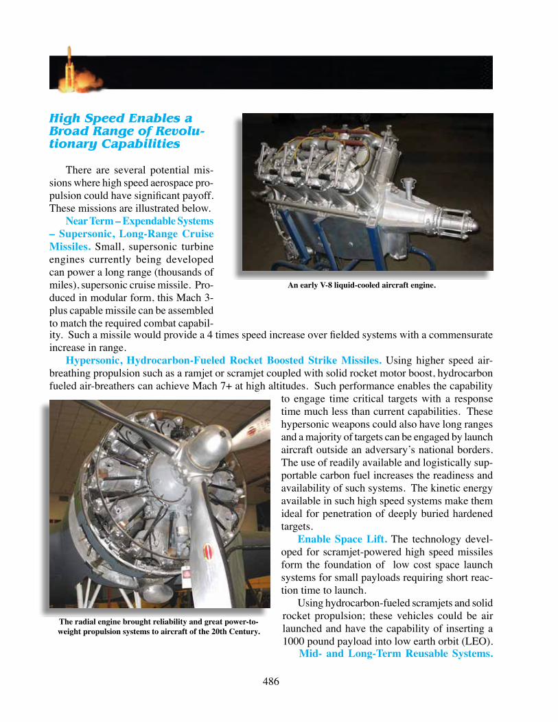
An early V-8 liquid-cooled aircraft engine.
High Speed Enables a Broad Range of Revolu-tionary Capabilities
There are several potential mis-sions where high speed aerospace pro-pulsion could have significant payoff. These missions are illustrated below.
Near Term – Expendable Systems – Supersonic, Long-Range Cruise Missiles. Small, supersonic turbine engines currently being developed can power a long range (thousands of miles), supersonic cruise missile. Pro-duced in modular form, this Mach 3-plus capable missile can be assembled to match the required combat capabil-ity. Such a missile would provide a 4 times speed increase over fielded systems with a commensurate increase in range.
Hypersonic, Hydrocarbon-Fueled Rocket Boosted Strike Missiles. Using higher speed air-breathing propulsion such as a ramjet or scramjet coupled with solid rocket motor boost, hydrocarbon fueled air-breathers can achieve Mach 7+ at high altitudes. Such performance enables the capability
to engage time critical targets with a response time much less than current capabilities. These hypersonic weapons could also have long ranges and a majority of targets can be engaged by launch aircraft outside an adversary’s national borders. The use of readily available and logistically sup-portable carbon fuel increases the readiness and availability of such systems. The kinetic energy available in such high speed systems make them ideal for penetration of deeply buried hardened targets.
Enable Space Lift. The technology devel-oped for scramjet-powered high speed missiles form the foundation of low cost space launch systems for small payloads requiring short reac-tion time to launch.
Using hydrocarbon-fueled scramjets and solid rocket propulsion; these vehicles could be air launched and have the capability of inserting a 1000 pound payload into low earth orbit (LEO).
Mid- and Long-Term Reusable Systems.
The radial engine brought reliability and great power-to- weight propulsion systems to aircraft of the 20th Century.

Chapter 22- Propulsion Systems
487
Sir Frank Whittle’s first jet engine. He personally provided the funds to patent this propulsion system and is credited with being the inventor of
the first working jet engine prototype.
While expendable high speed propulsion systems can take us through the en-tire ground-to-orbit flight regime, the most significant pay off will be realized from reusable high speed systems. That will allow frequent and reliable, high speed flight for systems ranging from global range, high speed reconnaissance vehicles to orbit – capable platforms.
Significant advances in materials and manufacturing processes must be made to build vehicle and propulsion systems capable of withstanding the severe environment presented by hypersonic flight.
Cutaway Axial Flow Turbojet Engine of the ’60s.
Advanced thermal pro-pulsion systems and air frame structures must be developed. Vehicles in this class will operate much like military and commer-cial aircraft of today. They will take off and land from conventional runways.
Affordable, Reliable, Responsive Access to Space. The ultimate ex-pression of aerospace pro-pulsion technology com-bines scramjets with high speed turbines and rockets to form combined cycle engines capable of propel-ling a vehicle from take-off into low earth orbit. Such vehicles will have numer-
ous advantages over pure rocket powered vehicles. They could operate from conventional runways and possess the ability to abort missions at any time during the mission flight profile. Because of this characteristic, a combined cycle vehicle offers a much faster operational tempo over current launch systems. This reduction in the cost of putting payloads in orbit leads to an enormously greater flexibility in the launching and utilization of space-based assets for both military and civil needs.

488
How Do Aerospace Propulsion Systems Provide Transformational Capabilities?
The Air-Breathing Advantage. The advantage of air-breathing hypersonic propulsion systems stem from the fact that they obtain oxygen for combustion from the earth’s atmosphere. Unlike pure rocket-powered vehicles, the resultant vehicle does not have to carry the oxygen inside the vehicle.
Higher Propulsion Efficiency (Isp). Propulsion efficiency, designated Isp, is defined as the ratio of an engines thrust to the weight of fuel burned in one second. The higher the number, the more efficient the propulsion system. High bypass turbofan engines have the highest specific impulse that are capable of only modest velocities. High speed turbojets can generate appreciable velocities and the chart curves indicate the practical limits of pure turbo propulsion. Ramjets and scramjets take the Mach range out much further and using hydrogen as a fuel can theoretically accelerate a vehicle to Mach 25.
Improved Mass Fractions. With higher propulsive efficiency, more of the flight vehicle can be dedicated to performing mission requirements. This is typically defined as the vehicle systems mass fractions. As an example, a typical unmanned rocket powered launch vehicle has a mass fraction of about 10%. That means 90% of the vehicles total launch weight is made up of propellant. If scramjets were used as the primary propulsive system for a space launch vehicle, up to 28% of the vehicle weight could be dedicated to mission requirements, or over twice that of a conventional all-rocket powered launch vehicle.
America’s First Operational Jet Fighter, the Bell P-59 Airacomet. (USAF Photo)
Airplane-Like Design and Flight Characteristics. Using air-breathing propulsion for space access systems allows vehicles to be designed that operate like airplanes while in the atmosphere. This advantage allows for greater margin of safety in space launch vehicles whereby the mission can be ter-minated at practically any point of the flight profile (unlike a pure rocket, which has limited mission termination margin.) Vehicles can be made smaller and lighter for a given payload. This reduces the amount and cost of support infrastructure necessary to sustain flight operations.
Earth-orbit capable systems can be made to operate more like aircraft and be truly reusable, thus increasing the frequency and reliability of space launch.

Chapter 22- Propulsion Systems
489
X-15, the First True Aerospace Plane. (NASA photo)
High Speed Propulsion Technology Challenges
The ultimate propulsion technology for high speed flight will combine the best of turbo machinery, ramjet, scramjet and rocket propulsion. When combined into one vehicle, such a propulsion system will enable systems to deliver unprecedented capabilities for swift delivery of munitions for time criti-cal targets. Such a system will also create rapid response expendable space launch for small payloads’ long range strike and reconnaissance; and low cost reliable, affordable and frequent access to space. To deliver such capabilities requires advances in all three firms of propulsion.
Turbine and rocket propulsion have proven their value operationally for over half a century. Super-sonic combustion ramjets represent an emerging technology. These high speed air-breathing engines are the key to enabling the many advanced capabilities of aerospace propulsion.
Ramjets-A Building Block for the Scramjet. Ramjets were postulated in the first half of the 20th century and flew as early as the 1930’s. A ramjet engine can be thought of as a long duct mounted to a supersonic vehicle in a suitably aerodynamically efficient manner. Incoming air enters the front of the engine and passes straight through and out the rear without the use of any rotating parts inside the flow path. The flow path essentially is open all the way through from front to back. The air is fun-neled and compressed – or rammed – into the engine inlet by the forward motion of the vehicle and by the shape of the front section of the ramjet. Once inside the engine, the air mixes with the injected fuel that is introduced part way along the flow path, and the oxygen in the air combines with the fuel and this provides ignition. The resultant hot gas exits out the rear of the engine to produce the needed thrust for the vehicle.
Since a ramjet relies on the forward motion of the vehicle to provide the needed compression of the air, some kind of booster or low speed engine is needed to acceler-ate the vehicle to the point where the ramjet can take over. The ramjet becomes effective only at speeds above Mach 2.
Once in operation, the ramjet is effective up to speeds of about Mach 5. Above this speed, ramjets start to lose efficiency for several reasons. It is necessary to change its mode of operation into that of a supersonic combustion ramjet, which is usable to much higher speeds. The next step involves scramjet technology.
Scramjets – Bridging the Speed Gap. The basic difference between a ramjet and a scramjet is

490
that in a scramjet, the air is allowed to exceed sonic (Mach 1) speed inside the engine. Like the ramjet, a scramjet is a visually simple ma-chine. There are no moving parts in the flow path. The look, however, belies a complexity that is presented to engine designers when speeds significantly increase. In fact, the higher the speed, the tougher the problem.
There are several major chal-lenges faced by the aerospace pro-pulsion developers. By focusing ini-tial development on missile-sized, expendable scramjets, significant progress has been made to overcome these challenges and to establish a solid technical base to extend toward large, reusable systems.
An exoatmospheric propulsion system
The problem of mixing and burning the fuel in a supersonic flow. Lighting a match in a hurricane is easy compared to the problem of mixing and burning propellant in a scramjet. In a scramjet, the time required for mixing of the fuel with the incoming air and combusting it to produce thrust is rough-ly one millisecond or less. If not accom-plished in this very short time, the reactions are likely to be quenched as the flow expands in the nozzle, greatly reducing thrust.
Survivable engine structures. The heat of scramjet operation is extremely high and requires innovative and robust structures. Materials must be high temperature capable and lightweight while maintaining the abil-ity to preserve the critical geometry required for efficient flow path operation. Using fuel to cool combustion components has been commonplace in rocket engines for decades. The combination of pressure and temperature in a reusable rocket combustion chamber is The legendary SR -71 use ramjet technology to reach
and sustain Mach 3. (NASA photo)

Chapter 22- Propulsion Systems
491
required to maintain structural integrity of the engine. For much the same reason, a scramjet re-quires a fuel cooled structure and, in fact, requires more cooling because the run time for a reusable scramjet is longer than typical for rocket propul-sion. Knowing how much fuel to use, the exact pressures and volumes, and at what locations is a challenging problem for high speed propulsion systems.
Fuels Technology. Fuel is the lifeblood of any propulsion system. For scramjets, the fuel plays a dual role – cooling the engine structure and pro-viding the combustion energy to produce thrust. Choosing the right fuel is difficult. On the one hand, we need the highest available energy for the combustion process. Hydrogen, the simplest fuel
A Fighter for the 21st Century—The F-22 Raptor (USAF photo)
Pratt & Whitney Rockedyne’s State- of-the-Art Rocket Propulsion System
has the highest energy and also the highest ability to absorb heat; however, it is volumetrically inef-ficient – it takes a large tank to hold the hydrogen. Larger tanks mean larger structures, which mean larger vehicles and the circle keeps on widening. Cryogenic hydrogen also requires insulation of the fuel tank, further reducing volumetric efficiency. Hydrocarbon fuels also have a lower rate of heat absorption.
Variable Geometry Inlet and Nozzle for Turbine and Scramjet Flow Paths. Scramjets need an inlet design that keeps the air flow supersonic. To operate over a broad range of mach numbers, scramjet inlets may require variable geometry. This represents a challenge in several ways: it adds complexity and weight to the vehicle, and the forces impinging on this variable geometry are enormous at hyper-sonic speeds requiring robust materials and control systems. The same challenges apply to variable geometry nozzles.
The major technical challenges for combined cycle engines include:Airframe/Engine Integration.Integrating the propulsion system with the airframe has been an important technical necessity

492
for many decades. Pis-ton engine-powered craft worked best when the frontal area of the air-craft could be reduced or at least streamlined to reduce the drag on the vehicle. The same problem was encountered at a more serious level with the introduction of the jet engine. In today’s turbine-powered world, engine/airframe integra-tion is a concept used to ensure the highest perfor-mance and reliability of the turbine engine.
X-43A Mission Profile (NASA illustration)
In a hypersonic vehicle, this integration is so pronounced and critical that the airframe and engine are essentially blended. Many hypersonic vehicle concepts look very much the same. The reason is that the physical rules for hypersonic flight dictate designs such as is shown above where the front of the vehicle, in conjunction with a shock wave, forms the intake of the engine. The “engine” module is where the fuel is injected and combustion takes place while the rear of the vehicle forms the ex-haust nozzle to allow for complete expansion of the combustion process. The aerothermodynamic performance cannot be decoupled from the propulsion performance since both share surfaces and the flow fields interact. In essence, we no longer look at an engine simply as a part that is mounted to the airframe, but rather as part of a complete aircraft system, the components of which must be designed in complete concert which each other.
Variable Geometry Inlet and Nozzle for Turbine and Scramjet Flow Paths. Advanced turbine engines are capable of speeds from Mach number zero (Mn0) to near hypersonic speeds (Mn4+) de-pending on the engine cycle chosen. Inlets for turbine engines are designed to keep the incoming flow at subsonic velocity. Scramjets are designed to operate with supersonic flows throughout the engine. Therefore, the inlet must have variable geometry to satisfy both propulsion cycles, bringing the com-plexity and need for robust control systems.
Integrated Scramjet/Rocket Nozzles. In order to generate thrust efficiency, the engine exhaust must be expanded through a nozzle. The challenge is designing a nozzle that provides near optimal expansion for the two different propulsion systems over a broad range of Mach numbers.
Low Drag Scramjet Injectors with Internal Rockets. A combined cycle powered vehicle has the potential to fly into orbit. At hypervelocity speeds (Mn15+), the energy of the flow begins to approach the energy of combustion. Any internal drag subtracts from the output of the engine in the airbreath-ing mode. Therefore, a fuel injection stream that allows for complete mixing and combustion at the velocities is required.
Chapter 22- Propulsion Systems
493
Thermal Management. A vehicle powered by combined cycle engines accelerating to orbital ve-locity spend a far longer time in the atmosphere than a pure rocket-powered vehicle, which “punches” straight through the atmosphere as quickly as possible. Because of this long residence time in the atmosphere, the vehicle will experience extreme thermal loads throughout. Managing this energy is critical to vehicle operation and, indeed, survival. A complete knowledge of the aerodynamic heat-ing coupled with the heat generated through high speed turbine and scramjet combustion is required. Heat resistant materials capable of surviving the dynamic loads must be developed for both engine and airframe components. How the latent energy of the fuel is used is also part of the thermal balance equation and must be done correctly and efficiently for a hypervelocity airbreathing propulsion system to become a reality.
High Heat Sink Fuels and Actively Cooled Structures. The temperatures experienced in very high speed airbreathing engines exceed the limits of even the best high temperature materials. To pre-serve their structural integrity, these materials must be actively cooled. The most efficient way to cool these structures is by circulating the fuel through them prior to the fuel be used for combustion. Fuel characteristics play a critical role in the thermal management scheme. Ideally, the fuel should be en-dothermic. That is, have the ability to absorb the heat energy of combustion thereby cooling the engine walls. During the process of absorbing the energy, an endothermic fuel breaks down chemically into simpler, combustible species, which can be mixed and burned more rapidly than the complete fuel.
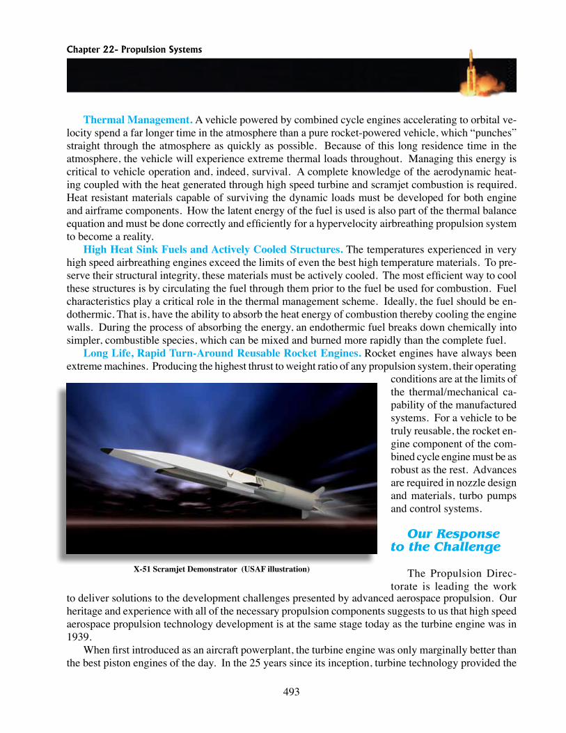
Long Life, Rapid Turn-Around Reusable Rocket Engines. Rocket engines have always been extreme machines. Producing the highest thrust to weight ratio of any propulsion system, their operating
X-51 Scramjet Demonstrator (USAF illustration)
conditions are at the limits of the thermal/mechanical ca-pability of the manufactured systems. For a vehicle to be truly reusable, the rocket en-gine component of the com-bined cycle engine must be as robust as the rest. Advances are required in nozzle design and materials, turbo pumps and control systems.
Our Response to the Challenge
The Propulsion Direc-torate is leading the work
to deliver solutions to the development challenges presented by advanced aerospace propulsion. Our heritage and experience with all of the necessary propulsion components suggests to us that high speed aerospace propulsion technology development is at the same stage today as the turbine engine was in 1939.
When first introduced as an aircraft powerplant, the turbine engine was only marginally better than the best piston engines of the day. In the 25 years since its inception, turbine technology provided the

494
U.S. Air Force with revolutionary, high speed capabilities and holds even more promise as a critical component of advanced aerospace systems.
By using focused research and technology demonstrations, a technological revolution can begin that will transform the Air Force by providing a series of capabilities far beyond what we have today.
High Speed Today. After literally decades of scientific work, the Propulsion Directorate stands ready to begin the revolutionary change in capabilities for our national defense. The development and demonstration of the hydrocarbon fueled and cooled scramjet will introduce the first component of a radically improved aerospace capability.
High Speed 2034. In the future, we’ll see a natural outgrowth of this early scramjet development maturing into aerospace propulsion systems capable of delivering routine, reliable access to any part of the earth in minutes.
To realize the future, the Propulsion Directorate is taking a stair step approach. This approach will add new capabilities on a planned, incremental basis by taking advantage of the high speed aerospace propulsion technologies as they can be demonstrated. Three propulsion system types form the backbone of this approach; small scram jets, medium scram jets and finally, combined cycle engines.
The first step will demonstrate the small scramjet currently being developed for a flight test vehi-cle called the X-51 Scramjet Engine Demonstrator or SED. Boosted by an available solid propellant rocket, the scramjet will take over the flight at Mach 4-plus and accelerate the vehicle to a cruising speed of over Mach 7.
The Directorate is well along the road to providing the propulsion system for this vehicle. We have demonstrated an engine flow path that provides significant positive thrust in a wind tunnel at Mach numbers 4.5 and 6.5. This engine, in its current form, is known as the Ground Demonstrator Engine, or GDE. It incorporates such features as a 2D inlet, 2D scramjet combustor, endothermic fuel-cooled metallic engine and uncooled Carbon/Silicon Carbide.
Part of step one will be to missionize the expendable scramjet into a hypersonic cruise missile. Such a missile, with a maximum speed of Mach 7 flying at over 100,000 feet altitude, will have few, if any, threats to successful mission accomplishment. With a range of well over 500 miles and transit times measured in minutes, these missiles can be employed against tactical and strategic targets. Their speed enables two important capabilities. The first is to destroy time sensitive targets from very long ranges. The second capability is the missile’s ability to deliver high kinetic energy to destroy a hardened target. In addition, such weapons could be employed against 95% of strategic and tactical targets without the launch aircraft ever crossing an adversary’s border.
Step two is to take the proven flow paths of the small scram jets and scale them up to medium size engines for expandable space lift vehicles. Such launch vehicles would capitalize on the high efficiency of air-breathing propulsion combined with advanced rocket propulsion to provide an on-demand capa-bility for placing small payloads into low earth orbit.
Step three involves the much more difficult but very high payoff of development of the combined cycle propulsion system. Propulsion systems using a combination of turbine, ramjet, scramjet and rocket propulsion will engender radical capabilities when compared to our current state-of-the-art.
In 20 to 25 years aerospace vehicles using conventional runways will be able to conduct global range reconnaissance and precision strike missions on a frequent “sortie” basis.
With the addition of advanced rocket propulsion to the combined cycle system, airplane-like vehicles that are completely reusable will be able to perform multiple missions on a routine basis. Low-earth
Chapter 22- Propulsion Systems
495
orbit using conventional runways as their bases of operations will be possible. These vehicles will likely be two-stage-to-orbit and will combine high speed turbine accelerators, turbo-ramjets, scram jets and advanced liquid rocket engines to provide almost immediate and frequent access to space for military missions. Such vehicles will not only revolutionize the military missions but commercial space launch as well. (This feature was generously provided for publication to the Civil Air Patrol by the Air Force Research Laboratory, Wright Patterson Air Force Base, Ohio)
HIGH ENERGY PROPULSION SYSTEMS
Current Technology Feature — The Pratt & Whitney CECE Rocket Engine
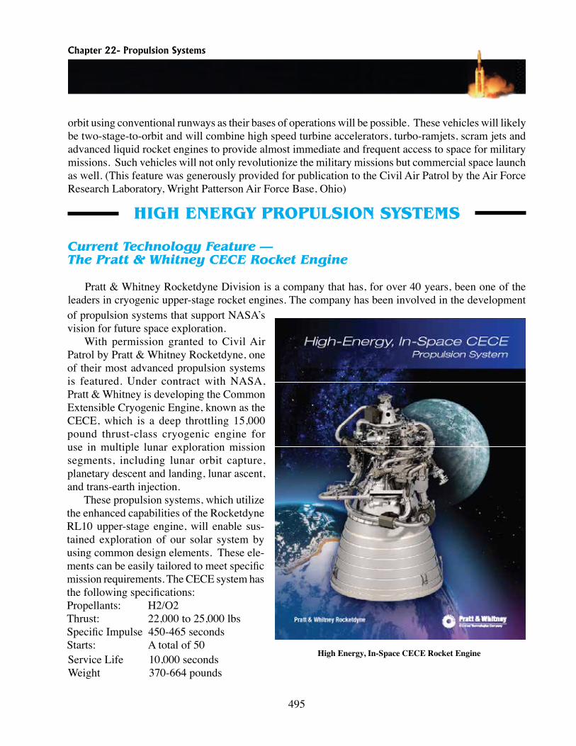
Pratt & Whitney Rocketdyne Division is a company that has, for over 40 years, been one of the leaders in cryogenic upper-stage rocket engines. The company has been involved in the development of propulsion systems that support NASA’s vision for future space exploration.
With permission granted to Civil Air Patrol by Pratt & Whitney Rocketdyne, one of their most advanced propulsion systems is featured. Under contract with NASA, Pratt & Whitney is developing the Common Extensible Cryogenic Engine, known as the CECE, which is a deep throttling 15,000 pound thrust-class cryogenic engine for use in multiple lunar exploration mission segments, including lunar orbit capture, planetary descent and landing, lunar ascent, and trans-earth injection.
These propulsion systems, which utilize the enhanced capabilities of the Rocketdyne RL10 upper-stage engine, will enable sus-tained exploration of our solar system by using common design elements. These ele-ments can be easily tailored to meet specific mission requirements. The CECE system has the following specifications:Propellants: H2/O2Thrust: 22,000 to 25,000 lbsSpecific Impulse 450-465 secondsStarts: A total of 50Service Life 10,000 secondsWeight 370-664 pounds
High Energy, In-Space CECE Rocket Engine
496
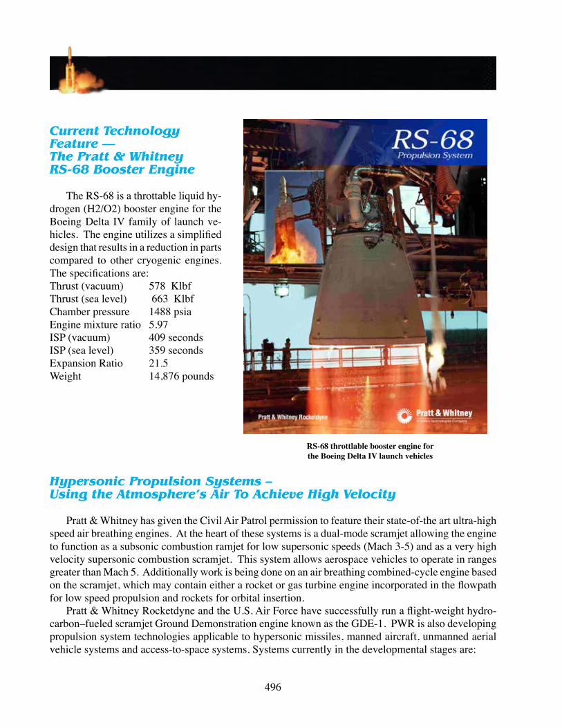
Current Technology Feature —The Pratt & Whitney RS-68 Booster Engine
The RS-68 is a throttable liquid hy-drogen (H2/O2) booster engine for the Boeing Delta IV family of launch ve-hicles. The engine utilizes a simplified design that results in a reduction in parts compared to other cryogenic engines. The specifications are:Thrust (vacuum) 578 KlbfThrust (sea level) 663 KlbfChamber pressure 1488 psiaEngine mixture ratio 5.97ISP (vacuum) 409 secondsISP (sea level) 359 secondsExpansion Ratio 21.5Weight 14,876 pounds
RS-68 throttlable booster engine for the Boeing Delta IV launch vehicles
Hypersonic Propulsion Systems – Using the Atmosphere’s Air To Achieve High Velocity
Pratt & Whitney has given the Civil Air Patrol permission to feature their state-of-the art ultra-high speed air breathing engines. At the heart of these systems is a dual-mode scramjet allowing the engine to function as a subsonic combustion ramjet for low supersonic speeds (Mach 3-5) and as a very high velocity supersonic combustion scramjet. This system allows aerospace vehicles to operate in ranges greater than Mach 5. Additionally work is being done on an air breathing combined-cycle engine based on the scramjet, which may contain either a rocket or gas turbine engine incorporated in the flowpath for low speed propulsion and rockets for orbital insertion.
Pratt & Whitney Rocketdyne and the U.S. Air Force have successfully run a flight-weight hydro-carbon–fueled scramjet Ground Demonstration engine known as the GDE-1. PWR is also developing propulsion system technologies applicable to hypersonic missiles, manned aircraft, unmanned aerial vehicle systems and access-to-space systems. Systems currently in the developmental stages are:

Chapter 22- Propulsion Systems
497
HySET (Hydrocarbon Scramjet Engine Tech-nology) – is a three-phase program sponsored by the U.S. Air Force to develop and demonstrate a Mach 4-8 hydrocarbon-fueled scramjet propulsion system. Addi-tionally, the program will serve as a stepping stone to developing a family of hypersonic vehicles, such as air-to-surface missiles, access-to-space systems and global strike/reconnaissance systems.
SED-WR (Scramjet Engine Demonstrator -Wave Rider) – The U.S. Air Force Research Labora-tory selected PWR and the Boeing Phantom Works to flight-test the SED-WR. The team is exploring the air-breathing system-level po-tential of scramjets through multiple flight tests.
Scramjet Powered X-51 Mounted Under Wing Of B-52 Carrier Aircraft

498
nOxidationn reducernoxidizerncryogenicsnpropellantnbipropellantnmonopropellantn self-reacting compoundncombustionn ignition characteristicsn low explosiven solid propellantsn liquid propellantsncompoundsncrystalline
nprogressive burn raten regressive burn raten ignitersngrainnnonhypergolicnhypergolicncatalystncombustion chambernatomizingncoupled valven swirl-jet typen impinging-jet typenhybrid propellantnhybrid rockets
SELECT THE CORRECT ANSWER
1. To use it in its pure form as an (oxidizer / reducer), oxygen must be (chilled / heated) until it becomes a (liquid / gas).2. A (neutral, progressive, regressive) burn rate design was used in the Space Shuttle’ solid rocket boosterstoprovidemaximumthrustinthefirstfewsecondsoflaunch.3. Generally, (mono- / bi-) propellants require more heat for ignition and react more slowly than (mono- / bi-) propellants.4. The majority of liquid-propellant rockets use the (mono- / bi-) propellant arrangement.5. (Motor / engine) is usually associated with (liquid / solid) propellants.6. Solid propellants are sometimes called (low / slow) explosives.
FILL IN THE BLANKS
7. Rustandcorrosion,aburningfireandaviolentexplosionareallexamplesof______________, thecombinationof_____________with_________________.

Chapter 22- Propulsion Systems
499
8. The propellant substance is molded into its motor and casing as a single solid mass called _______________.9. ______________ is the science concernedwith the production of low temperatures and the effects of those temperatures on matter.10. Bi-propellantsaretwotypes—_________________(non-self-igniting)and________________ (self-igniting).11. A______________,consistingoftwopropellants__________openedbyasinglepiston,operates
througha____________,causingbothfuelandoxidizertoenterthe_____________________ _______________atthesametime.12. Which is not a solid propellant rocket mentioned in the text?
a. Submarine launched ballistic missileb. Minuteman intercontinental ballistic missilec. The main engines for the space shuttled. The MX (Peacekeeper) missile
13. Which is not a drawback to liquid chemical systems?a. Their requirement for expensive plumbing,b. Expensive turbines,c. Expensive pumps and enginesd. Costly igniters
MATCHING
14. Match the terms with their correct definitions:a. Propellant (1) Separate storage tanks are not required b.Bipropellant (2)Moleculescontainatomsofbothoxidizerandreducerc.Monopropellant (3)Requiresseparatestoragetanksforoxidizerandreducer
d.Self-reactingcompound(4)Asinglereferencetotheoxidizerandreducer
TRUE OR FALSE
15. Nothing is gained or lost in an oxidation.16. Solid propellants are more costly and less reliable than liquid propellants.17. Controllingthethrustofasolidpropellantmotorismoredifficultthancontrollingthethrustof
a liquid propellant engine.18. The phases in proper order in a combustion chamber are atomizing, preheating, mixing and the reaction of the propellant.19. It is possible to stop thrust in a solid propellant rocket.
SHORT ANSWER
20. What are the four qualities of a good propellant?21. How can the amount of thrust produced by a solid propellant engine be controlled?22. Describe a squib. What type of propellant is it used with?