protection of medium- sized and large generators with ... and large generators with siprotec 7um6...
TRANSCRIPT

Siemens PTD EA · Applications for SIPROTEC Protection Relays · 2005 1
Generator Protection
Protection of Medium-Sized and Large Generatorswith SIPROTEC 7UM6
Fig. 2 Block diagram of generator protection
Fig. 1 SIPROTEC generator protection
1. IntroductionMedium-sized and large generators make a majorcontribution to power generation. They carry thebasic load and ensure the stability of an energysystem.
The task of electrical protection in these systems isto detect deviations from the normal conditionand to react according to the protection conceptand the setting. Based on experience with largerpower station units, cost-effective protection con-cepts can also be implemented with SIPROTECrelays for medium-sized generators.
The scope of protection must be in reasonable re-lation to the total system costs and the importanceof the system.
2. Basic connectionsIn medium-sized and large power stations thegenerators are operated exclusively in unitconnection.
In the unit connection the generator is linked tothe busbar of the higher voltage level via a trans-former. In the case of several parallel units, thegenerators are electrically isolated by the trans-formers. A circuit-breaker can be connected be-tween the generator and the transformer(see Figs. 2 and 3).
Generator Protection
Siemens PTD EA · Applications for SIPROTEC Protection Relays · 20052
3. Protection conceptComponents of the protection concept are:
The redundancy concept The tripping concept Protection function scope
3.1 Redundancy conceptThe redundancy concept is crucial in the design ofprotection systems. Many concepts are based onthe n-1 principle. That means that the failure of acomponent is under control and does not lead to atotal system failure. However, this principle is notalways applied consistently. In smaller systemsthere is a compromise between redundancy andcosts. The following strategies are common inpractice for medium-sized and large generators.
Partial redundancy (see Fig. 4)
At least 2 protection relays are used here. The pro-tection relays/functions are selected so that thesystem can continue to operate when a relay fails.However, certain restrictions have to be accepted.This system design is seldom used in high-powergenerators. The protection is connected to thesame transformers for example.
Full redundancy (see Fig. 5)
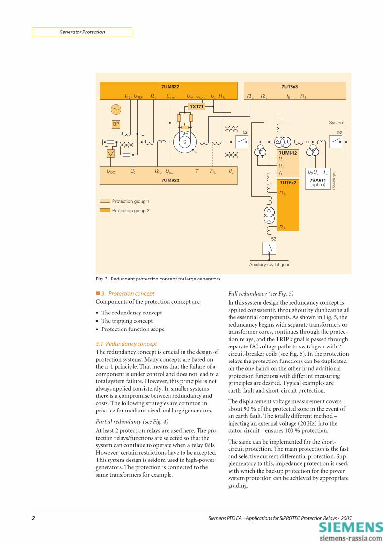
In this system design the redundancy concept isapplied consistently throughout by duplicating allthe essential components. As shown in Fig. 5, theredundancy begins with separate transformers ortransformer cores, continues through the protec-tion relays, and the TRIP signal is passed throughseparate DC voltage paths to switchgear with 2circuit-breaker coils (see Fig. 5). In the protectionrelays the protection functions can be duplicatedon the one hand; on the other hand additionalprotection functions with different measuringprinciples are desired. Typical examples areearth-fault and short-circuit protection.
The displacement voltage measurement coversabout 90 % of the protected zone in the event ofan earth fault. The totally different method –injecting an external voltage (20 Hz) into thestator circuit – ensures 100 % protection.
The same can be implemented for the short-circuit protection. The main protection is the fastand selective current differential protection. Sup-plementary to this, impedance protection is used,with which the backup protection for the powersystem protection can be achieved by appropriategrading.
Fig. 3 Redundant protection concept for large generators

Siemens PTD EA · Applications for SIPROTEC Protection Relays · 2005 3
Generator Protection
3.2 Tripping conceptThe special feature of generator protection is thatdifferent switching devices have to be activated de-pending on the fault. The number is basically de-termined by the system/plant concept. As a rule,most of the switching devices need to be actuatedin the larger units. Special trippings are used inhydro-electric power stations.
Fig. 6 shows the basic concepts. On one side thereare the switching devices to be actuated and on theother side the connected protection functions.The tripping program or tripping concept de-pends on the recommendations/experiences andthe operating conditions. There are two opposingphilosophies. The tripping program is determinedindividually by a tripping matrix (a software ma-trix in digital technology) and the switching de-vices are activated directly. The other (American-influenced) variant reduces the tripping to twoprograms, e.g. exclusive shutdown of the gener-ator and shutdown of the power station unit.Lockout relays are used to control the switchingdevices. The protection needs only a few trip con-tacts.
3.3 Protection function scopeNumerous protection functions are necessary forreliable protection of electrical generators. Thescope and the combination are determined byvarious factors such as generator size, operatingprinciple, system design, availability requirements,experiences and philosophies. This automaticallyleads to a multifunctionality which can be con-trolled excellently by numerical technology.
The function matrix is scalable to meet different re-quirements (see Table 1).
The selection simplifies division intoobject and application-related groups.
Fig. 4 Example: Partial redundancy
Fig. 6 Protection tripping by the matrix
Generator circuit-breaker De-excitation switch Turbine valve closing System switch Auxiliaries switch 1 Auxiliaries switch 2 Auxiliaries transfer Spray water system, unit transformer Spray water system, station-service trans-
former Backup Special trippings for hydropower
(e.g. braking)
Fig. 5 Example: Full redundancy

Siemens PTD EA · Applications for SIPROTEC Protection Relays · 20054
Generator Protection
A function selection taking redundancy intoconsideration is shown in Table 2.
Protection group A(System 1, 7UM622)
Protection group B(System 2, 7UM622)
Stator earth-fault 100 % Stator earth-fault 90 %
Differential protection Differential protection (asunit protection)
Impedance Impedance
Rotor earth-fault Negative-sequence
Negative-sequence Underexcitation
Underexcitation Out-of-step
Overvoltage Stator overload
Frequency f >< Overvoltage
Reverse power Frequency f ><
Overexcitation Reverse power
Overexcitation
Table 2 Function selection for a redundancy concept
4. Protection functions and settingThe basic connection (Fig. 2) is considered for thesetting value calculation – with generator datafrom the Table 3. Manufacturer characteristics(e.g. power diagram) are necessary for some pro-tection settings. The physical backgrounds and theformulae for calculation are in the manual. Thesecondary setting values are shown.
Protection functions Generator rated power
5 - 50 MVA 50 - 200 MVA > 200 MVA
Stator earth-fault protection 90 %
Stator earth-fault protection 100 %
Differential protection
Overcurrent-time protection
Impedance protection
Rotor earth-fault protection
Negative-sequence(or load unbalance) protection
Underexcitation protection
Out-of-step protection
Stator overload protection
Rotor overload protection
Overvoltage protection
Frequency protection f >
Frequency protection f <
Reverse-power protection
Undervoltage protection
Overexcitation protection
Available Optional Pumped-storage station (motor protection and phase modifier operation)
Table 1 Recommended protection functions according to generator rated power

Siemens PTD EA · Applications for SIPROTEC Protection Relays · 2005 5
Generator Protection
Generator data
Rated voltage UN 15.75 kV ± 5 %
Rated apparent power (40 °C cold gas) SN 327 MVA
Circuit-breaker cos ϕ 0.8
Rated active power PN 261.6 MW
Rated current IN 12 kA
Rated frequency fN 50 Hz
Maximum overexcitation (U/f)max % from the manufacturer’s overexcitation characteristic
Permissible overexcitation duration t (U/f)max from the manufacturer’s overexcitation characteristic
Synchronous longitudinal reactance xd
(for drum rotor generators: xd = xq)264.6 %
Transient reactance xd1 29.2 %
Maximum exciter voltage Uexc-min 77 V
Maximum continuous permissible inverse current Imax prim / IN 10 %
Thermal continuous permissible primary current Imax / IN 1.2
Asymmetry factor (I2) K = (I2/IN)2 t 20 s
Current transformer Iprim Isec ü Target
Star-point sideT1, core 1T1, core 3
14 kA14 kA
1 A1 A
14 00014 000
System 1System 2
Busbar sideT2, core 1T2, core 3
14 kA14 kA
1 A1 A
14 00014 000
System 1System 2
110 kV sideT3, core 1 2 000 A 1 A 2 000 System 2
Earthing transformer Uprim Usec ü Target
T4; U0 15.75 kV/ 3 5 V/ 3 54.56 System 1
External voltagetransformer
Uprim Usec ü Target
Generator sideT5, UL1, UL2, UL3 15.75 kV/ 3 100 V/ 3 157.5 System 1, 2
Unit transformer dataVector group Ynd5
Total coupling capacity HV-LV Ck 14.4 nF (4.8 per phase)
Maximum overexcitation (U/f)max 120 %
Permissible overexcitation time t (U/f)max from the manufacturer’s overexcitation characteristic
Permissible overload Imax / IN from the manufacturer’s overexcitation characteristic
Winding Primary Secondary
Rated voltage UN 115 kV 15.75 kV
Rated apparent power SN 318 MVA 318 MVA
Rated current IN 1.596 kA 11.657 kA
Short-circuit voltage uSC 15 %
Control range of the tap changer ± 9 x 1.25 %
Table 3 Data of the power station unit with gas turbine

Siemens PTD EA · Applications for SIPROTEC Protection Relays · 20056
Generator Protection
4.1 Current differential protection(ANSI 87G, 87M, 87T)
The function is the instantaneous short-circuitprotection in generators, motors and transformersand is based on the current differential protectionprinciple (node set). The difference and restraint(stabilization) current is calculated from the phasecurrents. Optimized digital filters safely attenuatedisturbance variables such as aperiodic DC ele-ments and harmonics. The high resolution of themeasuring variables enables small difference cur-rents (10 % of IN) to be picked up, i.e. a very highsensitivity. A settable restraint characteristic al-lows optimum adaptation to the conditions of theprotected object.
Setting instructions
An important setting is the position of the starpoints of the current transformer sets on bothsides of the protected object. In addition, the rateddata (SN GEN/MOTOR, UN GEN/MOTOR) of the genera-tor to be protected and the primary and secondaryrated currents of the main current transformersare requested on both sides. The setting valuesrefer to these. In addition, they are used for exam-ple to determine the primary measured values.
As an additional security measure against unwant-ed operation when connecting a previously non-energized protected object, the increased pickupvalue can be switched on when starting up.
The table below shows the setting options ofselected parameters. The settings are relevant forthe generator and not for the unit (protectiongroup A).
4.2 Stator overload protection(ANSI 49)
The overload protection should protect the statorwinding of generators and motors against exces-sively high continuous current overloads. All loadcycles are evaluated by a mathematical model. Thebasis for the calculation is the thermal effect of thecurrent r.m.s. value. The transformation corre-sponds to IEC 60255-8.
Setting instructions
The cooling time constant is prolonged automati-cally, dependent on the current. If the ambienttemperature or coolant temperature is fed inthrough a transducer (MU2) or via thePROFIBUS-DP, the model automatically adaptsto the ambient conditions; otherwise a constantambient temperature is assumed.
The following table shows the setting options andthe setting example of important parameters(without taking the ambient or coolant tempera-ture into account).
Parameter Setting options Setting
k-factor 0.1 to 4.0 1.11
Thermal warninglevel
70 to 100 % 95 %
Current warninglevel
0.1 to 4.0 A 1.0 A
kt-time factor atstandstill
1.0 to 10.0 1.0
Limit current forthe thermal replica
0.5 to 8.0 A 3.30 A
Dropout time afteremergency start
10 to 15000 s 100 s
Table 5 Parameter overview for the stator overloadprotection
The setting ranges and presettings (defaults) arespecified for a secondary rated current of IN = 1 A.At a secondary rated current of IN = 5 A, these va-lues must be multiplied by 5. The ratio of the cur-rent transformer must be taken into accountadditionally for settings of primary values.
Parameter Setting options Default *)
Pickup value of the tripstage Idiff>
0.05 to 2.0 I/INObject 0.2 I/INObject
Delay of the trip stageIdiff>
0 to 60.0 s; ∞ 0.00 s
Pickup value of the tripstage Idiff>>
0.05 to 12.0 I/INObject 7 I/INObject
Delay of the trip stageIdiff>>
0 to 60.0 s; ∞ 0.00 s
Slope 1 of the tripcharacteristic
0.1 to 0.5 0.15
Foot of slope 1 of thetrip characteristic
0 to 2.0 I/INObject 0 I/INObject
Slope 2 of the tripcharacteristic
0.25 to 0.95 0.5
Foot for slope 2 of thetrip characteristic
0 to 10.0 I/INObject 2.50 I/INObject
Table 4 Parameter overview for the differentialprotection
*) In this example, most of the default settings can be used.

Siemens PTD EA · Applications for SIPROTEC Protection Relays · 2005 7
Generator Protection
4.3 Negative-sequence protection (ANSI 46)Asymmetrical current loads of the three phases ofa generator lead to heating up in the rotor due tothe reverse field. The protection detects an unbal-anced load of three-phase generators. It operateson the basis of symmetrical components and eval-uates the negative-sequence component of thephase currents. The thermal processes are takeninto account in the algorithm and lead to aninverse-time characteristic. In addition, the nega-tive-sequence is evaluated by a definite-timewarning and tripping stage which is supplementedby delay elements.
Setting instructionsThermal characteristic
The generator manufacturers specify the permissi-ble negative-sequence with the following formula:
tI
I
permK
2
N
=
2
tperm = Maximum permissible application time ofthe negative-sequence current I2
K = Asymmetry factor (generator constant)
I2/IN = Negative-sequence (ratio of negative-sequence current I2 to rated current IN)
The asymmetry factor is generator-dependent andrepresents the time in seconds for which the gen-erator may be loaded at the maximum with 100 %unbalanced load. The factor is mainly in the rangebetween 5 s and 30 s. On exceeding the permissi-ble load unbalance (value of the continuously per-missible negative-sequence current), simulation ofthe heating of the object to be protected in the re-lay begins. The current-time-area is calculatedcontinuously taking different load cases correctlyinto consideration. If the current-time-area((I2/IN)2· t) reaches the asymmetry factor K, trip-ping takes place with the thermal characteristic.
Table 6 shows the setting options and the settingexample.
Parameter Setting options Setting
Continuously permissibleload unbalance
3.0 to 30.0 % 8.6 %
Delay time of warningstage
0 to 60.0 s; ∞ 10.0 s
Asymmetry factor K 2.0 to 100.0 s; ∞ 11 s
Cooling time of thermalmodel
0 to 50000 s 1500 s
Excitation current I2>> 10 to 100 % 51.4 %
Delay time T I2>> 0 to 60.0 s; ∞ 3.0 s
Table 6 Parameter overview for negative-sequenceprotection
4.4 Underexcitation protection (ANSI 40)The protection prevents damage due to out-of-steps resulting from underexcitation. The complexmaster value is calculated from the generator ter-minal voltage and current. The protection func-tion offers three characteristics for monitoring thestatic and dynamic stability. The exciter voltagecan be fed in through a transducer and a fast re-sponse of the protection can be achieved by timerswitching in the event of a failure. The straightline characteristics allow optimum adaptation ofthe protection to the generator diagram. The set-ting values can be read out directly from the per-unit representation of the diagram. The positive-sequence components of the currents and voltagesare used for calculating the variables, wherebycorrect operation is ensured even under asymme-trical conditions.
Setting instructions
The tripping characteristics of the underexcitationprotection are made up of straight lines in themaster value diagram, defined by their reactivepart of the admittance 1/xd and their angle ofinclination α.Table 7 shows the settings for this applicationexample.
Parameter Setting options Default *)
Pickup threshold 1/xd characteristic 1 0.25 to 3.0 0.37
Characteristic slope characteristic 1 50 to 120 ° 80 °
Delay time characteristic 1 0 to 60.0 s; ∞ 10.0 s
Pickup threshold 1/xd characteristic 2 0.25 to 3.0 0.33
Characteristic slope characteristic 2 50 to 120 ° 90 °
Delay time characteristic 2 0 to 60.0 s; ∞ 10.0 s
Pickup threshold 1/xd characteristic 3 0.25 to 3.0 1.0
Characteristic slope characteristic 3 50 to 120 ° 100 °
Delay time characteristic 3 0 to 60.0 s; ∞ 1.5 s
Table 7 Parameter overview for underexcitation protection
*) In this example, most of the default settings can be used.

Siemens PTD EA · Applications for SIPROTEC Protection Relays · 20058
Generator Protection
4.5 Reverse-power protection (ANSI 32R)The reverse-power protection monitors the activepower direction and picks up in the event of a me-chanical energy failure, because the drive energy isthen taken out of the system. This function can beused for operational shutdown of the generatorbut also prevents damage to steam turbines. Theposition of the emergency tripping valve is enteredas binary information. This switches between twodelays of the open command. The reverse power iscalculated from the positive phase sequence sys-tems of current and voltage. Asymmetrical systemconditions therefore do not impair the measuringaccuracy.
If reverse power occurs, the turbo set must be dis-connected from the system, because operation ofthe turbines is not permissible without a certainminimum steam throughput (cooling effect), orthe motorized load is too great for the system in agas turbo set.
The trip command is delayed by an adjustabletime to bridge any brief power consumptionduring synchronization or in the event of powerswings due to system faults. In the event of aclosed emergency tripping valve on the otherhand, the unit must be shut down with a short de-lay. By entering the position of the emergencytripping valve through a binary input, the shortdelay becomes effective in the event of emergencytripping. It is also possible to block the tripping bymeans of an external signal.
The value of the consumed active power is deter-mined by the friction losses to be overcome and,depending on the system, is approximately:
Steam turbines: Prev/SN 1 % to 3 % Gas turbines: Prev/SN 3 % to 5 % Diesel drives: Prev/SN > 5 %
However, it is advisable to measure the reversepower with the protection itself in the primarytest. About 0.5 times of the measured motoringenergy, which can be read out under the “percent-age operational measured values”, is chosen as asetting value.
Table 8 shows the setting of selected parameters.
Parameter Setting options Setting
Delay time with emer-gency tripping
0 to 60.0 s; ∞ ∞ s
Delay time withoutemergency tripping
0 to 60.0 s; ∞ 6.00 s
Pickup threshold re-verse power
30.0 to 0.50 % -3.42 %
Pickup seal-in time 0 to 60.0 s; ∞ 1.00 s
Table 8 Parameter overview of reverse-powerprotection
4.6 Impedance protection (ANSI 21)This fast acting short-circuit protection protectsthe generator or unit transformer on the one handand is the backup protection for the system. It hastwo adjustable impedance stages whereby the firststage is additionally switchable by a binary input.The impedance measuring range can be extendedwith open system switch. The overcurrent pickupwith undervoltage seal-in provides reliable pickupand loop selection logic for determining the faultyloop. It also allows correct measurement throughthe transformer.
Setting instructions
The maximum load current occurring during op-eration is decisive for setting the overcurrentpickup. Pickup by overload must be ruled out.The pickup value must therefore be set above themaximum expected (over) load current. Recom-mended setting: 1.2 to 1.5 times rated generatorcurrent.
The pickup logic corresponds to that of the defi-nite-time overcurrent protection I>. If the excita-tion is derived from the generator terminals andthe short-circuit current is able to drop below thepickup value due to collapsing voltage, the under-voltage seal-in is activated.The undervoltage seal-in U< is set to a value justbelow the lowest phase-to-phase voltage occurringduring operation, e.g. to U< = 75 % to 80 % of therated voltage. The seal-in time must be greaterthan the maximum fault clearance time in thebackup case. (Recommended: This time + 1 s).

Siemens PTD EA · Applications for SIPROTEC Protection Relays · 2005 9
Generator Protection
As described in the manual, the protection hasthree characteristics which can be set independ-ently:
Zone (instantaneous zone Z1) with the settingparametersZONE Z1 reactance = reach,ZONE1 T1 = 0 or short delay if necessary.
Overreach zone Z1B, controlled externally by abinary input with the setting parametersOVERR. Z1B reactance = reach,OVERR. T1B T1B = 0 or short delay if necessary.
2nd zone (Zone Z2) with the setting parametersZONE Z2 reactance = reach,ZONE2 T2 T2 should be chosen so high that itis above the grading time of the system protec-tion.
Undirected final stage with the setting parame-ters T END T END must be chosen such thatthe second or third stage of the series-connectedpower system distance protection is overreached.
Since it can be assumed that the impedance pro-tection measures into the generator transformer,it must be ensured that the parameterizationselec- tion sufficiently considers the control rangeof the transformer. For ZONE Z1, a reach ofabout 70 % of the zone to be protected is thereforenormally chosen (i.e. about 70 % of the trans-former reactance) without or with only slight de-lay (i.e. = 0 s to 0.50 s).
For ZONE Z2, the reach could be set to about100 % of the transformer reactance or a systemimpedance additionally. The corresponding timestage ZONE2 T2 must be chosen so that itovergrades the system protection relays of the fol-lowing lines.
The following settings apply for the configurationexample (without activation of the out-of-stepblock):
4.7 Overvoltage protection (ANSI 59)This protection prevents insulation faults as aresult of high voltage. Optionally the maximumphase-to-phase voltages or phase-to-earth volt-ages (in low-voltage generators) can be evaluated.In the phase-to-phase voltages, the measuring re-sult is independent of the zero point displace-ments resulting from earth-faults. The protectionfunction is designed in two stages.
The setting of the limit values and delay times ofthe overvoltage protection depends on the speedat which the voltage regulator can regulate volt-age fluctuations. The protection may not interve-ne in the regulating process of the voltage regula-tor when it is operating trouble-free. The two-stage characteristic must therefore always beabove the voltage time characteristic of the regu-lating process.
Setting instructions
The long-time stage U> and T U> should inter-vene in the case of steady-state overvoltages. It isset to about 110 to 115 % UN and to 1.5 to 5 s,depending on the regulator speed. In the event ofa full load disconnection of the generator, thevoltage first rises according to the transient volt-age and is reduced to its rated value by the voltageregulator afterwards. The U>> stage is generallyset as a short-time stage so that the transient pro-cess in full load shutdown does not lead to trip-ping. About 130 % UN – with a delay T U>> ran-ging from zero to 0.5 s – are usual (for example)for U>>.
Parameter Setting options Setting
Pickup value of theovercurrent pickup
0.10 to 20.0 A 1.20 A
Pickup voltage of theundervoltage seal-in
10.0 to 125.0 V 75.0 V
Seal-in time of theundervoltage seal-in
0.1 to 60.0 s 10.0 s
Trip time of the end time stage 0.1 to 60.0 s 3.0 s
Impedance zone Z1 0.05 to 130.0 Ω 7.28 Ω
Trip time zone Z1 0 to 60.0 s; ∞ 0.30 s
Impedance overreach stage Z1B 0.05 to 65.0 Ω 11.44 Ω
Trip time overreach stage Z1B 0 to 60.0 s; ∞ 8.00 s
Impedance zone Z2 0.05 to 65.0 Ω 11.44 Ω
Trip time Z2 0 to 60.0 s; ∞ 8.00 s
Table 9 Parameter overview for the impedance protection

Siemens PTD EA · Applications for SIPROTEC Protection Relays · 200510
Generator Protection
4.8 Frequency protection (ANSI 81)Frequency protection prevents impermissibleloading of the equipment (e.g. turbine) at underand overfrequency, and also serves often as a mo-nitoring and control element. The function is de-signed in four stages, whereby the stages canoperate either as under or overfrequency protecti-on. Each stage can be delayed individually. Thecomplex frequency measuring algorithm also fil-ters out the fundamental harmonic reliably in theevent of distorted voltages and determines fre-quency very accurately. The frequency measure-ment can be blocked by an undervoltage stage.
Setting instructions
If the frequency protection is used for the task ofsystem decoupling and load shedding, the settingvalues depend on the concrete system conditions.Usually a grading according to the importance ofthe consumers or consumer groups is aimed at forload shedding. Other applications are to be foundin the power station sector. Basically the frequen-cy values to be set depend on the presettings of thesystem or power station operator.
The following table shows the settings which meetpractical requirements.
Parameter Settingoptions
Setting
Pickup frequency f1 40 to 65 Hz 47.5 Hz
Delay time T f1 0 to 600 s 40 s
Pickup frequency f2 40 to 65 Hz 47 Hz
Delay time T f2 0 to 100 s 20 s
Pickup frequency f3 40 to 65 Hz 51.50 Hz
Delay time T f3 0 to 100 s 40 s
Pickup frequency f4 40 to 65 Hz 52 Hz
Delay time T f4 0 to 100 s 20 s
Minimum voltage 10 to 125 V; 0 65 V
Table 11 Parameter overview for frequency protection
4.9 Overexcitation protection (ANSI 24)Overexcitation protection serves to detect an im-permissibly high induction (proportional to U/f)in generators or transformers which leads tothermal overloading. This danger can occur instart-up processes, in full load disconnections, in“weak” systems and in separate island operation.The inverse-time characteristic is set with the ma-nufacturer data by way of 8 points. A definite-time alarm stage and a short-time stage can beused additionally. Apart from the frequency, themaximum of the three phase-to-phase voltages isused for calculating the quotient U/f. The monito-rable frequency range is between 11 and 69 Hz.
Setting instructions
The overexcitation protection contains two-stagedcharacteristics and one thermal characteristic forapproximate simulation of the heating of the pro-tected object due to overexcitation. On exceedingof an initial pickup threshold (alarm stage U/f), atime stage T U/f > is started, at the end of whichan alarm message is output.
The limit value of induction in relation to therated induction (B/BN) specified by the protectedobject manufacturer forms the basis for settingthe limit value U/f >.
The characteristic for a Siemens standard trans-former has been chosen as default. If the protectedobject manufacturer supplies no data, the defaultstandard characteristic is retained. Otherwise, anytripping characteristic can be specified by point-by-point input of parameters by a maximum of7 straight sections.
Parameter Setting options Default *)
Pickup voltage U> 30 to 170 V 115 V
Delay time T U> 0 to 60 s; ∞ 3 s
Pickup voltage U>> 30 to 170 V 130 V
Delay time T U>> 0 to 60 s; ∞ 0.50 s
Dropout ratio RV U> 0.90 to 0.99 0.95
Table 10 Parameter overview for the overvoltageprotection
*) In this example, most of the default settings can be used.
Siemens PTD EA · Applications for SIPROTEC Protection Relays · 2005 11
Generator Protection
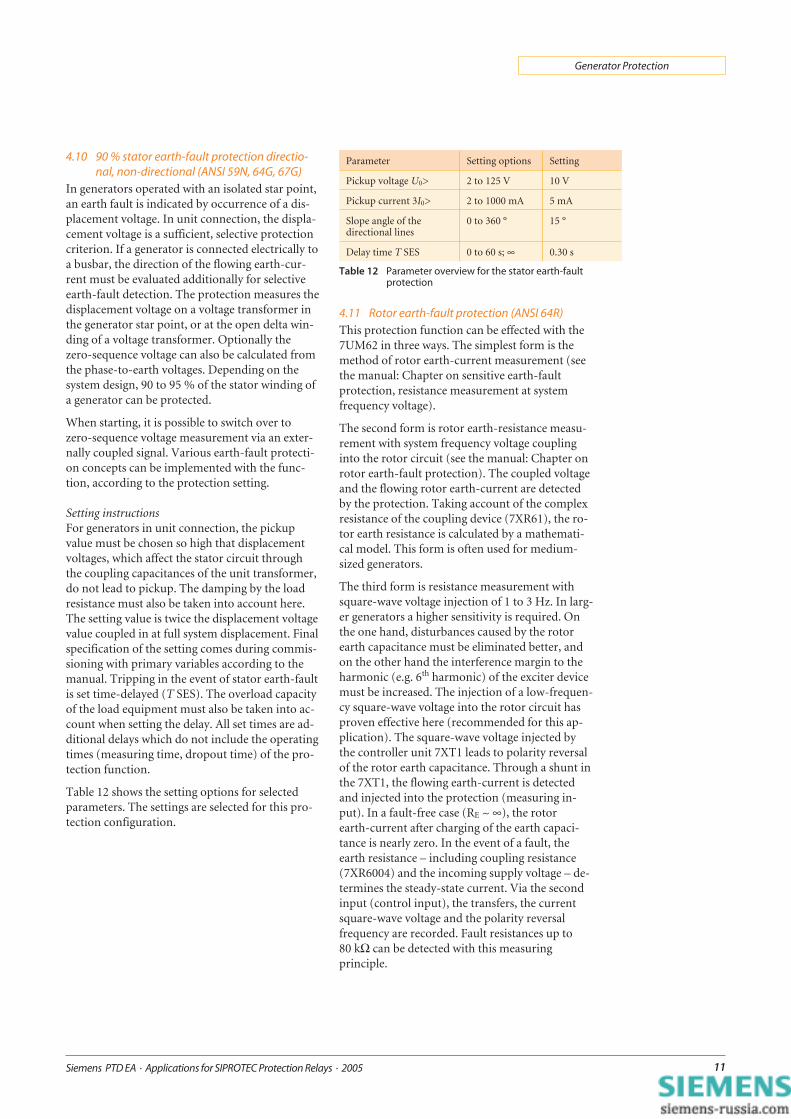
4.10 90 % stator earth-fault protection directio-nal, non-directional (ANSI 59N, 64G, 67G)
In generators operated with an isolated star point,an earth fault is indicated by occurrence of a dis-placement voltage. In unit connection, the displa-cement voltage is a sufficient, selective protectioncriterion. If a generator is connected electrically toa busbar, the direction of the flowing earth-cur-rent must be evaluated additionally for selectiveearth-fault detection. The protection measures thedisplacement voltage on a voltage transformer inthe generator star point, or at the open delta win-ding of a voltage transformer. Optionally thezero-sequence voltage can also be calculated fromthe phase-to-earth voltages. Depending on thesystem design, 90 to 95 % of the stator winding ofa generator can be protected.
When starting, it is possible to switch over tozero-sequence voltage measurement via an exter-nally coupled signal. Various earth-fault protecti-on concepts can be implemented with the func-tion, according to the protection setting.
Setting instructionsFor generators in unit connection, the pickupvalue must be chosen so high that displacementvoltages, which affect the stator circuit throughthe coupling capacitances of the unit transformer,do not lead to pickup. The damping by the loadresistance must also be taken into account here.The setting value is twice the displacement voltagevalue coupled in at full system displacement. Finalspecification of the setting comes during commis-sioning with primary variables according to themanual. Tripping in the event of stator earth-faultis set time-delayed (T SES). The overload capacityof the load equipment must also be taken into ac-count when setting the delay. All set times are ad-ditional delays which do not include the operatingtimes (measuring time, dropout time) of the pro-tection function.
Table 12 shows the setting options for selectedparameters. The settings are selected for this pro-tection configuration.
4.11 Rotor earth-fault protection (ANSI 64R)This protection function can be effected with the7UM62 in three ways. The simplest form is themethod of rotor earth-current measurement (seethe manual: Chapter on sensitive earth-faultprotection, resistance measurement at systemfrequency voltage).
The second form is rotor earth-resistance measu-rement with system frequency voltage couplinginto the rotor circuit (see the manual: Chapter onrotor earth-fault protection). The coupled voltageand the flowing rotor earth-current are detectedby the protection. Taking account of the complexresistance of the coupling device (7XR61), the ro-tor earth resistance is calculated by a mathemati-cal model. This form is often used for medium-sized generators.
The third form is resistance measurement withsquare-wave voltage injection of 1 to 3 Hz. In larg-er generators a higher sensitivity is required. Onthe one hand, disturbances caused by the rotorearth capacitance must be eliminated better, andon the other hand the interference margin to theharmonic (e.g. 6th harmonic) of the exciter devicemust be increased. The injection of a low-frequen-cy square-wave voltage into the rotor circuit hasproven effective here (recommended for this ap-plication). The square-wave voltage injected bythe controller unit 7XT1 leads to polarity reversalof the rotor earth capacitance. Through a shunt inthe 7XT1, the flowing earth-current is detectedand injected into the protection (measuring in-put). In a fault-free case (RE ~ ∞), the rotorearth-current after charging of the earth capaci-tance is nearly zero. In the event of a fault, theearth resistance – including coupling resistance(7XR6004) and the incoming supply voltage – de-termines the steady-state current. Via the secondinput (control input), the transfers, the currentsquare-wave voltage and the polarity reversalfrequency are recorded. Fault resistances up to80 kΩ can be detected with this measuringprinciple.
Parameter Setting options Setting
Pickup voltage U0> 2 to 125 V 10 V
Pickup current 3I0> 2 to 1000 mA 5 mA
Slope angle of thedirectional lines
0 to 360 ° 15 °
Delay time T SES 0 to 60 s; ∞ 0.30 s
Table 12 Parameter overview for the stator earth-faultprotection

Siemens PTD EA · Applications for SIPROTEC Protection Relays · 200512
Generator Protection
Monitoring of the rotor earth circuit for interrup-tion takes place by evaluating the current duringpolarity reversals.
Setting instructions (1 to 3 Hz protection)Since the protection calculates the resistive rotorearth resistance directly from the values of appliedvoltage, series resistance and flowing earth-current,the limit values for the alarm stage (RE WARN) andthe trip stage (RE TRIP) can be set immediately asresistance values. In most cases the preset values(RE WARN = 40 kΩ and RE TRIP = 5 kΩ) are suffi-cient. Depending on the insulation resistance andcoolant, these values can be changed. It is impor-tant to pay attention to an adequate margin be-tween the setting value and the actual insulationresistance. As a result of possible disturbances dueto the exciter device, the setting for the alarm stageis finally determined during the primary tests.The delay is usually set for the alarm stage (T RE
WARN) to about 10 s, and for the trip stage (T RE
TRIP) to a short time of about 1 s.The set times are additional time delays which donot include the operating times (measuring time,dropout time) of the protection function.
4.12 100 % stator earth-fault protection with20 Hz injection (ANSI 64 G (100 %))
The injection of a 20 Hz voltage for detection offaults in the star point or close to the star point ofgenerators has proven a safe and reliable method.Unlike the 3rd harmonic criterion (see page 12,Catalog SIP 6.1), it is independent of the genera-tor properties and the operating method. Mea-surement at system standstill is still possible. Thisprotection function is designed so that it detectsearth-faults both in the whole generator (real100 %) and in all galvanically connected systemcomponents. The protection relay detects the in-jected 20 Hz voltage and the flowing 20 Hz cur-rent. Disturbance variables such as stator earthcapacitances are eliminated, and the ohmic faultresistance is determined by a mathematical model.As a result, high sensitivity is ensured and the use
in generators with high earth capacitances – e.g.large hydroelectric generators – is enabled. Anglefaults due to the earthing or star-point trans-former are detected during commissioning andcorrected in the algorithm. The protection func-tion has a warning and trip stage. In addition, themeasuring circuit is monitored and a failure of the
20 Hz generator detected. Regardless of the earthresistance calculation, the protection function ad-ditionally evaluates the r.m.s. value of the current.Another stage is available for earth-faults in whichthe displacement voltage and thus the fault cur-rent exceed a certain value.
Taking the following parameters into considera-tion, the following settings for the applicationexample apply.
Load resistance on the earthing transformerRL = 4.63 Ω
Transformation ratio, voltage dividerüKl = 200 / 5
Transformation ratio, voltage dividerüdivider = 2 / 5
Transformation ratio, earthing transformerütransf = 15.75: 3 / 0.5 kV
Parameter Setting options Default *)
Pickup value of thealarm stage
5 to 80 kΩ 40 kΩ
Pickup value of thetrip stage
1 to 10 kΩ 5 kΩ
Delay time of thealarm stage
0 to 60 s; ∞ 10 s
Delay time of thetrip stage
0 to 60 s; ∞ 1 s
Table 13 Parameter overview for the rotor earth-faultprotection
Parameter Settingoptions
Setting
Pickup value of thealarm stage SES 100 %
20 to 700 Ω 193 Ω
Pickup value of thetrip stage SES 100 %
20 to 700 Ω 48 Ω
Delay time of the alarm stageSES 100 %
0 to 60 s; ∞ 10 s
Delay time of the trip stageSES 100 %
0 to 60 s; ∞ 1 s
Pickup value 100 % I>> 0.02 to 1.5 A 0.27 A
Monitoring threshold for20 Hz voltage
0.3 to 15 V 1 V
Monitoring threshold for20 Hz current
5 to 40 mA 10 mA
Angle correction for I SES 60 ° 0 °
Transition resistance Rps 0 to 700 Ω 0 Ω
Parallel load resistance 20 to 700 Ω; ∞ ∞ Ω
Table 14 Parameter overview for the 100 % stator earth-faultprotection
*) In this example, most of the default settings can be used.

Siemens PTD EA · Applications for SIPROTEC Protection Relays · 2005 13
Generator Protection
4.13 Out-of-step protection (ANSI 78)This protection function serves to detect powerswings in the system. If generators feed too longonto a system short-circuit, a compensation pro-cess (active power swings) may take place be-tween the system and the generator after fault dis-connection. If the center of power swings is in thearea of the unit, the “active power surges” lead toimpermissible mechanical stressing of the gener-ator and the whole generator mounting – includ-ing the turbine. Since these are symmetrical proc-esses, the positive-sequence impedance is calculat-ed from the voltage and current positive-sequencecomponents and the impedance curve is evalua-ted. In addition, the symmetry is monitored byevaluating the negative-phase sequence systemcurrent. Two characteristics in the R/X diagramdescribe the range of effect (generator, unit trans-former or system) of the out-of-step protection.The appropriate counters are incremented, de-pending on in which characteristic range the im-pedance vector enters and exits. If the set counterreading is reached, tripping takes place. If no morepower swings occur after a set time, the countersare automatically reset. Every power swing can besignalled by a settable pulse. The extending of thecharacteristic in R direction determines the de-tectable power swing angle. 120 ° are practicable.The characteristic can be tilted at an adjustableangle to adapt to the conditions when the systemis feeding off several parallel generators.
Setting instructions
A minimum value of the positive-sequence com-ponents of the currents I1> must be exceeded(overcurrent pickup) to enable the measurement.In addition, a maximum value of the negative-sequence components of the currents I2< may notbe exceeded, due to the symmetry condition. As arule, the setting value I1> is chosen above ratedcurrent – i.e. about 120 % IN – to avoid pickup byoverload. The pickup threshold of the negative-sequence component of the current I2< is set toabout 20 % IN.
The impedances of the protected zone seen fromthe protection relay are decisive for determiningthe setting values. In the direction of the generator(seen from the installation position of the voltagetransformer set), the power swing reactance of thegenerator must be taken into account; it can be setapproximately equal to the transient reactance xd'.This means the transient reactance related to thesecondary side is calculated and set for Zb xd' (seeFig. 7).
The meaning, calculation and setting of the pa-rameters for the trip characteristics are describedin detail in the manual.
The following table shows the setting options andthe calculated settings.
The setting ranges and presettings are specified fora secondary rated current of IN = 1 A.
Fig. 7 Power swing polygon
Parameter Setting options Setting
Pickup value of themeasurement release I1>
20 to 400 % 120 %
Pickup value of themeasurement release I2>
5 to 100 % 20 %
Resistance Za of the polygon(width)
0.2 to 130 Ω 8.25 Ω
Reactance Zb of the polygon(reverse)
0.1 to 130 Ω 19.60 Ω
Reactance Zc of the polygon(forward char. 1)
0.1 to 130 Ω 8.90 Ω
Reactance differencechar. 2 – char. 1
0 to 130 Ω 1.10 Ω
Inclination angle of the polygon 60 to 90 ° 90 °
Number of oscillations bycharacteristic 1
1 to 4 1
Number of oscillations bycharacteristic 2
1 to 8 4
Seal-in time of characteristic 1and characteristic 2
0.2 to 60 s 20 s
Seal-in time of the messageout-of-step, char. 1 andout-of-step char. 2
0.02 to 0.15 s 0.05 s
Table 15 Parameter overview for out-of-step protection

Siemens PTD EA · Applications for SIPROTEC Protection Relays · 200514
Generator Protection
5. Connection diagram 6. CommunicationThe 7UM6 relays fully meet the requirements ofmodern communication technology. They haveinterfaces which allow integration in master con-trol stations, convenient parameterization andoperation by PC (locally or via a modem). The7UM6 supports the widely used internationalopen communication standards
PROFIBUS-DP, RS485 or optical 820 nmdouble-ring ST connector
IEC 60870-5-103, DNP3.0, RS485 or optical 820 nm double-ring
ST connector and MODBUS, RS485 or optical 820 nm
double-ring ST connector
NoteAll SIPROTEC 4 relays also operate with starcoupler. This enables the user to access all infor-mation from the office or en route (for simple ap-plications). With the PROFIBUS-DP protocol,SIPROTEC relays can easily be integrated in PLC-based process control systems (e.g. SIMATICS5/S7). The protocols DNP3.0 and MODBUSASCII/RTU allow integration in numerous instru-mentation and control systems of other manu-facturers.
7. SummaryBeginning with the recommendations for protec-tion functions [1], it has been described that effi-cient concepts can be created with modernSIPROTEC relays in medium-sized generators,despite the need to consider cost factors. The mul-tifunctional, numerical SIPROTEC relays enable agreater functional scope than the previous singlerelays. Self-monitoring substantially improves theavailability of the protection relays.
For further information about the function rangeand setting, the 7UM62 manual is recommended,chapter 2 of which has been compiled as an appli-cation manual.
8. ReferencesHerrmann, H.-J.: “Digitale Schutztechnik”(Digital Protection Technology).Basic principles, software, examples ofimplementation.VDE-Verlag GmbH, Berlin 1997,ISBN 3-8007-1850-2.
Herrmann, H.-J.: “Elektrischer Schutz vonKleinkraftwerken” (Electrical Protection of SmallPower Stations).“Elektrizitätswirtschaft Jg. 97”(Electricity Industry Year 97) (1998) Issue 24
Manual7UM62 Multifunction Generator, Motor andTransformer Protection Relay
Fig. 8 Connection diagram of 7UM6