protection of mv transformers at utility …...– as transformers are designed to closer...
TRANSCRIPT
87T
PROTECTION OF MV TRANSFORMERSAT UTILITY AND INDUSTRIAL
FACILITIESChuck Mozina
ConsultantBeckwith Electric

87T
Chuck Mozina -- is a Consultant, Protection and Protection Systems for Beckwith Electric and resides in Palm Harbor (near Tampa), Florida. His consulting practice involves projects relating to protective relay applications, protection system design and coordination. He specializes in generator and power plant protection.
Chuck is an active 25-year member of the IEEE Power System Relay Committee (PSRC) and is the past chairman of the Rotating Machinery Subcommittee. He is active in the IEEE IAS I&CPS, PCIC and PPIC committees, which address industrial system protection. He is a former U.S. representative to the CIGRE Study Committee 34 on System Protection and has chaired a CIGRE working group on generator protection. He also chaired the IEEE task force that produced the tutorial “The Protection of Synchronous Generators,” which won the PSRC’s 1997 Outstanding Working Group Award. Chuck is the 1993 recipient of the Power System Relay Committee’s Career Service Award and he recently received the 2002 IAS I&CPS Ralph Lee Prize Paper Award. His papers have been republished in the IAS Industrial Applications Magazine.
Chuck has a Bachelor of Science in Electrical Engineering from Purdue University and is a graduate of the eight month GE Power System Engineering Course. He has authored a number of papers and magazine articles on protective relaying. He has over 25 years of experience as a protection engineer at Centerior Energy, a major investor-owned utility in Cleveland, Ohio where he was the Manager of the System Protection Section. He spent 10 years as the Applications Manager for Relay Products for Beckwith Electric. He is also a former instructor in the Graduate School of Electrical Engineering at Cleveland State University as well as a registered Professional Engineer in the state of Ohio and a Life Fellow of the IEEE.

87T
OUTLINE• IEEE PROTECTION STANDARDS• WHY TRANSFORMERS FAIL• TRANSFORMER BASICS• PHASING STANDARDS
+ IEEE/ANSI+ IEC
• TRANSFORMER DIFFERNTIAL+ Phase (87T)+ Gnd (87GD)
• OVEREXCITATION PROTECTION• DIGITAL TRANSFORMER RELAYS

87T
IEEE Standards• Latest developments reflected in:
– Std. 242: Buff Book Transformer Protection Chapter 11
– ANSI / IEEEC37.91“Guide for Protective Relay Applications for Power Transformers”
These are created/maintained by the IEEE PSRC & IASThey are updated every 5 years

87T
WHY TRANSFORMERS
FAIL
87T
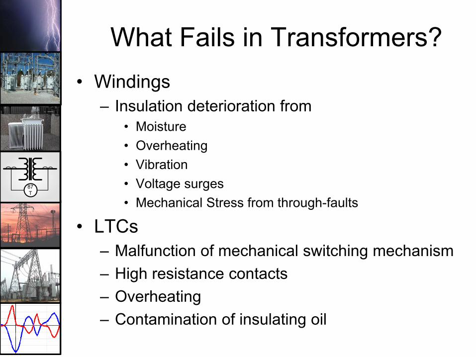
What Fails in Transformers?• Windings
– Insulation deterioration from• Moisture• Overheating• Vibration• Voltage surges• Mechanical Stress from through-faults
• LTCs– Malfunction of mechanical switching mechanism– High resistance contacts– Overheating– Contamination of insulating oil

87T
What Fails in Transformers?HARTFORD STEAM BOILER INSPECTION & INSURANCE CO.
Improper Maintenance
% of FailuresCause
Insulation Failure 26%
Manufacturing Problems 24%
Unknown 16%
Loose Connections 7%
Through Faults 5%
5%
Overloading 4%
Oil Contamination 4%
Fire/Explosions 3%
Lighting 3%
Floods 2%
Moisture 1%
87T
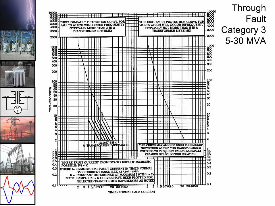
Through Fault
Category 35-30 MVA
87T
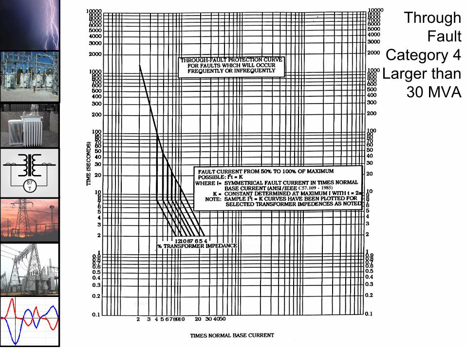
Through Fault
Category 4Larger than
30 MVA

87T
TRANSFORMER PROTECTION BASICS

87T
• V1I1 = V2I2• N1V2 = N2V1• N1I1 = N2I2
AA
I1 = 5 I2 = 10
V1 = 100 V2 = 50
N1 = 100 N2 = 50
Transformer Formulas
Ideal Transformer – No Losses
Transformer Fundamentals

87T
INSULATION MATERIALS
• Dry- Used where liquid spills cannot be tolerated- Small ratings, lower voltage distribution
• Wet- Offers smaller size, lower cost and greater
overload capacity- Liquids have greater coefficient of heat transfer
then dry insulation- Vast majority of power transformers use wet (oil)
insulation.

87T
Basic Transformer Designs Gas-Oil Sealed Transformers
OIL
Transformer RatingsOA/FA/FA
NI GAS
NI Gas Tank
Gas Regulator
Pressure Relief
RegulatingValve
Fans

87T
Basic Transformer DesignsConservator Tank System
OIL
Transformer are Generally notForced Cooled
OIL
ConservatorTank
Oil Level
Breather &ScreenPressure Relief
Sump
Oil Drain
87T
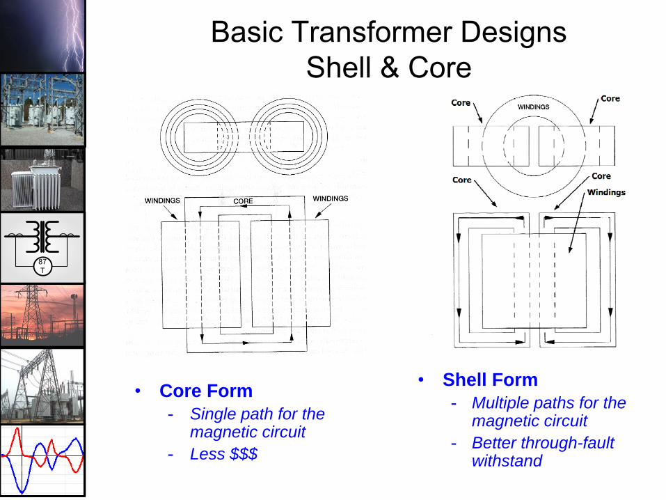
• Core Form- Single path for the
magnetic circuit- Less $$$
• Shell Form- Multiple paths for the
magnetic circuit- Better through-fault
withstand
Basic Transformer DesignsShell & Core

87T
IEEE Devices used in Transformer Protection
• 24: Overexcitation (V/Hz) • 46: Negative Sequence Overcurrent• 49: Thermal Overload• 50: Instantaneous Phase Overcurrent• 50G: Instantaneous Ground Overcurrent• 50N: Instantaneous Neutral Overcurrent• 50BF: Breaker Failure• 51G: Ground Inverse Time Overcurrent• 51N: Neutral Inverse Time Overcurrent• 63: Sudden Pressure Relay (Buccholtz Relay)• 81U: Underfrequency• 87HS: High-set Phase Differential (Unrestrained)• 87T: Transformer Phase Differential with Restraints• 87GD: Ground Differential (also known as “restricted earth fault”)

87T
BASIC UTILITY SOLIDLY GROUNDED TRANSFORMER
PROTECTIONS87T
50
5151G
High Side Low Side
51

87T
Basic Industrial Transformer Protection
87T
50
5151G
High Side Low Side
RESISTOR200-400 A
87GD
Aux. CT
51
87T
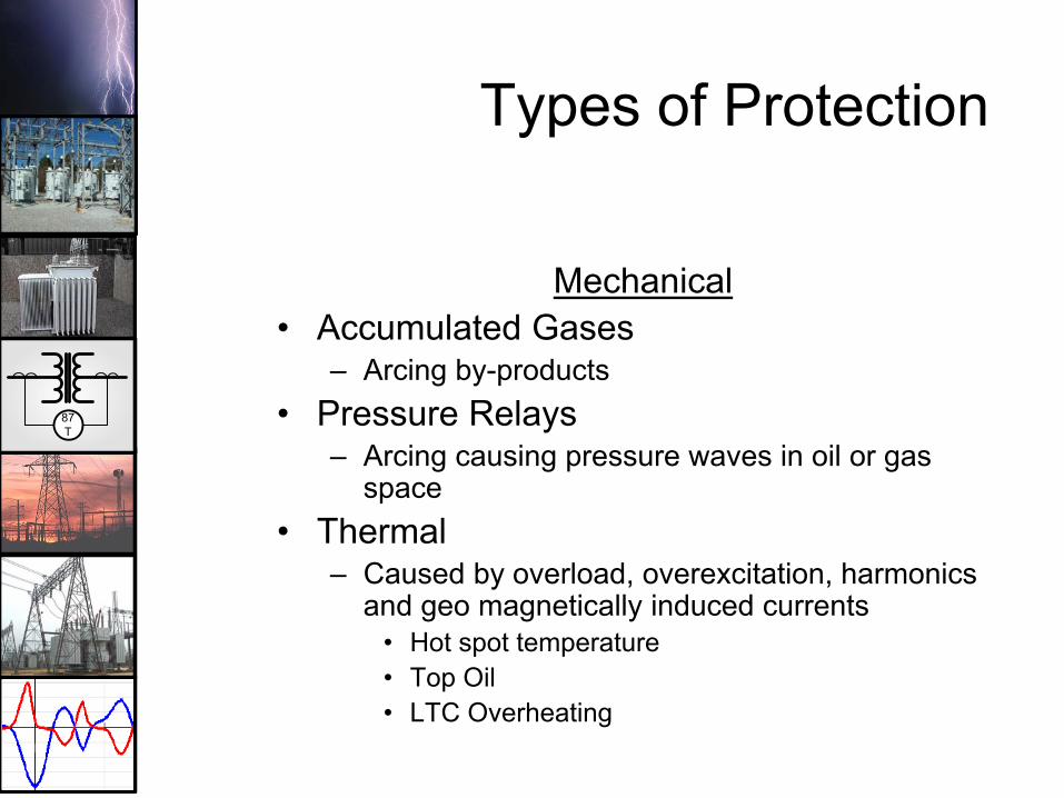
Types of Protection
Mechanical• Accumulated Gases
– Arcing by-products• Pressure Relays
– Arcing causing pressure waves in oil or gas space
• Thermal– Caused by overload, overexcitation, harmonics
and geo magnetically induced currents• Hot spot temperature• Top Oil• LTC Overheating

87T
Sudden Pressure Relay (SPR) Protection
OIL
Ni Gas
TransformerSudden Pressure Relay
NI GAS

87T
Transformer Thermal Monitoring
OIL
NI GAS
49W
Winding HotSpot
49
Top OilTemp.

87T
Types of ProtectionFusesSmall transformers ( <10 MVA Solidly Grounded)Short circuit protection only
Overcurrent ProtectionHigh side
Through fault protectionDifferential back-up protection for high side faults
Low sideSystem back up protection
Differential ProtectionPhase Diff.Ground Diff.

87T
DELTA-WYE TRANSFORMERS UNDER FAULT CONDITIONS
R
R
R
1.0
1.0
1.0
1.0
1.0
1.0
A) Three Phase Fault
B) Phase to Phase Fault in pu of Three Phase Fault
0.577
0.577
0.577
C) Line to Ground Fault
0.866
0.866
0.5
O.5
1.0
0.5
0.5
1.0
0.577
0.577
0.5770
00
0

87T
DELTA-WYE TRANSFORMERS LIMITATIONS OF FUSING
400A
Line to Ground Fault 10 MVA 138/13.8KV
IFL = 10,000/1.73 X 138 = 42A
WHEN FUSES ARE SIZED TO CARRY LOADTHEY CAN’T DETECT A GROUND FAULT
400A
0.577
40A/1.73=23A
40A/1.73=23A0
00
138KV 13.8KV
F
F
F

87T
TRANSFORMER PHASING STANDARDS
IEEE/ANSI & IEC

87T
ANSI/IEEE PHASING STANDARD
• H1, H2, H3– Primary Bushings
• X1, X2, X3– Secondary Bushings
TransformerH1H2H3
X1X2X3
Wye-Wye H1 and X1 at zero degreesDelta-Delta H1 and X1 at zero degreesDelta-Wye H1 lead X1 by 30 degreesWye-Delta H1 lead X1 by 30 degrees
87T
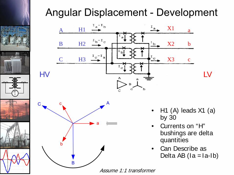
Angular Displacement - Development
• H1 (A) leads X1 (a) by 30
• Currents on “H” bushings are delta quantities
• Can Describe as Delta AB (Ia =Ia-Ib)
HV LV
H1
H2
H3
X1
X3
X2
A
B
C
a
b
c
a
b
c A
B
C
Assume 1:1 transformer
87T
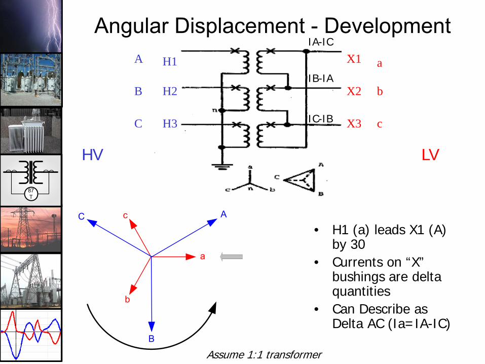
Angular Displacement - Development
• H1 (a) leads X1 (A) by 30
• Currents on “X” bushings are delta quantities
• Can Describe as Delta AC (Ia=IA-IC)
HV LV
H1
H2
H3
X1
X3
X2
a
b
c
A
B
C
IA-IC
IB-IA
IC-IB
Assume 1:1 transformer
a
b
c A
B
C

87T
Transformer Phasing – IEC Phasing Standard
Euro-designations use 30° increments of LAG from the X1 bushing to the H1 bushings
0
6
39
8
7
10
11 12
5
4
87T
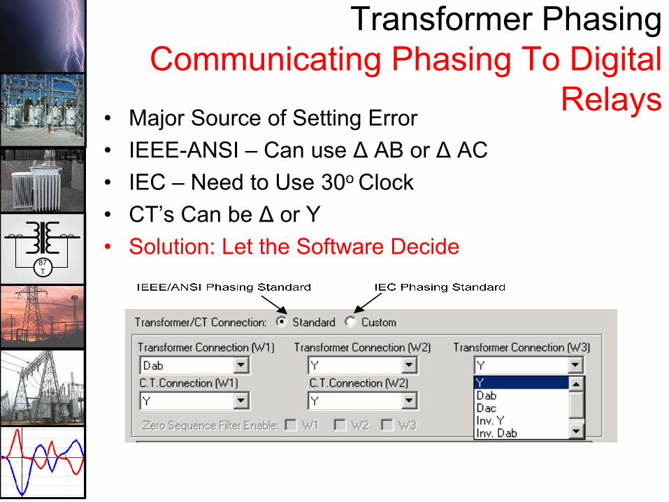
Transformer Phasing Communicating Phasing To Digital
Relays• Major Source of Setting Error• IEEE-ANSI – Can use ∆ AB or ∆ AC• IEC – Need to Use 30o Clock• CT’s Can be ∆ or Y• Solution: Let the Software Decide

87T
• IEC (Euro) practice does not have a standard like ANSI
• Most common connection is Dy11 (low lead high by 30!)
• Obviously observation of angular displacement is extremely important when paralleling transformers!
Angular Displacement*1
*1
*2
*2
*1 = ANSI std. @ 0°
*2 = ANSI std. @ X1 lag H1 by 30°, or “high lead low by 30 ° “

87T
Winding Arrangements• Wye-Wye
– Conduct zero-sequence between circuits– Provides ground source for secondary circuit
• Delta-Delta– Blocks zero-sequence between circuits– Does not provide a ground source
• Delta-Wye– Blocks zero-sequence between circuits– Provides ground source for secondary circuit
• Wye-Delta– Blocks zero-sequence between circuits– Does not provide a ground source for secondary circuit

87T
TRANSFORMER DIFFERENTIAL PROTECTION

87T
Types of ProtectionElectrical
• Phase Differential– Applied with variable percentage slopes to
accommodate CT saturation and CT ratio errors– Applied with inrush and overexcitation restraints– Set with at least a 15% pick up to accommodate
CT performance• Class “C” CT; 10% at 20X rated
– If unit is LTC, add another 10%– May not be sensitive enough for all faults (low
level, ground faults near neutral, resistor grounded transformers )

87T
Basic Differential Relay
TRANSFORMER
TAP W-1TAP W-2
Restraint W-1 Restraint W-2
OperateRELAY
87T
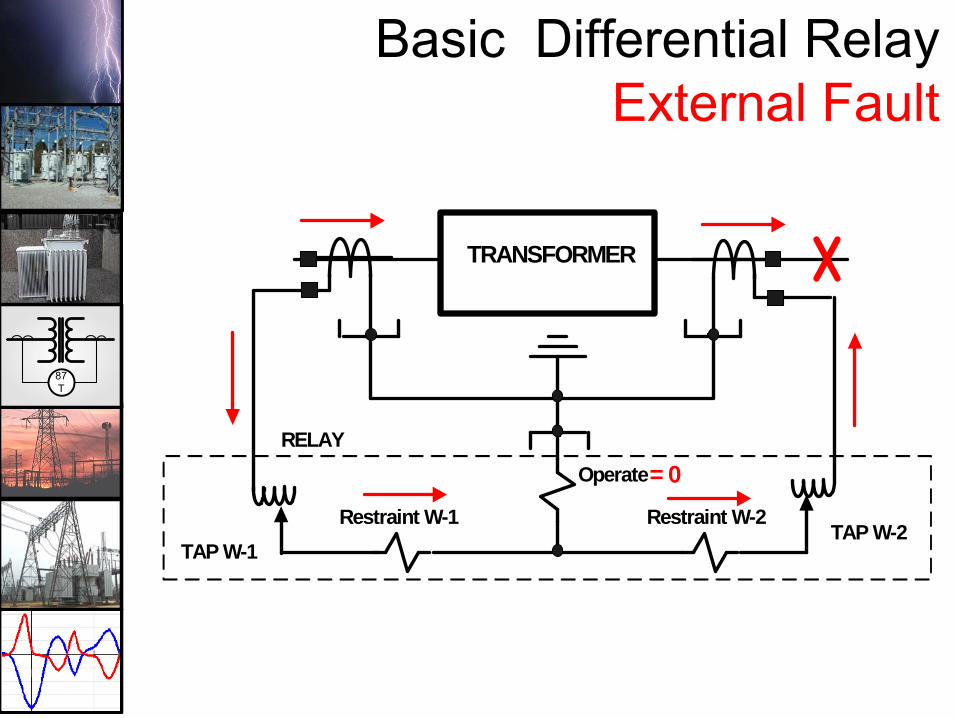
Basic Differential RelayExternal Fault
TRANSFORMER
TAP W-1TAP W-2
Restraint W-1 Restraint W-2
OperateRELAY
= 0
87T
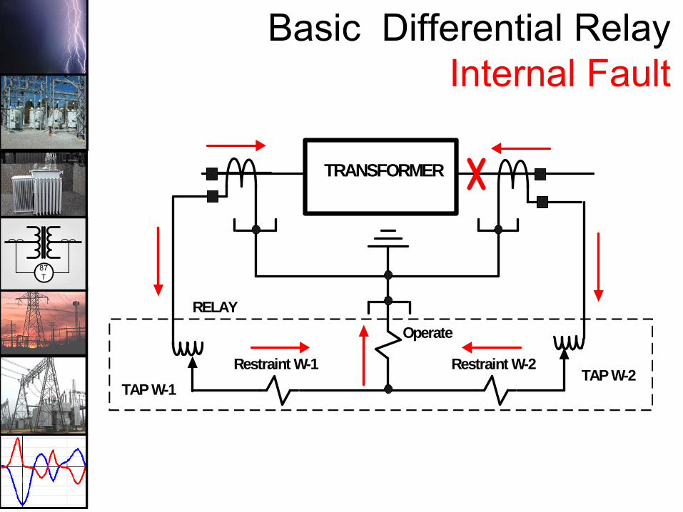
Basic Differential RelayInternal Fault
TRANSFORMER
TAP W-1TAP W-2
Restraint W-1 Restraint W-2
OperateRELAY

87T
TypicalPhase DifferentialCharacteristic –Percentage Slope Concept
UNITI1 I2
I3
I1 + I2 + I3 = 0

87T
Unique Issues Applying to Transformer Differential Protection
• CT ratio caused current mismatch• Transformation ratio caused current
mismatch (fixed taps)• LTC induced current mismatch• Delta-wye transformation of currents
– Vector group and current derivation issues• Zero-sequence current elimination for
external ground faults on wye windings• Inrush phenomena and its resultant
current mismatch

87T
Classical Differential Compensation
• CT ratios must be selected to account for:– Transformer ratios– If delta or wye connected CTs are
applied– Delta increases ratio by 1.73
• Delta CTs must be used to filter zero-sequence current on wye transformer windings
87T
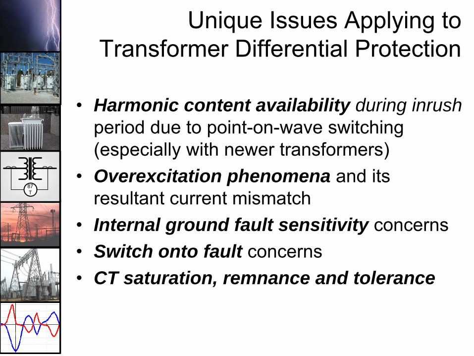
Unique Issues Applying to Transformer Differential Protection
• Harmonic content availability during inrushperiod due to point-on-wave switching (especially with newer transformers)
• Overexcitation phenomena and its resultant current mismatch
• Internal ground fault sensitivity concerns• Switch onto fault concerns• CT saturation, remnance and tolerance

87T
Classical Electro-Mechanical Differential Compensation

87T
Digital Relay Application

87T
Compensation in Digital Relays
• Transformer ratio• CT ratio• Vector quantities
– Which vectors are used– Where the 1.73 factor (√3) is applied
• When examining line to line quantities on delta connected transformer windings and CT windings
• Zero-sequence current filtering for wye windings so the differential quantities do not occur from external ground faults

87T
Digital Relay Application
All wye CTs shown, can retrofit legacy delta CT applications

87T
Benefits of Wye CTs
• Phase segregated line currents– Individual line current oscillography– Currents may be easily used for
overcurrent protection and metering– Easier to commission and troubleshoot– Zero sequence elimination performed by
calculation – BUT IS IT WORTH ALL THE RE-WIRING
IN RETRO-FIT APPICATIONS ?

87T
• Two winding transformer, with Neutral Input
Typical Applications
M-3310 REF

87T
• Main-Tie-Main Substation
REF REF
Typical Applications
87T
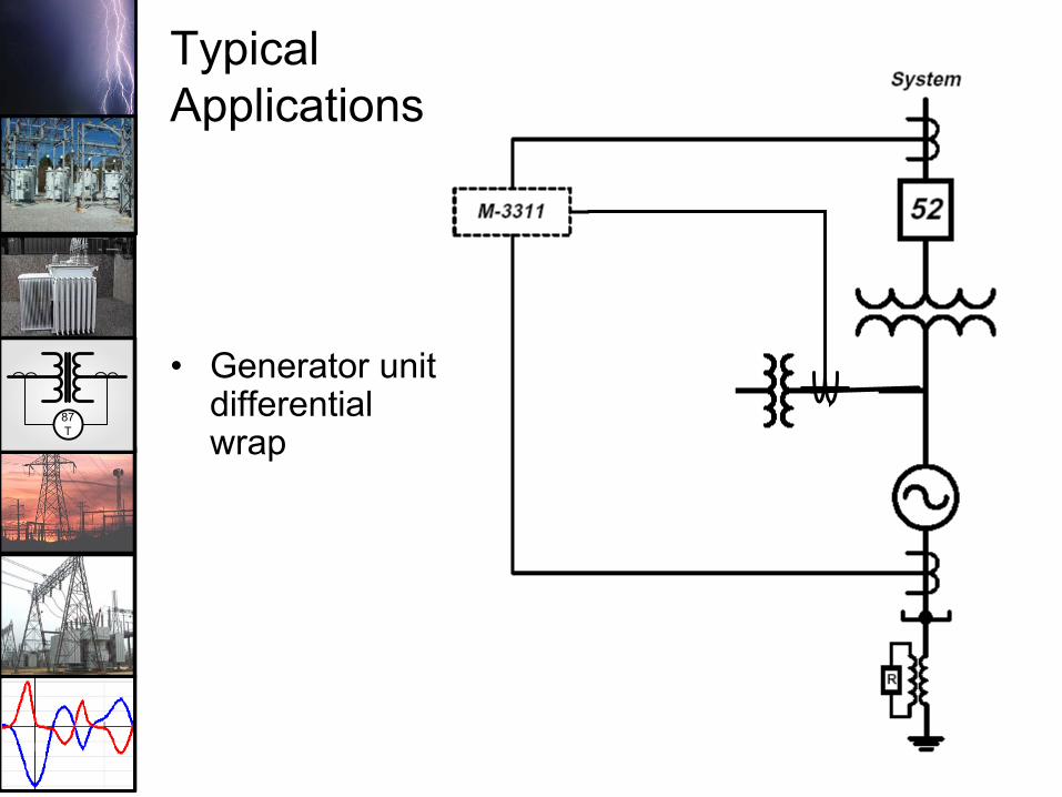
Typical Applications
• Generator unit differential wrap

87T
Inrush Restraint

87T
Advanced Element Design: 87T
• Inrush Detection and Restraint– 2nd harmonic restraint has been employed for
years– “Gap” detection has also been employed– As transformers are designed to closer
tolerances, both 2nd harmonic and low current gaps in waveform have decreased
– If 2nd harmonic restraint level is set too low, differential element may be blocked for internal faults with CT saturation (with associated harmonics generated)
87T
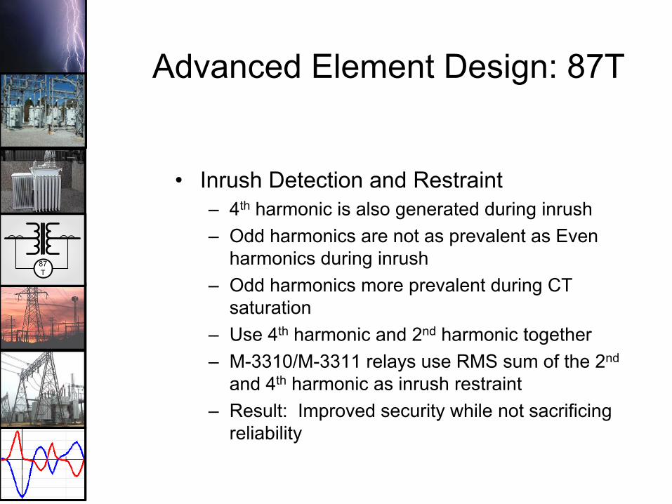
Advanced Element Design: 87T
• Inrush Detection and Restraint– 4th harmonic is also generated during inrush– Odd harmonics are not as prevalent as Even
harmonics during inrush– Odd harmonics more prevalent during CT
saturation– Use 4th harmonic and 2nd harmonic together– M-3310/M-3311 relays use RMS sum of the 2nd
and 4th harmonic as inrush restraint– Result: Improved security while not sacrificing
reliability
87T
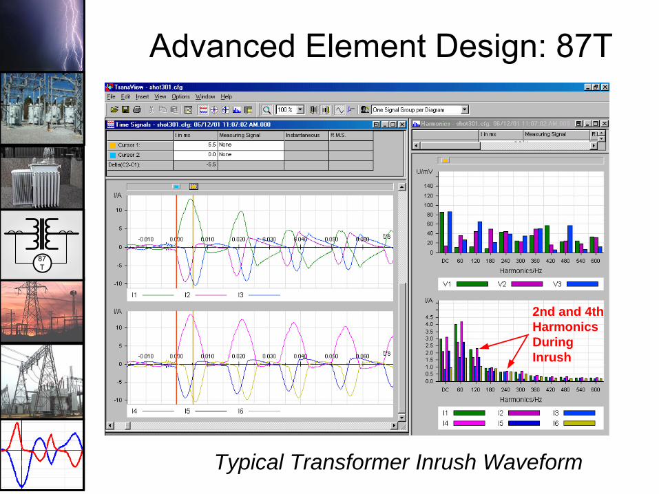
Advanced Element Design: 87T
Typical Transformer Inrush Waveform
2nd and 4thHarmonicsDuringInrush

87T
Cross Phase Averaging
• Provides security if any phase has low harmonic content during inrush or overexcitation
• This can occur depending on the voltage point-on-wave when the transformer is energized for a given phase
• Cross phase averaging uses the average of harmonics on all three phases to determine level

87T
Advanced Element Design: 87T• Overexcitation Restraint
– Overexcitation occurs when volts per hertz level rises (V/Hz)
– This typically occurs from load rejection and malfunctioning generation AVRs
– The voltage rise at nominal frequency causes the V/Hz to rise
– This causes 5th harmonics to be generated in the transformer as it begins to go into saturation
– The current entering the transformer is more than the current leaving due to this increase in magnetizing current
– This causes the differential element to pick-up– Use 5th harmonic level to detect overexcitation

87T
Advanced Element Design: 87T
• Overexcitation Restraint– Most other relays block the differential element
from functioning during transformer overexcitation
– M-3310/M-3311 do not block it, but rather raise the pick up level to accommodate the difference currents caused by the transformer saturation
– This allows the differential element to trip if an internal fault occurs during the overexcitation period due to increased stress level on the insulation
– Result: Improved reliability while not sacrificing security

87T
Trip Characteristic – 87T

87T
Trip Characteristic – 87T• 87T Pick Up
– Class C CTs, use 10%– 5% Margin– LTC, add 10%– Magnetizing losses, add 1%– 0.15 to 0.3 pu typically setting
• Slope 1– Used for low level currents– Can be set as low as 15%– With LTC 25-30%
• Slope 2 “breakpoint”– Typically set at 2X rated current– This setting assumes that any current over 2X rated is a
through fault or internal fault, and is used to desensitize the element against unfaithful replication

87T
Trip Characteristic – 87T• Slope 2
– Typically set at 60% (double slope 1)• Inrush Restraint (2nd and 4th harmonic)
– Typically set from 10-15%– Employ cross phase averaging blocking for
security– Blocks tripping for 10 cycles• Overexcitation Restraint (5th harmonic)
– Typically set at 30%– Raise 87T pick up by 200% or 0.60 pu during
overexcitation– No cross phase averaging needed, as
overexcitation is symmetric on the phases

87T
Trip Characteristic – 87H• 87H Pick Up
– Typically set at 10pu rated current– This value should be above maximum possible
inrush current and lower than the CT saturation current
– C37.91, section 5.2.3, states 10pu an acceptable value
– Can use data captured from energizations to fine tune the setting

87T
CT Issues
• Remnance: Residual magnetism that causes dc saturation of the CTs
• Saturation: Error signal resulting from too high a primary current combined with a large burden
• Tolerance: Class “C” CTs are rated 10% for currents x20 of nominal – Thru-faults and internal faults may reach those
levels depending on ratio selected

87T
IS THE CT GOOD ENOUGH ?• Provides security for high fault current levels outside the differential zone where CT inputs can saturate.• Factors effecting CT saturation
- Residual magnetism in CT core- CT characteristic mismatch- CT circuit burden
• CT Burden Check– want to operate below the knee-point voltage (Vk) for worst-case fault external to diff. Zone.
Where IP is the maximum external fault current
Iex – Excitation Current
VS = IPN
[RCT + RW +RR]

87T
CT Issues• Best defense is to use high “Class C”
voltage levels– C200,C400, C800– These have superior characteristics against
saturation and relay/wiring burden• Use low burden relays
– Digital systems are typically 0.020 ohms• Use a variable percentage slope
characteristic to desensitize the differential element when challenged by high currents that may cause replication errors

87T
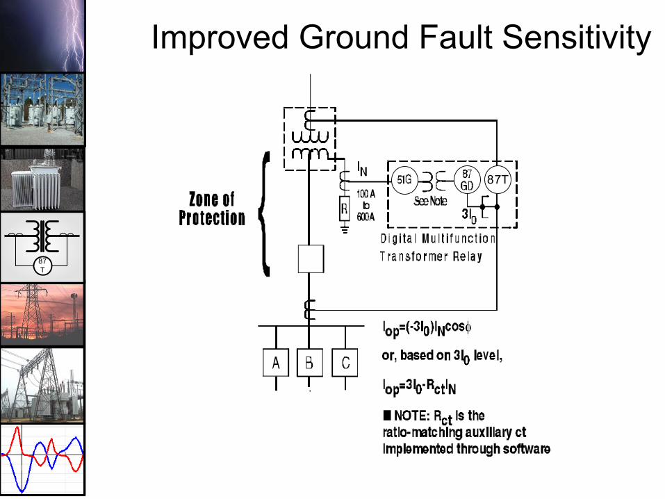
Improved Ground Fault SensitivityGround Differential Protection (87GD)
• 87T element is typically set with 15-30% pick up -
• This is to accommodate Class “C” CT accuracy during a fault plus the effects of LTCs
• That leaves 10-15% of the winding not covered for a ground fault (Solidly Grounded Winding)
• When a neutral resistor limits ground current to 200-400A no ground fault protection is provided for that winding by the 87T element.
• Employ a ground differential element to improve sensitivity (87GD)
87T
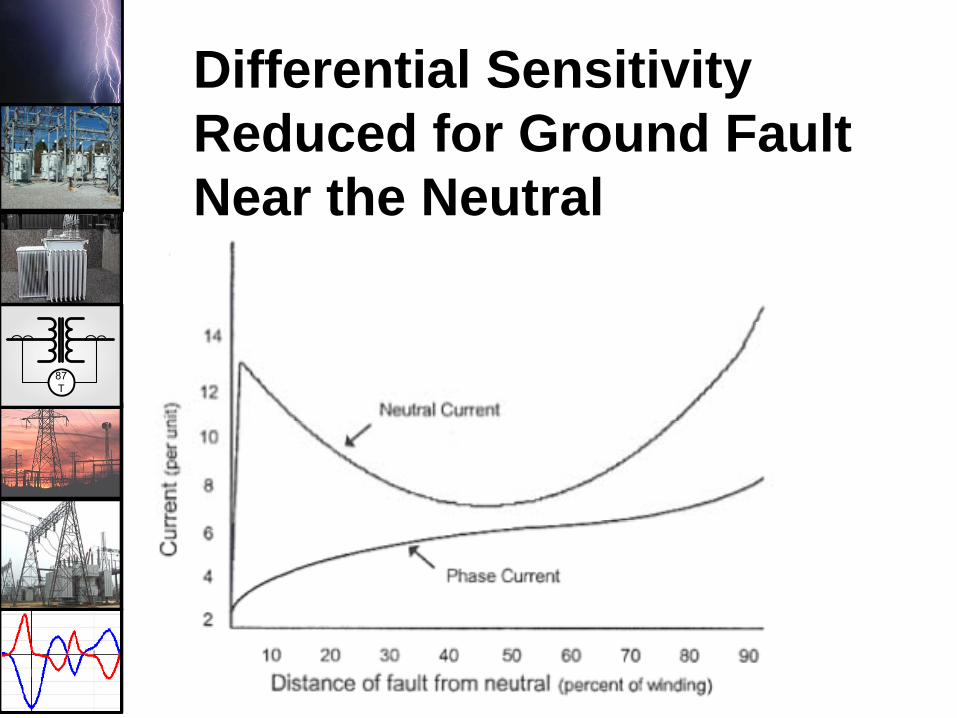
Differential Sensitivity Reduced for Ground Fault Near the Neutral

87T
Improved Ground Fault Sensitivity
• WITHOUT GROUND DIFF. (87GD) THERE IS NO HIGHSPEED PROTECTION FOR SEC. GND FAULTS
Typical Pickup of 87T:• O.3 pu pickup• Relay Tap set at
Trans. Rating (45MVA)
IFL138KV = 4.71 Amps
• PU = 4.71A x 0.3 = 1.41A
Open
R
87T
2000/5
200/5
400A
13.8KV
138KV
I=0400A
40A/1.73
40A/1.73*40/1=0.58A
45 MVA
87T
Improved Ground Fault Sensitivity
87T

87T
Trip Characteristic – 87GD• 87GD Pick Up
– Element normally uses directional comparison between phase residual current (3I0) and measured ground current (IG)
• No user setting
– Pick up only applicable when 3I0 current is below 140mA (5A nom.)
• Pick up = 3I0 - IG
– If 3I0 greater than 140mA, element uses:• –3I0 * IG * cosθ. It will trip only when the directions
of the currents is opposite, indicating an internal fault• Using direction comparison mitigates the effects of
saturation on the phase and ground CTs

87T
Trip Characteristic – 87GD
IG
IA
IB
IC
3I0IG
Residual currentcalculated fromindividual phasecurrents. ParalleledCTs shown toillustrate principle.
0
90
180
270IG
3IO
-3Io x IG cos (180) = 3IoIG

87T
Trip Characteristic – 87GD
IG
IA
IB
IC
3I0IG
Residual currentcalculated fromindividual phasecurrents. ParalleledCTs shown toillustrate principle.
0
90
180
270
IG
3IO-3Io x IG cos (0) = -3IoIG

87T
TRANSFORMER OVEREXCITATION
PROTECTION
87T
Transformer Limits• Overexcitation
– Responds to overfluxing; excessive V/Hz– Continuous operational limits
• ANSI C37.91 & C57.12– 1.05 loaded, 1.10 unloaded– Measured at the transformer output
• Inverse curves typically available for values over the continuous allowable maximum
• Protection required application of V/Hz (24) protection
87T
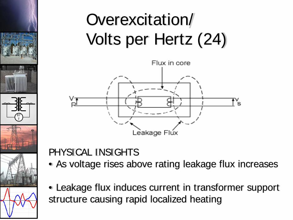
Overexcitation/Volts per Hertz (24)
PHYSICAL INSIGHTS• As voltage rises above rating leakage flux increases
• Leakage flux induces current in transformer support structure causing rapid localized heating

87T
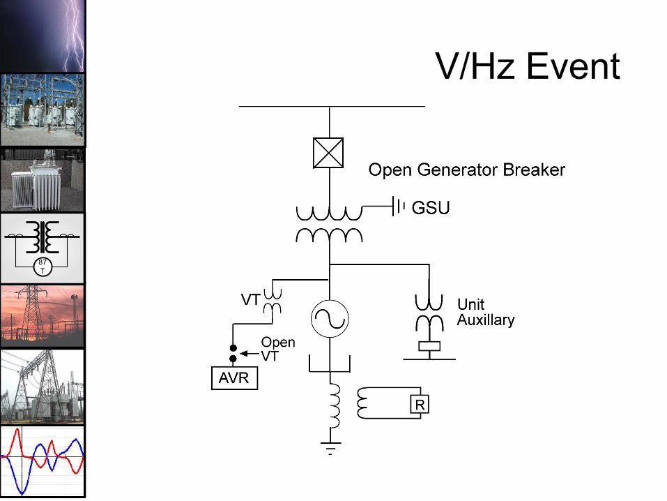
Industrial System Overexcitation
Power SystemHigh Voltage During Major
System Disturbance
TransformersStill Connected
to Power SystemEven After LoadTransfered ontoPlant Generation
Plant Separated ontoLocal Plant Gen.

87T
Overexcitation Event on EHV Transmission System
C C C C
OPEN
OPEN
OPEN
SHUNT REACTOR DISCONNECTSWITCH INADVERTENTLY LEFT OPEN
FAILEDAUTOTRANSFORMER
C = DISTRIBUTED LINE CAPACITANCE
CLOSED
CLOSED
Fig. 11 Overexcitation Failure of an EHV Autotransformer

87T
Overexcitation Curve
This is typically how the apparatus manufacturer specs it

87T
Overexcitation Digital Relay Curve
87T
V/Hz Event

87T
VA & IA
TRIPGEN. BREAKER OPENALARM
ALARM
87T
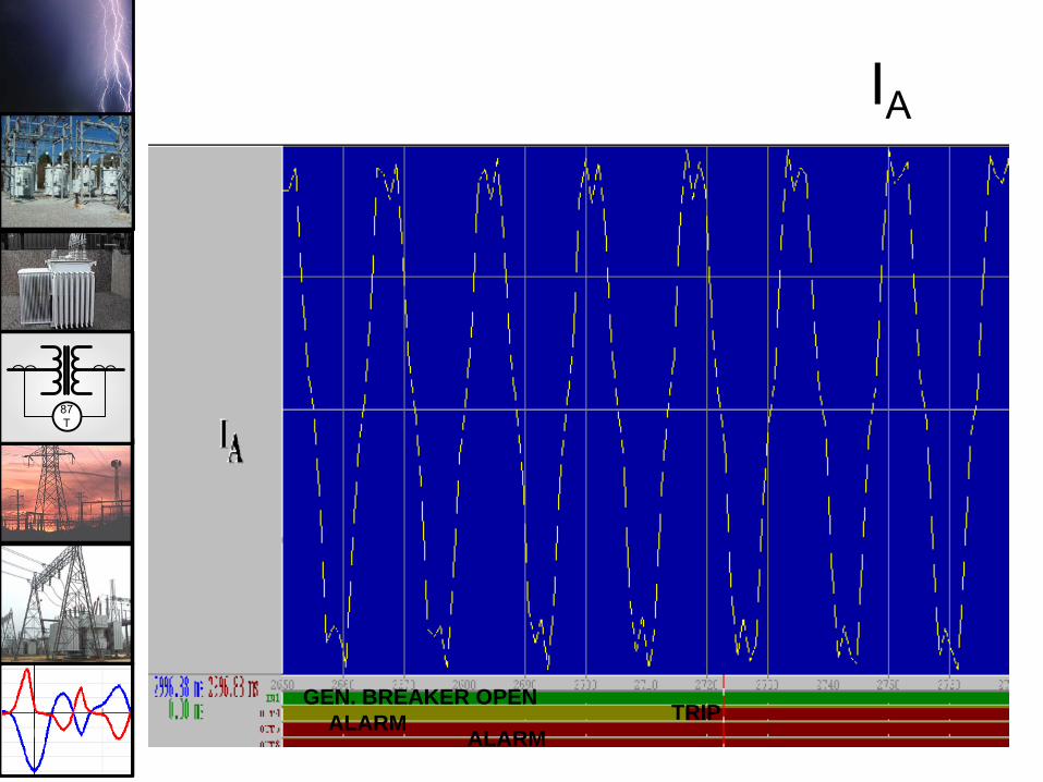
IA
TRIPGEN. BREAKER OPEN
ALARMALARM

87T
DIGITAL RELAY TRANSFORMER
PROTECTION

87T
Digital Transformer Relays
87T
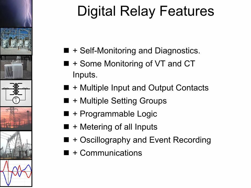
Digital Relay Features
+ Self-Monitoring and Diagnostics.+ Some Monitoring of VT and CT Inputs.+ Multiple Input and Output Contacts+ Multiple Setting Groups+ Programmable Logic+ Metering of all Inputs+ Oscillography and Event Recording + Communications
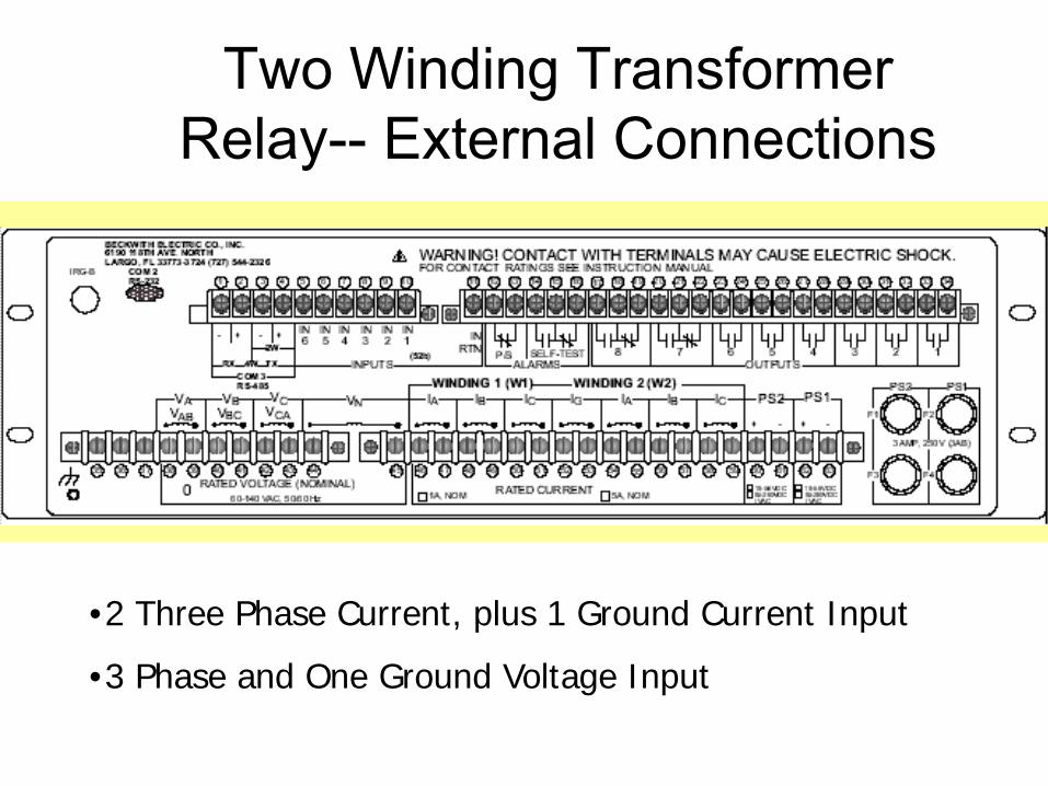
Two Winding Transformer Relay-- External Connections
•2 Three Phase Current, plus 1 Ground Current Input
•3 Phase and One Ground Voltage Input
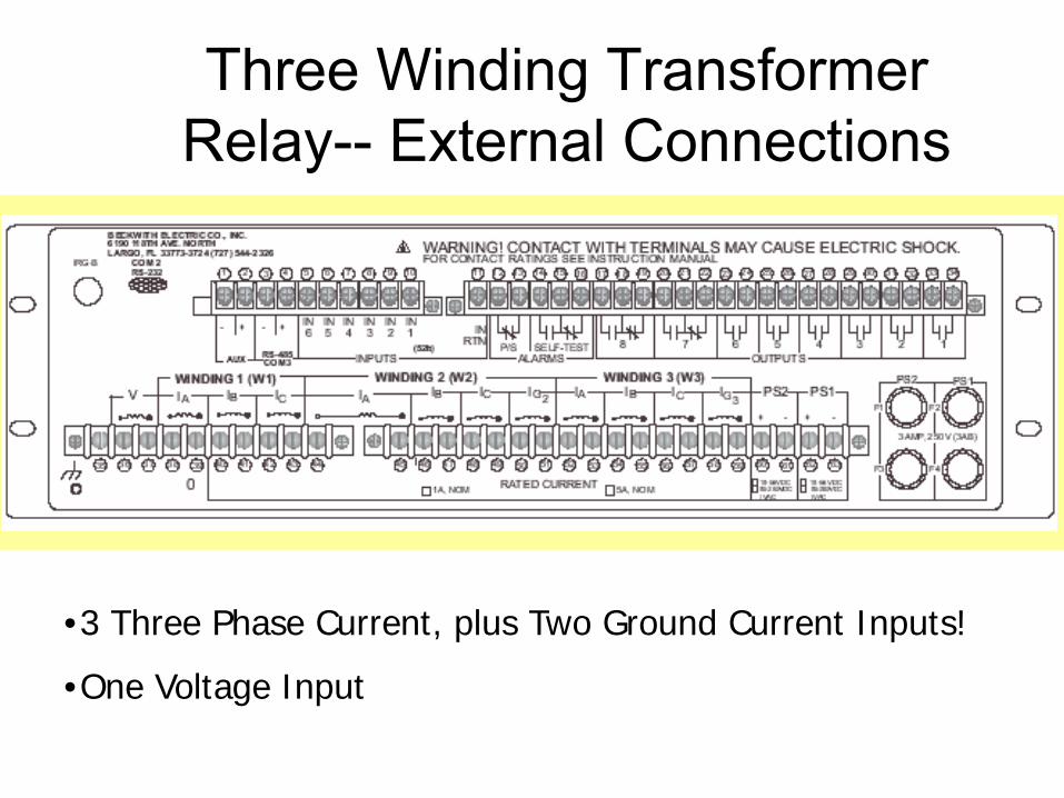
Three Winding Transformer Relay-- External Connections
•3 Three Phase Current, plus Two Ground Current Inputs!
•One Voltage Input

87T
Four Winding Transformer Relay-- External Connections
•4 Three Phase Current, plus 3 Ground Current Inputs!
• Two Voltage Input

87T
51W1
50W1
87T
4650BF
50W2
51W2
24 81U 27
50G 51G
CT
VT
CT
M-3310 Transformer Protection Relay
This function is available as astandard protective function.
This function is available as aoptional protective
function.
B
CT
R59G
87GD
50NBF
51NW2
51NW1
87H
Winding1
(W1)
Winding2
(W2)
Targets(Optional)
Integral HMI(Optional)
Metering
Sequence OfEvents
WaveformCapture
IRIG-B
Front RS-232Communication
Multiple SettingGroups
Programmable I/O
Self Diagnostics
Dual Power Supply(Optional)
Rear BECO 2200 or MODBUS
Communication
A
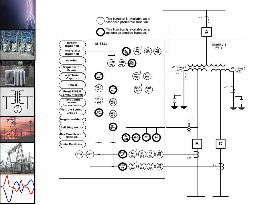
87T
51W1
A
50W1
46W3
50BFW3
50W3
51W3
59G81O/U 27
3-CT
3-CT
M-3311
This function is available as astandard protective function.
This function is available as aoptional protective function.
B
1-CT
R
87GDW2
50NBFW2
51NW2
87H
Winding 1(W1)
Winding 2(W2) Winding 3
(W3)50GW2
51GW2
C24
87T
1
46W2
50BFW2
50W2
51W2
1
50GW3
51GW3
87GDW3
50NBFW3
51NW3
R
1
1
1
VT2
3-CT
1-CT
50NBFW 1
51NW1
50BFW1
49W1
49W2
49W3
50NW2
50NW1
50NW3
Targets(Optional)
Integral HMI(Optional)
Metering
Sequence OfEvents
WaveformCapture
IRIG-B
Front RS-232Communication
Multiple SettingGroups
Programmable I/O
Self Diagnostics
Dual Power Supply(Optional)
Rear MODBUS or DNP
Communication
Breaker Monitoring

87T
Power Supply
ProgrammableGain Amplifier
MUX
Digital Signal Processor (DSP)
Dual-Ported RAM
Character Liquid Crystal Display
RAM
Flash-Programmable ROM
Host Processor
EEPROM
Clock with battery backup
MMI Module) Target ModuleRS232 and
RS485 Communi-cation
ports
IRIG-B Time Code input
Relay Outputs
Contact Inputs
Anti-Aliasing Low-Pass Filters (LPF)
Analog Multiplexer
VTs & CTs
Va
Vb
Vc
Vn
ia
ib
ic
iA
iB
iC
iN
RAM
Address/Data Bus
Analog-to-Digital Converter
Hardware Block Diagram
87T
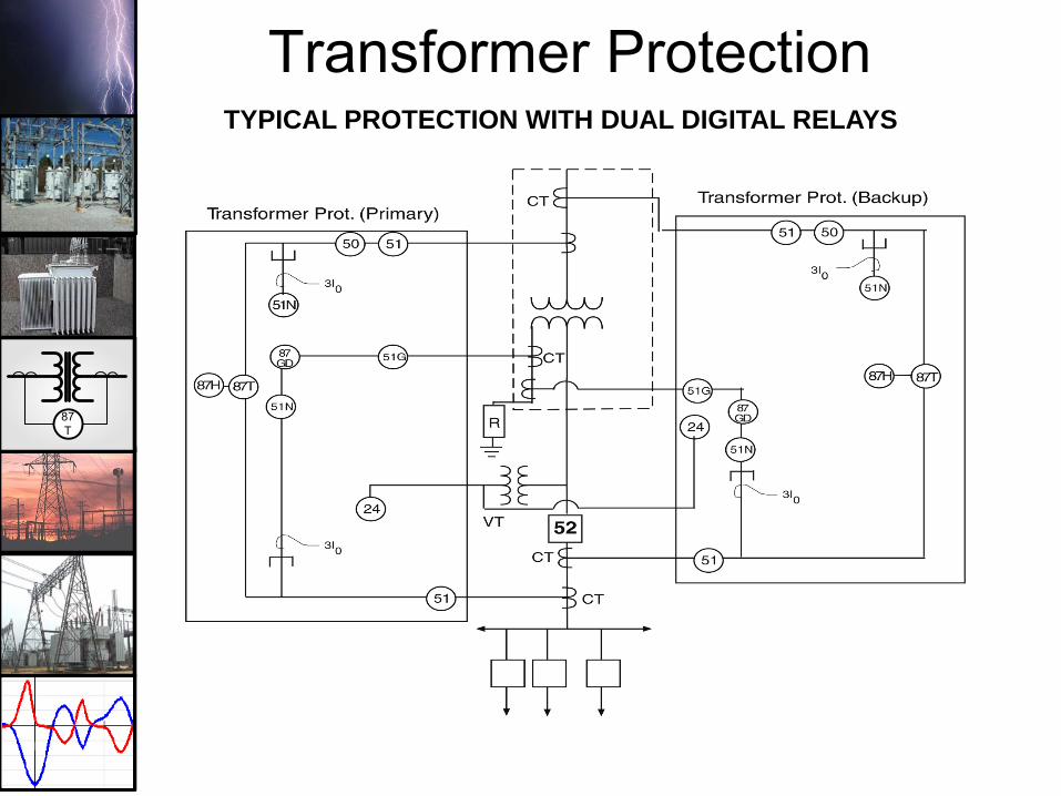
TYPICAL PROTECTION WITH DUAL DIGITAL RELAYS
Transformer Protection

87T
Traditional ApproachTripping Redundancy

87T
New ApproachTripping Redundancy Improvement

87T
Schemes - Bus Fault Protection
• Use interlocked overcurrent to avoid long time delays
• Inexpensive solution for lower voltage distribution buses

87T
Vector Display, 87
R
87T

87T
Waveform Capture

87T
THE END??
FINALQUESTIIONS??