protocol for addressing induced seismicity associated with
TRANSCRIPT

GEOTHERMAL TECHNOLOGIES PROGRAM
Protocol for Addressing Induced Seismicity Associated with Enhanced Geothermal Systems
by
Ernie Majer, James Nelson, Ann Robertson-Tait, Jean Savy, and Ivan Wong
January 2012 | DOE/EE-0662

Cover Image
Courtesy of Katie L. Boyle, Lawrence Berkeley National Laboratory

i
iProtocol for Addressing Induced Seismicity Associated with Enhanced Geothermal Systems
Preface
In June 2009, the New York Times published an article about the public fear of geothermal development causing earthquakes. The article highlighted a project funded by the U.S. Department of Energy’s (DOE) Geothermal Technologies Program bringing power production at The Geysers back up to capacity using Enhanced Geothermal Systems (EGS) technology. The Geysers geothermal field is located two hours north of San Francisco, California, and therefore, the article drew comparisons to a similar geothermal EGS project in Basel, Switzerland believed to cause a magnitude 3.4 earthquake.
In order to address public concern and gain acceptance from the general public and policymakers for geothermal energy development, specifically EGS, the U.S. Department of Energy commissioned a group of experts in induced seismicity, geothermal power development and risk assessment to write a revised Induced Seismicity Protocol. The authors met with the domestic and international scientific community, policymakers, and other stakeholders to gain their perspectives and incorporate them into the Protocol. They also incorporated the lessons learned from Basel, Switzerland and other EGS projects around the world to better understand the issues associated with induced seismicity in EGS projects. The Protocol concludes that with proper study and technology development induced seismicity will not only be mitigated, but will become a useful tool for reservoir management.
This Protocol is a living guidance document for geothermal developers, public officials, regulators and the general public that provides a set of general guidelines detailing useful steps to evaluate and manage the effects of induced seismicity related to EGS projects. This Protocol puts high importance on safety while allowing geothermal technology to move forward in a cost effective manner.
The goal of this Protocol is to help facilitate the successful deployment of EGS projects, thus increasing the availability of clean, renewable and domestic energy in the United States.
Project developers should work closely with the National Environmental Policy Act (NEPA) compliance officials of the involved Federal agency(ies) to align information needs and public involvement activities with the NEPA review process. The authors emphasize this Protocol is neither a substitute nor a panacea for regulatory requirements that may be imposed by federal, state or local regulators.
I would like to acknowledge everyone who gave their time and expertise at the induced seismicity workshops (see Appendix D) that led to this updated Protocol. Their input was critical to develop an informed and useful document. In addition, I would like to thank the authors of this document, whose ideas and support came together to write a clear and concise Protocol.
This document was put out for public comment and reviewed by NEPA, the U.S. Department of Energy and General Counsel. Special thanks to Christy King-Gilmore and Brian Costner for their guidance.
Sincerely,
Jay Nathwani
U.S. Department of Energy

ii Protocol for Addressing Induced Seismicity Associated with Enhanced Geothermal Systems

iii
iiiProtocol for Addressing Induced Seismicity Associated with Enhanced Geothermal Systems
Table of Contents1. Introduction . . . . . . . . . . . . . . . . . . . . . . . . . . . . . . . . . . . . . . . . . . . . . . . . . . . . . . . . . . . . . . . . . . . . . . . . . . . . . . . . . . . . . . . . . . . . . . . . . . . . . . . . . . . . . . . 1
1.1 Intended Use . . . . . . . . . . . . . . . . . . . . . . . . . . . . . . . . . . . . . . . . . . . . . . . . . . . . . . . . . . . . . . . . . . . . . . . . . . . . . . . . . . . . . . . . . . . . . . . . . . . . . 1
1.2 Objective . . . . . . . . . . . . . . . . . . . . . . . . . . . . . . . . . . . . . . . . . . . . . . . . . . . . . . . . . . . . . . . . . . . . . . . . . . . . . . . . . . . . . . . . . . . . . . . . . . . . . . . . 2
1.3 Background . . . . . . . . . . . . . . . . . . . . . . . . . . . . . . . . . . . . . . . . . . . . . . . . . . . . . . . . . . . . . . . . . . . . . . . . . . . . . . . . . . . . . . . . . . . . . . . . . . . . . 2
2. Steps in Addressing Induced Seismicity . . . . . . . . . . . . . . . . . . . . . . . . . . . . . . . . . . . . . . . . . . . . . . . . . . . . . . . . . . . . . . . . . . . . . . . . . . 5
STEP 1: Perform Preliminary Screening Evaluation . . . . . . . . . . . . . . . . . . . . . . . . . . . . . . . . . . . . . . . . . . . . . . . . . . . . . . . . . . . . . . . . . . 62.1.1 Purpose . . . . . . . . . . . . . . . . . . . . . . . . . . . . . . . . . . . . . . . . . . . . . . . . . . . . . . . . . . . . . . . . . . . . . . . . . . . . . . . . . . . . . . . . . . . . . . . . . . . 6
2.1.2 Recommended Approach . . . . . . . . . . . . . . . . . . . . . . . . . . . . . . . . . . . . . . . . . . . . . . . . . . . . . . . . . . . . . . . . . . . . . . . . . . . . . . . . . 6
2.1.3 Summary . . . . . . . . . . . . . . . . . . . . . . . . . . . . . . . . . . . . . . . . . . . . . . . . . . . . . . . . . . . . . . . . . . . . . . . . . . . . . . . . . . . . . . . . . . . . . . . . . 7
STEP 2: Implement an Outreach and Communication Program. . . . . . . . . . . . . . . . . . . . . . . . . . . . . . . . . . . . . . . . . . . . . . . . . . . . . 82.2.1 Purpose . . . . . . . . . . . . . . . . . . . . . . . . . . . . . . . . . . . . . . . . . . . . . . . . . . . . . . . . . . . . . . . . . . . . . . . . . . . . . . . . . . . . . . . . . . . . . . . . . . . 8
2.2.2 Recommended Approach . . . . . . . . . . . . . . . . . . . . . . . . . . . . . . . . . . . . . . . . . . . . . . . . . . . . . . . . . . . . . . . . . . . . . . . . . . . . . . . . . 8
2.2.3 Summary . . . . . . . . . . . . . . . . . . . . . . . . . . . . . . . . . . . . . . . . . . . . . . . . . . . . . . . . . . . . . . . . . . . . . . . . . . . . . . . . . . . . . . . . . . . . . . . . 10
STEP 3: Review and Select Criteria for Ground Vibration and Noise . . . . . . . . . . . . . . . . . . . . . . . . . . . . . . . . . . . . . . . . . . . . . . . . 112.3.1 Purpose . . . . . . . . . . . . . . . . . . . . . . . . . . . . . . . . . . . . . . . . . . . . . . . . . . . . . . . . . . . . . . . . . . . . . . . . . . . . . . . . . . . . . . . . . . . . . . . . . . . 11
2.3.2 Recommended Approach . . . . . . . . . . . . . . . . . . . . . . . . . . . . . . . . . . . . . . . . . . . . . . . . . . . . . . . . . . . . . . . . . . . . . . . . . . . . . . . . . 11
2.3.3 Summary . . . . . . . . . . . . . . . . . . . . . . . . . . . . . . . . . . . . . . . . . . . . . . . . . . . . . . . . . . . . . . . . . . . . . . . . . . . . . . . . . . . . . . . . . . . . . . . . . 12
STEP 4: Establish Local Seismic Monitoring . . . . . . . . . . . . . . . . . . . . . . . . . . . . . . . . . . . . . . . . . . . . . . . . . . . . . . . . . . . . . . . . . . . . . . . . 132.4.1 Purpose . . . . . . . . . . . . . . . . . . . . . . . . . . . . . . . . . . . . . . . . . . . . . . . . . . . . . . . . . . . . . . . . . . . . . . . . . . . . . . . . . . . . . . . . . . . . . . . . . . . 13
2.4.2 Recommended Approach . . . . . . . . . . . . . . . . . . . . . . . . . . . . . . . . . . . . . . . . . . . . . . . . . . . . . . . . . . . . . . . . . . . . . . . . . . . . . . . . . 13
2.4.3 Summary . . . . . . . . . . . . . . . . . . . . . . . . . . . . . . . . . . . . . . . . . . . . . . . . . . . . . . . . . . . . . . . . . . . . . . . . . . . . . . . . . . . . . . . . . . . . . . . . 14
STEP 5: Quantify the Hazard from Natural and Induced Seismic Events . . . . . . . . . . . . . . . . . . . . . . . . . . . . . . . . . . . . . . . . . . . 152.5.1 Purpose . . . . . . . . . . . . . . . . . . . . . . . . . . . . . . . . . . . . . . . . . . . . . . . . . . . . . . . . . . . . . . . . . . . . . . . . . . . . . . . . . . . . . . . . . . . . . . . . . . . 15
2.5.2 Recommended Approach . . . . . . . . . . . . . . . . . . . . . . . . . . . . . . . . . . . . . . . . . . . . . . . . . . . . . . . . . . . . . . . . . . . . . . . . . . . . . . . . 16
2.5.3 Summary . . . . . . . . . . . . . . . . . . . . . . . . . . . . . . . . . . . . . . . . . . . . . . . . . . . . . . . . . . . . . . . . . . . . . . . . . . . . . . . . . . . . . . . . . . . . . . . . . 17
STEP 6: Characterize the Risk of Induced Seismic Events . . . . . . . . . . . . . . . . . . . . . . . . . . . . . . . . . . . . . . . . . . . . . . . . . . . . . . . . . 182.6.1 Purpose . . . . . . . . . . . . . . . . . . . . . . . . . . . . . . . . . . . . . . . . . . . . . . . . . . . . . . . . . . . . . . . . . . . . . . . . . . . . . . . . . . . . . . . . . . . . . . . . . . 18
2.6.2 Recommended Approach . . . . . . . . . . . . . . . . . . . . . . . . . . . . . . . . . . . . . . . . . . . . . . . . . . . . . . . . . . . . . . . . . . . . . . . . . . . . . . . . 18
2.6.3 Summary . . . . . . . . . . . . . . . . . . . . . . . . . . . . . . . . . . . . . . . . . . . . . . . . . . . . . . . . . . . . . . . . . . . . . . . . . . . . . . . . . . . . . . . . . . . . . . . . 20
STEP 7: Develop Risk-Based Mitigation Plan . . . . . . . . . . . . . . . . . . . . . . . . . . . . . . . . . . . . . . . . . . . . . . . . . . . . . . . . . . . . . . . . . . . . . . . 212.7.1 Purpose . . . . . . . . . . . . . . . . . . . . . . . . . . . . . . . . . . . . . . . . . . . . . . . . . . . . . . . . . . . . . . . . . . . . . . . . . . . . . . . . . . . . . . . . . . . . . . . . . . . 21
2.7.2 Recommended Approach . . . . . . . . . . . . . . . . . . . . . . . . . . . . . . . . . . . . . . . . . . . . . . . . . . . . . . . . . . . . . . . . . . . . . . . . . . . . . . . . . 21
2.7.3 Summary . . . . . . . . . . . . . . . . . . . . . . . . . . . . . . . . . . . . . . . . . . . . . . . . . . . . . . . . . . . . . . . . . . . . . . . . . . . . . . . . . . . . . . . . . . . . . . . . 23
3. Acknowledgements . . . . . . . . . . . . . . . . . . . . . . . . . . . . . . . . . . . . . . . . . . . . . . . . . . . . . . . . . . . . . . . . . . . . . . . . . . . . . . . . . . . . . . . . . . . . . . . . . . . 25
4. References. . . . . . . . . . . . . . . . . . . . . . . . . . . . . . . . . . . . . . . . . . . . . . . . . . . . . . . . . . . . . . . . . . . . . . . . . . . . . . . . . . . . . . . . . . . . . . . . . . . . . . . . . . . . . . . 27
AppendicesA. Background & Motivation: Induced Seismicity Associated with Geothermal Systems . . . . . . . . . . . . . . . . . . . . . . . . . . . 29
B. List of Acronyms . . . . . . . . . . . . . . . . . . . . . . . . . . . . . . . . . . . . . . . . . . . . . . . . . . . . . . . . . . . . . . . . . . . . . . . . . . . . . . . . . . . . . . . . . . . . . . . 39
C. Glossary of Terms . . . . . . . . . . . . . . . . . . . . . . . . . . . . . . . . . . . . . . . . . . . . . . . . . . . . . . . . . . . . . . . . . . . . . . . . . . . . . . . . . . . . . . . . . . . . . . 41
D. Workshop Participants/Reviewers . . . . . . . . . . . . . . . . . . . . . . . . . . . . . . . . . . . . . . . . . . . . . . . . . . . . . . . . . . . . . . . . . . . . . . . . . . . . . 43
E. Relevant Websites . . . . . . . . . . . . . . . . . . . . . . . . . . . . . . . . . . . . . . . . . . . . . . . . . . . . . . . . . . . . . . . . . . . . . . . . . . . . . . . . . . . . . . . . . . . . . . 45

iv Protocol for Addressing Induced Seismicity Associated with Enhanced Geothermal Systems

1
1. INTRODUCTION
1Protocol for Addressing Induced Seismicity Associated with Enhanced Geothermal Systems
1. Introduction
Geothermal energy is a viable form of alternative energy that is expected to grow significantly in the near and long term. The energy estimated from hydrothermal systems is large, but the total supply from geothermal systems has the potential to become orders of magnitude larger if the energy from geothermal systems can be enhanced, i.e. through Enhanced Geothermal Systems (EGS). EGS is defined as any activities that are undertaken to increase the permeability in a targeted subsurface volume via injecting and withdrawing fluids into and from the rock formations that are intended to result in an increased ability to extract energy from a subsurface heat source. This can be done through such approaches as fluid pressurization, hydrofracture, and chemical stimulation. As with the development of any new technology, some aspects are accepted, and others need clarification and study. In the case of EGS, fluid injection is used to enhance rock permeability and recover heat from the rock. During the process of creating an underground heat exchanger by injection or the subsequent circulation of the system, stress patterns in the rock may change, resulting in seismic events (see Appendix A: Background and Motivation). In almost all cases, these events have been of relatively small magnitude, and by the time the energy reaches the surface, the vast majority are rarely felt (Majer et al. 2007). The impacts of a seismic event created by EGS can be significantly different from those associated with a natural earthquake: the former generally falls into the category of an annoyance, as with the passing of a rail transit vehicle or large truck, whereas the latter may cause damage in a moderate to large event. Although to date there is no recorded instance of a significant danger or damage (significant is defined here as damage that would affect a structure’s physical integrity; this is not to say that seismicity has not caused less severe damage such as cracks in walls or similar damage) associated with induced seismicity related to geothermal energy production, the introduction of EGS technology in populated areas could be regarded by some as an intrusion on the peace and tranquility of populated areas due to its potential “annoyance factor.”
Historically, induced seismicity has occurred in many different energy and industrial applications (reservoir impoundment, mining, construction, waste disposal, and oil and gas production). Although certain projects have stopped because of induced seismicity issues, proper study and engineering controls have always been applied to enable the safe and economic implementation of these technologies. Recent publicity surrounding induced seismicity at several geothermal sites points out the need to address and mitigate any potential problems that induced seismicity may cause in geothermal projects (Majer et al. 2007). Therefore, it is critical that the policy makers and the general community are assured geothermal technologies relying on fluid injections will be engineered to minimize induced seismicity risks, ensuring the resource is developed in a safe and cost effective manner.
1.1 Intended UseThe Protocol is intended to be a living document for the public and regulators, and geothermal operators. This version is intended to supplement the existing International Energy Agency (IEA) protocol (Majer et al. 2009) and as practically as possible, be kept up-to-date with state-of-the-art knowledge and practices, both technical and non-technical. As methods, experience, knowledge and regulations change with respect to induced seismicity, so should the Protocol. It also recognizes that “one size” does not fit every geothermal project, and not everything presented herein should be required for every EGS project. Local conditions at each site will call for different types of action. Variations in procedures will result from such factors as the population density around the project, past seismicity in the area, the size of the project, the depth and amount of injection and its relation to any faults, etc.
This document was prepared at the direction of the U. S. Department of Energy’s Geothermal Technologies Program. It is an advisory document intended to assist industry and regulators to identify important issues and parameters that may be necessary for the evaluation and mitigation of adverse effects of induced seismicity. Determination of actual site-specific criteria that must be met by a particular project is beyond the scope of this document; it remains the obligation of project developers to meet any and all applicable federal, state or local regulations.

1. INTRODUCTION
2 Protocol for Addressing Induced Seismicity Associated with Enhanced Geothermal Systems
1.2 Objective
Provide a flexible protocol that puts high importance on safety while allowing geothermal technology to move forward in a cost effective manner.
To promote the safety of EGS projects and to help gain acceptance from the general public for geothermal activities in general, and EGS projects specifically, it is beneficial to clarify the role and risks of induced seismicity, which can occur during the development stages of the EGS reservoir and the subsequent extraction of the geothermal energy. This document provides a set of general procedures that detail useful steps geothermal project proponents can take to deal with induced seismicity issues. The procedures are not prescriptive, but suggest an approach to engage public officials, industry, regulators, and the public at large, facilitating the approval process, helping to avoid project delays and promoting safety.
With respect to the existing IEA protocol (Majer et al. 2009), this document addresses many of the same issues, and others that arose after the protocol was published. For example, it provides a more accurate approach to address and estimate the seismic risk associated with EGS induced seismic events. Regulators, the public, the geothermal industry and investors need to have a framework to estimate such a risk. Another significant change is a shift toward addressing ground motions rather than event magnitudes to measure the impact of seismicity. This led to a discussion of the thresholds for vibration, which involve not only the amplitude of the ground motions but also such factors as the duration, frequency content and other measures of impact. Also, attention was paid to the legal implications with respect to the impact or effect of any recommended actions. Lastly, an effort was made to base recommendations on existing and accepted engineering standards that are used in such industries as mining, construction, or similar activities that produce or have the potential for producing unwanted ground motions and noise.
1.3 BackgroundTo access geothermal resources, wells are drilled to depths at which the required high temperatures and thermal capacities are reached. The depth required to reach that temperature depends upon the temperature gradient (the rate of temperature increase with depth), which varies significantly from place to place. Therefore, the depths of geothermal wells vary over a wide range, from less than 1,000 to 5,000 meters (m) in rare cases. In addition to elevated temperatures, a geothermal well for commercial development must also intersect sufficient permeability to enable the extraction and/or circulation of fluids at certain flow rates, i.e., at least a sustained production of 5 megawatts (MW) over a 30-year period.
The combination of sufficiently high temperature and good natural permeability occurs in certain areas of the earth, such as some areas of active tectonism and volcanism. However, these comprise only a fraction of the earth; elsewhere, permeability is lower, even though the desired temperature may be accessible by drilling. In such cases, the permeability of the rock must be enhanced to enable commercial flow rates. To date, the only method of adequate permeability enhancement in EGS is through fluid injection, which can have the side-effect of causing induced seismicity. In an important way, this side-effect is beneficial: EGS project developers monitor and map induced seismicity to understand and manage the EGS reservoir. The induced event locations show where fractures have slipped slightly in response to increasing pore pressure and/or temperature change during injection, a process that can increase the aperture and conductive length of some fractures, and therefore the permeability of the reservoir. Typically, monitoring and mapping of induced seismicity is used to help site and target deep wells.
The orientation of the fractures that tend to slip most easily in response to fluid injection depends upon the orientation of the ambient stresses acting on the reservoir rock. In turn, these depend on the regional tectonic framework and the local geologic structure. The ease with which fractures slip during injection depends upon the strength of the reservoir rock, the magnitudes of the stresses acting on it, and the pore pressure increase. The size of the seismic event will depend upon the amount of stress available to cause the slip and the dimensions of the slip area. Injection may cause thermal contraction, which also may play a role. The amount of fracture slip (the main cause of induced seismicity in EGS projects) depends upon the interplay between these elements. This explains the importance of understanding the geomechanics, temperature and hydraulics in EGS planning, assessment and development.

3
1. INTRODUCTION
3Protocol for Addressing Induced Seismicity Associated with Enhanced Geothermal Systems
It is noted that there is little if any potential for induced seismicity in geothermal applications where no fluid is injected or withdrawn from the native formations or if the fluids that are injected and/or withdrawn are at a shallow depth (less than 300 to 600 m). Therefore, such applications as heat pumps and shallow injections are not considered in this EGS Protocol because of the low potential for induced seismicity.
In this Protocol, we use the terms “vibration” and “ground shaking” or “ground motion.” We use “vibration” when referring to the regulatory aspects of ground motions, since vibrations can be and are regulated. We use “ground shaking” and “ground motion” interchangeably when referring to the ground motions resulting from natural earthquakes and induced seismic events. We also distinguish between natural tectonic “earthquakes” and “induced seismic events” even though the processes of generation are generally the same.
Finally we also note that the terms “induced” and “triggered” are often used interchangeably in the literature on induced seismicity and by practitioners in those fields and in the field of seismology. In terms of the process of causing a seismic event, the two terms should be used differently although admittedly it is difficult to define where an induced seismic event should be called a triggered seismic event and vice versa. As an example of the discussion that is ongoing in the induced seismicity community, the U.S. Society of Dams has officially adopted the use of the term “reservoir-triggered seismicity” rather than the traditional 50-year old phrase “reservoir-induced seismicity.” In this Protocol we use the term “induced” to include all seismic events that result from fluid injection and will only use the term “triggered” in well-defined situations. A glossary of terms can be found in Appendix C.

4 Protocol for Addressing Induced Seismicity Associated with Enhanced Geothermal Systems
5
2. StepS in AddreSSing induced SeiSmicity
5Protocol for Addressing Induced Seismicity Associated with Enhanced Geothermal Systems
2. Steps In Addressing Induced Seismicity
A series of recommended steps to meet the objective stated above is included below. This is not a “one size fits all” approach, and stakeholders should tailor their actions to project-specific needs and circumstances.
This document outlines the suggested steps a developer should follow to address induced seismicity issues, implement an outreach campaign, and cooperate with regulatory authorities and local groups. With the goal in mind of gaining acceptance by non-industry stakeholders and promoting safety, the Protocol is a series of technical steps to inform the project proponent, as well as complementary outreach and/or education steps to inform and involve the public.
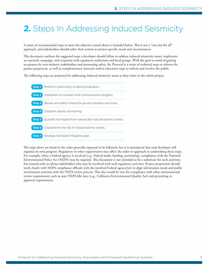
The following steps are proposed for addressing induced seismicity issues as they relate to the whole project.
Step 1 Perform a preliminary screening evaluation.
Step 2 Implement an outreach and communication program.
Step 3 Review and select criteria for ground vibration and noise.
Step 4 Establish seismic monitoring.
Step 5 Quantify the hazard from natural and induced seismic events.
Step 6 Characterize the risk of induced seismic events.
Step 7 Develop risk-based mitigation plan.
The steps above are listed in the order generally expected to be followed, but it is anticipated that each developer will organize its own program. Regulatory or other requirements may affect the order or approach to undertaking these steps. For example, when a Federal agency is involved (e.g., Federal lands, funding, permitting), compliance with the National Environmental Policy Act (NEPA) may be required. This document is not intended to be a substitute for such activities, but instead seeks to advise stakeholders who may be involved with such regulatory activities. Project proponents should work closely with NEPA compliance officials with the involved Federal agency(ies) to align information needs and public involvement activities with the NEPA review process. This also would be true for compliance with other environmental review requirements such as state NEPA-like laws (e.g., California Environmental Quality Act) and permitting or approval requirements.

2. StepS in AddreSSing induced SeiSmicity
6 Protocol for Addressing Induced Seismicity Associated with Enhanced Geothermal Systems
STEP 1
Perform a Preliminary Screening Evaluation
2.1.1 Purpose Sources of opposition to projects such as an EGS project often arise from a variety of possible issues, ranging from local politics to community preferences or regulations. Technical considerations such as those associated with seismic risk, although often secondary, must also be evaluated to decide if the project can proceed. Therefore, before going forward in the planning and engineering of an EGS facility, the feasibility of such a project and the associated socioeconomic and financial risks must be evaluated to determine whether there are any obvious “show-stoppers.” This first step is therefore a “screening” analysis designed to eliminate sites that would present a low probability of success, and to confirm those that have manageable risks and remain strong contenders. This provides an initial measure of project acceptability, and should include consistency with Executive Order 12898, Federal Actions to Address Environmental Justice in Minority Populations and Low-Income Populations (February 11, 1994).
Although not intended to be a complete analysis, Step 1 should have enough rigor and credibility to support early technical communications, identify potential impacts, and establish credible plans to go forward, with enough confidence to demonstrate that public and regulatory acceptability is achievable. This step focuses on expected ground motion, damages, and nuisance. Its goals are to identify projects that have a low likelihood of technical success or of being accepted by local populations—and to give an opportunity to the responsible developer to make an informed decision as to whether it is viable to proceed, and to determine the analysis needs for those projects that do proceed.
2.1.2 Recommended ApproachA bounding type of analysis should be performed to quickly establish the likelihood that the project would obtain regulatory approval to proceed. The likelihood should be categorized as one of four levels: (I) High-to-very high, (II) Medium-to-high, (III) Medium-to-low, or (IV) Low-to-very low.
Potential EGS geographic areas may vary significantly in terms of their populations and the existing level of seismicity. The screening analysis for some projects may be quite clear; for example, a remote site with little natural seismicity would be categorized as a clear Level I, and an urban site with active faulting would be a clear Level IV. For those projects in all but category Level IV (which should be discarded after initial screening), this process will highlight the areas of risk that need to be addressed.
The same general approach to standard risk analysis is suggested for this screening process, but with an emphasis on simplicity, and using an approximate or qualitative approach rather than the often more onerous quantitative approaches.
a. Review relevant federal, state, and local laws and regulations.
Generally assess the prospect of proceeding with the project; i.e., determine if the local regulations are so restrictive that any effects of induced seismicity would not be allowed.
b. Determine the radius of influence within which there could be a negative impact as a result of seismic activity due to EGS.
Identify the existing potential seismic hazards for natural seismicity (e.g., U.S. Geological Survey National Hazard Maps, Petersen et al. 2008). This radius of influence will be determined by many local factors such as proximity to structures, expected seismicity, types of structures, local geology, and expected size of EGS project. Estimate the maximum injection-induced seismic event, including a realistic maximum estimate of ground motion, using similarities with existing EGS projects; this will allow a refinement of the radius of influence.

7
2. StepS in AddreSSing induced SeiSmicity
7Protocol for Addressing Induced Seismicity Associated with Enhanced Geothermal Systems
c. Identify potential impacts, including physical damages, social disturbances, nuisance, economic disruption, and environmental impacts.
d. Establish an approximate lower and upper bound of potential damages, using both the average expected induced seismicity, and the worst case, based on: 1) the number, type and average value of structures impacted, and 2) the likely range of ground motion, either from observations or from assumed event magnitudes and existing ground motion attenuation relationships.
e. Based on these results, classify the overall risk as one of the four above described categories (Levels I to IV), from which the recommended decision is as follows:
Additionally, consider and factor in the public’s level of concern regarding the project. Therefore, the final decision needs to be made after interaction with the local community in recognition of the fact that different communities may have different acceptance levels of risk, and/or possibly different socioeconomic needs. This will allow this risk scale to be calibrated; hence, outreach and transparency play an important role.
If it is decided to proceed with planning, the results of the bounding analysis would be presented to the public in the potentially impacted geographical region (as defined in the radius of influence) to facilitate communication and feedback. In particular, a scientifically credible estimate of the worst-case scenario should be made to quantify its probability of occurrence, and to compare the worst-case scenario with events of comparable levels of risk, including the risk associated with natural seismicity. (See Step 2 which discusses mechanisms for outreach.)
At a minimum, the following estimates should be included in the screening study:
• A description (location, magnitude, frequency of occurrence) of the selected natural earthquakes and/or induced seismic events considered in the screening study.
• A map of the ground motion people might experience from these earthquakes and/or induced seismic event, and its frequency of occurrence.
• A description of conditions that could constitute nuisances, and what is commonly accepted in other similar cases (mining, transportation, industrial manufacturing, construction, etc.)
• The level of impact perceived to be safe by the stakeholders (regulators, community, operator, etc.)
• An estimate of the number of people, institutions, and industries located in the region that might be exposed to any impact of concern, the expected frequency of occurrence, and possible mitigation measures.
2.1.3 SummaryStep 1 is an initial screening that should be capable of withstanding regulatory and public scrutiny for the purpose of determining the overall feasibility of the project, and identifying possible flaws or circumstances that could become “show-stoppers” for the EGS project.
The recommended process for Step 1 includes the collection of readily available information and scientific and nontechnical information that could be used to assess the potential impact on the communities and stakeholders, a simple but rigorous analysis to evaluate the possible minimum impact in routine operations, and possible worst-case impact of the proposed project.
I. Very Low: II. Low: III. Medium: IV. High:
Proceed with planning. Can proceed with planning, but may require additional analysis to confirm.
Probably should not proceed at this site, but additional analysis might support proceeding.
Do not proceed.

2. StepS in AddreSSing induced SeiSmicity
8 Protocol for Addressing Induced Seismicity Associated with Enhanced Geothermal Systems
STEP 2
Implement an Outreach and Communications Program
2.2.1 PurposeAcceptability to the local community is an important milestone in an EGS project. It is critical that public stakeholders are kept informed and their input is considered and acted upon as the project proceeds. The outreach and communications program is designed to facilitate communication and maintain positive relationships with the local community, stakeholders, regulators, and public safety officials. All of these groups are likely to provide their feedback to the geothermal developer at different times during the project.
The outreach program should help the project achieve a level of transparency and participation based on the following suggested framework for interaction:
• The project developer should create an outreach plan at the start of the project and periodically update and modify the plan as needed as the project proceeds, addressing stakeholder concerns.
• The amount and type of outreach should be related to the specific project situation, including distance from population, size of the project, duration of activities with potential for induced seismicity, the regulatory environment, and the number and types of entities responsible for public safety.
• The dialogue should be open, informative and multi-directional.
• Multiple meetings should be held as the project progresses and more information is obtained.
• Each group (community, stakeholders, regulators, public officials) should be approached at an appropriate technical level. A mechanism to respond to their concerns and questions should be put in place and maintained throughout the project.
It is expected that there would be many participants in the outreach and communications plan, including the project proponents (developer team, seismologist, civil or structural engineer, local utility company, and a representative of the funding entity), the community (local project employees, community leaders, and community members at large), and public safety officials, regulators and/or organizations (law enforcement, fire department, emergency medical personnel).
2.2.2 Recommended ApproachThe following list is relatively long and tries to envisage many scenarios in which the public may become involved with an EGS project. As for the Protocol itself, there is no “one size fits all” approach to outreach and communications, and it is expected that project proponents will prepare their own outreach plans that are suitable to the issues at hand. All of the following are considered as suggestions only; some may not be needed, depending on the specifics of the project and the local communities.
a. Evaluate outreach needs.
Identify the people and organizations who would be the outreach targets; hold preliminary discussions with community leaders, regulators and public safety officials to explain the project and determine their concerns; identify individuals (community, regulatory, and public safety) who have the trust of the community at large, and engage them in discussions about the project; identify community needs that could be partially or fully met by the EGS project (e.g., school science programs, support to libraries, or community facilities supplied by produced geothermal fluids, such as a community greenhouses, heating systems, and swimming pools); consider what the project could reasonably offer the community to increase their involvement, appreciation, and pride in the project, including employment opportunities.

9
2. StepS in AddreSSing induced SeiSmicity
9Protocol for Addressing Induced Seismicity Associated with Enhanced Geothermal Systems
b. Develop plans to approach community, stakeholders, regulators, and public safety officials.
c. Develop a public relations plan to generate interest in the project from local media.
d. Set up a local office in the community, ideally including technical displays for visitors.
e. Hold an initial public meeting and site visit that covers both technical and non-technical issues.
Assume that the audience is well informed and knowledgeable, but also be prepared to explain issues in relatively simple terms. Explain how the project is funded and introduce the team and its qualifications. If applicable, explain that public institutions such as the U.S. Geological Survey, universities and national labs may also be involved, not only as technical help but as independent agencies to check results. Begin with an overview of the project and the motivation for doing it; then explain the steps in the project and the approximate timeline. Explain why induced seismicity may occur and the history of induced seismicity in other applications. This may require an explanation of the difference between induced seismicity and natural earthquakes (size, frequency, etc.). Ideally, the public would get involved in the discussion through questions and answers, ensuring a two-way dialogue, with both sides asking and answering questions. The developer can ask about any felt seismicity in the past, and should be prepared with a historic earthquake catalogue of the area (if available). If events have occurred nearby, the developer could ask if specific events were felt or not and if there was any damage.
• During this discussion, it can be acknowledged that EGS projects might have implications that are technical (for the project), safety-related (ensuring no danger to life and property), and economic (a path toward an indigenous, stable, and renewable energy supply; jobs). Explain the specific local benefit (jobs, school, library, heating, greenhouse, swimming pool, etc.). Explain the analyses already undertaken and the potential risks and advise the public that a procedure is being developed prior to execution to prevent adverse induced seismicity as well as modifying the planned operations if induced seismicity becomes a problem. Similarly, advise that a procedure is being developed for evaluating damage, and that it may require building inspections before any significant geothermal operations take place.
• Explain the benefits of the project, both locally and globally. If possible, provide some images of what the geothermal power plant might look like. If any activity is occurring on site, use it as part of the technical explanation; if there is no activity at the time the meeting is held, use that to demonstrate that the fundamental nature of the site will not change very much.
• The developer should listen to concerns and respond openly, and ideally would set up mechanisms to notify the community as work proceeds (phone tree, e-mail list, website, etc.) and for the community to ask questions and receive answers about the project.
f. If feasible, hold another site visit during a period of active drilling.
This will get people interested and involved, since drilling activities are genuinely interesting to most people.
g. Hold another meeting in advance of the first stimulation.
Explain the procedure for monitoring induced seismicity, the thresholds that have been set for induced seismicity and their rationale, the procedure for modifying the stimulation procedure in the event that the community will find the impacts of the induced seismicity intolerable, the call-in line (“hot line”) that is available for reporting felt events and how calls will be handled, and the liaison between the project and public safety officials.
h. If feasible, bring community members to the site when stimulation is occurring so that they can see the simplicity of the operation (water pumping).
i. After stimulation, hold another meeting to report on the results. Explain what happens next, and discuss the positive and any negative effects associated with the project to the community.
j. As additional operations at the site proceed, advise the community via the communications network and seek feedback.
k. Plan and conduct additional meetings and media events as appropriate.

2. StepS in AddreSSing induced SeiSmicity
10 Protocol for Addressing Induced Seismicity Associated with Enhanced Geothermal Systems
2.2.3 SummaryThe overarching goal of the outreach and communications program is to engage the community in a positive and open manner before onsite activities begin, and continuing as operations proceed. The first step is to understand the community and its needs and concerns, and then to determine creative ways to inform the community, engage them in a dialogue, and demonstrate the benefits of the project, particularly at the local scale. In addition to being an information exchange, the outreach and communications program should be designed to engender long-term support for the project. To the extent that a project is distant from local population, the requirements of the outreach program would decrease.

11
2. StepS in AddreSSing induced SeiSmicity
11Protocol for Addressing Induced Seismicity Associated with Enhanced Geothermal Systems
STEP 3
Review and Select Criteria for Ground Vibration and Noise
2.3.1 PurposeThe geothermal developer should identify and evaluate existing standards and criteria, thus becoming informed of the applicable regulations for ground-borne noise and vibration impact assessment and mitigation that have been developed and applied by other industries and could be helpful in evaluating the EGS project. These standards and criteria apply to damage to buildings, human activity interference, industrial/commercial/research/medical activity interference, and wildlife habitat. Existing criteria developed for non-EGS industries may or may not apply specifically to EGS, and appropriate acceptance criteria for an EGS project would likely be based on a variety of factors, such as land use, population, frequency of occurrence of EGS events, magnitudes, etc.
2.3.2 Recommended ApproachSteps for selecting environmental noise and vibration impact criteria are outlined below.
a. Assess Existing Conditions
Evaluate the existing ground vibration and noise environments in areas of potential impact to establish a baseline. Then evaluate the impacts anticipated from the project. Absolute vibration or noise limits for EGS seismic events would be at least equal to or more likely greater than that associated with existing natural and cultural background levels.
b. Review Local Ordinances
Identify local ordinances or requirements that may be appropriate as they relate to noise and vibration or other such disturbances. For example, noise and vibration from railroads or highways are not subject to local noise ordinances, while lawn mowers often are.
c. Review Building Threshold Cosmetic Damage Criteria
Building damage criteria are usually stated in terms of the peak particle velocity (PPV) (equivalent to the peak ground velocity or PGV) measured at the ground surface (typically the building foundation, but more appropriately the ground surface in the free-field). Building damage criteria usually focus on cosmetic damage, which includes hairline cracking of paint or stucco, where the cracks usually do not remain open.
Threshold cracking criteria have been recommended in U.S. Bureau of Mines (USBM) Report RI 8507 (Siskind et al. 1980). Although these criteria were developed for blasting and construction activities, the seismic energy from these activities would be similar to that from induced seismic events (in frequency bandwidth and range) and thus be applicable to induced seismicity cases. These criteria are almost universally used by the construction and mining industry to assess the potential for threshold cracking due to blasting, and are employed in many commercially available vibration monitoring systems. Transient ground vibration from blasting at mining operations is probably most closely related to EGS-induced seismicity, and the USBM criteria for threshold cracking due to blasting would appear to be directly applicable to EGS-induced seismicity.
Vibration limits are often applied to construction projects to avoid threshold damage to structures. Construction vibration limits may be lower than the USBM criteria, possibly for two reasons. One is the desire to be conservative in assessing damage risk. Another is that construction vibration may involve general earth-moving operations and continuous excitation from sources such as vibratory pile drivers, soil compactors, and impact pile drivers, which may operate for several weeks at a major project. Examples of construction vibration limits include those used by the California Department of Transportation (2004) and the Federal Transit Administration (FTA 2006). These construction vibration limits may be less applicable to EGS than the USBM criteria for blasting given in RI 8507.

2. StepS in AddreSSing induced SeiSmicity
12 Protocol for Addressing Induced Seismicity Associated with Enhanced Geothermal Systems
d. Review Structural Damage Criteria
Local building codes and structure types should be reviewed to determine appropriate ground-motion limits that might be applicable. Dowding (1996) suggests that reinforced concrete structures can experience high vibration without damage, perhaps as high as 125 to 250 mm/sec (5 to 10 in/sec) peak particle velocity (PPV). These PGVs are considerably higher than thresholds for cosmetic damage. Siskind (2000) discusses a number of case histories and experiments that indicate the PGVs at which both cosmetic and structural damage may occur. In particular, cracking of free-standing masonry walls was found for PGVs of 150 mm/sec to 275 mm/sec (6 to 11 in/sec). Continuous exposure of full-scale free-standing concrete masonry unit walls to PGVs of up to 175 mm/sec (7 in/sec) at 10 Hz for 26 hours did not produce cracking (Siskind 2000).
Soil settlement due to vibration is discussed by Dowding (1996). Pile driving can induce some densification, though usually within a distance associated with the length of the pile. A review of the literature concerning foundation settlement due to repetitive exposure to ground motions expected for EGS should be conducted. Damage criteria for underground structures, such as pipelines or basement walls, should be reviewed; a useful discussion is provided by Dowding (1996).
e. Assess Human Exposure to Vibration
Guidelines for assessing human response to vibration are provided in American National Standard Institute (ANSI) S2.71-1983 (formerly ANSI S3.29-1983) Guide to the Evaluation of Human Exposure to Vibration in Buildings. This standard corresponds to International Organization for Standardization (ISO) 2631, parts 1 and 2 (ISO 2003). The ANSI S2.71 guidelines include human response curves that define the levels of acceptability for vertical and horizontal third octave velocity and acceleration. Dowding (1996) discusses the use of PPV versus ANSI S2.71 and ANSI S2.18 criteria for human exposure to vibration.
f. Assess Interference with Industrial and Institutional Land Uses
Vibration limits for various industrial and institutional activities should be identified. The types of industrial and institutional land uses include hospitals, university research laboratories, biomedical research facilities, semiconductor manufacturing facilities, recording studios, metrology laboratories, and the like. The Institute for Environmental Sciences (IES 1995) has recommended generic vibration criteria for various types of equipment and instrumentation. Where available, specifications for specific equipment (such as hospital MRI machines, scanning electron microscopes, etc.) should be relied on.
g. Assess Ground-Borne Noise
Ground motions produced by an EGS-induced seismic event can produce audible noise inside buildings. The FTA provides guidelines for assessing ground-borne noise and vibration impacts from new transit systems (FTA 2006). These criteria may not be directly applicable to EGS, but they are likely to be referred to by stakeholders or regulators.
2.3.3 SummaryNumerous criteria, standards, and equipment specifications exist that may be drawn upon in assessing the impact of EGS seismicity on neighboring communities. These should be reviewed in detail and used to develop appropriate criteria for risk assessment. Some of the information may be directly applicable to EGS, but most would likely require some adjustment considering the short duration and unpredictability of induced seismic events. No doubt additional criteria can be found. For example, European countries where EGS activities have been developed are considering EGS-specific impact assessment criteria or mitigation design provisions.
13
2. StepS in AddreSSing induced SeiSmicity
13Protocol for Addressing Induced Seismicity Associated with Enhanced Geothermal Systems
STEP 4
Establish Local Seismic Monitoring
2.4.1 PurposeGather seismic data from the project area and vicinity to supplement existing seismic data (see Step 5, Section 2.5). The seismic data will include baseline data collected before operations begin at the site, and data collected during operations. The seismic data will be used not only to forecast induced seismicity activity, but also to understand induced seismicity for mitigation and reservoir management purposes.
As will be pointed out in Steps 5 and 6, a main element in forecasting the level of induced seismicity is to determine the baseline level of seismic activity that exists before the project starts. That is, how will the geothermal project modify existing “natural” seismicity? The amount of available seismic data will vary depending on the project location; in many areas, it is likely that the available baseline data will be from regional seismic monitoring (with distances between seismic monitoring stations on the order of tens of kilometers, if not more). Current experience indicates that geothermal projects (particularly EGS projects) require a high sensitivity to seismicity at low magnitude thresholds (magnitude 0 to 1 range) to enable active seismic zones to be properly identified. However, regional seismic monitoring is usually only reliable at or above magnitude 2.0. Also in most cases of geothermal induced seismicity, a great majority of the seismicity is below the magnitude 2.0 level, thus it is important to know the baseline level of seismicity at the lower magnitudes. Once the natural or baseline seismic data have been collected and evaluated, they are typically used for making operational decisions that relate to stress directions, seismic source types (faulting types) and other characteristics that will be useful for designing and operating the overall project. Finally, it is necessary to collect a minimum amount of seismic information to perform the screening step (Step 1), including some information on the frequency of occurrence of natural earthquakes that will be needed to estimate the potential impact on any nearby real-estate and/or industrial assets.
2.4.2 Recommended Approacha. The seismic monitoring program should strive to collect data that is not biased in time or space in the vicinity
of the potential geothermal project.
The overall objective is to collect enough information to characterize background seismicity and identify any active faults that have the potential to be affected by the EGS activities. The length of monitoring time before the injection begins will depend upon the existing information on local seismicity. If there is existing monitoring that detects small-magnitude events (in the magnitude 1.0 range), then the duration of seismic monitoring of the potential injection area may be as short as one month. Alternatively, in areas with no prior monitoring, the duration may need to be as long as six months. This implies that one should start monitoring with an array of instruments that has enough elements, sensitivity and aperture to capture seismicity in the volume at least twice the radius of the anticipated stimulated (reservoir) volume, at magnitudes of as small as magnitude 1.0, and preferably magnitude 0.0.
b. The more sensitive the array of instruments, the more detail can be collected on fault structure, seismicity rates, failure mechanisms, and state of stress.
These are all needed to not only model and forecast seismicity, but also to design the EGS resource development program. Evaluating the ongoing natural background seismicity also enables an understanding of the mechanisms of stress buildup and release that may be more easily triggered by fluid injection. Ideally, bandwidth and dynamic range should be maximized to the extent possible; however, typical seismic networks for capturing seismicity in these types of applications target the frequency range from a few hertz to several hundred hertz. Twenty-four bit resolution is now common at these data rates, and should be used in EGS projects. Borehole installations of wide-bandwidth sensors are better than surface sensors owing to the increased signal-to-noise ratio and the ability to capture small magnitude events, increasing resolution, and location accuracy. The sensors (surface or borehole) should record three-component data in order to provide complete information on the failure mechanisms and wave propagation (compressional and shear waves) attributes, in addition to providing data for more precise locations.
2. StepS in AddreSSing induced SeiSmicity
14 Protocol for Addressing Induced Seismicity Associated with Enhanced Geothermal Systems
c. The minimum data processing should provide the location, magnitude and source mechanisms.
More sophisticated analysis such as advanced location schemes (double difference locations, tomographic analysis for improved velocity models, moment tensor analysis and joint inversions, etc.) will probably be needed in the operational phases of the project, but are unlikely to be needed during the background monitoring phase. Procedures for almost all of these methods are available in the public domain. To estimate the instrumentation requirements, we have defined a “typical geothermal project” as one or two injection wells and several production wells, all located in an area with a diameter of 5 km or less. In such a “typical” project, achieving the above objectives requires at least eight three-component stations distributed over and around the area. Deep or wider area projects may require more than eight stations, keeping in mind that at least five stations are needed to collect enough data to reliably locate events. As the project advances and the seismic events are characterized, more stations may be needed to “follow” and characterize the seismic activity and utilize the events to develop strategies not only for mitigation of induced seismicity, but also for reservoir enhancement and management. In certain instances, it may be beneficial or required to “in-fill” the main array with temporary stations to increase array sensitivity and achieve better location accuracy and focal mechanism coverage, particularly at the time of reservoir creation or when the overall operational strategy is changed. The final issue with regard to instrumentation is the decision regarding continuous recording vs. triggered recording. In any case, especially during the injection phase, the data should be processed in close to real time for location and magnitude to enable rapid feedback for both technical analyses and any required mitigation.
d. The monitoring should be maintained throughout the injection activity to validate the engineering design of the injection in terms of fluid movement directions, and to guide the operators on optimal injection volumes and rates.
Background and local monitoring will also separate any natural seismicity from induced seismicity, providing protection to the operators against specious claims, and ensuring that local vibration regulations are being followed. The local monitoring should include less sensitive recorders that only record ground shaking that can be felt. Typically, this is achieved by installing a few strong motion recorders near any sensitive structure to record vibrations that may be problematic. It is also important to make the results of the local monitoring available to the public in as close to real time as feasible. The monitoring should be maintained at a comprehensive level throughout the life of the project, and possibly longer; however, if the rate and level of seismicity decrease significantly during the project, consideration can be given to discontinuing the monitoring.
2.4.3 SummarySeismic monitoring should be commenced as soon as a project site is selected. It should be comprehensive enough to allow complete spatial coverage of background or baseline seismicity over an area that is at least twice as large as the largest anticipated enhanced reservoir. The monitoring should be maintained for the lifetime of the project and possibly longer, depending on seismicity created and volume affected. Instrumentation should be able to detect events at least as small as magnitude 1.0 and preferably to magnitude 0.0.

15
2. StepS in AddreSSing induced SeiSmicity
15Protocol for Addressing Induced Seismicity Associated with Enhanced Geothermal Systems
STEP 5
Quantify the Hazard from Natural and Induced Seismic Events
2.5.1 PurposeEstimate the ground shaking hazard at a proposed EGS site due to natural seismicity and induced seismicity. Assessing the ground shaking hazard from natural seismicity will provide a baseline from which to evaluate the additional hazard from induced seismicity. Hazard is defined as the result of a physical phenomenon (such as an earthquake or induced seismic event) that can cause damage or loss. There are several types of hazards that can result from an earthquake; however, for induced seismic events, we are only concerned with ground shaking and to a much lesser extent, noise.
The preferred approach to characterizing ground shaking is to characterize it in terms of a quantifiable measure such as acceleration, velocity, or displacement. Instrumental recordings of ground shaking are generally in terms of acceleration or velocity. Seismology engineers prefer acceleration because that is the measure they use in their practice. In the absence of recording instruments and particularly before the development of seismographs, the qualitative measure called “intensity” was used in seismology to describe ground shaking. In the United States, the Modified Mercalli Intensity scale is used. However, intensity is difficult to equate to acceleration or velocity making it of limited value in evaluating hazard and in engineering.
Step 5 should be performed before any geothermal stimulation and operations are initiated. Characterization of future induced seismicity at a site is very difficult and assessments must be made based upon the empirical data from other case histories and numerical models, which include specific site characteristics.
Two approaches can be taken to assess the seismic ground motion at a proposed site: a probabilistic seismic hazard analysis (PSHA) and a deterministic seismic hazard analysis (DSHA). Hazard results feed into risk analysis. Probabilistic hazard is more useful for risk analysis because it provides the probabilities of specified levels of ground motions being exceeded. Scenario-based risk analysis using the results of DSHA is useful to describe potential maximum effects to stakeholders.
In typical PSHAs for engineering design, the minimum magnitude considered is magnitude 5.0 because empirical data suggests that smaller events seldom cause structural damage (Bommer et al. 2006). Since no EGS-induced earthquake has exceeded magnitude 5.0 in size to date, the hazard analyses should be performed at lower minimum magnitudes. The Protocol recommends that PSHAs be performed for magnitude 4.0 so that the hazard with EGS seismicity can be compared with the baseline hazard. To provide input into the risk analysis (Step 6), an even lower minimum magnitude should be considered for nuisance effects or interference with sensitive activities.
The ground-motion hazard should be expressed in terms of peak ground acceleration (PGA), acceleration response spectra (to compare with spectra from natural earthquakes and building code design spectra) and PGV. Since induced earthquakes are generally small magnitude, durations will be short and not of structural concern. PGV or PPV will be needed for comparison with cosmetic and structural building damage criteria, with criteria for vibration-sensitive research and manufacturing, and for human activity interference.

2. StepS in AddreSSing induced SeiSmicity
16 Protocol for Addressing Induced Seismicity Associated with Enhanced Geothermal Systems
2.5.2 Recommended ApproachPSHAs should be performed first for the natural seismicity, and then the EGS-induced seismicity should be superimposed on top of that.
a. Estimate the Baseline Hazard from Natural Seismicity
• Evaluate historical seismicity and calculate frequency of occurrence of background seismicity based on a catalog of natural earthquakes. If baseline seismic monitoring was performed in the EGS geothermal project area, incorporate the data into the catalog. Account for the incompleteness of the catalog and remove dependent events (e.g., aftershocks and foreshocks). Examine any focal mechanisms of natural seismicity to assess the tectonic stress field.
• Characterize any active or potentially active faults in the site region and estimate their source parameters (source geometry and orientation, rupture process, maximum magnitude, recurrence model, and rate) for input into the hazard analysis. The maximum earthquake that can occur on a fault is a function of the available fault area and the amount of displacement that will occur in an event. Empirical relationships have been developed that estimate magnitude from rupture length, rupture area, and maximum and average event displacement.
• For communities that may be impacted by EGS-induced seismicity, evaluate the geological site conditions and, if practical, estimate the shear-wave velocities of the shallow subsurface beneath the potentially impacted communities. The shear-wave velocity profile is often used in ground-motion prediction models to quantify site and building foundation responses.
• Select appropriate ground-motion prediction models for tectonic earthquakes for input into the hazard analysis. These models are generally based on strong motion data and relate a specified ground-motion parameter (e.g., PGA) with the magnitude and distance of the causative event, and the specific conditions at the potentially affected site(s).
• Perform a PSHA and produce hazard curves to assess the baseline hazard due to natural seismicity prior to the occurrence of any induced seismicity. De-aggregate the hazard results in terms of seismic source contributions.
b. Estimate the Hazard from Induced Seismicity
Estimating the hazard from induced seismicity is more difficult than for natural seismicity because of the small database of induced seismicity observations both in terms of seismic source characterization and ground-motion prediction. However, as more information becomes available (particularly seismic monitoring results), the hazard can be re-calculated and the uncertainties reduced. Possible steps that should be taken include the following:
• Evaluate and characterize the tectonic stress field based on earthquake focal mechanisms, the structural framework of the potential geothermal area, and any other available data, particularly the results from any prior seismic monitoring. To the extent practicable given the available data, develop a 3D model of the geothermal area with particular focus on 1) the stratigraphy, 2) pre-existing faults and fractures which could be sources of future induced seismicity, and 3) the prevailing stress field in which they exist. This should include evaluations of drilling results, wellbore image logs, and any other subsurface imaging data that may exist (e.g., seismic tomography, potential field data).
• Review known cases of induced seismicity and compare the tectonic and structural framework from those cases with the potential geothermal area. In particular, examine and compile the information on the maximum magnitude and the frequencies of occurrence of the induced seismicity.
• Evaluate the geologic framework of the project area, the characteristics and distribution of pre-existing faults and fractures, the tectonic stress field, etc. (See Step 4, Section 2.4.2). This characterization will be useful in assessing the potential and characteristics of future EGS-induced seismicity. The best approach to estimating the potential maximum induced earthquake is to characterize the maximum dimensions of pre-existing faults which could rupture in an induced earthquake. To be able to estimate fault dimensions, imaging faults in the subsurface is required (see Step 1, Section 2.1 above).

17
2. StepS in AddreSSing induced SeiSmicity
17Protocol for Addressing Induced Seismicity Associated with Enhanced Geothermal Systems
• Review and evaluate available models for induced seismicity (e.g., Shapiro et al. 2007; McGarr 1976) that also estimate the maximum magnitude of induced seismicity but based on injection parameters. This is an active area of research and there are models being developed as this document is being written. The models that are referred to here are only examples and others should be considered. Developing a model for induced seismicity is the most challenging task in assessing the hazard. Induced seismicity is the interaction between the injection parameters such as injection rates, pressures, and volume and depth of injection and the in situ stress conditions, lithologic, structural, hydrologic, and thermal conditions (e.g., faults, fractures, rock strength, porosity, permeability). These are the most challenging geologic characteristics to evaluate because of the difficulty in imaging and the general heterogeneity and complexity inherent in rock masses. Given this challenge, conservative assumptions on the maximum induced event and rates of induced seismicity can be made for upper-bound estimates of the hazard. Best estimates of the hazard can be improved by incorporating the possible ranges of parameters and their uncertainties. In some circumstances, an evaluation of the potential for far-field triggering a damaging earthquake on a nearby fault due to fluid-injection induced seismicity may be required although no such cases have been observed to date.
• Review and select empirical ground-motion prediction model(s) appropriate for induced seismicity, if any are available, or at a minimum, one that is appropriate for small to moderate magnitude natural earthquakes (magnitude < 5.0). Almost all existing ground-motion models have been developed for magnitude 5.0 and above natural earthquakes, and it has been suggested that there is a break in scaling between small and large earthquakes (Chiou et al. 2010). Since the maximum induced earthquake will likely be smaller than magnitude 5.0, the ground-motion prediction model only needs to be accurate at short distances (less than 10 to 20 km. Include the uncertainty in the ground-motion models.
• Calculate scenario ground motions from the maximum induced seismic event by performing a DSHA.
2.5.3 SummaryCompare the hazard results from the natural and induced earthquakes to assess the potential increase in hazard associated with the EGS project. The hazard results are fed into Step 6, the risk analysis. The hazard estimates should be updated as new information becomes available after injection activities have commenced and if and when induced seismicity has been initiated. In particular, the results of the seismic monitoring should be evaluated and incorporated into the hazard analyses where possible.

2. StepS in AddreSSing induced SeiSmicity
18 Protocol for Addressing Induced Seismicity Associated with Enhanced Geothermal Systems
STEP 6
Characterize the Risk of Induced Seismic Events
2.6.1 PurposeThe purpose of this step is to develop a rigorous and credible estimate of the risk associated with the design, construction, and operation of the proposed EGS facility, and to compare the future expected risk associated with the operation to the baseline risk existing prior to operation. Conceptually this step is the same as Step 1, but instead of aiming at an order of magnitude and a bounding of the risk only for the purpose of screening, Step 6 is intended to generate a higher resolution and more precise estimate for the purpose of making decisions on design and operations of the planned EGS. It will provide a measure of the variation of risk during future operation, and helps in evaluating alternative operational procedures, including those that could mitigate the negative effects and minimize the risk of induced seismicity.
2.6.2 Recommended ApproachThe standard method (Kaplan and Garrick 1981, U.S. Nuclear Regulatory Commission 1981, Whitman et al. 1997, McGuire 1984, Molina et al. 2010) of characterizing seismic risk concentrates on the impact of moderate-to-large earthquakes that have greater magnitudes than those generally seen in injection-induced seismicity. To date, the maximum observed earthquakes attributed to EGS operations have been magnitude 3.0 to 3.7 and the largest geothermal injection-related event was magnitude 4.6 (Majer et al. 2007). For all types of fluid injection, the largest events have been about magnitude 5.0, which occurred at the Rocky Mountain Arsenal (Majer et al. 2007, Cladouhos et al. 2010). The vast majority of EGS induced events are less than magnitude 3.0. Therefore, the dominant risk is associated with events that have low magnitudes and cause low-to-very-low ground motions. Consequently, the attention to risk will shift relatively, from the high-level risk of physical damage associated with large natural earthquakes to the more mundane level of a nuisance, and possibly the related economic impacts.
The fundamentals of the risk estimation method do not change for small ground motions. Physical damages to structures are deemed to be very small to nil, but some of the basic elements used to describe the damages will have to account for this shift by, for example, considering the appearance of small cracks and other minor architectural damages that usually constitute a very small portion of the damage. Also, human perception of small vibrations and the associated nuisance need to be considered as elements of the risk. This nuisance produced by small vibrations is difficult to quantify, as it depends not only on the dominant frequency of the vibration, but also how frequently it occurs.
The elements of a detailed risk analysis are as follows (see example of existing risk-analysis software, such as HAZUS 2010 or SELENA 2010):
a. Characterize the ground motion at each location within the area potentially impacted (See Step 5; Section 5.1).
b. Identify the assets that could be adversely affected and that could contribute to the total risk.
Ground shaking from EGS operations may impact the quality of people’s lives, the built environment, and the economy in several ways for which the risk needs to be evaluated. Contributing to the risk are those elements of our socioeconomic and living environment for which ground-motion impact would be perceived as negative because of its consequences on the financial, environmental, or personal well-being of the affected community (Mileti 1982). Including all the possible risk contributors would be a daunting task and difficult to achieve, and it is reasonable to restrict the range of consideration to the most important areas of concern. Some of the impacts to consider are purely physical, such as damage to structures, and there are well-accepted methods to assess them and to quantify their associated risks, usually in monetary terms (see HAZUS, SELENA). Other impacts dealing with human perception and sensitivity are more difficult to assess and quantify. However, there are existing methods, albeit not as well established as those associated with damage.

19
2. StepS in AddreSSing induced SeiSmicity
19Protocol for Addressing Induced Seismicity Associated with Enhanced Geothermal Systems
Four classes of impacts can be identified, as follows:
I. Physical damage to residential housing and community facilities.
Damage to structures would probably be the main concern of any community. Much has been published concerning damage from medium-to-large earthquakes (see Applied Technology Council (ATC) publications, particularly ATC-3 Tentative Provisions for the Development of Seismic Regulations for Buildings. For small magnitude and small ground-motion events, the existing information is largely based on USBM research conducted in the 1970s with respect to vibration from controlled blasting (controlled detonation). Damage to the built environment to be considered (e.g., structures) must be separated into at least two categories: 1) minor cosmetic (threshold cracking), and 2) major structural damage.
II. Physical damage to the infrastructure of industrial/commercial/research/medical facilities.
It is unlikely that strong ground shaking generated by EGS-induced seismic events would occur; however, stakeholders nevertheless tend to be concerned with infrastructure damage. Significant structural damage to infrastructures by EGS is also equally unlikely, but should damage occur, its assessment should be based on design, seismic code requirements, and, in the absence of such data, site visit and observation of structural characteristics. Adverse effects should at least be considered for all the vital elements of the infrastructure in the potentially impacted area, including industrial facilities (e.g., manufacturing, chemical/oil processing) and research facilities (both industrial and medical).
III. Human activity interference.
Human activity interference includes interference with sleep, conversation, enjoyment of recreation or entertainment, and the like. Of these, sleep disturbance is probably the defining activity interference, and induced seismicity from EGS activity may occur at any time of day or night. Speech interference is not likely, as seismicity usually does not radiate sufficient noise to be audible. However, secondary noise radiation such as squeaking walls may occur, and conversations may be suspended in response to perceptible seismic events. This can become problematic if it occurs often enough during the course of a day.
IV. Socioeconomic impact from damaged infrastructure and operation interference in businesses and industrial facilities.
Social and economic activity and personal well-being rely heavily on the reliability of complex utility networks (telephone, internet, water, gas, electricity, public transportation systems) that are vital to conducting business and for maintaining quality of life. The potential damage to infrastructure is consequently an important potential contributing component of the risk, and any damage leading to operational malfunctions (e.g., telephone service becoming unavailable) creates interruptions that can be very costly. Sometimes, very little physical damage can lead to a cascade of network consequences in a “domino effect,” particularly (but not exclusively) in communications (e.g., Internet interruptions leading to the loss of data).
c. Characterize the damage potential (vulnerability) from the risk contributors.
The potential damages are usually characterized in terms of a relation (called a vulnerability function) that gives the level of damages (physical damage, nuisance, and economic losses) for that contributor or a class of contributors, as a function of the level of the ground motion at a particular location. In a detailed probabilistic risk analysis, the vulnerability function gives the probability of failure of a structure in response to a particular stimulus (e.g., a given level of ground motion). Alternatively, it gives the average cost of replacement for an entire class (see HAZUS 2010, SELENA 2010, and ATC publications).
d. Estimate the risk.
The elemental risk associated with one risk contributor at a given location is the product of the damage that would be observed at this location for a given level of seismic ground motion, and the probability that this ground-motion level would occur. The value of interest is the total risk at this location, which is obtained by summing the elemental risks for all possible ground-motion levels, using the probabilistic seismic hazard curve developed in Step 5. A risk

2. StepS in AddreSSing induced SeiSmicity
20 Protocol for Addressing Induced Seismicity Associated with Enhanced Geothermal Systems
map, or map of expected losses, can be obtained by repeating this calculation for all points within the impacted area. Usually, modern probabilistic risk analyses provide a full probability distribution of the total risk, which enables an estimate of the probability that a certain level of risk (monetary loss) will be exceeded. In that case, if the annual probability of exceedance of risk (losses) of X dollars ($) is p, it is customary to say that the “return period,” in years, of $X of risk (losses) is T=1/p years.
e. Present the results.
The general purpose for presenting the results of the risk analysis is to demonstrate that the probable (or a certain percentile) future negative effects of the EGS operation are within a range that will be tolerated by the regulators and community, with consideration of the overall benefits of the project, as judged by the community and all the stakeholders. It is also meant to provide input for comparing benefits and adverse effects on a rational, probabilistic, and rigorous basis.
For this purpose, results for all locations in the area impacted need to be presented and displayed in Geographic Information Systems (GIS) map format. The results should be separated into a least three categories: physical damage, nuisance, and economic losses. At a minimum, maps should be developed for each category using a simple calculation of the estimate of the risk. Ideally, risk maps would be developed for one or several return periods, providing useful information on the range of possible risk, and contributing to the development of mitigation procedures.
The following is a list of possible useful presentation materials:
• Map of region impacted, as a function of time (months, years, decades, centuries)
• Map of short-term (10 to 20 years) probable (expected) impact, showing the potential for physical damages. These maps will be prepared for several levels of confidence to express the uncertainty in the models
• Map of short-term impacts in terms of the probable (expected) number of people experiencing ground shaking or exceeding design expectations, as a function of time, and proximity to the project
• A map showing the “red-flag” locations, either because they are specially sensitive or likely to experience high ground motion because of specific local site geological conditions, the nature of their business, or the fact that they are, e.g., a particularly sensitive node in a socioeconomic system or utility network
• A table showing the total probable cost, by category (physical, nuisance, economic), each year in the future, as a function of time.
2.6.3 SummaryThe purpose of Step 6 is to identify the different types of risks, and develop a quantitative estimate for each type, using well-accepted methods of risk assessment. The risk estimates should be revised after each update of the seismic hazard analysis described in Step 6. The estimate of risk should be a function of time and of the various possible future alternative plans of operation of the planned EGS to permit evaluations and comparisons between the alternatives, and help in the decision making. Results should be presented in ways that account for the nature of the potential risks and the parties that may be affected by the risk, in space and time, and with estimates of the potential costs associated with the risks.

21
2. StepS in AddreSSing induced SeiSmicity
21Protocol for Addressing Induced Seismicity Associated with Enhanced Geothermal Systems
STEP 7
Develop Risk-Based Mitigation Plan
2.7.1 PurposeThis step presents some suggested mitigation measures. Several types of mitigation can be applied. For example, direct mitigation might include modifying the injection rates and/or production rates. Indirect mitigation might include some sort of incentive for the affected community. Establishing a bond or insurance policy to mitigate potential liability claims may be a prudent option for an EGS developer. It is hoped that by properly carrying out the preceding 6 steps, mitigation will not be required in the majority of projects.
2.7.2 Recommended Approach
a. Direct Mitigation
If the level and impacts of seismicity are exceeding original expectations, it may be necessary to put mitigation measures in place and establish a means to “control” the seismicity. One obvious direct mitigation measure is to stop injection. This may stop induced seismicity in the long run, but because the induced seismicity probably did not start immediately, it will not stop immediately. That is, the stress states have been altered and immediately shutting off the injection without reducing the pressure may cause unexpected results. For example, in two EGS projects, magnitude 3.0 plus events occurred after the injection well was shot in (Majer et al. 2007). This suggests that it may be better to gradually decrease pressures and injections until the designed/desired levels of seismicity are achieved.
One system of direct mitigation is a calibrated control system, dubbed the “traffic light” system (Majer et al. 2007). This is a system for real-time monitoring and management of the induced seismic vibrations that continuously calculates and plots a cumulative window of the ground motion (usually PGV) as a function of injection rates and time.
The boundaries on this traffic light system, in terms of guiding decisions regarding the pumping operations, are as follows (Majer et al. 2007):
• RED—the lower bound of the red zone is the level of ground shaking at which damage to buildings in the area is expected to set in. Pumping suspended immediately.
• AMBER—the amber zone was defined by ground-motion levels at which people would be aware of the seismic activity associated with the stimulation, but damage would be unlikely. Pumping proceeds with caution, possibly at reduced flow rates, and observations are intensified.
• GREEN—the green zone was defined by levels of ground motion that are either below the threshold of general detectability or, at higher ground-motion levels, at occurrence rates lower than the already-established background activity level in the area. Pumping operations proceed as planned.
The major shortcoming of this type of approach is that it does not address the issue of seismicity that occurs after the end of the pumping operation. If seismicity exceeding the design levels occurs after all EGS activities stop, current knowledge of induced seismicity indicates that the seismicity will stop as the subsurface conditions return to the natural state. The time for this to occur will depend on the rate, length, and volume of injections and withdrawals. If seismicity does not subside in a reasonable time (few months), one should consider indirect mitigation activities (see next section). In any case, monitoring should continue for at least 6 months beyond the end of the project to determine whether any seismicity is occurring that exceeds background levels before the project began.

2. StepS in AddreSSing induced SeiSmicity
22 Protocol for Addressing Induced Seismicity Associated with Enhanced Geothermal Systems
The results of one such application at the Berlin geothermal field in El Salvador (see Majer et al. 2007 and Bommer et al. 2006) showed that the ground shaking hazard caused by small-magnitude induced seismic events presents a very different problem from the usual considerations of seismic hazard for the engineering design of new structures. On the one hand, the levels of hazard that can be important, particularly in an environment such as rural El Salvador (where buildings are particularly vulnerable owing to their method of construction), are below the levels that would normally be considered of relevance to engineering design. As stated previously, in PSHA for engineering purposes, it is common practice to specify a lower bound of magnitude 5.0. On the other hand, unlike the hazard associated with natural seismicity, there is the possibility to actually control the induced hazard, at least to some degree, by reducing or terminating the activity generating the small events.
b. Indirect Mitigation
Different methods of indirect mitigation may be considered; a few are described below.
• Seismic Monitoring—as has been discussed previously in this Protocol, seismic monitoring in any potentially affected communities is expected to be part of an adequate EGS development plan. The monitoring program should consider the relevant regulations, standards and criteria regarding structural damage and noise, and the need for building inspections ahead of any EGS operations. Although there has been no documented case of damage from induced seismicity caused by fluid injection, seismic monitoring and reporting to the public is needed. The ideal monitoring program establishes background conditions and permits the evaluation of any EGS-related impact, providing a quantitative basis upon which an accurate evaluation of any claims can be made. This is fair to both the public and the geothermal developer. Evaluating the dominant frequency and PGA or PGV (the variables used to assess structural damage) normally requires the use of surface-mounted seismometers and/or accelerometers, so these may need to be installed at certain locations in the affected community. Continuous seismic monitoring to assess background cultural noise during various parts of the day, week and/or year is likely to be required. Regular reporting should be a matter of course, similar to evaluating the effects of blasting during a construction project.
• Increased Outreach—although it is assumed that the community is already informed about the EGS operations, it may be necessary to step up the communication and information flow during certain periods, particularly those characterized by any “unusual” seismicity. This should be done in conjunction with forecasts of trends in seismicity and analyses of the relationships between operational changes and changes in seismicity. To the extent that the public is informed about and involved with the project, they may be more accepting of the minor and temporary nuisance of induced seismicity.
• Community Support—in addition to jobs, a geothermal project may be able to offer other types of support to the local community to help establish good will. This can come in almost any form, including support for schools, libraries, community projects and scholarships. To the extent that a community support program is established early, the public may be favorably disposed toward the project.
• Compensation—if any damages can be documented to be caused by the induced seismicity, then fair compensation should be made to the affected parties. This could be directed toward the community at large, perhaps in the form of community grants, rather than individuals. This is particularly appropriate in the case of trespass and nuisance, although it may also be applicable in cases of strict liability and negligence as well. The amount of compensation should be negotiated with the affected parties.

23
2. StepS in AddreSSing induced SeiSmicity
23Protocol for Addressing Induced Seismicity Associated with Enhanced Geothermal Systems
c. Liability and Insurance
Legal studies specifically related to geothermal-induced seismicity and its effect on man-made structures and public perceptions are rare. One of the few studies by Cypser and Davis (1998) that addresses legal issues in the United States related to seismicity induced by dams, oil and gas operations, and geothermal operations points out the following:
Liability for damage caused by vibrations can be based on several legal theories: trespass, strict liability, negligence and nuisance. Our research revealed no cases in which an appellate court has upheld or rejected the application of tort liability to an induced earthquake situation. However, there are numerous analogous cases that support the application of these legal theories to induced seismicity. Vibrations or concussions due to blasting or heavy machinery are sometimes viewed as a ‘trespass’ analogous to a physical invasion. In some states activities which induce earthquakes might be considered `abnormally dangerous’ activities that require companies engaged in them to pay for injuries the quakes cause regardless of how careful the inducers were. In some circumstances, a court may find that an inducer was negligent in its site selection or in maintenance of the project. If induced seismicity interferes with the use or enjoyment of another’s land, then the inducing activity may be a legal nuisance, even if the seismicity causes little physical damage.
In the course of project planning and implementation an obvious mitigation procedure could be establishing a bond or insurance “policy” that would be activated as appropriate in the case of induced seismicity.
2.7.3 SummaryAlthough the risks associated with induced seismicity in EGS projects are relatively low, it is nevertheless prudent to consider that some type of mitigation may be needed at some point during the project. Therefore the developer should prepare mitigation plans that focus on both the operations themselves and the nuisance or damage that might result from those operations. The “traffic light” system may be appropriate for many EGS operations, and provides a clear set of procedures to be followed in the event that certain seismicity thresholds are reached. The traffic light system and the thresholds that would trigger certain activities by the geothermal developer should be defined and explained in advance of any operations.
Seismic monitoring, information sharing, community support and direct compensation to affected parties are among the types of indirect mitigation that may be needed. Early support from the developer to the community can improve the ability to respond effectively to a potentially impacted community in the event of problematic induced seismicity. This may come in the form of jobs or other forms of support that the community specifically needs.

24 Protocol for Addressing Induced Seismicity Associated with Enhanced Geothermal Systems

25
3. ACKNOWLEDGEMENTS
25Protocol for Addressing Induced Seismicity Associated with Enhanced Geothermal Systems
3. Acknowledgements
This work was primarily funded by the Assistant Secretary for Energy Efficiency and Renewable Energy, Geothermal Technologies Program, of the U.S. Department of Energy under Contract No. DE-AC02-05CH11231 at Lawrence Berkeley National Laboratory.

26 Protocol for Addressing Induced Seismicity Associated with Enhanced Geothermal Systems

27
4. references
27Protocol for Addressing Induced Seismicity Associated with Enhanced Geothermal Systems
4. References
American Standards Institute (ANSI) S2.71-1983 (R2006) (formerly ANSI S3.29-1983). Guide to the Evaluation of Human Exposure to Vibration in Buildings.
Applied Technology Council (ATC): http://www.atcouncil.org/onlinestore.html
Bommer, J. J., S. Oates J. M. Cepeda, C. Lindholm, J. Bird, R. Torres, G. Marroquín, and J. Rivas (2006). “Control of hazard due to seismicity induced by a hot fractured rock geothermal project.” Engineering Geology, v. 83, pp. 287-306.
California Department of Transportation, 2004. Transportation- and Construction-Induced Vibration Guidance Manual.
Chiou, B., Youngs, R., Abrahamson, N., and Addo, K., 2010. “Ground-motion attenuation model for small-to-moderate shallow crustal earthquakes in California and its implications on regionalization of ground-motion prediction models.” Earthquake Spectra, v.26, pp. 907-926.
Cladouhos, T., Petty, S., Foulger, G., Julian, B., and Fehler, M., 2010. “Injection induced seismicity and geothermal energy.” Geothermal Research Council Transactions, v. 34, pp. 1213-1220.
Cypser, D.A. and Davis, S.D., 1998. “Induced seismicity and the potential for liability under U.S. law.” Tectonophysics, v. 289, pp. 239-255.
Dowding, C.H., 1996. Construction Vibrations, Prentice Hall.
Federal Transit Administration (FTA), 2006. Transit Noise and Vibration Impact Assessment, FTA-VA-90-1003-06.
HAZUS, 2010: FEMA’s Methodology for Estimating Potential Losses from Disasters. http://www.fema.gov/plan/prevent/hazus/
Institute of Environmental Sciences, 1995. Contamination Control Division Recommended Practice, Considerations in Cleanroom Design, IES-RP-CC012.1, Appendix C.
International Organization of Standardization (ISO) 2631-2, 2003. Mechanical vibration and shock — Evaluation of human exposure to whole-body vibration — Part 2: Vibration in buildings (1 Hz to 80 Hz).
Kaplan, S. and Garrick, B.J.,1981. “On the Quantitative Assessment of Risk.” Risk Analysis, Vol. 1, No. 1, pp. 11-27.
Majer, E.L., Baria, R., Stark, M., Oates, S., Bommer, J., Smith, B., and Asanuma, H., 2007. “Induced seismicity associated with enhanced geothermal systems.” Geothermics, v. 36, pp. 185-222.
Majer, E., Baria, R. and Stark, M. (2009). ”Protocol for induced seismicity associated with Enhanced Geothermal Systems.” Report produced in Task D Annex I (9 April 2008), International Energy Agency-Geothermal Implementing Agreement (incorporating comments by C. Bromley, W. Cumming, A. Jelacic and L. Rybach). Available at: http://www.iea-gia.org/publications.asp.
McGarr, A., 1976. “Seismic moments and volume change.” J. Geophysical Res., v. 81, pp. 1487-1494.
McGuire, R.K., 1984. “Seismic Hazard and Risk Analysis.” Earthquake Engineering Research Institute Monograph 10, p. 221 .
Mileti D., 1982. “Public perceptions of seismic hazards and critical facilities.” Bulletin of the Seismological Society of America, v. 72, pp. S13-S18.
MIT, 2006: The Future of Geothermal Energy – Impact of Enhanced Geothermal Systems (EGS) on the United States in the 21st Century. MIT Press, Boston, USA.
Molina S., D.H. Lang, and C.D. Lindholm, 2010. SELENA – “An open-source tool for seismic risk and loss assessment using logic tree computation procedure.” Computer & Geosciences, Vol. 36, Issue 3, pp. 257-269.
Petersen, M.D., Frankel, A.D., Harmsen, S.C., Mueller, C.S., Haller, K.M., Wheeler, R.L., Wesson, R.L., Zeng, Y., Boyd, O.S., Perkins, D.M., Luco, N., Field, E.H., Wills, C.J., and Rukstales, K.S., 2008. Documentation for the 2008 update of the United States National Seismic Hazard Maps: U.S. Geological Survey Open-File Report 2008-1128, 61 p.
SELENA, 2010, The SELENA-RISE Open Risk Package, downloadable at: http://sourceforge.net/projects/selena/
Shapiro, S.A., Dinske, C., and Kummerow, J., 2007. “Probability of a given-magnitude earthquake induced by a fluid injection.” Geophysical Research Letters, v. 34, p. L22314.
Siskind, D. E., 2000. Vibrations from Blasting, International Society of Explosives Engineers, Cleveland, OH USA.
Siskind, D. E., Stagg, M. S., Kopp, J. W., and Dowding, C. H., 1980. Structure Response and Damage Produced by Ground Vibration from Surface Mine Blasting, U.S. Bureau of Mines Report RI 8507.
U.S. Nuclear Regulatory Commission, 1981. Fault Tree Handbook. NUREG-0492.
Whitman R.V., Anagnos T., Kircher C. A., Lagorio H. J., Lawson R. S. and Schneider P.l., 1997. “Development of a national earthquake loss estimation methodology.” Earthquake Spectra Vol. 13, No. 4, pp. 643-661.

28 Protocol for Addressing Induced Seismicity Associated with Enhanced Geothermal Systems

29
APPENDIX A. BACKGROUND & MOTIVATION
29Protocol for Addressing Induced Seismicity Associated with Enhanced Geothermal Systems
Appendix A Background and Motivation
SummaryTo produce economic geothermal energy, sufficient fluid, heat and permeability must be present in a rock mass. In many cases there is sufficient heat, especially if one drills deep enough, however, there is often a need to enhance permeability and/or fluid content, i.e., to enhance geothermal systems. This could be true in not only new geothermal projects but in existing geothermal projects where one would want to expand current production. One of the issues associated with Enhanced Geothermal Systems (EGS) is the effect and role of induced seismicity during the creation or expansion of the underground reservoir and the subsequent long-term extraction of the geothermal energy. Induced seismicity has been the cause of delays and possibly cancellation of at least two EGS projects worldwide, although to date there have been no or few adverse physical effects on the operations or on surrounding communities from existing geothermal projects. Still, there is public concern over the possible amount and magnitude of the seismicity associated with current and future geothermal operations. One of the more publicized incidents was the magnitude 3.4 event that occurred in the vicinity of the Basel, Switzerland EGS project on December 7, 2006. It caused local officials to stop the project and ultimately the project was cancelled. This is an example of where a more comprehensive understanding of the type and nature of seismicity would be of benefit to the operators as well as the public.
It should also be noted that induced seismicity is not new, it has successfully been dealt with in many different environments ranging from a variety of injection and engineering applications, including waste and water disposal, mining, oil and gas, and reservoir impoundment (Majer et al. 2007). Nevertheless, in order to address public and regulatory acceptance, as well as maintain industry buy-in of geothermal energy development, a set of recommendations/protocols are needed to be set out on how to deal with induced seismicity issues. Presented here are summaries of several case histories in order to illustrate a variety of technical and public acceptance issues. It is concluded that EGS induced seismicity needs do not pose any threat to the development of geothermal resources if community issues are properly handled and the operators understand the underlying mechanisms causing the seismicity and develop procedures for mitigating any adverse effects it is perceived to cause. In fact, induced seismicity by itself provides benefits because it can be used as a monitoring tool to understand the effectiveness of the EGS operations and shed light on the mechanics of the reservoir.
BackgroundNaturally fractured hydrothermal systems provide the easiest method of extracting heat from the earth, but the total resource and its availability tend to be restricted to certain areas. Reasons for pursuing the development of the EGS technology are two-fold: (1) to bring uneconomic hydrothermal systems into production by improving underground conditions (stimulation), and (2) to engineer an underground condition that creates a hydrothermal system, whereby injected fluids can be heated by circulation through a hot fractured region at depth and then produced to deliver heat to the surface for power conversion. The process of enhancing the permeability and the subsequent extraction of energy, however, may create seismic events. In addition to the above-mentioned seismicity at Basel, events as small as magnitude 2 and above near certain projects (e.g., the Soultz project in France, Baria et al. 2005) have raised residents’ concern for both damage from single events and the effect on seismicity over long time periods as the EGS project continues over many years (Majer et al. 2005). Some residents believe that the induced seismicity may cause structural damage similar to that caused by larger natural earthquakes. There is also fear and uncertainty that the small events may be an indication of larger events to follow. Recognizing the potential of the extremely large geothermal energy resource worldwide, and recognizing the possibility of misunderstanding about induced seismicity, the Geothermal Implementing Agreement under the International Energy Agency (IEA) initiated an international collaboration. The purpose of this collaboration is to “pursue an effort to address an issue of significant concern to the acceptance of geothermal energy in general but EGS in particular… The objective is to investigate these events to obtain a better understanding of why they occur so that they can either be avoided or mitigated…”

APPENDIX A. BACKGROUND & MOTIVATION
30 Protocol for Addressing Induced Seismicity Associated with Enhanced Geothermal Systems
I. Relevant Seismological Concepts and History of Non-Geothermal Induced SeismicitySeismicity has been linked to a number of human activities such as mining/rock removal (Richardson and Jordan 2002, McGarr 1976), fluid extraction in oil and gas (Grasso 1992, Segall 1989, Segall et al. 1994), waste fluid injection (Raleigh et al. 1972), reservoir impoundment (Simpson 1976) and cavity collapses created as a result of an underground nuclear explosion (Boucher et al. 1969).
Seismicity in general occurs over many different time and spatial scales. Growth faults in the overpressurized zones of the Gulf Coast of the United States are one example of a slowly changing earthquake stress environment, as they creep along an active fault zone (Mauk et al. 1981). The size of an earthquake (or how much energy is released from one) depends on how much slip occurs on the fault, how much stress there is on the fault before slipping, how fast it fails, and over how large an area its ruptures occur (Brune and Thatcher 2002). Damaging earthquakes (usually greater than magnitude 4 or 5, Bommer et al. 2001) require the surfaces to slip over relatively large distances (kilometers). In most regions where there are economic geothermal resources, there is usually tectonic activity. These areas of high tectonic activity are more prone to seismicity than more stable areas, such as the central continents (Brune and Thatcher 2002). Note, however, that one of the largest earthquakes ever to occur in the United States was the New Madrid series of events the early 1800s in the center of the United States. It must also be noted that seismic activity is only a risk if it occurs above a certain level and close enough to an affected community.
Large or damaging earthquakes tend to occur on developed or active fault systems. In other words, large earthquakes rarely occur where no fault exists, and the small ones that do occur do not last long enough to release substantial energy. Also, it is difficult to create a large, new fault, because there is usually a pre-existing fault that will slip first. For example, all significant historical activity above magnitude 5.0 that has been observed in California has occurred on preexisting faults (bulletins of the Seismographic Stations, University of California). When large earthquakes occur on previously unknown faults, it is generally discovered that these faults already existed but were unmapped, as was the case of the Northridge, California earthquake (Southern California Earthquake Center. http://www.earthquakecountry.info/roots/socal-faults.html).
One last important feature to note regarding earthquake activity is that the size of the fault (in addition to the forces available) and the strength of the rock determine how large an event may potentially be. It has been shown that in almost all cases, large earthquakes (magnitude 6 and above) start at depths of at least 5 to 10 km (Brune and Thatcher 2002). It is only at depth that sufficient energy can be stored to provide an adequate amount of force to move the large volumes of rock required to create a large earthquake.
Water injection seems to be one of the most common causes of induced seismicity. Rubey and Hubbert (1959) suggested that a pore pressure increase would reduce the “effective strength of rock” and thus weaken a fault. The seismicity (many events over a 10-year period, with the largest having a magnitude of 5.3) associated with the Rocky Mountain Arsenal fluid disposal operations (injection rates of up to thirty million liters per month over a four-year period) was directly related to this phenomenon, involving a significant increase in the pore pressure at depth, which reduced the “effective strength” of the rocks in the subsurface (Brune and Thatcher 2002). The size, rate, and manner of seismicity is controlled by the rate and amount of fluid injected in the subsurface, the orientation of the stress field relative to the pore pressure increase, how extensive the local fault system is, and, last (but not least), the deviatoric stress field in the subsurface, i.e., how much excess stress there is available to cause an earthquake (Cornet et al. 1992, Cornet and Scotti 1992, Cornet and Julien 1993, Cornet and Jianmin 1995, Brune and Thatcher 2002).

31
APPENDIX A. BACKGROUND & MOTIVATION
31Protocol for Addressing Induced Seismicity Associated with Enhanced Geothermal Systems
II. Description of Enhanced Geothermal Systems (EGS)An Enhanced Geothermal System (EGS) is an engineered subsurface heat exchanger designed to either extract geothermal energy under circumstances in which conventional geothermal production is uneconomic, or to improve and potentially expand the production operations so that they become more economic. Most commonly, EGS is needed in cases where the reservoir is hot but permeability is low. In such systems, permeability may be enhanced by hydraulic fracturing, high-rate water injection, and/or chemical stimulation (Allis 1982, Batra et al. 1984, Beauce et al. 1991, Fehler 1989). Once the permeability has been increased, production can be sustained by injecting water (supplemented as necessary from external sources) into injection wells and circulating that water through the newly created permeability, where it is heated as it travels to the production wells. As the injected water cools the engineered fractures, slippage on the fractures and faults from the induced seismicity and chemical dissolution of minerals may also create new permeability, continually expanding the reservoir and exposing more heat to be mined. In most EGS and hydrothermal applications the pressures are kept below the “hydrofracture” pressure and are designed to induce failure on preexisting fractures and faults, i.e., shear failure on preexisting fractures and faults. The idea being that one wants to open an interconnected region of fractures in order to maximize the surface area exposed to the injected fluids which in turn optimizes the heat extraction from the rock.
A hydrofracture on the other hand has the potential to create a “fast path” which may not allow an optimal “sweep” of injected fluid throughout the rock formation. Hydrofractures are used in the oil and gas industry to enhance permeability by creating a large fracture (hundreds of feet long) that connects existing fractures and porosity which will then allow one to “drain” the formation of fluids (oil and/or gas). Subsidiary shear failure does occur during the “leak-off” of the fluids from the hydrofracture intersecting the existing fractures (assuming they are oriented in the right direction with the principal stresses) by the same mechanism used in EGS, but it is temporary, mainly happening only during the hydrofracturing process. Thus, actual hydrofracturing for geothermal applications may not be as common as in oil and gas applications. Other EGS schemes focus on improving the chemistry of the natural reservoir fluid. Steam impurities such as noncondensable gases decrease the efficiency of the power plants, and acid constituents (principally HCl and H2SO4) cause corrosion of wells, pipelines, and turbines (Baria et al. 2005). Water injection is again an important EGS tool to help manage these fluid chemistry problems.
Each of the major EGS techniques—hydrofracturing, fluid injection, and acidization—has been used to some extent in selected geothermal fields, and in most cases there is some information on the seismicity (or lack thereof ) induced by these techniques. Specific examples are summarized below and discussed in detail in Majer et al. (2007).
As pointed out and observed, injection at sub-hydrofracture pressures can also induce seismicity, as documented in a number of EGS projects (Ludwin et al. 1982, Mauk et al. 1981, O’Connell and Johnson 1991, Stevenson 1985). These studies of low-pressure injection-induced seismicity in geothermal fields have concluded that the seismicity is predominantly of low magnitude. The largest recorded event associated with a geothermal operation has been a magnitude 4.6 at The Geysers field in northern California in the 1980s, when production was at its peak. Since then, there have been more magnitude 4 events, but none as large as the event in the early 1980s. Almost all other seismicity at other geothermal fields has been in the range of magnitude 3 or less (Majer et al. 2007).
Mechanisms of Induced Seismicity in Geothermal Environments
In the geothermal world, induced seismicity has been documented in a number of operating geothermal fields and EGS projects. In the most prominent cases, thousands of earthquakes are induced annually. These are predominantly microearthquakes that are not felt by people, but also include earthquakes of magnitudes up to the mid-magnitude 4s. At other sites, the induced seismicity may be entirely of very low magnitudes, or may be a short-lived transient phenomenon. In the majority of the dozens of operating hydrothermal fields around the world, there is no evidence whatsoever of any induced seismicity causing significant structural damage to the surrounding community (Majer et al. 2005, Baria et al. 2006). However, as mentioned above, depending on where the geothermal project is located, the induced seismicity may still exceed previously agreed-upon levels to any near-by communities for a variety of reasons.

APPENDIX A. BACKGROUND & MOTIVATION
32 Protocol for Addressing Induced Seismicity Associated with Enhanced Geothermal Systems
Several different mechanisms have been hypothesized to explain these occurrences of induced seismicity in geothermal settings:
1. Pore-pressure increase. As explained above, in a process known as effective stress reduction, increased fluid pressure can reduce static frictional resistance and thereby facilitate seismic slip in the presence of a deviatoric stress field. In such cases, the seismicity is driven by the local stress field, but triggered on an existing fracture by the pore-pressure increase. In many cases, the pore pressure required to shear favorably oriented joints can be very low, and vast numbers of microseismic events occur as the pressure migrates away from the well bore in a preferred direction associated with the direction of maximum principal stress. In a geothermal field, one obvious mechanism is fluid injection. Point injection from wells can locally increase pore pressure and thus possibly account for high seismicity around injection wells, if there are local regions of low permeability. At higher pressures, fluid injection can exceed the rock strength, actually creating new fractures in the rock (as discussed above).
2. Temperature changes. Cool fluids interacting with hot rock can cause contraction of fracture surfaces, in a process known as thermoelastic strain. As with effective stress, the slight opening of the fracture reduces static friction and triggers slip along a fracture that is already near failure in a regional stress field. Alternatively, cool fluids interacting with hot rock can create fractures and seismicity directly related to thermal contraction. In some cases, researchers have detected non-shear components, indicating tensile failure, contraction, or spalling mechanisms.
3. Volume change due to fluid withdrawal/injection. As fluid is produced (or also injected) from an underground resource, the reservoir rock may compact or be stressed. These volume changes cause a perturbation in local stresses, which are already close to the failure state (geothermal systems are typically located within faulted regions under high states of stress). This situation can lead to seismic slip within or around the reservoir. A similar phenomenon occurs where solid material is removed underground, such as in mines, leading to “rockbursts” as the surrounding rock adjusts to the newly created void.
4. Chemical alteration of fracture surfaces. Injecting non-native fluids into the formation (or allowing fluids to flow into the reservoir due to extraction) may cause geochemical alteration of fracture surfaces, thus reducing or increasing the coefficient of friction on the surface. In the case of reduced friction, microearthquakes (smaller events) would be more likely to occur. Pennington et al. (1986) hypothesized that if seismic barriers evolve and asperities form (resulting in increased friction), events larger than microearthquakes may become more common.
All four mechanisms are of concern for EGS applications. The extent to which these mechanisms are active within any specific situation is influenced by a number of local and regional geologic conditions that can include the following:
a. Orientation and magnitude of the deviatoric stress field in relation to existing faults
b. Extent of faults and fractures. The magnitude of an earthquake is related to the area of fault slippage and the stress drop across the fault. Larger faults have more potential for a larger event, with a large proportion of the seismic energy being at the dominant frequency of the seismic event related to the length of the shearing fault (i.e., the larger the fault, the lower the emitted frequency which brings it closer to the ranges of frequencies where soils and structures are directly affected and therefore the greater likelihood of structural damage). Large magnitude can also be generated by high stress drop on smaller fault ruptures, but the frequency emitted is too high to cause structural damage. As a general rule, EGS projects should be careful with any operation that includes direct physical contact or hydrologic communication with large active faults
c. Rock mechanical properties such as compaction coefficient, shear modulus, damping and ductility
d. Hydrologic factors such as the static pressure profile, existence of aquifers and aquicludes, rock permeability and porosity
e. Historical natural seismicity. In some cases, induced seismicity has occurred in places where there was little or no baseline record of natural seismicity. In other cases, exploitation of underground resources in areas of high background seismicity has resulted in little or no induced seismicity. Still, any assessment of induced seismicity potential should include a study of historical earthquake activity.

33
APPENDIX A. BACKGROUND & MOTIVATION
33Protocol for Addressing Induced Seismicity Associated with Enhanced Geothermal Systems
As stated above, several conditions must be met for significant (damaging) earthquakes to occur. There must be a fault system large enough to allow significant slip, there must be forces present to cause this slip along the fault (as opposed to some other direction), and these forces must be greater than the forces holding the fault together (the sum of the forces perpendicular to the fault plus the strength of the material in the fault). Also, as pointed out above, the larger earthquakes that can cause damage to a structure usually can only occur at depths greater than 5 km. Consequently, it is easy to see why the occurrence of large magnitude events is not a common phenomenon. In fact, a variety of factors must come together at the right time (enough energy stored up by the earth to be released) and in the right place (on a fault large enough to produce a large event) for a significant earthquake to occur. It is also easy to see why seismicity may take the form of many small events.
III. Geothermal Case HistoriesSeveral case histories are summarized to demonstrate the different experiences with, and the technical and public perception issues encountered with, EGS systems. These represent a variety of different conditions (but see also Knoll 1992, Guha 2000, Talebi 1998).
The primary issues addressed in these case histories include the following (for details see Majer et al. 2007):
Technical Approach
The objective of the injection is to increase the productivity of the reservoir. Each case history will have different technical specifications and conditions. Important parameters in the design of injection programs are:
• Injection pressure
• Volume of injection
• Rate of injection
• Temperature of fluids
• Chemistry of fluid
• Continuity of injection
• Location and depth of injections
• In situ stress magnitudes and patterns
• Fracture/permeability of rocks
• Historical seismicity
Public Concerns
Each site will also present different levels and types of public concerns. Some sites are very remote, and thus there is little public concern regarding induced seismicity. On the other hand, some sites are near or close to urban areas. Felt seismicity may be perceived as an isolated annoyance, or there may be concern about the cumulative effects of repeated events and the possibility of larger earthquakes in the future.
Commonalities and Lessons Learned
In order to recommend how to best mitigate the effects of induced seismicity, one must examine the common aspects of the different environments and determine what has been learned to date. For example, a preliminary examination of data in certain cases has revealed an emerging pattern of larger events occurring on the edges of the injection areas, even occurring after injection has stopped. In other cases, there is an initial burst of seismicity as injection commences, but then seismicity decreases or even ceases as injection stabilizes. If one can learn from previous EGS projects then past lessons can help prevent future mistakes.

APPENDIX A. BACKGROUND & MOTIVATION
34 Protocol for Addressing Induced Seismicity Associated with Enhanced Geothermal Systems
In this study (Majer et al. 2007) the case histories included are the following:
a. The Geysers, USA. A large body of seismic and production/injection data have been collected over the last 35 years, and induced seismicity has been tied to both steam production and water injection. Supplemental injection projects were faced with substantial community opposition, despite prior studies predicting less than significant impact. The opposition has abated somewhat because of improved communication with residents and actual experience with the increased injection.
b. Cooper Basin, Australia. This is an example of a new project that has the potential for massive injection. Test injections have triggered seismic events over magnitude 3.0. The project is, however, in a remote area, and there is little or no community concern.
c. Berlin, El Salvador. This was an EGS project on the margins of an existing geothermal field. The proponents have developed and implemented a procedure for managing injection-induced seismicity that involves simple criteria to determine whether to continue injection or not. This procedure may be applicable to other EGS projects.
d. Soultz, France. This is a well-studied example, with many types of data collected over the last 15 years in addition to the seismic data. EGS reservoirs were created at two depths (3,500 m and 5,000 m), with the deeper reservoir aimed at proving the concept at great depth and high temperature (200ºC). Concern about induced seismicity has curtailed activity at the project, and no further stimulations are planned until the issue with the local community—associated with microseismicity and possible damage to structures from an event of around magnitude 2.9—is resolved.
IV. Gaps in KnowledgeAs stated above, following the six international workshops held on induced seismicity under the auspices of the International Energy Agency’s Geothermal Implementing Agreement (IEA-GIA), DOE and GEISER, it has been shown that existing scientific research, case histories, and industrial standards provide a solid basis for characterizing induced seismicity and the planning of its monitoring. Therefore, the focus for additional study should be not only on understanding how to mitigate and control the seismicity, if necessary, but on the beneficial use of induced seismicity as a tool for creating, sustaining, and characterizing the improved subsurface heat exchangers, whose performance is crucial to the success of future EGS projects. Following is a list of the primary scientific issues that were discussed at the workshops. These are in no particular priority order and are not meant to exclude other issues, but were the ones most discussed:
1. Do the larger seismic events triggered during EGS operations have a pattern with respect to the general seismicity? It was pointed out that at Soultz, The Geysers, and other sites, the largest events tend to occur on the fringes, even outside the “main cloud” of events and often well after injection has been stopped. Moreover, large, apparently triggered events are often observed after shut-in of EGS injection operations, making such events still more difficult to control. The development and use of suitable coupled reservoir fluid flow/geomechanical simulation programs will offer a great help in this respect, and advances are being made in this area; see, for example, Hazzard et al. (2002), Cornet and Julien (1993), Kohl and Mégel (2005), Ghassemi and Tarasovs (2005). By looking at an extensive suite of such models, it should be possible to determine what features are correlated to the occurrence of this phenomenon and would eventually allow the development of predictive models of seismicity. Laboratory acoustic emission work would greatly help in this effort by complementing the numerical studies and helping to calibrate the models used.
2. What are the source parameters and mechanisms of induced events? The issue of stress drop versus fault size and moment is important. There is some evidence that large stress drops may be occurring on small faults, resulting in larger-magnitude events than the conventional models would predict (Brune and Thatcher 2002 and Kanamori and Rivera 2004). It was pointed out that understanding stress heterogeneity may be a key to understanding EGS seismicity. Some results support this hypothesis (Baria et al. 2005). For example, the regional stress field must be determined before any stability analysis is done, which (it was concluded) requires integration of various techniques such as borehole stress tests and source mechanism studies. It was also found that the existence of induced seismicity does not prove that the rock mass is close to failure; it merely outlines local stress concentrations (Cornet et al. 1992). In addition, it was found that at Soultz, it took a 4 to 5 megapascal (MPa) pore-pressure increase over

35
APPENDIX A. BACKGROUND & MOTIVATION
35Protocol for Addressing Induced Seismicity Associated with Enhanced Geothermal Systems
in situ stress, at around 3,500 m depth, to induce seismicity into a fresh fault that ignores large-scale pre-existing fractures. Finally, it is difficult to identify the failure criterion of large-scale pre-existing faults, many of which do not have significant cohesion.
3. Are there experiments that can be performed that will shed light on key mechanisms causing EGS seismicity? Over the years of observing geothermal induced seismicity, many different mechanisms have been proposed. Pore-pressure increase, thermal stresses, volume change, chemical alteration, stress redistribution, and subsidence are just a few of the proposed mechanisms. Are repeating events a good sign or not? Does similarity of signals provide clues to overall mechanisms? One proposed experiment is to study the injection of hot water versus cold water to determine if thermal effects are the cause of seismicity. If we can come up with a few key experiments to either eliminate or determine the relative effects of different mechanisms, we would be heading in the right direction.
4. How does induced seismicity differ in naturally fractured systems from hydrofracturing environments? The variability of natural systems is quite large—they vary from systems such as The Geysers, to low-temperature systems, each varying in geologic and structural complexity. Do similar mechanisms apply, and will it be necessary to start afresh with each system, or can we learn from each system, such that subsequently encountered systems would be easier to address?
5. Is it possible to mitigate the effects of induced seismicity and optimize production at the same time? In other words, can EGS fracture networks be engineered to have both the desirable properties for efficient heat extraction (large fracture surface area, reasonable permeability, etc.) and yet be generated by a process in which the associated induced seismicity does not exceed well-defined thresholds of tolerable ground shaking? The traffic light system developed by Bommer et al. (2006) goes some way to achieving this end, but the idea of fracture network engineering (as introduced in Hazzard et al. 2002) should be further investigated. Microearthquake activity could be a sign of enhanced fluid paths, fracture opening/movement, and possibly permeability enhancement (especially in hydrofracture operations) or a repeated movement on an existing fault or parts of a fault. The generation of seismicity is a measure of how we are perturbing an already dynamic system as a result of fluid injection or extraction.
6. Does the reservoir reach equilibrium? Steady state may be the wrong term, but energy can be released in many different ways. Steam/hot water releases energy, as does seismicity, creep, subsidence, etc. (local and regional stress are the energy inputs or storage). It has been pointed out that while the number of events at The Geysers is increasing, the average energy release (as measured by cumulative magnitude of events) is actually constant or slightly decreasing (Majer and Peterson 2005). If this decrease in energy occurs as the result of many small events, then this is good; if it occurs as the result of a few big events, then this is undesirable. Thus, an understanding of magnitude distribution in both space and time is necessary.
V. Summary and Conclusions/Way ForwardAt least six international workshops that have been convened in the last four years to date to address the issue of EGS-induced seismicity have come to the conclusion that induced seismicity poses little threat to produce damaging seismicity, but it must be taken seriously and dealt with to make the project acceptable to regulators and any affected communities. If properly planned and executed it should not pose any threat to the overall development of the geothermal resources. In fact, induced seismicity provides a direct benefit because it can be used as a monitoring tool to understand the effectiveness of the EGS operations and shed light on the mechanics of the reservoir. It was pointed out many times in these workshops that even in nongeothermal cases where there has been significant induced seismicity (reservoir impoundment (Koyna), hydrocarbon production (Gazli), and waste disposal activities (Rocky Mountain Arsenal, Hoover and Dietrich 1969, and Hsieh and Bredehoft 1981)), effects of induced seismicity has been dealt with in a successful manner as not to hinder the objective of the primary project.
During these workshops, scientists and engineers working in this field have guided us toward a short- and long-term path. The short-term path is to ensure that there is open communication between the geothermal energy producer and the local inhabitants. This involves early establishment of a monitoring and reporting plan, communication of the plan to the affected community, and diligent follow-up in the form of reporting and meeting commitments. The establishment of good working relationships between the geothermal producer and the local inhabitants is essential. Adoption of best

APPENDIX A. BACKGROUND & MOTIVATION
36 Protocol for Addressing Induced Seismicity Associated with Enhanced Geothermal Systems
practices from other industries should also be considered. For example, in the Netherlands, gas producers adopt a good neighbor policy, based on a proactive approach to monitoring, reporting, investigating and, if necessary, compensating for any damage (see NAM 2002). Similarly, geothermal operators in Iceland have consistently shown that it is possible to gain public acceptance and even vocal support for field development operations by ensuring that local inhabitants see the direct economic benefit of those activities (Gudni Axelsson, personal communication).
The long-term path must surely be the achievement of a step-change in our understanding of the processes underlying induced seismicity, so that any associated benefit can be correctly applied and thus reduce any risk. At the same time, subsurface fracture networks with the desired properties must be engineered. Seismicity is a key piece of information in understanding fracture networks and is now routinely being used to understand the dynamics of fracturing and the all-important relationship between the fractures and the fluid behavior. Future research will be most effective by encouraging international cooperation through data exchange, sharing results of field studies and research at regular meetings, and engaging industry in the research projects. Additional experience and the application of the practices discussed above will provide further knowledge, helping us to successfully utilize EGS-induced seismicity and achieve the full potential of EGS.
References for Appendix AAllis, R.G. (1982). “Mechanisms of induced seismicity at The Geysers geothermal reservoir.” California. Geophys. Res. Lett., 9, 629.
Baria, R., S. Michelet, J. Baumgärtner, B. Dyer, J. Nicholls, T. Hettkamp, D. Teza, N. Soma, H. Asanuma, J. Garnish and T. Megel (2005). “Creation and mapping of 5000 m deep HDR/HFR Reservoir to produce electricity.” Proceedings, Paper 1627.pdf, World Geothermal Congress 2005, Antalya, Turkey, April 24–29, 2005.
Baria, R., E. Majer, M. Fehler, N. Toksoz, C. Bromley, and D. Teza (2006). “International cooperation to address induced seismicity in geothermal systems.” Thirty-First Workshop on Geothermal Reservoir Engineering Stanford University, Stanford, California, January 30-February 1, 2006 SGP-TR-179
Batra, R, J.N. Albright, and C. Bradley (1984). “Downhole seismic monitoring of an acid treatment in the Beowawe Geothermal Field.” Trans. Geothermal Resources Council, 8, 479.
Beauce, A., H. Fabriol, D. LeMasne, C.Cavoit, P. Mechler, and X. K. Chen (1991), “Seismic studies on the HDR Site of Soultz-forets (Alsace, France).” Geotherm. Sci. Tech., 3, 239.
Bommer, J.J., G. Georgallides, and I.J. Tromans (2001). “Is there a near field for small-to-moderate-magnitude earthquakes?” Journal of Earthquake Engineering, 5(3), 395–423.
Bommer, J. J., S. Oates J. M. Cepeda, C. Lindholm, J. Bird, R. Torres, G. Marroquín, and J. Rivas (2006). “Control of hazard due to seismicity induced by a hot fractured rock geothermal project.” Engineering Geology, 83(4), 287–306.
Boucher, G, A. Ryall, and A.E. Jones (1969). “Earthquakes associated with underground nuclear explosions.” J. Geophys. Res., 74, 3808.
Brune, J., and W. Thatcher (2002). International Handbook of Earthquake and Engineering Seismology. V 81A. Intl Assoc. Seismology and Phys of Earth’s Interior, Committee on Education, pp 569–588.
Cornet, F.H., and Yin Jianmin (1995). “Analysis of induced seismicity for stress field determination.” Pure and Applied Geophys., 145, 677.
Cornet, F.H., and O. Scotti (1992). “Analysis of induced seismicity for fault zone identification.” Int. J. Rock Mech. Min. Sci. & Geomech Abstr., 30, 789.
Cornet, F.H., Y. Jianmin, and L. Martel (1992). “Stress heterogeneities and flow paths in a granite Rock Mass.” Pre-Workshop Volume for the Workshop on Induced Seismicity, 33rd U.S. Symposium on Rock Mechanics. 184.
Cornet, F.H., and P. Julien (1993). “Stress determination from hydraulic test data and focal mechanisms of induced seismicity.” Int. J. Rock Mech. Min. Sci. & Geomech. Abstr., 26, 235.
Cypser, D.A., S.D. Davis (1998). “Induced seismicity and the potential for liability under U.S. law.” Tectonophysics, 289(1), 239–255.
Fehler, M.,(1989). “Stress control of seismicity patterns observed during hydraulic fracturing experiments at the Fenton Hill hot dry rock geothermal energy site, New Mexico.” International J, of Rock Mech. and Mining Sci. & Geomech. Abstracts, V. 26, p 211- 219.
Ghassemi, A., and S. Tarasovs. (2005), “A three-dimensional study of the effects of thermo-mechanical loads on fracture slip in enhanced geothermal reservoirs.” Submitted to International Journal of Rock Mech. Min. Sci. & Geomech.

37
APPENDIX A. BACKGROUND & MOTIVATION
37Protocol for Addressing Induced Seismicity Associated with Enhanced Geothermal Systems
Grasso, J. (1992). “Mechanics of seismic instabilities induced by the recovery of hydrocarbons.” Pure & Applied Geophysics, 139, 507.
Guha, S.K. (2000). Induced Earthquakes. Kluwer Academic Publishers, Dordrecht, The Netherlands.
Hazzard, J.F., R.P. Young, and S.J. Oates. (2002), “Numerical modeling of seismicity induced by fluid injection in a fractured reservoir.” Mining and Tunnel Innovation and Opportunity, Proceedings of the 5th North American Rock Mechanics Symposium, Toronto, Canada, 1023-1030. University of Toronto Press.
Hoover, D.B., and J.A. Dietrich, (1969). “Seismic activity during the 1968 test pumping at the Rocky Mountain Arsenal disposal well.” US Geological Survey Circular 613.
Hsieh, P.A., and J.D. Bredehoft, (1981). “A reservoir analysis of the Denver earthquakes: a case of induced seismicity.” J. Geophys. Res., 86 (B2), 903-920.
Kanamori, H., and L. Rivera, (2004). “Static and Dynamic Scaling Relations for Earthquakes and their implications for Rupture Speed and Stress Drop.” Bull. Seismol. Soc. Am., v. 94, no. 1, p. 314-319.
Knoll, P. (Ed.) (1992). Induced Seismicity. A.A. Balkema, Rotterdam, The Netherlands.
Kohl, T., and T. Mégel, (2005). “Coupled hydro-mechanical modelling of the GPK3 reservoir stimulation at the European EGS site Soultz-Sous-Forets.” Proceedings, Thirtieth workshop on Geothermal Reservoir Engineering, Stanford University, Stanford, California, January 31-February 2, 2005.
Ludwin, R.S., V. Cagnetti, and C.G. Bufe (1982). “Comparision of seismicity in the Geysers geothermal area with the surrounding area.” Bulletin Seismol. Soc. Am., 72, 863.
Majer, E.L., and J.E. Peterson (2005). “Application of microearthquake monitoring for evaluating and managing the effects of fluid injection at naturally fractured EGS Sites.” GRC Transactions, 29, 103–107.
Majer, E., R. Baria, and M. Fehler (2005). “Cooperative research on induced seismicity associated with enhanced geothermal systems.” Geothermal Resources Council Transactions, 29, GRC 2005 Annual Meeting, Sept. 25–28, 2005.
Majer, E.L., Baria, R., Stark, M., Oates, S., Bommer, J., Smith, B., and Asanuma, H., 2007. Induced seismicity associated with enhanced geothermal systems: Geothermics, v. 36, p. 185-222.
Mauk, F., G.G. Sorrells, and B. Kimball (1981). “Microseismicity associated with development of Gulf Coast geopressured-geothermal wells: Two studies, Pleasant Bayou No. 2 and Dow L.R. Sweezy No. 1.” Geopressured-Geothermal Energy, 105 (Proc. 5th U.S. Gulf Coast Geopressured-Geothermal Energy Conf., D.G. Bebout and A.L. Bachman, eds.).
McGarr, A. (1976). “Seismic moment and volume change.” J. Geophys. Res., 81, 1487.
NAM, (2002), Aardtrillingen. Nederlandse Aardolie Maatschappij (NAM) public information leaflet, available from www.nam.nl, September 2002.
O’Connell, D.R.H. and L.R. Johnson (1991). “Progressive Inversion for Hypocenters and P Wave and S Wave Velocity Structure: Application to the Geysers, California, Geothermal Field.” Journal of Geophysical Research, v. 96, B4, 6223-6236, doi:10.1029/91JB00154.
Pennington, W.D., S.D. Davis, S.M. Carlson, J. DuPree, and T.E. Ewing (1986). “The evolution of seismic barriers and asperities caused by the depressuring of fault planes in oil and gas fields of South Texas.” Bull. of the Seismological Soc. of America, 76(4), 939–948.
Raleigh, C.B., J.H. Healy, and J.D. Bredehoeft (1972). “Faulting and crustal stress at Rangely, Colorado.” AGU Geophysical Monograph, 16, 275–284.
Richardson, E., and T. Jordan (2002). “Seismicity in deep gold mines of South Africa: Implications for tectonic earthquakes.” Bulletin of the Seismological Society of America, 92(5), 1766–1782.
Ruby, W. W, and Hubbert, M. K., 1959. “Role of pore pressure in mechanics of overthrust faulting II.” “Overthrust belt in geosynclinals area of western Wyoming in light of fluids pressure hypothesis.” GSA Bulletin, V. 70 , no. 2, p 167-206.
Segall, P. (1989). “Earthquakes triggered by fluid extraction.” Geology, 17, 942–946.
Segall, P., J.R. Grasso, and A. Mossop (1994). “Poroelastic stressing and induced seismicity near the Lacq gas field, southwestern France.” Jour. Geophys. Res., 99, 15423–15438.
Simpson, D.W. (1976). “Seismicity changes associated with reservoir loading.” Engineering Geology, 10, 123.
Stevenson, D.A. (1985). “Louisiana Gulf Coast seismicity induced by geopressured-geothermal well development.” 6th Conf. Geopressured-Geothermal Energy, 319 (M.H. Dorfman & R.A. Morton, ed., 1985)
Talebi, S. (Ed.), 1998. Seismicity Associated with Mines, Reservoirs and Fluid Injection. Birkha¨user Verlag, Basel.

38 Protocol for Addressing Induced Seismicity Associated with Enhanced Geothermal Systems

39
APPENDIX B. LIST OF AcrOnymS
39Protocol for Addressing Induced Seismicity Associated with Enhanced Geothermal Systems
Appendix B List of Acronyms
ANSI American National Standard Institute
ATC Applied Technology Council
DSHA Deterministic Seismic Hazard Analysis
EGS Enhanced Geothermal System
GIS Geographic Information Systems
IES Institute for Environmental Sciences
ISO International Organization for Standardization
FTA Federal Transportation Administration
km Kilometer
m Meter
MRI Magnetic Resonance Imaging
MW Megawatt
PGA Peak Ground Acceleration
PGV Peak Ground Velocity
PPV Peak Particle Velocity
PSHA Probabilistic Seismic Hazard Analysis
USBM U.S. Bureau of Mines

40 Protocol for Addressing Induced Seismicity Associated with Enhanced Geothermal Systems

41
APPENDIX C. Glossary oF TErMs
41Protocol for Addressing Induced Seismicity Associated with Enhanced Geothermal Systems
Appendix C Glossary of Terms
Amplitude Peak-to-peak measure of a parameter associated with a seismic wave or vibration (e.g., displacement, velocity); usually refers to the level or intensity of ground shaking or vibration.
Average annual value Amount of damage per causative event multiplied by the annual probability of occurrence of such events, summed over all possible earthquakes and all possible consequences of each earthquake.
Deterministic seismic hazard analysis Estimation of the hazard from a selected scenario earthquake or seismic event.
Earthquake Result of slip or displacement on a geologic fault resulting in the release of seismic energy. Some earthquakes can be “induced” as a result of a man-made activity, e.g., fluid injection.
Enhanced Geothermal Systems (EGS) Activities undertaken to increase the permeability in a targeted subsurface volume via injecting and withdrawing fluids into and from the rock formations that is intended to result in an increased ability to extract energy from a subsurface heat source.
Fault mechanism Description of the rupture process of an earthquake, i.e., style of faulting, and the rupture fault plane on which it occurs.
Focal mechanism Graphic representation of the faulting mechanism of an earthquake, calculated by seismologists.
Ground-motion prediction model Relationship usually based on strong motion data that predicts the amplitude of a specified ground-motion parameter, e.g., peak ground acceleration (PGA) as a function of magnitude, distance, and site conditions.
Human response curves Graphic representation of a human’s sensitivity and response to vibration as a function of frequency.
Induced seismic event Seismic event, e.g., an earthquake that is induced by manmade activities such as fluid injection, reservoir impoundment, mining, and other activities. The term “induced” has been used to include “triggered seismic events” and so sometimes the terms are used interchangeably. See “triggered seismic events” below and in this report.
Moment magnitude Preferred method to calculate the magnitude of an earthquake or seismic event based on its seismic moment. Seismologists regard moment magnitude as a more accurate estimate of the size of an earthquake than earlier scales such as Richter local magnitude. Moment magnitude and Richter local magnitude are roughly equivalent at magnitudes less than 7.0.
Peak ground acceleration (PGA) Maximum instantaneous amplitude of the absolute value of the acceleration of the ground.
Peak particle velocity (PPV) Maximum instantaneous amplitude of the absolute value of the velocity of an object or surface.
Peak ground velocity (PGV) Maximum instantaneous amplitude of the absolute value of the velocity of the ground.
Probabilistic seismic hazard analysis Probabilistic estimation of the ground motions that are expected to occur or be exceeded given a specified annual frequency or return period.
Probability of exceedance Probability or more accurately the frequency at which the value of a specified parameter is equaled or exceeded.
Quad Unit of energy equal to 1015 BTU, 1.055 x 10¹⁸ Joule, and 293.07 Terrawatt-hours.
Rock permeability Ability of a rock to transmit fluids (oil, water, gas, etc.).
APPENDIX C. Glossary oF TErMs
42 Protocol for Addressing Induced Seismicity Associated with Enhanced Geothermal Systems
Seismic hazard Effect of an earthquake that can result in loss or damage, such as ground shaking, liquefaction, and landslides.
Seismic hazard curve Result of a probabilistic seismic hazard analysis. The probabilistic hazard is expressed as the relationship between some ground-motion parameter, e.g., PGA and annual exceedance probability (frequency) or return period.
Seismic risk Probability of loss or damage due to seismicity.
Shear-wave velocity profile Relationship between the shear-wave velocity of the earth and depth. Shear-wave velocities of the near-surface (top hundreds of meters) of the ground control the amplification of incoming seismic waves resulting in frequency-dependent increases or decreases in the amplitudes of ground shaking.
Spectral frequency Frequencies that constitute the ground-motion record. They are the frequencies for which it is necessary to know the energy they carry to be able to reconstitute the full record in the time domain.
Tectonic stresses Stresses in the earth due to geologic processes such as movement of the tectonic plates.
Temperature gradient Physical quantity that describes (in this context) the change in temperature with depth in the earth. The temperature gradient is a dimensional quantity expressed in units of degrees (on a particular temperature scale) per unit length (e.g., ºC/km).
Thermal contraction Contracting response of hot materials when interacting with cool fluids.
Tomography Imaging by sections or sectioning, through the use of any kind of penetrating wave. A device used in tomography is called a tomograph, while the image produced is a tomogram.
Transient ground vibration Temporarily sustained ground vibration.
Triggered seismic event Seismic event that is the result of failure along a pre-existing zone of weakness, e.g., a fault that is already critically stressed and is pushed to failure by a stress perturbation from natural or manmade activities.
Vibration Dynamic motion of an object, characterized by direction and amplitude.
Vibration exposure Person’s exposure to vibrations, in this case ground-motion vibrations.
Vulnerability function Function that characterizes potential damages in terms of a relation that gives the level of consequence (damage, nuisance, economic losses) as a function of the level of the ground motion at a particular location.

43
APPENDIX D. workshop pArTICIpANTs/rEVIEwErs
43Protocol for Addressing Induced Seismicity Associated with Enhanced Geothermal Systems
Affiliation Name
AltaRock Energy Joe Iovenitti
Will Osborn
Anderson Springs Community Alliance
Jeff Gospe
APEX Ken Maher
Bureau of Land Management
Linda Christian
Calpine Corporation Mark Walters
Melinda Wright
Rosemary Antonopoulos
Consultant John R. Haught
Cumming Geoscience William Cumming
Friends of Cobb Mt. Hamilton Hess
GeothermEx, Inc. Ann Robertson-Tait
Institute of Earth Science and Engineering (NZ)
Mike Hasting
Lake County Special Districts
Mark Dellinger
Lawrence Berkeley National Lab
Bob Budnitz
Ernie Majer
Larry Hutchings
Larry Myer
Mack Kennedy
Pat Dobson
Lawrence Livermore National Lab
Bill Foxall
Los Alamos National Lab James Ruthledge
Affiliation Name
Massachusetts Institute of Technology
Michael Fehler
Michigan Technological University
Wayne Pennington
Northern California Power Agency
Bill Smith
People Wise Lucy Fine
Savy Risk Consulting Jean Savy
Southern Methodist University
Brian Stump
Stanford University Mark Zoback
The University of Texas at Austin
Cliff Frohlich
U.S. Department of Energy Alexandra Pressman
Alison LaBonte
Avi Gopstein
Brian Costner
Chris Carusona
Christy King-Gilmore
Douglas Kaempf
Jay Nathwani
Lauren Boyd
U.S. Geological Survey Art McGarr
Dave Oppenheimer
Steve Hickman
URS Corporation Ivan Wong
Wilson Ihrig & Associates Jim Nelson
Appendix D Workshop Participants/Reviewers

44 Protocol for Addressing Induced Seismicity Associated with Enhanced Geothermal Systems

45
APPENDIX E. RElEVANT WEbsiTEs
45Protocol for Addressing Induced Seismicity Associated with Enhanced Geothermal Systems
Appendix E Relevant Websites
U.S. Department of Energy’s Geothermal Technologies’ Program
http://www.eere.energy.gov/geothermal/
Original Induced Seismicity Protocol
http://esd.lbl.gov/files/research/projects/induced_seismicity/egs/EGS-IS-Protocol-Final-Draft-20110531.pdf
IEA-GIA Induced Seismicity Protocol
http://www.iea-gia.org/documents/ProtocolforInducedSeismicityEGS-GIADoc25Feb09.pdf
Lawrence Berkeley National Lab’s Induced Seismicity Website
http://esd.lbl.gov/research/projects/induced_seismicity/
Primer on EGS Induced Seismicity
http://esd.lbl.gov/files/research/projects/induced_seismicity/egs/primeregs.pdf
.

EERE Information Center 1-877-EERE-INFO (1-877-337-3463) www.eere.energy.gov/informationcenter
January 2012 | DOE/EE-0662
For information on the Geothermal Technologies Program visit geothermal.energy.gov