proton-conducting sulfonated and phosphonated polymers and … · proton-conducting sulfonated and...
TRANSCRIPT
LUND UNIVERSITY
PO Box 117221 00 Lund+46 46-222 00 00
Proton-Conducting Sulfonated and Phosphonated Polymers and Fuel Cell Membranesby Chemical Modification of Polysulfones
Lafitte, Benoit
2007
Link to publication
Citation for published version (APA):Lafitte, B. (2007). Proton-Conducting Sulfonated and Phosphonated Polymers and Fuel Cell Membranes byChemical Modification of Polysulfones. Division of Polymer & Materials Chemistry.
General rightsCopyright and moral rights for the publications made accessible in the public portal are retained by the authorsand/or other copyright owners and it is a condition of accessing publications that users recognise and abide by thelegal requirements associated with these rights.
• Users may download and print one copy of any publication from the public portal for the purpose of private studyor research. • You may not further distribute the material or use it for any profit-making activity or commercial gain • You may freely distribute the URL identifying the publication in the public portalTake down policyIf you believe that this document breaches copyright please contact us providing details, and we will removeaccess to the work immediately and investigate your claim.

Proton-Conducting Sulfonated and Phosphonated Polymers and Fuel Cell
Membranes by Chemical Modification of Polysulfones
”An expert is a person who has made all the mistakes that can be made in a very narrow field.” ”Un expert est une personne qui a fait toutes les erreurs qui peuvent être faites dans un domaine très étroit.” Bohr, Niels 1885-1962 (Denmark)

Proton-Conducting Sulfonated and
Phosphonated Polymers and Fuel Cell Membranes by Chemical Modification of
Polysulfones
Benoît Lafitte Division of Polymer & Materials Chemistry
Thesis 2007
Thesis submitted for the degree of Doctor of Philosophy in Engineering, to be
defended in public at the Center for Chemistry and Chemical Engineering, Lecture Hall B, on February 26, at 10.15 a.m., as approved by the Faculty of
Engineering, Lund University. Opponent: Dr. Bruno Améduri, Laboratory of Macromolecular Chemistry,
UMR (CNRS) 5076, Ecole Nat Sup de Chimie de Montpellier, France.

© Benoît Lafitte, 2007 Doctoral Thesis Division of Polymer & Materials Chemistry Lund University P.O. Box 124, SE-221 00 Lund, Sweden Cover picture by Benoît Lafitte Paper VI - Reprinted from Advances in Fuel Cells, Vol. 1, 2007, with permission from Elsevier. All rights reserved ISBN 978-91-7422-146-6 Printed by KFS i Lund AB, Lund

List of Papers and Contribution 1
LIST OF PAPERS
This thesis is a result of the work presented in the following papers, referred to in the
text by their respective Roman numerals.
I. Sulfophenylation of Polysulfones for Proton-Conducting Fuel Cell Membranes Benoît Lafitte, Lina E. Karlsson, and Patric Jannasch
Macromol. Rapid Commun., 23, 896-900 (2002)
II. Proton Conducting Polysulfone Ionomers Carrying Sulfoaryloxybenzoyl Side Chains Benoît Lafitte, Mario Puchner, and Patric Jannasch
Macromol. Rapid Commun., 26, 1464-1468 (2005)
III. Proton-Conducting Aromatic Polymers Carrying Hypersulfonated Side Chains for Fuel Cell Applications Benoît Lafitte and Patric Jannasch
Manuscript.
IV. Phosphonation of Polysulfones via Lithiation and Reaction with Chlorophosphonic Acid Esters Benoît Lafitte and Patric Jannasch
J. Polym. Sci. Part A: Polym. Chem., 43, 273-286 (2005)
V. Polysulfone Ionomers Functionalized with Benzoyl(difluoromethylene-phosphonic Acid) Side Chains for Proton-Conducting Fuel Cell Mem-branes Benoît Lafitte and Patric Jannasch
J. Polym. Sci. Part A: Polym. Chem, 45, 269-283 (2007)
VI. On the Prospects for Phosphonated Polymers as Proton-Exchange Fuel Cell Membranes Benoît Lafitte and Patric Jannasch
Advances in Fuel Cells, 1, 119-186 (2007)

2 List of Papers and Contribution
ADDITIONAL PAPERS NOT INCLUDED IN THE THESIS
A Sulfophenylated Polysulfone as the DMFC Electrolyte Membrane - an Evalua-
tion of Methanol Permeability and Cell Performance
Thomas Vernersson, Benoît Lafitte, Göran Lindbergh, and Patric Jannasch
Fuel Cells, 6, 340-346 (2006)
Evaluation of a Sulfophenylated Polysulfone Membrane in a Fuel Cell at 60 to
110 °C
Henrik Ekström, Benoît Lafitte, Jari Ihonen, Henrik Markusson, Per Jacobsson,
Anders Lundblad, Patric Jannasch, and Göran Lindbergh
Solid State Ionics, submitted
MY CONTRIBUTION TO THE PAPERS
Paper I. I took an active part in planning the study. I performed all the experimental
work and wrote the first draft of the manuscript.
Paper II. I took an active part in planning the study. I performed all the experimental
work related to the preparation of the precursor polymers. I carried out the conduc-
tivity measurements.
Paper III. I took an active part in planning the study. I performed all the experimen-
tal work and wrote the paper.
Paper IV. I took an active part in planning the study. I performed all the experimen-
tal work and wrote the paper.
Paper V. I took an active part in planning the study. I performed all the experimental
work and wrote the paper.
Paper VI. I took an active part in planning the content of the review. I performed the
literature research related to sections 2, 3 and 4. I wrote sections 2, 3 and 4.
Contents 3
CONTENTS
1. Scope of the Work ................................................................................................ 5 2. Introduction ......................................................................................................... 9
2.1 Fuel Cells........................................................................................................ 9 2.2 Polymer Electrolyte Membrane Fuel Cells .................................................... 10 2.3 The Membrane Electrode Assembly.............................................................. 14 2.4 Proton-Conducting Polymer Membranes ..................................................... 15 2.5 Chemical Modification of Polysulfones for the Preparation of Proton-
Conducting Polymers ......................................................................................... 24 2.6 Phosphonated Polymers for Fuel Cell Applications ....................................... 32
3. Thesis Work ....................................................................................................... 37 3.1 Polysulfones Carrying Sulfonated Aromatic Side Chains (Papers I-III).......... 39 3.2 Polysulfones With Phosphonic Acid Units Grafted on the Main Chain (Paper
IV)...................................................................................................................... 49 3.3 Polysulfones Carrying Highly Acidic Phosphonated Aromatic Side Chains
(Paper V) ............................................................................................................ 53 4. Summary & Outlook.......................................................................................... 59 Acknowledgments................................................................................................... 63 References............................................................................................................... 65

4 Contents

Scope of the Work 5
CHAPTER 1
SCOPE OF THE WORK
Proton exchange membrane (PEM) fuel cells, or PEMFCs, are becoming increasingly
important as alternative power sources for stationary, automobile and portable appli-
cations. PEMFCs generate more power for a given volume or weight of a hydrogen-
air fuel cell than any other type of fuel cell. The operating temperature is less than
130 °C, thus allowing rapid start-up. The latter alongside the ability to quickly
change power output are some of the characteristics that make the PEMFC the top
candidate for several power applications. In addition, PEMFCs have drawn a lot of
attention because of their high efficiencies, quiet operation, use of fuel from totally
renewable resources, and environmentally friendly processes. Ideally, the only by-
product of a hydrogen-powered PEMFC is water. However, there are many chal-
lenges that face materials scientists in the preparation of catalyst layers and polymeric
materials that can sustain operation in the aggressive in-cell environment for extended
times.
It is recognized in the fuel cell industry that cost remains a major issue. Re-
duction of cost and improving performance are the two major goals of almost all
companies developing this technology. Most of these organizations strive to adapt
current technology, which is typically accomplished in small steps, but bold im-
provements are needed. One such approach is to completely replace the costly per-
fluorinated sulfonic acid membranes with novel polymeric systems that can be pre-
pared more easily and therefore be less expensive. In addition, the largest current limi-
tation for the widespread use of fuel cells in automobiles is perhaps their low operat-
ing temperature. Current membrane technology limits the maximum temperature for
hydrogen fuel cells to about 80 °C. The small difference between the ambient and
operating temperature makes it difficult to remove the excess heat, generated by the
6 Scope of the Work
electrochemical reactions in the system. Raising the operating temperature of hydro-
gen fuel cells simultaneously solves many problems with the current systems in that it,
for instance, improves the electrochemical kinetics for both electrode reactions, sim-
plifies water management and increases the CO tolerance of the catalysts. Research ef-
forts are, therefore, aimed at extending the operational conditions of the fuel cells by
increasing the cell temperature above 100 °C (typically around 120 °C). This is one
aspect of PEMFC operations where the commercial perfluorinated Nafion® mem-
brane has limitations as a PEM. Aromatic polymers are used in many areas such as
microelectronics, automotive, structural adhesives and aerospace industries due to
their excellent thermal and chemical resistance and superior mechanical integrity.
These properties, alongside their generally elevated glass-transition temperature (Tg),
suggest that appropriate aromatic polymer systems should be good candidates for high
temperature PEMFC applications (i.e. at around 120 °C).
This doctoral thesis was carried out within the framework of the MISTRA
programme for fuel cells targeted at high temperature PEMFC operations for the
automotive industry. The aim of the thesis project was to investigate the chemical
modification of commercially available polysulfones, which are high-performance
aromatic polymers, in order to prepare proton-conducting polymer membranes that
can operate at elevated temperature. The molecular structure of the ionomer has a
profound impact on the macroscopic membrane properties. Therefore, by manipulat-
ing the polymeric structure, structure-property relationships can be investigated and
important aspects of the synthesis of durable high temperature PEMs may be ex-
tracted. Proton-conducting polymers may be prepared by either the copolymerization
of sulfonated and non-sulfonated monomers or by the chemical modification of non-
sulfonated polymers. One of the principal merits of the chemical modification tech-
nique is that it gives access to ionomers where the sulfonic acid units may be placed
on side chains to the polymer main chains. Therefore, by using the latter methodol-
ogy, we investigated the preparation and properties of sulfonated polysulfones where
the sulfonic acid units were placed on aromatic side chains of varying lengths and

Scope of the Work 7
characters (Papers I-III). Another interesting possibility of the chemical modification
approach is that it allows for the preparation of phosphonated polysulfones. Such
polymers are in general more complicated to synthesize than ‘conventional’ sulfonated
polymers. The area of phosphonated membranes for fuel cells is still an emerging field
and the vast majority of the phosphonated polymers reported in the literature up un-
til now have not been molecularly designed or studied as proton conducting materials
(Paper VI). Consequently, it was of interest to investigate the preparation and proper-
ties of phosphonated polysulfones (Papers IV & V).

8 Scope of the Work
Introduction – Fuel Cells 9
CHAPTER 2
INTRODUCTION
Fuel cells and in particular PEMFCs are actively investigated throughout the world.
Several books, book chapters and reviews are available which provide in-depth infor-
mation regarding the current status of the technology.1-11 PEMFCs and one of its vital
components, the proton-conducting polymer membrane, are briefly introduced in the
following sections.
2.1 Fuel Cells
A fuel cell is an electrochemical device that converts chemical energy directly into
electrical energy. The basic principle of a fuel cell was discovered in 1839 by Sir Wil-
liam Grove.12 However, fuel cells found their first major application when NASA util-
ized hydrogen-powered fuel cells to produce electricity and water for the Gemini
space missions.13 The high cost and short lifetimes of these systems have prevented the
use of fuel cells in mass markets. Although the comparison between a fuel cell and a
battery is obvious because they serve many of the same functions, a fuel cell differs
from a battery since it does not undergo a reversible material change or run down.14
In principle, it does not require recharging and operates as long as fuel is available.
Fuel cells offer the promise of a low-polluting and highly efficient energy
source, which can be designed to utilize an almost limitless abundance of fuel. In its
most basic form, the fuel cell uses hydrogen and oxygen from the air to create water
and electricity.1,13 Such a benign by-product makes the fuel cell an environmentally
friendly energy source. Notably, the most efficient heat engines, like internal combus-
tion engines, are limited to a maximum theoretical efficiency of about 40-50%. In
contrast, the fuel cell is not a heat engine and it is not subjected to the Carnot Cycle.
Therefore, almost all the chemical energy of the fuel may in theory be converted to

10 Polymer Electrolyte Membrane Fuel Cells
Table 1. Different types of fuel cells. electricity.14 In addition, as fuel pumps
are likely to be the only moving parts of
a fuel cell, high reliability and quiet op-
erations may be achieved. With the goal
of obtaining more environmentally
friendly power sources that do not rely
heavily on fossil fuels, fuel cells have be-
come the leading candidate to replace
internal combustion engines and may
also replace partially lower energy den-
sity power storage devices such as bat-
teries.13
A separator or electrolyte,
which allows for a flow of ionic charges
but prevents the transfer of chemical
species, is needed in electrochemical
cells such as fuel cells. The temperature
of operation, the type of electrolyte, as
well as, the type of fuel used distin-
guishes the various types of fuel cells
(see Table 1). This doctoral thesis has focused on PEMFCs. This class of fuel cells
currently operates at moderate temperatures (60 to 130 °C) and uses a hydrated PEM
to separate the fuel and oxidizer compartments, and to conduct protons from the an-
ode to the cathode.
2.2 Polymer Electrolyte Membrane Fuel Cells
The idea of using an organic cation exchange membrane as a solid electrolyte in elec-
trochemical cells was first described for a fuel cell by Grubb in 1959.15,16 However, the
research in the area of PEMFC has only experienced a dramatic increase from the

Polymer Electrolyte Membrane Fuel Cells 11
1990s and onwards, as repre-
sented by the amount of scien-
tific reports published from
1980 to 2005 (see Figure 1).
The main components
of a PEMFC power source are
(i) single cells containing the
porous gas diffusion electrodes,
the proton conducting electro-
lyte, anodic and cathodic cata-
lyst layers and current collec-
tors with the reactant flow
fields; (ii) a stack of cells in se-
ries, with the current collectors
also serving as bipolar plates;
(iii) cell stacks connected in series or parallel, depending of the voltage and current
requirements for specific applications; and (iv) required auxiliaries for thermal and
water management and for the compression of gases.7 The power output of a single
cell is typically less than 0.5 W and its voltage typically around 0.7 V. A schematic
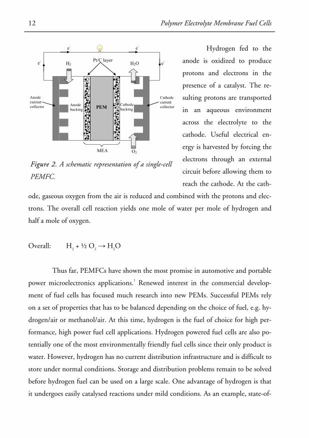
representation of a single-cell PEMFC is given in Figure 2.
The operation of a hydrogen-oxygen PEMFC is relatively straightforward.
The “heart” of the PEMFC is the membrane electrode assembly (MEA) (or catalyst-
coated membrane) which consists of two electrodes (anode, cathode) separated by an
ion-conducting polymer electrolyte. When supplied with fuel (hydrogen) and an oxi-
dant (oxygen), two electrochemical half-cell reactions take place.
Anode: H2 → 2H+ + 2e-
Cathode: ½ O2 + 2H+ + 2e- → H2O
Figure 1. The number of references found in the sci-
entific database ’CAplus’ by using the ACS search fa-
cility ’Scifinder® Scholar 2006’ and a combination of
the words: ’polymer’, ’fuel’ and ’cell’.
12 Polymer Electrolyte Membrane Fuel Cells
Hydrogen fed to the
anode is oxidized to produce
protons and electrons in the
presence of a catalyst. The re-
sulting protons are transported
in an aqueous environment
across the electrolyte to the
cathode. Useful electrical en-
ergy is harvested by forcing the
electrons through an external
circuit before allowing them to
reach the cathode. At the cath-
ode, gaseous oxygen from the air is reduced and combined with the protons and elec-
trons. The overall cell reaction yields one mole of water per mole of hydrogen and
half a mole of oxygen.
Overall: H2 + ½ O2 → H2O
Thus far, PEMFCs have shown the most promise in automotive and portable
power microelectronics applications.1 Renewed interest in the commercial develop-
ment of fuel cells has focused much research into new PEMs. Successful PEMs rely
on a set of properties that has to be balanced depending on the choice of fuel, e.g. hy-
drogen/air or methanol/air. At this time, hydrogen is the fuel of choice for high per-
formance, high power fuel cell applications. Hydrogen powered fuel cells are also po-
tentially one of the most environmentally friendly fuel cells since their only product is
water. However, hydrogen has no current distribution infrastructure and is difficult to
store under normal conditions. Storage and distribution problems remain to be solved
before hydrogen fuel can be used on a large scale. One advantage of hydrogen is that
it undergoes easily catalysed reactions under mild conditions. As an example, state-of-
Anode backing
Cathode backing
Pt/C layer
Anode current collector
Cathode current collector
H2 H2O
O2
e-
e- e-
e-
PEM
MEA
Figure 2. A schematic representation of a single-cell
PEMFC.

Polymer Electrolyte Membrane Fuel Cells 13
the-art anode catalysts are alloys of platinum and ruthenium supported on carbon
black.3 To date, Nafion® is the most prevalent membrane used in hydrogen fuel cells.
Specifically, Nafion® 1135 (1100 equivalent weight, 90 μm thick) and Nafion® 112
(1100 equivalent weight, 50 μm thick) are the products most often used. Thin mem-
branes are preferred since the decrease in cell resistance more than offsets any per-
formance losses associated with the permeability of hydrogen and oxygen through the
membrane. Even though perfluorosulfonic acid copolymer membranes are expensive,
they are the standard by which other membrane candidates are judged. However,
these polymers fail to operate at elevated temperature, which has triggered much re-
search effort into finding alternative systems.17-22 Notably, aromatic hydrocarbon
polymers have been recognized as one of the most promising candidates.
Methanol can also be used as a fuel and is currently the most attractive of the
hydrocarbon fuels due to the relative ease of oxidation at the anode liberating protons
and electrons. In particular, methanol fuel cell research has focused on the direct oxi-
dation of liquid methanol from a methanol/water solution fed to the anode.13 The
oxidation of methanol can be achieved with nanocrystalline platinum, but alloys of
platinum and ruthenium are currently the catalysts of choice.23 Methanol that is not
oxidized at the anode can diffuse through the proton exchange membrane and react at
the cathode. This problem is most often called “methanol crossover” and results in
the removal of available catalytic sites from the oxygen reduction reaction, thus caus-
ing a mixed potential at the cathode. Diffusion of methanol through the membrane
acts essentially as “chemical short circuits” in the fuel cell and lowers the open circuit
voltage, the voltage efficiency of the cell, and the overall fuel efficiency of the system.
Direct methanol fuel cells have not undergone as rapid a development as hydrogen
fuel cells, largely because Nafion® membranes are very poor methanol barriers.24,25
Typically, a relatively thick Nafion® 117 (1100 equivalent weight, 180 μm thick) is
used for direct methanol fuel cells. Any performance penalties associated with the in-
creased resistance of a thicker membrane are more than offset by the complimentary
14 The Membrane Electrode Assembly
decrease in methanol crossover. Much fuel cell engineering has been done to reduce
the methanol crossover in Nafion®-based direct methanol fuel cells, but the results
are still insufficient in promoting direct methanol fuel cells for a wide-ranging com-
mercialization. Consequently, methanol crossover is a central issue of much of the
new membrane development in direct methanol fuel cell research. Also here, aromatic
hydrocarbon polymers have proved to be suitable candidates.24,26-29
2.3 The Membrane Electrode Assembly
Catalysts and membranes are parts of the basic unit of the fuel cell, the MEA. The
MEA consists of two porous electrically and ionically conductive electrodes contain-
ing the platinum catalyst bonded to the PEM (see Figure 2). The electrodes can con-
tain either unsupported (methanol fuel cells) or supported (hydrogen fuel cells) cata-
lysts and are usually composed of the same polymer as the PEM.30 The precious metal
loading needed is determined by the amount of catalyst per active area and the iono-
mer content of the electrode can vary between 5-20 wt.%, depending on the applica-
tion requirements.
Two basic methods commonly used for bonding the electrodes to the PEM
involve making a catalyst “ink” composed of the ion conducting copolymer dispersed
in a diluent (usually 5% polymer by weight), the catalyst particles, and any other ad-
ditives to ease processing. In the first method, this ink is painted directly onto the
membrane and dried to form the condensed catalyst layer or electrode. This method
requires that the ink solution does not dissolve the membrane during painting, or
otherwise compromise its integrity during the painting process. After painting, the
MEA is ready to be placed into the fuel cell or processed further prior to fuel cell test-
ing. In the second method, the catalyst ink is first painted and dried onto a decal or
“blank” with the size of the desired active area. The painted and dried decal is then
hot-pressed against the membrane at typically 150-200 °C and pressures of about
20 MPa, so as to bond the composite in the electrode to the membrane. If the correct

Proton-Conducting Polymer Membranes 15
conditions and decal are chosen, the electrode will adhere well to the membrane and
the decal can simply be peeled off.
Since the MEA is the heart of a fuel cell, considerable ongoing research is
aimed at investigating its exact structure and component interactions.30 The phenom-
ena of “break in” and aging of the MEA structure are of major concern. Break in re-
lates to the slow increase in performance observed over the first 24 h once a fresh
MEA is placed in a fuel cell. Aging is the slow degradation of performance during
long-term fuel cell operation. Researchers are investigating the electrode and mem-
brane structure, and the interaction between the membrane and electrode for possible
physical changes that may occur over time, in order to correlate these physical prop-
erty changes with the fuel cell performance. In addition, much work has to be carried
out for the development of fully integrated MEAs in which newly developed polymers
are used both as a component of the porous electrodes and as the electrolyte.22,31 In-
deed, in most cases these polymers are evaluated against Nafion® impregnated elec-
trodes using slightly modified procedures to those used for the preparation of
Nafion® based MEAs. However, the inherent incompatibility between perfluoro-
polymers and aromatic hydrocarbon polymers results in significant interfacial resis-
tances, and often delamination. It is, therefore, difficult to efficiently evaluate new
materials. New methodologies have to be developed in relation to a given new poly-
mer membrane. This represents a crucial step for the successful replacement of
Nafion® by aromatic polymer membranes.
2.4 Proton-Conducting Polymer Membranes
A membrane has been defined as “an interphase between two adjacent phases acting
as a selective barrier, regulating the transport of substances between two compart-
ments thanks to its unique separation principle, i.e. transport selectivity”.32 Polymer
membranes find applications in several important industrial processes such as separa-
tion processes for liquid and gaseous mixtures, biomaterials, catalysis, lab-on-chip
technologies and fuel cells.32

16 Proton-Conducting Polymer Membranes
Originally, the PEM used in the US space flight program was a sulfonated
styrene-divinylbenzene copolymer. These membranes showed very short lifetimes due
to oxidative degradation of the polymer backbone. In 1968, DuPont commercialized
a PEM based on poly(perfluorosulfonic acid) under the trade name Nafion®.33,34 The
perfluorinated structure shown in Scheme 1 displays a much greater stability in a fuel
cell environment and thus increasingly longer fuel cell lifetimes.
* CF2 CF2 CF CF2 *O CF2CF
CF3
O(CF2)2SO3Hx
y
Scheme 1. The chemical structure of Nafion® (x = 6-10, y = 1).
Since then other companies, such as Asahi, Dow and Solvay, have investigated
membranes based on poly(perfluorosulfonic acid) structures, but Dow has stopped
their activities and Asahi remains a small player. Nafion® has remained the industry
standard proton exchange membrane and almost all current PEMFC research from a
device standpoint focuses on this type of electrolyte. Major applications for Nafion®
also include chlorine synthesis via electrolysis (chlor-alkali processes).35
Moderate operating temperatures for Nafion®-based PEMFCs are required
because of the need for aqueous proton transport and the perfluoropolymers used
have relatively low Tg, especially when hydrated.36 These systems are currently ongo-
ing further developments in order to improve their characteristics.37,38 To increase the
operating temperature of PEMFCs to 120 °C, membranes that retain water and con-
ductivity and that are more thermally and mechanically robust at high temperatures,
are needed. Another challenge is to produce inexpensive materials that meet the above
requirements. Presently, some of the most promising candidates for PEMs are based
on high performance aromatic polymers, i.e. polyimides, poly(ether ketone)s,
poly(arylene ether sulfone)s, polybenzimidazoles, etc.18,19,27,39-41 Advantages of using

Proton-Conducting Polymer Membranes 17
these materials include lower cost than perfluorinated membranes, inclusion of polar
groups to improve water uptake over a range of temperatures, and the possibility of
recycling by conventional methods. Many aromatic polymer systems have been inves-
tigated and it is beyond the scope of this introduction to provide a review covering
the developments in this area. A number of reviews have recently been published
which provide an in-depth information on the current research efforts throughout the
world.17-20,22,27,39,42-44 Scheme 2 presents some examples of polymeric structures investi-
gated as PEMs. Among others, the preparation of sulfonated poly(arylene ether sul-
fone)s,45-49 and sulfonated poly(arylene ether ketone)s by direct polymerization,50-52 as
well as the chemical modification of polysulfones,53-59 radiation grafting of polymer
membranes,60 blending and crosslinking of ionomer membranes,61 and the synthesis of
sulfonated poly(arylene ether)s and polyimides,62-64 are actively studied.
The successful PEM has to combine a number of specific properties, includ-
ing (i) low cost; (ii) good film-formation; (iii) high proton conductivity (preferably
around or above 100 mS/cm), (iv) low electronic conductivity, (v) water retention
above 100 °C; (vi) thermal, oxidative and hydrolytic stability; (vii) effective reactant
barrier; (viii) possibility of fabrication into MEAs; and (ix) mechanical durability at
elevated temperature (80 – 140 °C) for extended durations (typically around 5000 to
10000 h for automobiles).65 Unfortunately, many of the desired properties are partly
conflicting which further complicates the optimization of the membranes. Thus, the
ionomer has to be a high-performing multifunctional material with carefully balanced
properties optimized for a quite specific set of operational parameters.
A proton-conducting polymer membrane is typically a poor proton conduc-
tor unless water is present. Therefore the hydration of a PEM is very important for
the performance of the fuel cell. The water sorption of PEMs has a profound effect on
membrane conductivity and mechanical properties. Membranes with little water up-
take typically have low proton conductivity, while the mechanical strength is com-
promised in membranes with too high water sorption.

18 Proton-Conducting Polymer Membranes
* S S O O *
O
O
O
On
m
k
SO3H
HO3S
N
N NH
N** n
SO3H
* N N N N *
O
O
O
O
O
O
O
O
SO3H
HO3S
n
m
k
* P N P N *O
O O
O
SO2NHSO2CF3 OMe
OMeOMe
n
m
k
O S OO
On
O
O
HO3S
SO3H
SO3H
O S OO
On
O
CF2 PO3H2
O O S O O **
F F
FF F F
FF
F
F F
F F F
F F
HO3S SO3H
SO3HHO3S
O
On
m
Ar
(a)
(b)
(c)
(d)
(e)
(f)
(g)
Scheme 2. Examples of proton-conducting polymers designed for PEM materials: (a) sul-
fonated poly(arylene ether sulfone); (b) polysulfone carrying benzoyl(difluoromethylene-
phosphonic acid) side chains (Paper V); (c) sulfopropylated PBI; (d) sulfonated naphtha-
lenic polyimide (Ar, various aromatic moieties); (e) polysulfone carrying trisulfonated ary-
lene ether side chains (Paper III); (f) poly(aryloxyphosphazene) having sulfonimide units;
and (g) partially fluorinated and sulfonated poly(arylene ether sulfone) copolymer.

Proton-Conducting Polymer Membranes 19
The water content in ionomers is represented by both the water uptake and
the number of water molecules per acid unit, also referred to as the hydration number
(λ). The water uptake is calculated by weighing the membrane under both hydrated
and dry conditions (Equation 1), and λ can be calculated from the water uptake and
the ion-exchange capacity (Equation 2).
Equation 1. Water Uptake (%) = [(Wwet – Wdry) / Wdry] ×100
Equation 2. λ = 1000 × [(Wwet – Wdry) / Wdry] / (18 × IEC)
The ion-exchange capacity, or IEC, is defined as the moles of exchangeable
acidic protons per gram of dry polymer and the IEC of membranes can be experimen-
tally determined by potentiometric titration of the acid groups. Another common
term used to describe the ionic content is the equivalent weight, which is the inverse
of the IEC. It is worth mentioning that a complication arises with phosphonic acid
units because they carry two acidic protons. In general, only one acidic proton should
be considered per phosphonic acid group since the second proton usually does not
participate in the proton conduction due to its high pKa value. Yet, both protons
might be consumed during the titration depending on the methodology used. In ad-
dition, when electron-withdrawing substituents are located in the α position to the
phosphonic acid unit, the pKa value of the second proton might be decreased to such
a level that both protons should be taken into account. Although there are many
other properties of PEMs that have important correlations to fuel cell performance
(thermal stability, methanol crossover, electroosmotic drag, etc.), the IEC, water up-
take and proton conductivity are essential when it comes to evaluating membranes as
candidates for PEMFCs.66 In addition, the hydrolytic and oxidative stability is also of
great importance.64,67
Proton-conducting polymers typically phase separate upon hydration to form
a morphology consisting of a percolating network of hydrophilic nano-metric pores

20 Proton-Conducting Polymer Membranes
embedded in a hydrophobic polymer-rich phase domain, thus allowing the formation
of a continuous pathway for proton conduction.24 The pores contain water and the
acid units, and conductivity occurs by transport of dissociated protons via the dynam-
ics of the water, as described in more detail later. The hydrophobic phase domain sta-
bilizes the morphology of the membrane by balancing the swelling pressure of the wa-
ter against its mechanical strength. Important differences arise when considering per-
fluorinated polymers such as Nafion® and aromatic main-chain polymers. First of all,
they differ in their values of pKa of the sulfonic acid units and also in their micro-
structures. Structural analyses suggest that the less pronounced hydropho-
bic/hydrophilic separation of sulfonated polyarylenes such as sulfonated polyetherke-
tones corresponds to narrower, less connected hydrophilic channels and to larger
separations between less acidic sulfonic acid units as compared to Nafion® (see Fig-
ure 3).24 These morphological features have a profound impact on the macroscopic
membrane properties. Large water domains result in a lower degree of water-polymer
interaction and more ‘bulk-like’ water than smaller water domains within a similar
chemical environment. The tortuosity (or continuity of the phases) is important for
both transport properties and mechanical stability. Most importantly, interanionic
distances are a contributing factor to water domain features and primarily affect the
proton conductivity of the membrane. Indeed, the energy barriers associated with
proton transport are dependant on the distance between anionic sites so that the
greater the distance between the sites, the greater are the resistive losses associated
with transport.68 Notably, it was found that ionic aggregation and phase separation
play an important role in the proton conductivity of low IEC membranes, but less of
a role in high IEC membranes.69,70

Proton-Conducting Polymer Membranes 21
Figure 3. Schematic representations of the microstructures of Nafion® and a sulfonated
polyetherketone (adapted from ref. 24). The serpentine black lines, the open circles and the
black circles represent the polymer chains, the sulfonic acid units and water, respectively.
In PEMFCs the proton conductivity of the membrane is particularly impor-
tant since it plays a significant role in the performance of the fuel cell. Higher levels of
proton conductivity result in higher power densities. The proton conductivity of hy-
drated polymer electrolytes dramatically increases with temperature and water con-
tent; therefore, it is of importance to report the exact conditions under which the pro-
ton conductivity is measured. Currently, automotive companies are pushing for
membranes capable of operating in a wide temperature window, typically from sub-

22 Proton-Conducting Polymer Membranes
zero degrees up to approx. 120 °C, at low humidification with water vapour partial
pressures below 0.5 bar, or with no humidification at all.65
The proton conductivity of membranes can be measured by AC impedance
spectroscopy. Under true fuel cell conditions, the protons move through the plane of
the membrane. However, through-plane conductivity experiments are difficult to per-
form due to the significant interfacial resistances that may occur during testing. Con-
versely, it is generally easier to determine membrane conductivities by measuring the
resistance in the plane of the membrane.71 This technique allows for higher and more
easily measurable resistances and a simplified set-up. The proton conductivity, σ, is
calculated from the impedance data using Equation 3 below. The minimum resis-
tance is derived from the low intersect of the high frequency semicircle on a complex
impedance plane with the Re(z) axis. It is worth noting that two- and four-probe cells
are commonly used to study the ionic conductivity of PEMs and that some level of
discrepancy arises when comparing the results obtained by the two methods.72
Equation 3. σ = ρ-1 = L / (R×W×T)
ρ = resistivity
L = length between electrodes
W = width of sample
T = thickness of sample
R = minimum resistance
The proton is the only ion without an electron shell of its own. Therefore, it
interacts strongly with the electron density of its environment (e.g. the valence elec-
tron density of one or two nearest neighbours).73 Proton conduction occurs via two
main mechanisms in which the protons remain shielded by some electron density
along the entire diffusion path.73,74 In other words, the existence of a free proton is not
needed for the proton conduction to occur. In systems where proton conduction re-
lies on the presence of water molecules, which is the case for the proton conducting

Proton-Conducting Polymer Membranes 23
polymer membranes discussed in this thesis, proton migration occurs by the transi-
tional dynamics of larger species referred to as the vehicle mechanism. The proton
diffuses together with a vehicle (e.g. H3O+) where the counter diffusion of unproto-
nated vehicles (e.g. H2O) allows a net proton transport (see Figure 4). Proton trans-
port may also occur via the transfer of protons within hydrogen bonded species from
one “carrier” to the other. Such proton hopping is usually termed the Grotthuss
mechanism or structure diffusion,75 and is responsible for the proton conducting
character of anhydrous proton conductors such as imidazoles and benzimidazoles.59,76-
82 The study of the dynamics of the proton conduction is very complex due to the
multi-scale hierarchical structure of ionomer membranes. It has to be investigated in a
wide range of relevant correlation times, meaning that different experimental tech-
niques such as quasi-elastic neutron scattering, field-cycling nuclear magnetic relaxa-
tion and pulsed field gradient NMR have to be used together with the modelling of
proton transport.83-85
Many bulk properties of the polymer
membrane are due to the ionic interactions in sub
molecular regions of the polymeric material, and
the macromolecular properties of the system are,
thereby, critical characteristics.66 The polymeric
architectures can be different by the position, type
and concentration of the ionic groups on the
polymer backbone, therefore, producing a large
amount of potential systems to study. It is worth
noting that other factors such as the conditions
used during membrane formation, and post-
treatments such as acidification and humidity ex-
posure also influence the nature of the network of
nanopores, which in turn influence the macro-
Figure 4. A graphic represen-
tation of proton transfer.

24 Chemical Modification of Polysulfones
scopic membrane properties.86,87 Chemical grafting of commercially available poly-
mers, such as polysulfones, gives a high degree of freedom to vary the polymeric struc-
ture, the acidic group and the IEC of the polymer electrolyte, thus providing mem-
branes with different water domain sizes and shapes, interanionic distances, and tor-
tuosities.88 These differences in the structural features of the membranes dictate the
proton conductivity, water transport properties, water uptake characteristics, and re-
actant permeabilities.66,89,90 Consequently, we decided to develop synthetic methods to
prepare sulfonated and phosphonated polysulfones by chemical grafting using lithia-
tion chemistry, with the goal to prepare and study the properties of durable proton-
conducting polymer membranes for high temperature PEMFC applications.
2.5 Chemical Modification of Polysulfones for the Preparation of
Proton-Conducting Polymers
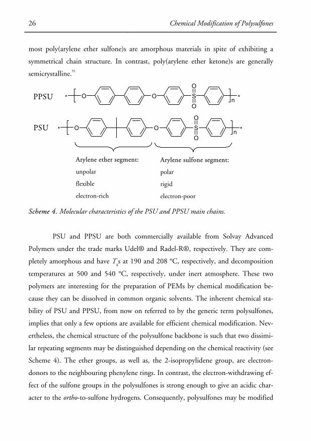
2.5.1 Characteristics of Polysulfones
Poly(arylene ether sulfone)s
comprise of a class of materi-
als used as engineering ther-
moplastics because of their
excellent properties, such as
high Tg and superior ther-
mooxidative stability.91,92 Syn-
thetic routes to poly(arylene
ether sulfone)s were discov-
ered independently in three
laboratories: the 3M Corpora-
tion, the Union Carbide Cor-
poration, and the plastics di-
vision of ICI. Two main
OO SO
O* *n
OO SO
O
CF3
CF3
* *n
OO SO
O* *n
SO
OO* *n
Polyethersulfone, PES
Polyphenylsulfone, PPSU
Polysulfone, PSU
Polysulfone-6F
Scheme 3. Examples of poly(arylene ether sulfone)s.
Chemical Modification of Polysulfones 25
routes have been reported, either a polysulfonylation process, which is a classical elec-
trophilic aromatic substitution, or a polyether synthesis, which is a nucleophilic sub-
stitution of activated aromatic dihalides. Examples of common poly(arylene ether sul-
fone)s are given in Scheme 3.
Poly(arylene ether sulfone)s are useful engineering plastics since processing is
feasible in the melt and in solution, and since the polymers possess a high thermal
stability. Even in air, slow degradation is only detectable at temperatures above 420–
450°C. The incorporation of sulfone groups into the macromolecular chain often
generates interesting properties, such as an increased Tg. Indeed, the Tg of a polymer
depends on both chain rigidity and polarity. The polar arylene sulfone segment has an
inherent chain rigidity, which arises from the phenyl groups, and from the presence of
the inductive polar sulfone groups.91 The high polarity of the sulfone group leads to
an electron-withdrawing effect, which delocalizes the π-electrons from the aromatic
rings, producing some of a double-bond character in the neighbouring links. Such de-
localization considerably enhances the rotational barrier around the C-S link and con-
sequently the chain rigidity. A Tg of 272.5 °C was obtained by extrapolation to infi-
nite number-average molecular mass for PES as suggested by the Flory-Fox theory.93
This value is in good agreement with the Tg of 269.5°C obtained using Carlier et al.’s
concept of the percentage of rigid chain length.93 In contrast, the ether links have a
comparatively low rotational barrier. This provides flexibility to the arylene ether
segments. In addition, the unpolar 2-propylidene link of PSU also contributes to the
overall chain flexibility.
In poly(arylene ether sulfone)s, the valence angle for C-SO2-C is 105° and for
C-O-C it is 124°.91 This substantial difference in the inter-ring bond angles reduces
the packing density of the unit cell. This corresponds to a substantial decrease in the
melting enthalpy and in Tm. As a result, the (Tm–Tg ) interval is quite narrow for
poly(arylene ether sulfone)s, and the crystallization is, in most cases, inhibited.
Devaux and Carlier have observed that a percentage of rigid chain length greater than
60 is necessary to obtain crystallizable poly(arylene ether sulfone)s.91 Consequently
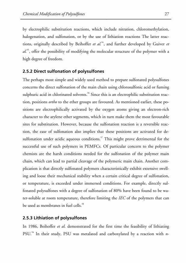
26 Chemical Modification of Polysulfones
most poly(arylene ether sulfone)s are amorphous materials in spite of exhibiting a
symmetrical chain structure. In contrast, poly(arylene ether ketone)s are generally
semicrystalline.91
O SO
OO ** n
OO SO
O** n
Arylene ether segment:
unpolar
flexible
electron-rich
Arylene sulfone segment:
polar
rigid
electron-poor
PSU
PPSU
Scheme 4. Molecular characteristics of the PSU and PPSU main chains.
PSU and PPSU are both commercially available from Solvay Advanced
Polymers under the trade marks Udel® and Radel-R®, respectively. They are com-
pletely amorphous and have Tgs at 190 and 208 °C, respectively, and decomposition
temperatures at 500 and 540 °C, respectively, under inert atmosphere. These two
polymers are interesting for the preparation of PEMs by chemical modification be-
cause they can be dissolved in common organic solvents. The inherent chemical sta-
bility of PSU and PPSU, from now on referred to by the generic term polysulfones,
implies that only a few options are available for efficient chemical modification. Nev-
ertheless, the chemical structure of the polysulfone backbone is such that two dissimi-
lar repeating segments may be distinguished depending on the chemical reactivity (see
Scheme 4). The ether groups, as well as, the 2-isopropylidene group, are electron-
donors to the neighbouring phenylene rings. In contrast, the electron-withdrawing ef-
fect of the sulfone groups in the polysulfones is strong enough to give an acidic char-
acter to the ortho-to-sulfone hydrogens. Consequently, polysulfones may be modified
Chemical Modification of Polysulfones 27
by electrophilic substitution reactions, which include nitration, chloromethylation,
halogenation, and sulfonation, or by the use of lithiation reactions The latter reac-
tions, originally described by Beihoffer et al.94, and further developed by Guiver et
al.95, offer the possibility of modifying the molecular structure of the polymer with a
high degree of freedom.
2.5.2 Direct sulfonation of polysulfones
The perhaps most simple and widely used method to prepare sulfonated polysulfones
concerns the direct sulfonation of the main chain using chlorosulfonic acid or fuming
sulphuric acid in chlorinated solvents.96 Since this is an electrophilic substitution reac-
tion, positions ortho to the ether groups are favoured. As mentioned earlier, these po-
sitions are electrophilically activated by the oxygen atoms giving an electron-rich
character to the arylene ether segments, which in turn make them the most favourable
sites for substitution. However, because the sulfonation reaction is a reversible reac-
tion, the ease of sulfonation also implies that these positions are activated for de-
sulfonation under acidic aqueous conditions.97 This might prove detrimental for the
successful use of such polymers in PEMFCs. Of particular concern to the polymer
chemists are the harsh conditions needed for the sulfonation of the polymer main
chain, which can lead to partial cleavage of the polymeric main chain. Another com-
plication is that directly sulfonated polymers characteristically exhibit extensive swell-
ing and loose their mechanical stability when a certain critical degree of sulfonation,
or temperature, is exceeded under immersed conditions. For example, directly sul-
fonated polysulfones with a degree of sulfonation of 80% have been found to be wa-
ter-soluble at room temperature, therefore limiting the IEC of the polymers that can
be used as membranes in fuel cells.98
2.5.3 Lithiation of polysulfones
In 1986, Beihoffer et al. demonstrated for the first time the feasibility of lithiating
PSU.94 In their study, PSU was metalated and carboxylated by a reaction with n-

28 Chemical Modification of Polysulfones
butyllithium (n-BuLi, 1.6 M in hexanes) and carbon dioxide at room temperature in
dry tetrahydrofuran (THF). After acidification with HCl the product was recovered
via precipitation in water. It was reported that the lithiated PSU precipitated from the
reaction mixture at relatively low levels of metallation, and that an uneven carboxyla-
tion occurred. No indication regarding the sites of the substitution was reported at
that point. It was not until 1988, based on reports by Guiver et al., that the mecha-
nism of the lithiation of polysulfones was understood.99 In addition, the lithiation of
polysulfones proved to be a fast and selective way of modifying the main chain. In
their study, Guiver et al. reacted lithiated PSU with D2O and iodomethane in order
to identify the reactive sites on the PSU backbone by analyzing the resulting polymers
using 1H NMR spectroscopy. In contrast to the methodology used by Beihoffer et al.,
the lithiation reaction was carried out at low temperature, typically at -78 °C in THF
using a 2-propanol / dry-ice bath. Guiver et al. indicated that the temperature had to
be maintained in the temperature range -10 °C to -78 °C. Higher temperatures re-
sulted in the precipitation of the polymer caused by intramolecular rearrangements.
The formation of lithiated polysulfone was observed by the appearance of a greenish
brown to reddish brown viscous solution. Analyses by 1H NMR spectroscopy indi-
cated that the reaction proceeded rapidly and homogenously in high yields and re-
quired little or no excess of reagent or catalyst. In addition, the site of lithiation was at
the ortho-to-sulfone position and the degree of lithiation (DL), i.e. the number of
metalated carbons per repeating unit of the polysulfone, could be conveniently con-
trolled by the amount of n-BuLi added to the reaction mixture up to a DL = 2.
Chemical Modification of Polysulfones 29
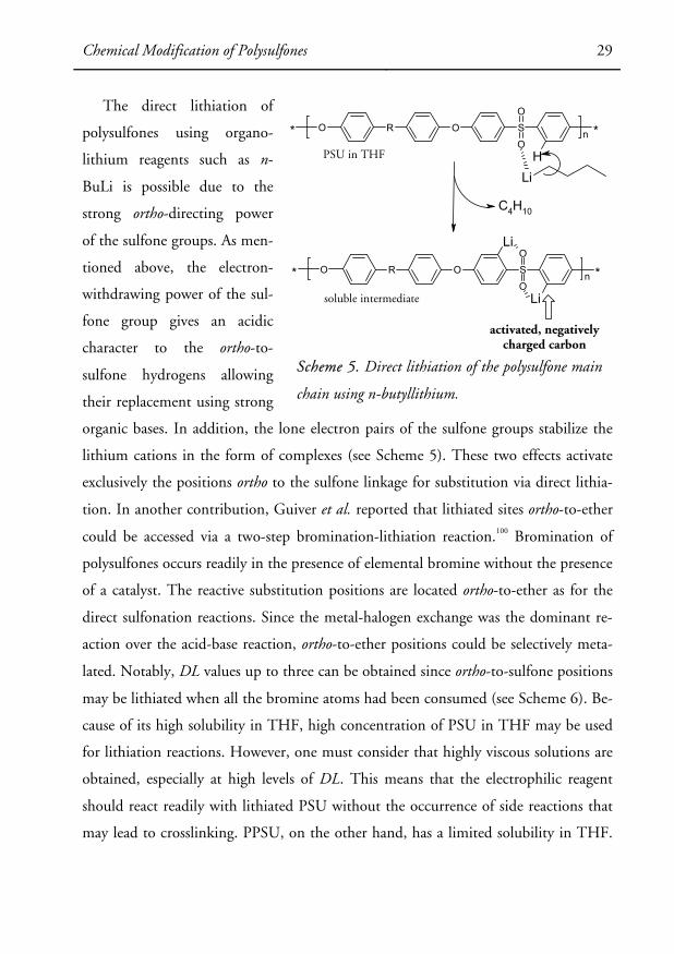
The direct lithiation of
polysulfones using organo-
lithium reagents such as n-
BuLi is possible due to the
strong ortho-directing power
of the sulfone groups. As men-
tioned above, the electron-
withdrawing power of the sul-
fone group gives an acidic
character to the ortho-to-
sulfone hydrogens allowing
their replacement using strong
organic bases. In addition, the lone electron pairs of the sulfone groups stabilize the
lithium cations in the form of complexes (see Scheme 5). These two effects activate
exclusively the positions ortho to the sulfone linkage for substitution via direct lithia-
tion. In another contribution, Guiver et al. reported that lithiated sites ortho-to-ether
could be accessed via a two-step bromination-lithiation reaction.100 Bromination of
polysulfones occurs readily in the presence of elemental bromine without the presence
of a catalyst. The reactive substitution positions are located ortho-to-ether as for the
direct sulfonation reactions. Since the metal-halogen exchange was the dominant re-
action over the acid-base reaction, ortho-to-ether positions could be selectively meta-
lated. Notably, DL values up to three can be obtained since ortho-to-sulfone positions
may be lithiated when all the bromine atoms had been consumed (see Scheme 6). Be-
cause of its high solubility in THF, high concentration of PSU in THF may be used
for lithiation reactions. However, one must consider that highly viscous solutions are
obtained, especially at high levels of DL. This means that the electrophilic reagent
should react readily with lithiated PSU without the occurrence of side reactions that
may lead to crosslinking. PPSU, on the other hand, has a limited solubility in THF.
R OO SO
OH
* *n
Li
C4H10
R OO SO
OLi
Li
* *n
activated, negativelycharged carbon
soluble intermediate
PSU in THF
Scheme 5. Direct lithiation of the polysulfone main
chain using n-butyllithium.

30 Chemical Modification of Polysulfones
Consequently, lower concentrations
should be used. Notably, the solu-
bility of PPSU in THF increases
when the temperature of the solu-
tion is lowered.
The great advantage of us-
ing lithiation chemistry is that, after
lithiation, the polysulfone main
chain is activated for reactions with
numerous different electrophilic re-
agents, of which many are commer-
cially available.88,95 Negatively
charged carbon atoms on the poly-
sulfone main chain react with elec-
trophilic carbons or heteroatom
centres, either by addition reactions
(e.g. with CO2, SO2) or by replace-
ment of a leaving group (e.g. with
activated halogenated compounds,
esters). Complex functional groups
may be introduced by a judicious choice of the electrophile. When the electrophile
has the potential for inducing crosslinks, it has to be added rapidly in excess at an op-
timum temperature and under the appropriate conditions in order to efficiently
quench the reactive carbanions. Factors such as the rate of addition, temperature,
crosslinking potential, viscosity and mixing of the reagents are of particular impor-
tance. It is worth noting that polymer membranes may be lithiated heterogeneously.101
Guiver et al. found that the optimum conditions for membrane functionalization
were 0.2 M n-butyllithium in hexane at room temperature and that the reaction rate
R O S OO
On
H
LiLi
Li
C4H10
R O S OO
On
LiLiLi
R O S OO
On
R O S OO
On
Br Br
C4H10
Insoluble in THF
Soluble in THF
Br2
Scheme 6. Bromination and lithiation of the
polysulfone main chain.

Chemical Modification of Polysulfones 31
increased substantially in the presence of 2% THF.101 The surface-lithiated mem-
branes can be derivatized, potentially with a wide variety of functional groups.
R OO SO
O* *n
SOO
OLi
SOO
OSO2Cl
SOO
OCO2Li
SOO
OSO2LiSO
O
OCO2H SO
O
OSO3H
SOO
OSO3H
butyllithium
hydrolysis
oxidation
CO2
SO2Cl2
SO2
ion-exchange
Scheme 7. Carboxylation and sulfonation of polysulfones using lithiation chemistry.
The lithiation of polysulfones gives possibilities to prepare sulfonated poly-
sulfones in which the sulfonic acid units are located on the electron-poor segments of
the backbone in contrast to the direct sulfonation method discussed above (see
Scheme 7). As a result, the former units are expected to be less prone to desulfona-
tion. In particular, Kerres et al. have prepared sulfonated PSU by first reacting the
lithiated polymer with sulphur dioxide to produce sulfinated PSU. In a second step,
the sulfinate groups were oxidized to sulfonate groups by the use of various oxidizing
agents including H2O2, NaOCl, and KMNO4. Ionomers with IEC values between 0.5
and 3.2 meq/g were obtained and an ionomer having 2.4 meq of SO3H/g dry sample
was found to be water soluble.102 Karlsson et al. extended the use of the sulfinated
PSU intermediate to prepare ionomers where the sulfonic acid groups are placed on

32 Phosphonated Polymers for Fuel Cell Applications
alkyl spacers of different lengths.54 Sulfinated PSU was grafted with sulfoethyl and sul-
fopropyl units by reaction with an excess of the sodium salts of 2-bromoethyl sul-
fonate and 3-bromopropyl sulfonate, respectively, in N-methyl pyrrolidinone at 40
°C. Correspondingly, sulfobutylated PSU was prepared by reaction of sulfinated PSU
with 1,4-butane sultone.
2.6 Phosphonated Polymers for Fuel Cell Applications
The search for alternative proton-conducting membranes capable of operating at high
temperatures has widened the focus of the research area, and increased the interest of
investigating alternative acidic or “protogenic” groups which have the ability to facili-
tate proton conductivity under low-humidity conditions.21,103,104 These groups include
for example the phosphonic acid and various heterocycles such as imidazole and ben-
zimidazole, and are perhaps best described as amphoteric. Thus, polymers carrying
these groups have quite different properties than sulfonated polymers. For example,
phosphonated polymers generally show a higher degree of hydrogen bonding and
lower water uptake than their sulfonated analogues at comparable IECs. Moreover,
phosphonated model compounds have recently been shown to possess an attractive
combination of properties that further motivates investigations of phosphonated
polymers as proton conductors under low-humidity conditions.21 However, the area
of phosphonated membranes for fuel cells is still an emerging field. Since this is a rela-
tively new topic, some key characteristics of the phosphonic acid unit as compared to
the sulfonic acid unit have to be underlined. The reader is referred to Paper VI, in
this thesis, for in-depth information regarding phosphonic acid units and the pros-
pects of phosphonated polymers for fuel cell applications.

Phosphonated Polymers for Fuel Cell Applications 33
When it comes to the
preparation of novel ionomers for
fuel cells, one major difference be-
tween polymers based on phos-
phonic acid units and conventional
sulfonated polymers is the important
chemical transformations that the
former acidic units may undergo
(see Scheme 8). Phosphonic acids
possess two ionizable acid moieties.
For aryl- and alkylphosphonic acid
the pKa values are typically between
2-3 and 7-8 for the first and second
protons, respectively (see Table 2).
The first acidic moiety has an ioniza-
tion potential intermediate to those
of sulfonic and carboxylic acids. Be-
cause of the intermediate acid
strength of the first acid moiety and
the higher IEC of the phosphonic acid, as compared to sulfonic and carboxylic acids
at the same acid concentration, many of the properties of ionomers based on phos-
phonic acid may be found intermediate to the properties of sulfonated and carboxy-
lated ionomers or, perhaps, even comparable to sulfonated ionomers.
As outlined in Scheme 8, one characteristic of the phosphonic acid unit is
that it may be obtained by the hydrolysis of the corresponding phosphonate ester.
The synthesis of phosphonate esters is often the only route to polymers functionalized
with phosphonic acid units. It is therefore of importance to find suitable chemical re-
actions for the conversion of phosphonate esters into their acidic form. Figure 5 pre-
sents different possibilities found in the literature. The use of trimethylchlorosilane is
Scheme 8. A comparison of important trans-
formations of phosphonic acid units (A) and
sulfonic acid units (B).
PO
OHOHR
PO
OOHR
PO
ROH
PO
OR'OR'R
PO
ONaONaR
SO
OHO
R
H3PO4 RH
SO3 RH SO
ONaO
R
SO
ClO
R
PO
ClClR
A
B
+
+
R and R' = alkyl or aryl
hydrolysisesterification chlorination
chlorination
sulfonation
desulfonation
hydrolysis anhydride formation
ion-exchange
ion-exchangeC-P bond cleavage

34 Phosphonated Polymers for Fuel Cell Applications
particularly advantageous for polyfunctional molecules as it reacts with phosphonate
ester units under mild conditions, therefore avoiding side-reactions and allowing for a
selective conversion into phosphonic acid units.
Table 2. Acid dissociation constants in water for selected acidic compounds.
Acid pKa1 pKa2
CF3P(O)(OH)2 1.2 3.9
C6H5CH2P(O)(OH)2 2.3 7.6
CH3P(O)(OH)2 2.4 7.5
(HO)2(O)PCH2P(O)(OH)2 <2 and 2.6 6.9 and 10.3
C6H5P(O)(OH)2 1.8 7.1
C6H5SO3H <1 -
The published data on fuel cell membranes based on phosphonated polymers
is still very limited. However, a careful examination of the results obtained up until
now indicates that these membranes may potentially show some advantages over sul-
fonated polymer membranes. This is perhaps particularly true when it comes to op-
eration under low humidity conditions at high temperatures. At high water contents,
the protons may be transported through the dynamics of the water, much in the same
way as in conventional membranes based on sulfonated polymers. In addition, be-
cause of the amphoteric nature of the phosphonic group, there seems to be a possibil-
ity of transporting protons through structure diffusion within the hydrogen bonded
phosphonic acid networks at low water contents. Moreover, phosphonated polymers
generally show a higher hydrolytic and thermal stability than sulfonated polymers due
to the strength of the C-P bond.
A survey of the literature indicates that phosphonation of polymers is in gen-
eral more difficult than the corresponding sulfonation. The difference is perhaps most
striking when it comes to attaching acid groups on aromatic rings. In addition, the
water uptake of phosphonated polymer membranes is generally much more moderate

Phosphonated Polymers for Fuel Cell Applications 35
than for corresponding sulfonated polymer membranes. In this respect, most of the
polymers studied up until now tend to have an insufficient degree of phosphonation
for use as fuel cell membranes. An alternative way to increase the water uptake may be
to enhance the acidity by attaching the phosphonic acid via CF2-P bonds. This will
obviously change the acid-base character in relation to phosphonic acid units attached
through aromatic or alkyl C-P bonds.
R P(O)(OR)2
R P(O)(OH)2
R P(O)(OR)(OH)
basic hydrolysis
acid hydrolysis
silylation + methanolysis
selective reaction with inorganic halides
Figure 5. Schematic representations of various pathways yielding monoacid monoester
phosphonate and/or phosphonic acid groups from phosphonate esters.

36 Phosphonated Polymers for Fuel Cell Applications
Thesis Work 37
CHAPTER 3
THESIS WORK
In order to study structure-property relationships, we have first investigated new
methods to prepare durable proton-conducting polymers functionalized with sulfonic
acid groups placed on aromatic side chains of varying lengths and character, and stud-
ied their properties as PEMs (Papers I to III). As mentioned already in the introduc-
tion, placing the sulfonic acid units away from the hydrophobic polymer main chain
may prevent excessive water uptake and the loss of the mechanical integrity of the
polymer membrane when a certain degree of sulfonation or a certain temperature is
exceeded, as in the case of directly sulfonated PSU. In addition, minimizing the local
inter-acid distance might also prove beneficial to promoting a distinctly phase sepa-
rated morphology. Finally, phosphonated polymers may potentially exhibit interest-
ing properties as PEMs, especially for high temperature operation. Therefore, we have
investigated new synthetic pathways to phosphonated polysulfones. Our first attempt
has consisted in attaching phosphonic acid units directly onto the polymer main
chain (Paper IV). Then, PSUs tethered with phosphonic acid units with increased
acidity located on aromatic side chains to the polymer main chain were prepared and
studied (Paper V). Figure 6 represents a graphic overview of the research work intro-
duced above.
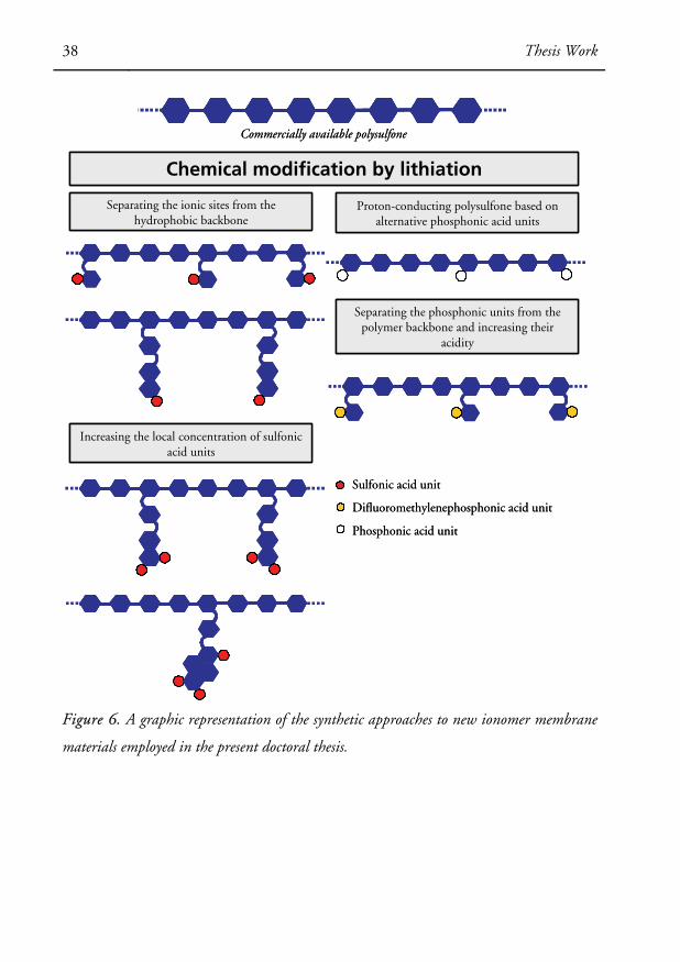
38 Thesis Work
Increasing the local concentration of sulfonic acid units
Separating the ionic sites from the hydrophobic backbone
Chemical modification by lithiation
Proton-conducting polysulfone based on alternative phosphonic acid units
Separating the phosphonic units from the polymer backbone and increasing their
acidity
Commercially available polysulfone
Sulfonic acid unit
Difluoromethylenephosphonic acid unit
Phosphonic acid unit
Figure 6. A graphic representation of the synthetic approaches to new ionomer membrane
materials employed in the present doctoral thesis.

Polysulfones Carrying Sulfonated Aromatic Side Chains 39
3.1 Polysulfones Carrying Sulfonated Aromatic Side Chains (Pa-
pers I-III)
3.1.1 Preparation
The different sulfonated polymer structures covered by this thesis project are
shown in Scheme 9.
R OO SO
O* *n
SOO
OLi
SOO
O
SO3H
O
SOO
OO
F
O SO
O
O
O
HO3S
SO3H
SO3H
O SO
OO
O
HO3S
SO3H
O SO
O
O
O
SO3H
O SO
O
O
O
SO3H
SO
O
O OO
Cl
F
OH
SO3Na
OH SO3Na
OHSO3K
SO3K
OHSO3Na
SO3Na
SO3Na butyllithium
A
B C
D
A
B
C
D
(i)
(ii)
(iii)
(iv)
(v)
(vi)
PSU
PSU-sb
PSU-tspb
PSU-fp
PSU-dsnb
PSU-snb
PSU-sphb
Scheme 9. Synthetic pathways to polysulfones carrying sulfonated aromatic side chains.
40 Polysulfones Carrying Sulfonated Aromatic Side Chains
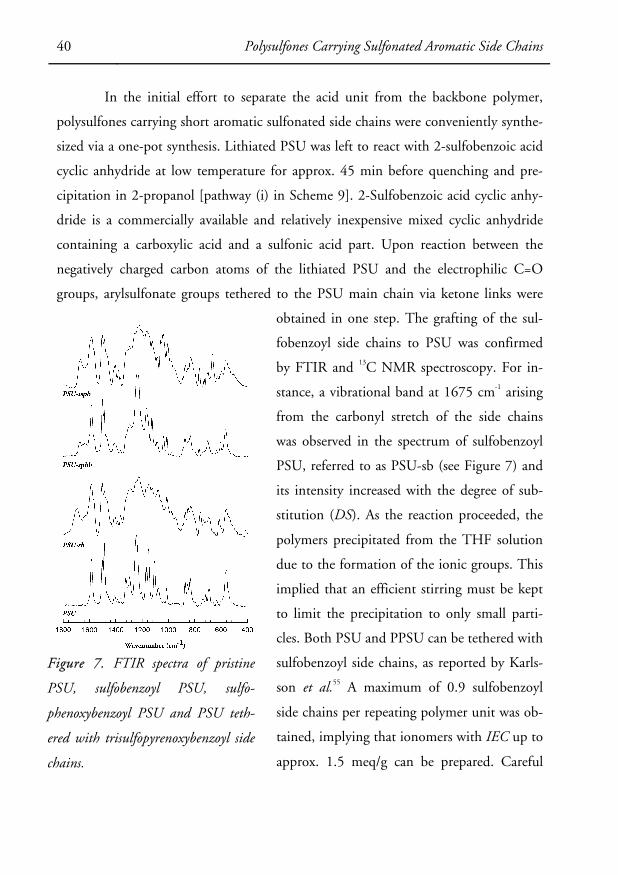
In the initial effort to separate the acid unit from the backbone polymer,
polysulfones carrying short aromatic sulfonated side chains were conveniently synthe-
sized via a one-pot synthesis. Lithiated PSU was left to react with 2-sulfobenzoic acid
cyclic anhydride at low temperature for approx. 45 min before quenching and pre-
cipitation in 2-propanol [pathway (i) in Scheme 9]. 2-Sulfobenzoic acid cyclic anhy-
dride is a commercially available and relatively inexpensive mixed cyclic anhydride
containing a carboxylic acid and a sulfonic acid part. Upon reaction between the
negatively charged carbon atoms of the lithiated PSU and the electrophilic C=O
groups, arylsulfonate groups tethered to the PSU main chain via ketone links were
obtained in one step. The grafting of the sul-
fobenzoyl side chains to PSU was confirmed
by FTIR and 13C NMR spectroscopy. For in-
stance, a vibrational band at 1675 cm-1 arising
from the carbonyl stretch of the side chains
was observed in the spectrum of sulfobenzoyl
PSU, referred to as PSU-sb (see Figure 7) and
its intensity increased with the degree of sub-
stitution (DS). As the reaction proceeded, the
polymers precipitated from the THF solution
due to the formation of the ionic groups. This
implied that an efficient stirring must be kept
to limit the precipitation to only small parti-
cles. Both PSU and PPSU can be tethered with
sulfobenzoyl side chains, as reported by Karls-
son et al.55 A maximum of 0.9 sulfobenzoyl
side chains per repeating polymer unit was ob-
tained, implying that ionomers with IEC up to
approx. 1.5 meq/g can be prepared. Careful
Figure 7. FTIR spectra of pristine
PSU, sulfobenzoyl PSU, sulfo-
phenoxybenzoyl PSU and PSU teth-
ered with trisulfopyrenoxybenzoyl side
chains.
Polysulfones Carrying Sulfonated Aromatic Side Chains 41
purification of the solvent and reactants afforded a good control on the DS of the fi-
nal polymers by the DL selected.
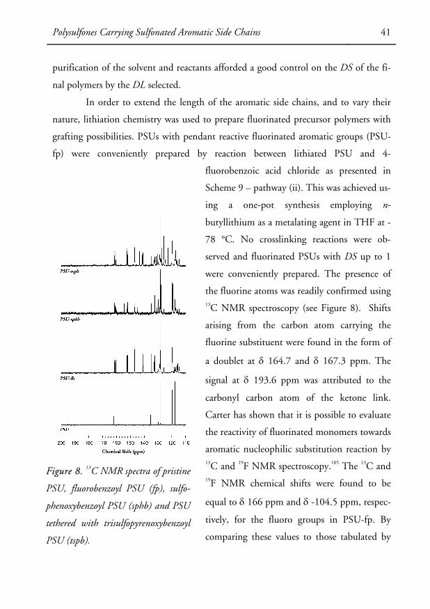
In order to extend the length of the aromatic side chains, and to vary their
nature, lithiation chemistry was used to prepare fluorinated precursor polymers with
grafting possibilities. PSUs with pendant reactive fluorinated aromatic groups (PSU-
fp) were conveniently prepared by reaction between lithiated PSU and 4-
fluorobenzoic acid chloride as presented in
Scheme 9 – pathway (ii). This was achieved us-
ing a one-pot synthesis employing n-
butyllithium as a metalating agent in THF at -
78 °C. No crosslinking reactions were ob-
served and fluorinated PSUs with DS up to 1
were conveniently prepared. The presence of
the fluorine atoms was readily confirmed using 13C NMR spectroscopy (see Figure 8). Shifts
arising from the carbon atom carrying the
fluorine substituent were found in the form of
a doublet at δ 164.7 and δ 167.3 ppm. The
signal at δ 193.6 ppm was attributed to the
carbonyl carbon atom of the ketone link.
Carter has shown that it is possible to evaluate
the reactivity of fluorinated monomers towards
aromatic nucleophilic substitution reaction by 13C and 19F NMR spectroscopy.105 The 13C and 19F NMR chemical shifts were found to be
equal to δ 166 ppm and δ -104.5 ppm, respec-
tively, for the fluoro groups in PSU-fp. By
comparing these values to those tabulated by
Figure 8. 13C NMR spectra of pristine
PSU, fluorobenzoyl PSU (fp), sulfo-
phenoxybenzoyl PSU (sphb) and PSU
tethered with trisulfopyrenoxybenzoyl
PSU (tspb).

42 Polysulfones Carrying Sulfonated Aromatic Side Chains
Carter, it was found that the reactivity of the precursor polymer was in the range of
the highly reactive 4,4’-difluorodiphenyl sulfone monomer and superior to the di-
fluorodiphenyl ketone monomer. This finding indicated that the carbonyl groups
linked to the electron-poor diaryl sulfone segments of the PSU main chain had an
electron-withdrawing power in the order of a sulfone group, and superior to a ketone
group.
We first investigated the synthesis of sulfophenoxy- and sulfonaphthoxyben-
zoyl PSUs, referred to as PSU-sphb and PSU-snb, respectively, via such a route [path-
ways (iii) and (iv) in Scheme 9]. These reactions were typically carried out in N,N-
dimethylacetamide (DMAc) under reflux using a methodology commonly employed
in the polycondensation reactions of polysulfones. This reaction proceeded under full
conversion and the IEC was easily controlled by the DL in the first step. The grafting
of the sulfophenolate and sulfonaphtholate groups was confirmed by the complete
disappearance of the peak arising from the fluorinated carbon atoms in the 13C NMR
spectra (see Figure 8), and by the presence of a strong absorption band at 1036 cm-1
in the FTIR spectra accounting for the S-O stretching of the sulfonated side chains
(see Figure 7). One limitation arose from the fact that a maximum of one side chain
per repeating polymer unit could be obtained, thereby limiting the IEC of the result-
ing ionomers to approx. 1.4 meq/g.
One way to increase the IEC of the ionomers consists of selecting reactants
that carry more than one sulfonic acid units. This was done by selecting 2-naphthol-
6,8-disulfonate and 8-hydroxy-1,3,6-pyrenetrisulfonate salts to carry out the syntheses
in pathways (v) and (vi), respectively, in Scheme 9. The resulting side chains were de-
fined as hypersulfonated since two sulfonic acid units were concentrated on one aro-
matic ring. Initial attempts to employ the same reaction conditions as in the study
presented above proved unsuccessful because of the limited solubility of the highly
charged salts in DMAc. After studying solvents with higher dielectric constants capa-
ble of solvating the salts, the reactions were successfully carried out in dimethylsulfox-
ide (DMSO). The temperature was kept quite low at 90 °C to suppress chain-

Polysulfones Carrying Sulfonated Aromatic Side Chains 43
breaking transetherification reactions which are detrimental to the molecular weight.
The decreased reactivity at the low temperature was at least partly compensated for by
the highly activated fluorine atoms during the reactions. After careful purification, the
sulfonated polymers were characterized by 1H NMR, 13C NMR and FTIR spectros-
copy. Figure 8 shows a representative 13C NMR spectrum of trisulfopyrenoxybenzoyl
PSU (PSU-tspb), along with a spectrum of a precursor polymer (PSU-fp). As seen,
signals originating from the fluorinated carbons were completely absent in the former
spectrum, indicating that all the fluorine atoms had been displaced during the reac-
tions. In addition, characteristic peaks arising from sulfonated carbon atoms were
clearly identified. Chemical shifts at δ 143.4, δ 141.1, and δ 140.9 ppm for the PSU-
tspb samples. FTIR spectroscopy further confirmed the successful substitution of the
fluorine atoms by sulfonated aryl ether groups. Characteristic absorption bands of the
symmetric S=O stretching of the sulfonate groups were found at 1056-1042 cm-1 for
the PSU-tspb samples (see Figure 7). The conversion of the substitution reaction was
calculated from 1H NMR data by comparing the integral of the signals originating
specifically from the di- or trisulfonated groups, respectively, with the integral of the
isopropylidene group of the polymer main chain at δ 1.67 ppm. It was found that the
conversions were in the range of 60-75%, indicating that a substantial reactivity was
retained at 90 °C. Notably, conversions of approx. 70-75% were obtained with the
disulfonated reactant. The fact that the reactions were not driven to full conversions
may be partly explained by the slow removal of water during the reaction at low tem-
perature. Nucleophilic hydroxide anions, formed under the basic conditions, may
have partly displaced the fluorine atoms. Such side reactions may thus explain the in-
complete conversions while the C-F groups were completely consumed.
3.1.2 Properties
Membranes were prepared by a solvent-casting methodology. Typically 5-10% solu-
tions of the polymers in polar aprotic solvents, such as DMSO or DMAc, were used
to prepare 100 μm-thick membranes by evaporation of the solvent. Membranes

44 Polysulfones Carrying Sulfonated Aromatic Side Chains
based on PSU-sph and PSU-sphb were successfully prepared from DMAc solutions at
60 °C. Notably, it was not possible to obtain mechanically strong membranes from
PSU-snb. This might be a consequence of the occurrence of chain-breaking trans-
etherification reactions that lowered the molecular weight, coupled with a decrease of
the chain flexibility of the sulfonaphthoxy derivatives in comparison with the sulfo-
phenoxy derivatives. Due to their poor solubility in DMAc, membranes based on di-
sulfonaphthoxy- and trisulfopyrenoxybenzoyl PSU were cast from DMSO solutions
at 100 °C to obtain membranes. All the polymers were cast in the salt form before be-
ing ion-exchanged to the protonated form by immersion in an aqueous 1M HCl solu-
tion for 24 h. The IEC of each polymer membrane was evaluated by acid-base titra-
tion.
The thermal stability of the PEMFC membranes is a key property that indi-
cates the durability under fuel cell operation. The latter was investigated by thermo-
gravimetrical analysis (TGA) by heating the membranes in their protonated form at
1 °C/min under air or at 10 °C/min under N2. The temperature at which the mem-
branes based on PSU-tspb retained 95 wt% of their initial weight decreased gradually
from 284 °C to 203 °C, in air, as the IEC of the membranes based on the polymers
with trisulfonated aromatic side chains increased from 0.87 to 2.28 meq/g. Further-
more, it was found that at a given IEC the polymer membranes containing disulfo-
nated aryl side chains had a somewhat higher thermal stability than the membranes
containing trisulfonated aryl side chains. This was in line with the results obtained
from the TGA measurements under N2. Indeed, onsets of degradation were recorded
in the temperature ranges 233-280 °C and 260-420 °C, under N2, for PSU-tspb and
PSU-dsnb, respectively. PSU-sphb typically degraded around 285 °C and PSU-sph at
temperatures >300 °C, indicating that increasing the length of the aromatic side
chains leads to a slight decrease of the thermal stability of the polymer. Nonetheless,
these onsets of degradation are in the range of other sulfonated non-fluorinated
polymer membranes that typically degrade at around 250 °C due to the loss of –
SO3H groups.27

Polysulfones Carrying Sulfonated Aromatic Side Chains 45
The morphological features of the
membranes based on PSU-dnsb and PSU-
tspb were studied by small-angle X-ray scat-
tering (SAXS) on lead-ion exchanged
membranes to enhance the contrast by se-
lectively staining the ionic domains. The
SAXS profiles of three different membranes
based on the polymers with hypersulfo-
nated side chains are shown in Figure 9.
The SAXS profiles of Nafion® 117 and a
conventionally sulfonated PSU (PSU-ds,
IEC = 1.34 meq/g) with the acid units at-
tached directly onto the polymer main
chain were also studied for comparison.
The synthesis of the latter polymer has
been described elsewhere.102 In general, the
characteristic separation lengths between
the ion-rich do-mains and the hydrophobic
polymer-rich domains in ionomers can be
observed in terms of the values of q corresponding to the so-called ionomer peak. As
seen in Figure 9 the ionomer peak of the conventionally sulfonated polymer mem-
brane was broader and shifted towards higher q value, as compared to the profile of
the Nafion® membrane. This indicated a smaller characteristic separation length with
a wider distribution in the former membrane. By comparing the SAXS traces of
membrane PSU-ds and the membranes based on the polymers with hypersulfonated
side chains, it is clear that the latter polymers showed larger characteristic separation
lengths, indicating the formation of larger ionic clusters. Moreover, the relatively nar-
row peak profiles of membranes based on the side-chain sulfonated PSUs suggested
that the ionic clusters were quite uniform in size. In addition, it was found that the
Figure 9. SAXS data recorded using
polymer membranes stained by ion-
exchange with lead acetate.
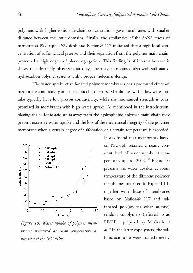
46 Polysulfones Carrying Sulfonated Aromatic Side Chains
polymers with higher ionic side-chain concentrations gave membranes with smaller
distance between the ionic domains. Finally, the similarities of the SAXS traces of
membranes PSU-tspb, PSU-dsnb and Nafion® 117 indicated that a high local con-
centration of sulfonic acid groups, and their separation from the polymer main chain,
promoted a high degree of phase segregation. This finding is of interest because it
shows that distinctly phase separated systems may be obtained also with sulfonated
hydrocarbon polymer systems with a proper molecular design.
The water uptake of sulfonated polymer membranes has a profound effect on
membrane conductivity and mechanical properties. Membranes with a low water up-
take typically have low proton conductivity, while the mechanical strength is com-
promised in membranes with high water uptake. As mentioned in the introduction,
placing the sulfonic acid units away from the hydrophobic polymer main chain may
prevent excessive water uptake and the loss of the mechanical integrity of the polymer
membrane when a certain degree of sulfonation or a certain temperature is exceeded.
It was found that membranes based
on PSU-sph retained a nearly con-
stant level of water uptake at tem-
peratures up to 120 °C.55 Figure 10
presents the water uptakes at room
temperature of the different polymer
membranes prepared in Papers I-III,
together with those of membranes
based on Nafion® 117 and sul-
fonated poly(arylene ether sulfone)
random copolymers (referred to as
BPSH), prepared by McGrath et
al.46 In the latter copolymers, the sul-
fonic acid units were located directly
Figure 10. Water uptake of polymer mem-
branes measured at room temperature as
function of the IEC value.
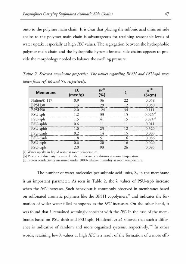
Polysulfones Carrying Sulfonated Aromatic Side Chains 47
onto to the polymer main chain. It is clear that placing the sulfonic acid units on side
chains to the polymer main chain is advantageous for retaining reasonable levels of
water uptake, especially at high IEC values. The segregation between the hydrophobic
polymer main chain and the hydrophilic hypersulfonated side chains appears to pro-
vide the morphology needed to balance the swelling pressure.
Table 2. Selected membrane properties. The values regarding BPSH and PSU-sph were
taken from ref. 66 and 55, respectively.
Membrane IEC
(meq/g) w [a] (%) λ
σ [b]
(S/cm) Nafion® 117 0.9 36 22 0.058 BPSH30 1.3 29 12 0.050 BPSH50 2.0 124 34 0.111 PSU-sph 1.2 33 15 0.026[c]
PSU-sph 1.5 41 15 0.024[c]
PSU-sphb 0.6 11 11 0.011 PSU-sphb 1.0 23 12 0.320 PSU-dsnb 0.2 14 15 0.003 PSU-dsnb 1.8 51 16 0.086 PSU-tspb 0.6 20 16 0.020 PSU-tspb 2.0 93 26 0.095
[a] Water uptake in liquid water at room temperature. [b] Proton conductivity measured under immersed conditions at room temperature. [c] Proton conductivity measured under 100% relative humidity at room temperature.
The number of water molecules per sulfonic acid units, λ, in the membrane
is an important parameter. As seen in Table 2, the λ values of PSU-tspb increase
when the IEC increases. Such behaviour is commonly observed in membranes based
on sulfonated aromatic polymers like the BPSH copolymers,66 and indicates the for-
mation of wider water-filled nanopores as the IEC increases. On the other hand, it
was found that λ remained seemingly constant with the IEC in the case of the mem-
branes based on PSU-dsnb and PSU-sph. Holdcroft et al. showed that such a differ-
ence is indicative of random and more organized systems, respectively.106 In other
words, retaining low λ values at high IEC is a result of the formation of a more effi-
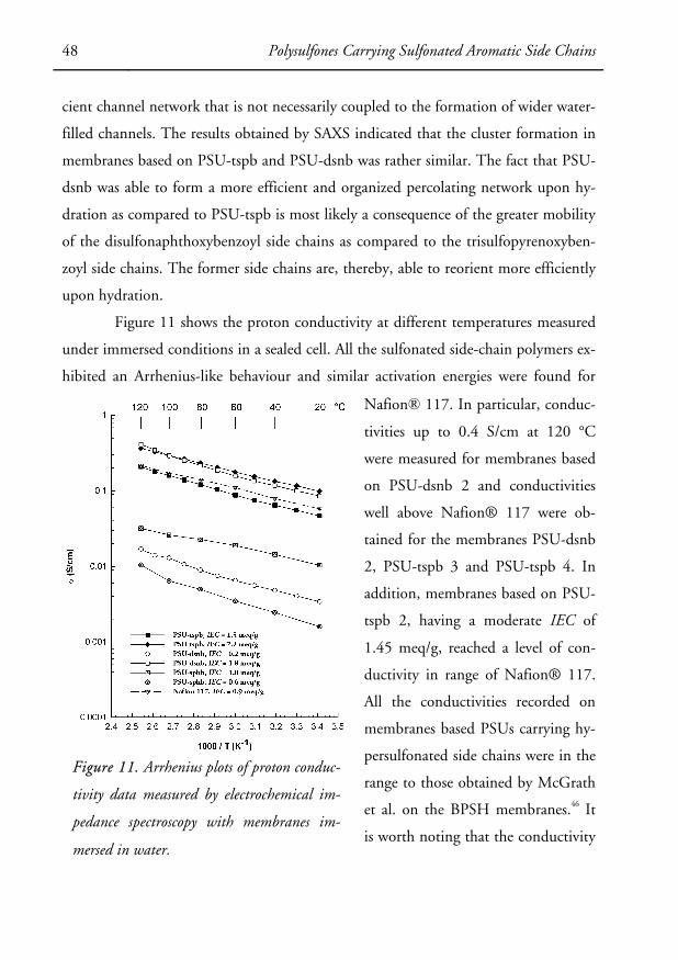
48 Polysulfones Carrying Sulfonated Aromatic Side Chains
cient channel network that is not necessarily coupled to the formation of wider water-
filled channels. The results obtained by SAXS indicated that the cluster formation in
membranes based on PSU-tspb and PSU-dsnb was rather similar. The fact that PSU-
dsnb was able to form a more efficient and organized percolating network upon hy-
dration as compared to PSU-tspb is most likely a consequence of the greater mobility
of the disulfonaphthoxybenzoyl side chains as compared to the trisulfopyrenoxyben-
zoyl side chains. The former side chains are, thereby, able to reorient more efficiently
upon hydration.
Figure 11 shows the proton conductivity at different temperatures measured
under immersed conditions in a sealed cell. All the sulfonated side-chain polymers ex-
hibited an Arrhenius-like behaviour and similar activation energies were found for
Nafion® 117. In particular, conduc-
tivities up to 0.4 S/cm at 120 °C
were measured for membranes based
on PSU-dsnb 2 and conductivities
well above Nafion® 117 were ob-
tained for the membranes PSU-dsnb
2, PSU-tspb 3 and PSU-tspb 4. In
addition, membranes based on PSU-
tspb 2, having a moderate IEC of
1.45 meq/g, reached a level of con-
ductivity in range of Nafion® 117.
All the conductivities recorded on
membranes based PSUs carrying hy-
persulfonated side chains were in the
range to those obtained by McGrath
et al. on the BPSH membranes.46 It
is worth noting that the conductivity
Figure 11. Arrhenius plots of proton conduc-
tivity data measured by electrochemical im-
pedance spectroscopy with membranes im-
mersed in water.
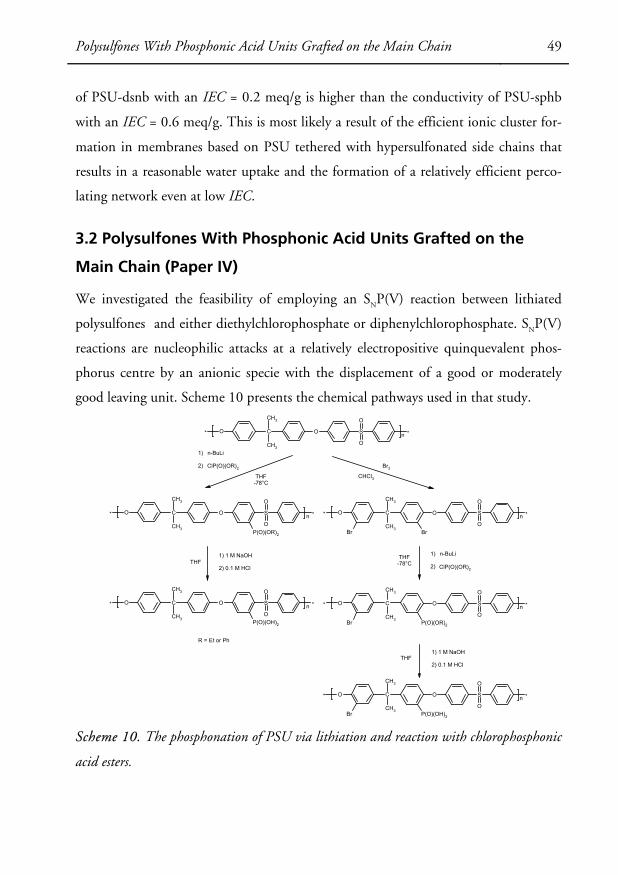
Polysulfones With Phosphonic Acid Units Grafted on the Main Chain 49
of PSU-dsnb with an IEC = 0.2 meq/g is higher than the conductivity of PSU-sphb
with an IEC = 0.6 meq/g. This is most likely a result of the efficient ionic cluster for-
mation in membranes based on PSU tethered with hypersulfonated side chains that
results in a reasonable water uptake and the formation of a relatively efficient perco-
lating network even at low IEC.
3.2 Polysulfones With Phosphonic Acid Units Grafted on the
Main Chain (Paper IV)
We investigated the feasibility of employing an SNP(V) reaction between lithiated
polysulfones and either diethylchlorophosphate or diphenylchlorophosphate. SNP(V)
reactions are nucleophilic attacks at a relatively electropositive quinquevalent phos-
phorus centre by an anionic specie with the displacement of a good or moderately
good leaving unit. Scheme 10 presents the chemical pathways used in that study.
* O C O S *
O
O
n
CH3
CH3
* O C O S *
O
O
n
CH3
CH3P(O)(OR)2
* O C O S *
O
O
n
CH3
CH3P(O)(OH)2
* O C O S *
O
O
n
CH3
CH3P(O)(OR)2Br
* O C O S *
O
O
n
CH3
CH3P(O)(OH)2Br
* O C O S *
O
O
n
CH3
CH3BrBr
Br2
CHCl3
ClP(O)(OR)2
ClP(O)(OR)2
1)
2)
n-BuLi
THF-78°C
THF1) 1 M NaOH
2) 0.1 M HCl
1)
2)
n-BuLi
1) 1 M NaOH
2) 0.1 M HCl
THF-78°C
THF
R = Et or Ph
Scheme 10. The phosphonation of PSU via lithiation and reaction with chlorophosphonic
acid esters.

50 Polysulfones With Phosphonic Acid Units Grafted on the Main Chain
The different reaction parameters such as the reaction temperature and time,
the excess of electrophile and rate of addition, etc. are, in this case, of particular im-
portance since the electrophile has a potential for crosslinking via the displacement of
phenoxy or ethoxy units. Allcock et al. reported that a large excess (approx. 200%) of
chlorophosphonic acid ester was required in order to suppress crosslinking reactions
in polyphosphazenes.107 A systematic study of the reaction was carried out to identify
the experimental conditions favouring this carbanionic displacement reaction.
FTIR and NMR spectroscopy were used to characterize the synthesized
polymers synthesized. Typical FTIR spectra of phosphonated PSU (PSU-p) in the es-
ter and the acid forms are shown in Figure 12 (b) and (c), respectively. Characteristic
bands at 1184 cm-1and at 933–943 cm-1 in Figure 12 (b) were assigned to (P)-O-C
stretching and to P-O-(C) vibrations, respectively. These observations indicated the
successful grafting of diphenyl phosphonate ester units onto PSU. A qualitative char-
acterization with FTIR spec-
troscopy was carried out
through the normalization of
each spectrum to the band
originating from the asymmet-
rical stretching of the main-
chain ether linkages at 1014
cm-1 in order to asses the de-
gree of substitution (DS) ob-
tained after each reaction. The
quantitative assessment of DS
was carried out by 1H NMR
spectroscopy. The actual at-
tachment on the main chain
was confirmed by 31P NMR
Wavenumber (cm-1)
60080010001200140016001800
1265 1184 938 768 (cm-1)
a)
b)
c)
Figure 12. FTIR spectra of a) pristine PSU, b)
PSU tethered with diphenylphosphonate ester units,
and c) PSU tethered with phosphonic acid units.
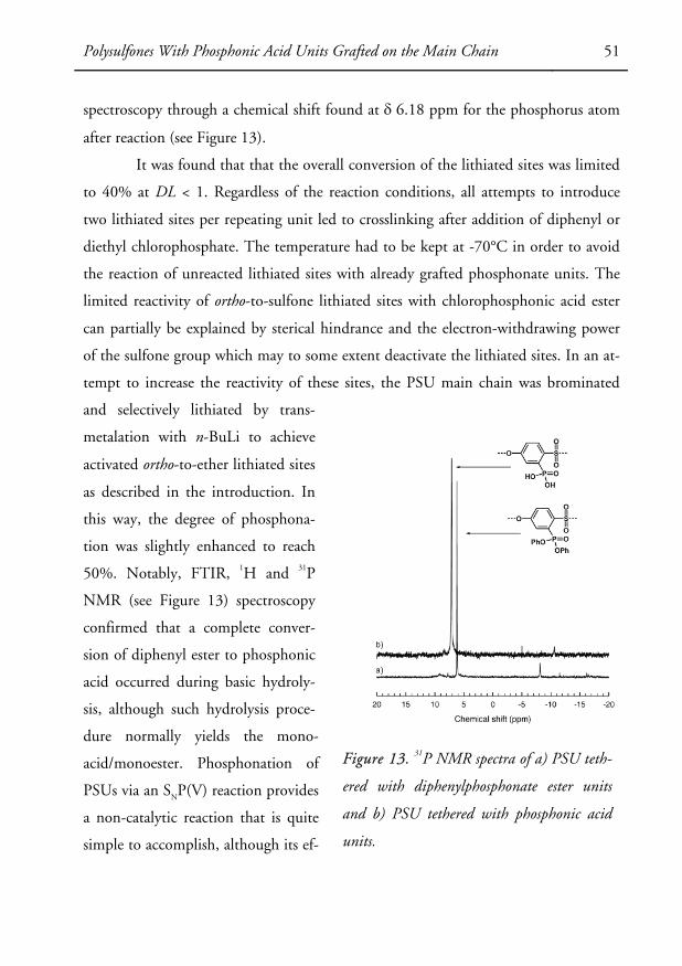
Polysulfones With Phosphonic Acid Units Grafted on the Main Chain 51
spectroscopy through a chemical shift found at δ 6.18 ppm for the phosphorus atom
after reaction (see Figure 13).
It was found that that the overall conversion of the lithiated sites was limited
to 40% at DL < 1. Regardless of the reaction conditions, all attempts to introduce
two lithiated sites per repeating unit led to crosslinking after addition of diphenyl or
diethyl chlorophosphate. The temperature had to be kept at -70°C in order to avoid
the reaction of unreacted lithiated sites with already grafted phosphonate units. The
limited reactivity of ortho-to-sulfone lithiated sites with chlorophosphonic acid ester
can partially be explained by sterical hindrance and the electron-withdrawing power
of the sulfone group which may to some extent deactivate the lithiated sites. In an at-
tempt to increase the reactivity of these sites, the PSU main chain was brominated
and selectively lithiated by trans-
metalation with n-BuLi to achieve
activated ortho-to-ether lithiated sites
as described in the introduction. In
this way, the degree of phosphona-
tion was slightly enhanced to reach
50%. Notably, FTIR, 1H and 31P
NMR (see Figure 13) spectroscopy
confirmed that a complete conver-
sion of diphenyl ester to phosphonic
acid occurred during basic hydroly-
sis, although such hydrolysis proce-
dure normally yields the mono-
acid/monoester. Phosphonation of
PSUs via an SNP(V) reaction provides
a non-catalytic reaction that is quite
simple to accomplish, although its ef-
Figure 13. 31P NMR spectra of a) PSU teth-
ered with diphenylphosphonate ester units
and b) PSU tethered with phosphonic acid
units.
52 Polysulfones With Phosphonic Acid Units Grafted on the Main Chain
ficiency for converting lithiated sites to phosphonate units is limited. PSUs with de-
grees of phosphonation up to 0.4-0.5 and the phosphonic acid placed either on the
bisphenol-A or the biphenyl sulfone segments were, however, conveniently synthe-
sized.
Thermogravimetrical analysis showed that an initial small loss of mass oc-
curred between 200 and 320 °C for phosphonated PSUs where the phosphonic acid
was located ortho-to-ether and ortho-to-sulfone. This initial weight loss was attributed
to the formation of anhydrides by the creation of P-O-P linkages, as shown in
Scheme 8. The main decomposition step of PSU with ortho-to-ether phosphonic acid
units occurred above 350 °C, while PSU with phosphonic acid units ortho-to-sulfone
started above 375 °C. This may be explained by both the slightly lower value of DS of
the latter sample and by the stabilization effect originating from the localization of the
acidic units on electron-poor segments of the PSU main chain.
Finally, the phosphonated polymers possessed a good membrane-forming
property. However, the low level of IEC of the polymer membranes obtained in this
study did not lead to water uptake levels sufficient enough to promote proton con-
duction. An original approach was attempted in which the phosphonated polymer
was used as a component, together with phosphoric acid and m-
sulfophenylphosphonic acid, in the preparation of precursor solutions of hybrid
polymer membranes using the procedure developed by Alberti et al.108,109 Such a
methodology may provide a system in which the polymer contributes to the mechani-
cal integrity of the membrane while the inorganic layer provides the proton conduc-
tion. Notably, upon casting of the precursor solutions, totally transparent and strong
membranes were obtained at levels up to 50 wt.% of inorganic filler. The incorpora-
tion of the phosphonated polymer within the organically modified zirconium phos-
phate layer was confirmed by immersing the membranes in DMAc which is a solvent
for the polymer. Interestingly, the membranes retained their integrity and were in-
soluble even after 48h of stirring. These preliminary results may serve as a basis for a
more detailed and thorough study on new hybrid polymer membranes for fuel cells.

Polysulfones Carrying Highly Acidic Phosphonated Aromatic Side Chains 53
3.3 Polysulfones Carrying Highly Acidic Phosphonated Aromatic
Side Chains (Paper V)
One conclusion from the study presented in Section 3.2 is that the water uptake of
the phosphonated ionomers is much lower than that of the corresponding sulfonated
ionomers. One way to increase the water
uptake of the former ionomers is to enhance
the acidity of the phosphonic acid in order
to favour the formation of a morphology of
a percolating network of water-filled hydro-
philic nanopores embedded in a hydropho-
bic polymer-rich phase domain. Conse-
quently, we prepared and investigated novel
PSUs carrying benzoyl(difluoromethylene-
phosphonic acid) side chains (PSU-bfp) via
the preparation of iodinated PSUs (PSU-ib)
which served as precursors for the prepara-
tion of the phosphonated polymers (see
Scheme 11).
The iodinated polymers were char-
acterized by 1H and 13C NMR and FTIR
spectroscopy. The 13C NMR spectra of
PSU-ib and pristine PSU are presented in
Figure 14. As expected, several new peaks
were present in the spectrum of PSU-ib, in-
cluding the peak at δ 193.1 ppm. This is
typically the chemical shift at which carbonyl
groups belonging to benzoyl side-chains at-
Scheme 11. Synthetic pathway to o-
benzoyl(difluoromethylenephosphonic
acid) PSU.
O* O SO
OLi
*n
O* O SO
O*n
O
I
O* O SO
O*n
CH3OO
I
O
O* O SO
O*n
CF2 P
OOEt
OEt
O
O* O SO
O*n
CF2 P
OOH
OH
n-BuLi THF, -75 oC
THF, -75 oC
Zn, BrCF2P(O)(OEt)2, CuBrDMF, ultrasound, 25 °C
1) BrSiMe3, CHCl3, 40 °C2) 5 vol.-% 1M HCl in MeOH
PSU
PSU-ib
PSU-bfphydrolyzed
PSU-bfp
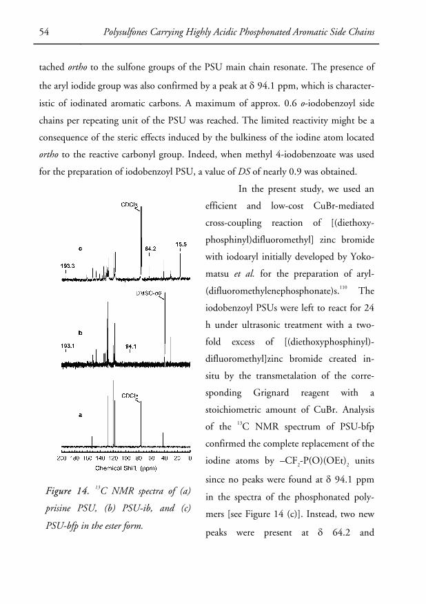
54 Polysulfones Carrying Highly Acidic Phosphonated Aromatic Side Chains
tached ortho to the sulfone groups of the PSU main chain resonate. The presence of
the aryl iodide group was also confirmed by a peak at δ 94.1 ppm, which is character-
istic of iodinated aromatic carbons. A maximum of approx. 0.6 o-iodobenzoyl side
chains per repeating unit of the PSU was reached. The limited reactivity might be a
consequence of the steric effects induced by the bulkiness of the iodine atom located
ortho to the reactive carbonyl group. Indeed, when methyl 4-iodobenzoate was used
for the preparation of iodobenzoyl PSU, a value of DS of nearly 0.9 was obtained.
In the present study, we used an
efficient and low-cost CuBr-mediated
cross-coupling reaction of [(diethoxy-
phosphinyl)difluoromethyl] zinc bromide
with iodoaryl initially developed by Yoko-
matsu et al. for the preparation of aryl-
(difluoromethylenephosphonate)s.110 The
iodobenzoyl PSUs were left to react for 24
h under ultrasonic treatment with a two-
fold excess of [(diethoxyphosphinyl)-
difluoromethyl]zinc bromide created in-
situ by the transmetalation of the corre-
sponding Grignard reagent with a
stoichiometric amount of CuBr. Analysis
of the 13C NMR spectrum of PSU-bfp
confirmed the complete replacement of the
iodine atoms by –CF2-P(O)(OEt)2 units
since no peaks were found at δ 94.1 ppm
in the spectra of the phosphonated poly-
mers [see Figure 14 (c)]. Instead, two new
peaks were present at δ 64.2 and
Figure 14. 13C NMR spectra of (a)
prisine PSU, (b) PSU-ib, and (c)
PSU-bfp in the ester form.

Polysulfones Carrying Highly Acidic Phosphonated Aromatic Side Chains 55
δ 15.5 ppm and were attributed to the signals arising from the ethoxy groups of the
diethyl phosphonate ester units. The phosphonation reaction proceeded with an ex-
cellent yield of approximately 90% when o-iodobenzoyl PSU was used. However, in
the case of p-iodobenzoyl PSU the yield decreased to 48%.
The complete hydrolysis of PSU-bfp was achieved by reaction of the phos-
phonated polymers with BrSiMe3 at 40 °C for 24 h. 31P NMR spectroscopy con-
firmed the successful hydrolysis (see Figure 15). The phosphorus atom of the diethyl
phosphonate ester unit resonated at δ 6.47 ppm in a triplet as a result of the coupling
with CF2. After hydrolysis, only a single triplet was visible at δ 3.92 ppm, accounting
for the phosphonic acid units.
It was found that the thermal de-
composition of the phosphonated polymers
in their ester form proceeded via two distinc-
tive degradation steps. The weight loss con-
nected with the first degradation step, which
occurred between 200 and 320 °C, corre-
sponded to the weight of all the –
CF2P(O)(OEt)2 units. The thermal decom-
position of the samples in the acid form also
proceeded in two steps, which is typical of
polymers containing phosphonic acid. In
this case, the first weight loss started at
Td ~ 230 °C and corresponded to the weight
of all the phosphonic acid units. As described
in Paper VI, alkyl-P bonds are usually weak-
ened by the presence of electron-
withdrawing units, whereas aryl-P bonds are
weakened by electron-donating units. This
Figure 15. 31P NMR spectra of
PSU-bfp in (a) ester and (b) acid
forms.
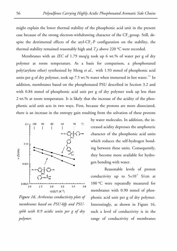
56 Polysulfones Carrying Highly Acidic Phosphonated Aromatic Side Chains
might explain the lower thermal stability of the phosphonic acid unit in the present
case because of the strong electron-withdrawing character of the CF2 group. Still, de-
spite the detrimental effects of the aryl-CF2-P configuration on the stability, the
thermal stability remained reasonably high and Tds above 220 °C were recorded.
Membranes with an IEC of 1.79 meq/g took up 6 wt.% of water per g of dry
polymer at room temperature. As a basis for comparison, a phosphonated
poly(arylene ether) synthesized by Meng et al., with 1.93 mmol of phosphonic acid
units per g of dry polymer, took up 7.5 wt.% water when immersed in hot water.111 In
addition, membranes based on the phosphonated PSU described in Section 3.2 and
with 0.84 mmol of phosphonic acid unit per g of dry polymer took up less than
2 wt.% at room temperature. It is likely that the increase of the acidity of the phos-
phonic acid unit acts in two ways. First, because the protons are more dissociated,
there is an increase in the entropy gain resulting from the solvation of these protons
by water molecules. In addition, the in-
creased acidity depresses the amphoteric
character of the phosphonic acid units
which reduces the self-hydrogen bond-
ing between these units. Consequently,
they become more available for hydro-
gen bonding with water.
Reasonable levels of proton
conductivity up to 5×10⁻³ S/cm at
100 °C were repeatedly measured for
membranes with 0.90 mmol of phos-
phonic acid unit per g of dry polymer.
Interestingly, as shown in Figure 16,
such a level of conductivity is in the
range of conductivity of membranes
Figure 16. Arrhenius conductivity plots of
membranes based on PSU-bfp and PSU-
sphb with 0.9 acidic units per g of dry
polymer.
Polysulfones Carrying Highly Acidic Phosphonated Aromatic Side Chains 57
based on sulfophenoxybenzoyl PSU with approximately the same content of acid
units per g of dry polymer, i.e., 0.86 mmol of sulfonic acid unit per g of dry polymer.
The slightly lower level of conductivity of the phosphonated polymer membranes
may be explained by the lower water uptake of these membranes as compared to the
sulfonated polymer membranes; 6 wt.% of water at room temperature versus 11 wt.%
for the sulfonated polymer membranes.

58 Polysulfones Carrying Highly Acidic Phosphonated Aromatic Side Chains

Summary & Outlook 59
CHAPTER 4
SUMMARY & OUTLOOK
New pathways to phosphonated and sulfonated polysulfones have been established by
new lithiation-grafting techniques. Such a methodology afforded polymers with pen-
dant phosphonic acid units, or pendant phosphonated or sulfonated aromatic side
chains. In particular, polysulfones carrying short aromatic sulfonated side chains were
conveniently synthesized via a one-pot synthesis. Access to longer side chains was pos-
sible thanks to the preparation of a precursor polymer tethered with highly reactive
fluorobenzoyl side chains that were activated for nucleophilic aromatic substitution
reactions. Consequently, by a careful choice of reactants and reaction conditions,
polysulfones carrying hypersulfonated aromatic side chains were synthesized and stud-
ied. In general, it was difficult to obtain more than one side chain per repeating unit
of the polysulfone due to problems of reactivity connected with sterical hindrance and
side reactions. Finally, phosphonated polysulfones were also successfully prepared via
either SNP(V) reactions between lithiated polysulfones and chlorophosphonic acid es-
ters or via a two step reaction involving the preparation of polysulfones tethered with
iodobenzoyl side chains. The iodine atoms were then replaced by –CF2-PO3H2 units
via a CuBr-crosscoupling reaction.
It was found that membranes with controlled water uptake were obtained by
attaching the sulfonic acid unit to short and stiff aromatic side chains, demonstrating
that by placing the cohesion of the hydrophobic main-chain polymer phase was re-
tained despite the formation of a highly water-swollen phase. Placing the sulfonic acid
units on side chains proved particularly advantageous to retain reasonable water up-
takes at high IECs. Of particular interest, membranes based on a polysulfone main
chain carrying disulfonated naphthoxybenzoyl side chains exhibited a distinct phase
separation and formed a well-defined and efficient network of water-filled nanopores.

60 Summary & Outlook
This afforded excellent proton conductivity at controlled levels of water uptake in
contrast to conventional sulfonated aromatic polymers. In addition, it was found that
a certain level of flexibility of the side chains is necessary for the formation of an effi-
cient percolating network. Increasing the local concentration of sulfonic acid units as
well as separating the hydrophilic moieties from the hydrophobic polymer main chain
enabled the stabilization of the morphology of the water-swollen membranes and a
promotion of the proton conduction.
The investigation of alternative acidic moieties is also of great interest as
desulfonation may become a critical issue at high temperatures. However, the acidity
of phosphonic acid directly attached to aromatic rings was found to be too low to re-
sult in reasonable levels of water uptake. An original approach was therefore devel-
oped in which PSU with pendant iodinated benzoyl side chains were prepared using
lithiation chemistry. The latter polymer was then further modified to yield the more
acidic –CF2PO3H2 units located on aromatic side chains. Membranes based on iono-
mers with 0.90 mmol of phosphonic acid units/g of dry polymer took up 6 wt.% wa-
ter when immersed at room temperature, and levels of conductivity comparable to
those reached by a membrane based on a sulfonated polysulfone with 0.86 mmol of
sulfonic acid per g of dry polymer were recorded, indicating that phosphonated
polymers may be used in the context of water-assisted proton-conducting polymer
membrane systems.
This work may efficiently serve as a basis for new projects as many aspects
need to be investigated further. First, it would be interesting to devote a study to the
direct comparison of the different sulfonated side chain polysulfones in order to elu-
cidate the exact morphological features of these membranes, especially in the swollen
state. High local concentrations of sulfonic acid units might also prove to be benefi-
cial for the preparation of composite polymer membranes based on zirconium phos-
phate using the precipitation methodology. Indeed, the high conductivity of the neat
polymer membrane implies that suitable stabilizing inorganic fillers may be added
without suffering from detrimental performance losses. Furthermore, the phospho-

Summary & Outlook 61
nated polymers have shown promise as PEMs and the chemical modification ap-
proach has proven to be an efficient route to phosphonated polymers with various ar-
chitectures. Of particular interest, phosphonated polymers may be included into the
formation of zirconium phosphate layers. Consequently, hybrid polymer membranes
in which the polymer main chain is covalently linked to the inorganic filler may be
formed. Such an approach should be investigated further as it may provide highly sta-
ble morphologies resulting in PEMs capable of operating efficiently at elevated tem-
peratures. Finally, membranes based on polysulfones tethered with disulfonaphthoxy-
benzoyl side chains appeared to combine a unique set of properties that make them
interesting for testing in PEMFC and DMFC environments.

62 Summary & Outlook

Acknowledgments 63
ACKNOWLEDGMENTS
First of all, the Swedish Foundation for Strategic Environmental Research, MISTRA, is
acknowledged for financial support.
The writing of this doctoral thesis would have never been possible without the
support of some key individuals that I would like to thank here in a few words:
… Patric. You were first to me a teacher, then a supervisor and now a friend. I have
learned so much from you that it would be pointless to specify anything further. I can
only say one thing, “Keep on the amazing work!” We will keep in touch for sure since
our little Elin(n)s have to get to know each other ;-) And to be honest, you have to
come down to France to practise your “Et Aleur…”.
… Everyone from the “Polymer Group” that I have met through these years. A spe-
cial thanks to Petra (and Chris) and Christian who have been wonderful friends on
top of being good buddies at work; Frans for leading the polymer group through all
these changes; Helen for taking care of all the little things that count for creating a
pleasant working environment; Bengt, Bodil and Bertill for all the nice chats that we
have had; Mario for all your help in several aspects of my project; Anette, Magnus
and Stefan, for their friendships; and last but not least, Lottie, Anna, Julien and
Renaud with whom I had the pleasure to work until the end of my time at the de-
partment.
… All the colleagues at the new “Div. of Polymer & Materials Chemistry”. It is a pity
that we have not had much time to do a lot of things together despite moving things!
… The Portuguese community at fkem1, together with some Belgium, Swedish and
Italian Mix.
… Rita & Jens for bridging the gap between southern and northern Europe :-)
… Lina & Ola for being wonderful life-long friends! Even though we won’t be in the
Alpes right away, I do hope that you will visit us some time soon :-)

64 Acknowledgments
… Ulrika & Eric. Hundreds of kilometres will not stop us from sharing good wine,
cheese and whisky!
… Pauline, notre ch’tite globetrotteuse.
… Magali & Ludovic, qui auront testé pour nous le système de santé suédois pour en-
fants.
… Yannick et Erquy pour tous les bons moments passés ensemble.
… Did, La Piche et le Pierrot. Disons que ça se passe de commentaires ; des soirées de
tarot au mariage, on aura presque tout fait (enfin il n’y aurait pas un baptême et une
naissance bientôt ?!); niveau mariage, Pierrot ?
… Mes parents et fréros pour ceux qu’ils sont !
… Et enfin les deux femmes de ma vie, Gégé et Elinn, pour qui les mots faillissent à
exprimer mes sentiments.

References 65
REFERENCES
1. Acres, G. J. K. Recent advances in fuel cell technology and its applications. Journal of Power Sources 100, 60-66 (2001). 2. Busby, R. L. Hydrogen and fuel cells : a comprehensive guide (PennWell Corp., Tulsa, Okla., 2005). 3. Brandon, N. P., Skinner, S. & Steele, B. C. H. Recent advances in materials for fuel cells. Annual Review of Materials Research 33, 183-213 (2003). 4. Costamagna, P. & Srinivasan, S. Quantum jumps in the PEMFC science and technology from the 1960s to the year 2000 Part II. Engineering, technology devel-opment and application aspects. Journal of Power Sources 102, 253-269 (2001). 5. Costamagna, P. & Srinivasan, S. Quantum jumps in the PEMFC science and technology from the 1960s to the year 2000 Part I. Fundamental scientific aspects. Journal of Power Sources 102, 242-252 (2001). 6. Gamburzev, S. & Appleby, A. J. Recent progress in performance improvement of the proton exchange membrane fuel cell (PEMFC). Journal of Power Sources 107, 5-12 (2002). 7. Gottesfeld, S. Polymer electrolyte fuel cells (Pergamon, Oxford, 1995). 8. Li, X. Principles of fuel cells (Taylor & Francis, New York, 2006). 9. Steele, B. C. H. & Heinzel, A. Materials for fuel-cell technologies. Nature 414, 345-352 (2001). 10. Vielstich, W., Gasteiger, H. A. & Lamm, A. Handbook of fuel cells : fundamentals, technology, applications (Wiley, Chichester, 2003). 11. Wang, C. Y. Fundamental models for fuel cell engineering. Chemical Reviews 104, 4727-4765 (2004). 12. Perry, M. L. & Fuller, T. F. A historical perspective of fuel cell technology in the 20th century. Journal of the Electrochemical Society 149, S59-S67 (2002). 13. Zalbowitz, M. & Thomas, S. (Department of Energy, 1999). 14. Winter, M. & Brodd, R. J. What are batteries, fuel cells, and supercapacitors? Chemical Reviews 104, 4245-4269 (2004). 15. Grubb, W. T. Batteries with Solid Ion Exchange Electrolytes .1. Secondary Cells Employing Metal Electrodes. Journal of the Electrochemical Society 106, 275-278 (1959). 16. Grubb, W. T., Jr. 5 pp. ((Electric Co.). Us, 1959). 17. Alberti, G. et al. Proton conducting membranes for medium temperature fuel cells: recent advances and new strategies. Desalination 199, 4-5 (2006). 18. Jannasch, P. Recent developments in high-temperature proton conducting poly-mer electrolyte membranes. Current Opinion in Colloid & Interface Science 8, 96-102 (2003).

66 References
19. Li, Q. F., He, R. H., Jensen, J. O. & Bjerrum, N. J. Approaches and recent de-velopment of polymer electrolyte membranes for fuel cells operating above 100 de-grees C. Chemistry of Materials 15, 4896-4915 (2003). 20. Savadogo, O. Emerging membranes for electrochemical systems - Part II. High temperature composite membranes for polymer electrolyte fuel cell (PEFC) applica-tions. Journal of Power Sources 127, 135-161 (2004). 21. Schuster, M., Rager, T., Noda, A., Kreuer, K. D. & Maier, J. About the Choice of the Protogenic Group in PEM Separator Materials for Intermediate Temperature, Low Humidity Operation: A Critical Comparison of Sulfonic Acid, Phosphonic Acid and Imidazole Functionalized Model Compounds. Fuel Cells 5, 355-365 (2005). 22. Zhang, J. L. et al. High temperature PEM fuel cells. Journal of Power Sources 160, 872-891 (2006). 23. Acres, G. J. K. & Hards, G. A. Electrocatalysts for fuel cells. Philosophical Trans-actions of the Royal Society of London Series a-Mathematical Physical and Engineering Sciences 354, 1671-1680 (1996). 24. Kreuer, K. D. On the development of proton conducting polymer membranes for hydrogen and methanol fuel cells. Journal of Membrane Science 185, 29-39 (2001). 25. Ling, J. & Savadogo, O. Comparison of methanol crossover among four types of Nafion membranes. Journal of the Electrochemical Society 151, A1604-A1610 (2004). 26. Jones, D. J. et al. High-temperature DMFC stack operating with non-fluorinated membranes. Fuel Cells Bulletin, 12-15 (2005). 27. Roziere, J. & Jones, D. J. Non-fluorinated polymer materials for proton exchange membrane fuel cells. Annual Review of Materials Research 33, 503-555 (2003). 28. Vernersson, T., Lafitte, B., Lindbergh, G. & Jannasch, P. A sulfophenylated poly-sulfone as the DMFC electrolyte membrane - an evaluation of methanol permeability and cell performance. Fuel Cells 6, 340-346 (2006). 29. Jorissen, L., Gogel, V., Kerres, J. & Garche, J. New membranes for direct metha-nol fuel cells. Journal of Power Sources 105, 267-273 (2002). 30. Litster, S. & McLean, G. PEM fuel cell electrodes. Journal of Power Sources 130, 61-76 (2004). 31. von Kraemer, S., Puchner, M., Jannasch, P., Lundblad, A. & Lindbergh, G. Gas diffusion electrodes and membrane electrode assemblies based on a sulfonated poly-sulfone for high-temperature PEMFC (vol 153, pg A2077, 2006). Journal of the Elec-trochemical Society 153, L35-L35 (2006). 32. Ulbricht, M. Advanced functional polymer membranes. Polymer 47, 2217-2262 (2006). 33. Banerjee, S. & Curtin, D. E. Nafion (R) perfluorinated membranes in fuel cells. Journal of Fluorine Chemistry 125, 1211-1216 (2004). 34. Mauritz, K. A. & Moore, R. B. State of understanding of Nafion. Chemical Re-views 104, 4535-4585 (2004). 35. Berzins, T. Electrochemical Characterization of Nafion Perfluorosulfonic Acid Membranes in Chlor-Alkali Cells. Journal of the Electrochemical Society 124, C318-C318 (1977).

References 67
36. Casciola, M., Alberti, G., Sganappa, M. & Narducci, R. On the decay of Nafion proton conductivity at high temperature and relative humidity. Journal of Power Sources 162, 141-145 (2006). 37. Souzy, R. & Ameduri, B. Functional fluoropolymers for fuel cell membranes. Progress in Polymer Science 30, 644-687 (2005). 38. Souzy, R. et al. Proton-conducting polymer electrolyte membranes based on fluoropolymers incorporating perfluorovinyl ether sulfonic acids and fluoroalkenes: Synthesis and characterization. Fuel Cells 5, 383-397 (2005). 39. Hickner, M. A., Ghassemi, H., Kim, Y. S., Einsla, B. R. & McGrath, J. E. Alter-native polymer systems for proton exchange membranes (PEMs). Chemical Reviews 104, 4587-4611 (2004). 40. Rikukawa, M. & Sanui, K. Proton-conducting polymer electrolyte membranes based on hydrocarbon polymers. Progress in Polymer Science 25, 1463-1502 (2000). 41. Savadogo, O. Emerging membranes for electrochemical systems: (I) solid polymer electrolyte membranes for fuel cell systems. Journal of New Materials for Electrochemi-cal Systems 1, 47-66 (1998). 42. Alberti, G., Casciola, M., Massinelli, L. & Bauer, B. Polymeric proton conduct-ing membranes for medium temperature fuel cells (110-160 degrees C). Journal of Membrane Science 185, 73-81 (2001). 43. Kerres, J. A. Development of ionomer membranes for fuel cells. Journal of Mem-brane Science 185, 3-27 (2001). 44. Rusanov, A. L., Likhatchev, D. Y. & Mullen, K. Proton-conducting electrolyte membranes based on aromatic condensation polymers. Russian Chemical Reviews 71, 761-774 (2002). 45. Harrison, W. L., Hickner, M. A., Kim, Y. S. & McGrath, J. E. Poly(Arylene Ether Sulfone) Copolymers and Related Systems from Disulfonated Monomer Build-ing Blocks: Synthesis, Characterization, and Performance - A Topical Review. Fuel Cells 5, 201-212 (2005). 46. Wang, F. et al. Synthesis of highly sulfonated poly(arylene ether sulfone) random (statistical) copolymers via direct polymerization. Macromolecular Symposia 175, 387-395 (2001). 47. Li, Y. X. et al. Synthesis and characterization of controlled molecular weight di-sulfonated poly(arylene ether sulfone) copolymers and their applications to proton ex-change membranes. Polymer 47, 4210-4217 (2006). 48. Ghassemi, H., McGrath, J. E. & Zawodzinski, T. A. Multiblock sulfonated-fluorinated poly(arylene ether)s for a proton exchange membrane fuel cell. Polymer 47, 4132-4139 (2006). 49. Poppe, D., Frey, H., Kreuer, K. D., Heinzel, A. & Mulhaupt, R. Carboxylated and sulfonated poly(arylene-co-arylene sulfone)s: Thermostable polyelectrolytes for fuel cell applications. Macromolecules 35, 7936-7941 (2002). 50. Gao, Y. et al. Direct copolymerization of sulfonated poly(phthalazinone arylene ether)s for proton-exchange-membrane materials. Journal of Polymer Science Part a-Polymer Chemistry 41, 2731-2742 (2003).

68 References
51. Gao, Y. et al. Synthesis of poly(arylene ether ether ketone ketone) copolymers containing pendant sulfonic acid groups bonded to naphthalene as proton exchange membrane materials. Macromolecules 37, 6748-6754 (2004). 52. Gao, Y. et al. Sulfonated copoly(phthalazinone ether ketone nitrile)s as proton exchange membrane materials. Journal of Membrane Science 278, 26-34 (2006). 53. Lafitte, B. & Jannasch, P. Polysulfone ionomers functionalized with ben-zoyl(difluoromethylenephosphonic acid) side chains for proton-conducting fuel-cell membranes. Journal of Polymer Science Part A: Polymer Chemistry 45, 269-283 (2007). 54. Karlsson, L. E. & Jannasch, P. Polysulfone ionomers for proton-conducting fuel cell membranes: sulfoalkylated polysulfones. Journal of Membrane Science 230, 61-70 (2004). 55. Karlsson, L. E. & Jannasch, P. Polysulfone ionomers for proton-conducting fuel cell membranes - 2. Sulfophenylated polysulfones and polyphenylsulfones. Electro-chimica Acta 50, 1939-1946 (2005). 56. Lafitte, B., Karlsson, L. E. & Jannasch, P. Sulfophenylation of polysulfones for proton-conducting fuel cell membranes. Macromolecular Rapid Communications 23, 896-900 (2002). 57. Lafitte, B., Puchner, M. & Jannasch, P. Proton conducting polysulfone ionomers carrying sulfoaryloxybenzoyl side chains. Macromolecular Rapid Communications 26, 1464-1468 (2005). 58. Lafitte, B. & Jannasch, P. Phosphonation of polysulfones via lithiation and reac-tion with chlorophosphonic acid esters. Journal of Polymer Science Part a-Polymer Chemistry 43, 273-286 (2005). 59. Persson, J. C., Josefsson, K. & Jannasch, P. Polysulfones tethered with benzimi-dazole. Polymer 47, 991-998 (2006). 60. Gubler, L., Gursel, S. A. & Scherer, G. G. Radiation grafted membranes for polymer electrolyte fuel cells. Fuel Cells 5, 317-335 (2005). 61. Kerres, J. A. Blended and Cross-Linked Ionomer Membranes for Application in Membrane Fuel Cells. Fuel Cells 5, 230-247 (2005). 62. Miyatake, K. & Hay, A. S. Synthesis and properties of poly(arylene ether)s bear-ing sulfonic acid groups on pendant phenyl rings. Journal of Polymer Science Part a-Polymer Chemistry 39, 3211-3217 (2001). 63. Zhou, H., Miyatake, K. & Watanabe, M. Polyimide electrolyte membranes hav-ing fluorenyl and sulfopropoxy groups for high temperature PEFCs. Fuel Cells 5, 296-301 (2005). 64. Genies, C. et al. Stability study of sulfonated phthalic and naphthalenic polyim-ide structures in aqueous medium. Polymer 42, 5097-5105 (2001). 65. Wieser, C. Novel Polymer Electrolyte Membranes for Automotive Applications - Requirements and Benefits. Fuel Cells 4, 245-250 (2004). 66. Hickner, M. A. & Pivovar, B. S. The Chemical and Structural Nature of Proton Exchange Membrane Fuel Cell Properties. Fuel Cells 5, 213-229 (2005). 67. Perrot, C., Meyer, G., Gonon, L. & Gebel, G. Ageing mechanisms of proton ex-change membrane used in fuel cell applications. Fuel Cells 6, 10-15 (2006).

References 69
68. Kreuer, K. D., Paddison, S. J., Spohr, E. & Schuster, M. Transport in proton conductors for fuel-cell applications: Simulations, elementary reactions, and phe-nomenology. Chemical Reviews 104, 4637-4678 (2004). 69. Yang, Y. & Holdcroft, S. Synthetic strategies for controlling the morphology of proton conducting polymer membranes. Fuel Cells 5, 171-186 (2005). 70. Ding, J. F., Chuy, C. & Holdcroft, S. Solid polymer electrolytes based on ionic graft polymers: Effect of graft chain length on nano-structured, ionic networks. Ad-vanced Functional Materials 12, 389-394 (2002). 71. Springer, T. E., Zawodzinski, T. A., Wilson, M. S. & Gottesfeld, S. Characteriza-tion of polymer electrolyte fuel cells using AC impedance spectroscopy. Journal of the Electrochemical Society 143, 587-599 (1996). 72. Xie, Z. et al. Discrepancies in the measurement of ionic conductivity of PEMs us-ing two- and four-probe AC impedance Spectroscopy. Journal of the Electrochemical Society 153, E173-E178 (2006). 73. Kreuer, K. D. Proton conductivity: Materials and applications. Chemistry of Mate-rials 8, 610-641 (1996). 74. Eikerling, M., Kornyshev, A. A., Kuznetsov, A. M., Ulstrup, J. & Walbran, S. Mechanisms of proton conductance in polymer electrolyte membranes. Journal of Physical Chemistry B 105, 3646-3662 (2001). 75. Agmon, N. The Grotthuss Mechanism. Chemical Physics Letters 244, 456-462 (1995). 76. Persson, J. C. & Jannasch, P. Self-conducting benzimidazole oligomers for proton transport. Chemistry of Materials 15, 3044-3045 (2003). 77. Persson, J. C. & Jannasch, P. Intrinsically proton-conducting benzimidazole units tethered to polysiloxanes. Macromolecules 38, 3283-3289 (2005). 78. Persson, J. C. & Jannasch, P. Block copolymers containing intrinsically proton-conducting blocks tethered with benzimidazole units. Chemistry of Materials 18, 3096-3102 (2006). 79. Persson, J. C. & Jannasch, P. Intrinsically proton-conducting comb-like copoly-mers with benzimidazole tethered to the side chains. Solid State Ionics 177, 653-658 (2006). 80. Schuster, M. et al. Proton mobility in oligomer-bound proton solvents: imidazole immobilization via flexible spacers. Solid State Ionics 145, 85-92 (2001). 81. Schuster, M. E. & Meyer, W. H. Anhydrous proton-conducting polymers. An-nual Review of Materials Research 33, 233-261 (2003). 82. Schuster, M. F. H., Meyer, W. H., Schuster, M. & Kreuer, K. D. Toward a new type of anhydrous organic proton conductor based on immobilized imidazole. Chem-istry of Materials 16, 329-337 (2004). 83. Gebel, G. & Diat, O. Neutron and x-ray scattering: Suitable tools for studying ionomer membranes. Fuel Cells 5, 261-276 (2005). 84. Perrin, J. C., Lyonnard, S., Guillermo, A. & Levitz, P. Water dynamics in lono-mer membranes by field-cycling NMR relaxometry. Fuel Cells 6, 5-9 (2006).

70 References
85. Weber, A. Z. & Newman, J. Modeling transport in polymer-electrolyte fuel cells. Chemical Reviews 104, 4679-4726 (2004). 86. Kim, Y. S. et al. Effect of acidification treatment and morphological stability of sulfonated poly(arylene ether sulfone) copolymer proton-exchange membranes for fuel-cell use above 100 degrees C. Journal of Polymer Science Part B-Polymer Physics 41, 2816-2828 (2003). 87. Robertson, G. P. et al. Casting solvent interactions with sulfonated poly(ether ether ketone) during proton exchange membrane fabrication. Journal of Membrane Science 219, 113-121 (2003). 88. Jannasch, P. Fuel Cell Membrane Materials by Chemical Grafting of Aromatic Main-Chain Polymers. Fuel Cells 5, 248-260 (2005). 89. Iojoiu, C. et al. From polymer chemistry to membrane elaboration - A global ap-proach of fuel cell polymeric electrolytes. Journal of Power Sources 153, 198-209 (2006). 90. Kim, Y. S., Einsla, B., Sankir, M., Harrison, W. & Pivovar, B. S. Structure-property-performance relationships of sulfonated poly(arylene ether sulfone)s as a polymer electrolyte for fuel cell applications. Polymer 47, 4026-4035 (2006). 91. McGrail, P. T. Polyaromatics. Polymer International 41, 103-121 (1996). 92. Rao, V. L. Polyether sulfones. Journal of Macromolecular Science-Reviews in Mac-romolecular Chemistry and Physics C39, 655-711 (1999). 93. Carlier, V., Devaux, J., Legras, R. & Mcgrail, P. T. Percentage of Rigid Chain-Length, a New Concept for Predicting Glass-Transition Temperatures and Melting-Points of Poly(Aryl Ether Ketone)S and Poly(Aryl Ether Sulfone)S. Macromolecules 25, 6646-6650 (1992). 94. Beihoffer, T. W. & Glass, J. E. Hydrophilic modification of engineering poly-mers. Polymer 27, 1626-32 (1986). 95. Guiver, M. D., Robertson, G. P., Yoshikawa, M. & Tam, C. M. Functionalized polysulfones: methods for chemical modification and membrane applications. ACS Symposium Series 744, 137-161 (2000). 96. Iojoiu, C., Maréchal, M., Chabert, F. & Sanchez, J.-Y. Mastering Sulfonation of Aromatic Polysulfones: Crucial for Membranes for Fuel Cell Application. Fuel Cells 5, 344-354 (2005). 97. Vogel, C., Meier-Haack, J., Taeger, A. & Lehmann, D. On the Stability of Se-lected Monomeric and Polymeric Aryl Sulfonic Acdis on Heating in Water (Part I). Fuel Cells 4, 1-8 (2004). 98. Nolte, R., Ledjeff, K., Bauer, M. & Mulhaupt, R. Partially Sulfonated Poly(Arylene Ether Sulfone) - a Versatile Proton Conducting Membrane Material for Modern Energy-Conversion Technologies. Journal of Membrane Science 83, 211-220 (1993). 99. Guiver, M. D., Apsimon, J. W. & Kutowy, O. The modification of polysulfone by metalation. Journal of Polymer Science, Part C: Polymer Letters 26, 123-7 (1988). 100. Guiver, M. D., Kutowy, O. & Apsimon, J. W. Functional-Group Polysulfones by Bromination Metalation. Polymer 30, 1137-1142 (1989).
References 71
101. Guiver, M. D., Black, P., Tam, C. M. & Deslandes, Y. Functionalized Polysul-fone Membranes by Heterogeneous Lithiation. Journal of Applied Polymer Science 48, 1597-1606 (1993). 102. Kerres, J., Cui, W. & Reichle, S. New sulfonated engineering polymers via the metalation route. I. Sulfonated poly(ether sulfone) PSU Udel via metalation-sulfination-oxidation. Journal of Polymer Science, Part A: Polymer Chemistry 34, 2421-2438 (1996). 103. Kreuer, K. D. On solids with liquidlike properties and the challenge to develop new proton-conducting separator materials for intermediate-temperature fuel cells. Chemphyschem 3, 771-+ (2002). 104. Paddison, S. J., Kreuer, K. D. & Maier, J. About the choice of the protogenic group in polymer electrolyte membranes: Ab initio modelling of sulfonic acid, phos-phonic acid, and imidazole functionalized alkanes. Physical Chemistry Chemical Physics 8, 4530-4542 (2006). 105. Carter, K. R. Aryl Fluoride Monomers in Nucleophilic Aromatic-Substitution Polymerization - Evaluation of Monomer Reactivity by F-19 Nmr-Spectroscopy. Macromolecules 28, 6462-6470 (1995). 106. Ding, J. F., Chuy, C. & Holdcroft, S. Enhanced conductivity in morphologi-cally controlled proton exchange membranes: Synthesis of macromonomers by SFRP and their incorporation into graft polymers. Macromolecules 35, 1348-1355 (2002). 107. Allcock, H. R., Hofmann, M. A., Ambler, C. M. & Morford, R. V. Phenyl-phosphonic acid functionalized poly [aryloxyphosphazenes]. Macromolecules 35, 3484-3489 (2002). 108. Alberti, G. & Casciola, M. Composite membranes for medium-temperature PEM fuel cells. Annual Review of Materials Research 33, 129-154 (2003). 109. Alberti, G., Casciola, M., Pica, M., Tarpanelli, T. & Sganappa, M. New prepa-ration methods for composite membranes for medium temperature fuel cells based on precursor solutions of insoluble inorganic compounds. Fuel Cells 5, 366-374 (2005). 110. Yokomatsu, T., Murano, T., Suemune, K. & Shibuya, S. Facile synthesis of aryl(difluoromethyl)phosphonates through CuBr-mediated cross coupling reactions of [(Diethoxyphosphinyl)difluoromethyl] zinc bromide with aryl iodides. Tetrahedron 53, 815-822 (1997). 111. Meng, Y. Z., Tjong, S. C., Hay, A. S. & Wang, S. J. Synthesis and proton con-ductivities of phosphonic acid containing poly-(arylene ether)s. Journal of Polymer Sci-ence, Part A: Polymer Chemistry 39, 3218-3226 (2001).