psi-proc. 9502 p-7
TRANSCRIPT
PSI-Proc. 9502 P-7
ICANS-XIII 13th Meeting of the International Collaboration on
Advanced Neutron Sources October ll-14,1995
Paul Scherrer Institut, 5232 Villigen PSI, Switzerland
THE EUROPEAN SPALLATION SOURCE STUDY (ESS)
H. Lengeler
CERN and ESS Study Group
ABSTRACT
The present status of the ESS study is described. A reference layout has been futed including a 1.334 GeV H- injector linac, two proton accumulator rings operated in parallel and two target stations fed with ys proton pulses: one at 50 Hz up to a beam power of 5 MW, the second one at 10 Hz with 1 MW beam power. The study of a mercury target has been given first priority.
1. Preface
In 1990 the need for a next generation pulsed European neutron source was identified by the “Large Installation Plan’s Panel” of the European Community (CEC). In a series of workshops, neutron experimental&s together with accelerator experts and target designers have explored possibilities for such a next generation neutron source, resulting in the proposal for an accelerator driven, pulsed spallation source with the following design parameters: - Average proton beam power up to 5 MW - Repetition rate of 50 Hz - Proton pulse length at the targets of _ 1 ys - Two target stations, one operated at 50 Hz up to 5 MW beam power and the second one operated at 10 Hz at 1 MW beam power
In June 1993 a conceptual design study was initiated and supported by seven European countries. Since December 1994 it is also supported by CEC and it is continued as a two year, site independent study. A reference design has been fixed (Fig. 1 and Table 1) and more detailed studies will be continued to establish its potential and a project costing at the 20 % precision level. R+D work has already been started to asses the feasibility of some accelerator components and to investigate target material problems. Neutron scattering instrumentation and technique development is the subject of a parallel European-wide programme under the same initiative. A first intermediate outline report has been issued in September 1995 [l]. The final report will be ready in October 1996.
2. Accelerator issues
At the start of the study a proton energy range of 0,8 to 3 GeV had been recommended. There are a number of ways to meet the source specifications given above. With present day technologies the combination of a linear (injector) accelerator and compressor or accelerator rings is favoured for achieving a time compression of the proton beam into 1 ps pulses. Various combinations have been considered namely (in ascending order of proton energy or decreasing average current):
Keywords: Spallation Neutron Sources; H-linear accelerators, Proton Accumulator rings, Targets for Spallation Sources.
819

OS I70 _ _ _,I - - -
* SCCl OR -ln 8
_--____ ---zaqz ______-
Fig. 1 Layout of the ESS reference design (to scale)
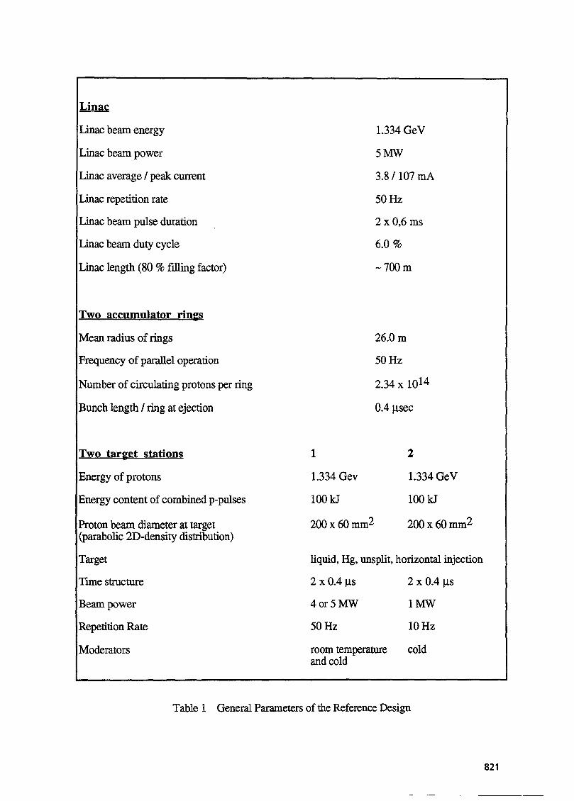
Linac
Linac beam energy
Linac beam power
Linac average / peak current
Linac repetition rate
Linac beam pulse duration
Linac beam duty cycle
Lmac length (80 9% filling factor)
Two accumulator riws
Mean radius of rings
Frequency of parallel operation
Number of circulating protons per ring
Bunch length / ring at ejection
Two
Energy of protons
Energy content of combined p-pulses
Proton beam diameter at target (parabolic 2D-density distribution)
Target
Time structure
Beam power
Repetition Rate
Moderators
1.334 GeV
5Mw
3.8 / 107 mA
50 Hz
2 x 0,6 ms
6.0 %
-700m
26.0 m
50 Hz
2.34 x 10¹⁴
0.4 psec
1 2
1.334 Gev 1.334 GeV
1OOkJ 1OOkJ
200 x 60 mm2 200x60mm2
liquid, Hg, unsplit, horizontal injection
2 x 0.4 ps 2 x 0.4 &S
4or5MW 1MW
50 Hz 10 Hz
room temperature cold and cold
Table 1 General Parameters of the Reference Design
821

1. A 0.8 GeV H- linac and three accumulator (compressor) rings; 2. A 1.334 GeV H- linac and two accumulator rings; 3. A 2.4 GeV H- linac and one accumulator ring; 4. A 0.8 GeV H- linac and two 3 GeV, 25 Hz proton synchrotrons (RCS); 5. A 0.8 GeV H- linac and a single 3 GeV FFAG accelerator. Priority has been given to a 1.334 GeV linac (Fig. 2), developing the full beam power of 5 MW at 50 Hz and followed by two accumulator rings operated in parallel (Fig. 3).
This combination has been preferred because of:
- an energy choice presenting a reasonable compromise between the size and cost of accelerators and the energy density produced by the proton pulses at the target
- a simple and reliable layout of rings with constant magnetic fields, a relatively small r-f-system only used for particle bunching and lower ring space charge levels than option 1
A key issue and the dominating design principle for the accelerators are low beam losses, allowing “hands on” maintenance and repair on short notice. At high energy this corresponds to beam losses in the linac below 1 nA/m. The linac is also optimised for low loss injection into the accumulator rings and this fuces almost completely its most important parameters. A charge exchange injection (H- --> H+) is used and as a consequence H--ions have to be accelerated in the linac. The time compression of the linac beam into 1 us pulses is obtained by multiturn injection into the rings and by a fast one turn ejection_ As a compromise between linac peak currents and a limited injection time (2 x 0,6 ms or 2 x 900 turns) a hnac pulse length of 1,2 ms has been chosen.
Each ring delivers a 0,4 ps proton pulse with a 0,2 ~_ls gap inbetween to the targets. In order to avoid beam losses during the rise time of the ejection kicker the linac beam has to be chopped with a beam-on time of 400 ns and a beam-off time 270 nsec (60 % chopping efficiency). Together with a 50 Hz operation this leads for the linac to a beam duty cycle of 6 %, an average current of 3,75 mA and a peak current of lO;r mA, well below the space charge limit of the linac. For a well designed high current linac less than 10-3 particles are outside 20 times the r.m.s. emittance [2]. The proposed linac layout is shown in Fig. 2 and a few more parameters are given in Table 1. A special feature of the high intensity linac is the double front end. This layout has been adopted for two reasons [l]: - State of the art H- sources do not yet reach the combination of 100 mA peak currents, 6 % d-c. and low emittance, therefore it seemed advisable to use two H--sources in parallel with reduced currents. - Emittance increase with the concomitant enlarged beam losses can be kept smaller by the use of a double front end with subsequent combination of beams in a funnel.
Behind the funnel a classical drift tube linac (DTL) and side coupled accelerating structures of the type pioneered at Los Alamos are used. For the reference linac design, normal-conducting side coupled cavities have been preferred to superconducting disk loaded cavities. Superconducting cavities have been retained as an option with the advantage of a larger acceleration efficiency, higher acceleration fields resulting in a shorter linac and large beam openings decreasing the risk of cavity activation by beam losses. However at the present state it has to be seen if these advantages do not outweigh the disadvantages of greater complexity and more complex r-f-control systems.
The dominant requirement for the accumulator rings (Fig. 3) 1 is to minimise and localise the beam losses, especially at the injection and ejection region. Design values for uncollected losses are set at less than 2 x 10⁻⁴ which corresponds to less than 500 W per ring. The quality of the injected linac beam and the layout of the injection region are crucial for achieving this limit. A
822

IS
Rings.
Fig. 2 Schematic Layout of the ESS linac
H’ Cl.334 cd )
Fig. 3 Layout of the 1,334 GeV accumulator (compressor) rings.
823

lattice with three superperiods containing separate straight-sections for betatron collimation, extraction and i-f-systems is used. An important feature is a long straight section for the charge exchange injection using a thin snipping foil located inside a low field dipole. The field value of this dipole has been chosen to give negligible pre-stripping of H-ions ahead of the foil, to minimise delayed stripping of (partly stripped) Ho atoms and to provide a bending radius for electrons large enough for direct collection. For the accumulator rings a field level of 0,177 T and an injection energy of 1.334 GeV have been chosen. An Al203 stripping foil of 345 pg/cm2 thickness is proposed. It will strip 98,5 % of the injected H--beam. The rest is mainly partially stripped Ho atoms leaving the foil in a range of excited quantum states with different lifetimes. The Ho beam will have a power of about 75 kW and could be used for instance as a powerful source for a muon beam with a pulse time structure of 4001270 ns and a pulse length of 1,2 ms.
The injection scheme will use simultaneous “painting” in the longitudinal and transverse phase planes and will reduce the average number of foil traversals (an important source of injection losses) below 10 [3]. For sufficiently low injection losses the halo of the injected H- beam has to be carefully controlled and removed [2]. It is planned to introduce a 180’ achromat bend for momentum and transverse collimation in the transfer line between linac and rings (Fig. 1). This line has in addition to provide some energy ramping and a vertical separation into two matching sections for the rings, which will be located one above the other at a distance of - 1,5 m.
A schematic view of the transfer lines between the two accumulator rings and the two target stations is shown in Fig. 1. After passing vertically separated transfer sections, the beam is combined in a common external line including a septum and a fast kicker magnet. The following switchyard allows to channel the proton pulses either to one of the 2 targets or to a 5 MW beam dump, common for the linac and the ring beams. In front of the two target stations a horizontal bend of 1 lo is foreseen; it should shield upstream beam components against backstreaming fast neutrons from the target and it will increase somewhat the distance between the two target stations. At the target an elliptical beam cross-section (200 x 60 mm2) with a parabolic intensity distribution is proposed. An adequate distance and shielding of target stations as well as of beam stoppers and accelerators is still under discussion. This issue can influence considerably the cost of the target and transfer line areas. More information from existing spallation sources on the behaviour of skyshine and groundshine neutron background will be needed for futing a final layout.
Besides the detailed accumulator ring studies some work is also devoted to the option of two rapid cycling synchrotons (RCS) accelerating protons in 25 Hz altemance from 0,8 to 3 GeV.
3. Target issues
At the beginning of the ESS study a number of options for the target stations had been considered [ 11:
1. A stationary, solid, unsplit target; 2. A stationary, solid, split target; 3. A rotating target; 4. A liquid metal target (Pb-Bi); and variants of the above with horizontal and vertical injection and different target materials.
At its June 1995 meeting, the target group has proposed and given priority to an unsplit mercury target with horizontal injection. The decision for replacing the initial liquid material candidate Pb-Bi by Hg had been taken after an assessment of the mechanical, thermal and neutronic properties of Hg which indicate its basic feasibility for a 5 MW, 1 ys pulsed target r.41.
824

There exist many arguments in favour of a liquid metal target. One may mention:
- Radiation damage confined essentially to the target window and target container where some flexibility of design is possible.
- Convective heat remove1 from the proton reaction zone by flowing liquid metal.
- Reduced neutron absorption, radiolysis and tritium production due to the absence of cooling water.
- Low specific activation and afterheat of the target material.
- Good self shielding.
- Very long lifetime of target material.
- Larger potential for higher beam power.
Neutronically, mercury is characterised by a large thermal neutron absorption cross section of 263 barns as compared to Ta with 15 barns and W with 12,5 barns. This excludes Hg for a system with full moderation to thermal energies but allows its use in a pulsed system with short neutron pulses where moderators are usually decoupled against thermal neutron return from their surrounding. Resonance absorption in the slowing down region is less severe in Hg than in Ta and W (Hg: 73 barns; Ta: 710 barns; W: 352 barns) and neutrons will leave the surface of the Hg target without significant energy loss and with little absorption. The hard spectrum of neutrons may influence the configuration of moderator- reflector layouts as compared to watercooled Ta or W-targets. In Fig. 4 the neutron flux leaving a 5 MW Hg and a watercooled, W- or Ta-target is shown [S]. A target of 14 x 14 x 60 cm3 dimension and surrounded by a large Pb-reflector is assumed. In this approximation the high energy neutron fluxes of W and Hg are comparable. In Fig. 5 the calculated time behaviour of afterheat for three target materials is compared. An irradiation of 1 year at 5 MW is assumed [5]. Obviously W and Hg are again comparable and typically a factor 5 to 10 smaller than for Ta during the first 3 years of decay.
The problem of pressure waves induced in the Hg by the ps, 100 kI proton pulses has been considered [6] and it is expected that the dynamic stress on the container will be too close to the recommended design values of the container material (e.g. Manet HT 9 steel [7]). It has been proposed to increase the compressibility of the Hg target by introducing a small amount of He-gas (e.g. 3 % [6]). Theoretical investigations suggest that dynamical stresses are decreased by two orders of magnitude. More theoretical and practical work is under preparation on this issue. In summary the work carried out so far has not identified “show stoppers” for the Hg- target.
Up to now some detailed work had been devoted to the layout of a solid, unsplit, Ta plate target and should be mentioned here although it is considered as a second priority option [ 11. In Fig. 6 a possible layout for a watercooled Ta-target with partly integrated Ni-reflector is shown. The cooling and hydrodynamic conditions for pulsed 5 MW operation can be handled but more experimental work will be needed to assess the lifetime of the target and the target window under heavy irradiation and stress wave conditions. R and D work for these issues using electron pulses at 100 MeV with pulse durations and energy contents comparable to the ones of the ESS proton beam are under preparation. Similarily a long term investigations on heavy irradiation damage is actively pursued.
825

Fig. 4
N n cm’*sec
1 Proton Beam 5 MW, 1334 MeV
0.8E15 - reflectorpb
Total Response
- MERCURY
---- TUNGSTEN
. . . .._..... TmT&
02E15-
0 I I I 0 20 40 60
Target-depth [cm]
Leakage distribution for neutrons below 20 MeV and a target with Pb-reflector
time after beam shut down [dj
Fig. 5 Time behaviour of afterheat in a target after 1 year full power operation_
826

3
9 0.5 m
I 4
Fig. 6 A 5 MW Ta-target with moderators and cooling water supply (cut away view). 1: proton beam, 2: target plates, 3. wing reflector plates (half cut), 4: coolant inlet, 5: coolant outlet, 6: target vessel, 7: beam entrance window, 8: cold wing moderator, 9: room temperature wing moderator.
A modular layout for the target stations has been fixed (Fig. 7 and 8). The 5 MW and 1 MW should be made as similar as possible. A layout with horizontal removal of the target including its cooling circuits and a vertical upward removal of the moderator-reflector units have been retained. This layout limits the position of neutron beam tubes to an angle of about 2 x 120”. A total of 18 beam holes, some equipped with neutron guides, are considered for each target station. 4 basic types of moderators have been suggested, namely: a high intensity room temperature moderator a high resolution (fast) room temperature moderator a high intensity cold moderator a high resolution cold moderator.
With a beam power up to 5 MW liquid water and liquid H2 are considered as moderator materials. Besides these basic types, a low intensity, lOOoK moderator optimised for a wavelength range around 3 A has been proposed by some users. The number and type of moderators for the two target stations has to fixed after more discussions with the users. Detailed engineering of a layout where the inner parts of the target block can be either a Hg target or a solid, unsplit Ta plate target has been started. In Fig. 8 a conceptual layout of the Hg target with its auxiliaries is shown. The Hg target will presumably be operated at a few hundred OC in a forced flow mode [8] . Classical heat exchangers [9] or heat pipes [lo] are considered for cooling. On line purification and trapping of gaseous spallation products are foreseen. A separately cooled security hull and a separated beam window are under study. At present two options for removing the target complex are under discussion and have to be worked out in detail: a removable trolley with the whole liquid metal circuit and its shielding or a “plug” containing only the target, the safety hull and their corresponding feeder lines (Fig. 9) [l 13. Work on the diagnostics for liquid metal target system is also going on ’ _ WI.
827

COLLIMATION SHIELDING
IOm RADIUS I--- -. SHUTTERS
\
/ /
-./ ”
\ /
’
CONCRETE
BULK STEEL SHIELDING
Fig. 7 Schematic layout of a ESS target station

ESS-Liquid Metal Target Circuit
- Conceptual working
Vent/Gas Trap
,’ / . ,
b-B1 storage & dump
Fig. 8 Concept of liquid metal circuit with safety hull around the beam interaction zone w leakage return flow tube located behind the reflector unit.
ith
reflector -7_-__ fi._ . ll
main flange to the carrier unit
Hg and He tubes
safety hull
H,O moderators
Fig. 9 Crosscut through the reflector-moderator assembly with the Hg target inserted.
829

4. Other uses of ESS
A number of add-on facilities could be integrated in the ESS design; however they will not be worked but in detail nor costed.
- Muons may be producedin a transmission target in front of the 5 MW target station (Fig. 1). It is suggested to use 0,4 % of the proton beam (- 20 kW) with the time structure of 2 x 0,4 /..ts at 50 Hz. Obviously the muon target area has to be heavily shielded to keep the background in the neutron target once sufficiently low. Muons may also be generated by the Ho beam emerging from the stripping foil inside the accumulator rings. A beam power of 75 kW with the linac bam time strncture (60 % chopping) and emittance would be available.
For a neutrino detector a shielded cave could be located below the high power target. It would then extend at least 20 m below ground level and has to support a target block of about 12000 t weight.
- Irradiation facilities, as developed for SINQ, are expected to be in demand at ESS but are at present not considered in the target layout. - A radioactive beam facility could be developed around the Ho beam (also considered for muon pruduction). This could produce beams much more powerful than CERN’s Isolde facility.
The philosophy adopted for the ESS study is not to design away recognised future uses.
Acknowledgements
I would like to thank all members of the ESS study group for their contributions to this report.
5. References
[l] Outline Design of the European Spallation Neutron Source, ESS Report ESS 95-30-M (1995) Editors I.S.K. Gardner, H. Lengeler and G.H. Rees A large number of references can be found in this report.
[2] M. Pabst, K. Bongardt and A. Latchford to be published in: Proc. Workshop on advanced beam dynamics studies, Bloomington, IN, USA, October 1995
[3] C. Prior in reference [2]
[4] G.S. Bauer “Mercury as a Target Material for Pulsed (Fast) Spallation Neutron Sources Systems”, ” Proc. ICANS-XIII, Paul Scherrer Insitut, PSI-Proceedings 95-02 (1995)
[5] D. Filges, R.D. Neef and H. Schaal “Nuclear Studies of Different Target Systems for the European Spallation Source (ESS)” Proc. ICANS-XIII, Paul Scherrer Znsitut, PSI- Proceedings 95-02 (1995)
[6] K. Skala and G.S. Bauer, “On the Pressure Wave Problem in Liquid Metal Targets for Pulsed Spallation Neutron Sources” Proc. ICANS-XIII, Paul Scherrer Insitut, PSI- Proceedings 95-02 ( 1995)
[7] Y. Dai, “Suitability of Steels as ESS Mercury Target Container Materials” Proc. ZCANS-XIII, Paul Scherrer Insitut, PSI-Proceedings 95-02 (1995)
[S] B.L. Smith, “Thermal Hydraulics of the ESS Liquid Metal Target” Proc. ICAZVS-XIII, Paul Scherrer Znsitut, PSI-Proceedings 95-02 (1995)
[9] L. Griesser and B. Sigg, “Mercury Circuit and Cooling System Using an Intermediate Water Loop” in: ESS-Liquid Metal Taget Studies / 2nd Status Report;
[lo] M.T. North, J.H. Rosenfeld, D.B. Sarraf, G.S. Bauer and Y. Takeda, ” Water/Monel Heat Pipes for Cooling of Liquid Metal Targets For SINQ and ES!?’ Proc. ICANS- XIII, Paul Scherrer Insitut, PSI-Proceedings 95-02 (1995)
[ 1 l] B. Guttek, to be published as ESS internal report [ 121 Y. Takeda “Metrology for diagnostics of liquid metal target system” in: ESS-Liquid
Metal Taget Studies / 2nd Status Report
830