ptg - the eye various/windows_7_device_driver.pdf · ptg i would like to dedicate this book to my...
TRANSCRIPT


ptg
WINDOWS 7DEVICE DRIVER
Ronald D. Reeves, Ph.D.
Upper Saddle River, NJ • Boston • Indianapolis • San FranciscoNew York • Toronto • Montreal • London • Munich • Paris • Madrid
Capetown • Sydney • Tokyo • Singapore • Mexico City
www.it-ebooks.info
ptg
Many of the designations used by manufacturers and sellers to distinguish their products are claimed as trademarks. Where those designations appear in this book, and the publisher was aware of a trademark claim, thedesignations have been printed with initial capital letters or in all capitals.
The author and publisher have taken care in the preparation of this book, but make no expressed or implied warranty of any kind and assume no responsibility for errors or omissions. No liability is assumed for incidental or consequential damages in connection with or arising out of the use of the information or programs containedherein.
The publisher offers excellent discounts on this book when ordered in quantity for bulk purchases or special sales, which may include electronic versions and/or custom covers and content particular to your business, traininggoals, marketing focus, and branding interests. For more information, please contact:
U.S. Corporate and Government Sales(800) [email protected]
For sales outside the United States, please contact:
International [email protected]
Visit us on the Web: informit.com/aw
Library of Congress Cataloging-in-Publication Data
Reeves, Ron.Windows 7 device driver / Ronald D. Reeves.
p. cm.Includes bibliographical references and index.ISBN-13: 978-0-321-67021-2 (pbk. : alk. paper)ISBN-10: 0-321-67021-3 (pbk. : alk. paper)1. Microsoft Windows device drivers (Computer programs)
I. Title.QA76.76.D49R44 2011005.7'1—dc22
2010039109
Copyright © 2011 Pearson Education, Inc.
All rights reserved. Printed in the United States of America. This publication is protected by copyright, and permis-sion must be obtained from the publisher prior to any prohibited reproduction, storage in a retrieval system, or trans-mission in any form or by any means, electronic, mechanical, photocopying, recording, or likewise. For informationregarding permissions, write to:
Pearson Education, Inc.Rights and Contracts Department501 Boylston Street, Suite 900Boston, MA 02116Fax: (617) 671-3447
ISBN-13: 978-0-321-67021-2ISBN-10: 0-321-67021-3
Text printed in the United States on recycled paper at RR Donnelley in Crawfordsville, Indiana.First printing, November 2010
Wow! eBook <WoweBook.Com>
www.it-ebooks.info

ptg
I would like to dedicate this book to my best friend, and partner in life,my wife, Paulette. Her untiring support and love over the years have been
a great source of inspiration.
Wow! eBook <WoweBook.Com>
www.it-ebooks.info

ptg
This page intentionally left blank
Wow! eBook <WoweBook.Com>
www.it-ebooks.info

ptg
CONTENTS
Preface . . . . . . . . . . . . . . . . . . . . . . . . . . . . . . . . . . . . . . . . . . . . . . xvAbout the Author . . . . . . . . . . . . . . . . . . . . . . . . . . . . . . . . . . . . . . xix
Introduction . . . . . . . . . . . . . . . . . . . . . . . . . . . . . . . . . 1
PART I DEVICE DRIVER ARCHITECTURE OVERVIEW . . . . . . 5Chapter 1 Objects . . . . . . . . . . . . . . . . . . . . . . . . . . . . . . . . . . . . . . 7
1.1 Nature of an Object . . . . . . . . . . . . . . . . . . . . . . . . . . . . . . . . . . 71.2 What Is a Software Object? . . . . . . . . . . . . . . . . . . . . . . . . . . . . 81.3 Gaining an Understanding . . . . . . . . . . . . . . . . . . . . . . . . . . . . .101.4 Software Components . . . . . . . . . . . . . . . . . . . . . . . . . . . . . . . .11
Chapter 2 Windows Driver Foundation (WDF) Architecture . . . . . . .13
2.1 WDF Component Functions . . . . . . . . . . . . . . . . . . . . . . . . . . . .132.2 Design Goals for WDF . . . . . . . . . . . . . . . . . . . . . . . . . . . . . . .142.3 Device and Driver Support in WDF . . . . . . . . . . . . . . . . . . . . . . .152.4 WDF Driver Model . . . . . . . . . . . . . . . . . . . . . . . . . . . . . . . . . .162.5 WDF Object Model . . . . . . . . . . . . . . . . . . . . . . . . . . . . . . . . .17
2.5.1 Kernel Mode Objects . . . . . . . . . . . . . . . . . . . . . . . . . . . .192.5.2 User Mode Objects . . . . . . . . . . . . . . . . . . . . . . . . . . . . .19
2.6 Plug and Play and Power Management Support . . . . . . . . . . . . . 202.6.1 Plug and Play/Power Management State Machine . . . . . . . 21
2.7 Integrated I/O Queuing and Cancellation . . . . . . . . . . . . . . . . . 222.7.1 Concurrency . . . . . . . . . . . . . . . . . . . . . . . . . . . . . . . . . 222.7.2 I/O Model . . . . . . . . . . . . . . . . . . . . . . . . . . . . . . . . . . 232.7.3 I/O Request Flow . . . . . . . . . . . . . . . . . . . . . . . . . . . . . . 242.7.4 Device I/O Requests . . . . . . . . . . . . . . . . . . . . . . . . . . . . 252.7.5 Plug and Play and Power Management Requests . . . . . . . . 26
vii
Wow! eBook <WoweBook.Com>
www.it-ebooks.info
ptg
2.8 WMI Requests (Kernel Mode Drivers Only) . . . . . . . . . . . . . . . . 272.9 Driver Frameworks . . . . . . . . . . . . . . . . . . . . . . . . . . . . . . . . . 28
2.9.1 Kernel Mode Framework . . . . . . . . . . . . . . . . . . . . . . . . 292.9.2 User Mode Framework . . . . . . . . . . . . . . . . . . . . . . . . . 31
2.10 Windows Kernel . . . . . . . . . . . . . . . . . . . . . . . . . . . . . . . . . . 322.10.1 Reflector . . . . . . . . . . . . . . . . . . . . . . . . . . . . . . . . . . 322.10.2 Driver Host Process . . . . . . . . . . . . . . . . . . . . . . . . . . . 322.10.3 Driver Manager . . . . . . . . . . . . . . . . . . . . . . . . . . . . . 33
2.11 Tools for Development and Testing . . . . . . . . . . . . . . . . . . . . . . 332.11.1 PREfast for Drivers . . . . . . . . . . . . . . . . . . . . . . . . . . . 342.11.2 Static Driver Verification (SDV) . . . . . . . . . . . . . . . . . . . 352.11.3 Frameworks Verifier . . . . . . . . . . . . . . . . . . . . . . . . . . 362.11.4 Trace Logging . . . . . . . . . . . . . . . . . . . . . . . . . . . . . . 362.11.5 Debugger Extensions . . . . . . . . . . . . . . . . . . . . . . . . . . 372.11.6 Serviceability and Versioning . . . . . . . . . . . . . . . . . . . . 37
PART II USER MODE DRIVERS . . . . . . . . . . . . . . . . . . 39Chapter 3 Windows 7 User Mode Drivers Overview
and Operation . . . . . . . . . . . . . . . . . . . . . . . . . . . . . . . . 41
3.1 Devices Supported in User Mode . . . . . . . . . . . . . . . . . . . . . . . 423.2 UMDF Model Overview . . . . . . . . . . . . . . . . . . . . . . . . . . . . . 43
3.2.1 UMDF Object Model . . . . . . . . . . . . . . . . . . . . . . . . . . . 453.2.2 UMDF Objects . . . . . . . . . . . . . . . . . . . . . . . . . . . . . . . 45
3.3 Driver Callback Interfaces . . . . . . . . . . . . . . . . . . . . . . . . . . . . 473.4 UMDF Driver Features . . . . . . . . . . . . . . . . . . . . . . . . . . . . . . . 49
3.4.1 Impersonation . . . . . . . . . . . . . . . . . . . . . . . . . . . . . . . 503.4.2 Device Property Store . . . . . . . . . . . . . . . . . . . . . . . . . . 50
3.5 I/O Request Flow . . . . . . . . . . . . . . . . . . . . . . . . . . . . . . . . . . 513.5.1 I/O Request Dispatching . . . . . . . . . . . . . . . . . . . . . . . . 533.5.2 Create, Cleanup, and Close Requests . . . . . . . . . . . . . . . 533.5.3 Create, Read, Write, and Device I/O Control Requests . . 56
3.6 I/O Queues . . . . . . . . . . . . . . . . . . . . . . . . . . . . . . . . . . . . . . 563.6.1 Dispatch Type . . . . . . . . . . . . . . . . . . . . . . . . . . . . . . . 583.6.2 Queues and Power Management . . . . . . . . . . . . . . . . . . 59
3.7 I/O Request Objects . . . . . . . . . . . . . . . . . . . . . . . . . . . . . . . . 603.7.1 Retrieving Buffers from I/O Requests . . . . . . . . . . . . . . . . 613.7.2 Sending I/O Requests to an I/O Target . . . . . . . . . . . . . 613.7.3 Creating Buffers for I/O Requests . . . . . . . . . . . . . . . . . . 63
viii Contents
Wow! eBook <WoweBook.Com>
www.it-ebooks.info

ptg
3.7.4 Canceled and Suspended Requests . . . . . . . . . . . . . . . . 643.7.5 Completing I/O Requests . . . . . . . . . . . . . . . . . . . . . . . 663.7.6 Adaptive Time-Outs . . . . . . . . . . . . . . . . . . . . . . . . . . . . 66
3.8 Self-Managed I/O . . . . . . . . . . . . . . . . . . . . . . . . . . . . . . . . . 673.9 Synchronization Issues . . . . . . . . . . . . . . . . . . . . . . . . . . . . . . 683.10 Locks . . . . . . . . . . . . . . . . . . . . . . . . . . . . . . . . . . . . . . . . . . 703.11 Plug and Play and Power Management Notification . . . . . . . . . 703.12 Device Enumeration and Startup . . . . . . . . . . . . . . . . . . . . . . . 713.13 Device Power-Down and Removal . . . . . . . . . . . . . . . . . . . . . . 72
3.13.1 Surprise-Removal Sequence . . . . . . . . . . . . . . . . . . . . . 743.14 Build, Test, and Debug . . . . . . . . . . . . . . . . . . . . . . . . . . . . . . 75
3.14.1 Installation and Configuration . . . . . . . . . . . . . . . . . . . 763.14.2 Versioning and Updates . . . . . . . . . . . . . . . . . . . . . . . 77
Chapter 4 Programming Drivers for the User Mode Driver Framework . . . . . . . . . . . . . . . . . . . . . . . . . . . . 79
4.1 Windows I/O Overview . . . . . . . . . . . . . . . . . . . . . . . . . . . . . 794.2 Brief COM Information . . . . . . . . . . . . . . . . . . . . . . . . . . . . . . 814.3 UMDF Architecture . . . . . . . . . . . . . . . . . . . . . . . . . . . . . . . . . 824.4 Required Driver Functionality . . . . . . . . . . . . . . . . . . . . . . . . . . 844.5 UMDF Sample Drivers . . . . . . . . . . . . . . . . . . . . . . . . . . . . . . . 87
4.5.1 Minimal UMDF Driver: The Skeleton Driver . . . . . . . . . . . 884.5.2 Skeleton Driver Classes, Objects, and Interfaces . . . . . . . 89
4.6 Driver Dynamic-Link Library and Exports . . . . . . . . . . . . . . . . . . 914.6.1 Driver Entry Point: DllMain . . . . . . . . . . . . . . . . . . . . . . . 914.6.2 Get Class Object: DllGetClassObject . . . . . . . . . . . . . . . 93
4.7 Functions for COM Support . . . . . . . . . . . . . . . . . . . . . . . . . . . 954.7.1 IUnknown Methods . . . . . . . . . . . . . . . . . . . . . . . . . . . . 954.7.2 IClassFactory Interface . . . . . . . . . . . . . . . . . . . . . . . . . 964.7.3 Driver Callback Object . . . . . . . . . . . . . . . . . . . . . . . . . 964.7.4 Device Callback Object . . . . . . . . . . . . . . . . . . . . . . . .100
4.8 Using the Skeleton Driver as a Basis for Development . . . . . . . .1064.8.1 Customize the Exports File . . . . . . . . . . . . . . . . . . . . . .1074.8.2 Customize the Sources File . . . . . . . . . . . . . . . . . . . . . .1074.8.3 Customize the INX File . . . . . . . . . . . . . . . . . . . . . . . . .1084.8.4 Customize the Comsup.cpp File . . . . . . . . . . . . . . . . . . .1084.8.5 Add Device-Specific Code to Driver.cpp . . . . . . . . . . . . .1094.8.6 Add Device-Specific Code to Device.cpp . . . . . . . . . . . .109
Contents ix
Wow! eBook <WoweBook.Com>
www.it-ebooks.info

ptg
Chapter 5 Using COM to Develop UMDF Drivers . . . . . . . . . . . . . .111
5.1 Getting Started . . . . . . . . . . . . . . . . . . . . . . . . . . . . . . . . . . . .1115.1.1 COM Fundamentals . . . . . . . . . . . . . . . . . . . . . . . . . . .1125.1.2 HRESULT . . . . . . . . . . . . . . . . . . . . . . . . . . . . . . . . . . . .114
5.2 Using UMDF COM Objects . . . . . . . . . . . . . . . . . . . . . . . . . . .1165.2.1 Obtaining an Interface on a UMDF Object . . . . . . . . . . .1175.2.2 Reference Counting . . . . . . . . . . . . . . . . . . . . . . . . . . . .119
5.3 Basic Infrastructure Implementation . . . . . . . . . . . . . . . . . . . . . . 1205.3.1 DllMain . . . . . . . . . . . . . . . . . . . . . . . . . . . . . . . . . . . .1215.3.2 DllGetClassObject . . . . . . . . . . . . . . . . . . . . . . . . . . . . .1215.3.3 Driver Object’s Class Factory . . . . . . . . . . . . . . . . . . . . .1225.3.4 Implementing a UMDF Callback Object . . . . . . . . . . . . . .1225.3.5 Implementing QueryInterface . . . . . . . . . . . . . . . . . . . . .125
PART III KERNEL MODE DRIVERS . . . . . . . . . . . . . . . .127Chapter 6 Windows 7 Kernel Mode Drivers
Overview and Operations . . . . . . . . . . . . . . . . . . . . . .129
6.1 KMDF Supported Devices . . . . . . . . . . . . . . . . . . . . . . . . . . . .1296.2 KMDF Components . . . . . . . . . . . . . . . . . . . . . . . . . . . . . . . . .1316.3 KMDF Driver Structure . . . . . . . . . . . . . . . . . . . . . . . . . . . . . . .1326.4 Comparing KMDF and WDM Drivers . . . . . . . . . . . . . . . . . . . .1326.5 Device Objects and Driver Roles . . . . . . . . . . . . . . . . . . . . . . . .135
6.5.1 Filter Drivers and Filter Device Objects . . . . . . . . . . . . . . .1366.5.2 Function Drivers and Functional Device Objects . . . . . . . .1366.5.3 Bus Drivers and Physical Device Objects . . . . . . . . . . . . .1376.5.4 Legacy Device Drivers and Control Device Objects . . . . . .138
6.6 KMDF Object Model . . . . . . . . . . . . . . . . . . . . . . . . . . . . . . . . 1396.6.1 Methods, Properties, and Events . . . . . . . . . . . . . . . . . . .1396.6.2 Object Hierarchy . . . . . . . . . . . . . . . . . . . . . . . . . . . . .1416.6.3 Object Attributes . . . . . . . . . . . . . . . . . . . . . . . . . . . . . .1446.6.4 Object Context . . . . . . . . . . . . . . . . . . . . . . . . . . . . . . .1456.6.5 Object Creation and Deletion . . . . . . . . . . . . . . . . . . . . .146
6.7 KMDF I/O Model . . . . . . . . . . . . . . . . . . . . . . . . . . . . . . . . . .1476.7.1 I/O Request Handler . . . . . . . . . . . . . . . . . . . . . . . . . . .1496.7.2 I/O Queues . . . . . . . . . . . . . . . . . . . . . . . . . . . . . . . . .1526.7.3 I/O Request Objects . . . . . . . . . . . . . . . . . . . . . . . . . . .1546.7.4 Retrieving Buffers from I/O Requests . . . . . . . . . . . . . . . .155
x Contents
Wow! eBook <WoweBook.Com>
www.it-ebooks.info

ptg
6.7.5 I/O Targets . . . . . . . . . . . . . . . . . . . . . . . . . . . . . . . . . .1566.7.6 Creating Buffers for I/O Requests . . . . . . . . . . . . . . . . . .1576.7.7 Canceled and Suspended Requests . . . . . . . . . . . . . . . . .1586.7.8 Completing I/O Requests . . . . . . . . . . . . . . . . . . . . . . . .1606.7.9 Self-Managed I/O . . . . . . . . . . . . . . . . . . . . . . . . . . . . .1616.7.10 Accessing IRPs and WDM Structures . . . . . . . . . . . . . . .161
Chapter 7 Plug and Play and Power Management . . . . . . . . . . . .163
7.1 Plug and Play and Power Management Overview . . . . . . . . . . .1637.2 Device Enumeration and Startup . . . . . . . . . . . . . . . . . . . . . . . .164
7.2.1 Startup Sequence for a Function or Filter Device Object . . .1657.2.2 Startup Sequence for a Physical Device Object . . . . . . . . .1667.2.3 Device Power-Down and Removal . . . . . . . . . . . . . . . . . .167
7.3 WMI Request Handler . . . . . . . . . . . . . . . . . . . . . . . . . . . . . . .1727.4 Synchronization Issues . . . . . . . . . . . . . . . . . . . . . . . . . . . . . . .173
7.4.1 Synchronization Scope . . . . . . . . . . . . . . . . . . . . . . . . .1757.4.2 Execution Level . . . . . . . . . . . . . . . . . . . . . . . . . . . . . . .1777.4.3 Locks . . . . . . . . . . . . . . . . . . . . . . . . . . . . . . . . . . . . . .1787.4.4 Interaction of Synchronization Mechanisms . . . . . . . . . . .179
7.5 Security . . . . . . . . . . . . . . . . . . . . . . . . . . . . . . . . . . . . . . . . .1807.5.1 Safe Defaults . . . . . . . . . . . . . . . . . . . . . . . . . . . . . . . .1807.5.2 Parameter Validation . . . . . . . . . . . . . . . . . . . . . . . . . . .1807.5.3 Counted UNICODE Strings . . . . . . . . . . . . . . . . . . . . . . .1817.5.4 Safe Device Naming Techniques . . . . . . . . . . . . . . . . . . .181
Chapter 8 Kernel Mode Installation and Build . . . . . . . . . . . . . . .183
8.1 WDK Build Tools . . . . . . . . . . . . . . . . . . . . . . . . . . . . . . . . . . .1838.2 Build Environment . . . . . . . . . . . . . . . . . . . . . . . . . . . . . . . . . .1858.3 Building a Project . . . . . . . . . . . . . . . . . . . . . . . . . . . . . . . . . .1868.4 Building Featured Toaster . . . . . . . . . . . . . . . . . . . . . . . . . . . . .187
8.4.1 Makefile and Makefile.inc . . . . . . . . . . . . . . . . . . . . . . .1878.4.2 The Sources File . . . . . . . . . . . . . . . . . . . . . . . . . . . . . .1888.4.3 The Build . . . . . . . . . . . . . . . . . . . . . . . . . . . . . . . . . . .190
8.5 Installing a KMDF Driver . . . . . . . . . . . . . . . . . . . . . . . . . . . . .1908.5.1 The WDF Co-Installer . . . . . . . . . . . . . . . . . . . . . . . . . . .1918.5.2 The INF . . . . . . . . . . . . . . . . . . . . . . . . . . . . . . . . . . . .1918.5.3 INFs for KMDF Drivers . . . . . . . . . . . . . . . . . . . . . . . . . .1928.5.4 wdffeatured.inf . . . . . . . . . . . . . . . . . . . . . . . . . . . . . . .192
Contents xi
Wow! eBook <WoweBook.Com>
www.it-ebooks.info

ptg
8.6 Catalog Files and Digital Signature . . . . . . . . . . . . . . . . . . . . .1938.7 Installing Featured Toaster . . . . . . . . . . . . . . . . . . . . . . . . . . .1948.8 Testing a KMDF Driver . . . . . . . . . . . . . . . . . . . . . . . . . . . . . .196
8.8.1 PREfast . . . . . . . . . . . . . . . . . . . . . . . . . . . . . . . . . . . .1968.8.2 Static Driver Verifier . . . . . . . . . . . . . . . . . . . . . . . . . . .1978.8.3 KMDF Log . . . . . . . . . . . . . . . . . . . . . . . . . . . . . . . . . .1988.8.4 KMDF Verifier . . . . . . . . . . . . . . . . . . . . . . . . . . . . . . .1988.8.5 Debugging a KMDF Driver . . . . . . . . . . . . . . . . . . . . . .1988.8.6 Kernel Debugging . . . . . . . . . . . . . . . . . . . . . . . . . . . 2008.8.7 KMDF Driver Features . . . . . . . . . . . . . . . . . . . . . . . . . 201
8.9 Debugging Macros and Routines . . . . . . . . . . . . . . . . . . . . . . 2038.10 WDF Debugger Extension Commands . . . . . . . . . . . . . . . . . . 2048.11 Using WPP Tracing with a KMDF Driver . . . . . . . . . . . . . . . . . 2058.12 Using WinDbg with Featured Toaster . . . . . . . . . . . . . . . . . . . 2058.13 Versioning and Dynamic Binding . . . . . . . . . . . . . . . . . . . . . . 208
Chapter 9 Programming Drivers for the Kernel Mode Driver Framework . . . . . . . . . . . . . . . . . . . . . . . 211
9.1 Differences Between KMDF and WDM Samples . . . . . . . . . . . 2169.2 Macros Used in KMDF Samples . . . . . . . . . . . . . . . . . . . . . . . 2189.3 KMDF Driver Structure and Concepts . . . . . . . . . . . . . . . . . . . 219
9.3.1 Object Creation . . . . . . . . . . . . . . . . . . . . . . . . . . . . . 2209.3.2 Object Context Area . . . . . . . . . . . . . . . . . . . . . . . . . . 2219.3.3 I/O Queues . . . . . . . . . . . . . . . . . . . . . . . . . . . . . . . . 2229.3.4 I/O Requests . . . . . . . . . . . . . . . . . . . . . . . . . . . . . . . 224
9.4 A Minimal KMDF Driver: The Simple Toaster . . . . . . . . . . . . . . 2249.4.1 Creating a WDF Driver Object: DriverEntry . . . . . . . . . . 2259.4.2 Creating the Device Object, Device Interface, and
I/O Queue: EvtDriverDeviceAdd . . . . . . . . . . . . . . . . . 2279.4.3 Device Object and Device Context Area . . . . . . . . . . . . 2299.4.4 Device Interface . . . . . . . . . . . . . . . . . . . . . . . . . . . . . 2319.4.5 Default I/O Queue . . . . . . . . . . . . . . . . . . . . . . . . . . . 2329.4.6 Handling I/O Request: EvtIoRead, EvtIoWrite,
EvtIoDevice Control . . . . . . . . . . . . . . . . . . . . . . . . . . . 2339.5 Sample Software-Only Driver . . . . . . . . . . . . . . . . . . . . . . . . . 235
9.5.1 File Create and Close Requests . . . . . . . . . . . . . . . . . . 2359.5.2 Additional Device Object Attributes . . . . . . . . . . . . . . . 2379.5.3 Setting Additional Device Object Attributes . . . . . . . . . . 240
xii Contents
Wow! eBook <WoweBook.Com>
www.it-ebooks.info

ptg
Chapter 10 Programming Plug and Play and Power Management . . . . . . . . . . . . . . . . . . . . . . . . . . 243
10.1 Registering Callbacks . . . . . . . . . . . . . . . . . . . . . . . . . . . . . . 24310.1.1 Sample Code to Register Plug and
Play and Power Callbacks . . . . . . . . . . . . . . . . . . . . . 24510.2 Managing Power Policy . . . . . . . . . . . . . . . . . . . . . . . . . . . . 248
10.2.1 Code to Set Power Policy . . . . . . . . . . . . . . . . . . . . . 24910.3 Callbacks for Power-Up and Power-Down . . . . . . . . . . . . . . . . 25010.4 Callback for Wake Signal Support . . . . . . . . . . . . . . . . . . . . . 251
Chapter 11 Programming WMI Support . . . . . . . . . . . . . . . . . . . . 253
11.1 WMI Architecture . . . . . . . . . . . . . . . . . . . . . . . . . . . . . . . . . 25311.2 Registering as a WMI Data Provider . . . . . . . . . . . . . . . . . . . 25411.3 Handling WMI Requests . . . . . . . . . . . . . . . . . . . . . . . . . . . . 25511.4 WMI Requirements for WDM Drivers . . . . . . . . . . . . . . . . . . . 25611.5 WMI Class Names and Base Classes . . . . . . . . . . . . . . . . . . . 25711.6 Firing WMI Events . . . . . . . . . . . . . . . . . . . . . . . . . . . . . . . . 26011.7 Troubleshooting Specific WMI Problems . . . . . . . . . . . . . . . . . 265
11.7.1 Driver’s WMI Classes Do Not Appear in the \root\wmi NameSpace . . . . . . . . . . . . . . . . . . . . 265
11.7.2 Driver’s WMI Properties or Methods Cannot Be Accessed . . . . . . . . . . . . . . . . . . . . . . . . . . . . . . 266
11.7.3 Driver’s WMI Events Are Not Being Received . . . . . . . 26711.7.4 Changes in Security Settings for WMI Requests
Do Not Take Effect . . . . . . . . . . . . . . . . . . . . . . . . . . 26711.8 Techniques for Testing WMI Driver Support . . . . . . . . . . . . . . . 268
11.8.1 WMI IRPs and the System Event Log . . . . . . . . . . . . . . 26911.8.2 WMI WDM Provider Log . . . . . . . . . . . . . . . . . . . . . 269
11.9 WMI Event Tracing . . . . . . . . . . . . . . . . . . . . . . . . . . . . . . . . 269
Chapter 12 Programming KMDF Hardware Driver . . . . . . . . . . . . 273
12.1 Support Device Interrupts . . . . . . . . . . . . . . . . . . . . . . . . . . . 27412.1.1 Creating an Interrupt Object . . . . . . . . . . . . . . . . . . . 27412.1.2 Code to Create an Interrupt Object . . . . . . . . . . . . . . 27512.1.3 Enabling and Disabling Interrupts . . . . . . . . . . . . . . . . 27612.1.4 Code to Enable Interrupts . . . . . . . . . . . . . . . . . . . . . 27612.1.5 Code to Disable Interrupts . . . . . . . . . . . . . . . . . . . . . 277
Contents xiii
Wow! eBook <WoweBook.Com>
www.it-ebooks.info

ptg
12.1.6 Post-Interrupt Enable and Pre-Interrupt Disable Processing . . . . . . . . . . . . . . . . . . . . . . . . . . 277
12.2 Handling Interrupts . . . . . . . . . . . . . . . . . . . . . . . . . . . . . . . . 27812.2.1 Code for EvtInterruptIsr Callback . . . . . . . . . . . . . . . . 27912.2.2 Deferred Processing for Interrupts . . . . . . . . . . . . . . . . 281
12.3 Mapping Resources. . . . . . . . . . . . . . . . . . . . . . . . . . . . . . . . 28312.3.1 Code to Map Resources . . . . . . . . . . . . . . . . . . . . . . 28412.3.2 Code to Unmap Resources . . . . . . . . . . . . . . . . . . . . . 288
Chapter 13 Programming Multiple I/O Queues and Programming I/O . . . . . . . . . . . . . . . . . . . . . . . . . . . . 291
13.1 Introduction to Programming I/O Queues . . . . . . . . . . . . . . . . 29113.2 Creating and Configuring the Queues . . . . . . . . . . . . . . . . . . 293
13.2.1 Code to Create Queues for Write Requests . . . . . . . . . 29413.2.2 Code to Create Queues for Read Requests . . . . . . . . . 29613.2.3 Code to Create Queues for Device I/O
Control Requests . . . . . . . . . . . . . . . . . . . . . . . . . . . . 29713.3 Handling Requests from a Parallel Queue . . . . . . . . . . . . . . . . 298
13.3.1 Code to Handle I/O Requests . . . . . . . . . . . . . . . . . . 29913.3.2 Performing Buffered I/O . . . . . . . . . . . . . . . . . . . . . . 301
13.4 Forwarding Requests to a Queue . . . . . . . . . . . . . . . . . . . . . . 30213.5 Retrieving Requests from a Manual Queue. . . . . . . . . . . . . . . . 303
13.5.1 Code to Find a Request . . . . . . . . . . . . . . . . . . . . . . . 30413.6 Reading and Writing the Registry . . . . . . . . . . . . . . . . . . . . . . 308
13.6.1 Code to Read and Write the Registry . . . . . . . . . . . . . 30913.7 Watchdog Timer: Self-Managed I/O. . . . . . . . . . . . . . . . . . . . 312
13.7.1 Self-Managed I/O Device Startup and Restart . . . . . . . 31313.7.2 Self-Managed I/O During Device
Power-Down and Removal . . . . . . . . . . . . . . . . . . . . . 31413.7.3 Implementing a Watchdog Timer . . . . . . . . . . . . . . . . 315
Appendix Driver Information Web Sites . . . . . . . . . . . . . . . . . . . 323
Bibliography . . . . . . . . . . . . . . . . . . . . . . . . . . . . . . . . . . . . . . . . . . 331
Index . . . . . . . . . . . . . . . . . . . . . . . . . . . . . . . . . . . . . . . . . . . . . . . . 333
xiv Contents
Wow! eBook <WoweBook.Com>
www.it-ebooks.info

ptg
PREFACE
This book provides the technical guidance and understanding needed towrite device drivers for the new Windows 7 Operating System. It takes thisvery complex programming development, and shows how the WindowsDriver Framework has greatly simplified this undertaking. It explains thehardware and software architecture you must understand as a driver devel-oper. However, it focuses this around the actual development steps onemust take to develop one or the other of the two types of drivers. Thus, thisbook’s approach is a very pragmatic one in that it explains the various soft-ware APIs and computer and device hardware based upon our actualdevice handler development.
There has been great progress in the art of creating and debuggingdevice drivers. There is now a great deal of object-oriented design tech-niques associated with the driver frameworks that are available to thedevice driver developer. Much of the previous grunt work, thank goodness,is now being handled by the latest device development frameworkWindows Driver Foundation (WDF). We will be covering both the usermode and kernel mode of device driver development. WDF has excellentsubmodels contained within it, called the User Mode Driver Frameworkand the Kernel Mode Driver Framework.
It is really great to see a Windows Driver Framework involved in thecreation of Windows Device Drivers. I started working with Windows in1990 and we primarily used the Win32 System APIs to communicate andcontrol the Windows Operating System for our applications. We used theDevice Driver Kit (DDK) to create the Windows drivers. Because I hadmy own company to create application software, I obviously was very con-cerned about the time it took to develop application software, and therobustness of the application. There were more than 2,000 Win32 APIs tobe used for this task.
Then in about 1992, Microsoft came out with the MicrosoftFramework Classes (MFC). In these 600+ classes, most of the Win32 APIs were encapsulated. Of course, prior to this, around 1988, the C++compiler came out, and Object Oriented Programming started to come
xv
Wow! eBook <WoweBook.Com>
www.it-ebooks.info

ptg
into its own. By using the MFC Framework, we could produce more appli-cation software faster and with better quality. My return on investment(ROI) went up, and I made more money. This sure made a believer of mein the use of frameworks. I used MFC until the .NET Framework cameout, and for the last nine years I have been using this great collection ofclasses. All along, Microsoft was working to bring this same kind of soft-ware development improvements to developing device drivers. We camefrom the DDK, to the Windows Driver Model, to the Windows DriverFoundation Framework.
Therefore, this book shows how to create Windows 7 Device Driversusing the Windows Driver Foundation Framework. This should give usdriver developers a little more sanity when meeting our deadlines.
The book is broken into three major parts as follows:
■ Part I, “Device Driver Architecture Overview”—This part laysout the architecture involved in both software and hardware fordevice handler development. It also covers the driver developmentenvironment needed for driver development, for both types of driv-ers that are normally developed—that is, User Mode and Drivers.This section also covers the two Windows driver frameworks that aremost commonly used for driver device development today, whichare part of the Windows Driver Framework (WDF). These twoWindows Driver Frameworks are the User Mode Driver Framework(UMDF) and the Kernel Mode Driver Framework (KMDF).
■ Part II, “User Mode Drivers”—This part outlines the approach,design, development, and debug of User Mode Drivers. This parttakes the driver programmer from start to finish in developing UserMode Drivers. We primarily use the User Mode Driver Frameworkfor all of this work. The code is done in C++ because it is the best wayto develop these types of drivers. Discussions are based on a USBUser Mode Driver that we will develop using the UMDF. We will usea USB hardware learning kit from Open Systems Resources, Inc. (OSR). This provides a hardware simulation to test our UserMode Drivers. This part is primarily stand-alone and could be readand used without reading any other parts of the book. However,you will probably want to read Part I to get a feel for what we are using.
xvi Preface
Wow! eBook <WoweBook.Com>
www.it-ebooks.info
ptg
■ Part III, “Kernel Mode Drivers”—This part outlines theapproach, design, development, and debug of Kernel ModeDrivers. The intent again is to take the driver programmer fromstart to finish in developing Kernel Mode Drivers. For this section,we primarily use the Kernel Mode Driver Framework for all of thiswork. The code is done in C because this is the best way to developthese types of drivers. Discussions are based on a Kernel ModeDriver that we develop using the KMDF. We use a PeripheralComponent Interconnect (PCI) hardware learning kit from OSR.This provides a hardware simulation to test our Kernel ModeDrivers. The section is also primarily stand-alone and could be readand used without reading any other parts of the book. Again, youwill probably want to read Part I to get a feel for what we are using.
ACKNOWLEDGMENTS
I am most grateful to my editor Bernard Goodwin at Pearson Education forgiving me the opportunity to write this book. His support during the prepa-ration was great. I would also like to thank his assistant Michelle Housley forher timely fashion in getting me reference books and material. Also, I wouldlike to thank John Herrin, Video Project Manager at Pearson Education, forsupport and help in creating the book video. Thanks to Michael Thurston,my development editor, for making the book sound very polished.
Preface xvii
Wow! eBook <WoweBook.Com>
www.it-ebooks.info

ptg
This page intentionally left blank
Wow! eBook <WoweBook.Com>
www.it-ebooks.info
ptg
ABOUT THE AUTHOR
Ronald D. Reeves, Ph.D., is founder and president of Software Genesis,LLC, a software development and consulting company based inBrighton, Michigan. Dr. Reeves has some forty years of experience indesigning and developing computer hardware and software applications.He holds degrees in engineering and computer science and is a nation-ally recognized author, consultant, and teacher.
If you have questions, comments, or suggestions for improving this book, we would like to hear from you. You can contact the author by U.S. Mail or by email at the following addresses:
Dr. Ronald D. ReevesPO Box 2425Brighton, MI 48116Email: [email protected]
xix
Wow! eBook <WoweBook.Com>
www.it-ebooks.info

ptg
This page intentionally left blank
Wow! eBook <WoweBook.Com>
www.it-ebooks.info

ptg
1
INTRODUCTION
Device drivers are where the rubber meets the road, and are very specialized pieces of software that allow your application programs to com-municate to the outside world. Any communications your Windows 7makes to the outside world requires a Device Driver. These devicesinclude such things as mouse, display, keyboard, CD-ROMS, data acquisi-tion, data network communication, and printers. However, Microsoft haswritten and supplied a great many drivers with the Windows 7 OperatingSystem. These drivers support most of what we call the standard devices,and we will not be covering them in this book.
This book is about how we create device drivers for the nonstandarddevices—devices that are not typically found on standard PCs. Quite often,the market is too small for Microsoft to create a standard device driver forthese types of devices—such things as data acquisition boards, laboratoryequipment, special test equipment, and communications boards.
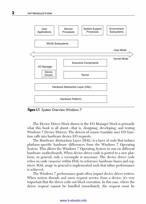
This discussion will highlight the significant features of interest to thedevice driver developers. Figure I.1 shows a general block diagram ofWindows 7. We develop more detailed block diagrams in the discussions invarious parts of the book.
In Figure I.1 the user applications don’t call the Windows 7 OperatingSystem Services directly. They go thru the Win32 subsystem dynamic-linked libraries (DLL). The User Mode Device Drivers, discussed later, gothrough this same communication channel.
The various Windows 7 services that run independently are handled bythe Service Processes. They are typically started by the service controlmanager.
The various Windows 7 System Support Processes are not consideredWindows 7 services. They are therefore not started by the service controlmanager.
The Windows 7 I/O Manager actually consists of several executive sub-systems that manage hardware devices, priority interfaces for both the system and the applications. We cover this in detail in Parts II and III ofthis book.
Wow! eBook <WoweBook.Com>
www.it-ebooks.info
ptg
The Device Driver block shown in the I/O Manager block is primarilywhat this book is all about—that is, designing, developing, and testingWindows 7 Device Drivers. The drivers of course translate user I/O func-tion calls into hardware device I/O requests.
The Hardware Abstraction Layer (HAL) is a layer of code that isolatesplatform-specific hardware differences from the Windows 7 OperatingSystem. This allows the Windows 7 Operating System to run on differenthardware motherboards. When device driver code is ported to a new plat-form, in general, only a recompile is necessary. The device driver coderelies on code (macros) within HAL to reference hardware buses and reg-isters. HAL usage in general is implemented such that inline performanceis achieved.
The Windows 7 performance goals often impact device driver writers.When system threads and users request service from a device, it’s veryimportant that the driver code not block execution. In this case, where thedriver request cannot be handled immediately, the request must be
2 Introduction
UserApplications
ServiceProcesses
System SupportProcesses
EnvironmentSubsystems
Win32 Subsystems
User Mode
Kernel Mode
I/O Manager
DeviceDrivers
Executive Components
Kernel
Hardware Abstraction Layer (HAL)
Hardware Platform
Figure I.1 System Overview Windows 7
Wow! eBook <WoweBook.Com>
www.it-ebooks.info
ptg
queued for subsequent handling. As we will show in later discussions, theI/O Manager routines available allow us to do this.
Windows 7 gives us a rich architecture for applications to utilize.However, this richness has a price that device driver authors often have topay. Microsoft, realizing this early on some 14 years ago, started develop-ing the driver development models and framework to aid the device driverauthor. The earliest model, the Windows Driver Model (WDM) had asteep learning curve, but was a good step forward. Microsoft has subse-quently developed the Windows Driver Foundation (WDF) that makesdeveloping robust Windows 7 drivers easier to implement and learn. Thisbook is about developing Windows 7 Device Driver using WDF.
Introduction 3
Wow! eBook <WoweBook.Com>
www.it-ebooks.info

ptg
This page intentionally left blank
Wow! eBook <WoweBook.Com>
www.it-ebooks.info

ptg
P A R T I
DEVICE DRIVER ARCHITECTUREOVERVIEW
Wow! eBook <WoweBook.Com>
www.it-ebooks.info

ptg
This page intentionally left blank
Wow! eBook <WoweBook.Com>
www.it-ebooks.info

ptg
7
C H A P T E R 1
OBJECTS
Before we go into the discussion on drivers, we need to first briefly reviewobjects, which are mentioned extensively throughout the book.
1.1 Nature of an Object
One of the fundamental ideas in software component engineering is theuse of objects. But just what is an object? There doesn’t seem to be auniversally accepted idea as to what an object is. The view that thecomputer scientist Grady Booch (1991) takes is that an object is definedprimarily by three characteristics: its state, its behavior, and its identity.The fundamental unit of analysis, in most cognitive theories, is theinformation-processing component. A component is an elementary infor-mation process that operates on the internal representation of objects orsymbols (Newell & Simon 1972; Sternberg 1977). If we look at the waythese components work, they may translate a sensory input into a concep-tual representation, transform one conceptual representation into another,or translate a conceptual representation into a motor output.
The Object Oriented Programming (OOP) techniques for softwarehave been around now for approximately a quarter of a century. But thephenomenon is not new. Ancient philosophers, such as Plato and Aristotle,as well as modern philosophers like Immanuel Kant have been involved inexplaining the meaning of existence in general and determining theessential characteristics of concepts and objects (Rand 1990). Very recentlyMinsky developed a theory of objects, whose behavior closely resemblesprocesses that take place in the human mind (Minsky 1986). Novak andGowin (Novak and Gowin 1984) showed how objects play an importantrole in education and cognitive science. Their approach is one in whichconcepts are discovered by finding patterns in objects designated by somename. But wait, we were talking about objects and now we are talkingabout concepts. That is because concepts reflect the way we divide the
Wow! eBook <WoweBook.Com>
www.it-ebooks.info

ptg
world into classes, and much of what we learn, communicate, and reasonabout involves relations among these classes. Concepts are mental repre-sentations of classes, and their salient function is to promote cognitiveeconomy. A class then can be seen as a template for generating objectswith similar structure and behavior.
The Object Management Group (OMG) defines a class as follows:
A class is an implementation that can be instantiated to createmultiple objects with the same behavior. An object is an instanceof a class.
From the software point of view, by partitioning the software intoclasses, we decrease the amount of information we must perceive, learn,remember, communicate, and reason about.
1.2 What Is a Software Object?
What is a software object? In 1976, Niklaus Wirth published his bookAlgorithms + Data Structures = Programs. The relationship of these twoaspects heightens our awareness of the major parts of a program. In 1986,J. Craig Cleaveland published his book Data Types. In 1979 BjarneStroustrup had started the work on C with classes. By 1985, the C++Programming Language had evolved and in 1990 the book The AnnotatedC++ Reference Manual was published by Bjarne Stroustrup. In thisdiscussion, I will only talk about .NET Framework base classes and .NETFramework library classes with respect to objects, because that seems tobe the main focus of where we are going today.
When Bjarne Stroustrup published the above book on C++ or C withclasses, we started associating the word class and object with the termabstract data type. But what is the difference between data types andabstract data types? A data type is a set of values. Some algorithm then oper-ates upon managing and changing the set of values. An abstract data type hasnot only a set of values, but also a set of operations that can be performedupon the set of values. The main idea behind the abstract data types is theseparation of the use of the data type from its implementation. Figure 1.1shows the four major parts of an abstract data type. Syntax and semanticsdefine how an application program will use the abstract data type.Representation and algorithms show a possible implementation.
8 Chapter 1 Objects
Wow! eBook <WoweBook.Com>
www.it-ebooks.info

ptgFor an abstract data type, we have therefore defined a set of behaviors,
and a range of values that the abstract data type can assume. Using the datatype does not involve knowing the implementation details. Representationis specified to define how values will be represented in memory. We callthese representations class member variables in VB.NET or C#. The algo-rithm or programs specify how the operations are implemented. We callthese programs member functions in VB.NET or C#. The semantics spec-ify what results would be returned for any possible input value for eachmember function. The syntax specifies the VB.NET or C# operator sym-bols or function names, the number and types of all the operands, and thereturn values of the member functions. We are therefore creating our owndata object (abstract data type) for the software to work with and use. Thisis opposed to only using the data types predefined by the compiler, such asinteger, character, and so on. These abstract data types or objects, asdefined in Grady Booch’s book Object-Oriented Analysis and Design withApplications, Third Edition (2007), are as follows: “an object represents anindividual, identifiable item, unit, or entity, either real or abstract, with awell-defined role in the problem domain.”
Another classic book relating to objects is Design Patterns (Gamma1995). This books points out the elements of reusable object-orientedsoftware.
1.2 What Is a Software Object? 9
Figure 1.1 Abstract Data Type
AbstractData Types
Specification Implementation
Syntax Semantics Representation Algorithms
Wow! eBook <WoweBook.Com>
www.it-ebooks.info

ptg
1.3 Gaining an Understanding
We have slowly come to the realization of just what properties our programshould have to make it work in solving complex real world problems.Having a new language like VB.NET or C# and their associated capabili-ties to create classes and objects was not enough. We realized that justusing the abstract data type or class was not enough. As part of this ongoingdevelopment, the methodology called object-oriented technology evolvedinto what is called the object model. The software engineering foundationwhose elements are collectively called the object model encompass theprinciples of abstraction, modularity, encapsulation, hierarchy, typing,concurrency, and persistence. The object model defines the use of theseelements in such a way that they form a synergistic association.
As with any discipline, such as calculus in mathematics, we need a sym-bolism or notation in which to express the design of the objects. The creationof the C++ language, as an example, supplied one language notation neededto write our object-oriented programs. However, we still needed a notationfor the design methodology to express our overall approach to the softwaredevelopment. In 1991, Grady Booch first published his book Object-Oriented Analysis and Design with Applications in which he defined a set ofnotations. These notations have become the defacto standard for ObjectOriented Design. His second edition does an even better job of describingthe overall Object Oriented Design notation and the object model. In thissecond edition, he expresses all examples in terms of the C++ language,which for a time became the predominate language for object-oriented soft-ware development. We even have a Windows GUI tool based upon this nota-tion to aid us in our thinking. This tool by Rational Corporation and GradyBooch was called ROSE. Quite a change from how calculus and its notationwere initially used. We almost immediately have the same engine we wish toprogram on, aiding us in doing the programming. This tool has continued toevolve and is now called the Universal Modeling Language (UML).
An object (or component) then is an entity based upon abstract datatype theory, implemented as a class in a language such as VB.NET or C#,and the class incorporates the attributes of the object model. What we havebeen describing, however, is just the tip of the iceberg relative to objects.The description so far has described the static definitions and has nottalked about objects talking with other objects. Let’s just look at one of theobject model attributes: inheritance. Inheritance is our software equiva-lent of the integrated electronic circuit (IC) manufacturing technique of
10 Chapter 1 Objects
Wow! eBook <WoweBook.Com>
www.it-ebooks.info

ptg
large-scale integration (LSI) that allows such tremendous advances inelectronic system creations. Software using inheritance is certainly verysmall scale at the present, but the direction is set. Inheritance allows thecreating of a small-scale integration (SSI) black box in software. This SSIcreates an encapsulated software cluster of objects directed toward thesolution of some function needed for the application. We have thusabstracted away a large amount of the complexity and the programmerworks only with the interfaces of the cluster. The programmer then sendsmessages between these clusters, just like the electronic logic designed haswires between ICs, over which signals are sent.
1.4 Software Components
Although we allude to software components having an analogy to hardwarechips, this is only true in a most general sense. Software components cre-ated with the rich vocabularies of the programming language, and basedupon the constructs created by the programmer’s mind, have a far greaterrange of flexibility and power for problem solving than hardware chips. Ofcourse, therein lays a great deal of the complexity nature of softwareprograms. However, the software components ride on top of the hardwarechips adding another complete level of abstraction. The deterministic logicinvolved in a complex LSI chip is very impressive. But the LSI chip is verylimited in the possibility of forming any synergist relationship with ahuman mental object.
The more we dwell upon the direction of the .NET Framework’sobject model, in all its technologies, the more it seems to feel like we areexternalizing the mind’s use of mental object behavior mechanics.Certainly, the object relationships formed with linking and embedding of software objects, via interfaces, doesn’t look much like the dendritedistribution of influences on clusters of neurons. But certainly now, onesoftware object is starting to effect one or more other software objects toaccomplish its goal.
Let’s look at a control object or collection of control objects from aneveryday practical standpoint that we are using in other engineering fields.One of our early loves is the automobile. We can hardly wait to learn howto drive one. Notice, we said drive one, any one. We have done such a greatjob on our encapsulation and interface exposure that we can learn to driveany kind and be able to drive any other kind. The automobile object we
1.4 Software Components 11
Wow! eBook <WoweBook.Com>
www.it-ebooks.info

ptg
interact with has three primary interface controls: steering wheel, throttle,and brake. We realize that encapsulated within that automobile object ismany internal functions. We can be assured that these control interfaceswill not change from automobile object to automobile object. In otherwords, if we go from a General Motors car to a Ford car we can depend onthe same functionality of these control interfaces.
Another characteristic of a software object is persistence. Persistenceof an object is learned very early by a child. Eventually, when we show achild a toy and then hide it behind our back, the child knows the toy stillexists. The child has now conceptualized the toy object as part of its mentalset of objects. As the programmer does a mental conceptualization ofvarious software objects, this will lead to a high level of persistence of theobjects in the programmer’s mind. Because one of the main features ofstandard software objects is reusability, the efficiency of the programmerwill continue to increase as the standard objects are conceptualized in theprogrammer’s mental model.
Polymorphic behavior is another characteristic that can be imple-mented in a software object. Probably one of the earlier forms that a childrealizes has different behavior, based upon form, is the chair object. Thechair object is polymorphic in that its behavior depends on its form. Wehave rocking chairs, kitchen chairs, lounge chairs, and so on. This idea ofform and related behavior has created a whole field of study calledmorphology. Certainly, this is a key idea in how we relate cognitively tovarious objects. Not only does the clustering of our objects have form rela-tionships, the internal constructs of the objects have a form relationship.There is a definite relationship between the logic flow of a program andthe placement of the various meaningful chunks of a program. This issomewhat different than a pure polymorphic nature of a function, but doespoint out that we should be aware of the morphology of our objects andtheir parts and placement in our program.
12 Chapter 1 Objects
Wow! eBook <WoweBook.Com>
www.it-ebooks.info
ptg
13
C H A P T E R 2
WINDOWS DRIVER FOUNDATION(WDF) ARCHITECTURE
The next generation driver model for the Windows family of operatingsystems is the Windows Driver Foundation (WDF). This new model canreduce driver development time, contribute to greater system stability, andimprove driver serviceability. In this chapter, we cover the overall WDFDriver Model and its various functionality. In the subsequent chapters onUser Mode Drivers and Kernel Mode Drivers, we will drill down into theprogramming details of developing one or the other type driver. This chap-ter then should give a good overall feel for the general WDF driver modelarchitecture. Note: In general, when we have a programming construct orvariable, we present that information in a bold format. This of course cov-ers the various WDF APIs available to us for developing the driver.
2.1 WDF Component Functions
WDF includes a suite of components that support the development,deployment, and maintenance of both Kernel Mode and User ModeDrivers. WDF components work with existing driver development tools toaddress the entire driver cycle of the following:
■ Plan & Design: Driver Model—The WDF driver model supportsthe creation of object-oriented, event-driven drivers. By usingWDF, driver writers can focus on their device hardware, rather thanon the operating system. WDF drivers can be written for either ker-nel mode or user mode.
■ Develop: Frameworks and Windows Driver Kit (WDK)—WDFdefines a single driver model and includes frameworks for bothKernel Mode and User Mode Driver development. The frameworks
Wow! eBook <WoweBook.Com>
www.it-ebooks.info

ptg
14 Chapter 2 Windows Driver Foundation Architecture
provide the basic infrastructure to support the WDF model. Theyimplement common features, provide intelligent defaults, and man-age most interactions with the operating system.
The Kernel Mode Driver Framework (KMDF) implementsbasic Kernel Mode Driver support features that are required byWindows and are common to all Kernel Mode Drivers.
The User Mode Driver Framework (UMDF) provides func-tional support similar to that in the KMDF, but enables drivers forsome types of devices to run in user mode instead of in kernel mode.
■ Test: Tracing and Static Analysis Tools—Both the KMDF and theUMDF have built-in verification code and support integrated trac-ing through Event Tracing for Windows (ETW). The generatedtraces can help in debugging drivers during development and indiagnosing problems in released drivers. WDF drivers also workwith the existing driver verifier. In addition, compile-time driververification tools, such as PREfast and Static Driver Verifier (SDV),are also part of the WDF effort.
■ Qualify: Driver Signing—WDF drivers are signed in the same wayas Windows Driver Model (WDM) drivers.
■ Deploy: Driver Installation Tools—WDF drivers are installed byusing INF files and work with existing driver installation tools,including the Driver Install Frameworks (DIFx) tools.
■ Maintain: Versioning—WDF supports versioning so that a singledriver binary can run on any version of the operating system and usethe same version of the framework on which it was built and tested.
2.2 Design Goals for WDF
Writing a Windows driver is not easy. The current Kernel Mode Driverdevelopment model Windows Driver Model (WDM) is complex and hasserious limitations.
WDM requires that drivers be designed to manage interactions with theoperating system, not just the device hardware. A simple WDM driver hasthousands of lines of code, much of which implements common features thatevery driver must support. WDM drivers must use device-driver interfaces(DDIs) that are exported directly from the operating system kernel. Theseinterfaces were designed for performance, not for ease of use. In many cases,the DDIs expose essential operating system data structures directly to the
Wow! eBook <WoweBook.Com>
www.it-ebooks.info

ptg
driver, thus increasing the chance that a driver error might crash or corruptthe system.
For some device types, port/miniport models implement much of theWDM code. However, Windows supports more than 10 such models andeach is different. So the knowledge gained from writing a miniport driverfor one type of device does not necessarily apply to writing a miniportdriver for a different type of device.
Unlike Kernel Mode Drivers, User Mode Drivers have no commoninfrastructure that is comparable to WDM.
The following are the primary design principles underlying the WDFmodel:
■ Separate the driver model from the core operating system compo-nents.
■ Provide a user mode option for some device types.■ Implement common and default driver features so that driver devel-
opers can focus on their hardware.■ Make drivers event driven and define the events at a detailed level
so that driver tasks are straightforward.■ Support Plug and Play and power management implementation for
all drivers.■ Support a consistent installation process for both User Mode and
Kernel Mode Drivers.■ Provide integrated tools, including built-in tracing and verification
support, to help find and diagnose problems both during debuggingand after release.
■ Enable a single driver binary to work with several versions of theframework and the operating system.
2.3 Device and Driver Support in WDF
Table 2.1 lists the WDF support for various device classes and driver mod-els in Windows 7. From this table, we can get a feel for the wide range ofdevice types that Windows 7 supports. As we have mentioned earlier, thisbook is primarily about creating custom device drivers. That is, ones notnormally supplied by Microsoft. Notice also the distribution of devicetypes across the two driver modes—that is, Kernel Mode DriverFramework (KMDF) and User Mode Driver Framework (UMDF).
2.3 Device and Driver Support in WDF 15
Wow! eBook <WoweBook.Com>
www.it-ebooks.info

ptg
Table 2.1 WDF Device Support for Windows 7
16 Chapter 2 Windows Driver Foundation Architecture
Device Class/Driver Model KMDF UMDF SDV PREfast
Antivirus filters No No Yes YesCD-ROM device Yes No Yes YesCell phones No Yes No YesDigital cameras No Yes No YesDisplay adapters No No No YesDSL/Cable modems Yes No No YesEthernet devices No No No YesKeyboards and mouse devices Yes No Yes YesModems Yes No Yes YesOther device (not listed here) No Yes No Yesthat connect to a Protocolbus such as USB or IEEE 1394PDAs No Yes No YesPortable media players No Yes No YesPrinters No No No YesScanners No No No YesSCSI/StorePort No No No YesVideo capture devices No No No Yes
2.4 WDF Driver Model
The WDF driver model defines an object-oriented, event-driven environ-ment in which driver code manages device-specific features and aMicrosoft-supplied framework calls the driver to respond to events thataffect operation of its device. The driver model includes the following:
■ An object model that is implemented by both KMDF and UMDF.■ A Plug and Play and power management implementation that both
frameworks use.■ An I/O model in which the frameworks handle interactions with the
operating system and manage the flow of I/O, Plug and Play, andpower management requests.
Wow! eBook <WoweBook.Com>
www.it-ebooks.info
ptg
■ A versioning strategy that applies to both Kernel Mode and UserMode Drivers.
■ Consistent installation techniques for both Kernel Mode and UserMode Drivers.
This design has several important advantages:
■ The frameworks implement common driver features and defaultbehavior, thus making vendor-written drivers smaller and faster todevelop and debug.
■ Microsoft can change the operating system’s internal data structurewithout introducing driver incompatibilities.
■ Driver developers and hardware vendors are better isolated fromincremental changes in each new version or update of the operatingsystem.
■ Each framework can track the state of the driver, operating system,and device, thus eliminating much of the complex logic oftenrequired in a driver, particularly in respect to Plug and Play andpower management.
The WDF model provides a consistent but extensible driver developmentinterface. Both frameworks conform to conventions for naming, parametertypes and usage, object hierarchy, and default. Features that are requiredby or common to all device types are part of each overall framework, sodriver writers can apply knowledge gained from writing a driver for onedevice type to writing a driver for another device type.
2.5 WDF Object Model
In Chapter 1, Objects, we covered what are objects and classes. This isthe point in our discussion of the WDF object model: that we start totalk about the use of objects by the WDF. Objects are a significant fun-damental element of our device driver program development. Ofcourse, many other aspects of Windows 7 use objects as well. After look-ing over this section, you might want to go back and revisit Chapter 1again.
2.5 WDF Object Model 17
Wow! eBook <WoweBook.Com>
www.it-ebooks.info

ptg
18 Chapter 2 Windows Driver Foundation Architecture
In the WDF object model:
■ Objects work as building blocks for the driver. A driver modifiesthese objects through well-defined interfaces. The objects them-selves have well-defined life cycles.
■ A set of events can affect each type of object. The framework definesdefault behavior for each event. To support device-specific behavior,the driver includes callback routines that override the defaults.
The model defines a set of objects that represents common driver con-structs, such as devices, queues, I/O requests, and the driver itself. Theobjects have properties, methods, and events:
■ Properties describe characteristics of the object. Each property isassociated with methods that get and (if relevant) set the value ofthe property.
■ Methods perform actions on the objects.■ Events are conditions for which a driver might need to take action.
WDF identifies possible events for each object and defines defaultactions for most of them. The driver includes code to handle onlythe events for which the default actions are inappropriate or inade-quate for its device. When the event occurs, WDF invokes therelated callback.
The WDF driver creates instances of the objects that it requires to serviceits device and customizes those instances to suit its requirements. For eachinstance, the driver provides callbacks for the events that require actionsother than the WDF defaults. The callbacks call methods on the object toperform any additional actions.
Objects are organized hierarchically. The WDF driver object is theroot object; all other objects are subordinate to it. For most types, a drivercan specify the parent when it creates the object. If the driver does notspecify a parent at object creation, the framework sets the parent to theWDF driver object by default. Some object types, however, have prede-fined parents that cannot be changed at creation. For example, I/O queueobjects are children of the device object. Each child object is deleted whenits parent object is deleted.
Although the object model applies to both the KMDF and UMDF, WDFobjects themselves are implemented differently in the two frameworks.
Wow! eBook <WoweBook.Com>
www.it-ebooks.info

ptg
2.5 WDF Object Model 19
2.5.1 Kernel Mode ObjectsKMDF objects are structures that are opaque to the driver. Drivers neverdirectly access instances of KMDF objects. Instead, they reference objectinstances by handles. To read, write, or perform an action on an object, adriver calls a method on the object and passes the handle.
The KMDF defines more than 20 types of objects. Table 2.2 lists someof the most commonly used.
KMDF objects are unique to the framework. They are not managed bythe Windows object manager and therefore cannot be manipulated byusing the system’s ObXxx functions. Only the framework and WDF driv-ers can create and manipulate them.
Similarly, KMDF events are not related to the kernel dispatcher eventsthat Windows uses as synchronization mechanisms. A driver cannot create,manipulate, or wait on a WDF event. Instead, the driver registers a call-back for the event and WDF calls the driver when the event occurs.
2.5.2 User Mode ObjectsUMDF objects are based on the component object model (COM). TheUMDF uses a small subset of COM for query-interface and referencecounting features. In User Mode Drivers, both the driver and the framework
Object Type Name Usage
WDFDRIVER Represents the driver objectWDFDEVICE Represents a device objectWDFQUEUE Represents a queue of I/O requestWDFINTERRUPT Represents an interrupt resourceWDFREQUEST Describes an I/O requestWDFMEMORY Describes a buffer for an I/O requestWDFDMANENABLE Describes the characteristic of all DMA transfers
for a deviceWDFDMATRANSACTION Manages operations for an individual DMA
requestWDFIOTARGET Represents the driver that is the target of an
I/O request
Table 2.2 Commonly Used KMDF Object Types
Wow! eBook <WoweBook.Com>
www.it-ebooks.info

ptg
20 Chapter 2 Windows Driver Foundation Architecture
implement and expose COM-style interfaces. Handles are not requiredbecause the interfaces are abstract base classes and thus identify the object.
The UMDF defines fewer objects than the KMDF because UserMode Drivers cannot directly access hardware and therefore do not per-form direct memory access (DMA) or handle interrupts. Table 2.3 lists theinterfaces that expose the UMDF object types.
2.6 Plug and Play and Power Management Support
Simplifying driver support for Plug and Play and power management andmaking it available in both kernel mode and user mode were primarydesign goals for WDF. Seamless handling of Plug and Play and powerevents is critically important to system reliability and a good user experi-ence, but is exceedingly complex to implement correctly.
Much of this complexity occurs because drivers must determine the cor-rect way to handle each Plug and Play or power management request. Properhandling depends on the driver’s position, the device stack, the current stateof its device, the current state of the operating system, and sometimes thenature of an impending state change for the device or system. Such supporttypically requires thousands of lines of code to handle tricky, state-dependentsituations. Most drivers require code to handle requests that they don’t evensupport.
Object Interface Name Usage
IWDFObject Defines the base WDF object typeIWDFDriver Represents the driver objectIWDFDevice Represents a device objectIWDFFile Represents a file objectIWDFIoQueue Represents a queue of I/O requestsIWDFIoRequest Describes an I/O requestIWDFIoTarget Represents the driver that is the target of an I/O
requestIWDFMemory Provides access to an area of memory
Table 2.3 Interfaces for UMDF Object Types
Wow! eBook <WoweBook.Com>
www.it-ebooks.info
ptg
2.6 Plug and Play and Power Management Support 21
WDF concentrates the state-tracking and decision-making logic in theframeworks, instead of requiring it in each driver. WDF support for Plugand Play and power management is based on the following principles:
■ The driver should not be required to interpret or respond to everyuninteresting request. Instead, the driver should be able to “opt in”and handle only the requests that are relevant to its device.
■ The frameworks should provide default behavior for a rich set ofPlug and Play and power features, including device stop, deviceremoval, device ejection, fast resume, low run-time power usage,and device wake-up by external events.
■ WDF actions at each point must be well-defined and predictable; ineffect, a “contract” applies to each driver callback.
■ Plug and Play and power management should be thoroughlyintegrated with other parts of the frameworks, such as queuemanagement.
■ The frameworks must support both simple and complex hardwareand driver designs.
■ A driver should be able to override any framework-supplieddefaults.
2.6.1 Plug and Play/Power ManagementState Machine
Internally, WDF implements Plug and Play and power management as astate machine. Both the KMDF and UMDF use the same state machine.A driver includes callbacks so that it can perform device-specific actions atindividual states in the machine. For example, a driver can provide a call-back that is called immediately after its device enters the working state.
At each state transition, a predetermined set of events is valid for eachtype of object, and the framework invokes the driver’s callbacks for theseevents in a defined order. Thus, a driver can assume that both the systemand its device are in a particular state whenever it is asked to perform aPlug and Play or power management action.
The complicated logic that tracks system and device state is incorpo-rated into the framework, not into the driver. This approach vastly reducesthe amount of required decision-making in the driver—especially duringpower transitions—and eliminates much redundant code. Instead, theframework defines a state-related event and the driver optionally supplies
Wow! eBook <WoweBook.Com>
www.it-ebooks.info

ptg
22 Chapter 2 Windows Driver Foundation Architecture
a corresponding callback. As a result, a WDF driver includes code tohandle only those events for which it requires device-specific support. Allother events can be handled by WDF defaults.
Furthermore, Plug and Play and power management support are inte-grated throughout the framework so that other aspects of the driver oper-ate properly when state transitions occur. For example, a driver canconfigure its I/O queues so that the framework stops dispatching requestswhile the device is in a low-power state.
2.7 Integrated I/O Queuing and Cancellation
WDF integrates Plug and Play and power management support with thequeuing of I/O requests and, in turn, integrates queuing with requestcancellation.
Both the KMDF and UMDF provide configurable I/O queues. Thedriver creates the queues and configures them for specific I/O request,power management characteristics, and dispatching requirements. Theframework queues and dispatches requests according to the driver’s specifi-cations: sequentially (one at a time), in parallel (as soon as they arrive), ormanually (at the driver’s explicit request). When Plug and Play or powermanagement events affect queuing, WDF can start, stop, or resume queu-ing as appropriate, depending on how the driver configured the queue.
Because Windows I/O is inherently asynchronous, handling the can-cellation of an I/O request is often complex. The driver must cope withseveral potential race conditions and one or more locks, and the requiredcode is typically scattered among several driver routines.
WDF relieves drivers of much of this burden by managing the locks forthe I/O queues and by canceling queued requests without driver interven-tion. (A driver can, however, register for notification when a request is can-celed.) By default, requests that are in a queue can be canceled. Requeststhat have been removed from a queue and dispatched to a driver cannot becanceled unless the driver specifically marks them so. WDF drivers that usethese defaults typically require little if any cancellation code.
2.7.1 ConcurrencyManaging concurrent operations is another challenge in writinga Windows driver. Because Windows is a pre-emptive, multitasking
Wow! eBook <WoweBook.Com>
www.it-ebooks.info

ptg
2.7 Integrated I/O Queuing and Cancellation 23
operating system, multiple threads can concurrently try to access shareddata structures or resources, and multiple driver routines can run concur-rently. To ensure data integrity, drivers must synchronize access to shareddata structures.
WDF simplifies synchronization by implementing several internal syn-chronization mechanisms and by holding any required locks. In addition,WDF synchronization scope is a configurable object-based mechanism forspecifying the degree of concurrency. (Synchronization scope is called thelocking constraint in the UMDF.) An object’s synchronization scope deter-mines whether WDF invokes multiple event callbacks on the object con-currently. Drivers that use the KMDF can specify synchronization scopefor driver, device, and file objects. In the UMDF, synchronization scopeapplies only to device objects.
WDF defines the following synchronization scopes:
■ Device scope—WDF does not call certain I/O event callbacks con-currently for an individual device object or any file objects or queueobjects that are its children.
■ Queue scope—These I/O callbacks are not called concurrently on aper-queue basis. If a Kernel Mode Driver specifies queue scope fora device object, these callbacks can run concurrently for multiplequeues. However, multiple callbacks for an individual queue objectwill not be called concurrently. The initial UMDF release does notsupport queue scope.
■ No scope—WDF does not acquire any locks and can call any eventcallback concurrently with any other event callback.
By default, the KMDF uses no scope. A Kernel Mode Driver must “opt in”to synchronization for its objects by setting device scope or queue scopewhen it creates an object. The UMDF uses device scope by default.
For Kernel Mode Drivers, the KMDF also enables driver writers toconstrain the interrupt request level (IRQL) at which the callbacks can beinvoked.
2.7.2 I/O ModelIn Windows, the I/O request packet (IRP) does more than just presenttraditional I/O requests (read, write, create, and so forth) to drivers. Itworks as a general packet-based communication mechanism between the
Wow! eBook <WoweBook.Com>
www.it-ebooks.info
ptg
24 Chapter 2 Windows Driver Foundation Architecture
operating system and drivers, and between drivers themselves. TheWindows I/O manager sends IRPs to notify drivers of Plug and Playrequests, power management requests, changes in device status, andqueries about device and driver resources (among other purposes) in addi-tion to passing I/O requests. Therefore, the WDF I/O model encompassesmore than just data transfers to and from a device.
For WDF drivers, the framework manages the mechanics of dispatch-ing, queuing, completing, and canceling IRPs on behalf of its drivers. Theframework calls the driver’s event callback routines to notify it of signifi-cant events such as requests that the driver must handle.
After receiving a request, the framework records information aboutthe request, creates a WDF object to represent the request (if neces-sary), and calls one or more of the driver’s event callbacks to handle therequest as appropriate. WDF queue objects help drivers to manage thearrival of I/O requests. A driver can create one or more such queues andconfigure each to receive specific types of requests. Depending on thedispatch mechanism that the driver has designed for each queue, theframework either delivers the request to the driver immediately orqueues it for later delivery.
The framework keeps track of every I/O request, whereas the driver“owns” the request—that is, until the request has been canceled, com-pleted, or passed to another target. Because the framework is aware ofall the active requests, it can call the appropriate driver callbacks incase of IRP cancellation, power state changes, hardware removal, andso forth.
2.7.3 I/O Request FlowBoth the KMDF and UMDF use the same I/O model, although it is imple-mented by different components. Within this model, I/O request flow is asshown in Figure 2.1.
As Figure 2.1 shows, WDF dispatcher code directs I/O request packetswithin the framework. WDF dispatches I/O requests according to theirmajor I/O function code. The major function code is a field within the IRPthat identifies the type of request. Based on the major I/O function code,the dispatcher determines which package within the framework shouldinitially handle the request.
The following sections describe how WDF processes requests.
Wow! eBook <WoweBook.Com>
www.it-ebooks.info

ptg
2.7.4 Device I/O RequestsWhen an IRP that requests device I/O arrives, the dispatcher passes it tothe I/O package. If the driver has not configured a queue or exposed a call-back for the requested type, the framework takes a default action thatdepends on the type of driver. For a User Mode Driver, or for a KernelMode Function Driver or Bus Driver, the framework fails the request. Fora Kernel Mode Filter Driver, the framework forwards the request to thenext lower driver in the stack.
If the driver has configured a queue or exposed a callback for therequest type, the framework creates a WDF request object, which containsthe information in the original IRP structure along with additionalinformation about the driver state. The framework then places the requestobject in the corresponding queue.
2.7 Integrated I/O Queuing and Cancellation 25
Figure 2.1 Block Diagram I/O Request Flow
Dispatcher
I/O Package
Nonpower-Managed I/O
Queues
Power ManagedI/O Queues
DriverCallbacks
I/O Target
Plug and Play/Power
Package
DriverCallbacks
WMI PackageDriver
Callbacks
IRPs
WMIRequests
(KMDF only)
Plug and Playand PowerRequests
I/O Requests
Wow! eBook <WoweBook.Com>
www.it-ebooks.info
ptg
If the queue is configured for automatic power management, theframework then determines whether the device is in the correct powerstate. If not, the Plug and Play and power package puts the device in theworking state. If the driver has registered callbacks for power events, theframework calls the Plug and Play; otherwise, it takes whatever defaultsteps are required.
After the device has entered the working state, the frameworkdispatches the I/O request according to the driver’s specifications byinvoking the callbacks registered for the I/O request. A driver can alsorequest manual dispatching, which means that it must call the frameworkto get a request. The framework passes the WDF request object when itinvokes the callbacks. The driver’s callbacks might set or get properties forthe request, call methods on the request object or other WDF objects,perform device I/O, and take other actions as necessary to handle therequest.
When the driver has finished processing the request, the driver cancomplete it or pass it on to an I/O target. An I/O target is an external des-tination for the I/O request. The next lower driver in the device stack isconsidered the local I/O target; any other driver is considered a remoteI/O target.
If a driver does not complete an I/O request, it typically sends therequest to its local I/O target. Occasionally, however, a driver might requireinformation from a different driver before it can complete a request. Toobtain this information, the driver creates an object to represent theremote I/O target, creates a WDF request object, and then calls methodson the I/O target to send the request.
2.7.5 Plug and Play and Power ManagementRequests
When a Plug and Play or power request arrives, the framework determineswhether any Plug and Play or power management state changes arerequired to satisfy the request. If so, the framework takes the necessaryactions to change the state and either calls the driver’s registered eventcallbacks or performs default actions if the driver has not registered anycallbacks for those events.
After the relevant callbacks have returned, the framework completesor forwards the request, as appropriate, on the driver’s behalf.
26 Chapter 2 Windows Driver Foundation Architecture
Wow! eBook <WoweBook.Com>
www.it-ebooks.info

ptg
2.8 WMI Requests (Kernel Mode Drivers Only)
A Windows Management Instrumentation (WMI) request triggers call-backs that the driver registered for any current WMI events. In its WMIcallbacks, the driver might call WMI methods on the device object to cre-ate and manipulate WMI instances of to change its status as a WMIprovider. After the WMI callbacks have returned, the framework com-pletes or forwards the request, as appropriate, on the driver’s behalf. Onlythe KMDF supports WMI.
To understand how an I/O request flows through a WDF driver, con-sider the following scenario:
■ A user mode process requests a read from a device.■ At the time of the request, the device is in a low-power state.■ The driver has configured a power-managed queue to accept read
requests.
The request is processed by the WDF function driver as follows:
1. The IRP dispatcher inspects the IRP and directs it to the I/O pack-age. The I/O package creates a WDF request object to representthe IRP, adds the WDF request object to the queue, and checksthe current device power state. Because the device is in a low-power state, the I/O package calls the Plug and Play/power man-agement package to put the device in the fully powered workingstate so that it can perform the read operation.
2. The Plug and Play/power management package returns the deviceto the working state by taking default actions and calling the appro-priate power management callbacks implemented by the driver.
3. When the device has successfully reentered the working state, theframework dispatches the read request to the driver. If the driverhas configured manual dispatching, the driver calls a method onthe queue to get a request. Otherwise, the framework dispatchesthe request either immediately or when the driver has completedthe previous request, depending on the queue’s configuration.
4. If the driver can satisfy the request, it does; if it cannot, it sends therequest to an I/O target.
2.8 WMI Requests (Kernel Mode Drivers Only) 27
Wow! eBook <WoweBook.Com>
www.it-ebooks.info

ptg
2.9 Driver Frameworks
The WDF driver model is implemented through the KMDF, which sup-ports Kernel Mode Driver development, and the UMDF, which supportsUser Mode Driver development. The frameworks provide the basicdriver infrastructure and perform the following services for WDFDrivers:
■ Define WDF objects that drivers can instantiate.■ Manage object lifetimes.■ Expose a basic set of DDIs that drivers call to manipulate the
objects.■ Provide a common implementation of features that drivers typically
require, such as Plug and Play, power management, synchroniza-tion, I/O queues, and access to the registry.
■ Manage the flow of I/O requests and Plug and Play and power noti-fications from the operating system to the driver.
Instead of calling the operating system directly, drivers interact with theappropriate framework for most services. The frameworks manage most ofthe interactions with the operating system on behalf of the driver. In effect,the frameworks shield driver developers from the details of the operatingsystem.
The frameworks implement the WDF I/O model, object model, andPlug and Play and power management support. Each framework receivesI/O requests, calls the driver to handle events according to the driver’s con-figuration, and applies defaults otherwise. Both frameworks provide intel-ligent defaults for common operations so that drivers do not require largeamounts of potentially buggy “boilerplate” code.
The frameworks support common features required for all deviceclasses. Device-class-specific extensions can also be added. For example,the initial release of the KMDF supports extensions specifically for USBdevices. As new features are added to the operating system, and as newdevice classes are supported, features that are common to all device classeswill be added to the base set of DDIs in the frameworks. Extensions willprovide features that are required by one or more specific device classes,but not by every device class. The extensions are intended to replace theminiport models common with WDM.
28 Chapter 2 Windows Driver Foundation Architecture
Wow! eBook <WoweBook.Com>
www.it-ebooks.info
ptg
2.9 Driver Frameworks 29
2.9.1 Kernel Mode FrameworkFor Kernel Mode Drivers, the KMDF does not replace WDM; instead, itprovides a skeletal WDM implementation. In effect, the driver developerconfigures the skeletal driver to work with a particular device by creatingobjects and providing event-based callback routines.
The KMDF is a reentrant library that can be shared by multiple drivers.Drivers are dynamically bound with the library at load time, and multipleversions of the library can be used by multiple drivers simultaneously.
The KMDF currently supports creation of the following types ofKernel Mode Drivers:
■ Function drivers for Plug and Play devices.■ Filter drivers for Plug and Play devices.■ Bus drivers for Plug and Play device stacks.■ Control device drivers for legacy (NT 4.0-style) devices that are not
part of a Plug and Play stack.
Currently, the KMDF does not support bus filter drivers.WDF provides certain methods and callbacks specifically for bus driv-
ers, others specifically for function and filter drivers, and still others forcontrol device drivers.
The KMDF identifies a function driver, control device driver, or a busdriver based on the methods that the driver calls and the callbacks that thedriver supports. For example, the bus driver for a device typically supportscallbacks to enumerate the children of the device and to supply a list of thehardware resources that the device requires. A function driver for a devicetypically supports callbacks to manage power to its device.
A filter driver explicitly identifies itself as such before creating a deviceobject. The KMDF uses this information when passing I/O requests to thedriver. A filter driver registers for only the I/O requests it chooses to filter;the KMDF passes all other requests to the next lower driver. (For a func-tion or bus driver, WDF fails other requests.) By contrast, a WDM filterdriver must accept all I/O requests that could be targeted to its device, passthose it does not filter to a lower driver, and act on the remaining subset.A WDM filter driver requires logic to inspect and forward many types ofrequests; a WDF filter driver has no such code because it receives only therequests it is interested in.
When an application sends an I/O request to a Kernel Mode WDFDriver, the request travels through the components shown in Figure 2.2.
Wow! eBook <WoweBook.Com>
www.it-ebooks.info

ptg
As the figure shows, the following components are involved in handling anI/O request to a Kernel Mode WDF Driver:
■ Application—The application is a user mode process that issuesI/O requests through the Win32 API.
■ Win32 API—In response to the application’s I/O request, theWin32 API calls I/O routines in the Windows kernel.
■ Windows kernel—The I/O manager in the Windows kernel cre-ates an IRP to represent the request and presents it to the targetdriver by calling the driver at a designated entry point. For KernelMode WDF Drivers, the KMDF registers the entry points, in effectintercepting the request on behalf of the driver.
■ KMDF—The KMDF processes the request as previously describedin the section “I/O Request Flow,” creating a WDF request objectand calling the driver’s event callback routines as required.
30 Chapter 2 Windows Driver Foundation Architecture
Figure 2.2 I/O Flow to Kernel Mode WDF Driver
Application
Win32 API
Windows KernelI/O Manager
Kernel Mode DriverKMDF
I/O Request
User Mode
Kernel Mode
Wow! eBook <WoweBook.Com>
www.it-ebooks.info

ptg
2.9 Driver Frameworks 31
2.9.2 User Mode FrameworkThe UMDF implements a subset of the KMDF functionality, includingsupport for Plug and Play, power management, and asynchronous I/O.Drivers that run in user mode have access only to the user address spaceand therefore pose low risk to system stability. User Mode Drivers cannothandle interrupts, perform DMA, or use kernel mode resources such asnonpaged pool.
Using the UMDF, developers can create drivers for any protocol orserial-bus based device. Although these drivers run in user mode, they usethe standard Plug and Play installation mechanism and the same I/O modelas Kernel Mode WDF Drivers. Figure 2.3 shows the components involvedin transmitting an I/O request from an application to a User Mode WDFDriver.
Figure 2.3 I/O Flow to User Mode WDF Driver
Application
Win32 API
Windows KernelI/O Manager
Reflector
I/O Request
User Mode
Kernel Mode
Host Process
User ModeDriver
UMDF
Run-TimeEnvironment
DriverManager
Wow! eBook <WoweBook.Com>
www.it-ebooks.info

ptg
Figure 2.3 includes the following components, described according tothe typical flow of an I/O request:
■ Application—The application is a user mode process that issuesI/O requests through the Win32 API.
■ Win32 API—In response to the application’s I/O request, theWin32 API calls I/O routines in the Windows kernel.
2.10 Windows Kernel
The I/O manager in the Windows kernel creates IRPs to represent therequests and presents them to the target driver by calling the driver at adesignated entry point. If the target of the request is a User Mode WDFDriver, however, the I/O manager cannot call the driver or the UMDFdirectly because these components run a user mode process, and kernelmode components cannot be called back to user mode. Therefore, the I/Omanager does not present the request directly to the User Mode Driver.Instead, the I/O manager presents the request to a kernel mode compo-nent called the reflector.
2.10.1 ReflectorThe reflector is a Kernel Mode WDM Filter Driver that represents theUser Mode Driver in the Kernel Mode Driver stack. The reflector passesthe I/O request to the User Mode Driver host process.
The reflector manages communication between the kernel mode com-ponents and the User Mode Driver host process. It monitors the driverhost process to ensure that it responds properly to messages and completescritical operations in a timely manner, thus helping to prevent driver andapplication hangs. The reflector also sends messages to the driver manageras required.
The reflector is supplied by Microsoft and is added as the top driver inthe Kernel Mode Driver stack during installation of the User Mode Driver.
2.10.2 Driver Host ProcessThe driver host process is the user mode process in which the User ModeDriver runs. It includes the following components:
■ The User Mode WDF Driver is an in-process COM component thatcontrols the hardware from user mode.
32 Chapter 2 Windows Driver Foundation Architecture
Wow! eBook <WoweBook.Com>
www.it-ebooks.info
ptg
■ The UMDF exposes the User Mode DDI. The UMDF is adynamic-link library (DLL) of COM-style objects that support thepresentation, flow, and management of I/O, Plug and Play, andpower management requests to the driver.
■ The run-time environment dispatches I/O requests, loads the driver,constructs and destroys the user mode device stack, manages a usermode thread pool, and handles messages from the reflector and thedriver manager.
The driver host process is separate from the application process andthe driver manager. It runs in the security credentials of a LocalServiceaccount, although it is not a Windows service. The driver host processcontains the user mode device stack for the device. The device stack isvisible to all applications across the system. Each instance of a device hasits own device stack. Currently, each instance has a separate driver hostprocess, too. The driver host process is a child process of the drivermanager.
2.10.3 Driver ManagerThe driver manager creates and shuts down the driver host process andmaintains status information about it. It also responds to messages fromthe reflector. The driver manager runs as a Windows service is started dur-ing installation of the first device that is managed by a User Mode WDFDriver. The driver manager must be running all the time that any devicecontrolled by a User Mode WDF Driver is installed on the system.
2.11 Tools for Development and Testing
The WDF has some outstanding tools to aid in the testing of drivers. Wewill cover those in the following discussion. Thoroughly testing a driver isnearly as complex as writing one for two main reasons:
■ Observing the point of error can be difficult. In many cases, a drivererror is not apparent until long after it has actually occurred. If aKernel Mode Driver uses a DDI incorrectly, the system might notcrash until another driver attempts to perform an action based onthe first driver’s error.
■ Subtle, condition-dependent errors and related code paths are difficultto exercise. Drivers that work correctly under normal circumstances
2.11 Tools for Development and Testing 33
Wow! eBook <WoweBook.Com>
www.it-ebooks.info

ptg
can have subtle errors that occur only under exceptional situations,such as when another driver, lower in the stack, fails an I/O request.
Too often, testing becomes a hit-or-miss, trial-and-error affair. To helpremedy the situation, WDF has several testing and tracing features thatmake it easier for driver writers to find problems early in the developmentcycle. We will cover these features in more detail in the subsequent dis-cussion. These features include the following:
■ Built-in verification with the frameworks verifier■ Built-in trace logging■ Debugger extensions
In addition, WDF includes PREfast and Static Driver Verifier (SDV).PREfast and SDV are both compile-time code verification tools that areprovided with the Windows Driver Kit (WDK). PREfast analyzes code ona function-by-function basis, looking for a wide variety of common logicand usage errors. SDV applies knowledge about system internals to KernelMode Driver verification.
2.11.1 PREfast for DriversPREfast for Drivers (PFD), an extension of PREfast, is a compile-timestatic verification tool that detects errors missed by the compiler and byconventional run-time testing. It detects common coding errors in C andC++ programs, and is designed to detect errors in Kernel Mode Drivercode. You can run PFD very early in the development cycle—as soon asthe code compiles correctly. PFD is integrated into the Windows 7 buildenvironments in the Windows Driver Kit (WDK) as well as into WindowsAutomated Code Review (known as OACR). PFD supports a large vocab-ulary of annotations beyond those supported for generic PREfast, includ-ing annotations for IRQLs, resource-object leaks, memory leaks, andstricter type checking.
PREfast for Drivers examines each function in the code indepen-dently, looking for common errors and unwise coding practices. PFD runsquickly, even on large drivers, and generates a report that identifies theline of driver code with the suspected error.
PREfast for Drivers runs on Windows XP and later versions ofWindows and is designed to analyze code written for X86-based and
34 Chapter 2 Windows Driver Foundation Architecture
Wow! eBook <WoweBook.Com>
www.it-ebooks.info
ptg
X64-based platforms. It can analyze C and C++ source files for driversin any driver model, including managed code.
You should use PREfast for Drivers in conjunction with DriverVerifier, Static Driver Verifier, and the checked build of Windows toensure that your driver code is safe and reliable.
The following new features for PFD are in Windows 7:
■ PFD now supports a broader range of expressions for analysis, suchas const, member names, and side effect-free C expressions.
■ PFD now has better annotation error checking.■ PFD now has improved defect detection, including “banned API”
checking.■ PFD now generates warnings that help you prepare to analyze a
driver with Static Driver Verifier (SDV). SDV requires drivers tohave declarations that define the role of the driver-supplied callbackfunctions. PFD will indicate when you need to add these role typedeclarations to the drive code.
■ PFD is now integrated into the build environments and OACR inthe WDK. When you build your driver using the WDK build envi-ronments, PFD runs automatically in the background and presentsan easy-to-read view for any potential defects it finds.
For Windows 7, all Microsoft drivers that ship with the operating systemand all WDK samples have been verified with PFD, and identified defectshave been fixed. In addition, the WDK public headers are now annotatedto enable PFD to better find code defects. The following functionality aidsin finding code defects.
■ Because PFD annotations are not in public header files, driver writ-ers can take advantage of these checks by simply running PFD ontheir drivers. Adding PFD annotations to your driver code will giveyou deeper analysis.
■ Windows headers for drivers now provide a comprehensive set ofexamples of how to annotate your functions.
2.11.2 Static Driver Verification (SDV)Static Driver Verifier (SDV) is a static verification tool that runs at compiletime. It explores paths in the driver code by symbolically executing the
2.11 Tools for Development and Testing 35
Wow! eBook <WoweBook.Com>
www.it-ebooks.info
ptg
source code, making the fewest possible assumptions about the state of theoperating system and the initial state of the driver. As a result, SDV canexercise code in paths that are missed in traditional testing.
SDV includes a set of rules that defines proper interaction between adriver and the operating system kernel. During verification, SDV examinesevery applicable branch of the driver code and the library code that it uses,and tries to prove that the driver violates the rules. If SDV fails to prove aviolation, it reports that the driver complies with the rules and passes theverification.
2.11.3 Frameworks VerifierWDF includes an internal driver verifier that provides framework-specificfeatures that are not currently available in the driver verifier (Verifier.exe).The frameworks verifier provides extensive tracing messages that supplydetailed information about activities within the framework. It tracks refer-ences to each WDF object and builds a trace that can be sent to thedebugger.
In kernel mode, the frameworks verifier checks lock acquisition andhierarchies, and ensures that calls to the framework occur at the correctIRQL. It also verifies correct I/O cancellation and queue usage. It can alsosimulate low-memory and out-of-memory conditions and test a driver’sresponse to these situations to determine whether the driver respondsproperly without crashing, hanging, or failing to unload.
In user mode, the frameworks verifier checks for correct use of param-eters, validates configurations, and correct responses to events.
2.11.4 Trace LoggingBoth the KMDF and UMDF support integrated internal trace logging.The following discussions cover this internal trace logging.
The KMDF includes an internal trace logger called the in-flightrecorder (IFR), which is based on the Windows Software TracePreprocessor (WPP). The IFR provides a recent history of events (cur-rently, about the last 100 trace events) on a per-driver-instance basis. Thetrace logs track the progress of IRPs through the framework and the cor-responding requests through a driver. Each WDF driver has its own log.
Kernel Mode Drivers can use Event Tracing for Windows (ETW) andWPP software tracing to generate a trace log that contains information
36 Chapter 2 Windows Driver Foundation Architecture
Wow! eBook <WoweBook.Com>
www.it-ebooks.info
ptg
about both the driver and the KMDF. Driver-level tracing providesinformation about events in the driver code. Internal WDF tracing pro-vides information about events internal to WDF that might affect driveractivities. A driver developer can choose whether to implement driver-level tracing, but internal WDF tracing is always available.
Driver writers can use the software tracing tools provided with theWDK to view the IFR logs during interactive debugging. These logs canalso be made available as part of a mini dump for inspection after a crash.The typical saved IFR log file is small (10K to 20K bytes) and written in abinary form that humans cannot read.
The User Mode Driver components supplied by Microsoft starttrace sessions that record their activities and note such events as driverhangs, timeouts, and failures. The log files from these sessions can besent as input to Windows Error Reporting (WER). Vendor-suppliedUser Mode WDRF Drivers can use ETW to generate a trace log ofdriver events.
2.11.5 Debugger ExtensionsWDF also includes several debugger extensions that can dump internaltrace records. These extensions are specialized commands that run in thecontext of the WinDbg debugger. These extensions are packaged in twoDLLs: WudfExt.dll contains the UMDF extensions, and WdfKd.dll con-tains the KMDF extensions. The information they provide can help locatethe exact point in I/O processing at which an error occurred and can oftengive a clue to faulty assumptions or unexpected behavior.
The two sets of debugger extensions are provided for WDF. As men-tioned, one set supports user mode debuggers, and the other supportskernel mode debuggers.
2.11.6 Serviceability and VersioningTo improve driver serviceability, WDF includes versioning and side-by-side support. Versioning allows a driver binary to run with the same majorversion of WDF with which it was built. Side-by-side support enables thesimultaneous use of two or more major versions of WDF by two or moredrivers.
Serviceability is a common problem for drivers. When Microsoftreleases a new version of Windows, driver vendors must test their drivers
2.11 Tools for Development and Testing 37
Wow! eBook <WoweBook.Com>
www.it-ebooks.info
ptg
to ensure that they operate properly on the new release. Any driver thatuses undocumented features, or that uses documented features in a non-standard way, is likely to encounter compatibility problems from onerelease to the next. Even drivers that follow the rules might be affected bysubtle changes between versions of Windows.
Drivers that use the frameworks, however, are less susceptible to suchproblems. Microsoft is responsible for testing the frameworks on each newversion of the operating system and ensuring that drivers built with olderversions maintain consistent behavior from one release to the next.
In addition, the versioning support in WDF helps to prevent compat-ibility problems. The frameworks have major and minor version numbers,which are recorded in the driver binaries. In general, a WDF driver runsagainst the latest available minor version of the major version against whichit was compiled, so that it can benefit from bug fixes in the new version.
A WDF driver can use a newer minor version, but not an older minorversion, than the one against which it was built. Multiple WDF drivers canuse a single WDF library. They can also run side by side using differentmajor versions of the framework.
38 Chapter 2 Windows Driver Foundation Architecture
Wow! eBook <WoweBook.Com>
www.it-ebooks.info

ptg
P A R T I I
USER MODE DRIVERS
Wow! eBook <WoweBook.Com>
www.it-ebooks.info

ptg
This page intentionally left blank
Wow! eBook <WoweBook.Com>
www.it-ebooks.info

ptg
41
C H A P T E R 3
WINDOWS 7 USER MODEDRIVERS OVERVIEW ANDOPERATION
The Windows Driver Foundation (WDF) contains a framework for thecreation of User Mode Drivers. The User Mode Driver Framework(UMDF) is designed to support protocol device classes such as camerasand portable music players. It integrates the installation and managementof these devices with standard operating system facilities, such as I/O andPlug and Play and power management.
UMDF is based on the same conceptual driver programming model asthe Kernel Mode Driver Framework (KMDF) that is also part of WDF.However, the two frameworks implement the model with different com-ponents, device-driver interfaces (DDIs), and data structures. KMDFincludes some objects that are available only in kernel mode, and UMDFincludes some objects that are available only in user mode.
Like KMDF, UMDF provides intelligent defaults, so that driver devel-opers can focus on their device hardware and avoid writing code to per-form many common driver tasks. Instead, that code is built into theframework, thus making vendor-written drivers smaller, ensuring greatercode reuse, and providing for global bug fixes by Microsoft.
This chapter describes the architecture and features of UMDF andoutlines the requirements for drivers that use UMDF (sometimes calledUMDF-based drivers or simply UMDF drivers).
Wow! eBook <WoweBook.Com>
www.it-ebooks.info

ptg
42 Chapter 3 Windows 7 UMD Overview and Operation
3.1 Devices Supported in User Mode
UMDF supports the development of drivers for protocol-based or serialbus-based devices, such as Universal Serial Bus (USB) devices and network-connected devices. For example, drivers for the following types of devicescan be written in user mode:
■ Portable storage devices■ Portable media players■ USB bulk transfer devices■ Auxiliary display devices
The device can be directly connected, connected on the network, or con-nected via a wireless protocol such as Bluetooth. UMDF also supportssoftware-only drivers.
The initial UMDF release includes the following sample UMDF drivers:
■ Skeleton—A minimal driver that is intended for use as a templatefor driver development.
■ Echo—A simple-software-only driver that shows the use of a serialI/O queue.
■ USB/FX2_Driver and USB/Echo Driver—Function drivers for theUSB-FX2 board that was designed by Open Systems Resources,Inc. (OSR). This is the board we will be using for our driver exam-ple developments for UMDF.
■ USB/Filter—A filter driver for the USB-FX2 device stack.
User Mode Drivers can support 32-bit or 64-bit devices for any Windowshardware platform and can be distributed on Windows Update. UMDF iscurrently supported for Windows 7, Windows Vista, and Windows XP.
Drivers that require the following cannot be written as UMDF drivers;they must be written as Kernel Mode Drivers:
■ Handling interrupts■ Direct access to the hardware, such as direct memory access (DMA)■ Strict timing loops■ Use of nonpaged pool or other resources that are reserved for
kernel mode.
In addition, a UMDF driver cannot be a client of the Windows kernel orof a Kernel Mode Driver.
Wow! eBook <WoweBook.Com>
www.it-ebooks.info

ptg
3.2 UMDF Model Overview
A UMDF driver runs in a driver host process that also hosts UMDF and arun-time environment. Each such driver operates as part of a stack of driv-ers that manage a device. The User Mode Drivers are loaded above theKernel Mode Drivers at the top of the stack. Because user mode compo-nents do not have access to the system address space where the system andKernel Mode Drivers maintain I/O requests and other shared data, theUMDF architecture includes components that communicate between ker-nel mode and user mode. Figure 3.1 shows the overall architecture of theUMDF driver model.
3.2 UMDF Model Overview 43
Figure 3.1 UMDF Driver Architecture
Run-TimeEnvironment
Host Process
User ModeDriver
Framework
Run-TimeEnvironment
Host Process
User ModeDriver
Framework
Applications
DriverManager
Windows Kernel
User Mode
Kernel Mode
Reflector(Filter)
Reflector(Filter)
Kernel ModeDriver
Kernel ModeDriver
Kernel ModeDriver
Win32 API
Device Stack Device Stack
Wow! eBook <WoweBook.Com>
www.it-ebooks.info

ptg
Figure 3.1 shows two device stacks that service two different devices.Each device stack includes a UMDF driver that runs in its own driver hostprocess. The figure includes the following components, described accord-ing to the typical flow of an I/O request.
Applications. The applications are clients of the drivers. These applica-tions are user mode processes that issue I/O requests through the Win32 FileI/O API. The Win32 functions call I/O routines in the Windows kernel.
Windows kernel. The Windows kernel creates I/O request packets(IRPs) to represent the user mode I/O requests and forwards them to thetop of the Kernel Mode Driver stack for the target device.
Reflector. The reflector is a Kernel Mode WDM Filter Driver that isinstalled at the top of the kernel mode device stack for each device that aUMDF driver manages. The reflector manages communication betweenthe kernel mode components and the User Mode Driver host process. Thereflector forwards I/O, power, and Plug and Play messages from the oper-ating system to the driver host process, so that User Mode Drivers canrespond to I/O requests and participate in Plug and Play device installa-tion, enumeration, and management. The reflector also monitors the driverhost process to ensure that it responds properly to messages and completescritical operations in a timely manner, thus helping to prevent driver andapplication hangs. Microsoft provides the reflector.
Driver manager. The driver manager creates and shuts down thedriver host processes and maintains status information about them. It alsoresponds to messages from the reflector. The driver manager runs as aWindows service and is started during installation of the first device thathas a UMDF driver. One instance of the driver manager handles all of thedriver host processes. The driver manager must be running all of the timethat any device controlled by a UMDF driver is installed on the system.Microsoft provides the driver manager.
Host process. The host process is the process in which the User ModeDriver runs. It is separate from the application process and the drivermanager. It runs in the security credentials of a LocalService account,although it is not a Windows service. The host process contains the usermode device stack for the device. The device stack is visible to all applica-tions across the system. Each instance of a device has its own device stack.Currently, each instance has a separate driver host process, too.
The host process includes the following components:
■ The UMDF driver is an in-process component object model(COM) component that controls the hardware from user mode.
44 Chapter 3 Windows 7 UMD Overview and Operation
Wow! eBook <WoweBook.Com>
www.it-ebooks.info

ptg
■ The framework exposes the user mode DDI, which is a dynamic-linklibrary (DLL) of COM-style objects that support the presentation,flow, and management of I/O, power, and Plug and Play requests tothe driver.
■ The run-time environment dispatches I/O requests, loads the driver,constructs and destroys the user mode device stack, manages a usermode thread pool, and handles messages from the reflector and thedriver manager.
The host process is a child process of the driver manager.Kernel Mode Drivers. Additional Kernel Mode Drivers can service
each device. These device drivers are supplied either by Microsoft or bythe device writer.
3.2.1 UMDF Object ModelUMDF drivers are object oriented and event driven. The driver and theframework create instances of objects that are required to support the driv-er’s device. The driver implements event callback interfaces to handleevents that affect these objects.
The objects and interfaces are based on the COM programming pattern.UMDF uses only a small subset of COM, specifically the COM lifetimemodel; it does not depend on the entire COM infrastructure and run-timelibrary. The UMDF run-time environment loads the driver by reading infor-mation that is stored in the registry under the WDF service key.
UMDF uses only the query-interface and reference-counting featuresof COM. Every UMDF interface derives from IUnknow and thereforesupports the QueryInterface, AddRef, and Release methods by default.The AddRef and Release methods manage object lifetime. TheQueryInterface method enables other components to determine whichinterfaces the driver supports.
3.2.2 UMDF ObjectsUMDF manages a series of objects that are exposed to the User ModeDriver. UMDF creates some of these objects in response to application-triggered actions, such as an I/O request; the driver creates other objectsby calling methods on UMDF interfaces.
For each type of object, UMDF defines one or more interfaces throughwhich to manipulate instances of the object. The interfaces provide
3.2 UMDF Model Overview 45
Wow! eBook <WoweBook.Com>
www.it-ebooks.info
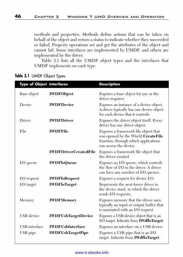
ptg
46 Chapter 3 Windows 7 UMD Overview and Operation
methods and properties. Methods define actions that can be taken onbehalf of the object and return a status to indicate whether they succeededor failed. Property operations set and get the attributes of the object andcannot fail. Some interfaces are implemented by UMDF, and others areimplemented by the driver.
Table 3.1 lists all the UMDF object types and the interfaces thatUMDF implements on each type.
Table 3.1 UMDF Object Types
Type of Object Interfaces Description
Base object IWDFObject Exposes a base object for use as thedriver requires.
Device IWDFDevice Exposes an instance of a device object.A driver typically has one device objectfor each device that it controls.
Driver IWDFDriver Exposes the driver object itself. Everydriver has one driver object.
File IWDFFile Exposes a framework file object thatwas opened by the Win32 CreateFilefunction, through which applicationscan access the device.
IWDFDriverCreatedFile Exposes a framework file object thatthe driver created.
I/O queue IWDFloQueue Exposes an I/O queue, which controlsthe flow of I/O in the driver. A drivercan have any number of I/O queues.
I/O request IWDFloRequest Exposes a request for device I/O.I/O target IWDFloTarget Represents the next-lower driver in
the device stack, to which the driversends I/O requests.
Memory IWDFMemory Exposes memory that the driver uses,typically an input or output buffer thatis associated with an I/O request.
USB device IWDFUsbTargetDevice Exposes a USB device object that is anI/O target. Inherits from IWdfloTarget.
USB interface IWDFUsbInterface Exposes an interface on a USB device.USB pipe IWDFUsbTargetPipe Exposes a USB pipe that is an I/O
target. Inherits from IWdfloTarget.
Wow! eBook <WoweBook.Com>
www.it-ebooks.info
ptg
3.3 Driver Callback Interfaces 47
The driver calls methods on these interfaces to perform operations onits objects. For example, UMDF implements the IWDFloRequestinterface, and the driver calls methods in this interface to retrieve theparameters for the I/O request.
For the driver, devices, and queues, both the framework and the drivermaintain objects. The driver-created objects are callback objects, on whichthe driver implements the callback interfaces that are required to serviceits device. A driver has one callback object, one device callback object foreach device that it supports, and one queue callback object for each queuethat it creates. The callback objects serve as the “context memory” for thedriver.
3.3 Driver Callback Interfaces
The driver implements callback interfaces to provide device-specific responsesto events. Each callback interface is implemented on a specific object type. Forexample, Plug and Play callback interface (IPnpCallback, IPnpCallback-Hardware, and IPnpCallbackSelfManagedIo) are implemented for deviceobjects, and I/O queue callback interfaces (IQueueCallbackCreate,IQueueCallbackRead, and so forth) are implemented on I/O queue objects.
When a Plug and Play, power management, or I/O request arrives,UMDF calls methods in the driver’s callback interfaces to handle the asso-ciated events. For example, when UMDF receives a read request, it callsmethods in the driver’s IQueueCallbackRead interface.
A driver implements callback interfaces only for the events that areimportant to its operation. When the event occurs for an object, the frame-work invokes the callback for that object. For example, the unexpectedremoval of a device is a Plug and Play event. If a device can be removedunexpectedly, its driver should implement the IPnpCallback interface(which includes the OnSurpriseRemoval method) to perform device-specific operations upon ejection. When the Plug and Play manager sendsa surprise-removal notification for the device, UMDF calls theOnSurpriseRemoval method with a pointer to the IWDFDevice inter-face for the device that has been removed.
For most events, a driver can either provide a callback interface orallow UMDF to perform a default action in response. For a few events,however, a driver-specific callback is required. For example, adding a
Wow! eBook <WoweBook.Com>
www.it-ebooks.info

ptg
48 Chapter 3 Windows 7 UMD Overview and Operation
device is an event for which every Plug and Play driver must include a call-back. The driver object’s IDriverEntry::OnDeviceAdd callback createsthe device object.
The names of the driver-implemented callback interfaces are generallyin the form IObjectAction, where Object identifies the object to whichthe interface applies and Action indicates what the interface does. Forexample, the IQueueCallbackRead interface is implemented for I/Oqueues and contains methods called when a queue receives a read request.
Table 3.2 lists the possible callback interfaces a driver might implement.
Table 3.2 Driver Callback Objects and Interfaces
Description
Provides process that isrequired before an object isdeleted, typically releasing anyreferences held on the object.Provides main entry point andmethods to initialize the driverand add its devices.Handles device stop, removal,and power state changes.Provides hardware-relatedoperations before device power-up and after device power-down.Provides driver, rather thanframework, control over I/Ooperations at specific Plug andPlay and power managementstates.Handles clean-up requests forfile objects on a specific device.Handles close requests for fileobjects on a specific device.Handles file create requests.Handles create, device I/Ocontrol, read, and writerequests for which no otherinterface has beenimplemented.
Type of Object
Base object, orany object thatinherits from thebase object typeDriver
Device
I/O queue
Callback Interfaces
IObjectCleanup
IDriverEntry
IPnpCallback
IPnpCallbackHardware
IPnpCallbackSelfManagedIo
IFileCallbackCleanup
IFileCallbackClose
IQueueCallbackCreateIQueueCallbackDefault-IoHandler
Wow! eBook <WoweBook.Com>
www.it-ebooks.info

ptg
3.4 UMDF Driver Features
UMDF drivers can call methods in the framework and can use the Win32API and other Windows user mode features.
Every UMDF driver must do the following:
■ Support the DllGetClassObject export that is required by COM.■ Implement the IClassFactory interface to create a driver object.■ Implement the IDriverEntry interface on the driver class.
UMDF drivers are implemented as in-process COM servers. The COMrun-time environment requires the DLL export DllGetClassObject,which must return an IClassFactory interface so that UMDF can createthe driver callback object.
The IDriverEntry interface includes methods that initialize anduninitialize the driver and perform other required tasks when the device isadded to the system. UMDF calls these methods when the driver is loaded
3.4 UMDF Driver Features 49
Description
Handles device I/O controlrequests.Resumes processing an I/Orequest after its queue hasbeen stopped.Stops processing an I/Orequest because its queue isstopping.Handles read requests.Handles write requests.Provides impersonation forcertain Win32 I/O operations.Handles cancellation of an I/Orequest.Handles completion of an I/Orequest.
Type of Object
I/O request
Callback Interfaces
IQueueCallbackDevice-IoControlIQueueCallbackIoResume
IQueueCallbackIoStop
IQueueCallbackReadIQueueCallbackWriteIImpersonateCallback
IRequestCallbackCancel
IRequestCallbackRequest-Completion
Wow! eBook <WoweBook.Com>
www.it-ebooks.info
ptg
50 Chapter 3 Windows 7 UMD Overview and Operation
or unloaded and when the Plug and Play manager enumerates one of thedriver’s devices. Every UMDF driver must implement the IDriverEntryinterface on the driver class.
3.4.1 ImpersonationUMDF drivers run in the LocalService security context. The LocalServicecontext has minimum security privileges on the local computer and pre-sents anonymous credentials on the network.
When necessary, a UMDF driver can impersonate the client processto handle I/O requests, but not Plug and Play, power, or other systemrequests. At driver installation, the INF file specifies the maximum imper-sonation level that the driver can use.
When an application calls the CreateFile function, it can specify theimpersonation level for the driver. The impersonation level determines theoperations that the driver can perform in the context of the applicationprocess. If the level that the application specifies is different from the min-imum that the INF provides, the reflector uses the lower of the two levels.
A driver requests impersonation by calling the IWDFIoRequest::-Impersonate method with the required impersonation level and apointer to the driver’s IImpersonateCallback interface. TheIImpersonateCallback interface includes one method, OnImpersonation,which should implement the code that must be run during impersonation.To prevent security leaks, OnImpersonation should perform only thetasks that require impersonation and should not call any other frameworkmethods. Properly handling impersonation is key to writing a securedriver.
3.4.2 Device Property StoreThe device property store is an area in the registry where a UMDFdriver can maintain information about the properties of its device. AUMDF driver can create a device property store (or retrieve an existing property store) during initialization by calling the IWDF-DeviceInitialize::RetrieveDevicePropertyStore method. Thismethod returns a pointer to the IWDFNamedPropertyStore inter-face, through which the driver can set and get the values of device properties.
Wow! eBook <WoweBook.Com>
www.it-ebooks.info
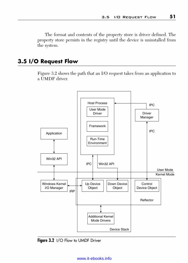
ptg
3.5 I/O Request Flow 51
The format and contents of the property store is driver defined. Theproperty store persists in the registry until the device is uninstalled fromthe system.
3.5 I/O Request Flow
Figure 3.2 shows the path that an I/O request takes from an application toa UMDF driver.
Figure 3.2 I/O Flow to UMDF Driver
Application
Win32 API
Windows KernelI/O Manager
Host Process
User ModeDriver
Framework
Run-TimeEnvironment
DriverManager
Up DeviceObject
Down DeviceObject
ControlDevice Object
Additional KernelMode Drivers
Reflector
IRP
IPC Win32 API
IPC
IPC
User ModeKernel Mode
Device Stack
Wow! eBook <WoweBook.Com>
www.it-ebooks.info

ptg
52 Chapter 3 Windows 7 UMD Overview and Operation
Callers use the Win32 API to send I/O requests to devices that aremanaged by UMDF drivers, just as they do for any other device. TheWin32 API calls the appropriate kernel mode I/O routine, and theWindows kernel I/O manager creates an I/O request packet (IRP) andsends this IRP to the driver at the top of the kernel mode device stack forthe target device. For a device that is managed by a UMDF driver, thereflector is the driver at the top of the kernel mode device stack.
The reflector creates three types of device objects:
■ up device object—This is at the top of the kernel mode stack for thedevice and thus is the reflector’s target for IRPs from the I/O man-ager. When an IRP arrives, the reflector uses interprocess commu-nications to forward it to the User Mode Driver host process, inwhich the framework and driver run. UMDF interprets the requestand calls methods in the driver’s event callback interfaces to handleit. The reflector creates an up device object for each device stack inwhich it participates.
■ down device object—This is the reflector’s target for I/O requests that originate in the User Mode Driver and is thereforethe default I/O target for the bottom driver in the user mode devicestack. A User Mode Driver might issue an I/O request to perform adevice I/O control operation on its own device or to retrieve datafrom another device to complete one of its own requests. Thereflector creates a down device object for each stack in which it participates.
■ control device object—This manages I/O requests to and from thedriver manager, which are not part of the normal I/O flow to thedriver. Instead, the control device object enables “sideband” I/Obetween the reflector and the driver manager, which is indepen-dent of the normal flow of I/O, power management, and Plug andPlay requests. The reflector creates only one control device objectper system.
In addition to creating IRPs to represent user I/O requests, the I/Omanager sends IRPs to notify drivers of Plug and Play requests, powermanagement requests, change to device status, and queries aboutdevice and driver resources (among other purposes). Therefore, theUMDF I/O mode encompasses both I/O request dispatching and Plug
Wow! eBook <WoweBook.Com>
www.it-ebooks.info

ptg
and Play and power notification. The following sections will describethese aspects of the model in more detail.
3.5.1 I/O Request DispatchingUMDF dispatches I/O requests to the driver, manages I/O cancellationand completion, and ensures that the Plug and Play and power state of thedevice is compatible with performing device I/O. Depending on the typeof I/O request, the UMDF either queues the request or invokes a methodin a callback interface.
UMDF provides configurable I/O queue objects that a driver caninstantiate. The driver specifies which types of requests to place in eachqueue and how to dispatch those requests. Each queue can hold one ormore types of requests.
UMDF queues and dispatches requests according to the driver’s spec-ifications: sequentially (one at a time), in parallel (as soon as they arrive),or manually (at the driver’s explicit request). If Plug and Play or powermanagement events affect queuing, a UMDF can start, stop, or resumequeuing as appropriate, depending on how the driver configured thequeue.
The driver provides callback interfaces to handle I/O requests on itsqueues. To dispatch a request, UMDF calls a method in the correspondingcallback interface. For example, to dispatch a read request, UMDF callsthe OnRead method of the driver’s IQueueCallbackRead interface. Thedriver can implement request type-specific interfaces (such as IQueue-CallbackRead); it can also optionally implement the default I/O callbackinterface IQueueCallbackDefaultIoHandler that UMDF calls when itreceives a create, read, write, or device I/O control request for which thedriver has not implemented any other interface.
3.5.2 Create, Cleanup, and Close RequestsUMDF can call the driver to handle create, cleanup, and close requests orcan automatically forward them to the default I/O target (typically, the nextlower driver in the driver stack). The framework queues create requests ifthe driver configures a queue accordingly. It does not queue cleanup orclose requests. Table 3.3 shows the interfaces and methods that a drivermust implement to support, cleanup, and close requests.
3.5 I/O Request Flow 53
Wow! eBook <WoweBook.Com>
www.it-ebooks.info
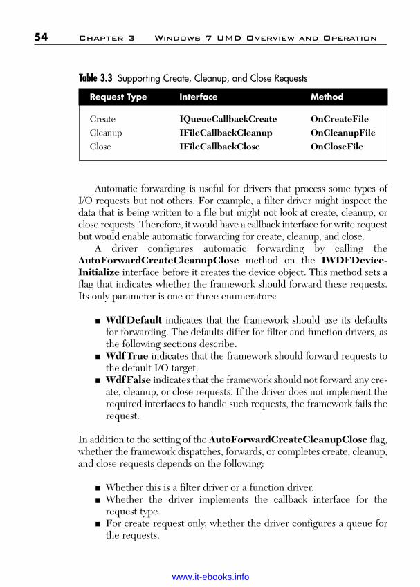
ptg
Automatic forwarding is useful for drivers that process some types of I/O requests but not others. For example, a filter driver might inspect thedata that is being written to a file but might not look at create, cleanup, orclose requests. Therefore, it would have a callback interface for write requestbut would enable automatic forwarding for create, cleanup, and close.
A driver configures automatic forwarding by calling theAutoForwardCreateCleanupClose method on the IWDFDevice-Initialize interface before it creates the device object. This method sets aflag that indicates whether the framework should forward these requests.Its only parameter is one of three enumerators:
■ WdfDefault indicates that the framework should use its defaultsfor forwarding. The defaults differ for filter and function drivers, asthe following sections describe.
■ WdfTrue indicates that the framework should forward requests tothe default I/O target.
■ WdfFalse indicates that the framework should not forward any cre-ate, cleanup, or close requests. If the driver does not implement therequired interfaces to handle such requests, the framework fails therequest.
In addition to the setting of the AutoForwardCreateCleanupClose flag,whether the framework dispatches, forwards, or completes create, cleanup,and close requests depends on the following:
■ Whether this is a filter driver or a function driver.■ Whether the driver implements the callback interface for the
request type.■ For create request only, whether the driver configures a queue for
the requests.
54 Chapter 3 Windows 7 UMD Overview and Operation
Table 3.3 Supporting Create, Cleanup, and Close Requests
Request Type Interface Method
Create IQueueCallbackCreate OnCreateFileCleanup IFileCallbackCleanup OnCleanupFileClose IFileCallbackClose OnCloseFile
Wow! eBook <WoweBook.Com>
www.it-ebooks.info
ptg
The following sections describe what the framework does with suchrequests for each type of driver.
3.5.2.1 Create, Cleanup, and Close in a Filter DriverThe driver calls IWDFDeviceInitialize::AutoForwardCreateCleanup-Close and sets WdfDefault. A UMDF driver identifies itself as a filterdriver by calling the IWDFDeviceInitialize::SetFilter method.
UMDF forwards cleanup and close requests for filter drivers to thedefault I/O target. If a filter driver does not implement theIQueueCallbackCreate::OnCreateFile method, UMDF forwards cre-ate requests, too. However, if the filter driver implements OnCreateFile,UMDF by default calls this method when a create request arrives.OnCreateFile should perform whatever filtering tasks are required andthen, if appropriate, forward the request to the default I/O target.
If the filter driver sets WdfTrue in the call toIWDFDeviceInitialize::AutoForwardCreateCleanupClose, UMDFforwards create requests unless the driver implements OnCreateFile. Ifthe filter driver sets WdfFalse, UMDF calls the corresponding method ifthe driver implements it; otherwise, UMDF fails the request.
If the filter driver completes a create request for a file object, itshould set AutoForwardCreateCleanupClose to WdfFalse so thatUMDF completes cleanup and close requests for the file object instead offorwarding them.
3.5.2.2 Create, Cleanup, and Close in a Function DriverIn a function driver, if a create request arrives for which the driver has nei-ther implemented the OnCreateFile method nor configured a queue toreceive create request, UMDF opens a file object to represent the deviceand completes the request with S_OK. Therefore, any function driver thatdoes not accept create or open requests from user mode applications—andthus does not register a device interface—must implement anIQueueCallbackCreate::OnCreateFile method that explicitly failssuch requests. Supplying a method to fail create requests ensures that arogue application cannot gain access to the device.
To handle file cleanup and close requests, a driver implements theIFileCallbackCleanup and IFileCallbackClose interfaces. If a functiondriver does not implement such interfaces, UMDF closes the file objectand completes the request with S_OK.
3.5 I/O Request Flow 55
Wow! eBook <WoweBook.Com>
www.it-ebooks.info

ptg
3.5.3 Create, Read, Write, and Device I/O ControlRequests
For read, write, and device I/O control requests, the driver creates one ormore queues and configures each queue to receive one or more types ofI/O requests. For create requests, the driver can configure automatic for-warding, as described in the preceding section, or can direct the requeststo a queue.
When such a request arrives, the I/O request handler:
■ Determines whether the driver has created a queue that handlesthis type of request (either by explicitly configuring the queue forthe request type or by creating a default I/O queue) or has imple-mented a default I/O handler. If neither is true, the handler fails aread, write, or device I/O control request if this is a function driver.If this is a filter driver, the handler forwards the request to thedefault I/O target.
■ Determines whether the queue is accepting requests and the deviceis powered on (in the DO state). If both are true, the handler cre-ates an I/O request object to represent the request and adds it to thequeue. If the queue is not accepting requests, the handler fails therequest.
■ Notifies the Plug and Play handler to power up the device if thequeue is power managed and the device is not in the DO state.
■ Queues the request.
Figure 3.3 summarizes the flow of a create, read, write, or device I/O con-trol request through the framework to the driver.
3.6 I/O Queues
The IWDFIoQueue interface exposes a queue object that presentsrequests from UMDF to the driver. Queues control the flow of I/Othrough the driver.
56 Chapter 3 Windows 7 UMD Overview and Operation
Wow! eBook <WoweBook.Com>
www.it-ebooks.info

ptg
3.6 I/O Queues 57
Figure 3.3 Flow of Create, Read, Write, and Device I/O Control Requests
Doesdriver have a
queue forthis type?
Is the queueaccepting requests?
Create an I/Orequest object to
represent therequest
Is the queue power
managed?
Is the devicein the working
state?
Notify the Plug andPlay/power
handler to powerup the device
Queue therequest
Is this a filter driver?
YESNO
NO YES
NO YES
NO YES
NO YES
Pass the requestto the default I/O
target
Fail the request
Wow! eBook <WoweBook.Com>
www.it-ebooks.info

ptg
A driver typically creates one or more I/O queues, each of which canaccept one or more types of requests. The driver configures the queueswhen it creates them. For each queue, the driver can specify:
■ The types of requests that are placed in the queue.■ The power management options for the queue.■ The dispatch method for the queue, which determines whether the
framework calls the driver to dispatch a request or whether thedriver calls the framework to dispatch a request. The dispatchmethod also determines whether the driver services multiplerequests from the queue at a given time.
■ Whether the queue accepts read and write requests that have azero-length buffer.
A driver can have any number of queues, which can all be configured dif-ferently. For example, a driver might have a parallel queue for read requestsand a sequential queue for write requests.
Although a request is in a queue and has not yet been presented to thedriver, the queue is considered the “owner” of the request. After the requesthas been dispatched to the driver, it is “owned” by the driver. Internally, eachqueue object keeps track of which requests it owns and which requests it hasdispatched to the driver. A driver can forward a request from one queue toanother by calling a method on the request object.
3.6.1 Dispatch TypeA queue’s dispatch type determines how and when I/O requests are deliv-ered to the driver and, as a result, whether multiple I/O requests from aqueue are active in the driver at one time. Drivers can control the concur-rency of I/O requests by configuring the dispatching method for theirqueues. UMDF supports three dispatch types:
■ Sequential—A queue that is configured for sequential dispatchingdelivers I/O requests to the driver one at a time. The queue does notdeliver another request to the driver until the previous request hasbeen completed or forwarded to another queue.
■ Parallel—A queue that is configured for parallel dispatching deliv-ers I/O requests to the driver as soon as possible, whether or notanother request is already active in the driver.
58 Chapter 3 Windows 7 UMD Overview and Operation
Wow! eBook <WoweBook.Com>
www.it-ebooks.info
ptg
■ Manual—A queue that is configured for manual dispatching doesnot deliver I/O requests to the driver. Instead, the driver retrievesrequests at its own pace by calling a method on the queue.
The dispatch type controls only the number of requests that are activewithin a driver at one time. It has no effect on whether the queue’s I/Oevent callbacks are invoked sequentially or concurrently; instead, the con-currency of callbacks is controlled by the synchronization model (lockingconstraint) of the device object. Even if the synchronization model doesnot allow concurrent callbacks, a parallel queue nevertheless might havemany requests active in the driver at one time.
All I/O requests that a driver receives from a queue are inherentlyasynchronous. The driver can complete the request within the event call-back or sometime later, after returning from the callback. The driver is notrequired to mark the request pending, as in a Kernel Mode WDM Driver;UMDF handles this on behalf of the driver.
3.6.2 Queues and Power ManagementUMDF integrates support for queues with Plug and Play/power manage-ment state machine. Power management is configurable on a per-queuebasis. A driver can use both power-managed and nonpower-managed queuesand can sort requests based on the requirements for its power model.
3.6.2.1 Power-Managed QueuesBy default, I/O queues are power managed, which means that the state ofthe queue can trigger power-management activities. Such queues have acouple of advantages, as the following scenarios show:
■ If an I/O request arrives while the system is in the working state(SO) but the device is not, UMDF notifies its Plug and Play andpower handler so that it can restore device power.
■ If the device power state begins to change while the driver “owns”an I/O request that was dispatched from a power-managed queue,UMDF can notify the driver through the IQueueCallback-IoStop::OnIoStop callback. The driver must complete, cancel, oracknowledge all of the I/O requests that it owns before the devicecan exit from the working state.
3.6 I/O Queues 59
Wow! eBook <WoweBook.Com>
www.it-ebooks.info
ptg
For power-managed queues, UMDF pauses the delivery of requests whenthe device leaves the working state (DO) and resumes delivery when thedevice returns to the working state. Although delivery stops while the queueis paused, queuing does not. If UMDF receives a request while the queue ispaused, UMDF adds the request to the queue for delivery after the queueresumes. If an I/O request arrives while the system is transitioning to a sleepstate, however, UMDF does not return the device to the working state untilthe system returns to the working state. The request remains in the queueuntil the system and the device have returned to the working state.
For requests to be delivered, both the driver and device power statemust allow processing. The driver can pause delivery manually by callingIWDFIoQueue::Stop or IWDFIoQueue::StopSynchronously andlater resume delivery by calling WdfIoQueue::Start.
3.6.2.2 Nonpower-Managed QueuesIf a queue is not power managed, the state of the queue has no effect onpower management, and conversely, UMDF delivers requests to the driverany time the system is in the working state, regardless of the power stateof the device. Drivers should use nonpower-managed queues to holdrequests that the driver can handle even while its device is not in the work-ing state.
3.7 I/O Request Objects
The IWDFIoRequest interface exposes an I/O request object, whichdescribes a read, write, or device I/O control request. When an I/O requestarrives from the reflector, the I/O handler creates an I/O request object andadds the object to the queue that the driver configured for requests of that type.The driver receives a pointer to IWDFIoRequest interface for the objectwhen UMDF calls the I/O event callback function or, if the queue supportsmanual dispatching, when the driver requests the object from the queue.
The driver can then call methods on the interface to retrieve informa-tion about the request, such as the request type, parameters, data buffers,and associated file object, among others.
Like all other UMDF objects, the I/O request object has a referencecount. When the driver completes the I/O request that the object repre-sents, UMDF automatically drops its reference on the object and any child
60 Chapter 3 Windows 7 UMD Overview and Operation
Wow! eBook <WoweBook.Com>
www.it-ebooks.info

ptg
objects such as memory buffers. After the driver that was called completesthe request, it must not attempt to access the request object or any of itschild objects.
3.7.1 Retrieving Buffers from I/O RequestsThe IWDFMemory interface exposes a memory object, which encapsu-lates an I/O buffer that is associated with an I/O request. The memoryobject can be used to copy data from the driver to the buffer and viceversa. The driver can also create its own memory object by callingIWDFDriver::CreatePreallocatedWdfMemory and can then associatethat memory object with the buffer that is supplied in an I/O request.
Like other UMDF objects, memory objects have reference counts andpersist until all references to them have been removed. The buffer thatunderlies the memory object, however, might not be “owned” by the objectitself. For example, if the issuer of the I/O request allocated the buffer orif the driver called CreatePreallocatedWdfMemory to assign an existingdriver-created buffer to the object, the memory object does not “own thebuffer.” In this case, the buffer pointer becomes invalid when the associ-ated I/O request has been completed, even if the memory object still exists.
Each memory object contains the length of the buffer that it repre-sents. IWDFMemory methods that copy data to and from the buffer val-idate the length of every transfer to prevent buffer over runs and underruns, which can result in corrupt data or security breaches.
Each memory object also controls access to the buffer and allows thedriver to write only buffers that support I/O from the device to the buffer.A buffer that is used to receive data from the device (as in a read request)is writable. The memory object does not allow write access to a buffer thatonly supplies data (as in a write request).
3.7.2 Sending I/O Requests to an I/O TargetIf a driver cannot satisfy an I/O request by itself, it typically forwards therequest to an I/O target. An I/O target represents a device object to whichthe driver sends an I/O request. The default I/O target is typically the next lower driver in the device stack. A UMDF driver can access thedefault I/O target through the IWDFIoTarget interface; it gets a pointerto this interface by calling the IWDFDevice::GetDefaultIoTargetmethod.
3.7 I/O Request Objects 61
Wow! eBook <WoweBook.Com>
www.it-ebooks.info
ptg
In addition to forwarding existing I/O requests, some UMDF driversissue I/O requests by creating or reusing an I/O request object and send-ing the request to an I/O target. Drivers can send requests either synchro-nously or asynchronously and can specify a time-out value for either typeof request. If the time-out period expires, UMDF cancels the request.
In addition to using the default I/O target, a driver can create addi-tional I/O targets. An I/O target can be a UMDF driver, a KMDF driver, aWDM driver, or any other Kernel Mode Driver. UMDF defines two inter-faces that create targets:
■ IWDFFileHandleTargetFactory creates an I/O target that isassociated with a file handle that the driver has already opened. Thedriver calls the Win32 CreateFile function to open the handle, andthen calls methods in this interface to create the I/O target. Thismechanism enables a driver to send I/O requests to a differentdevice stack.
■ IWDFUsbTargetFactory creates a USB device object and anassociated I/O target.
To create an I/O target, the driver queries the device object for theIWDFFileHandleTargetFactory or IWDFUsbTargetFactory inter-face and then calls the creation method that is supported by the interface.
If the driver is the originator of the request, it creates an I/O requestobject by calling IWDFDevice::CreateRequest. If the driver is merelyforwarding an existing request, this step is not required.
Whether this is a new or existing request, the driver must format itbefore sending it. To format a request for the default I/O target or for a filehandle-based target, the driver calls methods in the IWDFIoTarget inter-face. To format an I/O request for a USB target, the driver calls methodsin the IWDFUsbTargetDevice, which inherits from IWDFIoTarget.Formatting the request is important because it specifies the buffers andbuffer lengths that the target should use in performing the I/O.
The driver then can call IWDFIoRequest::Send to send the request.If the driver implements the IRequestCallbackCompletion::-OnCompletion and IRequestCallbackCancel::OnCancel interfaces,UMDF calls the driver if the request is completed or canceled.
The I/O target object racks queued and sent requests and can cancelthem when the state of the target device of the issuing driver changes.UMDF does not free the I/O target object until all of the I/O requests that
62 Chapter 3 Windows 7 UMD Overview and Operation
Wow! eBook <WoweBook.Com>
www.it-ebooks.info

ptg
have been sent to it are complete. If the driver created the I/O request, itmust release its reference to the request before deleting it.
By default, UMDF sends a request only when the target is in theproper state to receive it. However, a driver can request that UMDFignore the state of the target and send the request anyway. If the targetdevice has been stopped (but not removed), UMDF queues the request tosend later after the target device resumes. If the driver that forwarded therequest specifies a time-out value, the timer starts when the request isadded to the queue.
To manage an I/O target, the driver can call methods in theIWDFIoTargetStateManagement interface. These methods enable thedriver to start, stop, and remove the target and to query its current state.
3.7.3 Creating Buffers for I/O RequestsDrivers that issue I/O requests must supply buffers with those requests. Adriver can
■ Allocate the buffer from memory by using the C++ new operator ora Win32 memory allocation function and the call IWdfDriver::-CreatePreallocatedWdfMemory to associate the buffer with amemory object. The driver must ensure that the buffer persists untilthe request has completed.
■ Call IWdfDriver::CreateWdfMemory to create a memory objectwith a specified buffer size. UMDF ensures that the buffer persistsuntil the I/O request has completed back to the issuing driver.
■ Retrieve a memory object from an incoming I/O request for use ina new request.
If the driver uses a memory object, UMDF takes out a reference on thatobject on behalf of the new I/O target when it formats the memory objectto send to the I/O target. This reference persists until one of the followingoccurs:
■ The request has been completed.■ The driver reformats the request object by calling IWDFRequest::-
FormatUsingCurrentType or any of the IWDFIoTarget::Format-RequestForXxx methods.
■ The request has been deleted.
3.7 I/O Request Objects 63
Wow! eBook <WoweBook.Com>
www.it-ebooks.info

ptg
The driver can retrieve a memory object from an incoming I/O request andthen reformat it for use in a new request to a new I/O target. However, ifthe driver has not yet completed the original request, the driver still has areference on the memory object. The driver should implement an I/Ocompletion callback (the IRequestCallbackRequestCompletion inter-face) for the new I/O request, and in this callback must call Release on thememory object before it completes the original request.
3.7.4 Canceled and Suspended RequestsWindows I/O is inherently asynchronous. The system can request that adriver stop processing an I/O request at any time for many reasons, mostcommonly:
■ The thread or process that issued the request cancels it or exits.■ A system Plug and Play or power event such as hibernation occurs.■ The device is being, or has been, removed.
The action that a driver takes to stop processing an I/O request depends onthe reason for suspension or cancellation. In general, the driver can eithercancel the request or complete it with an error. In some situations, the sys-tem might request that a driver suspend (temporarily pause) processing;the system notifies the driver later when to resume processing.
To provide a good user experience, drivers should provide callbacks tohandle cancellation and suspension of any I/O request that might take along time to complete or that might not complete, such as a request forasynchronous input.
3.7.4.1 Request CancellationHow UMDF proceeds to cancel an I/O request depends on whether therequest has already been delivered to the target driver:
■ If the request has never been delivered—either because UMDFhas not yet queued it or because it is still in a queue—UMDFcancels or suspends it automatically without notifying the driver.
■ If the request has been delivered but the driver forwards it to a dif-ferent queue, UMDF automatically cancels the request withoutnotifying the driver.
64 Chapter 3 Windows 7 UMD Overview and Operation
Wow! eBook <WoweBook.Com>
www.it-ebooks.info
ptg
■ If the request has been delivered and is owned by the driver,UMDF does not cancel it. However, if the driver explicitly marksthe request cancelable by calling the IWDFIoRequest::-MarkCancelable method and registering a cancellation callback(IRequestCallbackCancel::OnCancel), UMDF notifies thedriver that the request was canceled.
A driver should mark a request cancelable and register an I/O cancellationcallback if either of the following is true:
■ The request involves a long-term operation.■ The request might never succeed; for example, the request is wait-
ing for synchronous input.
In the OnCancel callback, the driver must perform any tasks that arerequired to cancel the request, such as stopping any device I/O operationsthat are in progress and canceling any related requests that it has alreadyforwarded to an I/O target. Eventually, the driver must complete therequest with the status ERROR_CANCELLED.
Requests that the driver has marked cancelable cannot be forwardedto another queue. Before requeuing a request, the driver must first makeit noncancelable by calling IWDFIoRequest::UnmarkCancelable.After the request has been added to the new queue, UMDF again consid-ers it cancelable until that queue dispatches it to the driver.
3.7.4.2 Request SuspensionWhen the system transitions to a sleep state—typically because the userhas requested hibernation or closed the lid on a laptop—a driver can com-plete, requeue, or continue to hold any requests that it is currently pro-cessing. UMDF notifies the driver of the impending power change bycalling the IQueueCallbackIoStop::OnIoStop callback for each suchrequest. Each call includes flags that indicate the reason for stopping thequeue and whether the I/O request is currently cancelable.
Depending on the value of the flags, the driver can complete therequest, requeue the request, acknowledge the event but continue to holdthe request, or ignore the event if the current request will complete in atimely manner. If the queue is stopping because the device is beingremoved, either by an orderly removal or a surprise removal, the devicemust complete the request immediately.
3.7 I/O Request Objects 65
Wow! eBook <WoweBook.Com>
www.it-ebooks.info
ptg
Drivers should implement the OnIoStop method for any request thatmight take a long time to complete or that might not complete, such as arequest for asynchronous input. OnIoStop provides a good user experi-ence for laptops and other power-managed systems.
3.7.5 Completing I/O RequestsTo complete an I/O request, a driver calls IWDFIoRequest::Completeor CompleteWithInformation. In response, UMDF completes theunderlying I/O request from the system and then deletes the I/Orequest object and any child objects. If the driver implements theIObjectCleanup::OnCleanup method for the request object, UMDFinvokes that method before completing the underlying system I/Orequest, so that the system I/O request itself is still valid when the call-back runs. Because the underlying request is still valid, the UMDFdriver has access to its parameters and memory buffers.
After Complete or CompleteWithInformation returns, the I/Orequest object and its resources have been released. The driver must notattempt to access the object or any of its resources, such as parameters andmemory buffers that were passed in the request.
If the request was dispatched from a sequential queue, the driver’s callto complete the request might cause UMDF to deliver the next request inthe queue. (If the queue is configured for parallel dispatching, UMDF candeliver another request at any time.) If the driver holds any locks while itcalls Complete or CompleteWithInformation, it must ensure that itsevent callback methods for the queue do not use the same locks because adeadlock might occur. In practice, this is difficult to ensure, so the bestpractice is not to call Complete or CompleteWithInformation whileholding a lock.
3.7.6 Adaptive Time-outsDrivers for Windows 7 should follow the Windows guidelines for I/O com-pletion and cancellation, which require that drivers:
■ Support cancellation for I/O requests that might take an indefiniteperiod of time to complete.
66 Chapter 3 Windows 7 UMD Overview and Operation
Wow! eBook <WoweBook.Com>
www.it-ebooks.info

ptg
■ Complete I/O requests within a reasonable period (generally, 10 seconds or less) after cancellation.
■ Do not block I/O thread for an unreasonable period while perform-ing I/O. UMDF I/O threads are a limited resource, so blocking onsuch a thread for a long time can decrease driver performance.
To aid User Mode Drivers in conforming to these guidelines, UMDFsupports adaptive time-outs. UMDF tracks the progress on criticalI/O operations that can hold up the system if delayed. Critical opera-tions include cleanup, close, cancellation, and Plug and Play andpower requests.
When the reflector passes a critical request to the driver host process,it watches for progress to ensure that I/O operations are proceeding. Whilesuch a request is pending, the User Mode Driver must complete an oper-ation at regular intervals until it has completed the critical request. If thetime-out period expires, the reflector terminates the host process andreports the problem through Window Error Reporting (WER). By default,the time-out is currently one minute. If the driver must perform opera-tions that take a long time to complete, it should handle them asynchro-nously, create a separate thread to handle them, or handle them in a userwork item.
3.8 Self-Managed I/O
Some drivers have I/O paths that do not go through queues or are not sub-ject to power management. UMDF provides self-managed I/O features tosupport these requirements.
The self-managed I/O callbacks correspond directly to Plug and Playand power management state changes, and the automatic queuing featurein UMDF is built around the same mechanism. These routines are calledwith a pointer to the IWDFDevice interface and no other parameters. Ifa driver implements the IPnpCallbackSelfManagedIo interface,UMDF calls its methods at the designated times so that the driver can per-form whatever actions it requires.
Table 3.4 lists the methods of this interface and indicates when each is called.
3.8 Self-Managed I/O 67
Wow! eBook <WoweBook.Com>
www.it-ebooks.info

ptg
68 Chapter 3 Windows 7 UMD Overview and Operation
3.9 Synchronization Issues
Because Windows is a preemptive, multitasking operating sys-tem, multiple threads can try to access shared data structures orresources concurrently and multiple driver routines can runconcurrently. To ensure data integrity, all drivers must synchro-nize access to shared data structures.
Table 3.4 Self-Managed I/O Methods
Method When Called
OnSelfManagedIoCleanup During device removal, after callingOnSelfManagedIoSuspend
OnSelfManagedIoFlush After device removal has completed.OnSelfManagedIoInit During device start-up, after the
framework has called the driver’sIPnpCallback::OnDoEntry callbackfunction for the first time.
OnSelfManagedIoRestart When the device returns from a low-power state to its working (DO) state;called only if UMDF previously called the driver’s OnSelfManagedIo-Suspend method.
OnSelfManagedIoStop Not currently called.OnSelfManagedIoSuspend When one of the following is true:
■ The device is about to enter alow-power state.
■ The device is being removed orwas surprise-removed.
■ The Plug and Play manager ispreparing to redistribute the sys-tem’s hardware resources amongsystem’s attached devices.
Wow! eBook <WoweBook.Com>
www.it-ebooks.info
ptg
For UMDF drivers, ensuring proper synchronization requires attention toseveral areas:
■ The number of concurrently active requests that are dispatchedfrom a particular queue.
■ The number of concurrently active callbacks for a particular deviceobject.
■ The driver utility functions that access object-specific data.
The dispatch method for an I/O queue controls the number of requests fromthe queue that can concurrently be active in the driver, as described in“Dispatch Type” earlier. Limiting concurrent requests does not, however,resolve all potential synchronization issues. Concurrently active callbacks onthe same object might require access to shared object-specific data. Similarly,driver utility functions might share object-specific data with callbacks. Forexample, a driver’s cleanup and cancellation methods often use the same dataas its dispatch (read, write, and device I/O control) callbacks.
UMDF provides configurable concurrency control, called the syn-chronization model or locking constraint, for the callbacks of severaltypes of objects. An object’s synchronization model determineswhether UMDF invokes certain event callbacks on the object concurrently.
UMDF defines two synchronization models that is device scope andno scope.
Device Scope means that UMDF does not call certain I/O event call-backs concurrently for an individual device object or any file objects orqueues that are children of the device object. Specifically, device scopeapplies to the following event callbacks:
IFileCallbackCleanup::OnCleanupFileIFileCallbackClose::OnCloseFileIQueueCallbackCreate::OnCreateFileIQueueCallbackDefaultIoHandler::OnDefaultIoHandlerIQueueCallbackDeviceIoControl::OnDeviceIoControlIQueueCallbackIoResume::OnIoResumeIQueueCallbackIoStop::OnIoStopIQueueCallbackRead::OnReadIQueueCallbackStateChange::OnStateChangeIQueueCallbackWrite::OnWriteIRequestCallbackCancel::OnCancel
3.9 Synchronization Issues 69
Wow! eBook <WoweBook.Com>
www.it-ebooks.info
ptg
However, callbacks for different device objects that were created bythe same driver can be called concurrently. By default, a UMDF usesdevice scope.
No Scope means that UMDF can call any event callback concurrentlywith any other event callback. The driver must create and acquire all itsown locks.
A driver sets the synchronization mode by calling the SetLockingConstraint method of the IWDFDeviceInitialize interface before itcreates the device object.
3.10 Locks
In addition to the synchronization for the configurable synchronizationmodel, UMDF provides a lock for each device and I/O queue object. Adriver can acquire and release this lock by using the IWDFObject::-AcquireLock and IWDFObject::ReleaseLock methods. These methodsare supported for IWDFDevice and IWDFIoQueue, which inherit fromIWDFObject.
Driver code that runs outside an event callback sometimes must syn-chronize with code that runs inside an event callback. After acquiring thelock, the driver can safely access the object and perform other actions thataffect the object. However, to prevent a deadlock, the driver must releasethe lock before calling any methods in the framework, such asIWDFRequest::CompleteWithInformation.
3.11 Plug and Play and Power ManagementNotification
UMDF implements integrated Plug and Play and power management sup-port as an internal state machine. An event is associated with the transitionto each state, and a driver can supply callbacks that are invoked at specificstate changes.
UMDF is designed to work with drivers on an “opt-in” basis. A UMDFdriver implements Plug and Play callback interfaces for only the eventsthat affect its device. For example, some devices require interventionimmediately after they are turned on and immediately before they areturned off. The driver for such a device can implement the
70 Chapter 3 Windows 7 UMD Overview and Operation
Wow! eBook <WoweBook.Com>
www.it-ebooks.info

ptg
IPnpCallbackHardware interface, which provides methods to be calledat those times. If the device does not require such intervention, its driverdoes not implement the interface.
If you are familiar with WDM driver, you probably remember that anytime the system power state changes, the WDM driver must determine thecorrect power state for its device and then issue power managementrequests to put the device in that state at the appropriate time. The UMDFstate machine automatically handles the translation of system power eventsto device power events and notifies the driver to
■ Transition the device to low power when the system hibernates orgoes to sleep.
■ Return the device to full power when the system resumes.
UMDF automatically provides for the correct behavior in deviceparent/child relationships. If both a parent and a child device are powereddown and the child must power up, UMDF automatically returns the par-ent to full power and then powers up the child.
To accomplish these power transitions, a driver implements theIPnpCallback and IPnpCallbackHardware interfaces. The meth-ods in these two interfaces are called in a defined order and each con-forms to a “contract” so that both the device and the system areguaranteed to be in a particular state when the driver is called to per-form an action.
In addition, requests that the framework has received and not yetdelivered to the device driver can affect the power state of the device. Ifthe driver has configured a queue for power management, the frameworkcan automatically restore device power before it delivers the request to thedriver. It can also automatically stop and start the queue in response toPlug and Play and power events.
3.12 Device Enumeration and Startup
To prepare the device for operation, UMDF calls the driver’s callback rou-tines in a fixed sequence.
The following shows the callbacks for a driver that is involved in bring-ing a device to the fully operations state, starting from the DeviceArrivedstate at the bottom of the following steps.
3.12 Device Enumeration and Startup 71
Wow! eBook <WoweBook.Com>
www.it-ebooks.info
ptg
72 Chapter 3 Windows 7 UMD Overview and Operation
Device OperationalEnd Sequence
1. Enable self-managed I/O, if driver supports it.IPnpCallbackSelfManagedIo::OnSelfManageIoInit orOnSelfManagedIoRestart
2. Start power-managed queues.(Called only if UMDF earlier invokedIQueueCallbackIoStop::OnIoStop during power-down.)IQueueCallbackIoResume::OnIoResume
3. Notify driver of state change.IPnpCallback::OnDOEntry
Restart from here if device is in low-power state
4. Prepare hardware for power.IPnpCallbackHardware::OnPrepareHardware
Restart from here if rebalancing resources
5. Create device object.IDRiverEntry::OnDeviceAdd
Device ArrivedStart Sequence Above
At the bottom of the preceding steps, the device is not present on thesystem. When the user plugs it in, UMDF begins by calling the driver’sIDRiverEntry::OnDeviceAdd callback so the driver can create a deviceobject to represent the device. UMDF continues calling the driver’s callbackroutines by progressing up through the sequences above until the device isoperational. If the device was stopped because the PnP manger was rebal-ancing system resources or if the device was physically present but not in theworking state, not all of the steps are required, as the sequence shows.
3.13 Device Power-Down and Removal
UMDF might remove a device from the operational state for several reasons:
■ To put the device in a low-power state because the system is enteringa sleep state
Wow! eBook <WoweBook.Com>
www.it-ebooks.info

ptg
■ To rebalance resources■ To remove the device after the user has requested an orderly
removal■ To disable the device in response to the user’s request in Device
Manager
The following shows the sequence of callbacks that are involved in power-down and removal. The sequence starts at the top of the sequence belowwith an operational device that is in the working power state (DO).
3.13 Device Power-Down and Removal 73
Device OperationalStart Sequence
1. Suspend self-managed I/O.IPnpCallbackSelfManagedIo::OnSelfManagedIoSuspend
2. Stop power-managed queues.IQueueCallbackIoStop::OnIoStop
3. Notify driver of state change.IPnpCallback::OnDoExit
Stop here if transitioning to low-power state
4. Release hardware (Not called if target device state isWdfPowerDeviceD3Final).IPnpCallbackHardware::OnReleaseHardware
Stop here if rebalancing resources
5. Purge power-managed queues.IQueueCallbackIoStop::OnIoStop
6. Flush I/O buffers, if driver supports self-managed I/O.IPnpCallbackSelfManagedIo::OnSelfManagedIoFlush
7. Purge nonpower-managed queues.IQueueCallbackIoStop::OnIoStop
8. Clean up I/O buffers, if driver supports self-managed I/O.IPnpCallbackSelfManagedIo::OnSelfManagedIoCleanup
Device RemovedEnd Sequence
Wow! eBook <WoweBook.Com>
www.it-ebooks.info

ptg
As the preceding sequence shows, the UMDF power-down andremoval sequence involves calling the corresponding “undo” callbacks inthe reverse order from which UMDF called the methods that it invoked tomake the device operational.
3.13.1 Surprise-Removal SequenceIf the user removes the device without warning, by simply unplugging itwithout using Device Manager or the Safely Remove Hardware utility, thedevice is considered surprise removed. When this occurs, UMDF followsa slightly different removal sequence. It also follows the surprise-removalsequence if another driver invalidates the device state (for example, aKernel Mode Driver calls IoInvalidateDeviceState), even if the deviceis physically present.
In the surprise-removal sequence, UMDF calls the IPnpCallback::-OnSurpriseRemoval callback to notify the driver that the device hasbeen unexpectedly removed. This callback is not guaranteed to occur inany particular order with the other callbacks in the removal sequence.
Drivers for all removable devices must ensure that the callbacks inboth the shutdown and startup paths can handle failure, particularly fail-ures that are caused by the removal of the hardware. The reflector timesout the driver if an attempt to access the hardware waits indefinitely.
The following sequence shows the surprise-removal sequence.
74 Chapter 3 Windows 7 UMD Overview and Operation
Device Surprise RemovedStart here if device is in the working state
1. Suspend self-managed I/O.IPnpCallbackSelfManagedIo::OnSelfManagedIoSuspend
2. Stop power-managed queues.IQueueCallbackIoStop::OnIoStop
3. Notify driver of state change.IPnpCallback::OnDOExit
Start here if device is not in the working state
4. Release hardware.IPnpCallbackHardware::OnReleaseHardware
5. Purge power-managed queues.IQueueCallbackIoStop::OnIoStop
Wow! eBook <WoweBook.Com>
www.it-ebooks.info
ptg
If the device was not in the working state when it was removed, UMDFstarts with the IPnpCallbackHardware::OnReleaseHardware method.It omits the intervening steps, which were already performed when thedevice exited from the working state.
3.14 Build, Test, and Debug
Like Kernel Mode Drivers, UMDF drivers are built with the WindowsDriver Kit (WDK). The WDK includes the required libraries and headerfiles to build a UMDF driver, along with sample code and build scripts.
The WDK includes a library of debugger extensions for use withUMDF drivers. The debugger extensions work with CDB, NTSD, andWinDbg. UMDF drivers can be debugged in either user mode or kernelmode. Debugging a User Mode Driver is similar to debugging a service.Symbol files are also included as an aid in debugging.
UMDF drivers can use Event Tracing for Windows (ETW) to gener-ate a trace log of driver events. The logs can be viewed using the tracingtools provided with the WDK.
The user mode components that Microsoft supplies start trace sessionsthat record their activities and note such events as driver hangs, time-outs,and failures. UMDF has integrated verification code that is alwaysenabled. If a driver uses UMDF DDIs incorrectly or passes incorrectparameters, the verifier saves a memory dump in the system log file direc-tory and optionally creates a Windows error report. The trace log files anderror reports can optionally be sent to the Microsoft Windows ErrorReporting (WER) facility. WER captures software crash data and supports
3.14 Build, Test, and Debug 75
6. Flush I/O buffers, if driver supports self-managed I/O.IPnpCallbackSelfManagedIo::OnSelfManagedIoFlush
7. Purge nonpower-managed queues.IQueueCallbackIoStop::OnIoStop
8. Clean up I/O buffers, if driver supports self-managed I/O.IPnpCallbackSelfManagedIo::OnSelfManagedIoCleanup
Removal Processing Complete
Wow! eBook <WoweBook.Com>
www.it-ebooks.info

ptg
end-user reporting of crash information. The information collectedthrough WER is accessible to vendors so that they can analyze problemsand respond directly to their customers.
You can also use PREfast, a static analysis tool that is part of the WDK,with UMDF drivers. PREfast examines code paths on a per-function basisand can find logic and usage errors in a driver at compile time.
3.14.1 Installation and ConfigurationUMDF drivers are installed by using standard INF files, in the same wayas Kernel Mode Drivers. A hardware vendor’s installation package thusincludes
■ An INF file for the driver■ The redistributable update co-installer WUDF_Update_MMmmm.dll
(where MM is the major UMDF version number and mmm is theminor version number)
■ A driver binary■ An optional custom installation application
The INF file includes a [DDInstall.CoInstallers] section that referencesthe co-installer. The co-installer is available to hardware vendors in theWDK and in general distribution releases (GDRs). Microsoft provides theredistributable co-installer Wudf_Update_MMmmm.dll, which vendorscan ship as part of their driver packages. The co-installer is a signed com-ponent. Driver installation fails if the certificate with the co-installer wassigned and is not available on the target system.
The Wdf section of the driver’s INF file specifies the driver servicename, the driver class ID, the order in which the UMDF drivers should beinstalled in the device stack, and the maximum impersonation level thatthe UMDF driver can use.
The DestinationDirs section of the INF file specifies the location towhich to copy the driver. All UMDF drivers must reside in%SystemRoot%\system32\drivers\UMDF. This directory has sufficientACLs to ensure that an unprivileged user cannot tamper with the drivers.
If the UMDF device stack for the driver contains only filter drivers,the INF installs the reflector as the top-level filter driver in the KernelMode Driver stack. However, if the function driver for the device is aUMDF driver, the INF installs the reflector as the service for the device.
76 Chapter 3 Windows 7 UMD Overview and Operation
Wow! eBook <WoweBook.Com>
www.it-ebooks.info

ptg
When the INF for the device is processed, the co-installer starts thedriver manager if it is not already running. User Mode Driver installationmust not require a reboot of the system.
3.14.2 Versioning and UpdatesUMDF supports versioning, which enables a driver binary to run with thesame major version of UMDF independent of the operating system version.Versioning helps to ensure that a driver uses the components with which itwas designed, tested, and released. Each version of the operating systemsupports all versions of UMDF. Updates to UMDF or the operating systemdo not require updates to the driver. Microsoft is responsible for ensuringconsistent behavior across releases.
Although two major versions of UMDF can run side by side simulta-neously, two minor versions of the same major version cannot. At installa-tion, a more recent minor version of the UMDF run-time library or othercomponents overwrites an existing, older minor version. If the older ver-sion is already loaded when a user attempts to install a driver with a newerversion, the user must reboot the system.
3.14 Build, Test, and Debug 77
Wow! eBook <WoweBook.Com>
www.it-ebooks.info

ptg
This page intentionally left blank
Wow! eBook <WoweBook.Com>
www.it-ebooks.info
ptg
79
C H A P T E R 4
PROGRAMMING DRIVERSFOR THE USER MODE DRIVERFRAMEWORK
In this chapter, we will cover the overview of the User Mode DriverFramework (UMDF) as well as how to create a UMDF Driver. We willintroduce COM and how it is used in conjunction with creating a UMDFDriver. As was discussed in Chapter 3, UMDF Drivers create callbackobjects to represent the driver itself, each of its devices, and each of its I/Oqueues. The framework defines a set of interfaces, some of which thedriver must implement for the callback objects that it creates and othersthe framework itself implements for the objects that the frameworkcreates. In general, the framework creates an object that corresponds toeach of the driver’s callback objects. The framework makes the interfaceson its own objects available to the driver by passing pointers.
4.1 Windows I/O Overview
Before writing a driver—even a User Mode Driver—you must under-stand the basics of the Windows I/O architecture, as shown in Figure 4.1.In this overview, we will discuss some of the major principles behind theI/O system and define the most important terms. For a detailed explana-tion of Window I/O, see the book Windows Internals, Fifth Edition, whichis listed in the Bibliography.
As Figure 4.1 shows, Windows supports a layered I/O architecture.User mode applications and services issue I/O requests through the Win32API and communicate with the user mode PnP manager to perform Plugand Play and power activities. The Win32 API and user mode PnP manager,
Wow! eBook <WoweBook.Com>
www.it-ebooks.info

ptg
80 Chapter 4 Programming Drivers for the UMDF
Figure 4.1 Block Diagram Windows I/O
Applications and Windows Services
Win32 APIUser Mode PnP
Manager
Windows I/O System
I/O ManagerPower
ManagerPnP Manager
Device Stack
Filter Driver
FunctionDriver
Filter Driver
Bus Driver
User Mode
Kernel Mode
in turn, communicate with the kernel mode I/O system, which includes thekernel mode I/O manager, PnP manager, and power manager. The kernelmode I/O system communicates with the Kernel Mode Drivers.
Wow! eBook <WoweBook.Com>
www.it-ebooks.info

ptg
Drivers are also layered. Most devices are driven by not one but byseveral drivers, each layered atop the next. Together, the group of driversthat operates a particular device is called the device stack (sometimes alsocalled the driver stack). At the bottom of the device stack is a bus driver,which controls a bus and enumerates the devices that are connected to thebus. Layered above the bus driver are filter drivers and a function driver.The function driver is the primary driver for the device and exposes thedevice interface to the I/O manager. Filter drivers can be layered above orbelow the function driver and provide additional features, such as encryp-tion or security, or change the behavior of a device. Each driver in thedevice stack is represented by a device object. The device object is a datastructure that contains information about the driver and the device.
Drivers receive I/O, Plug and Play, and power management requestsin the form of I/O request packets (IRPs). When the Windows I/Omanager receives an I/O request, it determines which device stack corres-ponds to the virtual file that is specified in the request. It then packagesthe request into an IRP and forwards it to the target device object. Plugand Play and power management notifications are also packaged as IRPs,and drivers communicate with other drivers by sending IRPs.
When a driver receives an IRP, it takes whatever actions are requiredto satisfy the request and then completes it. Sometimes, however, a drivercannot satisfy an IRP by itself. If the driver cannot complete the IRP, ittypically passes the IRP down the device stack to the next driver andoptionally sets an I/O completion routine for callback when the request iscomplete. Eventually, the IRP arrives at a driver that satisfies and com-pletes the request. When the request is complete, the I/O manager callsany completion callback routines that drivers set as the request traveleddown the device stack. It calls these routines in the opposite order inwhich they were set—that is, it “unwinds” back up the device stack.
4.2 Brief COM Information
Chapter 5 covers the component object model (COM) in a fair amount ofdetail to get you up to speed on COM and the UMDF driver development.Here, we will just touch upon a few points.
The UMDF interfaces are defined in terms of COM. UMDF does notdepend on the COM infrastructure and run-time library. Instead, it usesonly the COM programming pattern, specifically the query-interface andreference-counting features. It does not use the COM run-time loader.
4.2 Brief COM Information 81
Wow! eBook <WoweBook.Com>
www.it-ebooks.info
ptg
The following is a brief overview on COM:
■ COM is based on a client-server model.■ COM maintains reference counts for all of its objects.■ COM objects expose interfaces, which support callable methods.■ COM interfaces are C++ abstract base classes. An interface con-
tains one or more methods that form the contract for any caller thatwants to use the class.
■ The query-interface (QI) feature of COM enables a client to querya server to determine whether the server supports a particularinterface. UMDF drivers can request notification of particularsystem events by exposing callback interfaces. UMDF uses the QIfeature to discover these callback interfaces.
■ IUnknown is the fundamental COM interface, and every COMobject supports it. IUnknown supports the QueryInterface,AddRef, and Release methods. The QueryInterface methodenables other components to determine which interfaces theobject supports. The AddRef and Release methods manage objectlifetime.
■ The IClassFactory interface creates instances of class objects.UMDF calls DllGetClassObject to get a pointer to anIClassFactory interface in the driver and then uses theCreateInstance method of the IClassFactory interface to createan instance of the driver object.
■ When COM returns an interface pointer to a driver, it takes out areference on the corresponding object. The driver should releasethis reference by calling the object’s Release method when it hasfinished using the object. Failing to release references causesobject leaks, which consume memory unnecessarily.
4.3 UMDF Architecture
A UMDF driver is a dynamic-link library (DLL) that runs as an in-processCOM server. Figure 4.2 shows the components that are involved when aUMDF driver controls a device.
As Figure 4.2 shows, the User Mode Driver runs under the HostProcess, which combines with Kernel Mode Drivers (including thereflector) to form the device stack for the device.
82 Chapter 4 Programming Drivers for the UMDF
Wow! eBook <WoweBook.Com>
www.it-ebooks.info
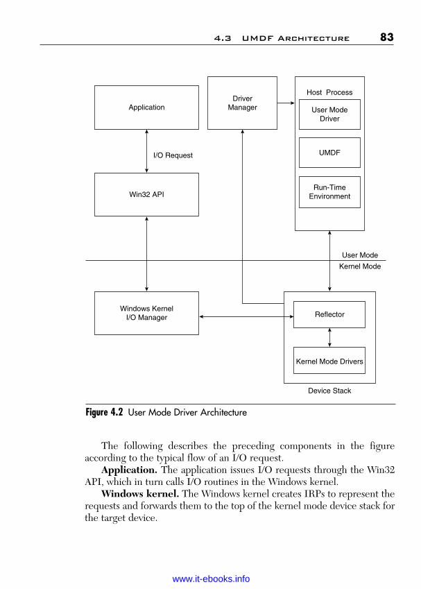
ptg
The following describes the preceding components in the figureaccording to the typical flow of an I/O request.
Application. The application issues I/O requests through the Win32API, which in turn calls I/O routines in the Windows kernel.
Windows kernel. The Windows kernel creates IRPs to represent therequests and forwards them to the top of the kernel mode device stack forthe target device.
4.3 UMDF Architecture 83
Figure 4.2 User Mode Driver Architecture
Application
Win32 API
Windows KernelI/O Manager
I/O Request
User Mode
Kernel Mode
Host Process
User ModeDriver
UMDF
Run-TimeEnvironment
DriverManager
Reflector
Kernel Mode Drivers
Device Stack
Wow! eBook <WoweBook.Com>
www.it-ebooks.info
ptg
Reflector. The reflector is a Kernel Mode WDM Filter Driver that isinstalled at the top of the kernel mode device stack for each device that ismanaged by a UMDF driver. The reflector manages communicationbetween the kernel mode components and the User Mode Driver hostprocess.
Driver manager. The driver manager creates and shuts down all thedriver host processes and maintains status information about them. It alsoresponds to messages from the reflector. The driver manager runs as aWindows service and is started during installation of the first device that ismanaged by a UMDF driver. The driver manager must be running all thetime that any device controlled by a UMDF driver is installed on thesystem. Microsoft provides the driver manager.
Host process. The host process is the process in which the UserMode Driver runs. The host process is a child process of the drivermanager and runs in the security credentials of a LocalService account,although it is not a Windows service. The host process includes the follow-ing components:
■ The UMDF driver is an in-process COM component that controlsthe hardware from user mode.
■ UMDF exposes the User Mode device-driver interface (DDI).UMDF is a DLL of COM-style objects that support the presentation,flow, and management of I/O and Plug and Play requests to the driver.
■ The run-time environment dispatches I/O requests, loads thedriver, constructs and destroys the user mode device stack, man-ages a user mode thread pool, and handles messages from thereflector and the driver managers.
Kernel Mode Drivers. Additional Kernel Mode Drivers can service eachdevice.
4.4 Required Driver Functionality
Every UMDF driver must provide the following functionality:
■ Support the DllMain export as its primary entry point.The driver must support DllMain as its primary entry point.
After the system creates the UMDF driver host process, the host
84 Chapter 4 Programming Drivers for the UMDF
Wow! eBook <WoweBook.Com>
www.it-ebooks.info

ptg
process loads the driver by calling the DllMain function. In aUMDF driver, this function does very little; typically, it enables trac-ing and then returns. As in all DLLs, the driver must not make block-ing calls such as WaitForSingleObject, which can deadlock thesystem. Drivers should defer resource allocation to IDriverEntry::-OnInitialize, instead of DllMain.
■ Support the DllGetClassObject export, which must return apointer to an IClassFactory interface that creates an instance ofthe driver callback object.
The driver must also support the DllGetClassObject function,which COM requires. This function returns a pointer to anIClassFactory interface with which UMDF can create an instanceof the driver callback object. The UMDF sample drivers show howto implement this function. Alternatively, the Active TemplateLibrary (ATL) wizard can be used to generate the supportingCOM code.
■ Implement the IDriverEntry interface on the driver class.Finally, every User Mode WDF driver must implement the
IDriverEntry interface on the driver class. This interface includesmethods that initialize and uninitialize driver-wide data. UMDFcalls the OnInitialize method when the first device for the driveris loaded and calls the OnDeinitialize method when the driver isunloaded. IDriverEntry also includes the OnAddDevicemethod, which UMDF calls when the Plug and Play manager enu-merates one of the driver’s devices.
Figure 4.3 shows the interactions of the functionality of a driver withUMDF and the system.
When the system starts, the driver manager is loaded and the follow-ing actions occur:
1. The driver manager creates the driver host process and then loadsthe driver library by calling the DllMain entry point. DllMainperforms any required global initialization for the driver, such asstarting tracing.
2. UMDF creates a framework driver object and calls the driver atDllGetClassObject to get an interface that I can use to create acorresponding callback object in the driver. DllGetClassObjectreturns a pointer to the driver’s IClassFactory interface.
4.4 Required Driver Functionality 85
Wow! eBook <WoweBook.Com>
www.it-ebooks.info
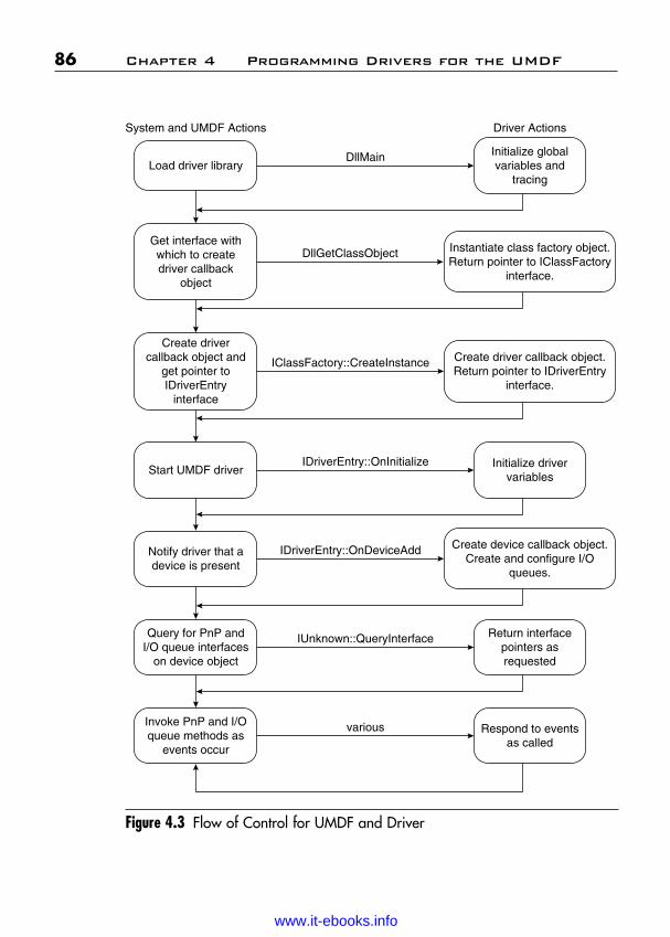
ptg
86 Chapter 4 Programming Drivers for the UMDF
Figure 4.3 Flow of Control for UMDF and Driver
System and UMDF Actions Driver Actions
Load driver libraryInitialize globalvariables and
tracing
Get interface withwhich to createdriver callback
object
Instantiate class factory object.Return pointer to IClassFactory
interface.
Create drivercallback object and
get pointer toIDriverEntry
interface
Create driver callback object.Return pointer to IDriverEntry
interface.
Start UMDF driverInitialize driver
variables
Notify driver that adevice is present
Create device callback object.Create and configure I/O
queues.
Query for PnP andI/O queue interfaces
on device object
Return interfacepointers asrequested
Invoke PnP and I/Oqueue methods as
events occur
DllMain
DllGetClassObject
IClassFactory::CreateInstance
IDriverEntry::OnInitialize
IDriverEntry::OnDeviceAdd
IUnknown::QueryInterface
various Respond to eventsas called
Wow! eBook <WoweBook.Com>
www.it-ebooks.info
ptg
3. UMDF calls the CreateInstance method of the IClassFactoryinterface to create an instance of the driver callback object. Thedriver callback object implements methods to initialize the driver,to notify it that one of its devices has been enumerated, and toprepare it for unloading.
4. UMDF calls the OnInitialize method of the driver callbackobject to initialize the driver.
5. Whenever one of the driver’s devices is enumerated, UMDF callsOnDeviceAdd. OnDeviceAdd performs any required configu-ration, creates a device callback object to represent the device,creates any required device interfaces, and creates and configuresthe queues into which UMDF will place I/O requests that are tar-geted at the driver. A device interface is a device feature thatdriver exposes to applications or other system components,whereas a COM interface is a related group of functions that acton an object.
6. UMDF queries for the Plug and Play and queue interfaces that itwill use to handle I/O requests.
7. When the device is removed, UMDF calls the Plug and Play meth-ods that are appropriate for the type of removal (orderly or surprise),deletes the objects, and calls the IDriverEntry::OnDeinitializemethod to clean up. It then unloads the DLL and deletes the driverhost process.
4.5 UMDF Sample Drivers
The UMDF release for Windows 7 includes several sample User ModeDrivers, which are installed at WDF\UMDF\src in the Windows DriverKit (WDK) installation directory. You can use these samples as the basis foryour own driver, as well as the examples in the book. Table 4.1 lists theUMDF samples.
Use the WDK build environment to build the samples. To build a par-ticular sample:
1. Start a build environment window.2. Set the working directory to the directory that contains the sample
to build.3. Type the following command: build –ceZ
4.5 UMDF Sample Drivers 87
Wow! eBook <WoweBook.Com>
www.it-ebooks.info

ptg
4.5.1 Minimal UMDF Driver: The Skeleton DriverThe Skeleton driver contains the minimum amount of code that is requiredin a loadable UMDF driver. It was designed as a starting point from which tobuild drivers for actual hardware. In addition to demonstrating the minimalrequired features and best practices, the Skeleton driver splits into appropri-ate modules the common code that is required in all UMDF drivers.
The Skeleton driver supports a driver entry point, functions to createand initialize the driver and device callback objects, and functions forCOM support. It does not support any I/O or Plug and Play operations.Table 4.2 lists the component source files.
88 Chapter 4 Programming Drivers for the UMDF
Name Description
Skeleton Minimal software-only driver that shows the structure and fundamental components of a simple UMDF driver.
Echo Simple driver that uses a serial I/O queue and handles one I/O request at a time. The Echo sample defers the completion of each I/O request to a worker thread and shows howto mark a request cancelable while it is pending in the driver. This sample was adapted from the KMDF Echo sample and is functionally similar to the WDM sample of the same name.
USB\Driver Hardware driver for the USB-FX2 Learning Kit from OSR. This sample supports a parallel I/O queue. It is similar to the Echo sample, but can handle multiple independent requests at one time. This driver also demonstrates how a User Mode Driver controls a device. It uses the memory in the OSR-USBFx2 device as a buffer and uses the WinUSB API and WinUSB Kernel Mode Driver to control the hardware. The driver demonstrates how to escape from UMDF and send I/O by using an alternate path and how to synchronize I/O on the alternate path with cancellation and file closure.
USB\Filter Filter driver for the WinUSB driver stack. This sample modifies the data in read and write requests as they flow through the device stack and uses I/O targets to communicate with a lower driver.
Table 4.1 List of UMDF Sample Drivers
Wow! eBook <WoweBook.Com>
www.it-ebooks.info

ptg
4.5 UMDF Sample Drivers 89
Filename Description
Comsup.cpp Source code for the CUnknown andCClassFactory classes.
Comsup.h Header file for COM support functions and classes.
Device.cpp Source code for the device callback object class, CMyDevice.
Device.h Header file for the device callback object.Dllsup.cpp Source code for the driver entry point and
exported COM support functions.Driver.cpp Source code for the driver callback object
class, CMyDriver.Driver.h Header file for the driver callback object.Exports.def Definition file that identifies the library
name and exported entry point for driver.Internal.h Header file for local type definitions.Makefile Generic makefile for building the sample.Makefile.inc Additional commands input to the makefile.Skeleton.htm Help file that describes the sample.Skeleton.rc Resource file for the sample.Sources Source file for the build procedure.UMDF_Skeleton_OSR.inx INF that installs the Skeleton sample as a
driver for the OSR USBFX2 device.UMDF_Skeleton_OSR_xp.inx INF that installs the Skeleton sample as a
driver for the OSR USBFX2 device on Windows 7.
UMDF_Skeleton_root.inx INF that installs the Skeleton sample as a driver for a root-enumerated device.
UMDF_Skeleton_root_xp.inx INF that installs the Skeleton sample as a driver for a root-enumerated device on Windows 7.
Table 4.2 Component Source Files
4.5.2 Skeleton Driver Classes, Objects, and InterfacesThe Skeleton driver implements the four classes that are listed in Table 4.3.
Wow! eBook <WoweBook.Com>
www.it-ebooks.info

ptg
90 Chapter 4 Programming Drivers for the UMDF
Table 4.3 Classes Implemented in Skeleton Driver
Class Name Description Public Interfaces
CUnknown Base Class from which others derive IUnknownCClassFactory Class factory that instantiates the IClassFactory
driver classCMyDriver Driver callback object class IDriverEntry
IUnknownCMyDevice Device callback object IUnknown
Figure 4.4 Interaction of Framework and Skeleton Objects
IWdfDeviceInitialize
CUnknownIUnknown
IClassFactory
IDriverEntry
IWdfDevice
CClassFactory
CMyDriver
CMyDeviceFramework
Device Object
IWdfDriver
Framework DriverObject
Figure 4.4 shows how the objects that are instantiated from theseclasses interact with the corresponding framework objects.
Wow! eBook <WoweBook.Com>
www.it-ebooks.info

ptg
4.6 Driver Dynamic-Link Library and Exports 91
As Figure 4.4 shows, the framework implements a driver object and adevice object. The framework’s driver object uses the IDriverEntry inter-face on the Skeleton driver’s CMyDriver object, and the CMyDriverobject, in turn, uses the IWdfDriver interface on the framework’s driverobject. The framework’s device object exposes the IWdfDevice andIWdfDeviceInitialize interfaces, which the driver’s CMyDevice objectuses. The Skeleton driver’s CMyDevice class does not implement addi-tional interfaces because it does not support hardware or handle I/Orequests. The device object in a typical driver would implement additionalinterfaces for Plug and Play notifications, I/O requests, I/O queues, andso forth.
4.6 Driver Dynamic-Link Library and Exports
Every UMDF driver must support DllMain as the driver’s primary entrypoint and must export the DllGetClassObject function so that COM caninstantiate the driver object. The Skeleton sample defines these functionsin the Dllsup.cpp file.
4.6.1 Driver Entry Point: DllMainDllMain is the driver’s primary entry point. This function typically ini-tializes any data that is required for tracing and debugging but otherwisedoes little because most driver-and-device-specific initialization takesplace in conjunction with the driver and device object creation. In theSkeleton driver, DllMain simply initializes tracing, as the followingsource code shows:
BOOLWINAPIDllMain{
HINSTANCE ModuleHandle,DWORD Reason,PVOID /* Reserved */}
/*++
Routine Description:
This is the entry point and exit point for the I/Odriver. It does very little because the driver has mini-mal global data.
Wow! eBook <WoweBook.Com>
www.it-ebooks.info

ptg
92 Chapter 4 Programming Drivers for the UMDF
This method initializes tracing.
Arguments:ModuleHandle - the Dll handle for this module.Reason - the reason this entry point was called.Reserved - unused
Return Value:TRUE
--*/{
If (DLL_PROCESS_ATTACH == Reason){
//// Initialize tracing.//
WPP_INIT_TRACING(MYDRIVER_TRACING_ID);
}else if (DLL_PROCESS_DETACH == Reason){
//// Clean up tracing.//
WPP_CLEANUP();}
return TRUE;}
When the driver host process calls DllMain, it passes a reason for thecall, along with a handle and a reserved value, both of which the functioncan ignore. If the driver host process is starting and the DLL is beingloaded, the reason is DLL_PROCESS_ATTACH. In this case, the func-tion initializes tracing. If the driver host process is terminating or thelibrary did not load successfully, the reason is DLL_PROCESS_DETACH, so the function ends tracing. Starting and ending tracing inDllMain ensures that trace information is recorded for the entire life ofthe driver.
Wow! eBook <WoweBook.Com>
www.it-ebooks.info
ptg
4.6 Driver Dynamic-Link Library and Exports 93
4.6.2 Get Class Object: DllGetClassObjectCOM calls the driver’s DllGetClassObject function to get a pointer toan interface through which it can instantiate a driver callback object. Thismethod should create an instance of the class factory for the driver object;UMDF later calls methods on the class factory to actually instantiate thedriver callback object.
The following is the source code for the Skeleton driver’s DllGet-ClassObject function:
HRESULTSTDAPICALLTYPEDllGetClassObject{
__in REFCLSID ClassId,__in REFIID InterfaceId,__deref_out LPVOID *Interface}
/*++Routine Description:This routine is called by COM to instantiate the skeletondriver callback object and do an initial query interfaceon it.
This method only creates an instance of the driver’sclass factory, which is the minimum required to supportUMDF.
Arguments:ClassId - the CLSID of the object being “gotten”InterfaceId - the interface the caller wants from thatobjectInterface - a location to store the referenced interfacepointer
Return Value:S_OK if the function succeeds, orError code indicating the reason for failure
--*/{
PCClassFactory factory;
HRESULT hr = S_OK;
*interface = NULL;
Wow! eBook <WoweBook.Com>
www.it-ebooks.info
ptg
//// If the CLSID doesn’t match that of our “coclass” // defined in the IDL file) then we can’t create the // object that the caller wants. This error may indicate // that the COM registration is incorrect, and another // CLSID is referencing this driver.//If (IsEqualCLSID(ClassId, CLSID_MyDriverCoClass == false){
Trace{TRACE_LEVEL_ERROR,L”ERROR: Called to create instance of unrecognizedclass
“(%!GUID!)”,};
Return CLASS_E_CLASSNOTAVAILABLE;}
//// Create an instance of the class factory for the caller//
factory = new CClassFactory();
if (NULL == factory){
Hr = E_OUTOFMEMORY;}
//// Query the object we created for the interface that the// caller requested. Then release the object. If the QI // succeeded and referenced the object, its reference // count will now be 1. If the QI failed, the reference // count is 0 and the object is automatically deleted.//
If (S_OK == hr){
hr = factory->QueryInterface(InterfaceId, Interface);factory->Release();
}
return hr;}
94 Chapter 4 Programming Drivers for the UMDF
Wow! eBook <WoweBook.Com>
www.it-ebooks.info

ptg
In the Skeleton driver, DllGetClassObject verifies that the class IDpassed in by the caller (COM) matches the class ID of the object, asdefined in the IDL file. It creates an instance of the class factory, callsQueryInterface on the class factory to get a pointer to theIClassFactory interface and increment its reference count, and thenreturns.
4.7 Functions for COM Support
The source file Comsup.cpp supplies code that is required to supportCOM. It implements methods for the IUnknown and IClassFactoryinterfaces. This section briefly describes what these methods do, but doesnot show any of the sample code. You can simply copy the Comsup.cppand Comsup.h files for use in your own drivers, typically without anychanges.
4.7.1 IUnknown MethodsCUnknown is the base class from which all other classes derive, and itsupports the IUnknown interface. Every UMDF driver must implementthis class with a constructor method and the IUnknown interface, whichincludes the AddRef, QueryInterface, QueryIUnknown, and Releasemethods. Table 4.4 summarizes the IUnknown methods.
4.7 Functions for COM Support 95
Method Name Description
CUnknown Constructor, which initializes the reference count for thisinstance of the CUnknown class to 1.
QueryInterface Returns a pointer to the IUnknown interface for theobject.
QueryIUnknown Public helper method that casts a CUnknown pointer toan IUnknown pointer.
AddRef Increments the reference count for the object.Release Decrements the object’s reference count and deletes the
object if the reference count reaches zero.
Table 4.4 IUnknown Method Names
Wow! eBook <WoweBook.Com>
www.it-ebooks.info

ptg
4.7.2 IClassFactory InterfaceThe CClassFactory class object implements the IClassFactory inter-face. The framework invokes methods in this interface to create aninstance of the driver callback class. The driver callback class instance isthe only callback object that the framework creates; the driver itself cre-ates all other callback objects in response to calls from the framework.Table 4.5 summarizes the methods in this interface.
4.7.3 Driver CallBack ObjectWhen UMDF gets a pointer to the IClassFactory interface, it calls theCreateInstance method in that interface to create an instance of anobject. That method, in turn, calls the CMyDriver::CreateInstancemethod, which creates and initializes the driver callback object. In gen-eral, any CreateInstance method is a factory method that creates anobject.
96 Chapter 4 Programming Drivers for the UMDF
Method Description
QueryInterface Returns a pointer to the requested interface.QueryIClassFactory Public helper method that casts a CClassFactory pointer
to an IClassFactory pointer; essentially similar to theIQueryIUnknown method in the IUnknown interface.
CreateInstance Creates an instance of the driver callback class and returnsa pointer to a requested interface for that class.
LockServer Maintains a lock count that indicates whether the driverDLL should remain in memory.
Table 4.5 IClassFactory Methods
Wow! eBook <WoweBook.Com>
www.it-ebooks.info

ptg
CMyDriver::CreateInstance is defined in the source fileDriver.cpp and is straightforward, as the following shows:
HRESULTCMyDriver::CreateInstance(
__out PCMyDriver *Driver)/*++
Routine Description:
This static method is invoked to create and initialize a newinstance of the driver class. The caller should arrange forthe object to be released when it is no longer in use.
Arguments:
Driver - a location to store a referenced pointer tothe new instance
Return Value:
S_OK if successful, or error otherwise
--*/{PCMyDriver driver;HRESULT hr;
//// Allocate the callback object//driver = new CMyDriver();
if (NULL == driver){return E_OUTOFMEMORY;
}
//// Initialize the callback object//hr = driver->Initialize();
if (SUCCEEDED (hr)){
4.7 Functions for COM Support 97
Wow! eBook <WoweBook.Com>
www.it-ebooks.info
ptg
//// Store a pointer to the new, initialized object in// the output parameter.//*Driver = driver;
}else{
//// Release the reference on the driver object so that// it will delete itself//driver->Release();
}return hr;}
This method allocates and creates an instance of the driver callbackobject, and then calls the initialize method to initialize the object. TheSkeleton driver object requires no initialization, so the Initialize methodis a stub (and so is not shown here). CreateInstance returns a pointer tothe new driver callback object and releases its reference on this objectbefore returning.
Every UMDF driver must implement the IDriverEntry interfaceon the driver callback object. This interface supports methods to ini-tialize the driver, perform tasks when one of the driver’s devices is addedto the system, and prepare the driver for unloading, just beforeDllMain.DetachProcess is called. The driver.cpp file contains codethat implements IDriverEntry.
IDriverEntry defines three methods: OnDeviceAdd,OnInitialize, and OnDeInitialize. In the Skeleton driver, theOnInitialize and OnDeInitialize methods are stubs.
When one of the driver’s devices is added, UMDF calls theOnDevice method, passing as parameters pointers to the IWdfDriverand IWdfDeviceInitialize interfaces, which the framework implements.The Skeleton driver does not support physical hardware, so itsOnDeviceAdd method is minimal:
HRESULTCMyDriver::OnDeviceAdd{
__in IWDFDriver *FxWdDriver,__in IWDFDeviceInitialize *FxDeviceInit
}/*++
98 Chapter 4 Programming Drivers for the UMDF
Wow! eBook <WoweBook.Com>
www.it-ebooks.info

ptg
Routine Description:
The FX invokes this method to install our driver on a devicestack. This method creates a device callback object, thencalls the Fx to create an Fx device object and associate thenew callback object with it.
Arguments:
FxWdfDriver - the Fx driver object.FxDeviceInit - the initialization information for thedevice.
Return Value:Status
--*/{
HRESULT hr;
PCMyDevice device = NULL;
//// TODO: Here is where to do any per device initialization// (reading settings from the registry, for example) that is// required before you create the device callback object.// You can leave initialization of the device callback // object itself to the device event handler.//
//// Create a new instance of our device callback object//
hr = CMyDevice::CreateInstance(FxWdfDriver, FxDeviceInit,&device);
//// TODO: Change any per device settings that the object // exposes before you call Configure to complete its // initialization.//
4.7 Functions for COM Support 99
Wow! eBook <WoweBook.Com>
www.it-ebooks.info

ptg
//// If that succeeded then call the device’s construct // method. The construct method can create queues or // other structures that are required for the device object.
if (S_OK == hr){
hr = device->Configure();}
//// Release the reference on the device callback object // now that it’s associated with an fx device object.//
if (NULL != device){
device->Release();}
return hr;}
The Skeleton driver’s OnDeviceAdd method calls theCreateInstance method on the CMyDevice class to instantiatethe device callback object. It passes the pointers to the IWdfDevice-Initialize and IWdfDriver interfaces so that CreateInstance can usethese UMDF defined interfaces to create and initialize the deviceobject.
By convention, a CreateInstance method in the sample represents afactory for building objects of a particular type.
4.7.4 Device CallBack ObjectThe device callback object represents the device in the driver. The drivercreates an instance of this object when its IDriverEntry::OnDeviceAddmethod is called. The driver implements the CreateInstance, Initialize,Configure, and QueryInterface methods for the device callback object.
The code for the device callback object for the Skeleton driver is inthe Device.cpp. This module includes the header files Internal.h, whichcontains driver-specific internal definitions, and Device.tmh, whichdefines tracing information for Event Tracing for Windows (ETW).
100 Chapter 4 Programming Drivers for the UMDF
Wow! eBook <WoweBook.Com>
www.it-ebooks.info
ptg
4.7.4.1 CreateInstance MethodA driver’s IDriverEntry::OnDeviceAdd method calls IDeviceObject::-CreateInstance to create an instance of the device callback object. Thismethod simply allocates and initializes an instance of the device callbackobject as follows:
HRESULTCMyDevice::CreateInstance(
__in IWDFDriver *FxDriver,__in IWDFDeviceInitialize *FxDeviceInit,__out PCMyDevice *Device)
/*++
Routine Description:
This method creates and initializes an instance of theskeleton Driver’s device callback object.
Arguments:
FxDeviceInit - the settings for the device.Device - a location to store the referenced pointed to the
device object.Return Value:
Status--*/{
PCMyDevice device;HRESULT hr;
//// Allocate a new instance of the device class.//
device = new CMyDevice();
if (NULL == device){
Return E_OUTOFMEMORY;}
4.7 Functions for COM Support 101
Wow! eBook <WoweBook.Com>
www.it-ebooks.info

ptg
//// Initialize the instance.//
hr = device->Initialize(FxDriver, FxDeviceInit);
if (S_OK == hr){
*Device = device;}else{
device->Release();}
return hr;}
When UMDF calls the OnDeviceAdd method, it passes a pointer to theIWdfDriver interface and a pointer to the IWdfDeviceInitialize interface.These interfaces provide methods through which the driver can initialize per-device-object settings and create a device callback object. OnDeviceAddpasses these pointers to CreateInstance, which in turn passes them asparameters to the Initialize method to initialize the instance.
4.7.4.2 Initialize MethodThe Initialize method of the device callback object does exactly what itsname implies: It initializes the callback object. It also calls the frameworkto create the framework’s device object.
The initialize method receives a handle to the framework’sIWdfDeviceInitialize interface and stores it in FxDeviceInit. It usesthis handle to call methods on that interface to initialize certain devicecharacteristics that must be set before the framework’s device object iscreated. Such characteristics include the synchronization (locking) modeland the Plug and Play features. They also indicate whether the driver is afilter driver, whether the driver controls device power policy, and whetherthe framework should forward or fail certain request types. The drivermust set these values before creating the framework’s device objectbecause they determine which callbacks the framework initializes for thedevice object. The following code shows how to set the needed values:
HRESULTCMyDevice::Initialize(
102 Chapter 4 Programming Drivers for the UMDF
Wow! eBook <WoweBook.Com>
www.it-ebooks.info

ptg
__in IWDFDriver *FxDriver,__in IWDFDeviceInitialize *FxDeviceInit)/*++
Routine Description:
This method initializes the device callback object and creates the partner device object.
The method should perform any device specific configurationthat:
Could fail (these can’t be done in the constructor)must be done before the partner object is created-or-can be done after the partner object is created and isn’t influenced, by any device level parameters that theparent (the driver in this case) might set.
Arguments:
FxDeviceInit - the settings for this device.
Return Value:
status.
--*/{
IWDFDevice *fxDevice;HRESULT hr;
//// Configure things like the locking model before we // create our partner device.//
//// TODO: Set her locking mode. The skeleton uses device level// locking, but you can choose “none” as well.//
FxDeviceInit->SetLockingConstraint (WdfDeviceLevel);
//// TODO: If you’re writing a filter driver indicate that // here.//
4.7 Functions for COM Support 103
Wow! eBook <WoweBook.Com>
www.it-ebooks.info

ptg
// FxDeviceInit->SetFilter();//
//// TODO: Any per-device initialization which must be done // before creating the partner object.////// Create a new FX device object and assign the new // callback object to handle any device level events that// occur.//
//// QueryIUnknown references the IUnknown interface that it// returns (which is the same as referencing the device). We// pass that to CreateDevice, which takes its own reference// if everything works.//
{IUnknown *unknown = this->QueryIUnknown();
hr = FxDriver->CreateDevice(FxDeviceInit, unknown,&fxDevice);
unknown->Release();}
//// If that succeeded, then set our FxDevice member variable.//
if (S_OK == hr){
m_FxDevice = fxDevice;//// Drop the reference we got from CreateDevice. Since // this object is partnered with the framework object // they have the same lifespan. There is no need for an// additional reference.//
}
return hr;}
104 Chapter 4 Programming Drivers for the UMDF
Wow! eBook <WoweBook.Com>
www.it-ebooks.info

ptg
The Initialize method first sets the locking model for the driverby calling the SetLockingConstraint method of the IWdf-DeviceInitialize interface. The locking model determines whether theframework calls the driver’s callback methods concurrently on a per-device-object level or not at all. The Skeleton driver setsWdfDeviceLevel, which means that the framework synchronizes calls tomethods at the device object level or lower. Therefore, the driver does notrequire code to synchronize access to shared data in such methods.
Device-level locking applies to methods on the IWdfIoQueueinterface, the IFileCallbackCleanup interface, and the IFileCallback-Close interface. The IWdfIoQueue interface is implemented by the I/Oqueue object, and the IFileCallbackCleanup and IFileCallbackCloseinterfaces are implemented by the device object.
The Skeleton does not support physical hardware, so it does not setany Plug and Play characteristics. If it supported an actual Plug and Playdevice, it might also have to specify whether the device is ejectable, lock-able, and other similar settings.
After the driver has set the device characteristics, it can call UMDFto create the framework’s device object. The IWdfDriver::Create-Device method takes a pointer to the IWdfDeviceInitialize interfacethat was passed to the driver, a pointer to the driver’s device callbackobject, and a location in which to return the handle to the created frame-work device object. To get a pointer to the device callback object, thedriver calls QueryIUnknown on the current interface. It then passes thispointer when it calls CreateDevice. Calling QueryIUnknown adds areference on the IUnknown interface it returns—in this case, the driver’scallback object interface. After the CreateDevice method returns, thedriver releases this reference.
If UMDF successfully creates the framework device object, the driverinitializes the variable m_FxDevice to hold the pointer to the returnedinterface. It then calls the Release method to release the reference thatthe CreateDevice method added on the returned interface. Them_FxDevice interface has the same lifetime as the framework’sIWdfDevice interface, so this reference is not required to ensure that theinterface persists for the driver.
4.7.4.3 Configure MethodThe Configure method handles tasks that are related to configurationafter the framework and device callback objects have been created. The
4.7 Functions for COM Support 105
Wow! eBook <WoweBook.Com>
www.it-ebooks.info
ptg
Skeleton driver’s OnDeviceAdd callback invokes the Configuremethod after CreateInstance has successfully returned.
In the Skeleton driver, Configure is a stub. In a driver that handlesI/O requests, this method would create and configure I/O queues andqueue callback objects.
4.7.4.4 QueryInterface MethodThe QueryInterface method returns a pointer to any of the device call-back object’s interfaces. It takes the interfaceId as an input parameterand returns a pointer to the interface.
The Skeleton driver does not implement any of the event callbackinterfaces for the device object because it does not support actual hard-ware. Therefore, it simply returns the pointer to the IUnknown interfaceof the base class CUnknown, as follows:
return CUnknown::QueryInterface(InterfaceId, object);
In a driver that supports actual hardware, this method should validatethe input interfaceId and return a pointer to the requested interface.
4.8 Using the Skeleton Driver as a Basis for Development
The Skeleton driver is designed for use as a basis for UMDF driver develop-ment. By customizing the existing code and adding some of your own code, youcan create a driver for your specific device. The following tasks are required:
■ Customize the exports.■ Customize the Sources file.■ Customize the INF file.■ Customize the Comsup.cpp file.■ Add device-specific code to the Driver.cpp file.■ Add device-specific code to the Device.cpp file.
For most drivers, you can use the following files from the Skeletonunchanged:
■ Resource.h■ Makefile
106 Chapter 4 Programming Drivers for the UMDF
Wow! eBook <WoweBook.Com>
www.it-ebooks.info

ptg
■ ComSup.cpp and ComSup.h, which supply basic support for COM■ DllSup.cpp, which supports basic DLL functions
4.8.1 Customize the Exports FileThe file Exports.def lists the library and function names that the DLLexports. To customize this file, replace the value in the LIBRARY statementwith the name of the binary file that contains the DLL. For example:
LIBRARY “MyDevice.DLL”
Your driver must export the DLLGetClassObject function, so youcan leave the EXPORTS area unchanged.
4.8.2 Customize the Sources FileThe Sources file defines environment variables and settings that arerequired to build the driver. It is input to the generic makefile that is sup-plied with the samples. To create a makefile to build your own driver, youdo not edit the generic makefile. Instead, you edit the Sources file.
To customize the Sources file:
■ Change the TARGETNAME statement to include the name foryour driver. For example:
TARGETNAME=MyDevice
■ Change the SOURCES statement to include the source files foryour driver. For example:
SOURCES=\MyDevice.rc \dllsup.cpp \comsup.cpp \driver.cpp \device.cpp \
■ Change the NTTARGETFILES statement to include the INFfiles and any other miscellaneous files for your driver. For example:
NTTARGETFILES=$(OBJ_PATH)\$(0)\UMDFSkeleton_Root.inf\$(OBJ_PATH)\$(0)\UMDFSkeleton_OSR.inf
4.8 Using the Skeleton Driver 107
Wow! eBook <WoweBook.Com>
www.it-ebooks.info

ptg
4.8.3 Customize the INX FileThe INX file contains the INF that is used to install the driver. To use thisfile as a basis for your own driver’s installation, you must change a varietyof settings. The following list outlines the types of required changes:
■ Change the [Manufacturer] section to include the name of yourcompany and the [Manufacturer.NT$ARCH$] section to includethe name and location of your driver.
■ Change the [SourceDisksFiles] section to include the name ofyour DLL.
■ If your driver is a filter driver, change the [DDInstall.Services]section to install the reflector as the top filter driver in the kernelmode device stack. If your driver is a function driver, the[DDInstall.Services] section should install the reflector as theservice for the device.
■ Change the [DDInstall.Wdf] section to install your driver as aservice and list it in the UMDFServiceOrder directive.
■ If your driver performs impersonation, add the UMDF-Impersonation directive that specifies the maximum imperson-ation level for the driver.
■ In the [UMDFServiceInstall] section, change the name of thebinary to the name of your driver binary and specify your driver’sclass ID in the DriverCLSID directive.
■ In the UMDriverCopy section, specify the name of your DLL.■ In the [Strings] section, change the strings to specify the name of
your company, installation medium, and so forth.
Additional changes might be required depending on the type ofdevice that your driver supports or whether yours is a software-onlydriver.
4.8.4 Customize the Comsup.cpp FileIf you change the name of the driver class to something differentfrom CMyDriver, you must change the following line inCClassFactory::CreateInstance to reflect the new class name:
hr = CMyDriver::CreateInstance(&driver);
108 Chapter 4 Programming Drivers for the UMDF
Wow! eBook <WoweBook.Com>
www.it-ebooks.info

ptg
4.8.5 Add Device-Specific Code to Driver.cppIn the driver.cpp file, you should add code to the OnDeviceAdd methodto initialize your device and to change any device-specific settings. Forexample, if your driver must read settings from the registry before initial-izing the device, it should do so in OnDeviceAdd.
The CreateInstance, AddRef, Release, and QueryInterfacemethods from the Skeleton driver should suffice for most drivers.
4.8.6 Add Device-Specific Code to Device.cppThe file Device.cpp is where you must do the most work. The Skeletonsample does not support an actual device, so it implements very few of theinterfaces and callback objects that are required for the typical device.
In the Initialize method, you should set the locking constraint foryour driver. The locking constraint determines whether your driver’s call-back methods can be called concurrently or whether only one suchmethod at a time can be active. Note, however, that the locking modelapplies strictly to the number of callback methods that are concurrent; itdoes not limit the number of I/O requests that can be active in your driverat one time.
If your driver is a filter driver, you should indicate that in theInitialize method as well, by calling the SetFilter method of theIDeviceInitialize interface.
In the Configure method, you create the I/O queues for the driver.Because the Skeleton driver does not handle actual I/O requests, it doesnot set up any queues. Most drivers, however, implement one or morequeues through which UMDF dispatches I/O requests. To create aqueue, the driver calls the IWdfDevice::CreateIoQueue method andspecifies how the queue dispatches requests to the driver: in parallel assoon as they arrive, sequentially (one at a time), or only when the drivercalls a method on the queue to request one. The driver then callsIWdfIoQueue::ConfigureRequestDispatching to specify the types ofrequests that should be directed to the queue. The driver must also imple-ment methods in the IQueueCallbackXxx, IRequestCallbackXxx, andIFileCallbackXxx interfaces as appropriate to handle the requests thatare directed to its queues.
Finally, a driver that supports a Plug and Play device typically mustimplement the IPnPCallback interface and possibly the
4.8 Using the Skeleton Driver 109
Wow! eBook <WoweBook.Com>
www.it-ebooks.info

ptg
IPnPCallbackHardware and IPnPCallbackSelfManagedIo inter-faces as well.
You should also either update the header file Internal.h or add yourown device-specific header file with any additional definitions pertinentto your device-specific code.
110 Chapter 4 Programming Drivers for the UMDF
Wow! eBook <WoweBook.Com>
www.it-ebooks.info

ptg
111
C H A P T E R 5
USING COM TO DEVELOPUMDF DRIVERS
The Component Object Model (COM) is a specification for a way of building applications based on using components. In the traditional sense,applications were divided into files, modules, or classes. They were thenlinked to form a monolithic application. A component, however, is like asmall application that comes packaged as a binary piece of code that is com-piled, linked, and ready to use. This piece of code then links with othercomponents at run-time to form an application. One of the great features ofthis approach is that one can change or enhance the application by simplyreplacing one of the components. This chapter introduces COM and its usein creating UMDF drivers. For a more detailed discussion on COM, see theBibliography for a reference to the book Inside COM (Rogerson 1997).
For our work in the UMDF driver development, we must use a numberof COM objects that are part of the WDF framework. A number of callbackobjects are needed to be created based on COM-based callback objects. Inthe UMDF driver development, we will not use the COM run-time, whichcontained a good deal of complexity. In the UMDF driver development, weuse the essential core of the COM programming model. This keeps theUMDF driver fairly lightweight and thus relatively easy to implement.
5.1 Getting Started
In general, the UMDF drivers are programmed using C++, and the COMobjects are developed and also written in C++. It is good to have an under-standing of class structure such as the struct and class keywords, public andprivate members, static methods, constructors, destructors, and pureabstract classes. Also, you should understand object creation, whichincludes base and derived classes, multiple inheritance, and pure virtualmethods.
Wow! eBook <WoweBook.Com>
www.it-ebooks.info

ptg
See the Bibliography for a reference to C++ How to Program, SeventhEdition (Deitel 2009) to review or get an understanding of these concepts.In UMDF drivers, the operator overloading or templates are not neces-sary. The UMDF drivers could use, but are not required to use, the C++standard template libraries. This includes the Standard Template Library(STL) and the Active Template Library (ATL). We do not show examplesof the use of these libraries.
5.1.1 COM FundamentalsLet’s look at some of the fundamental aspects of COM to get us started:
■ IUnknown is the core COM interface. All COM interfaces derivefrom this interface. Every COM object exposes this interface and itis essential to the object’s operation.
■ One of the significant differences between objects in COM andother Object Oriented Programming (OOP) models is that there areno fundamental object pointers in COM. COM exposes interfacesthat are groups of related methods. Objects typically expose at leasttwo and sometimes many interfaces. Thus, when you obtain a COMobject, you are given a pointer to one of the object’s interfaces notthe object itself.
■ Globally Unique Identifiers (GUIDs) are used by COM touniquely identify COM interfaces. Some COM objects have GUIDidentifiers, which are referred to as CLSIDs. GUIDs are referred toas IIDs. We can request an interface pointer using these IIDs.COM uses GUIDs for two primary purposes:■ Interface ID (IID)—An IID is a GUID that uniquely identi-
fies a particular COM interface. The interface always has thesame IID, regardless of which object exposes it.
■ Class ID (CLSID)—A CLSID is a GUID that identifies a par-ticular COM object. CLSIDs are required for COM objects thatare created by a class factory, but optional for objects that arecreated in other ways. With UMDF, only the driver callbackobject has a class factory or a CLSID.
To simplify using GUIDs, an associated header file usually definesfriendly names that conventionally have a prefix of either IID_ orCLSID_ followed by the descriptive name. For example, thefriendly name for the GUID that is associated with IDriverEntry
112 Chapter 5 Using COM to Develop UMDF Drivers
Wow! eBook <WoweBook.Com>
www.it-ebooks.info

ptg
is IID_IDriveEntry. For convenience, the UMFD documentationusually refers to interfaces by the name used in their implementa-tion, such as IDriverEntry, rather than the IID.
■ Any of the methods on an interface can be used with an interfacepointer. If you want access to a method on another interface youmust obtain another interface pointer. That is done using theIUnknown::QueryInterface method.
■ There is no public data member’s exposure in COM objects. Publicdata is exposured through methods we call accessors. In UMDF, weuse a Get/Retrieve or Set/Assign prefix for its read and write acces-sors, respectively. Figure 5.1 shows the logical relationship betweenan object and its contents.
5.1 Getting Started 113
Figure 5.1 COM Objects, Interfaces, and Methods
Object 1
Interface 1 Methods
Interface 2 Methods
Additional Interfaces
Private Data, Utility MethodsEtc.
Wow! eBook <WoweBook.Com>
www.it-ebooks.info

ptg
All access to COM objects is through a virtual function table—com-monly called a VTable—that defines the physical memory structure of theinterface. The VTable is an array of pointers to the implementation of eachof the methods that the interface exposes. When a client gets a pointer toan interface, it is actually a pointer to the VTable pointer, which in turnpoints to the method pointer. For example, Figure 5.2 shows the memorystructure of the VTable for IWDFloRequest.
The VTable is exactly the memory structure that many C++ compilerscreate for a pure abstract base class. This is one of the main reasons thatCOM objects are normally implemented in C++, with interfaces declaredas pure abstract base classes. You can then use C++ inheritance to imple-ment the interface in your objects, and the VTable is created for you by thecompiler.
5.1.2 HRESULTBefore we look at using COM objects, let’s look at the return from a COMmethod. COM methods often return a 32-bit type called an HRESULT.It’s similar to the NTSTATUS type that Kernel Mode Driver routines useas a return value and is used in much the same way. Figure 5.3 shows thelayout of an HRESULT.
The HRESULT type has three fields:
■ Severity, which is essentially a Boolean value that indicates successor failure
■ Facility, which can usually be ignored■ Return code, which provides a more detailed description of the
results
114 Chapter 5 Using COM to Develop UMDF Drivers
Figure 5.2 VTable and Interface Pointers
Interface Pointer
VTable Pointer
Private Data
&CancelSentRequest
&Complete
&CompleteWithInformation
CancelSentRequest
Complete
CompleteWithInformation
ClientInterface
ClassImplementation
Wow! eBook <WoweBook.Com>
www.it-ebooks.info

ptg
As with NTSTATUS values, it’s rarely necessary to parse the HRESULTand examine the individual fields. Standard HRESULT values are definedin header files and described on method reference pages. By convention,success codes are assigned names that begin with S_ and failure codes withE_. For example, S_OK is the standard HRESULT value for simplesuccess.
It’s important not to think of HRESULT as error values. Methodsoften have multiple return values for success and for failure. S_OK is theusual return value for success, but methods sometimes return other suc-cess codes, such as S_FALSE.
The severity value is all that is needed to determine whether themethod simply succeeded or failed. Rather than parse the HRESULT toget the Severity value, COM provides two macros that work much like theNT_SUCCESS macro that is used to check NTSTATUS values for suc-cess or failure. For an HRESULT return value of hr:
FAILED(hr)Returns TRUE if the Severity code for hr indicatesfailure and FALSE if it indicates success.
SUCCEEDED(hr)Returns FALSE if the Severity code for hr indicatesfailure and TRUE if it indicates success.
You can examine the HRESULT’s return code to determine whethera failure is actionable. Usually, you just compare the returned HRESULTto the list of possible return values on the method’s reference page.However, be aware that those lists are often incomplete. They typicallyhave only those HRESULTs that are specific to the method or standardHRESULTs that have some method-specific meaning. The method mightalso return other HRESULTs.
5.1 Getting Started 115
Figure 5.3 HRESULT Layout
Severity
Facility Return Code
015163031
Wow! eBook <WoweBook.Com>
www.it-ebooks.info

ptg
Always test for simple success or failure with the SUCCEEDED orFAILED macros, whether or not you test for specific HRESULT values.Otherwise, for example, if you test for success by comparing the HRE-SULT to S_OK and the method unexpectedly returns S_FALSE, yourcode will probably fail.
Although NTSTATUS and HRESULT are similar, they are not inter-changeable. Occasionally, information in the form of an NTSTATUSvalue must be returned as an HRESULT. In that case, use the HRE-SULT_FROM_NT macro to convert the NTSTATUS value into an equiv-alent HRESULT. However, do not use this macro for an NTSTATUSvalue of STATUS_SUCCESS. Instead, return the S_OK HRESULTvalue. If you need to return a Windows error value, you can convert it toan HRESULT with the HRESULT_FROM_WIN32 macro.
5.2 Using UMDF COM Objects
A process that uses a COM object is known as a COM client. Both UMDFdrivers and the UMDF run-time function as COM clients. UMDF driversinteract with UMDF run time by using UMDF-provided COM objects.For example, the UMDF device object represents the device, and driverscan use the object for tasks such as setting or retrieving the device’s Plugand Play state.
The UMDF run time interacts with drivers through the drive-providedCOM-based callback objects. For example, a driver can create one or morequeue callback objects to handle I/O requests. The UMDF run time usesthose objects to pass request to the driver.
After you get a pointer to an interface, you can call the interface meth-ods by using the same syntax that is used for a pointer to a C++ method.For example, if pWdfRequest is a pointer to an IWDFloRequest inter-face, the following code is an example of how to invoke the interface’sSend method:
HRESULT hr;
hr = pWdfRequest- >Send( m_pIUsbTargetDevice,
WDR_REQUEST_SEND_OPTION_SYNCHRONOUS,
0);
116 Chapter 5 Using COM to Develop UMDF Drivers
Wow! eBook <WoweBook.Com>
www.it-ebooks.info

ptg
The method’s return value is an HRESULT, a typical return type forCOM methods. HRESULT is similar to the NTSTATUS type that KernelMode Drivers use as a return value and is used in much the same way. Itis important not to think of HRESULT as error values. Methods some-times have multiple return values for success as well as for failure. You candetermine the result of calling a method by comparing the returned HRESULT to the list of possible values in the reference documentation.However, be aware that these lists are not always complete. Use the error-checking macros that are discussed shortly to ensure that you do not missa possible return value.
You can also test an HRESULT for simple success or failure. COMprovides two macros for that purpose that work much like theNT_SUCCESS macro. For an HRESULT return value of hr:
■ FAILED(hr) returns TRUE for failure and FALSE for success.■ SUCCEEDED(hr) returns FALSE for failure and TRUE for
success.
Although NTSTATUS and HRESULT are similar, they are not inter-changeable. Occasionally, information in the form of an NTSTATUS valuemust be returned as an HRESULT. In that case, you can use the HRESULT_FROM_NT macro to convert the NTSTATUS into an equivalent HRESULT. Do not use this macro for an NTSTATUS value ofSTATUS_SUCCESS. In that case, return the S_OK HRESULT value.
5.2.1 Obtaining an Interface on a UMDF ObjectYou can obtain an interface on a UMDF object in one of three ways:
■ The UMDF run time passes an interface pointer in to one of thedriver’s callback methods.
■ The driver creates a new WDF object by calling a UMDF objectcreation method.
■ The driver calls IUnknown::QueryInterface to request a newinterface from an existing WDF object.
You can also receive an Interface through a Driver Method. The first caseis the simplest. For example, when the UMDF run time calls a driver’sIDriverEntry::OnDeviceAdd method, it passes a pointer to the deviceobject’s IWDFDriver interface.
5.2 Using UMDF COM Objects 117
Wow! eBook <WoweBook.Com>
www.it-ebooks.info

ptg
The following example shows this activity:
HRESULT CMyDriver::OnDeviceAdd(__in IWDFDriver *FxWdfDriver,__in IWDFDeviceInitialize *FxDeviceInit)
{// Install the driver in the device stack
}
You can then use FxWdfDriver to access the methods on the driverobject’s IWDFDriver interface. Do not release FxWdfDriver when youare finished with it. The caller ensures that the object remains valid duringthe scope of the method call.
Another way to create a WDF object is by calling the appropriateUMDF object creation method. For example, to create a request object,call the UMDF device object’s IWDFDevice::CreateRequest method.If you look at the UMDF reference in the Windows Driver Kit (WDK),you will find syntax like that for IWDFDevice::CreateRequest:
HRESULT CreateRequest(IN IUnknown* pCallbackInterface,IN IWdfObject* pParentObject,OUT IWDFIoRequest** ppRequest);
ppRequest is an OUT parameter that provides an address at which theCreateRequest method can store a pointer to the newly created requestobject’s IWDFObject interface. The following procedure and sample showhow to handle such parameters, by using a call to CreateRequest by theUMDF’s fx2_driver sample as an example.
We would declare a variable, pWdfRequest, to hold a pointer toIWDFloRequest.
Then we would pass a reference to pWdfRequest to CreateRequestas follows:
IWDFIoRequest *pWdfRequest = NULL;…hr = m_FxDevice- >CreateRequest ( NULL, NULL, &pWdfRequest);
When CreateRequest returns, pWdfRequest holds a pointer to anIWDFIoRequest interface. When the caller has finished with pWdf-Request, it should release the interface pointer by calling IUn-known::Release.
118 Chapter 5 Using COM to Develop UMDF Drivers
Wow! eBook <WoweBook.Com>
www.it-ebooks.info

ptg
Another approach is to call QueryInterface to request a new inter-face. Objects can expose more than one interface. Sometimes, you have apointer to one interface and need a pointer to another interface on thesame object. In that case, call IUnknown::QueryInterface to request thedesired pointer. Pass QueryInterface the IID of the desired interface andthe address of the interface pointer, and QueryInterface returns therequested pointer. When the caller is finished with the interface pointer,the caller should release it. The following is an example:
VOID CMyDevice::StartTarget ( IWDFIoTarget * pTarget){
IWDFIoTargetStateManagement * pStateMgmt = NULL;HRESULT hrQI =
pTarget->QueryInterface(IID_PPV_ARGS(&pStateMgmt));…
}
This example requests an IWDFIoTargetStateManagement inter-face pointer from the UMDF’s I/O target object. It uses theIID_PPV_ARGS macro—declared in objbase.h—which takes an interfacepointer and produces the correct arguments for QueryInterface.
QueryInterface belongs to the IUnknown interface. However, asshown earlier, there is no need to have an explicit pointer to an object’s IUnknown interface to call QueryInterface. All interfaces inheritfrom IUnknown, so you can use any interface to call QueryInterface.
5.2.2 Reference CountingUnlike C++ objects, a client does not directly manage the lifetime of aCOM object. Instead, a COM object maintains a reference count on itself.When a client creates a new object with an object-creation method, theobject has a reference count of 1. Each time the client requests an addi-tional interface on the object, the object increments the reference count.When a client is finished with an interface, it releases the interface pointer,which decrements the reference count. When all the interface pointers onthe object have been released, the reference count is zero and the objectdestroys itself.
You must be extremely careful about handling reference counts whenyou use or implement COM objects. Although clients do not explicitlydestroy COM objects, there is no garbage collection to take care of theproblem automatically as there is with managed code. A common
5.2 Using UMDF COM Objects 119
Wow! eBook <WoweBook.Com>
www.it-ebooks.info

ptg
mistake is to fail to release an interface. In that case, the reference countnever goes to zero and the object remains in memory indefinitely.Conversely, releasing the interface pointer too many times causes theobject to be destroyed prematurely, which can cause a crash. Failure tocorrectly manage reference counts is a common cause of memory leaksin COM-based applications, along with a variety of other problems. Evenworse, bugs that are caused by mismanaged reference counts can be verydifficult to locate.
The following are some basic rules for reference counting:
■ Release any interface pointer that is passed to you as an OUTparameter when you are finished with it by calling IUnknown::-Release. Do not release pointers that are passed as IN parameters.A common practice to ensure that all interface pointers are properlyreleased is to initialize all pointers to NULL. Then set them toNULL again when they are released. That convention allows you totest all the interface pointers in your cleanup code; any non-NULLpointers are still valid and should be released.
■ The reference count is usually incremented for you. The mainexception is when you make a copy of an interface pointer. In thatcase, call IUnknown::AddRef to explicitly increment the object’sreference count. You must then release the pointer when you arefinished.
■ When you discover that the driver has reference counting prob-lems, do not attempt to fix them by simply adding calls toAddRef or Release. Make sure that the driver is acquiring andreleasing references according to the rules. Otherwise, you mayfind, for example, that the Release calls that you added to solvea memory leak occasionally deletes the object prematurely andinstead causes a crash.
As with QueryInterface, you do not need a pointer to the object’sIUnknown interface to call AddRef or Release. You can call these meth-ods from any of the object’s interfaces.
5.3 Basic Infrastructure Implementation
In this section, we will discuss the required basic infrastructure to supportUMDF drivers. A good starting point for your implementation is to take
120 Chapter 5 Using COM to Develop UMDF Drivers
Wow! eBook <WoweBook.Com>
www.it-ebooks.info

ptg
the sample in this book and modify that code to suit your driver’s needs.That code should require at most only modest changes to adapt it to yourdriver’s requirements.
5.3.1 DllMainA dynamic-link library (DLL) can contain any number of in-process COMobjects, but it must have a single entry point that is named DllMain.Windows calls DllMain after the driver binary has been loaded into a hostprocess and before it is unloaded. The function is also called when threadsare created or destroyed. The dwReason parameter indicates why thefunction was called.
When a UMDF driver’s DllMain function is called for DLL loadingor unloading, it should perform only simple module-wide initialization andtermination tasks, such as initializing or freeing global variables and regis-tering or unregistering Window Software Trace Preprocessor (WPP) trac-ing. There is a number of things DllMain should definitely not do, such ascalling LoadLibrary.
When a UMDF driver’s DllMain function is called for thread creationor destruction, it can ignore the call. For more information, see the func-tion’s reference page in the Platform Software Developers Kit (SDK). Fora typical DllMain implementation, see the dllsup.cpp from the UMDFsample code.
5.3.2 DllGetClassObjectBecause class factories aren’t exported by name, there is no direct way fora client to get access to them. Instead, the DLL exports theDllGetClassObject function by name, which allows it to be called by anyclient with access to the DLL. For many COM DLLs, including theUMDF samples, DllGetClassObject is the only function that is listed inthe project’s .def file to be exported by name from the DLL.
When a client wants to create an instance of one of the COM objectsin the DLL, it passes the CLSID of the desired class factory object toDllGetClassObject and the IID of the desired interface, usuallyIClassFactory. DllGetClassObject creates a new class factory objectand returns a pointer to the appropriate interface on the object.The client can then use the IClassFactory::CreateInstance methodto create an instance of the object. For a typical implementation of
5.3 Basic Infrastructure Implementation 121
Wow! eBook <WoweBook.Com>
www.it-ebooks.info
ptg
DllGetClassObject, see dllsup.cpp from the UMDF’s sample code inthe book.
A standard COM server is also required to implement DllCanUnloadNow and, optionally, DllRegisterServer and DllUnregisterServer. These exports are not required for UMDF drivers.
5.3.3 Driver Object’s Class FactorySome COM objects must be created by external clients. For UMDF driv-ers, there is usually only one such object: that is the driver callback object.A COM object that can be created by an external client must have a classfactory. This is a small specialized COM object whose sole purpose is tocreate a new instance of its associated COM object and return a pointer toa specified interface. For a typical implementation of a class factory, seecomsup.cpp from the UMDF’s sample code.
Class factories usually expose only one interface in addition toIUnknown, IClassFactory. The IClassFactory interface has two members:
■ CreateInstance creates an instance of the object and returns therequested interface pointer to the client.
■ LockServer can be used to keep the DLL in memory. UMDF classfactories typically have only a token implementation becauseUMDF does not use LockServer.
Some recommendations for implementing CreateInstance are as follows.
■ Ignore the first parameter. Its purpose is to support COM aggrega-tion, which is not used by UMDF.
■ Create a new driver callback object by whatever means is conven-ient. The sample code puts the object creation code in a staticmethod on the class that implements the callback object.
■ Return the appropriate interface as an OUT parameter. At thispoint, the object should have a reference count of 1.
5.3.4 Implementing a UMDF Callback ObjectA UMDF driver consists of a collection of COM callback objects. Theseobjects respond to notification by the UMDF run time and allow the driverto process various events, such as read or write requests. All callback
122 Chapter 5 Using COM to Develop UMDF Drivers
Wow! eBook <WoweBook.Com>
www.it-ebooks.info

ptg
objects are in-process COM objects. This means that they are packaged ina DLL and run in the process context of a UMDF host.
The basic requirements for implementing UMDF callback objects arerelatively simple and straightforward:
■ Implement the IUnknown methods to handle reference countingand provide pointers to the object’s interfaces.
■ Implement the methods of the UMDF callback interfaces that areto be exported by the object.
5.3.4.1 Implementing the UMDF Callback ClassUMDF callback objects are typically implemented as a C++ class that contains the code to support IUnknown plus any UMDF interfaces thatthe object exposes. The UMDF interfaces are declared in wudfdd.h.Following are some of the requirements:
■ The class must inherit from every interface that it exposes.However, it can do so indirectly, for example, by inheriting from aclass that in turn inherits from one or more interfaces.
■ Interfaces are declared as abstract base classes, so the class mustimplement all the interface methods.
■ The class often inherits from a parent class in addition to interfaces.Many of the UMDF samples, for instance, inherit from a parentclass, named CUnknown, that contains a base implementation ofIUnknown.
■ The class can contain private data members, public methods thatare not part of an interface, and so on. These are for internal use andare not visible to clients.
■ Constructors are optional. However, if a class has a constructor, itshould contain no code in it that might fail. Put any code that canfail in a public initialization method that can be called after objectcreation.
As we mentioned, a UMDF callback object is typically implemented as aclass that inherits from IUnknown and one or more object-specific inter-faces. Listing 5.1 shows the full declaration of the CMyDriver class. Theclass inherits from a single UMDF interface IDriverEntry and inheritsfrom IUnknown through the CUnknown parent class. For convenience,several of the simpler methods are implemented here, rather than in theassociated .cpp file.
5.3 Basic Infrastructure Implementation 123
Wow! eBook <WoweBook.Com>
www.it-ebooks.info
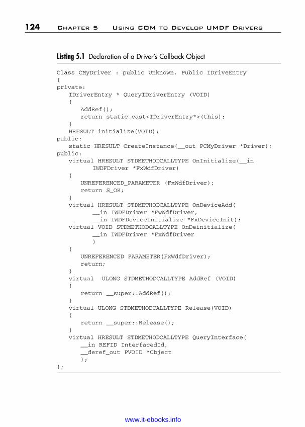
ptg
Listing 5.1 Declaration of a Driver’s Callback Object
Class CMyDriver : public Unknown, Public IDriveEntry{private:
IDriverEntry * QueryIDriverEntry (VOID){
AddRef();return static_cast<IDriverEntry*>(this);
}HRESULT initialize(VOID);
public:static HRESULT CreateInstance(__out PCMyDriver *Driver);
public:virtual HRESULT STDMETHODCALLTYPE OnInitialize(__in
IWDFDriver *FxWdfDriver){
UNREFERENCED_PARAMETER (FxWdfDriver);return S_OK;
}virtual HRESULT STDMETHODCALLTYPE OnDeviceAdd(
__in IWDFDriver *FwWdfDriver,__in IWDFDeviceInitialize *FxDeviceInit);
virtual VOID STDMETHODCALLTYPE OnDeinitialize(__in IWDFDriver *FxWdfDriver)
{UNREFERENCED PARAMETER(FxWdfDriver);return;
}virtual ULONG STDMETHODCALLTYPE AddRef (VOID){
return __super::AddRef();}virtual ULONG STDMETHODCALLTYPE Release(VOID){
return __super::Release();}virtual HRESULT STDMETHODCALLTYPE QueryInterface(
__in REFID InterfacedId,__deref_out PVOID *Object);
};
124 Chapter 5 Using COM to Develop UMDF Drivers
Wow! eBook <WoweBook.Com>
www.it-ebooks.info
ptg
IUnknown is the core COM interface; it is exposed by every COMobject and is essential to the object’s operation. The approach that is usedby the UMDF sample code is to have an IUnknown base class, calledCUnknown, plus an implementation for each exposed interface thatinherits from the base class.
5.3.4.2 Implementing AddRef and ReleaseReference counting is arguably the key task of IUnknown. Normally, asingle reference count is maintained for the object as a whole. The follow-ing are some recommendations for handling AddRef and Release:
■ Have the interface-specific implementations pass their calls to thebase implementation and let it handle incrementing or decrement-ing the reference count for the object.
■ Use InterlockedIncrement and InterlockedDecrement tomodify the reference count. This eliminates the possibility of a racecondition.
■ After the Release method decrements the reference count, checkto see whether the count has gone to zero. If so, there are no out-standing interface pointers and you can use delete to destroy theobject.
■ Both AddRef and Release return the current reference count. Usethis for debugging purposes.
5.3.5 Implementing QueryInterfaceQueryInterface is the fundamental mechanism by which a COM objectprovides pointers to its interfaces. It responds to a client’s request byreturning the specified interface pointer. The following are some recom-mendations for QueryInterface:
■ QueryInterface must check the incoming IID to see if the requestis for a supported interface. IsEquallD is a utility function declaredin guiddef.h that simplifies comparing IIDs.
■ If the object supports the requested interface, QueryInterface callsAddRef to increment the object’s reference count and returns therequested interface pointer. To return the pointer, QueryInterfacecasts a this pointer to the requested interface type. This cast is requiredbecause of the way in which C++ handles multiple inheritances.
5.3 Basic Infrastructure Implementation 125
Wow! eBook <WoweBook.Com>
www.it-ebooks.info

ptg
■ When a client queries for IUnknown, an object must always returnthe same IUnknown pointer regardless of which interfaceQueryInterface is called from.
The basic process of implementing UMDF callback interfaces is similar toIUnknown. Most of the implementation details are governed by therequirements of the individual methods.
126 Chapter 5 Using COM to Develop UMDF Drivers
Wow! eBook <WoweBook.Com>
www.it-ebooks.info

ptg
P A R T I I I
KERNEL MODE DRIVERS
Wow! eBook <WoweBook.Com>
www.it-ebooks.info

ptg
This page intentionally left blank
Wow! eBook <WoweBook.Com>
www.it-ebooks.info

ptg
C H A P T E R 6
WINDOWS 7 KERNEL MODEDRIVERS OVERVIEW ANDOPERATIONS
The Kernel Mode Driver Framework (KMDF) is an infrastructure fordeveloping Kernel Mode Drivers. It provides a C-language device-driverinterface (DDI) and can be used to create drivers for Windows 7. Inessence, the framework is a skeletal device driver that can be customizedfor specific devices. KMDF implements code to handle common driverrequirements. Drivers customize the framework by setting object proper-ties, registering callbacks to be notified of important events, and includingcode only for features that are unique to their device.
KMDF provides a well-defined object model and controls the lifetimeof objects and memory allocations. Objects are organized hierarchically ina parent/child model, and important driver data structures are maintainedby KMDF instead of by the driver.
This chapter provides an introduction to the architecture and featuresof KMDF and to the requirements for drivers that use KMDF (sometimescalled KMDF-based drivers or simply DMDF drivers).
As we covered in Part II, the Windows Driver Foundation (WDF) alsoincludes a User Mode Driver Framework (UMDF). If your device doesnot handle interrupts, perform direct memory access (DMA), or requireother kernel mode resources such as nonpaged pool memory, you shouldconsider writing a User Mode Driver instead.
6.1 KMDF Supported Devices
KMDF was designed to replace the Windows Driver Model (WDM).The initial KMDF release supports most of the same devices and deviceclasses as WDM, except in those that are currently supported by
129
Wow! eBook <WoweBook.Com>
www.it-ebooks.info

ptg
miniport models. Table 6.1 lists the device and driver types that KMDF supports.
Table 6.1 Devices and Driver Types That KMDF Supports
130 Chapter 6 Windows 7 KMD Overview and Operations
Device or Driver Type
Control and non-Plugand Play driversIEEE 1394 clientdrivers
ISA, PCI, PCMCIA, andsecure digital (SD)devices
NDIS protocol drivers
NDIS WDM drivers
SoftModem drivers
Storage class drivers andfilter driversTransport driverinterface (TDI) clientdriversUSB client drivers
Winsock client drivers
Existing Driver Model
Legacy
Depends on deviceclass
WDM driver
WDM upper edge andNDIS lower edgeNDIS upper edge andWDM lower edgeWDM driver withupper Edge supportfor TAPI InterfaceWDM driver
Generic WDM driver
Depends on deviceclassWDM driver with acallback interface fordevice-specificrequests
Comments
Supported
Supported for devicesthat do not conform toexisting device classspecificationsSupported, if device classor port drivers do notprovide the driverdispatch functionsSupported
Supported
Supported
Supported
Supported
Supported
Supported
In general, KMDF supports drivers that conform to WDM, supplyentry points for the major I/O dispatch routines, and handle I/O requestpackets (IRPs). For some device types, device class and port drivers sup-ply driver dispatch functions and call back to a miniport driver to handle
Wow! eBook <WoweBook.Com>
www.it-ebooks.info
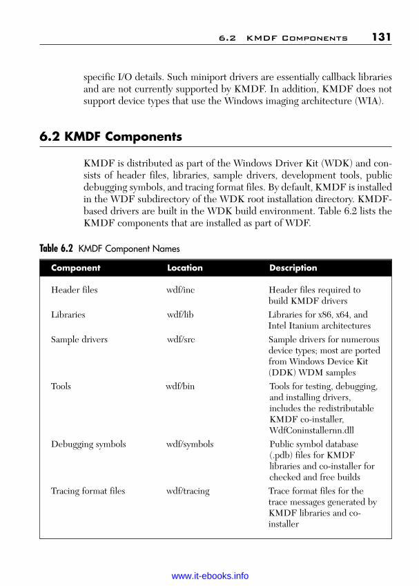
ptg
specific I/O details. Such miniport drivers are essentially callback librariesand are not currently supported by KMDF. In addition, KMDF does notsupport device types that use the Windows imaging architecture (WIA).
6.2 KMDF Components
KMDF is distributed as part of the Windows Driver Kit (WDK) and con-sists of header files, libraries, sample drivers, development tools, publicdebugging symbols, and tracing format files. By default, KMDF is installedin the WDF subdirectory of the WDK root installation directory. KMDF-based drivers are built in the WDK build environment. Table 6.2 lists theKMDF components that are installed as part of WDF.
Table 6.2 KMDF Component Names
6.2 KMDF Components 131
Component Location Description
Header files wdf/inc Header files required to build KMDF drivers
Libraries wdf/lib Libraries for x86, x64, and Intel Itanium architectures
Sample drivers wdf/src Sample drivers for numerousdevice types; most are portedfrom Windows Device Kit (DDK) WDM samples
Tools wdf/bin Tools for testing, debugging, and installing drivers, includes the redistributable KMDF co-installer, WdfConinstallernn.dll
Debugging symbols wdf/symbols Public symbol database (.pdb) files for KMDF libraries and co-installer for checked and free builds
Tracing format files wdf/tracing Trace format files for the trace messages generated by KMDF libraries and co-installer
Wow! eBook <WoweBook.Com>
www.it-ebooks.info
ptg
To aid in debugging, KMDF is distributed with free and checkedbuilds of the run-time libraries and loader, along with corresponding sym-bols. However, Microsoft does not provide a checked version of the redis-tributable co-installer itself.
6.3 KMDF Driver Structure
A KMDF driver consists of a DriverEntry function that identifies thedriver as based on KMDF, a set of callback functions that KMF calls sothat the driver can respond to events that affect its device, and otherdriver-specific utility functions. Nearly every KMDF driver must have thefollowing:
■ A DriverEntry function, which represents the driver’s primary entrypoint
■ An EvtDriverDeviceAdd callback, which is called when the Plugand Play manager enumerates one of the driver’s devices (notrequired for drivers that support non-Plug and Play devices)
■ One or more EvtIo* callbacks, which handle specific types of I/Orequests from a particular queue
Drivers typically create one or more queues into which KMDF places I/Orequests for the driver’s device. A driver can configure the queues by typeof request and type of dispatching.
A minimal Kernel Mode Driver for a simple device might have thesefunctions and nothing more. KMDF includes code to support defaultpower management and Plug and Play operations, so drivers that do notmanipulate physical hardware can omit most Plug and Play and powermanagement code. If a driver can use the default, it does not require codefor many common tasks, such as passing a power IRP down the devicestack. The more device-specific features a device supports and the morefunctionality the driver provides the more code the driver requires.
6.4 Comparing KMDF and WDM Drivers
The KMDF model results in drivers that are much simpler and easier todebug than WDM drivers. KMDF drivers require minimal commoncode for default operations because most such code resides in the
132 Chapter 6 Windows 7 KMD Overview and Operations
Wow! eBook <WoweBook.Com>
www.it-ebooks.info

ptg
framework, where it has been thoroughly tested and can be globallyupdated.
Because KMDF events are clearly and narrowly defined, KMDF-based drivers typically require little code complexity. Each driver callbackroutine is designed to perform a specific task. Therefore, compared toWDM drivers, KMDF-based drivers have fewer lines of code and virtuallyno state variables or locks.
As part of the WDF development effort, Microsoft has convertedmany of the sample drivers that shipped with the Windows DDK fromWDM drivers to KMDF drivers. Without exception, the KMDF driversare smaller and less complex.
Table 6.3 shows “before-and-after” statistics for the PCIDRV, Serial,and OSRUSBFX2 drivers.
Table 6.3 WDM-KMDF Statistics for Sample Drivers
6.4 Comparing KMDF and WDM Drivers 133
Statistic PCIDRV Serial OSRUSBFX2
WDM KMDF WDM KMDF WDM KMDF
Total lines of code 13,147 7,271 24,000 17,000 16,350 2,300Lines of code required 7,991 1,795 5,000 2,500 8,700 742for Plug and Play and power managementLocks and 8 3 10 0 9 0synchronizationState variables required 30 0 53 0 21 0for Plug and Play and power management
The PCIDRV sample supports the Intel E100B NIC card. The WDMand KMDF versions are functionally equivalent. The Serial sample sup-ports a serial device. In this case, the WDM sample supports a multiportdevice, but the KMDF sample supports only a single port. However, thestatistics for the WDM driver do not include code, locks, or variables thatare required solely to support multiport devices, so the statistics are com-parable. The OSRUSBFX2 sample supports the USB-FX2 board built byOSR. The WDM and KMDF versions are functionally equivalent.
Wow! eBook <WoweBook.Com>
www.it-ebooks.info

ptg
As the table shows, converting these drivers from WDM to KMDFresulted in significant reductions in the lines of code, particularly for Plugand Play and power management. The KMDF samples also require fewerlocks and synchronization primitives and state variables. The followinginformation shows more detail with respect to these requirements:
■ Lines of code—The KMDF drivers require significantly fewerlines of code both overall and to implement Plug and Play andpower management. Less code means a less complex driver withfewer opportunities for error and a smaller executable image.
■ Locks and synchronization primitives—Not only are theKMDF drivers smaller, but in all three cases the number of locksand synchronization primitives has been reduced significantly. Thischange is important because it eliminates a common source ofdriver problems. WDM drivers use locks to synchronize I/O queueswith Plug and Play and power operations and often supply locks tomanage I/O cancellation. The locking scenarios typically involve oneor more race conditions and can be difficult to implement correctly.KMDF drivers can be implemented with few such locks becausethe framework provides the locking.
■ State variables—The number of state variables that are requiredfor Plug and Play and power management is a measure of the com-plexity of the Plug and Play and power management implementa-tion within the driver. A WDM driver receives Plug and Play andpower management requests from the operating system in the formof IRPs. When such a driver receives a Plug and Play or power IRP,it must determine the current state of its device and the system and,based on those two states, must determine what to do to satisfy theIRP. Drivers must handle some IRPs immediately upon arrival asthey travel down the device stack, but must handle others only afterthey have been acted upon by drivers lower in the stack.Consequently, a WDM driver must keep track of numerous detailsabout the current state of its device and of current Plug and Playand power management requests. Tracking this informationrequires 30 variables in the WDM PCIDRV sample, 53 in the Serialsample, and 21 in the OSRUSBFX2 sample.
The KMDF versions of the three sample drivers require no state variables.The KMDF drivers do not maintain such information because the
134 Chapter 6 Windows 7 KMD Overview and Operations
Wow! eBook <WoweBook.Com>
www.it-ebooks.info

ptg
framework does so on their behalf. The framework implements an exten-sive state machine that integrates Plug and Play and power managementoperations with I/O operations. A driver provides callbacks that areinvoked only when its device requires manipulation. For example, a driverfor a device that supports a wake-up signal can register a callback that armsthe signal, and KMDF invokes the callback at the appropriate time. Bycontrast, a WDM driver must determine which power management IRPsrequire it to arm the signal and at which point in handling those IRPs itshould do so.
6.5 Device Objects and Driver Roles
Every driver creates one or more device objects, which represent thedriver’s roles in handling I/O requests and managing its device. KMDFsupports the development of the following types of device objects:
■ Filter device objects (filter DOs) represent the role of a filter driver.Filter DOs “filter,” or modify, one or more types of I/O requests thatare targeted at the device. Filter DOs are attached to the Plug andPlay device stack.
■ Functional device objects (FDOs) represent the role of a functiondriver, which is the primary driver for a device. FDOs are attachedto the Plug and Play device stack.
■ Physical device objects (PDOs) represent the role of the bus driver,which enumerates child devices. PDOs are attached to the Plug andPlay device stack.
■ Control device objects represent a legacy non-Plug and Play deviceor a control interface. They are not part of the Plug and Play devicestack.
Depending on the design of the device and the other drivers in the devicestack, a driver might assume one or more of these roles. Each Plug andPlay device has one function driver and one bus driver, but can have anynumber of filter drivers. In the Plug and Play device stack, a driver some-times acts as the function driver for one device and as the bus driver forthe devices that its device enumerates. For example, a USB hub driver actsas the function driver for the hub itself and the bus driver for each USB
6.5 Device Objects and Driver Roles 135
Wow! eBook <WoweBook.Com>
www.it-ebooks.info
ptg
device that is attached to the hub. Thus, it creates an FDO for the hub anda PDO for each attached USB device.
6.5.1 Filter Drivers and Filter Device ObjectsA filter driver receives one or more types of I/O requests that are targetedat its device, takes some action based on the request, and then passes therequest to the next driver in the stack. Filter drivers do not typically per-form device I/O themselves; instead, they modify or record a request thatanother driver satisfies. Device-specific data encryption/decryption soft-ware is commonly implemented as a filter driver.
A filter driver adds a filter DO to the Plug and Play device stack. AKMDF driver notifies the framework that it is a filter driver when itsdevice is added to the system, so that KMDF creates a filter DO and setsthe appropriate defaults.
Most filter drivers are not “interested” in every request that is targetedat their devices; a filter driver might filter only read requests or only cre-ate requests. To simplify filter driver implementation, KMDF dispatchesonly the types of requests that the filter driver specifies and passes all otherrequests down the device stack. The filter driver never receives them andso does not require code to inspect them or pass them to another driver.
The sample Firefly, Kbfiltr, and Toaster Filter drivers create filterDOs.
KMDF does not support the development of bus filter drivers. Suchdrivers are layered immediately above a bus driver that creates a PDO andadd their device objects to the stack when Plug and Play manager queriesthe bus driver for bus relations.
6.5.2 Function Drivers and Functional Device ObjectsFunction drivers are the primary drivers for their devices. A functiondriver communicates with its device to perform I/O and typically managespower policy for its device. In the Plug and Play device stack, a functiondriver exposes an FDO.
To support function drivers, KMDF includes an FDO interface, whichdefines a set of methods, events, and properties that apply to FDOs duringinitialization and operation. By using the FDO interface, a driver can
136 Chapter 6 Windows 7 KMD Overview and Operations
Wow! eBook <WoweBook.Com>
www.it-ebooks.info
ptg
■ Register event callbacks that are related to resource allocation for itsdevice.
■ Retrieve properties of its physical device.■ Open a registry key.■ Manage a list of child devices, if the device enumerates one or more
children.
When the driver creates its device object, KMDF creates an FDO unlessthe driver notifies it otherwise.
By default, KMDF assumes that the function driver is the power pol-icy manager for its device. If the device supports wake-up signals, the func-tion driver typically also sets power policy event callbacks to implementthis feature. All the sample drivers, except the KbFiltr and Firefly drivers,create an FDO.
6.5.3 Bus Drivers and Physical Device ObjectsA bus driver typically operates as the function driver for a parent devicethat enumerates one or more child devices. The parent device might be abus but could also be a multifunction device that enumerates childrenwhose functions require different types of drivers. In the Plug and Playdevice stack, a bus driver exposes a PDO.
KMDF defines methods, events, and properties that are specific toPDOs, just as it does for FDOs. By using the PDO interface, a driver can
■ Register event callbacks so that the driver can report the hardwareresources that its children require.
■ Register event callbacks that are related to device locking and ejec-tion.
■ Register event callbacks that perform bus-level operations so that itschild devices can trigger a wake signal.
■ Assign Plug and Play, compatible, and instance IDs to its childdevices.
■ Set removal and ejection relations for its child devices.■ Notify the system that a child device has been ejected or surprise
removed.■ Retrieve and update the bus address of a child device.■ Indicate that the driver controls a raw device. (A raw device is
driven directly by a bus driver, without a function driver.)
6.5 Device Objects and Driver Roles 137
Wow! eBook <WoweBook.Com>
www.it-ebooks.info
ptg
To indicate that it is a bus driver, a KMDF driver calls one or more ofthe PDO initialization methods before creating its device object. If thedriver indicates that it is driving a raw device, KMDF assumes that thedriver is the power policy manager for the device.
Writing bus drivers is much simpler with KMDF than with WDM.KMDF manages the state of the PDO on behalf of the driver, so that thedriver is only required to notify KMDF when the device is added orremoved. KMDF supports both static and dynamic models for enumerat-ing child devices. If the status of child devices rarely changes, the busdriver should use the static model. The dynamic model supports drivers fordevices such as IEEE 1394 buses, where the status of child devices mightchange at any time.
For bus drivers, KMDF handles most of the details of enumeration,including:
■ Reporting children to WDM.■ Coordinating scanning for children.■ Maintaining the list of children.
In addition, the KMDF interface through which drivers report resourcerequirements is easier to use than that provided by WDM.
The sample KbFiltr, OsrUsbFx2/EnumSwitches, and Toaster busdrivers create PDOs and use both the static and dynamic methods toenumerate their child devices.
6.5.4 Legacy Device Drivers and Control Device Objects
In addition to Plug and Play function, bus, and filter drivers, KMDF sup-ports the development of drivers for legacy devices, which are not con-trolled by a Plug and Play lifetime model. Such drivers create controldevice objects, which are not part of the Plug and Play device stack.
Plug and Play drivers can also use control device objects to imple-ment control interfaces that operate independently of the device stack. Anapplication can send requests directly to the control device object, thusbypassing any filtering performed by other drivers in the stack. Such a con-trol device object typically has a queue and might sometimes forwardrequests from that queue to a Plug and Play device object.
138 Chapter 6 Windows 7 KMD Overview and Operations
Wow! eBook <WoweBook.Com>
www.it-ebooks.info

ptg
Because control device objects are not part of the Plug and Playdevice stack, the driver must notify KMDF when their initialization iscomplete. In addition, the driver itself must delete the device object whenthe device has been removed because only the driver knows how to con-trol the lifetime of such a device. The sample NdisProt, NonPnP, andToaster Filter drivers create control device objects.
6.6 KMDF Object Model
KMDF defines an object-based programming model in which object typesrepresent common driver constructs. Each object exports methods (func-tions) and properties (data) that drivers can access and is associated withobject-specific events, which drivers can support by providing event call-backs. The objects themselves are opaque to the driver.
KMDF creates some objects on behalf of the driver, and the driver cre-ates others depending on its specific requirements. The driver also providescallbacks for the events for which the KMDF defaults do not suit its deviceand calls methods on the object to get and set properties and perform anyadditional actions. Consequently, a KMDF driver is essentially a Driver-Entry routine, a set of callback functions that perform device-specific tasks,and whatever utility functions the driver implementation requires.
Framework-base drivers never directly access instances of frameworkobjects. Instead, they reference object instances by handles, which thedriver passes as parameters to object methods and KMDF passes asparameters to event callbacks. Framework objects are unique to the frame-work. They are not managed by the Windows object manager and cannotbe manipulated by using the system’s ObXxx function. Only the frame-work (and its drivers) can create and operate on them.
6.6.1 Methods, Properties, and EventsMethods are functions that perform an action on an object, such as creat-ing or deleting the object. KMDF methods are named according to the fol-lowing pattern:
WdfObjectOperation
Object specifies the KMDF object on which the method operates,and Operation indicates what the method does. For example, theWdfDeviceCreate method creates a framework device object.
6.6 KMDF Object Model 139
Wow! eBook <WoweBook.Com>
www.it-ebooks.info

ptg
Properties are functions that read and write data fields in an object,thus defining object behavior and defaults. Properties are named accord-ing to the following pattern:
WdfObject{Set|Get}DataWdfObject{Assign|Retrieve}Data
Object specifies the KMDF object on which the function operates, andData specifies the field that the function reads or writes. Some properties canbe read and written without failure, but others can sometimes fail. Functionswith Set and Get in their names read and write fields without failure. The Setfunctions return VOID, and the Get functions typically return the value ofthe field. Functions with Assign and Retrieve in their names read and writefields but can fail. These functions return an NTSTATUS value.
For example, the WDFINTERRUPT object represents the interruptobject for a device. Each interrupt object is described by a set of charac-teristics that indicate the type of interrupt (message signaled or IRQbased) and provide additional information about the interrupt. TheWdfInterruptGetInfo method returns this information. A correspondingmethod to set the value is not available because the driver initializes thisinformation when it creates the interrupt object and cannot change it dur-ing device operation.
Events represent run-time states to which a driver can respond or dur-ing which a driver can participate. A driver registers callbacks only forthe events that are important to its operation. When the event occurs, theframework invokes the callback, passing as a parameter a handle tothe object for which the callback is registered. For example, the ejection ofa device is a Plug and Play event. If a device can be ejected, its driver reg-isters an EvtDeviceEject callback routine, which performs device-spe-cific operations upon ejection. KMDF calls this routine with a handle tothe device object when the Plug and Play manager sends an IRP_MN_EJECT request for the device. If the device cannot be ejected, thedriver does not require such a callback.
For most events, a driver can either provide a callback routine or allowKMDF to perform a default action in response. For a few events, however,a driver-specific callback is required. For example, adding a device is anevent for which every Plug and Play driver must include a callback. Thedriver’s EvtDriverDeviceAdd callback creates the device object and setsdevice attributes.
KMDF events are not related to the kernel-dispatcher events thatWindows provides as synchronization mechanisms. A driver cannot create,
140 Chapter 6 Windows 7 KMD Overview and Operations
Wow! eBook <WoweBook.Com>
www.it-ebooks.info

ptg
manipulate, or wait on a KMDF event. Instead, the driver registers acallback for the event and KMDF calls the driver when the event occurs.(For time-related waits, KMDF provides timer objects.)
6.6.2 Object HierarchyKMDF objects are organized hierarchically. WDFDRIVER is the rootobject; all other objects are considered its children. For most object types, adriver can specify the parent when it creates the object. If the driver does notspecify a parent at object creation, the framework sets the default parent to theWDFDRIVER object. Figure 6.1 shows the default KMDF object hierarchy.
6.6 KMDF Object Model 141
Figure 6.1 Parent-Child Relationships Among the KMDF Objects
WDFDRIVER
WDFDEVICE
WDFDMAENABLER
WDF COMMONBUFFERWDFTRANSACTION
WDFIORESREQLIST
WDFIORESLIST
WDFQUEUE
WDFDPCWDFTIMER
WDFWORKITEM
WDRWMIPROVIDER
WDFWMIINSTANCE
WDFCMRESLIST
WDFUSBDEVICE
WDFUSBINTERFACE
WDFUSBPIPE
WDFCHILDLISTWDFFILEOBJECTWDFINTERRUPTWDFIOTARGETWDFREQUEST
(Delivered from Queue)
WDFCOLLECTIONWDFKEY
WDFLOOKASIDEWDFMEMORYWDFOBJECT
WDFREQUEST(Driver Created)WDFSPINLOCK
WDFSTRINGWDFWAITLOCK
Wow! eBook <WoweBook.Com>
www.it-ebooks.info

ptg
For each object, the figure shows which other object(s) must be in its par-ent chain. These objects are not necessarily the immediate parent butcould be the grandparent, great-grandparent, and so forth. For example,Figure 6.1 shows the WDFDEVICE object as parent of theWDFQUEUE object. However, a WDFQUEUE object could be thechild of a WDFIOTARGET object, which in turn is the child of aWDFDEVICE object. Thus, the WDFDEVICE object is in the parentchain for the WDFQUEUE object.
The object hierarchy affects the object’s lifetime. The parent holds areference count for each child object. When the parent object is deleted,the child objects are deleted and their callbacks are invoked in a definedorder. Table 6.4 lists all the KMDF object types.
Table 6.4 KMDF Object Types
142 Chapter 6 Windows 7 KMD Overview and Operations
Object Type Description
Child list WDFCHILDLIST Represents a list of the child devices for adevice.
Collection WDFCOLLECTION Describes a list of similar objects, such as resources or the devices for which a filter driver filters requests.
Device WDFDEVICE Represents an instance of a device. A driver typically has one WDFDEVICE object for each device that it controls.
DMA WDFCOMMON Represents a buffer that can be accessed bycommon BUFFER both the device and the driver to performbuffer DMA.DMA enabler WDFDMAENABLER Enables a driver to use DMA. A driver that
handles device I/O operations has one WDFDMAENABLER object for each DMAchannel within the device.
DMA WDFDMATRANS- Represents a single DMA transaction.transaction ACTIONDeferred WDFDPC Represents a Deferred Procedure Call.ProcedureCall (DPC)Driver WDFDRIVER Represents the driver itself and maintains
information about the driver, such as its entrypoints. Every driver has one WDFDRIVER object.
Wow! eBook <WoweBook.Com>
www.it-ebooks.info
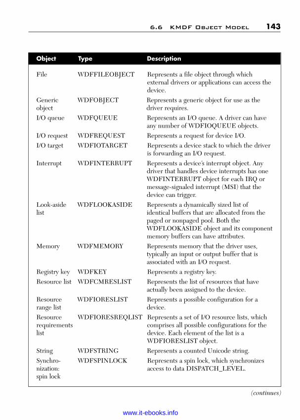
ptg
6.6 KMDF Object Model 143
Object Type Description
File WDFFILEOBJECT Represents a file object through which external drivers or applications can access thedevice.
Generic WDFOBJECT Represents a generic object for use as theobject driver requires.I/O queue WDFQUEUE Represents an I/O queue. A driver can have
any number of WDFIOQUEUE objects.I/O request WDFREQUEST Represents a request for device I/O.I/O target WDFIOTARGET Represents a device stack to which the driver
is forwarding an I/O request.Interrupt WDFINTERRUPT Represents a device’s interrupt object. Any
driver that handles device interrupts has one WDFINTERRUPT object for each IRQ or message-signaled interrupt (MSI) that the device can trigger.
Look-aside WDFLOOKASIDE Represents a dynamically sized list of list identical buffers that are allocated from the
paged or nonpaged pool. Both the WDFLOOKASIDE object and its componentmemory buffers can have attributes.
Memory WDFMEMORY Represents memory that the driver uses, typically an input or output buffer that is associated with an I/O request.
Registry key WDFKEY Represents a registry key.Resource list WDFCMRESLIST Represents the list of resources that have
actually been assigned to the device.Resource WDFIORESLIST Represents a possible configuration for arange list device.Resource WDFIORESREQLIST Represents a set of I/O resource lists, whichrequirements comprises all possible configurations for thelist device. Each element of the list is a
WDFIORESLIST object.String WDFSTRING Represents a counted Unicode string.Synchro- WDFSPINLOCK Represents a spin lock, which synchronizesnization: access to data DISPATCH_LEVEL.spin lock
(continues)
Wow! eBook <WoweBook.Com>
www.it-ebooks.info

ptg
6.6.3 Object AttributesEvery KMDF object is associated with a set of attributes. The attributesdefine information that KMDF requires for objects, as listed in Table 6.5.
Table 6.5 KMDF Object Attributes
144 Chapter 6 Windows 7 KMD Overview and Operations
Field Description
ContextSizeOverride Size of the context area; overrides the value in ContextTypeInfo->ContextSize.
ContextTypeInfo Pointer to the type information for the object context area.EvtCleanupCallback Pointer to a callback routine that is invoked to clean up the
object before it is deleted; the object might still have references.
Object Type Description
Synchronization: WDFWAITLOCK Represents a wait lock, which synchro-wait lock nizes access to data at PASSIVE_LEVEL.Timer WDFTIMER Represents a timer that fires either
once or periodically and causes a callback routine run.
USB device WDFUSBDEVICE Represents a USB device.USB interface WDFUSBINTERFACE Represents an interface on a USB
device.USB pipe WDFUSBPIPE Represents a pipe in a USB interface.Windows WDFWMIINSTANCE Represents an individual WMI dataManagement block that is associated with a particularInstrumentation provider(WMI) instanceWMI provider WDFWMIPROVIDER Represents the schema for WMI data
blocks that the driver provides.Work item WDFWORKITEM Represents a work item, which runs in
a system thread at PASSIVE_LEVEL.
Table 6.4 KMDF Object Types (continued)
Wow! eBook <WoweBook.Com>
www.it-ebooks.info

ptg
6.6 KMDF Object Model 145
Field Description
EvtDestroyCallback Pointer to a callback routine that is invoked when the reference count reaches zero for an object that is marked for deletion.
ExecutionLevel Maximum interrupt request level (IRQL) at which KMDFcan invoke certain object callbacks.
ParentObject Handle to the object’s parent.Size Size of the objectSynchronizationScope Level at which certain callbacks for this object are
synchronized; applies only to driver, device, and file objects.
The framework supplies defaults for most attributes. A driver canoverride these defaults when it creates the object by using the WDF_OBJECT_ATTRIBUTES_INIT function.
6.6.4 Object ContextEvery instance of a KMDF object can have one or more object contextareas. This area is a driver-defined storage area for data that is related to aspecific instance of an object, such as a driver-allocated lock or event forthe object. The size and layout of the object context area are determinedby the driver. When the driver creates the object, it initializes the contextarea and specifies its size and type. The driver can create additional con-text areas after the object has been created. For a KMDF device object,the object context area is the equivalent of the WDM device extension.
When KMDF creates the object, it allocates memory for context areasfrom the nonpaged pool and initializes them according to the driver’s spec-ifications. When KMDF deletes the object, it deletes the context areas,too. The framework provides macros to associate a type and a name withthe context area and to create a named accessor function that returns apointer to the context area.
If you are familiar with WDM, this design might seem unnecessarilycomplicated. However, it provides flexibility in attaching information to I/Orequests as they flow through the driver. In addition, it enables differentlibraries to have their own separate context for an object. For example, anIEEE 1394 library could track a WDFDEVICE object at the same time
Wow! eBook <WoweBook.Com>
www.it-ebooks.info

ptg
that the device’s function driver tracks it, but with separate contexts. Withina driver, the context area enables a design pattern that is similar to inheri-tance. If the driver uses a request for several different tasks, the requestobject can have a separate context area to each task. Functions that arerelated to a specific task can access their own contexts and do not requireany information about the existence or contents of any other contexts.
6.6.5 Object Creation and DeletionTo create an object, KMDF does the following:
■ Allocates memory from the nonpaged pool for the object and itscontext areas.
■ Initializes the object’s attributes with default values and the driver’sspecifications (if any).
■ Zeroes the object’s context areas.■ Configures the object by storing pointers to its event callbacks and
setting other object-specific characteristics.
If object initialization fails, KMDF deletes the object and any children thathave already been created.
To initialize object attributes and configuration structures, a driverinvokes KMDF initialization functions before it calls the object-creationmethods. KMDF uses the initialized attributes and structures when it cre-ates the object.
KMDF maintains a reference count for each object and ensures thatthe object persists until all references to it have been released. If the driverexplicitly deletes an object (by calling a deletion method), KMDF marksthe object for deletion but does not physically delete it until its referencecount reaches zero.
Drivers do not typically take out references on the objects that theycreate, but in some cases (such as when escaping directly to WDM) suchreferences are necessary to ensure that the object’s handle remains valid.For example, a driver that sends asynchronous I/O requests might take outa reference on the request object to guard against race conditions duringcancellation. Before the request object can be deleted, the driver mustrelease this reference.
Object deletion starts from the object farthest from the parent andworks up the object hierarchy toward the root. KMDF takes the followingsteps to delete an object:
146 Chapter 6 Windows 7 KMD Overview and Operations
Wow! eBook <WoweBook.Com>
www.it-ebooks.info

ptg
6.7 KMDF I/O Model 147
■ Starting with the child object farthest from the parent, calls theobject’s EvtCleanupCallback. In this routine, drivers should per-form any cleanup tasks that must be done before the object’s parentis deleted. Such tasks might include releasing explicit references onthe object or a parent object. Note that when the EvtCleanup-Callback function runs, the object’s children still exist; even thoughtheir EvtCleanupCallback functions have already been invoked.
■ When the object’s reference count reaches zero, calls the object’sEvtDestroyCallback, if the driver has registered one.
■ Deallocates the memory that was allocated to the object and its con-text area.
KMDF always calls the EvtCleanupCallback routines of child objectsbefore calling those of their parent objects, so drivers are guaranteed thatthe parent object still exists when a child’s EvtCleanupCallback runs.This guarantee does not apply to EvtDestroyCallbacks, however;KMDF can call the EvtDestroyCallback routines in any order, so thatthe EvtDestroyCallback for a parent might be called before that of oneof its children.
Drivers can change the parent of most KMDF objects by setting theParentObject attribute. By setting the parent/child relationships appro-priately, a driver can avoid taking out explicit references on related objectsand can instead use the hierarchy and the associated callbacks to managethe object’s lifetime.
6.7 KMDF I/O Model
KMDF established its own dispatch routines that intercept all IRPs thatare sent to the driver. Figure 6.2 shows the overall flow of I/O through theKMDF library and driver.
When an IRP arrives, KMDF directs it to one of the following com-ponents for processing:
■ I/O request handler, which handles requests that involve device I/O.■ Plug and Play/power request handler, which handles Plug and
Play and power request (IRP_MJ_PNP and IRP_MJ_POWER requests) and notifies other components of changes indevice status.
Wow! eBook <WoweBook.Com>
www.it-ebooks.info

ptg
148 Chapter 6 Windows 7 KMD Overview and Operations
■ WMI handler, which handles WMI and event-tracing request(IRP_MJ_SYSTEM_CONTROL requests).
Each component takes one or more of the following actions for eachrequest:
■ Raises one or more events to the driver.■ Forwards the request to another internal handler or I/O target for
further processing.■ Completes the request based on its own action.■ Completes the request as a result of a driver call.
If the request has not been processed when it reaches the end offrameworks processing, KMDF takes an action that is appropriate for thetype of driver. For function and bus drivers, KMDF completes the requestwith the status STATUS_INVALID_DEVICE_REQUEST. For filterdrivers, KMDF automatically forwards the request to the default I/O
IRPsDispatcher
Plug and Play/Power Request
Handler
WMI RequestHandler
I/O RequestHandler
Nonpower-Managed I/O
Queues
Power-ManagedI/O Queues
DriverCallbacks I/O Target
DriverCallbacks
DriverCallbacks
Figure 6.2 KMDF I/O Flow
Wow! eBook <WoweBook.Com>
www.it-ebooks.info

ptg
6.7 KMDF I/O Model 149
target (the next lower driver). The next sections describe how each of thethree components processes I/O requests.
6.7.1 I/O Request HandlerThe I/O request handler dispatches I/O requests to the driver, manages I/Ocancellation and completion, and works with the Plug and Play/power han-dler to ensure that the device state is compatible with performing device I/O.
Depending on the type of I/O request, the I/O request handler eitherqueues the request or invokes an event callback that the driver registeredfor the request.
6.7.1.1 Create, Cleanup, and Close RequestsTo handle create events, a driver can either configure a queue to receivethe events or can supply an event callback that is invoked immediately. Thedriver’s options are the following:
■ To be called immediately, the driver supplies an EvtDevice-FileCreate callback and registers it from the EvtDriverDevice-Add callback by calling WdfDeviceInitSetFileObjectConfig.
■ To configure a queue to receive the requests, the driver calls Wdf-DeviceConfigureRequestDispatching and specifies Wdf-RequestTypeCreate. If the queue is not manual, the driver mustregister an EvtIoDefault callback, which is called when a createrequest arrives.
Queuing takes precedence over the EvtDeviceFileCreate callback—that is,if the driver both registers for EvtDeviceFileCreate events and configuresa queue to receive such requests, KMDF queues the requests and does notinvoke the callback. KMDF does not queue create requests to a defaultqueue; the driver must explicitly configure a queue to receive them.
In a bus or function driver, if a create request arrives for which the driverhas neither registered an EvtDeviceFileCreate callback function nor con-figured a queue to receive create requests, KMDF opens a file object to rep-resent the device and completes the request with STATUS_SUCCESS.Therefore, any bus or function driver that does not accept create or openrequests from user mode application—and thus does not register a deviceinterface—must register an EvtDeviceFileCreate callback that explicitlyfails such requests. Supplying a callback to fail create requests ensures thata rogue user mode application cannot gain access to the device.
Wow! eBook <WoweBook.Com>
www.it-ebooks.info
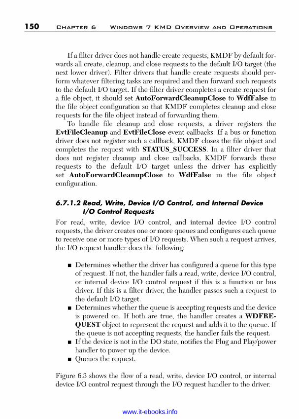
ptg
150 Chapter 6 Windows 7 KMD Overview and Operations
If a filter driver does not handle create requests, KMDF by default for-wards all create, cleanup, and close requests to the default I/O target (thenext lower driver). Filter drivers that handle create requests should per-form whatever filtering tasks are required and then forward such requeststo the default I/O target. If the filter driver completes a create request fora file object, it should set AutoForwardCleanupClose to WdfFalse inthe file object configuration so that KMDF completes cleanup and closerequests for the file object instead of forwarding them.
To handle file cleanup and close requests, a driver registers theEvtFileCleanup and EvtFileClose event callbacks. If a bus or functiondriver does not register such a callback, KMDF closes the file object andcompletes the request with STATUS_SUCCESS. In a filter driver thatdoes not register cleanup and close callbacks, KMDF forwards theserequests to the default I/O target unless the driver has explicitly set AutoForwardCleanupClose to WdfFalse in the file object configuration.
6.7.1.2 Read, Write, Device I/O Control, and Internal DeviceI/O Control Requests
For read, write, device I/O control, and internal device I/O controlrequests, the driver creates one or more queues and configures each queueto receive one or more types of I/O requests. When such a request arrives,the I/O request handler does the following:
■ Determines whether the driver has configured a queue for this typeof request. If not, the handler fails a read, write, device I/O control,or internal device I/O control request if this is a function or busdriver. If this is a filter driver, the handler passes such a request tothe default I/O target.
■ Determines whether the queue is accepting requests and the deviceis powered on. If both are true, the handler creates a WDFRE-QUEST object to represent the request and adds it to the queue. Ifthe queue is not accepting requests, the handler fails the request.
■ If the device is not in the DO state, notifies the Plug and Play/powerhandler to power up the device.
■ Queues the request.
Figure 6.3 shows the flow of a read, write, device I/O control, or internaldevice I/O control request through the I/O request handler to the driver.
Wow! eBook <WoweBook.Com>
www.it-ebooks.info
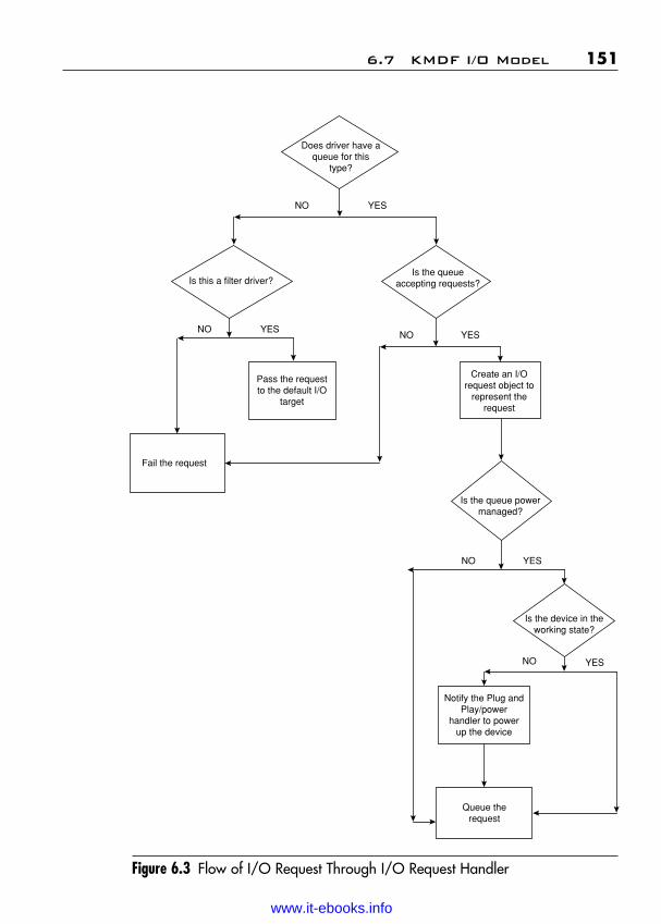
ptg
6.7 KMDF I/O Model 151
Figure 6.3 Flow of I/O Request Through I/O Request Handler
Does driver have aqueue for this
type?
NO YES
Is the queueaccepting requests?
NO YES
Create an I/Orequest object to
represent therequest
Is the queue powermanaged?
NO YES
Is the device in theworking state?
NO YES
Notify the Plug andPlay/power
handler to powerup the device
Queue therequest
Is this a filter driver?
NO YES
Pass the requestto the default I/O
target
Fail the request
Wow! eBook <WoweBook.Com>
www.it-ebooks.info

ptg
152 Chapter 6 Windows 7 KMD Overview and Operations
6.7.2 I/O QueuesA WDFQueue object represents a queue that presents requests fromKMDF to the driver. A WDFQUEUE is more than just a list of pendingrequests; however, it tracks requests that are active in the driver, supportsrequest cancellation, manages the concurrency of requests, and canoptionally synchronize calls to the driver’s I/O event callback functions.
A driver typically creates one or more queues, each of which canaccept one or more types of requests. The driver configures the queueswhen it creates them. For each queue, the driver can specify
■ The types of requests that are placed in the queue.■ The event callback functions that are registered to handle I/O
requests from the queue.■ The power management options for the queue.■ The dispatch method for the queue, which determines the number
of requests that are serviced at a given time.■ Whether the queue accepts requests that have a zero-length buffer.
A driver can have any number of queues, and they can all be configureddifferently. For example, a driver might have a parallel queue for readrequests and a sequential queue for write requests.
While a request is in a queue and has not yet been presented to thedriver, the queue is considered the “owner” of the request. After the requesthas been dispatched to the driver, it is “owned” by the driver and is consid-ered an in-flight request internally, and each WDFQUEUE object keepstrack of which requests it owns and which requests are pending. A driver canforward a request from one queue to another by calling a method on therequest object.
6.7.2.1 Queues and Power ManagementKMDF provides rich control of queues. The framework can manage thequeues for the driver, or the driver can manage queues on its own. Powermanagement is configurable on a per-queue basis. A driver can use bothpower-managed and non-power-managed queues and can sort requestsbased on the requirements for its power model.
By default, queues for FDOs and PDOs are power managed, whichmeans that the state of the queue can trigger power-management activi-ties. Such queues have several advantages:
Wow! eBook <WoweBook.Com>
www.it-ebooks.info

ptg
6.7 KMDF I/O Model 153
■ If an I/O request arrives while the system is in the working state(SO) but the device is not, KMDF notifies the Plug and Play/powerhandler so that it can restore device power.
■ When a queue becomes empty, KMDF notifies the Plug and Play/powerhandler so that it can track device usage through its idle timer.
■ If the device power state begins to change while the driver “owns” anI/O request, KMDF can notify the driver through the EvtIoStop call-back. The driver must complete, cancel, or acknowledge all the I/Orequests that it owns before the device can leave the working state.
For power-managed queues, KMDF pauses the delivery of requests whenthe device leaves the working state (DO) and resumes delivery when thedevice returns to the working state. Although delivery stops while the queueis paused, queuing does not. If KMDF receives a request while the queue is paused, KMDF adds the request to the queue for delivery afterthe queue resumes. If an I/O request arrives while the device is idle and thesystem is in the working state, KMDF returns the device to the workingstate so that it can handle the request. If an I/O request arrives while thesystem is transitioning to a sleep state, however, KMDF does not return thedevice to the working state until the system returns to the working state.
For requests to be delivered, both the driver and the device powerstate must allow processing. The driver can pause delivery manually bycalling WdfIoQueueStop and resume delivery by calling WdfIo-QueueStart.
If a queue is not power managed, the state of the queue has no effecton power management, and conversely, KMDF delivers requests to thedriver any time the system is in the working state, regardless of the powerstate of the device. KMDF does not start an idle timer when the queuebecomes empty, and it does not power up a sleeping device when I/Oarrives for the queue.
Drivers should use non-power-managed queues to hold requests thatthe driver can handle even while its device is not in the working state.
6.7.2.2 Dispatch TypeA queue’s dispatch type determines how and when I/O requests are deliv-ered to the driver and, as a result, whether multiple I/O requests from aqueue are active in the driver at one time. Drivers can control the concur-rency of in-flight requests by configuring the dispatching method for theirqueues. KMDF supports three dispatch types:
Wow! eBook <WoweBook.Com>
www.it-ebooks.info

ptg
154 Chapter 6 Windows 7 KMD Overview and Operations
■ Sequential—A queue that is configured for sequential dispatchingdelivers I/O requests to the driver one at a time. The queue does notdeliver another request to the driver until the previous request hasbeen completed. (Sequential dispatching is similar to the start-I/Otechnique in WDM.)
■ Parallel—A queue that is configured for parallel dispatching deliv-ers I/O requests to the driver as soon as possible, whether or notanother request is already active in the driver.
■ Manual—A queue that is configured for manual dispatching doesnot deliver I/O requests to the driver. Instead, the driver retrievesrequests at its own pace by calling a method on the queue.
The dispatch type controls only the number of requests that are activewithin a driver at one time. It has no effect on whether the queue’s I/Oevent callbacks are invoked sequentially or concurrently; instead, the con-currency of callbacks is controlled by the synchronization scope of thedevice object. Even if the synchronization scope for a parallel queue doesnot allow concurrent callbacks, the queue nevertheless might have manyin-flight requests.
All I/O requests that a driver receives from a queue are inherentlyasynchronous. The driver can complete the request within the event call-back or sometime later, after returning from the callback.
6.7.3 I/O Request ObjectsThe WDFREQUEST object is the KMDF representation of an IRP.When an I/O request arrives, the I/O handler creates a WDFREQUESTobject, queues the object, and eventually passes the object to the driver inits I/O callback function.
The properties of the WDFREQUEST object represent the fields ofthe IRP. The object also contains additional information. Like all otherKMDF objects, the WDFREQUEST object has a reference count andcan have its own object context area. When the driver completes the I/Orequest that the object represents, KMDF automatically frees the objectand any child resources such as associated memory buffers or memorydescriptor lists (MDLs). After the driver has called WdfRequest-Complete, the driver must not attempt to access the handle to theWDFREQUEST object or any of its child resources. A driver can createits own WDFREQUEST objects to request I/O from another device or tosplit an I/O request into multiple, smaller requests before completing it.
Wow! eBook <WoweBook.Com>
www.it-ebooks.info

ptg
6.7 KMDF I/O Model 155
6.7.4 Retrieving Buffers from I/O RequestsThe WDFMEMORY object encapsulates the I/O buffers that are sup-plied for an I/O request. To enable device drivers to handle complicatedrequests with widely scattered buffers, any number of WDFMEMORYobjects may be associated with a WDFREQUEST.
The WDFMEMORY object represents a buffer that the frameworkmanages. The object can be used to copy memory to and from the driverand the buffer represented by the WDFMEMORY handle. In addition,the driver can use the underlying buffer pointer and its length for complexaccess, such as casting to a known data structure.
Like other KMDF objects, WDFMEMORY objects have referencecounts and persist until all references to them have been removed. Thebuffer that underlies the WDFMEMORY object, however, might not be“owned” by the object itself. For example, if the issuer of the I/O requestallocated the buffer or if the driver called WdfMemoryCreate-Preallocated to assign an existing buffer to the object, theWDFMEMORY object does not “own” the buffer. In this case, the bufferpointer becomes invalid when the associated I/O request has been com-pleted, even if the WDFMEMORY object still exists.
Each WDFMEMORY object contains the length of the buffer that itrepresents. KMDF methods that copy data to and from the buffer validatethe length of every transfer to prevent buffer over- and underruns, whichcan result in corrupt data or security breaches.
Depending on the type of I/O that the device and driver support, theunderlying buffer might be any of the following:
■ For buffered I/O, a system-allocated buffer from the nonpagedpool.
■ For direct I/O, a system-allocated MDL that points to the physicalpages for DMA.
■ For neither buffered nor direct I/O, an unmapped and unverifieduser mode memory address.
The WDFMEMORY object supports methods that return each type ofbuffer from the object and methods to read and write the buffers. Fordevice I/O control requests (IOCTLs), KMDF provides methods to probeand lock user mode buffers. The driver must be running in the context ofthe process that sent the I/O request to probe and lock a user mode buffer,
Wow! eBook <WoweBook.Com>
www.it-ebooks.info

ptg
156 Chapter 6 Windows 7 KMD Overview and Operations
so KMDF also defines a callback that drivers can register to be called inthe context of the sending component.
Each WDFMEMORY object also controls access to the buffer andallows the driver to write only to buffers that support I/O from the deviceto the buffer. A buffer that is used to receive data from the device (as in aread request) is writable. The WDFMEMORY object does not allowwrite access to a buffer that only supplies data (as in a write request).
6.7.5 I/O TargetsDrivers send I/O requests by creating or reusing an I/O request object,creating an I/O target, and sending the request to the target. Drivers cansend requests either synchronously or asynchronously. A driver can spec-ify a time-out value for either type of request.
An I/O target represents a device object to which an I/O request isdirected. If a driver cannot complete an I/O request by itself, it typicallyforwards the request to an I/O target. An I/O target can be a KMDFdriver, a WDM driver, or any other Kernel Mode Driver.
Before a driver forwards an existing I/O request or sends a newrequest, it must create a WDFIOTARGET object to represent either alocal or remote target for the I/O request. The local I/O target is the nextlower driver in the device stack and is the default target or a filter or FDOdevice object. A remote I/O target is any other driver that might be the tar-get of an I/O request. A driver might use a remote I/O target if it requiresdata from another device to complete an I/O request. A function drivermight also use a remote I/O target to send a device I/O control request toits bus driver. In this case, the I/O request originates with the functiondriver itself, rather than originating with some other process.
The WDFIOTARGET object formats I/O requests to send to otherdrivers, handles changes in device state, and defines callbacks throughwhich a driver can request notification about target device removal. Adriver can call methods on the WDFIOTARGET to
■ Open a device object or device stack by name.■ Format read, write, and device I/O control requests to send to the
target. Some types of targets, such as WDFUSBDEVICE andWDFUSBPIPE, can format bus-specific requests in addition to thestandard request types.
Wow! eBook <WoweBook.Com>
www.it-ebooks.info

ptg
6.7 KMDF I/O Model 157
■ Send read, write, and device I/O control requests synchronously orasynchronously.
■ Determine the Plug and Play state of the target.
Internally, KMDF calls IoCallDriver to send the request. It takes out areference on the WDFREQUEST object to prevent the freeing of associ-ated resources while the request is pending for the target device object.
The WDFIOTARGET object racks queued and sent requests and cancancel them when the state of the target device or of the issuing driverchanges. From the driver’s perspective, the I/O target object behaves likea cancel-safe queue that retains forwarded requests until KMDF candeliver them. KMDF does not free the WDFIOTARGET object until allthe I/O requests that have been sent to it are complete.
By default, KMDF sends a request only when the target is in theproper state to receive it. However, a driver can also request that KMDFignore the state of the target and send the request anyway. If the targetdevice has been stopped (but not removed), KMDF queues the request tosend later after the target device resumes. If the issuing driver specifies atime-out value, the timer starts when the request is added to the queue.
If the device that is associated with a remote I/O target is removed,KMDF stops and closes the I/O target object, but does not notify the driverunless the driver has registered an EvtIoTargetXxx callback. If the drivermust perform any special processing of I/O requests that it sent to the I/Otarget, it should register one or more such callbacks. When the removal ofthe target device is queried, canceled, or completed, KMDF calls the cor-responding functions and then processes the target state changes on its own.
For local I/O targets, no such callbacks are defined. Because the driverand the target device are in the same device stack, the driver is notified ofdevice removal requests through its Plug and Play and power managementcallbacks.
6.7.6 Creating Buffers for I/O RequestsDrivers that issue I/O requests must supply buffers for the results of thoserequests. The buffers in a synchronous request can be allocated from any type of memory, such as the nonpaged pool or an MDL, as well as a WDFMEMORY object. Asynchronous requests must use
Wow! eBook <WoweBook.Com>
www.it-ebooks.info

ptg
158 Chapter 6 Windows 7 KMD Overview and Operations
WDFMEMORY object so that KMDF can ensure that the buffers persistuntil the I/O request has completed back to the issuing driver.
If the driver uses a WDFMEMORY object, the I/O target object takesout a reference on the WDFMEMORY object when it formats the objectto send to the I/O target. The target object retains this reference until oneof the following occurs:
■ The request has been completed.■ The driver reformats the WDFREQUEST object.■ The driver calls WdfRequestReuse to send a request to another
target.
A driver can retrieve a WDFMEMORY object from an incomingWDFREQUEST and reuse it later in a new request to a different target.However, if the driver has not yet completed the original request, the orig-inal I/O target still has a reference on the WDFMEMORY object. Toavoid a bug check, the driver must call WdfRequestReuse in its I/O com-pletion routine before it completes the original request.
6.7.7 Canceled and Suspended RequestsWindows I/O is inherently asynchronous. The system can request that adriver stop processing an I/O request at any time for many reasons, ofwhich these are the most common:
■ The thread or process that issued the request cancels it or exits.■ A system Plug and Play or power event such as hibernation occurs.■ The device is being, or has been, removed.
The actions that a driver takes to stop processing an I/O request depend onthe reason for suspension or cancellation. In general, the driver can eithercancel the request or complete it with an error. In some situations, the sys-tem might request that a driver suspend (temporarily pause) processing;the system notifies the driver later when to resume processing.
To provide a good user experience, drivers should provide callbacks tohandle cancellation and suspension of any I/O request that might take along time to complete or that might not complete, such as a request forasynchronous input.
Wow! eBook <WoweBook.Com>
www.it-ebooks.info

ptg
6.7 KMDF I/O Model 159
6.7.7.1 Request CancellationHow KMDF proceeds to cancel an I/O request depends on whether therequest has already been delivered to the target driver:
■ If the request has never been delivered—either because KMDF hasnot yet queued it or because it is still in a queue—KMDF cancelsor suspends it automatically. If the original IRP has been canceled,KMDF completes the request with a cancellation status.
■ If the request has been delivered and then requeued, KMDF noti-fies the driver of cancellation only if the driver has registered anEvtIoCanceledOnQueue callback for the queue.
After a request has been delivered, it cannot be canceled unless the driverthat owns it explicitly marks it cancelable by calling the WdfRequest-MarkCancelable method on the request and registering a cancellationcallback (EvtRequestCancel) for the request.
A driver should mark a request cancelable and register an I/O cancel-lation callback if either of the following is true:
■ The request involves a long-term operation.■ The request might never succeed; for example, the request is wait-
ing for synchronous input.
In the EvtRequestCancel callback, the driver must perform any tasksthat are required to cancel the request, such as stopping any device I/Ooperations that are in progress and canceling any related requests that ithas already forwarded to an I/O target. Eventually, the driver must com-plete the request with the status STATUS_CANCELLED.
Requests that are marked cancelable cannot be forwarded to anotherqueue. Before requeuing a request, the driver must first make it non-cancelable by calling WdfRequestUnmarkCancelable. After therequest has been added to the new queue, KMDF once again considers itcancelable until that queue dispatches it to the driver.
If the driver does not mark a request cancelable, it can callWdfRequestIsCanceled to determine whether the I/O manager or orig-inal requester has attempted to cancel the request. A driver that processesdata on a periodic basis might use this approach. For example, a driverinvolved in image processing might complete a transfer request in small
Wow! eBook <WoweBook.Com>
www.it-ebooks.info

ptg
chunks and poll for cancellation after processing each chunk. In this case,the driver supports cancellation of the I/O request, but only after each dis-crete chunk of processing is complete. If the driver determines that therequest has been canceled, it performs any required cleanup and com-pletes the request with the status STATUS_CANCELLED.
6.7.7.2 Request SuspensionWhen the system transitions to a sleep state—typically because the userhas requested hibernation or closed the lid on a laptop—a driver can com-plete, requeue, or continue to hold any in-flight requests. KMDF notifiesthe driver of the impending power change by calling the EvtIoStop call-back for each in-flight request. Each call includes flags that indicate thereason for stopping the queue and whether the I/O request is currentlycancelable.
Depending on the value of the flags, the driver can complete therequest, requeue the request, acknowledge the event but continue to holdthe request, or ignore the event if the current request will complete in atimely manner. If the queue is stopping because the device is beingremoved (either by an orderly removal or a surprise removal), the drivermust complete the request immediately.
Drivers should handle EvtIoStop events for any request that mighttake a long time to complete or that might not complete, such as a requestfor asynchronous input. Handling EvtIoStop provides a good user experi-ence for laptops and other power-managed systems.
6.7.8 Completing I/O RequestsTo complete an I/O request, a driver calls WdfRequestComplete. Inresponse, KMDF completes the underlying IRP and then deletes theWDFREQUEST object and any child objects. If the driver has set anEvtCleanupCallback for the WDFREQUEST object, KMDF invokesthe callback before completing the underlying IRP, so that the IRP itself isstill valid when the callback runs.
After WdfRequestComplete returns, the WDFREQUEST object’shandle is invalid and its resources have been released. The driver must notattempt to access the handle or any of its resources, such as parametersand memory buffers that were passed in the request.
160 Chapter 6 Windows 7 KMD Overview and Operations
Wow! eBook <WoweBook.Com>
www.it-ebooks.info

ptg
6.7 KMDF I/O Model 161
If the request was dispatched from a sequential queue, the driver’s callto complete the IRP might cause KMDF to deliver the next request in thequeue. (If the queue is configured for parallel dispatching, KMDF candeliver another request at any time.) If the driver holds any locks while itcalls WdfRequestComplete, it must ensure that its event callbacks forthe queue do not use the same locks because a deadlock might occur. Inpractice, this is difficult to ensure, so the best practice is not to callWdfRequestComplete while holding a lock.
6.7.9 Self-Managed I/OAlthough the I/O support that is built into KMDF is recommended formost drivers, some drivers have I/O paths that do not pass through queuesor are not subject to power management. KMDF provides self-managedI/O features for this purpose. For example, the PCIDRV sample uses self-managed I/O callbacks to start and stop a watchdog timer DPC.
The self-managed I/O callbacks correspond directly to WDM Plug andPlay and power management state changes. These routines are called witha handle to the device object and no other parameters. If a driver registersthese callbacks, KMDF calls them at the designated times so that thedriver can perform whatever actions it requires.
6.7.10 Accessing IRPs and WDM StructuresKMDF includes a mechanism nicknamed “the great escape” throughwhich a driver can access the underlying WDM structures and the I/Orequest packet as it was delivered from the operating system. Althoughthis mechanism exposes the driver to all the complexity of the WDMmodel, it can often be useful in converting a WDM driver to KMDF, suchas processing for some types of IRPs. Such drivers can use KMDF formost features but can rely on the “great escape” to gain access to theWDM features that they require.
To use the “great escape,” a driver calls WdfDeviceInit-AssignWdmIrpPreprocessCallback to register an EvtDeviceWdm-IrpPreprocess event callback function for an IRP major function code.When KMDF receives an IRP with that function code, it invokes the call-back. The driver must then handle the request just as a WDM driverwould, by using I/O manager functions such as IoCallDriver to forward
Wow! eBook <WoweBook.Com>
www.it-ebooks.info

ptg
162 Chapter 6 Windows 7 KMD Overview and Operations
the request and IoCompleteRequest to complete it. The Serial driversample shows how to use this feature.
In addition to the “great escape,” KMDF provides methods with whicha driver can access the WDM objects that the KMDF objects represent.For example, a driver can access the IRP that underlies a WDFRE-QUEST object, the WDM device object that underlies a WDFDEVICEobject, and so forth.
Wow! eBook <WoweBook.Com>
www.it-ebooks.info

ptg
163
C H A P T E R 7
PLUG AND PLAY ANDPOWER MANAGEMENT
The Windows Driver foundation (WDF) implements a fully integratedmodel for Plug and Play and power management. In this chapter, we willcover the Kernel Mode Driver Framework (KMDF) guidelines for imple-menting Plug and Play and power management. The model provides intel-ligent defaults so that some drivers do not require any code to supportsimple Plug and Play or power management.
7.1 Plug and Play and Power Management Overview
KMDF implements integrated Plug and Play and power managementsupport as an internal state machine. An event is associated with thetransition to each state, and a driver can supply callback routines that areinvoked at each such state change.
If you are familiar with WDM drivers, you probably remember that anytime the system power state changes, the WDM driver must determine thecorrect power state for its device and then issue power managementrequests to put the device in that state at the appropriate time. The KMDFstate machine automatically handles the translation of system power eventsto device power events. For example, KMDF notifies the driver to
■ Transition the device to low power when the system hibernates orgoes to sleep.
■ Enable the device’s wake signal so that it can be triggered while thesystem is running, if the device is idle.
■ Enable the device’s wake signal so that it can be triggered while thesystem is in a sleep state.
Wow! eBook <WoweBook.Com>
www.it-ebooks.info

ptg
KMDF automatically provides for the correct behavior in deviceparent/child relationships. If both a parent and a child device are powereddown and the child must power up, KMDF automatically returns theparent to full power and then powers up the child.
To manage idle devices, the KMDF state machine notifies the driverto remove the device from the working state and put it in the designatedlow-power state when the device is idle and to return the device to theworking state when there are requests to process.
To accomplish these power transitions, a driver includes a set of call-back routines. These routines are called in a defined order, and eachconforms to a “contract” so that both the device and the system areguaranteed to be in a particular state when the driver is called toperform an action. This support makes it much easier for drivers topower down idle devices. The driver simply sets an appropriate time-outvalue and low-power state for its device and notifies KMDF of thesevalues; KMDF calls the driver to power down the device at the correcttimes.
In addition, requests received by the framework and not yet deliveredto the device driver can affect the power state of the device. If the driverhas not configured a queue for power management, the framework canautomatically restore device power before it delivers the request to thedriver. It can also automatically stop and start the queue in response toPlug and Play and power events.
Finally, the driver that manages power policy for the device can spec-ify whether a user can control both the behavior of the device while it isidle and the capability of the device to wake up the system. All the drivermust do is specify the appropriate enumerator value when it initializescertain power policy settings. KMDF enables the necessary property sheetthrough Windows Management Instrumentation (WMI), and DeviceManager displays it.
7.2 Device Enumeration and Startup
To prepare the device for operation, KMDF calls the driver’s callback rou-tines in a fixed sequence. The sequence varies somewhat depending on thedriver’s role in the device stack.
164 Chapter 7 Plug and Play and Power Management
Wow! eBook <WoweBook.Com>
www.it-ebooks.info

ptg
7.2 Device Enumeration and Startup 165
Device OperationalEnable self-managed I/O, EvtDeviceSelfManagedIoInitif driver supports it or
EvtDeviceSelfManagedIoRestartStart power-managed EvtIoResumequeues (called only if EvtIoStop waspreviously called during power-down)Disarm wake signal, EvtDeviceDisarmWakeFromSxif it was armed EvtDeviceDisarmWakeFromSO
(called only during power-up; notcalled during resource rebalance)
Enable DMA, if driver EvtDmaEnablerSelfManagedIoStartsupports it EvtDmaEnablerEnable
EvtDmaEnableFillConnect interrupts EvtDeviceDOEntryPostInterruptsEnabled
EvtInterruptEnableNotify driver of state EvtDeviceDOEntrychange
Restart from here if device is in low-power state
Prepare hardware for EvtDevicePrepareHardwarepowerChange resource EvtDeviceRemoveAddedResourcesrequirements EvtDeviceFilterAddResourceRequirements
EvtDeviceFilterRemoveResourceRequirements
Restart from here if rebalancing resources
Create device object EvtDriverDeviceAdd
Device Inserted
7.2.1 Startup Sequence for a Function or Filter Device Object
The following example shows the callbacks for an FDO or filter DO that isinvolved in bringing a device to the fully operational state, starting from theDevice Inserted state at the bottom of the figure.
Wow! eBook <WoweBook.Com>
www.it-ebooks.info
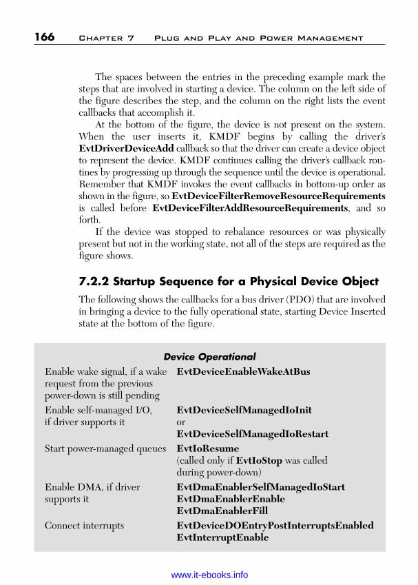
ptg
The spaces between the entries in the preceding example mark thesteps that are involved in starting a device. The column on the left side ofthe figure describes the step, and the column on the right lists the eventcallbacks that accomplish it.
At the bottom of the figure, the device is not present on the system.When the user inserts it, KMDF begins by calling the driver’sEvtDriverDeviceAdd callback so that the driver can create a device objectto represent the device. KMDF continues calling the driver’s callback rou-tines by progressing up through the sequence until the device is operational.Remember that KMDF invokes the event callbacks in bottom-up order asshown in the figure, so EvtDeviceFilterRemoveResourceRequirementsis called before EvtDeviceFilterAddResourceRequirements, and soforth.
If the device was stopped to rebalance resources or was physicallypresent but not in the working state, not all of the steps are required as thefigure shows.
7.2.2 Startup Sequence for a Physical Device ObjectThe following shows the callbacks for a bus driver (PDO) that are involvedin bringing a device to the fully operational state, starting Device Insertedstate at the bottom of the figure.
166 Chapter 7 Plug and Play and Power Management
Device OperationalEnable wake signal, if a wake EvtDeviceEnableWakeAtBusrequest from the previous power-down is still pendingEnable self-managed I/O, EvtDeviceSelfManagedIoInitif driver supports it or
EvtDeviceSelfManagedIoRestartStart power-managed queues EvtIoResume
(called only if EvtIoStop was calledduring power-down)
Enable DMA, if driver EvtDmaEnablerSelfManagedIoStartsupports it EvtDmaEnablerEnable
EvtDmaEnablerFillConnect interrupts EvtDeviceDOEntryPostInterruptsEnabled
EvtInterruptEnable
Wow! eBook <WoweBook.Com>
www.it-ebooks.info
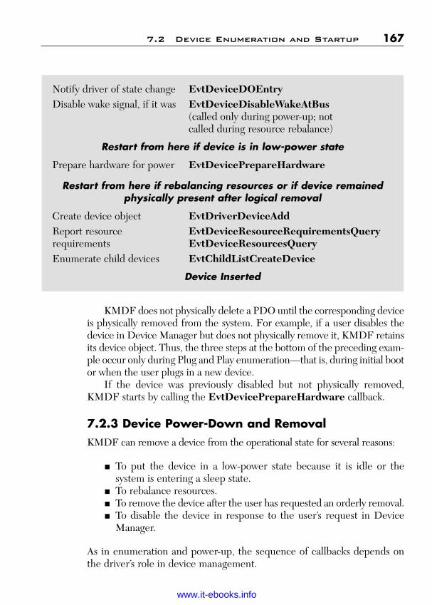
ptgKMDF does not physically delete a PDO until the corresponding deviceis physically removed from the system. For example, if a user disables thedevice in Device Manager but does not physically remove it, KMDF retainsits device object. Thus, the three steps at the bottom of the preceding exam-ple occur only during Plug and Play enumeration—that is, during initial bootor when the user plugs in a new device.
If the device was previously disabled but not physically removed,KMDF starts by calling the EvtDevicePrepareHardware callback.
7.2.3 Device Power-Down and RemovalKMDF can remove a device from the operational state for several reasons:
■ To put the device in a low-power state because it is idle or thesystem is entering a sleep state.
■ To rebalance resources.■ To remove the device after the user has requested an orderly removal.■ To disable the device in response to the user’s request in Device
Manager.
As in enumeration and power-up, the sequence of callbacks depends onthe driver’s role in device management.
7.2 Device Enumeration and Startup 167
Notify driver of state change EvtDeviceDOEntryDisable wake signal, if it was EvtDeviceDisableWakeAtBus
(called only during power-up; notcalled during resource rebalance)
Restart from here if device is in low-power state
Prepare hardware for power EvtDevicePrepareHardware
Restart from here if rebalancing resources or if device remainedphysically present after logical removal
Create device object EvtDriverDeviceAddReport resource EvtDeviceResourceRequirementsQueryrequirements EvtDeviceResourcesQueryEnumerate child devices EvtChildListCreateDevice
Device Inserted
Wow! eBook <WoweBook.Com>
www.it-ebooks.info

ptg
7.2.3.1 Power-Down and Removal Sequence for a Function or Filter Driver Object
The following shows the sequence of callbacks that are involved in power-down and removal for an FDO or filter DO. The sequence starts at the top ofthe figure with an operational device that is in the working power state (DO).
168 Chapter 7 Plug and Play and Power Management
Device OperationalSuspend self-managed I/O, EvtDeviceSelfManagedIoSuspendif driver supports itStop power-managed queues EvtIoStopArm wake signal, if driver EvtDeviceArmWakeFromSxsupports it EvtDeviceArmWakeFromSO
(called only during transitions to low power, not during resource rebalance or device removal)
Disable DMA, if driver EvtDmaEnablerSelfManagedIoStopsupports it EvtDmaEnablerDisable
EvtDmaEnableFlushDisconnect interrupts EvtDeviceDOExitPreInterruptsDisabled
EvtInterruptDisableNotify driver of state change EvtDeviceDOExit
Stop here if transitioning to low-power state
Release hardware EvtDeviceReleaseHardware
Stop here if rebalancing resources
Purge power-managed queues EvtIoStopFlush I/O buffers, if driver EvtDeviceSelfManagedIoFlushsupports self-managed I/OPurge non-power-managed EvtIoStopqueuesClean up I/O buffers, if driver EvtDeviceSelfManagedIoCleanupsupports self-managed I/ODelete device object’s EvtCleanupContextcontext area EvtDestroyContext
Device Removed
Wow! eBook <WoweBook.Com>
www.it-ebooks.info

ptg
As the preceding example shows, the KMDF power-down and removalsequence involves calling the corresponding “undo” callbacks in thereverse order from which KMDF called the functions that are involved inmaking the device operational.
7.2.3.2 Power-Down and Removal Sequence for a Physical Device Object
The following example shows the callbacks involved in power-down andremoval for a PDO.
7.2 Device Enumeration and Startup 169
Device OperationalEnable wake signal, if driver EvtDeviceEnableWakeAtBussupports it (called only during transitions to lower power, not during resource rebalance or device removal)Suspend self-managed I/O, EvtDeviceSelfManagedIoSuspendif driver supports itStop power-managed queues EvtIoStopDisable DMA, if driver EvtDmaEnablerSelfManagedIoStopsupports it EvtDmaEnablerDisable
EvtDmaEnableFlushDisconnect interrupts EvtDeviceDOExitPreInterruptsDisabled
EvtInterruptDisableNotify driver of state change EvtDeviceDOExitDisable wake signal, if it is EvtDeviceDisableWakeAtBusenabled (called only during device removal)
Stop here if transitioning to low-power state
Release hardware EvtDeviceReleaseHardwareStop here if rebalancing resourcesPurge power-managed I/O EvtIoStopqueues
(continues)
Wow! eBook <WoweBook.Com>
www.it-ebooks.info
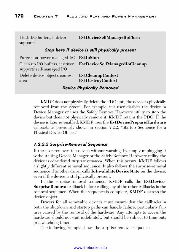
ptg
KMDF does not physically delete the PDO until the device is physicallyremoved from the system. For example, if a user disables the device inDevice Manager or uses the Safely Remove Hardware utility to stop thedevice but does not physically remove it, KMDF retains the PDO. If thedevice is later re-enabled, KMDF uses the EvtDevicePrepareHardwarecallback, as previously shown in section 7.2.2, “Startup Sequence for aPhysical Device Object.”
7.2.3.3 Surprise-Removal SequenceIf the user removes the device without warning, by simply unplugging itwithout using Device Manager or the Safely Remove Hardware utility, thedevice is considered surprise removed. When this occurs, KMDF followsa slightly different removal sequence. It also follows the surprise-removalsequence if another driver calls IoInvalidateDeviceState on the device,even if the device is still physically present.
In the surprise-removal sequence, KMDF calls the EvtDevice-SurpriseRemoval callback before calling any of the other callbacks in theremoval sequence. When the sequence is complete, KMDF destroys thedevice object.
Drivers for all removable devices must ensure that the callbacks inboth the shutdown and startup paths can handle failure, particularly fail-ures caused by the removal of the hardware. Any attempts to access thehardware should not wait indefinitely, but should be subject to time-outsor a watchdog timer.
The following example shows the surprise-removal sequence.
170 Chapter 7 Plug and Play and Power Management
Flush I/O buffers, if driver EvtDeviceSelfManagedIoFlushsupports
Stop here if device is still physically present
Purge non-power-managed I/O EvtIoStopClean up I/O buffers, if driver EvtDeviceSelfManagedIoCleanupsupports self-managed I/ODelete device object’s context EvtCleanupContextarea EvtDestroyContext
Device Physically Removed
Wow! eBook <WoweBook.Com>
www.it-ebooks.info
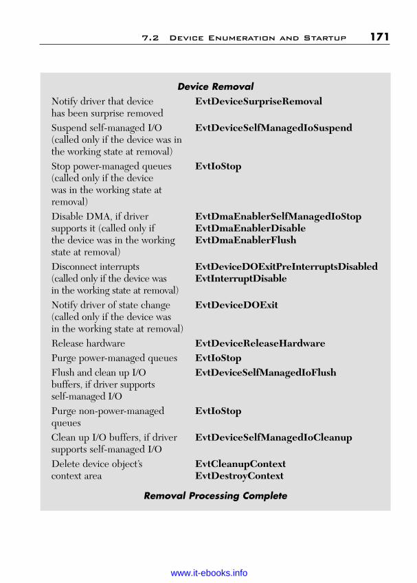
ptg
7.2 Device Enumeration and Startup 171
Device RemovalNotify driver that device EvtDeviceSurpriseRemovalhas been surprise removedSuspend self-managed I/O EvtDeviceSelfManagedIoSuspend(called only if the device was in the working state at removal)Stop power-managed queues EvtIoStop(called only if the device was in the working state at removal)Disable DMA, if driver EvtDmaEnablerSelfManagedIoStopsupports it (called only if EvtDmaEnablerDisablethe device was in the working EvtDmaEnablerFlushstate at removal)Disconnect interrupts EvtDeviceDOExitPreInterruptsDisabled(called only if the device was EvtInterruptDisablein the working state at removal)Notify driver of state change EvtDeviceDOExit(called only if the device was in the working state at removal)Release hardware EvtDeviceReleaseHardwarePurge power-managed queues EvtIoStopFlush and clean up I/O EvtDeviceSelfManagedIoFlushbuffers, if driver supports self-managed I/OPurge non-power-managed EvtIoStopqueuesClean up I/O buffers, if driver EvtDeviceSelfManagedIoCleanupsupports self-managed I/ODelete device object’s EvtCleanupContextcontext area EvtDestroyContext
Removal Processing Complete
Wow! eBook <WoweBook.Com>
www.it-ebooks.info
ptg
If the device was not in the working state when it was removed, KMDFcalls the EvtDeviceReleaseHardware event callback immediately afterEvtDeviceSurpriseRemoval. It omits the intervening steps, which werealready performed when the device exited from the working state.
7.3 WMI Request Handler
WMI provides a way for drivers to export information to other compo-nents. Drivers typically use WMI to enable the following:
■ User mode applications to query and set device-related information,such as time-out values.
■ An administrator with the necessary privileges to control a device byrunning an application on a remote system.
A driver that supports WMI registers as a provider of information andregisters one or more instances of that information. Each WMI provider isassociated with a particular Globally Unique Identifier (GUID). Anothercomponent can register with the same GUID to consume the datafrom the instances. User mode components request WMI instance databy calling COM functions, which the system translates into IRP_MJ_SYSTEM_CONTROL requests and sends to the target providers.
KMDF supports WMI requests through its WMI request handler,which provides the following features for drivers:
■ A default WMI implementation. Drivers that do not provide WMIdata are not required to register as WMI providers; KMDF handlesall IRP_MJ_SYSTEM_CONTROL requests.
■ Callbacks on individual instances, rather than just at the deviceobject level, so that different instances can behave differently.
■ Validation of buffer sizes to ensure that buffers that are used inWMI queries meet the size requirements of the associated providerand instance.
The default WMI implementation includes support for the check boxes onthe Power Management tab of Device Manager. These check boxes enable auser to control whether the device can wake the system and whether thesystem can power down the device when it is idle. WDM drivers must include
172 Chapter 7 Plug and Play and Power Management
Wow! eBook <WoweBook.Com>
www.it-ebooks.info

ptg
code to support the WMI controls that map to these check boxes, but KMDFdrivers do not require such code. If the driver enables this feature in its powerpolicy options, KMDF handles these requests automatically.
The driver enables buffer size validation when it configures a WMIprovider object (WDFWMIPROVIDER). In the WDF_WMI_PROVIDER_CONFIG structure, the driver can specify the minimumsize of the buffer that is required for the provider’s EvtWmiInstance-QueryInstance and EvtWmiInstanceSetInstance callbacks. If thedriver specifies such a value, KMDF validates the buffer size when theIRP_MJ_SYSTEM_CONTROL request arrives and calls the callbacksonly if the supplied buffer is large enough. If the driver does not configurea buffer size—because the instance size is either dynamic or is not avail-able when the provider is created—the driver should specify zero for thisfield and the callbacks themselves should validate the buffer size.
When KMDF receives an IRP_MJ_SYSTEM_CONTROL requestthat is targeted at a KMDF driver, it proceeds as follows:
■ If the driver has registered as a WMI provider and registered one ormore instances, the WMI handler invokes the callbacks for thoseinstances as appropriate.
■ If the driver has not registered any WMI instances, the WMI handlerresponds to the request by providing the requested data (if it can),passing the request to the next lower driver, or failing the request.
Like all KMDF objects, WMI instance objects (WDFWMIINSTANCE)have a context area. A driver can use the context area of a WDFWMIIN-STANCE object as a source of read-only data, thus enabling easy data col-lection with minimal effort. A driver can delete WDFWMIINSTANCEobjects any time after their creation.
WMI callbacks are not synchronized with the Plug and Play and powermanagement state of the device. Therefore, when WMI events occur, KMDFcalls a driver’s WMI callbacks even if the device is not in the working state.
7.4 Synchronization Issues
Because Windows is a pre-emptive, multitasking operating system, multi-ple threads can try to access shared data structures or resources concur-rently and multiple driver routines can run concurrently. To ensure data
7.4 Synchronization Issues 173
Wow! eBook <WoweBook.Com>
www.it-ebooks.info

ptg
integrity, all drivers must synchronize access to shared data structures.Correctly implementing such synchronization can be difficult in WDMdrivers.
For KMDF drivers, ensuring proper synchronization requires attentionto several areas:
■ The number of concurrently active requests that are dispatchedfrom a particular queue.
■ The number of concurrently active callbacks for a particular object.■ The driver utility functions that access object-specific data.■ The IRQL at which an object’s callbacks run.
The dispatch method for an I/O queue controls the number of requestsfrom the queue that can be concurrently active in the driver, as describedpreviously in the section “Dispatch Type” in both Chapters 3 and 6.Limiting concurrent requests does not, however, resolve all potentialsynchronization issues. Concurrently active callbacks on the same objectmight require access to shared object-specific data, such as the informationthat is stored in the object context area. Similarly, driver utility functionsmight share object-specific data with callbacks. Furthermore, a drivermust be aware of the IRQL at which its callbacks can be invoked. AtDISPATCH_LEVEL and above, drivers must not access pageable dataand thread pre-emption does not occur.
KMDF simplifies synchronization for driver by providing automaticsynchronization of many callbacks. Calls to most PDO, FDO, Plug and Play,and power event callback functions are synchronized so that only one suchcallback function is invoked at a time for each device. These callbackfunctions are called at IRQL PASSIVE_LEVEL. Note, however, that callsto the EvtDeviceSurpriseRemoval, EvtDeviceQueryRemove, andEvtDeviceQueryStop callbacks are not synchronized with the othercallbacks and so occur while the device is changing power state or is not in theworking state.
For other types of callbacks—primarily I/O related callbacks—thedriver can specify the synchronization scope (degree of concurrency) andthe maximum execution level (IRQL).
KMDF provides the following configurable synchronization features:
■ Synchronization scope■ Execution level■ Locks
174 Chapter 7 Plug and Play and Power Management
Wow! eBook <WoweBook.Com>
www.it-ebooks.info

ptg
Although implementing synchronization is much less complicated inKMDF drivers than in WDM drivers, you should nevertheless be familiarwith the basics of Windows IRQL, synchronization, and locking.
7.4.1 Synchronization ScopeKMDF provides configurable concurrency control, called synchronizationscope, for the callbacks of several types of objects. An object’s synchro-nization scope determines whether KMDF invokes certain event callbackson the object concurrently.
KMDF define the following synchronization scopes:
■ Device scope means that KMDF does not call certain I/Oevent callbacks concurrently for an individual device object orany file objects or queues that are children of the device object.Specifically, device scope applies to the following event call-backs: EvtDeviceFileCreate, EvtFileCleanup, EvtFileClose,EvtIoDefault, EvtIoRead, EvtIoWrite, EvtIoDeviceControl,EvtIoInternalDeviceControl, EvtIoStop, EvtIoResume, EvtIo-QueueState, EvtIoCanceledOnQueue, and EvtRequestCancel.
However, callbacks for different device objects that were cre-ated by the same driver object can be called concurrently. Internally,KMDF creates a synchronization lock for each device object. Toimplement device synchronization scope, KMDF acquires this lockbefore invoking any of the device callbacks.
■ Queue scope means that KMDF does not call certain I/O callbacksconcurrently on a per-queue basis. If a Kernel Mode Driver speci-fies queue scope for a device object, some callbacks for the deviceobject and its queues can run concurrently. However, the followingcallbacks for an individual queue object are not called concurrently:EvtIoDefault, EvtIoRead, EvtIoWrite, EvtIoDeviceControl,EvtIoInternalDeviceControl, EvtIoStop, EvtIoResume,EvtIoQueueState, EvtIoCanceledOnQueue, and EvtRequest-Cancel. If the driver specifies queue scope, KMDF creates a syn-chronization lock for each queue object and acquires this lockbefore invoking any of the listed callbacks.
■ No scope means that KMDF does not acquire any locks and cancall any event callback concurrently with any other event callback.The driver must create and acquire all its own locks. By default,
7.4 Synchronization Issues 175
Wow! eBook <WoweBook.Com>
www.it-ebooks.info

ptg
KMDF uses no scope. A driver must “opt in” to synchronization forits objects by setting device scope explicitly.
Each KMDF object inherits its scope from its parent object(WdfSynchronizationScopeInheritFromParent). The parent of eachWDFDEVICE object is the WDFDRIVER object, and the default valueof the synchronization scope for the WDFDRIVER object isWdfSynchronizationScopeNone. Thus, a driver must explicitly set thesynchronization scope on its objects to use frameworks synchronization.
A driver can change the scope by setting a value in theWDR_OBJECT_ATTRIBUTES structure when it creates the object.Because scope is inherited, a driver can easily set synchronization for mostof its objects by setting the scope for the device object, which is the parentto most KMDF objects. (For the complete hierarchy, refer to Figure 6.1.)
For example, to set the concurrency for its I/O callback functions,a driver sets the SynchronizationScope in the WDF_OBJECT_ATTRIBUTES for the device object that is the parent to the I/O queues. Ifthe driver sets device scope (WdfSynchronizationScopeDevice), KMDFcalls only one I/O callback function at a time across all the queues. To usequeue scope, the driver sets WdfSynchronizationScopeQueue for thedevice object and WdfSynchronizationScopeInheritFromParent for thequeue object. Queue scope means that only one of the listed callback func-tions can be active for the queue at any time. A driver cannot set concurrencyseparately for each queue. Restricting the concurrency of I/O callbacks canhelp to manage access to shared data in the WDFQUEUE context memory.
By default, a file object inherits its scope from its parent device object.Attempting to set queue scope for a file object causes an error. Therefore,drivers that set queue scope for a device object must manually set the syn-chronization scope for any file objects that are its children. The best prac-tice for file objects is to use no scope and to acquire locks in the eventcallback functions when they are required to synchronize access.
If a driver sets device scope for a file object, it must also set the pas-sive execution level for the object, as described in the upcoming section“Execution Level.” The reason is that the framework uses spin locks(which raise IRQL to DISPATCH_LEVEL) to synchronize access toobjects with device scope. However, the EvtDeviceFileCreate,EvtFileClose, and EvtFileCleanup callbacks run in the caller’sthread context and use pageable data, so they must be called at
176 Chapter 7 Plug and Play and Power Management
Wow! eBook <WoweBook.Com>
www.it-ebooks.info

ptg
PASSIVE_LEVEL. At PASSIVE_LEVEL, the framework uses aFAST_MUTEX instead of a spin lock for synchronization.
Interrupt objects are the children of device objects. KMDF acquiresthe interrupt object’s spin lock at device interrupt request level (DIRQL)to synchronize calls to the EvtInterruptEnable, EvtInterruptDisable,and EvtInterruptlsr callbacks. A driver can also ensure that calls to itsinterrupt object’s EvtInterruptDpc callback are serialized with other call-backs on the parent device object.
Deferred Procedure Call (DPC), timer, and work item objects can bechildren of device objects or of queue objects. To simplify a driver’s imple-mentation of callbacks for DPCs, timers, and work items, KMDF enablesthe driver to synchronize their callbacks with those of either the associatedqueue object or the device object (which might be the parent or the grand-parent of the DPC, timer, or work item).
A driver sets callback synchronization on interrupt, DPC, timer, andwork item objects by setting AutomaticSerialization in the object’s con-figuration structure during object creation.
7.4.2 Execution LevelKMDF drivers can specify the maximum IRQL at which the callbacks fordriver, device, file, and general objects are invoked. Like synchronizationscope, execution level is an attribute that the driver can configure when itcreates the object. KMDF supports the following execution levels:
■ Default execution level indicates that the driver has placed noparticular constraints on the IRQL at which the callbacks for theobject can be invoked. For most objects, this is the default.
■ Passive execution level (WdfExecutionLevelPassive) meansthat all event callbacks for the object occur at PASSIVE_LEVEL.If necessary, KMDF invokes the callback from a system workerthread. Drivers can set this level only for device and file object.Typically, a driver should set passive execution level only if the call-backs access pageable code or data or call other functions that mustbe called at PASSIVE_LEVEL.
Callbacks for events on file objects (WDFFILEOBJECT type)are always called at PASSIVE_LEVEL because these functionsmust be able to access pageable code and data.
7.4 Synchronization Issues 177
Wow! eBook <WoweBook.Com>
www.it-ebooks.info

ptg
■ Dispatch execution level (WdfExecutionLevelDispatch)means that KMDF can invoke the callbacks from any IRQL up toand including DISPATCH_LEVEL. This setting does not force allcallbacks to occur at DISPATCH_LEVEL. However, if a callbackrequires synchronization, KMDF uses a spin lock, which raisesIRQL to DISPATCH_LEVEL. Drivers can set dispatch executionlevel but nevertheless ensure that some tasks are performed atPASSIVE_LEVEL by using work items (WDFWORKITEMobjects). Work item callbacks are always invoked at PASSIVE_LEVEL in the context of a system thread.
By default, an object inherits its execution level from its parent object.The default execution level for the WDFDRIVER object isWdfExecutionLevelDispatch.
7.4.3 LocksIn addition to internal synchronization, synchronization scope, and execu-tion level, KMDF provides the following additional ways for a driver tosynchronize operations:
■ Acquire the lock that is associated with a device or queue object.■ Create and use additional, KMDF-defined, driver-created lock
objects.
Driver code that runs outside an event callback sometimes must synchro-nize with code that runs inside an event callback. To accomplish this syn-chronization, KMDF provides methods (WdfObjectAcquireLock andWdfObjectReleaseLock) through which the driver can acquire andrelease the internal framework lock that is associated with a particulardevice or queue object.
Given the handle to a device or queue object, WdfObjectAcquireLockacquires the lock that protects that object. After acquiring the lock, thedriver can safely access the object context data or properties and canperform other actions that affect the object. If the driver has setWdfExecutionLevelPassive for the object (or if the object has inheritedthis value from its parent), KMDF uses a PASSIVE_LEVEL synchroniza-tion primitive (a fast mutex) for the lock. If the object does not have thisconstraint, use of the lock raises IRQL to DISPATCH_LEVEL and, while
178 Chapter 7 Plug and Play and Power Management
Wow! eBook <WoweBook.Com>
www.it-ebooks.info

ptg
the driver holds the lock, it must not touch pageable code or data or callfunctions that must run at PASSIVE_LEVEL.
KMDF also defines two types of lock objects:
■ Wait locks (WDFWAITLOCK) synchronize access from code thatruns at IRQL PASSIVE_LEVEL or APC_LEVEL. Such locksprevent thread suspension. Internally, KMDF implements waitlocks by using kernel dispatcher events, so each wait lock is associ-ated with an optional time-out value (as are the kernel dispatcherevents). If the time-out value is zero, the driver can acquire the lockat DISPATCH_LEVEL.
■ Spin locks (WDFSPINLOCK) synchronize access from code thatruns at any IRQL up to DISPATCH_LEVEL. Because code thatholds a spin lock runs at DISPATCH_LEVEL, it cannot take apage fault and therefore must not access any pageable data. TheWDFSPINLOCK object keeps track of its acquisition history andensures that deadlocks cannot occur. Internally, KMDF uses thesystem’s spin lock mechanisms to implement spin lock objects.
As with all other KMDF objects, each instance of a lock object can have itsown context area that holds lock-specific information.
Drivers that do not use the built-in frameworks locking (synchroniza-tion scope, execution level, and AutomaticSerialization) can implementtheir own locking schemes by using KMDF wait locks and spin locks.Drivers that use frameworks locking can use KMDF wait locks and spinlocks to synchronize access to data that is not associated with a particulardevice or queue object. In general, drivers can rely on frameworks lockingwhile communicating with their own hardware and calling within theirown code. Drivers that communicate with other drivers generally mustimplement their own locking schemes.
7.4.4 Interaction of Synchronization MechanismsSynchronization scope and execution level interact because of the way inwhich KMDF implements synchronization. By default, KMDF uses spinlocks, which raise IRQL to DISPATCH_LEVEL, to synchronize callbacks. Therefore, if the driver specifies device or queue synchroniza-tion scope, its device and queue callbacks must be able to run atDISPATCH_LEVEL.
7.4 Synchronization Issues 179
Wow! eBook <WoweBook.Com>
www.it-ebooks.info

ptg
If the driver sets the WdfExecutionLevelPassive constraint for aparent device or queue object, KMDF uses a fast mutex instead of a spin lock.In this case, however, KMDF cannot automatically synchronize callbacks fortimer and DPC child objects (including the DPC object that is associatedwith the interrupt object) because DPC and timer callbacks, by definition,always run at DISPATCH_LEVEL. Trying to create any of these objectswith AutomaticSerialization fails if the WdfExecutionLevelPassiveconstraint is set for the parent object.
Instead, the driver can synchronize the event callbacks for these objectsby using a WDFSPINLOCK object. The driver acquires and releases thelock manually by the KMDF locking methods WdfSpinLockAcquireand WdfSpinLockRelease.
Alternatively, the driver can perform whatever processing is requiredwithin the DPC or timer callback and then queue a work item that is syn-chronized with the callbacks at PASSIVE_LEVEL to perform furtherdetailed processing.
7.5 Security
KMDF is designed to enhance the creation of secure driver by providing:
■ Safe defaults■ Parameter validation■ Counted Unicode strings■ Safe device naming techniques
7.5.1 Safe DefaultsUnless the driver specifies otherwise, KMDF provides access control lists(ACLs) that require Administrator privileges for access to any exposeddriver constructs, such as names, device IDs, WMI management inter-faces, and so forth. In addition, KMDF automatically handles I/O requestsfor which a driver has not registered by completing them withSTATUS_INVALID_DEVICE_REQUEST.
7.5.2 Parameter ValidationOne of the most common driver security problems involves improper han-dling of buffers in IOCTL requests, particularly requests that specify
180 Chapter 7 Plug and Play and Power Management
Wow! eBook <WoweBook.Com>
www.it-ebooks.info

ptg
neither buffered nor direct I/O (METHOD_NEITHER). By default,KMDF does not grant drivers direct access to user mode buffer pointers,which is inherently unsafe. Instead, it provides methods for accessing theuser mode buffer pointer that require probing and locking, and it providesmethods to probe and lock the buffer for reading and writing.
All KMDF DDIs that require a buffer take a length parameter that spec-ifies a required minimum buffer size. I/O buffers use the WDFMEMORYobject, which provides data access methods that automatically validate lengthand determine whether the buffer permissions allow write access to theunderlying memory.
7.5.3 Counted UNICODE StringsTo help prevent string handling errors, KMDF DDIs use only countedPUNICCODE_STRING values. To aid drivers in using and formattingUNICODE_STRING values, the safe string routines in ntstrsafe.h havebeen updated to take PUNICODE_STRING parameters.
7.5.4 Safe Device Naming TechniquesKMDF device objects do not have fixed names. KMDF setsFILE_AUTOGENERATED_DEVICE_NAME in the device’s charac-teristics for PDOs, according to the WDM requirements.
KMDF also supports the creation and registration of device interfaceson all Plug and Play devices and manages device interfaces for its drivers.Whenever possible, you should use device interfaces instead of the olderfixed name/symbolic link techniques.
However, if legacy applications require that a device has a name,KMDF enables you to name a device and to specify its security descriptiondefinition language (SDDL). The SDDL controls which users can openthe device.
By convention, a fixed device name is associated with a fixed symboliclink name (such as \DosDevices\MyDeviceName). KMDF supports thecreation and management of a symbolic link and automatically deletes thelink when the device is destroyed. KMDF also enables the creation of asymbolic link name for an unnamed Plug and Play device.
7.5 Security 181
Wow! eBook <WoweBook.Com>
www.it-ebooks.info

ptg
This page intentionally left blank
Wow! eBook <WoweBook.Com>
www.it-ebooks.info
ptg
183
C H A P T E R 8
KERNEL MODE INSTALLATIONAND BUILD
In this chapter, we will cover the kernel mode installation and buildapproach.
Although KMDF supports a completely new device-driver interface(DDI) and programming model, the basic process of implementing andbuilding a KMDF driver still has much in common with Windows DriverModel (WDM). If you are new to driver development, here are a few keypoints:
■ Drivers are normally written in C. C++ can be used for driver devel-opment in only a very limited way. You can safely use some basicC++ features, but the object-oriented features of C++ produce gen-erated code that is not guaranteed to work correctly in kernel mode.
■ You can use a .cpp extension with the C++ compiler to compiledriver code. The C++ compiler works fine with C code and providesbetter error detection and type safety than the C compiler.
■ Include Ntddk.h and Wdf.h. These are standard header files thatare used for all KMDF drivers.
■ Drivers must be built with the WDK or DDK build tools. MicrosoftVisual Studio is not designed to support driver development and canbe used only in a limited way.
8.1 WDK Build Tools
KMDF drivers are built with the WDK build utility build.exe. This is acommand line tool that is essentially identical to the tool that is used tobuild Windows itself. The build utility can be used for a variety of projecttypes including user mode applications, but it must be used for drivers.
Wow! eBook <WoweBook.Com>
www.it-ebooks.info

ptg
The build utility requires a number of supporting files. The followingare required for any project:
■ Source code files—A project must have at least one source codefile (.c or .cpp) and typically one or more header files (.h).
■ Make file—This file contains build instruction. It should be namedmakefile and consist of the following statement that includes thestandard WDK make file:
!INCLUDE $(NTMAKEENV)\makefile.def
■ Sources file—This file contains project-specific information that isused to build the driver, such as the list of source files. The followingexample shows the content of a basic Sources file. An example of a some-what more complex Sources file along with an explanation of its elementis given in the “Building Featured Toaster,” later in this section.
TARGETNAME=WdfSimpleTARGETTYPE=DRIVERKMDF_VERSION=1SOURCES=WdfSimple.c
Optional files include
■ Makefile.inc—Project with custom targets, such as WindowsManagement Instrumentation-(WMI)-related files, must put thenecessary directives in Makefile.inc. Do not modify the standardmake file.
■ Dirs—This file is used by projects that have source files in multiplesubfolders or to build multiple projects with a single build com-mand.
■ Resource files (.rc)—These files contain resources such as stringtables.
■ Managed object format (MOF) resource files (.mof)—Driversthat support WMI must have a MOF resource file (.mof).
■ INX file (.inx)—An INX file is an architecture-independent INFfile. When the appropriate instructions are specified, the Build util-ity uses the data in an INX file to produce an appropriate INF filefor the project.
You can use any names that are convenient for most project files andfolders, with one important restriction: the names cannot contain spaces or
184 Chapter 8 Kernel Mode Installation and Build
Wow! eBook <WoweBook.Com>
www.it-ebooks.info

ptg
nonANSI characters. However, the build utility assumes by default that themake, makefile.inc, Sources, and Dirs files are named makefile, make-file.inc, sources, and dirs, respectively.
The supporting files must all be created manually. However, you canusually simplify the process by copying the files from an appropriate sam-ple and modifying them to suit the project.
Visual Studio can be used in only a limited way for driver development.In particular, its compiler and debugger are not designed to be used withdrivers. However, if you are accustomed to using Visual Studio, you canstill use its integrated development environment (IDE) to edit source codeand build the driver. Essentially, you reprogram the Visual Studio Buildcommand to bypass the Visual build utility and instead run a command linethat launches the WDK build utility. You still must manually create thebuild utility supporting files that were discussed earlier in this section.
KMDF drivers, like WDM drivers, are built in the WDK build envi-ronment. KMDF drivers include the header files Wdf.h (shipped withKMDF) and ntddk.h.
To build a KMDF driver, you must set the /GS flag on the compilerand the KMDF_VERSION environment variable in the Sources file.Setting KMDF_VERSION=1 indicates that the driver should be builtwith the first version of KMDF.
8.2 Build Environment
There are two basic types of build:
■ Checked builds are similar to the Debug builds that are used inapplication development. They generate detailed debugging infor-mation and enable certain types of debugging-related code such asASSERT macros. Checked builds are normally used during theearlier stages of driver development because they are much easierto debug than free builds. Checked builds are typically somewhatslow.
■ Free builds are similar to the Release builds that are used inapplication development. They lack the detailed debugging informa-tion of a checked build and are fully optimized. Free builds aremore difficult to debug, so they are typically used at the end of thedevelopment cycle for final testing and performance tuning.
8.2 Build Environment 185
Wow! eBook <WoweBook.Com>
www.it-ebooks.info

ptg
To simplify the process of setting up the build environment, the WDKincludes a set of console windows with the correct settings for each buildenvironment/platform/architecture combination.
To open a build environment window:
1. On the taskbar, click Start, and then click All Programs.2. Click Windows Driver Kits, click the latest WDK version, and
then click Build Environments.3. Click the appropriate CPU architecture, and then open a checked or
free build environment window for the appropriate Windows version.
The build environment window for a specified version of Windows worksfor that version and all later versions.
8.3 Building a Project
After you have launched the correct build window, use cd to move to theproject folder and run the build utility to compile and link the driver. Thecommand syntax is simple:
build –a[b[c]...]
The build utility assumes by default that the project has a make filethat is named makefile, a Sources file with the list of source files, and soon. There is no need to specify these files explicitly. a[b[c]...] representsthe build arguments, most of which consists of a single case-sensitivecharacter. The WDK has a complete list of flags, but here are some of thecommonly used ones:
■ ?—Displays a list of all command-line flags.■ c—Deletes all object files.■ e—Generates log, error, and warning files.■ g—Uses colored text to display warnings, errors, and summaries.■ Z—Prevents dependency checking or scanning of source files.
The following example shows a commonly used build command:
build –ceZ
The build utility produces several output files, including
186 Chapter 8 Kernel Mode Installation and Build
Wow! eBook <WoweBook.Com>
www.it-ebooks.info

ptg
■ TargetName.sys—The driver binaries.■ SourceFileName.obj—Object files that are produced from the
corresponding source files.■ TargetName.pdb—The driver’s symbol tables.■ TargetName.inf—The project’s INF file. This file is produced by
the build utility only if the project uses an INX file. Otherwise, youmust create the INF file separately.
The output normally goes in a subfolder of the project folder. The defaultoutput folder name depends on the build environment. For example, thedefault output folder for a Windows XP x86 free build is named Project-Folder\objfre_wxp_x86\i386.
8.4 Building Featured Toaster
The Toaster sample is set of simple software drivers that were created byMicrosoft as a learning tool for new driver developers. If you are new toKMDF driver development, it’s the first sample you should look at.Not only does Toaster provide a simple example of how to write drivers by using the best coding practices, it includes detailed comments that explain every step. Toaster is located at WinDDK\BuildNmber\src\kmdf\toaster.
Toaster includes a number of drivers, including two function drivers. One is a minimal version that is named Simple and the other afull-featured version that is named Featured. This section uses theFeatured Toaster sample as a convenient way to demonstrate thebasics of the build, install, and debug process. We will walk through howto create a Windows 7 checked build of Featured Toaster. We will dis-cuss some of the supporting files that are mentioned in the previousmaterial. The KMDF version of Toaster is essentially a port of theWDM Toaster sample. If you are familiar with the WDM version, com-pare it to the KMDF version to see just how much KMDF can simplifydriver code.
8.4.1 Makefile and Makefile.incThe contents of Makefile are the same for all driver projects. FeaturedToaster also includes an optional file, Makefile.inc. This file contains
8.4 Building Featured Toaster 187
Wow! eBook <WoweBook.Com>
www.it-ebooks.info

ptg
some additional make directives that handle two targets that aren’t coveredby makefile.def. The following example shows the contents of FeaturedToaster’s makefile.inc file:
_LNG=$(LANGUAGE)_INX=.STAMP=$(STAMPINF_PATH) –f $@ -a $(_BUILDARCH) -v 1.0.0.0
$(OBJ_PATH)\$(0)\$(INF_NAME) .inf: $(_INX)\$(INF_NAME .inxcopy $(_INX)\$(@B) .inx $@
$(STAMP)
mofcomp: $(OBJ_PATH)\$(0)\toaster.bmf
$(OBJ_PATH)\$(0)\toaster.bmf: toaster.mofmofcomp –WMI –B:$(OBJ_PATH)\$0\toaster.bmf toaster.mofwmimofck –m –h$(OBJ_PATH)\$0\ToasterMof.h –
w$(OBJ_PATH)\$0\htm $(OBJ_PATH)\$(0)\toaster.bmf
The first part of makefile.inc uses the project’s INX file, wdffea-tured.inx, to produce an architecture-specific INF file. The second partof makefile.inc produces the WMI target file.
8.4.2 The Sources FileThe Sources file contains most of the project-specific information that thebuild utility uses to build the project. It consists of a series of directives thatassign project-specific values to a set of macros and environment variables.The following example shows the contents of the Featured ToasterSources file, which is a typical Sources file for a simple KMDF driver:
TARGETNAME=wdffeaturedTARGETTYPE=DRIVER
KMDF_VERSION=1.5
INF_NAME=wdffeaturedMISCFILES=$(OBJ_PATH)\$(0)\$(INF_NAME) .infINCLUDES = $(INCLUDES) ;..\..\inc;..\shared
NTTARGETFILES=NTTARGETDILE0=mofcomp
## List of source files to compile.
188 Chapter 8 Kernel Mode Installation and Build
Wow! eBook <WoweBook.Com>
www.it-ebooks.info
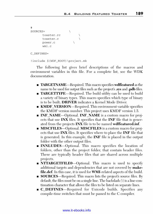
ptg
#SOURCES= \
toaster.rc \toaster.c \power.c \wmi.c
C_DEFINES=
!include $(WDF_ROOT)\project.mk
The following list gives brief descriptions of the macros andenvironment variables in this file. For a complete list, see the WDKdocumentation.
■ TARGETNAME—Required. This macro specifies wdffeatured as thename to be used for output files such as the project’s .sys and .pdb files.
■ TARGETTYPE—Required. The build utility can be used to builda variety of binary types. This macro specifies which type of binaryis to be built; DRIVER indicates a Kernel Mode Driver.
■ KMDF_VERSION—Required. This environment variable specifiesthe KMDF version number. This project uses KMDF version 1.5.
■ INF_NAME—Optional. INF_NAME is a custom macro for proj-ects that use INX files. It specifies that the INF file that is gener-ated from the projects INX file is to be named wdffeatured.inf.
■ MISCFILES—Optional. MISCFILES is a custom macro for proj-ects that use INX files. It specifies where to place the INF file thatis generated. In this example, the INF file is placed in the outputfolder with the other output files.
■ INNLUDES—Optional. This macro specifies the location offolders, other than the project folder, that contain header files.These are typically header files that are shared across multipleprojects.
■ NTTARGETFILE0—Optional. This macro is used to specifyadditional targets and dependencies that are not covered by make-file.def. In this case, it is used for WMI-related aspects of the build.
■ SOURCES—Required. This macro lists the project’s source files. Bydefault, the files must be on a single line. The backslash (\) is a line-con-tinuation character that allows the files to be listed on separate lines.
■ C_DEFINES—Required for Unicode builds. Specifies anycompile-time switches that must be passed to the C compiler.
8.4 Building Featured Toaster 189
Wow! eBook <WoweBook.Com>
www.it-ebooks.info

ptg
8.4.3 The BuildThe following procedure shows how to build Featured Toaster. For sim-plicity, assume that the WDK’s root folder is C:\WinDDK\6000.
1. Launch the Windows 7 Checked Build Environment consolewindow. It opens in the c:\WinDDK\6000 folder.
2. Use cd to move to the project folder. The project folder is atC:\WinDDK\6000\src\kmdf\toaster\func\featured.
3. Build the project by running the following command. This isn’t theonly way to build the project, but it’s a commonly used set of flags.
build –ceZ
The output files go in the featured\objchk\w7_x86\i386 subfolder.
8.5 Installing a KMDF Driver
Drivers must be installed before they can be used—either by the developerto test and debug the driver or by the end user who wants to use the relateddevice. The procedures for installing a driver are distinctly different fromthose that are used to install applications. This section discusses how to cre-ate a WDF installation package and install it on a system.
There is a variety of ways to install drivers on a user’s system. One com-mon way is to simply attach the associated hardware to the user’s system.The Plug and Play manager detects new hardware and prompts the user toinsert a disk that contains the driver package. The system then installs thedriver. Users can also install drivers manually with the New Hardwareapplication in Control Panel.
KMDF driver packages contain at least three files in addition to thedriver binaries:
■ The KMDF co-installer dynamic-link library (DLL).■ An INF file.■ A digitally signed catalog (.cat) file. This file is not necessary for test
installations.
Driver packages can optionally contain files such as icons, property sheetproviders, supporting DLLs, and so on. This section discusses the relativelysimple driver package and test-installation procedure for Featured Toaster.
190 Chapter 8 Kernel Mode Installation and Build
Wow! eBook <WoweBook.Com>
www.it-ebooks.info
ptg
8.5.1 The WDF Co-InstallerA KMDF driver package must include the redistributable WDF co-installDLL. Its primary purpose is to install the KMDF run time. The WDFco-installer is located under the WinDDK\BuildNumber\Redis\Wdffolder. There are six co-installers—a checked and a free build for eachsupported process architecture (x86, Intel Itanium, and amd64). To installthe WDF co-installer, add the appropriate DLL to the driver package andadd the appropriate directives to the INF file.
The WDF co-installer version number must be greater than or equalto the KMDF version with which the driver is compiled. The versionnumber is embedded in the DLL’s name. For example, the co-installerfor KMDF version 1.5 is named WdfCoInstaller01005.dll. The KMDFrun-time version and the KMDF co-installer version that are specified inthe project’s INF must be identical. The build type of the co-installermust match that of the Windows version on which the driver will beinstalled. You cannot use the checked build of a co-installer to install adriver on a free build of Windows, or vice versa.
8.5.2 The INFThe INF is the core of the installation package. It is a text file that containsmost of the information that the system uses to install a driver, including
■ General information about the device such as the device’s manufac-turer, installation class, and version number.
■ Names and locations of files on the distribution disk and where theyshould be installed on the user’s system.
■ Directives for creating or modifying registry entries for the driver ordevice.
■ Installation directives for which drivers are to be installed, whichbinaries contain the driver, and a list of drivers to be loaded on thedevice.
■ Directives for setting KMDF-specific configuration information.
The INF format is much like the earlier Windows .ini files. Each line con-tains a single entry, and there are two basic types of entries:
■ Section—Each INF contains a number of sections, indicated bysquare brackets—for example, [Version].
8.5 Installing a KMDF Driver 191
Wow! eBook <WoweBook.Com>
www.it-ebooks.info

ptg
■ Directive—Each section contains one or more directives. A direc-tive is a key-value pair and is used to specify various types of instal-lation-related data. For example, the Class=Mouse directive in theVersion section specifies the mouse device class.
8.5.3 INFs for KMDF DriversMost of the contents of an INF for a KMDF driver are similar to those thatare used for WDM drivers and aren’t discussed here. For further informa-tion, see the WDK document or examine the INF for Featured Toaster,wdffeatured.inf. The major difference is that INFs for KMDF driversmust contain several additional sections that are devoted to the KMDF co-installer. These sections instruct the system to run the co-installer and pro-vide it with necessary data. The co-installer unpacks and installs a numberof files that KMDF drivers require, including the KMDF run-time library.
8.5.4 wdffeatured.infThe following sample shows the WDF co-installer sections from theFeatured Toaster sample’s INF file, wdffeatured.inf. It was producedfrom an INX file by the build described earlier.
[DestinationDirs]ToasterClasInstallerCopyFiles = 11
[Toaster_Device.NT.CoInstallers]AddReg=Toaster_Device_CoInstaller_AddRegCopyFiles=Toaster_Device_CoInstaller_CopyFiles
[Toaster_Device_CoInstaller_AddReg]HKR, ,CoInstallers32, 0x00010000,“WdfCoinstaller01000.dll,WdfCoInstaller”
[Toaster_Device_CoInstaller_CopyFiles]WdfCoinstaller01000.dll
[SourceDisksFiles]WdfCoinstaller01000.dll=1
[Toaster_Device.NT.Wdf]KmdfService = wdffeatured, wdffeatured_wdfsect
192 Chapter 8 Kernel Mode Installation and Build
Wow! eBook <WoweBook.Com>
www.it-ebooks.info

ptg
[wdffeatured_wdfsect]KmdfLibraryVersion = 1.1
To modify this code for your driver, replace the text that is specific toFeatured Toaster with custom text of your choosing. The following example isa generic version of the co-installer section for a driver that is named MyDevice:
[DestinationDirs]MyDeviceClassInstallerCopyFiles = 11
[MyDevice.NT.CoInstallers]AddReg=MyDevice_CoInstaller_AddRegCopyFiles= MyDeviceClassInstallerCopyFiles
[MyDevice_CoInstaller_AddReg]HKR, ,CoInstallers32,0x00010000,“WdfCoinstaller01000.dll,WdfCoInstaller”
[MyDevice_CoInstaller_CopyFiles]wdfCoinstller01000.dll
[SourceDisksFiles]wdfCoinstaller01000.dll=1 ;
[MyDevice.NT.Wdf]KmdfService = MyDevice, MyDevice_wdfsect[MyDevice_wdfsect]KmdfLibraryVersion = 1.0
8.6 Catalog Files and Digital Signature
Because Kernel Mode Drivers have essentially unrestricted access to thesystem, they should be digitally signed. Digitally signing the package sim-plifies the installation process, but it also provides customers with two veryimportant additional benefits:
■ Customers can use the signature to identify the origin of thepackage.
■ Customers can use the signature to verify that the contents of thepackage have not been tampered with since it was signed. For exam-ple, this assures them that the driver has not been modified into aroot kit or infected with a virus.
8.6 Catalog Files and Digital Signature 193
Wow! eBook <WoweBook.Com>
www.it-ebooks.info

ptg
With recent versions of Windows, unsigned drivers can be installed only byan administrator, and even administrators receive a warning dialog box thatrequires them to explicitly approve the installation.
A signed catalog file (.cat) contains the digital signature for the entiredriver package. The signing process ties the catalog file to a specific driverpackage. If anyone subsequently modifies any member of the package byeven a single byte, it invalidates the signature. If you modify a driver pack-age, it must have a new signed catalog file.
There are two ways to obtain a signed catalog file for a driver package:
■ Obtain a Windows logo. Drivers that pass the Windows HardwareQuality Lab (WHQL) testing and receive a Windows logo alsoreceive a catalog file for the driver package, signed with the WHQLcertificate.
■ Create your own signed catalog file. You can obtain a digital certifi-cate from a certificate authority (CA). The WDK provides tools tocreate a catalog file and sign it with the certificate.
For testing purposes, you can create a test certificate and install it in thetrusted publishers’ certificates store on the test computer. Sign the testdriver packages with the test certificate and the driver will install withoutwarning messages.
The CatalogFile entry in the INF file’s Version section specifiesa package’s catalog file. The following example is from the FeaturedToaster sample’s INF file and declares KmdfSamples.cat as the pack-age’s catalog file:
[Version]Signature=”$WINDOWS NT$”Class=TOASTERClassGuid={B85B7C50-6A01-11d2-B841-00C04FAD5171}Provider=%MSFT%DriverVer=02/22/2006, 1.0.0.0CatalogFile=KmdfSamples.cat
8.7 Installing Featured Toaster
Kernel Mode Drivers under development are normally installed on a sep-arate test computer that is used specifically for testing and debugging
194 Chapter 8 Kernel Mode Installation and Build
Wow! eBook <WoweBook.Com>
www.it-ebooks.info
ptg
drivers. If you are new to drivers, there are two primary reasons for thispractice:
■ Kernel Mode Drivers have essentially unrestricted access to thesystem. This means that a misbehaving driver can corrupt systemmemory and possibly the contents of the hard disk. Drivers underdevelopment invariably have bugs, and it is better to have anyrelated damage happen to a stripped-down test computer that canbe easily reformatted.
■ Debugging Kernel Mode Drivers normally requires two computers:one to host the driver being debugged and one to host the debug-ging software. One important reason for this arrangement is thatdriver bugs often hang or crash the system. Hosting the debuggeron a separate system protects it from crashing along with the targetcomputer and allows you to immediately analyze the problem.
This section describes how to install Featured Toaster on a testcomputer. The driver is installed on a root-enumerated physical deviceobject, which is the simplest approach. More commonly, drivers areinstalled on a bus-enumerated physical device object. The Toaster sam-ple also includes a bus driver that can be used for this type of installation.
Remember that Featured Toaster is a software driver, not a devicedriver. This means that there is nothing for the Plug and Play manager todetect, so the driver must be installed manually. Because the test driver isunsigned, installing it requires administrator rights and an extra step. Fora more streamlined process, install a test certificate on the test computerand use the certificate to sign the package. The steps involved in installingthe Featured Toaster are as follows:
1. Copy the driver binary (WdfFeatured.sys) and INF file(WdfFeatured.inf) to installable media such as a USB drive.
2. Copy the WDF co-installer to the same media.3. Put the media on the test computer, start the Control Panel Add
Hardware wizard, and go to page 2.4. Page 2: Click Yes, I Have Already Added the Hardware.5. Page 3: Select Add a New Hardware Device, from the bottom of
the list.6. Page 4: Click Install the Hardware That I Manually Select From a
List.
8.7 Installing Featured Toaster 195
Wow! eBook <WoweBook.Com>
www.it-ebooks.info

ptg
7. Page 5: Select Show All Devices from the top of the list. It maytake awhile for page 6 to appear.
8. Page 6: Click Have Disk, which opens the Install From a Disk dia-log box.
9. Enter the drive letter for the media that contains the driver pack-age and click OK to return to the wizard.
10. Page 8: Select the Featured Toaster driver from the list and click Nexton this page and the following page. The system then loads the driver.
11. Page 10: Click Finish to complete the process.
Device Manager is the simplest way to uninstall the driver. On Windows 7,you can also use System Restore to restore the system to the state it hadbefore the driver installation—that uninstalls the driver, along with anyother system changes that took place in the interim.
8.8 Testing a KMDF Driver
Testing drivers is a large and complicated subject. This section touches ononly a few KMDF-specific issues.
There are two basic approaches to testing:
■ Static testing by using tools that analyze the source code for errorswithout actually executing it.
■ Dynamic testing that puts an installed driver through its paces inhopes of activating a bug and causing the driver to fail in some way.
Some related techniques, such as tracing tools, record the actions of adriver. This section only provides a brief introduction to the testing toolsthat WDF provides for KMDF drivers.
8.8.1 PREfastPREfast is a static source code analysis tool that detects certain classes oferrors not easily found by a compiler. PREfast steps through all possibleexecution paths in each function and evaluates each path for problems bysimulating execution. PREfast does not actually execute code and cannotfind all possible errors. However, it can find errors that the compiler mightnot catch and that can be difficult to find during debugging.
196 Chapter 8 Kernel Mode Installation and Build
Wow! eBook <WoweBook.Com>
www.it-ebooks.info

ptg
PREfast is a general-purpose tool that can be used with any type ofproject. WDF includes a customized version of PREfast that checks fordriver-specific issues such as the correct interrupt request level (IRQL),use of preferred driver routines, and misuse of driver routines. It alsoaggressively checks for memory and resource leaks.
PREfast is run in conjunction with a build. The following is a simpleexample of how to run a PREfast build. For the purposes of illustration,the command uses a typical set of build flags, but any build flags can beused with PREfast. The second line opens the PREfast viewer to displaythe error log.
prefast build –ceZprefast view
8.8.2 Static Driver VerifierStatic Driver Verifier (SDV) is a static compile-time unit-testing tool thatsymbolically executes the source code. SDV does deeper testing thanPREfast and creates what is in effect a hostile environment for the driver.It systematically tests all code paths by looking for violations of usage rules.The symbolic execution makes very few assumptions about the state of theoperating system or the initial state of the driver, so SDV can create sce-narios that are difficult to handle with traditional testing.
The set of rules that are packaged with SDV define how device driversshould use the DDI. The categories of rules tested include the following.
8.8 Testing a KMDF Driver 197
Category Tests
IRP Functions that use I/O request packetsIRQL Functions that use interrupt request levelsPnP Functions that use Plug and PlayPM Functions that use power managementWMI Functions that use Windows Management
InstrumentationSync Functions that use synchronization,
including spin locks, semaphores, timers, mutexes, and other methods of access control
Other Functions that are not fully described by any of the other categories
Wow! eBook <WoweBook.Com>
www.it-ebooks.info

ptg
198 Chapter 8 Kernel Mode Installation and Build
8.8.3 KMDF LogKMDF includes an internal trace logger that is based on the Windows soft-ware trace preprocessor (WPP). It tracks the progress of I/O request pack-ets (IRPs) through the framework and the correspondingWDFREQUEST objects through the driver. The KMDF log maintains arecord of recent race events—currently, approximately the last 100—foreach driver instance. Each KMDF driver has its own log.
You can use WDF debugger extensions to view and save the KMDFlog during interactive debugging. The typical saved log file is small (10 to20 KB) and written in a binary format. You can also make logs available aspart of a small-memory dump for inspection after a crash.
8.8.4 KMDF VerifierKMDF Verifier operates on an installed and running driver. It comple-ments Driver Verifier and supports a number of WDF-specific features.In addition, if the target driver is not loaded, KMDF Verifier can beturned on without rebooting the system. In general, you should run bothDriver Verifier and KMDF Verifier during development.
KMDF Verifier provides extensive tracing messages that supplydetailed information about activities within the framework. It tracks refer-ences to each WDF object and builds a trace that can be sent to thedebugger. In particular, KMDF Verifier
■ Checks lock acquisition and hierarchies.■ Ensures that calls to the framework occur at the correct IRQL.■ Verifies correct I/O cancellation and queue usage.■ Ensures that the driver and framework follow the documented
contracts.
KMDF Verifier can also simulate low-memory and out-of-memoryconditions. It tests a driver’s response to these situations to determinewhether the driver responds properly without crashing, hanging, or failingto unload.
8.8.5 Debugging a KMDF DriverDebuggers are an essential development tool; programs under develop-ment always have bugs, especially in the early stages. Debuggers can also
Wow! eBook <WoweBook.Com>
www.it-ebooks.info

ptg
be used as learning tools, to step through sample code and understand indetail how it functions.
Debugging is normally done at run time to determine why a driver isfailing. The exception to this rule is that kernel debuggers can also be usedto analyze crash-dump files. If you are new to driver development, you willfind kernel debugging a bit different from application debugging. Oneimmediately noticeable difference is that kernel debugging requires threehardware components:
■ A host computer running WinDbg. This is typically the computerthat is used to develop and build the driver.
■ A test computer running an appropriate build of Windows with thedriver installed and kernel debugging enabled. Debugging is typi-cally done with a checked build of the driver because checked buildsare much easier to debug. Test computers also often run a checkedbuild of Windows.
■ A way for the two computers to communicate. Historically, this washandled by connecting serial ports on the host and test computers witha null-modem cable. An alternative is to use USB or IEEE 1394 cables.
The kernel debugging tools are available as a separate package fromWHDC that includes the debugging tools, documentation, and somerelated files. The procedures for setting up systems for kernel debuggingare covered in detail in the debugging documentation.
The debugging package includes two kernel debuggers, WinDbg andKD. They have essentially the same capabilities, but WinDbg has a graph-ical user interface (GUI) that many developers find convenient. The exam-ples we use are from WinDbg. We will cover a walkthrough of a simpledebugging session with Featured Toaster that demonstrates the basics ofhow to use WinDbg with a KMDF driver.
WinDbg is a debugger, not an IDE like Visual Studio. It comes intoplay only after you have successfully built the driver and installed it on atest machine. There are two basic ways to use WinDbg:
■ Kernel debugging—In this mode, WinDbg is connected to an activetest machine and can interact with a running driver.
■ Crash dump analysis—If the system crashes, you can use WinDbgto analyze the crash dump data to try to determine the cause.
8.8 Testing a KMDF Driver 199
Wow! eBook <WoweBook.Com>
www.it-ebooks.info

ptg
When you launch WinDbg, you must first point it to the driver’s source andsymbol files. To start a kernel debugging session, on the File menu, clickKernel Debug. You won’t be able to do much until the system breaks intothe debugger. This essentially stops the test computer and turns its opera-tion over to WinDbg. The following are common ways to cause a test sys-tem to break into the debugger:
■ You instruct WinDbg to force a break. This can be done from theUI, on the Debug menu by clicking Break, or by clicking the cor-responding toolbar button. You can also run the break command.
■ You use WinDbg to dynamically insert breakpoints into the runningdriver. This approach is quite flexible because it allows breakpointsto be inserted, disabled, enabled, or removed during the debuggingsession.
■ You insert DbgBreakPoint statements in the driver’s source code.This approach is simpler but less flexible because the driver must berecompiled and reinstalled to change a breakpoint.
■ The driver bug checks and crashes the test computer. At this point,you can use WinDbg to examine crash dump data, but the computermust be rebooted before it can run again. You can force a systemcrash by running the .crash command.
8.8.6 Kernel DebuggingWith the first two cases in the previous discussion, after the driver breaksinto the debugger, you can do most of the usual debugging procedure: exam-ine variables, step through lines of code, examine the call stack, and so on.
Much of the interaction with WinDbg is through the command-lineinterface. There are two basic types of commands:
■ Debugger commands are native to the debugger and are used toobtain basic information. Commands are typically one or two letterstrings, often followed by one or more arguments. For example, k andrelated commands display a thread’s stack frame and some relatedinformation. When you are finished, use the g command to break outof the debugger and return the driver and test computer to normaloperation. Some simple commands have corresponding menu itemsor toolbar buttons, but many can be run from the command line.
200 Chapter 8 Kernel Mode Installation and Build
Wow! eBook <WoweBook.Com>
www.it-ebooks.info

ptg
■ Debugger extensions extend the basic set of debugger com-mands. A number of them are included with the debugger packageand are launched from the command window in much the same wayas debugger commands. The first character of a debugger extensionis always an exclamation point (!), to distinguish it from a debuggercommand. For example, a particularly useful debugger extension is!analyze, which is used to analyze crash dumps. In addition to thedebugger extensions that are included with the debugger package,it is also possible to write custom debugger extensions.
The debugging Help file includes a complete reference for debuggingcommands, standard debugger extensions, and the API that is used to create custom extensions. In the next section, we will discuss some debug-ger extensions that were created specifically for KMDF drivers.
If a driver bug causes a system crash, the computer must be rebootedbefore it can run again. However, if WinDbg is running and connected whenthe test computer crashes, the system breaks into the debugger and you cananalyze the crash dump immediately. You can also configure your test computerto attempt to create a crash dump file when it crashes. If the file is successfullycreated, you can load it into WinDbg and analyze the crash after the fact.WinDbg doesn’t have to be connected to the test computer for this purpose.
8.8.7 KMDF Driver FeaturesDebugging a KMDF driver is similar in many ways to debugging any KernelMode Driver. However, some debugging features are specific to KMDF.
8.8.7.1 Registry SettingsA number of the WDF debugging features must be enabled by setting registry values for the driver’s Parameters\Wdf subkey. The driver keyitself is named for the driver and located under HKEY_LOCAL_MACHINE\System\CurrentControlSet\Services.
Table 8.1 summarizes the values that can be added to the Wdf subkey.The features are disabled by default. To enable most of these features, cre-ate the associated value and set it to a nonzero number. To enable handletracking, set TrackHandles to a MULTI_SZ string that contains thenames of the objects that you want to track. The settings do not take effectuntil the next time that the driver is loaded. The simplest way to reload a
8.8 Testing a KMDF Driver 201
Wow! eBook <WoweBook.Com>
www.it-ebooks.info

ptg
driver is to use Device Manager to disable and then reenable the driver.Table 8.1 shows some of the settings.
Table 8.1 Registry Values
202 Chapter 8 Kernel Mode Installation and Build
Category Type Tests
VerifierOn REG_DWORD Set to a nonzero value to enable the KMDF verifier.
VerifyOn Set to a nonzero value to enable the WDFVERIFY macro. If VerifierOn is set, WDFVERIFY is automaticallyenabled.
DbgBreakOnError REG_DWORD Set to a nonzero value to instruct theframework to break into the debugger when a driver calls WdfVerifierDbgBreakPoint.
VerboseOn REG_DWORD Set to a nonzero value to capture verbose information in the KMDF logger.
LogPages REG_DWORD Set to a value from 1 to 10 to specify the number of memory pages that the framework assigns to its logger. The default value is 1.
VerifierAllocateFailCount REG_DWORD Set to a nonzero value to test low-memory conditions. When VerifierAllocateFailCount is set to n, the framework fails every attempt to allocate memory for the driver’s objects after the nth allocation. This value works only if VerifierOn is also set.
TrackHandles MULTI_SZ Set to a MULTI_SZ string that contains the names of one or more object types to track handle references to those types. This feature can help find memory leaks that are caused by unreleased references. To track all objects types,set TrackHandles to “*”.
Wow! eBook <WoweBook.Com>
www.it-ebooks.info

ptg
8.8.7.2 SymbolsYou must explicitly provide WinDbg with paths to all the relevant symbolsfiles. For KMDF drivers, this normally includes the symbols for the driver,Windows, and the KMDF run time. The symbols file is namedWdf01000.pdb and is located under %WDF_ROOT%\Symbols\Build-Environment\wdf\sys. There are six Build Environment folders, one foreach of the standard build types and architectures. For most debugging,you should use the checked build for the appropriate architecture.
8.9 Debugging Macros and Routines
KMDF drivers can include any of the standard debugging macros and rou-tines, such as ASSERT or DbgPrintEx. Several routines and macros arealso specific to WDF as summarized in Table 8.2.
Table 8.2 Debugging Macros
8.9 Debugging Macros and Routines 203
Category Type Tests
ForceLogsInMiniDump REG_DWORD Set to a nonzero value to include theKMDF log in a small memory dump file if the system crashes.
Category Tests
WdfVerifierDbgBreakPoint This routine breaks into the debugger if the DbgBreakOnError value is set in the registry.
WDFVERIFY If the VerifyOn value is set in the registry, this macrotests a logical expression and breaks into the kernel debugger if the expression evaluates to FALSE. Unlike ASSERT, this macro is included in both checked and free builds.
VERIFY_IS_IRQL_ If the VerifyOn value is set in the register, this macroPASSIVE_LEVEL breaks into the kernel debugger if the driver is not
executing at IRQL=PASSIVE_LEVEL.
Wow! eBook <WoweBook.Com>
www.it-ebooks.info
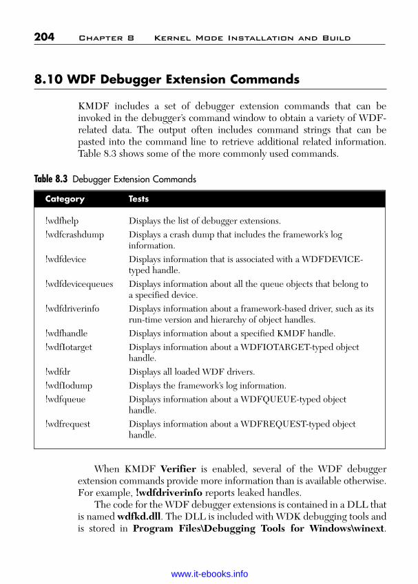
ptg
204 Chapter 8 Kernel Mode Installation and Build
Category Tests
!wdfhelp Displays the list of debugger extensions.!wdfcrashdump Displays a crash dump that includes the framework’s log
information.!wdfdevice Displays information that is associated with a WDFDEVICE-
typed handle.!wdfdevicequeues Displays information about all the queue objects that belong to
a specified device.!wdfdriverinfo Displays information about a framework-based driver, such as its
run-time version and hierarchy of object handles.!wdfhandle Displays information about a specified KMDF handle.!wdfIotarget Displays information about a WDFIOTARGET-typed object
handle.!wdfdr Displays all loaded WDF drivers.!wdfIodump Displays the framework’s log information.!wdfqueue Displays information about a WDFQUEUE-typed object
handle.!wdfrequest Displays information about a WDFREQUEST-typed object
handle.
8.10 WDF Debugger Extension Commands
KMDF includes a set of debugger extension commands that can beinvoked in the debugger’s command window to obtain a variety of WDF-related data. The output often includes command strings that can bepasted into the command line to retrieve additional related information.Table 8.3 shows some of the more commonly used commands.
Table 8.3 Debugger Extension Commands
When KMDF Verifier is enabled, several of the WDF debuggerextension commands provide more information than is available otherwise.For example, !wdfdriverinfo reports leaked handles.
The code for the WDF debugger extensions is contained in a DLL thatis named wdfkd.dll. The DLL is included with WDK debugging tools andis stored in Program Files\Debugging Tools for Windows\winext.
Wow! eBook <WoweBook.Com>
www.it-ebooks.info
ptg
Check it against the most recent version of the DLL, which is includedwith the latest KMDF distribution. Wdfkd.dll is stored under WinDDK\BuildNumber\bin\. There are actually three versions of wdfkd.dll, onefor each supported architecture (amd64, Intel Itanium, or x86). If neces-sary, overwrite the version that came with the debugger with the mostrecent version.
8.11 Using WPP Tracing with a KMDF Driver
WPP tracing works in essentially the same way with a KMDF driver as itdoes with a WDM driver. However, KMDF provides hundreds of frame-work-specific tracing messages. To enable KMDF support for WPP,include the following RUN_WPP directive in the project’s Sources file:
RUN_WPP = $(SOURCES) \-km \-func:TraceEvents(LEVEL,FLAGS,MSG,...) \-gen:{km-WdfDefault.tpl}*.tmh
8.12 Using WinDbg with Featured Toaster
Featured Toaster doesn’t have any known bugs, but WinDbg is still auseful tool to walk through the source and see how the driver works. Thewalkthrough also demonstrates the basics of how to use WinDbg.
The test computer should be running Windows with kernel debuggingenabled and be connected to the host computer. For convenience, this sec-tion assumes that the COM ports are connected with a null-modem cable.
The simplest way to use the debugger is to run a test application that accessesthe driver and hits a breakpoint, causing the driver to break into the debugger.KMDF doesn’t include a test application for Toaster, but the WDM test appli-cation, Toast.exe, works just as well with the KMDF version of the driver.
The source code for Toast.exe is located at WinDDK\BuildNumber\src\general\toaster\exe\toast. Use the same console window and buildcommands to build Toast.exe as for Featured Toaster. Unlike most proj-ects, the output folder is not a subfolder of the project folder. CopyToast.exe from the output folder WinDDK\BuildNumber\src\gen-eral\toaster\disk\chk_wxp_x86\i386 to a convenient folder on the test computer.
8.12 Using WinDbg with Featured Toaster 205
Wow! eBook <WoweBook.Com>
www.it-ebooks.info
ptg
To get WinDbg ready to debug Featured Toaster:
1. Launch WinDbg.2. On the File menu, click Symbol File Path, which causes the
Symbols Search Path dialog box to appear. It should have pathsfor the Featured Toaster, Windows, KMDF run time, andwdfkd.dll symbols files.
3. Select the Reload check box, which forces WinDbg to load thecurrent symbols, and close the dialog box.
4. On the File menu, click Source File Path, and add the path tothe Featured Toaster’s source files.
5. On the File menu, click Open Source File. Open FeaturedToaster’s Toaster.c file.
6. On the File menu, click Kernel Debug. This puts WinDbg into kerneldebugging mode and establishes the connection with the test computer.
7. Enter the appropriate baud rate and COM port in the KernelDebugging dialog box, and click OK to start the debugging session.
8. On the Debug menu, click Break, which forces a break andallows you to run debugging commands.
9. Use the bp command as follows to set a breakpoint in FeaturedToaster’s ToasterEvtIoRead routine.
bp ToasterEvtIoRead
To start debugging:
1. Go to the test computer, launch a command window, and runToast.exe. Type any character other than “q” to cause Toast.exeto send a read request to the driver. Toast.exe then callsFeatured Toaster’s ToasterEvtIoRead routine. When thedriver hits the breakpoint, it breaks into the debugger.
2. On the Debug menu, select the Source Mode check box if it isn’talready selected. This mode allows you to step through the sourcecode. Notice that the corresponding assembler appears in theCommand window. Even if you never write a line of assembler,it’s still useful to know something about it for debugging purposes.
3. Set the cursor on a line of source code. On the Debug menu, clickRun to Cursor. The selected line should be highlighted in blue.
4. On the Debug menu, click Step Over to execute the next line.There’s also a Toolbar button for this purpose, located under-neath the Window menu.
206 Chapter 8 Kernel Mode Installation and Build
Wow! eBook <WoweBook.Com>
www.it-ebooks.info
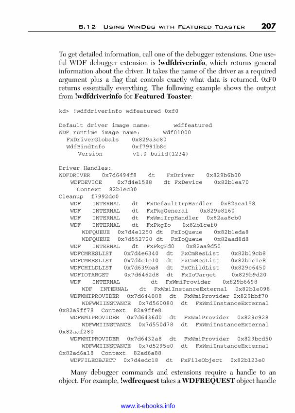
ptg
To get detailed information, call one of the debugger extensions. One use-ful WDF debugger extension is !wdfdriverinfo, which returns generalinformation about the driver. It takes the name of the driver as a requiredargument plus a flag that controls exactly what data is returned. 0xF0returns essentially everything. The following example shows the outputfrom !wdfdriverinfo for Featured Toaster:
kd> !wdfdriverinfo wdfeatured 0xf0
Default driver image name: wdffeaturedWDF runtime image name: Wdf01000
FxDriverGlobals 0x829a3c80WdfBindInfo 0xf7991b8c
Version v1.0 build(1234)
Driver Handles:WDFDRIVER 0x7d6494f8 dt FxDriver 0x829b6b00
WDFDEVICE 0x7d4e1588 dt FxDevice 0x82b1ea70Context 82b1ec30
Cleanup f7992dc0WDF INTERNAL dt FxDefaultIrpHandler 0x82aca158WDF INTERNAL dt FxPkgGeneral 0x829e8160WDF INTERNAL dt FxWmiIrpHandler 0x82aa8cb0WDF INTERNAL dt FxPkgIo 0x82b1cef0
WDFQUEUE 0x7d4e1250 dt FxIoQueue 0x82b1eda8WDFQUEUE 0x7d552720 dt FxIoQueue 0x82aad8d8
WDF INTERNAL dt FxPkgFd0 0x82aa9d50WDFCMRESLIST 0x7d4e6340 dt FxCmResList 0x82b19cb8WDFCMRESLIST 0x7d4e1e10 dt FxCmResList 0x82b1e1e8WDFCHILDLIST 0x7d639ba8 dt FxChildList 0x829c6450WDFIOTARGET 0x7d6462d8 dt FxIoTarget 0x829b9d20WDF INTERNAL dt FxWmiProvider 0x829b6698
WDF INTERNAL dt FxWmiInstanceExternal 0x82b1e098WDFWMIPROVIDER 0x7d644088 dt FxWmiProvider 0x829bbf70
WDFWMIINSTANCE 0x7d560080 dt FxWmiInstanceExternal0x82a9ff78 Context 82a9ffe8
WDFWMIPROVIDER 0x7d6436d0 dt FxWmiProvider 0x829c928WDFWMIINSTANCE 0x7d550d78 dt FxWmiInstanceExternal
0x82aaf280WDFWMIPROVIDER 0x7d6432a8 dt FxWmiProvider 0x829bcd50
WDFWMIINSTANCE 0x7d5295e0 dt FxWmiInstanceExternalOx82ad6a18 Context 82ad6a88
WDFFILEOBJECT 0x7d4edc18 dt FxFileObject 0x82b123e0
Many debugger commands and extensions require a handle to anobject. For example, !wdfrequest takes a WDFREQUEST object handle
8.12 Using WinDbg with Featured Toaster 207
Wow! eBook <WoweBook.Com>
www.it-ebooks.info
ptg
and returns information about the object. To get such a handle, on theView menu, click Locals. Assuming that the debugger is still in theToasterEvtIoRead routine, the associated WDFREQUEST object isname Request. The handle appears in the corresponding Value field inthe Locals window.
8.13 Versioning and Dynamic Binding
When Windows loads a KMDF driver, the driver is dynamically bound tothe KMDF run-time library (WdfMM000.sys). Multiple drivers can sharethe same run-time library (DLL) image, and the run-time libraries for twomajor versions can co-exist side-by-side.
When you build a KMDF driver, you link it with WdfDriverEntry.lib.This library contains information about the KMDF version in a static datastructure that becomes part of the driver binary. The internalFxDriverEntry function in WdfDriverEntry.lib wraps the driver’sDriverEntry routine, so that when the driver is loaded, FxDriverEntrybecomes the driver’s entry point. At load time, the following occurs:
■ FxDriverEntry calls the internal function WdfVersionBind(defined in wdfldr.sys) and passes the version number of theKMDF run-time library with which to bind.
■ The loader determines whether the specified major version of theframework library is already loaded. If not, it starts the service thatrepresents the framework library and loads the library and thedriver. If so, it adds the driver as a client of the service and returnsthe relevant information to the FxDriverEntry function. If thedriver requires a newer version of the run-time library than the onealready loaded, the loader fails and logs the failed attempt in the sys-tem event log.
■ FxDriverEntry calls the driver’s DriverEntry function, which inturn calls back to KMDF to create the KMDF driver object.
Although two major versions of KMDF can run side-by-sidesimultaneously, two minor versions of the same major version cannot.At installation, a more recent minor version of the KMDF run-time libraryoverwrites an existing, older minor version. If the older version is already
208 Chapter 8 Kernel Mode Installation and Build
Wow! eBook <WoweBook.Com>
www.it-ebooks.info
ptg
loaded when a user attempts to install a driver with a newer version, theuser must reboot the system.
For a boot driver, the loading scenario is different because the KMDFrun-time library must be loaded before the driver. At installation, the co-installer reads the INF (or the registry) to determine whether thedriver is a boot driver. If so, the co-installer both changes the start type ofthe KMDF service so that the Windows loader starts it at boot time andsets its load order so that it is loaded before the client driver.
8.13 Versioning and Dynamic Binding 209
Wow! eBook <WoweBook.Com>
www.it-ebooks.info

ptg
This page intentionally left blank
Wow! eBook <WoweBook.Com>
www.it-ebooks.info
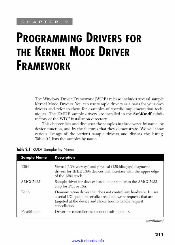
ptg
211
C H A P T E R 9
PROGRAMMING DRIVERS FORTHE KERNEL MODE DRIVERFRAMEWORK
The Windows Driver Framework (WDF) release includes several sampleKernel Mode Drivers. You can use sample drivers as a basis for your owndrivers and refer to them for examples of specific implementation tech-niques. The KMDF sample drivers are installed in the Src\Kmdf subdi-rectory of the WDF installation directory.
This chapter lists and discusses the samples in three ways: by name, bydevice function, and by the features that they demonstrate. We will showvarious listings of the various sample drivers and discuss the listing. Table 9.1 lists the samples by name.
Table 9.1 KMDF Samples by Name
Sample Name Description
1394 Virtual (1394vdev.sys) and physical (1394diag.sys) diagnosticdrivers for IEEE 1394 devices that interface with the upper edgeof the 1394 stack.
AMCC5933 Sample driver for devices based on or similar to the AMCC5933chip for PCI or ISA.
Echo Demonstration driver that does not control any hardware. It usesa serial I/O queue to serialize read and write requests that aretargeted at the device and shows how to handle requestcancellation.
FakeModem Driver for controllerless modem (soft modem).
(continues)
Wow! eBook <WoweBook.Com>
www.it-ebooks.info
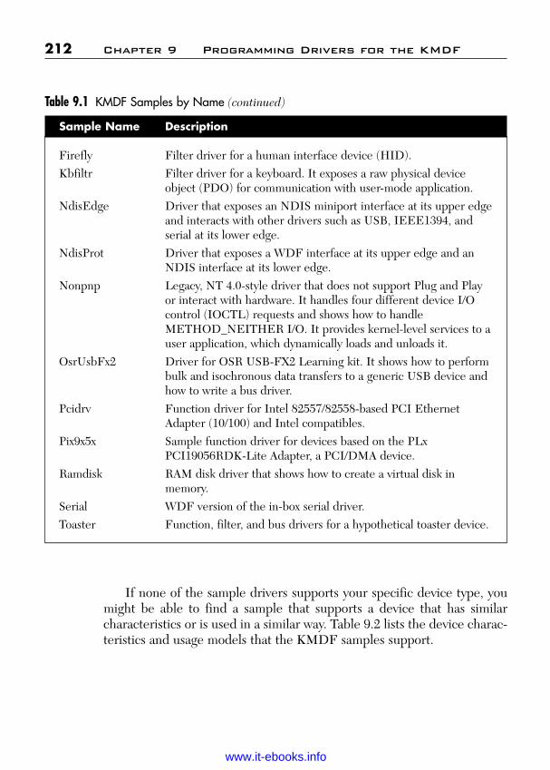
ptg
If none of the sample drivers supports your specific device type, youmight be able to find a sample that supports a device that has similar characteristics or is used in a similar way. Table 9.2 lists the device charac-teristics and usage models that the KMDF samples support.
212 Chapter 9 Programming Drivers for the KMDF
Firefly Filter driver for a human interface device (HID).Kbfiltr Filter driver for a keyboard. It exposes a raw physical device
object (PDO) for communication with user-mode application.NdisEdge Driver that exposes an NDIS miniport interface at its upper edge
and interacts with other drivers such as USB, IEEE1394, andserial at its lower edge.
NdisProt Driver that exposes a WDF interface at its upper edge and anNDIS interface at its lower edge.
Nonpnp Legacy, NT 4.0-style driver that does not support Plug and Playor interact with hardware. It handles four different device I/Ocontrol (IOCTL) requests and shows how to handleMETHOD_NEITHER I/O. It provides kernel-level services to auser application, which dynamically loads and unloads it.
OsrUsbFx2 Driver for OSR USB-FX2 Learning kit. It shows how to performbulk and isochronous data transfers to a generic USB device andhow to write a bus driver.
Pcidrv Function driver for Intel 82557/82558-based PCI EthernetAdapter (10/100) and Intel compatibles.
Pix9x5x Sample function driver for devices based on the PLxPCI19056RDK-Lite Adapter, a PCI/DMA device.
Ramdisk RAM disk driver that shows how to create a virtual disk inmemory.
Serial WDF version of the in-box serial driver.Toaster Function, filter, and bus drivers for a hypothetical toaster device.
Table 9.1 KMDF Samples by Name (continued)
Sample Name Description
Wow! eBook <WoweBook.Com>
www.it-ebooks.info

ptg
Table 9.2 KMDF Samples by Device Usage Model
Chapter 9 Programming Drivers for the KMDF 213
Device Usage Model Device or Driver Type KMDF Sample
Hardware that supportsonly port-mapped I/O
Driver that handles I/Ooperations serially andreads or writes one portat a timeDriver that polls readoperation at regularintervals from either adeferred procedure call(DPC) or a dedicatedkernel threadHardware that supportsport-mapped I/O andinterrupts to notify thedriver about input dataand other asynchronouseventsSame as previous, but alsosupports memory-mappedI/O
Same as previous, but alsosupports bus masterDMA channels to readand writeHardware that has morethan one function oremulates more than onedevice
Driver that supports avirtual bus
Parallel port, legacyjoystick port, and ISAdevices
Serial port, parallel port,IDE controller, and PS/2controller
Typical PCI and EISAdevices for dataacquisition that use directmemory access (DMA)Network adapters andsimilar PCI drivers
Multifunction PCIdevices that do notconfirm to the PCIspecification, multiportserial cards, and multiportnetwork cardsSerial cards, andmultiport network cards
AMCC5933 ISAsample (S5933DK1)
Serial
PLX9x5x
PCIDRV
Toaster bus driver
(continues)
Wow! eBook <WoweBook.Com>
www.it-ebooks.info

ptg
You can also refer to the samples to find out how to use specific KMDFfeatures. Table 9.3 lists the samples that support each fundamental feature.
214 Chapter 9 Programming Drivers for the KMDF
Device Usage Model Device or Driver Type KMDF Sample
Filter driver that modifiesI/O requests and providesan interface for applica-tions to directly controlthe filterFilter driver that modifiesthe hardware resourcesDriver that interacts withan Unrelated device stackto perform I/O
Driver that supports aUSB clientSoftware-only drivers ordrivers that are not partof any Plug and Play stackLegacy NT 4.0-styledrivers that do notsupport Plug and PlayDriver that must run inthe context of the userapplication so that it canhandle METHOD_IOCTsor map memory into useraddress spaceDrivers that registers in-process contextcallback to handleMETHOD_NEITHERI/O requests
Keyboard and mousefilters, storage class filterdrivers, and serial devices
NDIS protocol drivers,Asyncmac, transportdriver interface (TDI)client drivers, and Ftdiskor volsnapAny USB device
No device or legacydevices
Video capture devices,audio cards, and high-speed data acquisitiondevices
Toaster filter driver
NdisEdge andNdisProt
Osrusbfx2
Nonpnp
Nonpnp
Table 9.2 KMDF Samples by Device Usage Model (continued)
Wow! eBook <WoweBook.Com>
www.it-ebooks.info

ptg
Table 9.3 KMDF Feature Support in Samples
Chapter 9 Programming Drivers for the KMDF 215
KMDF Feature Sample
Buffered I/O NdisprotChild device enumeration OsrUsbFx2, Toaster busCollection PCIDRV, Toaster busDirect I/O RamdiskDMA AMCC5933, PCIDRV, PLX9x5xDPC PCIDRV, PLX9x5xEvent tracing AMCC5933, NonPnp, OxrUsbFx2, PCIDRVFunctional device object All samples(FDO) interfaceFile object NonPnPFilter driver Firefly, KbfiltrI/O request cancellation EchoI/O requests and I/O queues All samples(serial/parallel/manual)I/O target objects 1394, Firefly, NdisEdge, OsrUsbFx2Idle detection PCIDRV, serialIn-process callback to handle NonPnPevents in caller’s thread contextInterrupt handling PLX9x5x, SerialMemory pool All samplesMETHOD_NEITHER I/O NonPnPNon-Plug and Play, NT 4.0 Ndisprotstyle device objects (also called control device objects)Physical Device object (PDO) Kbfiltr, OsrUsbFx2/EnumSwitches, interface Toaster busPlug and Play device interface AMCC5933, PCIDRV, PIX9x5x, Toaster
functionPlug and Play hardware resources PCIDRV, PLX9x5x, AMCC5933Plug and Play query interfaces Toaster busPower policy owner PCIDRV
(continues)
Wow! eBook <WoweBook.Com>
www.it-ebooks.info

ptg
9.1 Differences between KMDF and WDM Samples
The KMDF samples are based on the similarly named Windows DriverModel (WDM) samples that are provided in the Windows Driver Kit(WDK). With a few exceptions, the corresponding drivers support similarfeatures. If you are experienced with WDM, you might find useful a com-parison of the KMDF and WDM samples.
The primary difference between the samples is that the KMDF sam-ples are much shorter and less complex. The reason is that KMDF imple-ments most of the details of WMD, so that you can avoid writing manylines of code that perform common tasks and implement common featuresrequired in all drivers. Instead, you define callbacks for the conditions andevents that your driver must handle.
For example, KMDF driver, like WDM drivers, support Plug and Playand power management for their devices. WDM drivers typically includethousands of lines of code to ensure that they handle every possible state
216 Chapter 9 Programming Drivers for the KMDF
Preprocessing callbacks for SerialIRP_MJ_FLUSH_BUFFERS,IRP_MJ_QUERY_INFORMATION, and IRP_MJ_SET_INFORMATIONRaw PDO Kbfiltr, OsrUsbFx2Registry Fakemodem, PCIDRV, Ramdisk, Serial,
Toaster busSelf-managed I/O Echo, PCIDRVSymbolic links to device names Fakemodem, RamdiskSynchronization scope EchoTimer objects EchoUSB device support OsrUsbFx2Wake signal support OsrUsbFx2, PCIDRV, SerialWindows management Firefly, PCIDRV, Serial, Toaster functioninstrumentation (WMI)Work items AMCC5933, PCIDRV
Table 9.3 KMDF Feature Support in Samples (continued)
KMDF Feature Sample
Wow! eBook <WoweBook.Com>
www.it-ebooks.info

ptg
and minor I/O request packet (IRP) code; drivers often require code tohandle IRPs that they don’t even support. A KMDF driver, however,includes code to handle only those features and requests that its devicesupports. All other Plug and Play and power requests are handled by WDFin a default manner. These defaults make possible the incremental devel-opment of KMDF drivers. You can implement a skeletal set of features,test the implementation, and then incrementally add code to support addi-tional features or perform more complicated tasks.
In a practical sense, the most significant difference between KMDFand WDM drivers is the number and complexity of the required func-tions. For an example of this difference, compare the simplest form of theWDM Toaster sample (src/general/toaster/func/Incomplete1 in the WDKinstallation directory) with the simplest KMDF Toaster sample (src/kmdf/toaster/func/simple in the WDF installation directory).
Both drivers support basic Plug and Play, power, and WMI requests. TheKMDF sample also includes stub functions to handle read, write, and IOCTLrequests. However, the KMDF sample contains many fewer lines of code thanthe WDM sample. Table 9.4 compares the functions in these two drivers.
Table 9.4 Comparison of a KMDF Simple Toaster and WDM incomplete1 Toaster Samples
9.1 Differences between KMDF and WDM Samples 217
WDM Function Equivalent KMDF Function Comments
DriverEntry DriverEntry Function has same prototype. KMDF driver creates WDF driver object.
ToasterAddDevice ToasterEvtDeviceAdd KMDF driver creates a default queue for I/O requests.
ToasterUnload None KMDF driver uses defaults.
ToasterDispatchPnP None KMDF driver uses defaults.
ToasterSendIrp- None WDM driver passes IRPs Synchronously down the stack to be
completed synchronously. KMDF driver uses defaults.
(continues)
Wow! eBook <WoweBook.Com>
www.it-ebooks.info
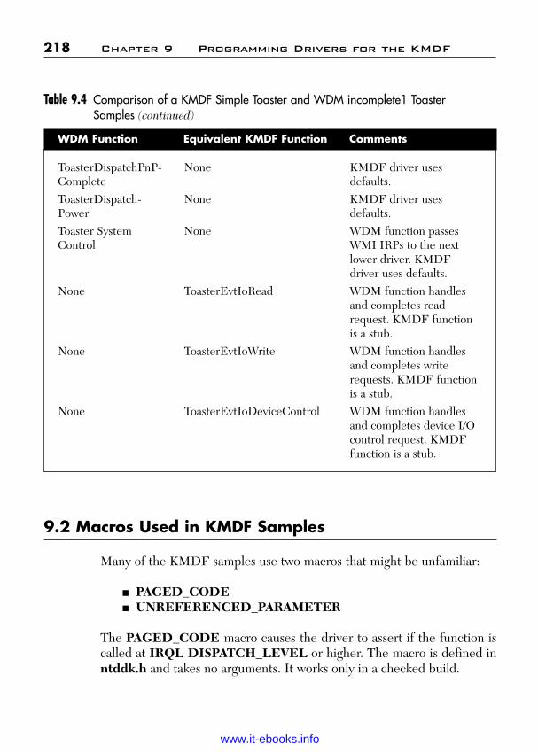
ptg
9.2 Macros Used in KMDF Samples
Many of the KMDF samples use two macros that might be unfamiliar:
■ PAGED_CODE■ UNREFERENCED_PARAMETER
The PAGED_CODE macro causes the driver to assert if the function iscalled at IRQL DISPATCH_LEVEL or higher. The macro is defined inntddk.h and takes no arguments. It works only in a checked build.
218 Chapter 9 Programming Drivers for the KMDF
ToasterDispatchPnP- None KMDF driver uses Complete defaults.ToasterDispatch- None KMDF driver uses Power defaults.Toaster System None WDM function passes Control WMI IRPs to the next
lower driver. KMDF driver uses defaults.
None ToasterEvtIoRead WDM function handles and completes read request. KMDF function is a stub.
None ToasterEvtIoWrite WDM function handles and completes write requests. KMDF function is a stub.
None ToasterEvtIoDeviceControl WDM function handles and completes device I/O control request. KMDF function is a stub.
Table 9.4 Comparison of a KMDF Simple Toaster and WDM incomplete1 Toaster Samples (continued)
WDM Function Equivalent KMDF Function Comments
Wow! eBook <WoweBook.Com>
www.it-ebooks.info
ptg
The UNREFERENCED_PARAMETER is defined in the standardWDK header file ntdef.h, which is included by ntddk.h. It disables com-piler warnings about unreferenced parameters. It can be used in any KernelMode Driver.
9.3 KMDF Driver Structure and Concepts
KMDF drivers are object-oriented, event-driven drivers that link dynami-cally with the Kernel Mode Driver Framework at run time. This discussionprovides a brief overview of KMDF concepts.
The KMDF object model defines object types to represent commondriver constructs. Each object exports methods (functions) and properties(data) that drivers can access and is associated with object-specific events,which drivers can support by providing event callbacks. The objects them-selves are opaque to the driver. KMDF and the driver instantiate theobjects that are required to service the device. The driver provides call-backs for the events for which the KMDF defaults do not suit its deviceand calls methods on the object to get and set properties and perform anyadditional actions. Thus, a KMDF driver consists of a DriverEntry func-tion, callback routines for events that affect the driver or its devices, andwhatever utility functions the driver requires.
All KMDF drivers create a WDFDRIVER object to represent thedriver and a WDFDEVICE object to represent each device that thedriver supports. Most drivers also create one or more WDFQUEUEobjects to represent the driver’s I/O queues. KMDF places I/O requestsinto the queues until the driver is ready to handle them.
Drivers can create additional objects as their device hardware anddriver features require. KMDF objects are organized hierarchically, withthe WDFDRIVER object as the root. The object hierarchy defines theobject’s lifetime—each object is deleted when its parent is deleted.
All KMDF objects are created in the same way, by using KMDF-defined initialization functions and an object creation method. Any KMDFobject has one or more driver-defined object context areas, in which thedriver can store data that is specific to that particular instance of the object.
The following discussions provide more information on object creationand context areas and on I/O queues and requests, which are fundamentalto KMDF drivers.
9.3 KMDF Driver Structure and Concepts 219
Wow! eBook <WoweBook.Com>
www.it-ebooks.info
ptg
9.3.1 Object CreationTo create a KMDF object, a driver follows these steps:
1. Initialize the configuration structure for the object, if one exists.2. Initialize the attributes structure for the object, if necessary.3. Call the creation method to create the object.
The object configuration structure and the object attributes structuresupply basic information about the object and how the driver uses it. Allobject types have the same attributes structure, but the configurationstructure for each type of object is different and some objects do nothave one.
The configuration structure holds pointers to object-specific informa-tion, such as the driver’s event callback functions for the object. Thedriver fills in this structure and then passes it to the framework when itcalls the object creation method. The framework uses the informationfrom the configuration structure to initialize the object. For example, theWDFDRIVER object contains a pointer to the driver’s EvtDriver-DeviceAdd callback function, which KMDF invokes when a Plug andPlay add-device event occurs.
KMDF defines functions named WDF_Object_Config_INIT toinitialize the configuration structures, where Object represents the nameof the object type. Not all object types have configuration structures or thecorresponding initialization functions.
The object attributes structure (WDF_OBJECT_ATTRIBUTES)specifies attributes that are common to all objects:
■ Callbacks to handle object cleanup and destruction.■ The interrupt request level (IRQL) at which the objects’ callback
functions are invoked and its locks are held.■ An object context area.■ Information about the context area, such as its size and type.
KMDF defines the following for use in initializing object attributes:
■ WDF_OBJECT_ATTRIBUTES_INIT■ WDF_OBJECT_ATTRIBUTES_INIT_CONTEXT_TYPE■ WDF_OBJECT_ATTIBUTES_SET_CONTEXT_TYPE
220 Chapter 9 Programming Drivers for the KMDF
Wow! eBook <WoweBook.Com>
www.it-ebooks.info
ptg
The WDF_OBJECT_ATTRIBUTES_INIT function sets values for synchronization and execution level, which determine which of the driver’scallbacks KMDF invokes concurrently and the highest IRQL at which theycan be called. The two context-type initialization macros set informationabout the object’s context area, which is described in the next section.
Although attributes can apply to any type of object, the defaults aretypically acceptable for objects for which the driver does not define a con-text area. To accept the defaults, a driver specifies WDF_NO_OBJECT_ATTRIBUTES, in which WDK defines a NULL.
After initializing the object’s configuration structure and attributes, thedriver creates an instance of the object by calling the creation method forthe object type with pointer to the attributes structure and any otherobject-type-specific parameters. Creation methods are all namedWdfObjectCreate, where Object indicates the type of object. The cre-ation method returns a handle to the created object. The driver subse-quently uses the handle to refer to the object.
9.3.2 Object Context AreaEvery instance of an object can have one or more object context areas. Theobject context area is a driver-defined storage area for data that is related tothat particular instance, such as a driver-allocated event. The driver deter-mines the size and layout of the object context area. For a device object, theobject context area is the equivalent of the WDM device extension.
A driver initializes the context area and specifies its size and type whenit creates the object. When KMDF creates the object, it allocates memoryfor the context areas from the nonpaged pool and initializes them accord-ing to the driver’s specification. When KMDF deletes the object, the con-text areas are deleted along with the object.
The context area is considered part of the object, which is opaque todrivers. Therefore, the driver must use an accessor method to get a pointerto the context area. Each context area has its own accessor method, andKMDF provides macros to create these methods.
For the driver, defining and initializing a context area is a multistepprocess. First, the driver defines a data structure that describes the contextarea. This definition typically appears in a header file.
Next, the driver declares the type of the context area, by using eitherthe WDF_DECLARE_CONTEXT_TYPE or WDF_DECLARE_CONTEXT_TYPE_WITH_NAME macro. These macros associate a type
9.3 KMDF Driver Structure and Concepts 221
Wow! eBook <WoweBook.Com>
www.it-ebooks.info

ptg
with the context area and create a named accessor method that returns apointer to the context area. WDF_DECLARE_CONTEXT_TYPE_WITH_NAME assigns a driver-specified name to the accessor method.WDF_DECLARE_CONTEXT_TYPE assigns the default name Wdf-ObjectGet_ContextStructure, where ContextStructure is the name of the context structure. This step, too, can be performed in a header file.
Finally, the driver associates the context area with a specific instance of an object. To do so, the driver initializes the object attribute structure with information about the context area by using the WDF_OBJECT_ATTRIBUTES_INIT_CONTEXT_TYPE or WDF_OBJECT_ATTRIBUTES_SET_CONTEXT_TYPE macro. The WDF_OBJECT_ATTRIBUTES_SET_CONTEXT_TYPE macro records informationabout the context area in an attributes structure, which the driver latersupplies when it creates the object. WDF_OBJECT_ATTRIBUTES_INIT_CONTEXT_TYPE combines the actions of WDF_OBJECT_ATTRIBUTES_INIT and WDF_OBJECT_ATTRIBUTES_SET_CONTEXT_TYPE—that is, it initializes the attribute structure withsettings for synchronization scope and execution level in addition toinformation about the context. The driver passes the resulting attributestructure when it calls the creation method for the object.
9.3.3 I/O QueuesKMDF I/O queues manage requests that are targeted at the driver. A driver typically creates one or more queues, each of which can acceptone or more types of request. A driver can have any number of queues, andthey can all be configured differently. Both KMDF and the driver itself canqueue I/O request.
The most important characteristics of any queue are the types ofrequests it accepts, the way in which it dispatches those requests, andwhether KMDF handles power management for it.
A queue can accept one or more types of requests. For example, adriver might have one queue for read and write request and another thataccepts only device I/O control requests.
The dispatch method determines how many requests the driver serv-ices at a given time. Queues can dispatch requests sequentially, in parallel,or manually. A sequential queue dispatches one request at a time. A paral-lel queue dispatches requests as soon as they arrive. A manual queue does
222 Chapter 9 Programming Drivers for the KMDF
Wow! eBook <WoweBook.Com>
www.it-ebooks.info

ptg
not dispatch requests automatically; the driver must call a method on thequeue each time it is ready to handle another request.
By default, all KMDF I/O queues are power managed, which meansthat KMDF handles starting and stopping the queue according to thepower management state of the device and the system. In addition, KMDFcan use an empty queue as a cue to start its idle-device timer.
The driver uses a WDF_IO_QUEUE_CONFIG structure to config-ure a queue. For each queue, the driver can specify
■ The types of I/O requests that are placed in the queue.■ The dispatch method for the queue.■ The power management options for the queue.■ The I/O event callback functions registered to handle I/O requests
from the queue.■ Whether the queue accepts requests that have a zero-length buffer.
WDF supplies two functions to initialize the WDF_QUEUE_CONFIGstructure:
■ WDF_IO_QUEUE_CONFIG_INIT, which configures a power-managed queue with a driver-specified dispatch method.
■ WDF_IO_QUEUE_CONFIG_INIT_DEFAULT_QUEUE,which configures a power-managed queue with a driver-specifieddispatch method and designates it as the driver’s default queue, intowhich KMDF places all read, write, and device I/O control requestsfor which no other queue is configured.
Like all other objects, queues have attributes. In many cases, the defaultattributes are acceptable for queues. A driver might override the defaultsfor one of the following reasons:
■ To create one or more queue-specific context areas in which to savedata specific to the queue.
■ To specify a callback function to be invoked when the queue isdeleted.
■ To specify a parent object for the queue. By default, the parentobject is the device object.
9.3 KMDF Driver Structure and Concepts 223
Wow! eBook <WoweBook.Com>
www.it-ebooks.info

ptg
9.3.4 I/O RequestsThe WDFREQUEST object represents the IRP sent by the application thatinitiated the I/O request. Like other KMDF objects, the WDFREQUESTobject is opaque to driver writers and is managed by the framework. MostKMDF drivers never directly see the underlying IRP.
When KMDF calls one of the driver’s I/O event callback functions, itpasses a handle to a WDFREQUEST object, along with additional infor-mation that the driver might require to handle the request. The WDFRE-QUEST object encapsulates the information passed in the original IRP.
KMDF drivers that support buffered or direct I/O can use the bufferpassed by the originator of the I/O request or can use a WDFMEMORYobject that represents the output buffer. Using a WDFMEMORY objectis simpler and requires less code because the framework handles all vali-dation and addressing issues. For example, the handle to the WDFMEMORYobject contains the size of the buffer, thus ensuring that buffer overruns donot occur.
9.4 A Minimal KMDF Driver: The Simple Toaster
The Simple Toaster sample provided in toaster\func\simple is a min-imal, software-only function driver. It creates a driver object, a deviceobject, a device interface, and a single I\O queue. The driver handlesread, write, and device I/O control requests that are targeted at itsdevice.
This minimal driver includes the following functions:
■ A DriverEntry routine, which creates the driver object.■ An EvtDriverDeviceAdd event callback, which creates the device
object, a device interface, and a default I/O queue.■ I/O callback functions for read, write, and device I/O control requests.
The driver does not manage any physical hardware, so no code to supportPlug and Play or power management is required; the driver uses the WDFdefaults.
224 Chapter 9 Programming Drivers for the KMDF
Wow! eBook <WoweBook.Com>
www.it-ebooks.info
ptg
9.4.1 Creating a WDF Driver Object: DriverEntryEvery KMDF driver must have a DriverEntry routine. The Driver-Entry routine is the first driver function called when the driver is loaded.The KMDF DriverEntry routine has the same prototype as that of aWDM driver:
NTSTATUSDriverEntry(
IN PDRIVER_OBJECT DriverObject,In PUNICODE_STRING RegistryPath);
The DriverEntry routine performs the following tasks:
■ Creates a driver object (WDFDRIVER), which represents theloaded instance of the driver in memory. In effect, creating thisobject “registers” the driver with KMDF.
■ Registers the driver’s EvtDriverDeviceAdd callback. KMDF callsthis function during device enumeration.
■ Optionally initializes event tracing for the driver.■ Optionally allocates resources that are required on a driver-wide
(rather than per-device) basis.
The following shows the DriverEntry function for the Simple Toastersample:
NTSTATUSDriverEntry(
IN PDRIVER_OBJ DriverObject,IN PUNICODE_STRING RegistryPath)
{NTSTATUS status = STATUS_SUCCESS;WDF_DRIVER_CONFIG config;
KdPrint((“Toaster Function Driver Sample-”Driver Framework Edition.\n));
KdPrint((“Built %s %s\n”, __DATE__, __TIME__));
9.4 A Minimal KMDF Driver: The Simple Toaster 225
Wow! eBook <WoweBook.Com>
www.it-ebooks.info
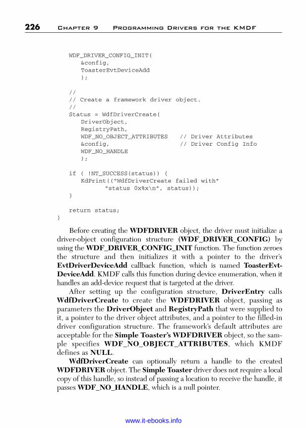
ptg
WDF_DRIVER_CONFIG_INIT(&config,ToasterEvtDeviceAdd);
//// Create a framework driver object.//Status = WdfDriverCreate(
DriverObject,RegistryPath,WDF_NO_OBJECT_ATTRIBUTES // Driver Attributes&config, // Driver Config InfoWDF_NO_HANDLE);
if ( !NT_SUCCESS(status)) {KdPrint((“WdfDriverCreate failed with”
“status 0x%x\n”, status));}
return status;}
Before creating the WDFDRIVER object, the driver must initialize adriver-object configuration structure (WDF_DRIVER_CONFIG) byusing the WDF_DRIVER_CONFIG_INIT function. The function zeroesthe structure and then initializes it with a pointer to the driver’sEvtDriverDeviceAdd callback function, which is named ToasterEvt-DeviceAdd. KMDF calls this function during device enumeration, when ithandles an add-device request that is targeted at the driver.
After setting up the configuration structure, DriverEntry callsWdfDriverCreate to create the WDFDRIVER object, passing asparameters the DriverObject and RegistryPath that were supplied toit, a pointer to the driver object attributes, and a pointer to the filled-indriver configuration structure. The framework’s default attributes areacceptable for the Simple Toaster’s WDFDRIVER object, so the sam-ple specifies WDF_NO_OBJECT_ATTRIBUTES, which KMDFdefines as NULL.
WdfDriverCreate can optionally return a handle to the createdWDFDRIVER object. The Simple Toaster driver does not require a localcopy of this handle, so instead of passing a location to receive the handle, itpasses WDF_NO_HANDLE, which is a null pointer.
226 Chapter 9 Programming Drivers for the KMDF
Wow! eBook <WoweBook.Com>
www.it-ebooks.info

ptg
A WDM driver would typically save pointers to the DriverObject andRegistryPath, but a KMDF driver does not require them because KMDFmaintains this information on behalf of the driver.
9.4.2 Creating the Device Object, Device Interface,and I/O Queue: EvtDriverDeviceAdd
Every KMDF driver that supports Plug and Play must have anEvtDriverDeviceAdd callback function, which is called each time the sys-tem enumerates a device that belongs to the driver. This callback performsactions required at device enumeration, such as the following:
■ Creates and initializes a device object (WDFDEVICE) and corre-sponding context areas.
■ Sets entry points for the driver’s Plug and Play and power manage-ment callbacks.
■ Creates a device interface.■ Configures and creates one or more I/O queues.■ Creates an interrupt object, if the device controls physical hardware
that generates interrupts.
The EvtDriverDeviceAdd function is called with two parameters: a han-dle to the WDFDRIVER object that the driver created during Driver-Entry and a handle to a WDFDEVICE_INIT object.
The Simple Toaster does not control hardware, so it does not set Plugand Play or power management callbacks, nor does it create an interruptobject. Its EvtDriverDeviceAdd callback creates the device object andcontext area, device interface, and a single default I/O queue. The follow-ing shows the source code for this function:
NTSTATUSToasterEvtDeviceAdd(
IN WDFDRIVER Driver,IN PWDFDEVICE_INIT DeviceInit)
{NTSTATUS status = STATUS_SUCCESS;PFDO_DATA fdoData;WDF_IO_QUEUE_CONFIG queueConfig;WDF_OBJECT_ATTRIBUTES fdoAttributes;WDFDEVICE hDevice;WDFQUEUE queue;
9.4 A Minimal KMDF Driver: The Simple Toaster 227
Wow! eBook <WoweBook.Com>
www.it-ebooks.info
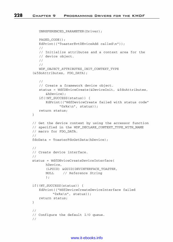
ptg
UNREFERENCED_PARAMETER(Driver);
PAGED_CODE();KdPrint((“ToasterEvtDEviceAdd called\n”));//// Initialize attributes and a context area for the// device object.////WDF_OBJECT_ATTRIBUTES_INIT_CONTEXT_TYPE
(&fdoAttributes, FDO_DATA);
//// Create a framework device object.status = WdfDEviceCreate(&DeviceInit, &fdoAttributes,
&hDevice);if(!NT_SUCCESS(status)) {
KdPrint((“WdfDeviceCreate failed with status code”“0x%x\n”, status));
return status;}
// Get the device context by using the accessor function// specified in the WDF_DECLARE_CONTEXT_TYPE_WITH_NAME// macro for FDO_DATA.//fdoData = ToasterFdoGetData(hDevice);
//// Create device interface.//status = WdfDEviceCreateDeviceInterface(
hDevice,(LPUID) &GUID)DEVINTERFACE_TOASTER,NULL // Reference String);
if(!NT_SUCCESS(status)) {KdPrint((“WdfDeviceCreateDeviceInterface failed
“0x%x\n”, status));return status;
}
//// Configure the default I/O queue.//
228 Chapter 9 Programming Drivers for the KMDF
Wow! eBook <WoweBook.Com>
www.it-ebooks.info
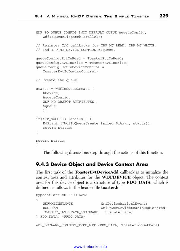
ptg
WDF_IO_QUEUE_CONFIG_INIT_DEFAULT_QUEUE(&queueConfig,WdfIoQueueDispatchParallel);
// Register I/O callbacks for IRP_MJ_READ, IRP_MJ_WRITE, // and IRP_MJ_DEVICE_CONTROL request.
queueConfig.EvtIoRead = ToasterEvtIoRead;queueConfig.EvtIoWrite = ToasterEvtIoWrite;queueConfig.EvtIoDeviceControl =
ToasterEvtIoDeviceControl;
// Create the queue.
status = WdfIoQueueCreate (hDevice,&queueConfig,WDF_NO_OBJECT_ATTRIBUTES,&queue);
if(!NT_SUCCESS (status)) {KdPrint((“WdfIoQueueCreate failed 0x%x\n, status));return status;
}
return status;}
The following discussions step through the actions of this function.
9.4.3 Device Object and Device Context AreaThe first task of the ToasterEvtDeviceAdd callback is to initialize thecontext area and attributes for the WDFDEVICE object. The contextarea for this device object is a structure of type FDO_DATA, which isdefined as follows in the header file toaster.h:
typedef struct _FDO_DATA{
WDFWMIINSTANCE WmiDeviceArrivalEvent;BOOLEAN WmiPowerDeviceEnableRegistered;TOASTER_INTERFACE_STANDARD BusInterface;
} FDO_DATA, *PFDO_DATA;
WDF_DECLARE_CONTEXT_TYPE_WITH(FDO_DATA, ToasterFdoGetData)
9.4 A Minimal KMDF Driver: The Simple Toaster 229
Wow! eBook <WoweBook.Com>
www.it-ebooks.info

ptg
As the example shows, the header file defines the context area andthen invokes the WDF_DECLARE_CONTEXT_TYPE_WITH_NAME macro. This macro creates an accessor method that is associatedwith a context type. Thus, when the ToasterEvtDeviceAdd function iscalled, the accessor method ToasterFdoGetData has already been cre-ated to read and write a context area of type FDO_DATA.
To associate the named context area with an object, the driver must ini-tialize the object’s attribute structure with information about the contextarea. The ToasterEvtDeviceAdd function invokes the WDF_OBJECT_ATTRIBUTES_INIT_CONTEXT_TYPE macro to do this:
WDF_OBJECT_ATTRIBUTES_INIT_CONTEXT_TYPE(&fdoAttributes,FDO_DATA);
This macro performs the following tasks:
■ Initializes fdoAttributes, which is a WDF_OBJECT_ATTRIBUTESstructure.
■ Sets pointers to the name and length of the context area and to thecontext area itself in the WDF_OBJECT_ATTRIBUTES structure.
The variable fdoData, of type PFDO_DATA, is defined to hold a pointerto the context area.
Next, the driver creates the WDFDEVICE object by calling WdfDeviceCreate, passing as parameters the addresses of theWDFDEVICE_INIT and WDF_OBJECT_ATTRIBUTES structuresand a location to receive a handle to the create object:
status = WdfDeviceCreate(&DeviceInit, &fdoAttributes,&hDevice);
The framework allocates the WDFDEVICE_INIT structure, which isopaque to the driver writer. This object supports several methods that adriver can use to initialize device and driver characteristics, including thetype of I/O that the driver supports, the device name, and a securitydescriptor definition language (SDDL) string for the device, among others.(These settings correspond to the device characteristics fields of the WDMdevice object, which is familiar to WDM driver writers.) By default, KMDFsets the I/O type to buffered I/O. This default, along with all the others, is
230 Chapter 9 Programming Drivers for the KMDF
Wow! eBook <WoweBook.Com>
www.it-ebooks.info
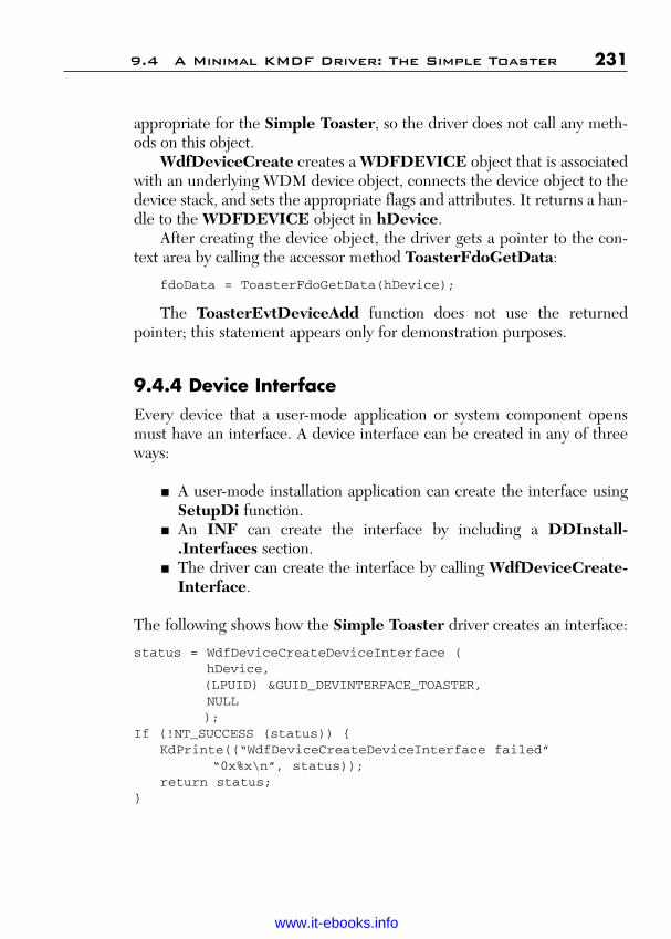
ptg
appropriate for the Simple Toaster, so the driver does not call any meth-ods on this object.
WdfDeviceCreate creates a WDFDEVICE object that is associatedwith an underlying WDM device object, connects the device object to thedevice stack, and sets the appropriate flags and attributes. It returns a han-dle to the WDFDEVICE object in hDevice.
After creating the device object, the driver gets a pointer to the con-text area by calling the accessor method ToasterFdoGetData:
fdoData = ToasterFdoGetData(hDevice);
The ToasterEvtDeviceAdd function does not use the returnedpointer; this statement appears only for demonstration purposes.
9.4.4 Device InterfaceEvery device that a user-mode application or system component opensmust have an interface. A device interface can be created in any of threeways:
■ A user-mode installation application can create the interface usingSetupDi function.
■ An INF can create the interface by including a DDInstall-.Interfaces section.
■ The driver can create the interface by calling WdfDeviceCreate-Interface.
The following shows how the Simple Toaster driver creates an interface:
status = WdfDeviceCreateDeviceInterface (hDevice,(LPUID) &GUID_DEVINTERFACE_TOASTER,NULL);
If (!NT_SUCCESS (status)) {KdPrinte((“WdfDeviceCreateDeviceInterface failed”
“0x%x\n”, status));return status;
}
9.4 A Minimal KMDF Driver: The Simple Toaster 231
Wow! eBook <WoweBook.Com>
www.it-ebooks.info
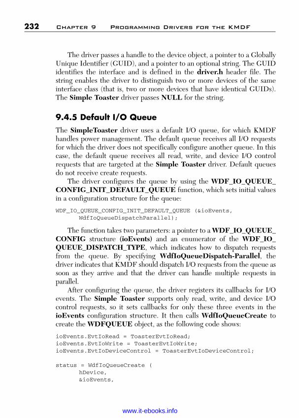
ptg
The driver passes a handle to the device object, a pointer to a GloballyUnique Identifier (GUID), and a pointer to an optional string. The GUIDidentifies the interface and is defined in the driver.h header file. Thestring enables the driver to distinguish two or more devices of the sameinterface class (that is, two or more devices that have identical GUIDs).The Simple Toaster driver passes NULL for the string.
9.4.5 Default I/O QueueThe SimpleToaster driver uses a default I/O queue, for which KMDFhandles power management. The default queue receives all I/O requestsfor which the driver does not specifically configure another queue. In thiscase, the default queue receives all read, write, and device I/O controlrequests that are targeted at the Simple Toaster driver. Default queuesdo not receive create requests.
The driver configures the queue by using the WDF_IO_QUEUE_CONFIG_INIT_DEFAULT_QUEUE function, which sets initial valuesin a configuration structure for the queue:
WDF_IO_QUEUE_CONFIG_INIT_DEFAULT_QUEUE (&ioEvents,WdfIoQueueDispatchParallel);
The function takes two parameters: a pointer to a WDF_IO_QUEUE_CONFIG structure (ioEvents) and an enumerator of the WDF_IO_QUEUE_DISPATCH_TYPE, which indicates how to dispatch requests from the queue. By specifying WdfIoQueueDispatch-Parallel, the driver indicates that KMDF should dispatch I/O requests from the queue assoon as they arrive and that the driver can handle multiple requests in parallel.
After configuring the queue, the driver registers its callbacks for I/Oevents. The Simple Toaster supports only read, write, and device I/Ocontrol requests, so it sets callbacks for only these three events in theioEvents configuration structure. It then calls WdfIoQueueCreate tocreate the WDFQUEUE object, as the following code shows:
ioEvents.EvtIoRead = ToasterEvtIoRead;ioEvents.EvtIoWrite = ToasterEvtIoWrite;ioEvents.EvtIoDeviceControl = ToasterEvtIoDeviceControl;
status = WdfIoQueueCreate (hDevice,&ioEvents,
232 Chapter 9 Programming Drivers for the KMDF
Wow! eBook <WoweBook.Com>
www.it-ebooks.info

ptg
WDF_NO_OBJECT_ATTRIBUTES,&queue // pointer to default queue);
When the driver calls WdfIoQueueCreate, it passes a handle to theWDFDEVICE object (hDevice) and a pointer to the ioEvents configu-ration structure. The driver accepts the default attributes for the queue, soit passes WDF_NO_OBJECT_ATTRIBUTES. The method returns ahandle to the queue at &queue. By default, KMDF places all read, write,and device I/O requests targeted at the device into this queue.
9.4.6 Handling I/O Request: EvtIoRead, EvtIoWrite,EvtIoDeviceControl
A driver can include one or more of the following I/O callback functions tohandle the I/O requests that are dispatched from its queues:
■ EvtIoRead■ EvtIoWrite■ EvtIoDeviceControl■ EvtIoInternalDeviceControl■ EvtIoDefault
For each queue, the driver registers one or more such callbacks. When anI/O request arrives, KMDF invokes the callback that is registered for thattype of request, if one exists. For example, when a read request arrives,KMDF dispatches it to the EvtIoRead callback. Write requests are dis-patched to the EvtIoWrite callback, and so forth. KMDF calls theEvtIoDefault callback when a request arrives for which the driver has notregistered another callback. (In some cases, EvtIoDefault is also called tohandle create request.)
KMDF queues and dispatches only the request for which the driverconfigures a queue. If KMDF receives any other I/O requests targeted atthe Simple Toaster driver, it fails the requests with STATUS_INVALID_DEVICE_REQUEST.
As the preceding section mentions, the Simple Toaster driver han-dles only read, write, and device I/O control requests, so it includesonly the EvtIoRead, EvtIoWrite, and EvtIoDeviceControl callbackfunctions.
9.4 A Minimal KMDF Driver: The Simple Toaster 233
Wow! eBook <WoweBook.Com>
www.it-ebooks.info

ptg
When KMDF invokes these callbacks, it passes a handle to theWDFQUEUE object, a handle to the WDFREQUEST object that rep-resents the I/O request, and one or more additional parameters that pro-vide details about the request. The additional parameters vary dependingon the specific callback.
If the driver supports buffered or direct I/O, it can use either thebuffer passed by the originator of the request or a WDFMEMORY objectthat represents that buffer. Using a WDFMEMORY object is simpler andrequires less code because the framework handles all validation andaddressing issues. For example, the handle to the WDFMEMORY objectcontains the size of the buffer, thus ensuring that buffer overruns does notoccur. The Simple Toaster driver uses this technique.
To get a handle to the WDFMEMORY object, the driver callsWdfRequestRetrieveOutputMemory for a read request andWdfRequestRetrieveInputMemory for a write request. Each of thesemethods creates a WDFMEMORY object that represents the correspon-ding buffer and is associated with the WDFREQUEST object.
To handle a read request, the driver then gets the data from its deviceand uses WdfMemoryCopyFromBuffer to copy the data from its inter-nal buffer into the WDFMEMORY object that is associated with therequest.
To handle a write request, the driver has three options:
■ Calling WdfMemoryCopyToBuffer to copy data from theWDFREQUEST object to the driver’s internal buffer, from whichthe driver can write to the device.
■ Getting the buffer pointer from the request by calling WdfRequest-RetrieveInputBuffer, which also returns the number of bytes towrite.
■ Getting the buffer pointer and the number of bytes to write by call-ing WdfMemoryGetBuffer.
For most write requests, drivers should use WdfMemoryCopyToBufferto copy data supplied in the I/O request (and now stored in the associatedWDFMEMORY object) to the driver’s output buffer. This function copiesthe data and returns an error if a buffer overflow occurs. Use theWdfRequestRetrieveInputBuffer and WdfMemoryGetBuffer meth-ods only if you require the buffer pointer so that you can cast it to a struc-ture, which might be necessary when handling a device I/O control request.
234 Chapter 9 Programming Drivers for the KMDF
Wow! eBook <WoweBook.Com>
www.it-ebooks.info

ptg
Initially, the names WdfMemoryCopyFromBuffer and Wdf-MemoryCopyToBuffer might appear somewhat confusing. Rememberthat the word “Memory” in the name means that the function acts on aWDFMEMORY object and copies data to or from a program buffer intothat object. Thus, WdfMemoryCopyFromBuffer copies data from thedriver’s internal buffer into a WDFMEMORY object, so it is used for readrequests. WdfMemoryCopyToBuffer copies data to the driver’s internalbuffer, so it is used for write requests.
When the driver has satisfied the I/O request, it calls WdfRequest-CompleteWithInformation, which completes the underlying I/Orequest with the specified status and passes the number of bytes read orwritten.
The Simple Toaster sample’s EvtIoRead, EvtIoWrite, and EvtIo-DeviceControl callbacks are essentially stubs. Although the Toaster-EvtIoRead function calls WdfRequestRetrieveOutput-Memory to getthe output buffer and the ToasterEvtIoWrite function calls Wdf-RequestRetrieveInputMemory to get the input buffer, neither functionreads, writes, or returns any data. Therefore, none of these I/O event call-backs is reproduced here.
9.5 Sample Software-Only Driver
The Featured Toaster sample extends the Simple Toaster sample byadding support for the following features:
■ File create and close requests.■ Additional device object attributes.■ Plug and Play and power management events.■ Windows management instrumentation (WMI).
This sample is supplied in Toaster\Func\Featured and supports thesame features as the Featured2 Toaster sample for WDM, which is pro-vided in the WDK.
9.5.1 File Create and Close RequestsFile object events occur when applications and kernel-mode componentsthat open a handle to the device issue create, close, and cleanup requests
9.5 Sample Software-Only Driver 235
Wow! eBook <WoweBook.Com>
www.it-ebooks.info

ptg
on the device. Drivers that handle such requests must configure the deviceobject with the appropriate callbacks.
To handle create events, a driver can either receive the events from aqueue or can supply an event callback that is invoked immediately. Thedriver’s options are the following:
■ To be called immediately, the driver supplies an EvtDeviceFile-Create callback and registers it from the EvtDriverDeviceAddcallback by calling WdfDeviceInitSetFileObjectConfig.
■ To configure a queue to receive the requests, the driver callsWdfDeviceConfigureRequestDispatching and specifies Wdf-RequestTypeCreate. If the queue is not manual, the driver mustregister an EvtIoDefault callback, which is called when a createrequest arrives.
Queuing takes precedence over the EvtDeviceFileCreate callback—thatis, if the driver both registers for EvtDeviceFileCreate events and con-figures a queue to receive such requests, KMDF queues the requests anddoes not invoke the callback. KMDF does not queue requests to a defaultqueue; the driver must explicitly configure a queue to receive them.
In a function or bus driver, if a create request arrives for which thedriver has neither registered an EvtDeviceFileCreate callback functionnor configured a queue to receive create request, KMDF opens a fileobject to represent the device and completes the request with STATUS_SUCCESS. Therefore, any function or bus driver that does notaccept create or open requests from user-mode applications—and thusdoes not register a device interface—must register an EvtDeviceFile-Create callback that explicitly fails such requests. Supplying a callback tofail create requests ensures that a rogue user-mode application cannot gainaccess to the device.
If a filter driver does not handle create requests, KMDF by defaultforwards all create, cleanup, and close requests to the default I/O target(the next lower driver).
Filter drivers that handle create requests should perform whatever filtering tasks are required and then forward such requests to the defaultI/O target. If the filter driver completes a create request for a file object,it should set AutoForwardCleanupClose to WdfFalse in the file objectconfiguration so that KMDF completes cleanup and close requests for thefile object instead of forwarding them.
236 Chapter 9 Programming Drivers for the KMDF
Wow! eBook <WoweBook.Com>
www.it-ebooks.info

ptg
To handle file close and cleanup requests on a device handle, thedriver supplies the EvtFileClose and EvtFileCleanup callbacks. It reg-isters both of these callbacks in its EvtDriverDeviceAdd function.
9.5.1.1 Register EvtDeviceFileCreate and EvtFileClose Callbacks
The following code is excerpted from the Featured Toaster’sToasterEvtDeviceAdd function. It shows how the driver registers theEvtDeviceFileCreate and EvtFileClose callbacks.
WDF_FILEOBJECT_CONFIG_INIT(&fileConfig,ToasterEvtDeviceFileCreate,ToasterEvtFileClose,WDF_NO_EVENT_CALLBACK // not interested in Cleanup);
WdfDeviceInitSetFileObjectConfig(DeviceInit,&fileConfig,WDF_NO_OBJECT_ATTRIBUTES);
As the example shows, the driver initializes a WDF_FILEOBJECT_CONFIG structure by calling the configuration function and supplyingpointers to its EvtDeviceFileCreate and EvtFileClose callbacks. Thedriver does not implement the EvtFileCleanup callback, so it suppliesWDF_NO_EVENT_CALLBACK instead of a third function pointer.
It then calls WdfDeviceInitSetFileObjectConfig to record thesesettings in the WDFDEVICE_INIT structure (DeviceInit), which theframework uses later when it creates the device object.
The EvtDeviceFileCreate and EvtFileClose functions are stubs inthe Featured Toaster driver, so they are not shown here.
9.5.2 Additional Device Object AttributesThe Featured Toaster sample sets three more attributes for the deviceobject than the Simple Toaster sample does:
■ Synchronization scope■ Execution level■ An EvtCleanupCallback function
9.5 Sample Software-Only Driver 237
Wow! eBook <WoweBook.Com>
www.it-ebooks.info

ptg
9.5.2.1 Synchronization ScopeThe synchronization scope determines which of the callbacks for a deviceor queue object KMDF calls concurrently and which it calls sequentially.The following are the possible scopes:
■ Device scope (WdfSynchronizationScopeDevice) means thatKMDF does not make concurrent calls to certain I/O event call-backs for the queue or file objects that are children of the deviceobject.
■ Queue scope (WdfSynchronizationScopeQueue) means thatKMDF does not call certain I/O event callbacks concurrently forthe individual queue objects that are children of the object.
■ No scope (WdfSynchronizationScopeNone) means that KMDFdoes not acquire any locks and can call any event callback concur-rently with any other event callback. This is the default value for theWDFDRIVER object, which is the root object.
■ Default scope (WdfSynchronizationScopeInheritFromParent)means that the object uses the same scope as its parent object. Thisis the default value for all objects other than the WDFDRIVERobject.
By setting synchronization scope to device level (WdfSynchronization-ScopeDevice), a driver tells KMDF to synchronize calls to certain I/Oevent callbacks (such as EvtIoRead, EvtIoWrite, and so forth) for queueand file objects that are children of the device object so that only one suchcallback executes at any given time. In effect, the callbacks execute syn-chronously. Because only one callback runs at a time, the driver is notrequired to hold locks to protect data that the callbacks share, such as thedevice context area.
Drivers can use these KMDF synchronization techniques (some-times called frameworks locking) to synchronize access to their ownhardware and their internal data. However, drivers should not use thesetechniques when calling externally, particularly to WDM drivers,because KMDF might hold a lock when the WDM driver does notexpect it. This problem can occur because of IRQL restrictions or whenthe WDM driver eventually calls back into the KMDF driver, whichresults in a deadlock.
238 Chapter 9 Programming Drivers for the KMDF
Wow! eBook <WoweBook.Com>
www.it-ebooks.info
ptg
9.5.2.2 Execution LevelThe execution level indicates the IRQL at which KMDF should call theevent callback for the object. A driver can select PASSIVE_LEVEL(WdfExecutionLevelPassive), DISPATCH_LEVEL (WdfExecution-LevelDispatch), or the default level (WdfExecutionLevelDefault).If the driver sets the default execution level for an object, KMDF doesnot guarantee callbacks at a particular IRQL, but can call them at anyIRQL <= Dispatch_Level. For example, KMDF would call the routinesat DISPATCH_LEVEL if an upper-level driver or KMDF itself alreadyholds a spin lock.
Setting dispatch execution level for an object does not force its call-backs to occur at DISPATCH_LEVEL. Instead, it indicates that thecallbacks are designed to be called at DISPATCH_LEVEL and so donot take any actions that might cause a page fault. If such a callbackrequires synchronization, KMDF uses a spin lock, which raises IRQL toDISPATCH_LEVEL.
Selecting passive execution level means that KMDF calls the callbacksat PASSIVE_LEVEL, even if it must queue a work item to do so. This levelis typically useful only for very basic drivers, such as the Toaster sample.The Featured Toaster driver specifies WdfExecutionLevelPassive,thus ensuring that certain callbacks are called at PASSIVE_LEVEL so itcan use pageable data in all such callbacks.
Most drivers must coexist in a stack with WDM drivers and thereforeshould accept the default.
9.5.2.3 EvtCleanupCallback FunctionKMDF calls the object’s EvtCleanupCallback callback when the objectis being deleted, so that the driver can perform any cleanup related to theobject. Device objects are typically deleted during device removal pro-cessing, so the EvtCleanupCallback for a device object is not calledunless the device is removed.
If the device explicitly takes out a reference on an object (by callingWdfObjectReference), it must implement EvtCleanupCallback forthat object so that it can release the reference. This callback also typicallydeallocates memory buffers that the driver previously allocated on a per-object basis and stored in the object context area.
9.5 Sample Software-Only Driver 239
Wow! eBook <WoweBook.Com>
www.it-ebooks.info

ptg
In many drivers, this callback is not required. Remember that KMDFdestroys the child objects of each parent object before deleting the parentobject itself. If you allocate a WDFMEMORY buffer for object-specificstorage and ensure that the ParentObject field in the attributes structureof the buffer points to the device object, you can often avoid the necessityof deallocating the buffer because KMDF deletes it automatically
In the Featured Toaster sample, this function is simply a stub.
9.5.3 Setting Additional Device Object AttributesThe following listing shows how the Featured Toaster driver sets theseadditional attributes and creates the WDFDEVICE_OBJECT:
//// Set the Synchronization scope to device so that only one Evt// callback for this device is executing at any time. This// eliminates the need to hold any lock to synchronize access// to the device context area.//// By specifying passive execution level, driver ensures// that the framework will never call the I/O callbacks// at DISPATCH_LEVEL.//
fdoAttributes.SynchronizationScope = WdfSynchronizationScopeDevice;
fdoAttributes.ExecutionLevel = WdfExecutionLevelPassive;
//// Set a context cleanup routine to clean up any resources// that are not defined in the parent to this device. This// cleanup routine will be called during remove-device// processing when the framework deletes the device object.//
fdoAttributes.EvtCleanupCallback = ToasterEvtDeviceContextCleanup;
//// DeviceInit is completely initialized. Now call the // framework to create the device object.//
240 Chapter 9 Programming Drivers for the KMDF
Wow! eBook <WoweBook.Com>
www.it-ebooks.info

ptg
status = WdfDeviceCreate(&DeviceInit, &fdoAttributes,&device);
if(!NT_SUCCESS(status)) {KdPrint((“WdfDEviceCreate failed with Stats code 0x%x\n”,
status));return status;
}
The driver sets the attributes in fdoAttributes, and then creates theWDFDEVICE object.
9.5 Sample Software-Only Driver 241
Wow! eBook <WoweBook.Com>
www.it-ebooks.info

ptg
This page intentionally left blank
Wow! eBook <WoweBook.Com>
www.it-ebooks.info
ptg
243
C H A P T E R 1 0
PROGRAMMING PLUG AND PLAYAND POWER MANAGEMENT
A few drivers, like the Simple Toaster sample, can use the WDF defaultfor Plug and Play and power management. Most drivers, however, mustperform device-specific activities in response to Plug and Play and powermanagement requests.
The Featured Toaster driver is the power policy manager for itsdevice and supports wake signals and idling in a low-power state. To implement such support, the driver must
■ Register callbacks for Plug and Play, power, and power policyevents.
■ Set power policy options for its device.■ Implement callbacks to handle wake-up when a wake signal arrives.■ Implement callbacks for power-up and power-down to support
idling in a low-power state.
This chapter provides an introduction to these features as they are imple-mented in the Featured Toaster sample. The chapter briefly outlines thepurpose of these functions. However, because the Featured Toastersample does not drive physical hardware, all of the callbacks are essentiallystubs.
10.1 Registering Callbacks
Plug and Play and power events are defined for the device object, so thedriver must register them in its EvtDriverDeviceAdd callback when itcreates the device object. Most of the Plug and Play and power callbacksare defined in pairs: One event occurs when the device is added or
Wow! eBook <WoweBook.Com>
www.it-ebooks.info
ptg
powered up, and the other occurs when the device is removed or powereddown. The following are the two most commonly used pairs:
■ EvtDeviceDOEntry and EvtDeviceDOExit, which are calledimmediately after the device enters the working state and before itexits the working state.
■ EvtDevicePrepareHardware and EvtDeviceReleaseHardware,which are called before the device enters the working state and after itexits the working state. Typically, drivers map and unmap hardwareresources in these callbacks.
KMDF defines the WDF_PNPPOWER_EVENT_CALLBACKS struc-ture to hold the Plug and Play and power settings and provides a functionto record the information from that structure into the WDFDEVICE_INIT structure. It also includes a method to set the Plug and Play andpower management callbacks. Thus, to register its Plug and Play andpower management callbacks, a driver
1. Calls WDF_PNPPOWER_EVENT_CALLBACKS_INIT to ini-tialize a WDF_PNPPOWER_EVENT_CALLBACKS structure.
2. Sets entry points in the WDF_PNPPOWER_EVENT_CALL-BACKS structure for its Plug and Play and power managementevent callbacks.
3. Calls WdfDeviceInitSetPnpPowerEventCallbacks, passingpointers to the WDFDEVICE_INIT structure and the com-pleted WDF_PNPPOWER_EVENT_CALLBACKS structure.
A driver that manages power policy for its devices also must provide callback functions for power policy events, such as arming and disarmingwake signals. The following are the power policy event callbacks:
■ EvtDeviceArmWakeFromSO, which is called to arm the deviceto wake the system from SO, the system working state.
■ EvtDeviceDisarmWakeFromSO, which is called to disarm wakesignals from SO.
■ EvtDeviceWakeFromSOTriggered, which is called when thesystem is in SO and the wake signal is triggered.
■ EvtDeviceArmWakeFromSx, which is called to arm the device towake the system from one of the lower-powered system sleep states.
244 Chapter 10 Plug and Play and Power Management
Wow! eBook <WoweBook.Com>
www.it-ebooks.info

ptg
■ EvtDeviceDisarmWakeFromSx, which is called to disarm the wakesignal, set by the EvtDeviceArmWakeFromSx callback.
■ EvtDeviceWakeFromSxTriggered, which is called when the wakesignal is triggered and the system is not in the working state.
Like the power management callbacks, the power policy event callbacksare required to initialize the device object. KMDF defines a structure andfunction that the driver can use to record this information in theDEVICE_INIT structure. The driver proceeds as follows:
1. Calls WDF_POWER_POLICY_EVENT_CALLBACKS_INITto initialize a WDF_POWER_POLICY_EVENT_CALLBACKSstructure.
2. Sets entry points for the power policy event callbacks that are sup-ported by the driver.
3. Calls WdfDeviceInitSetPowerPolicyEventCallbacks with point-ers to the WDFDEVICE_INIT structure and the completedWDF_POWER_POLICY_EVENT_CALLBACKS structure.
After creating the device object, the driver sets addition power policyoptions.
10.1.1 Sample Code to Register Plug and Play and Power Callbacks
The following code is excerpted from the Featured Toaster’s EvtDriver-DeviceAdd callback (ToasterEvtDeviceAdd). It shows how to registerthe Plug and Play, power management, and power policy callbacks.
//// Initialize the pnpPowerCallbacks structure. Callback events// for PNP and Power are specified here. If you don’t supply any// callbacks, KMDF will take appropriate default actions based on// whether DeviceInit is initialized as an FDO, a PDO, or a// filter device object.//
WDF_PNPPOWER_EVENT_CALLBACKS_INIT (&pnpPowerCallbacks);
//// Register PNP callbacks.//
10.1 Registering Callbacks 245
Wow! eBook <WoweBook.Com>
www.it-ebooks.info

ptg
pnpPowerCallbacks.EvtDevicePrepareHardware = ToasterEvtDevicePrepareHardware;
pnpPowerCallbacks.EvtDeviceReleaseHardware = ToasterEvtDeviceReleaseHardware;
//// Register Power callbacks.//
pnpPowerCallbacks.EvtDeviceDOEntry = ToasterEvtDeviceDOEntry;pnpPowerCallbacks.EvtDeviceDOExit = ToasterEvtDeviceDOExit;
WdfDeviceInitSetPnpPowerEventCallbacks(DeviceInit,&pnpPowerCallbacks);
//// Register power policy event callbacks so that driver is called// to arm/disarm the hardware to handle wait wake and// when the wake event is triggered by the hardware.//
WDF_POWER_POLICY_EVENT_CALLBACKS_INIT(&powerPolicyCallbacks);
//// This group of three callbacks allows this sample driver to// arm the device for wake from the SO or Sx state. We don’t// differentiate between SO and Sx state.//
powerPolicyCallbacks.EvtDeviceArmWakeFromSO =ToasterEvtDeviceWakeArm;
powerPolicyCallbacks.EvtDeviceDisarmWakeFromSO =ToasterEvtDeviceWakeDisarm;
powerPolicyCallBack.EvtDeviceWakeFromSOTriggered = ToasterEvtDeviceWakeTriggered;
powerPolicyCallbacks.EvtDeviceArmWakeFromSx = ToasterEvtDeviceWakeArm;
powerPolicyCallbacks.EvtDeviceDisarmWakeFromSx = ToasterEvtDeviceWakeDisarm;
powerPolicyCallbacks.EvtDeviceWakeFromSxTriggered = ToasterEvtDeviceWakeTriggered;
//// Register the power policy callbacks.//
246 Chapter 10 Plug and Play and Power Management
Wow! eBook <WoweBook.Com>
www.it-ebooks.info

ptg
WdfDeviceInitSetPowerPolicyEventCallbacks(DeviceInit,&powerPolicyCallbacks);
//// Additional code to initialize other features such as // device file callbacks, the device context area, and // other device object attributes is shown in the // previous discussions////// Call the framework to create the// device and attach it to the lower stack.//
status = WdfDeviceCreate(&DeviceInit, &fdoAttributes, &device);if (!NT_SUCCESS(status)) {
KdPrint((“WdfDeviceCreate failed with Status Code 0x%x\n”,status));
return status;}
The Featured Toaster driver sets callbacks for the EvtDevicePrepare-Hardware, EvtDeviceReleaseHardware, EvtDeviceDOEntry, andEvtDeviceDOExit events in pnpPowerCallbacks, which is aWDF_PNPPOWER_EVENT_CALLBACKS structure. It then callsWdfDeviceInitSetPnpPowerEventCallbacks to record this informa-tion in DeviceInit, which is a WDFDEVICE_INIT structure.
The Featured Toaster driver also sets callbacks for EvtDevice-PrepareHardware and EvtDeviceReleaseHardware, in which a drivercan map and unmap resources. However, because this driver does notoperate physical hardware, these functions are essentially stubs.
The driver sets callbacks for power policy in powerPolicyCallbacks,which is a WDF_POWER_POLICY_EVENT_CALLBACKS structure.The Featured Toaster device requires the same driver actions regardlessof the system state in which wake-up is armed, disarmed, or triggered.Therefore, the Featured Toaster sample provides only three callbacks forthe six possible power policy events:
■ ToasterEvtDeviceWakeArm arms the device for wake-up.■ ToasterEvtDeviceWakeDisarm disarms the device for wake-up.■ ToasterEvtDeviceWakeTrigger handles the wake-up signal.
10.1 Registering Callbacks 247
Wow! eBook <WoweBook.Com>
www.it-ebooks.info

ptg
The driver calls WdfDeviceInitSetPowerPolicyEventCallbacks torecord these callbacks in the DeviceInit structure. Finally, it passes theDeviceInit structure in its call to WdfDeviceCreate to create theWDFDEVICE object. (The excerpt shown here omits the code that reg-isters file object events and sets additional device object attributes; thiscode was shown previously.)
10.2 Managing Power Policy
After the driver creates the device object, it sets additional power policyoptions related to idling and wake signals before its EvtDriver-DeviceAdd callback returns.
The idle settings include the following:
■ Idle time-outs, so that KMDF can transition the device out of theworking state when it is not being used.
■ The power state in which to idle the device.■ A Boolean that indicates whether a user can change the idle
settings.
The WDF_DEVICE_POWER_POLICY_IDLE_SETTINGS_INITfunction initializes the structure that holds the idle settings. The driverpasses a pointer to the structure and an enumerator that describes whetherthe device can generate a wake signal when the system is in SO (the fullypowered, operational state). The IdleCannotWakeFromSO enumeratorindicates that the device and driver do not support wake-up for SO.IdleCanWakeFromSO indicates that the device and driver supportwake-up from SO. USB drivers that support Selective Suspend specifyIdleUsbSelectiveSuspend.
The driver also sets a 60-second idle time-out, which indicates that theframework will attempt to put the device in a low-power state when it hasbeen idle for more than 60 seconds.
By default, KMDF puts the driver in state D3 when idle and enablesthe user to control the idle settings. A driver can change these defaults bysetting values for the DxState field and the UserControlOfIdleSettingsfield in the WDF_DEVICE_POWER_POWER_IDLE_SETTINGSstructure.
248 Chapter 10 Plug and Play and Power Management
Wow! eBook <WoweBook.Com>
www.it-ebooks.info
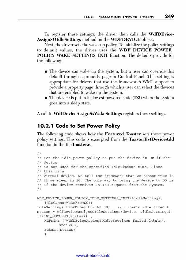
ptg
To register these settings, the driver then calls the WdfDEvice-AssignSOIdleSettings method on the WDFDEVICE object.
Next, the driver sets the wake-up policy. To initialize the policy settingsto default values, the driver uses the WDF_DEVICE_POWER_POLICY_WAKE_SETTINGS_INIT function. The defaults provide forthe following:
■ The device can wake up the system, but a user can override thisdefault through a property page in Control Panel. This setting isappropriate for drivers that use the framework’s WMI support toprovide a property page through which a user can select the devicesthat are enabled to wake up the system.
■ The device is put in its lowest powered state (D3) when the systemgoes into a sleep state.
A call to WdfDeviceAssignSxWakeSettings registers these settings.
10.2.1 Code to Set Power PolicyThe following code shows how the Featured Toaster sets these powerpolicy settings. This code is excerpted from the ToasterEvtDeviceAddfunction in the file toaster.c.
//// Set the idle power policy to put the device in Dx if the // device// is not used for the specified IdleTimeout time. Since// this is a// virtual device, we tell the framework that we cannot wake it// if we sleep in SO. The only way to bring the device to DO is// if the device receives an I/O request from the system.//
WDF_DEVICE_POWER_POLICY_IDLE_SETTINGS_INIT(&idleSettings,IdleCannotWakeFromSO);
idleSettings.IdleTimeout = 60000; // 60 secs idle timeoutstatus = WdfDeviceAssignSOIdleSettings(device, &idleSettings);if(!NT_SUCCESS(status)) {
KdPrint((“WdfDEviceAssignSOIdleSettings failed 0x%x\n”,status));
return status;}
10.2 Managing Power Policy 249
Wow! eBook <WoweBook.Com>
www.it-ebooks.info

ptg
//// Set the wait-wake policy.//
WDF_DEVICE_POWER_POLICY_WAKE_SETTINGS_INIT(&wakeSettings);
status = WdfDeviceAssignSxWakeSettings(device, &wakeSettings);if(!NT_SUCCESS(status)) {
//// We are probably enumerated on a bus that doesn’t support// Sx-wake. Do not fail the device add just because we can’t // support wait-wake.//
KdPrint((“WdfDEviceAssignSxWakeSettings failed 0x%x\n”,status));
status = STATUS_SUCCESS;}
The sample driver sets power policy idle characteristics and an idle time-out in the idleSetting structure, and then calls WdfDEvice-AssignSOIdleSettings method, passing as parameters this structure andthe handle to the device object that is received when it created the device object. It then proceeds in a similar fashion to set the wake-up characteristics.
If the call to WdfDeviceAssignScWakeSettings fails, the sampledriver resets the failure status to STATUS_SUCCESS. The reason is thatthis method fails if the underlying bus does not support wake from Sx states.If the device is on such a bus, the driver should not fail the add-devicerequest. Instead, it simply resets the failure status and continues processing.
10.3 Callbacks for Power-Up and Power-Down
Drivers implement the EvtDeviceDOEntry and EvtDeviceDOExitcallbacks to be notified when the device enters and exits the working state,respectively.
In a function driver (FDO), KMDF calls the EvtDeviceDOEntrycallback after the device has entered the DO power state. The functiondriver’s EvtDeviceDOEntry callback should initialize the device and per-form any other tasks that are required each time the device enters theworking state.
250 Chapter 10 Plug and Play and Power Management
Wow! eBook <WoweBook.Com>
www.it-ebooks.info
ptg
In a bus driver (PDO), KMDF calls the EvtDeviceDOEntry callbackto put the device into the DO power state. (If you are familiar with WDMdrivers, you probably remember that a request to power up a device mustbe handled by the bus driver first and then other drivers higher in thedevice stack. For a request to lower the power state, the opposite is true.)A bus driver’s EvtDeviceDOEntry callback should put the device hard-ware in the DO state and perform any additional initialization that thedevice requires at this time.
The EvtDeviceDOEntry callback is called with a pointer to theWDFDEVICE object and a pointer to an enumerator that identifies themost recent power state of the device, before the transition to DO began.
KMDF calls the EvtDeviceDOExit callback any time the device must leave the DO state. The callback is passed a pointer to the WDFDE-VICE object and a pointer to an enumerator that identifies the new powerstate. In a function driver (FDO), the callback should perform any finaltasks that are required before the device changes power state. In a busdriver, the callback should change the power state of the physical hardware.
In the Featured Toaster sample, both of these functions are stubs.
10.4 Callback for Wake Signal Support
Drivers for devices that can generate wake signals implement the following callbacks to support wake-up:
■ EvtDeviceArmWakeFromSO and EvtDeviceDisarmWake-FromSO
■ EvtDeviceWakeFromSOTriggered■ EvtDeviceArmWakeFromSx and EvtDeviceDisarmWake-
FromSx■ EvtDeviceWakeFromSxTriggered
To enable the wake signal, KMDF calls EvtDeviceArmWakeFromSOand EvtDeviceArmWakeFromSx while the device is in DO, but whilepower-managed I/O is stopped. Therefore, the driver does not receive I/Orequests from power-managed queues while arming its device and so is notrequired to synchronize its I/O operations with these callbacks.
In the wake-arming callbacks, a function driver should handle anydevice-specific tasks that are required to enable the device to generate a
10.4 Callback for Wake Signal Support 251
Wow! eBook <WoweBook.Com>
www.it-ebooks.info

ptg
wake signal. KMDF transitions the device out of the DO state soon afterthe wake signal is successfully enabled. The driver should not yet performany tasks related to power state change; KMDF calls the driver’sEvtDeviceDOExit function to do that.
The EvtDeviceDisarmWakeFromSO and EvtDeviceDisarm-WakeFromSx callbacks should undo any device-specific tasks that thedriver performed to enable the wake signal for its device. KMDF calls thedisarm callbacks after EvtDeviceDOEntry has returned the device tothe DO state.
The Featured Toaster sample registers the ToasterEvtDevice-WakeArm function for both the EvtDeviceArmWakeFromSO andEvtDeviceArmWakeFromSx events. Likewise, it registers Toaster-EvtDeviceWakeDisarm for both the EvtDeviceDisarmWakeFromSOand EvtDeviceDisarmWakeFromSx events.
In the Featured Toasted sample, these callbacks are stubs.If the device triggers a wake signal when the system is in SO or Sx, the
EvtDeviceWakeFromSOTriggered and EvtDeviceWakeFromSx-Triggered events occur, respectively. KMDF calls these functions afterthe driver’s EvtDeviceDOEntry callback and before the EvtDevice-DisarmWakeFromSO or EvtDeviceDisarmWakeFromSx callback.The wake-triggered callback should perform any tasks that are requiredafter the wake signal is triggered, but should not disarm the wake signal.
The Featured Toaster sample registers the ToasterEvtDevice-WakeTriggered callback for both the EvtDeviceWakeFrom-SOTriggered and EvtDeviceWakeFromSxTriggered events. In thesample, this callback is a stub.
252 Chapter 10 Plug and Play and Power Management
Wow! eBook <WoweBook.Com>
www.it-ebooks.info

ptg
253
C H A P T E R 1 1
PROGRAMMING WMI SUPPORT
This chapter covers the importance of using the Windows ManagementInstrumentation (WMI) in the development and utilization of a devicedriver.
By making your driver a Windows Management Instrumentation(WMI) provider, you can
■ Make custom data available to WMI consumers.■ Permit WMI consumers to configure a device through a standard
interface rather than a custom control panel application.■ Notify WMI consumers of driver-defined events without requiring
the consumer to poll or send IRPs.■ Reduce driver overhead by collection and sending only requested
data to a single destination.■ Annotate data and event blocks with descriptive driver-defined class
names and optional descriptions that WMI clients can enumerateand display to users.
11.1 WMI Architecture
To support WMI, your driver registers as a WMI provider. A WMIprovider is a Win32 dynamic-link library (DLL) that handles WMIrequests and supplies WMI instrumentation data.
After your driver is registered as a WMI provider, WMI consumersthen request data or invoke methods exposed by providers.
Query requests travel from user mode consumers down to WMI ker-nel mode service, which in turn send IRP requests to your driver.
For instance, when a WMI client requests a given data block, the WMIkernel component sends a query request to the driver to retrieve or setdata. Figure 11.1 shows this data flow.
Wow! eBook <WoweBook.Com>
www.it-ebooks.info
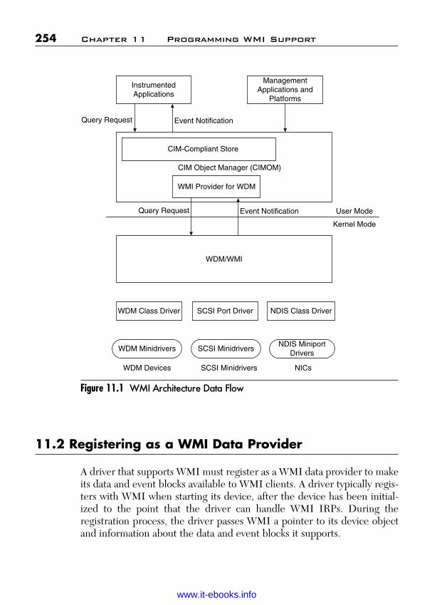
ptg
Figure 11.1 WMI Architecture Data Flow
11.2 Registering as a WMI Data Provider
A driver that supports WMI must register as a WMI data provider to makeits data and event blocks available to WMI clients. A driver typically regis-ters with WMI when starting its device, after the device has been initial-ized to the point that the driver can handle WMI IRPs. During theregistration process, the driver passes WMI a pointer to its device objectand information about the data and event blocks it supports.
254 Chapter 11 Programming WMI Support
InstrumentedApplications
ManagementApplications and
Platforms
CIM Object Manager (CIMOM)
CIM-Compliant Store
WMI Provider for WDM
WDM/WMI
User Mode
Kernel Mode
WDM Class Driver SCSI Port Driver NDIS Class Driver
WDM Minidrivers SCSI MinidriversNDIS Miniport
Drivers
WDM Devices SCSI Minidrivers NICs
Query Request Event Notification
Query Request Event Notification
Wow! eBook <WoweBook.Com>
www.it-ebooks.info

ptg
A driver registers with WMI in two phases:
1. The driver calls IoWMIRegistrationControl with the actionWMIREG_ACTION_REGISTER and a pointer to the deviceobject passed to the driver’s AddDevice routine.
2. The driver handles the IRP_MN_REGINFO or IRP_MN_REGINFO_EX request that WMI sends in response to the driv-er’s IoWMIRegistrationControl call. The Parameters.WMI.DataPath member of the IRP is set to WMIREGISTER andParameters.WMI.ProviderId is set to the driver’s device objectpointer. The driver supplies WMI with registration informationabout data and event blocks, either by using the WMI Library, orby handling the IRP_MN_REGINFO or IRP_MN_REGINFO_EX requests.
11.3 Handling WMI Requests
All drivers must set a dispatch table entry point for a DispatchSystemControl routine to handle WMI requests. If a driver registers as aWMI data provider, it must handle all WMI requests. Otherwise, thedriver must forward all WMI requests to the next lower driver.
All WMI IRPs have the major code IRP_MJ_SYSTEM_CONTROLand one of the following minor codes:
■ IRP_MN_REGINFO or IRP_MN_REGINFO_EX—Queries orupdates a driver’s registration information after the driver has calledIoWMIRegistrationControl.
■ IRP_MN_QUERY_All_DATA or IRP_MN_QUERY_SINGLE_INSTANCE—Queries for all instances or a single instance of agiven data block.
■ IRP_MN_CHANGE_SINGLE_ITEM, IRP_MN_CHANGE_SINGLE_INSTANCE—Requests the driver to change a singleitem or multiple items in an instance of a data block.
■ IRP_MN_ENABLE_COLLECTION, IRP_MN_DISABLE_COLLECTION—Requests the driver to start accumulating data
11.3 Handling WMI Requests 255
Wow! eBook <WoweBook.Com>
www.it-ebooks.info

ptg
for a block that the driver registered as expensive to collect, or tostop accumulating data for such a block.
■ IRP_MN_ENABLE_EVENTS, IRP_MN_DISABLE_EVENTS—Requests the driver to start sending notification of a given eventif the event occurs while it is enabled, or to stop sending notificationof such an event.
■ IRP_MN_EXECUTE_METHOD—Requests the driver to exe-cute a method associated with a data block.
The WMI kernel mode component sends WMI IRPs any time following adriver’s successful registration as a WMI data provider, typically when auser mode data consumer has requested WMI information for a driver’sdevice. If a driver registers as a WMI data provider by calling IoWMI-RegistrationControl, it must handle each subsequent WMI request inone of the following ways:
■ Call the kernel mode WMI library routine WmiSystemControl tohandle requests concerning only blocks that do not use dynamicinstance names, and that base static instance names on a single basename string or the device instance ID of a PDO.
■ In its DispatchSystemControl routine, process and complete anysuch request tagged with the pointer to its device object that thedriver passed in its call to IoWMIRegistrationControl, and for-ward other IRP_MJ_SYSTEM_CONTROL requests to the nextlower driver.
11.4 WMI Requirements for WDM Drivers
A driver that handles IRPs registers with WMI as a data provider. System-supplied storage port drivers, class drivers, and NDIS protocol drivers fallinto this category.
A driver that does not handle IRPs should simply forward WMIrequests to the next-lower driver in the driver stack. The next-lower driverthen registers with WMI and handles WMI requests on the first driver’sbehalf. For instance, SCSI miniport drivers and NDIS miniport driverscan register as WMI providers and supply WMI data to their correspon-ding class drivers.
256 Chapter 11 Programming WMI Support
Wow! eBook <WoweBook.Com>
www.it-ebooks.info
ptg
A driver that supplies WMI data to a class or port driver must support the driver-type-specific WMI interfaces that are defined by theclass or port driver. For example, a SCSI miniport driver must set WmiData Provider to TRUE in the PORT_CONFIGURATION_INFORMATION structure and handle SRB_FUNCTION_WMIrequests from the SCSI port driver.
Similarly, a connection-oriented NDIS miniport driver that definescustom data blocks must support OID_GEN_CO_SUPPORTED_GUIDS; otherwise, NDIS maps those OIDs and status indicationsreturned from OID_GEN_SUPPORTED_LIST that are common andknown to NDIS to GUIDS defined by NDIS.
11.5 WMI Class Names and Base Classes
WMI class names are case-insensitive, must start with a letter, and cannotbegin or end with an underscore. All remaining characters must be letters,digits, or underscores.
WMI client applications can access a driver’s WMI class names anddisplay them to users. Descriptive class names can help make classes moreintuitive to use.
WMI class names must be unique within the WMI name space.Consequently, a driver’s WMI class names cannot duplicate those definedby another driver.
To help prevent name collisions, a driver writer can define a driver-specific base class and derive all of the driver’s WMI classes from that baseclass. The class name and base class name together are more likely to yielda unique name. For example, the following shows an abstract base class fora serial driver’s data blocks:
// Serial drivers’ base class for data blocks[abstract]class MSSerial {}
// Example class definition for a data block[
// Class qualifiers]class MSSerial_StandardSerialInformation : MSSerial{
// Data items}
11.5 WMI Class Names and Base Classes 257
Wow! eBook <WoweBook.Com>
www.it-ebooks.info

ptg
Device-specific custom data blocks should include the manufacturer,model, and type of driver or device in the base class name. For example:
[abstract]class Adaptec1542 {}class Adaptec1542_Bandwidth : Adaptec 1542 {
// Data items}class Adaptec1542_Speed : Adaptec1542 {
// Data items}
WMI allows only one abstract base class in a given class hierarchy. Classesthat define event blocks must derive from WmiEvent, which is an abstractbase class, so the abstract qualifier cannot be used in a driver-defined baseclass for event blocks. Instead, derive a nonabstract base class fromWmiEvent, then derive individual event classes from that base class. Thefollowing examples show class definitions from the schema of a serial portdriver. Not that the guid values shown in these examples are placeholders.Each class definition must have a unique GUID generated byguidgen.exe or uuidgen.exe (which are included in the MicrosoftWindows SDK).
// Standard class for reporting serial port information// Class qualifiers[WMI, guid(“xxxxxxxx-xxxx-xxxx-xxxx-xxxxxxxxxxxx”),Dynamic, Provider(“WMIProv”),WmiExpense(1),Locale(“MS\\0x409”),Description(“Description of class”]
// Class nameclass Vendor_SerialInfo {// Required items
[key, read]string InstanceName;
[read]boolean Active;
// Bytes sent on port// Property qualifiers
[read,
258 Chapter 11 Programming WMI Support
Wow! eBook <WoweBook.Com>
www.it-ebooks.info
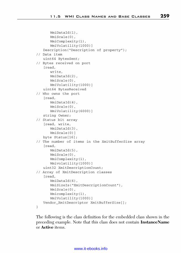
ptg
WmiDataId(1),WmiScale(0),WmiComplexity(1),WmiVolatility(1000)]
Description(“Description of property”);// Data item
uint64 BytesSent;// Bytes received on port
[read,write,WmiDataId(2),WmiScale(0),WmiVolatility(1000)]
uint64 BytesReceived// Who owns the port
[read,WmiDataId(4),WmiScale(0),WmiVolatility(6000)]
string Owner;// Status bit array
[read, write,WmiDataId(3),WmiScale(0)]
byte Status[16];// The number of items in the XmitBufferSize array
[read,WmiDataId(5),WmiScale(0),WmiComplexity(1),Wmivolatility(1000)]
uint32 XmitDescriptionCount;// Array of XmitDescription classes
[read,WmiDataId(6),WmiSizeIs(“XmitDescriptionCount”),WmiScale(0),Wmicomplexity(1),WmiVolatility(1000)]
Vendor_XmitDescriptor XmitBufferSize[];}
The following is the class definition for the embedded class shown in thepreceding example. Note that this class does not contain InstanceNameor Active items.
11.5 WMI Class Names and Base Classes 259
Wow! eBook <WoweBook.Com>
www.it-ebooks.info

ptg
// Example of an embedded class[WMI, guid(“xxxxxxxx-xxxx-xxxx-xxxx-xxxxxxxxxxxx”),class Vendor_XmitDescriptor {
[read, WmiDataId(1)] int32 DestinationIndex;[read, WmiDataId(2)] int32 DestinationTarget;
}
The following is a class definition for an event block. The class is derivedfrom WmiEvent.
// Example of an event[WMI, guid(“xxxxxxxx-xxxx-xxxx-xxxx-xxxxxxxxxxxx”),Dynamic, Provider(“WMIProve”),Locale(“MS\\0x409),Description(“Serial Send Event”),WmiExpense(1)]
class Vendor_SerialSentEvent : WMIEvent{// Required items
[key, read]string InstanceName;
[read]boolean Active;
11.6 Firing WMI Events
In the Featured Toaster sample driver, the ToasterFireArrivalEventfunction shows how to generate a WMI event that has a dynamic instancename. The WMI event contains the name of the device model, whichWMI records to log the arrival of this device. The driver calls this functionfrom its EvtDevicePrepareHardware callback to indicate that thedevice has been configured. Parts of this function are standard WMI tasksand have little to do with KMDF. This discussion focuses on the KMDF-specific code:
NTSTATUSToasterFireArrivalEvent(
IN WDFDEIVE Device)
{WDFMEMORY memory;PWNODE_SINGLE_INSTANCE wnode;ULONG wnodeSize;
260 Chapter 11 Programming WMI Support
Wow! eBook <WoweBook.Com>
www.it-ebooks.info
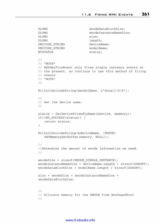
ptg
ULONG wnodeDataBlockSize;ULONG wnodeInstanceNameSize;ULONG size;ULONG length;UNICODE_STRING deviceName;UNICODE_STRING modelName;NTSTATUS status;
//// *NOTE*// WdfWmiFireEvent only fires single instance events at// the present, so continue to use this method of firing // events// *NOTE*//
RtlInitUnicodeString(&modelName, L“Sonali\0\0”);
//// Get the device name.//
status = GetDeviceFriendlyName(&Device, &memory);if(!NT_SUCCESS(status)) {
return status;}
RtlInitUnicodeString(&deviceName, (PWSTR)WdfMemoryGetBuffer(memory, NULL));
////Determine the amount of wnode information we need.//
wnodeSize = sizeof(WNODE_SINGLE_INSTANCE);wnodeInstanceNameSize = deviceName.Length + sizeof(USHORT);wnodeDataBlockSize = modelName.Length + sizeof(USHORT);
size = wnodeSize + wnodeInstanceNameSize + wnodeDataBlockSize;
//// Allocate memory for the WNODE from NonPagedPool//
11.6 Firing WMI Events 261
Wow! eBook <WoweBook.Com>
www.it-ebooks.info

ptg
wnode = ExAllocatePoolWithTag(NoPagedPool, size,TOASTER_POOL_TAG);
If(NULL != wnode) {RtlZeroMemory(wnode, size);wnode->WnodeHeader.BufferSize = sizewnode->WnodeHeader.ProviderId =
IoWMIDeviceObjectToProviderId(WdfDeviceWdmGetDeviceObject(Device));
wnode->WnodeHeader.Version = 1;KeQuerySystemTime(&wnode->WnodeHeader.TimeStamp);
RtlCopyMemory(&wnode->WnodeHeader.Guid,&TOASTER_NOTIFY_DEVICE_ARRIVAL_EVENT,Sizeof(GUID));
//// Set flags to indicate that you are creating dynamic// instance names. This driver supports dynamic// instances because it can fire the events at any time.// If it used static instance names instead, it could only// fire events after WMI queries for IRP_MN_REGINFO,// which happens after the device has been started.// Note also that if you are firing an event after the// device is started, you should// check whether the event is enabled, because that// indicates that someone is interested in receiving the // event. Why waste system resources by firing an event// when nobody is interested?//
wnode->WnodeHeader.Flags = WNODE_FLAG_EVENT_ITEM |WNODE_FLAG_SINGLE_INSTANCE;
wnode->OffsetInstanceName = wnodeSize;wnode->DataBlockOffset= wnodeSize + wnodeInstanceNameSize;wnode->SizeDataBlock = wnodeDataBlockSize;
//// Write the instance name.//
262 Chapter 11 Programming WMI Support
Wow! eBook <WoweBook.Com>
www.it-ebooks.info

ptg
size -= wnodeSize;status = WDF_WMI_BUFFER_APPEND_STRING(
WDF_PTR_ADD_OFFSET(wnode, wnod->OffsetInstance),size,&deviceName,&length);
//// Size was precomputed, so this should never fail.//
ASSERT(NT_SUCCESS(status));
//// Write the data, which is the model name as a
string.//
size = -= wnodeInstanceNameSize;WDF_WMI_BUFFER_APPEND_STRING(
WDF_PTR_ADD_OFFSET(wnode, wnode->DataBlockOffset),size,&modelName,&length);
//// Size was precomputed, so this should never fail.//
ASSERT(NT_SUCCESS(status));
//// Indicate the event to WMI. WMI will take care of // freeing the WMI struct back to pool.//
status = IoWMIWriteEvent(wnode);
if(!NT_SUCCESS(status)) {KdPrint((“IoWMIWriteEvent failed %x\n”, status));ExFreePool(wnode);
}}
11.6 Firing WMI Events 263
Wow! eBook <WoweBook.Com>
www.it-ebooks.info

ptg
else {status = STATUS_INSUFFICIENT_RESOURCES;
}
//// Free the memory allocated by GetDeviceFriendlyName// function.//
WdfObjectDelete(memory);return status;
}
ToasterfireArrivalEvent first defines a model name for its device andthen retrieves the friendly name for the device by calling the internal rou-tine GetDeviceFriendlyName. GetDeviceFriendlyName takes a han-dle to the device object and returns a handle to a WDFMEMORY objectthat contains a buffer that holds the name.
The driver passes the returned WDFMEMORY object handle toWdfGetMemoryBuffer to retrieve a pointer to the buffer itself and callsRtlUnicodeString to copy the contents of the buffer into the Unicodestring variable deviceName, as follows:
RtlInitUnicodeString(&deviceName,(PWSTR)WdfMemoryGetBuffer(memory, NULL));
The driver now constructs the WMI event by using standard WMIstructures and routines (defined in wmistr.h) along with standardWindows device driver interfaces (DDIs), which are defined in wdm.hand ntddk.h. The driver allocates memory from the nonpaged pool for the WNODE_SINGLE_INSTANCE structure (wnode) by calling ExAllocatePoolWithTag. If memory allocation succeeds, the driver zero-initializes the wnode structure and then fills it in the usual way for WMI.To supply the WMI provider ID, the driver calls IoWmiDevice-ObjectToProviderId, passing as a parameter the WDM device objectreturned by WdfDeviceWdmGetDeviceObject.
After the wnode structure is filled, the driver calls the WDF_WMI_BUFFER_APPEND_STRING function once to append theinstance name to the WNODE_SINGLE_INSTANCE structure and asecond time to append the model name.
264 Chapter 11 Programming WMI Support
Wow! eBook <WoweBook.Com>
www.it-ebooks.info

ptg
Finally, the driver fires the event by calling IoWMIWriteEvent. WMIrecords the data and frees the memory allocated for the WNODE_SIN-GLE_INSTANCE structure.
11.7 Troubleshooting Specific WMI Problems
The following paragraphs cover some of the common problems found insetting up and using WMI.
11.7.1 Driver’s WMI Classes Do Not Appear in the\root\wmi Namespace
The following steps cover how we would approach the troubleshooting ofthis particular problem.
1. Use wmimofck driver.bmf to check if the binary MOF file for-mat is correct. Additional error messages may be found in mofcomp.log.
2. Check the system event log to see if the driver is returning a mal-formed WMIREGINFO data structure in response to the regis-tration request.
3. Check that the driver is returning the correct values forRegistryPath and MofResourceName within the WMIREG-INFO structure.
4. If the driver provides its MOF data in a separate file, check thatthe MofImagePath registry value for the driver is set correctly.
5. Check the WMI WDM provider log for errors.6. Use Mofcomp to recompile and reload your MOF text file. For
example, the command mofcomp –N:root/wmi driver.mof triesto recompile and reload any MOF data in the driver.mof file.Check to see what error messages Mofcomp generates in mofcomp.log. Note that if your MOF file uses preprocessordirectives such as #define, you need to use the already pre-processed MOF file, and not the original source file. If the opera-tion succeeds, it actually registers the new WMI class data with the system. You need to delete these classes (by using Wbemtest, forexample) to test if your driver’s MOF data is being read correctly.
11.7 Troubleshooting Specific WMI Problems 265
Wow! eBook <WoweBook.Com>
www.it-ebooks.info

ptg
If this step succeeds, the most likely problem is that the mem-bers of WMIREGINFO, such as MofResourceName, are speci-fied incorrectly. Alternatively, the problem could be that your MOFfile specifies a class derived from a base class that doesn’t exist.
7. If the driver is using dynamic MOF data, check that the driver isreceiving WMI IRP requests for the MSWmi_MofData_GUIDGUID and that is completing the IRP successfully and with noerror logged.
11.7.2 Driver’s WMI Properties or Methods CannotBe Accessed
Use the following steps if you cannot access the driver’s WMI properties ormethods:
1. Use wmimofck driver.bmf to check if the binary MOF file for-mat is correct.
2. Check the system event log for errors.3. Check the WMI WDM Provider log for errors.4. Make sure the driver receives a WMI IRP whenever you use
Wbemtest to query the driver’s classes. If not, check that the spec-ified GUID in the MOF file matches the GUID the driver isexpecting. Also check that the driver is receiving the WMI regis-tration request, it is succeeding, and the driver is registering theright GUIDs.
5. If the driver receives the IRP, ensure that the IRP is completedsuccessfully, and that the driver is returning the right type ofWNOFE_XXX structure.
6. If Wbemtest returns an error, click the More Information buttonand check the Description property for a description of the error.
7. For methods, check that your driver supports handling the IRP_MN_QUERY_ALL_DATA and IRP_MN_QUERY_SIGLE_INSTANCE requests for the method’s GUID. WMI always per-forms one of those two requests before executing a method.
266 Chapter 11 Programming WMI Support
Wow! eBook <WoweBook.Com>
www.it-ebooks.info
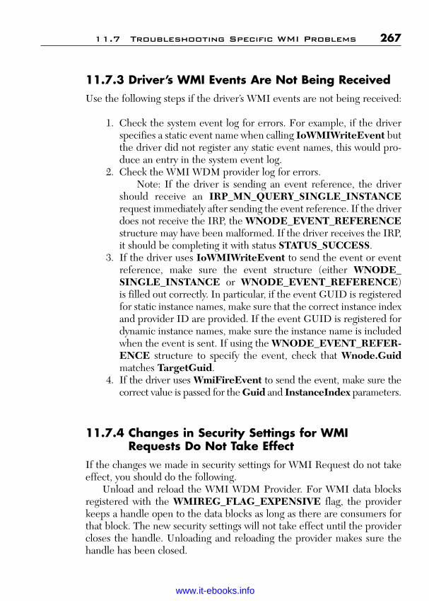
ptg
11.7.3 Driver’s WMI Events Are Not Being ReceivedUse the following steps if the driver’s WMI events are not being received:
1. Check the system event log for errors. For example, if the driverspecifies a static event name when calling IoWMIWriteEvent butthe driver did not register any static event names, this would pro-duce an entry in the system event log.
2. Check the WMI WDM provider log for errors.Note: If the driver is sending an event reference, the driver
should receive an IRP_MN_QUERY_SINGLE_INSTANCErequest immediately after sending the event reference. If the driverdoes not receive the IRP, the WNODE_EVENT_REFERENCEstructure may have been malformed. If the driver receives the IRP,it should be completing it with status STATUS_SUCCESS.
3. If the driver uses IoWMIWriteEvent to send the event or eventreference, make sure the event structure (either WNODE_SINGLE_INSTANCE or WNODE_EVENT_REFERENCE)is filled out correctly. In particular, if the event GUID is registeredfor static instance names, make sure that the correct instance indexand provider ID are provided. If the event GUID is registered fordynamic instance names, make sure the instance name is includedwhen the event is sent. If using the WNODE_EVENT_REFER-ENCE structure to specify the event, check that Wnode.Guidmatches TargetGuid.
4. If the driver uses WmiFireEvent to send the event, make sure thecorrect value is passed for the Guid and InstanceIndex parameters.
11.7.4 Changes in Security Settings for WMIRequests Do Not Take Effect
If the changes we made in security settings for WMI Request do not takeeffect, you should do the following.
Unload and reload the WMI WDM Provider. For WMI data blocksregistered with the WMIREG_FLAG_EXPENSIVE flag, the providerkeeps a handle open to the data blocks as long as there are consumers forthat block. The new security settings will not take effect until the providercloses the handle. Unloading and reloading the provider makes sure thehandle has been closed.
11.7 Troubleshooting Specific WMI Problems 267
Wow! eBook <WoweBook.Com>
www.it-ebooks.info
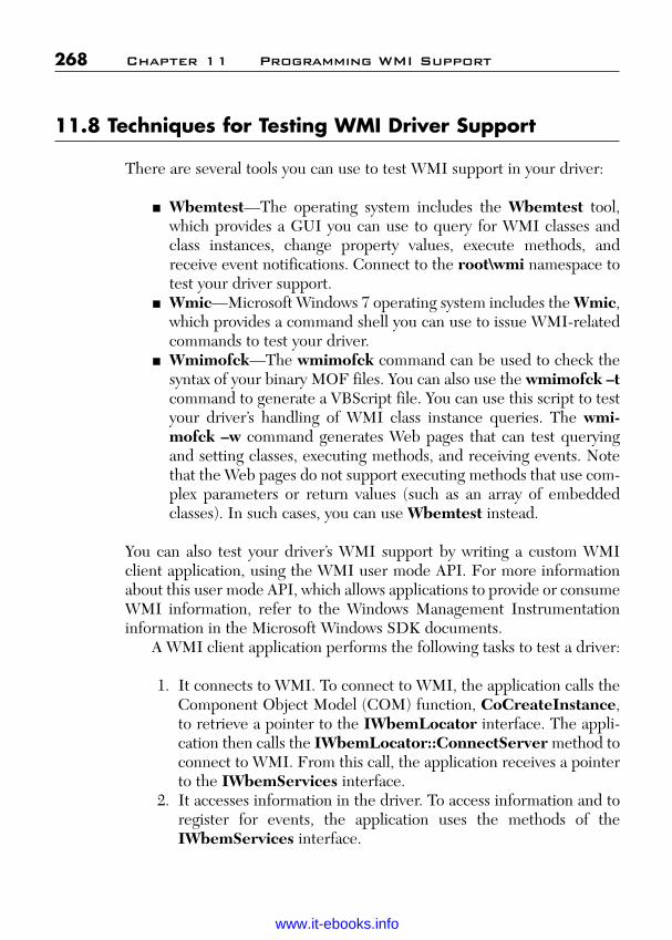
ptg
11.8 Techniques for Testing WMI Driver Support
There are several tools you can use to test WMI support in your driver:
■ Wbemtest—The operating system includes the Wbemtest tool,which provides a GUI you can use to query for WMI classes andclass instances, change property values, execute methods, andreceive event notifications. Connect to the root\wmi namespace totest your driver support.
■ Wmic—Microsoft Windows 7 operating system includes the Wmic,which provides a command shell you can use to issue WMI-relatedcommands to test your driver.
■ Wmimofck—The wmimofck command can be used to check thesyntax of your binary MOF files. You can also use the wmimofck –tcommand to generate a VBScript file. You can use this script to testyour driver’s handling of WMI class instance queries. The wmi-mofck –w command generates Web pages that can test queryingand setting classes, executing methods, and receiving events. Notethat the Web pages do not support executing methods that use com-plex parameters or return values (such as an array of embeddedclasses). In such cases, you can use Wbemtest instead.
You can also test your driver’s WMI support by writing a custom WMIclient application, using the WMI user mode API. For more informationabout this user mode API, which allows applications to provide or consumeWMI information, refer to the Windows Management Instrumentationinformation in the Microsoft Windows SDK documents.
A WMI client application performs the following tasks to test a driver:
1. It connects to WMI. To connect to WMI, the application calls theComponent Object Model (COM) function, CoCreateInstance,to retrieve a pointer to the IWbemLocator interface. The appli-cation then calls the IWbemLocator::ConnectServer method toconnect to WMI. From this call, the application receives a pointerto the IWbemServices interface.
2. It accesses information in the driver. To access information and toregister for events, the application uses the methods of theIWbemServices interface.
268 Chapter 11 Programming WMI Support
Wow! eBook <WoweBook.Com>
www.it-ebooks.info
ptg
11.8.1 WMI IRPs and the System Event LogWMI errors that occur strictly in kernel mode are logged to the systemevent log. You can use the Event Viewer to examine the system event log.
The two main sources of such errors are malformed replies to WMIrequests and incorrect parameters to event notifications. For example, ifthe driver returns a malformed WMIREGINFO data structure inresponse to an IRP_MN_REGINFO or IRP_MN_REGINFO_EXrequest, the system will log that to the system event log. The system wouldalso log an invalid call to IoWMIWriteEvent and WmiFireEvent toissue a WMI event notification.
11.8.2 WMI WDM Provider LogWMI errors that occur while being handled by the WMI WDM provider(wmiprov.dll) are logged to the log file for the WMI WDM Provider,wmiprov.log. This is a text file that can be found in %windir%\system32\wbem\logs\wmiprov.log. Errors, such as a bad or missingMOF resource for the driver, are logged here. In the case of a bad MOFresource, the file %windir%\system32\mofcomp.log might have addi-tional information related to the error.
You can change the logging settings for all WMI providers by using theWmimgmt.msc application. You can disable or reenable logging, changethe directory where WMI log files are kept, as well as set the maximumsize for such files.
11.9 WMI Event Tracing
This discussion describes the WMI extensions to WDM that Kernel ModeDrivers, as information providers, can use to provide information to infor-mation consumers. Drivers typically provide information that a consumeruses to determine the driver’s configuration and resource usage. In addi-tion to the WMI extensions to WDM, a user mode API supports providersor consumers of WMI event information.
The event tracing logger supports up to 32 instances. One of theinstances is reserved for tracing the kernel. The logger supports tracing ahigh event rate.
11.9 WMI Event Tracing 269
Wow! eBook <WoweBook.Com>
www.it-ebooks.info
ptg
Trace events are defined in the same manner as other WMI events.WMI events are described in the MOF file.
The process by which Kernel Mode Drivers log information is inte-grated into the existing WMI infrastructure. To log trace events, a driverdoes the following:
1. Register as a WMI provider by calling IoWMIRegistrationControl.
2. Mark events as traceable by setting WMIREG_FLAG_TRACED_GUID in the Flags member of the WMIREGGUID structurethat is passed when the driver registers events with WMI.
3. Specify one event as the control event for overall enabling/dis-abling of a set of trace events by setting WMIREG_FLAG_TRACE_CONTROL_GUID in the Flags member of theWMIREGGUID structure that is passed when the driver regis-ters events with WMI.
4. Upon receiving a request from WMI to enable events where theGUID matches the trace control GUID, the driver should storethe handle to the logger. The value will be needed when writing anevent. For information about how to use this handle, see step 6.The logger handle value is contained in the HistoricalContextmember of the WNODE_HEADER portion of the WMI bufferthat is part of the parameters in the enable events request.
5. Decide whether the trace event will be sent to WMI event con-sumers or is targeted for the WMI event logger only. This deter-mines where the memory for the EVENT_TRACE_HEADERstructure should come from. This memory eventually is passed toIoWMIWriteEvent.
If the event is a log event only, the memory is not deleted byWMI. In this case, the driver should pass in a buffer on the stackor should be reusing an allocated buffer for this purpose. For per-formance reasons, the driver should minimize any unnecessarycalls to allocate or free memory. Failure to comply with this rec-ommendation compromises the integrity of the timing informationcontained in the log file.
If the event is to be sent to both the logger and to WMI eventconsumers, the memory must be allocated from a nonpaged pool.In this case, the event is sent to the logger and then forwarded toWMI to be sent to WMI event consumers who have requested
270 Chapter 11 Programming WMI Support
Wow! eBook <WoweBook.Com>
www.it-ebooks.info
ptg
notification of the event. The memory for the event is then freedby WMI according to the behavior of IoWMIWriteEvent.
6. After the memory for the EVENT_TRACE_HEADER and anydriver event data, if any, has been secured, the following informa-tion should be set:■ Set the Size member to the size of (EVENT_TRACE
_HEADER) plus the size of any additional driver event datathat will be appended on to the end of EVENT_TRACE_HEADER.
■ Set the Flags member to WNODE_FLAG_TRACED_GUIDto have the event sent to the logger. If the event is to be sent toWMI event consumers as well, set the WNODE_FLAG_LOG_WNODE. Note, it is not necessary to set WNODE_FLAG_TRACED_GUID if setting WNODE_FLAG_LOG_WNODE. If both are set, WNODE_FLAG_TRACED_GUID takes precedence and the event is not sent to WMI event consumers.
■ Set the Guid or the GuidPtr member. If using GuidPtr, setWNODE_FLAG_USE_GUID_PTR in the Flags member.Optionally, specify a value for TimeStamp. If the driver does notspecify a TimeStamp value, the logger fills this in. If the driverdoes not want the logger to set the time stamp, it should setWNODE_FLAG_USE_TIMESTAMP in the Flags member.
■ Set any of the following EVENT_TRACE_HEADER mem-bers that have meaning to the driver—that is, Class.Type,Class.Level, and Class.Version.
■ Finally, cast the EVENT_TRACE_HEADER to a WNODE_HEADER and set the HistoricalContext value of the Wnodeto the logger handle that was saved in the preceding step 4.
7. Call IoWMIWriteEvent with the pointer to the EVENT_TRACE_HEADER structure.
The driver should continue logging trace events associated with the controlGUID until the driver receives notification to disable event logging via anIRP_MN_DISABLE_EVENTS request.
11.9 WMI Event Tracing 271
Wow! eBook <WoweBook.Com>
www.it-ebooks.info

ptg
This page intentionally left blank
Wow! eBook <WoweBook.Com>
www.it-ebooks.info

ptg
273
C H A P T E R 1 2
PROGRAMMING KMDFHARDWARE DRIVER
This chapter will cover the sample PCIDRV sample driver, and how to useit to create a KMDF hardware driver.
The sample PCIDRV driver is a fully functional KMDF driver for theIntel 82557/82558 based-PCI Ethernet Adapter (10/100) and Intel com-patibles. This device can use either port or memory resources to controlthe device. It can be stopped and started at run time and supports a low-power state. The driver supports multiple concurrent read and writerequests for the device.
The PCIDRV sample is installed in the samples directory atpcidrv\sys. The sample supports the following features in addition tothose previously described for the Toaster samples:
■ Handling Plug and Play and power events■ Supporting DMA interfaces■ Performing event tracing■ Handling interrupts■ Mapping resources■ Using multiple I/O queues and performing device I/O■ Reading and writing to the registry■ Using self-managed I/O to implement a watchdog timer
The PCIDRV sample supports physical hardware and contains many linesof device-specific code, so it is significantly more complicated than theToaster drivers.
The sample also uses event tracing for Windows to record driver datafor debugging and logging purposes. Event tracing is supported for allWindows drivers.
Wow! eBook <WoweBook.Com>
www.it-ebooks.info
ptg
12.1 Support Device Interrupts
To support interrupt handling for its device, a KMDF driver must
■ Create an interrupt object.■ Enable and disable the interrupt.■ Optionally perform pre-enable and post-disable processing that is
related to the interrupt.■ Handle interrupts as they occur.
12.1.1 Creating an Interrupt ObjectA driver typically creates its interrupt objects (WDFINTERRUPT) in itsEvtDriverDeviceAdd callback. The driver must have an interrupt objectfor each interrupt vector or message-signaled interrupt (MSI) that each ofits devices support. Each interrupt object must include pointers toEvtInterruptIsr and EvtInterruptDpc event callback functions andmay also include additional information.
The framework calls EvtInterruptIsr when an interrupt occurs. Thiscallback runs at device interrupt request level (DIRQL) for the device andis the equivalent of the WDM InterruptService function. TheEvtInterruptIsr callback queues a DPC to perform additional interrupt-related processing. The framework calls the driver’s EvtInterruptDpccallback when the DPC is ready to run. The EvtInterruptDpc callbackruns at DISPATCH_LEVEL and is equivalent of the WDM DpcForisrfunction.
Creating an interrupt object, like creating any other WDF object,involves filling in a configuration structure and calling a creation method.The driver calls the WDF_INTERRUPT_CONFIG_INIT function toinitialize the WDF_INTERRUPT_CONFIG structure with pointers tothe EvtInterruptIsr and EvtInterruptDpc callbacks. After initializingthe structure, the driver can set additional information in it, including apointer to a spin lock and pointers to the EvtInterruptEnable andEvtInterruptDisable callbacks, which enable and disable interrupts forthe device. KMDF calls these functions at DIRQL while holding theinterrupt spin lock during device power state transitions and when thedriver calls WdfEnableInterrupt or WdfDisableInterrupt.
If the driver must perform additional tasks immediately afterthe interrupt is enabled and before it is disabled, it should also register
274 Chapter 12 Programming KMDF Hardware Driver
Wow! eBook <WoweBook.Com>
www.it-ebooks.info

ptg
the EvtDeviceDOEntryPostInterruptsEnabled and EvtDevice-DOExitPreInterruptsDisabled callbacks. KMDF calls both of thesefunctions at PASSIVE_LEVEL without holding the interrupt spin lock.
To create the interrupt object, the driver calls the WdfInterrupt-Create method and passes a handle to the device object, a pointer to theinterrupt configuration structure, a pointer to an attribute configurationblock, and a pointer to a variable that receives the handle to the interruptobject. Drivers typically specify WDF_NO_ATTRIBUTES when creatingan interrupt object.
12.1.2 Code to Create an Interrupt ObjectThe PCIDRV sample creates its interrupt object in the NICAllocate-SoftwareResources function, which is called by PciDrvEvtDeviceAdd(the driver’s EvtDriverDeviceAdd callback). The following code showshow the PCIDRV sample creates its interrupt object:
WDF_INTERRUPT_CONFIG_INIT(&interruptConfig,NICEvtInterruptIsr,NICEvtInterruptDpc);
interruptConfig.EvtInterruptEnable =NICEvtInterruptEnable;
interruptConfig.EvtInterruptDisable =NICEvtInterruptDisable;
status = WdfInterruptCreate(FdoData->WdfDevice,&interruptConfig,WDF_NO_OBJECT_ATTRIBUTES,&FdoData->WdfInterrupt);
If(!NT_SUCCESS (status)) {return status;
}
The PCIDRV sample configures the interrupt object by specifyingpointers to NICEvtInterruptIsr and NICEvtInterruptDpc, which arecalled to handle interrupts and to perform deferred interrupt processing atIRQ DISPATCH_LEVEL, respectively. The driver also sets pointers toNICEvtInterruptEnable and NICEvtInterruptDisable, which enableand disable interrupts in the hardware. The call to WdfInterruptCreatereturns a handle to the interrupt object, which the driver stores in the con-text area of its device object.
12.1 Support Device Interrupts 275
Wow! eBook <WoweBook.Com>
www.it-ebooks.info
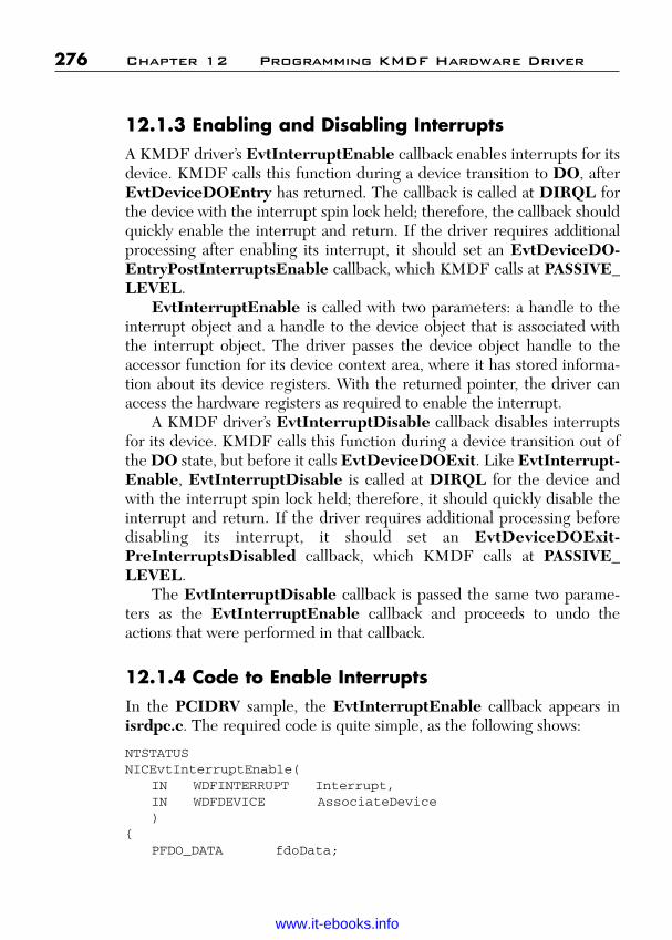
ptg
12.1.3 Enabling and Disabling InterruptsA KMDF driver’s EvtInterruptEnable callback enables interrupts for itsdevice. KMDF calls this function during a device transition to DO, afterEvtDeviceDOEntry has returned. The callback is called at DIRQL forthe device with the interrupt spin lock held; therefore, the callback shouldquickly enable the interrupt and return. If the driver requires additionalprocessing after enabling its interrupt, it should set an EvtDeviceDO-EntryPostInterruptsEnable callback, which KMDF calls at PASSIVE_LEVEL.
EvtInterruptEnable is called with two parameters: a handle to theinterrupt object and a handle to the device object that is associated withthe interrupt object. The driver passes the device object handle to theaccessor function for its device context area, where it has stored informa-tion about its device registers. With the returned pointer, the driver canaccess the hardware registers as required to enable the interrupt.
A KMDF driver’s EvtInterruptDisable callback disables interruptsfor its device. KMDF calls this function during a device transition out ofthe DO state, but before it calls EvtDeviceDOExit. Like EvtInterrupt-Enable, EvtInterruptDisable is called at DIRQL for the device andwith the interrupt spin lock held; therefore, it should quickly disable theinterrupt and return. If the driver requires additional processing beforedisabling its interrupt, it should set an EvtDeviceDOExit-PreInterruptsDisabled callback, which KMDF calls at PASSIVE_LEVEL.
The EvtInterruptDisable callback is passed the same two parame-ters as the EvtInterruptEnable callback and proceeds to undo theactions that were performed in that callback.
12.1.4 Code to Enable InterruptsIn the PCIDRV sample, the EvtInterruptEnable callback appears inisrdpc.c. The required code is quite simple, as the following shows:
NTSTATUSNICEvtInterruptEnable(
IN WDFINTERRUPT Interrupt,IN WDFDEVICE AssociateDevice)
{PFDO_DATA fdoData;
276 Chapter 12 Programming KMDF Hardware Driver
Wow! eBook <WoweBook.Com>
www.it-ebooks.info

ptg
fdoData = FdoGetData(AssociateDevice);NICEnalbeInterrupt(Interrupt, fdoData);return STATUS_SUCCESS;
}
NICEnableInterupt is simply a macro that sets the PCI device register to enable interrupts.
12.1.5 Code to Disable InterruptsIn the PCIDRV sample, the EvtInterruptDisable callback (also inisrdpc.c) simply calls the internal NICDisableInterrupt macro to set thePCI device register to disable interrupts. The following is the code:
NTSTATUSNICEvtInterruptDisable(
IN WDFINTERRUPT Interrupt,IN WDFDEVICE AssociatedDevice)
{PFDO_DATA fdoData;
fdoData = FdoGetData(AssociatedDevice);NICDisableInterrupt(fdoData);return STATUS_SUCCESS;
}
12.1.6 Post-Interrupt Enable and Pre-InterruptDisable Processing
Some devices cause interrupt storms if they are initialized after their inter-rupts are enabled. The driver for such a device must therefore be able toperform initialization after the device enters DO but before its interrupt isenabled. Other devices, however, cannot be initialized until the interruptis enabled. To enable correct operation of both types of devices, KMDFsupplies post-interrupt enable and pre-interrupt disable events for whichdrivers can register.
When powering up a device, KMDF invokes a driver’s callbacks in thefollowing order:
1. EvtDeviceDOEntry2. EvtInterruptEnable3. EvtDeviceDOEntryPostInterruptsEnabled
12.1 Support Device Interrupts 277
Wow! eBook <WoweBook.Com>
www.it-ebooks.info

ptg
KMDF calls EvtDeviceDOEntry first. Drivers that must initialize theirdevices before the interrupt is connected (for example, to prevent inter-rupt storms) should do so in this callback. Next, KMDF callsEvtInterruptEnable. Drivers should enable their interrupts and do littleor nothing else in this function because it is called at DIRQL. Finally,KMDF calls EvtDeviceDOEntryPostInterruptsEnabled at PASSIVE_LEVEL. Drivers that must initialize their devices after the interrupt isconnected should do so in this callback.
At power-down, KMDF calls the corresponding paired functions in theopposite order:
1. EvtDeviceDOExitPreInterruptsDisabled2. EvtInterruptDisable3. EvtDeviceDOEXit
To undo work done by the EvtDeviceDOEntryPostInterrupts-Enabled, a driver registers an EvtDeviceDOExitPreInterrupts-Disabled function. Like the post-enable function, the pre-disable functiondoes work at PASSIVE_LEVEL in preparation for disabling the interrupt.
A driver must register the post-interrupt enable and pre-interrupt dis-able callbacks in the WDF_PNPPOWER_EVENT_CALLBACKS struc-ture before creating the device object. The PCIDRV sample fills thisstructure in its EvtDriverDeviceAdd callback, as follows:
pnpPowerCallbacks.EvtDeviceDOEntryPostInterruptsEnabled = NICEvtDeviceDOEntryPostInterruptsEnabled;
pnpPowerCallbacks.EvtDeviceDOExitPreInterruptsDisabled = NICEvtDeviceDOExitPreInterruptsDisabled;
In the current version of the PCIDRV sample, both of these functionsare stubs.
12.2 Handling Interrupts
When a device interrupts, Windows calls the driver to service the interrupt.However, more than one device can be connected to a single interrupt vec-tor. Internally, the operating system keeps a list of the InterruptServiceroutines of the drivers for devices that interrupt at the same level. When aninterrupt signal arrives, Windows traverses the list and calls the drivers insequence until one of them acknowledges and services the interrupt.
278 Chapter 12 Programming KMDF Hardware Driver
Wow! eBook <WoweBook.Com>
www.it-ebooks.info

ptg
KMDF intercepts the call from the operating system and, in turn, callsthe EvtInterruptIsr callback that the driver registered. Like traditionalInterruptService functions, this callback runs at DIRQL. BecauseEvtInterruptIsr runs at such a high IRQL, it should do its work quicklyand then return. Remember that it cannot take any action that would causea page fault (or wait on any dispatcher objects) because it runs at an IRQLgreater than APC_LEVEL.
The EvtInterruptIsr callback should perform the following tasks, andnothing more:
■ Determine whether its device is interrupting, and if not, returnFALSE immediately.
■ Stop the device from interrupting.■ Queue a DPC to perform any work related to the interrupt.
The EvtInterruptIsr function is called with a handle to the interruptobject for the driver’s device and a ULONG value that specifies the mes-sage ID if the device is configured for MSIs and zero otherwise.
12.2.1 Code for EvtInterruptIsr CallbackThe following is the PCIDRV sample’s EvtInterruptIsr callback (whichis defined in pcidrv\sys\hw\isrdpc.c):
BOOLEANNICEvtInterruptIsr(
IN WDFINTERRUPT Interrupt,IN ULONG MessageID)
{BOOLEAN InterruptRecognized = FALSE;PFDO_DATA FdoData = NULL;USHORT IntStatus;
UNREFERENCED_PARAMETER (MessageID);
FdoData = FdoGetData (WdfInterruptGetDevice (Interrupt));
//// Process the interrupt if it is enabled// and active.//
12.2 Handling Interrupts 279
Wow! eBook <WoweBook.Com>
www.it-ebooks.info
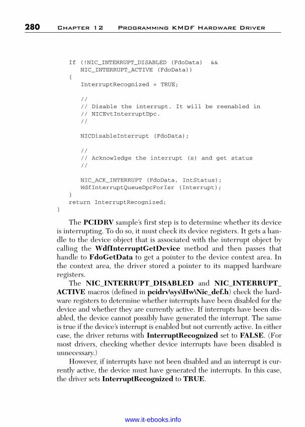
ptg
If (!NIC_INTERRUPT_DISABLED (FdoData) &&NIC_INTERRUPT_ACTIVE (FdoData))
{InterruptRecognized = TRUE;
//// Disable the interrupt. It will be reenabled in// NICEvtInterruptDpc.//
NICDisableInterrupt (FdoData);
//// Acknowledge the interrupt (s) and get status//
NIC_ACK_INTERRUPT (FdoData, IntStatus);WdfInterruptQueueDpcForIsr (Interrupt);
}return InterruptRecognized;
}
The PCIDRV sample’s first step is to determine whether its deviceis interrupting. To do so, it must check its device registers. It gets a han-dle to the device object that is associated with the interrupt object bycalling the WdfInterruptGetDevice method and then passes thathandle to FdoGetData to get a pointer to the device context area. Inthe context area, the driver stored a pointer to its mapped hardwareregisters.
The NIC_INTERRUPT_DISABLED and NIC_INTERRUPT_ACTIVE macros (defined in pcidrv\sys\Hw\Nic_def.h) check the hard-ware registers to determine whether interrupts have been disabled for thedevice and whether they are currently active. If interrupts have been dis-abled, the device cannot possibly have generated the interrupt. The sameis true if the device’s interrupt is enabled but not currently active. In eithercase, the driver returns with InterruptRecognized set to FALSE. (Formost drivers, checking whether device interrupts have been disabled isunnecessary.)
However, if interrupts have not been disabled and an interrupt is cur-rently active, the device must have generated the interrupts. In this case,the driver sets InterruptRecognized to TRUE.
280 Chapter 12 Programming KMDF Hardware Driver
Wow! eBook <WoweBook.Com>
www.it-ebooks.info

ptg
To stop the device from interrupting, the driver calls NICDisable-Interrupt and then uses the driver-defined NIC_ACK_INTERRUPTmacro to acknowledge the interrupt in the hardware. Finally, it queues aDPC by calling WdfInterruptQueueDpcForIsr and then returns.
12.2.2 Deferred Processing for InterruptsWhen the DPC runs, KMDF calls the driver’s EvtInterruptDpc call-back. This function performs device-specific interrupt processing andreenables the interrupt for the device. It runs at DISPATCH_LEVELand therefore must not attempt any operations that might cause a pagefault (or wait on any dispatcher objects).
12.2.2.1 Code for EvtInterruptDpc CallbackThe following is the PCIDRV sample’s EvtInterruptDpc callback:
VOIDNICEvtInterruptDpc(
IN WDFINTERRUPT WdfInterrupt,IN WDFOBJECT WdfDevice)
{PFDO_DATA fdoData = NULL;
fdoData = FdoGetData (WdfDevice);
WdfSpinLockAcquire (fdoData->RcvLock);NICHandleRecvInterrupt (fdoData);WdfSpinLockRelease (fdoData->RcvLock);
//// Handle send interrupt.//
WdfSpinLockAcquire (fdoData->SendLock);NICHandleSendInterrupt (fdoData);WdfSpinLockRelease (fdoData->SendLock);
//// Check if any queued sends need to be reprocessed.//
12.2 Handling Interrupts 281
Wow! eBook <WoweBook.Com>
www.it-ebooks.info

ptg
NICCheckForQueuedSends (fdoData);
//// Start the receive unit if it was stopped//
WdfSpinLockAcquire (fdoData->RcvLock);NICStartRecv (fdoData);WdfSpinLockRelease (fdoData->RcvLock);
//// Reenable the interrupt.//
WdfInterruptSynchronize (WdfInterrupt,NICEnableInterrupt,fdoData);
return;}
Most of the code in this callback is device specific. However, its use ofspin locks is worth noting.
When the driver created its I/O queues, it also created two spin locksand stored their handles in its device context area. One (RcvLock) pro-tects read-related buffers and operations, and the (SendLock) protectswrite-related buffers and operations. In this function, it uses these spinlocks to protect against preemption and concurrent users while it processesthe results of the I/O operation. The driver calls WdfSpinLockAcquireand WdfSpinLockRelease to acquire and release the locks.
When the driver has completed all device-specific processing, it reen-ables the interrupt. The function that reenables the interrupt(NICEnableInterrupt) must run at DIRQL, so the driver callsWdfInterruptSynchronize to run it. WdfInterruptSynchronize takesa handle to the interrupt object, a pointer to the function to be run(NICEnableInterrupt), and a pointer to the device context area, which itpassed as an argument to NICEnableInterrupt. WdfInterrupt-Synchronize raises IRQL to DIRQL and calls NICEnableInterrupt.When NICEnableInterrupt completes, KMDF lowers the IRQL toDISPATCH_LEVEL and returns.
282 Chapter 12 Programming KMDF Hardware Driver
Wow! eBook <WoweBook.Com>
www.it-ebooks.info
ptg
12.3 Mapping Resources
A KMDF driver maps resources for its hardware as part of itsEvtDevicePrepareHardware callback and unmaps them in itsEvtDeviceReleaseHardware callback. These callbacks provide a wayfor a driver to prepare its device hardware immediately before thedevice enters and after the device leaves the operational (DO) state.These two routines are always called in pairs—that is, after KMDF callsEvtDevicePrepareHardware, it always calls EvtDeviceRelease-Hardware before calling EvtDevicePrepareHardware again.
KMDF calls a driver’s EvtDevicePrepareHardware callbackbefore calling EvtDeviceDOEntry whenever resources are assigned tothe device—specifically, during initial device enumeration and duringpower-up after resource rebalancing. EvtDevicePrepareHardwareshould map device resources but should not load firmware or performother device initialization tasks. Drivers for USB devices might also getdevice and configuration descriptors and select configurations in this call-back. Drivers should not attempt to access their device hardware in thiscallback.
EvtDeviceReleaseHardware undoes any work that was done byEvtDevicePrepareHardware. For example, if EvtDevicePrepare-Hardware maps resources, EvtDeviceReleaseHardware releases them.
Within its EvtDevicePrepareHardware function, a driver callsWdfCmResourceListGetCount to get the number of resources that thesystem has assigned to its device and then calls WdfCmResourceList-GetDescriptor to get details about a particular resource from the list.
The chipset on an individual machine can map hardware resourcesinto either I/O or memory space, regardless of how the device itself isdesigned. To be platform independent, all drivers should support bothtypes of mapping, just as the PCIDRV sample does. For I/O and memory-mapped resources, a KMDF driver takes steps that are similar to those aWDM driver would take:
■ For an I/O-mapped resource (CmResourceTypePort), the driversaves the base address and range at which the resource is mappedand saves a pointer to the HAL’s *_PORT_* functions that it will useto access the resource.
12.3 Mapping Resources 283
Wow! eBook <WoweBook.Com>
www.it-ebooks.info
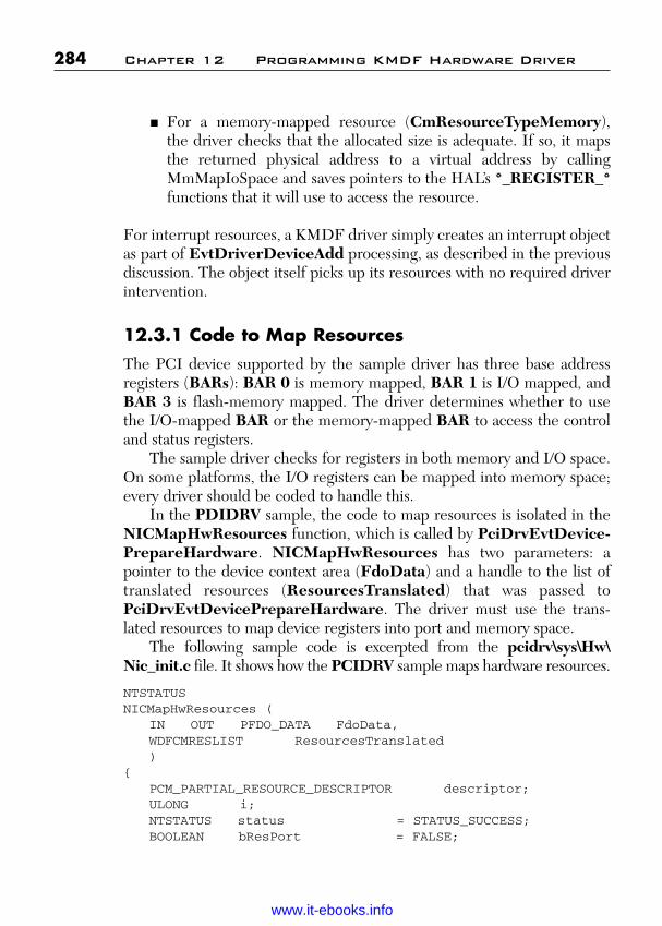
ptg
■ For a memory-mapped resource (CmResourceTypeMemory),the driver checks that the allocated size is adequate. If so, it mapsthe returned physical address to a virtual address by callingMmMapIoSpace and saves pointers to the HAL’s *_REGISTER_*functions that it will use to access the resource.
For interrupt resources, a KMDF driver simply creates an interrupt objectas part of EvtDriverDeviceAdd processing, as described in the previousdiscussion. The object itself picks up its resources with no required driverintervention.
12.3.1 Code to Map ResourcesThe PCI device supported by the sample driver has three base addressregisters (BARs): BAR 0 is memory mapped, BAR 1 is I/O mapped, andBAR 3 is flash-memory mapped. The driver determines whether to usethe I/O-mapped BAR or the memory-mapped BAR to access the controland status registers.
The sample driver checks for registers in both memory and I/O space.On some platforms, the I/O registers can be mapped into memory space;every driver should be coded to handle this.
In the PDIDRV sample, the code to map resources is isolated in theNICMapHwResources function, which is called by PciDrvEvtDevice-PrepareHardware. NICMapHwResources has two parameters: apointer to the device context area (FdoData) and a handle to the list oftranslated resources (ResourcesTranslated) that was passed toPciDrvEvtDevicePrepareHardware. The driver must use the trans-lated resources to map device registers into port and memory space.
The following sample code is excerpted from the pcidrv\sys\Hw\Nic_init.c file. It shows how the PCIDRV sample maps hardware resources.
NTSTATUSNICMapHwResources (
IN OUT PFDO_DATA FdoData,WDFCMRESLIST ResourcesTranslated)
{PCM_PARTIAL_RESOURCE_DESCRIPTOR descriptor;ULONG i;NTSTATUS status = STATUS_SUCCESS;BOOLEAN bResPort = FALSE;
284 Chapter 12 Programming KMDF Hardware Driver
Wow! eBook <WoweBook.Com>
www.it-ebooks.info
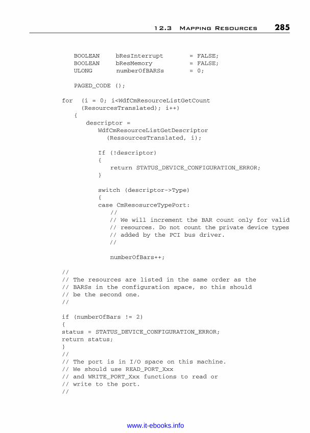
ptg
BOOLEAN bResInterrupt = FALSE;BOOLEAN bResMemory = FALSE;ULONG numberOfBARSs = 0;
PAGED_CODE ();
for (i = 0; i<WdfCmResourceListGetCount (ResourcesTranslated); i++)
{descriptor =
WdfCmResourceListGetDescriptor(RessourcesTranslated, i);
If (!descriptor){
return STATUS_DEVICE_CONFIGURATION_ERROR;}
switch (descriptor->Type){case CmResosurceTypePort:
//// We will increment the BAR count only for valid// resources. Do not count the private device types// added by the PCI bus driver.//
numberOfBars++;
//// The resources are listed in the same order as the // BARSs in the configuration space, so this should// be the second one.//
if (numberOfBars != 2){status = STATUS_DEVICE_CONFIGURATION_ERROR;return status;}//// The port is in I/O space on this machine.// We should use READ_PORT_Xxx// and WRITE_PORT_Xxx functions to read or// write to the port.//
12.3 Mapping Resources 285
Wow! eBook <WoweBook.Com>
www.it-ebooks.info

ptg
FdoData->IoBaseAddress =ULongToPtr (descriptor->u.Port.Start.LowPart);
FdoData->IoRange = descriptor->u.Port.Length;
//// Since all our accesses are USHORT wide, we will// create an accessor table just for these two// functions.//
FdoData->ReadPort = NICReadPortUShort;FdoData->WritePort = NICWritePortUShort;
bResPort = TRUE;FdoData->MappedPorts = FALSE;break;
case CmResourceTypeMemory:numberOfBARs++;if (numberOfBARs == 1){
//// Our CSR memory space should be 0x1000 in// size.//
ASSERT (descriptor->u.Memory.Length == 0x1000);FdoData->MemPhysAddress =
descriptor->u.Memory.Start;FdoData->CSRAddress = MmMapIoSpace (
descriptor->u.Memory.Start,NIC_MAP_IOSPACE_LEGTH,MmNonCached);
bResMemory = TRUE;}
else if (numberOfBARs == 2){
//// The port is in memory space on this machine.// Call MmMapIoSpace to map the // physical to virtual address, and use the// READ/WRITE_REGISTER_xxx function// to read or write to the port.//FdoData->IoBaseAddress = MmMapIoSpace (
descriptor->u.Memory.Start,descriptor->u.Memory.Length,MmNonCached);
286 Chapter 12 Programming KMDF Hardware Driver
Wow! eBook <WoweBook.Com>
www.it-ebooks.info

ptg
FdoData->ReadPort = NICReadRegisterUShort;FdoData->WritePort = NICWriteRegisterUShort;FdoData->MappedPorts = TRUE;bResPort = TRUE;
}else if (numberOfBARs == 3){
//// Our flash memory should be 1MB in size. We// don’t access it, so do not bother mapping it.//// ASSERT (descriptor->u.Memory.Length ==// 0x100000);
}else{
status = STATUS_DEVICE_CONFIGURATION_ERROR;return status;
}break;
case CmResourceTypeInterrupt:ASSERT (!bResInterrupt);bResInterrupt = TRUE;break;
default://// This could be a device-private type added by// the PCI bus driver. We shouldn’t filter this// or change the information contained in it.//break;
}}
// Make sure we got all the resources to work with.//
if (! (bResPort && bResInterrupt && bResMemory)){
status = STATUS_DEVICE_CONFIGURATION_ERROR;
}return status;
}
12.3 Mapping Resources 287
Wow! eBook <WoweBook.Com>
www.it-ebooks.info

ptg
The driver parses the list of translated resources in a loop that starts atzero and ends when it has reached the last resource in the list. The driverdetermines the number of resources in the list by calling theWdfCmResourceListGetCount function.
For each resource in the list, the driver calls WdfCmResource-ListGetDescriptor to get a pointer to the resource descriptor. Theresource descriptor is an enumerator that indicates the type ofthe resource. (If you are familiar with WDM drivers, you will notice thatthe resource types are the same as those for WDM.)
For the CmResourceTypePort resources, the driver saves the start-ing address and range in the device context area and then sets theaddresses of the functions that it uses to access the port resources.
For CmResourceTypeMemory resources, the driver also saves thestarting address and range in the device context area, but then usesMmMapIoSpace to map the resources and get a virtual address throughwhich it can access them.
For CmResourceTypeInterrupt resources, the driver is notrequired to save the resource information because KMDF handles thistransparently for the driver when the driver creates the WDFINTER-RUPT object. The sample driver merely checks this resource for com-pleteness.
12.3.2 Code to Unmap ResourcesWhen the device is removed or when the system rebalances resources, thedriver must release its mapped resources in an EvtDeviceRelease-Hardware callback. KMDF calls this function after calling the driverEvtDeviceDOExit function.
The PCIDRV sample does so in the internal function NICUnmap-HwResources, which is called by its EvtDeviceReleaseHardware.NICUnmapHwResources appears in the pcidrv\sys\hw\nic_init.csource file and releases the resources as follows:
if (FdoData->CSRAddress){
MmUnmapIoSpace (FdoData->CSRAddress,NIC_MAP_IOSPACE_LENGTH);
288 Chapter 12 Programming KMDF Hardware Driver
Wow! eBook <WoweBook.Com>
www.it-ebooks.info

ptg
FdoData->CSRAddress = NULL;
}if (FdoData->MappedPorts){
MmUnMapIoSpace (FdoData->IoBaseAddress,FdoData->IoRange);
FdoData->IoBaseAddress = NULL;}
12.3 Mapping Resources 289
Wow! eBook <WoweBook.Com>
www.it-ebooks.info

ptg
This page intentionally left blank
Wow! eBook <WoweBook.Com>
www.it-ebooks.info
ptg
291
C H A P T E R 1 3
PROGRAMMING MULTIPLE I/OQUEUES AND PROGRAMMING I/O
This chapter covers the important aspect of device driver developmentinvolving the handling of I/O queues.
13.1 Introduction to Programming I/O Queues
Drivers have several options when creating and configuring I/O queues.The most important are which I/O requests to queue, what type of dis-patching to use, and whether to let KMDF manage the queue. A deviceobject can have any number of I/O queues, and each can be configured differently.
One queue for each device object can be configured as a defaultqueue, into which KMDF places requests for which the driver has notspecifically configured any other queue. If the device object has a defaultqueue and one or more other queues, KMDF queues specific requests tothe correspondingly configured queues and queues all other requests tothe default queue. If the device object does not have a default queue,KMDF queues only the specific request types to the configured queuesand, for a function or bus driver, fails all other requests. (For a filter driver,it passes all other requests to the next lower driver.)
A queue’s dispatch type determines when KMDF presents I/Orequests from the queue to the driver. KMDF supports three dispatchtypes:
■ Sequential■ Parallel■ Manual
Wow! eBook <WoweBook.Com>
www.it-ebooks.info

ptg
KMDF presents requests from a sequential queue to the driver one at atime. When the first request arrives, KMDF calls the event callback thatwas specified for the request type and queue. After the driver completesthe request, KMDF calls the event callback for another request if thequeue is not empty. A sequential queue is thus used for synchronous I/O.By default, queues are configured as sequential (WdfIoQueueDispatch-Sequential).
For a parallel queue, KMDF presents requests to the driver as soon asthey arrive. KMDF does not wait for any “inflight” requests to completebefore sending another request. An inflight request is an I/O request thatis currently active—that is, it is not in a queue and has not been completed.A parallel queue can thus be used for asynchronous I/O.
For a manual queue, KMDF does not present requests to the driver.Instead, the driver must call WdfIoQueueRetrieveRequest when it isready to handle a request. A driver can thus use manual queuing for eithersynchronous or asynchronous I/O.
A driver can temporarily stop the delivery of requests from a sequen-tial or parallel queue by calling WdfIoQueueStop or WdfIoQueue-StopSynchronously, depending on the type of queue and the reasons forpausing delivery. To restart the queue, the driver calls WdfIoQueueStart.
By default, KMDF handles I/O cancellation for queued I/O requests.Consequently, if the user cancels an I/O request after KMDF has queuedit but before KMDF has delivered it to the driver, KMDF removes it fromthe queue and completes it with STATUS_CANCELED. The driver canrequest notification by registering an EvtIoCanceledOnQueue callbackfor the queue; otherwise, KMDF cancels the request without notifying thedriver.
After a request has been dispatched to the driver, it cannot be canceledunless the driver specifically marks it as cancelable and registers anEvtRequestCancel callback. If the driver forwards the request to anotherqueue, it immediately becomes cancelable again.
Also by default, KMDF handles power management for I/O queues,and each I/O queue inherits the power state of its associated device.During Plug and Play or power state transitions and any time the device isnot in the working state, KMDF queues incoming I/O requests but doesnot dispatch them to the driver. Therefore, if the driver creates its queuesbefore the device enters DO, the queues are in the WDF_IO_QUEUE_STOPPED state, and KMDF queues any I/O requests targetedat the device. When the device enters the working state, KMDF resumes
292 Chapter 13 Programming Multiple I/O Queues
Wow! eBook <WoweBook.Com>
www.it-ebooks.info

ptg
presenting requests. A driver can change this default when it configureseach queue by setting the PowerManaged field of the configurationstructure to FALSE.
A driver can also specify whether a queue accepts I/O requests thathave a zero-length buffer. By default, KMDF does not dispatch suchrequests to the driver; instead, it completes them with STATUS_SUCCESS.
13.2 Creating and Configuring the Queues
To create and configure a queue, a driver takes the following steps:
1. Defines a WDF_IO_QUEUE_CONFIG structure to hold con-figuration settings for the queue.
2. Initializes the configuration structure by calling the WDF_IO_QUEUE_CONFIG_INIT or WDF_IO_QUEUE_CONFIG_INIT_DEFAULT_QUEUE function (for a default queue). Thesefunctions take a pointer to the configuration structure and an enu-merator that defines the dispatching type for the queue.
3. Sets the event callbacks for this queue in theWDF_IO_QUEUE_CONFIG structure, if the queue usessequential or parallel dispatching. A driver can set callbacks forone or more of the following I/O events: EvtIoRead,EvtIoWrite, EvtIoDeviceIoControl, EvtIoInternalDeviceIo-Control, EvtIoDefault, EvtIoStop, EvtIoResume, and EvtIoCanceledOnQueue.
4. Sets Boolean values for the PowerManaged and AllowZero-LengthRequests fields in the queue configuration structure if thedefault values are not suitable.
5. Creates the queue by calling WdfIoQueueCreate, passing a han-dle to the WDFDEVICE object, a pointer to the filled-inWDF_IO_QUEUE_CONFIG structure, a pointer to aWDF_OBJECT_ATTRIBUTES structure, and a pointer toreceive a handle to the created queue instance.
6. Specifies which I/O requests KMDF should direct to the queue bycalling WdfDeviceConfigureRequestDispatching.
13.2 Creating and Configuring the Queues 293
Wow! eBook <WoweBook.Com>
www.it-ebooks.info
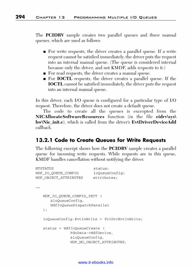
ptg
The PCIDRV sample creates two parallel queues and three manualqueues, which are used as follows:
■ For write requests, the driver creates a parallel queue. If a writerequest cannot be satisfied immediately, the driver puts the requestinto an internal manual queue. (The queue is considered internalbecause only the driver, and not KMDF, adds requests to it.)
■ For read requests, the driver creates a manual queue.■ For IOCTL requests, the driver creates a parallel queue. If the
IOCTL cannot be satisfied immediately, the driver puts the requestinto an internal manual queue.
In this driver, each I/O queue is configured for a particular type of I/Orequest. Therefore, the driver does not create a default queue.
The code to create all the queues is excerpted from theNICAllocateSoftwareResources function (in the file cidrv\sys\hw\Nic_init.c), which is called from the driver’s EvtDriverDeviceAddcallback.
13.2.1 Code to Create Queues for Write RequestsThe following excerpt shows how the PCIDRV sample creates a parallelqueue for incoming write requests. While requests are in this queue,KMDF handles cancellation without notifying the driver.
NTSTATUS status;WDF_IO_QUEUE_CONFIG ioQueueConfig;WDF_OBJECT_ATTRIBUTES attributes;
……
WDF_IO_QUEUE_CONFIG_INIT (&ioQueueConfig,WdfIoQueueDispatchParallel
);
ioQueueConfig.EvtIoWrite = PciDrvEvtIoWrite;
status = WdfIoQueueCreate (FdoData->WdfDevice,&ioQueueConfig,WDF_NO_OBJECT_ATTRIBUTES,
294 Chapter 13 Programming Multiple I/O Queues
Wow! eBook <WoweBook.Com>
www.it-ebooks.info

ptg
&FdoData->WriteQueue // queue handle);
if (!NT_SUCCESS (status)){
return status;}
status = WdfDeviceconfigureRequestDispatching (FdoData->WdfDevice,FdoData->WriteQueue,WdfRequestTypeWrite );
if (!NT_SUCCESS (status)){
ASSERT (NT_SUCCESS (status));return status;
}
The driver calls WDF_IO_QUEUE_CONFIG_INIT to initialize thequeue as a parallel queue. The queue holds only write requests, so the driversets only an EvtIoWrite callback in the ioQueueConfig structure. It cre-ates the queue, and then calls WdfDeviceConfigureRequest-Dispatching to configure the queue for requests of typeWdfRequestTypeWrite only. All other I/O requests are directed to aqueue that is configured for them or, if the driver has not configured a queuefor them, are handled by the framework without being sent to the driver.
The PCIDRV sample also creates a manual queue into which to placepending write requests. The driver’s EvtIoWrite callback places an I/Orequest in this internal queue when it cannot handle the request immediately.
The driver creates this queue as follows:
WDF_IO_QUEUE_CONFIG_INIT (&ioQueueConfig,WdfIoQueueDispatchManual);
status = WdfIoQueueCreate (FdoData->WdfDevice,&ioQueueConfig,WDF_NO_OBJECT_ATTRIBUTES,&FdoData->PndingWriteQueue);
13.2 Creating and Configuring the Queues 295
Wow! eBook <WoweBook.Com>
www.it-ebooks.info
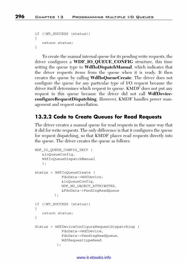
ptg
if (!NT_SUCCESS (status)){
return status;}
To create the manual internal queue for its pending write requests, thedriver configures a WDF_IO_QUEUE_CONFIG structure, this timesetting the queue type to WdfIoDispatchManual, which indicates thatthe driver requests items from the queue when it is ready. It then creates the queue by calling WdfIoQueueCreate. The driver does notconfigure the queue for any particular type of I/O request because thedriver itself determines which request to queue. KMDF does not put anyrequest in this queue because the driver did not call WdfDevice-configureRequestDispatching. However, KMDF handles power man-agement and request cancellation.
13.2.2 Code to Create Queues for Read RequestsThe driver creates a manual queue for read requests in the same way thatit did for write requests. The only difference is that it configures the queuefor request dispatching, so that KMDF places read requests directly intothe queue. The driver creates the queue as follows:
WDF_IO_QUEUE_CONFIG_INIT (&ioQueueConfig,WdfIoQueueDispatchManual);
status = WdfIoQueueCreate (FdoData->WdfDevice,&ioQueueConfig,WDF_NO_OBJECT_ATTRIBUTES,&FdoData->PendingReadQueue
);
if (!NT_SUCCESS (status)){
return status;}
Status = WdfDeviceConfigureRequestDispatching (FdoData->WdfDevice,FdoData->PendingReadQueue,WdfRequesttypeRead
);
296 Chapter 13 Programming Multiple I/O Queues
Wow! eBook <WoweBook.Com>
www.it-ebooks.info

ptg
if (!NT_SUCCESS (status)){
ASSERT (NT_SUCCESS (status));return status;
}
13.2.3 Code to Create Queues for Device I/O Control Requests
The driver creates a second pair of parallel and internal manual queues forIRP_MJ_DEVICE_IO_CONTROL requests, just as it did for writerequests, as follows:
WDF_IO_QUEUE_CONFIG_INIT (&ioQueueConfig,WdfIoQueueDispatchParallel);
ioQueueConfig.EvtIoDeviceControl = PciDrvEvtIoDeviceControl;
status = WdfIoQueueCreate (FdoData->WdfDevice,&ioQueueConfig,WDF_NO_OBJECT_ATTRIBUTES,&FdoData->IoctlQueue
);
if (!NT_SUCCESS (status)){
return status;}
status = WdfDeviceConfigureRequestDispatching (FdoData->WdfDevice,FdoData->IoctlQueue,WdfRequestTypeDeviceControl
);
if (!NT_SUCCESS (status))
13.2 Creating and Configuring the Queues 297
Wow! eBook <WoweBook.Com>
www.it-ebooks.info

ptg
{ASSERT (NT_SUCCESS (status));return status;
}
// Create internal queue for pending IOCTL requests.
WDF_IO_QUEUE_CONFIG_INIT (&ioQueueConfig,WdfIoQueueDispatchManual);
status = WdfIoQueueCreate (FdoData->WdfDevice,&ioQueueConfig,WDF_NO_OBJECT_ATTRIBUTES,&FdoData-PendingIoctlQueue
);
if (!NT_SUCCESS (status)){
return status;}
The driver configures these two queues exactly as it did the paralleland manual queues for write requests. The only difference is that it set acallback for EvtDeviceIoControl instead of EvtIoWrite and configuresrequest dispatching for WdfRequestTypeDeviceControl instead ofWdfRequestTypeWrite.
13.3 Handling Requests from a Parallel Queue
KMDF delivers I/O requests from a parallel queue by calling the appro-priate callback function that the driver registered for the queue. For exam-ple, the PCIDRV sample configures its parallel device I/O control queue,which accepts only WdfRequestTypeDeviceControl requests, with anEvtIoDeviceControl callback.
The driver’s actions in the callback depend on the type of I/O that isrequired to satisfy the request. If the request required DMA, the drivershould retrieve a pointer to the device context area and then set up theDMA transaction.
298 Chapter 13 Programming Multiple I/O Queues
Wow! eBook <WoweBook.Com>
www.it-ebooks.info
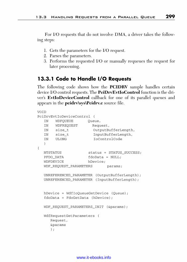
ptg
For I/O requests that do not involve DMA, a driver takes the follow-ing steps:
1. Gets the parameters for the I/O request.2. Parses the parameters.3. Performs the requested I/O or manually requeues the request for
later processing.
13.3.1 Code to Handle I/O RequestsThe following code shows how the PCIDRV sample handles certaindevice I/O control requests. The PciDrvEvtIoControl function is the dri-ver’s EvtIoDeviceControl callback for one of its parallel queues andappears in the pcidrv\sys\Pcidrv.c source file.
VOIDPciDrvEvtIoDeviceControl (
IN WDFQUEUE Queue,IN WDFREQUEST Request,IN size_t OutputBufferLength,IN size_t InputBufferLength,IN ULONG IoControlCode)
{NTSTATUS status = STATUS_SUCCESS;PFDO_DATA fdoData = NULL;WDFDEVICE hDevice;WDF_REQUEST_PARAMETERS params;
UNREFERENCED_PARAMETER (OutputBufferLength);UNREFERENCED_PARAMETER (InputBufferLength);
hDevice = WdfIoQueueGetDevice (Queue);fdoData = FdoGetData (hDevice);
WDF_REQUEST_PARAMETERS_INIT (¶ms);
WdfRequestGetParameters (Request,¶ms);
13.3 Handling Requests from a Parallel Queue 299
Wow! eBook <WoweBook.Com>
www.it-ebooks.info

ptg
switch (IoControlCode){
case IOCTL_NDISPROT_QUERY_OID_VALUE:ASSERT ((IoControlCode * 0x3) ==
METHOD_BUFFERED);NICHandleQueryOldRequest (
Queue,Request,¶ms);
break;
// code omitted// …..//
case IOCTL_NDISPROT_INDICATE_STAUS:status = WdfRequestForwardToIoQueue (Request,
fdoData->PendingIoctlQueue);if (!NT_SUCCESS (status)){
WdfRequestcomplete (Request, status);break;}
break;
default:ASSERTMSG (FALSE, “Invalid IOCTL request\n”);WdfRequestComplete (Request,
STATUS_INVALID_DEVICE_REQUEST);break;
}return;
}
The driver requires access to its device object context area, so it startsby calling WdfIoQueueGetDevice, which returns a handle to the deviceobject that is associated with the I/O queue. It then passes the returnedhandle to FdoGetData, the accessor function for its device context area,which returns a pointer to the context area.
Next, the driver retrieves the parameters that were passed with the I/Orequest. KMDF defines the WDF_REQUEST_PARAMETERS struc-ture for this purpose. The driver initializes the structure by callingWDF_REQUEST_PARAMETERS_INIT and then passes it to theWdfRequestParameters method. This method fills in the requested
300 Chapter 13 Programming Multiple I/O Queues
Wow! eBook <WoweBook.Com>
www.it-ebooks.info
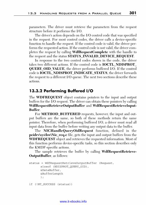
ptg
parameters. The driver must retrieve the parameters from the requeststructure before it performs the I/O.
The driver’s action depends on the I/O control code that was specifiedin the request. For most control codes, the driver calls a device-specificfunction to handle the request. If the control code is valid, the driver per-forms the requested action. If the control code is not valid, the driver com-pletes the request by calling WdfRequestComplete with the handle tothe request and the status STATUS_INVALID_DEVICE_REQUEST.
In response to the two control codes shown in the code, the drivertakes two different actions. If the control code is IOCTL_NDISPROT_QUERY_OID_VALUE, the driver performs buffered I/O. If the controlcode is IOCTL_NDISPROT_INDICATE_STATUS, the driver forwardsthe request to a different I/O queue. The next two sections describe theseactions.
13.3.2 Performing Buffered I/OThe WDFREQUEST object contains pointers to the input and outputbuffers for the I/O request. The driver can obtain these pointers by callingWdfRequestRetrieveOutputBuffer and WdfRequestRetrieveInput-Buffer.
For METHOD_BUFFERED requests, however, the input and out-put buffers are the same, so both of these methods return the samepointer. Therefore, when performing buffered I/O, a driver must read allinput data from the buffer before writing any output data to the buffer.
The NICHandleQueryOidRequest function, defined in thepcidrv\sys\hw\Nic_req.c file, gets the input and output buffers from theWDFREQUEST object and retrieves the requested information. Most ofthis function performs device-specific tasks, so this section describes onlythe KMDF-specific actions.
The sample retrieves the buffer by calling WdfRequestRetrieve-OutputBuffer, as follows:
status = WdfRequestRetrieveOutputBuffer (Request,sizeof (NDISPROT_QUERY_OID),&DataBuffer,&BufferLength);
if (!NT_SUCCESS (status))
13.3 Handling Requests from a Parallel Queue 301
Wow! eBook <WoweBook.Com>
www.it-ebooks.info

ptg
{WdfRequestcomplete (Request, status);return;
}
The input parameters to WdfRequestRetrieveOutputBuffer arethe handle to the request object and the minimum required size for thebuffer. The method returns a pointer to the buffer and a pointer to itslength. If the length is smaller than the minimum required or if some othererror occurs, WdfRequestRetrieveOutputBuffer returns a failure sta-tus and the driver immediately completes the request with that status.
The driver then performs device-specific queries for the requestedinformation and writes the returned data into the output buffer. If thebuffer is too small to hold the data, the driver sets status toSTATUS_BUFFER_TOO_SMALL.
Next, the driver updates the buffer length to include the number ofbytes of data, the size of the structure that holds it, and any padding bytesthat are required to align the structure correctly. The driver performs thiscalculation even if the buffer is too small, so that it can return the bufferlength that would be required to successfully complete the request.Finally, the driver completes the request by calling WdfRequest-CompleteWithInformation with the handle to the request, the previ-ously set status value, and the calculated buffer length, as follows:
//// Adjust the size to include the structure.//ulInfoLen += FIELD_OFFSET (NDISPROT_QUERY_OID, Data);
WdfRequestCompleteWithInformation (Request,Status, ulInfoLen);
13.4 Forwarding Requests to a Queue
In some situations, a driver must requeue requests on its own, after it hasreceived them from KMDF. For example, a driver might be able torespond to some device I/O control requests immediately, but might haveto handle others at a later time. Because the requests are all of the sametype (WdfRequestTypeDeviceControl), KMDF cannot deliver some to
302 Chapter 13 Programming Multiple I/O Queues
Wow! eBook <WoweBook.Com>
www.it-ebooks.info
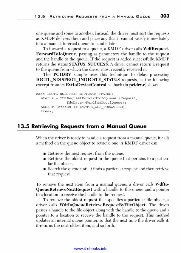
ptg
one queue and some to another. Instead, the driver must sort the requestsas KMDF delivers them and place any that it cannot satisfy immediatelyinto a manual, internal queue to handle later.
To forward a request to a queue, a KMDF driver calls WdfRequest-ForwardToIoQueue, passing as parameters the handle to the requestand the handle to the queue. If the request is added successfully, KMDFreturns the status STATUS_SUCCESS. A driver cannot return a requestto the queue from which the driver most recently received it.
The PCIDRV sample uses this technique to delay processingIOCTL_NDISPROT_INDICATE_STATUS requests, as the followingexcerpt from its EvtIoDeviceControl callback (in pcidrv.c) shows:
case IOCTL_NDISPROT_INDICATE_STATUS:status = WdfRequestForwardToIoQueue (Request,
fdoData->PendingIoctlQueue);ASSERT (status == STATUS_WDF_FORWARDED);break;
13.5 Retrieving Requests from a Manual Queue
When the driver is ready to handle a request from a manual queue, it callsa method on the queue object to retrieve one. A KMDF driver can
■ Retrieve the next request from the queue.■ Retrieve the oldest request in the queue that pertains to a particu-
lar file object.■ Search the queue until it finds a particular request and then retrieve
that request.
To remove the next item from a manual queue, a driver calls WdfIo-QueueRetrieveNextRequest with a handle to the queue and a pointerto a location to receive the handle to the request.
To remove the oldest request that specifies a particular file object, adriver calls WdfIoQueueRetrieveRequestByFileObject. The driverpasses a handle to the file object along with the handle to the queue and apointer to a location to receive the handle to the request. This methodupdates an internal queue pointer, so that the next time the driver calls it,it returns the next-oldest item, and so forth.
13.5 Retrieving Requests from a Manual Queue 303
Wow! eBook <WoweBook.Com>
www.it-ebooks.info
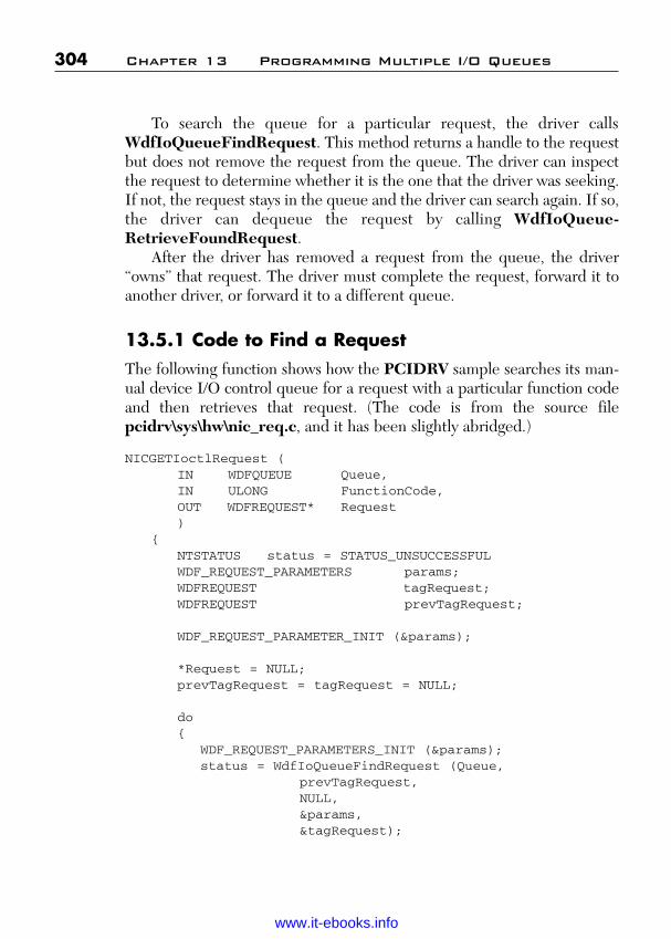
ptg
To search the queue for a particular request, the driver callsWdfIoQueueFindRequest. This method returns a handle to the requestbut does not remove the request from the queue. The driver can inspectthe request to determine whether it is the one that the driver was seeking.If not, the request stays in the queue and the driver can search again. If so,the driver can dequeue the request by calling WdfIoQueue-RetrieveFoundRequest.
After the driver has removed a request from the queue, the driver“owns” that request. The driver must complete the request, forward it toanother driver, or forward it to a different queue.
13.5.1 Code to Find a RequestThe following function shows how the PCIDRV sample searches its man-ual device I/O control queue for a request with a particular function codeand then retrieves that request. (The code is from the source filepcidrv\sys\hw\nic_req.c, and it has been slightly abridged.)
NICGETIoctlRequest (IN WDFQUEUE Queue,IN ULONG FunctionCode,OUT WDFREQUEST* Request)
{NTSTATUS status = STATUS_UNSUCCESSFULWDF_REQUEST_PARAMETERS params;WDFREQUEST tagRequest;WDFREQUEST prevTagRequest;
WDF_REQUEST_PARAMETER_INIT (¶ms);
*Request = NULL;prevTagRequest = tagRequest = NULL;
do{
WDF_REQUEST_PARAMETERS_INIT (¶ms);status = WdfIoQueueFindRequest (Queue,
prevTagRequest,NULL,¶ms,&tagRequest);
304 Chapter 13 Programming Multiple I/O Queues
Wow! eBook <WoweBook.Com>
www.it-ebooks.info

ptg
// WdfIoQueueFindRequest takes an extra reference on// the returned tagRequest to prevent the memory// being freed. However, the tagRequest is still// in the queue and can be canceled or removed by// another thread and completed.//
if (prevTagRequest){
WdfObjectDereference (prevTagRequest);}
if (status == STATUS_NO_MORE_ENTRIES){
status = STATUS_UNSUCCESSFUL;break;
}
if (status == STATUS_NOT_FOUND){
//// The prevTagRequest disappeared from the // queue for some reason – either it was// canceled or dispatched to the driver. There// might be other requests that match our // criteria so restart the search.//prevTagRequest = tagRequest = NULL;continue;
}
if (!NT_SUCCESS (status )){
status = STATUS_UNSUCCESSFUL;break;
}
if (FunctionCode ==params.Parameters.DeviceIoControl.IoControlCode)
{status = WdfIoQueueRetrieveFoundRequest (
Queue,tagRequest, // TagRequestRequest
);
13.5 Retrieving Requests from a Manual Queue 305
Wow! eBook <WoweBook.Com>
www.it-ebooks.info

ptg
WdfObjectDereference (tagRequest);
if (status == STATUS_NOT_FOUND){
//// The TagRequest disappeared // for some reason – either it was// canceled or dispatched to the driver.// Other requests might match our// criteria so restart the search.//prevTagRequest = tagRequest = NULL;continue;
}
if (!NT_SUCCESS (status)){
status = STATUS_UNSUCCESSFUL;break;
}
//// Found a request. Drop the extra reference// before returning.//ASSERT (*Request == tagRequest);status = STATUS_SUCCESS;break;
}else{
//// This is not the request we need. Drop the // reference on the tagRequest after looking for // the next request.prevTagRequest = tagRequest;continue;
}} WHILE (TRUE);return status;
}
The sample driver starts by calling WDF_REQUEST_PARAMETERS_INIT to initialize a WDF_REQUEST_PARAMETERSstructure. Later, when the driver calls WdfIoQueueFindRequest,KMDF returns the parameters for the request in this structure.
306 Chapter 13 Programming Multiple I/O Queues
Wow! eBook <WoweBook.Com>
www.it-ebooks.info

ptg
Next, the driver initializes the variables that it uses to keep track of therequests it has searched through. The variable prevTagRequest holds ahandle to the previous request that the driver inspected, and tagRequestholds a handle to the current request. The driver initializes both values toNULL before it starts searching.
The search is conducted in a loop. Each time NICGetIoctlRequestcalls WdfIoQueueFindRequest, it passes prevTagRequest to indicatewhere KMDF should start searching and passes a pointer to tagRequestto receive the handle to the current request. WdfIoQueueFindRequestalso takes a handle to the queue, a handle to the related file object, and apointer to the initialized WDF_REQUEST_PARAMETERS structure.The PCIDRV sample does not use file objects, so it passes NULLfor the file object handle. Note that the driver reinitializes theWDF_REQUEST_PARAMETERS structure before each call, thusensuring that it does not receive old data.
On the first iteration of the loop, preTagRequest is NULL.Therefore, the search starts at the beginning of the queue. WdfIo-QueueFindRequest searches the queue and returns the request’s param-eters (in the Params variable) and a handle to the request (intagRequest). To prevent another component from deleting the requestwhile the driver inspects it, WdfIoQueueFindRequest takes out a refer-ence on request.
NICGetIoctlRequest compares the function code value that wasreturned in the request’s parameters structure with the function code thatthe caller passed in. If the codes match, the driver calls WdfIo-QueueRetrieveFoundRequest to dequeue the request. WdfIoQueue-RetrieveFoundRequest takes three parameters: the handle to thequeue, the handle returned by WdfIoQueueFindRequest that indicateswhich request to dequeue, and pointer to a location that will receive a han-dle to the dequeued request.
When WdfIoQueueRetrieveFoundRequest returns successfully,the driver “owns” the retrieved request. It deletes extra reference previ-ously taken on the request by calling WdfObjectDeference. It then exitsfrom the loop, and the NICGetIoctlRequest function returns a handle tothe retrieved request. The caller can then perform the I/O operations thatare required to satisfy the request.
If the function codes do not match, the driver sets prevTagRequestto tagRequest so that the search starts at the current location in thequeue. However, the driver does not yet dereference the request object
13.5 Retrieving Requests from a Manual Queue 307
Wow! eBook <WoweBook.Com>
www.it-ebooks.info

ptg
that prevTagRequest represents. It must maintain this reference untilWdfIoQueueFindRequest has returned on the next iteration of the loop.The loop then executes again. This time, if WdfIoQueueFindRequestsuccessfully finds a request, the driver deletes the reference thatWdfIoQueueFindRequest acquired for the prevTagRequest and thencompares the function codes as it did in the previous iteration.
If the request is no longer in the queue, WdfIoQueueFindRequestreturns STATUS_NOT_FOUND. For example, the request might not bein the queue if it was canceled or was already retrieved by another thread.WdfIoQueueRetrieveFoundRequest can also return this same status ifthe handle passed in tagRequest is not valid. If either of these errorsoccurs, the driver restarts the search at the beginning. If either of thesemethods fails for any other reason, such as exhausting the queue, the driverexits from the loop.
13.6 Reading and Writing the Registry
KMDF includes numerous methods with which a driver can read andwrite the registry. These methods enable the driver to create, open, andclose a registry key, and to query, change, and delete the values of keys and individual data items within them.
To read the value of a registry key, a driver opens the registry key andthen calls a method that queries the registry for data. A driver can read theregistry either before or after creating its device object.
To read the registry before creating the device object, a driver calls theWdfFdoInitOpenRegistryKey method with the following parameters:
■ A handle to the WDFDEVICE_INIT structure that was passed toits EvtDriverDeviceAdd function.
■ A ULONG value that identifies the key to open.■ A bit mask that indicates the type of required access.■ An optional attribute structure.■ A location to receive a handle to a WDFKEY object.
The WDFDEVICE_INIT structure contains settings that the frameworkrequires before the device object has been created. WdfFdoInit-OpenRegisterKey requires some of this information so that it can findthe requested key.
308 Chapter 13 Programming Multiple I/O Queues
Wow! eBook <WoweBook.Com>
www.it-ebooks.info

ptg
To read the registry after creating the device object, a driver callsWdfDeviceOpenRegistryKey with a handle to the device object insteadof the WDFDEVICE_INIT structure.
To get the value of a single setting within the key, the driver mustquery the key. KMDF provides several query methods, each of whichreturns a different type of value. For example, if the information is storedas a ULONG, the driver calls WdfRegisteryQueryUlong with the han-dle to the keys, a pointer to the name of the value, and a pointer to aULONG variable to receive the value. After completing its query, thedriver closes the registry key by calling WdfRegistryClose.
13.6.1 Code to Read and Write the RegistryThe PCIDRV sample provides functions that
■ Read a REG_DWORD registry value that was written by anotheruser mode or kernel mode component.
■ Read a REG_DWORD registry value that was stored under thedevice key.
■ Write a REG_DWORD registry value that was stored under thedevice key.
These functions are in the pcidrv.c source file.The PCIDRV sample driver’s PciDrvReadFdoRegistryKeyValue
function is called from the EvtDriverDeviceAdd callback, before thedriver creates the device object. It reads a key that the driver’s INF wroteat installation, which indicates whether the driver was installed as an NDISupper-edge miniport driver. This information is important because itdetermines whether the driver registers certain power policy and I/O eventcallbacks. If the driver was installed as an upper-edge miniport driver, it isnot the power policy manager for its device; NDIS manages power policy.
The following is the source code for this function:
BOOLEANPciDrvReadFdoRegistryKeyValue (
__in PWDFDEVICE_INIT DeviceInit,__in PWCHAR Name,__out PULONG Value)
{WDFKEY hKey = NULL;
13.6 Reading and Writing the Registry 309
Wow! eBook <WoweBook.Com>
www.it-ebooks.info

ptg
NTSTATUS status;BOOLEAN retValue = FALSE;UNICODE_STRING valueName;
PAGED_CODE();
*Value = 0;status = WdfFdoInitOpenRegistryKey (DeviceInit,
PLUGPLAY_REGKEY_DEVICE,STANDARD_RIGHTS_ALL,WDF_NO_OBJECT_ATTRIBUTES,&hKey);
if (NT_SUCCESS (status)){
RtlInitUnicodeString (&valueName, Name);status = WdfRegistryQueryULong (hKey,
&valueName,Value);
if (NT_SUCCESS (status)){
retValue = TRUE;}WdfRegistryClose (hKey);
}return retValue;
}
First, the driver initializes the Value parameter that will receive therequested key value. Next, it opens the registry key by callingWdfFdoInitOpenRegistryKey. The WDF_DEVICEINIT object pro-vides information that is required to identify the driver-specific key. Thenext parameter is a ULONG that contains flags that identify the key toopen; the constant PLUGPLAY_REGKEY_DEVICE indicates thedevice’s hardware key. Although the sample requests all access rights to theregistry (STANDARD_RIGHTS_ALL), the driver only reads the key anddoes not write it, so STANDARD_RIGHTS_READ would also work.Finally, the driver specifies WDF_NO_OBJECT_ATTRIBUTES to indi-cate that it is not passing an attribute structure for the key object. The out-put parameter hKey receives a handle to the returned WDFKEY object.
If the driver successfully opens the hardware key, it can query the keyfor the requested value. The name of the value is passed into the currentfunction as a pointer to a string. However, the KMDF query method
310 Chapter 13 Programming Multiple I/O Queues
Wow! eBook <WoweBook.Com>
www.it-ebooks.info

ptg
requires the name in a counted Unicode string. Therefore, before query-ing for the value, the driver calls RtInitUnicodeString to copy the inputstring into a string of the correct format.
The driver then queries for the value by calling WdfRegistry-QueryUlong, which returns the ULONG value of the key in the Valueparameter. The driver then closes the key by calling WdfRegisterCloseand the function returns.
The driver’s other function to read the registry is similar. The only dif-ference is that PciDrvReadRegistryValue is always called after theWDFDEVICE object has been created and therefore uses a handle to theWDFDEVICE object instead of a handle to the WDFDEVICE_INITobject.
The following is the code for this function:
BOOLEANPciDrvReadRegistryValue (
__in PFDO_DATA FdoData,__in PWCHAR Name,
__out PULONG Value)
{WDFKEY hKey = NULL;NTSTATUS status;BOOLEAN retValue = FALSE;UNICODE_STRING valueName;
PAGED_CODE ();
*Value = 0;status = WdfDeviceOpenRegistryKey (FdoData->WdfDevice,
PLUGPLAY_REGKEY_DEVICE,STANDARD_RIGHTS_ALL,WDF_NO_OBJECT_ATTRIBUTES,&hKey);
if (NT_SUCCESS (status)){
RtlInitUnicodeString (&valueName, Name);status = WdfRegistryQueryULong (hKey,
&valueName, Value);
if (NT_SUCCESS (status)){
retValue = TRUE;}
13.6 Reading and Writing the Registry 311
Wow! eBook <WoweBook.Com>
www.it-ebooks.info

ptg
WdfRegistryClost (hKey);}return retValue;
}
This function is passed a pointer to the device context area (FdoData),where the driver keeps a handle to the device object. It passes the deviceobject handle to the WdfDeviceOpenRegistryKey method. The driverthen proceeds in exactly the same way as the previously discussedPciDrvReadFdoRegisterKeyValue function: It calls RtlUnicode-StringCopyString to build a Unicode string that holds the requestedvalue name, calls WdfRegistryQueryUlong to get the ULONG value ofthe key, and calls WdfRegistryClose when it is finished.
The third registry function in the driver is PciDrvWriteRegistry-Value, which writes a ULONG value to the registry. This function differsfrom PciDrvReadRegistryValue in only two aspects:
■ The value of the key is an input parameter to PciDrvWrite-RegistryValue but an output parameter to PciDrvReadRegistry-Value.
■ PciDrvWriteRegistryValue calls WdfRegistryAssignULong towrite a new value for the key, whereas PciDrvReadRegistryValuecalls WdfRegistryQueryULong to read the current value of the key.
Otherwise, the functions are identical. The following statement shows howthe driver writes the new value for the key:
status = WdfREgistryAssignULong (hKey, &valueName, Value);
Currently, the PCIDRV sample driver does not call PciDrv-WriteRegistryValue; this function is included only for demonstration.
13.7 WatchDog Timer: Self-Managed I/O
Some drivers perform I/O activities that are not related to queued I/Orequests or must be synchronized with activities of WDM drivers in thesame device stack. For example, a driver might maintain a timer that
312 Chapter 13 Programming Multiple I/O Queues
Wow! eBook <WoweBook.Com>
www.it-ebooks.info

ptg
monitors the status of its device. Similarly, a driver might be required tocommunicate with its device or another driver at a particular point duringthe device’s start-up or shut-down sequence. KMDF provides self-man-aged I/O to accommodate such requirements. The self-managed I/O call-backs correspond more closely to the underlying WDM Plug and Play andpower management IRPs than do other WDF Plug and Play and powermanagement callbacks.
To use self-managed I/O, a driver implements the self-managed I/Oevent callbacks. KMDF calls these callbacks during Plug and Play andpower state transitions when the device is added to or removed from thesystem, when the device is stopped to rebalance resources, when the idledevice transitions to a low-power state, and when the device returns to theworking state from a low-power idle state.
The following are the self-managed I/O callbacks:
■ EvtDeviceSelfManagedIoInit■ EvtDeviceSelfManagedIoSuspend■ EvtDeviceSelfManagedIoFlush■ EvtDeviceSelfManagedIoCleanup■ EvtDEviceSelfManagedIoRestart
13.7.1 Self-Managed I/O Device Startup and RestartWhen the system is booted or the user plugs in the device, KMDF calls thedriver’s EvtDeviceSelfManagedIoInit callback after the driver’sEvtDeviceDOEntry function has returned but before KMDF completesthe underlying Plug and Play or power IRP. KMDF calls this function onlyduring the initial start-up sequence; it does not call this function when thedevice returns to the working state from a low-power state.
The EvtDeviceSelfManagedIoInit callback should perform what-ever tasks are required to initiate the I/O that the framework doesn’t man-age. For example, a driver that must monitor the state of its device mightinitialize and start a timer.
When the device returns to the working state from a low-power state,such as occurs when the device has been idle or has been stopped to rebal-ance resources, KMDF calls the EvtDeviceSelfManagedIoRestartcallback.
Like the self-managed I/O initialization callback, this function is the lastone that is called after the device returns to the working state, but before
13.7 WatchDog Timer: Self-Managed I/O 313
Wow! eBook <WoweBook.Com>
www.it-ebooks.info
ptg
WDF completes the underlying IRP. EvtDeviceSelfManaged-IoRestart should resume any I/O activities that EvtDeviceSelfManaged-IoInit initialized and that were later suspended when the device exitedfrom the working state. Typically, this means that it reverses the actions ofEvtDeviceSelfManagedIoSuspend.
EvtDeviceSelfManagedIoRestart is called only after EvtDevice-SelfManagedIoSuspend has previously been called. This function iscalled only when the device has been in a low-power state or its resourceshave been rebalanced; it is not called when the user initially plugs in thedevice.
13.7.2 Self-Managed I/O During Device Power-Down and Removal
When the device is powered down or removed, KMDF calls one or moreof the self-managed I/O callbacks so that the driver can stop and clean upafter its self-managed I/O operations.
Every time the device goes through the power-down sequence—whether because it is idle, it is being removed, or system resources arebeing rebalanced—KMDF calls the EvtDeviceSelfManagedIo-Suspend callback. This function should stop any self-managed I/O activi-ties that are in progress and must be handled while the device is present.During rebalance, power-down, and orderly removal, it is called while thedevice is still operational, before EvtDeviceDOExit. During surpriseremoval, it is called before EvtDeviceSurpriseRemoval if the device was in a low-power state and afterward if the device was in the DOstate.
If the device is being removed, KMDF calls EvtDevice-SelfManagedIoFlush after the device has been stopped. This functionshould fail any I/O requests that the driver did not complete before thedevice was removed. It is called after the driver’s EvtDEvice-SelfManagedIoSuspend and EvtDeviceDOExit functions havereturned.
Finally, KMDF calls EvtDeviceSelfManagedIoCleanup afterdevice removal is complete. This function should ensure that all self-managed I/O has stopped completely and should release any resourcesthat EvtDEviceSelfManagedIoInit allocated for self-managed I/O. Theclean-up function is called only once.
314 Chapter 13 Programming Multiple I/O Queues
Wow! eBook <WoweBook.Com>
www.it-ebooks.info

ptg
13.7.3 Implementing a Watchdog TimerThe PCIDRV sample uses self-managed I/O to implement a watchdogtimer, which is used during hardware link detection to check for hangs.Implementing the watchdog timer involves the following driver tasks:
■ Setting callbacks for the self-managed I/O events.■ Initializing the timer in EvtDeviceSelfManagedIoInit.■ Stopping the timer in EvtDeviceSelf-ManagedIoSuspend.■ Restarting the timer in EvtDeviceSelfManagedIoRestart.■ Deleting the timer and resources in EvtDeviceSelfManaged-
IoCleanup.
The PCIDRV sample does not implement the EvtDeviceSelf-ManagedIoFlush callback because no I/O requests are involved in itsself-managed I/O. The suspend and clean-up callbacks are sufficient.
A driver registers its self-managed I/O callbacks by setting their entrypoints in the WDF_PNP_POWER_CALLBACKS structure along withthe other Plug and Play and power event callbacks (such asEvtDEviceDOEntry and EvtDeviceDOExit, among others). Thedriver sets these in the EvtDriverDeviceAdd callback, before it createsthe WDFDEVICE object.
13.7.3.1 Code to Set Self-Managed I/O CallbacksThe PCIDRV sample registers these callbacks in the PciDrvEvtDevice-Add function in pcidrv.c:
WDF_PNPPOWER_EVENT_CALLBACKS pnpPowerCallbacks;
//// Initialize the PnpPowerCallbacks structure.//WDF_PNPPOWER_EVENT_CALLBACK_INIT (&pnpPowerCallbacks);
//// Set entry points for self-managed I/O callbacks.//pnpPowerCallbacks.EvtDeviceSElfManagedIoInit =
PciDrvEvtDEvicesSelfManagedIoInit;pnpPowerCallbacks.EvtDeviceSelfManagedIoCleanup =
PciDrvEvtDeviceSelfManagedIoCleanup;
13.7 WatchDog Timer: Self-Managed I/O 315
Wow! eBook <WoweBook.Com>
www.it-ebooks.info

ptg
pnpPowerCallbacks.EvtDeviceSelfManagedIoSuspend =PciDrvEvtDeviceSelfManagedIoSuspend;
pnpPowerCallbacks.EvtDeviceSelfManageIoRestart =PciDrvEvtDeviceSelfManagedIoRestart;
//// Register the PnP and power callbacks.//WdfDeviceInitSetPnpPowerEventCallbacks (DeviceInit,
&pnpPowerCallbacks);
As the example shows, the PCIDRV sample sets callbacks forEvtDeviceSelfManagedIoInit, EvtDeviceSelfManagedIoCleanup,EvtDeviceSelfManagedIoSuspend, and EvtDeviceSelfManagedIo-Restart.
13.7.3.2 Code to Create and Initialize the TimerThe PCIDRV sample creates, initializes, and starts the watchdog timer inits EvtDeviceSelfManagedIoInit callback. The watchdog timer is aWDF time object (WDFTIMER). When the timer expires, KMDFqueues a DPC, which calls the driver’s EvtTimerFunc.
The following code is the sample’s EvtDeviceSelfManagedIoInitcallback, which appears in the pcidrv.c source file:
NTSTATUSPciDrvEvtDeviceSelfManagedIoInit (
IN WDFDEVICE Device)
{PFDO_DATA fdoData = NULL;WDF_TIMER_CONFIG wdfTimerconfig;NTSTATUS status;WDF_OBJECT_ATTRIBUTES timerAttributes;
PAGED_CODE ();
TraceEvents (TRACE_LEVEL_INFORMATION, DBG_PNP,“--> PciDrvEvtDeviceSelfManagedIoInit\n”);
fdoData = FdoGetData (Device);
//// To minimize init-time, create a timer DPC to do link// detection. The DPC will also be used to check for hardware// hang.
316 Chapter 13 Programming Multiple I/O Queues
Wow! eBook <WoweBook.Com>
www.it-ebooks.info

ptg
WDF_TIMER_CONFIG_INIT (&wdfTimerconfig, NICWatchDogEvtTimerFunc);
WDF_OBJECT_ATTRIBUTES_INIT (&timerAttributes);timerAttributes.ParentObject = fdoData->WdfDevice;
status = WdfTimerCreate (&wdfTimerConfig,&timerAttributes,&fdoData->WatchDogTimer);
if (!NT_SUCCESS (status)){
TraceEvents (TRACE_LEVEL_ERROR, DBG_PNP,“Error: WdfTimerCreate create failed 0x%x\n”,Status);
return status;}
NICStartWatchDogTimer (fdoData);
TraceEvents (TRACE_LEVEL_INFORMATION, DBG_PNP,“<-PciDrvEvtDeviceSelfManagedIoInit\n”);
return status;}
The driver declares two structures for use in creating the timer: aWDF_TIMER_CONFIG structure named wdfTimerConfig and aWDF_OBJECT_ATTRIBUTES structure named timerAttributes.To initialize the WdfTimerConfig structure, the driver uses the WDF_TIMER_CONFIG_INIT function, passing as parameters the WdfTimerConfig structure and a pointer to NICWatchdogEvtTimer-Func, which is the driver’s EvtTimerFunc callback.
Next, the driver initializes the attribute’s structure by using theWDF_OBJECT_ATTRIBUTES_INIT function. By default, a timerobject has no parent, so the driver sets the ParentObject field to thedevice object (WdfDevice) so that KMDF deletes the timer when itdeletes the device object.
Finally, the driver calls WdfTimerCreate to create the timer, passingas parameters the configuration structure, the attribute’s structure, and alocation to receive the handle to the timer. If KMDF successfully createsthe timer, PCIDRV calls the internal function NICStartWatchDog-Timer to start the timer.
13.7 WatchDog Timer: Self-Managed I/O 317
Wow! eBook <WoweBook.Com>
www.it-ebooks.info

ptg
13.7.3.3 Code to Start the TimerThe NICStartWatchDogTimer function appears in the sys/HW/isrdpc.c source file, as follows:
VOIDNICStartWatchDogTimer (
IN PFDO_DATA FdoData)
{LARGE_INTEGER dueTime;
if (!FdoData->CheckForHang){
//// Set the link detection flag to indicate that// NICWatchDogEvtTimerFunc// is first doing link detection.//MP_SET_FLAG (FdoData,
fMP_ADAPTER_LINK_DETECTION);FdoData->CheckforHang = FALSE;FdoData->bLinkDetectionWait = FALSE;FdoData->bLookForLink = FALSE;dueTime.QuadPart = NIC_LINK_DETECTION_DELAY;
}else{
dueTime.QuadPart = NIC_CHECK_FOR_HANG_DELAY;}WdfTimerStart (FdoData->WatchDogTimer,
dueTime.QuadPart);
return;}
This function sets the expiration time for the timer to a hardware-dependent value, depending on whether the driver is attempting to detecta link or check for a device hang. It then starts the timer by callingWdfTimerStart. When the timer expires, KMDF queues a DPC thatinvokes the driver’s timer function, NICWatchDogEvtTimerFunc. Thetimer function performs the required task (link detection or check forhang) and then restarts the timer by calling WdfTimerStart in the sameway shown in the preceding example.
318 Chapter 13 Programming Multiple I/O Queues
Wow! eBook <WoweBook.Com>
www.it-ebooks.info

ptg
13.7.3.4 Code to Stop the TimerWhen the device leaves the working state or is removed from the system,KMDF calls the EvtDeviceSelfManagedIoSuspend callback. In thePCIDRV sample, this callback stops the timer, as the following code frompcidrv.c shows:
NTSTATUSPciDrvEvtDeviceSelfManagedIoSuspend (
IN WDFDEVICE Device)
{PFDO_DATA fdoData = NULL;
PAGED_CODE ();
fdoData = FdoGetData (Device);
//// Stop the watchdog timer and wait for DPC to run// to completion// if it has already fired.//WdfTimerStop (fdoData->WatchDogTimer, TRUE);return STATUS_SUCCESS;
}
To stop the timer, the driver simply calls WdfTimerStop, passing asparameters the handle to the timer and a Boolean value. The PCIDRVsample passes TRUE to specify that if the driver has any DPCs in theDPC queue (including the NICWatchDogEvtTimerFunc timer DPCfunction), KMDF should wait until all of those functions have returnedbefore stopping the timer. Specifying FALSE means that KMDF shouldstop the timer immediately without waiting for any DPCs to complete.
WdfTimerStop is defined as a Boolean function, which returnsTRUE if the timer object was in the system’s timer queue. However, thePCIDRV sample does not check the return value because it waits for allthe driver’s DPCs to complete, so whether the timer was already set is notimportant.
13.7.3.5 Code to Restart the TimerWhen the device returns to the working state after being in low-powerstate, KMDF calls the EvtDeviceSelfManagedIoRestart callback.
13.7 WatchDog Timer: Self-Managed I/O 319
Wow! eBook <WoweBook.Com>
www.it-ebooks.info
ptg
In the PCIDRV driver, this callback restarts the timer as follows, from thepcidrv.c source file:
NTSTATUSPciDrvEvtDeviceSelfManagedIoRestart (
IN WDFDEVICE Device)
{PFDO_DATA fdoData;
PAGED_CODE ();
fdoData = FdoGetData (Device);
//// Restart the watchdog timer.//NICStartWatchDogTimer (fdoData);return STATUS_SUCCESS;
}
Restarting the timer simply requires a call to the internalNICStartWatchDogTimer, as previously discussed. Because the deviceobject and the timer (a child of the device object) were not deleted whenthe device transitioned out of the working state, the driver is not requiredto reinitialize or recreate the timer object.
13.7.5.6 Code to Delete the TimerWhen the device is removed, the driver deletes the timer in itsEvtDeviceSelfManagedIoCleanup function, as follows:
VOIDPciDrvEvtDeviceSelfManagedIoCleanup (
IN WDFDEVICE Device)
{PFDO_DATA fdoData = NULL;
PAGED_CODE ();
fdoData = FdoGetData (Device);
if (fdoData->WatchDogTimer){
320 Chapter 13 Programming Multiple I/O Queues
Wow! eBook <WoweBook.Com>
www.it-ebooks.info

ptg
WdfObjectDelete (fdoData->WatchDogTimer);}return;
}
To delete the timer, the driver simply calls WdfObjectDelete, pass-ing a handle to the timer object. If the driver had allocated any additionalresources related to the timer, it would release those resources in this function.
13.7 WatchDog Timer: Self-Managed I/O 321
Wow! eBook <WoweBook.Com>
www.it-ebooks.info

ptg
This page intentionally left blank
Wow! eBook <WoweBook.Com>
www.it-ebooks.info

ptg
323
A P P E N D I X
DRIVER INFORMATIONWEB SITES
This appendix contains a list of relevant topics available on the Internet.These were accurate and active at the time this book was written; however,URLs change and some may no longer be active.
1. Using WinUSB for User-Mode to USB Device Communicationhttp://www.osronline.com/article.cfm?article=532
2. Getting Started with Windows Drivershttp://go.microsoft.com/fwlink/?LinkId=79284
3. Kernel-Mode Driver Architecturehttp://go.microsoft.com/fwlink/?LinkId=79288
4. Device and Driver Installationhttp://go.microsoft.com/fwlink/?LinkId=79294
5. Driver Developer Toolshttp://go.microsoft.com/fwlink/?LinkId=79298
6. Using Checked Builds of Windowshttp://go.microsoft.com/fwlink/?LinkId=79304
7. Download Windows Symbol Packageshttp://go.microsoft.com/fwlink/?LinkId=79331
8. Windows Driver Foundation (WDF)http://go.microsoft.com/fwlink/?LinkId=79335
9. About WDK and Developer Toolshttp://go.microsoft.com/fwlink/?LinkId=79337
10. Getting Started with Driver Developmenthttp://go.microsoft.com/fwlink/?LinkId=79338
11. Managing Hardware Prioritieshttp://go.microsoft.com/fwlink/?LinkId=79339
12. User-Mode Driver Framework Design Guidehttp://go.microsoft.com/fwlink/?LinkId=79341
Wow! eBook <WoweBook.Com>
www.it-ebooks.info
ptg
13. Kernel-Mode Driver Framework Design Guidehttp://go.microsoft.com/fwlink/?LinkId=79342
14. Installing UMDF Drivershttp://go.microsoft.com/fwlink/?LinkId=79345
15. Building and Loading a Framework-Based Driverhttp://go.microsoft.com/fwlink/?LinkId=79347
16. Building Drivershttp://go.microsoft.com/fwlink/?LinkId=79348
17. Build Utility Referencehttp://go.microsoft.com/fwlink/?LinkId=79349
18. Utilizing a Sources File Templatehttp://go.microsoft.com/fwlink/?LinkId=79350
19. Roadmapshttp://go.microsoft.com/fwlink/?LinkId=79351
20. Installing a Framework-Based Driverhttp://go.microsoft.com/fwlink/?LinkId=79352
21. Installation and Driver Signing—Papershttp://go.microsoft.com/fwlink/?LinkId=79354
22. Framework Library Versionshttp://go.microsoft.com/fwlink/?LinkId=79355
23. Driver Signing Requirements for Windowshttp://go.microsoft.com/fwlink/?LinkId=79358
24. Windows Logo Program—Overviewhttp://go.microsoft.com/fwlink/?LinkId=79359
25. Creating a Catalog file for a PnP Driver Packagehttp://go.microsoft.com/fwlink/?LinkId=79360
26. Code-Signing Best Practiceshttp://go.microsoft.com/fwlink/?LinkId=79361
27. Distributing Drivers on Windows Updatehttp://go.microsoft.com/fwlink/?LinkId=79362
28. Kernel-Mode Code Signing Walkthroughhttp://go.microsoft.com/fwlink/?LinkId=79363
29. How Setup Selects Drivers—PnP Managerhttp://go.microsoft.com/fwlink/?LinkId=79364
30. Driver Installation Ruleshttp://go.microsoft.com/fwlink/?LinkId=79365
31. Using Driver Install Frameworks (DIFx)http://go.microsoft.com/fwlink/?LinkId=79366
324 Appendix Driver Information Web Sites
Wow! eBook <WoweBook.Com>
www.it-ebooks.info

ptg
32. Writing a Device Installation Applicationhttp://go.microsoft.com/fwlink/?LinkId=79367
33. Troubleshooting Device and Driver Installationhttp://go.microsoft.com/fwlink/?LinkId=79370
34. Guidelines for Using SetAPIhttp://go.microsoft.com/fwlink/?LinkId=79371
35. Hardware and Driver Developer Blogshttp://go.microsoft.com/fwlink/?LinkId=79579
36. Hardware and Driver Developer Communityhttp://go.microsoft.com/fwlink/?LinkId=79580
37. UMDF Objects and Interfaceshttp://go.microsoft.com/fwlink/?LinkId=79583
38. Kernel-Mode Driver Framework Objectshttp://go.microsoft.com/fwlink/?LinkId=79584
39. Driver Verifierhttp://go.microsoft.com/fwlink/?LinkId=79588
40. Microsoft Application Verifierhttp://go.microsoft.com/fwlink/?LinkId=79601
41. How do I keep my driver from running out of kernel-mode stack?http://go.microsoft.com/fwlink/?LinkId=79604
42. Component Object Modelhttp://go.microsoft.com/fwlink/?LinkId=79770
43. Inside COMhttp://go.microsoft.com/fwlink/?LinkId=79771
44. ATL (Active Template Library)http://go.microsoft.com/fwlink/?LinkId=79772
45. Installing Just the Checked Operating System and HALhttp://go.microsoft.com/fwlink/?LinkId=79774
46. ChkIN—INF Syntax Checkerhttp://go.microsoft.com/fwlink/?LinkId=79776
47. DevCon WDK Command-Line Toolhttp://go.microsoft.com/fwlink/?LinkId=79777
48. Device Path Exerciserhttp://go.microsoft.com/fwlink/?LinkId=79778
49. KrView—The Kernrate Viewerhttp://go.microsoft.com/fwlink/?LinkId=79779
50. Plug and Play Driver Testhttp://go.microsoft.com/fwlink/?LinkId=79780
Appendix Driver Information Web Sites 325
Wow! eBook <WoweBook.Com>
www.it-ebooks.info

ptg
51. PNPCPUhttp://go.microsoft.com/fwlink/?LinkId=79781
52. PoolMonhttp://go.microsoft.com/fwlink/?LinkId=79782
53. PwrTesthttp://go.microsoft.com/fwlink/?LinkId=79783
54. Windows Device Testing Frameworkhttp://go.microsoft.com/fwlink/?LinkId=79785
55. Verifier Command Linehttp://go.microsoft.com/fwlink/?LinkId=79788
56. Driver Verifier Managerhttp://go.microsoft.com/fwlink/?LinkId=79789
57. Debugging a Framework-Based Driverhttp://go.microsoft.com/fwlink/?LinkId=79790
58. Windows Error Reporting: Getting Startedhttp://go.microsoft.com/fwlink/?LinkId=79792
59. Handing Driver Failures—UMDF drivershttp://go.microsoft.com/fwlink/?LinkId=79794
60. Scanning the Driverhttp://go.microsoft.com/fwlink/?LinkId=80057
61. Adding the Reflectorhttp://go.microsoft.com/fwlink/?LinkId=80058
62. Build Utility Limitations and Ruleshttp://go.microsoft.com/fwlink/?LinkId=80059
63. C++ for Kernel Mode Drivers: Pros and Conshttp://go.microsoft.com/fwlink/?LinkId=80060
64. Can I customize DoTraceMessage?http://go.microsoft.com/fwlink/?LinkId=80061
65. Creating Reliable and Secure Drivershttp://go.microsoft.com/fwlink/?LinkId=80063
66. Debugging Tools for Windows—Overviewhttp://go.microsoft.com/fwlink/?LinkId=80065
67. Defect Viewerhttp://go.microsoft.com/fwlink/?LinkId=80066
68. Device Manager Error Messageshttp://go.microsoft.com/fwlink/?LinkId=80068
69. DllMain Callback Functionhttp://go.microsoft.com/fwlink/?LinkId=80069
326 Appendix Driver Information Web Sites
Wow! eBook <WoweBook.Com>
www.it-ebooks.info
ptg
70. DMA Verificationhttp://go.microsoft.com/fwlink/?LinkId=80070
71. Waits and APCshttp://go.microsoft.com/fwlink/?LinkId=80071
72. Handling DMA Operations in Framework-Based Drivershttp://go.microsoft.com/fwlink/?LinkId=80073
73. Interface Definition Language (IDL) Filehttp://go.microsoft.com/fwlink/?LinkId=80074
74. Library Processing in Static Driver Verifierhttp://go.microsoft.com/fwlink/?LinkId=80077
75. PREfast for Drivershttp://go.microsoft.com/fwlink/?LinkId=80079
76. Results Pane in the Static Driver Verifier Reporthttp://go.microsoft.com/fwlink/?LinkId=80081
77. Static Driver Verifier—WHDC Web Sitehttp://go.microsoft.com/fwlink/?LinkId=80082
78. Static Driver Verifier—WDK Documentationhttp://go.microsoft.com/fwlink/?LinkId=80084
79. Static Driver Verifier Commandshttp://go.microsoft.com/fwlink/?LinkId=80085
80. Static Driver Verifier Limitationshttp://go.microsoft.com/fwlink/?LinkId=80086
81. Uninstalling Drivers and Deviceshttp://go.microsoft.com/fwlink/?LinkId=80089
82. WPP Software Tracinghttp://go.microsoft.com/fwlink/?LinkId=80090
83. Preparing to Run Static Driver Verifierhttp://go.microsoft.com/fwlink/?LinkId=80606
84. Build (Build Utility)http://go.microsoft.com/fwlink/?LinkId=80609
85. Thorough Static Analysis of Device Drivershttp://go.microsoft.com/fwlink/?LinkId=80612
86. Handling I/O Requests in Framework-Based Drivershttp://go.microsoft.com/fwlink/?LinkId=80613
87. Object Nameshttp://go.microsoft.com/fwlink/?LinkId=80615
88. ACCESS_MASKhttp://go.microsoft.com/fwlink/?LinkId=80616
Appendix Driver Information Web Sites 327
Wow! eBook <WoweBook.Com>
www.it-ebooks.info
ptg
89. Boot Options for Driver Testing and Debugginghttp://go.microsoft.com/fwlink/?LinkId=80622
90. Trace Message Prefixhttp://go.microsoft.com/fwlink/?LinkId=80623
91. Securing Device Objectshttp://go.microsoft.com/fwlink/?LinkId=80624
92. Creating Secure Device Installationshttp://go.microsoft.com/fwlink/?LinkId=80625
93. SDDL for Device Objectshttp://go.microsoft.com/fwlink/?LinkId=80626
94. Synchronizationhttp://go.microsoft.com/fwlink/?LinkId=80899
95. How to: Specify Additional Code Informationhttp://go.microsoft.com/fwlink/?LinkId=80906
96. Using a Pragma Warning Directivehttp://go.microsoft.com/fwlink/?LinkId=80908
97. Developing Drivers with WDFhttp://go.microsoft.com/fwlink/?LinkId=80911
98. Boot Configuration Datahttp://go.microsoft.com/fwlink/?LinkId=80914
99. Device Interface Classeshttp://go.microsoft.com/fwlink/?LinkId=81577
100. Using Device Interfaceshttp://go.microsoft.com/fwlink/?LinkId=81578
101. Controlling Device Access in Framework-Based Drivershttp://go.microsoft.com/fwlink/?LinkId=81579
102. Implementing WMIhttp://go.microsoft.com/fwlink/?LinkId=81581
103. Specifying Priority Boosts When Completing I/O Requestshttp://go.microsoft.com/fwlink/?LinkId=81582
104. Writing a Bug Check Callback Routinehttp://go.microsoft.com/fwlink/?LinkId=81587
105. KeRegisterNmiCallbackhttp://go.microsoft.com/fwlink/?LinkId=81588
106. HAL Library Routineshttp://go.microsoft.com/fwlink/?LinkId=81591
107. Using Device Installation Functionshttp://go.microsoft.com/fwlink/?LinkId=82107
328 Appendix Driver Information Web Sites
Wow! eBook <WoweBook.Com>
www.it-ebooks.info
ptg
108. Using GUIDs in Drivershttp://go.microsoft.com/fwlink/?LinkId=82109
109. PnP and Power Management in Framework-Based Drivershttp://go.microsoft.com/fwlink/?LinkId=82110
110. USB Power Managementhttp://go.microsoft.com/fwlink/?LinkId=82114
111. Plug and Play—Architecture and Driver Supporthttp://go.microsoft.com/fwlink/?LinkId=82116
112. Managing Kernel Objectshttp://go.microsoft.com/fwlink/?LinkId=82272
113. Device Managementhttp://go.microsoft.com/fwlink/?LinkId=82273
114. Introduction to UMDFhttp://go.microsoft.com/fwlink/?LinkId=82316
115. Getting Started with Kernel-Mode Driver Frameworkhttp://go.microsoft.com/fwlink/?LinkId=82317
116. Service User Accountshttp://go.microsoft.com/fwlink/?LinkId=82318
117. WDM to KMDF Porting Guidehttp://go.microsoft.com/fwlink/?LinkId=82319
118. Interpreting Bug Check Codeshttp://go.microsoft.com/fwlink/?LinkId=82820
119. I/O Completion/Cancellation Guidelineshttp://go.microsoft.com/fwlink/?LinkId=82321
120. Introduction to WMIhttp://go.microsoft.com/fwlink/?LinkId=82322
121. ExAllocatePoolWithTaghttp://go.microsoft.com/fwlink/?LinkId=82323
122. Locks, Deadlocks, and Synchronizationhttp://go.microsoft.com/fwlink/?LinkId=82717
123. Operating Systems, Stallingshttp://go.microsoft.com/fwlink/?LinkId=82718
124. Locking Pageable Code or Datahttp://go.microsoft.com/fwlink/?LinkId=82719
125. Microsoft Windows Internals Fourth Editionhttp://go.microsoft.com/fwlink/?LinkId=82721
126. PAGED_CODEhttp://go.microsoft.com/fwlink/?LinkId=82722
Appendix Driver Information Web Sites 329
Wow! eBook <WoweBook.Com>
www.it-ebooks.info

ptg
127. PAGED_CODE_LOCKEDhttp://go.microsoft.com/fwlink/?LinkId=82723
128. SECURITY_IMPERSONATE_LEVEL Enumerationhttp://go.microsoft.com/fwlink/?LinkId=82952
129. Specifying WDF Directives in INF Fileshttp://go.microsoft.com/fwlink/?LinkId=82953
130. WINUSB_SETUP_PACKEThttp://go.microsoft.com/fwlink/?LinkId=83355
131. Event Tracinghttp://go.microsoft.com/fwlink/?LinkId=84477
132. Engineering Windows 7 Bloghttp://blogs.msdn.com/e7
133. Microsoft Developer Networkhttp://msdn.microsoft.com
134. Microsoft Hardware Newsletterhttp://www.microsoft.com/whdc
135. Microsoft Research: SLAM—Automatically Checks C-BasedProgramshttp://research.microsoft.com/slam
136. Obtain the WDK version 7.0.0http://www.microsoft.com/whdc
137. Using WinUSB for User-Mode to USB Device Communicationhttp://www.osronline.com/article.cfm?article=532
138. The Windows Bloghttp://windowsteamblog.com/blogs/developers/default.aspx
139. The Windows 7 Team Bloghttp://windowsteamblog.com/blogs/windows7/default.aspx
140. Windows 7 Device Drivers Available for Downloadwww.blogsdna.com/2462/official_windows_7_device_drivers_available_for_download.htm
141. Windows 7 Sensor Windows Driver Kitwww.pctipsbox.com/windows_7_sensor_windows.driver_kit
142. Windows 7 WDK—New for Device and Driver Installationmsdn.microsoft.com/en-us/library/dd835060.aspx
330 Appendix Driver Information Web Sites
Wow! eBook <WoweBook.Com>
www.it-ebooks.info
ptg
331
BIBLIOGRAPHY
Anderson, Don. Universal Serial Bus System Architecture, Second Edition.Addison-Wesley, 2001. ISBN 0-201-30975-0
Booch, Grady. Object-Oriented Analysis and Design with Applications,Third Edition. Addison-Wesley, 2007. ISBN 0-201-89551-X
Deitel, Paul J., and Harvey M. Deitel. C++ How to Program, SeventhEdition. Prentice Hall, 2009. ISBN 0-13-611726-0
Deitel, Paul J., and Harvey M. Deitel. C How to Program, Sixth Edition.Prentice Hall, 2009. ISBN 0-13-612356-2
Gamma, Erich, and Richard Helm, Ralph Johnson, John Vlissides. DesignPatterns: Elements of Reusable Object-Oriented Software. Addison-Wesley, 1994. ISBN 0-201-63361-2
Hewardt, Mario, and Daniel Pravat. Advanced Windows Debugging.Addison-Wesley, 2007. ISBN 0-321-37446-0
Oney, Walter. Programming the Microsoft Windows Driver Model, SecondEdition. Microsoft Press, 2002. ISBN 0-73-561803-8
Rogerson, Dale. Inside COM: Microsoft’s Component Object Model.Microsoft Press, 1997. ISBN 1-57-231349-8
Russinovich, Mark E., and David A. Solomon. Windows Internals, FifthEdition. Microsoft Press, 2009. ISBN 0-73-562530-1
Shanley, Tom, and Don Anderson. PCI System Architecture, FourthEdition. Addison-Wesley, 1999. ISBN 0-201-30974-2
Wow! eBook <WoweBook.Com>
www.it-ebooks.info

ptg
This page intentionally left blank
Wow! eBook <WoweBook.Com>
www.it-ebooks.info
ptg
Aabstract data types
data types vs., 8–9objects (components) based on, 10
ACLs (access control lists), in KMDF, 180AcquireLock method, IWDFObject, 70Active Template Library (ATL), UMDF, 85, 112adaptive time-outs, I/O requests, 66–67AddRef method, IUnknown
defined, 82, 95implementing, 125rules for reference counting, 120UMDF object model, 45
Administrators, privileges of, 180algorithms, 8–9Algorithms + Data Structures = Programs
(Wirth), 8The Annotated C++ Reference Manual
(Stroustrup), 8applications, UMDF driver architecture,
44, 83architecture
device driver objects, 7–12UMDF, 82–84WDF. See WDF (Windows Driver
Foundation)Windows I/O layered, 79–81WMI, 253–254
Aristotle, on characteristics of objects and concepts, 7
ATL (Active Template Library), UMDF, 85, 112
attributesinitializing for KMDF objects, 220–221initializing for WDFDEVICE, 229–231of KMDF objects, 144–145setting, 237, 240–241
automatic forwarding, UMDF drivers config-uring, 54–55
automobiles, functionality of control interfacesin, 11–12
Bbase classes, WMI, 257–260behaviors, defining abstract data type, 9Brooch, Grady, 7buffers
creating for I/O requests, 63–64, 157–158performing buffered I/O, 301–302retrieving from I/O requests, 61, 155–156
build.exe, WDK build utility, 183builds, KMDF
building a project, 186–187building Toaster example, 187–190types of, 185–186WDK build tools, 183–185
builds, UMDF, 75–77bus drivers, in KMDF
creating, 29overview of, 135, 137–138
CC programming language
DDIs (device-driver interfaces), 129driver development and, 183
C# programming language, abstract data typebehaviors in, 9
C++ How to Program, Seventh Edition (Deitel2009), 112
C++ programming languagedevelopment of, 8driver development and, 183object-oriented software development and, 10supplying notation for writing OOP, 10
INDEX
333
Wow! eBook <WoweBook.Com>
www.it-ebooks.info

ptg
C++ template libraries, UMDF drivers using,112
callbackscode for registering, 245–248code for setting self-managed I/O, 315–316creating and deleting objects, 53–55, 147,
239–240device callback object, 100–106driver callback object, 96–100EvtInterruptDpc callback, 281–282EvtInterruptIsr callback, 279–281interfaces for UMDF driver, 47–49I/O request suspension, 65Plug and Play support and, 227power management notification, 71for power-up/power-down, 250–251registering for Plug and Play and power
management, 243–245retrieving buffers from I/O requests, 62self-managed I/O, 67–68, 161surprise removal sequence, 75UMDF driver implementation and, 122–125wake signal support, 251–252
cancellationguidelines for I/O requests, 66–67integrated I/O queuing and, 22–26of I/O request, 64–65
CAs (certificate authorities), obtaining signedcatalog file from, 194
catalog files (.cat)in KMDF driver package, 190obtaining for driver package, 193–194
certificate authorities (CAs), obtaining signedcatalog file from, 194
checked builds, types of builds, 185class factories, implementing UMDF drivers
with, 122class IDs (CLSIDs), used by COM, 112class member variables, defining abstract data
type representations as, 9classes
definition of, 8implementing objects as, 10Skeleton driver, 89–90troubleshooting WMI, 265WMI class name, 257–260
cleanup requestsdeleting objects, 147, 239–240device callback, 105driver callback, 48in filter driver, 55I/O requests in KMDF, 149–150UMDF drivers handling, 53–55
client-server model, COM based on, 82close requests
devices, 105files, 48, 235–237in filter driver, 55UMDF drivers handling, 53–55
CLSIDs (class IDs), used by COM, 112CMyDriver object, Skeleton driver, 91CMyDriver::CreateInstance method, 96–98co-install DLL, WDF, 191co-installer section, INF file, 76COM (component object model)
UMDF driver development and, 81–82UMDF interfaces based on, 45UMDF objects based on, 19–20, 45User Mode Driver host process, 44–45
COM (component object model), creatingUMDF drivers
basic infrastructure implementation,120–126
COM fundamentals and, 112–114getting started, 111–112HRESULT, 114–116overview of, 111using COM objects, 116–120
COM (component object model), UMDFsupport for device callback object, 100–106
driver callback object, 96–100IClassFactory methods, 96IUnknown methods, 95overview of, 95
COM clients, 116Complete or CompleteWithInformation method,
IWDFIoRequest, 65–66components
defined, 7KMDF, 131–132software components, 11–12
334 Index
Wow! eBook <WoweBook.Com>
www.it-ebooks.info

ptg
WDF, 13–14WMI exporting information from drivers to
other components, 172–173Comsup.cpp source file, 95, 108Comsup.h source file, 95concurrency
managing in Windows drivers, 22–23UMDF and, 69
Configure method, device callback objects,105–106
context. See object contextcontrol device drivers, for legacy (NT 4.0-style)
devices, 29control device objects
in KMDF, 138–139overview of, 135in UMDF, 52
counted UNICODE strings, KMDF securityand, 181
create requestsCreateRequest method, IWDFDevice, 62driver callback, 47–48files, 235–237filter drivers, 55flow of I/O control requests, 56–57UMDF drivers handling, 53–55
CreateInstance method, IClassFactorycreating driver callback object, 96defined, 82, 96implementing, 122UMDF driver functionality, 87
CreateInstance method, of device callbackobject, 101–102
CreateIOQueue method, IWdfDevice, 109
CreatePreallocatedWdfMemory method,IWdfDriver, 61, 63–64
CreateRequest method, IWDFDevice, 62CreateWdfMemory method, IWdfDriver, 63–64CUnknown class, 123CUnknown method, IUnknown, 95
Ddata providers, registering drivers as WMI data
provider, 254–255data types, abstract data types vs., 8–9
Data Types (Cleaveland), 8DDIs (device-driver interfaces)
C-language, 129driver frameworks, 28in KMDF drivers, 183in WDM drivers, 14–15
debugger extensionsfor KMDF drivers, 204–205for UMDF drivers, 75for WDF drivers, 37in WinDbg, 201
debuggingdriver verification, 198drivers, 198–200kernel mode drivers, 200–201macros and routines for, 203PREfast tool for, 196–197registry settings and, 201–203SDV (Static Driver Verifier) tool, 197symbols file and, 203trace logging and, 198WinDbg applied to Toaster example, 205–208WinDbg commands, 200–201WPP tracing and, 205
defaultsconfiguring default I/O queue, 232–233execution level in KMDF, 177safe defaults in KMDF security, 180synchronization scope in KMDF, 238
designWDF component functions for, 13WDF goals, 14–15
Design Patterns (Gamma), 9DestinationDirs section, INF file, 76device callback object
overview of, 100–106Skeleton driver, UMDF, 96–100
device driver architecture overviewobjects, 7–12WDF. See WDF (Windows Driver
Foundation)device I/O requests
code for creating queues for device I/O controlrequests, 297–298
code for finding manual requests, 304–308code for handling, 299–301
Index 335
Wow! eBook <WoweBook.Com>
www.it-ebooks.info
ptg
device I/O requests (contd.)KMDF, 150UMDF drivers, 56–57WDF architecture, 25–26
device objects (DOs), KMDFbus drivers and PDOs, 135, 137–138filter drivers and FDO, 135–136function drivers and functional device objects,
135–137legacy drivers and control device objects,
138–139overview of, 135–136power-down and removal of FDOs, 168–169power-down and removal of PDOs, 169–170startup sequence for FDOs, 165–166startup sequence for PDOs, 166–167
device property store, UMDF, 50–51device scope
KMDF synchronization, 175, 238UMDF synchronization, 69–70WDF architecture, 23
device usage model, KMD driver samples listedby, 213–215
Device.cpp, adding device-specific code to, 109device-driver interfaces. See DDIs (device-driver
interfaces)devices
control device objects in. See control deviceobjects
creating device interface, 231–232enumeration and startup in KMDF, 164enumeration and startup in UMDF, 71–72filters. See filter DOs (filter device objects)functional device objects. See FDOs
(functional device objects)initializing device context area, 229–231KMDF supported, 129–131physical device objects. See PDOs (physical
device objects)power-down and removal in KMDF, 168–170power-down and removal in UMDF, 72–75safe naming techniques, 181setting attributes, 237, 240–241startup sequence for, 165–167support for device interrupts, 274support in WDF, 15–16
supported in User Mode, 42surprise removal sequence in KMDF, 170–172
DIFx (Driver Install Frameworks), 14digital signatures, 193–194direct memory access (DMA), 42Dirs, optional files in builds, 184dispatch execution level, KMDF synchronization,
178dispatch types
handling WMI requests, 255–256I/O queues, 58–59, 153–154KMDF supported, 291–292
DLL_PROCESS_ATTACH, 91–92DLL_PROCESS_DETACH, 91–92DllGetClassObject function, UMDF
defined, 49driver functionality, 84–86implementing UMDF driver infrastructure,
121–122overview of, 93–95
DllMain exportas driver entry main point, 91–92implementing UMDF driver infrastructure,
121UMDF driver functionality and, 84–86
DLLs (dynamic-link libraries)in KMDF driver package, 190UMDF as, 33, 82–83UMDF driver functionality and, 84–85WDF debugger extensions in, 37WMI providers and, 253
DMA (direct memory access), 42DMDF. See KMDF (Kernel Mode Driver
Framework)DOs. See device objects (DOs)down device object, I/O requests, 52DPC, deferred processing of interrupts, 281driver callback object
creating, 98–100implementing UMDF driver with class factory,
122UMDF functions supporting COM, 96–100
driver frameworks, WDF, 28–32driver host process, in Windows kernel, 32driver information, web sites for, 323–330Driver Install Frameworks (DIFx), 14
336 Index
Wow! eBook <WoweBook.Com>
www.it-ebooks.info
ptg
driver managerin UMDF driver architecture, 43–44,
83–84in Windows kernel, 33
driver model, KMDF, 129–131driver model, UMDF, 43–45driver model, WDF
functions of, 13–14overview of, 16–17support for Windows 7, 15–16
driver roles, KMDF, 135–136driver signing, WDF, 14driver.cpp file
adding device-specific code to, 109creating driver callback object, 98
DriverEntry objectcreating, 225–227in KMDF drivers, 132
dynamic binding, in KMDF, 208dynamic testing, in KMDF, 196dynamic-link libraries. See DLLs (dynamic-link
libraries)
EEcho driver, UMDF, 42, 88enumeration
KMDF devices, 164UMDF devices, 71–72
ERROR_CANCELLED, I/O requests, 65errors, detecting with PREfast utility, 34–35ETW (Event Tracing for Windows)
defined, 14Kernel Mode Drivers using, 36–37UMDF drivers using, 75
eventsdrivers implementing callback interfaces for
important, 47–49driver’s WMI events are not being received,
267firing WMI events, 260–265KMDF object model, 139–141trace events, 269–271WDF object model, 18WMI system event log, 269
EvtCleanupCallback routine, 147, 239–240EvtDestroyCallback routine, 147
EvtDevicePrepareHardware, 283EvtDeviceReleaseHardware, 283EvtDriverDeviceAdd callback
managing power policy, 248–249Plug and Play support and, 227registering callbacks, 243
EvtInterruptDisable callback, 277EvtInterruptDpc callback, 281–282EvtInterruptEnable callback, 276–277EvtInterruptlsr callback, 279–281EvtIo* callback, 132execution levels, KMDF
interaction with synchronization scope,179–180
overview of, 177–178setting, 239
Exports.def file, 107extensions. See debugger extensions
FFacility field, HRESULT, 114–115FAILED macro, HRESULT, 115–117FDOs (functional device objects)
overview of, 135–137power-down and removal, 168–169, 250startup sequence for, 165–166
featuresKMDF driver, 215–216UMDF driver, 49–51
fields, HRESULT, 114–115file close request, I/O requests in KMDF,
235–237file create request, I/O requests in KMDF,
235–237filter DOs (filter device objects)
overview of, 135–136power managed queues and, 152–153
filter driverscreate, cleanup, and close in, 55KMDF supporting creation of, 29UMDF drivers identifying themselves as, 55
flags, WDK, 186frameworks, WDF
component functions for, 13–14verifier, 36
free builds, types of builds, 185
Index 337
Wow! eBook <WoweBook.Com>
www.it-ebooks.info

ptg
functional device objects. See FDOs (functionaldevice objects)
function driversKMDF, 29, 135–137UMDF, 55
FxDeviceInit, 102–105FxWdfDriver, 118
GGetDefaultIoTarget method, IWDFDevice,
61–62globally unique identifiers. See GUIDs (globally
unique identifiers)GUIDs (globally unique identifiers)
guidgen.exe, 258used by COM, 112–113WMI and, 172
HHAL (Hardware Abstraction Layer), 2hardware resources
code for mapping, 284–288code for unmapping, 288–289mapping, 283–284
hierarchical arrangementof KMDF objects, 141–144of objects, 18
host process, UMDF driver architecture, 43–45,82–84
HRESULToverview of, 114–116testing for simple success or failure, 117
IIClassFactory interface, UMDF
defined, 82driver support for, 49, 85–87implementing UMDF driver infrastructure,
122methods, 96
IDeviceInitialize interface, 109IDriverEntry interface, UMDF
device enumeration and startup, 72driver support for, 48–50, 85–87methods, 98Skeleton driver, 90–91
IDWFxx interfacesUMDF, 46–47IFileCallbackCleanup interface, UMDF
defined, 48device callback object, 105handling cleanup and close in function drivers,
55handling cleanup request, 53–55
IFileCallbackClose interface, UMDFdefined, 48device callback object, 105handling cleanup and close in function drivers,
55handling cleanup request, 53–55
IFR (in-flight recorder), 36IIDs (interface IDs)
implementing QueryInterface, 125used by COM, 112–113
IImpersonateCallback interface, UMDF, 50Impersonate method, IWDFIoRequest, 50impersonation, UMDF driver, 50INF files
creating device interface, 231for KMDF drivers, 190–193specifying maximum impersonation level of
UMDF driver, 50for UMDF drivers, 76–77using Skeleton driver as basis for development,
108for WDF drivers, 14
in-flight recorder (IFR), 36in-flight requests, suspending, 160inheritance, software using, 10–11Initialize method
adding device-specific code to Device.cpp, 109
device callback object, 102–105installation
KMDF drivers, 190–193in Toaster example, 194–196UMDF drivers, 76–77WDF drivers, 14
integrated I/O queuing and cancellation, WDF,22–26, 117
interface IDs (IIDs)implementing QueryInterface, 125used by COM, 112–113
338 Index
Wow! eBook <WoweBook.Com>
www.it-ebooks.info

ptg
interface pointers, COMobtaining interface on UMDF object with,
117–118overview of, 113–114reference counting and, 120
interfacesCOM, 82, 113creating device interface for Simple Toaster
example, 231–232obtaining on UMDF objects, 117–119Skeleton driver, 90–91UMDF, 45–47ways to create device interfaces, 231–232
internal device I/O request, KMDF, 150internal trace logging, 36–37interrupt request level (IRLQ), 23interrupts
code for creating, 275–276code for enabling, 276–277code for EvtInterruptDpc callback, 281–282creating, 274–275deferred processing of, 281enabling/disabling, 276handling, 278–279overview of, 273post- interrupt enable and pre-interrupt
disable processing, 277–278support for, 274writing Kernel Mode Drivers for handling, 42
InterruptService routines, 278INX files
optional files in builds, 184using Skeleton driver as basis for development,
108I/O manager
defined, 1–2in Windows kernel, 32–33
I/O mapped resources, 283–284I/O model, KMDF
accessing IRPs and WDM structures, 161–162cancelling/suspending requests, 158–160completing requests, 160–161creating buffers for requests, 157–158integrated queuing and cancellation,
22–26, 111overview of, 147–149queues, 152–154
request handler, 149–151request objects, 154retrieving buffers from requests, 155–156self-managed callbacks, 161targets, 156–157Windows layered architecture for, 79–81
I/O queuesadding device-specific code to Device.cpp, 109configuring, 293–294integrated I/O queuing and cancellation,
22–26, 47–49programming. See programming I/O queues
I/O queues, KMDFconfiguring, 222–223dispatch types and, 153–154power management and, 152–153WDFQUEUE object, 152
I/O queues, UMDFcallback interfaces, 47dispatch types, 58–59dispatching I/O request to UMDF driver, 53overview of, 56–58power management and, 59–60
I/O queues, WDFintegrated queuing and cancellation, 22–26,
279–281interfaces for UMDF object types, 20
I/O request packets. See IRPs (I/O requestpackets)
I/O requestscode for finding, 304–308code for handling device I/O requests,
299–301forwarding requests to queues, 302–303retrieving requests from manual queues,
303–304WMI, 255–256
I/O requests, KMDFcancelling/suspending, 158–160completing, 160–161configuring, 224creating, cleaning up, and closing, 149–150file create and close requests, 235–237flow of requests through request handler, 151handling in Simple Toaster example, 233–235reading, writing, device I/O control, and
internal device I/O control, 150
Index 339
Wow! eBook <WoweBook.Com>
www.it-ebooks.info

ptg
I/O requests, KMDF (contd.)request handler, 149–151request objects, 154retrieving buffers from, 155–156
I/O requests, UMDFadaptive time-outs, 66–67canceled and suspended, 64–66completing, 66creating buffers for, 63–64I/O queues and, 56–60overview of, 51–56, 60–61retrieving buffers from, 61self-managed I/O, 67–68sending to I/O target, 61–63
I/O requests, WDFdriver frameworks, 28–30driver model, 16integrated queuing and cancellation, 22–26,
232–233overview of, 24–25
I/O targetcreating buffers for I/O requests, 63–64in KMDF, 156–157sending I/O requests to, 61–63
IObjectCleanup interface, 48IOCTL requests, parameter validation and,
180–181IPnpCallback interface, UMDF
adding device-specific code to Device.cpp, 109driver callback, 47–48power management notification, 71surprise removal sequence, 74–75
IPnpCallbackHardware interface, UMDFdriver callback, 47–48power management notification, 71surprise removal sequence, 75
IPnpCallbackSelfManagedIo interface, UMDFdriver callback, 47–48self-managed I/O callbacks, 67–68
IQueueCallbackCreate interfacecreate, cleanup, and close in filter drivers, 55create request in function drivers, 55driver callback, 47–48handling create requests, 53–55
IQueueCallbackDefaultIoHandler interface, 48IQueueCallbackDeviceIoControl interface, 49IQueueCallbackIoResume interface, 49
IQueueCallbackIoStop interface, UMDFdefined, 49I/O request suspension, 65power-managed queues, 59
IQueueCallbackRead interface, UMDF, 47–49IQueueCallbackWrite interface, UMDF, 49IRequestCallbackCancel interface, UMDF
defined, 49I/O request cancellation, 65retrieving buffers from I/O requests, 62
IRequestCallbackCompletion interface, UMDF,62
IRequestCallbackRequestCompletion interface,UMDF, 49
IRLQ (interrupt request level), 23IRP_MJ_SYSTEM_CONTROL requests,
172–173, 255–256IRPs (I/O request packets)
accessing from KMDF, 161–162creating in Windows kernel, 32–33handling WMI requests, 255–256I/O request flow to UMDF driver and, 52–53overview of, 23–24Windows I/O architecture and, 81WMI IRPs and system event log, 269
IsEqualID function, comparing IIDs, 125–126IUnknown interface, COM
as core COM interface, 112defined, 82device callback objects and, 105implementing UMDF callback objects,
123–125method names, 95
IWDFDevice interface, UMDFcreating targets, 62device callback object, 105self-managed I/O callbacks, 67–68sending I/O requests to I/O target, 61–62Skeleton driver, 91
IWDFDeviceInitialize interface, UMDFconfiguring automatic forwarding, 54–55create, cleanup, and close in filter drivers, 55device callback object and, 102–105driver callback object and, 98Skeleton driver, 91UMDF driver creating property store,
50–51
340 Index
Wow! eBook <WoweBook.Com>
www.it-ebooks.info

ptg
IWdfDriver interface, UMDFcreating buffers for I/O requests, 63–64creating driver callback object, 98retrieving buffers from I/O requests, 61Skeleton driver, 91
IWDFFileHandleTargetFactory interface, 62IWdfIoQueue interface, UMDF
device callback object, 105overview of, 56–58Start method, 60Stop method, 60StopSynchronously method, 60
IWDFIoRequest interface, UMDFimpersonation requests, 50I/O request cancellation, 65UMDF driver impersonation requests, 66
IWDFIoTarget interface, UMDF, 61–62IWDFIoTargetStateManagement interface,
UMDF, 63IWDFloRequest interface, UMDF, 60–61IWDFMemory interface, UMDF, 61IWDFNamedPropertyStore interface, UMDF,
50–51IWDFObject interface, drivers, 70IWDFoRequest interface, UMDF, 62IWDFUsbTargetFactory interface, UMDF, 62
KKant, Immanuel, 7KD, for kernel debugging, 199Kernel Mode Driver Framework. See KMDF
(Kernel Mode Driver Framework)kernel mode drivers
debugging, 200–201internal trace logging for, 36–37UMDF driver architecture and, 43, 45, 82–84WDF component functions for, 13–14WMI requests for, 27writing, 42
KMDF (Kernel Mode Driver Framework)bus drivers and physical device objects, 135,
137–138comparing KMDF drivers with WDM drivers,
132–135components of, 131–132design goals for WDF, 15device and driver support in WDF, 15–16
device objects and driver roles, 135–136driver structure, 132filter drivers and filter device objects, 135–136function drivers and functional device objects,
135–137internal trace logging for, 36–37I/O model. See I/O model, KMDFlegacy drivers and control device objects,
138–139object model. See object model, KMDFoverview of, 129plug and play and power management support.
See Plug and Play and powermanagement
programming drivers for. See programmingKMDF drivers
programming hardware drivers. See program-ming KMDF hardware drivers
supported devices and driver types, 129–131understanding, 28–30WDF component functions for, 14WDF driver model, 16–17
KMDF installation and buildbuilding a project, 186–187building Toaster example, 187–190catalog files and digital signatures, 193–194debugger extensions, 204–205debugging drivers, 198–200debugging kernel mode drivers, 200–201driver verification, 198installing drivers, 190–193installing Toaster example, 194–196macros and routines for debugging, 203overview of, 183PREfast debugging tool, 196–197registry settings and debugging features,
201–203SDV (Static Driver Verifier) tool, 197symbols file and debugging features, 203testing approaches, 196trace logging, 198types of builds, 185–186versioning and dynamic binding and, 208–209WDK build tools, 183–185WinDbg applied to Toaster example, 205–208WPP tracing and, 205
KMDF Verifier, 198
Index 341
Wow! eBook <WoweBook.Com>
www.it-ebooks.info

ptg
Llegacy drivers, in KMDF, 138–139lines of code, comparing KMDF drivers with
WDM drivers, 134LocalService security context, UMDF drivers, 50locking constraint, UMDF, 23, 69locks
comparing KMDF drivers with WDM drivers,134
KMDF drivers, 178–179UMDF drivers, 70
LockServer method, IClassFactory, 96, 122logs
system event log, 269trace logging. See trace loggingWMI WDM provider log, 269
Mmacros
for debugging in KMDF, 203for declaring object context, 221–222initializing context area and attributes for
device objects, 230–231used in KMDF samples, 218–219using HRESULT, 115–117
makefilerequired files in builds, 184in Toaster sample, 187–188
Makefile.incoptional files in builds, 184in Toaster sample, 187–188
managed object format (.mof) resource files, 184
manual dispatch typecode for finding manual requests, 304–308creating manual queues, 294I/O queues and, 59KMDF and, 154, 291–292retrieving requests from manual queues,
303–304mapping hardware resources
code for, 284–288overview of, 283–284
MarkCancelable method, IWDFIoRequest, 65member functions, abstract data type algorithms
as, 9
memorycreating buffers for I/O requests, 63–64retrieving buffers from I/O requests, 61
memory-mapped resources, 284methods
COM, 113KMDF objects, 139–141return from COM, 114–116unable to access driver’s WMI method, 266WDF objects, 18
.mof (managed object format) resource files, 184morphology, of objects, 12
Nnames
KMD driver samples listed by, 211–212security of KMDF names, 181simplifying GUID, 112–113
network-connected devices, UMDF support for, 42no scope
KMDF, 175, 238UMDF, 70WDF, 23
nonpaged pools, writing kernel mode drivers for, 42
nonpower-managed queues, UMDF, 60notations, Object Oriented Design, 10NT_SUCCESS macro, 115NTSTATUS, converting into HRESULT,
116–117NTTARGETFILES statement, 107
OOBG (Object Management Group), 8object context
initializing device context area, 229–231in KMDF object model, 145–146programming KMDF drivers and, 221–222
Object Management Group (OBG), 8object model
classes incorporating attributes of, 10defined, 10inheritance as attribute of, 10–11software components, 11–12UMDF, 45WDF, 17–20
342 Index
Wow! eBook <WoweBook.Com>
www.it-ebooks.info
ptg
object model, KMDFcreating objects, 146–147, 220–221deleting objects, 146–147, 239–240driver structure and concepts and, 219hierarchical structure of, 141–144methods, properties, and events, 139–141object attributes, 144–145object context, 145–146, 221–222object types, 18–19overview of, 139setting object attributes, 144–145, 237,
240–241types of objects, 142–144
Object-Oriented Analysis and Design withApplications, Third Edition (Booch),9, 10
Object Oriented Programming (OOP)evolution into object model, 10software techniques, 7
objectsCOM, 112–113creating driver objects, 225–227defining software, 8–9driver callback, 47–49nature of, 7–8Skeleton driver, 90–91software components, 11–12UMDF driver, 45–47understanding, 10–11
OnCancel method, IRequestCallbackCancel, 62, 65
OnCompletion method, IRequestCallbackCompletion, 62
OnCreateFile method, IQueueCallbackCreate,UMDF create request in function drivers, 55
OnDeInitialize method, IDriverEntry, 85, 98
OnDeviceAdd method, IDriverEntryadding device-specific code to Driver.cpp, 109creating driver callback object, 98–100device enumeration and startup, 72UMDF driver functionality, 85–87
OnImpersonation method, UMDF drivers, 50OnInitialize method, IDriverEntry, 85–87, 98OnIoStop method, IQueueCallbackIoStop,
59, 65
OnReleaseHardware method,IPnpCallbackHardware, 75
OnSurpriseRemoval method, IPnpCallback, 47,74–75
OOP (Object Oriented Programming)evolution into object model, 10software techniques, 7
Operation, in KMDF object model, 139
PPAGED_CODE macro, 218parallel dispatch type
creating parallel queues, 294handling requests from parallel queues,
298–299I/O queues and, 58KMDF supported, 154, 291–292
parameter validation, KMDF security, 180–181parent/child relationships, in KMDF object
model, 141–144passive execution level, KMDF synchronization,
177PCIDRV driver. See also programming KMDF
hardware drivers, 273PDOs (physical device objects)
in KMDF, 137–138overview of, 135power-down and removal, 169–170power managed queues and, 152–153power-up/power-down, 251startup sequence for, 166–167
performance goals, impacting device driverauthors, 2–3
persistence, implementing in software object, 12PFD (PREFAST for Drivers). See PREfast
debugging toolphysical device objects. See PDOs (physical
device objects)Plato, on characteristics of objects and concepts, 7Plug and Play and power management
flow of I/O control requests, 56–57integrated I/O queuing and cancellation,
22–26, 55I/O queues and, 59–60overview of, 20–22programming. See Programming Plug and Play
and power management
Index 343
Wow! eBook <WoweBook.Com>
www.it-ebooks.info

ptg
Plug and Play and power management (contd.)UMDF notification, 70–71UMDF support for, 31WDF driver model including, 16WDF support for, 20–22
Plug and Play and power management, inKMDF
counted UNICODE strings, 181device enumeration and startup, 164execution levels, 177–178interactions of synchronization mechanisms,
179–180I/O queues and, 152–153locks, 178–179overview of, 163–164parameter validation, 180–181power down and removal of filter DOs,
168–169power down and removal of physical DOs,
169–170safe defaults, 180safe device naming techniques, 181security, 180startup sequence for function and filter DOs,
165–166startup sequence for physical DOs, 166–167support for, 29–30surprise removal sequence, 170–172synchronization issues, 173–175synchronization scope, 175–177WMI request handler, 172–173
Plug and Play callback interface, 47–48policies
power management and, 244–245, 248–249sample code for setting power policy,
249–250polymorphic behavior, implementing in software
object, 12power down
callbacks for, 250–251of filter DOs, 168–169overview of, 167of physical DOs, 169–170self-managed I/O during device power down
and removal, 314surprise removal sequence, 170–172
UMDF device, 72–74power management. See Plug and Play and
power managementpower up, callbacks for, 250–251power-managed queues, UMDF, 59PREfast debugging tool
source code analysis with, 196–197UMDF drivers using, 76WDF testing tool, 34–35
privileges, administrators, 180programming I/O queues
buffered I/O and, 301–302code for creating and initializing watchdog
timer, 316–317code for creating queues for device I/O control
requests, 297–298code for creating queues for read requests,
296–297code for creating queues for write requests,
294–296code for deleting watchdog timer, 320–321code for finding requests, 304–308code for handling device I/O requests,
299–301code for reading/writing the registry, 309–312code for restarting watchdog timer, 319–320code for setting self-managed I/O callbacks,
315–316code for starting watchdog timer, 317code for stopping watchdog timer, 318creating and configuring, 293–294forwarding requests to queues, 302–303handling requests from parallel queues,
298–299implementing watchdog timers, 315overview of, 291–293reading/writing the registry, 308–309retrieving requests from manual queues,
303–304self-managed I/O device startup and restart,
313–314self-managed I/O during device power down
and removal, 314watchdog timer for self-managed I/O, 312–313
programming KMDF driverscreating objects, 220–221
344 Index
Wow! eBook <WoweBook.Com>
www.it-ebooks.info

ptg
driver structure and concepts and, 219I/O queues, 222–223I/O requests, 224macros used in KMDF samples, 218–219object context areas, 221–222overview of, 211samples listed by device usage model, 213–215samples listed by features supported, 215–216samples listed by name, 211–212WDM samples compared with KMDF
samples, 216–218programming KMDF drivers, in Featured
Toaster exampledeleting objects, 239–240file create and close requests, 235–237overview of, 235setting device object attributes, 237, 240–241setting execution levels, 239setting synchronization scope, 238
programming KMDF drivers, in Simple Toasterexample
configuring default I/O queue, 232–233creating device interface, 231–232creating DriverEntry object, 225–227initializing device context area, 229–231I/O request handler, 233–235overview of, 224
programming KMDF hardware driverscode for creating interrupts, 275–276code for enabling interrupts, 276–277code for EvtInterruptDpc callback, 281–282code for EvtInterruptIsr callback, 279–281code for mapping resources, 284–288code for unmapping resources, 288–289creating interrupts, 274–275deferred processing for interrupts, 281enabling/disabling interrupts, 276handling interrupts, 278–279mapping resources, 283–284overview of, 273post-interrupt enable and pre-interrupt disable
processing, 277–278supporting device interrupts, 274
programming Plug and Play and powermanagement
callback for wake signal support, 251–252
callbacks for power-up/power-down, 250–251managing power policy, 248–249overview of, 243registering callbacks, 243–245sample code for callbacks, 245–248sample code for setting power policy,
249–250programming UMDF drivers
brief COM information, 81–82driver DDL and exports, 91–95functions for COM support. See COM
(component object model), UMDFsupport for
overview of, 79required driver functionality, 84–87sample drivers, 87–91UMDF architecture, 82–84using Skeleton driver as basis for development,
106–110Windows I/O, 79–81
programming WMI supportclass names and base classes, 257–260event tracing, 269–271firing events, 260–265handling WMI requests, 255–256overview of, 253registering driver as WMI data provider,
254–255requirements for WDM drivers,
256–257testing driver support, 268–269troubleshooting, 265–268WMI architecture and, 253–254
propertiesKMDF object model, 139–141unable to access driver’s WMI properties, 266WDF object model, 18
QQI (query-interface), COM, 82QueryIClassFactory method, IClassFactory, 96query-interface (QI), COM, 82QueryInterface method, IClassFactory, 96QueryInterface method, IUnknown
defined, 82, 95device callback object, 106
Index 345
Wow! eBook <WoweBook.Com>
www.it-ebooks.info

ptg
QueryInterface method, IUnknown (contd.)implementing, 125–126obtaining interface on UMDF object, 117, 119obtaining interface pointer in COM, 113UMDF object model, 45
QueryIUnknown method, IUnknowndefined, 95device callback object, 105
queue scopeKMDF, 175, 238WDF, 23
queues, I/O. See I/O queues
R.rc (resource files), optional files in builds, 184read requests
code for creating queues for, 296–297creating manual queues, 294flow of I/O control requests, 56–57KMDF I/O requests, 150
reference countingimplementing UMDF callback objects, 125overview of, 119–120
reflectorI/O request flow to UMDF driver, 52, 83–84in UMDF driver architecture, 43–44in Windows kernel, 32
registrycode for reading/writing, 309–312KMDF debugging features and, 201–203reading/writing, 308–309
Release method, IUnknowndefined, 82, 95implementing, 125rules for reference counting, 120UMDF object model, 45
ReleaseLock method, IWDFObject, 70removal, KMDF devices
filter DOs, 168–169overview of, 167physical DOs, 169–170surprise removal sequence, 170–172
removal, of devices, 314removal, UMDF device
overview of, 72–74surprise removal sequence, 74–75
representations, abstract data type, 8–9requests. See I/O requestsresource files (.rc), optional files in builds, 184RetrieveDevicePropertyStore method,
IWDFDeviceInitialize, 50–51Return code field, HRESULT, 114–115\root\wmi class, 265–266ROSE tool, 10routines, for debugging in KMDF, 203run-time environment
UMDF driver architecture, 43using UMDF COM objects in, 116–120
SS_FALSE return value, HRESULT, 115–116S_OK return value, HRESULT, 55, 115–116SDDL (security description definition
language), 181SDV (Static Driver Verifier) tool
compile-time unit-testing with, 197overview of, 35–36PFD helping to prepare for, 35
security, KMDFcounted UNICODE strings, 181overview of, 180parameter validation, 180–181safe defaults, 180safe device naming techniques, 181
security, WMI, 267security description definition language (SDDL),
181self-managed I/O
callbacks in KMDF, 161callbacks in UMDF, 67–68code for creating and initializing watchdog
timer, 316–317code for deleting watchdog timer, 320–321code for restarting watchdog timer, 319–320code for setting self-managed I/O callbacks,
315–316code for starting watchdog timer, 317code for stopping watchdog timer, 318during device power-down and removal, 314device startup and restart, 313–314implementing watchdog timers, 315watchdog timer for, 312–313
346 Index
Wow! eBook <WoweBook.Com>
www.it-ebooks.info

ptg
semantics, abstract data type, 8–9sequential dispatch type
I/O queues and, 58KMDF support for, 154, 291–292
service control manager, 1–2Service Processes, 1–2serviceability, WDF support for, 37–38SetFilter method
IDeviceInitialize, 109IWDFDeviceInitialize, 55
SetLockingConstraint method,IWdfDeviceInitialize, 105
Severity field, HRESULT, 114–115Skeleton driver, UMDF
as basis for development, 106–110classes, objects and interfaces, 89–90component source files, 89defined, 42, 88device callback object, 96–106overview of, 88
small-scale integration (SSI) in software, 11software
defining objects, 8–9gaining understanding, 10–11on nature of objects, 7–8
software-only drivers, UMDF supporting, 42source code files
analysis with PREfast tool, 196–197required files in builds, 184
sources filesrequired files in builds, 184in Toaster sample, 188–189using Skeleton driver as basis for
development, 107SOURCES statement, customizing Sources
file, 107spin locks, in KMDF synchronization, 179–180SSI (small-scale integration) in software, 11Standard Template Library (STL), UMDF
drivers, 112Start method, IWDFIoQueue, 60startup
for functions and filter DOs, 165–166KMDF devices, 164for physical DOs, 166–167
self-managed I/O for, 313–314UMDF devices, 71–72
state machine, 21–22state variables, 134static analysis, 14Static Driver Verifier. See SDV (Static Driver
Verifier)static testing, KMDF approaches to testing, 196STL (Standard Template Library), UMDF
drivers, 112Stop method, IWDFIoQueue, 60StopSynchronously method,
IWDFIoQueue, 60strict timing loops, kernel mode drivers for, 42strings, preventing string handling errors in
KMDF, 181SUCCEEDED macro, HRESULT,
115–117Support Processes, 1–2surprise removal sequence
KMDF devices, 170–172UMDF devices, 74–75
suspension, of I/O requests, 65–67symbols file, KMDF debugging and, 203synchronization, KMDF
comparing KMDF drivers with WDM drivers, 134
execution levels, 177–178, 239interactions of synchronization mechanisms,
179–180issues, 173–175locks, 178–179scope, 175–177scope options, 238setting synchronization scope for Featured
Toaster example, 238synchronization, UMDF
issues, 68–70overview of, 69
synchronization scopeKMDF and, 175–177options for, 238WDF and, 23syntax, abstract data type, 8–9system event log, 269
Index 347
Wow! eBook <WoweBook.Com>
www.it-ebooks.info

ptg
TTARGETNAME statement, customizing sources
file, 107targets, I/O
creating buffers for I/O requests, 63–64KMDF, 156–157sending I/O requests to, 61–63
template libraries, UMDF drivers using C++, 112
testing. See also debuggingKMDF approaches to, 196UMDF drivers, 75–77WDF component functions for, 14WDF tools for, 33–38WMI driver support, 268–269
timers. See watchdog timerToaster sample
building, 190installing, 194–196makefile and Makefile.inc, 187–188sources files in, 188–189WinDbg applied to, 205–208
trace loggingKMDF, 198WDF component functions for, 14WDF support for, 36–37WMI, 269–271WPP, 205
troubleshooting WMIchanges in WMI security settings not taking
effects, 267driver’s WMI events are not being received,
267overview of, 265–268unable to access driver’s WMI properties and
methods, 266
UUMDF (User Mode Driver Framework)
build, test and debug, 75–77COM support. See COM (component object
model), UMDF support fordesign goals for WDF, 15developing drivers with COM. See COM
(component object model), creatingUMDF drivers
device and driver support in WDF, 15–16
device enumeration and startup, 71–72device power-down and removal, 72–75devices supported, 42driver callback interfaces, 47–49driver features, 49–51driver model, 43–45integrated I/O queuing and cancellation,
22–26, 179–180interfaces for object types, 19–20internal trace logging for, 36–37I/O queues, 56–60I/O request flow, 51–56I/O request objects, 60–67KMDF vs., 41locking constraint, 23locks, 70object model, 45objects, 45–47overview of, 28, 41Plug and Play and power management
notification, 70–71Plug and Play and power management
support, 20–22programming drivers for. See programming
UMDF driversself-managed I/O, 67–68synchronization issues, 68–70understanding, 31–32WDF component functions for, 14WDF driver model, 16–17when to use User Mode Drivers, 129in Windows kernel, 32–33
UML (Universal Modeling Language), 10UNICODE, counted UNICODE strings, 181unit testing, with SDV (Static Driver Verifier),
197Universal Modeling Language (UML), 10Universal Serial Bus (USB) devices, 42UnmarkCancelable method, IWDFIoRequest,
65UNREFERENCED_PARAMETER macro,
218–219up device object, 52updates, UMDF drivers, 77USB (Universal Serial Bus) devices, 42USB/Echo Driver, UMDF, 42USB/Filter driver, UMDF, 42, 88
348 Index
Wow! eBook <WoweBook.Com>
www.it-ebooks.info

ptg
USB/FX2_Driver, UMDF, 42User Mode DDI, 33User Mode Driver Framework. See UMDF
(User Mode Driver Framework)user mode drivers
host process, 44–45when to use User Mode Drivers, 129
uuidgen.exe, 258
Vvalues, of data types vs. abstract data types, 8VB.NET programming language, 9verification, using Static Driver Verifier
for, 35–36Verifier, KMDF, 198versioning
KMDF drivers and, 208–209UMDF drivers and, 77WDF driver model including, 16WDF support for, 14, 37–38
VTable pointers, COM, 114
Wwait locks, in KMDF synchronization, 179wake signal support, 251–252watchdog timer
code for deleting watchdog timer, 320–321code for restarting watchdog timer, 319–320code for setting self-managed I/O callbacks,
315–316code for starting watchdog timer, 317code for stopping watchdog timer, 318implementing watchdog timers, 315for self-managed I/O, 312–313self-managed I/O device startup and restart,
313–314self-managed I/O during device power down
and removal, 314Wbemtest, testing WMI support, 268WDF (Windows Driver Foundation)
co-install DLL, 191component functions, 13–14defined, 3design goals for, 14–15device and driver support in, 15–16driver frameworks, 28–32driver model, 16–17
execution levels, 177–178installation package, 190integrated I/O queuing and cancellation,
22–26, 88KMD driver samples listed by device usage,
213–214KMD driver samples listed by features
supported, 215–216KMD driver samples listed by name, 211–212locks, 178–179object model, 17–20obtaining interface on UMDF object,
117–118Plug and Play and power management
support, 20–22, 163synchronization scope, 175–177Windows kernel, 32–33WMI requests for kernel mode drivers only, 27
WDF (Windows Driver Foundation), develop-ment and testing tools
debugger extensions, 37defined, 13frameworks verifier, 36overview of, 33–34PREfast debugging tool, 34–35serviceability and versioning, 37–38Static Driver Verifier (SDV), 35–36trace logging, 36–37
Wdf section, INF file, 76WDF_IO_QUEUE_CONFIG, 223WdfDefault, 54–55WDFDEVICE
creating and initializing, 227, 316–317initializing context area and attributes for,
229–231KMDF driver structure and concepts, 219
WDFDRIVERcreating, 226KMDF driver structure and concepts, 219as root object of KMDF object model, 141
WDFINTERRUPT, 274WDFIOTARGET object, 156–157WdfKd.dll, 37WDFMEMORY object, 155–158WDFQUEUE object, 152, 219WDFREQUEST object, 154, 224WdfTrue, 54–55
Index 349
Wow! eBook <WoweBook.Com>
www.it-ebooks.info
ptg
WDFWMIINSTANCE, 173WDK (Windows Driver Kit)
building UMDF drivers with, 75flags, 186functions, 13–14KMDF distributed via, 131PFD tool in, 34–35
WDM (Windows Driver Model)accessing WDM structures from KMDF,
161–162comparing KMDF drivers with WDM drivers,
132–135complexity and limitations of, 14–15defined, 3KMDF and, 183KMDF as replacement for, 129–130power state changes and, 163signing WDF drivers same way as drivers
in, 14WDM samples compared with KMDF
samples, 216–218WMI requirements for WDM drivers,
256–257WMI WDM provider log, 269
web sites, for driver information, 323–330WinDbg
applied to Toaster example, 205–208kernel debugging, 199–200symbols files and, 203types of commands, 200–201
WindDbg, 199Windows Driver Foundation. See WDF
(Windows Driver Foundation)Windows Driver Kit. See WDK (Windows Driver
Kit)Windows Driver Model. See WDM (Windows
Driver Model)Windows Internals, Fifth Edition (Russinovich
and Solomon), 79Windows I/O architecture, 79–81
Windows kernelUMDF, 43–44, 83WDF, 32–33
Windows Management Instrumentation. SeeWMI (Windows ManagementInstrumentation)
Windows Software Trace Preprocessor. See WPP(Windows Software Trace Preprocessor)
WMI (Windows Management Instrumentation)architecture data flow, 54–55, 253–254class names and base classes, 257–260event tracing, 269–271exporting information from drivers to other
components, 172–173firing events, 260–265for Kernel Mode Drivers only, 27programming support for. See programming
WMI supportregistering driver as WMI data provider,
254–255request handling, 255–256requirements for WDM drivers, 256–257testing driver support, 268–269troubleshooting, 265–268
Wmic, testing WMI support in driver, 268WmiEvent class, 258, 260Wmimofck, testing WMI support in driver, 268wmiprov.log, 269WPP (Windows Software Trace Preprocessor)
applying to KMDF drivers, 205kernel mode drivers using, 36–37KMDF trace logging based on, 198
write requestscode for creating queues for, 294–296creating parallel queues, 294flow of I/O control requests, 56–57KMDF I/O requests, 150options for, 234
wudfdd.h, 123WudfExt.dll, 37
350 Index
Wow! eBook <WoweBook.Com>
www.it-ebooks.info