public works design standards - canbyoregon.gov
TRANSCRIPT

Public Works Design Standards
City of Canby 222 NE 2nd Avenue
PO Box 930
Canby, Oregon 97013
R
evis
ed
De
cem
be
r 2019
City of Canby – Public Works Design Standards TOC - 1
Revised December 2019
Table of Contents
CHAPTER 1 - GENERAL ........................................................................................................... 1
1.100 Requirements for Public Infrastructure Improvements .................................................. 1
1.200 Design Plan Format ..................................................................................................... 2
1.300 Review Procedure ........................................................................................................ 4
1.400 Record Drawings.......................................................................................................... 4
CHAPTER 2 – STREETS ........................................................................................................... 1
2.100 General ........................................................................................................................ 1
2.200 Street Design ............................................................................................................... 2
2.300 Mobility Standard ....................................................................................................... 10
CHAPTER 3 – SANITARY SEWER DESIGN ............................................................................. 1
3.100 General ........................................................................................................................ 1
3.200 Design Calculations ..................................................................................................... 2
3.300 Design Guidelines ........................................................................................................ 2
3.400 Connection to Existing Sewers ..................................................................................... 4
3.500 Easements ................................................................................................................... 5
3.600 Separation From Water Lines ...................................................................................... 5
3.700 Relation to Watercourses ............................................................................................. 5
3.800 Testing ......................................................................................................................... 6
3.900 Special Facilities .......................................................................................................... 6
CHAPTER 4 – STORM DRAINAGE DESIGN ............................................................................ 1
4.100 General ........................................................................................................................ 1
4.200 Storm Drainage Report ................................................................................................ 2
4.300 Minimum Design Standards ......................................................................................... 5
4.400 Easements ................................................................................................................. 10
4.500 Relation to Watercourses ........................................................................................... 10
CHAPTER 5 – CONSTRUCTION OBSERSVATION and SPECIFICATIONS ............................ 1
5.100 Construction Observation ............................................................................................. 1
5.200 Specifications ............................................................................................................... 2
ATTACHMENT
A CANBY TRANSPORTATION SYSTEM PLAN (DECEMBER 2010)
ROADWAY STANDARDS
City of Canby – Public Works Design Standards Chapter 1 - 1
Revised December 2019
CITY OF CANBY
PUBLIC FACILITY IMPROVEMENTS
DESIGN MANUAL AND STANDARD SPECIFICATIONS
Revised December 2019
CHAPTER 1 - GENERAL
1.100 REQUIREMENTS FOR PUBLIC INFRASTRUCTURE IMPROVEMENTS
1.101 Public infrastructure improvements are conditioned through the development
review process, City of Canby ordinances, and other policies adopted by the City of Canby (City). No public street improvements or utility construction shall commence before the City of Canby’s (City), Canby Utility’s or other owning agencies (such as ODOT, Clackamas County, etc.) approval of the construction plans. Designs submitted for approval shall be stamped by a Registered Professional Engineer licensed to practice in the State of Oregon.
1.102 Submittal requirements consist of design plans, grading plans, erosion control
plans, and other information as required for street or utility construction, including paving, curbs and sidewalks, sanitary sewer, water system and storm drainage. Other information required may include a transportation study, stormwater report, and geotechnical report. Developers shall be responsible for the preparation of plans and specifications to comply with all conditions of approval from the City of Canby (City), and requirements from other owning and regulatory agencies.
1.103 Developers shall be responsible to coordinate with City staff and all utility
providers prior to the preparation of preliminary design drawings. The Developer shall be responsible for amending the design plans such that the review agencies accept the documents.
1.104 The current revision of the American Public Works Association (APWA) and
Oregon Department of Transportation (ODOT) Standard Specifications for Construction and Drawings for Public Works Construction is hereby adopted and incorporated as part of this document by reference except as modified herein.
1.105 Before any construction activity within a Public Right-of-Way, the Contractor
shall apply for a street opening permit which must be approved by the City Administrator or designee. Contractors shall post a 100% performance bond or equivalent with the City of Canby (City) for the duration of the work, which shall be released upon satisfactory completion. The Contractor shall be responsible for a 12- month maintenance bond equal to 5% of the construction value for one year after acceptance of all work in the Public-Right-of-Way.
1.106 These design standards are intended for standard development projects and
therefore do not provide for all situations such as pump stations, bridge crossings, railroad crossings, retaining walls, bridges and similar improvements. Deviations from these guidelines may be allowed by the City on a case by case basis if a specific need can be demonstrated.

City of Canby – Public Works Design Standards Chapter 1 - 2
Revised December 2019
1.107 These design standards are for streets, sanitary sewer and storm drainage. For water system design standards contact Canby Utility.
1.108 Where there are discrepancies between the design standards and the standard
details, the design standards take precedence. In particular, the standard details have not been updated concerning the new street Right-of-Way and pavement widths.
1.109 Where sections are referenced from the City development code, it shall be
defined as the referenced section or the updated section/location within the code.
1.200 DESIGN PLAN FORMAT
1.201 The plans shall be submitted on 22-inch x 34-inch plan sheets.
1.202 Vicinity Maps shall be located on the first sheet of all plans and shall show the
location of the project to the nearest major street intersection.
1.203 A north arrow shall be shown on each plan view sheet of the plans and
adjacent to any other drawing which is not oriented the same as other drawings on the sheet.
1.204 Plan scales shall be 1" = 1'V, 1" = 10'H: l" = 2'V, 1" = 20'H; 1" = 4'V, 1"= 40'H; or 1"= 5'V, 1"= 50'H for all drawings except details. (note: 1” corresponds with 1-inch and 1’ corresponds with 1-foot)
1.205 Letter size shall not be smaller than 0.10 inch.
1.206 The location and elevation of a National Geodetic Survey, United States
Geological Survey, State Highway or Clackamas County benchmark shall be shown. No other datum shall be used without permission of the City of Canby (City) or Canby Utility. Temporary benchmarks and elevations shall be shown on the plans.
1.207 A title block shall appear on each sheet of the plan set and shall be placed in
the lower right-hand corner, of the sheet, across the bottom edge of the sheet or the right-hand edge of the sheet. The title block shall include the names of the project, the engineering firm, the owner, the sheet title and the sheet number.
1.208 The seal of the Registered Professional Engineer responsible for the
preparation of the plans shall appear on each sheet.
1.209 The description and date of all revisions to the plans shall be shown on each
sheet affected and shall be approved and dated by a Registered Professional Engineer as evidenced by signature or initial
1.210 General Sheets shall include the following: a. A title sheet with the vicinity map, index of sheets, legend and general
construction notes. The general notes should include general construction notes, construction execution, material types, and testing requirements.
City of Canby – Public Works Design Standards Chapter 1 - 3
Revised December 2019
b. A site plan showing the entire development including streets, utilities and
lots. The boundaries of this map should extend at least 150-feet past the development. This map may be provided at a scale of 1” = 100’, or 1” = 200’.
c. A grading plan showing the existing and proposed grading. This would also show the location of any retaining walls.
d. An erosion control plan and details.
1.211 Plan views shall show the following: a. Right-of-Way, property, tract, and easement lines. b. Subdivision name, lot numbers, street names and other identifying labels.
Developer's name, address and phone number. Subdivision and street names are subject to the approval of the City of Canby Planning Department.
c. Location and stationing of existing and proposed street centerlines and face of the curb.
d. Horizontal alignment and curve data of street centerline and curb returns including radius, delta, and length.
e. Existing underground utilities and vegetation in conflict with the construction or operation of the street.
f. Match lines with sheet number references. g. Street stationing to be noted at 100-foot intervals. h. Top of curve elevations along with curb returns at quarter-deltas. I. Location of the low points of street grades and curb returns. j. Sidewalk ramp locations. k. Crown lines along portions of streets transitioning from one typical section
to another. l. Centerline stationing of all intersecting streets. m. Location and description of existing survey monuments, including but not
limited to, section corners, quarter corners and donation land claim corners.
n. Legend. o. Location of proposed utilities including pipes, manholes, cleanouts,
valves, fire hydrants, vaults, water meters and other features. The pipes and manholes shall be stationed, and the manholes shall be numbered.
p. Show the location of the water and sanitary sewer service lines. Standard sizes can be established in the construction notes or details. Other than standard size should be noted on the plans.
q. The location of driveways and street trees should be shown to determine if there are conflicts with utilities.
1.212 Profile views shall show the following: a. Stationing, elevations, vertical curve data and slopes for the center of
streets or top of curbs. For offset or super-elevation cross sections, both curbs shall be profiled. Where curbs are not required, the centerline of street and ditch inverts shall be shown.
b. Original ground along the centerline. If necessary, profile views shall show the edges of the Right-of-Way, if grade differences are significant.
c. The centerline of existing streets for a distance of at least one hundred fifty (150) feet each way at intersections with proposed streets and past the limits of construction.
d. Vertical alignment of streets.
City of Canby – Public Works Design Standards Chapter 1 - 4
Revised December 2019
e. The top of the curve for all cul-de-sacs, eyebrows and curb returns. f. For sewer and storm lines, show the pipe size, slope and length. Provide
the manhole number, station, rim elevation and inverts. Also, show the backfill type, and the surface material.
g. For water lines, show the pipe size and location of fittings. Also, show the backfill type and the surface material.
h. Show all other known underground facilities such as gas lines, power, cable, etc.
1.213 Detail sheets shall include the following items: a. All details required for the work shall be included in the construction
drawings including standard details. These may be modified with notes to cover slight changes required in unique circumstances.
b. Show unique details that are not covered by standard details. c. Show details of manufacturer designed items such as gravity block
retaining walls. Also, provide the design criteria.
1.300 REVIEW PROCEDURE
1.301 Ten (10) sets of complete plans shall be submitted for review by the City of Canby (City) and Canby Utility. This review is to check that all required information has been submitted, that the plans meet the City design standards, that plans are following the City master planning, and that they are reasonable.
a. The plan submittal should include the construction documents and final reports as required.
b. Construction documents must be submitted as a single package to the City.
c. The Developer is responsible for submitting the plans to other review agencies. The only exception is that the City will coordinate with Canby Utility.
d. Before construction documents can be approved, a copy of all required permits or approvals from other agencies must be sent to the City. These may be submitted separately, but the construction documents will be reviewed again concerning the permit requirements.
1.302 Upon completion of the detailed review by the City, the City will provide the developer the design review comments. This may be in the form of one (1) set of plans with "Red Line" comments, and/or a design review memo.
1.303 After the Design Engineer has completed all revisions, ten (10) revised plans and the original "Red Line" plans (and/or review memo with reply) shall be returned to the City for review. This process shall continue until the plans are accepted.
1.400 RECORD DRAWINGS
1.401 Following the completion of construction, the Design Engineer shall submit to the City of Canby (City) and Canby Utility Board, as applicable, two (2) sets of record drawing blue lines, a half size 11”x17” pdf format and one (1) set on electronic media in AutoCAD format.

City of Canby – Public Works Design Standards Chapter 1 - 5
Revised December 2019
1.402 Record drawings shall be labeled as such on each sheet whether there were changes on that sheet or not.
1.403 As-built drawings shall describe any revisions to the previously approved
construction plans. These drawings shall indicate the limits of any surplus material placed as fill on building sites and shall be accompanied by a certification letter from the Design Engineer, indicating that the record drawings are accurate.
1.404 Final plan signatures or occupancy permits will not be issued before receipt of
record drawings.

City of Canby – Public Works Design Standards Chapter 2 - 1
Revised December 2019
CITY OF CANBY
PUBLIC FACILITY IMPROVEMENTS
DESIGN MANUAL AND STANDARD SPECIFICATIONS
Revised December 2019
CHAPTER 2 – STREETS
2.100 GENERAL
2.101 All street designs shall provide for safe and efficient travel to the public.
Streets shall be designed to carry the recommended traffic volumes identified for each street classification. Street classifications are outlined in the Canby Transportation System Plan as updated.
2.102 Streets shall be designed to meet or exceed minimum guidelines. These
guidelines are outlined in the "American Association of State Highway and Transportation Officials (AASHTO) Policy on Geometric Design of Highways and Streets" (latest edition). Traffic Control Devices shall conform to the "Manual on Uniform Traffic Control Devices for Streets and Highways,” Federal Highway Administration, with Oregon Supplements, Oregon Department of Transportation (latest edition).
2.103 A transportation impact study (TIS) may be required.
a. If a transportation impact study was required during land use planning, then it shall be finalized as part of the design. This should take into account any changes to the development, existing conditions, or agency requirements since the time the draft report was done.
b. If a transportation study was not required during land use planning, it shall be required during design if the proposed development creates more than 1,000 trips per day based upon the ITE Trip Generation Manual, if the development appears to have a significant impact upon local transportation, or if the development will negatively affect an existing traffic concern.
c. The scope of the TIS shall be determined by the City as detailed in the City of Canby Development Code section 16.08.150 E and F. The traffic report shall evaluate nearby intersections as identified by the City and shall determine existing conditions (service level, v/c ratio, cueing) during average day conditions, PM peak and AM peak; projected conditions, identify changes and impacts, and recommend potential solutions. The potential solutions should also be evaluated.
d. The scope of the TIS shall also be verified with ODOT or Clackamas County, if their facilities may be affected by the development.
e. The TIS shall be conducted by a Registered Traffic or Civil Engineer in the State of Oregon.
City of Canby – Public Works Design Standards Chapter 2 - 2
Revised December 2019
2.104 A geotechnical report may be required for the streets or general site grading. The report shall be conducted by a Registered Engineer in the State of Oregon. The report shall include a site-specific investigation, slope stability, groundwater location, design criteria and construction recommendations. The report shall be required under certain conditions such as:
a. If there are suspect ground conditions such as potentially poor soil, unstable ground or slide conditions on the site or nearby,
b. If there will be a significant cut of fill, c. If there will be structures that are public or are supporting infrastructure
such as retaining walls over 48 inches high or bridges.
2.105 Refer to the adopted transportation system plan (TSP) for functional
classifications, required upgrades to existing facilities, alternative transportation systems, and routes.
2.200 STREET DESIGN
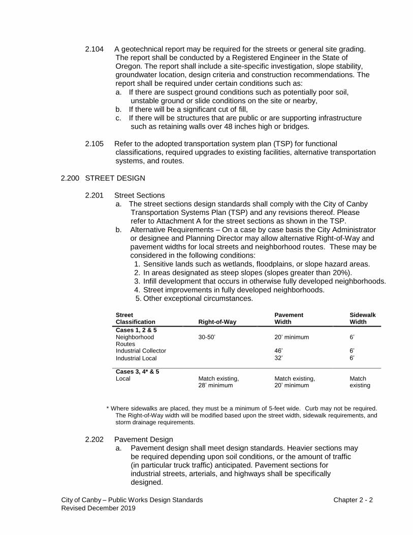
2.201 Street Sections
a. The street sections design standards shall comply with the City of Canby Transportation Systems Plan (TSP) and any revisions thereof. Please refer to Attachment A for the street sections as shown in the TSP.
b. Alternative Requirements – On a case by case basis the City Administrator or designee and Planning Director may allow alternative Right-of-Way and pavement widths for local streets and neighborhood routes. These may be considered in the following conditions: 1. Sensitive lands such as wetlands, floodplains, or slope hazard areas. 2. In areas designated as steep slopes (slopes greater than 20%). 3. Infill development that occurs in otherwise fully developed neighborhoods. 4. Street improvements in fully developed neighborhoods. 5. Other exceptional circumstances.
Street Classification
Right-of-Way
Pavement Width
Sidewalk Width
Cases 1, 2 & 5
Neighborhood 30-50’ 20’ minimum 6’ Routes
Industrial Collector 46’ 6’
Industrial Local 32’ 6’
Cases 3, 4* & 5
Local Match existing, Match existing, Match 28’ minimum 20’ minimum existing
* Where sidewalks are placed, they must be a minimum of 5-feet wide. Curb may not be required. The Right-of-Way width will be modified based upon the street width, sidewalk requirements, and storm drainage requirements.
2.202 Pavement Design a. Pavement design shall meet design standards. Heavier sections may
be required depending upon soil conditions, or the amount of traffic (in particular truck traffic) anticipated. Pavement sections for industrial streets, arterials, and highways shall be specifically designed.

City of Canby – Public Works Design Standards Chapter 2 - 3
Revised December 2019
b. Perpetual pavement design will be considered in place of standard pavement design.
c. Local and collector streets shall be a minimum of 4 inches of asphalt in two lifts, over 12 inches of base rock. The sub-base shall be proof rolled at the time of construction. The City shall inspect the sub-base as it is proof rolled. The City shall determine if the sub-base needs to be improved.
d. Arterial streets shall be a minimum of 5 inches of asphalt in two lifts, over 14 inches of base rock. The sub-base shall be proof rolled at the time of construction. The City shall inspect the sub-base as it is proof rolled and determine if the sub-base needs to be improved.
e. Specific designs shall be used for designated truck routes. In no case shall the section be less than the minimum for arterial streets.
2.203 Horizontal Alignment
a. Centerline alignment of improvements should be parallel to the centerline of the Right-of-Way.
b. The centerline of a proposed street extension shall be aligned with the existing street centerline.
c. The intersection of any two streets shall have a minimum of 50 feet of straight (tangent) alignment perpendicular to the intersection.
d. The following are guidelines for the minimum centerline horizontal curve radius:
Arterial Streets - 450 feet Collector & Neighborhood Streets - 270 feet Local Streets - 165 feet
2.204 Vertical Alignment
a. Minimum tangent street gradients shall be one-half (0.5) percent along with the crown and curb.
b. Maximum street gradients shall be fifteen (15) percent for the collector, and local streets, and ten (10) percent for arterials. Grades above the standards must be approved by the City Administrator or designee on an individual basis based upon the following criteria:
1. There is no practical access to the property being developed through adjacent properties.
2. The cut/fill required to maintain the standard slopes may cause the destabilization of soils.
c. Local streets intersecting with a collector street, or greater functional classification street, or streets intended to be posted with a stop sign shall provide a landing averaging two (2) percent or less. Landings are that portion of the street within fifty (50) feet of the edge of the intersecting street at full improvement.
d. Grade changes of more than one (1%) percent shall be accomplished with vertical curves. Vertical curves shall be designed per the "AASHTO Policy on Geometric Design of Highways and Streets". “K” values shall be shown on the plans.
1. Vertical curves may be shortened at intersections where there is a stop sign or a “tee” intersection.

City of Canby – Public Works Design Standards Chapter 2 - 4
Revised December 2019
e. At street intersections, the crown of the major (higher classification) street shall continue through the intersection. The roadway section of the minor street will flatten to match the major street at the quarter panel.
f. Street grades, intersections, and super elevation transitions shall be designed to prevent concentrations of stormwater from flowing over the pavement.
g. The standard street cross-slope shall be designed to match the centerline with the top of the curb. The minimum cross slope shall be 2%. The maximum cross slope shall be 3.6%.
2.205 Intersections
a. The interior angle at intersecting streets shall be kept as near to ninety (90) degrees as possible. In no case shall it be less than seventy-five (75) degrees.
b. Offset intersections shall not be allowed. For intersections where the centerline of the streets does not align, the minimum spacing shall be as follows:
Street Class Intersection Spacing (Ft.)
Arterial 660 - 1,000* Collector 250 - 600* Neighborhood Route 150 - 600 Local/Cul-de-sac 150 - 600
*The City Administrator or designee may permit a minimum spacing of not less than 300 feet (Arterial) and 200 feet (Collector) when findings are made to establish that:
1. Without the change, there would be no public street access from the
parcel(s) to the existing street, or 2. The change is necessary to support local pedestrian, bicycle
circulation and access, and 3. The change is necessary due to topographic constraints, and 4. All other provisions of the street design requirements can be met.
c. The following shall be used as a guideline for curb radii at intersections for the various classifications. The Right-of-Way radii at intersections shall be sufficient to maintain at least the same Right-of-Way to curb spacing as the higher classified street.
Arterial Streets R = 40 feet Collector Streets R = 30 feet
*Local Streets R = 25 feet *In accordance with the Oregon Fire Code
2.206 Cul-de-sacs and Eyebrows a. Cul-de-sacs shall only be allowed per the City of Canby Development
Code Chapter 16.64.010. Cul-de-sacs and eyebrows shall be allowed only on local streets.

City of Canby – Public Works Design Standards Chapter 2 - 5
Revised December 2019
b. Cul-de-sacs shall not be more than four hundred (400) feet in length and shall serve no more than 25 dwellings. The length of a cul-de-sac shall be measured along the centerline of the roadway from the near side Right-of-Way of the nearest through traffic intersecting street to the farthest point of the cul-de-sac Right-of-Way.
c. The minimum radius for a cul-de-sac bulb Right-of-Way shall be 54 feet with a minimum curb radius of 48 feet.
d. The minimum curb radius for transitions into cul-de-sac bulbs shall be twenty-eight (28) feet minimum, and the Right-of-Way radius shall be sufficient to maintain the same Right-of-Way to curb spacing as in the adjacent portion of the road.
e. When cul-de-sacs are allowed, provisions for connectivity of other public facilities shall be made. Specifically, pedestrian connections as called for in the City of Canby Development Code Chapter 16.64.010 and looping of the water distribution system.
2.207 Half Street Improvements
a. Half-street construction is generally not acceptable. Where such a street is justified, the Right-of-Way and pavement width will be approved by the City Administrator or designee. In no case shall the pavement width required be less than that required to provide two lanes of traffic to pass at a safe distance. For a 32-foot local street, the half-street pavement width shall be 20-feet. Half-streets will only be approved when the abutting or opposite frontage property is undeveloped and the full improvement will be provided with development of the abutting or opposite (upon Right-of-Way dedication) frontage property.
b. Development on an unimproved substandard street shall be responsible for constructing a continuous, 20’ wide half street to a connection with the nearest publically owned Right-of-Way.
c. In cases where an existing street is to be improved, the improvement shall be to the centerline of the street or 20’ wide, whichever is greater.
2.208 Pavement Transitions and Tapers
a. In the direction of vehicular traffic, where the street width transitions from narrower to wider, the taper shall be three (3) to one (1).
b. In the direction of vehicular traffic, where the street width transitions from wider to narrower, the length of the transition taper shall be determined as follows:
L = S x W for S = 45 mph or greater
L = S x S x W/60 for S less than 45 mph
L – length of taper in feet
S – design speed in mph
W – offset width in feet
c. Delineators may be required at tapers.
2.209 Sidewalks a. Sidewalks shall be a minimum of 4 inches of concrete over 2 inches of
base rock.

City of Canby – Public Works Design Standards Chapter 2 - 6
Revised December 2019
b. The maximum cross slope shall be 2-percent and the design slope shall be1.50%.
c. Concerning obstructions, such as mailboxes, signs posts, power poles, etc., the minimum horizontal clearance on a sidewalk, for an accessible route, shall be 48”. The minimum vertical clearance shall be 7-feet.
d. Sidewalks are intended to be within the Right-of-Way. In special circumstances, the City may allow sidewalks to be outside of the Right-of-Way, but they must be within a dedicated easement.
e. Handrails or fences may be required on sidewalks adjacent to a steep slope or a vertical drop of six inches or more.
f. One sidewalk ramp meeting Americans with Disabilities Acts (ADA) requirements shall be located at each corner of an intersection where two through roads meet (crossroads). In areas with greater than 1,000 trips per day, two sidewalk ramps meeting (ADA) standards shall be located at each corner of a crossroads. Mid-block sidewalk ramps may be required where there are pedestrian facilities. Other factors may dictate the location of ramps.
2.210 Curb & Gutter
a. A standard monolithic curb and gutter shall be used. It shall be 12-inches deep, have an 18-inches pan with a 1-inch radius, and be 6-inches wide at the top.
b. Mountable curbs shall not be used unless approved by the City Administrator or designee. For a mountable curb to be permitted, a special circumstance must exist, like a development with townhouses where 90% of the frontage is the driveway.
c. A standard curb may not be used without consent from the City of Canby Public Works Department.
2.211 Driveways
a. Access to private property shall be permitted with the use of driveway curb cuts. The access points with the street shall be the minimum necessary to provide access and must not inhibit the safe circulation and carrying capacity of the street. Driveways shall meet all applicable guidelines of the Americans with Disabilities Act (ADA).
b. Driveways shall be limited to one per property except for certain uses which include:
1. large commercial uses such as large box stores,
2. large public uses such as schools and parks,
3. drive-through facilities,
4. property with a frontage of over 250-feet
c. Double frontage lots and corner lots may be limited to access from a single street, usually the lower classification street. Single family residential lots shall not have access to arterials and shall have access to collectors only if there is no other option.
d. For additional driveways to be approved by the City Administrator or designee, a finding shall be made that no eminent traffic hazard would result. Furthermore, impacts on through traffic must be minimal. Restrictions may be imposed on additional driveways. These restrictions may include limited turn movements, shared access between uses, closure of existing driveways, or other access management actions.
City of Canby – Public Works Design Standards Chapter 2 - 7
Revised December 2019
e. Within commercial, industrial, and multi-family areas, shared driveways and internal access between similar uses are encouraged to 1) reduce the access points to the higher classified roadways 2) improve internal site circulation, 3) reduce local trips on the street system. Shared driveways or internal access between uses will be established by means of common access easements at the time of development.
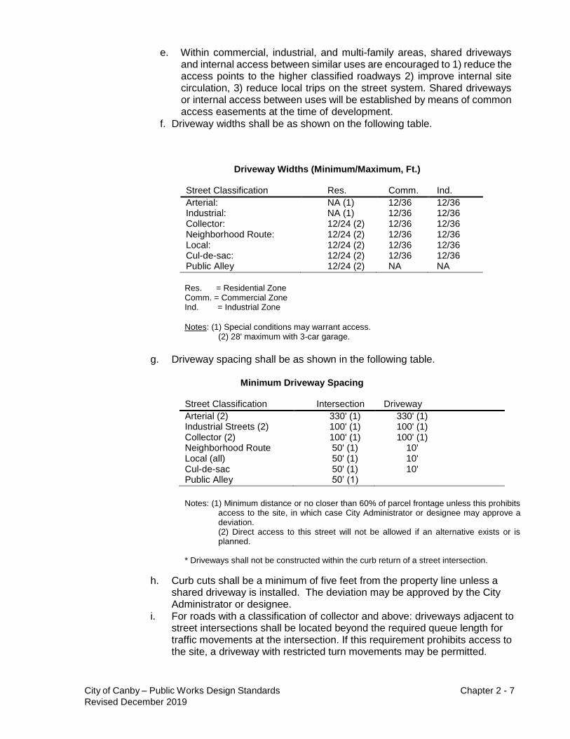
f. Driveway widths shall be as shown on the following table.
Driveway Widths (Minimum/Maximum, Ft.)
Street Classification Res. Comm. Ind.
Arterial: NA (1) 12/36 12/36 Industrial: NA (1) 12/36 12/36 Collector: 12/24 (2) 12/36 12/36 Neighborhood Route: 12/24 (2) 12/36 12/36 Local: 12/24 (2) 12/36 12/36 Cul-de-sac: 12/24 (2) 12/36 12/36 Public Alley 12/24 (2) NA NA
Res. = Residential Zone Comm. = Commercial Zone Ind. = Industrial Zone
Notes: (1) Special conditions may warrant access.
(2) 28' maximum with 3-car garage.
g. Driveway spacing shall be as shown in the following table.
Minimum Driveway Spacing
Street Classification Intersection Driveway
Arterial (2) 330' (1) 330' (1) Industrial Streets (2) 100' (1) 100' (1) Collector (2) 100' (1) 100' (1) Neighborhood Route 50' (1) 10' Local (all) 50' (1) 10' Cul-de-sac 50' (1) 10' Public Alley 50’ (1)
Notes: (1) Minimum distance or no closer than 60% of parcel frontage unless this prohibits
access to the site, in which case City Administrator or designee may approve a deviation. (2) Direct access to this street will not be allowed if an alternative exists or is planned.
* Driveways shall not be constructed within the curb return of a street intersection.
h. Curb cuts shall be a minimum of five feet from the property line unless a shared driveway is installed. The deviation may be approved by the City Administrator or designee.
i. For roads with a classification of collector and above: driveways adjacent to street intersections shall be located beyond the required queue length for traffic movements at the intersection. If this requirement prohibits access to the site, a driveway with restricted turn movements may be permitted.
City of Canby – Public Works Design Standards Chapter 2 - 8
Revised December 2019
j. Multi-family access driveways will be required to meet the same access requirements as commercial driveways if the multi-family site generated 100 or more trips per day.
2.212 Bikeways
a. General - The City has adopted a Transportation System Plan (TSP), which includes a Bicycle/Pedestrian Plan. This plan summarizes the City's policy and implementation strategies for bikeways within the City. The City will use both AASHTO and ODOT standards and criteria as the minimum guidelines for bikeway design, construction, and control.
The guidelines for bikeways consist of the following: 1. AASHTO, “Guide to Development of Bicycle Facilities,” latest edition. 2. ODOT, “Oregon Bicycle & Pedestrian Plan”, latest edition. 3. Manual on Uniform Traffic Control Devices with Oregon supplements
by Oregon Transportation Commission, the latest edition. b. Location - Bikeway location and widths for on-street bike lanes are shown
on the street section table in paragraph 2.201 of these standards. Bikeways that are outside of street sections will be considered “two-way” (See paragraph 2.201 for the width). These bikeways shall have a minimum of 2-foot wide gravel shoulders on both sides.
c. Design Criteria – Designs shall meet the criteria per AASHTO and ODOT, and shall also meet the following criteria: 1. All bikeways shall have a minimum cross-slope of two percent (2%)
and a maximum cross-slope of five percent (5%). 2. Bikeway curvature will be based on a minimum design speed of 20
MPH. 3. Bikeway grades shall be limited to a maximum of five percent (5%).
Where topography dictates, grades over five percent (5%) are acceptable when a higher design speed is used and additional width is provided.
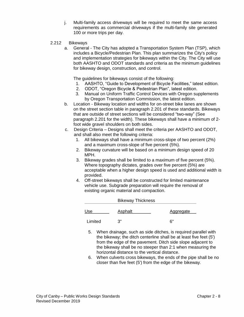
4. Off-street bikeways shall be constructed for limited maintenance vehicle use. Subgrade preparation will require the removal of existing organic material and compaction.
Bikeway Thickness
Use
Asphalt
Aggregate
Limited 3" 6"
5. When drainage, such as side ditches, is required parallel with
the bikeway; the ditch centerline shall be at least five feet (5') from the edge of the pavement. Ditch side slope adjacent to the bikeway shall be no steeper than 2:1 when measuring the horizontal distance to the vertical distance.
6. When culverts cross bikeways, the ends of the pipe shall be no closer than five feet (5') from the edge of the bikeway.

City of Canby – Public Works Design Standards Chapter 2 - 9
Revised December 2019
2.213 Parking a. Location – On street parking location and widths are shown on the street
section table in paragraph 2.201 of these standards. 1. On street parking is considered optional on one-way arterials
and collector streets. Both parallel and diagonal parking are options for one-way arterials. The requirements for on street parking in these locations are at the City’s discretion.
2. Neighborhood routes and local streets shall have parallel parking. Parking may be deleted at the City’s discretion in special circumstances.
3. On street parking is not allowed on two-way arterials and industrial streets (local and collector).
2.214 Street Signs & Striping
a. A street signing and striping plan shall be included in plan submittals for new streets. Street striping and signing shall be per ODOT standards and guidelines.
2.215 Street Lighting a. A street lighting plan shall be included in plan submittals for new streets.
Street lighting shall be for the safety of pedestrians as well as traffic safety.
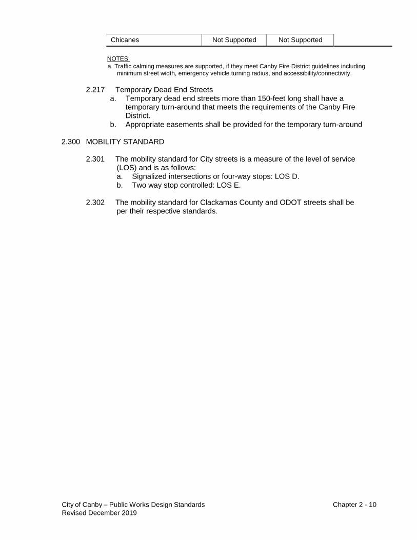
2.216 Traffic Calming a. Traffic calming measures are encouraged and are supported as shown in
the following table.
Allowed Traffic Calming Measures by Roadway Functional Classification
Traffic Calming Measure
Is Measure Supported? (per Roadway Classification)a
Arterial
Collector
Neighborhood Route/ Local
Street
Curb Extensions Supported Supported
Calming
measures are supported on
roads that have connectivity
(more than two accesses) and are accepted
and field tested by the Canby Fire District.
Roundabouts Supported Supported
Medians and Pedestrian Supported Supported
Islands
Pavement Texture Supported Supported
Speed Hump Not Supported Not Supported
Raised Crosswalk Not Supported Not Supported
Speed Cushion (provides Not Supported Not Supported emergency pass-through
with no vertical deflection)
Choker Not Supported Not Supported
Traffic Circle Not Supported Not Supported
Diverter (with emergency Not Supported Supported
vehicle pass through)
City of Canby – Public Works Design Standards Chapter 2 - 10
Revised December 2019
Chicanes Not Supported Not Supported
NOTES:
a. Traffic calming measures are supported, if they meet Canby Fire District guidelines including minimum street width, emergency vehicle turning radius, and accessibility/connectivity.
2.217 Temporary Dead End Streets
a. Temporary dead end streets more than 150-feet long shall have a temporary turn-around that meets the requirements of the Canby Fire District.
b. Appropriate easements shall be provided for the temporary turn-around
2.300 MOBILITY STANDARD
2.301 The mobility standard for City streets is a measure of the level of service (LOS) and is as follows: a. Signalized intersections or four-way stops: LOS D. b. Two way stop controlled: LOS E.
2.302 The mobility standard for Clackamas County and ODOT streets shall be
per their respective standards.

City of Canby – Public Works Design Standards Chapter 3 - 1
Revised December 2019
CITY OF CANBY
PUBLIC FACILITY IMPROVEMENTS
DESIGN MANUAL AND STANDARD SPECIFICATIONS
Revised December 2019
CHAPTER 3 – SANITARY SEWER DESIGN
3.100 GENERAL
3.101 Sanitary sewer design shall comply with all requirements of the Oregon Department of Environmental Quality (ODEQ) design guidelines and be approved by ODEQ before beginning any construction. Sanitary sewer design shall comply with the City's master planning requirements as well.
3.102 Sanitary sewer systems shall be designed to provide gravity service to all areas
of development. Approval by the City Administrator or designee shall be obtained before the design of any sewer which cannot provide gravity service.
3.103 Sanitary sewer system capacity shall be designed for the ultimate
development density of the tributary area. The system shall allow for future system extension and future development based on current or proposed land use designations.
3.104 Sanitary sewers shall be designed to remove the domestic sewage and
industrial wastes from: a. basements of houses, where practical b. commercial or industrial buildings, c. all public and private establishments where possible.
3.105 Stormwater, including street runoff, roof runoff, or footing drainage, shall not
be discharged into the sanitary sewer system. Stormwater shall be removed by a system of storm drains or by some other method separate from the sanitary sewer system.
3.106 All public sewer pipelines shall be located within the public Right-of-Way wherever possible. These lines are placed in public streets and Right-of-Way for ease of maintenance, ease of access, control of the facility, operation of the facility, and to provide required replacement and/or repair. Under special topographical conditions, the placing of public sewers outside of the Public Right-of-Way may be approved by the City Administrator or designee.
3.107 Sanitary sewer lines shall be extended to the edge of the property being
developed to facilitate the future extension of the collection system.
3.108 Refer to the adopted wastewater master plan and facility plan for required upgrades to existing facilities.
City of Canby – Public Works Design Standards Chapter 3 - 2
Revised December 2019
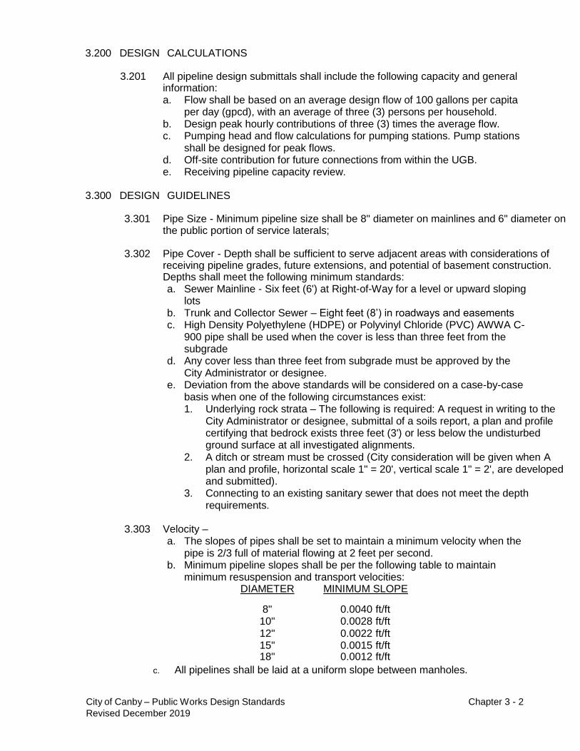
3.200 DESIGN CALCULATIONS 3.201 All pipeline design submittals shall include the following capacity and general
information: a. Flow shall be based on an average design flow of 100 gallons per capita
per day (gpcd), with an average of three (3) persons per household. b. Design peak hourly contributions of three (3) times the average flow. c. Pumping head and flow calculations for pumping stations. Pump stations
shall be designed for peak flows. d. Off-site contribution for future connections from within the UGB. e. Receiving pipeline capacity review.
3.300 DESIGN GUIDELINES 3.301 Pipe Size - Minimum pipeline size shall be 8" diameter on mainlines and 6" diameter on
the public portion of service laterals;
3.302 Pipe Cover - Depth shall be sufficient to serve adjacent areas with considerations of receiving pipeline grades, future extensions, and potential of basement construction. Depths shall meet the following minimum standards: a. Sewer Mainline - Six feet (6') at Right-of-Way for a level or upward sloping
lots b. Trunk and Collector Sewer – Eight feet (8’) in roadways and easements c. High Density Polyethylene (HDPE) or Polyvinyl Chloride (PVC) AWWA C-
900 pipe shall be used when the cover is less than three feet from the subgrade
d. Any cover less than three feet from subgrade must be approved by the City Administrator or designee.
e. Deviation from the above standards will be considered on a case-by-case basis when one of the following circumstances exist: 1. Underlying rock strata – The following is required: A request in writing to the
City Administrator or designee, submittal of a soils report, a plan and profile certifying that bedrock exists three feet (3') or less below the undisturbed ground surface at all investigated alignments.
2. A ditch or stream must be crossed (City consideration will be given when A plan and profile, horizontal scale 1" = 20', vertical scale 1" = 2', are developed and submitted).
3. Connecting to an existing sanitary sewer that does not meet the depth requirements.
3.303 Velocity – a. The slopes of pipes shall be set to maintain a minimum velocity when the
pipe is 2/3 full of material flowing at 2 feet per second. b. Minimum pipeline slopes shall be per the following table to maintain
minimum resuspension and transport velocities: DIAMETER MINIMUM SLOPE
8" 10" 12" 15" 18"
0.0040 ft/ft 0.0028 ft/ft 0.0022 ft/ft 0.0015 ft/ft 0.0012 ft/ft
c. All pipelines shall be laid at a uniform slope between manholes.
City of Canby – Public Works Design Standards Chapter 3 - 3
Revised December 2019
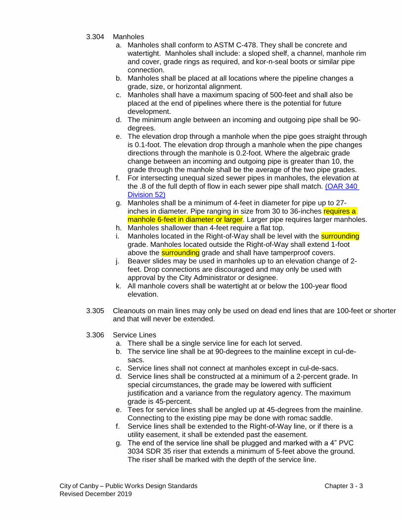
3.304 Manholes a. Manholes shall conform to ASTM C-478. They shall be concrete and
watertight. Manholes shall include: a sloped shelf, a channel, manhole rim and cover, grade rings as required, and kor-n-seal boots or similar pipe connection.
b. Manholes shall be placed at all locations where the pipeline changes a grade, size, or horizontal alignment.
c. Manholes shall have a maximum spacing of 500-feet and shall also be placed at the end of pipelines where there is the potential for future development.
d. The minimum angle between an incoming and outgoing pipe shall be 90- degrees.
e. The elevation drop through a manhole when the pipe goes straight through is 0.1-foot. The elevation drop through a manhole when the pipe changes directions through the manhole is 0.2-foot. Where the algebraic grade change between an incoming and outgoing pipe is greater than 10, the grade through the manhole shall be the average of the two pipe grades.
f. For intersecting unequal sized sewer pipes in manholes, the elevation at the .8 of the full depth of flow in each sewer pipe shall match. (OAR 340 Division 52)
g. Manholes shall be a minimum of 4-feet in diameter for pipe up to 27- inches in diameter. Pipe ranging in size from 30 to 36-inches requires a manhole 6-feet in diameter or larger. Larger pipe requires larger manholes.
h. Manholes shallower than 4-feet require a flat top. i. Manholes located in the Right-of-Way shall be level with the surrounding
grade. Manholes located outside the Right-of-Way shall extend 1-foot above the surrounding grade and shall have tamperproof covers.
j. Beaver slides may be used in manholes up to an elevation change of 2- feet. Drop connections are discouraged and may only be used with approval by the City Administrator or designee.
k. All manhole covers shall be watertight at or below the 100-year flood elevation.
3.305 Cleanouts on main lines may only be used on dead end lines that are 100-feet or shorter
and that will never be extended.
3.306 Service Lines a. There shall be a single service line for each lot served. b. The service line shall be at 90-degrees to the mainline except in cul-de-
sacs. c. Service lines shall not connect at manholes except in cul-de-sacs. d. Service lines shall be constructed at a minimum of a 2-percent grade. In
special circumstances, the grade may be lowered with sufficient justification and a variance from the regulatory agency. The maximum grade is 45-percent.
e. Tees for service lines shall be angled up at 45-degrees from the mainline. Connecting to the existing pipe may be done with romac saddle.
f. Service lines shall be extended to the Right-of-Way line, or if there is a utility easement, it shall be extended past the easement.
g. The end of the service line shall be plugged and marked with a 4” PVC 3034 SDR 35 riser that extends a minimum of 5-feet above the ground. The riser shall be marked with the depth of the service line.

City of Canby – Public Works Design Standards Chapter 3 - 4
Revised December 2019
h. Curb shall be stamped with an “S” on the face or top where the service line crosses.
i. There shall be a 6-inch cleanout located in the sidewalk on each service line to differentiate between the public and private line maintenance responsibility.
j. In special cases where a lot may not be able to be served by gravity, individual pumping facilities may be used. These may only be used with the approval of the City Administrator or designee. The pumping facility will be considered private, and this should be noted on the design plans.
3.307 Toning Wire
a. Where non-metallic pipe is used for both main lines and services lines, toning wire is required. It shall be laid along the pipe and shall be extended into the manholes and cleanouts.
3.308 Materials
a. Sanitary sewer pipelines and services shall be PVC 3034 SDR 35, and comply with the requirements of ASTM F-477 and ASTM 3212.
b. Where additional pipe strength is required, two pipe materials are acceptable. These pipe materials are High Density Polyethylene (HDPE) and Polyvinyl Chloride (PVC) AWWA C-900.
c. Stream crossing shall be made with fusion butt-welded HDPE pipe or equivalent as approved by the City Administrator or designee.
d. Toning wire shall be a minimum of 18-gauge copper wire with green insulation.
3.400 CONNECTION TO EXISTING SEWERS
3.401 Connections to and extensions of existing sewers may occur to facilitate new
development.
3.402 Connection to an existing manhole is the preferable method for extending the mainline. a. Connection to an existing stub out is preferred. b. Where there is no stub out, the existing manhole may be core drilled at
the top of the shelf. A core-n-seal boot or similar watertight connection method shall be used. The shelf shall be rechanneled as needed to accommodate the new pipe.
c. Where there is insufficient depth to connect to an existing manhole at the top of the shelf, the connection may be made lower. This will require reconstruction of the channel and shelf. Note that the crown elevation of the new pipe must be no lower than the crown of the outgoing pipe. The base of the manhole may need to be rebuilt.
d. Drop connections may only be made in special circumstances such as intervening structures that prevent the appropriate slope. The depth of sewer alone does not warrant a drop connection.
3.403 Connection to Main Line
a. When there is not an existing manhole for the mainline to connect to, a new manhole may be constructed over an existing pipe. The manhole base may be poured around the existing pipe, and the top cut out of the existing pipe. The shelf will be formed around the existing pipe, and the new pipe shall enter the manhole no lower than where the existing pipe is

City of Canby – Public Works Design Standards Chapter 3 - 5
Revised December 2019
cut.
b. The manhole should be tested before cutting the existing pipe.
3.404 Connection to Clean Outs
a. When sewers are extended from cleanouts, the entire cleanout assembly, including the wye, shall be removed. The new pipe shall be installed at the same grade as the existing pipe.
b. The new pipe will need to be tested before connecting to the existing pipe.
3.405 Service Connections
a. New building service laterals shall be made at existing tees where possible. b. When tees do not exist on the Public Sanitary Sewer System, the new
lateral sewer will enter the collection system through a "cored" opening. Connection to the Public Sanitary Sewer System shall be made with an approved romac saddle connector.
3.500 EASEMENTS
3.501 Public Easements
a. Easements for public sewer less than or equal to 12-inches in diameter shall be a minimum of 15-feet wide. Easements for public sewer greater than 12-inches in diameter shall be a minimum of 20-feet wide.
b. Easements for sewer greater than 24-inches in diameter or more than 8- feet deep shall require wider easements. Easements will be enlarged in increments of 5-feet.
3.502 Private Easements
a. Private easements for service lines are the responsibility of the owner. However, if the design plans for a development require a service line to cross another’s property, the private easements shall be shown on the plans and must be included in the plat.
b. Private easements shall not be permitted within the Public Right-of-Way.
3.600 SEPARATION FROM WATER LINES
3.601 Water mains shall be installed a minimum clear distance as defined in OAR Chapter 333, Public Water Systems. The horizontal distance between a sanitary sewer line and a water main must be greater than or equal to five feet.
3.602 Water lines shall be installed over the top of sewer lines. There must be at least
eighteen (18) inches of vertical separation at the intersection of the water pipe and the sewer pipe.
3.603 Exceptions shall be approved by the City Administrator or designee. In all
instances, the distances shall be measured surface to surface.
3.700 RELATION TO WATERCOURSES
3.701 Generally, the top of all sanitary sewers entering, crossing, or adjacent to
streams shall be at a sufficient depth below the natural bottom of the streambed to protect the sewer line. One foot (1') of cover is required where the sewer is in solid rock; three feet (3') of cover is required in other materials. In paved
City of Canby – Public Works Design Standards Chapter 3 - 6
Revised December 2019
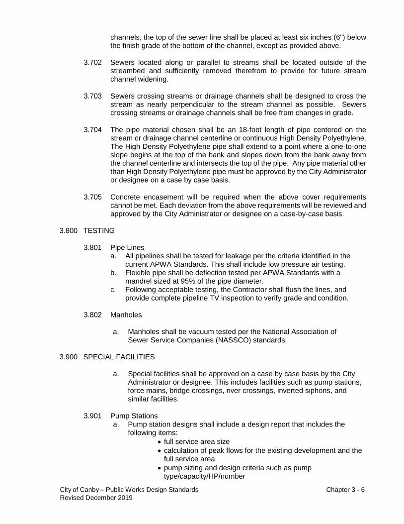
channels, the top of the sewer line shall be placed at least six inches (6") below the finish grade of the bottom of the channel, except as provided above.
3.702 Sewers located along or parallel to streams shall be located outside of the
streambed and sufficiently removed therefrom to provide for future stream channel widening.
3.703 Sewers crossing streams or drainage channels shall be designed to cross the
stream as nearly perpendicular to the stream channel as possible. Sewers crossing streams or drainage channels shall be free from changes in grade.
3.704 The pipe material chosen shall be an 18-foot length of pipe centered on the
stream or drainage channel centerline or continuous High Density Polyethylene. The High Density Polyethylene pipe shall extend to a point where a one-to-one slope begins at the top of the bank and slopes down from the bank away from the channel centerline and intersects the top of the pipe. Any pipe material other than High Density Polyethylene pipe must be approved by the City Administrator or designee on a case by case basis.
3.705 Concrete encasement will be required when the above cover requirements
cannot be met. Each deviation from the above requirements will be reviewed and approved by the City Administrator or designee on a case-by-case basis.
3.800 TESTING
3.801 Pipe Lines
a. All pipelines shall be tested for leakage per the criteria identified in the current APWA Standards. This shall include low pressure air testing.
b. Flexible pipe shall be deflection tested per APWA Standards with a mandrel sized at 95% of the pipe diameter.
c. Following acceptable testing, the Contractor shall flush the lines, and provide complete pipeline TV inspection to verify grade and condition.
3.802 Manholes
a. Manholes shall be vacuum tested per the National Association of
Sewer Service Companies (NASSCO) standards.
3.900 SPECIAL FACILITIES
a. Special facilities shall be approved on a case by case basis by the City Administrator or designee. This includes facilities such as pump stations, force mains, bridge crossings, river crossings, inverted siphons, and similar facilities.
3.901 Pump Stations
a. Pump station designs shall include a design report that includes the following items:
full service area size
calculation of peak flows for the existing development and the full service area
pump sizing and design criteria such as pump type/capacity/HP/number

City of Canby – Public Works Design Standards Chapter 3 - 7
Revised December 2019
overflow location
control elevations and equipment
wet well sizing
alarm type
transfer switch type
force main size
hydrogen sulfide control
discharge manhole protection
downstream capacity analysis
b. In general pump station shall be designed to meet peak design flows with full pumping redundancy. The wet wells shall have a minimum of four (4) hours storage above the alarm elevation.
c. Features that are required in a pump station design include:
pumps (a minimum of two)
wet well
valves
valve vault
associated piping
level control
electrical
control panel and weatherproof enclosure
instrumentation
pressure gauges
alarms
telemetry
access road
parking
fencing
landscaping
potable water supply
lighting
power outlets
standby power
d. The following features may be required on a case by case basis: odor control, downstream discharge point for hydrogen sulfide, and air relief valves on the force main.
e. Standby power with an automatic transfer switch will be required for all new lift stations. Standby power with an automatic transfer switch shall be approved by the City Administrator or designee.
f. Additional requirements include an operation and maintenance manual, a minimum of two hours of training, and spare parts (gaskets, bearings, and mechanical seals).
g. Pump stations shall utilize submersible pumping systems unless an alternative is approved by the City Administrator or designee.

City of Canby – Public Works Design Standards Chapter 4 - 1
Revised December 2019
CITY OF CANBY
PUBLIC FACILITY IMPROVEMENTS
DESIGN MANUAL AND STANDARD SPECIFICATIONS
Revised December 2019
CHAPTER 4 – STORM DRAINAGE DESIGN
4.100 GENERAL
4.101 Performance Standards - Storm drainage design within a development area
must include provisions to adequately control run-off from all public streets and runoff from private property areas identified in the City Stormwater Master Plan. The design must ensure the future extension of the drainage system to the entire drainage basin in conformance with the adopted Stormwater Master Plan and these Design Standards.
4.102 Discharge Location: Surface or subsurface drainage; caused or affected by
changing the natural grade of the existing ground, removal of natural ground cover, or placement of impervious surfaces; shall not be allowed to flow over an adjacent public or private property in a volume or location materially different from that which existed before development occurred. Surface or subsurface drainage shall be collected and conveyed, in an approved manner, to an approved point of disposal.
4.103 Discharge Location: Surface water entering and exiting the subject property
shall be received and discharged at naturally occurring locations. Adequate energy dissipaters within the subject property may be required to minimize downstream damage. Diversions of the natural points of entry and exit of stormwater are not allowed without the approval of the City Administrator or designee.
4.104 Discharge Location: The approved point of disposal for all stormwater may be a
storm drain, existing open channel, creek, subsurface, detention or retention pond, or facility approved by the City Administrator or designee. Acceptance of suggested systems will depend upon the prevailing site conditions, the capacity of existing downstream facilities, and feasibility of an alternate design.
4.105 Underground Injection Control: New Underground Injection Control (UIC) devices shall not be approved for public stormwater facilities unless there is no other method for discharging stormwater. New UIC’s may only be used as a source of stormwater discharge if they are Registered and Rule Authorized by DEQ.
4.106 Private Drainage: Design for private storm drainage, where permitted by the
Stormwater Master Plan, shall meet the same requirements as public facilities. The design of these facilities shall be included in the public improvement plans, including facilities for individual lots.

City of Canby – Public Works Design Standards Chapter 4 - 2
Revised December 2019
4.107 Peak Discharge Rate: Unless adequate capacity is available, the peak discharge from the subject property may not be increased from conditions existing before the proposed development. Detention and/or retention will be required to obtain this result. Where it can be satisfactorily demonstrated by the applicant that there is already detention, and there are no adverse impacts to the downstream system, additional detention/retention may not be required.
4.108 Treatment: Stormwater quality facilities may be required to control the
discharge of pollutants from the development and redevelopment of the municipal storm drainage system, UIC’s, or natural watercourse. Where required by ODEQ or the City Administrator or designee, the City will encourage the use of LID standards. Please refer to the Clean Water Services Low Impact Development Approaches Handbook July 2009.
4.109 Flow Through Capacity: All storm drain system designs shall make adequate
provisions for collecting all the stormwater run-off. The system shall accommodate all run-off from upstream tributary areas whether or not such areas are within the proposed development. The amount of run-off to be accommodated shall be based upon the ultimate development of all upstream tributary areas.
4.110 Downstream Capacity: Proposed storm drain systems shall not discharge
flows into inadequate downstream systems unless approved by the City Administrator or designee.
4.111 System Location: Public storm lines shall be located within the Public Right-of-
Way if feasible. These lines are placed in the Public Right-of-Way for ease of maintenance and access, control of the facility, operation of the facility, and to provide required replacement and/or repair. Any storm lines not placed in the Public Right-of-Way shall be located in a public utility easement.
4.112 Only Public Right-of-Way runoff shall be collected and disposed of within the
public storm drainage system. Upon development, runoff from private properties shall not be permitted to discharge to public storm sewer facilities except as identified in the City Stormwater Master Plan.
4.200 STORM DRAINAGE REPORT a. If a storm drainage report was required during land use planning, then it
shall be finalized as part of the design. This should take into account any changes to the development, existing conditions, or agency requirements since the time the draft report was done.
b. If a storm drainage report was not required during land use planning, it shall be required during design.
c. A storm drainage report shall include the following (4.201-4.207)
4.201 Existing Drainage Plan - shall contain a topographical contour map defining existing conditions. The topographical contour map shall include: a. Two-foot (2') contour intervals; slopes over 10% may use 5-foot (5')
intervals; very flat sites may need contour interval of one-foot (1’) or even one-half foot (1/2’); extend contours a minimum of 100 feet beyond the property.

City of Canby – Public Works Design Standards Chapter 4 - 3
Revised December 2019
b. Location of all structures, buildings, parking lots, and utilities on the property. c. Location of all existing drainage facilities and watercourses, including
wetlands and floodplain areas. d. Locations of all subsurface water outlets (e.g., springs). e. Show arrows to indicate the direction of flow for all drainage information.
4.202 Proposed Drainage Plan - shall show proposed site grading and drainage
facilities on a topographical contour map. Unless the detail for proposed improvements will obscure the conditions shown on the existing drainage plan, proposed site grading and drainage may be shown on the existing drainage plan. The following information shall also be shown:
a. Finished contours of the property, at two-foot (2') or five-foot (5') intervals as required.
b. Percent grade for graded slopes; elevations, dimensions, and locations for all graded slopes.
c. Cut/fill areas; structural fill placement areas; erosion/sedimentation control methods; reseeding areas.
d. All proposed drainage facilities - public and private systems; paved areas, curbs, sidewalks; drainage ditches, culverts.
4.203 Drainage Calculations - The storm drainage report shall provide the following
information: a. Pre and post development conditions concerning basin boundary maps, b. pervious and impervious areas, c. flow routing, d. discharge rates for design storms, e. discharge velocity, and f. time of concentration calculation. g. a general description of the proposed facilities, h. soils identification, i. curve number (CN) (and calculation of composite CN’s), j. design storms, k. detention sizing, l. treatment sizing, m. downstream analysis, n. infiltration rates with supporting data. o. references for soils type, p. CN (note: use ODOT Zone 8 Rainfall Intensity-Duration Frequency curve)
q. The discharge rates to be evaluated include the 2, 5, 10 and 25- year storm events.
r. The conveyance system shall be designed to pass the 10- year storm events without surcharge, and a 25- year event with surcharge but keeping the hydraulic grade line below the manhole lids.
4.204 Geotechnical Report -
a. If subsurface disposal of the stormwater is proposed as the discharge method, then a site-specific geotechnical investigation is required to define the infiltration rate of the existing soil. All tests shall be done during periods when the groundwater table is expected to be at its maximum. This investigation shall include background data from existing soils mapping, but it shall also include a field test of the infiltration rate at the site in question. Nearby field tests on other properties are not acceptable.

City of Canby – Public Works Design Standards Chapter 4 - 4
Revised December 2019
1. For the test, an excavation shall be made to the bottom elevation of the proposed infiltration system. The maximum infiltration rate shall be determined using either the EPA falling head percolation test procedure (Design Manual – Onsite Wastewater Treatment and Disposal Systems, EPA, 1980) or the double ring infiltrometer test (ASTM D3385).
2. The test hole or apparatus shall be filled with water and maintained at depths above the test elevation for not less than 4 hours. This represents the saturation period.
3. Following the saturation period, the infiltration rate shall be determined following one of the test procedures specified above, with a head of 6 inches of water.
4. The Engineer shall perform at least 1 test per contributing acre to determine a representative infiltration rate for the site.
5. A factor of safety of 2 shall be applied to the field measured infiltration rate.
6. The test shall be witnessed by a representative of the City or a geotechnical report submitted by a licensed geotechnical engineer. a) The maximum groundwater table shall also be identified.
4.205. Downstream Analysis Report
a. The downstream analysis will show what impacts, if any, a project will have on the hydraulic conveyance system(s) downstream of the project site. The analysis is to be divided into three parts that are followed sequentially. The three parts include a review of resources, an inspection of the affected area, and analysis of downstream effects.
1. During the review of resources, the designer will review any existing data concerning the drainage of the project area. This data will commonly include:
• area maps,
• floodplain maps,
• wetland inventories,
• stream surveys,
• habitat surveys,
• engineering reports concerning the entire drainage basin,
• inventories of known drainage problems,
• previously completed downstream analyses
The City may be able to provide some of this information. Other sources of information include ODEQ, Oregon Division of State Lands, and Oregon Department of Fish and Wildlife.
2. The Designer will physically inspect the drainage system at the project site and downstream of the site. During the inspection, the designer should investigate any problems or areas of concern that were noted during the review of resources. The designer should also identify any existing or potential capacity problems in the drainage system, any existing or potential areas where flooding may occur, any existing or potential areas of channel destruction (including erosion and sedimentation), and existing or potential areas of significant destruction of aquatic habitat.
3. The information that has been gathered is analyzed to determine if the construction of the project will create any drainage problems downstream or will make any existing problems worse. Often, if the other minimum requirements are met, the project will not negatively

City of Canby – Public Works Design Standards Chapter 4 - 5
Revised December 2019
impact the downstream drainage system. Some situations will still have negative impacts after all requirements are met. Whenever a situation is encountered where it has been determined that there will be negative impacts resulting from the project, mitigation measures must be included in the project to correct for the impacts.
4.206. Stormwater Flows - Several methods are available for estimating peak runoff rates. Three of these are the “Rational Method”, the SCS “Curve Number” method, and the Santa Barbara Urban Hydrograph (SBUH) method. These methods will be acceptable for estimating the peak runoff rates to be used in sizing storm drainage conveyance improvements in those areas for which there are no specific Master Plan recommendations.
4.207. Detention/Retention Volumes - Several methods are available for the
calculation of run-off rate volumes to calculating detention/retention storage volume requirements. Detention volume estimates shall be based on hydrographs developed for the storm duration specified by the City for the applicable return frequencies. A method shall be used which routes the design hydrograph through the proposed detention system. Unless specified otherwise, the standard design storm duration shall be 24 hours. For the development of the appropriate hydrograph(s), the SCS Type 1A 24-hour rainfall distribution is accepted for all development submittals.
4.300 MINIMUM DESIGN STANDARDS
4.301 Minimum Design Criteria
a. Storm Frequency - All public storm drain systems shall be designed for the design storm recurrence interval in the following table:
DRAINAGE SYSTEM DESIGN CAPACITY
Design Storm
Drainage System Description Recurrence Interval, Element Years
Minor: Streets, curbs, gutters, inlets, catch basin 10 and connector drains
Major: Laterals (collectors) <250 tributary acres 10 Trunk >250 tributary acres 25* Arterial Streets and the Drainage System 10* in or under Arterial Streets
Watercourses: Without designated floodplain 25 Within designated floodplain 100
Bridges: 100
Detention Facilities:
Storage volume (on site) 25
Discharge rate Function of down- stream capacity(a)
Retention Facilities:
Infiltration capacity 25
Detention capacity 25
Infiltration Facilities UIC, LID elements 10
NOTES
(a) Typically, this will mean designing for the 2,5,10 and 25-year storm events.
* Surcharged conditions for pipe systems, culverts, and bank full conditions for open ditches and channels are acceptable for demonstrating the adequacy of the conveyance system to convey the peak run-off for the 25-

City of Canby – Public Works Design Standards Chapter 4 - 6
Revised December 2019
year design storm (as required), provided that: a. run-off is contained within defined conveyance system elements; AND b. the hydraulic grade line does not exceed the elevation of the roadway subgrade; AND c. no portions of a building will be flooded.
b. Velocity and Slope - All storm drains shall be on a grade that produces a mean velocity, when flowing full, of at least three (3’) feet per second.
c. Velocity in Natural Channels - Control of discharge from developed areas to natural channels shall be such that the average velocity resulting from all design storms less than or equal to the 25-year event remains below the erosive velocity of the channel.
d. Manning Equations - When calculating minimum pipe slopes and velocities, the Design Engineer shall use the Manning pipe friction formula.
e. Pipe Coefficient - The storm-drain pipe roughness coefficient to be used in the Manning formula shall be greater than or equal to 0.013.
f. Slope - All pipelines shall be laid at a uniform slope between manholes.
4.302 Pipe Materials and Size a. All public storm drains shall be constructed with either ribbed PVC or
HDPE smooth interior, corrugated exterior pipe (Hancor ADS N-12, PVC C-900, or –equal). Where required, for added strength, PVC C-900 will be used.
b. Corrugated aluminum pipe or concrete pipe may be used for culvert applications if the material is specified as having a 75-year design life. Submittal of the manufacturer’s specifications, test results, and warranty will be required for City review before approval.
c. Private storm-drain pipe shall meet the appropriate sections of applicable building and plumbing codes.
d. All public storm-drain main lines shall be a minimum of twelve inches (12”) in diameter. Lateral lines to catch basins and other inlet structures shall be a minimum of ten inches (10”) in diameter.
e. Drywells (UIC’s) shall be constructed of perforated concrete pipe conforming to ASTM-478. The upper portion of the drywell shall be constructed in a manner that meets the requirements of a standard manhole with rim and lid.
f. Curb inlets shall be cast-in-place or precast concrete conforming to the City of Canby standard drawing 209 with minimum 18-inch sump.
g. Manholes shall be concrete and shall conform to ASTM C-478. They shall be concrete and shall include a sloped shelf, channel, manhole rim and cover, grade rings as required, kor-n-seal boots or similar pipe connection and shall be watertight.
4.303 Minimum Cover
a. Minimum cover shall be thirty inches (30") above the top of the pipe in paved areas and thirty-six inches (36") at all other locations. Curb inlets leader lines shall have a minimum of 18” cover if feasible. Lines with less than 18” cover shall be constructed of HDPE or PVC C-900.
b. If the minimum cover cannot be attained due to uncontrollable circumstances, then alternatives may be approved by the City Administrator or designee. These alternatives include the use of HDPE or PVC C-900 pipe or the use of control density fill.
c. In areas of relatively flat terrain, the Design Engineer must show that sufficient depth is provided at the boundary of the development to properly drain the remainder of the upstream basin area tributary to the site.

City of Canby – Public Works Design Standards Chapter 4 - 7
Revised December 2019
4.304 Manholes a. Manholes shall be located at all changes in pipe slope, pipe alignment,
pipe size, and at all pipe junctions with present or future storm drains. b. Manhole spacing shall not be greater than 500 feet. c. Manholes are required at all pipe junctions, except where private service
laterals are “T’ed” into a municipal main storm line as defined in the City of Canby Stormwater Master plan.
d. Flat-top manholes shall be used when rim to the crown of pipe elevations are less than four feet (4').
e. When the downstream pipe size increases, the crown of all upstream pipes shall not be lower than the crown of the larger downstream pipe.
f. Outside drops on manholes are required where the drop exceeds four (4) feet. Drops of less than two (2) feet shall have beaver slides.
g. Manholes shall not have open grate lids except in special circumstances approved by the City Administrator or designee.
h. Manhole rims shall be level with the ground surface where the ground is covered by improved surfaces (asphalt, concrete, crushed rock). In unimproved areas, the manhole rim shall be one foot above the finished grade.
i. Manholes shall have sixteen (16) hole lids. Tamper proof lids are required outside of vehicle or pedestrian travel ways.
j. Pollution control (PC) manholes shall be located just before the stormwater detention/retention and treatment facilities. A pollution control manhole shall have a sump for sediment to accumulate, and shall be located so that a vactor truck can access it.
4.305 Curb Inlets and catch basins
a. Curb inlets shall be located in streets at the curb line to receive stormwater run-off and convey it to the main storm drain or treatment facility.
b. Curb Inlets shall be located at the following locations. In no case shall curb inlets be spaced further than 400 feet apart. Any single curb inlet shall not receive stormwater from more than 400 feet of the street. 1. At curb returns on the upstream side of an intersection. 2. Where geometry dictates the need for a catch basin, such as large
curves in the street. 3. When street slopes are less than one percent (1%), maximum catch
basin spacing should be decreased to 300 feet. 4. When street slopes are greater than six percent (6%), maximum catch
basin spacing should be decreased to 300 feet. When street slopes are greater than fifteen percent (15%), maximum catch basin spacing should be decreased to 200 feet.
5. At the ends of all dead-end streets with a descending grade. 6. At intermediate locations, so that storm flows at the curb line do not
exceed three feet (3') in width (measured from the curb face) or three inches (3") in depth (measured at the curb face), whichever is less.
7. At the downstream end of the street improvements which abut unimproved roads or undeveloped property.
8. At the upstream end of the street improvements which abut unimproved roads or undeveloped property.
9. Additional inlet capacity is required at sag vertical curves. This may be accomplished in one of three ways:
a. A single unit double curb inlet at the low point of the sag vertical curves.
b. Three curb inlets may be used: one at the bottom and one to

City of Canby – Public Works Design Standards Chapter 4 - 8
Revised December 2019
either side partway up the sag curve.
c. This requirement may be waived by the City Administrator or designee where the drainage area is small or the vertical curve is minimal.
10. Curb inlets shall be capable of intercepting the entire design storm
flow at the curb.
4.306 Culverts
a. Culverts at road crossings in natural, perennial channels shall be designed to pass the peak discharge for the 50-year design storm such that the headwater water surface elevation: 1. Does not exceed 1.5 times the culvert diameter; OR 2. Remains at least 1 foot below the roadway subgrade, whichever is
less. b. In waters federally designated as critical habitat, a tribute to, or have
endangered or threatened fish species, water-crossing structures shall be constructed and maintained so that listed species are not deprived of habitat or the ability to migrate.
c. Proposed culvert crossings shall address the Oregon Department of Fish & Wildlife and National Marine Fisheries Service’s regulations and stream crossing guidelines.
4.307 Bridges
a. New and replacement bridges over natural and perennial channels shall be designed to pass the 100-year peak discharge at full development from the tributary area. Vertical clearance between the design water surface and the bottom of any part of the bridge shall be a minimum of two feet or 25% of the mean channel width between ordinary highwater marks at the crossing. The option with the greater vertical clearance shall be used.
4.308 Site Grading a. Site grading shall be done such that it does not redirect surface drainage
onto neighboring properties. b. Site grading shall be done such that it does not impede surface water
drainage on neighboring properties causing ponding. c. Where it appears that off-site impacts cannot be avoided, private drainage
systems shall be designed and constructed to mitigate the effect. The design shall be submitted as part of the development design plans. This shall include appropriate private easements.
4.309 Low Impact Development (DELETED)
4.310 Water Quality Facilities
Where water quality facilities are required by ODEQ or the Environmental Protection Agency (EPA), the following standards will apply:
a. Instead of constructing new facilities, the City Administrator or designee
may permit development to upgrade an existing public treatment facility, if the effect of the improvement will improve the overall stormwater treatment to the same extent as a new facility.
b. Treatment processes that are accepted include:

City of Canby – Public Works Design Standards Chapter 4 - 9
Revised December 2019
1. Vegetated Swales 2. Extended Dry Ponds 3. Wetlands 4. Proprietary treatment devices as approved by the City Administrator or
designee. c. The design criteria for water quality facilities are found in the Clean Water
Services (CWS) Design Manual under Chapter 4, paragraph 4.06.
d. Special water quality requirements may be added based upon stormwater permits that the City may be issued in the future.
4.311 Detention/Retention
Where Detention/Retention facilities are required by ODEQ/EPA, the following standards will apply:
a. When detention is required or downstream facilities are inadequate, the
volume to be detained may be up to the volume necessary to limit the developed site peak discharge to pre-developed rates for all storm events with a recurrence interval less than or equal to 25 years.
b. An emergency overflow is required for storm events from a 25 year to 100 year 24-hour storm event such that the facility does not “over-top” or exceed the capacity of the overflow.
c. Sufficient armoring will be required to prevent failure of the facility from erosion.
d. The following are the approved detention methods in preferential order:
Surface storage - off channel
Surface storage – on channel
Subsurface storage – may only be used if no other method is possible and with approval of the City Administrator or designee.
e. Control Manholes
1. A flow control manhole shall be located at the discharge location of all detention facilities. The flow control manhole shall be position so that it is accessible by a vactor truck.
2. A water quality manhole shall be located upstream of all detention/retention facilities. The water quality manhole shall be positioned so that it is accessible by a vactor truck.
f. The design criteria for the detention/retention facilities are found in the CWS Design Manual under Chapter 4, paragraph 4.04.
4.312 Infiltration facilities
a. Infiltration facilities are an acceptable discharge method. Acceptable methods include the options as outlined in the CWS LIDA Handbook, July 2009 and correctly constructed UIC’s. Alternative infiltration methods should be evaluated before using UIC’s.
b. All UIC devices must be preceded by a water quality manhole or curb inlet with snouts.
c. Dry wells are considered underground injection control (UIC) devices. They must be constructed to meet the EPA regulations as administered by ODEQ. They must also be registered and Rule Authorized.

City of Canby – Public Works Design Standards Chapter 4 - 10
Revised December 2019
1. Dry wells (UIC’s) shall be preceded by City approved treatment devices or facilities. This includes treatment methods such as G2 type catch basins or curb inlets, swales, vegetated swales, wetlands, extended dry ponds and ODEQ approved proprietary devices.
2. When there is sufficient depth to groundwater, per the UIC regulations, UIC design shall be a minimum of 26 feet deep, with the bottom 10' perforated. Site specific designs will be allowed with adequate analysis submitted by a Registered Engineer.
3. Drywells (UIC’s) shall be located to collect up to a maximum of one half of an acre-foot of runoff. Gutter flow shall be limited to 400-500 lineal feet, provided the flow does not exceed 3” in height against the curb line. Any variation from this guideline shall be based on field infiltration tests.
4.400 EASEMENTS a. Easements for storm drain lines from 12-inches to 24-inches shall be 15-
feet wide. Easement for storm lines up to thirty-six inches (36") shall have a minimum width of twenty feet (20'). The easement width shall be on a case by case basis for pipelines greater than thirty-six inches (36"), where the pipe is excessively deep, or where there are impediments to the easement. Easement increments shall be in 5-foot intervals.
b. Open channels shall have easements sufficient in width to cover the 100- year Floodplain Line when a 100-year design storm is required; fifteen feet (15') from the waterway centerline; or ten feet (10') from the top of the recognized bank. The greatest width shall be the width of the easement.
c. Easement locations for public storm drains serving a PUD, apartment complex, or commercial/industrial development shall be in parking lots, private drives, or similar open areas. This will permit unobstructed vehicle access for maintenance.
d. When private property must be crossed to reach an approved point of disposal, it shall be the development’s responsibility to acquire a recorded drainage easement. Drainage facilities crossing private property must be engineered to contain stormwater without causing erosion or other adverse effects on private property.
e. All easements must be submitted to the City Administrator or designee for review and approval before recording.
4.500 RELATION TO WATERCOURSES
a. Storm drain lines shall enter a creek or drainage channel at 90˚ or less to the direction of flow.
b. The outlet shall have a headwall and scour pad or riprap to prevent erosion of the existing bank or channel bottom. An energy dissipation structure may be required depending upon the velocity of the storm flow in the pipe. The size of the pipe or channel being entered will govern which protective measures are required.
c. Where a rip-rap is used, it shall meet the requirements of ODOT/APWA specifications. It shall be a minimum of 12-inches thick, have a minimum width of 3 times the pipe diameter, and be at least 6-feet long. The minimum size of the rip-rap will be class 100, but a larger class may be required. There should also be a filter blanket beneath the rip-rap.
d. Discharges on slopes steeper than 15% or greater than 20-feet tall require special consideration concerning erosion. Energy dissipation will be required, and additional slope stabilization may be needed. In severe cases, the pipe may need to be extended to the bottom of the slope.

City of Canby – Public Works Design Standards Chapter 5 - 1
Revised December 2019
CITY OF CANBY
PUBLIC FACILITY IMPROVEMENTS
DESIGN MANUAL AND STANDARD SPECIFICATIONS
Revised December 2019
CHAPTER 5 – CONSTRUCTION OBSERSVATION AND SPECIFICATIONS
5.100 CONSTRUCTION OBSERVATION
5.101 All public improvements shall be inspected by an Oregon Registered Engineer or a qualified individual under the supervision of an Oregon Registered Engineer. The City will not authorize work to begin on public improvements without the designation of an inspecting engineer by the owner or developer. All inspection costs including required testing shall be paid by the owner or developer.
5.102 An engineer whose firm has an interest in development cannot be designated
engineering inspector for that development unless full disclosure is made and prior approvals are granted. The engineering inspector’s relationship to the project must be solely that of a professional service nature.
5.103 Construction services provided by the City shall be limited to:
a. Liaison between the engineering inspector and the City. b. General monitoring of work progress. c. Observation of all performance testing. d. Participate in final inspection for acceptance of improvements.
5.104 The following minimum activities are required of the designated engineering inspector:
a. Maintain a project logbook which contains the following information: 1. Job number, name of engineer and designers; 2. Date and time of site visits; 3. Weather conditions, including temperature; 4. A description of construction activities; 5. Statements of directions to change plans, specifications, stop work,
reject materials, or other work quality actions; 6. Public agency contacts which result in plan changes or other
significant actions; 7. Perceived problems and action taken; 8. General remarks; 9. Staged and final inspections; 10. Record of all material, soil, and compaction tests.
b. The engineering inspector shall obtain and use a copy of City-approved construction plans and specifications;
c. Review and approve all pipe, aggregate, concrete, asphalt concrete (A.C.). and other materials to ensure their compliance with City standards;
d. Approve all plan or specification changes in writing and obtain City approval;
e. Monitor and concur in construction activities to ensure that end products meet City specifications;

City of Canby – Public Works Design Standards Chapter 5 - 2
Revised December 2019
f. Perform material composition and other tests required to ensure that City specifications are met;
g. For pavement construction, perform the following stage inspections and record the date of each: 1. Curbs are built to line and grade; 2. Subgrade meets grade and compaction specifications; 3. Base rock meets grade and compaction specifications; 4. Wearing course meets grade and compaction specifications.
h. The City shall be given twenty-four (24) hour notice of impending stage inspections.
i. The contractor is responsible for observing the safety of the work and all persons and property coming into contact with the work. The contractor shall conduct his/her work in a manner that complies with all the requirements prescribed by the Oregon Occupational Safety and Health Administration (OSHA).
5.105 The City engineering Inspector's role is not one of supervision or safety
management but is one of watchful care only. Nothing contained in this section or elsewhere in this book shall be interpreted to obligate the City to act in any situation, nor shift the owner's responsibility for safety compliance to the City. No responsibility for the safety of the work or construction means, methods, techniques, sequences or procedures shall attach to the City under its action or inaction under this section.
5.200 SPECIFICATIONS
5.201 Specifications shall be per the ODOT/APWA and Oregon Standard Specifications
for Construction, latest edition except as modified here. a. The maximum density of compacted materials will be determined by
AASHT0 T 180. The density of compacted materials in place will be determined by AASHTO T 238, or other approved methods.
b. For the one-year between the placement of the base lift and top lift of asphalt, temporary ramps shall be placed at all grade changes. Manhole lids and valve boxes shall be set flush to the base lift and raised only at the time of placing the top lift. One and one-half inch (11/2”) steel riser rings shall be used to adjust manhole lid elevations. Valve boxes shall be raised to finish grade.
c. Weep holes will not be allowed.
Attachment A Page 1
ATTACHMENT A
Canby Transportation System Plan
Roadway Standards
This section discusses the various roadway standards that are important to managing the
transportation system. These standards include the following:
• Roadway Cross-Sections • Industrial Area Roadway Cross-Sections
• Access Management
• Traffic Signal Spacing
Roadway Cross-Section Standards
Street cross-section standards consist of minimum, maximum, and/or typical cross-
sections that are required for City roadways based on their functional
classification. The purposes of the cross-section standards are to ensure that the
City’s roadways can meet the multi modal function and demand associated with
their functional classification and to provide consistency throughout the City.
Because the actual design of roadways can vary from segment to segment,
flexibility has been built into these standards. This is why the ranges of required
components are provided for each functional class. Physical limitations exist for
some roadways; therefore, "low impact" standards may be used when an existing
roadway with physical limitations is being improved. Specific Right-of-Way
requirements will be monitored through the development review process. More
specific details may become evident during development review, thereby requiring
improvements other than those outlined in this TSP.
Additional design considerations are required for OR 99E. The state highway
design considerations are defined in the Oregon Highway Plan (OHP) and the
Highway Design Manual (HDM). Any deviation from these standards requires the
approval of a design exception. Design and future improvements to OR 99E must
also address ORS 366.215 (Reduction in Vehicle Carrying Capacity) on this
national freight network facility. The City also intends to conduct a future OR 99E
corridor plan that will refine the cross sections, roadway features, and cost
estimates for highway improvements in Canby.
The cross-section standards are provided in Figure 7-3 for OR 99E, Figure 7-4 for
arterial streets, Figure 7-5 for collector streets, and Figure 7-6 for neighborhood
routes and local streets. To ensure suitability for roadway improvements, final
cross-section designs must be coordinated with City staff and are subject to City
staff approval; cross sections of state highways are also subject to ODOT
approval.

Attachment A Page 2
Canby Transportation System Plan
Industrial Area Roadway Cross-Sections
In the City of Canby (City), industrial uses currently play an important economic
role. Having industrial area roadway cross-section standards will help the City
ensure that new and improved roadways in the industrial areas are built to
accommodate efficient freight movement.
The industrial area roadway cross-section standards for the City are shown in
Figure 7-7 and were determined from geometric analysis documented in the
Industrial Area Cross-Section Analysis Memorandum included as Appendix I. The
identified cross-sections will allow two trucks to simultaneously make opposing
turn maneuvers through intersections and not have overlapping paths. This
objective for large trucks is often not applied to the general road system because
a balance is desired between accommodations for all transportation modes
(particularly pedestrians). However, in major industrial areas, truck movements
become a higher priority and wider streets and intersections are more important.
A key component considered in the cross-section standards is the balance of
street width with the required curb return radii to facilitate truck movements.
Narrower roadways require larger curb returns, while wider roadways mean that
smaller curb returns are needed. For the City of Canby (City), narrower roadways
were sought compared to smaller curb return radii to minimize the overall Right-of-
way and impervious area footprint of the roadways. This strategy can be
compatible with the pedestrian environment by separating the sidewalks from the
roadway and by landscaping/swale areas. This would minimize issues with curb
ramp design.
As shown in Figure 7-7, bike lanes are to be provided on collector roadways. It is
expected that trucks may use the portion of the bicycle lanes adjacent to
intersections when making turn maneuvers. To make it clear to truck drivers and
cyclists that there are likely to be conflicts in the turning area, bike lane stripes
should be dotted instead of solid within the turning maneuver area of trucks.
The analysis to determine street widths was focused on collector and local streets.
This can be translated to required private access curb-cuts in the industrial area by
applying the local street design.
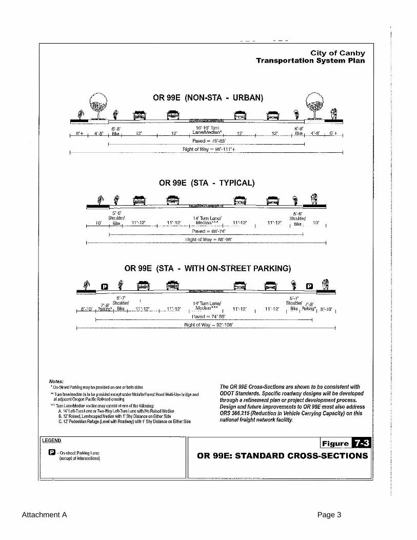
Attachment A Page 3

Attachment A Page 4
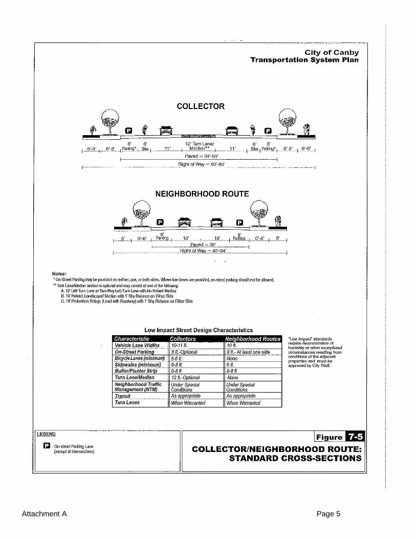
Attachment A Page 5

Attachment A Page 6
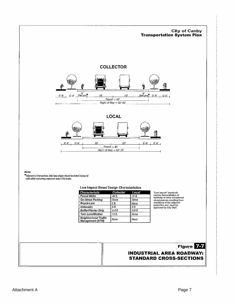
Attachment A Page 7