public works standards - greshamoregon.gov
TRANSCRIPT

Public Works StandardsDesign Standards | Standard Specifications | Standard Details

Public Works Standards
Design Standards
Standard Specifications
Standard Details
January 1, 2019
Revised: January 1, 2020
and March 29, 2021
DEPARTMENT OF ENVIRONMENTAL SERVICES
CITY OF GRESHAM, OREGON
Approved:
Steve Fancher Director


City of Gresham
Department of Environmental Services
1333 NW Eastman Parkway
Gresham, Oregon 97030-3813
503-618-2525
Fax 503-661-5927
www.greshamoregon.gov
PUBLIC WORKS STANDARDS ORDER FORM
Name Title
Organization Department
Address
City State Zip Code
Phone Number Fax Number E-mail Address
Copies Item Unit Price (Each) Total
Public Works Standards Document $75.00
Public Works Standards on CD $25.00
Grand Total:
Send order to: City of Gresham, Department of Environmental Services
1333 NW Eastman Parkway, Gresham, OR 97030-3813

DESIGN STANDARDS TABLE OF CONTENTS
CHAPTER 1 - GENERAL DESIGN
1.01 Authority and Purpose ............................................................................................................ 1
1.02 Definitions ................................................................................................................................ 1
1.03 Engineering Policy .................................................................................................................. 6
1.04 Applicability ............................................................................................................................. 6
1.05 Standard Specifications .......................................................................................................... 6
1.06 Approval of Alternate Materials or Methods ......................................................................... 6
1.07 Special Design Problems ........................................................................................................ 6
1.08 Revisions to Public Works Standards ................................................................................... 7
CHAPTER 2 - GENERAL TECHNICAL DESIGN
2.01 Construction Plan General Information ................................................................................ 1
2.02 CAD Drafting Standards ......................................................................................................... 1
2.03 Existing City As-Built Plans ................................................................................................... 1
2.04 Supporting Information ........................................................................................................... 1
2.04.01 Geotechnical Report ............................................................................................................. 1
2.04.02 Stormwater Report ................................................................................................................ 1
2.04.03 Stormwater Facility Operations and Maintenance Plan ........................................................ 2
2.05 Plan Submittal .......................................................................................................................... 2
2.06 As-Built Plan Requirements ................................................................................................... 2
2.07 Easements ................................................................................................................................ 2
2.07.01 General Utility Easements (GUE) ......................................................................................... 2
2.07.02 Public Utility Easements ........................................................................................................ 2
2.08 Depths of Bury for Pipes ........................................................................................................ 4
2.09 Private Utilities in Rights-of-Way ........................................................................................... 4
2.09.01 Private Utilities on City-owned Poles .................................................................................... 6
CHAPTER 3 - WASTEWATER SYSTEM DESIGN
3.01 General Design Requirements ............................................................................................... 1
3.02 Minimum Design Criteria ........................................................................................................ 1
3.03 Alignment and Cover .............................................................................................................. 3
3.03.01 Right-of-way Location ........................................................................................................... 4
3.03.02 Minimum Depth ..................................................................................................................... 4
3.03.03 Maximum Depth .................................................................................................................... 4

3.03.04 Easements ............................................................................................................................ 4
3.03.05 Separation with Utilities ......................................................................................................... 4
3.03.06 Relation to Watercourses ...................................................................................................... 4
3.04 Pipe Materials and Size ........................................................................................................... 5
3.05 Structures ................................................................................................................................. 5
3.05.01 Access ................................................................................................................................... 5
3.05.02 Manholes ............................................................................................................................... 5
3.05.03 Cleanouts .............................................................................................................................. 6
3.06 Sanitary Sewer Laterals .......................................................................................................... 6
3.07 Connection to Existing Sewers .............................................................................................. 7
3.08 Private Sewer Lines ................................................................................................................. 7
3.09 Subsurface Disposal ............................................................................................................... 7
3.10 Wastewater Pump Station Design Standards ....................................................................... 8
3.10.01 General .................................................................................................................................. 8
3.10.02 Design ................................................................................................................................... 8
3.10.03 Key Components ................................................................................................................... 8
CHAPTER 4 - STORMWATER DRAINAGE SYSTEM DESIGN
4.01 General Design Requirements ............................................................................................... 1
4.02 Minimum Design Criteria ........................................................................................................ 2
4.03 Alignment and Cover .............................................................................................................. 2
4.03.01 Right-of-way Location ........................................................................................................... 2
4.03.02 Minimum Depth ..................................................................................................................... 2
4.03.03 Maximum Depth .................................................................................................................... 3
4.03.04 Easements ............................................................................................................................ 3
4.03.05 Relation to Watercourses ...................................................................................................... 3
4.03.06 Outfalls on Slopes ................................................................................................................. 3
4.04 Pipe Materials and Size ........................................................................................................... 3
4.05 Structures ................................................................................................................................. 4
4.05.01 Access ................................................................................................................................... 4
4.05.02 Manholes ............................................................................................................................... 4
4.05.03 Cleanouts .............................................................................................................................. 4
4.05.04 Stormwater Inlets .................................................................................................................. 5
4.05.05 Outfall Protection ................................................................................................................... 5
4.06 Culverts .................................................................................................................................... 7
4.06.01 Inlet and Outlet Control Analysis ........................................................................................... 7
4.06.02 Headwalls and Endwalls ....................................................................................................... 8
4.07 Conveyance Systems .............................................................................................................. 8

4.07.01 Hydraulic Design ................................................................................................................... 9
4.08 Downstream Analysis Report................................................................................................. 9
4.09 Erosion Prevention and Sediment Control ........................................................................... 9
4.10 Stormwater Flow Control (Detention/Retention) .................................................................. 9
4.11 Stormwater Quality Treatment ............................................................................................... 9
4.12 Open Channel Design ............................................................................................................. 9
4.13 Rear Lot Drainage .................................................................................................................. 10
4.14 Private Storm Drain Systems ............................................................................................... 10
CHAPTER 5 - WATER SYSTEM DESIGN
5.01 General Design Requirements ............................................................................................... 1
5.02 Alignment and Cover .............................................................................................................. 1
5.02.01 Right-of-way Location ........................................................................................................... 2
5.02.02 Minimum Depth ..................................................................................................................... 2
5.02.03 Maximum Depth .................................................................................................................... 2
5.02.04 Separation with Sanitary Sewer Lines .................................................................................. 2
5.02.05 Separation with Utilities Other than Sanitary Sewer Lines.................................................... 3
5.02.06 Easements ............................................................................................................................ 3
5.02.07 Relation to Watercourses ...................................................................................................... 3
5.03 Pipe Materials and Size ........................................................................................................... 3
5.04 Appurtenances ........................................................................................................................ 4
5.04.01 Valves .................................................................................................................................... 4
5.04.02 Fittings ................................................................................................................................... 4
5.04.03 Fire Hydrants ......................................................................................................................... 5
5.04.04 Pressure-reducing and Combination Air Valve Units ............................................................ 5
5.04.05 Railroad or Freeway Crossings ............................................................................................. 6
5.05 Backflow Prevention ............................................................................................................... 6
5.06 Water Service Lines ................................................................................................................ 6
5.07 System Testing ........................................................................................................................ 7
5.08 Water Quality Sampling Stations ........................................................................................... 7
CHAPTER 6 - TRANSPORTATION DESIGN
6.01 General Design Requirements ............................................................................................... 1
6.01.01 Access ................................................................................................................................... 1
6.01.02 Permanent Dead-end Streets ............................................................................................... 1
6.01.03 Traffic Analysis ...................................................................................................................... 2
6.02 Streets ....................................................................................................................................... 5

6.02.01 General .................................................................................................................................. 5
6.02.02 Functional Classification ....................................................................................................... 5
6.02.03 Alleys ..................................................................................................................................... 5
6.02.04 Private Accessways .............................................................................................................. 5
6.02.05 Right-of-way and Pavement Width ........................................................................................ 6
6.02.06 Half-street and Frontage Improvement Construction ............................................................ 7
6.02.07 Pavement Design .................................................................................................................. 7
6.02.08 Design Speed ........................................................................................................................ 8
6.02.09 Horizontal Curves .................................................................................................................. 8
6.02.10 Vertical Curves ...................................................................................................................... 9
6.02.11 Grades ................................................................................................................................... 9
6.02.12 Concrete Curb ....................................................................................................................... 9
6.02.13 Intersections .......................................................................................................................... 9
6.02.14 Curb Return Radius ............................................................................................................ 10
6.02.15 Parking ................................................................................................................................ 11
6.02.16 Local Street Design for Adverse Topography ..................................................................... 11
6.02.17 Streetlighting ....................................................................................................................... 12
6.02.18 Street Trees ......................................................................................................................... 14
6.02.19 Street Names and Traffic Control Signage ......................................................................... 15
6.02.20 Pavement Markings............................................................................................................. 15
6.03 Driveways ............................................................................................................................... 16
6.04 Sidewalks ............................................................................................................................... 17
6.04.01 Sidewalk Width .................................................................................................................... 17
6.04.02 Sidewalk Ramps.................................................................................................................. 17
6.04.03 Asphalt Transition Sidewalk Ramps.................................................................................... 18
6.05 Pedestrian/Bicycle Facilities ................................................................................................ 19
6.05.01 Bicycle Facilities .................................................................................................................. 19
6.05.02 Multi-use Paths and Trails ................................................................................................... 19
CHAPTER 7 - PARKS DESIGN
7.01 General Design Requirements ............................................................................................... 1
7.01.01 General .................................................................................................................................. 1
7.01.02 Park Standard Details and Specifications ............................................................................. 1
7.01.03 Additional Technical Specifications ....................................................................................... 1
7.01.04 Irrigation System Submittals ................................................................................................. 1
7.02 Planning Process .................................................................................................................... 2
7.02.01 Developer Constructed Parks ............................................................................................... 2
7.03 Parkland Descriptions ............................................................................................................. 3

7.03.01 Neighborhood Parks and Pocket Parks ................................................................................ 3
7.03.02 Community Parks .................................................................................................................. 4
7.03.03 Urban Plazas and Town Squares ......................................................................................... 5
7.03.04 Natural Areas and Greenways .............................................................................................. 6
7.03.05 Trails, Trailheads and Multi-Use Paths ................................................................................. 6
7.03.06 Regional Parks ...................................................................................................................... 7
7.04 Design Requirements .............................................................................................................. 8
7.04.01 Grading .................................................................................................................................. 8
7.04.02 Planting ................................................................................................................................. 8
7.04.03 Water, Irrigation, and Drinking Fountains ............................................................................. 8
7.04.04 Lighting .................................................................................................................................. 9
7.04.05 Designing for Maintenance ................................................................................................... 9
7.04.06 Structures .............................................................................................................................. 9
7.04.07 Stairs and Bridges ................................................................................................................. 9
7.04.08 Play Structures .................................................................................................................... 10
7.04.09 Access Roads ..................................................................................................................... 10
7.05 Signage Program ................................................................................................................... 10
7.06 Product Standards ................................................................................................................ 11
7.06.01 Site Furnishing Product Standards ..................................................................................... 11
7.06.02 Restroom Product Standards .............................................................................................. 14
7.06.03 Irrigation Product Standards ............................................................................................... 15

STANDARD SPECIFICATIONS TABLE OF CONTENTS
CHAPTER 100 - GENERAL REQUIREMENTS
101 DEFINITIONS, ABBREVIATIONS, AND PRIVATELY FINANCED PUBLIC
IMPROVEMENT REQUIREMENTS
101.01 Definitions ................................................................................................................................ 1
101.02 Abbreviations ........................................................................................................................... 5
101.03 Applicability of Public Works Standards to Privately Financed Public Improvements ... 5
102 INSTRUCTIONS TO BIDDERS
102.01 Solicitation Protest (Not applicable to privately financed public improvements) ............ 6
102.02 Bid Provisions (Not applicable to privately financed public improvements) .................... 6
102.03 Qualification of Bidders And Contractors (Not applicable to privately financed public
improvements) ......................................................................................................................... 7
102.04 Form of Bid (Not applicable to privately financed public improvements) ......................... 7
102.05 Withdrawal, Modification, Or Alteration of Bid (Not applicable to privately financed
public improvements) ............................................................................................................. 8
102.06 Late Offers (Not applicable to privately financed public improvements) .......................... 8
102.07 Bid Security (Not applicable to privately financed public improvements) ........................ 8
102.08 Addenda (Not applicable to privately financed public improvements).............................. 8
102.09 Examination of The Contract Documents, Site Of Work, And Subsurface Data (Not
applicable to privately financed public improvements) ...................................................... 9
102.10 Familiarity with Laws and Ordinances (Not applicable to privately financed public
improvements) ......................................................................................................................... 9
102.11 Unit Prices (Not applicable to privately financed public improvements) .......................... 9
102.12 Rejection of Offers (Not applicable to privately financed public improvements) ............. 9
102.13 Conflict of Interest (Not applicable to privately financed public improvements) ............. 9
103 LEGAL RELATIONS AND RESPONSIBILITIES
103.01 Applicable Laws and Venue ................................................................................................. 10
103.02 Equal Employment Opportunity/Affirmative Action .......................................................... 10
103.03 Subcontractors ...................................................................................................................... 10
103.04 No Waiver of Legal Rights (Not applicable to privately financed public
improvements) ....................................................................................................................... 10
103.05 Other Contracts ..................................................................................................................... 11
103.06 Liability and Indemnification ................................................................................................ 12
103.07 Insurance (Not applicable to privately financed public improvements) .......................... 12
103.08 Royalties and Patents ........................................................................................................... 14

103.09 Permits .................................................................................................................................... 14
103.10 Sanitary Facilities at Construction Projects ....................................................................... 15
103.11 Compliance with Oregon Revised Statutes Chapters 279a and 279c (Not applicable to
privately financed public improvements) ........................................................................... 15
103.12 Labor ....................................................................................................................................... 16
103.13 Prevailing Wages (Not applicable to privately financed public improvements) ............. 16
103.14 Overtime for City Personnel ................................................................................................. 16
103.15 Safety ...................................................................................................................................... 17
103.16 Two (2) Year Warranty ........................................................................................................... 18
103.17 Street Cut/Dig Moratorium After Major Street Work .......................................................... 19
103.18 Contractor Is Independent Contractor (Not applicable to privately financed public
improvements) ....................................................................................................................... 20
103.19 Successors in Interest .......................................................................................................... 20
103.20 Construction Contractor’s Board ........................................................................................ 20
103.21 Severability............................................................................................................................. 20
103.22 Merger Clause (Not applicable to privately financed public improvements) .................. 21
103.23 No Third-Party Beneficiaries (Not applicable to privately financed public
improvements) ....................................................................................................................... 21
103.24 Examination of The Contract Documents, Site of Work, And Subsurface Data ............. 21
103.25 Familiarity With Laws and Ordinances ............................................................................... 21
104 AWARD AND EXECUTION OF THE CONTRACT
104.01 Award of The Contract (Not applicable to privately financed public improvements) .... 23
104.02 Selection Protest (Not applicable to privately financed public improvements) ............. 23
104.03 Execution Of The Contract (Not applicable to privately financed public
improvements) ....................................................................................................................... 24
104.04 Transfer of The Contract And Interests Therein (Not applicable to privately financed
public improvements) ........................................................................................................... 24
104.05 Performance And Payment Bonds; Warranty Guarantee ................................................. 25
104.06 Certificate of Insurance (Not applicable to privately financed public improvements) ... 25
104.07 Failure To Execute The Contract (Not applicable to privately financed public
improvements) ....................................................................................................................... 25
104.08 Return of Bid Security (Not applicable to privately financed public improvements) ..... 26
105 SCOPE OF WORK
105.01 Plans and Specifications ...................................................................................................... 26
105.02 Precedence of The Contract Documents ............................................................................ 26
105.03 Shop Drawings and Other Submittals (Not applicable to privately financed public
improvements) ....................................................................................................................... 26

105.04 Changes in The Work ............................................................................................................ 28
105.05 Force Account Work (Not applicable to privately financed public improvements) ........ 28
105.06 Salvage ................................................................................................................................... 28
106 PROSECUTION AND PROGRESS OF WORK
106.01 Contractor's Construction Schedule ................................................................................... 28
106.02 Preconstruction Conference ................................................................................................ 29
106.03 Contractor's Representative ................................................................................................ 29
106.04 Notice to Proceed .................................................................................................................. 29
106.05 Contract Time......................................................................................................................... 30
106.06 Suspension of Work .............................................................................................................. 30
106.07 Delays and Extensions of Time (Not applicable to privately financed public
improvements) ....................................................................................................................... 32
106.08 Contract Incentive and Liquidated Damages (Not applicable to privately financed
public improvements) ........................................................................................................... 32
106.09 Record Drawings ................................................................................................................... 33
106.10 Conflicts, Errors, Omissions, and Additional Drawings ................................................... 33
106.11 The City's Right to Do Work ................................................................................................. 33
106.12 Termination for Default (Not applicable to privately financed public improvements) ... 34
106.13 Termination in The Public Interest (Not applicable to privately financed public
improvements) ....................................................................................................................... 35
107 CONTROL OF WORK
107.01 Authority of The Project Manager and Engineer ................................................................ 35
107.02 Authority and Duties of Inspectors ..................................................................................... 36
107.03 Responsibility of The Contractor ......................................................................................... 36
107.04 Notification of Utilities and Agencies .................................................................................. 36
107.05 Utilities and Existing Improvements ................................................................................... 37
107.06 Survey Service ....................................................................................................................... 38
107.07 Protection of Survey Markers ............................................................................................... 38
107.08 Protection of Property ........................................................................................................... 39
107.09 Rights-Of-Way, Easements, and Premises ......................................................................... 39
107.10 Use of Work During Construction........................................................................................ 40
107.11 Furnishing Temporary Services and Facilities................................................................... 40
107.12 Verbal Agreements or Representations .............................................................................. 40
107.13 Environmental Pollution Control ......................................................................................... 40
107.14 Noise ....................................................................................................................................... 41
107.15 Access to The Work .............................................................................................................. 41
107.16 Defective or Unauthorized Work .......................................................................................... 41

107.17 Railroad Crossings or Right-Of-Way ................................................................................... 42
108 CONTROL OF MATERIALS
108.01 Preference for Use of Oregon Products (Not applicable to privately financed public
improvements) ....................................................................................................................... 42
108.02 Quality of Work ...................................................................................................................... 42
108.03 Sampling and Testing ........................................................................................................... 42
108.04 Proof of Compliance ............................................................................................................. 43
108.05 Inspection by Others ............................................................................................................. 43
108.06 Storage and Protection of Items of Work ............................................................................ 43
108.07 Trade Names, Equals, or Substitutions .............................................................................. 43
109 MEASUREMENT AND PAYMENT
109.01 Measurement of Quantities (Not applicable to privately financed public
improvements) ....................................................................................................................... 44
109.02 Scope of Payment (Not applicable to privately financed public improvements) ............ 45
109.03 Compensation for Alteration of The Contract (Not applicable to privately financed
public improvements) ........................................................................................................... 45
109.04 Payment for Change Orders (Not applicable to privately financed public
improvements) ....................................................................................................................... 46
109.05 Claims and Notice (Not applicable to privately financed public improvements) ............ 49
109.06 The City's Right to Access Contractor's Records (Not applicable to privately financed
public improvements) ........................................................................................................... 50
109.07 Payments and Retainage (Not applicable to privately financed public improvements) 51
109.08 Completion, Final Pay Estimate, and Final Payment (Not applicable to privately
financed public improvements) ........................................................................................... 53
CHAPTER 200 - GENERAL TECHNICAL REQUIREMENTS
201 EROSION PREVENTION AND SEDIMENT CONTROL
201.01 Description ............................................................................................................................... 1
201.02 Materials ................................................................................................................................... 1
201.03 Construction ............................................................................................................................ 1
201.04 Measurement and Payment (Not applicable to privately financed public
improvements) ......................................................................................................................... 1
201.04.01 Lump Sum Basis ........................................................................................................... 1
201.04.02 Incidental Basis ............................................................................................................. 1

202 TRAFFIC CONTROL
202.01 Description ............................................................................................................................... 1
202.02 Materials ................................................................................................................................... 1
202.02.01 Uniform Traffic Control Devices .................................................................................... 1
202.03 Construction ............................................................................................................................ 2
202.03.01 General .......................................................................................................................... 2
202.03.02 Traffic Lane and Sidewalk Restriction Requirements ................................................... 4
202.03.03 Traffic Control Plans ...................................................................................................... 5
202.03.04 Construction and Maintenance of Detours .................................................................... 7
202.03.05 Flagging Requirements ................................................................................................. 7
202.04 Measurement and Payment (Not applicable to privately financed public
improvements) ......................................................................................................................... 7
202.04.01 Lump Sum Basis ........................................................................................................... 7
202.04.02 Incidental Basis ............................................................................................................. 7
203 MOBILIZATION
203.01 Description ............................................................................................................................... 7
203.02 Materials ................................................................................................................................... 7
203.03 Construction ............................................................................................................................ 8
203.04 Measurement and Payment (Not applicable to privately financed public
improvements) ......................................................................................................................... 8
203.04.01 Lump Sum Basis ........................................................................................................... 8
203.04.02 Incidental Basis ............................................................................................................. 8
204 CLEARING AND GRUBBING
204.01 Description ............................................................................................................................... 8
204.02 Materials ................................................................................................................................... 9
204.03 Construction ............................................................................................................................ 9
204.03.01 General .......................................................................................................................... 9
204.03.02 Timber Salvage ............................................................................................................. 9
204.03.03 Protection of Existing Vegetation ................................................................................ 10
204.03.04 Protection of Migratory Birds ....................................................................................... 10
204.03.05 Clearing ....................................................................................................................... 10
204.03.06 Clearing Borrow and Waste Disposal Areas ............................................................... 10
204.03.07 Grubbing and Stripping ............................................................................................... 10
204.03.08 Disposal of Waste Material ......................................................................................... 11
204.03.09 Backfilling and Clean-up ............................................................................................. 11
204.03.10 Removal and Replacement of Signs, Mailboxes, Posts, etc. ..................................... 11

204.04 Measurement and Payment (Not applicable to privately financed public
improvements) ....................................................................................................................... 11
204.04.01 Lump Sum Basis ......................................................................................................... 11
204.04.02 Incidental Basis ........................................................................................................... 11
205 MATERIALS - TYPES AND USE
205.01 Description ............................................................................................................................. 11
205.02 Materials ................................................................................................................................. 11
205.02.01 General ........................................................................................................................ 11
205.02.02 Explosives ................................................................................................................... 12
205.02.03 Water ........................................................................................................................... 12
205.02.04 Aggregates .................................................................................................................. 12
205.02.05 Portland Cement ......................................................................................................... 16
205.02.06 Cement Mortar ............................................................................................................ 16
205.02.07 Cement Grout .............................................................................................................. 16
205.02.08 Epoxy Cement ............................................................................................................. 17
205.02.09 Portland Cement Concrete .......................................................................................... 17
205.02.10 Asphalt Materials ......................................................................................................... 20
205.02.11 Geotextiles .................................................................................................................. 20
205.03 Construction .......................................................................................................................... 23
205.03.01 Geotextiles .................................................................................................................. 23
205.04 Measurement and Payment (Not applicable to privately financed public
improvements) ....................................................................................................................... 26
205.04.01 Geotextiles .................................................................................................................. 26
206 EXCAVATION, EMBANKMENT, BEDDING, AND BACKFILL
206.01 Description ............................................................................................................................. 26
206.01.01 General ........................................................................................................................ 26
206.01.02 Unclassified Excavation .............................................................................................. 26
206.01.03 Rock Excavation .......................................................................................................... 26
206.01.04 Trench Excavation ....................................................................................................... 27
206.01.05 Embankment ............................................................................................................... 27
206.01.06 Foundation Stabilization .............................................................................................. 27
206.01.07 Pipe Zone .................................................................................................................... 27
206.01.08 Trench Backfill ............................................................................................................. 27
206.02 Materials ................................................................................................................................. 27
206.02.01 Embankment Materials................................................................................................ 27
206.02.02 Foundation Stabilization .............................................................................................. 28
206.02.03 Pipe Zone Material ...................................................................................................... 28

206.02.04 Native Backfill Material ................................................................................................ 28
206.02.05 Select Backfill Material ................................................................................................ 28
206.02.06 Riprap .......................................................................................................................... 30
206.02.07 Imported Topsoil .......................................................................................................... 31
206.02.08 Native Topsoil .............................................................................................................. 31
206.02.09 Stormwater Facility Topsoil ......................................................................................... 31
206.02.10 Water ........................................................................................................................... 31
206.03 Construction .......................................................................................................................... 31
206.03.01 Excavation ................................................................................................................... 31
206.03.02 Rock Excavation and Explosives ................................................................................ 31
206.03.03 Preservation of Existing Improvements ....................................................................... 32
206.03.04 Excavation of Existing Improvements and Miscellaneous .......................................... 32
206.03.05 Limits of Excavation .................................................................................................... 33
206.03.06 Slope Grading ............................................................................................................. 33
206.03.07 Foundation Stabilization .............................................................................................. 33
206.03.08 Disposal of Excess Material ........................................................................................ 33
206.03.09 Temporary Location of Excavated Materials ............................................................... 33
206.03.10 Surface Removal and Replacement for Trenches ...................................................... 33
206.03.11 Trench Excavation and Shoring .................................................................................. 34
206.03.12 Dewatering .................................................................................................................. 36
206.03.13 Compaction ................................................................................................................. 36
206.03.14 Embankment ............................................................................................................... 37
206.03.15 Pipe or Conduit Bedding and Pipe Zone ..................................................................... 38
206.03.16 Trench Backfill and Compaction ................................................................................. 38
206.03.17 Topsoil ......................................................................................................................... 41
206.04 Measurement and Payment (Not applicable to privately financed public
improvements) ....................................................................................................................... 41
206.04.01 Unclassified Excavation .............................................................................................. 41
206.04.02 Rock Excavation .......................................................................................................... 43
206.04.03 Hard Surface Removal and Replacement for Trenches ............................................. 43
206.04.04 Embankment ............................................................................................................... 43
206.04.05 Foundation Stabilization .............................................................................................. 44
206.04.06 Pipe or Conduit Bedding and Pipe Zone ..................................................................... 44
206.04.07 Riprap .......................................................................................................................... 44
206.04.08 Imported Topsoil .......................................................................................................... 44
206.04.09 Shoring ........................................................................................................................ 44
206.04.10 Dewatering .................................................................................................................. 45

207 BORING AND JACKING
207.01 Description ............................................................................................................................. 45
207.01.01 Boring .......................................................................................................................... 45
207.01.02 Jacking ........................................................................................................................ 45
207.01.03 Permits ........................................................................................................................ 45
207.02 Materials ................................................................................................................................. 45
207.02.01 Pipe Bedding and Pipe Zone Material......................................................................... 45
207.02.02 Pipe ............................................................................................................................. 45
207.02.03 Casing ......................................................................................................................... 45
207.02.04 Grout............................................................................................................................ 46
207.02.05 Stainless Steel Bands ................................................................................................. 46
207.02.06 Supports, Skids, and Casing Spacers ......................................................................... 46
207.03 Construction .......................................................................................................................... 46
207.03.01 General ........................................................................................................................ 46
207.03.02 Excavation ................................................................................................................... 46
207.03.03 Alternate of Jacking or Boring ..................................................................................... 47
207.03.04 Jacking and Boring ...................................................................................................... 47
207.03.05 Concrete Pipe and Box Section .................................................................................. 47
207.03.06 Smooth Steel Casing................................................................................................... 47
207.03.07 Grouting Voids Outside Casing or Carrier Pipe .......................................................... 47
207.03.08 Cased Pipe .................................................................................................................. 48
207.03.09 Grouting Voids Between Carrier Pipe and Casing ...................................................... 48
207.03.10 Railroad Crossings ...................................................................................................... 48
207.03.11 Contractor's Responsibility .......................................................................................... 48
207.04 Measurement and Payment (Not applicable to privately financed public
improvements) ....................................................................................................................... 48
207.04.01 Boring and Jacking ...................................................................................................... 48
207.04.02 Jacking or Boring In Lieu of Open Trench .................................................................. 49
208 CONCRETE STRUCTURES
208.01 Description ............................................................................................................................. 49
208.02 Materials ................................................................................................................................. 49
208.02.01 Portland Cement ......................................................................................................... 49
208.02.02 Aggregates .................................................................................................................. 49
208.03 Construction .......................................................................................................................... 49
208.03.01 General ........................................................................................................................ 49
208.03.02 Mix Design ................................................................................................................... 49
208.03.03 Consistency ................................................................................................................. 50

208.03.04 Measurement of Materials ........................................................................................... 50
208.03.05 Mixing .......................................................................................................................... 51
208.03.06 Falsework .................................................................................................................... 52
208.03.07 Forms .......................................................................................................................... 53
208.03.08 Removal of Falsework and Forms .............................................................................. 53
208.03.09 Weather Limitations ..................................................................................................... 54
208.03.10 Handling and Placing .................................................................................................. 54
208.03.11 Construction Joints ...................................................................................................... 56
208.03.12 Expansion and Fixed Joints ........................................................................................ 56
208.03.13 Surface Finishing ......................................................................................................... 57
208.03.14 Curing .......................................................................................................................... 58
208.03.15 Protection of Concrete................................................................................................. 58
208.04 Measurement And Payment (Not applicable to privately financed public
improvements) ....................................................................................................................... 59
208.04.01 Concrete ...................................................................................................................... 59
209 LANDSCAPING AND LANDSCAPE RESTORATION
209.01 Description ............................................................................................................................. 59
209.02 Materials ................................................................................................................................. 60
209.02.01 Plants .......................................................................................................................... 60
209.02.02 Seed ............................................................................................................................ 60
209.02.03 Sod .............................................................................................................................. 60
209.02.04 Topsoil ......................................................................................................................... 60
209.02.05 Sand ............................................................................................................................ 60
209.02.06 Organic Material for Soil Amendment ......................................................................... 60
209.02.07 Lime ............................................................................................................................. 60
209.02.08 Subdrains .................................................................................................................... 61
209.02.09 Irrigation and Water Systems ...................................................................................... 61
209.02.10 Fertilizer ....................................................................................................................... 61
209.02.11 Mulch and Ground Covers .......................................................................................... 62
209.02.12 Tie-Downs ................................................................................................................... 62
209.02.13 Soil Sterilant ................................................................................................................ 62
209.03 Construction .......................................................................................................................... 62
209.03.01 General ........................................................................................................................ 62
209.03.02 Soil Test ...................................................................................................................... 63
209.03.03 Lawns and Grass ........................................................................................................ 63
209.03.04 Trees, Shrubs, and Ground Cover .............................................................................. 65
209.03.05 Irrigation Systems ........................................................................................................ 68

209.04 Measurement and Payment (Not applicable to privately financed public
improvements) ....................................................................................................................... 69
209.04.01 Incidental Basis ........................................................................................................... 69
209.04.02 Unit Price Basis ........................................................................................................... 69
209.04.03 Lump Sum Basis ......................................................................................................... 69
210 RESURFACING
210.01 Description ............................................................................................................................. 69
210.02 Materials ................................................................................................................................. 69
210.02.01 Asphalt Concrete ......................................................................................................... 69
210.02.02 Pavement Base ........................................................................................................... 69
210.02.03 Forms .......................................................................................................................... 69
210.02.04 Rock Surfacing ............................................................................................................ 69
210.02.05 Subgrade ..................................................................................................................... 69
210.03 Construction .......................................................................................................................... 69
210.03.01 Street Maintenance ..................................................................................................... 69
210.03.02 Temporary Hot or Cold Mix Asphalt ............................................................................ 70
210.03.03 Pavement Base ........................................................................................................... 70
210.03.04 Asphalt Concrete Pavement ....................................................................................... 70
210.03.05 Portland Cement Concrete Pavement ........................................................................ 71
210.03.06 Rock Surfacing ............................................................................................................ 72
210.03.07 Concrete Driveways, Sidewalks, and Curbs ............................................................... 72
210.04 Measurement and Payment (Not applicable to privately financed public
improvements) ....................................................................................................................... 72
210.04.01 Temporary Hot or Cold Mix Asphalt ............................................................................ 72
210.04.02 Rock Surfacing ............................................................................................................ 72
210.04.03 Asphalt Concrete and Portland Cement Pavement Replacement .............................. 72
210.04.04 Sidewalk and Driveway Replacement ......................................................................... 73
210.04.05 Curb Replacement ...................................................................................................... 73
210.04.06 Removal and Replacement of Culverts, Stormwater Lines, or Catch Basins ............. 73
211 RESTORATION AND CLEANUP
211.01 Description ............................................................................................................................. 73
211.02 Materials ................................................................................................................................. 73
211.03 Construction .......................................................................................................................... 74
211.03.01 Surface Dressing ......................................................................................................... 74
211.03.02 Removal of Materials................................................................................................... 74
211.03.03 Cleaning Drains ........................................................................................................... 74
211.03.04 Cleaning Paved Surfaces and Appurtenances ........................................................... 74

211.03.05 Restoring Planted Areas ............................................................................................. 74
211.03.06 Restoring Mobilization, Borrow, and Disposal Areas .................................................. 74
211.03.07 Removal of Signs ........................................................................................................ 74
211.03.08 Restoring Curbs, Sidewalks, and Driveways .............................................................. 75
211.04 Measurement and Payment (Not applicable to privately financed public
improvements) ....................................................................................................................... 75
211.04.01 Lump Sum Basis ......................................................................................................... 75
211.04.02 Incidental Basis ........................................................................................................... 75
CHAPTER 300 - WASTEWATER TECHNICAL REQUIREMENTS
301 PIPES AND FITTINGS
301.01 Description ............................................................................................................................... 1
301.02 Materials ................................................................................................................................... 1
301.02.01 General .......................................................................................................................... 1
301.02.02 Reinforced Concrete Pipe ............................................................................................. 1
301.02.03 Ductile Iron Pipe ............................................................................................................ 5
301.02.04 Polyvinyl Chloride (PVC) Pipe ....................................................................................... 6
301.02.05 High Density Polyethylene (HDPE) Pipe, Solid Wall .................................................... 6
301.02.06 Service Connection Markers ......................................................................................... 8
301.02.07 Cleanouts ...................................................................................................................... 8
301.03 Construction ............................................................................................................................ 8
301.03.01 Excavation and Backfill ................................................................................................. 8
301.03.02 Line and Grade for Gravity and Pressure Sanitary Sewers .......................................... 9
301.03.03 Pipe Distribution and Handling ...................................................................................... 9
301.03.04 Pipe Laying and Jointing of Pipes and Fittings ............................................................. 9
301.03.05 Installation of Sanitary Sewer Laterals, Tees, and Wyes............................................ 11
301.03.06 Service Connection Markers ....................................................................................... 12
301.03.07 Closure Collars ............................................................................................................ 12
301.03.08 Field Fabricated Connections ..................................................................................... 12
301.03.09 Cleanouts .................................................................................................................... 13
301.03.10 Service Risers ............................................................................................................. 13
301.03.11 Testing ......................................................................................................................... 13
301.04 Measurement and Payment (Not applicable to privately financed public
improvements) ....................................................................................................................... 17
301.04.01 Sanitary Sewer Pipe .................................................................................................... 17
301.04.02 Service Risers ............................................................................................................. 18
301.04.03 Tee and Wye Fittings .................................................................................................. 18
301.04.04 Closure Collars ............................................................................................................ 18

301.04.05 Field Fabricated Connections ..................................................................................... 18
301.04.06 Cleanouts .................................................................................................................... 19
301.04.07 Other Items .................................................................................................................. 19
302 MANHOLES AND CONCRETE STRUCTURES
302.01 Description ............................................................................................................................. 19
302.02 Materials ................................................................................................................................. 19
302.02.01 Base Rock ................................................................................................................... 19
302.02.02 Forms .......................................................................................................................... 19
302.02.03 Concrete and Reinforcing Steel .................................................................................. 19
302.02.04 Cement Mortar ............................................................................................................ 19
302.02.05 Manholes ..................................................................................................................... 20
302.02.06 Manhole and Cleanout Frames and Covers ............................................................... 21
302.02.07 Non-shrink Grout ......................................................................................................... 22
302.02.08 Drop Assemblies ......................................................................................................... 22
302.02.09 Concrete Encasement ................................................................................................. 22
302.03 Construction .......................................................................................................................... 22
302.03.01 General ........................................................................................................................ 22
302.03.02 Manholes ..................................................................................................................... 23
302.03.03 Drop Assemblies ......................................................................................................... 24
302.03.04 Pipe Stub-outs from Manholes .................................................................................... 24
302.03.05 Manhole Grade Rings ................................................................................................. 24
302.03.06 Manhole and Cleanout Frames and Covers ............................................................... 24
302.03.07 Vacuum Testing .......................................................................................................... 24
302.03.08 Concrete Encasement ................................................................................................. 25
302.03.09 Anchor Walls ............................................................................................................... 25
302.03.10 Manhole Steps ............................................................................................................ 25
302.03.11 Cleaning ...................................................................................................................... 25
302.04 Measurement and Payment (Not applicable to privately financed public
improvements) ....................................................................................................................... 26
302.04.01 Manholes ..................................................................................................................... 26
302.04.02 Drop Assemblies ......................................................................................................... 26
302.04.03 Tamperproof and Watertight Manhole Frames and Covers........................................ 26
302.04.04 Concrete Encasement ................................................................................................. 26
302.04.05 Anchor Walls ............................................................................................................... 26
302.04.06 Other Items .................................................................................................................. 26
303 WORK ON EXISTING SANITARY SEWER PIPES
303.01 Description ............................................................................................................................. 27
303.02 Materials ................................................................................................................................. 27
303.02.01 Pipe Patch Repair ....................................................................................................... 27
303.03 Construction .......................................................................................................................... 27
303.03.01 Excavation and Backfill ............................................................................................... 27
303.03.02 New Manholes Over Existing Sanitary Sewer Lines ................................................... 27
303.03.03 Connection to Existing Sanitary Sewer Pipe ............................................................... 27
303.03.04 Disconnect and Reconnect Existing Sanitary Sewer Laterals .................................... 28
303.03.05 Removal of Existing Pipes, Manholes, and Appurtenances ....................................... 28
303.03.06 Filling Abandoned Structures ...................................................................................... 28
303.03.07 Existing Manhole Frames and Covers ........................................................................ 28
303.03.08 Permanent Plugs ......................................................................................................... 28
303.03.09 Adjusting Existing Structures to Grade ....................................................................... 29
303.03.10 Reconstruct Manhole Base ......................................................................................... 29
303.03.11 Connect to Existing Structures .................................................................................... 29
303.04 Measurement and Payment (Not applicable to privately financed public
improvements) ....................................................................................................................... 29
303.04.01 New Manholes Over Existing Sanitary Sewer Lines ................................................... 29
303.04.02 Disconnect and Reconnect Existing Sanitary Sewer Laterals .................................... 29
303.04.03 Removal of Existing Pipes, Manholes, and Appurtenances ....................................... 29
303.04.04 Filling Abandoned Structures ...................................................................................... 29
303.04.05 Adjusting Existing Structures to Grade ....................................................................... 30
303.04.06 Reconstruct Manhole Base ......................................................................................... 30
303.04.07 Connect to Existing Structures .................................................................................... 30
303.04.08 Other Items .................................................................................................................. 30
CHAPTER 400 - STORMWATER TECHNICAL REQUIREMENTS
401 PIPES AND FITTINGS
401.01 Description ............................................................................................................................... 1
401.02 Materials ................................................................................................................................... 1
401.02.01 General .......................................................................................................................... 1
401.02.02 Reinforced Concrete Pipe ............................................................................................. 1
401.02.03 Ductile Iron Pipe ............................................................................................................ 1
401.02.04 Polyvinyl Chloride (PVC) Pipe ....................................................................................... 1
401.02.05 High Density Polyethylene (HDPE) Pipe, Solid Wall .................................................... 1
401.02.06 Polypropylene Dual Wall Pipe ....................................................................................... 1

401.03 Construction ............................................................................................................................ 2
401.03.01 Excavation and Backfill ................................................................................................. 2
401.03.02 Line and Grade for Gravity Stormwater Lines ............................................................... 2
401.03.03 Pipe Distribution and Handling ...................................................................................... 2
401.03.04 Pipe Laying and Jointing of Pipes and Fittings ............................................................. 2
401.03.05 Service Connection Markers ......................................................................................... 2
401.03.06 Closure Collars .............................................................................................................. 2
401.03.07 Testing ........................................................................................................................... 3
401.04 Measurement and Payment (Not applicable to privately financed public
improvements) ......................................................................................................................... 4
401.04.01 Stormwater Pipe ............................................................................................................ 4
401.04.02 Closure Collars .............................................................................................................. 4
401.04.03 Field Fabricated Connections ....................................................................................... 4
402 MANHOLES, INLETS, AND CONCRETE STRUCTURES
402.01 Description ............................................................................................................................... 4
402.02 Materials ................................................................................................................................... 4
402.02.01 Base Rock ..................................................................................................................... 4
402.02.02 Forms ............................................................................................................................ 5
402.02.03 Concrete and Reinforcing Steel .................................................................................... 5
402.02.04 Cement Mortar .............................................................................................................. 5
402.02.05 Manholes ....................................................................................................................... 5
402.02.06 Pipes and Fittings .......................................................................................................... 5
402.02.07 Precast Inlets and Catch Basins ................................................................................... 5
402.02.08 Manhole Frames and Covers ........................................................................................ 5
402.02.09 Standard Frames and Grates for Inlets and Catch Basins ........................................... 5
402.02.10 Sedimentation Manhole and Drywell Systems .............................................................. 6
402.02.11 Drop Assemblies ........................................................................................................... 6
402.02.12 Beehive Inlets ................................................................................................................ 6
402.03 Construction ............................................................................................................................ 6
402.03.01 General .......................................................................................................................... 6
402.03.02 Manholes ....................................................................................................................... 7
402.03.03 Pipe Stub-outs from Manholes ...................................................................................... 7
402.03.04 Manhole Grade Rings ................................................................................................... 7
402.03.05 Manhole Frames and Covers ........................................................................................ 7
402.03.06 Vacuum Testing ............................................................................................................ 7
402.03.07 Concrete Encasement ................................................................................................... 7
402.03.08 Installation of Inlets and Catch Basins .......................................................................... 7
402.03.09 Inlet Extensions ............................................................................................................. 7

402.03.10 Manhole Steps .............................................................................................................. 7
402.03.11 Cleaning ........................................................................................................................ 8
402.03.12 Sedimentation Manhole and Drywell Systems .............................................................. 8
402.04 Measurement and Payment (Not applicable to privately financed public
improvements) ......................................................................................................................... 8
402.04.01 Manholes ....................................................................................................................... 8
402.04.02 Tamperproof and Watertight Manhole Frames and Covers.......................................... 8
402.04.03 Concrete Encasement ................................................................................................... 8
402.04.04 Catch Basins and Inlets ................................................................................................ 8
402.04.05 Sedimentation Manhole and Drywell Systems .............................................................. 8
402.04.06 Other Items .................................................................................................................... 9
403 WORK ON EXISTING STORMWATER DRAINAGE STRUCTURES
403.01 Description ............................................................................................................................... 9
403.02 Materials ................................................................................................................................... 9
403.03 Construction ............................................................................................................................ 9
403.03.01 Excavation and Backfill ................................................................................................. 9
403.03.02 New Manholes Over Existing Stormwater Lines ........................................................... 9
403.03.03 Removal of Existing Pipes, Manholes, and Appurtenances ......................................... 9
403.03.04 Filling Abandoned Structures ........................................................................................ 9
403.03.05 Existing Manhole Frames and Covers .......................................................................... 9
403.03.06 Permanent Plugs ........................................................................................................... 9
403.03.07 Adjusting Existing Structures to Grade ....................................................................... 10
403.03.08 Reconstruct Manhole Base ......................................................................................... 10
403.03.09 Connect to Existing Structures .................................................................................... 10
403.03.10 Drywell Protection ....................................................................................................... 10
403.03.11 Sedimentation Manhole and Drywell System Retrofits ............................................... 10
403.04 Measurement and Payment (Not applicable to privately financed public
improvements) ....................................................................................................................... 10
403.04.01 New Manholes Over Existing Stormwater Lines ......................................................... 10
403.04.02 Removal of Existing Pipes, Manholes, and Appurtenances ....................................... 10
403.04.03 Filling Abandoned Structures ...................................................................................... 10
403.04.04 Adjusting Existing Structures to Grade ....................................................................... 10
403.04.05 Reconstruct Manhole Base ......................................................................................... 11
403.04.06 Connect to Existing Structures .................................................................................... 11
403.04.07 Drywell Protection ....................................................................................................... 11
403.04.08 Sedimentation Manhole and Drywell System Retrofits ............................................... 11
403.04.09 Other Items .................................................................................................................. 11
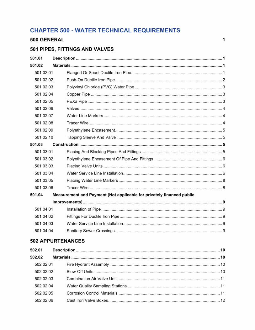
CHAPTER 500 - WATER TECHNICAL REQUIREMENTS
500 GENERAL 1
501 PIPES, FITTINGS AND VALVES
501.01 Description ............................................................................................................................... 1
501.02 Materials ................................................................................................................................... 1
501.02.01 Flanged Or Spool Ductile Iron Pipe ............................................................................... 1
501.02.02 Push-On Ductile Iron Pipe ............................................................................................. 2
501.02.03 Polyvinyl Chloride (PVC) Water Pipe ............................................................................ 3
501.02.04 Copper Pipe .................................................................................................................. 3
501.02.05 PEXa Pipe ..................................................................................................................... 3
501.02.06 Valves ............................................................................................................................ 4
501.02.07 Water Line Markers ....................................................................................................... 4
501.02.08 Tracer Wire .................................................................................................................... 4
501.02.09 Polyethylene Encasement ............................................................................................. 5
501.02.10 Tapping Sleeve And Valve ............................................................................................ 5
501.03 Construction ............................................................................................................................ 5
501.03.01 Placing And Blocking Pipes And Fittings ...................................................................... 5
501.03.02 Polyethylene Encasement Of Pipe And Fittings ........................................................... 6
501.03.03 Placing Valve Units ....................................................................................................... 6
501.03.04 Water Service Line Installation ...................................................................................... 6
501.03.05 Placing Water Line Markers .......................................................................................... 8
501.03.06 Tracer Wire .................................................................................................................... 8
501.04 Measurement and Payment (Not applicable for privately financed public
improvements) ......................................................................................................................... 9
501.04.01 Installation of Pipe ......................................................................................................... 9
501.04.02 Fittings For Ductile Iron Pipe ......................................................................................... 9
501.04.03 Water Service Line Installation ...................................................................................... 9
501.04.04 Sanitary Sewer Crossings ............................................................................................. 9
502 APPURTENANCES
502.01 Description ............................................................................................................................. 10
502.02 Materials ................................................................................................................................. 10
502.02.01 Fire Hydrant Assembly ................................................................................................ 10
502.02.02 Blow-Off Units ............................................................................................................. 10
502.02.03 Combination Air Valve Unit ......................................................................................... 11
502.02.04 Water Quality Sampling Stations ................................................................................ 11
502.02.05 Corrosion Control Materials ........................................................................................ 11
502.02.06 Cast Iron Valve Boxes ................................................................................................. 12

502.02.07 Meter Boxes And Cover .............................................................................................. 13
502.02.08 2-Inch Service Saddles ............................................................................................... 13
502.03 Construction .......................................................................................................................... 13
502.03.01 Placing Fire Hydrant Assemblies ................................................................................ 13
502.03.02 Placing Permanent Blow-Off Assemblies ................................................................... 14
502.03.03 Placing Combination Air Valve Units ........................................................................... 14
502.03.04 Corrosion Control Installation ...................................................................................... 14
502.03.05 Backflow Prevention Assemblies ................................................................................ 16
502.04 Measurement and Payment (Not applicable for privately financed public
improvements) ....................................................................................................................... 18
502.04.01 Fire Hydrant Assembly ................................................................................................ 18
502.04.02 Blow-Off Assemblies ................................................................................................... 18
502.04.03 Combination Air Valve Unit ......................................................................................... 18
502.04.04 Water Quality Sampling Station .................................................................................. 19
502.04.05 Corrosion Control ........................................................................................................ 19
503 WORK ON WATER SYSTEMS
503.01 Description ............................................................................................................................. 19
503.02 Construction .......................................................................................................................... 19
503.02.01 Storage Of Equipment And Materials .......................................................................... 19
503.02.02 Water Line Tapping ..................................................................................................... 19
503.02.03 Removing Existing Water Works Materials ................................................................. 20
503.02.04 Abandoning Existing Mains And Valves...................................................................... 20
503.02.05 Maintaining Service ..................................................................................................... 20
503.02.06 Flushing ....................................................................................................................... 20
503.02.07 Pressure Testing ......................................................................................................... 22
503.02.08 Chlorination ................................................................................................................. 23
503.02.09 Cut-In And Connection To Existing Mains .................................................................. 23
503.02.10 Impervious Dams ........................................................................................................ 24
503.03 Measurement and Payment (Not applicable for privately financed public
improvements) ....................................................................................................................... 24
503.03.01 Cut-In And Connection To Existing Main .................................................................... 24
503.03.02 Water Line Tapping ..................................................................................................... 25
503.03.03 Abandoning Existing Main And Valves ....................................................................... 25
503.03.04 Over-Excavation .......................................................................................................... 25
503.03.05 Other Items .................................................................................................................. 25
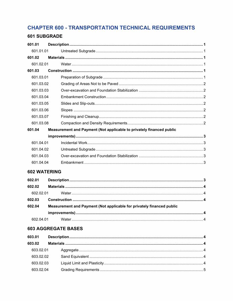
CHAPTER 600 - TRANSPORTATION TECHNICAL REQUIREMENTS
601 SUBGRADE
601.01 Description ............................................................................................................................... 1
601.01.01 Untreated Subgrade ...................................................................................................... 1
601.02 Materials ................................................................................................................................... 1
601.02.01 Water ............................................................................................................................. 1
601.03 Construction ............................................................................................................................ 1
601.03.01 Preparation of Subgrade ............................................................................................... 1
601.03.02 Grading of Areas Not to be Paved ................................................................................ 2
601.03.03 Over-excavation and Foundation Stabilization ............................................................. 2
601.03.04 Embankment Construction ............................................................................................ 2
601.03.05 Slides and Slip-outs....................................................................................................... 2
601.03.06 Slopes ........................................................................................................................... 2
601.03.07 Finishing and Cleanup................................................................................................... 2
601.03.08 Compaction and Density Requirements........................................................................ 2
601.04 Measurement and Payment (Not applicable to privately financed public
improvements) ......................................................................................................................... 3
601.04.01 Incidental Work .............................................................................................................. 3
601.04.02 Untreated Subgrade ...................................................................................................... 3
601.04.03 Over-excavation and Foundation Stabilization ............................................................. 3
601.04.04 Embankment ................................................................................................................. 3
602 WATERING
602.01 Description ............................................................................................................................... 3
602.02 Materials ................................................................................................................................... 4
602.02.01 Water ............................................................................................................................. 4
602.03 Construction ............................................................................................................................ 4
602.04 Measurement and Payment (Not applicable for privately financed public
improvements) ......................................................................................................................... 4
602.04.01 Water ............................................................................................................................. 4
603 AGGREGATE BASES
603.01 Description ............................................................................................................................... 4
603.02 Materials ................................................................................................................................... 4
603.02.01 Aggregate ...................................................................................................................... 4
603.02.02 Sand Equivalent ............................................................................................................ 4
603.02.03 Liquid Limit and Plasticity .............................................................................................. 4
603.02.04 Grading Requirements .................................................................................................. 5

603.02.05 Acceptance .................................................................................................................... 5
603.03 Construction ............................................................................................................................ 5
603.03.01 Preparation of Subgrade ............................................................................................... 5
603.03.02 Mixing ............................................................................................................................ 5
603.03.03 Placing ........................................................................................................................... 5
603.03.04 Compaction ................................................................................................................... 6
603.03.05 Surface Finish ............................................................................................................... 6
603.04 Measurement and Payment (Not applicable to privately financed public
improvements) ......................................................................................................................... 6
603.04.01 Aggregate Bases ........................................................................................................... 6
604 CEMENT-TREATED BASE
604.01 Description ............................................................................................................................... 6
604.02 Materials ................................................................................................................................... 7
604.02.01 Aggregate ...................................................................................................................... 7
604.02.02 Portland Cement ........................................................................................................... 7
604.02.03 Water ............................................................................................................................. 7
604.02.04 Asphalt Materials ........................................................................................................... 7
604.02.05 Mix Design and Certification ......................................................................................... 7
604.03 Construction ............................................................................................................................ 8
604.03.01 Mixture ........................................................................................................................... 8
604.03.02 Weather Limitations ....................................................................................................... 8
604.03.03 Equipment ..................................................................................................................... 8
604.03.04 Hauling and Placing ...................................................................................................... 9
604.03.05 Thickness and Number of Layers ................................................................................. 9
604.03.06 Construction Joints ........................................................................................................ 9
604.03.07 Compaction ................................................................................................................. 10
604.03.08 Surface Finish ............................................................................................................. 10
604.03.09 Bituminous Curing Seal ............................................................................................... 10
604.03.10 Care of Work ............................................................................................................... 11
604.03.11 Modification of Equipment and Methods ..................................................................... 11
604.03.12 Timing of Operations, Adequacy of Organization, and Rejection of Mixture .............. 11
604.03.13 Handling Traffic Over Cement-Treated Base .............................................................. 11
604.03.14 Testing ......................................................................................................................... 11
604.04 Measurement And Payment (Not applicable to privately financed public
improvements) ....................................................................................................................... 12
604.04.01 Cement-Treated Base ................................................................................................. 12
604.04.02 Bituminous Curing Seal ............................................................................................... 12

605 ASPHALT CONCRETE PAVEMENT
605.01 Description ............................................................................................................................. 12
605.02 Materials ................................................................................................................................. 13
605.02.01 General ........................................................................................................................ 13
605.02.02 Asphalt Cement ........................................................................................................... 13
605.02.03 Aggregates .................................................................................................................. 13
605.02.04 Mineral Filler ................................................................................................................ 13
605.02.05 Additives ...................................................................................................................... 13
605.02.06 Composition and Proportion of Mixtures ..................................................................... 13
605.02.07 Mix Formulas ............................................................................................................... 14
605.02.08 Recycled Asphalt Pavement (RAP) Materials Permitted ............................................ 14
605.02.09 Tolerances ................................................................................................................... 15
605.02.10 Feathering ................................................................................................................... 15
605.03 Construction .......................................................................................................................... 15
605.03.01 Pre-paving Conference ............................................................................................... 15
605.03.02 Preparation of Bases ................................................................................................... 15
605.03.03 Reconditioning Old Roadbed ...................................................................................... 16
605.03.04 Tack Coat .................................................................................................................... 16
605.03.05 Mixing .......................................................................................................................... 16
605.03.06 Placing ......................................................................................................................... 16
605.03.07 Protection of Structures ............................................................................................... 17
605.03.08 Paving Plant Equipment .............................................................................................. 17
605.03.09 Weigh Scales .............................................................................................................. 17
605.03.10 Hauling Equipment ...................................................................................................... 17
605.03.11 Asphalt Concrete Pavers ............................................................................................ 18
605.03.12 Weather Limitations ..................................................................................................... 18
605.03.13 Compaction ................................................................................................................. 18
605.03.14 Compactors ................................................................................................................. 18
605.03.15 Density Requirements ................................................................................................. 19
605.03.16 Transverse Joints ........................................................................................................ 20
605.03.17 Longitudinal Joints ....................................................................................................... 20
605.03.18 Thickness and Number of Layers ............................................................................... 21
605.03.19 Pavement Samples ..................................................................................................... 21
605.03.20 Pavement Smoothness ............................................................................................... 21
605.03.21 Special Protection Under Traffic ................................................................................. 21

605.04 Measurement and Payment (Not applicable to privately financed public
improvements) ....................................................................................................................... 22
605.04.01 Asphalt Concrete on Ton Basis ................................................................................... 22
605.04.02 Asphalt Concrete on Square Yard Basis..................................................................... 22
606 PORTLAND CEMENT CONCRETE PAVEMENT
606.01 Description ............................................................................................................................. 23
606.02 Materials ................................................................................................................................. 23
606.03 Construction .......................................................................................................................... 23
606.03.01 General ........................................................................................................................ 23
606.03.02 Preparation of Concrete Mix ....................................................................................... 23
606.03.03 Hauling ........................................................................................................................ 24
606.03.04 Forms .......................................................................................................................... 24
606.03.05 Handling and Placing .................................................................................................. 24
606.03.06 Preparation of Roadway .............................................................................................. 25
606.03.07 Weather Limitations ..................................................................................................... 25
606.03.08 Slip Form Paving ......................................................................................................... 25
606.03.09 Tamping and Screeding .............................................................................................. 26
606.03.10 Finishing ...................................................................................................................... 26
606.03.11 Joints ........................................................................................................................... 27
606.03.12 Tolerances ................................................................................................................... 27
606.03.13 Curing and Protection of Concrete .............................................................................. 27
606.04 Measurement and Payment (Not applicable to privately financed public
improvements) ....................................................................................................................... 27
606.04.01 Portland Cement Concrete Pavement ........................................................................ 27
607 CURBS, GUTTERS, DRIVEWAYS, AND SIDEWALKS
607.01 Description ............................................................................................................................. 28
607.02 Materials ................................................................................................................................. 28
607.02.01 General ........................................................................................................................ 28
607.02.02 Portland Cement Concrete .......................................................................................... 28
607.02.03 Aggregate .................................................................................................................... 28
607.02.04 Wire Fabric Reinforcement ......................................................................................... 29
607.03 Construction .......................................................................................................................... 29
607.03.01 Preparation of Base..................................................................................................... 29
607.03.02 Forms .......................................................................................................................... 29
607.03.03 Equipment ................................................................................................................... 29
607.03.04 Placing Material ........................................................................................................... 30
607.03.05 Finishing ...................................................................................................................... 30

607.03.06 Curing Portland Cement Concrete .............................................................................. 31
607.03.07 Joints in Portland Cement Concrete ........................................................................... 31
607.03.08 Dowels, Tie Bars, and Reinforcing .............................................................................. 32
607.04 Measurement and Payment (Not applicable to privately financed public
improvement projects) .......................................................................................................... 32
607.04.01 Curbs ........................................................................................................................... 32
607.04.02 Combination Curb and Gutter ..................................................................................... 32
607.04.03 Sidewalks and Pathways ............................................................................................ 32
607.04.04 Concrete Valley Gutter ................................................................................................ 32
607.04.05 Median Islands ............................................................................................................ 32
607.04.06 Driveways .................................................................................................................... 33
607.04.07 Sawed Joints ............................................................................................................... 33
607.04.08 Aggregate Base ........................................................................................................... 33
608 GEOTEXTILE FABRICS
608.01 Description ............................................................................................................................. 33
608.02 Materials ................................................................................................................................. 33
608.03 Construction .......................................................................................................................... 33
608.03.01 General ........................................................................................................................ 33
608.03.02 Subgrade Geotextile.................................................................................................... 33
608.03.03 Pavement Overlay Geotextile ..................................................................................... 33
608.04 Measurement and Payment (Not applicable to privately financed public
improvements) ....................................................................................................................... 35
609 COLD PLANE PAVEMENT REMOVAL
609.01 Description ............................................................................................................................. 35
609.02 Construction .......................................................................................................................... 35
609.02.01 Equipment ................................................................................................................... 35
609.02.02 Pavement Removal ..................................................................................................... 35
609.02.03 Surface Tolerance ....................................................................................................... 35
609.02.04 Disposal of Materials ................................................................................................... 36
609.03 Measurement and Payment (Not applicable to privately financed public
improvements) ....................................................................................................................... 36
610 ADJUSTMENT OF STRUCTURES TO GRADE
610.01 Description ............................................................................................................................. 36
610.02 Materials ................................................................................................................................. 36
610.03 Construction .......................................................................................................................... 36
610.03.01 General ........................................................................................................................ 36

610.03.02 Salvage of Existing Structures .................................................................................... 36
610.03.03 Raising Tops of Masonry Structures ........................................................................... 37
610.03.04 Lowering Tops of Masonry Structures ........................................................................ 37
610.03.05 Adjusting Metal Structures .......................................................................................... 37
610.04 Measurement and Payment (Not applicable to privately financed public
improvements) ....................................................................................................................... 37
610.04.01 Adjustment of Structures to Grade .............................................................................. 37

STANDARD DETAILS TABLE OF CONTENTS
Drawing Number GENERAL
201 Standard Manhole for 27” and Lesser Diameter Pipes
202 Standard Manhole for 30” and Larger Diameter Pipes
203 Shallow Manhole for 27” and Lesser Diameter Pipes
204 Cast-in-Place Manhole
205 Standard Manhole Frame
206 Suburban Manhole Frame
207 Tamperproof and Watertight Manhole Frame
208 Off-road Elevated Frame Assembly (HINGE)
209 Off-road Elevated Frame Assembly (PIN)
210 Manhole Step
211 Standard Cleanout
212 Pipe Anchor Wall
213 Pipe Concrete Encasement
214 Trench and Backfill
Drawing Number WASTEWATER
301 Standard Inside Drop Manhole
302 Shallow Inside Drop Manhole
303 Standard Wastewater Manhole Cover
304 Wastewater Tamperproof and Watertight Manhole Cover
305 Wastewater Manhole, Off-road Elevated Cover (HINGE)
306 Wastewater Manhole, Off-road Elevated Cover (PIN)
307 Sanitary Sewer Lateral
308 Tap in Existing Main for Sanitary Sewer Lateral
309 Wastewater Connection, 3 or 4 Lots with Private Easements
310 Joint Detail Reinforced Concrete (T=less than 4 5/8”)
311 Joint Detail Reinforced Concrete (T=4 5/8” and Larger)
312 Typical Joint Detail and Data Form
Drawing Number STORMWATER
401A Catch Basin
401B Catch Basin Section
401C Catch Basin Frame and Grate
401D Double Catch Basin
401E Catch Basin with P-45 Grate
401F Modified Catch Basin Frame with Single P-45 Grate
402 Non-Grated Catch Basin
403A Ditch Inlet Type D - 30°
403B Ditch Inlet Type D - 15°
403C Ditch Inlet Frame and Grate
404A Inlet-Manhole Standard
404B Inlet-Manhole Combination Curb Inlet
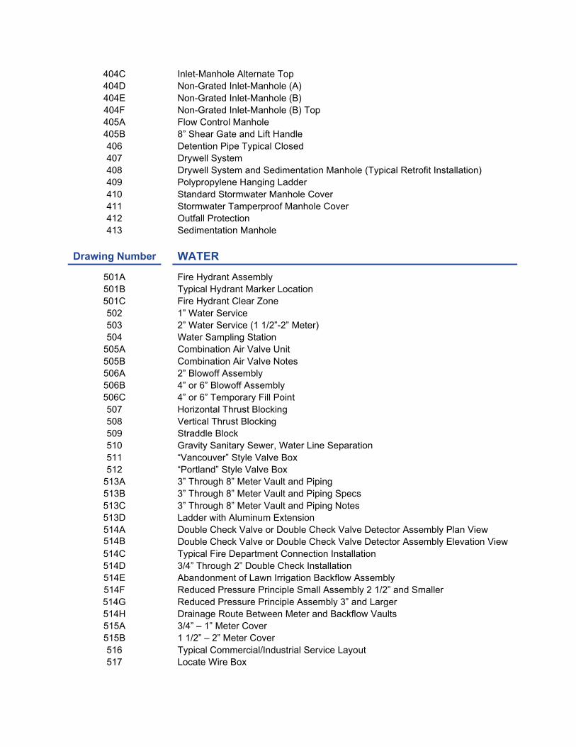
404C Inlet-Manhole Alternate Top
404D Non-Grated Inlet-Manhole (A)
404E Non-Grated Inlet-Manhole (B)
404F Non-Grated Inlet-Manhole (B) Top
405A Flow Control Manhole
405B 8” Shear Gate and Lift Handle
406 Detention Pipe Typical Closed
407 Drywell System
408 Drywell System and Sedimentation Manhole (Typical Retrofit Installation)
409 Polypropylene Hanging Ladder
410 Standard Stormwater Manhole Cover
411 Stormwater Tamperproof Manhole Cover
412 Outfall Protection
413 Sedimentation Manhole
Drawing Number WATER
501A Fire Hydrant Assembly
501B Typical Hydrant Marker Location
501C Fire Hydrant Clear Zone
502 1” Water Service
503 2” Water Service (1 1/2”-2” Meter)
504 Water Sampling Station
505A Combination Air Valve Unit
505B Combination Air Valve Notes
506A 2” Blowoff Assembly
506B 4” or 6” Blowoff Assembly
506C 4” or 6” Temporary Fill Point
507 Horizontal Thrust Blocking
508 Vertical Thrust Blocking
509 Straddle Block
510 Gravity Sanitary Sewer, Water Line Separation
511 “Vancouver” Style Valve Box
512 “Portland” Style Valve Box
513A 3” Through 8” Meter Vault and Piping
513B 3” Through 8” Meter Vault and Piping Specs
513C 3” Through 8” Meter Vault and Piping Notes
513D Ladder with Aluminum Extension
514A Double Check Valve or Double Check Valve Detector Assembly Plan View
514B Double Check Valve or Double Check Valve Detector Assembly Elevation View
514C Typical Fire Department Connection Installation
514D 3/4” Through 2” Double Check Installation
514E Abandonment of Lawn Irrigation Backflow Assembly
514F Reduced Pressure Principle Small Assembly 2 1/2” and Smaller
514G Reduced Pressure Principle Assembly 3” and Larger
514H Drainage Route Between Meter and Backflow Vaults
515A 3/4” – 1” Meter Cover
515B 1 1/2” – 2” Meter Cover
516 Typical Commercial/Industrial Service Layout
517 Locate Wire Box

Drawing Number TRANSPORTATION
601 Typical Utility Placement
602A Gravel Public Access Road
602B Paved Public Access Road
603 Alley Street Section
604 Minor Access Street Section
605 Local Street Sections
606 Collector Street Sections
607 Arterial Street Sections
608 Shared Street Section
609 Downtown/Civic Local Street Section
610 Civic Connector Street Section
611 Downtown Main (Powell to 4th) Street Section
612 Downtown Stanley Street Section
613 Roberts (Powell to Regner) Street Section
614 Boulevard
615 Standard Cul-de-sac
616 Branch Turnaround
617 Eyebrow Corner
618 Driveway Approach
619 Curb Return Driveway Approach
620 Monolithic Curb and Gutter
621 Type ‘C’ Curb
622 Mountable Curb
623 Typical Sidewalk
624 Sidewalk Ramp
625 Corner Curb Extension
626 Multi-Use Path / Trail
627 Bollard
628 End of Road Markers
629 End of Sidewalk Marker
630 Street Barricade
631 Standard Signpost
632 Sign Attachment
633 Street Name Signs
634 Standard 8” Monument Box
635 Speed Bump
636 Median Island Signing, Striping and Marking
637 Overlay Notching
638 Manhole Frame Adjustment
639 Trench Pavement Restoration
640 PCC Pavement Restoration
641 Town Center Street Tree
642 Street Tree Planting
643 Fiberglass Streetlight
644 Aluminum Davit Streetlight
645 Decorative Acorn Streetlight
646 Decorative Pendant Streetlight
647 Luminaire Mounted on Wood Pole
648 Electrical Junction Boxes

649 Streetlight Service Disconnect and Conduit System
650 Streetlight Electrical Service Pedestal
651 Signal Communications Conduit
Drawing Number PARKS
701 Trash Receptacle
Drawing Number GREEN STREET
GS-101 Planter Plan View
GS-102 Planter Section View
GS-103 Planter Wall and Modified Curb
GS-104 Concrete Curb Inlet
GS-105 Concrete Check Dam
GS-106 Liner Attachment and Pipe Boot
GS-107 Underdrain and Rock Requirements
GS-108 Beehive Overflow
GS-109 Stormwater Facility, Meter and Hydrant Locations
GS-110 Stormwater Facility Residential Driveway Approach
GS-111 Stormwater Tree Well with Structural Soil

City of Gresham PWS Version March 2021 Design Standards
Public Works Standards
DESIGN STANDARDS
DEPARTMENT OF ENVIRONMENTAL SERVICES
CITY OF GRESHAM, OREGON

City of Gresham General Design PWS Version March 2021 Design Standards Chapter 1 – Page 1 (Last Revised January 2019)
CHAPTER 1 - GENERAL DESIGN
1.01 AUTHORITY AND PURPOSE
The City of Gresham has a Gresham Community Development Plan that regulates land use
and development issues within the City. This comprehensive planning document consists of five volumes
which are periodically amended by the Gresham City Council following a public process. Volume 3, titled
Gresham Community Development Code, consists of thirteen articles defining separate development
standards. Appendix 5.000 – Public Facilities discusses generalized public facility design requirements and
requires compliance with the Public Works Standards, which includes the Design Standard, the Standard
Specifications and the Standard Details. Chapters One through Seven of the Public Works Standards
shall be known as the Design Standards.
The purpose of these Design Standards is to provide a consistent policy under which certain
physical aspects of public facility design shall be implemented. Most of the elements contained in this
document are public works oriented and it is intended that they apply to both publicly financed public
improvements under City contract and privately financed public improvements under private contract
designated herein.
These Design Standards cannot provide for all situations. They are intended to assist but not
to substitute for competent work by design professionals. It is expected that engineers will bring to each
project the best skills from their respective disciplines.
The Design Standards are also not intended to unreasonably limit any innovative or creative
effort that could result in better quality, better cost savings, or both. Any proposed departure from the Design
Standards will be judged, however, on the likelihood that such variance will produce a compensating or
comparable result to that of the Design Standard.
Alternate materials and methods will be considered for approval by the Engineer as the need
arises and conditions warrant modification. This consideration will be on a case-by-case basis and require
sufficient justification prior to approval.
1.02 DEFINITIONS
As-Built Plans Plans signed and dated by the Engineer of Record indicating that the plans have been reviewed and revised, if necessary, to accurately show all as-built construction. Also referred to as record drawings.
Building Sewer A private wastewater service between the property line or public easement line connecting to the sanitary sewer lateral and a point 5-feet outside the building.
CAD Computer aided design.
City The City of Gresham, a municipal corporation of the State of Oregon, and its elected officials, officers, employees, volunteers and agents.
Datum, Horizontal The horizontal control network of the City was adjusted to the North American Datum 83(91) (NAD83(91)) expressed in Oregon North Zone State Plane Coordinates in international feet.
Datum, Vertical The vertical elevation control for the City is "The National Geodetic Vertical Datum of 1929" (NAD29) that corresponds to the USC&GS 1947 Datum.

City of Gresham General Design PWS Version March 2021 Design Standards Chapter 1 – Page 2 (Last Revised January 2019)
Dead-end Street A street or series of streets that can be accessed from only one point. Dead-end streets can be either temporary (intended for future extension as part of a future street plan) or permanent.
Demand The total quantity of water supplied for a given period of time to meet the various required uses. The various uses include residential, irrigation, commercial, and industrial uses as well as firefighting, system losses, and other unaccounted for or miscellaneous uses.
Design Storm A rainfall event of a specified duration (e.g., 6-hour, 12-hour, 24-hour) and return frequency (e.g., 2-years, 10-years, etc.) that is used to calculate the runoff volume and/or discharge rate to be used for stormwater system design.
Detention The storage and subsequent release of excess stormwater runoff to control peak discharge rates prior to discharge to the storm drain or natural drainageway.
Detention Volume The storage volume required to control the peak discharge rates at the point of discharge from a development.
Development Any human-made change to improved or unimproved real estate, including but not limited to construction, installation, or alteration of buildings or other structures, condominium conversion, land division, establishment or termination of a right of access, storage on real property, tree removal, drilling and site alteration such as land surface mining, dredging, filling, grading, paving, excavation or clearing.
Domestic Wastewater The liquid and water-borne waste derived from the ordinary living processes, free from industrial wastes, and of such character to permit satisfactory disposal, without special treatment, into the public wastewater system or by means of private wastewater disposal system.
Double Check Valve Detector Assembly
A line-sized, approved double check valve assembly with a parallel meter and meter-sized, approved double check valve assembly. The purpose of this assembly is to provide backflow protection for the distribution system and, at the same time, provide a metering of the fire system showing any system leakage or unauthorized use of water.
Double Check Valve Assembly
An assembly composed of two single, independently acting approved check valves, including tightly closing shut-off valves located at each end of the assembly and fitted with properly located test cocks.
Drainage Facilities Pipes, ditches, detention basins, creeks, culverts, bridges, etc., used singularly or in combination with each other for the purpose of conveying or storing stormwater runoff.
Drywell A drainage facility (or system) designed to utilize the infiltration capability of the ground, commonly referred to as percolation, to dispose of surface and stormwater runoff.
Easement The recorded right that allows others to use a defined area of property for specific purpose(s), such as access or utilities.
Engineer The applicable City Department of Environmental Services division manager, or designee, who is licensed as a registered professional engineer in the State of Oregon.

City of Gresham General Design PWS Version March 2021 Design Standards Chapter 1 – Page 3 (Last Revised January 2019)
Engineer of Record A registered professional engineer licensed to practice in the State of Oregon who is responsible for the design of a public improvement project and has stamped the plans.
Expansion Joint A joint to control cracking in the concrete surface structure and is filled with preformed expansion joint filler.
Fire Service Line A metered connection to the public water main intended only for the extinguishment of fires and the flushing necessary for its proper maintenance.
Grade The degree of inclination of a road or slope.
Hydrant Lead The waterline connecting the fire hydrant to the auxiliary valve on the City distribution main.
Impervious Area Those hard surface areas that either prevent or retard saturation of water into the land surface, as existed under natural conditions pre-existent to development, and cause water to run off the land surface in greater quantities or at an increased rate of flow from that present under natural conditions pre-existent to development.
Industrial Waste Solid, liquid, or gaseous waste resulting from any industrial, manufacturing, trade, or business process from development, recovery, or processing of natural resources.
Irrigation Service A metered connection intended for seasonal use and delivering water that is not discharged to the wastewater system.
Longitudinal Joint A joint, which follows a course approximately parallel to the centerline of the roadway.
Manager The City Manager of the City of Gresham acting either directly or through authorized representatives.
Natural Grade The grade of the land in an undisturbed state.
OnSite Detention The detention of stormwater from a private storm drain in a privately owned and maintained storm drain system to provide a controlled release, at or below a maximum allowable rate, to the public storm drain system.
Outfall The point at which collected, concentrated stormwater is discharged, generally from a pipe(s), from a development to an open drainage element such as a ditch, channel, swale, stream, river, pond, lake or wetland.
Owner The owner of record of real property as shown on the latest tax rolls or deed records of the County and includes a person who furnishes evidence that he is purchasing a parcel of property under a written recorded land sale contract.
Partition To divide land into 2 or 3 parcels of land within a calendar year.
Peak Runoff The maximum stormwater runoff rate (CFS) determined for the design storm or design rainfall intensity.
Person Individual, firm, corporation, association, agency, or other entity.

City of Gresham General Design PWS Version March 2021 Design Standards Chapter 1 – Page 4 (Last Revised January 2019)
Plans The Standard Details or reproductions thereof and project specific plans, profiles, cross sections, elevations, details, and other working or supplementary drawings signed by the Engineer of Record that show the location, character, dimensions, and details of the work to be performed. Plans for privately financed public improvement projects must be approved by the Project Manager. Plans for publicly financed public improvement projects may either be bound in the same book as the balance of the Contract Documents or bound in separate sets and are a part of the Contract Documents regardless of the method of binding.
Potable Water Water that is satisfactory for drinking, culinary, and domestic purposes and meets the requirements of the health authority having jurisdiction.
Private Stormwater Line A stormwater line located on private property.
Project Manager The City’s representative charged with the management of the project. For publicly financed public improvement projects the Project Manager is typically the Engineer or the Engineer’s representative. For privately financed public improvement projects the Project Manager is typically a Development Engineering Specialist of the City.
Projected Maximum Daily Demand
The maximum volume of water anticipated to be delivered to the system in a future single-day of a year divided by 1-day.
Public Stormwater Line Any stormwater line in public right-of-way or easement operated and maintained by the City.
Public Wastewater System
Any wastewater system in public right-of-way or easement operated and maintained by the City for carrying wastewater and industrial wastes.
Release Rate The controlled rate of release of drainage, storm, and runoff water from property, storage pond, detention pond, or other facility during and following a storm event.
Retention The process of collecting and holding surface and stormwater runoff with no surface outflow from a developed property.
Right-of-Way A general term denoting public land, property, or interest therein acquired for or devoted to a public street or accessway. It includes, but is not limited to, streets, roads, highways, bridges, alleys, sidewalks and all other public ways, including the subsurface under and air space over these areas under the jurisdiction of the City or other public entity.
Roadway That portion of a street and its appurtenances, typically between curbs or ditches, primarily used for vehicular traffic.
Sedimentation Deposition of erosional debris soil sediment transported by water.
Sewage A combination of dirty water and waste matter from residences, business buildings, institutions, and industrial establishments, not including industrial waste.
Sanitary Sewer Lateral A public wastewater service between the property line or public easement line and the sanitary sewer main line.

City of Gresham General Design PWS Version March 2021 Design Standards Chapter 1 – Page 5 (Last Revised January 2019)
Sidewalk Any paved or unpaved walkway for use by non-vehicular traffic and capable of use by pedestrians. Public sidewalks are located within a public right-of-way, a public access easement, a dedicated public accessway, or the land located between the curb line or outside edge of the pavement of any road, street or highway and the adjacent property line.
Standard Details Detailed representations of structures, devices, or instructions set forth in the Public Works Standards.
Subdivision To divide an area or tract of land into 4 or more lots within a calendar year when such area or tract of land existed as a unit or contiguous units of land under a single ownership at the beginning of such year.
Temporary Any pipe, structure, etc. used during the construction of the project that is removed before the project completion. Any object that is still in place when the project is deemed complete shall be considered permanent.
Transmission Water Main
A water line typically larger than 8 inches in diameter and used to convey water throughout the City with minimal water service line connections.
Transverse Joint A joint that follows a course approximately perpendicular to the centerline of the roadway.
Trees, Major Trees that are 30-inches or larger in diameter and are either within the right-of-way or public easement or are within 10-feet of the right-of-way or public easement. Major trees are protected by the City’s “Trees First” policy and design modifications of public facilities may be required to accommodate tree preservation. See Resolution 2267.
Trunk Sewer A wastewater pipe that is primarily intended to receive wastewater from sanitary sewer main lines, other trunk sewers, existing major discharges of raw or inadequately treated wastewater, or water pollution control facilities.
Uniform Plumbing Code The Uniform Plumbing Code adopted by the International Association of Plumbing and Mechanical Officials (current edition) as revised by the State of Oregon and called the “Oregon Plumbing Specialty Code”.
Wastewater The total fluid flow in the wastewater system that includes industrial waste, sewage, or any other waste (including that which may be combined with any ground water, surface water, or stormwater) that may be discharged into the wastewater system.
Water Distribution System
Water distribution pipelines, pumping stations, reservoirs, valves, and ancillary equipment used to transmit water from the supply source to the service line.
Water Main The water supply pipe for public use.
Water Service Line The pipe connection from the City water main to the metering device, hydrant, or fire line backflow prevention assembly.
Wet Weather Season The period of the year in which the frequency and volume of precipitation is expected to be the greatest. Defined for the purposes of construction and development in the City of Gresham as the period between October 1 and the following May 31.

City of Gresham General Design PWS Version March 2021 Design Standards Chapter 1 – Page 6 (Last Revised January 2019)
Wetlands Those lands adjacent to watercourses or isolated therefrom that may normally or periodically be inundated by the waters from the watercourse or the drainage waters from the drainage basin in which it is located. These include swamps, bogs, sinks, marshes, and lakes, all of which are considered to be part of the watercourse and drainage system of the City and shall include the headwater areas where the watercourse first surfaces. They may be, but are not necessarily, characterized by special soils such as peat, muck, and mud.
1.03 ENGINEERING POLICY
It shall be the policy of the City to require compliance with Oregon Revised Statute 672 for
professional engineers.
All engineering plans, reports, or documents shall be prepared by a registered professional
engineer or by a subordinate employee under the engineer's direction, and shall be signed by the engineer
and stamped with the engineer's seal to indicate the engineer's responsibility for them. It shall be this
Engineer of Record’s responsibility to review any proposed public facility extension, modification, or other
change with the City prior to engineering or other proposed design work to determine any special
requirements or whether the proposal is permissible. City comments or approval of the plans, etc., for any
job does not in any way relieve the engineer of responsibility to meet all requirements of the City or
obligation to protect life, health, and property of the public. The plan for any project shall be revised or
supplemented at any time it is determined that the full requirements of the City have not been met.
1.04 APPLICABILITY
These Design Standards shall govern all construction and upgrading of all public and privately
financed public facilities in the City and applicable work within its service areas.
1.05 STANDARD SPECIFICATIONS
Except as otherwise provided by these Design Standards, all construction design detail,
workmanship, and materials shall be in accordance with the current edition of the City Standard
Specifications and Standard Details.
1.06 APPROVAL OF ALTERNATE MATERIALS OR METHODS
Any substitution material or alternate method not explicitly approved herein will be considered
for approval as set forth in Section 1.01. Persons seeking such approvals shall make application in writing.
Approval of any major deviation from these Design Standards shall be in written form. Approval of minor
matters shall be made in writing if requested.
Any alternate must meet or exceed the minimum requirements set in these Design Standards.
The written application is to include, but is not limited to, the manufacturer's specifications and
testing results, design drawings, calculations, application recommendations and other pertinent information.
Any deviations or special problems shall be reviewed on a case-by-case basis and approved
by the Engineer. When requested by the Project Manager, full design calculations shall be submitted for
review with the request for approval.
1.07 SPECIAL DESIGN PROBLEMS
Special applications not covered in these Design Standards require review and approval by the
City. Submittal of full design calculations, supplemental drawings, and information will be required prior to
any approval.

City of Gresham General Design PWS Version March 2021 Design Standards Chapter 1 – Page 7 (Last Revised January 2019)
Such applications that may require special review and approval include, but are not limited to,
the following:
Energy Dissipaters
Internal Sealing of Existing Sewers
Relining of Existing Sewers
Relining of Existing Water Mains
Sewage Pump Stations
Sewage Treatment Plants
Sewer Flow Measurement/Monitoring Devices
Sewer Force Mains
Sewer Regulatory Devices
Sewer Siphons
Water Distribution Pump Stations
Water Flow Measurement/Monitoring/Telemetry Devices
Water Pressure Regulating Devices
Water Reservoirs
Water Treatment Plants
1.08 REVISIONS TO PUBLIC WORKS STANDARDS
It is anticipated that revisions to these Public Works Standards will be made from time to
time. The date appearing on the title page is the date of the latest revision. Users should apply the latest
published revision to the work contemplated.
Parenthetical notations at the bottom of the pages indicate the most recent change to these
sections. It shall be the user's responsibility to maintain his/her copy of these Public Works Standards
with the latest changes.
*END OF CHAPTER*

City of Gresham General Technical Design PWS Version March 2021 Design Standards Chapter 2 – Page 1 (Last Revised March 2021)
CHAPTER 2 - GENERAL TECHNICAL DESIGN
2.01 CONSTRUCTION PLAN GENERAL INFORMATION
Prior to any construction work, construction plans, specifications, and all other necessary
submittals must be approved by the Project Manager.
2.02 CAD DRAFTING STANDARDS
See the current City of Gresham CAD Manual.
2.03 EXISTING CITY AS-BUILT PLANS
City as-built plans are only to be used as an aid to the Engineer of Record. When a conflict
occurs, the Engineer of Record shall field locate, or cause to be located, and verify the alignment, depth,
and inverts of all existing facilities shown on the plans that will be crossed by the proposed facility.
2.04 SUPPORTING INFORMATION
The Engineer of Record shall submit sufficient supporting information to justify the proposed
design. Such information shall include, but not be limited to, the following:
A. Design Calculations
B. For projects proposing to use alternate materials, a design modification must be requested
and include specifications and manufacturer’s design application recommendations
C. Requirements in Subsections 2.04.01, 2.04.02 and 2.04.03.
2.04.01 GEOTECHNICAL REPORT
Provide a Geotechnical Report for projects which include any of the following:
A. Grading of 50 cubic yards or greater,
B. Construction of public roadways,
C. Construction of stormwater facilities.
The Geotechnical Report shall include:
A. Data regarding the nature, distribution, strength and erodibility of existing soils;
B. Conclusions and recommendations for grading procedures and design criteria for corrective measures where necessary;
C. Opinions and recommendations covering adequacy of site to be developed by the proposed grading; and
D. For sites where infiltration will be utilized, the results of soil testing methods as specified in the Stormwater Management Manual.
2.04.02 STORMWATER REPORT
Sites including stormwater facilities must provide a Stormwater Report in accordance with
Stormwater Management Manual Section 2.4.4.

City of Gresham General Technical Design PWS Version March 2021 Design Standards Chapter 2 – Page 2 (Last Revised March 2021)
2.04.03 STORMWATER FACILITY OPERATIONS AND MAINTENANCE PLAN
An operations and maintenance plan shall be submitted per the Stormwater Management
Manual.
2.05 PLAN SUBMITTAL
Construction plans for all privately financed public improvements shall be submitted to the
Project Manager. The Project Manager will coordinate the plan review and approval of all construction
plans. This review will include verification for compliance with all conditions of approval from the affiliated
development permit, Public Works Standards, the Gresham Community Development Plan, City Code,
Resolutions, Ordinances, and any applicable master plans.
All plan submittals shall include information required in the current City of Gresham CAD
Manual along with all other information requested by the Project Manager. This information is to include,
but not be limited to, construction cost estimates, easement documents, right-of-way dedications, executed
agreements, and a plan check and inspection fee. All submittals will be reviewed for completeness and the
applicant or applicant’s representative notified if required information is missing. Submittals should be made
in a timely manner as lack of information to the City may impede the review process.
Obtaining permits from outside agencies is the responsibility of the applicant. These agencies
include, but are not limited to, the Department of Environmental Quality, the National Marine Fisheries
Service, the Division of State Lands, the Army Corps of Engineers, and the Oregon Department of Fish and
Wildlife.
2.06 AS-BUILT PLAN REQUIREMENTS
For all public works improvements, the Engineer of Record shall submit certified as-built plans
for all plan sheets that were approved for construction, including title and detail sheets, within 3-months of
the completion of construction. As-built plans shall meet the requirements of the current City of Gresham
CAD Manual and be graphically and mathematically correct.
The Engineer of Record shall be responsible for as-built surveying of the project to incorporate
information including, but not limited to, manhole locations, depths of pipes at manholes, and distances
from ends of sewer laterals to each of its side-lot property lines at right-of-way for inclusion in as-built plans;
and shall submit, along with the as-built plans, a statement certifying that all work for which plans were
approved has been completed in accordance with the Public Works Standards.
The words “As-built Plan” shall appear as the last entry in the revision block along with the
month, day, and year the as-built plan was prepared.
2.07 EASEMENTS
2.07.01 GENERAL UTILITY EASEMENTS (GUE)
An 8-foot wide general utility easement shall be provided in accordance with GCDC 9.0301
requirements. A general utility easement may be used for City purposes and by utilities with franchise
agreements and utility licenses in the City.
2.07.02 PUBLIC UTILITY EASEMENTS
When the Engineer determines it is impractical to locate City utilities in rights-of-way, the
utilities shall be placed in a public utility easement. All public utility easements granted to the City shall
be perpetual easements. All easements must be furnished to the Engineer for review and approval
prior to recording and the start of construction.

City of Gresham General Technical Design PWS Version March 2021 Design Standards Chapter 2 – Page 3 (Last Revised March 2021)
All easements for the benefit of the City shall be exclusive of all other (non-City) utilities
unless otherwise approved by the Engineer.
The easement shall not be used for any purpose that would interfere with the unrestricted
operation and maintenance of the utility. Under no circumstances shall a building or any other structure
be placed over a utility or utility easement. This shall include overhanging structures with footings
located outside the easement. Easements with cross slopes over 5% or grade over 10% shall be
explicitly approved by the Project Manager.
Easement locations for public utility facilities serving a planned development, apartment
complex, or commercial or industrial development shall be in parking lots, private drives, or similar open
areas that will permit an unobstructed vehicle access for maintenance.
If a public utility access easement is necessary, the minimum width shall be 20-feet.
Except with approval of the Engineer, easements shall be placed on a single property, not
centered on property lines, and the utility shall be centered in the easement. If an easement centered
along a property line is approved by the Project Manager, the utility shall be offset 18-inches from the
property line.
Easement location, purpose, width, and description shall be shown on the plans.
Minimum width of a public utility easement shall be 20-feet, unless the easement is for rear
lot drainage (See Section 4.13). Easement width shall be determined by multiplying the vertical
distance from the pipe invert to the ground surface by 2, then adding the nominal pipe diameter plus 2-
feet. Easement width shall be rounded upward to even 5-foot increments, but in no case shall be less
than 20-feet, unless the easement is for rear lot drainage (See Section 4.13). In areas of steep (15%
slope or greater) or unusual topography, a wider easement may be required as determined by the
Engineer.
For multiple utilities to be located within the same easement, the same above rules apply
except that the separation of the utilities, both horizontally and vertically, must be considered. Utilities
must have at least a 1-foot horizontal separation of the outside surfaces, including bells. For multiple
utilities at differing elevations, the horizontal separation and easement width is determined as shown
below:
Open channels shall have easements sufficient in width to cover the 100-year floodplain
line when a 100-year design storm is required, or 15-feet from the waterway centerline, or 10-feet from

City of Gresham General Technical Design PWS Version March 2021 Design Standards Chapter 2 – Page 4 (Last Revised March 2021)
the top of the recognized bank, or such a distance that is required by the Natural Resource Overlay
(NRO), whichever is greater. Standards relating to the NRO are found in Section 5.0700 of the Gresham
Community Development Code. In addition, a 20-foot wide access easement shall be provided on both
sides of the channel for channel widths greater than 14-feet at the top of the recognized bank.
Any Gresham water main placed within an easement will be permanently marked with blue
plastic markers at all angle points, and no less than every 200-feet, or at a change in direction. In
addition, markers shall be placed where the waterline intersects the public right-of-way at the easement
location. A monument cap set in the pavement of parking lots, driveways, etc. shall be an acceptable
alternative to the blue plastic marker.
2.08 DEPTHS OF BURY FOR PIPES
The depth of bury table shown below is based on design methodology for each material type.
To develop this table, numerous assumptions were required for each pipe material. In general, when
assumptions were required, the values that would provide more conservative results were selected.
Table 2.08 DEPTHS OF BURY
PIPE MATERIAL MINIMUM
DEPTH
MAXIMUM
DEPTH
ALLOWABLE
FOR
WASTEWATER
ALLOWABLE
FOR
STORMWATER
ALLOWABLE
FOR
WATER
D3034 SDR-35 PVC 3 ft 20 ft X X
AWWA C900/C905 PVC 2 ft 35 ft X X
AWWA C909 PVC 1 ft 20 ft X
HDPE Solid Wall, SDR-17 1 ft 25 ft X X
HDPE Solid Wall, SDR-26 3 ft 20 ft X X
Polypropylene, Dual Wall 2 ft 20 ft X
Reinforced Concrete C76,
Class III (8”-10”) 1 ft 8 ft X
Reinforced Concrete C76,
Class III (12”-84”) 1 ft 10 ft X X
Reinforced Concrete C76,
Class V (8”-10”) 1 ft 19 ft X
Reinforced Concrete C76,
Class V (12”-84”) 1 ft 22 ft X X
Ductile Iron, Class 52 2.5 ft 35 ft X X X
The minimum depth values shown in this table are based on the characteristic properties of the
pipe material. The City requirements for minimum depth can be found in Subsections 3.03.02
(Wastewater), 4.03.02 (Stormwater) and 5.02.02 (Water).
2.09 PRIVATE UTILITIES IN RIGHTS-OF-WAY
All private utilities in City rights-of-way shall obtain the appropriate license and/or permit(s) for
the work being performed based on GRC Articles 6.30 and 6.35. Utility location shall conform to Standard
Detail 601, Typical Utility Placement, unless otherwise approved by the City. Facilities shall be
constructed, installed, operated and maintained in accordance with all applicable federal, state and local
codes, rules and regulations, including the National Electrical Code and the National Electrical Safety Code.
For purposes of this section, utility pole appurtenances are attachments to utility poles that include, but are
not limited to, antenna, equipment, equipment cabinetry, and transformers. Linear pole attachments such
as conduit, cables, wires, and other similar facilities are not considered utility pole appurtenances.

City of Gresham General Technical Design PWS Version March 2021 Design Standards Chapter 2 – Page 5 (Last Revised March 2021)
A. Replacement utility poles shall not exceed the height of the pole being replaced by more
than 15 feet, including the height of utility facilities, except to the extent the additional height
is necessary to provide clearance required by applicable electrical codes.
B. A non-wood replacement utility pole shall have a finish of non-reflective gray, brown,
weathered steel or other finish approved by the Manager that best matches the nearest
five utility poles along the same pole line.
C. The replacement utility pole shall be located to allow the maximum available width for a
pedestrian access route, which in no case shall be less than a five-foot clearance or the
sidewalk width as defined in Subsection 6.04.01, whichever is greater.
D. Replacement utility poles must be located as to physically support the same span of utility
lines as the utility pole being replaced. Upon installation of the replacement utility pole, the
utility pole being replaced shall be completely removed from the public right-of-way.
E. Utility facilities may be installed on the top of the utility pole but shall not extend more than
10 feet higher than the utility pole, except to the extent the additional height is necessary
to provide clearance required by applicable electrical codes.
F. Utility pole appurtenances installed on the side of the utility pole or pole extension shall not
extend higher than the top of the utility pole or such pole extension, except to the extent
the additional height is necessary to provide clearance required by applicable electrical
codes.
G. Antennas, mounting hardware, conduit, cabling, and other equipment, except for
transformers, installed on the utility pole shall have a non-reflective surface treatment to
best match the color of the utility pole, except to the extent regulated by NEC and NESC.
All transformers shall be industry standard gray.
H. All cables and wiring shall be covered by conduits and cabinets to the extent that it is
technically feasible, if allowed by the pole owner. The number of conduits shall be
minimized to the number technically necessary to accommodate the facility being served.
I. Antennas and antenna equipment, including but not limited to ancillary equipment, radios,
cables, associated shrouding, disconnect boxes, meters, microwaves, and conduit, which
are mounted on poles, shall be mounted as close to the pole as technically feasible from
the surface of the utility pole. Additional distance is allowed, if needed, for pole owner
requirements or effective operation of the facility.
J. Antenna and equipment on a utility pole shall have at least a 14-foot vertical clearance
from the ground.
K. No lighting of a utility facility is allowed except as required by the Federal Aviation
Administration or when lighting is the primary purpose of the utility facility, such as
streetlights and traffic signals.
L. Noise generating equipment shall meet the requirements of Gresham Revised Code Article
7.20, Gresham Noise Control Code.
M. No audible or visible alarms are allowed.
N. Utility facilities in the public right-of-way, which are not placed on or beneath the ground
surface, shall only be installed on a utility pole.
O. Utility pole appurtenances on an individual utility pole shall not exceed five, in number, or
a total of 20 cubic feet in volume excluding electric meters and telecommunication

City of Gresham General Technical Design PWS Version March 2021 Design Standards Chapter 2 – Page 6 (Last Revised March 2021)
demarcation boxes, and linear pole attachments such as conduit, cables, wires and other
similar facilities.
P. Three phase submersible transformers will generally only be allowed where the building
structure is on a zero-lot line, where no parking lot, landscaping or planter strip is available,
where no immediately adjacent lot has above ground availability, or where there is no other
feasible option, as determined by the City.
2.09.01 PRIVATE UTILITIES ON CITY-OWNED POLES
Per the City of Gresham Pole Attachment Agreement, an applicant wishing to install an
appurtenance on a City-owned pole will be expected to replace the pole. If there is an adequate pole
provided in the standard City of Gresham details, then the applicant is exempt from meeting the
following design criteria. If no standard pole design meets the applicant’s needs, the following design
criteria will be used to evaluate the proposed replacement pole design:
A. The replacement pole and foundation must have structural capacity to accommodate
all pole attachments associated with the wireless facility, in addition to attachments on
the pole being replaced. (See also Section 6D2 of Pole Attachment Agreement.)
B. The replacement pole shall have a service disconnect that allows power to either the
wireless facility or other pole attachments (e.g. streetlights) to be turned off without
affecting power to the replacement pole’s other electrical use(s). (See also Section 6E7
of Pole Attachment Agreement.)
C. The wireless facility shall obtain its power from an underground circuit via a remote
service pedestal or a service-rated disconnecting means. (See also Section 6E2 of the
Pole Attachment Agreement.)
D. The wireless facility shall not share power from the circuit which provides power to pole
attachments not associated with the wireless facility (e.g. streetlights). (See also
Section 6E2 of the Pole Attachment Agreement.)
E. All conduit shall be internal to the pole.
F. The replacement pole shall allow for the physical separation between the electrical
supply associated with the wireless facility and the electrical supply for the streetlight,
traffic signal, or other City uses. The interior of the pole shall be channelized or shall
allow for the installation of flexible watertight metallic conduit to provide a physical
barrier between the electrical needs.
G. Pole material, height (excluding antenna requirements), diameter and color shall
substantially match the pole being replaced.
H. If the bolt circle for the replacement pole differs from the bolt circle of the pole being
replaced, the applicant shall provide a base plate adapter. In the event that the
applicant abandons the pole site, this base plate adapter shall be designed to allow
the City to install a standard pole on top of the existing larger footing without having to
install a new footing.
I. At the City’s discretion, the replaced pole and/or foundation will be delivered to the City
yard for reuse.
*END OF CHAPTER*

City of Gresham Wastewater System Design PWS Version March 2021 Design Standards Chapter 3 – Page 1 (Last Revised March 2021)
CHAPTER 3 - WASTEWATER SYSTEM DESIGN
3.01 GENERAL DESIGN REQUIREMENTS
Wastewater system design shall meet the policies and guidelines of the latest wastewater
master plan and its updates. Designs shall also comply with applicable sections of the Oregon
Department of Environmental Quality sewer design guidelines, Oregon Administrative Rule (OAR) 340,
Division 52.
Wastewater systems shall be designed to provide gravity service to all areas of development,
including the upper reaches of wastewater drainage basins. Attention shall be paid to ensure all lots on
the low side of the street can be served by gravity.
Wastewater system capacity shall be designed for ultimate development density of the
contributing area. The system shall allow for future system extension and for future development of the
specific drainage area or basin based on current and on proposed land use designations.
Wastewater systems shall be designed to remove the domestic wastewater and industrial
wastes from basements of houses, commercial or industrial buildings, and all public and private
establishments, where possible. The overflow drains and filter backwash lines of swimming pools and hot
tubs shall also drain into a wastewater system.
Stormwater, including but not limited to street, roof, or footing drainage, shall not be
discharged into the wastewater system but shall be removed by a system of storm drains or by some
other method separate from the wastewater system. Additionally, unpolluted or non-contact cooling
waters shall not be discharged into wastewater systems.
As a condition of wastewater service, all developments will be required to provide public
wastewater systems to adjacent upstream parcels in order to provide for an orderly development of the
drainage area. This shall include the extension of wastewater mains in easements across the property to
adjoining properties, and across and along the street frontage of the property to adjoining properties when
the main is located in the street right-of-way. This shall include trunk sewer lines that are sized to provide
capacity for upstream development.
All public wastewater systems shall be located within the public right-of-way whenever
possible. Under special topographical conditions, the placing of public wastewater systems outside of
public right-of-way within a public wastewater easement may be approved by the Engineer.
For any project requiring construction within or adjacent to watercourses and/or wetlands, in
addition to approval by the City, permits from the appropriate responsible agencies (Oregon Department
of Fish and Wildlife, Oregon Division of State Lands, U.S. Army Corps of Engineers, U.S. Fish and
Wildlife Service, U.S. National Marine Fisheries Service, etc.) shall be obtained. Copies thereof, or written
evidence that no permit is required, shall be given to the City prior to any clearing or construction.
3.02 MINIMUM DESIGN CRITERIA
Design Values – If there are no specific project values for the quantity of sewage to be
generated for a project in a day (based on Uniform Plumbing Code flows), the following design values
shall be used:

City of Gresham Wastewater System Design PWS Version March 2021 Design Standards Chapter 3 – Page 2 (Last Revised March 2021)
Table 3.02-1 DESIGN VALUES
LAND USE
DESIGNATION
NET DENSITY (Dwelling
Units/Acre)
NET POPULATION (People per Acre)
DAILY WASTEWATER FLOW
(Gallons/Day/Acre)
Residential Land Use Districts
LDR-5 8.71 19.2 1,533
LDR-7 6.22 13.7 1,095
TLDR 20.00 44.0 3,520
TR 18.15 39.9 3,194
MDR-12 12.10 26.6 2,130
MDR-24 24.20 53.2 4,259
OFR 12.10 26.6 2,130
Gresham Butte Overlay 1.00 2.2 176
Industrial Land Use Districts
HI & GI 2.18 4.8 384
Commercial District
NC 4.36 9.6 767
Corridor Districts
RTC, CC & MC 40.00 88.0 7,040
SC & SC-RJ 60.00 132.0 10,560
CMF & CMU 24.00 52.8 4,224
Downtown Districts
DCC, DMU, DTM, DEM, DRL-2
& DCL 60.00 132.0 10,560
DRL-1 12.45 27.4 2,191
Civic Neighborhood
TDM-C, TDHC, & HDR- C 60.00 132.0 10,560
MDR-C 30.00 66.0 5,280
Pleasant Valley Plan District
LDR-PV 7.9 17.4 1,390
MDR-PV 20 44.0 3,520
HDR-PV 30 66.0 5,280
HDR-PV in TC 40 88.0 7,040
TC-PV, NC-PV, & MUE-PV 60 132.0 10,560
EC-PV 2.18 4.8 384
Springwater Plan District
VLDR-SW 3.6 7.9 634
LDR-SW 7.3 16.1 1,285
THR-SW 17.4 38.3 3,062
VC-SW 60 132.0 10,560
RTI-SW & IND-SW 2.18 4.8 384
In addition to the daily wastewater flows in this table, an allowance of 1,000-gallons/day/acre
shall be added for all the land area in the basin being served to account for inflow and infiltration (I & I).
The wastewater design flow in gallons per day (gpd) is calculated as: Acres * (1,000 + DWF *
3.0) where DWF = Daily Wastewater Flow in gpd/acre from the table above and 3.0 is the peaking factor.
This is also the peak instantaneous flow for purposes of wastewater pump station design, unless
otherwise approved by the Engineer.

City of Gresham Wastewater System Design PWS Version March 2021 Design Standards Chapter 3 – Page 3 (Last Revised March 2021)
Velocity – All wastewater pipes shall be designed at a grade that produces a mean velocity
of the wastewater design flow of no less than 2-feet per second and not more than 15-feet per second. If
topography requires a grade that would result in a velocity greater than 15-feet per second in one pipe
section, additional drop manholes shall be installed as required by the Engineer.
The velocity shall be calculated using the wastewater design flow for the basin to be served
now and at ultimate design flow in the future.
Size – The pipe size shall be based on the minimum size needed for the design flow and not
the size needed to result in a desired slope. The pipe size shall be determined by using one-half of the
maximum gravity flow capacity of the pipe for pipes 15-inches in diameter and less, and shall be two-
thirds for pipes larger than 15-inches in diameter.
Manning’s Equation – When calculating volumes, slopes, and velocities, the Engineer of
Record shall use the Manning pipe friction formula.
� = 1.486 (
��)√�
�
Where: V = Q/A = 2 ft./second minimum n = Manning’s roughness coefficient (0.013
minimum) R = Hydraulic Radius, ft S = Slope, ft/ft
Minimum Slope – The following table of minimum pipe slopes shall be used for informational
purposes only. The actual slopes shall be determined by the calculated wastewater design flow.
Table 3.02-2 MINIMUM SLOPE
PIPE SIZE (Inches) SLOPE (Feet/Feet)
8 0.00334
10 0.00248
12 0.00195
15 0.00145
18 0.00114
21 0.00093
24 0.00078
27 0.00066
30 0.00058
36 0.00045
42 0.00037
48 0.00031
54 0.00027
60 0.00023
66 0.00020
72 0.00018
Pipes with slopes of 20% or more, while having to conform to the maximum velocity
requirements specified above, are required to have anchor walls as shown in Standard Detail 212, Pipe
Anchor Wall.
3.03 ALIGNMENT AND COVER
Curved alignments in wastewater systems, vertically or horizontally, are not permitted.

City of Gresham Wastewater System Design PWS Version March 2021 Design Standards Chapter 3 – Page 4 (Last Revised March 2021)
3.03.01 RIGHT-OF-WAY LOCATION
Wastewater systems shall be located in the street right-of-way, where possible.
Wastewater lines shall be located 5-feet north or west of the right-of-way centerline. If streets have
curved alignments, the center of the manhole structure shall not be less than 6-feet from the curb
face.
3.03.02 MINIMUM DEPTH
Whenever possible the sewer lateral shall have 6-feet of cover (measured from the top of
the pipe to the finished grade) at the back of the general utility easement, when one exists, or at the
property line.
The minimum depth of bury shall be 3 feet. City approval is required when minimum
cover requirements cannot be met. C900, C905, or ductile iron pipe shall be used in accordance with
Section 3.04 when cover is less than 3-feet from finished grade.
3.03.03 MAXIMUM DEPTH
The maximum depth of bury shall conform to the requirements shown in Section 2.08.
3.03.04 EASEMENTS
Easements shall meet the requirements of Subsection 2.07.02.
3.03.05 SEPARATION WITH UTILITIES
In all instances, the distance between utilities shall be measured surface to surface.
Separation between wastewater lines and water lines shall be in accordance with Standard Detail
510, Gravity Sanitary Sewer, Water Line Separation. Exceptions shall first be approved by the
Engineer.
Where wastewater pipes are being designed for installation parallel with other public or
private utilities, the vertical separation shall be 12-inches or in such a manner that will permit future
side connections of mains, or services, and avoid conflicts with parallel utilities without abrupt
changes in vertical grade of the wastewater pipe. Where crossing of utilities, other than water mains,
is required, the minimum vertical clearance shall be 6-inches.
3.03.06 RELATION TO WATERCOURSES
Wastewater lines located along or parallel to streams shall be located outside of the
streambed and sufficiently removed therefrom to provide for future, possible stream channel
widening. All manhole covers at or below the 100-year flood elevation shall be watertight.
Generally, the top of all wastewater pipes crossing, or adjacent to streams shall be at a
sufficient depth below the natural bottom of the streambed to protect the line. Wastewater lines
crossing streams or drainage channels shall be designed to cross the stream as nearly perpendicular
to the stream channel as possible. The pipe material shall be continuous high-density polyethylene
ASTM F714 and D3035.
Concrete encasement per Standard Detail 213, Pipe Concrete Encasement will be
required when minimum cover requirements cannot be met. Each deviation from the above
requirements will be reviewed by the Engineer on a case-by-case basis.

City of Gresham Wastewater System Design PWS Version March 2021 Design Standards Chapter 3 – Page 5 (Last Revised March 2021)
3.04 PIPE MATERIALS AND SIZE
All public wastewater systems shall be constructed with ASTM D3034, SDR-35 PVC pipe as
specified in Section 301 of the Standard Specifications. Where required, for added strength or pressure
systems, AWWA C900 PVC or AWWA C905 PVC shall be used. ASTM C76 reinforced concrete pipe,
Class III minimum, shall be used where added strength is required and Class 52 ductile iron pipe will be
used when added strength is needed and pipe wall thickness is limited.
Solid wall high-density polyethylene (HDPE) pipe may be used in boring, jacking, pipe
bursting, and other similar applications when approved by the Engineer. Private sanitary sewer lines shall
meet the appropriate sections of the Uniform Plumbing Code.
All public sanitary sewer main lines shall be a minimum diameter of 8-inches.
3.05 STRUCTURES
3.05.01 ACCESS
Access to manholes and vaults, not located in a public roadway, shall be provided within
12 feet of the edge of a vehicular access, measured from center of structure lid, when designed to be
accessed perpendicularly by the maintenance vehicle and within 6 feet when designed to be
accessed from the front of the maintenance vehicle. Structures may be farther from the edge of the
roadway if a gravel public access road is provided that allows for maintenance trucks to get within the
appropriate distances specified above, see Standard Detail 602A, Gravel Public Access Road.
3.05.02 MANHOLES
Manholes shall be located at all changes in pipe slope, alignment, size, type, and at all
pipe junctions with existing or future wastewater lines excluding 4-inch or 6-inch sanitary sewer
laterals.
Manhole spacing shall not be greater than 500-feet.
New designs or revisions to Standard Details should not be shown on the construction
drawings unless the standard designs are not suitable. New or revised designs may be necessary if:
A. One or more of the sanitary sewer lines to be connected to the manhole is over 27-
inches in diameter
B. Several sanitary sewer lines will be connected to the manhole
C. There is less than 90º between the incoming and outgoing sanitary sewer line
D. The manhole will be subject to unusual structural loads
E. Diversion or other flow control measures are required
Where one or more of conditions A, B, or C are encountered, a drawing of the manhole
base shall be drafted to determine if it is feasible to use designs shown in the Standard Details. It may
be necessary for the Engineer of Record to restrict the manhole options to a specific Standard Detail
specified by a note on the construction drawings. If a special design is required for any reason, it will
be necessary to show that design on the construction drawings and to provide the Project Manager
with structural calculations.
Some alternate manhole features are shown in the Standard Details. Where these
features are required, they must be specified by a note on the construction drawings. Some examples
are:

City of Gresham Wastewater System Design PWS Version March 2021 Design Standards Chapter 3 – Page 6 (Last Revised March 2021)
A. Slab tops must be used in lieu of cones where there will be less than 4-feet between
the top of pipe and the top of the manhole lid.
B. Watertight manhole frames and covers are to be used if floodwaters are expected to
cover the manhole top or if the manhole must be located in the street gutter. Such
conditions should be avoided wherever feasible.
C. Tamperproof manhole frames (7-inch depth) and covers are required in all areas
outside the paved public right-of-way. See Subsection 302.03.06 to determine the
appropriate manhole frame and cover.
Standards for elevation differences at manholes have been established to compensate
for normal energy losses and to prevent surcharging of the wastewater system. For purposes of slope
calculation and for establishing elevation differences, the elevations are given at the theoretical
horizontal intersection of the wastewater centerlines (usually the center of the manhole). The rules for
elevation differences at manholes are:
A. The crowns of incoming pipes shall be at least as high as the crown of the outgoing
pipe.
B. If the incoming and outgoing pipes are of equal size and are passing straight through
the manhole, no added elevation change is required.
C. If the pipe alignment changes at the manhole, the invert elevation difference shall be
at least 0.10-feet for 0° – 45° of horizontal deflection angle, and 0.20-feet for 45° –
90º of horizontal deflection angle. Horizontal deflection angles of greater than 90º are
not allowed.
D. Drop connections are required when the vertical distance between flow-lines exceeds
2-feet.
E. All connections must enter the manhole through a channel in the base. This includes
drop connections and connections to existing manholes.
Where conditions make compliance with these rules impractical, exceptions may be
permitted by the Engineer. It will be necessary, however, for the Engineer of Record to provide a
complete analysis of the need for such designs.
3.05.03 CLEANOUTS
Cleanouts will not be approved as substitutes for manholes on public wastewater lines.
Cleanouts are permitted at the end of a non-extendable sewer line that does not exceed
250-feet in length nor serve more than 8 residential units and wastewater lines designed to be
extended during a future phase of construction. If future extension requires a change in pipe slope,
alignment, size, or type, a manhole will be required at the cleanout location.
3.06 SANITARY SEWER LATERALS
Each individual building lot shall typically be connected by a single, separate, private, sanitary
sewer lateral connected to the public wastewater system. Individual sanitary sewer laterals shall be
located no closer than 10-feet to the side property line and shall have a minimum of 18-inches between
sewer laterals. Combined (Siamese) sanitary sewer laterals are not allowed.
The minimum nominal diameter of a sewer lateral shall be 4-inches. In all cases the sewer
lateral shall be equal to or greater than the building sewer diameter. Sewer laterals shall be built to the
same construction standards and of the same materials as the wastewater main line. Sewer laterals, in

City of Gresham Wastewater System Design PWS Version March 2021 Design Standards Chapter 3 – Page 7 (Last Revised March 2021)
general, shall be placed at 90º to the wastewater main line. Angles other than 90º (45º minimum) may be
approved by the Engineer for cul-de-sac lots. Sewer lateral connections may be made at manholes if
such placement would not interfere with other existing or future connections to the manhole.
The minimum slope of sewer laterals shall be 2% unless approved by the Engineer. The
maximum slope shall be 100% (45º). Connections to deep wastewater main lines shall be made with
risers. See Standard Detail 307, Sanitary Sewer Lateral. Alternately, drop connections into manholes
must be used where sewer lateral slopes would exceed 100%.
3.07 CONNECTION TO EXISTING SEWERS
When connections are made to existing sanitary sewer main lines, taps will be required per
Standard Detail 308, Taps in Existing Main for sanitary Sewer Lateral or the connection will need to
be made at a manhole. Other connection, such as cut-in tees, will only be permitted with approval by the
Engineer.
Connections to existing manholes shall be made with the following guidelines:
A. Where the invert of the connecting pipe is 2-feet or less above the invert of the outgoing
pipe, the sewage entering the manhole shall follow a smooth concrete channel
transitioning evenly from the invert of the inlet pipe into the main channel. Sewage will not
be allowed to fall freely to the manhole base.
B. Where the invert of the connecting pipe is more than 2-feet above the invert of the
outgoing pipe, an inside drop per Standard Detail 301, Standard Inside Drop Manhole
will be required for pipes 15-inches and smaller. Drops for larger pipes will not be
allowed. Wastewater entering the manhole shall follow a smooth concrete channel
transition from the bottom of the drop into the main channel.
C. Where the invert is required to enter below the existing shelf of the manhole, the shelf
shall be removed and replaced with a smooth channel transitioning from the inlet pipe to
the main channel. The base of the manhole will be rebuilt if damaged in this process.
D. No pipe will enter an existing manhole where the angle between the incoming flow and
the outgoing flow is less than 90°.
3.08 PRIVATE SEWER LINES
Private sewer lines shall be installed on private property in accordance with the requirements
of the Uniform Plumbing Code.
Easements for private sewer lines are the responsibility of the owners; but copies of the
recorded easements must be given to the Project Manager prior to any construction.
Private sewer lines are not permitted within the public right-of-way.
3.09 SUBSURFACE DISPOSAL
Subsurface wastewater disposal is permitted only when connection to a public wastewater
system is not practical per the criteria found in A5.105 of the Gresham Community Development Code.
Contact the City of Portland, as the responsible regulatory body, for questions and permits for subsurface
disposal within the Multnomah County area.

City of Gresham Wastewater System Design PWS Version March 2021 Design Standards Chapter 3 – Page 8 (Last Revised March 2021)
3.10 WASTEWATER PUMP STATION DESIGN STANDARDS
3.10.01 GENERAL
The pump station shall be a submersible pump-type facility and shall generally conform
to the plans and specifications for the City of Gresham Wastewater Pump Station. A copy of these
documents may be obtained from the City’s Wastewater Division. In addition, the design shall meet or
exceed the minimum requirements of the Oregon Department of Environmental Quality (DEQ) as
established in OAR 340, Division 52, and as presented in the DEQ publication “Oregon Standards for
Design and Construction of Wastewater Pump Stations”. Where conflicts exist between the Public
Works Standards and the aforementioned documents, or any other technical specifications identified
therein, the most stringent requirements shall take precedence.
The pump station wet well shall be considered a hazardous location.
The station shall include: Submersible pumps, wet well, valve vault, associated piping
and valves, electrical controls, instrumentation, telemetry, access road, fencing, landscaping, and
potable water supply.
3.10.02 DESIGN
Capacity - Pump station shall be designed to pump the peak instantaneous flow from the
service area. When the service area is not built-out, staging of pump station capacity may be allowed.
Standby Power - At a minimum, a connection for an external power source must be
provided. Where the flow is substantial or where environmental damage may occur due to power
failure, the Engineer may require permanent standby power.
Code Authority - Pump station, and related facilities, will be constructed in conformance
with Oregon Plumbing Specialty Code, as adopted by OAR Chapter 918, as amended or revised by
the State of Oregon and except as modified by Gresham Revised Code.
Fabricated Steel Surface Finish - Steel fabrications shall be 304 stainless steel or hot
dipped galvanized. Corrosion resistant painting shall be required on valves, piping, and pipe fittings or
other items not capable of being galvanized.
Operating and Maintenance Data - Prepare an operation and maintenance (O&M)
manual including all product data and related information necessary for the City’s operation and
maintenance of all products and systems provided with the pump station.
The O&M manual shall conform to the guidelines as set forth in the Oregon DEQ
publication “Guidelines for Writing Pump Station O&M Manuals”.
Spare Parts - Supply two sets each of all gaskets, bearings, and mechanical seals for
rotating equipment.
Calculations Required - Service area, peak instantaneous flow, and pump station
calculations shall be submitted to the Project Manager.
Storage Volume - Wet well shall be designed to provide 1-hour peak instantaneous flow
storage above high water alarm elevation.
3.10.03 KEY COMPONENTS
Pumps - A minimum of 2 pumps shall be supplied. Each pump shall be capable of
pumping the peak instantaneous flow. Where more than 2 pumps are used, the station shall be able
to pump peak instantaneous flow when the largest pump is out of service.

City of Gresham Wastewater System Design PWS Version March 2021 Design Standards Chapter 3 – Page 9 (Last Revised March 2021)
Pumps shall be submersible pumps manufactured by FLYGT (or approved equal),
explosion-proof, suitable for hazardous location, capable of passing solids and shall be UL or Force
Main (FM) listed.
Piping and Valves - Piping and valves shall be in accordance with DEQ publication
“Oregon Standards for Design and Construction of Wastewater Pump Stations”.
Electrical - Electrical controls shall be located above ground, mounted in a waterproof
enclosure. Electrical panels shall be UL listed.
Controls - Pump stations shall utilize a Programmable Logic Controller (PLC) based
control system. An ultrasonic level transducer shall control pump operation and alarms.
A redundant float activated circuit shall provide a fail-safe, high-water alarm system. The
Engineer shall provide the brand and model of the programmable logic controller, as well as other
devices, in order to ensure compatibility with the existing system.
Control system design shall be subject to the approval of the Engineer.
Alarms and Telemetry - Alarms shall be telemetered to the City of Gresham Wastewater
Treatment Plant. Telemetry shall conform to specifications and requirements provided by the
Engineer to ensure compatibility with existing systems. Alarms are required for pump failure, power
failure, high water, and telemetry failure.
Landscaping – Provide landscaping as required by the City.
Fencing – For fencing requirements refer to plans and specifications for the City of
Gresham Wastewater Pump Station. A copy of these documents may be obtained from the City’s
Wastewater Division.
Additional Features - Provide 1-inch hose bib at valve vault.
Provide potable water by reduced pressure backflow prevention assembly.
Provide positive ventilation in valve vault.
Provide odor control systems as required by the City.
Force Main - Force main shall be designed for a nominal flow velocity in the range of 3-
feet to 5-feet per second, shall be a minimum of 4-inches in diameter and shall be constructed of solid
wall HDPE with welded connections.
*END OF CHAPTER*

City of Gresham Stormwater Drainage System Design PWS Version March 2021 Design Standards Chapter 4 – Page 1 (Last Revised March 2021)
CHAPTER 4 - STORMWATER DRAINAGE SYSTEM DESIGN
4.01 GENERAL DESIGN REQUIREMENTS
Stormwater design within a development must include provisions to adequately control runoff
from all public and private streets, all impervious surfaces to be constructed on the site. The design must
ensure future extension of the stormwater drainage system to the entire drainage basin in conformance
with the adopted City of Gresham Stormwater Master Plans, Stormwater Management Manual (SWMM)
and Design Standards.
Surface or subsurface drainage, caused or affected by the changing of the natural grade of
the existing ground, removal of natural ground cover or placement of impervious surfaces, shall not be
allowed to flow over adjacent public or private property in a volume or location materially different from
that which existed before development occurred. Instead, the drainage shall be collected and conveyed in
an approved manner to an approved point of disposal.
Surface water entering the subject property shall be received at the naturally occurring
locations. Surface water exiting the subject property shall be discharged at the naturally occurring
locations with adequate energy dissipaters within the subject property to minimize downstream damage.
The approved point of disposal for all stormwater may be a stormwater line, existing open
channel, creek, detention pond or retention pond. If approved by the Engineer, a vegetated or non-
vegetated infiltration facility may be an approved point of disposal. Acceptance of proposed systems will
depend upon the prevailing site conditions, capacity of existing downstream facilities, environmental
regulatory requirements, and feasibility of the design.
When adjacent private property must be crossed to reach an approved point of disposal, it
shall be the developer's responsibility to acquire a recorded private drainage easement (of dimensions in
accordance with Subsection 2.07.02). The drainage facility installed must be a piped system. Temporary
drainage ditch facilities, when approved, must be engineered to contain the stormwater without causing
erosion or other adverse effects to the adjacent private property.
The peak runoff from the subject property, for all applicable design storms, may not be
increased from conditions existing prior to any development. Retention and/or detention facilities will be
required, where necessary, to meet this requirement. Additional flow control requirements, as stated in
the Stormwater Management Manual and adopted Stormwater Master Plan, must also be met as
applicable.
Drainage from roofs, footings, downspouts, and side yard swales may only drain directly to a
street through the curb when on site disposal is not practicable, and the following conditions are met:
A. The building pad ground elevation is at least 2-feet above the existing street curb, and
B. The existing street is adequately crowned to avoid sheet flow across the street. This
requirement may be waived for conditions such as narrow streets.
Vegetation shall be established on areas disturbed or on areas of construction, as necessary,
to minimize erosion in accordance with the City's Erosion Prevention and Sediment Control Manual.
Stormwater facilities will be required to control the discharge of pollutants from development
to the municipal stormwater drainage system or natural watercourse according to the Stormwater
Management Manual.

City of Gresham Stormwater Drainage System Design PWS Version March 2021 Design Standards Chapter 4 – Page 2 (Last Revised March 2021)
All stormwater drainage system designs shall make adequate provisions for collecting all
stormwater runoff. The system shall accommodate all runoff from upstream tributary areas whether or not
such areas are within the proposed development. The amount of runoff to be accommodated shall be
based upon ultimate development of all upstream tributary areas.
Proposed stormwater drainage systems shall not discharge flows into inadequate
downstream systems.
If trash racks or debris barriers are required by the City for pipe or culvert systems, the
Engineer of Record shall submit the system design to the Project Manager for approval.
4.02 MINIMUM DESIGN CRITERIA
Storm Frequency – All public stormwater drainage systems shall be designed for the design
storm recurrence intervals in the Stormwater Management Manual.
Time of Concentration (Tc) for conveyance – Shall be a maximum of 10 minutes for post-
developed conditions. However, if the portion of the contributing area within 300-feet upstream of the
developed site will remain in an undeveloped condition and is 50% or more of the total contributing area,
the post-developed Tc shall be determined by the Engineer of Record and may exceed 10 minutes.
Velocity – All stormwater pipes shall be designed at a grade that produces a mean velocity
of at least 3 feet per second when flowing full.
Manning’s Equations – When calculating minimum pipe slopes and velocities, the Engineer
of Record shall use the Manning pipe friction formula. Manning’s equation shall also be used to calculate
pipe capacity under open channel (gravity) flow conditions.
Pipe Coefficient – The stormwater pipe roughness coefficient to be used in Manning’s
equation shall be 0.013.
Flow Control (Detention/Retention) and Water Quality Requirements – All development
is required to minimize the rate and amount of runoff to receiving systems and streams as required by the
City’s Stormwater Management Manual, as well as any additional requirements or recommendations from
the adopted Stormwater Master Plan covering the development location.
Storm Drainage Facilities – Storm drainage facilities shall be designed and constructed to
accommodate all assumed future full build-out flows generated from upstream property within the basin.
4.03 ALIGNMENT AND COVER
Curved alignments in piped stormwater drainage systems, vertically or horizontally, are not
permitted.
4.03.01 RIGHT-OF-WAY LOCATION
Stormwater drainage systems shall be located in the street right-of-way, where possible,
except as noted in Subsection 2.07.02. Stormwater lines shall generally be located 5-feet south or
east from the right-of-way centerline. For roadways with 28-feet or less in width, the stormwater line
may be adjusted to be a minimum of 3-feet from the centerline. All changes in direction of pipe shall
be made at an approved structure. If streets have curved alignments, the center of the manhole
structure shall be more than 6-feet from the curb face.
4.03.02 MINIMUM DEPTH
All stormwater lines shall be laid at a depth sufficient to protect against damage by traffic
and to drain building footings, where practicable. Minimum depth shall be 30-inches from the top of

City of Gresham Stormwater Drainage System Design PWS Version March 2021 Design Standards Chapter 4 – Page 3 (Last Revised March 2021)
the pipe to finished grade in paved areas and 36-inches from the top of the pipe to finished grade at
all other locations.
In areas of relatively flat terrain, the Engineer of Record must show that sufficient depth is
provided at the boundary of the development to properly drain the remainder of the upstream basin
area contributing to the site.
4.03.03 MAXIMUM DEPTH
The maximum depth of bury shall conform to the requirements shown in Section 2.08.
4.03.04 EASEMENTS
Easements shall meet the requirements of Subsection 2.07.02.
4.03.05 RELATION TO WATERCOURSES
Stormwater lines shall enter a creek or drainage channel at 60˚ or less to the direction of
flow with the confluence of flow oriented in the downstream direction. Outfalls shall be located at a
higher elevation than the downstream mean low water level. The mean low water lever is defined as
the average height of the low waters of a 10-year period. The area between the mean low water and
the outfall discharge location shall be stabilized with material to dissipate energy. The outlet shall
have a head wall and scour pad or riprap to prevent erosion of the existing bank or channel bottom.
The size of pipe or channel being entered will govern which protective measures are required. All
protective measures must conform to the requirements of Subsection 4.05.05.
4.03.06 OUTFALLS ON SLOPES
Outfalls on slopes will meet requirements established by the Engineer to provide
stabilization of slopes. At a minimum, outfalls proposed on slopes greater than 15% must comply with
Table 4.05.05-1 and meet the discharge requirement of 0.5 cfs, unless approved by the Engineer.
Outfalls shall be located at the toe of slope whenever practicable.
4.04 PIPE MATERIALS AND SIZE
Except as noted in Standard Detail 620, Monolithic Curb and Gutter and Standard Detail
621, Type ‘C’ Curb and in A below, all public stormwater lines shall be constructed with the following
materials: reinforced concrete, D3034 PVC, HDPE solid wall, or Polypropylene smooth interior corrugated
exterior pipe as specified in Subsection 401.02 of the Standard Specifications. Where required, for
added strength, ductile iron, PVC C900 or C905 will be used. PVC pipe may not be used for culverts
where there is not a connected structure on both the upstream end and the downstream end of the pipe.
When HDPE is used for culverts, solid wall SDR-17 or SDR-26 must be used.
Polypropylene or Reinforced Concrete pipe may be used for public detention pipe
applications within the right-of-way. All detention pipe diameters are limited to a maximum of 36-inches
within the right-of-way. Refer to Standard Detail 406, Detention Pipe Typical Closed.
Stormwater drain connections to curb that convey water directly from private property shall be
in conformance with Standard Detail 620, Monolithic Curb and Gutter or Standard Detail 621, Type
‘C’ Curb.
All public stormwater main lines and lateral lines to catch basins and other inlet structures
shall be a minimum of 12-inches in diameter, unless specifically noted below and shall include cleanouts,
tracer wire and curb markings as specified in the following:
A. Stormwater lines that convey water directly from private property and connect to catch
basins and other inlet structures outside the paved section of the right-of-way may be a

City of Gresham Stormwater Drainage System Design PWS Version March 2021 Design Standards Chapter 4 – Page 4 (Last Revised March 2021)
minimum of 4-inches in diameter. These installations may use ABS, PVC Schedule 40 or
PVC Schedule 80 pipe materials and must include tracer wire. Cleanouts and curb
markings are not required for these installations.
B. Stormwater lines that convey water directly from private property and connect to
manholes or other structures within the paved section of the right-of-way may be a
minimum of 4-inches in diameter. These installations shall have cleanout and curb
marking type and locations consistent with Standard Detail 307, Sanitary Sewer
Lateral, except that the curb shall be marked with an “ST” rather than an “S”.
C. Stormwater lines that convey water directly from private property and connect directly to
public stormwater mains will only be allowed when conventional connections, including
curb connections and those listed above in A and B, are not practicable. Private lines
connecting directly to public stormwater mains may only be 4-inch or 6-inch diameter
lines and must connect perpendicular to the mainline. Cleanouts and curb markings, as
described in B above, as well as tracer wire along the entire portion of the lateral in the
right-of-way, are required for these installations.
D. Public stormwater lines used to convey water from backyard storm drain systems may be
a minimum of 8-inches in diameter.
Private stormwater drainpipe shall meet the appropriate sections of the Uniform Plumbing
Code.
4.05 STRUCTURES
4.05.01 ACCESS
Access for structures shall follow the design standards addressed in Subsection
3.05.01.
4.05.02 MANHOLES
Manholes shall be located at all changes in pipe slope, alignment, size, type, and at all
pipe junctions with existing or future stormwater lines excluding 4-inch and 6-inch stormwater laterals
installed in accordance with Section 4.04.
Manhole spacing shall not be greater than 500-feet.
The crowns of incoming pipes shall be at least as high as the crown of the outgoing pipe.
4.05.03 CLEANOUTS
Cleanouts will not be approved as substitutes for manholes on public stormwater lines.
Cleanouts are permitted at the end of stormwater lines designed to be extended during a
future phase of construction as long as the stormwater main segment terminating at a future street
extension does not convey any runoff, including mid-line connections. The developer must
demonstrate that future development could reasonably extend the stormwater main in line and on
grade while satisfying the PWS for manhole location and pipe segment length. If future extension
requires a change in pipe slope, alignment, size, or type, a manhole will be required at the cleanout
location.
All technical requirements for cleanouts shall comply with Chapter 300.

City of Gresham Stormwater Drainage System Design PWS Version March 2021 Design Standards Chapter 4 – Page 5 (Last Revised March 2021)
4.05.04 STORMWATER INLETS
Stormwater inlets shall be located at the following locations, but, in no case, be spaced
further than 400-feet apart:
A. Within 50-feet of the curb returns on the upstream side of an intersection
B. At the ends of all dead-end streets with a descending grade
C. At intermediate locations so that stormwater flows at the curb line do not exceed 3-
feet in width (measured from the curb face) or 3-inches in depth (measured at the
curb face)
D. At the upstream or downstream end of the street improvements that abut unimproved
roads or undeveloped property
Stormwater inlets shall be capable of completely intercepting the design stormwater flow.
4.05.04A CATCH BASINS
Catch basins shall be located in the roadway at the curb line to receive stormwater
runoff and convey it to the main stormwater line.
A single unit double catch basin is required at the low point (sag) of all vertical
curves. Refer to Standard Detail 401D, Double Catch Basin.
4.05.04B INLET MANHOLES
Where proposed stormwater drainage systems connect to the existing or proposed
public stormwater drainage system at a catch basin location, inlet manholes shall be required
where any of the following conditions apply. Refer to Standard Details 404 (A-F).
A. the pipe connection is larger than 6-inches in diameter,
B. 2 or more pipes discharge to the location, or
C. the design peak flow from the onsite system exceeds 0.5 cfs
4.05.04C DITCH INLETS
Ditch inlets are required any time stormwater is collected from a ditch and conveyed
to a piped system.
4.05.04D BEEHIVE INLETS
Where proposed street side stormwater planters connect to the existing or proposed
public stormwater drainage system, beehive inlets shall be required.
4.05.05 OUTFALL PROTECTION
The outfalls of all stormwater drainage systems shall be adequately protected to prevent
erosion of slopes and channels. All outfalls shall include, at a minimum, the erosion protection as
shown in the table below. Alternative approaches to protection may be accepted as approved by the
Engineer. Where rock is placed within existing bank slopes, the bank shall typically be excavated a
minimum of 18 inches or 1.5 times the size of the largest stone being used, whichever is greater.

City of Gresham Stormwater Drainage System Design PWS Version March 2021 Design Standards Chapter 4 – Page 6 (Last Revised March 2021)
Table 4.05.05-1 ROCK PROTECTION AT OUTFALLS
PIPE DIAMETER (inches) PIPE SLOPE (%) TYPE OF REQUIRED
PROTECTION Greater than Less than or
equal to
Greater
than
Less than
or equal to
6 10
Min 1 Riprap A
1 4.5 Riprap B
4.5 20 Gabion Outfall
20 Above Engineered energy
dissipator required*
10 18
Min 0.5 Riprap A
0.5 2 Riprap B
2 8.5 Gabion Outfall
8.5 Above Engineered energy
dissipator required*
18 36
Min 0.2 Riprap A
0.2 0.8 Riprap B
0.8 3.5 Gabion Outfall
3.5 Above Engineered energy
dissipator required*
36 ---
Min 0.1 Riprap A
0.1 0.6 Riprap B
0.6 2 Gabion Outfall
2 Above Engineered energy
dissipator required*
* Engineered energy dissipaters, including stilling basins, drop pools, hydraulic jump basins,
baffled aprons, and bucket aprons, are required for outfalls with velocity at design flow greater
than 20 fps. These should be designed by a Professional Engineer using published or
commonly known techniques found in such references as “Hydraulic Design of Energy
Dissipators for Culverts and Channels”, published by the Federal Highway Administration of the
United States Department of Transportation; “Open Channel Hydraulics”, by V.T. Chow; And the
most current version of the Oregon Department of Transportation Hydraulics Manual. Alternate
mechanisms, such as structures fitted with reinforced concrete posts, may require an approved
adjustment and must be designed using sound hydraulic principles and considering
constructability and ease of maintenance. Bubble-up structures (bubblers) will not be permitted.

City of Gresham Stormwater Drainage System Design PWS Version March 2021 Design Standards Chapter 4 – Page 7 (Last Revised March 2021)
Table 4.05.05-2 ROCK PROTECTION DESIGN
TYPES OF
REQUIRED
PROTECTION
GRADATION* MINIMUM DIMENSIONS
Thickness Width Length Height**
Riprap A
Quarry spalls with
100% passing the 8-
inch square sieve,
40-60% passing the 3-
inch square sieve,
And 0-10% passing the
3/4-inch square sieve
1 foot
Pipe
Diameter +
6 feet
8 feet or 4 times
the Pipe
Diameter,
whichever is
greater
Pipe
Crown +
1 foot
Riprap B
Maximum Stone Size =
24 inches
Median Stone Size =
16 inches
Minimum Stone Size =
4 inches
2 feet
Pipe
Diameter +
6 feet or 3
times the
Diameter,
whichever
is greater
12 feet or 4 times
the Pipe
Diameter,
whichever is
greater
Pipe
Crown +
1 foot
Gabion Outfall Engineered – As
Required Engineered – As Required
Pipe
Crown +
1 foot
*Riprap to be reasonably well graded and lined with drainage geotextile
**When pipe is entering a watercourse the outfall protection shall cover the sides of the water course
to the height specified. See Standard Detail 412, Outfall Protection.
4.06 CULVERTS
Water crossing structures on all creeks and tributaries shall be constructed and maintained
so as to not impede or eliminate a native fish species’ access to habitat or ability to migrate. In general,
use bridge crossings rather than culverts wherever possible. If culverts are utilized, install slab, arch or
box type culverts, preferably using bottomless designs that more closely mimic stream bottom habitat.
Proposed culvert crossings, regardless of tributary size, intermittent or perennial, shall conform to Oregon
Department of Fish & Wildlife and National Marine Fisheries Service’s regulations and stream crossing
guidelines. In addition to designing stream crossings for fish passage, culverts should include shelves
and other design features to facilitate terrestrial wildlife passage.
Culverts within roadside ditches not deemed jurisdictional waterways and 18 inches in
diameter or larger, shall have riprap installed at the inlets to protect from erosion. All riprap shall be lined
with drainage geotextile in accordance with Section 205. The riprap shall be the gradation, thickness
and width for riprap A shown in Subsection 4.05.05 with a length of 5 feet and shall be as high as the
designed headwater elevation. Riprap for culvert outlets shall be in accordance with Subsection 4.05.05.
Cross culverts shall require a headwall.
Additional requirements may apply to meet State and Federal requirements.
4.06.01 INLET AND OUTLET CONTROL ANALYSIS
The headwater depth for pipes under inlet or outlet control shall be determined using the
nomographs contained in the ODOT Hydraulics Manual.

City of Gresham Stormwater Drainage System Design PWS Version March 2021 Design Standards Chapter 4 – Page 8 (Last Revised March 2021)
4.06.02 HEADWALLS AND ENDWALLS
Pipe headwalls, endwalls, or other approved end protection shall be required where pipe
material other than concrete or ductile iron is exposed in the design of an outlet or inlet pipe or where
required to provide slope stability. Details of all headwalls, endwalls, and other end protection shall be
included in the construction drawings.
4.07 CONVEYANCE SYSTEMS
Conveyance systems shall be designed and constructed to carry the design storm flowing full
with no surcharge or pressure flow. Flow conditions in existing pipe systems shall be evaluated on a case
by case basis for adequacy in accordance with SWMM 4.4.1.
Unless an alternative method is approved by the City in writing, calculation of storm runoff
used for conveyance capacity design shall be based on the Santa Barbara Urban Hydrograph (SBUH),
the National Resource and Conservation Service Technical Release 55 (SCS TR-55) or the US
Environmental Protection Agency Stormwater Management Model (EPA SWMM-Runoff). For drainage
basins 10 acres or less, the Rational Method is acceptable.
The rainfall distribution to be used within the City is the design storm of 24-hour duration
based on the standard National Resources Conservation Service’s (NRCS) Type 1A rainfall distribution
using the 24-hour precipitation isopluvials in the National Oceanic and Atmospheric Administration Atlas
2, Volume 10, Precipitation Frequency Atlas of the Western United States.
Curve numbers shall be derived from the NRCS runoff curve numbers contained in TR-55
Urban Hydrology for Small Watersheds.
Soil types shall be derived from the NRCS Soil Survey for Multnomah County found online at
https://websoilsurvey.sc.egov.usda.gov/App/HomePage.htm.
A maximum overland distance for sheet flow used in calculations shall be 300 feet.
Table 4.07 CONVEYANCE DESIGN STORM SIZING CRITERIA
STRUCTURE OR FACILITY DESCRIPTION DESIGN STORM RECURRENCE
INTERVAL (years)
Storm sewers, ditches and
outfall pipes
Draining less than 250 acres
(including residential streets,
curbs, gutters, inlets, catch
basins, connector drains)
10
Draining greater than 250 acres
(including culverts, trunk lines
and drainage systems
associated with arterial streets)
50
Creek or Stream Channel Without designated floodplain 50
With designated floodplain 100
Land use assumptions for analyzing and designing the capacity of the conveyance system for
design storm flows shown in Table 4.07, above, shall be based on full build-out of the upstream drainage
basin based upon City of Gresham zoning and/or realistic estimates of development densities in areas
included in recent additions to the Urban Growth Boundary or Urban Growth Reserve.
For large or complex drainage areas containing a variety of different land uses or topography,
select several homogenous areas and determine the slope for each and average the slope of them
together to determine a representative area slope. The City accepts this simplifying assumption because

City of Gresham Stormwater Drainage System Design PWS Version March 2021 Design Standards Chapter 4 – Page 9 (Last Revised March 2021)
it is impossible to explicitly define all of the potential slopes that could occur across anything but a very
simple homogeneous area.
4.07.01 HYDRAULIC DESIGN
For new development utilizing an existing, undersized storm conveyance system, there
shall be a 1-foot minimum freeboard between the hydraulic grade line and the top of the structure or
finish grade above pipe for the conveyance design storm post-development peak rate of runoff.
Stormwater runoff along a street during the peak conveyance design storm event shall
not run deeper than 3 inches against the curb or extend more than 3 feet into the roadway, measured
from face of curb.
4.08 DOWNSTREAM ANALYSIS REPORT
The analysis of downstream effects must be analyzed to determine if construction of the
project will create any drainage problems downstream or will make any existing problems worse.
Requirements for the Downstream Analysis Report are contained in the Stormwater Management
Manual.
4.09 EROSION PREVENTION AND SEDIMENT CONTROL
Developments shall provide erosion prevention and sediment control methods in accordance
with the City of Gresham Erosion Prevention and Sediment Control Manual to limit the transportation of
soil materials by stormwater runoff and construction activities during all phases of the construction project.
4.10 STORMWATER FLOW CONTROL (DETENTION/RETENTION)
Flow Control (detention/retention) requirements and methods can be found in the Stormwater
Management Manual.
4.11 STORMWATER QUALITY TREATMENT
Stormwater quality treatment shall be in accordance with the Stormwater Management
Manual.
4.12 OPEN CHANNEL DESIGN
Open channels shall be designed to prevent scouring of the channel. If a minimum slope of
0.1% cannot be achieved then the channel shall be designed with features that encourage infiltration,
water use by vegetation or evaporation.
Vegetation-lined channels shall be used whenever practicable as determined by the City.
Rock-lined channels shall be used only where a vegetative lining will not provide adequate protection
from erosion. Where riprap protection is specified, riprap shall be placed over a woven geo-textile fabric.
Constructed open channels shall be sized to pass the required flows without causing erosion
and shall have side slopes no steeper than 2:1 (2 horizontal to 1 vertical).
Manning’s Roughness Coefficient (“n”) shall generally comply with the ODOT Hydraulics
Manual.
No protruding pipes, culverts or other structures, which reduce or hinder the flow
characteristics of the channel, will be allowed. Channel connections shall be designed to prevent
scouring. All pipe connections shall match side slopes and incorporate a headwall.

City of Gresham Stormwater Drainage System Design PWS Version March 2021 Design Standards Chapter 4 – Page 10 (Last Revised March 2021)
Open channel designs shall be based on the minimum level of protection shown in Table
4.12, below. Maximum design velocity shall be 6 feet per second (fps), unless approved by Engineer.
Areas of extreme curvature, changes in channel cross-section, or low-flow channels with
design flow velocities exceeding 3 fps shall be designed and constructed with bank stabilization to
consider additional potential for scouring from turbulent flows.
Table 4.12 PROTECTION FOR NEW CHANNEL CONSTRUCTION
VELOCITY AT DESIGN FLOW
(fps) REQUIRED
PROTECTION
THICKNESS
(ft)
MINIMUM HEIGHT
ABOVE DESIGN
WATER SURFACE (ft) Greater
than
Less than or
equal to
0 5 Vegetation lining Not applicable 0.5
5 8 Bioengineered lining Not applicable 1
Riprap A1 1.5 1
8 12 Riprap B1 2.5 2
12 20 Slope mattress, etc. Varies 2
20 Engineer designed per ODOT Hydraulics Manual 1Gradations for Riprap A and B can be found in Table 4.05.05-2.
4.13 REAR LOT DRAINAGE
When subdivision lots drain away from the right-of-way, it may be necessary to provide a
backyard storm drain system. When necessary, a public main line collecting drainage from multiple
properties may be approved by the City. In this case, all laterals and appurtenances will be considered
private and will be the responsibility of the homeowner. If the system only collects stormwater from
individual lots, the public main line shall be a minimum of 8-inches in diameter. Any public main shall be
publicly owned, in a public easement, and must follow requirements outlined in these Public Works
Standards. All pipe and structures must be within a 500-foot reach of a truck accessible manhole
structure. If the upstream terminus of the public main is in a backyard, a cleanout, in lieu of a manhole,
may be considered at that location on a case-by-case basis. Whenever practicable, access structures
shall be located in the right-of-way. Additional structures are still required for all grade and alignment
changes.
Publicly maintained storm systems shall be within an easement granted to the City that meets
the easement requirements in Chapter 2. If the system only collects stormwater from individual lots, the
easement shall be centered over the main line and shall be a minimum of 10 feet wide.
4.14 PRIVATE STORM DRAIN SYSTEMS
Private storm drain systems shall be in accordance with the Stormwater Management Manual
and the Oregon Plumbing Specialty Code (OPSC).
*END OF CHAPTER*

City of Gresham Water System Design PWS Version March 2021 Design Standards Chapter 5 – Page 1 (Last Revised January 2020)
CHAPTER 5 - WATER SYSTEM DESIGN
5.01 GENERAL DESIGN REQUIREMENTS
Water distribution systems shall be designed to meet Oregon Administrative Rule Chapter
333 (including Oregon Revised Statute (ORS) 448), American Water Works Association (AWWA)
Standards, and guidelines of the current City of Gresham Water System Master Plan (Master Plan) and
its updates.
Water system design shall provide adequate flow for fire protection during projected
maximum water usage and consumption. Required water system demands shall be met while maintaining
the minimum operating pressures of 20 psi required by the State of Oregon. For single-family residential
homes less than or equal to 3,600 square feet (including attached single-family homes (based on
aggregate size)) the minimum static pressure shall be 35 psi and the minimum available fire flow shall be
1,000 GPM. For all other developments, including areas with single-family homes larger than 3,600
square feet or mixed-use areas, the required fire flow shall be as determined by Fire & Emergency
Services Department up to a maximum of 3,500 GPM. Developments which require fire flows above
3,500 GPM, shall provide supplemental fire flow as approved by the City.
Where system static pressures allow, and field flow measurement or system modeling shows
adequacy, velocities in distribution mains may be designed, but shall not exceed 8-feet per second in cast
iron piping and 14-feet per second in ductile iron piping, for combined fire, domestic, and irrigation flows.
Velocity in service lines (as specified in Section 5.06) shall be designed not to exceed 10-feet per
second.
Water system design shall meet distribution needs for projected maximum daily demand
within the service area and; New water systems shall allow for future extensions beyond present
development that are consistent with the Master Plan and; Shall be sized according to the current zoning
area fire flow needs, velocity, standards, and water modeling determinations.
All water lines shall be located within the public right-of-way as specified in Subsection
5.02.01. The Engineer, under special conditions, may allow a public water line to be located within a
public easement as referenced in Subsection 2.07.02.
The water system shall be constructed using mechanical restraint. Thrust and straddle blocks
will only be required at water line taps greater than 2 inches or at connections to the existing system
where the degree of restraint of the existing system is unknown or insufficient as determined by the
Engineer.
The distribution system mains shall be looped at all possible locations. All developments will
be required to extend mains across existing or proposed streets for future extensions of other
developments. All terminations shall be planned and located such that new or existing pavement will not
have to be cut in the future when the main is extended.
A portion of the public water system within the City boundaries is within the jurisdiction of the
Rockwood Water People’s Utility District (PUD). The public water system within the Rockwood Water
PUD shall follow requirements and standards set forth by Rockwood Water PUD.
5.02 ALIGNMENT AND COVER
Curved alignment for water mains is permitted and shall follow the street centerline when
practical. The minimum allowed radius shall be based on allowable pipe deflection for the pipe diameter
and the pipe laying length but shall not exceed AWWA specs or manufacturer specs.

City of Gresham Water System Design PWS Version March 2021 Design Standards Chapter 5 – Page 2 (Last Revised January 2020)
5.02.01 RIGHT-OF-WAY LOCATION
Where water mains are located within narrow rights-of-way (less than 50-feet), location of
water main shall be reviewed and approved by the Engineer.
In general, water mains shall be located 12-feet south or east from the right-of-way
centerline or as approved by the Engineer. For roadways less than 28-feet in width, the water line
location shall be a minimum of 4-feet from the face of curb and shall maintain 5-feet minimum center-
to-center spacing with the stormwater line. Except as provided in Subsection 2.07.02, all water
mains and service lines shall be in the public right-of-way. All abrupt changes in vertical or horizontal
alignment shall be made with a fitting and adequate thrust restraint. Refer to Standard Detail 507,
Horizontal Thrust Blocking, Standard Detail 508, Vertical Thrust Blocking and Standard Detail
509, Straddle Block.
5.02.02 MINIMUM DEPTH
The standard minimum depth of bury for water mains within the street right-of-way shall
be 36-inches from the top of the pipe to the finished grade. Standard Detail 214, Trench and
Backfill, will be utilized for all water pipes installed.
The minimum depth for mains in unimproved areas shall be 48-inches from the top of the
pipe to the finished grade. See Subsection 5.02.07(B) for minimum depth requirements under water
crossings. Service lines shall have a minimum cover of 30-inches, except at road ditch crossings
where the cover may be reduced to 24-inches.
Finish grade shall normally mean the existing or proposed pavement elevation. Where
the main is located in the cut or fill side slope or where mains are located in easements, finish grade
shall mean final ground elevation at the water pipe alignment.
Deviation from the above standards will typically only be considered on a case-by-case
basis for underlying rock strata and significant utility conflicts. Where the water main or service is
installed at a depth of 24-inches or less below finished grade, controlled low-strength material (CLSM)
shall be used in place of standard backfill material.
5.02.03 MAXIMUM DEPTH
The maximum depth of bury shall conform to the requirements shown in Section 2.08.
5.02.04 SEPARATION WITH SANITARY SEWER LINES
In all instances, the distance between utilities shall be measured surface to surface.
When water mains or service lines are in a parallel configuration with gravity sanitary sewer mains or
laterals, the separation between the two shall be as indicated on Standard Detail 510, Gravity
Sanitary Sewer, Water Line Separation. Whenever possible 10-feet of clear horizontal separation
shall be maintained between sanitary sewer and water main lines.
When approved by the Engineer, water mains and service lines may be installed with a
minimum 5-feet clear horizontal separation from gravity sanitary sewer mains and laterals and shall
be installed such that the bottom of the water line is above the top of the sanitary sewer line.
When water mains or service lines cross gravity sanitary mains or laterals, whenever
possible, the bottom of the water line shall be installed with 18-inches of clear vertical separation
above the sanitary sewer line.
Separation from sanitary sewer force mains shall be reviewed on a case-by-case basis.
Any exception to this standard shall be reviewed by the Engineer and be in accordance with
Standard Detail 510, Gravity Sanitary Sewer, Water Line Separation.

City of Gresham Water System Design PWS Version March 2021 Design Standards Chapter 5 – Page 3 (Last Revised January 2020)
5.02.05 SEPARATION WITH UTILITIES OTHER THAN SANITARY SEWER LINES
The minimum spacing between water mains and utilities other than sanitary sewer, shall
be 3-feet horizontally. This separation also applies to water service and utility service lines.
Where water mains are being designed for installation parallel with other water mains,
utility pipes, or conduit lines, the vertical separation shall be 12-inches below or in such a manner that
will permit future side connections of mains, hydrants, or services, and avoid conflicts with parallel
utilities without abrupt changes in vertical grade of the above mentioned main, hydrant, or service.
Where crossing of utilities is required, the minimum vertical clearance shall be 6-inches. For cathodic
protection at utility crossings, see Section 5.03.
5.02.06 EASEMENTS
Easements shall meet the requirements of Subsection 2.07.02.
5.02.07 RELATION TO WATERCOURSES
New water mains may cross over or under existing streams, ponds, rivers, or other
bodies of water.
Mains crossing stream or drainage channels shall be designed to cross as close to
perpendicular to the channel as possible.
Valves shall be provided at both ends of the water crossing so that the section can be
isolated for testing or repair. The valves shall be easily accessible and not subject to flooding.
A. Above Water Crossings – The pipe shall be designed by the Engineer of Record to
provide support, anchorage, and protection from freezing and damage, yet shall
remain accessible for repair and maintenance. All above water crossings will require
review and approval by the Engineer.
B. Underwater Crossings
(1) The minimum cover from the bottom of the stream bed or drainage channel to
the top of pipe shall be 36-inches, except as noted below.
(2) A scour pad centered on the water line will be required for mains when the cover
from the top of the pipe to the bottom of the stream bed or drainage channel is
less than 36-inches. The scour pad shall be concrete, 6-inches thick and 6-feet
wide; reinforced with #4 bars 12-inches on center both directions; and shall
extend to a point 10 feet beyond the mean high-water bank level. There shall be
a minimum 6-inches clearance between bottom of pad and top of water line.
(3) The following surface water crossings will be treated on a case-by-case basis:
(a) Stream or drainage channel crossing for pipes 12-inches nominal diameter
and greater.
(b) River or creek crossings requiring special approval from the other
jurisdictions.
5.03 PIPE MATERIALS AND SIZE
All public water distribution systems shall be constructed with ductile iron pipe, in accordance
with Subsection 501.02.02. When a potentially corrosive condition is encountered, all ductile iron pipe
will be polyethylene encased per Subsection 501.02.08 and meeting Ductile Iron Pipe Research

City of Gresham Water System Design PWS Version March 2021 Design Standards Chapter 5 – Page 4 (Last Revised January 2020)
Association (DIPRA) and AWWA Standards. Where an active cathodic protection system is encountered,
Polyvinyl Chloride (PVC) pipe may be considered as an alternate to ductile iron pipe, with approval by the
Engineer. All pipe joints shall be fully mechanically restrained.
Polyvinyl chloride (PVC) pipe, 4-inches to 12-inches, shall conform to AWWA C909 (C900
and C905 may be approved on a case by case basis), in accordance with Subsection 501.02.03. Tracer
wire, per Subsection 501.02.07, shall be installed with all PVC water pipe.
Water distribution main sizes shall meet the design requirements listed above and conform to
the following:
A. 4-inch pipe shall be used in residential zones, on dead end streets, only when approved
by the Engineer. The maximum length may not exceed 250 feet. Not more than 12
services may be connected.
B. 6-inch pipe shall be the minimum standard size of distribution mains and shall only be
used directly off of looped systems of 8-inch and larger pipe sizes. No hydrants are
permitted on 6-inch lines.
C. 8-inch pipe shall be used for mains supplying hydrants requiring a flow rate of 1,000
GPM.
D. 10-inch or larger pipe shall be required as specified in the Master Plan and as required by
the Engineer to meet Commercial and Industrial usage or fire flow demands exceeding
1,000 GPM.
The distribution grid shall be looped at 600-foot maximum intervals. Transmission water
mains identified by the Engineer do not require looping. Dead end mains, permanent or temporary, shall
be provided with a properly sized blow-off per Standard Details 506(A-B), Blowoff Assembly.
5.04 APPURTENANCES
5.04.01 VALVES
Valves shall be the same size as the pipes in which they are installed with. Valve types
and materials shall conform to Section 501.
Distribution system valves shall be located at and flanged to the tee or cross fitting. Use
of MJ valves must be approved by the Engineer and must be mechanically restrained. There shall be
a sufficient number of valves located in the distribution system so that, whenever practicable, only 3
valves, but not more than 4, must be operated to affect any one shutdown. A tee intersection shall
have valves in 2 branches and a cross intersection shall have valves in 3 branches. The spacing of
valves in distribution systems shall be such that the length of any one shutdown in commercial or
industrial areas shall not exceed 500-feet or 800-feet in other areas. Transmission water mains shall
have valves at not more than 1,000-foot spacing. Hazardous crossings such as creeks, railroad, and
freeway crossings shall have valves on each side. Valves shall be accessible at all times.
When a hydrant tee or a tee branching to a cul-de-sac blow-off is installed on an uphill
sloped water line, install a main line valve on the uphill run of the hydrant or blow-off tee to allow for
release of air from hydrant or blow-off. An additional main line valve may be needed on the downhill
run of the tee for other operational purposes.
Distribution tees and crosses with valves for future branch lines on transmission water
mains may be required at the direction of the Engineer.
5.04.02 FITTINGS
All fittings shall be constructed and mechanically restrained in accordance with Section
501.

City of Gresham Water System Design PWS Version March 2021 Design Standards Chapter 5 – Page 5 (Last Revised January 2020)
When a corrosive potential condition is encountered, all fittings will be polyethylene
encased with an 8-mil tubing meeting Ductile Iron Pipe Research Association (DIPRA) and AWWA
Standards.
5.04.03 FIRE HYDRANTS
The public water system supplying public fire hydrants shall be designed to provide up to
a maximum of 3,500 GPM. Minimum fire flow in single-family residential areas shall be 1,000 GPM,
except in areas where homes exceed 3,600 square feet or areas of mixed use, in which case fire
flows will be as determined by the Fire & Emergency Services Department.
The distribution of hydrants shall be based upon the required average fire flow for the
area served. Design coverage shall result in hydrant spacing of approximately 400-feet along the
street frontage, except for commercial and industrial areas where hydrant spacing shall be
approximately 300-feet along the street frontage. Additional hydrants shall be placed as required by
the Fire & Emergency Services Department and the Engineer.
Residential hydrants shall be located as close as possible to the corner of street
intersections.
No fire hydrant shall be installed on a main of less than 8-inches inside diameter. The
hydrant lead shall be a minimum of 6-inches nominal diameter.
All fire hydrants will be located behind the curb in accordance with Standard Detail
501A, Fire Hydrant Assembly. If no curb exists, the location must be approved by the Engineer. If
any public hydrant encroaches on private property, an easement must be provided to the City. In
general, fire hydrants will be located at or near the point of curvature of the curb return or at a
common property line. Pumper port of fire hydrant shall be perpendicular to the curb line or shoulder,
as applicable.
No hydrant shall be installed near an existing above-ground facility which would impede
on the fire hydrant clear zone shown in Standard Detail 501C, nor shall any above-ground facility be
installed within the clear zone per Standard Detail 501C of any existing hydrant.
Hydrant installation shall conform to Standard Details 501(A-C) and shall include the
installation of a blue reflective raised pavement marker. Maximum 6-foot bury hydrants will be
required in all installations. Installation of hydrant extensions will not be allowed, unless approved by
the Engineer.
Unless the fire hydrant is off of a fire line/fire sprinkler service, the hydrant shall be placed
on the same side of the right-of-way as the water line serving the fire hydrant. Other proposed
locations must be approved by the Engineer.
Guard posts shall be required for protection from vehicles when necessary. See
Subsection 502.03.01.
Fire hydrants shall be permanently equipped with a 5-inch Storz quick connect adaptor
on the 4.5-inch pumper port. See Subsection 502.02.01.
5.04.04 PRESSURE-REDUCING AND COMBINATION AIR VALVE UNITS
The City's water distribution system is divided into several pressure zones. Where water
systems cross these zone lines, a pressure-reducing valve station may be required. The specific
design and location for such valves will be reviewed and approved by the Engineer.
When shown on the plans or designated by the Engineer, combination air valve units, per
Standard Details 505(A-B), shall be installed. Such valves will be required on large diameter

City of Gresham Water System Design PWS Version March 2021 Design Standards Chapter 5 – Page 6 (Last Revised January 2020)
transmission water mains at all high points in grade and at other points as determined by the
Engineer.
5.04.05 RAILROAD OR FREEWAY CROSSINGS
All railroad and freeway crossings assumed to be of a hazardous nature, or as
determined by the City, shall have valves on both sides of the crossing. Casing of railroad or freeway
crossings, if required, shall be as noted in the permit from the respective agency.
5.05 BACKFLOW PREVENTION
Backflow prevention assemblies shall be required on all irrigation services, fire service lines,
commercial/industrial water services, and as provided for in Chapter Five of the Gresham Revised Code.
Backflow prevention assemblies shall be located on the lot it serves at the right-of-way line. When it is not
possible to locate the assembly at the right-of-way line, the proposed location must be approved by the
Engineer before installation. For installation requirements, see Subsection 502.03.05.
For installation requirements on assemblies 3-inches through 10-inches, see Subsection
502.03.05. All backflow prevention assemblies shall be Oregon Health Authority approved and testable.
All backflow prevention assemblies shall be installed, inspected, tested, and registered with
the City prior to turning on the water service. All meter stops and valves shall remain locked and off until
the testing has been approved. Cost of all installation, including all cost of initial inspection and testing
fees, shall be the responsibility of the customer. The customer will be responsible for all maintenance and
testing of the assembly and vault, when used.
5.06 WATER SERVICE LINES
The sizes of water service lines that may be used are 1-inch, 2-inch, 4-inch, 6-inch, 8-inch,
10-inch, and 12-inch. Water service lines will be reviewed for impacts on the distribution system and shall
not be greater in size than the distribution main. In no case shall a new service be provided off of an
existing galvanized water line.
Domestic service lines, 1-inch and 2-inch, shall extend from the main to behind the curb, with
a meter setter (2-inch only) and meter box located at the termination of the service connection (Standard
Details 502 and 503. Meter shall be provided and installed by City Water Operations personnel.
Whenever possible, individual service connections shall terminate in front of the property to be served
along the street frontage where property is addressed and shall be located 18-inches each side of a
common side property line. Water service via an easement across a separate lot or parcel under separate
ownership, or capable of being sold off, is not allowed unless otherwise approved by the Engineer.
For services 4-inch and larger (3-inch and larger meters), a design drawing must be
submitted to the City showing the vault and fitting requirements with the expected flow (normal and
maximum daily flow) requirements and proposed usage, and meter vaults shall be placed at the entrance
to the property being served, unless otherwise approved by the Engineer. See Standard Details 513(A-
D).
Multiple service connections to a premises shall be laid out to follow a logical sequence of
addresses to facilitate matching of service connection to building(s). Each meter must have its own
service line and connection to a water main. No manifolding will be allowed unless approved by the
Engineer.
When a potentially corrosive condition is encountered, and the copper service passes over or
under an active cathodic protection system, the service will be installed in a Schedule 40 PVC conduit for
a distance of 10-feet on each side of the active cathodic protection system. All conduit placements shall
be included in the as-built plans.

City of Gresham Water System Design PWS Version March 2021 Design Standards Chapter 5 – Page 7 (Last Revised January 2020)
Table 5.06 WATER & FIRE SERVICE AND METER SIZING
SERVICE
SIZE
(INCHES)
METER
SIZE
(INCHES)
MAXIMUM INTERMITTENT
OPERATING CAPACITY
(GPM)
MAXIMUM CONTINUOUS
OPERATING CAPACITY
(GPM)
1 ¾ 30 30
1 1 50 50
2 1½ 120 120
2 2 190 160
4 3 435 400
4 4 750 750
6 6 1,600 1,600
8 8 2,800 2,700
Notes:
1. Meters larger than 8-inches will be reviewed on a case-by-case basis
Fire Service – There are 3 categories of private fire services: (1) hydrants, (2) fire sprinkler
lines, and (3) combination hydrant and fire sprinkler lines.
The water fire service line shall normally extend from the main to the property line and end
with a vault, metering device, and valves. All costs for the installation shall be the responsibility of the
property owner being served.
Fire service lines shall be metered by a detector meter on the approved backflow prevention
assembly.
Whenever possible, the fire service shall be located along the street frontage where the
parcel is street addressed.
Fire sprinkler systems for single-family residences or rowhouse-type residences shall be
served through a standard metered service. The fire sprinkler system may be served through the
domestic service for the same residence. The combined domestic, irrigation, and fire sprinkler flow
demands may not exceed the City of Gresham allowable flow for that particular size of service and meter.
A vault for a double check detector assembly, greater than 2 inches, will be required when a
development provides a fire suppression system. The vault drawing shall be included on construction
drawings submitted to the City. See Standard Detail 514(A-H).
5.07 SYSTEM TESTING
Prior to connection to the existing water system, all new water systems shall be individually
pressure tested, chlorinated, and pass a test for bacteria. All testing shall be performed in accordance
with the Standard Specifications, including but not limited to the requirements of Subsections 503.02.07
and 503.02.08, and in the presence of an Inspector.
5.08 WATER QUALITY SAMPLING STATIONS
Water sampling stations will be required and installed in all new subdivisions, or as directed
by the Engineer. In general, install one station for every 20 single-family lots. See Standard Detail 504,
Water Sampling Station.
*END OF CHAPTER*

City of Gresham Transportation Design PWS Version March 2021 Design Standards Chapter 6 – Page 1 (Last Revised March 2021)
CHAPTER 6 - TRANSPORTATION DESIGN
6.01 GENERAL DESIGN REQUIREMENTS
All street designs shall provide for the safe and efficient travel of motorists, bicyclists, and
pedestrians. Streets shall be designed to carry the recommended traffic volumes identified for each street’s
functional classification. Functional classifications are set forth in the current Transportation System Plan
(TSP), which is Volume 4 of the Gresham Comprehensive Plan. Additional design criteria are set forth in
Volumes 1, 2 and 3 of the Comprehensive Plan.
Streets shall be designed to meet or exceed minimum design guidelines, including Americans
with Disabilities Act (ADA) regulations. These guidelines are set forth in the latest edition of the American
Association of State Highway and Transportation Officials “A Policy on Geometric Design of Highways and
Streets” (AASHTO Policy). Traffic control devices shall conform to the latest edition of the “Manual on
Uniform Traffic Control Devices (MUTCD)” issued by the Federal Highway Administration (FHWA) and the
“Oregon Supplement to the MUTCD” produced by the Oregon Department of Transportation (ODOT). All
infrastructure improvements shall meet the minimum design standards as outlined by the United States
Access Board. Any retrofit improvement affecting existing infrastructure shall require that infrastructure to
be upgraded to Access Board standards.
All vertical and horizontal curves shall meet the guidelines of the AASHTO Policy and the
design speed for each street’s functional classification. Where practical, the Engineer of Record shall
provide the decision sight distance for the design speed based on the methodology in the AASHTO Policy,
or the stopping sight distance based on the 85% speed as set forth in the AASHTO Policy, whichever is
greater. Only with the approval of the Engineer shall a lesser sight distance be permitted.
6.01.01 ACCESS
All developments shall be provided with public street access. Streets (public and/or
private), driveways, and easements shall be as set forth in other sections of these Design Standards.
6.01.02 PERMANENT DEAD-END STREETS
A standard cul-de-sac turnaround shall be provided at the end of a permanent dead-end
street that does not provide looped circulation, except on minor access streets. In keeping with the
Gresham Community Development Code (GCDC) Section A5.402(F), permanent dead-end streets
shall be limited to service no more than 25 dwellings and shall not exceed 200-feet in length. See
Standard Detail 615, Standard Cul-de-sac.
Branch turnarounds shall be used at the end of minor access streets. The maximum length
of the minor access street, including the turnaround, shall be 150 feet. To serve emergency services
and recycling and solid waste services, branch turnarounds shall also be used at the end of all other
classifications of roadways which dead-end but are intended to be extended in the future, except in the
cases where these roadways are less than 150 feet in length and do not serve any property access.
See Standard Detail 616, Branch Turnaround.
A dead-end street is measured from the right-of-way line at the furthest end of the dead-
end street to the nearest right-of-way line at the first intersecting street.

City of Gresham Transportation Design PWS Version March 2021 Design Standards Chapter 6 – Page 2 (Last Revised March 2021)
6.01.03 TRAFFIC ANALYSIS
The Engineer will require a traffic analysis report based on the type of development and its
potential impact to existing street systems. A traffic analysis will generally be required for a development
when:
A. it will generate 1,000 vehicle trips or more per weekday based on the current ITE Trip
Generation Manual;
B. a development's location, proposed site plan, or traffic characteristics could affect
traffic safety, access management or street capacity;
C. known traffic problems or deficiencies exist in a development's study area; or
D. a proposed change in zoning designation could result in higher trip generation than
current zoning.
The report will be prepared by a traffic engineer licensed in the State of Oregon. At a
minimum the report shall contain the following:
1. Purpose of Report and Study Objectives
A discussion of key traffic issues to be addressed and the transportation system and development
objectives related to a specific development.
General transportation system objectives are to:
A. maintain safe and efficient traffic flow on the surrounding street system;
B. provide effective and safe transfer of vehicle traffic between the site and the street
system;
C. provide convenient, safe, and efficient onsite and offsite movement of vehicles,
pedestrians, transit, service and delivery trucks, and bicycles;
D. effectively mitigate adverse site-generated traffic impacts on affected streets and
intersections – site-specific objectives may be established by the Engineer for each
study; and
E. analyze accident history in study area and evaluate impacts of site-generated traffic.
2. Executive Summary
The Executive Summary shall contain a concise summary of the study purpose/objectives, site location
and study area, development description, key assumptions, findings, conclusions, and
recommendations.
3. Description of Site and Study Area Streets
Include a description of the site and study area, existing traffic conditions and accident history in the
study area and anticipated nearby development and committed street improvements that would affect
future traffic in the study area.
The study area will be defined to include:
A. All streets, ramps, and intersections through which peak-hour site traffic comprises at
least 5% of the existing capacity of an intersection approach, and

City of Gresham Transportation Design PWS Version March 2021 Design Standards Chapter 6 – Page 3 (Last Revised March 2021)
B. All street segments and intersections impacted by site traffic on which existing overall
volume to capacity (V/C) ratio exceeds 0.90, or
C. All street segments and intersections where accident character or residential traffic
character is expected to be significantly impacted.
4. Onsite Traffic Evaluation
Include an evaluation of the proposed (and alternative) site access locations; the adequacy of access
drive depth, driveway lanes, and queuing storage; and the safety and efficiency of proposed vehicular
circulation, parking layout, and pedestrian and service vehicle routes/facilities, together with
recommendations for onsite traffic markings and controls.
5. Offsite Traffic Analysis
The analysis shall include:
A. Existing p.m. peak-hour counts by traffic movements at intersections affected by
generated traffic from the development (use traffic flow diagrams). Bicycle, pedestrian,
and heavy vehicle counts shall be included. Site peak-hour and a.m. peak-hour counts
may also be required at the Engineer’s discretion.
B. Background p.m. peak-hour volumes for these same intersections. Site peak-hour and
a.m. peak-hour counts may also be required at the Engineer’s discretion. Background
traffic includes existing volumes plus traffic projected from developments that have
filed a land use application.
C. Project build-out p.m. peak-hour volumes for these same intersections and proposed
access points (total volumes when the development is in full service, use traffic flow
diagrams). Site peak-hour and a.m. peak-hour counts may also be required at the
Engineer’s discretion. In the case of zoning changes, the traffic study shall assume
land uses that result in reasonable worst-case trip generation and the study shall also
include a 20-year forecast.
D. A determination of the p.m. peak-hour intersection and individual movement volume to
capacity (V/C) ratios at each intersection and access point studied for the existing,
background, and build-out conditions. For signalized intersections, the V/C ratio shall
be determined using existing timing plans and lane configurations. At Engineer’s
discretion, V/C ratios for the site peak hour and a.m. peak hour may also be required.
All intersections must be shown to meet City performance standards (see subsection
G., below) in their existing condition or improvements must be recommended that will
meet the standards.
Recommended improvements should be specific. As an example, if a traffic signal is
recommended, the recommendation should include the type of traffic signal control
and what movements should be signalized. If a storage lane for right turns or left turns
is needed, the recommendation should include the amount of storage needed. If
several intersections are involved for signalization and an interconnect system is
considered, specific analysis should be made concerning progression of traffic
between intersections.
E. A determination of the need for traffic signals. This should include a traffic warrant
analysis based on the MUTCD criteria.
F. A discussion of bike and pedestrian usage and the availability of mass transit to serve
the development.

City of Gresham Transportation Design PWS Version March 2021 Design Standards Chapter 6 – Page 4 (Last Revised March 2021)
G. A report of performance based on the following criteria. Minimum performance levels
must be maintained at intersections. Different performance standards apply depending
on where in the City the intersection is located and whether it is signalized. At
signalized intersections that the City has determined to be within Metro-designated
Regional or Town Centers (Downtown Gresham, Central Rockwood, and the town
centers within the Pleasant Valley and Springwater Plan Areas), the intersection V/C
ratio must be 0.99 or lower and there is no maximum V/C ratio for individual
movements. At all other signalized intersections, the intersection V/C ratio must be
0.90 or less, with no individual movement having a V/C ratio larger than 0.95. For stop-
controlled intersections, the V/C ratio for a minor approach must be 0.95 or less. The
V/C ratios should be calculated using the methodology in the Transportation Research
Board's Highway Capacity Manual. The Engineer may approve other methods.
6. Recommendations for Public Improvements
Recommendations should be made for external roadway improvements, such as additional through
lanes and turn lanes, and traffic control devices necessitated as a result of the development.
Recommended improvements to transit facilities and pedestrian and bike circulation should also be
reported.
The recommendations should specify the time period within which improvements should be made,
particularly if improvements are associated with a phased development, the estimated cost of
improvements, and any monitoring of operating conditions and improvements that may be needed. If
needed street improvements unrelated to the development are identified during the analysis, such
improvements should be reported.
Traffic signals proposed within 1/2-mile of an existing signal shall incorporate a Synchro/SimTraffic
analysis to verify compatibility of operation. Where time-of-day plans are in operation, proposed signals
shall be analyzed with those time-of-day plans and recommendations made accordingly.
7. Access Management
On sites with arterial and collector street frontages, the report shall evaluate and recommend the use
of access management plans or techniques to:
A. separate basic conflict areas (reduce number of driveways or increase spacing
between driveways and intersections); and
B. remove turning vehicles or queues from the through lanes (reduce both the frequency
and severity of conflicts by providing separate paths and storage area for turning
vehicles and queues).
These techniques may include turn restrictions, striping, medians, frontage streets, channelization of
lanes or driveways, shared driveways and access between similar uses, access consolidation, lanes
for left or right turns, and other transportation system management (TSM) actions.
8. Safe Routes to Schools
Traffic studies for developments including a school shall include a “Safe Routes to School Study”. The
purpose of the study is to designate primary walking routes that are safe for children to walk to and
from school. The routes should guide students over the safest and best path to and from school, at a
minimum from all four cardinal directions. The primary walking routes should be streets that are likely
to have the most students using them to walk or bike to school. The routes should cross the fewest
major streets possible and have the most protection available from existing traffic controls. The study
shall inventory the primary walking routes by identifying missing infrastructure and obstructions along
the sidewalk path, such as missing ADA ramps or utility pole intrusions in the sidewalk. If necessary,

City of Gresham Transportation Design PWS Version March 2021 Design Standards Chapter 6 – Page 5 (Last Revised March 2021)
school boundaries should be revised to eliminate extremely hazardous conditions, otherwise bus
transportation should be considered. At times, children may be required to take a longer route to avoid
hazardous locations, or to use existing safety features or controls.
9. Technical Appendix
The technical appendix shall include worksheets, charts, software-generated reports, and drawings to
support findings described in the body of the report. Developer should be prepared to provide HCS,
Traffix and Synchro/SimTraffic files used in the traffic analysis report. The files shall be clearly identified
for easy reference.
6.02 STREETS
6.02.01 GENERAL
Corner curb extensions are only allowed on streets with a local street functional
classification and shall be located at intersections only. No bulb-outs are allowed at mid-block locations
unless approved as an exception by the Engineer.
Eyebrow corners, per Standard Detail 617, Eyebrow Corner, are only allowed on local
streets with the approval of the Engineer. Eyebrow corners may be required to provide sufficient lot
frontage, for adequate emergency service clearance or when the minimum horizontal curve radius
cannot be met.
6.02.02 FUNCTIONAL CLASSIFICATION
All streets within the City shall be classified as listed in the Transportation Systems Plan
(TSP) except as noted herein. The classification for any street not listed shall be determined by the
Manager.
The Downtown/Civic Local street section, streets with unique sections in the Downtown
Plan District, and the Roberts street section shall follow all requirements for Local Streets. The Civic
Connector street section shall follow all requirements for Collector Streets.
For any street that includes light rail within the right-of-way boundaries, half street
improvements shall be made on both sides of the light rail as if the appropriate cross-section centerline
were placed 2 feet outside of each of the light rail’s median face of curbs.
6.02.03 ALLEYS
Alleys may be provided in commercial, industrial, and residential developments with
approval of the Engineer. Alleys shall be designed for one-way operation.
Alleys must begin and end at connections with streets classified between and including
Minor Arterial and Local Queuing Streets. All lots must have frontage to a public street, other than an
alley, unless otherwise allowed by the GCDC. The length of any alley shall not exceed 400 feet. If there
are parking restrictions on the fronting public street or there is no fronting public street, additional
parking spaces must be provided off the alley.
Alleys shall be dedicated to the City as right-of-way unless specified otherwise by the
Engineer.
6.02.04 PRIVATE ACCESSWAYS
In general, private accessways shall be provided for multi-family developments such as
condominiums and shall be connected to public streets with a concrete driveway approach per
Standard Detail 618, Driveway Approach or Standard Detail 619, Curb Return Driveway

City of Gresham Transportation Design PWS Version March 2021 Design Standards Chapter 6 – Page 6 (Last Revised March 2021)
Approach. If those accessways are named with a street sign, they shall also include “PRIVATE
STREET” signage and those signs shall be placed at the intersection with the public street to clearly
identify the accessway as private.
6.02.05 RIGHT-OF-WAY AND PAVEMENT WIDTH
At a minimum, right-of-way dedication at intersections shall be along the long chord of the
curb return radius (in accordance with Subsection 6.02.14) translated back to the right-of-way line,
except at intersections with alleys. See diagram below.
Right-of-way and pavement widths for each street’s functional classification are identified
in the Standard Details of the Public Works Standards. Gresham roads are classified as Arterials,
Collectors, or Local Streets, with each classification having multiple street types. Special design
overlays for boulevard treatments are required in the locations as shown in the current TSP Functional
Classification Map. Additionally, multi-use path treatments are required in the locations shown in the
adopted City of Gresham Paths and Trails Master Map, which can be found in Appendix J of the Parks
and Recreation, Trails and Natural Areas Master Plan.
The standard local street classification in residential areas is the Local Queueing Street,
with a 26-foot pavement width curb to curb. The Local Transitional Street, with a 32-foot pavement
width, applies in place of the Local Queueing Street the following areas:
A. Continuation of existing local streets in established neighborhoods to the next
intersection.
B. In multi-family or mixed-use neighborhoods where density precludes queuing streets
due to insufficient off-street parking and breaks in on-street parking, as determined by
the Manager.
C. On primary emergency response routes.
D. On local streets where volumes are expected to exceed 800 average daily trips (ADT).
For streets designated Minor Arterial and below, the Engineer of Record must consider
design modifications to conserve major trees in the public right-of-way and submit to the Project
Manager for review. Pavement width on a Minor Arterial Street may be reduced to no less than 34-feet,
consisting of two 11-foot travel lanes and two 6-foot bicycle lanes.
All street sections can include green street features, such as stormwater planters, in the
planter strip. The typical planter strip width if green street features are included is 6 feet for arterials
and 4 feet for local streets, with a minimum planted width of 3 feet required.
TRANSLATED CURB
RETURN RADIUS
LONG CHORD OF
TRANSLATED RADIUS
CURB RETURN
RADIUS PER 6.02.14
PT
PC
CENTER OF CURB
RETURN RADIUS
NEW R/W LINE
NE
W R
/W L
INE
NEW CURB LINE
NE
W C
UR
B L
INE

City of Gresham Transportation Design PWS Version March 2021 Design Standards Chapter 6 – Page 7 (Last Revised March 2021)
6.02.06 HALF-STREET AND FRONTAGE IMPROVEMENT CONSTRUCTION
Where construction of a half-street is justified, the right-of-way and pavement width will be
approved by the Engineer. The pavement width shall be at least one half of the standard street’s
functional classification width, but in no case shall the pavement width be less than 20 feet. Half-streets
will only be approved when the abutting or opposite frontage property is undeveloped, and the full
improvement will be provided (upon right-of-way dedication) with development of the abutting or
opposite frontage property. Half-streets shall be signed “No Parking” on the improved (curb) side of the
street and, if necessary, the unimproved side of the street to provide a clear travel way of 20 feet. Right-
of-way dedication for a half street must include a 6-inch-wide monumentation strip between the
pavement and the abutting or opposite undeveloped property to allow for the installation of signs.
A development on an unimproved substandard street shall be responsible for constructing
a continuous 20-foot half street to a connection with the nearest standard (publicly-maintained) street.
Frontage improvements and analysis of existing pavement sections will be required in
cases where a paved street that is substandard exists along the frontage to be developed. Required
actions will be based on the design life remaining in the pavement.
Table 6.02.06 REQUIRED ACTION BASED ON DESIGN LIFE
DESIGN LIFE REMAINING ACTION
0-10 Years Replace the half-street pavement
10-20 years Replace the existing half street pavement at the Manager’s
discretion
20+ years Replacement not required
6.02.07 PAVEMENT DESIGN
In general, all streets shall be constructed with hot mixed asphalt concrete (HMAC);
however, other materials such as Portland Cement Concrete (PCC), concrete paver stones, etc., are
permitted as approved by the Engineer. When required by the Engineer, all public street improvements
shall include a specific pavement design based on existing soil conditions and the recommended traffic
volumes for the street’s functional classification.
• Street Pavements – The street pavement sections shown in the Standard Details are
typical and are comprised of PCC or HMAC with crushed rock base on compacted
subgrade soil. Treated subgrades in the pavement section are also acceptable as
approved by the Engineer.
• Soil Tests – Conduct two soil tests for projects that have 500 feet or less of new street.
An additional soil test may be required for each additional 500-foot section. For asphalt
pavements, conduct soil testing to determine the design subgrade resilient modulus
(Mr) within the top 2 feet of the proposed subgrade elevation.
• Design Life – The design life of all new roads shall be 20 years or better.
• Design Procedure for Asphalt Pavements – The design procedures contained in the
following references are preferred:
AASHTO Guide for Design of Pavement Structures, current edition – American
Association of State Highway and Transportation Officials
Thickness Design – Asphalt Pavements for Highways and Streets, current edition –
The Asphalt Institute

City of Gresham Transportation Design PWS Version March 2021 Design Standards Chapter 6 – Page 8 (Last Revised March 2021)
• Design Procedure for Concrete Pavements – The design procedures contained in
the following references are preferred:
AASHTO Guide for Design of Pavement Structures, current edition. (FHWA funded
Capital Improvement Projects (CIP) shall solely use this guide.)
Thickness Design for Concrete Highway and Street Pavements, current edition –
Portland Cement Association
• Minimum Thickness – The thickness designs specified in the Standard Details are
minimums. Actual pavement thickness may be based on specific pavement designs
as approved by the Engineer.
• Treated Base Materials – For asphalt pavement sections that include a cement
treated base (CTB), specify a finish surface pavement of not less than 3 inches of
asphalt concrete.
Pavement design shall take into account the topography and include subsurface drains
and/or geotextiles as required.
6.02.08 DESIGN SPEED
Design speeds for classified streets shall be as follows:
Table 6.02.08 DESIGN SPEED
FUNCTIONAL CLASSIFICATION DESIGN SPEED*
Major Arterial 45 mph
Standard Arterial 40 mph
Minor Arterial 35 mph
Major, Standard, & Minor Collector 30 mph
Local Industrial/Commercial/
Transitional/Queuing Streets 25 mph
Minor Access Street/Alley 15 mph
* The posted speed shall be 5 mph lower for arterial streets and at
design speed for all lower functional classifications.
6.02.09 HORIZONTAL CURVES
Horizontal curve radius (on centerline) for each street’s functional classification shall be
designed according to the roadway design speed. The radius shall not be less than the following:
Table 6.02.09 HORIZONTAL CURVE RADIUS
DESIGN SPEED (MPH) RADIUS (feet)
15 100
25 180
30 300
35 450
40 670
45 900
Traffic-calmed local roads that are designed to self-enforce lower speeds, may use a
centerline radius as low as 50 feet with the Engineer’s approval. Such roads shall be limited to low-
density residential developments with a maximum of 50 dwelling units and 500 ADT. Maximum distance

City of Gresham Transportation Design PWS Version March 2021 Design Standards Chapter 6 – Page 9 (Last Revised March 2021)
between speed control points shall be 500 feet. Speed control points include horizontal curves with 50-
foot to 100-foot radii, traffic circles, textured pavement sections, or other similar traffic calming devices.
The use of speed bumps is discouraged.
6.02.10 VERTICAL CURVES
Vertical curve length shall be based on the design speed and either stopping sight distance
for crest curves or headlight and stopping sight distance for sag curves. All vertical curves shall meet
AASHTO design criteria and be parabolic. Vertical curves are required for any centerline profile grade
change of 2% or greater on Major and Standard Arterials and 2.5% or greater for all other street
functional classifications.
6.02.11 GRADES
Maximum grades for each street functional classification shall be as follows:
Table 6.02.11 MAXIMUM GRADE
FUNCTIONAL CLASSIFICATION MAX. GRADE
Major/Standard Arterial 6%
Minor Arterial 8%
Major/Standard/Minor Collector 10%
Local Industrial/Commercial/Transitional 12%
Local Queuing 12%
Minor Access/Alley 12%
Local streets may exceed a grade of 12%, but in no case are permitted to exceed 15%.
The Engineer may approve a grade greater than 12% when all the following conditions exist:
A. Topographic constraints do not allow the development to be served by a street with a
maximum grade of 12% without causing destabilization of soils by excessive cuts and
fills.
B. There is no access to the property being developed through adjacent properties at a
maximum 12% grade.
C. The section of local street being designed will not exceed a combination of length,
horizontal alignment, or grades exceeding 12% that will create hazardous traffic
conditions.
For unsignalized intersections, keep the longitudinal grade on stop-controlled approaches
below 8% for an approach distance of 50 feet.
Minimum grade for all streets shall be 0.50%. In all cases street grades shall allow for
proper and adequate drainage. Cul-de-sac “bulbs” shall have a minimum slope of 0.60%.
6.02.12 CONCRETE CURB
All street improvements will be constructed with monolithic curb and gutter, as shown in
Standard Detail 620. Type ‘C’ curb, as shown in Standard Detail 621, may only be used when the
longitudinal street grade is 1.0% or greater or where cross slope of roadway drains away from curb,
such as with raised median construction, and when necessary to match existing curb type.
6.02.13 INTERSECTIONS
Connecting street intersections shall be located to provide for traffic flow, safety, and
turning movements as conditions warrant. Where signalization is approved, design shall provide for

City of Gresham Transportation Design PWS Version March 2021 Design Standards Chapter 6 – Page 10 (Last Revised March 2021)
optimal signal phasing. Pre-approved materials and equipment are listed in the Gresham Pre-approved
Materials Lists, which are available upon request. Designers shall consult with the Project Manager for
layout and design requirements. Consideration is required for arterial street progression and permitted
and protected/permitted left turn phasing. Proposals for new traffic signals in remote locations shall first
include an evaluation of alternate traffic control methods, such as roundabouts.
Major, Standard, and Minor Arterial Intersections: Exclusive left-turn lanes will be
provided; crosswalks will be provided at all approaches; street alignments across intersections shall be
continuous.
Major, Standard, and Minor Collector and Local Street Intersections: Street and
intersection alignments should facilitate local circulation but avoid alignments that encourage non-local
through traffic. When a collector street intersects with an arterial street a left-turn lane, sized to provide
queue storage for a 20-year horizon, is required.
Streets shall be aligned to intersect at right angles (90). Angles of less than 70 will not
be permitted. Intersection of more than 2 streets at one point will not be permitted.
New streets shall align with existing street intersections so that centerlines are not offset,
except as provided in the table below. Where existing streets adjacent to a proposed development do
not align properly, conditions may be required of the development to correct this misalignment. For
intersections that are not directly aligned with street centerlines, the centerline spacing must meet the
following minimum separation distance:
Table 6.02.13 INTERSECTION SPACING
STREET FUNCTIONAL
CLASSIFICATION
INTERSECTION SPACING (feet)
Major Arterial 500*
Standard Arterial 400*
Minor Arterial 300*
Major, Standard, Minor Collector 150
All Local street sections 100
* The Engineer may permit a minimum spacing of not less than 300 feet (Major
Arterial), 200 feet (Standard Arterial), 200 feet (Minor Arterial) when findings are
made to establish that:
Notes:
1. Without the change there could be no public street access from the parcel(s) to
the existing street, or
2. The change is necessary to support local pedestrian/bicycle circulation and
access; and the change is necessary due to topographic constraints; and all other
provisions of the street design requirements can be met.
6.02.14 CURB RETURN RADIUS
Curb extensions and/or special crosswalk/sidewalk features designed to enhance
pedestrian safety may be required to encourage pedestrian usage.
The standard curb return radii between intersecting streets are shown in the table below.
When two streets with different classifications intersect, the curb return radii are based on the lower
classification of the two intersecting streets. For example, if a Major Arterial intersects a Standard
Collector, the curb return radius for the four intersection corners should be 25 feet. Intersections
between alleys and other functional classifications shall utilize a commercial driveway per Standard
Detail 618, Driveway Approach.

City of Gresham Transportation Design PWS Version March 2021 Design Standards Chapter 6 – Page 11 (Last Revised March 2021)
Table 6.02.14 MINIMUM CURB RETURN RADII AT EDGE OF
PAVEMENT/CURB FLOW LINE
LOWER FUNCTIONAL
CLASSIFICATION OF
TWO INTERSECTING STREETS
MINIMUM CURB RETURN
RADIUS (feet)
Major Arterial 30
Standard Arterial 30
Minor Arterial 25
Major, Standard & Minor Collector 25
Local Industrial/Commercial/
Transitional 20
Local Queuing 20
Minor Access Street 15
If a bicycle lane or on-street parking exists, the above turning radii may be reduced by 5
feet.
The Engineer will provide direction if a curb return radius at a specific intersection needs
to vary from standard. Streets with heavy truck movements may require the installation of larger curb
return radii than shown in the table. A smaller curb return radius may improve pedestrian accessibility
in some cases. If the Engineer requires a developer to design a curb return radius larger than the
minimum, the Engineer will identify the design vehicle to be used in the design. To accommodate safe
bus turning movements, streets with daily transit routes shall not have curb return radii of less than 25
feet.
6.02.15 PARKING
For parking requirements, refer to the Standard Details for the appropriate functional
classification.
For streets designated Minor Arterial and below, the Engineer may require design
modifications to conserve major trees in the public right-of-way and to further the goals set in Council
Resolution 2267 for tree preservation. Subject to approval by the Engineer, parking lanes may be
removed on one or on both sides of a street.
6.02.16 LOCAL STREET DESIGN FOR ADVERSE TOPOGRAPHY
Local streets shall have a cross-section slope of 2.0% downward toward the curb with the
peak of the cross-section along the centerline (“crown”), except in situations of adverse topography.
When approved by the Engineer, the Engineer of Record may utilize an “offset” or unequal crown
section when the existing ground slope exceeds 8.0% across the roadway section.
The offset crown design shall meet the following conditions:
A. Minimum distance from “crown” to (one) face of curb is 10 feet.
B. Maximum cross-slope of pavement is 5.0%, except for horizontal curves. On horizontal
curves, maximum reverse superelevation is 2.0%.
C. Maximum differential in top of curb elevation from one side to the other is 1 foot.
The existing ground “side-slope” criteria are based on the relationship of the slope of the
ground to the transverse slope of the roadway profile. This relationship shall be met for the entire length
of the roadway alignment utilizing an offset crown.

City of Gresham Transportation Design PWS Version March 2021 Design Standards Chapter 6 – Page 12 (Last Revised March 2021)
6.02.17 STREETLIGHTING
Design and installation of a complete streetlighting system shall be the responsibility of the
developer for all streets fronting the property, including multi-use paths associated with the
development. Developments will be required to submit a lighting plan that provides pole spacing less
than or equal to the maximum spacing shown in Table 6.02.17. The spacing shall be measured from
the center of each pole. If the proposed street grade exceeds the maximum grades shown in
Subsection 6.02.11, the spacing shown in Table 6.02.17 is not applicable and a site-specific
photometric analysis will be required. See Project Manager for requirements.
Streetlights and streetlight infrastructure shall conform to the Standard Details. Streetlights
per Standard Detail 645, Decorative Acorn Streetlight, are required on designated boulevards in the
Pleasant Valley and Springwater Plan Districts. At the Engineer’s discretion, infill development may
meet requirements for streetlighting by installing new lights on existing utility poles per Standard Detail
647. If spacing of utility poles is substandard, additional underground-fed lights may be required along
the frontage to meet lighting standards.
Streetlights are required to be installed along both sides of the street for arterials and
streets within designated centers. For developments along arterial streets, where streetlighting is
already provided on the other side of the street, streetlighting must be provided on both sides of the
street.
Streetlight power for new lighting shall be supplied from underground. At the Engineer’s
discretion, the electrical conduits installed for streetlighting shall be extended to a junction box installed
in the last panel of sidewalk at the property line to support future development.
The City standard for 35-foot poles is shown in Standard Detail 644, Aluminum Davit
Streetlight. The standard for 25-foot poles is shown in Standard Detail 643, Fiberglass Streetlight.
All streetlighting materials and equipment installed in the public right-of-way must be listed
on the City of Gresham Pre-Approved Materials List for Streetlight Equipment and Materials, with
exceptions made at the Engineer’s discretion. The City of Gresham Pre-Approved Materials List is
available for download on the City’s website.
(See table on the following page.)

City of Gresham Transportation Design PWS Version March 2021 Design Standards Chapter 6 – Page 13 (Last Revised March 2021)
Table 6.02.17 STANDARD STREETLIGHT LAYOUT AND TYPE
FUNCTIONAL
CLASSIFICATION
LIGHT
HEIGHT
(FT)
STREET
SIDE
MAXIMUM
FRONTAGE
SPACING (FT)
LUMINAIRE
TYPE4
WATTAGE
LEVEL
Major Arterial1 35 Both Sides2 150 Medium
Cobra High
Standard Arterial1 35 Both Sides2 150 Medium
Cobra High
Minor Arterial1 35 Both Sides3 160 Medium
Cobra Medium
Major Collector1 35
Staggered6
or One Side
170 Large Cobra Low
Standard and Minor
Collector1 25 120
Medium
Cobra Medium
Local Industrial1 35 185 Large Cobra Low
Local Commercial1 25 130 Medium
Cobra Low
Local Transitional1 25 150 Small Cobra Medium
Local Queuing1 25 150 Small Cobra Medium
Pedestrian Paths 12 60 Small Cobra Low
Shared Street 14 Staggered6 50 Acorn5 Low
Civic Neighborhood
Standard Arterial 18
Both Sides
85 Pendant High
Standard Collector 14 110 Acorn Low
Civic Connector 18 100 Pendant High
Civic Local 14 120 Acorn Low
Downtown
Downtown Boulevard 16
Both Sides
100 Acorn Medium
Non-Boulevard Streets
in Downtown 14 110 Acorn Low
Rockwood Design District
Boulevard 18
Both Sides
85 Pendant High
Local Streets Inside the
Triangle8 18 100 Pendant7 Low
Local Streets Outside
the Triangle8 14 110 Acorn Low
Designated Centers in Pleasant Valley and Springwater
Standard Arterial 16
Both Sides
120 Acorn Medium
Minor Arterial 16 110 Acorn Medium
Major Collector 14 105 Acorn Low 1 Only applies to streets outside of the designated centers in the Downtown and Civic Neighborhood Plan
Districts, the Rockwood Town Center portion of the Rockwood Design District, and the designated centers
within the Pleasant Valley and Springwater Plan Areas. 2 For Major Arterial and Standard Arterial frontages where streetlighting isn’t currently provided or where
lighting is currently provided only on the development’s side of the arterial street, Extra-Large Cobra Head
luminaires with High wattage shall be installed at 150-foot spacing and 35-foot light height.
City of Gresham Transportation Design PWS Version March 2021 Design Standards Chapter 6 – Page 14 (Last Revised March 2021)
3 For Minor Arterial frontages where streetlighting isn’t currently provided or where lighting is currently
provided only on the development’s side of the arterial street, Large Cobra Head luminaires with Medium
wattage shall be installed at 160-foot spacing and 35-foot light height. 4 See Gresham Pre-Approved Materials List for luminaire models for the listed luminaire types. 5 Light poles may not be more than 10 feet off the right-of-way lines. 6 If lights are installed on both sides of the street in a staggered pattern, the maximum frontage spacing
may be double what is shown in Table 6.02.17. 7 If overhead utilities have not been moved underground at the streetlight installation location, a Decorative
Acorn Streetlight may be installed in place of the required Decorative Pendant Streetlight. A payment of
cash in lieu for the cost difference between the Pendant and Acorn poles and luminaire fixtures must be
provided to City for each substitution. 8 The Rockwood Triangle Area per GCDC Section 7.0500 is defined as the area bound by Stark Street on
the south, Burnside on the north, 181st on the west and 190th on the east.
New streetlight poles shall be installed with their centers placed 30 inches from the face of
curb. Lights shall be no closer than 15 feet to a street tree trunk.
All new installations with power supplied underground shall include a service disconnect
between the PGE power supply and the first streetlight junction box, as shown in Standard Detail 649,
unless otherwise directed by the Engineer. In developments where there are fewer than four
streetlights, the service pedestal may be replaced with a fused disconnect in a junction box and a
separate PGE Type 1730 junction box installed between the PGE transformer and that fused
disconnect junction box.
Each service pedestal shall have a lighting contactor with manual override, with a separate
control circuit to a photocell installed on the nearest streetlight. Each service pedestal may have multiple
lighting circuits. Copper conductor with a minimum wire size of #8 AWG are required for lighting circuits
until the wire reaches the hand hole in the light pole. Wire inside the light pole shall be #10 AWG. For
each circuit using copper #8 AWG wire, the total length of the circuit (one-way in feet) multiplied by the
total load (in Watts) shall not exceed 1,105,750. The total load for each circuit must include the largest
available system wattage for each light fixture. If the proposed circuit exceeds the allowable limit
specified above, an additional circuit shall be utilized. The Project Manager may require developer to
submit detailed voltage drop calculations for lighting systems with 15 or more lights.
6.02.18 STREET TREES
Street trees in the public right-of-way will be required of all developments. A copy of the
City’s Approved Tree List can be found on the City’s website. The particular species will be reviewed
and approved as part of overall project submittals. A deposit for street trees to assure installation of the
trees prior to occupancy may be required at the time of building permit issuance.
Minimum caliper of street trees shall be 1.75-inch. Trees planted in the clear vision area
shall have a minimum caliper of 2-inches. All street trees shall have a minimum branch clearance of 8
feet above the centerline elevation of the intersection. Lower branches will need to be removed in
successive years to provide a 14-foot clearance over arterial and collector streets, a 12-foot clearance
over all other street functional classifications and 8-foot clearance over sidewalks. Newly planted trees
shall be securely staked for the first 2 years after planting and shall be replaced if they die or are
destroyed. If a tree dies and needs to be replanted, the warranty period begins again from the date City
staff verifies the tree has been replaced. Trees should be planted while they are dormant which is
generally between October and April. For additional standards relating to street tree planting, see
Standard Detail 642.

City of Gresham Transportation Design PWS Version March 2021 Design Standards Chapter 6 – Page 15 (Last Revised March 2021)
Table 6.02.18 STREET TREE FRONTAGE REQUIREMENTS
FUNCTIONAL CLASSIFICATION
TREE SPACING
MINIMUM TREES ALONG FRONTAGE FOR INTERIOR LOTS (EXCEPT FLAG LOTS)
MINIMUM TREES ALONG FRONTAGE FOR CORNER LOTS
Non-Residential Areas
All 30* N/A N/A
Residential Areas (Not Including Single-Family Attached Dwellings)
Arterial 30 2 3
Collector 30 2 3
Local** 30 N/A N/A
Minor Access 30 N/A N/A
Residential Areas (Single-Family Attached Dwellings)
All N/A 1 2
*Does not include the frontage that is driveways or clear vision area. Trees shall be minimum 20 ft, maximum 40 ft spacing.
**Including the outer curve of cul-de-sac right-of-way.
Notes:
1. No street trees shall be planted in the right-of-way within 12 feet of the nearside of the crosswalk on the vehicular approach side of the street at street intersections.
2. Street trees shall be located at least 15 feet from streetlights and stormwater catch basins and at least 5 feet from driveway cuts and underground utilities.
Street trees being removed from the public right-of-way require a street tree removal permit
and shall be cut flush with the ground surface or the stump shall be ground in place.
6.02.19 STREET NAMES AND TRAFFIC CONTROL SIGNAGE
Street names for all new developments will be assigned and approved by the City
Addressing Coordinator prior to recording of any maps or plats.
The development shall pay for all street name and traffic control signage prior to the signing
of the final plat or map. In general, all new signage will be installed by City staff.
6.02.20 PAVEMENT MARKINGS
All pavement markings shall be designed and installed in accordance with the current
editions of the ODOT Traffic Line Manual and the MUTCD, including the Oregon Supplements to the
MUTCD.
Paint is allowed for line striping only. Where line striping is within 75 feet of an intersection,
thermoplastic material shall be used. All other markings, including arrows, stop bars, crosswalks, bike
lane symbols, railroad crossings, and word legends, must be pre-formed thermoplastic material. The
City requires specific styles of some of these thermoplastic markings, so only those markings listed in
the City of Gresham Pre-approved Materials List may be installed.
For all channelizing lines and where crossing the lane line markings is discouraged, the
line markings shall consist of a wide solid white 8-inch line. If yield lines are used, they shall have a
base width of 12 inches, a height of 18 inches and be spaced 12 inches apart from each other. All stop
bars shall be 12 inches wide and are not required when a marked crosswalk is present. All crosswalks
shall be the staggered continental type, per ODOT standards, with each bar being 24 inches in width,
8 to 10 feet in length, and placed to avoid wheel paths. If an intersection is required to remain clear, a
white word message stating DO NOT BLOCK, shall be required within the intersection area that
vehicles must not block. Pavement words, symbols, and arrow markings shall all be elongated, per
ODOT standards. Where speed hump markings are required, use Option A markings per the MUTCD.

City of Gresham Transportation Design PWS Version March 2021 Design Standards Chapter 6 – Page 16 (Last Revised March 2021)
Temporary pavement markings shall be foil-back tape and flexible pavement markers, only
if the expected time period for use is less than one month and in areas where traffic will not subject
them to heavy wear. Painted pavement marking will be permitted if the time period does not exceed
one year.
6.03 DRIVEWAYS
Access to private property shall be permitted with the use of driveway curb cuts where curbs
exist and with asphalt concrete connections where no curbs exist. The access points with the street shall
be the minimum necessary to provide access while not inhibiting the safe circulation and carrying capacity
of the street. Driveways shall meet all applicable ADA regulations.
One driveway per site frontage will be the normal maximum. Double frontage lots and corner
lots may be limited to access from a single street, usually the lower classification street. Commercial
developments with frontage greater than 250-feet may request an additional driveway if needed. If
additional driveways are approved by the Engineer, a finding shall be made that no traffic hazard would
result, impacts on through traffic would be minimal, projected travel demands indicate it is in the interest of
good traffic operations, and adequate street frontage exists to meet the driveway spacing standards of this
section. Restrictions may be imposed on driveways, such as limited turn movements, the requirement of
shared access between uses, relocation or closure of existing driveways, or other access management
actions.
In the following circumstances, a new driveway will not be allowed (measured to the driveway
centerline):
A. Within 30-feet of any commercial property line except when it is a shared-use driveway
serving 2 or more abutting properties;
B. Within 100-feet of the curb return of an intersecting Major or Standard Arterial street;
C. When adequate sight distance cannot be provided.
Residential curb cuts shall be a minimum distance from adjacent property lines such that
driveway curb wings and ramped sidewalk do not encroach on adjacent properties, unless approved by the
Engineer.
Table 6.03 DRIVEWAY APPROACH LOCATIONS
(Minimum Distance from Driveway Centerline to Curb Return)
FUNCTIONAL CLASSIFICATION RESIDENTIAL COMMERCIAL/INDUSTRIAL
Major Arterial 100 feet1,3 100 feet1
Standard Arterial 100 feet1,3 100 feet1
Minor Arterial 45 feet3 100 feet1
Major, Standard, Minor Collector 45 feet2,3 100 feet1
Local Transitional, Industrial, Commercial 45 feet2 45 feet
Local Queuing 45 feet2
Minor Access Street 45 feet2
Notes:
1. Minimum distance from curb return unless this prohibits access to the site.
2. Corner lot driveways on a frontage that is less than 75-feet shall be located no more than 7-feet from
the interior property line and shall be no more than 24-feet wide.
3. Direct access to this street may not be allowed if an alternative exists or is planned.

City of Gresham Transportation Design PWS Version March 2021 Design Standards Chapter 6 – Page 17 (Last Revised March 2021)
All driveway approach widths shall be a minimum of 9 feet wide. Residential driveway
approaches shall be a maximum of 24 feet wide but may be increased to 28 feet for 3-car garages.
Commercial, industrial and multi-family driveway approaches shall be a maximum of 36 feet wide.
Driveways entering onto Arterials adjacent to street intersections shall be located beyond the
prevailing queue length for traffic movements on that approach to the intersection. If this requirement
prohibits access to the site, a driveway with restricted turn movements may be required.
For commercial, industrial, and multi-family developments, shared driveways and internal
access between similar uses are encouraged and may be required to reduce the access points to the higher
classified roadways, to improve internal site circulation, and to reduce local trips or movements on the street
system. Shared driveways or internal access between uses shall be required and will be established by
means of common access easements at the time of development.
6.04 SIDEWALKS
In general, new sidewalks with curbs are required for all development requiring a development
permit. Sidewalks shall be buffered from the roadway by a planter strip to provide for the safety and comfort
of pedestrians and shall comply with ADA regulations.
6.04.01 SIDEWALK WIDTH
Sidewalk width shall be provided as shown in the Standard Details. Streets with the
Boulevard overlay require 9-foot wide sidewalks and streets with the Multi-Use Path overlay require 14-
foot wide sidewalks on one or both sides.
Sidewalks shall be installed such that back of walk is 6 inches inside the right-of-way,
except where buildings abut the right-of-way, in which case the sidewalk will be widened by 6 inches
to abut the building.
In order to accommodate existing trees or similar circumstances, sidewalks may meander
within the dedicated right-of-way or outside of the right-of-way within an easement with the approval of
the Engineer.
Sidewalks shall have a maximum cross slope no greater than 1.5%. Sidewalks shall be
constructed with a minimum 5-foot-wide continuous passage clear of all obstructions, including poles,
mailboxes, signposts, and street furniture. Only with the Engineer’s approval, may utilities locate above
ground facilities in the sidewalk. In no circumstance shall there be less than a 48-inch horizontal
clearance. An 8-foot vertical clearance above the sidewalk shall be maintained.
Handrails or fences must be installed at the back of the sidewalk to protect pedestrians
when there is a vertical drop of 30 inches or greater adjacent to the sidewalk.
6.04.02 SIDEWALK RAMPS
New street intersections shall incorporate two sidewalk ramps per corner, unless approved
otherwise by the Engineer. Retrofits shall incorporate ramps that line up with existing ramps. Where
curb ramps do not exist opposite the new ramps proposed as part of new frontage construction, new
ramps shall be constructed on the opposite side of the street in addition to the new ramps constructed
as part of the frontage. If there is no sidewalk opposite the proposed frontage construction, no new
ramps are required to be installed on the opposite side of the street. All curb ramps shall be built per
Standard Detail 624, Sidewalk Ramp, and shall meet applicable current ADA regulations.
The placement of sidewalk ramps shall consider the direction of stormwater flows, the
location of above-ground and below-ground utilities, and street grades. Other factors may also dictate
sidewalk ramp location.

City of Gresham Transportation Design PWS Version March 2021 Design Standards Chapter 6 – Page 18 (Last Revised March 2021)
In areas of existing steep terrain, the Engineer encourages the Engineer of Record to utilize
existing code provisions to eliminate sidewalk on one side of the street when permissible. This is
permitted by development code and will reduce the overall number of ADA ramps. However, designer
will need to provide continuity in the pedestrian network.
The Project Manager will review crosswalk cross slopes on construction plans as follows:
• For street grades of less than 8%, crosswalk cross slopes shall not exceed 1.5%.
• For street grades equal to or greater than 8%, crosswalk cross slopes of up to 5% will
be permitted if considered reasonable in the engineering judgment of the City.
• Crosswalk cross slopes greater than 5% may be proposed in cases of technical
infeasibility and will only be permitted if considered reasonable in the engineering
judgment of the City.
The Engineer will not approve crosswalk cross slope more than 1.5% in advance of the
submittal of construction plans. Written construction plans must be submitted to, reviewed, and
approved by the Engineer prior to construction.
There may be rare cases in which circumstances justify a cross slope greater than 5%.
The Engineer will permit such cross slopes only if, in the exercise of the Engineer’s reasonable
engineering judgment, the Engineer determines that there are no other practical alternatives. The
following considerations will apply to the exercise of reasonable engineering judgment by the Engineer:
• For cross slope of greater than 5%, the Engineer of Record must state that every effort
has been made to design a project with 5% cross slopes. Rough plans showing 5%
cross slopes must be submitted with additional information to identify why the plan is
not a practical alternative.
• Engineer approval shall include a disclaimer that the Engineer’s approval will not act
as an agreement or obligation to indemnify anyone if an ADA violation is alleged.
• The Engineer will consider the following factors in determining whether allowing a cross
slope greater than 1.5% is a reasonable exercise of engineering judgment:
o Street grades and width
o Anticipated vehicle speeds
o The nature of intersection controls
o Alternative accessible routes
o Permitted land uses in the area
o Impact on natural resources
The engineering judgment will be documented by the Engineer of Record and approved
by the City. If the cross slope exceeds 5%, the Manager’s approval of the engineering judgment must
also be obtained. See Standard Detail 624, Sidewalk Ramp, for additional details.
6.04.03 ASPHALT TRANSITION SIDEWALK RAMPS
Discontinuous segments of new sidewalk, which have been installed as part of required
frontage improvements along otherwise unimproved roadways, shall have their ends connected to the
fronting roadway pavement with ADA-compliant asphalt transition ramps. A 6-foot segment of new

City of Gresham Transportation Design PWS Version March 2021 Design Standards Chapter 6 – Page 19 (Last Revised March 2021)
frontage curb may be omitted to facilitate the construction of the ramp if there is no right of way available
at the end of the new sidewalk.
The requirement for asphalt transition sidewalk ramps is waived for segments of new
sidewalk that are shorter than 75 feet, are mid-block, and are disconnected from any existing sidewalk.
6.05 PEDESTRIAN/BICYCLE FACILITIES
6.05.01 BICYCLE FACILITIES
The City has adopted guidelines for bikeways based on the latest edition of the following:
A. AASHTO, “Guide for the Development of Bicycle Facilities”
B. ODOT, “Oregon Bicycle and Pedestrian Plan”
C. Manual on Uniform Traffic Control Devices with Oregon supplements by Oregon
Transportation Commission
D. National Association of City Transportation Officials (NACTO) Urban Bikeway Design
Guide
E. NACTO Urban Street Design Guide
6.05.02 MULTI-USE PATHS AND TRAILS
All rights-of-way for multi-use paths and trails shall be dedicated to the City for public use
or may be approved as public access easements on private property.
Right-of-way or easement width for multi-use paths shall be 20 feet. Right-of-way or
easement width for multi-use trails shall be 10 feet.
A clear-vision area, as specified in GCDC Section 9.0200, shall be provided at path and
trail intersections with the street network. On-street parking shall be prohibited within 15 feet of the
intersection of a path or trail and a public street to preserve safe sight distance. For developments with
discontinuous segments of a multi-use path, an asphalt transition ramp shall be installed per
Subsection 6.04.03.
GCDC may require buffering, fencing, screening, lighting, or other path and trail features.
The construction of stairways shall be avoided whenever possible. Where the path grade
would exceed 12% slope, a path will be constructed as stairs for pedestrians. Based on local conditions,
the Engineer may approve alternatives to stairs, including the use of switchbacks and alternative
materials. If stairways are needed, they shall be at least 5 feet wide with handrails on both sides.
Multi-use paths and trails shall be designed to prohibit unauthorized motorized traffic.
When drainage, such as side ditches, is required parallel with the path or trail, the ditch
centerline shall be at least 5 feet from the edge of the pavement and additional right-of-way or easement
width may be required. Ditch side slope adjacent to the path or trail shall be no steeper than 2:1 when
measuring the horizontal distance to the vertical distance. When multi-use paths or trails cross culverts,
the ends of the pipe shall be no closer than 5 feet from the edge of the path or trail.
*END OF CHAPTER*

City of Gresham Parks Design PWS Version March 2021 Design Standards Chapter 7 – Page 1 (Last Revised March 2021)
CHAPTER 7 - PARKS DESIGN
7.01 GENERAL DESIGN REQUIREMENTS
7.01.01 GENERAL
The development standards are not intended to cover every possible situation encountered
during the design and construction of park facilities. The standards are intended to provide the flexibility
to incorporate products and materials in an easy and consistent manner. Other designs and products
may be submitted as variances and equals for approval.
Utilize well-qualified and experienced professional park designers for all planning and
design.
Designs should comply with the latest edition of the Crime Prevention through
Environmental Design (CPTED) concepts and strategies, which is available from the City of Gresham’s
Police Department.
It is essential that park development be consistent for the ease of maintenance and quick
approval of products for our parks, trails, and other recreational facilities.
7.01.02 PARK STANDARD DETAILS AND SPECIFICATIONS
Assemble and install all products in accordance with the manufacturer’s recommendations,
as modified or shown on the drawings, and as approved by the City. Obtain approval of layout/location
from the City prior to installing.
7.01.03 ADDITIONAL TECHNICAL SPECIFICATIONS
In addition to the technical specifications in these Public Works Standards, the following
additional technical specifications are incorporated herein by reference for the development of
Gresham’s parks, trails, and natural areas. The additional technical specifications are listed below as
per the Construction Specifications Institute (CSI) standard titles. If a conflict exists between these
Public Works Standards and the referenced CSI standards, the Public Works Standards will take
precedence.
DIVISION 2 SITE WORK
Section 02100 – Site Preparation/Demolition
Section 02710 – Subsurface Drainage System
Section 02780 – Concrete Unit Pavers
Section 02795 – Porous Pavement
Section 02810 – Irrigation
Section 02810 – Temporary Irrigation
Section 02830 – Chain Link Fences
Section 02910 – Tree, Shrub, and Groundcover Transplanting
Section 02930 – Seeded Lawns
Section 02950 – Tree, Shrub, and Groundcover Planting
7.01.04 IRRIGATION SYSTEM SUBMITTALS
Photocopy the Irrigation Valve Schedule from the as-built plan (with any revisions noted).
Laminate both sides of the copy with plastic and tape inside the controller. Provide equipment operating
instructions, parts lists, service manuals, specification sheets, warranty information, winterization

City of Gresham Parks Design PWS Version March 2021 Design Standards Chapter 7 – Page 2 (Last Revised March 2021)
instructions, precipitation rates per hour, and circuit operating time for each zone. Punch and place all
materials in a 3-ring binder. Submit to Owner’s Representative for review. Deliver to owner after
Owner’s Representatives' approval.
The contractor shall conduct a training and orientation session covering the operation,
adjustment, and maintenance of the irrigation system. Contractor shall be responsible for one full
winterization and one spring activation of the sprinkler system including backflow test and any repairs
and shall conduct these operations as part of the owner's training and orientation procedures.
Irrigation product standards are found in Subsection 7.06.03.
7.02 PLANNING PROCESS
7.02.01 DEVELOPER CONSTRUCTED PARKS
Applicability
Before design and construction, a site-specific Park Master Plan may be required at the
discretion of the City, typically for larger neighborhood parks or community parks. Developers should
contact the City early in project development to determine if a site-specific Park Master Plan will be
required. If so required, the effort may be led by the City prior to design and construction by the
developer.
If a site-specific Park Master Plan is not required by the City, a developer may proceed
directly with the process below.
If a developer wishes to receive Park System Development charge (SDC) credits, the
project must be identified in the Parks System Development Charges Methodology project list.
Process
The following is the required process:
A. (1) If a park is proposed as part of a development permit application, the development
permit must include the park location and size. Once the development permit is
approved and the appeal period has passed, Developer shall schedule a pre-design
meeting with staff to review, discuss and agree upon goals for the park per the Public
Works Standards as well as the current Parks & Recreation, Trails & Natural Areas
Master Plan, the Pleasant Valley Public Facility Plan, the Springwater Public Facility
Plan, and the site-specific Park Master Plan (Applicable Plans).
(2) If the proposed park is not part of a development permit application, Developer shall
schedule a pre-design meeting with City staff to review, discuss and agree upon goals
for the park per the Public Works Standards and the Applicable Plans.
B. Developer shall prepare a Conceptual Site Design by a licensed design professional.
Developer shall schedule a meeting with the City for review of the Conceptual Site
Design. An electronic PDF file of the Conceptual Site Design, along with a short-written
statement and cost estimate, shall be submitted to the City at least 3 weeks prior to
the meeting.
C. After the City and Developer agree on the Conceptual Site Design, Developer shall
hold a public meeting using the process described in the Gresham Community
Development Code’s Early Neighborhood Notification Process (Section 11.0800). City
staff shall be invited to the meeting. The public shall have 14 days following the meeting

City of Gresham Parks Design PWS Version March 2021 Design Standards Chapter 7 – Page 3 (Last Revised March 2021)
to submit comments to the City and the Developer regarding the Conceptual Site
Design.
D. Developer shall prepare construction documents (plans and specifications) and submit
the documents to City of Gresham Permit Center for review and approval per the
Development Code, the Public Work Standards, Applicable Plans, and any
applicable Building Codes. If additional land use permits are required, such as a tree
removal or overlay permit, the construction plans will not be approved until these
permits have been secured.
E. Parks SDC credits are provided when the public improvements are accepted for
ownership and operation by the City or as otherwise provided by GRC 11.05.060. The
City may allow credit release at completion of the Master Plan or Conceptual Site
Design phases. With any release of credits, the City shall take full ownership of the
work products for future use at its discretion.
F. The City may elect to waive some of these requirements if the City determines that the
public involvement and land use processes were sufficient to notify and involve the
neighborhood of the proposed park and of its Conceptual Site Design.
7.03 PARKLAND DESCRIPTIONS
The parkland managed by Gresham Parks and Recreation is generally categorized into six
park types.
• Neighborhood Parks and Pocket Parks
• Community Parks
• Urban Plazas and Town Squares
• Natural Areas and Greenways
• Trails, Trailheads and Multi-Use Paths
• Regional Parks
Each park type offers a different experience and function. Developed park sites, within the
system, offer space for active and intensive recreation, including sports fields, play equipment and ball
courts. Natural areas and greenways are lands of natural quality set aside for protection of natural
resources, nature-oriented outdoor recreation, and trail and trail-oriented activities.
The following are general guidelines. Each park development will be approved by staff based
on what is appropriate for that specific site.
7.03.01 NEIGHBORHOOD PARKS AND POCKET PARKS
A neighborhood park generally serves nearby residents; enhances neighborhood identity;
preserves neighborhood open space; and is within walking and bicycling distance (½ miles or less) of
a person’s home. They provide access to basic recreational opportunities for residents of all ages; and
are designed primarily for non-organized recreation. They are typically 1-8 acres in size and may
include restrooms and a skate park, but do not include parking lots, unless warranted by unique
circumstances.
Neighborhood Parks include Pocket Parks in denser urban areas which are usually less
than 1 acre in size.
Neighborhood parks often include amenities such as:
• Graded and seeded lawns

City of Gresham Parks Design PWS Version March 2021 Design Standards Chapter 7 – Page 4 (Last Revised March 2021)
• Play equipment / children’s play area for early childhood as well as youth ages 5-12
• Picnic areas, tables / picnic shelter / BBQ
• Benches
• Multi-use path system
• Automatic irrigation system
• Landscaping: trees, shrubs and lawn
• 8 foot x 8 foot backstop panel for children’s games
• Hard court play area, such as volleyball, half-court basketball, or other sports facilities
• Security bollards and/or fencing
• Signage
• Restroom building
• Lighting
• On-street parking
• Bike racks
• Community gardens where space is available
• Trash cans and drinking fountain
• Public art
• Horseshoe pits
• Special gardens
• Skate park
Neighborhood parks typically do not include:
• Recreational facilities intended for large groups, i.e. sports fields
• Off-street parking
Examples:
• Yamhill Neighborhood Park
• Bella Vista Neighborhood Park
• Davis Neighborhood Park
7.03.02 COMMUNITY PARKS
Community parks provide a focal point and gathering place for broad groups of users and
are used by all segments of the population. A community park generally serves the community within
a 5-mile radius service area. They are typically 10-50 acres in size and are intended to serve a larger
community need. Community parks provide access to active and passive recreational opportunities
and accommodations for larger groups. They provide: a variety of accessible recreation opportunities
for all age groups; environmental education; the recreational needs of families; and community social
activities. Because of their large service area, community parks require more support facilities, such as
larger restrooms and off-street parking.
Community parks often include amenities such as:
• Graded and seeded lawn areas
• Play equipment / children’s play area for early childhood as well as youth ages 5-12
• Picnic areas, tables, picnic shelter, BBQs, and group picnic areas
• Benches
• Multi-use path system
• Automatic irrigation system
• Landscaping: trees, shrubs and lawn

City of Gresham Parks Design PWS Version March 2021 Design Standards Chapter 7 – Page 5 (Last Revised March 2021)
• Recreation facilities for organized activities
• Competitive sports fields and facilities such as softball, baseball, or soccer fields
• Hard or soft play court areas, such as basketball, skateboard area, or volleyball
• Security bollards and/or fencing
• Signage
• Off-street parking lots, possibly with pull through bus parking
• Restroom building
• Community gardens
• Natural areas or botanical gardens
• Lighting
• Bike racks
• Trash cans and drinking fountain
• Passive recreation space
• Public art, fountains, interpretive facilities, and larger community facilities such as
community centers, amphitheaters, festival space, and swimming pools
• Dog off leash area
• Skate parks
Additional programming and activities can be included within a community park. The City
relies on the sports groups to construct, operate and maintain concessions at their expense.
Examples:
• Main City Park
• Pat Pfeifer Community Park
• Red Sunset Community Park
• Zimmerman Heritage Farm Community Park
7.03.03 URBAN PLAZAS AND TOWN SQUARES
Urban plazas are multi-purpose paved areas within high density urban developments and
along transit corridors and include town squares. They are focal points of town center districts. Urban
plazas provide for the day to day recreational needs of nearby residents and employees, as well as
shoppers, transit-users, and recreationalists. They provide space for community events; help balance
high density development; and communicate neighborhood character. They are expected to be
relatively small, usually less than 1 acre in size.
They may include:
• A multi-use paved area
• Community green or garden
• Children’s integrated play areas, such as climbable sculpture and boulders
• Public art and fountains
• Landscaping and irrigation
• Seating
• Multi-purpose performance space
• Small scale sports facilities, such as basketball hoops
• Signage
• Restroom building
• Trash cans and drinking fountain

City of Gresham Parks Design PWS Version March 2021 Design Standards Chapter 7 – Page 6 (Last Revised March 2021)
Urban plazas usually do not include:
• Off-street parking
• Lawns
Examples:
• Pioneer Square, Portland
• Westlake Park, Seattle
• Union Square, San Francisco
7.03.04 NATURAL AREAS AND GREENWAYS
These are areas of natural quality for protection of natural resources, nature-oriented
outdoor recreation, trail and trail-oriented activities. Open spaces include buttes, view points, and
undeveloped natural areas. Greenways are linear open spaces along significant waterways, wetlands,
seasonal streams, sloughs, river frontage or simply a continuous open area. Many Natural Areas and
Greenways are forested or wetlands. They provide opportunities for rest and relaxation; protect
valuable natural resources; protect wildlife; and contribute to the environmental health of the
community.
Natural Areas and Greenways should have sufficient size to protect resources. They
should have sufficient width and suitable topography to accommodate pedestrian or bicycle trails.
They may include:
• Trails
• Parking
• Restroom building
• Bike racks
• Trash cans and drinking fountain
• Picnic areas
• Benches
• Signage
• Outdoor classroom
• Native plants
Open Spaces and Greenways usually do not include:
• Facilities that do not directly support nature and trail oriented passive recreation
• Ornamental plants
• Lawns
• Parking within the greenway
Examples:
• Nadaka Open Space
• Butler Creek Greenway
• Gresham Butte Open Space
• Hogan Butte Nature Park
7.03.05 TRAILS, TRAILHEADS AND MULTI-USE PATHS
Paths are paved, off-street travel ways designed to serve non-motorized travelers. Trails
provide both recreation and transportation routes through natural environments and urban areas. Trails

City of Gresham Parks Design PWS Version March 2021 Design Standards Chapter 7 – Page 7 (Last Revised March 2021)
are not necessarily paved and tend to be more recreational in nature, serving a variety of activities
including biking and hiking. Trailheads are an integral part of this system. They provide opportunities
for rest and relaxation; provide opportunities for trail-oriented activities; reduce auto-dependency; and
connect community facilities.
Trails and trailheads should have the appropriate size to protect the surrounding natural
resources. Multi-use paths and trails shall meet the requirements of Subsection 6.05.02 and Standard
Detail 626.
Trails, trailheads and multi-use paths may include:
• Walk-in trailheads or access points
• Parking
• Restroom building
• Picnic shelter
• Picnic tables
• Lighting outside of important wildlife habitat
• Trash cans
• Drinking fountains
• Bike racks
• Benches
• Signage
• Structures
• Native plantings; and landscaping and automatic irrigation system for trailheads
Trails, trailheads and multi-use paths do not include:
• Ornamental plants
• Lawns
Trail and Trailhead Examples:
• Gresham Butte Saddle Trail
• Kelly Creek Greenway Trail
• Linnemann Station Trailhead
• Hogan Road Trailhead
Multi-Use Path Examples:
• Springwater Trail
• Gresham-Fairview Trail
• I-84 Bike and Pedestrian Path
• Wy’ East Way
7.03.06 REGIONAL PARKS
Regional parks are recreational areas that serve residents from throughout Multnomah and
Clackamas Counties and beyond. The regional park system consists primarily of conservation and
habitat properties or large scale parks provided and managed by Metro regional government or county
government. Regional parks are usually larger than 50 acres in size and provide opportunities for
diverse recreational activities. Currently Gresham does not have a regional park.
Facilities may include:
• Sports fields

City of Gresham Parks Design PWS Version March 2021 Design Standards Chapter 7 – Page 8 (Last Revised March 2021)
• Extensive trail systems
• Large picnic areas
• Large natural areas
• Boat Launch Facilities
In addition, regional parks often include passive recreation space and unique features,
such as significant natural areas or access to lakes or rivers. Because of their large size and broad
service area, regional parks typically require more support facilities, such as parking and restrooms.
These parks are usually designed to accommodate large numbers of people.
Examples:
• Delta Park Sports Complex
• Oxbow Regional Park
• Blue Lake Regional Park
7.04 DESIGN REQUIREMENTS
7.04.01 GRADING
Design grass slopes no steeper than 3.5:1 to facilitate mowing of lawns. Steeper slopes
should be planted in shrubs or possibly ground covers.
Limit the height and extent of mounds and berms to avoid creating hiding places.
7.04.02 PLANTING
As part of the park construction contract, contractor shall spray kill lawn and install 2-foot
clear radius mulch circles around the outside of new and existing trees.
Place new trees 17 feet minimum from fence lines, buildings, other structures; and 12 feet
minimum from sidewalks and roads to maximize lawn mowing efficiency; minimize root heave damage;
and damage to trees.
Limit installation of new shrubs in areas other than main park entry points.
Avoid using plant material which will prohibit clean, clear sight lines. Avoid using shrubbery
within the 3-foot to 6-foot height range. Avoid creating hiding places.
Long, gentle sweeping curves for lawn lines are preferred over short, abrupt changes in
direction.
7.04.03 WATER, IRRIGATION, AND DRINKING FOUNTAINS
Quick coupling valves should be located less than 100 feet from play areas, play
equipment, drinking fountains, restroom buildings, and shelters. A drinking fountain with an interior hose
bib may be installed instead.
Irrigation designs should anticipate possible volume loss due to future adjacent
development. Designers should contact the local water district to determine minimum available water
pressure and flow for that area of the service district. Any private sprinkler (fire, irrigation) system or
on-site private hydrant system needs to be designed to function at a pressure at least 10psi lower than
the lowest expected pressure of the adjacent public water system.
Valve boxes should be located in shrub beds whenever possible. Pipes, sharing a trench,
must be spaced a minimum of 2 inches apart. Install a locator tracing wire for all mainline pipes. As-

City of Gresham Parks Design PWS Version March 2021 Design Standards Chapter 7 – Page 9 (Last Revised March 2021)
built plans must be provided for all irrigation systems in accordance with the City of Gresham CAD
Manual.
Back flow devices must be installed a minimum of 24 inches, to the top of the device, below
finish grade to protect from freezing as per building code requirements. Wherever possible this should
also be the maximum depth. In some cases, when approved in advance, the Project Manager may
allow a minimum of 18 inches from finish grade to the top of the device.
Backflow devices are to be positioned/rotated to allow clearance/access for inspections
and repairs.
Do not install frost-resistant drinking fountains.
For installation of new water meters, install a minimum 2-inch service water line and a
minimum 3/4-inch water meter.
7.04.04 LIGHTING
Lighting shall meet the standards set forth in Subsection 6.02.17.
7.04.05 DESIGNING FOR MAINTENANCE
Consider replacement costs, maintenance costs, and graffiti removal when selecting
materials. Apply anti-graffiti coatings to applicable surfaces.
Do not use exposed aggregate concrete for paving, walls and site furnishings.
Use standard poured in place curbing in parking lots. Wheel stops and 6-inch x 6-inch
extruded curbing are not acceptable.
7.04.06 STRUCTURES
Restroom fixtures, including sinks, toilets, hardware, and urinals, shall be stainless steel.
Do not use spring loaded doors and seats. Restrooms should have a large utility chase room with a
door to the outside. Chase door shall be on the same side of the building as the restroom doors.
Restroom fixtures should use parts and brands that are locally and currently available. Only the toilet
flush ignition button should be located within the restroom; with the activator located within the chase.
Shelter structures should be designed to seat approximately 50-100 people. Typical
construction material is steel columns and roofs. Other materials may be used if approved by the
Engineer. Shelters shall be simple and open with few opportunities for birds to nest or people to climb.
Shelters shall have a strong gutter system with schedule 40 steel downspouts to direct stormwater,
minimize vandalism and be designed for low maintenance and up keep. Concrete flooring is required
unless otherwise approved by the Engineer. Metal parts shall be powder coated and the structure
coated with an anti-graffiti coating.
Good examples of shelters are the 32-foot x 32-foot shelters at Red Sunset Park or the
shelter at Main City Park, each of which provide seating for approximately 100 people.
Avoid providing routes and ways to access roofs of park structures. All new shelters shall
include security cameras and video surveillance signs.
7.04.07 STAIRS AND BRIDGES
Do not include stairs unless otherwise explicitly approved by the Engineer.

City of Gresham Parks Design PWS Version March 2021 Design Standards Chapter 7 – Page 10 (Last Revised March 2021)
Trail bridges shall be the same width as the trail, plus 18 inches on each side, and capable
of similar use as the trail. Steel bridges with concrete or metal decking are required unless otherwise
approved by the Engineer. Bridges should not be designed with columns in streams.
7.04.08 PLAY STRUCTURES
A City standard concrete curb shall be installed to contain the engineered wood chips used
under and around play structures. Wood members shall not be used in play structures and decking
should be of coated metal.
Green and blue have been standard Gresham park colors; however other colors may be
approved by the Project Manager. Play structure colors should be naturalistic utilizing browns and green
tones. Avoid garish bright colors.
7.04.09 ACCESS ROADS
All public access roads within parks and open spaces shall be constructed in accordance
with Standard Detail 602B, Paved Public Access Road.
7.05 SIGNAGE PROGRAM
Recommended signage types for park property includes:
1. One or more park site identification signs at main entrances
2. One or more park general regulatory signs at main entrances
3. Interpretive signage as desired and located near the resource of interest
4. Accessibility signage as required
5. Traffic and parking control signage as required
6. Dog enforcement code signs at park entrances
7. No Smoking signs
8. Restroom signs
9. Other signage as required
All signage shall be as per Park and City standards. Utilize metal break away posts on single
post signs. See Standard Detail 631. Restroom signs include signs on all restroom doors stating that it is
against GRC 7.10.145 to remain in a locked or barricaded restroom for more than 30 minutes.
Recommended signage for specific park property types is listed below. Additional signage may
be required by the City.
Table 7.05 RECOMMENDED SIGNAGE
PARK TYPE SIGNAGE TYPE (see above)
Neighborhood and Pocket 1, 2, 4, 6, 7, 8
Community 1, 2, 4, 6, 7, 8
Urban Plazas and Town Squares 1, 2, 3, 6, 7, 8
Natural Areas and Greenways 1, 2, 3, 4, 6, 7, 8
Trails and Multi-Use Paths 1, 2, 3, 4, 6, 7, 8
Regional 1, 2, 3, 4, 6, 7, 8

City of Gresham Parks Design PWS Version March 2021 Design Standards Chapter 7 – Page 11 (Last Revised March 2021)
7.06 PRODUCT STANDARDS
7.06.01 SITE FURNISHING PRODUCT STANDARDS
Other designs and products may be submitted for consideration as an approved equal per
Section 1.06, Approval Of Alternate Materials Or Methods, of these Design Standards, and
Subsection 108.07, Trade Names, Equals, Or Substitutions, of the Standard Specifications.
Table 7.06.01 SITE FURNISHING
ITEM MANUFACTURER MODEL NUMBER AND NOTES
Barbecue:
For picnic shelters & community parks: Group Barbecue
Pilot Rock P-1000/S B7 B7 surface mount base, bolt down 1008 sq. inches, 215 lbs. Example: Red Sunset Community Park
For single family & neighborhood parks: Barbecue
Pilot Rock B-24/SB2 w/ optional shelf B2 standard base, concrete embedded 384 sq inches, 91 lbs. Example: Red Sunset Community Park
Benches:
Embedded Mount Bench Pilot Rock Model SCXB/G-6DW10 or SCXB/G-8DW10 Embedded mount 6-foot or 8-foot bench plastisol coated expanded steel back and seat Color: Brown
Renaissance bench w/ 3 armrests
Columbia Cascade 8-foot, surface mount; Solid steel
Parkway bench w/ 3 armrests
Columbia Cascade 2016-8-E-M 8-foot, Thermo plastic coated expanded steel
Tables:
Extra Heavy Duty Portable Rectangular Table
Pilot Rock Model XT/G-6DW or XT/G-8DW Portable 6-foot or 8-foot rectangular table with D-type thermoplastic coated expanded steel top and seats Color: Brown
Wheelchair Accessible Extra Heavy Duty Portable Rectangular Table
Pilot Rock Model XT/G-6DW/E Wheelchair accessible rectangular table extended one end with D-type thermoplastic coated expanded steel top and seats Color: Brown
Parkway Table Columbia Cascade 8-foot, continuity with Thermo plastic coated expanded steel Can be built as an accessible table with an overhang
Picnic Table Natural Structures Thermo plastic coated expanded steel

City of Gresham Parks Design PWS Version March 2021 Design Standards Chapter 7 – Page 12 (Last Revised March 2021)
Bicycle Racks:
Bicycle Rack Columbia Cascade Model 2172 (bollard type) Example: Linnemann Station Trailhead, Springwater Trail
TimberForm Cycloops embedded
Columbia Cascade #2170-7G or C (approx. 5 foot-3 inch x 3 foot-0 inch)
Bollards:
Bollard – Wood Not acceptable
Bollard - Concrete Might be approved for urban settings, provide details
Bollard – Embedded metal Columbia Cascade TimberForm #2190-E, Evergreen color Power-coated Example: Pat Pfeifer Community Park
Bollard – Removable metal Columbia Cascade TimberForm #2190-RC, Evergreen color Power-coated, provide sleeve cap Examples: Pat Pfeifer Community Park and Gresham-Fairview Trail Phase 1
Drinking Fountains:
Drinking Fountain Most Dependable Fountains, Inc.
Model 440SM w/ concrete pad, surface mount, emerald color, w/ recessed hose bib w/ lock door Example: Red Sunset Community Park
Concrete Drinking Fountain Not acceptable
Pet Fountains Most Dependable Fountains, Inc.
Trash Receptacle:
Trash Receptacle Concrete Shop, Inc., Vancouver, WA
With Rubbermaid dome top Model SF034, smooth finish concrete, open bottom spring loaded door & metal ring to hold bag. Install per Standard Detail 701 on concrete pad. Examples: Linnemann Station Trailhead, Springwater Trail
Basketball Equipment:
Basketball Posts Gared GN 45 (1266-4 system) 4 ½ inch O.D. schedule 40 galvanized steel pipe, single post, 4' offset arch
Basketball Backboards Gared 1266; Regulation 54 inch fan shaped, galvanized 12 gage reinforced steel plate, power coated white
Basketball Goal and Net Gared #266; goal comprised of 5/8 inch steel ring and ½ inch reinforcing ring, with 12 no-tie hooks for net, power coated orange
Collegiate Pacific Coated Cable

City of Gresham Parks Design PWS Version March 2021 Design Standards Chapter 7 – Page 13 (Last Revised March 2021)
Baseball, Softball, Soccer, Football, Tennis, Skate Park Equipment:
Aluminum Bleachers Collegiate Pacific Stationary Bleachers – Preferred Double foot planks on all rows
Backstop
Children’s Play Equipment and Safety Surfacing:
Play Equipment Landscape Structures & Ross Recreation
Model & color varies Examples: Pat Pfeifer and Main City Community Parks; Bella Vista and Butler Creek Neighborhood Parks
Drainage: Drain rock 6-inch min depth of 1 inch washed round drain rock
Safety Surfacing: Sof’Fall engineered wood fiber
Landscape Structures, Recreation Resource, Inc., & Ross Recreation
Example: Pat Pfeifer Community Park
or
GT IMPAX engineered wood fiber
Site Lines Park & Playground Products
Geotextile Fabric Minimum of 28 mills thick and 26 gallons per square foot per minute permeability Example: Pat Pfeifer Community Park
Signage:
Park Identification Sign Gresham Sign Shop Fabricated per photo, use graffiti film
Park Regulatory Sign Gresham Sign Shop Fabricated per photo, use graffiti film
Other signs Commercial Sign Shop Use graffiti film
Metal posts 2” square 14 gauge break away posts For single post signs see Standard Detail 631.
Trails and Walks:
Interior Paved Walks and Trails
See Standard Detail 626, Multi-use Path/Trail.
Concrete Unit Pavers: (Stamped concrete shall be used whenever feasible in place of concrete pavers.)
Double Soldier Course Edges, under benches, and Paver Bands:
“Holland-Stone” Willamette Graystone (60 mm) thickness, 3.9” x 7.9”, Charcoal color
Inner Field Pattern 6 / Muster K:
“Holland-Stone” Willamette Graystone (60 mm) thickness, Walnut Blend color
Permaloc “StructurEdge” metal
Permaloc Corp. 1/8” x 2 ¼”, black DuraFlex finish, 8-foot lengths
Snap Edge plastic edge restraint
Willamette Graystone
Geotextile:
AMOCO 4545 (non-woven) A.C.F. West Inc.
or
Mirafi 600 X soil stabilization fabric
Willamette Graystone

City of Gresham Parks Design PWS Version March 2021 Design Standards Chapter 7 – Page 14 (Last Revised March 2021)
Bedding Course Sand: Clean concrete sand, fine, sharp, non-plastic aggregate complying with ASTM C33; do not use mason sand. No material shall pass the No. 200 sieve
Joint Sand: ASTM C144 except use aggregate graded with 100 percent passing the No. 8 sieve and 95%, the No. 16 sieve; no material shall pass the No. 200 sieve.
Paver Sealant: Techni-Seal “iN Sealant”
Invisible, water based and non-film forming; apply as per manufacturer’s specifications
Paver Joint Filler: Techni-Seal “HP Polymeric Sand”, Granite Grey
Install per manufacturer’s specifications Example: Pat Pfeifer Community Park
Lighting:
Parking Lot Lighting Ameron Pole Products VEF-6.1 (513A) Pole w/ Alum Tenon – PGE Brown Nat., Exp. Aggregate Finish w/ Gloss Coat Victorian Series Fluted Pole. Similar to Main City Park
Multi-use Path Lighting See Subsection 6.02.17 and Pre-Approved Materials List for Streetlight Materials and Equipment
Lawn Seed:
CPR Perennial Ryegrass Blend
For parks & sports fields Example: Pat Pfeifer Community Park
7.06.02 RESTROOM PRODUCT STANDARDS
Table 7.06.02 RESTROOM PRODUCTS
ITEM MANUFACTURER MODEL NUMBER AND NOTES
Complete Restroom* CXT Precast Products Cortez – Double flush restroom Examples: Rockwood Central Neighborhood Park and Pat Pfeifer Community Park
Complete Restroom* Romtec Sierra II – Double restroom with 8’ storage and 2 roof extensions with exterior siding fixture package (cedar board & batten with stone veneer)
Complete Restroom* Romtec Sierra Stretch Quattro (quad restroom) – Title 24 w/4’ center storage/mech. room with exterior siding fixture package (cedar board and batten with stone veneer)
* The City will determine which restroom or approved equal will be constructed at each park.

City of Gresham Parks Design PWS Version March 2021 Design Standards Chapter 7 – Page 15 (Last Revised March 2021)
Plumbing Fixtures:
Urinal Acorn 1705-ADA-W-1-SW-Q
Penal-ware
Urinal Flush Valve Sloan Royal 952-FW
Toilet Acorn 1675-W-1-SW Wall mount stainless steel
Toilet Mount Behind wall carrier
Toilet Flush Sloan Royal 952-FW Flush valve
Toilet Seat Olsonite Open end solid plastic
Sink Acorn 1652-ADA-1-LF-3-M-LW1-SW
Wall mount stainless steel
Floor Drains Josam 30000 A series 6-inch interior floor drains
Drinking Fountains Most Dependable Fountains, Inc
Exterior stainless steel wall mount
Exterior Hose Bib Smith 5509qt Exterior recessed stainless steel box
Cleanouts Smith 4020 Flush mounted
Waterhammers Smith series 5000 Hydrotrols hammer arresters
Pressure Regulator Valve Wilkins 25-75 PSI
Architectural:
Toilet Paper Dispenser Furnished by owner
HC Grab Bars Cipco Stainless steel surface mount vandal resist
Doors/Frames Metal; 12-gauge steel with grouted frame
Locks Best
Kick Plate Stainless Steel 10-inch x 35-inch
Push Plates Stainless Steel 10-inch x 16-inch
Vents Galvanized Steel
Electrical Components:
Hand Dryer Through wall mount
Chase Lights Florescent fixture Example: Pat Pfeifer Community Park
7.06.03 IRRIGATION PRODUCT STANDARDS
Table 7.06.03 IRRIGATION PRODUCTS
ITEM MANUFACTURER MODEL NUMBER AND NOTES
PVC Pipe and Fittings:
PVC Pipe (Polyvinyl Chloride Plastic)
PVC 1120, Type 1, normal impact, I.P.S., N.S.F. approved.; Schedule 40 pipe conforming to ASTM D1784-69, ASTM D1785, PS22-70; Class 200 pipe conforming to ASTM D1784-69, ASTM D2241, PS22-70; all pipes shall be new, defect free, and continuously and permanently marked with the manufacturer's name or trademark, size, schedule and type of pipe; minimum 200PSI rated and with SDR 21 walls

City of Gresham Parks Design PWS Version March 2021 Design Standards Chapter 7 – Page 16 (Last Revised March 2021)
PVC Pipe Fittings PVC 1120, Schedule 40 Type 1, normal impact, I.P.S., N.S.F. approved; meeting requirements of ASTM D2466
PVC Solvent Cement Weld-On 721 meeting N.S.F. approval for Type I and II PVC through 6 inch and meeting requirements of ASTM D2564
PVC Cleaner and Primer Weld-On P-68 or P-70 or meeting requirements of ASTM F656, purple color; one step glue with built-in primer is not acceptable
PVC Sleeves Schedule 40; 4-inch min.
Galvanized Steel Pipe and Fittings
Schedule 40, hot dip galvanized, conforming to ASTM A120-76; fittings shall be malleable iron, hot-dip galvanized
Irrigation Heads Rainbird or Hunter Use rubber cap option on rotors in sports fields
Valves and Accessories:
Automatic Control Valves See valve schedule on drawings; supply and install PVC unions on both sides of valves (see details)
Ball Valves (full port) Conbraco, Apollo 70 series, Watts, or Nibco
Brass or bronze, 400PSI min. with standard seat and threaded ports; stainless steel ball and stem; non-latching stainless steel lever handle (not latching or chrome plated or tee handle); same size as pipe or as indicated on drawings; Nibco requires contractor to replace zinc coated steel handle with the stainless steel handle; supply and install PVC male adapters or PVC nipples into valve, not galvanized nipples; supply and install PVC unions or flanges on both sides of valves
Gate Valves 200PSI min. cold working pressure; supply and install PVC adapters or PVC nipples into valve, not galvanize nipples; supply and install PVC unions or flanges on both sides of valves (PVC unions manufactured by KBI)
Gate Valves at P.O.C. and mainlines over 2½ inches in diameter
Nibco model MJF-619-RW-SON
Ductile iron, resilient wedge, non-rising stem, flanged end, square operating nut; size to match mainline
Gate Valves on mainlines less than 3 inches and at automatic control valves
Nibco model T-113-BHW
Domestic manufactured bronze, threaded ports, solid wedge, non-rising stem, round bronze hand wheel, dezincification resistant; size to match mainline and or valves
Drain Valves Ball valves as described in second item above

City of Gresham Parks Design PWS Version March 2021 Design Standards Chapter 7 – Page 17 (Last Revised March 2021)
Quick coupling valves:
For potable water lines Rainbird # 44LRC Locking Rubber [yellow] Cap
For non-potable Rainbird #44NP This has a locking purple cap, which says “DO NOT DRINK!” in English and Spanish
Valve boxes: For control, gate, and ball valves – 11-inch wide x 16-inch long x 12-inch deep with locking top, stainless steel bolts, and 3 inch and/or 6-inch extensions as needed to meet finish grade; install filter fabric under and around all valve boxes
Paver Blocks Under Valve Boxes
Shrub Areas Carson #1419-12 With stainless steel bolt and washers with #1419-4B bolt down tee lid, color deep green
Lawn Areas Carson #1419-12 With stainless steel bolt and washers with #1419-4B bolt down tee lid, color deep green
Valve Box for Quick-coupling Valve:
10-inch round twist lock box
Shrub Areas Carson #910-3B With optional locking stainless steel bolt
Lawn Areas Carson #910-3B With optional locking stainless steel bolt
Other Materials:
Keys Two valve operating keys (heavy galvanized plate iron) length as needed to operate deepest valve(s) for systems that use manual zone valves
Low Voltage Control Wire Color coded direct burial cable, solid copper, type UF, UL listed for direct burial in ground; use white for common wire, red for control wires, and blue for spares; size of wire shall be in accordance with manufacturer's recommendation, but in no case smaller than single strand number 14 gauge
Electrical Connectors 3M DBY All wire connections and splices to be placed in a box
Pipe Backfill Material Imported riverbank sand
Drain Rock 1½ inch round drain rock; no fines
Detector Tape Allen Systems or Lineguard
2-inch wide blue metallic tape with permanent “Caution – Buried Waterline Below”
Permanent Waterproof Number Tags for Control Wires
In Valve Boxes Permatag Aluminum tie-on markers
In Controller Coated adhesive numbers labels
Swing Joints for Rotary Heads
Same size as head inlets

City of Gresham Parks Design PWS Version March 2021 Design Standards Chapter 7 – Page 18 (Last Revised March 2021)
Irrigation Controller Hunter See drawings for controller model number
Backflow Preventer Wilkens 950
Backflow Preventer Valve Box
Size to match backflow with locking top, stainless steel bolts, and 3 inch and/or 6-inch extensions as needed to meet finish grade; install filter fabric under and around all valve boxes
*END OF CHAPTER*

City of Gresham PWS Version March 2021 Standard Specifications
Public Works Standards
STANDARD SPECIFICATIONS
DEPARTMENT OF ENVIRONMENTAL SERVICES
CITY OF GRESHAM, OREGON

City of Gresham General Requirements PWS Version March 2021 Standard Specifications Chapter 100 – Page 1 (Last Revised March 2021)
CHAPTER 100 - GENERAL REQUIREMENTS
101 DEFINITIONS, ABBREVIATIONS, AND PRIVATELY
FINANCED PUBLIC IMPROVEMENT REQUIREMENTS
The definitions provided by Oregon Revised Statutes (ORS) Chapters 279A and 279C and Oregon
Administrative Rules (OAR) Chapter 137 Divisions 46 and 49 apply to all projects that incorporate the
Public Works Standards of the City of Gresham into the Contract Documents of a project. Unless
otherwise defined by applicable law or the Contract Documents, the following definitions and abbreviations
shall apply whenever used.
The words directed, required, permitted, ordered, requested, instructed, designated, considered necessary,
prescribed, approved, acceptable, satisfactory, or words of like meaning, refer to actions, expressions, and
prerogatives of the Manager.
Command type sentences are used but are not exclusive of other directives, throughout these Standard
Specifications. In all cases the command expressed or implied is directed to the Contractor.
The Standard Specifications contained herein are divided into categories: (1) Chapter; (2) Section; and (3)
Subsection, and are designated as in the following example:
(1) Chapter: CHAPTER 200 – GENERAL TECHNICAL REQUIREMENTS
(2) Section: 206 EXCAVATION, EMBANKMENT, BEDDING, AND BACKFILL
(3) Subsection: 206.02 Materials or
206.02.05 Select Backfill Material or
206.02.05A Crushed Aggregate
Paragraphs under subsections are alphabetical with subparagraphs numbered (1), (2), etc.
101.01 DEFINITIONS
Attorney The City Attorney of the City of Gresham, Oregon.
Bid Item A specific unit of work for which a price or basis of payment is provided in the Contract.
Bidder An entity that submits an Offer in response to a Notice to Contractors.
Certificate of Compliance and Final Completion
Standard City form including one part that must be signed by the Contractor stating compliance with the Contract and an additional section that must be signed by the Inspector, Project Manager, Engineer and Manager when the Work has been 100% completed in accordance with all requirements.
Certificate of Substantial Completion
Standard City form that is signed by the Project Manager when the Work (or a specified part thereof) has progressed to the point where, in the opinion of the Project Manager, it is sufficiently complete in accordance with the Contract, so that the Work (or specified part) can be utilized for the purposes for which it is intended.
Change Order A written order issued by the Project Manager to the Contractor directing changes in the Work, subject to approval of the Manager.

City of Gresham General Requirements PWS Version March 2021 Standard Specifications Chapter 100 – Page 2 (Last Revised March 2021)
City The City of Gresham, a municipal corporation of the State of Oregon, and its elected officials, officers, employees, volunteers and agents.
Contract The written agreement, resulting from the Notice to Contractors and Offer that sets forth the rights and obligations of the City and the Contractor.
Contract Documents
For publicly financed public improvement projects, the Contract Documents include, but are not limited to, the Public Works Standards, the solicitation documents, plans, and bid book provided to Bidders and includes all documents included or referenced therein, the Contract, any addendums issued before Offers are opened, and any amendments or Change Orders after the Contract is signed.
For privately financed public improvements projects, the Contract Documents include, but are not limited to, the Public Works Standards, the applicable permit(s) including any conditions of approval, and the approved Plans for the Work.
Contract Price The total price to be paid for the Work satisfactorily completed in accordance with the Contract Documents, including any approved alternates and any fully executed Change Orders or amendments.
Contractor For publicly financed public improvement projects, “contractor” will mean the entity awarded the Contract. For privately financed public improvement projects, “contractor” will mean the development permit holder; provided that use of the term contractor for privately financing public improvements shall not be deemed to mean that the development permit holder is a contractor in the sense of selling a good, service, personal service or public improvement to the City.
Days Calendar days, including weekends and holidays, unless otherwise specified in the Contract Documents.
Engineer The applicable City of Gresham Department of Environmental Services division manager, or designee, who is licensed as a registered professional engineer in the State of Oregon.
Engineer of Record
A registered professional engineer licensed to practice in the State of Oregon who is responsible for the design of a public improvement and who has stamped the Plans.
Improvement General term encompassing all phases of the Work to be performed under the Contract Documents and synonymous with the term Project.
Inspector The authorized representative of the City whose authority, instructions, and decisions shall be limited to the particular duties and responsibilities entrusted to them in making detailed inspections of any or all portions of the Work or materials thereof.
Lump Sum A method of payment providing for one all-inclusive payment for the Work described to be done, complete and accepted without further measurement, as such Work is covered under the applicable Lump Sum pay item.
Manager The City Manager of the City of Gresham acting either directly or through authorized representatives.
Notice A written communication delivered by hand or by mail (including electronically) to the authorized individual, member of the firm, or officer of the corporation for which it is intended. If delivered or sent by mail it shall be addressed to the last known business address of the individual, firm, or corporation. In the case of a Contract with two (2) or more persons, firms, or corporations, notice to one shall be deemed notice to all.

City of Gresham General Requirements PWS Version March 2021 Standard Specifications Chapter 100 – Page 3 (Last Revised March 2021)
Notice to Contractors
The public announcement inviting Offers for Work to be performed or materials to be furnished.
Offer A written offer to conduct the Work, binding on Bidder and submitted in response to a Notice to Contractors.
Oregon Standard Specifications for Construction
The edition of the specification document published by the Oregon Department of Transportation and the American Public Works Association entitled Standard Specifications for Construction in effect on the date the Notice to Contractors is published. This document is available from the Oregon Department of Transportation, Salem, Oregon.
Plans The Standard Details, or reproductions thereof, and project specific plans, profiles, cross sections, elevations, details, and other working or supplementary drawings signed by the Engineer of Record that show the location, character, dimensions, and details of the Work to be performed. Plans for privately financed public improvement projects must be approved by the Project Manager. Plans for publicly financed public improvement projects may either be bound in the same book as the balance of the Contract Documents or bound in separate sets and are a part of the Contract Documents regardless of the method of binding.
Project General term encompassing all phases of the Work to be performed under the Contract Documents and synonymous with the term Improvement.
Project Manager The City’s representative charged with the management of the Project. For publicly financed public improvement projects, the Project Manager is typically the Engineer or the Engineer’s representative. For privately financed public improvement projects, the Project Manager is typically a Development Engineering Specialist of the City.
Provide When related to an item of work, the word “provide” shall be understood to mean furnish and install the Work complete in place.
Public Works Standards
The Public Works Standards adopted by the City of Gresham and containing Design Standards, Standard Specifications, and Standard Details.
Right-of-way A general term denoting public land, property, or interest therein, acquired for or devoted to a public street or accessway. It includes, but is not limited to, streets, roads, highways, bridges, alleys, sidewalks and all other public ways, including the subsurface under and air space over these areas under the jurisdiction of the City or other public entity.
Roadway That portion of a street and its appurtenances, typically between curbs or ditches, primarily used for vehicular traffic.
Schedule of Prices
The list of Bid Items, including the unit of measurement and Unit Price, included in the Contract Documents.
Shop Drawing Supplementary plan(s) or data or other information that the Contract Documents require the Contractor to submit to the Project Manager.
Shown As used herein, the word “shown,” or “as shown,” shall be understood to refer to work shown on the Plans in the Contract Documents.
Special Provisions
Project specific requirements that make changes, modifications, or clarifications to the Standard Specifications.

City of Gresham General Requirements PWS Version March 2021 Standard Specifications Chapter 100 – Page 4 (Last Revised March 2021)
Specifications The Standard Specifications, Special Provisions and Unique Specifications referred to or set forth in the Contract Documents.
Specified As used herein, the word “specified,” or “as specified,” means as required by the Contract Documents.
Standard Details Detailed representations of structures, devices, or instructions set forth in the Public
Works Standards.
Standard Specifications
The terms, directions, provisions and requirements set forth in Chapters 100 through 600 of the Public Works Standards.
Station A distance measured horizontally along the established centerline of a street, sewer, or other work, unless specified otherwise.
Subcontractor An individual, partnership, firm, corporation, or any combination thereof, which the Contractor has selected to perform part of the Work.
Submittal Supplementary Plans or data or other information that the Contract Documents require the Contractor to submit to the Project Manager.
Surety The corporate body that is bound with and for the Contractor for the acceptable performance of the Project and for the payment of all obligations arising out of the Contract Documents.
Surveyor A registered professional land surveyor licensed to practice in the State of Oregon.
Temporary Pedestrian Accessible Route
An area within a work zone, marked by signing, delineation, PCD, and TCD, for the use of pedestrians to navigate through or around the work area. The TPAR is included as part of the traffic control plan.
Temporary Pedestrian Accessible Route Plan
A written and drawn plan within the traffic control plan that identifies requirements for providing safe, effective and accessible routes for pedestrians through or around the work zone including TPAR details, advance public notification, and construction and maintenance responsibilities.
Traffic Control Device
Signs, signals, markings, and other devices placed on, over, or adjacent to a roadway used to regulate, warn, or guide public traffic by authority of a public body or official having jurisdiction.
Traffic Control Measure
Elements of the traffic control plan including, but not limited to, TCD, personnel, materials and equipment used to control public traffic through a work zone.
Unique Specifications
Project specific technical requirements included in the Contract Documents that supplement Chapters 200 through 600 of the Public Works Standards.
Unit Price A Bid Item of work providing for payment based on a specific unit of measurement; e.g., lineal foot or cubic yard.
Use of Pronoun As used herein, the singular shall include the plural, and the plural the singular; any masculine pronoun shall include the feminine or neuter gender; and the term "person" includes natural person or persons, firm, co-partnership, corporation or association, or combination thereof.
Utility Tracks, overhead or underground wires, pipelines, conduits, ducts, or structures, owned, operated, or maintained in or across a public Right-of-way or easement.
City of Gresham General Requirements PWS Version March 2021 Standard Specifications Chapter 100 – Page 5 (Last Revised March 2021)
Work The furnishing of all materials, equipment, labor, and incidentals necessary to successfully complete any individual item or, if the context requires, the entire Project including the successful completion of all duties and obligations imposed by the Contract Documents.
Work Zone In terms of street construction, the work zone is an area which extends from the first road work, bridge work, or utility work warning sign to the last sign or the last traffic control device.
Working Day Calendar day, any and every day shown on the calendar, excluding Saturdays, Sundays, and legal holidays.
101.02 ABBREVIATIONS
AAN American Association of Nurserymen
AASHTO American Association of State Highway and Transportation Officials
ACI American Concrete Institute
ANSI American National Standards Institute
APWA American Public Works Association
ASTM American Society for Testing and Materials
AWWA American Water Works Association
BCD Bicycle Channelizing Device
DEQ Department of Environmental Quality
EPA Environmental Protection Agency
GCDC Gresham Community Development Code
GRC Gresham Revised Code
MUTCD Manual on Uniform Traffic Control Devices
NEC National Electrical Code
ODOT Oregon Department of Transportation
ORS Oregon Revised Statutes
OSHA Occupational Safety and Health Administration
PCD Pedestrian Channelizing Devices
TCD Traffic Control Devices
TCM Traffic Control Measures
TPAR Temporary Pedestrian Accessible Route
UL Underwriters’ Laboratories, Inc.
101.03 APPLICABILITY OF PUBLIC WORKS STANDARDS TO PRIVATELY FINANCED
PUBLIC IMPROVEMENTS
A. The Public Works Standards are applicable to all public improvements constructed within
the City of Gresham, including public improvements built in conjunction with private
development.
B. The Public Works Standards contains provisions relating to solicitations, offers and
contracts awarded by the City for publicly financed public improvement projects. These
provisions are not applicable to privately financed public improvement projects. The
remaining provisions of the Public Works Standards are applicable to privately financed
public improvement projects.
C. If a section, subsection, or portion thereof, of the Public Works Standards is not
applicable to privately financed public improvements, it is so noted in the title or text of the
section or subsection. If not noted in the title or text as “Not applicable to privately financed

City of Gresham General Requirements PWS Version March 2021 Standard Specifications Chapter 100 – Page 6 (Last Revised March 2021)
public improvements”, the section or subsection is applicable to privately financed public
improvements except as specifically stated in the subsection.
102 INSTRUCTIONS TO BIDDERS
(Not applicable to privately financed public improvements)
The provisions of Oregon Revised Statutes Chapter 279A and 279C and Oregon Administrative Rules
Chapter 137, Divisions 46 and 49, apply to all publicly financed public improvement projects that incorporate
the Public Works Standards of the City of Gresham into the Contract. In case of conflict, the order of
precedence in controlling the work shall be: Oregon Revised Statutes Chapter 279A and 279C, the Public
Works Standards, and the Oregon Administrative Rules Chapter 137, Divisions 46 and 49.
102.01 SOLICITATION PROTEST (NOT APPLICABLE TO PRIVATELY FINANCED PUBLIC
IMPROVEMENTS)
A person may protest or request a change of a solicitation provision, evaluation criteria, plan,
specification, or contract term no later than ten calendar days prior to the offer due date. No protest of the
selection of a contractor or the award of a contract because of a solicitation provision, evaluation criteria,
plan, specification, or contract term will be considered after such time. The protest or request for change
shall include the reason for such and any proposed change. The Manager shall consider the protest or
request for change and may reject the protest or request for change, issue an addendum, or cancel the
Notice to Contractors. The protest must be submitted to the Project Manager. Failure to submit a protest
prior to the deadline constitutes a waiver of any and all objections to or protests of the solicitation
documents.
102.02 BID PROVISIONS (NOT APPLICABLE TO PRIVATELY FINANCED PUBLIC IMPROVEMENTS)
A. This contract is for a public works project subject to the state prevailing rates of wage under
ORS 279C.800 to 279C.870. No offer will be received or considered by the City unless the
offer contains a statement by the Bidder as a part of its offer that Bidder will comply with
the provisions of Oregon’s Prevailing Wage Laws and the applicable Oregon Administrative
Rules including ORS 279C.840. The applicable wages in effect on the first date the Notice
to Contractors was published can be found in Prevailing Wage Rates for Public Works
Contracts in Oregon published by the Bureau of Labor and Industries (BOLI) at
https://www.oregon.gov/boli/WHD/PWR/Pages/pwr_state.aspx.
B. Each Bidder must identify in the Offer and Schedule of Prices whether the Bidder is a
“resident bidder” as defined in ORS 279A.120.
C. The Bidder need not be licensed under ORS 468A.720 relating to asbestos abatement
unless required in the Special Provisions.
D. No offer for a public improvement contract shall be received or considered by the City
unless the Bidder is licensed with the Construction Contractors Board. If the work is
required by law to be performed by a landscape contractor, the Bidder must be licensed
with the State Landscape Contractors Board.
E. First-Tier Subcontractors Disclosure. Bidders are required to disclose information about
certain first-tier subcontractors when the contract value estimated by the City for the Work
is greater than $100,000.
Specifically, when the contract amount of a first-tier subcontractor furnishing labor or labor
and materials would be greater than or equal to (i) 5% of the project bid, but a least

City of Gresham General Requirements PWS Version March 2021 Standard Specifications Chapter 100 – Page 7 (Last Revised March 2021)
$15,000, or (ii) $350,000 regardless of the percentage, the Bidder must disclose the
following information about that subcontract in its bid submission or within two working
hours after bid closing:
(1) The subcontractor’s name,
(2) The dollar value, and
(3) The category of work that the subcontractor would be performing.
If the Bidder will not be using any subcontractors that are subject to the above disclosure
requirements, the Bidder is required to indicate “NONE” on the accompanying form.
THE CITY OF GRESHAM MUST REJECT A BID IF THE BIDDER FAILS TO SUBMIT THE
DISCLOSURE FORM WITH THIS INFORMATION BY THE STATED DEADLINE.
F. Persons obtaining contract documents from sources other than the City must register in
writing with the Project Manager to be assured of receiving addenda.
102.03 QUALIFICATION OF BIDDERS AND CONTRACTORS (NOT APPLICABLE TO PRIVATELY
FINANCED PUBLIC IMPROVEMENTS)
A. Bidders need not be prequalified unless required by a Special Provision. All prequalification
requirements shall be included in the Special Provisions.
B. Bidder’s responsibility pursuant to ORS 279C.375 will be evaluated after bid opening when
the Manager determines the lowest responsible Bidder.
C. If required by the City, a Contractor’s Qualification Application must be submitted prior to
award of the Contract. Qualification application forms may be obtained from the Project
Manager.
102.04 FORM OF BID (NOT APPLICABLE TO PRIVATELY FINANCED PUBLIC IMPROVEMENTS)
A. Bidders shall enclose the offer, any documents required to be submitted with the offer, and
bid security in a sealed, labeled, and addressed envelope and submit the envelope as
required in the Notice to Contractors. The outside of the envelope should plainly identify
the Project name and the offer opening date and time. Facsimile and electronic data
interchange offers shall not be accepted unless otherwise specified in the Special
Provisions.
B. All offers must be clearly and distinctly typed or written with ink or indelible pencil and be
on the form furnished by the City and, in addition to necessary unit price items and total
prices in the column of totals to make a complete bid, all applicable blanks giving general
information must be filled in and the offer signed by the Bidder or a duly authorized agent.
Any statement accompanying and tending to qualify an offer may cause rejection of such
bid, unless such statement is required in an offer embracing alternative bids.
C. Unless otherwise specified, Bidders shall offer on all items included in the Contract
Documents, and the lowest responsible Bidder shall be determined as noted in
Subsection 104.01. Except as provided herein, offers that are incomplete or fail to reply
to all items required in the Contract Documents may be rejected.
D. The bid must state whether business is being done as an individual, a co partnership, a
corporation, or a combination thereof, and if incorporated, in what state, and if a co
partnership, state names of all partners. The person signing on behalf of a corporation, a
co partnership, or combination thereof shall state their position with the firm or corporation,

City of Gresham General Requirements PWS Version March 2021 Standard Specifications Chapter 100 – Page 8 (Last Revised March 2021)
and by submitting the bid, expressly represent that the signer is duly authorized to bind
Bidder, and shall state whether the Bidder is licensed to do business in the State of Oregon.
E. Bidder, in submitting the bid, certifies that Bidder is not ineligible to receive a contract for a
public work pursuant to ORS 279C.860 and that every subcontractor will not be ineligible
to receive a contract for a public work pursuant to ORS 279C.860.
F. Bidder, in submitting the bid, certifies that Bidder is not on the list created by the
Construction Contractors Board under ORS 701.227 as not qualified to hold a public
improvement contract
G. Bidder, in submitting the bid, certifies that the Bidder has not and will not discriminate
against minorities, women, emerging small business enterprises or a business enterprise
that is owned or controlled by or that employs a disabled veteran, in the awarding of
subcontracts.
H. Bidder, in submitting the bid, certifies that the Bidder has access to and has reviewed the
current edition of the Public Works Standards.
102.05 WITHDRAWAL, MODIFICATION, OR ALTERATION OF BID (NOT APPLICABLE TO
PRIVATELY FINANCED PUBLIC IMPROVEMENTS)
A. An offer may only be withdrawn on written or electronic request of the Bidder and received
by the Project Manager prior to the scheduled closing time for submitting offers.
B. Prior to offer opening, changes may be made provided the Bidder or the Bidder’s agent
initials the change. If the intent of the Bidder is not clearly identifiable, the interpretation
most advantageous to the City will prevail.
C. Once opened, all bids are irrevocable for 60 days. No Bidder may withdraw an offer after
offer opening unless 60-days have elapsed, and the Manager has not awarded a contract.
102.06 LATE OFFERS (NOT APPLICABLE TO PRIVATELY FINANCED PUBLIC IMPROVEMENTS)
Offers not actually received at the specified location or received after the scheduled closing
time for submission of offers, both as set forth in the Notice to Contractors, will be rejected and returned
unopened to the Bidder.
102.07 BID SECURITY (NOT APPLICABLE TO PRIVATELY FINANCED PUBLIC IMPROVEMENTS)
All offers must be accompanied by a Bid Security guaranteeing that the offer will be irrevocable
for 60-days, unless specified otherwise, in the form of a certified check or cashier's check payable to the
order of the City of Gresham, or a surety bond in such form as is approved by the Attorney in an amount of
at least ten percent (10%) of the amount of the bid. Such bid security shall be forfeited if the Bidder shall
fail or neglect to furnish the performance and payment bonds, certificate of insurance, and to execute and
return the Contract within fifteen (15) days after issuance of the Contract. Bid Security shall be returned as
provided in Subsection 104.08.
102.08 ADDENDA (NOT APPLICABLE TO PRIVATELY FINANCED PUBLIC IMPROVEMENTS)
A. Written Addenda will be issued if, in the opinion of the Project Manager, a change to or
additional information or interpretation of the Contract Documents is required. Addenda to
the Contract Documents shall be mailed or, with explicit consent, sent electronically to the
address provided by potential Bidders that have obtained a copy of the Contract
Documents from the Department of Environmental Services. Addenda shall also be mailed
or, with explicit consent, sent electronically to the address provided by potential Bidders

City of Gresham General Requirements PWS Version March 2021 Standard Specifications Chapter 100 – Page 9 (Last Revised March 2021)
who have registered in writing with the Project Manager listed in the Notice to Contractors
of their interest in a particular project.
B. Any addendum issued by the Manager that may include changes, corrections, additions,
interpretations, or information and issued seventy-two (72) hours or more before the
scheduled closing time for submission of offers (Saturday, Sunday, and legal holidays not
included) shall be binding upon the Bidder. The Manager may issue Addenda on less than
72 hours’ notice provided the addenda extends the bid closing.
C. Oral instructions or information given out by officers, employees, or agents of the City shall
not bind the City.
102.09 EXAMINATION OF THE CONTRACT DOCUMENTS, SITE OF WORK, AND
SUBSURFACE DATA (NOT APPLICABLE TO PRIVATELY FINANCED PUBLIC IMPROVEMENTS)
Bidders are advised to review Subsection 103.24 regarding this matter.
102.10 FAMILIARITY WITH LAWS AND ORDINANCES (NOT APPLICABLE TO PRIVATELY
FINANCED PUBLIC IMPROVEMENTS)
Bidders are advised to review Subsection 103.25 regarding this matter.
102.11 UNIT PRICES (NOT APPLICABLE TO PRIVATELY FINANCED PUBLIC IMPROVEMENTS)
A. The estimate of quantities of work to be done under unit prices is approximate and is given
only as a basis of calculation for comparison of offers and award of the Contract. The
Manager does not warrant that the actual amount of work will correspond to the amount as
shown or estimated. Payment at unit prices will only be made for work actually performed
or materials actually furnished according to actual measurements that were necessary to
complete the work.
B. Bidders must include in their unit prices the entire cost of each item of work set forth in the
offer, and when, in the opinion of the Manager, the prices in any offer are obviously
unbalanced, such offer may be rejected.
C. The unit prices for the various Contract Items shall be full compensation for all labor,
materials, supplies, equipment, tools, and all things of whatsoever nature are required for
the complete incorporation of the item into the work the same as though the item were to
read "In Place."
102.12 REJECTION OF OFFERS (NOT APPLICABLE TO PRIVATELY FINANCED PUBLIC IMPROVEMENTS)
The Manager may reject any offer not in compliance with all prescribed public bidding
procedures and requirements including the requirement to demonstrate the bidder’s responsibility under
ORS 279C.375 (3)(b). The Manager may, for good cause, reject any or all offers upon a finding doing so
is in the public interest. In any case where competitive offers are required and all offers are rejected, and
the project is not abandoned, new offers may be called for as in the first instance. The Project Manager
may waive minor informalities at its own discretion.
102.13 CONFLICT OF INTEREST (NOT APPLICABLE TO PRIVATELY FINANCED PUBLIC IMPROVEMENTS)
A Bidder submitting an offer thereby certifies that no officer, agent, or employee of the City who
has a pecuniary interest in the offer has participated in the Contract negotiations on the part of the City, that
the offer is made in good faith without fraud, collusion, or connection of any kind with any other Bidder, and

City of Gresham General Requirements PWS Version March 2021 Standard Specifications Chapter 100 – Page 10 (Last Revised March 2021)
that the Bidder is competing solely on its own behalf without connection with, or obligation to, any
undisclosed person or firm.
103 LEGAL RELATIONS AND RESPONSIBILITIES
103.01 APPLICABLE LAWS AND VENUE
The provisions of the Contract Documents shall be construed in accordance with the laws of
the State of Oregon and ordinances of the City. Any action or suits involving any question arising under the
Contract Documents must be brought in the appropriate court in Multnomah County, Oregon. If the claim
must be brought in a federal forum, then it shall be brought and conducted in the United States District
Court for the District of Oregon. In construing the Contract Documents, no presumption or burden of proof
against the drafter or in favor of any party by virtue of authorship shall be given.
103.02 EQUAL EMPLOYMENT OPPORTUNITY/AFFIRMATIVE ACTION
The Contractor must comply with the City of Gresham's Equal Opportunity Policy for
Contractors. The Contractor shall not discriminate against minorities, women, emerging small business
enterprises or a business enterprise that is owned or controlled by or that employs a disabled veteran, in
the awarding of subcontracts.
103.03 SUBCONTRACTORS
A. Use of subcontractors, material suppliers, or equipment suppliers shall in no way release
the Contractor from any obligations to the City.
B. The Contractor will provide in all subcontract agreements that the subcontractor, material
supplier, and equipment supplier will be bound by the terms and conditions of the Contract
Documents to the extent that they relate to the subcontractor's work, material, or
equipment. For publicly financed public improvement projects, each subcontract shall
expressly provide that the subcontract is assignable to the City at the City's option, in the
event the Contract is terminated for default of the Contractor.
C. For publicly financed public improvement projects, Contractor will require each
subcontractor providing labor for the project to:
(1) Demonstrate to the Contractor that it has a Qualifying Employee Drug-testing Program
(See Subsection 104.03B) for the subcontractor’s Subject Employees.
Subcontractors shall represent and warrant to the Contractor that the Qualifying
Employee Drug-testing Program is in place at the time of subcontract execution and
will continue in full force and effect for the duration of the subcontract; or
(2) Require that the subcontractor’s Subject Employees participate in the Contractor’s
Qualifying Employee Drug-testing Program for the duration of the subcontract.
103.04 NO WAIVER OF LEGAL RIGHTS (NOT APPLICABLE TO PRIVATELY FINANCED PUBLIC
IMPROVEMENTS)
A. The City shall not be precluded or estopped by any measurement, estimate, or certificate
made either before or after completion and acceptance of work or payment therefore, from
showing the true amount and character of work performed and materials furnished by the
Contractor, or from showing that any such measurement, estimate, or certificate is untrue
or incorrectly made, or that work or materials do not conform to the Contract Documents.
The City shall not be precluded or estopped, notwithstanding any such measurement,

City of Gresham General Requirements PWS Version March 2021 Standard Specifications Chapter 100 – Page 11 (Last Revised March 2021)
estimate, or certificate, or payment in accordance therewith, from recovering from the
Contractor and the surety such damages as it may sustain by reason of failure to comply
with terms of the Contract Documents, or from enforcing compliance with the Contract
Documents.
B. Neither acceptance by the City, or by any representative or agent of the City, of the whole
or any part of the work, nor any extension of time, nor any possession taken by the City,
nor any payment for all or any part of the project, shall operate as a waiver of any portion
of the Contract Documents or of any power herein reserved, or any right to damages herein
provided. Any failure to enforce any provision or any waiver of any breach of the Contract
shall not be held to be a waiver of any other provision or breach.
103.05 OTHER CONTRACTS
A. The City reserves the right to award other contracts or issue permits for work that may
require coordination with the work to be performed under the Contract Documents.
B. When other contracts or permits are awarded or issued by the City for different portions of
the work, "the contractor" in each case shall be the person who signs the other contract or
is the holder of the permit.
C. Mutual Responsibility of Contractors – The Contractor shall afford other contractors’
reasonable opportunity for the introduction and storage of their materials and equipment
and the execution of their work, and shall properly connect and coordinate said work with
theirs.
D. If any part of the Contractor's work depends, for proper execution or results, upon the work
of any other contractor, the Contractor shall inspect and promptly report to the Project
Manager any apparent discrepancies or defects in such work that render it unsuitable for
such proper execution and results. Failure of the Contractor to inspect and report shall
constitute an acceptance of the other contractor's work by the Contractor as fit proper to
receive the work, except as to defects that may develop in the other contractor's work after
the execution of the Contractor's work.
E. Should the Contractor cause damage to the work or property of any other contractor which
results in a claim against the City, and if the claim is not satisfied by the Contractor and the
other contractor sues the City or initiates an alternative dispute resolution proceeding on
account of any damage alleged to have been so sustained, the City shall notify the
Contractor who shall defend if requested such proceedings at the Contractor's expense,
and if there is any judgment or award against the City, the Contractor shall pay or satisfy it
and shall reimburse the City for all attorney's fees, and court, alternative dispute resolution,
or appeal costs which the City has incurred.
F. The Contractor shall be responsible for any cutting, fitting, and patching that may be
required to complete the work except as otherwise specifically provided in the Contract
Documents. The Contractor shall not endanger any work of any other contractors by
cutting, excavating or otherwise altering any work and shall not cut or alter the work of any
other contractor. Any costs caused by defective or ill-timed work shall be borne by the party
responsible therefore.
G. If a dispute arises as to the responsibility for cleaning up or finishing work, the City may
clean up and charge the cost thereof to the Contractor and other contractors as the Project
Manager shall determine to be just.

City of Gresham General Requirements PWS Version March 2021 Standard Specifications Chapter 100 – Page 12 (Last Revised March 2021)
103.06 LIABILITY AND INDEMNIFICATION
The Contractor shall assume all responsibility for the work and shall bear all losses and
damages directly or indirectly resulting to the Contractor or to the City, on account of (a) the character or
performance of the work, (b) unforeseen difficulties, (c) accidents, or (d) any other cause whatsoever.
Contractor shall defend, save, hold harmless, and indemnify the City, the Engineer of Record,
and their officers, agents, and employees from all claims, suit, or actions of whatsoever nature resulting
from arising out of the activities of the Contractor or its officers, employees, subcontractors, or agents under
the Contract Documents. The Contractor shall assume this responsibility even if (a) fault is the basis of the
claim, or (b) any act, omission or conduct of the City is a condition or contributory cause of the claim, loss,
damage or injury. The Contractor waives any and all statutory or common law rights of defense and
indemnification by the City.
The Contractor shall not be liable for, nor be required to defend or indemnify the City or the
Engineer of Record relative to any claim, loss, damage, or injury resulting solely from negligent acts or
omissions by the City, the Engineer of Record, or their officers, agents or employees.
Any specific duty or liability imposed or assumed by the Contractor as may be otherwise set
forth in the Contract Documents shall not be construed as a limitation or restriction of the general liability or
duty imposed upon the Contractor by this subsection.
103.07 INSURANCE (NOT APPLICABLE TO PRIVATELY FINANCED PUBLIC IMPROVEMENTS)
A. General
(1) The Contractor shall provide and maintain during the life of the Contract the
insurance coverage described below. All costs for such insurance shall be borne
by the Contractor at no expense to the City. The Contractor shall comply with all
conditions and obligations of insurance policies.
(2) In case of the breach of any provision of this subsection, the City may elect to take
out and maintain, at the expense of the Contractor, such insurance as the City may
deem proper. The City may deduct the cost of such insurance from any monies
that may be due or become due the Contractor under the Contract. Failure to
maintain insurance as provided is also cause for immediate termination of the
Contract.
B. Review and Approval of Insurance
Contractor shall furnish the Project Manager certificates of insurance, which must be
acceptable to the Attorney prior to execution of the Contract by the City and before the
Contractor or any subcontractor commences work under the Contract. The certificate
shall show the name of the insurance carrier, coverage, type, amount (or limits), policy
numbers, effective and expiration dates, and a description of operations covered. The
certificate will include the deductible or retention level and required endorsements.
Insuring companies or entities are subject to the Attorney’s acceptance. If requested,
copies of insurance policies shall be provided to the Attorney. The Contractor shall be
responsible for all deductibles, self-insured retention’s, and/or self-insurance. Approval
of the insurance shall not relieve or decrease the liability of the Contractor hereunder.
C. Workers' Compensation
(1) The Contractor shall provide and shall require all subcontractors to provide
workers' compensation insurance in compliance with ORS 656.017. All employers,
including the Contractor, that employ subject workers who work under the Contract

City of Gresham General Requirements PWS Version March 2021 Standard Specifications Chapter 100 – Page 13 (Last Revised March 2021)
in the State of Oregon shall comply with ORS 656.017 and provide the required
Workers’ Compensation coverage, unless such employers are exempt under ORS
656.126. The Contractor shall ensure that each of its subcontractors complies with
these requirements.
In addition to the statutory benefits outlined above, the Contractor and all
subcontractors shall provide employers’ liability insurance with limits of not less
than:
$500,000 each accident for bodily injury by accident
$500,000 each employee for bodily injury for disease
$500,000 policy limit for bodily injury by disease
(2) The Contractor shall defend, indemnify, and hold harmless, the City and the City’s
officers, agents, and employees against any liability that may be imposed upon
them by reason of the Contractor’s or subcontractor’s failure to provide workers’
compensation and employers liability coverage.
(3) Where work under the Contract is subject to the Federal Longshoremen and
Harborworkers’ Act or the Federal Jones Act, the Contractor shall provide such
coverage.
D. General Liability and Automobile Liability for Publicly Financed Public Improvement
Projects
(1) The Contractor shall provide a commercial general liability policy that provides
coverage for bodily injury, personal injury and property damage and commercial
automobile liability insurance. Such insurance must protect the Contractor, the
City, and their officers and employees from all claims or damage which may arise
out of the Contract or in connection therewith, including all operations of
Subcontractors.
Such insurance shall provide coverage for not less than the following limits of
liability:
$2,000,000 each occurrence
$3,000,000 general aggregate
$1,000,000 product and completed operations aggregate
$50,000 fire damage (any one fire)
$500,000 employers liability
$1,000,000 combined single limit automobile liability for owned, non-owned, and
hired automobiles.
(2) The insurance shall be written on a form that includes coverage for broad form
contractual liability; broad form property damage; personal and advertising injury;
the owners and contractor protective; premises/operations; and
products/completed operations. Coverage shall not exclude excavation, collapse,
underground, or explosion hazards. Such insurance shall be maintained until the
expiration of the warranty period required by the Contract.

City of Gresham General Requirements PWS Version March 2021 Standard Specifications Chapter 100 – Page 14 (Last Revised March 2021)
(3) If there are insufficient insurance proceeds and assets of the Contractor to fully
indemnify the City, and the Engineer of Record if not an employee of the City, then
the City will be indemnified first with any remaining insurance proceeds and assets
to be used to indemnify the Engineer of Record if not an employee of the City.
(4) If set forth in a Special Provision, additional insured’s may be the City's consultant,
the Engineer of Record (if not an employee of the City), other governmental bodies
with jurisdiction in the area involved in the project, and their officers and employees
and such agents as may be specified.
E. Claims on Project
The Contractor, when notified of a claim by an affected party, shall:
(1) Refer claim to the Contractor's insurance carrier or claims administrator with a copy
to the Project Manager.
(2) The Contractor or Contractor's insurer will copy the Project Manager on
acknowledgment of claim.
(3) The Contractor or Contractor's insurer will copy the Project Manager on notice to
claimant of disposition of claim.
F. Notice of Cancellation or Change
Unless waived by the City, Contractor shall not cancel, fail to renew, or modify any
required insurance coverage without first providing the Project Manager with a
minimum of 30 days written notice. If Contractor cancels, fails to renew, or modifies
coverage, the City will only approve replacement insurance if the replacement
insurance complies with the requirements for coverage in this Section. Contractor
shall, immediately upon notice from its insurer, notify the Project Manager of insurer’s
intent to modify, cancel, or not renew existing policy. In the event of any anticipated
lapse in coverage, Contractor shall immediately obtain replacement insurance, and
submit to City for approval as provided above. City reserves the right to stop work if a
lapse in coverage occurs.
G. Additional Insured
For general liability insurance and automobile liability insurance, the City, its agents,
officers, and employees will be Additional Insured’s by endorsement, but only with
respect to the Contractor’s services to be provided under the Contract. This coverage
shall be by endorsement physically attached to the certificate of insurance.
103.08 ROYALTIES AND PATENTS
Contractor shall pay all royalties and license fees required to perform the work. Contractor
shall defend and indemnify the City from all loss or damage that may result from the Contractor's wrongful
or unauthorized use of any patented article or process.
103.09 PERMITS
Unless otherwise provided in the Special Provisions, and except for the Permits attached to
the Contract Documents, Contractor shall secure all Municipal, County, State, Federal or other permits or
licenses necessary or incidental to performance of the work under the Contract Documents. Contractor
shall comply with all permit requirements pertaining to the construction of the project.

City of Gresham General Requirements PWS Version March 2021 Standard Specifications Chapter 100 – Page 15 (Last Revised March 2021)
In all cases, the applicant shall be required to replace or restore the right-of-way and any
adjacent areas impacted by the applicant to an equal or better condition than existed prior to permit
issuance.
Applicant or his contractor shall advise the City at least 48-hours in advance of commencing
construction of the facility authorized by the permit. The City may require adjustment of the construction
schedule to allow for inspection by the City.
103.10 SANITARY FACILITIES AT CONSTRUCTION PROJECTS
Contractors shall comply with 29 CFR 1926.51 as adopted by OR-OSHS by reference in OAR
437-003-0001(4)(b). In addition, and as required by ORS 654.150, if the Contract price is estimated (unit
prices) or offered (lump sum) by the Contractor at $1,000,000 or more, the Contractor shall be responsible
for all costs (which costs shall be included in the offer whether or not a specific item is provided therefore)
that may be incurred in complying with or securing exemption or partial exemption from the requirements
of ORS 654.150 (Sanitary facilities at construction projects; standards, exemptions) and the rules adopted
pursuant thereto. Determination of applicability of ORS 654.150 to the project is the sole responsibility of
the Contractor.
The aforementioned requirements notwithstanding, the Contractor shall provide 1 toilet facility
for 20 or less employees or, if the Contractor has between 20 and 199 employees, 1 toilet facility per 40
employees shall be provided in accordance with OR-OSHA requirements.
103.11 COMPLIANCE WITH OREGON REVISED STATUTES CHAPTERS 279A AND
279C (NOT APPLICABLE TO PRIVATELY FINANCED PUBLIC IMPROVEMENTS)
Compliance with Applicable Law
Contractor shall comply with all federal, state, and local laws, regulations, executive orders and
ordinances applicable to the work under the Contract, including without limitation, ORS 279A.120, ORS
279C.505, ORS 279C.510, ORS 279C.515, ORS 279C.520, ORS 279C.530, ORS 279C.570, and ORS
279C.580 which can be found at https://greshamoregon.gov/WorkArea/DownloadAsset.aspx?id=8214. In
addition, the provisions of ORS 279C.525 (Provisions concerning environmental and natural resources
laws); ORS 279C.540 (Maximum hours of labor on public contracts); ORS 279C.545 (Claims for overtime);
ORS 279C.550 to ORS 279C.565 (Retainage); ORS 279C.585 (Authority to substitute undisclosed first-tier
subcontractor); ORS 279C.590 (Complaint process for substitutions of subcontractors); ORS 279C.600 to
ORS 279C.625 (Bonds); ORS 279C.650 to ORS 279C.670; (Termination for Public Interest) and ORS
279C.800 to ORS 279C.870 (Prevailing Wages) are all incorporated into the Contract by this reference as
though set forth in full.
Without limiting the foregoing, Contractor expressly agrees to comply with: (i) Titles VI and VII
of the Civil Rights Act of 1964, as amended; (ii) Sections 503 and 504 of the Rehabilitation Act of 1973, as
amended; (iii) the Americans with Disabilities Act of 1990, as amended; (iv) Executive Order 11246, as
amended; (v) the Health Insurance Portability and Accountability Act of 1996; (vi) the Age Discrimination in
Employment Act of 1967, as amended, and the Age Discrimination Act of 1975, as amended; (vii) the
Vietnam Era Veterans’ Readjustment Assistance Act of 1974, as amended; (viii) ORS Chapter 659, as
amended; (ix) all regulations and administrative rules established pursuant to the foregoing laws; and (x)
all other applicable requirements of federal and state civil rights and rehabilitation statutes, rules and
regulations. A condition or clause required by law to be in the Contract shall be considered included by
these references.

City of Gresham General Requirements PWS Version March 2021 Standard Specifications Chapter 100 – Page 16 (Last Revised March 2021)
103.12 LABOR
A. Contractor must comply with the City of Gresham’s Equal Opportunity Policy for
Contractors. The Contractor shall not discriminate against minorities, women, or emerging
small business enterprises in the awarding of subcontracts.
B. Upon notification in writing from the Manager, remove immediately from the job for its
duration any laborer, workman, mechanic, foreman, superintendent, or other person
employed who is found to be incompetent, intemperate, troublesome, disorderly or
otherwise objectionable, or who fails or refuses to perform their work properly or
acceptably.
C. Comply with ORS Chapter 659 relating to unlawful employment practices and
discrimination by employers against any employee or applicant for employment because
of race, religion, color, sex, sexual orientation, national origin, marital status or age.
Particular reference is made to ORS 659.030, which states that it is unlawful employment
practice for any employer, because of the race, religion, color, sex, or national origin of any
individual, to refuse to hire or employ or to bar or discharge from employment such
individual or to discriminate against such individual in compensation or in terms, conditions
or privileges of employment.
103.13 PREVAILING WAGES (NOT APPLICABLE TO PRIVATELY FINANCED PUBLIC IMPROVEMENTS)
The Contractor shall comply, and shall require subcontractors to comply, with ORS 279C.800
to 279C.870, Oregon’s Prevailing Wage Law. For public works for which the Contract Price is $50,000 or
more, all workers employed in the performance of the contract either by the contractor, subcontractor, or
other person doing or contracting to do the whole or any part of the work contemplated by the contract shall
be paid not less than such specified minimum hourly rate of wage in accordance with ORS 279C.840. The
Contractor and every tier of subcontractor shall file with the Project Manager the certified statement as
required by ORS 279C.845. The Contractor shall verify that first-tier subcontractors have filed certified
statements with the City. If a Contractor is required to file certified statements under ORS 279C.845, the
City shall retain from the Contractor 25 percent of any amount earned until the certified statement is filed.
103.14 OVERTIME FOR CITY PERSONNEL
A. The Contractor shall notify the Project Manager of any overtime operations as soon as
possible but no less than 48-hours before the work is to occur, except in cases of
emergency. The Contractor must provide documentation to the Project Manager’s
satisfaction detailing when and for how long the overtime work will occur.
B. For publicly financed public improvement projects, in the event that the Contractor wishes
to proceed with an overtime operation, the Contractor must first notify and obtain approval
from the Project Manager to do so, prior to commencing such work which approval will not
unreasonably be withheld provided the City, in its discretion, has inspectors and other
personnel available and the overtime will not unduly have an adverse impact on the public.
C. For overtime work the Contractor shall pay the applicable wage rate, including fringe
benefits, for the City’s personnel, and other staff required at the project during the overtime
hours at 1.5 times the regular rate of pay for all overtime worked, except for holidays where
the rate will be 2.5 times the regular rate of pay.
D. This subsection does not apply to labor performed in the manufacture or fabrication of any
material ordered by the Contractor or manufactured or fabricated in any plant or place other
than the place where the main work is to be performed.

City of Gresham General Requirements PWS Version March 2021 Standard Specifications Chapter 100 – Page 17 (Last Revised March 2021)
E. Overtime is defined as hours outside of the hours of an employee's regularly scheduled
40-hour workweek. Work performed on weekends and City-recognized holidays would also
constitute overtime.
103.15 SAFETY
A. Employee Safety:
The Contractor shall at all times be responsible for the safety of their employees and their
subcontractor's employees. The Contractor shall maintain the job site and perform the work
in a manner which meets the Contractor’s (and the City's, if any) responsibility under
statutory and common law for the provision of a safe place to work and which complies
with all applicable safety regulations.
B. Public Safety and Convenience:
The Contractor shall at all times conduct their work so as to ensure the least possible
obstruction to traffic and convenience to the general public and residents in the vicinity of
the work and to ensure the protection of persons and property.
C. Specific City Public Safety Requirements
Conduct the project with proper regard for the safety and convenience of the public. The
Contractor shall follow the following safety related requirements:
(1) No road or street shall be closed to the public except with the permission of the
Transportation Engineer and proper governmental authority. When the project involves
use of public ways, that are to be closed to the public, provide necessary flag persons
and proper signage.
(2) Fire hydrants on or adjacent to the work shall be kept accessible to firefighting
equipment at all times.
(3) Install and maintain means of reasonable access to all service stations, warehouses,
stores, houses, garages, and other property.
(4) Temporary provisions shall be made by the Contractor to ensure the use and proper
functioning of sidewalks, private and public driveways, all gutters, sewer inlets,
drainage ditches and culverts, irrigation ditches, and natural watercourses.
(5) Private residential driveways shall be closed only with approval of the Engineer or
specific permission of the property owner.
(6) The Contractor will minimize inconvenience to others due to mud and dust.
(7) Do not interfere with normal operation of public transit vehicles unless otherwise
authorized.
(8) Do not obstruct or interfere with travel over any public street or sidewalk without
approval.
(9) At all times provide open trenches and excavations with secured and adequate
barricades or fences of a type approved by the Manager that can be seen from a
reasonable distance.
(10) Close up or plate all open excavations at the end of each working day in all street areas
unless approved otherwise by the Manager and in all other areas when it is reasonably
required for public safety or as directed by the Manager.

City of Gresham General Requirements PWS Version March 2021 Standard Specifications Chapter 100 – Page 18 (Last Revised March 2021)
(11) At night, mark all open work and obstructions by lights.
(12) Install and maintain all necessary signs, lights, flares, barricades, railings, runways,
stairs, bridges, and facilities necessary to ensure safety and convenience of the public.
D. Safety Program:
The Contractor shall adopt a written safety program complying with the requirements of
employee and public safety set forth hereinabove and any applicable Special Provisions.
The safety program shall also comply with OAR Chapter 437, Division 3 and 29 CFR Part
1926 regarding general safety and health provisions.
E. Observe all safety instructions received from the Manager, manufacturer, or governmental
authorities but following of such instructions shall not relieve the Contractor from its
responsibility or liability for accidents to workers or damage or injury to person or property.
The City, the Project Manager, the Engineer, and the Inspector shall have no obligation or
duty to monitor or enforce the Contractor’s safety responsibility. Failure of Contractor to
comply with safety measures required under the contract or by law constitutes a breach of
contract.
103.16 TWO (2) YEAR WARRANTY
A. In addition to and not in lieu of any other warranties required elsewhere in the Contract
Documents, make all necessary repairs and replacements to remedy, in a manner
satisfactory to the Project Manager and at no cost to the City, the failure, as determined by
the City, to conform with Contract Documents including installation of any sidewalk
conditioned to the development that is not constructed, and any and all defects, breaks, or
failures of the work due to faulty or inadequate materials or workmanship occurring within
two (2) years following the date of signature by the Contractor of the Certificate of
Compliance and Final Completion (on publicly financed public improvement projects) or
following the date of acceptance of the public facilities for ownership and operation (for
privately financed public improvement projects). Additionally, on privately financed public
improvement projects, the warranty shall cover failures of the design by the Engineer of
Record that are discovered during the same warranty period.
B. In addition to and not in lieu of any other warranty required under the Contract Documents,
furnish any and all manufacturer's and installer's standard warranty forms setting forth
terms, conditions, and limitations. Contractor shall enforce such warranties during the two-
year warranty period described in Subsection 103.16(A). Contractor hereby assigns such
warranties to the City upon acceptance of the improvement by the City. Contractor shall
execute any documents necessary to assign or transfer the warranty to the City.
C. Contractor’s warranty provided for in this Section includes the repair of damage or
disturbances to other improvements under, within, or adjacent to the work, whether or not
caused by settling, washing, or slipping, when such damage or disturbance is caused, in
whole or in part, from activities of the Contractor in performing their duties and obligations
under the Contract Documents when such defects or damage occur within the warranty
period.
D. If performance of warranty work results in a street being cut or dug up, the Contractor shall
comply with Subsection 103.17 at no expense to the City.
E. The Contractor’s two-year warranty period and warranty guarantee shall, with relation to
any required repair, be extended two years from the date of completion of such repair. If

City of Gresham General Requirements PWS Version March 2021 Standard Specifications Chapter 100 – Page 19 (Last Revised March 2021)
failures have occurred during the warranty period, subsequent two-year warranty periods
shall be required.
F. If the Contractor, after written notice, fails within 2 months to complete the necessary
warranty work in compliance with the terms of this subsection, the City may have the
defects corrected, and the Contractor and the surety shall be liable for all expenses
incurred. In case of an emergency where, in the opinion of the Manager, delay would cause
serious loss or damage, repairs may be made without notice being given to the Contractor,
and the Contractor or the surety shall pay the cost of repairs. Failure of the Manager to act
in case of an emergency shall not relieve the Contractor or the surety from liability and
payment of all such costs or from any liability to third parties arising from the condition of
the work.
G. City of Gresham waterline facilities that require repair or replacement during the two-year
warranty period shall be repaired by the City or under the direction of the City and the
Contractor and the surety shall be liable for all expenses incurred.
H. Additional maintenance and guarantee requirements for landscaping are described in
Subsections 209.03.03(J-K) and 209.03.04(E-F).
103.17 STREET CUT/DIG MORATORIUM AFTER MAJOR STREET WORK
Moratorium After Major Street Work:
A. The surface of streets classified as an arterial or collector shall not be cut for a period of
five years after acceptance by the City of a street surface improvement, including major
maintenance work.
B. The surface of all other street classifications shall not be cut for a period of three years
after acceptance by the City of a street surface improvement, including major maintenance
work.
C. If such delay would cause undue hardship for the applicant, property owner, or other
person, the Manager may grant an exception. Such an exception shall be subject to the
applicant paying the estimated cost of the street repair described below or constructing the
street repair described below. The required street repair for asphalt streets includes the
following:
(1) The applicant shall restore the street cut with a 2-inch deep grind and 2-inch thick
(minimum) asphalt concrete inlay.
(2) If the cut is approximately perpendicular to the roadway centerline, the grind and inlay
described in (1) above shall extend 30 feet from both sides of the trench. If the street
cut is contained entirely on one side of the roadway centerline, then only that half of
the street is required to be rebuilt. If the street cut extends beyond the centerline of the
roadway, the full street width shall be rebuilt.
(3) If the street cut is approximately longitudinal to the roadway centerline, the grind and
inlay described in (1) above shall extend over the entire length of the trench and shall
extend 30 feet beyond both ends of the trench. If the street cut is contained entirely on
one side of the roadway centerline, then only that half of the street is required to be
rebuilt. If the street cut extends beyond the centerline of the roadway, the full street
width shall be rebuilt.
For any cuts on Portland Cement Concrete streets, restoration will be determined by the
Manager and shall include the requirements of Standard Detail 640, PCC Pavement Restoration.

City of Gresham General Requirements PWS Version March 2021 Standard Specifications Chapter 100 – Page 20 (Last Revised March 2021)
103.18 CONTRACTOR IS INDEPENDENT CONTRACTOR (NOT APPLICABLE TO PRIVATELY
FINANCED PUBLIC IMPROVEMENTS)
A. The Contractor shall perform the work required by the Contract as an independent
contractor. Although the City reserves the right (i) to specify the desired results; (ii) to
determine (and modify) the delivery schedule for the work to be performed; and (iii) to
evaluate the quality of the completed performance, the City cannot and will not control the
means or manner of the Contractor’s performance. The Contractor is responsible for
determining the appropriate means and manner of performing the work.
B. The Contractor represents and warrants that Contractor (i) is not currently an employee of
the Federal Government or the State of Oregon, and (ii) meets the specific independent
contractor standards of ORS 670.600. The Contractor represents and warrants that all
subcontractors shall also meet such independent contractor standards.
C. The Contractor will be responsible for any federal or state taxes applicable to any
compensation or payment paid to the Contractor under the Contract.
D. The Contractor is not eligible for any federal Social Security, unemployment insurance,
state Public Employees’ Retirement System, or workers’ compensation benefits from
compensation or payments to the Contractor under the Contract.
103.19 SUCCESSORS IN INTEREST
The provisions of the Contract shall be binding upon and shall inure to the benefit of the parties
hereto, and their respective successors and approved assigns, if any.
103.20 CONSTRUCTION CONTRACTOR’S BOARD
A. For publicly financed public improvements, the Contractor shall be licensed with the
Construction Contractors Board in accordance with ORS 701.035 to 701.055. All
subcontractors performing work as described in ORS 701.005(2) (i.e., construction work)
shall be licensed with the Construction Contractors Board in accordance with ORS 701.035
to 701.055 before the subcontractors commence work. The Contractor and every
subcontractor shall have a public works bond filed with the Construction Contractors Board
before starting work on the project, unless exempt under ORS 279C.836(7), (8) or (9). The
Contractor shall include in every subcontract a provision requiring the subcontractor to
have a public works bond filed with the Construction Contractors Board before starting
work on the project, unless exempt under ORS 279C.836(7), (8) or (9). No Contractor or
subcontractor on the list of disqualified contractors maintained by the Construction
Contractor Board shall be retained or perform any Work.
B. For privately financed public improvements, the development permit holder shall be
licensed with, or shall contract with a general contractor that is licensed with, the
Construction Contractors Board in accordance with ORS 701.035 to 701.055. All
subcontractors performing work as described in ORS 701.005(2) (i.e., construction work)
shall be licensed with the Construction Contractors Board in accordance with ORS 701.035
to 701.055 before the subcontractors commence work.
103.21 SEVERABILITY
If any term or provision of the Contract Documents are declared by a court of competent
jurisdiction to be illegal or in conflict with any law, the validity of the remaining terms and provisions shall
not be affected, and the rights and obligations of the parties shall be construed and enforced as if the
Contract Documents did not contain the particular term or provision held invalid.

City of Gresham General Requirements PWS Version March 2021 Standard Specifications Chapter 100 – Page 21 (Last Revised March 2021)
103.22 MERGER CLAUSE (NOT APPLICABLE TO PRIVATELY FINANCED PUBLIC IMPROVEMENTS)
The Contract, Contract Documents, and all items identified therein, constitutes the entire
agreement between the parties. No waiver, consent, modification, or change of terms of the Contract shall
bind either party unless in writing and signed by both parties. Such waiver, consent, modification, or change,
if made, shall be effective only in the specific instance and for the specific purpose given. There are no
understandings, agreements, or representations, oral or written, not specified herein regarding the
Contract. By its signature, the Contractor acknowledges it has read and understands the Contract and
agrees to be bound by its terms and conditions.
103.23 NO THIRD-PARTY BENEFICIARIES (NOT APPLICABLE TO PRIVATELY FINANCED PUBLIC
IMPROVEMENTS)
The City and the Contractor are the only parties to the Contract and are the only parties entitled
to enforce its terms. Nothing in the Contract gives or provides any benefit or right, whether directly,
indirectly, or otherwise, to third persons unless such third persons are individually identified by name and
expressly described as intended beneficiaries of the terms of the Contract.
103.24 EXAMINATION OF THE CONTRACT DOCUMENTS, SITE OF WORK, AND
SUBSURFACE DATA
A. For publicly financed public improvements, the City shall make the project site reasonably
available to prospective bidders for examination. Bidders may request to conduct site
testing which request shall not unreasonably be withheld provided the Bidder provides
adequate assurances that the site will be restored to its prior state and assumes all liability
for any claims arising from the testing. The submission of an offer shall be conclusive
evidence that the Bidder has investigated and is satisfied as to the site subsurface
conditions to be encountered, as to the character, quality, and quantities of work to be
performed and materials to be furnished, and as to the requirements of the Contract
Documents. The City will not pay any costs incurred by any Bidder in the submission of an
offer or in making necessary studies, subsurface investigations, or designs for the
preparation of an offer.
B. For privately financed public improvements, the development permit holder shall be solely
responsible to investigate and determine the subsurface conditions to be encountered and
the character, quality, and quantities of work to be performed and materials to be furnished.
103.25 FAMILIARITY WITH LAWS AND ORDINANCES
A. The Bidder and the Contractor shall be familiar with all federal, state, and local laws,
ordinances, and regulations that in any manner affect those engaged or employed in the
work or the materials or equipment used in the proposed construction, or which in any way
affect the conduct of the work. If the Bidder or the Contractor discovers any provision in
the Contract Documents that is contrary to or inconsistent with any law, ordinance, or
regulation, it shall immediately be reported to the Project Manager in writing.
B. Pursuant to ORS 279C.525, the following is a list of federal, state and local agencies that
have enacted ordinances or regulations dealing with the prevention of environmental
pollution and the preservation of natural resources that may affect the performance of the
Contract.
Federal Agencies:
Agriculture, Department of
Army Corps of Engineers

City of Gresham General Requirements PWS Version March 2021 Standard Specifications Chapter 100 – Page 22 (Last Revised March 2021)
Coast Guard
Defense, Department of
Energy, Department of
Environmental Protection Agency
Federal Energy Regulatory Commission
Federal Highway Administration
Forest Service
Geological Survey
Health and Human Services, Department of
Housing and Urban Development, Department of
Indian Affairs, Bureau of
Interior, Department of
Labor, Department of
Land Management, Bureau of
Mine Safety and Health Administration
Minerals Management Service
Mines, Bureau of
Occupational Safety and Health Administration
Reclamation, Bureau of
Solar Energy and Energy Conservation Bank
Soil Conservation Service
Transportation, Department of
U.S. Fish and Wildlife Service
Water Resources Council
State Agencies:
Administrative Services, Department of
Agriculture, Department of
Columbia River Gorge Commission
Consumer and Business Services, Department of
Energy, Department of
Environmental Quality, Department of
Fish and Wildlife, Department of
Forestry, Department of
Geology and Mineral Industries, Department of
Human Resources, Department of
Land Conservation and Development Commission
Parks and Recreation, Department of
Soil and Water Conservation Commission
State Lands, Division of
Water Resources, Department of
Local Agencies:
City Councils
County Commissioners, Board of
County Courts
County Service Districts
Design Commissions
Fire Protection Districts
Historical Preservation Commissions
Metropolitan Service Districts

City of Gresham General Requirements PWS Version March 2021 Standard Specifications Chapter 100 – Page 23 (Last Revised March 2021)
Planning Commissions
Port Districts
Sanitary Districts
TriMet
Water Districts
C. The Contractor and their subcontractors shall obtain a City of Gresham business license
prior to beginning any work within the City of Gresham.
104 AWARD AND EXECUTION OF THE CONTRACT
(Not applicable to privately financed public improvements)
104.01 AWARD OF THE CONTRACT (NOT APPLICABLE TO PRIVATELY FINANCED PUBLIC
IMPROVEMENTS)
A. The City will award the Contract to the responsible Bidder with the lowest responsive offer.
B. While price extensions are required as a matter of convenience, in the event of error in
extensions, the unit prices shall govern. In the event of discrepancy between the written
and numerical amounts, the written prices will govern.
C. Award and issuance of the Contract for signing shall be made within forty-five (45) calendar
days, unless otherwise specified, after the date of opening of offers.
D. If all responsive offers from responsible Bidders exceed the City’s cost estimate, the City
may elect to negotiate with the lowest responsive, responsible Bidder prior to awarding the
Contract, in order to solicit value engineering and other options to attempt to bring the
project within the City’s cost estimate. Negotiation will not result in significant changes from
the scope of the project in the Contract Documents.
E. Preference may be given to services, articles, or materials produced or manufactured in
Oregon if price, fitness, availability, and quality are otherwise equal.
104.02 SELECTION PROTEST (NOT APPLICABLE TO PRIVATELY FINANCED PUBLIC IMPROVEMENTS)
Upon selection of the Contractor, the Project Manager shall issue a Notice of Intent to Award.
A Bidder adversely affected or aggrieved may protest the Notice of Intent to Award. No protest because of
a solicitation provision, evaluation criteria, plan, specification or contract term that could have been raised
as a Solicitation Protest will be considered. The selection protest must be submitted in writing within seven
calendar days of the date of the Notice of Intent to Award. The protest shall be submitted to the Project
Manager.
The selection protest will be denied unless the protester, in the discretion of the City, submits
facts demonstrating that: all lower bids or higher ranked proposals are nonresponsive; the City has failed
to conduct the evaluation of proposals in accordance with the criteria or processes described in the
solicitation materials; the City has abused its discretion in rejecting the protestor’s bid or proposal as
nonresponsive; or the City’s evaluation of bids or proposals or the contracting agency’s subsequent
determination of award otherwise violates state law. A written decision will be sent to the protester.

City of Gresham General Requirements PWS Version March 2021 Standard Specifications Chapter 100 – Page 24 (Last Revised March 2021)
104.03 EXECUTION OF THE CONTRACT (NOT APPLICABLE TO PRIVATELY FINANCED PUBLIC
IMPROVEMENTS)
A. The Bidder to whom award is made shall execute and return the Contract in the required
number of copies, and shall furnish separate performance bond and payment bonds and
certificates of insurance satisfactory to the Manager and Attorney within fifteen (15) days
after the Project Manager issues the Contract. The date of the Contract will be the date the
Manager or designee executes the Contract.
B. Drug Testing
(1) The Contractor awarded the Contract shall certify to the City that it has a drug-testing
program in place for its employees that includes, at a minimum, the following:
(a) A written employee drug-testing policy,
(b) Required drug testing for all new Subject Employees or alternatively, required
testing of all Subject Employees every 12 months on a random selection basis,
and
(c) Required testing of a Subject Employee when the Contractor has reasonable
cause to believe the Subject Employee is under the influence of drugs.\
(2) A drug-testing program that meets the above requirements will be deemed a
“Qualifying Employee Drug-testing Program.” An employee is a “Subject Employee”
only if that employee will be working on the project job site.
(3) By executing and returning the Contract, the Contractor certifies, represents, and
warrants to the City that a Qualifying Employee Drug-testing Program is in place at the
time of execution, will continue in full force and effect for the duration of the Contract,
and that the Contractor will comply with the provisions of Subsection 103.03(C).
Further, the City’s performance obligation (which includes, without limitation, the City’s
obligation to make payment) is contingent on the Contractor’s compliance with this
representation and warranty.
104.04 TRANSFER OF THE CONTRACT AND INTERESTS THEREIN (NOT APPLICABLE TO
PRIVATELY FINANCED PUBLIC IMPROVEMENTS)
A. Excepting Surety assignment under the performance and payment bonds, the Contract is
not assignable or transferable, nor shall Contractor delegate its responsibilities, to any
other party or parties without the prior written consent of the Manager. Unless City
expressly approves otherwise, no assignment, transfer, or delegation shall relieve
Contractor of its obligations under this Contract. Any transfer, assignment or delegation
without prior permission shall be void and the Manager may refuse to carry out the Contract
either with the Contractor or the transferee, but all rights of action for any breach of the
Contract by said Contractor are reserved to the City. No officer of the City, or any person
employed in its service, is or shall be permitted any share or part of the Contract or is or
shall be entitled to any benefit which may arise from the Contract.
B. Any assignment of money shall be subject to all proper setoffs and withholdings in favor of
the City and to all deductions provided for in the Contract and particularly all money
withheld, whether assigned or not, shall be subject to being used by the City for completion
of the work in the event the Contractor should be in default therein.

City of Gresham General Requirements PWS Version March 2021 Standard Specifications Chapter 100 – Page 25 (Last Revised March 2021)
104.05 PERFORMANCE AND PAYMENT BONDS; WARRANTY GUARANTEE
A. The following is not applicable to privately financed public improvements:
At the time of execution of the Contract, the Contractor shall furnish separate Performance
and Payment Bonds written by a corporate surety, or other financial assurance approved
by the Manager and Attorney, each in an amount equal to the contract price based upon
the estimate of quantities and unit prices or lump sum as set forth in the Contract. The
bonds shall be continuous in effect and shall remain in full force and effect until compliance
with and fulfillment of all terms and provisions of the Contract, including the warranty
obligation and any extension thereof pursuant to Subsection 103.16, all applicable laws,
and the prompt payment of all persons supplying labor and/or material for prosecution of
the work. The bonds or other financial assurance is subject to approval by the Manager
and Attorney.
Contractor may request to furnish a separate warranty bond written by a corporate surety
or other financial assurance, in an amount equal to 10% of the final Contract Price in lieu
of the performance and payment bonds including the warranty obligation. The warranty
bond or other financial assurance shall be in effect for a period of two years from the date
of Final Completion. The Project Manager may require a separate warranty bond or
financial assurance for any repairs done pursuant to the warranty obligation. Such separate
warranty bond or financial assurance shall be for a period of two years from the date of
completion of such repairs. The warranty bond or other financial assurance is subject to
approval by the Manager and Attorney.
B. The following is not applicable to publicly financed public improvements:
(1) Prior to issuance of the Notice to Proceed for privately financed public improvement
projects, a Guarantee of Completion shall be provided that meets the requirements of
Gresham Community Development Code (GCDC) Appendix 3 and A5.003 and is
subject to approval by the Manager and Attorney. The Guarantee of Completion shall
be conditioned upon compliance with and fulfillment of all terms and provisions of the
GCDC, Gresham Revised Code (GRC), the Contract Documents, and any agreement
relating to the construction of the public improvements.
(2) A Warranty Guarantee pursuant to GCDC A5.004 shall be required before the
Engineer accepts the work for ownership and operation.
104.06 CERTIFICATE OF INSURANCE (NOT APPLICABLE TO PRIVATELY FINANCED PUBLIC
IMPROVEMENTS)
Work shall not commence until all insurance required by the Contract has been obtained and
the Attorney has approved Certificate(s) of Insurance. The Contractor shall maintain insurance throughout
the life of the Contract.
104.07 FAILURE TO EXECUTE THE CONTRACT (NOT APPLICABLE TO PRIVATELY FINANCED
PUBLIC IMPROVEMENTS)
Failure on the part of the Bidder to whom the Contract is awarded to execute the Contract and
to deliver the Contract, the required performance and payment bonds and the certificate of insurance shall
be just cause for cancellation of the award, withdrawing of the Contract and forfeiture of the Bid Security to
the City. Award may then be made to the next lowest responsible and responsive Bidder, or the work may
be re-advertised, or otherwise, as the City may decide.

City of Gresham General Requirements PWS Version March 2021 Standard Specifications Chapter 100 – Page 26 (Last Revised March 2021)
104.08 RETURN OF BID SECURITY (NOT APPLICABLE TO PRIVATELY FINANCED PUBLIC
IMPROVEMENTS)
The bid security of unsuccessful Bidders will be returned after the offers have been opened
and the Contract has been awarded. The City reserves the right to retain the bid security of the three (3)
lowest Bidders until the Contract has been signed and returned. The bid security of the Contractor shall be
returned upon execution of the Contract by the City.
105 SCOPE OF WORK
105.01 PLANS AND SPECIFICATIONS
The Contract Documents will govern the work to be done. Anything mentioned in the
specifications and not shown on the plans, or shown on the plans and not mentioned in the specifications,
shall be of like effect as though shown or mentioned in both. Specifications and plans referred to in any part
of the Contract Documents shall be considered as being included in the document in which such reference
is made. When a particular Standard Detail or Standard Specification is referred to, such reference shall
be to the Standard Detail or Standard Specification that is in force at the time of the Notice to Contractors.
The phrases, "Contractor shall", "Contractor will", etc. may not always be specifically stated in all
paragraphs but is considered understood where not specifically stated otherwise.
105.02 PRECEDENCE OF THE CONTRACT DOCUMENTS
In case of conflict, the order of precedence of the following documents in controlling the work
shall be:
1. CIP Agreement (for publicly financed public improvements)
2. Offer (for publicly financed public improvements)
3. Permits from outside agencies required by law
4. Special Provisions
5. Project Specific Plans (for publicly financed public improvements)
6. Unique Specifications
7. The Public Work Standards, including Design Standards, Standard Specifications and
Standard Details
8. Approved Plans (for privately financed public improvements)
9. Oregon Standard Specifications for Construction (latest revision)
Addenda, change orders, supplemental agreements, and approved revisions to plans and
specifications will take precedence over the contract documents listed above.
Any bulletins, standards, rules, methods of analysis or test, codes and specifications of other
agencies, engineering societies, or industrial associations referred to in the Contract Documents specified
herein refer to the latest edition thereof, including any amendments, updates, or new editions thereto that
are in effect and published at the time of the Notice to Contractors for publicly financed public improvements
or date of development application for privately financed public improvements. If a conflict exists between
these hereabove mentioned documents and the Public Works Standards, the Public Works Standards
will take precedence.
105.03 SHOP DRAWINGS AND OTHER SUBMITTALS (NOT APPLICABLE TO PRIVATELY
FINANCED PUBLIC IMPROVEMENTS)
A. Plans and specifications furnished and included with the Contract Documents indicate the
work proposed and the results that are intended to be accomplished.

City of Gresham General Requirements PWS Version March 2021 Standard Specifications Chapter 100 – Page 27 (Last Revised March 2021)
B. Unless otherwise specified, furnish all layout, detail, shop, and working drawings, product
data and samples required by the plans and specifications to be submitted or as requested
by the Engineer. Drawings shall be of sufficient size and scale to clearly show details and
six (6) copies shall be provided or a single copy shall be submitted electronically. After
review and approval by the Engineer, two copies will be returned to the Contractor.
C. By submitting drawings, product data and samples, the Contractor represents that they
have determined and verified all materials, field measurements, and field construction
criteria related thereto, and that they have checked and coordinated the information
contained within such submittals with the requirements of the work and of the Contract
Documents and that they are satisfied they conform to the Contract Documents.
D. All required drawings, product data and samples shall be furnished to the Project Manager
for review and any required testing before any of the work or related work is performed, or
products or material ordered prior to the Project Manager’s review and completion of any
testing will be at the Contractor's risk.
E. The Engineer will review all drawings, product data, and samples and conduct such tests
as are required by the Contract Documents within a reasonable time but in no event will
the Engineer be required to complete such review or conduct such tests in less than
fourteen (14) days after submission. The Engineer will return marked-up submittal copies
indicating one of the following actions:
(1) If review and checking indicate no exceptions, copies will be returned marked "NO
EXCEPTIONS TAKEN" and work may begin immediately on incorporating the material
or equipment covered by the submittal into the work.
(2) If review and checking indicate limited corrections are required, copies will be returned
marked, “Make Corrections Noted”, and upon making the corrections noted, work may
begin immediately to incorporate the material or equipment covered by the submittal
into the work.
(3) If review and checking indicate insufficient or incorrect data have been submitted,
copies will be returned marked "REVISE AND RESUBMIT." No work may begin on
incorporating the material or equipment covered by the submittal into the work until the
submittal is revised, resubmitted, and returned marked either "NO EXCEPTIONS
TAKEN" OR "MAKE CORRECTIONS NOTED."
(4) If review and checking indicate the material or equipment submittal is unacceptable,
copies will be returned marked "REJECTED." No work may begin on incorporating the
material or equipment covered by the submittal into the work until a new submittal is
made and returned marked either "NO EXCEPTIONS TAKEN" OR "MAKE
CORRECTIONS NOTED."
(5) If review and checking indicate additional information is required, copies will be
returned marked "SUBMIT SPECIFIED ITEM." Work may begin immediately on
incorporating the material or equipment covered by the submittal into the work, only if
it is not affected by the item to be submitted. If any material or equipment is affected,
no work may begin on incorporating that material or equipment into the work until it
and the submittal are submitted and returned marked either "NO EXCEPTIONS
TAKEN" or "MAKE CORRECTIONS NOTED."
F. The review by the Engineer of any shop drawings, product data, samples, construction
methods and equipment or other submittals is only for conformance with the general design
concept of the project and does not extend to consideration of structural integrity, safety,

City of Gresham General Requirements PWS Version March 2021 Standard Specifications Chapter 100 – Page 28 (Last Revised March 2021)
detailed compliance with Contract Documents, or any other obligation of the Contractor.
Any work shown is subject to the requirements of the plans and specifications. The
Contractor is responsible for confirming and correlating all dimensions; fabricating, and
construction techniques; coordinating their entire work in strict accordance with the
Contract Documents. The review does not relieve the Contractor from their obligation fully
to perform all requirements of the Contract Documents, nor shall such review give rise to
any right of action or suit in favor of the Contractor or third persons against the Engineer
or the City.
105.04 CHANGES IN THE WORK
A. Without notice to a surety, the City may, at any time, order additions, deletions or revisions
in the Work. A written amendment, a change order, or a work directive will authorize these
additions, deletions or revisions.
B. Upon receipt of any such document, the Contractor shall promptly proceed with the work
under the applicable conditions of the Contract Documents (except as otherwise
specifically provided).
105.05 FORCE ACCOUNT WORK (NOT APPLICABLE TO PRIVATELY FINANCED PUBLIC
IMPROVEMENTS)
The Contractor shall perform work on a force account basis upon written notice by the Project
Manager. If the Project Manager determines the work increases the amount due under the Contract,
payment will be made pursuant to Subsection 109.04(D)(3), Method 3 – Force Account Work.
105.06 SALVAGE
When shown or specified, carefully salvage and stockpile within the construction area all
castings, pipe, and any discarded facilities, to be salvaged by the City. If directed by the Project Manager,
the Contractor shall deliver any discarded facilities to a location designated by the Project Manager.
106 PROSECUTION AND PROGRESS OF WORK
106.01 CONTRACTOR'S CONSTRUCTION SCHEDULE
A. At least one (1) week in advance of starting work, submit for written approval a proposed
construction schedule to the Project Manager. The Contractor shall not commence work
until the construction schedule is approved by the Project Manager.
B. If it is desirable to carry on operations in more than one location simultaneously, submit a
schedule that addresses all locations at least one (1) week in advance of beginning such
operations.
C. If the Contractor's proposed construction schedule does not meet the necessary
construction program schedule as determined by the Project Manager, immediately submit
a revised construction schedule for approval. The Contractor shall not commence work
until the revised construction schedule is approved by the Project Manager.
D. The schedule shall show the proposed order of work and indicate the time required for
completion of the major items of work. This working schedule shall take into account traffic
with the least practicable interference therewith and the orderly, timely, and efficient
prosecution of work. It will also be used as an indication of the sequence of the major
construction operations and as a check on the progress of work.

City of Gresham General Requirements PWS Version March 2021 Standard Specifications Chapter 100 – Page 29 (Last Revised March 2021)
E. At any time the Project Manager considers that the work, or any portion of the work, is
more than 10% behind the approved schedule, or whenever the Project Manager
reasonably requests, the Contractor shall submit information to demonstrate how the work
will be accomplished within the approved schedule or submit an updated schedule to the
Project Manager for review and approval.
F. Contractor shall not be entitled to any compensation for delay if the work is completed
within the contract time but after the approved contractor’s schedule.
106.02 PRECONSTRUCTION CONFERENCE
Attend a preconstruction conference, if requested, at a time prior to start of work designated by
the Project Manager. Comply with information and instructions provided at the preconstruction conference
as recorded in the minutes of the meeting. Representative(s) of the Contractor expected to be directly
involved with the project shall be in attendance.
106.03 CONTRACTOR'S REPRESENTATIVE
Designate in writing before starting work an authorized representative who shall have complete
authority to represent and to act for the Contractor. The Contractor or its authorized representative shall
supervise the work, and shall be present onsite continually during its progress. If the Contractor or its
authorized representative is not present, the Engineer may give directions to the apparent person in charge
at the site and such directions shall be received and followed. Any direction will be confirmed in writing
upon request from the Contractor.
106.04 NOTICE TO PROCEED
A. The following is not applicable to privately financed public improvements:
(1) Unless stated otherwise in the Special Provisions, written Notice to Proceed will be
given by the Project Manager within 30-days of the date of the Contract. Do not
commence work under the Contract until such written notice has been given. Notify the
Project Manager forty-eight (48) hours in advance of the time and place work will be
started.
(2) Notice to Proceed may be delayed by the Project Manager up to an additional thirty
(30) days (for a total of sixty (60) days) from date of the Contract if, in the Project
Manager’s opinion, necessary easements or permits have not been obtained, or
required utility relocation, construction, or reconstruction has not been completed or
has not progressed to a degree that will allow work to commence.
(3) Commence work within 10 working days after the date of the Notice to Proceed, or
such other date as may be fixed by the Notice to Proceed. The date work is required
to begin establishes the commencement date of the Contract time.
B. The following is not applicable to publicly financed public improvements:
(1) Work may not commence until the Project Manager issues a Notice to Proceed.
(2) A Notice to Proceed for privately financed public improvement projects shall not be
issued unless the subject development, and any other development of the developer
within the City, is in substantial compliance with all applicable federal, state, and local
laws, rules, regulations, permits, and the Contract Documents relating to such
developments. If there is a material violation of any such requirement, the Manager
may elect to withhold the Notice to Proceed for privately financed public improvement

City of Gresham General Requirements PWS Version March 2021 Standard Specifications Chapter 100 – Page 30 (Last Revised March 2021)
projects until such time as the violation has been resolved to the satisfaction of the
Manager.
106.05 CONTRACT TIME
A. The following is not applicable to privately financed public improvements:
(1) Time shall be considered of the essence of the Contract.
(2) Upon commencement of work, the Contractor shall provide adequate labor, materials,
and equipment, and work shall be performed vigorously and continuously in
accordance with a schedule that will ensure completion within the specified time limit.
Failure to diligently pursue the work may jeopardize additional contract time.
(3) Work shall be completed within the specified contract time.
B. The following is not applicable to publicly financed public improvements:
(1) Privately financed public improvement projects shall be completed within two years of
the issuance of the Notice to Proceed unless the Manager extends the completion
date. The Project Manager may require an additional Guarantee of Completion and
impose other conditions before granting such an extension.
(2) When the improvements are sufficiently complete, as determined by the Project
Manager, the City will inspect the improvements and create a list of any deficient items.
These items must be rectified prior to the City’s acceptance of the public
improvements.
(3) Privately financed public improvements shall not be accepted for ownership and
operation by the City until the Project Manager determines to its satisfaction that the
Work is complete and in compliance with the Contract Documents and all other
applicable requirements, the Warranty Guarantee is in place, and all fees and charges
have been paid.
106.06 SUSPENSION OF WORK
A. If the work is suspended for public interest:
The Manager may temporarily suspend work on the project wholly or in part for any reason
deemed to be in the public interest. In the event of such suspension, the Manager shall,
except in emergency and except as hereinafter provided, give the Contractor three (3) days
notice.
(1) For publicly financed public improvements, work shall be resumed within five (5) days
after notice has been given by the Manager to the Contractor to do so. The Manager
shall allow the Contractor an extension of time for completion corresponding to the
total period of temporary suspension. The Contractor will be entitled to recover
damages limited to reimbursement for necessary rental of unused equipment, services
of watch persons, documented direct overhead costs, documented direct unavoidable
expenses accruing by reason of the suspension, plus fifteen percent (15%) of the
foregoing to cover Contractor’s profit. The Contractor shall not be entitled to indirect
costs or any other damages arising out of the delay, including but not limited to
interruption of schedules, or any other impact claim or ripple effect.

City of Gresham General Requirements PWS Version March 2021 Standard Specifications Chapter 100 – Page 31 (Last Revised March 2021)
B. If work is suspended by the Manager:
The Manager may immediately suspend work on the project, wholly or in part, as directed
by the Manager, for reasonable periods of time as the Manager may deem necessary,
when conditions are deemed unsuitable for satisfactory performance of the work.
(1) For publicly financed public improvement projects the City shall allow the Contractor
an extension of time for completion corresponding to the total period of suspension,
but the Contractor shall not be entitled to reimbursement for any costs or damages
arising under this clause.
C. If work is suspended for cause:
The Manager may immediately suspend work on the project, wholly or in part, for
reasonable periods of time if the Manager determines that the Contractor has failed to: (1)
correct unsafe conditions for working personnel, the general public, or the City's
employees, (2) immediately correct defective and unacceptable work in accordance with
Subsection 107.16, (3) carry out provisions of the Contract Documents, or (4) carry out
change orders or directives. The Manager may direct all or a portion of the work be
suspended and the conditions under which work may commence.
(1) For publicly financed public improvements, Contractor may be entitled to a time
extension or compensation, but only if it is determined that the suspension did not arise
from the actions, inactions or omissions of Contractor in breach of the Contract
Documents. The Contractor shall not be entitled to indirect costs or any other damages
arising out of the delay, including but not limited to interruption of schedules, or any
other impact claim or ripple effect.
D. Voluntary suspension by the Contractor:
Such suspension shall not relieve the Contractor from the responsibility to complete the
work within the prescribed time specified in the Contract Documents. Should operations be
discontinued, the Contractor shall notify, in writing, the Project Manager at least twenty-four
(24) hours in advance of resuming operations.
(1) For publicly financed public improvement projects, there shall be no voluntary
suspension or slowing of operations without the prior written approval of the Project
Manager and such approval shall not relieve the Contractor from the responsibility to
complete the work within the prescribed time in the Contract Documents.
E. Responsibilities of the Contractor:
(1) At the commencement of and during any suspension of work, protect all work
performed to prevent any damage or deterioration of the work. Provide temporary
protection devices to warn, safeguard, protect, guide, and inform traffic during
suspension, the same as though the work had been continuous and without
interferences.
(2) Bear all costs for providing suitable provisions for traffic control and for maintenance
and protection of the work during suspension unless the suspension was for
convenience.
F. In all cases of suspension, except voluntary suspension by the Contractor, work will be
resumed only upon written order of the Project Manager.

City of Gresham General Requirements PWS Version March 2021 Standard Specifications Chapter 100 – Page 32 (Last Revised March 2021)
106.07 DELAYS AND EXTENSIONS OF TIME (NOT APPLICABLE TO PRIVATELY FINANCED PUBLIC
IMPROVEMENTS)
A. If the Contractor is significantly delayed due to court orders enjoining the prosecution of
the project, unavoidable strikes, earthquake, flood, cloudburst, tornado, hurricane, or other
phenomenon of nature of catastrophic proportions or intensity, unusual and extraordinary
action of the elements that are of such severity to stop all progress of the work, the
Contractor shall, within forty-eight (48) hours of the start of the occurrence, give notice to
the Project Manager of the cause of the potential delay and estimate the possible time
extension involved. Within ten (10) days after the cause of the delay has been remedied
the Contractor shall give notice to the Project Manager of any actual time extension
requested as a result of the aforementioned occurrence in accordance with Subsection
109.05, Claims and Notice.
B. No extension of time will be considered for weather conditions normal to the area and time
of year in which the work is being performed. Delays in delivery of equipment or material
purchased by the Contractor or subcontractors (including the City-selected equipment)
shall not be considered as a just cause for delay, when timely ordering would have made
the equipment available. The Contractor shall be fully responsible for the timely ordering,
scheduling, expediting, delivery, and installation of all equipment and materials. Extensions
of time will be considered for delayed delivery of the City-specified equipment "without
equal.”
C. Within a reasonable period after the Contractor submits to the Project Manager a written
request for an extension of time, the Project Manager will make the decision on each
request. All extensions of time shall be approved by the Manager.
D. An adjustment of Contract time as herein provided shall be the Contractor's sole remedy
for any delay in completion of the project arising from causes beyond the control of the
Contractor, except for unreasonable delay caused by acts or omissions of the City or
persons acting therefore. In no event shall the Contractor be entitled to collect or recover
any damages, loss or expense incurred by reason of such delay, except for an
unreasonable delay caused by acts or omissions of the City or persons acting therefore.
E. If the Contractor is delayed due solely to a breach by the City, the Contractor will be entitled
to recover damages limited to reimbursement for necessary rental of unused equipment,
services of watch persons, documented direct overhead costs, documented direct
unavoidable expenses accruing by reason of the suspension, plus fifteen percent (15%) of
the foregoing to cover Contractor’s profit. The Contractor shall not be entitled to indirect
costs or any other damages arising out of the delay, including but not limited to, interruption
of schedules, or any other impact claim or ripple effect. If a delay is caused by the City and
the Contractor (joint delay), the Contractor shall only be entitled to a time extension.
106.08 CONTRACT INCENTIVE AND LIQUIDATED DAMAGES (NOT APPLICABLE TO
PRIVATELY FINANCED PUBLIC IMPROVEMENTS)
A. If the Contractor fails to complete the project or to deliver the supplies or perform the
services within the time specified in the Contract or any extension thereof by the City, the
parties agree that the actual damage to the City for the delay will be substantial but will be
difficult or impractical to determine. If the Contractor completes the project before the time
specified in the Contract or any extension thereof by the City, the City shall receive a benefit
by reason of the early completion.

City of Gresham General Requirements PWS Version March 2021 Standard Specifications Chapter 100 – Page 33 (Last Revised March 2021)
B. It is therefore agreed that, if a per diem amount for a contract incentive is included in a
Special Provision, the City shall pay to the Contractor the per diem amount for each and
every calendar day the work is substantially and/or finally complete as specified before the
time established in the Special Provision. Notwithstanding whether a contract incentive is
provided, the Contractor will pay to the City, not as a penalty but as liquidated damages,
the per diem amount for each and every calendar day elapsed in excess of the Contract
time or the final adjusted Contract time for final completion applicable to the work required
under the Contract.
C. Permitting the Contractor to continue and finish the work or any part thereof after the
Contract time or adjusted Contract time, as pertinent, has expired shall in no way operate
as a waiver on the part of the City or any of its rights under the Contract.
D. Payment of a contract incentive or liquidated damages shall not release the Contractor
from obligations in respect to the fulfillment of the entire Contract, nor shall the payment
constitute a waiver of the City's right to collect damages which may be sustained by failure
of the Contractor to carry out the terms of the Contract, it being the intent of the parties that
the contract incentive or liquidated damages be full and complete payment only related to
the timely completion of the work.
106.09 RECORD DRAWINGS
The Contractor shall maintain, at the site, one set of clean, readable plans, specifications, full-
size drawings, shop drawings, and supplemental drawings that shall be available for inspection by the City.
Upon completion of the work, the Contractor’s field as-built drawings shall be turned over to the Project
Manager prior to final payment or release of funds by the City. For privately financed public improvements,
submission of drawings, conforming to Subsection 2.06, is required prior to final acceptance.
106.10 CONFLICTS, ERRORS, OMISSIONS, AND ADDITIONAL DRAWINGS
Contractor shall check and compare all plans and specifications prior to construction and notify
the Engineer of Record and the Project Manager of any doubts regarding their meaning, any discrepancies,
and any omissions in order to permit correction by the Engineer of Record. Coordination of plans and
specifications is intended. Should any work or materials be reasonably required or intended for carrying the
project to completion that are omitted on the plans and specifications, furnish same as fully as if particularly
delineated or described. The intent of the plans and specifications is to show and describe a complete
project within the limits stated. Dimensions shown on plans shall be followed, rather than scale
measurements. Whenever the plans are not sufficiently detailed or explicit, the Engineer of Record will be
required to furnish additional detail drawings or written instructions at the request of the Contractor or the
City. The Contractor shall perform the work in accordance with the additional details or instructions.
106.11 THE CITY'S RIGHT TO DO WORK
Failure or refusal to comply with any of the terms or conditions of the Contract Documents will
permit the City to supply or correct any deficiency or defect or take other appropriate action without prejudice
to any other remedy. Such action by the City shall be taken only after seven (7) days notice by the Manager
to the Contractor and their surety, unless in the judgment of the Manager an emergency or danger to the
work or to the public exists, in which event action of the City as set forth above may be taken without any
notice whatsoever. The cost of such action by the City shall be at the Contractor’s expense and shall be
billed to the Contractor or deducted from payment owed the Contractor. The Contractor remains fully
responsible for all aspects of the Contract Documents, even if this right is exercised. Nothing in this
subsection shall be construed to require the City to do any work to cure any deficiency or defect.

City of Gresham General Requirements PWS Version March 2021 Standard Specifications Chapter 100 – Page 34 (Last Revised March 2021)
106.12 TERMINATION FOR DEFAULT (NOT APPLICABLE TO PRIVATELY FINANCED PUBLIC
IMPROVEMENTS)
A. If the Contractor should be adjudged bankrupt, or if the Contractor should make a general
assignment for the benefit of their creditors, or if a receiver should be appointed on account
of insolvency, or if the Contractor should refuse to or fail to supply enough properly skilled
workers, proper materials, or proper equipment for the efficient prosecution of the project,
disregard laws, ordinances or the instructions of the City, or is otherwise in material breach
of any provision of the Contract Documents, the Manager may, without prejudice to any
other right or remedy and after giving the Contractor and its surety seven (7) days written
notice, terminate the Contract and take possession of the site and of all materials, tools,
and appliances thereon required by the Contract Documents whether on the site or not, for
which the Contractor has received partial payment, and finish the work by whatever method
it may deem expedient.
B. In the event action as above indicated is taken by the City, the Contractor, or its surety,
shall provide the City with immediate and peaceful possession of all of the materials, tools,
and appliances located on the site as well as all other materials whether on the site or not,
on which the Contractor has received any progress payment. Upon termination, in the
event that the surety does not complete the Contract, at the election of the City, the
Contractor shall assign any and all subcontracts and material contracts to the City or the
City's designee. Further, the Contractor shall not be entitled to receive any further payment
until the work is completed.
C. On completion of the work by the City, determination shall be made by the Project Manager
of the total amount the Contractor would have been entitled to receive for the work, under
the terms of the Contract, had the Contractor completed the work. If the difference between
said total amount and the sum of all amounts previously paid to the Contractor, which
difference will hereinafter be called the "unpaid balance," exceeds the expense incurred by
the City in completing the work, including expense for additional managerial and
administrative services, such excess will be paid to the Contractor, with the consent of the
surety. If the expense incurred by the City exceeds the unpaid balance, the amount of the
excess shall be paid to the City by the Contractor or its surety. The expense incurred by
the City as herein provided, and the damage incurred through the Contractor's default,
shall be as determined and certified by the Manager.
D. In addition to and apart from the above-mentioned right of the City to terminate the
Contract, the Contract may be terminated at the election of the City for any willful failure or
refusal on the part of the Contractor to faithfully perform the Contract according to all of its
terms and conditions; provided, however, that in the event the City should terminate the
Contract, neither the Contractor nor its surety shall be relieved from damages or losses
suffered by the City on account of the Contractor's breach of the Contract.
E. The City may, at its discretion, avail itself of any or all of the above rights or remedies and
invoking of any one of the above rights or remedies by the City will not prejudice or preclude
the City from subsequently invoking any other right or remedy set forth above or elsewhere
in the Contract.
F. None of the foregoing provisions shall be construed to require the City to complete the
work, to waive or in any way limit or modify the provisions of the Contract, including
damages suffered by the City on account of the project not being completed within the time
prescribed or other breach.

City of Gresham General Requirements PWS Version March 2021 Standard Specifications Chapter 100 – Page 35 (Last Revised March 2021)
106.13 TERMINATION IN THE PUBLIC INTEREST (NOT APPLICABLE TO PRIVATELY FINANCED
PUBLIC IMPROVEMENTS)
A. It is hereby agreed that the City has the right to terminate the Contract in whole or in part
when it is considered to be in the public interest.
B. In the event the Contract is terminated as being in the public interest, the Contractor shall
be entitled to a reasonable amount of compensation for preparatory work and for all costs
and expenses arising out of the termination excluding lost profits.
The amount to be paid to the Contractor:
(1) Shall be determined on the basis of the Contract price in the case of any fully completed
separate item or portion of the work for which there is a separate lump sum or unit
price; and
(2) In respect to any other work, the Contractor will be paid a percent of the Contract price
equal to the percentage of the work completed.
107 CONTROL OF WORK
107.01 AUTHORITY OF THE PROJECT MANAGER AND ENGINEER
A. The Project Manager will decide all questions that may arise as to quantity, quality, and
acceptability of materials furnished and work performed, the rate of progress of the work;
interpretation of the plans and specifications; the measurement of all quantities; and the
acceptable fulfillment of the Contract Documents on the part of the Contractor. The Project
Manager is not obligated to pay for quantities incorporated in the project in excess of
quantities estimated in the Schedule of Prices unless the Project Manager or their designee
has approved such overrun. The Project Manager's estimates, decisions, and approval
signify favorable opinion and qualified consent; it does not carry with it certification or
assurance of completeness, quality, or accuracy concerning details. Such approval does
not relieve the Contractor from responsibility for errors, improper fabrication, improper
construction methods, and non-conformance to requirements, or for deficiencies within
their control.
B. All work to be done under the Contract Documents will not be considered completed until
it has passed final inspection by the Engineer and is accepted by the Manager. It is further
understood that the authority of the Engineer is such that the Contractor shall at all times
carry out and fulfill the instructions and directions of the Engineer insofar as they concern
the work to be done under the Contract Documents.
C. The Project Manager shall have the authority to order unacceptable work to be corrected,
removed or replaced, and unauthorized work to be removed and, pending completion of
such order, to deduct the estimated cost thereof from any monies due, including retainage,
or to become due the Contractor. This authority shall take precedence over any and all
requirements for payment.
D. In the Engineer's sole discretion, minor defects in the work may be accepted. These may
be subject to a reasonable deduction from the Contract price or other credits to the City.
Such determination by the Engineer shall be final.
E. The Inspector, Project Manager or Engineer is not authorized to waive any written notice
required of the Contractor by the Contract Documents.

City of Gresham General Requirements PWS Version March 2021 Standard Specifications Chapter 100 – Page 36 (Last Revised March 2021)
107.02 AUTHORITY AND DUTIES OF INSPECTORS
A. The City may designate persons to inspect material used and all work done. Such
inspection may extend to any or all parts of the work and to the preparation or manufacture
of materials to be used. Inspectors are not authorized to change the provisions of the
Contract Documents. Contractor remains responsible for the quality of the work and
compliance with all specifications notwithstanding that work has passed inspection.
Inspection approval does not constitute final approval by City. An Inspector is placed on
the work to keep the Project Manager informed of progress of the work and the manner in
which it is being done. In addition, the Inspector shall call to the attention of the Contractor
any deviation from the plans or specifications. An Inspector is not authorized to inspect,
accept, or approve any changes to the work in the Contract Documents unless such
changes have been previously approved by the City and the Engineer of Record.
B. An Inspector will not be authorized to approve or accept any portion of the work or to issue
instructions contrary to the plans and specifications. Furthermore, the Inspector is not
authorized to waive any written notices required by the Contract Documents. The Inspector
will have authority to reject defective material and to suspend any work that is being
improperly done, subject to final decision by the Engineer.
C. In instances where the Contractor did not afford the Inspector appropriate opportunity or
notice to inspect, the Inspector may require the removal and replacement of the un-
inspected item(s) at no expense to the City.
107.03 RESPONSIBILITY OF THE CONTRACTOR
A. Do all work and furnish all labor, materials, equipment, tools, and machines necessary for
the performance and completion of the project in accordance with the Contract Documents.
Be obligated to determine and be responsible for the method of construction.
B. The Contractor shall be solely liable for any accident, loss, or damage happening to work
referred to in the Contract Documents prior to completion and acceptance thereof.
107.04 NOTIFICATION OF UTILITIES AND AGENCIES
A. Obtain prior approval from the Transportation Manager for closing or partial closing of any
street. Give at least two working days advance notice of such closure to all agencies
providing emergency services, including without limitation police, fire, and ambulance
services. Notification shall include, but not be limited to, the time of commencement and
completion of work, names of streets or location of alleys to be closed or partially closed,
schedule of operations, and routes of detours where applicable.
B. When performing work in streets and easements, notify all of the affected utilities and local
agencies about the operations so as to properly coordinate and expedite the work in such
a manner as to cause the least amount of conflict and interference between the operations
and those of other agencies.
C. The Contractor and its subcontractors must comply with all provisions of ORS 757.542 to
757.562 and 757.993 and OAR Chapter 952, Division One, including notification of all
owners of underground facilities at least forty-eight (48) business day hours but not more
than ten (10) business days before beginning work. Contact the City of Gresham to acquire
the current list of utility providers and notify them at least 2 working days before
commencing any work on the project.
City of Gresham General Requirements PWS Version March 2021 Standard Specifications Chapter 100 – Page 37 (Last Revised March 2021)
D. The City, for publicly financed public improvement projects, shall relocate or cause to be
relocated all privately or publicly owned utility conduits, lines, poles, mains, pipes, and such
other facilities where such relocation is necessary in order to conform said utility and other
facilities with the plans and ultimate requirements of the project. The Contractor, for
privately financed public improvement projects, shall coordinate relocation of all privately
or publicly owned utility conduits, lines, poles, mains, pipes, and such other facilities with
the utility owner where such relocation is necessary in order to conform said utility and
other facilities with the plans and ultimate requirements of the project.
107.05 UTILITIES AND EXISTING IMPROVEMENTS
A. Information shown on the plans as to location of utilities and associated appurtenances,
existing improvements, and all topographical features is provided for the Contractor's
information and convenience and is not in any way warranted to be accurate by the City.
The Contractor shall verify all such information and shall deal with varying conditions at its
own expense.
B. Operation of water valves and hydrants by unauthorized personnel is strictly prohibited.
Obtain written permission from and pay any fee required from the water authority in whose
jurisdiction the work is being performed prior to using hydrant water.
C. The Contractor is responsible to provide for the flow of sewers, drains, or watercourses
interrupted during the progress of the work, and restore such drains or watercourses as
approved by the Engineer at no additional cost to the City.
D. The Contractor is responsible for all costs for the repair of any and all damage to any utility,
whether previously known or disclosed during the work, as may be caused by the work.
Maintain in place utilities not shown on the drawings to be relocated or altered by others.
If the Contractor requires temporary relocation, for convenience or because of a method of
construction or as a result of site conditions, the Contractor shall bear all costs for said
temporary relocation and must obtain the appropriate approvals from the City and the utility
prior to relocation. Maintain utilities that have been relocated by others in their relocated
positions in order to avoid interference with structures that cross the project work.
E. The Contractor must make excavations and borings ahead of work, as necessary, to
determine the exact location of interfering utilities or underground structures. If the
Contractor damages a utility, the utility owners shall have the right to enter upon the
right-of-way and upon any structure therein for the purpose of making new installations,
changes, or repairs. Conduct operations so as to provide the time needed for such work to
be accomplished during the progress of the improvement, at no additional cost to the City.
F. It is understood that there will be interfering utilities, service laterals, and other underground
pipes, drains, or structures encountered on underground projects that are not shown or are
shown incorrectly on the plans and/or have not been previously discovered in the field. The
Contractor agrees this is a normal and usual occurrence in the construction of underground
improvements. Furthermore, the Contractor understands and agrees that work in some
cases must be done in close proximity to said utilities and underground pipes, drains, and
structures not shown or shown incorrectly on the plans which may require a change in
operations and may cause sloughing of the trench, additional traffic control, additional
excavation, backfill and restoration costs, and time. The Contractor agrees that these
occurrences are usual and ordinary on underground projects and are reflected in the offer
and construction schedule.

City of Gresham General Requirements PWS Version March 2021 Standard Specifications Chapter 100 – Page 38 (Last Revised March 2021)
G. The Engineer will require a reasonable amount of time to perform design changes
necessitated by directly conflicting utilities and/or the utility owners will require a reasonable
amount of time to make necessary utility relocations.
H. The Contractor agrees to provide for these conflicts and interferences and agrees to
provide for a reasonable amount of time for design changes and/or utility relocations due
to said interference, that the cost of these conflicts and interferences has been incorporated
into the offer, and Contractor understands that no additional compensation for interruption
of schedule, extended overhead, delay, or any other impact claim or ripple effect or any
other costs whatsoever or additional time will be made for these conflicts or interferences.
107.06 SURVEY SERVICE
A. For publicly financed public improvement projects, the Contractor shall give notice to the
Project Manager not less than three working days in advance of when survey services will
be required in connection with the laying out of any portion of the work.
B. The Engineer of Record will furnish and set construction stakes establishing lines and
grades as determined necessary for all work under the Contract Documents. The
Contractor will be responsible for maintaining the stakes provided to areas of work.
C. The Engineer of Record will furnish appropriate offset lines and grades as deemed
necessary for all projects including those involving trenching operations. The Contractor
will be responsible for the transfer of the offset lines or grades into the ditch, to batter
boards, string lines, or any other point within the work. Work done without lines and grades
having been established by the Engineer of Record or work done beyond the lines and
grades will be considered as unauthorized and will not be paid for and may be ordered
removed, replaced, or corrected at no expense to the City.
D. The Engineer of Record shall furnish cut sheets to the Inspector prior to construction of the
facility.
E. Permanent property corners must be set prior to final inspection and comply with ORS 92.
107.07 PROTECTION OF SURVEY MARKERS
No portion of this subsection is intended to replace any of the Oregon Revised Statutes or
Oregon Administrative Rules pertaining to the act of surveying, and strict adherents to state law must be
observed.
A. Permanent Survey Markers
Notify the Engineer of Record not less than three working days prior to starting work in
order that the Engineer of Record may take necessary measures to ensure the
preservation of survey monuments, boundary corners, stakes, lot corners, and
benchmarks and other accessories. Do not disturb permanent survey monuments,
boundary corners, stakes, lot corners benchmarks and other accessories without the
consent of the Engineer of Record. The Contractor shall bear the expense of replacing
any that may be disturbed. All monument replacement or destruction must comply with
ORS 209.
When a change is made in the finished elevation of the pavement of any roadway in which
a permanent survey monument is located, preserve the monument by adding or adjusting
the monument box to the new grade at no expense to the City.

City of Gresham General Requirements PWS Version March 2021 Standard Specifications Chapter 100 – Page 39 (Last Revised March 2021)
B. Construction and Survey Markers
The Contractor shall preserve construction survey stakes and marks for the duration of
their usefulness during construction. If any construction survey stakes are lost or disturbed
during the work by the Contractor and its subcontractors and in the judgment of the
Engineer need to be replaced, such replacement shall be by the Engineer of Record at no
expense to the City. The cost of replacement may be charged against, and deducted from,
payments for Contract work.
107.08 PROTECTION OF PROPERTY
The Contractor shall:
A. Protect all public and private property insofar as it may be endangered by operations and
take every reasonable precaution to avoid damage to such property.
B. Restore and bear the cost of any public or private improvement, facility, structure, or land
and landscaping within the right-of-way or easement which is damaged or injured directly
or indirectly by or on account of an act, omission, or neglect in the execution of the work.
Restore to a condition substantially equivalent to that existing before such damage or injury
occurred, by repairing, rebuilding, or otherwise effecting restoration thereof, or if this is not
feasible, make a suitable settlement with the owner of the damaged property.
C. Give reasonable notice, typically 72 hours, to occupants of buildings on property adjacent
to the work to permit the occupants to remove vehicles, trailers, and other possessions as
well as salvage or relocate plants, trees, fences, sprinkler systems, or other improvements
in the right-of-way which are designated for removal or which might be destroyed or
damaged by work operations.
D. Protect all designated trees, lawns, and planted areas within the right-of-way or easements.
Restore all on-surface, disturbed areas by methods as set forth in the Special Provisions.
If conditions are such that the method specified cannot be done, provide erosion control
surface covering of such quality and quantity as will prevent erosion from occurring, without
adverse impacts to the environment, at no additional cost to the City.
E. Review with the Engineer of Record the location, limits, and methods to be used prior to
clearing work. Clearing and grubbing shall be performed in strict compliance with all local,
state, and federal laws and requirements pertaining to clearing and burning, and
particularly in conformity with the provisions of ORS Chapter 477, and all subsequent
amendments, which require, among other things, filing with the State Forester a general
description of the right-of-way to be cleared before the start of clearing operations. Obtain
the required permit from the State Forester and perform clearing work in conformance
thereto.
107.09 RIGHTS-OF-WAY, EASEMENTS, AND PREMISES
Confine construction activities within property lines, rights-of-way, limits of easements, and
limits of permits as shown or specified in the Contract Documents unless arrangements are made with the
owner(s) of adjacent private property. If additional space or property is needed to accommodate the
Contractor's method for construction of the work or for the convenience of the Contractor, the Contractor
shall bear all related costs and responsibilities. Prior to the use of any private property outside the specified
boundaries, submit to the Project Manager written permission from the property owner(s).

City of Gresham General Requirements PWS Version March 2021 Standard Specifications Chapter 100 – Page 40 (Last Revised March 2021)
Do not unreasonably encumber the specified work areas with materials and equipment. Obtain
and bear the costs of permits for special occupancy and use of the specified work areas from the proper
agencies. Comply with all requirements regarding signs, advertisements, fires, and smoking.
107.10 USE OF WORK DURING CONSTRUCTION
A. The City shall have the right to take possession of and use any completed or partially
completed portions of the work. Such use shall not be considered as acceptance of the
work or portions thereof.
B. Such action by the City will not relieve the Contractor of responsibility for injury or damage
to said completed portions of the work resulting from use by public traffic, action of the
elements, the Contractor's operations, defective work, or negligence, or from any other
cause, except for injury or damage resulting from the City's negligence. The Contractor will
not be required to again clean up such portions of the work prior to final acceptance,
excepting for such clean up as results from the Contractor's operations or defective work.
Use of any completed or partially completed portions of the work does not relieve the
Contractor from the warranty responsibility nor shall the warranty period commence to run
until final completion and acceptance of the work.
107.11 FURNISHING TEMPORARY SERVICES AND FACILITIES
When necessary or when directed by the Engineer, install, furnish, and maintain temporary
light, power, water, and any temporary services or facilities complete with connecting piping, wiring, lamps,
and similar equipment during construction of the work, including testing and start up. Remove temporary
facilities upon completion of work. Obtain all permits and bear all costs in connection with temporary
services and facilities. Conform to applicable statues, rules, codes, and other requirements in the use of
these facilities.
107.12 VERBAL AGREEMENTS OR REPRESENTATIONS
No verbal agreement or conversation by or with any officer, agent, or employee of the City,
either before or after execution of the Contract, shall affect or modify any of the terms or obligations
contained in any of the Contract Documents. Any such verbal agreement or conversation is in no way
binding upon the City.
107.13 ENVIRONMENTAL POLLUTION CONTROL
A. During performance of the work, the Contractor's operations shall conform to applicable
laws of the state and Federal Government and regulations of the Oregon Department of
Environmental Quality, other agencies of the state and Federal Government, the City of
Gresham Erosion Prevention and Sediment Control Manual, as well as other local
ordinances and resolutions designed to prevent, control, and abate environmental
contamination, including but not limited to handling and disposal of pollutants or hazardous
wastes.
B. Contractor shall obtain City’s approval prior to bringing onto the work site any hazardous
or toxic material or substance as defined by law or regulation. Contractor shall properly
handle, use and dispose of such substances as provided by the manufacturer and any
applicable law or rule; shall be responsible for promptly reporting to the appropriate agency
and to City any spill, release, leak or discharge of such substances and for containment
and clean-up in compliance with all laws and regulations.
C. Unless disposition of known environmental contaminants or hazardous or toxic substance
as provided for in the contract documents, Contractor immediately shall notify City of any

City of Gresham General Requirements PWS Version March 2021 Standard Specifications Chapter 100 – Page 41 (Last Revised March 2021)
hazardous substance, as defined by law or rule, discovered or encountered during
performance of the work. Contractor immediately shall stop work in the area of such
contaminants, take steps to contain the contaminants or substance and take all steps
reasonably necessary to protect employees and the public. City and Contractor, in
conjunction with any appropriate regulatory entity, shall arrange for proper excavation,
confinement, disposal or other handling of the contaminant or substance.
D. During all phases of the work, protect work sites, storage, and disposal areas from washout
and erosion, and take precautions to control or abate dust nuisance and air pollution by
cleaning up, sweeping, sprinkling, covering, enclosing, or sheltering work areas and
stockpiles, and by promptly removing from paved streets earth or other material which may
become airborne or may be washed into waterways or drainage systems.
107.14 NOISE
Conform and comply with applicable noise regulations as established in GRC, Article 7.20.
107.15 ACCESS TO THE WORK
A. Provide access to the work for representatives of the City, the State of Oregon, the Federal
Government, and other entities having jurisdiction in the area.
B. Allow access to the Project Manager, Engineer, and Inspector and their representatives to
all parts of the work at all times and coordinate access to plants of manufacturers. Furnish
them with every reasonable facility for ascertaining if the work meets requirements and
intent of the Contract Documents
C. It shall be the duty of the Contractor to cause the work to remain accessible and exposed
for inspection purposes. The City shall not be liable for expense entailed in the removal or
replacement of any material required to allow inspection.
107.16 DEFECTIVE OR UNAUTHORIZED WORK
A. All work that does not conform to the requirements of the Contract Documents shall be
considered as unacceptable.
B. Upon discovery, immediately remove unacceptable and defective work and replace by
work and materials that conform to the Contract Documents. This provision shall have full
effect regardless of the fact that the unacceptable work may have been done or the
defective materials used with the full knowledge of the Inspector.
C. Work that cannot be inspected due to subsequent work may be deemed unacceptable and
the subsequent work shall be removed at the Contractors expense if:
(1) The Inspector had directed that the subsequent work not be done until the original work
was inspected, or
(2) The Inspector reasonably believes that the original work may be unacceptable.
D. If the subsequent work was done with the full knowledge of the Inspector and the Inspector
did not direct that the subsequent work not be done until the original work was inspected,
the City shall pay the cost of removal of the subsequent work if the original work is deemed
to conform to the requirements of the Contract Documents.

City of Gresham General Requirements PWS Version March 2021 Standard Specifications Chapter 100 – Page 42 (Last Revised March 2021)
107.17 RAILROAD CROSSINGS OR RIGHT-OF-WAY
Submit a schedule of proposed operations to the Project Manager whenever work involves the
crossing of any railroad line or the encroachment on any railroad right-of-way, including MAX light rail lines.
The schedule shall be approved by the appropriate railroad officials and the Project Manager before the
work is started within such area. Pay for services of flag persons and/or watch persons furnished by the
railroad company and provide and drive piling, set cribbing, build bridges or tunnels, install enclosing pipe,
and do all other work required by the railroad company or necessary for safety or maintenance of railroad
traffic, including working on weekends, holidays, and providing extra shifts. Furnish any bond or insurance
required by the railroad company as a result of such intended operations and indemnify the City for any
and all expenses incurred by the City, and assume any and all liability or claims thereof imposed on the
City as a result of operations in railroad right-of-way area. Bear all costs resulting from interferences,
obstructions, or liabilities set forth in this subsection, whether or not herein specifically mentioned.
108 CONTROL OF MATERIALS
108.01 PREFERENCE FOR USE OF OREGON PRODUCTS (NOT APPLICABLE TO PRIVATELY
FINANCED PUBLIC IMPROVEMENTS)
Preference may be given to materials produced or manufactured in Oregon, if price, fitness,
availability, and quality are otherwise equal. These provisions do not apply to contracts on projects financed
wholly or in part by federal funds.
108.02 QUALITY OF WORK
Materials, parts, products, and equipment that are to be incorporated into the work shall be
new and shall conform to the Contract Documents.
108.03 SAMPLING AND TESTING
A. Tests of the work may be made by the City at any time during construction of the work or
during the production, fabrication, or preparation and use of materials, parts, products and
equipment.
B. The City reserves the right to require samples and to test materials, parts, products, and
equipment for compliance with pertinent requirements irrespective of prior certification of
the materials, parts, products, and equipment by the manufacturer.
C. When such tests of the work are necessary as determined by the Project Manager, such
tests will be made by the City at the Contractor’s expense unless otherwise specified.
Provide such facilities and cooperate as required for collecting and forwarding samples
and do not incorporate into the work until tests have been made and found acceptable to
the Project Manager. In all cases furnish the required samples without charge and in ample
time to permit testing prior to use. Provide safety measures and devices to protect those
who take the samples.
D. In the absence of any reference in the specification, it shall be understood that construction
materials shall meet the specifications and the requirements of the American Society for
Testing and Materials (ASTM), the American Association of State Highway and
Transportation Officials (AASHTO), or the Oregon Standard Specifications for Construction
(ODOT), as directed by the Engineer. When there is no pertinent coverage under ASTM,
AASHTO or ODOT, the material concerned shall meet specifications and the requirements
of applicable Commercial Standards of the Commodity Standards Division of the U.S.

City of Gresham General Requirements PWS Version March 2021 Standard Specifications Chapter 100 – Page 43 (Last Revised March 2021)
Department of Commerce. Lacking such coverage, materials shall meet requirements
established by reputable industry for a high-quality product of the kind involved.
E. All testing shall be performed by the Engineer, a testing laboratory selected by the City, or
as directed by the Engineer.
F. In the event that a Special Provision requires testing at the City’s expense and the work
fails, the Contractor shall bear all costs for all subsequent testing necessary to meet
specified requirements.
108.04 PROOF OF COMPLIANCE
The Engineer, at his/her sole discretion, may, in lieu of any other required sampling and testing,
accept from the Contractor two copies of the manufacturer's proof of compliance with respect to the product
involved, under conditions set forth as follows:
A. Proof of compliance shall state that the named product conforms to the City's requirements
and that representative samples thereof have been sampled and tested as specified.
B. Proof of compliance shall either be accompanied with a certified copy of test results or
certify that such test results are on file with the manufacturer and will be furnished to the
Engineer upon request.
C. Proof of compliance shall give the name and address of the manufacturer and the testing
agency and the date of tests; and shall set forth the means of identification which will permit
field determination of the product delivered to the project as being the product covered by
the proof of compliance.
D. Neither the Contractor nor the City shall be responsible for any costs of proof of compliance
or for any costs of the sampling and testing of products in connection therewith.
108.05 INSPECTION BY OTHERS
Inspection of work by persons other than duly designated representatives of the City will not
constitute inspection by the City.
108.06 STORAGE AND PROTECTION OF ITEMS OF WORK
Store items to be incorporated into the work to assure the preservation of their quality and
fitness for the work. Stored items, even though approved before storage, may be re-inspected and are
subject to rejection prior to being incorporated into the work. Stored items shall be located so as to facilitate
their prompt inspection.
108.07 TRADE NAMES, EQUALS, OR SUBSTITUTIONS
A. In order to establish a basis of quality, certain processes, types of machinery or equipment,
or kinds of materials may be specified either by description of process or by designating a
manufacturer by name and referring to a brand or product designation or by specifying a
kind of material. Generally, it is not the intent of the specifications to exclude other
processes, equipment, or materials of equal value, utility or merit.
B. Whenever a process is designated or a manufacturer's name, brand, or item designation
is given or whenever a process or material covered by patent is designated or described
with the words "or equal" or “or approved equal” following such name, designation, or
description, submittals for other processes, types of machinery or equipment, or kinds of

City of Gresham General Requirements PWS Version March 2021 Standard Specifications Chapter 100 – Page 44 (Last Revised March 2021)
materials may be submitted to the Engineer for evaluation. These clauses are not a
warranty by the City, either expressed or implied, that an equal exists.
C. The Contractor may offer to furnish materials or equipment of equal or better quality and
performance other than that specified as a substitute after the Contract is executed. If the
offer necessitates changes to or coordination with any other portion of the work, the data
submitted shall include drawings and details showing all such changes. The Contractor
agrees to perform these changes as part of the substitution of material or equipment.
Acceptance by the Engineer shall not relieve the Contractor from full responsibility for the
efficiency, sufficiency, quality and performance of the substituted material or equipment in
the same manner and degree as the material and equipment specified by name. For
publicly financed public improvement projects, any cost differential associated with a
substitution shall be reflected in the Contract Price and the Contract shall be appropriately
modified by Change Order as approved by the Project Manager.
D. If the Contract Documents includes a list of equipment, materials or articles for which the
Contractor must name the manufacturer at time of submission of the offer, no substitutions
therefore will be permitted unless approved in writing at the sole discretion of the Engineer.
E. All materials or equipment, proposed to be of equal or better quality, offered by the
Contractor for substituting shall be approved by the Engineer prior to incorporation into the
project.
109 MEASUREMENT AND PAYMENT
(Not applicable to privately financed public improvements)
109.01 MEASUREMENT OF QUANTITIES (NOT APPLICABLE TO PRIVATELY FINANCED PUBLIC
IMPROVEMENTS)
A. Payments shall be based on measurements of completed work in accordance with the
United States Standard Measures and as set forth in the specifications.
B. Volume of materials measured in the vehicles by which they are transported will require
computing of the volume of the vehicles to the nearest 0.1 cubic yard for its approved
capacity, and identification of the vehicle and its capacity. Pay quantities will be determined
by vehicle measurement at point of delivery with no allowance for settlement of material
during transit.
Loads shall be level and uniform. Payment will not be made for material in excess of the
approved capacity of the vehicle and deductions will be made for loads below approved
capacity.
C. Volume of concrete and masonry in structures will be measured according to neat lines as
shown on the plans or as altered on order of the Engineer of Record.
D. Volume of earthwork, particularly excavation and embankment, will be computed by the
average end area method or by other methods of equivalent accuracy.
E. Weight – When payment for materials other than bituminous cements is on a weight basis
and unless otherwise set forth in the specification under which material is to be furnished,
pay quantities will be determined by weighing material on weigh scales provided by the
Contractor as set forth hereinafter. Such weighing is to be of material in the hauling vehicle
as loaded for delivery. Determination of tare weights and weight of loaded vehicles will be
to the nearest ten (10) pounds. Tare weights will be determined by weighing empty vehicles

City of Gresham General Requirements PWS Version March 2021 Standard Specifications Chapter 100 – Page 45 (Last Revised March 2021)
at intervals of such frequency as the Engineer deems necessary to ensure accuracy of
payload weights.
F. Scales – When the Contract Documents call for materials that are to be measured by
weighing on scales, the Contractor shall provide suitable scales and transport materials to
scales at no expense to the City. Before use of scales is commenced, and as frequently
as the Engineer may deem necessary to ensure accuracy, have the scales examined by
an official of the Oregon Department of Agricultural Measurement Standards Division, and
bear all resulting costs. Maintain the scales in accurate condition at all times.
G. Furnish and locate scales so that the amount of hauling involved in the delivering of
materials is no greater than if no weighing were required; if not, bear expense of whatever
extra hauling is required. If hauling of materials is to be paid for as a separate pay item,
the distance shall be via the most direct practicable route and no allowance will be made
for any extra hauling required to reach the scales.
H. A representative of the City may be present at all times to witness the weighing and to
check and compile records of scale weights.
109.02 SCOPE OF PAYMENT (NOT APPLICABLE TO PRIVATELY FINANCED PUBLIC IMPROVEMENTS)
A. Quantities listed in the Schedule of Prices do not govern final payment. Payments to the
Contractor will be made only for actual quantities of items performed in accordance with
terms of the Contract and for items of work actually performed under change orders.
B. The City certifies that sufficient funds have been appropriated to make payments required
by the Contract during the fiscal year the Contract was executed by the City. Payment for
work performed after June 30 of any given year is subject to funds being appropriated by
the Gresham City Council. If funds are not appropriated, the City may terminate the
Contract for convenience by notice to the Contractor.
109.03 COMPENSATION FOR ALTERATION OF THE CONTRACT (NOT APPLICABLE TO
PRIVATELY FINANCED PUBLIC IMPROVEMENTS)
A. Unless changes and alterations in the Plans, Specifications, or quantities, or details of
construction materially change the character of the work to be performed or the unit price
thereof, the Contractor shall accept as payment in full, so far as Bid Items are concerned,
payment at the same unit prices as are provided under the Contract for the accepted
quantities of work done. If the Contract is done on a lump sum basis, the adjustment for
increases or decreases may be based, at the sole discretion of the Project Manager, on a
theoretical unit price. The price will be determined by dividing the Contractor's applicable
breakdown category price (as listed in the Unique Specifications or as set forth in the Bid)
by the estimated quantities of all units of work within the applicable breakdown category.
B. No claim shall be made by the Contractor, and Contractor shall not be compensated, for
any loss of anticipated profits because of any alterations or changes made pursuant to the
provisions of Subsections 105.04 and 109.04, nor by reason of any variation between the
approximate quantities and the quantities of work as done. Unless specifically authorized
in Subsection 109.04, no allowance will be made for any increased expense, loss of
expected reimbursement or loss of anticipated profits suffered or claimed by the Contractor
resulting directly from such alterations or changes or resulting indirectly from unbalanced
allocation of overhead expense among the Bid Items by the Contractor in its offer and
subsequent loss of expected reimbursements therefore or from any other cause.

City of Gresham General Requirements PWS Version March 2021 Standard Specifications Chapter 100 – Page 46 (Last Revised March 2021)
C. If either (1) the total cost of the work, using actual quantities and unit prices, or (2) the total
quantity of any major Bid Item, using actual quantities, changes more than 25%, then that
part of the increase or decrease exceeding 25 percent shall be adjusted as the parties
agree. A major item is any Bid Item, except lump sum items, having an actual cost greater
than 10% of the contract price. If the parties cannot agree, the Project Manager will
determine the equitable adjustment of time, payment, or both. The basis of the equitable
adjustment of time will be in accordance with Subsection 106.07. The basis of the
equitable cost adjustment for decreases will take into account a redistribution of fixed costs.
The basis of the equitable cost adjustment for increases will be by using one of the following
methods:
(1) Unit prices
(2) Other means of establishing costs
(3) Force account
D. The Contractor shall obtain written consent of the surety or sureties if: (1) changed work
increases the total cost by more than 25% of the original total contract price, or (2) the
Project Manager requests such consent.
E. The City will not adjust for increases or decreases in quantities if the City has entered the
quantity of an item in the Schedule of Prices only to provide a common basis for Bidders.
The Contractor shall bear all costs that result from such increases or decreases.
109.04 PAYMENT FOR CHANGE ORDERS (NOT APPLICABLE TO PRIVATELY FINANCED PUBLIC
IMPROVEMENTS)
A. Payment or credit for any alterations covered by a change order shall be determined by
one or a combination of the methods set forth in 1, 2, 3, or 4 below.
B. Any request for quotations on alterations to the work shall not be considered authorization
to proceed with the work prior to the issuance of a formal change order, nor shall such
request justify any delay in existing work. Lump sum quotations for alterations to the work
shall include substantiating documentation with an itemized breakdown of the Contractor
and subcontractor costs, including labor, material, rentals, and approved services,
overhead, and profit calculated as specified under method "3".
C. In methods "1" and "2", the Contractor's quotations for change orders shall be in writing
and firm for a period of thirty (30) days. Any compensation paid in conjunction with the
terms of a change order shall comprise total compensation due the Contractor for the work
or alteration defined in the change order. By signing the change order, the Contractor
acknowledges that the stipulated compensation includes payment for the work or alteration
plus all payment for the interruption of schedules, extended overhead, delay, or any other
impact claim or ripple effect, and by such signing specifically waives any reservation or
claim for additional compensation or time in respect to the subject of the change order.
D. Payment Methods
(1) METHOD 1 – UNIT PRICES: If applicable, those unit prices stipulated in the offer, or
unit prices negotiated and mutually acceptable to the Contractor and the Project
Manager.
(2) METHOD 2 – LUMP SUM: A total sum for the work negotiated and mutually acceptable
to the Contractor and the Project Manager.

City of Gresham General Requirements PWS Version March 2021 Standard Specifications Chapter 100 – Page 47 (Last Revised March 2021)
(3) METHOD 3 – FORCE ACCOUNT WORK:
(a) The Contractor shall perform work on a force account basis upon written notice
from the Project Manager. Payment will be made as set forth herein.
(b) The Contractor must maintain records in such a manner as to provide a clear
distinction between direct cost of work performed on force account basis and costs
of all other operations performed in connection with the Contract.
(c) Daily, furnish to the Project Manager signed reports itemizing materials used and
setting forth the cost of labor and charges for equipment rental, delineating whether
said equipment is Contractor or Subcontractor owned. Provide names,
identifications, and classifications of workmen, the hourly rate of pay and hours
worked, and the size, type and identification number of equipment and hours of
equipment operation. Substantiate material charges by vendor's invoices, submit
such invoices with the reports; or, if not available, submit with subsequent reports.
In the event said vendor's invoices are not submitted within 45 days after
completion of the force account work, the City reserves the right to establish the
cost of such materials.
(d) The Project Manager will review the records and reports furnished by the
Contractor, make any necessary adjustments, compile the costs of work paid for
on a force account basis and issue a change order covering the work.
(e) When work is ordered to be paid for on a force account basis, such work will be
paid for on the basis of cost, plus a negotiated percentage allowance, not to exceed
the maximum set forth herein.
(f) Items of cost for which payment will be made and to which payment will be
restricted, together with the maximum percentage allowance applicable to the
respective items, are as follows:
Items of Cost for Which Payment
Will Be Made
Maximum Percentage Additional
Allowance To Actual Costs
Labor, while engaged directly on force
account work 20
Materials and supplies used on force
account work 15
Rental on equipment having a value
in excess of $300
No allowance except as provided
in (i) to (l) below
(g) Payment for labor used in the work will be computed at the rates actually paid by
the Contractor, but not to exceed prevailing straight time rates established by the
Oregon Bureau of Labor and Industries, plus allowable allowance set forth above.
Time allowed shall be the number of hours worked directly on force account
operations. The employer’s cost for accident and unemployment compensation
premiums, labor insurance cost, public liability and property damage insurance
costs and fringe benefits will be included in the direct labor cost item before
applying the additional allowance. Any overtime worked on force account
operations will be compensated at the straight time rates unless previous approval
was obtained from the Project Manager.
(h) Payment for materials and supplies used on force account work must be supported
by paid invoices. The Contractor and subcontractors shall take advantage of all
practicable discounts on bills for materials and supplies, and such discounts shall

City of Gresham General Requirements PWS Version March 2021 Standard Specifications Chapter 100 – Page 48 (Last Revised March 2021)
be reflected on all bills and invoices submitted to the City for payment. Freight will
be considered to be part of the cost of materials and supplies and will be paid for
as materials and supplies. Materials and supplies will be paid for as agreed in
writing prior to their production or use. If there is no price agreement, the Project
Manager shall establish a reasonable price for such materials and supplies.
(i) For the use of the Contractor's equipment, the Contractor will be paid at the
monthly rental rates and the hourly operating costs set forth in the current edition
of the "Rental Rate Blue Book for Construction Equipment" and the "Rental Rate
Blue Book for Older Construction Equipment" which are published by the
Equipment Guidebook Company, 2800 W. Bayshore Road, Palo Alto, California
94303. Reference copies of the above publications are on file at the Oregon
Department of Transportation and the area offices of the Associated General
Contractors of America. While using the Blue Book to determine allowable rental
rates for equipment, the hourly rate will be calculated by using the monthly rate as
set forth in the book, divided by one hundred seventy-six (176) hours. The rental
rates will be the total compensation for all costs including fuel, supplies, repairs,
and renewals. No further allowance will be made for these items. For the use of
equipment not listed in said documents, the rental rates shall be as agreed to in
writing between the Contractor and the Project Manager prior to use of said
unlisted equipment. If there is no prior agreement, the Project Manager shall
establish a reasonable price for such equipment.
(j) Time allowed for the Contractor's equipment shall be only the number of hours that
the equipment actually operated directly on force account work.
(k) Compensation on equipment not owned by the Contractor will not exceed the rates
actually paid by the Contractor and must be supported with an invoice that
represents an arm’s length transaction. The Contractor and the Project Manager
will agree on the equipment to be used and the appropriate rental rates before
using said equipment on force account work. If prior approval is not obtained, the
Project Manager will establish the rates by either comparing the available
equipment and using the applicable rate for the least expensive equipment that will
accomplish the work or utilizing the applicable Blue Book rates as established
above. Rental cost for equipment not owned by the Contractor will be established
so as to minimize the cost to the City. The hourly rate will be used unless the
accumulated cost using the hourly rate exceeds the accumulated cost using the
daily rate. The daily rate will be used unless the accumulated cost using the daily
rate exceeds the accumulated cost using the weekly rate. This system will be
expanded to utilize monthly or yearly rates as appropriate. These rental rates will
be considered total compensation for all costs, including move-in, move-out, fuel,
supplies, repairs, and renewals. No further allowance will be made for these items
without specific approval of the Project Manager before the work is commenced.
Payment for rental on equipment not owned by the Contractor shall be at the rental
costs so determined, plus a negotiated percentage not to exceed the allowance
for materials and supplies.
(l) Individual pieces of equipment having a value of $350 or less will be considered to
be tools or small equipment, and no rental will be allowed on such, unless not
normally on work site and must be rented from others. Then (k) will apply.
(m) No standby charges will be considered as a compensable part of any force account
work. When a piece of equipment and operators thereof are hired, rented, or
furnished as a unit, (owner/operator), the additional percentage to be allowed shall

City of Gresham General Requirements PWS Version March 2021 Standard Specifications Chapter 100 – Page 49 (Last Revised March 2021)
be five (5) percent and the Contractor shall not be entitled to twenty (20) percent
on the time of operators of such equipment. Neither shall the Contractor be entitled
to payment for contributions made under terms of the Worker's Compensation Act,
Unemployment Compensation Act, or Social Security Act or any other benefits to
cover the time of these operators.
(n) The percentage allowances made to the Contractor in accordance with terms
outlined herein will be full reimbursement and compensation for all supervision,
use of tools and small equipment, overhead expense, bond costs, record keeping
expense, insurance premiums, profits, indirect costs, and all other items of cost
not specifically designated herein as items for which payment is to be made,
whether or not the services, costs, and other items involved are furnished or
incurred by the Contractor or subcontractor.
(o) When work is performed on a force account basis by a subcontractor, the
Contractor will be allowed a supplemental markup of 5% on amount charged by
subcontractor, provided the City will pay no more than a reasonable amount for
work performed by a subcontractor.
(4) METHOD 4 – PAYMENT DETERMINED BY THE PROJECT MANAGER:
In case no other basis can be agreed upon and the Project Manager has not directed
the work to be paid for on a force account basis, then an allowance may be made,
either for or against the Contractor, in such amount as the Project Manager may
determine to be fair and equitable.
109.05 CLAIMS AND NOTICE (NOT APPLICABLE TO PRIVATELY FINANCED PUBLIC IMPROVEMENTS)
A. In any case where the Contractor claims that he/she is entitled to or will be entitled to
additional compensation and/or additional Contract time, the Contractor shall notify the
Project Manager, in writing, of its intention to make a claim within 5-days of the occurrence
of the event giving rise to the claim. If the Contractor considers any interpretation or order
by the Project Manager to require additional compensation or contract time, or is a breach
of the Contract, the Contractor shall notify the Project Manager prior to beginning the work
or conforming to the interpretation on which the claim is based.
B. The Contractor's written notification shall be a written statement describing (1) the event or
the act of omission or commission by the City or its agent that allegedly caused damage to
the Contractor, (2) the nature of the claimed damage, (3) the clauses of the Contract or
general legal principles upon which the claim is based, and (4) the factual occurrences
upon which the Contractor bases the claim. Submission of notice of claim as specified shall
be mandatory, and failure to comply shall be a conclusive waiver to such claim for damages
by the Contractor. Oral notice will not be sufficient nor will notice after the specified time
period since it tends to hinder, if not prevent, the City's investigation of the pertinent facts.
After said written notification (if the claim is not resolved or withdrawn in writing) and only
upon written direction by the Project Manager, proceed without delay to perform the work
pursuant to the decision of the Project Manager. While the work on an unresolved claim is
being performed, the Contractor shall keep track of costs and maintain records in the
manner set forth in Subsection 109.04(D)(3) Force Account Work, at no cost to the City.
Such notice by the Contractor and the fact that the Contractor and the Project Manager are
keeping track of costs and maintaining records as required by Subsection 109.04(D)(3)
Force Account Work shall not in any way be construed as proving the validity of the claim
or the costs thereof.

City of Gresham General Requirements PWS Version March 2021 Standard Specifications Chapter 100 – Page 50 (Last Revised March 2021)
C. A fully documented claims package shall be submitted in writing to the Project Manager
within forty-five (45) days after completion of the work or the occurrence of the event upon
which the claim is based. Each claim submitted shall include substantiating documentation
with an itemized breakdown of the Contractor’s and subcontractor's costs on a daily basis
that shall include, but not be limited to, labor, material, equipment, supplies, services,
overhead, and profit. All documentation that the Contractor believes is relevant to the claim
shall be provided in said claim package including without limitation payroll records,
purchase orders, quotations, invoices, estimates, profit and loss statements, daily logs,
ledgers, and journals. The Project Manager may request from the Contractor additional
documentation relating to the claim at any time during the Project Manager’s investigation
of the claim. Failure to submit the claim package in full compliance with this requirement,
and/or maintain cost records as herein required, will constitute a waiver of the claim.
D. The requirements of this subsection shall apply to claims for additional or extra
compensation or time arising from any situation that may occur except for claims of error
in the final estimate as provided in Subsection 109.08.
E. Provided the claim or claims have been submitted in accordance with the requirements of
this subsection, the Project Manager will, as soon as possible, consider and investigate
the claim or claims of the Contractor for additional compensation. The Project Manager will
promptly advise the Contractor of the decision to accept or reject the claim or claims, in full
or in part. The Contractor shall proceed diligently with the work that is the subject of the
claim and is not justified or allowed to cease or slow work without prior written approval
from the Project Manager.
F. The Contractor shall commence any suit or action to collect or enforce any claim filed in
accordance with this subsection within a period of one year following the mailing of the
Project Manager's full or partial denial. If said suit is not commenced in said one-year
period, the Contractor expressly waives any and all claims for additional compensation and
any and all causes of suit for the enforcement thereof that the Contractor might have had.
109.06 THE CITY'S RIGHT TO ACCESS CONTRACTOR'S RECORDS (NOT APPLICABLE TO
PRIVATELY FINANCED PUBLIC IMPROVEMENTS)
A. The City or its designated representative shall have access and a right (at any time) to
inspect, audit, and copy the Contractor's books, records, documents, diaries, and logs and
other evidence (hereinafter referred to as records) pertinent to performance and payment
of the Contract and amendments, change orders, and any claims made in relation to the
Contract. Contractor shall retain such records for a period not less than ten years from the
date of contract execution.
B. The Contractor will make its records available within the boundaries of the City of Gresham,
Oregon, or pay all additional costs for travel and per diem or other additional expenses
incurred by the City in examining, auditing, inspecting, and copying the Contractor's
records, by reason of said records not being available within said boundaries.
C. The Contractor agrees to the disclosure of all records and to their admission as evidence
in any proceeding between the parties involving a claim or force account work.
D. In the event that the Contractor's records establish a discrepancy, favorable to the City, in
the representations the Contractor has made to the City involving claims or force account
work, the Contractor shall bear all costs incurred by the City in conducting the audit and
inspection provided herein.

City of Gresham General Requirements PWS Version March 2021 Standard Specifications Chapter 100 – Page 51 (Last Revised March 2021)
E. All costs referenced in subparagraphs “B” and “D” may be withheld and/or deducted from
any amount due or that becomes due the Contractor.
F. If an audit is conducted, it shall be in accordance with generally accepted auditing
standards. Contractor shall cooperate with any audit for a period of 10 years from contract
execution.
109.07 PAYMENTS AND RETAINAGE (NOT APPLICABLE TO PRIVATELY FINANCED PUBLIC
IMPROVEMENTS)
A. Payment for all work under the Contract will be made at the price or prices offered, and
those prices shall include full compensation for all incidental work.
B. Contractor shall make progress estimates of work performed in any calendar month and
submit to the Project Manager for approval, before the fifth of the following month, or as
mutually agreed between the Contractor and the Project Manager. These estimates shall
include value of labor performed and materials incorporated in the work since commencing
work under the Contract. Such estimates need not be made by strict measurements and
may be approximate only, and shall be based upon the whole amount of money that will
become due according to terms of the Contract when the project has been completed.
(1) The Project Manager may include in payments 85% of the cost to the Contractor of
materials or equipment not yet incorporated in the work but delivered and suitably
stored at the site, or at some other location agreed upon in writing.
(2) Such a payment shall be conditioned upon submission by the Contractor of bills of sale
or such other documentation satisfactory to the Attorney to establish the City's title to
such materials or equipment or otherwise protect the City's interest including applicable
insurance and transportation to the site, and a statement from the Contractor
explaining why it is necessary to procure said equipment and/or materials.
(3) When such payments are made, the Contractor warrants and guarantees that the title
to all materials and equipment covered by a progress payment, whether incorporated
in the project or not, will pass to the City upon receipt of such payment by the
Contractor, free and clear of all liens, claims, security interests, or encumbrances.
C. If the contract price is determined, in whole or in part, on a lump sum basis, Contractor
shall prepare an itemized cost breakdown relating thereto and have the Project Manager
approve it before commencing work; progress estimates based on said itemized cost
breakdown may be the basis for progress payments. Upon direction by the Project
Manager provide for revision of the costs breakdown to reflect the true costs of the work
as it progresses.
D. If the contract price is determined wholly on a unit price basis, the Project Manager may
use the unit prices in making progress estimates on the work. In case said unit prices do
not, in the opinion of the Project Manager, truly represent actual relative costs of different
parts of work, a percentage of the unit price may be used in making progress estimate
adjustments.
E. If the Project Manager receives written notice of any unsettled claims for damage or other
costs due to the Contractor's operations including, without limitation, claims from any City
department or other governmental agency, an amount equal to the claim may be withheld
from the progress payments, final payments, or retainage until such claim has been
resolved to the satisfaction of the Project Manager.

City of Gresham General Requirements PWS Version March 2021 Standard Specifications Chapter 100 – Page 52 (Last Revised March 2021)
F. If the Contract is for a public work and the contractor is required to file certified statements
under ORS 279C.845, the City shall retain from the Contractor 25 percent of any amount
earned until the certified statement is filed and shall pay the Contractor the amount retained
within 14 days after the Contractor files the certified statements.
G. Progress payments will be made by the City on a monthly basis within thirty (30) days from
receipt from the contractor of the Application and Certification of Payment or fifteen (15)
days after the Application and Certification of Payment is approved by the Manager.
Payment will be issued by the City for the amount of the approved estimate, less 5%
retainage. Such amount of retainage shall be withheld and retained by the City until it is
included in and paid to the Contractor as part of the final payment of the Contract Price.
No progress payments shall be made until the City received a completed Contract
Retention Preference form. A fee may be charged for some retainage options. The options
include:
(1) The City will hold all retention in the City's bank account and will disburse the money
directly to the Contractor upon final acceptance of the project.
(2) The City will establish and maintain an interest-bearing account in a bank, savings
bank, trust company or savings association in the City's name, bearing the current
interest rate. The City will deposit retention upon each progress payment, and all
interest earned will be in favor of the Contractor. No monies will be released from this
account until final acceptance of the project.
(3) The Contractor will deposit securities that are negotiable by the City with the City’s
bank, to be held in lieu of any retention. The face value of these negotiable properties
will equal or exceed the anticipated total amount of retention if option 1 or 2 were
chosen. This deposit must be made before any progress payments will be made on
the contract. All securities deposited will be returned to the Contractor upon final
acceptance of the project.
(4) City shall place amounts deducted as retainage into an interest-bearing escrow
account. Interest on the retainage amount accrues from the date the payment request
is approved until the date the retainage is paid to the contractor to which it is due.
(5) The Contractor chooses to deposit a surety bond in an amount that will equal or exceed
the anticipated total amount of retention if option 1 or 2 were chosen. The bond is
subject to approval by the City and Contractor must comply with ORS 279C.560(7) at
all times. The bond must be submitted before any progress payments will be made on
the contract. The bond will be released upon final acceptance of the project.
Upon substantial completion of the work under the Contract which shall be understood to
be not less than 97.5% of the work, the Project Manager may, at his/her discretion, reduce
the retained amount equivalent to not less than 200% of the balance of the contract price
or the estimated value or estimated cost, whichever is greater, of the work remaining to be
done.
H. The Project Manager may decline to approve an application for payment and may withhold
such approval if, in the Project Manager's opinion, the work has not progressed to the point
indicated by the Contractor's submittal. The Project Manager may also decline to approve
an application for payment or may reduce said payment or, because of subsequently
discovered evidence or subsequent inspections, the Project Manager may nullify the whole
or any part of any payment previously made to such extents as may be necessary in their
opinion to protect the City from loss because of: (1) defective work not remedied, (2) third
party claims filed or failure of the Contractor to make payments properly to subcontractors

City of Gresham General Requirements PWS Version March 2021 Standard Specifications Chapter 100 – Page 53 (Last Revised March 2021)
for labor, materials, or equipment, unless surety consents to such payment, (3) reasonable
doubt that the work can be completed for the unpaid balance of the contract price, (4)
damage to another contractor's work, (5) reasonable indication that the work will not be
completed within the contract time, (6) unsatisfactory prosecution of the work by the
Contractor, (7) claims against the Contractor by the City, (8) failure to submit a construction
schedule or failure to keep said construction schedule updated as set forth in Subsection
106.01, or (9) exceeding work limits as set forth in Subsection 206.03.
I. When any or all of the criteria set forth above have been remedied satisfactorily to the
Project Manager, payment shall be made for amounts withheld because of them.
Withholding of progress payments or partial payments under the criteria set forth above
shall not entitle the Contractor to interest on such withheld payments or partial payments.
J. If the Contractor fails to complete the project within the time limit fixed in the Contract or
any extension, no further estimate may be accepted or progress or other payments allowed
until the project is completed, unless approved otherwise by the Manager.
K. Progress estimates are for the sole purpose of determining progress payments and are not
to be relied on for any other purpose. The making of a progress payment shall not be
construed as an acceptance of any of the work or materials under the Contract.
L. When the progress estimate indicates that the progress payment would be less than
$1,000, no progress payment will be made for that estimate period, unless approved by
the Project Manager.
109.08 COMPLETION, FINAL PAY ESTIMATE, AND FINAL PAYMENT (NOT APPLICABLE
TO PRIVATELY FINANCED PUBLIC IMPROVEMENTS)
A. SUBSTANTIAL COMPLETION: The Contractor shall notify the Project Manager in writing
when all or a portion of the work is considered substantially complete. If it appears to the
Project Manager that the work is not substantially complete, the Project Manager shall not
authorize an inspection. The Project Manager may provide a general list of major work
components remaining before inspection will be authorized.
If it appears that the work is substantially complete, the Project Manager shall, within fifteen
(15) days after receiving notice, authorize an inspection and determine if the work is
substantially complete. If the work is not substantially complete, the Project Manager shall
notify the Contractor of the work that must be performed prior to requesting another
inspection.
If substantially complete, the Project Manager shall prepare a Certificate of Substantial
Completion. The certificate will include a general list of items remaining to be completed.
The date of substantial completion of all the work shall stop the accrual of liquidated
damages, if applicable.
After acceptance of the Certificate of Substantial Completion by both parties, the City may
elect to begin using the work. If the City so elects, the City shall be responsible for operation
and maintenance of the work utilized. Contractor shall continue to be responsible for the
warranty requirements of Subsection 103.16, protection of the work as required by
Subsection 107.08, and all other applicable terms of the Contract.
B. FINAL COMPLETION: Notify the Project Manager in writing when work is 100% complete.
If it appears to the Project Manager that the work is not 100% complete, the Project
Manager shall not authorize a final inspection. The Project Manager may provide a general
list of major work components remaining. If it appears that the work is 100% complete, the

City of Gresham General Requirements PWS Version March 2021 Standard Specifications Chapter 100 – Page 54 (Last Revised March 2021)
Project Manager shall, within fifteen (15) days after receiving notice, authorize a final
inspection and either accept the work or notify the Contractor of work yet to be performed.
If the work is 100% complete, the Project Manager shall prepare a final pay estimate and
Certificate of Compliance and Final Completion accepting the work as of a certain date. A
Certificate of Compliance and Final Completion shall not be prepared until all provisions of
the Contract have been met, including but not limited to, the submission by the Contractor
of the Contractor Race/Gender Summary Sheet. The Contractor shall execute and return
the final pay estimate and Certificate of Compliance and Final Completion within five (5)
working days of receipt. Unless otherwise provided as a Special Provision, when the
Manager accepts the Certificate of Compliance and Final Completion, the date the
Contractor signs the Certificate of Compliance and Final Completion shall be the date the
City accepts ownership of the work and the start date of the two (2) year warranty period.
The Project Manager shall include in the final pay estimate an addition to the contract price
for any contract incentive or a deduction from the contract price for any liquidated damages
and a deduction from the contract price in a fair and equitable amount for any damages to
the City or for any costs incurred or likely to be incurred by the City due to the Contractor’s
failure to meet any plan or specification other than timely completion.
C. If the Contractor believes the quantities and amounts specified in the final pay estimate
prepared by the Project Manager to be incorrect, the Contractor shall submit to the Project
Manager within five (5) working days of receipt of the Project Manager’s final pay estimate,
an itemized statement of any and all claims for additional compensation under the Contract
which are based on differences in measurements or errors of computation. Any such claim
not so submitted and supported by an itemized statement within said period is expressly
waived and the City shall not be obligated to pay the same. Nothing contained herein shall
limit the requirements of Subsection 109.05.
D. The Contractor shall commence any suit or action to collect or enforce the claim or claims
for any additional compensation arising from errors of computation in the final estimate
within a period of one (1) year following the original mailing of the Project Manager's final
estimate and Certificate of Compliance and Final Completion to the Contractor's last known
address as shown in the records of the Project Manager. The Project Manager's issuance
of a revised final estimate pursuant to this subsection does not alter the original final
estimate date. If said suit, action, or proceeding is not commenced in said one (1) year
period, the final estimate and Certificate of Compliance and Final Completion or revised
final estimate and Certificate of Compliance and Final Completion, if revisions are made,
shall be conclusive with respect to the amount earned by the Contractor, and the
Contractor expressly waives any and all claims for compensation and any and all causes
of suit or action for the enforcement thereof that the Contractor might have had.
E. Upon return of the fully executed Certificate of Compliance and Final Completion from the
Contractor, the Project Manager will submit the Certificate of Compliance and Final
Completion and final estimate to the Manager for approval. Upon approval and acceptance
by the Manager, the Contractor will be paid a total payment equal to the amount due under
the Contract including retainage within thirty (30) days in accordance with ORS 279C.570.
F. Monies earned by the Contractor are not due and payable until the procedures set forth in
the Contract for inspection, approval, and acceptance of the work; for determination of the
work done and the amount due therefore; for the preparation of the final estimate and
Certificate of Compliance and Final Completion and processing the same for payment; for
consideration of the Contractor's claim, or claims, if any; and for the preparing of a revised

City of Gresham General Requirements PWS Version March 2021 Standard Specifications Chapter 100 – Page 55 (Last Revised March 2021)
final estimate and Certificate of Compliance and Final Completion and processing same
for payment all have been carried out.
G. As a prerequisite to final payment, if the Contractor is not domiciled in or registered to do
business in the State of Oregon, the Contractor will provide the Project Manager with
evidence that the requirement of ORS 279A.120(3) has been satisfied.
H. If the City declares a default of the Contract, and surety completes the Contract, all
payments made after declaration of default and all retainage held by the City shall be paid
to surety and not to the Contractor in accordance with the terms of the Contract.
I. Unless otherwise specifically noted and documented as required in Subsection 109.05 or
this subsection, acceptance by the Contractor of final payment shall release the City and
the Engineer of Record from any and all claims by the Contractor whether known or
unknown, arising out of and relating to the work. No payment, however, final or otherwise,
shall operate to release the Contractor or its sureties from warranties or other obligations
required in the performance of the Contract.
J. The following provision survive the Certificate of Compliance and Final Completion of the
Contract:
103.07 INSURANCE
103.16 TWO (2) YEAR WARRANTY
107.17 RAILROAD CROSSINGS OR RIGHT OF WAY
109.06 THE CITY'S RIGHT TO ACCESS CONTRACTOR'S RECORDS
*END OF CHAPTER*

City of Gresham General Technical Requirements PWS Version March 2021 Standard Specifications Chapter 200 – Page 1 (Last Revised March 2021)
CHAPTER 200 - GENERAL TECHNICAL REQUIREMENTS
201 EROSION PREVENTION AND SEDIMENT CONTROL
201.01 DESCRIPTION
This section covers, but is not limited to, construction entrances, sediment fences/barriers,
temporary interceptor swales, temporary sediment basins, mulching, ground cover, and inlet protection for
erosion and sediment control provisions.
201.02 MATERIALS
Provide all materials required in conformance with the City of Gresham Erosion Prevention and
Sediment Control Manual, included in the City of Gresham Stormwater Management Manual.
201.03 CONSTRUCTION
Construction shall conform to the City of Gresham Erosion Prevention and Sediment Control
Manual, included in the City of Gresham Stormwater Management Manual.
201.04 MEASUREMENT AND PAYMENT (NOT APPLICABLE TO PRIVATELY FINANCED PUBLIC
IMPROVEMENTS)
201.04.01 LUMP SUM BASIS
When shown in the Schedule of Prices, payment for erosion prevention and sediment
control provisions will be made on a lump sum basis for all erosion and sediment control provisions
within the limits specified.
201.04.02 INCIDENTAL BASIS
When not listed in the Schedule of Prices for separate payment, all erosion and sediment
control provisions will be considered incidental work for which no separate payment will be made.
202 TRAFFIC CONTROL
202.01 DESCRIPTION
This Work consists of maintaining facilities to accommodate public traffic through and within
the Project limits for the life of the Contract. Public traffic includes motor vehicles, bicycles, and pedestrians.
The Work Area referred to in this section addresses the portion of the street closed to public traffic and set
aside for workers, construction equipment, and construction materials. The work area is typically delineated
by channelizing devices or separated from traffic using temporary barriers.
202.02 MATERIALS
202.02.01 UNIFORM TRAFFIC CONTROL DEVICES
Provide barricades, signs, and traffic control devices built in conformance with the Manual
on Uniform Traffic Control Devices (MUTCD), current edition, published by the U.S. Department of
Transportation, and the Oregon supplements to the Manual published by the Oregon Department of
Transportation (ODOT).

City of Gresham General Technical Requirements PWS Version March 2021 Standard Specifications Chapter 200 – Page 2 (Last Revised March 2021)
202.03 CONSTRUCTION
202.03.01 GENERAL
The Contractor shall assign at least one appropriately trained and certified person on each
project to have day-to-day responsibility for assuring that the traffic control elements are operating
effectively and that any needed operational changes are brought to the attention of their supervisors.
• Conduct Work at all times so there is the least possible interference with or hazard to
the traveling public and the affected community.
• Provide and maintain safe temporary access to business and residence driveways,
temporary intersections, and temporary connections with roads, streets, and bicycle
and pedestrian facilities.
• Use flag persons and provide and maintain such signs, barricades, warning lights, and
other traffic control devices in conformance with the manuals referenced in
Subsection 202.02.01. Provide approved protection and delineation between each
work area and public traffic.
Patrol the construction area at least twice daily and reset all disturbed signs and traffic
control devices immediately. Remove or cover non-applicable signs when not needed. Prior to closing
or partial closing of any street, conform to Subsection 107.04.
The Contractor shall be responsible for damages to property, injury to persons, loss,
expense, inconvenience, and delay caused by or resulting from any act, omission, or neglect of the
Contractor, the Contractor’s subcontractors and suppliers, or their employees while performing the
work.
Road users should be guided in a clear and positive manner while approaching and within
construction, maintenance, and utility work areas.
Do not stop or hold vehicles, block driveways, intersections, or connections for more than
15-minutes unless otherwise authorized. Allow emergency vehicles immediate passage.
Provide and maintain, in a safe and functional condition, temporary access to business and
residence driveways, temporary intersections, and temporary connections with roads, streets,
bikeways, sidewalks and footpaths.
While working on subgrade and other construction, provide adequate access to
businesses, residences, intersections, and connections by maintaining existing gravel connections with
well graded aggregate ramps and existing asphalt and concrete connections with temporary cold or hot
mix asphalt ramps. Dispose of the temporary material in a manner satisfactory to the City.
Provide approved access to private properties at all times, except during stages of
construction when it is impractical to perform construction and maintain access to private property
simultaneously, as determined by the Engineer. When access is to be denied, notify occupants of
affected properties at least 24-hours in advance.
Keep the surface being used by bicycles free of all dirt, mud, gravel, and other harmful
materials. These surfaces include bike paths, bike lanes, roadway shoulders, or the outside 6-feet of
the roadway.
When, in the judgment of the Engineer, vehicular parking is a hazard to through traffic or
to the work, furnish and place NO PARKING signs on any street that is directly involved in the
construction work.

City of Gresham General Technical Requirements PWS Version March 2021 Standard Specifications Chapter 200 – Page 3 (Last Revised March 2021)
At the end of each working day, backfill pavement edge excavations along shoulders to
the elevation of the existing pavement with base material.
Do not excavate along both edges of the pavement adjacent to traffic at the same time.
Before excavating at the edge of the pavement on the opposite side of the roadway, complete the
construction to existing pavement elevation on the side that was excavated first.
• Do not close any lanes or pedestrian facilities until the area is signed according to the
Plans and the requirements of this section.
• Do not place work zone signs or sign supports that will block existing walkways or
existing bikeways, except at the closure point of a walkway or bikeway.
Steel Plates
If approved, Anti-Skid steel road plates are allowed for a maximum of 5-days per opening
and must meet the following requirements.
Plate Thickness and Span – The following table lists the minimum plate thickness and
maximum trench span for an AASHTO HS20-44 load configuration. All steel plating must be grade
ASTM-36 or better. Trench walls must be stable, and plates must extend beyond the excavation a
minimum of 2-feet on each side. The trench span shall be measured as the width of excavation if the
surrounding surface is AC or other hard surface. If the surrounding surface is dirt or other soft surface,
the trench span shall be measured as the width of excavation plus 12-inches.
Plate Thickness (Minimum) Trench Span (Maximum) 3/4-inch 2-feet 6-inches 7/8-inch 3-feet 4-inches 1-inch 4-feet 5-inches
1 1/4-inch 7-feet 1 3/8-inch 8-feet 6-inches 1 1/2-inch 10-feet
If the span is greater than 10 feet, submit a stamped, engineered temporary plating plan
for review. Multiple stacked plates are not allowed.
Plates shall be pinned securely and ramped on all sides with a trench plate securing device,
to ensure a smooth transition from the road surface to the top of the plate surface and back to the road
surface. Ramping slope shall not be less than 12 inches for every 1 inch in height (measured from the
lowest point of the covered surface to top of plate) and can be accomplished by mechanical fastening
or wedging asphalt.
Ramping may be accomplished with either approved bituminous asphalt or, a mechanical
fastening trench plate securing system. When a mechanical fastening system is used it shall be
installed per manufacturer’s direction and continuously maintained around all outside edges of the
trench plate(s) until removal of the plate(s). Ramp transition on all edges exposed to traffic.
Steel plates shall be removed after 5-days and will be replaced with hot mix asphalt. In all
cases a smooth transition over the construction project will be required at all times. Advance “STEEL
PLATE AHEAD” warning sign shall be placed when plates are within the traveled way. Contractor shall
make permanent repairs to the asphalt surface within 5-days after underground work has been
completed.

City of Gresham General Technical Requirements PWS Version March 2021 Standard Specifications Chapter 200 – Page 4 (Last Revised March 2021)
202.03.02 TRAFFIC LANE AND SIDEWALK RESTRICTION REQUIREMENTS
Obtain the Engineer’s approval before closing any lanes or sidewalks and do not close any
lane or sidewalk until the area is signed according to the plans and the requirements of this section.
In general, the existing lanes of traffic should be open and in operation through the project
at all times.
One lane may be closed to traffic in the immediate work area but only during hours when
work is actually performed and in accordance with an approved traffic control plan.
All lanes may be closed to traffic if such closure is determined to be in the public’s interest.
Submit proposed methods of street closure times in each instance to the Engineer for approval in ample
time to allow the traveling public to be notified through the news media.
Do not perform work that would restrict or interrupt traffic movement on opposite sides of
the traveled way at the same time unless explicitly approved by the Engineer.
More than one intersection cannot be closed concurrently without prior explicit approval by
the Engineer.
For the safety and accessibility of bicyclists:
• Protect bicyclists and delineate temporary bicycle routes by placing bicycle
channelizing devices (BCD), or other approved devices, between the temporary
bicycle route and the work area, as shown or as directed. Keep BCD in place, except
as required for actual Work, until the permanent bicycle facility is completed and
reopened, or bicycle traffic is returned to its original facility.
• When Work blocks the use of a bicycle route, and a temporary bicycle route detour is
not practicable, install “Bicycles ON ROADWAY” (CW11-1) signs in advance of the
point where bicyclists must share a traffic lane with motor vehicle traffic. Locate the
“Bicycles ON ROADWAY” signs as directed.
• Provide traversable surfaces for temporary bicycle routes free of dirt, mud, gravel or
other materials that could cause a bicyclist to slip and fall.
Per GRC 6.35.050(4) requirements, do not close any traffic lane, sidewalk, or parking lane
during the annual Holiday Construction Ban period, commencing at 6:00 p.m. on Friday preceding
Thanksgiving and running until 8:00 a.m. on the first business day on the following New Year, without
a written waiver from the Manager.
Do not close any traffic lanes Monday through Friday between 4:00 p.m. and 8:00 a.m. the
following day unless otherwise explicitly approved by the Engineer on the traffic control plan. Lane
closure hours may be more restrictive on major arterials if determined by the Engineer to be in the best
interest of the traveling public.
In addition, do not close any traffic lanes between:
• 3:00 p.m. on Fridays and 12:00 midnight on Sundays
• 12:00 noon on the day preceding legal holidays or holiday weekends and 12:00
midnight on legal holidays or the last day of holiday weekends.
For the purposes of this section, legal holidays are as follows:
• New Year’s Day on January 1

City of Gresham General Technical Requirements PWS Version March 2021 Standard Specifications Chapter 200 – Page 5 (Last Revised March 2021)
• Memorial Day on the last Monday in May
• Independence Day on July 4
• Labor Day on the first Monday of September
• Thanksgiving Day on the fourth Thursday in November
• Christmas Day on December 25
When a holiday falls on Sunday, the following Monday shall be recognized as a legal
holiday. When a holiday falls on Saturday, the preceding Friday shall be recognized as a legal holiday.
202.03.03 TRAFFIC CONTROL PLANS
Formulate and submit a traffic control plan and a work schedule to minimize the disruption
of traffic. Plan shall be submitted at the pre-construction conference. If no conference is held, plan shall
be submitted at least 5 working days in advance of beginning work or 15 working days in advance of
beginning work if a street closure is involved. Obtain approval of plan and schedule from Engineer and
any other governing authority before commencing work. Allow traffic to pass through the work with as
little inconvenience and delay as possible.
The traffic control plan shall contain a complete signing plan for semi-permanent and
portable signs, barricades, and other traffic control provisions to keep the signs or devices current with
the construction activities and the illumination of all detours and obstructions during hours of darkness.
The Contractor shall be responsible for furnishing, installing, and maintaining all traffic control devices.
Maintain these devices at all times including non-working hours.
The following information must be included in all traffic control plans prior to submitting for
approval:
A. State date and time of day that construction will take place.
B. Specify what kind of work is being performed.
C. Provide name and number of person who can be contacted at all hours in case of
emergency.
Approval by the Engineer of a general submittal for traffic control that does not identify
specific request(s) for variance to the standards, such as outside lane restrictions of normal hours, will
be deemed a denial of those specific items.
It will be the Contractor’s responsibility to ensure that all traffic control plans follow the
guidelines as outlined in the MUTCD and/or the Oregon Temporary Traffic Control Handbook prepared
by the Oregon Department of Transportation.
Contractor is required to notify and provide a copy of the traffic control plan to all emergency
service providers, school bus services, US Postal Service, garbage haulers and TriMet (if lane closure
is on a bus route) after the traffic control plan has been approved, and a minimum of 48-hours prior to
scheduled construction.
If signal operations are affected, the Contractor shall notify City of Gresham Signals at
(971) 413-5800 a minimum of 48 hours prior to scheduled construction.
The Contractor is required to have a copy of the approved Traffic Control Plan on site at
all times.

City of Gresham General Technical Requirements PWS Version March 2021 Standard Specifications Chapter 200 – Page 6 (Last Revised March 2021)
Temporary Pedestrian Accessible Route (TPAR) Plan
For the safety and accessibility of pedestrians, the temporary pedestrian accessible route
plan shall provide and maintain TPAR for pedestrian pathways impacted by construction or construction
staging, and the following:
• TPAR shall meet the requirements of Part 6 of the MUTCD.
• For intersection work that impacts the accessibility of pedestrian routes through or
around the work zone, limit impacts to one corner of an intersection at a time, unless
otherwise shown on the plans.
• For all sidewalk or sidewalk ramp closures, install signs and other TCD as shown, and
do the following:
o Limit pedestrian detour lengths to three sides of a city block or 1,000 feet,
whichever is less.
o Close the sidewalk at a point where there is an alternate way to proceed and
provide signing and other TCD directing pedestrians to an alternate pedestrian
route.
o Place closure signing at the closure point, as shown.
• For TPAR where the existing facilities do not meet the requirements of Part 6 of the
MUTCD, provide additional TCM and pedestrian detour routes that, as nearly as is
practicable, meet or exceed the level of accessibility of existing facility features.
• For TPAR where the existing facilities meet the requirements of Part 6 of the MUTCD:
o Provide additional TCM and pedestrian detour routes with an approved, non-slip,
60-inch minimum wide surface.
o Where a 60-inch minimum width along the entire alternate pedestrian route is not
possible, provide a minimum 48-inch wide route with a 60-by-60 inch passing
space every 200 feet along the route.
• Protect pedestrians and delineate the pedestrian detour route by placing PCD, or other
approved devices, between the pedestrian detour route and the work area. Keep PCD
in place, except as required for actual Work, until the permanent pedestrian facility is
completed and reopened.
• Where the TPAR moves pedestrians vertically between a sidewalk curb and the
roadway surface, and for other similar sudden changes in elevation, provide or
construct a temporary sidewalk ramp.
• When Work briefly or intermittently blocks or restricts the use of a pedestrian route,
and a temporary detour route is not practicable due to the short duration of the
restriction, provide a temporary means of allowing pedestrian access through or
around the work area. Means of providing temporary pedestrian accessibility may
include, but are not limited to:
o Temporarily suspending the Work and making the pathway passable.
o Use of construction staff to guide pedestrians through or around the work area.

City of Gresham General Technical Requirements PWS Version March 2021 Standard Specifications Chapter 200 – Page 7 (Last Revised March 2021)
o Keep existing pedestrian facilities open during non-work hours or continue to
provide a TPAR.
202.03.04 CONSTRUCTION AND MAINTENANCE OF DETOURS
Construct and maintain temporary detours for protection of the work and the safe passage
of traffic around work area.
Conform to requirements in Subsection 103.15 for detours.
202.03.05 FLAGGING REQUIREMENTS
The Contractor shall provide and maintain such signs, barricades, and warning lights as
are necessary to warn and protect the public at all times on highways, roads, or streets affected by
work operations. In addition, the Contractor shall also provide all necessary flag persons and guards
necessary to warn and protect the public. Each flagger on duty shall wear a hard-hat and vest that
conform to ODOT and/or OSHA requirements and shall be equipped with a highly visible, reflectorized
"Stop/Slow" hand sign conforming to current standards for daylight use and with illuminated stand area
of high visibility for night use.
For work zones on low volume rural roads that require flaggers, a single flagger may be
adequate if the flagger is visible to approaching traffic from all appropriate directions.
Qualifications for Flaggers
• Completed and passed an ODOT-approved work zone, traffic control course within the
past three years.
• The mental and physical ability to provide timely, clear, and positive guidance.
• A sense of responsibility for safety of public and work crew.
• A neat appearance.
• A courteous but firm manner.
202.04 MEASUREMENT AND PAYMENT (NOT APPLICABLE TO PRIVATELY FINANCED PUBLIC
IMPROVEMENTS)
202.04.01 LUMP SUM BASIS
When listed in the Schedule of Prices as a separate pay item, payment for Temporary
Traffic Control will be made on a lump sum basis.
202.04.02 INCIDENTAL BASIS
When not listed in the Proposal for separate payment, all Temporary Traffic Control will be
considered incidental work for which no separate payment will be made.
203 MOBILIZATION
203.01 DESCRIPTION
This section covers, but is not limited to, work necessary to obtain all bonds, insurance,
licenses, and permits; move in personnel and equipment; set up all offices, buildings, and facilities; provide
all required light, power, and water; install project information signs if required; prepare for construction

City of Gresham General Technical Requirements PWS Version March 2021 Standard Specifications Chapter 200 – Page 8 (Last Revised March 2021)
completion; demobilize, including removal of all facilities and clean up; and all other work to successfully
complete the project that is not covered in other bid items.
203.02 MATERIALS
Provide all materials required to accomplish the work as specified.
203.03 CONSTRUCTION
Set up construction facilities in a neat and orderly manner within designated or approved work
areas. Provide for an acceptable material and equipment storage area. Supply all labor and equipment
necessary to accomplish the work as specified. Conform to applicable requirements of Section 107 and
202 including, but not limited to, required notifications, protection of surveying monuments and other
markers, temporary traffic control, temporary utility connections, protection of property, water and air
pollution, and noise.
203.04 MEASUREMENT AND PAYMENT (NOT APPLICABLE TO PRIVATELY FINANCED PUBLIC
IMPROVEMENTS)
203.04.01 LUMP SUM BASIS
When mobilization is listed as a separate pay item on the Schedule of Prices, it will be paid
for on a lump sum basis. Normal retainage will be deducted from partial payments.
Partial payments for mobilization under the Contract will be made under the following
schedule:
A. When 5% of the total original contract amount is earned from other bid items, 50% of
the amount bid for mobilization, or 5% of the total original contract amount, whichever
is the least, less normal retainage, will be paid.
B. When 10% of the total original contract amount is earned from other bid items, 100%
of the amount bid for mobilization, or 10% of the total original contract amount,
whichever is the least, less normal retainage, will be paid.
C. Upon completion of all work on the project, payment of any amount bid for mobilization
in excess of 10% of the total original contract amount will be paid.
The above schedule of progress payments for mobilization shall not be construed to limit
or preclude partial payments otherwise provided by the Contract.
203.04.02 INCIDENTAL BASIS
When not listed in the Proposal, all mobilization costs will be considered incidental work
for which no separate payment will be made.
204 CLEARING AND GRUBBING
204.01 DESCRIPTION
This section covers work necessary to clear, remove, and dispose of all debris and vegetation
such as stumps, trees, logs, roots, shrubs, vines, grass, and weeds within the designated limits, to preserve
from injury or defacement such objects and vegetation as are designated to remain in place, and to perform
final clean-up of the designated area.

City of Gresham General Technical Requirements PWS Version March 2021 Standard Specifications Chapter 200 – Page 9 (Last Revised March 2021)
Clearing is defined as cutting of trees, bushes, vines, and other vegetative growth at or above
ground surface and removal from the site of all such cut or downed vegetation.
Grubbing shall consist of the elimination of wooden and vegetative matter occurring at or below
ground surface including, but not limited to, stumps, trunks, roots, canes, stems, debris remaining from
clearing work, and sticks having a diameter of one inch or more.
Review with the Project Manager the location, limits, and methods to be used prior to
commencing work under this section.
For publicly financed improvements, removal of man-made structures including, but not limited
to, concrete slabs, walls, vaults, footings, asphaltic surfaced areas, and graveled areas, shall be included
in payment for excavation or excavation and backfill as provided in Subsection 206.03, and will not be
included in clearing and grubbing.
As indicated in Subsection 107.08, owners of buildings fronting to the work shall have salvage
rights to plants, trees, shrubs, fences, and other improvements in the right-of-way. Contractor shall notify
adjacent property owners. Contractor does not assume ownership of clearing and grubbing items until after
fulfilling the requirements of Subsections 107.08 and 204.03.02.
204.02 MATERIALS
Materials shall conform to requirements of Section 205.
204.03 CONSTRUCTION
204.03.01 GENERAL
No explosives shall be used without the expressly written permission of the Engineer.
The Contractor shall obtain the required permits as specified in Subsection 107.08 and
perform clearing work in conformance thereto.
Remove trees and plants as designated within the area of work and remove all sod, topsoil,
and organic earth within designated areas.
Remove and stockpile as directed all topsoil that is free of roots, rocks, and other
objectionable material and is determined by the Engineer to be suitable for future use. Take reasonable
care to prevent topsoil from becoming mixed with subsoil.
For publicly financed improvements, provide imported topsoil per Subsections 206.02.07,
at no expense to the City, when existing topsoil is not adequately segregated as determined by the
Engineer.
204.03.02 TIMBER SALVAGE
204.03.02A TREES IN STREET RIGHT-OF-WAY
The adjacent property owner shall have the right to any trees felled in the right-of-way
adjacent to owner's property. Contractor shall notify adjacent property owners by mail or door-
hanger at least 48-hours prior to felling trees. Trees shall be stacked and decked on owner's
property or removed from the construction site if the owner does not reserve the right of ownership.
Prior to cutting a tree in the public right-of-way, all required permits, as outlined in the Gresham
Community Development Code shall be acquired.

City of Gresham General Technical Requirements PWS Version March 2021 Standard Specifications Chapter 200 – Page 10 (Last Revised March 2021)
204.03.02B TREES ON CITY-OWNED PROPERTY
City reserves the right to merchant timber as designated in the Contract Documents
and as marked at the project site by the Engineer. The Contractor shall cut, trim, and handle marked
merchantable timber in such a manner as to ensure the best sale value to the City and dispose of
resulting waste materials as hereinafter specified, and shall assume ownership, remove, and
dispose of all other timber. Prior to cutting a tree on City property, all required permits, as outlined
in the Gresham Community Development Code shall be acquired.
204.03.03 PROTECTION OF EXISTING VEGETATION
Protect all trees, shrubbery, and other vegetation not designated for removal from damage
caused by the work. Cut and remove trees and branches only where approved by the Engineer. When
directed by the Engineer, remove branches other than those required to provide a balanced
appearance of any tree. Contractor will provide adequate protection for trees, shrubbery, and other
vegetation adjacent to the work area that are to remain, as indicated on the plans. No roots projecting
into the excavation will be cut except in the presence of the Inspector. All roots authorized to be cut will
be cut neatly with a sharp tool to avoid torn root endings. Remove branches only as directed by the
Engineer and treat scars with approved tree sealant.
204.03.04 PROTECTION OF MIGRATORY BIRDS
The removal of trees should be conducted in accordance with the Migratory Bird Treaty
Act (MBTA) and outside of the peak bird nesting seasons (February 15 through September 15). If tree
removal must be conducted during this time period, the Engineer will hire a qualified Biologist to conduct
a survey for active bird nests within 3 days prior to commencement of any demolition or construction
activities. Should an active nest be identified, restrictions will be placed on construction activities in the
vicinity of any active nest observed until the nest is no longer active, as determined by a qualified
Biologist. These restrictions may include a 300- to 500-foot buffer zone designated around a nest to
allow construction to proceed while minimizing disturbance to the active nest. Once the nest is no longer
active, construction can proceed within the buffer zone.
204.03.05 CLEARING
The Contractor shall clear the area above the natural ground surface of all vegetation and
objectionable materials in accordance with approved plans. Cut timber and timber growth so that no
stump extends above ground surface more than 6-inches. Prune all limbs over paved streets to an
elevation 14-feet above the pavement on arterial and collector streets, and 12-feet above the pavement
on all other street functional classifications. Prune all limbs over sidewalks to an elevation 8-feet above
the sidewalk. All such pruning shall be done in accordance with accepted arboricultural standards and
shall be approved by the Project Manager.
204.03.06 CLEARING BORROW AND WASTE DISPOSAL AREAS
The Contractor shall clear areas designated as borrow and waste disposal areas to
designated limits and dispose of all waste as herein specified.
204.03.07 GRUBBING AND STRIPPING
The Contractor shall completely remove all stumps and roots within the limits of required
excavations and fill areas. No stumps or portion thereof shall come within 3-feet of fill subgrades or
slope surfaces. Use of explosives for stump removal shall conform to requirements of Subsections
204.03.01 and 205.02.02. Obtain any and all permits required for use of explosives from controlling
jurisdiction.

City of Gresham General Technical Requirements PWS Version March 2021 Standard Specifications Chapter 200 – Page 11 (Last Revised March 2021)
On areas to be occupied by fills, remove all grass, roots, and embedded wood to a depth
not less than 3-feet below subgrade or slope surface on which the fill is to be constructed.
On excavation areas, remove all roots and embedded wood to a depth not less than 1-foot
below subgrade or slope surface through which excavation is required.
204.03.08 DISPOSAL OF WASTE MATERIAL
The Contractor shall remove and dispose of all waste material or debris from the site and
shall obtain all necessary permits for disposing of waste materials. Copies of such permits shall be
provided to the Project Manager prior to disposal.
204.03.09 BACKFILLING AND CLEAN-UP
The Contractor shall fill all holes and depressions caused by clearing and grubbing with
material acceptable to the Engineer and reshape area to drain properly and to conform to adjacent
undisturbed topography.
The Contractor shall leave the work area in a clean and orderly condition, free from litter
and debris.
204.03.10 REMOVAL AND REPLACEMENT OF SIGNS, MAILBOXES, POSTS, ETC.
The Contractor will be responsible for the removal and replacement of all signs, mailboxes,
posts, etc., when not specifically designated otherwise by the Engineer. Contractor will contact property
owner prior to removal and reinstallation of mailbox. Mailboxes in work area must be temporarily moved
to allow clearing and excavation as well as easy access by mail carrier and residents. Upon completion
of excavation, mailboxes shall be permanently replaced behind curb to postal service regulations.
204.04 MEASUREMENT AND PAYMENT (NOT APPLICABLE TO PRIVATELY FINANCED PUBLIC
IMPROVEMENTS)
204.04.01 LUMP SUM BASIS
When shown in the Schedule of Prices, payment for clearing and grubbing will be made on
a lump sum basis for all clearing and grubbing within the limits specified.
204.04.02 INCIDENTAL BASIS
When not listed in the Proposal for separate payment, all clearing and grubbing will be
considered incidental work for which no separate payment will be made.
205 MATERIALS - TYPES AND USE
205.01 DESCRIPTION
This section covers certain types of materials and their use that are common to appropriate
forms of construction contained throughout Chapters 300 through 600.
205.02 MATERIALS
205.02.01 GENERAL
Unless specified otherwise in the Contract Documents, materials contained herein will be
used in required work.

City of Gresham General Technical Requirements PWS Version March 2021 Standard Specifications Chapter 200 – Page 12 (Last Revised March 2021)
205.02.02 EXPLOSIVES
Explosives must be fresh, stable materials manufactured to the standards of the “Institute
of Makers of Explosives” and conform to applicable requirements of ORS Chapters 476 and 480.
205.02.03 WATER
Water used in all work must be reasonably clean and free of oil, salt, acid, alkali, sugar,
vegetable matter, or other deleterious substances. Use water conforming to AASHTO T 26 for mixing
and curing Portland Cement Concrete, mortar, or grout. Water of approved potable quality may be used
without test.
205.02.04 AGGREGATES
205.02.04A GENERAL
Aggregates shall be subject to approval at the source or at the actual stockpile from
which the aggregate is taken for incorporation in the work. During production of the aggregate,
provide samples of each size for testing if requested by the Engineer. On the basis of testing,
modify or adjust crushing and screening operations to bring each separate size of aggregate within
gradings, proportions, and quantities as specified.
In all stages of production, transporting, and stockpiling, handle aggregates in such a
manner as will prevent the segregation of materials and the intermingling of separate gradings or
kinds of aggregates.
Grading of designated aggregate sizes shall conform to the requirements of
appropriate types of work contained within applicable sections throughout these specifications.
The determination of sizes and grading of aggregate shall conform to AASHTO T 27
and AASHTO T 11.
Durability
The source material from which aggregate is produced shall meet the following
qualifying test requirements:
Table 205.02.04A-1 TEST REQUIREMENTS
TEST TEST METHOD REQUIREMENTS
Degradation:
Passing No. 20 Sieve ODOT TM 208 30% Maximum
Sediment Height ODOT TM 208 3” Maximum
Abrasion AASHTO T 96 30% Maximum
Other sampling and testing of aggregate shall be in accordance with the following
methods:
(See table on the following page.)

City of Gresham General Technical Requirements PWS Version March 2021 Standard Specifications Chapter 200 – Page 13 (Last Revised March 2021)
Table 205.02.04A-2 SAMPLING AND TESTING METHODS
Sampling AASHTO T 2
Material Passing No. 200 Sieve AASHTO T 11
Organic Impurities AASHTO T 21
Sieve Analysis AASHTO T 27
Soundness AASHTO T 104
Friable Particles AASHTO T 112
Lightweight Pieces AASHTO T 113
Sand Equivalent AASHTO T 176
Wood Particles ODOT TM 225
Elongated Pieces ODOT TM 229
205.02.04B COARSE AGGREGATES
Coarse aggregates shall be natural or crushed rock or gravel that is retained on a No.
4 sieve and is free from flat, elongated, soft, or disintegrated pieces, vegetable material, or other
deleterious matter.
Use crushed rock for coarse aggregate in aggregate bases and all asphalt construction
requiring coarse aggregate. Coarse aggregate in Portland Cement Concrete may also use natural
gravel or other inert materials of similar characteristics or combinations thereof. Total deleterious
matter shall not exceed 2% by weight.
Do not allow amount of deleterious substances to exceed the following amounts:
Table 205.02.04B-1 DELETERIOUS SUBSTANCE LIMITS – COURSE
AGGREGATE
Lightweight Pieces 0.25% (by weight)
Friable Particles 0.25% (by weight)
Material Passing No. 200 Sieve 1.00% (by weight)
Wood Particles 0.05% (by weight)
Use coarse aggregates having weighted percentages of loss that do not exceed 12%
by weight when subjected to five alternations of the sodium sulfate soundness test (AASHTO T
104).
For Portland Cement Concrete: Coarse aggregate must conform to the specified
maximum size, and when each maximum size is separated into designated sizes, the separated
designated sizes shall be as follows:
Table 205.02.04B-2 MAXIMUM SIZE – COURSE AGGREGATE
MAXIMUM SIZE OF AGGREGATES SEPARATED SIZES
2” (2" – 1"), (1" – No. 4)
1½” (1½" – ¾"), (¾"– No. 4)
1” (1" – No. 4)
¾” (¾"– No. 4)
Do not allow oversized and undersized materials to exceed a combined 15% of any
separated size, nor allow any pieces to have any dimension greater than twice the maximum
square screen size for the specified grading.

City of Gresham General Technical Requirements PWS Version March 2021 Standard Specifications Chapter 200 – Page 14 (Last Revised March 2021)
Grading of each of the specified separated sizes of coarse aggregate shall conform to
the following:
Table 205.02.04B-3 GRADING REQUIREMENTS – COARSE AGGREGATE –
PORTLAND CEMENT CONCRETE
SEPARATED SIZES – PERCENTAGES (by weight)
Sieve Size Passing 2” – 1” 1½” – ¾” 1” – No. 4 ¾” – No. 4
2½” 100
2 90 – 100 100
1½” 35 – 70 90 – 100 100
1” 0 – 15 30 – 65 90 – 100 100
¾” 0 – 15 50 – 80 90 – 100
⅜” 15 – 40 20 – 50
No. 4 0 – 10 0 – 10
For extrusions use the gradation specified in Subsection 607.02.02.
When a tolerance range is set forth in the above grading requirements, it shall be
understood that the midpoint of the tolerance range is the target value and the product shall conform
as closely as realistically possible to this target value. The purpose of the tolerance range is only
to permit occasional minor variations from the target value that are, for practical reasons,
unavoidable.
When coarse aggregate is to be separated into two sizes, as set forth hereinabove,
control grading of material in each separated size within the applicable range of percentages given
in grading requirements for coarse aggregate hereinabove so that the quantity of each separated
size measured into the batch shall be not less than 35% nor more than 65% of total quantity of
coarse aggregate measured into the batch.
Fracture of Gravel
When crushed gravel is furnished, it shall have at least two mechanically fractured
faces on not less than the following percentages (by weight) of the material as determined by ASTM
D5821.
Table 205.02.04B-4 FRACTURE OF GRAVEL
TYPE OF USE PERCENTAGES
Asphalt Concrete Pavement 75
Asphalt Surface Treatment 95
Asphalt Treated Bases 75
Aggregate Bases 70
Aggregate Trench Backfill 70
205.02.04C FINE AGGREGATE
Use fine aggregate consisting of finely crushed rock or gravel, fine sand, and other
finely divided natural and inert mineral matter, thoroughly washed, and free of clay, loam, shale,
alkali, vegetable matter, and other deleterious matter. Do not mix fine aggregate from different
geological sources, and do not store in the same pile nor use alternately in the same class of
construction or mix.
Fine aggregate shall meet the fracture face specification in Subsection 205.02.04B
and shall not have deleterious material content exceeding the following limits:

City of Gresham General Technical Requirements PWS Version March 2021 Standard Specifications Chapter 200 – Page 15 (Last Revised March 2021)
Table 205.02.04C-1 DELETERIOUS SUBSTANCE LIMITS – COURSE
AGGREGATE
Friable Particles 1% (by weight)
Lightweight Particles 1% (by weight)
Material Passing No. 200 Sieve 1% (by weight)
When this fine aggregate for Portland Cement Concrete is subject to five alternations
of the sodium sulfate soundness test (AASHTO T 104), weighted percentage of loss must not
exceed 10% by weight.
Asphaltic concrete and surface treatments shall contain fine aggregate having a
weighted loss of not more than 15 mass percent when sodium sulfate is used or 20 mass percent
when magnesium sulfate is used in five cycles of the soundness test. Total deleterious matter shall
not exceed 2% by weight.
Use fine aggregates that meet the durability requirements for coarse aggregates
contained hereinbefore, and that meet the following liquid limit and plasticity index requirements:
Table 205.02.04C-2 LIQUID LIMIT AND PLASTICITY INDEX
QUALITY TEST METHOD REQUIREMENT
Liquid Limit AASHTO T 89 NP or 33 Maximum*
Plasticity Index AASHTO T 90 NP or 6 Maximum*
*When tested as specified, both the liquid limit and the plasticity index test results shall conform to
the following:
Table 205.02.04C-3 LIQUID LIMIT AND PLASTICITY INDEX TEST RESULT
REQUIREMENTS
PERCENT OF MATERIAL
PASSING NO. 40 SIEVE
AASHTO T 89 LIQUID
LIMIT (Maximum)
AASHTO T 90 PLASTICITY
INDEX (Maximum)
0.0 to 5.5, Inclusive 33 6
5.1 to 10.0, Inclusive 30 5
10.1 to 15.0, Inclusive 27 4
15.1 to 20.0, Inclusive 24 3
20.1 to 25.0, Inclusive 21 2
Over 25.0 21 0 or NP
For Portland Cement Concrete: Fine aggregate must be graded from coarse to fine
within the following limits. All fine aggregate shall meet the requirements of ASTM C33.
Table 205.02.05C-4 GRADING REQUIREMENTS – FINE
AGGREGATE – PORTLAND CEMENT CONCRETE
SIEVE SIZE PASSING PERCENTAGES (by weight)
3/8” 100
No. 4 90 – 100
No. 16 45 – 75
No. 30 25 – 55
No. 50 5 – 30
No. 100 0 – 8
For extrusions, use the gradation specified in Subsection 607.02.02.

City of Gresham General Technical Requirements PWS Version March 2021 Standard Specifications Chapter 200 – Page 16 (Last Revised March 2021)
Use fine aggregate that has a sand equivalent of not less than 68, and that develops
in the mortar strength test taken at seven days, a compressive strength of at least 95% of mortar
using Ottawa sand.
Sand for mortar shall conform to the requirements of AASHTO M 45; testing shall
conform to ASTM C109 for mortar strength.
205.02.05 PORTLAND CEMENT
Furnish one or more of the following types as specified:
Table 205.02.05 PORTLAND CEMENT TYPES
Type I – For general use when special properties of other type
cements are not required
Type IA – Air-entraining cement for same uses as Type I, where
air-entrainment is desired
Type II – For use when moderate sulfate resistance or moderate heat
of hydration is desired
Type IIA – Air-entraining cement for same uses as Type II, where
air-entrainment is desired
Type III – For use when high early strength is desired
Type IIIA – Air-entraining cement for same use as Type III, where
air-entrainment is desired
Portland Cement shall conform to AASHTO M 85 for low alkali cement except as follows:
A. Total alkali content (sodium and potassium oxide calculated as Na20+0.658K20) shall
not exceed 0.6%.
B. Types I, IA, III, or IIIA must contain a maximum of 10% tricalcium aluminate.
C. Time-of-setting tests shall be by either the Gillmore test or the Vicat test or both, as
Engineer elects.
When not otherwise specified, use Type I. Contractor, at his option, may use Type III
Portland Cement (high early strength) in lieu of Type I in the identical quantity specified for the latter.
Differing brands or types of cement, or the same brand or type of cement from different
plants, shall not be mixed during use nor be used alternately. Cement may be sampled either at the
plant or site of work at the option of the Engineer.
205.02.06 CEMENT MORTAR
Use either standard premixed mortar conforming to ASTM C387, or mortar proportioned
with 1-part Portland Cement to 2-parts clean, well-graded sand which passes a ⅛-inch screen and
which conforms to AASHTO M 45. Admixtures may be used, but do not exceed the following
percentages of cement by weight: hydrated lime – 10%; diatomaceous earth or other inert materials –
5%. Testing shall conform to ASTM C109 for mortar strength.
205.02.07 CEMENT GROUT
205.02.07A TYPE "A" GROUT
Utilize grout that consists of 1-part Portland Cement, 3-parts clean and well-graded
sand by volume. Use minimum amount of water to produce a thick, creamy consistency.

City of Gresham General Technical Requirements PWS Version March 2021 Standard Specifications Chapter 200 – Page 17 (Last Revised March 2021)
205.02.07B TYPE "B" GROUT
Where Type "B" grout is specified, use a mixture consisting of 1-part Portland Cement,
5-parts clean and well-graded sand, and 7-parts pea gravel, by volume. Use minimum amount of
water to produce a thick, creamy consistency.
205.02.07C NON-SHRINK GROUT
Non-shrink grout shall be SikaGrout 212, Euco NS, Five-Star, or approved equal non-
metallic, cementitious commercial grout exhibiting zero shrinkage per ASTM C827. Grout shall not
be amended with cement or sand and shall not be reconditioned with water after initial mixing.
Unused grout shall be discarded after 20-minutes and shall not be used.
Non-shrink grouts shall be placed or packed only with the use of an approved
commercial concrete bonding agent applied to all cured concrete surfaces being grouted. The
bonding agent shall be compatible with the brand of grout being used. Water as a substitute for
commercial bonding agent for non-shrink grout will not be allowed.
205.02.08 EPOXY CEMENT
Epoxy cement shall be a two-compound epoxy resin adhesive conforming to requirements
of AASHTO M 235.
205.02.09 PORTLAND CEMENT CONCRETE
Use concrete having a 28-day design strength of 4,000 psi for curbs, sidewalks, and
poured-in-place manholes and catch basins, and 5,000psi minimum for Portland Cement Concrete
pavement and commercial driveways per AASHTO T 22 and T 23 with 1½-inch maximum size
aggregate.
High-early strength concrete (Type III cement) shall be used when patching trenches in
Portland Cement Concrete pavement.
Use Type II cement concrete for all sewer and water main construction and appurtenances
thereto.
Portland Cement Concrete shall be sampled and tested in accordance with the following
ASTM test methods:
A. Sampling fresh concrete ……………………. ASTM C172
B. Obtaining drilled cores ………………………. ASTM C42
C. Molding and curing specimens ……………… ASTM C31
D. Compressive strength ……………………….. ASTM C39
E. Flexural strength ……………………………… ASTM C78
F. Slump ………………………………………….. ASTM C143
G. Air content …………………………………….. ASTM C173 or C231
H. Unit weight, yield ……………………………... ASTM C138
I. Setting of mortar ……………………………… ASTM C191 or C266

City of Gresham General Technical Requirements PWS Version March 2021 Standard Specifications Chapter 200 – Page 18 (Last Revised March 2021)
205.02.09A ADMIXTURES
Air-Entraining Admixtures – Air-entraining admixtures shall conform to AASHTO M
154 (ASTM C260) using one or another of several tests as directed by the Engineer. Chloride
content of admixture must not exceed 0.5% by weight.
Water-reducing, Retarding, and Accelerating Admixtures – Water-reducing,
retarding, and accelerating admixtures shall conform to AASHTO M 194 (ASTM C494) using one
or more of several tests as Engineer may direct. Chloride content of admixture must not exceed
0.5% by weight.
205.02.09B STEEL REINFORCEMENT
Use steel deformed bars conforming to ASTM A615, Grade 40; except, longitudinal
bars in continuously reinforced concrete pavement shall be Grade 60.
Ties and supports shall be of 16-gauge, black, soft-annealed wire and bar supports for
the intended uses. Bar supports in beams and slabs exposed to view after stripping must be
galvanized or plastic coated. Use concrete supports for reinforcing in concrete placed on grade.
Galvanizing shall conform to ASTM A153 Class D. Plastic shall not chemically react with concrete,
shall be impervious and have a minimum thickness of 3/32-inches at point of contact with form.
205.02.09C DOWELS
Utilize steel dowels that conform to ASTM A663 Grade 70. Where specified, dowels
shall be epoxy coated in conformance with ASTM A775.
205.02.09D JOINT MATERIAL
Preformed Expansion Joint Fillers – Use preformed expansion joint fillers for
concrete conforming to AASHTO M 153 or AASHTO M 213 except that those furnished under
AASHTO M 213 shall be tested in conformance to ASTM D1751. Fillers conforming to AASHTO M
213, except the binder if other than bituminous material, may also be used provided that they
otherwise meet these specifications and provided further that they have been demonstrated to be
rot and vermin proof for a period of at least 5-years. Preformed elastomeric joint seals must conform
to AASHTO M 220. Poured filler must conform to AASHTO M 173.
Flatwork Joints – For joints in Portland Cement Concrete pavement refer to
Subsection 208.03. For curbs, gutters, driveways, sidewalks, and pathways, refer to Subsection
607.03.07.
Compound for Precast Manhole Section Joints – Preformed plastic gaskets
conforming to the requirements of AASHTO M 198 or joints using confined O-ring with rubber
gaskets conforming to ASTM C443 shall be used.
Water Stop – Water stop shall be either plastic or rubber as the Contractor may elect
conforming to the following:
A. Plastic – Polyvinylchloride water stop shall be manufactured to the dimensions
called for on the plans from virgin polyvinylchloride (PVC) compound. No reclaimed
PVC will be allowed. The water stop shall have the following properties:

City of Gresham General Technical Requirements PWS Version March 2021 Standard Specifications Chapter 200 – Page 19 (Last Revised March 2021)
Table 205.05.09D-1 PLASTIC WATER STOP PROPERTIES
ASTM TEST METHOD SPECIFICATION
Tensile, PSI D412, 1800
Elongation, % D412, 350
100% Modulus, PSI D412, 760
Low Brittle Temperature D746, 50º F
Cold Bend Test* No Failures
*Samples maintained at minus 70º F for 2 hours then bent quickly around a ¼”
mandrel to 180º
The supplier shall furnish test samples of the material from which his water stop is
to be manufactured. Samples shall be in sheet-form having a uniform thickness of
from 1/16 to 1/8 inch and having a total area of not less than 2 sq. ft. Each sample
shall be comprised of pieces not smaller than 6 in. x 6 in.
B. Rubber – Rubber water stop shall be manufactured to the dimensions shown on
the plans in such a manner that the finished product shall have an integral cross
section which will be dense, homogeneous, and free from porosity and other
imperfections. The water stop shall have the following properties:
Table 205.05.09D-2 RUBBER WATER STOP PROPERTIES
Hardness – The shore A Durometer hardness shall be 60 to 70
when tested in accordance with ASTM D2240
Elongation – Minimum of 450%
Tensile Strength – Minimum of 3000 pounds per square inch
Water Absorption – Maximum of 55% by weight after immersion in water
for 2 days at 158º F
Tensile Strength After Aging – The test specimen, after accelerated aging of 7-
days at 158° F, shall retain not less than 80% of the original tensile strength. The
tensile strength of the test specimen, after accelerated aging of 48-hours in oxygen
at 158º F and tensile stress of 300 pounds per square inch, shall be not less than
80% of the original tensile strength.
Compression Set – After 22-hours at 158° F, shall be not more than 30% when
tested in accordance with ASTM D395, Method B.
Specific Gravity – 1.17 ± 0.03.
Defects – Minor surface defects such as surface peel covering less than one
square inch, surface cavities or bumps less than ¼-inch in longest lateral
dimensions and less than 1/16- inch deep will be acceptable.
205.02.09E CURING MATERIALS FOR PORTLAND CEMENT CONCRETE
Conform to one or more of the following requirements for curing materials; choice of
method to be used is dependent on weather and existing conditions:
A. White burlap – polyethylene sheets ……………………………….. AASHTO M 171
B. Waterproof paper…………………………………………………….. AASHTO M 171
C. White, pigmented liquid, membrane-forming compound** ……… AASHTO M 148
D. White polyethylene film ……………………………………………… AASHTO M 171

City of Gresham General Technical Requirements PWS Version March 2021 Standard Specifications Chapter 200 – Page 20 (Last Revised March 2021)
E. Burlap cloth (Jute or Kenaf) …………………………………………. AASHTO M 182
**Required for Portland Cement Concrete curbs, but do not use on bridges or box
culverts.
Test in accordance with ODOT TM 721.
205.02.10 ASPHALT MATERIALS
205.02.10A GENERAL
Unless otherwise specified herein or in applicable subsections, types and grades of
material shall conform to the edition of the Oregon Standard Specifications for Construction in effect
on the date the Notice to Contractors is published.
The asphalt cement furnished under this specification shall be petroleum asphalt
prepared by the refining of crude petroleum and, when necessary, by the addition of modifiers
designed to provide the asphalt characteristics specified. It shall be homogeneous and free from
water and it shall not have been distilled at a temperature high enough to injure by burning or high
enough to produce flecks of carbonaceous matter. It shall meet the requirements of AASHTO M
320-10, Standard Specification for Performance Graded Asphalt Binder, at the time of use when
tested according to the methods specified.
205.02.10B ASPHALTIC CEMENT
Use performance grade (PG) 64-22 asphalt that meets ODOT requirements.
205.02.10C TACK COAT
Tack coat shall consist of CSS-1, CSS-1h, CMS-2, CMS-2S, CMS-2h, CRS-1, CRS-2,
HFRS-2, or HFMS-2 emulsified asphalts.
205.02.10D CRACK SEAL
Furnish hot poured joint filler conforming to the requirements of AASHTO M 324, Type
II (ASTM D6690, Type II)
205.02.11 GEOTEXTILES
205.02.11A DESCRIPTION
Geotextiles will be accepted for use in various applications according to the provisions
of this section.
205.02.11B DEFINITIONS
A. GEOTEXTILE – A fabric manufactured specifically for use in civil engineering
applications. Fibers used in the manufacture of geotextiles consist of long chain
synthetic polymers; at least 85% by weight of the long chain polymers are
polyolefins, polyesters, or polyamides.
(1) DRAINAGE GEOTEXTILE – For installation in subsurface drains or other
drainage locations.
(2) EMBANKMENT GEOTEXTILE – For installation within or under embankments
for stabilization.
(3) RIPRAP GEOTEXTILE – For installation behind and beneath riprap,
buttresses, inlays, shear keys, and erosion control applications.
(4) WALL GEOTEXTILE – For construction of retained earth walls.

City of Gresham General Technical Requirements PWS Version March 2021 Standard Specifications Chapter 200 – Page 21 (Last Revised March 2021)
(5) SUBGRADE GEOTEXTILE – For installation on subgrades and in other
material separation applications.
(6) PAVEMENT OVERLAY GEOTEXTILE – For installation beneath an asphalt
concrete overlay.
B. MACHINE DIRECTION – The long, or warp, direction of the geotextile. The cross-
machine, or fill, direction is perpendicular to the machine direction.
C. NON-WOVEN GEOTEXTILE – A textile produced by bonding and/or interlocking of
fibers by mechanical, heat, or chemical means.
D. ROLL – Unit of continuous geotextile without transverse seams as furnished by the
manufacturer. Roll size may vary between manufacturers and types of geotextiles.
205.02.11C ACCEPTANCE REQUIREMENTS
Base the actual minimum average roll values furnished by the manufacturer on
representative test results from the manufacturing plant that produced the rolls. The geotextile shall
meet or exceed each of those specified minimum values. Clearly label all rolls that are part of the
same production run certified as meeting all applicable requirements.
The geotextile shall:
A. Be composed of a polymeric yarn or fiber oriented into a stable network that retains
its relative structure during handling, placement, and design service life.
B. Meet or exceed the properties outlined below in Table 205.02.11C, Geotextile
Property Values.
C. Be free of any chemical treatment or coating that might significantly reduce
permeability.
D. Have the selvage finished so the outer fibers are prevented from pulling away from
the fabric.
E. Be free of defects or tears.
F. Be resistant to ambient temperatures, acid and alkaline conditions,
micro-organisms and insects.
G. Be for the intended purpose and have dimensional stability.
(See table on the following page.)

City of Gresham General Technical Requirements PWS Version March 2021 Standard Specifications Chapter 200 – Page 22 (Last Revised March 2021)
Table 205.02.11C GEOTEXTILE PROPERTY VALUES
Minimum Value
Geotextile
Property
Test Method
Drainage (1)
Geotextile
Riprap (1)
Geotextile
Su
bg
rad
e
Geo
texti
le
Em
ban
km
en
t
Geo
texti
le
Wall (
1)
Geo
texti
le
Pav
em
en
t (1
)
Overl
ay
Geo
texti
le
Type 1 Type 2 Type 1 Type 2
Grab tensile
strength
minimum in
each principal
direction –
ASTM D4632
80 lb 180 lb 200 lb 260 lb 180 lb 230 lb --- 80 lb
Grab
elongation –
ASTM D4632
15% 15% 15% 15% --- --- --- 50%
Burst strength,
diaphragm
method –
ASTM D3786
Mod.
130psi 290psi 320psi 430psi 290psi 430psi --- ---
Puncture
strength –
ASTM D4833
or ASTM
D3787 Mod.
35 lb 80 lb 80 lb 110 lb 80 lb 110 lb --- ---
Apparent
opening size
(AOS), U.S.
std. sieve –
ASTM D4751
No. 70
sieve or
smaller
opening
No. 70
sieve or
smaller
opening
No. 70
sieve or
smaller
opening
No. 70
sieve or
smaller
opening
No. 30
sieve or
smaller
opening
No. 30
sieve or
smaller
opening
(2) ---
Water
permeability –
ASTM D4491
0.1
cm/sec
0.1
cm/sec
0.1
cm/sec
0.1
cm/sec
0.005
cm/sec
0.005
cm/sec (2) ---
Ultraviolet
stability –
ASTM D4355
at 500 hours
--- ---
70%
strength
retained
70%
strength
retained
--- ---
70%
strength
retained
---
Wide strip
tensile
strength –
ASTM D4595
--- --- --- --- --- --- (2) ---
Asphalt
retention –
ASTM D6140
(3)
--- --- --- --- --- --- --- 0.20
gal/sq yd
Melting point –
ASTM D276 --- --- --- --- --- --- --- 300º F

City of Gresham General Technical Requirements PWS Version March 2021 Standard Specifications Chapter 200 – Page 23 (Last Revised March 2021)
205.03 CONSTRUCTION
205.03.01 GEOTEXTILES
This work consists of furnishing and placing geotextiles in drains, under embankments, for
embankment reinforcement, under riprap, buttresses, inlays, shear keys and erosion control
applications, behind retaining structures, over roadbed subgrades, and beneath pavement overlays as
shown on the plans and at other locations as directed by the Engineer.
Installation Requirements
Acquisition and Storage: Provide complete rolls of geotextile as furnished by the
manufacturer and protect against damage and deterioration. Store all geotextile rolls in a dry place and
off the ground at all times according to ASTM D4873. Cover all rolls and partial rolls with a dark
protective covering when received. The geotextile will be rejected for use if the Engineer determines it
has defects, deterioration, or has been damaged.
Placement:
A. Surface Preparation – Prepare the surface receiving the geotextile to a smooth
condition free of obstructions, depressions and debris unless otherwise directed. Do
not drag the geotextile on the ground or mishandle in any way.
Loosely place the geotextile without wrinkles so placement of the overlying material
will not tear the geotextile. Lap or sew the geotextile at the ends and sides of adjoining
sheets as specified.
B. On Slopes – Place the geotextile with the machine direction oriented up-down the
slope. Lap the upper sheets over the top of the lower sheets. When the geotextile is
placed on a slope steeper than 6:1, securely anchor the laps to the ground surface
with pins or stakes as necessary to prevent slippage and tearing of the geotextile. Start
placement of fill material on the geotextile at the toe of the slope and proceed upwards.
C. Where Exposed To Water – When geotextiles are placed under water or in areas
where water will flow, the geotextile may be placed with the machine direction parallel
to the direction of water flow instead of the placement direction specified on slopes, if
approved by the Engineer. Overlap sheets so the upstream sheet is placed over the
top of the downstream sheet. Adequately secure the geotextile to prevent slippage. As
the geotextile is placed under water, place the backfill material on it to the required
thickness. Do not place geotextile more than 50-feet ahead of the specified cover
material.
Overlaps: Minimum overlap requirements for geotextiles are:
Table 205.03.01 GEOTEXTILE OVERLAP
GEOTEXTILE APPLICATION MINIMUM OVERLAP
REQUIREMENT, INCHES
Drains 12
Embankment stabilization 24
Geotextile wall reinforcement 24
Pavement overlays **
Riprap and rock buttresses 24
Roadbed subgrade stabilization 24
**Use sufficient overlap to ensure closure, but not more then 6-inches.

City of Gresham General Technical Requirements PWS Version March 2021 Standard Specifications Chapter 200 – Page 24 (Last Revised March 2021)
If the Engineer determines the specified overlap is not sufficient, increase the overlap to
provide adequate coverage or sew the geotextile together in the field.
Field Seams:
A. General – Obtain the Engineer's approval before field seaming and stitching. Sew field
seams with polymeric thread consisting of polypropylene, polyester, or kevlar, and as
resistant to deterioration as the geotextile being sewn. Use a color of thread that
contrasts with the geotextile being sewn so the stitches are exposed for inspection
when the geotextile is placed. Seams must achieve 90% of the product’s tensile and
grab strengths.
B. Equipment – Use field seam stitching equipment that provides an acceptable lock-
type stitch as recommended by the geotextile manufacturer and approved by the
Engineer.
C. Seam Type – Obtain the geotextile manufacturer's recommendation for the type of
seam and stitch to be used. If the Contractor does not obtain and provide the foregoing
technical information, use a "J" seam with at least 3 stitches per inch. The flat, or
prayer, seam may be used for repair of damaged in-place geotextile.
Protection of Geotextile: Protect the geotextile at all times from ultraviolet (UV) rays,
contamination by surface runoff, and construction activities.
Traffic or construction equipment will not be permitted directly on the geotextile except as
authorized.
When placed for construction, cover the geotextile with specified cover material as soon
as possible. Do not leave in uncovered condition for more than 5-days.
Place cover material on the geotextile in a manner that the geotextile is not torn, punctured,
or shifted. Use a minimum 6-inches thick cover layer or twice the maximum aggregate size, whichever
is thicker. End-dumping cover material directly on the geotextile will not be permitted.
Limit construction vehicles in size and weight so rutting in the initial layer above the
geotextile is not more than 3-inches deep or half the layer thickness, whichever is lesser. Turning of
vehicles on the first layer will not be permitted.
Repair of Geotextile: Repair or replace all torn, punctured, or contaminated geotextiles
during construction at no cost to the City. Repair by placing a patch of the specified geotextile over the
affected area. Overlap the existing geotextile with the patch. Where geotextile seams are required to
be sewn, repair any damaged sheet by sewing unless otherwise indicated on the plans or special
provisions or as directed.
205.03.01A DRAINAGE GEOTEXTILE
When used in trenches for drains, place the geotextile in the trench as shown on the
plans to loosely conform to the shape of the trench with no wrinkles or folds.
205.03.01B EMBANKMENT GEOTEXTILE
Construct embankment stabilization according to details shown on the plans. Place the
geotextile layers so the geotextile machine direction is transverse to the edge of the embankment
Spread the geotextile so all slack and wrinkles are eliminated.

City of Gresham General Technical Requirements PWS Version March 2021 Standard Specifications Chapter 200 – Page 25 (Last Revised March 2021)
205.03.01C RIPRAP GEOTEXTILE
Place geotextile behind and beneath riprap, buttresses, inlays, shear keys, and erosion
control applications according to the details shown. Demonstrate, to the satisfaction of the
Engineer, that the combination of the rock-fill drop height and the thickness of any aggregate
cushion, when specified or required, are adequate to not puncture or damage the geotextile when
placing the riprap or stone embankment material. In addition, the following limits apply:
Table 205.03.01C MAXIMUM DROP HEIGHT (Feet)
SIZE OF ROCK
MATERIAL
ONTO
GEOTEXTILE
ONTO AN
AGGREGATE
CUSHION BLANKET
Greater than 200 lbs. 0 3
200 lbs. or less 3 3
After placing the riprap, backfill all voids in the riprap face so the geotextile is
completely covered and not visible.
205.03.01D WALL GEOTEXTILE
A. General – Begin wall construction at the lowest portion of the excavation and place
each layer horizontally as shown on the plans. Complete each layer in its entirety
before the next layer is started. Seams will be allowed only at the wall face. Either
overlap geotextile sheets perpendicular to the wall or sew seams parallel to the
wall face. Stretch the geotextile in a perpendicular direction to the wall face to
eliminate slack before backfilling.
B. Forming the Wall – Use a temporary form system at the wall face during
construction. Use pegs, pins, or the manufacturer's recommended method as
approved by the Engineer, in combination with the forming system, to hold the
geotextile in place until the cover material is placed.
C. Backfill for Wall Construction – Compact the backfill for the wall within the limits
shown on the plans or as directed by the Engineer of Record. Compact each layer
to 95% of maximum density as determined in ASTM D1557. Maintain the water
content to within ± 3% of the optimum moisture content. Sheepsfoot rollers and
vibratory rollers or other rollers with protrusions will not be allowed within 3-feet of
the wall face. Compact this area using approved light mechanical tampers, without
damaging or distorting the wall facing or reinforcing layers.
205.03.01E SUBGRADE GEOTEXTILE
Subgrade geotextile shall be installed in accordance with Subsection 608.03.02.
205.03.01F PAVEMENT OVERLAY GEOTEXTILE
Pavement overlay geotextile shall be installed in accordance with Subsection
608.03.03.

City of Gresham General Technical Requirements PWS Version March 2021 Standard Specifications Chapter 200 – Page 26 (Last Revised March 2021)
205.04 MEASUREMENT AND PAYMENT (NOT APPLICABLE TO PRIVATELY FINANCED PUBLIC
IMPROVEMENTS)
205.04.01 GEOTEXTILES
Square Unit Basis (Measurements) – Each geotextile installation will be measured along
the lines and grades of the installation to the nearest square yard of surface area actually covered
according to the plans or as required, except for drainage and wall geotextile applications.
The number of square yards of drainage geotextile will be computed by multiplying the
length of the trench where geotextile is used by the perimeter of the trench as determined from the neat
lines shown. For drainage geotextile under riprap, refer to Subsection 206.04.07.
Geotextile walls will be measured to the nearest square foot of wall face computed by
multiplying the length times the sloped height of the wall.
Square Unit Basis (Payment) – The accepted quantities for geotextiles will be paid for at
the contract price per square yard. Payment for wall geotextile includes all backfilling costs and
geotextile shown on the plans. Payment for pavement overlay geotextile includes preparation work,
sealant, and geotextile. For drainage geotextile under riprap, refer to Subsection 206.04.07.
Payment will be payment in full for all equipment, tools, labor, and incidentals necessary
to complete the work. No separate payment will be made for constructing laps, seams, joints, and
patches unless the Engineer orders additional amounts over the minimum. For laps wider than the
minimum or specified width, payment will be made for the added lap width at the contract unit prices.
If the Engineer orders geotextiles with properties more stringent than specified, price
adjustment will be allowed only for the difference in material cost.
206 EXCAVATION, EMBANKMENT, BEDDING, AND
BACKFILL
206.01 DESCRIPTION
206.01.01 GENERAL
This section covers work necessary for excavation, construction of embankment,
foundation stabilization, pipe bedding, pipe zone backfill, trench backfill, and disposal of material
required in construction of streets, wastewater systems, water systems, stormwater drainage systems,
structures, and appurtenances thereto.
206.01.02 UNCLASSIFIED EXCAVATION
Unclassified excavation is defined as all excavation, regardless of type, nature, or condition
of materials, encountered unless separately designated. The Contractor shall assume full responsibility
to estimate the kind and extent of various materials to be encountered in order to accomplish the work.
206.01.03 ROCK EXCAVATION
Rock excavation is defined as the removal of all material that, by actual demonstration,
cannot, in Engineer's judgment, be reasonably excavated with equipment comparable to types listed in
Table 206.01.03 and equipped with rippers or similar approved equipment and which is, in fact,
systematically drilled and blasted or broken by power-operated tools designed for rock excavation. The
Engineer may waive the demonstration if material encountered is well-defined rock. The term “rock
excavation” shall be understood to indicate a method of removal and not a geological formation.

City of Gresham General Technical Requirements PWS Version March 2021 Standard Specifications Chapter 200 – Page 27 (Last Revised March 2021)
Table 206.01.03 EXCAVATION EQUIPMENT
MANUFACTURER MODEL MINIMUM NET
HORSEPOWER
TYPE OF
EXCAVATION
Caterpillar 225 125 Trench
John Deere 690 125 Trench
Case 125B/980B 125 Trench
Caterpillar D8 300 Grading & Structural
In trenches, boulders or pieces of concrete below grade larger than half cubic yard will be
classified as rock if drilling and blasting or other approved methods are actually used for their removal
from the trench. If material that would be classified as rock by the above definition is mechanically
removed without blasting, breaking, or splitting, it will be considered unclassified excavation, or upon
approval by the Engineer of Record if larger equipment is specifically brought in for the sole purpose of
rock removal, as defined above, then such removal will be considered rock excavation.
206.01.04 TRENCH EXCAVATION
Trench excavation is defined as removal of all material encountered in the trench to the
depths and widths as shown and, unless otherwise classified by the Contract Documents, shall be
considered unclassified or rock excavation.
206.01.05 EMBANKMENT
Embankment is defined as furnishing, placing, and compacting embankment materials to
the depth and configuration as shown in the Contract Documents or as directed by the Engineer.
206.01.06 FOUNDATION STABILIZATION
Foundation stabilization is defined as the removal of unsuitable material in the bottom of
an excavation, as approved by the Engineer, and replacement with specified material for support of a
roadbed, pipe, structure, or appurtenances thereto.
206.01.07 PIPE ZONE
Pipe zone is defined as the full width of the trench from 6-inches below outside of the pipe
barrel to a point 12-inches above the top outside surface of the pipe barrel.
206.01.08 TRENCH BACKFILL
Trench backfill is defined as furnishing, placing, and compacting backfill material in the
trench between the top of the pipe zone and the bottom of the pavement base or ground surface.
Trench backfill will be classified as either native or select backfill.
206.02 MATERIALS
206.02.01 EMBANKMENT MATERIALS
The Contractor shall provide native or imported embankment materials approved by the
Engineer of earth, sand, crushed aggregate, bank-run or river-run gravel or combinations thereof, that
can be compacted to the densities specified, free of peat, humus, muck, frozen ground, organic matter,
or other materials detrimental to construction of firm, dense, and sound embankments. Maximum size
of material shall be 6-inches in diameter unless otherwise approved by the Engineer.

City of Gresham General Technical Requirements PWS Version March 2021 Standard Specifications Chapter 200 – Page 28 (Last Revised March 2021)
206.02.02 FOUNDATION STABILIZATION
Use foundation stabilization consisting of gravel or crushed aggregate ranging in size from
6”– 0” to ¾”– 0” as specified and approved. Material shall be well graded from coarse to fine unless
otherwise specified by the Engineer of Record, shall be free from organic material, and shall not have
more than 5% by weight passing the #200 sieve.
206.02.03 PIPE ZONE MATERIAL
Use pipe zone material consisting of 3/4”– 0” crushed aggregate, or sand as required by
the Contract Documents.
Pipe zone material shall be as specified in Subsection 206.02.05A for crushed aggregate
and as specified in this section for sand.
Sand shall consist of fine granular material naturally produced by the disintegration of rock
produced from crushed gravel or from river dredging. Sand must be reasonably free of organic material,
mica, clay, and other deleterious substances.
The grading of sand shall conform to one of the following grading requirements as
specified. Gradation and sizes shall be tested in conformance with AASHTO T 27 and T 11.
Table 206.02.03 GRADATION OF SAND
SIEVE SIZE PERCENTAGE PASSING BY WEIGHT
COARSE SAND FINE SAND
1” 100 100
⅜” 95 – 100 ---
#4 80 – 100 90 – 100
#30 10 – 30 ---
#100 --- 2 – 10
#200 0 – 8 0 – 4
Sand Equivalent 50 Minimum 50 Minimum
Table ranges are inclusive of tolerances. Material must be able to stand on a minimum 60º
angle from horizontal following compaction to specified density. For the purpose of this specification,
specified density will be a minimum of 95% of relative density as determined by ASTM D1557 at
optimum moisture.
206.02.04 NATIVE BACKFILL MATERIAL
Native backfill material use is limited to trench backfill where the trench is not beneath a
roadway or a designated future roadway, and its use must be approved by the Engineer.
The Contractor shall use native material excavated from within limits of the project that can
be compacted to the density specified, that is free from vegetation and other deleterious material, and
that contains no frozen ground.
Maximum particle size shall not exceed 6-inches in diameter.
206.02.05 SELECT BACKFILL MATERIAL
The Contractor shall use imported granular material for backfill consisting of crushed
aggregate or controlled low-strength material as specified.
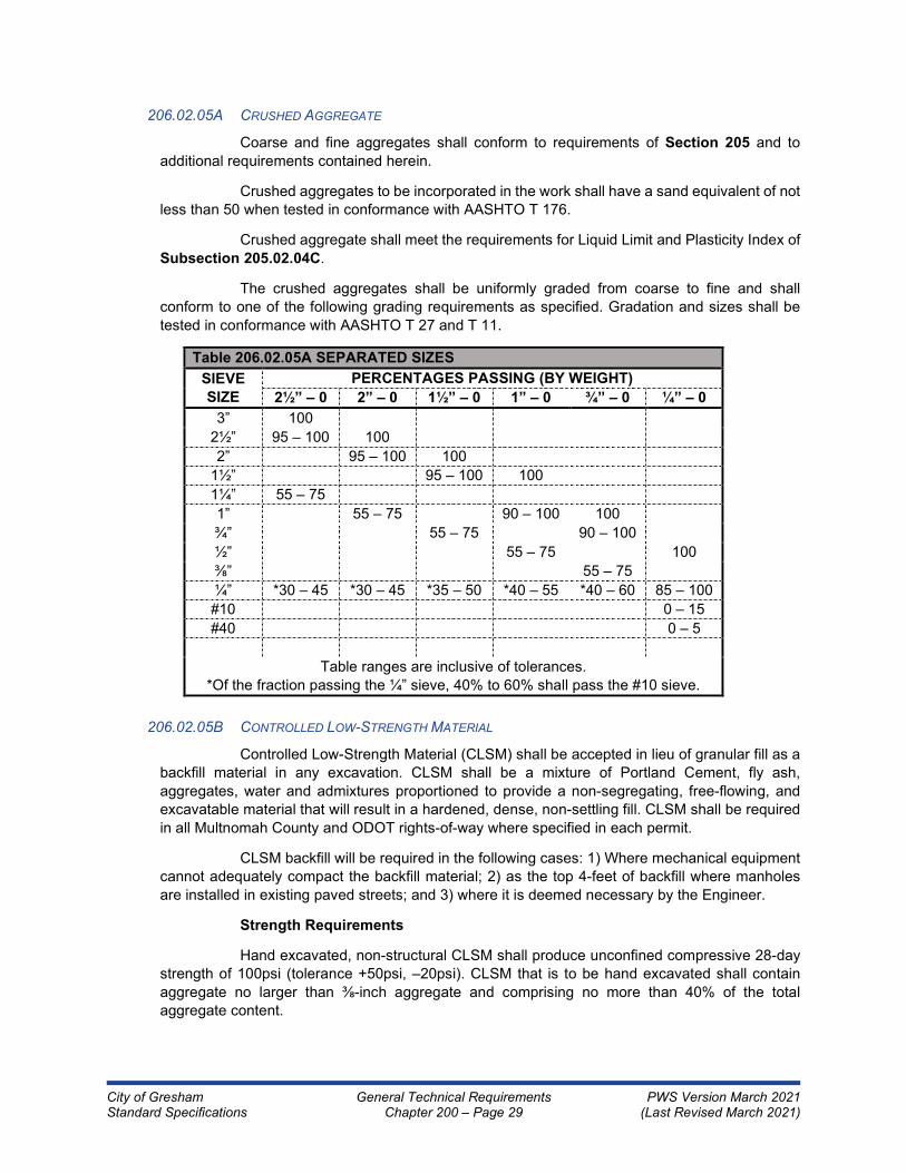
City of Gresham General Technical Requirements PWS Version March 2021 Standard Specifications Chapter 200 – Page 29 (Last Revised March 2021)
206.02.05A CRUSHED AGGREGATE
Coarse and fine aggregates shall conform to requirements of Section 205 and to
additional requirements contained herein.
Crushed aggregates to be incorporated in the work shall have a sand equivalent of not
less than 50 when tested in conformance with AASHTO T 176.
Crushed aggregate shall meet the requirements for Liquid Limit and Plasticity Index of
Subsection 205.02.04C.
The crushed aggregates shall be uniformly graded from coarse to fine and shall
conform to one of the following grading requirements as specified. Gradation and sizes shall be
tested in conformance with AASHTO T 27 and T 11.
Table 206.02.05A SEPARATED SIZES
SIEVE
SIZE
PERCENTAGES PASSING (BY WEIGHT)
2½” – 0 2” – 0 1½” – 0 1” – 0 ¾” – 0 ¼” – 0
3” 100
2½” 95 – 100 100
2” 95 – 100 100
1½” 95 – 100 100
1¼” 55 – 75
1” 55 – 75 90 – 100 100
¾” 55 – 75 90 – 100
½” 55 – 75 100
⅜” 55 – 75
¼” *30 – 45 *30 – 45 *35 – 50 *40 – 55 *40 – 60 85 – 100
#10 0 – 15
#40 0 – 5
Table ranges are inclusive of tolerances.
*Of the fraction passing the ¼” sieve, 40% to 60% shall pass the #10 sieve.
206.02.05B CONTROLLED LOW-STRENGTH MATERIAL
Controlled Low-Strength Material (CLSM) shall be accepted in lieu of granular fill as a
backfill material in any excavation. CLSM shall be a mixture of Portland Cement, fly ash,
aggregates, water and admixtures proportioned to provide a non-segregating, free-flowing, and
excavatable material that will result in a hardened, dense, non-settling fill. CLSM shall be required
in all Multnomah County and ODOT rights-of-way where specified in each permit.
CLSM backfill will be required in the following cases: 1) Where mechanical equipment
cannot adequately compact the backfill material; 2) as the top 4-feet of backfill where manholes
are installed in existing paved streets; and 3) where it is deemed necessary by the Engineer.
Strength Requirements
Hand excavated, non-structural CLSM shall produce unconfined compressive 28-day
strength of 100psi (tolerance +50psi, –20psi). CLSM that is to be hand excavated shall contain
aggregate no larger than ⅜-inch aggregate and comprising no more than 40% of the total
aggregate content.

City of Gresham General Technical Requirements PWS Version March 2021 Standard Specifications Chapter 200 – Page 30 (Last Revised March 2021)
Materials
Portland Cement shall meet the standards as set forth in ASTM C150, Type I or II
Cement.
Fly ash shall meet the standards as set forth in ASTM C618, for Class F pozzolans.
The fly ash shall not inhibit the entrainment of air.
Air entraining agent shall meet the standards as set forth in ASTM C260.
Aggregates need not meet the standards as set forth in ASTM C33. Any aggregates
that will produce the desired performance characteristics of the CLSM considered, will be accepted
for consideration, except as follows. The amount of material passing a #200 sieve shall not exceed
12%, and no plastic fines shall be present.
Proportioning
CLSM shall be a mixture of cement, Class F pozzolan, sand, sometimes coarse
aggregate, air entraining agent, and water. It is usually batched by a ready mixed concrete plant
and delivered to the job site by means of transit mixing trucks.
The actual mix proportions shall be determined by the producer of the CLSM to meet
job site conditions, minimum or maximum strengths, and unit weight. Entrained air content shall be
a minimum of 8.0%. The actual entrained air content shall be established for each particular job
with the materials and aggregates to be used to meet the placing and unit weight requirements.
Entrained air content may be as high as 20% for fluidity requirements.
The table below provides a guideline for CLSM mixes. The weights shown are only an
estimate of the amount to be used per cubic yard of CLSM. Actual amounts may vary from those
shown as approved by the Engineer or approved trial mix data or field test results for proper
strength, workability, consistency and density.
Table 206.02.05B CONTROLLED LOW-STRENGTH MATERIAL
CLASS OF CONTROLLED LOW-STRENGTH MATERIAL CLASS 100 HAND
EXCAVATABLE
Maximum compressive strength, PSI allowable variation, PSI 100 (+50/–20)
Maximum gallons of mixing water per cubic yard 50
Lbs. of cement per cubic yard, approximate 30 to 50
Lbs. of fly ash per cubic yard, approximate 200
Lbs. of dry aggregate per cubic yard, approximate (assumed
SP.G. 2.67) 3200
A. If air entraining or water reducing admixture is used for flowability, total water and
aggregates may be adjusted for yield.
B. For publicly financed improvements, design with prior test results shall be
submitted to the Engineer for acceptance prior to placement.
C. Weights may be adjusted for flowability and pumpability.
206.02.06 RIPRAP
Riprap shall consist of 2-inch or 4 – 2-inch open graded crushed rock conforming to
Subsection 205.02.04, having at least two fractured faces on 90% of the material, and being free from
organic material.

City of Gresham General Technical Requirements PWS Version March 2021 Standard Specifications Chapter 200 – Page 31 (Last Revised March 2021)
206.02.07 IMPORTED TOPSOIL
Unless specified otherwise, imported topsoil shall be used. Provide natural, fertile, friable
topsoil, representative of local productive soil, and 90% free of clay lumps or other foreign matter larger
than 2-inch diameter, not frozen or muddy, with pH 5.0 to 7.0, and not less than 3% humus as
determined by loss on ignition of moisture-free samples dried at 100º C. Gravel portion (particles larger
than 2 mm) shall not exceed 15% of total volume. Imported topsoil shall be free of quack grass,
horsetail, and other noxious vegetation and their seeds. Should such regenerative material be present
in the soil all resultant growth, both surface and root, shall be removed and replaced to original
specifications at the Contractor's expense within 2-years of acceptance of the work.
206.02.08 NATIVE TOPSOIL
When specified, use topsoil from the site. Save, store, protect, and reuse approved native
topsoil taken from the top 12-inches of the excavation. Ensure that topsoil is free from grass,
overburden and roots, sticks, hard clay, and any stones that will pass a 1-inch square opening.
Wherever native topsoil cannot be saved or is not satisfactory for reuse, use imported topsoil
conforming to Subsection 206.02.07, but only with the approval of the Engineer.
206.02.09 STORMWATER FACILITY TOPSOIL
Topsoil for stormwater facilities shall conform to the requirements specified in the City of
Gresham Stormwater Management Manual.
206.02.10 WATER
Use water that conforms to requirements of Section 205. Provide water at the Contractor's
sole expense. Whenever City water is to be used, the Contractor shall obtain a meter issued by the
City.
206.03 CONSTRUCTION
206.03.01 EXCAVATION
Excavate, remove, and dispose of all formations and materials, natural or man-made,
irrespective of nature or conditions, encountered within limits hereinafter defined or as specified,
necessary for construction of the project. Method of excavation used is optional. Overbreak shall be
removed at the Contractor's expense. Use hand methods for excavation that cannot be accomplished
without endangering existing or new structures or other facilities. Excavations shall also comply with
requirements of Subsection 204.03.07.
Furnishing, installing, and removal of all shoring, sheeting, and bracing as required to
support adjacent earth banks and structures, and for the safety of the public and of all personnel
working in the excavation shall be the Contractor's responsibility and shall be considered incidental to
the construction.
206.03.02 ROCK EXCAVATION AND EXPLOSIVES
206.03.02A DEPTH OF EXCAVATION
Excavate to the depths designated or as shown on the appropriate plan or standard
drawing. Correct over-excavation with compacted material as directed at no additional expense to
City. In trenches for sewers and water mains or conduits, remove all material necessary to provide
a minimum clearance of 6-inches under the pipe and replace with bedding material in conformance
with Subsection 206.02.03.

City of Gresham General Technical Requirements PWS Version March 2021 Standard Specifications Chapter 200 – Page 32 (Last Revised March 2021)
206.03.02B METHODS AND RECORDS REQUIRED
Before rock removal by systematic drilling and blasting, or other methods, will be
permitted, notify Engineer who, with Contractor or its representative, will determine the amount of
material to be removed as rock excavation and will record the information. Then drill, blast, or break
with power-operated tools specially designed for rock excavation, and excavate the material.
206.03.02C USE OF EXPLOSIVES
Explosives shall be in accordance with Subsection 205.02.02. Obtain any and all
permits required for use of explosives required by the City of Gresham, and other governing
agencies. No explosives shall be used without the expressed written permission of the Engineer.
Use of explosives shall be avoided as far as practicable, and in no case shall tunnel-
blasting methods be used. Such blasting as must be done shall be controlled in a manner that will
avoid possible shattering or loosening of materials back of lines to which the excavations are to be
made. All blasting shall be supervised and/or done by a state-certified powder person. Be
responsible for any and all damages to property or injury to persons resulting from blasting, or
accidental or premature explosions that may occur in connection with the use of explosives. Give
adequate warning to all affected persons and adjacent property owners prior to blasting.
Where excavation in hard, solid rock is to be made to depths of 10-feet or more;
blasting thereof shall be done by the presplitting or preshearing method unless other methods are
approved by the Engineer.
206.03.02D TRENCH BLASTING
When blasting rock in trenches, cover area to be shot with blasting mats or other
approved types of protective material that will prevent scattering of rock fragments outside of the
excavation.
206.03.03 PRESERVATION OF EXISTING IMPROVEMENTS
Conduct operations in such a manner that existing streets, utilities, railroad tracks,
structures, and other facilities which are to remain in place will not be damaged, as specified in Section
107. Furnish and install cribbing and shoring, or whatever means necessary to support material carrying
existing facilities, or to support the facilities themselves, and maintain such supports until no longer
needed.
Protect temporary facilities, until they are no longer required, and remove and dispose of
temporary supports and other protective means when they are no longer required.
206.03.04 EXCAVATION OF EXISTING IMPROVEMENTS AND MISCELLANEOUS
Unless otherwise specifically provided for, excavation or excavation and backfill includes
all excavating, removing, hauling, and depositing, including but not limited to, existing pavements,
walks, driveways, surfaces, slabs, curbs, gutters, and similar cement concrete structures, bituminous
materials, all rock or gravel road surfacing materials, abandoned sewers, pipes and conduits, logs,
piling, footings, foundations, vaults, and chambers, when such materials are within the limits of
excavation.
Remove remaining ends of abandoned pipes, or portions of other items partially removed
under this work, that would be left exposed after final excavation, to a minimum of 1-foot below the
finished grade or elevation. Plug or seal ends of abandoned pipes in backfill or embankment areas.
Stormwater pipe shall be reconnected as directed by the Engineer.

City of Gresham General Technical Requirements PWS Version March 2021 Standard Specifications Chapter 200 – Page 33 (Last Revised March 2021)
For publicly financed improvements, payment for all work in this section and repair of any
damage will be considered incidental to the work and included under bid items for Excavation,
Excavation and Backfill, or other specified earthwork items.
206.03.05 LIMITS OF EXCAVATION
Excavate to the depths and widths designated, allowing for forms, shoring, working space,
base material, and finish topsoil where required. Do not excavate deeper than elevation shown.
Excavation carried below grade lines shown or established without approval shall be replaced with
approved compacted material at the Contractor's expense. Over-excavation under footings shall be
filled with concrete of a strength equal to that of the footing, and cuts below grade shall be corrected
by similarly cutting adjoining areas and creating a smooth transition, all at the Contractor's expense.
When the precise location of subsurface structures is unknown, locate such structures by hand
excavation prior to utilizing mechanical excavation equipment.
206.03.06 SLOPE GRADING
Make slopes free of all exposed roots, unstable rock, and loose stones exceeding 3-inches
in any dimension. Shape tops of banks to circular curves with, in general, not less than a 6-foot radius,
unless rock makes such work impractical. All surfaces shall be neatly and smoothly trimmed.
206.03.07 FOUNDATION STABILIZATION
If, in the judgment of the Engineer of Record, having consulted with the Contractor, material
in the bottom of an excavation is unsuitable for supporting foundations, piers, retaining walls, cribbing,
sewers, pipes, or similar facilities, the Contractor shall over-excavate as necessary for successful
construction of the facility and backfill to required grade with thoroughly compacted foundation
stabilization material conforming to Subsection 206.02.02.
206.03.08 DISPOSAL OF EXCESS MATERIAL
Excavated materials not suitable or not required for backfill or embankment shall be
deposited at predesignated sites specified, or sites supplied by the Contractor. A grading permit will be
necessary within the City for any embankment exceeding 50 cubic yards before the Contractor places
any excavated material from City projects on any property. The Contractor shall make all arrangements
for disposal of excess material, obtain the necessary permits when not provided by the City at
predesignated sites, and bear all cost or retain any profit incidental to such disposal.
206.03.09 TEMPORARY LOCATION OF EXCAVATED MATERIALS
Place excavated material specified for embankment or backfills only, not excess material,
within the construction easement, right-of-way, or specified working area. Pile in such a manner that it
will cause a minimum of inconvenience to the public. Furnish the Engineer a copy of written approval
from each property owner prior to stockpiling material on private property outside of easements.
Conform to all federal, state, and local codes governing the safe loading of ground adjacent to trenches
with excavated material.
Provide free access to all fire hydrants, water valves, and meters, and leave clearance to
enable free flow of stormwater in all gutters, conduits, and natural watercourses.
206.03.10 SURFACE REMOVAL AND REPLACEMENT FOR TRENCHES
206.03.10A REMOVAL AND REPLACEMENT OF TOPSOIL
When specified and where trenches within easements cross lawns, garden areas,
pasture lands, cultivated fields, or other areas on which topsoil conditions exist, remove all topsoil
to a depth of at least 12-inches for the full width of the trench to be excavated. Stockpile topsoil to

City of Gresham General Technical Requirements PWS Version March 2021 Standard Specifications Chapter 200 – Page 34 (Last Revised March 2021)
one side of the easement in an approved location and do not mix with remaining excavated
material. Replace and compact removed topsoil in the top of backfilled trench to the depth removed.
Maintain finished grade of topsoil level with area adjacent to the trench until final
acceptance by the Engineer. Repair damage to adjacent topsoil caused by work operations.
Remove all rock, gravel, clay, and any other foreign materials from surface; re-grade and add
topsoil as required.
In lieu of stockpiling topsoil, Imported Topsoil as defined in Subsection 206.02.07 may
be substituted and replaced to the actual depth removed at the Contractor's expense. If, in the
opinion of the Engineer, the Contractor does not take precautions to protect the stockpiled topsoil
from contamination by rocks, clay, excess water, etc., the Contractor will be required to import
topsoil meeting the requirements of Subsection 206.02.07 at Contractor’s own expense.
For publicly financed improvements, payment for removing, stockpiling, and replacing
topsoil in the trench is included in the Trench Excavation and Backfill bid item.
206.03.10B REMOVAL OF PAVEMENT, CURBS, DRIVEWAYS, AND SIDEWALKS
Cut all asphalt pavement to full depth with a pavement saw or other suitable pavement
cutter prior to excavation of trenches.
Saw Portland Cement Concrete pavement, curbs, and sidewalks to a minimum depth
of 4-inches or half the concrete thickness, whichever is greater. Subsequent removal may be
accomplished by using a jackhammer; but, if the Contractor damages the portion of the facility that
is to remain, it shall be replaced to the nearest joint at no expense to the City. Full depth cut by
pavement saw can be done at the option of the Contractor. Use of any machine utilizing a falling
or swinging weight in the form of a "headache ball" will not be permitted.
No slurry, dust, or other material created by sawcutting will be allowed to enter the
stormwater drainage system.
Width of cut shall be as shown on the plans or standard drawings. Remove all loose,
undermined, or damaged pavement. Remove all pavement between the trench and curb, pavement
edge, or construction joint whenever the cut is 3-feet or less from the curb, pavement edge, or
construction joint. Joints shall not be located in wheel paths. Prior to paving, all loose, cracked,
sunken, or otherwise damaged edges will be sawcut in continuous straight cuts. Straight-line
sawcut lengths will not be less than 50-feet. Cut angles will not exceed 15º.
Pavement and concrete materials removed shall be hauled from the site and not used
for trench backfill. Replacement of pavement, curb, and sidewalk shall conform to the requirements
of Section 210.
206.03.11 TRENCH EXCAVATION AND SHORING
206.03.11A MAXIMUM LENGTH OF OPEN TRENCH
Length of trench excavated in advance of the pipe laying shall be kept to a minimum,
and in no case shall it exceed 200-feet unless otherwise authorized. The length of unrestored work
area and total unfinished trench construction shall not exceed a length of 600-feet for main line
pipe laying operation unless otherwise authorized. Trench construction will not be considered
completed until all restoration is completed. If the unfinished trench or restoration exceeds 600-feet
in length, the main line construction shall be suspended and shall not be resumed until authorized
by the Engineer.
In no case will any trench be left unfinished or uncovered overnight or outside working
hours.

City of Gresham General Technical Requirements PWS Version March 2021 Standard Specifications Chapter 200 – Page 35 (Last Revised March 2021)
For purposes of this subsection, trench shall be considered as unfinished until
excavation, construction, backfilling, and resurfacing with temporary cold mix or the same material
as the adjacent finished surface has been installed to finish grade, and cleanup operations have
been completed. Cleanup of backfilled and construction area shall include resurfacing and cleaning
of area so as to allow use of trench and adjacent construction area for normal use as required in
Section 211.
Where paved shoulders adjacent to excavations are less than 4-feet wide, protect the
traffic at the end of each working day by backfilling pavement edge excavations to the elevation of
the existing pavement with permanent base material or with temporary wedge of aggregate as
shown on the plans.
206.03.11B TRENCH WIDTH
The maximum trench width at the ground surface will be kept to a minimum necessary
to install the pipe in a safe manner. Trenches shall be of sufficient width to allow for shoring and
permit proper joining of pipe and compaction of the backfill material along the sides of the pipe.
Minimum trench width of unshored trenches shall provide a clear working space of at least 6-inches
on each side of the outside diameter of the pipe bell. Shoring requirements shall be independent
of trench widths.
Trench width at the top of the pipe will be the pipe nominal diameter plus 18-inches,
except where specifically shown on the drawings, or specified in the Special Provisions. The pipe
will be centered in the trench online and grade at all times. When authorized by the Engineer, the
Contractor may use pipe of greater strength or install a superior pipe bedding in lieu of maintaining
the trench widths shown. If maximum width shown is exceeded by Contractor (without written
authorization), the Contractor shall provide pipe of a higher strength designation, a higher class of
bedding, or both, as approved by the Engineer, at no expense to the City.
Make the excavation for manholes and other structures wide enough to provide a
minimum of 12-inches between sides of structure and sides of excavation.
Confine top width of trench to dedicated rights-of-way or construction easements.
Special written agreements to extend width may be made by the Contractor with affected property
owners, provided such agreements are approved by the Project Manager.
206.03.11C GRADE
Excavate trench to lines and grades shown or as established by the Engineer, with
proper allowance for pipe thickness, pipe bedding, and foundation stabilization. The subgrade upon
which bedding is to be placed shall be firm, undisturbed, and true to grade. If the trench is over-
excavated without approval of the Engineer, restore to grade with thoroughly compacted foundation
stabilization material or pipe bedding material at the Contractor's expense. Place material over full
width of the trench in compacted layers to established grade with allowance for pipe bedding.
206.03.11D SHORING AND BRACING OF TRENCHES
Shore and brace trench when necessary to prevent caving and to protect adjacent
structures, property, workers, and the public. Increase trench widths by the thickness of the shoring
and maintain shoring until pipe has been placed and backfilled at the pipe zone. Remove shoring
as backfilling is done, in a manner that will maintain compaction of the backfill material in the trench
and will not damage the pipe or permit voids in the backfill. All sheeting, shoring, and bracing of
trenches shall conform to the safety requirements of the federal, state, or local agency having
jurisdiction. The most stringent of these requirements shall apply.

City of Gresham General Technical Requirements PWS Version March 2021 Standard Specifications Chapter 200 – Page 36 (Last Revised March 2021)
206.03.12 DEWATERING
Furnish, install, and operate all necessary machinery, appliances, and equipment to keep
excavations free from water during construction. Remove and dispose of all water entering the trench
excavation continuously during the time the trench is being prepared for the pipe laying, during the pipe
laying, when concrete is being placed, and until the backfill has been completed. Dewater and dispose
of water so as to prevent injury to public or private property, and to prevent nuisance or menace to the
public. Drainage of trench water through the pipeline under construction is prohibited unless otherwise
approved by the Engineer. At all times the Contractor shall have on hand sufficient pumping equipment
and machinery in good working condition for all ordinary emergencies, including power outage. The
Contractor shall have competent workers for operation of the pumping equipment available at all times.
Control surface runoff to prevent entry or collection of water in excavations.
Control ground water such that softening of the bottom of excavations or formation of
"quick" conditions or "boils" during excavation shall be prevented. Design and operate dewatering
systems so as to prevent removal of natural soils and so that ground water level outside the excavation
is not reduced to the extent that would damage or endanger adjacent structures or property.
Before dewatering is started, submit to the Project Manager a statement of the method,
installation, and details of the dewatering system proposed to be used. Open and cased sumps shall
not be used as primary dewatering for excavations deeper than 3-feet below static water table.
Release ground water to its static level in such a manner as to maintain the undisturbed
state of natural foundation soils. Prevent disturbance of compacted backfill and flotation or movement
of structures, water mains, sewers, and other utilities.
All foundation, vault, and trench de-watering water that has similar characteristics to
stormwater runoff at the site, shall be discharged into a controlled conveyance system prior to discharge
to a sediment trap or sediment pond.
Clean, non-turbid de-watering water, such as well-point groundwater, can be discharged
to the public system. These clean waters should not be routed through sediment traps or sediment
ponds with stormwater.
Highly turbid or otherwise contaminated de-watering water, such as from construction
equipment operation, clamshell digging, concrete pour, or work inside a cofferdam, shall be handled
separately from stormwater at the site.
Other disposal options, depending on site constraints, may include: 1) sanitary sewer
discharge with City Wastewater Services approval, 2) over-land infiltration, 3) filter fabric/media
filtration, or 4) transport off-site in a vehicle, such as a vacuum flush truck, for legal disposal in a manner
that does not pollute local or state waters.
For publicly financed improvements, dewatering shall be considered as incidental to, and
all costs included in, the various contract pay items in the Schedule of Prices.
206.03.13 COMPACTION
Compaction shall be by mechanical methods only.
Compaction equipment shall be of suitable type and adequate to obtain the amount of
compaction specified. Compaction equipment shall be operated in strict accordance with the
manufacturer's instructions and recommendations and shall be maintained in such condition that it will
deliver the manufacturer's rated compactive effort. Compaction equipment for granular materials shall
be vibratory plate or vibratory drum compactors.

City of Gresham General Technical Requirements PWS Version March 2021 Standard Specifications Chapter 200 – Page 37 (Last Revised March 2021)
Any settlement noted in backfill, embankment, or in structures built over the backfill or
embankment within the 2-year warranty period, in accordance with the CHAPTER 100 - GENERAL
REQUIREMENTS, will be considered to be caused by improper compaction methods and shall be
corrected at the Contractor's expense. Structures damaged by settlement shall be restored to their
original condition by the Contractor at the Contractor's expense.
206.03.14 EMBANKMENT
206.03.14A EMBANKMENT
Preparation of Embankment Foundations:
Prior to construction of embankments, excavate and dispose of unstable material or
unsuitable foundation material. Limit excavation to lines, grades, and cross sections shown. Fill
basements, trenches, and holes that occur within embankment limits with specified material.
Compact natural ground underlying embankments to the depth of grubbing or a minimum of 12-
inches to density specified for the embankment material to be placed. Embankment construction
shall also comply with requirements of Subsection 204.03.07.
Embankment Construction:
Construct embankments to the lines and grades shown. Deposit material in layers thin
enough to ensure compaction requirements are achieved throughout the entire lift and not
exceeding 12- inches deep across the full width of the embankment. Place material in continuous
horizontal layers. Compact each lift to the appropriate density as determined by ASTM D1557.
For structural foundation embankment, the maximum aggregate size shall not exceed
3-inches and shall be compacted to not less than a relative maximum density of 95% throughout
the embankment. For all other embankments, the compacted materials within 3-feet of established
subgrade elevation shall have a density in place of not less than 95% of relative maximum density,
and below 3-feet shall have a density in place of not less than 90% of relative maximum density
and will show no appreciable deflection or adverse reaction under the compacting equipment during
compaction.
In the immediate vicinity of curbs, walks, driveways, inlets, manholes and similar
structures, holes, and where embankment and fill materials cannot be reached by the normal
compacting equipment, the Contractor shall compact to specified density by approved methods.
Where embankments are constructed predominantly of rock fragments, the Contractor
shall place material in layers of the thickness as directed by the Engineer of Record, but not greater
than 3-feet. Placing of individual rock fragments having dimensions greater than 3-feet may be
permitted upon approval of the Engineer, provided they have no dimensions greater than 6-feet,
that clearances between adjacent fragments provide adequate space for the placing and
compacting of material in horizontal layers as specified, and that no part comes within 4-feet of
subgrade. The Contractor shall distribute and manipulate rock so that the space between the larger
pieces is filled with smaller material, forming a dense and compact mass.
The Contractor shall exercise caution to ensure that embankment construction and fill
does not move, endanger, or overstress any structure. The Contractor shall place and compact
embankments at the end of bridges prior to the time that work begins on the bridge. When placing
material against an existing slope face, Contractor shall terrace and key each 4-foot of fill.
If the surface of the prepared foundation or the compacted surface of a preceding lift
is too dry or smooth to bond properly with the next layer of material, moisten or scarify, or both,
before the next layer of material is placed. Compact slopes of all embankments thoroughly, and
true to line and grade.

City of Gresham General Technical Requirements PWS Version March 2021 Standard Specifications Chapter 200 – Page 38 (Last Revised March 2021)
Do not place embankment material when the material, foundation, or previously placed
embankment material is frozen. Embankment material shall not be placed in final position until
moisture in excess of optimum moisture has been removed. Water settling of embankments will
not be permitted.
206.03.14B PIPELINE EMBANKMENT
Where pipelines are to be placed within an embankment, construct the embankment
to its final specified elevation prior to trench excavation for the pipeline. Place pipe bedding and
pipe zone materials in accordance with applicable portions of Subsection 206.03.15. Place trench
backfill material as specified in Subsection 206.03.16.
206.03.15 PIPE OR CONDUIT BEDDING AND PIPE ZONE
Construct bedding in conformance with Standard Detail 214, Trench and Backfill.
Class A Pipe Zone Bedding consists of a pipe cradle of Portland Cement Concrete.
Bottom of trench shall be fully compacted before placement of pipe or cradle. Place concrete in such a
manner that no dirt or foreign material becomes mixed with the concrete. Allow concrete sufficient time
to reach initial set before any additional backfill material is placed in the trench. Conform to applicable
provisions for concrete encasement in CHAPTER 300 (WASTEWATER).
Class B Pipe Zone Bedding consists of leveling the bottom of the trench or top of the
foundation material and placing pipe bedding select material to the horizontal centerline (springline) of
the pipe. Bedding select material shall be placed in at least two lifts. Place the first lift to provide the
minimum depth of bedding select material before the pipe is installed. Spread smoothly to proper grade
so that pipe is uniformly supported along the barrel. Excavate bell holes at each joint to permit proper
assembly and inspection of the entire joint. Bedding under pipe shall provide a firm, unyielding support
along the entire pipe length. Place subsequent lifts of not more than 6-inch-thickness up to the
horizontal centerline of the pipe. Bring lifts up together on both sides of the pipe and carefully work
under pipe haunches. Bedding material shall be per Standard Detail 214, Trench and Backfill except
for water lines wrapped with polyethylene encasement or coal-tar coated steel pipe, in which case sand
shall be used within the entire pipe zone area.
Pipe zone bedding shall be considered to include full width of excavated trench from the
bottom of the trench or top of the foundation stabilization material to the top of the bedding.
Particular attention must be given to the area from the invert to the horizontal centerline of
the pipe or top of the bedding to ensure that firm support is obtained to prevent any lateral movement
of the pipe during the final backfilling of the pipe zone.
When placing lifts for the remainder of the pipe zone, pipe zone material shall be placed
carefully around the pipe in layers with a maximum thickness of 6-inches and shall be compacted per
Standard Detail 214, Trench and Backfill. Prevent pipe from movement either horizontally or
vertically during placement and compaction of pipe zone material.
206.03.16 TRENCH BACKFILL AND COMPACTION
206.03.16A GENERAL
The type of backfill to be used above the pipe zone is indicated on the plans. The right
is reserved to modify the use, location, and quantities of the type of backfill during construction as
the Engineer considers being in the best interest of the City.
When backfill is placed mechanically, push the backfill material onto the slope of the
backfill previously placed and allow to slide down into the trench. Do not push backfill into the trench
in such a way as to permit free fall of the material until at least 2-feet of cover is provided over the

City of Gresham General Technical Requirements PWS Version March 2021 Standard Specifications Chapter 200 – Page 39 (Last Revised March 2021)
top of the pipe. Under no circumstances allow sharp, heavy pieces of material to drop directly onto
the pipe or the tamped material around the pipe.
Take reasonable precautions to prevent excavated material that is designated to be
used for backfill from becoming wet and exceeding the critical moisture limits. If native material
does become wet and exceeds the critical moisture limits due to the Contractor's operations,
replace with imported granular material at the Contractor's expense.
206.03.16B CRUSHED AGGREGATE
Backfill the trench above the pipe zone with imported crushed rock backfill material.
Compact the entire trench depth in suitable lifts not to exceed 4-feet in depth, loose measure, with
mechanical vibrating compactors with sufficient compactive effort to meet the specified density.
Determine the type of equipment, method of placing lifts, and the amount of compactive effort
required to prevent subsequent settlement. Compaction with hydra-hammer equipment will not be
approved.
The top 3-feet of select backfill shall be compacted to 95% of maximum dry density as
determined by ASTM D1557.
In the zone below the top 3-feet of backfill compact to 90% of maximum dry density as
determined by ASTM D1557.
Any subsequent settlement of the finished surface during the 2-year warranty period
shall be considered to be a result of improper or insufficient compaction and shall be promptly
repaired by the Contractor at the Contractor's expense.
206.03.16C NATIVE BACKFILL
Backfill the trench above the pipe zone with excavated trench material.
As shown on the construction drawings, leave the trench with the backfill material level
with the existing ground for the entire width of the trench. Material will be compacted to a minimum
of 90% maximum dry density as determined by ASTM D1557. Any deficiency of backfill material
that becomes apparent after settlement and within the warranty period shall be corrected by re-
grading and adding additional material, where required, by the Contractor at the Contractor’s
expense. Remove rocks larger than 2-inches in any dimension from the upper 8-inches of the
backfill.
206.03.16D CONTROLLED LOW-STRENGTH MATERIAL
Controlled Low-Strength Material (CLSM) shall be discharged from the mixer by any
reasonable means into the area to be filled. The CLSM shall be brought uniformly to the elevation
as shown in the Contract Documents. Trench sections to be filled with CLSM shall be contained at
either end by bulkheads of earth fill.
CLSM can be used only after the pipe, conduit, service lateral, or fitting has been
backfilled with crushed rock, as specified in Subsection 206.02.03, unless otherwise specified by
the Engineer. Where CLSM is placed directly around waterline, polyethylene encasement is
required around all waterline and fittings.
CLSM shall not be placed on frozen ground. Subgrade on which CLSM is placed shall
be free of disturbed or softened material and water.
CLSM batching, mixing, and placing may be started if weather conditions are favorable,
as when the air temperature is at least 34º F or more and rising. At the time of placement, CLSM

City of Gresham General Technical Requirements PWS Version March 2021 Standard Specifications Chapter 200 – Page 40 (Last Revised March 2021)
must have a temperature of at least 40º F. Mixing and placing shall stop when the air temperature
is 38º F or less and falling. Each filling stage shall be as continuous an operation as practical.
Permanent pavement may be placed directly upon the CLSM as soon as it has
sufficiently self-consolidated so that the surface will withstand the process of paving without
displacement or disruption. If the placement of the CLSM is not completed early enough to allow
for permanent paving to be completed the same day, the Contractor shall provide steel plates to
span the trench and prevent traffic contact with the CLSM overnight or until permanent paving can
be placed.
The Contractor shall provide test cylinders for laboratory testing by the City. Test
cylinders shall be prepared in conformance with ASTM D4832. Unless otherwise directed by the
Engineer, a set of test cylinders shall be prepared for each day CLSM is placed on the project. A
set shall consist of two cylinders for testing at 7 days and two cylinders for testing at 28 days. The
Engineer may permit other testing methods more suitable for low strength concrete.
206.03.16E COMPACTION TESTING
Sampling and testing of materials for determination of compliance with the specified
compaction requirements may be taken at any location and time as the Engineer may determine.
Excavate test pits in the backfill as directed by the Engineer for the purpose of testing the backfill
compaction. At the option of the Engineer, density tests may be taken on a lift of compacted backfill
immediately before placing the next lift. All costs in connection with excavating test pits, providing
and installing safety shoring as required to protect the testing person, and standby time during field
density test shall be considered incidental to backfill and shall be included in unit price bid for the
various items involved.
When compaction testing has been performed by the Engineer and the required
density has not been obtained by the Contractor, the Contractor shall bear all costs for all
subsequent retesting in the areas of non-compliance. All testing shall be performed by the testing
laboratory of the Engineer. The Engineer shall keep an accurate account of the time spent for the
testing laboratory to perform retesting. The Contractor shall be totally responsible for rescheduling
compaction testing with the Engineer. Any and all costs for tests associated with delays due to
retesting shall be the sole responsibility of the Contractor.
If required density has not been obtained, remove the backfill from the trench, replace
with backfill, and re-compact as many times as it is necessary to obtain the required specified
minimum densities.
206.03.16F TRENCH MAINTENANCE
In graveled areas, maintain surface of the backfilled trench level with the adjacent and
existing grade, before and after the area is opened to traffic, with 1”– 0” crushed aggregate material.
In paved areas, temporary hot or cold mix asphalt pavement shall be used until the final pavement
replacement is completed. The temporary asphalt or steel plating shall be in place at the end of
each workday. Place temporary hot or cold mix asphalt in conformance with Section 210.
Maintain backfilled trench surface between any two successive manholes until the
following operations have been completed and accepted by the Engineer:
A. Service connections installed, backfilled, and compacted.
B. Construction of manholes and appurtenances.
C. Air testing.

City of Gresham General Technical Requirements PWS Version March 2021 Standard Specifications Chapter 200 – Page 41 (Last Revised March 2021)
D. Cleanup and restoration of all physical features, including concrete curbs, gutters,
and driveways.
E. Utilities restored to their original condition or better.
F. All work required between the two manholes accomplished.
Maintain backfilled trench surface between any two successive valves until the
following operations have been completed and accepted by the Engineer:
A. Service connections installed, backfilled, and compacted.
B. Valves, valve boxes, and hydrants installed.
C. Hydrostatic testing.
D. Flushing and disinfection.
E. Cleanup and restoration of all physical features, including concrete curbs, gutters,
and driveways.
F. Utilities restored to their original condition or better.
G. All work required between the two valves accomplished.
Do not undertake final pavement replacement until all items outlined above have been
completed and accepted, unless otherwise approved by the Engineer.
Maintenance of backfilled trenches is considered as incidental to this item of work and
payment for such maintenance will be considered as included in payment for Excavation and
Backfill.
206.03.17 TOPSOIL
For topsoil application, refer to Subsections 209.03.03E and 601.03.02.
206.04 MEASUREMENT AND PAYMENT (NOT APPLICABLE TO PRIVATELY FINANCED PUBLIC
IMPROVEMENTS)
206.04.01 UNCLASSIFIED EXCAVATION
All unclassified excavation will be measured on a cubic yard basis, or on a linear foot basis
for trench excavation and backfill when so shown in the Schedule of Prices, all in original position prior
to excavation. The quantity measured for payment will include only material excavated from within the
limits defined herein. Any additional excavation outside of these limits, unless ordered in writing by the
Engineer, shall be considered as having been made for Contractor's benefit and will be considered as
incidental to the work. Excavation required for the volume displaced by new concrete curbs, driveway,
sidewalks, steps, and pathways shall be considered incidental to the work and no payment will be made
for removal of this material.
206.04.01A ROADBED AND SLOPE EXCAVATION
Pay quantities shall be computed to the neat lines of cross sections as staked or as
otherwise specified.

City of Gresham General Technical Requirements PWS Version March 2021 Standard Specifications Chapter 200 – Page 42 (Last Revised March 2021)
206.04.01B TRENCH EXCAVATION AND BACKFILL
General
Length of all trenches will be measured horizontally along center of pipe or conduit
from center-to-center of valves, fittings, couplings, manholes, structures, or end of pipe or conduit,
whichever is applicable. Measurement through structures will be deducted if the Schedule of Prices
carries a separate item of structure excavation applicable to the structures.
Measurement and payment for trench excavation and backfill shall include all work
specified herein, or not specifically paid for in other pay items.
If a portion of the native material is approved as backfill material in areas requiring
such, there may be a need for additional granular backfill to be imported. No additional payment
will be made for the granular backfill. It will be considered incidental to the bid item for native backfill
material.
Trench backfill above the pipe zone will either be native, crushed aggregate or CLSM
for purposes of payment. Payment will be made based on the type of backfill actually installed.
The price per linear foot for trench excavation and backfill shall be considered full
compensation for the removal, protection, and replacement if damaged or interfering portions of
existing sanitary sewer lines, stormwater lines, waterlines, and other improvements; the plugging
or removing of abandoned conduit and structures; the excavations of the trench; disposal of excess
excavation; the control of ground and surface waters; the preparation of subgrade; backfilling the
trench; removing, stockpiling, and replacing topsoil; and all other work necessary to install the pipe
or conduit, complete in place.
Gravity Sanitary Sewer Lines and Stormwater Lines
When contained in the Schedule of Prices, trench excavation and backfill will be paid
for on a linear foot basis for type and depth of backfill used, with depth being measured from original
ground or paved surface to invert of the pipe. The price bid per linear foot shall include the
excavation required to provide space for the pipe bedding and any excavation and backfill
necessary to widen the trench for installation of manholes and appurtenances.
For sanitary sewer lines and stormwater lines, depth figures shown in the Schedule of
Prices are inclusive to the nearest 0.1-foot; that is, a trench depth measured as 11.9-feet will be
paid for at the unit price for excavation 10 to 12-feet deep. A trench depth measured as 12.0-feet
will be paid for at the unit price for excavation 12 to 14-feet deep. Depths measured at less than 8-
feet will be included in the base depth of range of 0 to 8-feet. Depth of trench will be measured at
intervals of 50-feet along the centerline of the trench, and the ends. Depths will be interpolated
between each 50-foot station or the ends if the line is less than 50-feet long.
Pressure Sanitary Sewer Lines, Water Lines, and Conduits
Payment for trench excavation and backfill will be made at the respective unit prices
stated in the Schedule of Prices for the trench excavation, the type of backfill used, and all incidental
work, including all extra excavation required to provide space for pipe bedding, and shall also
include any incidental excavation and backfill necessary to widen the trench for installation of
branch-line fittings and appurtenances.
For waterline installations, payment for trench excavation and backfill will be included
within the "Installation of Pipe" bid item, Subsection 501.04.01.

City of Gresham General Technical Requirements PWS Version March 2021 Standard Specifications Chapter 200 – Page 43 (Last Revised March 2021)
206.04.02 ROCK EXCAVATION
206.04.02A STRUCTURAL ROCK EXCAVATION
Rock excavation will be measured on a cubic-yard basis for the actual quantity
removed within the limits of excavation as defined for unclassified excavation. Quantity for payment
shall be the amount approved by the Engineer.
206.04.02B ROADBED AND SLOPE ROCK EXCAVATION
Rock excavation will be measured on a cubic-yard basis for the actual quantity
removed within the limits of excavation as defined for unclassified excavation. Quantity for payment
shall be the amount approved by the Engineer.
206.04.02C TRENCH ROCK EXCAVATION
Rock excavation will be measured on a cubic-yard basis as follows:
Length
Length will be the entire horizontal distance where rock is encountered, measured on
a lineal foot basis along the centerline of the trench.
Width
For sanitary sewer lines, stormwater lines, and water lines, the width for payment of
trench rock excavation shall not exceed the inside pipe diameter plus 18-inches, except at manhole
locations where the width will be the manhole diameter plus 2-feet where rock is encountered.
Depth
Measurement for depth will be the vertical distance from the top of the rock to the
bottom of the rock or a depth that is 6-inches below the sanitary sewer line, stormwater line, water
line, or structure, whichever is less. Depth will be measured at intervals of 25-feet for sanitary sewer
lines and stormwater lines and 50-feet for water lines along the centerline of the trench, beginning
at the first location that rock is encountered and ending where the rock stops. The average depth
between measuring points will be the depth used for computing depth of rock.
Payment for rock excavation will be based on the unit price per cubic yard stated in the
bid and will be paid in addition to the payment for trench excavation and backfill. Payment for rock
excavation shall include full compensation for all work necessary to excavate the rock material. No
payment will be made for rock excavated below the required grade or outside the widths mentioned
above.
206.04.03 HARD SURFACE REMOVAL AND REPLACEMENT FOR TRENCHES
Measurement and payment for the removal and replacement of Portland Cement Concrete
pavement, asphaltic concrete pavement and surfaces, curbs, driveways, and sidewalks shall conform
to the provisions of Section 210.
Payment for removal will be covered under excavation unless specifically stated otherwise
in this document.
206.04.04 EMBANKMENT
Measurement for payment for embankment compacted in place will be made on a cubic
yard basis. Computation of volume for payment will be based on field measurement of the actual
number of cubic yards constructed within limits shown or directed. Where applicable, this shall be within
neat lines of the staked cross section.

City of Gresham General Technical Requirements PWS Version March 2021 Standard Specifications Chapter 200 – Page 44 (Last Revised March 2021)
No payment will be made for quantities required due to subsidence or settlement of ground
or foundation, for settlement of materials within the embankment or for shrinkage, settlement, washout,
slippage, or loss regardless of cause, subject to the provisions of Subsection 107.03.
Deduction may be made for piers, columns, pipes, or miscellaneous construction features
constructed within embankment limits.
Payment shall constitute full compensation for all work and all materials used, whether
obtained from the site of work or imported.
Trench excavation, bedding, and backfill placed in the compacted embankment will be paid
for separately for the particular item and class of construction.
206.04.05 FOUNDATION STABILIZATION
Payment for this item will be based on the unit price per cubic yard stated in the Schedule
of Prices. Measurement will be based upon a trench pay width of the nominal pipe diameter plus 18-
inches. Payment for this item shall constitute full compensation for all materials, labor, equipment, and
incidentals necessary to furnish materials at the site and for placing and compacting it and for the extra
depth of excavation required below the pipe base grade structure or roadway to provide for a stable
base. This item is to provide for unstable base encountered in the progress of the work and shall be
used only under the direction of the Engineer. Foundation stabilization will only be paid in those areas
where the Engineer has given written direction for installation.
206.04.06 PIPE OR CONDUIT BEDDING AND PIPE ZONE
Payment for pipe bedding and pipe zone material will be included in the lineal foot payment
for pipe as specified in Subsection 301.04, Subsection 401.04 and/or Subsection 501.04.
206.04.07 RIPRAP
Riprap material will be measured for payment on a cubic yard or ton basis only when listed
in the Schedule of Prices as a separate bid item, or when directed by the Engineer. Measurement will
be based upon individual trip tickets of actual truck measure furnished to the City for the cubic yards or
tons used under this item. Trip tickets shall be presented to the City on the day the material is delivered.
No payment will be allowed on trip tickets not so provided.
Payment for riprap shall include all work necessary to furnish and place the material
complete, including any required geotextile. When not listed in the Schedule of Prices, payment for
riprap shall be incidental to other items of work.
206.04.08 IMPORTED TOPSOIL
Measurement and payment for the imported topsoil will be made on a cubic yard or ton
basis and only when listed in the Schedule of Prices as a separate bid item. Measurement will be based
upon individual trip tickets of actual truck measure furnished to the City for the cubic yards or tons used
under this item. Trip tickets shall be presented to the City on the day the material is delivered. No
payment will be allowed on trip tickets not so provided.
Payment for imported topsoil shall constitute full compensation for all work necessary to
furnish materials onsite, placing material, and for full compaction in place.
206.04.09 SHORING
Shoring, including but not limited to bracing and cribbing, and including all work and
materials expended in furnishing, placing, and removing such equipment necessary to complete the
excavation, shall be considered incidental to the pay item for excavation.

City of Gresham General Technical Requirements PWS Version March 2021 Standard Specifications Chapter 200 – Page 45 (Last Revised March 2021)
206.04.10 DEWATERING
Dewatering shall be considered as incidental to and included in the pay item for excavation.
207 BORING AND JACKING
207.01 DESCRIPTION
207.01.01 BORING
Boring shall include all methods by which a pipe or conduit is pushed or pulled into place
and by which the excavation method precludes the stationing of a worker within the pipe or conduit
without stopping or removing the excavation equipment.
207.01.02 JACKING
Jacking shall include all methods by which a pipe or conduit is pushed or pulled into place
and one or more workers inside the conduit excavate and assist in keeping the conduit on a straight
and true grade and alignment.
207.01.03 PERMITS
Permitter shall designate the owner of railroad tracks or other facilities with prior rights
under which a pipe or conduit must be bored or jacked.
All necessary permits for the undercrossing will be obtained by the City.
The operation across the permitter's right-of-way must conform to the requirements of the
permitter as outlined in a pipeline crossing agreement made between the permitter and the City. The
Contractor shall conform to all requirements of the pipeline crossing agreement. Before work is
commenced, the Contractor shall be solely responsible for obtaining and delivering to the permitter a
public liability and property damage insurance policy in the amount required in the pipeline crossing
agreement. The insurance company writing the policy shall be authorized to do business in the State
of Oregon and shall be satisfactory to the permitter. The insurance policy or policies shall be delivered
to and remain in the possession of the permitter. If any special agreement is required between the
Contractor and the permitter, it shall be completed and signed before the Contractor enters upon or
commences work on the permitter's property.
207.02 MATERIALS
207.02.01 PIPE BEDDING AND PIPE ZONE MATERIAL
Conform to the requirements of Section 206 unless otherwise specified in the Contract
Documents.
207.02.02 PIPE
Conform to Section 301, 401 or 501 for the strength, class, and type as shown unless
otherwise specified in the Contract Documents.
207.02.03 CASING
Provide casing of size to permit proper construction to the required lines and grades.
Casing shall be the type shown in the table below.

City of Gresham General Technical Requirements PWS Version March 2021 Standard Specifications Chapter 200 – Page 46 (Last Revised March 2021)
Use minimum gauge or wall thickness corresponding to the size of casing selected from
the following; however, be responsible for selecting the gauge consistent with the operations and the
specified requirements of the permitter.
Table 207.02.03 CASING
DIAMETER INCHES SMOOTH STEEL PIPE MINIMUM THICKNESS
12 & under 3/16 ASTM A53
15 – 24 1/4 ASTM A53
30 – 36 5/16 AWWA C201
48 – 78 As specified by the Engineer of Record
Equip jacked casings with nipples at the springline and crown at 10-foot centers when
pressure grouting is specified.
207.02.04 GROUT
Grout for filling the annular space between the carrier pipe and casing pipe shall be a
mixture of Portland Cement, sand, and pea gravel proportioned to allow complete filling of the annular
space. The mixture shall have a creamy consistency that enables it to be pumped with a concrete
pump.
Grout for pressure grouting outside jacked carrier or casing pipe shall be a mixture of
Portland Cement (Type 1P) and water proportioned to allow complete filling of all voids. The maximum
allowable slump shall be 5-inches.
207.02.05 STAINLESS STEEL BANDS
One-half-inch wide by 0.020-inch thick steel bands or approved equal.
207.02.06 SUPPORTS, SKIDS, AND CASING SPACERS
Casing spacers shall be used on all pipes within the casing, as manufactured by Cascade
Waterworks Manufacturing, or approved equal.
207.03 CONSTRUCTION
207.03.01 GENERAL
Conform to all federal, state and local laws and regulations pertaining to tunneling and
specifically to the standards set forth by OSHA.
Before the start of the work, submit satisfactory evidence to the Project Manager that all
insurance coverage requirements called for by the permitter have been complied with. If required,
proposed construction methods and materials shall be submitted to the permitter before the start of
construction. Written authorization to proceed from the permitter shall be submitted to the Project
Manager before the start of construction.
Prior to starting construction, all required labor, materials, and equipment shall be on the
site. Notify all permitters at least 48-hours in advance of working within their right-of-way unless
otherwise specified in the permit.
207.03.02 EXCAVATION
Excavation shall be unclassified and shall include whatever materials are encountered to
the depths as shown or as required. The Contractor will visit the site and make an estimate of the kind
and extent of various materials that may be encountered in the excavation.

City of Gresham General Technical Requirements PWS Version March 2021 Standard Specifications Chapter 200 – Page 47 (Last Revised March 2021)
207.03.03 ALTERNATE OF JACKING OR BORING
Jacking or boring may be allowed in lieu of the open trench method. However, written
authorization by the Engineer must first be obtained. The Engineer retains the right to reject either the
jacking or boring method without rejecting the other. Authorization by the Engineer shall in no way
relieve the Contractor of the responsibility for making a satisfactory installation meeting the
requirements set forth herein.
207.03.04 JACKING AND BORING
Equip the leading section of pipe or conduit with a jacking head securely anchored thereto
to prevent any wobble or alignment variation during the jacking or boring operation. For jacking, all
excavation shall be carried out entirely within the jacking head and no excavation in advance thereof
shall be permitted. For jacking, every effort shall be made to avoid any loss of earth outside the jacking
head. Remove excavated material from the pipe or conduit as excavation progresses, and do not allow
such material to accumulate within the pipe or conduit.
Jack or bore all pipes or conduits to true line and grade. Should any deviation from true
line and grade be considered excessive, in the judgment of the Engineer, the Contractor shall correct
at no expense to the City.
Should appreciable loss of ground occur during the jacking or boring operations, backpack
all voids promptly. Fill all remaining voids upon completion of the operations; such filling or backpacking
shall be with grout.
The design of all sanitary sewer pipe or conduit is based upon the superimposed loads and
not upon the loads resulting from the jacking or boring operations. The Contractor shall be responsible
for any increase in pipe strength necessary to withstand jacking or boring loads and grouting.
207.03.05 CONCRETE PIPE AND BOX SECTION
Protect the driving ends of concrete pipe or conduit against spalling and other damage.
Intermediate joints shall be similarly protected by the installation of sufficient bearing shims to properly
distribute the bearing stresses. Remove any section of pipe or conduit showing signs of failure and
replace with a new section.
207.03.06 SMOOTH STEEL CASING
Join sections of smooth steel casing to be jacked or bored by welding the joints with a
continuous weld for full circumference or by other means approved by the Engineer. Provide joints that
are capable of resisting the jacking and boring forces without failure.
Brace pipe or conduit installed in a casing to prevent shifting and flotation. Fill the void
between the casing and the pipe or conduit with grout unless otherwise specified by the Engineer.
If not shown on plans or specified in the Contract Documents, the casing diameter shall be
the option of the Contractor. Provide casing of such strength as to withstand the jacking or boring loads
and of such diameter to allow filling the void between the pipe or conduit and casing with the approved
material.
207.03.07 GROUTING VOIDS OUTSIDE CASING OR CARRIER PIPE
After the casing, or carrier pipe where no casing is specified, has been jacked or bored into
position, pressure grout to fill all voids outside the casing through the grout holes provided. Start
grouting at the springline hole at one end and pump grout until grout appears in the grout hole at the
crown; then start grouting through the opposite springline hole until grout appears at the hole in the
crown. Next grout through the hole at the crown until grout appears in the next set of holes along the

City of Gresham General Technical Requirements PWS Version March 2021 Standard Specifications Chapter 200 – Page 48 (Last Revised March 2021)
pipe. Plug the holes at the starting point and move to the next set of holes and repeat grouting sequence
until full-length of jacked pipe has been grouted. Grouting once commenced at any one point shall be
completed without stopping.
Nipples installed in grout holes must be removed and the holes grouted flush with the pipe
wall, or nipples should be cut off flush with pipe wall and grouted over, or use flush mount pipe nipples
and plugs.
207.03.08 CASED PIPE
Provide casing spacers under barrel of pipe, join pipe and slide into casing. Pipe barrel
shall bear continuously on spacers. Pipe installation shall conform to applicable requirements in
Section 301, 401 or 501, including spacers air testing and line and grade.
Spacers shall be center-restrained configured. Spacers shall be 6 to 12-inches from ends
of casing and 6 to 12-inches from each side of joints with one spacer at center of pipe lengths.
207.03.09 GROUTING VOIDS BETWEEN CARRIER PIPE AND CASING
Completely fill the annular space between the casing and the carrier pipe with Type “B”
grout per Subsection 205.02.07B or as specified. When approved by the Engineer, sand may be used
in lieu of grout. Fill the voids by continuously pumping grout from one end of casing pipe until grout
appears at the other open end. When grouting, use low pressure grouting equipment. The grouting
pressures shall not be greater than the design loads of the carrier pipe. The Contractor shall, at his sole
expense, remove and replace any pipe sections that fail during the grouting process.
The ends of the casing shall be sacked and sealed at the ends using wrap around end
seals as manufactured by Cascade Waterworks Manufacturing or approved equal.
207.03.10 RAILROAD CROSSINGS
The right is reserved by the City to require jacking or boring under any or all crossings.
Should open trench construction be required by the City at a railroad crossing, the railroad
will take up and relay the tracks at no expense to the Contractor. Submit a schedule of operations to
the railroad company and to the City 72-hours before trenching within 20-feet of the railroad
right-of-way. Construct the pipe crossing and compact backfill through the track location within 72-hours
after the tracks have been removed by the railroad unless otherwise specified.
207.03.11 CONTRACTOR'S RESPONSIBILITY
The Contractor shall be fully responsible for settlement or deterioration of the finished crossing
until a period of two-years after final acceptance by the City.
207.04 MEASUREMENT AND PAYMENT (NOT APPLICABLE TO PRIVATELY FINANCED PUBLIC
IMPROVEMENTS)
207.04.01 BORING AND JACKING
Measurement and payment for bored and jacked pipe or conduit will be made on a linear
foot basis, complete in-place. Payment will include, but is not limited to, all excavation, shafts, portals,
jacking pits, backfill, lubricant, grouting voids outside of casing, filling the annular space between the
pipe and the casing, pipe casing, and all appurtenances.
Where casing is not required but is used at the option of the Contractor, the casing and the
backfill between the pipe or conduit and the casing shall be included in the pay item for boring or jacking
as applicable and no separate payment for pipe will be made.

City of Gresham General Technical Requirements PWS Version March 2021 Standard Specifications Chapter 200 – Page 49 (Last Revised March 2021)
Measurement for jacking and boring will be made on a linear foot basis along the centerline
of the pipe or conduit between the limits shown. Jacking and boring extensions beyond the limits shown
shall be considered to be for the Contractor's convenience, unless ordered in writing, and measurement
and payment for said extension shall be made as if the open trench method of construction had been
used.
Final payment for each crossing will be made after the Contractor furnishes a satisfactory
release from the permitter stating that all claims for labor and materials have been satisfied and that
the Contractor's work across the permitter's right-of-way has been completed to the satisfaction of the
permitter.
207.04.02 JACKING OR BORING IN LIEU OF OPEN TRENCH
Where jacking or boring of a conduit is authorized in lieu of open trench construction,
measurement and payment will be made as though the open trench method had been used and will
include all the pay items that would have been applicable if the open trench construction method had
been used.
208 CONCRETE STRUCTURES
208.01 DESCRIPTION
This section covers Portland Cement Concrete (plain or reinforced; precast or cast-in-place) in
bridges, box culverts, retaining walls, catch basins, abutments, piers, footings, foundations, curbs,
sidewalks, and similar structures.
208.02 MATERIALS
208.02.01 PORTLAND CEMENT
Conform to Section 205.
208.02.02 AGGREGATES
Use aggregates that conform to requirements of Section 205 and the additional
requirements contained herein.
208.03 CONSTRUCTION
208.03.01 GENERAL
When purchasing concrete from others during performance of the Contract, be fully
responsible for such concrete conforming to all requirements contained herein.
208.03.02 MIX DESIGN
208.03.02A CLASSES OF CONCRETE
Classes of concrete shall designate design field strength of concrete in 28-days
(measured in pounds per square inch, psi) followed by maximum size of aggregate to be used in
the concrete, i.e., Class 3300–1 1/2 shall constitute a mix with a compressive strength of 3300psi
in 28-days with 1½-inch maximum size aggregate used in that concrete.
Use the class of concrete as specified or shown for each component part of the project.
If not so specified or shown, use Class 4000–1 1/2 concrete.

City of Gresham General Technical Requirements PWS Version March 2021 Standard Specifications Chapter 200 – Page 50 (Last Revised March 2021)
In all precast, prestressed concrete members in the stems of post-tensioned box
girders and in all other members where the spacing of reinforcement is less than 2-inches, use 1-
inch maximum size aggregate, unless specified otherwise.
208.03.02B CLASSIFICATION AND PROPORTIONING OF CONCRETE MIXTURES
Before beginning any concrete work, the Contractor shall submit a concrete mix design
to the Project Manager.
During progress of the work, if concrete strength and quality, as determined by the test
results, fail to attain the requirements specified, suspend all concrete work and make necessary
adjustments to obtain required results.
A mix using different proportions or aggregate sizes of any concrete materials in the
mix may be requested by the Engineer. Any requested and authorized alteration to proportions of
any of the concrete materials in the mix shall be made at the Contractor's sole expense.
The Contractor shall design the mix to meet the following requirements unless
otherwise specified:
A. Entrained air range 3% to 6% (percent by volume) - AASHTO T 152.
B. Slump range 2-inches to 4-inches - AASHTO T 119.
C. When using ¾-inch maximum size aggregate, the fine aggregate shall be between
40% and 48% of the total aggregate used.
D. When using 1½-inch maximum size aggregate, the fine aggregate shall be
between 35% and 45% of the total aggregate used.
E. When specified, use a water-reducing admixture in conformance with
manufacturer's recommendations.
Tests for strength shall be made in accordance with the following:
Molding concrete specimens in the field – AASHTO T 23
Compressive strength of molded cylinders – AASHTO T 22
Curing of cylinders shall conform to AASHTO T 23 except as modified herein.
208.03.03 CONSISTENCY
In general, use a mixture that contains the minimum amount of water consistent with
required workability. Consistency of concrete shall be gauged by ability of equipment to properly place
it without segregating or honeycombing, and not by the difficulty in mixing or transporting.
208.03.04 MEASUREMENT OF MATERIALS
Provide facilities for weighing and accurately measure all materials by weight, except
water, when batching concrete; weigh fine and coarse aggregates separately. Take representative
samples and determine moisture content for each kind of aggregate. Store or handle aggregates so
that their water content remains constant during any day's run. Equipment for weighing materials shall
provide convenient and positive means of determining quantities in the batch of concrete, and means
shall be provided for addition or removal of small quantities of materials to obtain exact weight per
batch. Device for measuring water shall show accurately the quantity in gallons and be so designed
that the water supply will be automatically cut off while water is being discharged into the mixer. Water
shall be assumed to weigh 8.34 pounds per gallon.

City of Gresham General Technical Requirements PWS Version March 2021 Standard Specifications Chapter 200 – Page 51 (Last Revised March 2021)
208.03.05 MIXING
208.03.05A GENERAL
Machine mix all concrete. Ready-mix concrete may be used if it meets all specified
requirements herein.
208.03.05B MIXING AT THE SITE
Mix concrete thoroughly in a batch mixer of a size and type that will ensure a uniform
distribution of materials throughout the mass.
Equip mixer with adequate water storage and a device for accurately measuring and
automatically controlling amount of water used in each batch. Preferably provide mechanical
means for recording the number of revolutions for each batch and automatically preventing
discharge of mixer until materials have been mixed the required minimum time.
Remove entire contents of the mixer from the drum before materials for a succeeding
batch are placed therein. Deposit materials composing a batch simultaneously in the mixer. Do not
use any mixer having a rated capacity of less than 1-sack batch. Do not charge a mixer in excess
of its rated capacity.
Mix all concrete for a period of not less than 1½-minutes after all materials, including
water, are in the mixer. During the period of mixing, operate at a design speed of not less than 14
or more than 20 revolutions per minute.
The first batch of concrete materials placed in the mixer shall contain a sufficient
excess of cement, sand, and water to coat the inside of the drum without reducing the required
mortar content of the mix. Upon cessation of mixing for a considerable period, clean the mixer
thoroughly.
The above specification contemplates the use of conventional revolving drum type
mixers. Other types may be used with written permission of the Engineer.
208.03.05C TRUCK MIXING
Unless otherwise authorized by the Engineer, use only revolving drum type truck
mixers that are watertight and so constructed that concrete can be mixed to ensure a uniform
distribution of materials throughout the mass.
Accurately measure all solid materials for concrete in accordance with Subsection
208.03.04 and charge into the drum at the proportioning plant. Except as subsequently provided,
equip the truck mixer with a tank for carrying mixing water. Place only the prescribed amount of
water in the tank unless the tank is equipped with a device by which quantity of water added could
be readily verified. Mixing water may be added directly to the batch, in which case a tank will not
be required. Truck mixers may be required to be provided with means by which the mixing time can
be readily verified by the Engineer.
Do not allow any batch in a truck mixer to exceed the maximum rated capacity of mixer
as stated by the manufacturer and stamped in metal on the mixer. Continue truck mixing for not
less than 70 revolutions or more than 100 revolutions of the drum at the rate of rotation designated
by the manufacturer and stamped in metal on the mixer. Commence mixing after all ingredients,
including water, are in the drum. Additional mixing, if any, shall be of the rate of rotation as
designated by the manufacturer as agitating speed. Begin mixing within 30-minutes after cement
has been added to either the water or the aggregate. When cement is charged into a mixer drum
containing water or surface-wet aggregate and when the temperature is above 90º F, or when
high-early strength Portland Cement is used, reduce this limit to 15-minutes.

City of Gresham General Technical Requirements PWS Version March 2021 Standard Specifications Chapter 200 – Page 52 (Last Revised March 2021)
208.03.05D PARTIAL MIXING AT CENTRAL PLANT
When a stationary mixer is used for partial mixing of concrete (shrink-mixing), mixing
time in stationary mixer may be no more than is required to intermingle the ingredients. After
transfer to a truck mixer, further mixing at a designated mixing speed will be required only as
necessary to meet the requirements for uniformity of concrete as specified for truck mixing.
208.03.05E PLANT MIX
Conform mixing at a central plant to requirements for mixing at the site.
208.03.05F TIME OF HAULING AND PLACING MIXED CONCRETE
Completely discharge and place in the forms all concrete transported to the project in
a truck mixer or truck agitator within 90-minutes after material is placed in the truck or before 250
revolutions of the truck drum or blades, whichever comes first.
Reduce this time during conditions that contribute to accelerated setting of concrete,
or when temperature of concrete is 85º F or above.
Add no water to concrete during hauling or before discharge, unless ordered by the
Engineer of Record. Engineer of Record shall not generally approve any water addition that
increases the slump by more than 1-inch or exceeds the design water-cement ratio.
208.03.05G DELIVERY
Utilize a plant capacity and transportation equipment that are adequate to ensure
continuous delivery of concrete during concreting operations and that will provide for proper
handling, placing, and finishing of the concrete. Use a rate of delivery such that the interval between
batches does not exceed 20-minutes. Methods of delivery and handling concrete shall allow placing
with a minimum of rehandling and without damage to the structure or concrete. Time interval may
be reduced when deck concrete is being placed. Control delivery of concrete for decks so that deck
pour will progress at a rate of not less than 20-feet per hour unless some other rate of pour is
specified.
208.03.05H RETEMPERING
Mix concrete only in such quantities as are required for immediate use and do not use
any that has developed initial set. Concrete that has partially hardened shall not be retempered or
remixed.
208.03.06 FALSEWORK
For structures requiring poured-in-place concrete superstructures, working drawings and
calculations for falsework, prepared by the Engineer of Record, may be required to be submitted to the
City for review. For a guideline on designing formwork and falsework, the Contractor shall refer to the
current version of the ACI Standard, "Recommended Practice for Concrete Formwork" (ACI 347-68).
Design and construct all falsework to support the total applied loads with a deflection/span
ratio not to exceed 1/500 in any falsework span. Employ screw jacks or hardwood wedges to take up
any settlement in formwork either before or during the placing of concrete. Set falsework for p-
ost-tensioned structures to carry full dead load and any additional vertical or horizontal loads caused
by the prestressing operation.
Contractor is directed to the fact that post-tensioned structures are not self-supporting until
post-tensioning is complete and Contractor shall consider this fact in the design, maintenance, and
protection of falsework.

City of Gresham General Technical Requirements PWS Version March 2021 Standard Specifications Chapter 200 – Page 53 (Last Revised March 2021)
208.03.07 FORMS
Forms shall be constructed for all concrete work. Adjacent surfacing such as asphaltic
concrete shall not be used as a form for placing concrete. Make all forms mortar-tight; set them so
finished concrete will conform to the proper dimensions and contours; and make them sufficiently rigid
to prevent distortion due to the pressure of the concrete and other loads incidental to the construction
operations. Construct and maintain forms to prevent warping and opening of joints.
Design forms to withstand the effects of vibration of concrete as it is placed.
Support deck forms for concrete box girder spans by girder stems. Posts or other supports
for deck forms will not be permitted to come in contact with the bottom slab of the box girder.
Make wood forms for concrete surfaces, not subject to backfill, of dressed lumber of
uniform thickness with a form liner of an approved type. Wood forms for interior cells of box girders may
be made with or without a form liner. Shiplap or S4S boards are acceptable provided forms are
mortar-tight. Plywood will be acceptable as a form liner if sufficiently supported. Ensure that all formwork
for exposed concrete surfaces is smooth with the grain running in the same direction to give a good
finished appearance. Construct metal ties or anchorages within forms to permit their removal to a depth
of at least 1-inch from face without injury to the concrete. Where wire ties are permitted, all wires, upon
removal of forms, shall be cut back at least ¼-inch from the face of the concrete with chisels or nippers;
for green concrete, nippers are necessary. Design all fittings for metal ties so that upon their removal,
cavities that are left will be of the smallest possible size. Fill cavities with cement mortar and leave
surface sound, smooth, even, and uniform in color.
Fillet forms at all sharp corners and bevel or draft all projections, such as girders and
copings, to ensure easy removal. For narrow walls and columns, where the bottom of the form is
inaccessible, leave the lower form boards loose so that they may be removed for cleaning out
extraneous material immediately before placing of the concrete.
Keep the forms in place for periods that shall be determined hereinafter. When the forms
appear to be unsatisfactory in any way to the Inspector, either before or during the placing of concrete,
work shall be stopped until defects have been corrected.
Maintain shape, strength, rigidity, water-tightness, and surface-smoothness of re-used
forms at all times. Do not re-use warped or bulged lumber, and do not re-use any forms which are
unsatisfactory in any respect. Thoroughly clean re-used forms of all dirt, mortar, and foreign matter.
Treat all forms with form oil or wax or saturate with water immediately before placing
concrete. Do not use material that will adhere to or discolor the concrete.
208.03.08 REMOVAL OF FALSEWORK AND FORMS
Assume full responsibility for all damage resulting from premature removal of forms. Do
not place earth backfill against walls below grade, and do not remove forms and shoring from structural
slabs or beams until concrete has reached an actual field strength equal to 75% of the specified 28-day
design field strength. Actual field strength shall be determined from field cured test cylinders that shall
be cured under conditions equivalent to the most unfavorable conditions for the portions of concrete
that the cylinders represent.
Do not use methods of form removal likely to cause over-stressing of the concrete. Remove
supports in such a manner as to permit concrete to uniformly and gradually take the stresses due to its
own weight.
Remove all form work from cells of concrete box girders to which access is provided and
all form work, except that necessary to support deck slab, from the remaining cells of the box girder.

City of Gresham General Technical Requirements PWS Version March 2021 Standard Specifications Chapter 200 – Page 54 (Last Revised March 2021)
208.03.09 WEATHER LIMITATIONS
208.03.09A GENERAL
The Contractor shall assume full responsibility for the concrete work during any
weather conditions, including, but not limited, too hot and cold weather. Any work not in
conformance to the Contract Documents may be rejected by the Project Manager. Replacement or
repairs shall be at the Contractor's sole expense.
208.03.09B HOT WEATHER
Take special precautions for hot weather in placing, finishing, and curing concrete
when the ambient temperature reaches 85º F or higher and whenever relative humidity, wind
velocity, or exposure to the sun at lower air temperatures are expected to cause hot weather
conditions for the concrete. Specify cool materials for the mix; add additional water to the forms,
subgrades, and other areas to be in contact with concrete, but allow no standing water when
concrete is placed; schedule work carefully to place and finish concrete as rapidly as possible;
reduce evaporation from the concrete with windbreaks, covers, and fog nozzles; and begin curing
as soon as possible.
208.03.09C COLD WEATHER
Do not place concrete when ambient temperature is below 35º F. Enclose structure in
such a way that concrete and air within the enclosure can be kept above 50º F for a period of 7-
days after placing the concrete. When enclosures are used to maintain specified temperatures,
furnish a 24-hour temperature-recording thermometer to record all temperature within the
enclosure.
Supply heating apparatus such as stoves, salamanders, or steam equipment and the
necessary fuel. When dry heat is used, provide means of maintaining atmospheric moisture. Heat
all aggregates and mixing water to a temperature of at least 70º F, but not more than 150º F;
aggregates may be heated by either steam or dry heat.
Where practicable, forms insulated with at least 2-inch thick blankets made of
fiberglass, rock wool, balsam wood, or similar commercial material capable of maintaining the
surface of the concrete at no less than 50º F may be used in lieu of other protection of concrete
involving housing and heating. When forms are insulated, protect exposed horizontal surfaces with
a similar layer of the insulating materials securely fastened in place. If insulated forms do not
maintain proper temperature at the surface of the concrete, use auxiliary protection and heat. The
Contractor may also use plastic and straw to protect the concrete. The Contractor will keep the
straw confined to the surfaces being protected and clean up all materials as soon as the concrete
no longer requires the protection. No staining of the concrete will be accepted due to the use of
straw as a method of protection.
208.03.10 HANDLING AND PLACING
208.03.10A GENERAL
In preparation for placing of concrete, remove all sawdust, chips, and other
construction debris and extraneous matter from interior of forms. Remove struts, stays, and braces,
serving temporarily to hold forms in correct shape and alignment prior to placing of the concrete
when the concrete has reached a position rendering their service unnecessary. Remove these
temporary members entirely from the forms and do not leave them buried in the concrete.
Do not use concrete that does not reach its final position in forms within time stipulated
in Subsection 208.03.05F.

City of Gresham General Technical Requirements PWS Version March 2021 Standard Specifications Chapter 200 – Page 55 (Last Revised March 2021)
Place concrete so as to avoid segregation of material and displacement of
reinforcement. Do not use long troughs, chutes, and pipes for conveying concrete from mixer to
forms.
For open troughs and chutes, use steel or steel lined material. Where steep slopes are
required, equip chutes with baffles or make in short lengths that reverse direction of movement.
Keep all chutes, troughs, and pipes clean and free from coatings of hardened concrete by
thoroughly flushing with water after each run; discharge water used for flushing clear of structure
and do not discharge into any sewer or culvert or appurtenances thereto.
When placing-operations would involve dropping concrete more than 3-feet, deposit
through an "elephant trunk." Aluminum pipe will not be allowed.
After initial set of concrete, do not jar forms nor place strain on the ends of the
reinforcing bars that project out of the concrete.
Thoroughly compact concrete during and immediately after depositing.
Provide compaction by mechanical vibration subject to the following provisions:
A. Use internal vibration or other methods provided herein.
B. Use vibrators of a sufficient type and design, capable of transmitting vibration to
concrete at frequencies of not less than 4,500 impulses per minute.
C. Provide intensity of vibration such as to visibly affect the mass of the concrete of
1-inch slump over a radius of at least 18-inches.
D. Provide a sufficient number of vibrators to properly compact each batch
immediately after it is placed in forms.
E. Manipulate vibrators so as to thoroughly work concrete around reinforcement and
embedded fixtures and into corners and angles of forms.
F. Apply vibration at the point of deposit and in the area of freshly deposited concrete.
Insert vibrators and withdraw from concrete slowly. Use vibration of sufficient
duration and intensity to thoroughly compact concrete but do not continue so as to
cause segregation. Do not continue vibration at any one-point to the extent that
localized areas of grout are formed.
G. Make application of vibrators at points uniformly spaced and not farther apart than
twice the radius over which vibration is visibly effective.
H. Do not apply vibration directly or through reinforcement to sections or layers of
concrete that have hardened to the degree that concrete ceases to be plastic under
vibration. Do not use vibration to make concrete flow in forms over distances so
great as to cause segregation, nor to transport concrete in forms.
I. Supplement vibration by such spading as is necessary to ensure smooth surfaces
and dense concrete along form surfaces and in corners and locations impossible
to reach with vibrators.
Place concrete in horizontal layers not more than 12-inches thick except as hereinafter
provided. When less than a complete layer is placed in one operation, terminate in a vertical
bulkhead. Place each layer and compact before the preceding layer has taken initial set to avoid
surfaces of separation between the layers. Compact each layer so as to avoid formation of a
surface of separation with a preceding layer.

City of Gresham General Technical Requirements PWS Version March 2021 Standard Specifications Chapter 200 – Page 56 (Last Revised March 2021)
When placing of concrete is temporarily discontinued and after concrete has become
firm enough to retain its form, clean off laitance and other objectionable material to a sufficient
depth to expose sound concrete. Smooth top surface of the concrete adjacent to forms with a
trowel. Where a "feather edge" might be produced at a construction joint, as in the sloped top
surface of a wing wall, use inset formwork to produce a blocked out portion in the preceding layer
that produces an edge thickness of not less than 6-inches in succeeding layer. Do not discontinue
work within 18-inches of the top of any face unless provision has been made for a coping, in which
case a construction joint shall be made at the under side of the coping.
208.03.10B PUMPING
Placement of concrete by pumping will be permitted provided clean equipment is used
that is of sufficient size and capacity to satisfactorily handle the concrete mix specified. For
discharge line of pump, use steel or rubber pipe. Provide additional cement or additives required
to obtain a pumpable mix at the sole expense of the Contractor.
Furnish evidence of backup means of placing structural concrete in the event of failure
of equipment during placement.
208.03.11 CONSTRUCTION JOINTS
208.03.11A GENERAL
Use construction joints only where shown or designated in the Contract Documents,
unless otherwise specified. Taper wooden key forms and pre-soak or treat to prevent swelling.
When placing operation is interrupted for any reason, place construction joints and provide with
keys to resist shear and dowels to develop bond. Construction joints for curbs, gutters, driveways,
and sidewalks shall conform to Subsection 607.03.07.
208.03.11B BONDING
Before depositing new concrete on or against concrete that has hardened, the forms
shall be retightened. The surface of the hardened concrete shall be roughened in a manner that
will not leave loosened particles or aggregate or damaged concrete at the surface. It shall be
thoroughly cleaned of foreign matter and laitance and saturated with water. At the juncture of the
hardened and the newly deposited concrete, the cleaned and saturated surfaces, including vertical
and inclined surfaces, shall first be thoroughly covered with a coating or mortar or neat cement
grout against which the new concrete shall be placed before the grout has attained its initial set.
The placing of concrete shall be continuous from joint to joint. The face edges of all
joints that are exposed to view shall be carefully finished true to line and elevation.
208.03.12 EXPANSION AND FIXED JOINTS
Construct all joints according to details shown.
208.03.12A OPEN JOINTS
Place open joint in locations shown. Construct by insertion and subsequent removal of
a template without chipping or breaking corners of the concrete. Do not extend reinforcement
across an open joint unless so shown.
208.03.12B FILLED JOINTS
Construct poured expansion joints similar to open joints. When pre-molded types are
specified, drive nails at about 1-foot on centers through filler to provide anchors into concrete when
it is placed. Place pre-molded joint filler in forms in proper rigid position before concrete is poured.

City of Gresham General Technical Requirements PWS Version March 2021 Standard Specifications Chapter 200 – Page 57 (Last Revised March 2021)
208.03.12C STEEL JOINTS
Shape plates, angles, or other structural shapes accurately at the shop to conform to
the section of concrete. Fabricate and paint to conform to requirements of these specifications.
Take care to ensure that surface in finished plane is true and free of warping. Employ positive
methods in placing joints to keep them in correct position during placement of concrete. Opening
at expansion joints at normal temperature shall be as shown. Do not impair clearance in any
manner.
208.03.12D PREFORMED ELASTOMERIC JOINT SEALS
Use compression joint seals in the longest practicable lengths for longitudinal joints. In
transverse joints, one factory splice will be permitted in joint seals where required length of material
in any one joint exceeds manufacturers' standard stock lengths. Make such splices are true and
smooth on outside surfaces with no offsets of abutting sections and with complete bond on all
abutting surfaces. Make joints clean and dry and free of spalls and irregularities that would impair
a tight seal in service. Place seals in the joint under compression, as recommended by
manufacturer, using a lubricant adhesive as a covering film applied to both sides of the seal just
prior to its installation.
For lubricant adhesive material, use a compound of same base polymer as the joint
seal with which it is used, blended with a suitable volatile solvent. Lubricant adhesive shall be
compatible with joint seal and concrete and be relatively unaffected by normal moisture in the
concrete. It shall maintain a suitable consistency at the temperature at which joint seal is installed.
Set seal as shown and make sure it contacts walls of joint throughout its length.
Longitudinal elongation of an installed seal by 3% or more of its original length will be cause for its
removal and reinstallation.
Remove all lubricant adhesive that comes upon the exposed top of an installed seal
before it dries, and remove all seals that show twist, curl, nicks, or other malformation as installed.
Seal all ends of preformed elastomeric joint seals with watertight plug prior to installation of joint
seal. Use a foam rubber plug or other acceptable closed-cell cellular material that is compressible
to 15% of its uncompressed thickness. Plug shall be a minimum of 2-inches in length and be
secured in elastomeric joint seal with an adhesive that will ensure a watertight plug.
208.03.13 SURFACE FINISHING
208.03.13A GENERAL
After forms have been removed, carefully point all depressions resulting from removal
of form ties, or from other causes, with mortar conforming to Section 205. Maintain thorough
saturation of concrete surface during pointing and patching. Type of finish to be used shall be as
specified or as shown.
208.03.13B SLAB FINISHES
A. General – Refrain from excessive use of "jitterbugs" or other special tools
designed for the purpose of forcing coarse aggregate away from slab surface.
Dusting of surfaces with dry materials will not be permitted. Compact slabs and
floors thoroughly by vibration. Round off edges of slabs and tops of walls with a
½-inch radius, steel-edging tool unless specified otherwise.
B. Monolithic Finish – Finish by screeding and floating with straightedge to bring
surfaces to the required finish elevation shown. While concrete is still green, but
sufficiently hardened to bear a person's weight without deep imprint, wood float to
a true, even plane with no coarse aggregate visible. Apply sufficient pressure on

City of Gresham General Technical Requirements PWS Version March 2021 Standard Specifications Chapter 200 – Page 58 (Last Revised March 2021)
wood floats to bring moisture to surface. After surface moisture has disappeared,
steel trowel concrete to produce a smooth, impervious surface free from trowel
marks. Give an additional troweling to surface for the purpose of burnishing. Final
troweling shall produce a ringing sound from the trowel. Do not use dry cement or
additional water in troweling. Do not use excessive troweling.
C. Rough Slab Finish – Finish slabs to receive fill and mortar setting beds by
screeding with straightedges to bring surface to required finish plane. Remove all
laitance and leave surface clean. Subject to approval, an acceptable aggregate-
revealing material may be used and laitance washed off when concrete has set.
D. Wood Float Finish – Finish by screeding with straightedges to bring surface to
required line as shown. While concrete is still green, but hardened sufficiently to
bear cement finisher's weight, work flat surface to a true and uniform plane with no
coarse aggregate visible.
E. Broomed Floor Finish – Finish concrete as specified for monolithic finish above,
except omit final troweling, and finish surface by drawing a fine-hair broom lightly
across surface. Broom water reservoir roof slab surface in radial direction. Do all
other brooming in same direction and parallel to expansion joints; or in cases of
inclined slabs, perpendicular to slope.
F. Power Machine Finish – In lieu of hand finishing, a power machine may be used
for finishing concrete floors and slabs in conformance with directions of machine
manufacturer.
208.03.14 CURING
Immediately after the final floating, surface finishing, and edging has been completed and
while the concrete surface is still moist, cover the entire exposed concrete and cure in accordance with
one of the following provisions as specified.
A. Apply membrane-forming compound of the white-pigmented type uniformly to damp
concrete by pressure-spray methods at a rate that will form an impervious membrane
when tested in accordance with AASHTO T 155.
B. Apply white polyethylene film, waterproof paper, or burlap polyethylene sheets to damp
concrete as soon as it can be placed without marring the surface. Place in intimate
contact with the surface, extend over and beyond the sides or edges of the slabs or
forms, and use a weight as approved to hold the covering in position as a moisture
proof covering. Laps shall be of approved dimensions and design to maintain tightness
equivalent to the covering.
Use covering that is best suited to existing conditions. Regardless of which of the above
methods the Contractor chooses, keep the curing medium intact and effective for a period of not less
than 72-hours after application.
208.03.15 PROTECTION OF CONCRETE
Protect slab concrete exposed to conditions causing premature drying during placing
operations by providing wind breaks, fog spray, or by other necessary methods.
Erect and maintain suitable barriers to protect the concrete from traffic or other detrimental
trespass until the pavement is opened to traffic. If necessary, maintain watchmen to ensure that barriers
remain effective.

City of Gresham General Technical Requirements PWS Version March 2021 Standard Specifications Chapter 200 – Page 59 (Last Revised March 2021)
Whenever it is necessary that traffic, including Contractor’s vehicles and equipment, be
carried from one side of the concrete surface to the other, construct and maintain suitable bridges over
the pavement.
Prior to allowing equipment or traffic on the new surface, the concrete must have attained
the specified compressive strength and shall be free from scarring, abrasion, stones, loose mortar, and
other matter apt to be deleterious to the concrete surface. Operate all equipment without damage to
the new concrete.
Repair or replace any part of the pavement, as directed, which has been damaged by traffic
or from any other cause, prior to its official acceptance, at no expense to the City.
208.04 MEASUREMENT AND PAYMENT (NOT APPLICABLE TO PRIVATELY FINANCED PUBLIC
IMPROVEMENTS)
208.04.01 CONCRETE
Concrete will be measured on a lump sum basis, square yard surface basis, square foot
surface basis, or on a cubic yard basis for payment as shown in the Contract Documents. In all cases
the part or parts of work to be measured on each basis shall be as shown and as specified.
When reinforcing steel, metal expansion plates, or miscellaneous metal items are not
specified or shown as a separate pay item in the Contract Documents, payment for said item is
considered to be incidental to the related item of work and no separate payment will be made.
208.04.01A LUMP SUM BASIS
Measurement and payment will be made on a lump sum basis as shown in the Contract
Documents.
208.04.01B SQUARE YARD SURFACE BASIS
Measurement and payment will be made on a square yard surface basis for each class
of concrete as shown in the Contract Documents.
208.04.01C SQUARE FOOT SURFACE BASIS
Measurement and payment will be made on a square foot surface basis for each class
of concrete as shown in the Contract Documents.
208.04.01D CUBIC YARD BASIS
Measurement and payment will be made on a cubic yard basis for each class of
concrete as shown in the Contract Documents.
209 LANDSCAPING AND LANDSCAPE RESTORATION
209.01 DESCRIPTION
This section covers the work necessary for finish grading, addition of topsoil, fertilizer, and
weed control, establishment of lawns or grass areas by sod or seeding; and maintenance of lawn or grass
areas, mulching, fertilization, and planting of ground cover; establishment of nursery stock, such as trees,
shrubs, and small plants; and maintenance of ground cover and nursery stock, irrigation system, and
subsurface drainage.

City of Gresham General Technical Requirements PWS Version March 2021 Standard Specifications Chapter 200 – Page 60 (Last Revised March 2021)
209.02 MATERIALS
209.02.01 PLANTS
Names of plants to conform to standardized names of the American Joint Committee on
Horticultural Nomenclature. Names of varieties not included therein conform to names generally
accepted in the nursery trade. Provide plants that are nursery-grown with habit of growth that is normal
for the species, sound, healthy, vigorous, and free from insects, diseases, and injuries and equal to or
exceeding measurements specified when measured before pruning with branches in normal position.
Provide sizes and methods of handling according to the code of standards recommended by the
American Association of Nurserymen (AAN).
209.02.02 SEED
Provide tested grass and legume seed from the latest crop available. Deliver each variety
or mixture in standard containers labeled in accordance with Oregon State laws and U.S. Department
of Agriculture rules and regulations under the Federal Seed Act. Provide with label showing the date of
testing (must be within 9-months of date of delivery) and location of where the original stock seed
originated. Seed must be certified as “Oregon Certified Seed” at the time of planting. The current
certified seeds are found in the most recent edition of the “Oregon Certification Acres Applied for
Certification Summary”. The minimum requirements of Oregon certified seed are published in the
current year’s “Oregon Certified Seed Handbook”. Both certified seed references are available from
County Extension Offices or Oregon State University. Mold or evidence of container having been wet
or otherwise damaged will be cause for rejection of each lot of seed.
209.02.03 SOD
Provide grass sod that is from a certified or approved source, strongly rooted, and free of
pernicious weeds. Sod should be composed of several seed varieties excluding blue and bent grass
varieties.
209.02.04 TOPSOIL
Conform to the applicable requirements of Subsections 206.02.07 and 206.02.08.
Stormwater facility topsoil shall comply with the City of Gresham Stormwater Management Manual.
209.02.05 SAND
Conform to the requirements of Subsection 206.02.03.
209.02.06 ORGANIC MATERIAL FOR SOIL AMENDMENT
Use a peat consisting of natural residue formed by decomposition of reeds, sedges, or
mosses from freshwater site. Peat must be free from lumps, roots, and stones and capable of absorbing
at least 4-times its dry weight of water. It must contain organic matter not less than 90% on a dry weight
basis, and have a maximum moisture content at time of delivery of 65% by weight. For stormwater
facilities, follow the soil amendment specifications as required by the City of Gresham Stormwater
Management Manual.
209.02.07 LIME
Provide a lime composed of ground dolomitic limestone not less than 85% total carbonates
and magnesium; ground so that 50% passes #100 sieve and 90% passes #20 sieve. Coarser material
may be acceptable provided the specified rates of application are increased proportionately on the
basis of quantities passing #100 sieve.

City of Gresham General Technical Requirements PWS Version March 2021 Standard Specifications Chapter 200 – Page 61 (Last Revised March 2021)
209.02.08 SUBDRAINS
Use perforated PVC drainpipe. Perforated PVC pipe shall conform to ASTM D1785,
Schedule 40. The perforations shall consist of 2-rows of 2-inch slots. The slots shall be transverse to
the axis of the pipe. Two rows of slots shall be 120º on centers. Slot size shall be 0.4-inches.
209.02.09 IRRIGATION AND WATER SYSTEMS
209.02.09A PIPE
Use PVC pipe meeting the requirements set forth in Federal Specification P22-70 with
an appropriate standard dimension ratio, conforming to ASTM D2241 and fittings of PVC with deep
socket dimensions conforming to ASTM D2466.
209.02.09B GATE VALVES
Install the following gate valves: Up to and including 3-inches with bronze bodies;
4-inches and larger with either bronze or iron bodies, all having bronze stems, bronze seat rings,
and bronze disc faces and conforming to ASTM B62.
209.02.09C PRESSURE-REDUCING VALVES
Use adjustable, heavy-duty bronze pressure reducing valves. Must have approved
stainless steel or Monel strainer to permit quick cleaning or replacement without dismantling or
removing the valve from the line and with integral or independent union.
209.02.09D CONTROL VALVES
Provide manual control valves of molded plastic, brass, or bronze for underground
installation. Valves shall have cross or slot-type handle for operation with a standard key, a
removable bonnet and stem assembly, an adjustable packing gland, a rising stem to assure full
opening of the valve, a renewable disc-type washer seat, and an integral or independent union.
Use electrically-operated control valves of molded plastic, bronze, brass, or stainless
steel. These shall be of the normally-closed type, having an open or close time greater than 4-
seconds, and capable of manual control during power failure. Provide with a motor assembly or
operating parts that are removable without disturbing the valve body. Must be all waterproof for
underground burial, and with integral or independent union for supply line connection.
209.02.09E QUICK-COUPLING VALVES
Supply one-piece or two-piece body-type, locking cap, having body of approved heavy-
duty brass or bronze, watertight before and after the coupler is inserted, and designed so that the
valve seat is closed before the coupler is removed. Provide valve couplers, keys, and hose swivels
of compatible design to quick-coupling valves.
209.02.09F RISERS
Connect sprinkler heads and quick-coupling valves to PVC pipe water supply lines with
PVC pipe risers and with an approved swing joint.
209.02.09G BACKFLOW PREVENTERS
Use either reduced-pressure or double check assemblies, as indicated in Contract
Documents, of a type and size approved by the City.
209.02.10 FERTILIZER
Use fertilizer conforming to the recommended content as provided for in Subsection
209.03.02. Furnish fertilizer in moisture-proof bags with weight and the manufacturer's certified analysis

City of Gresham General Technical Requirements PWS Version March 2021 Standard Specifications Chapter 200 – Page 62 (Last Revised March 2021)
of the contents showing the percentage for each ingredient. Furnish fertilizer in a dry condition, free
from lumps and caking, in a uniform-granular or palletized form of standard commercial grade
conforming to all state and federal regulations and to the standards of the Association of Official
Agricultural Chemists. Fertilizer may be furnished in bulk form if an approved transfer hopper is
provided. Do not apply fertilizer to stormwater facilities without written approval from the Engineer.
209.02.11 MULCH AND GROUND COVERS
Unless in stormwater facilities, use one or more of the following types of mulch:
A. Organic mulch of clean, ground Douglas fir or hemlock bark graded so that 50%
consists of particles larger than ¼-inch, but not exceeding 1-inch, and 20% will pass a
#10 sieve.
B. Fiber-glass mulch of approved commercial grade fiber-glass yarn mat.
C. Straw mulch of threshed straw of oats, wheat, or rye, free from seed of noxious weeds
or clean salt hay.
D. On steep slopes use approved mesh to reinforce mulch or plantings such as fiber
mulch of heavy, twisted jute mesh, or other material as approved, with openings
between strands approximately 1-inch square.
E. Spray mulch of a verdyol complex with nontoxic, 100% organic, water-soluble powder-
binding agent with silva fiber used in hydraulic seeding operations.
In stormwater facilities, mulch shall be compliant with the requirements in the City of Gresham
Stormwater Management Manual.
209.02.12 TIE-DOWNS
Use one or more of the following materials as needed:
A. Eye-bolt masonry anchors of galvanized steel with approved lead shield or flush shell
for setting into masonry joint or concrete.
B. 2-inch x 2-inch x 96-inch clear, straight cedar wood stakes.
C. 12-gauge pliable galvanized steel wire for guys or for fastening trees to stakes.
D. 2-ply reinforced rubber garden hose for guy wire encasement having a minimum
⅝-inch diameter threaded openings fitted with screw eyes.
E. Zinc-coated turnbuckles with a 6½-inch lengthwise opening and ⅜-inch diameter
threaded openings fitted with screw eyes.
209.02.13 SOIL STERILANT
Soil sterilant shall be approved by the Engineer and shall be applied conforming to
manufacturer's recommendations.
209.03 CONSTRUCTION
209.03.01 GENERAL
Conform to the following standards, the manufacturer's and supplier's recommendations
and instructions, and to accepted practices in the industry.

City of Gresham General Technical Requirements PWS Version March 2021 Standard Specifications Chapter 200 – Page 63 (Last Revised March 2021)
209.03.02 SOIL TEST
If directed by the Engineer, have a soil test performed. The test may be performed by any
Oregon State University County Extension Agent or by any other approved soils testing laboratory. The
soils analysis shall provide a chemical analysis of the soil and recommendations for soil improvement
for the vegetation to be grown. The recommendations shall be used to select the particular fertilizer
and soil improvement materials to be used prior to planting.
209.03.03 LAWNS AND GRASS
209.03.03A PROJECT SCHEDULE
Within 20-calendar-days of the date specified for commencement of work, submit for
approval a time schedule indicating dates for beginning and completion of the following operations:
A. Delivery of materials
B. Preparation of seedbed
C. Planting grass
D. Maintenance
209.03.03B DELIVERY, HANDLING, AND STORAGE OF SOD
Deliver sod immediately on lifting and after lawn bed is prepared for planting. Protect
sod from drying by covering during delivery to protect from sun and wind. Store materials only in
designated areas.
If sod is not laid within 2-days of delivery, spread out flat with grass side up in cool
place and keep moist. Rolled or stacked sod that becomes yellow will not be accepted.
209.03.03C PREPARATION OF SUBGRADE
After rough grading is completed and before topsoil is spread, apply lime and/or super
phosphate, as determined by soil analysis, and mix to a depth of 4 to 6-inches. Conform to
manufacturer's recommendations for applying lime and super phosphate simultaneously and
schedule application(s) accordingly.
209.03.03D SUBSURFACE DRAINAGE
Lay drainage pipe as specified in Subsection 209.02.08 on firm bed of ¾”-0” crushed
rock with minimum fall of 0.5% and located and sized as shown on the plans. Begin laying pipe at
the outlet end of the pipeline and proceed upgrade. Install PVC drainpipe with slots facing upward.
Place pipe at a minimum depth of 24-inches and not any deeper than required to produce minimum
fall. Backfill trenches and pipe zone with 1½ to ¾-inch crushed rock to within 4-inches of subgrade.
Cover backfill with fiberglass mat or approved material to prevent infiltrations of soil.
Complete backfilling of trenches with a 4-inch layer of coarse sand as specified in
Subsection 206.02.03 and tamp for compaction, as approved.
209.03.03E TOPSOIL AND FINISH GRADING
Spread topsoil and soil conditioner over the prepared rough grade using a rubber-tired
tractor with grader blade or equivalent, weighing a maximum of 3½-tons. Imported topsoil must be
incorporated with at least a 2-inch layer of subsoil. Thoroughly mix the applied materials to a depth
of 8-inches using a disc or cultivator over the entire area in two directions at right angles. Rake
topsoil areas to a uniform grade so that all areas drain as shown on the plans or as approved.

City of Gresham General Technical Requirements PWS Version March 2021 Standard Specifications Chapter 200 – Page 64 (Last Revised March 2021)
Remove all trash and any stones exceeding 1-inch in diameter from the area to a depth of 2-inches
prior to preparation and planting grass.
For work in the right-of-way, not a part of a larger grading project, see Subsection
601.03.02.
209.03.03F SOIL STERILANT
Apply specified soil sterilant at the rate recommended and by the method approved by
the manufacturer or as specified in the Contract Documents.
209.03.03G SEEDING
Plant grass seed only at times when local weather and other conditions are favorable
to the preparation of the soil and to the germination and growth of grass seed. Sow grassed areas
evenly with a mechanical spreader at the recommended rate and method approved by Oregon
Department of Agriculture Extension Service. Method of seeding may be varied as approved;
however, the responsibility to establish a smooth, uniformly-grassed area will not be waived.
Hydroseeding will be permitted unless otherwise specified.
209.03.03H SODDING
Before sod is laid, correct soft spots and irregularities in grade of the prepared bed, as
approved by the Engineer. Lay sod and tamp or roll so that no voids occur. Water sod thoroughly.
Complete sod surface true to finished grade, even and firm. On slopes steeper than 1 to 2, fasten
sod with wooden pins 6-inches long driven through the sod into the soil, flush with the top of the
sod at intervals approved by the Engineer.
209.03.03I MULCHING AND PROTECTION OF SLOPES
Mulch all areas with a slope from 5% to 20% by spreading a uniform light cover of
straw mulch over the seeded area at a rate of 1½-tons per acre.
In areas with slopes between 20% and 25%, install erosion control netting. In non-turf
areas, cover netting with fir bark mulch.
Mulch all areas with a slope steeper than 25% with spray mulch applied at a rate of 15
gallons per 1,000 square feet after wetting the ground, with water penetrating at least 1-inch deep.
Protect new seeded area from pedestrian traffic. Unless otherwise approved by the
Project Manager, erect a fence of 6-foot tall steel fence posts spaced 10-feet on center and strung
with orange mesh safety fencing.
209.03.03J MAINTENANCE
Begin maintenance immediately after each portion of lawn is planted and continue for
8-weeks after all lawn planting is completed.
Water to keep surface soil moist. Repair washed-out areas by filling with topsoil,
fertilizing, and seeding. Replace mulch on banks when washed or blown away. Repair fencing as
needed. Mow to 2-inches after grass reaches 3-inches in height, and mow frequently enough to
keep grass from exceeding 2½-inches. Weed by local spot application of selective herbicide only
after first planting season when grass is established.
209.03.03K LAWN GUARANTEE
This guarantee is in addition to the standard 2-year warranty period outlined in
Subsection 103.16. If, at the end of the 8-week lawn maintenance period a satisfactory stand of
grass has not been produced, immediately renovate and reseed the unsatisfactory portions of lawn;

City of Gresham General Technical Requirements PWS Version March 2021 Standard Specifications Chapter 200 – Page 65 (Last Revised March 2021)
or when approved, reseed at the beginning of the next planting season. If a satisfactory stand of
grass develops by June 1 of the following year, the lawn will be accepted. If the lawn is not
accepted, a complete replanting will be required during the ensuing planting season.
A satisfactory stand is defined as a lawn or section of lawn that has:
A. No bare spots larger than 3-square-feet.
B. Not more than 10% of the total area with bare spots larger than 1-square-foot.
C. Not more than 15% of the total area with bare spots larger than 6-inches square.
209.03.03L INSPECTION FOR ACCEPTANCE (NOT APPLICABLE TO PRIVATELY FINANCED PUBLIC
IMPROVEMENTS)
Submit a written notice 8-weeks after the start of maintenance on the last section of
completed lawn. Within 15-days of such written notice the Engineer will make an inspection of the
lawn to determine if a satisfactory stand of grass has been produced.
209.03.04 TREES, SHRUBS, AND GROUND COVER
209.03.04A DELIVERY, PREPARATION, AND STORAGE
Dig plants designated in the Contract Documents as balled and burlapped with firm,
natural balls of earth of diameter and depth sufficient to encompass the fibrous and feeding root
system required for full recovery of the plant. Firmly wrap balls with burlap and bind with twine,
cord, or wire mesh. Where necessary to prevent breaking or cracking of the ball during the process
of planting, or where the tree exceeds 4-inches in diameter, secure the ball to a platform. Meet or
exceed the current edition of AAN standards.
Dig bare root plants during dormant period to remove earth with the least possible
injury to the fibrous root system. Cover the roots with thick coating of mud immediately after digging
by puddling or wrapping in wet straw, moss, or other suitable packing material for protection until
delivery.
Furnish container-grown plants with self-established root systems sufficient to hold
earth together after removal from the container but not root-bound. Plants shall have grown for at
least 3-months in the container with inside diameter specified. Meet or exceed the current edition
of AAN standards.
If plants are not in the dormant state, spray with anti-desiccant to cover foliage, as
recommended by manufacturer, prior to digging the plants. During shipment, protect the plants with
tarpaulin or other approved covering to prevent excessive drying from the sun and wind.
Cover balls of balled and burlapped plants and containers of container-grown plants
that cannot be planted immediately upon delivery with moist mulch to protect from drying. Plant or
heel-in bare root plants immediately upon delivery. Water plants as necessary to prevent drying
until planted.
Open and separate all bundles of heeled-in bare root plants before the roots are
covered. Avoid leaving air pockets among the roots.
209.03.04B SOIL CONDITIONING
After the specified chemical analysis report for topsoil is received, prepare the topsoil
mixture for plant pits and beds by thoroughly mixing the approved topsoil with soil conditioner
materials, fertilizer, and lime. Thoroughly mix with rotary mixer or other approved method in the
following proportions:

City of Gresham General Technical Requirements PWS Version March 2021 Standard Specifications Chapter 200 – Page 66 (Last Revised March 2021)
Table 209.03.04B SOIL CONDITIONING
TOPSOIL
CLASSIFICATION
BY CLAY
CONTENT
REQUIRED MIXTURE RATIO PARTS BY VOLUME
TOPSOIL SAND LIME PEAT FERTILIZER*
Clay 5 – 10% 4 0 1 1 lb./CY ½ lb./CY
Clay 10 – 15% 2 2 1 1 lb./CY ½ lb./CY
Clay 15 – 25% 2 4 1 1½
lbs./CY ½ lb./CY
*Adjust in accordance with soil test chemical analysis report per Subsection 209.03.02.
Store and protect topsoil mixture and other materials at designated area of the site.
Protect topsoil mixture from excessive leaching by covering with tarpaulin if stored for more than
6-weeks.
For stormwater facilities, in place of conventional soil conditioning, comply with the City
of Gresham Stormwater Management Manual.
209.03.04C PLANTING PROCEDURES
Within 20-calendar-days after receiving the notice to proceed, submit a time schedule
for approval indicating dates for commencement and completion of the following operations:
A. Tagging of plants in the nurseries
B. Survey and staking of plant locations
C. Delivery of topsoil and other materials
D. Digging and preparation of plant pits and beds
E. Delivery of trees and plants to the site
F. Planting of trees and other plants
G. Fertilization and application of pre-emergent herbicide
H. Guying, staking and mulching
I. Completion of work for start of guarantee period
At least 20-days before start of the guarantee period, submit a schedule of proposed
maintenance operations indicating the number of man-hours contemplated for each operation by
season during autumn, winter, spring and summer.
Locate new planting where shown on plans, except make approved adjustments where
obstructions below ground are encountered or where changes have been made in the construction.
Place no planting, except ground cover, closer than 18-inches to pavements and structures. Dig
plant pits and have soil mixture for planting ready before plants are delivered. Excavate circular
pits with vertical sides a minimum of 2-feet greater than the diameter of the ball. For trees, shrubs,
and vines, excavate pits to depth sufficient to accommodate ball or roots when plant is set to
finished grade. Place 3-inches of compacted soil mixture in the bottom of pit. Set plants upright and
face as approved to give the best appearance or relationship to adjacent structures. Remove wire,
burlap, and surplus binding from top and sides of balls. Spread roots in normal position. Cut all
broken or frayed roots off cleanly. Place prepared soil mixture and compact carefully to avoid injury
to roots and to fill voids. When hole is nearly filled, add water as necessary and allow to soak away.

City of Gresham General Technical Requirements PWS Version March 2021 Standard Specifications Chapter 200 – Page 67 (Last Revised March 2021)
Fill hole to finished grade. When directed by Engineer, form shallow saucer around plant by placing
ridge of topsoil around edge of pit 2-feet greater than diameter of ball. After ground settles, fill with
additional soil to level of finished grade.
Plant trees before surrounding smaller plants and covers are placed. Position trees as
shown on plans or, where spacing dimensions or locations are not clear, as approved.
Plant shrubs on centers as shown on plans with spacing adjusted if required to evenly
fill bed using specified quantity of plants.
Plant hedges on centers as shown on plans. Excavate trenches a maximum of 4-
inches deeper and 12-inches wider than spread of roots or diameter of balls. Make adjustments to
spacing if necessary to fill trench evenly with the quantity of plants shown on plans.
Plant ground covers in beds having minimum 8-inchs of prepared soil mixture. Treat
ground cover beds with soil fumigant, after preparation for planting but before any plants are
installed within bed area, to destroy weed seeds. Apply according to manufacturer's directions,
delaying planting for the recommended minimum period to allow dissipation of herbicide. Space
plants as shown on plans. Mulch and water immediately after planting.
Plant bulbs in ground cover beds to recommended depths for each bulb type as shown
on plans.
Provide trees and planting beds with 3-inch layer of fir or hemlock bark mulch within 2-
days after planting and keep at this depth throughout maintenance period. Mulch to entirely cover
area of saucer around each tree.
Use 4 guys equally spaced as shown on plans for all trees greater than 4-inches in
diameter.
Use 3 guys equally spaced as shown on plans for all trees 4-inches in diameter or less.
Where shown on plans, wrap trunks of trees spirally from ground line to height of
second branches. Make all wrappings neat and snug and hold material in place by raffia cord at
top and bottom.
209.03.04D PRUNING AND REPAIR
At completion of planting work, prune and repair injuries to all plants. Limit amount of
pruning to minimum necessary to remove dead or injured twigs and branches and to compensate
for the loss of roots as a result of planting operations. Do not change natural habit or shape of plant.
Make cuts to branch collar leaving no stubs.
209.03.04E PLANT GUARANTEE
Guarantee all plants and trees for a minimum of 2-years to be alive and in vigorous
growing condition at the end of the guarantee period. Guarantee period shall begin from the date
of acceptance of work as described in Subsection 103.16. Remove unsatisfactory plants and
replace with plants of the same kind, quality, and size as originally specified. Guarantee all plant
replacements to be alive and in vigorous growing condition 2-years after replacement. Bear all
costs of replacement except for replacements resulting from removal, loss or damage due to
occupancy of project in any part, vandalism, or acts of neglect on the part of others. Replace plants
that die immediately, unless during a season unfavorable for planting. When season is unfavorable,
plant during the first month of the next favorable planting season.

City of Gresham General Technical Requirements PWS Version March 2021 Standard Specifications Chapter 200 – Page 68 (Last Revised March 2021)
209.03.04F MAINTENANCE
Begin maintenance immediately after each plant and tree is installed and continue to
maintain until the end of the guarantee period.
Perform the following operations:
A. Watering as often as required to maintain capillary water within 2-inches of the soil
surface around plants and trees;
B. Weeding of plant beds, planting saucers, and plant pockets to keep free of weeds
by removing by hand, or by using approved selective herbicide according to the
manufacturer's directions for use. Pre-emergent herbicides are prohibited in
stormwater facilities; approved aquatic herbicides may be used from June 1 to
September 30 and no herbicide application can occur from October 1 to May 31.
C. Mulching monthly to replenish mulch and keep at required 2-inch minimum depth;
D. Tightening and repairing guy wires to keep trees erect and supported without
damage to bark;
E. Resetting plants or trees to proper grades or upright position;
F. Restoration of planting saucers;
G. Replace plants and trees required by the guarantee on a regular monthly basis
during the planting season, which is between September 1 and March 31.
209.03.05 IRRIGATION SYSTEMS
209.03.05A GENERAL
Install components of the irrigation system as shown and as recommended by the
equipment manufacturers. All sprinkler run-outs shall be evenly graded to the drain points shown
on plans. Piping beneath paved areas and concrete walks shall be installed in PVC sleeves.
Construct irrigation system in areas to receive topsoil after topsoil is spread, compacted, and rough
graded. Bed PVC pipe in sand as shown on plans and backfill to a minimum of 3-inches above the
pipe with sand. Determine the final number and location of sprinkler heads after grading is
complete, such that complete coverage of all sprinkled areas is provided. Flush out system
thoroughly and pressure test before installing sprinkler heads. Adjust flow on each head for proper
coverage.
Repair and replace irrigation parts and winterize as necessary.
209.03.05B PVC PIPE
Cut, make up, and install PVC pipe in accordance with the manufacturer's
recommendations, as approved. Lay PVC pipe using the practice of snaking from one side of the
trench to the other, one cycle per 40-feet or less. Use strap wrenches for tightening threaded plastic
joints. Take care not to over-tighten fittings. Do not lay PVC pipe when the temperature is below
40º F. Sprinklers and valves shall be installed in accordance with the manufacturer's
recommendations, as approved.

City of Gresham General Technical Requirements PWS Version March 2021 Standard Specifications Chapter 200 – Page 69 (Last Revised March 2021)
209.04 MEASUREMENT AND PAYMENT (NOT APPLICABLE TO PRIVATELY FINANCED PUBLIC
IMPROVEMENTS)
209.04.01 INCIDENTAL BASIS
When not specified or shown as a separate pay item in the Schedule of Prices, payment
for all landscape work is considered to be incidental to the construction.
209.04.02 UNIT PRICE BASIS
When so listed in the bid, payment for the landscaping items will be made on a unit price
basis for the number of items actually placed and accepted.
209.04.03 LUMP SUM BASIS
When so listed in the bid, measurement and payment will be made at the contract lump
sum pay item for landscaping, complete.
210 RESURFACING
210.01 DESCRIPTION
This section covers the work necessary to replace all pavement, pavement base, curbs,
sidewalks, rock surfacing, and other surface features impacted either directly or indirectly by the operations
related to the construction of wastewater systems, stormwater drainage systems, water distribution
systems, and conduits.
210.02 MATERIALS
210.02.01 ASPHALT CONCRETE
Use hot mix asphalt concrete ½-inch Level 2 or 3 mix (as specified in the Standard Details)
conforming to the requirements for hot mix asphalt concrete in Section 605 and Section 205, unless
otherwise specified.
210.02.02 PAVEMENT BASE
Use pavement base material for resurfacing trenches that conform to Section 603.
210.02.03 FORMS
All forms shall conform to requirements for forms in Section 208.
210.02.04 ROCK SURFACING
Rock surfacing shall be 1½” or 1”– 0” crushed aggregate as specified in Subsection
206.02.05A.
210.02.05 SUBGRADE
Subgrade material shall conform to the requirements for subgrade in Section 601.
210.03 CONSTRUCTION
210.03.01 STREET MAINTENANCE
Maintain all trenches as specified under Section 206.

City of Gresham General Technical Requirements PWS Version March 2021 Standard Specifications Chapter 200 – Page 70 (Last Revised March 2021)
210.03.02 TEMPORARY HOT OR COLD MIX ASPHALT
Unless steel plates are approved, all excavations on hard surfaces shall be paved with a
temporary hot or cold mix asphalt patch at the end of each workday.
Place and compact temporary hot or cold mix asphalt to a minimum depth of 2-inches over
the backfilled and compacted trench areas as specified under Section 206. Spread with a mechanical
spreading machine or place by hand methods. Distribute into place by means of shovel, or suitable
forks, and spread with rakes in a loose layer of uniform density.
After spreading, the mixture shall be thoroughly and uniformly compacted with a
power-driven roller capable of providing compression of 200 to 300 pounds per linear inch as soon as
raking is complete. Compact areas inaccessible to the roller by tamping. After compaction, the
temporary asphalt shall have the minimum thickness specified and shall match the adjacent existing
grade. The temporary asphalt patch shall be maintained such that a continuous surface will exist without
depressions or potholes.
210.03.03 PAVEMENT BASE
Place pavement base to the specified depth; when not specified, place to a compacted
depth of 12-inches. Bring the top of the pavement base to a smooth, even grade at a distance below
finished grade equivalent to the required pavement depth.
Compact the pavement base with mechanical vibratory or impact tampers to a density of
not less than 95% of the maximum dry density as determined by ASTM D1557.
210.03.04 ASPHALT CONCRETE PAVEMENT
210.03.04A TACK COAT
Tack coat shall be applied in accordance with Subsection 605.03.04.
210.03.04B ASPHALT CONCRETE PLACEMENT
Sawcut the existing pavement a minimum of 6-inches from the edge of the existing
pavement at the side of the trench. The sawcut shall be a straight line and shall follow lines parallel
to the pipe centerline to remove any pavement that has been damaged or that is broken and
unsound. The sawcut pavement edges shall be free of irregularities. Provide a smooth, sound edge
for joining the new pavement. Asphaltic concrete placement must also comply with requirements
of Subsection 206.03.10B.
Place the asphalt concrete on the prepared subgrade over the trench to the specified
depth, or the depth of the adjacent pavement, whichever is greater. When a prime coat is specified,
place asphalt concrete after the prime coat has set. Maximum thickness for any one lift of pavement
shall not exceed 3-inches when compacted. The minimum thickness for placement of compacted
pavement shall not be less than twice the nominal maximum aggregate size. Spread and level the
asphalt concrete with hand tools or by use of a mechanical spreader, depending upon the area to
be paved. Bring the asphalt concrete to the proper grade and compact by rolling or the use of hand
tampers where rolling is impossible or impractical.
If the existing asphaltic concrete being replaced is pervious asphalt, it must be replaced
in kind.
Roll with power rollers capable of providing compression of 200 to 300 pounds per
linear inch. Begin the rolling from the outside edge of the replacement progressing toward the
existing surfacing, lapping the existing surface at least half the width of the roller. If existing
surfacing bounds both edges of the replacement, begin rolling at the edges of the replacement,

City of Gresham General Technical Requirements PWS Version March 2021 Standard Specifications Chapter 200 – Page 71 (Last Revised March 2021)
lapping the existing surfacing at least half the width of the roller, and progress toward the center of
the replacement area. Overlap each preceding track by at least half the width of the roller and make
sufficient passes over the entire area to remove all roller marks and to produce a smooth, uniform
surface. Density requirements for asphalt concrete pavement shall conform to those in Subsection
605.03.15.
Finished surface of the new, compacted paving shall be flush with the existing surface
and conform to the grade and crown of the adjacent pavement.
210.03.04C CRACK SEAL
Immediately after the new paving is completed, apply poured joint filler, conforming to
Subsection 205.02.10D, to all joints between the new and original asphalt pavement. The joint
filler shall be centered on the joint, so that it completely covers the joint and a minimum of 3-inches
in width.
Before opening the street to traffic, the Contractor shall verify that the crack seal is
entirely dried or use a manufacturer approved detackifier.
210.03.04D PAVEMENT SMOOTHNESS
Pavement smoothness must comply with requirements of Subsection 605.03.20.
210.03.04E WEATHER LIMITATIONS
Weather limitations must conform to requirements of Subsection 605.03.12.
210.03.04F PROTECTION OF STRUCTURES
Provide whatever protective coverings may be necessary to protect the exposed
portions of bridges, culverts, curbs, gutters, posts, guard fences, road signs, and any other
structures from splashing oil and asphalt from the surfacing operations. Remove any oil, asphalt,
dirt, or any other undesirable matter that may come upon these structures by reason of the
surfacing operations.
Where existing structures (e.g., water valve boxes, manholes, catch basins, or other
underground utility appurtenances) are within the area to be surfaced, make the resurfacing level
with the top of the existing finished elevation of these facilities. The Contractor shall be responsible
for adjusting the existing structures as specified in Section 610. Consider any delays experienced
from such obstructions as incidental to the paving operation. No additional payment will be made.
Protect all covers during asphalt application.
210.03.04G EXCESS MATERIALS
Dispose of all excess materials. Make arrangements for the disposal and bear all costs
or retain any profit incidental to such disposal.
210.03.05 PORTLAND CEMENT CONCRETE PAVEMENT
Pavement replaced shall be the same thickness as that removed, or a minimum of 6-
inches, unless otherwise specified. Protect the newly placed concrete from traffic for a period of at least
7-days.
Sawcut the existing pavement a minimum of 6-inches from the edge of the existing
pavement at the side of the trench. The sawcut shall be a straight line following lines parallel to the pipe
centerline, and shall remove any pavement that has been damaged or that is broken and unsound. The
sawcut pavement edges shall be free of irregularities. Provide a smooth, sound edge for joining the
new pavement.

City of Gresham General Technical Requirements PWS Version March 2021 Standard Specifications Chapter 200 – Page 72 (Last Revised March 2021)
If the existing pavement being replaced is pervious concrete, it must be replaced in kind.
Handle, place, finish, and cure concrete pavement in conformance with the applicable
provisions of Section 606.
210.03.06 ROCK SURFACING
Place rock surfacing only where shown or directed on streets, driveways, parking areas,
street shoulders, and other areas disturbed by the construction. Spread the rock by tailgating and
supplement by hand labor where necessary. Level and grade the rock surfacing to conform to adjacent
existing grades and surfaces as directed.
210.03.07 CONCRETE DRIVEWAYS, SIDEWALKS, AND CURBS
Replace concrete driveways, sidewalks and curbs to the same section, width, depth, line,
and grade as that removed or damaged. If the existing concrete being replaced is pervious concrete, it
must be replaced in kind. Saw broken or jagged ends of existing concrete on a straight line and to a
vertical plane. Prior to replacing the concrete sections, properly backfill and compact the backfill to
prevent subsequent settlement.
Replace concrete driveways and sidewalks between scored joints unless otherwise
directed by the Engineer. Provide a minimum 2-inch thick compacted leveling course of clean 1”-0” or
¾”– 0” crushed aggregate. All concrete replacement work shall be completed prior to the placement of
adjacent asphalt concrete. Restoration and clean up shall be as specified under Section 211.
Construct forms to match existing. Place concrete and finish exposed surfaces similar to
adjacent surface in conformance with Section 607.
210.04 MEASUREMENT AND PAYMENT (NOT APPLICABLE TO PRIVATELY FINANCED PUBLIC
IMPROVEMENTS)
210.04.01 TEMPORARY HOT OR COLD MIX ASPHALT
Payment for temporary hot or cold mix asphalt pavement placed in all paved areas to be
maintained over trench backfill shall be based on the unit price per linear foot stated in the Schedule of
Prices.
The unit price will include all work and materials required to place and maintain the surface.
If not included in the Schedule of Prices, then it will be considered incidental to the work and included
in the unit price for pavement replacement.
210.04.02 ROCK SURFACING
Payment for replacement of rock surfacing shall be based on the unit price per ton or cubic
yard as stated in the Schedule of Prices. The quantity of rock replaced shall be the actual number of
tons or cubic yards used as directed by the Engineer and shall be based on weight tickets from state
certified weigh stations. The Contractor shall supply certified conversion factors to get from ton to cubic
yard. Trip tickets shall be presented to the Inspector on the date of delivery. No payment will be allowed
on trip tickets not so provided. The unit price for the rock shall include payment for excavating to provide
space for the rock if necessary and disposal of all excess excavated material.
210.04.03 ASPHALT CONCRETE AND PORTLAND CEMENT PAVEMENT REPLACEMENT
Payment for asphalt concrete and portland cement concrete pavement used for resurfacing
will be based on the unit price per lineal foot stated in the Schedule of Prices for each. All other asphalt
concrete or portland cement concrete applications shall be paid for per Subsection 605.04 or 606.04.

City of Gresham General Technical Requirements PWS Version March 2021 Standard Specifications Chapter 200 – Page 73 (Last Revised March 2021)
The unit prices shall include payment for excavation and dig-out required to provide space
for the surfacing and compacted crushed rock, preparation of the trench, surfacing, disposal of all
excess excavated materials, temporary hot or cold mix asphalt (if not a separate pay item), and all other
work required to complete the resurfacing. The crushed rock base and leveling course, crushed rock
for the dig-out area, crack seal and seal coat will also be considered as included in the bid price for
pavement replacement as stated in the Schedule of Prices.
210.04.04 SIDEWALK AND DRIVEWAY REPLACEMENT
Payment for sidewalk and driveway replacement will be based on the unit price bid per
square foot, as stated in the Schedule of Prices. No differentiation will be made between concrete and
asphalt sidewalks. All sidewalks and driveways damaged outside of 3-feet of the pipe centerline shall
be replaced at the expense of the Contractor.
The leveling course will be considered as included in the bid price for sidewalk and
driveway replacement, as stated in the Schedule of Prices.
210.04.05 CURB REPLACEMENT
Payment for replacing concrete curbs, curb and gutter, or gutter sections shall be based
on the unit price bid per linear foot as stated in the Schedule of Prices. All curbs damaged outside of
three feet of the pipe centerline shall be replaced at the expense of the Contractor.
No differentiation for payment will be made between curb and monolithic curb and gutter
sections.
210.04.06 REMOVAL AND REPLACEMENT OF CULVERTS, STORMWATER LINES, OR CATCH
BASINS
Payment for the removal and replacement of existing culverts or stormwater lines lying
parallel to and within 3-feet of pipe centerline will be based on the unit price per linear foot, irrespective
of size, as stated in the Schedule of Prices. Payment shall be considered to include full compensation
for all work and material required to remove and replace the pipe and restore the culvert or stormwater
line to at least its original condition and function. Replacement of existing culvert headwalls will also be
included in this payment.
Payment for removal and replacement of catch basins will be based on the unit price for
each, regardless of size or shape, as stated in the Schedule of Prices. Payment shall be considered to
include full compensation for all work required to remove and replace the catch basins and restore the
basins to their original condition and intended function.
211 RESTORATION AND CLEANUP
211.01 DESCRIPTION
This section covers the work necessary to restore and clean up the site and remove all
construction equipment, refuse, and unused materials of any kind resulting from project activities.
211.02 MATERIALS
Provide all materials required to accomplish the work as specified.

City of Gresham General Technical Requirements PWS Version March 2021 Standard Specifications Chapter 200 – Page 74 (Last Revised March 2021)
211.03 CONSTRUCTION
211.03.01 SURFACE DRESSING
Slopes, sidewalk areas, planting areas, and roadway shall be smoothed and dressed to
the required cross section and grade by means of a grading machine, insofar as it is possible to do,
without damaging the work or existing improvements, trees, and shrubs. Unless specified otherwise,
the maximum slope shall be 2 to 1 in cut and fill. Supplement machine dressing by hand work as
necessary.
Upon completion of the cleaning and dressing, the project shall appear uniform in all
respects. Grade all areas true to line and grade as shown. Excavated areas adjoining new walkways
and curbs shall be backfilled with topsoil. Where the existing ground is below the sidewalk and curb, fill
and dress the area to the walk. Wherever fill material is required in the planting area, make finish
surface high enough to allow for final settlement. Surface improvements, other than topsoil, which are
adjacent to new walkways or curbs, such as asphalt paving or brickwork, shall be replaced with like
materials.
211.03.02 REMOVAL OF MATERIALS
Remove and dispose of all excavated or construction materials, equipment, and trash of
all kinds resulting from the work. Where brush and trees have been disturbed, remove and dispose of
or restore same as directed by the Engineer at the Contractor's expense.
211.03.03 CLEANING DRAINS
Clean all drainage facilities such as inlets, catch basins, culverts, and open ditches of all
excess material or debris that is the result of the work.
211.03.04 CLEANING PAVED SURFACES AND APPURTENANCES
Clean all pavement surfaces, whether new or existing, within the limits of the project. All
haul routes will be kept free of dust, dirt, gravel, and debris at all times. Clean all existing improvements,
including but not limited to, curbs, gutters, walls, sidewalks, lamp poles, vaults, signs, and castings for
manholes, monuments, and water valves.
Sweep the street with a vacuum sweeper and hand broom all sidewalks.
211.03.05 RESTORING PLANTED AREAS
Hand-rake and drag all former grasses and/or planted areas leaving disturbed areas free
from rocks, gravel, clay, or any other foreign material and ready, in all respects, for seeding. The
finished surface shall conform to the original surface, be free-draining and free from holes, rough spots,
or other surface features detrimental to a seeded area.
211.03.06 RESTORING MOBILIZATION, BORROW, AND DISPOSAL AREAS
Clean all properties that were disturbed during construction of the project. Dispose of all
uprooted stumps, felled trees, brush, excess excavation, rock, discarded materials, rubbish, and debris.
Remove all plants, equipment, tools, and supplies and restore the property to a neat, clean, and orderly
condition in equal or better condition to that existing before move in.
211.03.07 REMOVAL OF SIGNS
Do not remove warning, regulatory, guide, or project signs prior to formal acceptance
except as directed.

City of Gresham General Technical Requirements PWS Version March 2021 Standard Specifications Chapter 200 – Page 75 (Last Revised March 2021)
211.03.08 RESTORING CURBS, SIDEWALKS, AND DRIVEWAYS
Repair or replace all curbs, sidewalks, driveways, and other structures damaged during
construction of the work. Construct curbs, sidewalks, driveways, and other structures in conformance
with the applicable requirements in Chapter 600 – TRANSPORTATION TECHNICAL
REQUIREMENTS.
211.04 MEASUREMENT AND PAYMENT (NOT APPLICABLE TO PRIVATELY FINANCED PUBLIC
IMPROVEMENTS)
211.04.01 LUMP SUM BASIS
When restoration and cleanup is listed as a separate pay item on the Schedule of Prices,
it will be paid for on a lump sum basis.
211.04.02 INCIDENTAL BASIS
When not listed in the Schedule of Prices for separate payment, all restoration and cleanup
will be considered incidental work for which no separate payment will be made.
*END OF CHAPTER*

City of Gresham Wastewater Technical Requirements PWS Version March 2021 Standard Specifications Chapter 300 – Page 1 (Last Revised March 2021)
CHAPTER 300 - WASTEWATER TECHNICAL REQUIREMENTS
301 PIPES AND FITTINGS
301.01 DESCRIPTION
This section covers the following work:
A. Gravity and pressure sanitary sewer pipe
B. Fittings
C. Sanitary sewer laterals
301.02 MATERIALS
301.02.01 GENERAL
Use all sewer pipe and fittings of the size, strength, material, and joint type specified on
the drawings and/or in the Proposal. Use jointing material as hereinafter specified for each pipe
material. Each piece of pipe shall be clearly identified as to strength, class, and date of manufacture.
The manufacturer or fabricator shall furnish appropriate certification, based on manufacturer's routine
quality control tests, that the materials in the pipe and fittings meet the requirements specified herein.
Strength, permeability, hydrostatic tests, and pipe joints will be used as the basis of acceptance as
described under Subsection 301.03.11. Minimum length of pipe shall be 3½-feet.
Use pipe and fittings for sanitary sewer laterals of like material throughout; no interchanging
of pipe and fittings will be allowed.
Provide tee or wye fittings in the sanitary sewer main for sanitary sewer laterals. Tees and
wyes for sanitary sewer laterals shall be a minimum of 4-inches nominal diameter. All fittings shall be
of sufficient strength to withstand all handling and load stresses encountered. All fittings shall be of the
same materials as the pipe. Material joining the fittings to the pipe shall be free from cracks and shall
adhere tightly to each joining surface. Use the same type of joints on all fittings that are used on the
sanitary sewer main. Tee or wye fittings shall not be closer than 18-inches to any joint or bell of main
line sanitary sewer.
Do not coat pipes for sewers, internally or externally, with any substance of any type in an
attempt to improve its performance when tested.
Only lubricants for jointing materials approved by the manufacturer shall be used.
Furnish to the Project Manager a certified statement from the manufacturer of the gaskets,
setting forth the basic polymer used in the gaskets, and results of the tests of the physical properties of
the compound. Gaskets shall be shipped in containers with identification of the batch from which the
gaskets were fabricated.
301.02.02 REINFORCED CONCRETE PIPE
Reinforced concrete pipe shall conform to ASTM C76 minimum Class III, as shown or
specified, with Wall B design and the following additional requirements:
A. Cement shall be Type II or Type III conforming to ASTM C150.
B. The minimum Portland Cement content shall be 564 pounds per cubic yard.

City of Gresham Wastewater Technical Requirements PWS Version March 2021 Standard Specifications Chapter 300 – Page 2 (Last Revised March 2021)
C. The water/cement ratio shall not exceed 0.49.
D. Elliptically reinforcing is not permitted.
E. The Contractor shall provide the Project Manager with proof of compliance from the
pipe manufacturer that the pipe and concrete mix conforms in all respects to these
specifications and other non-conflicting requirements of the referenced ASTM
specifications.
301.02.02A JOINTS FOR REINFORCED CONCRETE PIPE
Use rubber gaskets for bell and spigot pipe conforming to ASTM C443 except as
modified herein.
Use captive gasket in groove design for pipe 24-inches in diameter and larger.
Use only lubricants for jointing materials approved by the manufacturer.
The following specification is for all concrete sewer pipe with a nominal inside diameter
equal to or greater than 24-inches:
A. General – The joint assemblies shall be so formed and manufactured that when
the pipe is drawn together in the trenches, the pipe shall form a continuous
watertight conduit with a smooth and uniform interior surface and shall provide for
slight movements of any pipe in the pipeline due to expansion, contraction,
settlement, or lateral displacement. The rubber gasket shall be the sole element of
the joint depended upon to provide water tightness. The ends of the pipe shall be
in planes at right angles to the longitudinal centerline of the pipe, except where
bevel-end pipe for deflections up to 5º is specified or indicated for bends. Joint
faces shall be finished to regular, smooth surface and shall have all surface points
within ¼-inch of a theoretical plane taken normal to the pipe axis.
B. Design – The joint design shall be similar to that shown on Standard Details 310
or 311, Joint Detail Reinforced Concrete. The shape and dimensions of the joint
shall be such as to provide the following minimum requirements:
(1) The rubber gaskets shall be solid gaskets of circular cross section.
(2) The gasket shall be confined in a groove in the spigot end of the pipe so that
movement of the pipe or hydrostatic pressure cannot displace the gasket.
When the joint is assembled, the gasket shall be compressed to form a
watertight seal.
(3) The volume of the annular space provided for the gasket, with the engaged
joint in normal joint closure in concentric position, shall not be less than the
design volume of the gasket given on Standard Detail 312, Typical Joint
Detail and Data Form, supplied by the Engineer of Record and approved by
the Engineer. The cross-sectional area of the annular space shall be
calculated for minimum bell diameter, maximum spigot diameter, minimum
width of groove at surface of spigot, and minimum depth of groove. The volume
of the annular space shall be calculated considering the centroid of the cross-
sectional area to be at the midpoint between the inside bell surface and the
surface of the groove on which the gasket is seated at the centerline of the
groove.
(4) Each gasket shall be manufactured to provide the design volume of rubber
required by the joint design used and within a tolerance of ±3% for gaskets up

City of Gresham Wastewater Technical Requirements PWS Version March 2021 Standard Specifications Chapter 300 – Page 3 (Last Revised March 2021)
to and including ½-inch diameter and ±1% for gaskets of 1-inch diameter and
larger. The allowable percent tolerance shall vary linearly between ±3% and
±1% for gasket diameters between ½-inch and 1-inch.
(5) The tolerances permitted in the construction of the joint shall be those stated
for joint design on the approved Typical Joint Detail and Data Form,
Standard Detail 312.
(6) The taper on all surfaces on the bells and/or spigots on which the rubber
gaskets may bear during closure of the joint and at any degree of partial
closure, except within the gasket groove, shall not exceed 2º.
The Engineer will utilize the joint data to determine an acceptable joint gap for
the particular joint design submitted. The gap will be established by subtracting
the settlement allowance, from the following table, from the total distance over
which the joint may be pulled while meeting the provisions of this specification,
or shall be equal to 1½-inches, whichever is smaller.
The surfaces of the bell and spigot in contact with the gasket and adjacent
surfaces that may come in contact with the gasket within the specified joint
movement range, shall be free from defects.
Table 301.02.02A-1 SETTLEMENT ALLOWANCE
PIPE INSIDE DIAMETER (Inches)
SETTLEMENT ALLOWANCE (Inches)
30 or less ⅜
36 ½
42 ½
48 ⅝
54 ⅝
60 ¾
66 ¾
72 ⅞
84 or more 1
(7) The inside surface of the bell adjacent to the bell face shall be flared to facilitate
joining the pipe sections without damaging or displacing the gasket.
(8) In all pipes 36-inches or more in diameter, the bell and the spigot of the joint
shall contain both circumferential and longitudinal reinforcement. For double-
cage pipe, the reinforcement shall be at least equal in area to that of the
outside cage or line for bells and the inside cage of line for spigots. For single-
cage pipe, the reinforcement shall be at least equal in area to that of the cage
for the bell and the spigot. The location of reinforcement shall be subject,
however, to the permissible variations in dimensions given in the “position of
reinforcement” sections in the appropriate ASTM Standard Specification (C76,
C655, etc.)
C. Approval of Joints – A detail showing exact dimensions of the joint and diameter
of rubber gaskets, including tolerances, and details of the spigot groove, and other
required data shall be submitted to the Engineer for approval on the Typical Joint
Detail and Data Form, Standard Detail 312. Data must be submitted on City’s
form.

City of Gresham Wastewater Technical Requirements PWS Version March 2021 Standard Specifications Chapter 300 – Page 4 (Last Revised March 2021)
Any fabrication or procurement of material performed prior to approval of details
shall be at the Contractor’s risk. Approval of the pipe details by the Engineer shall
not relieve the Contractor of any of his responsibility to meet all the requirements
of these specifications or of the responsibility for the correctness of the pipe details.
Should a joint gap in the completed sewer line exceed that permissible or should
visible leakage exist at the joint, a reinforced concrete closure collar shall be
constructed around the joint or the joint shall be re-laid as directed by the Engineer
at the Contractor’s expense.
Responsibility for checking pipe dimensions and any problems arising there from
is the Contractor’s.
D. Material for Rubber Gaskets
(1) Composition and Properties – The term “rubber gaskets” as used in these
Specifications shall be construed to include natural rubber or synthetic rubber
compound. Rubber gaskets shall be extruded or molded and cured in such a
manner that any cross-section will be dense, homogeneous, and free from
porosity, blisters, pitting, and other imperfections. The gaskets shall be
extruded or molded to the design cross-section diameter shown on the
approved Typical Joint Detail and Data Form, Standard Detail 312, within
a tolerance of ± 1/64-inches or ± 1.5% of the diameter, whichever is the larger.
The gaskets shall be fabricated from an elastomeric compound having the
following physical properties:
Table 301.02.02A-2 GASKET PROPERTIES
Tensile strength, PSI, minimum 1,200
Elongation at break, percent, minimum 350
Shore durometer hardness, Type A 35 to 65
Compression set (constant deflection) Percent of original deflection, maximum 25
Change in weight, water immersion, percent Maximum (2 days at 158º F) 10
Accelerated aging, oxygen pressure test (48 hours, 158º F, 300psi) or air oven test (96 hours, 158º F): Tensile strength after aging, percent of original,
minimum 85
(2) Storage – All gaskets shall be stored in as cool a place as practicable,
preferably at 70º F or less, and protected from the direct rays of the sun.
Gaskets that show evidence of deterioration and other defects, such as
surface checking or cracking, will be rejected.
(3) Compound Tests
(a) Methods of Test – Laboratory tests to determine the physical properties of
the rubber gaskets to be furnished under this specification shall be
performed on test specimens taken from the finished rubber product;
except that, at the option of the pipe manufacturer with the approval of the
Engineer, specimens may be furnished in accordance with the appropriate
ASTM method:
(i) Tensile Strength and Elongation – ASTM D412.

City of Gresham Wastewater Technical Requirements PWS Version March 2021 Standard Specifications Chapter 300 – Page 5 (Last Revised March 2021)
(ii) Hardness – ASTM D2240 (with the exception of Section 3). The
determination shall be taken directly on the gasket. The presser foot
shall be applied on areas that are ¼-inch or greater in thickness. If a
sample ¼-inch or greater in thickness is not available in the gasket,
thinner samples may be piled up to obtain this thickness.
(iii) Compression Set – Method B of ASTM D395. The specimens shall be
a ½-inch long section of gasket with a minimum diameter of ½-inch,
deflected axially. Test conditions shall be 22-hours at 158º F (70º C).
(iv) Accelerated Aging – ASTM D573. Test conditions shall be 96-hours
at 158º F (70º C).
(v) Water Absorption – ASTM D471. Use distilled water for the standard
test liquid. When a 1-inch wide test specimen cannot be obtained, use
the greatest width obtainable from the test sample. Test conditions
shall be 48-hours at 158º F (70º C).
(vi) Splices – If a splice is made in the fabrication of the gasket, the
strength shall be such that the gasket shall withstand 100% elongation
over the part of the gasket that includes the splice with no visible
separation of the splice. While in the stretched position, the gasket
shall be rotated in the spliced area a minimum of 180º in each direction
in order to inspect for separation. Any portion of the splice shall be
capable of passing a bend test without visible separation. The bend
test of circular gaskets is defined as wrapping the portion of the un-
stretched gasket containing the splice a minimum of 180º and a
maximum of 270º around a rod of a diameter equal to the cross-
section of the gasket.
(b) Test Reports – The manufacturer shall, if required, furnish certified copies
of the test reports of the rubber compound used in all rubber gaskets.
301.02.02B FITTINGS FOR CONCRETE PIPE
Use only shop fabricated fittings on all concrete pipes.
Submit fabrication details to the Project Manager for shop-fabricated fittings for review
prior to delivery of fittings to the job site.
301.02.03 DUCTILE IRON PIPE
Ductile iron pipe shall be Class 52 or greater, shall be centrifugally cast of 60 42 10 iron,
and shall conform to ANSI/AWWA C151/A21.51. Joints shall normally be push on, or mechanical joint,
conforming to ANSI/AWWA C111/A21.11. If specified and approved by the Engineer in writing, flanged
pipe may be used and shall conform to ANSI/AWWA C115/A21.15.
Ductile iron pipe shall be lined with cement mortar and seal-coated in accordance with
ANSI/AWWA C104/A21.4.
301.02.03A JOINTS FOR DUCTILE IRON PIPE
Rubber gaskets shall conform to ANSI/AWWA C111/A21.11.
301.02.03B FITTINGS FOR DUCTILE IRON PIPE
Use mechanical-joint, cast-iron fittings conforming to ANSI A21.10/AWWA C110, and
a class of at least equal to that of the adjacent pipe. Use push-on fittings of gray cast iron with body

City of Gresham Wastewater Technical Requirements PWS Version March 2021 Standard Specifications Chapter 300 – Page 6 (Last Revised March 2021)
thickness and radii of curvature conforming to ANSI A21.10 and joints conforming to ANSI
A21.11/AWWA C111.
301.02.04 POLYVINYL CHLORIDE (PVC) PIPE
All PVC pipe and fittings shall conform to ASTM D3034 SDR 35 and ASTM F679 standards.
Where required for added strength or pressure systems, AWWA C900 or C905 may be
used.
The Contractor shall use the same material for all pipes and fittings for both the sewer
mainline and any service connections between consecutive manholes. Pipe bedding for PVC pipe shall
be in accordance with Section 206.
301.02.04A JOINTS FOR PVC PIPE
Joints shall be bell and spigot joints with a rubber gasket conforming to ASTM D3212
and ASTM F477. Additives and fillers, including but not limited to, stabilizers, antioxidants,
lubricants, etc., shall not exceed 10 parts per 100 by weight.
301.02.04B FITTINGS FOR POLYVINYL CHLORIDE (PVC) PIPE
PVC fittings shall be in conformance with the requirements of ASTM D3034 SDR 35
and ASTM F679 as applicable.
PVC pipe shall be connected to sanitary sewer manholes using an approved manhole
adapter specifically manufactured for the intended service. PVC pipe manhole adapters shall be
Kor-N-Seal or approved equal commercial product. Field fabricated waterstops or improvised
adapters such as gaskets stretched over the pipe will not be allowed.
Manhole adapters requiring the use of grout for installation, such as sand collars, shall
be bonded, anchored, and finished using an approved non-shrink grout as specified in Subsection
205.02.07C. Plain Portland Cement mortar is not acceptable. Sand collars shall be fabricated by
an approved manufacturer and not field made. Sand collars shall be coated with an epoxy adhesive
compatible with both PVC and concrete grout and coated with aggregate. The installation of the
sand collar shall be such that the bell portion of the adapter is adjacent and external to the wall of
the manhole, and the spigot shall protrude through and into the manhole 3-inches beyond the
interior of the wall of the manhole.
301.02.04C FITTINGS FOR PVC PRESSURE PIPE
PVC pressure pipe fittings shall conform to AWWA C900 Class 100 for pipe diameters
4-inches to 12-inches and AWWA C905 DR 51 for pipe diameters 14-inches and above.
301.02.04D COUPLING ADAPTERS FOR PVC PIPE
Rigid couplers (solid sleeves) manufactured to couple PVC pipe will be required when
connecting PVC pipe. When rigid couplers cannot be used, use flexible mechanical compression
joint coupling with No. 305 stainless steel bands such as Fernco, Calder, or approved equal.
301.02.05 HIGH DENSITY POLYETHYLENE (HDPE) PIPE, SOLID WALL
Use pipe made from premium high-density polyethylene resin qualified as Type III,
Category 5, Class C, Grade P34 as specified in ASTM D1238. This material shall have a long-term
hydrostatic strength of 1,600psi when tested and analyzed in accordance with ASTM D2837 and shall
be listed by the Plastic Pipe Institute as a PE 3408 resin. Pipe sizing is to be according to ASTM F714
and ASTM D3035 and shall be SDR17 or SDR26, as necessary.

City of Gresham Wastewater Technical Requirements PWS Version March 2021 Standard Specifications Chapter 300 – Page 7 (Last Revised March 2021)
The minimum engineering design properties shall be:
Table 301.02.05 HDPE DESIGN PROPERTIES
Tensile Strength Yield ASTM D638 (2”/min.) 3,200psi
Elongation at Break ASTM D638 750%
Modulus of Elasticity ASTM D638 105,000psi
Flexural Modulus ASTM D3350 124,000psi
Environmental Stress Crack Resistance, Condition C ASTM D1693 F20 at >5,000 hrs.
Long-term Hydrostatic Strength @ 73.4º F ASTM D2837 1,600psi
The pipe shall contain no recycled compound except that generated in the manufacturer’s
own plant from resin of the same specification from the same raw material supplier.
The polyethylene pipe shall be homogeneous throughout and free of visible cracks, holes,
foreign inclusions, or other injurious defects. The pipe shall be uniform in color, opacity, density, and
other physical properties. The raw material shall contain a minimum of 2%, well dispersed, carbon
black. Additives that can be conclusively proven not to be detrimental to the pipe may be also used,
provided the pipe produced meets the requirements of this standard.
The following information shall be continuously marked on the pipe or spaced at intervals
not exceeding 5-feet:
A. Name and/or trademark of the pipe manufacturer
B. Nominal pipe size
C. Standard dimensional ratio (SDR)
D. The letters “PE” followed by the polyethylene grade per ASTM D3350, followed by the
hydrostatic design basis in 100’s of PSI, e.g., PE 3408
E. Manufacturing standard reference, e.g., ASTM F714
F. A production code from which the date and place of manufacture can be determined
Compliance with requirements of these specifications shall be certified in writing by the
pipe supplier.
Tee and wye fittings to connect sanitary sewer laterals shall be either molded butt fusion
fittings, or molded saddle fusion fittings. Connections to manholes shall be made with approved, cast-
in-place, gasketed adapters or other approved equal.
301.02.05A JOINTS FOR HDPE PIPE
High-density polyethylene (HDPE) pipe and fittings shall be jointed by the thermal butt
fusion per ASTM F2620 and the manufacturer’s specific recommendations or approved coupler.
The temperature of the heater plate should be 400º F – 450º F. Of additional importance are the
interface pressures. The tensile strength at yield of the butt fusion joints shall be not less than that
of the pipe.
The HDPE pipe may be adapted to fittings or other systems by means of an assembly
consisting of an HDPE stub-end, butt-fused to the pipe, a backup flange of ductile iron made to
Class 150, ANSI B1 6.1/B1 6.5 dimensional standards with exceptions, bolts of comparable
material, and a gasket of suitable neoprene, red rubber or non-asbestos rubber compound cut to
fit the joint. In all cases, the bolts shall be drawn up evenly and in line.

City of Gresham Wastewater Technical Requirements PWS Version March 2021 Standard Specifications Chapter 300 – Page 8 (Last Revised March 2021)
HDPE pipes of the same outside diameter but different wall thickness shall be joined
by means of a flange assembly as designated above or by thermal butt fusion and will only be
allowed when expressly approved by the Engineer.
The pipe supplier shall be consulted to obtain machinery and expertise for the joining
by butt fusion of HDPE pipe and fittings. No pipe or fittings shall be joined by fusion by any
Contractor until he is qualified in the techniques involved.
301.02.05B FITTINGS FOR HDPE PIPE
The pipe used to fabricate fittings shall comply with AWWA C906 and ASTM D1248
requirements for Type III, Class C, Category 5, Grade P34 polyethylene material. Standard fittings
and special fittings shall be manufactured from the same class of material as the pipe and be fully
compatible.
Fittings shall be manufactured in accordance with ASTM D3261. Fabricated fittings
shall be pressure-rated to match the system piping. HDPE electrofusion fittings, or equivalent, shall
conform to ASTM F1055.
301.02.05C COUPLINGS FOR HDPE PIPE
Mechanical connections of polyethylene pipe to fittings or other materials shall be by
means of flanged connections (flanged coupling adapters and ANSI backup rings rated for the
same pressure service as the system piping) or flexible couplings designed for joining polyethylene
pipe to polyethylene pipe or to another piping material such as a head PVC coupler as applicable,
as approved by the Engineer. Flanged joints shall use bolts of compatible material. Gaskets shall
be required when joining to non-polyethylene materials. In all cases, the bolts shall be evenly
torqued using a crisscross pattern like the one used to tighten lug nuts on a car wheel. Flanged
joints are to be re-torqued after one-hour or more has passed since initial torquing.
301.02.06 SERVICE CONNECTION MARKERS
Service connection markers shall be new 2-inch x 4-inch utility grade lumber, or better, and
one piece shall be used. No splicing will be permitted.
301.02.07 CLEANOUTS
Cleanouts shall be of the same material and size as the line it is serving or shall be 8-inch
nominal diameter, whichever is smaller.
301.03 CONSTRUCTION
301.03.01 EXCAVATION AND BACKFILL
Excavation and backfill shall conform to the requirements of Section 206 as further
specified herein.
301.03.01A EXCAVATION
All excavation shall be unclassified unless otherwise specified.
301.03.01B BACKFILL
301.03.01B1 Off-road Trench Backfill
For public pipe installations outside of dedicated street rights-of-way, or where
current or future hard-surfaced improvements shall not be made, native backfill material as
specified in Subsection 206.02.04 for use above the pipe zone may be used.

City of Gresham Wastewater Technical Requirements PWS Version March 2021 Standard Specifications Chapter 300 – Page 9 (Last Revised March 2021)
301.03.01B2 Traffic Area Trench Backfill
For public pipe installations within dedicated street rights-of-way or where current
or future hard-surfaced improvements shall be made, select backfill material as specified in
Subsection 206.02.05A, for crushed gravel, or as specified in Subsection 206.02.05B, for
controlled low-strength material, shall be used.
301.03.02 LINE AND GRADE FOR GRAVITY AND PRESSURE SANITARY SEWERS
Do not deviate from the line or grade, as established by the Engineer of Record, more than
½-inch for line and ¼-inch for grade, provided that such variation does not result in a level or reverse
sloping invert. Measure for grade at the pipe invert, not at the top of the pipe, because of permissible
variation in pipe wall thickness.
Establish line and grade for pipe by the use of pipe lasers and the Contractor shall check
the line and cut from the offset stakes at maximum intervals of 50-feet.
301.03.02A LINE AND GRADE FOR SANITARY SEWER LATERALS
The Engineer will establish line and grade to the tract of land to be serviced by the
wastewater system. At the pre-selected location of the sanitary sewer lateral, a stake will be driven
into the ground showing the depth of excavation required at the property line.
Lay the pipe on a straight line and at a 2% grade between the tee or riser and the
stake. Lay the pipe by means of a builder's level of good quality and not less than 24-inches in
length.
301.03.03 PIPE DISTRIBUTION AND HANDLING
Distribute material on the job no faster than it can be used to good advantage. Unload pipe
only by means recommended by the pipe manufacturer. Do not unload pipe by dropping it to the ground.
For publicly financed improvement projects, do not distribute more than one week's supply of material
in advance of laying, unless approved by the Project Manager.
Pipe shall not be unloaded or stored in the public right-of-way or easement unless it has
been certified and accepted by the Engineer. Inspect all pipe and fittings prior to lowering into trench to
ensure no cracked, broken, or otherwise defective materials are used. Clean ends of pipe thoroughly.
Remove foreign matter and dirt from inside of pipe and keep clean during and after laying.
Use proper implements, tools, and facilities for the safe and proper protection of the work.
Lower pipe into the trench in such a manner as to avoid any physical damage to the pipe. Remove all
damaged pipes showing kinks, cracks, buckles, cuts, gouges or any other damage from the job site.
Do not drop or dump pipe into trenches.
301.03.04 PIPE LAYING AND JOINTING OF PIPES AND FITTINGS
301.03.04A GENERAL
Proceed with pipe laying upgrade with spigot ends pointing in direction of flow. Place
pipe in such a manner as to ensure solid bearing between the pipe and the full cross-sectional area
of the bedding for the full length of the pipe between joints. Make assembly of the joint in
accordance with the recommendations of the manufacturer. Take care to properly align the pipe
before forced entirely home. Upon completion of pipe laying, all pipe joints shall be in the "home"
position, which is defined as the position where the least gap (if any) exists, when the pipe
components that comprise the joint are fitted together as tightly as the approved joint design will
permit. Joints with gaps exceeding the normal gap in the “home” position by more than ¼-inch shall
be repaired as required by the Engineer at no cost to the City. In cases where gaps exist in joints

City of Gresham Wastewater Technical Requirements PWS Version March 2021 Standard Specifications Chapter 300 – Page 10 (Last Revised March 2021)
but do not exceed the normal gap in the “home” position by more than ¼-inch, the Engineer may
require repair of the joint if, in his judgment, these detract from the integrity of the joint based upon
soil conditions and the intended use of the pipeline.
After installation, prevent movement from any cause, including uplift or floating.
Take special care to prevent movement of the pipe after installation when laid within a
movable trench shield.
When laying operations are not in progress, protect the open end of the pipe from entry
of foreign material and block the pipe to prevent movement or creep of gasketed joints.
Plug off pipes that are stubbed out for manhole construction or for connection by others
by use of a cap or Cherne (or approved equal) plug designed for that purpose. Such plugs or caps
shall be removable, and their removal shall provide a bell end suitable for extension of the line.
Provide all rigid sewer pipes, 36-inches or smaller in diameter, entering or leaving
manholes or other structures, with flexible joints within 18-inches of the exterior wall. Rigid pipes
larger than 36-inches in diameter shall have this flexible joint within a distance from the exterior
wall equal to one-half the nominal pipe diameter. If the flexible joint is in excess of the distance
specified from the exterior wall, it will be concrete-bedded to the height of ¼ pipe inside diameter
with a minimum of 6-inches and a maximum of 12-inches required beneath the pipe barrel. Length
shall be from structure to back of pipe bell for incoming pipes and from structure to 6-inches from
bell of the adjoining pipe for outgoing pipes. Also required will be a #4 rebar mat with three
longitudinal bars minimum, cross tied on 12-inch centers beneath the pipe bell and extended into
the structure wall or base or as required by the Engineer. All extra costs will be borne by the
Contractor.
When cutting and/or machining of the pipe is necessary, use only tools and methods
recommended by pipe manufacturer.
When 3 or more joint gaps exceed the permissible distance as described herein before,
or when 3 or more corrections of defective work are necessary between 2 structures, then all pipe
between the first and last defect shall be properly re-laid to reduce the total repairs to 2 per
structure-to-structure section. This will be done at the Contractor’s sole expense.
301.03.04B CONCRETE PIPE
Use rubber ring gasket joints unless mortar joints are specified by the Engineer. When
mortared joints are specified, the entire joint for the full circumference of the pipe shall be
completely filled with mortar. The surfaces of the pipe joint shall be brushed clean prior to mortaring.
Fill the exterior of the joint with mortar and in the case of bell and spigot joints, fill to an angle of
45º.
301.03.04C POLYVINYL CHLORIDE (PVC) PIPE
The Contractor shall use the same material for all pipe and fittings for both mainline
and sanitary sewer laterals between two consecutive manholes, unless otherwise approved by the
Engineer.
Connections to manholes shall be made by an approved manhole adapter that is
grouted into the manhole wall or poured in place with the manhole base. If the joint at the coupling
meets the requirement of a flexible joint as determined by the Engineer, no additional flexible joint
within 18-inches of the manhole wall will be required.
Sanitary sewer laterals shall be connected to mainline PVC sanitary sewer pipe with
full-line tees or wyes and ⅛ bends.

City of Gresham Wastewater Technical Requirements PWS Version March 2021 Standard Specifications Chapter 300 – Page 11 (Last Revised March 2021)
301.03.04D HIGH DENSITY POLYETHYLENE (HDPE) PIPE
Prior to placing the HDPE pipe, all joints shall be complete except as noted. The full
length of each section of pipe shall rest solidly upon the pipe bed. Pipe that has the grade of the
joint disturbed after laying shall be taken up and re-laid.
Pipe fusion shall be performed as recommended by the manufacturer and shall not be
done in water or when trench conditions are unsuitable for the work. Water shall be kept out of the
trench until joining is completed. When work is not in progress, the open ends of pipe and fittings
shall be securely closed so that no trench water, earth, or other substance will enter the pipe or
fittings. Pipe ends left for future connections shall be immediately plugged or capped.
HDPE pipe shall be brought to within 5º F of earth temperature prior to cutting to length
for placement of tee, elbows, or other fittings.
HDPE pipe shall be joined by the thermal, butt-fusion method or other coupling
methods specifically approved by the Engineer prior to installation.
Any jointing shall be only conducted by personnel possessing the qualifications and
certifications specified herein. The joining sites shall be cleared and graded, if necessary, to provide
enough space for pipe storage and fusion. The site shall be free of rocks, stumps, and other debris
that could cut, scar, gouge, or otherwise damage the pipe. The Contractor shall provide a shelter
over the joining operation during adverse weather conditions. Particular caution is required to
prevent any water from coming in contact with the heater plate.
The Contractor shall be responsible to provide training and instruction for his
personnel at no cost to the City. Training shall include, but not be limited to, familiarization with
HDPE pipe and fittings, fusion, testing, and installation of pipe. The personnel requiring training
includes, but is not limited to, quality control personnel and polyethylene fusion machine operators
as applicable for the project. Only instructed personnel will be allowed to perform the installation or
supervision of polyethylene fusion joints.
A listing of those authorized for polyethylene fusion work shall be submitted and
approved by the Project Manager prior to any installation or work on the HDPE pipe.
The Contractor shall make all training sessions available to City Inspectors and other
quality assurance personnel at no charge and shall schedule the training sessions at a date, place,
and time agreeable to the Project Manager.
301.03.05 INSTALLATION OF SANITARY SEWER LATERALS, TEES, AND WYES
Install tee and wye fittings and sanitary sewer laterals as shown on the Standard Details.
Use 4-inch diameter pipe for residential services or match existing building sewer size, whichever is
greater. Provide pipe-bedding material, compacted to a minimum of 90% of maximum density as
determined by ASTM D1557, under all tees, wyes, and branch fittings extending to the springline of the
fittings. Place pipe bedding material on undisturbed native material or compacted foundation
stabilization material.
Maximum vertical deflection permissible with any one fitting shall not exceed 45º. No
horizontal deflection is allowed.
Provide ends of all sanitary sewer laterals and fittings with approved watertight plugs or
caps suitably braced to prevent blow-off during internal air testing. Such plugs or caps shall be
removable and their removal shall provide a socket suitable for making a flexible joint service
connection or extension.

City of Gresham Wastewater Technical Requirements PWS Version March 2021 Standard Specifications Chapter 300 – Page 12 (Last Revised March 2021)
301.03.06 SERVICE CONNECTION MARKERS
After the sanitary sewer lateral is installed, block the capped or plugged end and install the
2-inch x 4-inch marker. Extend markers at least 24-inches above the ground surface. Green magnetic
tape with “caution sewer line buried below” in red or black letters shall be laid 1-foot above the top of
the sanitary sewer lateral from the main line then wrapped around the cap at the end of the service and
brought to the surface wrapped around the 2-inch x 4-inch marker. Paint the top portion of the marker
after its installation with first-quality, white, quick-drying enamel. After the paint has dried, use black,
quick-drying enamel and neatly indicate the distance from the natural ground surface to the top of the
sanitary sewer lateral in feet and inches. If curbs or curbs and gutters are present or to be poured as
part of the project, stamp the top of the curb and gutter with an “S” over the sanitary sewer lateral
crossing.
In cases where the sanitary sewer lateral is not perpendicular to the curb, in addition to the
“S” stamp on the top of the curb at the crossing, an “S” shall be cut into the top of the curb at the location
perpendicular to the end of the sanitary sewer lateral. The “S” cut into the top of the curb shall indicate
the distance from the face of curb to the 2-inch x 4-inch marker.
Take precautions during the backfilling operation to ensure the position and location of the
marker remain in place. If the marker is broken or knocked out of vertical alignment during the backfilling
operation, reopen the trench and replace the marker.
301.03.07 CLOSURE COLLARS
301.03.07A CONCRETE COUPLING CLOSURE COLLARS
Only install concrete closure collars where specified in the Contract Documents.
Construct concrete closure collars in conformance with the details provided. Wash pipe to remove
all loose material and soil from the surface on which the concrete will be placed. Wet pipe
thoroughly prior to placing the collars. Construct forms with materials that will ensure that no
concrete shall enter the line. Make entire collar in one placement and do not place collars in water.
Concrete closure collars shall be placed using an approved commercial concrete bonding agent
applied to all surfaces in contact with the collar. Where concrete closure collars are necessary to
join PVC pipe, the PVC surface shall first be prepared for bonding to the concrete by applying a
dense coating of clean mortar sand to the pipe using PVC solvent cement. After the cement has
cured, commercial concrete bonding agent shall be applied to the sand surface prior to placement
of concrete. Water as a substitute for commercial bonding agent will not be allowed. Do not backfill
the trench until the concrete has sufficient strength.
301.03.07B FLEXIBLE COUPLING CLOSURE COLLARS
Use flexible coupling collars only when specified or approved. Couplings must
incorporate full length and full diameter stainless steel shear bands. Couplings shall be of the type
produced by Fernco, Mission, or approved equal.
301.03.08 FIELD FABRICATED CONNECTIONS
Field fabricate tees or wyes for required connections when shown or required. Make all
field fabricated tees or wyes similar to approved, manufacturer-supplied tees or wyes and provide for
a flexible joint at the point of connection to the tee or wye. Do not allow tee or wye to protrude past the
inside wall surface of the sanitary sewer pipe, and finish the inside wall surface of the sanitary sewer
pipe to provide a smooth surface for uninhibited flow through the pipe. Fabricate fittings by inserting a
stub into a hole cut in the pipe and grout with a non-shrinking grout. Coat surfaces to receive grout with
an epoxy bonding agent prior to grouting. Fabrication details for fittings shall be submitted to the
Engineer for review prior to fabrication. Steel reinforcement may be required by the Engineer at no

City of Gresham Wastewater Technical Requirements PWS Version March 2021 Standard Specifications Chapter 300 – Page 13 (Last Revised March 2021)
expense to the City. Inserta Tee or approved equal may be used in lieu of field-fabricated connections
if approved by the Engineer.
301.03.09 CLEANOUTS
Cleanouts will be constructed per the Standard Details. The cleanout will stand vertical and
the Contractor will bring compacted bedding material up around the vertical portion of the top. Frames
and covers shall comply with requirements of Subsection 302.02.06.
301.03.10 SERVICE RISERS
The service risers will be constructed with a tee fitting at the main line. If a wye fitting is
necessary and approved, then a ⅛ bend will be utilized as part of the assembly replacing the tee. Risers
will be avoided whenever possible. Risers less than 5-feet will not be allowed unless approved by the
Engineer.
301.03.11 TESTING
301.03.11A GENERAL
All gravity sanitary sewers including sewer laterals and appurtenances shall
successfully pass an air test prior to acceptance and shall be free of leakage.
Manholes shall be tested as specified in Subsection 302.03.07.
All pressure sanitary sewer force mains shall be tested in accordance with applicable
portions of Subsection 503.02.07, when not otherwise specified.
Perform the tests in a manner satisfactory to the Engineer. Calibrate gauges for air
testing with a standardized test gauge provided by the Contractor at the start of each testing day.
The calibration shall also be witnessed by the Inspector; notify the Inspector at least 24-hours prior
to each test.
All testing, including but not limited to deflection and air tests and television (TV)
inspections, must be passed before final lift of paving can be placed over the pipe.
The City shall make a televised inspection of the pipe after the Contractor has
completed the installation of the pipe, including all backfill, deflection and air testing but before
paving. When the Contractor has jetted and cleaned the pipe, the inspection shall be scheduled by
the Contractor with the Inspector. Any defects in material or workmanship shall be satisfactorily
corrected at no expense to the City. The Contractor shall re-TV the pipe after any corrections in
accordance with Subsection 301.03.11D and supply the TV video and the report to the Project
Manager for review and approval. This process will repeat until the pipe complies with the
specifications prior to paving.
Make tests of sections of constructed pipeline for acceptance only after all service
connections, manholes, backfilling, and compaction are completed between the stations to be
tested. The Project Manager may require testing of manhole-to-manhole sections as they are
completed in order to expedite the acceptance of sections of pipeline and allow connections prior
to the whole system being completed.
Water and Equipment for Test – The Contractor shall make all arrangements,
perform the test, and provide personnel, plugs, and other necessary equipment to complete the
tests at no cost to the City except that the initial TV inspection will be performed by City staff at the
Contractor’s expense. The method, equipment, and personnel shall be subject to approval by the
Engineer.

City of Gresham Wastewater Technical Requirements PWS Version March 2021 Standard Specifications Chapter 300 – Page 14 (Last Revised March 2021)
Cleaning Prior to Testing and Acceptance – Prior to any testing for acceptance, the
Contractor shall jet rod and clean all parts of the system. Remove all accumulated construction
debris, rocks, gravel, sand silt, and other foreign material from the system at or near the closest
downstream manhole. If necessary, use mechanical rodding or bucketing equipment. The
Contractor shall continue to clean the system until the TV inspection shows no foreign material in
the pipe. Engineer’s re-inspection may be required if the amount of debris is, in the Engineer’s
opinion, excessive.
Repairs – Repair or replace in accordance with Subsection 301.03.04, and in a
manner satisfactory to the Engineer, any section of pipe not meeting the air test requirements,
deflection test requirements, joint testing requirements, alignment requirements, or that has
leakage. Re-rounding of the pipe will only be allowed if approved by the Engineer.
301.03.11B DEFLECTION TEST FOR FLEXIBLE PIPE
In addition to air testing, perform a deflection test for all lines constructed of flexible
pipe after the trench backfill and compaction has been completed to the required specifications in
these Public Works Standards. The test shall be conducted by pulling an approved solid pointed
mandrel having at least 6 vanes through the completed pipeline. The diameter of the mandrel shall
be 95% of the internal pipe diameter. Conduct testing on a manhole-to-manhole basis, and only
after the manholes have been channeled and the line has been completely cleaned. Locate and
repair any sections failing to pass the test and retest the section at the Contractor’s sole expense.
301.03.11C AIR TESTING
301.03.11C1 Standard Air Testing
General
For pipes greater than 35-inches in diameter, refer to Subsection 301.03.11C2
for air testing requirements.
The Engineer may, at any time, require a calibration check of the instrumentation
used. Use a pressure gauge having minimum divisions of 0.10psi and an accuracy of 0.01psi.
All air used shall pass through a single control panel.
All plugs used to close the pipe for the air test must be capable of resisting the
internal pressures and must be securely braced. Place all air testing equipment above ground
and allow no one to enter a manhole or trench where a plugged pipe is under pressure. Release
all pressure before the plugs are removed. The testing equipment used must include a pressure
relief device designed to relieve pressure in the pipe under test at 10psi or less, and must allow
continuous monitoring of the test pressures in order to avoid excessive pressure. Use care to
avoid the flooding of the air inlet by infiltrated ground water (inject the air at the upper plug if
possible). Use only qualified personnel to conduct the test.
Ground Water
The presence of ground water will affect the results of the test. Determine the
average height of ground water over the sanitary sewer line immediately before starting the
test.
In every case, determine the height of the water table at the time of the test by
exploratory holes or such other methods satisfactory to the Engineer. The Engineer will make
the final decisions regarding test height for the water in the pipe section being tested.

City of Gresham Wastewater Technical Requirements PWS Version March 2021 Standard Specifications Chapter 300 – Page 15 (Last Revised March 2021)
Method
Use the time-pressure drop method for all air testing. The test procedures are
described as follows:
1. Clean the pipe to be tested and remove all debris where noted.
2. Wet the pipe prior to testing, if desirable.
3. Plug all pipe outlets with suitable test plugs. Brace each plug securely.
4. Check the average height of the groundwater over the pipe. The test pressures
required below shall be increased 0.433psi for each foot of average water
depth over the pipe.
5. Add air slowly to the section of pipe being tested until the internal air pressure
is raised to 4.0psig greater than the average backpressure of any groundwater
that may submerge the pipe.
6. After the internal test pressure is reached, allow at least 2-minutes for the air
temperature to stabilize, adding only the amount of air required to maintain
pressure.
7. After the temperature stabilization period, disconnect the air supply.
8. Determine and record the time, in seconds, that is required for the internal air
pressure to drop from 3.5psig to 2.5psig greater than the average
backpressure of any groundwater that may submerge the pipe.
9. Compare the time recorded in step 8 with the time required as determined
hereinafter.
Acceptance
The tested section will be acceptable if the time recorded in step 8 above is not
less than the time in seconds (T) computed by the formula: T=K/C
Where:
K = the sum of the computations (0.011 d2L) for each size of pipe and its
length in the section
C = the sum of the computations (0.0003882 dL) for each size of pipe and
its length in the section, except that the minimum value for C shall be
1
d = nominal diameter of the pipe in inches
L = length of pipe in feet
Subsequent Failure – Following a successful air test, visible infiltration of ground
water in any section will be considered evidence that the original test was in error or that failure
of the section has occurred. Correct such failures and retest the repaired sections at no
expense to the City.
301.03.11C2 Joint Air Testing for Pipe Diameters Greater than 35-Inches
General
Because of the difficulty of adequately restraining plugs and the inherent danger
of air pressure on large surfaces, the Contractor is encouraged to test each individual joint for
leakage using a pneumatic joint testing apparatus in lieu of performing the above required pipe

City of Gresham Wastewater Technical Requirements PWS Version March 2021 Standard Specifications Chapter 300 – Page 16 (Last Revised March 2021)
section air testing. Such testing apparatus for each pipe size to be tested shall be tested,
calibrated, and approved prior to acceptance testing.
The Engineer may, at any time, require a calibration check of the instrumentation
used. A pressure gauge having a minimum division of 0.1psi and an accuracy of 0.0625psi
shall be used for the check. All air shall pass through a single control panel.
Groundwater
The pressure of groundwater will affect the results of the test. Determine the
average height of groundwater over the pipe immediately before starting the test. The method
of checking the groundwater height shall be as approved.
Evaluation
The allowable minimum time for a drop in the test air pressure from 3.5 to 2.5psi
greater than the average backpressure of any groundwater will be the time per unit length,
along centerline of pipe, (T) in seconds, from the following table. (One foot of groundwater over
the top of the pipe adds 0.443psi to the test air pressure.)
Table 301.03.11C2 ALLOWABLE MINIMUM TIME
PIPE INSIDE DIAMETER
(Inches)
TIME PER UNIT LENGTH (T)
(along centerline of pipe) Sec./In.
36 11.1
42 12.9
48 14.8
54 16.7
60 18.4
66 20.2
72 22.0
78 23.9
84 26.0
Testing
Testing of individual mainline pipe joints shall be done as mainline pipe laying
progresses. It is the intent of this specification that a joint test will be made immediately after
each mainline pipe section is laid and backfilled, and the joint gap, excluding settlement
allowance, is found to be within acceptable tolerances.
At the sole discretion of the Engineer, upon satisfactory installation and testing of
the first 10 successive pipe joints of each pipe size, the Contractor may elect to test joints at
no greater than 1-work-day intervals instead of making tests after laying each pipe section.
If a joint does not meet the test time established herein, a reinforced concrete
closure collar shall be constructed around the joint or the joint shall be reassembled as
approved by the Engineer at no expense to the City.
Subsequent Failure – Following a successful air test, visible infiltration of ground
water in any section will be considered evidence that the original test was in error or that failure
of the section has occurred. Correct such failures and retest the repaired sections at no
expense to the City.

City of Gresham Wastewater Technical Requirements PWS Version March 2021 Standard Specifications Chapter 300 – Page 17 (Last Revised March 2021)
301.03.11D TELEVISION INSPECTION OF SANITARY SEWER PIPES
Upon completion of all sewer construction, repairs, cleaning, and required tests, notify
the Inspector that all lines are ready for TV inspection.
The Engineer may, at its own option, perform a deflection test at the same time it
performs its TV inspection.
After being notified, the Engineer shall commence examination of lines. Findings will
be recorded. Correct all deficiencies at no expense to the City.
Upon correction of deficiencies revealed by TV inspection, the Contractor will be
responsible for providing a TV inspection and verifying repairs at no expense to the City.
The TV inspection shall be conducted by a technical service that is equipped to make
audio-visual tape recordings. The audio-visual tape recording shall:
A. Be in color electronic format acceptable to the Engineer and be continuous from
beginning to end of each pipe run
B. Be clear, usable, and free of visual distortions; the image in the video shall appear
level
C. Include a visual footage meter recording on the tape
D. Include a voice recording of suspected deficiencies
E. Use a 360º pan and tilt camera
F. Be performed by experienced personnel trained in locating breaks, obstacles, and
service connections by remote video inspection utilizing a 360º pan and tilt camera
G. Identify visually, with audio, and on the written report the location of the beginning
and end of each pipe run, the lineal feet of pipe, all deficiencies, the name of the
company creating the tape recording, name of the operator, and date and time of
the tape recording
H. Include a 360º inspection of each joint
I. Include a clear view up each lateral connection
J. Identify groundwater infiltration sources associated with construction or material
defects
Submit the audio-visual tape and written report to the Engineer for review. Correct all
deficiencies that are revealed in the tape and written report. Make an additional TV inspection of
repaired pipes at no additional cost to the City. All tapes and written reports shall become the
property of the City.
Locate and repair any sections failing to pass the required tests and inspections.
Repeat the specified test and inspections on those sections at no expense to the City.
301.04 MEASUREMENT AND PAYMENT (NOT APPLICABLE TO PRIVATELY FINANCED PUBLIC
IMPROVEMENTS)
301.04.01 SANITARY SEWER PIPE
Measurement and payment for sanitary sewer pipe, including gravity sanitary sewers,
pressure sanitary sewers, and pipe stub-outs from manholes, will be made on a lineal foot basis for the

City of Gresham Wastewater Technical Requirements PWS Version March 2021 Standard Specifications Chapter 300 – Page 18 (Last Revised March 2021)
various classes, types, and sizes of pipe listed in the Contract Documents and as actually installed. All
pipe, except sanitary sewer laterals, will be measured horizontally from center-to-center of manholes
or to the ends of the pipe, whichever is applicable. No deductions will be made for fittings or for
structures unless specifically called out in the construction drawings or elsewhere in this document.
Measurement and payment for sanitary sewer lateral pipe will be made on a horizontal foot
basis for the type and size of pipe installed as shown in the Contract Documents. Length will be
measured as the horizontal distance, commencing at the point of connection to the tee, wye, manhole,
or pipe, as applicable and terminating at the end of the pipe or at the point of reconnection to the existing
sanitary sewer lateral, including all fittings, measured along the horizontal centerline of the service if
risers are not included in the Contract Documents. If risers are included in the Contract Documents as
a separate pay item, then the horizontal distance will start at the top of the riser and terminate at the
end of the pipe or point of reconnection to the existing sanitary sewer lateral.
Payment shall constitute full compensation for the pipe in place, including furnishing,
placing, and compacting pipe bedding and pipe zone material, testing, plugs, and the markers for
sanitary sewer laterals.
301.04.02 SERVICE RISERS
Measurement and payment for service risers will be made on a lineal foot basis for type
and size of pipe installed as shown in the Contract Documents. Length will be measured from the tee
at the main line to the bend at the top of the riser. Compensation will include all pipe, fittings, bedding,
pipe zone, backfill, labor, and equipment to install the riser complete in place. If no separate item is
included in the Contract Documents, then compensation for the riser assembly will be included in the
price per foot for the sanitary sewer lateral. If a wye and a ⅛ bend are used in place of a tee, payment
will begin at the wye at the main line.
The Engineer will determine the length of each riser. That length will be set by the sanitary
sewer lateral depth requirement at the property line with a 2% slope back to the top of the riser.
301.04.03 TEE AND WYE FITTINGS
Measurement and payment for service tees and wyes installed in the sanitary sewer lines
will be made at the unit price for each size and type as shown in the Contract Documents. If no item is
listed in the Contract Documents, then the tee and wye fittings will be incidental to the sanitary sewer
lateral and main line installation and no extra compensation will be allowed. Since no deduction will be
made under the payment item for pipe for the length of the tee or wye, the unit price for tee and wye
fittings shall include only the additional cost of furnishing and installing the tee or wye fitting over the
cost of furnishing and installing an equivalent straight run of pipe. Payment will include full
compensation for pipe plugs, stoppers, or caps installed.
301.04.04 CLOSURE COLLARS
Measurement and payment for closure collars will be made at the unit price each as shown
in the Contract Documents and actually constructed. Payment shall include full compensation for all
materials, equipment, and labor necessary to complete the work. If not listed in the Contract
Documents, then they will be considered incidental to the other work.
301.04.05 FIELD FABRICATED CONNECTIONS
Measurement and payment for field-fabricated connections will be made at the unit price
each for the type and size as shown in Contract Documents. Payment shall include full compensation
for all materials, equipment, and labor necessary to complete the work. If not shown in the Contract
Documents, then they will be incidental to the other work.

City of Gresham Wastewater Technical Requirements PWS Version March 2021 Standard Specifications Chapter 300 – Page 19 (Last Revised March 2021)
301.04.06 CLEANOUTS
Measurement and payment for cleanouts will be made at the unit price each for the type
and size as shown in the Contract Documents. Payment shall include full compensation for all materials,
equipment, and labor necessary to complete the work.
301.04.07 OTHER ITEMS
Measurement and payment for other items not specified above shall be made at either the
unit price or lump sum basis for each bid item as shown in the Contract Documents, or the incidental
basis for work not listed in the Contract Documents. Payment shall be full compensation for all
materials, equipment, and labor necessary to complete the work.
302 MANHOLES AND CONCRETE STRUCTURES
302.01 DESCRIPTION
This section covers the work necessary for the construction of the following items:
A. Manholes
B. Drop assemblies
C. Special concrete structures
D. Concrete encasement
E. Anchor walls
302.02 MATERIALS
302.02.01 BASE ROCK
Use ¾”-0”, 1”-0”, or 1½”-0” base rock as approved, conforming to the requirements for
aggregate backfill material in Subsection 206.02.05.
302.02.02 FORMS
Forms for exposed surfaces shall be steel or plywood. Other surfaces shall be formed by
means of matched boards, plywood, or other approved material. Form all vertical surfaces. Trench
walls, large rock, and earth shall not be used as form material.
302.02.03 CONCRETE AND REINFORCING STEEL
Concrete and reinforcing steel shall conform to Section 205.
302.02.04 CEMENT MORTAR
When specified for use, cement mortar shall conform to Section 205. Consistency of
mortar shall be such that it will readily adhere to the pipe. Mortar mixed for longer than 30-minutes shall
not be used.

City of Gresham Wastewater Technical Requirements PWS Version March 2021 Standard Specifications Chapter 300 – Page 20 (Last Revised March 2021)
302.02.05 MANHOLES
302.02.05A STANDARD PRECAST MANHOLE SECTIONS
Precast manhole sections shall conform to the Standard Details and be in conformance
with ASTM C478. Minimum wall thickness shall be 5-inches. Top and bottom of all sections shall
be parallel. Tongue and groove manhole sections will not be allowed.
Provide eccentric cones for all manholes over 4-feet from crown of pipe to rim.
Eccentric cone sections shall conform to all the requirements of ASTM C478, with the exception of
the steel reinforcement requirement, and shall have same wall thickness and reinforcement as the
riser manhole sections. Eccentric cones shall be designed to withstand AASHTO H-20 loadings.
Flat slab tops with precast grooves reinforced to withstand AASHTO H-20 loadings
shall be provided for manholes 4 or fewer feet deep from crown of pipe to rim. Manholes with 2 to
4-feet from crown of pipe to rim shall have eccentric access flat slab tops. Manholes with less than
2-feet from crown of pipe to rim shall have concentric access flat slab tops.
Prior to the delivery on the job site of any size of precast manhole section, yard
permeability tests may be conducted at the point of manufacture. The precast sections to be tested
will be selected at random from the stockpiled material that is to be supplied for the job. All test
specimens will be mat tested and shall meet the permeability test requirements of ASTM C14 and
ASTM C497.
302.02.05B PRECAST CONCRETE BASES
Manholes, except when placed over existing pipes, shall be constructed using precast,
reinforced concrete bases. Construction of precast bases shall conform to the requirements of
ASTM C478. The base riser section shall be integral with the base slab. The riser section shall
extend a minimum of 8-inches above the crown of the largest mainline pipe entering the manhole
exclusive of drop lines.
302.02.05C POURED-IN-PLACE MANHOLE BASES
The Contractor may use poured-in-place manhole bases only over existing sewer
pipes. Concrete shall conform to Section 205.
302.02.05D MANHOLE GRADE RINGS
Concrete grade rings for extensions shall be key-lock joint and shall be designed to
withstand AASHTO H-20 loadings.
302.02.05E JOINTING MATERIALS
Manhole jointing materials shall conform to Subsection 205.02.09D.
302.02.05F MANHOLE STEPS
Steps for concrete manholes shall be steel reinforced polypropylene plastic, M. A.
Industries, Inc., No. PS1-PF, or Lane International Corp. No. P-10938, or approved equal with red
reflectorized markers on the top of the step wings. All steps shall be in conformance with ASTM
C478 and ASTM C497 except that the minimum horizontal pullout load shall be 1,500 pounds. The
steel shall be Grade 60, ½-inch deformed reinforcing bar conforming to ASTM A615. The
polypropylene shall conform to ASTM D4101 Type II. The steps shall be capable of withstanding
an impact load of 70 pounds at 20º F without cracking or fracturing.

City of Gresham Wastewater Technical Requirements PWS Version March 2021 Standard Specifications Chapter 300 – Page 21 (Last Revised March 2021)
The entire polypropylene plastic material surrounding the reinforcing steel bar shall be
encased monolithically and have a minimum thickness over the steel of 1/16-inch. Excessive voids
will be cause to have the steps rejected by the Engineer.
302.02.06 MANHOLE AND CLEANOUT FRAMES AND COVERS
302.02.06A GENERAL
All castings shall be true to size, weight, and tolerances shown on the Standard Details.
Delivered weight shall be ±5% of the specified weight. The bearing seat shall not rock when
checked by the test jig. The foundry shall supply all test gauges and shall not subcontract any of
the work other than testing procedure, patterns, machining, and cartage. The casting shall not be
made by the open-mold method and shall be free of porosity, shrink cavities, cold shuts, cracks, or
any defects that would impair serviceability. Repair of defects by welding or by the use of
"smooth-on" or similar material will not be permitted. All castings shall be shot or sand blasted and
the application of paint or other coating will not be permitted. Each casting shall have directly cast
upon it the initials of the manufacturer and the year of the cast. These characters shall be a
minimum of 1¼-inch in height and ⅛-inch in relief. The heat number shall be cast upon each
casting. The foundry or Contractor shall provide all labor and equipment for handling all castings
during testing and inspection.
All manhole frames and covers located outside of the right-of-way shall be
tamper-proof.
302.02.06B MATERIALS
Conform to ASTM A48, Class 30B and AASHTO M 105, Class 30B, with the following
modifications and additional requirements:
Tensile Strength …………………………………………… 30,000psi
Traverse Strength (1.2 diameter bar 18” centers):
Load …………………………………………… 2,600 – 3,000 lbs.
Deflection …………………………………………… 0.22” – 0.34”
Brinell Hardness (as cast) ………………………………… 173 – 200
Where the ASTM A48 and ASSHTO M 105 specifications differ, the more stringent
shall apply.
The foundry shall certify as to the tensile and traverse properties and the Brinell hardness.
302.02.06C INSPECTION
The Engineer reserves the right to require a rough transverse bar (size of bar 1.2-inch
diameter x 20-inches long) and/or a tensile bar as per ASTM A48 for each 20 castings, or heat
when less than 20 castings are made.
The following tests shall be performed at the Engineer’s option in accordance with one
or both of the following methods:
Method A shall consist of testing tensile specimens in accordance with ASTM A48.
The Engineer shall be notified at least 24-hours in advance of casting the units and bars so that
she may be present at the time of the melt to permit identification of both bars and castings. The
test specimens shall be provided and machined by the manufacturer to the dimensions specified
for Specimen B of ASTM A48. Machining of the test specimens shall be at no expense to the City.

City of Gresham Wastewater Technical Requirements PWS Version March 2021 Standard Specifications Chapter 300 – Page 22 (Last Revised March 2021)
Method B shall consist of a proof load test. The cover, when resting in its frame, shall
sustain a 40,000 pound vertical load applied through a 1-inch thick x 9-inches x 9-inches ASTM
A36 steel plate on a ¼-inch rubber pad centered on the manhole cover.
The specified loads shall be applied by a calibrated testing machine and held for a
period of 1-minute. Upon removal of the load, the test specimens shall be examined for cracks and
permanent deformation. Any cracks or permanent deformation shall be cause for rejection.
The testing will be performed by the City at no expense to the City.
Test specimens shall be selected by the Engineer and tested as follows:
A. Two assembled test specimens shall be proof-load tested for each 20 castings or
heat when less than 20 castings are made from one heat (lot).
B. If the tested specimens of a designated lot pass the test, all of the units of that lot
shall be considered as complying with the load requirements.
C. If either of the tested specimens of a designated lot fails to pass the test, then 5
additional specimens from the same lot shall be selected for testing.
D. If the 5 additional specimens pass the load requirements of the test, the total
number of that lot to be furnished shall be considered as complying with the
requirements except that any of the previous test specimens that failed to meet the
load test requirements shall be rejected.
E. If any of the 5 additional specimens fail to meet the load test requirements, the
entire lot shall be rejected except for the test specimens that passed the test. All
covers that pass this test will be returned. The City will not be responsible for those
that fail the test.
302.02.06D CAP SCREWS
Cap screws and washers for tamperproof and watertight manhole covers shall be
stainless steel with 60,000psi minimum tensile strength conforming to ASTM A453.
302.02.07 NON-SHRINK GROUT
Conform to requirements of Subsection 205.02.07C.
302.02.08 DROP ASSEMBLIES
Use the Reliner inside drop or approved equal.
302.02.09 CONCRETE ENCASEMENT
When specified, tube type polyethylene encasement shall conform to ANSI/AWWA
C105/A21.5.
302.03 CONSTRUCTION
302.03.01 GENERAL
302.03.01A EXCAVATION AND BACKFILL
Conform to applicable provisions in Section 206. Backfill around manholes, cleanouts,
and other appurtenances shall be of the same quality as the trench backfill immediately adjacent.

City of Gresham Wastewater Technical Requirements PWS Version March 2021 Standard Specifications Chapter 300 – Page 23 (Last Revised March 2021)
302.03.01B BASE ROCK
Place crushed aggregate base rock and thoroughly compact with a mechanical-
vibrating or power tamper.
302.03.01C FOUNDATION STABILIZATION
If material in bottom of excavation is unsuitable for supporting manholes and other
sewer appurtenances, excavate below subgrade as required by soil conditions and backfill to
required grade with rock conforming to Foundation Stabilization in Subsection 206.03.07.
302.03.02 MANHOLES
Prepare the soil and base rock for manholes by leveling and compacting to provide a
uniform bearing surface. If necessary, install foundation stabilization material as specified in
Subsection 302.03.01C above.
Manholes over existing pipes shall be constructed using a cast-in-place base. Densify the
concrete base by vibrating or working, and screed to provide a level surface for precast riser sections
or formed walls. Deposit sufficient mortar on the base to assure watertight seal between base and
manhole wall or place the first precast section of manhole in the concrete base before the concrete has
set, if preferred. The precast section shall be properly located and plumb. Stacking additional manhole
sections shall be prohibited until the concrete has cured a minimum of 24-hours in moist conditions.
Precast manhole bases, precast riser sections, and other precast appurtenances shall
conform to ASTM C478 and shall be placed plumb.
When placing precast manhole sections, clean the ends of any foreign material prior to
placing any jointing material. Then place the jointing material and the next precast section.
Preformed plastic gaskets shall be installed in strict accordance with the manufacturer's
recommendation. Only pipe primer furnished by the gasket manufacturer will be approved. When using
preformed plastic gaskets, manhole sections with chips or cracks in the joint surfaces shall not be used.
Completed manholes shall be rigid and all manholes shall pass the vacuum test. Construct manhole
inverts in conformance with the Standard Details and with smooth transitions to ensure an unobstructed
flow through manhole. Where a manhole is poured over a section of pipe, the top portion of the pipe to
the full width of pipe and diameter of the manhole shall be removed. Smooth and then cover the
exposed edges of pipe completely with mortar. Trowel all mortar surfaces smooth. Apply an approved
curing compound or use a comparable approved method to cure cement-based grouts and mortar.
Chip-out, remove, and replace all defective or cracked mortar.
The inside of all manholes will be grouted smooth on all spaces between rings and on all
picking holes.
Holes for installing pipe into precast manhole sections shall be cast-in-place or core drilled.
Making a hole for a pipe in a manhole section by impact-based methods (jackhammer, percussion
hammer, etc.) or sawcutting shall not be allowed.
Channels shall be sloped such that the design drop through the manhole is uniformly
graded between the inlet and the outlet pipes. When more than one pipe enters a manhole, the lowest
inlet pipe will be uniformly graded to the outlet pipe and the other inlet pipes shall uniformly meet the
grade of the channel. Channels shall be formed to allow a 3-foot long by 6-inch diameter TV camera to
enter all pipes. If, at the time of TV acceptance testing, it is found that the camera is obstructed from
entering any pipe, the Contractor shall, at his sole expense, revise the channels as necessary.
Construct cast-in-place channel and shelf in the field in one operation. Finish concrete shelf between
channels with a brush. Precast channels will not be allowed.

City of Gresham Wastewater Technical Requirements PWS Version March 2021 Standard Specifications Chapter 300 – Page 24 (Last Revised March 2021)
302.03.03 DROP ASSEMBLIES
Construct drop assemblies at locations indicated and as shown on the Standard Details.
Drop assemblies shall not be constructed for pipes where the invert is less than 2-feet above the invert
of the outgoing pipe.
302.03.04 PIPE STUB-OUTS FROM MANHOLES
Install stub-outs from manholes at locations as shown on the plans or as required by the
Engineer. Pipe connections to manholes shall be grouted watertight with non-shrink grout using an
approved commercial concrete bonding agent applied to all concrete surfaces being grouted. Provide
watertight manhole adapters for PVC pipe connections. Pipe connections to the cone section of a
manhole are prohibited unless specifically approved by the Engineer prior to construction.
302.03.05 MANHOLE GRADE RINGS
In general, manhole grade rings will be used on all manholes in streets or roads or other
locations where a subsequent change in existing grade may take place. Extensions will be limited to a
maximum height of 12-inches.
Install appropriate combination of grade rings to a height that will accommodate the finish
manhole surface elevation as shown on the plans. Lay grade rings in mortar with sides plumb and tops
level. All grade ring joints shall be constructed using an approved commercial concrete bonding agent
applied to all cured concrete surfaces being mortared. No joints, necks, frames, or grade rings shall be
mortared without an approved bonding agent. Water as a substitute for commercial concrete bonding
agent will not be approved. Grade ring extensions shall be watertight.
302.03.06 MANHOLE AND CLEANOUT FRAMES AND COVERS
Set frame in a bed of mortar carried over the flange of the frame. In off-road locations the
frame and cover shall be set to 1-foot above existing ground. Off-road manholes shall use the off-road
manhole frame and cover. Where the rim is 4-foot or less from the finished ground elevation use the
frame and cover shown in Standard Details 208 and 305, Off-Road Elevated Frame Assembly and
Cover (HINGE). Where the rim is more then 4-foot from the finished ground elevation use the frame
and cover shown in Standard Details 209 and 306, Off-Road Elevated Frame Assembly and Cover
(PIN). When frames and covers are installed in unpaved vehicular accessways, a 5-foot x 5-foot pad,
4-inches thick of asphaltic concrete, shall be placed to finished grade centered around the frame. For
installations that are flush with the existing or finished grade, use the frame and cover shown in
Standard Details 207 and 304, Tamperproof and Watertight Manhole Frame and Cover. In areas
to be paved, the frame and cover shall be adjusted to final finish grade after the first lift of AC has been
placed and prior to the final lift. The void between the frame and the first lift of AC will be filled with Type
“B” grout conforming to Subsection 205.02.07B.
302.03.07 VACUUM TESTING
All sanitary sewer manholes, except those with pipes larger than 24-inches in diameter,
shall be tested for acceptance after backfilling, compaction, and paving. Manholes with pipes larger
than 24-inches in diameter will only be visually inspected for infiltration.
Manholes shall be vacuum tested as follows:
A. Each manhole may be tested immediately after assembly and prior to backfilling for
Contractor information and ease of repair if necessary. Acceptance testing will be
accomplished after backfilling and final paving is complete.

City of Gresham Wastewater Technical Requirements PWS Version March 2021 Standard Specifications Chapter 300 – Page 25 (Last Revised March 2021)
B. All lift holes shall be plugged with an approved non-shrink grout. Manhole frame to
grade ring or cone connection shall use commercial concrete bonding agent and
non-shrink grout.
C. All pipes entering the manhole shall be plugged, taking care to securely brace the plug
from being drawn into the manhole.
D. The test head shall be placed at the inside of the top of the manhole frame and the
seal inflated in accordance with the manufacturer's recommendations. The seal at
grade rings and frame shall be subject to the test.
E. A vacuum of 10-inches of mercury shall be drawn and the vacuum pump shut off. With
valves closed, the time shall be measured for the vacuum to drop to 9-inches. The
manhole shall pass if the time is greater than 60 seconds for 48-inch diameter, 75
seconds for 60-inch, and 90 seconds for 72-inch diameter manholes.
F. If the manhole fails the initial test, necessary repairs shall be made with an approved
non-shrink, quick setting grout. Re-testing shall proceed until a satisfactory test is
obtained.
302.03.08 CONCRETE ENCASEMENT
Conform to the requirements shown on Standard Detail 213, Pipe Concrete
Encasement. Foundation stabilization, if necessary, shall be completed and the bottom of the trench
compacted, as approved. Sides of encasement shall be formed, not poured, against soil or rock unless
specifically approved by the Engineer.
Support pipe true to line and grade before and during placement of concrete. Encasement
shall be placed in a minimum of 2 lifts. Place concrete starting at the lower end of the encasement.
Adequately support the pipe to prevent pipe deflection during concrete placement and initial set.
After concrete encasement has been placed and taken an initial set, cure by covering with
well-moistened earth or backfill material.
302.03.09 ANCHOR WALLS
See Standard Detail 212, Pipe Anchor Wall. Do not over-excavate in the areas where
the anchor walls are to be poured. Construct suitable forms that will allow the downhill wall face to have
a full-bearing surface against undisturbed earth. Cure concrete for 5-days before conducting air testing.
302.03.10 MANHOLE STEPS
Steel reinforced polypropylene steps are to be installed in precast concrete manhole cones
and sections by the manhole manufacture prior to delivery to the job site, except for in shallow, flat-top
manholes. Shallow, flat-top manholes shall have the manhole steps installed in the field by the
Contractor with guidance and approval from the Engineer.
Installation of the steps shall be in accordance with the manufacturer’s recommendations
and as approved by the Engineer. All steps within a manhole shall be of the same design, type, and
size (mixing of unmatched steps within the same manhole is not permitted). Steps shall be aligned
vertically, and loose steps shall be cause for rejection of the manhole cone or section.
302.03.11 CLEANING
Upon completion, clean each structure of all silt, debris, construction-related sediment, and
foreign matter.

City of Gresham Wastewater Technical Requirements PWS Version March 2021 Standard Specifications Chapter 300 – Page 26 (Last Revised March 2021)
302.04 MEASUREMENT AND PAYMENT (NOT APPLICABLE TO PRIVATELY FINANCED PUBLIC
IMPROVEMENTS)
302.04.01 MANHOLES
Measurement and payment for manholes will be made on a unit price basis for each type
shown in the Contract Documents for concrete manholes 0 to 8-feet deep, plus the unit price per foot
shown in the Contract Documents for extra depth of manholes over 8-feet. No deduction will be made
for depths less than 8-feet. Measurement of manhole depth will be from the top of the manhole frame
and cover to the manhole invert at the center of the manhole to the nearest 1/10-foot. Payment shall
include full compensation for all excavation, backfill, materials, labor, and foundation stabilization or
base rock when required, steps, manhole frame and cover as required, pipe stubs and plugs, and
equipment required to construct the manhole complete-in-place.
No separate payment shall be made for manhole steps. Payment for manhole steps shall
be made as part of the installation or modification of manholes.
302.04.02 DROP ASSEMBLIES
Measurement and payment for drop assemblies will be made on a unit price basis as
shown in the Contract Documents for drop assemblies 2-feet in depth, plus the unit price per foot shown
in the Contract Documents for extra depth over 2-feet. No deduction will be made for depths less than
2-feet. Drop assemblies will be vertically measured from the invert of the pipe at the top of the assembly
to the bottom of the assembly to the nearest 1/10-foot. Payment shall include full compensation for all
materials, labor, and equipment required to construct the work complete-in-place.
302.04.03 TAMPERPROOF AND WATERTIGHT MANHOLE FRAMES AND COVERS
Measurement and payment for tamperproof and watertight manhole frames and covers
shall be considered as incidental to the construction of manholes and no separate payment shall be
made.
302.04.04 CONCRETE ENCASEMENT
Measurement and payment for concrete encasement will be made on a lineal foot basis as
shown in the Contract Documents for the size pipe to be encased. Length shall be measured along the
centerline of the pipe. Payment shall include full compensation for all materials, equipment, and labor
required to construct the work complete-in-place.
302.04.05 ANCHOR WALLS
Measurement and payment for anchor walls shall be made on a unit price basis for each
unit installed. Payment shall include full compensation for all materials, equipment, and labor necessary
to construct the work complete-in-place.
302.04.06 OTHER ITEMS
Measurement and payment for other items not specified above shall be made at either the
unit price or lump sum basis for each bid item as shown in the Contract Documents or shall be incidental
for work not listed in the Contract Documents. Payment shall be full compensation for all materials,
equipment, and labor necessary to complete the work.

City of Gresham Wastewater Technical Requirements PWS Version March 2021 Standard Specifications Chapter 300 – Page 27 (Last Revised March 2021)
303 WORK ON EXISTING SANITARY SEWER PIPES
303.01 DESCRIPTION
This section covers the work necessary to join new work to existing, the abandoning of sanitary
sewer lines, and structures, and adjusting existing utility structures to finished grades, and shall include the
requirements of Sections 301 and 302 unless otherwise modified herein.
303.02 MATERIALS
Conform to requirements of Section 205 and to the requirements for related work referred to
herein.
303.02.01 PIPE PATCH REPAIR
Pipe patch repairs shall be conducted using resin and fiberglass cured-in-place pipe
meeting the standards of ASTM F1216 and ASTM D790. Pipe patch material shall be PipePatch Pipe
Repair Systems by Source One Environmental or approved equal.
303.03 CONSTRUCTION
303.03.01 EXCAVATION AND BACKFILL
Conform to requirements of Section 206.
303.03.02 NEW MANHOLES OVER EXISTING SANITARY SEWER LINES
Advise Engineer of system for diverting sewage flow and obtain authorization before
starting. The Contractor shall be solely responsible for maintaining adequate capacity for flow at all
times and adequately protecting new and existing work.
Perform necessary excavation and construct new manholes in conformance with
applicable requirements of Section 302.
New manholes shall be constructed over existing concrete sanitary sewer lines after first
cleaning and applying approved commercial concrete bonding agent to all surfaces of the pipe that will
be in contact with the manhole. Manholes shall be constructed over existing PVC sanitary sewer lines
after first applying a dense coating of clean mortar sand to all pipe surfaces that will be in contact with
the manhole, using PVC solvent cement. After the cement has cured, commercial concrete bonding
agent shall be applied to the sand prior to placement of concrete. Water as a substitute for commercial
bonding agent will not be allowed.
Prevent broken material or debris from entering wastewater flow. Maintain flow through
existing sanitary sewer lines at all times. Protect new concrete and mortar for a period of 7 days after
placing. All sanitary sewer manholes shall be vacuum tested in accordance with Subsection
302.03.07. Premature breakage into the existing sanitary sewer line prior to testing shall not excuse
the requirement for testing.
303.03.03 CONNECTION TO EXISTING SANITARY SEWER PIPE
Connections of building sewers to sanitary sewer laterals shall be made watertight.
Transition couplings between dissimilar pipe materials shall be made using approved commercial
adapters with No. 305 stainless steel bands such as Fernco, Calder, or approved equal. Transitions
between similar pipe materials shall be made at the nearest adequate joint.

City of Gresham Wastewater Technical Requirements PWS Version March 2021 Standard Specifications Chapter 300 – Page 28 (Last Revised March 2021)
Connection of new sanitary sewer laterals to existing mains shall be made where possible
to existing tees or wyes previously installed and plugged. The plug shall be removed and connection
made in accordance with the applicable portions of this section. Where tees or wyes for connection are
absent or unusable, connection of sanitary sewer laterals shall be made with an approved tap such as
Sealtite saddle, Inserta Tee, or approved equal commercial tap. Taps will not be allowed when the
main is degraded, or otherwise lacks structural integrity, and taps which are for sanitary sewer laterals
of the same nominal diameter as the main will not be allowed. In cases where taps are not allowed,
tees will need to be cut into the main.
All taps and cut-in tees shall be inspected and approved by the Inspector prior to covering.
Taps shall be installed without protrusion into or damage to the existing sanitary sewer line.
No compromise of the sanitary sewer line will be allowed, such as undermining and settlement of the
pipe grade, debris in the pipe, or longitudinal or transverse cracking of the sanitary sewer pipe. Any
necessary repairs will be at the Contractor’s sole expense. If it is necessary to cut in a tee, rigid couplers
(solid sleeves), manufactured to couple PVC pipe, will be required when connecting PVC pipe. When
rigid couplers cannot be used, flexible mechanical compression joint coupling with No. 305 stainless
steel bands such as Fernco, Calder, or approved equal, shall be used on both sides of the tee.
303.03.04 DISCONNECT AND RECONNECT EXISTING SANITARY SEWER LATERALS
When shown or required, disconnect existing sanitary sewer laterals from existing sanitary
sewer mains and reconnect them to the new mains. The Contractor shall be responsible for locating
the existing sanitary sewer laterals prior to installing the tee or wye in the new sanitary sewer line. The
Contractor shall verify and reconnect all active sanitary sewer laterals to the sanitary sewer main.
303.03.05 REMOVAL OF EXISTING PIPES, MANHOLES, AND APPURTENANCES
When pipes are extended from cleanouts, the entire cleanout assembly, including the wye,
shall be removed.
Existing pipes, manholes, and appurtenances that lie in the line of and are to be replaced
by the new construction shall be removed from the site and disposed of as provided for in Section 204.
303.03.06 FILLING ABANDONED STRUCTURES
Existing structures shown to be abandoned shall be filled with granular backfill material as
specified in Section 206. Compact to at least 90% maximum density as determined by ASTM D1557.
Remove structure frame and cover or grate and plug all pipes with permanent plugs as specified. Break
or perforate the bottom to prevent the entrapment of water.
303.03.07 EXISTING MANHOLE FRAMES AND COVERS
Manhole frames and covers removed by the Contractor that will not be reused on the
project shall become the property of the City. Notify the Engineer a minimum of 1-day prior to removal
to arrange for picking up the removed frames and covers.
303.03.08 PERMANENT PLUGS
Clean interior contact surfaces of all pipes to be cut off or abandoned. Construct concrete
plug in end of all pipe 18-inches or less in diameter. Minimum length of concrete plugs shall be 8-
inches. For pipe larger than 18-inches, the plugs may be constructed of common brick or concrete
block. Plaster the exposed face of block or brick plugs with mortar. All plugs shall be watertight and
capable of withstanding all internal and external pressures without leakage. Where required by the
Engineer, abandoned pipes may be required to be filled with grout or CLSM.

City of Gresham Wastewater Technical Requirements PWS Version March 2021 Standard Specifications Chapter 300 – Page 29 (Last Revised March 2021)
All laterals shall be appropriately plugged and abandoned at the main line. Main lines shall
be patched using material as specified in Subsection 303.02.01.
303.03.09 ADJUSTING EXISTING STRUCTURES TO GRADE
Existing manholes, cleanouts and similar structures shall be brought to the specified
finished grade by methods of construction as required in Section 610.
303.03.10 RECONSTRUCT MANHOLE BASE
Conform to applicable requirements of Section 302. Exercise caution in chipping out
existing concrete base to prevent cracking of manhole walls. Prevent all material from entering the
sewer flow. Pour new base to a minimum of 6-inches below the lowest projection of the pipe. Construct
new channels to the elevations shown. Conform to details for channel construction in the Standard
Details. Repair any cracks that occur, as a result of work operations, with new grout to form a watertight
seal.
303.03.11 CONNECT TO EXISTING STRUCTURES
Conform to applicable requirements of Section 302. Sawcut opening in structure with a
concrete saw and grout in a watertight seal between the new pipe and structure wall. Plaster mortar
smooth inside pipe opening. Alignment, slope of pipe, and other construction details shall be as
specified.
303.04 MEASUREMENT AND PAYMENT (NOT APPLICABLE TO PRIVATELY FINANCED PUBLIC
IMPROVEMENTS)
303.04.01 NEW MANHOLES OVER EXISTING SANITARY SEWER LINES
Measurement and payment for new manholes over existing sanitary sewer lines will be
made at the unit price for each. Payment will include compensation for excavation and backfill,
constructing manhole over existing line (complete-in-place), final adjustment to grade, maintaining flow,
and forming new flow channel.
303.04.02 DISCONNECT AND RECONNECT EXISTING SANITARY SEWER LATERALS
Measurement and payment for disconnecting and reconnecting existing sanitary sewer
lateral will be made at the unit price for each as shown in the Contract Documents. Payment shall
include full compensation for locating the existing sanitary sewer lateral, rerouting any flow, making the
disconnection, and reconnecting the new sanitary sewer lateral with the existing building sewer and
sanitary sewer main. When not shown as a separate item in the Contract Documents, the disconnection
and reconnection will be included in the sanitary sewer lateral cost.
303.04.03 REMOVAL OF EXISTING PIPES, MANHOLES, AND APPURTENANCES
Payment for removal and disposal of existing pipes, manholes, and appurtenances will be
considered as incidental to the work and included in the bid item for excavation and backfill as specified
in Section 206.
303.04.04 FILLING ABANDONED STRUCTURES
Measurement and payment to filling abandoned structures will be made on a unit price
each basis.

City of Gresham Wastewater Technical Requirements PWS Version March 2021 Standard Specifications Chapter 300 – Page 30 (Last Revised March 2021)
303.04.05 ADJUSTING EXISTING STRUCTURES TO GRADE
Measurement and payment for adjusting existing manholes, cleanouts, and similar
structures will be made on a unit price each basis for the type shown in the Contract Documents. If no
item is included in the Contract Documents for “adjust existing structures to grade”, all costs will be
considered incidental work for which no separate payment will be made.
303.04.06 RECONSTRUCT MANHOLE BASE
Measurement and payment for reconstructing manhole base will be made on a unit price
each basis. If no item is included in the Contract Documents for “reconstruct manhole base”, all costs
will be considered incidental work for which no separate payment will be made.
303.04.07 CONNECT TO EXISTING STRUCTURES
Measurement and payment for connection to existing structures will be made on a unit
price each basis. If no item is included in the Contract Documents for “connection to existing structures”,
all costs will be considered incidental work for which no separate payment will be made.
303.04.08 OTHER ITEMS
Measurement and payment for other items not specified above shall be made at either the
unit price or lump sum basis for each bid item as shown in the Contract Documents, or incidental for
work not listed in the Contract Documents. Payment shall be full compensation for all materials,
equipment, and labor necessary to complete the work.
*END OF CHAPTER*

City of Gresham Stormwater Technical Requirements PWS Version March 2021 Standard Specifications Chapter 400 – Page 1 (Last Revised March 2021)
CHAPTER 400 - STORMWATER TECHNICAL REQUIREMENTS
401 PIPES AND FITTINGS
401.01 DESCRIPTION
This section covers the following work:
A. Gravity stormwater pipes
B. Fittings
401.02 MATERIALS
401.02.01 GENERAL
Use all stormwater pipe and fittings of the size, strength, material, and joint type specified
on the Standard Details and/or the Contract Documents. Use jointing material as hereinafter specified
for each pipe material. Each piece of pipe shall be clearly identified as to strength, class, and date of
manufacture. The manufacturer or fabricator shall furnish appropriate certification, based on
manufacturer's routine quality control tests, that the materials in the pipe and fittings meet the
requirements specified herein. Strength, permeability, hydrostatic tests, and pipe joints will be used as
the basis of acceptance as described under Subsection 401.03.07. Minimum length of pipe shall be
3.5-feet.
Do not coat pipes for stormwater internally or externally with any substance of any type in
an attempt to improve its performance when tested.
401.02.02 REINFORCED CONCRETE PIPE
Reinforced concrete pipe, joints, and fittings shall conform to requirements of Subsection
301.02.02.
401.02.03 DUCTILE IRON PIPE
Ductile iron pipe, joints, and fittings shall conform to requirements of Subsection
301.02.03.
401.02.04 POLYVINYL CHLORIDE (PVC) PIPE
Polyvinyl chloride pipe, joints, fittings and coupling adaptors shall conform to requirements
of Subsection 301.02.04.
401.02.05 HIGH DENSITY POLYETHYLENE (HDPE) PIPE, SOLID WALL
Solid wall HDPE pipe, fittings and couplings shall conform to the requirements of
Subsection 301.02.05.
401.02.05A JOINTS FOR HDPE SOLID WALL PIPE
Rubber gaskets for HDPE Solid Wall pipe shall conform to ASTM D3212.
401.02.06 POLYPROPYLENE DUAL WALL PIPE
Smooth interior, annular corrugated exterior polypropylene pipe and associated
polypropylene fittings shall be watertight and shall conform to AASHTO M 330 or ASTM F2881. All

City of Gresham Stormwater Technical Requirements PWS Version March 2021 Standard Specifications Chapter 400 – Page 2 (Last Revised March 2021)
polypropylene dual wall pipe shall be ADS HP Storm pipe, or approved equal, smooth interior
corrugated exterior bell and spigot type pipe with a minimum pipe size of 12 inches.
401.02.06A JOINTS FOR POLYPROPYLENE DUAL WALL PIPE
Rubber gaskets for Polypropylene pipe shall conform to ASTM F477.
401.02.06B FITTINGS FOR POLYPROPYLENE DUAL WALL PIPE
Polypropylene fittings shall conform to ASTM F2881 or AASHTO M 330. Bell and
spigot connections shall utilize a welded or integral bell and valley or inline gasket meeting the
watertight joint performance requirements of ASTM D3212.
401.03 CONSTRUCTION
401.03.01 EXCAVATION AND BACKFILL
Conform to the requirements of Subsection 301.03.01.
401.03.02 LINE AND GRADE FOR GRAVITY STORMWATER LINES
Line and grade gravity stormwater lines shall conform to Subsection 301.03.02.
401.03.03 PIPE DISTRIBUTION AND HANDLING
Pipe distribution and handling shall conform to Subsection 301.03.03.
401.03.04 PIPE LAYING AND JOINTING OF PIPES AND FITTINGS
Pipe laying and jointing of pipes and fittings shall conform to Subsection 301.03.04.
401.03.04A POLYPROPYLENE DUAL WALL PIPE
The Contractor shall use the same material for all pipe and fittings between two
consecutive structures, unless otherwise approved by the Engineer. Gaskets shall be installed by
the pipe manufacturer. The use of a manufacturer specified joint lubricant is required on the gasket
and bell during assembly. All installation shall be in accordance with ASTM D2321 with the
exception that minimum depth shall conform to the requirements of Subsection 4.03.02.
401.03.05 SERVICE CONNECTION MARKERS
After the stormwater lateral is installed, block the capped or plugged end and install the 2-
inch x 4-inch marker. Extend markers at least 24-inches above the ground surface. Green magnetic
tape with “storm drain” in red letters shall be laid 1-foot above the top of the stormwater lateral from the
main line then wrapped around the cap at the end of the service and brought to the surface wrapped
around the 2-inch x 4-inch marker. Paint the top portion of the marker after its installation with first-
quality green, quick drying enamel. After the paint has dried, use black, quick-drying enamel and neatly
indicate the distance from the natural ground surface to the top of the stormwater lateral in feet and
inches.
Take precautions during the backfilling operation to ensure the position and location of the
marker remain in place. If the marker is broken or knocked out of vertical alignment during the backfilling
operation, reopen the trench and replace the marker.
401.03.06 CLOSURE COLLARS
Closure collars shall conform to Subsection 301.03.07.

City of Gresham Stormwater Technical Requirements PWS Version March 2021 Standard Specifications Chapter 400 – Page 3 (Last Revised March 2021)
401.03.07 TESTING
401.03.07A GENERAL
When required by the Contract Documents or when the groundwater is too low to
permit the visual inspection of leaks or when the quality of materials used or workmanship
performed during the construction of stormwater lines is in doubt for any reason, the Engineer may
require the stormwater line and all applicable appurtenances to be tested. When so, the stormwater
line shall be required to pass the same tests as specified for wastewater lines in Subsection
301.03.11.
Perform the tests in a manner satisfactory to the Engineer. Calibrate gauges for air
testing with standardized test gauge provided by the Contractor at the start of each testing day.
The Inspector shall also witness the calibration. Notify the Inspector at least 24-hours prior to each
test.
All testing, including but not limited to deflection and air tests, if required, and TV
inspections, must be passed before final lift of paving can be placed over the pipe.
The City shall make a televised (TV) inspection of the pipe after the Contractor has
completed the installation of the pipe, including all backfill and including deflection and air tests if
required, but before paving. When the Contractor has jetted and cleaned the pipe, the inspection
shall be scheduled by the Contractor with the Inspector. Any defects in material or workmanship
shall be satisfactorily corrected at no expense to the City. The Contractor shall re-TV the pipe after
any corrections, in accordance with Subsection 301.03.11D and supply the TV video and the
report to the Project Manager for review and approval. This process will repeat until the pipe
complies with the specifications prior to paving.
The Project Manager may require testing of manhole-to-manhole sections as they are
completed in order to expedite the acceptance of sections of stormwater lines and allow
connections prior to the whole system being completed.
Water and Equipment for Test – Water and equipment for tests shall conform to the
applicable portion of Subsection 301.03.11A.
Cleaning Prior to Testing and Acceptance – Cleaning shall conform to the
applicable portion of Subsection 301.03.11A.
Repairs – Repair or replace in accordance with Subsection 301.03.04 and 401.03.04,
and in a manner satisfactory to the Engineer, any section of pipe not meeting the air test
requirements, deflection test requirements, joint testing requirements, alignment requirements, or
which has leakage and/or infiltration. Re-rounding of the pipe will only be allowed if approved by
the Engineer.
401.03.07B DEFLECTION TEST FOR FLEXIBLE PIPE
Deflection tests for flexible pipe shall be in accordance with Subsection 301.03.11B.
401.03.07C AIR TESTING
401.03.07C1 Standard Air Testing
Standard air testing shall be in accordance with Subsection
301.03.11C1.

City of Gresham Stormwater Technical Requirements PWS Version March 2021 Standard Specifications Chapter 400 – Page 4 (Last Revised March 2021)
401.03.07C2 Joint Air Testing for Pipe Diameters Greater than 35-Inches
Joint air testing for pipe diameters greater than 35-inches shall be in
accordance with Subsection 301.03.11C2.
401.03.07D TELEVISION INSPECTION OF STORMWATER LINES
TV inspections of stormwater lines will be in accordance with Subsection 301.03.11D.
401.04 MEASUREMENT AND PAYMENT (NOT APPLICABLE TO PRIVATELY FINANCED PUBLIC
IMPROVEMENTS)
401.04.01 STORMWATER PIPE
Measurement and payment for stormwater pipe, including culverts and pipe stub-outs from
manholes, will be made on a lineal foot basis for the various classes, types, and sizes of pipe listed in
the Contract Documents and as actually installed. All pipe will be measured horizontally from
center-to-center of manholes or to the ends of the pipe, whichever is applicable. No deductions will be
made for fittings or for structures.
Payment shall constitute full compensation for the pipe in-place, including trench
excavation, furnishing, placing and compacting pipe bedding, pipe zone material, and native backfill
material, testing, and plugs.
401.04.02 CLOSURE COLLARS
Measurement and payment for closure collars will be made at the unit price each as shown
in the Contract Documents and actually constructed. Payment shall include full compensation for all
materials, equipment, and labor necessary to complete the work. If not listed in the Contract
Documents, then they will be considered incidental to the other work.
401.04.03 FIELD FABRICATED CONNECTIONS
Measurement and payment for field-fabricated connections will be made at the unit price
each for the type and size as shown in Contract Documents. Payment shall include full compensation
for all materials, equipment, and labor necessary to complete the work. If not shown in the Contract
Documents, then they will be incidental to the other work.
402 MANHOLES, INLETS, AND CONCRETE STRUCTURES
402.01 DESCRIPTION
This section covers the work necessary for the construction of the following items:
A. Manholes
B. Drywells
C. Inlets and catch basins
D. Concrete encasement
402.02 MATERIALS
402.02.01 BASE ROCK
Base rock requirements shall be in accordance with Subsection 302.02.01.

City of Gresham Stormwater Technical Requirements PWS Version March 2021 Standard Specifications Chapter 400 – Page 5 (Last Revised March 2021)
402.02.02 FORMS
Form requirements shall be in accordance with Subsection 302.02.02.
402.02.03 CONCRETE AND REINFORCING STEEL
Concrete and reinforcing steel shall conform to Section 205.
402.02.04 CEMENT MORTAR
Cement mortar requirements shall be in accordance with Subsection 302.02.04.
402.02.05 MANHOLES
402.02.05A STANDARD PRECAST MANHOLE SECTIONS
Standard precast manhole sections shall conform to the requirements of Subsection
302.02.05A.
402.02.05B PRECAST CONCRETE BASES
Precast concrete bases shall conform to the requirements of Subsection 302.02.05B.
402.02.05C POURED-IN-PLACE MANHOLE BASES
The Contractor may use poured-in-place manhole bases only over existing stormwater
pipes. Concrete shall conform to Section 205.
402.02.05D MANHOLE GRADE RINGS
Manhole grade rings shall conform to Subsection 302.02.05D.
402.02.05E JOINTING MATERIALS
Manhole jointing materials shall conform to Subsection 205.02.09D.
402.02.05F MANHOLE STEPS
Manhole steps shall comply with Subsection 302.02.05F.
402.02.06 PIPES AND FITTINGS
Conform to requirements of Section 401.
402.02.07 PRECAST INLETS AND CATCH BASINS
Precast base and extension units shall conform to ASTM C913 and shall be used in the
construction of all inlets. Concrete risers for extensions shall be a minimum of 4-inches in height and
shall be the same quality as the main section. All catch basins shall be poured-in-place. Precast catch
basins are prohibited.
402.02.08 MANHOLE FRAMES AND COVERS
Manhole frames and cover requirements shall be in accordance with Subsection
302.02.06.
402.02.09 STANDARD FRAMES AND GRATES FOR INLETS AND CATCH BASINS
Frames and grates for catch basins and inlets shall be fabricated of steel conforming to
ASTM A36 in accordance with the Standard Details. All connections shall be welded. Welding shall
conform to requirements of current code for welding in building construction of the American Welding
Society. Frames and gratings shall be tested, one within the other, and there shall be no more than

City of Gresham Stormwater Technical Requirements PWS Version March 2021 Standard Specifications Chapter 400 – Page 6 (Last Revised March 2021)
1/16-inch rock. When checked by a test jig, the bearing seat of either component shall have no more
than 1/16-inch rock. Test jibs shall be furnished by the manufacturer.
402.02.10 SEDIMENTATION MANHOLE AND DRYWELL SYSTEMS
The precast sections shall comply with Subsection 302.02.05. The frame and cover shall
comply with Subsection 302.02.06 and shall be tamper-proof when the system is located in unpaved
areas.
Drain Rock: Drain rock shall be 2-inches to 4-inches in size, clean, round, imported
material. When 2-inch to 4-inch size is unavailable, drain rock shall be 2-inches in size, clean, round,
imported material with each precast perforated drywell section encased with Type III or IV polyethylene
netting.
Polyethylene Netting: Netting shall be in accordance with ASTM D1248. Netting shall
meet the following specifications:
A. 1.5% carbon black
B. Tensile strength of 300 lbs./ft., per ASTM D5034
C. 0.50-inch openings
402.02.11 DROP ASSEMBLIES
Drop assemblies are only required when specified by the Engineer. Drop assemblies shall
conform to the requirements of Subsection 302.02.08.
402.02.12 BEEHIVE INLETS
The precast sections shall be standard class III reinforced concrete pipe and shall comply
with Subsection 301.02.02. The manhole frame shall be reversible and shall comply with Subsection
302.02.06. The beehive grated cover shall be cast iron with materials conforming to ASTM A48 Class
30 specifications. Beehive grated cover shall be attached to the precast concrete pipe section with 54”
of 1/8” – 3/16” diameter stainless steel wire rope made up of 7 strands of #19 wire.
402.03 CONSTRUCTION
402.03.01 GENERAL
402.03.01A EXCAVATION AND BACKFILL
Conform to applicable provisions in Section 206. Backfill around manholes, inlets,
catch basins, and other appurtenances shall be of the same type as the trench backfill immediately
adjacent.
402.03.01B BASE ROCK
Place crushed aggregate base rock and thoroughly compact with a mechanical
vibrating or power tamper.
402.03.01C FOUNDATION STABILIZATION
If material in bottom of excavation is unsuitable for supporting manholes and other
stormwater appurtenances, excavate below subgrade as directed and backfill to required grade
with rock conforming to Foundation Stabilization in Subsection 206.03.07.

City of Gresham Stormwater Technical Requirements PWS Version March 2021 Standard Specifications Chapter 400 – Page 7 (Last Revised March 2021)
402.03.02 MANHOLES
Manhole requirements shall conform to Subsection 302.03.02, except that manholes will
only need to be vacuum tested as specified in Subsection 402.03.06.
402.03.03 PIPE STUB-OUTS FROM MANHOLES
Pipe stub-outs from manholes shall be installed in accordance with Subsection 302.03.04.
402.03.04 MANHOLE GRADE RINGS
Manhole grade rings shall be installed in accordance with Subsection 302.03.05.
402.03.05 MANHOLE FRAMES AND COVERS
Manhole frames and covers shall be installed in accordance with Subsection 302.03.06,
except that Standard Detail 411, Stormwater Tamperproof Manhole Cover, shall be used for all off-
road applications.
402.03.06 VACUUM TESTING
When required by the Contract Documents, or when the groundwater is too low to permit
visual detection of leaks, or when the quality of materials used or workmanship performed during the
construction of stormwater facilities are in doubt for any reason, the Engineer may require the
stormwater line and all applicable appurtenances to be tested. When so ordered, the manholes shall
be required to pass tests as specified in Subsection 302.03.07.
402.03.07 CONCRETE ENCASEMENT
Concrete encasement shall conform to requirements in Subsection 302.03.08.
402.03.08 INSTALLATION OF INLETS AND CATCH BASINS
Install inlets and catch basins at the locations shown on the plans and in accordance with
Subsection 4.05.04.
Construct inlets and catch basins as shown on the Standard Details.
Set frames and grates at elevations shown or as directed. Frames shall be cast in concrete.
Bearing surfaces shall be clean and provide uniform contact. Anchor bolts and other fastenings shall
be firmly embedded in concrete.
Any surrounding structures (e.g., pavement, curbs, gutters, sidewalks, driveways) and
landscaping damaged during installation of inlets or catch basins shall be restored in accordance with
the Standard Specifications at no expense to the City.
402.03.09 INLET EXTENSIONS
Install extensions to height as required. Use the largest size (in height) pre-cast extension
risers available from the manufacturer that will allow for conformance with the specified finished grade.
Stacking small pre-cast extensions where a larger extension could be used is prohibited. Lay risers in
mortar with sides plumb and tops to grade. Joints shall be sealed with mortar with interior and exterior
troweled smooth. Prevent mortar from drying out and cure by applying an approved curing compound
or other approved method. Extensions shall be watertight.
402.03.10 MANHOLE STEPS
Steps shall comply with requirements of Subsection 302.03.10.

City of Gresham Stormwater Technical Requirements PWS Version March 2021 Standard Specifications Chapter 400 – Page 8 (Last Revised March 2021)
402.03.11 CLEANING
Upon completion, clean each structure of all silt, debris, construction-related sediment, and
foreign matter.
402.03.12 SEDIMENTATION MANHOLE AND DRYWELL SYSTEMS
Precast sedimentation manhole and drywell systems shall be constructed in conformance
with the Standard Details. Maximum depth of drywells shall not exceed 30-feet as measured from the
manhole rim and shall not be less than 20-feet unless approved by the Engineer.
Precast perforated drywell sections encased with HDPE netting shall have the HDPE
netting overlap a minimum of 1-foot. Netting shall be banded in 3 locations per manhole section with
¾-inch steel bands. The first band shall be located above the weep hole openings; the second shall be
located at mid-section; and the third shall be located below the weep hole openings.
402.04 MEASUREMENT AND PAYMENT (NOT APPLICABLE TO PRIVATELY FINANCED PUBLIC
IMPROVEMENTS)
402.04.01 MANHOLES
Measurement and payment for manholes will be made on a unit price basis for each type
shown in the Contract Documents for manholes 0 to 6-feet deep, plus the unit price per foot shown in
the Contract Documents for extra depth of manholes over 6-feet. No deduction will be made for depths
less than 6-feet. Measurement of manhole depth will be from the top of the manhole frame and cover
to the manhole invert at the center of the manhole to the nearest 1/10-foot. Payment shall include full
compensation for all materials, labor, steps, and equipment required to construct manhole complete-
in-place.
402.04.02 TAMPERPROOF AND WATERTIGHT MANHOLE FRAMES AND COVERS
Measurement and payment for tamperproof manhole frames and covers shall be
considered as incidental to the construction of manholes and no separate payment shall be made.
402.04.03 CONCRETE ENCASEMENT
Measurement and payment for concrete encasement will be made on a lineal foot basis as
shown in the Contract Documents for the size pipe to be encased. Length shall be measured along the
centerline of the pipe. Payment shall include full compensation for all materials, equipment, and labor
required to construct the work complete-in-place.
402.04.04 CATCH BASINS AND INLETS
Measurement and payment for catch basins and inlets will be made on a unit price basis,
per each catch basin or inlet, for the number and type actually constructed. Payment shall include full
compensation for all materials, equipment, and labor required to construct the work complete-in-place,
including the replacement of any surrounding structures damaged during construction.
402.04.05 SEDIMENTATION MANHOLE AND DRYWELL SYSTEMS
Measurement and payment for precast sedimentation manhole and drywell systems will
be made on a unit price basis per each line item in the Contract Documents. Payment shall include full
compensation for all materials, equipment, and labor required to construct the work complete-in-place,
including the replacement of any surrounding structures damaged during construction.

City of Gresham Stormwater Technical Requirements PWS Version March 2021 Standard Specifications Chapter 400 – Page 9 (Last Revised March 2021)
402.04.06 OTHER ITEMS
Measurement and payment for other items not specified above shall be made at either the
unit price or lump sum basis for each bid item as shown in the Contract Documents or shall be incidental
for work not listed in the Contract Documents. Payment shall be full compensation for all materials,
equipment, and labor necessary to complete the work.
403 WORK ON EXISTING STORMWATER DRAINAGE
STRUCTURES
403.01 DESCRIPTION
This section covers the work necessary to join new work to existing, the abandoning of
stormwater lines and structures, and adjusting existing utility structures to finished grades, and shall include
the requirements of Sections 401 and 402 unless otherwise modified herein.
403.02 MATERIALS
Conform to requirements of Section 205 and to the requirements for related work referred to
herein.
403.03 CONSTRUCTION
403.03.01 EXCAVATION AND BACKFILL
Conform to requirements of Section 206.
403.03.02 NEW MANHOLES OVER EXISTING STORMWATER LINES
New manholes over existing stormwater lines shall conform to the requirements for
wastewater systems of Subsection 303.03.02, except that manholes will only need to be vacuum
tested as specified in Subsection 402.03.06.
403.03.03 REMOVAL OF EXISTING PIPES, MANHOLES, AND APPURTENANCES
Removal of existing pipes, manholes, and appurtenances shall conform to the
requirements of Subsection 303.03.05. Filling, removing, and/or abandoning of drywells shall be per
approved DEQ procedures and permits.
403.03.04 FILLING ABANDONED STRUCTURES
Filling abandoned manholes, inlets, drywells and catch basins shall conform to the
requirements of Subsection 303.03.06.
403.03.05 EXISTING MANHOLE FRAMES AND COVERS
Requirements for existing manhole frames and covers shall be according to Subsection
303.03.07.
403.03.06 PERMANENT PLUGS
Requirements for permanent plugs shall be according to Subsection 303.03.08.

City of Gresham Stormwater Technical Requirements PWS Version March 2021 Standard Specifications Chapter 400 – Page 10 (Last Revised March 2021)
403.03.07 ADJUSTING EXISTING STRUCTURES TO GRADE
Existing manholes, inlets, catch basins, and similar structures shall be brought to the
specified finished grade by methods of construction as required in Section 610.
403.03.08 RECONSTRUCT MANHOLE BASE
Reconstruct manhole bases in accordance with requirements of Subsection 303.03.10.
403.03.09 CONNECT TO EXISTING STRUCTURES
Provide all diversion facilities and perform all work necessary to maintain flow in existing
lines during connection. Breakout existing base or sawcut opening in wall with concrete saw. Grout in
new pipe to provide watertight seal and, when applicable, smooth flow into and through existing
manhole as specified in Subsection 303.03.10. Connect pipes to existing structures in accordance
with requirements of Subsection 303.03.11.
403.03.10 DRYWELL PROTECTION
When a drywell is encountered, the Contractor will take all precautions to protect the
structure and replace all disturbed structures and materials to their original condition.
403.03.11 SEDIMENTATION MANHOLE AND DRYWELL SYSTEM RETROFITS
Conform to applicable requirements of Sections 205 and 206. Precast sedimentation
manhole and drywell systems shall be constructed in conformance with the Standard Details, and
applicable requirements for Sedimentation Manhole and Drywell Systems of Sections 402 and 403
herein.
403.04 MEASUREMENT AND PAYMENT (NOT APPLICABLE TO PRIVATELY FINANCED PUBLIC
IMPROVEMENTS)
403.04.01 NEW MANHOLES OVER EXISTING STORMWATER LINES
Measurement and payment for new manholes over existing stormwater lines will be made
at the unit price for each. Payment will include compensation for excavation and backfill, constructing
new manhole over existing line (complete-in-place), final adjustment to grade, maintaining flow, and
forming new flow channel.
403.04.02 REMOVAL OF EXISTING PIPES, MANHOLES, AND APPURTENANCES
Payment for removal and disposal of existing pipes, manholes, and appurtenances will be
considered as incidental to the work and included in the bid item for excavation and backfill as specified
in Section 206.
403.04.03 FILLING ABANDONED STRUCTURES
Measurement and payment for filling abandoned structures will be made on a unit price
each basis.
403.04.04 ADJUSTING EXISTING STRUCTURES TO GRADE
Measurement and payment for adjusting existing manholes, catch basins, inlets, and
similar structures will be made on a unit-price-each basis for the type shown in the Contract Documents.
If no item is included in the Contract Documents for “adjust existing structures to grade”, all costs will
be considered incidental work for which no separate payment will be made.

City of Gresham Stormwater Technical Requirements PWS Version March 2021 Standard Specifications Chapter 400 – Page 11 (Last Revised March 2021)
403.04.05 RECONSTRUCT MANHOLE BASE
Measurement and payment for reconstructing manhole base will be made on a unit-price-
each basis. If no item is included in the Contract Documents for “reconstruct manhole base”, all costs
will be considered incidental work for which no separate payment will be made.
403.04.06 CONNECT TO EXISTING STRUCTURES
Measurement and payment for connection to existing structures will be made on a unit
price each basis. If no item is included in the Contract Documents for “connection to existing structures”,
all costs will be considered incidental work for which no separate payment will be made.
403.04.07 DRYWELL PROTECTION
Measurement and payment for drywell protection will be made on a unit-price-each basis
if shown in the Contract Documents. Compensation will be for all materials, labor, and equipment
necessary to protect the structure or bring the structure equal to its original undisturbed condition.
If no item is included in the Contract Documents for “drywell protection”, all costs will be
considered incidental work for which no separate payment will be made.
403.04.08 SEDIMENTATION MANHOLE AND DRYWELL SYSTEM RETROFITS
Measurement and payment for retrofit of sedimentation manhole and drywell systems will
be made on a unit price basis per each line item in the Contract Documents. Payment shall include full
compensation for all materials, equipment, and labor required to construct the work complete and in-
place, including the replacement of any surrounding structures damaged during construction.
403.04.09 OTHER ITEMS
Measurement and payment for other items not specified above shall be made at either the
unit-price or lump-sum basis for each bid item as shown in the Contract Documents or shall be
incidental for work not listed in the Contract Documents. Payment shall be full compensation for all
materials, equipment, and labor necessary to complete the work.
*END OF CHAPTER*

City of Gresham Water Technical Requirements PWS Version March 2021 Standard Specifications Chapter 500 – Page 1 (Last Revised March 2021)
CHAPTER 500 - WATER TECHNICAL REQUIREMENTS
500 GENERAL
The following specifications, in conjunction with applicable requirements of other parts of the
Contract Documents, the Plans, and Addenda, shall govern the character and quality of material,
equipment, and construction procedures for water work. All work done shall be in compliance with the
requirements and restraints of the Occupational Safety and Health Administration (OSHA), the State of
Oregon Accident Prevention Division regulations, and the Workers' Compensation Board. In addition, all
work shall be completed in conformance with State of Oregon, Multnomah County, City of Portland and/or
City of Gresham street opening permits.
501 PIPES, FITTINGS AND VALVES
501.01 DESCRIPTION
This section covers, but is not limited to, the following work:
A. Water pipe for water mains and water services
B. Fittings
C. Valves
D. Tracer Wire
501.02 MATERIALS
If the system in the area is at a higher than normal operating class, the Engineer may require
higher pressure rating materials.
501.02.01 FLANGED OR SPOOL DUCTILE IRON PIPE
Flanged pipe or spools shall conform to the latest edition of ANSI/AWWA C115/A21.15.
Flanges shall conform to requirements as specified in Subsection 501.02.01A. Pipe used shall be
Class 53 Ductile Iron. Pipe shall be furnished with coatings as specified in Subsection 501.02.02.
Threads on the flanges and pipe barrel shall be taper pipe threads (NPT) in accordance with ANSI
B1.20.1.
Manufacturer shall provide the following information: length and weight shown on each
pipe, flange manufacturer marking, country where cast, and ductile iron or cast iron stamped on
flanges. If fabricator is other than flange manufacturer, fabricator's mark shall be stamped with metal
die on each flange after assembly. Also, manufacturer shall provide statement that the flange pipe
complies with the specified standards.
501.02.01A JOINTS FOR FLANGED OR SPOOL DUCTILE IRON PIPE
Flanges shall conform to ANSI Specification B16.1 for Class 125 flanges and shall
conform in all other respects to ANSI/AWWA C110/A21.11. Bolts for assembly of flanged joints
shall be of the size and quantity shown in the latest version of AWWA C110. As stated in AWWA
C110, bolts shall conform to ANSI B18.2.1, Square and Hex Bolts and Screws Inch Series,
Including Hex Cap Screws and Lag Screws. Nuts shall conform to ANSI B18.2.2, Square and

City of Gresham Water Technical Requirements PWS Version March 2021 Standard Specifications Chapter 500 – Page 2 (Last Revised March 2021)
Hex Nuts. Threads shall conform to ANSI B1.1, Standard for Unified Inch Screw Threads (UN
and UNR Thread Form), Class 2A external and Class 2B internal.
Bolts and nuts shall be of low-carbon steel conforming to the requirements of ASTM
A307, Grade B. All buried flange nuts and bolts shall receive a protective coating of an approved
spray-on, auto-body asphalt undercoating. Protective coating shall be dried and cured before
fitting is placed and covered.
Contractor shall provide the Project Manager with the manufacturer's specifications
regarding the bolts to be used on the project.
Flange gaskets shall be ring-type, 1/8-inch thick, red rubber as specified. Full-face
gaskets shall not be used.
501.02.01B FITTINGS FOR FLANGED OR SPOOL DUCTILE IRON PIPE
Flanged pipe or spool fittings shall conform to Subsection 501.02.02B.
501.02.02 PUSH-ON DUCTILE IRON PIPE
Ductile iron pipe shall be Class 52. Physical properties shall not be less than ASTM
Grade 60-42-10 iron and pipe shall conform to the latest revision of ANSI/AWWA C151/A21.51.
Ductile iron pipe shall be factory lined with cement mortar and bituminous seal coat and coated
outside with asphaltic seal coat. Push-on rubber gasket joint pipe shall be U.S. Pipe’s TYTON joint or
American’s Fastite joint or approved equal.
501.02.02A JOINTS FOR PUSH-ON DUCTILE IRON PIPE
For all pipes, pipe shall be restrained using FIELD LOK gaskets as manufactured by
the U.S. Pipe; Fast-Grip gaskets as manufactured by American Cast Iron Pipe Company; or, TR
FLEX joint pipe or approved equal. Series 1100HD Restraint Harness as manufactured by EBAA
Iron Sales, Inc.; MJ/TJ or THRUST-LOCK joint with “Megalug” retainer glands as manufactured
by the Pacific States Cast Iron Pipe Company is approved when external pipe restraint is required
or when specified by the Engineer.
Mechanical joints (MJ), in addition to accessory glands, gaskets, and bolts, shall
conform to the requirements of ANSI/AWWA C111/A21.11, except where specifically modified in
ANSI/AWWA C153/C21.53 for compact ductile iron fittings. As stated in AWWA C111, T-bolts
shall be made of either ductile iron or Cor-Ten type, or approved equal. Bolts shall be marked to
identify material and producer. Contractor shall provide the Project Manager with the bolt
manufacturer's specifications that shall give the following information: manufacturer's name, type
of material, and identifying mark.
Mechanical joint gaskets shall be made of vulcanized synthetic rubber and shall be
manufactured no earlier than the year prior to installation.
The recommended installation procedures in AWWA C111, Appendix A,
"Mechanical-Joints Bolts, Gaskets, and Installation", including bolt torque ranges, shall be
followed.
Retainer glands for mechanical joints shall be “Megalug” series as manufactured by
EBBA Iron Sales, Inc., RomaGrip as manufactured by Romac Industries, Inc or approved equal.
Restrained mechanical joints shall be used on all fittings.
501.02.02B FITTINGS FOR DUCTILE IRON PIPE
All fittings shall conform to ANSI/AWWA C110/A21.10 or ANSI/AWWA C153/A21.53.
All cast iron fittings and flanged ductile iron fittings shall be Class 250 and all ductile iron

City of Gresham Water Technical Requirements PWS Version March 2021 Standard Specifications Chapter 500 – Page 3 (Last Revised March 2021)
mechanical joint fittings shall be Class 350. Fittings shall be furnished with flanged or mechanical
joints as specified on the plans. Fittings shall be furnished with a standard outside coating and a
cement mortar lining with bituminous seal coat conforming to ANSI/AWWA C104/A21.4. Fittings
shall be factory lined with cement mortar or cement lined to factory standards. No field coating
with cement will be approved other than for minor repairs as approved by the Engineer. Fittings
shall be new and free of defects in coating, body, and lining. During installation, fittings shall be
properly aligned and bolted securely to provide watertight joints.
Fittings shall be manufactured by Griffin, Tyler Union, U.S. Pipe, or approved equal.
501.02.03 POLYVINYL CHLORIDE (PVC) WATER PIPE
PVC pipe shall only be used where approved by the Engineer. PVC pipe shall conform to
the Standards of AWWA C909 (C900 and C905 may be approved on a case by case basis) and Uni-
Bell pressure pipe. All PVC pipe shall have a pressure class not less than 235, with an outside
diameter identical to ductile iron. Sand shall be used in pipe zone around PVC. Tracer wire shall
conform to Subsection 501.02.07.
501.02.03A FITTINGS FOR PVC PIPE
Fittings for PVC pipe shall conform to Subsection 501.02.02B.
501.02.04 COPPER PIPE
1-inch service lines shall be soft temper Type K, copper water tube, meeting ASTM B88.
2-inch service lines shall be (hard) drawn temper, Type K, meeting ASTM B88.
501.02.04A BRASS FITTINGS FOR COPPER PIPE
501.02.04A1 CORPORATION STOPS
3/4-inch or 1-inch corporation stops shall be Mueller B-25008N or approved
equal. 2-inch corporation stops shall be Mueller B-2969N or approved equal.
501.02.04A2 ANGLE METER STOPS
1-inch Angle meter stops shall be Mueller B-24258N (110 Compression) or
approved equal. 2-inch shall be Mueller B-24276 2 (110 Compression) or approved equal.
501.02.04A3 METER YOKE (SETTER)
2-inch meter yoke (setter) shall be Mueller B-2423-99000N or approved equal.
501.02.04A4 COPPER UNIONS
Three-part copper-to-copper union shall be Mueller H-15403N (110
Compression) or approved equal.
501.02.04A5 COPPER COUPLINGS
Straight couplings, copper to inside iron pipe thread, shall be Mueller H-15451N
(110 Compression x F.I.P.) or approved equal. Straight couplings, copper to outside iron pipe
threads, shall be Mueller H-15428N (110 Compression), or approved equal.
501.02.05 PEXA PIPE
PEXa pipe may by used for 1-inch and 2-inch service lines and shall be crosslinked
polyethylene, produced in accordance with AWWA C904, manufactured by Rehau Municipex or
approved equal.

City of Gresham Water Technical Requirements PWS Version March 2021 Standard Specifications Chapter 500 – Page 4 (Last Revised March 2021)
501.02.05A FITTINGS FOR PEXA PIPE
Fittings for PEXa pipe shall conform to Subsection 501.02.04A.
501.02.06 VALVES
Direct-buried line valves of 12-inch size and larger shall be butterfly valves. All smaller,
direct-buried line valves shall be gate valves. All valves shall be designed to AWWA specifications
and shall have standard 2-inch-square operating nut unless otherwise shown on the plans. All valves
shall open counter clockwise when viewing valve from above.
501.02.06A GATE VALVES
Gate valves 2-inches through 10-inches shall be resilient-wedge (RW), non-rising
stem with “O” ring packing, complying with AWWA C509 or C515. The valves shall be designed
to withstand water-working pressures of 250psi or more. Valves shall be coated inside and out
with epoxy coating complying with AWWA C550.
Operation of the valve shall permit full withdrawal of the disc from the waterway to
provide a clear, unrestricted passage when the valve is in the open position. The valve shall be
furnished with joint ends as specified on the plans. Where flanges are furnished on valves, they
shall conform to ANSI B16.1, Class 125.
Specified gate valves shall be Mueller, U.S. Pipe, Clow, M&H, Kennedy, American
Cast Iron Pipe Company, or approved equal.
501.02.06B BUTTERFLY VALVES
All butterfly valves shall be resilient, rubber-seat type conforming to AWWA C504
Class 150B and bubble-tight at 150psi pressure with flow in either direction. They shall be
designed for direct burial and be satisfactory for application involving valve operation after long
periods of inactivity. All valves shall be Mueller, U.S. Pipe, Clow, Pratt, M&H, Kennedy, American
Cast Iron Pipe Company, or approved equal. Operating nut for the valve shall be located on the
side of the main shown on the plans.
501.02.07 WATER LINE MARKERS
Plastic water line markers shall be 6-feet long, blue plastic, Carsonite Model CUM-375
with label No. CW-112 or approved equal. Markers for paved easement areas shall be brass
surveyor’s monument caps inscribed with the words, “CAUTION: BURIED PUBLIC WATER LINE.
CALL FOR LOCATES BEFORE DIGGING.”
501.02.08 TRACER WIRE
Tracer wire for locating mains and services shall be 12-gauge tin coated solid copper with
blue HDPE outer jacket. All wire, connectors and splices shall be Neptco Trace-Safe or approved
equal. When grounding a wire to an existing iron main, 12-gauge tin coated solid copper wire shall
be thermite welded to the main with Erico CADWELD or approved equal.
Tracer wire shall be laid on top of the water line, or as directed by the Engineer. Wire
shall be continuously conductive. Wire shall be insulation-coated and brought to the surface at
locations shown on the plans. Wire shall be brought into a valve box through a 1-inch conduit. The
conduit shall be buried at least 2 feet below the dirt line and shall extend to approximately 6-inches
above the dirt line. Tracer wire shall be threaded through a glue-on conduit cap and shall end with a
Trace-Safe locate clip or approved equal. A minimum of 2 feet of excess wire shall be provided
between the conduit cap and locate clip. See Standard Detail 517, Locate Wire Box.

City of Gresham Water Technical Requirements PWS Version March 2021 Standard Specifications Chapter 500 – Page 5 (Last Revised March 2021)
501.02.09 POLYETHYLENE ENCASEMENT
Polyethylene film shall conform to ASTM D4976 and AWWA C105, Method A, having a
minimum thickness of 0.008-inch (8 mil). Only polyethylene tubing matching the pipe diameter shall
be installed. Sheet material shall not be used.
Polyethylene tubing shall be held in place with 2-inch wide adhesive tape that is
compatible with polyethylene, with plastic binder twine, with nylon tie straps, or other method
approved by the Engineer.
501.02.10 TAPPING SLEEVE AND VALVE
Tapping sleeve shall be JCM Model No. 432 or Mueller Catalog No. H-304 furnished with
Class 125 ANSI B16.1 stainless steel outlet flange. Valve shall be mechanical joint by flange, Mueller
Resilient Wedge Gate Valve No. A-2361 or approved equal.
501.03 CONSTRUCTION
501.03.01 PLACING AND BLOCKING PIPES AND FITTINGS
The pipe shall be laid true to line, without objectionable breaks in grade, and shall be
firmly bedded with 6-inches of ¾”-0” crushed rock for the entire length of the pipe.
Where conflicts arise between the designed grade of the water line and an existing
underground structure, the depth of the trench may be increased to permit proper installation of the
water line.
Care shall be taken to clean joints and to keep them free of water during construction.
Whenever water is excluded from the interior of the pipe, adequate backfill shall be deposited on the
pipe to prevent floating. In the event of any flotation occurring, the pipe so affected shall be removed
from the trench, replaced, and re-laid at the Contractor's sole expense.
Each section of the pipe and each fitting and valve shall be clean before it is lowered into
the trench. Cleaning of each pipe or fitting shall be accomplished by swabbing out, brushing out, or
blowing out with compressed air, or washing to remove all foreign matter. The most adequate method
of cleaning out pipe and fittings will be determined on the job by the Inspector.
If clean pipe sections and fittings cannot be placed in the trench without getting dirt into
the open ends, the Inspector may require that a piece of tightly woven canvas be tied over the ends
of the pipe or fitting until it has been lowered into position in the trench. After the pipe or fitting has
been lowered into the trench, all foreign matter shall be completely brushed from the bell and spigot
ends before assembly. At the end of each day or during suspension of the work, the pipe ends shall
be securely closed by means of a secure plug or approved equivalent. Water in the trench shall not
be allowed to enter the pipe and fittings.
All tees, elbows, and any major changes in direction of pipe alignment shall be secured
using mechanical restraint. If thrust blocks or straddle blocks are required, pursuant to Subsection
5.01, all pipe and fittings in contact with concrete shall be completely wrapped in 2-layers of 8-mil
plastic prior to the placement of the concrete. Concrete used for thrust and straddle blocking shall
have a slump of 2-inches to 4-inches and a minimum 28-day strength of 4000psi. Concrete mix shall
be uniformly blended with appropriate quantity of water before being placed in the trench and shall
not contain any dirt or other foreign matter. Thrust blocks shall be formed so that fitting joints and
bolts remain accessible. Blocks that are to be removed in future water line extensions shall be
supplied with a rebar-pulling loop and formed so that the block may be pulled off without disturbing
the fitting. See Standard Detail 507, Horizontal Thrust Blocking, Standard Detail 508, Vertical
Thrust Blocking and Standard Detail 509, Straddle Block. Water pressure shall not be applied to

City of Gresham Water Technical Requirements PWS Version March 2021 Standard Specifications Chapter 500 – Page 6 (Last Revised March 2021)
the water line for a minimum of 48-hours after placement of thrust and straddle blocks. All concrete
shall be subject to sampling and testing as directed by the Engineer.
If it is necessary to cut the pipe to lay it on curves or to cause a change in direction, the
Contractor shall cut the pipe as required for proper installation. Where the cut length of pipe is to be
installed into the bell end of another pipe, the cut end shall be beveled to ensure a proper seal. To set
valves and fittings properly, the pipe shall be cut to the exact length required to obtain the designated
locations.
In all areas where PVC pipe is installed, tracer wire shall be installed per Subsection
501.03.06.
Pipelines crossing a sanitary sewer line shall be treated as outlined on Standard Detail
510, Gravity Sanitary Sewer, Water Line Separation, as directed in the field by the Inspector and
according to Oregon Department of Human Services (Oregon Administrative Rules Chapter 333).
All dead end lines require a standard 2-inch, 4-inch or 6-inch blow-off assembly. This will
allow for flushing and release of line pressure during future water line extension.
501.03.02 POLYETHYLENE ENCASEMENT OF PIPE AND FITTINGS
When specified, install polyethylene encasement, tube type, on all pipe and
appurtenances. Polyethylene film shall conform to Subsection 501.02.08. Install one length of poly-
ethylene tube for each length of pipe. The use of polyethylene sheets will not be allowed. Sand
backfill shall be placed within the pipe zone and bedding area wherever polyethylene encasement is
used.
Cut tubing open if necessary to wrap valves and fittings. Valves shall be wrapped up to
the bottom of the operating nut. Polyethylene shall be wrapped snugly around the pipe and held in
place by using an adhesive tape compatible with polyethylene, plastic binder twine, or nylon tie
straps. Backfill material shall not be allowed to get under the polyethylene and pockets in the
polyethylene that can trap backfill material shall be eliminated.
501.03.03 PLACING VALVE UNITS
A valve unit shall consist of a valve, bolts, gaskets, followers, PVC riser pipe, and
“Vancouver” style cast iron valve box and lid.
Valves shall be placed in a vertical position at locations shown on the plans. The
Contractor shall check each valve to determine that the valve is properly adjusted to seat securely
and open fully. Valves not meeting these requirements shall not be installed. Valve boxes and PVC
riser pipe shall be placed in a vertical position centered over the valve operating nut and the backfill
shall be carefully compacted around the box. Any valve boxes found off center from the valve-
operating nut shall be removed and replaced into the proper position. The top of the valve box shall
be adjusted to meet finish grade.
The Contractor shall not operate any valve touching potable water unless authorized by
the City Water staff.
501.03.04 WATER SERVICE LINE INSTALLATION
Where indicated on the drawings or as determined in the field by City Water Operations
personnel, the Contractor shall install water service lines prior to the main line being connected to the
City’s water system. The Contractor is required to make all taps for the service, install new copper or
PEXa pipe, and install either 1-inch corporation stops or 2-inch gate valves. See Standard Detail
502, 1” Water Service and Standard Detail 503, 2” Water Service (1 1/2”-2” Meter).

City of Gresham Water Technical Requirements PWS Version March 2021 Standard Specifications Chapter 500 – Page 7 (Last Revised March 2021)
All direct taps made to the water line for 1-inch corporation stops shall be made with a
tapping bit with cc threads and with a machine designed for that purpose.
Where a new 1-inch service line is to be installed at the existing meter location, the new
angle meter stop shall be set near the same elevation as the existing angle meter stop a maximum of
2 inches away from connection point on the existing meter, unless specified otherwise by the City. All
new pipe and service fittings shall be kept clean and free of debris. City Water Operations personnel
will make connection of new angle meter stop to existing meter, only to include removal of the
existing angle meter stop, connection to the new angle meter stop, and flushing the new service. Any
extra time and materials required due to the Contractor's negligence shall be recorded and charged to
the Contractor. A new meter box will be installed by Contractor on all new services.
New meter boxes shall be set with the top of the box at finish grade. The longest
dimension of the box shall be set perpendicular to the adjacent curb. Where an existing meter must
be relocated, Contractor shall provide and install the new service, angle meter stop, and meter box,
complete and adjusted to finished grade. City Water Operations personnel will install the meter and
extend or shorten customer's service line on the customer’s side of the meter. Where a meter is
located within a traffic area, including driveways, aprons and all locations adjacent to streets with
mountable curb, a traffic bearing meter box cover shall be supplied.
All copper and brass structures shall be bedded with ¾”-0” crushed aggregate to a depth
of 6-inches on all sides and backfilled in accordance with Standard Detail 502, 1” Water Service
and Standard Detail 503, 2” Water Service (1 1/2”-2” Meter). The interior of the meter box shall be
backfilled with soft earth, free of gravel and organic matter.
Service lines shall be located in a direct line between the main line and the meter,
perpendicular to the curb. Typically, the meter shall be located 18-inches inside side lot line. The side
lot line shall be projected perpendicular to curb. If that location conflicts with other facilities, the
location shall be approved by the Engineer.
Where an existing service is to be transferred to new main, and the existing main is to
remain live City Water Operations personnel shall disconnect corporation stop from old main and
install a brass plug. Contractor shall provide excavation down to old corporation stop, install select
backfill, and compact. On publicly financed improvement projects the Contractor shall perform surface
restoration according to the bid item for that work. Transfer of service to new main shall be performed
by City Water Operations personnel once new water line is tested and accepted. The Contractor shall
provide new corporation stop in new main in line with existing service.
Existing galvanized service lines encountered by the Contractor shall be entirely replaced
with new service pipe up to and through the angle meter stop.
All new services crossing existing metal gas lines or other cathodically protected systems
shall have PVC sleeves as shown on Standard Detail 502, 1” Water Service and Standard Detail
503, 2” Water Service (1 1/2”-2” Meter) or shall be PEXa pipe.
Corporation stops shall be installed at a 45º angle from the horizontal centerline of the
main. The operating nut shall be at 3 or 9 o’clock and parallel to the main centerline. Taps shall be a
minimum distance of 18-inches from the bell or spigot end of the main, a fitting, or another service
tap.
Where a new section of 1-inch copper service is to be installed, it shall be Type K
seamless soft-annealed copper pipe conforming to ASTM B88. 2-inch copper shall be Type K rigid
pipe conforming to ASTM B88. For 1-inch services, there shall be no splicing of copper unless service
is longer than 100-feet or as approved by the Engineer. When splicing is approved between 2 pieces
of copper, it shall be done with a 3-piece, copper-to-copper compression union. No more than 1

City of Gresham Water Technical Requirements PWS Version March 2021 Standard Specifications Chapter 500 – Page 8 (Last Revised March 2021)
splice per service shall be made and splicing shall be made outside of the existing or proposed travel
lane.
No kinks, dents, abrasions, or deformations will be allowed. If any are discovered in
copper, the entire length of copper shall be replaced at the Contractor’s expense.
PEXa pipes shall conform to AWWA C904. There shall be no splicing of PEXa services.
If deformations in PEXa cannot be repaired with use of a heat gun, the entire length of PEXa shall be
replaced at the Contractor’s expense.
Each service shall be visually inspected by the Inspector upon completion, prior to
backfilling.
Where 2-inch services for 1½-inch and 2-inch meters are to be installed, the new main
shall be tapped 2-inches, a double strap 2-inch F.I.P. service saddle, 2-inch brass M.I.P. nipple, 2-
inch RW F.I.P. gate valve and Mueller H 15428N M.I.P. x 110 Compression adapter installed, 2-inch
copper or PEXa tubing and 2-inch meter setter shall then be installed to the new meter location.
Where meter box is located in any portion of a driveway or apron, or any other traffic area, a traffic-
bearing box and cover shall be used. See Standard Detail 503, 2” Water Service (1 1/2”-2” Meter).
Once the new services are installed by the Contractor and the new water line facilities are
pressure tested, chlorinated, and accepted, City Water Operations personnel shall install the new or
replaced meters and replumb the service. It shall be the responsibility of the Contractor to coordinate
meter installation with the Inspector. Placement of new sidewalks or other surface restoration shall
not take place until meters and tailpieces have been installed.
501.03.05 PLACING WATER LINE MARKERS
Install permanent flexible water line markers per Subsection 501.02.06 above the
centerline of the water pipe wherever the water line lies in an easement or off-road area. Install
markers spaced a maximum of 200-feet apart, at all changes in direction of the water line, at each
crossing with the public right-of-way line, at blow-offs as shown on the plans, and directed by the
Engineer. Install flat side of marker perpendicular to centerline of water line. Install marker in a plumb
position with 2-feet buried and 4-feet exposed. In paved areas in easements, brass surveyor’s
monument caps shall be permanently installed in the pavement in lieu of the plastic markers.
501.03.06 TRACER WIRE
Copper tracer wire is required on all non-metallic piping and to assist in locating water
lines in easements, off-road areas, and road areas on transmission water mains where there are few
or no services. Tracer wire shall be provided in lengths sufficient so that no splices will be required.
Install copper tracer wire in the trench directly on top of the pipe, or as directed by the Engineer, for
the entire length of the water line. In off-road areas, wire shall be brought vertically to the surface at
400-foot intervals and fastened to the plastic water line marker. A ¼-inch galvanized bolt and nut shall
be installed in a ⅜-inch hole drilled in the marker l-foot above the ground surface. The tracer wire on
each side shall be looped twice around the bolt and a 1-foot piece of free wire left on the end. Where
the 400-foot interval falls in a paved area in an easement, the tracer wires shall be brought up into a
meter box with traffic lid as described below.
For transmission water mains in road areas, provide and install a tracer wire station
behind the curb at 400-foot intervals and as shown on the plans or directed by the Engineer. Tracer
wire station shall consist of a meter box and lid, 1-inch PVC conduit to house the wire, and a copper
wire connected to the main line wire with a splice per Subsection 501.02.07. From the top of the
water pipeline, tracer wires shall be brought up vertically to a depth of 30-inches of cover, then run
horizontally, perpendicular to the water line over to the meter box, and vertically into the box where a

City of Gresham Water Technical Requirements PWS Version March 2021 Standard Specifications Chapter 500 – Page 9 (Last Revised March 2021)
2-foot length of wire ending in a locate clip shall be coiled. See Standard Detail 517, Locate Wire
Box. Install minimum 1-foot radius sweep at each change of direction of the conduit. Allow sufficient
slack in the wire that stress will not be placed on the wire during backfilling operations. A 4-inch thick
concrete pad shall be installed around each tracing station box where not in sidewalk area. Pad shall
measure a minimum of 12-inches from the outside of the box to the outside edge of the concrete pad.
501.04 MEASUREMENT AND PAYMENT (NOT APPLICABLE FOR PRIVATELY FINANCED PUBLIC
IMPROVEMENTS)
501.04.01 INSTALLATION OF PIPE
Pipe installation shall include furnishing of pipe; water works materials required for proper
installation; standard or restraint gaskets; pipe zone and bedding material; impervious dam material;
transportation to the job site; all required excavation to the depth designated on construction plans;
disposal of excavated materials not re-used; shaping the bottom of the trench for proper bedding of
the pipe; wrapping with polyethylene encasement; cutting, placing, and testing pipe; furnishing
chlorine or chlorine compounds; disinfection; flushing the pipe line; furnishing, placing, and removing
thrust blocks, blow-off units, and temporary plugs and caps; ground water control; placing and
compacting pipe zone, bedding, impervious dams and backfill material; and incidental traffic control.
Where PVC pipe is installed, installation price shall also include tracer wire. Pipe installation shall also
include providing and installing plastic or brass water line markers, copper tracer wire, and tracer wire
stations.
Pipe installation shall be paid on a lineal foot basis and measured along the centerline of
the pipe installed. The laying length of gate valves, fittings, and other appurtenances shall be included
in the pipe centerline measurement. Payment shall constitute full compensation for the pipe in place,
including furnishing, placing and compacting pipe bedding, pipe zone and backfill material. See
Standard Detail 214, Trench and Backfill and Section 206.
501.04.02 FITTINGS FOR DUCTILE IRON PIPE
Payment for the cost of furnishing and installing cast iron and ductile iron fittings, in
addition to that amount paid for the laying length of the fitting under the pipe item, shall be paid for on
a per-each basis as listed in the Schedule of Prices. Payment shall include all accessories installed
complete-in-place. Follower glands and mechanical restraint retainer glands are to be considered
accessories and are not paid for separately.
501.04.03 WATER SERVICE LINE INSTALLATION
Water service line installation shall be paid on a per-each basis by size. The unit price
quoted shall include furnishing all materials and work necessary to either transfer existing service or
install new service pipe, tapping the new main, installing corporation stop or gate valve, and all other
materials as shown on Standard Detail 502, 1” Water Service and Standard Detail 503, 2” Water
Service (1 1/2”-2” Meter). It shall also include excavation, boring, backfill, groundwater control, and
other incidental work items complete-in-place.
501.04.04 SANITARY SEWER CROSSINGS
Centering a length of water pipe over each sanitary sewer crossing shall be considered
incidental to construction and no additional payment shall be made.
Replacement of existing sanitary sewer lateral shall be paid on a per-each basis and
shall include all excavation, piping, couplers, bends or fittings, connection to main, grouting, select
backfill, and all work needed to replace the sanitary sewer lateral and install in-place. See Standard
Detail 510, Gravity Sanitary Sewer, Water Line Separation.

City of Gresham Water Technical Requirements PWS Version March 2021 Standard Specifications Chapter 500 – Page 10 (Last Revised March 2021)
502 APPURTENANCES
502.01 DESCRIPTION
This section covers the work necessary for the construction of the following items:
A. Fire Hydrant Assemblies
B. Blow-off Assemblies
C. Combination Air Valve Units
D. Corrosion Control Installation
E. Backflow Prevention Assemblies
502.02 MATERIALS
502.02.01 FIRE HYDRANT ASSEMBLY
Fire hydrants shall conform to AWWA C502. The hydrants shall have a 5¼-inch minimum
valve opening with a 6-inch mechanical joint inlet, a 6-inch mechanical joint by flanged resilient
wedge auxiliary gate valve, two 2½-inch hose nozzles, 1 to 4½-inch pumper port, a 1½-inch pentagon
operating nut (opening counter clockwise) and a safety flange. The hydrant color shall be yellow,
Sherwin Williams, GCC-5006, or approved equal. Fire hydrant shall be Mueller Super Centurion 250
only. See Standard Detail 501(A-C) for additional requirements.
The auxiliary valve shall be as described in Subsection 501.02.06A and be furnished
complete with “Vancouver” valve box and accessories.
Fire hydrant shall have been manufactured no earlier than two years prior to installation.
The Storz adaptor shall be a 5-inch x 4.5-inch Harrington Permanent Hydrant Adaptor
(HPHA), HPHA 50-45 NH/CAP with HBC 50 with national standard threads or approved equal.
Hydrants shall be marked with a 4-inch x 4-inch blue reflective raised pavement marker.
Reflective markers shall be 3M 209-B two way blue or approved equal.
Polyethylene wrap shall conform to ASTM D2103 and AWWA C105, Method A, having a
minimum thickness of 0.008-inch (8 mil).
502.02.02 BLOW-OFF UNITS
502.02.02A 2-INCH
2-inch blow-off units shall consist of cast iron or ductile iron MJ cap, brass nipple, RW
gate valve, mechanical restraint assemblies, galvanized pipe and fittings, and “Vancouver” style
valve box assemblies. See Standard Detail 506A, 2” Blowoff Assembly.
502.02.02B 4-INCH AND 6-INCH
4-inch and 6-inch blow-off units shall consist of a reducer, companion flange, RW
gate valve, mechanical restraint assemblies, galvanized pipe and fittings, and “Vancouver” style
valve box assemblies. See Standard Detail 506B, 4” or 6” Blowoff Assembly.

City of Gresham Water Technical Requirements PWS Version March 2021 Standard Specifications Chapter 500 – Page 11 (Last Revised March 2021)
502.02.03 COMBINATION AIR VALVE UNIT
Combination air valve unit shall consist of a 2-inch double-strap service saddle, 2-inch
brass ¼ bend (various end configurations), 2-inch RW gate valve (F.I.P. x F.I.P.), 2-inch brass
nipples, 2-inch brass coupling (M.I.P. x Mueller 110 Compression), 2-inch ASTM B88 Type K rigid
copper, 2-inch Val-matic #202C.2 or APCO #145C-2 combination air valve unit, 2-inch unions
(Mueller 110 Compression), Brooks #65 meter box without pipe holes or approved equal, 12-inch
concrete blocks, Hot Box EZ.75 EZ Box or approved equal and all other items as noted on Standard
Detail 505A, Combination Air Valve Unit and Standard Detail 505B, Combination Air Valve
Notes.
502.02.04 WATER QUALITY SAMPLING STATIONS
Water quality sampling station shall consist of a ¾-inch ball valve, corporation stop , ¾-
inch Type K soft temper copper tubing, ¾-inch M.I.P. x (110 Compression) quarter bend coupling
Mueller H-15531N (110 Compression x MIP), ¾-inch ball valve Mueller B-25209N (110
Compression), Eclipse No. 88-SS Sampling Station (Kupferle Foundry) or approved equal, standard
”Vancouver” valve box assembly, ¾”-0" crushed rock backfill, and surface restoration as required.
See Standard Detail 504, Water Sampling Station. See Standard Detail 511, “Vancouver” Style
Valve Box for valve box detail. Re-coating paint shall be Miller Paint “Spray and Go-Hunter Green”
#108 (ID #10013) or approved equal.
502.02.05 CORROSION CONTROL MATERIALS
502.02.05A GENERAL
Furnish catalog data for all corrosion control materials and obtain approval before
ordering.
502.02.05B EXOTHERMIC WELDS
Furnish molds, cartridges, and all required materials for exothermic (copper) welding
as produced by Erico Products, Inc., or approved equal. Provide molds and cartridges as
recommended in writing by the manufacturer. Use CADWELD F33 alloy or approved equal for
connections to steel pipe. For connections to ductile iron pipe, CADWELD F33 alloy or approved
equal may be used if field-testing indicates that it works adequately. Otherwise, use CADWELD
XF19 alloy or approved equal. Welder molds shall be graphite; ceramic molds are not acceptable.
502.02.05C GRAY PAD
Furnish gray pad as manufactured by Tapecoat or approved equal for protection of
exothermic weld. Pads shall meet AWWA C209. Pads shall have a minimum thickness of 55-mils.
Furnish liquid primer to be applied to the pipe surface as supplied by the
manufacturer.
502.02.05D TEST STATION MATERIALS
Flush-mounted test station shall be a “Portland” cast iron valve box complete with a
terminal board suited to the application.
Post-mounted test station shall be a rigid pipe design with a terminal board suited to
the application. Test station shall be of molded Makrolon polycarbonate, mounted on white ultra-
violet stabilized polyethylene conduit pre-drilled with anchor and access holes for wires. Conduit
shall be supplied in standard 6-foot length with anchor. Hardware (machine screws, washers,
hex-nuts) shall be marine brass nickel-plated. Each test station shall consist of a lockable cover,
a terminal board with integral compression fit base, a compression nut for clamping the base to

City of Gresham Water Technical Requirements PWS Version March 2021 Standard Specifications Chapter 500 – Page 12 (Last Revised March 2021)
the conduit, and complete hardware. Test station shall be yellow-colored and 3-inch diameter
conduit size unless otherwise indicated on the plans, with a 5-lead or 8-lead terminal board as
required. Test station shall be Big Fink by Cott Manufacturing Company or approved equal.
502.02.05E WIRE
Wire for test stations and galvanic anodes shall be single-conductor, stranded copper
with 600-volt type TW or THWN insulation. Wire for joint bonds shall be single-conductor,
stranded copper with 600-volt type HMWPE insulation. Provide the wire size shown on the plans,
Standard Details, or as specified by the Engineer.
502.02.05F REFERENCE ELECTRODES
Reference electrodes shall be 1.4-inches by 1.4-inches by 9-inches long, cast of
special high-grade zinc as specified in ASTM B6. Reference electrodes shall be supplied
prepackaged in a permeable cloth bag with 75% gypsum, 20% bentonite, and 5% sodium sulfate
backfill. Lead wire shall be unspliced and sized by the manufacturer for the specific site, but a
minimum of 25-feet long of No. 12 AWG stranded copper wire with yellow 600-volt Type THWN
insulation shall be used. The lead wire shall be attached to the electrode core with the
manufacturer’s standard connection. The connection shall be stronger than the wire.
502.02.05G GALVANIC ANODES
Supply galvanic anodes of the quantity, composition, dimensions, metal weight, and
packaged backfill specified by the Engineer of Record and approved by the Engineer. The
anodes shall be prepackaged in a permeable cloth bag containing the manufacturer’s prescribed
backfill and the packaged anode shall be a minimum of 2.5-times the bare anode weight. The
anode lead wire shall be connected by the manufacturer and it shall be of an unspliced length
specific to the application but not less than 10-feet.
502.02.05H CONDUIT
Rigid PVC conduit shall be Schedule 40 UL listed for direct burial, concrete
encasement and exposed. Approved manufacturers are Carlon, US Plastics, or approved equal.
Openings into conduit shall be smooth and rounded to prevent damage to wire insulation.
Changes in direction shall be made with manufactured 2-foot-radius minimum sweeps.
502.02.05I WIRE SPLICE KITS
A. Wire connectors shall be compression type suitably sized for wire size.
B. For wire splices the connectors shall be butt style HyLink Type YSV or approved
equal.
C. For test lead-ends the connectors shall be HyLug Type YAV or approved equal.
Where Engineer orders wires to be spliced and extended, the following materials, or
approved equal, shall be used: for #8 AWG wire, splice with Burndy No. KS20 split bolt connector
and 3M Scotchcast resin-splicing kit No. 90-B1; for #12 AWG wire, splice with 3M DBY Direct
Bury Splice Kit.
502.02.06 CAST IRON VALVE BOXES
Valve boxes shall be the cast iron "Vancouver" pattern (18-inches tall casting only) or
"Portland" pattern. Valve riser pipe from the valve to the cast iron top shall be 6-inch PVC pipe ASTM
D3034, SDR35 for the “Vancouver” box, or 8-inch PVC pipe ASTM D3034, SDR35 for the “Portland”
box. See Standard Detail 511, “Vancouver” Style Valve Box and Standard Detail 512,
“Portland” Style Valve Box. “Vancouver” pattern valve boxes shall be used for all valves and 2-inch

City of Gresham Water Technical Requirements PWS Version March 2021 Standard Specifications Chapter 500 – Page 13 (Last Revised March 2021)
blow-off standpipes. “Portland” pattern shall only be used for 4-inch and 6-inch blow-off standpipes
and for cathodic protection test stations.
Valve box castings shall be smooth and uniform. Box lid shall not protrude above the rim
and lids shall seat flat without rocking. Boxes of uneven thickness, pitted, or otherwise flawed in the
casting will be rejected. PVC pipe shall be cut off smooth with no sharp edges and shall be one
continuous piece from valve to valve box assembly.
502.02.07 METER BOXES AND COVER
Meter boxes for 1” service lines shall be Brooks #37, or approved equal, without pipe
holes and with a concrete meter box cover, Brooks part #70CV028RR or approved equal, as shown
in Standard Detail 515A, 3/4” – 1” Meter Cover. Where the meter box cover is located within a
traffic area, including driveways, aprons and all locations adjacent to streets with mountable curb, a
20K rated, cast iron cover, Brooks part #CI51009T&RO or approved equal, shall be supplied at no
additional cost to the City.
Meter boxes for 2” service lines shall be Brooks #65, or approved equal, without pipe
holes and with a concrete meter box cover, Brooks part #70CV033 with insert #CI51023RR or
approved equal, as shown in Standard Detail 515B, 1 1/2” – 2” Meter Cover. Where the meter box
cover is located within a traffic area, including driveways and aprons, a 20K rated and steel cover,
Brooks #65 TFR steel cover (flush) or approved equal, shall be supplied at no additional cost to the
City.
502.02.08 2-INCH SERVICE SADDLES
Service saddles shall be 2-inch F.I.P.T., double strap. Service saddles shall be by Romac
Industries or approved equal. Body of saddle and nuts shall be ductile iron ASTM A536 Grade 05-45-
12, and straps shall be stainless steel 202NS ASTM A194.
502.03 CONSTRUCTION
502.03.01 PLACING FIRE HYDRANT ASSEMBLIES
The fire hydrant assembly shall consist of a hydrant, gate valve, valve box, accessories,
concrete block, drain rock, and retainer glands.
The fire hydrant shall be placed in a vertical plumb position on a precast 6-inch-thick
concrete “pier-block” having a bearing surface of not less than 1.75 square feet. The hydrant shall be
securely mechanically restrained in accordance with Subsection 501.02.02A. A minimum of 10-feet
of mainline each side of hydrant tee and all pipe and fittings between tee valve and hydrant shoe shall
be restrained. No pipe joints shall exist between auxiliary valve and fire hydrant, unless the distance
is greater than 18-feet. If distance from valve to fire hydrant is greater than 18-feet, a “field-lok” type
gasket or approved equal shall be used in the bell joint. Hydrant drain holes shall not be blocked. Not
less than 4 cubic feet of clean 1 1/2-inch to 3/4-inch round drain rock shall be placed around the base
of the hydrant for drainage. Drain rock shall be placed a minimum of 6-inches above the drain outlets.
Geotextile fabric meeting the requirements of Subsection 205.02.11 shall be placed around the drain
rock. When directed by the Inspector, the fire hydrant shall be spray painted upon completion of
installation. Where no sidewalk exists around hydrant bury, a 6-foot x 6-foot x 6-inch concrete pad
shall be placed around hydrant. Place any adjacent sidewalk at the time the hydrant pad is poured. If
the 6-foot x 6-foot pad extends into the adjacent sidewalk, the sidewalk shall be 6-inches thick
through back of walk. Where the hydrant barrel is encased in concrete, polyethylene wrap shall be in
accordance with Subsection 502.02.01. See Standard Detail 501A, Fire Hydrant Assembly. All
above ground utilities, mailboxes, posts, etc. shall be a minimum distance of 5-feet from the hydrant
in accordance with Standard Detail 501C, Fire Hydrant Clear Zone.
City of Gresham Water Technical Requirements PWS Version March 2021 Standard Specifications Chapter 500 – Page 14 (Last Revised March 2021)
Bury line of fire hydrant shall not be below finished grade. Bury line of hydrant shall be a
maximum of 2-inches above finished grade. Pumper port of fire hydrant shall be perpendicular to curb
or shoulder, as applicable.
All fire hydrants shall be arranged with a maximum of a 6-foot bury, measured from the
bury line to the bottom of the connecting pipe. Where the depth of the water main serving the fire
hydrant is deeper than would allow a 6-foot bury to be installed, restrained vertical bends shall be
used in the 6-inch fire hydrant lead pipe to allow for a 6-foot or less bury. See Subsection 5.04.03.
Fire hydrant extension kits are not allowed, unless authorized by the Engineer. A
representative of City Water Operations personnel shall be present at any extension kit installation
procedure.
Guard posts, a minimum of 3.5-feet high, shall be required for protection from vehicles
when necessary. Such protection shall consist of 4-inch diameter steel pipes 6-feet long, filled with
concrete, and buried a minimum of 3-feet deep in concrete, and located at the corners of a 6-foot
square with the hydrant located in the center. Posts shall be painted with the same paint as the fire
hydrant.
One blue reflective marker shall be installed adjacent to the hydrant location per
Standard Detail 501B, Typical Hydrant Marker Location.
502.03.02 PLACING PERMANENT BLOW-OFF ASSEMBLIES
The blow-off assembly shall be placed as shown in Standard Detail 506A, 2” Blowoff
Assembly or Standard Detail 506B, 4” or 6” Blowoff Assembly and securely blocked with
concrete or mechanically restrained as required.
The mainline pipe shall be mechanically restrained in accordance with Subsection 5.01.
If a straddle block is required, it shall be installed in accordance with Standard Detail 509, Straddle
Block. Blow off pipe and fittings shall remain fully accessible for repair and replacement without
disturbing the permanent water line.
502.03.03 PLACING COMBINATION AIR VALVE UNITS
A combination air valve unit shall consist of all items as described in Subsection
502.02.03 and as noted on Standard Details 505(A-B), Combination Air Valve Unit and Notes.
The combination air valve unit shall be placed as shown on the plans, secure in place
with concrete block, and all crushed gravel compacted as specified. Placing the combination air valve
unit shall consist of transporting, assembling, and placing of the complete unit, tapping the water
main, excavating and backfilling as specified, servicing, and all surface restoration.
502.03.04 CORROSION CONTROL INSTALLATION
502.03.04A EXOTHERMIC WELDING AND UNDERGROUND ELECTRICAL CONNECTIONS
Exothermic Weld: The electrical connection of copper wire to steel, ductile iron, and
cast iron surfaces shall be by the thermite weld method. Before the connection is made, the
surface shall be cleaned to bare metal by making a 2-inch x 2-inch window in the coating, and
then filing or grinding the surface to produce a bright metal finish. After the weld connection is
made, it shall be covered with a Tapecoat Gray Pad or approved equal. Any damage to the pipe
coating or lining shall be repaired according to the coating manufacturer’s recommendations.

City of Gresham Water Technical Requirements PWS Version March 2021 Standard Specifications Chapter 500 – Page 15 (Last Revised March 2021)
502.03.04B TEST STATION INSTALLATION
On all metallic and metallic-reinforced pipelines that are specified to be joint-bonded
or are otherwise electrically continuous, install test stations of the type indicated and locate as
shown on the plans and as specified herein. Where possible, locate test stations near existing
structures such as telephone and power poles or fire hydrants with appropriate separation as
necessary.
Unless specified otherwise by the Engineer, locate test stations as follows:
A. General – Install typical test stations as appropriate to maintain 1,000-foot
maximum intervals.
B. Foreign – Where the City’s pipeline crosses at any clearance, a foreign-owned
pipeline that is cathodically protected or is 12-inches or larger in diameter.
C. Insulating Connection – At all buried connections between bonded and
unbonded pipe, except insulated service connections where the service line
diameter is 2-inches or less.
D. Cased Crossing – At all cased crossings. For casings 50-feet long or less, install
one test station. For casings over 50-feet long, install one test station at each
end of the casing.
Test station wire shall be color-coded as specified or shown on the plans. Wire can
be color-coded with colored plastic electrical tape. Wrap tape around wire with a 50% overlap
over the last 6-inches of the wire before the terminal connector. Test station wires shall be
encased in rigid PVC conduit from the pipeline to the test station box.
502.03.04C INSTALLATION OF REFERENCE ELECTRODE CELLS
Use water in the installation of reference electrode cell according to the electrode
manufacturer’s instructions, unless specified otherwise. Install reference electrode at the depth of
the centerline of the water main and 6-inches away from the outside of the pipe. Do not install the
electrode cell within 3-feet of a neighboring metallic structure. Compact the backfill around
reference cells to 90% of maximum density as determined by ASTM D1557.
502.03.04D GALVANIC ANODE INSTALLATION
Unless specified otherwise, anodes shall be installed 1-foot below the pipe invert and
5-feet perpendicular to the edge of the pipe or alternately 5-feet below the pipe invert and up to 3-
feet perpendicular from the pipe edge. Do not place the anodes within 3-feet of a neighboring
metallic structure. When anodes are distributed along the pipeline, alternate the perpendicular
offset from one side of the pipe to the other. Install the anode in clean, native backfill and not in
the select bedding material. Compact the soil to 90% of maximum density as determined by
ASTM D1557.
502.03.04E WIRING
All wiring is to be splice-free, except where splices are specified or shown in the
plans. All underground connections must be pre-approved in writing by the Engineer. Coil and
snake buried wire in a slack fashion to prevent stress from backfill operations and earth
settlement. All wire is to be buried a minimum of 30-inches below finish grade and installed in
rigid conduit. All wire connections to test station terminal boards are to be made with crimp-on
ring terminals. Repair any damage to the wire insulation with 2-layers of self-adhering ethylene
rubber electrical tape Scotch No. 130C, or approved equal, and over-wrap with 2-layers of vinyl
City of Gresham Water Technical Requirements PWS Version March 2021 Standard Specifications Chapter 500 – Page 16 (Last Revised March 2021)
electrical tape Scotch No. 88 or approved equal. Spirally apply each layer at 50% overlap. This
repair method is not applicable to repair of anode wire for impressed current systems.
502.03.04F CONTINUITY TESTING
When specified, perform electrical continuity testing and record test data as specified
by the Engineer. Repair any joint not passing the electrical continuity test at no cost to the City.
502.03.04G FOREIGN PIPELINE COORDINATION
Coordinate indicated welds to foreign pipelines with proper authorities governing the
pipeline. Contractor is responsible for obtaining necessary approvals and coordination.
Where crossing a cathodically protected utility, a geomembrane or PVC casing may
be required around water line.
502.03.04H POLYETHYLENE ENCASEMENT
When specified, install polyethylene encasement on all pipe and appurtenances per
Subsection 501.03.02.
502.03.05 BACKFLOW PREVENTION ASSEMBLIES
Backflow requirements are governed by the Oregon Health Authority and Oregon
Plumbing Specialty Code, as adopted by OAR Chapter 918, as amended or revised by the State of
Oregon and except as modified by Gresham Revised Code. Variances from the Public Works
Standards shall be consistent with the Oregon Health Authority and Oregon Plumbing Specialty
Code. Any deviations must have prior written approval of the Engineer prior to installation.
502.03.05A DOUBLE CHECK VALVE AND DOUBLE CHECK VALVE DETECTOR ASSEMBLIES
Unless approved by the Engineer, as noted below, the following requirements shall
apply to the installation of double check valve and double check valve detector assemblies:
A. No part of the backflow prevention assembly shall be submerged in water or
installed in a location subject to flooding. If installed in a vault or chamber,
adequate drainage shall be provided onto owner’s property by either drainage to
daylight or by sump pump to daylight. Water tight plugs, made of similar metals,
shall be installed on the test cocks.
B. The assembly must be protected from freezing and other severe weather
conditions.
C. Only assemblies approved for vertical installation may be installed vertically.
D. The assembly shall be readily accessible with adequate room for maintenance
and testing.
(1) Assemblies 2 inches and smaller shall have at least a 12-inch clearance
below and on both sides of the assembly; and if located in a vault, the top of
the assembly shall be between 18 and 24 inches below grade. See
Standard Detail 514A, Double Check Valve or Double Check Valve
Detector Assembly Plan View and Standard Detail 514B, Double Check
Valve or Double Check Valve Detector Assembly Elevation View.
(2) All assemblies larger than 2 inches shall have a 12-inch clearance on the
backside, a 24-inch clearance on the test-cock side, and 12-inch clearance
below the assembly. Adequate clearance (3 inches minimum) must be

City of Gresham Water Technical Requirements PWS Version March 2021 Standard Specifications Chapter 500 – Page 17 (Last Revised March 2021)
maintained above the outside stem and yolk (OS&Y) gate valve stem.
Headroom of 6 feet is required in vaults.
E. An OR/OSHA approved chamber ladder that extends 3 feet above the surface of
vaults shall be installed.
F. No post indicating valves are allowed to be installed directly on double check
valve detector assemblies.
G. Only approved double check valve detector assemblies are to be used for
system containment on fire line services in the City. The meter on the bypass
assembly shall read in cubic feet.
H. If a fire line or tamper switch is installed, it must be connected to a monitored fire
detection system approved by the Fire Marshall. Installation shall not modify the
backflow assembly or interfere with its operation or maintenance.
I. All backflow assemblies shall be installed at the service connection to the
premises per OAR 333-061-0070, Cross Connection Control Requirements.
J. All pipe between main and assembly shall be restrained. See Section 501 for
restraint specifications. Uni-flange adaptors may be used in vaults.
K. Approved backflow assembly may not be modified in any way from which it was
manufactured, tested and approved.
L. Assembly flow line shall not be greater than 5 feet above ground without a
permanent platform, meeting OSHA requirements, to provide for testing and
maintenance.
502.03.05B REDUCED PRESSURE PRINCIPLE BACKFLOW PREVENTION ASSEMBLIES
The following requirements shall apply to the installation of reduced pressure (RP)
Principle backflow prevention assemblies:
A. RPs must be sized to provide an adequate supply of water and pressure for the
premises being served. Flow characteristics are not standards. Consult the
manufacturer’s specifications for specific performance data.
B. Premises where interruption of water supply is critical should be provided with
two assemblies installed in parallel. They should be sized in such a manner that
either assembly will provide the minimum water requirements while the two
together will provide the maximum flow required.
C. Bypass lines are prohibited. Pipe fittings which could be used for connection of a
bypass line shall not be installed.
D. The assembly shall be readily accessible for testing and maintenance and shall
be located in an area where water damage to building or furnishing would not
occur from relief valve discharge. An approved air gap funnel assembly may be
used to direct minor discharges away from the assembly; this assembly will not
control flow in a continuous relief situation. Drain lines to accommodate full relief
valve discharge flow shall be required.
E. RPs shall be installed above grade in well drained areas but may be installed
below grade if an adequate drain by gravity through a “boresight” drain to
daylight is provided and with approval from the Engineer before installation.

City of Gresham Water Technical Requirements PWS Version March 2021 Standard Specifications Chapter 500 – Page 18 (Last Revised March 2021)
F. Enclosures shall be designed for ready access and sized to allow for the
minimum clearances established below. Removable protective enclosures are
typically installed on the smaller assemblies. Bore sighted daylight drain ports
must be provided to accommodate full pressure discharge from the assembly.
G. All assemblies larger than 2 inches shall have a minimum 12-inch clearance on
the backside, a 24-inch clearance on the test-cock side, and relief valve opening
shall be at least 12-inches plus nominal size of assembly above the floor or
highest possible water level whichever is higher. Headroom of 6 feet is required
in vaults. A minimum access opening of 36-inches x 72-inches is required on all
vault lids.
H. A chamber ladder, meeting OSHA requirements, shall be permanently installed
in the vault, unless a side entry enclosure is used.
I. Assemblies installed more than 5 feet above floor level must have a permanent
OSHA approved platform for use by testing or maintenance personnel.
J. The assembly must be protected from freezing and other severe weather
conditions.
K. RP assemblies must only be installed horizontally, vertical installation is not
permitted.
L. The property owner assumes all responsibility for leaks and damage.
502.04 MEASUREMENT AND PAYMENT (NOT APPLICABLE FOR PRIVATELY FINANCED PUBLIC
IMPROVEMENTS)
502.04.01 FIRE HYDRANT ASSEMBLY
Bid item shall include furnishing and installing hydrant, gate valve, mechanical restraint,
valve box, and painting as shown on Standard Detail 501A, Fire Hydrant Assembly and described
in Subsection 502.03.01. 6-inch ductile iron and tee for fire hydrant shall be paid for separately.
502.04.02 BLOW-OFF ASSEMBLIES
Payment for the blow-off assembly shall include furnishing, transporting, assembling, and
placing of the complete assembly as shown on Standard Details 506(A-B), Blowoff Assembly, plus
backfill and compaction. Main line straddle blocking shall be paid under separate bid item.
Mechanical restraints shall be absorbed into the cost of the blow-off assembly and water line bid
items.
502.04.03 COMBINATION AIR VALVE UNIT
Payment shall be on a per-each basis and shall include, but not be limited to, a 2-inch
double-strap service saddle, 2-inch brass ¼-bend adapter, 2-inch rigid copper tubing, 2-inch
combination air valve unit, meter box and lid and any other appropriate fittings needed for plumbing
the valve as described in Subsection 502.02.03, or as noted on the Standard Detail 505(A-B),
Combination Air Valve Unit and Notes. Payment shall also include excavation and backfill, but
pavement and sidewalk cut and repair each shall be paid for separately as described in the Contract
Documents. All materials used shall be of the type as designated in Subsection 502.02.03 and
Standard Detail 505(A-B), Combination Air Valve Unit and Notes.

City of Gresham Water Technical Requirements PWS Version March 2021 Standard Specifications Chapter 500 – Page 19 (Last Revised March 2021)
502.04.04 WATER QUALITY SAMPLING STATION
Payment for sampling station shall be on a per-each basis and shall include furnishing
and installing all materials, complete-in-place, as shown on Standard Detail 504, Water Sampling
Station, including but not limited to excavation, backfill, groundwater control, testing, and other
incidental work items. When not listed in the Schedule of Prices, sidewalk cut and repair shall be
considered incidental work for which no separate payment will be made.
502.04.05 CORROSION CONTROL
Any items under this section that are specifically shown as bid items in the Schedule of
Prices will be bid and paid accordingly. All items under this section that are not specifically shown as
separate items in the Schedule of Prices must be included in the price bid for the pipeline and no
additional payment will be made for them. The bid prices, whether covered as separate items or as
part of the pipeline price, include all costs for labor and materials required for a complete installation
as shown on the plans, Standard Details, and as described in the Contract Documents.
Payment for bonded and poly-wrapped pipe shall include all materials and labor for joint
bonding, exothermic welding, continuity testing, polyethylene encasement, and any other corrosion
control measures shown on the plans or described in the Contract Documents, in addition to the work
described in Subsection 501.04.01, Installation of Pipe.
Payment for test stations shall be made on a per-each basis under the bid item “Install
Test Station”, and shall include all labor and materials to install test station wires, thermo-welding,
rigid PVC conduit, test station box, terminal board, excavation and backfill, groundwater control,
landscape restoration, continuity testing, and other incidentals.
Payment for providing and installing dielectric insulating connection between bonded and
unbonded pipe shall be absorbed into the bid item, “Cut-In and Connect to Existing Main.”
503 WORK ON WATER SYSTEMS
503.01 DESCRIPTION
This section covers, but is not limited to, the work necessary for removing and/or abandoning
existing water works materials, testing requirements and connecting to existing mains. All work in this
section shall be in accordance with the requirements of Sections 501 and 502 unless otherwise modified
herein.
503.02 CONSTRUCTION
503.02.01 STORAGE OF EQUIPMENT AND MATERIALS
Unless otherwise noted on the plans or in the Contract Documents, it shall be the
responsibility of the Contractor to locate an approved storage site for all equipment and materials.
Prior approval shall be obtained from the governing agency for any storage of equipment
or materials within the right-of-way (e.g., stringing of pipe).
Pipes, fittings, and valves shall be stored in such a way as to minimize contamination or
damage prior to installation.
503.02.02 WATER LINE TAPPING
When specified, a tap on existing water line shall be made to minimize interruption of
service to customers. When taps are done by non-City Water Operations personnel, only qualified

City of Gresham Water Technical Requirements PWS Version March 2021 Standard Specifications Chapter 500 – Page 20 (Last Revised March 2021)
and City approved tapping companies shall be permitted to tap City water lines. Tapping sleeve and
valve shall conform to Subsection 501.02.10.
Before attaching tapping sleeve, care shall be taken to clean water main of all debris and
defects. Attach sleeve and valve to the main. Then attach proper tapping machine to valve. Pressure
test this assembly before making tap. After making tap, remove the tapping machine and inspect
fitting and valve for leaks. If any such leaks are found, Contractor shall be required to repair the
defect. Attach branch to valve and install pipe in accordance with Subsection 501.03.01. Taps shall
be made no closer than 18-inches from end of sleeve to nearest joint, tap, or fitting. Maximum
allowable tap shall be 10-inches, unless authorized by the Engineer.
Thrust blocks are required for any tap greater than a 2-inch. Excavation for tap shall be
such as to fully expose main with a minimum depth below main of 12-inches. A minimum of 18-inches
of main shall be exposed from the end of the tapping sleeve. Also, excavate enough area to
accommodate tapping machine, workers and thrust block.
503.02.03 REMOVING EXISTING WATER WORKS MATERIALS
When the Contractor removes existing pipe, gate valve units, fittings, fire hydrant units or
other items to allow installation of the work specified herein, Contractor shall haul the removed water
works materials to the City's designated storage yard unless otherwise directed by the Engineer. Title
to the removed materials shall remain with the City unless otherwise designated by the Engineer. If
directed, Contractor shall be responsible for disposal of materials.
503.02.04 ABANDONING EXISTING MAINS AND VALVES
Any existing water lines less than 3-inches in diameter that are abandoned shall be
severed and plugged with non-shrink grout, or as directed in the field by the Inspector. Any existing
water lines 3-inches in diameter or greater that are abandoned shall be severed and plugged with an
appropriately sized mechanical joint cap.
Any valves associated exclusively with abandoned water lines shall be abandoned by
removing the valve box and cutting off the riser 12-inches below grade. The hole shall be gravel filled
and asphalt plugged. Valve abandonment shall be considered incidental work to any water line
abandonment no separate payment will be made.
503.02.05 MAINTAINING SERVICE
The Contractor shall schedule construction work specified herein to maintain continuous
water service to existing water users. Where it is necessary to shutdown service to make required
inter-ties, the Contractor shall coordinate with the Public Works Inspector at least 2-working-days
prior to a planned water service shutdown to allow the City staff to notify users of the impending
interruption of water service. More notice may be required by the Engineer.
The Inspector shall notify Water Operations. If a fire hydrant will be affected by the
shutdown, Water Operations will notify the Fire and Emergency Services Department. The Contractor
may be required to make necessary service shutdowns of affected businesses after regular business
hours at no additional cost to the City.
503.02.06 FLUSHING
The new pipeline, which includes all fittings, valves, services, and fire hydrants, shall be
flushed, pressure tested, and disinfected, in this order, before any connection to the existing water
system is made. Blow offs shall be provided by Contractor at all dead ends and points of connection
to the existing system as shown on Standard Details 506(A-B), Blowoff Assembly. A temporary fill
point shall be provided by the Contractor as shown on Standard Detail 506C, 4” or 6” Temporary

City of Gresham Water Technical Requirements PWS Version March 2021 Standard Specifications Chapter 500 – Page 21 (Last Revised March 2021)
Fill Point for filling, flushing, pressure testing, and chlorinating the new water system. The new water
line shall be built as close as possible, as determined by the Inspector, to the existing water system at
points where connections are to be made. Blow-offs shall be located at high elevation points and fill
points shall be located at low elevation points where practical.
Prior to any flushing procedures taking place, the Contractor may be required to submit a
flushing plan providing direction of flow, water damage control, and a written schedule to the Engineer
for approval. A minimum 48-hour notice shall be given to the Inspector prior to any system shutdown
or flushing procedures. Under no circumstance shall the Contractor operate any City valves without
prior explicit approval by the Engineer.
The following chart shows minimum temporary blow off/inlet sizes that shall be provided
by the Contractor. Gate valves shall be provided on blow off and inlet pipes to pressure test against,
and to keep the pipe interior clean when backflow assembly is removed. See Standard Details
506(A-C).
Table 503.02.06 REQUIRED OPENINGS TO FLUSH PIPELINES
NOMINAL PIPE
SIZE (inches)
FLOW REQUIRED TO PRODUCE
3.0 FPS VELOCITY (GPM)
MINIMUM INLET & OUTLET PIPE
SIZE REQUIRED (inches)
4 120 2
6 260 2
8 470 4
10 730 4
12 1,060 4
14 1,440 6
16 1,880 6
18 2,380 6
20 2,940 6
24 4,230 6
Flushing shall be done at a velocity of 3.0 FPS or greater for a length of time necessary
to fully exchange the water in the system two times or until the flushed water is visibly clean,
whichever is greater. If the static pressure in the City’s existing system is insufficient to create a
flushing velocity of 3.0 FPS or greater, the system shall be flushed at the maximum velocity possible
for a length of time necessary to fully exchange the water in the system three times or until the water
is visibly clean, whichever is greater.
Contractor is required to de-chlorinate all water flushed onto the street surface or into any
stormwater drainage system. Dechlorination process shall be approved by Engineer of Record prior
to flushing.
All flushing and testing water shall be delivered to the new water line through a double
check valve assembly.
The City can provide a 2-inch or 6-inch double check valve assembly, or Contractor may
provide an assembly. Certified backflow tester shall test assembly and furnish documentation to the
Inspector indicating a passing test after assembly is installed onsite and before it may be used.
Contractor shall coordinate with the Inspector at least 5-working-days in advance of when
the backflow assembly will be needed onsite.
All water used during flushing, pressure testing, and chlorinating shall be metered and
billed to Contractor. Metering device shall be installed by the City Water Operations personnel at the
same time and location as the double check valve assembly.

City of Gresham Water Technical Requirements PWS Version March 2021 Standard Specifications Chapter 500 – Page 22 (Last Revised March 2021)
503.02.07 PRESSURE TESTING
Pressure testing must be performed on all new pipe after flushing and before chlorination.
After being installed, all pipes, fittings, services, fire hydrants, and all individual closed
valves, except the last connection with the existing main, must be pressure tested, conforming to
AWWA C600 Section 5 Specifications except as noted. The pipeline may be divided into sections and
tested in stages at the option of the Contractor. If the Contractor elects to test the line in sections, the
lengths of the sections and provisions for testing shall be subject to approval by the Engineer. Test
pressure shall not exceed 150% of pipe pressure rating in any section.
Before testing the pipeline for leakage, the pipeline shall be properly restrained.
The Contractor shall furnish necessary thrust blocks, pumps, medium range pressure
gauges, means of measuring water loss, and all other equipment, materials, and labor required for
making the tests. Pressure gauges shall be graduated to a minimum of 1psi increments.
All air vents shall be open during the filling of the pipeline with water. After a test section
is completely flushed and filled, it shall be allowed, at the Contractor’s option, to stand under slight
pressure for 24-hours to allow the lining to absorb what water it will and to allow the escape of air
from any small air pockets. During this period, the bulkheads, valves, and exposed connections shall
be examined for leaks. If any leaks are found, they shall be repaired. The pressure shall then be
raised slowly to the hydrostatic pressure of 150 pounds per square inch, or 1.5 times the normal
working pressure, whichever is higher, measured at the point of highest elevation. The test pressure
shall be maintained for a period of at least 1-hour, beginning at a time of day to be mutually agreed
upon between the Contractor and the Inspector.
The acceptable leakage allowance shall be ½ of AWWA C600 Section 5 Specifications.
While the pipe is under pressure and regardless of whether or not the measured leakage is within
allowable limits as set forth, an inspection for leaks along the pipeline shall be made by the
Contractor. Any leaks found shall be recorded and shall be repaired by the Contractor. All such
repairs shall be made subject to the approval of the Engineer and in the presence of the Inspector.
The Contractor, at no expense to City, shall perform any excavation required to locate
and repair leaks or other defects that may develop under the test. The Contractor shall remove
backfill and paving already placed, shall replace such removed material, and shall make all repairs
necessary to achieve the required water-tightness.
If any considerable leakage has been discovered or if the measured leakage exceeds the
limit stated, the Engineer shall require one or more re-tests after repairs have been made. All repairs
and re-tests shall be made at the Contractor's sole expense.
Once the entire system or section has passed the 1-hour pressure test, the Contractor
shall then proceed testing each individually closed valve within the new system. Individually closed
valves shall be pressure tested for a minimum of 10-minutes using the same rate of loss criteria
stated above. If any valves are found to not hold pressure, they shall be operated, repaired or
replaced, and retested until they pass.
If at any point leakage requires the system to be opened to atmosphere, the system shall
be flushed and pressure tested again.
All leakage tests shall be made in the presence of the Contractor and the Inspector.

City of Gresham Water Technical Requirements PWS Version March 2021 Standard Specifications Chapter 500 – Page 23 (Last Revised March 2021)
503.02.08 CHLORINATION
After flushing and pressure testing, all new pipe must be chlorinated in accordance with
this section.
The Contractor shall furnish and place all necessary fittings required for the testing,
chlorinating, and flushing of the pipeline. See Standard Detail 506C, 4” or 6” Temporary Fill Point.
At the contractor’s option, a valve may be added between the main and fill point.
The pipeline fittings and valves shall be thoroughly chlorinated and flushed in accordance
with Oregon Administrative Rule 333-061 and AWWA C651 through C654. Chlorine in the form of
calcium hypochlorite or sodium hypochlorite containing approval from the National Sanitation
Foundation (NSF) shall be applied at the beginning of the section adjacent to the feeder connection
and shall be injected through the temporary fill point per Standard Detail 506C to ensure treatment of
the entire line. Water with chlorine shall be fed slowly into new line to produce a free chlorine residual
greater than 25-mg/l but not more than 50-mg/l throughout the system. Filling shall ensure the wetting
of all surfaces and the discharge of all trapped air. The solution shall remain in place for 24 hours.
After the 24-hour period, the free chlorine residual shall be checked. If the measurement is found to
be 10-mg/l or more, the chlorine solution shall be flushed from the facility with potable water. If a free
chlorine residual of less than 10-mg/l is indicated, the facilities shall be flushed and re-chlorinated by
the Contractor at no cost to the City, and rechecked until a final residual of 10-mg/l or more is
achieved after a 24-hour standing time.
After the final residual is confirmed at 10-mg/l or more and the facility is flushed and filled
with potable water, bacteriological samples shall be taken to determine the procedure’s effectiveness.
A sample must be collected a minimum of every 1000 feet and at each dead end, branch, and point
of input. Sample points may be required to be removed upon completion of testing. No hose or fire
hydrant shall be used to collect samples. A minimum of two samples must be collected at least 16
hours apart for microbiological analysis. If the pipe has held potable water for at least 16 hours before
sample collection, two samples may be collected at least 15 minutes apart while the sample tap is left
running. If the results of both analyses indicate the water is free of coliform organisms, the facility may
be put into service. If the microbiological analysis indicates the presence of coliform organisms,
flushing and disinfection must be repeated by the Contractor at no cost to the City until a sample free
of coliform organisms is obtained.
During the chlorination process, all valves, fire hydrants, and services shall be operated.
All parts of the line and services shall be chlorinated. After chlorination, the water shall be flushed
from the line at its extremities until the replacement water tests are equal chemically and
bacteriologically to those of the permanent source of supply. At no time can chlorinated water be
discharged to the stormwater drainage system or a waterway. All chlorinated water shall be
discharged into the public sanitary sewer system. If a sanitary sewer is not available, the Contractor
shall employ the use of storage tanks, basins, or other means to transport or treat the chlorinated
water for discharge to an approved point of disposal.
503.02.09 CUT-IN AND CONNECTION TO EXISTING MAINS
After a new water line is flushed, pressure tested, and disinfected, but prior to any cut-in
and connections, Contractor shall hold an onsite pre-connection meeting. Those to attend shall
include the onsite foreman, the Public Works Inspector, City Water Operations personnel, and the
Engineer.
This meeting shall take place prior to each connection but not longer than one-week prior
to the connection. At this meeting Contractor shall have all fittings, pipe, chlorine swabbing
equipment, pumps and hoses, and all equipment needed to make the cut-in and connection. Cut-in
schedule and coordination shall be discussed.

City of Gresham Water Technical Requirements PWS Version March 2021 Standard Specifications Chapter 500 – Page 24 (Last Revised March 2021)
Once the bacteria test has been passed, cut-ins and connections to the existing water
system shall be made within one week or as approved by the Engineer. All fittings necessary for the
cut-in and pumps adequate to handle water in the trench shall be on hand and ready for service
before connection is commenced. If the new water line is opened to the air before Contractor and City
Water Operations personnel are ready to proceed with the connection, or if new water line is
contaminated by dirt or dirty water, the new water line shall be flushed, disinfected, and
microbiologically re-tested. All work associated with cut-in and connections shall be done in the
presence of the Inspector.
Fittings and pipe for cut-ins shall be cleaned and swabbed-out thoroughly with a 1%
chlorine solution (one-half pound of 64% calcium hypochlorite in 4-gallons of water). Swabbing
equipment shall be new and solution shall be kept clean and fresh.
During each connection, work shall proceed until the connection is completed and water
service is turned back on. Groundwater shall not be allowed around any of the existing piping during
the connection.
Where connections are made between new ductile iron water line and a water line of
similar outside diameter, a long-pattern, mechanical-joint sleeve shall be used. Where connections
are made between new ductile iron water line and a water line of the same nominal diameter but a
different outside diameter, a transition coupling as manufactured by Dresser, or approved equal shall
be used.
After the connection is completed and water service is turned back on, Contractor shall
dry all fittings. A visual leak inspection of all fittings shall be done by the Inspector prior to backfilling.
Visual inspection shall be done in such a manner that any amount of leakage may be detected.
503.02.10 IMPERVIOUS DAMS
In areas where a water line is installed outside of paved surfaces and indicated on the
plans or as directed by the Inspector, the Contractor shall place impervious dams to prevent
groundwater movement along the trench. Dams shall be made of impervious backfill material
composed of particles at least 50% of which pass a No. 200 sieve and with a plasticity index not less
than 20, unless otherwise approved by the Engineer.
In areas where a water line is installed under existing or future paved surfaces and
indicated on the plans or as directed by the Inspector, the Contractor shall place controlled low-
strength material (CLSM) dams to prevent groundwater movement along the trench. CLSM shall
meet specifications as outlined Subsection 206.02.05B.
A dam shall fill the trench completely from side to side and top to bottom, except for the
volume occupied by the pipeline and any materials required for surface restoration. Pipe in contact
with clay or CLSM dam shall be wrapped with two layers of 8-mil polyethylene.
503.03 MEASUREMENT AND PAYMENT (NOT APPLICABLE FOR PRIVATELY FINANCED PUBLIC
IMPROVEMENTS)
503.03.01 CUT-IN AND CONNECTION TO EXISTING MAIN
Connections that require cutting into existing lines shall be paid for as bid in the Schedule
of Prices for cut and connect to existing main. Existing line sizes shall be field-verified by the
Contractor before ordering fittings and undertaking the work involved in this item. Payment for the
connections shall include removal of existing pipe, fittings, thrust blocking, and furnishing and
installing all adapters, solid sleeves, spools, and excavation and clearing and grubbing necessary to

City of Gresham Water Technical Requirements PWS Version March 2021 Standard Specifications Chapter 500 – Page 25 (Last Revised March 2021)
make the connection. Valves, bends, tees, or crosses required for such connections shall be paid for
separately as listed in the Schedule of Prices for valves and fittings respectively.
503.03.02 WATER LINE TAPPING
Connections that require wet tapping of existing mains shall be paid for as bid in the
Schedule of Prices for wet tapping of existing main. Existing line sizes shall be field-verified by
Contractor before ordering materials and undertaking work involved in this item. Payment for this item
shall include providing tapping tee, resilient wedge gate valve, tapping of main, any extra adapters,
sleeves, and spools, thrust blocks, and all excavation required to make tap and connect new water
line.
503.03.03 ABANDONING EXISTING MAIN AND VALVES
Payment for water main abandonments shall be paid on a per each basis and shall
include labor and materials as specified in Subsection 503.02.04.
503.03.04 OVER-EXCAVATION
Over-excavation shall be paid by the cubic-yard based on the volume of the trench
excavated. The quantity measured for payment of over-excavation shall begin once the extra depth
reaches 18-inches below the designed grade and payment shall be only for the material lower than
18-inches below design grade.
Payment for over-excavation shall include excavating the trench, disposing of material
removed, placing and compacting select backfill material, shoring, and other requirements for working
at a greater depth. Provision for select backfill, for over-excavated areas, shall be paid for by the
linear foot as provided in the Contract Documents.
503.03.05 OTHER ITEMS
Unless otherwise specified on the plans or in the Contract Documents, valve units, fire
hydrant units, blow off units, air release valve units, connections to existing mains, and services shall
be paid on a per-each unit basis for furnishing and installation of the unit complete-in-place, tested,
and ready for service.
Items that are specifically listed in the Schedule of Prices will be bid and paid accordingly.
All items that are not specifically shown as separate items in the Schedule of Prices must be included
in the price bid for the pipeline, and no additional payment will be made for them. The bid prices,
whether covered as separate items or as part of the pipeline price, include all costs for labor and
materials required for a complete installation as shown on the plans and described in the Contract
Documents.
*END OF CHAPTER*

City of Gresham Transportation Technical Requirements PWS Version March 2021 Standard Specifications Chapter 600 – Page 1 (Last Revised March 2021)
CHAPTER 600 - TRANSPORTATION TECHNICAL REQUIREMENTS
601 SUBGRADE
601.01 DESCRIPTION
This section covers work necessary for preparation of the subgrade, complete. See also
Section 204 and Section 206.
Subgrade is defined as the area of new or existing roads, streets, alleys, driveways, sidewalks,
or other locations upon which additional materials are to be placed as a part of work or by future work.
Where applicable, subgrade may be considered to extend over the full width of the specified base course.
601.01.01 UNTREATED SUBGRADE
The material placed in fills or unmoved from cuts in the normal grading of the roadbed, and
that is brought to true line and grade, shaped and compacted, as required by these specifications to
provide a foundation for the pavement structure.
601.02 MATERIALS
601.02.01 WATER
Conform to the requirements in Subsection 205.02.03.
601.03 CONSTRUCTION
601.03.01 PREPARATION OF SUBGRADE
Subgrade upon which pavement, sidewalk, curb and gutter, driveways, or other structures
are to be directly placed shall not vary more than .05-feet from the specified grade and cross section.
Subgrade upon which subbase or base material is to be placed shall not vary more than .10-foot from
the specified grade and cross section at any point. Variations within the above specified tolerances
shall be compensating so that the average grade and cross section specified are met.
Blade and shape subgrade to meet grade and cross sections shown on plans.
Prior to starting subgrade work, including backfill, all underground work contemplated in
the area of the subgrade shall be completed. This requirement includes the Contractor’s work and work
to be performed by the City or by others.
The Contractor shall remove all soft or otherwise unsuitable material as directed and
replace with approved material. The Contractor shall compact to a line 1-foot beyond the edge of
paving, curb, or form.
Subgrade areas that cannot be compacted to specified density but, in the judgment of the
Engineer, otherwise meet the requirements herein, may be removed and aerated or stabilized with an
approved soil stabilizing material – all at no additional expense to the City.
Subgrade materials that cannot be compacted to specified density due to excess moisture
shall be dried out to bring materials to ±2% of optimum moisture. The Contractor shall aerate, drain, re-
handle, amend with lime or cement, or by other means at his option remove the excess moisture. All
costs involved in the removal of excess moisture from the material are the responsibility of the
Contractor for which no additional payment will be made.

City of Gresham Transportation Technical Requirements PWS Version March 2021 Standard Specifications Chapter 600 – Page 2 (Last Revised March 2021)
601.03.02 GRADING OF AREAS NOT TO BE PAVED
When specified, areas within and adjacent to the project that are intended for lawns,
planting areas, flower beds, and similar uses shall be finished with 4-inches of topsoil and graded
smooth as directed. Topsoil for such finishing shall be fertile, loamy, natural-surface soil consisting of
sands, silts, clays, and organic matter and shall be free of toxic substances, weeds, roots, refuse, sticks,
large rocks, or lumps. Topsoil available from required excavation shall be used to the greatest extent
possible in this work. The premature disposal of suitable topsoil material shall be prohibited.
601.03.03 OVER-EXCAVATION AND FOUNDATION STABILIZATION
When, in the opinion of the Engineer, unsuitable material or other conditions are discovered
that render the subgrade unable to be compacted to the specified density, then the Engineer may order
the Contractor to remove and dispose of the unsuitable material and then backfill with crushed rock as
specified in the applicable portions of Section 206. Geotextiles may be required before backfilling.
601.03.04 EMBANKMENT CONSTRUCTION
Embankments shall be constructed per Subsection 206.03.14A.
601.03.05 SLIDES AND SLIP-OUTS
Material outside the planned roadway or ditch slopes that, in the opinion of the Engineer,
is unstable and constitutes potential slide material that may come into the roadway, channel, or ditch,
and material that has slipped out of new or old embankments shall be excavated and removed. The
material shall be excavated to designated lines or sloped either by benching or in such a manner as
directed by the Engineer. Such material shall be used in the construction of the embankments or
disposed of as directed by the Engineer.
The above provisions shall not be so construed as to relieve the Contractor of his obligation
to maintain all slopes true and smooth.
601.03.06 SLOPES
Excavation and embankment slopes shall be finished in conformance with the lines and
grades shown on the plans.
601.03.07 FINISHING AND CLEANUP
All roadbeds, planting areas, ditches, embankments, and other areas on which earthwork
is performed shall be trimmed reasonably close to established lines, grades, and cross sections and
shall be finished in a thoroughly workmanlike manner. They shall be kept free, throughout the work, of
debris and foreign matter of all kinds. Prior to final acceptance the entire right-of-way shall be cleaned
up and finished as directed by the Project Manager.
601.03.08 COMPACTION AND DENSITY REQUIREMENTS
The density of compacted materials in-place will be determined by nuclear densometer or
other methods as approved by the Engineer, and the maximum density will be determined by ASTM
D1557.
The Contractor shall compact all embankments, fills, and backfills within 3-feet of
established subgrade elevation to a minimum density in place of 95% of maximum density. Below said
3-foot limit compaction shall be a minimum density in-place of 90% of maximum density.

City of Gresham Transportation Technical Requirements PWS Version March 2021 Standard Specifications Chapter 600 – Page 3 (Last Revised March 2021)
Roadbed cuts and foundations for structures to a depth of 1-foot below established
subgrade or foundation elevation shall be 3-inch maximum material and shall be compacted to a
minimum density in-place of 95% of maximum density.
601.04 MEASUREMENT AND PAYMENT (NOT APPLICABLE TO PRIVATELY FINANCED PUBLIC
IMPROVEMENTS)
601.04.01 INCIDENTAL WORK
No measurement will be made for work involved in draining water from the subgrade,
grading the subgrade in preparation for staking, or blading, shaping, and compacting the subgrade,
including roadbed materials to a depth of 12-inches below the subgrade, to final line, grade, and cross
section. All work involved in these processes will be considered incidental to and included in the various
other items of work in the Contract Documents.
Water used in the work (compaction, dust control, etc.) will be considered incidental to and
included in the various other items of work in the Contract Documents.
601.04.02 UNTREATED SUBGRADE
No measurement and payment will be made for preparation of untreated subgrade unless
otherwise provided.
601.04.03 OVER-EXCAVATION AND FOUNDATION STABILIZATION
Measurement and payment for over-excavation and foundation stabilization will be made
on “neat line”, cubic-yard basis for quantities removed.
601.04.04 EMBANKMENT
Embankment in-place will be measured by the cubic yard of embankment as set forth
below.
The pay quantities of embankment will be determined by cross-section measurement of
the material in place in final embankment position in the work as specified and in accordance with the
directions of the Project Manager. The pay quantities of embankment will be limited to the neat lines of
specified cross-sections, lines, grades, and slopes, and above the ground or base elevations existing
at the time embankment construction thereon begins. The pay quantities will not include additional
quantities required due to subsidence and settlement of the ground or foundation, or to settlement of
materials within the embankments, or to shrinkage, settlement, washout, slippage, or loss, regardless
of cause.
There will be no measurement of overhaul on embankment materials.
Payment for embankment will comprise full compensation for the excavating, selecting,
handling, hauling, placing, and compacting of the materials and all other costs incurred in the
construction of the embankments involved.
602 WATERING
602.01 DESCRIPTION
This section covers work necessary to furnish and apply water for roadway excavations, fills,
subgrades, roadbeds, backfill, subbases, bases, and surfacings, and water used for the alleviation or
prevention of dust within the project limits.

City of Gresham Transportation Technical Requirements PWS Version March 2021 Standard Specifications Chapter 600 – Page 4 (Last Revised March 2021)
602.02 MATERIALS
602.02.01 WATER
Conform to the requirements in Subsection 205.02.03.
602.03 CONSTRUCTION
The Contractor shall make all arrangements necessary for the procurement of water and its
application. The Contractor shall obtain a hydrant meter from the City for the purposes of measuring all
water used on the project.
Water by means of tank trucks equipped with spray bars, by hose and nozzle, or by other
approved equal means that ensure uniform and controlled application. The use of splashboards will not be
permitted without prior approval.
Perform watering at any hour of the day and on any day of the week as necessary. Make all
necessary arrangements for obtaining water. Maintain an adequate supply of water at all times to complete
the required work.
602.04 MEASUREMENT AND PAYMENT (NOT APPLICABLE FOR PRIVATELY FINANCED PUBLIC
IMPROVEMENTS)
602.04.01 WATER
When neither specified nor shown in the Contract Documents for separate payment, all
water will be considered incidental to the other items of work and no separate measurement or payment
will be made.
603 AGGREGATE BASES
603.01 DESCRIPTION
This section covers work necessary to furnish and place all courses of aggregates, as base,
on a prepared surface.
603.02 MATERIALS
Aggregates for aggregate base shall be crushed rock.
603.02.01 AGGREGATE
Coarse and fine aggregates shall conform to requirements of Subsection 205.02.04 and
to additional requirements contained herein.
603.02.02 SAND EQUIVALENT
Base aggregates to be incorporated in the work shall have a sand equivalent of not less
than 50 when tested in conformance with AASHTO T 176.
603.02.03 LIQUID LIMIT AND PLASTICITY
Base aggregate shall meet the requirements for liquid limit and plasticity index of
Subsection 205.02.04C.

City of Gresham Transportation Technical Requirements PWS Version March 2021 Standard Specifications Chapter 600 – Page 5 (Last Revised March 2021)
603.02.04 GRADING REQUIREMENTS
The base aggregates shall be uniformly graded from coarse to fine and shall conform to
requirements of Subsection 206.02.05A and additional requirements contained herein.
603.02.05 ACCEPTANCE
Acceptance will be based on periodic samples taken following mixing or placement.
603.03 CONSTRUCTION
603.03.01 PREPARATION OF SUBGRADE
Ensure that all surfaces and materials on which subbase or base is to be constructed are
firm and have been prepared as specified in the applicable portions of Section 601.
603.03.02 MIXING
Mix to provide a homogeneous mixture of un-segregated and uniformly dispersed materials
that will compact as specified in Subsection 603.03.04.
603.03.03 PLACING
603.03.03A WEATHER LIMITATIONS
When the weather is such that satisfactory results cannot be secured, the Contractor
shall suspend operations. Place no surfacing materials in snow or on a soft, muddy, or frozen
subgrade. The City will not be liable to damages or claims of any kind or description by reason of
operations being suspended due to weather limitation.
603.03.03B EQUIPMENT
Furnish equipment that will provide for efficient and continuous operations insofar as
practicable.
Aggregate bases shall be deposited on the roadbed at a uniform quantity per lineal
foot so that the Contract will not resort to spotting, picking up, or otherwise shifting of aggregate
base material. Segregation of aggregates shall be avoided and the material as spread shall be free
of pockets of coarse or fine material.
Spreading equipment shall have an adjustable screed or strike-off assembly and it may
have a receiving, mixing, and distribution system. It may be a complete and integral unit,
self-propelled and powered; a crawler-track or wheeled type tractor intimately combined with a
receiving, mixing, spreading, and screeding unit attached thereto; or a heavy-duty self-propelled
grader, of an approved type, equipped with at least an 8-foot blade. Equipment shall be capable of
spreading or striking off material to the designed line, grade, and transverse slope with surface
texture of uniform appearance without excessive segregation or fracture of material.
Spreading equipment may be provided with an automatic control system if Contractor
so elects or if specified.
603.03.03C THICKNESS OF LIFTS
If the required compacted depth of the base course exceeds 12-inches, construct in 2
or more layers of approximate equal thickness. Maximum compacted thickness of any 1-layer shall
not exceed 12-inches. Place each layer in widths as wide as practicable and to full width of the
course before a succeeding lift is placed.

City of Gresham Transportation Technical Requirements PWS Version March 2021 Standard Specifications Chapter 600 – Page 6 (Last Revised March 2021)
603.03.04 COMPACTION
At the time compaction begins, the materials shall be at optimum moisture content ±2%.
Compaction of each layer shall continue until a density of 95% of the maximum density has been
obtained according to ASTM D1557. Water shall be added to the materials as necessary during the
compaction to maintain the proper moisture content.
603.03.05 SURFACE FINISH
Surface of the base shall parallel the established cross section and grade for the finished
surface within 0.04-foot. The finished surface of base, when tested with a 12-foot straight edge, shall
not vary from the testing edge by more than 0.04-foot at any point. Variations within the above specified
tolerances shall be compensating so that the average grade and cross section specified are met.
603.04 MEASUREMENT AND PAYMENT (NOT APPLICABLE TO PRIVATELY FINANCED PUBLIC
IMPROVEMENTS)
603.04.01 AGGREGATE BASES
603.04.01A SQUARE YARD BASIS
Measurement and payment of aggregate base made on a square-yard basis will be
made of width and length of each separately-constructed strip of aggregate base incorporated in
the work and accepted wherein width is the design width or edge-to-edge width of aggregate base,
whichever is the lesser, and length is from end to end along the center of the strip. Measurement
shall be on the surface of the aggregate base to the nearest 0.1-foot and the square yardage shall
be to the nearest full square yard.
Extra thickness of aggregate base, when directed by the Project Manager, will be
measured by conversion on a proportionate volume basis to an equivalent number of square yards
of specified standard thickness of base.
603.04.01B CUBIC YARD IN-PLACE BASIS
Measurement and payment of aggregate base made on a cubic yard, in-place basis
will be limited to the quantities required to construct neat lines of cross-sections, lines, grades, and
slopes as depicted in the project plans. Measurement and payment will not include additional
quantities used for the contractor’s convenience or careless placement.
603.04.01C TON BASIS
Measurement and payment made on a ton basis will be for the number of tons of
aggregate base as weighed on approved and tested scales. Give scale tickets to the City as the
material is delivered. Each ticket shall show the date and time of delivery, truck number, driver's
name, and net weight of material and will be considered as valid delivery receipts only when so
provided. Deductions in weight will be made at the point of weighing for moisture in excess of the
optimum moisture content determined for the material being supplied.
604 CEMENT-TREATED BASE
604.01 DESCRIPTION
This section covers the work necessary for the furnishing and construction of cement treated
base (CTB) complete-in-place.

City of Gresham Transportation Technical Requirements PWS Version March 2021 Standard Specifications Chapter 600 – Page 7 (Last Revised March 2021)
604.02 MATERIALS
Composition of Mixture
The CTB mixture shall be comprised of aggregate, Portland Cement, and water in the
proportions and amounts established by the mix design. The cement content normally is to be between
4.5% and 5.5% of the dry weight of the aggregate. The mixture shall be proportioned to provide for a
minimum 28-day ultimate compressive strength of 1,000psi. The proportions of the materials will be subject
to change as required to meet the herein specifications.
In all plants the weight or rates of feed of aggregates and water shall be within 5% of the
amounts of each material that is specified. The weights or rates of feed of cement shall be such that the
variations in cement content in samples taken from any part of a mixed batch, or from different batches, or
from time to time from the product of continuous mixers, or from mixtures spread on the roadbed shall not
have variations above or below the cement content designated by the Engineer of Record of more than 0.5
of a percentage point.
604.02.01 AGGREGATE
The aggregate shall meet the requirements of Section 603 and shall be crushed rock,
including sand conforming to specifications.
604.02.02 PORTLAND CEMENT
Cement to be used shall be Portland Cement Type I or Type II conforming to the
requirements of AASHTO M 85 for low alkali cement. The total alkali content shall not exceed 0.8%
and the tricalcium aluminate content shall not exceed 10%.
604.02.03 WATER
Conform to the requirements in Subsection 205.02.03.
604.02.04 ASPHALT MATERIALS
Conform to the requirements of Subsection 205.02.10 for the bituminous curing seal.
604.02.05 MIX DESIGN AND CERTIFICATION
Ten days prior to production, the Contractor shall furnish the Project Manager a complete
mix design showing the proportions of all constituents proposed for use, and strength test results of
samples prepared using the proposed proportions and constituents for a minimum of 7-day, 14-day,
and 28-day curing periods. The mixture shall be spread and screeded by specified equipment in one
or more layers to provide the compacted thickness called for by the mix design and in accordance with
Subsection 604.03.05. Also accompanying the mix design, the Contractor shall submit the
manufacturer's certification and a copy of test results with respect to the product involved. The
certification shall consist of the name of the project, the name and address of the manufacturer, and
the testing agency and the date of testing. The certification shall also set forth a means of identification
that will permit field determination of the product delivered to the project as being the product covered
by the certification.
The Contractor shall be responsible for all costs of certification and testing of products in
connection therewith.

City of Gresham Transportation Technical Requirements PWS Version March 2021 Standard Specifications Chapter 600 – Page 8 (Last Revised March 2021)
604.03 CONSTRUCTION
Preparation of Underlying Course
Prior to the production or placing of CTB, complete all utility work and prepare the subgrade in
strict accordance with Section 601.
604.03.01 MIXTURE
The CTB mixture shall be mixed at a centrally located plant of the batch type or of the
continuous mixing type, capable of providing a mix of aggregate, cement, and water of uniform
proportions and consistency as designated by the mix design.
The charging of the materials into the mixer shall be by means whereby the quantities of
the several materials are accurately controlled. Mixing shall continue until a uniform and homogeneous
mixture of aggregate, cement, and water has been obtained. In general, the time of mixing shall not be
less than 30-seconds, except that the time may be reduced when tests indicate that the requirement
for the variation of cement content as specified can be consistently complied with.
604.03.02 WEATHER LIMITATIONS
The CTB shall be constructed in accordance with the weather limitations as set forth in
Subsection 208.03.09.
604.03.03 EQUIPMENT
Equipment used shall conform to the following requirements unless otherwise approved by
the Engineer.
604.03.03A HAULING EQUIPMENT
Vehicles for hauling the mixture shall be watertight, agitating or non-agitating, and
capable of discharging the mix without waste and with practicable minimum amount of separation.
604.03.03B SPREADING EQUIPMENT
Spreading of the CTB mixture shall be by a machine that has an adjustable screed or
strike-off assembly, and it may have a receiving and distribution system. The equipment shall be
capable of spreading the material and striking it off to the required thickness and the designated
line, grade, and transverse slope without segregation, dragging, or fracture of material. The
spreading and screeding equipment may be a complete and integral self-propelled and powered
unit; a crawler-track or wheeled-type tractor intimately combined with a receiving, spreading, and
screeding unit attached thereto; or, if approved by the Engineer, a heavy-duty, self-propelled grader
equipped with at least an 8-foot blade. The screed or strike-off assembly shall operate by an
approved action that produces specified results and a surface texture of uniform appearance.
Spreading equipment that rides on freshly spread material and produces tracks or
partially compacted areas thereon will be acceptable provided no displacement of material or filling
of tracks occur and provided further that the tracks are not of such depth as to be visible after
compaction is completed.
If the Contractor so elects, the spreading equipment may be provided with a control
system automatically controlling the laying of the mix to specified transverse slope and longitudinal
grade by means of actuation from an independent line and grade control reference.

City of Gresham Transportation Technical Requirements PWS Version March 2021 Standard Specifications Chapter 600 – Page 9 (Last Revised March 2021)
604.03.03C OTHER EQUIPMENT
Equipment shall be provided to apply water by spray method to the CTB mixture during
its compaction, the spray attachments being of a type that will produce a uniform and controlled,
fine spray. Equipment for application of the bituminous curing seal shall provide application by
pressure spray method in a uniform and controlled application. Motor graders shall be available for
correction of unavoidable segregation at edges of the mix.
604.03.03D COMPACTING EQUIPMENT
Compaction shall be with vibrating type, pneumatic tire type, steel wheel type, or other
approved type compactor, as the Contractor may elect; provided, however, that compactors with
lugs, projections, or other features that would leave ruts, holes, grooves, or uneven surfaces in the
CTB after compaction or that would loosen the mixture while operating will not be permitted. Either
a pneumatic tire roller or a smooth steel wheel roller shall be provided for the final rolling and
compacting of the mixture.
604.03.04 HAULING AND PLACING
Maintain the surface of the underlying course in a wet condition by sprinkling just in
advance of placing. The CTB mixture shall be delivered and deposited without delay. Mixture that has
begun to harden and take an initial set prior to placement, or that has been re-tempered in transit with
water, will be rejected and shall be disposed of at the sole expense of the Contractor.
The mixture shall be delivered to the spreading machine by direct deposit in the receiving
hopper, by placing in windrows in front of the machine, or by other means acceptable to the Engineer.
If material is placed in windrows, it shall be deposited on the roadbed at a uniform quantity per lineal
foot; quantity shall be sufficient to provide the required compacted thickness without resorting to excess
spotting, picking-up, or otherwise shifting of the mixture. The mixture shall be delivered and placed
without hauling equipment operating over any uncured material.
Placing shall be in strip widths a minimum of 10-feet wide.
The depositing and spreading shall progress continuously without breaks insofar as is
practicable. Should stoppage of operations be of such duration as to allow the mixture to take its initial
set, the Contractor shall construct a transverse construction joint as hereinafter provided.
The mixture shall be spread and screeded to required thickness and to designated line,
grade, and transverse slope without segregation, dragging, or fracture of the components of the
mixture.
Motor graders shall be used to correct unavoidable segregation at edges and to reprocess
minor areas of deficiency.
604.03.05 THICKNESS AND NUMBER OF LAYERS
If the required compacted depth of CTB exceeds 6-inches, it shall be constructed in 2 or
more layers of approximate equal thickness. The maximum compacted thickness of any one-layer shall
not exceed 6-inches.
604.03.06 CONSTRUCTION JOINTS
When it is necessary, due to the termination of the day's run or to shutdown, to discontinue
placing the mixture for a period of time, which will allow the placed mixture to take its initial set, the
Contractor shall construct a temporary transverse construction joint. This joint shall be formed with a
wooden block, such as a 6-inch thick timber with width equal to or greater that the depth of the course,
or with other devices acceptable to the Engineer, extending across the width of the strip and held firmly

City of Gresham Transportation Technical Requirements PWS Version March 2021 Standard Specifications Chapter 600 – Page 10 (Last Revised March 2021)
against the vertical end of the strip of mixture that is to terminate at the joint. The top of the joint form
shall be set true to the slope and grade of the CTB and shall be firm under pressure from compacting
equipment. When construction of the CTB is resumed, the form shall be removed without damage to
the adjacent CTB.
604.03.07 COMPACTION
Compaction of the CTB mixture with specified compactors shall begin as soon as it has
been spread and shall be continuous until completion. Not more than 60-minutes shall elapse between
the start of the mixing and the time of starting compaction of the CTB mixture on the prepared subgrade.
Compaction shall begin at edges and shall be controlled to prevent breakdown at the sides of a strip.
Successive passes of the compactor shall be so spaced that no more than 75% of the
compactive width of the compactor shall be on an uncompacted area at any time.
During compacting, sprinkling with water by fine spray application shall be done at the time
and in the amounts required. Surfaces of uncompacted or partially-compacted mixture shall be kept
moist at all times until the bituminous seal has been placed thereon.
Compaction on the completed CTB shall be 95% of the maximum density as determined
by ASTM D1557 indicated by the mix design.
604.03.08 SURFACE FINISH
The CTB surface shall parallel the cross section and grade of the finished surface within
0.04-foot and, when tested with a 10-foot straight edge, shall not vary from the testing edge by more
than 0.04-foot at any point.
When Portland Cement Concrete (PCC) pavement is to be placed on the CTB, the surface
of the CTB at any point shall not extend above the grade established by the Engineer of Record. The
specified finish shall be attained by the following method.
After compaction of the final lift, the surface of the CTB shall be brought within the specified
tolerances by trimming with a subgrade planner, by motor grader equipped with an electronically
controlled blade, or by grinding. Areas on which trimming or grinding is performed shall be rolled until
a smooth surface is attained.
The excess material may be used at other locations in the work area provided said excess
material complies with applicable specification requirements.
604.03.09 BITUMINOUS CURING SEAL
As soon as possible after each layer of the CTB is constructed as hereinbefore specified
and while it is still moist, the surface and exposed edges shall be covered with a bituminous curing
seal. The liquefied asphalt shall be applied by a pressure spray method at a uniform rate between 0.25
gallon and 0.35 gallon per square yard.
After the curing seal has been applied it shall cure for a period of 4-days and, during this
period, no vehicle shall be permitted to use the section. In case of damage to the curing seal after
application and during the curing period, the damaged section shall be repaired by resealing at the
Contractor’s sole expense.
The curing seal on any lift of CTB may be omitted if, within 2-hours after the start of mixing
of the preceding lift of CTB, a succeeding lift of material (CTB, bituminous base, or asphalt concrete)
is placed over the preceding lift. Vibratory rollers will not be permitted in the compaction of any
succeeding lift of CTB, bituminous base, or asphalt concrete during the period of time from 2-hours to
96-hours after the mixing of any of the underlying lifts of CTB.

City of Gresham Transportation Technical Requirements PWS Version March 2021 Standard Specifications Chapter 600 – Page 11 (Last Revised March 2021)
604.03.10 CARE OF WORK
During the construction of the CTB, the Contractor shall exercise care to protect the work
from damage. Following construction of each strip and each layer of the base and following construction
of the entire course of the CTB, the Contractor shall perform such work as specified and as the Engineer
may determine to be necessary to prevent raveling and rutting, to prevent segregation of materials, and
to maintain the layer or course of the CTB to the specified compaction and surface finish – all until the
strip, layer, or course is covered by a following layer or course of material as specified or until all work
under the Contract Documents is completed.
604.03.11 MODIFICATION OF EQUIPMENT AND METHODS
On tapers and other areas of irregular shape, limited length, restrictive width, or other
conditions where the Engineer determines that full compliance with the above equipment and
construction requirements is not practicable, the specified equipment and construction requirements
may be modified subject to approval by the Engineer.
604.03.12 TIMING OF OPERATIONS, ADEQUACY OF ORGANIZATION, AND REJECTION OF
MIXTURE
All operations involved in constructing the CTB shall be so timed and coordinated that,
regardless of daily or seasonal variations in weather, temperature, or humidity, such work shall result
in a finished CTB conforming in all respects to specified requirements.
In this respect, the Contractor shall provide and have readily available at all times adequate
equipment, tools, material, and labor, and shall achieve the hauling, spreading, compacting, and
trimming of the CTB mixture within 2-hours after mixing.
Any CTB mixture not placed and trimmed within this 2-hour period shall be subject to
rejection, wasting, removal, and replacement as the Engineer determines to be applicable, and all costs
involved in such removal, wasting, and replacement shall be borne by the Contractor.
604.03.13 HANDLING TRAFFIC OVER CEMENT-TREATED BASE
At locations where traffic must be routed over the CTB, the CTB mixture shall be made
with Type III or Type IIIA (high-early strength) cement to expedite development of strength at an early
date. Any extra costs of using high-early strength cement shall be considered as incidental to the bid
item for cement-treated base.
If the Engineer so directs, traffic over recently constructed CTB shall be controlled as to
speed and routing.
604.03.14 TESTING
604.03.14A AGGREGATE AND CEMENT
Aggregate and cement will be subject to acceptance as specified under Section 205.
Plant mixed mixtures will be subject to final acceptance after blending and mixing either at the plant
or place of delivery. Acceptance will be based on periodic sample taking.
When specified the Contractor shall furnish certified laboratory tests that show results
of the tests at no expense to the City. The Engineer may do sampling and/or testing of the materials
at the sole expense of the Contractor. If evidence of non-compliance with the requirements exists,
additional tests may be required to assure that the materials meet the requirements as specified

City of Gresham Transportation Technical Requirements PWS Version March 2021 Standard Specifications Chapter 600 – Page 12 (Last Revised March 2021)
604.03.14B IN-PLACE SAMPLE
The Engineer shall be permitted to cut samples or take cores, or to require the
Contractor to cut samples or take cores, from the full depth of the compacted mixture or from the
separate layers and courses thereof for testing purposes and at such locations and at such
frequencies as the Engineer determines necessary for proper representation. Sampling shall be at
the expense of the Contractor. Where samples have been taken and where the samples show
deficiencies according to these specifications, the Contractor shall repair the cuts or cores with like
material and shall make repairs to the pavement as directed by the Engineer, all at no expense to
the City.
604.04 MEASUREMENT AND PAYMENT (NOT APPLICABLE TO PRIVATELY FINANCED PUBLIC
IMPROVEMENTS)
604.04.01 CEMENT-TREATED BASE
Quantities for CTB will be measured and paid for on a square yard basis. The measurement
will be based on the surface length and width up to the specified length and width of the CTB measured
to the nearest 0.1-foot and the area measured to the nearest square yard.
Payment for CTB will comprise full and complete compensation for all labor, equipment,
tools, materials and incidentals necessary for all of the contract work as specified under or covered by
this section.
When neither specified nor listed in the Contract Documents for separate payment, any
and all work specified for performance under or covered by this section will be considered as incidental
work for which no separate payment will be made.
604.04.02 BITUMINOUS CURING SEAL
The asphalt emulsion used for the bituminous curing seal shall be measured on a square
yard basis and shall include only that asphalt emulsion actually incorporated in the seal.
Payment for the asphalt curing seal shall be based on the price stated in the Contractor's
Proposal and shall be understood to comprise full and complete compensation for all labor, equipment,
tools, materials, and incidentals necessary for all of the contract work as specified under or covered by
this section.
When neither specified nor listed in the Contract Documents for separate payment, any
and all work specified for performance under or covered by this section will be considered as incidental
work for which no separate payment will be made.
605 ASPHALT CONCRETE PAVEMENT
605.01 DESCRIPTION
This section covers work necessary for the construction of hot mix asphalt pavements over
prepared foundations or base surfaces. Hot mix asphalt concrete is defined as a mixture of asphalt cement,
high quality aggregate well graded, mineral filler and additives as required, heated and plant mixed into a
uniformly coated mass; hot laid on a prepared foundation and compacted to specified density.

City of Gresham Transportation Technical Requirements PWS Version March 2021 Standard Specifications Chapter 600 – Page 13 (Last Revised March 2021)
605.02 MATERIALS
605.02.01 GENERAL
Plant mixed mixtures will be subject to final approval after blending and mixing, either at
the plant or at the place of delivery, prior to rolling. Approval will be based on periodic sampling and
testing of the materials and visual inspection by the Inspector or Engineer.
605.02.02 ASPHALT CEMENT
Asphalt materials incorporated in the mix shall conform to the requirements of Subsection
205.02.10B.
605.02.03 AGGREGATES
Aggregates shall conform to requirements of Section 205.
605.02.04 MINERAL FILLER
Mineral filler shall conform to the requirements of AASHTO M 17.
Collector dust may be used as mineral filler, in whole or in part, provided the dust or the
resultant mineral filler mixture conforms to the above requirements.
605.02.05 ADDITIVES
Additives may be used to prevent stripping or separation of asphalt coatings from
aggregates, and admixtures may be used to aid in the mixing or use of asphalt mixes. Use admixtures
and additives of standard, recognized products of known value for the intended purpose, and obtain
approval on the basis of laboratory tests prior to their use. They shall have no deleterious effect on the
bituminous material and shall be completely miscible. Do not use silicones as an additive.
605.02.06 COMPOSITION AND PROPORTION OF MIXTURES
The class of asphalt concrete to be used shall be as shown and shall conform to the
following requirements. Table ranges are inclusive of tolerances.
Table 605.02.06-1 DENSE GRADE ASPHALT
SIEVE SIZE PASSING
DENSE GRADED
Percentage of Total Aggregate (by weight)
3/4” Dense 1/2” Dense 3/8” Dense
1” 99 – 100 --- ---
3/4” 90 – 100 100 ---
1/2” 0 – 90 90 – 100 0 – 100
#4 --- --- 0 – 90
#8 12 – 49 28 – 58 32 – 67
#200 2.0 – 8.0 2.0 – 10.0 2.0 – 10.0
Asphalt Cement* 4 – 8 3 – 8 4 – 8
*Percent of total mix (by weight).
The amount of new asphalt cement to be added to a recycled mixture will vary from 3% to
8%. Class “B”, “C”, and “D” asphalt concrete shall meet the following qualifying test requirements:

City of Gresham Transportation Technical Requirements PWS Version March 2021 Standard Specifications Chapter 600 – Page 14 (Last Revised March 2021)
Table 605.02.06-2 TEST REQUIREMENTS
TEST TEST METHOD REQUIREMENTS
Stability, first compaction
ODOT standard test* 35 min. (residential streets)
40 min. (all other streets)
Voids, first compaction ODOT standard test* 7% max.
Voids, second compaction
ODOT standard test* 1% min.
Retained strength ODOT TM 313 70% min.
*Available from ODOT’s Pavement Services Engineer in Salem, Oregon
605.02.07 MIX FORMULAS
The Contractor may be required to submit a job-mix formula for review by the Engineer.
Job mix formulas shall meet the requirements of ODOT Level 2 mix, except on Local
Industrial, Major Collector and all Arterials a formula meeting ODOT Level 3 mix shall be used. For
Standard Collectors the Engineer may require ODOT Level 3 mix be used.
Table 605.02.07 JOB MIX FORMULAS
LEVEL 2 LEVEL 3
Design Method 75 Gyration 75 Gyration
Air Voids, percent 4.0 Base: 4.0
Wearing: 4.0 – 4.5
Voids in Mineral Aggregate, percent
minimum
3/4” – 13.0 3/4” – 13.0
1/2” – 14.0 1/2” – 14.0
3/8” – 15.0 3/8” – 15.0
P #200/Eff AC ratio 0.8 to 1.6 0.8 to 1.6
Tensile Strength Ratio, percent minimum
80 80
Voids Filled with Asphalt, percent
65 – 78 65 – 75
The job-mix formula shall indicate the gradation of each of the several aggregate
constituents to be used in the mixture and shall establish the exact proportion of each constituent to be
used to produce a combined gradation of aggregate within the appropriate limits stated above.
The job-mix formula shall also indicate: ASTM bulk specific gravity of each aggregate
constituent; the measured maximum specific gravity of the mix at the optimum asphalt content
determined in accordance with ASTM D2041; all properties as stated in Subsection 605.02.06 of these
specifications for at least 4 different asphalt contents other than optimum, 2 of which will be below
optimum and 2 of which will be above optimum; the percent of asphalt lost due to absorption by the
aggregate; and any other information pertinent to the design of the mix.
605.02.08 RECYCLED ASPHALT PAVEMENT (RAP) MATERIALS PERMITTED
The Contractor shall have the option of using processed recycled asphalt pavement
materials in the production of new asphalt concrete pavement. The RAP materials proposed for use in
the recycled mix shall contain hard, sound, and durable aggregates and asphalt of a composition to
provide properties equivalent to asphalt as specified in these specifications when in the mix. Recycled
material that is used in the asphalt concrete pavement shall be no larger than the specified maximum
allowable aggregate size prior to entering the cold feed. If there is evidence of the recycled material not
breaking down during the heating and mixing of the asphalt concrete mixture, the Engineer may elect
to modify the maximum size requirement. Not more than 30% by weight of recycled materials may be
used in the mix.

City of Gresham Transportation Technical Requirements PWS Version March 2021 Standard Specifications Chapter 600 – Page 15 (Last Revised March 2021)
605.02.09 TOLERANCES
After the mix formula is submitted, the several constituents shall meet the following
tolerances, but always within the range of proportions specified in Subsection 605.02.06:
Table 605.02.09 ASPHALT CONCRETE MIX TOLERANCES
TOLERANCE (± to job mix formula)
Specifications
Aggregate passing 1”, 3/4”, 1/2” sieves 0%
Aggregate passing 1/4” sieve 5%
Aggregate passing No. 10 & No. 40 sieve 4%
Aggregate passing No. 200 sieve 2%
Asphalt cement 0.5%
Each day the City shall be permitted to take as many samples as she considers necessary
for checking the uniformity of the mixture. When unsatisfactory results or other conditions make it
necessary, the Engineer may require a new mix formula.
Should a change in source of material be made or should conditions arise that the Engineer
determines to be justified, the Contractor shall establish a new job-mix formula.
The materials to be used in the work shall be of such nature that a mixture of them,
proportioned in accordance with the mix formula, will have a retained strength of no less than 70%
when tested in accordance with ODOT TM 313. The City shall be permitted to take as many samples
as he considers necessary for checking the uniformity of the mixture.
605.02.10 FEATHERING
Asphalt concrete for use in feathering at curb or gutter lines, at intersections, at connections
with existing pavement, in spot patching, and under similar conditions shall be a fine mix of asphalt
concrete such as 3/8-inch mix. Wedge cutting or grinding shall be used when connecting local streets
to neighborhood collectors and higher classifications of streets.
605.03 CONSTRUCTION
605.03.01 PRE-PAVING CONFERENCE
The Contractor and his supervisory personnel, plus any subcontractors and their
supervisory personnel, who are to be involved in the paving work shall meet with the Project Manager
and his representatives for a pre-paving conference at a time mutually agreed upon. At this conference,
the Contractor shall discuss his methods of accomplishing all phases of the paving work. The plan of
the work, order of paving, and other details of performance shall be approved by the Project Manager.
605.03.02 PREPARATION OF BASES
All pavement bases and foundations constructed under these Contract Documents shall
be completed and finished as prescribed under the applicable specification for its construction.
Manholes, inlets, water valve boxes, and other such structures shall have been completed,
cured, and otherwise prepared as applicable and made clean and ready for asphalt pavement. Unless
otherwise approved, manholes shall be adjusted to designed finish grade prior to paving. If otherwise
approved, manholes will be adjusted to finished grade after paving. Paint vertical surfaces that will
come in contact with asphalt pavement with tack coat material to provide a good bond and seal. Cover
top surfaces with paper or other material to prevent adherence of asphalt pavement, tack coat, or prime
coat.

City of Gresham Transportation Technical Requirements PWS Version March 2021 Standard Specifications Chapter 600 – Page 16 (Last Revised March 2021)
605.03.03 RECONDITIONING OLD ROADBED
This work consists of reconditioning and preparing previously constructed roadbed
subgrades, existing stone bases and surfacings, and existing pavements; none of which were
constructed by the Contractor under the pertinent Contract, but on which an additional layer or course
of material is to be placed.
Existing aggregate subbases, bases, and surfacings shall be bladed, scarified, leveled,
and compacted in conformance to lines, grades, and cross sections as established and the density and
tolerance requirements of Section 603.
Pre-level uneven or broken asphalt, cement concrete, or brick surfaces with asphaltic
concrete as specified. Spread and compact pre-leveling asphaltic concrete to the density and surface
condition as directed.
605.03.04 TACK COAT
Tack Coat shall conform to Subsection 205.02.10C.
Spread asphalt by means of pressure-spray equipment that will provide uniformity of
application at prescribed rates. Do not apply aggregate cover material to the tack coat. Asphalt shall
be applied to the prepared surface at a residual rate of 0.04 to 0.08 gallons per square yard. The tack
coat shall not be applied during wet or cold weather or during darkness; apply only so far in advance
as is appropriate to maintain a tacky, sticky condition of the asphalt. Apply tack coat in such a manner
as to offer the least interference to traffic and to permit at least one-way traffic without pickup or tracking
of asphalt.
Tack coat all edges of existing pavement and manholes and clean out frames, inlet boxes,
and like items. Tack the lift of pavement when traffic has been allowed on it prior to subsequent lifts.
605.03.05 MIXING
Mix the asphalt concrete by combining aggregate, asphalt, and additives at an approved
central mixing plant equipped with controls to accurately measure and monitor the various components
of the mix to produce a uniform, homogeneous mixture at the specified temperature.
The discharge temperature of the mix will vary with the type of mixing plant, climatic
conditions, and other variables. However, the temperature shall be sufficient to provide thorough mixing
and coating and to provide a mass viscosity of the mix on the grade that will permit compaction to
required density. Mix temperatures and asphalt in storage shall generally not exceed 340º F.
605.03.06 PLACING
Conform to the Contract Documents for order of paving, lift thickness, and other
requirements of performance as approved.
Transport the asphalt concrete mixture from the mixing plant to the point of use in trucks.
Send no loads so late in the day as to prevent the spreading and compacting of the mixture during
daylight, unless approved lighting is provided. The temperature of hot mix at the time it is spread into
final position shall be between 240º F and 302º F.
When the capacity of the paver to properly spread and finish exceeds the rate of delivery
of mixture, operate the paver at a reduced and uniform speed to give continuous spreading and
finishing.
Take care at all times to prevent segregation in the mixture as evidenced by areas of fine
and coarse materials and correct any such segregation with fresh mixture either spread and worked

City of Gresham Transportation Technical Requirements PWS Version March 2021 Standard Specifications Chapter 600 – Page 17 (Last Revised March 2021)
into the surface or by complete removal and replacement of segregated mixture as deemed appropriate
by the Inspector. This work shall be done at no expense to the City. At no time shall the course
aggregate segregated from the mix from hand spreading or raking of joints be scattered across the
paved mat. Such material shall be collected and disposed of.
On areas to be patched with asphalt concrete mixture and on areas of irregular shape or
limited size, the spreading and finishing requirements may be modified as approved by the Project
Manager.
Boils and slicks occurring in the pavement must be immediately removed and replaced
with suitable materials at the sole expense of the Contractor.
605.03.07 PROTECTION OF STRUCTURES
Protection of structures must conform to Subsection 210.03.04F.
605.03.08 PAVING PLANT EQUIPMENT
All plant and equipment used by the Contractor in the preparation and mixing of asphalt
concrete shall conform to the requirements of the edition of the Oregon Standard Specifications for
Construction in effect on the date the Notice to Contractors is published.
605.03.09 WEIGH SCALES
When materials are to be measured for payment by weighing on vehicle scales, the
Contractor shall provide the scales and transport the materials to the scales provided.
The vehicle scales furnished shall be accurate within the tolerances required by state law
and shall be licensed with the Oregon Department of Agriculture. Scales shall be suitable for the
weighing to be done and shall be properly installed and maintained.
At each end of the vehicle scale there shall be a straight approach in the same plane as
the platform. The approaches shall be of sufficient length and width to ensure the level positioning of
combination vehicles longer than the scale platform during weight determinations. All vehicle brakes
shall be released while combination vehicles are being weighed.
Vehicle scales shall be inspected and the accuracy tested every 6 months by either the
State Department of Agriculture or a scale service company. Scales installed at a new site shall be
inspected and the accuracy tested before use. Testing by a scale service company shall be done by
using a minimum of 10,000 pounds of test weights certified by the State Department of Agriculture.
605.03.10 HAULING EQUIPMENT
Vehicles used for hauling asphalt concrete mixtures shall have tight, clean, and smooth
beds that have been thinly coated with a minimum amount of paraffin oil, lime solution, soapy water or
other approved release agent to prevent the mixture from adhering to the beds.
During each application of an approved coating material and prior to loading, the vehicle
bed shall be drained of all excess coating material by raising the truck bed, opening belly dump gates,
or operating the conveyer belt as appropriate for the type of equipment being used.
Vehicles that cause excessive segregation, that leak badly, or that delay normal operations
as such are determined by the Engineer shall not be used.
Contractor’s hauling vehicles shall be constructed and equipped with covers to protect
against moisture and heat loss, and shall have a 3/8-inch diameter hole near the middle of the left
sidewall of the bed to allow access for a thermometer.

City of Gresham Transportation Technical Requirements PWS Version March 2021 Standard Specifications Chapter 600 – Page 18 (Last Revised March 2021)
605.03.11 ASPHALT CONCRETE PAVERS
Pavers shall be self-contained, power-propelled units provided with an activated screed or
strike-off assembly, heated if necessary, and capable of spreading and finishing layers of asphalt
concrete material in lane widths applicable to the specified typical sections and to required thicknesses,
lines, grades and cross sections.
Extensions added to the paver when used on travel lanes shall have the same augering
and screeding equipment as the rest of the paver.
The paver shall be equipped with a receiving and distribution system of sufficient capacity
for a uniform spreading operation and be capable of placing the mixture uniformly in front of the screed
without segregation of materials.
The paver shall be designed to compensate for minor irregularities of the base on which it
is supported so that such will not be reflected immediately in the surface of the layer being placed. The
weight of the paver shall be supported on tracks or wheels, none of which shall contact the mixture
being laid. The contact area of the screed or strike-off assembly shall be uniform over the entire width
of the strip of mixture being placed.
The screed or strike-off assembly shall produce a finished surface of the required evenness
and texture without tearing, shoving, or gouging the mixture. The paver shall be equipped with either a
manual or electronic line and grade control.
605.03.12 WEATHER LIMITATIONS
Asphalt concrete mixtures shall be placed on dry prepared surfaces when the air
temperature in the shade and the surface temperature is not less than those specified in the following
table:
Table 605.03.12 SURFACE TEMPERATURE LIMITATIONS
COMPACTED THICKNESS OF INDIVIDUAL COURSES:
TRAVEL LANES/WEARING
COURSE
ALL OTHER COURSES
Less than 1½ inches 60º F 55º F
1½ inches to 2½ inches 50º F 45º F
Over 2½ inches 40º F 35º F
Placing of any mixture during rain or other adverse weather conditions normally will not be
permitted except that mix in transit at the time these adverse conditions occur may be laid if of proper
temperature, if the mix has been covered during transit, if placed on a foundation free of pools or flow
of water, and if all other requirements of these specifications are met. Asphalt concrete mixtures shall
not be placed when the underlying layer is frozen or when, in the opinion of the Engineer, weather
conditions either existing or expected will prevent the proper handling, finishing, or compaction of the
mixtures.
605.03.13 COMPACTION
The Contractor will not be permitted to use any equipment that crushes the aggregate to
any extent. The Contractor will be required to obtain the densities required in Subsection 605.03.15.
605.03.14 COMPACTORS
Rollers shall be steel wheel, vibratory, pneumatic tire, or a combination of these types as
the Contractor may elect. They shall be in good condition and capable of reversing without backlash.

City of Gresham Transportation Technical Requirements PWS Version March 2021 Standard Specifications Chapter 600 – Page 19 (Last Revised March 2021)
605.03.14A STEEL WHEEL ROLLERS
Steel wheel rollers shall have a minimum gross static weight of 8 tons and a minimum
static weight on the drive wheel of 250 pounds per inch of width. For finish rolling a 6-ton minimum
gross static weight is acceptable and the 250 pounds per inch of width will not be required.
605.03.14B VIBRATORY ROLLERS
Vibratory rollers shall be equipped with amplitude and frequency controls and shall be
specifically designed for compaction of asphalt concrete mixtures. The rollers shall be capable of
frequencies of not less than 2,000 vibrations per minute and a static weight of 8 tons.
605.03.14C PNEUMATIC TIRE ROLLERS
The pneumatic tire rollers shall be self-propelled, tandem, or multiple axle, multiple
wheel type with smooth-tread pneumatic tires of equal size staggered on the axles at such spacings
and overlaps as will provide uniform compacting pressure for the full compacting width of the roller
and shall be capable of exerting ground pressures of at least 800 pounds per square inch of tire
contact area. Pneumatic tire rollers shall be fully skirted to insulate the tires from significant heat
loss during compaction.
605.03.15 DENSITY REQUIREMENTS
The density of asphaltic concrete shall be at least 91% of Rice theoretical maximum density
as determined in conformance with AASHTO T 209.
Asphaltic concrete pavements that do not meet the requirements for compaction and are
deemed by the Engineer to be not suitable for use will be rejected and removed at no cost to the City.
Asphaltic concrete pavements that do not meet the requirements for compaction but are
deemed by the Engineer to be suitable for use may be left in place if the Contractor so elects.
Samples and tests will be taken as frequently and at such locations as the Engineer elects,
and the results will be made known to the Contractor as soon as practical. However, it shall be the
responsibility of the Contractor to obtain specified density at all times and delay in advising the
Contractor of test results shall not act as a waiver of this responsibility. When it is determined that
specified density is not being obtained, discontinue all paving operations until corrective measures have
been taken.
Any displacement occurring as a result of the reversing of the direction of a roller or from
other causes shall be corrected at once by the use of rakes and addition of fresh mixture when required.
Do not displace the line and grade of edges. Moisten steel roller wheels with water or other approved
material to the least extent necessary to prevent pickup of mixture and yet not cause spotting or
defacement of the surface of the mixture.
Along curbs and walls, on walks, irregular areas, and other areas not practicably accessible
to specified rollers, compact the mixture with small rollers, mechanical tampers, hot hand tampers, or
smoothing irons. On depressed areas, a trench roller may be used or cleated compression strips may
be used under the roller to transmit compression to the depressed area. Top lift of AC shall be minimum
of 1.5-feet in width, mechanically compacted such that no bridging of work area by compacting
equipment occurs.
Remove and replace any mixture that becomes loose and broken, mixed with dirt, or is
defective in any way. Remove and replace any area showing an excess or deficiency of bituminous
cement. Removal and replacement under these provisions shall be at the sole expense of the
Contractor.

City of Gresham Transportation Technical Requirements PWS Version March 2021 Standard Specifications Chapter 600 – Page 20 (Last Revised March 2021)
605.03.16 TRANSVERSE JOINTS
Form transverse joints by cutting back on the previous run to expose the full depth of the
layer or course.
Place a course or strip of asphalt concrete as nearly continuous as practicable. Carefully
construct transverse joints using vertical faces and thoroughly compacted to provide a smooth riding
surface. Apply a coat of bituminous material to contact surfaces just before mixture is placed against
previously rolled mixture. The Contractor shall use a 12-foot straight edge to determine the location of
the full depth vertical faces.
At bridge ends or at joints with other rigid type structures, existing bases shall be
conditioned and compacted and place asphalt concrete to extra thickness and compact in transverse
direction as well as longitudinally.
When the end of a course or strip of asphalt concrete is to be temporarily subject to traffic,
the end shall be left on a bevel of approximately 20:1 (horizontal to vertical) being later cut back to a
vertical edge.
605.03.17 LONGITUDINAL JOINTS
Before any paving is started the Contractor shall submit to the Project Manager for review
a drawing indicating locations of longitudinal joints.
The mixture shall be laid in strips of such widths as to hold to a practical minimum the
number of longitudinal joints required. Longitudinal joints in the wearing course shall not occur within
the area or width of a traffic lane or auxiliary lane. On median lanes and on shoulder areas such joints
shall occur only at points of change in the transverse slopes as shown on the plans or designated by
the Engineer. The longitudinal joints in one layer shall offset those in the layer immediately below by a
minimum of 6-inches. Underlying longitudinal joints shall be within 12-inches of the edge of a lane or
within 12-inches of the center of a lane, except in irregular areas or if otherwise shown on the plans.
Joints shall not be located in wheel paths.
When the end of a course or strip of asphalt concrete is to be temporarily subjected to
traffic, the end shall be on a bevel of approximately 20:1 (horizontal to vertical). Install paper joint, grind,
or cut back to a vertical edge to provide a fresh surface against which subsequently placed asphalt
concrete is to abut.
When placing of asphalt concrete pavement in layers in excess of 2-inch nominal thickness
is being performed under traffic, work shall be scheduled in a manner such that at the end of each
working day the full width of the area to be paved shall be completed to the same elevation with no
longitudinal drop-offs within this width.
When placing of asphalt concrete pavement in layers of 2-inches or less in thickness is
being performed under traffic, work shall be scheduled in a manner such that at the end of each working
shift one strip of new travel lane pavement shall not extend ahead of the adjoining strip of travel lane
pavement more than the distance normally covered by each shift.
Where abrupt or sloped drop-offs occur at the edge of the paved surface, the Contractor
shall construct and maintain a wedge of asphalt concrete at a slope of 10:1 or flatter along the exposed
joint.

City of Gresham Transportation Technical Requirements PWS Version March 2021 Standard Specifications Chapter 600 – Page 21 (Last Revised March 2021)
605.03.18 THICKNESS AND NUMBER OF LAYERS
In case the course of pavement involves the placing of a layer of variable thickness as for
leveling existing irregular surfacings, the course may include or consist of a layer of asphalt concrete
of variable compacted thickness, the thickness of which layer shall not exceed the following:
Table 605.03.18 COMPACTED THICKNESS LAYERS
TYPE OF MIX MINIMUM MAXIMUM
3/4” 3-inches 3-inches
1/2” 2-inches 3-inches
3/8” 1-inch 2-inches
The top surface of each layer of asphalt concrete shall be spread at grade and cross
section closely paralleling the specified top surface of the finished pavement.
605.03.19 PAVEMENT SAMPLES
The Engineer shall be permitted to cut samples or to take cores from the full depth of
compacted mixture or from the separate layers and courses thereof for testing purposes, and at such
locations and at such frequencies as the Engineer determines necessary for proper representation.
Where samples have been taken and when directed by the Engineer, the Contractor shall furnish new
like material for filling the holes at no cost to the City.
605.03.20 PAVEMENT SMOOTHNESS
The top surface of the asphalt concrete pavement, when tested with a 12-foot straightedge
furnished by the Contractor, shall not vary by more than 0.02-foot either parallel to or perpendicular to
the centerline. The Inspector will observe this testing and may require additional testing. The means of
correction of a surface that does not meet the smoothness requirements shall have the approval of the
Engineer.
When tests show the pavement is not within the above tolerances, the Contractor shall
take immediate action to correct equipment or procedures in his paving operation to eliminate the
unacceptable pavement roughness.
Any surface irregularities exceeding the above tolerances shall be corrected by the
Contractor using a method or methods listed herein and approved by the Engineer.
1. Remove and replace the surface course.
2. Place an overlay of a thickness approved by the Engineer.
3. Grind the pavement surface utilizing diamond blades up to a maximum depth of 0.3-
inch and apply an emulsion fog coat as directed by the Engineer.
Unless otherwise directed, all corrective work shall be completed within 10 working days
following notification from the City that the pavement does not meet the specified tolerances.
All corrective work, including furnishing of materials, shall be performed at no expense to
the City. On publicly financed improvement projects, no adjustment in contract time will be made for
corrective action work.
605.03.21 SPECIAL PROTECTION UNDER TRAFFIC
In addition to other required provisions for traffic, the following shall apply to pavement
construction:

City of Gresham Transportation Technical Requirements PWS Version March 2021 Standard Specifications Chapter 600 – Page 22 (Last Revised March 2021)
• No traffic or equipment shall come in contact with the compacted mixture until it has
cooled and set sufficiently to prevent marking,
• Edges shall be protected from being broken down, and
• Edge drop-offs one or more inches in height shall be marked with warning devices
visible by day and night to the traveling public and placed at spacings indicated on the
plans or as directed by the Engineer.
605.04 MEASUREMENT AND PAYMENT (NOT APPLICABLE TO PRIVATELY FINANCED PUBLIC
IMPROVEMENTS)
Pay quantities for hot mix asphalt concrete and other asphalt construction under this section
will be measured by one of the methods as set forth hereinafter.
A deduction of 1% of the in-place price will be made for each 1% cumulative deviation from the
allowable tolerance of each component of the job mix formula required by the specification, except as
follows:
• Deviations in asphalt cement shall be weighted 8 times; deviations in #200 minus material
shall be weighted 2 times the deviation in other specified aggregate sieve sizes.
• All materials furnished where the cumulative deviation equals or exceeds 12% shall be
removed and replaced with acceptable material at the sole expense of the Contractor.
• When asphalt paving materials with a cumulative deviation of less than 12% are furnished,
the City shall notify the Contractor, in writing, to remove and replace defective materials at
the sole expense of the Contractor or to pay to the City liquidated damages in accordance
with the above deduction schedule.
605.04.01 ASPHALT CONCRETE ON TON BASIS
When pay items in the Contract Documents so indicate, the quantity of asphalt concrete
used in the accepted work as specified will be measured and paid for on a ton basis. There will be no
separate measurement of bituminous cement or additives contained in the mixture or used otherwise
in the work. Measurement will be made on the number of tons of asphalt concrete as weighed on
approved and tested scales. Give trip tickets to the City as the material is delivered. Each trip ticket
shall show date and time of delivery, truck number, driver's name, and net weight of material and will
be considered as valid delivery receipts only so provided. No material will be accepted or paid for
without a trip ticket being available at the time of delivery.
When the pavement is found deficient in thickness by more than 0.2-inch, but not more
than 1-inch as determined by test cores of reasonable test samplings, payment for pavement will be
made by adjusting the unit price downward 4% for each tenth of an inch below the specified depth.
Pavement found deficient in thickness by 1-inch or more will not be accepted or paid for.
When the pavement is found deficient in required density a price reduction for such
materials will be determined as follows: The percentage below the required density will be squared and
then rounded off to the nearest whole figure and a percentage deduction made to the in-place price
equal to the results. Any pavement with a density less than 89% will not be considered suitable.
605.04.02 ASPHALT CONCRETE ON SQUARE YARD BASIS
When the pay items in the Contract Documents indicate specific class and thickness,
asphalt concrete complete-in-place as specified and accepted will be measured and paid for on a
square yard basis. Measurement will be made of width and length of each separately constructed strip

City of Gresham Transportation Technical Requirements PWS Version March 2021 Standard Specifications Chapter 600 – Page 23 (Last Revised March 2021)
of pavement wherein width is the design width or edge to edge width of pavement, whichever is the
lesser, and length is from end to end of the pavement along the center of the strip. Measurement will
be on the surface of the pavement to the nearest 0.1-foot and the square yardage will be to the nearest
full square yard.
The Engineer may take core samples of the pavement or use other methods to determine
the actual pavement thickness constructed. Extra thickness of pavement as shown or as directed will
be measured by conversion on a proportionate volume basis to an equivalent number of square yards
of specified standard thickness pavement.
No additional payment over the Contract Documents unit price will be made for pavement
having a thickness greater than shown or directed. When the pavement is found deficient in thickness
by more than 0.2-inch, but not more than 1-inch as determined by test cores of reasonable test
samplings, payment for pavement will be made by adjusting the unit price downward 4% for each tenth
of an inch below the specified depth. Pavement found deficient in thickness by 1-inch or more will not
be accepted or paid for.
When the pavement is found deficient in required density a price reduction for such
materials will be determined as follows: The percentage below the required density will be squared and
then rounded off to the nearest whole figure and a percentage deduction made to the in-place price
equal to the results. Any pavement with a density less than 89% will not be considered suitable.
606 PORTLAND CEMENT CONCRETE PAVEMENT
606.01 DESCRIPTION
This section covers work necessary for construction of Portland Cement Concrete pavements,
with or without reinforcement, on a prepared subgrade or base course complete.
606.02 MATERIALS
All material shall conform to requirements of Section 205.
606.03 CONSTRUCTION
606.03.01 GENERAL
The plant, equipment, and tools required in the performance of the work must be of the
design, capacity, and in condition to efficiently perform their respective functions of the work. Schedule
and coordinate all operations involved in constructing the pavement so that regardless of the daily or
seasonal variations in weather, temperature, and humidity under which the work is permitted to
proceed, such work will result in a finished pavement conforming in all respects to specified
requirements. Provide and have available at all times adequate equipment, tools, materials, and labor
to achieve these results. Failure to so provide will be cause for discontinuance or rejection of the work
as determined by the Project Manager. Conform to applicable requirements of concrete construction in
Section 208.
606.03.02 PREPARATION OF CONCRETE MIX
Before beginning any concrete work, the Contractor shall have the concrete mix designed
and submit the mix design for approval. The mix design shall be tested by a laboratory approved by
the Engineer and by preparing trial batches of which 4 standard test cylinders shall be cast, cured, and
tested as specified for the concrete. Certified copies of all laboratory reports stating whether or not the

City of Gresham Transportation Technical Requirements PWS Version March 2021 Standard Specifications Chapter 600 – Page 24 (Last Revised March 2021)
items reported meet specifications shall be sent directly to the Project Manager from the testing
laboratory.
Portland Cement, fine aggregate, coarse aggregate (in required separated sizes), water,
air-entraining agents, and other admixtures as required shall be used in the concrete in such
proportions as may be determined to be necessary to produce a concrete of suitable workability,
plasticity, and entrained-air content and of such strength as required. The proportions may be changed
by the Engineer of Record during the progress of the work, but they shall at no time be such that test
cylinders of the resultant concrete made in accordance with the applicable provisions of AASHTO T 23
will show compressive strengths of less than 5,000 pounds per square inch or as specified in the
Contract Documents at an age of 28-days, whichever is greater.
The 28-day strength test value shall be the average compressive strength of 3 cylinders
tested in accordance with AASHTO T 22. If the compressive strength of a single test specimen varies
by more than 10% from the average of the other 2 specimens taken during the same pour, that
compressive strength value shall be disregarded and the average compressive strength test of the 2
remaining specimens will be used. The 28-day strength test value shall not be less than the specified
strength for the mix design.
Changes in proportions, and particularly in the proportion of cement, may be made not only
for the purpose of causing the concrete to meet specified 28-day requirements, but also to produce
concrete of high-early strength when concrete of that kind is required. The maximum amount of cement
to be used shall be 750 pounds per cubic yard of concrete.
The proportions of water to be used shall be determined by the Engineer of Record, it being
the intent of the specification to have the water/cement ratio held as low as is consistent with the
production of a workable, uniform, and dense concrete. The maximum water/cement ratio shall be 6-
gallons of water per 94 pounds of cement.
Entrained air in the concrete shall be as directed by the Engineer of Record and will be
from 4% to 6% by volume. The entrained air shall be obtained by use of air-entraining cement, by
air-entraining additives or admixtures, or by combinations thereof.
The Contractor shall provide and use approved means for adding controlled amounts of
additives, admixtures, and retardants to the mix.
No change in the source or character of any material shall be made without due notice to
the Engineer of Record and the Project Manager. No material shall be used in the mix until the Engineer
of Record has approved such material and has designated the proportions of the materials in the mix
based on the use of such approved materials.
606.03.03 HAULING
Hauling of Portland Cement Concrete mixed at a central plant or in transit will conform to
the provisions of Section 208.
606.03.04 FORMS
Conform to the applicable requirements of forms in Subsection 208.03.07.
606.03.05 HANDLING AND PLACING
Conform to requirements for handling and placing in Subsection 208.03.10.
During the placing of concrete, make provisions for the construction of joints and the
placing of dowels, tie bars, and other devices as shown.

City of Gresham Transportation Technical Requirements PWS Version March 2021 Standard Specifications Chapter 600 – Page 25 (Last Revised March 2021)
606.03.06 PREPARATION OF ROADWAY
Before beginning paving operations, the base constructed under the Contract Documents
shall be in accordance with the applicable specification for its construction. Old base and foundations
constructed under other contracts shall be brought, by the Contractor, to an acceptable condition as
prescribed in Subsection 605.03.03 by the Contractor.
In addition to the base under the pavement, an area of sufficient width alongside the
pavement base that will support the paving equipment shall be brought to proper grade and compacted
so as to support the equipment at proper grade and cross section. The base for the pavement shall be
maintained and firm and true to established grade and cross section until the concrete is placed
thereon.
Manholes, inlets, and other such structures shall have been completed, adjusted, cured,
and otherwise prepared, as applicable, and made clean and ready to have concrete placed in contact
therewith. Manhole frames and other independent metal structures in the pavement area shall be
painted with suitable asphalt material.
The conditioned base shall be in a compacted and smooth condition when the concrete is
placed thereon and shall be moist. Watering of the base shall be thorough and uniform.
The Engineer shall be permitted to place plates on prepared base and to reference them
for later determination of thickness of concrete; the Contractor shall exercise care to preserve such
plates from displacement.
606.03.07 WEATHER LIMITATIONS
Except with written permission from the Engineer, construction of Portland Cement
Concrete pavement shall not be in progress or continued when a descending air temperature in the
shade and away from artificial heat reaches 35º F. Unless otherwise permitted, the temperature of the
mix shall be not less than 50º F or more than 80º F at the time of placing. Material containing frost or
lumps of hardened material shall not be used.
Concreting operations shall be discontinued if there is insufficient natural light, unless an
adequate and approved artificial lighting system is provided and operated.
When concrete is being placed during cold weather and the air temperature may be
expected to drop below 35° F, a sufficient supply of blankets as specified in Subsection 208.03.09C
shall be provided along the work. Any time within 7-days of placing the concrete the air temperature
may be expected to reach the freezing point, the material so provided shall be placed over the
pavement to prevent freezing of the concrete. Any concrete injured by frost action shall be removed
and replaced at the Contractor's expense.
The Contractor shall have available at all times materials for the protection of the edges
and surface of the unhardened concrete from the effects of rain or other precipitation. Protective
material may consist of sheets of burlap, paper, or plastic film. It will be the Contractor's responsibility
to protect the pavement from damage, and failure to properly protect unhardened concrete may
constitute cause for the removal and replacement of defective pavement at no expense to the City.
606.03.08 SLIP FORM PAVING
Place the concrete uniformly in final position by the slip-form method in one complete pass
in such a manner that a minimum of finishing will be necessary to provide a dense and homogeneous
pavement in conformance to true grade and cross section. The machine shall vibrate the concrete for
the full width and depth of the pavement being placed. Such vibration shall be accomplished with
vibrating tubes or arms working in the concrete. The sliding forms shall be rigidly held together to

City of Gresham Transportation Technical Requirements PWS Version March 2021 Standard Specifications Chapter 600 – Page 26 (Last Revised March 2021)
prevent spreading of the forms. Use forms of sufficient length so that no appreciable slumping of the
concrete will occur.
Operate the slip form paver with as nearly continuous forward movement as possible and
coordinate all operations of mixing, delivery, and spreading concrete to provide uniform progress.
Stopping and starting the paving machine shall be held to an absolute minimum. If, for any reason, it is
necessary to stop the forward motion of the paver, stop the vibratory and tamping elements
immediately. Apply no tractive force to the machine except that which is controlled from the machine.
The Contractor shall stop his operation immediately if the finished work is not of specified quality.
Deficient areas shall be repaired before the concrete starts to set.
Ensure that supports of the slip-form paver and other equipment that ride on previously
placed pavement are offset over that pavement sufficiently to prevent breakage of the edge thereof and
provide such supports with suitable protective means to avoid marring or chipping of the previously
placed pavement.
Hand-spreading and distributing shall be with shovels, not rakes, and the concrete shall
not be fouled with foreign matter, nor shall joint devices be disturbed during such operations. The
Contractor shall furnish hand operated mechanical vibrators of a type and design approved by the
Engineer. These vibrators shall be used in the consolidation of the concrete pavement within at least
6-feet on each side of construction and expansion joints and such other areas as the Engineer may
direct.
During the placing of concrete, provision shall be made for the construction of joints and
the placing of dowels, tie bars, and other devices as called for by the plans or as directed by the
Engineer.
Concrete that is not in place within 90-minutes after being mixed (or 1-hour if mixed at a
central plant or in transit) shall be subject to rejection and wasting at the direction of the Engineer.
Concrete that has begun to harden or take an initial set prior to placement, or that has been re-tempered
with water will be rejected and shall be wasted by the Contractor in an approved manner and at no
expense to the City.
606.03.09 TAMPING AND SCREEDING
Compact the concrete pavement by means of vibrating screeds, mechanical tampers,
tamping templates, and such other implements as approved. A vibratory screed or an automatic
screeding and tamping machine may be substituted for a tamping template, subject to approval by the
Engineer. Operate the equipment in such a manner that a satisfactory compaction of the concrete is
produced and the surface of the pavement is uniform, true to grade and cross section.
Immediately after placing concrete upon the subgrade and before initial set has occurred,
strike off the concrete and tamp by means of a tamping template used at right angles to the centerline
of the street until the concrete is thoroughly consolidated to specified grade and crown section, and
sufficient mortar is brought to the surface for finishing purposes. If the design or location of the base is
such as to preclude the possibility of tamping as previously described (such as a variable crown section,
curb being constructed monolithic with base or where the grade exceeds 10%), employ other approved
methods to obtain the prescribed results.
606.03.10 FINISHING
After the concrete is placed and compacted, strike it true to line, grade, and cross section
as shown and float to a smooth, even texture with an approved long-handled wood float having a
troweling or smoothing surface from 6 to 12-inches wide, or other approved floating device. Apply the
float to the surface of the concrete with its length parallel to the centerline of the street and operate it

City of Gresham Transportation Technical Requirements PWS Version March 2021 Standard Specifications Chapter 600 – Page 27 (Last Revised March 2021)
from bridges, planing off the high places and filling the low places. Lap preceding applications of the
float by at least one-half its length. If, after such planing, low places are discovered in the surface of
the concrete, add material to meet specified grade, cross section, and surface tolerance with a surface
free from laitance, soupy mortar, marks, or irregularities.
Fill any areas of minor honeycomb or other minor defect in composition of the concrete
along the exposed edges with a stiff mortar or cement and fine aggregate applied to the moistened
concrete in a workmanlike manner. Areas showing serious defects in composition of the concrete shall
be cause for removal of affected pavement and replacement with pavement of specified quality for the
full width of strip between longitudinal joints or edges and for a length not less than 10-feet.
Tool the free edges of new pavement and joints with previously placed Portland Cement
Concrete with an approved edging tool to remove laitance and mortar resulting from finishing operations
and to provide a clean rounded edge to the new pavement. Tooling shall not form ridges on the surface
of the concrete. Perform tooling of edges at transverse joints and longitudinal joints are directed.
Upon completion of the floating, straightedge testing, and edge-tooling, and before initial
set of the surface concrete, give the surface of the concrete a textured finish. Accomplish the textured
finish with a steel-tine tool with ⅛-inch tines that will mark the finished concrete to a depth of ⅛-inch to
3/16-inch. Randomly space the markings from ½-inch to 1¼-inch as approved. Avoid overlaps of the
texturing. Markings shall be transverse to the roadway centerline and full roadway width.
606.03.11 JOINTS
Conform to applicable requirements of Section 208.
606.03.12 TOLERANCES
At the conclusion of the finishing operation, the surface of the pavement shall not vary from
a true surface, when tested with a 12-foot testing straight-edge, more than 0.02 of a foot in 12-feet.
The finished surface shall not vary more than 0.03-foot from the design elevations at any
point.
If the surface smoothness of the pavement after curing is found to exceed the tolerance
permitted, grind the high spots until they meet the tolerance. The practicable extent of grinding shall
not exceed 0.5-inch, nor create spalling of aggregate, nor create deficiencies in pavement thickness. If
approved by the City, low spots, if in hardened concrete, may be filled with an approved epoxy grout
provided such filling is performed in a neat, workmanlike manner and blended inconspicuously with
adjoining concrete. All repairs to be at no expense to the City.
606.03.13 CURING AND PROTECTION OF CONCRETE
Cure and protect concrete in accordance with Subsections 208.03.14 and 208.03.15.
606.04 MEASUREMENT AND PAYMENT (NOT APPLICABLE TO PRIVATELY FINANCED PUBLIC
IMPROVEMENTS)
606.04.01 PORTLAND CEMENT CONCRETE PAVEMENT
Measurement of Portland Cement Concrete pavement will be made on a square yard basis
for the pavement complete-in-place as specified and accepted. Measurement will be made of width
and length of each separately constructed strip of pavement, wherein the width is the design width or
edge-to-edge width of pavement, whichever is the lesser, and the length is from end to end of pavement
to the nearest 0.1-foot and the calculated square yardage shall be to the nearest square yard.

City of Gresham Transportation Technical Requirements PWS Version March 2021 Standard Specifications Chapter 600 – Page 28 (Last Revised March 2021)
Extra thickness of pavement, when shown or specifically directed to be placed, will be
measured by conversion on a proportionate volume basis to an equivalent number of square yards of
specified standard thickness pavement.
Payment will be made on a square yard basis for any or all of the following items when
listed as pay items in the Contract Documents for any particular contract:
• Continuously Reinforced Concrete Pavement (specify class, thickness, reinforcing
steel)
• Reinforced Concrete Pavement (specify class, thickness, reinforcing steel)
• Plain Concrete Pavement (specify class, thickness)
Payment for concrete pavement, whether continuously reinforced, reinforced, or plain shall
be full compensation for furnishing and placing all materials including, but not limited to, water,
reinforcement, joint materials, dowels, tie bars, and performing all work specified to complete the item
including preparation of the base.
607 CURBS, GUTTERS, DRIVEWAYS, AND SIDEWALKS
607.01 DESCRIPTION
This section covers work necessary for the construction of curbs, gutters, combination curb
and gutter, combination of curb, gutter and sidewalk, islands, traffic separators, driveways, sidewalks, and
pathways, hereinafter referred to collectively as structures. Conform to applicable requirements of Section
208.
607.02 MATERIALS
607.02.01 GENERAL
Materials shall conform to requirements of Section 205 and to additional requirements
contained herein.
607.02.02 PORTLAND CEMENT CONCRETE
Portland Cement Concrete shall conform to Subsection 205.02.09 except that extruded
curbs and/or gutters shall have a maximum slump of 2-inches and shall have aggregates graded within
the following limits:
Table 607.02.02 AGGREGATE GRADATION
SIEVE SIZES TOTAL PASSING PERCENT BY WEIGHT
1/2” 100
3/8” 75 – 100
No. 4 50 – 75
No. 16 20 – 40
No. 50 5 – 15
No. 100 0 – 5
607.02.03 AGGREGATE
Aggregate materials for base, foundation, leveling courses, or bedding shall conform to the
3/4"-0” or 1”-0” gradation in Subsection 206.02.

City of Gresham Transportation Technical Requirements PWS Version March 2021 Standard Specifications Chapter 600 – Page 29 (Last Revised March 2021)
607.02.04 WIRE FABRIC REINFORCEMENT
Welded wire fabric shall conform to ASTM A185.
607.03 CONSTRUCTION
607.03.01 PREPARATION OF BASE
607.03.01A EARTHWORK
When roadway earthwork is called for in connection with other items of work under the
same Contract Documents that include structure construction under this section, all excavation,
backfilling, and berm construction for the structures and in the vicinities thereof as required or as
shown shall conform to applicable requirements of Section 206.
607.03.01B AGGREGATE FOUNDATION OR BEDDING
Construct sidewalk structures on aggregate foundation course or bedding of selected
granular material as specified.
When structures are to be constructed on areas where approved aggregate material
is already in place, such materials may be salvaged and reused as bedding.
Foundation courses or beddings involving the furnishing of new materials shall be
constructed in conformance to the applicable requirements of Section 603.
607.03.01C BASE FOR PORTLAND CEMENT CONCRETE
All bases upon which new cement concrete structures are to be constructed shall be
firm and free of all deleterious matter. Thoroughly dampen surfaces upon which new cement
concrete is to be placed. No separate payment will be made for water and the work of placing base
materials. The cost of preparing bases shall be considered as incidental to the construction of
structures. See Subsections 601.03.08 and 603.03.04 for compaction requirements.
When new concrete is placed by the mechanical extrusion method, if approved by the
Engineer, vertical dowel fastening to underlying concrete or asphalt may be eliminated when the
bond between new concrete and underlying concrete or asphalt is provided with epoxy cement
applied in conformance with the manufacturer's recommendations. Spread epoxy at a rate that will
provide a thorough coating to the surface with all voids and depressions filled. Place new structure
on the epoxy cement within 15-minutes after spreading.
607.03.02 FORMS
Conform to requirements for forms in Subsection 208.03.07.
607.03.03 EQUIPMENT
Conform to the requirements of Sections 605 and 606 unless otherwise specified herein
by the Engineer. For asphalt sidewalks or islands, spread asphalt concrete by small or special pavers,
by spreader boxes, or by blade graders. Compact with small, self-propelled rollers, vibratory
compactors, or mechanical tampers. Spread or compact the mixture by hand methods only when
approved.
The machine for extruding cement concrete curb shall be of the self-propelled type
equipped with a material hopper, distributing screw, and adjustable curb forming devices capable of
placing and compacting cement concrete to the lines, grades, and cross section as shown in an even
homogeneous manner.

City of Gresham Transportation Technical Requirements PWS Version March 2021 Standard Specifications Chapter 600 – Page 30 (Last Revised March 2021)
Set top of curb grade by an offset guideline using the survey marks established by the
Engineer of Record. The forming tube portion of the extrusion machine shall be readily adjustable
vertically during the forward motion of the machine to provide, when necessary, a variable height of
curb conforming to the predetermined curb grade. A grade line gauge or pointer shall be attached to
the machine in such manner that a continual comparison can be made between the curb being placed
and established curb grade as indicated by the offset guideline.
In lieu of the above method for maintaining the curb grade, the extrusion machine may be
operated on approved rails or forms set at the proper relative grade.
607.03.04 PLACING MATERIAL
No asphalt or cement concrete shall be placed until the surface and forms, where used,
have been inspected and approved.
607.03.04A PORTLAND CEMENT CONCRETE
Construct Portland Cement Concrete structures between specified forms or by a
mechanical extrusion method as the Contractor may elect. If forms are used, maintain a 2 to 4-inch
slump and thoroughly compact and strike off. If the structures are constructed by a mechanical
extrusion method, maintain a maximum slump of 2-inches. Feed cement concrete into the extruding
machine at a uniform rate and operate the machine under sufficient restraint in a forward motion to
produce a well-compacted mass of concrete.
607.03.05 FINISHING
607.03.05A GENERAL
Construct all structures within 1/4-inch of true line and within 1/4-inch of established
surface grade, cross-section, and slope and within 1/4-inch of specified thickness; all finished
surfaces shall be free from humps, sags, or other irregularities. When a straightedge 12-foot long
is laid on a finished surface, the surface shall not vary more than 0.02-feet from edge of the
straightedge.
Where Portland Cement Concrete sidewalks or pathways are to be placed around or
adjacent to manholes, pipe inlets, or other miscellaneous structures, form around the
miscellaneous structure and allow one panel of clearance. After the sidewalk is poured and cured,
adjust miscellaneous structures to grade and finish placing the sidewalk or pathway panel(s).
607.03.05B PORTLAND CEMENT CONCRETE
Finish surface of concrete to grade and cross section with a bull float, trowel smooth,
score if required, and then finish with a broom. Before broom finish, all joints shall be formed in
accordance with Subsection 607.03.07, and all edges shall be formed with a 1/2-inch radius steel
edging tool. Use floats of not less than 10-feet in length for straight grade sections and not less
than 6-inches in width. Light brooming shall be transverse to the line of traffic; if water is necessary
it shall be lightly applied to the surface immediately in advance of brooming. All placement, jointing,
edging, and finishing shall be done in a workmanlike manner.
The surface of concrete shall be scored/jointed into squares based on full width. For
widths greater than 7-feet, scoring and dimensions shall be as directed by the Engineer. The faces
that are to be exposed shall be free from chips, cracks, air holes, honeycomb, or other
imperfections. If portions of the work are deemed unacceptable by the Engineer, they shall be
removed and replaced between the nearest joints at no expense to the City.

City of Gresham Transportation Technical Requirements PWS Version March 2021 Standard Specifications Chapter 600 – Page 31 (Last Revised March 2021)
Curbs:
All concrete curbs shall be cast-in-place.
Remove forms after the concrete has taken initial set and while the concrete is still
green. Minor defects shall be repaired with mortar containing 1-part Portland Cement and 2-parts
sand. Plastering will not be permitted on the faces and exposed surfaces. Structurally defective
concrete shall be removed and replaced at no expense to the City. While the concrete is still green,
finish exposed surfaces as required to provide a uniform texture and smooth surface.
When constructing concrete curbs, the proportions of sand, gravel, and cement, the
type of forms used (if applicable), and the method of compacting the concrete in the forms shall all
be such that as dense, smooth, and uniform a surface as is practicable for a concrete masonry unit
will be obtained on the finished curb.
Furnish and install a minimum of two 3-inch PVC Schedule 40 pipe curb drains to serve
each lot per Standard Detail 620, Monolithic Curb and Gutter or Standard Detail 621, Type ‘C’
Curb. Curb drains shall be installed during curb construction. In cases where curb drains are
installed in existing cured concrete curbs, the curb must be core drilled. Breaking or sawing out
sections of the curb for curb drains will not be permitted. PVC pipe shall conform to ASTM D2241.
607.03.06 CURING PORTLAND CEMENT CONCRETE
After the concrete has been placed and finished in structures as specified, it shall be cured
by application of a white pigmented, liquid membrane-forming compound applied uniformly to the damp
concrete by pressure spray methods according to Subsection 208.03.14. The concrete structure shall
be kept free from contact, strain, and public traffic for at least 7-days.
607.03.07 JOINTS IN PORTLAND CEMENT CONCRETE
Contraction Joints in Sidewalks and Incidental Surfacing:
Form transverse contraction joints of the weakened plane in the exposed surfaces of
concrete sidewalks and incidental surfacings at such locations as are required to confine the contraction
joint spacing to a maximum of 15-feet. The joints shall be formed to a depth of 1/3 of the thickness of
concrete and to a width of about 1/8-inch. Joint edges shall be tooled to 1/2-inch radius. Contraction
joints should coincide with joints in curbs. Add contraction joints as directed by the City Inspectors.
Contraction Joints in Curbs:
Place contraction joints in curbs at intervals not exceeding 15-feet. Contraction joints shall
be of the open joint type and shall be provided by inserting a thin, oiled steel sheet vertically in the fresh
concrete to force coarse aggregate away from the joint. The steel sheet shall be inserted 1/2 the depth
of the curb. After initial set has occurred in the concrete the steel sheet shall be removed with a sawing
motion. Joint edges shall be tooled to 1/2-inch radius. Contraction joints of curbs should coincide with
joints in sidewalks and streets. Add contraction joints as specified by the City Inspectors.
Expansion Joints:
Transverse expansion joints for curbs shall be provided opposite abutting expansion joints
in Portland Cement Concrete and over expansion joints in concrete underlying the new concrete.
Additional transverse expansion joints shall be provided at other locations as required to confine the
expansion joint spacing to the maximum distance indicated on the plans. The width of joint and
thickness of filler shall match those of the joints in abutting or underlying concrete, and elsewhere shall
be 1/2-inch. Each expansion joint shall be at right angles to the structure alignment, normal to the
structure surface, and shall provide complete separation of new concrete.

City of Gresham Transportation Technical Requirements PWS Version March 2021 Standard Specifications Chapter 600 – Page 32 (Last Revised March 2021)
Expansion joints for sidewalks and driveways shall be provided around poles, pipes, and
conduit that protrude through, into, or against the structures, and alongside or transverse to the new
surfacing at such locations and frequencies as is necessary to provide for expansion of both new and
abutting Portland Cement Concrete.
Requirements Near Existing Structures:
Cut back existing curbs, walks, driveways and other such structures to permit the new
construction; where the new structures are to be constructed against or within 4-inches of the end,
edge, or side of other structures, the new construction shall include the construction of approved
connections therewith using the same kind of concrete as is used in the new construction. Make the
joint between the old and new material with a sawcut at the nearest existing joint.
607.03.08 DOWELS, TIE BARS, AND REINFORCING
Provide metal reinforcing bars and wire fabric reinforcement when and as shown. When
shown, provide and place dowels with “slip sleeves” as load transfer mediums. Provide and place
dowels (without “slip sleeves”) as fastenings or ties between new concrete and existing underlying
concrete when shown. Provide tie bars when shown. Place reinforcing dowels and tie bars in
conformance to the applicable requirements in Section 205.
607.04 MEASUREMENT AND PAYMENT (NOT APPLICABLE TO PRIVATELY FINANCED PUBLIC
IMPROVEMENT)
607.04.01 CURBS
Curb will be measured and paid for on a lineal foot basis along the face of the curb for the
actual length constructed. Curb drains will be considered incidental work for which no separate payment
will be made. The bid item shall specify the material of the curb to be asphalt or cement concrete.
Payment will include full compensation for all labor, materials, and equipment.
607.04.02 COMBINATION CURB AND GUTTER
Combination curb and gutter will be measured and paid for on a lineal foot basis along the
face of the curb for the actual length constructed. Curb drains will be considered incidental work for
which no separate payment will be made. Payment will include full compensation for all labor, materials,
and equipment.
607.04.03 SIDEWALKS AND PATHWAYS
Sidewalk shall be measured and paid for on a square yard basis for the actual square yards
of sidewalk constructed.
Payment will include full compensation for all labor, materials, and equipment.
607.04.04 CONCRETE VALLEY GUTTER
Concrete valley gutter will be measured and paid for on a lineal foot basis for the actual
length of gutter constructed. Payment will include full compensation for all labor, materials, and
equipment.
607.04.05 MEDIAN ISLANDS
Median islands will be measured by component parts of curb and sidewalks as described
above.

City of Gresham Transportation Technical Requirements PWS Version March 2021 Standard Specifications Chapter 600 – Page 33 (Last Revised March 2021)
607.04.06 DRIVEWAYS
Measurement and payment of Portland Cement or asphalt concrete driveways will be made
on a square yard basis on the actual surface of the specified thickness concrete or asphalt completed
and accepted. Payment will include full compensation for all labor, materials, and equipment.
607.04.07 SAWED JOINTS
Sawed joints will be measured and paid for on a lineal foot basis for each joint sawed,
cleaned, and sealed as specified and directed by the Engineer. Payment will include full compensation
for all labor, materials, and equipment. When neither specified nor shown in the Contract Documents
for separate payment, it shall be considered incidental to the other items of work and no separate
payment will be made.
607.04.08 AGGREGATE BASE
Pay quantities of aggregate base material will be measured and paid for as set forth in
Section 603. When neither specified nor shown in the Contract Documents for separate payment, it
shall be considered incidental to the other items of work and no separate payment will be made.
608 GEOTEXTILE FABRICS
608.01 DESCRIPTION
This work consists of furnishing and placing geotextile fabrics on subgrades (subgrade
geotextile) and beneath an asphalt overlay (pavement overlay geotextile) as shown on the plans or as
directed by the Engineer.
608.02 MATERIALS
Geotextile materials shall conform to Subsection 205.02.11.
608.03 CONSTRUCTION
608.03.01 GENERAL
General requirements for placement of geotextile shall be in accordance with Subsection
205.03.01.
608.03.02 SUBGRADE GEOTEXTILE
For roadbed subgrade separation, prepare the subgrade according to Section 601.
Correct geotextile failures, as evidenced by soil pumping or roadbed distortion, by
removing any covering material in the affected area and placing a geotextile patch on the exposed
geotextile. The patch shall overlap the exposed geotextile a minimum of 12-inches. Cover the patch
with the specified cover material and compact before proceeding.
608.03.03 PAVEMENT OVERLAY GEOTEXTILE
A. GENERAL – Place geotextile and pavement overlay in four basic steps:
(1) Surface preparation
(2) Sealant application
(3) Geotextile placement

City of Gresham Transportation Technical Requirements PWS Version March 2021 Standard Specifications Chapter 600 – Page 34 (Last Revised March 2021)
(4) Overlay placement
B. WEATHER LIMITATIONS – Place sealant and geotextile in accordance with
Subsection 605.03.12, except the minimum air temperature shall be 50º F for paving
grade asphalt sealant placement and 60º F for asphalt emulsion sealant placement.
C. SURFACE PREPARATION – Prepare the pavement surface on which the sealant is
to be placed according to specifications and the following:
(1) Clean and fill cracks exceeding 1/8-inch width with an approved asphalt crack filler.
(2) Repair minor irregularities or depressions as directed.
(3) Allow crack filling material to cure before placing geotextile.
(4) Where the pavement is severely cracked, rutted, deformed, or otherwise
distressed, place a leveling course as directed by the Engineer instead of
extensive surface preparation.
D. SEALANT APPLICATION – Use a normal paving grade asphalt. A cationic or anionic
emulsion may be used as approved. Do not use cutbacks or emulsions that contain
solvents.
Uniformly spray the asphalt sealant at normal application temperature by means of a
pressure distributor on the prepared dry pavement surface. Apply at the normal rate of
0.20 to 0.30 gallon per square yard or as recommended by the geotextile manufacturer
when directed by the Engineer.
If using emulsions, increase the application rate 50% or as directed by the Engineer.
Some underlying surfaces may require a higher application rate. Within street
intersections, on steep grades, or in other zones where vehicle speed changes are
commonplace, reduce the normal application rate by 20% or as directed by the
Engineer.
The target width of sealant application shall be geotextile width plus 6-inches. Apply
the sealant only as far in advance of geotextile installation as appropriate to ensure a
tacky surface at the time of geotextile placement. Place geotextile the same day as the
sealant. Do not allow traffic on the sealant. Clean excess asphalt from the road surface.
E. GEOTEXTILE PLACEMENT – Place the geotextile into the sealant using mechanical
or manual lay-down equipment capable of providing a smooth installation with a
minimum amount of wrinkling or folding before the sealant loses tackiness. When
asphalt emulsions are used, allow the asphalt to separate from the water (break) before
placing the geotextile.
Slit wrinkles or folds exceeding 1-inch and lay flat. Shingle-lap not more than 6-inches
in the direction of the paving. Broom and/or pneumatic roll to maximize geotextile
contact with the pavement surface. Additional hand-placed sealant material may be
required at laps as determined.
Limit traffic to necessary construction equipment and emergency vehicles on the
geotextile before and during paving unless otherwise directed. Turn the paver and
other vehicles gradually. Keep turning to a minimum to avoid geotextile movement and
damage. Avoid abrupt starts and stops.
F. OVERLAY PLACEMENT – Place the overlay the same day the geotextile is placed.
Remove sealant that bleeds through the geotextile. Do not windrow asphalt concrete

City of Gresham Transportation Technical Requirements PWS Version March 2021 Standard Specifications Chapter 600 – Page 35 (Last Revised March 2021)
material on the geotextile ahead of the paving machines. Do not use an asphalt
concrete material pickup machine. In the event of rain, the Contractor shall place sand
over uncovered fabric to absorb sealant.
608.04 MEASUREMENT AND PAYMENT (NOT APPLICABLE TO PRIVATELY FINANCED PUBLIC
IMPROVEMENTS)
Measurement and payment for the work in this section shall be in accordance with Subsection
205.04.01.
609 COLD PLANE PAVEMENT REMOVAL
609.01 DESCRIPTION
This work shall consist of preparing a foundation for placement of new surfacing by removal of
existing surfacing to the depth, width, and cross section shown on the plans.
609.02 CONSTRUCTION
609.02.01 EQUIPMENT
The existing surfacing shall be removed with a self-propelled planning machine or grinder.
The equipment shall be capable of accurately establishing profile grades within a tolerance of 0.02-foot
by reference from either the existing pavement or from independent grade control and shall have a
positive means for controlling cross slope elevations. The equipment shall incorporate a totally
enclosed cutting drum with replaceable cutting teeth and shall have an effective means for removing
excess material from the surface and for preventing dust from escaping into the air. The use of a heating
device to soften the pavement will not be permitted.
When existing structures exist in the area of work, smaller equipment and handwork may
be necessary to remove the material adjacent to the structures.
609.02.02 PAVEMENT REMOVAL
The existing pavement shall be removed to the depth, width, grade, and cross section
shown on the plans or as directed by the Engineer to provide a surface profile true to specified grade
and transverse slope.
Except where samples are taken to establish a job mix formula, the existing surfacing shall
not be removed more than 5-days prior to construction of the new surfacing unless otherwise approved
by the Engineer.
Wherever samples are obtained from existing surfacing more than 5-days prior to
construction of the new surfacing, the Contractor shall patch the samples areas with asphalt concrete
at no expense to the City.
All material to the depths specified shall be removed adjacent to existing structures and
the structures shall be adjusted to grade in accordance with Section 610 at no additional expense to
the City.
609.02.03 SURFACE TOLERANCE
The new surface resulting from the pavement removal will be tested by the City for trueness
to specified grade and transverse slope at selected locations. Testing will be with a 10-foot straightedge.

City of Gresham Transportation Technical Requirements PWS Version March 2021 Standard Specifications Chapter 600 – Page 36 (Last Revised March 2021)
The variation of the surface from the testing edge of the straightedge between any 2 contact points
shall not exceed 0.02-foot.
609.02.04 DISPOSAL OF MATERIALS
Materials removed under this specification that are not recycled and used on the project
shall become the property of the Contractor at the point of removal and shall be disposed of off the
limits of the project in a manner satisfactory to the Engineer.
The Contractor is encouraged to salvage any removed, cold-planed materials that are not
recycled and used on the project for use on future projects.
609.03 MEASUREMENT AND PAYMENT (NOT APPLICABLE TO PRIVATELY FINANCED PUBLIC
IMPROVEMENTS)
Materials removed under this specification, regardless of thickness, will be measured for
payment on a square yard basis. The pay quantities will be determined by measurement of the actual
surface of the area from which the materials have been removed and computed to the nearest 0.1 square
yard.
610 ADJUSTMENT OF STRUCTURES TO GRADE
610.01 DESCRIPTION
This section covers the work necessary for adjusting tops of structures (e.g., manholes, sumps,
catch basins, inlets, valve boxes, meter boxes, monument boxes, and similar structures) to required
elevation and/or horizontal alignment, complete.
610.02 MATERIALS
Materials used in adjustment of existing structures shall be materials salvaged from the existing
installation and brought to a condition approved for reuse by the Engineer. If existing materials cannot be
brought to a condition approved for reuse, new materials must be supplied at no additional cost to the City.
610.03 CONSTRUCTION
610.03.01 GENERAL
Excavation shall be unclassified and shall include whatever materials are encountered to
the depths as necessary to accomplish the work.
Except for overlay work, structures such as manholes, sumps, catch basins, inlets, and
similar structures shall be adjusted to final finished grade before the final lift of paving. When these
structures are affected during overlay work, adjust them according to Standard Detail 638, Manhole
Frame Adjustment. Do not use a jackhammer for pavement cutting. For all paving work, structures
such as valve boxes, monument boxes, and similar structures shall be loosened and otherwise repaired
prior to final lift of paving and shall be adjusted to final finished grade during the installation of the final
lift of paving.
Backfill shall be done in accordance with the applicable requirements of Section 206.
610.03.02 SALVAGE OF EXISTING STRUCTURES
Metal frames, covers, grates, and fittings may be salvaged from structures to be adjusted
or abandoned.

City of Gresham Transportation Technical Requirements PWS Version March 2021 Standard Specifications Chapter 600 – Page 37 (Last Revised March 2021)
Salvaged components to be reused shall be cleaned of foreign material by solvents, sand
blasting, or other methods that will not harm the component but will restore it to a nearly new condition.
Salvaged structures not reused on the project shall become the property of the City.
610.03.03 RAISING TOPS OF MASONRY STRUCTURES
After existing frames, covers, and grates have been removed, expose the top surface on
which new concrete is to be placed and chip away at least ½-inch to expose firm concrete. The new
surface shall be cleaned by brushing and shall be moistened with water at the time of placing new
concrete. New concrete shall then be placed to required grade and cured at least 7-days after which
the frame shall be seated in fresh mortar and brought to the proper grade.
Masonry of bricks or concrete blocks shall be raised with new bricks, blocks, mortar, or
combinations thereof or with Portland Cement Concrete as conditions may require. Concrete boxes
may be lifted and placed on precast concrete box extensions, on new brick, or on cast-in-place concrete
as may be suitable.
Mortar for building up existing masonry shall not be placed to a depth exceeding 1-inch.
Concrete shall not be placed to a depth of less than 4-inches. To conform to these requirements,
existing shells or walls of structures to be raised shall be cut down as necessary to provide space for
the new construction.
Fabricated metal rings or plates may be furnished and used in adjustment work, provided
the metal and its fabrication design is at least equal to specified characteristics of strength and support
required of the covers or grates to be placed, that uniform bearing of bearing surfaces is assured, and
that positive provision is afforded against displacement when in service.
610.03.04 LOWERING TOPS OF MASONRY STRUCTURES
Where the top of an existing masonry structure is to be lowered, the masonry portion of
the structure shall be exposed to required depth and cut off or removed to an elevation below that
established for the bottom of metal frame or cover which is to be reset on masonry, and shall then be
built up with mortar, concrete, brick, or concrete blocks, or with metal rings or plates to required
elevation and top design. Joining of new material to old shall be as specified in Section 208. The
Engineer of Record shall certify that the strength and loading capacity of the structure has not been
compromised or the structure shall be removed and replaced with a structure with adequate strength
and loading capacity.
610.03.05 ADJUSTING METAL STRUCTURES
Metal inlets, valve boxes, meter boxes, monument boxes, or other like structures shall be
normally raised or lowered to grade by resetting the entire structure on firm foundation. In the case of
raising the structure to a point where it would not enclose or protect its contents, add metal extensions
of like design below the original structure. Contractor may replace the structure with a new structure of
adequate design as approved and at no expense to the City. Salvaged structures not reused on the
project shall become the property of the City. Metal structures shall meet the surface smoothness
requirements of Subsection 605.03.20. Conform to applicable Sections of Chapters 300 and 400.
610.04 MEASUREMENT AND PAYMENT (NOT APPLICABLE TO PRIVATELY FINANCED PUBLIC
IMPROVEMENTS)
610.04.01 ADJUSTMENT OF STRUCTURES TO GRADE
When no pay item is listed in the Contract Documents, all work will be considered as
incidental to the other pay items and no separate payment will be made.

City of Gresham Transportation Technical Requirements PWS Version March 2021 Standard Specifications Chapter 600 – Page 38 (Last Revised March 2021)
When listed in the Contract Documents, measurement will be the actual number of
manholes, sumps, catch basins, inlets, valve boxes, meter boxes, monument boxes, and other like
structures adjusted under this section, measured as units per each in place, completed and accepted.
Separate measurement will be made of each specific type or of each separate grouping of types of
structures for which separate items are shown in the Contract Documents. Required earthwork, backfill,
replacement of base drains, stone bases, pavements, and other miscellaneous work will be considered
as incidental to the adjusting work and no separate measurement thereof will be made.
Bid items for adjusting manholes or reconstructing concrete manholes shall refer to
manholes, sumps and like structures designed to permit human entry and working space therein, and
to confine and control the flow of pipe conveyed liquids – which structures are herein collectively
referred to as manholes. Bid items shall be broken into two categories for manholes under the following
regulations:
A. Manholes (regardless of the kind of materials of which they are composed and
regardless of design, type, or depth) that have had the tops thereof adjusted as
specified, and
B. Monolithic concrete manholes that, in having their tops adjusted as specified, have
necessarily had their entire existing cones destroyed and new cones constructed, or
had their entire existing top slabs destroyed and new slabs constructed, or precast
manholes that have necessarily had adjustments made below the cone.
Bid items for adjusting inlets shall refer to inlets and catch basins, defined as structures
designed to receive surface water through grates and orifices and to discharge said waters under
control through pipes and is applicable to such structures regardless of their designs, types, or sizes.
Bid items for adjusting boxes shall refer to valve boxes, meter boxes, monument boxes,
and other like structures that are comprised of a box like body and removable cover provided for the
protection of and access to meters, valves, markers, monuments, shut offs, and similar items. If a
protective coating is required on the new metal used in the work, the coating shall be provided as an
incidental item without separate or additional compensation.
*END OF CHAPTER*