pulsed power physics branch, plasma physics division d. mosher1 pfrp mhd nrl symposium on recent...
TRANSCRIPT

Pulsed Power Physics Branch, Plasma Physics Division D. Mosher 1PFRP MHD
NRLNRL
Symposium on Recent Advances in Plasma Physics June 10-12, 2007
The Plasma-Filled Rod Pinch:a Pulsed-Power HED Plasma Radiographic Source
D. Mosher, B.V. Weber, and J.W. Schumer
Plasma Physics Division, Naval Research Laboratory, Washington, DC 20375, USA
* Work supported by the U.S. Office of Naval Research, Sandia National Laboratories, and AWE Aldermaston, UK

Pulsed Power Physics Branch, Plasma Physics Division D. Mosher 2PFRP MHD
NRLNRLBackground
• NRL has a long-term program to develop intense, mm-diam bremsstrahlung radiography sources driven by 100-ns, 1- to 6-MV, TW-level pulsed-power generators
• Our star performer is the plasma-filled rod pinch (PFRP), a sub-mm source concentrating a 0.5-MA, MeV electron beam onto the tip of a 1-mm-diam, tapered tungsten rod1
• Tungsten plasma expansion during the x-ray pulse limits the source brightness
• Understanding the dynamics of the high-energy-density tungsten plasma will help to improve this promising radiography source
• W plasma expansion was studied with holographic interferometry2
• These measurements and radiation imaging are compared with the results of simple, self-similar modeling of the plasma expansion
• Model predictions of the expansion and radiation patterns agree with measurements and indicate peak thermal energy densities of about2 MJ/cc, corresponding to > 10 Mbar peak pressure
1B.V. Weber, et al., Phys. Plas. 11, 2916-2927(2004).2D.M. Ponce, D. Phipps, D.D. Hinshelwood, and B.V Weber, Proc. 14 th Inter. Pulsed Power Conf.

Pulsed Power Physics Branch, Plasma Physics Division D. Mosher 3PFRP MHD
NRLNRLPFRP operation on Gamble II
• 1-mm-diam rod tapered to a point over 1- to 1.5-cm length
• Voltage before x-rays due tod(LI)/dt of the run-down phase
• About 40% of the 30-kJ diode energy is deposited as electrons in the tip
Plasmaconductscurrent
Gap opens,MeV electronsdeposited at tip
Tip explodes, anode plasma expands
0 50 1000.0
0.5
1.0
1.5Shot 7956
MV
, M
A
Time (ns)0
25
50
75
x-rays
current
voltage
+ MV
plasmaguns
mm-diamrod
Cathode
1016 cm-3
plasmaAnode

Pulsed Power Physics Branch, Plasma Physics Division D. Mosher 4PFRP MHD
NRLNRLX-Ray Radiography 101: Edge Spread
x z
y
x-y view at IPon line of sight
tungstenrollededge
x-raysource
imageplate(IP)
0
2
4
6
8
10
0 4 8 12 16
LSV (2.0e01) ESVcor (1.0e01)9127
ESF
y
do
se o
n IP
Edge Spread FunctionY
0
-Y-Y 0 Y

Pulsed Power Physics Branch, Plasma Physics Division D. Mosher 5PFRP MHD
NRLNRLX-Ray Radiography 101: Edge Spread
x z
y
x-y view at IPon line of sight
tungstenrollededge
x-raysource
imageplate
Y
0
-Y0
2
4
6
8
10
0 4 8 12 16
LSV (2.0e01) ESVcor (1.0e01)9127
ESF
do
se o
n IP
-Y 0 Yy

Pulsed Power Physics Branch, Plasma Physics Division D. Mosher 6PFRP MHD
NRLNRLX-Ray Radiography 101: Edge Spread
x z
y
x-y view at IPon line of sight
tungstenrollededge
x-raysource
imageplate
Y
0
-Y0
2
4
6
8
10
0 4 8 12 16
LSV (2.0e01) ESVcor (1.0e01)9127
ESF
do
se o
n IP
-Y 0 Yy

Pulsed Power Physics Branch, Plasma Physics Division D. Mosher 7PFRP MHD
NRLNRLX-Ray Radiography 101: Line Spread
• LSF(y)dy is a measure of x-ray energy emitted in a thin strip along x
• Source radial distribution:Point Spread Function PSF(r)
• PSF recovered from LSF byAbel inversion
x z
y
x-raysourcePSF(r)
y 22 yr
rdr)r(PSF2ESF
dy
d)y(LSF
0
2
4
6
8
10
0 4 8 12 16
LSV (2.0e01) ESVcor (1.0e01)9127
ESF
LSF
do
se o
n IP
Line Spread Function
y
x-y view
Pulsed Power Physics Branch, Plasma Physics Division D. Mosher 8PFRP MHD
NRLNRL
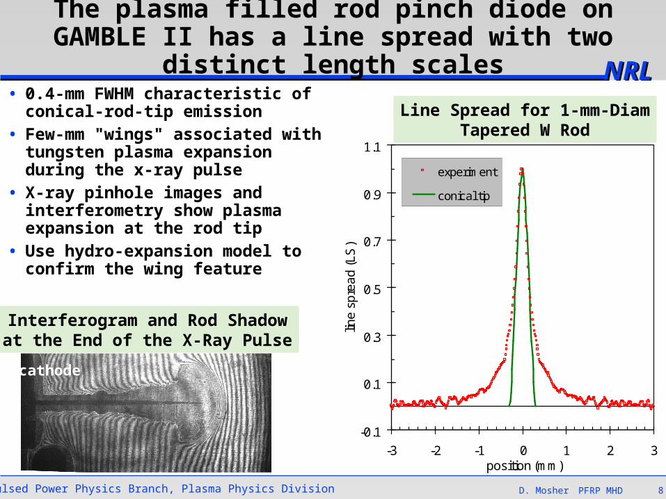
The plasma filled rod pinch diode on GAMBLE II has a line spread with two distinct length scales
• 0.4-mm FWHM characteristic of conical-rod-tip emission
• Few-mm "wings" associated with tungsten plasma expansion during the x-ray pulse
• X-ray pinhole images and interferometry show plasma expansion at the rod tip
• Use hydro-expansion model to confirm the wing feature
cathode
-0.1
0.1
0.3
0.5
0.7
0.9
1.1
-3 -2 -1 0 1 2 3position (mm)
line
sp
rea
d (
LS
)
experiment
conical tip
Line Spread for 1-mm-DiamTapered W Rod
Interferogram and Rod Shadowat the End of the X-Ray Pulse

Pulsed Power Physics Branch, Plasma Physics Division D. Mosher 9PFRP MHD
NRLNRL
The axial line spread measures the x-ray intensity emitted along the rod
• The axial line spread is a measure of electron-beam heating vs z
• Beam heating near the rod tip has a FWHM of about 4 mm
• This axial heating profile is used in the model to drive tungsten-plasma expansion
• Hydro-expansion model predictions are compared to– 2D, time-dependent interferometry– the measured time-integrated LSF
• Agreement with these measurements will indicate that the tungsten plasma parameters are reasonable and in the HED regime
x z
y
image plate
rollededge
0.00.2
0.40.60.8
1.0
0 10 20 30 40axial position (mm)
Edge Spread
Line Spread
pinhole image

Pulsed Power Physics Branch, Plasma Physics Division D. Mosher 10PFRP MHD
NRLNRL
dt)t,r(P~)r(P
P)t,r(n~)t,r(P
dt
dR
2
NmdtR2TP)t(E
Rm
kT)Z1(2
dt
Rd
)0(Rm
N
R/rexp)t(R
N)t,r(n
end
0brbr
4/5hbr
2W
t
0
4hint
W2
2
W2
W
222
A self-similar expansion model is used to estimate the line spread of the PFRP
• Tungsten mass in length L of the conical tip is distributed in a cylinder
• The axial LSF suggestsL in the 3- to 5-mm range
• Ph(t) = 0.4IdiodeVdiode/L
• Black-body radiation with emissivity from radius R(t)
• Tungsten equation of statefrom SESAME3
– Eint = 1.5(1+Z)NkT + ionization
– Eth = 1.5(1+Z)NkT 0.4Eint
– max pressure = 0.67Eth/R2(t)
• <Pbr>(r) is the PSF from which the model line spread is calculated
Self-Similar Cylindrical Expansion(per cm length of plasma)
3NTIS Doc. DE94-011699, J. D. Johnson, ‘‘SESAME Data Base’’

Pulsed Power Physics Branch, Plasma Physics Division D. Mosher 11PFRP MHD
NRLNRL
0.0E+00
5.0E+03
1.0E+04
1.5E+04
2.0E+04
2.5E+04
3.0E+04
0 20 40 60 80t (ns)
en
erg
y (J
/cm
)
heating
kinetic
internal
radiation
Self-Similar Expansion of the Rod Tip = 0.1, L = 3.5 mm
Energy PartitionExpansion History
0
1
2
3
4
5
6
7
8
0 10 20 30 40 50 60 70t (ns)
Eth /R2 (MJ/cc)
R (mm)
T(eV)/10
Z/3
Ph (1011 W/cm)

Pulsed Power Physics Branch, Plasma Physics Division D. Mosher 12PFRP MHD
NRLNRL
0.0
0.2
0.4
0.6
0.8
1.0
0.0 0.5 1.0 1.5r (mm)
<P
br>
(r)
-0.1
0.1
0.3
0.5
0.7
0.9
1.1
1.3
1.5
-3 -2 -1 0 1 2 3position (mm)
line
sp
rea
d
experiment
L = 3 mm
L = 4 mm
Self-similar hydro expansion reproduces the PFRP line spread
• Predicted line spreads are nearly independent of emissivity
• Best fit to data for L = 3 - 4 mm,agrees with axial line spread
PSF from Model for L = 3.5 mm Line Spreads from Experimentand Model for L = 3 and 4 mm
y 22
br
yr
rdrP2)y(LS

Pulsed Power Physics Branch, Plasma Physics Division D. Mosher 13PFRP MHD
NRLNRL
0.0
0.2
0.4
0.6
0.8
0.0 0.2 0.4 0.6 0.8 1.0 1.2 1.4 1.6z(cm)
R (
cm)
0
10
20
30
40
50
60
70
T (
eV
)
R, 40 ns
R, 70 ns
R, 110 ns
T, 40 ns
The self-similar expansion model can be generalized to one-dimensional axial variations1
• N(z) = Rrod(z)2W/mW
• Ph(z,t) from axial line spread
• Add return-current ohmic heating to the energy balance– Iz ~ axial edge spread
– Spitzer resistivity
Expansion Model Variations with z
1B.V. Weber, et al., Phys. Plas. 11, 2916-2927(2004).
Je
Iz
return current
t = 40 nsz
0

Pulsed Power Physics Branch, Plasma Physics Division D. Mosher 14PFRP MHD
NRLNRL
• Fringe count determines experimental electron density neS(z,t) at the schlieren boundary RexS(z,t)
• Axial-expansion equations provide the self-similar expansion radius R(z,t)
• Determine theoretical schlieren boundary RthS(z,t) from
Schlieren boundary can be calculated from axial hydro and compared to experiment
22thS2eS R/Rexp
)t,z(R
)z(N)t,z(Z)t,z(n
mm
neS at RexS
RthS -1.0
-0.8
-0.6
-0.4
-0.2
0.0
0.2
0.4
0.6
0.8
1.0
0.0 0.2 0.4 0.6 0.8 1.0 1.2 1.4 1.6 1.8 2.0
Interferogram and Rod Shadow at 110 ns
• Axial-cylindrical modeling reproduces expansion
• Analysis valid for dR/dz < 1
• Does not predict spherical expansion at z < 2 mm from tip

Pulsed Power Physics Branch, Plasma Physics Division D. Mosher 15PFRP MHD
NRLNRLConclusions
• For the tapered-rod PFRP on Gamble II, intense beam heating of the low-mass rod tip produces rapid tungsten-plasma expansion leading to extended wings in the line spread
• Measured Schlieren images and line-spread distributions compare well with self-similar hydrodynamic modeling of rod-plasma expansion
• Model predictions indicate peak thermal energy densities of about2 MJ/cc, corresponding to > 10 Mbar peak pressure
• When axial variations are taken into account, higher energy density is predicted very close to the rod tip early in the expansion, though the assumption of 2D-cylindrical expansion breaks down
• Future plans include 2-D MHD and PIC simulations of the PFRP
• Challenges for future work include– rod return-current-heating effects during the run-down phase– the role of adsorbed gases in the rod– following the run-down/plasma-opening transition– beam- and plasma-current distributions in the expanding rod plasma– geometries that reduce the wings in the line spread