pumping machine control solutions for industry ... · > somachine and the control platforms...
TRANSCRIPT

Catalogue 2012
Pumping machine control solutions for Industry & Infrastructure


1
Improve your pumping system & business performance
Water & wastewater, commercial buildings, industry or irrigation - Whatever your focus. In order to increase customer satisfaction you must supply machines which are more safe, energy efficient, reliable, at a reduced cost and shorter lead-time.
Your choice of Control Solutions is now, more than ever, a determining factor in distinguishing yourself at each stage, from the design and development to implementation and maintenance of the machine
Your Pumping solutions must be: > Reliable > Energy efficient > Innovative and adaptable > Open > Environment compliant
The requirements of a competitive market: > Quicker time to market > Optimized machines > Reduce maintenance cost > Compliance with worldwide standards > Worldwide services and support
To meet this demand, Schneider Electric offers MachineStruxure™, automation solutions, which help Machine Builders to quickly design pumping machines that are optimized regarding costs and energy efficiency, whilst maximising their performance throughout the service life of the machine. MachineStruxure™ solutions for pumping applications allow you to: > Reduce your machine’s time-to-market with predefined “Tested, Validated, and Documented Architectures” and comprehensive pumping library
> Improve machine performance with innovative automation technology and expert pumping application functions, supplemented by advanced drive technology, in order to increase energy efficiency while reducing maintenance and improving reliability
> Gain a competitive advantage and optimize the global cost of your machine: from design to maintenance, we are ready to help you wherever you are through our worldwide network of training, solution design and delivery centres, after-sales services, and pumping control experts

2
General contents

3
Contents Pumping Control Solutions
Solution Overview . . . . . . . . . . . . . . . . . . . . . . . . .
SoMachine software & Application Function Blocks library . . . . . . . .
Hardware control platform . . . . . . . . . . . . . . . . .
Communication . . . . . . . . . . . . . . . . . . . . . . . . . . .
Associated offers . . . . . . . . . . . . . . . . . . . . . . . . . .
2
1
3
4
5
6

chapter 1Pumping Control Solutions Solution overview
bb PumpingbControlbSolutionsbinformationbarebavailablebon:bwww.schneider-electric.com/pumping
2
1
3
4
5
6
7
8
9
10
1/1
Contents PumpingbControlbSolutionsSolution Overview
bb ReducebyourbPumpingbapplication’sbtime-to-market
bv Reachb100b%bofbflexibilitybandboptimisationbusingbanbinnovativebflexiblebcontrolbsystem ................................................................................................. 1/2
bv UsebthebsolidbbasebofbTested,bValidatedbandbDocumentedbArchitecturesbandbfunctionbblocksbdedicatedbtobPumpingbbapplications .......................... 1/3
bv ReducebthebcomplexitybofbyourbprogrambdesignbandbimplementationbtimesbwithbSoMachinebsoftwarebsuite ..................................................................... 1/3
bv Customizebyourbmachinesbandbupgradebthembwithoutbincreasingbthebdesignbphasesborbcosts .................................................................................. 1/3
bb Applicationbsolutions
bv BoosterbMulti-drive ......................................................................................... 1/4
bv BoosterbSinglebdrive ....................................................................................... 1/5
bb ApplicationbFunctionbBlocks
bv PumpbstagebandbDe-Stage .............................................................................. 1/6
bv Boosterbworkingbmode ................................................................................... 1/7
bv AuxiliarybPump ................................................................................................ 1/8
bv Cavitationbprotection ...................................................................................... 1/9
bv Frictionbloss ................................................................................................... 1/10
bv PID ....................................................................................................................1/11
bb EnergybEfficiency
bv 4bstepsbtobensurebimmediatebresultsbwhenboptimizingbthebenergybconsumptionbofbyourbpumpingbmachine .................................................... 1/12
bv Increasebperformancebwhilstbreducingbenergybconsumptionbbofbyourbpumpingbmachine ............................................................................ 1/13
bb Developbyourbbusiness
bv Servicebandbsupportbthatbarebbehindbyouballbthebway................................. 1/14
bv Gainbabcompetitivebadvantagebinbeachbstagebofbyourbmachine ................. 1/15
bv AbcompletebpumpingbsetupbtobvalidatebyourbPumpingbapplication .......... 1/15
bv World-classbmonitoringbservicebforbyoubandbyourbcustomers ................. 1/16
bv Easybandbhassle-freebremotebmonitoringbsolution .................................... 1/17
bv Yourbone-stopbshopbfrombsimplebcontrolbsystemsbtobglobalbautomationbsolutions ........................................................................................................ 1/18
2
1
3
4
5
6
7
8
9
10
1/2
Presentation PumpingbControlbSolutionsSolution OverviewReduce your Pumping application’s time-to-market
Reachb100b%bofbflexibilitybandbOptimizationbusingbanbinnovativebflexiblebcontrolbsystem
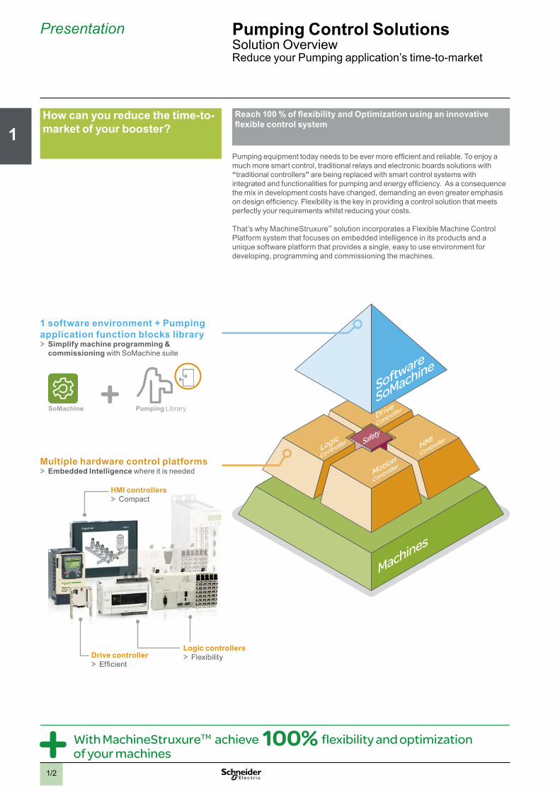
Pumping equipment today needs to be ever more efficient and reliable. To enjoy a much more smart control, traditional relays and electronic boards solutions with “traditional controllers” are being replaced with smart control systems with integrated and functionalities for pumping and energy efficiency. As a consequence the mix in development costs have changed, demanding an even greater emphasis on design efficiency. Flexibility is the key in providing a control solution that meets perfectly your requirements whilst reducing your costs.
That’s why MachineStruxure™ solution incorporates a Flexible Machine Control Platform system that focuses on embedded intelligence in its products and a unique software platform that provides a single, easy to use environment for developing, programming and commissioning the machines.
Howbcanbyoubreducebthebtime-to-marketbofbyourbbooster?
With MachineStruxureTM achieve 100% flexibility and optimization of your machines
1bsoftwarebenvironmentb+bPumpingbapplicationbfunctionbblocksblibraryb> Simplifybmachinebprogrammingb&bcommissioning with SoMachine suite
Multiplebhardwarebcontrolbplatformsb> EmbeddedbIntelligence where it is needed
SoMachine Pumping Library
Drivebcontroller > Efficient
Logicbcontrollers > Flexibility
HMIbcontrollers > Compact

2
1
3
4
5
6
7
8
9
10
1/3
Presentation PumpingbControlbSolutionsSolution OverviewReduce your Pumping application’s time-to-market
UsebthebsolidbbasebofbTested,bValidatedbandbDocumentedbArchitecturesbandbfunctionbblocksbdedicatedbtobpumpingbbapplications
Based upon flexible and scalable hardware platforms and a comprehensive single software suite, MachineStruxureTM proposes Tested, Validated and Documented Architectures (TVDA) with pumping application function block (AFB) libraries.
ReducebthebcomplexitybofbyourbprogrambdesignbandbimplementationbtimesbwithbSoMachinebsoftwarebsuiteDuebtobabrichbsetbofbtemplatesbandblibraries: > Programming and template libraries > Graphical objects > Alarm management > Application Function Blocks (AFB) library > Application examples
Customizebyourbmachinesbandbupgradebthembwithoutbincreasingbthebdesignbphasesborbcosts
Simplebcustomizationbandbintegration > With our existing function blocks you can simply modify, reuse or create your own
> Easily integrate your own systems into our architectures utilizing FDT/DTM technology
Compliancebwithbglobalbstandardsbforbmaximumbflexibilitybandbdurability > SoMachine and the control platforms support the 6 programming languages (FBD, ST, SFC, LD, IL, CFC) and is compliant with IEC 61131-3
> Integrated open and standard networks in devices > SoMachine software combined with our control platforms allow you simply upgrade your architectures
Remotebconnection > Ethernet connection allows remote connection between the pump and the ground with Wi-Fi
> Bluetooth connection available as well on Controller port
> Suggested equipment listsb> Tested: to ensure that they function in each possible configurationb> Validated: full functional compatibility of devicesb> Documented: a complete System User Guide
MachineStruxureTM solutions use open standards through IEC languages, open networks and transparency through FDT/DTM technology, providing you time savings.
Our pre-programmed function blocks offer speed in development for your applications. they can be configured with a simple copy and paste.They can be quickly implemented in the machine programs, reducing the effort required to create an application and reducing the risk of errors.
Save up 50% of design and implementation time
Pumping solutions examples
Wi-Fi- Bluetooth

2
1
3
4
5
6
7
8
9
10
1/4
Presentation Pumping Control SolutionsSolution OverviewApplication solutions
Application solutions
Booster Multi-drive
> Simplifi ed cabling > Phase control functionality integrated in the drive > Monitor Energy Effi ciency through a large range of Power Meter and easy-to-use Application function blocks > Best Effi ciency with the drive technology additional up to 20% Energy saving > Advanced pumps protection performed by the drive > All information available on HMI screen with ready to use pages matching application example > Supports fi xed speed pumps in addition to variable speed pumps
With logic controller Modicon M238Powerful solution for machines requiring maximum fl exibility and scalability plus higher level of functionality
With HMI controller Magelis SCUHigher level of functionality with an cost effective controller with built-in HMI for scalable systems
Solution breakdown1 Safety module Preventa XPS (1)2 Circuit breaker Compact NSX (1)3 Phase sequence relay Zelio control (1)4 Contactor TeSys D (1)5 Modular Circuit breaker C60L-MA (1)6 Switch mode power supply Phaseo (1)7 DC Circuit breaker C60L-DC (1)8 Logic controller Modicon M238 (See chapter 3)9 Display Magelis HMI STU (1) 10 Circuit breaker TeSys GV2M (1)11 Magnetic Circuit breaker TeSys GV2L (1)12 Contactor TeSys D (1)13 Variable speed drive Altivar 212 (1)14 Control & Signalling units Harmony XB4/XB5 (1)15 Flow meter (Third-party product)16 Pressure sensor OsiSense XMLP (1)17 Emergency stop push button Harmony XALK (1)18 Enclosure Spacial 3D ACM & AP (1)
Solution breakdown1 Safety module Preventa XPS (1)2 Circuit breaker Compact NSX (1)3 Phase sequence relay Zelio control (1) 4 Contactor TeSys D (1)5 Modular Circuit breaker C60L-MA (1)6 Switch mode power supply Phaseo (1)7 DC Circuit breaker C60L-DC (1)8 HMI controller Magelis SCU (1)9 Circuit breaker TeSys GV2M (1)10 Magnetic Circuit breaker TeSys GV2L (1)11 Contactor TeSys D (1)12 Variable speed drive Altivar 212 (1)13 Control & Signalling units Harmony XB4/XB5 (1)14 Flow meter (Third-party product)15 Pressure sensor OsiSense XMLP (1)16 Emergency stop push button Harmony XALK (1)17 Enclosure Spacial 3D ACM & AP (1)
(1) Please consult the chapter 5 - Associated offers, or our web site: www.schneider-electric.com

2
1
3
4
5
6
7
8
9
10
1/5
Presentation Pumping Control SolutionsSolution OverviewApplication solutions
Booster Single drive
> Drive connected to the same pump > Cost effective & simple solution for small booster
With drive controller Altivar IMCAn open and 30% less costly system than a PLC - based solution: without any compromise on functionalities
With logic controller Modicon M238Simple solution for machines requiring a minimum fl exibility and scalability with a good level of functionality
Solution breakdown1 Safety module Preventa XPS (1)2 Circuit breaker Compact NSX (1)3 Phase sequence relay Zelio control (1) 4 Contactor TeSys D (1)5 Modular Circuit breaker C60L-MA (1)6 Switch mode power supply Phaseo (1)7 DC Circuit breaker C60L-DC (1)8 Circuit breaker TeSys GV2M (1)9 Magnetic Circuit breaker TeSys GV2L (1)10 Contactor TeSys D (1)11 Drive controller Altivar IMC + Altivar 61 (See chapter 3)12 Control & Signalling units Harmony XB4/XB5 (1) 13 Flow meter (Third-party product)14 Pressure sensor OsiSense XMLP (1)15 Emergency stop push button Harmony XALK (1)16 Enclosure Spacial 3D ACM & AP (1)
Solution breakdown1 PowerMeter (1)2 Safety module Preventa XPS (1)3 Circuit breaker Compact NSX (1)4 Phase sequence relay Zelio control (1)5 Contactor TeSys D (1)6 Modular Circuit breaker C60L-MA (1)7 Switch mode power supply Phaseo (1)8 DC Circuit breaker C60L-DC (1)9 Logic controller Modicon M238 (See chapter 3)10 Display Magelis HMI STU (1)11 Magnetic Circuit breaker TeSys GV2L (1)12 Circuit breaker TeSys GV2M (1)13 Variable speed drive Altivar 212 (1)14 Contactor TeSys D (1)15 Control & Signalling units Harmony XB4/XB5 (1)16 Flow meter (Third-party product)17 Pressure sensor OsiSense XMLP (1)18 Emergency stop push button Harmony XALK (1)19 Enclosure Spacial 3D ACM & AP (1)
(1) See chapter 5 - Associated offers. Or please consult on our web site: www.schneider-electric.com
Other possibility for Single drive, multi lead
> Energy effi cient solution, fl exible > Drive is used to start successively all pumps
> Save 50% in design and installation time
> Modularity and fl exibility > Energy effi ciency > Openness Plug & play connectivity
2
1
3
4
5
6
7
8
9
10
1/6
Presentation PumpingbControlbSolutionsSolution OverviewApplication Function Blocks
PumpbstagebandbDe-Stage Toboptimizebboosterbsystemboperationbbybswitchingbpumps
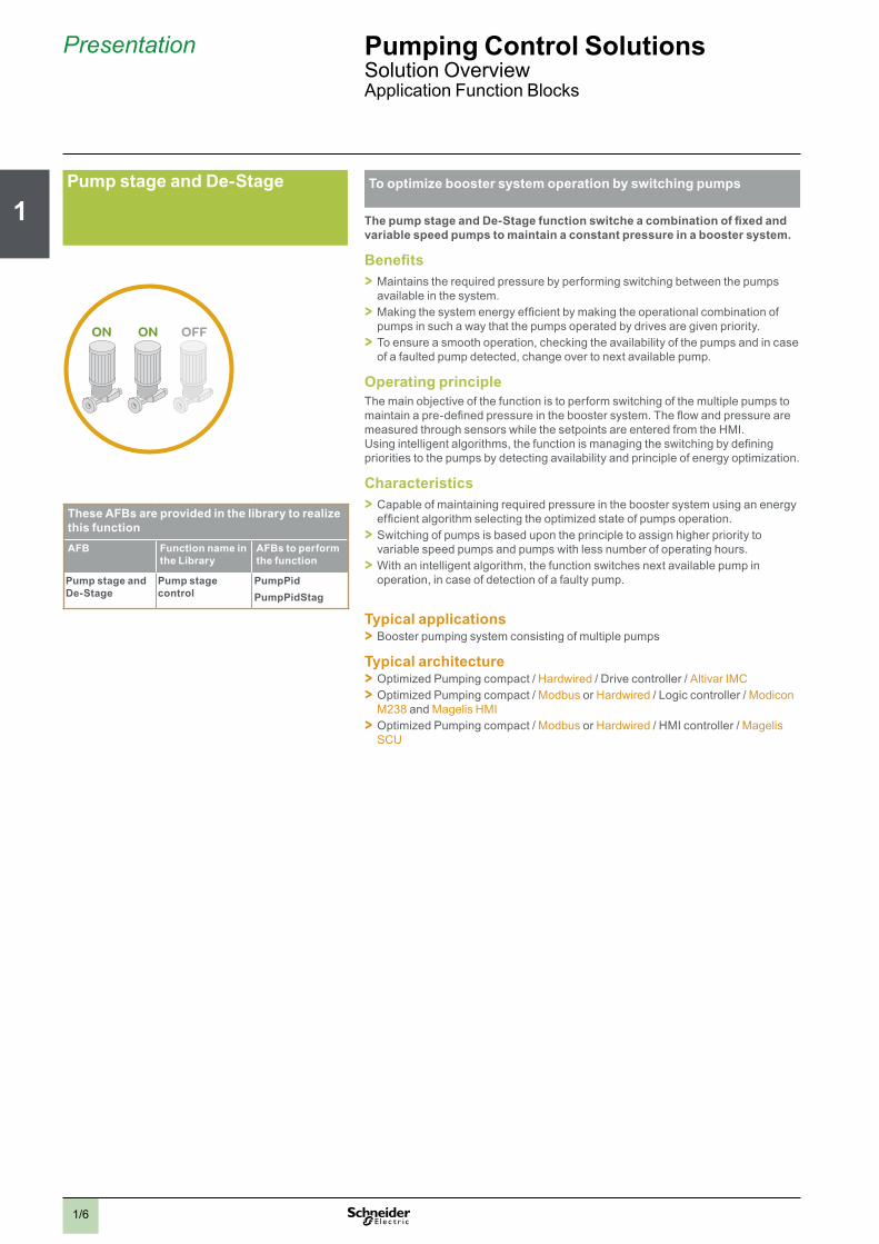
ThebpumpbstagebandbDe-Stagebfunctionbswitchebabcombinationbofbfixedbandbvariablebspeedbpumpsbtobmaintainbabconstantbpressurebinbabboosterbsystem.
Benefits > Maintains the required pressure by performing switching between the pumps available in the system. > Making the system energy efficient by making the operational combination of pumps in such a way that the pumps operated by drives are given priority. > To ensure a smooth operation, checking the availability of the pumps and in case of a faulted pump detected, change over to next available pump.
OperatingbprincipleThe main objective of the function is to perform switching of the multiple pumps to maintain a pre-defined pressure in the booster system. The flow and pressure are measured through sensors while the setpoints are entered from the HMI. Using intelligent algorithms, the function is managing the switching by defining priorities to the pumps by detecting availability and principle of energy optimization.
Characteristics > Capable of maintaining required pressure in the booster system using an energy efficient algorithm selecting the optimized state of pumps operation. > Switching of pumps is based upon the principle to assign higher priority to variable speed pumps and pumps with less number of operating hours. > With an intelligent algorithm, the function switches next available pump in operation, in case of detection of a faulty pump.
Typicalbapplications > Booster pumping system consisting of multiple pumps
Typicalbarchitecture > Optimized Pumping compact / Hardwired / Drive controller / Altivar IMC > Optimized Pumping compact / Modbus or Hardwired / Logic controller / Modicon M238 and Magelis HMI > Optimized Pumping compact / Modbus or Hardwired / HMI controller / Magelis SCU
ON ON OFF
ThesebAFBsbarebprovidedbinbtheblibrarybtobrealizebthisbfunctionAFB Functionbnamebinb
thebLibraryAFBsbtobperformbthebfunction
PumpbstagebandbDe-Stage
Pumpbstagebcontrol
PumpPidPumpPidStag
2
1
3
4
5
6
7
8
9
10
1/7
Presentation PumpingbControlbSolutionsSolution OverviewApplication Function Blocks
Boosterbworkingbmode Toboperatebthebboosterbsystembinbanboptimizedbmethodbbybselectingbappropriatebworkingbmodebofbthebpumpsb
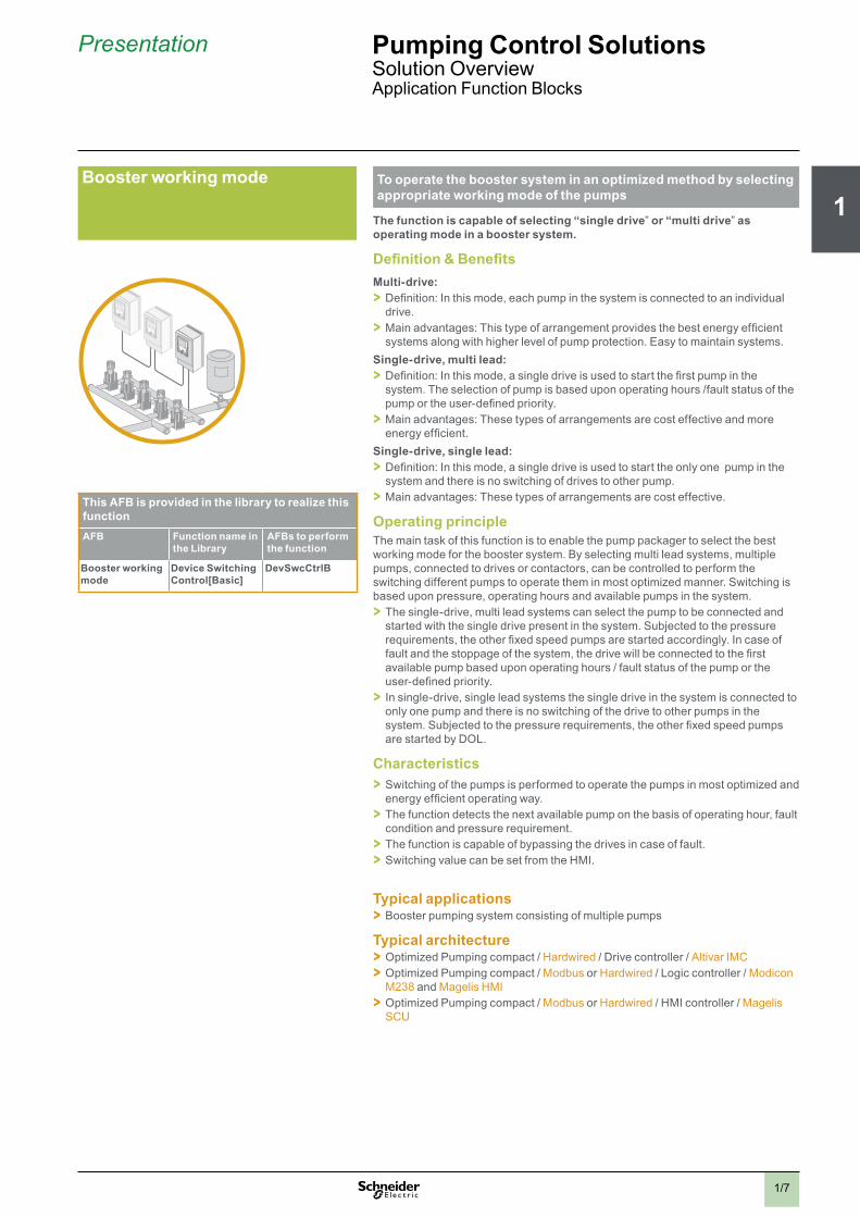
Thebfunctionbisbcapablebofbselectingb“singlebdrive”borb“multibdrive”basboperatingbmodebinbabboosterbsystem.
Definitionb&bBenefitsMulti-drive:b > Definition: In this mode, each pump in the system is connected to an individual drive. > Main advantages: This type of arrangement provides the best energy efficient systems along with higher level of pump protection. Easy to maintain systems.
Single-drive,bmultiblead:b > Definition: In this mode, a single drive is used to start the first pump in the system. The selection of pump is based upon operating hours /fault status of the pump or the user-defined priority. > Main advantages: These types of arrangements are cost effective and more energy efficient.
Single-drive,bsingleblead:b > Definition: In this mode, a single drive is used to start the only one pump in the system and there is no switching of drives to other pump. > Main advantages: These types of arrangements are cost effective.
OperatingbprincipleThe main task of this function is to enable the pump packager to select the best working mode for the booster system. By selecting multi lead systems, multiple pumps, connected to drives or contactors, can be controlled to perform the switching different pumps to operate them in most optimized manner. Switching is based upon pressure, operating hours and available pumps in the system. > The single-drive, multi lead systems can select the pump to be connected and started with the single drive present in the system. Subjected to the pressure requirements, the other fixed speed pumps are started accordingly. In case of fault and the stoppage of the system, the drive will be connected to the first available pump based upon operating hours / fault status of the pump or the user-defined priority. > In single-drive, single lead systems the single drive in the system is connected to only one pump and there is no switching of the drive to other pumps in the system. Subjected to the pressure requirements, the other fixed speed pumps are started by DOL.
Characteristics > Switching of the pumps is performed to operate the pumps in most optimized and energy efficient operating way. > The function detects the next available pump on the basis of operating hour, fault condition and pressure requirement. > The function is capable of bypassing the drives in case of fault. > Switching value can be set from the HMI.
Typicalbapplications > Booster pumping system consisting of multiple pumps
Typicalbarchitecture > Optimized Pumping compact / Hardwired / Drive controller / Altivar IMC > Optimized Pumping compact / Modbus or Hardwired / Logic controller / Modicon M238 and Magelis HMI > Optimized Pumping compact / Modbus or Hardwired / HMI controller / Magelis SCU
ThisbAFBbisbprovidedbinbtheblibrarybtobrealizebthisbfunctionAFB Functionbnamebinb
thebLibraryAFBsbtobperformbthebfunction
Boosterbworkingbmode
DevicebSwitchingbControl[Basic]
DevSwcCtrlB

2
1
3
4
5
6
7
8
9
10
1/8
Presentation PumpingbControlbSolutionsSolution OverviewApplication Function Blocks
AuxiliarybPump Operatingbauxiliarybspeedbpumpsbinbabboosterbsystem
Thebauxiliarybpumpbcontrolbfunctionbisbcontrollingbthebauxiliarybpumpbtobmaintainbthebwaterbpressurebduringbsleepbmodeb(night)bwithbmonitoringbofbalarms.
Benefits > Detect condition where an auxiliary pump needs to be operated. > Ensure optimized pump efficiency by switching auxiliary pumps to maintain pressure in the system. > Increase the energy efficiency of the system by operating smaller pumps to maintain lower flow.
OperatingbprincipleThe main task of this function is to maintain the pressure during low flow situations, like in the night (sleep-mode), in a water distribution system. The sleep mode is detected by the PID-stage/de-stage function. By detecting a low pressure, the system sends command to start the auxiliary pump. Similarly, the sleep modes ends by detecting pressure dropping below the required limit.
Characteristics > With the setpoints and actual pressure values, the function activates the auxiliary pump. > The function detects the end of the sleep mode with the help of the flow value or the pressure value and limit set-points. If the flow overruns the limit, the function resets the sleep mode state. > The function is capable of displaying the operating hour value.
Typicalbapplications > Booster pumping system consisting of multiple pumps
Typicalbarchitecture > Optimized Pumping compact / Hardwired / Drive controller / Altivar IMC > Optimized Pumping compact / Modbus or Hardwired / Logic controller / Modicon M238 and Magelis HMI > Optimized Pumping compact / Modbus or Hardwired / HMI controller / Magelis SCU
AUX
ThisbAFBbisbprovidedbinbtheblibrarybtobrealizebthisbfunctionAFB Functionbnamebinb
thebLibraryAFBsbtobperformbthebfunction
AuxiliarybPump AuxiliarybPumpbControl
AuxPumpCtrl
2
1
3
4
5
6
7
8
9
10
1/9
Presentation PumpingbControlbSolutionsSolution OverviewApplication Function Blocks
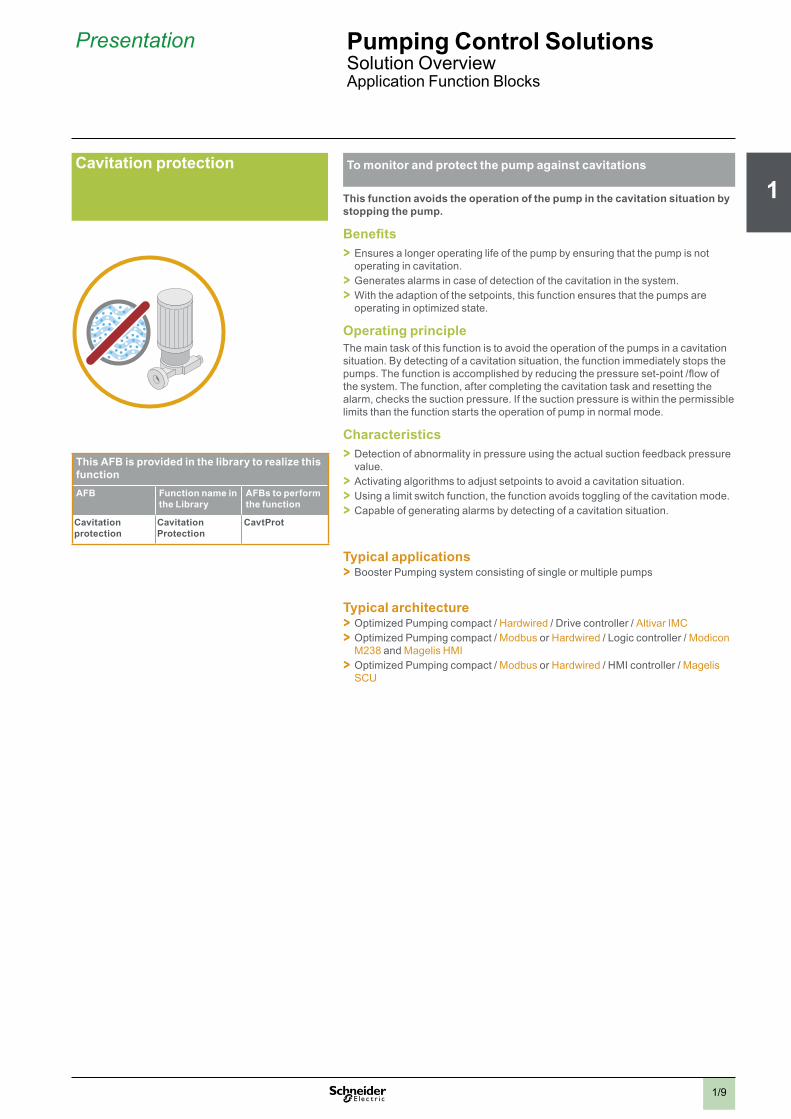
Cavitationbprotection Tobmonitorbandbprotectbthebpumpbagainstbcavitations
Thisbfunctionbavoidsbtheboperationbofbthebpumpbinbthebcavitationbsituationbbybstoppingbthebpump.
Benefits > Ensures a longer operating life of the pump by ensuring that the pump is not operating in cavitation. > Generates alarms in case of detection of the cavitation in the system. > With the adaption of the setpoints, this function ensures that the pumps are operating in optimized state.
OperatingbprincipleThe main task of this function is to avoid the operation of the pumps in a cavitation situation. By detecting of a cavitation situation, the function immediately stops the pumps. The function is accomplished by reducing the pressure set-point /flow of the system. The function, after completing the cavitation task and resetting the alarm, checks the suction pressure. If the suction pressure is within the permissible limits than the function starts the operation of pump in normal mode.
Characteristics > Detection of abnormality in pressure using the actual suction feedback pressure value. > Activating algorithms to adjust setpoints to avoid a cavitation situation. > Using a limit switch function, the function avoids toggling of the cavitation mode. > Capable of generating alarms by detecting of a cavitation situation.
Typicalbapplications > Booster Pumping system consisting of single or multiple pumps
Typicalbarchitecture > Optimized Pumping compact / Hardwired / Drive controller / Altivar IMC > Optimized Pumping compact / Modbus or Hardwired / Logic controller / Modicon M238 and Magelis HMI > Optimized Pumping compact / Modbus or Hardwired / HMI controller / Magelis SCU
ThisbAFBbisbprovidedbinbtheblibrarybtobrealizebthisbfunctionAFB Functionbnamebinb
thebLibraryAFBsbtobperformbthebfunction
Cavitationbprotection
CavitationbProtection
CavtProt

2
1
3
4
5
6
7
8
9
10
1/10
Presentation PumpingbControlbSolutionsSolution OverviewApplication Function Blocks
Frictionbloss bTobensurebablinearbpressurebinbthebboosterbsystem
Thisbfunctionbcompensatesbthebfrictionblostbbybadaptingbthebpressurebsetpointbaccordingbtobthebnumberbofbrunningbpumpsborbthebflowbvalueb(optional)binbthebdischargebside.
Benefits > Ensures a longer operating life of the pump by ensuring a linear pressure in the system. > Generates alarms in case of detection of the abnormality in suction pressure curve. > With the adaption of the pressure setpoints, this function ensures that the pumps are operating in optimized state.
Operatingbprinciple > Ideal pressure can be maintained either on the basis of flow or setpoints of each pump in the system. For flow, the function adapts the set-point to the system curve with the help of the actual flow value using actual flow value and setpoint. Both absolute and percentage values can be used. The minimal setting (two points) to use this function are:b> 1.bThe raised value in percent (% to increase the standard set-point) or the absolute value of the set-point to reach the set-point value on the highest and farthest point of the system in case of minimal flow. The standard value of this point is zero (relative) or equal to the set-point (absolute).b> 2.bThe raised value in percent (% to increase the standard set-point) or absolute value of the set-point to reach the set-point value on the highest and farthest point of the system in case of maximal flow. The value of this point is higher than zero (relative) or greater than the set-point (absolute.).
> The results of this measurement are minimum two correction values in percent or absolute values and its corresponding flow values.
In case of adaptation of the setpoints of the pumps, the function adapts the set-point depending on the number of used pumps and the moment of the stage change.
Characteristics > Detection of abnormality in pressure in the system. > Execution of algorithms to maintain the pressure using flow or setpoints management of the pumps. > Capable of generating alarms by detecting abnormality in pressure in the system.
Typicalbapplications > Booster Pumping system consisting of single or multiple Pumps
Typicalbarchitecture > Optimized Pumping compact / Hardwired / Drive controller / Altivar IMC > Optimized Pumping compact / Modbus or Hardwired / Logic controller / Modicon M238 and Magelis HMI > Optimized Pumping compact / Modbus or Hardwired / HMI controller / Magelis SCU
ThesebAFBsbarebprovidedbinbtheblibrarybtobrealizebthisbfunctionAFB Functionbnamebinb
thebLibraryAFBsbtobperformbthebfunction
FrictionbLoss Setpointbhandling CompSpBCompSpFlow

2
1
3
4
5
6
7
8
9
10
1/11
Presentation PumpingbControlbSolutionsSolution OverviewApplication Function Blocks
PID Tobbmaintainbabconstantbpressurebbybadaptingbsetpoints
ThebPIDbfunctionbadjustsbthebsetpointbofbthebpumpsbtobmaintainbabconstantbpressurebinbabboosterbsystembonbthebbasisbofbflowbandbpressure.
Benefits > Maintains the required pressure by adjusting the setpoint. > Generates alarms in case of deviation of limits. > To ensure a smooth operation, by maintaining the setpoints curve by avoiding damping.
OperatingbprincipleThe main objective of this function is to generate the set-point for the VSD in the booster system. The flow and pressure are measured through sensors while the setpoints are entered from the HMI. Using intelligent algorithms, the function manages the setpoint using flow and pressure values as input and generating the outputs values in percentage. Alarms are generated in case of deviation of values with reference of defined limits.
Characteristics > Capable of calculating the cycle time. > Capable of limiting different attributes with corresponding set of values like error value for the I-part calculation, the control value. > Detection and display of alarms in HMI.
Typicalbapplications > Booster Pumping system consisting of single or multiple Pumps
Typicalbarchitecture > Optimized Pumping compact / Hardwired / Drive controller / Altivar IMC > Optimized Pumping compact / Modbus or Hardwired / Logic controller / Modicon M238 and Magelis HMI > Optimized Pumping compact / Modbus or Hardwired / HMI controller / Magelis SCU
PID
ThisbAFBbisbprovidedbinbtheblibrarybtobrealizebthisbfunctionAFB Functionbnamebinb
thebLibraryAFBsbtobperformbthebfunction
PID PumpPid PumpPid

2
1
3
4
5
6
7
8
9
10
1/12
4bstepsbtobensurebimmediatebresultsbwhenboptimizingbthebenergybconsumptionbofbyourbpumpingbmachines
Improvebtimebtobmarket,breducingbtheboverallbcostbofbpumpingbmachinesbwhilstbincreasingbtheirbperformancesbandbaddingbinnovationsbarebeverydaybchallengesbforbyou.bOnbtopbofbthis,byourbcustomersbarebincreasinglybaskingbyoubtobdesignbmachinesbthatbrequireblessbenergy.
Forbsupportingbenergybsavingsbandbobtainingbimmediatebresults,bwebfollowbtheb4bEnergybEfficientbprinciplesbadaptedbtobthebmachineblifebcycle.b
ThebapproachbisbcompliantbwithbthebguidelinesbinbEuropeanbstandardbENb16001bandbwithbthebISOb50001b“energybmanagementbsystem”bwhichbtargetsbcontinuousbimprovementbinbthebenergybperformancebofbeveryborganization.
Model complies with EN16001 & ISO50001
Active energy efficiency
OptimizeFix the basicsMonitor, maintain, improve
Audit & Measure
Passive energy efficiency
1
2 3 4
Boostbthebenergybefficiencybofbyourbpumpingbmachines
Presentation PumpingbControlbSolutionsSolution OverviewEnergy Efficiency
MachinebBuilderbbenefits > Improve the visibility of your machines’ energy consumption
> Detection of the “over-sized” equipments as these consumes more energy
> Possible marketing argument to your customers with a real evidence of Energy savings
Endbcustomerbbenefits > Significant reductions in energy bills
> Improved preventive maintenance for machines
> Increased lifespan for motors and electronic equipment

2
1
3
4
5
6
7
8
9
10
1/13
Presentation Pumping Control SolutionsSolution OverviewEnergy Effi ciency
Increase performance whilst reducing energy consumption of your pumping machine
1 Audit & Measure energy consumption with a Schneider Electric expert. They will identify devices with high energy consumption (pumps, motors, compressors etc.) and recommend potential savings.
3 Optimize machines by using the energy effi ciency function block libraries available in the SoMachine software suite, specifi cally designed for the various applications. Example: pumps, packaging, conveyors, etc
2 Fix the basics by selecting the appropriate motor,using servo-drives, improved cabinet thermal management etc.
4 Monitor, maintain, improve. The SoMachine software suite contains function blocks dedicated to collecting energy information from metering units and electronic equipment (variable speed drive, servomotor etc.). The information provided allows the dedicated function blocks to create indicators that are used to monitor the relevant information by correlating energy readings (active power, power, current etc.) with the machine’s operational modes and production data. All of the indicators produced can be manipulated on-screen via predefi ned graphic objects supplied with SoMachine and Vijeo Designer.
1
2
34
2
1
3
4
5
6
7
8
9
10
1/14
Presentation PumpingbControlbSolutionsSolution OverviewHow can you develop your business?
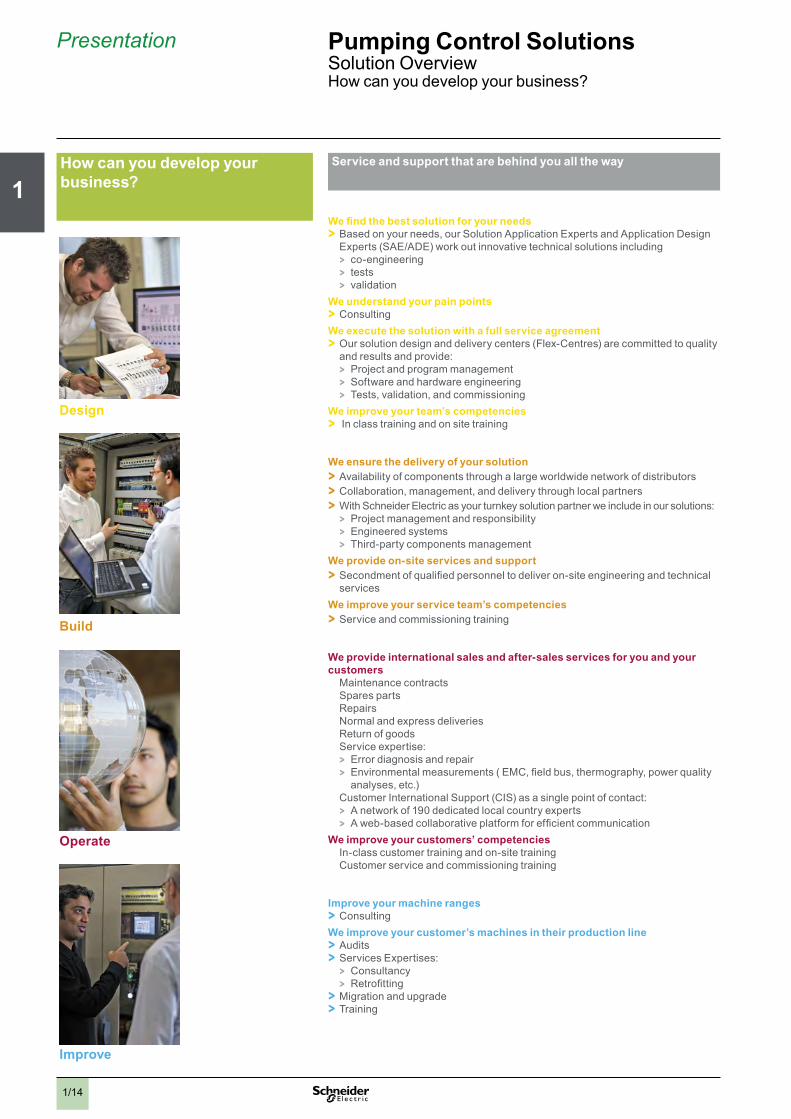
Servicebandbsupportbthatbarebbehindbyouballbthebway
Webfindbthebbestbsolutionbforbyourbneeds > Based on your needs, our Solution Application Experts and Application Design Experts (SAE/ADE) work out innovative technical solutions including > co-engineering > tests > validation
Webunderstandbyourbpainbpoints > Consulting
Webexecutebthebsolutionbwithbabfullbservicebagreement > Our solution design and delivery centers (Flex-Centres) are committed to quality and results and provide: > Project and program management > Software and hardware engineering > Tests, validation, and commissioning
Webimprovebyourbteam’sbcompetencies > In class training and on site training
Webensurebthebdeliverybofbyourbsolution > Availability of components through a large worldwide network of distributors > Collaboration, management, and delivery through local partners > With Schneider Electric as your turnkey solution partner we include in our solutions:
> Project management and responsibility > Engineered systems > Third-party components management
Webprovidebon-sitebservicesbandbsupport > Secondment of qualified personnel to deliver on-site engineering and technical services
Webimprovebyourbservicebteam’sbcompetencies > Service and commissioning training
Webprovidebinternationalbsalesbandbafter-salesbservicesbforbyoubandbyourbcustomers > Maintenance contracts > Spares parts > Repairs > Normal and express deliveries > Return of goods > Service expertise:
> Error diagnosis and repair > Environmental measurements ( EMC, field bus, thermography, power quality analyses, etc.)
> Customer International Support (CIS) as a single point of contact: > A network of 190 dedicated local country experts > A web-based collaborative platform for efficient communication
Webimprovebyourbcustomers’bcompetencies > In-class customer training and on-site training > Customer service and commissioning training
Improvebyourbmachinebranges > Consulting
Webimprovebyourbcustomer’sbmachinesbinbtheirbproductionbline > Audits > Services Expertises:
> Consultancy > Retrofitting
> Migration and upgrade > Training
Howbcanbyoubdevelopbyourbbusiness?
Operate
Build
Improveb
Designb

2
1
3
4
5
6
7
8
9
10
1/15
Presentation PumpingbControlbSolutionsSolution OverviewHow can you develop your business?
Gainbabcompetitivebadvantagebinbeachbstagebofbyourbmachine
MachineStruxureTMbsolutionsbofferbmorebthanbjustbproductsbandbarchitectures,byoubalsobgetbcompletebservicebandbsupportbatbeverybstagebofbthebproductblifebcycle.bOurbunparalleledbPumpingbandbcontrolbexpertsbwillbhelpbyoubminimisebyourbglobalbmachinebcosts,bincreasebsalesbandbprofitability,bandbdeliverbtotalbcustomerbsatisfaction.
From design to commissioning to maintenance, we’re ready to help you wherever you are with our worldwide network of training, solution design centres, distribution, and after-sales services.
AbcompletebpumpingbsetupbtobvalidatebyourbPumpingbapplication
SchneiderbElectricbwithbitsbtestbunitsbandbexpertisebisbablebtobsimulatebyourbinstallationbasbfollows:
> Select the architecture you want > DOL, Single drive, Multidrive > I/O control, Field-bus control > Controllers & HMI > Drives: Altivar 212 / Altivar 61
> Select Hydraulic circuit > Apply to hydraulic system for test case
> Run complete test and Monitor > Energy consumption > Pressure, Flow, etc
Increase your efficiency and competitiveness
Connect with the experts
www.schneider-electric.com/pumping
Build
Operate
Improve
Design
Your machine

2
1
3
4
5
6
7
8
9
10
1/16
Presentation PumpingbControlbSolutionsSolution OverviewHow can you develop your business?
Howbcanbyoubdevelopbyourbbusiness?
World-classbmonitoringbservicebforbyoubandbyourbcustomers
Thebweb-enabledbcapabilitiesbofbthebcontrollerbofferbassociatedbwithbthebOptiM2MTMbsolutionbforbremotebmonitoringbofbmachinesballowbanbunrivalledbqualitybofbmachinebservicebforbyourbcustomers,bwithbreducedbreactionbtimesbandbattractivebmaintenancebplans.
Getbconstantbvisibilitybintobyourbmachinebdata
> With OptiM2M, a web-based machine-to-machine monitoring application, you can remotely view and analyse incoming machine data. At any time, from anywhere in the world, using only your smart phone, laptop or another web-connected device with a browser.
> OptiM2M users can harvest detailed, real-time equipment usage statistics, such as energy consumption of Pumping machines or usage statistics data access can be configured according to user type (equipment manager/owner/user, etc)
WhybchosebOptiM2M?
> Grow your business and profits > Develop sales with new customers and reach new markets > Generate additional business with existing customers > Develop your portfolio of smart services
> Build your service provider image and customer satisfaction > Maximise machine uptime and minimise after-sales intervention costs on site > Achieve higher energy efficiency in true operating conditions > Add value to your product with quality machine lifecycle support
Unirivalled machine services for you and your customers
> Improved control of remote equipment
> Enhanced reaction time and productivity: detailed reports on equipment use (usage statistics, machine energy consumption, etc.)
> New services for your established customers

2
1
3
4
5
6
7
8
9
10
1/17
Presentation PumpingbControlbSolutionsSolution OverviewHow can you develop your business?
Easybandbhassle-freebremotebmonitoringbsolution
Asbabmachinebmanufacturerbyoubknowbthatbinstallingbandbdeployingbabcommunicationbsolutionbisboftenbeasierbonbpaperbthanbinbrealblife.bThat’sbwhybatbSchneiderbElectricbwebarebcommitedbtobmakingbourbmachine-to-machinebcloudbsolutionbasbeasybtobconfigurebasbitbgets.ThebOptiM2Mbsystembisbanbinstall-and-gobsolutionbthatbdeliversbsecuredbend-to-endbwirelessbconnectivitybforbmachine-to-machinebapplications.
Improve pumping machine management through remote control
Justbconnectbthebmodembtobthebpowerbsupplybandbtobthebcontrollerbofbeverybmachinebinbyourbpool.
Enterbinformationbofbthebnewbmonitoredbmachine,bmodifybparametersbofbyourbmonitoringbapplication,bandbeasilybcopybthebconfigurationbtoballbyourbmachinesbofbthebsamebtype.
Tobmanagebandbmonitorbdata,byoubwillbneedbabdevicebwithbabbrowserbandbwebbaccess.Inbcasebofbmachinebalert,byoubwillbreceivebnotificationsbwithbadditionalbdiagnosisbinformation.
Install Server
Operate
Configure
and deploy
GPRSGSM
InternetGSM
Internet

2
1
3
4
5
6
7
8
9
10
1/18
Presentation PumpingbControlbSolutionsSolution OverviewHow can you develop your business?
Howbcanbyoubdevelopbyourbbusiness?
Yourbone-stopbshopbfrombsimplebcontrolbsystemsbtobglobalbautomationbsolutions
SchneiderbElectricbisbabworldbleaderbinbautomation.bWebhelpbyoubbenefitbfrombtheblatestbtechnologiesbthatbcanbturnbyourbmachinesbintobabcommercialbsuccess.bFrombactuatorsbtobcontrolbsystems,bwebhavebthebsolutionbthatbisbsuitedbtobyourbspecificbneeds
Motorbcontrol > Maximum productivity and efficiency
HMI,bcontrolbandbdialogbdevices > Intuitive and ergonomic design
Detection,bcommunication,benergybdistribution,bswitching > Assembly and supply systems, protection and control of LV power circuits, power meters, HVAC & R sensors, valves and actuators
AlliancebPartnersBuilding on our open automation platforms and strategies, we work with strategic partners who compliment our capabilities in order to provide you with solutions that fully meet your business objectives. Within this collaboration partnership that can deliver the most complete and effective solution for your applications.
> wide range > simple to use > network opening > worldwide availability
Innovationbdedicatedbtobreductionbof: > enclosure size > wiring time > installation time

2
1
3
4
5
6
7
8
9
10
1/19
Presentation PumpingbControlbSolutionsSolution OverviewHow can you develop your business?
Yourbone-stopbshopbfrombsimplebcontrolbsystemsbtobglobalbautomationbsolutions
Frombmachinebtobplant,bSchneiderbElectricbprovidesbabsingle,bopenbandbfullybcoherentbsystem.
PlantStruxure™barchitecturebisbSchneiderbElectric’sbcomprehensivebsolutionbforbindustrialbbprocessbcontrol,bwhereasbMachineStruxureTMbarchitecturebisbdedicatedbtobmachinebcontrol.Because both architectures are based on open standards and designed to be fully compatible, your machines can easily be integrated into your customers’ factory processes. In addition, open standards allow your machines to evolve with your customers’ changing requirements.h
Pumping machine control
Ethernet TCP/IP
Process & machine managment
Mod
bus
Mod
bus
Mod
bus
Drive controller
HMI controller
Logic controller
Logic controller
MachineStruxureTMbarchitecture,bonebofbthebmainstaysbofbEcoStruxurebarchitectureEcoStruxureTM system architecture enables the convergence of five key domains of our expertise: management of Power, Processes and Machines, the IT Room, Buildings, and Security.EcoStruxureTM architecture takes multiple, siloed systems and adapts them to an integrated solution, reducing redundancy in equipment, software, and personnel.
Power Management
Process & Machine
Management
White Space Management
Building Comfort Management
SecurityManagement
From machine to plant, Schneider Electric provides a single, fully coherent system

chapter 2SoMachine software suite
All technical information about products listed in this chapter are available on www.schneider-electric.com

2
1
3
4
5
6
7
8
9
10
2/1
b SoMachine software suite
v Visual graphic user interface . . . . . . . . . . . . . . . . . . . . . . . . . . . . . . . . . . . . 2/2
v Learning centre . . . . . . . . . . . . . . . . . . . . . . . . . . . . . . . . . . . . . . . . . . . . . . . 2/2
v Projects management . . . . . . . . . . . . . . . . . . . . . . . . . . . . . . . . . . . . . . . . . . 2/2
v Project properties . . . . . . . . . . . . . . . . . . . . . . . . . . . . . . . . . . . . . . . . . . . . . 2/3
v Configuration . . . . . . . . . . . . . . . . . . . . . . . . . . . . . . . . . . . . . . . . . . . . . . . . . 2/3
v Programming and debug . . . . . . . . . . . . . . . . . . . . . . . . . . . . . . . . . . . . . . . . 2/3
v Commissioning . . . . . . . . . . . . . . . . . . . . . . . . . . . . . . . . . . . . . . . . . . . . . . . 2/3
v Documentation . . . . . . . . . . . . . . . . . . . . . . . . . . . . . . . . . . . . . . . . . . . . . . . . 2/3
v Transparency . . . . . . . . . . . . . . . . . . . . . . . . . . . . . . . . . . . . . . . . . . . . . . . . . 2/3
v Dedicated OEM application libraries (AFB libraries) . . . . . . . . . . . . . . . . . 2/3
v Tested Validated Documented Architectures (TVDA) . . . . . . . . . . . . . . . . 2/3
b SoMachine characteristics . . . . . . . . . . . . . . . . . . . . . . . . . . 2/4
b References . . . . . . . . . . . . . . . . . . . . . . . . . . . . . . . . . . . . . . . 2/5
Contents SoMachine software suite

2
1
3
4
5
6
7
8
9
10
2/2
Presentation SoMachine software suiteSimplify machine programming and commissioning
PresentationSoMachine is the Machine Builder solution software for developing, configuring and commissioning the entire machine in a single software environment, including logic, motion control, HMI and related network automation functions.
SoMachine allows you to program and commission all the elements in Schneider Electric’s Flexible and Scalable Control platform, the comprehensive solution-oriented offer for Machine Builders, which helps you achieve optimized control solution for each machine’s requirements.
Flexible and Scalable Control platforms include:Controllers:
b HMI controllers: XBT GC, XBT GT/GK CANopen, b Logic controllers for Solutions with AFB: Modicon M238S, Modicon M258S, b Drive Controller: Altivar IMC for Solutions with AFB, b I/Os range: Modicon TM2, Modicon TM5 and Modicon TM7 offers
HMI: b Small Panels MagelisTM STO/STU b Advanced Panels MagelisTM GH/GK/GT b Optimum Advanced Panels MagelisTM GTO
SoMachine is a professional, efficient, and open software solution integrating Vijeo-Designer.It integrates also the configuring and commissioning tool for motion control devices.It features the IEC 61131-3 languages, integrated field bus configurators, expert diagnostics and debugging, as well as outstanding capabilities for maintenance and visualisation.
SoMachine integrates tested, validated, documented and supported expert application libraries dedicated to applications in Pumping, Packaging, Hoisting and Conveying.
SoMachine provides you: b One software package b One project file b One cable connection b One download operation
Visual graphic user interfaceNavigation within SoMachine is intuitive and highly visual. Presentation is optimized in such a way that selecting the development stage of the desired project makes the appropriate tools available. The user interface ensures nothing is overlooked, and suggests the tasks to be performed throughout the project development cycle. The workspace has been streamlined, so that only that which is necessary and relevant to the current task is featured, without any superfluous information.
Learning centreFrom the home menu, the learning centre provides several tools to get started with SoMachine. An animated file explains briefly the SoMachine interface and concept. An e-learning allows to run a self-training about SoMachine. A third section gives access to several documented examples of simple coding with SoMachine. An intuitive and efficient online help is also available, guiding you to get the appropriate answer.
Projects managementThe implemented project management principle allows to browse quickly through the existing projects getting the relevant information without the need to open them before selection.The user can create a new project, starting from several means: using Tested Validated and Documented Architectures, using the provided examples, using an existing project or start with an empty project. There is quick access to the most recently-used projects. There is as well a way to start a project from standard project taking advantages of a pre-configured program (task, library, ....)
Project management
SoMachine software platform
HMI
PC + SoMachine software
Variable speed driveDrive
Controller
Sensors
Software solution
Modbus

2
1
3
4
5
6
7
8
9
10
2/3
Presentation (continued) SoMachine software suiteSimplify machine programming and commissioning
Project propertiesFor each project, the user has the option to define additional information, through simple forms. It’s also possible to attach documents, a customer picture and a configuration picture.
Configuration From the graphic user interface, the user can easily build his architecture and configure the devices of the architecture.
Description of the architectureA graphic editor can be used to assemble the various elements easily by a simple drag & drop. A devices catalogue is displayed on the left of the screen. It is split into several sections: controllers, HMI, Miscellaneous and search.
Configuration of the deviceDirectly from the topologic view of the user interface, a simple click drives the user to the configuration screen of the selected device.
Programming and debugProgramming is an essential step, and the user has to carefully design it to be as efficient as possible. Advanced control and HMI functions cover all the needs of an engineer in terms of creating the control and visualisation system.Powerful tools allow debug and functional tests such as simulation, step by step execution, break points and trace.
CommissioningFor an easy and fast diagnostic, the menu commissioning allows the user to check the online state of his architecture.Through the topologic view of the configuration, the devices display if you are logged in or not, as well as if they are in run or stop mode.
DocumentationBecause a printed file of the project is an important element, it is possible to build and customize the project report: - select the items to be included in the report, - organize the sections, - define the page layout - and then launch the printing.
Transparency SoMachine supports Device Type manager (DTM) because it is a field device tool (FDT) container.With DTM’s representing field device in SoMachine, direct communications are possible to every single device via SoMachine, the controller and the field bus (Modbus for all devices and CANopen for the I/O’s). From the SoMachine unique environment, the remote devices can be set-up off-line and tuned on-line.
Dedicated application libraries (AFB libraries)SoMachine can be extended through its solution extension DVD. It integrates tested, validated, documented and supported expert application libraries dedicated to many Machine Builder applications. Their simple configuration speeds up design, commissioning, installation and troubleshooting.These libraries cover the following applications:
b Packaging, b Hoisting, b Conveying b Pumping
Tested Validated Documented Architectures (TVDA)SoMachine provides a variety of preset projects with ready-to-use architectures you can adapt to individual requirements. Some of them are generic TVDA, they are based on controllers configuration. The solution extension DVD brings specific application solutions oriented TVDA’s to SoMachine.
Commissioning
Transparency
Application Function Blocks
Configuration

2
1
3
4
5
6
7
8
9
10
2/4
Characteristics SoMachine software suiteSimplify machine programming and commissioning
SoMachine characteristicsOverview
IEC 61131-3 programming languages b IL (Instruction List) b LD (Ladder Diagram) b SFC (Sequential Function Chart) b ST (Structured Text) b FBD (Function Block Diagram) b + CFC (Continous Function Chart)
Controller programming services b Multi-tasking: Mast, Fast, Event b Functions (Func) and Function Blocks (FBs) b Data Unit Type (DUTs) b On-line changes b Watch windows b Graphical monitoring of variables (trace) b Breakpoints, step-by-step execution b Simulation b Visualization for application and machine set-up
HMI-based services b Graphics libraries containing more than 4000 2D and 3D objects. b Simple drawing objects (points, line, rectangles, ellipses, etc …) b Preconfigured objects (button, switch, bar graph, etc …) b Recipes (32 groups of 256 recipes with max. 1024 ingredients) b Action tables b Alarms b Printing b Java scripts b Multimedia file support: wav, png, jpg, emf, bmp b Variable trending
Motion services b Embeded devices configuration and commissioning b CAM profile editor b Sample application trace b Motion and drive function blocks libraries for inverters, servos and steppers b Visualization screens b Logical encoder
Global services b User access and profile b Project documentation printing b Project comparison (control) b Variable sharing based on publish/subscribe mechanism b Library version management b Energy efficiency machine monitoring
Integrated fieldbus configurators b Control network: v Modbus Serial Line v Modbus TCP
b Field bus: v CANopen v CANmotion
b Connectivity: v Profibus-DP v Ethernet IP
Expert and solutions libraries b PLCopen function blocks for Motion control v Example: MC_MoveAbsolute, MC_CamIn, ServoDrive, ...
b Packaging function blocks v Example: Analog film tension control, rotary knife, lateral film position control, ...
b Conveying function blocks v Example: tracking, turntable, conveyor , ...
b Hoisting functions v Hoisting function blocks: anti-sway, anti-crab, hoisting position
synchronisation, ... v Application template for industrial crane
b Pumping application v Pumping function blocks v Application template for booster
b Energy Efficiency library

2
1
3
4
5
6
7
8
9
10
2/5
References SoMachine software suiteSimplify machine programming and commissioning
Product offerSoMachine software is delivered on a DVD, it is a product oriented version that includes all SoMachine features related to generic hardware (M238, M258, LMC058, XBT GC, Altivar IMC), as well as generic TVDA.
The solution features are added to SoMachine by installing its solution extension DVD. It includes all SoMachine solutions hardware, plus all the dedicated application libraries and TVDA.
References b SoMachine is available in 6 languages:
v English v French v German v Italian v Spanish v Simplified Chinese.
b System Requirements: v Processor: Pentium 4 - 1,8 GHz or higher , Pentium M 1.0 GHz or equivalent v RAM Memory: 2 GByte; recommended: 3 GByte v Hard Disk: 3.5 GB, recommended: 5 GB v OS: Windows XP Professional, Windows 7 Professional 32/64 bytes v Drive: DVD reader v Display: 1024 × 768 pixel resolution or higher v Peripherals: a Mouse or compatible pointing device v Peripherals: USB interface v Web Access: Web registration requires Internet access
b The documentation is supplied in electronic format: complete on-line help plus complementary documentation in pdf version.
SoMachine solution extension for Solution controllers (1)
Added controllers
Added TVDA Added libraries
Reference (2)
DVDs and Licence / number & type
b M238S b M258S b LMC058S b XBT GC with CANopen
module type S b XBT GT/GK with control
function type S b Altivar IMC with control
function type S
- Optimized CANopen Altivar IMC - Performance CANmotion
LMC058 - Hoisting Optimized
CANopen M238 - Conveying Performance
CANmotion LMC058
HoistingConveyingPackagingPumping
MSDCHLLMUV31S0 / 1 (Single)
MSDCHLLMTV31S0 / 10 (Team)
MSDCHLLMFV31S0 /100 (Facility)
SoMachine software compatibility and hardware control platformsProduct type Version
Logic controller Modicon M238 ≥ V1.0HMI controller XBT GCLogic controller Modicon M238S ≥ V2.0Logic controller Modicon M258Logic controller Modicon M258SMotion controller Modicon LMC058 ≥ V3.0Motion controller Modicon LMC058S ≥ V2.0HMI controller XBT GT/GK with control function type S, XBT GC with CANopen module type SAltivar IMC integrated controller card ≥ V3.1Altivar IMC integrated controller card with control function type S ≥ V2.0TM5 CANopen Interface ≥ V3.0TM7 CANopen Interface blockAltivar IMC integrated controller card (with patch)(1) For this offer, please contact your Customer Care Centre.(2) Each reference for SoMachine solution software contains: one generic trail DVD, one solution extension V3.1 DVD and one licence.
chapter 3Hardware control platforms
All technical information about products listed in this chapter are available on www.schneider-electric.com

2
1
3
4
5
6
7
8
9
10
3/1
b Drive controller for Solutions with AFB, HMI controllers, Logic controllers compact base for Solutions with AFB
General selection guide ............................................................................... 3/2
b Drive controller for Solutions with AFB
v Altivar IMC drive controller card type S solutions with AFB for Altivar 61 variable speed drivePresentation ................................................................................................ 3/4Functions .................................................................................................... 3/6Description, References .............................................................................. 3/7
b HMI controllers
v MagelisTM XBT GC HMI ControllersSelection guide ............................................................................................ 3/8Presentation .............................................................................................. 3/10Functions ................................................................................................... 3/12Description ................................................................................................ 3/13References ................................................................................................ 3/14Combination .............................................................................................. 3/15
b Logic compact bases for Solutions with AFB
v Modicon M238 logic controller compact base for Solutions with AFBSelection guide .......................................................................................... 3/16Presentation .............................................................................................. 3/18Description ................................................................................................ 3/20References ................................................................................................ 3/21Memory structure....................................................................................... 3/23
v Modicon M258 logic controller compact base for Solutions with AFBSelection guide .......................................................................................... 3/24Presentation .............................................................................................. 3/26Description ................................................................................................ 3/31References ................................................................................................ 3/32
b I/O expansion modules for Hardware platform control
v Local and remote I/O expansion modulesSelection guide .......................................................................................... 3/34
v Distributed I/O expansion modulesSelection guide .......................................................................................... 3/34
Contents Hardware control platforms

2
1
3
4
5
6
7
8
9
10
3/23/2
General selection guide Hardware control platformsDrive controller type S Solutions with AFB, HMI controllers, Logic controllers for Solutions with AFB
Applications Control by integration of automation functions on Altivar 61 variable speed drive
Data control and parameter-settingIEC 1131-2 control function Display of text messages, graphic objects and mimics
High speed counter control and simple position control Speed control, high speed counter control and motion control
Machines Textile, hoisting, pumping, woodworking, etc.
All machine types, pumping Packaging, conveying, hoisting, pumping, ... Packaging, conveying, hoisting, pumping, ...
Configuration software SoMachine
Power supply 24 V c 24 V c 24 V c and 100/240 V a 24 V c
Embedded inputs (depending on model)
v 10 digital inputs including 4 available for 2 HSC inputs or 2 incremental encoders
v 2 analog inputs
12 to 16 digital outputs v 14 digital inputs, 8 of which can be configured as fast inputs v 26 to 38 digital inputs including 8 counter inputs (200 kHz) v 4 analog inputs
Embedded outputs(depending on model)
v 6 transistor outputs v 2 analog outputs
v 6 to 16 transistor outputs v 4 transistor outputs + 6 relay outputs or 10 transistor outputs, 4 of which can be configured as fast outputs
v 16 to 28 transistor outputs including 4 reflex outputs v Up to 12 relay outputs
I/O expansion With expansion card VW3A320p: v Digital, analog, relay, frequency control
and probe I/O (see page 3/4)
With Modicon TM2 expansion modules: v Digital I/O (see page 3/34) v Analog I/O (see page 3/34)
With Modicon TM2 modules: v Digital I/O (see page 3/34) v Analog I/O (see page 3/34)
With Modicon TM5 compact blocks: v Digital and analog I/O (see page 3/34)
With Modicon TM5 modules: v Digital (see page 3/34) v Digital/Analog (see page 3/34) v Analog (see page 3/34)
Integrated functions v HSC v Analog v Position control
v Display of animated mimics and current date and time
v Control and modification of numeric or alphanumeric variables
v Real-time and trending curves with log v Multiwindow management v Page calls initiated by the operator v Multilingual application management v Recipe management v Data processing via Java script v Application support and external memory logs v Management of printers and barcode readers v Execution of programmed logic sequences v CANopen fieldbus device management v Management of digital/analog I/O on
expansion modules
v HSC v PTO v PWM v PID control v Event processing
v HSC v Analog v Position control v PWM
Communication Embedded v Protocols: Ethernet Modbus TCP, UDP, TCP, SNMP
v Web/FTP servers v CANopen master v Ethernet
v Serial links: RS 232C/RS 422/485 v Protocols: Uni-TE, Modbus, Modbus TCP/IP v Ethernet v Parallel printer
v Master/slave type isolated serial link v Protocols: Modbus master/slave RTU/ASCII, ASCII v CANopen master
v Serial links: RS232/RS485 v Web/FTP servers v Protocols: , Modbus master/slave RTU/ASCII, ASCII v CANopen master v Ethernet
Option v ModbusPlus v Uni-Telway v InterBus-S v Profibus DP v DeviceNet v Ethernet Modbus/TCP v Fipio v EtherNet IP v CC-Link v Lonworks v METASYS N2 v APOGEE FLN v BACnet
v CANopen master v Ethernet v Profibus v DeviceNet
v Modbus RS232 serial link v Modbus RS485 serial link v Profibus DP (slave)
User memory RAM 2 MB 512 KB (SRAM) 500 or 1000 KB (depending on model) 64 MB (program + data)Flash 2 MB 16 to 32 MB (Flash EEPROM) 2 MB 128 MB
Controller ATV IMC drive controller card type S solutions with AFBControl by integration of automation functions on Altivar 61 variable speed drives
XBTGC controllers M238 logic controller type S, compact base for solutions with AFB
M258 logic controllertype S, compact base for solutions with AFB
Pages 3/4 3/8 3/16 3/24

2
1
3
4
5
6
7
8
9
10
3/33/3
Applications Control by integration of automation functions on Altivar 61 variable speed drive
Data control and parameter-settingIEC 1131-2 control function Display of text messages, graphic objects and mimics
High speed counter control and simple position control Speed control, high speed counter control and motion control
Machines Textile, hoisting, pumping, woodworking, etc.
All machine types, pumping Packaging, conveying, hoisting, pumping, ... Packaging, conveying, hoisting, pumping, ...
Configuration software SoMachine
Power supply 24 V c 24 V c 24 V c and 100/240 V a 24 V c
Embedded inputs (depending on model)
v 10 digital inputs including 4 available for 2 HSC inputs or 2 incremental encoders
v 2 analog inputs
12 to 16 digital outputs v 14 digital inputs, 8 of which can be configured as fast inputs v 26 to 38 digital inputs including 8 counter inputs (200 kHz) v 4 analog inputs
Embedded outputs(depending on model)
v 6 transistor outputs v 2 analog outputs
v 6 to 16 transistor outputs v 4 transistor outputs + 6 relay outputs or 10 transistor outputs, 4 of which can be configured as fast outputs
v 16 to 28 transistor outputs including 4 reflex outputs v Up to 12 relay outputs
I/O expansion With expansion card VW3A320p: v Digital, analog, relay, frequency control
and probe I/O (see page 3/4)
With Modicon TM2 expansion modules: v Digital I/O (see page 3/34) v Analog I/O (see page 3/34)
With Modicon TM2 modules: v Digital I/O (see page 3/34) v Analog I/O (see page 3/34)
With Modicon TM5 compact blocks: v Digital and analog I/O (see page 3/34)
With Modicon TM5 modules: v Digital (see page 3/34) v Digital/Analog (see page 3/34) v Analog (see page 3/34)
Integrated functions v HSC v Analog v Position control
v Display of animated mimics and current date and time
v Control and modification of numeric or alphanumeric variables
v Real-time and trending curves with log v Multiwindow management v Page calls initiated by the operator v Multilingual application management v Recipe management v Data processing via Java script v Application support and external memory logs v Management of printers and barcode readers v Execution of programmed logic sequences v CANopen fieldbus device management v Management of digital/analog I/O on
expansion modules
v HSC v PTO v PWM v PID control v Event processing
v HSC v Analog v Position control v PWM
Communication Embedded v Protocols: Ethernet Modbus TCP, UDP, TCP, SNMP
v Web/FTP servers v CANopen master v Ethernet
v Serial links: RS 232C/RS 422/485 v Protocols: Uni-TE, Modbus, Modbus TCP/IP v Ethernet v Parallel printer
v Master/slave type isolated serial link v Protocols: Modbus master/slave RTU/ASCII, ASCII v CANopen master
v Serial links: RS232/RS485 v Web/FTP servers v Protocols: , Modbus master/slave RTU/ASCII, ASCII v CANopen master v Ethernet
Option v ModbusPlus v Uni-Telway v InterBus-S v Profibus DP v DeviceNet v Ethernet Modbus/TCP v Fipio v EtherNet IP v CC-Link v Lonworks v METASYS N2 v APOGEE FLN v BACnet
v CANopen master v Ethernet v Profibus v DeviceNet
v Modbus RS232 serial link v Modbus RS485 serial link v Profibus DP (slave)
User memory RAM 2 MB 512 KB (SRAM) 500 or 1000 KB (depending on model) 64 MB (program + data)Flash 2 MB 16 to 32 MB (Flash EEPROM) 2 MB 128 MB
Controller ATV IMC drive controller card type S solutions with AFBControl by integration of automation functions on Altivar 61 variable speed drives
XBTGC controllers M238 logic controller type S, compact base for solutions with AFB
M258 logic controllertype S, compact base for solutions with AFB
Pages 3/4 3/8 3/16 3/24

2
1
3
4
5
6
7
8
9
10
3/4
Presentation Hardware control platformsDrive controllerAltivar IMC drive controller card type S solutions with AFB, for Altivar 61 variable speed drive
PresentationThe Altivar IMC drive controller card type S Solutions with AFB forms a part of Flexible Machine Control approach, a key component of MachineStruxureTM, which brings you maximum flexibility and ensures the most optimised control solution. The Altivar IMC drive controller card type S Solutions with AFB VW3 A3521S0 is a compact optimised solution developed for Altivar 71 variable speed drives. When equipped with the ATV IMC card type S Solutions with AFB, Altivar 61 drives become controllers capable of meeting the needs of machine manufacturers in applications such as textiles, hoisting, pumping or woodworking, etc.
The Altivar IMC drive controller card type S Solutions with AFB VW3 A3521S0 is configured and programmed using SoMachine software (see page 2/2).
The Altivar IMC card type S Solutions with AFB boosts the expansion capability of machines and allows us to meet the Machine Builder market’s requirements in terms of performance, simplicity of use and openness.
InstallationThe Altivar IMC card type S Solutions with AFB is designed for integration on Altivar 61 variable speed drives in conjunction with other Altivar 61-specific cards, such as I/O expansion cards and communication cards.
1
1
2
3
1 Altivar 61 drive and graphic display terminal
2 Altivar IMC card VW3 A3521S03 I/O expansion card VW3A32pp or
communication card VW3A33pp
Note: Only one I/O expansion card or communication card can be mounted simultaneously with the Altivar IMC card type S Solutions with AFB on anAltivar 61 drive.
Special featuresUser memory RAM 2 MB
Flash 2 MB
Data storage memory FRAM (Ferroelectric RAM)
64 KB
Typical time (for 1000 Boolean instructions) 942 µs
User program size 1 MB
Power supply 24 V c
Inputs Digital 10 x 24 V c inputs, 4 of which can be used for 2 high-speed counter inputs (100 kHz) or 2 incremental encoders (A/B) (100 kHz)
Analog 2 x 0…20 mA inputs
Outputs Digital 6 transistor outputs (2 A) - source
Analog 2 x 0…20 mA outputs
Built-in communication ports
RJ45 port Ethernet Modbus TCP, Web/FTP Server
SUB-D connector (male 9-way)
Master CANopen bus (16 slaves)
USB Mini-B port SoMachine software programming
Real-time clock Integrated
Altivar IMC integrated controller card

2
1
3
4
5
6
7
8
9
10
3/5
Presentation Hardware control platformsDrive controllerAltivar IMC drive controller card type S solutions with AFB, for Altivar 61 variable speed drive
SoMachine software platform
PerformanceReduce the time it takes to develop your machines
b The use of a single SoMachine programming software environment offers a number of advantages:
v A single project file v A single software program v A single download for the whole application b The ease of use of PLCopen function blocks significantly reduces the time needed
to program motion control and independent axis control on machines.A more powerful machineThe Altivar IMC drive controller card type S Solutions with AFB has 8 tasks to suit different machine requirements (cyclic, event-triggered, free). A task can be synchronized with the task of the drive in which it is embedded. This task manages the speed reference, the torque reference, the speed feedback, the torque feedback, the number of encoder pulses feedback in order to increase machine performance.A more intelligent drive
v Performs more complex operations (2 MB memory) v Reduces program loading time (Mini-B USB connectors) v Communication with all the other system devices (built-in Ethernet and CANopen
connection ports)Transparency of your machinesAccess to all the other devices in the system architecture via CANopen is totally transparent due to FDT/DTM technology.
Development and technologyThe Altivar IMC drive controller card type S Solutions with AFB has been developed with two criteria in mind: low cost and practicality.
b Low cost because the standard equipment for the Altivar IMC card type S Solutions with AFB comprises:
v Sixteen discrete I/O v A built-in Ethernet port v Two analog inputs v Two analog outputs v And a CANopen master
b Practicality because the Altivar IMC card type S Solutions with AFB is ideal for integration in Altivar 61 drives, and can therefore use:
v Their inputs/outputs v Their communication cards v Their parameters: speed, current, torque, etc. v Their remote graphic display terminal v And also the inputs/outputs in their I/O expansion cards v Plus the speed feedback counter in the encoder interface cards
Software configurationConfiguration and programming of the Altivar IMC drive controller card type S Solutions with AFB and equipment in Schneider Electric’s “Flexible Machine Control” concept are both designed to cut costs and optimize your machine performance.Schneider Electric’s SoMachine software platform can be used to program Altivar IMC drive controller card type S Solutions with AFB using:
b IEC 61131-3 programming languages: Instruction List (IL), Ladder Diagram (LD), Function Block Diagram (FBD), Sequential Function Chart/Grafcet (SFC) and Structured Text (ST)
b CFC (Continuous Function Chart) language.PLCopen function blocks are used for managing motion control and axis control on your machines.See page 2/2.
Integration in the Schneider Electric product offerCombined with other dedicated products in the Schneider Electric offer, such as Altivar variable speed drives, Lexium servo drives, Magelis HMI terminals, TeSys motor starters and contactors, the Altivar IMC drive controller card type S Solutions with AFB can be integrated transparently in a number of architectures.

2
1
3
4
5
6
7
8
9
10
3/6
Functions Hardware control platformsDrive controller Altivar IMC drive controller card type S solutions with AFB, for Altivar 61 variable speed drive
Analog functions
FunctionsAnalog functions
For machines that require functions to process data issued by analog sensors/actuators (voltage or current), temperature sensors, pressure or PID control sensors, the Altivar IMC drive controller card type S Solutions with AFB has, as standard, 2 analog inputs (voltage or current) with 10-bit resolution and 2 analog outputs (current) with 10-bit resolution.
1 Altivar IMC drive controller card type S Solutions with AFB installed on Altivar 612 Pressure sensor3 Variable speed pump4 Fixed speed pumps
Communication functionEthernet
The Altivar IMC drive controller card type S Solutions with AFB has a built-in RJ45 Ethernet port (10/100 Mbps, MDI/MDIX) with Ethernet TCP Modbus, SoMachine on Ethernet, UDP, TCP and SNMP protocols.In addition, the Altivar IMC card type S Solutions with AFB has an embedded Web Server and FTP Server.As well as the default address based on the MAC address, it is possible to assign acontroller IP address via a DHCP server or via a BOOTP server.
Customization function on the graphic display terminalMenu 1.14
The remote graphic display terminal on Altivar 61 drive includes a menu dedicated to the Altivar IMC drive controller card type S Solutions with AFB.The user is offered a graphic display of 8 lines of 24 characters. This menu can be customized simply and directly using the SoMachine software. The user can define the language, name, unit, decimal point, and the type of parameter he wishes to customize for his own application. The user can also define alarms and error messages for his application.
Clock functionA time and date-stamping function combined with a clock backed up by a lithium battery makes it possible to keep a log of events that have occurred. When the Altivar IMC drive controller card type S Solutions with AFB is installed in the drive, drive faults are automatically time and date-stamped without the need for any special programming.Communication
The Altivar IMC drive controller card type S Solutions with AFB has the following built-in communication ports:Communication ports Use1 x RJ45 (MDI/MDIX port) v FTP server
v Web server v Modbus TCP server v Modbus TCP client v Manager SoMachine v SNMP v Modbus device
1 x mini-USB Programming port (480 Mbps)
1 x 9-way male SUB-D Master CANopen connection
Embedded EthernetThe Altivar IMC drive controller card type S Solutions with AFB has an embedded Ethernet link via a direct connection to its RJ45 port.
b Speed: “10 BaseT” and “100 BaseTX” with auto-negotiation b RJ45 port (MDI/MDIX): automatic adaptation to a straight or crossed cable
Protocols Number of connectionsModbus server 8Modbus device 2FTP server 4Web server 10
Menu 1.14

2
1
3
4
5
6
7
8
9
10
3/7
Description, references
Hardware control platformsDrive controllerAltivar IMC integrated controller card for Altivar 61 variable speed drive
DescriptionThe Altivar IMC drive controller card type S Solutions with AFB comprises: 1 Three spring connectors for:
v 10 digital inputs v 6 digital outputs v 2 analog inputs v 2 analog outputs v 2 commons
2 A connector with removable screw terminals, 3 contacts at intervals of 3.81 for the 24 V c power supply
3 A mini USB-B connector for programming using SoMachine software4 A 9-way SUB-D connector for connection to the CANopen machine bus5 An RJ45 connector for connection of the SoMachine software workshop and/or connection to an
Ethernet Modbus TCP network6 Five LEDs:
v 1 green/yellow ETH LED for Ethernet activity v 1 green/red NS (Network status) LED v 1 green/red MS (Module status) LED v 1 green/red CAN (CANopen activity) LED v 1 green/red LED programmable by the user
7 Four configuration selector switches
ReferencesVariable speed drivesDesignation Reference
Altivar 61 variable speed drives Refer to the “Altivar 61 variable speed drives” catalogue or visit our website www.schneider-electric.com
Altivar IMC drive controller card type S Solutions with AFB for Altivar 61Designation Voltage Reference Weight
kglb
Altivar IMC drive controller card type S Solutions with AFB
24 V c VW3A3521S0 0.185 kg0.408 lb
I/O expansion cards for Altivar 61(1) Designation Type of I/O Reference Weight
kglb
Logic input
Logic output
Analog input
Analog output
PTC probe input (2)
Frequency control input
I/O expansion cards (2)
4 3 – – 1 – VW3A3201 0.3000.661
4 3 2 2 1 1 VW3A3202 0.3000.661
For more information about digital I/O cards, visit our website www.schneider-electric.com.
Communication cardsDesignation Protocols available (depending on model) Reference
VW3A3 3pp communication cards
v Modbus Plus v Uni-Telway v InterBus-S v Profibus DP v DeviceNet v Ethernet Modbus TCP v Fipio
v EtherNet IP v CC-Link v Lonworks v METASYS N2 v APOGEE FLN v BACnet
Refer to “Altivar 61 variable speed drives” catalogue, or visit our website www.schneider-electric.com
Connection cableDesignation Use Length Reference Weight
kglb
Programming cable
From the mini USB-B port on the Altivar IMC drive controller card type S to the type A USB port on the PC terminal for programming and updating firmware
3 m9.843 ft
TCSXCNAMUM3P 0.0650.143
(1) Altivar 61 variable speed drive can only take one I/O expansion card with the same reference. (2) This PTC probe input must never be used to protect an ATEX motor in applications in explosive atmospheres. Please refer to the ATEX guide which is available on our website “www.schneider-electric.com”.
VW3A3 202
VW3A3521S0
Altivar 61 variable speed drives
TCSXCNAMUM3P
2
1
3
4
5
6
7
8
9
10
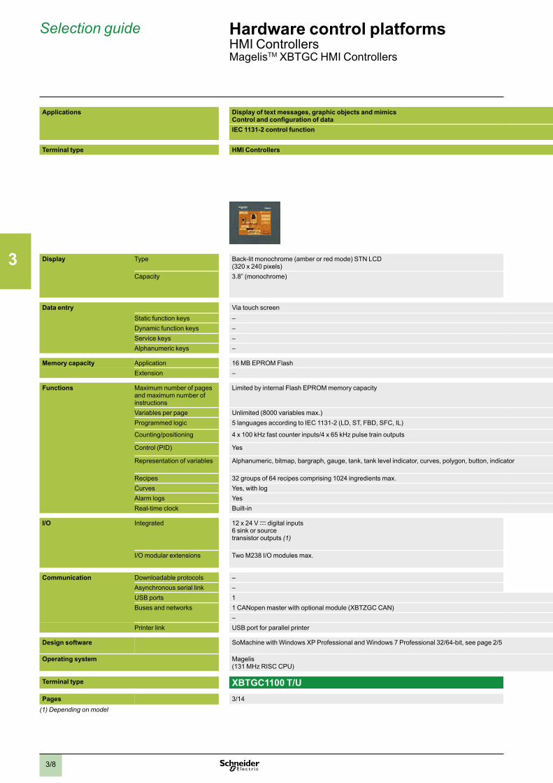
3/8
Selection guide Hardware control platformsHMI ControllersMagelisTM XBTGC HMI Controllers
Applications Display of text messages, graphic objects and mimicsControl and configuration of dataIEC 1131-2 control function
Terminal type HMI Controllers
Display Type Back-lit monochrome (amber or red mode) STN LCD (320 x 240 pixels)
Backlit monochrome STN LCD (320 x 240 pixels) Colour STN LCD (320 x 240 pixels)
Capacity 3.8” (monochrome) 5.7” (monochrome) 5.7” (colour)
Data entry Via touch screenStatic function keys –Dynamic function keys –Service keys –Alphanumeric keys –
Memory capacity Application 16 MB EPROM FlashExtension –
Functions Maximum number of pages and maximum number of instructions
Limited by internal Flash EPROM memory capacity
Variables per page Unlimited (8000 variables max.)Programmed logic 5 languages according to IEC 1131-2 (LD, ST, FBD, SFC, IL)
Counting/positioning 4 x 100 kHz fast counter inputs/4 x 65 kHz pulse train outputs
Control (PID) Yes
Representation of variables Alphanumeric, bitmap, bargraph, gauge, tank, tank level indicator, curves, polygon, button, indicator
Recipes 32 groups of 64 recipes comprising 1024 ingredients max.Curves Yes, with logAlarm logs YesReal-time clock Built-in
I/O Integrated 12 x 24 V c digital inputs6 sink or source transistor outputs (1)
16 x 24 V c digital inputs 16 sink or source transistor outputs (1)
I/O modular extensions Two M238 I/O modules max. Three M238 I/O modules max.
Communication Downloadable protocols – Uni-TE, Modbus, Modbus TCP/IP (1) and for PLC brands: Mitsubishi, Omron, Allen-Bradley and SiemensAsynchronous serial link – RS 232C/RS 422/485 (COM1)USB ports 1Buses and networks 1 CANopen master with optional module (XBTZGC CAN)
– Ethernet TCP/IP (10BASE-T/100 BASE-TX)Printer link USB port for parallel printer
Design software SoMachine with Windows XP Professional and Windows 7 Professional 32/64-bit, see page 2/5
Operating system Magelis(131 MHz RISC CPU)
Terminal type XBTGC1100 T/U XBTGC2120 T/U XBTGC2230 T/UPages 3/14 3/14 3/14
(1) Depending on model

2
1
3
4
5
6
7
8
9
10
3/9
Applications Display of text messages, graphic objects and mimicsControl and configuration of dataIEC 1131-2 control function
Terminal type HMI Controllers
Display Type Back-lit monochrome (amber or red mode) STN LCD (320 x 240 pixels)
Backlit monochrome STN LCD (320 x 240 pixels) Colour STN LCD (320 x 240 pixels)
Capacity 3.8” (monochrome) 5.7” (monochrome) 5.7” (colour)
Data entry Via touch screenStatic function keys –Dynamic function keys –Service keys –Alphanumeric keys –
Memory capacity Application 16 MB EPROM FlashExtension –
Functions Maximum number of pages and maximum number of instructions
Limited by internal Flash EPROM memory capacity
Variables per page Unlimited (8000 variables max.)Programmed logic 5 languages according to IEC 1131-2 (LD, ST, FBD, SFC, IL)
Counting/positioning 4 x 100 kHz fast counter inputs/4 x 65 kHz pulse train outputs
Control (PID) Yes
Representation of variables Alphanumeric, bitmap, bargraph, gauge, tank, tank level indicator, curves, polygon, button, indicator
Recipes 32 groups of 64 recipes comprising 1024 ingredients max.Curves Yes, with logAlarm logs YesReal-time clock Built-in
I/O Integrated 12 x 24 V c digital inputs6 sink or source transistor outputs (1)
16 x 24 V c digital inputs 16 sink or source transistor outputs (1)
I/O modular extensions Two M238 I/O modules max. Three M238 I/O modules max.
Communication Downloadable protocols – Uni-TE, Modbus, Modbus TCP/IP (1) and for PLC brands: Mitsubishi, Omron, Allen-Bradley and SiemensAsynchronous serial link – RS 232C/RS 422/485 (COM1)USB ports 1Buses and networks 1 CANopen master with optional module (XBTZGC CAN)
– Ethernet TCP/IP (10BASE-T/100 BASE-TX)Printer link USB port for parallel printer
Design software SoMachine with Windows XP Professional and Windows 7 Professional 32/64-bit, see page 2/5
Operating system Magelis(131 MHz RISC CPU)
Terminal type XBTGC1100 T/U XBTGC2120 T/U XBTGC2230 T/UPages 3/14 3/14 3/14
(1) Depending on model

2
1
3
4
5
6
7
8
9
10
3/10
Presentation Hardware control platformsHMI ControllersMagelisTM XBTGC HMI Controllers
PresentationMagelis HMI Controllers are part of Schneider's Flexible Machine Control concept, a key element in MachineStruxureTM.
The Magelis HMI Controller offer brings together Human Machine Interface and control functions within in a single product. This reduces the amount of equipment required and the associated costs throughout the life cycle of the machine.
Magelis XBTGC HMI ControllersThe compact design of Magelis XBTGC HMI Controllers optimizes setup.
This range comprises six touch screen terminals, with the following, depending on the model:
b 3.8” monochrome screen, 12 integrated inputs/6 integrated outputs (sink or source) b 5.7” monochrome or colour screen, 16 integrated inputs/16 integrated outputs (sink
or source) b A wide choice of communication interfaces (USB, serial link, CANopen and
Ethernet)
In order to adapt easily to different configurations, it is possible to add digital or analog I/O expansion modules at the rear of the Controller.
OperationWith their fast, multitasking processors, the HMI Controllers combine HMI and control functions and share the same screen and communication features and dimensions.
The internal memory can be freely used by both the HMI function and the control function.Processing is split 75% on the HMI part and 25% on the control part. The processing can be configured for 3 tasks, including 1 master task.
XBTGC HMI Controllers also share the same I/O modules, the same Telefast pre-wired system and the same peripherals on the CANopen bus as the M238 logic controller.
Magelis XBTGC HMI Controllers
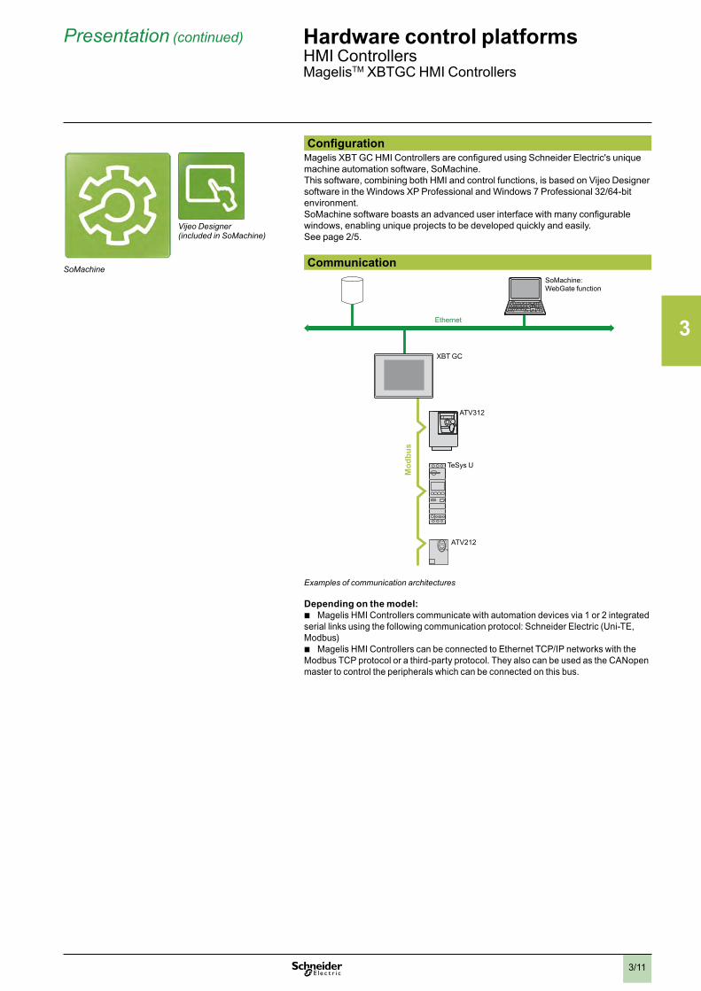
2
1
3
4
5
6
7
8
9
10
3/11
Presentation (continued) Hardware control platformsHMI ControllersMagelisTM XBTGC HMI Controllers
ConfigurationMagelis XBT GC HMI Controllers are configured using Schneider Electric's unique machine automation software, SoMachine.This software, combining both HMI and control functions, is based on Vijeo Designer software in the Windows XP Professional and Windows 7 Professional 32/64-bit environment.SoMachine software boasts an advanced user interface with many configurable windows, enabling unique projects to be developed quickly and easily.See page 2/5.
CommunicationSoMachine: WebGate function
Ethernet
TeSys U
ATV212
ATV312M
odbu
s
XBT GC
Examples of communication architectures
Depending on the model: b Magelis HMI Controllers communicate with automation devices via 1 or 2 integrated
serial links using the following communication protocol: Schneider Electric (Uni-TE, Modbus)
b Magelis HMI Controllers can be connected to Ethernet TCP/IP networks with the Modbus TCP protocol or a third-party protocol. They also can be used as the CANopen master to control the peripherals which can be connected on this bus.
SoMachine
Vijeo Designer (included in SoMachine)

2
1
3
4
5
6
7
8
9
10
3/12
Functions Hardware control platformsHMI ControllersMagelisTM XBTGC HMI Controllers
FunctionsMagelis HMI Controllers are part of Schneider's Flexible Machine Control concept, a key element in MachineStruxureTM. Magelis XBTGC HMI Controllers offer the following HMI functions:
b Display of animated mimics with 8 types of animation (pressing the touch panel, colour changes, filling, movement, rotation, size, visibility and value display)
b Control, modification of numeric and alphanumeric values b Display of current date and time b Real-time curves and trend curves with log b Alarm display, alarm log and management of alarm groups b Multi-window management b Page calls initiated by the operator b Multilingual application management (10 languages simultaneously) b Recipe management b Data processing via Java script b Application support and USB key external memory logs b Management of serial printers and barcode readers
Magelis XBTGC HMI Controllers (1) have been designed for Transparent Ready architectures and equipment (combination of Web and Ethernet TCP/IP technologies). With the WebGate function, it is possible to control or carry out maintenance remotely.Magelis XBTGC HMI Controllers offer the following functions for control:
b Execution of programmed logic sequences with the five IEC 1131-2 languages (LD, ST, FBD, SFC, IL)
b Management of equipment on the CANopen fieldbusIn addition to these functions, Magelis XBT GC HMI Controllers manage:
b Integrated and remote I/O on expansion modules b Remote analog I/O on expansion modules
Operating modes for the terminals The illustrations below show which equipment can be connected to XBT terminals based on their two operating modes.Edit mode
USB key
Connection cable XBTZG935
PC with software SoMachine
Ethernet network (1)
XBTGC
Run mode
Barcode reader (4)
Parallel printer (5)
USB port duplicator
Ethernet network (2)
Barcodereader (4) Keyboard
Mouse
Modicon OTB
ATV 212
COM2
COM1
XBTGC + 3 I/O modules (3)
(1) Depending on model(2) With XBTGC 2230T/U(3) With XBTGCppppT/U, maximum 2/3 I/O modules according to model(4) Should be a DataLogic Gryphon barcode reader(5) Should be a Hewlett Packard printer via a USB/PIO converter

2
1
3
4
5
6
7
8
9
10
3/13
Description Hardware control platformsHMI ControllersMagelisTM XBTGC HMI Controllers with 3.8” screen, MagelisTM XBTGC HMI Controllers with 5.7” screen
1
2
DescriptionMagelis XBTGC1100T and XBTGC1100U HMI ControllersThe front panel comprises:
1 A touch screen for displaying mimics (3.8” amber or red mode monochrome)2 A control indicator showing the terminal's operating mode
The rear panel comprises: 5 4
123
1 A removable screw terminal block for 24 V c power supply2 A type A USB master connector for peripheral connection and application transfer3 A removable terminal block for 12 digital inputs and 6 digital outputs4 An interface for connecting M238 logic controller I/O expansion modules5 An interface for connecting the CANopen bus master module 6 Digital (TM2Dpp) or analog (TM2App) I/O expansion module (to be ordered
separately, see page 3/34) It is possible to combine a maximum of two I/O expansion modules, depending on the module type (see page 3/34).
2
1
Magelis XBTGC2p20 and XBTGC2p30 HMI ControllersThe front panel comprises:
1 A touch screen for displaying mimics (5.7” monochrome or colour)2 A multicolour indicator (green, orange and red) showing the terminal's operating
mode
The rear panel comprises:
3
45
2
1
6
8
1 A removable screw terminal block for 24 V c power supply2 A type A USB master connector for peripheral connection and application transfer3 A 9-way male SUB-D connector for RS 232C or RS 422/485 serial link to PLCs
(COM1)4 An interface for connecting the M238 logic controller I/O expansion module5 An interface for connecting the CANopen bus master module.6 A removable terminal block for 16 digital inputs and 16 digital outputs7 Digital (TM2Dpp) or analog (TM2App) I/O expansion module (to be ordered
separately, see page 3/34) It is possible to combine a maximum of three I/O expansion modules, depending on the module type (see page 3/34).
For XBTGC2230 only: 8 An RJ45 connector for Ethernet TCP/IP 10BASE-T/100BASE-TX link
6
6
7

2
1
3
4
5
6
7
8
9
10
3/14
References Hardware control platformsHMI ControllersMagelisTM XBTGC HMI Controllers
XBTGC1100
XBTGC1100p
XBTGC2pppp
XBTZGUSB
Magelis XBTGC HMI Controllers (1)Type of screen No. of
portsApplication memory capacity
Compact Flash memory
Integrated I/O No. of Ethernet ports
Reference Weight kglb
3.8’’ screenSTNamber or red
1 USB 16 MB No 12 I/6 O source - XBTGC1100T 0.4000.882
12 I/6 O sink - XBTGC1100U 0.4000.882
5.7’’ screenSTNblack and white mode
1 COM 1 16 MB No 16 I/16 O source - XBTGC2120T 1.0002.205
1 USB 16 I/16 O sink - XBTGC2120U 1.0002.205
5.7’’ screenSTNcolour
1 COM 1 16 MB No 16 I/16 O source 1 XBTGC2230T 1.0002.205
1 USB 16 I/16 O sink 1 XBTGC2230U 1.0002.205
Separate partsDesignation Compatibility Size Reference Weight
kglb
Protective sheets(5 peel-off sheets)
XBTGC 1100 – XBTZG60 0.2000.441
XBTGC2pp0 – XBTZG62 0.2000.441
Designation Description Length Reference Weight kg
Remote USB port locationfor type A XBT terminal
Enables the USB port to be located remotely on the rear of the XBT terminal on a panel or cabinet door (Ø 21 mm / 826.772 in. mounting device)
1 m3.281 ft
XBTZGUSB –
Remote USB port locationfor mini type B XBT terminal
- XBTZGUSBB –
XBTGC connection to CANopen master fieldbus
Connection via card on bus extension - XBTZGCCAN –
Cable for transferringapplication to PC
USB TTL connector 2 m6.562 ft
XBTZG935 –
Replacement partsDesignation Used for Reference Weight
kglb
Joints d’étanchéité XBTGC1100 XBTZG51 0.0300.066
XBTGT21p0 XBTZG52 0.0300.066
Attache USB XBTGC 1100 XBTZGCLP2 –
XBTGC 2pp0 XBTZGCLP4 –
Mounting kit 4 clips and screws (max. tightening torque: 0,5 Nm), included with XBTGC terminals
XBTZGFIX 0.1000.220
Spring clip for expansion modules on XBTGC
XBTGC2pp0 terminals XBTZGCHOK 0.0300.066
Power supply connector XBTGC1ppp / GC2ppp XBTZGPWS1 0.0300.066
Dierct I/O connector XBTGC1000 XBTZGDIO1 –
XBTGC2000 XBTZGDIO2 –
(1) Terminals supplied with mounting kit (screw clips), locking device for USB connectors, spring clip for expansion modules (except XBTGC1100) and instruction sheet. The setup documentation for XBTGC terminals is supplied in electronic format with SoMachine software (see page 2/5).
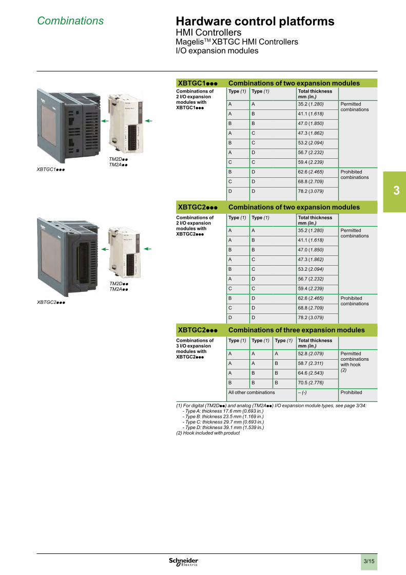
2
1
3
4
5
6
7
8
9
10
3/15
Combinations Hardware control platformsHMI ControllersMagelisTM XBTGC HMI Controllers I/O expansion modules
XBTGC1ppp Combinations of two expansion modulesCombinations of 2 I/O expansion modules with XBTGC1ppp
Type (1) Type (1) Total thickness mm (in.)
A A 35.2 (1.280) Permitted combinations
A B 41.1 (1.618)
B B 47.0 (1.850)
A C 47.3 (1.862)
B C 53.2 (2.094)
A D 56.7 (2.232)
C C 59.4 (2.239)
B D 62.6 (2.465) Prohibited combinations
C D 68.8 (2.709)
D D 78.2 (3.079)
XBTGC2ppp Combinations of two expansion modulesCombinations of 2 I/O expansion modules with XBTGC2ppp
Type (1) Type (1) Total thickness mm (in.)
A A 35.2 (1.280) Permitted combinations
A B 41.1 (1.618)
B B 47.0 (1.850)
A C 47.3 (1.862)
B C 53.2 (2.094)
A D 56.7 (2.232)
C C 59.4 (2.239)
B D 62.6 (2.465) Prohibited combinations
C D 68.8 (2.709)
D D 78.2 (3.079)
XBTGC2ppp Combinations of three expansion modulesCombinations of 3 I/O expansion modules with XBTGC2ppp
Type (1) Type (1) Type (1) Total thickness mm (in.)
A A A 52.8 (2.079) Permitted combinations with hook (2)
A A B 58.7 (2.311)
A B B 64.6 (2.543)
B B B 70.5 (2.776)
All other combinations – (-) Prohibited
(1) For digital (TM2Dpp) and analog (TM2App) I/O expansion module types, see page 3/34: - Type A: thickness 17.6 mm (0.693 in.) - Type B: thickness 23.5 mm (1.169 in.) - Type C: thickness 29.7 mm (0.693 in.) - Type D: thickness 39.1 mm (1.539 in.)(2) Hook included with product
XBTGC1ppp
TM2DppTM2App
XBTGC2ppp
TM2DppTM2App

2
1
3
4
5
6
7
8
9
10
3/16
Selection guide Hardware control platformsModicon M238 logic controller, Compact base for Solutions with Application function Blocks (AFB)
Application General control solutions for v Hoisting v Packaging v Conveying v Pumping v ...
Voltage 24 c (- 15% / + 20 %) 100-240 V a (+ 10% / - 15 %)
Certifications e, UL, CSA, ACA (C-Tick), GOST (pending) e, UL, CSA, ACA (C-Tick), GOST (pending), CSA (Class 1, Division 2, Groups A, B, C, D)
Digital I/O No. of 24 V c inputs 14, 8 of which can be configured as fast inputs 14, 8 of which can be configured as fast inputs
No. of outputs 10 transistor, 4 of which can be configured as fast outputs
4 transistor + 6 relay
I/O expansion Max. number of modules 7: digital, analog, high-speed counter, (3 high-speed counter TM200HSC060pp) 7: digital, analog, high-speed counter, (3 high-speed counter TM200HSC060pp)
Max. number of digital I/O 136/192/248 (1) 136/192/248 (1)
Embedded function HSC 8 x 100 kHz simple channels, 4 x 100 kHz simple channels and 1 x 100 kHz advanced channel (2) or 2 x 100 kHz advanced channels (2)
8 x 100 kHz simple channels, 4 x 100 kHz simple channels and 1 x 100 kHz advanced channel (2) or 2 x 100 kHz advanced channels (2)
Motion or Reflex functions 4 channels,frequency: 100 Hz
4 channels, frequency: 100 Hz
PID regulation Yes YesEvent processing Yes, up to 4 event tasks can be activated by the fast inputs or by the integrated counter channels
(on threshold)Yes, up to 4 event tasks that can be activated by the base's fast inputs or by the integrated counter channels (threshold attained)
Connection via 4 removable screw terminal blocks (supplied as standard) 4 removable spring terminal blocks with optional unit TM238 RSSPT (ordered separately)
4 removable screw terminal blocks (supplied as standard) 4 removable spring terminal blocks with optional unit TM238 RSSPT (ordered separately)
Embedded communication
RS 485/RS 232 serial port Master/slave type isolated serial link Master/slave type isolated serial linkRJ45 port, marking on front panel SL1 : 1 channelProtocols:
v Default : Modbus slave, v Modbus master/slave RTU/ASCII, ASCII
RJ45 Port, marking on front panel SL1 : 1 channelProtocols:
v Default : Modbus slave, v Modbus master/slave RTU/ASCII, ASCII
RS 485 serial port Master/slave type isolated serial link Master/slave type isolated serial linkRJ45 port, marking on front panel SL2 : 1 channelProtocols:
v Default : Modbus slave, v Modbus master/slave RTU/ASCII, ASCII
RJ45 port, marking on front panel SL2 : 1 channelProtocols:
v Default : Modbus slave, v Modbus master/slave RTU/ASCII, ASCII
Terminal port “Prg. Port” 1 USB 2.0 (Mini B USB connector): Programming port for SoMachine software 1 USB 2.0 (Connecteur type USB mini-B): Programming port for SoMachine software
CANopen Conformity class M10, limited to 16 slaves for 1 master Conformity class M10, limited to 16 slaves for 1 master
User zone in internal RAM Capacity 1000 KB 1000 KB
No. of instructions 25 K instructions depending on the language and type of instruction used 25 K instructions depending on the language and type of instruction used
Type of compact base TM238 LFDC24DTS0 TM238 LFAC24DRS0
Page 3/21 3/21(1) The 1st value corresponds to the maximum number of I/O (base and expansions) with expansion modules with screw terminals, the 2
nd to expansion modules with spring terminals and the 3
rd to expansion modules with HE 10 connectors..(2) Advanced channel with two-phase signal inputs for encoder, threshold detection function and reflex function.
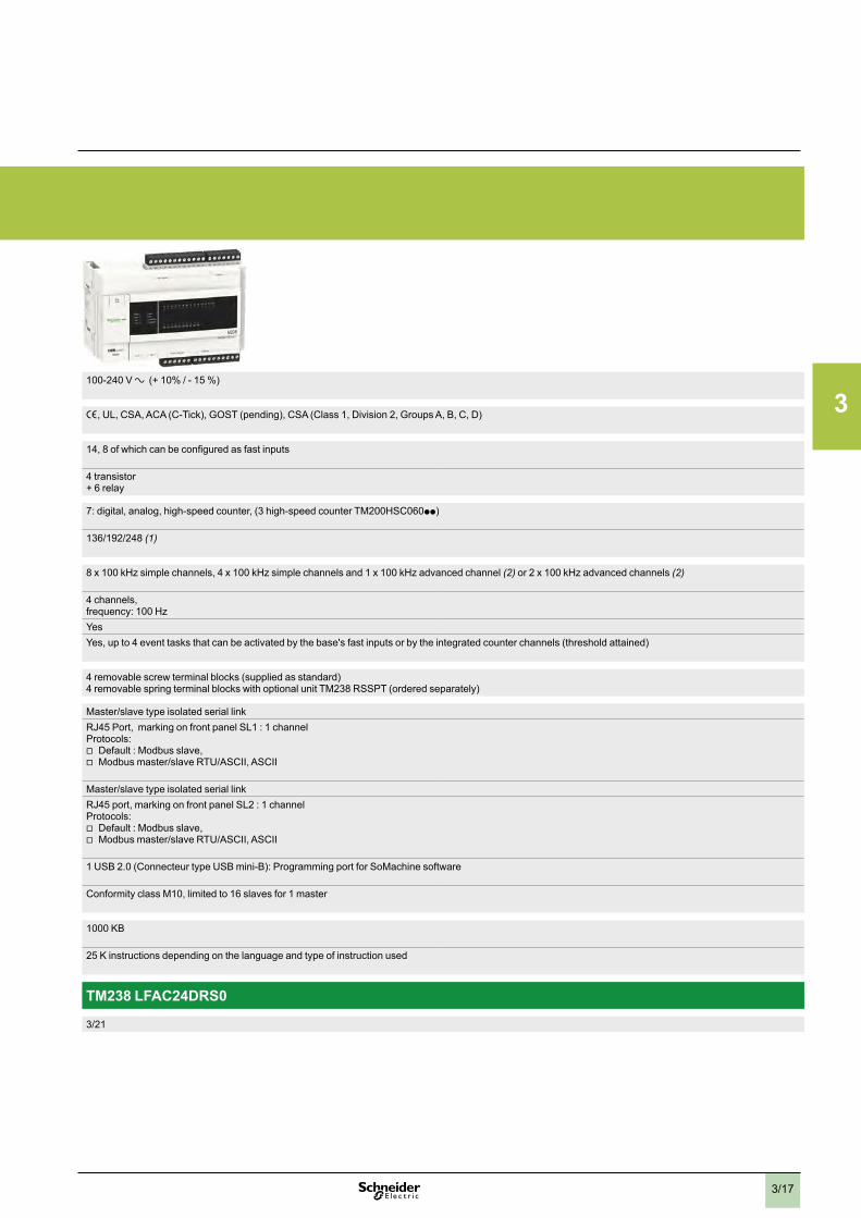
2
1
3
4
5
6
7
8
9
10
3/17
Application General control solutions for v Hoisting v Packaging v Conveying v Pumping v ...
Voltage 24 c (- 15% / + 20 %) 100-240 V a (+ 10% / - 15 %)
Certifications e, UL, CSA, ACA (C-Tick), GOST (pending) e, UL, CSA, ACA (C-Tick), GOST (pending), CSA (Class 1, Division 2, Groups A, B, C, D)
Digital I/O No. of 24 V c inputs 14, 8 of which can be configured as fast inputs 14, 8 of which can be configured as fast inputs
No. of outputs 10 transistor, 4 of which can be configured as fast outputs
4 transistor + 6 relay
I/O expansion Max. number of modules 7: digital, analog, high-speed counter, (3 high-speed counter TM200HSC060pp) 7: digital, analog, high-speed counter, (3 high-speed counter TM200HSC060pp)
Max. number of digital I/O 136/192/248 (1) 136/192/248 (1)
Embedded function HSC 8 x 100 kHz simple channels, 4 x 100 kHz simple channels and 1 x 100 kHz advanced channel (2) or 2 x 100 kHz advanced channels (2)
8 x 100 kHz simple channels, 4 x 100 kHz simple channels and 1 x 100 kHz advanced channel (2) or 2 x 100 kHz advanced channels (2)
Motion or Reflex functions 4 channels,frequency: 100 Hz
4 channels, frequency: 100 Hz
PID regulation Yes YesEvent processing Yes, up to 4 event tasks can be activated by the fast inputs or by the integrated counter channels
(on threshold)Yes, up to 4 event tasks that can be activated by the base's fast inputs or by the integrated counter channels (threshold attained)
Connection via 4 removable screw terminal blocks (supplied as standard) 4 removable spring terminal blocks with optional unit TM238 RSSPT (ordered separately)
4 removable screw terminal blocks (supplied as standard) 4 removable spring terminal blocks with optional unit TM238 RSSPT (ordered separately)
Embedded communication
RS 485/RS 232 serial port Master/slave type isolated serial link Master/slave type isolated serial linkRJ45 port, marking on front panel SL1 : 1 channelProtocols:
v Default : Modbus slave, v Modbus master/slave RTU/ASCII, ASCII
RJ45 Port, marking on front panel SL1 : 1 channelProtocols:
v Default : Modbus slave, v Modbus master/slave RTU/ASCII, ASCII
RS 485 serial port Master/slave type isolated serial link Master/slave type isolated serial linkRJ45 port, marking on front panel SL2 : 1 channelProtocols:
v Default : Modbus slave, v Modbus master/slave RTU/ASCII, ASCII
RJ45 port, marking on front panel SL2 : 1 channelProtocols:
v Default : Modbus slave, v Modbus master/slave RTU/ASCII, ASCII
Terminal port “Prg. Port” 1 USB 2.0 (Mini B USB connector): Programming port for SoMachine software 1 USB 2.0 (Connecteur type USB mini-B): Programming port for SoMachine software
CANopen Conformity class M10, limited to 16 slaves for 1 master Conformity class M10, limited to 16 slaves for 1 master
User zone in internal RAM Capacity 1000 KB 1000 KB
No. of instructions 25 K instructions depending on the language and type of instruction used 25 K instructions depending on the language and type of instruction used
Type of compact base TM238 LFDC24DTS0 TM238 LFAC24DRS0
Page 3/21 3/21(1) The 1st value corresponds to the maximum number of I/O (base and expansions) with expansion modules with screw terminals, the 2
nd to expansion modules with spring terminals and the 3
rd to expansion modules with HE 10 connectors..(2) Advanced channel with two-phase signal inputs for encoder, threshold detection function and reflex function.

2
1
3
4
5
6
7
8
9
10
3/18
Presentation Hardware control platformsModicon M238 logic controllerCompact base for Solutions with Application function Blocks (AFB)
PresentationThe Modicon M238 logic controller is the compact base for solutions with AFB, high-performance and fully expandable PLC. It forms a part of Flexible Machine Control approach, a key component of MachineStruxureTM, which brings you maximum flexibility and ensures the most optimised control solution.Modicon M238 compact logic controllers offer an “all-in-one” solution in a compact unit (157 x 118 x 86 mm excluding expansion modules).
Two models are available, with different embedded communications and supply voltages.
b Model TM238LFDC24DTS0, powered with 24 V c offers: v 14 x 24 V c inputs, including 8 fast inputs, dedicated to special functions such as
high-speed counting (HSC) v 10 x 24 V c solid state outputs, including 4 fast outputs, dedicated to special
functions such as PWM and PTO. v An RS 232/RS 485 serial link (SoMachine-Network, Modbus, ASCII protocols) v A CANopen bus master link v A second RS 485 serial link (SoMachine-Network, Modbus, ASCII protocols)
b Model TM238LFAC24DRS0, powered with 100-240 V a offers: v 14 x 24 V c inputs, including 8 fast inputs, dedicated to special functions such as
high-speed counting (HSC) v 4 x 24 V c solid state outputs, dedicated to HSC reflex functions, and 6 relay outputs
(PMW and PTO functions not supported on these models) v An RS 232/RS 485 serial link (SoMachine-Network, Modbus, ASCII protocols) v A CANopen bus master link v A second RS 485 serial link (SoMachine-Network, Modbus, ASCII protocols). v The number of I/O can be expanded on all four models by adding up to
7 expansion modules (1) of the following type on the right-hand side of the base unit: - Digital TM2DDI/DDO/DMM/DRA - Analog TM2AMI/ALM/ARI/AMO/AVO/AMM - up to 3 High-speed counter TM200HSC206DT/DF
Modems or communication gateways can be connected to the serial links in order to expand the connectivity capability to include
v Ethernet Modbus/TCP, v Profibus DP, v DeviceNet, v etc.
Note: A serial link on each controller delivers a 5 V c voltage dedicated primarily to powering a Magelis display unit or Small panel terminal XBTNp00/R400/RT500 or the Ethernet gateway 499TWD01100.
The compact controller solution also has great flexibility in terms of wiring. With digital I/O expansion modules, several connection options are available, including removable screw terminals, spring terminals and HE 10 connectors, providing simple, quick, safe wiring. The Modicon Telefast ABE 7 prewiring system can be used for easy connection of expansion modules with HE 10 connectors.(1) The addition of 7 expansion modules allows a maximum number per configuration of 136/192/248 I/O (depending on whether expansion modules with screw terminals, spring terminals or HE 10 connectors are being used).
TM238LFAC24DRS0
TM238LFDC24DTS0

2
1
3
4
5
6
7
8
9
10
3/19
Presentation (continued) Hardware control platformsModicon M238 logic controllerCompact base for Solutions with Application function Blocks (AFB)
SoMachine software platform
Presentation Design and installation of Modicon M238 applications
Schneider Electric’s SoMachine software platform is used to program Modicon M238 logic controllers for Solutions with AFB using:
b IEC 61131-3 programming languages: Instruction List (IL), Ladder Diagram (LD), Function Block Diagram (FBD), Sequential Function Chart/Grafcet (SFC) and Structured Text (ST)
b CFC (Continuous Function Chart) language.
Access to the hoisting libraries including all the specialized AFB, see page 2/2..
Program loader1
4
3
2 The TM2USBABDEV1 program loader is an accessory which is designed to simplify updating or duplication of applications on Modicon M238 logic controllers without the need for a programming terminal.
b For updating: an application generated by SoMachine, stored on a USB memory stick, will be transferred by the program loader to an M238 controller.
b For duplication: an application is transferred from an M238 controller to the program loader. The application is stored on a USB memory stick, then transferred from the program loader to another M238 controller.
The front panel of the TM2USBABDEV1 program loader features:1. A USB port (marked PLC) for the connection cable to the mini-B USB port
(marked Prg. Port) on the Modicon M238 logic controller.2. A USB port (marked key) for the USB memory stick (holding the application).3. An On/Off button to start the transfer.4. Four operation LED indicators (PWR, COM, ERR, STS).
Compact base configuration
+
10 transistor outputs (including 4 PWM/PTO outputs) with TM238LFDC24DTS0 4 transistor outputs + 6 relay outputs with TM238LFAC24DRS0
14 digital inputs (including 8 fast inputs)
- 1 RS 485/RS 232 serial link, SoMachine-Network/Modbus/ASCII protocols- 1 RS 485 serial link, SoMachine-Network/Modbus protocols
mini B USB port dedicated to the programming terminal /
program loader
CANopen integrated link
24 V c power supply: TM238LFDC24DTS0
100-240 V a power supply: TM238LFAC24DRS0
TM238LFpC24DpS0 ------------------------- I/O expansion modules (Up to 7) ------------------------------
Digital I/O TM2DpITM2DpO
Analog I/O TM2AMI/ARI/ApOTM2ApM
Counter with 2 x 60 kHz channels TM200HSC206Dp

2
1
3
4
5
6
7
8
9
10
3/20
Description Hardware control platformsModicon M238 logic controllerCompact base for Solutions with Application function Blocks (AFB)
Description
The Modicon M238 logic controller base for Solutions with AFB TM238LFDC24DTS0 and TM238LFAC24DRS0 comprise:1 A mini B USB connector, marked Prg. Port, for connecting a programming terminal2 A hinged access cover with 2 cable glands (1 removable for the terminal cordset and 1 for the CANopen cable)3 A removable screw terminal block (12 terminals) for connecting the sensors (24 V c fast inputs)4 A removable screw terminal block (7 terminals) for connecting the sensors (24 V c inputs)5 A connector for up to 7 digital TM2Dpp, analog TM2App and up to 3 counter TM200HSC206Dp I/O expansion modules 6 A display unit showing: - The controller status by means of 4 LEDs (PWR, RUN, Batt and Err) - The integrated communication port status by means of 4 LEDs (SL1, SL2,
CAN Run and CAN Err)7 A display unit showing the I/O states (I0…I13 and Q0…Q9)8 A removable screw terminal block (10 terminals) for connecting 6 preactuators9 A removable screw terminal block (6 terminals) for connecting 4 preactuators10 A removable screw terminal block (5 terminals marked CANopen) for connection to the CANopen bus.
Accessible from the underside of the controller:11 A removable screw terminal block (3 terminals):
v +, -, t marked 24 VDC for connecting the 24 V c power supply v L, N, t marked 100-240 VAC for connecting the 100-240 V a power supply
12 2 RJ45 connectors marked SL1 and SL2 for connecting the serial links13 A hinged cover for accessing the RAM backup battery (optional) and the internal real-time clock
The compact bases are mounted as standard on a symmetrical 5 rail or on a metal plate (two Ø 4.3 holes).
1 2 3 4 5
67
10 9 8
11 12 13

2
1
3
4
5
6
7
8
9
10
3/21
References Hardware control platformsModicon M238 logic controllerCompact base for Solutions with Application function Blocks (AFB)
ReferencesNumber of I/O
Inputs Outputs No. of I/O expansion modules
Integrated serial port
Integrated master CANopen port
Reference Weightkglb
Compact base for solutions with AFB, 24 V c power supply24 I/O(removable battery to be ordered separately)
6 x 24 V c inputs (sink/source) 8 x 24 V c fast inputs (sink)
10 transistor outputs (source) including 4 fast
7 modules max.
1 RS 232/485 (marked SL1)1 RS 485 (1)(marked SL2)
1 TM238LFDC24DTS0 0.5951.312
Compact base for solutions with AFB, 100-240 V a power supply24 I/O(removable battery to be ordered separately)
6 x 24 V c inputs (sink/source) 8 x 24 V c fast inputs (sink)
4 transistor outputs (source) and 6 relay outputs
7 modules max.
1 RS 232/485 (marked SL1)1 RS 485 (1)(marked SL2)
1 TM238LFAC24DRS0 0.5951.312
Separate partsDesignation Use Length
SoldReference Weight
kglb
Removable backup batteries
Lithium thionyl chloride type for Modicon M238 compact bases
Individual TSXPLP01 0.0120.026
Pack of 10 TSXPLP101 0.1890.417
Programming cable From the mini B USB port on the Modicon M238 compact bases to the type A USB port on the PC terminal for programming and updating firmware
3 m TCSXCNAMUM3P 0.0650.143
RS 232 serial link cordsets for DTE/DCE terminal device
1 RJ45 connector and one 9-way SUB-D connector
For DTE terminal (printer) 3 m TCSMCN3M4F3C2 0.1500.331
For DCE terminal (modem, converter)
3 m TCSMCN3M4M3S2 0.1500.331
Removable spring connectors for digital I/O
Set of 5 removable spring connectors. Replaces the 5 screw connectors supplied with Modicon M238 compact bases
– TM238RSSPT 0.0480.106
Shielding connection clamps
Attachment and earthing of the cable shielding Pack of 25 clamps including 20 clamps for Ø 4.8 mm cable and 5 for Ø 7.9 mm cable
Pack of 25 TM200RSRCEMC –
Modbus communication gateways
Connection of Modicon M238 compact bases to network/bus
Ethernet Modbus/TCP (2) 499TWD01100 0.2000.441
Profibus DP (3) LUFP7 0.2450540
DeviceNet (3) LUFP9 0.2450.540
GSM/GPRS modem(DCE terminal)
4-band 900/1800 MHz (Europe) and 850/1900 MHz (United States)IP 31 casing supplied with:
v 1.5 m power cable v SMA-M magnetic GSM 4-band aerial with 2.5 m
cable v Fixed on panel or 5
5.5…24 V c supply voltage
– SR2MOD03 0.3350.739
Designation UseFrom To
Length Reference Weightkglb
Modbus cables equipped with 2 RJ45 connectors
Serial port marked SL1/SL2
Ethernet gateway 499 TWD 01100 2.5 m XBTZ9980 –
Profibus DP LUF P7 or DeviceNet LUF P9, TSX CUSB 485 converter
1 m VW3A8306R10 0.0500.110
3 m VW3A8306R30 0.1500.331
0.3 m VW3A8306R03 0.0300.066
(1) RS 485 link delivering a 5 V c/200 mA power supply.(2) Connection to serial port SL1 on controller TM238LDA24DRS0 or to serial port SL2 on controller TM238LFAC24DRS0 via Modbus cable XBTZ9980 (to be ordered separately).(3) Connection to serial port SL1 on controller controller TM238LDA24DRS0, to serial port SL1 or SL2 on controllers TM238LFAC24DRS0 via Modbus cable VW3A8306 Rpp (to be ordered separately). Requires a 24 V c external power supply. Gateway configurable via the ABC Config Tool software, downloadable from our website www.schneider-electric.com
TSXPLP101
TM200RSRCEMC
499TWD01100
SR2MOD03
TM238LFAC24DR
TM238LFDC24DT
TCSXCNAMUM3P

2
1
3
4
5
6
7
8
9
10
3/22
References (continued) Hardware control platformsModicon M238 logic controllerCompact base for Solutions with Application function Blocks (AFB)
ReferencesAccessoriesDesignation Description Length Reference Weight
kglb
Remote location of the USB port for M238 controllers and XBTGT2pp0…GT7340, GT1pp5, GKppp, GTWppp terminals
Used to locate the USB port of M238 controllers (front) and XBTG terminals (rear) remotely on panel or enclosure door (Ø 21 mm (3.281 in.) mounting device)
1 m3.281 ft
HMIZSUSBB 0.1000.220
Program loaderKit consisting of the program loader, a cable (USB/mini-B USB), and 2 batteries (type AA/LR6)
Used to update and duplicate applicationsRequires the use of a USB memory stick (not supplied)
3 m 9.843 ft (cable)
TM2USBABDEV1 0.2500.551
Connection elements for RS 485 OS download port for M238 version V1.0 (1)Designation Use Length Reference Weight
kglb
USB/RS 485 converter Used to connect the RS 485 port (SL1) to the USB port on the PC to update the controller operating system.Requires Modbus cable VW3 A8 306 Rpp for the connection at the controller end
0.4 m1.312 ft(integrated cable at PC end)
TSXCUSB485 0.1440.317
Replacement partsDesignation Use Reference Weight
kglb
Removable screw connectors, supplied with Modicon M238 bases
Set of 5 removable screw connectors for digital I/O
TM238RSSCT 0.0550.121
One 5-way connector with line terminator for CANopen link
TM238CNTLSCT 0.0100.022
(1) For later versions, use the USB port and cable.
TSXCUSB485
HMIZSUSBB
TM2USBABDEV1

2
1
3
4
5
6
7
8
9
10
3/23
Memory structure Hardware control platformsModicon M238 logic controllerCompact base for Solutions with Application function Blocks (AFB)
Memory structure1
5
4
8
2
3
6
7
%MW located variables
System + system variables + relocation table
Symbols(55 KB + 0.13 KB/symbols)Program(eg. 41 bytes per ST instruction)
Unlocated variablesLibraries
CANopen variables
“Retain” and “Retain Persistent” remanent variables
Inte
rnal
RA
M
Use
r zon
e
Protected internal RAM and first 1000 %MW words
10 KB
Modicon M238 controllers offer great flexibility in memory management. Depending on the model used, they have a user memory zone of 1024 KB with TM238LFDC24DTS0 and TM238LFAC24DRS0 bases.
This user memory zone is divided according to the application program requirements and the volume needed by the symbols, unlocated variables and libraries required by the application.The memory structure of Modicon M238 controllers is shown opposite.
The table below lists the maximum memory capacities depending on the model (values are given for information only).
TM238LFDC24DTS0, TM238LFAC24DRS0Internal RAM KB 2048
1 Located variables KB 120 (60,000 %MW)2 System + system variables + relocation table KB 900User zone KB 1000
3 Symbols KB 200 (max. 1000 symbols)4 Program (including online program modification) As required by the application, within the limits of the size
of the user zone5 Unlocated variables6 Libraries7 CANopen variables KB 115 + 10 per slave
Protected internal RAM KB 108 “Retain” variables Bytes 81688 “Retain Persistent” variables Bytes 4008 First 1000 %MW words Bytes 2000
Storing variables Remanent variables can be one of two types depending on their declaration in the application:
v “Retain” variables, 8168 bytes maximum v “Retain Persistent” variables, 400 bytes maximum.
The first 1000 located variables 1 (first 1000 %MW words) and all the unlocated variables 5 configured as “Retain” and “Retain Persistent” type are backed up by the internal battery or by the optional external battery. They are maintained when the power returns if the startup context allows this (see “Restart context” below).In addition, “Retain Persistent” type variables are maintained on a change of application if the startup context allows this (see “Restart context” below).
Restart context The state of the remanent memory before disconnection is restored on the next power-up when the internal battery and/or the optional external battery is/are capable of protecting the internal RAM (no memory checksum error).If the internal battery or optional external battery does not have enough charge to back up the internal RAM, the values of the “Retain” and “Retain Persistent” remanent variables are reset to 0.In SoMachine V3, a new option accessible by configuration allows the choice of 3 modes to restart after powering off the controller; run / stop / original state when powered off. In this third case, the optional battery is required in case of powering off more than three days (autonomy of the battery after an initial charge of 22 hours ). If there is no optional battery, the controller will start in the stop mode after a three-day power off. The external battery can be monitored by the GetBatteryLevel software function, and its charging status is visible from the status of the Batt LED on the front of the controller.
Storing the programRegardless of the context and status of the internal battery and/or optional external battery, the program is backed up in the Flash RAM during the “boot application” creation procedure (SoMachine software procedure).

2
1
3
4
5
6
7
8
9
10
3/24
Selection guide Hardware control platformsModicon M258 logic controllerCompact base for Solutions with Application function Blocks (AFB)
Applications Control solutions for v Packaging v Conveying v Hoisting v Pumping v ...
42 digital I/O 42 digital I/O+ 4 analog inputs
42 digital I/O 66 digital I/O + 4 analog inputs
User memory RAM 64 MB (program + data) 64 MB (program + data)Flash 128 Mbytes 128 Mbytes
Typical Boolean instruction time 22 ns 22 ns
User program size 128 program K instructions 128 program K instructions
Power supply 24 V c 24 V c
Channel connection With removable spring terminal blocks (supplied) With removable spring terminal blocks (supplied)
Inputs Digital 26 x 24 V c inputs including 8 counter inputs (100 kHz) 26 x 24 V c inputs including 8 counter inputs (100 kHz) 38 x 24 V c inputs including 8 counter inputs (100 kHz)
Analog – 4 inputs + 10 V/- 10 V, 4-20 mA/0-20 mA,12-bit resolution
– 4 inputs + 10 V/- 10 V, 4-20 mA/0-20 mA,12-bit resolution
Digital outputs Transistor 16 outputs (0.5 A) including 4 reflex outputs 4 reflex outputs (0.5 A) 28 outputs (0.5 A) including 4 reflex outputs
Relay – 12 –
Built-in communication ports
USB-B mini-port Programming port for SoMachine software Programming port for SoMachine software
USB-A port Connection of a USB memory stick for transferring programs, data files, firmware updates Connection of a USB memory stick for transferring programs, data files, firmware updates
RJ45 port (MBS)
RS232 serial link, RS485 serial link (supplies 250 mA, 5 V for HMI power supply)Protocols: Master/Slave Modbus ASCII/RTU, ASCII (character string)
RS232 serial link, RS485 serial link (supplies 250 mA, 5 V for HMI power supply)Protocols: Master/Slave Modbus ASCII/RTU, ASCII (character string)
SUB-D connector (male 9-way) (CAN0)
Master CANopen bus (63 slaves) Master CANopen bus (63 slaves)
RJ45 port (Ethernet) Ethernet TCP IP, Web Server, FTP, Ethernet Modbus TCP
Ethernet TCP IP Modbus slave, Web Server, FTP
Ethernet TCP IP Modbus slave, Web Server, FTP
Optional communication ports – 2 PCI slots available on controller for optional communication modules TM5 PCppp (1):
v Modbus or ASCII serial link v connection to Profibus DP bus (slave)
2 PCI slots available on controller for optional communication modules TM5 PCppp (1): v Modbus or ASCII serial link v connection to Profibus DP bus (slave)
Logic controller type TM258 LF42DTS0 TM258 LF42DT4LS0 TM258 LF42DRS0 TM258 LF66DT4LS0
Page 3/32 3/32(1) To be ordered separately, see page 4/8.
More technical information on www.schneider-electric.com

2
1
3
4
5
6
7
8
9
10
3/25
Applications Control solutions for v Packaging v Conveying v Hoisting v Pumping v ...
42 digital I/O 42 digital I/O+ 4 analog inputs
42 digital I/O 66 digital I/O + 4 analog inputs
User memory RAM 64 MB (program + data) 64 MB (program + data)Flash 128 Mbytes 128 Mbytes
Typical Boolean instruction time 22 ns 22 ns
User program size 128 program K instructions 128 program K instructions
Power supply 24 V c 24 V c
Channel connection With removable spring terminal blocks (supplied) With removable spring terminal blocks (supplied)
Inputs Digital 26 x 24 V c inputs including 8 counter inputs (100 kHz) 26 x 24 V c inputs including 8 counter inputs (100 kHz) 38 x 24 V c inputs including 8 counter inputs (100 kHz)
Analog – 4 inputs + 10 V/- 10 V, 4-20 mA/0-20 mA,12-bit resolution
– 4 inputs + 10 V/- 10 V, 4-20 mA/0-20 mA,12-bit resolution
Digital outputs Transistor 16 outputs (0.5 A) including 4 reflex outputs 4 reflex outputs (0.5 A) 28 outputs (0.5 A) including 4 reflex outputs
Relay – 12 –
Built-in communication ports
USB-B mini-port Programming port for SoMachine software Programming port for SoMachine software
USB-A port Connection of a USB memory stick for transferring programs, data files, firmware updates Connection of a USB memory stick for transferring programs, data files, firmware updates
RJ45 port (MBS)
RS232 serial link, RS485 serial link (supplies 250 mA, 5 V for HMI power supply)Protocols: Master/Slave Modbus ASCII/RTU, ASCII (character string)
RS232 serial link, RS485 serial link (supplies 250 mA, 5 V for HMI power supply)Protocols: Master/Slave Modbus ASCII/RTU, ASCII (character string)
SUB-D connector (male 9-way) (CAN0)
Master CANopen bus (63 slaves) Master CANopen bus (63 slaves)
RJ45 port (Ethernet) Ethernet TCP IP, Web Server, FTP, Ethernet Modbus TCP
Ethernet TCP IP Modbus slave, Web Server, FTP
Ethernet TCP IP Modbus slave, Web Server, FTP
Optional communication ports – 2 PCI slots available on controller for optional communication modules TM5 PCppp (1):
v Modbus or ASCII serial link v connection to Profibus DP bus (slave)
2 PCI slots available on controller for optional communication modules TM5 PCppp (1): v Modbus or ASCII serial link v connection to Profibus DP bus (slave)
Logic controller type TM258 LF42DTS0 TM258 LF42DT4LS0 TM258 LF42DRS0 TM258 LF66DT4LS0
Page 3/32 3/32(1) To be ordered separately, see page 4/8.

2
1
3
4
5
6
7
8
9
10
3/26
Presentation Hardware control platformsModicon M258 logic controllerCompact base for Solutions with Application function Blocks (AFB)
The Modicon M258 logic controller is the compact base for Solutions with AFB using pre-defined AFB libraries, high-performance and fully expandable PLC. It forms a part of Flexible Machine Control approach, a key component of MachineStruxureTM, which brings you maximum flexibility and ensures the most optimised control solution.This PLC is designed for machine manufacturers focusing on applications such as packaging, conveying and storage, textiles and woodworking, hoisting, etc. It offers high-performance solutions for speed control, counting, axis control and communication functions.
PerformanceIn terms of performance, the Modicon M258 logic controller has a Dual-Core processor:
b Core 1 is dedicated exclusively to managing program tasks and offers the maximum resources for real-time execution of the application code.
b Core 2 is dedicated to executing communication tasks, which then have no further impact on the application execution performance.
With an execution speed of 22 ns for a Boolean instruction i.e. more than 45,000 Boolean instructions per ms, the capacity to manage up to 2400 I/O, a 64 MByte RAM memory that can store data and programs as well as a 128 MByte Flash memory for application and data backup, the Modicon M258 logic controller eliminates any doubts about the machine’s limits.
In developing the Modicon M258 logic controller, the cost aspect was taken into account, the CPUs are equipped as standard with:
b 42 or 66 digital I/O b Embedded serial link and Ethernet port b 4 analog inputs (TM258pppp4L references)
Development and technologyIn all its characteristics, the Modicon M258 logic controller has been developed to minimize the costs of assembly, cabling, commissioning and maintenance. To this end:
b All the modules have removable terminals. b All the electrical connections are made on spring terminals, speeding up the wiring
process and also avoiding the need for periodic retightening. In addition, each terminal has a test point for a voltage sensing device.
b The embedded serial link and Ethernet port on the Modicon M258 logic controller have an RJ45 connection at 45° for quick visible connection of your communication channels.
b The modularity of the various bases and expansion modules has been optimized in order to reduce significantly the number of references to be ordered and assembled, while ensuring the minimum investment in your configuration is necessary, thanks to a capacity of 2 to 42 channels per expansion module.
b Mechanical assembly of the various parts has been designed to save a considerable amount of time during assembly.
Software configurationConfiguration and programming of all M258 logic controllers for Solutions with AFB and equipment in Schneider Electric’s “Flexible Machine Control” concept are both designed to cut costs and optimize machine performance. Schneider Electric’s SoMachine software platform can be used to program M258 logic controllers for Solutions with AFB using:
b IEC 61131-3 programming languages: Instruction List (IL), Ladder Diagram (LD), Function Block Diagram (FBD), Sequential Function Chart/Grafcet (SFC) and Structured Text (ST)
b CFC (Continuous Function Chart) language.PLCopen function blocks are used for managing motion control and axis control on your machines.
Access to the hoisting libraries including all the specialised AFB, see page 2/2.
Integration in the Schneider Electric product offerCombined with other products dedicated to machine manufacturers in the Schneider Electric offer, such as ATV variable speed drives, Lexium servo drives, Magelis HMI terminals, TeSys motor starters and contactors, the Modicon M258 logic controller is now a must-have element in machine architectures, with hitherto unrivalled ease and speed of installation.
Modicon M258 logic controller for Solutions with AFB
SoMachine software platform

2
1
3
4
5
6
7
8
9
10
3/27
Presentation Hardware control platformsModicon M258 logic controllerCompact base for Solutions with Application function Blocks (AFB)
Analog functions
Pressure flow control >
FunctionsAnalog functions
For machines that require functions to process data issued by analog sensors/actuators (voltage or current), temperature sensors or PID control sensors, a complete range of expansion modules as well as advanced programming functions are included in the Modicon M258 logic controller for Solutions with AFB offer.In order to minimize the number of product references of your machines, optimize assembly time and cut costs, all M258 logic controllers for Solutions with AFB with the reference TM258LFppp4LS0 include as standard 4 voltage or current analog inputs with 12-bit resolution.The different expansion modules are available in 2, 4, 6 or 8-channel versions and with either 12 or 16-bit resolution.The powerful performance of the M258 logic controller for Solutions with AFB enables up to 200 analog I/O and/or temperature modules to be connected, thus extending the limits of machine requirements.High-speed counter function (HSC)
In order to meet requirements for machine productivity, the Modicon M258 logic controller for Solutions with AFB has 8 embedded high-speed counters with a counting frequency of 100 kHz for each channel as well as 4 reflex outputs. The availability of these embedded counters and also the presence of the Master CANopen link in TM258LFppppS0 logic controllers for Solutions with AFB makes it quick and easy to create low-cost, high-performance multi-axis functions that suit the machines’ limitations.With the availability of “PLCopen” function blocks specific to the motion control functions in the SoMachine software, you can be sure that developing your applications will be quick and reliable.Moreover, a complete range of high-speed counter modules is available so you can adapt your configuration to your machine’s specific requirements.
Communication functionsEthernet
All M258 logic controller for Solutions with AFB references have an embedded RJ45 Ethernet port (10/100 Mbps, MDI/MDIX) with Ethernet TCP Modbus, Ethernet IP Device, SoMachine on Ethernet, UDP, TCP and SNMP protocols. In addition, all the M258 logic controllers for Solutions with AFB have an embedded Web Server and FTP Server.As well as the default address based on the MAC address, it is possible to assign a controller IP address via a DHCP server or via a BOOTP server.
CANopen
Depending on the reference, M258 logic controllers for Solutions with AFB have an embedded CANopen master. The link can be configured between 125 Kbps and 1 Mbps and supports up to 63 slaves. Architectures based on CANopen can be used to distribute I/O modules as close to the sensors and actuators as possible, thus reducing wiring costs and times, and to communicate with different devices such as variable speed drives, servo drives, etc.The CANopen configurator is integrated in the SoMachine software and can also be used to import standard description files in EDS format.Modbus serial link
All M258 logic controllers for Solutions with AFB have as standard a serial link that can be configured as either RS232/RS485 and incorporates the two most commonly used protocols on the market:
v Master or Slave Modbus ASCII/RTU v Character string (ASCII)
Profibus DP (Decentralized Peripherals)
The Modicon TM258LF42DT4LS0, TM258LF42DRS0 and TM258LF66DT4LS0 logic controllers equipped with the TM5PCDPS communication module can be connected to Profibus bus: for controlling decentralized sensors, actuators or PLCs via a central master controller

2
1
3
4
5
6
7
8
9
10
3/28
Presentation Hardware control platformsModicon M258 logic controllerCompact base for Solutions with Application function Blocks (AFB)
TM258LF42DTS0 logic controller for Solutions with AFB
TM5C compact blocks TM5SD digital modules
TM5SA and TM5SEAISG analog modules
TM5SE Expert modules
TM5SPD Common Distribution modules
TM5SPS Power Distribution modules
TM5SBET1 transmitter module
TM5SBER2 receiver module
TM258LD42DT4LS0 logic controller for Solutions with AFB
TM5PCpp communication modules
PresentationRange
The M258 logic controller for Solutions with AFB range is divided into two controller sizes:
v TM258LF42DTS0 is 175 mm wide. v TM258LF42DTS0, TM258LF42DT4LS0, TM258LF42DRS0 and
TM258LF66DT4LS0 are at least 237.5 mm wide as they have two free PCI slots for optional Modicon TM5 communication modules (Modbus or ASCII serial link, and connection to Profibus DP bus).
The M258 logic controller for Solutions with AFB range is completed by an expansion module offer:
v Modicon TM5 Compact blocks v Modicon TM5 Digital modules v Modicon TM5 Digital/Analog module v Modicon TM5 Analog modules v Modicon TM5 Expert modules v Modicon TM5 Common Distribution modules v Modicon TM5 Power Distribution modules v Modicon TM5 Transmitter and receiver modules
FunctionsThe main component in a system is the controller: 4 M258 logic controller for Solutions with AFB models are offered to cover different control requirements (pressure, temperature, counting, speed, position control, motion, etc.).M258 logic controller for Solutions with AFB and I/O modules are programmed with the SoMachine software.
Reference Embedded functions
TM258LF42DTS0,TM258LF42DT4LS0, TM258LF42DRS0,TM258LF66DT4LS0
b 42 or 66 digital I/O including 8 high-speed counters (100 kHz) b Depending on the reference, 4 voltage/current analog inputs
can be added b Up to 16 independent axes b CANopen master
All M258 logic controllers for Solutions with AFB have two groups of high-speed I/O with, for each group:
v Four sink type high-speed inputs (up to 100 KHz), 2 standard inputs and 2 source type high-speed outputs (up to 100 KHz) dedicated to HSC or PWM functions
v A high-speed input which can be used as an “Encoder capture input” v Two commons for the inputs v One common for the outputs v A power supply (24 V c) consisting of 3 units:
- One for the CPU - One for the high-speed I/O modules - One for other modules (internal I/O Bus)
Conformity to standardsType Performance
Surge immunity 24 VDC circuit EN/IEC 61000-4-5 1 kV in common mode0.5 kV in differential mode
Surge immunity 230 VAC circuit EN/IEC 61000-4-5 2 kV in common mode1 kV in differential mode
Induced electromagnetic field EN/IEC 61000-4-6 10 Veff (0.15...80 MHz)
Conducted emission EN 55011 (IEC/CISPR11) 150...500 kHz, quasi peak 79 dBμV500 kHz...30 MHz, quasi peak 73 dBμV
Radiated emission EN 55011 (IEC/CISPR11) 30...230 MHz, 10 m @ 40 dBμV/m230 MHz...1 GHz, 10 m @ 47 dBμV/m
TM5SMM6D2L digital/Analog module

2
1
3
4
5
6
7
8
9
10
3/29
Presentation Hardware control platformsModicon M258 logic controllerCompact base for Solutions with Application function Blocks (AFB)
2 3 3
1
Local I/O
Ethe
rnet
Mod
bus/
TCP
I/O expansion
Embedded I/O
I/O expansion
Assembly and mounting The components of this system have been designed for simple interlocking mechanical assembly. An 8-way expansion bus connection (2 for the power supply, 2 for the bus and 4 for the data) is used to distribute data and the power supply when assembling the components: the M258 controller with compact blocks and modules (digital, digital/analog, analog, Expert, common distribution, power distribution, expansion bus).All the elements which make up the system are mounted and dismounted on a symmetrical rail using the locking levers located on top of each device.
Wiring and maintenance of devices is simplified since they are fitted with removable spring terminals. The spring terminals are undone by pressing a locking tab.
The system is integrated into communication networks: all the connectors (RJ45, USB, mini-USB and SUB-D type depending on the model) are accessible, as they are located on the controller front panels.
Local or remote architectureLocal I/O
A PLC configuration can be local or remote. It consists of an M258 controller with its embedded input and output channels, used in conjunction with compact blocks and/or modules which are used to increase the number of channels and/or “Application-specific” functions.
b Compact blocks represent a way of adding a large number of I/O with a single reference. This possibility reduces both the cost per channel, and also assembly times. These compact blocks are available in 4 references offering a high level of flexibility in configurations.
b I/O modules (a combination of a bus base, an electronic module and a terminal block) complete this configuration and, being modular with between 2 and 12 channels, make it possible to adjust the number of channels to exactly that required. Addition of digital or analog modules, temperature or high-speed modules increases the processing capabilities of applications.
Configuration of local I/O 1 XBTGT supervision graphic touch screen terminal2 M258 controller for Solutions with AFB3 Compact blocks or I/O modules
Remote I/O Because of its backplane bus management, the TM5 system can be used to control I/O remotely. The same modules can be used in either a local and/or remote configuration, linked together with expansion bus cables.The total maximum distance between 2 remote islands is 100 m and the maximum number of islands is 25, i.e. a total distance of up to 2500 m.
This function ensures a high level of flexibility, while retaining synchronization of all data acquisition, since all the expansion modules are on the same backplane bus.
Configuration of remote I/O 1 XBTGT supervision graphic touch screen terminal2 M258 controller for Solutions with AFB3 Compact blocks or I/O modules4 Transmitter modules5 Receiver modules6 TM5 expansion bus cables7 Common distribution modules
2 4
5
6
6
1
3 7 3 4
5 33 7 3 7
3 3
3
Ethe
rnet
Mod
bus/
TCP
I/O expansion
Embedded I/O
Remote I/O expansion
Remote I/O expansion
I/O expansion
Remote I/O
Remote I/O

2
1
3
4
5
6
7
8
9
10
3/30
Presentation Hardware control platformsModicon M258 logic controllerCompact base for Solutions with Application function Blocks (AFB)
CommunicationM258 logic controllers for Solutions with AFB have the following built-in communication ports: References Communication ports UseTM258LF42DTS0,TM258LF42DT4LS0, TM258LF42DRS0,TM258LF66DT4LS0
1 x RJ45Configurable as RS232 or RS485
ASCII or RTU exchange with Modbus communication protocol
1 x RJ45 (MDI/MDIX port) v FTP server v Web server v Modbus TCP server v Modbus TCP client v Manager SoMachine v SNMP v Ethernet IP device v Modbus device
1 x USB-A Connection of a USB memory stick for transferring (uploading/downloading) programs, data and/or firmware
1 x mini-USB Programming port (480 Mbps)
1 x 9-way male SUB-D Master CANopen connection
2 PCI slots for communication modules = 2 x 9-way male SUB-D
Addition of optional communication modules for a serial link and a connection on the bus Profibus DP (1)
Embedded EthernetM258 logic controllers for Solutions with AFB have an embedded Ethernet link via a direct connection to their RJ45 port.
v Speed: “10 BaseT” and “100 BaseTX” with auto-negotiation v RJ45 port (MDI/MDIX): automatic adaptation to a straight or crossed cable
References Protocols Number of connections
TM258LF42DTS0,TM258LF42DT4LS0, TM258LF42DRS0,TM258LF66DT4LS0
Modbus server 8Modbus device 2SoMachine 3 (2)Ethernet IP device 16FTP server 4Web server 10
(1) Only on TM258LF42DT4LS0, TM258LF42DRS0 and TM258LF66DT4LS0.(2) The Oscilloscope function uses one connection

2
1
3
4
5
6
7
8
9
10
3/31
Description Hardware control platformsModicon M258 logic controllerCompact base for Solutions with Application function Blocks (AFB)
1 2 3
7891011
4
6
12
5
1 2
9111213
54 6 7
810
3
DescriptionThe TM258LF42DTS0 logic controller for Solution comprises: 1 A display block with: - 4 controller status LEDs (RUN/MS, BATTERY, APP0 and APP1) - 6 built-in communication port status LEDs (Eth LA, Eth ST, Eth NS, USB Host,
MBS COM, CAN 0 STS)2 Locking lever for mounting/dismounting on 5 symmetrical rail.3 A 24 V c power supply module with removable terminal block and locking lever,
display block and slot for a label.4 I/O modules, each one with: a removable terminal block with locking lever, a
display block showing the I/O states and a slot for a label-holder.5 Removable terminal block with locking lever for locking/unlocking.6 On the side, an expansion bus connection for the link with the next module.7 A slot for the RTC (Real Time Clock) battery.8 A USB-A connector (marked Host) for connection of a USB memory stick for
transferring programs, data or firmware updates.9 A USB-B mini-connector (marked Pgr Port) for connection to the programming
PC10 An RJ45 connector (marked Ethernet) for connection to the Ethernet network
and/or connection to the Magelis XBTGT graphic terminal.11 An RJ45 connector (marked MBS) for the RS232 or RS485 serial link.12 A 9-way male SUB-D connector, marked CAN 0, for connection to the CANopen
bus.
The TM258LF42DT4LS0 / LF42DRS0 / LF66DT4LS0 logic controllers for Solutions with AFB comprise: 1 A display block with: - 4 controller status LEDs (RUN/MS, BATTERY, APP0 and APP1) - 6 built-in communication port status LEDs (Eth LA, Eth ST, Eth NS, USB Host,
MBS COM, CAN 0 STS)2 Locking lever for mounting/dismounting on 5 symmetrical rail.3 Two free PCI slots for the communication module.4 A 24 V c power supply module with removable terminal block and locking lever,
display block and slot for a label.5 I/O modules, each one with: a removable terminal block with locking lever, a
display block showing the I/O states and a slot for a label-holder.6 Removable terminal block with locking lever for locking/unlocking.7 On the side, an expansion bus connection for the link with the next module.8 A slot for the RTC (Real Time Clock) battery.9 A USB-A connector (marked Host) for connection of a USB memory stick for
transferring programs, data or firmware updates.10 A USB-B mini-connector (marked Pgr Port) for connection to the programming
PC.11 An RJ45 connector (marked Ethernet) for connection to the Ethernet network
and/or connection to the Magelis XBTGT graphic terminal.12 An RJ45 connector (marked MBS) for the RS232 or RS485 serial link.13 A 9-way male SUB-D connector, marked CAN 0, for connection to the CANopen
bus.

2
1
3
4
5
6
7
8
9
10
3/32
References Hardware control platformsModicon M258 logic controllerCompact base for Solutions with Application function Blocks (AFB)
TM258LF42DTS0
TM258LF42DT4LS0
TM258LF42DRS0
TM258LF66DT4LS0
ReferencesLogic controllers, Compact base for solutions with AFB, 24 V c power supply (1)Nbr. of I/O
Inputs Outputs Built-in communication ports Reference Weight kglb
42 I/O b 26 x 24 V c digital inputsincluding 8 counter inputs (100 kHz)
b 16 transistor digital outputs (0.5 A) including 4 reflex outputs
v 1 RJ45 port: Ethernet v 1 SUB-D port (9-way male):
CANopen master v 1 USB-A port: program transfer v 1 USB-B mini-port: software
programming v 1 RJ45 port: RS232/RS485 serial
link
TM258LF42DTS0 0.5501.213
42 + 4 I/O
b 26 x 24 V c digital inputs including 8 counter inputs (100 kHz)
b 4 analog inputs10 V/- 10 V, 4-20 mA/0-20 mA,12-bit resolution
b 16 digital transistor outputs (0.5 A) including 4 reflex outputs
v 1 RJ45 port: Ethernet v 1 SUB-D port (9-way male):
CANopen master v 1 USB-A port: program transfer v 1 USB-B mini-port: software
programming v 1 RJ45 port: RS232/RS485 serial
link
v + 2 free PCI slots for optional communication modules (2): RS232/RS485 serial link and Profibus DP bus
TM258LF42DT4LS0 0.7701.698
42 I/O b 26 x 24 V c digital inputs including 8 counter inputs (100 kHz)
b 4 digital transistor (reflex) outputs (0.5 A)
b 12 relay outputs
v 1 RJ45 port: Ethernet v 1 SUB-D port (9-way male):
CANopen master v 1 USB-A port: program transfer v 1 USB-B mini-port: software
programming v 1 RJ45 port: RS232/RS485 serial
link
v + 2 free PCI slots for optional communication modules (2): RS232/RS485 serial link and Profibus DP bus
TM258LF42DRS0 0.8001.764
66 + 4 I/O
b 38 x 24 V c digital inputsincluding 8 counter inputs (100 kHz)
b 4 analog inputs+ 10 V/- 10 V, 4-20 mA/0-20 mA,12-bit resolution
b 28 digital transistor outputs (0.5 A) including 4 reflex outputs
v 1 RJ45 port: Ethernet v 1 SUB-D port (9-way male):
CANopen master v 1 USB-A port: program transfer v 1 USB-B mini-port: software
programming v 1 RJ45 port: RS232/RS485 serial
link
v + 2 free PCI slots for optional communication modules (2): RS232/RS485 serial link and Profibus DP bus
TM258LF66DT4LS0 0.8001.764
(1) The Modicon M258 logic controllers type S Solutions with AFB require a power supply with a nominal voltage of 24 V c. The 24 V c power supply must be rated Separated Extra Low Voltage (SELV-rated) according to IEC 61140. The SELV-rating means that SELV isolation is provided between the electrical input and output of the power supply.(2) To be ordered separately see page 4/8.

2
1
3
4
5
6
7
8
9
10
3/33
References (continued) Hardware control platformsModicon M258 logic controllerCompact base for Solutions with Application function Blocks (AFB)
TM5ACTCH100
TM5ACTLC100
TM5ACLITW1
TM5ACLT1
ReferencesAccessoriesType Used for Colour Sold in
lots ofUnit reference
Weight kglb
Plain text cover holder (label-holder)
Marking the terminal blocks on the I/O channels
Transparent 100 TM5ACTCH100 0.0020.004
Plain text cover holder locking clip(Order with plain text cover holder TM5ACTCH100)
Locking plain text cover holder TM5 ACTCH100
Transparent 100 TM5ACTLC100 0.0010.002
Precut legend strips of paper Plain text cover holder TM5ACTCH100
White 100 TM5ACTLS100 0.0010.002
Coloured plastic identifiers
Labelling 16 connection channel terminals
White 1 TM5ACLITW1 0.0150.033
Red 1 TM5ACLITR1 0.0150.033
Blue 1 TM5ACLITB1 0.0150.033
Metal tool Inserting/removing TM5 ACLITp1 identifiers
Black 1 TM5ACLT1 0.0300.066
Connection cablesDescription Use from
toLength Reference Weight
kgSoftware programming cable Baud rate: 480 Mbps max.Protocol: Modbus, HTTP, FTP, Codesys or virtual, non-isolated
PC USB port USB mini-port on M258 controllers
3 m9.843 in.
TCSXCNAMUM3P 0.0650.143
RS485 serial link cablesModbus protocol
SUB-D port (25-way) on Small Panel compact display units: XBTN401, XBTN410, XBTR410, XBTR411, XBTGT2...GT7
RJ45 port on M258 controllers
1.8 m5.906 in.
XBTZ938 0.2300.507
RJ45 port on XBTGT graphic touch screen terminals
RJ45 port on M258 controllers
2.5 m8.220 in.
XBT9980 0.2300.507
RS232 serial link cablesCharacter mode
SUB-D port (9-way female) on DTE equipment (1): printer, hand-held bar code reader, etc.
RJ45 port on M258 controllers
3 m9.843 in.
TCSMCN3M4F3C2 0.1500.331
SUB-D port (9-way female) on DCE equipment (2): GSM modem
RJ45 port on M258 controllers
3 m9.843 in.
TCSMCN3M4M3S2 0.1500.331
(1) DTE: Data Terminal Equipment. (2) DCE: Data Communication Equipment.
TCSXCNAMUM3P

2
1
3
4
5
6
7
8
9
10
3/34
Selection guide Hardware control platformsI/O expansion modules for Hardware platform controlLocal and remote I/O expansion modulesDistributed I/O expansion modules
Local and remote I/O expansion modulesApplications Local I/O (IP 20) Local and/or remote I/O (IP 20) Remote I/O expansion bus (IP 67)Compatibility b Modicon M238 logic controller type S Solutions with AFB
b XBTGC HMI controllers b Modicon OTB
b Modicon M258 logic controller type S Solutions with AFB b Modicon M258 logic controller type S Solutions with AFBs
I/O type Digital Analog Digital Analog Digital/analog Digital AnalogRemote I/O configuration Hardware – –
Bus type – –
Inputs Number (depending on model)
4 to 32 inputs 2 to 8 inputs 2 to 12 inputs 2 to 6 inputs Digital: 12 to 14 inputsAnalog: 4 inputs
8 to 16 inputs 2 to 4 inputs
Type (depending on model) 24 V c120 V a
Voltage,Current,Temperature
24 V c100/120 V a, 100/240 V a
Voltage,Current,Temperature
Digital: 24 V cAnalog: Voltage,Current
24 V c Voltage,Current,Temperature Resistance
Outputs Number (depending on model)
8 to 32 outputs 1 to 2 outputs 2 to 12 outputs 2 to 4 outputs Digital: 6 to 18 outputsAnalog: 2 outputs
8 to 16 outputs 2 to 4 outputs
Type (depending on model) 24 V c transistor,Relay
0…10 V, ± 10 V,4…20 mA
24 V c30/230 V a,100/240 V a
- 10…+ 10 V,0…20 mA
Digital: 24 V cAnalog: Voltage/Current
24 V c Transistor/Source
- 10…+ 10 V,0…20 mA
Type of expansion module Modicon TM2 digital module Modicon TM2 analog module Modicon TM5 digital module Modicon TM5 analog module Modicon TM5 compact block Modicon TM7 digital block Modicon TM7 analog blockMore information Please consult on our web site www.schneider-electric.com Please consult on our web site www.schneider-electric.com
(1) Modicon TM5 transmitter/receiver modules, please consult our web site www.schneider-electric.com
Distributed I/O expansion modules Applications Optimum distributed I/O (IP 20)Compatibility b Modicon M238 logic controller type S Solutions with AFBs
b XBTGC HMI controller b Altivar IMC drive controller card type S solutions with AFB
Available buses and networks b Ethernet Modbus TCP/IP b CANopen bus b Modbus serial link (RS 485)
Configuration with I/O expansion modules
Module type Modicon TM2: v Digital I/O modules v Analog I/O modules v Common distribution modules
Capacity For 1 Modicon OTB interface module: 7 Modicon TM2 modules max. including: v Digital I/O modules:
- 132 I/O max. with modules with screw terminals - 188 I/O max. with modules with spring terminals - 244 I/O max. with modules with HE10 connector
v Analog I/O modules with screw terminals: up to 7 x 8 inputs, or 7 x 2 outputs, or 7 x (4I/2O) v Common distribution module
Integrated I/O Number and type(depending on model)
12 x 24 V c digital inputs2 x 24 V c solid state outputs6 x 30 V c/240 V a relay outputs2 channels: 5 kHz/20 kHz2 PWM function channels
Type of distributed I/O expansion module Modicon OTB interface modulesMore information Please consult on our web site www.schneider-electric.com

2
1
3
4
5
6
7
8
9
10
3/35
Local and remote I/O expansion modulesApplications Local I/O (IP 20) Local and/or remote I/O (IP 20) Remote I/O expansion bus (IP 67)Compatibility b Modicon M238 logic controller type S Solutions with AFB
b XBTGC HMI controllers b Modicon OTB
b Modicon M258 logic controller type S Solutions with AFB b Modicon M258 logic controller type S Solutions with AFBs
I/O type Digital Analog Digital Analog Digital/analog Digital AnalogRemote I/O configuration Hardware – –
Modicon TM5 transmitter/receiver: For use with remote I/O (1)
Modicon TM5 transmitter/receiver: Required (1)
Bus type – – TM5 expansion bus TM7 expansion bus
Inputs Number (depending on model)
4 to 32 inputs 2 to 8 inputs 2 to 12 inputs 2 to 6 inputs Digital: 12 to 14 inputsAnalog: 4 inputs
8 to 16 inputs 2 to 4 inputs
Type (depending on model) 24 V c120 V a
Voltage,Current,Temperature
24 V c100/120 V a, 100/240 V a
Voltage,Current,Temperature
Digital: 24 V cAnalog: Voltage,Current
24 V c Voltage,Current,Temperature Resistance
Outputs Number (depending on model)
8 to 32 outputs 1 to 2 outputs 2 to 12 outputs 2 to 4 outputs Digital: 6 to 18 outputsAnalog: 2 outputs
8 to 16 outputs 2 to 4 outputs
Type (depending on model) 24 V c transistor,Relay
0…10 V, ± 10 V,4…20 mA
24 V c30/230 V a,100/240 V a
- 10…+ 10 V,0…20 mA
Digital: 24 V cAnalog: Voltage/Current
24 V c Transistor/Source
- 10…+ 10 V,0…20 mA
Type of expansion module Modicon TM2 digital module Modicon TM2 analog module Modicon TM5 digital module Modicon TM5 analog module Modicon TM5 compact block Modicon TM7 digital block Modicon TM7 analog blockMore information Please consult on our web site www.schneider-electric.com Please consult on our web site www.schneider-electric.com
(1) Modicon TM5 transmitter/receiver modules, please consult our web site www.schneider-electric.com
Distributed I/O expansion modules Applications Optimum distributed I/O (IP 20)Compatibility b Modicon M238 logic controller type S Solutions with AFBs
b XBTGC HMI controller b Altivar IMC drive controller card type S solutions with AFB
Available buses and networks b Ethernet Modbus TCP/IP b CANopen bus b Modbus serial link (RS 485)
Configuration with I/O expansion modules
Module type Modicon TM2: v Digital I/O modules v Analog I/O modules v Common distribution modules
Capacity For 1 Modicon OTB interface module: 7 Modicon TM2 modules max. including: v Digital I/O modules:
- 132 I/O max. with modules with screw terminals - 188 I/O max. with modules with spring terminals - 244 I/O max. with modules with HE10 connector
v Analog I/O modules with screw terminals: up to 7 x 8 inputs, or 7 x 2 outputs, or 7 x (4I/2O) v Common distribution module
Integrated I/O Number and type(depending on model)
12 x 24 V c digital inputs2 x 24 V c solid state outputs6 x 30 V c/240 V a relay outputs2 channels: 5 kHz/20 kHz2 PWM function channels
Type of distributed I/O expansion module Modicon OTB interface modulesMore information Please consult on our web site www.schneider-electric.com

chapter 4Communication
All technical information about products listed in this chapter are available on www.schneider-electric.com

2
1
3
4
5
6
7
8
9
10
4/1
Contents Communication
b Modbus and Character mode serial link v Modicon TM5 communication modules for Modbus serial link dedicated to
Modicon M258 logic controller, compact base for Solutions with AFBPresentation................................................................................................. 4/2References................................................................................................... 4/3
v Cabling system for Modicon M238 & M258 logic controllers, compact bases for Solutions with AFBConnection................................................................................................... 4/4References................................................................................................... 4/5
b Ethernet Modbus/TCP network v Cabling system for Hardware platform controllersConnection................................................................................................... 4/6References................................................................................................... 4/7
v TwidoPort interface module for Modicon M238 logic controller, compact base for Solutions with AFB Presentation................................................................................................. 4/8References................................................................................................... 4/9
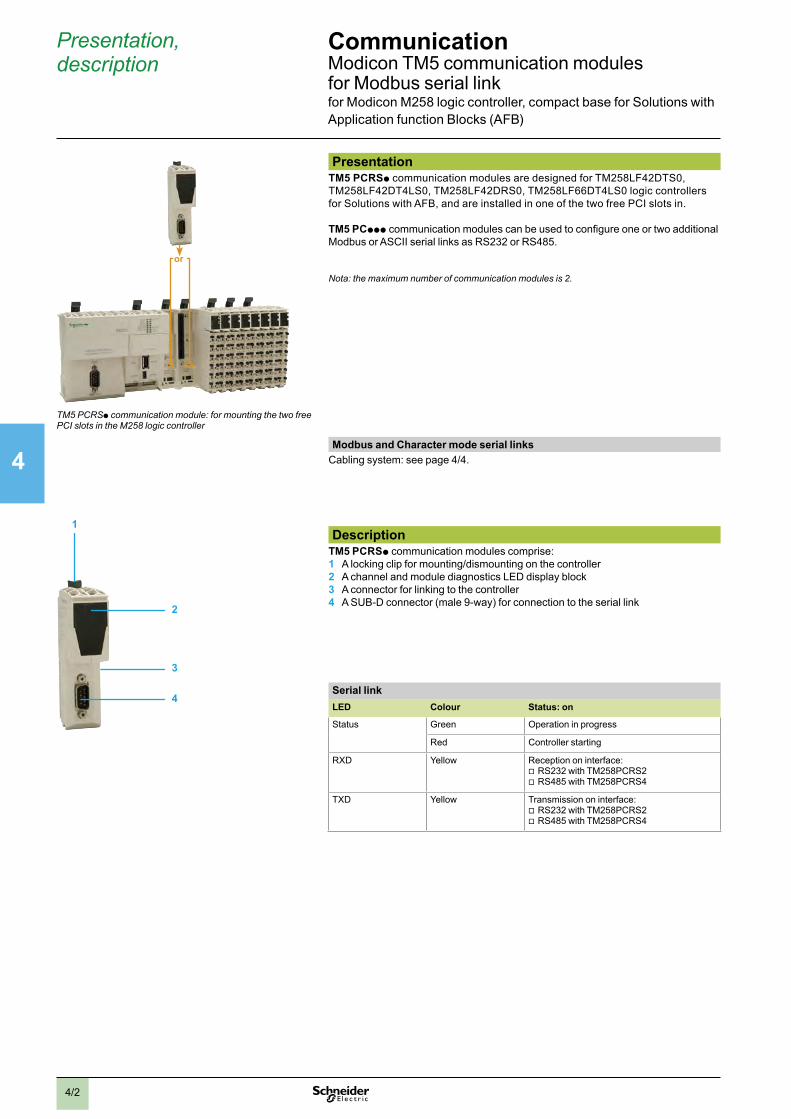
2
1
3
4
5
6
7
8
9
10
4/2
Presentation, description
CommunicationModicon.TM5.communication.modules..for.Modbus.serial.link.for.Modicon.M258.logic.controller,.compact.base.for.Solutions.with.Application.function.Blocks.(AFB)
PresentationTM5 PCRSp communication.modules.are.designed.for.TM258LF42DTS0,.TM258LF42DT4LS0,.TM258LF42DRS0,.TM258LF66DT4LS0.logic.controllers.for.Solutions.with.AFB,.and.are.installed.in.one.of.the.two.free.PCI.slots.in.
TM5 PCppp.communication.modules.can.be.used.to.configure.one.or.two.additional.Modbus.or.ASCII.serial.links.as.RS232.or.RS485.
Nota: the maximum number of communication modules is 2.
Modbus and Character mode serial linksCabling.system:.see.page.4/4...
DescriptionTM5 PCRSp communication.modules.comprise:1 A.locking.clip.for.mounting/dismounting.on.the.controller2 A.channel.and.module.diagnostics.LED.display.block3 A.connector.for.linking.to.the.controller4 A.SUB-D.connector.(male.9-way).for.connection.to.the.serial.link
Serial linkLED Colour Status: on
Status Green Operation.in.progress
Red Controller.starting
RXD Yellow Reception.on.interface:.v RS232.with.TM258PCRS2.v RS485.with.TM258PCRS4
TXD Yellow Transmission.on.interface:.v RS232.with.TM258PCRS2.v RS485.with.TM258PCRS4
TM5 PCRSp communication module: for mounting the two free PCI slots in the M258 logic controller
1
2
3
4
or

2
1
3
4
5
6
7
8
9
10
4/3
References CommunicationModicon.TM5.communication.modules..for.Modbus.serial.link.for.Modicon.M258.logic.controller,.compact.base.for.Solutions.with.Application.function.Blocks.(AFB)
ReferencesDescription Used for Physical
layer/ protocols
Built-in port Reference Weight kglb
Modbus serial link communication modules
Logic.controllers.type.S:.v TM258LF42DTS0.v TM258LF42DT4LS0.v TM258LF42DRS0.v TM258LF66DT4LS0
RS232/.Modbus/ASCII,.SoMachine
SUB-D.connector.(male.9-way)..
TM5PCRS2 0.0640.141
RS485./Modbus/ASCII,.SoMachine
SUB-D.connector.(male.9-way)
TM5PCRS4 0.0640.141
TM5 PCRSp

2
1
3
4
5
6
7
8
9
10
4/4
Communication Modbus.and.character.mode.serial.linkfor.Modicon.M238.&.Modicon.M258.logic.controllers,.compact.bases.for.Solutions.with.Application.function.Blocks.(AFB)
Connections, references
Modbus cabling system
Non isolated link (Modicon.M238/M258.master) Isolated link (Modicon.M238/M258.master)
7
1 1
44
1
6
32
544
c 24 V
4
7
Length of cables between Modicon M238S/M258S and Altivar 212: y 30 m max. (98.425 ft max.)
g Line polarization activeb Line termination
Total length of cables between isolation boxes 1: y 1000 m (3280.840 ft)Length of tap cables 4, 5 or 6: y 10 m (32.808 ft)
Phaseo.Modular
Twido.slave
b g b b
TeSys.UATV.212
Modicon.M258S
or
ATV.212TeSys.U
Modicon.M258S
HMIModicon.M238S
Modicon.M238Sor
References Tap-off and adapter components for RS 485 serial linkDescription Application Item Length Reference Weight
kglb
Tap isolation box Screw.terminal.block..for.main.cable2.x.RJ45.for.tap-off
-. RS.485.line.isolation.(1)-. Line.end.adapter.(RC.120.Ω,.1nF)-. Line.pre-polarisation.(2.R.620.Ω)c.24.V.supply.(screw.terminal.block).or.c.5.V.(via.RJ45)Mounting.on.35.mm.(1.378.in.).5
1 – TWDXCAISO 0.1000.220
Tap junction box1.x.RJ45.for.main.cable2.x.RJ45.for.tap-off.
-. Line.end.adapter.(RC.120.Ω,.1nF)-. Line.pre-polarisation.(2.R.620.Ω)Mounting.on.35.mm.(1.378.in.).5
2 – TWDXCAT3RJ 0.0800.176
Modbus hub Screw.terminal.block..for.main.cable10.x.RJ45.for.tap-off
Mounting.on.35.mm.(1.378.in.).5,.on..mounting.plate.or.panel.(2.x.Ø.4.mm.(2.x.Ø.0.157.in.).screws).
– – LU9GC3 0.5001.102
T-junction boxes2.x.RJ45.for.main.cable
1.integrated.cable.with.RJ45..connector.for.Altivar.variable..speed.controller.dedicated.tap-off
– 0.3.m0.984.ft
VW3A8306TF03 –
1.m3.281.ft
VW3A8306TF10 –
Passive tap junction box
-. Line.extension.and.single-channel.tap-off.on.screw.terminal.block-. Line.end.adapter
– – TSXSCA50 0.5201.146
RS 232C/RS 485 line converter
-. Flow.rate.19.2.Kbit/s.max.-. Without.modem.signalsc.24.V/20.mA.supply,.Mounting.on.35.mm.(1.378.in.).5
– – XGSZ24 0.1000.220
(1) Line isolation recommended for distances > 10 m (32.808 ft)
TWD XCA ISO TWD XCA T3RJ
LU9 GC3
TSX SCA 50 XGS Z24
HMI
HMI
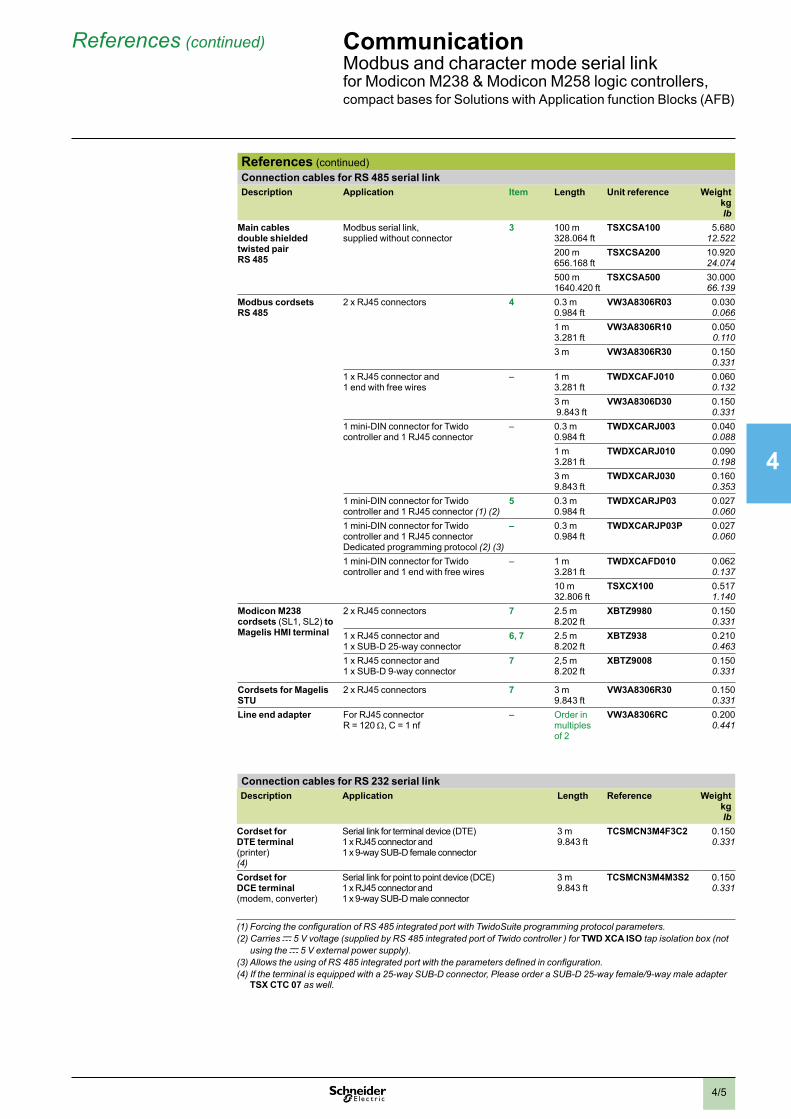
2
1
3
4
5
6
7
8
9
10
4/5
References (continued) Communication Modbus.and.character.mode.serial.linkfor.Modicon.M238.&.Modicon.M258.logic.controllers,.compact.bases.for.Solutions.with.Application.function.Blocks.(AFB)
References (continued)Connection cables for RS 485 serial link Description Application Item Length Unit reference Weight
kglb
Main cables double shielded twisted pair RS 485
Modbus.serial.link,..supplied.without.connector
3 100.m328.064.ft
TSXCSA100 5.68012.522
200.m656.168.ft
TSXCSA200 10.92024.074
500.m1640.420.ft
TSXCSA500 30.00066.139
Modbus cordsets RS 485
2.x.RJ45.connectors. 4 0.3.m0.984.ft
VW3A8306R03 0.0300.066
1.m3.281.ft
VW3A8306R10 0.0500.110
3.m VW3A8306R30 0.1500.331
1.x.RJ45.connector.and.1.end.with.free.wires
– 1.m3.281.ft
TWDXCAFJ010 0.0600.132
3.m.9.843.ft
VW3A8306D30 0.1500.331
1.mini-DIN.connector.for.Twido.controller.and.1.RJ45.connector
– 0.3.m0.984.ft
TWDXCARJ003 0.0400.088
1.m3.281.ft
TWDXCARJ010 0.0900.198
3.m9.843.ft
TWDXCARJ030 0.1600.353
1.mini-DIN.connector.for.Twido.controller.and.1.RJ45.connector.(1) (2)
5 0.3.m0.984.ft
TWDXCARJP03 0.0270.060
1.mini-DIN.connector.for.Twido.controller.and.1.RJ45.connector.Dedicated.programming.protocol.(2) (3)
– 0.3.m0.984.ft
TWDXCARJP03P 0.0270.060
1.mini-DIN.connector.for.Twido.controller.and.1.end.with.free.wires
– 1.m3.281.ft
TWDXCAFD010 0.0620.137
10.m32.806.ft
TSXCX100 0.5171.140
Modicon M238 cordsets.(SL1,.SL2).to Magelis HMI terminal
2.x.RJ45.connectors. 7 2.5.m8.202.ft
XBTZ9980 0.1500.331
1.x.RJ45.connector.and..1.x.SUB-D.25-way.connector
6, 7 2.5.m8.202.ft
XBTZ938 0.2100.463
1.x.RJ45.connector.and..1.x.SUB-D.9-way.connector
7 2,5.m8.202.ft
XBTZ9008 0.1500.331
Cordsets for Magelis STU
2.x.RJ45.connectors 7 3.m9.843.ft
VW3A8306R30 0.1500.331
Line end adapter For.RJ45.connector.R.=.120.Ω,.C.=.1.nf
– Order.in.multiples.of.2
VW3A8306RC 0.2000.441
Connection cables for RS 232 serial linkDescription Application Length Reference Weight
kglb
Cordset for DTE terminal (printer)(4)
Serial.link.for.terminal.device.(DTE).1.x.RJ45.connector.and..1.x.9-way.SUB-D.female.connector.
3.m9.843.ft
TCSMCN3M4F3C2 0.1500.331
Cordset for DCE terminal (modem,.converter)
Serial.link.for.point.to.point.device.(DCE)1.x.RJ45.connector.and..1.x.9-way.SUB-D.male.connector
3.m9.843.ft
TCSMCN3M4M3S2 0.1500.331
(1) Forcing the configuration of RS 485 integrated port with TwidoSuite programming protocol parameters.(2) Carries c 5 V voltage (supplied by RS 485 integrated port of Twido controller ) for TWD XCA ISO tap isolation box (not
using the c 5 V external power supply).(3) Allows the using of RS 485 integrated port with the parameters defined in configuration.(4) If the terminal is equipped with a 25-way SUB-D connector, Please order a SUB-D 25-way female/9-way male adapter
TSX CTC 07 as well.
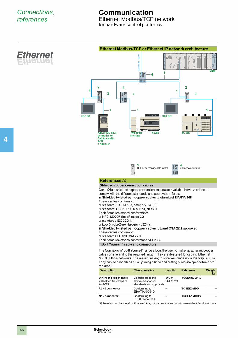
2
1
3
4
5
6
7
8
9
10
4/6
Connections, references
CommunicationEthernet.Modbus/TCP.networkfor.hardware.control.platforms
Ethernet Modbus/TCP or Ethernet IP network architecture
1
2
1
4
3
4
4
1
1
2
31
2
1
3
M238STwidoPortInterface
M258S
XBT GCXBT GC
Altivar IMC drive controller for Solutions with AFB + Altivar 61
M340
Manageable.switchHub.or.no.manageable.switch
Opt
ical
fib
re
References (1) Shielded copper connection cablesConneXium.shielded.copper.connection.cables.are.available.in.two.versions.to.comply.with.the.different.standards.and.approvals.in.force:
b Shielded twisted pair copper cables to standard EIA/TIA 568These.cables.conform.to:..v standard.EIA/TIA.568,.category.CAT.5E,..v standard.IEC.11801/EN.50173,.class.D..
Their.flame.resistance.conforms.to:..v NFC.32070#.classification.C2.v standards.IEC.322/1,..v Low.Smoke.Zero.Halogen.(LSZH). b Shielded twisted pair copper cables, UL and CSA 22.1 approved
These.cables.conform.to:..v standards.UL.and.CSA.22.1.
Their.flame.resistance.conforms.to.NFPA.70..“Do It Yourself” cable and connectors
The.ConneXium.“Do.It.Yourself”.range.allows.the.user.to.make.up.Ethernet.copper.cables.on.site.and.to.the.required.length..They.are.designed.for.cabling.Ethernet.10/100.Mbit/s.networks..The.maximum.length.of.cables.made.up.in.this.way.is.80.m..They.can.be.assembled.quickly.using.a.knife.and.cutting.pliers.(no.special.tools.are.required).Description Characteristics Length Reference Weight
kgEthernet copper cable 2.shielded.twisted.pairs.24.AWG
Conforming.to.the..above-mentioned.standards.and.approvals
300.m984.252.ft
TCSECN300R2 –
RJ 45 connector Conforming.to..EIA/TIA-568-D
– TCSEK3MDS –
M12 connector Conforming.to..IEC.60176-2-101
– TCSEK1MDRS –
(1) For other versions (optical fibre, switches,…), please consult our site www.schneider-electric.com

2
1
3
4
5
6
7
8
9
10
4/7
References (continued) CommunicationEthernet.Modbus/TCP.networkfor.hardware.control.platforms
References (continued)Shielded twisted pair cables to standard EIA/TIA568Description . Pre-formed at both ends Item Length Reference Weight
Straight cables 2.x.RJ45.connectorsFor.connection.to.terminal.equipment.(DTE)
1 2.m.(6.562.ft) 490NTW00002 –5.m.(16.404.ft) 490NTW00005 –12.m.(39.370.ft) 490NTW00012 –40.m.(131.234.ft) 490NTW00040 –80.m.(262.467.ft).490NTW00080
Crossover cables 2.x.RJ45.connectorsFor.connection.between.hubs,.switches.and.transceivers
2 5.m.(16.404.ft) 490NTC00005 –12.m.(39.370.ft) 490NTC00015 –40.m.(131.234.ft) 490NTC00040 –80.m.(262.467.ft) 490NTC00080 –
Shielded twisted pair cables, UL and CSA 22.1 approvedDescription Pre-formed at both endsItem Length Reference Weight
Straight cables 2.x.RJ45.connectorsFor.connection.to.terminal.equipment.(DTE)
1 2.m.(6.562.ft) 490NTW00002U –5.m.(16.404.ft) 490NTW00005U –12.m.(39.370.ft) 490NTW00012U –40.m.(131.234.ft) 490NTW00040U –80.m.(262.467.ft). 490NTW00080U –
Crossover cables 2.x.RJ45.connectorsFor.connection.between.hubs,.switches.and.transceivers
2 5.m.(16.404.ft) 490NTC00005U –40.m.(131.234.ft) 490NTC00040U –80.m.(262.467.ft). 490NTC00080U –
Shielded twisted pair cable for IP 67 switchDescription .. Pre-formed at both endsItem Length Reference Weight
Straight cables 1.x.IP.67.4-way.M12.connector..and.1.x.RJ45.connector
– 1.m.(3.281.ft) TCSECL1M3M1S2 –3.m..(9.843.ft) TCSECL1M3M3S2 –5.m.(16.404.ft) TCSECL1M3M5S2 –10.m.(32.808.ft) TCSECL1M3M10S2 –25.m.(82.021.ft) TCSECL1M3M25S2 –40.m.(131.234.ft) TCSECL1M3M40S2 –
ConneXium hubDescription Number of ports Item Reference Weight
kglb
Copper cable Fibre optic
Twisted pair hub10BASE-T.copper.ports,.RJ45.shielded.connectors
4 – 3 499NEH10410 0.5301.168
ConneXium switchesDescription Number of ports Item Manag
-eableReference Weight
kglb
Copper cable Fibre optic
Optimized twisted pair switch: 10BASE-T/100BASE-TX.copper.ports,.RJ45.shielded.connectors,.100BASE-FX.optic.port,.SC.connectors
3 – 3 No. TCSESU033FN0 0.1130.249
4 1 3 No TCSESU043FN0 0.1200.265
5 – 3 No TCSESU053FN0 0.1130.249
Twisted pair switches: 10BASE-T/100BASE-TX.copper.ports,.RJ45.shielded.connectors
8 – 3 No 499NES18100 0.2300.507
8 – 4 Yes TCSESM083F23F0 0.4100.904
Twisted pair and fibre optic switches10BASE-T/100BASE-TX.copper.ports,..RJ45.shielded.connectors..100BASE-FX.optic.ports,.SC.connectors
3 1,.multimode 4 Yes TCSESM043F1CU0 0.4000.882
2 2,.multimode 4 Yes. TCSESM043F2CU0 0.4000.882
3 1,.single-mode 4 Yes TCSESM043F1CS0 0.4000.882
2 2,.single-mode 4 Yes TCSESM043F2CS0 0.4000.882
4 1,.multimode 3 No 499NMS25101 0.3300.728
3 2,.multimode 3 No. 499NMS25102 0.3350.739
4 1,.single-mode 3 No 499NSS25101 0.3300.728
3 2,.single-mode 3 No. 499NSS25102 0.3350.739
7 1,.multimode 4 Yes TCSESM083F1CU0 0.4100.904
6 2,.multimode 4 Yes. TCSESM083F2CU0 0.4100.904
7 1,.single-mode 4 Yes TCSESM083F1CS0 0.4100.904
6 2,.single-mode 4 Yes TCSESM083F2CS0 0.4100.904
IP 67 twisted pair switch (1) 10BASE-T/100BASE-TX.copper.ports,.shielded.M12.connectors.(type.D)
5 – – No. TCSESU051F0 0.2100.463
(1) Require special cables with M12 connectors for their c 24 V supply: XZCP1p64Lp.
490 NTp 000 pp
TCS ESU 043F1N0
TCS ESM 043F2Cp0
499 NMS/NSS 251 02
TCS ESM 083F2Cp0
TCS ESU 051 F0

2
1
3
4
5
6
7
8
9
10
4/8
Presentation, description
CommunicationEthernet.Modbus/TCP.networkfor.Modicon.M238.logic.controller..compact.base.for.Solutions.with.Application.function.Blocks.(AFB)
2
1
3
4
Ethernet Modbus/TCP network
Modbus
Modicon M238 base for Solutions with AFB
TM238Lpppppp
Presentation TwidoPort.module.499TWD01100.is.an.Ethernet.interface.that.is.easy.to.use.and.dedicated.to.Modicon.M238.logic.controllers.for.Solutions.with.AFB.and.Twido.compact.or.modular.programmable.controllers..It.allows.incorporation.of.this.controllers.into.an.Ethernet.network.as.a.passive.device.(slave)..The.TwidoPort.module.is.ready.for.use.When.connected.to.the.integrated.RS.485.serial.port.acts.as.a.gateway.between.the.Ethernet.network.and.the.controller’s.Modbus.serial.link.port.
The.main.characteristics.of.the.TwidoPort.module.are.as.follows:b Connects.to.the.RS.485.of.the.Modicon.M238.controller.for.Solutions.with.AFB.(marked.SL1.or.SL2.depending.on.model).or.the.RS.485.port.of.the.Twido.controller;.no.external.auxiliary.supply.is.necessary.b Ethernet.configuration:v takes.the.Ethernet.configuration.from.the.Twido.application.configuration..(normal.mode),v supports.manual.configuration.using.Telnet.b Provides.Ethernet.statistics.via.a.Telnet.session.
..Description ..The.TwidoPort.499TWD01100.interface.module.comprises:1 Five.pilot.lights.indicating.the.status.of.the.interface.and.of.the.TwidoPort.module.
links.2 An.RJ45.type.connector.for.connection.of.the.power.supply.and.of.the.link.to.the.
controller’s.integrated.RS.485.port..This.connection.is.made.using.connection.cable.TWDXCARJP03P supplied.with.the.TwidoPort.interface.module.in.case.of.the.Twido.controller.
3 An.RJ45.connector.(accessed.through.the.bottom.of.the.module).for.connection.to.the.Ethernet.TCP/IP.network.
4 An.earthing.screw.(accessed.through.the.bottom.of.the.module).
The.TwidoPort.interface.module.can.be.mounted.as.standard.on.a.symmetrical.5.rail..Mounting.kit.TWDXMT5.(sold.in.lots.of.5).allows.plate.or.panel.mounting:.2.x.Ø.4.3.mm.(2.x.Ø.0.169.in.).holes.
To order separatelyFor.connecting.to.the.Modicon.M238.controller,.the.cordset.for.connection.Modbus.XBTZ9980,.lenght.2.5.m.(8.202.ft).
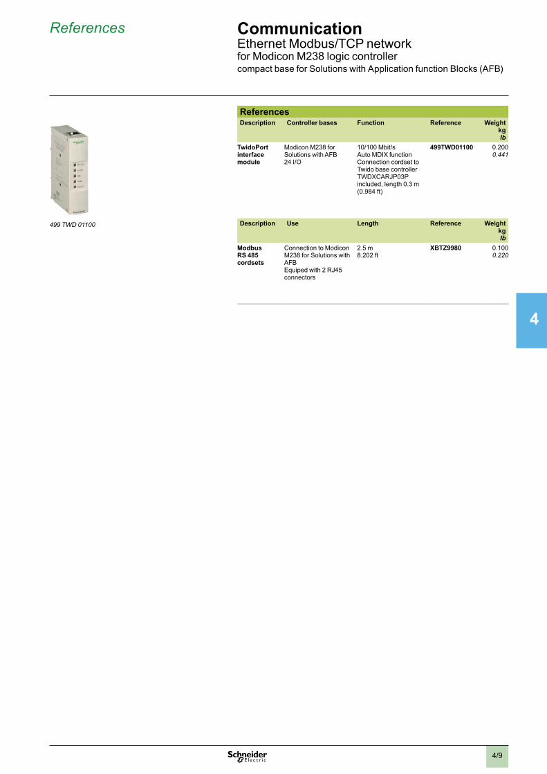
2
1
3
4
5
6
7
8
9
10
4/9
References CommunicationEthernet.Modbus/TCP.networkfor.Modicon.M238.logic.controller..compact.base.for.Solutions.with.Application.function.Blocks.(AFB)
ReferencesDescription Controller bases Function Reference . Weight
kglb
TwidoPort interface module
Modicon.M238.for.Solutions.with.AFB..24.I/O
10/100.Mbit/s.Auto.MDIX.function...Connection.cordset.to.Twido.base.controller.TWDXCARJP03P.included,.length.0.3.m.(0.984.ft)..
499TWD01100 0.2000.441
Description Use Length Reference Weightkglb
Modbus RS 485 cordsets
Connection.to.Modicon.M238.for.Solutions.with.AFBEquiped.with.2.RJ45.connectors....
2.5.m8.202.ft
XBTZ9980 0.1000.220
499 TWD 01100

chapter 5Associated offers
All technical information about products listed in this chapter are available on www.schneider-electric.com

2
1
3
4
5/1
b Altivar 212 and Altivar 61 variable speed drivesvv Presentationv. . . . . . . . . . . . . . . . . . . . . . . . . . . . . . . . . . . . . . . . . . . . . . . . . . . 5/2
vv Selectionvguidevv.v.v.v.v.v.v.v.v.v.v.v.v.v.v.v.v.v.v.v.v.v.v.v.v.v.v.v.v.v.v.v.v.v.v.v.v.v.v.v.v.v.v.v.v.v.v.v.v 5/4
b Altistart 01, Altistart 22 and Altistart 48 soft starters for asynchronous motorsvv Selectionvguidevv.v.v.v.v.v.v.v.v.v.v.v.v.v.v.v.v.v.v.v.v.v.v.v.v.v.v.v.v.v.v.v.v.v.v.v.v.v.v.v.v.v.v.v.v.v.v.v.v5/6
b Protection componentsvv Selectingvmotorvstartingvmodev. . . . . . . . . . . . . . . . . . . . . . . . . . . . . . . 5/8vtov5/10v
vv TeSysvContactorsv. . . . . . . . . . . . . . . . . . . . . . . . . . . . . . . . . . . . . . . . . . . . . . 5/12
vv TeSysvprotectionvcomponents:vThermal-magneticvmotorvcircuit-breakers v. . 5/13
vv Protectionvrelaysvandvcontrollersv. . . . . . . . . . . . . . . . . . . . . . . . . . . . . . . . . . 5/14
vv Feedervprotectionvandvcircuitvdisconnection v. . . . . . . . . . . . . . . . . . . . . . . . . 5/16
vv Branchvcircuitvandvcontrolvcircuitvprotectionv. . . . . . . . . . . . . . . . . . . . . . . . . . 5/17
vv Powerv&vEnergyv-vMonitoringv&vControlvv. . . . . . . . . . . . . . . . . . . . . . . . . . . . . 5/18
b Enclosures vv Spacialvenclosuresv. . . . . . . . . . . . . . . . . . . . . . . . . . . . . . . . . . . . . . . . . . . . . 5/20
vv Thalassavenclosures v. . . . . . . . . . . . . . . . . . . . . . . . . . . . . . . . . . . . . . . . . . . 5/21
b Control and signalling unitsvv Controlvandvsignallingvunits v. . . . . . . . . . . . . . . . . . . . . . . . . . . . . . . . . . . . . . 5/22
vv Controlvstationsvandvenclosuresv. . . . . . . . . . . . . . . . . . . . . . . . . . . . . . . . . . . 5/24
b Power supplies Phaseovv Regulatedvswitchvmodevpowervsupplies:vSelectionvguide v. . . . . . . . . . . . . . . 5/26
b Magelis Operator dialogue terminalsvv MagelisTMvSmallvPanels v. . . . . . . . . . . . . . . . . . . . . . . . . . . . . . . . . . . . . . . . . 5/28
vv MagelisTMvGTvAdvancedvPanelsv. . . . . . . . . . . . . . . . . . . . . . . . . . . . . . . . . . . 5/30
vv MagelisTMvGK,vGHvandvGTWvAdvancedvPanelsv. . . . . . . . . . . . . . . . . . . . . . . 5/32
vv MagelisTMvGTOvOptimumvAdvancedvPanelsv. . . . . . . . . . . . . . . . . . . . . . . . . . 5/34
vv MagelisTMvGTOvOptimumvAdvancedvPanels:vPresentationv. . . . . . . . . . . . . . . 5/35
vv MagelisTMvGTOvOptimumvAdvancedvPanels:vSelectionvguide v. . . . . . . . . . . . 5/36
b OsiSense XM pressure sensorsvv OsiSensevXMvpressurevsensorsvforvpumpingvapplication v. . . . . . . . . . . . . . . 5/38
b Measurement & control relays - Zelio Controlvv Modularvandvindustrialvrelaysv. . . . . . . . . . . . . . . . . . . . . . . . . . . . . . . 5/40vtov5/43
b Product reference indexvv indexv. . . . . . . . . . . . . . . . . . . . . . . . . . . . . . . . . . . . . . . . . . . . . . . . . . . . . . . . 5/44
Contents Associated offers

2
1
3
4
5
6
7
8
9
10
5/2
Presentation Associated offers Altivarv212vvariablevspeedvdrives
Orientated towards performance, intelligence and building protection
The Altivar 212 is focused on Pumping machine as a dedicated variable speed drive for pumps and compressors.
Drives v> fromv0 .75vupvtov75vkWv(fromv1vtov100vhp)v> fromv200vtov480vVv> 3vphases
Orientated towards performance, intelligence and pumping protectionv>Easyvintegrationvtovbuildingvsupervisionvnetworkvusingvembeddedvprotocolsv> Instantvdetectionvofvsystemvfailure:vbeltvbreakage,vpumpvrunningvdry,vphasevfailure,vetc .v>Preventivevmaintenancevforvreducingvcosts:vfaultvalert,voperatingvtime,vetcv>Energyvconsumptionvmonitoring
Focused on user-friendlinessv>Easyvset-up,vcommissioningvandvdiagnosticsvtools:vremotevgraphicvterminalvv(6vlanguagesvasvstandard),vMulti-Loader,vPCvSoftware,vBluetoothvcapabilityvandvSoMovevMobilevsoftwarev>Compactvsizevforvbettervintegration
Focused on cost savingsv>Reducedvinvestmentvcostsv(embeddedvfunctionalities)v>Quickvreturnvonvinvestmentv(energyvsaving)
Focused on protection & efficiencyv>Continuityvofvservicev> Functionsvdesignedvforvbuildings:vfirevmode,vdampervmonitoring,vmechanicalvprotection,vetc .v> IntegratedvEMCvfilterv>Antiharmonicvtechnologyv(THDIv v30%)
Selection guide: see page 5/4
Altivar 212 variable speed drives
Pumping application

2
1
3
4
5
6
7
8
9
10
5/3
Presentation Associated offers Altivarv61vvariablevspeedvdrives
Energy savings and performance for your pumps
The Altivar 61 is a variable speed drive with variable torque and is designed for exceptional versatility from the smallest application to the highest power rating.
Drives v> fromv0 .37vupvtov2400vkWv(fromv0 .49vtov3217vhp)v> fromv200vtov690vVv> 3vphases
Communicationv>Connectivityvtovallvfieldbusesv(integratedvModbusvandvCANopen)v>Multi-languagevgraphicvdisplayvterminal
Flexibilityv>Optionvcards:vprogrammablevI/O
Powerfulv>Multi-pumpvmanagementv>Savesvenergyv>Optimisesvautomationvsolutionsvwithvitsvseamlessvintegrationvintovthevarchitecturev>Suitablevforvavwidevrangevofvpowervratingsv(0 .37vtov2400vkWv-v0 .49vtov3217vhp)v> Integratedvsafetyvfunction
Rugged in harsh environmentsv> 3C2vreinforcedvversion,vstandardvIECv721-3-3v(gas,vliquids),vIP20/IP54v>Versionsvwithvwatervcoolingv> IP54/IP55vwall-mountedvorvfloor-standingvenclosuresvavailablev>CompliesvwithvATEXvsafetyvstandardsv(explosivevenvironments)
Selection guide: see page 5/5
Altivar 61 variable speed drives
Multi-pump solution
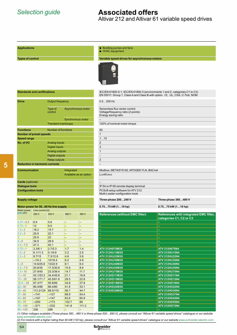
2
1
3
4
5
6
7
8
9
10
5/4
Selection guide Associated offers Altivarv212vandvAltivarv61vvariablevspeedvdrives
Applications vb Buildingvpumpsvandvfansvb HVACvequipment
vb Industrialvpumpsvandvfansvb HVACvequipmentvb Compressors
Types of control Variable speed drives for asynchronous motors Variable speed drives for asynchronous motors
vv
Standards and certifications IEC/ENv61800-5-1,vIEC/ENv61800-3v(environmentsv1vandv2,vcategoriesvC1vtovC3)vENv55011:vGroupv1,vClassvAvandvClassvBvwithvoption . e,vvUL,vCSA,vC-Tick,vNOM
IEC/ENv61800-5-1,vIEC/ENv61800-3v(environmentsv1vandv2,vcategoriesvC1vtovC3),vIEC/ENv61000-4-2/4-3/4-4/4-5/4-6/4-11,ve,vUL,vCSA,vDNV,vC-Tick,vNOM,vGOST
Drive Outputvfrequency 0 .5…200vHz 0 .1…500vHzvforvthevwholevrangev0 .1…599vHzvupvtov37vkW(upvtov50vhp)vinv200…240vVva andv380…480vVva
Typevofvcontrol
Asynchronousvmotor SensorlessvfluxvvectorvcontrolVoltage/frequencyvratiov(2vpoints)Energyvsavingvratio
SensorlessvfluxvvectorvcontrolVoltage/frequencyvratiov(2vorv5vpoints)vEnergyvsavingvratio
Synchronousvmotor – VectorvcontrolvwithoutvspeedvfeedbackTransientvovertorque 120%vofvnominalvmotorvtorque 120%vofvnominalvmotorvtorquevforv60vseconds
Functions Numbervofvfunctions 50 >v100Number of preset speeds 7 8Speed range 1…10 1…100vinvopenvloopvmodeNo. of I/O Analogvinputs 2 2…4
Digitalvinputs 3 6…20Analogvoutputs 1 1…3Digitalvoutputs – 0…8Relayvoutputs 2 2…4
Reduction in harmonic currents – DCvchokevintegratedvorvsuppliedvwithvthevdrive
Communication Integrated Modbus,vMETASYSvN2,vAPOGEEvFLN,vBACnet ModbusvandvCANopenAvailablevasvanvoption LonWorks ModbusvTCPvDaisyvChain,vModbus/Uni-Telway,vEtherNet/IP,vDeviceNet,vPROFIBUSvDPvV0vandvV1,vInterBus,vCC-Link,vLonWorks,vMETASYSvN2,vAPOGEEvFLN,v
BACnetCardsv(optional) – I/Ovexpansionvcards,vControllervInsidevprogrammablevcard,vAltivarvIMCvintegratedvcontrollervcard,vmulti-pumpvcards,vencodervinterfacevcards (2)Dialogue tools IPv54vorvIPv65vremotevdisplayvterminal IPv54vorvIPv65vremotevdisplayvterminalConfiguration tools PCSoftvsetupvsoftwarevforvATVv212
Multi-LoadervconfigurationvtoolsSoMovevsetupvsoftwareSimplevLoadervandvMulti-Loadervconfigurationvtools
Supply voltage Three-phase 200…240 V Three-phase 380…480 V Single-phase 200…240 Vv Three-phase 200…240 V (1)
Motor power for 50...60 Hz line supply 0.75…75 kW (1…10 hp) 0.75…75 kW (1…10 hp) 0.37…630 kW (0.50…845 hp) (2) 0.37…630 kW (0.50…845 hp) (2) 0.37…630 kW (0.50…845 hp) (2)Motorvpowerv(kW-HP)
Linevcurrentv(A)200vV 240vV 380vV 480vV References (without EMC filter) References with integrated EMC filter,
categories C1, C2 or C3References with integrated EMC filter, categories C1, C2 or C3
References with integrated EMC filter (up to 7.5 W), category C2
References (without EMC filter)
0 .37v-v0.5 6 .9 5 .8 – – – – ATV 61H075M3 – –0 .75v-v1 12 9 .9 – – – – ATV 61HU15M3 – –1 .5v-v2 18 .2 15 .7 – – – – ATV 61HU22M3 – –2 .2v-v3 25 .9 22 .1 – – – – ATV 61HU30M3 – –3 25 .9 22 – – – – ATV 61HU40M3 – –4v-v5 34 .9 29 .9 – – – – ATV 61HU55M3 – –5 .5v-v7.5 47 .3 40 .1 – – – – ATV 61HU75M3 – –0 .75v-v1 3.3/6.1 2 .7/5 .3 1 .7 1 .4 ATV 212H075M3X ATV 212H075N4 – ATV 61H075M3 –1 .5v-v2 6 .1/11 .3 5 .1/9 .6 3 .2 2 .5 ATV 212HU15M3X ATV 212HU15N4 – ATV 61HU15M3 –2 .2v-v3 8 .7/15 7 .3/12 .8 4 .6 3 .6 ATV 212HU22M3X ATV 212HU22N4 – ATV 61HU22M3 –3 –/19 .3 10/16 .4 6 .2 4 .9 ATV 212HU30M3X ATV 212HU30N4 – ATV 61HU30M3 –4v-v5 14 .6/25 .8 13/22 .9 8 .1 6 .4 ATV 212HU40M3X ATV 212HU40N4 – ATV 61HU40M3 –5 .5v-v7.5 20 .8/35 17 .3/30 .8 10 .9 8 .6 ATV 212HU55M3X ATV 212HU55N4 – ATV 61HU55M3 –7 .5v-v10 27 .9/45 23 .3/39 .4 14 .7 11 .7 ATV 212HU75M3X ATV 212HU75N4 – ATV 61HU75M3 –11v-v15 42 .1/53 .3 34 .4/45 .8 21 .1 16 .8 ATV 212HD11M3X ATV 212HD11N4 – – ATV 61HD11M3X15v-vv20 56 .1/71 .7 45 .5/61 .6 28 .5 22 .8 ATV 212HD15M3X ATV 212HD15N4 – – ATV 61HD15M3X18 .5v-vv25 67 .3/77 55 .8/69 34 .8 27 .8 ATV 212HD18M3X ATV 212HD18N4 – – ATV 61HD18M3X 22v-v30 80 .4/88 66 .4/80 41 .6 33 .1 ATV 212HD22M3X ATV 212HD22N4 – – ATV 61HD22M3X30v-v40 113 .3/124 89 .5/110 56 .7 44 .7 ATV 212HD30M3X ATV 212HD30N4 – – ATV 61HD30M3X 37v-v50 –/141 –/127 68 .9 54 .4 – ATV 212HD37N4 – – ATV 61HD37M3X45v-v60 –/167 –/147 83 .8 65 .9 – ATV 212HD45N4 – – ATV 61HD45M3X 55v-v75 –/200 –/173 102 .7 89 – ATV 212HD55N4 – – ATV 61HD55M3X 75v-v100 –/271 –/232 141 .8 111 .3 – ATV 212HD75N4 – – ATV 61HD75M3X 90v-v125 336 288 – – – – – – ATV 61HD90M3X (1) Other voltages available (Three-phase 380…480 V or three-phase 500…690 V), please consult our “Altivar 61 variable speed drives” catalogue or our website www.schneider-electric.com(2) For motors with a higher rating than 90 kW (120 hp), please consult our “Altivar 61 variable speed drives”vcatalogue or our website www.schneider-electric.com
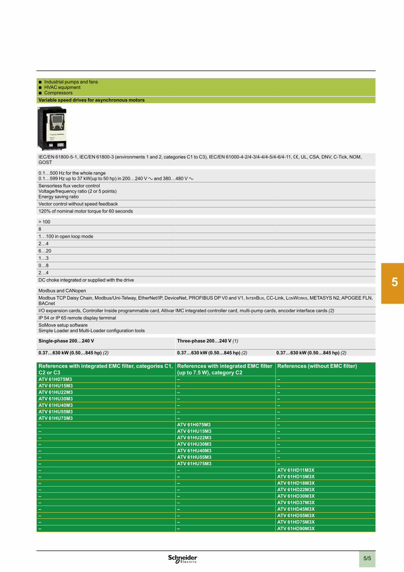
2
1
3
4
5
6
7
8
9
10
5/5
Applications vb Buildingvpumpsvandvfansvb HVACvequipment
vb Industrialvpumpsvandvfansvb HVACvequipmentvb Compressors
Types of control Variable speed drives for asynchronous motors Variable speed drives for asynchronous motors
vv
Standards and certifications IEC/ENv61800-5-1,vIEC/ENv61800-3v(environmentsv1vandv2,vcategoriesvC1vtovC3)vENv55011:vGroupv1,vClassvAvandvClassvBvwithvoption . e,vvUL,vCSA,vC-Tick,vNOM
IEC/ENv61800-5-1,vIEC/ENv61800-3v(environmentsv1vandv2,vcategoriesvC1vtovC3),vIEC/ENv61000-4-2/4-3/4-4/4-5/4-6/4-11,ve,vUL,vCSA,vDNV,vC-Tick,vNOM,vGOST
Drive Outputvfrequency 0 .5…200vHz 0 .1…500vHzvforvthevwholevrangev0 .1…599vHzvupvtov37vkW(upvtov50vhp)vinv200…240vVva andv380…480vVva
Typevofvcontrol
Asynchronousvmotor SensorlessvfluxvvectorvcontrolVoltage/frequencyvratiov(2vpoints)Energyvsavingvratio
SensorlessvfluxvvectorvcontrolVoltage/frequencyvratiov(2vorv5vpoints)vEnergyvsavingvratio
Synchronousvmotor – VectorvcontrolvwithoutvspeedvfeedbackTransientvovertorque 120%vofvnominalvmotorvtorque 120%vofvnominalvmotorvtorquevforv60vseconds
Functions Numbervofvfunctions 50 >v100Number of preset speeds 7 8Speed range 1…10 1…100vinvopenvloopvmodeNo. of I/O Analogvinputs 2 2…4
Digitalvinputs 3 6…20Analogvoutputs 1 1…3Digitalvoutputs – 0…8Relayvoutputs 2 2…4
Reduction in harmonic currents – DCvchokevintegratedvorvsuppliedvwithvthevdrive
Communication Integrated Modbus,vMETASYSvN2,vAPOGEEvFLN,vBACnet ModbusvandvCANopenAvailablevasvanvoption LonWorks ModbusvTCPvDaisyvChain,vModbus/Uni-Telway,vEtherNet/IP,vDeviceNet,vPROFIBUSvDPvV0vandvV1,vInterBus,vCC-Link,vLonWorks,vMETASYSvN2,vAPOGEEvFLN,v
BACnetCardsv(optional) – I/Ovexpansionvcards,vControllervInsidevprogrammablevcard,vAltivarvIMCvintegratedvcontrollervcard,vmulti-pumpvcards,vencodervinterfacevcards (2)Dialogue tools IPv54vorvIPv65vremotevdisplayvterminal IPv54vorvIPv65vremotevdisplayvterminalConfiguration tools PCSoftvsetupvsoftwarevforvATVv212
Multi-LoadervconfigurationvtoolsSoMovevsetupvsoftwareSimplevLoadervandvMulti-Loadervconfigurationvtools
Supply voltage Three-phase 200…240 V Three-phase 380…480 V Single-phase 200…240 Vv Three-phase 200…240 V (1)
Motor power for 50...60 Hz line supply 0.75…75 kW (1…10 hp) 0.75…75 kW (1…10 hp) 0.37…630 kW (0.50…845 hp) (2) 0.37…630 kW (0.50…845 hp) (2) 0.37…630 kW (0.50…845 hp) (2)Motorvpowerv(kW-HP)
Linevcurrentv(A)200vV 240vV 380vV 480vV References (without EMC filter) References with integrated EMC filter,
categories C1, C2 or C3References with integrated EMC filter, categories C1, C2 or C3
References with integrated EMC filter (up to 7.5 W), category C2
References (without EMC filter)
0 .37v-v0.5 6 .9 5 .8 – – – – ATV 61H075M3 – –0 .75v-v1 12 9 .9 – – – – ATV 61HU15M3 – –1 .5v-v2 18 .2 15 .7 – – – – ATV 61HU22M3 – –2 .2v-v3 25 .9 22 .1 – – – – ATV 61HU30M3 – –3 25 .9 22 – – – – ATV 61HU40M3 – –4v-v5 34 .9 29 .9 – – – – ATV 61HU55M3 – –5 .5v-v7.5 47 .3 40 .1 – – – – ATV 61HU75M3 – –0 .75v-v1 3.3/6.1 2 .7/5 .3 1 .7 1 .4 ATV 212H075M3X ATV 212H075N4 – ATV 61H075M3 –1 .5v-v2 6 .1/11 .3 5 .1/9 .6 3 .2 2 .5 ATV 212HU15M3X ATV 212HU15N4 – ATV 61HU15M3 –2 .2v-v3 8 .7/15 7 .3/12 .8 4 .6 3 .6 ATV 212HU22M3X ATV 212HU22N4 – ATV 61HU22M3 –3 –/19 .3 10/16 .4 6 .2 4 .9 ATV 212HU30M3X ATV 212HU30N4 – ATV 61HU30M3 –4v-v5 14 .6/25 .8 13/22 .9 8 .1 6 .4 ATV 212HU40M3X ATV 212HU40N4 – ATV 61HU40M3 –5 .5v-v7.5 20 .8/35 17 .3/30 .8 10 .9 8 .6 ATV 212HU55M3X ATV 212HU55N4 – ATV 61HU55M3 –7 .5v-v10 27 .9/45 23 .3/39 .4 14 .7 11 .7 ATV 212HU75M3X ATV 212HU75N4 – ATV 61HU75M3 –11v-v15 42 .1/53 .3 34 .4/45 .8 21 .1 16 .8 ATV 212HD11M3X ATV 212HD11N4 – – ATV 61HD11M3X15v-vv20 56 .1/71 .7 45 .5/61 .6 28 .5 22 .8 ATV 212HD15M3X ATV 212HD15N4 – – ATV 61HD15M3X18 .5v-vv25 67 .3/77 55 .8/69 34 .8 27 .8 ATV 212HD18M3X ATV 212HD18N4 – – ATV 61HD18M3X 22v-v30 80 .4/88 66 .4/80 41 .6 33 .1 ATV 212HD22M3X ATV 212HD22N4 – – ATV 61HD22M3X30v-v40 113 .3/124 89 .5/110 56 .7 44 .7 ATV 212HD30M3X ATV 212HD30N4 – – ATV 61HD30M3X 37v-v50 –/141 –/127 68 .9 54 .4 – ATV 212HD37N4 – – ATV 61HD37M3X45v-v60 –/167 –/147 83 .8 65 .9 – ATV 212HD45N4 – – ATV 61HD45M3X 55v-v75 –/200 –/173 102 .7 89 – ATV 212HD55N4 – – ATV 61HD55M3X 75v-v100 –/271 –/232 141 .8 111 .3 – ATV 212HD75N4 – – ATV 61HD75M3X 90v-v125 336 288 – – – – – – ATV 61HD90M3X (1) Other voltages available (Three-phase 380…480 V or three-phase 500…690 V), please consult our “Altivar 61 variable speed drives” catalogue or our website www.schneider-electric.com(2) For motors with a higher rating than 90 kW (120 hp), please consult our “Altivar 61 variable speed drives”vcatalogue or our website www.schneider-electric.com

2
1
3
4
5
6
7
8
9
10
5/6
Selection guide Associated offers Altistartv01,vAltistartv22vandvAltistartv48vsoftvstartersvforvasynchronousvmotors
Applications vb Single-phasevscrollvorvspiralvrefrigerationvcompressorsvb Single-phasevheatvpumpsvb Fansv(1)
vb Compressorsvb Fansvvb Pumps
Type of control Controlled starting of simple machines Controlled starting and deceleration of simple machines
Controlled starting and deceleration of simple and complex machines
Standards and certifications IEC/ENv60947-4-2,ve,vUL,vCSA,vC-Tick,vGOSTvandvCCC IEC/ENv60947-4-2,vEMCvclassvA,ve,vUL,vCSA,vC-Tick,vGOST,vCCC
IEC/ENv60947-4-2,vEMCvclassesvAvandvB,ve,vUL,vCSA,vDNV,vC-Tick,vGOST,vCCC,vNOMv117,vSEPROvandvTCF
Drive Numbervofvcontrolledvphases 1 2 3 3Adjustablevstartingvtime 1…5vs 1…10vsAdjustablevdecelerationvtime No:vfreewheelvstop Yes:v1…10vsTypevofvcontrol – – Configurablevvoltagevramp TCSv(TorquevControlvSystem)Operatingvcycle – – Standard Standardvandvsevere
Functions By-pass Integrated Integrated AvailablevasvanvoptionNumber of I/O
Analogvinputs – 1vPTCvprobe 1vPTCvprobeDigitalvinputs – 3v:vstart,vstopvandvstartupvboost 3vprogrammable 4Analogvoutputs – – 1Digitalvoutputs – – 2Relayvoutputs – 2vprogrammablev(N/CvorvN/O) 3
Dialogue tools – Integratedvdisplayvterminal Integratedvdisplayvterminal,voptionalvremotevdisplayvterminalConfiguration tools SoMovevLitevsoftwarevworkshop PowerSuitevsoftwarevworkshopCommunication Integrated – Modbus Modbus
Availablevasvanvoption CombinedvwithvTeSysvUvstarter-controller: – Fipio,vPROFIBUSvDP,vDeviceNet,vModbusvTCP
Supply voltage Single-phase 110…230 V Three-phase 200…240 V Three-phase 380…415 V Three-phase 440…480 V Three-phase 230…440 V (2) Three-phase 230…415 V (2)Motor power for 50...60 Hz line supply (kW-HP) 0.37…2.2 kW (0.50…3 hp) (3) 0.75…15 kW (0.50…20 hp) (3) 0.75…15 kW (0.50…20 hp) 0.75…15 kW (0.50…20 hp) 4…355 kW (5.4…476 hp) (3) 3…630 kW (4…845 hp) (3)
230vV 400vV 440vV 600vV IcLvnominalvcurrentv(A)
References
0 .37 –v – – 3 ATS01N103FT – – – – –0 .75 – –v – 6 ATS01N106FT – – – – –1 .1 – – – 9 ATS01N109FT – – – – –1 .5 – – – 12 ATS01N112FT – – – – –2 .2 – – – 25 ATS01N125FT – – – – –0 .75/1 .1v-v1/1.5 2 .2/3 – 2/3 6 – ATS01N206LU ATS01N206QN ATS01N206RT – –1 .5v-v2 4 – 5 9 – ATS01N209LU ATS01N209QN ATS01N209RT – –2 .2/3,v3/55 5 .5 – 7.5 12 – ATS01N212LU ATS01N212QN ATS01N212RT – –4/5 .5,v5/7.5 7 .5/11 – 10/15 22 – ATS01N222LU ATS01N222QN ATS01N222RT – –7 .5v-10 15 – 20 32 – ATS01N232LU ATS01N232QN ATS01N232RT – –4 7 .5 7 .5 – 17 – – – – ATS22D17Q ATS48D17Q5 .5 11 – – 22 – – – – – ATS48D22Q7 .5 15 15 – 32 – – – – ATS22D32Q ATS48D32Q9 18 .5 – – 38 – – – – – ATS48D38Q11 22 22 – 47 – – – – ATS22D47Q ATS48D47Q15 30 30 – 62 – – – – ATS22D62Q ATS48D62Q18 .5 37 37 – 75 – – – – ATS22D75Q ATS48D75Q22 45 45 – 88 – – – – ATS22D88Q ATS48D88Q30 55 55 – 110 – – – – ATS22C11Q ATS48C11Q37 75 75 – 140 – – – – ATS22C14Q ATS48C14Q45 90 90 – 170 – – – – ATS22C17Q ATS48C17Q55 110 110 – 210 – – – – ATS22C21Q ATS48C21Q75 132 132 – 250 – – – – ATS22C25Q ATS48C25Q90 160 160 – 320 – – – – ATS22C32Q ATS48C32Q110 220 220 – 410 – – – – ATS22C41Q ATS48C41Q132 250 250 – 480 – – – – ATS22C48Q ATS48C48Q160 315 355 – 590 – – – – ATS22C59Q ATS48C59Q– 355 – – 660 – – – – – ATS48C66Q220 400 – – 790 – – – – – ATS48C79Q250 500 – – 1000 – – – – – ATS48M10Q355 630 – – 1200 – – – – – ATS48M12Q(1) For optimum fan control, use of a variable speed drive is recommended. (2) Other voltages available: Three-phase 208…600 V, please consult our website www.schneider-electric.com(3) For other motor ratings, please consult our website www.schneider-electric.com

2
1
3
4
5
6
7
8
9
10
5/7
Applications vb Single-phasevscrollvorvspiralvrefrigerationvcompressorsvb Single-phasevheatvpumpsvb Fansv(1)
vb Compressorsvb Fansvvb Pumps
Type of control Controlled starting of simple machines Controlled starting and deceleration of simple machines
Controlled starting and deceleration of simple and complex machines
Standards and certifications IEC/ENv60947-4-2,ve,vUL,vCSA,vC-Tick,vGOSTvandvCCC IEC/ENv60947-4-2,vEMCvclassvA,ve,vUL,vCSA,vC-Tick,vGOST,vCCC
IEC/ENv60947-4-2,vEMCvclassesvAvandvB,ve,vUL,vCSA,vDNV,vC-Tick,vGOST,vCCC,vNOMv117,vSEPROvandvTCF
Drive Numbervofvcontrolledvphases 1 2 3 3Adjustablevstartingvtime 1…5vs 1…10vsAdjustablevdecelerationvtime No:vfreewheelvstop Yes:v1…10vsTypevofvcontrol – – Configurablevvoltagevramp TCSv(TorquevControlvSystem)Operatingvcycle – – Standard Standardvandvsevere
Functions By-pass Integrated Integrated AvailablevasvanvoptionNumber of I/O
Analogvinputs – 1vPTCvprobe 1vPTCvprobeDigitalvinputs – 3v:vstart,vstopvandvstartupvboost 3vprogrammable 4Analogvoutputs – – 1Digitalvoutputs – – 2Relayvoutputs – 2vprogrammablev(N/CvorvN/O) 3
Dialogue tools – Integratedvdisplayvterminal Integratedvdisplayvterminal,voptionalvremotevdisplayvterminalConfiguration tools SoMovevLitevsoftwarevworkshop PowerSuitevsoftwarevworkshopCommunication Integrated – Modbus Modbus
Availablevasvanvoption CombinedvwithvTeSysvUvstarter-controller: – Fipio,vPROFIBUSvDP,vDeviceNet,vModbusvTCP
Supply voltage Single-phase 110…230 V Three-phase 200…240 V Three-phase 380…415 V Three-phase 440…480 V Three-phase 230…440 V (2) Three-phase 230…415 V (2)Motor power for 50...60 Hz line supply (kW-HP) 0.37…2.2 kW (0.50…3 hp) (3) 0.75…15 kW (0.50…20 hp) (3) 0.75…15 kW (0.50…20 hp) 0.75…15 kW (0.50…20 hp) 4…355 kW (5.4…476 hp) (3) 3…630 kW (4…845 hp) (3)
230vV 400vV 440vV 600vV IcLvnominalvcurrentv(A)
References
0 .37 –v – – 3 ATS01N103FT – – – – –0 .75 – –v – 6 ATS01N106FT – – – – –1 .1 – – – 9 ATS01N109FT – – – – –1 .5 – – – 12 ATS01N112FT – – – – –2 .2 – – – 25 ATS01N125FT – – – – –0 .75/1 .1v-v1/1.5 2 .2/3 – 2/3 6 – ATS01N206LU ATS01N206QN ATS01N206RT – –1 .5v-v2 4 – 5 9 – ATS01N209LU ATS01N209QN ATS01N209RT – –2 .2/3,v3/55 5 .5 – 7.5 12 – ATS01N212LU ATS01N212QN ATS01N212RT – –4/5 .5,v5/7.5 7 .5/11 – 10/15 22 – ATS01N222LU ATS01N222QN ATS01N222RT – –7 .5v-10 15 – 20 32 – ATS01N232LU ATS01N232QN ATS01N232RT – –4 7 .5 7 .5 – 17 – – – – ATS22D17Q ATS48D17Q5 .5 11 – – 22 – – – – – ATS48D22Q7 .5 15 15 – 32 – – – – ATS22D32Q ATS48D32Q9 18 .5 – – 38 – – – – – ATS48D38Q11 22 22 – 47 – – – – ATS22D47Q ATS48D47Q15 30 30 – 62 – – – – ATS22D62Q ATS48D62Q18 .5 37 37 – 75 – – – – ATS22D75Q ATS48D75Q22 45 45 – 88 – – – – ATS22D88Q ATS48D88Q30 55 55 – 110 – – – – ATS22C11Q ATS48C11Q37 75 75 – 140 – – – – ATS22C14Q ATS48C14Q45 90 90 – 170 – – – – ATS22C17Q ATS48C17Q55 110 110 – 210 – – – – ATS22C21Q ATS48C21Q75 132 132 – 250 – – – – ATS22C25Q ATS48C25Q90 160 160 – 320 – – – – ATS22C32Q ATS48C32Q110 220 220 – 410 – – – – ATS22C41Q ATS48C41Q132 250 250 – 480 – – – – ATS22C48Q ATS48C48Q160 315 355 – 590 – – – – ATS22C59Q ATS48C59Q– 355 – – 660 – – – – – ATS48C66Q220 400 – – 790 – – – – – ATS48C79Q250 500 – – 1000 – – – – – ATS48M10Q355 630 – – 1200 – – – – – ATS48M12Q(1) For optimum fan control, use of a variable speed drive is recommended. (2) Other voltages available: Three-phase 208…600 V, please consult our website www.schneider-electric.com(3) For other motor ratings, please consult our website www.schneider-electric.com

2
1
3
4
5
6
7
8
9
10
5/8
Presentation Associated offersSelectingvmotorvstartingvmode
Selecting motor starting mode Selecting devices
The starter mode is closely linked to the load carried by the motor. The table below presents several typical applications in process control, part of which are used in processes such as water treatment or cement production. The examples illustrate how the selection is made.
Type of actuator Description/ comment Power range Torque Direct On Line (D.O.L.)
Soft starter Speed Drive
Centrifugal Pump
v>Centrifugalvpumpsvarevusedvtovcovervavwidevrangevofvvolumevandvpressurevconditionsv> Thevflowvcanvbevcontrolledvbyvusingvvalvesvonvthevpumpvdischargevmanifoldvorvbyvchangingvthevrotationvspeed
1vkWvtov10vKw Quadratic b b b
10kWvtov>v1MW Quadratic b b
Dosing pump v>Dosingvpumpsvarevfrequentlyvusedvtovinjectvfluidsvthatvmayvbevdifficultvtovmixvefficientlyvinvbatch-tankvsystemsvbecausevofvtheirvlowvvolume
<v10vkW Constant b b
Screw pump v>ScrewvpumpsvarevalsovknownvasvArchimedes’vscrewv> Theyvarevusedvforvliftingvlargevvolumesvofvfluidvorvmaterialvtovavlimitedvheightv> Theyvarevdrivenvthroughvavspeedvreductionvgear
1vtov50vkW Constant b b
Mixer v>Mixersvarevusedvtovgivevhomogeneityvtovfluidsv>Agitationvisvalsovusedvtovspeedvupvchemicalvprocessvv>Mixingvisvperformedvbyvavpropellervrotatingvinvthevfluidvdrivenvbyvavspeedvreductionvgear
1vtov50vkW Constant b b
Moving devices v>Movingvdevicesvdrivevvariousvtypesvofvmechanicalvsystemsvsuchvas:vrotators,vscrapers,vshields,vcompressors,vconveyors
1vtov10kW Constant b b
Air blower and fan
v>Airvblowersvorvfansvarevusedvtovprovidevairvorvoxygenvforvventilationvorvaerationvtankv> Flowvcanvbevadjustedvusingvavmechanicalvsystemv(fixedvspeed)vorvvariablevspeedvdrive .vEnergyvsavingsvarevpossiblevbyvoperatingvatvreducedvspeed
10vkWvtov1vMW Quadraticvorvconstant b b
Mill andcrusher
v>Millsvandvcrushersvarevusedvtovgrindvmaterialsv> Theyvarevtypicallyvhighvtorque
50vkWvtov2vMW Variable b b
2
1
3
4
5
6
7
8
9
10
5/9
Presentation Associated offersSelectingvmotorvstartingvmode
Selecting motor starting mode Control starter functions
Depending on needs, it is necessary to control some or all functions of a starter.The principal function groups are:Motor control performancev> Controlvonvpower,vtorque,vspeed,vreversing,vstartvtime,vandvriskvofvjammingvarevrequired . .vNextvtablevsummarizesvvthevmainvcharacteristicsvofvpumpsvfoundvinvprocessvapplications .
Motor protectionv> Itsvpurposevisvtovavoidvoperatingvmotorsvinvabnormalvconditionsvwhichvcouldvresultvinvnegativeveventsvsuchvas:v> overheatingv> prematurevageingv> destructionvofvelectricalvwindingsv> damagevtovcouplingvorvgearboxv> etc .
Motor metering and monitoring functionsv> Thevpurposevofvimplementingvmeasurementvdevicesvisvtovensurevcontinuousvsupervisionvofvmotorvoperatingvconditions .vThevcollectedvdatavcanvbevusedvwithvgreatvbenefitvonvimprovingvenergyvefficiencyvandvextendingvmotorvlifetimev> Monitoringvfunctionsvallowvyouvtovcontrolvcosts,vschedulevmaintenancevoperationsvandvkeepvhistoricalvinformationvforvlegalvrequirements
Thevtablevonvthevnextvpagevpresentsvavsynthesisvofvdifferentvdevicevfunctions .

2
1
3
4
5
6
7
8
9
10
5/10
Presentation Associated offersSelectingvmotorvstartingvmodev(continued)
Selecting motor starting mode D.O.L. starterMotorvcircuitvbreakerv+vContactorvLCpDvorvF
StartervcontrollervTeSysvU
Standardvcontrolvunit
Advancedvcontrolvunit
Multifunctionvcontrolvunit
Motor protection functionsv>Shortvcircuit b b b bv>Overload b b b bv> Lockedvrotor b b b bv>Novloadvrunning b bv>Earthvfault b bv>Supplyvphasesvfailurevandvimbalance b b b bv>Ventilationvfaultv>Abnormalvtemperaturevrisev>Shaftvbearingvseizurev> Insulationvfaultv> Longvstartingvtime b b b bv>Currentvphasevreversalv> Loadvfluctuationsv(I,vU,vP)v>Overtorque
Metering functionsv> Indicationvofvmotorvload b bv>Currentvonv3vphasesv(rmsvvalue) bv>Averagevcurrent bv> Thermalvcapacityvlevelv>Motorvtemperaturev>Voltagesvonv3vphasesv> Frequencyv>Activevpower,vpowervfactorv>Earthvcurrentv>Motorvtorque
Monitoring functions > Faultvdifferentiation b b >Remotevorvautomaticvthermalvreset b b > Localvcontrol,vwithvI/Ovonvproduct b > Localvcontrol,vwithvHMIvterminal b >Acceleration,vdeceleratingvtorquevcontrol > Linear,vS,vUvorvcustomizedvaccelerationvandvdecelerationvramps >Bypassvbyvcontactorvatvstartingvend >Brakevsequence >Automaticvcatchingvavspinningvload,vspeedvdetectionvandvautomaticvrestart >Energyvsavingvratio,v2-pointvorv5-pointvquadraticvratio >Presetvspeed >Adaptationvofvcurrentvlimitingvaccordingvtovspeed >Noisevandvresonancevsuppressionvbyvswitchingvfrequency >Electricityvandvservicevhoursvmeter >Detectionvofvabsencevofvfluid,vdetectionvofvzerovflowvrate,vlimitingvflowvrate >Sleepvfunction,vwake-upvfunction >Customervsettingsvwithvdisplayvofvphysicalvvalues:vbar,vI/s,v°C,vetc . >Safetyvfunction,vintegratedv“powervremoval”vSIL2 >PIvregulatorvandvreference > Faultvstatistics:vcountersvandvhistoryvpervtypevofvprotection b >Motorvstatistics:vstoragevofvmotorvstatisticsvvalues >Diagnosisvofvfaultsvaffectingvcorrectvoperationvofvthevproduct b >Downloadvandvsavevconfiguration

2
1
3
4
5
6
7
8
9
10
5/11
Presentation Associated offersSelectingvmotorvstartingvmode
D.O.L. Soft starter VSD
Motorvmanagementv
systemvTeSysvT
ATS48 ATV212 ATV61
Motor protection functionsv>Shortvcircuit by upstream CBv>Overload b b b bv> Lockedvrotor b b b bv>Novloadvrunning b b b bv>Earthvfault b b bv>Supplyvphasesvfailurevandvimbalance b b b bv>Ventilationvfault b b bv>Abnormalvtemperaturevrise b b bv>Shaftvbearingvseizure b b bv> Insulationvfault b bv> Longvstartingvtime b b b bv>Currentvphasevreversal b b b bv> Loadvfluctuationsv(I,vU,vP) b b bv>Overtorque b b b
Metering functionsv> Indicationvofvmotorvload b b b bv>Currentvonv3vphasesv(rmsvvalue) b bv>Averagevcurrent b b bv> Thermalvcapacityvlevel b b b bv>Motorvtemperature b bv>Voltagesvonv3vphases bv> Frequency bv>Activevpower,vpowervfactor b b bv>Earthvcurrent b bv>Motorvtorque b b
Monitoring functions > Faultvdifferentiation b b b b >Remotevorvautomaticvthermalvreset b b b b > Localvcontrol,vwithvI/Ovonvproduct b b b b > Localvcontrol,vwithvHMIvterminal b b b b >Acceleration,vdeceleratingvtorquevcontrol b b b > Linear,vS,vUvorvcustomizedvaccelerationvandvdecelerationvramps b b >Bypassvbyvcontactorvatvstartingvend b >Brakevsequence b b b >Automaticvcatchingvavspinningvload,vspeedvdetectionvandvautomaticvrestart b b >Energyvsavingvratio,v2-pointvorv5-pointvquadraticvratio b >Presetvspeed b b >Adaptationvofvcurrentvlimitingvaccordingvtovspeed b b >Noisevandvresonancevsuppressionvbyvswitchingvfrequency b b >Electricityvandvservicevhoursvmeter b b >Detectionvofvabsencevofvfluid,vdetectionvofvzerovflowvrate,vlimitingvflowvrate b >Sleepvfunction,vwake-upvfunction b >Customervsettingsvwithvdisplayvofvphysicalvvalues:vbar,vI/s,v°C,vetc . b >Safetyvfunction,vintegratedv“powervremoval”vSIL2 b >PIvregulatorvandvreference b b > Faultvstatistics:vcountersvandvhistoryvpervtypevofvprotection b >Motorvstatistics:vstoragevofvmotorvstatisticsvvalues b b b >Diagnosisvofvfaultsvaffectingvcorrectvoperationvofvthevproduct b b b >Downloadvandvsavevconfiguration b b b
b Withvexternalvprobes
Selecting motor starting mode

2
1
3
4
5
6
7
8
9
10
5/12
Selection guide Associated offersTeSysvContactors
Applications Equipment based on standard contactors Equipment requiring low consumption contactors which can be switched directly from solid state outputs
vv vv vv vv vv
vv vv vv vv vv vv vv
Rated operational current
AC-3 6vA 6 . .0 .16vA 9…150vA 115…800vA 750…1800vA 6 . . .12vA 9…25vA
AC-1 12vA 20vA 25…200vA 200…2100vA 800…2750vA 20vA 20…40vA
Rated operational voltage
690vV 690vV 690vV 1000vV 1000vV 690vV 690vV
Number of poles 2vorv3 3vorv4 3vorv4 2,v3vorv4 1…4 3vorv4 3
Contactor type references
LC1 SKLP1 SK
LC1 KLC7 KLP1 K
LC1 D LC1 F LC1 B LP4 K LC1 D
More information Detailsvandvtechnicalvdatasheetsvavailablevonvwww .schneider-electric .com
Protection
according to
IEC60947-2 and
UL508

2
1
3
4
5
6
7
8
9
10
5/13
Selection guide
Applications Protection of motors against short-circuits and overloads
vv vv vv vv
Tripping threshold on short-circuit
13vIn
Standard motor power ratings in AC-3, 415 V
Upvtov15vkWv(upvtov20vhp) Upvtov30vkWv(upvtov40vhp)
37vkWv(upvtov50vhp)
7 .5…110vkWv(10…147vhp)
Operational current at 415 V
0 .1…32vA 9…65vA 56…80vA 12…220vA
Breaking capacity at 415 V (Icu) to IEC 60947-2
10…100vkA 35…100vkA 50…100vkA 15vkA 35vandv36vkA
Door interlock mechanism Without With With Without With
Circuit-breaker type GV2 ME GV2 P GV3 P GV3 ME80 GV7 RE
More information Detailsvandvtechnicalvdatasheetsvavailablevonvwww .schneider-electric .com
Associated offersTeSysvprotectionvcomponents:vThermal-magneticvmotorvcircuit-breakers
Protection
according to
IEC60947-2 and
UL508

2
1
3
4
5
6
7
8
9
10
5/14
Selection guide TeSys protection componentsProtectionvrelaysvandvcontrollers
Applications Motor protection Machine protection Motor and machine protection
Thermal motor protection Protection of resistors, bearings, capacitors
Specific motor protection Protection and control
Protection -vMotorvoverload-vStalling-vPhasevfailure
-vFrequentvstarting-vHarshvenvironments
-vOvertorque-vMechanicalvshocks-vLockedvrotor-vPhasevfailure
-vOvertorque-vMechanicalvshocks
-vThermalvoverload-vPhasevimbalancevandvphasevfailure-vMotorvstalling-vLongvstartingvtimes-vEarthvfault
-vThermalvoverloadv-vPhasevimbalancevandvphasevfailure-vLockedvrotor-vLongvstartingvtimes-vPhasevreversalv-vEarthvfault
Tripping class Classv10vA Classesv10vAvandv20 Classesv10vandv20 – Classesv5vtov30 Classesv5vtov30
Communication – – Modbus,vCANopen,vDeviceNet,vProfibusvDP,vAdvantysvSTB,vAS-Interface
Modbus,vCANopen,vDeviceNet,vProfibusvDP,vEthernetvTCP/IP
Used with contactor type LC1vK,vLP1vK LC1vD LC1vF Allvcontactors
Motor current (In) 0 .11…16vA 0 .1…150vA 30…630vA Unlimited 0 .3…38vA 0 .3…60vA 0 .35…800vA 0 .4…810vA
Relay or controller type LR2 K LRD, LR2 D and LR9 D
LR9 F LT3 S LR97D LT47 LUTM p0BL LTM R
More information Detailsvandvtechnicalvdatasheetsvavailablevonvwww .schneider-electric .com Detailsvandvtechnicalvdatasheetsvavailablevonvwww .schneider-electric .com
Protection
according to
IEC60947-2 and
UL508
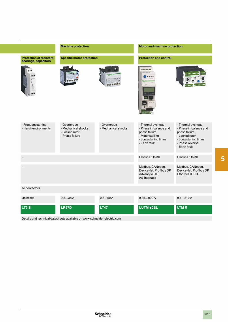
2
1
3
4
5
6
7
8
9
10
5/15
Applications Motor protection Machine protection Motor and machine protection
Thermal motor protection Protection of resistors, bearings, capacitors
Specific motor protection Protection and control
Protection -vMotorvoverload-vStalling-vPhasevfailure
-vFrequentvstarting-vHarshvenvironments
-vOvertorque-vMechanicalvshocks-vLockedvrotor-vPhasevfailure
-vOvertorque-vMechanicalvshocks
-vThermalvoverload-vPhasevimbalancevandvphasevfailure-vMotorvstalling-vLongvstartingvtimes-vEarthvfault
-vThermalvoverloadv-vPhasevimbalancevandvphasevfailure-vLockedvrotor-vLongvstartingvtimes-vPhasevreversalv-vEarthvfault
Tripping class Classv10vA Classesv10vAvandv20 Classesv10vandv20 – Classesv5vtov30 Classesv5vtov30
Communication – – Modbus,vCANopen,vDeviceNet,vProfibusvDP,vAdvantysvSTB,vAS-Interface
Modbus,vCANopen,vDeviceNet,vProfibusvDP,vEthernetvTCP/IP
Used with contactor type LC1vK,vLP1vK LC1vD LC1vF Allvcontactors
Motor current (In) 0 .11…16vA 0 .1…150vA 30…630vA Unlimited 0 .3…38vA 0 .3…60vA 0 .35…800vA 0 .4…810vA
Relay or controller type LR2 K LRD, LR2 D and LR9 D
LR9 F LT3 S LR97D LT47 LUTM p0BL LTM R
More information Detailsvandvtechnicalvdatasheetsvavailablevonvwww .schneider-electric .com Detailsvandvtechnicalvdatasheetsvavailablevonvwww .schneider-electric .com

2
1
3
4
5
6
7
8
9
10
5/16
Presentation Associated offersFeedervprotectionvandvcircuitvdisconnection
PowerpactHD HG HJ JD JG JJ LD LG LJ
Number of poles 3 3 3 3 3 3 3 3 3Current range 15-150 15-150 15-250 60-250 60-250 60-250 250-600 250-600 250-600
Interrupting ratingsUL/CSA/NOM rating (kA RMS) (50/60 Hz AC)
240vVAC 25 65 100 25 65 100 25 65 100480Y/277vVAC – – – – – – – – –480vVAC 18 35 65 18 35 65 18 35 65600vY/347vVAC – – – – – – – – –600vVAC 14 18 25 14 18 25 14 18 25
DC ratings 250vVDC 20 20 20 20 20 20 – – –500vVDC – – – – 20 – – – –
IEC 60947-2 kA RMS(50/60 Hz AC) Icu/Ics
220/240vVAC 25/25 65/65 100/100 25/25 65/65 100/100 25/25 65/65 100/100380/415vVAC 18/18 35/35 65/65 18/18 35/35 65/65 18/18 35/35 65/65
AccessoriesShunt TripUndervoltage TripAuxiliary SwitchesHandle OperatorsMechanical InterlocksHandle Padlock AttachmentTrip system typeThermal magnetic – – –ElectronicEnclosureDimensions(3-polevunitvmount)
Heightvmmv(in .) 163v(6 .4) 191v(7 .5) 340v(13 .38)Widthvmmv(in .) 104v(4 .1) 104v(4 .1) 140v(5 .51)Dephtvmmv(in .) 111v(4 .4) 127v(5 .0) 168v(6 .61)
PowerPact multistandard molded case circuit breakers
Proven performancev> Industry-leadingvcircuitvbreakervinnovationvandvprotectionvforvheavy-dutyvcommercialvandvindustrialvapplications
Flexiblev> Fullvrangevofvmoldedvcasevcircuitvbreakersvfromv15vAvtov3,000vAvdelivervthevratings,vconfigurations,vandvoperationsvforvyourvuniquevapplication
Simplev> Commonvcataloguevnumbers,vstandardizedvratings,vandvavfull-rangevofvfield-installablevaccessoriesvmakevproductvselection,vinstallation,vandvmaintenanceveasiervthanvever
Direct access to energy efficiencyv> Micrologic™velectronicvtripvunitsvenablevpowervandvenergyvmanagement
Feeder protection and circuit disconnection
TeSys Vario load break switch according to IEC947-3 / UL508
v> Thisvswitchvisvmarkedv‘‘SuitablevasvMotorvDisconnect’’vallowingvinstallationvonvthevloadvsidevofvthevmotorvbranchvcircuit,vshort-circuit,vandvground-faultvprotectionv> TeSysvVariovrotaryvswitchvdisconnectorsvfromv10vtov115vAvvULvv(12vtov175vAvIEC)varevsuitablevforvthevon-loadvmakingvandvbreakingvofvresistivevorvmixedvresistivevandvinductivevcircuitsvwherevfrequentvoperationvisvrequired
Protection
according to
IEC60947-2
and UL489
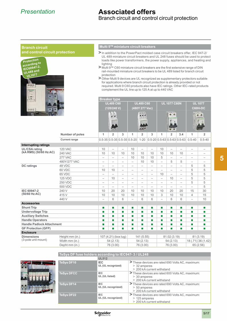
2
1
3
4
5
6
7
8
9
10
5/17
Presentation Associated offersBranchvcircuitvandvcontrolvcircuitvprotection
Breaker typeUL489 C60 (120/240 V)
UL489 C60(480Y 277 Vac)
UL 1077 C60N UL 1077C60H-DC
Number of poles 1 2 3 1 2 3 1 2 3.4 1 2Current range 0 .5-35 0 .5-35 0 .5-35 0 .5-20 1-20 0 .5-20 0 .5-63 0 .5-63 0 .5-63 0 .5-40 0 .5-40
Interrupting ratingsUL/CSA rating (kA RMS) (50/60 Hz AC)
120vVAC 10 – – 10 – – 10 – – – –240vVAC 10 10 10 10 10 10 10 10 10 – –277vVAC – – – 10 10 10 5 – – – –480Y/277vVAC – – – – 10 10 – 5 5 –v –
DC ratings 48vVDC – – – – – – – – – 5 560vVDC 10 10 – – – – – – – 5 565vVDC – – – – – – 10 – – 5 5125vVDC – 10 – – – – – 10 – 5 5250vVDC – – – – – – – – – 5 5500vVDC – – – – – – – – – – 5
IEC 60947-2 (50/60 Hz AC)
240vV 10 20 20 10 10 10 10 20 20 15 30415vV 10 10 10 10 10 10 3 10 10 4 15440vV – 6 6 – 6 6 – 6 6 – 10
AccessoriesShunt TripUndervoltage TripAuxiliary SwitchesHandle OperatorsHandle Padlock AttachmentGF Protection (GFP)EnclosureDimensions(3-polevunitvmount)
Heightvmmv(in .) 107v(4 .21)v(boxvlug) 141v(5 .55) 81 .02v(3 .19) 81v(3 .19)Widthvmmv(in .) 54v(2 .13) 54v(2 .13) 54v(2 .13) 18v( .71) 36v(1 .42)Dephtvmmv(in .) 76v(3 .00) 76v(3 .00) 76v(3 .00) 65v(2 .56)
Multi 9TM miniature circuit breakers
v> InvadditionvtovthevPowerPactvmoldedvcasevcircuitvbreakersvoffer,vIECv947-2/ULv489vminiaturevcircuitvbreakersvandvULv248vfusesvshouldvbevusedvtovprotectvloadsvlikevpowervtransformers,vthevpowervsupply,vappliances,vandvheatingvandvlightingv>Multiv9™vC60vminiaturevcircuitvbreakersvarevthevfirstvextensivevrangevofvDINvrail-mountedvminiaturevcircuitvbreakersvtovbevULv489vlistedvforvbranchvcircuitvprotectionv>OthervMultiv9vdevicesvarevULvrecognizedvasvsupplementaryvprotectorsvsuitablevforvapplicationsvwherevbranchvcircuitvprotectionvisvalreadyvprovidedvorvnotvrequired .vMultiv9vC60vproductsvalsovhavevIECvratings .vOthervIEC-ratedvproductsvcomplementvthevULvlinevupvtov125vAvatvupvtov440vVAC
Branch circuit and control circuit protection
TeSys DF fuse holders according to IEC947- 3 / UL248 UL512TeSys DF10 IEC
UL (UL recognized)v> Thesevdevicesvarevratedv690vVoltsvAC,vmaximum:v> 32vamperesv> 200vkAvcurrentvwithstand
TeSys DFCC IECUL (UL listed)
v> Thesevdevicesvarevratedv600vVoltsvAC,vmaximum:v> 30vamperesv> 200vkAvcurrentvwithstand
TeSys DF14 IECUL (UL recognized)
v> Thesevdevicesvarevratedv690vVoltsvAC,vmaximum:v> 50vamperesv> 200vkAvcurrentvwithstand
TeSys DF22 IECUL (UL recognized)
v> Thesevdevicesvarevratedv690vVoltsvAC,vmaximum:v> 125vamperesv> 200vkAvcurrentvwithstand
Protection
according to
IEC60947-2,
UL489 and
UL1077

2
1
3
4
5
6
7
8
9
10
5/18
Panorama Associated offersPowerv&vEnergyv-vMonitoringv&vControlv
Basic Monitoring Advanced Monitoring Power & Energy Monitoring Energy Management & Control Monitoring software
Power Logic System
vv vvvvv v vvvvvvvvvv
Name AMPv/vVLT DM6000vv/vDM6200
PM9vvvvvvvvvvvvvvvvvvvvPM1000vvvvvvvvvvvvvvvIEM3110/vPM700vvvvvvvvvvvvv/vPM1200
PM750vvvvvvvvvvvvvvvvvvvvPM3210/vPM820
PowerView
Function Ammetevr,vVoltmeter DigitalvpanelvMeter PowervMeter PowervMeter PowervMonitoring
Panel instrumentation Iv/vU I,vV,vF,vPF I,vU,vF,vP,vQ,vS,vPF,vE I,vU,vF,vP,vQ,vS,vPF,vE,vTHD,vv(Min/Max,vI/O,valarm)andvremotevmonitoring
v• Realvtimevviewingvofvdatav• HistoricalvtabularvdatavintovMicrosoftvExcelv• Historicalvtrendingv• Reporting
Integrated in Compact NSX circuit breaker
Name MicrologicvAvtripvunit MicrologicvEvtripvunit
Function Ammeter,vVoltmeter PowervMeter
Panel instrumentation Iv/vU I,vU,vF,vP,vQ,vS,vPF,vE
v• Readingveasinessv• Essentialvparametersv• Single-phase
v• “all-in-one”vinformationsv• UvandvIv(three-phase)v• PanelvFront
v• UvandvIv(three-phase)v• Energyvvaluesv• Back-up
v• UvandvIv(three-phase)v• Energyvvaluesv• Communicationvwithvsupervisionvsystemsv• RemotevMonitoringv(control,vloading/unloading,valarmsvandvalerts)
Remote Monitoringv• Remotevmonitoringvsoftware
Common accessories
vvv vv
Name CT CMAv/vCMV
Function CurrentvTransformers Ammeterv&vVoltmetervselector
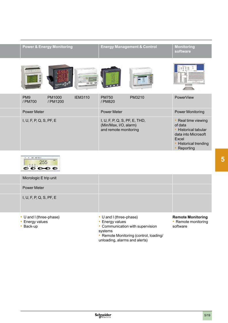
2
1
3
4
5
6
7
8
9
10
5/19
Basic Monitoring Advanced Monitoring Power & Energy Monitoring Energy Management & Control Monitoring software
Power Logic System
vv vvvvv v vvvvvvvvvv
Name AMPv/vVLT DM6000vv/vDM6200
PM9vvvvvvvvvvvvvvvvvvvvPM1000vvvvvvvvvvvvvvvIEM3110/vPM700vvvvvvvvvvvvv/vPM1200
PM750vvvvvvvvvvvvvvvvvvvvPM3210/vPM820
PowerView
Function Ammetevr,vVoltmeter DigitalvpanelvMeter PowervMeter PowervMeter PowervMonitoring
Panel instrumentation Iv/vU I,vV,vF,vPF I,vU,vF,vP,vQ,vS,vPF,vE I,vU,vF,vP,vQ,vS,vPF,vE,vTHD,vv(Min/Max,vI/O,valarm)andvremotevmonitoring
v• Realvtimevviewingvofvdatav• HistoricalvtabularvdatavintovMicrosoftvExcelv• Historicalvtrendingv• Reporting
Integrated in Compact NSX circuit breaker
Name MicrologicvAvtripvunit MicrologicvEvtripvunit
Function Ammeter,vVoltmeter PowervMeter
Panel instrumentation Iv/vU I,vU,vF,vP,vQ,vS,vPF,vE
v• Readingveasinessv• Essentialvparametersv• Single-phase
v• “all-in-one”vinformationsv• UvandvIv(three-phase)v• PanelvFront
v• UvandvIv(three-phase)v• Energyvvaluesv• Back-up
v• UvandvIv(three-phase)v• Energyvvaluesv• Communicationvwithvsupervisionvsystemsv• RemotevMonitoringv(control,vloading/unloading,valarmsvandvalerts)
Remote Monitoringv• Remotevmonitoringvsoftware
Common accessories
vvv vv
Name CT CMAv/vCMV
Function CurrentvTransformers Ammeterv&vVoltmetervselector

2
1
3
4
5
6
7
8
9
10
5/20
Presentation Associated offersSpacialvenclosures
Steel enclosuresDescriptionMostvcommonvpumpingvarchitecturesvcanvbevprotectedvbyvWallvMountingvenclosuresvSpacialvS3D,vespeciallyvinvindoorvapplications .
Dimensions Fromv300vxv200vmmvtov1400vxv1000vmm
Ingress protection ratingUpvtovIP66
Mechanical protection ratingUpvtovIK10
OptionsLargevchoicevofvenclosurevversionsvandvaccessories .
Why should I choose it? Durable, with high UV resistance, coated hinges, aluminium hinge pins and folded gutters that avoids the entry of water, oil and other liquids .
Wal
l-mou
ntin
gFl
oor-
stan
ding
S3DvWall-mountingvenclosuresS3DEXvPotentiallyvexplosivevatmospheresS3DMvDistributionvmodularvenclosures
DescriptionForvmorevequipmentvandvheavyvloads,vpumpingvsolutionsvcanvbevinstalledvinvrobustvsheetvmetalvcompactvenclosuresv(SpacialvSM)vorvmodularvenclosuresv(SpacialvSF) .vUpvtov600vdifferentvpossiblevconfigurations .vSpacialvSFvisvalsovavailablevinvkitvversion .
DimensionsFromv500vxv500vmmvtov2200vxv1800vmm
Ingress protection ratingIP55
Mechanical protection ratingUpvtovIK10
OptionsLargevchoicevofvenclosurevversionsvvandvaccessories .
Why should I choose it? High level of modularity and flexibility. Save up 25 % of time in assembly.
SMvFloor-standingvcompactSFvFloor-standingvmodular
CV-CA Ventilation/Airing
Mounting Powerdistribution
Cablemanagement
CEvExchangers CUvCoolingvUnits
Ther
mal
man
agem
ent
Clim
aSys
Acce
ssor
ies
Project & Services
Configured offerAdaptedvservices:vcut-outs,vpainting,vassemblies…
Specific offerThe co-developmentvservicevtailor-madevforvyou
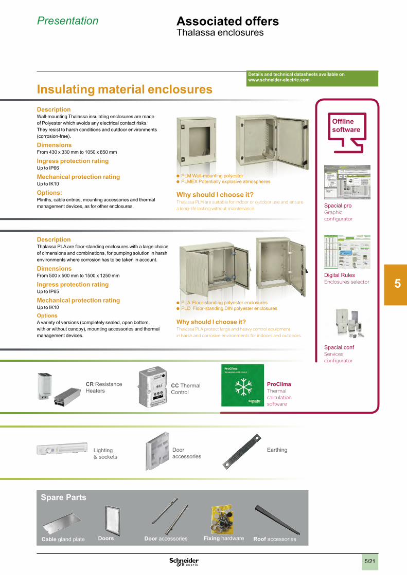
2
1
3
4
5
6
7
8
9
10
5/21
Presentation Associated offersThalassavenclosures
Insulating material enclosuresDescriptionWall-mountingvThalassavinsulatingvenclosuresvarevmadevvofvPolyestervwhichvavoidsvanyvelectricalvcontactvrisks .vvTheyvresistvtovharshvconditionsvandvoutdoorvenvironmentsv(corrosion-free) .
DimensionsFromv430vxv330vmmvtov1050vxv850vmm
Ingress protection ratingUpvtovIP66
Mechanical protection ratingUpvtovIK10
Options: Plinths,vcableventries,vmountingvaccessoriesvandvthermalvmanagementvdevices,vasvforvothervenclosures .
DescriptionThalassavPLAvarevfloor-standingvenclosuresvwithvavlargevchoicevofvdimensionsvandvcombinations,vforvpumpingvsolutionvinvharshvenvironmentsvwherevcorrosionvhasvtovbevtakenvinvaccount .
DimensionsFromv500vxv500vmmvtov1500vxv1250vmm
Ingress protection ratingUpvtovIP65
Mechanical protection ratingUpvtovIK10
OptionsAvvarietyvofvversionsv(completelyvsealed,vopenvbottom,vvwithvorvwithoutvcanopy),vmountingvaccessoriesvandvthermalvmanagementvdevices .
PLMvWall-mountingvpolyestervPLMEXvPotentiallyvexplosivevatmospheres
PLAvvFloor-standingvpolyestervenclosuresvPLDvvFloor-standingvDINvpolyestervenclosures
Details and technical datasheets available on www.schneider-electric.com
Why should I choose it? Thalassa PLM are suitable for indoor or outdoor use and ensure a long-life lasting without maintenance.
Why should I choose it? Thalassa PLA protect large and heavy control equipment in harsh and corrosive environments for indoors and outdoors.
CRvResistanceHeaters
CCvThermalvControl
Lightingvv&vsockets
Doorvvaccessories
Earthing
ProClimaThermal calculation software
Spare Parts
Cable glandvplate Doors Door accessories Fixing hardware Roof accessories
Offline software
Spacial .provGraphic configurator
DigitalvRulesEnclosures selector
Spacial .confServices configurator

2
1
3
4
5
6
7
8
9
10
5/22
Applications Pilot lights Pushbuttons, selector switches and pilot lights Biometric switches v Wireless and batteryless pushbuttons
Pushbuttons, selector switches and pilot lights
Joystick controllers Pushbuttons, selector switches and pilot lights
Cam switches
vv
Description of range b LEDvpilotvlights b Pushbuttonsb Multiple-headedvpushbuttonsvvb EmergencyvStopvbuttonsb Emergencyvswitchingvoffvpushbuttonsb Selectorvswitchesvandvkeyvswitchesb Illuminatedvpushbuttonsb Pilotvlights
Fingerprintvreadersvbiometricvswitches24Vvc
Wirelessvandvbatterylessvandvpushbuttonsv24vVvc orv24 . . .v240vVva /vc
b Pushbuttonsvvb Emergencyvswitchingvoffv
pushbuttonsb Selectorvswitchesvandvkeyv
switchesb Illuminatedvpushbuttonsb Pilotvlights
b 2vorv4vdirectionb Stayvputvorvspringvreturn
b Pushbuttonsb EmergencyvStopvbuttonsb Emergencyvswitchingvoffv
pushbuttonsb Selectorvswitchesvandv
keyvswitchesb Illuminatedvpushbuttonsb Pilotvlights
b Switchesb Steppingvswitchesb Reversingvandvchangeoverv
switchesb Ammetervswitchesb Voltmetervswitchesb Reversingvswitchesb Star-deltavandvreversingv
star-deltavswitchesb Polevchangevswitches
Features Products Monolithic,vcompact,vlowvconsumption
Completevunitsvorvsub-assembliesv(bodyv+vhead) Monolithic Ready-to-usevpacksv(1)vandv“components”vrange
Monolithic Completevunitsvorvsub-assembliesv(bodyv+vheadvwithvlever)
Completevunitsvorsub-assembliesv(bodyv+vhead)
Completevunitsvorvsub-assembliesv(bodyv+vfrontvpanelv+vhead)
Bezel Doublevinsulated Metal,vchromiumvplatedvorvblack
Doublevinsulated Doublevinsulated,vdarkvgrey
Metal,vchromiumvplatedvorvdoublevinsulated,vblackv
Doublevinsulated,vblack Metal,vchromiumvplated Doublevinsulated,vblack
Metal,vchromiumvplatedvorvdoublevinsulated,vblack
Shapevofvhead Circular Circular,vsquarevvorvrectangular
Circular Circularvorvsquare – Transmittervwithvcircularvhead
Circular Circular Hexagonal Square
Drilling or cut-out for mounting Øv8vmmvv(Øv0 .315vvin .)vvandvØv12vmmv(Øv0 .472vin .)
Øv16v(Øv0 .630vin .) Øv22vmmv(Øv0 .866vin .) Øv22vmmv(Øv0 .866vin .) Øv30vmmvv(Øv1 .181vin .) Øv16vvmmv(Øv0 .630vin .)vorvØv22vmmv(Øv0 .866vin .)v:vseries K10Øv22vmmv(Øv0 .866vin .)vandvmultifixing:vseries K1/K24vholes,v48vorv68vcentres:vseriesvK30…K150
Degree of protection
ConformingvtovIECv60529
IPv40IPv65vwithvseal
IPv65 IPv66 IPv65 vv
IPv65 IPv65v(pushbuttons,vpilotvlights,vselectorvswitches)IPv54v(Emergencyvswitchingvoffvpushbuttons)
IPv65 IPv66 IPv65 IPv65 IPv65:vseriesvK10IPv40,vIPv65vwithvseal:vseriesvK1/K2IPv40:vseriesvK30…K150
Cabling Tagsvforv2 .8vxv0 .5vmmvv(0 .110vxv0 .020vin .)connectors,vvorvthreadedvconnector
FastonvconnectorsSoldervpinsvforvprintedvcircuitvboards
SpringvclampvterminalvconnectionsScrewvclampvterminalvconnectionsFastonvconnectorsConnectorWithvadaptorvforvprintedvcircuitvboard
Cablevorvconnectors Wirelessv(transmitter)Throughvcablev(receiver)
ScrewvandvcaptivevclampvterminalvconnectionsForkedvUvtypevtagvconnectionsFastonvclipvconnectionsv(pilotvlights)
Screwvandvcaptivevclampvterminalvconnections
Mounting Panelvthickness 1…8vmmv(0 .039…v0 .315vin .)
1…6vmm(0 .039…v0 .236vin .)
1…6vmm(0 .039…v0 .236vin .)
0 .5…6vmmv1…6vmm(0 .020…v0 .236vin .)vDependingvonvmodel
Type references XVLA XB6 XB4 XB5 XB5S XB5R, XB4R XB7 XD4PA XD2GA XD5PA 9001K,9001SK K10, K1, K2, K30, K50, K63, K115, K150
Pages Pleasevconsultvourvwebvsitevwww .schneider-electric .com Pleasevconsultvourvwebvsitevwww .schneider-electric .com(1) Wireless and batteryless pushbutton and receiver ready-paired at the factory.
Associated offers Controlvandvsignallingvunits
Selection guide
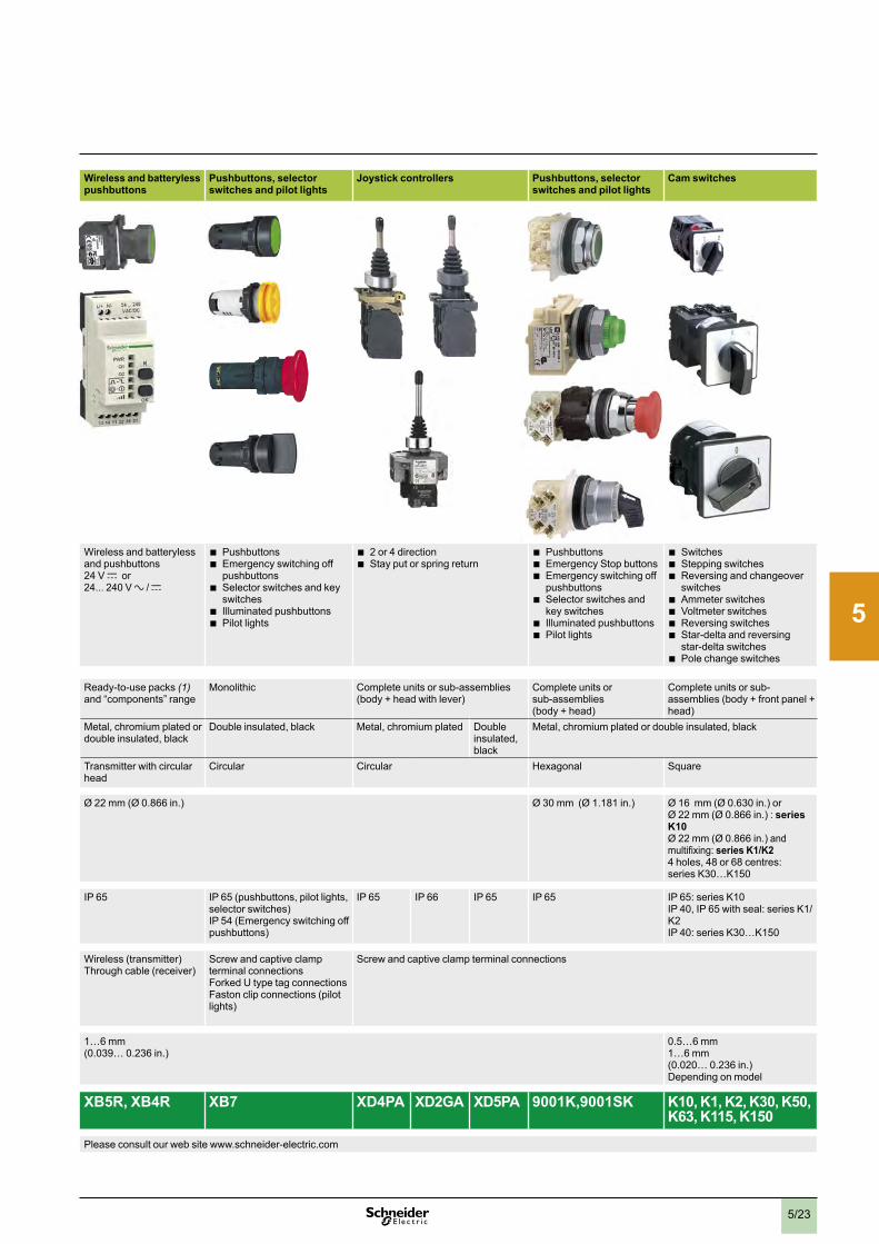
2
1
3
4
5
6
7
8
9
10
5/23
Applications Pilot lights Pushbuttons, selector switches and pilot lights Biometric switches v Wireless and batteryless pushbuttons
Pushbuttons, selector switches and pilot lights
Joystick controllers Pushbuttons, selector switches and pilot lights
Cam switches
vv
Description of range b LEDvpilotvlights b Pushbuttonsb Multiple-headedvpushbuttonsvvb EmergencyvStopvbuttonsb Emergencyvswitchingvoffvpushbuttonsb Selectorvswitchesvandvkeyvswitchesb Illuminatedvpushbuttonsb Pilotvlights
Fingerprintvreadersvbiometricvswitches24Vvc
Wirelessvandvbatterylessvandvpushbuttonsv24vVvc orv24 . . .v240vVva /vc
b Pushbuttonsvvb Emergencyvswitchingvoffv
pushbuttonsb Selectorvswitchesvandvkeyv
switchesb Illuminatedvpushbuttonsb Pilotvlights
b 2vorv4vdirectionb Stayvputvorvspringvreturn
b Pushbuttonsb EmergencyvStopvbuttonsb Emergencyvswitchingvoffv
pushbuttonsb Selectorvswitchesvandv
keyvswitchesb Illuminatedvpushbuttonsb Pilotvlights
b Switchesb Steppingvswitchesb Reversingvandvchangeoverv
switchesb Ammetervswitchesb Voltmetervswitchesb Reversingvswitchesb Star-deltavandvreversingv
star-deltavswitchesb Polevchangevswitches
Features Products Monolithic,vcompact,vlowvconsumption
Completevunitsvorvsub-assembliesv(bodyv+vhead) Monolithic Ready-to-usevpacksv(1)vandv“components”vrange
Monolithic Completevunitsvorvsub-assembliesv(bodyv+vheadvwithvlever)
Completevunitsvorsub-assembliesv(bodyv+vhead)
Completevunitsvorvsub-assembliesv(bodyv+vfrontvpanelv+vhead)
Bezel Doublevinsulated Metal,vchromiumvplatedvorvblack
Doublevinsulated Doublevinsulated,vdarkvgrey
Metal,vchromiumvplatedvorvdoublevinsulated,vblackv
Doublevinsulated,vblack Metal,vchromiumvplated Doublevinsulated,vblack
Metal,vchromiumvplatedvorvdoublevinsulated,vblack
Shapevofvhead Circular Circular,vsquarevvorvrectangular
Circular Circularvorvsquare – Transmittervwithvcircularvhead
Circular Circular Hexagonal Square
Drilling or cut-out for mounting Øv8vmmvv(Øv0 .315vvin .)vvandvØv12vmmv(Øv0 .472vin .)
Øv16v(Øv0 .630vin .) Øv22vmmv(Øv0 .866vin .) Øv22vmmv(Øv0 .866vin .) Øv30vmmvv(Øv1 .181vin .) Øv16vvmmv(Øv0 .630vin .)vorvØv22vmmv(Øv0 .866vin .)v:vseries K10Øv22vmmv(Øv0 .866vin .)vandvmultifixing:vseries K1/K24vholes,v48vorv68vcentres:vseriesvK30…K150
Degree of protection
ConformingvtovIECv60529
IPv40IPv65vwithvseal
IPv65 IPv66 IPv65 vv
IPv65 IPv65v(pushbuttons,vpilotvlights,vselectorvswitches)IPv54v(Emergencyvswitchingvoffvpushbuttons)
IPv65 IPv66 IPv65 IPv65 IPv65:vseriesvK10IPv40,vIPv65vwithvseal:vseriesvK1/K2IPv40:vseriesvK30…K150
Cabling Tagsvforv2 .8vxv0 .5vmmvv(0 .110vxv0 .020vin .)connectors,vvorvthreadedvconnector
FastonvconnectorsSoldervpinsvforvprintedvcircuitvboards
SpringvclampvterminalvconnectionsScrewvclampvterminalvconnectionsFastonvconnectorsConnectorWithvadaptorvforvprintedvcircuitvboard
Cablevorvconnectors Wirelessv(transmitter)Throughvcablev(receiver)
ScrewvandvcaptivevclampvterminalvconnectionsForkedvUvtypevtagvconnectionsFastonvclipvconnectionsv(pilotvlights)
Screwvandvcaptivevclampvterminalvconnections
Mounting Panelvthickness 1…8vmmv(0 .039…v0 .315vin .)
1…6vmm(0 .039…v0 .236vin .)
1…6vmm(0 .039…v0 .236vin .)
0 .5…6vmmv1…6vmm(0 .020…v0 .236vin .)vDependingvonvmodel
Type references XVLA XB6 XB4 XB5 XB5S XB5R, XB4R XB7 XD4PA XD2GA XD5PA 9001K,9001SK K10, K1, K2, K30, K50, K63, K115, K150
Pages Pleasevconsultvourvwebvsitevwww .schneider-electric .com Pleasevconsultvourvwebvsitevwww .schneider-electric .com(1) Wireless and batteryless pushbutton and receiver ready-paired at the factory.

2
1
3
4
5
6
7
8
9
10
5/24
Type of applications All applications Specific applications
Enclosures Plastic Glass-reinforced polyester
Metal Metal front plate, insulated protective rear cover
Plastic Metal
Complete stations and separate components for customer assembly
Empty insulated enclosures
Empty enclosures Empty, flush mounting enclosures: front plate + rear cover
Control stations for severe environments
Lift inspection stations Key operated control stations
vv vv
v
Main feature Pre-drilledvcontrolvstations Pre-drilledvorvundrilledvenclosures
Pre-drilledvenclosures Pre-drilledvorvundrilledvenclosures
Pre-drilledvfrontvplatesv&vrearvcovers
Pre-drilledvemptyvcontrolvstations
Pre-drilledvemptyvenclosuresvorvfittedvstationsv
Fittedvstations
Associated control and signalling units HarmonyvXB5vwithvplasticvbezelv HarmonyvXB7,vmonolithic,vplastic
HarmonyvXB4vwithvmetalvbezelHarmonyvXB5vwithvplasticvbezel
HarmonyvXB4vwithvmetalvbezelHarmonyvXB5vwithvplasticvbezel
HarmonyvXB5vwithvplasticvbezel
HarmonyvXB5vorvXB7vwithvplasticvbezel
Withvkeyvlock
Number of cut-outs for Ø 22 mm (Ø 0.866 in.) control and signalling units
1,v2,v3,v4vorv5v 1,v2vorv3v(completevstations)1,v2,v3,v4vorv5v(emptyvenclosures)
1,v2vorv3 1,v2,v4,v8vorv16 8,v16,v24,v30vorv40 1,v2,v3,v4,v6,v8vorv12 1,v2,v3,v4vorv5 1,v2,v3,v4vorv5 1,v2,v3,v4,v5vorv6vwithvorvwithoutvpowervsocketv
–
Material Polycarbonate ABS Glass-reinforcedvpolyester
Aluminiumvalloyvorvsheetvsteel
Zincvorvaluminiumvalloy Frontvplate:vbrushedvaluminiumvRearvcover:polystyrene
Mineralvreinforcedvpolyamide
Polycarbonate Zincvalloyv
Colour YellowvlidvLightvgreyvbase
DarkvgreyvlidvLightvgreyvbase
LightvgreyvorvyellowvlidvLightvgreyvbasev
Colouredvgreyvthroughout
Bluevlidvandvbase XAP M:vBluevlidBluevbaseXAP J:YellowvlidBluevbase
Unpaintedvaluminium BlackvlidvBlackvbase
YellowvlidLightvgreyvbase
Grey
Degree of protection IPv66 IPv54 IPv65 IPv54 IPv65 IPv66IPv69K
IPv44,vIPv55vorvIPv66vdependingvonvmodel
IPv54
Function EmergencyvStopvpushvbutton
StartvorvStopStart-StopvwithvpilotvlightMovementvcontrol
Accordingvtovequipmentvfitted:vv StartvorvStopvv Start-Stopvwithvpilotvlightvv Movementvcontrolvv Emergencyvstopvpushvbutton
Accordingvtovequipmentvfitted:vv StartvorvStopvv Start-Stopvwithvpilotvlightvv Movementvcontrolvv Emergencyvstopvpushvbutton
Start-Stop
Cable entries Knock-outs Tappedvforvcablevgland
Drilled Knock-outs ISOv20 Knock-outs Tappedvforvcablevgland
Type references XAL K XAL D XAL E XAP A XB2 SL XAP M, XAP J XAP E XAL G XAL F XAP S
Page(s) Pleasevconsultvourvwebvsitevwww .schneider-electric .com Pleasevconsultvourvwebvsitevwww .schneider-electric .com
Selection guide Associated offers Controlvstationsvandvenclosures

2
1
3
4
5
6
7
8
9
10
5/25
Type of applications All applications Specific applications
Enclosures Plastic Glass-reinforced polyester
Metal Metal front plate, insulated protective rear cover
Plastic Metal
Complete stations and separate components for customer assembly
Empty insulated enclosures
Empty enclosures Empty, flush mounting enclosures: front plate + rear cover
Control stations for severe environments
Lift inspection stations Key operated control stations
vv vv
v
Main feature Pre-drilledvcontrolvstations Pre-drilledvorvundrilledvenclosures
Pre-drilledvenclosures Pre-drilledvorvundrilledvenclosures
Pre-drilledvfrontvplatesv&vrearvcovers
Pre-drilledvemptyvcontrolvstations
Pre-drilledvemptyvenclosuresvorvfittedvstationsv
Fittedvstations
Associated control and signalling units HarmonyvXB5vwithvplasticvbezelv HarmonyvXB7,vmonolithic,vplastic
HarmonyvXB4vwithvmetalvbezelHarmonyvXB5vwithvplasticvbezel
HarmonyvXB4vwithvmetalvbezelHarmonyvXB5vwithvplasticvbezel
HarmonyvXB5vwithvplasticvbezel
HarmonyvXB5vorvXB7vwithvplasticvbezel
Withvkeyvlock
Number of cut-outs for Ø 22 mm (Ø 0.866 in.) control and signalling units
1,v2,v3,v4vorv5v 1,v2vorv3v(completevstations)1,v2,v3,v4vorv5v(emptyvenclosures)
1,v2vorv3 1,v2,v4,v8vorv16 8,v16,v24,v30vorv40 1,v2,v3,v4,v6,v8vorv12 1,v2,v3,v4vorv5 1,v2,v3,v4vorv5 1,v2,v3,v4,v5vorv6vwithvorvwithoutvpowervsocketv
–
Material Polycarbonate ABS Glass-reinforcedvpolyester
Aluminiumvalloyvorvsheetvsteel
Zincvorvaluminiumvalloy Frontvplate:vbrushedvaluminiumvRearvcover:polystyrene
Mineralvreinforcedvpolyamide
Polycarbonate Zincvalloyv
Colour YellowvlidvLightvgreyvbase
DarkvgreyvlidvLightvgreyvbase
LightvgreyvorvyellowvlidvLightvgreyvbasev
Colouredvgreyvthroughout
Bluevlidvandvbase XAP M:vBluevlidBluevbaseXAP J:YellowvlidBluevbase
Unpaintedvaluminium BlackvlidvBlackvbase
YellowvlidLightvgreyvbase
Grey
Degree of protection IPv66 IPv54 IPv65 IPv54 IPv65 IPv66IPv69K
IPv44,vIPv55vorvIPv66vdependingvonvmodel
IPv54
Function EmergencyvStopvpushvbutton
StartvorvStopStart-StopvwithvpilotvlightMovementvcontrol
Accordingvtovequipmentvfitted:vv StartvorvStopvv Start-Stopvwithvpilotvlightvv Movementvcontrolvv Emergencyvstopvpushvbutton
Accordingvtovequipmentvfitted:vv StartvorvStopvv Start-Stopvwithvpilotvlightvv Movementvcontrolvv Emergencyvstopvpushvbutton
Start-Stop
Cable entries Knock-outs Tappedvforvcablevgland
Drilled Knock-outs ISOv20 Knock-outs Tappedvforvcablevgland
Type references XAL K XAL D XAL E XAP A XB2 SL XAP M, XAP J XAP E XAL G XAL F XAP S
Page(s) Pleasevconsultvourvwebvsitevwww .schneider-electric .com Pleasevconsultvourvwebvsitevwww .schneider-electric .com
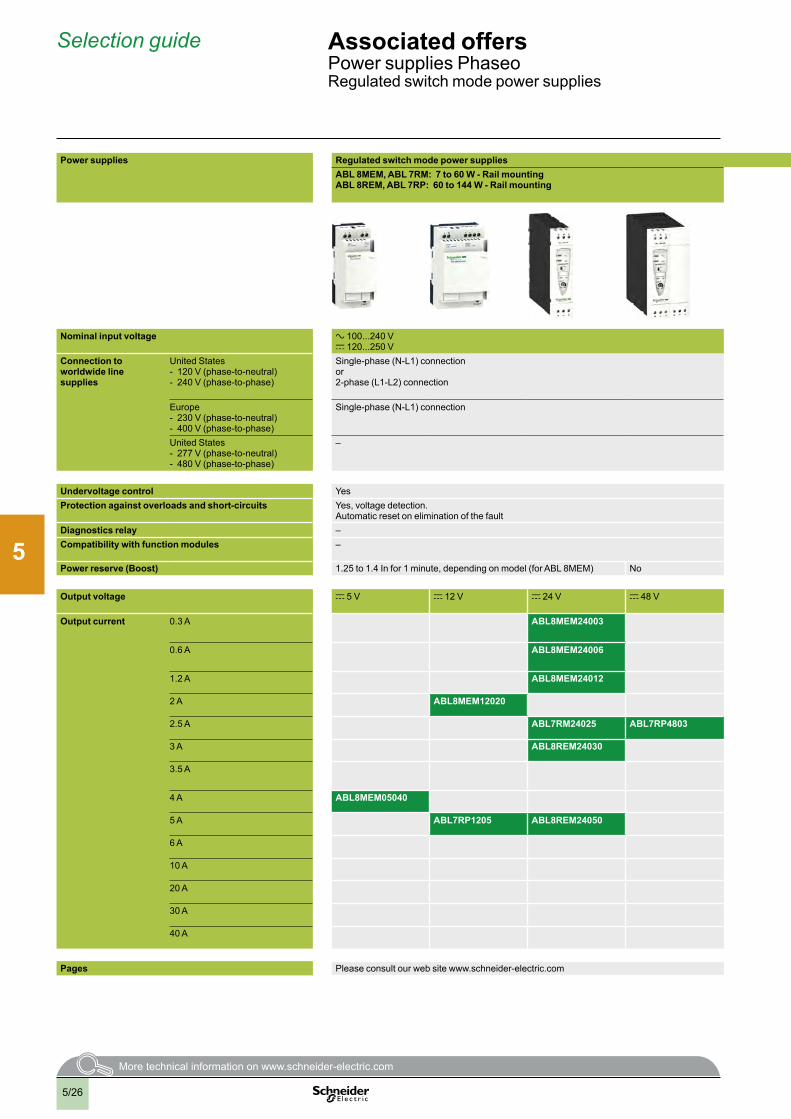
2
1
3
4
5
6
7
8
9
10
5/26
Selection guide Associated offersPowervsuppliesvPhaseoRegulatedvswitchvmodevpowervsupplies
Power supplies Regulated switch mode power suppliesABL 8MEM, ABL 7RM: 7 to 60 W - Rail mounting ABL 8REM, ABL 7RP: 60 to 144 W - Rail mounting
ABL4: 85 to 960 W - Compact - Rail mounting Function modules ABL 8DCC: converters c/c
v
Nominal input voltage a 100 . . .240vVc 120 . . .250vV
a 100…230vVv av120vVvorva 230vVv a 400…500vVv cv24vV
Connection to worldwide line supplies
UnitedvStates-v 120vVv(phase-to-neutral)-v 240vVv(phase-to-phase)
Single-phasev(N-L1)vconnectionvorv2-phasev(L1-L2)vconnection
Single-phasev(N-L1)vvconnectionvvv
Single-phasev(N-L1)vvconnectionvvor2-phasev(L1-L2)vconnection
– –
Europe-v 230vVv(phase-to-neutral)-v 400vVv(phase-to-phase)
Single-phasev(N-L1)vconnection – Single-phasev(N-L1)vvconnectionvvv
3-phasev(L1-L2-L3)vvconnection
–
UnitedvStates-v 277vVv(phase-to-neutral)-v 480vVv(phase-to-phase)
– – – 3-phasev(L1-L2-L3)vvconnection
–
Undervoltage control Yesv No No No –Protection against overloads and short-circuits Yes,vvoltagevdetection .v
AutomaticvresetvonveliminationvofvthevfaultYes,vcurrentvlimitationvAutomaticvresetvonveliminationvofvthevfault
Yes,vcurrentvlimitation
Diagnostics relay – Yes Yes Yes Yes,vdependingvonvmodelCompatibility with function modules – Yesvwithvbuffervmodule,vbatteryvandvbatteryvcheckvmodules,vredundancyvmodulevandvdiscriminatingvdownstreamvprotectionvmodule
Power reserve (Boost) 1 .25vtov1 .4vInvforv1vminute,vdependingvonvmodelv(forvABLv8MEM) No Dependingvonvmodel:v1 .5vtov1 .7vInvforv5vtov30vseconds No
Output voltage cv5vV cv12vV cv24vV cv48vV cv24vV cv5vV c 7 . . .12vV
Output current 0 .3vA ABL8MEM24003
0 .6vA ABL8MEM24006
1 .2vA ABL8MEM24012
2vA ABL8MEM12020 ABL8DCC12020 (1)
2 .5vA ABL7RM24025 ABL7RP4803
3vA ABL8REM24030
3 .5vA ABL4RSM24035
4vA ABL8MEM05040
5vA ABL7RP1205 ABL8REM24050 ABL4RSM24050
6vA ABL8DCC05060 (1)
10vA ABL4RSM24100
20vA ABL4RSM24200 ABL4WSR24200
30vA ABL4WSR24300
40vA ABL4WSR24400
Pages Pleasevconsultvourvwebvsitevwww .schneider-electric .com Pleasevconsultvourvwebvsitevwww .schneider-electric .comv(2)(1) Converter module c/c, must be used with a Phaseo power supply.(2) Certain offers can not be marketed in certain countries, please consult your “Customer Care Centre”.

2
1
3
4
5
6
7
8
9
10
5/27
Power supplies Regulated switch mode power suppliesABL 8MEM, ABL 7RM: 7 to 60 W - Rail mounting ABL 8REM, ABL 7RP: 60 to 144 W - Rail mounting
ABL4: 85 to 960 W - Compact - Rail mounting Function modules ABL 8DCC: converters c/c
v
Nominal input voltage a 100 . . .240vVc 120 . . .250vV
a 100…230vVv av120vVvorva 230vVv a 400…500vVv cv24vV
Connection to worldwide line supplies
UnitedvStates-v 120vVv(phase-to-neutral)-v 240vVv(phase-to-phase)
Single-phasev(N-L1)vconnectionvorv2-phasev(L1-L2)vconnection
Single-phasev(N-L1)vvconnectionvvv
Single-phasev(N-L1)vvconnectionvvor2-phasev(L1-L2)vconnection
– –
Europe-v 230vVv(phase-to-neutral)-v 400vVv(phase-to-phase)
Single-phasev(N-L1)vconnection – Single-phasev(N-L1)vvconnectionvvv
3-phasev(L1-L2-L3)vvconnection
–
UnitedvStates-v 277vVv(phase-to-neutral)-v 480vVv(phase-to-phase)
– – – 3-phasev(L1-L2-L3)vvconnection
–
Undervoltage control Yesv No No No –Protection against overloads and short-circuits Yes,vvoltagevdetection .v
AutomaticvresetvonveliminationvofvthevfaultYes,vcurrentvlimitationvAutomaticvresetvonveliminationvofvthevfault
Yes,vcurrentvlimitation
Diagnostics relay – Yes Yes Yes Yes,vdependingvonvmodelCompatibility with function modules – Yesvwithvbuffervmodule,vbatteryvandvbatteryvcheckvmodules,vredundancyvmodulevandvdiscriminatingvdownstreamvprotectionvmodule
Power reserve (Boost) 1 .25vtov1 .4vInvforv1vminute,vdependingvonvmodelv(forvABLv8MEM) No Dependingvonvmodel:v1 .5vtov1 .7vInvforv5vtov30vseconds No
Output voltage cv5vV cv12vV cv24vV cv48vV cv24vV cv5vV c 7 . . .12vV
Output current 0 .3vA ABL8MEM24003
0 .6vA ABL8MEM24006
1 .2vA ABL8MEM24012
2vA ABL8MEM12020 ABL8DCC12020 (1)
2 .5vA ABL7RM24025 ABL7RP4803
3vA ABL8REM24030
3 .5vA ABL4RSM24035
4vA ABL8MEM05040
5vA ABL7RP1205 ABL8REM24050 ABL4RSM24050
6vA ABL8DCC05060 (1)
10vA ABL4RSM24100
20vA ABL4RSM24200 ABL4WSR24200
30vA ABL4WSR24300
40vA ABL4WSR24400
Pages Pleasevconsultvourvwebvsitevwww .schneider-electric .com Pleasevconsultvourvwebvsitevwww .schneider-electric .comv(2)(1) Converter module c/c, must be used with a Phaseo power supply.(2) Certain offers can not be marketed in certain countries, please consult your “Customer Care Centre”.
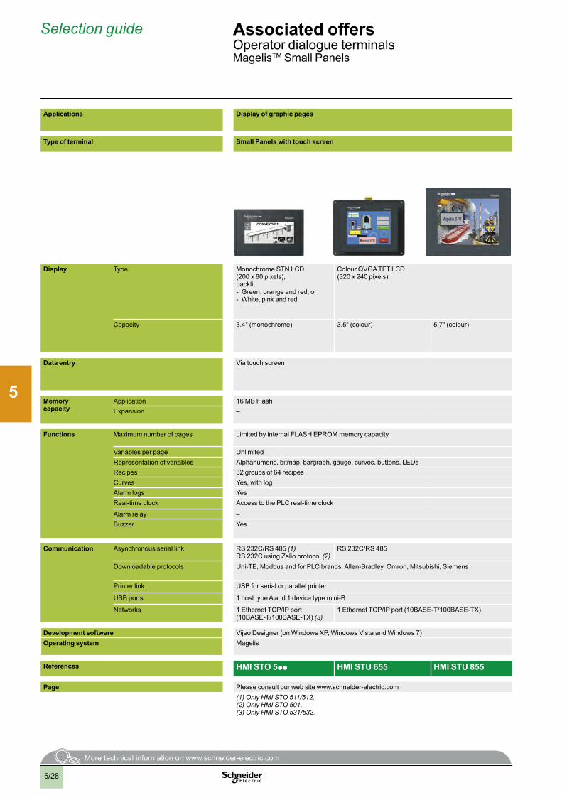
2
1
3
4
5
6
7
8
9
10
5/28
Selection guide Associated offersOperatorvdialoguevterminalsMagelisTMvSmallvPanels
Applications Display of graphic pages Display of text messages and/or semi-graphic pages
Display of text messages and/or semi-graphic pagesControl and configuration of data
Type of terminal Small Panels with touch screen Small Panels with keypad Small Panels with keypad Small Panels with touch screen and keypad
Display Type MonochromevSTNvLCD(200vxv80vpixels),backlit-v Green,vorangevandvred,vor-v White,vpinkvandvred
ColourvQVGAvTFTvLCD(320vxv240vpixels)
GreenvbacklitvmonochromevLCD,vheightv5 .5vmmv(0 .217vin .)vorvGreen,vorangevorvredvbacklitvmonochromevLCD,heightv4 .34…17 .36vmmv(0 .171…0 .683vin .)
Green,vorangevorvredvbacklitvmonochromevLCD,vheightv4 .34…17 .36vmmv(0 .171…0 .683vin .)
Green,vorangevorvredvbacklitvmonochromevmatrixvLCDv(198vxv80vpixels),vheightv4…16vmmv(0 .157…0 .630vin .)
Capacity 3 .4"v(monochrome) 3 .5"v(colour) 5 .7"v(colour) 2vlinesvofv20vcharactersvorvv1vtov4vlinesvofv5vtov20vcharacters(monochrome)
1vtov4vlinesvofv5vtov20vcharactersv(monochrome) 2vtov10vlinesvofv5vtov33vcharactersv(monochrome)
Data entry Viavtouchvscreen Viavkeypadvwithv8vkeysv(4vcustomizable)
Viavkeypadvwithvb 12vfunctionvkeysvorvnumericventryvv
(dependingvonvcontext)vb 8vservicevkeys
Viavkeypadvwithvb 4vfunctionvkeysvb 8vservicevkeys
Viavtouchvscreenvandvkeypadvwithvb 10vfunctionvkeysvb 2vservicevkeys
Memory capacity
Application 16vMBvFlash 512vKBvFlash 512vKBvFlashvEPROMExpansion – –
Functions Maximumvnumbervofvpages LimitedvbyvinternalvFLASHvEPROMvmemoryvcapacity 128/200vapplicationvpages256valarmvpages
128/200vapplicationvpagesv256valarmvpages
200vapplicationvpagesv256valarmvpages
Variablesvpervpage Unlimited 40…50 40…50,vbargraph,vbuttons,vLEDs 50Representationvofvvariables Alphanumeric,vbitmap,vbargraph,vgauge,vcurves,vbuttons,vLEDs Alphanumeric Alphanumeric,vbargraph,vbuttons,vLEDsRecipes 32vgroupsvofv64vrecipes –Curves Yes,vwithvlog YesAlarmvlogs Yes Yesv(5) YesReal-timevclock AccessvtovthevPLCvreal-timevclock AccessvtovthevPLCvreal-timevclock AccessvtovthevPLCvreal-timevclock
Alarmvrelay – –Buzzer Yes – Yesv(4)
Communication Asynchronousvserialvlink RSv232C/RSv485v(1)RSv232CvusingvZeliovprotocolv(2)
RSv232C/RSv485v RSv232C/RSv485
Downloadablevprotocols Uni-TE,vModbusvandvforvPLCvbrands:vAllen-Bradley,vOmron,vMitsubishi,vSiemens Uni-TE,vModbusvandvforvPLCvbrands:vAllen-Bradley,vOmron,vMitsubishi,vSiemens
Printervlink USBvforvserialvorvparallelvprinter RSv232Cvserialvlinkv(5)
USBvports 1vhostvtypevAvandv1vdevicevtypevmini-B –
Networks 1vEthernetvTCP/IPvportv(10BASE-T/100BASE-TX)v(3)
1vEthernetvTCP/IPvportv(10BASE-T/100BASE-TX) –
Development software VijeovDesignerv(onvWindowsvXP,vWindowsvVistavandvWindowsv7) VijeovDesignervLitev(onvWindowsv2000,vWindowsvXPvandvWindowsvVista)Operating system Magelis Magelis
References HMI STO 5pp HMI STU 655 HMI STU 855 XBT N pppp XBT R ppp XBT RT ppp
Page Pleasevconsultvourvwebvsitevwww .schneider-electric .com Pleasevconsultvourvwebvsitevwww .schneider-electric .com(1) Only HMI STO 511/512.(2) Only HMI STO 501.(3) Only HMI STO 531/532.
(4) Only XBT RT511.(5) Depending on model.

2
1
3
4
5
6
7
8
9
10
5/29
Applications Display of graphic pages Display of text messages and/or semi-graphic pages
Display of text messages and/or semi-graphic pagesControl and configuration of data
Type of terminal Small Panels with touch screen Small Panels with keypad Small Panels with keypad Small Panels with touch screen and keypad
Display Type MonochromevSTNvLCD(200vxv80vpixels),backlit-v Green,vorangevandvred,vor-v White,vpinkvandvred
ColourvQVGAvTFTvLCD(320vxv240vpixels)
GreenvbacklitvmonochromevLCD,vheightv5 .5vmmv(0 .217vin .)vorvGreen,vorangevorvredvbacklitvmonochromevLCD,heightv4 .34…17 .36vmmv(0 .171…0 .683vin .)
Green,vorangevorvredvbacklitvmonochromevLCD,vheightv4 .34…17 .36vmmv(0 .171…0 .683vin .)
Green,vorangevorvredvbacklitvmonochromevmatrixvLCDv(198vxv80vpixels),vheightv4…16vmmv(0 .157…0 .630vin .)
Capacity 3 .4"v(monochrome) 3 .5"v(colour) 5 .7"v(colour) 2vlinesvofv20vcharactersvorvv1vtov4vlinesvofv5vtov20vcharacters(monochrome)
1vtov4vlinesvofv5vtov20vcharactersv(monochrome) 2vtov10vlinesvofv5vtov33vcharactersv(monochrome)
Data entry Viavtouchvscreen Viavkeypadvwithv8vkeysv(4vcustomizable)
Viavkeypadvwithvb 12vfunctionvkeysvorvnumericventryvv
(dependingvonvcontext)vb 8vservicevkeys
Viavkeypadvwithvb 4vfunctionvkeysvb 8vservicevkeys
Viavtouchvscreenvandvkeypadvwithvb 10vfunctionvkeysvb 2vservicevkeys
Memory capacity
Application 16vMBvFlash 512vKBvFlash 512vKBvFlashvEPROMExpansion – –
Functions Maximumvnumbervofvpages LimitedvbyvinternalvFLASHvEPROMvmemoryvcapacity 128/200vapplicationvpages256valarmvpages
128/200vapplicationvpagesv256valarmvpages
200vapplicationvpagesv256valarmvpages
Variablesvpervpage Unlimited 40…50 40…50,vbargraph,vbuttons,vLEDs 50Representationvofvvariables Alphanumeric,vbitmap,vbargraph,vgauge,vcurves,vbuttons,vLEDs Alphanumeric Alphanumeric,vbargraph,vbuttons,vLEDsRecipes 32vgroupsvofv64vrecipes –Curves Yes,vwithvlog YesAlarmvlogs Yes Yesv(5) YesReal-timevclock AccessvtovthevPLCvreal-timevclock AccessvtovthevPLCvreal-timevclock AccessvtovthevPLCvreal-timevclock
Alarmvrelay – –Buzzer Yes – Yesv(4)
Communication Asynchronousvserialvlink RSv232C/RSv485v(1)RSv232CvusingvZeliovprotocolv(2)
RSv232C/RSv485v RSv232C/RSv485
Downloadablevprotocols Uni-TE,vModbusvandvforvPLCvbrands:vAllen-Bradley,vOmron,vMitsubishi,vSiemens Uni-TE,vModbusvandvforvPLCvbrands:vAllen-Bradley,vOmron,vMitsubishi,vSiemens
Printervlink USBvforvserialvorvparallelvprinter RSv232Cvserialvlinkv(5)
USBvports 1vhostvtypevAvandv1vdevicevtypevmini-B –
Networks 1vEthernetvTCP/IPvportv(10BASE-T/100BASE-TX)v(3)
1vEthernetvTCP/IPvportv(10BASE-T/100BASE-TX) –
Development software VijeovDesignerv(onvWindowsvXP,vWindowsvVistavandvWindowsv7) VijeovDesignervLitev(onvWindowsv2000,vWindowsvXPvandvWindowsvVista)Operating system Magelis Magelis
References HMI STO 5pp HMI STU 655 HMI STU 855 XBT N pppp XBT R ppp XBT RT ppp
Page Pleasevconsultvourvwebvsitevwww .schneider-electric .com Pleasevconsultvourvwebvsitevwww .schneider-electric .com(1) Only HMI STO 511/512.(2) Only HMI STO 501.(3) Only HMI STO 531/532.
(4) Only XBT RT511.(5) Depending on model.

2
1
3
4
5
6
7
8
9
10
5/30
Selection guide Associated offersOperatorvdialoguevterminalsMagelisTMvGTvAdvancedvPanels
Applications Display of text messages, graphic objects and synoptic viewsControl and configuration of data
Display of text messages, graphic objects and synoptic viewsControl and configuration of data
Type of terminal Touch screen Advanced Panels Touch screen Advanced Panels
Display Type Backlitvmonochromev(ambervorvredvmode)vSTNvLCDvv(320vxv240vpixels)vorvTFTvLCD
BacklitvmonochromevorvcolourvSTNvLCDvorvbacklitvcolourvTFTvLCDv(320vxv240vpixels)vorv(640vxv480vpixels)v(3)
BacklitvcolourvSTNvLCDvorvcolourvTFTvLCDv(640vxv480vpixels)
BacklitvcolourvSTNvLCDvorvcolourvTFTvLCDv(640vxv480vpixelsvorv800vxv600vpixels)v(4)
BacklitvcolourvTFTvLCDv(800vxv600vpixels) BacklitvcolourvTFTvLCDv(1024vxv768vpixels)
Capacity 3 .8"v(monochromevorvcolour) 5 .7"v(monochromevorvcolour) 7 .5"v(colour) 10 .4"v(colour) 12 .1"v(colour) 15"v(colour)
Data entry Viavtouchvscreen ViavtouchvscreenStaticvfunctionvkeys – –Dynamicvfunctionvkeys – –Servicevkeys – –Alphanumericvkeys – –
Memory capacity Applications 32vMBvFlashvEPROM 16vMBvFlashvEPROMv(3) 32vMBvFlashvEPROM 32vMBvFlashvEPROMExpansion – Byvmeansvofv128,v256,v512vMB,v1,v2vorv4vGBvCFvcardv(exceptv
XBTvGT2110)Byvmeansvofv128,v256,v512vMB,v1,v2vorv4vGBvCFvcard
Functions Maximumvnumbervofvpages LimitedvbyvinternalvFlashvEPROMvmemoryvcapacity
LimitedvbyvcapacityvofvinternalvFlashvEPROMvmemoryvorvCFvcardvmemory
LimitedvbyvcapacityvofvinternalvFlashvEPROMvmemoryvorvCFvcardvmemory
Variablesvpervpage Unlimitedv(8000vvariablesvmax .) Unlimitedv(8000vvariablesvmax .)Representationvofvvariables Alphanumeric,vbitmap,vbargraph,vgauge,vtank,vtankvlevelvindicator,vcurves,vpolygon,vbutton,v
LEDAlphanumeric,vbitmap,vbargraph,vgauge,vtank,vtankvlevelvindicator,vcurves,vpolygon,vbutton,vLED
Recipes 32vgroupsvofv64vrecipesvcomprisingv1024vingredientsvmax . 32vgroupsvofv64vrecipesvcomprisingv1024vingredientsvmax .Curves Yes,vwithvlog Yes,vwithvlogAlarmvlogs Yes YesReal-timevclock Built-in Built-inDiscretevI/O – 1vinputv(reset)vandv3voutputsv
(alarm,vbuzzer,vrun)1vinputv(reset)vandv3voutputsv(alarm,vbuzzer,vrun)
MultimediavI/O – (3) 1vaudiovinputv(microphone),1vcompositevvideovinputv(digitalvorvanaloguevvideovcamera),v1vaudiovoutputv(loudspeaker)v(1)
1vaudiovinputv(microphone),v1vcompositevvideovinputv(digitalvorvanaloguevvideovcamera),v1vaudiovoutputv(loudspeaker)v(1)
Communication Downloadablevprotocols Uni-TEv(2),vModbus,vModbusvTCP/IPv(1) andvforvPLCvbrands:vMitsubishi,vOmron,vAllen-BradleyvandvSiemens
Uni-TEv(2),vModbus,vModbusvTCP/IPv(1) andvforvPLCvbrands:vMitsubishi,vOmron,vAllen-BradleyvandvSiemens
Asynchronousvserialvlink RSv232C/485v(COM1) RSv232C/RSv422/485v(COM1)vandvRSv485v(COM2) RSv232C/RSv422/485v(COM1)vandvRSv485v(COM2)USBvports 1 1v(3) 1 2Busvandvnetworks – ModbusvPlusvandvFipwayvwithvUSBvgateway,vPROFIBUSvDPv
andvDevicevNetvwithvoptionalvcardModbusvPlusvwithvUSBvgateway
EthernetvTCP/IPv(10BASE-T/100BASE-TX)v(1) EthernetvTCP/IPv(10BASE-T/100BASE-TX)Printervlink USBvportvforvparallelvprinter RSv232Cv(COM1)vserialvlink,vUSBvportvforvparallelvprinter RSv232Cv(COM1)vserialvlink,vUSBvportvforvparallelvprinter
Development software VijeovDesignerv(onvWindowsvXP,vWindowsvVistavandvWindowsv7)v VijeovDesignerv(onvWindowsvXP,vWindowsvVistavandvWindowsv7)vOperating system Magelis
(200vMHzvRISCvCPU)Magelisvv(133vMHzvRISCvCPU)v(3)
Magelis(266vMHzvRISvCPU)
Magelis(266vMHzvRISvCPU)
Type of terminal XBT GT11/13 XBT GT21/22/23/24/29 XBT GT42/43 XBT GT52/53/54 XBT GT63 XBT GT73
Page Pleasevconsultvourvwebvsitevwww .schneider-electric .com Pleasevconsultvourvwebvsitevwww .schneider-electric .com(1) Depending on model.(2) Uni-TE version V2 for Twido controller and TSX Micro/Premium platform.(3) For XBTGT 2430, 32 MB Flash EPROM, 1 sound output, 2 USB ports, 266 MHz RISC CPU.(4) For XBT GT 5430.

2
1
3
4
5
6
7
8
9
10
5/31
Applications Display of text messages, graphic objects and synoptic viewsControl and configuration of data
Display of text messages, graphic objects and synoptic viewsControl and configuration of data
Type of terminal Touch screen Advanced Panels Touch screen Advanced Panels
Display Type Backlitvmonochromev(ambervorvredvmode)vSTNvLCDvv(320vxv240vpixels)vorvTFTvLCD
BacklitvmonochromevorvcolourvSTNvLCDvorvbacklitvcolourvTFTvLCDv(320vxv240vpixels)vorv(640vxv480vpixels)v(3)
BacklitvcolourvSTNvLCDvorvcolourvTFTvLCDv(640vxv480vpixels)
BacklitvcolourvSTNvLCDvorvcolourvTFTvLCDv(640vxv480vpixelsvorv800vxv600vpixels)v(4)
BacklitvcolourvTFTvLCDv(800vxv600vpixels) BacklitvcolourvTFTvLCDv(1024vxv768vpixels)
Capacity 3 .8"v(monochromevorvcolour) 5 .7"v(monochromevorvcolour) 7 .5"v(colour) 10 .4"v(colour) 12 .1"v(colour) 15"v(colour)
Data entry Viavtouchvscreen ViavtouchvscreenStaticvfunctionvkeys – –Dynamicvfunctionvkeys – –Servicevkeys – –Alphanumericvkeys – –
Memory capacity Applications 32vMBvFlashvEPROM 16vMBvFlashvEPROMv(3) 32vMBvFlashvEPROM 32vMBvFlashvEPROMExpansion – Byvmeansvofv128,v256,v512vMB,v1,v2vorv4vGBvCFvcardv(exceptv
XBTvGT2110)Byvmeansvofv128,v256,v512vMB,v1,v2vorv4vGBvCFvcard
Functions Maximumvnumbervofvpages LimitedvbyvinternalvFlashvEPROMvmemoryvcapacity
LimitedvbyvcapacityvofvinternalvFlashvEPROMvmemoryvorvCFvcardvmemory
LimitedvbyvcapacityvofvinternalvFlashvEPROMvmemoryvorvCFvcardvmemory
Variablesvpervpage Unlimitedv(8000vvariablesvmax .) Unlimitedv(8000vvariablesvmax .)Representationvofvvariables Alphanumeric,vbitmap,vbargraph,vgauge,vtank,vtankvlevelvindicator,vcurves,vpolygon,vbutton,v
LEDAlphanumeric,vbitmap,vbargraph,vgauge,vtank,vtankvlevelvindicator,vcurves,vpolygon,vbutton,vLED
Recipes 32vgroupsvofv64vrecipesvcomprisingv1024vingredientsvmax . 32vgroupsvofv64vrecipesvcomprisingv1024vingredientsvmax .Curves Yes,vwithvlog Yes,vwithvlogAlarmvlogs Yes YesReal-timevclock Built-in Built-inDiscretevI/O – 1vinputv(reset)vandv3voutputsv
(alarm,vbuzzer,vrun)1vinputv(reset)vandv3voutputsv(alarm,vbuzzer,vrun)
MultimediavI/O – (3) 1vaudiovinputv(microphone),1vcompositevvideovinputv(digitalvorvanaloguevvideovcamera),v1vaudiovoutputv(loudspeaker)v(1)
1vaudiovinputv(microphone),v1vcompositevvideovinputv(digitalvorvanaloguevvideovcamera),v1vaudiovoutputv(loudspeaker)v(1)
Communication Downloadablevprotocols Uni-TEv(2),vModbus,vModbusvTCP/IPv(1) andvforvPLCvbrands:vMitsubishi,vOmron,vAllen-BradleyvandvSiemens
Uni-TEv(2),vModbus,vModbusvTCP/IPv(1) andvforvPLCvbrands:vMitsubishi,vOmron,vAllen-BradleyvandvSiemens
Asynchronousvserialvlink RSv232C/485v(COM1) RSv232C/RSv422/485v(COM1)vandvRSv485v(COM2) RSv232C/RSv422/485v(COM1)vandvRSv485v(COM2)USBvports 1 1v(3) 1 2Busvandvnetworks – ModbusvPlusvandvFipwayvwithvUSBvgateway,vPROFIBUSvDPv
andvDevicevNetvwithvoptionalvcardModbusvPlusvwithvUSBvgateway
EthernetvTCP/IPv(10BASE-T/100BASE-TX)v(1) EthernetvTCP/IPv(10BASE-T/100BASE-TX)Printervlink USBvportvforvparallelvprinter RSv232Cv(COM1)vserialvlink,vUSBvportvforvparallelvprinter RSv232Cv(COM1)vserialvlink,vUSBvportvforvparallelvprinter
Development software VijeovDesignerv(onvWindowsvXP,vWindowsvVistavandvWindowsv7)v VijeovDesignerv(onvWindowsvXP,vWindowsvVistavandvWindowsv7)vOperating system Magelis
(200vMHzvRISCvCPU)Magelisvv(133vMHzvRISCvCPU)v(3)
Magelis(266vMHzvRISvCPU)
Magelis(266vMHzvRISvCPU)
Type of terminal XBT GT11/13 XBT GT21/22/23/24/29 XBT GT42/43 XBT GT52/53/54 XBT GT63 XBT GT73
Page Pleasevconsultvourvwebvsitevwww .schneider-electric .com Pleasevconsultvourvwebvsitevwww .schneider-electric .com(1) Depending on model.(2) Uni-TE version V2 for Twido controller and TSX Micro/Premium platform.(3) For XBTGT 2430, 32 MB Flash EPROM, 1 sound output, 2 USB ports, 266 MHz RISC CPU.(4) For XBT GT 5430.

2
1
3
4
5
6
7
8
9
10
5/32
Selection guide (continued) Associated offers OperatorvdialoguevterminalsMagelisTMvGK,vGHvandvGTWvAdvancedvPanels
Applications Display of text messages, graphic objects and synoptic viewsControl and configuration of data
Display of text messages, graphic objects and synoptic viewsControl and configuration of data
Type of terminal Advanced Panels with keypad Portable Advanced Panels Open touch screen Advanced Panels
Display Type ColourvTFTvLCDv(320vxv240vpixels)vorvmonochromevSTN
ColourvTFTvLCD(640vxv480vpixels)
ColourvTFTvLCDv(640vxv480vpixels)
ColourvTFTvLCDv(800vxv600vpixels)
ColourvTFTvLCDv(800vxv600vpixels)
ColourvTFTvLCDv(1024vxv768vpixels)
Capacity 5 .7"v(monochromevorvcolour) 10 .4"v(colour) 5 .7"v(colour) 8 .4"v(colour) 12"v(colour) 15"v(colour)
Data entry Viavkeypadvand/orvtouchvscreenv(configurable)vand/orvbyvindustrialvpointer Viavtouchvscreen Viavtouchvscreen
Staticvfunctionvkeys 10 12 11 –Dynamicvfunctionvkeys 14 18 – –Servicevkeys 8 – –Alphanumericvkeys 12 – –
Memory capacity Application 16vMBvFlashvEPROM 32vMBvFlashvEPROM 32vMBvFlashvEPROM 1vGBvCFvsystemvcardvincludedvwithvterminal,vexpandablevtov4vGB
2vGBvCFvsystemvcardvincludedvwithvterminal,expandablevtov4vGB
Expansion Byvmeansvofv128,v256,v512vMB,v1,v2vorv4vGBvCFvcard Byvmeansvofv128,v256,v512vMB,v1,v2vorv4vGBvCFvcard
Functions Maximumvnumbervofvpages LimitedvbyvcapacityvofvinternalvFlashvEPROMvmemoryvorvCFvcardvmemory LimitedvbyvcapacityvofvinternalvFlashvEPROMvmemoryvorvCFvcardvmemoryVariablesvpervpage Unlimitedv(8000vvariablesvmax .) Unlimitedv(8000vvariablesvmax .)Representationvofvvariables Alphanumeric,vbitmap,vbargraph,vgauge,vtank,vtankvlevelvindicator,vcurves,vpolygon,vbutton,v
LEDAlphanumeric,vbitmap,vbargraph,vgauge,vtank,vtankvlevelvindicator,vcurves,vpolygon,vbutton,vLED
Recipes 32vgroupsvofv64vrecipesvcomprisingv1024vingredientsvmax . 32vgroupsvofv64vrecipesvcomprisingv1024vingredientsvmax .Curves Yes,vwithvlog Yes,vwithvlogAlarmvlogs Yes YesReal-timevclock Built-in Built-inDiscretevI/O – 1vinputv-v3voutputs –MultimediavI/O – – 1vaudiovoutput
Communication Downloadablevprotocols Uni-TEv(2),vModbus,vModbusvTCP/IPv(1) andvforvPLCvbrands:vMitsubishi,vOmron,vAllen-BradleyvandvSiemens
Uni-TEv(2),vModbus,vModbusvTCP/IPvandvforvPLCvbrands:vMitsubishi,vOmron,vRockwellAutomationvandvSiemens
Uni-TEv(2),vModbus,vModbusvTCP/IPv(1) andvforvPLCvbrands:vMitsubishi,vOmron,vAllen-BradleyvandvSiemens
Asynchronousvserialvlink RSv232C/RSv422/485v(COM1)RSv485v(COM2)
RSv232C/RSv422-485v(COM1) RSv232Cv(COM1)RSv232Cv(COM2)
RSv232Cv(COM1) RSv232Cv(COM1)RSv232Cv(COM2)
USBvports 1 2 1 4 4v+v1vonvfront
Busvandvnetworks ModbusvPlus,vFipwayvwithvUSBvgateway,vPROFIBUSvDPvandvDevicevNetvwithvoptionalvcardvvvvvvvvvvvvvvvvvvvvvvvvvvv – ModbusvPlusvwithvUSBvgatewayEthernetvTCP/IPv(10BASE-T/100BASE-TX) 1vEthernetvportv(10BASE-T/100BASE-
TX)1vTCP/IPvEthernetvportv(10BASE-T/100BASE-TX)vandv1vEthernetvportv(10BASE-T/100BASE-TX/1vGB)
Printervlink RSv232Cv(COM1)vserialvlink,vUSBvportvforvparallelvprinter – RSv232Cv(COM1vorvCOM2)vserialvlink,vUSBvportvforvparallelvprinter
Development software VijeovDesignerv(onvWindowsvXP,vWindowsvVistavandvWindowsv7)v VijeovDesignerv(onvWindowsvXP,vWindowsvVistavandvWindowsv7)Operating system Magelis
(CPUv266vMHzvRISC)Magelis(266vMHzvRISCvCPU)
WindowsvXPvEmbedded
Type of terminal XBT GK 21/23 XBT GK 53 XBT GH 2460 XBT GTW 450 XBT GTW 652 HMI GTW 7353
Page Pleasevconsultvourvwebvsitevwww .schneider-electric .com Pleasevconsultvourvwebvsitevwww .schneider-electric .com(1) Depending on model.(2) Uni-TE version V2 for Twido controller and TSX Micro/Premium platform.
(1) Depending on model.(2) Uni-TE version V2 for Twido controller and TSX Micro/Premium platform.

2
1
3
4
5
6
7
8
9
10
5/33
Applications Display of text messages, graphic objects and synoptic viewsControl and configuration of data
Display of text messages, graphic objects and synoptic viewsControl and configuration of data
Type of terminal Advanced Panels with keypad Portable Advanced Panels Open touch screen Advanced Panels
Display Type ColourvTFTvLCDv(320vxv240vpixels)vorvmonochromevSTN
ColourvTFTvLCD(640vxv480vpixels)
ColourvTFTvLCDv(640vxv480vpixels)
ColourvTFTvLCDv(800vxv600vpixels)
ColourvTFTvLCDv(800vxv600vpixels)
ColourvTFTvLCDv(1024vxv768vpixels)
Capacity 5 .7"v(monochromevorvcolour) 10 .4"v(colour) 5 .7"v(colour) 8 .4"v(colour) 12"v(colour) 15"v(colour)
Data entry Viavkeypadvand/orvtouchvscreenv(configurable)vand/orvbyvindustrialvpointer Viavtouchvscreen Viavtouchvscreen
Staticvfunctionvkeys 10 12 11 –Dynamicvfunctionvkeys 14 18 – –Servicevkeys 8 – –Alphanumericvkeys 12 – –
Memory capacity Application 16vMBvFlashvEPROM 32vMBvFlashvEPROM 32vMBvFlashvEPROM 1vGBvCFvsystemvcardvincludedvwithvterminal,vexpandablevtov4vGB
2vGBvCFvsystemvcardvincludedvwithvterminal,expandablevtov4vGB
Expansion Byvmeansvofv128,v256,v512vMB,v1,v2vorv4vGBvCFvcard Byvmeansvofv128,v256,v512vMB,v1,v2vorv4vGBvCFvcard
Functions Maximumvnumbervofvpages LimitedvbyvcapacityvofvinternalvFlashvEPROMvmemoryvorvCFvcardvmemory LimitedvbyvcapacityvofvinternalvFlashvEPROMvmemoryvorvCFvcardvmemoryVariablesvpervpage Unlimitedv(8000vvariablesvmax .) Unlimitedv(8000vvariablesvmax .)Representationvofvvariables Alphanumeric,vbitmap,vbargraph,vgauge,vtank,vtankvlevelvindicator,vcurves,vpolygon,vbutton,v
LEDAlphanumeric,vbitmap,vbargraph,vgauge,vtank,vtankvlevelvindicator,vcurves,vpolygon,vbutton,vLED
Recipes 32vgroupsvofv64vrecipesvcomprisingv1024vingredientsvmax . 32vgroupsvofv64vrecipesvcomprisingv1024vingredientsvmax .Curves Yes,vwithvlog Yes,vwithvlogAlarmvlogs Yes YesReal-timevclock Built-in Built-inDiscretevI/O – 1vinputv-v3voutputs –MultimediavI/O – – 1vaudiovoutput
Communication Downloadablevprotocols Uni-TEv(2),vModbus,vModbusvTCP/IPv(1) andvforvPLCvbrands:vMitsubishi,vOmron,vAllen-BradleyvandvSiemens
Uni-TEv(2),vModbus,vModbusvTCP/IPvandvforvPLCvbrands:vMitsubishi,vOmron,vRockwellAutomationvandvSiemens
Uni-TEv(2),vModbus,vModbusvTCP/IPv(1) andvforvPLCvbrands:vMitsubishi,vOmron,vAllen-BradleyvandvSiemens
Asynchronousvserialvlink RSv232C/RSv422/485v(COM1)RSv485v(COM2)
RSv232C/RSv422-485v(COM1) RSv232Cv(COM1)RSv232Cv(COM2)
RSv232Cv(COM1) RSv232Cv(COM1)RSv232Cv(COM2)
USBvports 1 2 1 4 4v+v1vonvfront
Busvandvnetworks ModbusvPlus,vFipwayvwithvUSBvgateway,vPROFIBUSvDPvandvDevicevNetvwithvoptionalvcardvvvvvvvvvvvvvvvvvvvvvvvvvvv – ModbusvPlusvwithvUSBvgatewayEthernetvTCP/IPv(10BASE-T/100BASE-TX) 1vEthernetvportv(10BASE-T/100BASE-
TX)1vTCP/IPvEthernetvportv(10BASE-T/100BASE-TX)vandv1vEthernetvportv(10BASE-T/100BASE-TX/1vGB)
Printervlink RSv232Cv(COM1)vserialvlink,vUSBvportvforvparallelvprinter – RSv232Cv(COM1vorvCOM2)vserialvlink,vUSBvportvforvparallelvprinter
Development software VijeovDesignerv(onvWindowsvXP,vWindowsvVistavandvWindowsv7)v VijeovDesignerv(onvWindowsvXP,vWindowsvVistavandvWindowsv7)Operating system Magelis
(CPUv266vMHzvRISC)Magelis(266vMHzvRISCvCPU)
WindowsvXPvEmbedded
Type of terminal XBT GK 21/23 XBT GK 53 XBT GH 2460 XBT GTW 450 XBT GTW 652 HMI GTW 7353
Page Pleasevconsultvourvwebvsitevwww .schneider-electric .com Pleasevconsultvourvwebvsitevwww .schneider-electric .com(1) Depending on model.(2) Uni-TE version V2 for Twido controller and TSX Micro/Premium platform.
(1) Depending on model.(2) Uni-TE version V2 for Twido controller and TSX Micro/Premium platform.
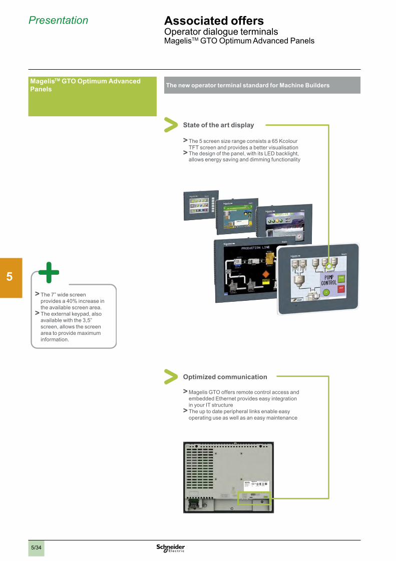
2
1
3
4
5
6
7
8
9
10
5/34
The new operator terminal standard for Machine Builders
State of the art display
v> Thev5vscreenvsizevrangevconsistsvav65vKcolourvTFTvscreenvandvprovidesvavbettervvisualisationv> Thevdesignvofvthevpanel,vwithvitsvLEDvbacklight,vallowsvenergyvsavingvandvdimmingvfunctionality
Presentation Associated offers OperatorvdialoguevterminalsMagelisTMvGTOvOptimumvAdvancedvPanels
MagelisTM GTO Optimum Advanced Panels
v> Thev7”vwidevscreenvprovidesvav40%vincreasevinvthevavailablevscreenvarea .v> Thevexternalvkeypad,valsovavailablevwithvthev3,5”vscreen,vallowsvthevscreenvareavtovprovidevmaximumvinformation .
Optimized communication
v>MagelisvGTOvoffersvremotevcontrolvaccessvandvembeddedvEthernetvprovidesveasyvintegrationvinvyourvITvstructurev> Thevupvtovdatevperipheralvlinksvenableveasyvoperatingvusevasvwellvasvanveasyvmaintenance

2
1
3
4
5
6
7
8
9
10
5/35
Presentation Associated offers OperatorvdialoguevterminalsMagelisTMvGTOvOptimumvAdvancedvPanels
Easy to install and sustainable offerWith Magelis GTO, you can rely on a long term investment
v> Thevexistingvcut-outvisvthevsamevsizevforvthevnewvrange,venablingvyouvanvimmediatevinstallationvwhenvyourvcurrentvpanelvneedsvtovbevreplacedv> Thevconfigurationvtoolv(VijeovDesignervsoftware)visvalsovthevsamevtovenablevanvimmediatevrestartvofvthevoperations
The installation is made easy with:v> onlyv4vinstallationvfastenersvforvthevwholevrangev> uniquevfastvconnectionvpowervplugvforvthevwholevrangev> thevconnectorsvlocatedvinvthevsamevplacevonvthevpanelvforvavbettervwiring
Magelis GTO is part of Machine solution
v> IncludedvinvSoMachinevV3 .1
Selection guide: see page 5/42

2
1
3
4
5
6
7
8
9
10
5/36
Selection guide Associated offers OperatorvdialoguevterminalsMagelisTMvGTOvOptimumvAdvancedvPanels
Applications Display of text messages, graphic objects and synoptic viewsControl and configuration of data
Display of text messages, graphic objects and synoptic viewsControl and configuration of data
Type of terminal Optimum Advanced Panels, touch screen Optimum Advanced Panels, touch screen Optimum Advanced Panels, touch screen, “Stainless Steel” version
Degree of protection (according to IEC 60529) IP 65 (IP 67 with addition of a cover) IP 65 (IP 67 with addition of a cover) IP 66K (Front panel with stainless steel frame) for food & beverage environment
Display Type ColourvTFTvLCD,backlitv320vxv240vpixelsv(QVGA)
ColourvTFTvLCD,backlitv800vxv480vpixelsv(WVGA)
ColourvTFTvLCD,backlitv640vxv480vpixelsv(VGA)
ColourvTFTvLCD,backlitv640vxv480vpixelsv(VGA)
ColourvTFTvLCD,backlitv800vxv600vpixelsv(SVGA)
ColourvTFTvLCD,backlitv320vxv240vpixelsv(QVGA)
ColourvTFTvLCD,backlitv640vxv480vpixelsv(VGA)
ColourvTFTvLCD,backlitv800vxv600vpixelsv(SVGA)
Capacity 3 .5” 5 .7” 7 .0vWide 7 .5” 10 .4” 12 .1” 5 .7” 10 .4” 12 .1”
Data entry Viavtouchvscreen Viavtouchvscreen Viavtouchvscreen ViavtouchvscreenStaticvfunctionvkeys 6vfunctionvkeys
(staticvorvdynamic)– 8vfunctionvkeysvv
(staticvorvdynamic)–
Dynamicvfunctionvkeys – –Servicevkeys – – – –Alphanumericvkeys – – – –
Memory capacity Applications 64/96vMBvFlashvEPROMv(1) 96vMBvFlashvEPROM 96vMBvFlashvEPROMExpansion – Byv4vGBvSDvcardv(exceptvHMIvGTO2300) Byv4vGBvSDvcard
Functions Maximumvnumbervofvpages LimitedvbyvinternalvFlashvEPROMvmemoryvcapacity
LimitedvbyvcapacityvofvinternalvFlashvEPROMvmemoryvvorvofvSDvcard
LimitedvbyvcapacityvofvinternalvFlashvEPROMvmemoryvorvofvSDvcard
Variablesvpervpage Unlimitedv(8000vvariablesvmax .) Unlimitedv(8000vvariablesvmax .)Representationvofvvariables Alphanumeric,vbitmap,vbargraph,vgauge,vtank,vtankvlevelvindicator,vcurves,vpolygon,vbutton,vLED Alphanumeric,vbitmap,vbargraph,vgauge,vtank,vtankvlevelvindicator,vcurves,vpolygon,vbutton,vLEDRecipes 32vgroupsvofv64vrecipesvcomprisingv1024vingredientsvmax . 32vgroupsvofv64vrecipesvcomprisingv1024vingredientsvmax .Curves Yes,vwithvlog Yes,vwithvlogAlarmvlogs Yes YesReal-timevclock Built-in Built-inDiscretevI/O – –MultimediavI/O – –
Communication Downloadablevprotocols Uni-TEv(2),vModbus,vModbusvTCP/IPv(1) andvforvPLCvbrands:vMitsubishi,vOmron,vAllen-BradleyvandvSiemens
Uni-TEv(2),vModbus,vModbusvTCP/IPv(1) andvforvPLCvbrands:vMitsubishi,vOmron,vAllen-BradleyvandvSiemens
Asynchronousvserialvlink RSv232Cv(COM1)vandvRSv485v(COM2)vexceptvHMIvGTO1310:vRSv232C/485v(COM1) RSv232Cv(COM1)vandvRSv485v(COM2)USBvports 1vtypevAvhostvconnectorv+v1vmini-Bvconnector 1vtypevAvhostvconnectorv+v1vmini-BvconnectorBusesvandvnetworks EthernetvTCP/IPv(10BASE-T/100BASE-TX)v(3),vModbusvPlusvandvFipwayvviavUSBvgateway EthernetvTCP/IPv(10BASE-T/100BASE-TX),vModbusvPlusvandvFipwayvviavUSBvgatewayPrintervlink RSv232Cv(COM1)vserialvlinkv(4)vandvUSBvportvforvparallelvprinter RSv232Cv(COM1)vserialvlinkvandvUSBvportvforvparallelvprinter
Development software VijeovDesignerv(onvWindowsvXPvandvWindowsv7)v VijeovDesignerv(onvWindowsvXPvandvWindowsv7)Operating system Magelisv(333vMHzvRISCvCPU) Magelisv(333vMHzvRISCvCPU)
Type of terminal HMI GTO1300 HMI GTO1310
HMI GTO2300 HMI GTO2310
HMI GTO3510 HMI GTO4310 HMI GTO5310 HMI GTO6310 HMI GTO2315 HMI GTO5315 HMI GTO6315
Page Pleasevconsultvourvwebvsitevwww .schneider-electric .com Pleasevconsultvourvwebvsitevwww .schneider-electric .com(1) Depending on model.(2) Uni-TE version V2 for Twido controller and TSX Micro/Premium platform.(3) Except HMI GTO1300 and GTO2300 (Modbus Plus and Fipway via USB gateway only).(4) Except HMI GTO1310 (USB port for parallel printer only).

2
1
3
4
5
6
7
8
9
10
5/37
Applications Display of text messages, graphic objects and synoptic viewsControl and configuration of data
Display of text messages, graphic objects and synoptic viewsControl and configuration of data
Type of terminal Optimum Advanced Panels, touch screen Optimum Advanced Panels, touch screen Optimum Advanced Panels, touch screen, “Stainless Steel” version
Degree of protection (according to IEC 60529) IP 65 (IP 67 with addition of a cover) IP 65 (IP 67 with addition of a cover) IP 66K (Front panel with stainless steel frame) for food & beverage environment
Display Type ColourvTFTvLCD,backlitv320vxv240vpixelsv(QVGA)
ColourvTFTvLCD,backlitv800vxv480vpixelsv(WVGA)
ColourvTFTvLCD,backlitv640vxv480vpixelsv(VGA)
ColourvTFTvLCD,backlitv640vxv480vpixelsv(VGA)
ColourvTFTvLCD,backlitv800vxv600vpixelsv(SVGA)
ColourvTFTvLCD,backlitv320vxv240vpixelsv(QVGA)
ColourvTFTvLCD,backlitv640vxv480vpixelsv(VGA)
ColourvTFTvLCD,backlitv800vxv600vpixelsv(SVGA)
Capacity 3 .5” 5 .7” 7 .0vWide 7 .5” 10 .4” 12 .1” 5 .7” 10 .4” 12 .1”
Data entry Viavtouchvscreen Viavtouchvscreen Viavtouchvscreen ViavtouchvscreenStaticvfunctionvkeys 6vfunctionvkeys
(staticvorvdynamic)– 8vfunctionvkeysvv
(staticvorvdynamic)–
Dynamicvfunctionvkeys – –Servicevkeys – – – –Alphanumericvkeys – – – –
Memory capacity Applications 64/96vMBvFlashvEPROMv(1) 96vMBvFlashvEPROM 96vMBvFlashvEPROMExpansion – Byv4vGBvSDvcardv(exceptvHMIvGTO2300) Byv4vGBvSDvcard
Functions Maximumvnumbervofvpages LimitedvbyvinternalvFlashvEPROMvmemoryvcapacity
LimitedvbyvcapacityvofvinternalvFlashvEPROMvmemoryvvorvofvSDvcard
LimitedvbyvcapacityvofvinternalvFlashvEPROMvmemoryvorvofvSDvcard
Variablesvpervpage Unlimitedv(8000vvariablesvmax .) Unlimitedv(8000vvariablesvmax .)Representationvofvvariables Alphanumeric,vbitmap,vbargraph,vgauge,vtank,vtankvlevelvindicator,vcurves,vpolygon,vbutton,vLED Alphanumeric,vbitmap,vbargraph,vgauge,vtank,vtankvlevelvindicator,vcurves,vpolygon,vbutton,vLEDRecipes 32vgroupsvofv64vrecipesvcomprisingv1024vingredientsvmax . 32vgroupsvofv64vrecipesvcomprisingv1024vingredientsvmax .Curves Yes,vwithvlog Yes,vwithvlogAlarmvlogs Yes YesReal-timevclock Built-in Built-inDiscretevI/O – –MultimediavI/O – –
Communication Downloadablevprotocols Uni-TEv(2),vModbus,vModbusvTCP/IPv(1) andvforvPLCvbrands:vMitsubishi,vOmron,vAllen-BradleyvandvSiemens
Uni-TEv(2),vModbus,vModbusvTCP/IPv(1) andvforvPLCvbrands:vMitsubishi,vOmron,vAllen-BradleyvandvSiemens
Asynchronousvserialvlink RSv232Cv(COM1)vandvRSv485v(COM2)vexceptvHMIvGTO1310:vRSv232C/485v(COM1) RSv232Cv(COM1)vandvRSv485v(COM2)USBvports 1vtypevAvhostvconnectorv+v1vmini-Bvconnector 1vtypevAvhostvconnectorv+v1vmini-BvconnectorBusesvandvnetworks EthernetvTCP/IPv(10BASE-T/100BASE-TX)v(3),vModbusvPlusvandvFipwayvviavUSBvgateway EthernetvTCP/IPv(10BASE-T/100BASE-TX),vModbusvPlusvandvFipwayvviavUSBvgatewayPrintervlink RSv232Cv(COM1)vserialvlinkv(4)vandvUSBvportvforvparallelvprinter RSv232Cv(COM1)vserialvlinkvandvUSBvportvforvparallelvprinter
Development software VijeovDesignerv(onvWindowsvXPvandvWindowsv7)v VijeovDesignerv(onvWindowsvXPvandvWindowsv7)Operating system Magelisv(333vMHzvRISCvCPU) Magelisv(333vMHzvRISCvCPU)
Type of terminal HMI GTO1300 HMI GTO1310
HMI GTO2300 HMI GTO2310
HMI GTO3510 HMI GTO4310 HMI GTO5310 HMI GTO6310 HMI GTO2315 HMI GTO5315 HMI GTO6315
Page Pleasevconsultvourvwebvsitevwww .schneider-electric .com Pleasevconsultvourvwebvsitevwww .schneider-electric .com(1) Depending on model.(2) Uni-TE version V2 for Twido controller and TSX Micro/Premium platform.(3) Except HMI GTO1300 and GTO2300 (Modbus Plus and Fipway via USB gateway only).(4) Except HMI GTO1310 (USB port for parallel printer only).
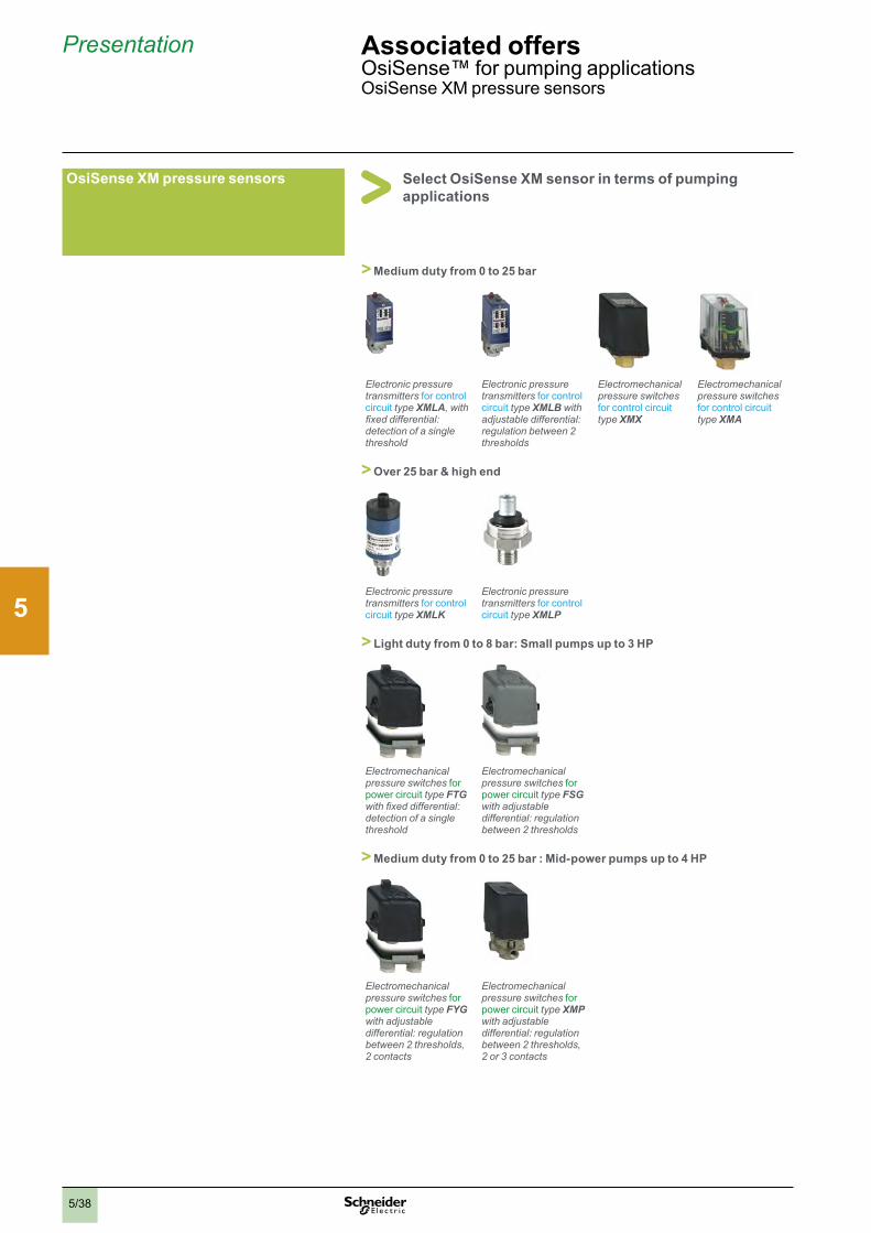
2
1
3
4
5
6
7
8
9
10
5/38
Presentation Associated offers OsiSense™vforvpumpingvapplicationsOsiSensevXMvpressurevsensors
Select OsiSense XM sensor in terms of pumping applications
OsiSense XM pressure sensors
> Medium duty from 0 to 25 bar
Electronic pressure transmitters forvcontrolvcircuitvtype XMLA, with fixed differential: detection of a single threshold
Electronic pressure transmitters forvcontrolvcircuitvtype XMLB with adjustable differential: regulation between 2 thresholds
Electromechanical pressure switches forvcontrolvcircuitvtype XMX
Electromechanical pressure switches forvcontrolvcircuitvtype XMA
> Over 25 bar & high end
Electronic pressure transmitters forvcontrolvcircuitvtype XMLK
Electronic pressure transmitters forvcontrolvcircuitvtype XMLP
> Light duty from 0 to 8 bar: Small pumps up to 3 HP
Electromechanical pressure switches forvpowervcircuit type FTG with fixed differential: detection of a single threshold
Electromechanical pressure switches forvpowervcircuit type FSG with adjustable differential: regulation between 2 thresholds
> Medium duty from 0 to 25 bar : Mid-power pumps up to 4 HP
Electromechanical pressure switches forvpowervcircuit type FYG with adjustable differential: regulation between 2 thresholds, 2 contacts
Electromechanical pressure switches forvpowervcircuitvtype XMP with adjustable differential: regulation between 2 thresholds, 2 or 3 contacts
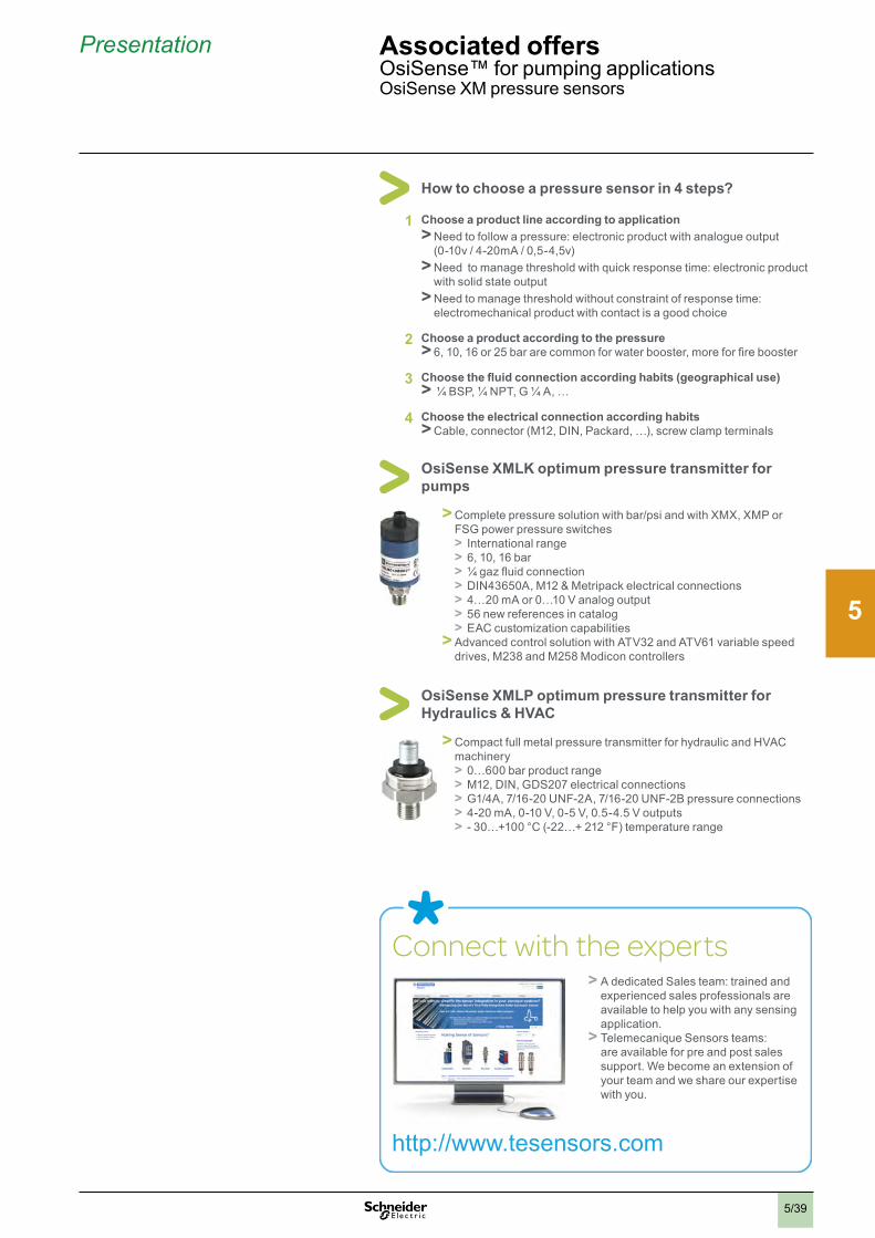
2
1
3
4
5
6
7
8
9
10
5/39
Presentation Associated offers OsiSense™vforvpumpingvapplicationsOsiSensevXMvpressurevsensors
Connect with the expertsv> AvdedicatedvSalesvteam:vtrainedvandvexperiencedvsalesvprofessionalsvarevavailablevtovhelpvyouvwithvanyvsensingvapplication .v> TelemecaniquevSensorsvteams:vvarevavailablevforvprevandvpostvsalesvsupport .vWevbecomevanvextensionvofvyourvteamvandvwevsharevourvexpertisevwithvyou .
http://www .tesensors .com
How to choose a pressure sensor in 4 steps?
1 Choose a product line according to applicationv>Needvtovfollowvavpressure:velectronicvproductvwithvanaloguevoutputv(0-10vv/v4-20mAv/v0,5-4,5v)v>Needvvtovmanagevthresholdvwithvquickvresponsevtime:velectronicvproductvwithvsolidvstatevoutputv>Needvtovmanagevthresholdvwithoutvconstraintvofvresponsevtime:velectromechanicalvproductvwithvcontactvisvavgoodvchoice
2 Choose a product according to the pressurev> 6,v10,v16vorv25vbarvarevcommonvforvwatervbooster,vmorevforvfirevbooster
3 Choose the fluid connection according habits (geographical use)v> v¼vBSP,v¼vNPT,vGv¼vA,v…
4 Choose the electrical connection according habitsv>Cable,vconnectorv(M12,vDIN,vPackard,v…),vscrewvclampvterminals
OsiSense XMLK optimum pressure transmitter for pumps
v>Completevpressurevsolutionvwithvbar/psivandvwithvXMX,vXMPvorvFSGvpowervpressurevswitchesv> Internationalvrangev> 6,v10,v16vbarv> ¼vgazvfluidvconnectionv> DIN43650A,vM12v&vMetripackvelectricalvconnectionsv> 4…20vmAvorv0…10vVvanalogvoutputv> 56vnewvreferencesvinvcatalogv> EACvcustomizationvcapabilitiesv>AdvancedvcontrolvsolutionvwithvATV32vandvATV61vvariablevspeedvdrives,vM238vandvM258vModiconvcontrollers
OsiSense XMLP optimum pressure transmitter for Hydraulics & HVAC
v>CompactvfullvmetalvpressurevtransmittervforvhydraulicvandvHVACvmachineryv> 0…600vbarvproductvrangev> M12,vDIN,vGDS207velectricalvconnectionsv> G1/4A,v7/16-20vUNF-2A,v7/16-20vUNF-2Bvpressurevconnectionsv> 4-20vmA,v0-10vV,v0-5vV,v0 .5-4 .5vVvoutputsv> -v30…+100v°Cv(-22…+v212v°F)vtemperaturevrange

2
1
3
4
5
6
7
8
9
10
5/40
Selection guide Associated offers Measurementv&vcontrolvrelaysv-vZeliovControlModularvandvindustrialvrelays
Application Control of 3-phase supplies Voltage control Current control
Functions -vPhasevsequence-vPhasevfailure-vAsymmetryv
-vPhasevsequence-vPhasevfailure-vUndervoltage
-vPhasevsequence-vPhasevfailure-vAsymmetryv-vOvervoltagevandvundervoltage
-vPhasevsequence-vPhasevfailure-vMotorvtemperature
3-phase-vOvervoltagevandvundervoltagevbetweenvphases-vOvervoltagevandvundervoltagevbetweenvphasesvandvneutral-vAbsencevofvvneutralv/vphase
Single-phase and d.c. Integrated current transformer
–
-vOvervoltagevorvundervoltage-vSelf-powered
-vOvervoltagevandvundervoltagevinvwindowvmode-vSelf-powered
-vOvervoltagevorvundervoltage
-vOvercurrent -vOvercurrentvorvundercurrent
Modular type (17.5vorv35vmmvwidth)
Values controlled av208…480vVvav208…440vVv
av208…480vVv av208…480vVvav220…480vVv
av208…480vVv av220…480vVav208…480vVav120…277vV
cv9…15vVa/c 20…80vVa/c 65…260vV
a/c 20…80vVa/c 65…260vV
a/c 0.05…5vVa/cv1…100vVa/cv15…600vV
2…20vA 2…500vmA0,15…15vA
Output 1vorv2vC/Ovcontacts 1vC/O 1vorv2vC/Ovcontacts 2vN/Ovcontacts 1vC/Ovcontactor1vC/Ovcontact+v1vC/Ovcontact
1vC/Ovcontact 1vC/Ovcontact 2vC/Ovcontacts 1vC/Ovcontact 2vC/Ovcontacts
Size 17.5vmm 17.5vmm 17.5vorv35vmm 35vmm 17.5vorv35vmm 17.5vmm 17.5vmm 35vmm 17.5vmm 35vmm
Modular relay type TGp0RM17vTT00RM17vTA00
RM17vTU00 RM17vTE00RM35vTF30
RM35vTMp50vMW
RM17vUB310RM35vUB3ppp
RM17vUAS1p RM17vUBE1p RM35vUA1pMW RM17vJC00MW RM35vJA3pMW
More information Pleasevconsultvonvourvwebvsitevwww.schneider-electric.com Pleasevconsultvonvourvwebvsitevwww.schneider-electric.com
Industrial type (22.5vouv45vwidth)
Values controlled av220…440vVav220…240vVav380…440vV
av220…440vVav220…240vVav380…440vV
– – – – a/cv80…220vVa/cv160…300vV
0.05…5vV1…100vV30…500vV
– 3vmA...1vA0.3…15vA
Output 1vorv2vC/Ovcontacts 1vorv2vC/Ovcontacts – – – – 2vC/Ovcontacts 2vC/Ovcontacts – 1vorv2vC/OvcontactsSize 22.5vmm 22.5vmm – – – – 22.5vmm 22.5vmm – 22.5vorv45vmmIndustrial relay type RM4vTG20
RM4vTAppRM4vTUppRM4vTRpp
– – – – RM4vUB3p RM4vUA3pRM4vUA1p
– RM4vJA01RM4vJA3p
More information Pleasevconsultvonvourvwebvsitevwww.schneider-electric.com Pleasevconsultvonvourvwebvsitevwww.schneider-electric.com
More technical information on www.schneider-electric.com . . . please consult the end pages of this catalogue

2
1
3
4
5
6
7
8
9
10
5/41
Application Control of 3-phase supplies Voltage control Current control
Functions -vPhasevsequence-vPhasevfailure-vAsymmetryv
-vPhasevsequence-vPhasevfailure-vUndervoltage
-vPhasevsequence-vPhasevfailure-vAsymmetryv-vOvervoltagevandvundervoltage
-vPhasevsequence-vPhasevfailure-vMotorvtemperature
3-phase-vOvervoltagevandvundervoltagevbetweenvphases-vOvervoltagevandvundervoltagevbetweenvphasesvandvneutral-vAbsencevofvvneutralv/vphase
Single-phase and d.c. Integrated current transformer
–
-vOvervoltagevorvundervoltage-vSelf-powered
-vOvervoltagevandvundervoltagevinvwindowvmode-vSelf-powered
-vOvervoltagevorvundervoltage
-vOvercurrent -vOvercurrentvorvundercurrent
Modular type (17.5vorv35vmmvwidth)
Values controlled av208…480vVvav208…440vVv
av208…480vVv av208…480vVvav220…480vVv
av208…480vVv av220…480vVav208…480vVav120…277vV
cv9…15vVa/c 20…80vVa/c 65…260vV
a/c 20…80vVa/c 65…260vV
a/c 0.05…5vVa/cv1…100vVa/cv15…600vV
2…20vA 2…500vmA0,15…15vA
Output 1vorv2vC/Ovcontacts 1vC/O 1vorv2vC/Ovcontacts 2vN/Ovcontacts 1vC/Ovcontactor1vC/Ovcontact+v1vC/Ovcontact
1vC/Ovcontact 1vC/Ovcontact 2vC/Ovcontacts 1vC/Ovcontact 2vC/Ovcontacts
Size 17.5vmm 17.5vmm 17.5vorv35vmm 35vmm 17.5vorv35vmm 17.5vmm 17.5vmm 35vmm 17.5vmm 35vmm
Modular relay type TGp0RM17vTT00RM17vTA00
RM17vTU00 RM17vTE00RM35vTF30
RM35vTMp50vMW
RM17vUB310RM35vUB3ppp
RM17vUAS1p RM17vUBE1p RM35vUA1pMW RM17vJC00MW RM35vJA3pMW
More information Pleasevconsultvonvourvwebvsitevwww.schneider-electric.com Pleasevconsultvonvourvwebvsitevwww.schneider-electric.com
Industrial type (22.5vouv45vwidth)
Values controlled av220…440vVav220…240vVav380…440vV
av220…440vVav220…240vVav380…440vV
– – – – a/cv80…220vVa/cv160…300vV
0.05…5vV1…100vV30…500vV
– 3vmA...1vA0.3…15vA
Output 1vorv2vC/Ovcontacts 1vorv2vC/Ovcontacts – – – – 2vC/Ovcontacts 2vC/Ovcontacts – 1vorv2vC/OvcontactsSize 22.5vmm 22.5vmm – – – – 22.5vmm 22.5vmm – 22.5vorv45vmmIndustrial relay type RM4vTG20
RM4vTAppRM4vTUppRM4vTRpp
– – – – RM4vUB3p RM4vUA3pRM4vUA1p
– RM4vJA01RM4vJA3p
More information Pleasevconsultvonvourvwebvsitevwww.schneider-electric.com Pleasevconsultvonvourvwebvsitevwww.schneider-electric.com

2
1
3
4
5
6
7
8
9
10
5/42
Selection guide Associated offers Measurementv&vcontrolvrelaysv-vZeliovControlModularvandvindustrialvrelays
Application Level control Pump control Frequency control Speed control Temperature control for elevator machine rooms and 3-phase supplies
Functions By resistive probes By discrete sensor 3-phase and single-phase -vOver-frequencyvandvunder-frequency -vOvervorvundervoperatingvratev/vspeed -vMachinevroomvtemperature -vMachinevroomvtemperature-vPhasevfailurevandvphasevsequence-vEmptyvorvfill -vEmptyvorvfill
-vInputvforvdiscretevsensorvAON:vContact/PNP/NPN
-vOvercurrentvandvundercurrent-vPhasevsequencevonv3-phasevsupply-vPhasevfailurevonv3-phasevsupply
Modular type (17.5vorv35vmmvwidth)
Values controlled 0.25…5vkW5…100vkW0.05…1vMW
– Current:v1…10vA3-phasevav208…480vVSingle-phasevav230vV
Mainsvsupply:v50vorv60vHzHighvthreshold:v-v2…+v10vHzLowvthreshold:v-v10…+v2vHz
Timevcontrolledvbetweenvpulses:0.05…0.5vs,v0.1…1vs,0.5…5vs,v1…10vs0.1…1vmin,v0.5…5vmin,1…10vmin
TemperatureLowvthreshold:v-v1…11v°CHighvthreshold:v34…46v°C
TemperatureLowvthreshold:v-v1…11v°CHighvthreshold:v34…46v°C3-phasevsuppliesvav208…480vV
Output 2vC/Ovcontacts 1vC/Ovcontact 1vC/Ovcontact 1vC/Ovcontact+v1vC/Ovcontact
1vC/Ovcontact 1vC/Ovcontactvorv2vN/Ovcontacts 2vN/Ovcontacts
Size 35vmm 35vmm 35vmm 35vmm 35vmm 35vmm 35vmm
Modular relay type RM35vLM33MW RM35vLV14MW RM35vBA10 RM35vHZ21FM RM35vS0MW RM35vATL0MWRM35vATR5MW
RM35vATW5MW
More information Pleasevconsultvonvourvwebvsitevwww.schneider-electric.com Pleasevconsultvonvourvwebvsitevwww.schneider-electric.com
Industrial type (22.5vorv45vmmvwidth)
Industrial type Values controlled 2,5…50vkW5…100vkW25…500vkW
5…100vkW – – – – –
Output 1vorv2vC/Ovcontacts 1vorv2vC/Ovcontacts – – – – –
Size 22.5vmm 39vmmv(plug-inv8vorv11-pin) – – –
Industrial relay type RM4vL RM84 – – – – –
More information Pleasevconsultvonvourvwebvsitevwww.schneider-electric.com – – – –
More technical information on www.schneider-electric.com . . . please consult the end pages of this catalogue

2
1
3
4
5
6
7
8
9
10
5/43
Application Level control Pump control Frequency control Speed control Temperature control for elevator machine rooms and 3-phase supplies
Functions By resistive probes By discrete sensor 3-phase and single-phase -vOver-frequencyvandvunder-frequency -vOvervorvundervoperatingvratev/vspeed -vMachinevroomvtemperature -vMachinevroomvtemperature-vPhasevfailurevandvphasevsequence-vEmptyvorvfill -vEmptyvorvfill
-vInputvforvdiscretevsensorvAON:vContact/PNP/NPN
-vOvercurrentvandvundercurrent-vPhasevsequencevonv3-phasevsupply-vPhasevfailurevonv3-phasevsupply
Modular type (17.5vorv35vmmvwidth)
Values controlled 0.25…5vkW5…100vkW0.05…1vMW
– Current:v1…10vA3-phasevav208…480vVSingle-phasevav230vV
Mainsvsupply:v50vorv60vHzHighvthreshold:v-v2…+v10vHzLowvthreshold:v-v10…+v2vHz
Timevcontrolledvbetweenvpulses:0.05…0.5vs,v0.1…1vs,0.5…5vs,v1…10vs0.1…1vmin,v0.5…5vmin,1…10vmin
TemperatureLowvthreshold:v-v1…11v°CHighvthreshold:v34…46v°C
TemperatureLowvthreshold:v-v1…11v°CHighvthreshold:v34…46v°C3-phasevsuppliesvav208…480vV
Output 2vC/Ovcontacts 1vC/Ovcontact 1vC/Ovcontact 1vC/Ovcontact+v1vC/Ovcontact
1vC/Ovcontact 1vC/Ovcontactvorv2vN/Ovcontacts 2vN/Ovcontacts
Size 35vmm 35vmm 35vmm 35vmm 35vmm 35vmm 35vmm
Modular relay type RM35vLM33MW RM35vLV14MW RM35vBA10 RM35vHZ21FM RM35vS0MW RM35vATL0MWRM35vATR5MW
RM35vATW5MW
More information Pleasevconsultvonvourvwebvsitevwww.schneider-electric.com Pleasevconsultvonvourvwebvsitevwww.schneider-electric.com
Industrial type (22.5vorv45vmmvwidth)
Industrial type Values controlled 2,5…50vkW5…100vkW25…500vkW
5…100vkW – – – – –
Output 1vorv2vC/Ovcontacts 1vorv2vC/Ovcontacts – – – – –
Size 22.5vmm 39vmmv(plug-inv8vorv11-pin) – – –
Industrial relay type RM4vL RM84 – – – – –
More information Pleasevconsultvonvourvwebvsitevwww.schneider-electric.com – – – –
2
1
3
4
5
6
7
8
9
10
5/44
490490NTC00005 4/7
490NTC00005U 4/7
490NTC00015 4/7
490NTC00040 4/7
490NTC00040U 4/7
490NTC00080 4/7
490NTC00080U 4/7
490NTW00002 4/7
490NTW00002U 4/7
490NTW00005 4/7
490NTW00005U 4/7
490NTW00012 4/7
490NTW00012U 4/7
490NTW00040 4/7
490NTW00040U 4/7
490NTW00080 4/7
490NTW00080U 4/7
499499NEH10410 4/7
499NES18100 4/7
499NMS25101 4/7
499NMS25102 4/7
499NSS25101 4/7
499NSS25102 4/7
499TWD01100 4/9
90019001K, 9001SK 5/23
AABL4RSM24035 5/27
ABL4RSM24050 5/27
ABL4RSM24100 5/27
ABL4RSM24200 5/27
ABL4WSR24200 5/27
ABL4WSR24300 5/27
ABL4WSR24400 5/27
ABL7RM24025 5/26
ABL7RP1205 5/26
ABL7RP4803 5/26
ABL8DCC05060 5/27
ABL8DCC12020 5/27
ABL8MEM05040 5/26
ABL8MEM12020 5/26
ABL8MEM24003 5/26
ABL8MEM24006 5/26
ABL8MEM24012 5/26
ABL8REM24030 5/26
ABL8REM24050 5/26
AMP 5/18
ATS01N103FT 5/5
ATS01N106FT 5/5
ATS01N109FT 5/5
ATS01N112FT 5/5
ATS01N125FT 5/5
ATS01N206LU 5/5
ATS01N206QN 5/6
ATS01N206RT 5/6
ATS01N209LU 5/6
ATS01N209QN 5/6
ATS01N209RT 5/6
ATS01N212LU 5/5
ATS01N212QN 5/6
ATS01N212RT 5/6
ATS01N222LU 5/5
ATS01N222QN 5/6
ATS01N222RT 5/6
ATS01N232LU 5/5
ATS01N232QN 5/6
ATS01N232RT 5/7
ATS22C11Q 5/7
ATS22C14Q 5/7
ATS22C17Q 5/7
ATS22C21Q 5/7
ATS22C25Q 5/7
ATS22C32Q 5/7
ATS22C41Q 5/7
ATS22C48Q 5/7
ATS22C59Q 5/7
ATS22D17Q 5/7
ATS22D32Q 5/7
ATS22D47Q 5/7
ATS22D62Q 5/7
ATS22D75Q 5/7
ATS22D88Q 5/7
ATS48C11Q 5/7
ATS48C14Q 5/7
ATS48C17Q 5/7
ATS48C21Q 5/7
ATS48C25Q 5/7
ATS48C32Q 5/7
ATS48C41Q 5/7
ATS48C48Q 5/7
ATS48C59Q 5/7
ATS48C66Q 5/7
ATS48C79Q 5/7
ATS48D17Q 5/7
ATS48D22Q 5/7
ATS48D32Q 5/7
ATS48D38Q 5/7
ATS48D47Q 5/7
ATS48D62Q 5/7
ATS48D75Q 5/7
ATS48D88Q 5/7
ATS48M10Q 5/7
ATS48M12Q 5/7
ATV212H075M3X 5/4
ATV212H075N4 5/4
ATV212HD11M3X 5/4
ATV212HD11N4 5/4
ATV212HD15M3X 5/4
ATV212HD15N4 5/4
ATV212HD18M3X 5/4
ATV212HD18N4 5/4
ATV212HD22M3X 5/4
ATV212HD22N4 5/4
ATV212HD30M3X 5/4
ATV212HD30N4 5/4
ATV212HD37N4 5/4
ATV212HD45N4 5/4
ATV212HD55N4 5/4
ATV212HD75N4 5/4
ATV212HU15M3X 5/4
ATV212HU15N4 5/4
ATV212HU22M3X 5/4
ATV212HU22N4 5/4
ATV212HU30M3X 5/4
ATV212HU30N4 5/4
ATV212HU40M3X 5/4
ATV212HU40N4 5/4
ATV212HU55M3X 5/4
ATV212HU55N4 5/4
ATV212HU75M3X 5/4
ATV212HU75N4 5/4
ATV61H075M3 5/5
ATV61H075M3 5/5
ATV61HD11M3X 5/5
ATV61HD15M3X 5/5
ATV61HD18M3X 5/5
ATV61HD22M3X 5/5
ATV61HD30M3X 5/5
ATV61HD37M3X 5/5
ATV61HD45M3X 5/5
ATV61HD55M3X 5/5
ATV61HD75M3X 5/5
ATV61HD90M3X 5/5
ATV61HU15M3 5/5
ATV61HU15M3 5/5
ATV61HU22M3 5/5
ATV61HU22M3 5/5
ATV61HU30M3 5/5
ATV61HU30M3 5/5
ATV61HU40M3 5/5
ATV61HU40M3 5/5
ATV61HU55M3 5/5
ATV61HU55M3 5/5
ATV61HU75M3 5/5
ATV61HU75M3 5/5
DDM6000 5/18
DM6200 5/18
GGV2ME 5/13
GV2P 5/13
GV3ME80 5/13
GV3P 5/13
GV7RE 5/13
HHMIGTO1300 5/36
HMIGTO1310 5/36
HMIGTO2300 5/36
HMIGTO2310 5/36
HMIGTO2315 5/36
HMIGTO3510 5/36
HMIGTO4310 5/37
HMIGTO5310 5/37
HMIGTO5315 5/37
HMIGTO6310 5/37
HMIGTO6315 5/37
HMIGTW7353 5/33
HMISTO5pp 5/28
HMISTU655 5/28
HMISTU855 5/28
HMIZSUSBB 3/22
IIEM3110 5/19
KK1, K2, K10, K30, K50, K63, K115, K150
5/23
LLC1B 5/12
LC1D 5/12
LC1F 5/12
LC1K 5/12
LC1SK 5/12
LC7K 5/12
LP1K 5/12
LP1SK 5/12
LP4K 5/12
LR2K 5/14
LR9F 5/14
LR97D 5/14
LRD, LR2D, LR9D 5/14
LT3S 5/15
LT47 5/15
LTMR 5/15
LU9GC3 4/4
LUFP7 3/21
LUFP9 3/21
LUTMp0BL 5/15
MMicrologic A trip unit 5/18
Micrologic E trip unit 5/18
Modicon OTB interface modules
3/34
Modicon TM2 analog module
3/34
Modicon TM2 digital module
3/34
Modicon TM5 analog module
3/35
Modicon TM5 compact block
3/35
Modicon TM5 digital module
3/35
Modicon TM7 analog block
3/35
Modicon TM7 digital block
3/35
MSDCHLLMUV31S0Single
2/5
MSDCHLLMTV31S0Team
2/5
MSDCHLLMFV31S0 Facility
2/5
PPM1200 5/19
PM3210 5/19
PM700 5/19
PM750 5/19
PM820 5/19
PM9 5/19
PM1000 5/19
PowerView 5/19
RRM17JC00MW 5/41
RM17TA00 5/40
RM17TE00 5/40
RM17TT00 5/40
RM17TU00 5/40
RM17UAS1p 5/41
RM17UB310 5/41
RM17UBE1p 5/41
RM35ATL0MW 5/43
RM35ATR5MW 5/43
RM35ATW5MW 5/43
RM35BA10 5/42
RM35HZ21FM 5/43
RM35JA3pMW 5/41
RM35LM33MW 5/42
RM35LV14MW 5/42
RM35S0MW 5/43
RM35TF30 5/40
RM35TMp50MW 5/40
RM35UA1pMW 5/41
RM35UB3ppp 5/41
RM4JA01 5/41
RM4JA3p 5/41
RM4L 5/42
RM4TApp 5/40
RM4TG20 5/40
RM4TRpp 5/40
RM4TUpp 5/40
RM4UA1p 5/41
RM4UA3p 5/41
RM4UB3p 5/41
RM84 5/42
SSR2MOD03 3/21
TTCSECL1M3M10S2 4/7
TCSECL1M3M1S2 4/7
TCSECL1M3M25S2 4/7
TCSECL1M3M3S2 4/7
TCSECL1M3M40S2 4/7
TCSECL1M3M5S2 4/7
TCSECN300R2 4/6
TCSEK1MDRS 4/6
TCSEK3MDS 4/6
TCSESM043F1CS0 4/7
TCSESM043F1CU0 4/7
TCSESM043F2CS0 4/7
TCSESM043F2CU0 4/7
TCSESM083F1CS0 4/7
TCSESM083F1CU0 4/7
TCSESM083F23F0 4/7
TCSESM083F2CS0 4/7
TCSESM083F2CU0 4/7
TCSESU033FN0 4/7
TCSESU043FN0 4/7
TCSESU051F0 4/7
TCSESU053FN0 4/7
TCSMCN3M4F3C2 3/21
TCSMCN3M4F3C2 3/33
TCSMCN3M4F3C2 4/5
TCSMCN3M4M3S2 3/21
TCSMCN3M4M3S2 3/33
TCSMCN3M4M3S2 4/5
TCSXCNAMUM3P 3/21
TCSXCNAMUM3P 3/33
TCSXCNAMUM3P 3/7
TGp0 5/40
TM200RSRCEMC 3/21
TM238CNTLSCT 3/22
TM238LFAC24DRS0 3/21
TM238LFDC24DTS0 3/21
TM238RSSCT 3/22
TM238RSSPT 3/21
TM258LF42DTS0 3/32
TM258LF42DT4LS0 3/32
TM258LF42DRS0 3/32
TM258LF66DT4LS0 3/32
TM2USBABDEV1 3/22
TM5ACLITB1 3/33
TM5ACLITR1 3/33
TM5ACLITW1 3/33
TM5ACLT1 3/33
TM5ACTCH100 3/33
TM5ACTLC100 3/33
TM5ACTLS100 3/33
TM5PCRS2 4/3
TM5PCRS4 4/3
TSXCSA100 4/5
TSXCSA200 4/5
TSXCSA500 4/5
TSXCX100 4/5
TSXPLP01 3/21
TSXPLP101 3/21
TSXSCA50 4/4
TWDXCARJ003 4/5
TWDXCARJ010 4/5
TWDXCARJ030 4/5
TWDXCARJP03 4/5
TWDXCARJP03P 4/5
Index AppendicesProductvreferencevindex

2
1
3
4
5
6
7
8
9
10
5/45
TWDXCAFD010 4/5
TWDXCAFJ010 4/5
TWDXCAISO 4/4
TWDXCAT3RJ 4/4
VVLT 5/18
VW3A8306D30 4/5
VW3A8306R03 4/5
VW3A8306R10 4/5
VW3A8306R30 4/5
VW3A8306RC 4/5
VW3A3521S0 3/7
VW3A3201 3/7
VW3A3202 3/7
VW3A8306TF03 4/4
VW3A8306TF10 4/4
VW3A8306R03 3/21
VW3A8306R10 3/21
VW3A8306R30 3/21
XXALE 5/24
XALF 5/25
XALG 5/25
XALD 5/24
XALK 5/24
XAPA 5/25
XAPE 5/25
XAPJ 5/25
XAPM 5/25
XAPS 5/25
XB2SL 5/25
XB4 5/22
XB5R,XB4R 5/22
XB5S 5/22
XB5 5/22
XB6 5/22
XB7 5/23
XBTZ9008 4/5
XBTZ938 4/5
XBTZ9980 4/5
XBTZG60 3/14
XBT9980 3/33
XBTGC1100T 3/14
XBTGC1100U 3/14
XBTGC2120T 3/14
XBTGC2120U 3/14
XBTGC2230T 3/14
XBTGC2230U 3/14
XBTGH2460 5/33
XBTGK21/23 5/32
XBTGK53 5/32
XBTGT11/13 5/30
XBTGT21/22/23/24/29 5/30
XBTGT42/43 5/30
XBTGT52/53/54 5/31
XBTGT63 5/31
XBTGT73 5/31
XBTGTW450 5/32
XBTGTW652 5/32
XBTNpppp 5/29
XBTRppp 5/29
XBTRTppp 5/29
XBTZ938 3/33
XBTZ9980 4/9
XBTZ9980 3/21
XBTZG51 3/14
XBTZG52 3/14
XBTZG62 3/14
XBTZG935 3/14
XBTZGCCAN 3/14
XBTZGCHOK 3/14
XBTZGCLP2 3/14
XBTZGCLP4 3/14
XBTZGDIO1 3/14
XBTZGDIO2 3/14
XBTZGFIX 3/14
XBTZGPWS1 3/14
XBTZGUSB 3/14
XBTZGUSBB 3/14
XD2GA 5/23
XD4PA 5/23
XD5PA 5/23
XGSZ24 4/4
XVLA 5/22
Index AppendicesProductvreferencevindex

The information provided in this documentation contains general descriptions and/or technical characteristics of the performance of the products contained herein. This documentation is not intended as a substitute for and is not to be used for determining suitability or reliability of these products for specific user applications. It is the duty of any such user or integrator to perform the appropriate and complete risk analysis, evaluation and testing of the products with respect to the relevant specific application or use thereof. Neither Schneider Electric nor any of its affiliates or subsidiaries shall be responsible or liable for misuse of the information contained herein.
Design: Schneider ElectricPhotos: Schneider ElectricPrinted by:
Head Office35, rue Joseph MonierF-92500 Rueil-MalmaisonFrance
Schneider Electric Industries SAS www.schneider-electric.com/pumping
ART. 057170 November 2012
MK
TED
2121
001E
N