pumps in district heating systems
TRANSCRIPT
energies
Review
Heat Roadmap Europe: Large-Scale Electric HeatPumps in District Heating Systems
Andrei David 1,*, Brian Vad Mathiesen 1, Helge Averfalk 2, Sven Werner 2 and Henrik Lund 3
1 Department of Planning, Aalborg University, AC Meyers Vænge 15, 2450 Copenhagen, Denmark;[email protected]
2 School of Business, Engineering and Science, Halmstad University, PO BOX 823, SE 30118 Halmstad,Sweden; [email protected] (H.A.); [email protected] (S.W.)
3 Department of Planning, Aalborg University, Rendsburggade 14, 9000 Aalborg, Denmark; [email protected]* Correspondence: [email protected]; Tel.: +45-2477-7368
Academic Editor: Kamel HoomanReceived: 13 March 2017; Accepted: 18 April 2017; Published: 22 April 2017
Abstract: The Heat Roadmap Europe (HRE) studies estimated a potential increase of the districtheating (DH) share to 50% of the entire heat demand by 2050, with approximately 25–30% of itbeing supplied using large-scale electric heat pumps. This study builds on this potential and aims todocument that such developments can begin now with technologies currently available. We present adatabase and the status of the technology and its ability of expansion to other European locations byreviewing experiences aimed at further research or application in the heating industry. This is basedon a survey of the existing capacity of electric large-scale heat pumps with more than 1 MW thermaloutput, operating in European DH systems. The survey is the first database of its kind containing thetechnical characteristics of these heat pumps, and provides the basis for the analysis of this paper.By quantifying the heat sources, refrigerants, efficiency and types of operation of 149 units with1580 MW of thermal output, the study further uses this data to analyze if the deployment of thistechnology on a large-scale is possible in other locations in Europe. It finally demonstrates that thetechnical level of the existing heat pumps is mature enough to make them suitable for replication inother locations in Europe.
Keywords: large-scale electric heat pumps; district heating; waste heat; sewage water; naturalrefrigerants; energy system flexibility
1. Introduction
It is generally agreed that the quantity of carbon emissions released in the atmosphere as a resultof human activities has reached alarming levels. In December 2015, at the 21st Conference of Partiessummit in Paris, a historic agreement was reached regarding climate changes. It was the first pactof its kind to cut the carbon emissions and to limit the rising global temperatures to “well below 2 ◦C,aiming for 1.5 ◦C” by 2100 [1]. To achieve this reduction, the EU has set itself a long-term goal to reducegreenhouse gas (GHG) emissions by 80–95% before the year 2050, as compared to the 1990 levels [2].Currently on a European level, energy and transport account for more than 75% of the current CO2
emissions [3], and for these two uses the European Union (EU) imports 53% of the fossil fuel energyit consumes at a price of over € 1 billion per day [4]. The heating and cooling sector is estimated touse half of the total energy consumed in Europe [5]. At the same time, potential wasted heat fromindustry and electricity production is on the same order of magnitude as the total heating demand ofall buildings in Europe, indicating that there is a possibility to reduce both the imported and consumedenergy, to decarbonize the energy sector, and increase the security of supply.
Energies 2017, 10, 578; doi:10.3390/en10040578 www.mdpi.com/journal/energies
Energies 2017, 10, 578 2 of 18
The heating sector has a decisive role in achieving these goals, and to mitigate its negative impact,energy efficiency improvement measures are required on both the supply and demand side, combinedwith the inclusion of more renewable energy sources (RES). Much attention was given to the demandside, by retrofitting the building stock, but lately the type of heat supply has received more attention [5].The synergy between these demand side energy savings and new supply options was analyzed in theHeat Roadmap Europe (HRE) studies [6,7]. The first study, which covered the EU27 countries, focusedon increasing DH levels to cover approximately 50% of the total heat demand. The results indicatedthat large-scale electric heat pumps and DH systems become increasingly important on a Europeanlevel. Therefore, the second study, which investigated the potential for a combined retrofitting anddistrict heating strategy, quantified and estimated the large-scale electric heat pumps needed to anaggregated capacity of approximately 40 GW of thermal output, and supply 25–30% of the total DHproduction by 2050. DH production for 2050 is calculated to be 1571 TWh/year including 17% heatlosses. The large-scale heat pumps are estimated to produce 520 TWh/year with a coefficient ofperformance (COP) of 3. Such an increase enables a much larger utilization of alternative sources ofheat, from RES to waste heat [7].
Waste heat can come mainly from various exothermic activities. Some of this heat has the desiredtemperature levels for direct use in the DH systems, such as the heat produced from thermal powergeneration. When the temperature levels are not high enough, add-on solutions are required in theshape of large-scale heat pumps, which move the heat from a low-temperature input (the heat source)to a high temperature output (the DH system) through a closed compression process. The advantageof using this technology is its efficiency (e.g., compared to electric boilers) and its ability for usinginexpensive sources of heat to balance the thermal and electricity grids [8].
Since the potential to expand the capacities of these heat pumps exists, there seems to be a lack ofunderstanding on the role of this technology by both the heat pump industry and utility companies.This is very concerning, as electric large-scale heat pumps were documented to be a critical partof an integrated Smart Energy System [9]. Such a Smart Energy System enables the flexible andefficient integration of large amounts of fluctuating and intermittent electricity from wind turbinesand photovoltaics by interconnecting the electrical, thermal and gas grids. The gas grids and liquidfuels allow for long-term storage, whilst heat pumps, DH and thermal storage allow for the short-termstorage [10].
The importance of large-scale electric heat pumps in DH systems has been already analyzed frommultiple perspectives. So far, the studies related to this technology have focused on their operationalintegration with other technologies [11–16], the role in the future Smart Energy Systems [9,17],the availability of heat sources [18], the role in limiting the use of biomass [19] and economic aspectsof integrating them on a local or national level [20–22]. HRE studies investigated the role of DHon a European scale, assigning large-scale electric heat pumps with a critical position in the futureenergy grids [6,7], whilst another study looked into the history and role of large-scale heat pumpsin Sweden [23]. None of the studies inquired as to the existing, state-of-the-art technological level ofthese heat pumps, and if they are ready to assume their role in the future energy systems, namely tointegrate the intermittent electricity sources.
Thus, an interest in having an overview of the status of the large-scale electric heat pumps inDH systems triggered the development of this study, which aims to be a first study of the majority ofsuch heat pumps operating in DH systems in the EU28, Norway and Switzerland. The heat pumpsoutside Europe are not taken into consideration, as the aim of this study is to quantify the statusof the technology in the context of the HRE findings, which gives large-scale electric heat pumps acritical role in their proposed future energy scenarios. The scope of this paper is to analyze the existingelectricity-driven units with a thermal capacity output equal or greater to 1 MW. Absorption heatpumps, as these do not have the capacity to integrate the intermittent RES and thus balance the electricand thermal grids.
Energies 2017, 10, 578 3 of 18
The study quantifies their most relevant technical characteristics to inquire if the technology usednowadays is mature enough to be deployed on a larger scale across Europe to integrate the increasingamounts of intermittent electricity supplied through renewable electricity sources. The intent of thisstudy is to raise awareness and facilitate the access of the stakeholders to more information for atechnology for which the knowledge is generally limited.
2. Materials and Methods
The units (available in Supplementary Materials), are grouped per country, heating plant andin the decreasing order of their age. The rest of the data includes information on the heat sources,refrigerants used, capacities, COP, input and output temperatures and possibility for providing cooling.The COP and the heat source and heat supply temperatures of the heat pumps in the survey representaverage values. The operating hours are available only for a limited number of heat pumps in thesurvey, and are not included in the survey. For Sweden, the average operating hours for almost allheat pumps are based on the capacity factor and its aggregated values.
The structure of the analysis focuses on the findings of the survey: capacities and marketdevelopment, heat sources, refrigerants, COP, output temperatures and types of operation, andthen considers the possible deployment based on the main findings.
Data collection was performed between September 2015 and February 2017, mainly through onlineresearch from heat pump manufacturers, utility companies, newspapers and fact sheets of energycompanies, presentations and databases of national DH associations. However, valuable informationwas also provided through email and phone correspondence with project, utility, association andmanufacturer representatives and in interviews with experts. Follow-ups were made using the phonefor personal communication with these representatives. The references for this data are presented inthe Supplementary Materials. Most of the data for the heat pumps in Sweden have been gathered froma national heat pump survey on large-scale electric heat pumps in DH systems [23].
Therefore, given the different sources and ways of gathering information for this survey, it islikely that some of the data is biased, or could not represent the exact situation on site. Some of theparameters of the heat pumps are based on information which is not always accurate, as variousdata collection channels were used. Some of the heat pumps, functional at the moment of the datacollection, may not be functional at the date of the publication of this study. The authors have tried tothe best of their ability to avoid such biases, by conducting expert interviews and having a broad baseof empirical data and sources. All the gathered data is published with references so others can improveand continue such efforts. The objective is to provide data for further research, industry, students andothers with interest in the field.
3. Findings of the Survey
3.1. Overall Capacities and Market Development
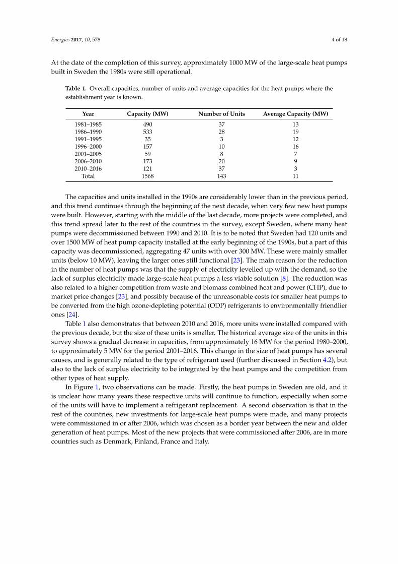
The data gathered in the Supplementary Materials contains the technical characteristics oflarge-scale electric heat pumps in DH systems in 11 countries, whilst in the rest of the countries,within the scope of this survey, such large-scale heat pumps were not identified. The survey found149 units, operating at almost 80 locations across 11 European countries, with an aggregated thermaloutput capacity of approximately 1580 MW. The establishment year of the heat pumps in the survey isknown for 143 of the total number of units and it is detailed in Table 1. The table also accounts for theunits added later on to existing heat pump plants.
Numerous heat pumps were installed mainly in Sweden in the 1980s, and this was caused, at thetime, by a temporary surplus of electricity produced by newly-built nuclear power plants. Given thelimited export capacities, the excess electricity had to be used within the country, so a legal frameworkwas created to support an increase of electricity demand, through the installation of individual andlarge-scale electric boilers and even grant the installation of individual and large-scale heat pumps [23].
Energies 2017, 10, 578 4 of 18
At the date of the completion of this survey, approximately 1000 MW of the large-scale heat pumpsbuilt in Sweden the 1980s were still operational.
Table 1. Overall capacities, number of units and average capacities for the heat pumps where theestablishment year is known.
Year Capacity (MW) Number of Units Average Capacity (MW)
1981–1985 490 37 131986–1990 533 28 191991–1995 35 3 121996–2000 157 10 162001–2005 59 8 72006–2010 173 20 92010–2016 121 37 3
Total 1568 143 11
The capacities and units installed in the 1990s are considerably lower than in the previous period,and this trend continues through the beginning of the next decade, when very few new heat pumpswere built. However, starting with the middle of the last decade, more projects were completed, andthis trend spread later to the rest of the countries in the survey, except Sweden, where many heatpumps were decommissioned between 1990 and 2010. It is to be noted that Sweden had 120 units andover 1500 MW of heat pump capacity installed at the early beginning of the 1990s, but a part of thiscapacity was decommissioned, aggregating 47 units with over 300 MW. These were mainly smallerunits (below 10 MW), leaving the larger ones still functional [23]. The main reason for the reductionin the number of heat pumps was that the supply of electricity levelled up with the demand, so thelack of surplus electricity made large-scale heat pumps a less viable solution [8]. The reduction wasalso related to a higher competition from waste and biomass combined heat and power (CHP), due tomarket price changes [23], and possibly because of the unreasonable costs for smaller heat pumps tobe converted from the high ozone-depleting potential (ODP) refrigerants to environmentally friendlierones [24].
Table 1 also demonstrates that between 2010 and 2016, more units were installed compared withthe previous decade, but the size of these units is smaller. The historical average size of the units in thissurvey shows a gradual decrease in capacities, from approximately 16 MW for the period 1980–2000,to approximately 5 MW for the period 2001–2016. This change in the size of heat pumps has severalcauses, and is generally related to the type of refrigerant used (further discussed in Section 4.2), butalso to the lack of surplus electricity to be integrated by the heat pumps and the competition fromother types of heat supply.
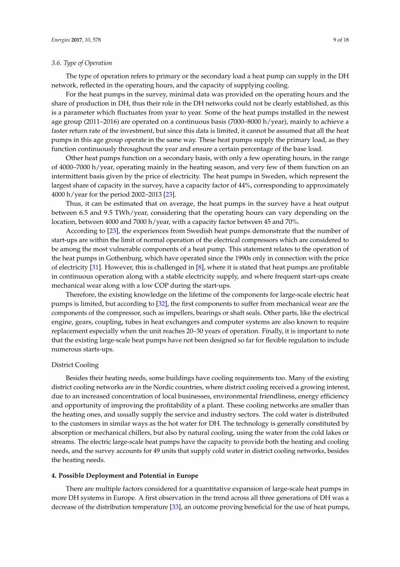
In Figure 1, two observations can be made. Firstly, the heat pumps in Sweden are old, and itis unclear how many years these respective units will continue to function, especially when someof the units will have to implement a refrigerant replacement. A second observation is that in therest of the countries, new investments for large-scale heat pumps were made, and many projectswere commissioned in or after 2006, which was chosen as a border year between the new and oldergeneration of heat pumps. Most of the new projects that were commissioned after 2006, are in morecountries such as Denmark, Finland, France and Italy.
Energies 2017, 10, 578 5 of 18Energies 2017, 10, 578 5 of 17
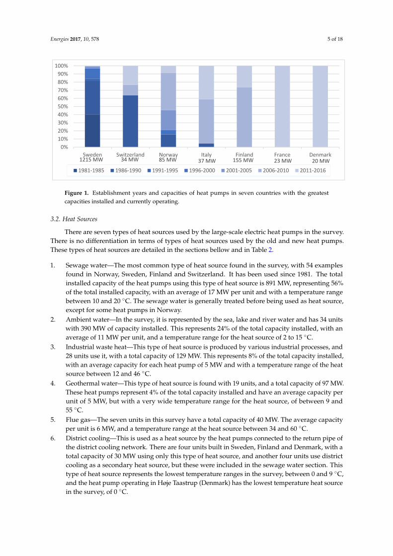
Figure 1. Establishment years and capacities of heat pumps in seven countries with the greatest capacities installed and currently operating.
3.2. Heat Sources
There are seven types of heat sources used by the large-scale electric heat pumps in the survey. There is no differentiation in terms of types of heat sources used by the old and new heat pumps. These types of heat sources are detailed in the sections bellow and in Table 2.
1. Sewage water—The most common type of heat source found in the survey, with 54 examples found in Norway, Sweden, Finland and Switzerland. It has been used since 1981. The total installed capacity of the heat pumps using this type of heat source is 891 MW, representing 56% of the total installed capacity, with an average of 17 MW per unit and with a temperature range between 10 and 20 °C. The sewage water is generally treated before being used as heat source, except for some heat pumps in Norway.
2. Ambient water—In the survey, it is represented by the sea, lake and river water and has 34 units with 390 MW of capacity installed. This represents 24% of the total capacity installed, with an average of 11 MW per unit, and a temperature range for the heat source of 2 to 15 °C.
3. Industrial waste heat—This type of heat source is produced by various industrial processes, and 28 units use it, with a total capacity of 129 MW. This represents 8% of the total capacity installed, with an average capacity for each heat pump of 5 MW and with a temperature range of the heat source between 12 and 46 °C.
4. Geothermal water—This type of heat source is found with 19 units, and a total capacity of 97 MW. These heat pumps represent 4% of the total capacity installed and have an average capacity per unit of 5 MW, but with a very wide temperature range for the heat source, of between 9 and 55 °C.
5. Flue gas—The seven units in this survey have a total capacity of 40 MW. The average capacity per unit is 6 MW, and a temperature range at the heat source between 34 and 60 °C.
6. District cooling—This is used as a heat source by the heat pumps connected to the return pipe of the district cooling network. There are four units built in Sweden, Finland and Denmark, with a total capacity of 30 MW using only this type of heat source, and another four units use district cooling as a secondary heat source, but these were included in the sewage water section. This type of heat source represents the lowest temperature ranges in the survey, between 0 and 9 °C, and the heat pump operating in Høje Taastrup (Denmark) has the lowest temperature heat source in the survey, of 0 °C.
7. Solar heat storage—All the heat pumps using this type of solar heat source are located in Denmark. These are three units and all have a capacity of 4 MW, with an average capacity between 1 and 1.5 MW. The temperature ranges for the heat sources are between 10 and 35 °C.
1215 MW 34 MW 85 MW 37 MW 155 MW 23 MW 20 MW
0%10%20%30%40%50%60%70%80%90%
100%
Sweden Switzerland Norway Italy Finland France Denmark
1981-1985 1986-1990 1991-1995 1996-2000 2001-2005 2006-2010 2011-2016
Figure 1. Establishment years and capacities of heat pumps in seven countries with the greatestcapacities installed and currently operating.
3.2. Heat Sources
There are seven types of heat sources used by the large-scale electric heat pumps in the survey.There is no differentiation in terms of types of heat sources used by the old and new heat pumps.These types of heat sources are detailed in the sections bellow and in Table 2.
1. Sewage water—The most common type of heat source found in the survey, with 54 examplesfound in Norway, Sweden, Finland and Switzerland. It has been used since 1981. The totalinstalled capacity of the heat pumps using this type of heat source is 891 MW, representing 56%of the total installed capacity, with an average of 17 MW per unit and with a temperature rangebetween 10 and 20 ◦C. The sewage water is generally treated before being used as heat source,except for some heat pumps in Norway.
2. Ambient water—In the survey, it is represented by the sea, lake and river water and has 34 unitswith 390 MW of capacity installed. This represents 24% of the total capacity installed, with anaverage of 11 MW per unit, and a temperature range for the heat source of 2 to 15 ◦C.
3. Industrial waste heat—This type of heat source is produced by various industrial processes, and28 units use it, with a total capacity of 129 MW. This represents 8% of the total capacity installed,with an average capacity for each heat pump of 5 MW and with a temperature range of the heatsource between 12 and 46 ◦C.
4. Geothermal water—This type of heat source is found with 19 units, and a total capacity of 97 MW.These heat pumps represent 4% of the total capacity installed and have an average capacity perunit of 5 MW, but with a very wide temperature range for the heat source, of between 9 and55 ◦C.
5. Flue gas—The seven units in this survey have a total capacity of 40 MW. The average capacityper unit is 6 MW, and a temperature range at the heat source between 34 and 60 ◦C.
6. District cooling—This is used as a heat source by the heat pumps connected to the return pipe ofthe district cooling network. There are four units built in Sweden, Finland and Denmark, with atotal capacity of 30 MW using only this type of heat source, and another four units use districtcooling as a secondary heat source, but these were included in the sewage water section. Thistype of heat source represents the lowest temperature ranges in the survey, between 0 and 9 ◦C,and the heat pump operating in Høje Taastrup (Denmark) has the lowest temperature heat sourcein the survey, of 0 ◦C.
Energies 2017, 10, 578 6 of 18
7. Solar heat storage—All the heat pumps using this type of solar heat source are located in Denmark.These are three units and all have a capacity of 4 MW, with an average capacity between 1 and1.5 MW. The temperature ranges for the heat sources are between 10 and 35 ◦C.
Table 2. Heat sources for the heat pumps in the survey and some of their most important features.
Type of Heat Source Capacity(MW)
Percentage ofTotal Capacity
Number ofUnits
Average CapacityPer Unit (MW)
TemperatureRange (◦C)
Sewage water 891 56% 54 17 10–20Ambient water 390 24% 34 11 2–15
Industrial waste heat 129 8% 28 5 12–46Geothermal heat 97 4% 19 5 9–55
Flue gas 40 2% 7 6 34–60District cooling 30 <2% 4 7 0–9
Solar heat storage 4 <1% 3 1 10–35Total 1580 149 0–60
3.3. Refrigerants
Information about the refrigerants is available for 140 units out of the total 149, and these areseparated in two categories: natural and synthetic refrigerants. The natural refrigerants are NH3
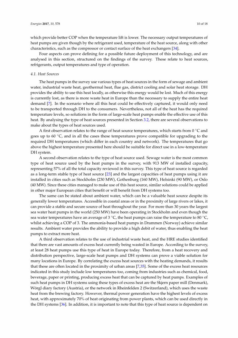
(ammonia) and CO2, whilst the synthetic refrigerants are hydrofluorocarbons (HFCs) further explainedbelow. By building on the findings for the establishment years of the heat pumps (Table 1), Figure 2uses the year 2006 as a border year between the new and older generations of heat pumps, to definethe trends in refrigerant use.
Energies 2017, 10, 578 6 of 17
Table 2. Heat sources for the heat pumps in the survey and some of their most important features.
Type of Heat Source Capacity (MW)
Percentage of Total Capacity
Number of Units
Average Capacity Per Unit (MW)
Temperature Range (°C)
Sewage water 891 56% 54 17 10–20 Ambient water 390 24% 34 11 2–15
Industrial waste heat 129 8% 28 5 12–46 Geothermal heat 97 4% 19 5 9–55
Flue gas 40 2% 7 6 34–60 District cooling 30 <2% 4 7 0–9
Solar heat storage 4 <1% 3 1 10–35 Total 1580 149 0–60
3.3. Refrigerants
Information about the refrigerants is available for 140 units out of the total 149, and these are separated in two categories: natural and synthetic refrigerants. The natural refrigerants are NH3 (ammonia) and CO2, whilst the synthetic refrigerants are hydrofluorocarbons (HFCs) further explained below. By building on the findings for the establishment years of the heat pumps (Table 1), Figure 2 uses the year 2006 as a border year between the new and older generations of heat pumps, to define the trends in refrigerant use.
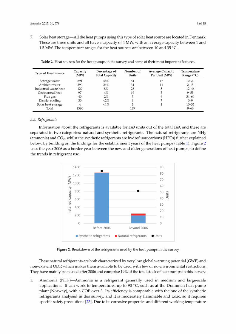
Figure 2. Breakdown of the refrigerants used by the heat pumps in the survey.
These natural refrigerants are both characterized by very low global warming potential (GWP) and non-existent ODP, which makes them available to be used with few or no environmental restrictions. They have mainly been used after 2006 and comprise 19% of the total stock of heat pumps in this survey:
1. Ammonia (NH3)—Ammonia is a refrigerant generally used in medium and large-scale applications. It can work to temperatures up to 90 °C, such as at the Drammen heat pump plant (Norway), with a COP over 3. Its efficiency is comparable with the one of the synthetic refrigerants analysed in this survey, and it is moderately flammable and toxic, so it requires specific safety precautions [25]. Due to its corrosive properties and different working temperature and pressure, ammonia cannot be used to retrofit the heat pumps using synthetic refrigerants, such as R-22 and R-134a. The heat pumps using NH3 account for 26 units with a total heating capacity of 51 MW, with the oldest units in the survey operating in Laussane (Switzerland) since 1986.
2. Carbon dioxide (CO2)—Carbon dioxide is a non-toxic, non-flammable and non-corrosive refrigerant, which is generally obtained as a waste product, making it as one of the low-cost
0
10
20
30
40
50
60
70
80
90
0
200
400
600
800
1000
1200
1400
Before 2006 Beyond 2006
Uni
ts
Inst
alle
d ca
paci
ty (M
W)
Synthetic refrigerants Natural refrigerants Units
Figure 2. Breakdown of the refrigerants used by the heat pumps in the survey.
These natural refrigerants are both characterized by very low global warming potential (GWP) andnon-existent ODP, which makes them available to be used with few or no environmental restrictions.They have mainly been used after 2006 and comprise 19% of the total stock of heat pumps in this survey:
1. Ammonia (NH3)—Ammonia is a refrigerant generally used in medium and large-scaleapplications. It can work to temperatures up to 90 ◦C, such as at the Drammen heat pumpplant (Norway), with a COP over 3. Its efficiency is comparable with the one of the syntheticrefrigerants analysed in this survey, and it is moderately flammable and toxic, so it requiresspecific safety precautions [25]. Due to its corrosive properties and different working temperature
Energies 2017, 10, 578 7 of 18
and pressure, ammonia cannot be used to retrofit the heat pumps using synthetic refrigerants,such as R-22 and R-134a. The heat pumps using NH3 account for 26 units with a total heatingcapacity of 51 MW, with the oldest units in the survey operating in Laussane (Switzerland)since 1986.
2. Carbon dioxide (CO2)—Carbon dioxide is a non-toxic, non-flammable and non-corrosiverefrigerant, which is generally obtained as a waste product, making it as one of the low-costrefrigerants [25]. It is also a transcritical fluid, meaning that temperature and pressure can becontrolled individually, unlike other condensing (subcritical) refrigerants. It’s heating COP is25–150% better than R-134a, and is suitable for high temperature lifts, as the lower the temperaturein the inlet is, the better overall efficiency it has [26]. A drawback of this refrigerant is the highpressures it must work under, making it less suitable for large-scale applications (larger than1–2 MW). There is only one example of a large-scale heat pump using CO2 refrigerant in thesurvey, in the Marstal DH network in Denmark, with a heating capacity of 1.5 MW.
On the other hand, the synthetic refrigerants dominate the survey, and R-134a, present in morethan 90% of the installed capacity, is the most common type of refrigerant used by the large-scale heatpumps in the survey. Another three units use R-152a and R-245fa. All these synthetic refrigerants wereincluded on the list of controlled substances to be phased down through the Montreal Protocol by2040 [27], and are further discussed in Section 4.2. The following section explains some of the maincharacteristics of these refrigerants:
1. R-134a—It is the most used HFC in the survey, and serves as refrigerant for 110 heat pumps in thesurvey, with a capacity over 1450 MW. It has zero ODP as it does not contain the chlorine atom,and good heat transfer properties by providing a wide temperature gap. It is also non-flammable,non-toxic and it was regarded as the most suitable option for retrofitting old heat pumps usingR-12 and R-22 [28]. The refrigerant has a GWP potential of 1300, which has caused it to beprohibited already in countries such as Denmark and Switzerland.
2. R-152a—It is a HFC which has a GWP of 124 and similar thermodynamic properties as R134a,even yielding a higher COP. Generally, this refrigerant is used in blends with other refrigerantsdue to its very high flammability, and in the survey two heat pumps use it [29].
3. R-245fa—A HFC, generally used in high temperature applications. It has a GWP of 950 and amoderate toxicity with a critical temperature of approximately 150 ◦C, but it works at a pressuresimilar to R134a [30]. In the survey, it is found in one example.
3.4. Coefficient of Performance
The COP represents the efficiency of a heat pump, and is given by the ratio between the thermaloutput and electricity input. For the heat pumps in the survey, the COP has a value between 3 and 4and this represents the average practical COP, generally achieved throughout one year and not as aseasonal mean value over an operational phase. Also, the COP values presented in this survey do notinclude the electricity used by the auxiliary pumps (to pump the heat source).
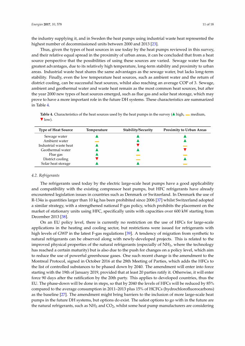
Two heat pumps in Sweden, which increase the return temperature of water in the DH system byseveral degrees and use the R-134a refrigerant, achieved the highest COP in the survey, at 6.5. A heatpump in Denmark uses NH3 refrigerant and boosts the temperature from the inlet of the heat pump byapproximately 30 ◦C, achieving the other high COP of 6.3. Two geothermal heat pumps in Milano givethe lowest COP of 2.65, with a temperature difference between the inlet and outlet of the heat pump of75 ◦C. An overview of the COP for the heat pumps in the survey is available in Figure 3, overlaid withthe operating temperatures and establishment years. As a general rule, the smaller the temperatureincrease is, the higher the COP.
Energies 2017, 10, 578 8 of 18Energies 2017, 10, 578 8 of 17
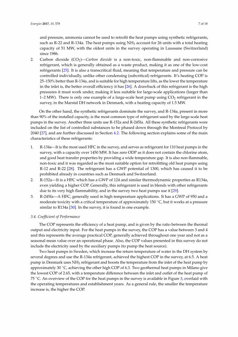
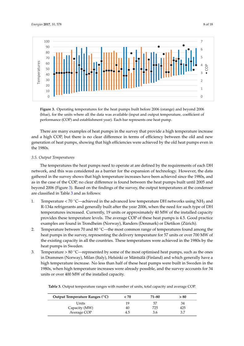
Figure 3. Operating temperatures for the heat pumps built before 2006 (orange) and beyond 2006 (blue), for the units where all the data was available (input and output temperature, coefficient of performance (COP) and establishment year). Each bar represents one heat pump.
3.5. Output Temperatures
The temperatures the heat pumps need to operate at are defined by the requirements of each DH network, and this was considered as a barrier for the expansion of technology. However, the data gathered in the survey shows that high temperature increases have been achieved since the 1980s, and as in the case of the COP, no clear difference is found between the heat pumps built until 2005 and beyond 2006 (Figure 3). Based on the findings of the survey, the output temperatures at the condenser are classified in Table 3 and as follows:
1. Temperature < 70 °C—achieved in the advanced low temperature DH networks using NH3 and R-134a refrigerants and generally built after the year 2006, when the need for such type of DH temperatures increased. Currently, 19 units or approximately 40 MW of the installed capacity provides these temperature levels. The average COP of these heat pumps is 4.5. Good practice examples are found in Trondheim (Norway), Randers (Denmark) or Dietikon (Zürich).
2. Temperature between 70 and 80 °C—the most common range of temperatures found among the heat pumps in the survey, representing the delivery temperature for 57 units or over 700 MW of the existing capacity in all the countries. These temperatures were achieved in the 1980s by the heat pumps in Sweden.
3. Temperature > 80 °C—represented by some of the most optimised heat pumps, such as the ones in Drammen (Norway), Milan (Italy), Helsinki or Mäntsälä (Finland) and which generally have a high temperature increase. No less than half of these heat pumps were built in Sweden in the 1980s, when high temperature increases were already possible, and the survey accounts for 34 units or over 400 MW of the installed capacity.
Table 3. Output temperature ranges with number of units, total capacity and average COP.
Output Temperature Ranges (°C) < 70 71–80 > 80Units 19 57 34
Capacity (MW) 40 725 425 Average COP 4.5 3.6 3.7
3.6. Type of Operation
The type of operation refers to primary or the secondary load a heat pump can supply in the DH network, reflected in the operating hours, and the capacity of supplying cooling.
For the heat pumps in the survey, minimal data was provided on the operating hours and the share of production in DH, thus their role in the DH networks could not be clearly established, as this is a parameter which fluctuates from year to year. Some of the heat pumps installed in the newest
0
1
2
3
4
5
6
7
0102030405060708090
100
•CO
P
Tem
pera
ture
s
Figure 3. Operating temperatures for the heat pumps built before 2006 (orange) and beyond 2006(blue), for the units where all the data was available (input and output temperature, coefficient ofperformance (COP) and establishment year). Each bar represents one heat pump.
There are many examples of heat pumps in the survey that provide a high temperature increaseand a high COP, but there is no clear difference in terms of efficiency between the old and newgeneration of heat pumps, showing that high efficiencies were achieved by the old heat pumps even inthe 1980s.
3.5. Output Temperatures
The temperatures the heat pumps need to operate at are defined by the requirements of each DHnetwork, and this was considered as a barrier for the expansion of technology. However, the datagathered in the survey shows that high temperature increases have been achieved since the 1980s, andas in the case of the COP, no clear difference is found between the heat pumps built until 2005 andbeyond 2006 (Figure 3). Based on the findings of the survey, the output temperatures at the condenserare classified in Table 3 and as follows:
1. Temperature < 70 ◦C—achieved in the advanced low temperature DH networks using NH3 andR-134a refrigerants and generally built after the year 2006, when the need for such type of DHtemperatures increased. Currently, 19 units or approximately 40 MW of the installed capacityprovides these temperature levels. The average COP of these heat pumps is 4.5. Good practiceexamples are found in Trondheim (Norway), Randers (Denmark) or Dietikon (Zürich).
2. Temperature between 70 and 80 ◦C—the most common range of temperatures found among theheat pumps in the survey, representing the delivery temperature for 57 units or over 700 MW ofthe existing capacity in all the countries. These temperatures were achieved in the 1980s by theheat pumps in Sweden.
3. Temperature > 80 ◦C—represented by some of the most optimised heat pumps, such as the onesin Drammen (Norway), Milan (Italy), Helsinki or Mäntsälä (Finland) and which generally have ahigh temperature increase. No less than half of these heat pumps were built in Sweden in the1980s, when high temperature increases were already possible, and the survey accounts for 34units or over 400 MW of the installed capacity.
Table 3. Output temperature ranges with number of units, total capacity and average COP.
Output Temperature Ranges (◦C) < 70 71–80 > 80
Units 19 57 34Capacity (MW) 40 725 425Average COP 4.5 3.6 3.7
Energies 2017, 10, 578 9 of 18
3.6. Type of Operation
The type of operation refers to primary or the secondary load a heat pump can supply in the DHnetwork, reflected in the operating hours, and the capacity of supplying cooling.
For the heat pumps in the survey, minimal data was provided on the operating hours and theshare of production in DH, thus their role in the DH networks could not be clearly established, as thisis a parameter which fluctuates from year to year. Some of the heat pumps installed in the newestage group (2011–2016) are operated on a continuous basis (7000–8000 h/year), mainly to achieve afaster return rate of the investment, but since this data is limited, it cannot be assumed that all the heatpumps in this age group operate in the same way. These heat pumps supply the primary load, as theyfunction continuously throughout the year and ensure a certain percentage of the base load.
Other heat pumps function on a secondary basis, with only a few operating hours, in the rangeof 4000–7000 h/year, operating mainly in the heating season, and very few of them function on anintermittent basis given by the price of electricity. The heat pumps in Sweden, which represent thelargest share of capacity in the survey, have a capacity factor of 44%, corresponding to approximately4000 h/year for the period 2002–2013 [23].
Thus, it can be estimated that on average, the heat pumps in the survey have a heat outputbetween 6.5 and 9.5 TWh/year, considering that the operating hours can vary depending on thelocation, between 4000 and 7000 h/year, with a capacity factor between 45 and 70%.
According to [23], the experiences from Swedish heat pumps demonstrate that the number ofstart-ups are within the limit of normal operation of the electrical compressors which are considered tobe among the most vulnerable components of a heat pump. This statement relates to the operation ofthe heat pumps in Gothenburg, which have operated since the 1990s only in connection with the priceof electricity [31]. However, this is challenged in [8], where it is stated that heat pumps are profitablein continuous operation along with a stable electricity supply, and where frequent start-ups createmechanical wear along with a low COP during the start-ups.
Therefore, the existing knowledge on the lifetime of the components for large-scale electric heatpumps is limited, but according to [32], the first components to suffer from mechanical wear are thecomponents of the compressor, such as impellers, bearings or shaft seals. Other parts, like the electricalengine, gears, coupling, tubes in heat exchangers and computer systems are also known to requirereplacement especially when the unit reaches 20–30 years of operation. Finally, it is important to notethat the existing large-scale heat pumps have not been designed so far for flexible regulation to includenumerous starts-ups.
District Cooling
Besides their heating needs, some buildings have cooling requirements too. Many of the existingdistrict cooling networks are in the Nordic countries, where district cooling received a growing interest,due to an increased concentration of local businesses, environmental friendliness, energy efficiencyand opportunity of improving the profitability of a plant. These cooling networks are smaller thanthe heating ones, and usually supply the service and industry sectors. The cold water is distributedto the customers in similar ways as the hot water for DH. The technology is generally constituted byabsorption or mechanical chillers, but also by natural cooling, using the water from the cold lakes orstreams. The electric large-scale heat pumps have the capacity to provide both the heating and coolingneeds, and the survey accounts for 49 units that supply cold water in district cooling networks, besidesthe heating needs.
4. Possible Deployment and Potential in Europe
There are multiple factors considered for a quantitative expansion of large-scale heat pumps inmore DH systems in Europe. A first observation in the trend across all three generations of DH was adecrease of the distribution temperature [33], an outcome proving beneficial for the use of heat pumps,
Energies 2017, 10, 578 10 of 18
which provide better COP when the temperature lift is lower. The necessary output temperatures ofheat pumps are given though by the refrigerant used, temperature of the heat source, along with othercharacteristics, such as the compressor or contact surface of the heat exchangers [34].
Four aspects can prove defining for a possible future deployment of this technology, and areanalysed in this section, structured on the findings of the survey. These relate to heat sources,refrigerants, output temperatures and type of operation.
4.1. Heat Sources
The heat pumps in the survey use various types of heat sources in the form of sewage and ambientwater, industrial waste heat, geothermal heat, flue gas, district cooling and solar heat storage. DHprovides the ability to use this heat locally, as otherwise this energy would be lost. Much of this energyis currently lost, as there is more waste heat in Europe than the necessary to supply the entire heatdemand [7]. In the scenario where all this heat could be effectively captured, it would only needto be transported through DH to the consumers. Nevertheless, not all of the heat has the requiredtemperature levels, so solutions in the form of large-scale heat pumps enable the effective use of thisheat. By analysing the type of heat sources presented in Section 3.2, there are several observations tomake about the types of heat sources used.
A first observation relates to the range of heat source temperatures, which starts from 0 ◦C andgoes up to 60 ◦C, and in all the cases these temperatures prove compatible for upgrading to therequired DH temperatures (which differ in each country and network). The temperatures that goabove the highest temperature presented here should be suitable for direct use in a low-temperatureDH system.
A second observation relates to the type of heat source used. Sewage water is the most commontype of heat source used by the heat pumps in the survey, with 913 MW of installed capacity,representing 57% of all the total capacity reviewed in this survey. This type of heat source is regardedas a long-term stable type of heat source [23] and the largest capacities of heat pumps using it areinstalled in cities such as Stockholm (230 MW), Gothenburg (160 MW), Helsinki (90 MW), or Oslo(40 MW). Since these cities managed to make use of this heat source, similar solutions could be appliedin other major European cities that benefit or will benefit from DH systems too.
The same can be stated about ambient water, which can be a valuable heat source despite itsgenerally lower temperatures. Accessible in coastal areas or in the proximity of large rivers or lakes, itcan provide a stable and secure source of heat throughout the year. For more than 30 years the largestsea water heat pumps in the world (250 MW) have been operating in Stockholm and even though thesea water temperatures have an average of 3 ◦C, the heat pumps can raise the temperature to 80 ◦C,whilst achieving a COP of 3. The ammonia-based heat pumps in Drammen (Norway) achieve similarresults. Ambient water provides the ability to provide a high debit of water, thus enabling the heatpumps to extract more heat.
A third observation relates to the use of industrial waste heat, and the HRE studies identifiedthat there are vast amounts of excess heat currently being wasted in Europe. According to the survey,at least 28 heat pumps use this type of heat in Europe today. Therefore, from a heat recovery anddistribution perspective, large-scale heat pumps and DH systems can prove a viable solution formany locations in Europe. By correlating the excess heat sources with the heating demands, it resultsthat these are often located in the proximity of urban areas [7,35]. Some of the excess heat resourcesindicated in this study include low temperatures too, coming from industries such as chemical, food,beverage, paper or printing, producing excess heat that can be captured by heat pumps. Examples ofsuch heat pumps in DH systems using these types of excess heat are the Skjern paper mill (Denmark),Wörgl diary factory (Austria), or the network in Rheinfelden 2 (Switzerland), which uses the wasteheat from the brewing factory. However, thermal power generation have the highest levels of excessheat, with approximately 70% of heat originating from power plants, which can be used directly inthe DH systems [36]. In addition, it is important to note that this type of heat source is dependent on
Energies 2017, 10, 578 11 of 18
the industry supplying it, and in Sweden the heat pumps using industrial waste heat represented thehighest number of decommissioned units between 2000 and 2013 [23].
Thus, given the types of heat sources in use today by the heat pumps reviewed in this survey,and their relative equal spread in the proximity of urban areas, it can be concluded that from a heatsource perspective that the possibilities of using these sources are varied. Sewage water has thegreatest advantages, due to its relatively high temperature, long-term stability and proximity to urbanareas. Industrial waste heat shares the same advantages as the sewage water, but lacks long-termstability. Finally, even the low temperature heat sources, such as ambient water and the return ofdistrict cooling, can be successful heat sources, whilst also reaching an average COP of 3. Sewage,ambient and geothermal water and waste heat remain as the most common heat sources, but afterthe year 2000 new types of heat sources emerged, such as flue gas and solar heat storage, which mayprove to have a more important role in the future DH systems. These characteristics are summarizedin Table 4.
Table 4. Characteristics of the heat sources used by the heat pumps in the survey (
Energies 2017, 10, 578 11 of 17
ambient and geothermal water and waste heat remain as the most common heat sources, but after the year 2000 new types of heat sources emerged, such as flue gas and solar heat storage, which may prove to have a more important role in the future DH systems. These characteristics are summarized in Table 4.
Table 4. Characteristics of the heat sources used by the heat pumps in the survey (▲ high, ▬ medium, ▼ low).
Type of Heat Source Temperature Stability/Security Proximity to Urban Areas Sewage water ▲ ▲ ▲
Ambient water ▬ ▲ ▲ Industrial waste heat ▲ ▼ ▬
Geothermal water ▲ ▲ ▼ Flue gas ▲ ▬ ▬
District cooling ▼ ▬ ▲ Solar heat storage ▲ ▲ ▬
4.2. Refrigerants
The refrigerants used today by the electric large-scale heat pumps have a good applicability and compatibility with the existing compressor heat pumps, but HFC refrigerants have already encountered legislation issues in countries such as Denmark or Switzerland. In Denmark the use of R-134a is quantities larger than 10 kg has been prohibited since 2006 [37] whilst Switzerland adopted a similar strategy, with a strengthened national F-gas policy, which prohibits the placement on the market of stationary units using HFC, specifically units with capacities over 600 kW starting from December 2013 [38].
On an EU policy level, there is currently no restriction on the use of HFCs for large-scale applications in the heating and cooling sector, but restrictions were issued for refrigerants with high levels of GWP in the latest F-gas regulations [39]. A tendency of migration from synthetic to natural refrigerants can be observed along with newly-developed projects. This is related to the improved physical properties of the natural refrigerants (especially of NH3, where the technology has reached a certain maturity) but is also due to the push for changes on a policy level, which aim to reduce the use of powerful greenhouse gases. One such recent change is the amendment to the Montreal Protocol, signed in October 2016 at the 28th Meeting of Parties, which adds the HFCs to the list of controlled substances to be phased down by 2040. The amendment will enter into force starting with the 19th of January 2019, provided that at least 20 parties ratify it. Otherwise, it will enter force 90 days after the ratification by the 20th party. This applies to developed countries, thus the EU. The phase-down will be done in steps, so that by 2040 the levels of HFCs will be reduced by 85% compared to the average consumption in 2011–2013 plus 15% of HCFCs (hydrochlorofluorocarbons) as the baseline [27]. The amendment might bring barriers to the inclusion of more large-scale heat pumps in the future DH systems, but options do exist. The safest options to go with in the future are the natural refrigerants, such as NH3 and CO2, whilst some heat pump manufacturers are considering the use of a new family of refrigerants, namely hydrofluoroolefins (HFOs). Each of these refrigerants has its advantages and disadvantages.
The new generations of heat pumps using NH3 have reached a certain level of technological maturity and can achieve similar performances or outrun the heat pumps using HFCs. A possible drawback is the capacity such heat pumps can achieve, which is currently not more than 6 MW thermal output per unit, but this can always be overcome by connecting multiple modules together if the space for them exists. Another possibly viable refrigerant for the future is CO2, which can provide high performances, but the high pressures this refrigerant needs to work at establish the main barrier in the development of larger capacities for this type of heat pump. This mainly affects the bigger parts of the assemblies and the internal piping. The larger the subassembly, the higher the pressure, and more compressors are necessary to achieve 1 MW thermal output than for an equivalent NH3 heat pump. Overall, the development of this technology in relation to DH could prove beneficial,
high,
Energies 2017, 10, 578 11 of 17
ambient and geothermal water and waste heat remain as the most common heat sources, but after the year 2000 new types of heat sources emerged, such as flue gas and solar heat storage, which may prove to have a more important role in the future DH systems. These characteristics are summarized in Table 4.
Table 4. Characteristics of the heat sources used by the heat pumps in the survey (▲ high, ▬ medium, ▼ low).
Type of Heat Source Temperature Stability/Security Proximity to Urban Areas Sewage water ▲ ▲ ▲
Ambient water ▬ ▲ ▲ Industrial waste heat ▲ ▼ ▬
Geothermal water ▲ ▲ ▼ Flue gas ▲ ▬ ▬
District cooling ▼ ▬ ▲ Solar heat storage ▲ ▲ ▬
4.2. Refrigerants
The refrigerants used today by the electric large-scale heat pumps have a good applicability and compatibility with the existing compressor heat pumps, but HFC refrigerants have already encountered legislation issues in countries such as Denmark or Switzerland. In Denmark the use of R-134a is quantities larger than 10 kg has been prohibited since 2006 [37] whilst Switzerland adopted a similar strategy, with a strengthened national F-gas policy, which prohibits the placement on the market of stationary units using HFC, specifically units with capacities over 600 kW starting from December 2013 [38].
On an EU policy level, there is currently no restriction on the use of HFCs for large-scale applications in the heating and cooling sector, but restrictions were issued for refrigerants with high levels of GWP in the latest F-gas regulations [39]. A tendency of migration from synthetic to natural refrigerants can be observed along with newly-developed projects. This is related to the improved physical properties of the natural refrigerants (especially of NH3, where the technology has reached a certain maturity) but is also due to the push for changes on a policy level, which aim to reduce the use of powerful greenhouse gases. One such recent change is the amendment to the Montreal Protocol, signed in October 2016 at the 28th Meeting of Parties, which adds the HFCs to the list of controlled substances to be phased down by 2040. The amendment will enter into force starting with the 19th of January 2019, provided that at least 20 parties ratify it. Otherwise, it will enter force 90 days after the ratification by the 20th party. This applies to developed countries, thus the EU. The phase-down will be done in steps, so that by 2040 the levels of HFCs will be reduced by 85% compared to the average consumption in 2011–2013 plus 15% of HCFCs (hydrochlorofluorocarbons) as the baseline [27]. The amendment might bring barriers to the inclusion of more large-scale heat pumps in the future DH systems, but options do exist. The safest options to go with in the future are the natural refrigerants, such as NH3 and CO2, whilst some heat pump manufacturers are considering the use of a new family of refrigerants, namely hydrofluoroolefins (HFOs). Each of these refrigerants has its advantages and disadvantages.
The new generations of heat pumps using NH3 have reached a certain level of technological maturity and can achieve similar performances or outrun the heat pumps using HFCs. A possible drawback is the capacity such heat pumps can achieve, which is currently not more than 6 MW thermal output per unit, but this can always be overcome by connecting multiple modules together if the space for them exists. Another possibly viable refrigerant for the future is CO2, which can provide high performances, but the high pressures this refrigerant needs to work at establish the main barrier in the development of larger capacities for this type of heat pump. This mainly affects the bigger parts of the assemblies and the internal piping. The larger the subassembly, the higher the pressure, and more compressors are necessary to achieve 1 MW thermal output than for an equivalent NH3 heat pump. Overall, the development of this technology in relation to DH could prove beneficial,
medium,
Energies 2017, 10, 578 11 of 17
ambient and geothermal water and waste heat remain as the most common heat sources, but after the year 2000 new types of heat sources emerged, such as flue gas and solar heat storage, which may prove to have a more important role in the future DH systems. These characteristics are summarized in Table 4.
Table 4. Characteristics of the heat sources used by the heat pumps in the survey (▲ high, ▬ medium, ▼ low).
Type of Heat Source Temperature Stability/Security Proximity to Urban Areas Sewage water ▲ ▲ ▲
Ambient water ▬ ▲ ▲ Industrial waste heat ▲ ▼ ▬
Geothermal water ▲ ▲ ▼ Flue gas ▲ ▬ ▬
District cooling ▼ ▬ ▲ Solar heat storage ▲ ▲ ▬
4.2. Refrigerants
The refrigerants used today by the electric large-scale heat pumps have a good applicability and compatibility with the existing compressor heat pumps, but HFC refrigerants have already encountered legislation issues in countries such as Denmark or Switzerland. In Denmark the use of R-134a is quantities larger than 10 kg has been prohibited since 2006 [37] whilst Switzerland adopted a similar strategy, with a strengthened national F-gas policy, which prohibits the placement on the market of stationary units using HFC, specifically units with capacities over 600 kW starting from December 2013 [38].
On an EU policy level, there is currently no restriction on the use of HFCs for large-scale applications in the heating and cooling sector, but restrictions were issued for refrigerants with high levels of GWP in the latest F-gas regulations [39]. A tendency of migration from synthetic to natural refrigerants can be observed along with newly-developed projects. This is related to the improved physical properties of the natural refrigerants (especially of NH3, where the technology has reached a certain maturity) but is also due to the push for changes on a policy level, which aim to reduce the use of powerful greenhouse gases. One such recent change is the amendment to the Montreal Protocol, signed in October 2016 at the 28th Meeting of Parties, which adds the HFCs to the list of controlled substances to be phased down by 2040. The amendment will enter into force starting with the 19th of January 2019, provided that at least 20 parties ratify it. Otherwise, it will enter force 90 days after the ratification by the 20th party. This applies to developed countries, thus the EU. The phase-down will be done in steps, so that by 2040 the levels of HFCs will be reduced by 85% compared to the average consumption in 2011–2013 plus 15% of HCFCs (hydrochlorofluorocarbons) as the baseline [27]. The amendment might bring barriers to the inclusion of more large-scale heat pumps in the future DH systems, but options do exist. The safest options to go with in the future are the natural refrigerants, such as NH3 and CO2, whilst some heat pump manufacturers are considering the use of a new family of refrigerants, namely hydrofluoroolefins (HFOs). Each of these refrigerants has its advantages and disadvantages.
The new generations of heat pumps using NH3 have reached a certain level of technological maturity and can achieve similar performances or outrun the heat pumps using HFCs. A possible drawback is the capacity such heat pumps can achieve, which is currently not more than 6 MW thermal output per unit, but this can always be overcome by connecting multiple modules together if the space for them exists. Another possibly viable refrigerant for the future is CO2, which can provide high performances, but the high pressures this refrigerant needs to work at establish the main barrier in the development of larger capacities for this type of heat pump. This mainly affects the bigger parts of the assemblies and the internal piping. The larger the subassembly, the higher the pressure, and more compressors are necessary to achieve 1 MW thermal output than for an equivalent NH3 heat pump. Overall, the development of this technology in relation to DH could prove beneficial,
low).
Type of Heat Source Temperature Stability/Security Proximity to Urban Areas
Sewage water
Energies 2017, 10, 578 11 of 17
ambient and geothermal water and waste heat remain as the most common heat sources, but after the year 2000 new types of heat sources emerged, such as flue gas and solar heat storage, which may prove to have a more important role in the future DH systems. These characteristics are summarized in Table 4.
Table 4. Characteristics of the heat sources used by the heat pumps in the survey (▲ high, ▬ medium, ▼ low).
Type of Heat Source Temperature Stability/Security Proximity to Urban Areas Sewage water ▲ ▲ ▲
Ambient water ▬ ▲ ▲ Industrial waste heat ▲ ▼ ▬
Geothermal water ▲ ▲ ▼ Flue gas ▲ ▬ ▬
District cooling ▼ ▬ ▲ Solar heat storage ▲ ▲ ▬
4.2. Refrigerants
The refrigerants used today by the electric large-scale heat pumps have a good applicability and compatibility with the existing compressor heat pumps, but HFC refrigerants have already encountered legislation issues in countries such as Denmark or Switzerland. In Denmark the use of R-134a is quantities larger than 10 kg has been prohibited since 2006 [37] whilst Switzerland adopted a similar strategy, with a strengthened national F-gas policy, which prohibits the placement on the market of stationary units using HFC, specifically units with capacities over 600 kW starting from December 2013 [38].
On an EU policy level, there is currently no restriction on the use of HFCs for large-scale applications in the heating and cooling sector, but restrictions were issued for refrigerants with high levels of GWP in the latest F-gas regulations [39]. A tendency of migration from synthetic to natural refrigerants can be observed along with newly-developed projects. This is related to the improved physical properties of the natural refrigerants (especially of NH3, where the technology has reached a certain maturity) but is also due to the push for changes on a policy level, which aim to reduce the use of powerful greenhouse gases. One such recent change is the amendment to the Montreal Protocol, signed in October 2016 at the 28th Meeting of Parties, which adds the HFCs to the list of controlled substances to be phased down by 2040. The amendment will enter into force starting with the 19th of January 2019, provided that at least 20 parties ratify it. Otherwise, it will enter force 90 days after the ratification by the 20th party. This applies to developed countries, thus the EU. The phase-down will be done in steps, so that by 2040 the levels of HFCs will be reduced by 85% compared to the average consumption in 2011–2013 plus 15% of HCFCs (hydrochlorofluorocarbons) as the baseline [27]. The amendment might bring barriers to the inclusion of more large-scale heat pumps in the future DH systems, but options do exist. The safest options to go with in the future are the natural refrigerants, such as NH3 and CO2, whilst some heat pump manufacturers are considering the use of a new family of refrigerants, namely hydrofluoroolefins (HFOs). Each of these refrigerants has its advantages and disadvantages.
The new generations of heat pumps using NH3 have reached a certain level of technological maturity and can achieve similar performances or outrun the heat pumps using HFCs. A possible drawback is the capacity such heat pumps can achieve, which is currently not more than 6 MW thermal output per unit, but this can always be overcome by connecting multiple modules together if the space for them exists. Another possibly viable refrigerant for the future is CO2, which can provide high performances, but the high pressures this refrigerant needs to work at establish the main barrier in the development of larger capacities for this type of heat pump. This mainly affects the bigger parts of the assemblies and the internal piping. The larger the subassembly, the higher the pressure, and more compressors are necessary to achieve 1 MW thermal output than for an equivalent NH3 heat pump. Overall, the development of this technology in relation to DH could prove beneficial,
Ambient water
Energies 2017, 10, 578 11 of 17
ambient and geothermal water and waste heat remain as the most common heat sources, but after the year 2000 new types of heat sources emerged, such as flue gas and solar heat storage, which may prove to have a more important role in the future DH systems. These characteristics are summarized in Table 4.
Table 4. Characteristics of the heat sources used by the heat pumps in the survey (▲ high, ▬ medium, ▼ low).
Type of Heat Source Temperature Stability/Security Proximity to Urban Areas Sewage water ▲ ▲ ▲
Ambient water ▬ ▲ ▲ Industrial waste heat ▲ ▼ ▬
Geothermal water ▲ ▲ ▼ Flue gas ▲ ▬ ▬
District cooling ▼ ▬ ▲ Solar heat storage ▲ ▲ ▬
4.2. Refrigerants
The refrigerants used today by the electric large-scale heat pumps have a good applicability and compatibility with the existing compressor heat pumps, but HFC refrigerants have already encountered legislation issues in countries such as Denmark or Switzerland. In Denmark the use of R-134a is quantities larger than 10 kg has been prohibited since 2006 [37] whilst Switzerland adopted a similar strategy, with a strengthened national F-gas policy, which prohibits the placement on the market of stationary units using HFC, specifically units with capacities over 600 kW starting from December 2013 [38].
On an EU policy level, there is currently no restriction on the use of HFCs for large-scale applications in the heating and cooling sector, but restrictions were issued for refrigerants with high levels of GWP in the latest F-gas regulations [39]. A tendency of migration from synthetic to natural refrigerants can be observed along with newly-developed projects. This is related to the improved physical properties of the natural refrigerants (especially of NH3, where the technology has reached a certain maturity) but is also due to the push for changes on a policy level, which aim to reduce the use of powerful greenhouse gases. One such recent change is the amendment to the Montreal Protocol, signed in October 2016 at the 28th Meeting of Parties, which adds the HFCs to the list of controlled substances to be phased down by 2040. The amendment will enter into force starting with the 19th of January 2019, provided that at least 20 parties ratify it. Otherwise, it will enter force 90 days after the ratification by the 20th party. This applies to developed countries, thus the EU. The phase-down will be done in steps, so that by 2040 the levels of HFCs will be reduced by 85% compared to the average consumption in 2011–2013 plus 15% of HCFCs (hydrochlorofluorocarbons) as the baseline [27]. The amendment might bring barriers to the inclusion of more large-scale heat pumps in the future DH systems, but options do exist. The safest options to go with in the future are the natural refrigerants, such as NH3 and CO2, whilst some heat pump manufacturers are considering the use of a new family of refrigerants, namely hydrofluoroolefins (HFOs). Each of these refrigerants has its advantages and disadvantages.
The new generations of heat pumps using NH3 have reached a certain level of technological maturity and can achieve similar performances or outrun the heat pumps using HFCs. A possible drawback is the capacity such heat pumps can achieve, which is currently not more than 6 MW thermal output per unit, but this can always be overcome by connecting multiple modules together if the space for them exists. Another possibly viable refrigerant for the future is CO2, which can provide high performances, but the high pressures this refrigerant needs to work at establish the main barrier in the development of larger capacities for this type of heat pump. This mainly affects the bigger parts of the assemblies and the internal piping. The larger the subassembly, the higher the pressure, and more compressors are necessary to achieve 1 MW thermal output than for an equivalent NH3 heat pump. Overall, the development of this technology in relation to DH could prove beneficial,
Industrial waste heat
Energies 2017, 10, 578 11 of 17
ambient and geothermal water and waste heat remain as the most common heat sources, but after the year 2000 new types of heat sources emerged, such as flue gas and solar heat storage, which may prove to have a more important role in the future DH systems. These characteristics are summarized in Table 4.
Table 4. Characteristics of the heat sources used by the heat pumps in the survey (▲ high, ▬ medium, ▼ low).
Type of Heat Source Temperature Stability/Security Proximity to Urban Areas Sewage water ▲ ▲ ▲
Ambient water ▬ ▲ ▲ Industrial waste heat ▲ ▼ ▬
Geothermal water ▲ ▲ ▼ Flue gas ▲ ▬ ▬
District cooling ▼ ▬ ▲ Solar heat storage ▲ ▲ ▬
4.2. Refrigerants
The refrigerants used today by the electric large-scale heat pumps have a good applicability and compatibility with the existing compressor heat pumps, but HFC refrigerants have already encountered legislation issues in countries such as Denmark or Switzerland. In Denmark the use of R-134a is quantities larger than 10 kg has been prohibited since 2006 [37] whilst Switzerland adopted a similar strategy, with a strengthened national F-gas policy, which prohibits the placement on the market of stationary units using HFC, specifically units with capacities over 600 kW starting from December 2013 [38].
On an EU policy level, there is currently no restriction on the use of HFCs for large-scale applications in the heating and cooling sector, but restrictions were issued for refrigerants with high levels of GWP in the latest F-gas regulations [39]. A tendency of migration from synthetic to natural refrigerants can be observed along with newly-developed projects. This is related to the improved physical properties of the natural refrigerants (especially of NH3, where the technology has reached a certain maturity) but is also due to the push for changes on a policy level, which aim to reduce the use of powerful greenhouse gases. One such recent change is the amendment to the Montreal Protocol, signed in October 2016 at the 28th Meeting of Parties, which adds the HFCs to the list of controlled substances to be phased down by 2040. The amendment will enter into force starting with the 19th of January 2019, provided that at least 20 parties ratify it. Otherwise, it will enter force 90 days after the ratification by the 20th party. This applies to developed countries, thus the EU. The phase-down will be done in steps, so that by 2040 the levels of HFCs will be reduced by 85% compared to the average consumption in 2011–2013 plus 15% of HCFCs (hydrochlorofluorocarbons) as the baseline [27]. The amendment might bring barriers to the inclusion of more large-scale heat pumps in the future DH systems, but options do exist. The safest options to go with in the future are the natural refrigerants, such as NH3 and CO2, whilst some heat pump manufacturers are considering the use of a new family of refrigerants, namely hydrofluoroolefins (HFOs). Each of these refrigerants has its advantages and disadvantages.
The new generations of heat pumps using NH3 have reached a certain level of technological maturity and can achieve similar performances or outrun the heat pumps using HFCs. A possible drawback is the capacity such heat pumps can achieve, which is currently not more than 6 MW thermal output per unit, but this can always be overcome by connecting multiple modules together if the space for them exists. Another possibly viable refrigerant for the future is CO2, which can provide high performances, but the high pressures this refrigerant needs to work at establish the main barrier in the development of larger capacities for this type of heat pump. This mainly affects the bigger parts of the assemblies and the internal piping. The larger the subassembly, the higher the pressure, and more compressors are necessary to achieve 1 MW thermal output than for an equivalent NH3 heat pump. Overall, the development of this technology in relation to DH could prove beneficial,
Geothermal water
Energies 2017, 10, 578 11 of 17
ambient and geothermal water and waste heat remain as the most common heat sources, but after the year 2000 new types of heat sources emerged, such as flue gas and solar heat storage, which may prove to have a more important role in the future DH systems. These characteristics are summarized in Table 4.
Table 4. Characteristics of the heat sources used by the heat pumps in the survey (▲ high, ▬ medium, ▼ low).
Type of Heat Source Temperature Stability/Security Proximity to Urban Areas Sewage water ▲ ▲ ▲
Ambient water ▬ ▲ ▲ Industrial waste heat ▲ ▼ ▬
Geothermal water ▲ ▲ ▼ Flue gas ▲ ▬ ▬
District cooling ▼ ▬ ▲ Solar heat storage ▲ ▲ ▬
4.2. Refrigerants
The refrigerants used today by the electric large-scale heat pumps have a good applicability and compatibility with the existing compressor heat pumps, but HFC refrigerants have already encountered legislation issues in countries such as Denmark or Switzerland. In Denmark the use of R-134a is quantities larger than 10 kg has been prohibited since 2006 [37] whilst Switzerland adopted a similar strategy, with a strengthened national F-gas policy, which prohibits the placement on the market of stationary units using HFC, specifically units with capacities over 600 kW starting from December 2013 [38].
On an EU policy level, there is currently no restriction on the use of HFCs for large-scale applications in the heating and cooling sector, but restrictions were issued for refrigerants with high levels of GWP in the latest F-gas regulations [39]. A tendency of migration from synthetic to natural refrigerants can be observed along with newly-developed projects. This is related to the improved physical properties of the natural refrigerants (especially of NH3, where the technology has reached a certain maturity) but is also due to the push for changes on a policy level, which aim to reduce the use of powerful greenhouse gases. One such recent change is the amendment to the Montreal Protocol, signed in October 2016 at the 28th Meeting of Parties, which adds the HFCs to the list of controlled substances to be phased down by 2040. The amendment will enter into force starting with the 19th of January 2019, provided that at least 20 parties ratify it. Otherwise, it will enter force 90 days after the ratification by the 20th party. This applies to developed countries, thus the EU. The phase-down will be done in steps, so that by 2040 the levels of HFCs will be reduced by 85% compared to the average consumption in 2011–2013 plus 15% of HCFCs (hydrochlorofluorocarbons) as the baseline [27]. The amendment might bring barriers to the inclusion of more large-scale heat pumps in the future DH systems, but options do exist. The safest options to go with in the future are the natural refrigerants, such as NH3 and CO2, whilst some heat pump manufacturers are considering the use of a new family of refrigerants, namely hydrofluoroolefins (HFOs). Each of these refrigerants has its advantages and disadvantages.
The new generations of heat pumps using NH3 have reached a certain level of technological maturity and can achieve similar performances or outrun the heat pumps using HFCs. A possible drawback is the capacity such heat pumps can achieve, which is currently not more than 6 MW thermal output per unit, but this can always be overcome by connecting multiple modules together if the space for them exists. Another possibly viable refrigerant for the future is CO2, which can provide high performances, but the high pressures this refrigerant needs to work at establish the main barrier in the development of larger capacities for this type of heat pump. This mainly affects the bigger parts of the assemblies and the internal piping. The larger the subassembly, the higher the pressure, and more compressors are necessary to achieve 1 MW thermal output than for an equivalent NH3 heat pump. Overall, the development of this technology in relation to DH could prove beneficial,
Flue gas
Energies 2017, 10, 578 11 of 17
ambient and geothermal water and waste heat remain as the most common heat sources, but after the year 2000 new types of heat sources emerged, such as flue gas and solar heat storage, which may prove to have a more important role in the future DH systems. These characteristics are summarized in Table 4.
Table 4. Characteristics of the heat sources used by the heat pumps in the survey (▲ high, ▬ medium, ▼ low).
Type of Heat Source Temperature Stability/Security Proximity to Urban Areas Sewage water ▲ ▲ ▲
Ambient water ▬ ▲ ▲ Industrial waste heat ▲ ▼ ▬
Geothermal water ▲ ▲ ▼ Flue gas ▲ ▬ ▬
District cooling ▼ ▬ ▲ Solar heat storage ▲ ▲ ▬
4.2. Refrigerants
The refrigerants used today by the electric large-scale heat pumps have a good applicability and compatibility with the existing compressor heat pumps, but HFC refrigerants have already encountered legislation issues in countries such as Denmark or Switzerland. In Denmark the use of R-134a is quantities larger than 10 kg has been prohibited since 2006 [37] whilst Switzerland adopted a similar strategy, with a strengthened national F-gas policy, which prohibits the placement on the market of stationary units using HFC, specifically units with capacities over 600 kW starting from December 2013 [38].
On an EU policy level, there is currently no restriction on the use of HFCs for large-scale applications in the heating and cooling sector, but restrictions were issued for refrigerants with high levels of GWP in the latest F-gas regulations [39]. A tendency of migration from synthetic to natural refrigerants can be observed along with newly-developed projects. This is related to the improved physical properties of the natural refrigerants (especially of NH3, where the technology has reached a certain maturity) but is also due to the push for changes on a policy level, which aim to reduce the use of powerful greenhouse gases. One such recent change is the amendment to the Montreal Protocol, signed in October 2016 at the 28th Meeting of Parties, which adds the HFCs to the list of controlled substances to be phased down by 2040. The amendment will enter into force starting with the 19th of January 2019, provided that at least 20 parties ratify it. Otherwise, it will enter force 90 days after the ratification by the 20th party. This applies to developed countries, thus the EU. The phase-down will be done in steps, so that by 2040 the levels of HFCs will be reduced by 85% compared to the average consumption in 2011–2013 plus 15% of HCFCs (hydrochlorofluorocarbons) as the baseline [27]. The amendment might bring barriers to the inclusion of more large-scale heat pumps in the future DH systems, but options do exist. The safest options to go with in the future are the natural refrigerants, such as NH3 and CO2, whilst some heat pump manufacturers are considering the use of a new family of refrigerants, namely hydrofluoroolefins (HFOs). Each of these refrigerants has its advantages and disadvantages.
The new generations of heat pumps using NH3 have reached a certain level of technological maturity and can achieve similar performances or outrun the heat pumps using HFCs. A possible drawback is the capacity such heat pumps can achieve, which is currently not more than 6 MW thermal output per unit, but this can always be overcome by connecting multiple modules together if the space for them exists. Another possibly viable refrigerant for the future is CO2, which can provide high performances, but the high pressures this refrigerant needs to work at establish the main barrier in the development of larger capacities for this type of heat pump. This mainly affects the bigger parts of the assemblies and the internal piping. The larger the subassembly, the higher the pressure, and more compressors are necessary to achieve 1 MW thermal output than for an equivalent NH3 heat pump. Overall, the development of this technology in relation to DH could prove beneficial,
District cooling
Energies 2017, 10, 578 11 of 17
ambient and geothermal water and waste heat remain as the most common heat sources, but after the year 2000 new types of heat sources emerged, such as flue gas and solar heat storage, which may prove to have a more important role in the future DH systems. These characteristics are summarized in Table 4.
Table 4. Characteristics of the heat sources used by the heat pumps in the survey (▲ high, ▬ medium, ▼ low).
Type of Heat Source Temperature Stability/Security Proximity to Urban Areas Sewage water ▲ ▲ ▲
Ambient water ▬ ▲ ▲ Industrial waste heat ▲ ▼ ▬
Geothermal water ▲ ▲ ▼ Flue gas ▲ ▬ ▬
District cooling ▼ ▬ ▲ Solar heat storage ▲ ▲ ▬
4.2. Refrigerants
The refrigerants used today by the electric large-scale heat pumps have a good applicability and compatibility with the existing compressor heat pumps, but HFC refrigerants have already encountered legislation issues in countries such as Denmark or Switzerland. In Denmark the use of R-134a is quantities larger than 10 kg has been prohibited since 2006 [37] whilst Switzerland adopted a similar strategy, with a strengthened national F-gas policy, which prohibits the placement on the market of stationary units using HFC, specifically units with capacities over 600 kW starting from December 2013 [38].
On an EU policy level, there is currently no restriction on the use of HFCs for large-scale applications in the heating and cooling sector, but restrictions were issued for refrigerants with high levels of GWP in the latest F-gas regulations [39]. A tendency of migration from synthetic to natural refrigerants can be observed along with newly-developed projects. This is related to the improved physical properties of the natural refrigerants (especially of NH3, where the technology has reached a certain maturity) but is also due to the push for changes on a policy level, which aim to reduce the use of powerful greenhouse gases. One such recent change is the amendment to the Montreal Protocol, signed in October 2016 at the 28th Meeting of Parties, which adds the HFCs to the list of controlled substances to be phased down by 2040. The amendment will enter into force starting with the 19th of January 2019, provided that at least 20 parties ratify it. Otherwise, it will enter force 90 days after the ratification by the 20th party. This applies to developed countries, thus the EU. The phase-down will be done in steps, so that by 2040 the levels of HFCs will be reduced by 85% compared to the average consumption in 2011–2013 plus 15% of HCFCs (hydrochlorofluorocarbons) as the baseline [27]. The amendment might bring barriers to the inclusion of more large-scale heat pumps in the future DH systems, but options do exist. The safest options to go with in the future are the natural refrigerants, such as NH3 and CO2, whilst some heat pump manufacturers are considering the use of a new family of refrigerants, namely hydrofluoroolefins (HFOs). Each of these refrigerants has its advantages and disadvantages.
The new generations of heat pumps using NH3 have reached a certain level of technological maturity and can achieve similar performances or outrun the heat pumps using HFCs. A possible drawback is the capacity such heat pumps can achieve, which is currently not more than 6 MW thermal output per unit, but this can always be overcome by connecting multiple modules together if the space for them exists. Another possibly viable refrigerant for the future is CO2, which can provide high performances, but the high pressures this refrigerant needs to work at establish the main barrier in the development of larger capacities for this type of heat pump. This mainly affects the bigger parts of the assemblies and the internal piping. The larger the subassembly, the higher the pressure, and more compressors are necessary to achieve 1 MW thermal output than for an equivalent NH3 heat pump. Overall, the development of this technology in relation to DH could prove beneficial,
Solar heat storage
Energies 2017, 10, 578 11 of 17
ambient and geothermal water and waste heat remain as the most common heat sources, but after the year 2000 new types of heat sources emerged, such as flue gas and solar heat storage, which may prove to have a more important role in the future DH systems. These characteristics are summarized in Table 4.
Table 4. Characteristics of the heat sources used by the heat pumps in the survey (▲ high, ▬ medium, ▼ low).
Type of Heat Source Temperature Stability/Security Proximity to Urban Areas Sewage water ▲ ▲ ▲
Ambient water ▬ ▲ ▲ Industrial waste heat ▲ ▼ ▬
Geothermal water ▲ ▲ ▼ Flue gas ▲ ▬ ▬
District cooling ▼ ▬ ▲ Solar heat storage ▲ ▲ ▬
4.2. Refrigerants
The refrigerants used today by the electric large-scale heat pumps have a good applicability and compatibility with the existing compressor heat pumps, but HFC refrigerants have already encountered legislation issues in countries such as Denmark or Switzerland. In Denmark the use of R-134a is quantities larger than 10 kg has been prohibited since 2006 [37] whilst Switzerland adopted a similar strategy, with a strengthened national F-gas policy, which prohibits the placement on the market of stationary units using HFC, specifically units with capacities over 600 kW starting from December 2013 [38].
On an EU policy level, there is currently no restriction on the use of HFCs for large-scale applications in the heating and cooling sector, but restrictions were issued for refrigerants with high levels of GWP in the latest F-gas regulations [39]. A tendency of migration from synthetic to natural refrigerants can be observed along with newly-developed projects. This is related to the improved physical properties of the natural refrigerants (especially of NH3, where the technology has reached a certain maturity) but is also due to the push for changes on a policy level, which aim to reduce the use of powerful greenhouse gases. One such recent change is the amendment to the Montreal Protocol, signed in October 2016 at the 28th Meeting of Parties, which adds the HFCs to the list of controlled substances to be phased down by 2040. The amendment will enter into force starting with the 19th of January 2019, provided that at least 20 parties ratify it. Otherwise, it will enter force 90 days after the ratification by the 20th party. This applies to developed countries, thus the EU. The phase-down will be done in steps, so that by 2040 the levels of HFCs will be reduced by 85% compared to the average consumption in 2011–2013 plus 15% of HCFCs (hydrochlorofluorocarbons) as the baseline [27]. The amendment might bring barriers to the inclusion of more large-scale heat pumps in the future DH systems, but options do exist. The safest options to go with in the future are the natural refrigerants, such as NH3 and CO2, whilst some heat pump manufacturers are considering the use of a new family of refrigerants, namely hydrofluoroolefins (HFOs). Each of these refrigerants has its advantages and disadvantages.
The new generations of heat pumps using NH3 have reached a certain level of technological maturity and can achieve similar performances or outrun the heat pumps using HFCs. A possible drawback is the capacity such heat pumps can achieve, which is currently not more than 6 MW thermal output per unit, but this can always be overcome by connecting multiple modules together if the space for them exists. Another possibly viable refrigerant for the future is CO2, which can provide high performances, but the high pressures this refrigerant needs to work at establish the main barrier in the development of larger capacities for this type of heat pump. This mainly affects the bigger parts of the assemblies and the internal piping. The larger the subassembly, the higher the pressure, and more compressors are necessary to achieve 1 MW thermal output than for an equivalent NH3 heat pump. Overall, the development of this technology in relation to DH could prove beneficial,
4.2. Refrigerants
The refrigerants used today by the electric large-scale heat pumps have a good applicabilityand compatibility with the existing compressor heat pumps, but HFC refrigerants have alreadyencountered legislation issues in countries such as Denmark or Switzerland. In Denmark the use ofR-134a is quantities larger than 10 kg has been prohibited since 2006 [37] whilst Switzerland adopteda similar strategy, with a strengthened national F-gas policy, which prohibits the placement on themarket of stationary units using HFC, specifically units with capacities over 600 kW starting fromDecember 2013 [38].
On an EU policy level, there is currently no restriction on the use of HFCs for large-scaleapplications in the heating and cooling sector, but restrictions were issued for refrigerants withhigh levels of GWP in the latest F-gas regulations [39]. A tendency of migration from synthetic tonatural refrigerants can be observed along with newly-developed projects. This is related to theimproved physical properties of the natural refrigerants (especially of NH3, where the technologyhas reached a certain maturity) but is also due to the push for changes on a policy level, which aimto reduce the use of powerful greenhouse gases. One such recent change is the amendment to theMontreal Protocol, signed in October 2016 at the 28th Meeting of Parties, which adds the HFCs tothe list of controlled substances to be phased down by 2040. The amendment will enter into forcestarting with the 19th of January 2019, provided that at least 20 parties ratify it. Otherwise, it will enterforce 90 days after the ratification by the 20th party. This applies to developed countries, thus theEU. The phase-down will be done in steps, so that by 2040 the levels of HFCs will be reduced by 85%compared to the average consumption in 2011–2013 plus 15% of HCFCs (hydrochlorofluorocarbons)as the baseline [27]. The amendment might bring barriers to the inclusion of more large-scale heatpumps in the future DH systems, but options do exist. The safest options to go with in the future arethe natural refrigerants, such as NH3 and CO2, whilst some heat pump manufacturers are considering
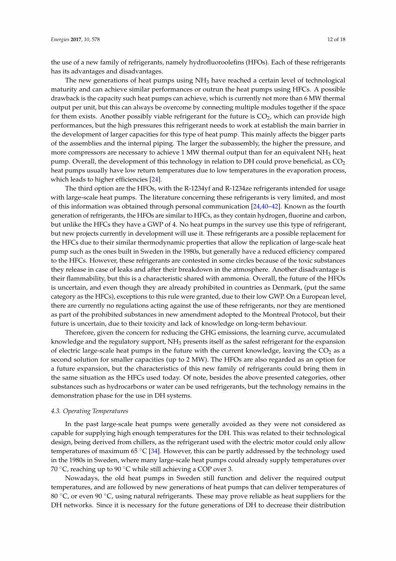
Energies 2017, 10, 578 12 of 18
the use of a new family of refrigerants, namely hydrofluoroolefins (HFOs). Each of these refrigerantshas its advantages and disadvantages.
The new generations of heat pumps using NH3 have reached a certain level of technologicalmaturity and can achieve similar performances or outrun the heat pumps using HFCs. A possibledrawback is the capacity such heat pumps can achieve, which is currently not more than 6 MW thermaloutput per unit, but this can always be overcome by connecting multiple modules together if the spacefor them exists. Another possibly viable refrigerant for the future is CO2, which can provide highperformances, but the high pressures this refrigerant needs to work at establish the main barrier inthe development of larger capacities for this type of heat pump. This mainly affects the bigger partsof the assemblies and the internal piping. The larger the subassembly, the higher the pressure, andmore compressors are necessary to achieve 1 MW thermal output than for an equivalent NH3 heatpump. Overall, the development of this technology in relation to DH could prove beneficial, as CO2
heat pumps usually have low return temperatures due to low temperatures in the evaporation process,which leads to higher efficiencies [24].
The third option are the HFOs, with the R-1234yf and R-1234ze refrigerants intended for usagewith large-scale heat pumps. The literature concerning these refrigerants is very limited, and mostof this information was obtained through personal communication [24,40–42]. Known as the fourthgeneration of refrigerants, the HFOs are similar to HFCs, as they contain hydrogen, fluorine and carbon,but unlike the HFCs they have a GWP of 4. No heat pumps in the survey use this type of refrigerant,but new projects currently in development will use it. These refrigerants are a possible replacement forthe HFCs due to their similar thermodynamic properties that allow the replication of large-scale heatpump such as the ones built in Sweden in the 1980s, but generally have a reduced efficiency comparedto the HFCs. However, these refrigerants are contested in some circles because of the toxic substancesthey release in case of leaks and after their breakdown in the atmosphere. Another disadvantage istheir flammability, but this is a characteristic shared with ammonia. Overall, the future of the HFOsis uncertain, and even though they are already prohibited in countries as Denmark, (put the samecategory as the HFCs), exceptions to this rule were granted, due to their low GWP. On a European level,there are currently no regulations acting against the use of these refrigerants, nor they are mentionedas part of the prohibited substances in new amendment adopted to the Montreal Protocol, but theirfuture is uncertain, due to their toxicity and lack of knowledge on long-term behaviour.
Therefore, given the concern for reducing the GHG emissions, the learning curve, accumulatedknowledge and the regulatory support, NH3 presents itself as the safest refrigerant for the expansionof electric large-scale heat pumps in the future with the current knowledge, leaving the CO2 as asecond solution for smaller capacities (up to 2 MW). The HFOs are also regarded as an option fora future expansion, but the characteristics of this new family of refrigerants could bring them inthe same situation as the HFCs used today. Of note, besides the above presented categories, othersubstances such as hydrocarbons or water can be used refrigerants, but the technology remains in thedemonstration phase for the use in DH systems.
4.3. Operating Temperatures
In the past large-scale heat pumps were generally avoided as they were not considered ascapable for supplying high enough temperatures for the DH. This was related to their technologicaldesign, being derived from chillers, as the refrigerant used with the electric motor could only allowtemperatures of maximum 65 ◦C [34]. However, this can be partly addressed by the technology usedin the 1980s in Sweden, where many large-scale heat pumps could already supply temperatures over70 ◦C, reaching up to 90 ◦C while still achieving a COP over 3.
Nowadays, the old heat pumps in Sweden still function and deliver the required outputtemperatures, and are followed by new generations of heat pumps that can deliver temperatures of80 ◦C, or even 90 ◦C, using natural refrigerants. These may prove reliable as heat suppliers for theDH networks. Since it is necessary for the future generations of DH to decrease their distribution
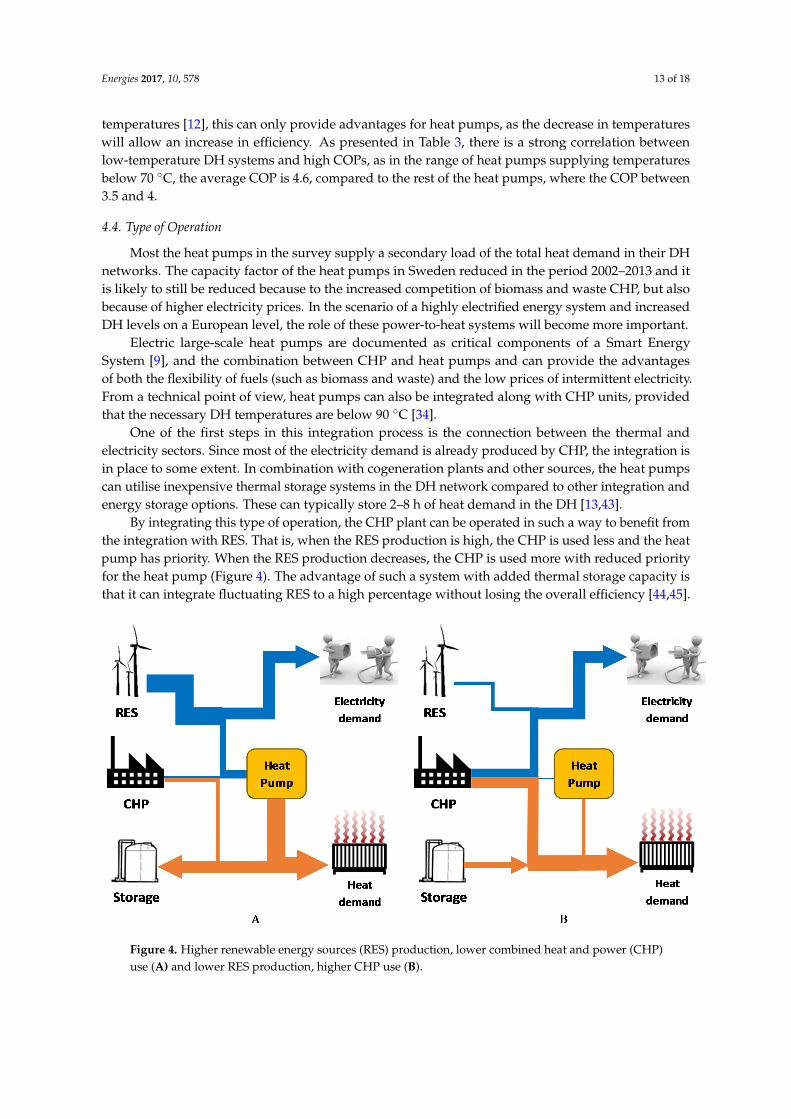
Energies 2017, 10, 578 13 of 18
temperatures [12], this can only provide advantages for heat pumps, as the decrease in temperatureswill allow an increase in efficiency. As presented in Table 3, there is a strong correlation betweenlow-temperature DH systems and high COPs, as in the range of heat pumps supplying temperaturesbelow 70 ◦C, the average COP is 4.6, compared to the rest of the heat pumps, where the COP between3.5 and 4.
4.4. Type of Operation
Most the heat pumps in the survey supply a secondary load of the total heat demand in their DHnetworks. The capacity factor of the heat pumps in Sweden reduced in the period 2002–2013 and itis likely to still be reduced because to the increased competition of biomass and waste CHP, but alsobecause of higher electricity prices. In the scenario of a highly electrified energy system and increasedDH levels on a European level, the role of these power-to-heat systems will become more important.
Electric large-scale heat pumps are documented as critical components of a Smart EnergySystem [9], and the combination between CHP and heat pumps and can provide the advantagesof both the flexibility of fuels (such as biomass and waste) and the low prices of intermittent electricity.From a technical point of view, heat pumps can also be integrated along with CHP units, providedthat the necessary DH temperatures are below 90 ◦C [34].
One of the first steps in this integration process is the connection between the thermal andelectricity sectors. Since most of the electricity demand is already produced by CHP, the integration isin place to some extent. In combination with cogeneration plants and other sources, the heat pumpscan utilise inexpensive thermal storage systems in the DH network compared to other integration andenergy storage options. These can typically store 2–8 h of heat demand in the DH [13,43].
By integrating this type of operation, the CHP plant can be operated in such a way to benefit fromthe integration with RES. That is, when the RES production is high, the CHP is used less and the heatpump has priority. When the RES production decreases, the CHP is used more with reduced priorityfor the heat pump (Figure 4). The advantage of such a system with added thermal storage capacity isthat it can integrate fluctuating RES to a high percentage without losing the overall efficiency [44,45].
Energies 2017, 10, 578 13 of 17
Electric large-scale heat pumps are documented as critical components of a Smart Energy System [9], and the combination between CHP and heat pumps and can provide the advantages of both the flexibility of fuels (such as biomass and waste) and the low prices of intermittent electricity. From a technical point of view, heat pumps can also be integrated along with CHP units, provided that the necessary DH temperatures are below 90 °C [34].
One of the first steps in this integration process is the connection between the thermal and electricity sectors. Since most of the electricity demand is already produced by CHP, the integration is in place to some extent. In combination with cogeneration plants and other sources, the heat pumps can utilise inexpensive thermal storage systems in the DH network compared to other integration and energy storage options. These can typically store 2–8 h of heat demand in the DH [13,43].
By integrating this type of operation, the CHP plant can be operated in such a way to benefit from the integration with RES. That is, when the RES production is high, the CHP is used less and the heat pump has priority. When the RES production decreases, the CHP is used more with reduced priority for the heat pump (Figure 4). The advantage of such a system with added thermal storage capacity is that it can integrate fluctuating RES to a high percentage without losing the overall efficiency [44,45].
The same functioning principle can be applied when the electricity price decreases and/or the fuel price increases, triggering more heat pump use, and vice-versa, when the electricity price increases and/or the fuel price decreases, allowing the CHP to be used more. Another advantage of this type of integration can be related to the outdoor temperatures, by using the CHP in times of very low outdoor temperatures and more heat pump when the temperatures are higher.
Figure 4. Higher renewable energy sources (RES) production, lower combined heat and power (CHP) use (A) and lower RES production, higher CHP use (B).
The future partnerships between CHP and large-scale heat pumps can also include ‘cold storage’, where the flue gases are stored and recovered later by the heat pump, which can operate even when the CHP is not functional. This type of operation opens the opportunity for a high degree of flexibility in the plant operation, allowing for efficient and flexible use of electricity for heat production, and allows the operation of the heat pump with no additional temperature lift towards heat storage. In the CHP - heat pump - cold storage combination, low temperature heat from flue gases is recovered and stored during the operation hours of the CHP. The stored heat in the ‘cold storage’ is used as a heat source for the heat pump, operational at high COP, due to the high temperature of the heat source. The heat pump can function even when the CHP is not operational and this mode can be used when the electricity prices are low due to a high proportion of intermittent
Figure 4. Higher renewable energy sources (RES) production, lower combined heat and power (CHP)use (A) and lower RES production, higher CHP use (B).
Energies 2017, 10, 578 14 of 18
The same functioning principle can be applied when the electricity price decreases and/or thefuel price increases, triggering more heat pump use, and vice-versa, when the electricity price increasesand/or the fuel price decreases, allowing the CHP to be used more. Another advantage of this type ofintegration can be related to the outdoor temperatures, by using the CHP in times of very low outdoortemperatures and more heat pump when the temperatures are higher.
The future partnerships between CHP and large-scale heat pumps can also include ‘cold storage’,where the flue gases are stored and recovered later by the heat pump, which can operate even whenthe CHP is not functional. This type of operation opens the opportunity for a high degree of flexibilityin the plant operation, allowing for efficient and flexible use of electricity for heat production, andallows the operation of the heat pump with no additional temperature lift towards heat storage. In theCHP - heat pump - cold storage combination, low temperature heat from flue gases is recovered andstored during the operation hours of the CHP. The stored heat in the ‘cold storage’ is used as a heatsource for the heat pump, operational at high COP, due to the high temperature of the heat source.The heat pump can function even when the CHP is not operational and this mode can be used whenthe electricity prices are low due to a high proportion of intermittent electricity. The main advantage ofthis type of operation is its capability to provide the required temperature for the DH, which usually isabove 80 ◦C [15]. While in [15] a transcritical heat pump was considered for this partnership, othersubcritical heat pumps can also be used.
Therefore, heat pumps are maximising the efficiencies of the heating plants by using their ownwaste heat, but have not been used so far to balance intermittent electricity sources on a large scale,only to integrate a constant surplus of electricity, like the one produced by the nuclear power plants inSweden in the 1980s.
Exceptions to this rule exist, as the largest existing heat pumps in Gothenburg have been usedsolely on a start/stop basis, dependent on the price of electricity [31]. If this is already achieved tosome extent with old technology, there is no reason this cannot be done with newer technology. Thus,it finally becomes a deliberation of risk management. If electricity prices are a constant low, then it isnot an issue, as the heat pumps can operate as much as possible, but then it is also difficult to competeeconomically for balancing purposes. If the mechanical wear can be ruled out for frequent start-upswith the new generations of heat pumps, or if the operation and management costs are low enough toencourage frequent start-ups, then the large variation of electricity prices becomes more practical, asmore intermittent power generation is added to the electrical grid.
Again, it is important to note that so far heat pumps have not been designed for flexible regulation.This should be a focus point in the future development.
District Cooling
As part of the operation of heat pumps, cooling can also provide operational gains. As mentionedbefore, the main advantage of such a network is the economic gains it can achieve, represented by theshared costs of installing and operating the system, as not everybody can afford to install and operatean individual cooling system. The space made vacant by the replacement of individual cooling unitswith district cooling can be an advantage, as well as the reduction in noise from the cooling machines.In some cases, individual air-conditioning systems can put additional stress on the local electricitygrids, so a cooling grid with water temperatures just over freezing can represent a solution. However,one issue with this system is with respect to the return temperatures of the grid, which are often below10 ◦C, so the piping must be larger for the same effect transport. Consequently, this could make adistrict cooling network more expensive than a DH network for the same piping length [46].
Currently, the district cooling covers approximately 1% of the cooling demands, whilst themajority is ensured by individual heat pumps/chillers [7]. The cooling sector itself represents onlya small fraction of the heating and cooling sector, leaving a great amount of choice for the futuredevelopment of the cooling supplies. According to the HRE studies, the choice of cooling supplies islikely to have minor influences on the national energy supplies if the demands remain the same, but
Energies 2017, 10, 578 15 of 18
could have higher impact on a local level [7]. One third of the heat pumps in the survey also supplydistrict cooling, due to the availability for such demand and its economic advantages. The futuredeployment of large-scale heat pumps should not be defined by the necessity for supplying both theheating and cooling demands, but by local strategies. Thus, the national strategies should focus moreon integrating the intermittent RES with the thermal sector, as the heating demands are higher thanthe cooling demands, even in the countries in Southern Europe [7].
5. Conclusions and Policy Implications
The available data was sufficient to create an overview over the status of this technology in Europe,and analyse its most relevant patterns. The lack of cooperation and interest of some stakeholders toshare more data affected the completion of this survey. More data would have made the results of thesurvey more precise, but overall, it would not have changed the understanding of the technology usednowadays by the electric large-scale heat pumps.
Summarising the identified types of heat sources used by the heat pumps in the survey indicatesthat there is a huge potential for using sewage water and ambient water as the main heat sourcesfor the future heat pumps due to their long-term stability, proximity to urban areas and not least ofall, temperatures, mainly for sewage water. These types of heat sources are considered as the mainenablers for achieving the capacities estimated in HRE, of 40 GW thermal output. Industrial wasteheat is also an important heat source, despite its higher risk of providing long-term stability, as thereis a high potential for using it either directly, or enabled by a heat pump, since the temperatures aregenerally high. The other heat sources are worth mentioning too, as solar heat storage, geo-thermalenergy or flue gas represent valuable resources that good can be quantitatively expanded to otherlocations in Europe.
DH temperatures are generally achieved without compromises in terms of COP, and the presentgeneration of heat pumps can supply the necessary temperatures of the DH systems by using naturalrefrigerants. However, since heat pumps are more efficient when providing lower temperatures,consideration should be given to low temperature networks, which have reduced losses in the gridsand provide low temperature return, of critical importance for the future DH networks.
Regarding their type of operation, in a future scenario with more renewables in the energysystem produced by wind and solar sources, the large-scale heat pumps can bring more advantagesby functioning on an intermittent basis. The integration of large-scale heat pumps in DH systemsadds resilience to the electric and thermal grids by taking advantage of the low-cost electricity priceson the spot market, and by using electricity to generate heat. Such an integration can help reducethe surplus electricity on a grid and help to shave the peak electricity production if enough capacityis installed. Since an electricity surplus once led to the expansion of large-scale heat pumps in DHsystems in Sweden in the 1980s, it is possible that the situation could repeat once again with theincreasing amounts of electricity from wind and solar.
Thus, the technological limitations do not seem to be a barrier, but there are policy limitationsthat do not give heat pumps an advantage compared to other technologies, even though from asocio-economic perspective, they are critical elements of the future energy system. Specifically, anenergy market with no carbon penalty, biomass and fossil fuel subsidies is not helpful for the expansionof this technology. For example, biomass is a limited resource, but has more financial incentives thanusing heat pumps. Even though DH is generally well promoted by policy makers, the connection withheat pumps is rarely made due to a lack of knowledge or willingness to remain technology-neutral.Since heat pumps do not benefit of tax exemptions or subsidies like other technologies do, theseend up with a higher investment cost than their competitors. One could also raise the question ofmore moderate DH expansion than that suggested in the HRE studies, as well as a lack of abundantheat sources, which would decrease the role of large-scale heat pumps in the future. However, asdemonstrated in this study, the potential exists.
Energies 2017, 10, 578 16 of 18
To conclude, the technology used nowadays by the electric large-scale heat pumps has reacheda satisfying level of maturity to be further deployed in existing and future DH systems acrossEurope if careful consideration is put in choosing the right refrigerant to comply with environmentalrequirements, and if the technological design is aimed at frequent start-ups to be able to integrateintermittent renewable electricity sources.
Supplementary Materials: The following are available online at www.mdpi.com/1996-1073/10/4/578/s1.
Acknowledgments: The work presented in this paper is a result of the research activities of the 4DH ResearchCentre, financed by The Innovation Fund Denmark (0603-00498B) and Heat Roadmap Europe 2050, financed bythe European Union’s Horizon 2020 research and innovation program (grant agreement 695989). Valuable inputhas been received from Heat Roadmap Europe 2050 colleagues, researchers and partners. The authors would alsolike to thank Paul Ingvarsson for valuable contributions throughout the development of this study.
Author Contributions: Andrei David collected data in the survey and wrote the paper; Brian Vad Mathiesenconceived the study and provided HRE knowledge; Helge Averfalk collected the data from Sweden; Sven Werneranalyzed the data and structured it; Henrik Lund designed and wrapped up the study.
Conflicts of Interest: The authors declare no conflict of interest.
References
1. United Nations Framework Convention on Climate Change (UNFCCC). The Paris Agreement. 2016.Available online: http://unfccc.int/paris_agreement/items/9485.php (accessed on 18 January 2017).
2. European Commission. Energy Roadmap 2050, COM(2011) 885 Final; European Commission: Brussels,Belgium, 2011.
3. Eurostat. Greenhouse Gas Emission Statistics. Eurostat Statistics Explained. 2015. Available online:http://ec.europa.eu/eurostat/statistics-explained/index.php/Greenhouse_gas_emission_statistics(accessed on 10 August 2016).
4. European Commission. European Energy Security Strategy; European Commission: Brussels, Belgium, 2014;p. 24.
5. European Commission. An EU Strategy on Heating and Cooling, COM(2016) 51 Final; European Commission:Brussels, Belgium, 2016.
6. Connolly, D.; Mathiesen, B.V.; Østergaard, P.A.; Möller, B.; Nielsen, S.; Lund, H.; Trier, D.; Persson, U.;Nilsson, D.; Werner, S. Heat Roadmap Europe: First Pre-Study for EU27; Aalborg University: Aalborg,Denmark, 2012.
7. Connolly, D.; Mathiesen, B.V.; Østergaard, P.A.; Möller, B.; Nielsen, S.; Lund, H.; Persson, U.; Werner, S.;Grözinger, J.; Boermans, T.; et al. Heat Roadmap Europe: Second Pre-Study; Aalborg University: Aalborg,Denmark, 2013.
8. Averfalk, H.; Ingvarsson, P.; Persson, U.; Werner, S. On the use of surplus electricity in district heatingsystems. In Proceedings of the 14th International Symposium on District Heating and Cooling, Stockholm,Sweden, 6–10 September 2014; pp. 7–12.
9. Mathiesen, B.V.; Lund, H.; Connolly, D.; Wenzel, H.; Ostergaard, P.A.; Möller, B.; Nielsen, S.; Ridjan, I.;Karnøe, P.; Sperling, K.; et al. Smart Energy Systems for coherent 100% renewable energy and transportsolutions. Appl. Energy 2015, 145, 139–154. [CrossRef]
10. Lund, H.; Hvelplund, F.; Mathiesen, B.V.; Østergaard, P.A.; Christensen, P.; Connolly, D.; Schaltz, E.;Pillay, J.R.; Nielsen, M.P.; Felby, C.; et al. Coherent Energy and Environmental System Analysis; AalborgUniversity: Aalborg, Danmark, 2011.
11. Blarke, M.B.; Lund, H. The effectiveness of storage and relocation options in renewable energy systems.Renew. Energy 2008, 33, 1499–1507. [CrossRef]
12. Lund, H.; Werner, S.; Wiltshire, R.; Svendsen, S.; Thorsen, J.E.; Hvelplund, F.; Mathiesen, B.V. 4th GenerationDistrict Heating (4GDH): Integrating smart thermal grids into future sustainable energy systems. Energy2014, 68, 1–11. [CrossRef]
13. Mathiesen, B.V.; Lund, H. Comparative analyses of seven technologies to facilitate the integration offluctuating renewable energy sources. IET Renew. Power Gener. 2009, 3, 190–204. [CrossRef]
Energies 2017, 10, 578 17 of 18
14. Mathiesen, B.V.; Blarke, M.B.; Hansen, K.; Connolly, D. The Role of Large-Scale Heat Pumps for Short TermIntegration of Renewable Energy; Department of Development and Planning, Aalborg University: Aalborg,Danmark, 2011.
15. Blarke, M.B.; Lund, H. Large-scale heat pumps in sustainable energy systems: System and projectperspectives. Therm. Sci. 2007, 11, 143–152. [CrossRef]
16. Blarke, M.B.; Dotzauer, E. Intermittency-friendly and high-efficiency cogeneration: Operational optimisationof cogeneration with compression heat pump, flue gas heat recovery, and intermediate cold storage. Energy2011, 36, 6867–6878. [CrossRef]
17. Sievers, J.; Faulstich, S.; Puchta, M.; Stadler, I.; Schmid, J.; Madina, C.; Díaz, Á.; Ruiz, N.; Turienzo, E.;Münster, E.; et al. Long-Term Perspectives for Balancing Fluctuating Renewable Energy Sources; University ofKassel: Kassel, Germany, 2007.
18. Lund, R.; Persson, U. Mapping of potential heat sources for heat pumps for district heating in Denmark.Energy 2016, 110, 129–138. [CrossRef]
19. Mathiesen, B.V.; Lund, H.; Connolly, D. Limiting biomass consumption for heating in 100% renewable energysystems. Energy 2012, 48, 160–168. [CrossRef]
20. Bach, B.; Werling, J.; Ommen, T.; Münster, M.; Morales, J.M.; Elmegaard, B. Integration of large-scale heatpumps in the district heating systems of Greater Copenhagen. Energy 2016, 107, 321–334. [CrossRef]
21. Mathiesen, B.V.; Lund, H.; Karlsson, K. 100% Renewable energy systems, climate mitigation and economicgrowth. Appl. Energy 2011, 88, 488–501. [CrossRef]
22. Lund, R.; Ilic, D.D.; Trygg, L. Socioeconomic potential for introducing large-scale heat pumps in districtheating in Denmark. J. Clean. Prod. 2016, 139, 219–229. [CrossRef]
23. Averfalk, H.; Ingvarsson, P.; Persson, U.; Werner, S. Large heat pumps in Swedish district heating systems.2017; Manuscript submitted for publication.
24. Ingvarsson, P.; AF Consult, Stockholm, Sweden. Personal Communication, 2017.25. Riffat, S.B.; Afonso, C.F.; Oliveira, A.C.; Reay, D.A. Natural refrigerants for refrigeration and air-conditioning
systems. Appl. Therm. Eng. 1997, 17, 33–42. [CrossRef]26. Austin, B.T.; Sumathy, K. Transcritical carbon dioxide heat pump systems: A review. Renew. Sustain.
Energy Rev. 2011, 15, 4013–4029. [CrossRef]27. United Nations Environment Programme (UNEP). Amendment to the montreal protocol on substances that
deplete the ozone layer. In Proceedings of the 28th Meeting of the Parties, Kigali, Rwanda, 8–14 October 2016.28. Johansson, A. Phase-Out of Refrigerant R22. Ph.D. Dissertation, Royal Institute of Technology, Stockholm,
Sweden, 2003.29. Kilicarslan, A.; Müller, N. A comparative study of water as a refrigerant with some current refrigerants.
Int. J. Energy Res. 2005, 29, 947–959. [CrossRef]30. Zyhowski, G.J.; Spatz, M.M.; and Motta, S.Y. An Overview Of The Properties And Applications of
HFC-245fa. Proceedings of the International Refrigeration and Air Conditioning Conference, Purdueuniversity, West Lafayette, IN, USA, 16–19 July 2002.
31. Dalman, B.G.; Göteborg Energi, Gothenburg, Sweden. Personal Communication, 2015.32. Ingvarsson, P. Handbok för livslängdsarbete med energianläggningar (Handbook for lifespan work with 719 energy
plants); Värmeforsk report no. 885; Swedish DH Association: Stockholm, Sweden, 2004.33. Frederiksen, S.; Werner, S. District Heating and Cooling; Studentlitteratu: Lund, Sweden, 2013.34. De Jong, K. Industrial Heat Pumps and CHP as Partners; Stichting Warmtenetwerk: Hilversum,
The Netherlands, 2014.35. Persson, U.; Möller, B.; Werner, S. Heat Roadmap Europe: Identifying strategic heat synergy regions. Energy
Policy 2014, 74, 663–681. [CrossRef]36. Persson, U. Stratego. Ehanced heating and Cooling Plans. In Quantifying the Excess Heat Available for District
Heating in Europe, WP2; Background Report 7; Aalborg University: Aalborg, Denmark, 2015.37. Ministry of the Environment & Danish Environmental Protection Agency. Statutory Order No. 552 of 2
July 2002 Regulating Certain Industrial Greenhouse Gases; No. 552; Ministry of the Environment & DanishEnvironmental Protection Agency: Copenhagen, Denmark, 2002.
38. Hydrocarbons21.com. Switzerland to Introduce HFC Bans in Several AC and Refrigeration Applications.2012. Available online: http://www.hydrocarbons21.com/articles/3659/switzerland_to_introduce_hfc_bans_in_several_ac_and_refrigeration_applications (accessed on 5 November 2016).
Energies 2017, 10, 578 18 of 18
39. The European Parliament and the Council of the European Union. Regulation (EU) No 517/2014 of theEuropean Parliament and of the Council of 16 April 2014 on fluorinated greenhouse gases and repealingRegulation (EC) No 842/2006. Off. J. Eur. Union 2014, 2014, 195–230.
40. Pachai, A.C.; Johnson Controls, Milwaukee, WI, USA. Personal Communication, 2016.41. Vonsild, A.L.; Danfoss, Copenhagen, Denmark. Personal Communication, 2016.42. Greenpeace. HFOs: The New Generation of F-Gases; Greenpeace: Amsterdam, The Netherlands, 2016.43. Mathiesen, B.V. Fuel Cells and Electrolysers in Future Energy Systems. Ph.D. Dissertation, Aalborg
Universitet, Aalborg, Denmark, 2008; p. 328.44. Lund, H.; Andersen, A.N.; Østergaard, P.A.; Mathiesen, B.V.; Connolly, D. From electricity smart grids to
smart energy systems—A market operation based approach and understanding. Energy 2012, 42, 96–102.[CrossRef]
45. Lund, H. Electric grid stability and the design of sustainable energy systems. Int. J. Sustain. Energy 2005, 24,45–54. [CrossRef]
46. Söderman, J. Optimisation of structure and operation of district cooling networks in urban regions.Appl. Therm. Eng. 2007, 27, 2665–2676. [CrossRef]
© 2017 by the authors. Licensee MDPI, Basel, Switzerland. This article is an open accessarticle distributed under the terms and conditions of the Creative Commons Attribution(CC BY) license (http://creativecommons.org/licenses/by/4.0/).