pvs800 adaptive programming application guide · pvs800 firmware manual 3aua0000058422 1)...
TRANSCRIPT

ABB solar inverters
Application guideAdaptive program for PVS800 central inverters
List of related manuals
1) Delivered as a printed copy with the PVS800.2) Delivered as a printed copy with the option.
Hardware manuals and guides Code (English)PVS800-57 hardware manual 3AUA0000053689 1)
Firmware manuals and guides Code (English)PVS800 firmware manual 3AUA0000058422 1)Application guide: Adaptive program for PVS800 3AUA0000091276
Option manuals and guidesManuals and quick guides for I/O extension modules, fieldbus adapters, etc.
2)
Application guide
Adaptive program for PVS800 central inverters
3AUA0000091276 Rev AEN
EFFECTIVE: 2010-12-20
© 2010 ABB Oy. All Rights Reserved.
Table of contents

5
Table of contents
List of related manuals . . . . . . . . . . . . . . . . . . . . . . . . . . . . . . . . . . . . . . . . . . . . . . . . . . . 2
1. Introduction to the guide
What this chapter contains . . . . . . . . . . . . . . . . . . . . . . . . . . . . . . . . . . . . . . . . . . . . . . . . 7Applicability . . . . . . . . . . . . . . . . . . . . . . . . . . . . . . . . . . . . . . . . . . . . . . . . . . . . . . . . . . . . 7Safety instructions . . . . . . . . . . . . . . . . . . . . . . . . . . . . . . . . . . . . . . . . . . . . . . . . . . . . . . . 7Target audience . . . . . . . . . . . . . . . . . . . . . . . . . . . . . . . . . . . . . . . . . . . . . . . . . . . . . . . . 7Contents of the guide . . . . . . . . . . . . . . . . . . . . . . . . . . . . . . . . . . . . . . . . . . . . . . . . . . . . 8
2. Adaptive program
What this chapter contains . . . . . . . . . . . . . . . . . . . . . . . . . . . . . . . . . . . . . . . . . . . . . . . . 9What an adaptive program is . . . . . . . . . . . . . . . . . . . . . . . . . . . . . . . . . . . . . . . . . . . . . . 9How to build the program . . . . . . . . . . . . . . . . . . . . . . . . . . . . . . . . . . . . . . . . . . . . . . . . 10How to connect the adaptive program to the PVS800 master control program . . . . . . . 11How to control the execution of the program . . . . . . . . . . . . . . . . . . . . . . . . . . . . . . . . . 11
3. Application blocks
What this chapter contains . . . . . . . . . . . . . . . . . . . . . . . . . . . . . . . . . . . . . . . . . . . . . . . 13General rules . . . . . . . . . . . . . . . . . . . . . . . . . . . . . . . . . . . . . . . . . . . . . . . . . . . . . . . . . . 13Block inputs . . . . . . . . . . . . . . . . . . . . . . . . . . . . . . . . . . . . . . . . . . . . . . . . . . . . . . . . . . . 13User parameters . . . . . . . . . . . . . . . . . . . . . . . . . . . . . . . . . . . . . . . . . . . . . . . . . . . . . . . 13Function blocks . . . . . . . . . . . . . . . . . . . . . . . . . . . . . . . . . . . . . . . . . . . . . . . . . . . . . . . . 14
ABS . . . . . . . . . . . . . . . . . . . . . . . . . . . . . . . . . . . . . . . . . . . . . . . . . . . . . . . . . . . . . . 14ADD . . . . . . . . . . . . . . . . . . . . . . . . . . . . . . . . . . . . . . . . . . . . . . . . . . . . . . . . . . . . . . 14AND . . . . . . . . . . . . . . . . . . . . . . . . . . . . . . . . . . . . . . . . . . . . . . . . . . . . . . . . . . . . . . 15BSET . . . . . . . . . . . . . . . . . . . . . . . . . . . . . . . . . . . . . . . . . . . . . . . . . . . . . . . . . . . . . 15COMPARE . . . . . . . . . . . . . . . . . . . . . . . . . . . . . . . . . . . . . . . . . . . . . . . . . . . . . . . . . 16COUNT . . . . . . . . . . . . . . . . . . . . . . . . . . . . . . . . . . . . . . . . . . . . . . . . . . . . . . . . . . . . 17DPOT . . . . . . . . . . . . . . . . . . . . . . . . . . . . . . . . . . . . . . . . . . . . . . . . . . . . . . . . . . . . . 17EVENT . . . . . . . . . . . . . . . . . . . . . . . . . . . . . . . . . . . . . . . . . . . . . . . . . . . . . . . . . . . . 18FILTER . . . . . . . . . . . . . . . . . . . . . . . . . . . . . . . . . . . . . . . . . . . . . . . . . . . . . . . . . . . . 18MAX . . . . . . . . . . . . . . . . . . . . . . . . . . . . . . . . . . . . . . . . . . . . . . . . . . . . . . . . . . . . . . 19MIN . . . . . . . . . . . . . . . . . . . . . . . . . . . . . . . . . . . . . . . . . . . . . . . . . . . . . . . . . . . . . . . 19MULDIV . . . . . . . . . . . . . . . . . . . . . . . . . . . . . . . . . . . . . . . . . . . . . . . . . . . . . . . . . . . 19OR . . . . . . . . . . . . . . . . . . . . . . . . . . . . . . . . . . . . . . . . . . . . . . . . . . . . . . . . . . . . . . . 20PI . . . . . . . . . . . . . . . . . . . . . . . . . . . . . . . . . . . . . . . . . . . . . . . . . . . . . . . . . . . . . . . . 21PI-BAL . . . . . . . . . . . . . . . . . . . . . . . . . . . . . . . . . . . . . . . . . . . . . . . . . . . . . . . . . . . . 21RAMP . . . . . . . . . . . . . . . . . . . . . . . . . . . . . . . . . . . . . . . . . . . . . . . . . . . . . . . . . . . . . 22SR . . . . . . . . . . . . . . . . . . . . . . . . . . . . . . . . . . . . . . . . . . . . . . . . . . . . . . . . . . . . . . . . 23TOFF . . . . . . . . . . . . . . . . . . . . . . . . . . . . . . . . . . . . . . . . . . . . . . . . . . . . . . . . . . . . . 25TON . . . . . . . . . . . . . . . . . . . . . . . . . . . . . . . . . . . . . . . . . . . . . . . . . . . . . . . . . . . . . . 26TRIGG . . . . . . . . . . . . . . . . . . . . . . . . . . . . . . . . . . . . . . . . . . . . . . . . . . . . . . . . . . . . 27WR-I . . . . . . . . . . . . . . . . . . . . . . . . . . . . . . . . . . . . . . . . . . . . . . . . . . . . . . . . . . . . . . 28WR-PB . . . . . . . . . . . . . . . . . . . . . . . . . . . . . . . . . . . . . . . . . . . . . . . . . . . . . . . . . . . . 29XOR . . . . . . . . . . . . . . . . . . . . . . . . . . . . . . . . . . . . . . . . . . . . . . . . . . . . . . . . . . . . . . 30
I/O and communication blocks . . . . . . . . . . . . . . . . . . . . . . . . . . . . . . . . . . . . . . . . . . . . 31A/F WORD . . . . . . . . . . . . . . . . . . . . . . . . . . . . . . . . . . . . . . . . . . . . . . . . . . . . . . . . . 31
6
AI1 . . . . . . . . . . . . . . . . . . . . . . . . . . . . . . . . . . . . . . . . . . . . . . . . . . . . . . . . . . . . . . . 31AI2 . . . . . . . . . . . . . . . . . . . . . . . . . . . . . . . . . . . . . . . . . . . . . . . . . . . . . . . . . . . . . . . 32AI3 . . . . . . . . . . . . . . . . . . . . . . . . . . . . . . . . . . . . . . . . . . . . . . . . . . . . . . . . . . . . . . . 32AO1 . . . . . . . . . . . . . . . . . . . . . . . . . . . . . . . . . . . . . . . . . . . . . . . . . . . . . . . . . . . . . . 33AO2 . . . . . . . . . . . . . . . . . . . . . . . . . . . . . . . . . . . . . . . . . . . . . . . . . . . . . . . . . . . . . . 33CW . . . . . . . . . . . . . . . . . . . . . . . . . . . . . . . . . . . . . . . . . . . . . . . . . . . . . . . . . . . . . . 34DI1…DI6, DI IL . . . . . . . . . . . . . . . . . . . . . . . . . . . . . . . . . . . . . . . . . . . . . . . . . . . . . 34DO1 . . . . . . . . . . . . . . . . . . . . . . . . . . . . . . . . . . . . . . . . . . . . . . . . . . . . . . . . . . . . . . 35DO2 . . . . . . . . . . . . . . . . . . . . . . . . . . . . . . . . . . . . . . . . . . . . . . . . . . . . . . . . . . . . . . 35DO3 . . . . . . . . . . . . . . . . . . . . . . . . . . . . . . . . . . . . . . . . . . . . . . . . . . . . . . . . . . . . . . 35EXT1 DI…DI3 . . . . . . . . . . . . . . . . . . . . . . . . . . . . . . . . . . . . . . . . . . . . . . . . . . . . . . 36EXT2 DI…DI3 . . . . . . . . . . . . . . . . . . . . . . . . . . . . . . . . . . . . . . . . . . . . . . . . . . . . . . 36EXT3 DI…DI3 . . . . . . . . . . . . . . . . . . . . . . . . . . . . . . . . . . . . . . . . . . . . . . . . . . . . . . 37EXT4 DI…DI3 . . . . . . . . . . . . . . . . . . . . . . . . . . . . . . . . . . . . . . . . . . . . . . . . . . . . . . 37EXT5 DI…DI3 . . . . . . . . . . . . . . . . . . . . . . . . . . . . . . . . . . . . . . . . . . . . . . . . . . . . . . 38EXT DO . . . . . . . . . . . . . . . . . . . . . . . . . . . . . . . . . . . . . . . . . . . . . . . . . . . . . . . . . . . 38EXT1…5 AI1…AI2 . . . . . . . . . . . . . . . . . . . . . . . . . . . . . . . . . . . . . . . . . . . . . . . . . . 39EXT1…5 AO1…AO2 . . . . . . . . . . . . . . . . . . . . . . . . . . . . . . . . . . . . . . . . . . . . . . . . . 39FUNG IN . . . . . . . . . . . . . . . . . . . . . . . . . . . . . . . . . . . . . . . . . . . . . . . . . . . . . . . . . . 40FUNG OUT . . . . . . . . . . . . . . . . . . . . . . . . . . . . . . . . . . . . . . . . . . . . . . . . . . . . . . . . 40PZD3 OUT . . . . . . . . . . . . . . . . . . . . . . . . . . . . . . . . . . . . . . . . . . . . . . . . . . . . . . . . 41PZD4 OUT . . . . . . . . . . . . . . . . . . . . . . . . . . . . . . . . . . . . . . . . . . . . . . . . . . . . . . . . 42PZD5 OUT . . . . . . . . . . . . . . . . . . . . . . . . . . . . . . . . . . . . . . . . . . . . . . . . . . . . . . . . 42PZD8 OUT . . . . . . . . . . . . . . . . . . . . . . . . . . . . . . . . . . . . . . . . . . . . . . . . . . . . . . . . 44PZD9 OUT . . . . . . . . . . . . . . . . . . . . . . . . . . . . . . . . . . . . . . . . . . . . . . . . . . . . . . . . 44PZD10 OUT . . . . . . . . . . . . . . . . . . . . . . . . . . . . . . . . . . . . . . . . . . . . . . . . . . . . . . . 45PZD3 IN . . . . . . . . . . . . . . . . . . . . . . . . . . . . . . . . . . . . . . . . . . . . . . . . . . . . . . . . . . 45PZD4 IN . . . . . . . . . . . . . . . . . . . . . . . . . . . . . . . . . . . . . . . . . . . . . . . . . . . . . . . . . . 46PZD5 IN . . . . . . . . . . . . . . . . . . . . . . . . . . . . . . . . . . . . . . . . . . . . . . . . . . . . . . . . . . 46PZD6 IN . . . . . . . . . . . . . . . . . . . . . . . . . . . . . . . . . . . . . . . . . . . . . . . . . . . . . . . . . . 47PZD7 IN . . . . . . . . . . . . . . . . . . . . . . . . . . . . . . . . . . . . . . . . . . . . . . . . . . . . . . . . . . 47PZD8 IN . . . . . . . . . . . . . . . . . . . . . . . . . . . . . . . . . . . . . . . . . . . . . . . . . . . . . . . . . . 48PZD9 IN . . . . . . . . . . . . . . . . . . . . . . . . . . . . . . . . . . . . . . . . . . . . . . . . . . . . . . . . . . 48PZD10 IN . . . . . . . . . . . . . . . . . . . . . . . . . . . . . . . . . . . . . . . . . . . . . . . . . . . . . . . . . 49SUB . . . . . . . . . . . . . . . . . . . . . . . . . . . . . . . . . . . . . . . . . . . . . . . . . . . . . . . . . . . . . . 49
Further information
Introduction to the guide 7
1
Introduction to the guide
What this chapter containsThis chapter gives general information on the guide.
ApplicabilityThe guide is applicable to the master control program of PVS800 central inverters.
Note: All parameter numbers and names refer to the PVS800 master control program (see PVS800 Firmware manual) unless otherwise indicated.
Safety instructionsFollow all safety instructions delivered with the PVS800.• Read the complete safety instructions before you install, commission, or use the
PVS800. The complete safety instructions are given at the beginning of the Hardware Manual.
• Read the software function specific warnings and notes before changing the default settings of the function. These warnings and notes are presented together with the parameter descriptions wherever appropriate.
WARNING! ABB is not responsible for the operation of a custom-made adaptive program, or for any damage or injury caused by the use of it.
Target audienceThis manual is intended for people who adjust the parameters of, or operate, monitor or troubleshoot PVS800 central inverters.

8 Introduction to the guide
The reader is expected to know the standard electrical wiring practices, electronic components, and electrical schematic symbols.
Contents of the guideThe guide is to be used together with the PVS800 firmware manual. The firmware manual contains the basic information on the master control program parameters including the parameters of the adaptive program. This guide gives more detailed information on the adaptive program:• what the adaptive program is• how to build an adaptive program• how the function blocks operate• how to document the adaptive program.
Adaptive program 9
2
Adaptive program
What this chapter containsThis chapter describes the basics of the adaptive program and instructs in building a program.
What an adaptive program isConventionally, the user can control the operation of the PVS800 by parameters. Each parameter has a fixed set of choices or a range of settings. The parameters make programming easy, but the choices are limited: you cannot customize the operation any further. The adaptive program makes freer customization possible without the need of a special programming tool or language.
The adaptive program is built of function blocks (see listing starting on page 13) by using the DriveAP 2.x PC tool or the CDP 312R control panel. The maximum size of the adaptive program is 10 blocks at 10 ms time level and 20 blocks at 100 ms time level.
The user can document the program by drawing it on block diagram template sheets.
Notes:• Only the master control program of the PVS800 is intended to be programmed this
way.• If the adaptive program originally created using the DriveAP 2.x tool is modified with
the control panel, the function block view in DriveAP 2.x will be different since the location of the function blocks cannot be determined by the control panel.
10 Adaptive program
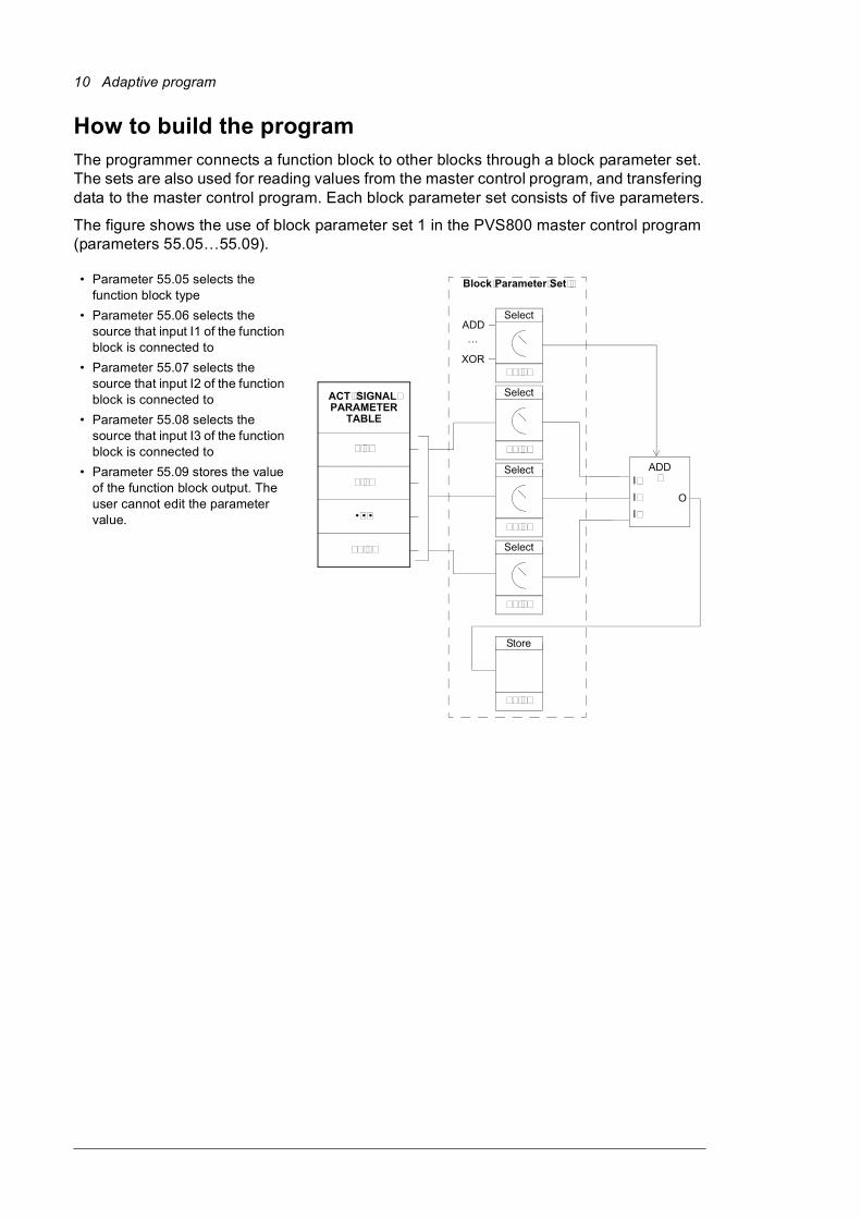
How to build the programThe programmer connects a function block to other blocks through a block parameter set. The sets are also used for reading values from the master control program, and transfering data to the master control program. Each block parameter set consists of five parameters.
The figure shows the use of block parameter set 1 in the PVS800 master control program (parameters 55.05…55.09).
��������� ���� ��
�����
�����
����
�����
�����
�����
�����
�����
����
����
������������
����
����
�����
�
���������
�����
���
���
�
��
��
��
���
�
�
• Parameter 55.05 selects the function block type
• Parameter 55.06 selects the source that input I1 of the function block is connected to
• Parameter 55.07 selects the source that input I2 of the function block is connected to
• Parameter 55.08 selects the source that input I3 of the function block is connected to
• Parameter 55.09 stores the value of the function block output. The user cannot edit the parameter value.
Adaptive program 11
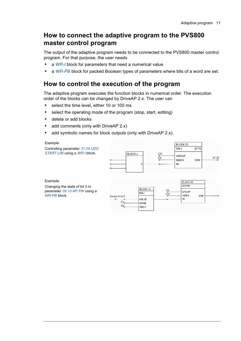
How to connect the adaptive program to the PVS800 master control programThe output of the adaptive program needs to be connected to the PVS800 master control program. For that purpose, the user needs• a WR-I block for parameters that need a numerical value• a WR-PB block for packed Boolean types of parameters where bits of a word are set.
How to control the execution of the programThe adaptive program executes the function blocks in numerical order. The execution order of the blocks can be changed by DriveAP 2.x. The user can• select the time level, either 10 or 100 ms• select the operating mode of the program (stop, start, editing)• delete or add blocks• add comments (only with DriveAP 2.x)• add symbolic names for block outputs (only with DriveAP 2.x).
Example:Controlling parameter 31.04 UDC START LIM using a WR-I block.
Example:Changing the state of bit 3 in parameter 09.13 AP FW using a WR-PB block.

12 Adaptive program
Application blocks 13
3
Application blocks
What this chapter containsThe chapter describes the function blocks available in the PVS800 master control program.
General rulesThe use of the first input is compulsory (it must not be left unconnected). Use of the second and third input is voluntary for most blocks. As a rule of thumb, an unconnected input does not affect the output of the block.
Block inputsThe blocks use three input formats: integer, boolean and text string. The format to use depends on the block. For example, the ADD block uses integer inputs and the OR block boolean inputs. Text string format is used only by EVENT blocks.
Notes:• The inputs of the blocks are read when the execution of the block starts, not
simultaneously for all blocks.• If blocks are programmed with CDP 312R control panel (or DriveWindow PC tool),
DriveAP 2.x cannot form a graphic block diagram. Only use DriveAP for adaptive programming if documentation of blocks is needed.
User parametersThere are 10 user parameters available for application purposes. See parameters 53.01 NUMERIC 1 … 53.10 NUMERIC 10. Group 19 parameters can also be used.
14 Application blocks
Function blocksABS Type
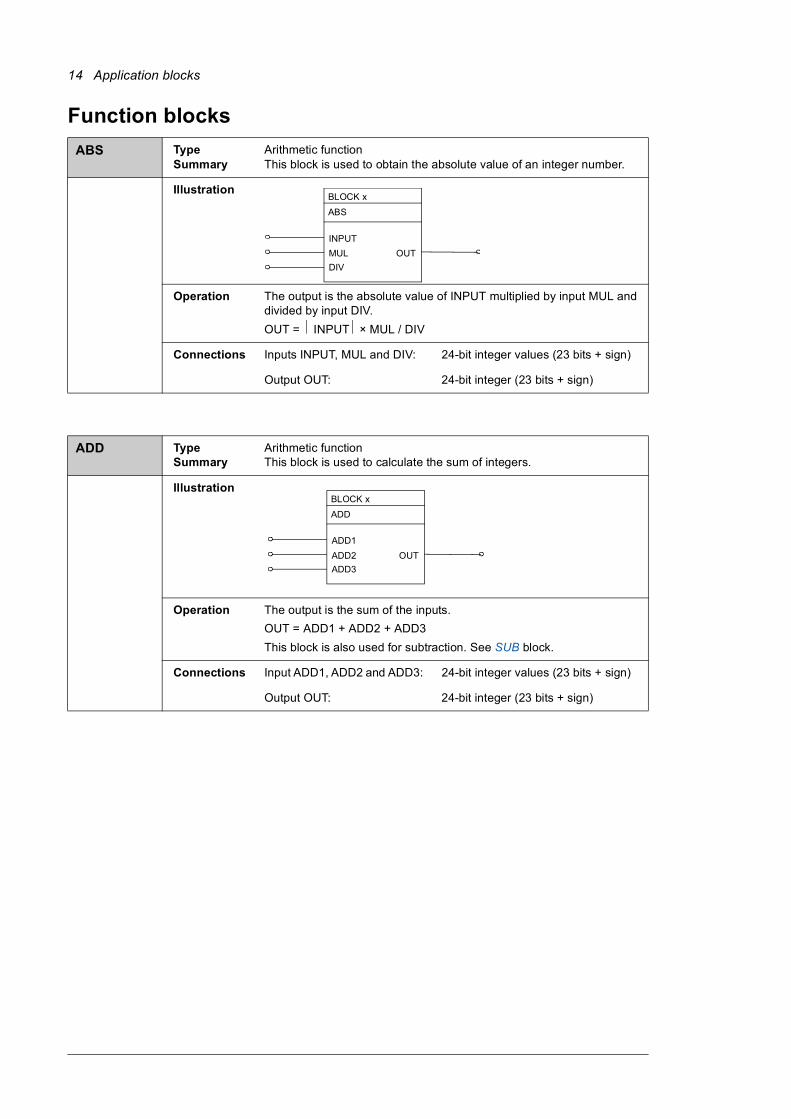
SummaryArithmetic functionThis block is used to obtain the absolute value of an integer number.
Illustration
Operation The output is the absolute value of INPUT multiplied by input MUL and divided by input DIV.OUT = INPUT × MUL / DIV
Connections Inputs INPUT, MUL and DIV: 24-bit integer values (23 bits + sign)
Output OUT: 24-bit integer (23 bits + sign)
ADD Type Summary
Arithmetic functionThis block is used to calculate the sum of integers.
Illustration
Operation The output is the sum of the inputs.OUT = ADD1 + ADD2 + ADD3This block is also used for subtraction. See SUB block.
Connections Input ADD1, ADD2 and ADD3: 24-bit integer values (23 bits + sign)
Output OUT: 24-bit integer (23 bits + sign)
BLOCK x ABS
INPUTMULDIV
OUT
BLOCK x
ADD
ADD1ADD2ADD3
OUT
Application blocks 15
AND Type Summary
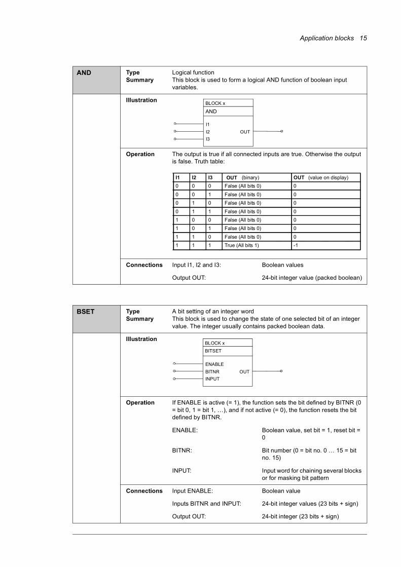
Logical functionThis block is used to form a logical AND function of boolean input variables.
Illustration
Operation The output is true if all connected inputs are true. Otherwise the output is false. Truth table:
Connections Input I1, I2 and I3: Boolean values
Output OUT: 24-bit integer value (packed boolean)
BSET Type Summary
A bit setting of an integer word This block is used to change the state of one selected bit of an integer value. The integer usually contains packed boolean data.
Illustration
Operation If ENABLE is active (= 1), the function sets the bit defined by BITNR (0 = bit 0, 1 = bit 1, …), and if not active (= 0), the function resets the bit defined by BITNR.
ENABLE: Boolean value, set bit = 1, reset bit = 0
BITNR: Bit number (0 = bit no. 0 … 15 = bit no. 15)
INPUT: Input word for chaining several blocks or for masking bit pattern
Connections Input ENABLE: Boolean value
Inputs BITNR and INPUT: 24-bit integer values (23 bits + sign)
Output OUT: 24-bit integer (23 bits + sign)
BLOCK x
AND
I1I2I3
OUT
I1 I2 I3 OUT (binary) OUT (value on display)0 0 0 False (All bits 0) 0 0 0 1 False (All bits 0) 0 0 1 0 False (All bits 0) 0 0 1 1 False (All bits 0) 0 1 0 0 False (All bits 0) 0 1 0 1 False (All bits 0) 0 1 1 0 False (All bits 0) 0 1 1 1 True (All bits 1) -1
BLOCK x
BITSET
ENABLEBITNRINPUT
OUT
16 Application blocks
COMPARE Type Summary
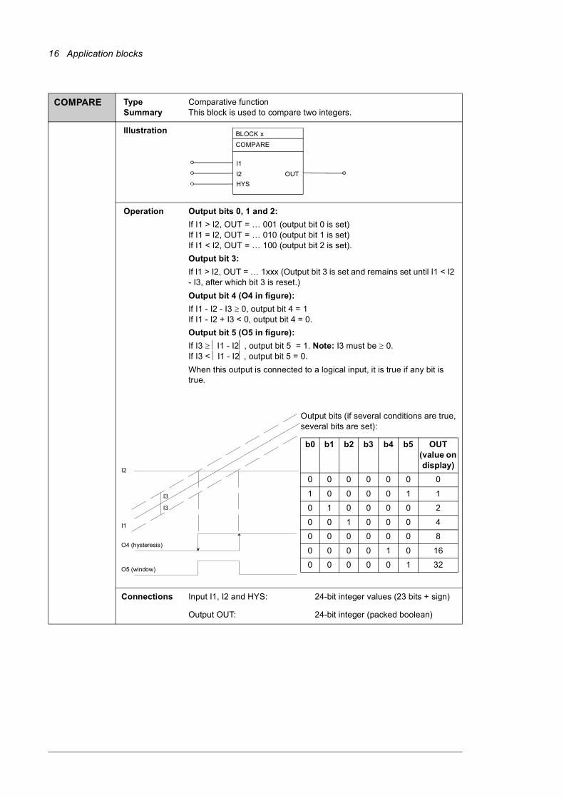
Comparative functionThis block is used to compare two integers.
Illustration
Operation Output bits 0, 1 and 2:If I1 > I2, OUT = … 001 (output bit 0 is set)If I1 = I2, OUT = … 010 (output bit 1 is set)If I1 < I2, OUT = … 100 (output bit 2 is set).Output bit 3:If I1 > I2, OUT = … 1xxx (Output bit 3 is set and remains set until I1 < I2 - I3, after which bit 3 is reset.)Output bit 4 (O4 in figure): If I1 - I2 - I3 ≥ 0, output bit 4 = 1If I1 - I2 + I3 < 0, output bit 4 = 0.Output bit 5 (O5 in figure):If I3 ≥ ⏐I1 - I2⏐, output bit 5 = 1. Note: I3 must be ≥ 0.If I3 < ⏐I1 - I2⏐, output bit 5 = 0.When this output is connected to a logical input, it is true if any bit is true.
Connections Input I1, I2 and HYS: 24-bit integer values (23 bits + sign)
Output OUT: 24-bit integer (packed boolean)
BLOCK x COMPARE
I1I2HYS
OUT
I1
I2
I3
I3
O4 (hysteresis)
O5 (window)
Output bits (if several conditions are true, several bits are set):
b0 b1 b2 b3 b4 b5 OUT (value on display)
0 0 0 0 0 0 0
1 0 0 0 0 1 1
0 1 0 0 0 0 2
0 0 1 0 0 0 4
0 0 0 0 0 0 8
0 0 0 0 1 0 16
0 0 0 0 0 1 32
Application blocks 17
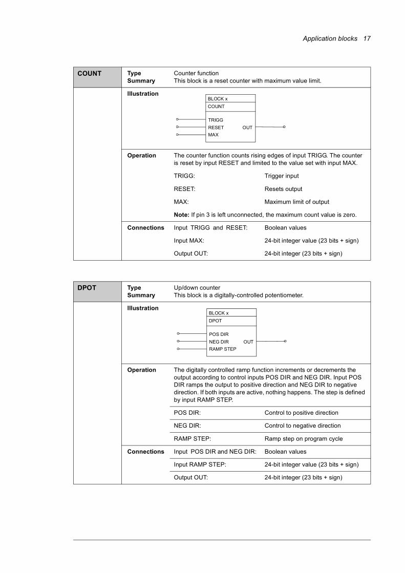
COUNT Type Summary
Counter functionThis block is a reset counter with maximum value limit.
Illustration
Operation The counter function counts rising edges of input TRIGG. The counter is reset by input RESET and limited to the value set with input MAX.
TRIGG: Trigger input
RESET: Resets output
MAX: Maximum limit of output
Note: If pin 3 is left unconnected, the maximum count value is zero.
Connections Input TRIGG and RESET: Boolean values
Input MAX: 24-bit integer value (23 bits + sign)
Output OUT: 24-bit integer (23 bits + sign)
DPOT Type Summary
Up/down counterThis block is a digitally-controlled potentiometer.
Illustration
Operation The digitally controlled ramp function increments or decrements the output according to control inputs POS DIR and NEG DIR. Input POS DIR ramps the output to positive direction and NEG DIR to negative direction. If both inputs are active, nothing happens. The step is defined by input RAMP STEP.
POS DIR: Control to positive direction
NEG DIR: Control to negative direction
RAMP STEP: Ramp step on program cycle
Connections Input POS DIR and NEG DIR: Boolean values
Input RAMP STEP: 24-bit integer value (23 bits + sign)
Output OUT: 24-bit integer (23 bits + sign)
BLOCK x COUNT
TRIGGRESETMAX
OUT
BLOCK x DPOT
POS DIRNEG DIRRAMP STEP
OUT
18 Application blocks
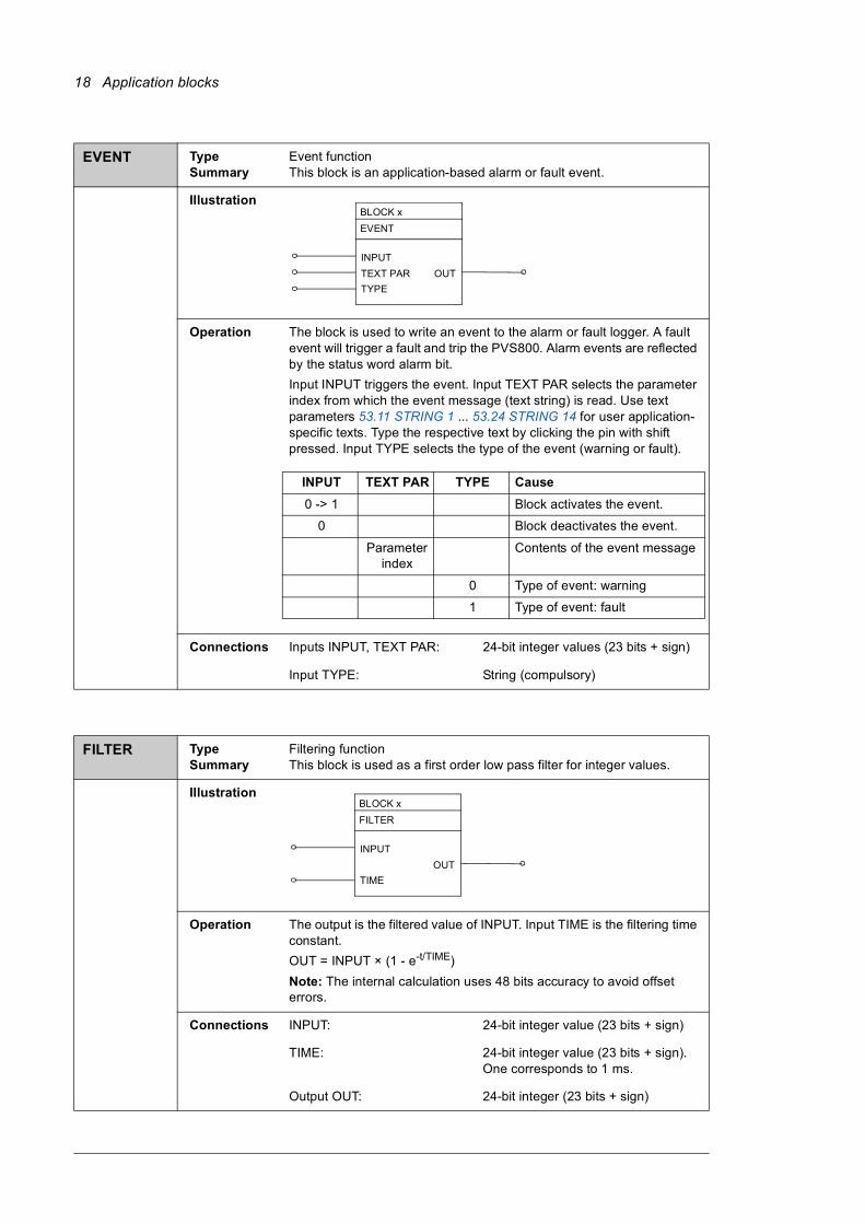
EVENT Type Summary
Event functionThis block is an application-based alarm or fault event.
Illustration
Operation The block is used to write an event to the alarm or fault logger. A fault event will trigger a fault and trip the PVS800. Alarm events are reflected by the status word alarm bit.Input INPUT triggers the event. Input TEXT PAR selects the parameter index from which the event message (text string) is read. Use text parameters 53.11 STRING 1 ... 53.24 STRING 14 for user application-specific texts. Type the respective text by clicking the pin with shift pressed. Input TYPE selects the type of the event (warning or fault).
Connections Inputs INPUT, TEXT PAR: 24-bit integer values (23 bits + sign)
Input TYPE: String (compulsory)
FILTER Type Summary
Filtering functionThis block is used as a first order low pass filter for integer values.
Illustration
Operation The output is the filtered value of INPUT. Input TIME is the filtering time constant.OUT = INPUT × (1 - e-t/TIME)Note: The internal calculation uses 48 bits accuracy to avoid offset errors.
Connections INPUT: 24-bit integer value (23 bits + sign)
TIME: 24-bit integer value (23 bits + sign). One corresponds to 1 ms.
Output OUT: 24-bit integer (23 bits + sign)
BLOCK x EVENT
INPUTTEXT PARTYPE
OUT
INPUT TEXT PAR TYPE Cause0 -> 1 Block activates the event.
0 Block deactivates the event.
Parameter index
Contents of the event message
0 Type of event: warning
1 Type of event: fault
BLOCK x FILTER
INPUT
TIMEOUT
Application blocks 19
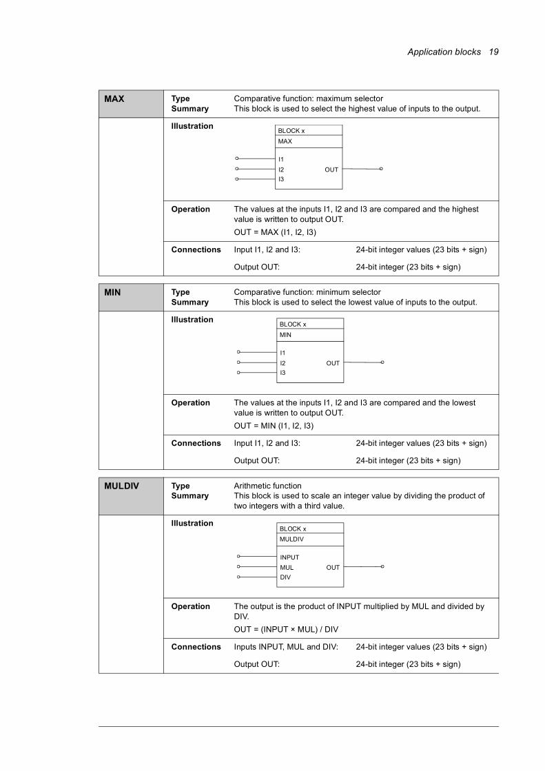
MAX Type Summary
Comparative function: maximum selectorThis block is used to select the highest value of inputs to the output.
Illustration
Operation The values at the inputs I1, I2 and I3 are compared and the highest value is written to output OUT.OUT = MAX (I1, I2, I3)
Connections Input I1, I2 and I3: 24-bit integer values (23 bits + sign)
Output OUT: 24-bit integer (23 bits + sign)
MIN Type Summary
Comparative function: minimum selectorThis block is used to select the lowest value of inputs to the output.
Illustration
Operation The values at the inputs I1, I2 and I3 are compared and the lowest value is written to output OUT.OUT = MIN (I1, I2, I3)
Connections Input I1, I2 and I3: 24-bit integer values (23 bits + sign)
Output OUT: 24-bit integer (23 bits + sign)
MULDIV Type Summary
Arithmetic functionThis block is used to scale an integer value by dividing the product of two integers with a third value.
Illustration
Operation The output is the product of INPUT multiplied by MUL and divided by DIV.OUT = (INPUT × MUL) / DIV
Connections Inputs INPUT, MUL and DIV: 24-bit integer values (23 bits + sign)
Output OUT: 24-bit integer (23 bits + sign)
BLOCK x
MAX
I1I2I3
OUT
BLOCK x
MIN
I1I2I3
OUT
BLOCK x MULDIV
INPUTMULDIV
OUT

20 Application blocks
OR Type Summary
Logical functionThis block is used to form general combinatory expressions with boolean variables.
Illustration
Operation The output is true if any of the inputs is true. Truth table:
Connections Input I1, I2 and I3: Boolean values
Output OUT: 24-bit integer value (packed boolean)
BLOCK x OR
I1I2I3
OUT
I1 I2 I3 OUT OUT (Value on display)
0 0 0 False (All bits 0) 0
0 0 1 True (All bits 1) -1
0 1 0 True (All bits 1) -1
0 1 1 True (All bits 1) -1
1 0 0 True (All bits 1) -1
1 1 0 True (All bits 1) -1
1 1 1 True (All bits 1) -1
Application blocks 21
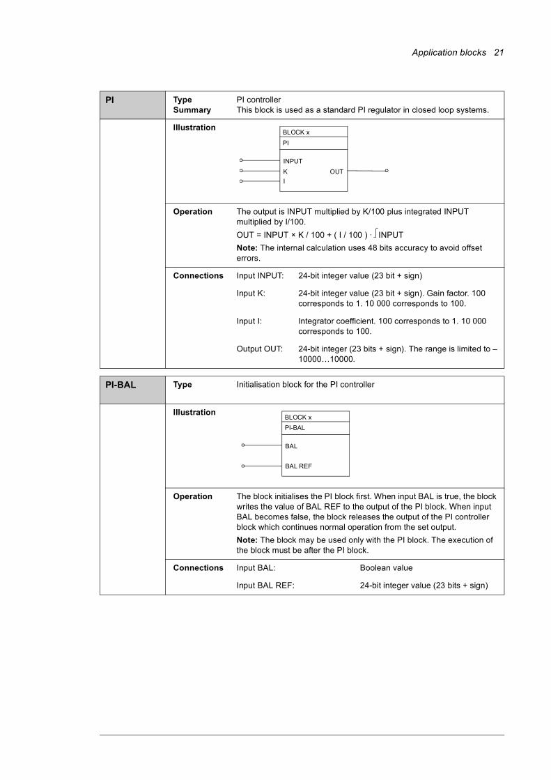
PI Type Summary
PI controllerThis block is used as a standard PI regulator in closed loop systems.
Illustration
Operation The output is INPUT multiplied by K/100 plus integrated INPUT multiplied by I/100. OUT = INPUT × K / 100 + ( I / 100 ) · INPUTNote: The internal calculation uses 48 bits accuracy to avoid offset errors.
Connections Input INPUT: 24-bit integer value (23 bit + sign)
Input K: 24-bit integer value (23 bit + sign). Gain factor. 100 corresponds to 1. 10 000 corresponds to 100.
Input I: Integrator coefficient. 100 corresponds to 1. 10 000 corresponds to 100.
Output OUT: 24-bit integer (23 bits + sign). The range is limited to –10000…10000.
PI-BAL Type
Initialisation block for the PI controller
Illustration
Operation The block initialises the PI block first. When input BAL is true, the block writes the value of BAL REF to the output of the PI block. When input BAL becomes false, the block releases the output of the PI controller block which continues normal operation from the set output.Note: The block may be used only with the PI block. The execution of the block must be after the PI block.
Connections Input BAL: Boolean value
Input BAL REF: 24-bit integer value (23 bits + sign)
BLOCK x
PI
INPUTKI
OUT
BLOCK x PI-BAL
BAL
BAL REF
22 Application blocks
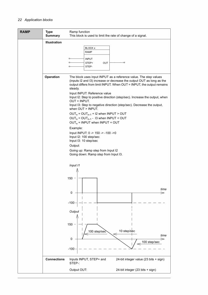
RAMP Type Summary
Ramp functionThis block is used to limit the rate of change of a signal.
Illustration
Operation The block uses input INPUT as a reference value. The step values (inputs I2 and I3) increase or decrease the output OUT as long as the output differs from limit INPUT. When OUT = INPUT, the output remains steady.Input INPUT: Reference valueInput I2: Step to positive direction (step/sec). Increase the output, when OUT < INPUT.Input I3: Step to negative direction (step/sec). Decrease the output, when OUT > INPUT.OUTn = OUTn-1 + I2 when INPUT > OUTOUTn = OUTn-1 - I3 when INPUT < OUTOUTn = INPUT when INPUT = OUT
Example:Input INPUT: 0 -> 150 -> -100 ->0Input I2: 100 step/secInput I3: 10 step/secOutput: Going up: Ramp step from Input I2Going down: Ramp step from Input I3.
Connections Inputs INPUT, STEP+ and STEP-:
24-bit integer value (23 bits + sign)
Output OUT: 24-bit integer (23 bits + sign)
BLOCK x
RAMP
INPUTSTEP+STEP-
OUT
time
Input I1
0
150
-100
time
Output
0
150
-100
100 step/sec
100 step/sec
10 step/sec
Application blocks 23
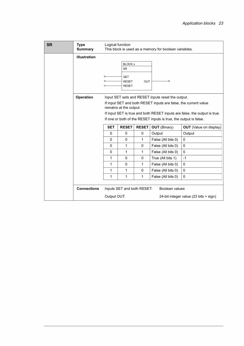
SR Type Summary
Logical functionThis block is used as a memory for boolean variables.
Illustration
Operation Input SET sets and RESET inputs reset the output.If input SET and both RESET inputs are false, the current value remains at the output.If input SET is true and both RESET inputs are false, the output is true. If one or both of the RESET inputs is true, the output is false.
Connections Inputs SET and both RESET: Boolean values
Output OUT: 24-bit integer value (23 bits + sign)
BLOCK x SR
SETRESETRESET
OUT
SET RESET RESET OUT (Binary) OUT (Value on display)
0 0 0 Output Output
0 0 1 False (All bits 0) 0
0 1 0 False (All bits 0) 0
0 1 1 False (All bits 0) 0
1 0 0 True (All bits 1) -1
1 0 1 False (All bits 0) 0
1 1 0 False (All bits 0) 0
1 1 1 False (All bits 0) 0

24 Application blocks
SWITCH-B Type Summary
Logical functionThis block is used as a changeover switch for boolean type of data.
Illustration
Operation The output is equal to input NO if input ACT is true and equal to input NC if input ACT is false.
NO = normally open, NC = normally closed
Connections Input ACT, NO and NC: Boolean values
Output OUT: 24-bit integer value (packed boolean)
SWITCH-I Type Summary
Logical functionThis block is used as a changeover switch for integer type of data.
Illustration
Operation The output is equal to input NO if input ACT is true and equal to input NC if input ACT is false.
NO = normally open, NC = normally closed
Connections Input ACT: Boolean value
Input NO and NC: 24-bit integer values (23 bits + sign)
Output OUT: 24-bit integer value (23 bits + sign)
BLOCK x SW-CB
ACTNONC
OUT
SWITCH-B
ACT NO NC OUT OUT (Value on display)
0 NO NC NC True = -1
1 NO NC NO False = 0
BLOCK x SW-IL
ACTNONC
OUT
SWITCH-I
ACT NO NC OUT0 NO NC NC
1 NO NC NO
Application blocks 25
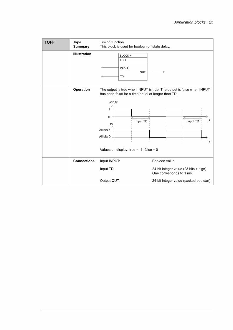
TOFF Type Summary
Timing functionThis block is used for boolean off state delay.
Illustration
Operation The output is true when INPUT is true. The output is false when INPUT has been false for a time equal or longer than TD.
Values on display: true = -1, false = 0
Connections Input INPUT: Boolean value
Input TD: 24-bit integer value (23 bits + sign). One corresponds to 1 ms.
Output OUT: 24-bit integer value (packed boolean)
BLOCK x TOFF
INPUT
TDOUT
INPUT
t
1
0Input TD
OUT
t
All bits 1
All bits 0
Input TD
26 Application blocks
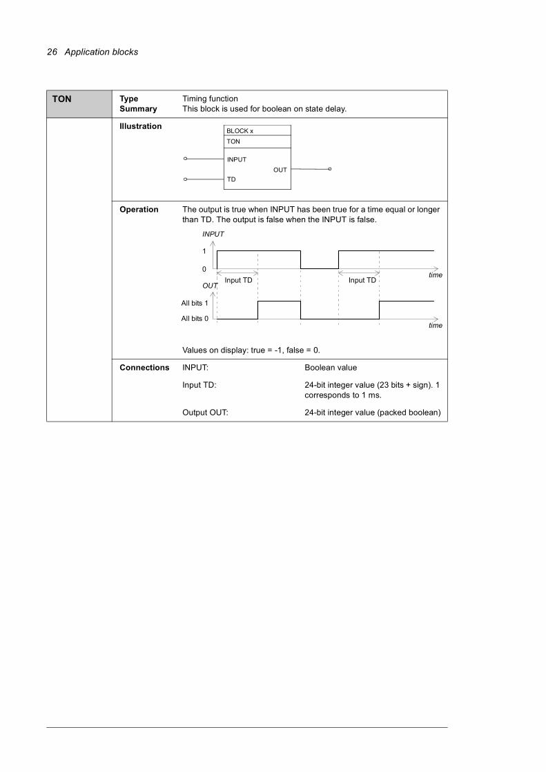
TON Type Summary
Timing functionThis block is used for boolean on state delay.
Illustration
Operation The output is true when INPUT has been true for a time equal or longer than TD. The output is false when the INPUT is false.
Values on display: true = -1, false = 0.
Connections INPUT: Boolean value
Input TD: 24-bit integer value (23 bits + sign). 1 corresponds to 1 ms.
Output OUT: 24-bit integer value (packed boolean)
BLOCK x
TON
INPUT
TDOUT
INPUT
time
1
0 Input TD Input TD
OUT
time
All bit s 1 All bit s 0
Application blocks 27
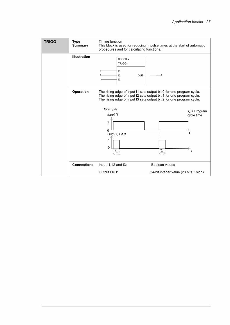
TRIGG Type Summary
Timing functionThis block is used for reducing impulse times at the start of automatic procedures and for calculating functions.
Illustration
Operation The rising edge of input I1 sets output bit 0 for one program cycle.The rising edge of input I2 sets output bit 1 for one program cycle.The rising edge of input I3 sets output bit 2 for one program cycle.
Connections Input I1, I2 and I3: Boolean values
Output OUT: 24-bit integer value (23 bits + sign)
BLOCK x TRIGG
I1I2I3
OUT
Input I1
t
1
0Output, Bit 0
t
1
0Tc
Example
Tc
Tc = Programcycle time
28 Application blocks
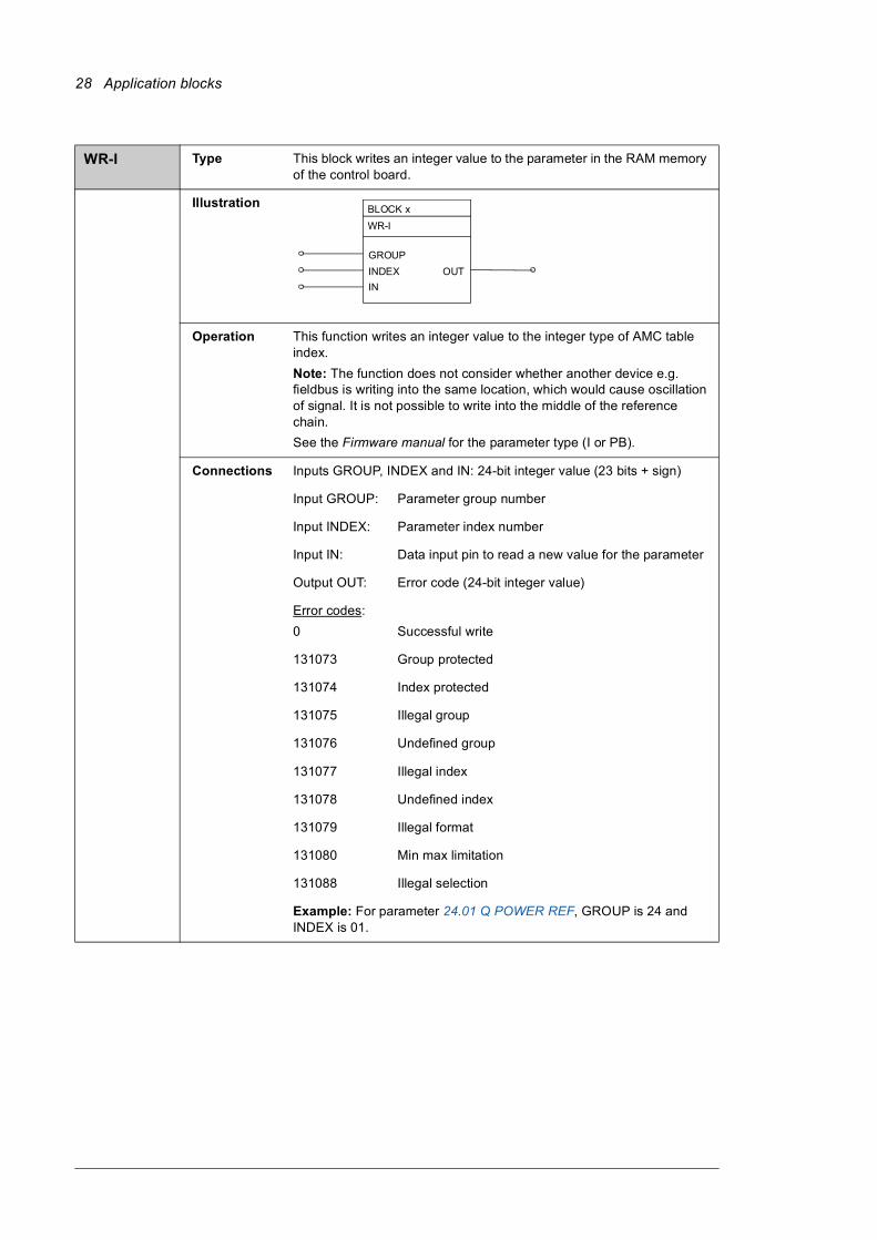
WR-I Type This block writes an integer value to the parameter in the RAM memory of the control board.
Illustration
Operation This function writes an integer value to the integer type of AMC table index. Note: The function does not consider whether another device e.g. fieldbus is writing into the same location, which would cause oscillation of signal. It is not possible to write into the middle of the reference chain.See the Firmware manual for the parameter type (I or PB).
Connections Inputs GROUP, INDEX and IN: 24-bit integer value (23 bits + sign)
Input GROUP: Parameter group number
Input INDEX: Parameter index number
Input IN: Data input pin to read a new value for the parameter
Output OUT: Error code (24-bit integer value)
Error codes:0 Successful write
131073 Group protected
131074 Index protected
131075 Illegal group
131076 Undefined group
131077 Illegal index
131078 Undefined index
131079 Illegal format
131080 Min max limitation
131088 Illegal selection
Example: For parameter 24.01 Q POWER REF, GROUP is 24 and INDEX is 01.
BLOCK x WR-I
GROUPINDEXIN
OUT
Application blocks 29
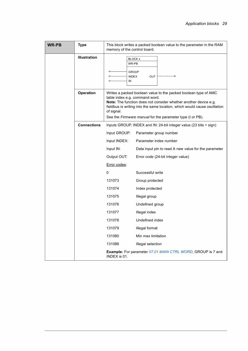
WR-PB Type This block writes a packed boolean value to the parameter in the RAM memory of the control board.
Illustration
Operation Writes a packed boolean value to the packed boolean type of AMC table index e.g. command word.Note: The function does not consider whether another device e.g. fieldbus is writing into the same location, which would cause oscillation of signal. See the Firmware manual for the parameter type (I or PB).
Connections Inputs GROUP, INDEX and IN: 24-bit integer value (23 bits + sign)
Input GROUP: Parameter group number
Input INDEX: Parameter index number
Input IN: Data input pin to read A new value for the parameter
Output OUT: Error code (24-bit integer value)
Error codes:
0 Successful write
131073 Group protected
131074 Index protected
131075 Illegal group
131076 Undefined group
131077 Illegal index
131078 Undefined index
131079 Illegal format
131080 Min max limitation
131088 Illegal selection
Example: For parameter 07.01 MAIN CTRL WORD, GROUP is 7 and INDEX is 01.
BLOCK x WR-PB
GROUPINDEXIN
OUT
30 Application blocks
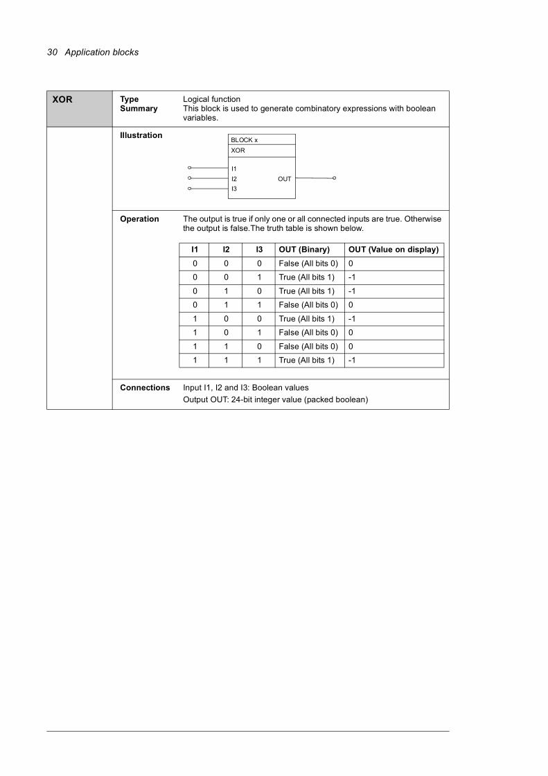
XOR Type Summary
Logical functionThis block is used to generate combinatory expressions with boolean variables.
Illustration
Operation The output is true if only one or all connected inputs are true. Otherwise the output is false.The truth table is shown below.
Connections Input I1, I2 and I3: Boolean valuesOutput OUT: 24-bit integer value (packed boolean)
BLOCK x XOR
I1I2I3
OUT
I1 I2 I3 OUT (Binary) OUT (Value on display)0 0 0 False (All bits 0) 0
0 0 1 True (All bits 1) -1
0 1 0 True (All bits 1) -1
0 1 1 False (All bits 0) 0
1 0 0 True (All bits 1) -1
1 0 1 False (All bits 0) 0
1 1 0 False (All bits 0) 0
1 1 1 True (All bits 1) -1
Application blocks 31
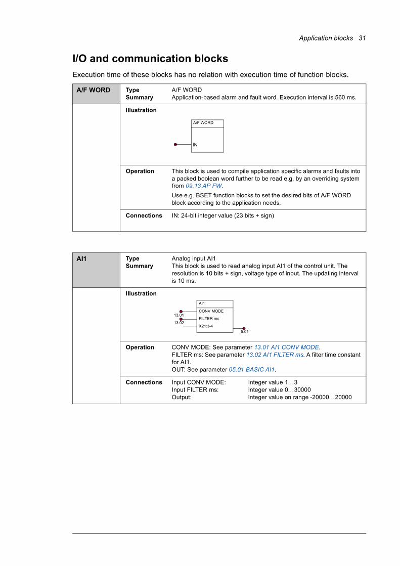
I/O and communication blocksExecution time of these blocks has no relation with execution time of function blocks.
A/F WORD Type Summary
A/F WORD Application-based alarm and fault word. Execution interval is 560 ms.
Illustration
Operation This block is used to compile application specific alarms and faults into a packed boolean word further to be read e.g. by an overriding system from 09.13 AP FW.Use e.g. BSET function blocks to set the desired bits of A/F WORD block according to the application needs.
Connections IN: 24-bit integer value (23 bits + sign)
AI1 Type Summary
Analog input AI1This block is used to read analog input AI1 of the control unit. The resolution is 10 bits + sign, voltage type of input. The updating interval is 10 ms.
Illustration
Operation CONV MODE: See parameter 13.01 AI1 CONV MODE.FILTER ms: See parameter 13.02 AI1 FILTER ms. A filter time constant for AI1.OUT: See parameter 05.01 BASIC AI1.
Connections Input CONV MODE: Integer value 1…3Input FILTER ms: Integer value 0…30000Output: Integer value on range -20000…20000
A/F WORD
IN
AI1
CONV MODE
FILTER ms
X21:3-4
13.01
13.02
5.01
32 Application blocks
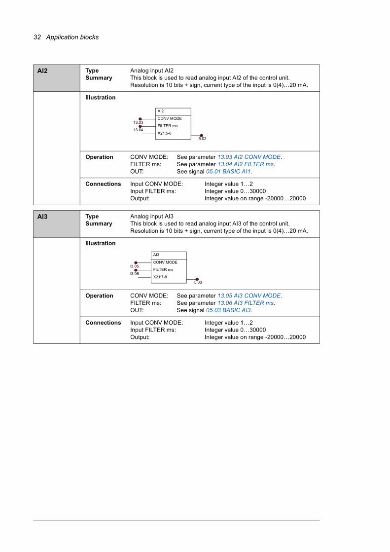
AI2 Type Summary
Analog input AI2This block is used to read analog input AI2 of the control unit. Resolution is 10 bits + sign, current type of the input is 0(4)…20 mA.
Illustration
Operation CONV MODE: See parameter 13.03 AI2 CONV MODE.FILTER ms: See parameter 13.04 AI2 FILTER ms.OUT: See signal 05.01 BASIC AI1.
Connections Input CONV MODE: Integer value 1…2Input FILTER ms: Integer value 0…30000Output: Integer value on range -20000…20000
AI3 Type Summary
Analog input AI3This block is used to read analog input AI3 of the control unit. Resolution is 10 bits + sign, current type of the input is 0(4)…20 mA.
Illustration
Operation CONV MODE: See parameter 13.05 AI3 CONV MODE.FILTER ms: See parameter 13.06 AI3 FILTER ms.OUT: See signal 05.03 BASIC AI3.
Connections Input CONV MODE: Integer value 1…2Input FILTER ms: Integer value 0…30000Output: Integer value on range -20000…20000
AI2
CONV MODE
FILTER ms
X21:5-6
13.03
13.04
5.02
AI3
CONV MODE
FILTER ms
X21:7-8
13.05
13.06
5.03
Application blocks 33
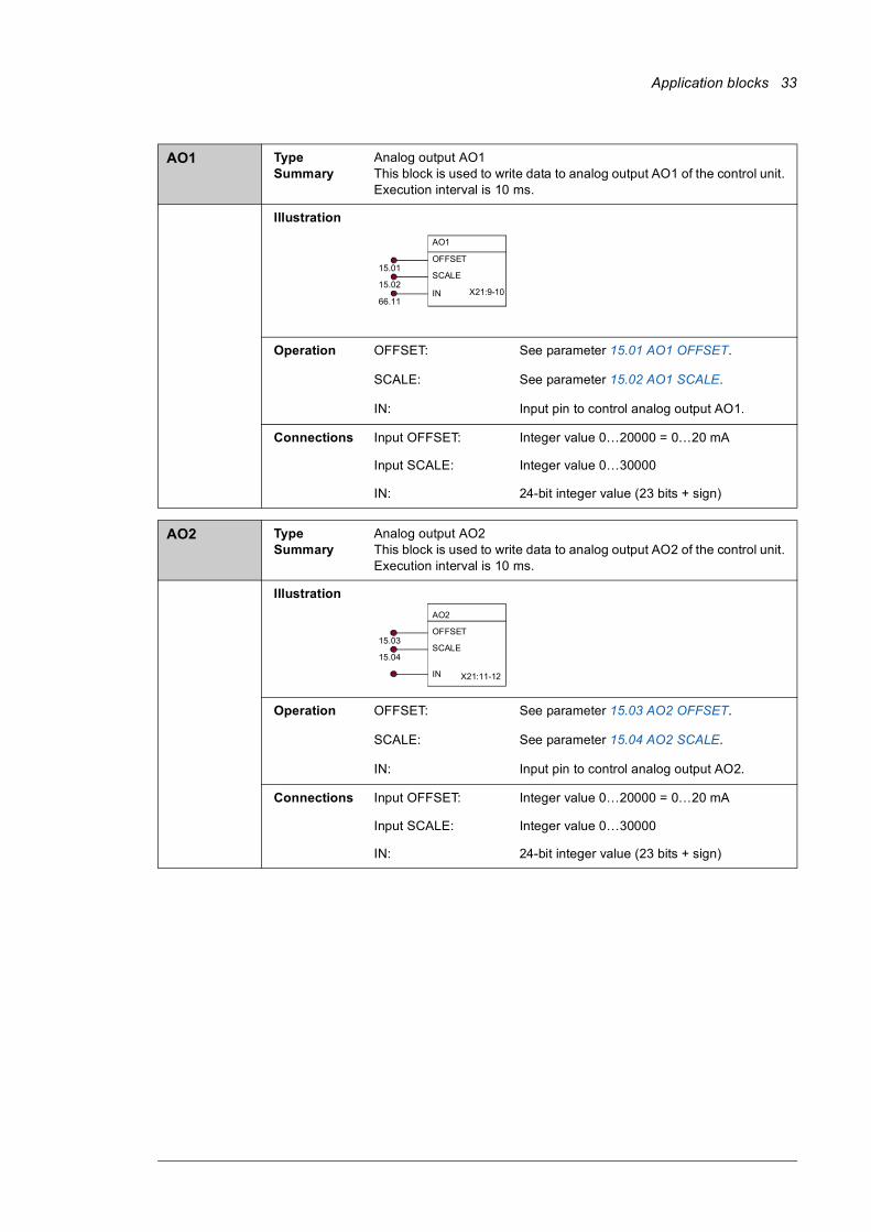
AO1 Type Summary
Analog output AO1This block is used to write data to analog output AO1 of the control unit. Execution interval is 10 ms.
Illustration
Operation OFFSET: See parameter 15.01 AO1 OFFSET.
SCALE: See parameter 15.02 AO1 SCALE.
IN: Input pin to control analog output AO1.
Connections Input OFFSET: Integer value 0…20000 = 0…20 mA
Input SCALE: Integer value 0…30000
IN: 24-bit integer value (23 bits + sign)
AO2 Type Summary
Analog output AO2This block is used to write data to analog output AO2 of the control unit. Execution interval is 10 ms.
Illustration
Operation OFFSET: See parameter 15.03 AO2 OFFSET.
SCALE: See parameter 15.04 AO2 SCALE.
IN: Input pin to control analog output AO2.
Connections Input OFFSET: Integer value 0…20000 = 0…20 mA
Input SCALE: Integer value 0…30000
IN: 24-bit integer value (23 bits + sign)
AO1
OFFSET
SCALE
X21:9-10
15.01
15.02
66.11IN
AO2
OFFSET
SCALE
X21:11-12
15.03
15.04
IN
34 Application blocks
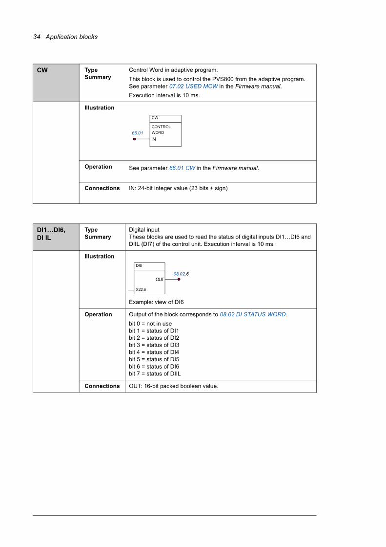
CW Type Summary
Control Word in adaptive program.This block is used to control the PVS800 from the adaptive program. See parameter 07.02 USED MCW in the Firmware manual.Execution interval is 10 ms.
Illustration
Operation See parameter 66.01 CW in the Firmware manual.
Connections IN: 24-bit integer value (23 bits + sign)
DI1…DI6, DI IL
Type Summary
Digital inputThese blocks are used to read the status of digital inputs DI1…DI6 and DIIL (DI7) of the control unit. Execution interval is 10 ms.
Illustration
Example: view of DI6
Operation Output of the block corresponds to 08.02 DI STATUS WORD.bit 0 = not in usebit 1 = status of DI1bit 2 = status of DI2bit 3 = status of DI3bit 4 = status of DI4bit 5 = status of DI5bit 6 = status of DI6bit 7 = status of DIIL
Connections OUT: 16-bit packed boolean value.
CW
IN
CONTROL WORD 66.01
DI6
X22:6
OUT8.05.608.02.6
Application blocks 35
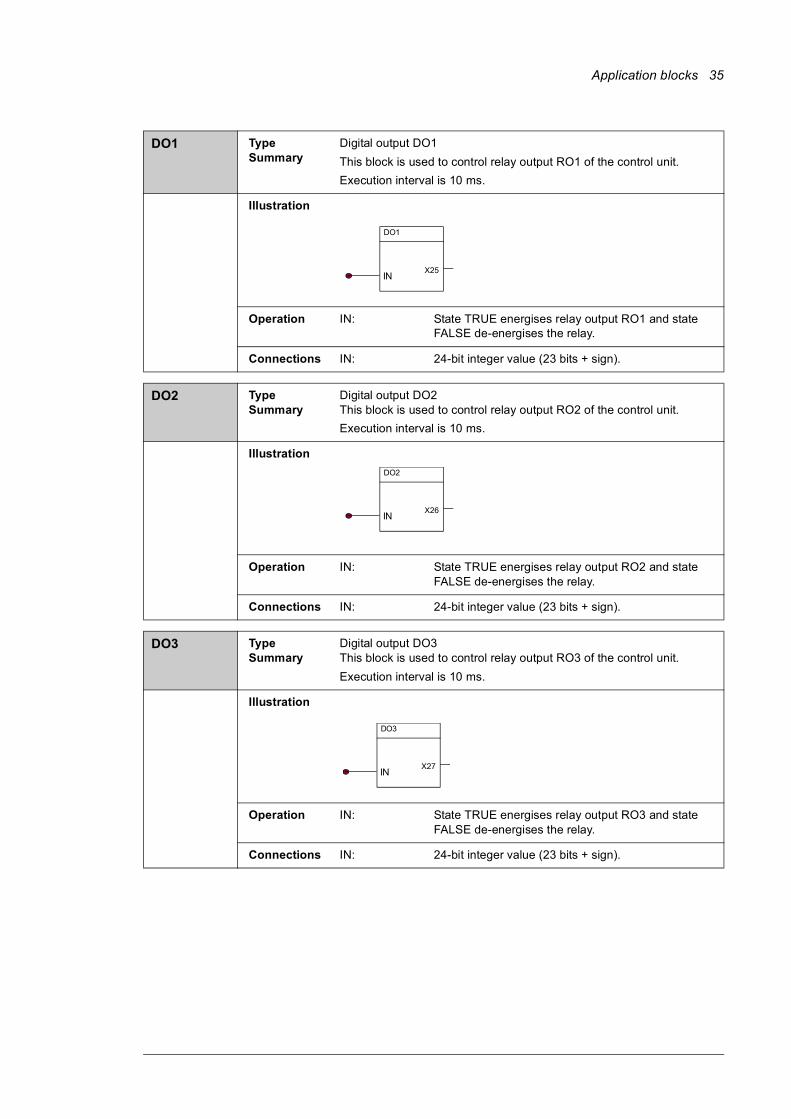
DO1 Type Summary
Digital output DO1This block is used to control relay output RO1 of the control unit.Execution interval is 10 ms.
Illustration
Operation IN: State TRUE energises relay output RO1 and state FALSE de-energises the relay.
Connections IN: 24-bit integer value (23 bits + sign).
DO2 Type Summary
Digital output DO2This block is used to control relay output RO2 of the control unit.Execution interval is 10 ms.
Illustration
Operation IN: State TRUE energises relay output RO2 and state FALSE de-energises the relay.
Connections IN: 24-bit integer value (23 bits + sign).
DO3 Type Summary
Digital output DO3This block is used to control relay output RO3 of the control unit.Execution interval is 10 ms.
Illustration
Operation IN: State TRUE energises relay output RO3 and state FALSE de-energises the relay.
Connections IN: 24-bit integer value (23 bits + sign).
DO1
X25IN
DO2
X26IN
DO3
X27IN
36 Application blocks
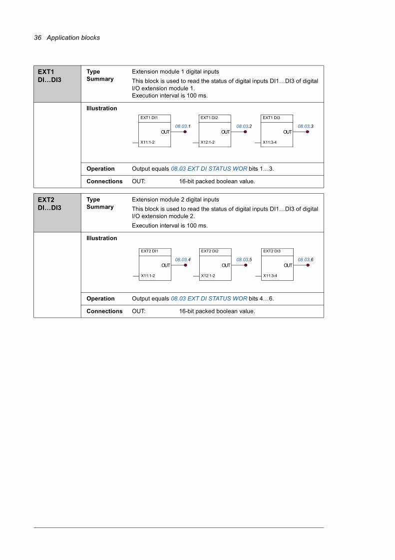
EXT1 DI…DI3
Type Summary
Extension module 1 digital inputsThis block is used to read the status of digital inputs DI1…DI3 of digital I/O extension module 1.Execution interval is 100 ms.
Illustration
Operation Output equals 08.03 EXT DI STATUS WOR bits 1…3.
Connections OUT: 16-bit packed boolean value.
EXT2 DI…DI3
Type Summary
Extension module 2 digital inputsThis block is used to read the status of digital inputs DI1…DI3 of digital I/O extension module 2.Execution interval is 100 ms.
Illustration
Operation Output equals 08.03 EXT DI STATUS WOR bits 4…6.
Connections OUT: 16-bit packed boolean value.
EXT1 DI1
X11:1-2
OUT8.06.1
EXT1 DI2
X12:1-2
OUT8.06.2
EXT1 DI3
X11:3-4
OUT8.06.308.03.1 08.03.2 08.03.3
EXT2 DI1
X11:1-2
OUT8.06.4
EXT2 DI2
X12:1-2
OUT8.06.5
EXT2 DI3
X11:3-4
OUT8.06.608.03.4 08.03.5 08.03.6

Application blocks 37
EXT3 DI…DI3
Type Summary
Extension module 3 digital inputsThis block is used to read the status of digital inputs DI1…DI3 of digital I/O extension module 3.Execution interval is 100 ms.
Illustration
Operation Output is the same as 08.03 EXT DI STATUS WOR bits 7…9.
Connections OUT: 16-bit packed boolean value.
EXT4 DI…DI3
Type Summary
Extension module 4 digital inputsThis block is used to read the status of digital inputs DI1…DI3 of digital I/O extension module 4.Execution interval is 100 ms.
Illustration
Operation Output is the same as 08.03 EXT DI STATUS WOR bits 10…12.
Connections OUT: 16-bit packed boolean value.
EXT3 DI1
X11:1-2
OUT8.06.7
EXT3 DI2
X12:1-2
OUT8.06.8
EXT3 DI3
X11:3-4
OUT8.06.908.03.7 08.03.8 08.03.9
EXT4 DI1
X11:1-2
OUT8.06.10
EXT4 DI2
X12:1-2
OUT8.06.11
EXT4 DI3
X11:3-4
OUT8.06.1208.03.10 08.03.11 08.03.12
38 Application blocks
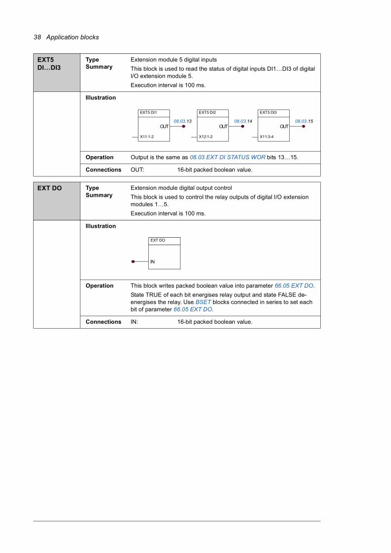
EXT5 DI…DI3
Type Summary
Extension module 5 digital inputsThis block is used to read the status of digital inputs DI1…DI3 of digital I/O extension module 5.Execution interval is 100 ms.
Illustration
Operation Output is the same as 08.03 EXT DI STATUS WOR bits 13…15.
Connections OUT: 16-bit packed boolean value.
EXT DO Type Summary
Extension module digital output controlThis block is used to control the relay outputs of digital I/O extension modules 1…5.Execution interval is 100 ms.
Illustration
Operation This block writes packed boolean value into parameter 66.05 EXT DO.State TRUE of each bit energises relay output and state FALSE de-energises the relay. Use BSET blocks connected in series to set each bit of parameter 66.05 EXT DO.
Connections IN: 16-bit packed boolean value.
EXT5 DI1
X11:1-2
OUT8.06.13
EXT5 DI2
X12:1-2
OUT8.06.14
EXT5 DI3
X11:3-4
OUT8.06.1508.03.13 08.03.14 08.03.15
EXT DO
IN
Application blocks 39
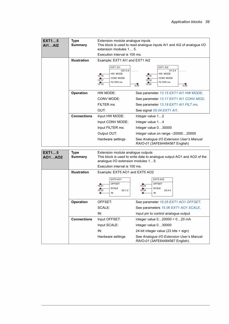
EXT1…5 AI1…AI2
Type Summary
Extension module analogue inputsThis block is used to read analogue inputs AI1 and AI2 of analogue I/O extension modules 1… 5.Execution interval is 100 ms.
Illustration Example: EXT1 AI1 and EXT1 AI2
Operation HW MODE: See parameter 13.15 EXT1 AI1 HW MODE.
CONV MODE: See parameter 13.17 EXT1 AI1 CONV MOD.
FILTER ms See parameter 13.19 EXT1 AI1 FILT ms.
OUT: See signal 05.04 EXT1 AI1.
Connections Input HW MODE: Integer value 1…2
Input CONV MODE: Integer value 1…4
Input FILTER ms: Integer value 0…30000
Output OUT: Integer value on range –20000…20000
Hardware settings See Analogue I/O Extension User’s Manual RAIO-01 (3AFE64484567 English)
EXT1…5 AO1…AO2
Type Summary
Extension module analogue outputsThis block is used to write data to analogue output AO1 and AO2 of the analogue I/O extension modules 1…5.Execution interval is 100 ms.
Illustration Example: EXT5 AO1 and EXT5 AO2
Operation OFFSET: See parameter 15.05 EXT1 AO1 OFFSET.
SCALE: See parameters 15.06 EXT1 AO1 SCALE.
IN: Input pin to control analogue output
Connections Input OFFSET: integer value 0…20000 = 0…20 mA
Input SCALE: integer value 0…30000
IN: 24-bit integer value (23 bits + sign)
Hardware settings See Analogue I/O Extension User’s Manual RAIO-01 (3AFE64484567 English).
EXT1 AI1
HW MODE
CONV MODE
X21:3-4
13.17
13.15
5.04FILTER ms
13.19
EXT1 AI2
HW MODE
CONV MODE
X1:3-4
13.18
13.16
5.05FILTER ms
13.20
EXT5 AO1
15.23
15.21OFFSET
SCALE
IN
EXT5 AO2
15.24
15.23OFFSET
SCALE
INX2:1-2 X2:3-4
40 Application blocks
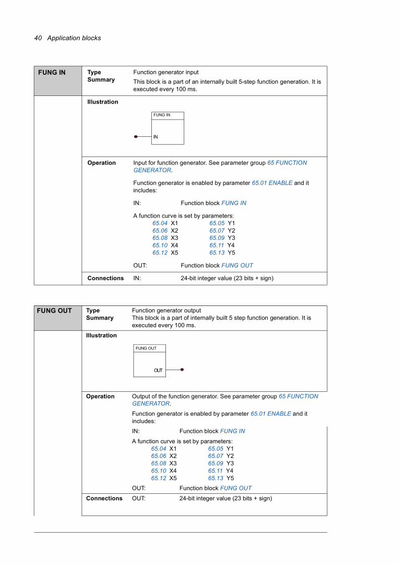
FUNG IN Type Summary
Function generator inputThis block is a part of an internally built 5-step function generation. It is executed every 100 ms.
Illustration
Operation Input for function generator. See parameter group 65 FUNCTION GENERATOR.
Function generator is enabled by parameter 65.01 ENABLE and it includes:
IN: Function block FUNG IN
A function curve is set by parameters:65.04 X1 65.05 Y165.06 X2 65.07 Y265.08 X3 65.09 Y365.10 X4 65.11 Y465.12 X5 65.13 Y5
OUT: Function block FUNG OUT
Connections IN: 24-bit integer value (23 bits + sign)
FUNG OUT Type Summary
Function generator outputThis block is a part of internally built 5 step function generation. It is executed every 100 ms.
Illustration
Operation Output of the function generator. See parameter group 65 FUNCTION GENERATOR.
Function generator is enabled by parameter 65.01 ENABLE and it includes:
IN: Function block FUNG IN
A function curve is set by parameters:65.04 X1 65.05 Y165.06 X2 65.07 Y265.08 X3 65.09 Y365.10 X4 65.11 Y465.12 X5 65.13 Y5
OUT: Function block FUNG OUT
Connections OUT: 24-bit integer value (23 bits + sign)
FUNG IN
IN
FUNG OUT
OUT
Application blocks 41
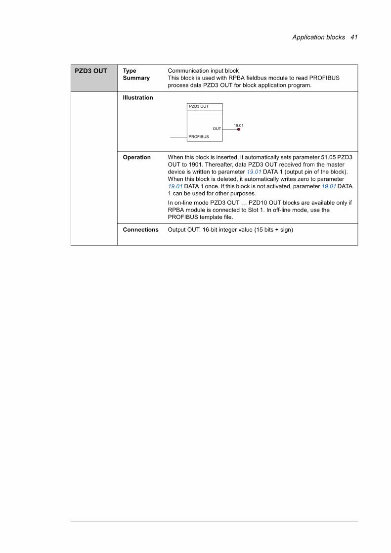
PZD3 OUT Type Summary
Communication input block This block is used with RPBA fieldbus module to read PROFIBUS process data PZD3 OUT for block application program.
Illustration
Operation When this block is inserted, it automatically sets parameter 51.05 PZD3 OUT to 1901. Thereafter, data PZD3 OUT received from the master device is written to parameter 19.01 DATA 1 (output pin of the block). When this block is deleted, it automatically writes zero to parameter 19.01 DATA 1 once. If this block is not activated, parameter 19.01 DATA 1 can be used for other purposes.In on-line mode PZD3 OUT … PZD10 OUT blocks are available only if RPBA module is connected to Slot 1. In off-line mode, use the PROFIBUS template file.
Connections Output OUT: 16-bit integer value (15 bits + sign)
19.01
PZD3 OUT
OUT
PROFIBUS
42 Application blocks
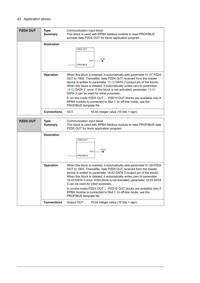
PZD4 OUT Type Summary
Communication input blockThis block is used with RPBA fieldbus module to read PROFIBUS process data PZD4 OUT for block application program..
Illustration
Operation When this block is inserted, it automatically sets parameter 51.07 PZD4 OUT to 1902. Thereafter, data PZD4 OUT received from the master device is written to parameter 19.02 DATA 2 (output pin of the block). When this block is deleted, it automatically writes zero to parameter 19.02 DATA 2 once. If this block is not activated, parameter 19.02 DATA 2 can be used for other purposes..In on-line mode PZD3 OUT … PZD10 OUT blocks are available only if RPBA module is connected to Slot 1. In off-line mode, use the PROFIBUS template file.
Connections OUT: 16-bit integer value (15 bits + sign)
PZD5 OUT Type Summary
Communication input block This block is used with RPBA fieldbus module to read PROFIBUS data PZD5 OUT for block application program.
Illustration
Operation When this block is inserted, it automatically sets parameter 51.09 PZD5 OUT to 1903. Thereafter, data PZD5 OUT received from the master device is written to parameter 19.03 DATA 3 (output pin of the block). When this block is deleted, it automatically writes zero to parameter 19.03 DATA 3 once. If this block is not activated, parameter 19.03 DATA 3 can be used for other purposes.In on-line mode PZD3 OUT … PZD10 OUT blocks are available only if RPBA module is connected to Slot 1. In off-line mode, use the PROFIBUS template file.
Connections Output OUT: 16-bit integer value (15 bits + sign)
19.02
PZD4 OUT
OUT
PROFIBUS
19.03
PZD5 OUT
OUT
PROFIBUS
Application blocks 43
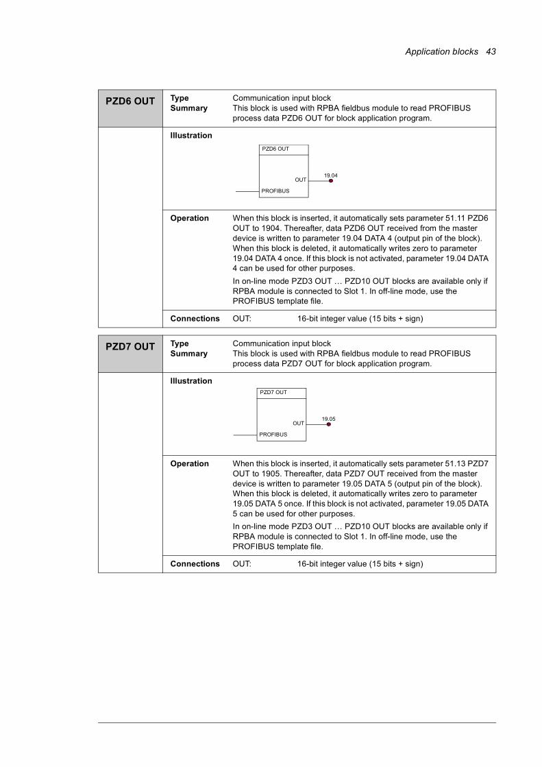
PZD6 OUT Type Summary
Communication input block This block is used with RPBA fieldbus module to read PROFIBUS process data PZD6 OUT for block application program.
Illustration
Operation When this block is inserted, it automatically sets parameter 51.11 PZD6 OUT to 1904. Thereafter, data PZD6 OUT received from the master device is written to parameter 19.04 DATA 4 (output pin of the block). When this block is deleted, it automatically writes zero to parameter 19.04 DATA 4 once. If this block is not activated, parameter 19.04 DATA 4 can be used for other purposes.In on-line mode PZD3 OUT … PZD10 OUT blocks are available only if RPBA module is connected to Slot 1. In off-line mode, use the PROFIBUS template file.
Connections OUT: 16-bit integer value (15 bits + sign)
PZD7 OUT Type Summary
Communication input block This block is used with RPBA fieldbus module to read PROFIBUS process data PZD7 OUT for block application program.
Illustration
Operation When this block is inserted, it automatically sets parameter 51.13 PZD7 OUT to 1905. Thereafter, data PZD7 OUT received from the master device is written to parameter 19.05 DATA 5 (output pin of the block). When this block is deleted, it automatically writes zero to parameter 19.05 DATA 5 once. If this block is not activated, parameter 19.05 DATA 5 can be used for other purposes.In on-line mode PZD3 OUT … PZD10 OUT blocks are available only if RPBA module is connected to Slot 1. In off-line mode, use the PROFIBUS template file.
Connections OUT: 16-bit integer value (15 bits + sign)
19.04
PZD6 OUT
OUT
PROFIBUS
19.05
PZD7 OUT
OUT
PROFIBUS
44 Application blocks
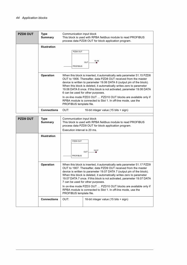
PZD8 OUT Type Summary
Communication input block This block is used with RPBA fieldbus module to read PROFIBUS process data PZD8 OUT for block application program.
Illustration
Operation When this block is inserted, it automatically sets parameter 51.15 PZD8 OUT to 1906. Thereafter, data PZD8 OUT received from the master device is written to parameter 19.06 DATA 6 (output pin of the block). When this block is deleted, it automatically writes zero to parameter 19.06 DATA 6 once. If this block is not activated, parameter 19.06 DATA 6 can be used for other purposes.In on-line mode PZD3 OUT … PZD10 OUT blocks are available only if RPBA module is connected to Slot 1. In off-line mode, use the PROFIBUS template file.
Connections OUT: 16-bit integer value (15 bits + sign)
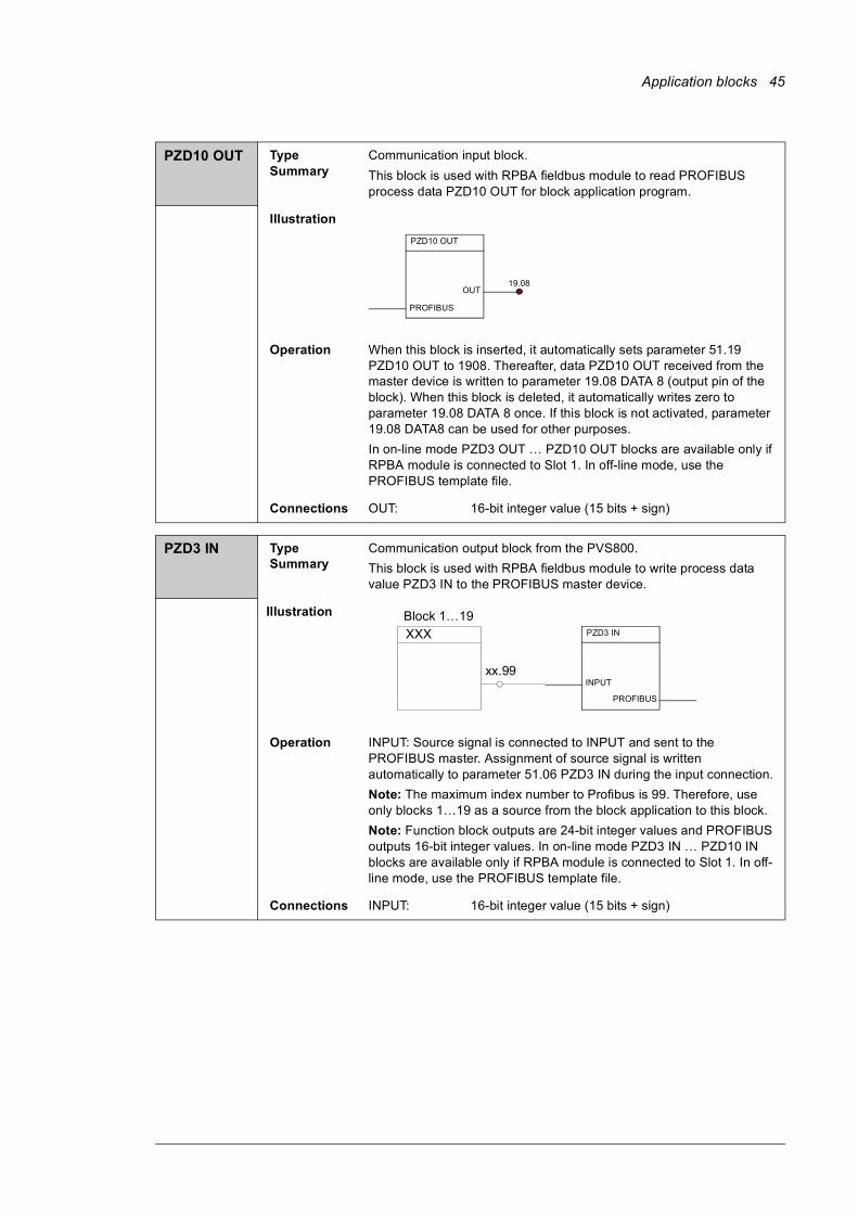
PZD9 OUT Type Summary
Communication input block This block is used with RPBA fieldbus module to read PROFIBUS process data PZD9 OUT for block application program.Execution interval is 20 ms.
Illustration
Operation When this block is inserted, it automatically sets parameter 51.17 PZD9 OUT to 1907. Thereafter, data PZD9 OUT received from the master device is written to parameter 19.07 DATA 7 (output pin of the block). When this block is deleted, it automatically writes zero to parameter 19.07 DATA 7 once. If this block is not activated, parameter 19.07 DATA 7 can be used for other purposes.In on-line mode PZD3 OUT … PZD10 OUT blocks are available only if RPBA module is connected to Slot 1. In off-line mode, use the PROFIBUS template file.
Connections OUT: 16-bit integer value (15 bits + sign)
19.06
PZD8 OUT
OUT
PROFIBUS
19.07
PZD9 OUT
OUT
PROFIBUS
Application blocks 45
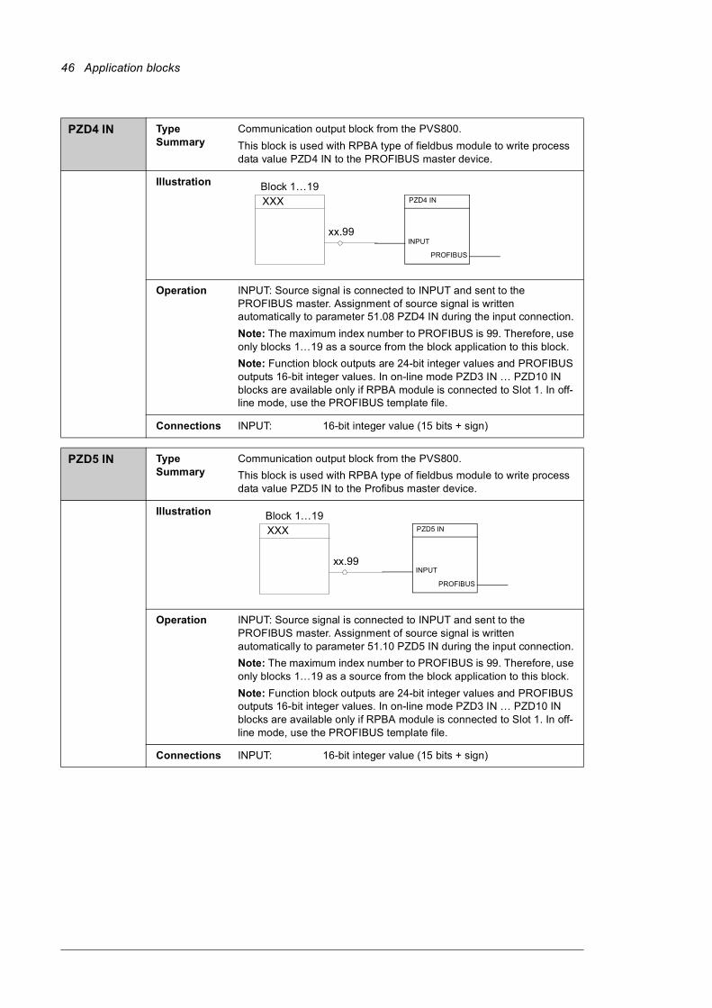
PZD10 OUT Type Summary
Communication input block.This block is used with RPBA fieldbus module to read PROFIBUS process data PZD10 OUT for block application program.
Illustration
Operation When this block is inserted, it automatically sets parameter 51.19 PZD10 OUT to 1908. Thereafter, data PZD10 OUT received from the master device is written to parameter 19.08 DATA 8 (output pin of the block). When this block is deleted, it automatically writes zero to parameter 19.08 DATA 8 once. If this block is not activated, parameter 19.08 DATA8 can be used for other purposes.In on-line mode PZD3 OUT … PZD10 OUT blocks are available only if RPBA module is connected to Slot 1. In off-line mode, use the PROFIBUS template file.
Connections OUT: 16-bit integer value (15 bits + sign)
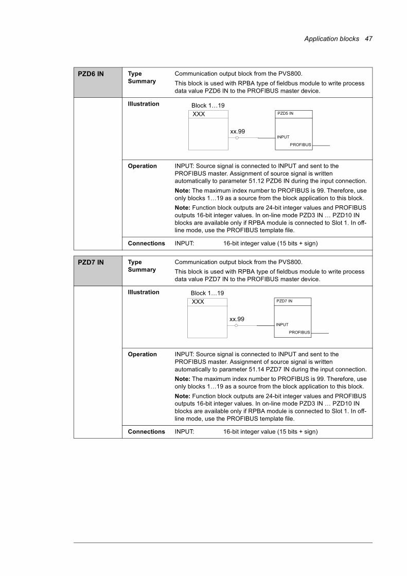
PZD3 IN Type Summary
Communication output block from the PVS800.This block is used with RPBA fieldbus module to write process data value PZD3 IN to the PROFIBUS master device.
Illustration
Operation INPUT: Source signal is connected to INPUT and sent to the PROFIBUS master. Assignment of source signal is written automatically to parameter 51.06 PZD3 IN during the input connection.Note: The maximum index number to Profibus is 99. Therefore, use only blocks 1…19 as a source from the block application to this block.Note: Function block outputs are 24-bit integer values and PROFIBUS outputs 16-bit integer values. In on-line mode PZD3 IN … PZD10 IN blocks are available only if RPBA module is connected to Slot 1. In off-line mode, use the PROFIBUS template file.
Connections INPUT: 16-bit integer value (15 bits + sign)
19.08
PZD10 OUT
OUT
PROFIBUS
PZD3 IN
PROFIBUS
INPUT
Block 1…19 XXX
xx.99
46 Application blocks
PZD4 IN Type Summary
Communication output block from the PVS800.This block is used with RPBA type of fieldbus module to write process data value PZD4 IN to the PROFIBUS master device.
Illustration
Operation INPUT: Source signal is connected to INPUT and sent to the PROFIBUS master. Assignment of source signal is written automatically to parameter 51.08 PZD4 IN during the input connection.Note: The maximum index number to PROFIBUS is 99. Therefore, use only blocks 1…19 as a source from the block application to this block.Note: Function block outputs are 24-bit integer values and PROFIBUS outputs 16-bit integer values. In on-line mode PZD3 IN … PZD10 IN blocks are available only if RPBA module is connected to Slot 1. In off-line mode, use the PROFIBUS template file.
Connections INPUT: 16-bit integer value (15 bits + sign)
PZD5 IN Type Summary
Communication output block from the PVS800.This block is used with RPBA type of fieldbus module to write process data value PZD5 IN to the Profibus master device.
Illustration
Operation INPUT: Source signal is connected to INPUT and sent to the PROFIBUS master. Assignment of source signal is written automatically to parameter 51.10 PZD5 IN during the input connection.Note: The maximum index number to PROFIBUS is 99. Therefore, use only blocks 1…19 as a source from the block application to this block.Note: Function block outputs are 24-bit integer values and PROFIBUS outputs 16-bit integer values. In on-line mode PZD3 IN … PZD10 IN blocks are available only if RPBA module is connected to Slot 1. In off-line mode, use the PROFIBUS template file.
Connections INPUT: 16-bit integer value (15 bits + sign)
PZD4 IN
PROFIBUS
INPUT
Block 1…19 XXX
xx.99
PZD5 IN
PROFIBUS
INPUT
Block 1…19 XXX
xx.99
Application blocks 47
PZD6 IN Type Summary
Communication output block from the PVS800.This block is used with RPBA type of fieldbus module to write process data value PZD6 IN to the PROFIBUS master device.
Illustration
Operation INPUT: Source signal is connected to INPUT and sent to the PROFIBUS master. Assignment of source signal is written automatically to parameter 51.12 PZD6 IN during the input connection.Note: The maximum index number to PROFIBUS is 99. Therefore, use only blocks 1…19 as a source from the block application to this block.Note: Function block outputs are 24-bit integer values and PROFIBUS outputs 16-bit integer values. In on-line mode PZD3 IN … PZD10 IN blocks are available only if RPBA module is connected to Slot 1. In off-line mode, use the PROFIBUS template file.
Connections INPUT: 16-bit integer value (15 bits + sign)
PZD7 IN Type Summary
Communication output block from the PVS800.This block is used with RPBA type of fieldbus module to write process data value PZD7 IN to the PROFIBUS master device.
Illustration
Operation INPUT: Source signal is connected to INPUT and sent to the PROFIBUS master. Assignment of source signal is written automatically to parameter 51.14 PZD7 IN during the input connection.Note: The maximum index number to PROFIBUS is 99. Therefore, use only blocks 1…19 as a source from the block application to this block.Note: Function block outputs are 24-bit integer values and PROFIBUS outputs 16-bit integer values. In on-line mode PZD3 IN … PZD10 IN blocks are available only if RPBA module is connected to Slot 1. In off-line mode, use the PROFIBUS template file.
Connections INPUT: 16-bit integer value (15 bits + sign)
PZD5 IN
PROFIBUS
INPUT
Block 1…19 XXX
xx.99
PZD7 IN
PROFIBUS
INPUT
Block 1…19 XXX
xx.99
48 Application blocks
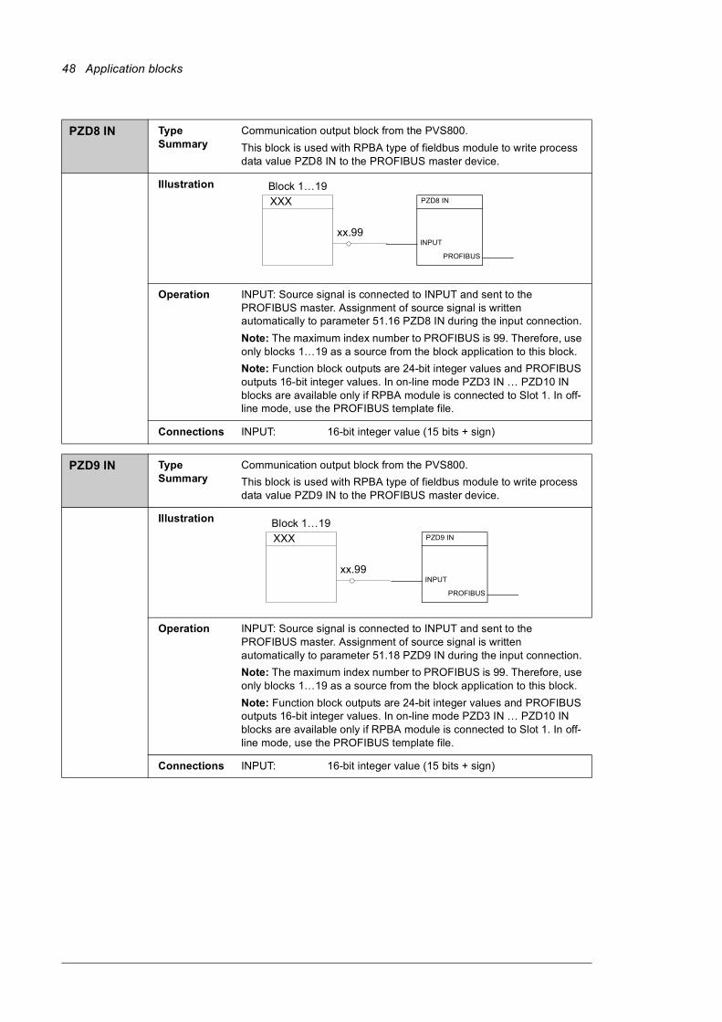
PZD8 IN Type Summary
Communication output block from the PVS800.This block is used with RPBA type of fieldbus module to write process data value PZD8 IN to the PROFIBUS master device.
Illustration
Operation INPUT: Source signal is connected to INPUT and sent to the PROFIBUS master. Assignment of source signal is written automatically to parameter 51.16 PZD8 IN during the input connection.Note: The maximum index number to PROFIBUS is 99. Therefore, use only blocks 1…19 as a source from the block application to this block.Note: Function block outputs are 24-bit integer values and PROFIBUS outputs 16-bit integer values. In on-line mode PZD3 IN … PZD10 IN blocks are available only if RPBA module is connected to Slot 1. In off-line mode, use the PROFIBUS template file.
Connections INPUT: 16-bit integer value (15 bits + sign)
PZD9 IN Type Summary
Communication output block from the PVS800.This block is used with RPBA type of fieldbus module to write process data value PZD9 IN to the PROFIBUS master device.
Illustration
Operation INPUT: Source signal is connected to INPUT and sent to the PROFIBUS master. Assignment of source signal is written automatically to parameter 51.18 PZD9 IN during the input connection.Note: The maximum index number to PROFIBUS is 99. Therefore, use only blocks 1…19 as a source from the block application to this block.Note: Function block outputs are 24-bit integer values and PROFIBUS outputs 16-bit integer values. In on-line mode PZD3 IN … PZD10 IN blocks are available only if RPBA module is connected to Slot 1. In off-line mode, use the PROFIBUS template file.
Connections INPUT: 16-bit integer value (15 bits + sign)
PZD8 IN
PROFIBUS
INPUT
Block 1…19 XXX
xx.99
PZD9 IN
PROFIBUS
INPUT
Block 1…19 XXX
xx.99
Application blocks 49
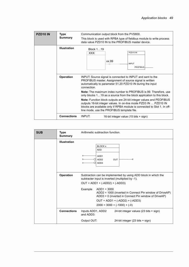
PZD10 IN Type Summary
Communication output block from the PVS800.This block is used with RPBA type of fieldbus module to write process data value PZD10 IN to the PROFIBUS master device.
Illustration
Operation INPUT: Source signal is connected to INPUT and sent to the PROFIBUS master. Assignment of source signal is written automatically to parameter 51.20 PZD10 IN during the input connection.Note: The maximum index number to PROFIBUS is 99. Therefore, use only blocks 1…19 as a source from the block application to this block.Note: Function block outputs are 24-bit integer values and PEOFIBUS outputs 16-bit integer values. In on-line mode PZD3 IN … PZD10 IN blocks are available only if RPBA module is connected to Slot 1. In off-line mode, use the PROFIBUS template file.
Connections INPUT: 16-bit integer value (15 bits + sign)
SUB Type Summary
Arithmetic subtraction function.
Illustration
Operation Subtraction can be implemented by using ADD block in which the subtracter input is inverted (multiplied by -1).OUT = ADD1 + (-ADD2) + (-ADD3)
Example ADD1 = 3000ADD2 = 1000 (inverted in Connect Pin window of DriveAP)ADD3 = 0 (inverted in Connect Pin window of DriveAP)OUT = ADD1 + (-ADD2) + (-ADD3)2000 = 3000 + (-1000) + (-0)
Connections Inputs ADD1, ADD2 and ADD3:
24-bit integer values (23 bits + sign)
Output OUT: 24-bit integer (23 bits + sign)
PZD10 IN
PROFIBUS
INPUT
Block 1…19 XXX
xx.99
BLOCK x ADD
ADD1ADD2ADD3
OUT

50 Application blocks

Further informationMore information about ABB products for solar applications on the Internet: www.abb.com/solar
3AU
A00
0009
1276
Rev
A (E
N) 2
010-
12-2
0Contact us
ABB OyDrivesP.O. Box 184FI-00381 HELSINKIFINLANDTelephone +358 10 22 11Fax +358 10 22 22681www.abb.com/drives
ABB Inc.Automation TechnologiesDrives & Motors16250 West Glendale DriveNew Berlin, WI 53151USATelephone 262 785-3200
1-800-HELP-365Fax 262 780-5135www.abb.com/drives
ABB Beijing Drive Systems Co. Ltd.No. 1, Block D, A-10 Jiuxianqiao BeiluChaoyang DistrictBeijing, P.R. China, 100015Telephone +86 10 5821 7788Fax +86 10 5821 7618www.abb.com/drives