q500 typhoon user manual v2.1 hr - yuneec-forum.com · pdf file ·...
TRANSCRIPT
Version 2.1


11
TABLE OF CONTENTSTABLE OF CONTENTSINTRODUCTIONSPECIFICATIONSNOTICES AND WARNINGSGENERAL SAFETY PRECAUTIONS AND WARNINGSFCC INFORMATIONQ500 RTF CONTENTSBATTERY WARNINGS AND USAGE GUIDELINESCHARGING THE BATTERIESPREPARING THE CGO2-GBINSTALLING THE PROPELLERSQ500, CGO2-GB AND ST10 OVERVIEWST10 DISPLAYST10 ACCESSORIESFLIGHT CONTROLSFLIGHT CONTROLS - SMART MODE
FLIGHT CONTROLS - ANGLE (PILOT) MODEFLIGHT CONTROLS - HOME MODELED STATUS INDICATIONSTAKING PHOTOS AND RECORDING VIDEOINSTALLING THE FLIGHT BATTERYGPS FUNCTIONALITYPREPARING TO FLYFLYINGDISABLING GPSGRAPHICAL USER INTERFACECOMPASS CALIBRATIONST10 AND RECEIVER BINDINGST10 AND CGO2-GB BINDINGTROUBLESHOOTINGWARRANTY INFORMATION
122345678991011121213
151617192020212223232426272829
2
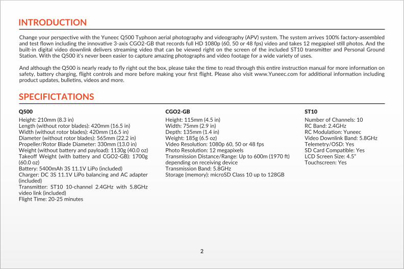
INTRODUCTIONChange your perspective with the Yuneec Q500 Typhoon aerial photography and videography (APV) system. The system arrives 100% factory-assembled and test flown including the innovative 3-axis CGO2-GB that records full HD 1080p (60, 50 or 48 fps) video and takes 12 megapixel still photos. And the built-in digital video downlink delivers streaming video that can be viewed right on the screen of the included ST10 transmitter and Personal Ground Station. With the Q500 it’s never been easier to capture amazing photographs and video footage for a wide variety of uses.
And although the Q500 is nearly ready to fly right out the box, please take the time to read through this entire instruction manual for more information on safety, battery charging, flight controls and more before making your first flight. Please also visit www.Yuneec.com for additional information including product updates, bulletins, videos and more.
SPECIFICTATIONSQ500 Height: 210mm (8.3 in)Length (without rotor blades): 420mm (16.5 in)Width (without rotor blades): 420mm (16.5 in)Diameter (without rotor blades): 565mm (22.2 in)Propeller/Rotor Blade Diameter: 330mm (13.0 in)Weight (without battery and payload): 1130g (40.0 oz)Takeoff Weight (with battery and CGO2-GB): 1700g (60.0 oz)Battery: 5400mAh 3S 11.1V LiPo (included)Charger: DC 3S 11.1V LiPo balancing and AC adapter (included)Transmitter: ST10 10-channel 2.4GHz with 5.8GHz video link (included)Flight Time: 20-25 minutes
CGO2-GBHeight: 115mm (4.5 in)Width: 75mm (2.9 in)Depth: 135mm (1.4 in)Weight: 185g (6.5 oz)Video Resolution: 1080p 60, 50 or 48 fpsPhoto Resolution: 12 megapixelsTransmission Distance/Range: Up to 600m (1970 ft) depending on receiving deviceTransmission Band: 5.8GHzStorage (memory): microSD Class 10 up to 128GB
ST10 Number of Channels: 10RC Band: 2.4GHzRC Modulation: YuneecVideo Downlink Band: 5.8GHzTelemetry/OSD: Yes SD Card Compatible: YesLCD Screen Size: 4.5”Touchscreen: Yes

3
NOTICES AND WARNINGSIMPORTANT NOTE: All safety precautions and warnings, instructions, warranties and other collateral information is subject to change at the sole discre-tion of Yuneec. For the most up-to-date information please visit the corresponding product page at www.Yuneec.com or contact the nearest Yuneec office or authorized distributor.
The following special language terms are used throughout the product literature to indicate various levels of potential harm when operating this product:
NOTICE: Procedures, which if not properly followed, create a possibility of property damage and/or little to no possibility of injury.CAUTION: Procedures, which if not properly followed, create the probability of property damage and/or a possibility of serious injury.WARNING: Procedures, which if not properly followed, create the probability of property damage, collateral damage and/or serious injury or create a high probability of superficial injury.
WARNING: Read the ENTIRE quick start guide and instruction manual to become familiar with the features of the product before operating. Failure to operate the product correctly can result in damage to the product, property and/or cause serious injury.
WARNING: This is a sophisticated consumer product. It must be operated with caution and common sense, and requires some basic mechanical ability. Failure to operate this product in a safe and responsible manner could result in damage to the product, property and/or cause serious injury. This product is not intended for use by children without direct adult supervision. Do not use with incompatible components or alter this product in any way outside of the instructions provided by Yuneec. The quick start guide and instruction manual contain instructions for safety, operation and maintenance. It is essential to read and follow all the instructions and warnings prior to assembly, setup and/or use in order to operate the product correctly and avoid damage or serious injury.
AGE RECOMMENDATION: NOT FOR CHILDREN UNDER 14 YEARS. THIS IS NOT A TOY.

4
GENERAL SAFETY PRECAUTIONS AND WARNINGS
WARNING: Failure to use this product in the intended manner as described in the quick start guide and instruction manual can result in damage to the product, property and/or cause serious injury. A Radio Controlled (RC) multirotor aircraft, APV platform, drone, etc. is not a toy! If misused it can cause serious bodily harm and damage to property.
WARNING: As the user of this product you are solely and wholly responsible for operating it in a manner that does not endanger yourself and others or result in damage to the product or the property of others.• Keep your hands, face and other parts of your body away from the spinning propellers/rotor blades and other moving parts at all times. Keep items that could impact or become entangled away from the propellers/rotor blades including debris, parts, tools, loose clothing, etc.• Always operate your aircraft in open areas that are free from people, vehicles and other obstructions. Never fly near or above crowds, airports or buildings.• To ensure proper operation and safe flight performance never attempt to operate your aircraft nearby buildings or other obstructions that do not offer a clear view of the sky and can restrict GPS reception.• Do not attempt to operate your aircraft in areas with potential magnetic and/or radio interference including areas nearby broadcast towers, power transmission stations, high voltage power lines, etc.• Always keep a safe distance in all directions around your aircraft to avoid collisions and/or injury. This aircraft is controlled by a radio signal subject to interference from many sources outside your control. Interference can cause momentary loss of control.• To ensure proper and safe operation of the automatic landing function in Home Mode you must start the motors with the aircraft in a position that has at least 10 feet (approximately 3 meters) of clear and open space around it and achieve a proper GPS lock.• Do not attempt to operate your aircraft with any worn and/or damaged components, parts, etc. (including, but not limited to, damaged propellers/rotor blades, old batteries, etc.).• Never operate your aircraft in poor or severe weather conditions including heavy winds, precipitation, lightning, etc.
DO NOT FLY OVER CROWDS!
DO NOT FLY NEAR AIRPORTS!
THE MAXIMUM FLYING ALTITUDE FOR THIS AIRCRAFT IS 8000FT ABOVE SEA LEVEL!
DO NOT FLY NEARBY TALL BUILDINGS/OBSTRUCTIONS (100° MINIMUM CLEARANCE REQUIRED)
KEEP CLEAR OF THE SPINNING PROPELLERS!
MAX 8000ft100˚
DO NOT FLY IN WINDS THAT EXCEED 8–12 MPH (13–19 KPH)!

5
FCC INFORMATIONThis device complies with part 15 of the FCC rules. Operation is subject to the following two conditions: (1) This device may not cause harmful interference, and (2) this device must accept any interference received, including interference that may cause undesired operation.
CAUTION: Changes or modifications not expressly approved by the party responsible for compliance could void the user’s authority to operate the equipment.
This product contains a radio transmitter with wireless technology which has been tested and found to be compliant with the applicable regulations govern-ing a radio transmitter in the 2.400GHz to 2.4835GHz frequency range.
Antenna Separation Distance:Maintain a separation distance of at least 2 in (50mm) between your body (not including your fingers, hands and wrists) and the antennas to meet the RF exposure safety requirements determined by FCC regulations.
• Always operate your aircraft starting with a fully charged battery. Always land as soon as possible after the first level low voltage battery warning or land immediately after the second level low voltage battery warning (as indicated by the vibrations and audible alerts from the transmitter/personal ground station).• Always operate your aircraft when the voltage of the battery in the transmitter/personal ground station is in a safe range (as indicated by the battery charge status icon on the screen of the transmitter/personal ground station).• Always keep the aircraft in clear line of sight and under control, and keep the transmitter/personal ground station powered on while the aircraft is powered on.• Always move the throttle control stick down fully and turn off the motors in the event the propellers/rotor blades come into contact with any objects.• Always allow components and parts to cool after use before touching them and flying again.• Always remove batteries after use and store/transport them per the corresponding guidelines.• Avoid water exposure to all electronic components, parts, etc. not specifically designed and protected for use in water. Moisture causes damage to electronic components and parts. • Never place any portion of the aircraft or any related accessories, components or parts in your mouth as doing so could cause serious injury or even death.• Always keep chemicals, small parts and electronic components out of the reach of children.• Carefully follow the instructions and warnings included with this aircraft and any related accessories, components or parts (including, but not limited to, chargers, rechargeable batteries, etc.).
CAUTION: The electronic speed controls (ESCs) installed in the Q500 are not compatible with any other product, and the Q500 is not compatible with any other ESCs. Use of any other ESCs in the Q500 will cause a crash, which may result in damage to the product, property and/or cause serious injury.

6
Q500 RTF CONTENTS
1
6 910
13
1114
8 73
15
2
4
5
12
The Q500 RTF includes everything needed to fly right out of the box. There’s nothing extra to buy or provide!
1 Q500 RTF Airframe w/Installed CGO2-GB2 ST10 Transmitter and Personal Ground Station3 ST10 LCD Screen Sun Shade/Shield4 ST10 Neck Strap5 AC to DC USB Adapter/Charger
6 USB to Micro USB Cable7 USB Interface/Programmer8 5400mAh 3S 11.1V LiPo Battery9 3S 11.1V LiPo Balance Connector Charge Lead 10 DC 3S 11.1V LiPo Balancing Charger
11 DC Automobile Accessory Socket/ Cigarette Lighter Receptacle Adapter12 AC to DC Adapter/Power Supply13 8GB microSD Card w/Adapter14 Motor Holder/Prop Installation Tool15 Propellers/Rotor Blades (2 sets)
7
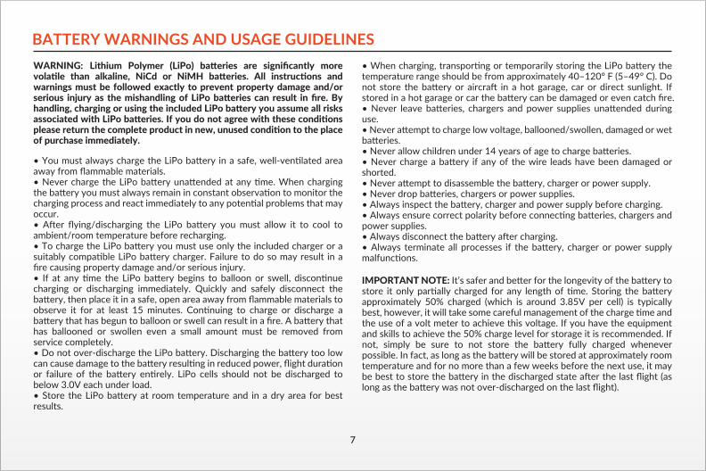
BATTERY WARNINGS AND USAGE GUIDELINESWARNING: Lithium Polymer (LiPo) batteries are significantly more volatile than alkaline, NiCd or NiMH batteries. All instructions and warnings must be followed exactly to prevent property damage and/or serious injury as the mishandling of LiPo batteries can result in fire. By handling, charging or using the included LiPo battery you assume all risks associated with LiPo batteries. If you do not agree with these conditions please return the complete product in new, unused condition to the place of purchase immediately.
• You must always charge the LiPo battery in a safe, well-ventilated area away from flammable materials.• Never charge the LiPo battery unattended at any time. When charging the battery you must always remain in constant observation to monitor the charging process and react immediately to any potential problems that may occur.• After flying/discharging the LiPo battery you must allow it to cool to ambient/room temperature before recharging.• To charge the LiPo battery you must use only the included charger or a suitably compatible LiPo battery charger. Failure to do so may result in a fire causing property damage and/or serious injury.• If at any time the LiPo battery begins to balloon or swell, discontinue charging or discharging immediately. Quickly and safely disconnect the battery, then place it in a safe, open area away from flammable materials to observe it for at least 15 minutes. Continuing to charge or discharge a battery that has begun to balloon or swell can result in a fire. A battery that has ballooned or swollen even a small amount must be removed from service completely.• Do not over-discharge the LiPo battery. Discharging the battery too low can cause damage to the battery resulting in reduced power, flight duration or failure of the battery entirely. LiPo cells should not be discharged to below 3.0V each under load.• Store the LiPo battery at room temperature and in a dry area for best results.
• When charging, transporting or temporarily storing the LiPo battery the temperature range should be from approximately 40–120° F (5–49° C). Do not store the battery or aircraft in a hot garage, car or direct sunlight. If stored in a hot garage or car the battery can be damaged or even catch fire.• Never leave batteries, chargers and power supplies unattended during use.• Never attempt to charge low voltage, ballooned/swollen, damaged or wet batteries.• Never allow children under 14 years of age to charge batteries.• Never charge a battery if any of the wire leads have been damaged or shorted.• Never attempt to disassemble the battery, charger or power supply.• Never drop batteries, chargers or power supplies.• Always inspect the battery, charger and power supply before charging.• Always ensure correct polarity before connecting batteries, chargers and power supplies.• Always disconnect the battery after charging.• Always terminate all processes if the battery, charger or power supply malfunctions.
IMPORTANT NOTE: It’s safer and better for the longevity of the battery to store it only partially charged for any length of time. Storing the battery approximately 50% charged (which is around 3.85V per cell) is typically best, however, it will take some careful management of the charge time and the use of a volt meter to achieve this voltage. If you have the equipment and skills to achieve the 50% charge level for storage it is recommended. If not, simply be sure to not store the battery fully charged whenever possible. In fact, as long as the battery will be stored at approximately room temperature and for no more than a few weeks before the next use, it may be best to store the battery in the discharged state after the last flight (as long as the battery was not over-discharged on the last flight).

CHARGING THE BATTERIESWARNING: Lithium Ion (LiIon) and Lithium Polymer (LiPo) batteries are significantly more volatile than alkaline, NiCd or NiMH batteries. All instructions and warnings must be followed exactly to prevent property damage and/or serious injury as the mishandling of LiIon/LiPo batteries can result in fire. By handling, charging or using the included LiIon/LiPo batteries you assume all risks associated with them. If you do not agree with these conditions please return the complete product in new, unused condition to the place of purchase immediately.
CHARGING THE LIPO FLIGHT BATTERYYou can power the SC3500-3 charger from a 100-240V AC outlet using the AC adapter/power supply, or from a 12V DC accessory socket/cigarette lighter receptacle in a vehicle using the corresponding adapter. Once you’ve verified the charger is powered on and ready to charge (green blinking LED), plug the balance connector charge lead into the charger, then connect the LiPo flight battery to the charge lead. The battery will begin charging (red blinking LED) and it will take approximately 2 hours to charge a fully discharged (not over-discharged) battery.
CHARGING THE LI-ION ST10 BATTERYYou can charge the LiIon battery installed in the ST10 from a 100-240V AC outlet using the USB adapter/charger, or from a suitable USB power source (2.0 amps max), with the USB to micro USB cable. While the ST10 is powered off connect the cable to the USB adapter/charger, then plug it into the USB connector/charging port on the right side. After approximate-ly 30-45 seconds the LED indicator for the battery will blink blue while the battery is charging, and will glow solid blue when the battery is fully charged. It will take approximately 5.5 hours to charge a fully discharged (not over-discharged ) battery.
NOTE: The AC plug type will vary depending on the region in which the product was imported/purchased (AU = Australian; EU = European; UK = United Kingdom; US = United States).
8
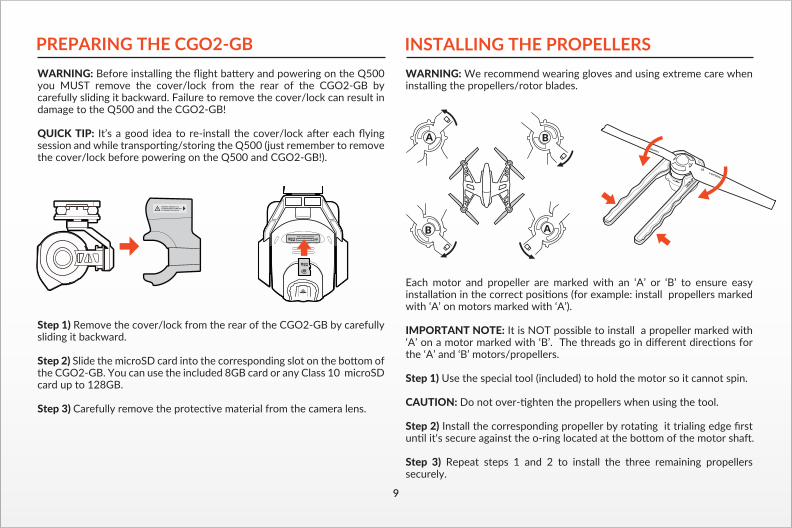
PREPARING THE CGO2-GBWARNING: Before installing the flight battery and powering on the Q500 you MUST remove the cover/lock from the rear of the CGO2-GB by carefully sliding it backward. Failure to remove the cover/lock can result in damage to the Q500 and the CGO2-GB!
QUICK TIP: It’s a good idea to re-install the cover/lock after each flying session and while transporting/storing the Q500 (just remember to remove the cover/lock before powering on the Q500 and CGO2-GB!).
Step 1) Remove the cover/lock from the rear of the CGO2-GB by carefully sliding it backward.
Step 2) Slide the microSD card into the corresponding slot on the bottom of the CGO2-GB. You can use the included 8GB card or any Class 10 microSD card up to 128GB.
Step 3) Carefully remove the protective material from the camera lens.
INSTALLING THE PROPELLERSWARNING: We recommend wearing gloves and using extreme care when installing the propellers/rotor blades.
Each motor and propeller are marked with an ‘A’ or ‘B’ to ensure easy installation in the correct positions (for example: install propellers marked with ‘A’ on motors marked with ‘A’).
IMPORTANT NOTE: It is NOT possible to install a propeller marked with ‘A’ on a motor marked with ‘B’. The threads go in different directions for the ‘A’ and ‘B’ motors/propellers.
Step 1) Use the special tool (included) to hold the motor so it cannot spin.
CAUTION: Do not over-tighten the propellers when using the tool.
Step 2) Install the corresponding propeller by rotating it trialing edge first until it‘s secure against the o-ring located at the bottom of the motor shaft.
Step 3) Repeat steps 1 and 2 to install the three remaining propellers securely.
A
A
B
B
9

Q500, CGO2-GB AND ST10 OVERVIEW
Q500 / CGO2-GB1 CGO2-GB Gimbal Camera2 Camera LED Status Indicator3 Camera Lens4 5.8GHz Antenna5 Main LED Status Indicator6 Power Switch
ST107 Proportional Control Rate Slider8 USB Connector/Charging Port9 Audio/Earphone Jack10 Take Still Photo Button11 Start/Stop Motors Button12 Rudder/Yaw Control (for Mode 2 and Mode 1)13 Throttle/Altitude Control (for Mode 2) Elevator/Pitch Control (for Mode 1)14 5.8GHz Antenna (located inside the case)15 Status Indicators (for ST10 battery, 5.8GHz WiFi and GPS)16 2.4GHz Antenna (located inside the handle)17 Start/Stop Video Recording Button18 Flight Mode Selection Switch19 Aileron/Roll Control (Mode 2 and Mode 1)20 Elevator/Pitch Control (Mode 2) Throttle/Altitude Control (Mode 1)21 Power Switch22 Volume and Navigation Touch-Activated Buttons (Volume Down/Volume Up/Menu/Home/Back)23 CGO2-GB Pitch Angle/Position Control Slider24 SD Card Slot (located under the battery)
The ST10 is equipped with an internal cooling fan and components that deliver vibrating and audible alerts.
IMPORTANT NOTE: Although the ST10 is equipped with digital ‘trims’ (located below the control sticks) they are not active/functional when controlling the Q500.
1 2
3
4
5
6
7
8
9
10
11
1213
14 15 16
17
18
192021
23
24
22
10

11
ST10 DISPLAY
1 Model Name2 Frames Per Second for Video Recording Button3 Status Information4 Direction to Home Point5 Clock/Current Time6 GPS Status and Number of Satellites for ST107 5.8GHz WiFi Video Link Status8 ST10 Battery Charge Level Status Icon9 Aircraft Battery Voltage10 Altitude of Aircraft (Above Ground Level)11 Ground Speed of Aircraft12 Distance of Aircraft from Home Point13 Model Select Menu Button14 Flight Settings Menu Button15 System Settings Menu Button16 Latitude/Longitude Position of Aircraft17 Number of Satellites for Aircraft18 GPS Status for Aircraft19 Flight Mode of Aircraft
The ST10 is equipped with a touchscreen display that allows for changing various settings and viewing real-time telemetry data and streaming video during flight.
QUICK TIP: Double tap on the screen to increase the size of the video viewing area to full-screen and double tap again to return to the standard size).
WARNING: NEVER attempt to fly the Q500 via First-Person View (FPV). There’s a slight ‘lag’ in the CGO2-GB streaming video downlink to the ST10, and as a result the streaming video/FPV should only be used for aligning camera shots and not for flying! Attempting to fly via FPV can result in a crash that will cause damage to the product, property and/or cause serious injury.
IMPORTANT NOTE: Streaming video from the CGO2-GB to the ST10 and to a separate phone/tablet (or another Yuneec transmitter/personal ground station) at the same time is NOT recommended as it will result in a very significant lag in the video downlink.
9
10
11
12
19
18
17
16
1415 13
6521 3 4 87
12
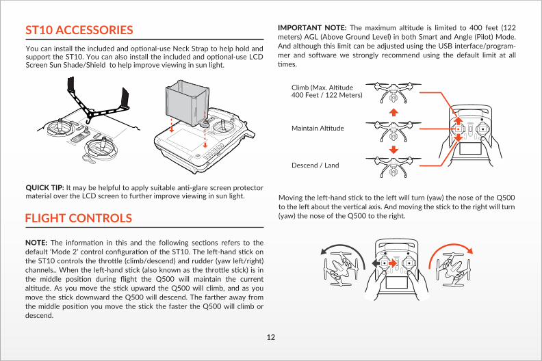
ST10 ACCESSORIESYou can install the included and optional-use Neck Strap to help hold and support the ST10. You can also install the included and optional-use LCD Screen Sun Shade/Shield to help improve viewing in sun light.
QUICK TIP: It may be helpful to apply suitable anti-glare screen protector material over the LCD screen to further improve viewing in sun light. Moving the left-hand stick to the left will turn (yaw) the nose of the Q500
to the left about the vertical axis. And moving the stick to the right will turn (yaw) the nose of the Q500 to the right.FLIGHT CONTROLS
NOTE: The information in this and the following sections refers to the default ‘Mode 2’ control configuration of the ST10. The left-hand stick on the ST10 controls the throttle (climb/descend) and rudder (yaw left/right) channels.. When the left-hand stick (also known as the throttle stick) is in the middle position during flight the Q500 will maintain the current altitude. As you move the stick upward the Q500 will climb, and as you move the stick downward the Q500 will descend. The farther away from the middle position you move the stick the faster the Q500 will climb or descend.?
IMPORTANT NOTE: The maximum altitude is limited to 400 feet (122 meters) AGL (Above Ground Level) in both Smart and Angle (Pilot) Mode. And although this limit can be adjusted using the USB interface/program-mer and software we strongly recommend using the default limit at all times.
13
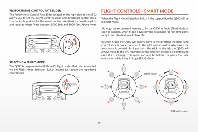
SELECTING A FLIGHT MODEThe Q500 is programmed with three (3) flight modes that can be selected via the Flight Mode Selection Switch located just above the right-hand control stick.
PROPORTIONAL CONTROL RATE SLIDERThe Proportional Control Rate Slider located on the right side of the ST10 allows you to set the overall climb/descend and directional control rates. Use the turtle position for the lowest control rates (best for first-time pilots and required when flying between 5000 feet and 8000 feet Above Mean
When the Flight Mode Selection Switch is the top position the Q500 will be in Smart Mode.
Although we recommend learning to fly the Q500 in Angle (Pilot) Mode as soon as possible, Smart Mode is typically the best mode for first-time pilots to fly in and also features ‘Follow Me’ .
In Smart Mode the Q500 will always move in the direction the right-hand control stick is pushed relative to the pilot and no matter which way the front/nose is pointed. So if you push the stick to the left the Q500 will always move to the left, regardless of the direction the nose is pointing and even if it’s spinning. This mode can also be helpful for pilots that lose orientation while flying in Angle (Pilot) Mode.
FLIGHT CONTROLS - SMART MODE
SMART CIRCLE*
*Ø 52 feet / 16 meters
14
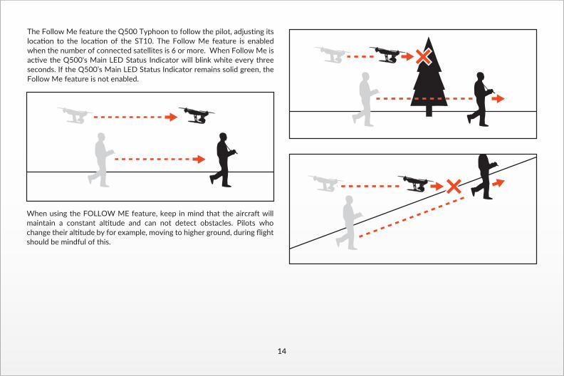
The Follow Me feature the Q500 Typhoon to follow the pilot, adjusting its location to the location of the ST10. The Follow Me feature is enabled when the number of connected satellites is 6 or more. When Follow Me is active the Q500's Main LED Status Indicator will blink white every three seconds. If the Q500’s Main LED Status Indicator remains solid green, the Follow Me feature is not enabled.
When using the FOLLOW ME feature, keep in mind that the aircraft will maintain a constant altitude and can not detect obstacles. Pilots who change their altitude by for example, moving to higher ground, during flight should be mindful of this.
15
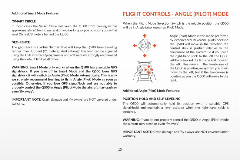
Additional Angle (Pilot) Mode Features:
POSITION HOLD AND SELF-LEVELINGThe Q500 will automatically hold its position (with a suitable GPS signal/lock) and maintain a level attitude when the right-hand stick is centered.
WARNING: If you do not properly control the Q500 in Angle (Pilot) Mode the aircraft may crash or even ‘fly away’.
IMPORTANT NOTE: Crash damage and ‘fly aways’ are NOT covered under warranty.
FLIGHT CONTROLS - ANGLE (PILOT) MODEWhen the Flight Mode Selection Switch is the middle position the Q500 will be in Angle (also known as Pilot) Mode.
Angle (Pilot) Mode is the mode preferred by experienced RC/drone pilots because the Q500 will move in the direction the control stick is pushed relative to the front/nose of the aircraft. So if you push the right-hand stick to the left the Q500 will bank toward the left side and move to the left. This means if the front/nose of the Q500 is pointing away from you it will move to the left, but if the front/nose is pointing at you the Q500 will move to the right.
Additional Smart Mode Features:
*SMART CIRCLEIn most cases the Smart Circle will keep the Q500 from coming within approximately 26 feet (8 meters) of you (as long as you position yourself at least 26 feet/8 meters behind the Q500.
GEO-FENCEThe geo-fence is a virtual ‘barrier’ that will keep the Q500 from traveling farther than 300 feet (91 meters). And although this limit can be adjusted using the USB interface/programmer and software we strongly recommend using the default limit at all times.
WARNING: Smart Mode only works when the Q500 has a suitable GPS signal/lock. If you take off in Smart Mode and the Q500 loses GPS signal/lock it will switch to Angle (Pilot) Mode automatically. This is why we strongly recommend learning to fly in Angle (Pilot) Mode as soon as possible. Otherwise, if you lose GPS signal/lock and are not able to properly control the Q500 in Angle (Pilot) Mode the aircraft may crash or even ‘fly away’.
IMPORTANT NOTE: Crash damage and ‘fly aways’ are NOT covered under warranty.

16
FLIGHT CONTROLS - HOME MODEWhen the Flight Mode Selection Switch is in the bottom position the Q500 will be in Home (also known as Return to Home) Mode.
PILOT LOCATION
13-26 ft (4-8m)
LANDING LOCATION
In Home Mode the the Follow Me feature will fly back the Q500 in a straight line in the direction of the pilots’ current location, and automatically land within 13-26 ft (4-8m) of the pilot. This can be very helpful for first-time pilots who aren’t quite ready to land the Q500 themselves. It can also be helpful for pilots that lose orienta-tion during flight; simply activate Home Mode until the Q500 automatically moves toward the home position, and once you’ve confirmed orientation switch back to Angle (Pilot) Mode. And if the Q500 ever loses the link with the
ST10 it will automatically enter Home Mode. When Home Mode is activated the Q500 will respond as follows:
10 m
10 m
B) When flying lower than 33 feet (10 meters) the Q500 will climb to 33 feet (10 meters) while flying back to the home point, then will descend vertically until it lands.
A) When flying higher than 33 feet (10 meters) the Q500 will maintain the current altitude, fly back to the home point, then descend vertically until it lands.

When the Flight Mode Selection Switch is in the bottom position the Q500 will be in Home (also known as Return to Home) Mode.
B) When flying lower than 33 feet (10 meters) the Q500 will climb to 33 feet (10 meters) while flying back to the home point, then will descend vertically until it lands.
17
CAUTION: You must be certain there are no obstacles in the ‘Return to Home’ flight path otherwise the Q500 may come into contact with them and crash. And while the Q500 is in Home Mode you will have a limited amount of directional control to help avoid obstacles, however, we strongly recommend switching to Smart or Angle Mode to avoid the obstacle (then you can switch back to Home Mode).
WARNING: Home Mode only works when the Q500 has a suitable GPS signal/lock. If the Q500 loses GPS signal/lock it will switch to Angle (Pilot) Mode automatically. This is why we strongly recommend learning to fly in Angle (Pilot) Mode as soon as possible. Otherwise, if you lose GPS signal/lock and are not able to properly control the Q500 in Angle (Pilot) Mode the aircraft may crash or even ‘fly away’.
IMPORTANT NOTE: Crash damage and ‘fly aways’ are NOT covered under warranty.
Flashes red, green and blue (2 times per second)Pulses red (3 times per second) Flashes orange very rapidly (10 times per second)Flashes blue rapidly (5 times per second)Flashes red and white rapidly (5 times per second)
Glows solid green Flashes green (3 times per second) then off (for 1 second)Glows solid purpleFlashes purple (3 times per second) then off (for 1 second)Flashes red rapidly (5 times per second) Flashes red, green and blue every 3 seconds
LED STATUS INDICATIONS
1 second 1 second 1 second
1 second 1 second 1 second
LED STATUS INDICATIONS DURING STARTUPMain LED Status IndicatorInitialization in progressInitialization failedThe aircraft is in ‘bind’ modeThe aircraft is not connected/linked to the transmitterThe aircraft is in a no-fly zone**Please see the instruction manual for more information regarding no-fly zones
LED STATUS INDICATIONS BEFORE/DURING FLIGHTMain LED Status IndicatorThe aircraft is in Smart Mode with GPS lockThe aircraft is in Smart Mode without GPS lock
The aircraft is in Angle Mode with GPS lockThe aircraft is in Angle Mode without GPS lock
The aircraft is in Home ModeFirst level low voltage battery warning
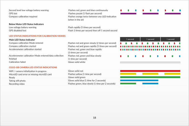
Flashes red and green slowly (2 times per second)Flashes red and green rapidly (5 times per second)Flashes red, green and blue rapidly (3 times per second)Flashes red, green and blue slowly (1 time per second)Glows solid white
Glows solid redFlashes yellow (1 time per second)Glows solid greenGlows solid blue (1 time for 2 seconds)Flashes green, blue slowly (1 time per 2 seconds)
LED STATUS INDICATIONS FOR CALIBRATION MODESMain LED Status IndicatorCompass calibration Mode enteredCompass calibration startedAccelerometer calibration started
Accelerometer calibration Mode entered/data collection finishedCalibration failed
CGO2-GB CAMERA LED STATUS INDICATIONS WiFi / camera initialization in progressMicroSD card error or missing microSD cardReadyTaking still photoRecording video
1 second 1 second 1 second
18
When the Flight Mode Selection Switch is in the bottom position the Q500 will be in Home (also known as Return to Home) Mode.
Flashes red, green and blue continuouslyFlashes purple (1 flash per second)
Second level low voltage battery warning GPS lostCompass calibration required
Below Motor LED Status IndicatorsLow voltage battery warningGPS disabled/lost
Flashes orange twice between any LED indication (when in the air)
Flash rapidly (5 times per second)Flash 3 times per second then off 1 second second

red dot next to the time length of the recording near the upper right-hand corner on the screen of the ST10.
TAKING PHOTOS AND RECORDING VIDEOThe ST10 seamlessly integrates control of the CGO2-GB so you can easily take still photos and start/stop video recording using the corresponding buttons located on top:
TO TAKE A STILL PHOTO
TO START/STOP RECORDING VIDEOPress the button located near the top right corner of the ST10. You’ll hear an audible indication from the ST10 each time the recording starts/stops. And while video is recording the LED indica-tor on the front of the CGO2-GB will flash blue and green, and there will be a
Press the button located near the top left corner of the ST10. You’ll hear an audible ‘shutter’ sound from the ST10 and the LED indicator on the front of the CGO2-GB will change from glowing solid green to glowing solid blue. It will take approximately 5 seconds to capture the photo and before you can take another still photo.
IMPORTANT NOTE: You cannot take still photos while recording video. You MUST stop recording video in order to take still photos.
IMPORTANT NOTE: You can choose to record video at 48, 50 (PAL) or 60 (NTSC) frames per second by tapping the corresponding button near the upper left-hand corner on the screen of the ST10. And keep in mind that the delay in the live video stream will be lowest at 48 and 50 as compared to 60 frames per second.
The slider located on the left side of the ST10 allows you to set the pitch/tilt position of the CGO2-GB from approximately straight ahead (when the slider is in the uppermost position) to approximately straight down (when the slider is in the lowermost position). And you can easily set a position in between by adjusting the slider accordingly.
QUICK TIP: There’s an adjustable counterbalance located on the rear of the CGO2-GB. This counterbalance has been adjusted at the factory to provide the best balance and performance overall so typically it should NOT need to be adjusted. However, if you find that the CGO2-GB is making any ‘buzzing’ sounds while powered on, carefully twist the counter-balance in or out until the sound stops in order to achieve the best balance, performance and photo/video quality.
19

INSTALLING THE FLIGHT BATTERYAfter the flight battery has been fully charged it’s ready to be installed in the Q500:
IMPORTANT NOTE: Keep the Q500 level relative to the ground when installing the battery.
STEP 1) Push the area at the top of the battery door to release the latch/lock, and then open the door.
STEP 2) With the side of the battery cartridge that has the ‘UP’ arrow marking oriented upward, hold the handle and slide the battery into the battery compartment until you feel the connector make a positive connec-tion.NOTE: If you do not install the battery in the correct orientation it will not be possible to make a positive connection.
STEP 3) Close the battery door by pushing the area at the top to engage the latch/lock.NOTE: If the door will not close because it’s coming into contact with the handle on the battery cartridge, the battery is not inserted far enough to engage the connector properly.
GPS FUNCTIONALITYThe Q500 requires a suitable GPS signal/lock in order to start the motors and to be flown. This means it should only be operated outdoors in open areas that are free from people, vehicles and other obstructions. And in order to acquire a suitable GPS signal/lock it’s critical that the GPS antenna installed in the top of the Q500 always have a clear view of the sky (100° minimum clearance required).
WARNING: Do NOT attempt to fly near or between tall buildings/ob-structions, near or under dense vegetation, structures or indoors. Do NOT attempt to fly the Q500 with GPS enabled indoors or in any location known to have poor GPS coverage. And do NOT disable/turn off GPS unless you’re able to properly control the Q500 in Angle (Pilot) Mode without GPS assistance and accept ALL responsibility and liability for crashes or ‘fly aways’. If the Q500 loses GPS signal/lock while flying it can only be flown in Angle (Pilot) Mode. Smart Mode and Home Mode, along with their corresponding features, will no longer work. And the Main LED Status Indicator will flash purple and the Below Motor LED Status Indicators will flash three (3) times per second then will stay off for one (1) second when the Q500 loses GPS signal/lock (or if GPS has been disabled/turned off). If the GPS signal/lock is reacquired (after receiving 5–10 seconds of suitable GPS signal), Smart Mode and Home Mode will work again. WARNING: Loss of GPS signal/lock may result in a crash or even a ‘fly away’.
100˚
20

21
IMPORTANT NOTE: Crash damage and ‘fly aways’ are NOT covered under warranty.
NO-FLY ZONESWith a suitable GPS signal/lock it will not be possible to start the motors, takeoff or fly the Q500 in the ‘No-Fly Zones’ within a 4 mile (6.4 kilometer) radius of most major airports.
PREPARING TO FLYWARNING: Before flying you MUST review and understand all of the NOTICES AND WARNINGS and the GENERAL SAFETY PRECAUTIONS AND WARNINGS found near the beginning of this instruction manual. Failure to operate this product in a safe and responsible manner could result in damage to the product, property and/or cause serious injury.
WARNING: Always operate the Q500 in open areas (approximately 10000 square feet/930 square meters or more) that are free from people, vehicles, trees and other obstructions. Never fly near or above crowds, airports or buildings.
IMPORTANT NOTE: If you’re a first-time pilot we strongly recommend putting the Flight Mode Selection Switch (located just above the right-hand control stick) in the top position to activate Smart Mode. Or, if you’re an experienced RC/drone pilot we strongly recommend putting the switch in the middle position to activate Angle (Pilot) Mode.
Step 2) Place the Q500 on a level and stable surface then slide the power switch to the ‘ON’ position. DO NOT TOUCH OR MOVE THE Q500 UNTIL THE INITIALIZATION PROCESS IS COMPLETE. The Main LED Status Indicator on the bottom of the Q500 will show one of the following indications when initialization is complete:
• The Q500 is in Smart Mode with GPS lock Glows solid green
• The Q500 is in Smart Mode without GPS lock Flashes green (3 times per second) then off (for 1 second)
• The Q500 is in Angle (Pilot) Mode with GPS lock Glows solid purple
• The Q500 is in Angle (Pilot) Mode without GPS lock Flashes purple (3 times per second) then off (for 1 second)
Step 3) If you do not have a GPS lock move the Q500 to a different area, turn it off, then back on again. Or, if you have a GPS lock, proceed to the next step.10000 ft² (930m²)
Never attempt to operate the Q500 nearby tall buildings/obstructions that do not offer a clear view of the sky (a minimum clearance of 100°).
After selecting a suitable flying area, please follow these steps:
Step 1) ALWAYS turn the ST10 on and allow it to boot up fully BEFORE turning the Q500 on.
Step 5) Step back approximately 26 feet (8 meters) behind the Q500.
PILOT LOCATION
TAKEOFF ZONE
26 ft (8m)

22
Step 5) Step back approximately 26 feet (8 meters) behind the Q500.
FLYINGTAKEOFF
To takeoff, slowly raise the left-hand stick to slightly above the center position. The Q500 will takeoff and climb slowly (or raise the stick further until it does). Allow the stick to return to the center position when the Q500 reaches the desired altitude.
FLYINGTake your time learning how the Q500 responds to various control inputs while flying. In Smart Mode the Q500 will always move in the direction the right-hand control stick is pushed relative to the pilot and no matter which way the front/nose is pointed. In Angle (Pilot) Mode the Q500 will move in the direction the control stick is pushed relative to the front/nose of the aircraft (and the ‘angle’ of movement is determined by how far you push the stick away from the center position). And please see the corresponding
sections of this instruction manual for more information on Smart Mode and Angle (Pilot) Mode.
IMPORTANT NOTE: If at any time during flight you feel like the Q500 is drifting out of/beyond your control, simply release both control sticks. The Q500 will automatically self-level and will even hold its position (with a suitable GPS signal/lock) when both control sticks are centered. You can also activate Home Mode so the Q500 automatically flies itself back to the home point and lands.
LANDINGThere are two ways to land the Q500:
1) Position the Q500 above the area where you would like to land. Slowly lower the left-hand stick to below the center position. The Q500 will descend slowly and land. After the Q500 lands, press and hold the red START/STOP button for approximately two (2) seconds to stop the motors.
2) Activate Home Mode and the Q500 will automatically fly itself back to the home point and will land within a 10 foot (3 meter) diameter circle around it.
WARNING: Always land as soon as possible after the first level low voltage battery warning, or land immediately after the second level low voltage battery warning (as indicated by the vibrations and audible alerts from the ST10, and by the Below Motor LED Status Indicators flashing rapidly). And if at any time the Aircraft Battery Voltage shown on the screen is below 10.7V, land the Q500 immediately.
AFTER LANDINGALWAYS turn off the Q500 BEFORE turning off the ST10. Then remove the battery from the Q500 and allow it to cool to ambient/room temperature before recharging.
WARNING: Do not attempt to operate the Q500 in winds that exceed 8–12 miles per hour (13–19 kilometers per hour).
Step 6) Press and hold the red START/STOP button for approxi-mately three (3) seconds to start the motors. Or you can lower the left-hand stick all the way, move it all the way to the left, then all the way to the right and back to the middle to start the motors.

sections of this instruction manual for more information on Smart Mode and Angle (Pilot) Mode.
IMPORTANT NOTE: If at any time during flight you feel like the Q500 is drifting out of/beyond your control, simply release both control sticks. The Q500 will automatically self-level and will even hold its position (with a suitable GPS signal/lock) when both control sticks are centered. You can also activate Home Mode so the Q500 automatically flies itself back to the home point and lands.
LANDINGThere are two ways to land the Q500:
1) Position the Q500 above the area where you would like to land. Slowly lower the left-hand stick to below the center position. The Q500 will descend slowly and land. After the Q500 lands, press and hold the red START/STOP button for approximately two (2) seconds to stop the motors.
2) Activate Home Mode and the Q500 will automatically fly itself back to the home point and will land within a 10 foot (3 meter) diameter circle around it.
WARNING: Always land as soon as possible after the first level low voltage battery warning, or land immediately after the second level low voltage battery warning (as indicated by the vibrations and audible alerts from the ST10, and by the Below Motor LED Status Indicators flashing rapidly). And if at any time the Aircraft Battery Voltage shown on the screen is below 10.7V, land the Q500 immediately.
AFTER LANDINGALWAYS turn off the Q500 BEFORE turning off the ST10. Then remove the battery from the Q500 and allow it to cool to ambient/room temperature before recharging.
Step 2) Move the right-hand stick all the way to the right and hold it there until step 3 is completed.
Step 3) Move the Flight Mode Selection Switch from Smart to Home and Home to Smart mode 4 times in 3 seconds.When GPS has been disabled successfully the Q500 will emit an audible indication and the GPS status on the ST10 screen will show ‘Disabled’. Also, the Main LED Status Indicator will flash purple and the Below Motor LED Status Indicators will flash three (3) times per second then will stay off for one (1) second.
WARNING: Do NOT leave the ST10 and Q500 powered on and do NOT leave the flight battery installed in the Q500 as doing so can over-discharge and damage the batteries. Over-discharging can cause damage to the batteries resulting in reduced performance or failure of the batteries entirely.
IMPORTANT NOTE: Battery damage, crash damage and ‘fly aways’ are NOT covered under warranty.
DISABLING GPSWARNING: Smart Mode and Home Mode, along with their corresponding features, only work when GPS is active and the Q500 has a suitable GPS signal/lock. If you disable/turn off GPS the Q500 can only be flown in Angle (Pilot) Mode. And if you cannot properly control the Q500 in Angle (Pilot) Mode the aircraft may crash or even ‘fly away’.
IMPORTANT NOTE: Crash damage and ‘fly aways’ are NOT covered under warranty.
We do not typically recommend disabling GPS for any reason, especially if you’re a first-time or low-time pilot. However, if you’re an experienced pilot that’s able to properly control the Q500 in Angle (Pilot) Mode, and you do not exceed any altitude/distance limits or fly in any ‘no fly zones’ in your area, you can disable/turn off GPS. And do NOT disable/turn off GPS unless you accept ALL responsibility and liability for crashes or ‘fly aways’.
IMPORTANT NOTE: Every time you turn the Q500 on it will default to having GPS active/on (even if you disabled GPS the last time is was powered on).
Step 1) While the ST10 and Q500 are powered on and linked (and the motors are NOT running), move the Proportional Control Rate Slider on the right side of the ST10 to the uppermost (rabbit) position.
GRAPHICAL USER INTERFACE (GUI)You can download the graphical user interface (GUI) software on the Q500 product page at www.Yuneec.com. Follow the on-screen instructions to install and operate the software which allows you to see the status of all sensors, to adjust various settings, check GPS accuracy, update firmware and more using the included USB Interface/Programmer.
23
24
COMPASS CALIBRATION
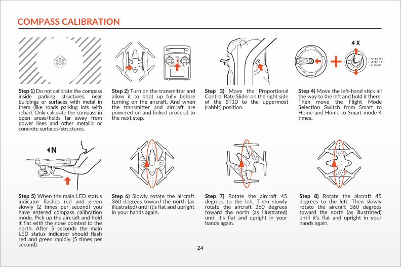
Step 5) When the main LED status indicator flashes red and green slowly (2 times per second) you have entered compass calibration mode. Pick up the aircraft and hold it flat with the nose pointed to the north. After 5 seconds the main LED status indicator should flash red and green rapidly (5 times per second).
Step 7) Rotate the aircraft 45 degrees to the left. Then slowly rotate the aircraft 360 degrees toward the north (as illustrated) until it's flat and upright in your hands again.
Step 6) Slowly rotate the aircraft 360 degrees toward the north (as illustrated) until it's flat and upright in your hands again.
Step 8) Rotate the aircraft 45 degrees to the left. Then slowly rotate the aircraft 360 degrees toward the north (as illustrated) until it's flat and upright in your hands again.
Step 1) Do not calibrate the compass inside parking structures, near buildings or surfaces with metal in them (like roads parking lots with rebar). Only calibrate the compass in open areas/fields far away from power lines and other metallic or concrete surfaces/structures.
Step 3) Move the Proportional Control Rate Slider on the right side of the ST10 to the uppermost (rabbit) position.
Step 2) Turn on the transmitter and allow it to boot up fully before turning on the aircraft. And when the transmitter and aircraft are powered on and linked proceed to the next step.
4 X
Step 4) Move the left-hand stick all the way to the left and hold it there. Then move the Flight Mode Selection Switch from Smart to Home and Home to Smart mode 4 times.
You can download the graphical user interface (GUI) software on the Q500 product page at www.Yuneec.com. Follow the on-screen instructions to install and operate the software which allows you to see the status of all sensors, to adjust various settings, check GPS accuracy, update firmware and more using the included USB Interface/Programmer.

Step 9) Rotate the aircraft 45 degrees to the left. Then slowly rotate the aircraft 360 degrees toward the north (as illustrated) until it's flat and upright in your hands again.
Step 11) If you hear an audible indication after the main LED status indicator stops blinking rapidly you have successfully completed compass calibration.
IMPORTANT NOTE: If compass calibration fails the main LED status indicator will glow solid white and you must restart the calibration process.
Step 10) The main LED status indicator should be flashing red and green rapidly (5 times per second). Hold the aircraft as still as possible until it main LED status indicator stops blinking rapidly.
IMPORTANT NOTE: Steps 6 to 9 must be completed in less than 30 seconds in order to successfully complete compass calibration.
30
25

ST10 AND RECEIVER BINDINGStep 1) Turn on the Q500, and after the Main LED Status Indicator begins to flash blue rapidly, lift the back end upward approximately 45° then back down to ‘level’ two (2) times to put the aircraft/receiver into bind mode. The Main LED Status Indicator will begin to the flash orange very rapidly when the aircraft/receiver are in bind mode.
2 x 45+°
Step 2) Turn on the ST10, and if required tap the screen (outside of the pop up status window) to bypass the RC and WiFi connection process.
Step 3) Tap the ‘Model Select’ button, and if required press ‘OK’ to bypass any pop up warnings/alerts.
Step 4) Select the existing model (for example: ‘Q500’) you would like to bind to (or create a ‘New Model’), and if required press ‘OK’ to bypass any pop up warnings/alerts.
Step 5) Tap the ‘Flight Settings’ button, and if required press ‘OK’ to bypass any pop up warnings/alerts.
Step 6) Tap the ‘Bind’ button and select the ‘SR12S_XXXXX’ receiver listed in the column under ‘Model’, then tap ‘OK’ after the connection has been established.
Step 7) Tap the ‘Back’ button two (2) times to return to the main screen and the model/receiver should automatically connect to the ST10.
26

27
Step 5) Tap the ‘Flight Settings’ button, and if required press ‘OK’ to bypass any pop up warnings/alerts.
Step 6) Tap the ‘Bind’ button and select the ‘SR12S_XXXXX’ receiver listed in the column under ‘Model’, then tap ‘OK’ after the connection has been established.
Step 7) Tap the ‘Back’ button two (2) times to return to the main screen and the model/receiver should automatically connect to the ST10.
ST10 AND CGO2-GB BINDINGStep 1) Turn on the ST10, and if required tap the screen (outside of the pop up status window) to bypass the RC and WiFi connection process.
Step 5) if required tap the screen (outside of the pop up status window) to bypass the RC and WiFi connection process, then tap the ‘Flight Settings’ button and press ‘OK’ to bypass any pop up warnings/alerts.
Step 6) Tap the ‘Bind’ button and select the ‘CGO2_XXXXXX’ camera listed in the column under ‘Camera’, then enter the password ‘1234567890’ when prompted and tap ‘OK’ after the connection has been established.
Step 7) Tap the ‘Back’ button two (2) times to return to the main screen and the camera should automatically connect to the ST10.
IMPORTANT NOTE: Streaming video from the CGO2-GB to the ST10 and to a separate phone/tablet (or another Yuneec transmitter/personal ground station) at the same time is NOT recommended as it will result in a very significant lag in the video downlink.
Step 2) Tap the ‘Model Select’ button, and if required press ‘OK’ to bypass any pop up warnings/alerts.
Step 3) Select the existing model (for example: ‘Q500’) you would like to bind to (or create a ‘New Model’), and if required press ‘OK’ to bypass any pop up warnings/alerts.
Step 4) Turn on the Q500 and ensure that the CGO2-GB is powered on.

28
TROUBLESHOOTINGISSUE
Q500 will not initialize
Flight battery will not charge (red LED on charger glows solid red).
Q500 GPS will not lock (ST10 indicates GPS Disabled)
Q500 GPS has reduced precision
Q500 GPS functions not operating properly
POSSIBLE CAUSE
The Q500 was moved during initialization.
The Q500 flight battery needs to be replaced.
Overcast, thick clouds blocking GPS reception.
Solar flares in progress.
Q500 is indoors.
Objects blocking 100 degrees of clear view of the sky.
(Possibly underneath a metallic or glass cover, inside a vehicle, near tall buildings, etc...)
Video transmitter nearby, such as an aftermarket video downlink system.
Raised threat level by the U.S. government.
The GPS module is possibly damaged.
The compass has been exposed to a magnet.
The GPS module is possibly damaged.
GPS lock has not been acquired.
Step 5) Tap the ‘Flight Settings’ button, and if required press ‘OK’ to bypass any pop up warnings/alerts.
Step 6) Tap the ‘Bind’ button and select the ‘SR12S_XXXXX’ receiver listed in the column under ‘Model’, then tap ‘OK’ after the connection has been established.
Step 7) Tap the ‘Back’ button two (2) times to return to the main screen and the model/receiver should automatically connect to the ST10.
Step 7) Tap the ‘Back’ button two (2) times to return to the main screen and the camera should automatically connect to the ST10.
IMPORTANT NOTE: Streaming video from the CGO2-GB to the ST10 and to a separate phone/tablet (or another Yuneec transmitter/personal ground station) at the same time is NOT recommended as it will result in a very significant lag in the video downlink.
SOLUTION
Turn the Q500 off then back on again, and ensure it does not move during the initialization process.
Replace the Q500 flight battery.
Wait for lighter cloud cover or disable GPS*.
Wait for disturbance to subside or disable GPS*.
Move the Q500 outside or disable GPS*.
Disable GPS. Flying indoors/disabling GPS NOT Recommended.
Move Q500 to a clear and open area.
Reposition or remove the video transmitter.
Wait for the threat level to be reduced or disable GPS*.
Replace the GPS module.
Move the Q500 away from the magnetic source. If problem persists, calibrate compass.
Replace the GPS module.
Ensure GPS antenna has clear view of sky and GPS lock has been acquired.
ISSUE
Q500 will not initialize
Flight battery will not charge (red LED on charger glows solid red).
Q500 GPS will not lock (ST10 indicates GPS Disabled)
Q500 GPS has reduced precision
Q500 GPS functions not operating properly
POSSIBLE CAUSE
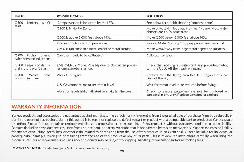
‘Compass error’ is indicated by the LED.
Q500 is in No Fly Zone.
Q500 is above 8,000 feet above MSL.
Incorrect motor start up procedure.
Q500 is too close to a metal object or metal surface .
Compass needs to be calibrated .
EMERGENCY Mode. Possibly due to obstructed propel-ler during motor start up.
Weak GPS signal.
U.S. Government has raised threat level.
Vibration levels high, indicated by shaky landing gear.
SOLUTION
See below for troubleshooting ‘compass error’.
Move at least 4 miles away from no fly zone. Most major airports are no fly zone areas.
Move Q500 below 8,000 feet above MSL.
Review Motor Starting/Stopping procedure in manual.
Move Q500 away from large metal objects or surfaces.
Calibrate compass.
Check that nothing is obstructing any propeller/motor, turn the Q500 off then back on again.
Confirm that the flying area has 100 degrees of clear view of the sky.
Wait for threat level to be reduced before flying.
Check to ensure propellers are not bent, nicked or damaged in any way. Replace damaged propellers.
WARRANTY INFORMATIONYuneec products and accessories are guaranteed against manufacturing defects for six (6) months from the original date of purchase. Yuneec’s sole obliga-tion in the event of such defects during this period is to repair or replace the defective part or product with a comparable part or product at Yuneec’s sole discretion. Except for such repair or replacement, the sale, processing or other handling of this product is without warranty, condition or other liability. Damage (including crash damage) resulting from use, accident, or normal wear and tear is not covered by this or any warranty. Yuneec assumes no liability for any accident, injury, death, loss, or other claim related to or resulting from the use of this product. In no event shall Yuneec be liable for incidental or consequential damages relating to or resulting from the use of this product or any of its parts. Please review the instructions carefully when using the products. Returns or replacements of parts and/or products may be subject to shipping, handling, replacement and/or restocking fees.
IMPORTANT NOTE: Crash damage is NOT covered under warranty.29
ISSUE
Q500 Motors won’t start
Q500 Flashes orange twice between indications
Q500 beeps constantly and motors won't start
Q500 Won’t hold position in hover