qcm-200as2cs rev-a1 datasheet - hmt.com.t rev-a1 datasheet.pdf · lcd indicator control module...
TRANSCRIPT

LCD Indicator Control Module Product Data Sheet
Model Name: QCM-200AS2CS…………………………………… Rev. A1
Contents
Introduction Page 1 - Feature
- Product Photo
Function / Specification
- Electronic Spec. Page 2
Hardware Descriptions
- PCB Diagram Page 3
- Jumpers / Connectors Description Page 3
- PCB Dimension Diagram Page 4
Hardware Operation Instructions
- Starting Screen Page 4
- Horizontal Display Description for Fl. Position Page 4
- Vertical Display Description for Fl. Position Page 5
- Node Setting Mode Description Page 5
- Style Position Display Description Page 6
- Data Transmission Screen description Page 7
Hwan Maw Technology Co., Ltd.
Tel.: +886-2-2274-1347 Fax. +886-2-2273-3014 Http://www.hmt.com.tw e-mail: [email protected]

LCD Indicator Control Module Product Data Sheet
Model Name: QCM-200AS2CS…………………………………… Rev. A1
Contents
Software Operation Instructions
- Software Information Page 8
- QCM-200AS2 Lift LCD Editor Interface Page 8
- QCM-200AS2 Lift LCD Editor Operation Page10
Housing Descriptions
- Metal Box Dimension for QCM-200AS2CS Page13
Product Information
- QCM-200AS2CS Page14
Hwan Maw Technology Co., Ltd.
Tel.: +886-2-2274-1347 Fax. +886-2-2273-3014 Http://www.hmt.com.tw e-mail: [email protected]

1
LCD Indicator Control Module Product Data Sheet
Model Name: QCM-200AS2CS…………………………………… Rev. A1
Introduction
QCM-200AS2CS LCD Indictor Control Module is designed innovatively to be
configured into elevators. Different from LED matrix and 7-segment indicators,
QCM-200AS2CS can select the up / down icons and number styles via PC, displaying fixed
simple messages like the company title or the name of the building…etc.
QCM-200AS2CS LCD Indictor Control Module can display horizontally or vertically.
Via RS-232 interface, all settings can be done by the tool software after downloading as
well as written into the module; For color display, adopt white color words / icons on a
blue background or a bright black one. Configured to the elevator car or hall, it boosts not
only the additional value of products but also its superior quality.
Feature
*Adopt LED back-lighted module with excellent durability. *Display floor No., up / down directions and easy messages. *Menus for settings of up/down arrows, number styles and time adjustment. *Display horizontally or vertically. * Communication Interface: CAN Bus
Product Photo

2
LCD Indicator Control Module Product Data Sheet
Model Name: QCM-200AS2CS…………………………………… Rev. A1
LCD Specification
LCD type Monochrome STN LCD
LCD back-lighted type LED
LCD screen dimension LCD 128 x 64M Blue-W / LCD 128 x 64M Black-W
LCD viewing area 72 x 40mm
LCD dpi 128 x 64 dots
LCD Dot size 0.52 mm
LCD screen display White words (icons) on blue / black background
Electronic Feature
Voltage Supply DC 12 - 30 V
Consumption DC 24V : 30mA
DC 12V : 60mA
Start Up Power Consumption DC 24V : 35mA
DC 12V : 70mA
TVS Protection Yes
Operating temperature 0℃ - 60℃
Input Signal Interface CAN-Bus (Transceiver. : TJA1040)
Download Communication Port RS-232

3
LCD Indicator Control Module Product Data Sheet
Model Name: QCM-200AS2CS…………………………………… Rev. A1
PCB Diagram
Jumpers / Connectors Description
A VR1:LCD Contrast Ratio Adjustment
B CN7:Power & Signal Connector
C CN2:D/L Cable Connector
D J1:System Reset
E CN1:LCD Connector
F
J4:SET J4 short to enter setting mode
CN3::::upward
CN4::::downward
CN5::::lock
CN6::::spare
X0:node increasing
X1:node decreasing
Ⓐ
Ⓑ
Ⓔ
Ⓕ
Ⓓ
Ⓒ

4
LCD Indicator Control Module Product Data Sheet
Model Name: QCM-200AS2CS…………………………………… Rev. A1
PCB Dimension Diagram
Hardware Operation Instructions
Starting Screen
When the power is on, QCM-200AS2CS will enter an elevator simulating operation screen automatically!
Horizontal Display Descriptions
Emergency Message
( Setup→Message )
( Make→Massage position ) Fl. Position Display ( Setup→FL Type )
Up/Dn DIR Display
( Setup→DIR Style )

5
LCD Indicator Control Module Product Data Sheet
Model Name: QCM-200AS2CS…………………………………… Rev. A1
Vertical Display Descriptions
Node Setting Mode Description: Operation::::
1. Short J4 from QCM-200AS2CS to enter the setting mode. Shown as Diagram 2:
2. Short CN3 (the red area from dia.1), dismantling, and then the node increases. Vice versa, short CN4 (the
red area from dia.1), dismantling, and then the node decreases.
3. Dismantling short of J4 means exiting the setting mode and saving the node setting at the same time.
Emergency Message
( Setup→Message )
( Make→Massage position )
Fl. Position Display ( Setup→
FL Type )
Up/Dn DIR Display
( Setup→DIR Style )
node
Diagram 1 Diagram 2

6
LCD Indicator Control Module Product Data Sheet
Model Name: QCM-200AS2CS…………………………………… Rev. A1
Style Position Display Descriptions The selections like FL styles, DIR styles and Emergency messages need to be edited via
QCM-200AS2 Lift LCD software after the module connects to PC. For Emergency messages, users
can select the display position via the software too.
FL Style / Fl. Position Display:Built in 4 font styles (Select one style to upload).
[Note] When the default setting is in horizontal display, it[Note] When the default setting is in horizontal display, it[Note] When the default setting is in horizontal display, it[Note] When the default setting is in horizontal display, it’’’’ll show users the selections for FL ll show users the selections for FL ll show users the selections for FL ll show users the selections for FL
Position DisplayPosition DisplayPosition DisplayPosition Display((((aaaatttt the the the the left/right side left/right side left/right side left/right side))))!!!!
DIR Style:Built in 5 arrow styles (Select one style to upload).
Message / Emergency Message:Built in 10 designed messages.
(Able to upload two display styles together at one time).
Emergency message for vertical display:Up/ Mid / Dn Three positions to select.
Emergency message for horizontal display:Up/ Dn Two positions to select.
Emergency Message Position List
Vertical Emergency Msg.-Up EmergencyMsg.-Mid Emergency Msg.-Dn
Horizontal Emergency Msg.-Up / Fl.-left Emergency Msg.-Dn. / Fl.-right

7
LCD Indicator Control Module Product Data Sheet
Model Name: QCM-200AS2CS…………………………………… Rev. A1
Data Transmission Screen Descriptions
1. After the module connects to PC, configure the transmission line on. There’ll show “Reminder Message” on the LCD immediately! It means the connection between QCM-200AS2CS and PC is done successfully!! Shown as left:
2. When PC starts uploading, the LCD will display the transmission
status under “Data recv.” Shown as left:
3. After uploading, LCD will show the initial “Reminder Message”
screen! It means the data from PC has been uploaded to QCM-200AS2CS successfully! Shown as left:
4. Dismantle the transmission line and the LCD will display elevator simulating operation screen immediately!
[PS]::::When the transmission failure happens to QCM-200AS2CS during connection or data
transmission, do not dismantle the transmission line! Just restart the power, and the system will transmit the data again.

8
LCD Indicator Control Module Product Data Sheet
Model Name: QCM-200AS2CS…………………………………… Rev. A1
Software Operation Descriptions
Software Information For providing the most convenience and efficiency, Lift LCD Editor supports the functions for uploading and
editing settings via connection to PC.
Software Name:QCM-200AS2 Lift LCD Editor
Version:R2-Build70508
QCM-200AS2 Lift LCD Editor Interface
Clear ALL:Clear all data in CTBL!
Load:Load in “qfl”, the setting file
Save:Save the file
CTBL Fl. Position Code Correspondences.
Key the data in the blanks.
FL Style, Version,
DIR Style, Emergency Message
9
LCD Indicator Control Module Product Data Sheet
Model Name: QCM-200AS2CS…………………………………… Rev. A1
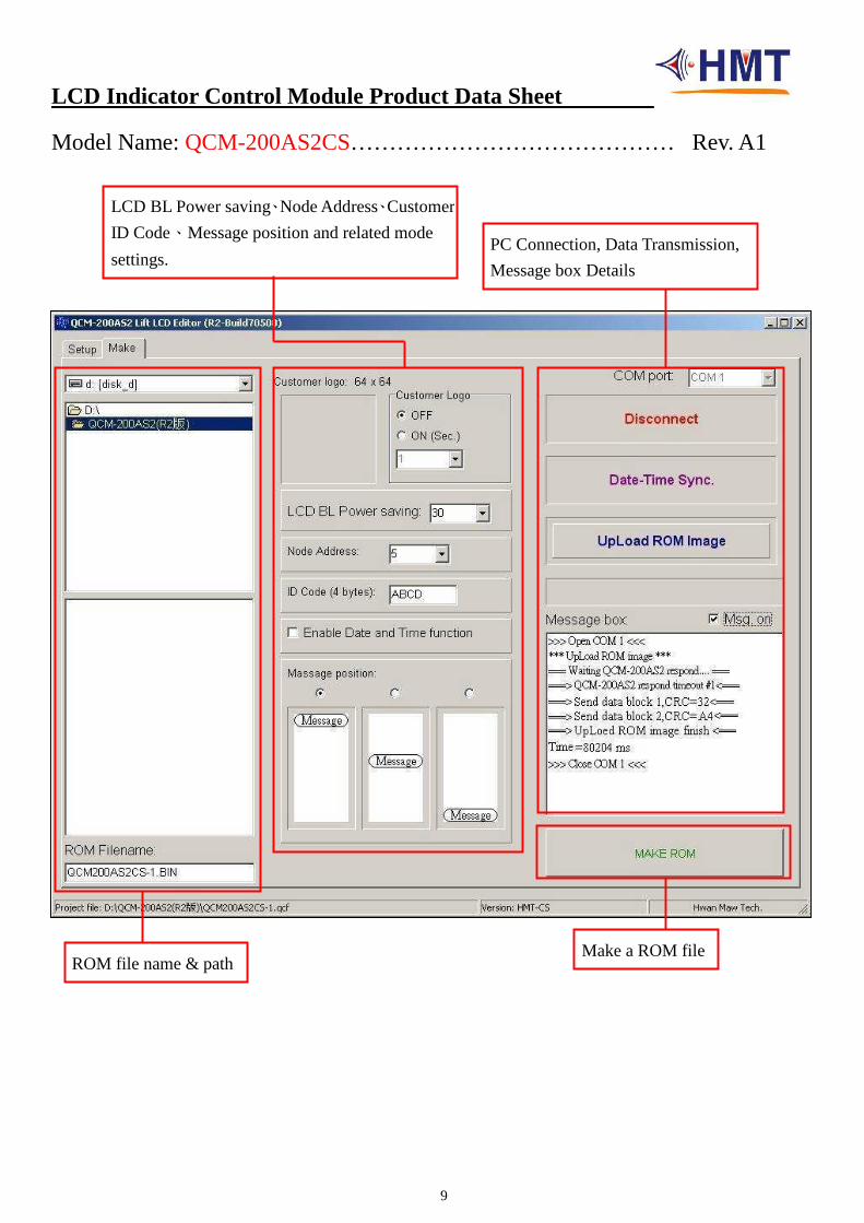
LCD BL Power saving、Node Address、Customer
ID Code、Message position and related mode
settings. PC Connection, Data Transmission,
Message box Details
ROM file name & path Make a ROM file

10
LCD Indicator Control Module Product Data Sheet
Model Name: QCM-200AS2CS…………………………………… Rev. A1
QCM-200AS2 Lift LCD Editor Operation 1. Setup Page::::Edit Lift LCD display screen & Fl. Position Code correspondence as request!
Setup settings as shown at - (A)(B)(C)(D)(E)part in the picture above::::
(A) CTBL ::::Edit CTBL、Upload the selections for CTBL. (3 CTBLs are available at most)
Double click on CTBL to key in data. (based on capital letters & within two digits)
(B) Version::::Select QCM-200AS2CS version & LCD vertical / horizontal display as request.
When select LCD horizontal display, the system will start the function of “Fl. display position” (to choose the display at the left or right)!
Ex. Vertical Display:HMT-CS Horizontal Display:HMT-CSH (H at the end of CS means Horizontal display)
(C) FL Style::::Built in 4 font styles. Users can preview them.
(D) DIR Style::::Built in 5 styles of the directional arrows.
(E) Message Display Style::::4 message styles (Chinese+ high light bkgnd., Chinese+ non- high light bkgnd
; English+ high light bkgnd., English+ non- high light bkgnd.)Users can select two versions together. As (E) in the picture, the Chinese words are flashing with high light bkgnd on the LCD.
Built-in 10 emergency messages::::Fire、、、、Earthquake、、、、Malfunction Alarm 、、、、PWR、、、、Over Load、、、、 Maintain 、、、、Full、、、、VIP、、、、Parking and IND.
Delete all data. Load in. Save Clear the file.
Set the extension name as.qcf
(A)
(B) (C)
(D)
(E)

11
LCD Indicator Control Module Product Data Sheet
Model Name: QCM-200AS2CS…………………………………… Rev. A1
2. Make Page::::Related status settings for Lift LCD & data transmission in this step!
1). Make settings for these statuses – shown at (A)(B)(C)(D) in the picture above::::
(A) ROM Path::::Select the path for ROM file saving.
(B) ROM Filename::::Build a ROM file name. (QCM-200AS2CS ROM’s extension name is BIN )
(C) LCD BL Power saving::::Set to turn off back-lighted function in 0 sec. ~ 600 secs.
Massage position::::Set the position (up / mid. / dn.) of the emergency msg. on the LCD panel!
Node Address::::Codes 0~63 can be set as fl. position addresses freely.
ID Code (4 bytes)::::Set 4 bytes code to customize users’ setting.
(D) MAKE ROM ::::When all settings are done, make a ROM file by clicking on this button!
[Note] Before connecting or transmitting data, save the file by clicking MAKE ROM button.
While saving the file, the system can also make a “BIN” ROM file for uploading as well!
(A) (C)
(E)
(B) (D)

12
LCD Indicator Control Module Product Data Sheet
Model Name: QCM-200AS2CS…………………………………… Rev. A1
2). Make PC Connection & Data Transmission- shown as (E)::::
○○○○1
Connection- PC :::: Select“COM port”first. Second, click on“Connect” to choose“UpLoad ROM Image”function.
QCM-200AS2CS:::: After the connection to PC, configure the transmission line and “ “ will be shown on the LCD right away. It means the connection between QCM-200AS2CS & PC is ready!
○○○○2 Transmission- PC:::: Click on“UpLoad ROM Image”to open a“BIN”ROM file and upload the file to QCM-200AS2CS.
QCM-200AS2CS::::
When PC starts uploading, “transmission icon” will be shown under on the LCD.
When there’s only left on the LCD, it means the uploading procedure completes
successfully! If dismantle the transmission line, the LCD will be in the stand-by mode.
○○○○3 Message box::::Tick “Mag.on” to show the connection, uploading… and other messages!
(E) PS:::: When the transmission failure happens to QCM-200AS2CS during connection or data
transmission, do not dismantle the transmission line! Just restart the power, and the system will transmit the data again.
Message box Descriptions
>>>Open COM1<<< Connection Msg.
>>>Close COM1<<< Disconnection Msg.
*** Date & Time Sync. *** ==Waiting QCM-200AS2 respond….== =>Send data block: 1,CRC = 99 <= => Date& Time Sync finish. <=
Date/Time Sync. Msg.
***UpLoad ROM image*** ==Waiting QCM-200AS2 respond….== =>Send data block: 1,CRC = 88 <= =>UpLoad ROM image finish. <= Time=14094 ms
Upload Msg.
=>QCM-200AS2 respond timeout #1<= Timeout Msg.

13
LCD Indicator Control Module Product Data Sheet
Model Name: QCM-200AS2CS…………………………………… Rev. A1
Dimension Diagram
Model No.: QCM-200AS2CS

14
LCD Indicator Control Module Product Data Sheet
Model Name: QCM-200AS2CS…………………………………… Rev. A1
Product Information
1. Style: QCM-200AS2CS / LCD Blue-W
Spec. : Size 128 x 64 dots. / Color white on Blue / Interface: CAN Bus.
2. Style: QCM-200AS2CS / LCD Black-W
Spec. : Size 128 x 64 dots. / Color white on Black / Interface: CAN Bus.