qc/qa, pfp, and qcp documents
TRANSCRIPT

QC/QA, PFP, and QCP Documents

QC/QA, PFP, and QCP Documents
Prepared and Published by Illinois Department of Transportation
Bureau of Materials and Physical Research
Springfield, Illinois
February 1, 2014
Preface
Reproduced from the Manual of Test Procedures for Materials are Appendices B, C, and E containing QC/QA, PFP, and QCP documents for Portland Cement Concrete (PCC) and Hot Mix Asphalt (HMA). For the complete Manual of Test Procedures for Materials, which cannot be reproduced here due to copyright, IDOT has hard copies available for purchase through the Policy Distribution Office (217)782-3464 or the link shown below. http://idot.illinois.gov/Assets/uploads/files/IDOT-Forms/BoBS/BoBS%203900.pdf

SEQUENTIAL TABLE OF CONTENTS (continued)
MANUAL OF TEST PROCEDURES FOR MATERIALS
June 1, 2012 Manual of Test Procedures for Materials
C—Portland Cement Concrete (PCC) Appendix C1
(Effective 12/01/93) (Revised 06/01/12)
Model Quality Control Plan for Concrete Production C 1
Appendix C2 (Effective 12/01/93) (Revised 06/01/12)
Qualifications and Duties of Concrete Quality Control Personnel ....................................................
C13
Appendix C3 (Effective 12/01/93) (Revised 06/01/12)
Required Sampling and Testing Equipment for Concrete ..................................................................
C19
Appendix C4 (Effective 12/01/93) (Revised 05/01/07)
Method for Obtaining Random Samples of Concrete C25
Appendix C5 (Effective 04/01/10)
IDOT Concrete Quality Control and Quality Assurance Documents
C29
June 1, 2012 Manual of Test Procedures for Materials C1 Appendix C1
+ILLINOIS DEPARTMENT OF TRANSPORTATION
MODEL QUALITY CONTROL PLAN FOR CONCRETE PRODUCTION Effective: December 1, 1993
Revised: June 1, 2012
INSTRUCTIONS: The Contractor shall respond to all items addressed in this model. This is applicable to work performed by the Contractor or subcontractor(s). Examples are provided to assist the Contractor, and any innovations to the quality control process may be presented.
Part 1 is completed by the Contractor.
Part 2 is completed by the Contractor or Commercial Concrete Producer. For the Contractor, Part 2 is submitted annually, for the period which begins April 1st, and which expires the following year on March 31st. For a Commercial Concrete Producer, Part 2 shall remain in effect until the Producer submits an updated document or the District requests the Producer to update Part 2. (Note: A District may require Part 2 to be updated annually or at a longer interval.)
If Part 2 is approved by the Department’s District office for a one year period, the Contractor shall either attach the approved Part 2 to each Quality Control Plan submitted, or shall state “The approved Part 2, for the period from mo/day/yr to mo/day/yr, is on file at the District office; the contents are fully and thoroughly understood, and the contents are a part of this Contract.” When Part 2 has been completed by the Commercial Concrete Producer, the Contractor shall not make any revisions. However, the Contractor and Commercial Concrete Producer have the option to amend Part 2 for a specific project, and submit it to the Department’s District office for approval.
QUALITY CONTROL PLAN CONCRETE
County:
Section:
Route:
District:
Contract No.:
Job No.:
Project:
Contractor:
P.O. Box:
Street Address:
City/State/Zip Code:
Telephone No.:
Fax No.:

June 1, 2012 Manual of Test Procedures for Materials C2 Appendix C1
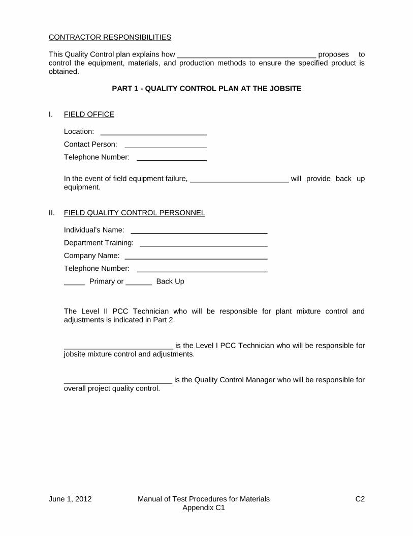
CONTRACTOR RESPONSIBILITIES This Quality Control plan explains how proposes to control the equipment, materials, and production methods to ensure the specified product is obtained.
PART 1 - QUALITY CONTROL PLAN AT THE JOBSITE I. FIELD OFFICE Location:
Contact Person:
Telephone Number:
In the event of field equipment failure, will provide back up
equipment. II. FIELD QUALITY CONTROL PERSONNEL Individual's Name:
Department Training:
Company Name:
Telephone Number:
Primary or Back Up
The Level II PCC Technician who will be responsible for plant mixture control and
adjustments is indicated in Part 2. is the Level I PCC Technician who will be responsible for
jobsite mixture control and adjustments. is the Quality Control Manager who will be responsible for
overall project quality control.

June 1, 2012 Manual of Test Procedures for Materials C3 Appendix C1
III. FIELD SAMPLING AND TESTING INSTRUCTIONS: Indicate whether beams and/or cylinders will be cast, as well as how the
specimens will be initially cured. Note: In some instances, such as Articles 503.05 and 503.06, only a flexural strength is
specified. An equivalent compressive strength may be used if approved by the Engineer. Example: Plastic cylinder molds [6 by 12 in. (152 by 305 mm)] will be used to cast strength
specimens. The plastic cylinder mold will be covered with a plastic cylinder lid. A curing box will be used to maintain the specimens within 60 to 80° F (16 to 27° C). The specimens will be transported after 24 hours for standard curing.
INSTRUCTIONS: Indicate the final location for standard curing and testing of the strength
specimens, and the method of curing. Example: The strength specimens will be transported to the consultant's lab for standard curing in a
water storage tank, and testing. IV. FAILING TESTS AND DEFECTIVE WORK INSTRUCTIONS: Indicate the communication procedures between the Commercial
Concrete Producer, the Contractor, and Department personnel in the event of failing tests or observation of defective work. This may also be in flow chart form.
Example: In the event of failing tests or observation of defective work at the jobsite, the Level I PCC
Technician will be responsible for notifying the Superintendent and the Quality Control Manager. The Superintendent will be responsible for notifying the Resident Engineer.
In the event of failing tests at the plant, the Level II PCC Technician will be responsible for
notifying the Superintendent and the Quality Control Manager. The Superintendent will be responsible for notifying the Resident Engineer.
V. COMMUNICATION INSTRUCTIONS: For concurrent pours, indicate how each Concrete Tester will be able to
contact the Level I PCC Technician. Indicate how jobsite personnel will be able to contact the Level II PCC Technician. Example: For concurrent pours, each Concrete Tester will be able to contact the Level I PCC
Technician by two-way radio. Jobsite personnel will use two-way radio to contact the Level II PCC Technician, when he/she is at the plant. When the Level II PCC Technician is not at the plant, jobsite personnel and the Level II PCC Technician will use a cellular phone.

June 1, 2012 Manual of Test Procedures for Materials C4 Appendix C1
VI. FIELD DOCUMENTATION INSTRUCTIONS: Indicate the forms, the bound hardback field books, and bound hardback
diaries that will be used to maintain documentation at the jobsite. Example: A bound hardback field book will be used for all documentation at the jobsite. VII. PRE-POUR MEETING INSTRUCTIONS: Indicate when a bridge deck pre-pour meeting will be scheduled.
Meetings for other important pours are encouraged. Examples: A meeting will be scheduled the day before the bridge deck pour to discuss mix, concrete
delivery, pumped concrete, finishing equipment and requirements, labor, deficiencies, curing, weather conditions (i.e. temperature, humidity, wind), and other pertinent issues.
Or
A meeting will be scheduled two months, two weeks, and two days before the bridge deck
pour. The meetings will discuss mix, concrete delivery, pumped concrete, finishing equipment and requirements, labor, deficiencies, curing, weather conditions (i.e. temperature, humidity, wind), and other pertinent issues.

June 1, 2012 Manual of Test Procedures for Materials C5 Appendix C1
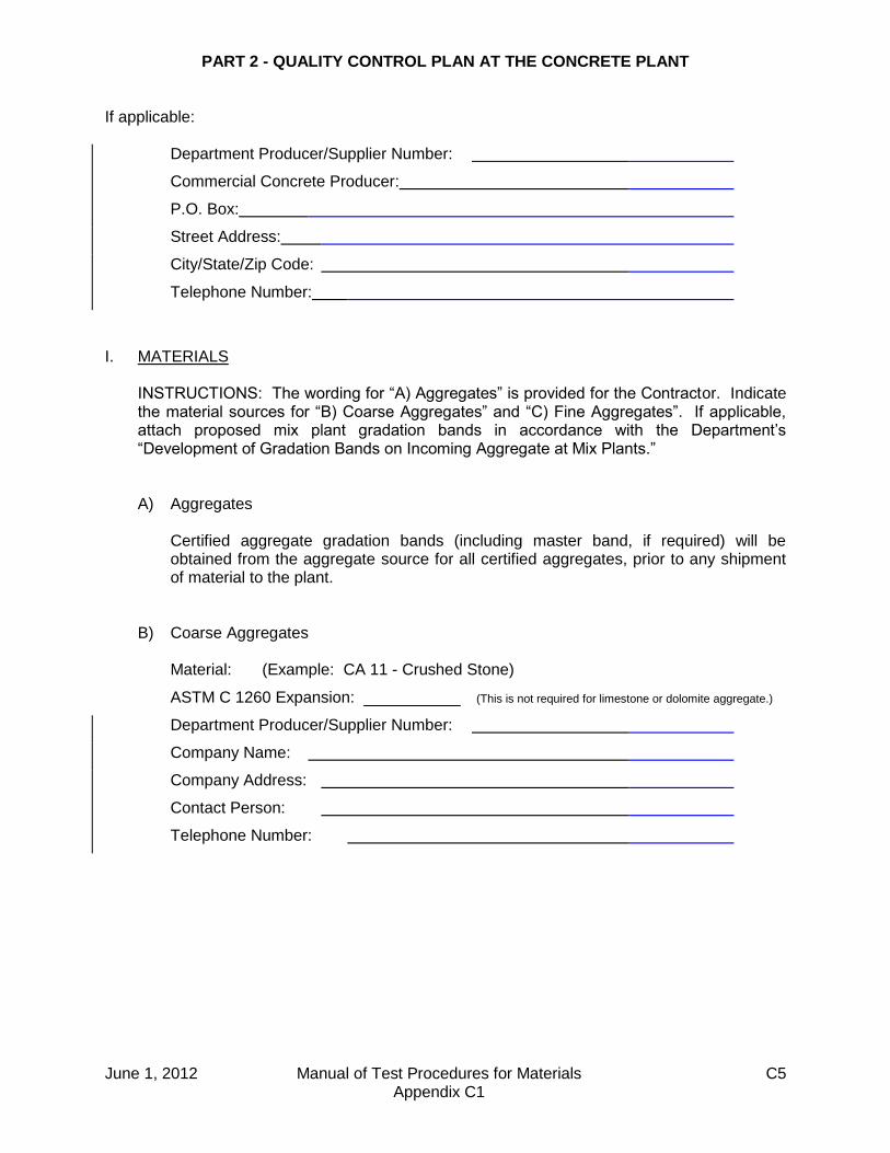
PART 2 - QUALITY CONTROL PLAN AT THE CONCRETE PLANT If applicable: Department Producer/Supplier Number:
Commercial Concrete Producer:
P.O. Box:
Street Address:
City/State/Zip Code:
Telephone Number:
I. MATERIALS INSTRUCTIONS: The wording for “A) Aggregates” is provided for the Contractor. Indicate
the material sources for “B) Coarse Aggregates” and “C) Fine Aggregates”. If applicable, attach proposed mix plant gradation bands in accordance with the Department’s “Development of Gradation Bands on Incoming Aggregate at Mix Plants.”
A) Aggregates Certified aggregate gradation bands (including master band, if required) will be
obtained from the aggregate source for all certified aggregates, prior to any shipment of material to the plant.
B) Coarse Aggregates Material: (Example: CA 11 - Crushed Stone)
ASTM C 1260 Expansion: (This is not required for limestone or dolomite aggregate.)
Department Producer/Supplier Number:
Company Name:
Company Address:
Contact Person:
Telephone Number:
June 1, 2012 Manual of Test Procedures for Materials C6 Appendix C1
C) Fine Aggregates Material: (Example: FA 01 - Natural Sand)
ASTM C 1260 Expansion: (This is not required for limestone or dolomite aggregate.)
Department Producer/Supplier Number:
Company Name:
Company Address:
Contact Person:
Telephone Number:
D) Aggregate Stockpiling and Handling INSTRUCTIONS: Aggregates shall be stockpiled and handled in a manner which
minimizes segregation and degradation, prevents contamination, and produces a uniform gradation, before placement in the plant bins. This is according to Articles 106.06, 106.07, 1003.01 (e), 1004.01 (e), 1004.02 (d), and 1020.10, of the Standard Specifications for Road and Bridge Construction (January 1, 2012). Indicate the specific methods to be used.
Example:
Coarse aggregates are shipped by rail to the plant, in a uniform gradation condition.
Upon delivery of the coarse aggregate, it will be transferred to a stockpile by a movable conveyor system. The stockpile will be built according to Article 1004.01 (e), of the Standard Specifications for Road and Bridge Construction (January 1, 2012).
Fine aggregates are shipped by truck to the plant, in a uniform gradation condition.
The fine aggregate will be truck dumped into a stockpile. The truck stockpile will be built according to Article 1003.01 (e) of the Standard Specifications for Road and Bridge Construction (January 1, 2012).
All stockpiles will be separated with concrete block walls, sufficient in width, length,
and height to prevent contamination. The maximum height of the walls will be ___ ft (___ m).
E) Uniform Aggregate Moisture INSTRUCTIONS: According to Article 1020.10 of the Standard Specifications for
Road and Bridge Construction (January 1, 2012), aggregates shall have a uniform moisture content before placement in the plant bins. Indicate the specific methods to be used.
Example: Coarse and fine aggregates will be stockpiled and allowed to drain for 12 hours, before
placement in the plant bins. However, during hot weather, the aggregate stockpiles will be periodically sprinkled with water.
June 1, 2012 Manual of Test Procedures for Materials C7 Appendix C1
F) Coarse Aggregate Moisture INSTRUCTIONS: Indicate the frequency of coarse aggregate moisture testing to
control production. NOTE: Fine aggregate moisture testing is specified in the Special Provision for
Quality Control/Quality Assurance of Concrete Mixtures. G) Aggregate Gradation Samples INSTRUCTIONS: Indicate how and where you will sample aggregates to assure they
will meet current Department gradation specifications. Example: For aggregates arriving at the plant, truck-dump sampling will be performed for fine
and coarse aggregate gradation tests. For aggregates used during concrete production, on-belt sampling will be performed
for fine and coarse aggregate gradation tests. The conveyor belt beneath the bin will be used.
H) Gradation Tests for Aggregates Arriving at the Plant INSTRUCTIONS: Indicate the frequency of gradation testing for aggregates arriving at
the plant, to check the source. NOTE: The frequency of gradation testing to check the production of concrete, for
aggregates stored at the plant in stockpiles or bins, is specified in the Special Provision for Quality Control/Quality Assurance of Concrete Mixtures.
II. PLANT AND DELIVERY TRUCKS Plant Name:
Plant Location:
Producer No.:
NOTE: The plant and delivery trucks are to be approved according to the Bureau of
Material and Physical Research’s Policy Memorandum, ”Approval of Concrete Plants and Delivery Trucks.” Contact the Department’s District office to obtain the required forms.

June 1, 2012 Manual of Test Procedures for Materials C8 Appendix C1
III. QUALITY CONTROL LABORATORY Location:
Contact Person:
Telephone Number:
The quality control laboratory is sq. ft. [The Department suggests 200 ft² (20 m²)]. The laboratory was approved on by District . In the event of lab equipment failure, will provide back up equipment. IV. PLANT QUALITY CONTROL PERSONNEL Individual's Name:
Department Training:
Company Name:
Telephone Number:
Primary or Back Up
NOTE: Include personnel who have been trained by the Level II PCC Technician to
sample and test aggregate for moisture. is the Level II PCC Technician who will be responsible for
plant mixture control and adjustments. The Level I PCC Technician who will be responsible for jobsite mixture control and
adjustments is indicated in Part 1. The Quality Control Manager who will be responsible for overall project quality control is
indicated in Part 1.

June 1, 2012 Manual of Test Procedures for Materials C9 Appendix C1
V. MIX DESIGNS INSTRUCTIONS: Provide mix design information as stated in 1.1 “Volumetric Mix Design
and Mix Design Submittal” of the Portland Cement Concrete Level III Technician Course – Manual of Instructions for Design of Concrete Mixtures.
Otherwise state: “Only mix designs previously verified by the Department will be used”.
INSTRUCTIONS: Based on the ASTM C 1260 test information provided for the aggregates, indicate the mixture option selected for minimizing the risk of alkali-silica reaction. Refer to Article 1020.05(d).
VI. PLANT MIXTURE TESTING INSTRUCTIONS: Indicate the plant start-up testing frequency, and the plant testing
frequency thereafter, to control production. This is required for slump, air content, unit weight, yield, and temperature tests performed at the plant. Indicate any other tests that will be performed.
NOTE: Plant start-up situations are defined in the “Portland Cement Concrete Level II
Technician Course” manual. Indicate if the manual’s plant start-up situations will be applicable, or if other start-up situations will apply.
VII. PLANT SUPERVISION INSTRUCTIONS: If the Level II will supervise more than one plant, indicate his/her
attendance at the various plants for large or critical pours. VIII. COMMUNICATION INSTRUCTIONS: Indicate how plant personnel will be able to contact the Level II PCC
Technician, when he/she is not at the plant. Example: Plant personnel will use a land phone, to contact the Level II PCC Technician by cellular
phone. IX. PLANT DOCUMENTATION INSTRUCTIONS: Indicate the forms, the bound hardback field books, and bound hardback
diaries that will be used to maintain documentation at the plant, and at the laboratory. Example: A loose-leaf binder will be used to maintain any Department form which is required at the
plant, or at the laboratory. A bound hardback field book will be used to record test results at the plant, and at the laboratory. A bound hardback diary will be used to document observations, inspections, adjustments to the mix design, and corrective actions at the plant.

June 1, 2012 Manual of Test Procedures for Materials C10 Appendix C1
INSTRUCTIONS:
To be completed by Contractor. Return with Quality Control Plan.
QUALITY CONTROL PLAN SIGNATURE SHEET
(IF AN INDIVIDUAL)
Firm Name
Print Name of Owner
Signature of Owner
Date:
(IF A CO-PARTNERSHIP)
Firm Name
Print Name of Partner
Signature of Partner
Date:
(IF A CORPORATION)
Corporate Name
Print Name of Authorized Representative
Signature of Authorized Representative
Date:
(ALL)
Business Address:
P.O. Box:
Street Address:
City/State/Zip Code:

June 1, 2012 Manual of Test Procedures for Materials C11 Appendix C1
INSTRUCTIONS: The Contractor shall complete this section for Addendums to a Quality Control Plan.
QUALITY CONTROL PLAN ADDENDUM
CONCRETE County:
Section:
Route:
District:
Contract No.:
Job No.:
Project:
Contractor:
P.O. Box:
Street Address:
City/State/Zip Code:
Telephone No.:
Fax No.:
ADDENDUMS INSTRUCTIONS: Indicate and/or attach addendums to Contractor Quality Control Plan.

June 1, 2012 Manual of Test Procedures for Materials C12 Appendix C1
INSTRUCTIONS:
To be completed by Contractor. Return with any amended Quality Control Plan.
QUALITY CONTROL PLAN ADDENDUM SIGNATURE SHEET
(IF AN INDIVIDUAL)
Firm Name
Print Name of Owner
Signature of Owner
Date:
(IF A CO-PARTNERSHIP)
Firm Name
Print Name of Partner
Signature of Partner
Date:
(IF A CORPORATION)
Corporate Name
Print Name of Authorized Representative
Signature of Authorized Representative
Date:
(ALL)
Business Address:
P.O. Box:
Street Address:
City/State/Zip Code:

June 1, 2012 Manual of Test Procedures for Materials C13 Appendix C2
ILLINOIS DEPARTMENT OF TRANSPORTATION
QUALIFICATIONS AND DUTIES OF CONCRETE QUALITY CONTROL PERSONNEL
Effective: December 1, 1993 Revised: June 1, 2012
This document summarizes the qualifications and duties of quality control personnel for Portland Cement Concrete (PCC) mixtures, Cement Aggregate Mixture II (CAM II), and Controlled Low-Strength Material (CLSM). Duties shall be performed daily, or as required, according to the QC/QA specifications and related documents. QUALITY CONTROL MANAGER: An individual who has the experience, responsibility, and
authority to make decisions regarding quality control of Portland Cement Concrete, Cement Aggregate Mixture II, and Controlled Low-Strength Material. This individual is required to have successfully completed the Department's Portland Cement Concrete Level I Technician Course, the Portland Cement Concrete Level II Technician Course, and either the 3-day Mixture Aggregate Technician Course or 5-day Aggregate Technician Course.
Duties: 1. Understand the specifications and related documents regarding QC/QA.
Read the Quality Control Plan and any amendments to the Plan. 2. Manage overall project quality control. 3. Ensure the laboratory, concrete plant, and delivery trucks are approved by the
Engineer. 4. Ensure the test equipment is maintained and calibrated as required by the
appropriate test procedure. 5. Ensure the mixture meets the requirements of the specifications. 6. Ensure good communication between the plant and jobsite to quickly resolve
quality control problems. Failure to resolve quality control problems shall result in mixture production suspension.
7. Ensure the Engineer is notified of any material supply problems. 8. Ensure the Engineer is immediately notified of any failing tests and
subsequent remedial action. Ensure passing tests are reported no later than the start of the next work day. Consult with the Engineer when questions arise concerning acceptance or rejection of materials.
9. Ensure all observations, inspections, adjustments to the mix design, test
results, retest results, and corrective actions are documented promptly, and in the specified format. Ensure form MI 504M, form MI 654, and form MI 655 are submitted to the Engineer weekly, or as required by the Engineer.
10. Supervise the Level III PCC Technician, Level II PCC Technician, Level I PCC
Technician, Concrete Tester, Gradation Technician, Mixture Aggregate Technician, and Aggregate Technician.
June 1, 2012 Manual of Test Procedures for Materials C14 Appendix C2
11. Ensure sufficient personnel are provided to perform the required inspections, sampling, testing, and documentation. Ensure work is accurate and done in a timely manner.
LEVEL III PCC TECHNICIAN: An individual who has successfully completed the
Department's Portland Cement Concrete Level I Technician Course, the Portland Cement Concrete Level II Technician Course, the Portland Cement Concrete Level III Technician Course, and either the 3-day Mixture Aggregate Technician Course or 5-day Aggregate Technician Course.
Duties: 1. Understand the specifications and related documents regarding QC/QA. Read the Quality Control Plan and any amendments to the Plan.
2. Read contract special provision(s) for project specific mix design information. 3. Obtain component materials’ specific gravities and absorptions (aggregates). 4. Ensure coarse aggregate voids tests are performed when necessary to
calculate mix design batch weights (mass). NOTE: The Level III PCC Technician may train anyone to sample and test coarse aggregate voids, provided the individual is monitored on a daily basis by the Level III PCC Technician. This is not applicable to aggregate sampling and testing for gradation, or to any other type of test.
5. Determine the correct proportions of aggregates, cement, finely divided
minerals, water, admixtures, and fiber reinforcement per cubic yard (meter). 6. Evaluate results when a trial mixture is performed. 7. Supervise a trial batch when requested by the Engineer. 8. Ensure the mix design is verified by the Engineer. 9. Ensure the mix design meets specification requirements during construction.
If not, take appropriate action and re-submit to the Engineer. LEVEL II PCC TECHNICIAN: An individual who has successfully completed the
Department's Portland Cement Concrete Level I Technician Course, the Portland Cement Concrete Level II Technician Course, and either the 3-day Mixture Aggregate Technician Course or 5-day Aggregate Technician Course.
Duties: 1. See Level I PCC Technician duties. 2. Check the operation of the concrete plant and condition of the delivery trucks. 3. Ensure only materials approved by the Department are used. 4. Obtain and split aggregate samples.

June 1, 2012 Manual of Test Procedures for Materials C15 Appendix C2
5. Perform gradation test for coarse and fine aggregates. If test results are near specification limits or unsatisfactory, take appropriate action and retest when applicable.
6. Perform aggregate moisture tests to adjust mix design aggregate batch
weights (mass). NOTE: The Level II PCC Technician may train anyone to sample and test aggregate for moisture, provided the individual is monitored on a daily basis by the Level II PCC Technician. This is not applicable to aggregate sampling and testing for gradation, or to any other type of test.
7. Verify the specified mix design is used, and the correct proportions of
aggregates, cement, finely divided minerals, water, admixtures, and fiber reinforcement are batched.
8. Control water/cement ratio by determining the allowable quantity of water
which can be added at the jobsite. 9. Maintain communications with jobsite personnel to control the mixture, for
compliance with the specifications. 10. Supervise the Gradation Technician, or assign the task to the Mixture
Aggregate Technician or Aggregate Technician. LEVEL I PCC TECHNICIAN: An individual who has successfully completed the
Department's Portland Cement Concrete Level I Technician Course. Duties: 1. Understand the specifications and related documents regarding QC/QA.
Read the Quality Control Plan and any amendments to the Plan. 2. Maintain and calibrate test equipment as required by the appropriate test
procedure.
3. Sample the mixture. 4. Perform temperature, slump, slump flow (self-consolidating concrete (SCC)),
flow (CLSM), J-Ring (SCC), L-Box (SCC), hardened visual stability index (SCC), measured stability index (SCC), dynamic segregation index (SCC), and air content tests and compare with specifications. If test results are unsatisfactory or near specification limits, take appropriate action and retest when applicable.
5. Perform unit weight test and determine yield. 6. Make strength and static segregation (SCC) specimens. Transport strength
specimens properly and ensure correct curing. Break strength specimens. NOTE: If an individual has the responsibility of breaking strength specimens only, such as at a consultant’s laboratory, this individual is required to have the Level I PCC Technician training or the Concrete Strength Testing Technician certification by the American Concrete Institute (ACI).
7. Monitor truck revolutions and haul time.
June 1, 2012 Manual of Test Procedures for Materials C16 Appendix C2
8. Determine the required quantity of water and admixtures for adjusting the
mixture, to meet specifications and field conditions. 9. Observe the discharge of a mixture by the delivery truck, and take appropriate
action if a problem is identified. 10. For a mixture which is not mixed on the jobsite, ensure the required
information is recorded on the delivery truck ticket. 11. Document all observations, inspections, adjustments to the mix design, test
results, retest results, and corrective actions promptly, and in the specified format.
12. Maintain communications with plant personnel to control the mixture, for
compliance with the specifications. 13. Notify the Engineer of test results. 14. Report test results to the Quality Control Manager. 15. Supervise the Concrete Tester. CONCRETE TESTER: An individual who has successfully completed the Department's
Portland Cement Concrete Tester Course. The Concrete Tester shall be monitored on a daily basis by the Level I or the Level II PCC Technician when performing tests.
Duties: 1. Sample the mixture. 2. Perform temperature, slump, slump flow (self-consolidating concrete (SCC)),
flow (CLSM), J-Ring (SCC), L-Box (SCC), hardened visual stability index (SCC), measured stability index (SCC), dynamic segregation index (SCC), air content and unit weight tests.
3. Make strength and static segregation (SCC) specimens. 4. Monitor truck revolutions and haul time. 5. Observe the mixture and notify the Level I or Level II PCC Technician of any
problems. 6. Assist the Level I or Level II PCC Technician with adjustments to a mixture, by
adding water or an admixture. 7. For a mixture which is not mixed on the jobsite, ensure the required
information is recorded on the delivery ticket. 8. Document all observations, inspections, adjustments to the mix design, test
results, retest results, and corrective actions promptly, and in the specified format.

June 1, 2012 Manual of Test Procedures for Materials C17 Appendix C2
9. Report truck revolutions, haul time, and test results to the Level I or Level II
PCC Technician. Immediate notification is required if truck revolutions, haul time, or test results are near specification limits or unsatisfactory.
GRADATION TECHNICIAN: An individual who has successfully completed the Department's
Aggregate Gradation Testing Course and has demonstrated satisfactory field performance. The Gradation Technician shall be monitored on a daily basis by the Level II PCC Technician when performing tests. The Level II PCC Technician may have the Mixture Aggregate Technician, or Aggregate Technician responsible for supervising the Gradation Technician on a daily basis.
Duties: 1. Split aggregate samples provided by others. 2. Perform gradation test for coarse and fine aggregates. 3. Document test results. 4. Report test results to Level II PCC Technician. Immediate notification is
required if test results are near specification limits or unsatisfactory. MIXTURE AGGREGATE TECHNICIAN: An individual who has successfully completed the
Department's 3-day Aggregate Training Course. Duties: 1. Obtain and split aggregate samples. 2. Perform gradation test for coarse and fine aggregates. 3. Document test results. 4. Report test results to Level II PCC Technician. Immediate notification is
required if test results are near specification limits or unsatisfactory. 5. Supervise the Gradation Technician, when required by the Level II PCC
Technician. NOTE: The duties listed are for assisting the Level II PCC Technician, and are not to be
confused with the “Aggregate Gradation Control System” program.

June 1, 2012 Manual of Test Procedures for Materials C18 Appendix C2
AGGREGATE TECHNICIAN: An individual who has successfully completed the
Department's 5-day Aggregate Training Course. Duties: 1. Obtain and split aggregate samples. 2. Perform gradation test for coarse and fine aggregates. 3. Document test results. 4. Report test results to Level II PCC Technician. Immediate notification is
required if test results are near specification limits or unsatisfactory. 5. Supervise the Gradation Technician, when required by the Level II PCC
Technician. NOTE: The duties listed are for assisting the Level II PCC Technician, and are not to be
confused with the “Aggregate Gradation Control System” program.

Illinois Department of Transportation
Required Sampling and Testing Equipment for Concrete
Effective: December 1, 1993
Revised: June 1, 2012
June 1, 2012 Manual of Test Procedures for Materials C19 Appendix C3
This document applies to cast-in-place, precast, and precast prestressed operations. This document summarizes the minimum requirements for sampling and testing Portland Cement Concrete (PCC) mixtures, Cement Aggregate Mixture II (CAM II), and Controlled Low-Strength Material (CLSM). Refer to the Manual of Test Procedures for Materials for detailed equipment information. AT THE PLANT OR LOCATION APPROVED BY THE ENGINEER: Proportioning PCC, CAM II, CLSM Aggregate Moisture Test Equipment, and Balance1 or Scale1 (1 The weighing equipment does not have to be electronic. Check weights are recommended.) Sampling Plastic PCC, CAM II, CLSM Wheelbarrow or Similar Equipment Shovel Testing Plastic PCC, CAM II, CLSM Slump Kit (PCC or CAM II) Plastic Cylinder for Flow Test (CLSM) Air Meter Kit and Calibration Equipment Unit Weight Kit, Calibration Equipment, and Balance1 or Scale1 (1 The weighing equipment does not have to be electronic. Check weights are recommended.) Thermometer Ruler Hand Scoop or Trowel Vibrator (if required) Slump Flow Kit (Required only for self-consolidating concrete.) J-Ring or L-Box Kit (Required only for self-consolidating concrete.) Aggregate Sampling Equipment for High/Low Volume Operation Template and brush, or sampling device, or shovel.
June 1, 2012 Manual of Test Procedures for Materials C20 Appendix C3
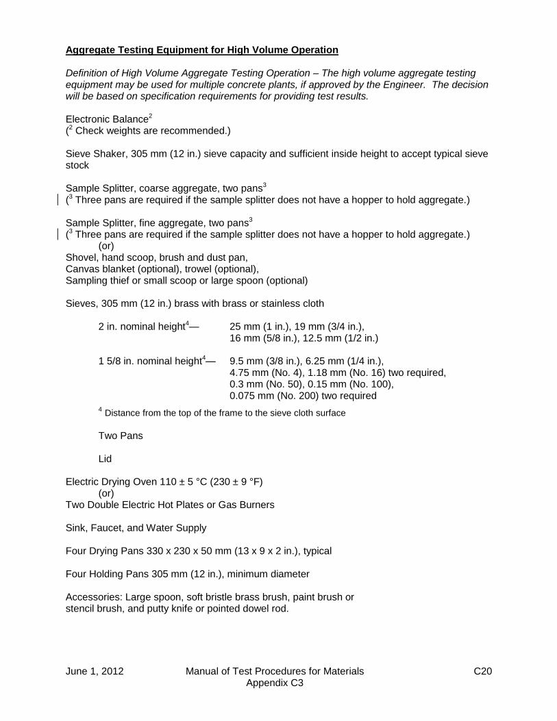
Aggregate Testing Equipment for High Volume Operation Definition of High Volume Aggregate Testing Operation – The high volume aggregate testing equipment may be used for multiple concrete plants, if approved by the Engineer. The decision will be based on specification requirements for providing test results. Electronic Balance2 (2 Check weights are recommended.) Sieve Shaker, 305 mm (12 in.) sieve capacity and sufficient inside height to accept typical sieve stock Sample Splitter, coarse aggregate, two pans3 (3 Three pans are required if the sample splitter does not have a hopper to hold aggregate.) Sample Splitter, fine aggregate, two pans3 (3 Three pans are required if the sample splitter does not have a hopper to hold aggregate.) (or) Shovel, hand scoop, brush and dust pan, Canvas blanket (optional), trowel (optional), Sampling thief or small scoop or large spoon (optional) Sieves, 305 mm (12 in.) brass with brass or stainless cloth 2 in. nominal height4— 25 mm (1 in.), 19 mm (3/4 in.), 16 mm (5/8 in.), 12.5 mm (1/2 in.) 1 5/8 in. nominal height4— 9.5 mm (3/8 in.), 6.25 mm (1/4 in.), 4.75 mm (No. 4), 1.18 mm (No. 16) two required, 0.3 mm (No. 50), 0.15 mm (No. 100), 0.075 mm (No. 200) two required
4 Distance from the top of the frame to the sieve cloth surface
Two Pans Lid Electric Drying Oven 110 ± 5 °C (230 ± 9 °F) (or) Two Double Electric Hot Plates or Gas Burners Sink, Faucet, and Water Supply Four Drying Pans 330 x 230 x 50 mm (13 x 9 x 2 in.), typical Four Holding Pans 305 mm (12 in.), minimum diameter Accessories: Large spoon, soft bristle brass brush, paint brush or stencil brush, and putty knife or pointed dowel rod.

June 1, 2012 Manual of Test Procedures for Materials C21 Appendix C3
Aggregate Testing Equipment for Low Volume Operation Definition of Low Volume Aggregate Testing Operation – The low volume aggregate testing equipment may be used only for a single concrete plant. If a reduced testing time is desired, the high volume aggregate testing equipment is recommended, since the low volume 200 mm (8 in.) sieves will normally require the coarse aggregate sample to be sieved in parts to prevent overloading. Electronic Balance2 (2 Check weights are recommended.) Sieve Shaker, 200 mm (8 in.) sieve capacity and sufficient inside height to accept typical sieve stock Sample Splitter, coarse aggregate, two pans3 (3 Three pans are required if the sample splitter does not have a hopper to hold aggregate.) Sample Splitter, fine aggregate, two pans3 (3 Three pans are required if the sample splitter does not have a hopper to hold aggregate.) (or) Shovel, hand scoop, brush and dust pan, Canvas blanket (optional), trowel (optional), Sampling thief or small scoop or large spoon (optional) Sieves, 200 mm (8 in.) brass with brass or stainless cloth 2 in. nominal height4— 25 mm (1 in.), 19 mm (3/4 in.), 16 mm (5/8 in.), 12.5 mm (1/2 in.), 9.5 mm (3/8 in.), 6.25 mm (1/4 in.), 4.75 mm (No. 4) 1 in. nominal height4— 1.18 mm (No. 16) two required, 0.3 mm (No. 50) 0.15 mm (No. 100), 0.075 mm (No. 200) two required
4 Distance from the top of the frame to the sieve cloth surface Two Pans Lid Two Double Electric Hot Plates or Gas Burners Sink, Faucet, and Water Supply Two Drying Pans 330 x 230 x 50 mm (13 x 9 x 2 in.), typical Three Holding Pans 305 mm (12 in.), minimum diameter Accessories: Large spoon, soft bristle brass brush, paint brush or stencil brush, and putty knife or pointed dowel rod.

June 1, 2012 Manual of Test Procedures for Materials C22 Appendix C3
AT THE JOBSITE: Sampling Plastic PCC, CAM II, CLSM Wheelbarrow or Similar Equipment Shovel Testing Plastic PCC, CAM II, CLSM Slump Kit (PCC or CAM II) Plastic Cylinder for Flow Test (CLSM) Air Meter Kit and Calibration Equipment Thermometer Ruler Hand Scoop or Trowel Vibrator (if required) Slump Flow Kit (Required only for self-consolidating concrete.) J-Ring or L-Box Kit (Required only for self-consolidating concrete.) Making Strength Specimens (Cylinders or Beams) Plastic Cylinder Molds, 152 x 305 mm (6 x 12 in.) Plastic Cylinder Lids, 152 mm (6 in.), or other material per Illinois Modified AASHTO T 23 -------------OR------------- Steel or Plastic Beam Molds (typical length) 152 x 152 x 457 mm (6 x 6 x 18 in.), 152 x 152 x 483 mm (6 x 6 x 19 in.), 152 x 152 x 508 mm (6 x 6 x 20 in.),
152 x 152 x 533 mm (6 x 6 x 21 in.), or 152 x 152 x 762 mm (6 x 6 x 30 in.) Plastic Cover with Absorbent Pad, or other material per Illinois Modified AASHTO T 23 ------------AND------------ Tamping Rod or Vibrator (as appropriate) Mallet Hand Scoop (optional) Trowel or Wood Float

June 1, 2012 Manual of Test Procedures for Materials C23 Appendix C3
AT THE JOBSITE OR LOCATION APPROVED BY THE ENGINEER: Curing Strength Specimens Moist Cabinet or Moist Room, with Air Temperature and Relative Humidity Control Equipment Recording Thermometer Relative Humidity Measuring Device and Logbook, or Relative Humidity Recording Device -------------OR------------- Water Storage Tank and Provisions for Water Temperature Control Maximum/Minimum Thermometer and Logbook, or Recording Thermometer Testing Strength Specimens Capping System for Compressive Strength Mechanical Testing Machine for Compressive Strength -------------OR------------- Mechanical or Hand-Operated Testing Machine for Flexural Strength (Using Simple Beam with Center-Point Loading) Self-Consolidating Concrete Saw to cut cylinders for hardened visual stability index. PRECAST CONCRETE PLANTS (ADDITIONAL REQUIREMENTS): For dry cast operations, the slump kit is optional and the air meter kit is not required. Block/Brick Products – A compression test machine is required. Pipe Products – A three-edge-bearing machine is required. Applicable Products – When cores are used to determine compressive strength, the core drill shall have diamond impregnated bits attached to the core barrel. Applicable Products – Absorption, permeability, hydrostatic, density, freeze/thaw, linear drying shrinkage, and abrasion resistance test equipment are required.

June 1, 2012 Manual of Test Procedures for Materials C24 Appendix C3
This Page Reserved
June 1, 2012 Manual of Test Procedures for Materials C25 Appendix C4
ILLINOIS DEPARTMENT OF TRANSPORTATION
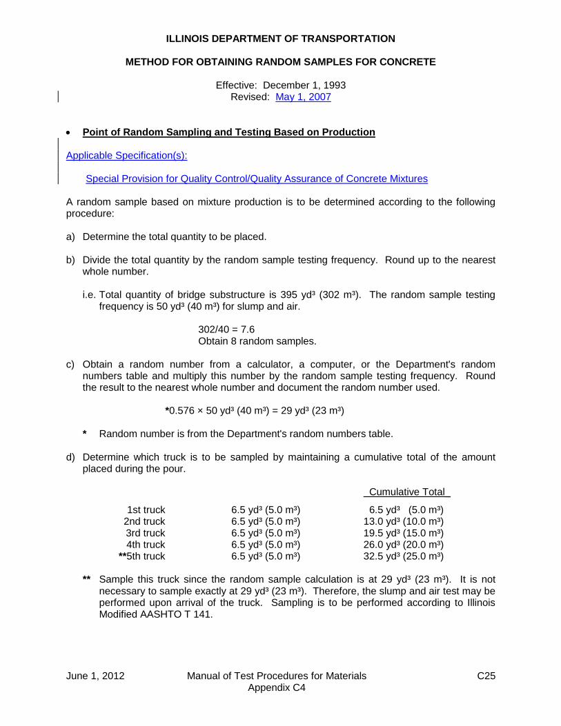
METHOD FOR OBTAINING RANDOM SAMPLES FOR CONCRETE
Effective: December 1, 1993 Revised: May 1, 2007
Point of Random Sampling and Testing Based on Production Applicable Specification(s): Special Provision for Quality Control/Quality Assurance of Concrete Mixtures A random sample based on mixture production is to be determined according to the following procedure: a) Determine the total quantity to be placed. b) Divide the total quantity by the random sample testing frequency. Round up to the nearest
whole number.
i.e. Total quantity of bridge substructure is 395 yd³ (302 m³). The random sample testing frequency is 50 yd³ (40 m³) for slump and air.
302/40 = 7.6 Obtain 8 random samples. c) Obtain a random number from a calculator, a computer, or the Department's random
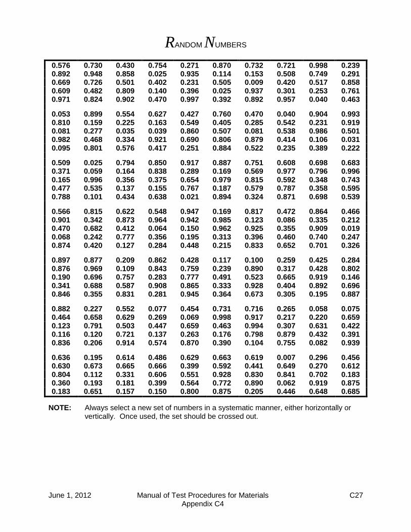
numbers table and multiply this number by the random sample testing frequency. Round the result to the nearest whole number and document the random number used.
*0.576 × 50 yd³ (40 m³) = 29 yd³ (23 m³)
* Random number is from the Department's random numbers table. d) Determine which truck is to be sampled by maintaining a cumulative total of the amount
placed during the pour. Cumulative Total_
1st truck 6.5 yd³ (5.0 m³) 6.5 yd³ (5.0 m³) 2nd truck 6.5 yd³ (5.0 m³) 13.0 yd³ (10.0 m³) 3rd truck 6.5 yd³ (5.0 m³) 19.5 yd³ (15.0 m³) 4th truck 6.5 yd³ (5.0 m³) 26.0 yd³ (20.0 m³) **5th truck 6.5 yd³ (5.0 m³) 32.5 yd³ (25.0 m³)
** Sample this truck since the random sample calculation is at 29 yd³ (23 m³). It is not necessary to sample exactly at 29 yd³ (23 m³). Therefore, the slump and air test may be performed upon arrival of the truck. Sampling is to be performed according to Illinois Modified AASHTO T 141.

June 1, 2012 Manual of Test Procedures for Materials C26 Appendix C4
e) Continue the random sampling method for the next 50 yd³ (40 m³).
i.e. Second sample random number = 0.892
Sample to be obtained at:
0.892 × 50 yd³ (40 m³) = 45 yd³ (36 m³) in the second 50 yd³ (40 m³). Using the cumulative total you would sample at 95 yd³ (76 m³).
Third sample random number = 0.669
Sample to be obtained at:
0.669 × 50 yd³ (40 m³) = 33 yd³ (27 m³) in the third 50 yd³ (40 m³). Using the cumulative total you would sample at 133 yd³ (107 m³).
f) The last random sample shall be obtained by multiplying a random number by the fractional portion of the random sample testing frequency. Refer to the value of 7.6 which was determined under part b).
Obtain the last sample at:
0.609 × [0.6 × 50 yd³ (40 m³)] = 18 yd³ (15 m³) in the final 50 yd³ (40 m³). Using the cumulative total you would sample at 368 yd³ (295 m³).
Point of Random Sampling and Testing Based on Location Applicable Specification(s): (Note: Specifically for pull-off tests.) Bridge Deck Microsilica Concrete Overlay Bridge Deck Latex Concrete Overlay Bridge Deck High-Reactivity Metakaolin (HRM) Concrete Overlay A random sample based on a location within an area of pavement or bridge deck is to be determined according to the following procedure: a) Obtain the length and width of the lot or sublot. b) Obtain a random number from a calculator, a computer, or the Department’s random
numbers table, and multiply this number by the total length of the lot or sublot. Obtain another random number and multiply this number by the total width of the lot or sublot. For each result round to the nearest 0.1. Document the result and random number used.
For example, the lot or sublot is 500 ft (152 m) long and 12 ft (3.6 m) wide.
* 0.576 × 500 ft (152 m) = 288.0 ft (87.6 m)
* 0.892 × 12 ft (3.6 m) = 10.7 ft (3.2 m)
* Random number is from the Department’s random numbers table.
Therefore, the random sample location shall be taken 288.0 ft (87.6 m) from the beginning of the lot or sublot, and 10.7 ft (3.2 m) from the designated right or left edge of the lot or sublot. The designated edge shall be determined by the Engineer, and shall not vary.
c) For each random sample location, determine the corresponding station location and
document. d) For each random sample location, the process shall be repeated for additional test locations
using new random numbers for each location.
June 1, 2012 Manual of Test Procedures for Materials C27 Appendix C4
RANDOM NUMBERS
0.576 0.730 0.430 0.754 0.271 0.870 0.732 0.721 0.998 0.239 0.892 0.948 0.858 0.025 0.935 0.114 0.153 0.508 0.749 0.291 0.669 0.726 0.501 0.402 0.231 0.505 0.009 0.420 0.517 0.858 0.609 0.482 0.809 0.140 0.396 0.025 0.937 0.301 0.253 0.761 0.971 0.824 0.902 0.470 0.997 0.392 0.892 0.957 0.040 0.463
0.053 0.899 0.554 0.627 0.427 0.760 0.470 0.040 0.904 0.993 0.810 0.159 0.225 0.163 0.549 0.405 0.285 0.542 0.231 0.919 0.081 0.277 0.035 0.039 0.860 0.507 0.081 0.538 0.986 0.501 0.982 0.468 0.334 0.921 0.690 0.806 0.879 0.414 0.106 0.031 0.095 0.801 0.576 0.417 0.251 0.884 0.522 0.235 0.389 0.222
0.509 0.025 0.794 0.850 0.917 0.887 0.751 0.608 0.698 0.683 0.371 0.059 0.164 0.838 0.289 0.169 0.569 0.977 0.796 0.996 0.165 0.996 0.356 0.375 0.654 0.979 0.815 0.592 0.348 0.743 0.477 0.535 0.137 0.155 0.767 0.187 0.579 0.787 0.358 0.595 0.788 0.101 0.434 0.638 0.021 0.894 0.324 0.871 0.698 0.539
0.566 0.815 0.622 0.548 0.947 0.169 0.817 0.472 0.864 0.466 0.901 0.342 0.873 0.964 0.942 0.985 0.123 0.086 0.335 0.212 0.470 0.682 0.412 0.064 0.150 0.962 0.925 0.355 0.909 0.019 0.068 0.242 0.777 0.356 0.195 0.313 0.396 0.460 0.740 0.247 0.874 0.420 0.127 0.284 0.448 0.215 0.833 0.652 0.701 0.326
0.897 0.877 0.209 0.862 0.428 0.117 0.100 0.259 0.425 0.284 0.876 0.969 0.109 0.843 0.759 0.239 0.890 0.317 0.428 0.802 0.190 0.696 0.757 0.283 0.777 0.491 0.523 0.665 0.919 0.146 0.341 0.688 0.587 0.908 0.865 0.333 0.928 0.404 0.892 0.696 0.846 0.355 0.831 0.281 0.945 0.364 0.673 0.305 0.195 0.887
0.882 0.227 0.552 0.077 0.454 0.731 0.716 0.265 0.058 0.075 0.464 0.658 0.629 0.269 0.069 0.998 0.917 0.217 0.220 0.659 0.123 0.791 0.503 0.447 0.659 0.463 0.994 0.307 0.631 0.422 0.116 0.120 0.721 0.137 0.263 0.176 0.798 0.879 0.432 0.391 0.836 0.206 0.914 0.574 0.870 0.390 0.104 0.755 0.082 0.939
0.636 0.195 0.614 0.486 0.629 0.663 0.619 0.007 0.296 0.456 0.630 0.673 0.665 0.666 0.399 0.592 0.441 0.649 0.270 0.612 0.804 0.112 0.331 0.606 0.551 0.928 0.830 0.841 0.702 0.183 0.360 0.193 0.181 0.399 0.564 0.772 0.890 0.062 0.919 0.875 0.183 0.651 0.157 0.150 0.800 0.875 0.205 0.446 0.648 0.685
NOTE: Always select a new set of numbers in a systematic manner, either horizontally or vertically. Once used, the set should be crossed out.

June 1, 2012 Manual of Test Procedures for Materials C28 Appendix C4
This Page Reserved
June 1, 2012 Manual of Test Procedures for Materials C29 Appendix C5
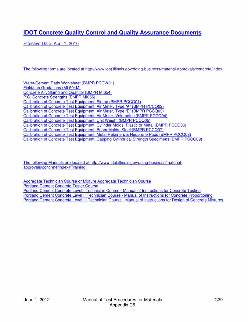
IDOT Concrete Quality Control and Quality Assurance Documents Effective Date: April 1, 2010 The following forms are located at http://www.idot.illinois.gov/doing-business/material-approvals/concrete/index. Water/Cement Ratio Worksheet (BMPR PCCW01) Field/Lab Gradations (MI 504M) Concrete Air, Slump and Quantity (BMPR MI654) P.C. Concrete Strengths (BMPR MI655) Calibration of Concrete Test Equipment, Slump (BMPR PCCQ01) Calibration of Concrete Test Equipment, Air Meter, Type “A” (BMPR PCCQ02) Calibration of Concrete Test Equipment, Air Meter, Type “B” (BMPR PCCQ03) Calibration of Concrete Test Equipment, Air Meter, Volumetric (BMPR PCCQ04) Calibration of Concrete Test Equipment, Unit Weight (BMPR PCCQ05) Calibration of Concrete Test Equipment, Cylinder Molds, Plastic or Metal (BMPR PCCQ06) Calibration of Concrete Test Equipment, Beam Molds, Steel (BMPR PCCQ07) Calibration of Concrete Test Equipment, Metal Retainers & Neoprene Pads (BMPR PCCQ08) Calibration of Concrete Test Equipment, Capping Cylindrical Strength Specimens (BMPR PCCQ09) The following Manuals are located at http://www.idot.illinois.gov/doing-business/material-approvals/concrete/index#Training. Aggregate Technician Course or Mixture Aggregate Technician Course Portland Cement Concrete Tester Course Portland Cement Concrete Level I Technician Course - Manual of Instructions for Concrete Testing Portland Cement Concrete Level II Technician Course - Manual of Instructions for Concrete Proportioning Portland Cement Concrete Level III Technician Course - Manual of Instructions for Design of Concrete Mixtures

June 1, 2012 Manual of Test Procedures for Materials C30 Appendix C5
This Page Reserved

2013 PCC Supporting Documents
No changes to Portland Cement Concrete (PCC) QC/QA Documents contained within Appendix C of the Manual of Test Procedures for Materials (MTP) at this time for 2013.

SEQUENTIAL TABLE OF CONTENTS (continued)
MANUAL OF TEST PROCEDURES FOR MATERIALS
June 1, 2012 Manual of Test Procedures for Materials
C—Portland Cement Concrete (PCC) Appendix C1
(Effective 12/01/93) (Revised 06/01/12)
Model Quality Control Plan for Concrete Production C 1
Appendix C2 (Effective 12/01/93) (Revised 01/01/14)
Qualifications and Duties of Concrete Quality Control Personnel ....................................................
C13
Appendix C3 (Effective 12/01/93) (Revised 01/01/14)
Required Sampling and Testing Equipment for Concrete ..................................................................
C19
Appendix C4 (Effective 12/01/93) (Revised 01/01/14)
Method for Obtaining Random Samples of Concrete C25
Appendix C5 (Effective 04/01/10) (Revised 01/01/14)
IDOT Concrete Quality Control and Quality Assurance Documents
C29

June 1, 2012 Manual of Test Procedures for Materials C1 Appendix C1
+ILLINOIS DEPARTMENT OF TRANSPORTATION
MODEL QUALITY CONTROL PLAN FOR CONCRETE PRODUCTION Effective: December 1, 1993
Revised: June 1, 2012
INSTRUCTIONS: The Contractor shall respond to all items addressed in this model. This is applicable to work performed by the Contractor or subcontractor(s). Examples are provided to assist the Contractor, and any innovations to the quality control process may be presented.
Part 1 is completed by the Contractor.
Part 2 is completed by the Contractor or Commercial Concrete Producer. For the Contractor, Part 2 is submitted annually, for the period which begins April 1st, and which expires the following year on March 31st. For a Commercial Concrete Producer, Part 2 shall remain in effect until the Producer submits an updated document or the District requests the Producer to update Part 2. (Note: A District may require Part 2 to be updated annually or at a longer interval.)
If Part 2 is approved by the Department’s District office for a one year period, the Contractor shall either attach the approved Part 2 to each Quality Control Plan submitted, or shall state “The approved Part 2, for the period from mo/day/yr to mo/day/yr, is on file at the District office; the contents are fully and thoroughly understood, and the contents are a part of this Contract.” When Part 2 has been completed by the Commercial Concrete Producer, the Contractor shall not make any revisions. However, the Contractor and Commercial Concrete Producer have the option to amend Part 2 for a specific project, and submit it to the Department’s District office for approval.
QUALITY CONTROL PLAN CONCRETE
County:
Section:
Route:
District:
Contract No.:
Job No.:
Project:
Contractor:
P.O. Box:
Street Address:
City/State/Zip Code:
Telephone No.:
Fax No.:
June 1, 2012 Manual of Test Procedures for Materials C2 Appendix C1
CONTRACTOR RESPONSIBILITIES This Quality Control plan explains how proposes to control the equipment, materials, and production methods to ensure the specified product is obtained.
PART 1 - QUALITY CONTROL PLAN AT THE JOBSITE I. FIELD OFFICE Location:
Contact Person:
Telephone Number:
In the event of field equipment failure, will provide back up
equipment. II. FIELD QUALITY CONTROL PERSONNEL Individual's Name:
Department Training:
Company Name:
Telephone Number:
Primary or Back Up
The Level II PCC Technician who will be responsible for plant mixture control and
adjustments is indicated in Part 2. is the Level I PCC Technician who will be responsible for
jobsite mixture control and adjustments. is the Quality Control Manager who will be responsible for
overall project quality control.

June 1, 2012 Manual of Test Procedures for Materials C3 Appendix C1
III. FIELD SAMPLING AND TESTING INSTRUCTIONS: Indicate whether beams and/or cylinders will be cast, as well as how the
specimens will be initially cured. Note: In some instances, such as Articles 503.05 and 503.06, only a flexural strength is
specified. An equivalent compressive strength may be used if approved by the Engineer. Example: Plastic cylinder molds [6 by 12 in. (152 by 305 mm)] will be used to cast strength
specimens. The plastic cylinder mold will be covered with a plastic cylinder lid. A curing box will be used to maintain the specimens within 60 to 80° F (16 to 27° C). The specimens will be transported after 24 hours for standard curing.
INSTRUCTIONS: Indicate the final location for standard curing and testing of the strength
specimens, and the method of curing. Example: The strength specimens will be transported to the consultant's lab for standard curing in a
water storage tank, and testing. IV. FAILING TESTS AND DEFECTIVE WORK INSTRUCTIONS: Indicate the communication procedures between the Commercial
Concrete Producer, the Contractor, and Department personnel in the event of failing tests or observation of defective work. This may also be in flow chart form.
Example: In the event of failing tests or observation of defective work at the jobsite, the Level I PCC
Technician will be responsible for notifying the Superintendent and the Quality Control Manager. The Superintendent will be responsible for notifying the Resident Engineer.
In the event of failing tests at the plant, the Level II PCC Technician will be responsible for
notifying the Superintendent and the Quality Control Manager. The Superintendent will be responsible for notifying the Resident Engineer.
V. COMMUNICATION INSTRUCTIONS: For concurrent pours, indicate how each Concrete Tester will be able to
contact the Level I PCC Technician. Indicate how jobsite personnel will be able to contact the Level II PCC Technician. Example: For concurrent pours, each Concrete Tester will be able to contact the Level I PCC
Technician by two-way radio. Jobsite personnel will use two-way radio to contact the Level II PCC Technician, when he/she is at the plant. When the Level II PCC Technician is not at the plant, jobsite personnel and the Level II PCC Technician will use a cellular phone.

June 1, 2012 Manual of Test Procedures for Materials C4 Appendix C1
VI. FIELD DOCUMENTATION INSTRUCTIONS: Indicate the forms, the bound hardback field books, and bound hardback
diaries that will be used to maintain documentation at the jobsite. Example: A bound hardback field book will be used for all documentation at the jobsite. VII. PRE-POUR MEETING INSTRUCTIONS: Indicate when a bridge deck pre-pour meeting will be scheduled.
Meetings for other important pours are encouraged. Examples: A meeting will be scheduled the day before the bridge deck pour to discuss mix, concrete
delivery, pumped concrete, finishing equipment and requirements, labor, deficiencies, curing, weather conditions (i.e. temperature, humidity, wind), and other pertinent issues.
Or
A meeting will be scheduled two months, two weeks, and two days before the bridge deck
pour. The meetings will discuss mix, concrete delivery, pumped concrete, finishing equipment and requirements, labor, deficiencies, curing, weather conditions (i.e. temperature, humidity, wind), and other pertinent issues.
June 1, 2012 Manual of Test Procedures for Materials C5 Appendix C1
PART 2 - QUALITY CONTROL PLAN AT THE CONCRETE PLANT If applicable: Department Producer/Supplier Number:
Commercial Concrete Producer:
P.O. Box:
Street Address:
City/State/Zip Code:
Telephone Number:
I. MATERIALS INSTRUCTIONS: The wording for “A) Aggregates” is provided for the Contractor. Indicate
the material sources for “B) Coarse Aggregates” and “C) Fine Aggregates”. If applicable, attach proposed mix plant gradation bands in accordance with the Department’s “Development of Gradation Bands on Incoming Aggregate at Mix Plants.”
A) Aggregates Certified aggregate gradation bands (including master band, if required) will be
obtained from the aggregate source for all certified aggregates, prior to any shipment of material to the plant.
B) Coarse Aggregates Material: (Example: CA 11 - Crushed Stone)
ASTM C 1260 Expansion: (This is not required for limestone or dolomite aggregate.)
Department Producer/Supplier Number:
Company Name:
Company Address:
Contact Person:
Telephone Number:

June 1, 2012 Manual of Test Procedures for Materials C6 Appendix C1
C) Fine Aggregates Material: (Example: FA 01 - Natural Sand)
ASTM C 1260 Expansion: (This is not required for limestone or dolomite aggregate.)
Department Producer/Supplier Number:
Company Name:
Company Address:
Contact Person:
Telephone Number:
D) Aggregate Stockpiling and Handling INSTRUCTIONS: Aggregates shall be stockpiled and handled in a manner which
minimizes segregation and degradation, prevents contamination, and produces a uniform gradation, before placement in the plant bins. This is according to Articles 106.06, 106.07, 1003.01 (e), 1004.01 (e), 1004.02 (d), and 1020.10, of the Standard Specifications for Road and Bridge Construction (January 1, 2012). Indicate the specific methods to be used.
Example:
Coarse aggregates are shipped by rail to the plant, in a uniform gradation condition.
Upon delivery of the coarse aggregate, it will be transferred to a stockpile by a movable conveyor system. The stockpile will be built according to Article 1004.01 (e), of the Standard Specifications for Road and Bridge Construction (January 1, 2012).
Fine aggregates are shipped by truck to the plant, in a uniform gradation condition.
The fine aggregate will be truck dumped into a stockpile. The truck stockpile will be built according to Article 1003.01 (e) of the Standard Specifications for Road and Bridge Construction (January 1, 2012).
All stockpiles will be separated with concrete block walls, sufficient in width, length,
and height to prevent contamination. The maximum height of the walls will be ___ ft (___ m).
E) Uniform Aggregate Moisture INSTRUCTIONS: According to Article 1020.10 of the Standard Specifications for
Road and Bridge Construction (January 1, 2012), aggregates shall have a uniform moisture content before placement in the plant bins. Indicate the specific methods to be used.
Example: Coarse and fine aggregates will be stockpiled and allowed to drain for 12 hours, before
placement in the plant bins. However, during hot weather, the aggregate stockpiles will be periodically sprinkled with water.

June 1, 2012 Manual of Test Procedures for Materials C7 Appendix C1
F) Coarse Aggregate Moisture INSTRUCTIONS: Indicate the frequency of coarse aggregate moisture testing to
control production. NOTE: Fine aggregate moisture testing is specified in the Special Provision for
Quality Control/Quality Assurance of Concrete Mixtures. G) Aggregate Gradation Samples INSTRUCTIONS: Indicate how and where you will sample aggregates to assure they
will meet current Department gradation specifications. Example: For aggregates arriving at the plant, truck-dump sampling will be performed for fine
and coarse aggregate gradation tests. For aggregates used during concrete production, on-belt sampling will be performed
for fine and coarse aggregate gradation tests. The conveyor belt beneath the bin will be used.
H) Gradation Tests for Aggregates Arriving at the Plant INSTRUCTIONS: Indicate the frequency of gradation testing for aggregates arriving at
the plant, to check the source. NOTE: The frequency of gradation testing to check the production of concrete, for
aggregates stored at the plant in stockpiles or bins, is specified in the Special Provision for Quality Control/Quality Assurance of Concrete Mixtures.
II. PLANT AND DELIVERY TRUCKS Plant Name:
Plant Location:
Producer No.:
NOTE: The plant and delivery trucks are to be approved according to the Bureau of
Material and Physical Research’s Policy Memorandum, ”Approval of Concrete Plants and Delivery Trucks.” Contact the Department’s District office to obtain the required forms.

June 1, 2012 Manual of Test Procedures for Materials C8 Appendix C1
III. QUALITY CONTROL LABORATORY Location:
Contact Person:
Telephone Number:
The quality control laboratory is sq. ft. [The Department suggests 200 ft² (20 m²)]. The laboratory was approved on by District . In the event of lab equipment failure, will provide back up equipment. IV. PLANT QUALITY CONTROL PERSONNEL Individual's Name:
Department Training:
Company Name:
Telephone Number:
Primary or Back Up
NOTE: Include personnel who have been trained by the Level II PCC Technician to
sample and test aggregate for moisture. is the Level II PCC Technician who will be responsible for
plant mixture control and adjustments. The Level I PCC Technician who will be responsible for jobsite mixture control and
adjustments is indicated in Part 1. The Quality Control Manager who will be responsible for overall project quality control is
indicated in Part 1.

June 1, 2012 Manual of Test Procedures for Materials C9 Appendix C1
V. MIX DESIGNS INSTRUCTIONS: Provide mix design information as stated in 1.1 “Volumetric Mix Design
and Mix Design Submittal” of the Portland Cement Concrete Level III Technician Course – Manual of Instructions for Design of Concrete Mixtures.
Otherwise state: “Only mix designs previously verified by the Department will be used”.
INSTRUCTIONS: Based on the ASTM C 1260 test information provided for the aggregates, indicate the mixture option selected for minimizing the risk of alkali-silica reaction. Refer to Article 1020.05(d).
VI. PLANT MIXTURE TESTING INSTRUCTIONS: Indicate the plant start-up testing frequency, and the plant testing
frequency thereafter, to control production. This is required for slump, air content, unit weight, yield, and temperature tests performed at the plant. Indicate any other tests that will be performed.
NOTE: Plant start-up situations are defined in the “Portland Cement Concrete Level II
Technician Course” manual. Indicate if the manual’s plant start-up situations will be applicable, or if other start-up situations will apply.
VII. PLANT SUPERVISION INSTRUCTIONS: If the Level II will supervise more than one plant, indicate his/her
attendance at the various plants for large or critical pours. VIII. COMMUNICATION INSTRUCTIONS: Indicate how plant personnel will be able to contact the Level II PCC
Technician, when he/she is not at the plant. Example: Plant personnel will use a land phone, to contact the Level II PCC Technician by cellular
phone. IX. PLANT DOCUMENTATION INSTRUCTIONS: Indicate the forms, the bound hardback field books, and bound hardback
diaries that will be used to maintain documentation at the plant, and at the laboratory. Example: A loose-leaf binder will be used to maintain any Department form which is required at the
plant, or at the laboratory. A bound hardback field book will be used to record test results at the plant, and at the laboratory. A bound hardback diary will be used to document observations, inspections, adjustments to the mix design, and corrective actions at the plant.

June 1, 2012 Manual of Test Procedures for Materials C10 Appendix C1
INSTRUCTIONS:
To be completed by Contractor. Return with Quality Control Plan.
QUALITY CONTROL PLAN SIGNATURE SHEET
(IF AN INDIVIDUAL)
Firm Name
Print Name of Owner
Signature of Owner
Date:
(IF A CO-PARTNERSHIP)
Firm Name
Print Name of Partner
Signature of Partner
Date:
(IF A CORPORATION)
Corporate Name
Print Name of Authorized Representative
Signature of Authorized Representative
Date:
(ALL)
Business Address:
P.O. Box:
Street Address:
City/State/Zip Code:

June 1, 2012 Manual of Test Procedures for Materials C11 Appendix C1
INSTRUCTIONS: The Contractor shall complete this section for Addendums to a Quality Control Plan.
QUALITY CONTROL PLAN ADDENDUM
CONCRETE County:
Section:
Route:
District:
Contract No.:
Job No.:
Project:
Contractor:
P.O. Box:
Street Address:
City/State/Zip Code:
Telephone No.:
Fax No.:
ADDENDUMS INSTRUCTIONS: Indicate and/or attach addendums to Contractor Quality Control Plan.

June 1, 2012 Manual of Test Procedures for Materials C12 Appendix C1
INSTRUCTIONS:
To be completed by Contractor. Return with any amended Quality Control Plan.
QUALITY CONTROL PLAN ADDENDUM SIGNATURE SHEET
(IF AN INDIVIDUAL)
Firm Name
Print Name of Owner
Signature of Owner
Date:
(IF A CO-PARTNERSHIP)
Firm Name
Print Name of Partner
Signature of Partner
Date:
(IF A CORPORATION)
Corporate Name
Print Name of Authorized Representative
Signature of Authorized Representative
Date:
(ALL)
Business Address:
P.O. Box:
Street Address:
City/State/Zip Code:

January 1, 2014 Manual of Test Procedures for Materials C13 Appendix C2
ILLINOIS DEPARTMENT OF TRANSPORTATION
QUALIFICATIONS AND DUTIES OF CONCRETE QUALITY CONTROL PERSONNEL
Effective: December 1, 1993 Revised: January 1, 2014
This document summarizes the qualifications and duties of quality control personnel for Portland Cement Concrete (PCC) mixtures, Cement Aggregate Mixture II (CAM II), and Controlled Low-Strength Material (CLSM). Duties shall be performed daily, or as required, according to the QC/QA specifications and related documents. QUALITY CONTROL MANAGER: An individual who has the experience, responsibility, and
authority to make decisions regarding quality control of Portland Cement Concrete, Cement Aggregate Mixture II, and Controlled Low-Strength Material. This individual is required to have successfully completed the Department's Portland Cement Concrete Level I Technician Course, the Portland Cement Concrete Level II Technician Course, and either the 3-day Mixture Aggregate Technician Course or 5-day Aggregate Technician Course.
Duties: 1. Understand the specifications and related documents regarding QC/QA.
Read the Quality Control Plan and any amendments to the Plan. 2. Manage overall project quality control. 3. Ensure the laboratory, concrete plant, and delivery trucks are approved by the
Engineer. 4. Ensure the test equipment is maintained and calibrated as required by the
appropriate test procedure. 5. Ensure the mixture meets the requirements of the specifications. 6. Ensure good communication between the plant and jobsite to quickly resolve
quality control problems. Failure to resolve quality control problems shall result in mixture production suspension.
7. Ensure the Engineer is notified of any material supply problems. 8. Ensure the Engineer is immediately notified of any failing tests and
subsequent remedial action. Ensure passing tests are reported no later than the start of the next work day. Consult with the Engineer when questions arise concerning acceptance or rejection of materials.
9. Ensure all observations, inspections, adjustments to the mix design, test
results, retest results, and corrective actions are documented promptly, and in the specified format. Ensure form MI504M, form MI654, and form MI655 are submitted to the Engineer weekly, or as required by the Engineer.
10. Supervise the Level III PCC Technician, Level II PCC Technician, Level I PCC
Technician, Concrete Tester, Gradation Technician, Mixture Aggregate Technician, and Aggregate Technician.
January 1, 2014 Manual of Test Procedures for Materials C14 Appendix C2
11. Ensure sufficient personnel are provided to perform the required inspections, sampling, testing, and documentation. Ensure work is accurate and done in a timely manner.
LEVEL III PCC TECHNICIAN: An individual who has successfully completed the
Department's Portland Cement Concrete Level I Technician Course, the Portland Cement Concrete Level II Technician Course, the Portland Cement Concrete Level III Technician Course, and either the 3-day Mixture Aggregate Technician Course or 5-day Aggregate Technician Course.
Duties: 1. Understand the specifications and related documents regarding QC/QA. Read the Quality Control Plan and any amendments to the Plan.
2. Read contract special provision(s) for project specific mix design information. 3. Obtain component materials’ specific gravities and absorptions (aggregates). 4. Ensure coarse aggregate voids tests are performed when necessary to
calculate mix design batch weights (mass). NOTE: The Level III PCC Technician may train anyone to sample and test coarse aggregate voids, provided the individual is monitored on a daily basis by the Level III PCC Technician. This is not applicable to aggregate sampling and testing for gradation, or to any other type of test.
5. Determine the correct proportions of aggregates, cement, finely divided
minerals, water, admixtures, and fiber reinforcement per cubic yard (meter). 6. Evaluate results when a trial mixture is performed. 7. Supervise a trial batch when requested by the Engineer. 8. Ensure the mix design is verified by the Engineer. 9. Ensure the mix design meets specification requirements during construction.
If not, take appropriate action and re-submit to the Engineer. LEVEL II PCC TECHNICIAN: An individual who has successfully completed the
Department's Portland Cement Concrete Level I Technician Course, the Portland Cement Concrete Level II Technician Course, and either the 3-day Mixture Aggregate Technician Course or 5-day Aggregate Technician Course.
Duties: 1. See Level I PCC Technician duties. 2. Check the operation of the concrete plant and condition of the delivery trucks. 3. Ensure only materials approved by the Department are used. 4. Obtain and split aggregate samples.

January 1, 2014 Manual of Test Procedures for Materials C15 Appendix C2
5. Perform gradation test for coarse and fine aggregates. If test results are near specification limits or unsatisfactory, take appropriate action and retest when applicable.
6. Perform aggregate moisture tests to adjust mix design aggregate batch
weights (mass). NOTE: The Level II PCC Technician may train anyone to sample and test aggregate for moisture, provided the individual is monitored on a daily basis by the Level II PCC Technician. This is not applicable to aggregate sampling and testing for gradation, or to any other type of test.
7. Verify the specified mix design is used, and the correct proportions of
aggregates, cement, finely divided minerals, water, admixtures, and fiber reinforcement are batched.
8. Control water/cement ratio by determining the allowable quantity of water
which can be added at the jobsite. 9. Maintain communications with jobsite personnel to control the mixture, for
compliance with the specifications. 10. Supervise the Gradation Technician, or assign the task to the Mixture
Aggregate Technician or Aggregate Technician. LEVEL I PCC TECHNICIAN: An individual who has successfully completed the
Department's Portland Cement Concrete Level I Technician Course. Duties: 1. Understand the specifications and related documents regarding QC/QA.
Read the Quality Control Plan and any amendments to the Plan. 2. Maintain and calibrate test equipment as required by the appropriate test
procedure.
3. Sample the mixture. 4. Perform temperature, slump, slump flow (self-consolidating concrete (SCC)),
flow (CLSM), J-Ring (SCC), L-Box (SCC), hardened visual stability index (SCC), dynamic segregation index (SCC), and air content tests and compare with specifications. If test results are unsatisfactory or near specification limits, take appropriate action and retest when applicable.
5. Perform unit weight test and determine yield. 6. Make strength and static segregation (SCC) specimens. Transport strength
specimens properly and ensure correct curing. Break strength specimens. NOTE: If an individual has the responsibility of breaking strength specimens only, such as at a consultant’s laboratory, this individual is required to have the Level I PCC Technician training or the Concrete Strength Testing Technician certification by the American Concrete Institute (ACI).
7. Monitor truck revolutions and haul time.
January 1, 2014 Manual of Test Procedures for Materials C16 Appendix C2
8. Determine the required quantity of water and admixtures for adjusting the
mixture, to meet specifications and field conditions. 9. Observe the discharge of a mixture by the delivery truck, and take appropriate
action if a problem is identified. 10. For a mixture which is not mixed on the jobsite, ensure the required
information is recorded on the delivery truck ticket. 11. Document all observations, inspections, adjustments to the mix design, test
results, retest results, and corrective actions promptly, and in the specified format.
12. Maintain communications with plant personnel to control the mixture, for
compliance with the specifications. 13. Notify the Engineer of test results. 14. Report test results to the Quality Control Manager. 15. Supervise the Concrete Tester. CONCRETE TESTER: An individual who has successfully completed the Department's
Portland Cement Concrete Tester Course. The Concrete Tester shall be monitored on a daily basis by the Level I or the Level II PCC Technician when performing tests.
Duties: 1. Sample the mixture. 2. Perform temperature, slump, slump flow (self-consolidating concrete (SCC)),
flow (CLSM), J-Ring (SCC), L-Box (SCC), hardened visual stability index (SCC), dynamic segregation index (SCC), air content and unit weight tests.
3. Make strength and static segregation (SCC) specimens. 4. Monitor truck revolutions and haul time. 5. Observe the mixture and notify the Level I or Level II PCC Technician of any
problems. 6. Assist the Level I or Level II PCC Technician with adjustments to a mixture, by
adding water or an admixture. 7. For a mixture which is not mixed on the jobsite, ensure the required
information is recorded on the delivery ticket. 8. Document all observations, inspections, adjustments to the mix design, test
results, retest results, and corrective actions promptly, and in the specified format.
January 1, 2014 Manual of Test Procedures for Materials C17 Appendix C2
9. Report truck revolutions, haul time, and test results to the Level I or Level II
PCC Technician. Immediate notification is required if truck revolutions, haul time, or test results are near specification limits or unsatisfactory.
GRADATION TECHNICIAN: An individual who has successfully completed the Department's
Aggregate Gradation Testing Course and has demonstrated satisfactory field performance. The Gradation Technician shall be monitored on a daily basis by the Level II PCC Technician when performing tests. The Level II PCC Technician may have the Mixture Aggregate Technician, or Aggregate Technician responsible for supervising the Gradation Technician on a daily basis.
Duties: 1. Split aggregate samples provided by others. 2. Perform gradation test for coarse and fine aggregates. 3. Document test results. 4. Report test results to Level II PCC Technician. Immediate notification is
required if test results are near specification limits or unsatisfactory. MIXTURE AGGREGATE TECHNICIAN: An individual who has successfully completed the
Department's 3-day Aggregate Training Course. Duties: 1. Obtain and split aggregate samples. 2. Perform gradation test for coarse and fine aggregates. 3. Document test results. 4. Report test results to Level II PCC Technician. Immediate notification is
required if test results are near specification limits or unsatisfactory. 5. Supervise the Gradation Technician, when required by the Level II PCC
Technician. NOTE: The duties listed are for assisting the Level II PCC Technician, and are not to be
confused with the “Aggregate Gradation Control System” program.

January 1, 2014 Manual of Test Procedures for Materials C18 Appendix C2
AGGREGATE TECHNICIAN: An individual who has successfully completed the
Department's 5-day Aggregate Training Course. Duties: 1. Obtain and split aggregate samples. 2. Perform gradation test for coarse and fine aggregates. 3. Document test results. 4. Report test results to Level II PCC Technician. Immediate notification is
required if test results are near specification limits or unsatisfactory. 5. Supervise the Gradation Technician, when required by the Level II PCC
Technician. NOTE: The duties listed are for assisting the Level II PCC Technician, and are not to be
confused with the “Aggregate Gradation Control System” program.
Illinois Department of Transportation
Required Sampling and Testing Equipment for Concrete
Effective: December 1, 1993
Revised: January 1, 2014
January 1, 2014 Manual of Test Procedures for Materials C19 Appendix C3
This document applies to cast-in-place, precast, and precast prestressed operations. This document summarizes the minimum requirements for sampling and testing Portland Cement Concrete (PCC) mixtures, Cement Aggregate Mixture II (CAM II), and Controlled Low-Strength Material (CLSM). Refer to the Manual of Test Procedures for Materials for detailed equipment information. AT THE PLANT OR LOCATION APPROVED BY THE ENGINEER: Proportioning PCC, CAM II, CLSM Aggregate Moisture Test Equipment, and Balance1 or Scale1 (1 The weighing equipment does not have to be electronic. Check weights are recommended.) Sampling Plastic PCC, CAM II, CLSM Wheelbarrow or Similar Equipment Shovel Testing Plastic PCC, CAM II, CLSM Slump Kit (PCC or CAM II) Plastic Cylinder for Flow Test (CLSM) Air Meter Kit and Calibration Equipment Unit Weight Kit, Calibration Equipment, and Balance1 or Scale1 (1 The weighing equipment does not have to be electronic. Check weights are recommended.) Thermometer Ruler Hand Scoop or Trowel Vibrator (if required) Slump Flow Kit (Required only for self-consolidating concrete.) J-Ring or L-Box Kit (Required only for self-consolidating concrete.) Aggregate Sampling Equipment for High/Low Volume Operation Template and brush, or sampling device, or shovel.

January 1, 2014 Manual of Test Procedures for Materials C20 Appendix C3
Aggregate Testing Equipment for High Volume Operation Definition of High Volume Aggregate Testing Operation – The high volume aggregate testing equipment may be used for multiple concrete plants, if approved by the Engineer. The decision will be based on specification requirements for providing test results. Electronic Balance2 (2 Check weights are recommended.) Sieve Shaker, 305 mm (12 in.) sieve capacity and sufficient inside height to accept typical sieve stock Sample Splitter, coarse aggregate, two pans3 (3 Three pans are required if the sample splitter does not have a hopper to hold aggregate.) Sample Splitter, fine aggregate, two pans3 (3 Three pans are required if the sample splitter does not have a hopper to hold aggregate.) (or) Shovel, hand scoop, brush and dust pan, Canvas blanket (optional), trowel (optional), Sampling thief or small scoop or large spoon (optional) Sieves, 305 mm (12 in.) brass with brass or stainless cloth 2 in. nominal height4— 25 mm (1 in.), 19 mm (3/4 in.), 16 mm (5/8 in.), 12.5 mm (1/2 in.) 1 5/8 in. nominal height4— 9.5 mm (3/8 in.), 6.25 mm (1/4 in.), 4.75 mm (No. 4), 1.18 mm (No. 16) two required, 0.3 mm (No. 50), 0.15 mm (No. 100), 0.075 mm (No. 200) two required
4 Distance from the top of the frame to the sieve cloth surface
Two Pans Lid Electric Drying Oven 110 ± 5 °C (230 ± 9 °F) (or) Two Double Electric Hot Plates or Gas Burners Sink, Faucet, and Water Supply Four Drying Pans 330 x 230 x 50 mm (13 x 9 x 2 in.), typical Four Holding Pans 305 mm (12 in.), minimum diameter Accessories: Large spoon, soft bristle brass brush, paint brush or stencil brush, and putty knife or pointed dowel rod.

January 1, 2014 Manual of Test Procedures for Materials C21 Appendix C3
Aggregate Testing Equipment for Low Volume Operation Definition of Low Volume Aggregate Testing Operation – The low volume aggregate testing equipment may be used only for a single concrete plant. If a reduced testing time is desired, the high volume aggregate testing equipment is recommended, since the low volume 200 mm (8 in.) sieves will normally require the coarse aggregate sample to be sieved in parts to prevent overloading. Electronic Balance2 (2 Check weights are recommended.) Sieve Shaker, 200 mm (8 in.) sieve capacity and sufficient inside height to accept typical sieve stock Sample Splitter, coarse aggregate, two pans3 (3 Three pans are required if the sample splitter does not have a hopper to hold aggregate.) Sample Splitter, fine aggregate, two pans3 (3 Three pans are required if the sample splitter does not have a hopper to hold aggregate.) (or) Shovel, hand scoop, brush and dust pan, Canvas blanket (optional), trowel (optional), Sampling thief or small scoop or large spoon (optional) Sieves, 200 mm (8 in.) brass with brass or stainless cloth 2 in. nominal height4— 25 mm (1 in.), 19 mm (3/4 in.), 16 mm (5/8 in.), 12.5 mm (1/2 in.), 9.5 mm (3/8 in.), 6.25 mm (1/4 in.), 4.75 mm (No. 4) 1 in. nominal height4— 1.18 mm (No. 16) two required, 0.3 mm (No. 50) 0.15 mm (No. 100), 0.075 mm (No. 200) two required
4 Distance from the top of the frame to the sieve cloth surface Two Pans Lid Two Double Electric Hot Plates or Gas Burners Sink, Faucet, and Water Supply Two Drying Pans 330 x 230 x 50 mm (13 x 9 x 2 in.), typical Three Holding Pans 305 mm (12 in.), minimum diameter Accessories: Large spoon, soft bristle brass brush, paint brush or stencil brush, and putty knife or pointed dowel rod.
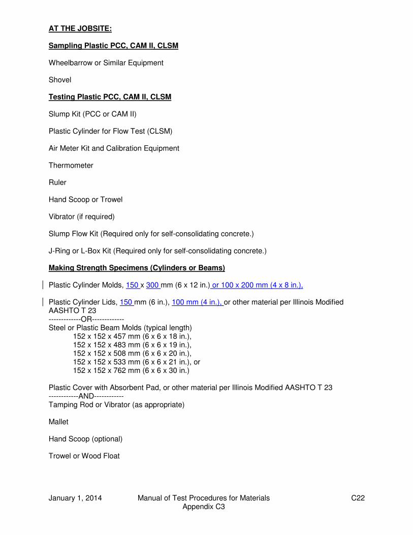
January 1, 2014 Manual of Test Procedures for Materials C22 Appendix C3
AT THE JOBSITE: Sampling Plastic PCC, CAM II, CLSM Wheelbarrow or Similar Equipment Shovel Testing Plastic PCC, CAM II, CLSM Slump Kit (PCC or CAM II) Plastic Cylinder for Flow Test (CLSM) Air Meter Kit and Calibration Equipment Thermometer Ruler Hand Scoop or Trowel Vibrator (if required) Slump Flow Kit (Required only for self-consolidating concrete.) J-Ring or L-Box Kit (Required only for self-consolidating concrete.) Making Strength Specimens (Cylinders or Beams) Plastic Cylinder Molds, 150 x 300 mm (6 x 12 in.) or 100 x 200 mm (4 x 8 in.), Plastic Cylinder Lids, 150 mm (6 in.), 100 mm (4 in.), or other material per Illinois Modified AASHTO T 23 -------------OR------------- Steel or Plastic Beam Molds (typical length) 152 x 152 x 457 mm (6 x 6 x 18 in.), 152 x 152 x 483 mm (6 x 6 x 19 in.), 152 x 152 x 508 mm (6 x 6 x 20 in.),
152 x 152 x 533 mm (6 x 6 x 21 in.), or 152 x 152 x 762 mm (6 x 6 x 30 in.) Plastic Cover with Absorbent Pad, or other material per Illinois Modified AASHTO T 23 ------------AND------------ Tamping Rod or Vibrator (as appropriate) Mallet Hand Scoop (optional) Trowel or Wood Float
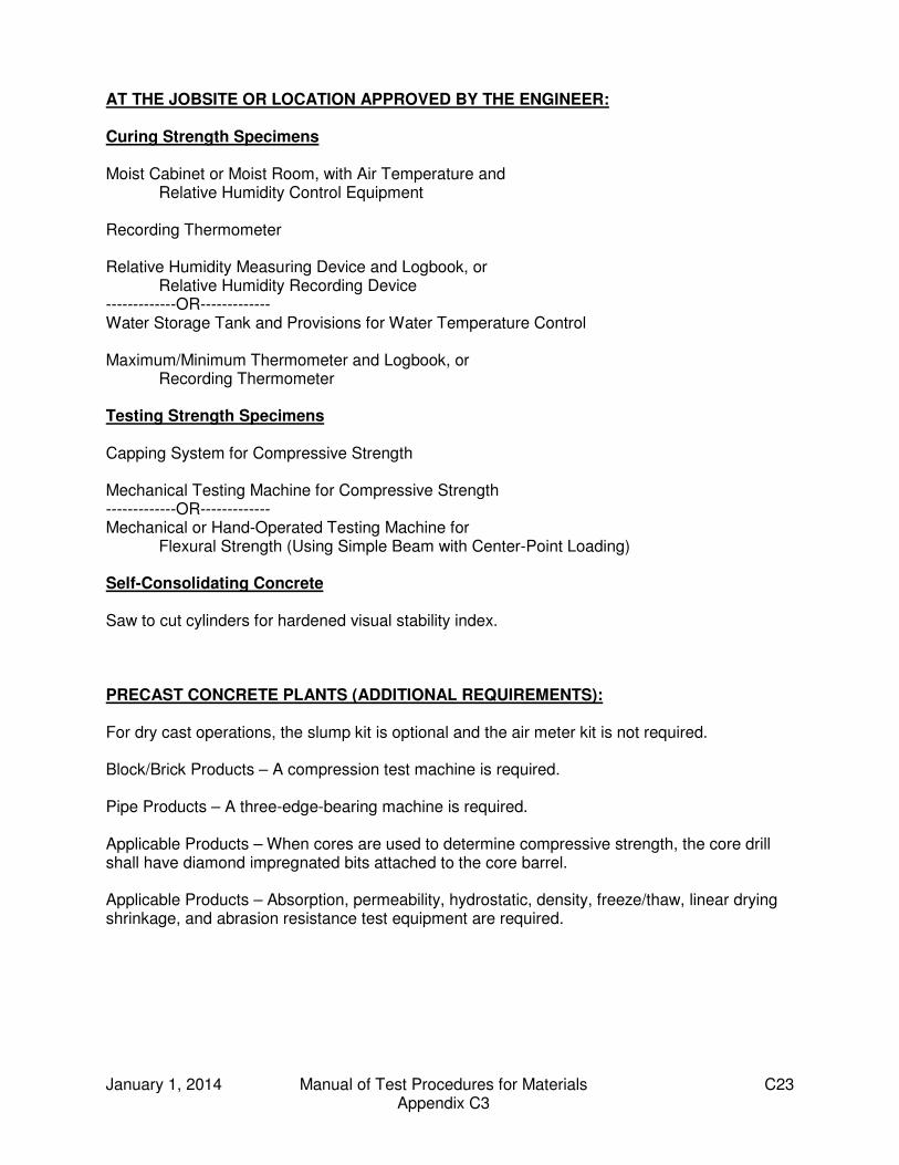
January 1, 2014 Manual of Test Procedures for Materials C23 Appendix C3
AT THE JOBSITE OR LOCATION APPROVED BY THE ENGINEER: Curing Strength Specimens Moist Cabinet or Moist Room, with Air Temperature and Relative Humidity Control Equipment Recording Thermometer Relative Humidity Measuring Device and Logbook, or Relative Humidity Recording Device -------------OR------------- Water Storage Tank and Provisions for Water Temperature Control Maximum/Minimum Thermometer and Logbook, or Recording Thermometer Testing Strength Specimens Capping System for Compressive Strength Mechanical Testing Machine for Compressive Strength -------------OR------------- Mechanical or Hand-Operated Testing Machine for Flexural Strength (Using Simple Beam with Center-Point Loading) Self-Consolidating Concrete Saw to cut cylinders for hardened visual stability index. PRECAST CONCRETE PLANTS (ADDITIONAL REQUIREMENTS): For dry cast operations, the slump kit is optional and the air meter kit is not required. Block/Brick Products – A compression test machine is required. Pipe Products – A three-edge-bearing machine is required. Applicable Products – When cores are used to determine compressive strength, the core drill shall have diamond impregnated bits attached to the core barrel. Applicable Products – Absorption, permeability, hydrostatic, density, freeze/thaw, linear drying shrinkage, and abrasion resistance test equipment are required.

January 1, 2014 Manual of Test Procedures for Materials C24 Appendix C3
This Page Reserved
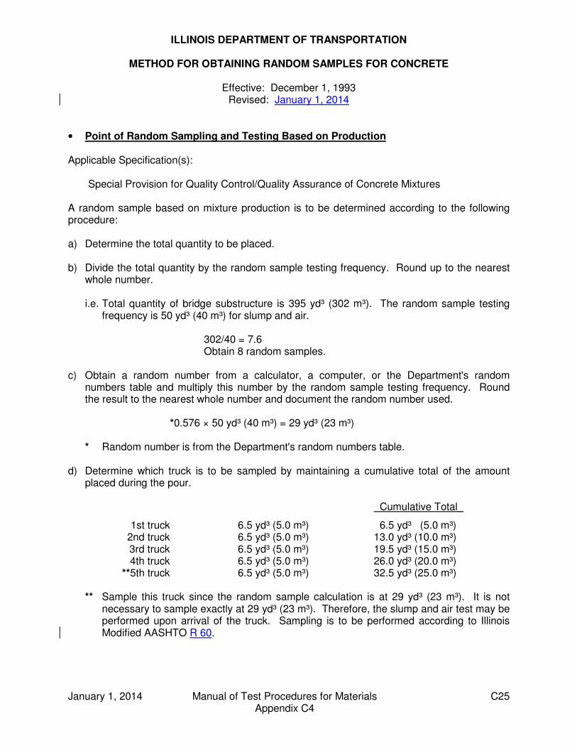
January 1, 2014 Manual of Test Procedures for Materials C25 Appendix C4
ILLINOIS DEPARTMENT OF TRANSPORTATION
METHOD FOR OBTAINING RANDOM SAMPLES FOR CONCRETE
Effective: December 1, 1993 Revised: January 1, 2014
• Point of Random Sampling and Testing Based on Production Applicable Specification(s): Special Provision for Quality Control/Quality Assurance of Concrete Mixtures A random sample based on mixture production is to be determined according to the following procedure: a) Determine the total quantity to be placed. b) Divide the total quantity by the random sample testing frequency. Round up to the nearest
whole number.
i.e. Total quantity of bridge substructure is 395 yd³ (302 m³). The random sample testing frequency is 50 yd³ (40 m³) for slump and air.
302/40 = 7.6 Obtain 8 random samples. c) Obtain a random number from a calculator, a computer, or the Department's random
numbers table and multiply this number by the random sample testing frequency. Round the result to the nearest whole number and document the random number used.
*0.576 × 50 yd³ (40 m³) = 29 yd³ (23 m³)
* Random number is from the Department's random numbers table. d) Determine which truck is to be sampled by maintaining a cumulative total of the amount
placed during the pour. Cumulative Total_
1st truck 6.5 yd³ (5.0 m³) 6.5 yd³ (5.0 m³) 2nd truck 6.5 yd³ (5.0 m³) 13.0 yd³ (10.0 m³) 3rd truck 6.5 yd³ (5.0 m³) 19.5 yd³ (15.0 m³) 4th truck 6.5 yd³ (5.0 m³) 26.0 yd³ (20.0 m³) **5th truck 6.5 yd³ (5.0 m³) 32.5 yd³ (25.0 m³)
** Sample this truck since the random sample calculation is at 29 yd³ (23 m³). It is not necessary to sample exactly at 29 yd³ (23 m³). Therefore, the slump and air test may be performed upon arrival of the truck. Sampling is to be performed according to Illinois Modified AASHTO R 60.
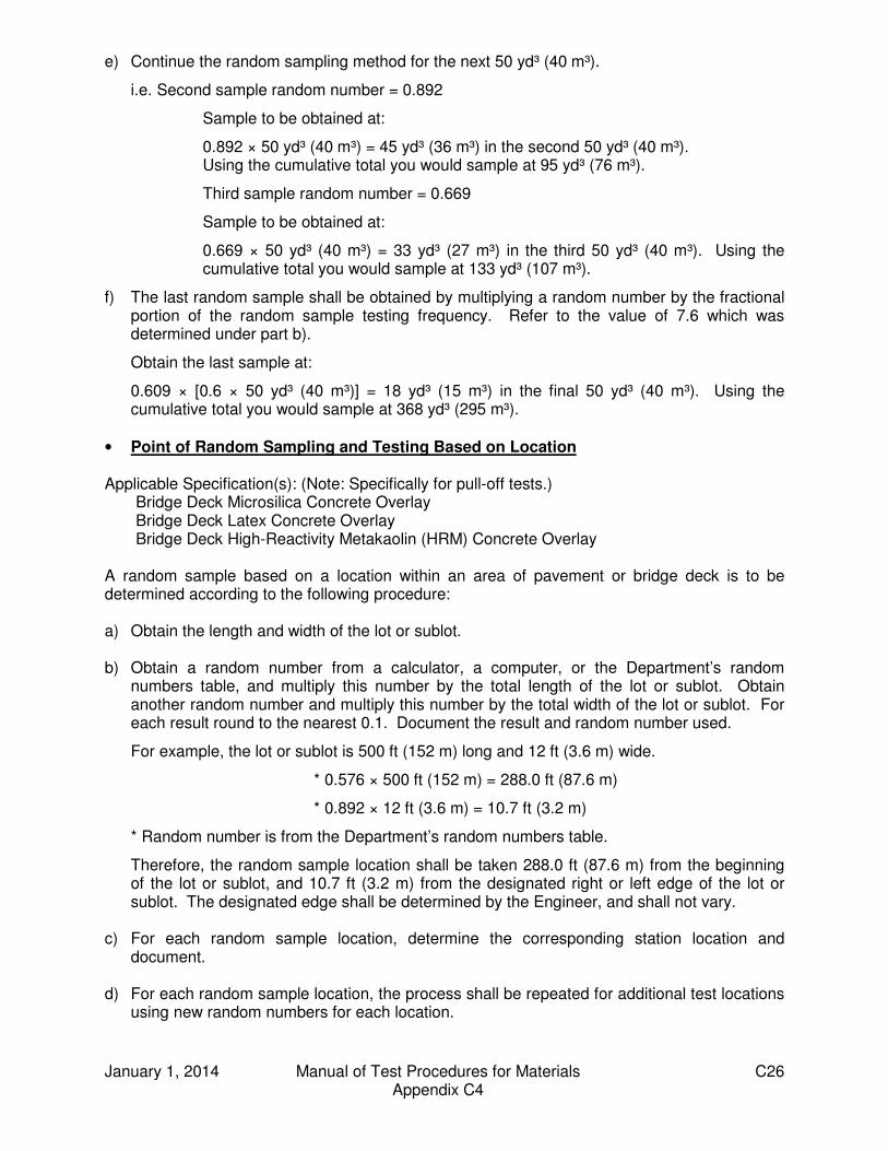
January 1, 2014 Manual of Test Procedures for Materials C26 Appendix C4
e) Continue the random sampling method for the next 50 yd³ (40 m³).
i.e. Second sample random number = 0.892
Sample to be obtained at:
0.892 × 50 yd³ (40 m³) = 45 yd³ (36 m³) in the second 50 yd³ (40 m³). Using the cumulative total you would sample at 95 yd³ (76 m³).
Third sample random number = 0.669
Sample to be obtained at:
0.669 × 50 yd³ (40 m³) = 33 yd³ (27 m³) in the third 50 yd³ (40 m³). Using the cumulative total you would sample at 133 yd³ (107 m³).
f) The last random sample shall be obtained by multiplying a random number by the fractional portion of the random sample testing frequency. Refer to the value of 7.6 which was determined under part b).
Obtain the last sample at:
0.609 × [0.6 × 50 yd³ (40 m³)] = 18 yd³ (15 m³) in the final 50 yd³ (40 m³). Using the cumulative total you would sample at 368 yd³ (295 m³).
• Point of Random Sampling and Testing Based on Location Applicable Specification(s): (Note: Specifically for pull-off tests.) Bridge Deck Microsilica Concrete Overlay Bridge Deck Latex Concrete Overlay Bridge Deck High-Reactivity Metakaolin (HRM) Concrete Overlay A random sample based on a location within an area of pavement or bridge deck is to be determined according to the following procedure: a) Obtain the length and width of the lot or sublot. b) Obtain a random number from a calculator, a computer, or the Department’s random
numbers table, and multiply this number by the total length of the lot or sublot. Obtain another random number and multiply this number by the total width of the lot or sublot. For each result round to the nearest 0.1. Document the result and random number used.
For example, the lot or sublot is 500 ft (152 m) long and 12 ft (3.6 m) wide.
* 0.576 × 500 ft (152 m) = 288.0 ft (87.6 m)
* 0.892 × 12 ft (3.6 m) = 10.7 ft (3.2 m)
* Random number is from the Department’s random numbers table.
Therefore, the random sample location shall be taken 288.0 ft (87.6 m) from the beginning of the lot or sublot, and 10.7 ft (3.2 m) from the designated right or left edge of the lot or sublot. The designated edge shall be determined by the Engineer, and shall not vary.
c) For each random sample location, determine the corresponding station location and
document. d) For each random sample location, the process shall be repeated for additional test locations
using new random numbers for each location.
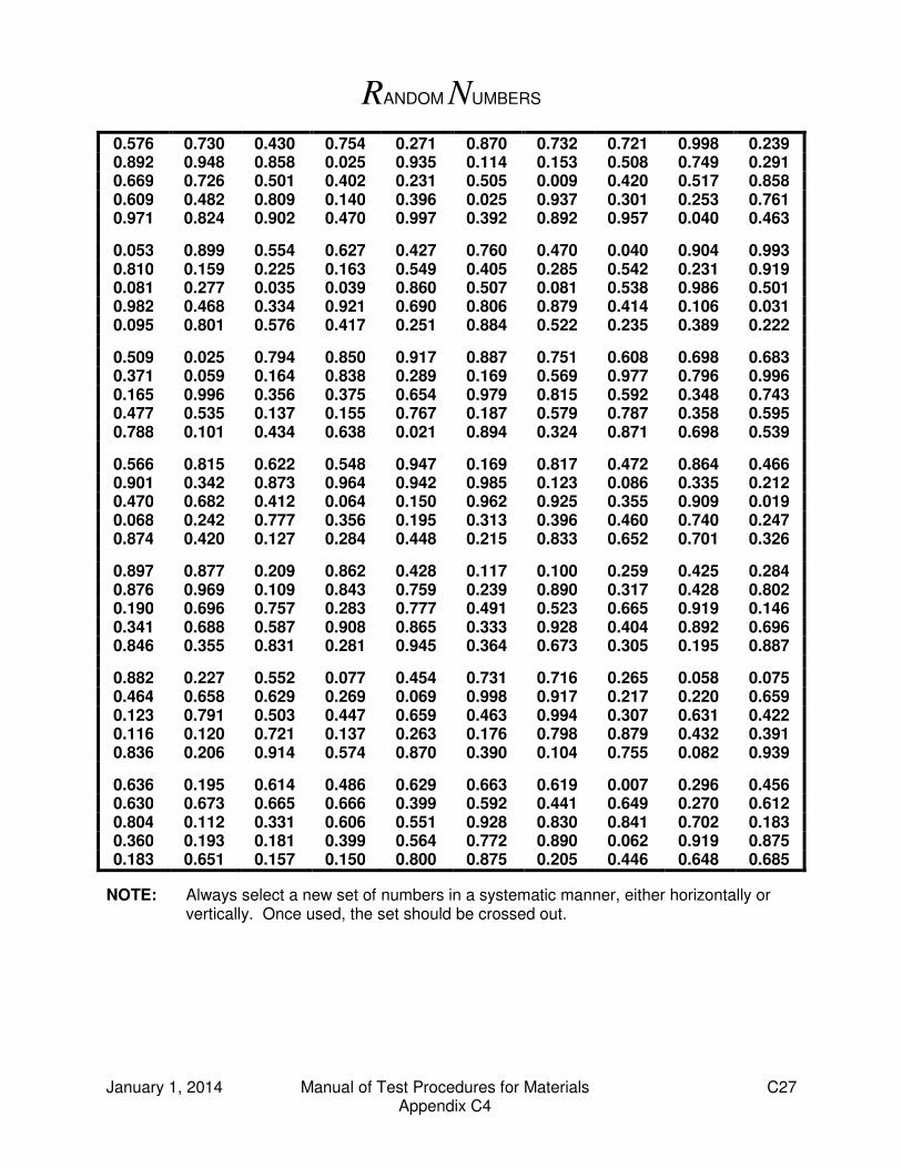
January 1, 2014 Manual of Test Procedures for Materials C27 Appendix C4
RANDOM NUMBERS
0.576 0.730 0.430 0.754 0.271 0.870 0.732 0.721 0.998 0.239 0.892 0.948 0.858 0.025 0.935 0.114 0.153 0.508 0.749 0.291 0.669 0.726 0.501 0.402 0.231 0.505 0.009 0.420 0.517 0.858 0.609 0.482 0.809 0.140 0.396 0.025 0.937 0.301 0.253 0.761 0.971 0.824 0.902 0.470 0.997 0.392 0.892 0.957 0.040 0.463
0.053 0.899 0.554 0.627 0.427 0.760 0.470 0.040 0.904 0.993 0.810 0.159 0.225 0.163 0.549 0.405 0.285 0.542 0.231 0.919 0.081 0.277 0.035 0.039 0.860 0.507 0.081 0.538 0.986 0.501 0.982 0.468 0.334 0.921 0.690 0.806 0.879 0.414 0.106 0.031 0.095 0.801 0.576 0.417 0.251 0.884 0.522 0.235 0.389 0.222
0.509 0.025 0.794 0.850 0.917 0.887 0.751 0.608 0.698 0.683 0.371 0.059 0.164 0.838 0.289 0.169 0.569 0.977 0.796 0.996 0.165 0.996 0.356 0.375 0.654 0.979 0.815 0.592 0.348 0.743 0.477 0.535 0.137 0.155 0.767 0.187 0.579 0.787 0.358 0.595 0.788 0.101 0.434 0.638 0.021 0.894 0.324 0.871 0.698 0.539
0.566 0.815 0.622 0.548 0.947 0.169 0.817 0.472 0.864 0.466 0.901 0.342 0.873 0.964 0.942 0.985 0.123 0.086 0.335 0.212 0.470 0.682 0.412 0.064 0.150 0.962 0.925 0.355 0.909 0.019 0.068 0.242 0.777 0.356 0.195 0.313 0.396 0.460 0.740 0.247 0.874 0.420 0.127 0.284 0.448 0.215 0.833 0.652 0.701 0.326
0.897 0.877 0.209 0.862 0.428 0.117 0.100 0.259 0.425 0.284 0.876 0.969 0.109 0.843 0.759 0.239 0.890 0.317 0.428 0.802 0.190 0.696 0.757 0.283 0.777 0.491 0.523 0.665 0.919 0.146 0.341 0.688 0.587 0.908 0.865 0.333 0.928 0.404 0.892 0.696 0.846 0.355 0.831 0.281 0.945 0.364 0.673 0.305 0.195 0.887
0.882 0.227 0.552 0.077 0.454 0.731 0.716 0.265 0.058 0.075 0.464 0.658 0.629 0.269 0.069 0.998 0.917 0.217 0.220 0.659 0.123 0.791 0.503 0.447 0.659 0.463 0.994 0.307 0.631 0.422 0.116 0.120 0.721 0.137 0.263 0.176 0.798 0.879 0.432 0.391 0.836 0.206 0.914 0.574 0.870 0.390 0.104 0.755 0.082 0.939
0.636 0.195 0.614 0.486 0.629 0.663 0.619 0.007 0.296 0.456 0.630 0.673 0.665 0.666 0.399 0.592 0.441 0.649 0.270 0.612 0.804 0.112 0.331 0.606 0.551 0.928 0.830 0.841 0.702 0.183 0.360 0.193 0.181 0.399 0.564 0.772 0.890 0.062 0.919 0.875 0.183 0.651 0.157 0.150 0.800 0.875 0.205 0.446 0.648 0.685
NOTE: Always select a new set of numbers in a systematic manner, either horizontally or vertically. Once used, the set should be crossed out.

January 1, 2014 Manual of Test Procedures for Materials C28 Appendix C4
This Page Reserved

January 1, 2014 Manual of Test Procedures for Materials C29 Appendix C5
IDOT Concrete Quality Control and Quality Assurance Documents Effective Date: April 1, 2010 Revised Date: January 1, 2014 The following forms are located at http://www.idot.illinois.gov/doing-business/material-approvals/concrete/index. Water/Cement Ratio Worksheet (BMPR PCCW01) Field/Lab Gradations (MI504M) Concrete Air, Slump and Quantity (BMPR MI654) P.C. Concrete Strengths (BMPR MI655) Calibration of Concrete Test Equipment, Slump (BMPR PCCQ01) Calibration of Concrete Test Equipment, Air Meter, Type “A” (BMPR PCCQ02) Calibration of Concrete Test Equipment, Air Meter, Type “B” (BMPR PCCQ03) Calibration of Concrete Test Equipment, Air Meter, Volumetric (BMPR PCCQ04) Calibration of Concrete Test Equipment, Unit Weight (BMPR PCCQ05) Calibration of Concrete Test Equipment, Cylinder Molds, Plastic or Metal, 6” x 12” (BMPR PCCQ06) Calibration of Concrete Test Equipment, Beam Molds, Steel (BMPR PCCQ07) Calibration of Concrete Test Equipment, Metal Retainers & Neoprene Pads (BMPR PCCQ08) Calibration of Concrete Test Equipment, Capping Cylindrical Strength Specimens (BMPR PCCQ09) Calibration of Concrete Test Equipment, Cylinder Molds, Plastic, 4” x 8” (BMPR PCCQ10)
The following Manuals are located at http://www.lakeland.cc.il.us/as/idt/manuals.cfm . Aggregate Technician Course or Mixture Aggregate Technician Course Portland Cement Concrete Tester Course Portland Cement Concrete Level I Technician Course - Manual of Instructions for Concrete Testing Portland Cement Concrete Level II Technician Course - Manual of Instructions for Concrete Proportioning Portland Cement Concrete Level III Technician Course - Manual of Instructions for Design of Concrete Mixtures

January 1, 2014 Manual of Test Procedures for Materials C30 Appendix C5
This Page Reserved

SEQUENTIAL TABLE OF CONTENTS (continued)
MANUAL OF TEST PROCEDURES FOR MATERIALS
June 1, 2012 Manual of Test Procedures for Materials
B—Hot Mix Asphalt (HMA) Appendix B1
(Effective 05/01/93) (Revised 01/01/08)
Model Annual Quality Control (QC) Plan for Hot-Mix Asphalt (HMA) Production .....................
B 1
Appendix B2 (Effective 07/01/95) (Revised 05/01/07)
Model Quality Control (QC) Addendum for Hot-Mix Asphalt (HMA) Production .....................
B11
Appendix B3 (Effective 05/01/01) (Revised 04/01/11)
Standard Test Method for Correlating Nuclear Gauge Densities with Core Densities ......................
B13
Appendix B4 (Effective 05/01/93) (Revised 01/01/08)
Hot-Mix Asphalt Concrete QC/QA Start-Up Procedures ................................................
B21
Appendix B5 (Effective 05/01/93) (Revised 05/01/07)
Hot-Mix Asphalt QC/QA QC Personnel Responsibilities and Duties Checklist ......................
B27
Appendix B6 (Effective 05/01/93) (Revised 05/01/07)
Hot-Mix Asphalt QC/QA Initial Daily Plant and Random Samples ....................................................
B37
Appendix B7 (Effective 05/01/93) (Revised 04/01/11)
Determination of Random Density Locations ........... B41
Appendix B8 (Effective 05/01/93) (Revised 01/01/08)
Control Charts / Rounding Test Values.................... B43
Appendix B9 (Effective 01/01/02) (Revised 06/01/12)
Hot-Mix Asphalt Mixture Design Verification Procedure ................................................................
B47
Appendix B10 (Effective 01/01/98) (Revised 05/01/07)
Illinois Test Procedure 401, Storage of Hot-Mix Asphalt Mixtures .......................
B53
Appendix B11 (Effective 01/01/02) (Revised 05/01/07)
Calibration of Equipment for Asphalt Binder Determination (Nuclear Gauge and Ignition Oven) ..
B55
Appendix B12 (Effective 01/01/98) (Revised 05/01/07)
Hot-Mix Asphalt Mix Design Procedure for Dust Correction Factor Determination ..............................
B59
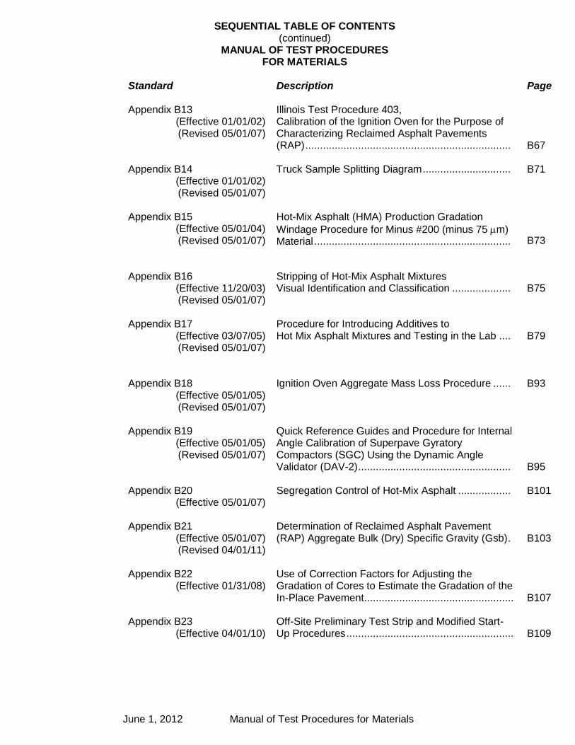
SEQUENTIAL TABLE OF CONTENTS (continued)
MANUAL OF TEST PROCEDURES FOR MATERIALS
June 1, 2012 Manual of Test Procedures for Materials
Standard
Description Page
Appendix B13 (Effective 01/01/02) (Revised 05/01/07)
Illinois Test Procedure 403, Calibration of the Ignition Oven for the Purpose of Characterizing Reclaimed Asphalt Pavements (RAP) ......................................................................
B67
Appendix B14 (Effective 01/01/02) (Revised 05/01/07)
Truck Sample Splitting Diagram .............................. B71
Appendix B15 (Effective 05/01/04) (Revised 05/01/07)
Hot-Mix Asphalt (HMA) Production Gradation
Windage Procedure for Minus #200 (minus 75 m) Material ...................................................................
B73
Appendix B16 (Effective 11/20/03) (Revised 05/01/07)
Stripping of Hot-Mix Asphalt Mixtures Visual Identification and Classification ....................
B75
Appendix B17 (Effective 03/07/05) (Revised 05/01/07)
Procedure for Introducing Additives to Hot Mix Asphalt Mixtures and Testing in the Lab ....
B79
Appendix B18 (Effective 05/01/05) (Revised 05/01/07)
Ignition Oven Aggregate Mass Loss Procedure ...... B93
Appendix B19 (Effective 05/01/05) (Revised 05/01/07)
Quick Reference Guides and Procedure for Internal Angle Calibration of Superpave Gyratory Compactors (SGC) Using the Dynamic Angle Validator (DAV-2) ....................................................
B95
Appendix B20 (Effective 05/01/07)
Segregation Control of Hot-Mix Asphalt .................. B101
Appendix B21 (Effective 05/01/07) (Revised 04/01/11)
Determination of Reclaimed Asphalt Pavement (RAP) Aggregate Bulk (Dry) Specific Gravity (Gsb) .
B103
Appendix B22 (Effective 01/31/08)
Use of Correction Factors for Adjusting the Gradation of Cores to Estimate the Gradation of the In-Place Pavement ...................................................
B107
Appendix B23 (Effective 04/01/10)
Off-Site Preliminary Test Strip and Modified Start-Up Procedures .........................................................
B109

Illinois Department of Transportation
Model Annual Quality Control (QC) Plan for Hot-Mix Asphalt (HMA) Production
Appendix B1
Effective: May 1, 1993 Revised: January 1, 2008
June 1, 2012 Manual of Test Procedures for Materials B1 Appendix B1
Producer Name:
Producer/Supplier No.:
Address:
City/State/ZIP Code:
Phone No.:
A. Contractor Responsibilities This Annual Quality Control (QC) Plan explains how ________________________
proposes to control the equipment, ingredient materials, and production methods to ensure the specified product is obtained. All requirements of section 1030 of the Standard Specifications and this Annual QC Plan will be adhered to. A Quality Control Addendum shall be completed for each contract and submitted prior to the preconstruction conference.
In joint ventures, where one Contractor is producing the mix and another is
responsible for the laydown, the Quality Control Manager, from either party, who is ultimately responsible for the Quality Control should be identified in the Quality Control Addendum.
B. Materials All materials proposed for use are from approved sources. Material sources are
identified below for coarse aggregate, fine aggregate, mineral filler, asphalt binder, prime, anti-strip additive, and release agent. This includes the mix type, Producer/Supplier Number, firm name, and firm location.
Material
Mix Type
Producer/ Supplier No.
Firm Name
Location
(1)
(2)
(3)
(4)
(5)
(6)
(7)

Illinois Department of Transportation
Model Annual Quality Control (QC) Plan for Hot-Mix Asphalt (HMA) Production
Appendix B1 (continued)
Effective: May 1, 1993 Revised: January 1, 2008
June 1, 2012 Manual of Test Procedures for Materials B2 Appendix B1
Material
Mix Type
Producer/ Supplier No.
Firm Name
Location
(8)
(9)
(10)
1. Aggregates
The incoming aggregate gradation bands have been developed from the source gradation bands and are attached. Listed below are the contact persons for the aggregate sources furnishing mixture aggregates.
Name Firm Phone Number
Coarse Aggregate
CA/CM 07/11 (Binder)
CA/CM 13/16 (Binder)
CA/CM 13/16 (Surface)
Fine Aggregate
FA/FM 01/02
FA/FM 20/21
a. Aggregate Stockpile Procedures All aggregate stockpiles will be built using procedures that will minimize
segregation and degradation. All coarse and fine aggregate will be placed in single-layer truck-dumped stockpiles at the mix plant. QC personnel will pay special attention to the loadout, replenishing, and remixing of the aggregate stockpile.
If segregation/degradation becomes a problem, stockpiling procedures
will be altered to correct the problem. b. Incoming Aggregate Gradation Samples A washed gradation test will be performed for each 500 (tons 450 metric
tons) for the first 1,000 tons (900 metric tons) for each aggregate received. Additional gradation tests (every third test will be a washed

Illinois Department of Transportation
Model Annual Quality Control (QC) Plan for Hot-Mix Asphalt (HMA) Production
Appendix B1 (continued)
Effective: May 1, 1993 Revised: January 1, 2008
June 1, 2012 Manual of Test Procedures for Materials B3 Appendix B1
gradation test) will be run on the frequency of one test per 2,000 tons (1,800 metric tons) for each aggregate received while the stockpiles are being built or aggregate is being shipped in. Gradation correction factors will be developed from washed gradation test results and applied to all dry gradation results. All aggregate (correction factors applied) will meet the mix plant gradation bands as developed according to the current Department policy, "Development of Gradation Bands on Incoming Aggregate at Mix Plants", before being used in mix production at the mix plant. All incoming aggregate gradation results shall be recorded in the plant diary. If a failing sample is encountered, the following resample procedure will be followed:
(1) Immediately resample the aggregate represented by the failing test. (2) If the first resample passes, the required frequency will be continued. (3) If the first resample fails, shipment of the aggregate will be halted,
and corrective action will be taken. Corrective action may be rejection of the material, remixing or addition of material by feeder/conveyor system, or any other action approved by the Engineer. The aggregate producer will be notified of the problem. A second resample will be taken immediately after corrective action.
(4) If the second resample passes, the aggregate represented will be
used, and aggregate shipment into the plant will be resumed. (5) If the second resample fails, the aggregate represented will not be
used in the QC/QA HMA mixture. The material will be removed from the certified aggregate stockpile.
Each contact person listed above has agreed to immediately provide
information on aggregate production changes or any significant variations in aggregate characteristics. These include, but are not limited to, changes in production methods, ledge footage, gradation, quality, specific gravity, and absorption. As gradation information is accumulated during stockpile construction, the aggregate gradations will be compared with the mix design gradation. Significant variations from the design gradation but within the acceptable gradation bands will be discussed with the Engineer. A new mix design will be performed when required by the Engineer.
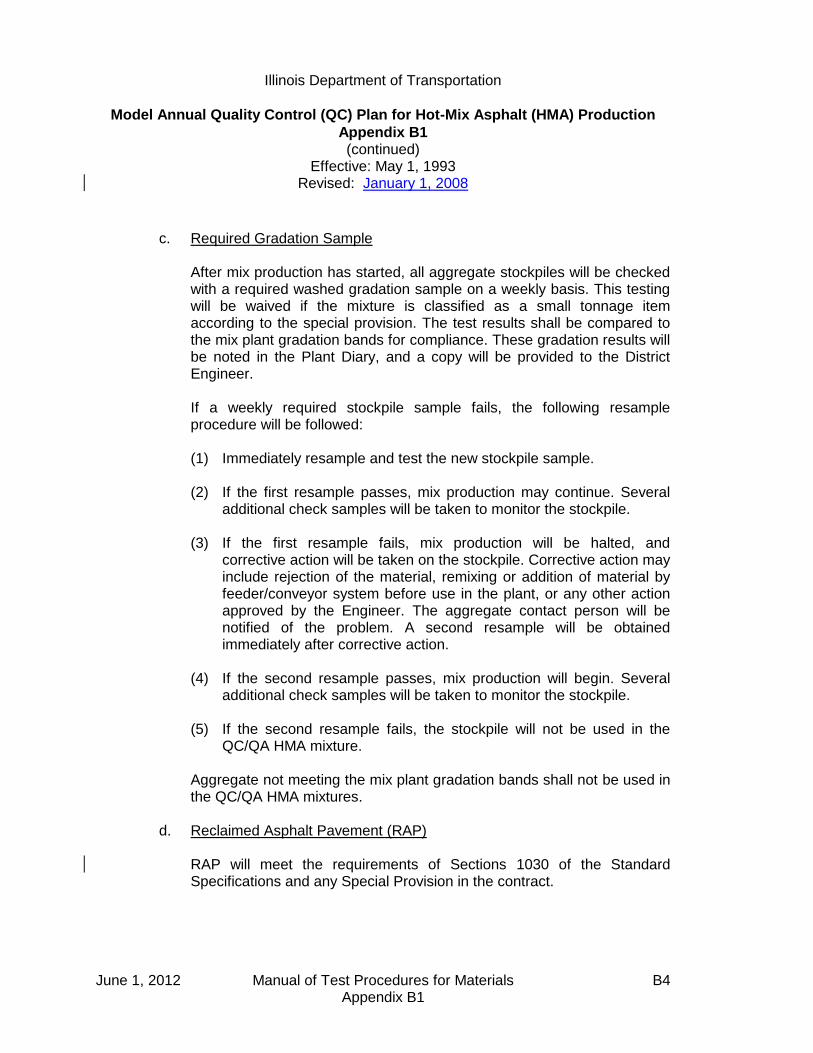
Illinois Department of Transportation
Model Annual Quality Control (QC) Plan for Hot-Mix Asphalt (HMA) Production
Appendix B1 (continued)
Effective: May 1, 1993 Revised: January 1, 2008
June 1, 2012 Manual of Test Procedures for Materials B4 Appendix B1
c. Required Gradation Sample After mix production has started, all aggregate stockpiles will be checked
with a required washed gradation sample on a weekly basis. This testing will be waived if the mixture is classified as a small tonnage item according to the special provision. The test results shall be compared to the mix plant gradation bands for compliance. These gradation results will be noted in the Plant Diary, and a copy will be provided to the District Engineer.
If a weekly required stockpile sample fails, the following resample
procedure will be followed:
(1) Immediately resample and test the new stockpile sample. (2) If the first resample passes, mix production may continue. Several
additional check samples will be taken to monitor the stockpile. (3) If the first resample fails, mix production will be halted, and
corrective action will be taken on the stockpile. Corrective action may include rejection of the material, remixing or addition of material by feeder/conveyor system before use in the plant, or any other action approved by the Engineer. The aggregate contact person will be notified of the problem. A second resample will be obtained immediately after corrective action.
(4) If the second resample passes, mix production will begin. Several
additional check samples will be taken to monitor the stockpile. (5) If the second resample fails, the stockpile will not be used in the
QC/QA HMA mixture.
Aggregate not meeting the mix plant gradation bands shall not be used in the QC/QA HMA mixtures.
d. Reclaimed Asphalt Pavement (RAP) RAP will meet the requirements of Sections 1030 of the Standard
Specifications and any Special Provision in the contract.
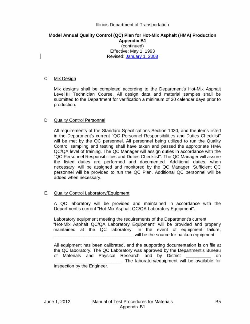
Illinois Department of Transportation
Model Annual Quality Control (QC) Plan for Hot-Mix Asphalt (HMA) Production
Appendix B1 (continued)
Effective: May 1, 1993 Revised: January 1, 2008
June 1, 2012 Manual of Test Procedures for Materials B5 Appendix B1
C. Mix Design Mix designs shall be completed according to the Department's Hot-Mix Asphalt
Level III Technician Course. All design data and material samples shall be submitted to the Department for verification a minimum of 30 calendar days prior to production.
D. Quality Control Personnel All requirements of the Standard Specifications Section 1030, and the items listed
in the Department's current "QC Personnel Responsibilities and Duties Checklist" will be met by the QC personnel. All personnel being utilized to run the Quality Control sampling and testing shall have taken and passed the appropriate HMA QC/QA level of training. The QC Manager will assign duties in accordance with the "QC Personnel Responsibilities and Duties Checklist". The QC Manager will assure the listed duties are performed and documented. Additional duties, when necessary, will be assigned and monitored by the QC Manager. Sufficient QC personnel will be provided to run the QC Plan. Additional QC personnel will be added when necessary.
E. Quality Control Laboratory/Equipment A QC laboratory will be provided and maintained in accordance with the
Department’s current "Hot-Mix Asphalt QC/QA Laboratory Equipment". Laboratory equipment meeting the requirements of the Department's current
"Hot-Mix Asphalt QC/QA Laboratory Equipment" will be provided and properly maintained at the QC laboratory. In the event of equipment failure, ________________________________ will be the source for backup equipment.
All equipment has been calibrated, and the supporting documentation is on file at
the QC laboratory. The QC Laboratory was approved by the Department's Bureau of Materials and Physical Research and by District __________ on ___________________________. The laboratory/equipment will be available for inspection by the Engineer.
Illinois Department of Transportation
Model Annual Quality Control (QC) Plan for Hot-Mix Asphalt (HMA) Production
Appendix B1 (continued)
Effective: May 1, 1993 Revised: January 1, 2008
June 1, 2012 Manual of Test Procedures for Materials B6 Appendix B1
F. Mix Plant/Production
Manufacturer
Model Number
Serial Number
Batch Size
Tons Per Hour
Approved By
Approval Date
It is our intent to run the day following start-up. Production will not begin until the
acceptable nuclear/core correlation is complete, all other required tests are acceptable, the targets are established, and the results are reviewed and agreed to by the Department.
The aggregate feeders will be calibrated prior to the start of production using the
aggregates and approximate percentages approved in the Job Mix Formula (JMF). At this time aggregate samples will be taken and compared with the JMF.
At the start of mix production or when adjustments are made to the mix, the QC
Manager will give the aggregate proportions to the plant operator, and then, periodically throughout the day, checks will be made of the actual proportions used. This will be especially noted and recorded when a nuclear asphalt and/or a mix sample is taken. The results will be immediately reported to the Resident Engineer and/or other designated Department personnel upon completion of the test.
All scale and sensitivity checks will be performed in accordance with the Hot-Mix
Asphalt Level II Technician Course manual. Surge bins may be utilized as part of the overall plant operation. The QC Manager shall contact the Department for approval when material will be stored overnight.
G. Sampling and Testing All sampling and testing, including all required plant tests, resamples, and
additional check tests (when necessary), will be performed in accordance with Department test methods in the time frame required in Section 1030 of the Standard Specifications. The "Radioactive Material License" required for nuclear density and asphalt binder content determinations are attached. District Materials or the Bureau of Materials and Physical Research personnel are welcome to observe all testing by the QC personnel. Time permitting, split samples will be

Illinois Department of Transportation
Model Annual Quality Control (QC) Plan for Hot-Mix Asphalt (HMA) Production
Appendix B1 (continued)
Effective: May 1, 1993 Revised: January 1, 2008
June 1, 2012 Manual of Test Procedures for Materials B7 Appendix B1
shared with Department personnel prior to start-up. Coring will be performed using a truck-mounted drill rig or by suitable equipment as approved by the Engineer. An adjustment of 1-1/2% to 2% for minus No. 200 (0.075 mm) material of washed samples vs. dry gradations will be used until a gradation correction factor is established based on preliminary aggregate sampling and testing.
All Department split samples will be stored on site. These samples will be identified with the date and time the material was sampled, Sequence Number, Contract Number, mix plant Producer/Supplier Number, aggregate source Producer/Supplier Number, and the initials of the individual who sampled the material.
H. Placement and Compaction Only approved equipment will be used in the placement and compaction of the mix
in accordance with the Standard Specification requirements. The QC Manager will verify that all laydown equipment conforms to Department
requirements prior to start-up. At the start of laydown, Two Growth Curves will be run on a test strip to determine the suitability of the mix. Mix samples shall be taken and tested from trucks representing material between both Growth Curves. From Growth Curve information, a rolling pattern will be established. Nuclear tests and cores will be taken from the start-up area to verify density and correlation of the nuclear density gauge. Temperatures of the mix will be taken and duly recorded. After the start-up data is approved by the Department and actual production has begun, daily nuclear density tests will be taken at the start of each day's production, along with temperature readings, to verify continued conformance with density requirements. Nuclear density tests according to the Section 1030 will be performed to assure compliance with specified density requirements. Testing will be conducted within the project traffic control, or by use of flaggers, as needed.
Start-up and construction of the test strip is planned to be performed in the morning
of the first day. If no problems are encountered, cores for nuclear/core correlation will be taken. The mat will be cooled with ice or dry ice. All tests will be completed for anticipated production the next day.
Should any adverse mix characteristics be observed, the QC Manager shall make
mix adjustments as needed to correct the situation. If segregation should occur, appropriate adjustments will be made in the aggregate
stockpiling/loadout, plant production, silo operation, truck loading, or paver operation to alleviate the condition. Only approved truck release agents will be used.

Illinois Department of Transportation
Model Annual Quality Control (QC) Plan for Hot-Mix Asphalt (HMA) Production
Appendix B1 (continued)
Effective: May 1, 1993 Revised: January 1, 2008
June 1, 2012 Manual of Test Procedures for Materials B8 Appendix B1
The QC Manager or his representative will check laydown equipment daily for
specification compliance and immediately repair or replace nonconforming equipment.
I. Corrective Action The QC Manager will initiate corrective action immediately according to Section
1030 of the Standard Specifications. Sufficient tests shall be taken to verify the corrective action has worked. Special care will be taken to assure that mix not complying with specifications is not placed on the road.
J. Reporting of Test Results All test results will be reported daily to the Resident Engineer and other designated
personnel as requested by the Department. The data will be reported on the following forms or on forms generated by the Department's current QC/QA software:
MI 504M Field/Lab Gradations (stockpile gradations)
MI 305 Bituminous Daily Plant Output (front) Plant Settings and Scale Checks (back)
MI 303C Bituminous Core Density Testing QC/QA
MI 303N QC Nuclear Density Report
MI 308 Nuclear Asphalt Content and Volumetric Testing
LM-6 Sample Identification (for liquid asphalt)
The completed forms will be forwarded to the District Engineer within three days of
test completion.

Illinois Department of Transportation
Model Annual Quality Control (QC) Plan for Hot-Mix Asphalt (HMA) Production
Appendix B1 (continued)
Effective: May 1, 1993 Revised: January 1, 2008
June 1, 2012 Manual of Test Procedures for Materials B9 Appendix B1
K. Control Charts In addition, control charts will be posted at the laboratory and kept updated for the
following test parameters in accordance with the Department's current "Hot-Mix Asphalt QC/QA Control Charts/Rounding Test Values".
1. Gradations Hot-Bins/Combined Belt
Percent Passing 1/2-in. (12.5-mm) Sieve
Percent Passing No. 4 (4.75-mm) Sieve
Percent Passing No. 8 (2.36-mm) Sieve
Percent Passing No. 30 (600-µm) Sieve
Percent Passing No. 200 (75-µm) Sieve
Ignition Oven
Total Dust Content 2. Gravities
a. Bulk specific gravity b. Maximum specific gravity
3. Marshall Air Voids 4. Density 5. Asphalt Binder Content 6. Stockpile Gradations
In the event the Total Dust Content is out of tolerance, measures will be taken to correct the problem, which may include adding Positive Dust Control Equipment.
Contractor's Signature Date
(Please type or print name) Title

June 1, 2012 Manual of Test Procedures for Materials B10 Appendix B1
This Page Reserved
Illinois Department of Transportation
Model Quality Control (QC) Addendum for Hot-Mix Asphalt (HMA) Production
Appendix B2
Effective: July 1, 1995 Revised: May 1, 2007
June 1, 2012 Manual of Test Procedures for Materials B11 Appendix B2
Contract No.:
Marked Route:
Route:
Section:
County:
Contractor:
Address:
City/State/ZIP Code:
Phone No.:
A. Contractor Responsibilities
This Quality Control Addendum to the Annual Quality Control Plan further explains
how ________________________________ proposes to control the equipment,
ingredient materials, and production methods to ensure the specified product is
obtained. All requirements in Section 1030, the Annual QC Plan, and this QC
Addendum will be adhered to.
In the case of joint ventures, ___________________________________________
of ________________________________________ will be the QC Manager and
will be ultimately responsible for the Quality Control on this Contract.
B. Reclaimed Asphalt Pavement (RAP)
RAP will meet the requirements of Sections 406, 1030 and 1102 of the Standard
Specifications and any Special Provisions in the Contract. ______ percent of RAP
is proposed for use in the ____________________________ course.

Illinois Department of Transportation
Model Quality Control (QC) Addendum for Hot-Mix Asphalt (HMA) Production
Appendix B2 (continued)
Effective: July 1, 1995 Revised: May 1, 2007
June 1, 2012 Manual of Test Procedures for Materials B12 Appendix B2
C. Mix Design Mix designs are attached for Department verification. D. Quality Control Personnel The project QC Manager will have overall responsibility and authority for Quality
Control at both the plant and on the road and will make the necessary adjustments in the mix production, placement, and compaction to assure conformance with the Standard Specifications and Contract Special Provisions.
The QC personnel and/or consulting firm that will be utilized, as well as the backup
QC personnel and/or consulting firm, are as follows:
Name
Level of Training
Firm
Phone Number
(1)
(2)
(3)
(4)
(5) (backup)
E. Mix Plant/Production The mix for this project will be produced by Producer/Supplier No. _____________. F. Control Charts A copy of the Control Charts will be submitted to the Engineer upon completion of
the Contract. Contractor's Signature Title (Please type or print name) Date

Illinois Department of Transportation QC/QA PROCEDURE
Standard Test Method for Correlating
Nuclear Gauge Densities with Core Densities Appendix B3
Effective: May 1, 2001 Revised: April 1, 2011
June 1, 2012 Manual of Test Procedures for Materials B13 Appendix B3
A. Scope
1. This method covers the proper procedures for correlating nuclear gauge densities to core densities. Procedures are applicable to both direct transmission and backscatter techniques.
2. The procedure shall be used on all projects containing 3000 tons (2750 metric tons) or
more of any hot-mix asphalt mixture. It may also be used on any other project where feasible. The direct transmission method shall be used for thick-lift layers. "Thick-lift" is defined as a layer 6 in. (152.4) mm or greater in compacted thickness.
B. Applicable Documents
1. Illinois Department of Transportation Standard Test Methods Illinois-Modified AASHTO T 166, "Bulk Specific Gravity of Compacted Asphalt
Mixtures Using Saturated Surface Dry Specimens" Illinois-Modified AASHTO T 275, "Bulk Specific Gravity of Compacted Asphalt
Mixtures Using Paraffin-Coated Specimens" 2. The density test procedure shall be in accordance with the Department's "Illinois-
Modified ASTM D 2950, Standard Test Method for Determination of Density of Bituminous Concrete In-Place by Nuclear Method".
C. Definitions
Test location: The station location used for density testing. Test site: Individual test site where a single density is determined. Five (5) test sites are located at each test location. Nuclear Density: The average of 2 or possibly 3 density readings on a given test site. Core Density: The core density result on a given test site.
Illinois Department of Transportation QC/QA PROCEDURE
Standard Test Method for Correlating
Nuclear Gauge Densities with Core Densities Appendix B3 (continued)
Effective: May 1, 2001 Revised: April 1, 2011
June 1, 2012 Manual of Test Procedures for Materials B14 Appendix B3
D. Significance and Use
1. Density results from a nuclear gauge are relative. If an approximation of core density results is required, a correlation must be developed to convert the nuclear density to core density.
2. A correlation developed in accordance with these procedures is applicable only to the
specific gauge being correlated, the specific mixture, each specific thickness (direct transmission only), and the specific project upon which it was correlated. A new correlation should be determined within a specific project if there is a significant change in the underlying material.
E. Site Selection
1. The nuclear density tests and cores necessary for nuclear/core correlation shall be obtained during the start-up of each specific mixture for which a density specification is applicable.
2. Three correlation locations shall be selected. Two sites will be located on the two
growth curves from the first acceptable test strip. The third location shall be chosen after an acceptable rolling pattern has been established and within the last 100 tons (90 metric tons) of material placed during start-up. The material from the third site shall correspond to the same material from which the second hot-mix sample was taken.
3. If a mixture start-up is not required, two of the three correlation locations shall be in an
area containing a growth curve. F. Procedures for Obtaining Nuclear Readings and Cores
1. Backscatter Mode
a. At each of the three correlation locations, five individual sites shall be chosen and identified as shown in Figure 1.
b. Two nuclear readings shall be taken at each of the 15 individual sites. (See
Figure 1.) The gauge shall be rotated 180 degrees between readings at each site. (The two uncorrected readings taken at a specific individual site shall be within 1.5 lbs/ft3 [23 kg/m3). If the two readings do not meet this criterion, one additional reading shall be taken in the desired direction. The nuclear densities are to be recorded on the correlation form (Figure 3).
Illinois Department of Transportation QC/QA PROCEDURE
Standard Test Method for Correlating
Nuclear Gauge Densities with Core Densities Appendix B3 (continued)
Effective: May 1, 2001 Revised: April 1, 2011
June 1, 2012 Manual of Test Procedures for Materials B15 Appendix B3
c. One core in good condition shall be obtained from each of 15 individual sites
(Figure 1). Care should be exercised that no additional compaction occurs between the nuclear testing and the coring. The cores shall be tested for density in accordance with Illinois-Modified AASHTO T 166 or T 275. The core densities are to be entered on the correlation form.
For quality assurance purposes, the Department may direct the Contractor to take additional cores adjacent to those above or to submit the quality control cores for Department testing.
d. Extreme care shall be taken in identifying which location each of the density
readings represents. The data points have to be paired accurately or the correlation process will be invalid.
2. Direct Transmission Mode
a. At each of the three correlation locations, five individual sites shall be chosen across the mat as shown on Figure 1.
b. A smooth hole in the pavement, slightly larger than the probe, shall be formed to
a depth 2 in. (50 mm) greater than the test depth. The probe shall be inserted so that the side of the probe facing the center of the gauge is in intimate contact with the side of the hole. Two nuclear readings shall be taken at each of the 15 individual sites. (See Figures 1 and 2)
The gauge shall be rotated 180 degrees (see Figure 2) around the core area at
each site. (The two uncorrected readings taken at a specific individual site shall be within 2.0 lbs/ft3 [30 kg/m3] (see Figure 2). If the two readings do not meet this criterion, one additional reading shall be taken in the desired direction. The nuclear densities are to be recorded on the correlation form (Figure 3).
c. One core in good condition shall be obtained from each of the 15 individual sites.
(See Figures 1 and 2) The cores shall be obtained from beneath the center of the gauge no closer than 3-1/2 in (87.5 mm) from either access hole. The thickness of the core should represent the thickness of the layer being tested. The layer shall be carefully separated for testing in accordance with Illinois-Modified AASHTO T 166. Care should be exercised that no additional compaction occurs between the nuclear testing and the coring. The cores shall be tested for density in accordance with Illinois-Modified AASHTO T 166 or T 275.
Illinois Department of Transportation QC/QA PROCEDURE
Standard Test Method for Correlating
Nuclear Gauge Densities with Core Densities Appendix B3 (continued)
Effective: May 1, 2001 Revised: April 1, 2011
June 1, 2012 Manual of Test Procedures for Materials B16 Appendix B3
For quality assurance purposes, the Department may direct the Contractor to
take additional cores adjacent to those above or to submit the quality control cores for Department testing.
The core densities are to be entered on the correlation form. d. Extreme care shall be taken in identifying which location each of the density
readings represents. The data points have to be paired accurately or the correlation process will be invalid.
G. Mathematical Correlation -- Linear Regression
1. The two (or possibly three) nuclear readings at each individual site shall be entered on the correlation form and then averaged. The core density taken at each individual site shall be entered on the correlation form. After the averaging, there will be 15 paired data points, each pair containing the average nuclear density and core density for each of the 15 individual sites.
2. The paired density values shall be correlated using the Department's linear regression
program. (Disks are available from the Bureau of Materials and Physical Research) or an approved and equivalent calculating method.
3. For the purpose of this procedure, standard statistical methods for measuring the
"best fit" of a line through a series of 15 paired data points consisting of core density and nuclear density shall be used.
4. It should be recognized that correlations obtained by this or similar procedures may or
may not be valid; each attempt should be judged on its merit. In general, a correlation coefficient for each correlation linear regression should be calculated.
5. Correlation coefficients (r) may range from minus 1.0 to plus 1.0. An "r" value greater than 0.715 is considered acceptable.
6. The correlation shall be stated and used in the form: y = mx + b
where: y = core density
x = nuclear gauge density
b = intercept
m = slope of linear regression ("best fit") line

Illinois Department of Transportation QC/QA PROCEDURE
Standard Test Method for Correlating
Nuclear Gauge Densities with Core Densities Appendix B3 (continued)
Effective: May 1, 2001 Revised: April 1, 2011
June 1, 2012 Manual of Test Procedures for Materials B17 Appendix B3
(BACKSCATTER)FIRST GROWTH CURVE IS BETWEEN 200 AND 225 METRIC TONS (225 AND 250
TONS), THE SECOND GROWTH CURVE IS BETWEEN 250 AND 275 METRIC TONS
(275 AND 300 TONS).
NUCLEAR/CORE CORRELATION TEST LOCATIONS
NUCLEAR SITE
PAVING DIRECTION
300 mm (1 FT.)
300 mm (1 FT.)
1 (6) B
3 (8) B
5 (10) A
CORE
300 mm (1 FT.)
300 mm (1 FT.)
12A
13A 13B
14A
15A
CORE
FIG
UR
E 1
11A1 (6) A
2 (7) A
3 (8) A
4 (9) A
5 (10) B
4 (9) B
2 (7) B
15B
14B
12B
11B
2 of 3 sites 1 of 3 sites
1 CORRELATION
LOCATION IN AN AREA
REPRESENTING A
REGULAR ROLLING
PATTERN.
2 CORRELATION LOCATIONS
IN GROWTH CURVE AREAS

Illinois Department of Transportation QC/QA PROCEDURE
Standard Test Method for Correlating
Nuclear Gauge Densities with Core Densities Appendix B3 (continued)
Effective: May 1, 2001 Revised: April 1, 2011
June 1, 2012 Manual of Test Procedures for Materials B18 Appendix B3
FIG
UR
E 2
DIRECT TRANSMISSION MODE
DIRECT TRANSMISSION
PROBE HOLENUCLEAR SITE
1 A 1 B
1ST NUCLEAR
READING2ND NUCLEAR
READING
CORE
87.5 mm (3 1/2") MIN.
87.5 mm (3 1/2") MIN.
NOTE: FOR TEST SITE LOCATIONS, SEE BACKSCATTER EXAMPLE.
NUCLEAR/CORE CORRELATION
1A 1B

June 1, 2012 Manual of Test Procedures for Materials B19 Appendix B3
Nuclear / Core Correlation Field Worksheet
Date:
Contract: Gauge No.:
Job No.: Layer Thickness:
Route: Gmm
Base Material: Milled Binder Aggregate Other:
Mix No.:
Mix Code:
Use: (surface, 1st lift binder, etc.)
Reading 1 Reading 2 (23 kg/m3 tol.)
Reading 3 (if applicable)
Average Nuc. Core Density
STATION:
1A) 1B) 1A) 1B) 1) 1)
2A) 2B) 2A) 2B) 2) 2)
3A) 3B) 3A) 3B) 3) 3)
4A) 4B) 4A) 4B) 4) 4)
5A) 5B) 5A) 5B) 5) 5)
STATION:
6A) 6B) 6A) 6B) 6) 6)
7A) 7B) 7A) 7B) 7) 7)
8A) 8B) 8A) 8B) 8) 8)
9A) 9B) 9A) 9B) 9) 9)
10A) 10B) 10A) 10B) 10) 10)
STATION:
11A) 11B) 11A) 11B) 11) 11)
12A) 12B) 12A) 12B) 12) 12)
13A) 13B) 13A) 13B) 13) 13)
14A) 14B) 14A) 14B) 14) 14)
15A) 15B) 15A) 15B) 15) 15)

June 1, 2012 Manual of Test Procedures for Materials B20 Appendix B3
This Page Reserved

Illinois Department of Transportation
Hot-Mix Asphalt QC/QA Start-Up Procedures
Appendix B4
Effective: May 1, 1993 Revised: January 1, 2008
June 1, 2012 Manual of Test Procedures for Materials B21 Appendix B4
When required, for projects with 3000 tons (2750 metric tons) or more of each type of mix, the Contractor and the Department shall evaluate the mixture to be produced for the contract. The Contractor shall follow the following procedures for start-up. A. Contractor/Department Start-Up Team A team of Contractor and Department personnel will construct a test strip and
evaluate mix produced at the plant. The start-up team shall consist of the following:
1. Resident Engineer 2. District Construction Supervising Field Engineer, or representative 3. District Materials Mixtures Control Engineer, or representative 4. District Nuclear Density Gauge Specialist 5. Contractor's QC Manager 6. Contractor's Density Tester 7. Bureau of Materials and Physical Research representative when requested
(optional) 8. Bureau of Construction representative when requested (optional)
B. Communications The Contractor shall advise the team members of the anticipated start time of
production for the mix. The QC Manager shall direct the activities of the start-up team. A Department-appointed representative from the start-up team will act as spokesperson for the Department.
C. Acceptance Criteria
1. Mix Design and Plant Proportioning — Target values shall be provided by the Contractor and will be approved by the Department prior to start-up. Prior to beginning the start-up, the Contractor shall provide the start-up team with documentation of test data for the combined hot-bin or the combined aggregate belt sample and mineral filler at a drier-drum plant.

Illinois Department of Transportation
Hot-Mix Asphalt QC/QA Start-Up Procedures
Appendix B4 (continued)
Effective: May 1, 1993 Revised: January 1, 2008
June 1, 2012 Manual of Test Procedures for Materials B22 Appendix B4
2. Evaluation of Growth Curves -- Mixtures which exhibit density potential less than or greater than the following density ranges shall be considered to have a potential density problem which is normally sufficient cause for mix adjustment.
Surface mixture Ndesign ≥ 90 92.0 - 96.0 %
Surface mixture Ndesign < 90 92.5 - 97.4 %
Binder mixture Ndesign ≥ 90 93.0 - 96.0 %
Binder mixture Ndesign < 90 93.0 - 97.4 %
If an adjustment has been made, the Engineer may require an addition test strip be constructed and evaluated. This information shall then be compared to the AJMF and required design criteria for acceptance.
3. Evaluation of Required Plant Tests — If the results of the required plant tests
exceed the JMF target value control limits, the Contractor shall make allowable mix adjustments/plant changes, resample, and retest. If the Engineer determines additional adjustments to the mix will not produce acceptable results, a new mix design may be required.
D. Start-Up Methods The Contractor shall normally follow Method 1 procedures. If requested by the
Contractor and approved by the Engineer, the Contractor may substitute Method 2 procedures for start-up.
1. Method 1 — Test Strip The Contractor shall produce up to 300 tons (275 metric tons) of mix and
cease production until the test strip, including required plant tests, has been completed; jointly evaluated by the Contractor and the Engineer (except nuclear/core correlation); and accepted by the Engineer.
The procedures listed below shall be followed to run a test strip. a. Location of Test Strip — The test strip shall be located on a relatively flat
portion of the roadway. Descending/ascending grades or ramps should be avoided.
b. Constructing the Test Strip — After the Contractor has produced and
placed approximately 225 to 250 tons (200 to 225 metric tons) of mix,

Illinois Department of Transportation
Hot-Mix Asphalt QC/QA Start-Up Procedures
Appendix B4 (continued)
Effective: May 1, 1993 Revised: January 1, 2008
June 1, 2012 Manual of Test Procedures for Materials B23 Appendix B4
paving shall cease and a growth curve shall be constructed. After completion of the first growth curve, paving shall resume for the remaining 50 to 75 tons (45 to 70 metric tons), and the second growth curve shall be constructed within this area. The Contractor shall use normal rolling procedures for all portions of the test strip except for the growth curve areas which shall be compacted solely with a vibratory roller as directed by the QC Manager.
c. Required Plant Tests — The first set of mixture and gradation samples
shall be taken at such a time as to represent the mixture in between the two growth curve trucks. After an acceptable test strip, production shall be resumed and an acceptable rolling pattern shall be established within the first 200 tons (180 metric tons) of mix placed. The second series of mixture and gradation samples shall represent the first 200 tons (90 to 180 metric tons) after an acceptable test strip. All samples shall be processed expediently for determination of mix composition and volumetric properties, including air voids. This shall include dry shaking of combined belt or hot bins and ignition oven gradations prior to washing each. This test data shall meet the JMF target value control limits to be considered acceptable.
2. Method 2 — Rapid Procedure If approved by the Engineer, the Contractor may evaluate the mix off-site.
Compensation for the test strip is waived.
a. Off-site Tests — Prior to the start of mix production, the mixture shall be placed off-site, at the Contractor's expense, for evaluation of the required plant test results.
The required plant test samples shall be taken after approximately 225
tons (200 metric tons) of mixture has been placed. The Contractor shall immediately split all required plant test samples for the Department. The Contractor shall test all samples expediently for determination of mix composition and volumetric properties, including air voids. This shall include running washed gradations on combined belt or hot bins as well as ignition oven samples.
If the Contractor's and the Department's test results are acceptable, the
following testing shall be followed at the job site. b. On-Site Tests — After the Contractor has produced and placed
approximately tons 225 to 250 tons (200 to 225 metric) of mix, paving

Illinois Department of Transportation
Hot-Mix Asphalt QC/QA Start-Up Procedures
Appendix B4 (continued)
Effective: May 1, 1993 Revised: January 1, 2008
June 1, 2012 Manual of Test Procedures for Materials B24 Appendix B4
shall cease, if required by the Engineer, and a growth curve shall be constructed.
Mixture and gradation samples for required plant tests shall be taken
representing mixture in the growth curve. If the growth curve and visual evaluation of the mix are satisfactory, the
placement may be resumed. If the growth curve and visual evaluation of the mix are unsatisfactory, the Contractor shall make appropriate adjustments, resample, and retest. If the adjustments do not correct the problem, production shall cease, corrective action shall be taken, and a test strip shall be constructed.
E. Compaction Requirements
1. Compaction Equipment — The Contractor shall provide a vibratory roller meeting the requirements of Article 1101.01(g) of the Standard Specifications. It shall be the responsibility of the start-up team to verify specification compliance before commencement of growth curve construction. An appropriate amplitude shall be selected on the basis of roller weight and mat thickness to achieve maximum density. The vibratory roller speed shall be balanced with frequency so as to provide compaction at a rate of not less than 10 impacts per 1 ft. (300 mm).
2. Compaction Temperature — In order to make an accurate analysis of the
density potential of the mixture, the temperature of the mixture on the
pavement at the beginning of the growth curve shall not be less than 280 F
(140 C). 3. Compaction and Testing — The Contractor shall direct the roller speed and
number of passes required to obtain a completed growth curve. The nuclear gauge shall be placed near the center of the hot mat and the position marked for future reference. With the bottom of the nuclear gauge and source rod clean, a 1-minute nuclear reading (without mineral filler) shall be taken after each pass of the roller. Rolling shall continue until a growth curve can be plotted, the maximum density determined, and three consecutive passes show no appreciable increase in density nor evident destruction of the mat.
4. Final Testing — A final nuclear reading, using mineral filler to eliminate
surface voids, will be taken at the marked position. This reading shall be used

Illinois Department of Transportation
Hot-Mix Asphalt QC/QA Start-Up Procedures
Appendix B4 (continued)
Effective: May 1, 1993 Revised: January 1, 2008
June 1, 2012 Manual of Test Procedures for Materials B25 Appendix B4
to adjust the maximum density reading obtained during the growth curve construction.
F. Rolling Pattern After completion of a satisfactory test strip/rapid procedure and required testing,
the Contractor shall establish a rolling pattern to achieve the specified density. The rolling pattern may not be changed unless approved by the Engineer.
G. Nuclear/Core Correlation A correlation of core and nuclear gauge test results shall be performed on-site as
defined in the Department's "Standard Test Method for Correlating Nuclear Gauge Densities with Core Densities". All correlation locations shall be cooled with ice or dry ice so that cores can be taken as soon as possible. Three locations shall be selected. Two sites shall be located on the two growth curves from the first acceptable test strip. The third location shall be in an area corresponding to the second set of mixture/gradation samples taken at the plant. This correlation shall be completed at the same time by the Department and the Contractor prior to the next day's production. Smoothness of the test strip shall be to the satisfaction of the Engineer.
H. Documentation All test strips, required plant tests, and rolling pattern information (including growth
curves) will be tabulated by the Contractor with a copy provided to each team member and the original retained in the project files.

June 1, 2012 Manual of Test Procedures for Materials B26 Appendix B4
This Page Reserved

Illinois Department of Transportation
Hot-Mix Asphalt QC/QA
QC Personnel Responsibilities and Duties Checklist
Appendix B5
Effective: May 1, 1993 Revised: May 1, 2007
June 1, 2012 Manual of Test Procedures for Materials B27 Appendix B5
The following checklists detail the required minimum duties of Contractor Quality Control (QC) personnel. The QC Manager has overall responsibility to ensure that the listed duties are performed and documented. The QC Manager shall not perform sampling and/or testing except in emergency situations or in any other situation approved by the Engineer. Additional duties, as necessary, may be required to control the quality of production and placement of the Hot-Mix Asphalt (HMA) mixtures. A Level II Technician may be used to perform any Level I Technician duties.
Note: Testing frequency denoted as "P" = "Prior to Start-up" and as "D" = "Daily". A. Level I Technician
1. Checklist a. Perform incoming aggregate gradations before start-up time. (PD) ___ b. Ensure lab equipment is on hand and in working order. (PD) ___ c. Run moisture samples daily (drum only). (PD) ___ d. Determine random sampling times one day in advance and inform the QC Manager and the Engineer of the sampling times. (D) ___ e. Take required samples when required using proper procedures. (D) ___ f. Split required sample and save the Department split; use proper identification. ___ g. Run required tests as soon as possible using proper QC/QA ___ procedures. h. Take resamples as required. ___ i. Plot all random and resample results on control charts as soon as test results are available. ___ j. Take check samples when necessary. (D) ___ k. Contact QC Manager immediately when tests fail or any time problems occur. (D) ___ l. Test cores for Nuclear/Core Correlation (after Start-up). ___

Illinois Department of Transportation
Hot-Mix Asphalt QC/QA
QC Personnel Responsibilities and Duties Checklist
Appendix B5 (continued)
Effective: May 1, 1993 Revised: May 1, 2007
June 1, 2012 Manual of Test Procedures for Materials B28 Appendix B5
2. Required Tests. The minimum test frequency shall be according to Section
1030 of the Standard Specifications. However, additional tests may be required by the Engineer. a. Stockpiles (washed gradations minimum one per week for each material used) ___ b. Moisture samples (drum only) ___ c. Gradations - Belt, Cold-feed, Hot-bin, etc. ___ d. Nuclear Asphalt Content ___ e. Gmb ___ f. Gmm ___
B. QC Manager and/or Level II Technician Checklist
1. Prior to Mix Production (Preliminary Inspection)
a. Check for the approved sources of the materials:
(1) Aggregates — ensure it is from Certified Source ___
(2) Mineral filler/flyash ___
(3) Asphalt binder (See d. below.) ___
(4) Other additives ___ b. Check the aggregate stockpiling and handling procedures:
(1) Observe stockpiling procedures to ensure they are built correctly. ___
(2) Discuss loadout and sampling procedures with endloader operator. ___
(3) Sample aggregate stockpiles, in conjunction with District inspectors, and submit for Mix Designs. ___
c. Check the gradation of the aggregates:
(1) Obtain average gradation of each aggregate (including Master Bands) from the aggregate source. ___

Illinois Department of Transportation
Hot-Mix Asphalt QC/QA
QC Personnel Responsibilities and Duties Checklist
Appendix B5 (continued)
Effective: May 1, 1993 Revised: May 1, 2007
June 1, 2012 Manual of Test Procedures for Materials B29 Appendix B5
(2) Compare aggregate source information to stockpile samples at the mix plant and with the design gradation. ___
d. Check asphalt binder:
(1) Source ___
(2) Grade ___
(3) Incoming temperatures ___
(4) Specific Gravity (drum only) ___ e. Verify that the laboratory and laboratory equipment have been inspected and approved by the Department and are in good working order. ___ f. Review Hot-Mix Asphalt Level I and Level II Technician Course manuals.
2. Prior to Production/During Start-Up/During Production a. Check the mix plant for the following:
(1) Approval and calibration (P) ___
(2) Asphalt binder storage (PD) ___
(3) Stockpiles (PD) ___
(a) correct loadout ___
(b) place in proper cold-feed bins ___
(4) Cold-feed bins or bulkheads and feeders (PD) ___
(5) Dust collecting systems (D) ___
(6) Screens and screening requirements (P) ___
(7) Hot-bin sampler (P) and hot-bin overflow (PD) ___
(8) Weigh belt 6-minute check (drum only) (D) ___
(9) Temperature recorders and thermometers (PD) ___
(10) Mixing timers (batch plant only) and pugmill dam gate (continuous plants) (PD) ___
(11) Surge and storage bins (PD) ___
(12) Platform scales or suspended weigh hopper (PD) ___

Illinois Department of Transportation
Hot-Mix Asphalt QC/QA
QC Personnel Responsibilities and Duties Checklist
Appendix B5 (continued)
Effective: May 1, 1993 Revised: May 1, 2007
June 1, 2012 Manual of Test Procedures for Materials B30 Appendix B5
(13) Anti-strip additive system (when required) (PD) ___
(14) Ticket printer (P) ___
(15) Computer and control systems (PD) ___ b. Check trucks for the following (QC Manager may assign these duties to a Level I Technician):
(1) Truck bed release agents (PD) ___
(2) Insulation (D) ___
(3) Tarps (D) ___
(4) Clean beds (D) ___
c. Coordinate any start-up per Department guidelines (QC Manager only). ___ d. Monitor sampling and testing procedures, density test, and laydown operations; contact man from aggregate producer (QC Manager only). ___ e. Check the mixtures for the following:
(1) Gradation test performed and bin percentages determined before start-up (P) ___
(2) Correct Job Mix Formula is being used (P) ___
(3) Moisture check (drum only) (PD) ___
(4) Temperature (D) ___
(5) Coating and segregation (D) ___
(6) Additives (D) ___ f. Laydown operation (QC Manager only) — Monitor the following field checks:
(1) Check for obvious defects in truck (segregation, uncoated, temperature, etc.) (D) ___
(2) Monitor paver operations (equipment, laydown procedures, etc.) (PD) ___
(3) Rollers and operations (equipment, pattern, procedure, etc.) (PD) ___
Illinois Department of Transportation
Hot-Mix Asphalt QC/QA
QC Personnel Responsibilities and Duties Checklist
Appendix B5 (continued)
Effective: May 1, 1993 Revised: May 1, 2007
June 1, 2012 Manual of Test Procedures for Materials B31 Appendix B5
(4) Mix characteristics on road (appearance, mat temperature, etc.) (D) ___
(5) Monitor densities as required (D) ___ g. Monitor all test results and make any adjustments necessary (QC Manager only) (D). ___ h. Perform scale checks (minimum one per
week per scale). Follow procedure in Construction Manual Documentation Section. ___ i. Prepare and store samples for the District laboratory as required. (D) ___ j. Ensure following records are kept and reports are submitted in a timely manner as required (QC Manager only): (D)
(1) Daily plant output ___
(2) Field gradation ___
(3) Density ___
(4) Marshall (stability and flow when required) ___
(5) Control charts ___
(6) Additives ___
(7) Scale checks ___
(8) Plant diary ___ C. Level I Technician, Level II Technician, and Quality Control Manager Duties
1. Material Source It is necessary to identify the source of the ingredients to ensure that they
have been inspected and the correct quality of aggregate, grade of asphalt binder, and anti-strip additive are being used in the specified mix. Sources shall be verified.
2. Aggregate Quality The Level II Technician may confirm the quality of the aggregate by requesting
current quality information from the District Materials office.
Illinois Department of Transportation
Hot-Mix Asphalt QC/QA
QC Personnel Responsibilities and Duties Checklist
Appendix B5 (continued)
Effective: May 1, 1993 Revised: May 1, 2007
June 1, 2012 Manual of Test Procedures for Materials B32 Appendix B5
3. Stockpiling Sites for stockpiles shall be grubbed and cleaned prior to storing the
aggregates. Separate stockpiles shall be provided for the various sources and kinds of
aggregates. Stockpiles shall be separated to prevent intermingling at the base (width of endloader bucket). If partitions are used, they shall be of sufficient heights to prevent intermingling. Aggregates for HMA mixtures shall be handled, in and out of the stockpiles, in such a manner that will prevent contamination and degradation.
Coarse aggregate stockpiles shall be built in layers not exceeding 1.5 m (5 ft)
in height and each layer shall be completely in place before the next layer is started. A stockpile may be expanded by again starting the expansion from the ground and building layers as before. End-dumping over the sides will not be permitted. Use of steel track equipment on Class B Quality, Class C Quality and all blast furnace slag aggregate stockpiles shall not be permitted where degradation is detected. When loading out of stockpiles, vertical faces shall be limited to reasonable heights to eliminate segregation due to tumbling. Segregation or degradation due to improper stockpiling or loading out of stockpiles shall be just cause for rejecting the material.
4. Gradations The Level II Technician shall obtain the average gradations as well as the
Master Bands from the aggregate source. He/She shall run the required gradation's test frequency on incoming aggregate as required in Section 1030 of the Standard Specifications.
5. Asphalt Binder
a. Incoming Asphalt Binder: The Level II Technician shall periodically check the grade and temperature of asphalt binder as received at the plant. If the asphalt binder is shipped by truck, the driver should have in his possession a numbered ticket showing the name and location of the refinery, the name of the material, date shipped, loading temperature, quantity, specific gravity or weight/L (weight/gal), and the number of the tank from which the asphalt was loaded. It is the responsibility of the refinery to load trucks only from tanks that have been tested and approved by the Department. If shipment is made by rail, a tag usually will

Illinois Department of Transportation
Hot-Mix Asphalt QC/QA
QC Personnel Responsibilities and Duties Checklist
Appendix B5 (continued)
Effective: May 1, 1993 Revised: May 1, 2007
June 1, 2012 Manual of Test Procedures for Materials B33 Appendix B5
be found on the top of the dome of the tank car indicating that it has been sampled at the refinery.
b. Asphalt Binder Storage: The Level II Technician shall check the
temperature of the asphalt binder in storage. The temperatures shall be maintained in accordance with the Standard Specifications. The Level II Technician should be aware of the grade of asphalt binder in each storage tank. Asphalt binders of different sources and grades shall not be intermixed in storage, and the tanks shall be identified.
6. Testing Equipment Care of the laboratory testing equipment is the responsibility of the Level I
Technician. Equipment shall be furnished by the Contractor or Consultant, kept clean, and kept in good working condition. At the start of the project, the technician shall check that all equipment required to be furnished is available and in good condition. Acceptance and, ultimately, performance of a mixture may be dependent on the accuracy of the field tests. Defective equipment could result in erroneous, as well as untimely, results.
7. Asphalt Plant
a. Plant Approval: Plant must be approved and calibrated prior to production
each construction season. The QC Manager shall review this information. If it is not available or current, the District Hot-Mix Asphalt Supervisor shall be notified.
b. Cold Aggregate Bins: The cold aggregate bins or bulkheads shall be
checked for aggregate intermingling. Each bin or compartment in a bin shall contain only one source and type of aggregate. The bins should be checked each day to ensure the charging of the compartments remains the same as it was for previous operations for the same mix. The QC Manager shall notify the state inspector of changes in aggregate source and gradation and/or gate settings.
c. Dust Collector: The Level II Technician shall check that the dust from the
primary collector is returned to the boot of the hot elevator by a metering system as required by Article 1102.01(a)(5) of the Standard Specifications. This metering system should be such as to require a few adjustments in maintaining a uniform rate of collected dust returned to the hot elevator. The primary dust-feed shall occur only when aggregate is being discharged from the drier.

Illinois Department of Transportation
Hot-Mix Asphalt QC/QA
QC Personnel Responsibilities and Duties Checklist
Appendix B5 (continued)
Effective: May 1, 1993 Revised: May 1, 2007
June 1, 2012 Manual of Test Procedures for Materials B34 Appendix B5
Plants having dry secondary collectors shall return this material to a storage silo or the mineral filler bin if it will meet the requirements of the mineral filler specifications (Section 1011 of the Standard Specifications).
d. Screens: Samples from the hot-bins shall be inspected for contamination.
An excess of coarse aggregate in the sand bin or sand in the coarse aggregate bins may indicate broken or clogged screens and/or a hole between the bins. The screens shall separate aggregate into sizes to produce a uniform gradation. If fluctuations in gradation occur, a change in screen size and/or aggregate flow rate may be required. Article 1102.01(b)(8) of the Standard Specifications shall be applied.
e. Hot-Bins: The Level II Technician is to ensure that each hot-bin overflow
pipe is working to prevent back-up of material into other compartments or bins. An overflow or sudden shortage of material in a bin may indicate a broken or clogged screen, a change in feeding rate, or a change in gradation of the aggregate being used. Overflow pipes shall not be discharged into the hot elevator.
f. Temperature Recording Device: The temperature recording devices shall
be checked for compliance with Article 1102.01(a)(7) of the Standard Specifications. A new chart shall be used each day.
g. Timers: The timers used for recycling the wet and dry mixing times for a
batch plant shall be checked and set at the required mixing times. On continuous plants, the pugmill dam gate shall be in the raised position. The required times are in the appropriate articles of the Standard Specifications.
h. Batching: The Level II Technician shall observe the batching operation to
ensure the approved batch weights are being met. Manually operated batch plants shall have markers on the scales to indicate the approved batch weight of each ingredient material. Automatic batching plants shall have posted near the scales the approved weights per bin. On continuous plants, the gate openings shall be checked for the proper setting. It is recommended that batch counters and/or ton counters be set at "zero" or that initial and final readings be taken and recorded each day.
i. Surge and Storage Bins: When a surge and storage bin are used,
approval and scale calibration information should be available. They shall be inspected for compliance with Article 1102.01(a)(6) of the Standard Specifications. Trucks shall be loaded in such a manner as to minimize segregation.

Illinois Department of Transportation
Hot-Mix Asphalt QC/QA
QC Personnel Responsibilities and Duties Checklist
Appendix B5 (continued)
Effective: May 1, 1993 Revised: May 1, 2007
June 1, 2012 Manual of Test Procedures for Materials B35 Appendix B5
j. The platform and/or suspended weigh hopper scale shall be checked for
proper zero. The scales shall be cleaned off before starting each day. k. The anti-strip additive system calibration shall be checked and the proper
flow rate determined. l. The weigh ticket printer shall be checked for information required by the
specifications. m. The computer and/or control system shall be checked to see if the correct
percentages of materials have been entered. The automatic printer for the computer of the drier drum should be turned on and working.
8. Trucks A Level I Technician, under the direct supervision of the QC Manager or the
Level II Technician, shall inspect the trucks used to transport the HMA mix. The technician shall see that each truck is provided with a cover and is properly insulated, if specified, before it is permitted to be used in the transportation of the mixture from the plant to the job. The truck bed shall be observed for foreign material before the bed is lubricated. He/She shall observe the spraying of the inside of the trucks with a release agent and shall see that no pools of release agent remain in the truck beds before loading.
9. Mixture Inspection The Level II Technician shall inspect the mixture at the plant, which includes
observing the weighing of the materials; checking the temperature of the mixture; and visually inspecting for coating of the aggregates, segregation, and moisture in the mixture. The Level I Technician shall sample and determine the gradation of the hot-bins and/or cold-feeds and the proper amount of asphalt binder being used to ensure conformity to the mix formula. The Level II Technician shall also verify and document the addition rates of the anti-strip additives.
In addition, the Level I Technician shall perform the required core density tests
and, when required, extraction tests at the field laboratory. The QC Manager shall furnish the Contractor with the mixing formulas which
have been established for a specific combination of sources of ingredients. The formulas shall state the percentage of aggregate for each sieve fraction and the percentage of asphalt binder. These formulas are to be used in

Illinois Department of Transportation
Hot-Mix Asphalt QC/QA
QC Personnel Responsibilities and Duties Checklist
Appendix B5 (continued)
Effective: May 1, 1993 Revised: May 1, 2007
June 1, 2012 Manual of Test Procedures for Materials B36 Appendix B5
proportioning the ingredient materials for HMA mixtures within the specified tolerances. Changes in the mix formulas are to be made only by the QC Manager.
It is important that the QC Manager observe the laying and compaction of the
mixture. Mixture variations are noticeable in the completed work, and variations that are
not apparent in the mixture at the plant sometimes show up as defects in the texture and uniformity of the surface. Flushing of the mixture is a defect that can be detected only on the road.
It is the duty of both the Level I and Level II Technicians to establish and
maintain an open line of communications. Timely and appropriate actions can be instituted by early detection of defects
or mixture variations. 10. Scale Checks When measurement of mixtures is on the basis of weights obtained from
batch weights or automatic printers, occasional scale checks shall be made by weighing full truckloads of the mixture on an approved platform scale at the plant site or on a commercial scale approved by the Engineer. The frequency and procedure for the check tests are described in the "Documentation" section of the [Bureau of] Construction Manual. The tests will be performed by the Level II Technician and reported on the "Daily Plant Output Report" and/or form BC 2367.
11. Samples The Level I Technician shall take check samples of the mixture in addition to
the required samples. He/She must also store split samples in a dry storage area for the Engineer. Section 1030 of the Standard Specifications discusses sampling procedures and sampling frequency.
12. Reports The Quality Control Manager is responsible for completion of a "Daily Plant
Output Report" (MI 305) for each day of production for each type of mix. Other reports, when required, are "Sample Identification" (LM-6), and Scale Checks.

Illinois Department of Transportation
Hot-Mix Asphalt QC/QA Initial Daily Plant and Random Samples
Appendix B6
Effective: May 1, 1993 Revised: May 1, 2007
June 1, 2012 Manual of Test Procedures for Materials B37 Appendix B6
Initial Daily Plant and Random Samples shall be obtained at the frequency specified in Section 1030 of the Standard Specifications. A. Truck samples shall be taken of the mixture for testing. Two sampling platforms
(one on each side of the truck) shall be provided for sampling of the mix. In order to obtain a representative sample of the entire truck, an equal amount of material shall be taken from each quarter point around the circumference of each pile in the truck to obtain a composite sample weighing approximately 150 lbs (70 kg). All truck samples shall be obtained by using a "D"-handled, square-ended shovel with built-up sides and back (1 to 1½ in. [25 to 37.5 mm]).
B. After the sample has been obtained, it shall be divided into two approximately equal
size (split) samples by the use of an approved mechanical sample splitter. One of the split samples shall be placed in a Department-approved sample container provided by the Contractor and shall be properly identified for use by the Department. These split samples shall be retained by the Contractor for assurance testing by the Engineer and may be disposed of only with the permission of the Engineer. The split samples shall be stored in a dry, protected location. The remaining split will be used for those tests described in Section 1030 of the Standard Specifications.
C. Starting with the first day of production (excluding start-up), the initial daily required
plant sample shall be obtained between the first ½ to 1½ hours of daily production of a particular mixture. These daily plant test samples shall be tested for, but not limited to, the following: 1. Bulk Specific Gravity, Gmb (d) 2. Maximum Theoretical Gravity, Gmm (D) 3. Asphalt Binder Content 4. Aggregate Gradations
a. Combined Belt
b. Individual Cold-Feeds
c. Hot-Bins
5. Total Dust Content of Mix from Ignition Oven or Solvent Extraction
D. The second daily required plant sample shall be taken at a randomly selected time within the third quarter of the anticipated production day using the "Random
Illinois Department of Transportation
Hot-Mix Asphalt QC/QA Initial Daily Plant and Random Samples
Appendix B6 (continued)
Effective: May 1, 1993 Revised: May 1, 2007
June 1, 2012 Manual of Test Procedures for Materials B38 Appendix B6
Numbers" table on the following page or the Department's QC/QA computer software. For HMA mixtures classified as “All Other” the Contractor shall use the anticipated full production day when calculating the random sampling time. The anticipated full production day shall be the time from a ½ hour after production begins to a ½ hour before production ends. The following procedure shall be used to calculate the second daily required plant sampling time.
1. Multiply the quarter production day (in minutes) by a three digit random
number, expressed as a decimal, selected from the "Random Numbers" table or the Department's QC/QA computer software.
2. The number obtained (rounded to a whole number) shall be added to the
starting time of the third quarter. The time represented by this addition is the randomly selected sampling time.
If the plant is producing HMA mixtures intermittently, the samples shall be
taken as close to the determined time as possible.

Illinois Department of Transportation
Hot-Mix Asphalt QC/QA Initial Daily Plant and Random Samples
Appendix B6 (continued)
Effective: May 1, 1993 Revised: May 1, 2007
June 1, 2012 Manual of Test Procedures for Materials B39 Appendix B6
RANDOM NUMBERS
0.576 0.730 0.430 0.754 0.271 0.870 0.732 0.721 0.998 0.239 0.892 0.948 0.858 0.025 0.935 0.114 0.153 0.508 0.749 0.291 0.669 0.726 0.501 0.402 0.231 0.505 0.009 0.420 0.517 0.858 0.609 0.482 0.809 0.140 0.396 0.025 0.937 0.301 0.253 0.761 0.971 0.824 0.902 0.470 0.997 0.392 0.892 0.957 0.040 0.463 0.053 0.899 0.554 0.627 0.427 0.760 0.470 0.040 0.904 0.993 0.810 0.159 0.225 0.163 0.549 0.405 0.285 0.542 0.231 0.919 0.081 0.277 0.035 0.039 0.860 0.507 0.081 0.538 0.986 0.501 0.982 0.468 0.334 0.921 0.690 0.806 0.879 0.414 0.106 0.031 0.095 0.801 0.576 0.417 0.251 0.884 0.522 0.235 0.389 0.222 0.509 0.025 0.794 0.850 0.917 0.887 0.751 0.608 0.698 0.683 0.371 0.059 0.164 0.838 0.289 0.169 0.569 0.977 0.796 0.996 0.165 0.996 0.356 0.375 0.654 0.979 0.815 0.592 0.348 0.743 0.477 0.535 0.137 0.155 0.767 0.187 0.579 0.787 0.358 0.595 0.788 0.101 0.434 0.638 0.021 0.894 0.324 0.871 0.698 0.539 0.566 0.815 0.622 0.548 0.947 0.169 0.817 0.472 0.864 0.466 0.901 0.342 0.873 0.964 0.942 0.985 0.123 0.086 0.335 0.212 0.470 0.682 0.412 0.064 0.150 0.962 0.925 0.355 0.909 0.019 0.068 0.242 0.777 0.356 0.195 0.313 0.396 0.460 0.740 0.247 0.874 0.420 0.127 0.284 0.448 0.215 0.833 0.652 0.701 0.326 0.897 0.877 0.209 0.862 0.428 0.117 0.100 0.259 0.425 0.284 0.876 0.969 0.109 0.843 0.759 0.239 0.890 0.317 0.428 0.802 0.190 0.696 0.757 0.283 0.777 0.491 0.523 0.665 0.919 0.146 0.341 0.688 0.587 0.908 0.865 0.333 0.928 0.404 0.892 0.696 0.846 0.355 0.831 0.281 0.945 0.364 0.673 0.305 0.195 0.887 0.882 0.227 0.552 0.077 0.454 0.731 0.716 0.265 0.058 0.075 0.464 0.658 0.629 0.269 0.069 0.998 0.917 0.217 0.220 0.659 0.123 0.791 0.503 0.447 0.659 0.463 0.994 0.307 0.631 0.422 0.116 0.120 0.721 0.137 0.263 0.176 0.798 0.879 0.432 0.391 0.836 0.206 0.914 0.574 0.870 0.390 0.104 0.755 0.082 0.939 0.636 0.195 0.614 0.486 0.629 0.663 0.619 0.007 0.296 0.456 0.630 0.673 0.665 0.666 0.399 0.592 0.441 0.649 0.270 0.612 0.804 0.112 0.331 0.606 0.551 0.928 0.830 0.841 0.702 0.183 0.360 0.193 0.181 0.399 0.564 0.772 0.890 0.062 0.919 0.875 0.183 0.651 0.157 0.150 0.800 0.875 0.205 0.446 0.648 0.685
Note: Always select a new set of numbers in a systematic manner, either horizontally or vertically. Once used, the set should be crossed out.

June 1, 2012 Manual of Test Procedures for Materials B40 Appendix B6
This Page Reserved

Illinois Department of Transportation
Determination of Random Density Locations
Appendix B7
Effective: May 1, 1993 Revised: April 1, 2011
June 1, 2012 Manual of Test Procedures for Materials B41 Appendix B7
Density tests (core or nuclear gauge) shall be performed at randomly located sites based on the frequency specified in Section 1030 of the Standard Specifications. The random test locations shall be determined as follows: A. The beginning station number shall be established daily and the estimated paving
distance computed for the day's production. The total distance to be paved shall then be subdivided into units representing 2640-ft. (800-m) or 1320-ft. (400-m) frequency.
B. The length of each unit shall be multiplied by the three digit random number
expressed as a decimal from the "Random Numbers" table on the following page or from the Department's QC/QA computer software. The number obtained shall be added to the beginning station number for the unit to determine the center of the test site location.
C. This process shall be repeated for the subsequent units for the day's production
using a new random number for each location. D. The partial unit at the end of each day shall be considered a whole unit, and the
test location shall be determined by multiplying the partial distance by the next available random number.
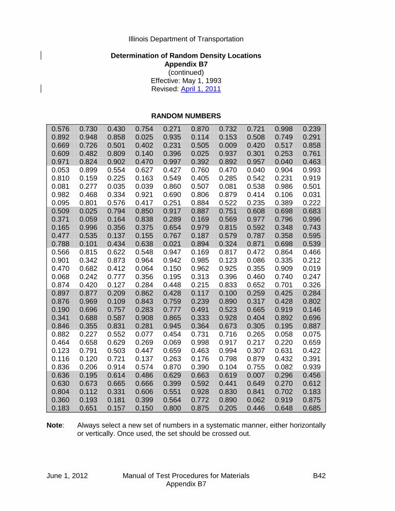
Illinois Department of Transportation
Determination of Random Density Locations
Appendix B7 (continued)
Effective: May 1, 1993 Revised: April 1, 2011
June 1, 2012 Manual of Test Procedures for Materials B42 Appendix B7
RANDOM NUMBERS
0.576 0.730 0.430 0.754 0.271 0.870 0.732 0.721 0.998 0.239 0.892 0.948 0.858 0.025 0.935 0.114 0.153 0.508 0.749 0.291 0.669 0.726 0.501 0.402 0.231 0.505 0.009 0.420 0.517 0.858 0.609 0.482 0.809 0.140 0.396 0.025 0.937 0.301 0.253 0.761 0.971 0.824 0.902 0.470 0.997 0.392 0.892 0.957 0.040 0.463 0.053 0.899 0.554 0.627 0.427 0.760 0.470 0.040 0.904 0.993 0.810 0.159 0.225 0.163 0.549 0.405 0.285 0.542 0.231 0.919 0.081 0.277 0.035 0.039 0.860 0.507 0.081 0.538 0.986 0.501 0.982 0.468 0.334 0.921 0.690 0.806 0.879 0.414 0.106 0.031 0.095 0.801 0.576 0.417 0.251 0.884 0.522 0.235 0.389 0.222 0.509 0.025 0.794 0.850 0.917 0.887 0.751 0.608 0.698 0.683 0.371 0.059 0.164 0.838 0.289 0.169 0.569 0.977 0.796 0.996 0.165 0.996 0.356 0.375 0.654 0.979 0.815 0.592 0.348 0.743 0.477 0.535 0.137 0.155 0.767 0.187 0.579 0.787 0.358 0.595 0.788 0.101 0.434 0.638 0.021 0.894 0.324 0.871 0.698 0.539 0.566 0.815 0.622 0.548 0.947 0.169 0.817 0.472 0.864 0.466 0.901 0.342 0.873 0.964 0.942 0.985 0.123 0.086 0.335 0.212 0.470 0.682 0.412 0.064 0.150 0.962 0.925 0.355 0.909 0.019 0.068 0.242 0.777 0.356 0.195 0.313 0.396 0.460 0.740 0.247 0.874 0.420 0.127 0.284 0.448 0.215 0.833 0.652 0.701 0.326 0.897 0.877 0.209 0.862 0.428 0.117 0.100 0.259 0.425 0.284 0.876 0.969 0.109 0.843 0.759 0.239 0.890 0.317 0.428 0.802 0.190 0.696 0.757 0.283 0.777 0.491 0.523 0.665 0.919 0.146 0.341 0.688 0.587 0.908 0.865 0.333 0.928 0.404 0.892 0.696 0.846 0.355 0.831 0.281 0.945 0.364 0.673 0.305 0.195 0.887 0.882 0.227 0.552 0.077 0.454 0.731 0.716 0.265 0.058 0.075 0.464 0.658 0.629 0.269 0.069 0.998 0.917 0.217 0.220 0.659 0.123 0.791 0.503 0.447 0.659 0.463 0.994 0.307 0.631 0.422 0.116 0.120 0.721 0.137 0.263 0.176 0.798 0.879 0.432 0.391 0.836 0.206 0.914 0.574 0.870 0.390 0.104 0.755 0.082 0.939 0.636 0.195 0.614 0.486 0.629 0.663 0.619 0.007 0.296 0.456 0.630 0.673 0.665 0.666 0.399 0.592 0.441 0.649 0.270 0.612 0.804 0.112 0.331 0.606 0.551 0.928 0.830 0.841 0.702 0.183 0.360 0.193 0.181 0.399 0.564 0.772 0.890 0.062 0.919 0.875 0.183 0.651 0.157 0.150 0.800 0.875 0.205 0.446 0.648 0.685
Note: Always select a new set of numbers in a systematic manner, either horizontally or vertically. Once used, the set should be crossed out.

Illinois Department of Transportation
Hot-Mix Asphalt QC/QA Control Charts / Rounding Test Values
Appendix B8
Effective: May 1, 1993 Revised: January 1, 2008
June 1, 2012 Manual of Test Procedures for Materials B43 Appendix B8
A. Scope
1. All required Contractor test results, including resample tests and mixture start-up, described in Article 1030.05(g) of the Standard Specification shall be split samples and plotted on Control Charts. (No check tests shall be plotted on these Control Charts.) In addition, the Engineer's "assurance" test results shall also be displayed. The minimum frequency of such tests shall be according to Section 1030 of the Standard Specifications.
2. Control Charts shall be maintained by the Contractor in the field laboratory.
Contractor test results shall be recorded within 24 hours of sampling. The Engineer shall be provided access to the location of the Control Charts at all times.
B. General Procedures
1. Control Charts shall be computer-printed or plotted in ink on standard cross-section paper (10 divisions per 1 in. [25 mm]). The vertical scale used shall conform to the following requirements in respect to rounded values of:
Gradation - 1% per 2.5 divisions (1 in [25 mm] = 4.0%). Air Voids, Field VMA, Minus No. 200 (Minus 75-µm), Field Density - 0.1% per division (1 in. [25 mm] = 1.0%). Asphalt Binder Content — 0.1% per 5 divisions (1 in. [25 mm] = 0.2%). Specific Gravity (Bulk or Maximum Theoretical) - 0.001 per division (1 in. [25 mm] = 0.01).
2. The horizontal scale shall be arranged such that each randomly selected test value obtained is plotted at ½ in. (12.5-mm) intervals. (See Figure 1.)
C. Symbols and Control Limits
1. Individual test values shall be represented on Control Charts by open circles centered on the correct test value except that washed ignition oven gradations shall be denoted by a solid circle. Moving average values shall be represented by open squares centered on the correct value. State assurance test values
Illinois Department of Transportation
Hot-Mix Asphalt QC/QA Control Charts / Rounding Test Values
Appendix B8
Effective: May 1, 1993 Revised: January 1, 2008
June 1, 2012 Manual of Test Procedures for Materials B44 Appendix B8
shall be represented by solid triangles for washed ignition gradations and by open triangles for dry gradations. All symbols shall be 0.1 in. (2.5 mm) in their largest dimension.
2. Individual test values shall be connected by dashed lines. Department
assurance test values shall not be connected with any other point. Moving average data points shall be connected by solid lines.
3. Target values shall be represented on Control Charts by horizontal solid lines.
Appropriate control limits (solid lines) for each control parameter shall extend horizontally across the chart and be identified with an appropriate solid symbol corresponding to the type of test it represents, i.e., individual or moving average.
D. Individual Test Values and Moving Average
1. Moving averages are applicable to all values except Department assurance split samples. The moving average is the average of four consecutive test values and is determined by starting with the fourth test value and averaging it with the three preceding test values. Plotting the average thereafter will be done in a similar manner starting with the test value just completed. Rounding procedures for the moving average are the same as used for the individual test values.
The moving average for minus 200 (minus 75 µm) for HMA production control shall include both washed ignition oven gradation and adjusted dry gradation individual results. When a given sublot includes both washed ignition and dry gradation test results for the minus 200 (minus 75 µm), only the washed ignition shall be used in the moving average.
The moving average for Gmm of a new mixture shall be established initially with the results from the start-up and shall include more tests in the moving average as they occur until the moving average of four is established. Unless otherwise specified by the Engineer, the moving average for Gmm of a previously placed mixture shall begin with the most recent moving average of four and shall be averaged with subsequent test results.

Illinois Department of Transportation
Hot-Mix Asphalt QC/QA Control Charts / Rounding Test Values
Appendix B8
Effective: May 1, 1993 Revised: January 1, 2008
June 1, 2012 Manual of Test Procedures for Materials B45 Appendix B8
2. At the bottom of the chart under the line on which the individual test data is plotted, the following information shall be listed:
a. Date and specific time (include a.m. or p.m.) of sampling. b. Lot Number. c. Test Sequence. d. Quantity of material represented (produced since previous test). e. Initials of person performing the test. f. Use "(rs)" to denote resample.
E. Mixture Start-Up Test Values
1. Test values obtained during start-up and the Job Mix Formula (JMF) adjustment period shall be placed at the beginning of the Control Charts. Once all these required tests have been completed and their values recorded, two vertical double black lines shall be drawn on the graph ½ in. (12.5 mm) apart. This constitutes the field verification process for the mixture.
2. At the completion of the field verification, production under QC/QA shall be
initiated with the agreed upon targets and appropriate limits being placed on the graph. Individual required plant test results shall be recorded from this point on with a moving average being established at the completion of the fourth test.
F. Adjusting Targets
1. If the adjustments in gradation or asphalt binder content are required in order to maintain proper voids, they shall be made according to Section 1030.06 of the Standard Specifications and shall be appropriately documented on the Control Charts.
2. When an adjustment to the Target value is made, two vertical double black
lines shall be drawn on the graph ½ in. (12.5 mm) apart. The new target value plus upper and lower control values will be placed on the chart. The moving average will continue as though the adjustment had not taken place.
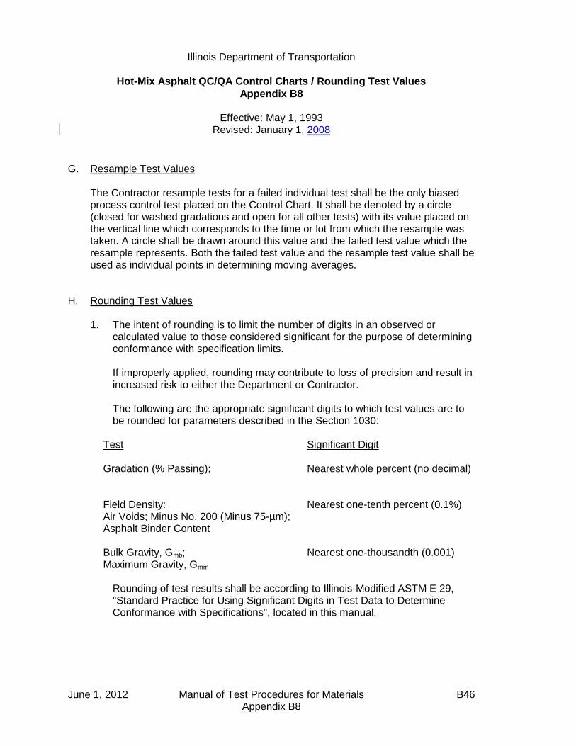
Illinois Department of Transportation
Hot-Mix Asphalt QC/QA Control Charts / Rounding Test Values
Appendix B8
Effective: May 1, 1993 Revised: January 1, 2008
June 1, 2012 Manual of Test Procedures for Materials B46 Appendix B8
G. Resample Test Values The Contractor resample tests for a failed individual test shall be the only biased
process control test placed on the Control Chart. It shall be denoted by a circle (closed for washed gradations and open for all other tests) with its value placed on the vertical line which corresponds to the time or lot from which the resample was taken. A circle shall be drawn around this value and the failed test value which the resample represents. Both the failed test value and the resample test value shall be used as individual points in determining moving averages.
H. Rounding Test Values
1. The intent of rounding is to limit the number of digits in an observed or calculated value to those considered significant for the purpose of determining conformance with specification limits.
If improperly applied, rounding may contribute to loss of precision and result in
increased risk to either the Department or Contractor. The following are the appropriate significant digits to which test values are to
be rounded for parameters described in the Section 1030:
Test Significant Digit Gradation (% Passing);
Nearest whole percent (no decimal)
Field Density: Air Voids; Minus No. 200 (Minus 75-µm); Asphalt Binder Content
Nearest one-tenth percent (0.1%)
Bulk Gravity, Gmb; Maximum Gravity, Gmm
Nearest one-thousandth (0.001)
Rounding of test results shall be according to Illinois-Modified ASTM E 29,
"Standard Practice for Using Significant Digits in Test Data to Determine Conformance with Specifications", located in this manual.
Illinois Department of Transportation
Hot-Mix Asphalt Mixture Design Verification Procedure
Appendix B9
Effective Date: January 1, 2002 Revised: June 1, 2012
June 1, 2012 Manual of Test Procedures for Materials B47 Appendix B9
1.0 GENERAL Contractors shall provide all hot-mix asphalt (HMA) mix designs for use on
Department contracts. All mix designs must provide mixture meeting Department mix criteria. The Department will provide current aggregate bulk specific gravity. The Engineer reserves the right to be present for the sampling of all aggregates for mix designs.
2.0 PURPOSE Establish a verification procedure to evaluate Contractor mix designs for use
on Department contracts. This procedure also allows for comparison of the test accuracy and precision between laboratories.
3.0 REQUIRED DESIGN DATA/MATERIAL SAMPLES 3.1 The Contractor shall provide a mix design prepared by a Hot-Mix Asphalt
Level III Technician in accordance with the Department's "Hot-Mix Asphalt Design Procedure" in the current Hot-Mix Asphalt Level III Technician Course manual. All testing shall be performed by Hot-Mix Asphalt Level I Technicians or higher. The mix design shall be submitted with the following design data:
A. The material name, material code number, source name, source
Producer/Supplier Number, and source location shall be provided for all materials used in the mix design.
B. The Contractor shall provide the average mix plant stockpile gradations
and aggregate blend percentages used to design the mix. Each of the individual aggregate gradations used in the Contractor design shall be an average of a minimum of 5 (five) stockpile gradations from existing stockpiles at the plant. Adjusted average aggregate source gradations (stockpile gradations preferred) may be substituted if aggregate has not been shipped to the mix plant. The adjustment shall be based on the amount of aggregate degradation during shipment to, and handling at, the mix plant. A design using gradation information not comparing to mix plant or aggregate source gradations shall be considered unacceptable.
C. The Contractor shall provide a summary of design test data and optimum
design data utilizing a design package with the same output format as the QC/QA software package.
Illinois Department of Transportation
Hot-Mix Asphalt Mixture Design Verification Procedure
Appendix B9 (continued)
Effective Date: January 1, 2002 Revised: June 1, 2012
June 1, 2012 Manual of Test Procedures for Materials B48 Appendix B9
(1) Design sheet. The design shall contain a minimum of four design points, two of which shall bracket the optimum
design asphalt binder (AB) content by at least 0.5%. Under remarks include: short-term aging time, dust correction factor, compaction temperature, and mixing temperature.
(2) Design summary data sheet (in the QC/QA software package
format). (3) Actual graph paper from the stability machine and actual Gmm
lab worksheets (original copy unless otherwise specified). (4) Batching worksheet. (5) Dust correction worksheet (include an example packet, such
as the one from the Level III manual). (6) Batching sources sheet.
(7) Mix design graphs (full page).
(a) Gradation (45 power curve). (b) Asphalt Binder Content vs. Gmb/Gmm. (c) Asphalt Binder Content vs. VMA. (d) Asphalt Binder Content vs. Air Voids. (e) Asphalt Binder Content vs. Voids Filled with Asphalt (VFA).
(8) Recalculations and/or retested points (e.g., recalculated Gmm's
using average Gse).
(9) TSR worksheet.
(10) Hamburg Wheel Test Result Sheet (if available)
The forms used shall be the Department's computer spreadsheet from the QC/QA software package, or other forms having the same format as the QC/QA software package.
Illinois Department of Transportation
Hot-Mix Asphalt Mixture Design Verification Procedure
Appendix B9 (continued)
Effective Date: January 1, 2002 Revised: June 1, 2012
June 1, 2012 Manual of Test Procedures for Materials B49 Appendix B9
3.2 The Contractor shall provide samples of blended aggregate, asphalt binder, and additives which represent the materials in the mix design. The representative samples shall be identified and submitted as follows:
A. Aggregate (including mineral filler/collected dust) -- Dried, split into the
individual sizes specified for the Batching Worksheet as stated in the current Hot-Mix Asphalt Level III Technician Course manual, and then blended to the chosen gradation. The amount submitted shall be two (2) 10,000-gram samples of dry aggregate, with an additional 2,000 grams for gradation testing if requested by the District. All material shall be bagged in plastic bags or other airtight containers. Each container shall be identified with the source names, source locations, source Producer/Supplier Numbers, material codes, sample location, and sample date.
B. Asphalt Binder -- A minimum of 4 qts (4,000 mL). Identified with source
name, source location, source Producer/Supplier Number, material code, sample location, and sample date.
C. Additive(s) -- The same additive(s) as used in the Contractor's design,
identified by the additive source name, source location, brand name or number, material code, sample location, sample date, additive MSDS, the manufacturer's recommended dosage rate, and the rate used in the design if different than the manufacturer's recommended dosage rate. NOTE: Prior to submitting the additive(s), the Contractor shall contact the District Materials Engineer for the required sample size.
3.3 The Contractor shall submit 150 mm diameter, gyratory-compacted
specimens, prepared according to IL modified AASHTO T 324, for Hamburg Wheel testing.
3.4 All design data and material samples shall be submitted to the Department a
minimum of 30 calendar days prior to production. 3.5 The Contractor shall certify in writing that all materials submitted for mix
design verification meet Department requirements and represent the materials to be used during mix production.
3.6 Previously verified mix designs shall be resubmitted for verifications as per
Section 4.1 herein.
Illinois Department of Transportation
Hot-Mix Asphalt Mixture Design Verification Procedure
Appendix B9 (continued)
Effective Date: January 1, 2002 Revised: June 1, 2012
June 1, 2012 Manual of Test Procedures for Materials B50 Appendix B9
4.0 DEPARTMENT VERIFICATION 4.1 Department verification for mix designs will include review of all mix design
data (including all aggregate field gradations) submitted by the Contractor, mixing the component materials submitted by the Contractor, and testing of the asphalt mixture.
At the option of the Department, previously verified mix designs may be
accepted either by reviewing the Contractor mix design data only or by re-verification based on successful production tests from previous construction seasons (after three years, the mix shall be redesigned). If stripping has been a problem with the materials to be used, the Contractor shall be required to re-validate TSR. If either of these options is used, the requirements of Section 3.2 herein may be waived. The Contractor shall contact the District Materials Engineer in regard to submitting materials. The current average gradations of the existing stockpiles at the asphalt mix plant shall be provided for comparison to the original mix design gradations. If the aggregate has not been shipped to the mix plant, the adjusted average source stockpile gradations shall be provided.
4.2 Verification testing will include volumetric tests/TSR test, as determined by the Engineer, on a mixture made from the individual materials submitted by the Contractor. The mixture at the optimum design asphalt binder content shall meet the mix design criteria for the following: VMA, VFA, Gmb, Gmm, Pa (voids), and/or TSR values.
4.3 Hamburg Wheel Tracker Verification Testing. Mixes with N50 design
gyrations and above, IL-4.75, and SMA mix designs submitted for verification will be tested according to IL modified AASHTO T 324 to ensure that the resulting mix designs will pass the required criteria specified herein. The Department will perform a Hamburg Wheel verification test on gyratory specimens compacted by the Contractor. If the mix fails the Department’s verification test, the Contractor shall make necessary changes to the mix and provide passing Hamburg Wheel test results from a private lab. The Department will verify the passing results.
4.4 Mix designs for All Other mixtures may, at the option of the Engineer, be
accepted by paper review of volumetric tests, gradation tests (or extraction tests), and/or TSR tests included in the design data submitted by the Contractor for verification.

Illinois Department of Transportation
Hot-Mix Asphalt Mixture Design Verification Procedure
Appendix B9 (continued)
Effective Date: January 1, 2002 Revised: June 1, 2012
June 1, 2012 Manual of Test Procedures for Materials B51 Appendix B9
4.5 The Contractor mix design data and Department verification data shall meet the mix design criteria in the Standard Specifications, any Special Provision in the Contract, and the following tolerances (where applicable):
Volumetric Testing Tolerance
Gse (effective SG of combined aggregates) ± 0.014
Gmb ± 0.020
Gmm ± 0.014
Air Voids ± 0.5 %
Gradation Tolerance
12.5 mm (1/2 in) ± 3.0
4.75 mm (No. 4) ± 2.0
2.36 mm (No. 8) ± 2.0
600 µm (No. 30) ± 1.0
75 µm (No. 200) ± 0.5
Pb (Asphalt Binder Content) ± 0.15
All aggregate field gradations submitted by the Contractor will be compared
to previous mix plant and/or Aggregate Gradation Control System gradations for validity.
Hamburg Wheel: All new and renewal mix designs shall meet the following requirements for verification testing.
The maximum allowable rut depth shall be 0.5 in. (12.5 mm). The minimum
number of wheel passes at the 0.5 in. (12.5 mm) rut depth criteria shall be selected based on the high temperature binder grade as specified in the mix requirements table of the plans.
PG Grade Number of Passes
PG 58-xx (or lower) 5,000
PG 64-xx 7,500
PG 70-xx 15,000
PG 76-xx (or higher) 20,000
Illinois Department of Transportation
Hot-Mix Asphalt Mixture Design Verification Procedure
Appendix B9 (continued)
Effective Date: January 1, 2002 Revised: June 1, 2012
June 1, 2012 Manual of Test Procedures for Materials B52 Appendix B9
4.6 The Department will notify the Contractor in writing within 30 calendar days of
receiving the design data/materials as to the acceptability of the submitted Contractor mix design. If the verification fails, the 30-calendar-day time for the Department to notify the Contractor starts over. Acceptable designs may be used in Department contracts, provided the design is reproducible in the mix plant.

Illinois Department of Transportation
Illinois Test Procedure 401
Storage of Hot-Mix Asphalt Mixtures
Appendix B10
Effective: January 1, 2002 Revised: May 1, 2007
June 1, 2012 Manual of Test Procedures for Materials B53 Appendix B10
1.0 SCOPE
1.1 The purpose of this procedure is to evaluate the effect of 20-hour storage on hot-mix asphalt.
1.2 Article 1102.01(a)(10) of the IDOT Standard Specifications for Road and
Bridge Construction allows for the storage of hot-mix asphalt in surge systems designed and operated to prevent segregation and loss of temperature. The specification allows for a maximum retention of eight hours. Longer retention times must be approved in writing by the Engineer.
2.0 REFERENCED DOCUMENTS
2.1 Illinois Modified AASHTO T 164, Method A or E 2.2 Illinois Modified AASHTO T 170
3.0 EQUIPMENT
3.1 One-quart (1-liter) and 1-gallon (4-liter) metal containers with lids for sample storage and transportation.
4.0 PROCEDURE 4.1 The Bureau of Materials and Physical Research will evaluate the effect of
additional storage time on the mixture. The Engineer will direct the Contractor to sample the mixture based on the following procedure. The Engineer reserves the right to witness the sampling.
4.2 The Contractor shall provide a minimum of 20 hours of uninterrupted
storage of the mixture to be sampled. 4.3 The bin must be filled with a binder mixture at a time mutually agreed
upon by the Contractor and Engineer. 4.4 A 1-quart (1-liter) sample of the asphalt binder shall be taken at this time. 4.5 A 1-gallon (4-liter) sample of the mixture shall be taken at this time.

Illinois Department of Transportation
Illinois Test Procedure 401
Storage of Hot-Mix Asphalt Mixtures
Appendix B10 (continued)
Effective: January 1, 2002 Revised: May 1, 2007
June 1, 2012 Manual of Test Procedures for Materials B54 Appendix B10
4.6 An additional 1-gallon (4-liter) mixture sample will be taken 20 hours after initial storage.
4.7 Samples shall be drawn from the silo by dumping the mixture into a truck
and sampling from the truck. All samples should be large enough to fill the metal container.
4.8 Each sample container shall be sealed immediately and marked with the
producer's or supplier's name and number, plant location, date, time, type of mixture, mixture temperature, and asphalt binder source and grade.
Note: If the sample container does not stay sealed, the container may
be cooled with the sample before sealing.
4.9 The samples should be immediately forwarded to the Bureau of Materials and Physical Research for evaluation.
4.10 Asphalt binder recovered from the mixture samples will be tested for the
effects of increased storage time on viscosity.
Grade Viscosity at 60 °C,
Pascal Seconds, Maximum
PG 64-28 125
PG 58-28 250
PG 58-22 500
PG 64-22 1000
PG 70-22 (neat) 2000
4.11 The test results of the initial mixture sample shall be used for
informational purposes only. 4.12 Approval will be based on the test results from the final mixture sample. 4.13 Test Method A or E of Illinois Modified AASHTO T 164, "Quantitative
Extraction of Bitumen from Bituminous Paving Mixtures," shall be used to extract asphalt binder from mixture samples.
4.14 The procedure for recovery of the extracted asphalt shall be Illinois
Modified AASHTO T 170, "Recovery of Asphalt from Solution by Abson Method."
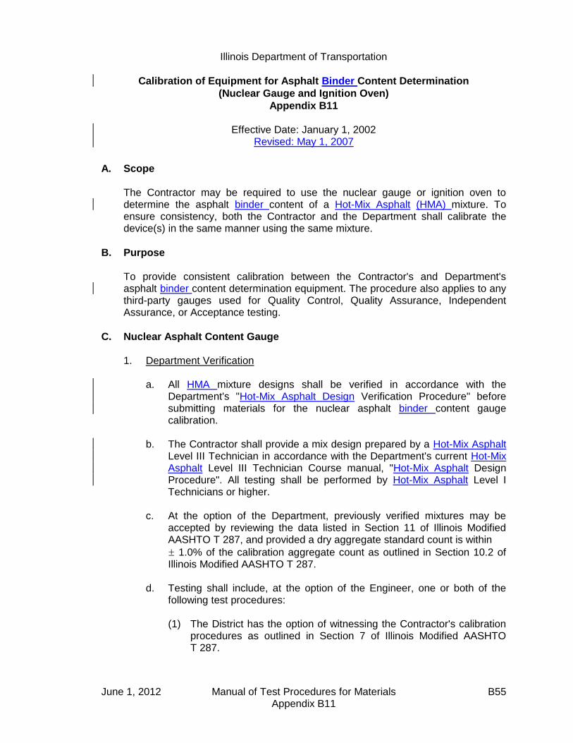
Illinois Department of Transportation
Calibration of Equipment for Asphalt Binder Content Determination
(Nuclear Gauge and Ignition Oven)
Appendix B11
Effective Date: January 1, 2002 Revised: May 1, 2007
June 1, 2012 Manual of Test Procedures for Materials B55 Appendix B11
A. Scope The Contractor may be required to use the nuclear gauge or ignition oven to determine the asphalt binder content of a Hot-Mix Asphalt (HMA) mixture. To ensure consistency, both the Contractor and the Department shall calibrate the device(s) in the same manner using the same mixture.
B. Purpose To provide consistent calibration between the Contractor's and Department's asphalt binder content determination equipment. The procedure also applies to any third-party gauges used for Quality Control, Quality Assurance, Independent Assurance, or Acceptance testing.
C. Nuclear Asphalt Content Gauge 1. Department Verification
a. All HMA mixture designs shall be verified in accordance with the Department's "Hot-Mix Asphalt Design Verification Procedure" before submitting materials for the nuclear asphalt binder content gauge calibration.
b. The Contractor shall provide a mix design prepared by a Hot-Mix Asphalt
Level III Technician in accordance with the Department's current Hot-Mix Asphalt Level III Technician Course manual, "Hot-Mix Asphalt Design Procedure". All testing shall be performed by Hot-Mix Asphalt Level I Technicians or higher.
c. At the option of the Department, previously verified mixtures may be
accepted by reviewing the data listed in Section 11 of Illinois Modified AASHTO T 287, and provided a dry aggregate standard count is within
1.0% of the calibration aggregate count as outlined in Section 10.2 of Illinois Modified AASHTO T 287.
d. Testing shall include, at the option of the Engineer, one or both of the
following test procedures:
(1) The District has the option of witnessing the Contractor's calibration procedures as outlined in Section 7 of Illinois Modified AASHTO T 287.

Illinois Department of Transportation
Calibration of Equipment for Asphalt Binder Content Determination
(Nuclear Gauge and Ignition Oven)
Appendix B11 (continued)
Effective Date: January 1, 2002
Revised: May 1, 2007
June 1, 2012 Manual of Test Procedures for Materials B56 Appendix B11
After the Contractor has calibrated his/her nuclear asphalt binder content gauge, the calibration pans shall be covered with plastic bags (to prevent the introduction of moisture) and given to the Department's representative.
The Department will calibrate its nuclear asphalt binder content
gauge, with the same calibration pans as the Contractor used. (2) Prior to calibrating the nuclear asphalt binder content gauge, the
Contractor shall submit the following to the District office at least 2 weeks prior to production:
3 empty nuclear asphalt pans
22 lbs (10 kg) of the HMA mixture at the design optimum asphalt binder content
22 lbs (10 kg) of the HMA mixture at 1% below the optimum asphalt binder content
22 lbs (10 kg) of the HMA mixture at 1% above the optimum asphalt binder content
The actual blended aggregate, including the pan, used to determine the dry aggregate standard count
The Engineer may split out approximately 16.5-lb (7500-g ) and/or
4.4-lb (2000-g) samples out of the 22 lb (10 kg) mixture samples. The 16.5-lb (7500-g) samples shall be used in the calibration pans for both the Department and the Contractor. The 4.4-lb (2000-g) samples may be used by the Department to run extractions on the samples for verification. The extraction results shall be within the following tolerances:
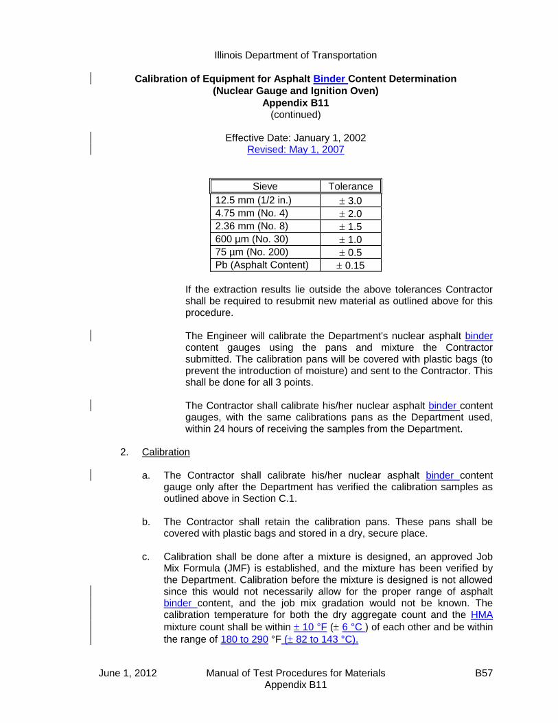
Illinois Department of Transportation
Calibration of Equipment for Asphalt Binder Content Determination
(Nuclear Gauge and Ignition Oven)
Appendix B11 (continued)
Effective Date: January 1, 2002
Revised: May 1, 2007
June 1, 2012 Manual of Test Procedures for Materials B57 Appendix B11
Sieve Tolerance
12.5 mm (1/2 in.) 3.0
4.75 mm (No. 4) 2.0
2.36 mm (No. 8) 1.5
600 µm (No. 30) 1.0
75 µm (No. 200) 0.5
Pb (Asphalt Content) 0.15
If the extraction results lie outside the above tolerances Contractor
shall be required to resubmit new material as outlined above for this procedure.
The Engineer will calibrate the Department's nuclear asphalt binder
content gauges using the pans and mixture the Contractor submitted. The calibration pans will be covered with plastic bags (to prevent the introduction of moisture) and sent to the Contractor. This shall be done for all 3 points.
The Contractor shall calibrate his/her nuclear asphalt binder content
gauges, with the same calibrations pans as the Department used, within 24 hours of receiving the samples from the Department.
2. Calibration
a. The Contractor shall calibrate his/her nuclear asphalt binder content gauge only after the Department has verified the calibration samples as outlined above in Section C.1.
b. The Contractor shall retain the calibration pans. These pans shall be
covered with plastic bags and stored in a dry, secure place. c. Calibration shall be done after a mixture is designed, an approved Job
Mix Formula (JMF) is established, and the mixture has been verified by the Department. Calibration before the mixture is designed is not allowed since this would not necessarily allow for the proper range of asphalt binder content, and the job mix gradation would not be known. The calibration temperature for both the dry aggregate count and the HMA
mixture count shall be within 10 °F ( 6 °C ) of each other and be within
the range of 180 to 290 °F ( 82 to 143 °C).

Illinois Department of Transportation
Calibration of Equipment for Asphalt Binder Content Determination
(Nuclear Gauge and Ignition Oven)
Appendix B11 (continued)
Effective Date: January 1, 2002
Revised: May 1, 2007
June 1, 2012 Manual of Test Procedures for Materials B58 Appendix B11
D. Ignition Oven 1. Department Verification
a. All HMA mixture designs shall be verified in accordance with the Department's "Hot-Mix Asphalt Design Verification Procedure" before submitting materials for the ignition oven calibration.
b. The Contractor shall provide a mix design prepared by an Hot-Mix
Asphalt Level III Technician in accordance with the Department's current Hot-Mix Asphalt Level III Technician Course Manual, "Hot-Mix Asphalt Design Procedure". All testing shall be performed by Hot-Mix Asphalt Level I Technicians or higher who have also successfully completed the Superpave Field Control Course.
c. Calibrations shall consist of, at the option of the Engineer, one or both of
the following procedures:
(1) The District has the option to witness the mixing and burning of the calibration sample. The Contractor shall mix enough mixture to provide the Department with calibration samples.
(2) The Contractor shall submit the following to the District office at least
two weeks prior to production:
Four individually batched, combined aggregate samples meeting the JMF. Each sample shall meet the minimum mass requirements listed in Section 5.6 of Illinois Modified AASHTO T308.
1 L (1 qt.) asphalt binder
Two samples will be used to calibrate the District's ignition oven. If the difference between the measured asphalt binder content of the two samples exceeds 0.15%, the tests will be repeated using the two remaining samples.

Illinois Department of Transportation
Hot-Mix Asphalt Mix Design
Procedure for Dust Correction Factor Determination
Appendix B12
Effective: January 1, 1998 Revised: May 1, 2007
June 1, 2012 Manual of Test Procedures for Materials B59 Appendix B12
A dust correction factor (DCF) shall be determined and applied to each new mix design using the procedure listed below. This procedure will be used to supplement the Hot-Mix Asphalt Level III Technician Course manual to account for additional minus No. 200 (minus 75-µm) material present as a result of batching with unwashed aggregates. It is important to note the Adjusted Blend Percentages are temporary percentages used during laboratory batching only. The original Blend Percentages on the “Design Summary Sheet” remain unchanged.
Note: When adjusting percentages to equal 100, the largest percentage should be adjusted accordingly.
A) Virgin Mix Design
1. Batch a combined aggregate sample matching the job mix formula (JMF). Test
sample size shall be determined using Illinois Specification 201 and based on the nominal maximum size of the largest coarse aggregate.
2. Perform a washed test on the combined aggregate sample using Illinois Modified
AASHTO T 11. 3. The DCF shall be the difference between the percent passing the No. 200 (75-µm)
sieve of the washed test and the JMF. 4. Determine the mineral filler reduction (MFR) by dividing the DCF by the percent (in
decimal form) mineral filler gradation passing the No. 200 (75-µm) sieve. 5. Subtract the MFR from the blend percentage of mineral filler. 6. Adjust the remaining blend percentages to sum to 100 by dividing each by the
quantity (1 - MFR).

Illinois Department of Transportation
Hot-Mix Asphalt Mix Design
Procedure for Dust Correction Factor Determination
Appendix B12 (continued)
Effective: January 1, 1998 Revised: May 1, 2007
June 1, 2012 Manual of Test Procedures for Materials B60 Appendix B12
Example
Bituminous Mixture Design
Design Number:-------> 50BITEXPL
Lab preparing the design?(PP,PL,IL ect.) IDOTProducer Name & Number--> 1111-01 Example Company Inc Somewhere 1, ILMaterial Code Number---> 17552 BITCONC BCS 1 B TONS
Agg No. #1 #2 #3 #4 #5 #6 ASPHALTSize 032CMM11 032CMM16 038FAM20 037FAM01 004MFM01 10124M
Source (PROD#) 51972-02 51972-02 51230-06 51790-04 51052-04
(NAME) MAT SER MAT SER MIDWEST CONICK LIVINGSTON 2260-01
(LOC) EMLSCOAT
Aggregate Blend 38.0 35.0 14.5 10.0 2.5 0.0 100.0
Agg No. #1 #2 #3 #4 #5 #6 Blend
Sieve Size1 100.0 100.0 100.0 100.0 100.0 100.0 100.0
3/4 88.0 100.0 100.0 100.0 100.0 100.0 95.4
1/2 45.0 100.0 100.0 100.0 100.0 100.0 79.13/8 19.0 97.0 100.0 100.0 100.0 100.0 68.2
#4 6.0 29.0 97.0 97.0 100.0 100.0 38.7
#8 2.0 7.0 80.0 85.0 100.0 100.0 25.8#16 2.0 4.0 50.0 65.0 100.0 100.0 18.4
#30 1.8 3.0 35.0 43.0 100.0 100.0 13.6
#50 1.7 3.0 19.0 16.0 100.0 100.0 8.6#100 1.5 3.0 10.0 5.0 90.0 100.0 5.8
#200 1.3 1.3 4.0 2.5 88.0 100.0 4.0
Step 1. Batch a combined aggregate sample meeting the JMF. Illinois
Specification 201 requires a 5000-gram sample when CM11 is present.
Step 2. Run a washed test using AASHTO T 11.
Step 3. Determine the Dust Correction Factor (DCF). The DCF is the difference in the percent passing the No. 200 (75-µm) sieve between the washed test and the JMF:
JMF Washed Test DCF
No. 200 (75 µm) 4.0% 5.6% 1.6%

Illinois Department of Transportation
Hot-Mix Asphalt Mix Design
Procedure for Dust Correction Factor Determination
Appendix B12 (continued)
Effective: January 1, 1998 Revised: May 1, 2007
June 1, 2012 Manual of Test Procedures for Materials B61 Appendix B12
Step 4. Determine the Mineral Filler Reduction (MFR) by dividing the DCF (%) by the percent (in decimal form) mineral filler gradation passing the No. 200 (75-µm) sieve:
MFR (%) = 1.6 / 0.88 = 1.8%
Step 5. Determine the adjusted mineral filler blend percentage by subtracting the MFR (%) from the blend percentage of mineral filler:
2.5% - 1.8% = 0.7%
Step 6. Adjust the remaining blend percentages to sum to 100 by dividing each by
the quantity [1 - MFR (in decimal form)]:
Blend
Percentage
Adjusted
Blend
Percentage1
032CMM11 38.0 38.7
032CMM16 35.0 35.6
038FAM20 14.5 14.8
037FAM01 10.0 10.2
004MFM01 2.5 0.7
100.0 100.0
Note 1: It is important to note the Adjusted Blend Percentages are temporary percentages used during laboratory batching only. The original Blend Percentages on the “Design Summary Sheet” remain unchanged.

Illinois Department of Transportation
Hot-Mix Asphalt Mix Design
Procedure for Dust Correction Factor Determination
Appendix B12 (continued)
Effective: January 1, 1998 Revised: May 1, 2007
June 1, 2012 Manual of Test Procedures for Materials B62 Appendix B12
B) RAP Mix Design
1. Determine the Virgin Aggregate Fraction (VAF). The virgin aggregate fraction is the percentage of virgin aggregate
2. Adjust to the virgin blend percentages by dividing each virgin aggregate by the VAF.
3. Determine the RAP Adjusted JMF (RJMF)
4. Batch the virgin aggregates according to the adjusted blend percentages matching the RJMF. Test sample size shall be determined using Illinois Specification 201 and based on the nominal maximum size of the largest coarse aggregate.
5. Perform a washed test on the combined aggregate sample using Illinois Modified AASHTO T 11.
6. The DCF shall be the difference between the percent passing the No. 200 (75-μm) sieve of the washed test and the RJMF.
7. Determine the mineral filler reduction (MFR)RAP by dividing the DCF by the percent (in decimal form) mineral filler gradation passing the No. 200 (75-μm) sieve.
8. Subtract the MFRRAP from the blend percentage of mineral filler.
9. Adjust the remaining virgin aggregate blend percentages to sum to 100 by dividing each by the quantity (1 – MFRRAP).
10. Determine the batching blend percentages with RAP by multiplying the adjusted virgin aggregate blend percentages by the VAF.

Illinois Department of Transportation
Hot-Mix Asphalt Mix Design
Procedure for Dust Correction Factor Determination
Appendix B12 (continued)
Effective: January 1, 1998 Revised: May 1, 2007
June 1, 2012 Manual of Test Procedures for Materials B63 Appendix B12
RAP
Example
Step 1. Determine the virgin aggregate fraction (VAF).
100
%)100( RAPAggVAF
100
)7.23100( VAF
VAF = 0.763

June 1, 2012 Manual of Test Procedures for Materials B64 Appendix B12
Step 2. Adjust to the virgin aggregate percentages by dividing each virgin aggregate by the VAF. Initial virgin agg % 042CMM11 38.3 (÷ 0.763) 50.3 (added 0.1 sum = 100.0) 042CMM16 23.0 (÷ 0.763) 30.1 037FMM01 13.0 (÷ 0.763) 17.0 004MF01 2.0 (÷ 0.763) 2.6 Sum 100.0 100.0
Step 3. Determine the RAP adjusted JMF (RJMF). Combine gradation using the adjusted virgin aggregate blend percentages.
1 100.0 ¾ 89.4 ½ 66.8 3/8 53.9 #4 28.5 #8 19.2 #16 17.4 #30 14.6 #50 7.8 #100 3.8 #200 3.4
Step 4. Batch the virgin aggregates according to the adjusted blend percentages matching the RJMF. Illinois specification 201 requires a 5000-gram sample when CM11 is present.
Step 5. Run a washed test using AASHTO T11. Step 6. Determine the dust correction factor (DCF). The DCF is the difference
between the percent passing the No. 200 (75-μm) sieve of the washed test and the RJMF. Washed RJMF DCF No. 200 (75-μm) 4.3 3.4 4.3-3.4= 0.9 DCF = 0.9

Illinois Department of Transportation
Hot-Mix Asphalt Mix Design
Procedure for Dust Correction Factor Determination
Appendix B12 (continued)
Effective: January 1, 1998 Revised: May 1, 2007
June 1, 2012 Manual of Test Procedures for Materials B65 Appendix B12
Step 7. Determine the mineral filler reduction (MFR)RAP. The (MFR)RAP is determined by dividing the DCF by the percent (in decimal form) mineral filler gradation passing the No. 200 (75-μm) sieve.
%1.185.0
9.0RAPMFR
Step 8. Determine the mineral filler blend percentage by subtracting the MFRRAP from
the blend percentage of mineral filler. 2.6 – 1.1 = 1.5%
Step 9. Adjust the remaining blend percentages to sum to 100% by dividing each by the quantity [1-MFRRAP (in decimal form)]: 1 – MFRRAP = 1 – 0.011 = 0.989 Virgin % Adj Virgin Blend% 042CMM11 50.3 (÷ 0.989) 50.9 042CMM16 30.1 (÷ 0.989) 30.4 037FMM01 17.0 (÷ 0.989) 17.2 004MF01 2.6 (from step 8) 1.5 Sum 100.0 100.0
Step 10. Determine the batching blend percentages with RAP by multiplying the adjusted virgin blend % by the VAF. VAF = 0.763 Adjusted Virgin % Batching Blend % 042CMM11 50.9 (x 0.763) 38.9 (added 0.1 sum = 100.0) 042CMM16 30.4 (x 0.763) 23.2 037FMM01 17.2 (x 0.763) 13.1 004MF01 1.5 (x 0.763) 1.1 RAPAgg 23.7 Sum 100.0

June 1, 2012 Manual of Test Procedures for Materials B66 Appendix B12
This Page Reserved

Illinois Department of Transportation
Illinois Test Procedure 403
Calibration of the Ignition Oven for the Purpose of Characterizing
Reclaimed Asphalt Pavements (RAP)
Appendix B13
Effective Date: January 1, 2002
Revised: May 1, 2007
June 1, 2012 Manual of Test Procedures for Materials B67 Appendix B13
1.0 GENERAL 1.1 This method covers the calibration of the ignition oven for
characterization of reclaimed asphalt pavement (RAP). Correction factors for both gradation and asphalt content are determined by conducting parallel ignition and extraction testing.
2.0 SIGNIFICANCE AND USE
2.1 The ignition oven may be used in place of solvent extractions at the frequency stated in Section 1031 of the Standard Specifications.
2.2 This method may be used only with the approval of the Engineer. 2.3 Each RAP stockpile shall require a separate ignition oven calibration. 2.4 All RAP stockpiles and sampling frequencies shall meet the requirements
stated in Section 1031 of the Standard Specifications.
3.0 REFERENCED DOCUMENTS
3.1 AASHTO Standards (as modified by Illinois): T 2 Sampling of Aggregates T 164 Quantitative Extraction of Bitumen from Bituminous Paving
Mixtures T 248 Reducing Field Samples of Aggregate to Testing Size T 308 Determining the Asphalt Binder Content of Hot-Mix Asphalt (HMA)
by the Ignition Method
4.0 PROCEDURE
4.1 Sample the RAP according to AASHTO T 2. Obtain an adequate amount of material to perform a minimum of two solvent extractions and four ignition oven burns. The minimum sample sizes shall be governed by the nominal maximum aggregate size of the mixture defined in Illinois Modified AASHTO T 164 and T 308. Reduce the samples to testing size according to Illinois Modified AASHTO T 248.

Illinois Department of Transportation
Illinois Test Procedure 403
Calibration of the Ignition Oven for the Purpose of Characterizing
Reclaimed Asphalt Pavements (RAP)
Appendix B13 (continued)
Effective January 1, 2002 Revised: May 1, 2007
June 1, 2012 Manual of Test Procedures for Materials B68 Appendix B13
4.2 Perform a minimum of two solvent extractions and a minimum of four ignition oven burns according to AASHTO T 164 and Illinois-Modified AASHTO T 308, respectively.
4.3 AB Binder Calibration 4.3.1 Calculate the average Asphalt Binder (AB) percentage of the two
extractions, Pext. Calculate the average AB percentage of the four ignition oven burns, Pign. Assuming the average AB content from the extraction to be correct, subtract the average extraction AB percentage from the average ignition oven AB percentage to determine the asphalt correction factor, Cf.
Cf = Pign - Pext
Use the asphalt correction factor to adjust the ignition oven asphalt
content on all subsequent testing of that stockpile.
4.4 Gradation Calibration 4.4.1 From the two extractions, calculate the average percent passing the
applicable sieve, Gext. Calculate the average percent passing each applicable sieve from the four ignition oven burns, Gign. Subtract the extraction average percent passing each sieve from the ignition oven average of the corresponding sieve to determine a correction factor, GCf, for gradation for each sieve.
GCf = Gign - Gext
5.0 REPORT 5.1 Report the correction factors to the nearest 0.1%
6.0 PRECISION AND BIAS 6.1 The estimates of precision and bias shall be considered those that apply
to the referenced documents.

Illinois Department of Transportation
Illinois Test Procedure 403
Calibration of the Ignition Oven for the Purpose of Characterizing
Reclaimed Asphalt Pavements (RAP)
Appendix B13 (continued)
Effective January 1, 2002 Revised: May 1, 2007
June 1, 2012 Manual of Test Procedures for Materials B69 Appendix B13
7.0 USE
7.1 Use the correction factor for percent passing the No. 200 (75-m) sieve
to adjust the minus No. 200 (75-m) material from the ignition oven on all subsequent testing of that stockpile.
7.2 Use the asphalt correction factor to adjust the ignition oven asphalt
content on all subsequent testing of that stockpile. 7.3 The ignition oven washed gradations may be used uncorrected for all
sieves except for the No. 200 (75-m) sieve.

June 1, 2012 Manual of Test Procedures for Materials B70 Appendix B13
This Page Reserved
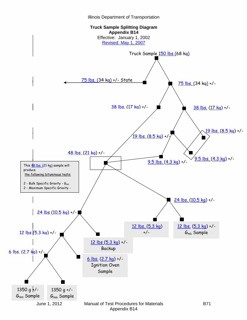
Illinois Department of Transportation
Truck Sample Splitting Diagram Appendix B14
Effective: January 1, 2002 Revised: May 1, 2007
June 1, 2012 Manual of Test Procedures for Materials B71 Appendix B14
Truck Sample 150 lbs (68 kg)
lllcwerlbs)lbs.)
75 lbs. (34 kg) +/- State
Sample 75 lbs. (34 kg) +/-
38 lbs. (17 kg) +/- 38 lbs. (17 kg) +/-
19 lbs. (8.5 kg) +/- 19 lbs. (8.5 kg) +/-
9.5 lbs. (4.3 kg) +/- 9.5 lbs. (4.3 kg) +/-
48 lbs. (21 kg) +/-
24 lbs. (10.5 kg) +/-
24 lbs (10.5 kg) +/-
+/-
12 lbs. (5.3 kg) +/-
Gmb Sample
12 lbs. (5.3 kg)
+/-
Gmb Sample 12 lbs (5.3 kg) +/-
Backup
12 lbs (5.3 kg) +/-
6 lbs. (2.7 kg) +/-
Ignition Oven
Sample
6 lbs. (2.7 kg) +/-
1350 g +/-
Gmm Sample
1350 g +/-
Gmm Sample
This 48 lbs. (21 kg) sample will
produce
the following bituminous tests:
2 - Bulk Specific Gravity - Gmb
2 - Maximum Specific Gravity -
Gmm
1 - Ignition Oven
1 - Backup

June 1, 2012 Manual of Test Procedures for Materials B72 Appendix B14
This Page Reserved
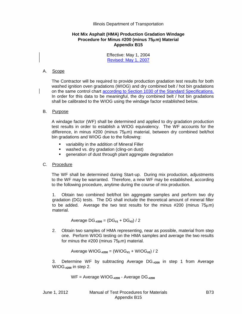
Illinois Department of Transportation
Hot Mix Asphalt (HMA) Production Gradation Windage
Procedure for Minus #200 (minus 75m) Material
Appendix B15
Effective: May 1, 2004 Revised: May 1, 2007
June 1, 2012 Manual of Test Procedures for Materials B73 Appendix B15
A. Scope
The Contractor will be required to provide production gradation test results for both washed ignition oven gradations (WIOG) and dry combined belt / hot bin gradations on the same control chart according to Section 1030 of the Standard Specifications. In order for this data to be meaningful, the dry combined belt / hot bin gradations shall be calibrated to the WIOG using the windage factor established below.
B. Purpose
A windage factor (WF) shall be determined and applied to dry gradation production test results in order to establish a WIOG equivalency. The WF accounts for the
difference, in minus #200 (minus 75m) material, between dry combined belt/hot bin gradations and WIOG due to the following:
variability in the addition of Mineral Filler washed vs. dry gradation (cling-on dust) generation of dust through plant aggregate degradation
C. Procedure
The WF shall be determined during Start-up. During mix production, adjustments to the WF may be warranted. Therefore, a new WF may be established, according to the following procedure, anytime during the course of mix production.
1. Obtain two combined belt/hot bin aggregate samples and perform two dry gradation (DG) tests. The DG shall include the theoretical amount of mineral filler
to be added. Average the two test results for the minus #200 (minus 75m) material.
Average DG-#200 = (DG#1 + DG#2) / 2 2. Obtain two samples of HMA representing, near as possible, material from step
one. Perform WIOG testing on the HMA samples and average the two results
for minus the #200 (minus 75m) material.
Average WIOG-#200 = (WIOG#1 + WIOG#2) / 2
3. Determine WF by subtracting Average DG-#200 in step 1 from Average
WIOG-#200 in step 2.
WF = Average WIOG-#200 - Average DG-#200

Illinois Department of Transportation
Hot Mix Asphalt (HMA) Production Gradation Windage
Procedure for Minus #200 (minus 75m) Material
Appendix B15
(continued)
Effective: May 1, 2004 Revised: May 1, 2007
June 1, 2012 Manual of Test Procedures for Materials B74 Appendix B15
4. Add WF to all combined belt/hot bin gradation test results prior to plotting on
the Minus #200 (minus 75m) Control Chart. All, (including WIOG test results
used to establish WF, are plotted directly on the Minus #200 (minus 75m) Control Chart. When both the DG and WIOG test results represent the same material, the WIOG are the results to be included in the moving average.
Example: Given:
WIOG#1 (minus #200) = 4.8% (Truck sample taken between growth curves)
WIOG#2 (minus #200) = 4.6% (Truck sample taken from outside Test Strip area during startup)
DG#1 (minus #200) = 2.7% (Combined belt sample taken to correspond to
material sampled for WIOG#1)
DG#2 (minus #200) = 2.1% (Combined belt sample taken to correspond to
material sampled for WIOG#2)
Step 1. Average the two DG test results for the minus #200 (minus 75m) material.
Average DG-#200 = (2.7% + 2.1%) / 2 = 2.4%
Step 2. Average the two WIOG test results for the minus #200 (minus 75m) material.
Average WIOG-#200 = (4.8% + 4.6%) / 2 = 4.7%
Step 3. Determine WF by subtracting Average DG-#200 in step 1 from Average
WIOG-#200 in step 2.
WF = 4.7% - 2.4% = 2.3%
Step 4. Add WF = 2.3% to all combined belt/hot bin gradation test results prior to
plotting on the Minus #200 (minus 75m) Control Chart.

Illinois Department of Transportation
Stripping of Hot-Mix Asphalt Mixtures Visual Identification and Classification
Appendix B16
Effective: November 20, 2003 Revised: May 1, 2007
June 1, 2012 Manual of Test Procedures for Materials B75 Appendix B16
The following instructions describe the method to be used for visually identifying and classifying the effect of moisture damage on the adhesion of asphalt binder to the aggregate in Hot-Mix Asphalt (HMA) mixtures. This procedure provides the means to rate this phenomenon in numerical terms. This procedure is applicable to both laboratory compacted specimens and pavement cores1. INSTRUCTIONS 1. This procedure should only be applied to freshly split specimen faces, such as those
obtained from split tensile testing. The observation of cored, sawed, or chiseled faces should be avoided, as the true condition of the stripping will be obscured.
2. The rating should be completed within 10 minutes of splitting for maximum clarity. When the
specimens dry out, they may look considerably different. The aggregate surfaces should be examined carefully to determine if the asphalt binder was stripped from the aggregate as a result of being “washed” by water before the specimen was split or if the asphalt binder was “ripped apart” near the asphalt/aggregate interface during the split tensile test. Also, aggregate surfaces with small, relatively isolated, globules of asphalt binder are quite likely not stripped.
3. Special attention should be given to fractured and broken aggregates. Fractured
aggregates are those that were cracked during compaction. These fractured aggregates will have a distinct face with a dull or discolored surface. Broken aggregates are those that were broken during the split tensile test. Broken aggregates often occur near the outside surface of the specimen where the compressive forces are greatest. These broken aggregates will also have a distinct broken face, but will have a bright, uncoated surface. The broken aggregates may be a continuation of a crack that was started during compaction. There is no evidence that a broken aggregate was broken entirely under the compressive force of the split tensile test.
4. Coarse aggregate particles shall be defined as those particles retained on the #8 sieve.
Fine aggregate particles shall be defined as those particles that will pass through a #8 sieve. 5. When examining the split face, use the entire face area of all the fine particles separately
from all the coarse particles on the split face to determine the percentage of the total area that is stripped. Do not use the percent of the area of each individual stone that is stripped to collectively determine the percentage of stripped aggregate particles on the entire split face of the specimen. Also, do not estimate the percentage of aggregate particles that are stripped based on the total number of aggregate particles. (i.e., a small stripped aggregate particle does not affect the entire specimen the same as a large stripped aggregate particle.)
1 Pavement cores taken from the field should be sealed in plastic bags immediately after coring in order to retain
their in-situ moisture. Pavement cores should be split and visually rated as soon as possible after coring to avoid any
“healing” of the asphalt to the aggregate surfaces.

Illinois Department of Transportation
Stripping of Hot-Mix Asphalt Mixtures Visual Identification and Classification
Appendix B16 (continued)
Effective: November 20, 2003 Revised: May 1, 2007
June 1, 2012 Manual of Test Procedures for Materials B76 Appendix B16
PROCEDURE 1. Obtain a freshly split face through the split tensile test. 2. Observe the coarse aggregate of the split face with the naked eye. Pay special attention to
the coarse aggregate that is broken or fractured. These particles are not stripped. 3. Assign a strip rating to the coarse aggregate of the split face based on the following
descriptions:
1 - Less than 10% of the entire area of all the coarse aggregate particles is stripped (no stripping to slight stripping).
2 - Between 10% and 40% of the entire area of all the coarse aggregate particles
is stripped (moderate stripping). 3 - More than 40% of the entire area of all the coarse aggregate particles is
stripped (severe stripping).
4. Observe the fine aggregate particles and rate the particles for percent of the area showing moisture damage. A microscope or magnifying glass with a total magnification of 10X should be used to aid in viewing the specimens. Observe the fine aggregate particles and mentally rate the particles present in the field of view. Move the specimen to a new field of view and rate the particles present. Repeat this process once more, ensuring a new field of view is chosen. Average the three observations.
5. Assign a strip rating to the fine aggregate of the split face based on the following
descriptions:
1 - Less than 10% of the entire area of all the fine aggregate particles viewed is stripped (no stripping to slight stripping).
2 - Between 10% and 25% of the entire area of all the fine aggregate particles
viewed is stripped (moderate stripping). 3 - More than 25% of the entire area of all the fine aggregate particles viewed is
stripped (severe stripping). 6. Report the individual strip ratings for both the coarse and fine aggregate on the strip rating
form. Include any comments or special notes about the observations from that specimen.

June 1, 2012 Manual of Test Procedures for Materials B77 Appendix B16
STRIP RATING FORM PROJECT DATE
GENERAL COMMENTS
SPECIMEN NO. TYPE OF
CONDITIONING COARSE RATING
FINE RATING
COMMENTS

June 1, 2012 Manual of Test Procedures for Materials B78 Appendix B16
This Page Reserved
Illinois Department of Transportation
Procedure for Introducing Additives to Hot Mix Asphalt Mixtures and Testing in the Lab
Appendix B17
Effective Date: March 7, 2005 Revised: May 1, 2007
June 1, 2012 Manual of Test Procedures for Materials B79 Appendix B17
1.0 GENERAL
Moisture damage or stripping is considered to be one of the main reasons for an asphalt pavement (especially full depth asphalt pavement) not lasting indefinitely. Stripping is the weakening and loss of the adhesive bond between aggregates and asphalt binder, in the presence of moisture. Various additives can be used to help reduce the stripping potential of an aggregate. In Illinois, liquid anti-strip additives are used almost exclusively. However, other states use or require adding hydrated lime in HMA. Hydrated Lime is considered, by many, as a superior additive for moisture damage control and prevention. It typically is added to the aggregate and asphalt mixture by one of three methods, the dry, the wet, or the slurry method.
Different levels of conditioning can be used in lab-prepared specimens to simulate the effect of the actual moisture conditions in the field. Four levels are described in this document. The level of conditioning actually used will be as specified in contract documents or as determined in the workplan for research.
2.0 PURPOSE
A. This procedure applies to using additives in hot mix asphalt (HMA) mixtures and testing those mixtures in the lab. This procedure includes the dry method of hydrated lime addition as well as the wet method and the slurry method. Also, this procedure includes specimens containing no additive, liquid anti-strip, polymer-modified asphalt, and polymer-modified asphalt with hydrated lime or liquid anti-strip.
B. Four levels of conditioning are included in this procedure and are used when
specified. These four levels are no conditioning (or control), submerging in a hot water bath, one cycle of freezing followed by submerging in the hot water bath, and five freeze and hot water bath cycles. The conditioned samples are all partially saturated with water before the freeze and hot water bath cycles begin.
C. Illinois-modified AASHTO T-283 is the standard specification in Illinois that is
required and used to test all HMA mixtures for moisture susceptibility. Only specimens with no conditioning and specimens conditioned in the hot water bath shall be tested according to Illinois-modified AASHTO T-283. In addition to the conditioning and testing specified in Illinois-modified AASHTO T-283, this procedure also contains guidelines for conditioning and testing specimens using freeze/thaw conditioning cycles. Freeze/thaw cycles shall be used if specified and also may be used for research projects. Utilizing five freeze/thaw cycles is harsher than the other conditioning methods in this procedure and is considered to more effectively predict the long-term susceptibility to moisture damage of specific materials and mixtures.

Illinois Department of Transportation
Procedure for Introducing Additives to Hot Mix Asphalt Mixtures and Testing in the Lab
Appendix B17 (continued)
Effective Date: March 7, 2005 Revised Date: May 1, 2007
June 1, 2012 Manual of Test Procedures for Materials B80 Appendix B17
D. Tensile strengths are determined and the tensile strength ratio (TSR) is
calculated. The tensile strength of the unconditioned specimens is compared with the tensile strength of the specimens from each of the applicable levels of conditioning to determine the TSR. The TSR is a measure of the relative effect that each additive type and conditioning method has on the moisture susceptibility of the samples. The results are used to compare the various additives and their effect on the stripping potential of each mix and to determine the best additive to be used for a specific mixture containing a specific blend of materials.
3.0 MATERIALS
A. The hydrated lime shall conform to Section 1012.01 of the Standard
Specifications for Road and Bridge Construction. Illinois-modified AASHTO T-27 shall be used to determine the maximum percent of the hydrated lime retained on specified sieves.
The HMA Mix Design shall be performed using the hydrated lime addition method that will be used during actual production in the field.
B. The liquid anti-strip must be included on the Illinois approved materials list.
4.0 SAMPLE PREPARATION
A. Dry Aggregates:
Dry the aggregate samples in a 230 9 F (110 5 C) oven so that the batch weights and additive amounts can be accurately determined.
B. Split Aggregates:
The aggregate samples will then be split according to Illinois-modified AASHTO T-248.
C. Blend Aggregates:
The aggregates will be blended into the correct batch size. Because of the large size of the gyratory specimens, each batch will contain enough material for two gyratory specimens (approximately 8000 - 8500 grams). Several batches will need to be prepared to produce the six gyratory specimens required for the test. Also, include sufficient material in one of the batches for a maximum specific gravity (Gmm) test run according to Illinois-modified AASHTO T-209 (total batch size of approximately 9500 - 10000 grams).
Illinois Department of Transportation
Procedure for Introducing Additives to Hot Mix Asphalt Mixtures and Testing in the Lab
Appendix B17 (continued)
Effective Date: March 7, 2005 Revised Date: May 1, 2007
June 1, 2012 Manual of Test Procedures for Materials B81 Appendix B17
D. Mix Samples: 1. With No Additive:
a. Heat the asphalt binder and the dry aggregate blend to a mixing
temperature of 295 5 F (146 ± 2.8°C) for neat asphalt.
b. Remove the blend from the oven and make a small crater in the top of the hot, dry aggregates.
c. Add the correct amount of asphalt binder to the batch.
d. Mix the aggregates and asphalt binder.
2. Hydrated Lime – Dry Method:
a. List the hydrated lime in its own column on the Aggregate Blending Sheet and enter the percent passing each sieve in the corresponding line on the form.
b. 1.0% hydrated lime is added to the mix. The 1.0% hydrated lime is based on the total dry weight of aggregate in the mix and is added in addition to the mineral filler specified in the mix design.
NOTE: Theoretically when hydrated lime is added by the dry method, it is assumed that half of the hydrated lime (0.5%) adheres to the aggregate and that the other half (0.5%) of the hydrated lime acts like mineral filler and becomes part of the asphalt binder in the HMA mix. However, for design purposes (and to adapt to existing design software), the hydrated lime is all considered as a separate aggregate, similar to mineral filler, and the gradation of all of the hydrated lime contributes to the overall blend gradation.
c. When hydrated lime is used in a mix design, it is important to include sufficient added mineral filler in the design. During plant production some of this mineral filler may need to be removed to compensate for the fines that are generated during production.
d. Calculate the dust correction factor (DCF) according to the “Hot-Mix Asphalt Mix Design Procedure for Dust Correction Factor Determination”, on each mix design with hydrated lime added. Include the hydrated lime in both the job mix formula (JMF) gradation and the washed gradation on the aggregate combined blend. The DCF procedure is performed to
account for additional minus 75-m (minus No. 200) material present as a result of batching with unwashed aggregates. Refer to the attached sheet which shows an example calculation of the DCF.

Illinois Department of Transportation
Procedure for Introducing Additives to Hot Mix Asphalt Mixtures and Testing in the Lab
Appendix B17 (continued)
Effective Date: March 7, 2005 Revised Date: May 1, 2007
June 1, 2012 Manual of Test Procedures for Materials B82 Appendix B17
Illinois Department of Transportation
Procedure for Introducing Additives to Hot Mix Asphalt Mixtures and Testing in the Lab
Appendix B17 (continued)
Effective Date: March 7, 2005 Revised Date: May 1, 2007
June 1, 2012 Manual of Test Procedures for Materials B83 Appendix B17
e. Heat the asphalt binder and the dry aggregates (not including mineral
filler) to a mixing temperature of 295 5 F (146 ± 2.8°C) for neat asphalt
or 325 5 F (163 ± 2.8°C) for polymer modified asphalt.
f. Make a small crater in the top of the hot, dry aggregates.
g. Add the correct amount of dry hydrated lime to the crater in the aggregates.
h. Mix the hydrated lime and aggregates until the aggregates are completely coated (approximately 10 to 15 seconds).
i. If the blend of aggregates and hydrated lime cools below the mixing temperature, place the blend back in the oven until the blend is returned to the mixing temperature (approximately 10 minutes).
j. Remove the blend from the oven and make a small crater in the top of the hot, dry aggregates and hydrated lime.
k. Add the correct amount of mineral filler, (if required in the mix design), to the crater in the aggregates.
l. Mix the mineral filler with the aggregates and hydrated lime until the mineral filler is uniformly dispersed in the blend (approximately 10 to 15 seconds).
m. If the blend of aggregates, hydrated lime, and mineral filler cools below the mixing temperature, place the blend back in the oven until the blend is returned to the mixing temperature (approximately 10 minutes).
n. Make a crater in the aggregates and add the correct amount of asphalt binder to aggregates, hydrated lime, and mineral filler.
o. Mix the asphalt binder with the blend of aggregates, hydrated lime, and mineral filler.
3. Hydrated Lime – Wet Method:
a. List the hydrated lime in its own column on the Aggregate Blending Sheet and enter the percent passing each sieve in the corresponding line on the form.
b. 1.0% hydrated lime is added to the mix. The 1.0% hydrated lime is based on the total dry weight of aggregate in the mix and is added in addition to the mineral filler specified in the mix design.
NOTE: Theoretically when hydrated lime is added by the wet method, it is assumed that all of the hydrated lime (1.0%) adheres to the aggregate and does not function like mineral filler which becomes mixed with the asphalt binder in the HMA mix. Accordingly, the lime is added in addition to the mineral filler specified in the mix design. For design purposes (and to adapt to existing design software), the hydrated lime is all considered as a separate

Illinois Department of Transportation
Procedure for Introducing Additives to Hot Mix Asphalt Mixtures and Testing in the Lab
Appendix B17 (continued)
Effective Date: March 7, 2005 Revised Date: May 1, 2007
June 1, 2012 Manual of Test Procedures for Materials B84 Appendix B17
aggregate, similar to mineral filler, and the gradation of all of the hydrated lime contributes to the overall blend gradation.
c. When hydrated lime is used in a mix design, it is important to include sufficient added mineral filler in the design. During plant production some of this mineral filler may need to be removed to compensate for the fines that are generated during production.
d. Calculate the dust correction factor (DCF) according to the “Hot-Mix Asphalt Mix Design Procedure for Dust Correction Factor Determination”, on each mix design with hydrated lime added to wet aggregates. Include the hydrated lime in both the job mix formula (JMF) gradation and the washed gradation on the aggregate combined blend. The DCF
procedure is performed to account for additional minus 75-m (minus No. 200) material present as a result of batching with unwashed aggregates. Perform the washed gradation on the combined aggregate blend containing the hydrated lime after it has been allowed to dry on the aggregates (step h.). Refer to the previously attached sheet which shows an example calculation of the DCF.
e. Add the amount of water that is equal to the aggregate’s water absorption capacity to the cooled and blended, oven-dried aggregates. The aggregates should be in their saturated surface dry (SSD) condition.
f. Add an additional three percent of water, based on the total dry weight of aggregates, to the aggregates in the SSD condition. Stir the aggregates and the additional water to ensure that the water is evenly mixed with the aggregates.
g. Add one percent dry hydrated lime to the wet aggregates, based on the total dry weight of the aggregates. Stir and mix until the hydrated lime coats the aggregates and the aggregates and hydrated lime make up a homogeneous mixture.
h. Dry the aggregates coated with the hydrated lime in a 230 9 F (110 ± 5°C) oven to constant mass, as defined in Illinois-modified AASHTO T-166.
i. Heat the hydrated lime-coated aggregates and the asphalt binder each to
a mixing temperature of 295 5 F (146 ± 2.8°C) for neat asphalt or 325
5 F (163 ± 2.8°C) for polymer modified asphalt.
j. Remove the blend from the oven and make a small crater in the top of the hot, dry, hydrated lime-covered aggregates.
k. Add the correct amount of mineral filler, (if required in the mix design), to the crater in the aggregates.
Illinois Department of Transportation
Procedure for Introducing Additives to Hot Mix Asphalt Mixtures and Testing in the Lab
Appendix B17 (continued)
Effective Date: March 7, 2005 Revised Date: May 1, 2007
June 1, 2012 Manual of Test Procedures for Materials B85 Appendix B17
l. Mix the mineral filler with the hydrated lime-covered aggregates until the mineral filler is uniformly dispersed in the blend (approximately 10 to 15 seconds).
m. If the blend of hydrated lime-coated aggregates and mineral filler cools below the mixing temperature, place the blend back in the oven until the blend is returned to the mixing temperature (approximately 10 minutes).
n. Make a crater in the aggregates and add the correct amount of asphalt binder to the mixture of hydrated lime-covered aggregates and mineral filler.
o. Mix the hydrated lime-coated aggregates, mineral filler, and asphalt binder together until the aggregates are completely coated with the asphalt binder.
4. Hydrated Lime – Slurry Method:
a. List the hydrated lime in its own column on the Aggregate Blending Sheet and enter the percent passing each sieve in the corresponding line on the form.
b. 1.0% hydrated lime is added to the mix. The 1.0% hydrated lime is based on the total dry weight of aggregate in the mix and is added in addition to the mineral filler specified in the mix design.
NOTE: Theoretically when hydrated lime is added by the slurry method, it is assumed that all of the hydrated lime (1.0%) adheres to the aggregate and does not function like mineral filler which becomes mixed with the asphalt binder in the HMA mix. Accordingly, the lime is added in addition to the mineral filler specified in the mix design. For design purposes (and to adapt to existing design software), the hydrated lime is all considered as a separate aggregate, similar to mineral filler, and the gradation of all of the hydrated lime contributes to the overall blend gradation.
c. When hydrated lime is used in a mix design, it is important to include sufficient added mineral filler in the design. During plant production some of this mineral filler may need to be removed to compensate for the fines that are generated during production.
d. Calculate the dust correction factor (DCF) according to the “Hot-Mix Asphalt Mix Design Procedure for Dust Correction Factor Determination”, on each mix design with hydrated lime slurry added. Include the hydrated lime in both the job mix formula (JMF) gradation and the washed gradation on the aggregate combined blend. The DCF procedure is
performed to account for additional minus 75-m (minus No. 200)

Illinois Department of Transportation
Procedure for Introducing Additives to Hot Mix Asphalt Mixtures and Testing in the Lab
Appendix B17 (continued)
Effective Date: March 7, 2005 Revised Date: May 1, 2007
June 1, 2012 Manual of Test Procedures for Materials B86 Appendix B17
material present as a result of batching with unwashed aggregates. Perform the washed gradation on the combined aggregate blend containing the hydrated lime slurry after it has been allowed to dry on the aggregates (step h.). Refer to the previously attached sheet which shows an example calculation of the DCF.
e. Add the amount of water that is equal to the aggregate’s water absorption capacity to the cooled and blended, oven-dried aggregates. The aggregates should be in their saturated surface dry (SSD) condition.
f. Mix one percent dry hydrated lime and three percent water together, each based on the total weight of aggregates, to form a slurry.
g. Add the slurry to the aggregates. Stir and mix until the aggregates and hydrated lime slurry make up a homogeneous mixture.
h. Dry the aggregates coated with the hydrated lime slurry in a 230 9 F (110 ± 5°C) oven to constant mass, as defined in Illinois-modified AASHTO T-166.
i. Heat the hydrated lime-coated aggregates and the asphalt binder each to
a mixing temperature of 295 5 F (146 ± 2.8°C) for neat asphalt or 325
5 F (163 ± 2.8°C) for polymer modified asphalt.
j. Remove the blend from the oven and make a small crater in the top of the hot, dry, hydrated lime-covered aggregates.
k. Add the correct amount of mineral filler, (if required in the mix design), to the crater in the aggregates.
l. Mix the mineral filler with the hydrated lime-covered aggregates until the mineral filler is uniformly dispersed in the blend (approximately 10 to 15 seconds).
m. If the blend of hydrated lime-coated aggregates and mineral filler cools below the mixing temperature, place the blend back in the oven until the blend is returned to the mixing temperature (approximately 10 minutes).
n. Make a crater in the aggregates and add the correct amount of asphalt binder to the mixture of hydrated lime-covered aggregates and mineral filler.
o. Mix the hydrated lime-coated aggregates, mineral filler, and asphalt binder together until the aggregates are completely coated with the asphalt binder.
5. Liquid Anti-strip
a. Add 0.5% of liquid anti-strip (by weight of asphalt) to the asphalt binder and mix together until the liquid anti-strip is distributed thoroughly in the asphalt binder.
Illinois Department of Transportation
Procedure for Introducing Additives to Hot Mix Asphalt Mixtures and Testing in the Lab
Appendix B17 (continued)
Effective Date: March 7, 2005 Revised Date: May 1, 2007
June 1, 2012 Manual of Test Procedures for Materials B87 Appendix B17
b. Heat the aggregates and asphalt binder each to a mixing temperature of
295 5 F (146 ± 2.8°C) for neat asphalt or 325 5 F (163 ± 2.8°C) for polymer modified asphalt.
c. Remove the aggregate blend from the oven and make a small crater in the top of the hot, dry aggregates.
d. Add the asphalt binder with liquid anti-strip to the dried aggregates.
e. Mix the aggregates and the asphalt binder.
6. Polymer
a. Heat the aggregates and asphalt binder each to a mixing temperature of
325 5 F (163 ± 2.8°C).
b. Remove the aggregate blend from the oven and make a small crater in the top of the hot, dry aggregates.
c. Add the correct amount of polymer-modified asphalt binder to aggregate blend.
d. Mix the aggregate blend and the polymer-modified asphalt binder.
7. Polymer with Hydrated Lime
a. Heat the polymer-modified asphalt binder to a mixing temperature of 325
5 F (163 ± 2.8°C).
b. Add the correct amount of hydrated lime to the dry aggregates. (1% based on the total weight of aggregates). Follow the instructions for adding hydrated lime dry method (section 2), hydrated lime wet method (section 3), or hydrated lime slurry method (section 4) above.
c. Heat the aggregates a mixing temperature of 325 5 F (163 ± 2.8°C).
d. Remove the blend from the oven and make a small crater in the top of the hot, dry aggregates and hydrated lime.
e. Add the correct amount of mineral filler (if required in the mix design) to the crater in the aggregates.
f. Mix the mineral filler with the aggregates and hydrated lime until the mineral filler is uniformly dispersed in the blend (approximately 10 to 15 seconds).
g. If the blend of aggregates, hydrated lime, and mineral filler cools below the mixing temperature, place the blend back in the oven until the blend is returned to the mixing temperature (approximately 10 minutes).
h. Make a crater in the aggregates and add the correct amount of polymer-modified asphalt binder to aggregates, hydrated lime, and mineral filler.

Illinois Department of Transportation
Procedure for Introducing Additives to Hot Mix Asphalt Mixtures and Testing in the Lab
Appendix B17 (continued)
Effective Date: March 7, 2005 Revised Date: May 1, 2007
June 1, 2012 Manual of Test Procedures for Materials B88 Appendix B17
i. Mix the hydrated lime-coated aggregates and the polymer-modified asphalt binder.
E. Split Samples:
Split the batches into the correct sample size which will make a gyratory specimen 3 ¾ in. (95 mm) high (approximately 4200 grams).
F. Compact Samples:
1. Run a maximum specific gravity (Gmm) for each of the additive mix types being evaluated.
2. Heat the mixture to a compaction temperature of 295 5 F (146 ± 2.8°C) for
neat asphalt or 305 5 F (152 ± 2.8°C) for polymer-modified asphalt. 3. Pilot bricks from the mixes for each type of additives being evaluated will be
made to determine the correct compaction level to achieve 7.0 0.5% air voids.
4. Run a bulk specific gravity (Gmb), according to Illinois-modified AASHTO
T-166, for each pilot brick to determine the air void content.
5. Compact samples to 7.0 0.5% air voids for each mix additive type using the number of gyrations determined above.
6. A total of 12 individual samples will be compacted for each additive mix type
for each complete round of testing. 7. Run a Gmb on each sample to verify that the air voids are within the range of
7.0 0.5%.
5.0 TESTING
For each set of samples for each additive type:
A. Control Sample Set – (Always use unless otherwise specified):
1. Three bricks will be tested with no conditioning. 2. The samples will be:

Illinois Department of Transportation
Procedure for Introducing Additives to Hot Mix Asphalt Mixtures and Testing in the Lab
Appendix B17 (continued)
Effective Date: March 7, 2005 Revised Date: May 1, 2007
June 1, 2012 Manual of Test Procedures for Materials B89 Appendix B17
a. Placed in a 77F (25C) water bath for a minimum of two hours to bring the sample to room temperature.
b. Placed between the loading heads and loaded at 2 in. (50 mm) per minute until failure.
3. The corresponding load will be recorded. 4. The indirect tensile strength (ITS) will be calculated using the equation:
where:
P = Load (pounds)
= 3.1416
t = Sample Thickness (inches)
d = Sample Diameter (inches)
5. Within 10 minutes after breaking the sample in the indirect tensile tester, the split samples will be inspected visually to evaluate the amount and degree of moisture damage. This will be done according to the IDOT procedure, “Stripping of Hot Mix Asphalt Mixtures - Visual Identification and Classification”.
B. Illinois-Modified AASHTO T-283 Sample Set – (Always use unless otherwise
specified):
1. Three bricks will be tested according to IL-modified AASHTO T-283. 2. The samples will be:
a. Vacuum saturated to 70 - 80%. Use a vacuum of approximately 0.8 to 1.0
in. (20 to 25 mm) of mercury (Hg) for one minute. Start with 0.8 in. (20 mm) Hg for one minute, and then weigh the specimen. Increase the vacuum until the saturation is 70 - 80%.
b. Soaked in a 140F (60°C) water bath for 24 1 hours, and
c. Tested as above in “Testing; A; 2, 3, 4, & 5.”

Illinois Department of Transportation
Procedure for Introducing Additives to Hot Mix Asphalt Mixtures and Testing in the Lab
Appendix B17 (continued)
Effective Date: March 7, 2005 Revised Date: May 1, 2007
June 1, 2012 Manual of Test Procedures for Materials B90 Appendix B17
C. AASHTO T-283 Sample Set (with one freeze-thaw cycle) – (Only use when specified):
1. Three bricks will be tested according to AASHTO T-283. 2. Each sample will be:
a. Vacuum saturated to 70 - 80%. Use a vacuum of approximately 0.8 to 1.0
in. (20 to 25 mm) of mercury (Hg) for one minute. Start with 0.8 in. (20 mm) Hg for one minute, and then weigh the specimen. Increase the vacuum until the saturation is 70 - 80%.
b. Wrapped in plastic wrap (Saran Wrap) placed in a plastic bag with 10 mL of water and sealed in a plastic bag.
c. Placed in a 0 5F (-18 ± 2.8°C) freezer for a minimum of 16 hours. (The exact time greater than 16 hours should be determined so that the testing can be done at approximately the same time each day).
d. After removal from the freezer, the samples will be placed in a 140F
(60C) water bath and soaked for 24 1 hours, with the plastic bag and plastic wrap removed as soon as possible after being placed in the bath.
e. After the freeze – thaw cycle is complete, follow the steps above in “Testing; A; 2, 3, 4, & 5.”
D. AASHTO T-283 Sample Set (with five freeze-thaw cycles) – (Only use when
specified):
1. Three bricks will be tested as in “Testing; C” above except that five complete freeze – thaw cycles will be completed instead of only one.
2. The plastic bag and plastic wrap should stay on the sample throughout the test and should not be removed until the beginning of the final thaw cycle in
the 140F (60C) bath. If the plastic bag tears or if the plastic wrap comes loose, replace them prior to the next freeze cycle and add 10 mL of water.
3. After the final thaw cycle is complete, follow the steps above in “Testing; A; 2,
3, 4, & 5.”
Illinois Department of Transportation
Procedure for Introducing Additives to Hot Mix Asphalt Mixtures and Testing in the Lab
Appendix B17 (continued)
Effective Date: March 7, 2005 Revised Date: May 1, 2007
June 1, 2012 Manual of Test Procedures for Materials B91 Appendix B17
6.0 DATA COLLECTION AND EVALUATION
A. All the data from testing will be collected and will/may include:
1. Gmm 2. Gmb
3. Voids 4. Indirect Tensile Strength
a. Unconditioned
b. Conditioned
i. 140°F (60°C) water bath
ii. One freeze / thaw cycle
iii. Five freeze / thaw cycles
5. The standard TSR, for each additive type (calculated with the unconditioned
strength in the denominator and with the conditioned strength in the numerator). For each additive type the TSR is calculated separately for each level of conditioning.
6. The combined TSR, which is similar to the standard TSR except that it is
calculated by always using the unconditioned strength from samples with no additive in the denominator, regardless of the additive type used.
7. Visual strip rating of each sample.
B. Evaluate the strengths and TSRs for each additive type, for each aggregate type
tested, to determine if:
1. An anti-strip additive is needed and improves the performance of the mix. 2. One of the additive types consistently gives higher strengths and TSR
ratings.

June 1, 2012 Manual of Test Procedures for Materials B92 Appendix B17
This Page Reserved

June 1, 2012 Manual of Test Procedures for Materials B93 Appendix B18
Illinois Department of Transportation
Ignition Oven Aggregate Mass Loss Procedure Appendix B18
Effective: May 1, 2005 Revised: May 1, 2007
A. Purpose
Dolomite aggregates that contain significant amounts of Magnesium Carbonate, when used in Hot-Mix Asphalt, have been found to undergo mass loss during ignition oven testing, which causes highly variable results in asphalt binder content. This procedure utilizes the ignition oven to identify these types of aggregates.
B. Procedure
1. Obtain a 3000 gram sample of the aggregate to be tested and oven dry to a constant mass in an oven set at 110º C ± 5º (230º F ± 9º). Constant mass is achieved by drying sample until further drying does not alter the mass by more than 0.5 g in one hour as stated in IL Modified AASHTO T-30.
2. Split sample into 3 separate 1000 gram samples.
3. Place one of the 1000 gram samples into the ignition oven catch pan.
4. Record the initial weight of the sample and catch pan at room temperature to the nearest
0.1 gram.
5. Place the sample and catch pan into an ignition oven preheated to 625 °C. Do not push the start button on the oven. Allow sample to remain in ignition oven for one hour.
6. After one hour, remove the sample and catch pan, allow it to cool to room temperature
and record the weight to the nearest 0.1 gram.
7. Repeat steps 3 through 10 for the two remaining 1000 gram samples.
8. Calculate the aggregate mass loss for each run according to the following:
∆ 100
Wi
WfWiW
Where: ∆W = Aggregate mass loss in percent
Wi = Initial weight of the aggregate sample in grams
Wf = Final weight of the aggregate sample in grams after
exposure to 625 °C
9. Calculate the average of the three mass loss results.
10. Aggregates exhibiting average mass loss in excess of 4% are likely to contain significant amounts of Magnesium Carbonate and will likely cause high variability in ignition oven test results for asphalt content.

June 1, 2012 Manual of Test Procedures for Materials B94 Appendix B18
This Page Reserved

June 1, 2012 Manual of Test Procedures for Materials B95 Appendix B19
Procedure for Internal Angle Calibration of Superpave Gyratory Compactors (SGCs) using the Dynamic Angle Validator (DAV-2) Internal Angle Testing with HMS Nomenclature and DAV-2 orientation in the specimen mold
In the following sections, the terms “top” and “bottom” angles, “first position”, and “turned 90 degrees” will be used. This refers to the position where the DAV-2 will be collecting angle data. The following diagrams will display how the DAV-2 will be oriented in the gyratory specimen mold and will help avoid confusion in the midst of testing:
Basic method for all compactors (additional instructions included for early model Troxler 4140s)
1. Attach the HMS sphere to the top of the DAV-2 using the supplied bolt. Tighten the bolt enough so that the sphere will not turn, but do not over tighten as this could strip out the bolt. The HMS plates are referred to by their eccentricity, or how far (in mm) from the center of the sphere the load is applied. The 22 mm plate (the one labeled “21”, referring to the angle in degrees ground into the bottom of the plate) will be the only plate used in this calibration. Apply lubricant to the top of the sphere and to the angled surface on the bottom of the plate, as this will help to reduce wear from metal on metal contact. Petroleum jelly is the best lubricant to use with the DAV-2 and HMS.
2. Prior to testing, select two good, clean specimen molds to use for calibration. Make sure
these molds are not too worn, are within specifications, and are used for production testing. The molds will be referred to as mold “A” and mold “B”. Place molds “A” and “B” into an oven set at 305
o F / 154
o C for a minimum of 30 minutes. Connect the DAV-2 to a
CPU using the supplied interface cable. If the CPU doesn’t have a serial port, a serial to USB adapter may be used; these adapters, however, need software in order to function and this software must be installed before they will operate. There are three buttons in the Test Quip software that will be used. They are as follows:
3. Open the Test Quip DAV-2 software and start data collection in the DAV-2 (“Start Button”
in the illustration above). When data collection has been successfully initialized, disconnect the cable from the DAV-2. The DAV-2 has ~26 minutes of memory for data collection, so begin testing quickly so all test points will be collected within that time frame. Before placing the DAV-2 into a mold, apply lubricant to the bottom of the DAV-2. As the DAV-2 will spin during gyration, the lubricant will allow for free movement and help to reduce wear from metal on metal contact.

June 1, 2012 Manual of Test Procedures for Materials B96 Appendix B19
4. Take mold “A” out of the oven and begin testing. For the first bottom angle, place the DAV-2 and HMS plate into the mold, illustrated on the previous page as “bottom orientation". Choose a reference point on the mold (for example, the notch on the top of the Troxler 4140 molds makes a handy reference point) and line the DAV-2’s prongs up with that point, as in the “first position” illustration on the previous page, before lowering it all the way into the mold. Place the mold in the SGC and gyrate for 25 gyrations. After this, extrude the DAV-2, flip the DAV-2 and HMS plate upside-down, and place the HMS plate and DAV-2 back into the mold, illustrated on the previous page as “top orientation”. Gyrate the first top angle using the “first position”, as was done with the first bottom angle, to line up the prongs. Extrude the DAV-2 and put mold “A” back in the oven to reheat for possible further testing.
5. Remove mold “B” from the oven. Repeat the same process as with mold “A” for the
second bottom and top angles; but for both these angles, line the prongs up with a point 90 degrees counter-clockwise from the “first position”, as in the “turned 90 degrees” illustration on the previous page. After running the second bottom and top angles, extrude the DAV-2 and put mold “B” back into the oven to reheat for possible further testing. These internal angles will yield a total of four test points for one “run”.
6. Connect the DAV-2 to the CPU with the interface cable and stop the data collection in the
DAV-2 (“Stop Button” in the illustration on the previous page). Download the data to the CPU (“Download Data Button” in the illustration on the previous page). Label the data sheet as needed and save it to a pre-labeled file that has been set up for internal angle data. The data will look something like this:
7. Open the DAV-2 Excel spreadsheet. Be sure to choose “Enable Macros” when prompted so the integrated buttons will function. A prompt should pop up asking to open a file. Choose the desired saved file and click “OK”. If the prompt doesn’t come up or an error occurs, simply click on the “Add Data” button. After the data imports to the spreadsheet, the initial page will look something like this:

June 1, 2012 Manual of Test Procedures for Materials B97 Appendix B19
8. Click on the “Data Sets” tab. In the “Data Sets” field, type in “4”; four individual angle measurements (or data sets) were run. In the “Gyrations” field, type in “24”; since the SGC and the DAV-2 may record the first gyration at different points, using a number one less than the number of gyrations entered into the SGC will ensure that the data will populate correctly. In the “Skip Gyrations” field, type in “2”; this is sufficient when running with the HMS. Click on the “Populate Data Sets” button and the internal angle data will be displayed in the blue boxes; the page will look something like this:
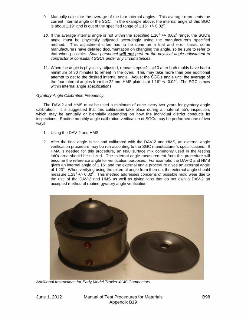
June 1, 2012 Manual of Test Procedures for Materials B98 Appendix B19
9. Manually calculate the average of the four internal angles. This average represents the current internal angle of the SGC. In the example above, the internal angle of this SGC is about 1.19
o and is out of the specified range of 1.16
o +/- 0.02
o.
10. If the average internal angle is not within the specified 1.16
o +/- 0.02
o range, the SGC’s
angle must be physically adjusted accordingly using the manufacturer’s specified method. This adjustment often has to be done on a trial and error basis; some manufacturers have detailed documentation on changing the angle, so be sure to refer to that when possible. State personnel will not perform the physical angle adjustment to contractor or consultant SGCs under any circumstances.
11. When the angle is physically adjusted, repeat steps #2 – #10 after both molds have had a
minimum of 30 minutes to reheat in the oven. This may take more than one additional attempt to get to the desired internal angle. Adjust the SGC’s angle until the average of the four internal angles from the 22 mm HMS plate is at 1.16
o +/- 0.02
o. The SGC is now
within internal angle specifications. Gyratory Angle Calibration Frequency
The DAV-2 and HMS must be used a minimum of once every two years for gyratory angle calibration. It is suggested that this calibration take place during a material lab’s inspection, which may be annually or biennially depending on how the individual district conducts its inspections. Routine monthly angle calibration verification of SGCs may be performed one of two ways:
1. Using the DAV-2 and HMS. 2. After the final angle is set and calibrated with the DAV-2 and HMS, an external angle
verification procedure may be run according to the SGC manufacturer’s specifications. If HMA is needed for this procedure, an N90 surface mix commonly used in the testing lab’s area should be utilized. The external angle measurement from this procedure will become the reference angle for verification purposes. For example: the DAV-2 and HMS gives an internal angle of 1.16
o and the external angle procedure gives an external angle
of 1.23o. When verifying using the external angle from then on, the external angle should
measure 1.23o +/- 0.02
o. This method addresses concerns of possible mold wear due to
the use of the DAV-2 and HMS as well as giving labs that do not own a DAV-2 an accepted method of routine gyratory angle verification.
Additional Instructions for Early Model Troxler 4140 Compactors

June 1, 2012 Manual of Test Procedures for Materials B99 Appendix B19
When mixless testing was first introduced, intermittent problems with consistency and reproducibility were noted during testing with some older Troxler 4140 compactors. It was later discovered that some early model 4140s (those with the sample chamber door that moves up and down) act in an unfriendly way when the DAV-2 and the HMS are used. It seems the load cell cannot react fast enough to reduce pressure when the ram head initially contacts the DAV-2 and HMS. This triggers an error in the load cell which essentially causes the compactor to apply excessive pressure; values as high as 1300 kPa have been recorded. This excessive pressure causes the internal angles drop significantly, often below 1.00
o, making them unusable for
calibration. Fortunately, this effect can be bypassed by using the alternate manual start procedure that follows:
1. Start data collection in the DAV-2. Load the DAV-2 and HMS into the mold, and place in the SGC sample chamber.
2. Hit the “MENU” button on the keypad. Hit “2” to adjust the maximum pressure setting. Type “200”, then hit the “ENTER” key to input the value. Hit the “ESC” key to exit the menu.
3. Hit the manual “RAM DOWN” key on the keypad.
4. When the ram reaches ~130 mm, hit the “ESC” key to stop the ram. Make sure the ram head and collar are seated squarely in the top of the mold, with the pin on the collar fully down into the notch on the top of the mold.
5. Hit the “ANGLE ON” key to induce the angle. Be sure that the angle stop block (inside the compactor) fully engages. Hit the “ESC” key after the tray stops rotating.
6. Hit the “RAM DOWN” key. The ram will travel down and contact the DAV-2 and HMS. Hit the “ESC” key when the ram has stopped completely.
7. Hit the “MENU” button on the keypad. Hit “2” to adjust maximum pressure setting. Type
“600”, then hit the “ENTER” key to input the value. Hit the “ESC” key to exit the menu. 8. Hit the “START” button to use automatic compaction to complete the rest of the internal
angle measurement.
9. Confirm that this procedure was effective by watching the end of the stepper motor shaft (illustration to the left) just above the sample chamber. When the compactor is gyrating, the end of the shaft should move clockwise and counterclockwise as much as one quarter of a turn as the pressure increases and decreases to adjust for the simulated loading that the HMS induces. Drawing a line on the end of the stepper motor shaft with a marker makes observing this motion easier. Enabling the pressure data collection feature on the compactor will also verify that the pressure is correct and will give a printout of pressure per gyration.
10. Repeat this procedure for each subsequent
internal angle measurement. Annual DAV-2 Calibration Verification Calibration verification on the DAV-2 units
will be performed by BMPR annually. The units are to be sent to the Central Bureau HMA Lab in
June 1, 2012 Manual of Test Procedures for Materials B100 Appendix B19
the late fall or early winter after the construction season ends. The calibration verification will be performed and the units will be returned to the districts in time for winter mix design verifications and lab inspections. Hints and Tips
1. Keep the DAV-2, the ram head, and the molds being used as clean as possible. Any debris on the bottom (or top) plate of the mold or on the ram head will have an effect on the angle when the bottom of the DAV-2 contacts it. A quick spray of WD-40 and a wipe down with a rag on the inside of the mold, the plate(s), and the ram head will ensure good angle data.
2. According to the DAV-2 manufacturer, mold temperature is important to collecting useful
angle data. After two runs with the DAV-2 and HMS at 25 gyrations (i.e. one bottom and one top), the mold will have cooled enough that it could affect angle data. This is the reason for using two molds for calibration as outlined in previous pages.
3. While the standard hydraulic jack set up may be used for extruding the DAV-2 and other
contents from the mold after testing, there is a more efficient way using Marshall molds. Start with a base plate, followed by a collar, then a mold, then another collar; then place your gyratory mold (with base plate) over the stack. This will give you enough height on most SGC molds to bring the gyratory mold base plate to the upper lip of the gyratory mold without coming out. Another Marshall base plate may be added to the top of the stack to give a little more height for taller gyratory molds (Troxler 4141, Pine compactors). This stack is also helpful in loading the DAV-2 into the mold without having to drop it down into the mold. Experiment to find the best setup to work with different models of SGCs.
4. Some early model Troxler 4140s have been noted to release the angle when the HMS is
used. This is attributed to a worn main bearing in the compactor. This causes the angle stop block inside the compactor to start moving away from the fixed angle screw block that is supposed to be “pushing” it to keep the angle “on”. As the angle stop block moves farther away from the fixed angle screw block, the angle is reduced. This is seen mostly when using the 25.8 mm HMS plate or when the SGC exhibits excessive pressure. This issue shouldn’t be a problem when calibrating with the 22 mm HMS plate at 600 kPa (using the alternate manual start procedure), but it is good to be aware of the potential for this problem. A symptom of a worn main bearing can be observed during compaction of hot mix when the angle stop block inside the compactor “chatters” (causing a rapping noise) and can physically be seen moving a little bit during gyration. It seems to not be a problem when compacting hot mix as the angle will stay engaged despite the “chattering”, but this can pose a problem with HMS testing. While not recommended, the following technique has been used as a way to continue testing until the main bearing could be replaced. To physically keep the angle block engaged, a shop rag was first folded in half twice. When the compactor induced the angle, the protruding collar inside the compactor was gripped with the rag. Pressure was then applied in the opposite direction of gyration. This held the angle block in place and kept the angle “on”.
5. When calibrating the angle on a contractor or consultant’s SGC, be sure to let their
personnel perform the physical angle adjustments when they are needed. This way the state is not held liable for any mechanical problems that may occur afterwards.
Illinois Department of Transportation
QC/QA Document Segregation Control of Hot-Mix Asphalt
Appendix B20
Effective: May 1, 2007
June 1, 2012 Manual of Test Procedures for Materials B101 Appendix B20
1.0 SCOPE 1.1 This work shall consist of the visual identification and corrective action to
prevent and/or correct segregation of hot-mix asphalt. 2.0 DEFINITIONS 2.1 Segregation. Areas of non-uniform distribution of coarse and fine aggregate
particles in a hot-mix asphalt pavement. 2.2 End-of-Load Segregation. A systematic form of segregation typically identified
by chevron-shaped segregated areas at either side of a lane of pavement, corresponding with the beginning and end of truck loads.
2.3 Longitudinal Segregation. A linear pattern of segregation that usually
corresponds to a specific area of the paver. 2.4 Severity of Segregation. 2.4.1 Low. A pattern of segregation where the mastic is in place between the
aggregate particles; however, there is slightly more coarse aggregate in comparison with the surrounding acceptable mat.
2.4.2 Medium. A pattern of segregation that has significantly more coarse
aggregate in comparison with the surrounding acceptable mat and which exhibits some lack of mastic.
2.4.3 High. A pattern of segregation what has significantly more coarse
aggregate in comparison with the surrounding acceptable mat and which contains little mastic.
3.0 PROCEDURE 3.1 When medium or high segregation of the mixture is identified by the Contractor,
the Engineer, or the daily evaluation, the following specific corrective actions shall be taken as soon as possible. The corrective actions shall be reported to the Engineer before the next day’s paving proceeds.
3.1.1 End of Load Segregation. When medium or high end of load segregation is
identified, the following actions as a minimum shall be taken.

Illinois Department of Transportation
QC/QA Document Segregation Control of Hot-Mix Asphalt
Appendix B20 (continued)
Effective: May 1, 2007
June 1, 2012 Manual of Test Procedures for Materials B102 Appendix B20
3.1.1.1 Trucks transporting the mixture shall be loaded in multiple dumps. The first against the front wall of the truck bed and the second against the tailgate in a manner which prevents the coarse aggregate from migrating to those locations.
3.1.1.2 The paver shall be operated so the hopper is never below 30
percent capacity between truck exchanges.
3.1.1.3 The “Head of Material” in the auger area shall be controlled to keep a constant level, with a 1 inch +25 mm tolerance.
3.1.2 Longitudinal Segregation. When medium or high longitudinal segregation is
identified, the Contractor shall make the necessary adjustment to the slats, augers or screeds to eliminate the segregation.
3.2 When the corrective actions initiated by the Contractor are insufficient in
controlling medium or high segregation, the Contractor and Engineer will investigate to determine the cause of the segregation.
When an investigation indicates additional corrective action is warranted, the
Contractor shall implement operational changes necessary to correct the segregation problems.
Any verification testing necessary for the investigation will be performed by the
Department according to the applicable project test procedures and specification limits.
3.3 The District Construction Engineer will represent the Department in any dispute
regarding the application of this procedure.
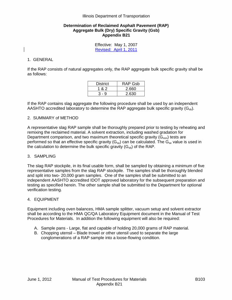
Illinois Department of Transportation
Determination of Reclaimed Asphalt Pavement (RAP) Aggregate Bulk (Dry) Specific Gravity (Gsb)
Appendix B21
Effective: May 1, 2007 Revised: April 1, 2011
June 1, 2012 Manual of Test Procedures for Materials B103 Appendix B21
1. GENERAL If the RAP consists of natural aggregates only, the RAP aggregate bulk specific gravity shall be as follows:
District RAP Gsb
1 & 2 2.660
3 - 9 2.630
If the RAP contains slag aggregate the following procedure shall be used by an independent AASHTO accredited laboratory to determine the RAP aggregate bulk specific gravity (Gsb). 2. SUMMARY of METHOD A representative slag RAP sample shall be thoroughly prepared prior to testing by reheating and remixing the reclaimed material. A solvent extraction, including washed gradation for Department comparison, and two maximum theoretical specific gravity (Gmm) tests are performed so that an effective specific gravity (Gse) can be calculated. The Gse value is used in the calculation to determine the bulk specific gravity (Gsb) of the RAP. 3. SAMPLING The slag RAP stockpile, in its final usable form, shall be sampled by obtaining a minimum of five representative samples from the slag RAP stockpile. The samples shall be thoroughly blended and split into two- 20,000 gram samples. One of the samples shall be submitted to an independent AASHTO accredited IDOT approved laboratory for the subsequent preparation and testing as specified herein. The other sample shall be submitted to the Department for optional verification testing. 4. EQUIPMENT Equipment including oven balances, HMA sample splitter, vacuum setup and solvent extractor shall be according to the HMA QC/QA Laboratory Equipment document in the Manual of Test Procedures for Materials. In addition the following equipment will also be required:
A. Sample pans - Large, flat and capable of holding 20,000 grams of RAP material. B. Chopping utensil – Blade trowel or other utensil used to separate the large
conglomerations of a RAP sample into a loose-flowing condition.

Illinois Department of Transportation
Determination of Reclaimed Asphalt Pavement (RAP) Aggregate Bulk (Dry) Specific Gravity (Gsb)
Appendix B21 (continued)
Effective: May 1, 2007 Revised: April 1, 2011
June 1, 2012 Manual of Test Procedures for Materials B104 Appendix B21
5. RAP SAMPLE PREPARATIONS
A. Transfer the entire 20,000 gram sample into a large flat pan(s). B. Place sample into a preheated oven at 230 ± 9° F. (110 ± 5° C.) and heat for 30 to 45
minutes. C. Remove the sample from the oven and begin breaking up the larger conglomerations of
RAP with the chopping utensil. D. As the material begins to soften, blend the heated RAP by mixing the freshly chopped
material with the fines in the pan. E. Return the RAP into the oven and continue heating for another 15 - 20 minutes. F. Remove the RAP from the oven and repeat the chopping of the conglomerations and
blending of the fines until the RAP sample is homogeneous and conglomerations of fine aggregate complies with Illinois Modified AASHTO T-209.
G. Place the loose RAP into a hopper or pan and uniformly pour it through a riffle splitter. Take each of the halves and re-pour through the splitter. Thoroughly blend the sample by repeating this process 2 - 3 times.
6. TESTING
A. Percent Asphalt Binder Pb: 1. Split out a 1,500 - 2,000 gram prepared RAP sample. 2. Dry the RAP sample to a constant weight in an oven at 230 ± 9° F. (110 ± 5° C.). 3. Determine the Pb of the dried RAP sample according to Illinois Modified T 164.
Record the Pb.
B. Maximum Specific Gravity determination, Gmm: 1. Split out one 3,000 gram prepared RAP sample. 2. Dry the sample to a constant weight in an oven at 230 ±9° F. (110 ± 5° C.) While
drying, chop and break up the sample as you would with a standard Gmm sample. Record as “dry RAP mass”.
3. Place the sample in 295° ± 5° F. (146° ± 3° C.) oven for one hour. 4. Add 1.5 percent virgin asphalt binder (PG64-22 or PG58-22) at 295° ± 5° F. (146° ±
3° C.), based on the “dry RAP mass” from step 6.B.2, to the RAP and thoroughly mix at 295° ± 5° F. (146° ± 3° C.) to ensure uniform coating of all particles.
5. Split sample into two equal samples. 6. Determine the Gmm of the prepared RAP samples according to Illinois Modified
AASHTO T209. 7. Calculate the individual Gmm values. The average result will be used in the
calculation provided the individual results do not vary by more than 0.011. If the individual results vary more than 0.011, repeat steps in 6.B., discard the high and low values and average the remaining individual results provided they do not vary more than 0.011. If remaining individual results vary more than 0.011 repeat steps in 6.B. until individual results compare within 0.011.

Illinois Department of Transportation
Determination of Reclaimed Asphalt Pavement (RAP) Aggregate Bulk (Dry) Specific Gravity (Gsb)
Appendix B21 (continued)
Effective: May 1, 2007 Revised: April 1, 2011
June 1, 2012 Manual of Test Procedures for Materials B105 Appendix B21
7. CALCULATIONS
A. Calculate the “adjusted Pb” of the RAP to account for the addition of the 1.5 percent virgin asphalt binder as follows: 1. Calculate “mass of RAP Asphalt Cement (AC)”:
Mass of RAP AC = 100
bPmassRAPDry
2. Calculate “mass of virgin AC added”:
Mass of virgin AC added = 0.015 x Dry RAP mass
3. Determine “New RAP mass”: New RAP mass = Dry RAP mass + Mass of virgin AC added 4. Calculate “Adjusted Pb”:
Adjusted Pb = MassRAPNew
addedACvirginofMassACRAPofMass x 100
B. Calculate the effective specific gravity (Gse) of the RAP:
Gse (RAP) =
040.1
100
)100(
b
mm
b
PAdjusted
G
PAdjusted
C. Calculate the stone bulk gravity (Gsb) of the RAP:
Gsb (RAP) = Gse (RAP) – 0.100 Example w/ 1.5% virgin asphalt binder added:
Dry RAP mass = 3,000 g
Pb, (% AC) in RAP = 4.9%
Determine “mass of RAP AC”:
- Mass of RAP AC = Dry RAP mass x (Pb / 100) = 3,000 x (4.9% / 100) = 147 grams

Illinois Department of Transportation
Determination of Reclaimed Asphalt Pavement (RAP) Aggregate Bulk (Dry) Specific Gravity (Gsb)
Appendix B21 (continued)
Effective: May 1, 2007 Revised: April 1, 2011
June 1, 2012 Manual of Test Procedures for Materials B106 Appendix B21
Add 1.5 percent virgin AC: - Determine “mass of virgin AC added”:
Mass of virgin AC added = 0.015 x Dry RAP mass
= 0.015 x 3,000 grams = 45 grams
- Determine “New RAP mass”:
New RAP mass = Dry RAP mass + Mass of virgin AC added = 3,000 + 45 = 3,045 grams
Calculate “Adjusted Pb”:
Adjusted Pb = MassRAPNew
addedACvirginofMassACRAPofMass x 100
= grams
gramsgrams
045,3
45147 x100 = 6.3%
Calculate Gse:
04.1
100
100
b
mm
bse P
G
PG
=
04.1
3.6
505.2
100
3.6100
=
1.69.39
7.93
= 2.772
Adjusted Pb = 6.3% Rice Test, Gmm = 2.505
Calculate Slag RAP Gsb:
672.210.0772.210.0 sesb GG
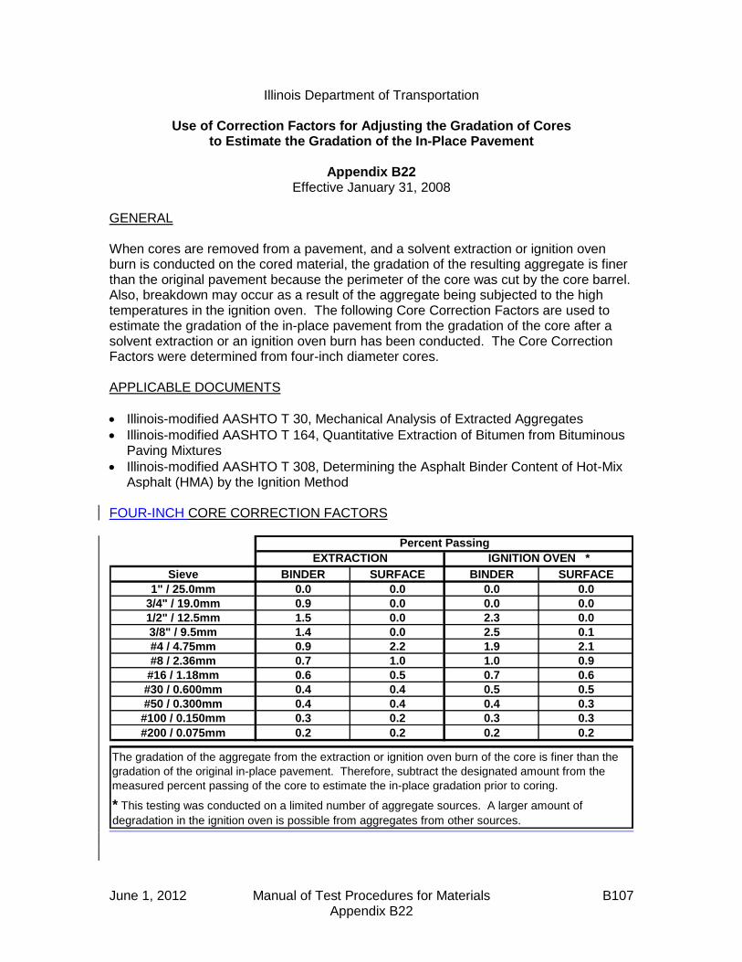
June 1, 2012 Manual of Test Procedures for Materials B107 Appendix B22
Illinois Department of Transportation
Use of Correction Factors for Adjusting the Gradation of Cores to Estimate the Gradation of the In-Place Pavement
Appendix B22
Effective January 31, 2008 GENERAL When cores are removed from a pavement, and a solvent extraction or ignition oven burn is conducted on the cored material, the gradation of the resulting aggregate is finer than the original pavement because the perimeter of the core was cut by the core barrel. Also, breakdown may occur as a result of the aggregate being subjected to the high temperatures in the ignition oven. The following Core Correction Factors are used to estimate the gradation of the in-place pavement from the gradation of the core after a solvent extraction or an ignition oven burn has been conducted. The Core Correction Factors were determined from four-inch diameter cores. APPLICABLE DOCUMENTS
Illinois-modified AASHTO T 30, Mechanical Analysis of Extracted Aggregates
Illinois-modified AASHTO T 164, Quantitative Extraction of Bitumen from Bituminous Paving Mixtures
Illinois-modified AASHTO T 308, Determining the Asphalt Binder Content of Hot-Mix Asphalt (HMA) by the Ignition Method
FOUR-INCH CORE CORRECTION FACTORS
Sieve BINDER SURFACE BINDER SURFACE
1" / 25.0mm 0.0 0.0 0.0 0.0
3/4" / 19.0mm 0.9 0.0 0.0 0.0
1/2" / 12.5mm 1.5 0.0 2.3 0.0
3/8" / 9.5mm 1.4 0.0 2.5 0.1
#4 / 4.75mm 0.9 2.2 1.9 2.1
#8 / 2.36mm 0.7 1.0 1.0 0.9
#16 / 1.18mm 0.6 0.5 0.7 0.6
#30 / 0.600mm 0.4 0.4 0.5 0.5
#50 / 0.300mm 0.4 0.4 0.4 0.3
#100 / 0.150mm 0.3 0.2 0.3 0.3
#200 / 0.075mm 0.2 0.2 0.2 0.2
* This testing was conducted on a limited number of aggregate sources. A larger amount of
degradation in the ignition oven is possible from aggregates from other sources.
The gradation of the aggregate from the extraction or ignition oven burn of the core is finer than the
gradation of the original in-place pavement. Therefore, subtract the designated amount from the
measured percent passing of the core to estimate the in-place gradation prior to coring.
EXTRACTION IGNITION OVEN *
Percent Passing
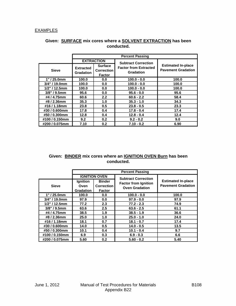
June 1, 2012 Manual of Test Procedures for Materials B108 Appendix B22
EXAMPLES
SieveExtracted
Gradation
Surface
Correction
Factor
1" / 25.0mm 100.0 0.0 100.0 - 0.0 100.0
3/4" / 19.0mm 100.0 0.0 100.0 - 0.0 100.0
1/2" / 12.5mm 100.0 0.0 100.0 - 0.0 100.0
3/8" / 9.5mm 95.6 0.0 95.6 - 0.0 95.6
#4 / 4.75mm 60.6 2.2 60.6 - 2.2 58.4
#8 / 2.36mm 35.3 1.0 35.3 - 1.0 34.3
#16 / 1.18mm 23.8 0.5 23.8 - 0.5 23.3
#30 / 0.600mm 17.8 0.4 17.8 - 0.4 17.4
#50 / 0.300mm 12.8 0.4 12.8 - 0.4 12.4
#100 / 0.150mm 9.2 0.2 9.2 - 0.2 9.0
#200 / 0.075mm 7.10 0.2 7.10 - 0.2 6.90
Sieve
Ignition
Oven
Gradation
Binder
Correction
Factor
1" / 25.0mm 100.0 0.0 100.0 - 0.0 100.0
3/4" / 19.0mm 97.9 0.0 97.9 - 0.0 97.9
1/2" / 12.5mm 77.2 2.3 77.2 - 2.3 74.9
3/8" / 9.5mm 63.6 2.5 63.6 - 2.5 61.1
#4 / 4.75mm 38.5 1.9 38.5 - 1.9 36.6
#8 / 2.36mm 25.0 1.0 25.0 - 1.0 24.0
#16 / 1.18mm 18.1 0.7 18.1 - 0.7 17.4
#30 / 0.600mm 14.0 0.5 14.0 - 0.5 13.5
#50 / 0.300mm 10.1 0.4 10.1 - 0.4 9.7
#100 / 0.150mm 6.9 0.3 6.9 - 0.3 6.6
#200 / 0.075mm 5.60 0.2 5.60 - 0.2 5.40
Percent Passing
IGNITION OVEN
Subtract Correction
Factor from Extracted
Gradation
Estimated In-place
Pavement Gradation
Given: BINDER mix cores where an IGNITION OVEN Burn has been
conducted.
Subtract Correction
Factor from Ignition
Oven Gradation
Estimated In-place
Pavement Gradation
EXTRACTION
Percent Passing
Given: SURFACE mix cores where a SOLVENT EXTRACTION has been
conducted.

Illinois Department of Transportation
Off-Site Preliminary Test Strip and Modified Start-Up Procedures Appendix B23
June 1, 2012 Manual of Test Procedures for Materials B109 Appendix B23
Effective Date: April 1, 2010 When required, an off-site preliminary test strip and modified start-up shall be performed as follows:
(a) Team Members. The start-up team, if required, shall consist of the following: (1) Resident Engineer (2) District Construction Supervising Field Engineer, or representative (3) District Materials Mixtures Control Engineer, or representative (4) District Nuclear Density Gauge Tester (5) Contractor's QC Manager (6) Bureau of Materials and Physical Research representative (7) Bureau of Construction representative (8) Contractor's Density Tester (9) Asphalt Binder Supplier representative
(b) Communication. The Contractor shall advise the team members of the anticipated start
time of production for both the off-site preliminary test strip and subsequent modified start-up for both the surface and binder courses. The QC Manager shall direct the activities of the start-up team. A Department-appointed representative from the start-up team will act as spokesperson for the Department.
(c) Off-site Preliminary Test Strip. The off-site preliminary test strip shall consist of 272 metric tons (300 tons). It shall contain two growth curves which shall be tested as outlined herein. (1) Mix and Gradation Test Strip Samples. The first and second sets of mixture and
gradation samples shall be taken by the Contractor at such times as to represent the mixture of the two growth curves, respectively. All off-site preliminary test strip samples shall be processed by the Contractor for determination of mixture composition and air voids. This shall include washed ignition gradation and asphalt content test results. This information shall then be compared to the JMF and required design criteria.
(2) Compaction Equipment. It shall be the responsibility of the QC manager to verify
roller compliance before commencement of growth curve construction. All rolling equipment intended for use on a project shall be utilized on the off-site preliminary test strip.

Illinois Department of Transportation
Off-Site Preliminary Test Strip and Modified Start-Up Procedures Appendix B23
(continued)
June 1, 2012 Manual of Test Procedures for Materials B110 Appendix B23
(3) Constructing the Off-site Preliminary Test Strip. After the Contractor has produced
the mix, transported the mix, and placed approximately 90 to 140 metric tons (100 to 150 tons) of mix, placement of the mix shall stop, and a growth curve shall be constructed. After completion of the first growth curve, paving shall resume for 45 to 90 metric tons (50 to 100 tons) of mix, placement shall stop, and the second growth curve shall be constructed within this area. Additional growth curves may be required if an adjustment/plant change is made during the off-site preliminary test strip. The Contractor shall use the specified rolling procedures for all portions of the test strip except for the growth curve areas which shall be compacted as directed by the QC Manager.
(4) Location of Off-site Preliminary Test Strip. The off-site preliminary test strip shall be located on a pavement type similar to the contract pavement and acceptable to the Engineer. It shall be on a relatively flat portion of the roadway.
(5) Compaction Temperature. In order to make an accurate analysis of the density potential of the mixture, the temperature of the mixture on the pavement at the beginning of the growth curve shall be not less than the minimum mixture placement temperature specified herein. The mat temperature, at the location of the each growth curve, shall be monitored throughout the construction of each growth curve.
(6) Compaction and Testing. The QC manager shall specify the roller(s) speed and number of passes required to obtain a completed growth curve. The nuclear gauge shall be placed near the center of the hot mat and the position marked for future reference. With the bottom of the nuclear gauge and the source rod clean, a one-minute nuclear reading (without mineral filler) shall be taken after each pass of the roller. Rolling shall continue until the maximum density is achieved and three consecutive passes show no appreciable increase in density or no evidence of destruction of the mat. The growth curve shall be plotted. No testing of initial passes shall be taken until the third pass is completed.
(7) Final Testing. After the growth curve information is obtained, a final nuclear reading, using mineral filler to eliminate surface voids, shall be taken at the marked position. This reading is used to adjust the maximum density reading obtained during the growth curve.
(8) Evaluation of Growth Curves. Mixtures which exhibit density potential outside of the specified density range shall be considered as sufficient cause for mix adjustment. If a mix adjustment is made, an additional test strip may be constructed, and associated tests shall be performed. This information shall then be compared to the AJMF and required design criteria. If the density potential of the mixture not meet the minimum specified, the operation shall cease until all test data is analyzed or a new mix design is produced. In addition, other aspects of the mixture, such as appearance, segregation, texture, or other evidence of mix problems, should be noted and corrective action taken at this time.

Illinois Department of Transportation
Off-Site Preliminary Test Strip and Modified Start-Up Procedures Appendix B23
(continued)
June 1, 2012 Manual of Test Procedures for Materials B111 Appendix B23
(d) Documentation. All off-site preliminary test strip, modified start-up, and rolling pattern
information (including growth curves) will be tabulated by the QC manager with copies provided to each team member, and the original retained in the project files. Any changes to the rolling pattern shall be by the Contractor and the Engineer and recorded.
(e) Modified Start-Up. At the start of placement on the jobsite, the Contractor shall construct
a growth curve in between the first 90 to 140 metric tons (100 to 150 tons) for the purposes of evaluating the properties of the mixture and ensuring that the established rolling pattern was valid. The placement shall stop until the growth curve has been evaluated. A hot-bin or a combined aggregate belt sample and a mix sample representative of the growth curve shall be obtained and tested expediently for determination of mix composition and air voids. This information shall then be compared to the preliminary test strip data. If the growth curve and visual evaluation of the mix are satisfactory, the placement may be resumed. If the growth curve and visual evaluation of the mix are unsatisfactory, placement shall remain on hold until the plant samples are completed and reviewed by the QC Manager and the Engineer. If agreed by the Engineer, the Contractor shall make appropriate adjustments, resample and retest, construct another growth curve, and evaluate the mixture. This procedure will be followed until satisfactory test results are obtained.

June 1, 2012 Manual of Test Procedures for Materials B112 Appendix B23
This Page Reserved

SEQUENTIAL TABLE OF CONTENTS (continued)
MANUAL OF TEST PROCEDURES FOR MATERIALS
June 1, 2012 Manual of Test Procedures for Materials
E – End Result Specification Appendix E1
(Effective 04/01/10)
PFP Quality Level Analysis ...................................... E 1
Appendix E2 (Effective 05/01/08)
PFP Hot-Mix Asphalt Random Plant Samples ......... E13
Appendix E3 (Effective 04/01/10) (Revised 04/01/12)
PFP Random Density Procedure ............................. E19
Appendix E4 (Effective 04/01/11) (Revised 04/01/12)
PFP Hot Mix Asphalt Random Jobsite Sampling ..... E23
Appendix E5 (Effective 04/01/10)
PFP Dispute Resolution Instructions ....................... E35
Appendix E6 (Effective 01/01/12)
QCP Pay Calculation ............................................... E37
Appendix E7 (Effective 04/01/12)
Best Practices for PFP and QCP Implementation .... E43
Illinois Department of Transportation
PFP Quality Level Analysis Appendix E1
Effective: December 12, 2003
Revised: April 1, 2010
June 1, 2012 Manual of Test Procedures for Materials E1 Appendix E1
This stand-alone document explains the statistical analysis and procedure used to determine the pay factor for a hot-mix asphalt (HMA) mixture on Pay for Performance (PFP) project. HMA materials specified to be sampled and tested for percent within limits payment adjustment (voids, VMA, and in-place density) and dust/AC adjustments will be evaluated for acceptance in accordance with this document. Pay parameters evaluated using percent within (PWL) limits will be analyzed collectively and statistically by the Quality Level Analysis method using the procedures listed to determine the total estimated percent of the lot that is within specification limits. Quality Level Analysis is a statistical procedure for estimating the percent compliance to a specification and is affected by shifts in the arithmetic mean and the sample standard deviation. Two measures of quality are required to establish the contract unit price adjustment. The first measure is the Acceptable Quality Level (AQL) which is the PWL at which the lot will receive 100 percent pay. The second measure of quality is the Rejectable Quality Level (RQL) at which the Department has determined the material may not perform as desired and may be rejected. The pay factor on full-depth projects shall be determined by weighing each mixture equally. Material placed at the same gyrations values but with and without polymer will be evaluated as two separate mixtures. For example: one surface mix and one binder mix will be weighted 50/50 regardless of tonnage. Additionally, one surface mix, one polymer binder mix and one non-polymer mix will be evaluated as three equally (1/3) weighted mixtures even if the polymer binder is the only difference between binder lifts. Pay adjustments for Dust/AC ratio will be applied using the Dust/AC Pay Adjustment Table found in the Hot Mix Asphalt Pay for Performance Using Percent within Limits special provision. QUALITY LEVEL ANALYSIS Note: Table 1: Pay Attributes and Price Adjustment Factors contain the UL, LL, and pay factor
“f” weights.
Items 1 through 8 of the following procedure will be repeated for each lot of the various pay factor parameters. (1) Determine the arithmetic mean ( x ) of the test results:
x = n
x
Where:
= summation of
x = individual test value n = total number of test values

Illinois Department of Transportation
PFP Quality Level Analysis Appendix E1 (continued)
Effective: December 12, 2003
Revised: April 1, 2010
June 1, 2012 Manual of Test Procedures for Materials E2 Appendix E1
(2) Calculate the sample standard deviation (s): s = Where:
)( 2x = summation of the squares of individual test values
2)( x = summation of the individual test values squared
(3) Calculate the upper quality index (QU):
QU = s
xUL
Where: UL = upper specification limit (target value (TV) plus allowable deviation) (4) Calculate the lower quality index (QL):
QL = s
LLx
Where: LL = lower specification limit(target value (TV) minus allowable deviation) (5) Determine PU (percent within the upper specification limit which corresponds to a given
QU) from Table 2. (Note: Round up to nearest QU in table 2.) Note: If a UL is not specified, PU will be 100. (6) Determine PL (percent within the lower specification limit which corresponds to a give
QL) from Table 2. (Note: Round up to nearest QL in table 2.) Note: If a LL is not specified, PL will be 100. (7) Determine the Quality Level or PWL (the total percent within specification limits). PWL = (PU + PL) – 100
(8) To determine the pay factor for each individual parameter lot: Pay Factor (PF) = 53 + 0.5 (PWL)
n S x( )2. S x( )
2
n n 1( )
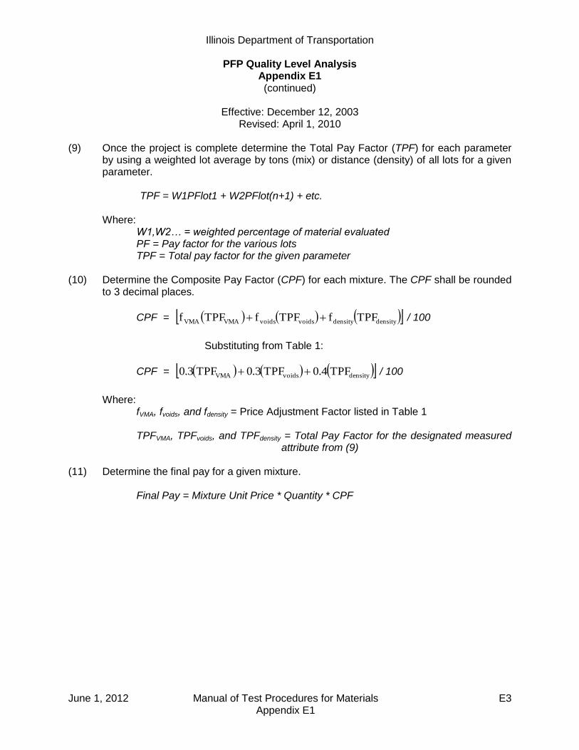
Illinois Department of Transportation
PFP Quality Level Analysis Appendix E1 (continued)
Effective: December 12, 2003
Revised: April 1, 2010
June 1, 2012 Manual of Test Procedures for Materials E3 Appendix E1
(9) Once the project is complete determine the Total Pay Factor (TPF) for each parameter by using a weighted lot average by tons (mix) or distance (density) of all lots for a given parameter. TPF = W1PFlot1 + W2PFlot(n+1) + etc. Where: W1,W2… = weighted percentage of material evaluated PF = Pay factor for the various lots TPF = Total pay factor for the given parameter
(10) Determine the Composite Pay Factor (CPF) for each mixture. The CPF shall be rounded to 3 decimal places.
CPF = densitydensityvoidsvoidsVMAVMA TPFfTPFfTPFf / 100
Substituting from Table 1:
CPF = densityvoidsVMA TPF0.4TPF0.3TPF0.3 / 100
Where: fVMA, fvoids, and fdensity = Price Adjustment Factor listed in Table 1 TPFVMA, TPFvoids, and TPFdensity = Total Pay Factor for the designated measured
attribute from (9) (11) Determine the final pay for a given mixture. Final Pay = Mixture Unit Price * Quantity * CPF
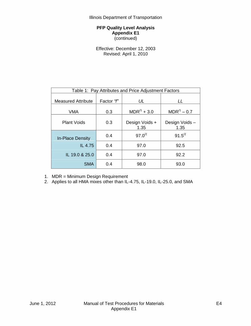
Illinois Department of Transportation
PFP Quality Level Analysis Appendix E1 (continued)
Effective: December 12, 2003
Revised: April 1, 2010
June 1, 2012 Manual of Test Procedures for Materials E4 Appendix E1
Table 1: Pay Attributes and Price Adjustment Factors
Measured Attribute
Factor “f”
UL
LL
VMA
0.3
MDR/1 + 3.0
MDR/1 – 0.7
Plant Voids
0.3
Design Voids +
1.35
Design Voids –
1.35
In-Place Density
0.4 97.0/2 91.5/2
IL 4.75 0.4 97.0 92.5
IL 19.0 & 25.0 0.4 97.0 92.2
SMA 0.4 98.0 93.0
1. MDR = Minimum Design Requirement 2. Applies to all HMA mixes other than IL-4.75, IL-19.0, IL-25.0, and SMA

Illinois Department of Transportation
PFP Quality Level Analysis Appendix E1 (continued)
Effective: December 12, 2003
Revised: April 1, 2010
June 1, 2012 Manual of Test Procedures for Materials E5 Appendix E1
Example:
Determine the Pay factor for the given lot of a N90 HMA surface being placed at 1.5 inches thick as an overlay. The project consists of 10,000 tons over 17 miles.
Note that mix sample and density lots are independent of each other.
In this example the mix sample lot represents 10,000 tons while the density lot represents 6 miles (N=30). The project would have two additional density lots following the same calculations as the first lot. All three lots are combined as per item (9).
Mix sample: Each sublot represents 1000 tons
Lot Sublot Voids VMA
# # TV = 4.0 Design Min = 14.51 4.2 14.4
2 4.5 14.7
3 3.3 13.9
4 5.0 15.0
5 5.4 15.2
6 2.5 13.5
7 3.8 14.2
8 4.1 14.3
9 4.3 14.4
10 4.5 14.6
4.16 14.42
0.825 0.498
1
Average:
Standard Deviation:
Density: Each density test interval represents 0.2 mile thus N=30 in which 5 cores are taken per mile would represent 6 miles of paving.
Lot
# Density
1 91.52 93.0
3 92.9
4 93.55 93.0
6 94.0
7 92.88 93.5
9 91.0… …
30 92.7
92.79
0.910
1
Average: Standard Deviation:
Density
Test
Interval
Determine the pay factor for each parameter.
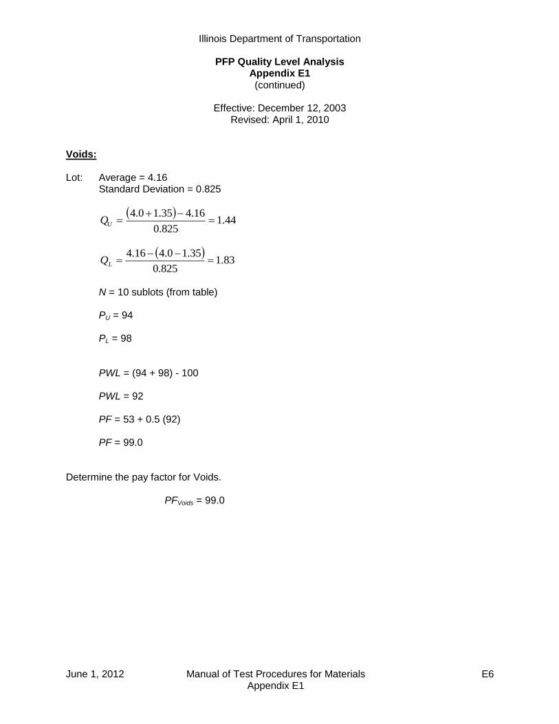
Illinois Department of Transportation
PFP Quality Level Analysis Appendix E1 (continued)
Effective: December 12, 2003
Revised: April 1, 2010
June 1, 2012 Manual of Test Procedures for Materials E6 Appendix E1
Voids:
Lot: Average = 4.16 Standard Deviation = 0.825
44.1
825.0
16.435.10.4
UQ
83.1
825.0
35.10.416.4
LQ
N = 10 sublots (from table) PU = 94 PL = 98 PWL = (94 + 98) - 100 PWL = 92 PF = 53 + 0.5 (92) PF = 99.0
Determine the pay factor for Voids.
PFVoids = 99.0

Illinois Department of Transportation
PFP Quality Level Analysis Appendix E1 (continued)
Effective: December 12, 2003
Revised: April 1, 2010
June 1, 2012 Manual of Test Procedures for Materials E7 Appendix E1
VMA:
Lot : Average = 14.42 Standard Deviation = 0.498
18.6
498.0
42.140.35.14
UQ
24.1
498.0
7.05.1442.14
LQ
N = 10 sublots (from table) PU = 100 PL = 90 PWL = (100 + 90) - 100 PWL = 90 PF = 53 + 0.5 (90) PF = 98
Determine the pay factor for VMA.
PFVMA = 98.0
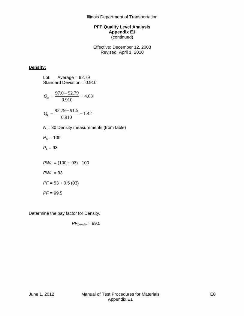
Illinois Department of Transportation
PFP Quality Level Analysis Appendix E1 (continued)
Effective: December 12, 2003
Revised: April 1, 2010
June 1, 2012 Manual of Test Procedures for Materials E8 Appendix E1
Density:
Lot: Average = 92.79
Standard Deviation = 0.910
63.4910.0
79.920.97
UQ
42.1910.0
5.9179.92
LQ
N = 30 Density measurements (from table) PU = 100 PL = 93 PWL = (100 + 93) - 100 PWL = 93 PF = 53 + 0.5 (93) PF = 99.5
Determine the pay factor for Density. PFDensity = 99.5

Illinois Department of Transportation
PFP Quality Level Analysis Appendix E1 (continued)
Effective: December 12, 2003
Revised: April 1, 2010
June 1, 2012 Manual of Test Procedures for Materials E9 Appendix E1
Determine the total pay factors for each parameter. In this example 10,000 tons of mix represents the entire project so only one lot exists for VMA and voids. If more mix lots occurred on a project they would be combined just like density as shown.
Lot # Mix Tons Void PF VMA PF Density Distance Density PF
1 10,000 99.0 98.0 31680 ft 99.5
2 31680 ft 101.4
3 24640 ft 97.3
TPF 99.0 98.0 88000 ft 99.6
TPFDensity= W1PFlot1 + W2PFlot2 + W3PFlot3 TPFDensity= (31680/88000)(99.5)+(31680/88000)(101.4)+(24640/88000)(97.3) TPFDensity= 99.6 Combine the three Total Pay Factors to determine the Composite Pay Factor for the mix.
CPF = [0.3(99.0) + 0.3(98.0) + 0.4(99.6)] / 100 CPF = 0.989
Determine the price paid for the given mixture.
Given that the mixture bid price per ton = $65.00 and 10,000 tons were placed.
Plan Unit Pay = $65.00/ton * 10,000 tons = $650,000
Adjusted Pay = $65.00/ ton * 10,000 tons * 0.989 = $642,850 Determine the difference between the adjusted pay and the plan unit pay. Adjusted pay – Plan Unit Pay = $642,850 – $650,000 = - $7,150 If the difference is a positive value this will be the incentive paid. If the difference is a negative value this will be the disincentive paid. In this case a $7,150 disincentive would be paid as per policy memorandum 9-4.

Illinois Department of Transportation
PFP Quality Level Analysis Appendix E1 (continued)
Effective: December 12, 2003
Revised: April 1, 2010
June 1, 2012 Manual of Test Procedures for Materials E10 Appendix E1
Full Depth Examples:
Given a full-depth project with two mixtures whose combined pay factors were determined to be 101.5% and 99.2%. The full-depth pay factor shall be calculated as follows:
101.5(1/2) + 99.2(1/2) = 100.4%
Determine the adjusted pay for the full-depth pay factor.
Given that the bid price per square yard = $25.00 and 1400 yd2 were placed. Plan Unit Pay = $25.00/ yd2 * 1400 yd2 = $35,000 Adjusted Pay = $25.00/ yd2 * 1400 yd2 * 1.004 = $35,140 Difference = $35,140 – $35,000 = $140 (Positive value = Incentive)
Given a full-depth project with three mixtures whose pay factors were determined to be 98.9%, 101.5% and 99.2%. The full depth pay factor shall be calculated as follows:
98.9(1/3) + 101.5(1/3) + 99.2(1/3) = 99.9%
Determine the adjusted pay for the full-depth pay factor.
Given that the bid price per square yard = $25.00 and 1400 yd2 were placed. Plan Unit Pay = $25.00/ yd2 * 1400 yd2 = $35,000 Adjusted Pay = $25.00/ yd2 * 1400 yd2 * 0.999 = $34,965 Difference = $34,965 – $35,000 = -$35 (Negative = Disincentive)
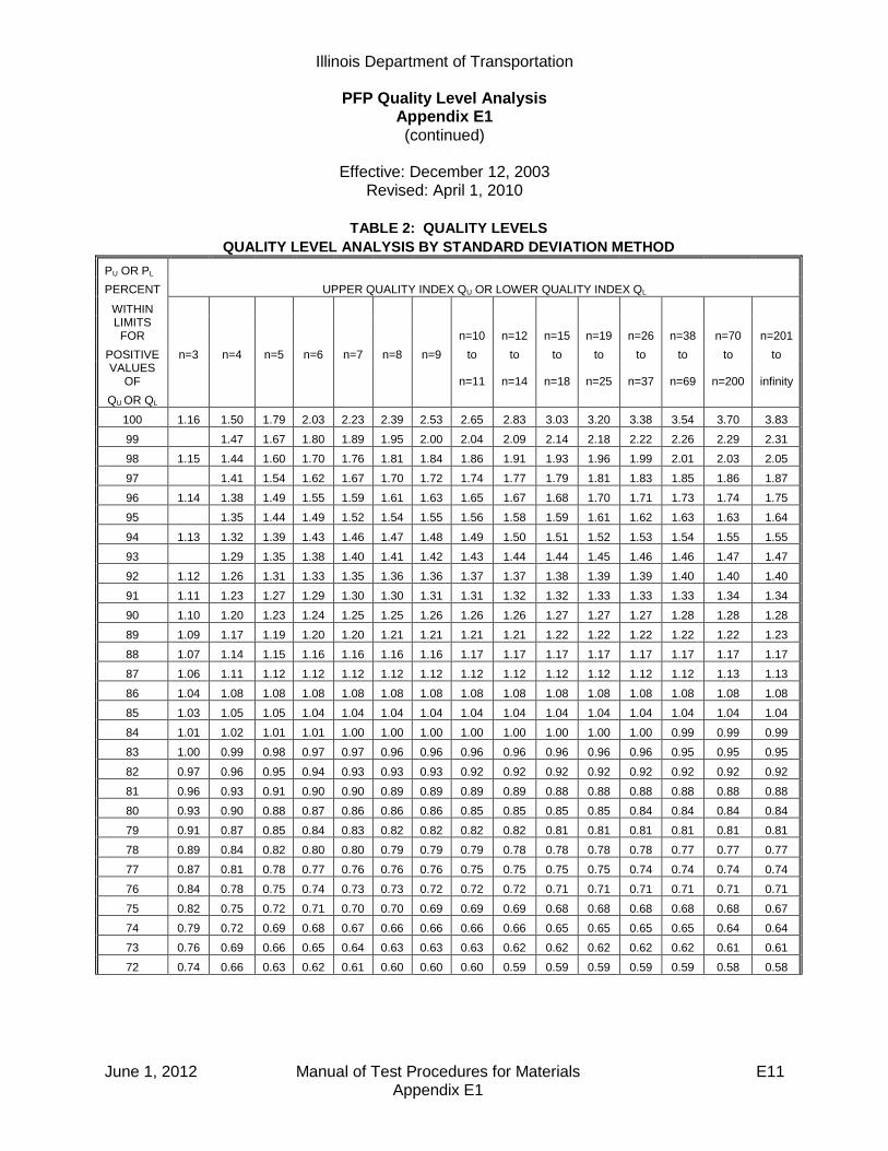
Illinois Department of Transportation
PFP Quality Level Analysis Appendix E1 (continued)
Effective: December 12, 2003
Revised: April 1, 2010
June 1, 2012 Manual of Test Procedures for Materials E11 Appendix E1
TABLE 2: QUALITY LEVELS
QUALITY LEVEL ANALYSIS BY STANDARD DEVIATION METHOD
PU OR PL
PERCENT UPPER QUALITY INDEX QU OR LOWER QUALITY INDEX QL
WITHIN
LIMITS FOR
n=10 n=12 n=15 n=19 n=26 n=38 n=70 n=201
POSITIVE n=3 n=4 n=5 n=6 n=7 n=8 n=9 to to to to to to to to VALUES
OF
n=11 n=14 n=18 n=25 n=37 n=69 n=200 infinity
QU OR QL
100 1.16 1.50 1.79 2.03 2.23 2.39 2.53 2.65 2.83 3.03 3.20 3.38 3.54 3.70 3.83
99 1.47 1.67 1.80 1.89 1.95 2.00 2.04 2.09 2.14 2.18 2.22 2.26 2.29 2.31
98 1.15 1.44 1.60 1.70 1.76 1.81 1.84 1.86 1.91 1.93 1.96 1.99 2.01 2.03 2.05
97 1.41 1.54 1.62 1.67 1.70 1.72 1.74 1.77 1.79 1.81 1.83 1.85 1.86 1.87
96 1.14 1.38 1.49 1.55 1.59 1.61 1.63 1.65 1.67 1.68 1.70 1.71 1.73 1.74 1.75
95 1.35 1.44 1.49 1.52 1.54 1.55 1.56 1.58 1.59 1.61 1.62 1.63 1.63 1.64
94 1.13 1.32 1.39 1.43 1.46 1.47 1.48 1.49 1.50 1.51 1.52 1.53 1.54 1.55 1.55
93 1.29 1.35 1.38 1.40 1.41 1.42 1.43 1.44 1.44 1.45 1.46 1.46 1.47 1.47
92 1.12 1.26 1.31 1.33 1.35 1.36 1.36 1.37 1.37 1.38 1.39 1.39 1.40 1.40 1.40
91 1.11 1.23 1.27 1.29 1.30 1.30 1.31 1.31 1.32 1.32 1.33 1.33 1.33 1.34 1.34
90 1.10 1.20 1.23 1.24 1.25 1.25 1.26 1.26 1.26 1.27 1.27 1.27 1.28 1.28 1.28
89 1.09 1.17 1.19 1.20 1.20 1.21 1.21 1.21 1.21 1.22 1.22 1.22 1.22 1.22 1.23
88 1.07 1.14 1.15 1.16 1.16 1.16 1.16 1.17 1.17 1.17 1.17 1.17 1.17 1.17 1.17
87 1.06 1.11 1.12 1.12 1.12 1.12 1.12 1.12 1.12 1.12 1.12 1.12 1.12 1.13 1.13
86 1.04 1.08 1.08 1.08 1.08 1.08 1.08 1.08 1.08 1.08 1.08 1.08 1.08 1.08 1.08
85 1.03 1.05 1.05 1.04 1.04 1.04 1.04 1.04 1.04 1.04 1.04 1.04 1.04 1.04 1.04
84 1.01 1.02 1.01 1.01 1.00 1.00 1.00 1.00 1.00 1.00 1.00 1.00 0.99 0.99 0.99
83 1.00 0.99 0.98 0.97 0.97 0.96 0.96 0.96 0.96 0.96 0.96 0.96 0.95 0.95 0.95
82 0.97 0.96 0.95 0.94 0.93 0.93 0.93 0.92 0.92 0.92 0.92 0.92 0.92 0.92 0.92
81 0.96 0.93 0.91 0.90 0.90 0.89 0.89 0.89 0.89 0.88 0.88 0.88 0.88 0.88 0.88
80 0.93 0.90 0.88 0.87 0.86 0.86 0.86 0.85 0.85 0.85 0.85 0.84 0.84 0.84 0.84
79 0.91 0.87 0.85 0.84 0.83 0.82 0.82 0.82 0.82 0.81 0.81 0.81 0.81 0.81 0.81
78 0.89 0.84 0.82 0.80 0.80 0.79 0.79 0.79 0.78 0.78 0.78 0.78 0.77 0.77 0.77
77 0.87 0.81 0.78 0.77 0.76 0.76 0.76 0.75 0.75 0.75 0.75 0.74 0.74 0.74 0.74
76 0.84 0.78 0.75 0.74 0.73 0.73 0.72 0.72 0.72 0.71 0.71 0.71 0.71 0.71 0.71
75 0.82 0.75 0.72 0.71 0.70 0.70 0.69 0.69 0.69 0.68 0.68 0.68 0.68 0.68 0.67
74 0.79 0.72 0.69 0.68 0.67 0.66 0.66 0.66 0.66 0.65 0.65 0.65 0.65 0.64 0.64
73 0.76 0.69 0.66 0.65 0.64 0.63 0.63 0.63 0.62 0.62 0.62 0.62 0.62 0.61 0.61
72 0.74 0.66 0.63 0.62 0.61 0.60 0.60 0.60 0.59 0.59 0.59 0.59 0.59 0.58 0.58

Illinois Department of Transportation
PFP Quality Level Analysis Appendix E1 (continued)
Effective: December 12, 2003
Revised: April 1, 2010
June 1, 2012 Manual of Test Procedures for Materials E12 Appendix E1
TABLE 2: QUALITY LEVELS
QUALITY LEVEL ANALYSIS BY STANDARD DEVIATION METHOD
PU OR PL
PERCENT UPPER QUALITY INDEX QU OR LOWER QUALITY INDEX QL
WITHIN
LIMITS FOR
n=10 n=12 n=15 n=19 n=26 n=38 n=70 n=201
POSITIVE n=3 n=4 n=5 n=6 n=7 n=8 n=9 to to to to to to to to VALUES
OF
n=11 n=14 n=18 n=25 n=37 n=69 n=200 infinity
QU OR QL
71 0.71 0.63 0.60 0.59 0.58 0.57 0.57 0.57 0.57 0.56 0.56 0.56 0.56 0.55 0.55
70 0.68 0.60 0.57 0.56 0.55 0.55 0.54 0.54 0.54 0.53 0.53 0.53 0.53 0.53 0.53
69 0.65 0.57 0.54 0.53 0.52 0.52 0.51 0.51 0.51 0.50 0.50 0.50 0.50 0.50 0.50
68 0.62 0.54 0.51 0.50 0.49 0.49 0.48 0.48 0.48 0.48 0.47 0.47 0.47 0.47 0.47
67 0.59 0.51 0.47 0.47 0.46 0.46 0.46 0.45 0.45 0.45 0.45 0.44 0.44 0.44 0.44
66 0.56 0.48 0.45 0.44 0.44 0.43 0.43 0.43 0.42 0.42 0.42 0.42 0.41 0.41 0.41
65 0.52 0.45 0.43 0.41 0.41 0.40 0.40 0.40 0.40 0.39 0.39 0.39 0.39 0.39 0.39
64 0.49 0.42 0.40 0.39 0.38 0.38 0.37 0.37 0.37 0.37 0.36 0.36 0.36 0.36 0.36
63 0.46 0.39 0.37 0.36 0.35 0.35 0.35 0.34 0.34 0.34 0.34 0.34 0.33 0.33 0.33
62 0.43 0.36 0.34 0.33 0.32 0.32 0.32 0.32 0.31 0.31 0.31 0.31 0.31 0.31 0.31
61 0.39 0.33 0.31 0.30 0.30 0.29 0.29 0.29 0.29 0.29 0.28 0.28 0.28 0.28 0.28
60 0.36 0.30 0.28 0.27 0.27 0.27 0.26 0.26 0.26 0.26 0.26 0.26 0.26 0.25 0.25
59 0.32 0.27 0.25 0.25 0.24 0.24 0.24 0.24 0.23 0.23 0.23 0.23 0.23 0.23 0.23
58 0.29 0.24 0.23 0.22 0.21 0.21 0.21 0.21 0.21 0.21 0.20 0.20 0.20 0.20 0.20
57 0.25 0.21 0.20 0.19 0.19 0.19 0.18 0.18 0.18 0.18 0.18 0.18 0.18 0.18 0.18
56 0.22 0.18 0.17 0.16 0.16 0.16 0.16 0.16 0.16 0.15 0.15 0.15 0.15 0.15 0.15
55 0.18 0.15 0.14 0.14 0.13 0.13 0.13 0.13 0.13 0.13 0.13 0.13 0.13 0.13 0.13
54 0.14 0.12 0.11 0.11 0.11 0.11 0.10 0.10 0.10 0.10 0.10 0.10 0.10 0.10 0.10
53 0.11 0.09 0.08 0.08 0.08 0.08 0.08 0.08 0.08 0.08 0.08 0.08 0.08 0.08 0.08
52 0.07 0.06 0.06 0.05 0.05 0.05 0.05 0.05 0.05 0.05 0.05 0.05 0.05 0.05 0.05
51 0.04 0.03 0.03 0.03 0.03 0.03 0.03 0.03 0.03 0.03 0.03 0.03 0.03 0.03 0.03
50 0.00 0.00 0.00 0.00 0.00 0.00 0.00 0.00 0.00 0.00 0.00 0.00 0.00 0.00 0.00
Note: For negative values of QU or QL, PU or PL is equal to 100 minus the table PU or PL. If the value of QU or QL does
not correspond exactly to a figure in the table, use the next higher value.

Illinois Department of Transportation
PFP Hot-Mix Asphalt Random Plant Samples Appendix E2
Effective Date: May 1, 2008
June 1, 2012 Manual of Test Procedures for Materials E13 Appendix E2
Samples shall be obtained at the frequency specified in the Hot Mix Asphalt Pay for Performance Using Percent within Limits special provision. A. The random plant samples shall be taken at the randomly selected tonnage within a sublot.
The random tonnage will be determined by the Engineer using the “Random Numbers” table as specified herein or an approved software program. The tonnage shall be calculated according to the following: 1. Unless otherwise known, determine the random locations for a tonnage in excess of
five percent over plan quantity by multiplying the plan quantity tonnage by 1.05 to determine an over-projected final quantity. If the over-projected final quantity is not achieved, disregard the additional random values.
2. Determine the maximum number of sublots needed for the given mixture by dividing
the over-projected tonnage calculated above by the sublot size in tons (metric tons). This will determine the maximum number of sublots for the given mixture.
3. Multiply the sublot tonnage by a three-digit random number, expressed as a decimal.
The number obtained (rounded to a whole number) shall be the random sampling tonnage within the given sublot.
4. The individual sublot random tonnages shall then be converted to the cumulative
random tonnages. This is accomplished by using the following equation for each sublot.
nRT)]1n(*)ST[(
nCT
Where: n = the sublot number CT = Cumulative tonnage RT = Random tonnage as determined in #3 above ST = Sublot tonnage (typically 1000 tons)
B. If the paving is completed for a particular mixture before the specified sampling tonnage for
the last sublot is achieved, the partial sublot shall be omitted.
C. Plant truck samples shall be taken of the mixture for testing. Two sampling platforms (one on each side of the truck) shall be provided for sampling of the mix. In order to obtain a representative sample of the entire truck, an equal amount of material shall be taken from each quarter point around the circumference of each pile in the truck to obtain a composite sample weighing approximately 200lbs. (95 kg). All truck samples shall be obtained by using a "D"-handled, square-ended shovel with built-up sides and back (1 to 1-1/2 in. [25 to 38 mm]). The sample shall be taken out of the truck containing the random tonnage as determined by the Engineer following the procedure described herein. The sample

Illinois Department of Transportation
PFP Hot-Mix Asphalt Random Plant Samples Appendix E2 (continued)
Effective Date: May 1, 2008
June 1, 2012 Manual of Test Procedures for Materials E14 Appendix E2
tonnage will be disclosed no more than 30 minutes prior to sampling. Sampling shall be performed by the Contractor under the supervision of the Engineer.
D. The truck sample shall be divided into three approximately equal size (split) samples by the
use of an approved mechanical sample splitter. The Engineer will witness all splitting. Two split samples for Department testing shall be placed in Department-approved sample containers provided by the Contractor and identified as per the Engineer's direction. The Engineer will gain immediate possession of both Department split samples. The Contractor may store, discard, or test the remaining split as described in Section 1030 of the Standard Specifications. However, the Contractor must test and provide the sample results in order to initiate the dispute resolution process as described in the Hot Mix Asphalt Pay for Performance Special Provision.
Example: Given: - Plan quantity = 10,000 tons for a given mixture. - Sublot = 1000 tons (725 metric tons). 1. Determine the over-projected final tonnage.
10,000 tons * 1.05 = 10,500 tons (Note: Always round up)
2. Determine the maximum number of sublots needed for the project based on the over-projected tonnage.
10,500 tons/1000 tons = 10.5 (Note: Always round up) Therefore, 11 maximum sublots
3. Obtain random numbers from the table and apply a different random number to each sublot.
1000 * 0.546 = 546 1000 * 0.123 = 123
Repeat for each sublot.
4. Convert individual tonnage to cumulative job tonnage.
[1000*(1-1)] + 546 = 546 [1000*(2-1)] + 123 = 1123
Repeat for each sublot.

Illinois Department of Transportation
PFP Hot-Mix Asphalt Random Plant Samples Appendix E2 (continued)
Effective Date: May 1, 2008
June 1, 2012 Manual of Test Procedures for Materials E15 Appendix E2
The following contains a completed table for the eleven plant random samples:
Lot Sublot Random
Number Number Number
1 0.546 1000 * 0.546 = 546 [1000 * (1-1)] + 546 = 546
2 0.123 1000 * 0.123 = 123 [1000 * (2-1)] + 123 = 1123
3 0.789 1000 * 0.789 = 789 [1000 * (3-1)] + 789 = 2789
4 0.372 1000 * 0.372 = 372 [1000 * (4-1)] + 372 = 3372
5 0.865 1000 * 0.865 = 865 [1000 * (5-1)] + 865 = 4865
6 0.921 1000 * 0.921 = 921 [1000 * (6-1)] + 921 = 5921
7 0.037 1000 * 0.037 = 37 [1000 * (7-1)] + 37 = 6037
8 0.405 1000 * 0.405 = 405 [1000 * (8-1)] + 405 = 7405
9 0.214 1000 * 0.214 = 214 [1000 * (9-1)] + 214 = 8214
10 0.698 1000 * 0.698 = 698 [1000 * (10-1)] + 698 = 9698
11 0.711 1000 * 0.711 = 711 [1000 * (11-1)] + 711 = 10711
1
Tonnage
within Sublot
Cumulative Job
Tonnage

June 1, 2012 Manual of Test Procedures for Materials E16 Appendix E2
This Page Reserved

Illinois Department of Transportation
PFP Hot-Mix Asphalt Random Plant Samples Appendix E2 (continued)
Effective Date: May 1, 2008
April 1, 2011 Manual of Test Procedures for Materials E17 Appendix E2
PFP Hot-Mix Asphalt Random Plant Samples (continued)
RANDOM NUMBERS
0.576 0.730 0.430 0.754 0.271 0.870 0.732 0.721 0.998 0.239 0.892 0.948 0.858 0.025 0.935 0.114 0.153 0.508 0.749 0.291 0.669 0.726 0.501 0.402 0.231 0.505 0.009 0.420 0.517 0.858 0.609 0.482 0.809 0.140 0.396 0.025 0.937 0.301 0.253 0.761 0.971 0.824 0.902 0.470 0.997 0.392 0.892 0.957 0.040 0.463 0.053 0.899 0.554 0.627 0.427 0.760 0.470 0.040 0.904 0.993 0.810 0.159 0.225 0.163 0.549 0.405 0.285 0.542 0.231 0.919 0.081 0.277 0.035 0.039 0.860 0.507 0.081 0.538 0.986 0.501 0.982 0.468 0.334 0.921 0.690 0.806 0.879 0.414 0.106 0.031 0.095 0.801 0.576 0.417 0.251 0.884 0.522 0.235 0.389 0.222 0.509 0.025 0.794 0.850 0.917 0.887 0.751 0.608 0.698 0.683 0.371 0.059 0.164 0.838 0.289 0.169 0.569 0.977 0.796 0.996 0.165 0.996 0.356 0.375 0.654 0.979 0.815 0.592 0.348 0.743 0.477 0.535 0.137 0.155 0.767 0.187 0.579 0.787 0.358 0.595 0.788 0.101 0.434 0.638 0.021 0.894 0.324 0.871 0.698 0.539 0.566 0.815 0.622 0.548 0.947 0.169 0.817 0.472 0.864 0.466 0.901 0.342 0.873 0.964 0.942 0.985 0.123 0.086 0.335 0.212 0.470 0.682 0.412 0.064 0.150 0.962 0.925 0.355 0.909 0.019 0.068 0.242 0.777 0.356 0.195 0.313 0.396 0.460 0.740 0.247 0.874 0.420 0.127 0.284 0.448 0.215 0.833 0.652 0.701 0.326 0.897 0.877 0.209 0.862 0.428 0.117 0.100 0.259 0.425 0.284 0.876 0.969 0.109 0.843 0.759 0.239 0.890 0.317 0.428 0.802 0.190 0.696 0.757 0.283 0.777 0.491 0.523 0.665 0.919 0.146 0.341 0.688 0.587 0.908 0.865 0.333 0.928 0.404 0.892 0.696 0.846 0.355 0.831 0.281 0.945 0.364 0.673 0.305 0.195 0.887 0.882 0.227 0.552 0.077 0.454 0.731 0.716 0.265 0.058 0.075 0.464 0.658 0.629 0.269 0.069 0.998 0.917 0.217 0.220 0.659 0.123 0.791 0.503 0.447 0.659 0.463 0.994 0.307 0.631 0.422 0.116 0.120 0.721 0.137 0.263 0.176 0.798 0.879 0.432 0.391 0.836 0.206 0.914 0.574 0.870 0.390 0.104 0.755 0.082 0.939 0.636 0.195 0.614 0.486 0.629 0.663 0.619 0.007 0.296 0.456 0.630 0.673 0.665 0.666 0.399 0.592 0.441 0.649 0.270 0.612 0.804 0.112 0.331 0.606 0.551 0.928 0.830 0.841 0.702 0.183 0.360 0.193 0.181 0.399 0.564 0.772 0.890 0.062 0.919 0.875 0.183 0.651 0.157 0.150 0.800 0.875 0.205 0.446 0.648 0.685
Note: Always select a new set of numbers in a systematic manner, either horizontally or
vertically. Once used, the set should be crossed out.

April 1, 2011 Manual of Test Procedures for Materials E18 Appendix E2
This Page Reserved

Illinois Department of Transportation
PFP and QCP Random Density Procedure Appendix E3
Effective: April 1, 2009 Revised: April 1, 2012
June 1, 2012 Manual of Test Procedures for Materials E19 Appendix E3
Density tests using cores shall be obtained at the frequency specified in the Hot Mix Asphalt Quality Control for Performance (QCP) and Pay for Performance (PFP) Using Percent within Limits special provisions. The random test locations shall be determined as follows: A) The random core locations shall be taken at the randomly selected test location within each
density testing interval. The random test location will be determined by the Engineer using the “Random Numbers” table as specified herein or an approved software program. This may be performed each day or predetermined for the project as per the Engineer. Regardless of when the values are determined, the values are to be considered confidential and are not to be disclosed to anyone outside of the Department. Disclosing the information would be in direct violation of federal regulations. Each core location shall be randomly located both longitudinally and transversely within each density testing interval. Each core location within the density testing interval shall be determined with two random numbers. The first random number shall be used to determine the longitudinal distance to the nearest foot into the density testing interval, and the second random number shall be used to determine the transverse offset to the nearest 0.1 foot from the left edge of the paving lane. The entire width of the pavement shall be used in calculating the transverse offset. Random locations that fall within 4 inches of an edge shall be moved to 4 inches off the edge.
1. PFP. Random locations that fall within 1.0 foot of an unconfined edge shall be moved to one foot from the given edge. Areas outside the mainline pavement that are paved concurrently with the mainline pavement (e.g. three-foot wide left shoulders, driveways, etc.) are not considered part of the paved mainline mat.
2. QCP. No offset movement shall be used for random locations that lie within 1.0 foot
from an unconfined edge. Cores taken within 1.0 foot from an unconfined edge will have 2.0% density added for pay adjustment calculation purposes.
This PFP example illustrates the determination of the core locations within the first mile of a lot. Given 1.5” thickness would require a density testing interval of 0.2 miles. The pavement consists of a 13.0 foot-wide mat with the left edge confined and the right edge unconfined. The random numbers for the longitudinal direction are 0.917, 0.289, 0.654, 0.347, and 0.777. The random numbers for the transverse direction are 0.890, 0.317, 0.428, 0.998, and 0.003. The core locations are determined by multiplying the longitudinal random numbers by 1056 ft (0.2 mile) and the transverse random number by multiplying the width of the paved mat (13.0 ft).

Illinois Department of Transportation
PFP and QCP Random Density Procedure Appendix E3
Effective: April 1, 2009 Revised: April 1, 2012
June 1, 2012 Manual of Test Procedures for Materials E20 Appendix E3
The individual density test interval distances can be converted to the cumulative random distance using the following equation:
Where: n = the density interval number CD = cumulative distance D = density testing interval length (typically 1056 feet (0.2 mile)) R = Random distance within the given density testing interval
The random location for the first mile measured from the beginning of the lot and the left (confined) edge of the paved mat are as follows:
Core #
Longitudinal Location Cumulative Distance Transverse Location
1 1056 x 0.917 = 968 ft 1056 x (1-1) + 968 = 968 ft 13.0 x 0.890 = 11.6 ft
2 1056 x 0.289 = 305 ft 1056 x (2-1) + 305 = 1361 ft 13.0 x 0.317 = 4.1 ft
3 1056 x 0.654 = 691 ft 1056 x (3-1) + 691 = 2803 ft 13.0 x 0.428 = 5.6 ft
4 1056 x 0.347 = 366 ft 1056 x (4-1) + 366 = 3534 ft 13.0 x 0.998 = 13.0 ft = 12.0 ft1/
5 1056 x 0.777 = 821 ft 1056 x (5-1) + 821 = 5045 ft 13.0 x 0.003 = 0.0 ft = 0.3 ft2/
1/ The 13.0 ft for Core #4 was moved in to 12.0 ft due to the minimum 1.0 ft from the
unconfined edge requirement. 2/ The 0.0 ft for Core #5 was moved in to 0.3 ft due to the 4 in. minimum from the edge
requirement. This QCP example illustrates the determination of the core locations within the first mile of a project. Given 1.5” thickness would require a density testing interval of 0.2 miles. The pavement consists of a 13.0 foot-wide mat with the left edge confined and the right edge unconfined. The random numbers for the longitudinal direction are 0.904, 0.231, 0.517, 0.253, and 0.040. The random numbers for the transverse direction are 0.007, 0.059, 0.996, 0.515, and 0.101. The core locations are determined by multiplying the longitudinal random numbers by 1056 ft (0.2 mile) and the transverse random number by multiplying the width of the paved mat (13.0 ft).

Illinois Department of Transportation
PFP and QCP Random Density Procedure Appendix E3
Effective: April 1, 2009 Revised: April 1, 2012
June 1, 2012 Manual of Test Procedures for Materials E21 Appendix E3
The individual density test interval distances can be converted to the cumulative random distance using the following equation:
Where: n = the density interval number CD = cumulative distance D = density testing interval length (typically 1056 feet (0.2 mile)) R = Random distance within the given density testing interval
The random location for the first mile measured from the beginning of the lot and the left (confined) edge of the paved mat are as follows:
Core #
Longitudinal Location Cumulative Distance Transverse Location
1 1056 x 0.904 = 955 ft 1056 x (1-1) + 955 = 955 ft 13.0 x 0.007 = 0.1 ft = 0.3 ft1/
2 1056 x 0.231 = 244 ft 1056 x (2-1) + 244 = 1300 ft 13.0 x 0.059 = 0.8 ft
3 1056 x 0.517 = 546 ft 1056 x (3-1) + 546 = 2658 ft 13.0 x 0.996 = 13.0 ft = 12.7 ft2/
4 1056 x 0.253 = 267 ft 1056 x (4-1) + 267 = 3435 ft 13.0 x 0.515 = 6.7 ft
5 1056 x 0.040 = 42 ft 1056 x (5-1) + 42 = 4266 ft 13.0 x 0.101 = 1.3 ft
1/ The 0.1 ft offset for Core #1 was moved in to 0.3 ft due to the 4 in. minimum from the
edge requirement. 2/ The 13.0 ft offset for Core #3 was move in to 12.7 ft due the 4 in. minimum from the edge
requirement. Since this core is within 1 ft from an unconfined edge 2% will be added to the measured core density.
B) This process shall be repeated for all lots/density intervals on a given project.
C) For PFP only, a core shall be cut along each unconfined edge at a rate of 1 per mile at a
density test interval determined by the Engineer. This core shall be located a distance equal to the mat thickness or a minimum of 4 in. from the unconfined edge. This core shall have a minimum density of 90.0%. Failing cores shall require corrective action on the following day’s production.

Illinois Department of Transportation
PFP and QCP Random Density Procedure Appendix E3
Effective: April 1, 2009 Revised: April 1, 2012
June 1, 2012 Manual of Test Procedures for Materials E22 Appendix E3
RANDOM NUMBERS
0.576 0.730 0.430 0.754 0.271 0.870 0.732 0.721 0.998 0.239 0.892 0.948 0.858 0.025 0.935 0.114 0.153 0.508 0.749 0.291 0.669 0.726 0.501 0.402 0.231 0.505 0.009 0.420 0.517 0.858 0.609 0.482 0.809 0.140 0.396 0.025 0.937 0.301 0.253 0.761 0.971 0.824 0.902 0.470 0.997 0.392 0.892 0.957 0.040 0.463 0.053 0.899 0.554 0.627 0.427 0.760 0.470 0.040 0.904 0.993 0.810 0.159 0.225 0.163 0.549 0.405 0.285 0.542 0.231 0.919 0.081 0.277 0.035 0.039 0.860 0.507 0.081 0.538 0.986 0.501 0.982 0.468 0.334 0.921 0.690 0.806 0.879 0.414 0.106 0.031 0.095 0.801 0.576 0.417 0.251 0.884 0.522 0.235 0.389 0.222 0.509 0.025 0.794 0.850 0.917 0.887 0.751 0.608 0.698 0.683 0.371 0.059 0.164 0.838 0.289 0.169 0.569 0.977 0.796 0.996 0.165 0.996 0.356 0.375 0.654 0.979 0.815 0.592 0.348 0.743 0.477 0.535 0.137 0.155 0.767 0.187 0.579 0.787 0.358 0.595 0.788 0.101 0.434 0.638 0.021 0.894 0.324 0.871 0.698 0.539 0.566 0.815 0.622 0.548 0.947 0.169 0.817 0.472 0.864 0.466 0.901 0.342 0.873 0.964 0.942 0.985 0.123 0.086 0.335 0.212 0.470 0.682 0.412 0.064 0.150 0.962 0.925 0.355 0.909 0.019 0.068 0.242 0.777 0.356 0.195 0.313 0.396 0.460 0.740 0.247 0.874 0.420 0.127 0.284 0.448 0.215 0.833 0.652 0.701 0.326 0.897 0.877 0.209 0.862 0.428 0.117 0.100 0.259 0.425 0.284 0.876 0.969 0.109 0.843 0.759 0.239 0.890 0.317 0.428 0.802 0.190 0.696 0.757 0.283 0.777 0.491 0.523 0.665 0.919 0.146 0.341 0.688 0.587 0.908 0.865 0.333 0.928 0.404 0.892 0.696 0.846 0.355 0.831 0.281 0.945 0.364 0.673 0.305 0.195 0.887 0.882 0.227 0.552 0.077 0.454 0.731 0.716 0.265 0.058 0.075 0.464 0.658 0.629 0.269 0.069 0.998 0.917 0.217 0.220 0.659 0.123 0.791 0.503 0.447 0.659 0.463 0.994 0.307 0.631 0.422 0.116 0.120 0.721 0.137 0.263 0.176 0.798 0.879 0.432 0.391 0.836 0.206 0.914 0.574 0.870 0.390 0.104 0.755 0.082 0.939 0.636 0.195 0.614 0.486 0.629 0.663 0.619 0.007 0.296 0.456 0.630 0.673 0.665 0.666 0.399 0.592 0.441 0.649 0.270 0.612 0.804 0.112 0.331 0.606 0.551 0.928 0.830 0.841 0.702 0.183 0.360 0.193 0.181 0.399 0.564 0.772 0.890 0.062 0.919 0.875 0.183 0.651 0.157 0.150 0.800 0.875 0.205 0.446 0.648 0.685
Note: Always select a new set of numbers in a systematic manner, either horizontally or vertically. Once used, the set should be crossed out.
Illinois Department of Transportation
PFP and QCP Hot Mix Asphalt Random Jobsite Sampling Appendix E4
Effective: April 1, 2008 Revised: April 1, 2012
June 1, 2012 Manual of Test Procedures for Materials E23 Appendix E4
Hot-mix asphalt (HMA) samples shall be obtained at the frequency specified in the Hot Mix Asphalt Quality Control for Performance (QC P) and Pay for Performance (PFP) Using Percent within Limits special provisions.
The random jobsite mixture samples shall be taken at the randomly selected test location within a sublot. The random test location will be determined by the Engineer using the “Random Numbers” table as specified herein or an approved software program. This may be performed each day or predetermined for the project as per the Engineer. Regardless of when the values are determined, the values are to be considered confidential and are not to be disclosed to anyone outside of the Department. Disclosing the information would violate the intent of this procedure and federal regulations.
The sample location shall be determined by calculating the longitudinal distance the truck would travel to produce the random sample tonnage. The starting station for the longitudinal distance measurement is the location of the paver where the truck begins to unload the mixture into the paver or Material Transfer Device (MTD). Computations are made to the nearest foot (see examples in appendix herein).
If the paving is completed for a mixture before the specified sampling test location for the last mixture sublot is completed, a test will not be taken and the tonnage will be added to the current lot.
The Contractor may select either sampling behind the paver or sampling from the MTD discharge chute. The Contractor shall provide the necessary equipment and HMA Level I personnel to obtain the required samples, for whatever method is chosen, as specified herein.
A. Behind Paver Sampling.
This method covers the procedures for sampling HMA paving mixtures at the point of delivery immediately behind the paver and before initial compaction. This method is intended to provide a single composite sample that is representative of the mixture as produced (i.e. excludes paver effects).
1. Equipment
a) IDOT Approved Sampling Shovel (Fig. 1).
b) Sample Containers (4 each). Metal sample buckets with a minimum capacity of 3.5 gallons (13 liters).
c) IDOT Approved HMA Sample Splitter.
d) Plate/Shovel Sampling. The following additional equipment is needed when sampling HMA placed directly over a milled surface, rubblized concrete or an aggregate base.
1) Sampling Plates (4 each). The sampling plates shall be rectangular and have a minimum size of 14 x 28 inches (360 x 720 mm). Plates shall have a hole approximately 0.25 inches (6 mm) in diameter drilled through each of the four corners.
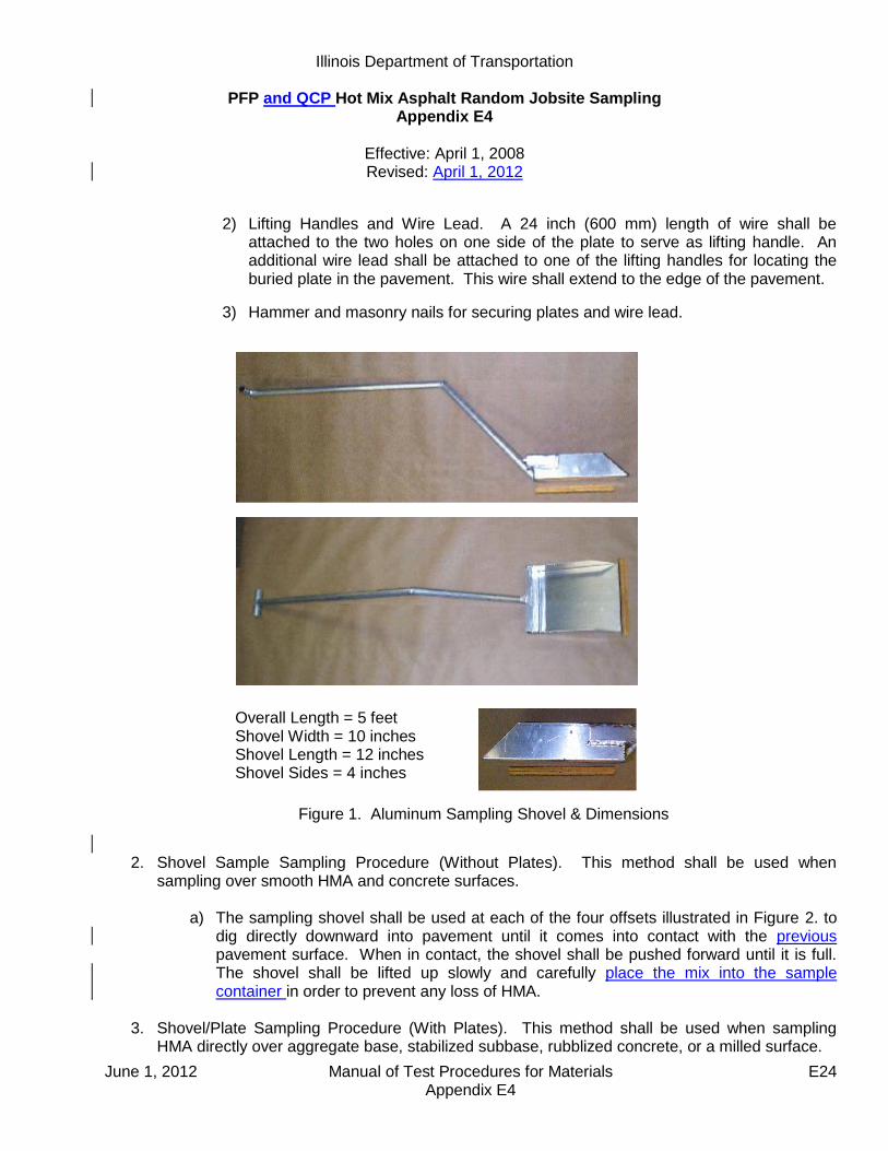
Illinois Department of Transportation
PFP and QCP Hot Mix Asphalt Random Jobsite Sampling Appendix E4
Effective: April 1, 2008 Revised: April 1, 2012
June 1, 2012 Manual of Test Procedures for Materials E24 Appendix E4
2) Lifting Handles and Wire Lead. A 24 inch (600 mm) length of wire shall be attached to the two holes on one side of the plate to serve as lifting handle. An additional wire lead shall be attached to one of the lifting handles for locating the buried plate in the pavement. This wire shall extend to the edge of the pavement.
3) Hammer and masonry nails for securing plates and wire lead.
Figure 1. Aluminum Sampling Shovel & Dimensions
2. Shovel Sample Sampling Procedure (Without Plates). This method shall be used when
sampling over smooth HMA and concrete surfaces.
a) The sampling shovel shall be used at each of the four offsets illustrated in Figure 2. to dig directly downward into pavement until it comes into contact with the previous pavement surface. When in contact, the shovel shall be pushed forward until it is full. The shovel shall be lifted up slowly and carefully place the mix into the sample container in order to prevent any loss of HMA.
3. Shovel/Plate Sampling Procedure (With Plates). This method shall be used when sampling
HMA directly over aggregate base, stabilized subbase, rubblized concrete, or a milled surface.
Overall Length = 5 feet Shovel Width = 10 inches Shovel Length = 12 inches Shovel Sides = 4 inches

Illinois Department of Transportation
PFP and QCP Hot Mix Asphalt Random Jobsite Sampling Appendix E4
Effective: April 1, 2008 Revised: April 1, 2012
June 1, 2012 Manual of Test Procedures for Materials E25 Appendix E4
a) Each plate with the wire lead attached to handle shall be placed at four locations
according for Figure 2. at the designated location ahead of the paver. If conditions on the project require restricting movement of the plate, a nail shall be driven through one of the holes in the plate and into the pavement.
b) The wire lead shall be extended beyond the edge of the pavement. Trucks, pavers,
and/or materials transfer devices will be allowed to cross over the pate and/or wire lead. c) After the HMA is placed, the wire lead shall be used to locate the plate. Once located,
the wire handles shall be lifted out of the pavement. This will locate the four corners of the plate.
d) Once the plate edges are defined, the shovel shall be used to dig downward through
the thickness of the pavement until it is in contact with the plate. The shovel shall be pushed forward until it is full. The shovel shall be lifted up slowly and carefully place the mix into the sample container in order to prevent any loss of HMA.
e) Remove sampling plates from pavement.
Figure 2. Behind Paver Sampling Layout
Direction of Paving
10 feet
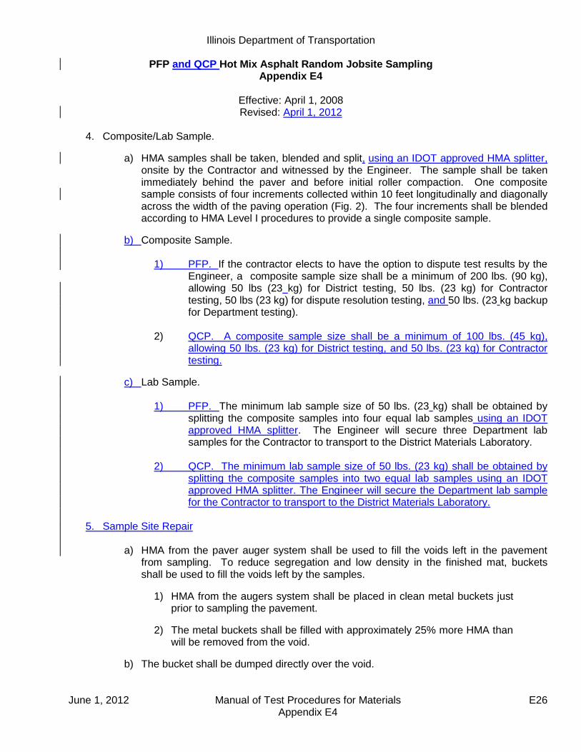
Illinois Department of Transportation
PFP and QCP Hot Mix Asphalt Random Jobsite Sampling Appendix E4
Effective: April 1, 2008 Revised: April 1, 2012
June 1, 2012 Manual of Test Procedures for Materials E26 Appendix E4
4. Composite/Lab Sample.
a) HMA samples shall be taken, blended and split, using an IDOT approved HMA splitter, onsite by the Contractor and witnessed by the Engineer. The sample shall be taken immediately behind the paver and before initial roller compaction. One composite sample consists of four increments collected within 10 feet longitudinally and diagonally across the width of the paving operation (Fig. 2). The four increments shall be blended according to HMA Level I procedures to provide a single composite sample.
b) Composite Sample.
1) PFP. If the contractor elects to have the option to dispute test results by the Engineer, a composite sample size shall be a minimum of 200 lbs. (90 kg), allowing 50 lbs (23 kg) for District testing, 50 lbs. (23 kg) for Contractor testing, 50 lbs (23 kg) for dispute resolution testing, and 50 lbs. (23 kg backup for Department testing).
2) QCP. A composite sample size shall be a minimum of 100 lbs. (45 kg),
allowing 50 lbs. (23 kg) for District testing, and 50 lbs. (23 kg) for Contractor testing.
c) Lab Sample.
1) PFP. The minimum lab sample size of 50 lbs. (23 kg) shall be obtained by splitting the composite samples into four equal lab samples using an IDOT approved HMA splitter. The Engineer will secure three Department lab samples for the Contractor to transport to the District Materials Laboratory.
2) QCP. The minimum lab sample size of 50 lbs. (23 kg) shall be obtained by
splitting the composite samples into two equal lab samples using an IDOT approved HMA splitter. The Engineer will secure the Department lab sample for the Contractor to transport to the District Materials Laboratory.
5. Sample Site Repair
a) HMA from the paver auger system shall be used to fill the voids left in the pavement
from sampling. To reduce segregation and low density in the finished mat, buckets shall be used to fill the voids left by the samples.
1) HMA from the augers system shall be placed in clean metal buckets just prior to sampling the pavement.
2) The metal buckets shall be filled with approximately 25% more HMA than will be removed from the void.
b) The bucket shall be dumped directly over the void.

Illinois Department of Transportation
PFP and QCP Hot Mix Asphalt Random Jobsite Sampling Appendix E4
Effective: April 1, 2008 Revised: April 1, 2012
June 1, 2012 Manual of Test Procedures for Materials E27 Appendix E4
c) The HMA shall be slightly leveled to provide a gradual hump over the filled void to allow compression of the mix by the roller.
d) Unacceptable site repair shall be removed and replaced at the Contractors expense.
B. MTD Sampling.
This method covers the procedures for sampling HMA paving mixtures at the point of delivery from a material transfer device (MTD).
1. Equipment.
a) MTD Sampling Device. A portable device mounted either in the bed of a pickup truck or on a trailer. The device shall be equipped with a funnel large enough to capture the full stream of HMA from the MTD discharge chute without spillage and shall be capable of capturing a minimum composite HMA sample of 200 lbs (90 kg). See appendix for illustrations of various MTD sampling device configurations.
b) Sample Containers – Metal containers each capable of holding a minimum of 50 lbs. of HMA.
2. MTD Sampling Procedure.
The Engineer will identify the truck containing the sample tonnage immediately prior to sampling. Immediately after the truck containing the random HMA tonnage has finished unloading, the MTD shall pull forward away from the paver far enough to allow the sampling device to be positioned under the MTD discharge chute. The sampling device shall be positioned as level as possible in a safe location readily accessible by the MTD. The MTD shall discharge without spillage a minimum of 200 lbs. (90 kg) of HMA for PFP or 100 lbs. (45 kg) for QCP into the funnel of the sampling device. 3. Composite/Lab Sample.
a) Composite Sample. HMA from all four sample containers of the sampling device shall be blended into one composite sample and split to lab sample size by the Contractor onsite using an IDOT approved HMA splitter. The blending and splitting shall be according to HMA Level I procedures and will be witnessed by the Engineer.
1) PFP. If the contractor elects to have the option to dispute test results by the
Engineer, a composite sample size shall be a minimum of 200 lbs. (90 kg), allowing 50 lbs (23 kg) for District testing, 50 lbs. (23 kg) for Contractor testing, 50 lbs (23 kg) for dispute resolution testing, and 50 lbs. (23 kg backup for Department testing).
2) QCP. A composite sample size shall be a minimum of 100 lbs. (45 kg),
allowing 50 lbs. (23 kg) for District testing, and 50 lbs. (23 kg) for Contractor testing.
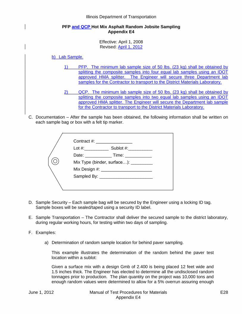
Illinois Department of Transportation
PFP and QCP Hot Mix Asphalt Random Jobsite Sampling Appendix E4
Effective: April 1, 2008 Revised: April 1, 2012
June 1, 2012 Manual of Test Procedures for Materials E28 Appendix E4
b) Lab Sample.
1) PFP. The minimum lab sample size of 50 lbs. (23 kg) shall be obtained by splitting the composite samples into four equal lab samples using an IDOT approved HMA splitter. The Engineer will secure three Department lab samples for the Contractor to transport to the District Materials Laboratory.
2) QCP. The minimum lab sample size of 50 lbs. (23 kg) shall be obtained by
splitting the composite samples into two equal lab samples using an IDOT approved HMA splitter. The Engineer will secure the Department lab sample for the Contractor to transport to the District Materials Laboratory.
C. Documentation – After the sample has been obtained, the following information shall be written on
each sample bag or box with a felt tip marker. D. Sample Security – Each sample bag will be secured by the Engineer using a locking ID tag.
Sample boxes will be sealed/taped using a security ID label.
E. Sample Transportation – The Contractor shall deliver the secured sample to the district laboratory, during regular working hours, for testing within two days of sampling.
F. Examples:
a) Determination of random sample location for behind paver sampling.
This example illustrates the determination of the random behind the paver test location within a sublot:
Given a surface mix with a design Gmb of 2.400 is being placed 12 feet wide and 1.5 inches thick. The Engineer has elected to determine all the undisclosed random tonnages prior to production. The plan quantity on the project was 10,000 tons and enough random values were determined to allow for a 5% overrun assuring enough
Contract #: _______________
Lot #:__________ Sublot #:__________
Date: ___________ Time: ___________
Mix Type (binder, surface…): _________
Mix Design #: _____________________
Sampled By: ______________________
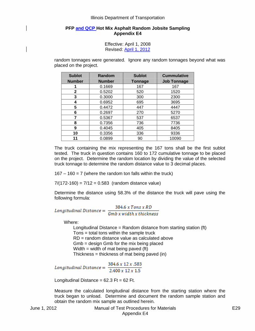
Illinois Department of Transportation
PFP and QCP Hot Mix Asphalt Random Jobsite Sampling Appendix E4
Effective: April 1, 2008 Revised: April 1, 2012
June 1, 2012 Manual of Test Procedures for Materials E29 Appendix E4
random tonnages were generated. Ignore any random tonnages beyond what was placed on the project.
Sublot Random Sublot Cummulative
Number Number Tonnage Job Tonnage
1 0.1669 167 167
2 0.5202 520 1520
3 0.3000 300 2300
4 0.6952 695 3695
5 0.4472 447 4447
6 0.2697 270 5270
7 0.5367 537 6537
8 0.7356 736 7736
9 0.4045 405 8405
10 0.3356 336 9336
11 0.0899 90 10090
The truck containing the mix representing the 167 tons shall be the first sublot tested. The truck in question contains 160 to 172 cumulative tonnage to be placed on the project. Determine the random location by dividing the value of the selected truck tonnage to determine the random distance value to 3 decimal places.
167 – 160 = 7 (where the random ton falls within the truck)
7/(172-160) = 7/12 = 0.583 (random distance value)
Determine the distance using 58.3% of the distance the truck will pave using the following formula:
Where: Longitudinal Distance = Random distance from starting station (ft) Tons = total tons within the sample truck RD = random distance value as calculated above Gmb = design Gmb for the mix being placed Width = width of mat being paved (ft) Thickness = thickness of mat being paved (in)
Longitudinal Distance = 62.3 Ft = 62 Ft. Measure the calculated longitudinal distance from the starting station where the truck began to unload. Determine and document the random sample station and obtain the random mix sample as outlined herein.

Illinois Department of Transportation
PFP and QCP Hot Mix Asphalt Random Jobsite Sampling Appendix E4
Effective: April 1, 2008 Revised: April 1, 2012
June 1, 2012 Manual of Test Procedures for Materials E30 Appendix E4
Starting Station = 105 + 00 Random Sample Location = 105 + 00 + 62 = 105 + 62 This process shall be repeated for the subsequent sublots.
b) Examples of MTD Sampling Devices

Illinois Department of Transportation
PFP and QCP Hot Mix Asphalt Random Jobsite Sampling Appendix E4
Effective: April 1, 2008 Revised: April 1, 2012
June 1, 2012 Manual of Test Procedures for Materials E31 Appendix E4
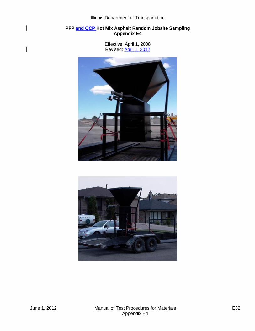
Illinois Department of Transportation
PFP and QCP Hot Mix Asphalt Random Jobsite Sampling Appendix E4
Effective: April 1, 2008 Revised: April 1, 2012
June 1, 2012 Manual of Test Procedures for Materials E32 Appendix E4

June 1, 2012 Manual of Test Procedures for Materials E33 Appendix E4
RANDOM NUMBERS
0.576 0.730 0.430 0.754 0.271 0.870 0.732 0.721 0.998 0.239 0.892 0.948 0.858 0.025 0.935 0.114 0.153 0.508 0.749 0.291 0.669 0.726 0.501 0.402 0.231 0.505 0.009 0.420 0.517 0.858 0.609 0.482 0.809 0.140 0.396 0.025 0.937 0.301 0.253 0.761 0.971 0.824 0.902 0.470 0.997 0.392 0.892 0.957 0.040 0.463 0.053 0.899 0.554 0.627 0.427 0.760 0.470 0.040 0.904 0.993 0.810 0.159 0.225 0.163 0.549 0.405 0.285 0.542 0.231 0.919 0.081 0.277 0.035 0.039 0.860 0.507 0.081 0.538 0.986 0.501 0.982 0.468 0.334 0.921 0.690 0.806 0.879 0.414 0.106 0.031 0.095 0.801 0.576 0.417 0.251 0.884 0.522 0.235 0.389 0.222 0.509 0.025 0.794 0.850 0.917 0.887 0.751 0.608 0.698 0.683 0.371 0.059 0.164 0.838 0.289 0.169 0.569 0.977 0.796 0.996 0.165 0.996 0.356 0.375 0.654 0.979 0.815 0.592 0.348 0.743 0.477 0.535 0.137 0.155 0.767 0.187 0.579 0.787 0.358 0.595 0.788 0.101 0.434 0.638 0.021 0.894 0.324 0.871 0.698 0.539 0.566 0.815 0.622 0.548 0.947 0.169 0.817 0.472 0.864 0.466 0.901 0.342 0.873 0.964 0.942 0.985 0.123 0.086 0.335 0.212 0.470 0.682 0.412 0.064 0.150 0.962 0.925 0.355 0.909 0.019 0.068 0.242 0.777 0.356 0.195 0.313 0.396 0.460 0.740 0.247 0.874 0.420 0.127 0.284 0.448 0.215 0.833 0.652 0.701 0.326 0.897 0.877 0.209 0.862 0.428 0.117 0.100 0.259 0.425 0.284 0.876 0.969 0.109 0.843 0.759 0.239 0.890 0.317 0.428 0.802 0.190 0.696 0.757 0.283 0.777 0.491 0.523 0.665 0.919 0.146 0.341 0.688 0.587 0.908 0.865 0.333 0.928 0.404 0.892 0.696 0.846 0.355 0.831 0.281 0.945 0.364 0.673 0.305 0.195 0.887 0.882 0.227 0.552 0.077 0.454 0.731 0.716 0.265 0.058 0.075 0.464 0.658 0.629 0.269 0.069 0.998 0.917 0.217 0.220 0.659 0.123 0.791 0.503 0.447 0.659 0.463 0.994 0.307 0.631 0.422 0.116 0.120 0.721 0.137 0.263 0.176 0.798 0.879 0.432 0.391 0.836 0.206 0.914 0.574 0.870 0.390 0.104 0.755 0.082 0.939 0.636 0.195 0.614 0.486 0.629 0.663 0.619 0.007 0.296 0.456 0.630 0.673 0.665 0.666 0.399 0.592 0.441 0.649 0.270 0.612 0.804 0.112 0.331 0.606 0.551 0.928 0.830 0.841 0.702 0.183 0.360 0.193 0.181 0.399 0.564 0.772 0.890 0.062 0.919 0.875 0.183 0.651 0.157 0.150 0.800 0.875 0.205 0.446 0.648 0.685
Note: Always select a new set of numbers in a systematic manner, either horizontally or vertically. Once used, the set should be crossed out.

Illinois Department of Transportation
PFP and QCP Hot Mix Asphalt Random Jobsite Sampling Appendix E4
Effective: April 1, 2008 Revised: April 1, 2012
June 1, 2012 Manual of Test Procedures for Materials E34 Appendix E4
PFP Jobsite Sampling Location Determination
Date: Contract #: Route:
Bit Mix #: Bit Code: Bit Desc.:
Design Gmb: Pvt width(w): Pvt thickness(t):
Lot #: Sublot #: Sampling Tonnage (st):
Lot #: Sublot #: Sampling Tonnage (st):
Lot #: Sublot #: Sampling Tonnage (st):
Lot #: Sublot #: Sampling Tonnage (st):
Begin Truck Tons (b): Longitudinal Distance(d):
(d)=[384.6(q)(rd)] / [Gmb(w)(t)]
End Truck Tons (e): Starting Station(ss):
Tons in Truck (q): (q)=(e)-(b)
Random sample location(rl):
(rl)=(ss)+/-(d) {add or subtract if up/down sta.}
Random Truck distance(rd):
(rd)=[(st)-(b)]/(q)
Begin Truck Tons (b): Longitudinal Distance(d):
(d)=[384.6(q)(rd)] / [Gmb(w)(t)]
End Truck Tons (e): Starting Station(ss):
Tons in Truck (q): (q)=(e)-(b)
Random sample location(rl):
(rl)=(ss)+/-(d) {add or subtract if up/down sta.}
Random Truck distance(rd):
(rd)=[(st)-(b)]/(q)
Begin Truck Tons (b): Longitudinal Distance(d):
(d)=[384.6(q)(rd)] / [Gmb(w)(t)]
End Truck Tons (e): Starting Station(ss):
Tons in Truck (q): (q)=(e)-(b)
Random sample location(rl):
(rl)=(ss)+/-(d) {add or subtract if up/down sta.}
Random Truck distance(rd):
(rd)=[(st)-(b)]/(q)
Begin Truck Tons (b): Longitudinal Distance(d):
(d)=[384.6(q)(rd)] / [Gmb(w)(t)]
End Truck Tons (e): Starting Station(ss):
Tons in Truck (q): (q)=(e)-(b)
Random sample location(rl):
(rl)=(ss)+/-(d) {add or subtract if up/down sta.}
Random Truck distance(rd):
(rd)=[(st)-(b)]/(q)

June 1, 2012 Manual of Test Procedures for Materials E35 Appendix E5
Illinois Department of Transportation
Instructions for Submitting Pay for Performance Dispute Resolution Samples Appendix E5
Effective Date: April 1, 2010
A. Scope
The following guidelines are provided to clarify the district submittal requirements for dispute
resolution samples; and expedite the testing process for HMA mix and/or core samples.
B. Procedure
When submitting HMA mix and/or core samples include the following:
All District and Contractor split sample test results on attached “PFP Dispute Resolution Form”,
Submit entire dispute resolution HMA mix split sample,
Cores must be split or sawed to lift testing thickness,
QC Package template and dailies sent electronically for mix being tested.
Send sample and requested documentation to:
Illinois Department of Transportation
Bureau of Materials & Physical Research
Hot Mix Asphalt Laboratory
126 E. Ash Street
Springfield, Illinois 62704-4766
Attention: Joe Rechner [email protected]
Any sample sent to BMPR without the above listed information will not be processed until all
requested information is received.
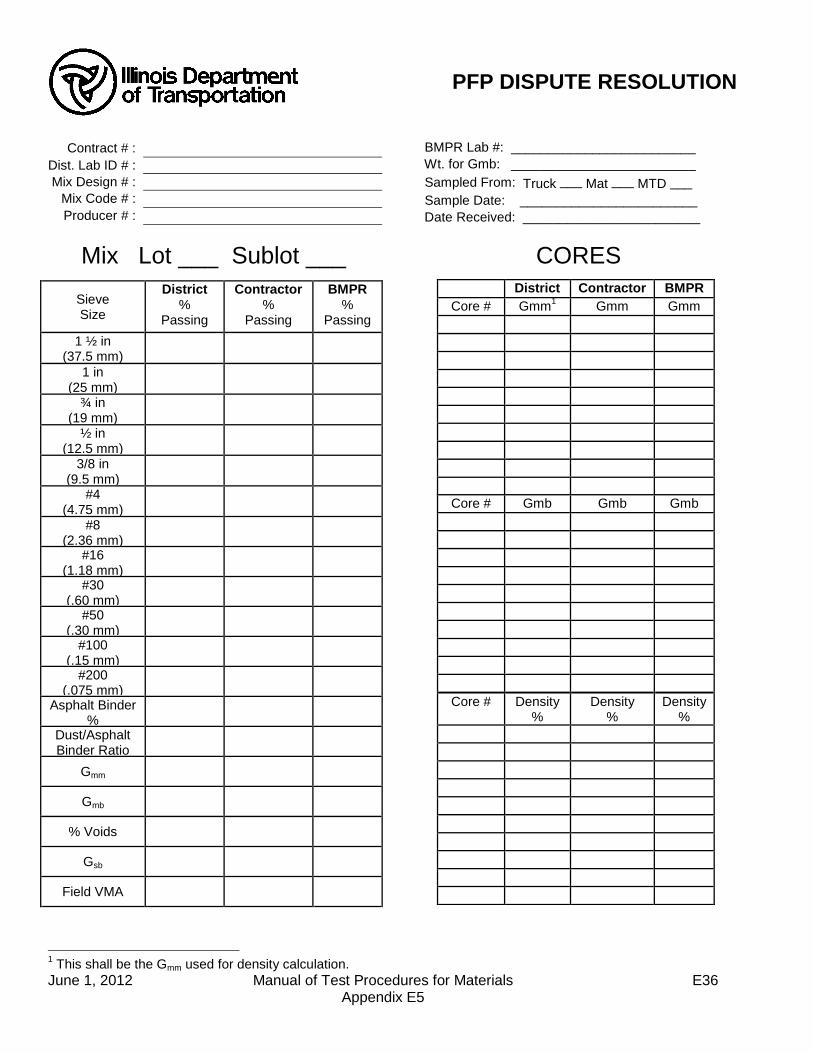
June 1, 2012 Manual of Test Procedures for Materials E36 Appendix E5
BMPR Lab #: _________________________
Wt. for Gmb: _________________________ Sampled From: Truck ___ Mat ___ MTD ___
Sample Date: ________________________
Date Received: ________________________
CORES
1 This shall be the Gmm used for density calculation.
Contract # :
Dist. Lab ID # :
Mix Design # :
Mix Code # :
Producer # :
Mix Lot ___ Sublot ___
Sieve Size
District %
Passing
Contractor %
Passing
BMPR %
Passing 1 ½ in
(37.5 mm)
1 in (25 mm)
¾ in (19 mm)
½ in (12.5 mm)
3/8 in (9.5 mm)
#4 (4.75 mm)
#8 (2.36 mm)
#16 (1.18 mm)
#30 (.60 mm)
#50 (.30 mm)
#100 (.15 mm)
#200 (.075 mm)
Asphalt Binder %
Dust/Asphalt Binder Ratio
Gmm
Gmb
% Voids
Gsb
Field VMA
District Contractor BMPR
Core # Gmm1 Gmm Gmm
Core # Gmb Gmb Gmb
Core # Density %
Density %
Density %
PFP DISPUTE RESOLUTION

Illinois Department of Transportation
QCP Pay Calculation Appendix E6
Effective: January 1, 2012
June 1, 2012 Manual of Test Procedures for Materials E37 Appendix E6
This document explains the procedure used to determine the pay adjustment for a hot-mix asphalt (HMA) mixture for Quality Control for Performance (QCP) projects. The following steps are used to determine the pay deduction for each QCP mixture:
1. Determine sublot deviation from target for each pay parameter. 2. Determine the sublot pay factor for each sublot using the Table 1 and the deviation from
target. 3. Determine the average sublot Pay Factor for each pay parameter. 4. Calculate a Combined Pay Factor using using the average sublot Pay Factors and
Equation 1. 5. Determine the QCP pay deduction for the mixture using Equation 2. 6. The Combined Pay Factor shall not exceed 100%. 7. The 103% column only applies when the district conducts testing of all the sublots within
a given lot and all of the tests are within the Acceptable Limits. The 103% column also applies to density sublots where no individual density test is less than 90.0% or greater than 98.0% density.
Table 1
Parameter
Pay Factor
103% 100% 95% 90%
Voids1/
± 0.8% ± 1.2% ± 1.6% ± 2.0%
VMA 0% to +1.5% above minimum
specified
-0.7% to +2.0% -0.8% to +2.5% -1.0% to +3.0%
Density2/ 93.5% to 95.5% 92.5% to 96.5% 91.0% to 97.0% 90.0% to 98.0%
1/ Ranges based on deviation from the specified design percent Voids. 2/ If no density requirement applies the Contractor will receive 100% for the density pay
factor in equation 1. Equation 1: CPF = 0.30(PF Voids) + 0.30(PFVMA) + 0.40(PFDensity)
Where: CPF = Combined Pay Factor
PFVoids, PFVMA, and PFDensity = Average sublot pay factors for the pay parameters
The QCP deduction for a given mixture is calculated by multiplying the Mixture Unit Price by the Quantity and the CPF according to Equation 2 below. Equation 2: QCP Deduction = (Mixture Unit Price x Mixture Quantity x CPF/100) –
(Mixture Unit Price x Mixture Quantity)
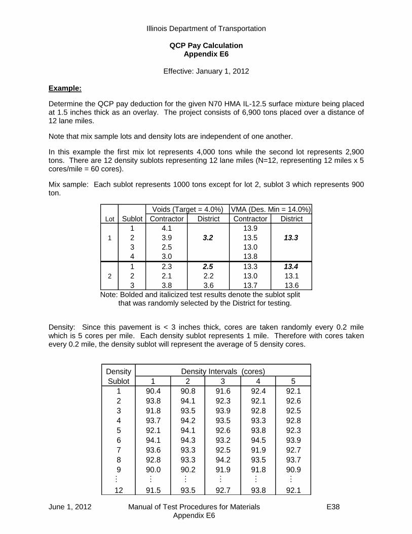
Illinois Department of Transportation
QCP Pay Calculation Appendix E6
Effective: January 1, 2012
June 1, 2012 Manual of Test Procedures for Materials E38 Appendix E6
Example:
Determine the QCP pay deduction for the given N70 HMA IL-12.5 surface mixture being placed at 1.5 inches thick as an overlay. The project consists of 6,900 tons placed over a distance of 12 lane miles.
Note that mix sample lots and density lots are independent of one another.
In this example the first mix lot represents 4,000 tons while the second lot represents 2,900 tons. There are 12 density sublots representing 12 lane miles (N=12, representing 12 miles x 5 cores/mile = 60 cores).
Mix sample: Each sublot represents 1000 tons except for lot 2, sublot 3 which represents 900 ton.
Lot Sublot Contractor District Contractor District
1 4.1 13.9
1 2 3.9 3.2 13.5 13.3
3 2.5 13.0
4 3.0 13.8
1 2.3 2.5 13.3 13.4
2 2 2.1 2.2 13.0 13.1
3 3.8 3.6 13.7 13.6
Voids (Target = 4.0%) VMA (Des. Min = 14.0%)
Note: Bolded and italicized test results denote the sublot split
that was randomly selected by the District for testing.
Density: Since this pavement is < 3 inches thick, cores are taken randomly every 0.2 mile which is 5 cores per mile. Each density sublot represents 1 mile. Therefore with cores taken every 0.2 mile, the density sublot will represent the average of 5 density cores.
1 2 3 4 5
1 90.4 90.8 91.6 92.4 92.1
2 93.8 94.1 92.3 92.1 92.6
3 91.8 93.5 93.9 92.8 92.5
4 93.7 94.2 93.5 93.3 92.8
5 92.1 94.1 92.6 93.8 92.3
6 94.1 94.3 93.2 94.5 93.9
7 93.6 93.3 92.5 91.9 92.7
8 92.8 93.3 94.2 93.5 93.7
9 90.0 90.2 91.9 91.8 90.9… … … … … …
12 91.5 93.5 92.7 93.8 92.1
Density
Sublot
Density Intervals (cores)

Illinois Department of Transportation
QCP Pay Calculation Appendix E6
Effective: January 1, 2012
June 1, 2012 Manual of Test Procedures for Materials E39 Appendix E6
Determine the average sublot pay factor for each parameter: Voids: Since the District randomly selected and tested the split from sublot 2 in Lot 1, and the void results were 1) within the 100% pay factor tolerance and 2) within Precision Limits of the Contractor’s results, the District does not need to test the remaining sublots in Lot 1 and the entire Lot receives a Pay Factor of 100%. For the second Lot the District randomly selected and tested the split from sublot 1. Since the District void results were not within the 100% pay factor tolerance, the District had to test all of the remaining Sublot splits. (see completed table below): Calculate the void deviation from target for each of the District sublot split results. Lot 1:
Sublot 2: Deviation = 3.2% - 4.0% = -0.8%
Lot 2: Sublot 1: Deviation = 2.5% - 4.0% = -1.5% Sublot 2: Deviation = 2.2% - 4.0% = -1.8%
Sublot 3: Deviation = 3.6% - 4.0% = -0.4% Using Table 1 and the deviation from Target, determine the corresponding Void sublot Pay Factor for each District test result. Lot 1: Sublot 2: Pay Factor associated with -0.8% in Table 1 is 100% Lot 2: Sublot 1: Pay Factor associated with -1.5% in Table 1 is 95% Sublot 2: Pay Factor associated with -1.8% in Table 1 is 90% Sublot 3: Pay Factor associated with -0.4% in Table 1 is 103%
Note: Bolded and italicized test results denote the sublot split that was randomly selected by the District for testing.
Lot Sublot Contractor District Deviation Sublot PF
1 4.1
1 2 3.9 3.2 -0.8 100.0
3 2.8
4 3.0
1 2.3 2.5 -1.5 95
2 2 2.1 2.2 -1.8 90
3 3.8 3.6 -0.4 103
Target Voids = 4.0%

Illinois Department of Transportation
QCP Pay Calculation Appendix E6
Effective: January 1, 2012
June 1, 2012 Manual of Test Procedures for Materials E40 Appendix E6
Calculate the average sublot Pay Factor for Voids. (Note: The 100% in Lot 1 represents four sublots and therefore is multiplied by four) Ave Sublot Pay Factor (PFVoids) = ((100% X 4) + 95% + 90% + 103%) / 7 sublots = 98.3% VMA:
Since the District randomly selected and tested the split from Sublot 2 in Lot 1, and the VMA results were 1) within the 100% pay factor tolerance and 2) within Precision Limits of the Contractor’s results, the District does not need to test the remaining sublots in Lot 1 and the entire Lot receives a Pay Factor of 100%. For the second Lot the District randomly selected and tested the split from Sublot 1. Since the District results were not within the 100% pay factor tolerance for Voids, the District had to test all of the remaining sublot splits. (see completed table below): Calculate the VMA deviation from target for each of the District sublot split results. Lot 1:
Sublot 2: Deviation = 13.3% - 14.0% = -0.7%
Lot 2: Sublot 1: Deviation = 13.4% - 14.0% = -0.6% Sublot 2: Deviation = 13.1% - 14.0% = -0.9%
Sublot 3: Deviation = 13.6% - 14.0% = -0.4% Using Table 1 and the deviation from Target, determine the corresponding VMA sublot pay factor for each District test result. Lot 1: Sublot 2: Pay Factor associated with -0.7% in Table 1 is 100% Lot 2: Sublot 1: Pay Factor associated with -0.6% in Table 1 is 100% Sublot 2: Pay Factor associated with -0.9% in Table 1 is 90% Sublot 3: Pay Factor associated with -0.4% in Table 1 is 100%
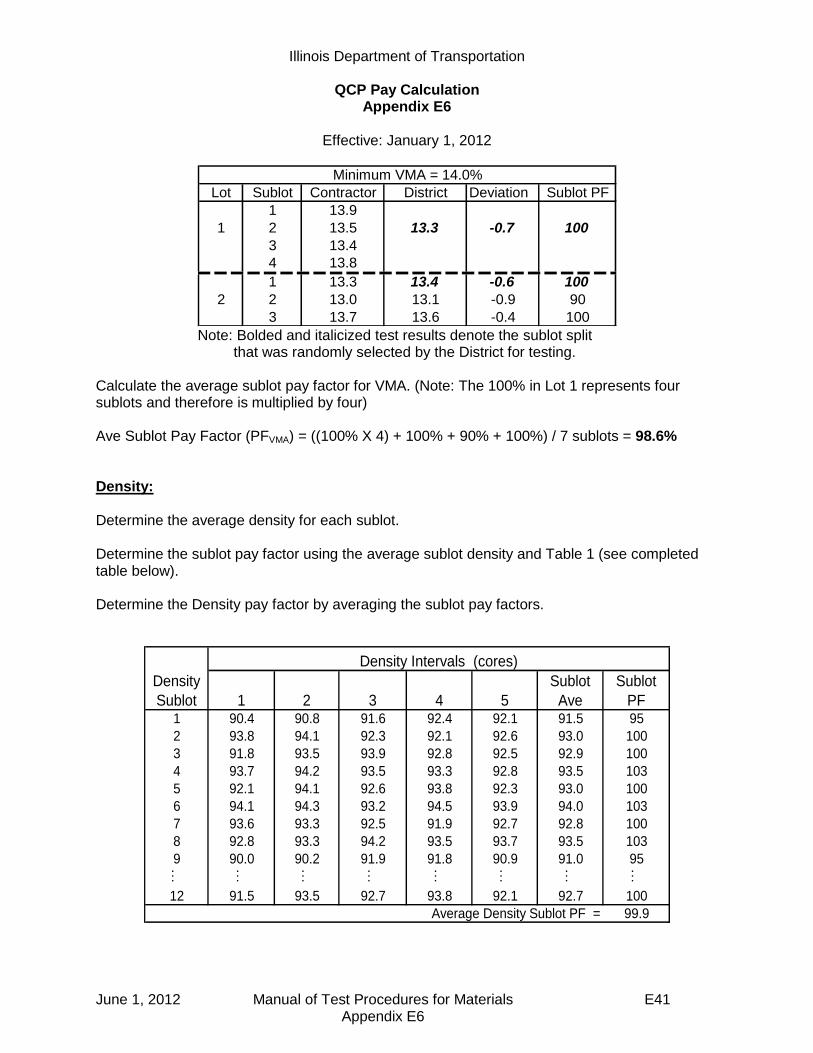
Illinois Department of Transportation
QCP Pay Calculation Appendix E6
Effective: January 1, 2012
June 1, 2012 Manual of Test Procedures for Materials E41 Appendix E6
Lot Sublot Contractor District Deviation Sublot PF
1 13.9
1 2 13.5 13.3 -0.7 100
3 13.4
4 13.8
1 13.3 13.4 -0.6 100
2 2 13.0 13.1 -0.9 90
3 13.7 13.6 -0.4 100
Minimum VMA = 14.0%
Note: Bolded and italicized test results denote the sublot split
that was randomly selected by the District for testing.
Calculate the average sublot pay factor for VMA. (Note: The 100% in Lot 1 represents four sublots and therefore is multiplied by four) Ave Sublot Pay Factor (PFVMA) = ((100% X 4) + 100% + 90% + 100%) / 7 sublots = 98.6% Density:
Determine the average density for each sublot. Determine the sublot pay factor using the average sublot density and Table 1 (see completed table below). Determine the Density pay factor by averaging the sublot pay factors.
1 2 3 4 5
Sublot
Ave
Sublot
PF1 90.4 90.8 91.6 92.4 92.1 91.5 95
2 93.8 94.1 92.3 92.1 92.6 93.0 100
3 91.8 93.5 93.9 92.8 92.5 92.9 100
4 93.7 94.2 93.5 93.3 92.8 93.5 103
5 92.1 94.1 92.6 93.8 92.3 93.0 100
6 94.1 94.3 93.2 94.5 93.9 94.0 103
7 93.6 93.3 92.5 91.9 92.7 92.8 100
8 92.8 93.3 94.2 93.5 93.7 93.5 103
9 90.0 90.2 91.9 91.8 90.9 91.0 95… … … … … … … …
12 91.5 93.5 92.7 93.8 92.1 92.7 100
99.9
Density
Sublot
Density Intervals (cores)
Average Density Sublot PF =
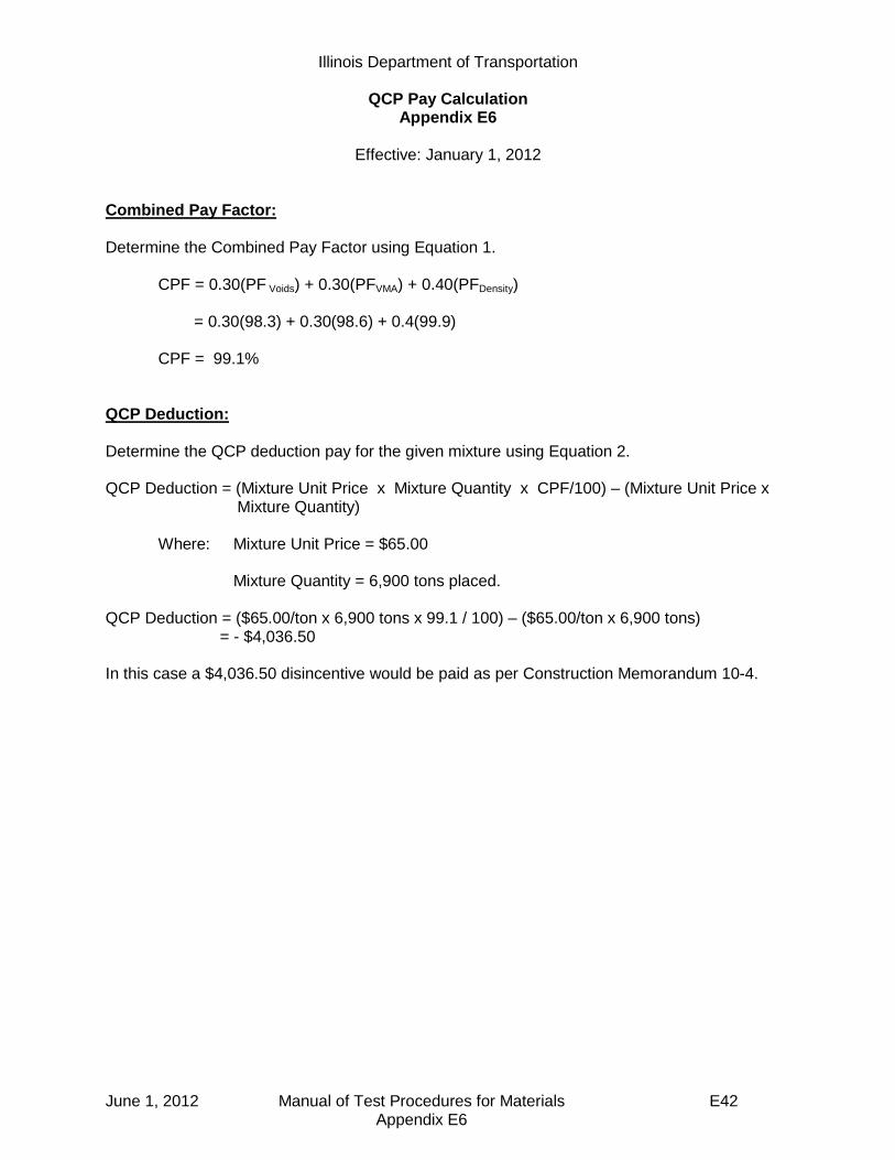
Illinois Department of Transportation
QCP Pay Calculation Appendix E6
Effective: January 1, 2012
June 1, 2012 Manual of Test Procedures for Materials E42 Appendix E6
Combined Pay Factor: Determine the Combined Pay Factor using Equation 1.
CPF = 0.30(PF Voids) + 0.30(PFVMA) + 0.40(PFDensity) = 0.30(98.3) + 0.30(98.6) + 0.4(99.9) CPF = 99.1%
QCP Deduction: Determine the QCP deduction pay for the given mixture using Equation 2. QCP Deduction = (Mixture Unit Price x Mixture Quantity x CPF/100) – (Mixture Unit Price x
Mixture Quantity)
Where: Mixture Unit Price = $65.00 Mixture Quantity = 6,900 tons placed.
QCP Deduction = ($65.00/ton x 6,900 tons x 99.1 / 100) – ($65.00/ton x 6,900 tons)
= - $4,036.50
In this case a $4,036.50 disincentive would be paid as per Construction Memorandum 10-4.

June 1, 2012 Manual of Test Procedures for Materials E43 Appendix E7
Illinois Department of Transportation
Best Practices For
Pay-For-Performance (PFP) and Quality Control for Performance (QCP) Implementation
Appendix E7
Effective Date: April 1, 2012
Purpose
This document is intended to aid district personnel in successfully preparing for and implementing the Pay-For-Performance (PFP) and Quality Control for Performance (QCP) specifications.
Lab
Since payment on PFP and QCP projects is based on Department test results, attention to laboratory equipment, qualified lab personnel and laboratory efficiency becomes paramount. Review of results from recent “Annual Bituminous Uniformity Studies” (aka Round Robins) and dispute resolutions and addressing any district lab issues resulting in poor comparisons will prove beneficial.
1) Equipment - It is imperative to inspect and calibrate all laboratory testing equipment according to frequencies listed in Policy Memorandum 21-08.0 “Minimum Requirements For Construction Materials Testing Laboratories - Department Operated Laboratories” at a minimum. Inspection and calibration immediately prior to PFP and QCP testing is highly recommended. Always use the same gyratory compactor for a given PFP or QCP contract.
Assessment of existing and needed equipment should be performed to determine possible benefits of purchasing additional equipment to optimize productivity. Each district should also develop an action plan in the event key equipment breaks down.
2) Personnel – It is also imperative that all laboratory personnel intended to be involved in PFP and QCP testing, be qualified with successful completion of HMA Level I as a minimum. Keep technician assignments as consistent as possible. It is highly recommended to conduct an in-house round robin with the above mentioned laboratory personnel to ensure repeatability.
3) Sample Treatment – Inconsistent treatment of samples prior to testing has been identified as the leading reason for differences in test results between the contractor and the state. It is recommended that samples, for all parties involved, be allowed to cool to room temperature immediately after splitting. The samples should then be reheated and compacted as soon as the samples reach compaction temperature.
4) Efficiency – PFP and QCP are based on Department testing which results in a higher
testing frequency for the district laboratory. An internal audit of your district
laboratory for efficiency may help identify ways to improve productivity. This activity
should be conducted by district materials staff that are not involved in day-to-day
testing, or BMPR staff if requested.

June 1, 2012 Manual of Test Procedures for Materials E44 Appendix E7
While the specification allows a 14 working day test turnaround time for PFP and a 10 day turnaround for QCP, the district should attempt to reduce the turnaround time as much as possible. Nationally recognized successful programs have test turnaround results within 5 days.
Project Personnel
Key components of PFP and QCP which provide the necessary compliance with the Code of Federal Regulations are 1) undisclosed random mix and density sample locations, 2) Sample either taken by the Engineer or witnessed by the Engineer, and 3) sample security. The CFR is intended to assure that the sample is under control of the Engineer at all times to verify the quality of the product. Most districts will need to rely on project staff to determine random mix sample and density core locations. It will be important for project personnel to understand their role in witnessing and securing the sample. District Materials and Construction staff should meet prior to the start of a PFP or QCP project to discuss:
1) Responsibilities: a) Discuss who will be responsible for sample identifying undisclosed sample
location and sample layout b) Sample Security; discuss who will transport and / or store samples. c) Pay Calculations; discuss who will be responsible for entering data in software
and how communication regarding pay factors will occur. 2) Procedures:
a) Random sample locations i) Discuss when to disclose sampling location ii) Familiarize Construction personnel with random sample procedures detailed
in the Manual of Test Procedures b) Sample Layout (utilization of random number table)
i) Discuss how core densities will be: (1) transversely no closer than 1 foot to an unconfined longitudinal joint and 4
inches on a confined longitudinal joint for PFP. (2) transversely no closer than 4 inches from an edge for QCP.
ii) Discuss how to handle coring locations that will need to be opened immediately to traffic
Also, it will be important to make sure Construction personnel have copies of all the necessary supporting documents.

SEQUENTIAL TABLE OF CONTENTS (continued)
MANUAL OF TEST PROCEDURES FOR MATERIALS
June 1, 2012 Manual of Test Procedures for Materials
B—Hot Mix Asphalt (HMA) Appendix B1
(Effective 05/01/93) (Revised 01/01/08)
Model Annual Quality Control (QC) Plan for Hot-Mix Asphalt (HMA) Production .....................
B 1
Appendix B2 (Effective 07/01/95) (Revised 05/01/07)
Model Quality Control (QC) Addendum for Hot-Mix Asphalt (HMA) Production .....................
B11
Appendix B3 (Effective 05/01/01) (Revised 04/01/11)
Standard Test Method for Correlating Nuclear Gauge Densities with Core Densities ......................
B13
Appendix B4 (Effective 05/01/93) (Revised 01/01/08)
Hot-Mix Asphalt Concrete QC/QA Start-Up Procedures ................................................
B21
Appendix B5 (Effective 05/01/93) (Revised 05/01/07)
Hot-Mix Asphalt QC/QA QC Personnel Responsibilities and Duties Checklist ......................
B27
Appendix B6 (Effective 05/01/93) (Revised 05/01/07)
Hot-Mix Asphalt QC/QA Initial Daily Plant and Random Samples ....................................................
B37
Appendix B7 (Effective 05/01/93) (Revised 04/01/11)
Determination of Random Density Locations ........... B41
Appendix B8 (Effective 05/01/93) (Revised 01/01/08)
Control Charts / Rounding Test Values.................... B43
Appendix B9 (Effective 01/01/02) (Revised 01/01/13)
Hot-Mix Asphalt Mixture Design Verification Procedure ................................................................
B47
Appendix B10 (Effective 01/01/98) (Revised 05/01/07)
Illinois Test Procedure 401, Storage of Hot-Mix Asphalt Mixtures .......................
B53
Appendix B11 (Effective 01/01/02) (Revised 05/01/07)
Calibration of Equipment for Asphalt Binder Determination (Nuclear Gauge and Ignition Oven) ..
B55
Appendix B12 (Effective 01/01/98) (Revised 05/01/07)
Hot-Mix Asphalt Mix Design Procedure for Dust Correction Factor Determination ..............................
B59

SEQUENTIAL TABLE OF CONTENTS (continued)
MANUAL OF TEST PROCEDURES FOR MATERIALS
June 1, 2012 Manual of Test Procedures for Materials
Standard
Description Page
Appendix B13 (Effective 01/01/02) (Revised 05/01/07)
Illinois Test Procedure 403, Calibration of the Ignition Oven for the Purpose of Characterizing Reclaimed Asphalt Pavements (RAP) ......................................................................
B67
Appendix B14 (Effective 01/01/02) (Revised 05/01/07)
Truck Sample Splitting Diagram .............................. B71
Appendix B15 (Effective 05/01/04) (Revised 05/01/07)
Hot-Mix Asphalt (HMA) Production Gradation
Windage Procedure for Minus #200 (minus 75 m) Material ...................................................................
B73
Appendix B16 (Effective 11/20/03) (Revised 05/01/07)
Stripping of Hot-Mix Asphalt Mixtures Visual Identification and Classification ....................
B75
Appendix B17 (Effective 03/07/05) (Revised 01/01/13)
Procedure for Introducing Additives to Hot Mix Asphalt Mixtures and Testing in the Lab ....
B79
Appendix B18 (Effective 05/01/05) (Revised 05/01/07)
Ignition Oven Aggregate Mass Loss Procedure ...... B93
Appendix B19 (Effective 05/01/05) (Revised 05/01/07)
Quick Reference Guides and Procedure for Internal Angle Calibration of Superpave Gyratory Compactors (SGC) Using the Dynamic Angle Validator (DAV-2) ....................................................
B95
Appendix B20 (Effective 05/01/07)
Segregation Control of Hot-Mix Asphalt .................. B101
Appendix B21 (Effective 05/01/07) (Revised 04/01/11)
Determination of Reclaimed Asphalt Pavement (RAP) Aggregate Bulk (Dry) Specific Gravity (Gsb) .
B103
Appendix B22 (Effective 01/31/08)
Use of Correction Factors for Adjusting the Gradation of Cores to Estimate the Gradation of the In-Place Pavement ...................................................
B107
Appendix B23 (Effective 04/01/10)
Off-Site Preliminary Test Strip and Modified Start-Up Procedures .........................................................
B109
Appendix B24 (Effective 03/01/13)
Determination of Residual Asphalt in Prime and Tack Coat Materials .................................................
B113

Illinois Department of Transportation
Model Annual Quality Control (QC) Plan for Hot-Mix Asphalt (HMA) Production
Appendix B1
Effective: May 1, 1993 Revised: January 1, 2008
June 1, 2012 Manual of Test Procedures for Materials B1 Appendix B1
Producer Name:
Producer/Supplier No.:
Address:
City/State/ZIP Code:
Phone No.:
A. Contractor Responsibilities This Annual Quality Control (QC) Plan explains how ________________________
proposes to control the equipment, ingredient materials, and production methods to ensure the specified product is obtained. All requirements of section 1030 of the Standard Specifications and this Annual QC Plan will be adhered to. A Quality Control Addendum shall be completed for each contract and submitted prior to the preconstruction conference.
In joint ventures, where one Contractor is producing the mix and another is
responsible for the laydown, the Quality Control Manager, from either party, who is ultimately responsible for the Quality Control should be identified in the Quality Control Addendum.
B. Materials All materials proposed for use are from approved sources. Material sources are
identified below for coarse aggregate, fine aggregate, mineral filler, asphalt binder, prime, anti-strip additive, and release agent. This includes the mix type, Producer/Supplier Number, firm name, and firm location.
Material
Mix Type
Producer/ Supplier No.
Firm Name
Location
(1)
(2)
(3)
(4)
(5)
(6)
(7)
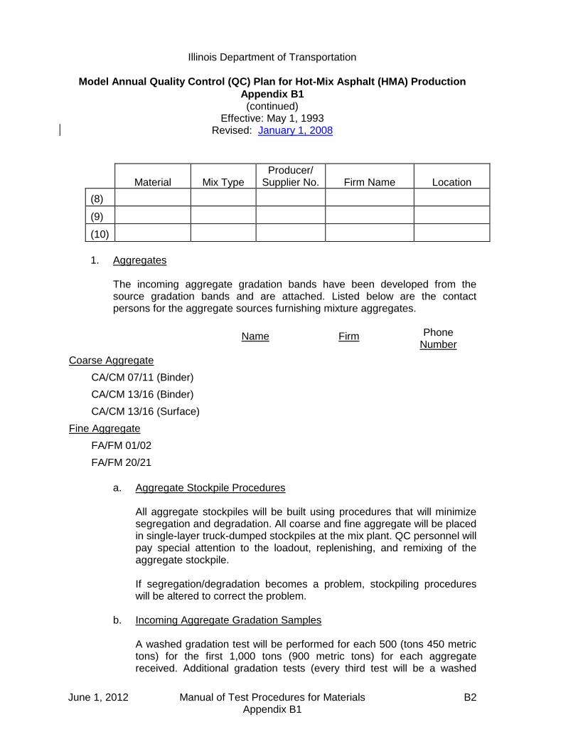
Illinois Department of Transportation
Model Annual Quality Control (QC) Plan for Hot-Mix Asphalt (HMA) Production
Appendix B1 (continued)
Effective: May 1, 1993 Revised: January 1, 2008
June 1, 2012 Manual of Test Procedures for Materials B2 Appendix B1
Material
Mix Type
Producer/ Supplier No.
Firm Name
Location
(8)
(9)
(10)
1. Aggregates
The incoming aggregate gradation bands have been developed from the source gradation bands and are attached. Listed below are the contact persons for the aggregate sources furnishing mixture aggregates.
Name Firm Phone Number
Coarse Aggregate
CA/CM 07/11 (Binder)
CA/CM 13/16 (Binder)
CA/CM 13/16 (Surface)
Fine Aggregate
FA/FM 01/02
FA/FM 20/21
a. Aggregate Stockpile Procedures All aggregate stockpiles will be built using procedures that will minimize
segregation and degradation. All coarse and fine aggregate will be placed in single-layer truck-dumped stockpiles at the mix plant. QC personnel will pay special attention to the loadout, replenishing, and remixing of the aggregate stockpile.
If segregation/degradation becomes a problem, stockpiling procedures
will be altered to correct the problem. b. Incoming Aggregate Gradation Samples A washed gradation test will be performed for each 500 (tons 450 metric
tons) for the first 1,000 tons (900 metric tons) for each aggregate received. Additional gradation tests (every third test will be a washed

Illinois Department of Transportation
Model Annual Quality Control (QC) Plan for Hot-Mix Asphalt (HMA) Production
Appendix B1 (continued)
Effective: May 1, 1993 Revised: January 1, 2008
June 1, 2012 Manual of Test Procedures for Materials B3 Appendix B1
gradation test) will be run on the frequency of one test per 2,000 tons (1,800 metric tons) for each aggregate received while the stockpiles are being built or aggregate is being shipped in. Gradation correction factors will be developed from washed gradation test results and applied to all dry gradation results. All aggregate (correction factors applied) will meet the mix plant gradation bands as developed according to the current Department policy, "Development of Gradation Bands on Incoming Aggregate at Mix Plants", before being used in mix production at the mix plant. All incoming aggregate gradation results shall be recorded in the plant diary. If a failing sample is encountered, the following resample procedure will be followed:
(1) Immediately resample the aggregate represented by the failing test. (2) If the first resample passes, the required frequency will be continued. (3) If the first resample fails, shipment of the aggregate will be halted,
and corrective action will be taken. Corrective action may be rejection of the material, remixing or addition of material by feeder/conveyor system, or any other action approved by the Engineer. The aggregate producer will be notified of the problem. A second resample will be taken immediately after corrective action.
(4) If the second resample passes, the aggregate represented will be
used, and aggregate shipment into the plant will be resumed. (5) If the second resample fails, the aggregate represented will not be
used in the QC/QA HMA mixture. The material will be removed from the certified aggregate stockpile.
Each contact person listed above has agreed to immediately provide
information on aggregate production changes or any significant variations in aggregate characteristics. These include, but are not limited to, changes in production methods, ledge footage, gradation, quality, specific gravity, and absorption. As gradation information is accumulated during stockpile construction, the aggregate gradations will be compared with the mix design gradation. Significant variations from the design gradation but within the acceptable gradation bands will be discussed with the Engineer. A new mix design will be performed when required by the Engineer.

Illinois Department of Transportation
Model Annual Quality Control (QC) Plan for Hot-Mix Asphalt (HMA) Production
Appendix B1 (continued)
Effective: May 1, 1993 Revised: January 1, 2008
June 1, 2012 Manual of Test Procedures for Materials B4 Appendix B1
c. Required Gradation Sample After mix production has started, all aggregate stockpiles will be checked
with a required washed gradation sample on a weekly basis. This testing will be waived if the mixture is classified as a small tonnage item according to the special provision. The test results shall be compared to the mix plant gradation bands for compliance. These gradation results will be noted in the Plant Diary, and a copy will be provided to the District Engineer.
If a weekly required stockpile sample fails, the following resample
procedure will be followed:
(1) Immediately resample and test the new stockpile sample. (2) If the first resample passes, mix production may continue. Several
additional check samples will be taken to monitor the stockpile. (3) If the first resample fails, mix production will be halted, and
corrective action will be taken on the stockpile. Corrective action may include rejection of the material, remixing or addition of material by feeder/conveyor system before use in the plant, or any other action approved by the Engineer. The aggregate contact person will be notified of the problem. A second resample will be obtained immediately after corrective action.
(4) If the second resample passes, mix production will begin. Several
additional check samples will be taken to monitor the stockpile. (5) If the second resample fails, the stockpile will not be used in the
QC/QA HMA mixture.
Aggregate not meeting the mix plant gradation bands shall not be used in the QC/QA HMA mixtures.
d. Reclaimed Asphalt Pavement (RAP) RAP will meet the requirements of Sections 1030 of the Standard
Specifications and any Special Provision in the contract.

Illinois Department of Transportation
Model Annual Quality Control (QC) Plan for Hot-Mix Asphalt (HMA) Production
Appendix B1 (continued)
Effective: May 1, 1993 Revised: January 1, 2008
June 1, 2012 Manual of Test Procedures for Materials B5 Appendix B1
C. Mix Design Mix designs shall be completed according to the Department's Hot-Mix Asphalt
Level III Technician Course. All design data and material samples shall be submitted to the Department for verification a minimum of 30 calendar days prior to production.
D. Quality Control Personnel All requirements of the Standard Specifications Section 1030, and the items listed
in the Department's current "QC Personnel Responsibilities and Duties Checklist" will be met by the QC personnel. All personnel being utilized to run the Quality Control sampling and testing shall have taken and passed the appropriate HMA QC/QA level of training. The QC Manager will assign duties in accordance with the "QC Personnel Responsibilities and Duties Checklist". The QC Manager will assure the listed duties are performed and documented. Additional duties, when necessary, will be assigned and monitored by the QC Manager. Sufficient QC personnel will be provided to run the QC Plan. Additional QC personnel will be added when necessary.
E. Quality Control Laboratory/Equipment A QC laboratory will be provided and maintained in accordance with the
Department’s current "Hot-Mix Asphalt QC/QA Laboratory Equipment". Laboratory equipment meeting the requirements of the Department's current
"Hot-Mix Asphalt QC/QA Laboratory Equipment" will be provided and properly maintained at the QC laboratory. In the event of equipment failure, ________________________________ will be the source for backup equipment.
All equipment has been calibrated, and the supporting documentation is on file at
the QC laboratory. The QC Laboratory was approved by the Department's Bureau of Materials and Physical Research and by District __________ on ___________________________. The laboratory/equipment will be available for inspection by the Engineer.

Illinois Department of Transportation
Model Annual Quality Control (QC) Plan for Hot-Mix Asphalt (HMA) Production
Appendix B1 (continued)
Effective: May 1, 1993 Revised: January 1, 2008
June 1, 2012 Manual of Test Procedures for Materials B6 Appendix B1
F. Mix Plant/Production
Manufacturer
Model Number
Serial Number
Batch Size
Tons Per Hour
Approved By
Approval Date
It is our intent to run the day following start-up. Production will not begin until the
acceptable nuclear/core correlation is complete, all other required tests are acceptable, the targets are established, and the results are reviewed and agreed to by the Department.
The aggregate feeders will be calibrated prior to the start of production using the
aggregates and approximate percentages approved in the Job Mix Formula (JMF). At this time aggregate samples will be taken and compared with the JMF.
At the start of mix production or when adjustments are made to the mix, the QC
Manager will give the aggregate proportions to the plant operator, and then, periodically throughout the day, checks will be made of the actual proportions used. This will be especially noted and recorded when a nuclear asphalt and/or a mix sample is taken. The results will be immediately reported to the Resident Engineer and/or other designated Department personnel upon completion of the test.
All scale and sensitivity checks will be performed in accordance with the Hot-Mix
Asphalt Level II Technician Course manual. Surge bins may be utilized as part of the overall plant operation. The QC Manager shall contact the Department for approval when material will be stored overnight.
G. Sampling and Testing All sampling and testing, including all required plant tests, resamples, and
additional check tests (when necessary), will be performed in accordance with Department test methods in the time frame required in Section 1030 of the Standard Specifications. The "Radioactive Material License" required for nuclear density and asphalt binder content determinations are attached. District Materials or the Bureau of Materials and Physical Research personnel are welcome to observe all testing by the QC personnel. Time permitting, split samples will be
Illinois Department of Transportation
Model Annual Quality Control (QC) Plan for Hot-Mix Asphalt (HMA) Production
Appendix B1 (continued)
Effective: May 1, 1993 Revised: January 1, 2008
June 1, 2012 Manual of Test Procedures for Materials B7 Appendix B1
shared with Department personnel prior to start-up. Coring will be performed using a truck-mounted drill rig or by suitable equipment as approved by the Engineer. An adjustment of 1-1/2% to 2% for minus No. 200 (0.075 mm) material of washed samples vs. dry gradations will be used until a gradation correction factor is established based on preliminary aggregate sampling and testing.
All Department split samples will be stored on site. These samples will be identified with the date and time the material was sampled, Sequence Number, Contract Number, mix plant Producer/Supplier Number, aggregate source Producer/Supplier Number, and the initials of the individual who sampled the material.
H. Placement and Compaction Only approved equipment will be used in the placement and compaction of the mix
in accordance with the Standard Specification requirements. The QC Manager will verify that all laydown equipment conforms to Department
requirements prior to start-up. At the start of laydown, Two Growth Curves will be run on a test strip to determine the suitability of the mix. Mix samples shall be taken and tested from trucks representing material between both Growth Curves. From Growth Curve information, a rolling pattern will be established. Nuclear tests and cores will be taken from the start-up area to verify density and correlation of the nuclear density gauge. Temperatures of the mix will be taken and duly recorded. After the start-up data is approved by the Department and actual production has begun, daily nuclear density tests will be taken at the start of each day's production, along with temperature readings, to verify continued conformance with density requirements. Nuclear density tests according to the Section 1030 will be performed to assure compliance with specified density requirements. Testing will be conducted within the project traffic control, or by use of flaggers, as needed.
Start-up and construction of the test strip is planned to be performed in the morning
of the first day. If no problems are encountered, cores for nuclear/core correlation will be taken. The mat will be cooled with ice or dry ice. All tests will be completed for anticipated production the next day.
Should any adverse mix characteristics be observed, the QC Manager shall make
mix adjustments as needed to correct the situation. If segregation should occur, appropriate adjustments will be made in the aggregate
stockpiling/loadout, plant production, silo operation, truck loading, or paver operation to alleviate the condition. Only approved truck release agents will be used.

Illinois Department of Transportation
Model Annual Quality Control (QC) Plan for Hot-Mix Asphalt (HMA) Production
Appendix B1 (continued)
Effective: May 1, 1993 Revised: January 1, 2008
June 1, 2012 Manual of Test Procedures for Materials B8 Appendix B1
The QC Manager or his representative will check laydown equipment daily for
specification compliance and immediately repair or replace nonconforming equipment.
I. Corrective Action The QC Manager will initiate corrective action immediately according to Section
1030 of the Standard Specifications. Sufficient tests shall be taken to verify the corrective action has worked. Special care will be taken to assure that mix not complying with specifications is not placed on the road.
J. Reporting of Test Results All test results will be reported daily to the Resident Engineer and other designated
personnel as requested by the Department. The data will be reported on the following forms or on forms generated by the Department's current QC/QA software:
MI 504M Field/Lab Gradations (stockpile gradations)
MI 305 Bituminous Daily Plant Output (front) Plant Settings and Scale Checks (back)
MI 303C Bituminous Core Density Testing QC/QA
MI 303N QC Nuclear Density Report
MI 308 Nuclear Asphalt Content and Volumetric Testing
LM-6 Sample Identification (for liquid asphalt)
The completed forms will be forwarded to the District Engineer within three days of
test completion.

Illinois Department of Transportation
Model Annual Quality Control (QC) Plan for Hot-Mix Asphalt (HMA) Production
Appendix B1 (continued)
Effective: May 1, 1993 Revised: January 1, 2008
June 1, 2012 Manual of Test Procedures for Materials B9 Appendix B1
K. Control Charts In addition, control charts will be posted at the laboratory and kept updated for the
following test parameters in accordance with the Department's current "Hot-Mix Asphalt QC/QA Control Charts/Rounding Test Values".
1. Gradations Hot-Bins/Combined Belt
Percent Passing 1/2-in. (12.5-mm) Sieve
Percent Passing No. 4 (4.75-mm) Sieve
Percent Passing No. 8 (2.36-mm) Sieve
Percent Passing No. 30 (600-µm) Sieve
Percent Passing No. 200 (75-µm) Sieve
Ignition Oven
Total Dust Content 2. Gravities
a. Bulk specific gravity b. Maximum specific gravity
3. Marshall Air Voids 4. Density 5. Asphalt Binder Content 6. Stockpile Gradations
In the event the Total Dust Content is out of tolerance, measures will be taken to correct the problem, which may include adding Positive Dust Control Equipment.
Contractor's Signature Date
(Please type or print name) Title

June 1, 2012 Manual of Test Procedures for Materials B10 Appendix B1
This Page Reserved

Illinois Department of Transportation
Model Quality Control (QC) Addendum for Hot-Mix Asphalt (HMA) Production
Appendix B2
Effective: July 1, 1995 Revised: May 1, 2007
June 1, 2012 Manual of Test Procedures for Materials B11 Appendix B2
Contract No.:
Marked Route:
Route:
Section:
County:
Contractor:
Address:
City/State/ZIP Code:
Phone No.:
A. Contractor Responsibilities
This Quality Control Addendum to the Annual Quality Control Plan further explains
how ________________________________ proposes to control the equipment,
ingredient materials, and production methods to ensure the specified product is
obtained. All requirements in Section 1030, the Annual QC Plan, and this QC
Addendum will be adhered to.
In the case of joint ventures, ___________________________________________
of ________________________________________ will be the QC Manager and
will be ultimately responsible for the Quality Control on this Contract.
B. Reclaimed Asphalt Pavement (RAP)
RAP will meet the requirements of Sections 406, 1030 and 1102 of the Standard
Specifications and any Special Provisions in the Contract. ______ percent of RAP
is proposed for use in the ____________________________ course.
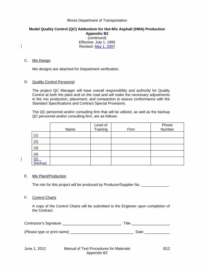
Illinois Department of Transportation
Model Quality Control (QC) Addendum for Hot-Mix Asphalt (HMA) Production
Appendix B2 (continued)
Effective: July 1, 1995 Revised: May 1, 2007
June 1, 2012 Manual of Test Procedures for Materials B12 Appendix B2
C. Mix Design Mix designs are attached for Department verification. D. Quality Control Personnel The project QC Manager will have overall responsibility and authority for Quality
Control at both the plant and on the road and will make the necessary adjustments in the mix production, placement, and compaction to assure conformance with the Standard Specifications and Contract Special Provisions.
The QC personnel and/or consulting firm that will be utilized, as well as the backup
QC personnel and/or consulting firm, are as follows:
Name
Level of Training
Firm
Phone Number
(1)
(2)
(3)
(4)
(5) (backup)
E. Mix Plant/Production The mix for this project will be produced by Producer/Supplier No. _____________. F. Control Charts A copy of the Control Charts will be submitted to the Engineer upon completion of
the Contract. Contractor's Signature Title (Please type or print name) Date

Illinois Department of Transportation QC/QA PROCEDURE
Standard Test Method for Correlating
Nuclear Gauge Densities with Core Densities Appendix B3
Effective: May 1, 2001 Revised: April 1, 2011
June 1, 2012 Manual of Test Procedures for Materials B13 Appendix B3
A. Scope
1. This method covers the proper procedures for correlating nuclear gauge densities to core densities. Procedures are applicable to both direct transmission and backscatter techniques.
2. The procedure shall be used on all projects containing 3000 tons (2750 metric tons) or
more of any hot-mix asphalt mixture. It may also be used on any other project where feasible. The direct transmission method shall be used for thick-lift layers. "Thick-lift" is defined as a layer 6 in. (152.4) mm or greater in compacted thickness.
B. Applicable Documents
1. Illinois Department of Transportation Standard Test Methods Illinois-Modified AASHTO T 166, "Bulk Specific Gravity of Compacted Asphalt
Mixtures Using Saturated Surface Dry Specimens" Illinois-Modified AASHTO T 275, "Bulk Specific Gravity of Compacted Asphalt
Mixtures Using Paraffin-Coated Specimens" 2. The density test procedure shall be in accordance with the Department's "Illinois-
Modified ASTM D 2950, Standard Test Method for Determination of Density of Bituminous Concrete In-Place by Nuclear Method".
C. Definitions
Test location: The station location used for density testing. Test site: Individual test site where a single density is determined. Five (5) test sites are located at each test location. Nuclear Density: The average of 2 or possibly 3 density readings on a given test site. Core Density: The core density result on a given test site.

Illinois Department of Transportation QC/QA PROCEDURE
Standard Test Method for Correlating
Nuclear Gauge Densities with Core Densities Appendix B3 (continued)
Effective: May 1, 2001 Revised: April 1, 2011
June 1, 2012 Manual of Test Procedures for Materials B14 Appendix B3
D. Significance and Use
1. Density results from a nuclear gauge are relative. If an approximation of core density results is required, a correlation must be developed to convert the nuclear density to core density.
2. A correlation developed in accordance with these procedures is applicable only to the
specific gauge being correlated, the specific mixture, each specific thickness (direct transmission only), and the specific project upon which it was correlated. A new correlation should be determined within a specific project if there is a significant change in the underlying material.
E. Site Selection
1. The nuclear density tests and cores necessary for nuclear/core correlation shall be obtained during the start-up of each specific mixture for which a density specification is applicable.
2. Three correlation locations shall be selected. Two sites will be located on the two
growth curves from the first acceptable test strip. The third location shall be chosen after an acceptable rolling pattern has been established and within the last 100 tons (90 metric tons) of material placed during start-up. The material from the third site shall correspond to the same material from which the second hot-mix sample was taken.
3. If a mixture start-up is not required, two of the three correlation locations shall be in an
area containing a growth curve. F. Procedures for Obtaining Nuclear Readings and Cores
1. Backscatter Mode
a. At each of the three correlation locations, five individual sites shall be chosen and identified as shown in Figure 1.
b. Two nuclear readings shall be taken at each of the 15 individual sites. (See
Figure 1.) The gauge shall be rotated 180 degrees between readings at each site. (The two uncorrected readings taken at a specific individual site shall be within 1.5 lbs/ft3 [23 kg/m3). If the two readings do not meet this criterion, one additional reading shall be taken in the desired direction. The nuclear densities are to be recorded on the correlation form (Figure 3).

Illinois Department of Transportation QC/QA PROCEDURE
Standard Test Method for Correlating
Nuclear Gauge Densities with Core Densities Appendix B3 (continued)
Effective: May 1, 2001 Revised: April 1, 2011
June 1, 2012 Manual of Test Procedures for Materials B15 Appendix B3
c. One core in good condition shall be obtained from each of 15 individual sites
(Figure 1). Care should be exercised that no additional compaction occurs between the nuclear testing and the coring. The cores shall be tested for density in accordance with Illinois-Modified AASHTO T 166 or T 275. The core densities are to be entered on the correlation form.
For quality assurance purposes, the Department may direct the Contractor to take additional cores adjacent to those above or to submit the quality control cores for Department testing.
d. Extreme care shall be taken in identifying which location each of the density
readings represents. The data points have to be paired accurately or the correlation process will be invalid.
2. Direct Transmission Mode
a. At each of the three correlation locations, five individual sites shall be chosen across the mat as shown on Figure 1.
b. A smooth hole in the pavement, slightly larger than the probe, shall be formed to
a depth 2 in. (50 mm) greater than the test depth. The probe shall be inserted so that the side of the probe facing the center of the gauge is in intimate contact with the side of the hole. Two nuclear readings shall be taken at each of the 15 individual sites. (See Figures 1 and 2)
The gauge shall be rotated 180 degrees (see Figure 2) around the core area at
each site. (The two uncorrected readings taken at a specific individual site shall be within 2.0 lbs/ft3 [30 kg/m3] (see Figure 2). If the two readings do not meet this criterion, one additional reading shall be taken in the desired direction. The nuclear densities are to be recorded on the correlation form (Figure 3).
c. One core in good condition shall be obtained from each of the 15 individual sites.
(See Figures 1 and 2) The cores shall be obtained from beneath the center of the gauge no closer than 3-1/2 in (87.5 mm) from either access hole. The thickness of the core should represent the thickness of the layer being tested. The layer shall be carefully separated for testing in accordance with Illinois-Modified AASHTO T 166. Care should be exercised that no additional compaction occurs between the nuclear testing and the coring. The cores shall be tested for density in accordance with Illinois-Modified AASHTO T 166 or T 275.

Illinois Department of Transportation QC/QA PROCEDURE
Standard Test Method for Correlating
Nuclear Gauge Densities with Core Densities Appendix B3 (continued)
Effective: May 1, 2001 Revised: April 1, 2011
June 1, 2012 Manual of Test Procedures for Materials B16 Appendix B3
For quality assurance purposes, the Department may direct the Contractor to
take additional cores adjacent to those above or to submit the quality control cores for Department testing.
The core densities are to be entered on the correlation form. d. Extreme care shall be taken in identifying which location each of the density
readings represents. The data points have to be paired accurately or the correlation process will be invalid.
G. Mathematical Correlation -- Linear Regression
1. The two (or possibly three) nuclear readings at each individual site shall be entered on the correlation form and then averaged. The core density taken at each individual site shall be entered on the correlation form. After the averaging, there will be 15 paired data points, each pair containing the average nuclear density and core density for each of the 15 individual sites.
2. The paired density values shall be correlated using the Department's linear regression
program. (Disks are available from the Bureau of Materials and Physical Research) or an approved and equivalent calculating method.
3. For the purpose of this procedure, standard statistical methods for measuring the
"best fit" of a line through a series of 15 paired data points consisting of core density and nuclear density shall be used.
4. It should be recognized that correlations obtained by this or similar procedures may or
may not be valid; each attempt should be judged on its merit. In general, a correlation coefficient for each correlation linear regression should be calculated.
5. Correlation coefficients (r) may range from minus 1.0 to plus 1.0. An "r" value greater than 0.715 is considered acceptable.
6. The correlation shall be stated and used in the form: y = mx + b
where: y = core density
x = nuclear gauge density
b = intercept
m = slope of linear regression ("best fit") line
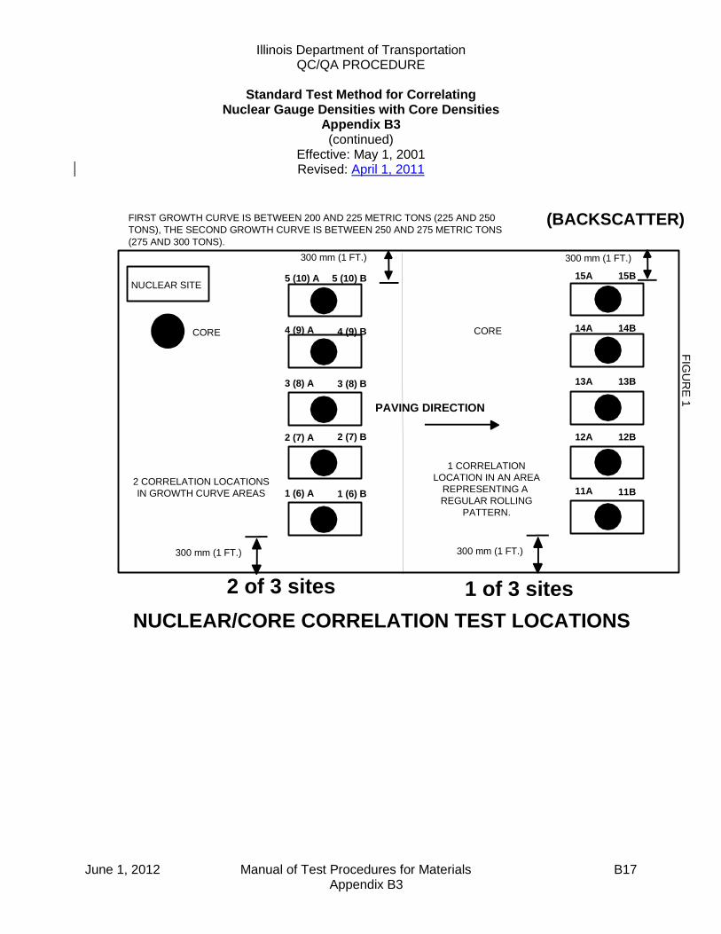
Illinois Department of Transportation QC/QA PROCEDURE
Standard Test Method for Correlating
Nuclear Gauge Densities with Core Densities Appendix B3 (continued)
Effective: May 1, 2001 Revised: April 1, 2011
June 1, 2012 Manual of Test Procedures for Materials B17 Appendix B3
(BACKSCATTER)FIRST GROWTH CURVE IS BETWEEN 200 AND 225 METRIC TONS (225 AND 250
TONS), THE SECOND GROWTH CURVE IS BETWEEN 250 AND 275 METRIC TONS
(275 AND 300 TONS).
NUCLEAR/CORE CORRELATION TEST LOCATIONS
NUCLEAR SITE
PAVING DIRECTION
300 mm (1 FT.)
300 mm (1 FT.)
1 (6) B
3 (8) B
5 (10) A
CORE
300 mm (1 FT.)
300 mm (1 FT.)
12A
13A 13B
14A
15A
CORE
FIG
UR
E 1
11A1 (6) A
2 (7) A
3 (8) A
4 (9) A
5 (10) B
4 (9) B
2 (7) B
15B
14B
12B
11B
2 of 3 sites 1 of 3 sites
1 CORRELATION
LOCATION IN AN AREA
REPRESENTING A
REGULAR ROLLING
PATTERN.
2 CORRELATION LOCATIONS
IN GROWTH CURVE AREAS

Illinois Department of Transportation QC/QA PROCEDURE
Standard Test Method for Correlating
Nuclear Gauge Densities with Core Densities Appendix B3 (continued)
Effective: May 1, 2001 Revised: April 1, 2011
June 1, 2012 Manual of Test Procedures for Materials B18 Appendix B3
FIG
UR
E 2
DIRECT TRANSMISSION MODE
DIRECT TRANSMISSION
PROBE HOLENUCLEAR SITE
1 A 1 B
1ST NUCLEAR
READING2ND NUCLEAR
READING
CORE
87.5 mm (3 1/2") MIN.
87.5 mm (3 1/2") MIN.
NOTE: FOR TEST SITE LOCATIONS, SEE BACKSCATTER EXAMPLE.
NUCLEAR/CORE CORRELATION
1A 1B

June 1, 2012 Manual of Test Procedures for Materials B19 Appendix B3
Nuclear / Core Correlation Field Worksheet
Date:
Contract: Gauge No.:
Job No.: Layer Thickness:
Route: Gmm
Base Material: Milled Binder Aggregate Other:
Mix No.:
Mix Code:
Use: (surface, 1st lift binder, etc.)
Reading 1 Reading 2 (23 kg/m3 tol.)
Reading 3 (if applicable)
Average Nuc. Core Density
STATION:
1A) 1B) 1A) 1B) 1) 1)
2A) 2B) 2A) 2B) 2) 2)
3A) 3B) 3A) 3B) 3) 3)
4A) 4B) 4A) 4B) 4) 4)
5A) 5B) 5A) 5B) 5) 5)
STATION:
6A) 6B) 6A) 6B) 6) 6)
7A) 7B) 7A) 7B) 7) 7)
8A) 8B) 8A) 8B) 8) 8)
9A) 9B) 9A) 9B) 9) 9)
10A) 10B) 10A) 10B) 10) 10)
STATION:
11A) 11B) 11A) 11B) 11) 11)
12A) 12B) 12A) 12B) 12) 12)
13A) 13B) 13A) 13B) 13) 13)
14A) 14B) 14A) 14B) 14) 14)
15A) 15B) 15A) 15B) 15) 15)

June 1, 2012 Manual of Test Procedures for Materials B20 Appendix B3
This Page Reserved

Illinois Department of Transportation
Hot-Mix Asphalt QC/QA Start-Up Procedures
Appendix B4
Effective: May 1, 1993 Revised: January 1, 2008
June 1, 2012 Manual of Test Procedures for Materials B21 Appendix B4
When required, for projects with 3000 tons (2750 metric tons) or more of each type of mix, the Contractor and the Department shall evaluate the mixture to be produced for the contract. The Contractor shall follow the following procedures for start-up. A. Contractor/Department Start-Up Team A team of Contractor and Department personnel will construct a test strip and
evaluate mix produced at the plant. The start-up team shall consist of the following:
1. Resident Engineer 2. District Construction Supervising Field Engineer, or representative 3. District Materials Mixtures Control Engineer, or representative 4. District Nuclear Density Gauge Specialist 5. Contractor's QC Manager 6. Contractor's Density Tester 7. Bureau of Materials and Physical Research representative when requested
(optional) 8. Bureau of Construction representative when requested (optional)
B. Communications The Contractor shall advise the team members of the anticipated start time of
production for the mix. The QC Manager shall direct the activities of the start-up team. A Department-appointed representative from the start-up team will act as spokesperson for the Department.
C. Acceptance Criteria
1. Mix Design and Plant Proportioning — Target values shall be provided by the Contractor and will be approved by the Department prior to start-up. Prior to beginning the start-up, the Contractor shall provide the start-up team with documentation of test data for the combined hot-bin or the combined aggregate belt sample and mineral filler at a drier-drum plant.
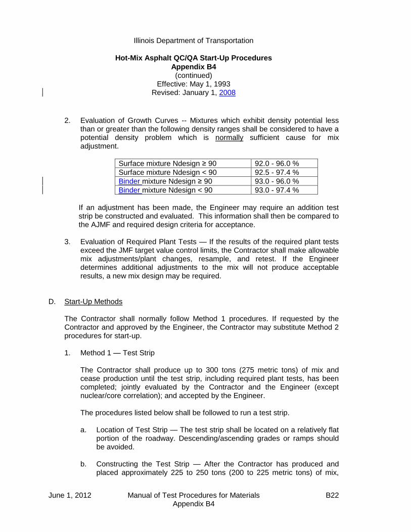
Illinois Department of Transportation
Hot-Mix Asphalt QC/QA Start-Up Procedures
Appendix B4 (continued)
Effective: May 1, 1993 Revised: January 1, 2008
June 1, 2012 Manual of Test Procedures for Materials B22 Appendix B4
2. Evaluation of Growth Curves -- Mixtures which exhibit density potential less than or greater than the following density ranges shall be considered to have a potential density problem which is normally sufficient cause for mix adjustment.
Surface mixture Ndesign ≥ 90 92.0 - 96.0 %
Surface mixture Ndesign < 90 92.5 - 97.4 %
Binder mixture Ndesign ≥ 90 93.0 - 96.0 %
Binder mixture Ndesign < 90 93.0 - 97.4 %
If an adjustment has been made, the Engineer may require an addition test strip be constructed and evaluated. This information shall then be compared to the AJMF and required design criteria for acceptance.
3. Evaluation of Required Plant Tests — If the results of the required plant tests
exceed the JMF target value control limits, the Contractor shall make allowable mix adjustments/plant changes, resample, and retest. If the Engineer determines additional adjustments to the mix will not produce acceptable results, a new mix design may be required.
D. Start-Up Methods The Contractor shall normally follow Method 1 procedures. If requested by the
Contractor and approved by the Engineer, the Contractor may substitute Method 2 procedures for start-up.
1. Method 1 — Test Strip The Contractor shall produce up to 300 tons (275 metric tons) of mix and
cease production until the test strip, including required plant tests, has been completed; jointly evaluated by the Contractor and the Engineer (except nuclear/core correlation); and accepted by the Engineer.
The procedures listed below shall be followed to run a test strip. a. Location of Test Strip — The test strip shall be located on a relatively flat
portion of the roadway. Descending/ascending grades or ramps should be avoided.
b. Constructing the Test Strip — After the Contractor has produced and
placed approximately 225 to 250 tons (200 to 225 metric tons) of mix,
Illinois Department of Transportation
Hot-Mix Asphalt QC/QA Start-Up Procedures
Appendix B4 (continued)
Effective: May 1, 1993 Revised: January 1, 2008
June 1, 2012 Manual of Test Procedures for Materials B23 Appendix B4
paving shall cease and a growth curve shall be constructed. After completion of the first growth curve, paving shall resume for the remaining 50 to 75 tons (45 to 70 metric tons), and the second growth curve shall be constructed within this area. The Contractor shall use normal rolling procedures for all portions of the test strip except for the growth curve areas which shall be compacted solely with a vibratory roller as directed by the QC Manager.
c. Required Plant Tests — The first set of mixture and gradation samples
shall be taken at such a time as to represent the mixture in between the two growth curve trucks. After an acceptable test strip, production shall be resumed and an acceptable rolling pattern shall be established within the first 200 tons (180 metric tons) of mix placed. The second series of mixture and gradation samples shall represent the first 200 tons (90 to 180 metric tons) after an acceptable test strip. All samples shall be processed expediently for determination of mix composition and volumetric properties, including air voids. This shall include dry shaking of combined belt or hot bins and ignition oven gradations prior to washing each. This test data shall meet the JMF target value control limits to be considered acceptable.
2. Method 2 — Rapid Procedure If approved by the Engineer, the Contractor may evaluate the mix off-site.
Compensation for the test strip is waived.
a. Off-site Tests — Prior to the start of mix production, the mixture shall be placed off-site, at the Contractor's expense, for evaluation of the required plant test results.
The required plant test samples shall be taken after approximately 225
tons (200 metric tons) of mixture has been placed. The Contractor shall immediately split all required plant test samples for the Department. The Contractor shall test all samples expediently for determination of mix composition and volumetric properties, including air voids. This shall include running washed gradations on combined belt or hot bins as well as ignition oven samples.
If the Contractor's and the Department's test results are acceptable, the
following testing shall be followed at the job site. b. On-Site Tests — After the Contractor has produced and placed
approximately tons 225 to 250 tons (200 to 225 metric) of mix, paving

Illinois Department of Transportation
Hot-Mix Asphalt QC/QA Start-Up Procedures
Appendix B4 (continued)
Effective: May 1, 1993 Revised: January 1, 2008
June 1, 2012 Manual of Test Procedures for Materials B24 Appendix B4
shall cease, if required by the Engineer, and a growth curve shall be constructed.
Mixture and gradation samples for required plant tests shall be taken
representing mixture in the growth curve. If the growth curve and visual evaluation of the mix are satisfactory, the
placement may be resumed. If the growth curve and visual evaluation of the mix are unsatisfactory, the Contractor shall make appropriate adjustments, resample, and retest. If the adjustments do not correct the problem, production shall cease, corrective action shall be taken, and a test strip shall be constructed.
E. Compaction Requirements
1. Compaction Equipment — The Contractor shall provide a vibratory roller meeting the requirements of Article 1101.01(g) of the Standard Specifications. It shall be the responsibility of the start-up team to verify specification compliance before commencement of growth curve construction. An appropriate amplitude shall be selected on the basis of roller weight and mat thickness to achieve maximum density. The vibratory roller speed shall be balanced with frequency so as to provide compaction at a rate of not less than 10 impacts per 1 ft. (300 mm).
2. Compaction Temperature — In order to make an accurate analysis of the
density potential of the mixture, the temperature of the mixture on the
pavement at the beginning of the growth curve shall not be less than 280 F
(140 C). 3. Compaction and Testing — The Contractor shall direct the roller speed and
number of passes required to obtain a completed growth curve. The nuclear gauge shall be placed near the center of the hot mat and the position marked for future reference. With the bottom of the nuclear gauge and source rod clean, a 1-minute nuclear reading (without mineral filler) shall be taken after each pass of the roller. Rolling shall continue until a growth curve can be plotted, the maximum density determined, and three consecutive passes show no appreciable increase in density nor evident destruction of the mat.
4. Final Testing — A final nuclear reading, using mineral filler to eliminate
surface voids, will be taken at the marked position. This reading shall be used
Illinois Department of Transportation
Hot-Mix Asphalt QC/QA Start-Up Procedures
Appendix B4 (continued)
Effective: May 1, 1993 Revised: January 1, 2008
June 1, 2012 Manual of Test Procedures for Materials B25 Appendix B4
to adjust the maximum density reading obtained during the growth curve construction.
F. Rolling Pattern After completion of a satisfactory test strip/rapid procedure and required testing,
the Contractor shall establish a rolling pattern to achieve the specified density. The rolling pattern may not be changed unless approved by the Engineer.
G. Nuclear/Core Correlation A correlation of core and nuclear gauge test results shall be performed on-site as
defined in the Department's "Standard Test Method for Correlating Nuclear Gauge Densities with Core Densities". All correlation locations shall be cooled with ice or dry ice so that cores can be taken as soon as possible. Three locations shall be selected. Two sites shall be located on the two growth curves from the first acceptable test strip. The third location shall be in an area corresponding to the second set of mixture/gradation samples taken at the plant. This correlation shall be completed at the same time by the Department and the Contractor prior to the next day's production. Smoothness of the test strip shall be to the satisfaction of the Engineer.
H. Documentation All test strips, required plant tests, and rolling pattern information (including growth
curves) will be tabulated by the Contractor with a copy provided to each team member and the original retained in the project files.

June 1, 2012 Manual of Test Procedures for Materials B26 Appendix B4
This Page Reserved
Illinois Department of Transportation
Hot-Mix Asphalt QC/QA
QC Personnel Responsibilities and Duties Checklist
Appendix B5
Effective: May 1, 1993 Revised: May 1, 2007
June 1, 2012 Manual of Test Procedures for Materials B27 Appendix B5
The following checklists detail the required minimum duties of Contractor Quality Control (QC) personnel. The QC Manager has overall responsibility to ensure that the listed duties are performed and documented. The QC Manager shall not perform sampling and/or testing except in emergency situations or in any other situation approved by the Engineer. Additional duties, as necessary, may be required to control the quality of production and placement of the Hot-Mix Asphalt (HMA) mixtures. A Level II Technician may be used to perform any Level I Technician duties.
Note: Testing frequency denoted as "P" = "Prior to Start-up" and as "D" = "Daily". A. Level I Technician
1. Checklist a. Perform incoming aggregate gradations before start-up time. (PD) ___ b. Ensure lab equipment is on hand and in working order. (PD) ___ c. Run moisture samples daily (drum only). (PD) ___ d. Determine random sampling times one day in advance and inform the QC Manager and the Engineer of the sampling times. (D) ___ e. Take required samples when required using proper procedures. (D) ___ f. Split required sample and save the Department split; use proper identification. ___ g. Run required tests as soon as possible using proper QC/QA ___ procedures. h. Take resamples as required. ___ i. Plot all random and resample results on control charts as soon as test results are available. ___ j. Take check samples when necessary. (D) ___ k. Contact QC Manager immediately when tests fail or any time problems occur. (D) ___ l. Test cores for Nuclear/Core Correlation (after Start-up). ___

Illinois Department of Transportation
Hot-Mix Asphalt QC/QA
QC Personnel Responsibilities and Duties Checklist
Appendix B5 (continued)
Effective: May 1, 1993 Revised: May 1, 2007
June 1, 2012 Manual of Test Procedures for Materials B28 Appendix B5
2. Required Tests. The minimum test frequency shall be according to Section
1030 of the Standard Specifications. However, additional tests may be required by the Engineer. a. Stockpiles (washed gradations minimum one per week for each material used) ___ b. Moisture samples (drum only) ___ c. Gradations - Belt, Cold-feed, Hot-bin, etc. ___ d. Nuclear Asphalt Content ___ e. Gmb ___ f. Gmm ___
B. QC Manager and/or Level II Technician Checklist
1. Prior to Mix Production (Preliminary Inspection)
a. Check for the approved sources of the materials:
(1) Aggregates — ensure it is from Certified Source ___
(2) Mineral filler/flyash ___
(3) Asphalt binder (See d. below.) ___
(4) Other additives ___ b. Check the aggregate stockpiling and handling procedures:
(1) Observe stockpiling procedures to ensure they are built correctly. ___
(2) Discuss loadout and sampling procedures with endloader operator. ___
(3) Sample aggregate stockpiles, in conjunction with District inspectors, and submit for Mix Designs. ___
c. Check the gradation of the aggregates:
(1) Obtain average gradation of each aggregate (including Master Bands) from the aggregate source. ___

Illinois Department of Transportation
Hot-Mix Asphalt QC/QA
QC Personnel Responsibilities and Duties Checklist
Appendix B5 (continued)
Effective: May 1, 1993 Revised: May 1, 2007
June 1, 2012 Manual of Test Procedures for Materials B29 Appendix B5
(2) Compare aggregate source information to stockpile samples at the mix plant and with the design gradation. ___
d. Check asphalt binder:
(1) Source ___
(2) Grade ___
(3) Incoming temperatures ___
(4) Specific Gravity (drum only) ___ e. Verify that the laboratory and laboratory equipment have been inspected and approved by the Department and are in good working order. ___ f. Review Hot-Mix Asphalt Level I and Level II Technician Course manuals.
2. Prior to Production/During Start-Up/During Production a. Check the mix plant for the following:
(1) Approval and calibration (P) ___
(2) Asphalt binder storage (PD) ___
(3) Stockpiles (PD) ___
(a) correct loadout ___
(b) place in proper cold-feed bins ___
(4) Cold-feed bins or bulkheads and feeders (PD) ___
(5) Dust collecting systems (D) ___
(6) Screens and screening requirements (P) ___
(7) Hot-bin sampler (P) and hot-bin overflow (PD) ___
(8) Weigh belt 6-minute check (drum only) (D) ___
(9) Temperature recorders and thermometers (PD) ___
(10) Mixing timers (batch plant only) and pugmill dam gate (continuous plants) (PD) ___
(11) Surge and storage bins (PD) ___
(12) Platform scales or suspended weigh hopper (PD) ___
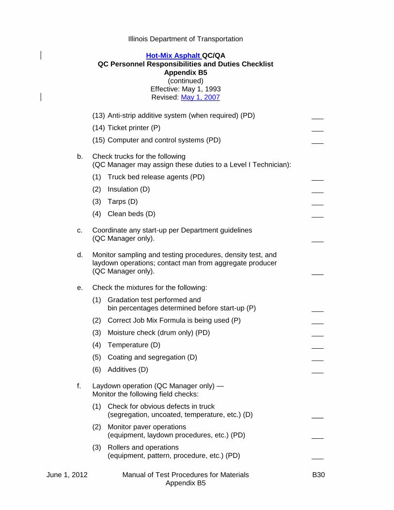
Illinois Department of Transportation
Hot-Mix Asphalt QC/QA
QC Personnel Responsibilities and Duties Checklist
Appendix B5 (continued)
Effective: May 1, 1993 Revised: May 1, 2007
June 1, 2012 Manual of Test Procedures for Materials B30 Appendix B5
(13) Anti-strip additive system (when required) (PD) ___
(14) Ticket printer (P) ___
(15) Computer and control systems (PD) ___ b. Check trucks for the following (QC Manager may assign these duties to a Level I Technician):
(1) Truck bed release agents (PD) ___
(2) Insulation (D) ___
(3) Tarps (D) ___
(4) Clean beds (D) ___
c. Coordinate any start-up per Department guidelines (QC Manager only). ___ d. Monitor sampling and testing procedures, density test, and laydown operations; contact man from aggregate producer (QC Manager only). ___ e. Check the mixtures for the following:
(1) Gradation test performed and bin percentages determined before start-up (P) ___
(2) Correct Job Mix Formula is being used (P) ___
(3) Moisture check (drum only) (PD) ___
(4) Temperature (D) ___
(5) Coating and segregation (D) ___
(6) Additives (D) ___ f. Laydown operation (QC Manager only) — Monitor the following field checks:
(1) Check for obvious defects in truck (segregation, uncoated, temperature, etc.) (D) ___
(2) Monitor paver operations (equipment, laydown procedures, etc.) (PD) ___
(3) Rollers and operations (equipment, pattern, procedure, etc.) (PD) ___

Illinois Department of Transportation
Hot-Mix Asphalt QC/QA
QC Personnel Responsibilities and Duties Checklist
Appendix B5 (continued)
Effective: May 1, 1993 Revised: May 1, 2007
June 1, 2012 Manual of Test Procedures for Materials B31 Appendix B5
(4) Mix characteristics on road (appearance, mat temperature, etc.) (D) ___
(5) Monitor densities as required (D) ___ g. Monitor all test results and make any adjustments necessary (QC Manager only) (D). ___ h. Perform scale checks (minimum one per
week per scale). Follow procedure in Construction Manual Documentation Section. ___ i. Prepare and store samples for the District laboratory as required. (D) ___ j. Ensure following records are kept and reports are submitted in a timely manner as required (QC Manager only): (D)
(1) Daily plant output ___
(2) Field gradation ___
(3) Density ___
(4) Marshall (stability and flow when required) ___
(5) Control charts ___
(6) Additives ___
(7) Scale checks ___
(8) Plant diary ___ C. Level I Technician, Level II Technician, and Quality Control Manager Duties
1. Material Source It is necessary to identify the source of the ingredients to ensure that they
have been inspected and the correct quality of aggregate, grade of asphalt binder, and anti-strip additive are being used in the specified mix. Sources shall be verified.
2. Aggregate Quality The Level II Technician may confirm the quality of the aggregate by requesting
current quality information from the District Materials office.

Illinois Department of Transportation
Hot-Mix Asphalt QC/QA
QC Personnel Responsibilities and Duties Checklist
Appendix B5 (continued)
Effective: May 1, 1993 Revised: May 1, 2007
June 1, 2012 Manual of Test Procedures for Materials B32 Appendix B5
3. Stockpiling Sites for stockpiles shall be grubbed and cleaned prior to storing the
aggregates. Separate stockpiles shall be provided for the various sources and kinds of
aggregates. Stockpiles shall be separated to prevent intermingling at the base (width of endloader bucket). If partitions are used, they shall be of sufficient heights to prevent intermingling. Aggregates for HMA mixtures shall be handled, in and out of the stockpiles, in such a manner that will prevent contamination and degradation.
Coarse aggregate stockpiles shall be built in layers not exceeding 1.5 m (5 ft)
in height and each layer shall be completely in place before the next layer is started. A stockpile may be expanded by again starting the expansion from the ground and building layers as before. End-dumping over the sides will not be permitted. Use of steel track equipment on Class B Quality, Class C Quality and all blast furnace slag aggregate stockpiles shall not be permitted where degradation is detected. When loading out of stockpiles, vertical faces shall be limited to reasonable heights to eliminate segregation due to tumbling. Segregation or degradation due to improper stockpiling or loading out of stockpiles shall be just cause for rejecting the material.
4. Gradations The Level II Technician shall obtain the average gradations as well as the
Master Bands from the aggregate source. He/She shall run the required gradation's test frequency on incoming aggregate as required in Section 1030 of the Standard Specifications.
5. Asphalt Binder
a. Incoming Asphalt Binder: The Level II Technician shall periodically check the grade and temperature of asphalt binder as received at the plant. If the asphalt binder is shipped by truck, the driver should have in his possession a numbered ticket showing the name and location of the refinery, the name of the material, date shipped, loading temperature, quantity, specific gravity or weight/L (weight/gal), and the number of the tank from which the asphalt was loaded. It is the responsibility of the refinery to load trucks only from tanks that have been tested and approved by the Department. If shipment is made by rail, a tag usually will
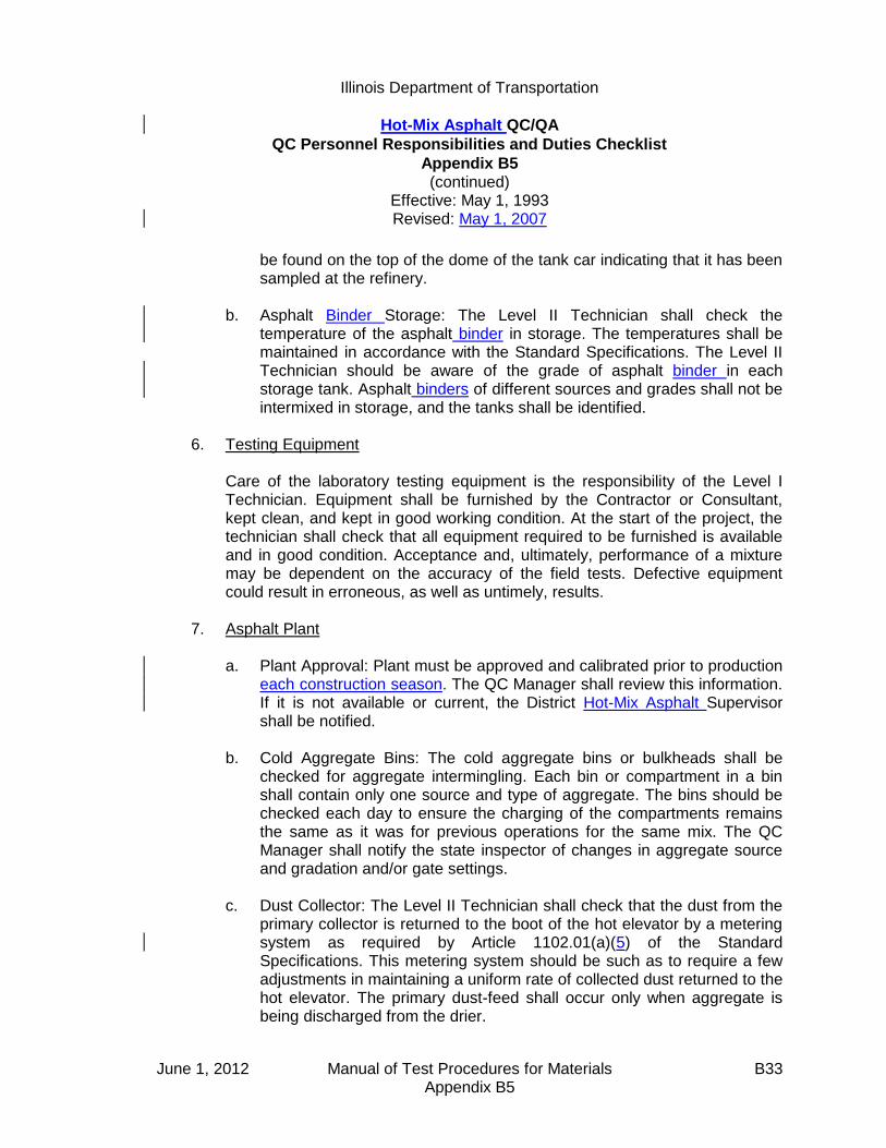
Illinois Department of Transportation
Hot-Mix Asphalt QC/QA
QC Personnel Responsibilities and Duties Checklist
Appendix B5 (continued)
Effective: May 1, 1993 Revised: May 1, 2007
June 1, 2012 Manual of Test Procedures for Materials B33 Appendix B5
be found on the top of the dome of the tank car indicating that it has been sampled at the refinery.
b. Asphalt Binder Storage: The Level II Technician shall check the
temperature of the asphalt binder in storage. The temperatures shall be maintained in accordance with the Standard Specifications. The Level II Technician should be aware of the grade of asphalt binder in each storage tank. Asphalt binders of different sources and grades shall not be intermixed in storage, and the tanks shall be identified.
6. Testing Equipment Care of the laboratory testing equipment is the responsibility of the Level I
Technician. Equipment shall be furnished by the Contractor or Consultant, kept clean, and kept in good working condition. At the start of the project, the technician shall check that all equipment required to be furnished is available and in good condition. Acceptance and, ultimately, performance of a mixture may be dependent on the accuracy of the field tests. Defective equipment could result in erroneous, as well as untimely, results.
7. Asphalt Plant
a. Plant Approval: Plant must be approved and calibrated prior to production
each construction season. The QC Manager shall review this information. If it is not available or current, the District Hot-Mix Asphalt Supervisor shall be notified.
b. Cold Aggregate Bins: The cold aggregate bins or bulkheads shall be
checked for aggregate intermingling. Each bin or compartment in a bin shall contain only one source and type of aggregate. The bins should be checked each day to ensure the charging of the compartments remains the same as it was for previous operations for the same mix. The QC Manager shall notify the state inspector of changes in aggregate source and gradation and/or gate settings.
c. Dust Collector: The Level II Technician shall check that the dust from the
primary collector is returned to the boot of the hot elevator by a metering system as required by Article 1102.01(a)(5) of the Standard Specifications. This metering system should be such as to require a few adjustments in maintaining a uniform rate of collected dust returned to the hot elevator. The primary dust-feed shall occur only when aggregate is being discharged from the drier.

Illinois Department of Transportation
Hot-Mix Asphalt QC/QA
QC Personnel Responsibilities and Duties Checklist
Appendix B5 (continued)
Effective: May 1, 1993 Revised: May 1, 2007
June 1, 2012 Manual of Test Procedures for Materials B34 Appendix B5
Plants having dry secondary collectors shall return this material to a storage silo or the mineral filler bin if it will meet the requirements of the mineral filler specifications (Section 1011 of the Standard Specifications).
d. Screens: Samples from the hot-bins shall be inspected for contamination.
An excess of coarse aggregate in the sand bin or sand in the coarse aggregate bins may indicate broken or clogged screens and/or a hole between the bins. The screens shall separate aggregate into sizes to produce a uniform gradation. If fluctuations in gradation occur, a change in screen size and/or aggregate flow rate may be required. Article 1102.01(b)(8) of the Standard Specifications shall be applied.
e. Hot-Bins: The Level II Technician is to ensure that each hot-bin overflow
pipe is working to prevent back-up of material into other compartments or bins. An overflow or sudden shortage of material in a bin may indicate a broken or clogged screen, a change in feeding rate, or a change in gradation of the aggregate being used. Overflow pipes shall not be discharged into the hot elevator.
f. Temperature Recording Device: The temperature recording devices shall
be checked for compliance with Article 1102.01(a)(7) of the Standard Specifications. A new chart shall be used each day.
g. Timers: The timers used for recycling the wet and dry mixing times for a
batch plant shall be checked and set at the required mixing times. On continuous plants, the pugmill dam gate shall be in the raised position. The required times are in the appropriate articles of the Standard Specifications.
h. Batching: The Level II Technician shall observe the batching operation to
ensure the approved batch weights are being met. Manually operated batch plants shall have markers on the scales to indicate the approved batch weight of each ingredient material. Automatic batching plants shall have posted near the scales the approved weights per bin. On continuous plants, the gate openings shall be checked for the proper setting. It is recommended that batch counters and/or ton counters be set at "zero" or that initial and final readings be taken and recorded each day.
i. Surge and Storage Bins: When a surge and storage bin are used,
approval and scale calibration information should be available. They shall be inspected for compliance with Article 1102.01(a)(6) of the Standard Specifications. Trucks shall be loaded in such a manner as to minimize segregation.

Illinois Department of Transportation
Hot-Mix Asphalt QC/QA
QC Personnel Responsibilities and Duties Checklist
Appendix B5 (continued)
Effective: May 1, 1993 Revised: May 1, 2007
June 1, 2012 Manual of Test Procedures for Materials B35 Appendix B5
j. The platform and/or suspended weigh hopper scale shall be checked for
proper zero. The scales shall be cleaned off before starting each day. k. The anti-strip additive system calibration shall be checked and the proper
flow rate determined. l. The weigh ticket printer shall be checked for information required by the
specifications. m. The computer and/or control system shall be checked to see if the correct
percentages of materials have been entered. The automatic printer for the computer of the drier drum should be turned on and working.
8. Trucks A Level I Technician, under the direct supervision of the QC Manager or the
Level II Technician, shall inspect the trucks used to transport the HMA mix. The technician shall see that each truck is provided with a cover and is properly insulated, if specified, before it is permitted to be used in the transportation of the mixture from the plant to the job. The truck bed shall be observed for foreign material before the bed is lubricated. He/She shall observe the spraying of the inside of the trucks with a release agent and shall see that no pools of release agent remain in the truck beds before loading.
9. Mixture Inspection The Level II Technician shall inspect the mixture at the plant, which includes
observing the weighing of the materials; checking the temperature of the mixture; and visually inspecting for coating of the aggregates, segregation, and moisture in the mixture. The Level I Technician shall sample and determine the gradation of the hot-bins and/or cold-feeds and the proper amount of asphalt binder being used to ensure conformity to the mix formula. The Level II Technician shall also verify and document the addition rates of the anti-strip additives.
In addition, the Level I Technician shall perform the required core density tests
and, when required, extraction tests at the field laboratory. The QC Manager shall furnish the Contractor with the mixing formulas which
have been established for a specific combination of sources of ingredients. The formulas shall state the percentage of aggregate for each sieve fraction and the percentage of asphalt binder. These formulas are to be used in

Illinois Department of Transportation
Hot-Mix Asphalt QC/QA
QC Personnel Responsibilities and Duties Checklist
Appendix B5 (continued)
Effective: May 1, 1993 Revised: May 1, 2007
June 1, 2012 Manual of Test Procedures for Materials B36 Appendix B5
proportioning the ingredient materials for HMA mixtures within the specified tolerances. Changes in the mix formulas are to be made only by the QC Manager.
It is important that the QC Manager observe the laying and compaction of the
mixture. Mixture variations are noticeable in the completed work, and variations that are
not apparent in the mixture at the plant sometimes show up as defects in the texture and uniformity of the surface. Flushing of the mixture is a defect that can be detected only on the road.
It is the duty of both the Level I and Level II Technicians to establish and
maintain an open line of communications. Timely and appropriate actions can be instituted by early detection of defects
or mixture variations. 10. Scale Checks When measurement of mixtures is on the basis of weights obtained from
batch weights or automatic printers, occasional scale checks shall be made by weighing full truckloads of the mixture on an approved platform scale at the plant site or on a commercial scale approved by the Engineer. The frequency and procedure for the check tests are described in the "Documentation" section of the [Bureau of] Construction Manual. The tests will be performed by the Level II Technician and reported on the "Daily Plant Output Report" and/or form BC 2367.
11. Samples The Level I Technician shall take check samples of the mixture in addition to
the required samples. He/She must also store split samples in a dry storage area for the Engineer. Section 1030 of the Standard Specifications discusses sampling procedures and sampling frequency.
12. Reports The Quality Control Manager is responsible for completion of a "Daily Plant
Output Report" (MI 305) for each day of production for each type of mix. Other reports, when required, are "Sample Identification" (LM-6), and Scale Checks.
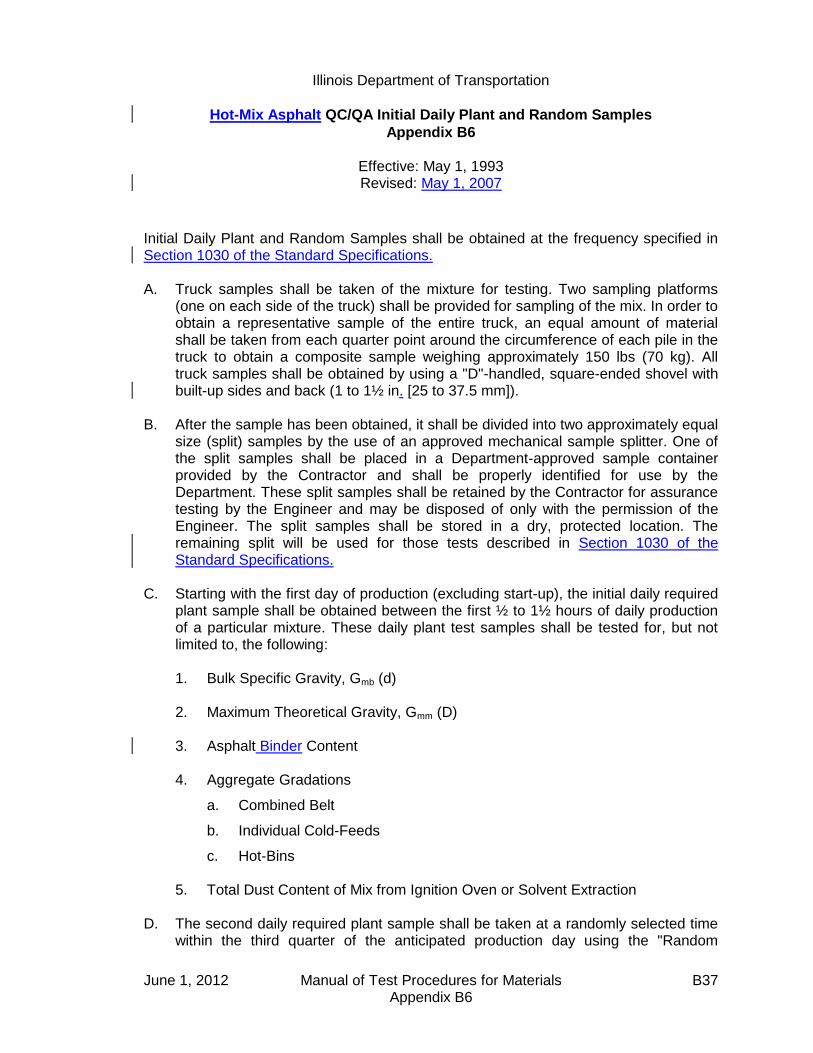
Illinois Department of Transportation
Hot-Mix Asphalt QC/QA Initial Daily Plant and Random Samples
Appendix B6
Effective: May 1, 1993 Revised: May 1, 2007
June 1, 2012 Manual of Test Procedures for Materials B37 Appendix B6
Initial Daily Plant and Random Samples shall be obtained at the frequency specified in Section 1030 of the Standard Specifications. A. Truck samples shall be taken of the mixture for testing. Two sampling platforms
(one on each side of the truck) shall be provided for sampling of the mix. In order to obtain a representative sample of the entire truck, an equal amount of material shall be taken from each quarter point around the circumference of each pile in the truck to obtain a composite sample weighing approximately 150 lbs (70 kg). All truck samples shall be obtained by using a "D"-handled, square-ended shovel with built-up sides and back (1 to 1½ in. [25 to 37.5 mm]).
B. After the sample has been obtained, it shall be divided into two approximately equal
size (split) samples by the use of an approved mechanical sample splitter. One of the split samples shall be placed in a Department-approved sample container provided by the Contractor and shall be properly identified for use by the Department. These split samples shall be retained by the Contractor for assurance testing by the Engineer and may be disposed of only with the permission of the Engineer. The split samples shall be stored in a dry, protected location. The remaining split will be used for those tests described in Section 1030 of the Standard Specifications.
C. Starting with the first day of production (excluding start-up), the initial daily required
plant sample shall be obtained between the first ½ to 1½ hours of daily production of a particular mixture. These daily plant test samples shall be tested for, but not limited to, the following: 1. Bulk Specific Gravity, Gmb (d) 2. Maximum Theoretical Gravity, Gmm (D) 3. Asphalt Binder Content 4. Aggregate Gradations
a. Combined Belt
b. Individual Cold-Feeds
c. Hot-Bins
5. Total Dust Content of Mix from Ignition Oven or Solvent Extraction
D. The second daily required plant sample shall be taken at a randomly selected time within the third quarter of the anticipated production day using the "Random

Illinois Department of Transportation
Hot-Mix Asphalt QC/QA Initial Daily Plant and Random Samples
Appendix B6 (continued)
Effective: May 1, 1993 Revised: May 1, 2007
June 1, 2012 Manual of Test Procedures for Materials B38 Appendix B6
Numbers" table on the following page or the Department's QC/QA computer software. For HMA mixtures classified as “All Other” the Contractor shall use the anticipated full production day when calculating the random sampling time. The anticipated full production day shall be the time from a ½ hour after production begins to a ½ hour before production ends. The following procedure shall be used to calculate the second daily required plant sampling time.
1. Multiply the quarter production day (in minutes) by a three digit random
number, expressed as a decimal, selected from the "Random Numbers" table or the Department's QC/QA computer software.
2. The number obtained (rounded to a whole number) shall be added to the
starting time of the third quarter. The time represented by this addition is the randomly selected sampling time.
If the plant is producing HMA mixtures intermittently, the samples shall be
taken as close to the determined time as possible.

Illinois Department of Transportation
Hot-Mix Asphalt QC/QA Initial Daily Plant and Random Samples
Appendix B6 (continued)
Effective: May 1, 1993 Revised: May 1, 2007
June 1, 2012 Manual of Test Procedures for Materials B39 Appendix B6
RANDOM NUMBERS
0.576 0.730 0.430 0.754 0.271 0.870 0.732 0.721 0.998 0.239 0.892 0.948 0.858 0.025 0.935 0.114 0.153 0.508 0.749 0.291 0.669 0.726 0.501 0.402 0.231 0.505 0.009 0.420 0.517 0.858 0.609 0.482 0.809 0.140 0.396 0.025 0.937 0.301 0.253 0.761 0.971 0.824 0.902 0.470 0.997 0.392 0.892 0.957 0.040 0.463 0.053 0.899 0.554 0.627 0.427 0.760 0.470 0.040 0.904 0.993 0.810 0.159 0.225 0.163 0.549 0.405 0.285 0.542 0.231 0.919 0.081 0.277 0.035 0.039 0.860 0.507 0.081 0.538 0.986 0.501 0.982 0.468 0.334 0.921 0.690 0.806 0.879 0.414 0.106 0.031 0.095 0.801 0.576 0.417 0.251 0.884 0.522 0.235 0.389 0.222 0.509 0.025 0.794 0.850 0.917 0.887 0.751 0.608 0.698 0.683 0.371 0.059 0.164 0.838 0.289 0.169 0.569 0.977 0.796 0.996 0.165 0.996 0.356 0.375 0.654 0.979 0.815 0.592 0.348 0.743 0.477 0.535 0.137 0.155 0.767 0.187 0.579 0.787 0.358 0.595 0.788 0.101 0.434 0.638 0.021 0.894 0.324 0.871 0.698 0.539 0.566 0.815 0.622 0.548 0.947 0.169 0.817 0.472 0.864 0.466 0.901 0.342 0.873 0.964 0.942 0.985 0.123 0.086 0.335 0.212 0.470 0.682 0.412 0.064 0.150 0.962 0.925 0.355 0.909 0.019 0.068 0.242 0.777 0.356 0.195 0.313 0.396 0.460 0.740 0.247 0.874 0.420 0.127 0.284 0.448 0.215 0.833 0.652 0.701 0.326 0.897 0.877 0.209 0.862 0.428 0.117 0.100 0.259 0.425 0.284 0.876 0.969 0.109 0.843 0.759 0.239 0.890 0.317 0.428 0.802 0.190 0.696 0.757 0.283 0.777 0.491 0.523 0.665 0.919 0.146 0.341 0.688 0.587 0.908 0.865 0.333 0.928 0.404 0.892 0.696 0.846 0.355 0.831 0.281 0.945 0.364 0.673 0.305 0.195 0.887 0.882 0.227 0.552 0.077 0.454 0.731 0.716 0.265 0.058 0.075 0.464 0.658 0.629 0.269 0.069 0.998 0.917 0.217 0.220 0.659 0.123 0.791 0.503 0.447 0.659 0.463 0.994 0.307 0.631 0.422 0.116 0.120 0.721 0.137 0.263 0.176 0.798 0.879 0.432 0.391 0.836 0.206 0.914 0.574 0.870 0.390 0.104 0.755 0.082 0.939 0.636 0.195 0.614 0.486 0.629 0.663 0.619 0.007 0.296 0.456 0.630 0.673 0.665 0.666 0.399 0.592 0.441 0.649 0.270 0.612 0.804 0.112 0.331 0.606 0.551 0.928 0.830 0.841 0.702 0.183 0.360 0.193 0.181 0.399 0.564 0.772 0.890 0.062 0.919 0.875 0.183 0.651 0.157 0.150 0.800 0.875 0.205 0.446 0.648 0.685
Note: Always select a new set of numbers in a systematic manner, either horizontally or vertically. Once used, the set should be crossed out.

June 1, 2012 Manual of Test Procedures for Materials B40 Appendix B6
This Page Reserved

Illinois Department of Transportation
Determination of Random Density Locations
Appendix B7
Effective: May 1, 1993 Revised: April 1, 2011
June 1, 2012 Manual of Test Procedures for Materials B41 Appendix B7
Density tests (core or nuclear gauge) shall be performed at randomly located sites based on the frequency specified in Section 1030 of the Standard Specifications. The random test locations shall be determined as follows: A. The beginning station number shall be established daily and the estimated paving
distance computed for the day's production. The total distance to be paved shall then be subdivided into units representing 2640-ft. (800-m) or 1320-ft. (400-m) frequency.
B. The length of each unit shall be multiplied by the three digit random number
expressed as a decimal from the "Random Numbers" table on the following page or from the Department's QC/QA computer software. The number obtained shall be added to the beginning station number for the unit to determine the center of the test site location.
C. This process shall be repeated for the subsequent units for the day's production
using a new random number for each location. D. The partial unit at the end of each day shall be considered a whole unit, and the
test location shall be determined by multiplying the partial distance by the next available random number.

Illinois Department of Transportation
Determination of Random Density Locations
Appendix B7 (continued)
Effective: May 1, 1993 Revised: April 1, 2011
June 1, 2012 Manual of Test Procedures for Materials B42 Appendix B7
RANDOM NUMBERS
0.576 0.730 0.430 0.754 0.271 0.870 0.732 0.721 0.998 0.239 0.892 0.948 0.858 0.025 0.935 0.114 0.153 0.508 0.749 0.291 0.669 0.726 0.501 0.402 0.231 0.505 0.009 0.420 0.517 0.858 0.609 0.482 0.809 0.140 0.396 0.025 0.937 0.301 0.253 0.761 0.971 0.824 0.902 0.470 0.997 0.392 0.892 0.957 0.040 0.463 0.053 0.899 0.554 0.627 0.427 0.760 0.470 0.040 0.904 0.993 0.810 0.159 0.225 0.163 0.549 0.405 0.285 0.542 0.231 0.919 0.081 0.277 0.035 0.039 0.860 0.507 0.081 0.538 0.986 0.501 0.982 0.468 0.334 0.921 0.690 0.806 0.879 0.414 0.106 0.031 0.095 0.801 0.576 0.417 0.251 0.884 0.522 0.235 0.389 0.222 0.509 0.025 0.794 0.850 0.917 0.887 0.751 0.608 0.698 0.683 0.371 0.059 0.164 0.838 0.289 0.169 0.569 0.977 0.796 0.996 0.165 0.996 0.356 0.375 0.654 0.979 0.815 0.592 0.348 0.743 0.477 0.535 0.137 0.155 0.767 0.187 0.579 0.787 0.358 0.595 0.788 0.101 0.434 0.638 0.021 0.894 0.324 0.871 0.698 0.539 0.566 0.815 0.622 0.548 0.947 0.169 0.817 0.472 0.864 0.466 0.901 0.342 0.873 0.964 0.942 0.985 0.123 0.086 0.335 0.212 0.470 0.682 0.412 0.064 0.150 0.962 0.925 0.355 0.909 0.019 0.068 0.242 0.777 0.356 0.195 0.313 0.396 0.460 0.740 0.247 0.874 0.420 0.127 0.284 0.448 0.215 0.833 0.652 0.701 0.326 0.897 0.877 0.209 0.862 0.428 0.117 0.100 0.259 0.425 0.284 0.876 0.969 0.109 0.843 0.759 0.239 0.890 0.317 0.428 0.802 0.190 0.696 0.757 0.283 0.777 0.491 0.523 0.665 0.919 0.146 0.341 0.688 0.587 0.908 0.865 0.333 0.928 0.404 0.892 0.696 0.846 0.355 0.831 0.281 0.945 0.364 0.673 0.305 0.195 0.887 0.882 0.227 0.552 0.077 0.454 0.731 0.716 0.265 0.058 0.075 0.464 0.658 0.629 0.269 0.069 0.998 0.917 0.217 0.220 0.659 0.123 0.791 0.503 0.447 0.659 0.463 0.994 0.307 0.631 0.422 0.116 0.120 0.721 0.137 0.263 0.176 0.798 0.879 0.432 0.391 0.836 0.206 0.914 0.574 0.870 0.390 0.104 0.755 0.082 0.939 0.636 0.195 0.614 0.486 0.629 0.663 0.619 0.007 0.296 0.456 0.630 0.673 0.665 0.666 0.399 0.592 0.441 0.649 0.270 0.612 0.804 0.112 0.331 0.606 0.551 0.928 0.830 0.841 0.702 0.183 0.360 0.193 0.181 0.399 0.564 0.772 0.890 0.062 0.919 0.875 0.183 0.651 0.157 0.150 0.800 0.875 0.205 0.446 0.648 0.685
Note: Always select a new set of numbers in a systematic manner, either horizontally or vertically. Once used, the set should be crossed out.
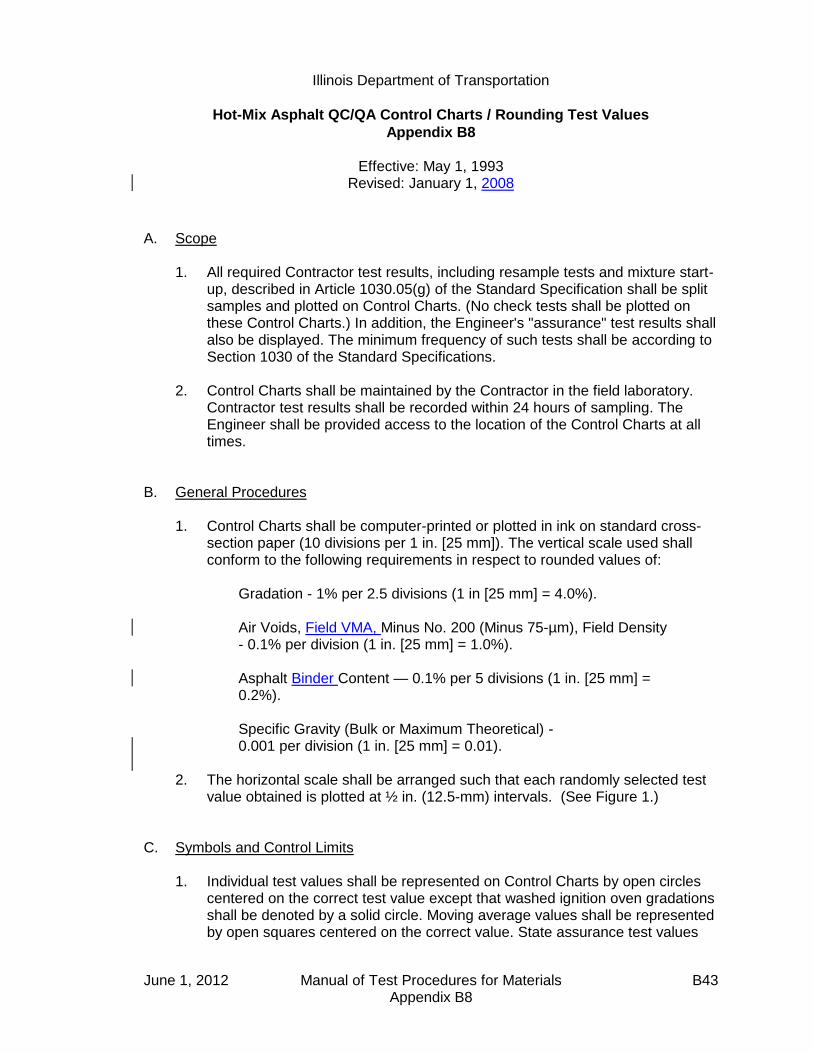
Illinois Department of Transportation
Hot-Mix Asphalt QC/QA Control Charts / Rounding Test Values
Appendix B8
Effective: May 1, 1993 Revised: January 1, 2008
June 1, 2012 Manual of Test Procedures for Materials B43 Appendix B8
A. Scope
1. All required Contractor test results, including resample tests and mixture start-up, described in Article 1030.05(g) of the Standard Specification shall be split samples and plotted on Control Charts. (No check tests shall be plotted on these Control Charts.) In addition, the Engineer's "assurance" test results shall also be displayed. The minimum frequency of such tests shall be according to Section 1030 of the Standard Specifications.
2. Control Charts shall be maintained by the Contractor in the field laboratory.
Contractor test results shall be recorded within 24 hours of sampling. The Engineer shall be provided access to the location of the Control Charts at all times.
B. General Procedures
1. Control Charts shall be computer-printed or plotted in ink on standard cross-section paper (10 divisions per 1 in. [25 mm]). The vertical scale used shall conform to the following requirements in respect to rounded values of:
Gradation - 1% per 2.5 divisions (1 in [25 mm] = 4.0%). Air Voids, Field VMA, Minus No. 200 (Minus 75-µm), Field Density - 0.1% per division (1 in. [25 mm] = 1.0%). Asphalt Binder Content — 0.1% per 5 divisions (1 in. [25 mm] = 0.2%). Specific Gravity (Bulk or Maximum Theoretical) - 0.001 per division (1 in. [25 mm] = 0.01).
2. The horizontal scale shall be arranged such that each randomly selected test value obtained is plotted at ½ in. (12.5-mm) intervals. (See Figure 1.)
C. Symbols and Control Limits
1. Individual test values shall be represented on Control Charts by open circles centered on the correct test value except that washed ignition oven gradations shall be denoted by a solid circle. Moving average values shall be represented by open squares centered on the correct value. State assurance test values

Illinois Department of Transportation
Hot-Mix Asphalt QC/QA Control Charts / Rounding Test Values
Appendix B8
Effective: May 1, 1993 Revised: January 1, 2008
June 1, 2012 Manual of Test Procedures for Materials B44 Appendix B8
shall be represented by solid triangles for washed ignition gradations and by open triangles for dry gradations. All symbols shall be 0.1 in. (2.5 mm) in their largest dimension.
2. Individual test values shall be connected by dashed lines. Department
assurance test values shall not be connected with any other point. Moving average data points shall be connected by solid lines.
3. Target values shall be represented on Control Charts by horizontal solid lines.
Appropriate control limits (solid lines) for each control parameter shall extend horizontally across the chart and be identified with an appropriate solid symbol corresponding to the type of test it represents, i.e., individual or moving average.
D. Individual Test Values and Moving Average
1. Moving averages are applicable to all values except Department assurance split samples. The moving average is the average of four consecutive test values and is determined by starting with the fourth test value and averaging it with the three preceding test values. Plotting the average thereafter will be done in a similar manner starting with the test value just completed. Rounding procedures for the moving average are the same as used for the individual test values.
The moving average for minus 200 (minus 75 µm) for HMA production control shall include both washed ignition oven gradation and adjusted dry gradation individual results. When a given sublot includes both washed ignition and dry gradation test results for the minus 200 (minus 75 µm), only the washed ignition shall be used in the moving average.
The moving average for Gmm of a new mixture shall be established initially with the results from the start-up and shall include more tests in the moving average as they occur until the moving average of four is established. Unless otherwise specified by the Engineer, the moving average for Gmm of a previously placed mixture shall begin with the most recent moving average of four and shall be averaged with subsequent test results.

Illinois Department of Transportation
Hot-Mix Asphalt QC/QA Control Charts / Rounding Test Values
Appendix B8
Effective: May 1, 1993 Revised: January 1, 2008
June 1, 2012 Manual of Test Procedures for Materials B45 Appendix B8
2. At the bottom of the chart under the line on which the individual test data is plotted, the following information shall be listed:
a. Date and specific time (include a.m. or p.m.) of sampling. b. Lot Number. c. Test Sequence. d. Quantity of material represented (produced since previous test). e. Initials of person performing the test. f. Use "(rs)" to denote resample.
E. Mixture Start-Up Test Values
1. Test values obtained during start-up and the Job Mix Formula (JMF) adjustment period shall be placed at the beginning of the Control Charts. Once all these required tests have been completed and their values recorded, two vertical double black lines shall be drawn on the graph ½ in. (12.5 mm) apart. This constitutes the field verification process for the mixture.
2. At the completion of the field verification, production under QC/QA shall be
initiated with the agreed upon targets and appropriate limits being placed on the graph. Individual required plant test results shall be recorded from this point on with a moving average being established at the completion of the fourth test.
F. Adjusting Targets
1. If the adjustments in gradation or asphalt binder content are required in order to maintain proper voids, they shall be made according to Section 1030.06 of the Standard Specifications and shall be appropriately documented on the Control Charts.
2. When an adjustment to the Target value is made, two vertical double black
lines shall be drawn on the graph ½ in. (12.5 mm) apart. The new target value plus upper and lower control values will be placed on the chart. The moving average will continue as though the adjustment had not taken place.

Illinois Department of Transportation
Hot-Mix Asphalt QC/QA Control Charts / Rounding Test Values
Appendix B8
Effective: May 1, 1993 Revised: January 1, 2008
June 1, 2012 Manual of Test Procedures for Materials B46 Appendix B8
G. Resample Test Values The Contractor resample tests for a failed individual test shall be the only biased
process control test placed on the Control Chart. It shall be denoted by a circle (closed for washed gradations and open for all other tests) with its value placed on the vertical line which corresponds to the time or lot from which the resample was taken. A circle shall be drawn around this value and the failed test value which the resample represents. Both the failed test value and the resample test value shall be used as individual points in determining moving averages.
H. Rounding Test Values
1. The intent of rounding is to limit the number of digits in an observed or calculated value to those considered significant for the purpose of determining conformance with specification limits.
If improperly applied, rounding may contribute to loss of precision and result in
increased risk to either the Department or Contractor. The following are the appropriate significant digits to which test values are to
be rounded for parameters described in the Section 1030:
Test Significant Digit Gradation (% Passing);
Nearest whole percent (no decimal)
Field Density: Air Voids; Minus No. 200 (Minus 75-µm); Asphalt Binder Content
Nearest one-tenth percent (0.1%)
Bulk Gravity, Gmb; Maximum Gravity, Gmm
Nearest one-thousandth (0.001)
Rounding of test results shall be according to Illinois-Modified ASTM E 29,
"Standard Practice for Using Significant Digits in Test Data to Determine Conformance with Specifications", located in this manual.
Illinois Department of Transportation
Hot-Mix Asphalt Mixture Design Verification Procedure
Appendix B9
Effective Date: January 1, 2002 Revised: January 1, 2013
January 1, 2013 Manual of Test Procedures for Materials B47 Appendix B9
1.0 GENERAL Contractors shall provide all hot-mix asphalt (HMA) mix designs for use on
Department contracts. All mix designs must provide mixture meeting Department mix criteria. The Department will provide current aggregate bulk specific gravity. The Engineer reserves the right to be present for the sampling of all aggregates for mix designs. Once verified, a mix design will be approved for use for a three year period. After three years, the mix design shall be redesigned if necessary, and re-verified.
2.0 PURPOSE Establish a verification procedure to evaluate Contractor mix designs for use on
Department contracts. This procedure also allows for comparison of the test accuracy and precision between laboratories.
3.0 REQUIRED DESIGN DATA/MATERIAL SAMPLES 3.1 The Contractor shall provide a mix design prepared by a Hot-Mix Asphalt Level III
Technician in accordance with the Department's "Hot-Mix Asphalt Design Procedure" in the current Hot-Mix Asphalt Level III Technician Course manual. All testing shall be performed by Hot-Mix Asphalt Level I Technicians or higher. The mix design shall be submitted with the following design data:
A. The material name, material code number, source name, source
Producer/Supplier Number, and source location shall be provided for all materials used in the mix design.
B. The Contractor shall provide the average mix plant stockpile gradations and
aggregate blend percentages used to design the mix. Each of the individual aggregate gradations used in the Contractor design shall be an average of a minimum of 5 (five) stockpile gradations from existing stockpiles at the plant. Adjusted average aggregate source gradations (stockpile gradations preferred) may be substituted if aggregate has not been shipped to the mix plant. The adjustment shall be based on the amount of aggregate degradation during shipment to, and handling at, the mix plant. A design using gradation information not comparing to mix plant or aggregate source gradations shall be considered unacceptable.

Illinois Department of Transportation
Hot-Mix Asphalt Mixture Design Verification Procedure
Appendix B9 (continued)
Effective Date: January 1, 2002 Revised: January 1, 2013
January 1, 2013 Manual of Test Procedures for Materials B48 Appendix B9
C. The Contractor shall provide a summary of design test data and optimum design data utilizing a design package with the same output format as CARE-AC.
(1) Design sheet. The design shall contain a minimum of four design
points, two of which shall bracket the optimum design asphalt binder
(AB) content by at least 0.5%. Under remarks include: short-term aging time, dust correction factor, compaction temperature, and mixing temperature.
(2) Design summary data sheet (in CARE-AC format). (3) Actual graph paper from the stability machine and actual Gmm lab
worksheets (original copy unless otherwise specified). (4) Batching worksheet. (5) Dust correction worksheet (include an example packet, such as the
one from the Level III manual). (6) Batching sources sheet.
(7) Mix design graphs (full page).
(a) Gradation (45 power curve). (b) Asphalt Binder Content vs. Gmb/Gmm. (c) Asphalt Binder Content vs. VMA. (d) Asphalt Binder Content vs. Air Voids. (e) Asphalt Binder Content vs. Voids Filled with Asphalt (VFA).
(8) Recalculations and/or retested points (e.g., recalculated Gmm's using
average Gse).
(9) TSR worksheet.
The forms used shall be the Department's computer spreadsheet from CARE-AC, or other forms having the same format as CARE-AC.

Illinois Department of Transportation
Hot-Mix Asphalt Mixture Design Verification Procedure
Appendix B9 (continued)
Effective Date: January 1, 2002 Revised: January 1, 2013
January 1, 2013 Manual of Test Procedures for Materials B49 Appendix B9
3.2 The Contractor shall provide samples of blended aggregate, asphalt binder, and additives which represent the materials in the mix design. The representative samples shall be identified and submitted as follows:
A. Aggregate (including mineral filler/collected dust) -- Dried, split into the individual
sizes specified for the Batching Worksheet as stated in the current Hot-Mix Asphalt Level III Technician Course manual, and then blended to the chosen gradation. The amount submitted shall be two (2) 10,000-gram samples of dry aggregate, with an additional 2,000 grams for gradation testing if requested by the District. All material shall be bagged in plastic bags or other airtight containers. Each container shall be identified with the source names, source locations, source Producer/Supplier Numbers, material codes, sample location, and sample date.
B. Asphalt Binder -- A minimum of 4 qts (4,000 mL ). Identified with source name,
source location, source Producer/Supplier Number, material code, sample location, and sample date.
C. Additive(s) -- The same additive(s) as used in the Contractor's design, identified
by the additive source name, source location, brand name or number, material code, sample location, sample date, additive MSDS, the manufacturer's recommended dosage rate, and the rate used in the design if different than the manufacturer's recommended dosage rate. NOTE: Prior to submitting the additive(s), the Contractor shall contact the District Materials Engineer for the required sample size.
3.3 All design data and material samples shall be submitted to the Department a
minimum of 30 calendar days prior to production. 3.4 The Contractor shall certify in writing that all materials submitted for mix design
verification meet Department requirements and represent the materials to be used during mix production.
3.5 Previously verified mix designs shall be resubmitted for verifications as per
Section 4.1 herein. 4.0 DEPARTMENT VERIFICATION 4.1 At the option of the Department, mix designs may be verified using either Method A
or Method B listed below:

Illinois Department of Transportation
Hot-Mix Asphalt Mixture Design Verification Procedure
Appendix B9 (continued)
Effective Date: January 1, 2002 Revised: January 1, 2013
January 1, 2013 Manual of Test Procedures for Materials B50 Appendix B9
Method A. Department verification for mix designs will include review of all mix design data (including all aggregate field gradations) submitted by the Contractor, mixing the component materials submitted by the Contractor, and testing of the asphalt mixture. Verification testing will include volumetric, TSR and Hamburg Wheel on a mixture made from the individual materials submitted by the Contractor. The mixture at the optimum design asphalt binder content shall meet the mix design criteria for the following: VMA, VFA, Gmb, Gmm, Pa (voids), Tensile Strengths, TSR values, and Hamburg Wheel.
Method B. Department verification for mix designs will be based on 1) a review of
all mix design data (including all aggregate field gradations) submitted by the Contractor and 2) Department verification testing for IL Modified AASHTO T 283 and IL Modified AASHTO T 324. IL Modified AASHTO T 324 will not be required for “All Other” HMA mixes.
4.2 The Contractor mix design data and Department verification testing shall meet the mix
design criteria in the Standard Specifications, any Special Provision in the Contract, and the following tolerances (where applicable):
Volumetric Testing Tolerance
Gse (effective SG of combined aggregates) ± 0.014
Gmb ± 0.020
Gmm ± 0.014
Air Voids ± 0.5 %
Gradation Tolerance
12.5 mm (1/2 in) ± 3.0
4.75 mm (No. 4) ± 2.0
2.36 mm (No. 8) ± 2.0
600 µm (No. 30) ± 1.0
75 µm (No. 200) ± 0.5
Pb (Asphalt Binder Content) ± 0.15
Illinois Department of Transportation
Hot-Mix Asphalt Mixture Design Verification Procedure
Appendix B9 (continued)
Effective Date: January 1, 2002 Revised: January 1, 2013
January 1, 2013 Manual of Test Procedures for Materials B51 Appendix B9
All aggregate field gradations submitted by the Contractor will be compared to previous mix plant and/or Aggregate Gradation Control System gradations for validity.
4.3 The Department will notify the Contractor in writing within 30 calendar days of
receiving the design data/materials as to the acceptability of the submitted Contractor mix design. If the verification fails, the 30-calendar-day time for the Department to notify the Contractor starts over. Acceptable designs may be used in Department contracts, provided the design is reproducible in the mix plant.

January 1, 2013 Manual of Test Procedures for Materials B52 Appendix B9
This Page Reserved
Illinois Department of Transportation
Illinois Test Procedure 401
Storage of Hot-Mix Asphalt Mixtures
Appendix B10
Effective: January 1, 2002 Revised: May 1, 2007
June 1, 2012 Manual of Test Procedures for Materials B53 Appendix B10
1.0 SCOPE
1.1 The purpose of this procedure is to evaluate the effect of 20-hour storage on hot-mix asphalt.
1.2 Article 1102.01(a)(10) of the IDOT Standard Specifications for Road and
Bridge Construction allows for the storage of hot-mix asphalt in surge systems designed and operated to prevent segregation and loss of temperature. The specification allows for a maximum retention of eight hours. Longer retention times must be approved in writing by the Engineer.
2.0 REFERENCED DOCUMENTS
2.1 Illinois Modified AASHTO T 164, Method A or E 2.2 Illinois Modified AASHTO T 170
3.0 EQUIPMENT
3.1 One-quart (1-liter) and 1-gallon (4-liter) metal containers with lids for sample storage and transportation.
4.0 PROCEDURE 4.1 The Bureau of Materials and Physical Research will evaluate the effect of
additional storage time on the mixture. The Engineer will direct the Contractor to sample the mixture based on the following procedure. The Engineer reserves the right to witness the sampling.
4.2 The Contractor shall provide a minimum of 20 hours of uninterrupted
storage of the mixture to be sampled. 4.3 The bin must be filled with a binder mixture at a time mutually agreed
upon by the Contractor and Engineer. 4.4 A 1-quart (1-liter) sample of the asphalt binder shall be taken at this time. 4.5 A 1-gallon (4-liter) sample of the mixture shall be taken at this time.
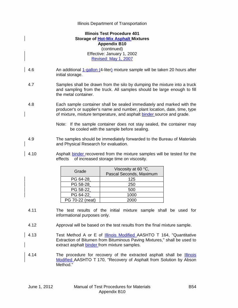
Illinois Department of Transportation
Illinois Test Procedure 401
Storage of Hot-Mix Asphalt Mixtures
Appendix B10 (continued)
Effective: January 1, 2002 Revised: May 1, 2007
June 1, 2012 Manual of Test Procedures for Materials B54 Appendix B10
4.6 An additional 1-gallon (4-liter) mixture sample will be taken 20 hours after initial storage.
4.7 Samples shall be drawn from the silo by dumping the mixture into a truck
and sampling from the truck. All samples should be large enough to fill the metal container.
4.8 Each sample container shall be sealed immediately and marked with the
producer's or supplier's name and number, plant location, date, time, type of mixture, mixture temperature, and asphalt binder source and grade.
Note: If the sample container does not stay sealed, the container may
be cooled with the sample before sealing.
4.9 The samples should be immediately forwarded to the Bureau of Materials and Physical Research for evaluation.
4.10 Asphalt binder recovered from the mixture samples will be tested for the
effects of increased storage time on viscosity.
Grade Viscosity at 60 °C,
Pascal Seconds, Maximum
PG 64-28 125
PG 58-28 250
PG 58-22 500
PG 64-22 1000
PG 70-22 (neat) 2000
4.11 The test results of the initial mixture sample shall be used for
informational purposes only. 4.12 Approval will be based on the test results from the final mixture sample. 4.13 Test Method A or E of Illinois Modified AASHTO T 164, "Quantitative
Extraction of Bitumen from Bituminous Paving Mixtures," shall be used to extract asphalt binder from mixture samples.
4.14 The procedure for recovery of the extracted asphalt shall be Illinois
Modified AASHTO T 170, "Recovery of Asphalt from Solution by Abson Method."

Illinois Department of Transportation
Calibration of Equipment for Asphalt Binder Content Determination
(Nuclear Gauge and Ignition Oven)
Appendix B11
Effective Date: January 1, 2002 Revised: May 1, 2007
June 1, 2012 Manual of Test Procedures for Materials B55 Appendix B11
A. Scope The Contractor may be required to use the nuclear gauge or ignition oven to determine the asphalt binder content of a Hot-Mix Asphalt (HMA) mixture. To ensure consistency, both the Contractor and the Department shall calibrate the device(s) in the same manner using the same mixture.
B. Purpose To provide consistent calibration between the Contractor's and Department's asphalt binder content determination equipment. The procedure also applies to any third-party gauges used for Quality Control, Quality Assurance, Independent Assurance, or Acceptance testing.
C. Nuclear Asphalt Content Gauge 1. Department Verification
a. All HMA mixture designs shall be verified in accordance with the Department's "Hot-Mix Asphalt Design Verification Procedure" before submitting materials for the nuclear asphalt binder content gauge calibration.
b. The Contractor shall provide a mix design prepared by a Hot-Mix Asphalt
Level III Technician in accordance with the Department's current Hot-Mix Asphalt Level III Technician Course manual, "Hot-Mix Asphalt Design Procedure". All testing shall be performed by Hot-Mix Asphalt Level I Technicians or higher.
c. At the option of the Department, previously verified mixtures may be
accepted by reviewing the data listed in Section 11 of Illinois Modified AASHTO T 287, and provided a dry aggregate standard count is within
1.0% of the calibration aggregate count as outlined in Section 10.2 of Illinois Modified AASHTO T 287.
d. Testing shall include, at the option of the Engineer, one or both of the
following test procedures:
(1) The District has the option of witnessing the Contractor's calibration procedures as outlined in Section 7 of Illinois Modified AASHTO T 287.

Illinois Department of Transportation
Calibration of Equipment for Asphalt Binder Content Determination
(Nuclear Gauge and Ignition Oven)
Appendix B11 (continued)
Effective Date: January 1, 2002
Revised: May 1, 2007
June 1, 2012 Manual of Test Procedures for Materials B56 Appendix B11
After the Contractor has calibrated his/her nuclear asphalt binder content gauge, the calibration pans shall be covered with plastic bags (to prevent the introduction of moisture) and given to the Department's representative.
The Department will calibrate its nuclear asphalt binder content
gauge, with the same calibration pans as the Contractor used. (2) Prior to calibrating the nuclear asphalt binder content gauge, the
Contractor shall submit the following to the District office at least 2 weeks prior to production:
3 empty nuclear asphalt pans
22 lbs (10 kg) of the HMA mixture at the design optimum asphalt binder content
22 lbs (10 kg) of the HMA mixture at 1% below the optimum asphalt binder content
22 lbs (10 kg) of the HMA mixture at 1% above the optimum asphalt binder content
The actual blended aggregate, including the pan, used to determine the dry aggregate standard count
The Engineer may split out approximately 16.5-lb (7500-g ) and/or
4.4-lb (2000-g) samples out of the 22 lb (10 kg) mixture samples. The 16.5-lb (7500-g) samples shall be used in the calibration pans for both the Department and the Contractor. The 4.4-lb (2000-g) samples may be used by the Department to run extractions on the samples for verification. The extraction results shall be within the following tolerances:

Illinois Department of Transportation
Calibration of Equipment for Asphalt Binder Content Determination
(Nuclear Gauge and Ignition Oven)
Appendix B11 (continued)
Effective Date: January 1, 2002
Revised: May 1, 2007
June 1, 2012 Manual of Test Procedures for Materials B57 Appendix B11
Sieve Tolerance
12.5 mm (1/2 in.) 3.0
4.75 mm (No. 4) 2.0
2.36 mm (No. 8) 1.5
600 µm (No. 30) 1.0
75 µm (No. 200) 0.5
Pb (Asphalt Content) 0.15
If the extraction results lie outside the above tolerances Contractor
shall be required to resubmit new material as outlined above for this procedure.
The Engineer will calibrate the Department's nuclear asphalt binder
content gauges using the pans and mixture the Contractor submitted. The calibration pans will be covered with plastic bags (to prevent the introduction of moisture) and sent to the Contractor. This shall be done for all 3 points.
The Contractor shall calibrate his/her nuclear asphalt binder content
gauges, with the same calibrations pans as the Department used, within 24 hours of receiving the samples from the Department.
2. Calibration
a. The Contractor shall calibrate his/her nuclear asphalt binder content gauge only after the Department has verified the calibration samples as outlined above in Section C.1.
b. The Contractor shall retain the calibration pans. These pans shall be
covered with plastic bags and stored in a dry, secure place. c. Calibration shall be done after a mixture is designed, an approved Job
Mix Formula (JMF) is established, and the mixture has been verified by the Department. Calibration before the mixture is designed is not allowed since this would not necessarily allow for the proper range of asphalt binder content, and the job mix gradation would not be known. The calibration temperature for both the dry aggregate count and the HMA
mixture count shall be within 10 °F ( 6 °C ) of each other and be within
the range of 180 to 290 °F ( 82 to 143 °C).

Illinois Department of Transportation
Calibration of Equipment for Asphalt Binder Content Determination
(Nuclear Gauge and Ignition Oven)
Appendix B11 (continued)
Effective Date: January 1, 2002
Revised: May 1, 2007
June 1, 2012 Manual of Test Procedures for Materials B58 Appendix B11
D. Ignition Oven 1. Department Verification
a. All HMA mixture designs shall be verified in accordance with the Department's "Hot-Mix Asphalt Design Verification Procedure" before submitting materials for the ignition oven calibration.
b. The Contractor shall provide a mix design prepared by an Hot-Mix
Asphalt Level III Technician in accordance with the Department's current Hot-Mix Asphalt Level III Technician Course Manual, "Hot-Mix Asphalt Design Procedure". All testing shall be performed by Hot-Mix Asphalt Level I Technicians or higher who have also successfully completed the Superpave Field Control Course.
c. Calibrations shall consist of, at the option of the Engineer, one or both of
the following procedures:
(1) The District has the option to witness the mixing and burning of the calibration sample. The Contractor shall mix enough mixture to provide the Department with calibration samples.
(2) The Contractor shall submit the following to the District office at least
two weeks prior to production:
Four individually batched, combined aggregate samples meeting the JMF. Each sample shall meet the minimum mass requirements listed in Section 5.6 of Illinois Modified AASHTO T308.
1 L (1 qt.) asphalt binder
Two samples will be used to calibrate the District's ignition oven. If the difference between the measured asphalt binder content of the two samples exceeds 0.15%, the tests will be repeated using the two remaining samples.

Illinois Department of Transportation
Hot-Mix Asphalt Mix Design
Procedure for Dust Correction Factor Determination
Appendix B12
Effective: January 1, 1998 Revised: May 1, 2007
June 1, 2012 Manual of Test Procedures for Materials B59 Appendix B12
A dust correction factor (DCF) shall be determined and applied to each new mix design using the procedure listed below. This procedure will be used to supplement the Hot-Mix Asphalt Level III Technician Course manual to account for additional minus No. 200 (minus 75-µm) material present as a result of batching with unwashed aggregates. It is important to note the Adjusted Blend Percentages are temporary percentages used during laboratory batching only. The original Blend Percentages on the “Design Summary Sheet” remain unchanged.
Note: When adjusting percentages to equal 100, the largest percentage should be adjusted accordingly.
A) Virgin Mix Design
1. Batch a combined aggregate sample matching the job mix formula (JMF). Test
sample size shall be determined using Illinois Specification 201 and based on the nominal maximum size of the largest coarse aggregate.
2. Perform a washed test on the combined aggregate sample using Illinois Modified
AASHTO T 11. 3. The DCF shall be the difference between the percent passing the No. 200 (75-µm)
sieve of the washed test and the JMF. 4. Determine the mineral filler reduction (MFR) by dividing the DCF by the percent (in
decimal form) mineral filler gradation passing the No. 200 (75-µm) sieve. 5. Subtract the MFR from the blend percentage of mineral filler. 6. Adjust the remaining blend percentages to sum to 100 by dividing each by the
quantity (1 - MFR).

Illinois Department of Transportation
Hot-Mix Asphalt Mix Design
Procedure for Dust Correction Factor Determination
Appendix B12 (continued)
Effective: January 1, 1998 Revised: May 1, 2007
June 1, 2012 Manual of Test Procedures for Materials B60 Appendix B12
Example
Bituminous Mixture Design
Design Number:-------> 50BITEXPL
Lab preparing the design?(PP,PL,IL ect.) IDOTProducer Name & Number--> 1111-01 Example Company Inc Somewhere 1, ILMaterial Code Number---> 17552 BITCONC BCS 1 B TONS
Agg No. #1 #2 #3 #4 #5 #6 ASPHALTSize 032CMM11 032CMM16 038FAM20 037FAM01 004MFM01 10124M
Source (PROD#) 51972-02 51972-02 51230-06 51790-04 51052-04
(NAME) MAT SER MAT SER MIDWEST CONICK LIVINGSTON 2260-01
(LOC) EMLSCOAT
Aggregate Blend 38.0 35.0 14.5 10.0 2.5 0.0 100.0
Agg No. #1 #2 #3 #4 #5 #6 Blend
Sieve Size1 100.0 100.0 100.0 100.0 100.0 100.0 100.0
3/4 88.0 100.0 100.0 100.0 100.0 100.0 95.4
1/2 45.0 100.0 100.0 100.0 100.0 100.0 79.13/8 19.0 97.0 100.0 100.0 100.0 100.0 68.2
#4 6.0 29.0 97.0 97.0 100.0 100.0 38.7
#8 2.0 7.0 80.0 85.0 100.0 100.0 25.8#16 2.0 4.0 50.0 65.0 100.0 100.0 18.4
#30 1.8 3.0 35.0 43.0 100.0 100.0 13.6
#50 1.7 3.0 19.0 16.0 100.0 100.0 8.6#100 1.5 3.0 10.0 5.0 90.0 100.0 5.8
#200 1.3 1.3 4.0 2.5 88.0 100.0 4.0
Step 1. Batch a combined aggregate sample meeting the JMF. Illinois
Specification 201 requires a 5000-gram sample when CM11 is present.
Step 2. Run a washed test using AASHTO T 11.
Step 3. Determine the Dust Correction Factor (DCF). The DCF is the difference in the percent passing the No. 200 (75-µm) sieve between the washed test and the JMF:
JMF Washed Test DCF
No. 200 (75 µm) 4.0% 5.6% 1.6%
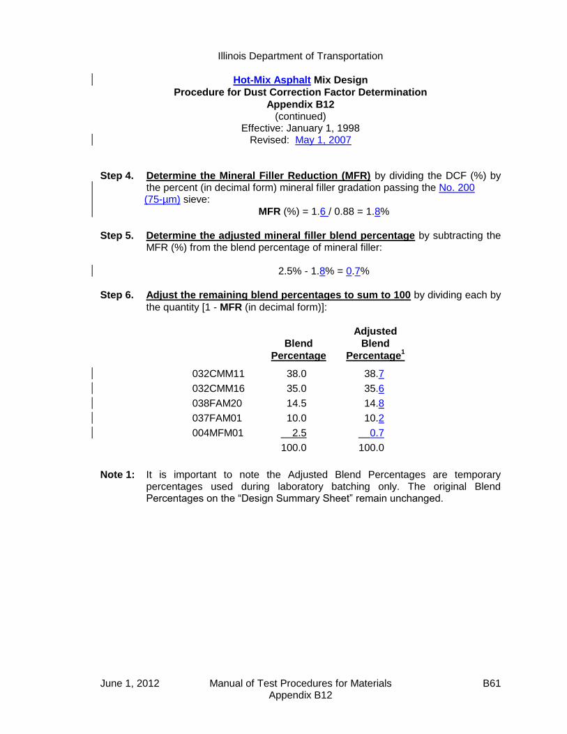
Illinois Department of Transportation
Hot-Mix Asphalt Mix Design
Procedure for Dust Correction Factor Determination
Appendix B12 (continued)
Effective: January 1, 1998 Revised: May 1, 2007
June 1, 2012 Manual of Test Procedures for Materials B61 Appendix B12
Step 4. Determine the Mineral Filler Reduction (MFR) by dividing the DCF (%) by the percent (in decimal form) mineral filler gradation passing the No. 200 (75-µm) sieve:
MFR (%) = 1.6 / 0.88 = 1.8%
Step 5. Determine the adjusted mineral filler blend percentage by subtracting the MFR (%) from the blend percentage of mineral filler:
2.5% - 1.8% = 0.7%
Step 6. Adjust the remaining blend percentages to sum to 100 by dividing each by
the quantity [1 - MFR (in decimal form)]:
Blend
Percentage
Adjusted
Blend
Percentage1
032CMM11 38.0 38.7
032CMM16 35.0 35.6
038FAM20 14.5 14.8
037FAM01 10.0 10.2
004MFM01 2.5 0.7
100.0 100.0
Note 1: It is important to note the Adjusted Blend Percentages are temporary percentages used during laboratory batching only. The original Blend Percentages on the “Design Summary Sheet” remain unchanged.

Illinois Department of Transportation
Hot-Mix Asphalt Mix Design
Procedure for Dust Correction Factor Determination
Appendix B12 (continued)
Effective: January 1, 1998 Revised: May 1, 2007
June 1, 2012 Manual of Test Procedures for Materials B62 Appendix B12
B) RAP Mix Design
1. Determine the Virgin Aggregate Fraction (VAF). The virgin aggregate fraction is the percentage of virgin aggregate
2. Adjust to the virgin blend percentages by dividing each virgin aggregate by the VAF.
3. Determine the RAP Adjusted JMF (RJMF)
4. Batch the virgin aggregates according to the adjusted blend percentages matching the RJMF. Test sample size shall be determined using Illinois Specification 201 and based on the nominal maximum size of the largest coarse aggregate.
5. Perform a washed test on the combined aggregate sample using Illinois Modified AASHTO T 11.
6. The DCF shall be the difference between the percent passing the No. 200 (75-μm) sieve of the washed test and the RJMF.
7. Determine the mineral filler reduction (MFR)RAP by dividing the DCF by the percent (in decimal form) mineral filler gradation passing the No. 200 (75-μm) sieve.
8. Subtract the MFRRAP from the blend percentage of mineral filler.
9. Adjust the remaining virgin aggregate blend percentages to sum to 100 by dividing each by the quantity (1 – MFRRAP).
10. Determine the batching blend percentages with RAP by multiplying the adjusted virgin aggregate blend percentages by the VAF.

Illinois Department of Transportation
Hot-Mix Asphalt Mix Design
Procedure for Dust Correction Factor Determination
Appendix B12 (continued)
Effective: January 1, 1998 Revised: May 1, 2007
June 1, 2012 Manual of Test Procedures for Materials B63 Appendix B12
RAP
Example
Step 1. Determine the virgin aggregate fraction (VAF).
100
%)100( RAPAggVAF
100
)7.23100( VAF
VAF = 0.763

June 1, 2012 Manual of Test Procedures for Materials B64 Appendix B12
Step 2. Adjust to the virgin aggregate percentages by dividing each virgin aggregate by the VAF. Initial virgin agg % 042CMM11 38.3 (÷ 0.763) 50.3 (added 0.1 sum = 100.0) 042CMM16 23.0 (÷ 0.763) 30.1 037FMM01 13.0 (÷ 0.763) 17.0 004MF01 2.0 (÷ 0.763) 2.6 Sum 100.0 100.0
Step 3. Determine the RAP adjusted JMF (RJMF). Combine gradation using the adjusted virgin aggregate blend percentages.
1 100.0 ¾ 89.4 ½ 66.8 3/8 53.9 #4 28.5 #8 19.2 #16 17.4 #30 14.6 #50 7.8 #100 3.8 #200 3.4
Step 4. Batch the virgin aggregates according to the adjusted blend percentages matching the RJMF. Illinois specification 201 requires a 5000-gram sample when CM11 is present.
Step 5. Run a washed test using AASHTO T11. Step 6. Determine the dust correction factor (DCF). The DCF is the difference
between the percent passing the No. 200 (75-μm) sieve of the washed test and the RJMF. Washed RJMF DCF No. 200 (75-μm) 4.3 3.4 4.3-3.4= 0.9 DCF = 0.9

Illinois Department of Transportation
Hot-Mix Asphalt Mix Design
Procedure for Dust Correction Factor Determination
Appendix B12 (continued)
Effective: January 1, 1998 Revised: May 1, 2007
June 1, 2012 Manual of Test Procedures for Materials B65 Appendix B12
Step 7. Determine the mineral filler reduction (MFR)RAP. The (MFR)RAP is determined by dividing the DCF by the percent (in decimal form) mineral filler gradation passing the No. 200 (75-μm) sieve.
%1.185.0
9.0RAPMFR
Step 8. Determine the mineral filler blend percentage by subtracting the MFRRAP from
the blend percentage of mineral filler. 2.6 – 1.1 = 1.5%
Step 9. Adjust the remaining blend percentages to sum to 100% by dividing each by the quantity [1-MFRRAP (in decimal form)]: 1 – MFRRAP = 1 – 0.011 = 0.989 Virgin % Adj Virgin Blend% 042CMM11 50.3 (÷ 0.989) 50.9 042CMM16 30.1 (÷ 0.989) 30.4 037FMM01 17.0 (÷ 0.989) 17.2 004MF01 2.6 (from step 8) 1.5 Sum 100.0 100.0
Step 10. Determine the batching blend percentages with RAP by multiplying the adjusted virgin blend % by the VAF. VAF = 0.763 Adjusted Virgin % Batching Blend % 042CMM11 50.9 (x 0.763) 38.9 (added 0.1 sum = 100.0) 042CMM16 30.4 (x 0.763) 23.2 037FMM01 17.2 (x 0.763) 13.1 004MF01 1.5 (x 0.763) 1.1 RAPAgg 23.7 Sum 100.0

June 1, 2012 Manual of Test Procedures for Materials B66 Appendix B12
This Page Reserved

Illinois Department of Transportation
Illinois Test Procedure 403
Calibration of the Ignition Oven for the Purpose of Characterizing
Reclaimed Asphalt Pavements (RAP)
Appendix B13
Effective Date: January 1, 2002
Revised: May 1, 2007
June 1, 2012 Manual of Test Procedures for Materials B67 Appendix B13
1.0 GENERAL 1.1 This method covers the calibration of the ignition oven for
characterization of reclaimed asphalt pavement (RAP). Correction factors for both gradation and asphalt content are determined by conducting parallel ignition and extraction testing.
2.0 SIGNIFICANCE AND USE
2.1 The ignition oven may be used in place of solvent extractions at the frequency stated in Section 1031 of the Standard Specifications.
2.2 This method may be used only with the approval of the Engineer. 2.3 Each RAP stockpile shall require a separate ignition oven calibration. 2.4 All RAP stockpiles and sampling frequencies shall meet the requirements
stated in Section 1031 of the Standard Specifications.
3.0 REFERENCED DOCUMENTS
3.1 AASHTO Standards (as modified by Illinois): T 2 Sampling of Aggregates T 164 Quantitative Extraction of Bitumen from Bituminous Paving
Mixtures T 248 Reducing Field Samples of Aggregate to Testing Size T 308 Determining the Asphalt Binder Content of Hot-Mix Asphalt (HMA)
by the Ignition Method
4.0 PROCEDURE
4.1 Sample the RAP according to AASHTO T 2. Obtain an adequate amount of material to perform a minimum of two solvent extractions and four ignition oven burns. The minimum sample sizes shall be governed by the nominal maximum aggregate size of the mixture defined in Illinois Modified AASHTO T 164 and T 308. Reduce the samples to testing size according to Illinois Modified AASHTO T 248.

Illinois Department of Transportation
Illinois Test Procedure 403
Calibration of the Ignition Oven for the Purpose of Characterizing
Reclaimed Asphalt Pavements (RAP)
Appendix B13 (continued)
Effective January 1, 2002 Revised: May 1, 2007
June 1, 2012 Manual of Test Procedures for Materials B68 Appendix B13
4.2 Perform a minimum of two solvent extractions and a minimum of four ignition oven burns according to AASHTO T 164 and Illinois-Modified AASHTO T 308, respectively.
4.3 AB Binder Calibration 4.3.1 Calculate the average Asphalt Binder (AB) percentage of the two
extractions, Pext. Calculate the average AB percentage of the four ignition oven burns, Pign. Assuming the average AB content from the extraction to be correct, subtract the average extraction AB percentage from the average ignition oven AB percentage to determine the asphalt correction factor, Cf.
Cf = Pign - Pext
Use the asphalt correction factor to adjust the ignition oven asphalt
content on all subsequent testing of that stockpile.
4.4 Gradation Calibration 4.4.1 From the two extractions, calculate the average percent passing the
applicable sieve, Gext. Calculate the average percent passing each applicable sieve from the four ignition oven burns, Gign. Subtract the extraction average percent passing each sieve from the ignition oven average of the corresponding sieve to determine a correction factor, GCf, for gradation for each sieve.
GCf = Gign - Gext
5.0 REPORT 5.1 Report the correction factors to the nearest 0.1%
6.0 PRECISION AND BIAS 6.1 The estimates of precision and bias shall be considered those that apply
to the referenced documents.
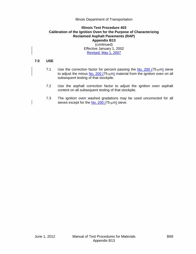
Illinois Department of Transportation
Illinois Test Procedure 403
Calibration of the Ignition Oven for the Purpose of Characterizing
Reclaimed Asphalt Pavements (RAP)
Appendix B13 (continued)
Effective January 1, 2002 Revised: May 1, 2007
June 1, 2012 Manual of Test Procedures for Materials B69 Appendix B13
7.0 USE
7.1 Use the correction factor for percent passing the No. 200 (75-m) sieve
to adjust the minus No. 200 (75-m) material from the ignition oven on all subsequent testing of that stockpile.
7.2 Use the asphalt correction factor to adjust the ignition oven asphalt
content on all subsequent testing of that stockpile. 7.3 The ignition oven washed gradations may be used uncorrected for all
sieves except for the No. 200 (75-m) sieve.

June 1, 2012 Manual of Test Procedures for Materials B70 Appendix B13
This Page Reserved

Illinois Department of Transportation
Truck Sample Splitting Diagram Appendix B14
Effective: January 1, 2002 Revised: May 1, 2007
June 1, 2012 Manual of Test Procedures for Materials B71 Appendix B14
Truck Sample 150 lbs (68 kg)
lllcwerlbs)lbs.)
75 lbs. (34 kg) +/- State
Sample 75 lbs. (34 kg) +/-
38 lbs. (17 kg) +/- 38 lbs. (17 kg) +/-
19 lbs. (8.5 kg) +/- 19 lbs. (8.5 kg) +/-
9.5 lbs. (4.3 kg) +/- 9.5 lbs. (4.3 kg) +/-
48 lbs. (21 kg) +/-
24 lbs. (10.5 kg) +/-
24 lbs (10.5 kg) +/-
+/-
12 lbs. (5.3 kg) +/-
Gmb Sample
12 lbs. (5.3 kg)
+/-
Gmb Sample 12 lbs (5.3 kg) +/-
Backup
12 lbs (5.3 kg) +/-
6 lbs. (2.7 kg) +/-
Ignition Oven
Sample
6 lbs. (2.7 kg) +/-
1350 g +/-
Gmm Sample
1350 g +/-
Gmm Sample
This 48 lbs. (21 kg) sample will
produce
the following bituminous tests:
2 - Bulk Specific Gravity - Gmb
2 - Maximum Specific Gravity -
Gmm
1 - Ignition Oven
1 - Backup

June 1, 2012 Manual of Test Procedures for Materials B72 Appendix B14
This Page Reserved

Illinois Department of Transportation
Hot Mix Asphalt (HMA) Production Gradation Windage
Procedure for Minus #200 (minus 75m) Material
Appendix B15
Effective: May 1, 2004 Revised: May 1, 2007
June 1, 2012 Manual of Test Procedures for Materials B73 Appendix B15
A. Scope
The Contractor will be required to provide production gradation test results for both washed ignition oven gradations (WIOG) and dry combined belt / hot bin gradations on the same control chart according to Section 1030 of the Standard Specifications. In order for this data to be meaningful, the dry combined belt / hot bin gradations shall be calibrated to the WIOG using the windage factor established below.
B. Purpose
A windage factor (WF) shall be determined and applied to dry gradation production test results in order to establish a WIOG equivalency. The WF accounts for the
difference, in minus #200 (minus 75m) material, between dry combined belt/hot bin gradations and WIOG due to the following:
variability in the addition of Mineral Filler washed vs. dry gradation (cling-on dust) generation of dust through plant aggregate degradation
C. Procedure
The WF shall be determined during Start-up. During mix production, adjustments to the WF may be warranted. Therefore, a new WF may be established, according to the following procedure, anytime during the course of mix production.
1. Obtain two combined belt/hot bin aggregate samples and perform two dry gradation (DG) tests. The DG shall include the theoretical amount of mineral filler
to be added. Average the two test results for the minus #200 (minus 75m) material.
Average DG-#200 = (DG#1 + DG#2) / 2 2. Obtain two samples of HMA representing, near as possible, material from step
one. Perform WIOG testing on the HMA samples and average the two results
for minus the #200 (minus 75m) material.
Average WIOG-#200 = (WIOG#1 + WIOG#2) / 2
3. Determine WF by subtracting Average DG-#200 in step 1 from Average
WIOG-#200 in step 2.
WF = Average WIOG-#200 - Average DG-#200

Illinois Department of Transportation
Hot Mix Asphalt (HMA) Production Gradation Windage
Procedure for Minus #200 (minus 75m) Material
Appendix B15
(continued)
Effective: May 1, 2004 Revised: May 1, 2007
June 1, 2012 Manual of Test Procedures for Materials B74 Appendix B15
4. Add WF to all combined belt/hot bin gradation test results prior to plotting on
the Minus #200 (minus 75m) Control Chart. All, (including WIOG test results
used to establish WF, are plotted directly on the Minus #200 (minus 75m) Control Chart. When both the DG and WIOG test results represent the same material, the WIOG are the results to be included in the moving average.
Example: Given:
WIOG#1 (minus #200) = 4.8% (Truck sample taken between growth curves)
WIOG#2 (minus #200) = 4.6% (Truck sample taken from outside Test Strip area during startup)
DG#1 (minus #200) = 2.7% (Combined belt sample taken to correspond to
material sampled for WIOG#1)
DG#2 (minus #200) = 2.1% (Combined belt sample taken to correspond to
material sampled for WIOG#2)
Step 1. Average the two DG test results for the minus #200 (minus 75m) material.
Average DG-#200 = (2.7% + 2.1%) / 2 = 2.4%
Step 2. Average the two WIOG test results for the minus #200 (minus 75m) material.
Average WIOG-#200 = (4.8% + 4.6%) / 2 = 4.7%
Step 3. Determine WF by subtracting Average DG-#200 in step 1 from Average
WIOG-#200 in step 2.
WF = 4.7% - 2.4% = 2.3%
Step 4. Add WF = 2.3% to all combined belt/hot bin gradation test results prior to
plotting on the Minus #200 (minus 75m) Control Chart.

Illinois Department of Transportation
Stripping of Hot-Mix Asphalt Mixtures Visual Identification and Classification
Appendix B16
Effective: November 20, 2003 Revised: May 1, 2007
June 1, 2012 Manual of Test Procedures for Materials B75 Appendix B16
The following instructions describe the method to be used for visually identifying and classifying the effect of moisture damage on the adhesion of asphalt binder to the aggregate in Hot-Mix Asphalt (HMA) mixtures. This procedure provides the means to rate this phenomenon in numerical terms. This procedure is applicable to both laboratory compacted specimens and pavement cores1. INSTRUCTIONS 1. This procedure should only be applied to freshly split specimen faces, such as those
obtained from split tensile testing. The observation of cored, sawed, or chiseled faces should be avoided, as the true condition of the stripping will be obscured.
2. The rating should be completed within 10 minutes of splitting for maximum clarity. When the
specimens dry out, they may look considerably different. The aggregate surfaces should be examined carefully to determine if the asphalt binder was stripped from the aggregate as a result of being “washed” by water before the specimen was split or if the asphalt binder was “ripped apart” near the asphalt/aggregate interface during the split tensile test. Also, aggregate surfaces with small, relatively isolated, globules of asphalt binder are quite likely not stripped.
3. Special attention should be given to fractured and broken aggregates. Fractured
aggregates are those that were cracked during compaction. These fractured aggregates will have a distinct face with a dull or discolored surface. Broken aggregates are those that were broken during the split tensile test. Broken aggregates often occur near the outside surface of the specimen where the compressive forces are greatest. These broken aggregates will also have a distinct broken face, but will have a bright, uncoated surface. The broken aggregates may be a continuation of a crack that was started during compaction. There is no evidence that a broken aggregate was broken entirely under the compressive force of the split tensile test.
4. Coarse aggregate particles shall be defined as those particles retained on the #8 sieve.
Fine aggregate particles shall be defined as those particles that will pass through a #8 sieve. 5. When examining the split face, use the entire face area of all the fine particles separately
from all the coarse particles on the split face to determine the percentage of the total area that is stripped. Do not use the percent of the area of each individual stone that is stripped to collectively determine the percentage of stripped aggregate particles on the entire split face of the specimen. Also, do not estimate the percentage of aggregate particles that are stripped based on the total number of aggregate particles. (i.e., a small stripped aggregate particle does not affect the entire specimen the same as a large stripped aggregate particle.)
1 Pavement cores taken from the field should be sealed in plastic bags immediately after coring in order to retain
their in-situ moisture. Pavement cores should be split and visually rated as soon as possible after coring to avoid any
“healing” of the asphalt to the aggregate surfaces.
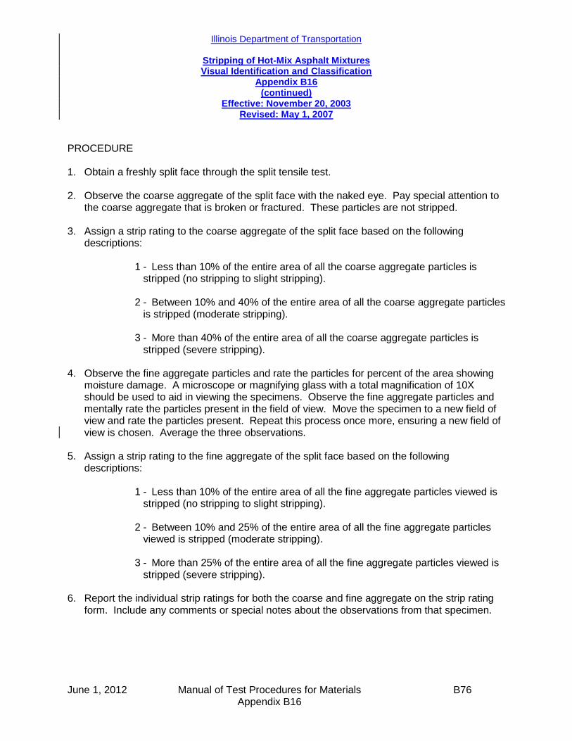
Illinois Department of Transportation
Stripping of Hot-Mix Asphalt Mixtures Visual Identification and Classification
Appendix B16 (continued)
Effective: November 20, 2003 Revised: May 1, 2007
June 1, 2012 Manual of Test Procedures for Materials B76 Appendix B16
PROCEDURE 1. Obtain a freshly split face through the split tensile test. 2. Observe the coarse aggregate of the split face with the naked eye. Pay special attention to
the coarse aggregate that is broken or fractured. These particles are not stripped. 3. Assign a strip rating to the coarse aggregate of the split face based on the following
descriptions:
1 - Less than 10% of the entire area of all the coarse aggregate particles is stripped (no stripping to slight stripping).
2 - Between 10% and 40% of the entire area of all the coarse aggregate particles
is stripped (moderate stripping). 3 - More than 40% of the entire area of all the coarse aggregate particles is
stripped (severe stripping).
4. Observe the fine aggregate particles and rate the particles for percent of the area showing moisture damage. A microscope or magnifying glass with a total magnification of 10X should be used to aid in viewing the specimens. Observe the fine aggregate particles and mentally rate the particles present in the field of view. Move the specimen to a new field of view and rate the particles present. Repeat this process once more, ensuring a new field of view is chosen. Average the three observations.
5. Assign a strip rating to the fine aggregate of the split face based on the following
descriptions:
1 - Less than 10% of the entire area of all the fine aggregate particles viewed is stripped (no stripping to slight stripping).
2 - Between 10% and 25% of the entire area of all the fine aggregate particles
viewed is stripped (moderate stripping). 3 - More than 25% of the entire area of all the fine aggregate particles viewed is
stripped (severe stripping). 6. Report the individual strip ratings for both the coarse and fine aggregate on the strip rating
form. Include any comments or special notes about the observations from that specimen.

June 1, 2012 Manual of Test Procedures for Materials B77 Appendix B16
STRIP RATING FORM PROJECT DATE
GENERAL COMMENTS
SPECIMEN NO. TYPE OF
CONDITIONING COARSE RATING
FINE RATING
COMMENTS

June 1, 2012 Manual of Test Procedures for Materials B78 Appendix B16
This Page Reserved

Illinois Department of Transportation
Procedure for Introducing Additives to Hot Mix Asphalt Mixtures and Testing in the Lab
Appendix B17
Effective Date: March 7, 2005 Revised: January 1, 2013
January 1, 2013 Manual of Test Procedures for Materials B79 Appendix B17
1.0 GENERAL
Moisture damage or stripping is considered to be one of the main reasons for an asphalt pavement (especially full depth asphalt pavement) not lasting indefinitely. Stripping is the weakening and loss of the adhesive bond between aggregates and asphalt binder, in the presence of moisture. Various additives can be used to help reduce the stripping potential of an aggregate. In Illinois, liquid anti-strip additives are used almost exclusively. However, other states use or require adding hydrated lime in HMA. Hydrated Lime is considered, by many, as a superior additive for moisture damage control and prevention. It typically is added to the aggregate and asphalt mixture by one of three methods, the dry, the wet, or the slurry method.
Different levels of conditioning can be used in lab-prepared specimens to simulate the effect of the actual moisture conditions in the field. Four levels are described in this document. The level of conditioning actually used will be as specified in contract documents or as determined in the workplan for research.
2.0 PURPOSE
A. This procedure applies to using additives in hot mix asphalt (HMA) mixtures and testing those mixtures in the lab. This procedure includes the dry method of hydrated lime addition as well as the wet method and the slurry method. Also, this procedure includes specimens containing no additive, liquid anti-strip, polymer-modified asphalt, and polymer-modified asphalt with hydrated lime or liquid anti-strip.
B. Four levels of conditioning are included in this procedure and are used when
specified. These four levels are no conditioning (or control), submerging in a hot water bath, one cycle of freezing followed by submerging in the hot water bath, and five freeze and hot water bath cycles. The conditioned samples are all partially saturated with water before the freeze and hot water bath cycles begin.
C. Illinois-modified AASHTO T-283 and T-324 are the standard specifications in
Illinois that are required and used to test all HMA mixtures for moisture susceptibility. Only specimens with no conditioning and specimens conditioned in the hot water bath shall be tested according to Illinois-modified AASHTO T-283. In addition to the conditioning and testing specified in Illinois-modified AASHTO T-283 and T-324, this procedure also contains guidelines for conditioning and testing specimens using freeze/thaw conditioning cycles. Freeze/thaw cycles shall be used if specified and also may be used for research projects. Utilizing five freeze/thaw cycles is harsher than the other conditioning methods in this
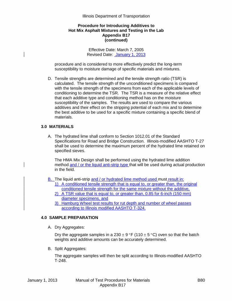
Illinois Department of Transportation
Procedure for Introducing Additives to Hot Mix Asphalt Mixtures and Testing in the Lab
Appendix B17 (continued)
Effective Date: March 7, 2005
Revised Date: January 1, 2013
January 1, 2013 Manual of Test Procedures for Materials B80 Appendix B17
procedure and is considered to more effectively predict the long-term susceptibility to moisture damage of specific materials and mixtures.
D. Tensile strengths are determined and the tensile strength ratio (TSR) is
calculated. The tensile strength of the unconditioned specimens is compared with the tensile strength of the specimens from each of the applicable levels of conditioning to determine the TSR. The TSR is a measure of the relative effect that each additive type and conditioning method has on the moisture susceptibility of the samples. The results are used to compare the various additives and their effect on the stripping potential of each mix and to determine the best additive to be used for a specific mixture containing a specific blend of materials.
3.0 MATERIALS
A. The hydrated lime shall conform to Section 1012.01 of the Standard
Specifications for Road and Bridge Construction. Illinois-modified AASHTO T-27 shall be used to determine the maximum percent of the hydrated lime retained on specified sieves.
The HMA Mix Design shall be performed using the hydrated lime addition method and / or the liquid anti-strip type that will be used during actual production in the field.
B. The liquid anti-strip and / or hydrated lime method used must result in: 1) A conditioned tensile strength that is equal to, or greater than, the original
conditioned tensile strength for the same mixture without the additive, 2) A TSR value that is equal to, or greater than, 0.85 for 6-inch (150 mm)
diameter specimens, and 3) Hamburg Wheel test results for rut depth and number of wheel passes
according to Illinois modified AASHTO T-324.
4.0 SAMPLE PREPARATION
A. Dry Aggregates:
Dry the aggregate samples in a 230 9 F (110 5 C) oven so that the batch weights and additive amounts can be accurately determined.
B. Split Aggregates:
The aggregate samples will then be split according to Illinois-modified AASHTO T-248.
Illinois Department of Transportation
Procedure for Introducing Additives to Hot Mix Asphalt Mixtures and Testing in the Lab
Appendix B17 (continued)
Effective Date: March 7, 2005
Revised Date: January 1, 2013
January 1, 2013 Manual of Test Procedures for Materials B81 Appendix B17
C. Blend Aggregates:
The aggregates will be blended into the correct batch size. Because of the large size of the gyratory specimens, each batch will contain enough material for two gyratory specimens (approximately 8000 - 8500 grams for tensile strength and TSR and approximately 5000 – 5500 grams for the Hamburg Wheel test). Several batches will need to be prepared to produce the required number of gyratory specimens (six for strength and TSR and four for Hamburg Wheel testing as well as pilot specimens). Also, include sufficient material in one of the batches for a maximum specific gravity (Gmm) test run according to Illinois-modified AASHTO T-209 (approximately 2000 grams).
D. Mix Samples: 1. With No Additive:
a. Heat the asphalt binder and the dry aggregate blend to a mixing
temperature of 295 5 F (146 ± 2.8°C) for neat asphalt.
b. Remove the blend from the oven and make a small crater in the top of the hot, dry aggregates.
c. Add the correct amount of asphalt binder to the batch.
d. Mix the aggregates and asphalt binder.
2. Hydrated Lime – Dry Method:
a. List the hydrated lime in its own column on the Aggregate Blending Sheet and enter the percent passing each sieve in the corresponding line on the form.
b. 1.0% hydrated lime is added to the mix. The 1.0% hydrated lime is based on the total dry weight of aggregate in the mix and is added in addition to the mineral filler specified in the mix design.
NOTE: Theoretically when hydrated lime is added by the dry method, it is assumed that half of the hydrated lime (0.5%) adheres to the aggregate and that the other half (0.5%) of the hydrated lime acts like mineral filler and becomes part of the asphalt binder in the HMA mix. However, for design purposes (and to adapt to existing design software), the hydrated lime is all considered as a separate aggregate, similar to mineral filler, and the gradation of all of the hydrated lime contributes to the overall blend gradation.

Illinois Department of Transportation
Procedure for Introducing Additives to Hot Mix Asphalt Mixtures and Testing in the Lab
Appendix B17 (continued)
Effective Date: March 7, 2005
Revised Date: January 1, 2013
January 1, 2013 Manual of Test Procedures for Materials B82 Appendix B17
c. When hydrated lime is used in a mix design, it is important to include sufficient added mineral filler in the design. During plant production some of this mineral filler may need to be removed to compensate for the fines that are generated during production.
d. Calculate the dust correction factor (DCF) according to the “Hot-Mix Asphalt Mix Design Procedure for Dust Correction Factor Determination”, on each mix design with hydrated lime added. Include the hydrated lime in both the job mix formula (JMF) gradation and the washed gradation on the aggregate combined blend. The DCF procedure is performed to
account for additional minus 75-m (minus No. 200) material present as a result of batching with unwashed aggregates. Refer to the attached sheet which shows an example calculation of the DCF.
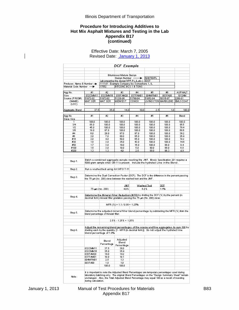
Illinois Department of Transportation
Procedure for Introducing Additives to Hot Mix Asphalt Mixtures and Testing in the Lab
Appendix B17 (continued)
Effective Date: March 7, 2005
Revised Date: January 1, 2013
January 1, 2013 Manual of Test Procedures for Materials B83 Appendix B17
Illinois Department of Transportation
Procedure for Introducing Additives to Hot Mix Asphalt Mixtures and Testing in the Lab
Appendix B17 (continued)
Effective Date: March 7, 2005
Revised Date: January 1, 2013
January 1, 2013 Manual of Test Procedures for Materials B84 Appendix B17
e. Heat the asphalt binder and the dry aggregates (not including mineral
filler) to a mixing temperature of 295 5 F (146 ± 2.8°C) for neat asphalt
or 325 5 F (163 ± 2.8°C) for polymer modified asphalt.
f. Make a small crater in the top of the hot, dry aggregates.
g. Add the correct amount of dry hydrated lime to the crater in the aggregates.
h. Mix the hydrated lime and aggregates until the aggregates are completely coated (approximately 10 to 15 seconds).
i. If the blend of aggregates and hydrated lime cools below the mixing temperature, place the blend back in the oven until the blend is returned to the mixing temperature (approximately 10 minutes).
j. Remove the blend from the oven and make a small crater in the top of the hot, dry aggregates and hydrated lime.
k. Add the correct amount of mineral filler, (if required in the mix design), to the crater in the aggregates.
l. Mix the mineral filler with the aggregates and hydrated lime until the mineral filler is uniformly dispersed in the blend (approximately 10 to 15 seconds).
m. If the blend of aggregates, hydrated lime, and mineral filler cools below the mixing temperature, place the blend back in the oven until the blend is returned to the mixing temperature (approximately 10 minutes).
n. Make a crater in the aggregates and add the correct amount of asphalt binder to aggregates, hydrated lime, and mineral filler.
o. Mix the asphalt binder with the blend of aggregates, hydrated lime, and mineral filler.
3. Hydrated Lime – Wet Method:
a. List the hydrated lime in its own column on the Aggregate Blending Sheet and enter the percent passing each sieve in the corresponding line on the form.
b. 1.0% hydrated lime is added to the mix. The 1.0% hydrated lime is based on the total dry weight of aggregate in the mix and is added in addition to the mineral filler specified in the mix design.
NOTE: Theoretically when hydrated lime is added by the wet method, it is assumed that all of the hydrated lime (1.0%) adheres to the aggregate and does not function like mineral filler which becomes mixed with the asphalt binder in the HMA mix. Accordingly, the lime is added in addition to the mineral filler specified in the mix design. For design purposes (and to adapt to existing design software), the hydrated lime is all considered as a separate
Illinois Department of Transportation
Procedure for Introducing Additives to Hot Mix Asphalt Mixtures and Testing in the Lab
Appendix B17 (continued)
Effective Date: March 7, 2005
Revised Date: January 1, 2013
January 1, 2013 Manual of Test Procedures for Materials B85 Appendix B17
aggregate, similar to mineral filler, and the gradation of all of the hydrated lime contributes to the overall blend gradation.
c. When hydrated lime is used in a mix design, it is important to include sufficient added mineral filler in the design. During plant production some of this mineral filler may need to be removed to compensate for the fines that are generated during production.
d. Calculate the dust correction factor (DCF) according to the “Hot-Mix Asphalt Mix Design Procedure for Dust Correction Factor Determination”, on each mix design with hydrated lime added to wet aggregates. Include the hydrated lime in both the job mix formula (JMF) gradation and the washed gradation on the aggregate combined blend. The DCF
procedure is performed to account for additional minus 75-m (minus No. 200) material present as a result of batching with unwashed aggregates. Perform the washed gradation on the combined aggregate blend containing the hydrated lime after it has been allowed to dry on the aggregates (step h.). Refer to the previously attached sheet which shows an example calculation of the DCF.
e. Add the amount of water that is equal to the aggregate’s water absorption capacity to the cooled and blended, oven-dried aggregates. The aggregates should be in their saturated surface dry (SSD) condition.
f. Add an additional three percent of water, based on the total dry weight of aggregates, to the aggregates in the SSD condition. Stir the aggregates and the additional water to ensure that the water is evenly mixed with the aggregates.
g. Add one percent dry hydrated lime to the wet aggregates, based on the total dry weight of the aggregates. Stir and mix until the hydrated lime coats the aggregates and the aggregates and hydrated lime make up a homogeneous mixture.
h. Dry the aggregates coated with the hydrated lime in a 230 9 F (110 ± 5°C) oven to constant mass, as defined in Illinois-modified AASHTO T-166.
i. Heat the hydrated lime-coated aggregates and the asphalt binder each to
a mixing temperature of 295 5 F (146 ± 2.8°C) for neat asphalt or 325
5 F (163 ± 2.8°C) for polymer modified asphalt.
j. Remove the blend from the oven and make a small crater in the top of the hot, dry, hydrated lime-covered aggregates.
k. Add the correct amount of mineral filler, (if required in the mix design), to the crater in the aggregates.

Illinois Department of Transportation
Procedure for Introducing Additives to Hot Mix Asphalt Mixtures and Testing in the Lab
Appendix B17 (continued)
Effective Date: March 7, 2005
Revised Date: January 1, 2013
January 1, 2013 Manual of Test Procedures for Materials B86 Appendix B17
l. Mix the mineral filler with the hydrated lime-covered aggregates until the mineral filler is uniformly dispersed in the blend (approximately 10 to 15 seconds).
m. If the blend of hydrated lime-coated aggregates and mineral filler cools below the mixing temperature, place the blend back in the oven until the blend is returned to the mixing temperature (approximately 10 minutes).
n. Make a crater in the aggregates and add the correct amount of asphalt binder to the mixture of hydrated lime-covered aggregates and mineral filler.
o. Mix the hydrated lime-coated aggregates, mineral filler, and asphalt binder together until the aggregates are completely coated with the asphalt binder.
4. Hydrated Lime – Slurry Method:
a. List the hydrated lime in its own column on the Aggregate Blending Sheet and enter the percent passing each sieve in the corresponding line on the form.
b. 1.0% hydrated lime is added to the mix. The 1.0% hydrated lime is based on the total dry weight of aggregate in the mix and is added in addition to the mineral filler specified in the mix design.
NOTE: Theoretically when hydrated lime is added by the slurry method, it is assumed that all of the hydrated lime (1.0%) adheres to the aggregate and does not function like mineral filler which becomes mixed with the asphalt binder in the HMA mix. Accordingly, the lime is added in addition to the mineral filler specified in the mix design. For design purposes (and to adapt to existing design software), the hydrated lime is all considered as a separate aggregate, similar to mineral filler, and the gradation of all of the hydrated lime contributes to the overall blend gradation.
c. When hydrated lime is used in a mix design, it is important to include sufficient added mineral filler in the design. During plant production some of this mineral filler may need to be removed to compensate for the fines that are generated during production.
d. Calculate the dust correction factor (DCF) according to the “Hot-Mix Asphalt Mix Design Procedure for Dust Correction Factor Determination”, on each mix design with hydrated lime slurry added. Include the hydrated lime in both the job mix formula (JMF) gradation and the washed gradation on the aggregate combined blend. The DCF procedure is
performed to account for additional minus 75-m (minus No. 200)
Illinois Department of Transportation
Procedure for Introducing Additives to Hot Mix Asphalt Mixtures and Testing in the Lab
Appendix B17 (continued)
Effective Date: March 7, 2005
Revised Date: January 1, 2013
January 1, 2013 Manual of Test Procedures for Materials B87 Appendix B17
material present as a result of batching with unwashed aggregates. Perform the washed gradation on the combined aggregate blend containing the hydrated lime slurry after it has been allowed to dry on the aggregates (step h.). Refer to the previously attached sheet which shows an example calculation of the DCF.
e. Add the amount of water that is equal to the aggregate’s water absorption capacity to the cooled and blended, oven-dried aggregates. The aggregates should be in their saturated surface dry (SSD) condition.
f. Mix one percent dry hydrated lime and three percent water together, each based on the total weight of aggregates, to form a slurry.
g. Add the slurry to the aggregates. Stir and mix until the aggregates and hydrated lime slurry make up a homogeneous mixture.
h. Dry the aggregates coated with the hydrated lime slurry in a 230 9 F (110 ± 5°C) oven to constant mass, as defined in Illinois-modified AASHTO T-166.
i. Heat the hydrated lime-coated aggregates and the asphalt binder each to
a mixing temperature of 295 5 F (146 ± 2.8°C) for neat asphalt or 325
5 F (163 ± 2.8°C) for polymer modified asphalt.
j. Remove the blend from the oven and make a small crater in the top of the hot, dry, hydrated lime-covered aggregates.
k. Add the correct amount of mineral filler, (if required in the mix design), to the crater in the aggregates.
l. Mix the mineral filler with the hydrated lime-covered aggregates until the mineral filler is uniformly dispersed in the blend (approximately 10 to 15 seconds).
m. If the blend of hydrated lime-coated aggregates and mineral filler cools below the mixing temperature, place the blend back in the oven until the blend is returned to the mixing temperature (approximately 10 minutes).
n. Make a crater in the aggregates and add the correct amount of asphalt binder to the mixture of hydrated lime-covered aggregates and mineral filler.
o. Mix the hydrated lime-coated aggregates, mineral filler, and asphalt binder together until the aggregates are completely coated with the asphalt binder.
5. Liquid Anti-strip
a. Add 0.5% of liquid anti-strip (by weight of asphalt) to the asphalt binder and mix together until the liquid anti-strip is distributed thoroughly in the asphalt binder.

Illinois Department of Transportation
Procedure for Introducing Additives to Hot Mix Asphalt Mixtures and Testing in the Lab
Appendix B17 (continued)
Effective Date: March 7, 2005
Revised Date: January 1, 2013
January 1, 2013 Manual of Test Procedures for Materials B88 Appendix B17
b. Heat the aggregates and asphalt binder each to a mixing temperature of
295 5 F (146 ± 2.8°C) for neat asphalt or 325 5 F (163 ± 2.8°C) for polymer modified asphalt.
c. Remove the aggregate blend from the oven and make a small crater in the top of the hot, dry aggregates.
d. Add the asphalt binder with liquid anti-strip to the dried aggregates.
e. Mix the aggregates and the asphalt binder.
6. Polymer
a. Heat the aggregates and asphalt binder each to a mixing temperature of
325 5 F (163 ± 2.8°C).
b. Remove the aggregate blend from the oven and make a small crater in the top of the hot, dry aggregates.
c. Add the correct amount of polymer-modified asphalt binder to aggregate blend.
d. Mix the aggregate blend and the polymer-modified asphalt binder.
7. Polymer with Hydrated Lime
a. Heat the polymer-modified asphalt binder to a mixing temperature of 325
5 F (163 ± 2.8°C).
b. Add the correct amount of hydrated lime to the dry aggregates. (1% based on the total weight of aggregates). Follow the instructions for adding hydrated lime dry method (section 2), hydrated lime wet method (section 3), or hydrated lime slurry method (section 4) above.
c. Heat the aggregates a mixing temperature of 325 5 F (163 ± 2.8°C).
d. Remove the blend from the oven and make a small crater in the top of the hot, dry aggregates and hydrated lime.
e. Add the correct amount of mineral filler (if required in the mix design) to the crater in the aggregates.
f. Mix the mineral filler with the aggregates and hydrated lime until the mineral filler is uniformly dispersed in the blend (approximately 10 to 15 seconds).
g. If the blend of aggregates, hydrated lime, and mineral filler cools below the mixing temperature, place the blend back in the oven until the blend is returned to the mixing temperature (approximately 10 minutes).
h. Make a crater in the aggregates and add the correct amount of polymer-modified asphalt binder to aggregates, hydrated lime, and mineral filler.

Illinois Department of Transportation
Procedure for Introducing Additives to Hot Mix Asphalt Mixtures and Testing in the Lab
Appendix B17 (continued)
Effective Date: March 7, 2005
Revised Date: January 1, 2013
January 1, 2013 Manual of Test Procedures for Materials B89 Appendix B17
i. Mix the hydrated lime-coated aggregates and the polymer-modified asphalt binder.
E. Split Samples:
Split the batches into the correct sample size which will make a gyratory specimen 3 ¾ in. (95 mm) high (approximately 4200 grams).
F. Compact Samples:
1. Run a maximum specific gravity (Gmm) for each of the additive mix types being evaluated.
2. Heat the mixture to a compaction temperature of 295 5 F (146 ± 2.8°C) for
neat asphalt or 305 5 F (152 ± 2.8°C) for polymer-modified asphalt. 3. Pilot bricks from the mixes for each type of additives being evaluated will be
made to determine the correct compaction level to achieve 7.0 0.5% air voids.
4. Run a bulk specific gravity (Gmb), according to Illinois-modified AASHTO
T-166, for each pilot brick to determine the air void content.
5. Compact samples to 7.0 0.5% air voids for each mix additive type using the number of gyrations determined above.
6. A total of 12 individual samples will be compacted for each additive mix type
for each complete round of testing. 7. Run a Gmb on each sample to verify that the air voids are within the range of
7.0 0.5%.
5.0 TESTING
Illinois Modified AASHTO T-283
For each set of samples for each additive type:
A. Control Sample Set – (Always use unless otherwise specified):
1. Three bricks will be tested with no conditioning.

Illinois Department of Transportation
Procedure for Introducing Additives to Hot Mix Asphalt Mixtures and Testing in the Lab
Appendix B17 (continued)
Effective Date: March 7, 2005
Revised Date: January 1, 2013
January 1, 2013 Manual of Test Procedures for Materials B90 Appendix B17
2. The samples will be:
a. Placed in a 77F (25C) water bath for a minimum of two hours to bring the sample to room temperature.
b. Placed between the loading heads and loaded at 2 in. (50 mm) per minute until failure.
3. The corresponding load will be recorded. 4. The indirect tensile strength (ITS) will be calculated using the equation:
dt
PITS
2
where:
P = Load (pounds)
= 3.1416
t = Sample Thickness (inches)
d = Sample Diameter (inches)
5. Within 10 minutes after breaking the sample in the indirect tensile tester, the split samples will be inspected visually to evaluate the amount and degree of moisture damage. This will be done according to the IDOT procedure, “Stripping of Hot Mix Asphalt Mixtures - Visual Identification and Classification”.
B. Illinois-Modified AASHTO T-283 Sample Set – (Always use unless otherwise
specified):
1. Three bricks will be tested according to IL-modified AASHTO T-283. 2. The samples will be:
a. Vacuum saturated to 70 - 80%. Use a vacuum of approximately 0.8 to 1.0
in. (20 to 25 mm) of mercury (Hg) for one minute. Start with 0.8 in. (20 mm) Hg for one minute, and then weigh the specimen. Increase the vacuum until the saturation is 70 - 80%.
b. Soaked in a 140F (60°C) water bath for 24 1 hours, and
c. Tested as above in “Testing; A; 2, 3, 4, & 5.”

Illinois Department of Transportation
Procedure for Introducing Additives to Hot Mix Asphalt Mixtures and Testing in the Lab
Appendix B17 (continued)
Effective Date: March 7, 2005
Revised Date: January 1, 2013
January 1, 2013 Manual of Test Procedures for Materials B91 Appendix B17
C. AASHTO T-283 Sample Set (with one freeze-thaw cycle) – (Only use when specified):
1. Three bricks will be tested according to AASHTO T-283. 2. Each sample will be:
a. Vacuum saturated to 70 - 80%. Use a vacuum of approximately 0.8 to 1.0
in. (20 to 25 mm) of mercury (Hg) for one minute. Start with 0.8 in. (20 mm) Hg for one minute, and then weigh the specimen. Increase the vacuum until the saturation is 70 - 80%.
b. Wrapped in plastic wrap (Saran Wrap) placed in a plastic bag with 10 mL of water and sealed in a plastic bag.
c. Placed in a 0 5F (-18 ± 2.8°C) freezer for a minimum of 16 hours. (The exact time greater than 16 hours should be determined so that the testing can be done at approximately the same time each day).
d. After removal from the freezer, the samples will be placed in a 140F
(60C) water bath and soaked for 24 1 hours, with the plastic bag and plastic wrap removed as soon as possible after being placed in the bath.
e. After the freeze – thaw cycle is complete, follow the steps above in “Testing; A; 2, 3, 4, & 5.”
D. AASHTO T-283 Sample Set (with five freeze-thaw cycles) – (Only use when
specified):
1. Three bricks will be tested as in “Testing; C” above except that five complete freeze – thaw cycles will be completed instead of only one.
2. The plastic bag and plastic wrap should stay on the sample throughout the test and should not be removed until the beginning of the final thaw cycle in
the 140F (60C) bath. If the plastic bag tears or if the plastic wrap comes loose, replace them prior to the next freeze cycle and add 10 mL of water.
3. After the final thaw cycle is complete, follow the steps above in “Testing; A; 2,
3, 4, & 5.” Illinois Modified AASHTO T-324: Perform a Loaded Wheel test according to Illinois modified AASHTO T-324.

Illinois Department of Transportation
Procedure for Introducing Additives to Hot Mix Asphalt Mixtures and Testing in the Lab
Appendix B17 (continued)
Effective Date: March 7, 2005
Revised Date: January 1, 2013
January 1, 2013 Manual of Test Procedures for Materials B92 Appendix B17
6.0 DATA COLLECTION AND EVALUATION
A. All the data from testing will be collected and will/may include:
1. Gmm 2. Gmb
3. Voids 4. Indirect Tensile Strength
a. Unconditioned
b. Conditioned
i. 140°F (60°C) water bath
ii. One freeze / thaw cycle
iii. Five freeze / thaw cycles
5. The standard TSR, for each additive type (calculated with the unconditioned
strength in the denominator and with the conditioned strength in the numerator). For each additive type the TSR is calculated separately for each level of conditioning.
6. The combined TSR, which is similar to the standard TSR except that it is
calculated by always using the unconditioned strength from samples with no additive in the denominator, regardless of the additive type used.
7. Visual strip rating of each sample.
8. Rut depth and number of wheel passes.
B. Evaluate the strengths, TSRs, rut depths, and wheel passes for each additive
type, for each aggregate type tested, to determine if:
1. An anti-strip additive is needed and improves the performance of the mix. 2. One of the additive types consistently gives higher strengths, TSR ratings, rut
depths, and wheel passes.

June 1, 2012 Manual of Test Procedures for Materials B93 Appendix B18
Illinois Department of Transportation
Ignition Oven Aggregate Mass Loss Procedure Appendix B18
Effective: May 1, 2005 Revised: May 1, 2007
A. Purpose
Dolomite aggregates that contain significant amounts of Magnesium Carbonate, when used in Hot-Mix Asphalt, have been found to undergo mass loss during ignition oven testing, which causes highly variable results in asphalt binder content. This procedure utilizes the ignition oven to identify these types of aggregates.
B. Procedure
1. Obtain a 3000 gram sample of the aggregate to be tested and oven dry to a constant mass in an oven set at 110º C ± 5º (230º F ± 9º). Constant mass is achieved by drying sample until further drying does not alter the mass by more than 0.5 g in one hour as stated in IL Modified AASHTO T-30.
2. Split sample into 3 separate 1000 gram samples.
3. Place one of the 1000 gram samples into the ignition oven catch pan.
4. Record the initial weight of the sample and catch pan at room temperature to the nearest
0.1 gram.
5. Place the sample and catch pan into an ignition oven preheated to 625 °C. Do not push the start button on the oven. Allow sample to remain in ignition oven for one hour.
6. After one hour, remove the sample and catch pan, allow it to cool to room temperature
and record the weight to the nearest 0.1 gram.
7. Repeat steps 3 through 10 for the two remaining 1000 gram samples.
8. Calculate the aggregate mass loss for each run according to the following:
∆ 100
Wi
WfWiW
Where: ∆W = Aggregate mass loss in percent
Wi = Initial weight of the aggregate sample in grams
Wf = Final weight of the aggregate sample in grams after
exposure to 625 °C
9. Calculate the average of the three mass loss results.
10. Aggregates exhibiting average mass loss in excess of 4% are likely to contain significant amounts of Magnesium Carbonate and will likely cause high variability in ignition oven test results for asphalt content.

June 1, 2012 Manual of Test Procedures for Materials B94 Appendix B18
This Page Reserved
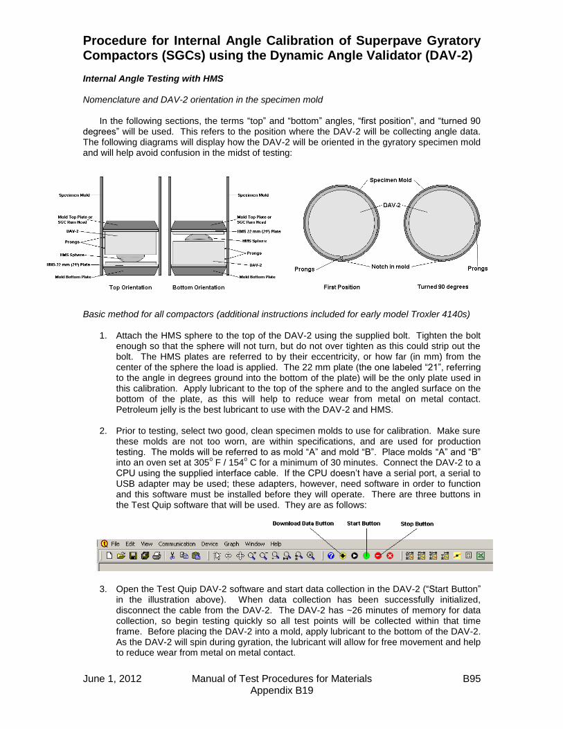
June 1, 2012 Manual of Test Procedures for Materials B95 Appendix B19
Procedure for Internal Angle Calibration of Superpave Gyratory Compactors (SGCs) using the Dynamic Angle Validator (DAV-2) Internal Angle Testing with HMS Nomenclature and DAV-2 orientation in the specimen mold
In the following sections, the terms “top” and “bottom” angles, “first position”, and “turned 90 degrees” will be used. This refers to the position where the DAV-2 will be collecting angle data. The following diagrams will display how the DAV-2 will be oriented in the gyratory specimen mold and will help avoid confusion in the midst of testing:
Basic method for all compactors (additional instructions included for early model Troxler 4140s)
1. Attach the HMS sphere to the top of the DAV-2 using the supplied bolt. Tighten the bolt enough so that the sphere will not turn, but do not over tighten as this could strip out the bolt. The HMS plates are referred to by their eccentricity, or how far (in mm) from the center of the sphere the load is applied. The 22 mm plate (the one labeled “21”, referring to the angle in degrees ground into the bottom of the plate) will be the only plate used in this calibration. Apply lubricant to the top of the sphere and to the angled surface on the bottom of the plate, as this will help to reduce wear from metal on metal contact. Petroleum jelly is the best lubricant to use with the DAV-2 and HMS.
2. Prior to testing, select two good, clean specimen molds to use for calibration. Make sure
these molds are not too worn, are within specifications, and are used for production testing. The molds will be referred to as mold “A” and mold “B”. Place molds “A” and “B” into an oven set at 305
o F / 154
o C for a minimum of 30 minutes. Connect the DAV-2 to a
CPU using the supplied interface cable. If the CPU doesn’t have a serial port, a serial to USB adapter may be used; these adapters, however, need software in order to function and this software must be installed before they will operate. There are three buttons in the Test Quip software that will be used. They are as follows:
3. Open the Test Quip DAV-2 software and start data collection in the DAV-2 (“Start Button”
in the illustration above). When data collection has been successfully initialized, disconnect the cable from the DAV-2. The DAV-2 has ~26 minutes of memory for data collection, so begin testing quickly so all test points will be collected within that time frame. Before placing the DAV-2 into a mold, apply lubricant to the bottom of the DAV-2. As the DAV-2 will spin during gyration, the lubricant will allow for free movement and help to reduce wear from metal on metal contact.

June 1, 2012 Manual of Test Procedures for Materials B96 Appendix B19
4. Take mold “A” out of the oven and begin testing. For the first bottom angle, place the DAV-2 and HMS plate into the mold, illustrated on the previous page as “bottom orientation". Choose a reference point on the mold (for example, the notch on the top of the Troxler 4140 molds makes a handy reference point) and line the DAV-2’s prongs up with that point, as in the “first position” illustration on the previous page, before lowering it all the way into the mold. Place the mold in the SGC and gyrate for 25 gyrations. After this, extrude the DAV-2, flip the DAV-2 and HMS plate upside-down, and place the HMS plate and DAV-2 back into the mold, illustrated on the previous page as “top orientation”. Gyrate the first top angle using the “first position”, as was done with the first bottom angle, to line up the prongs. Extrude the DAV-2 and put mold “A” back in the oven to reheat for possible further testing.
5. Remove mold “B” from the oven. Repeat the same process as with mold “A” for the
second bottom and top angles; but for both these angles, line the prongs up with a point 90 degrees counter-clockwise from the “first position”, as in the “turned 90 degrees” illustration on the previous page. After running the second bottom and top angles, extrude the DAV-2 and put mold “B” back into the oven to reheat for possible further testing. These internal angles will yield a total of four test points for one “run”.
6. Connect the DAV-2 to the CPU with the interface cable and stop the data collection in the
DAV-2 (“Stop Button” in the illustration on the previous page). Download the data to the CPU (“Download Data Button” in the illustration on the previous page). Label the data sheet as needed and save it to a pre-labeled file that has been set up for internal angle data. The data will look something like this:
7. Open the DAV-2 Excel spreadsheet. Be sure to choose “Enable Macros” when prompted so the integrated buttons will function. A prompt should pop up asking to open a file. Choose the desired saved file and click “OK”. If the prompt doesn’t come up or an error occurs, simply click on the “Add Data” button. After the data imports to the spreadsheet, the initial page will look something like this:

June 1, 2012 Manual of Test Procedures for Materials B97 Appendix B19
8. Click on the “Data Sets” tab. In the “Data Sets” field, type in “4”; four individual angle measurements (or data sets) were run. In the “Gyrations” field, type in “24”; since the SGC and the DAV-2 may record the first gyration at different points, using a number one less than the number of gyrations entered into the SGC will ensure that the data will populate correctly. In the “Skip Gyrations” field, type in “2”; this is sufficient when running with the HMS. Click on the “Populate Data Sets” button and the internal angle data will be displayed in the blue boxes; the page will look something like this:

June 1, 2012 Manual of Test Procedures for Materials B98 Appendix B19
9. Manually calculate the average of the four internal angles. This average represents the current internal angle of the SGC. In the example above, the internal angle of this SGC is about 1.19
o and is out of the specified range of 1.16
o +/- 0.02
o.
10. If the average internal angle is not within the specified 1.16
o +/- 0.02
o range, the SGC’s
angle must be physically adjusted accordingly using the manufacturer’s specified method. This adjustment often has to be done on a trial and error basis; some manufacturers have detailed documentation on changing the angle, so be sure to refer to that when possible. State personnel will not perform the physical angle adjustment to contractor or consultant SGCs under any circumstances.
11. When the angle is physically adjusted, repeat steps #2 – #10 after both molds have had a
minimum of 30 minutes to reheat in the oven. This may take more than one additional attempt to get to the desired internal angle. Adjust the SGC’s angle until the average of the four internal angles from the 22 mm HMS plate is at 1.16
o +/- 0.02
o. The SGC is now
within internal angle specifications. Gyratory Angle Calibration Frequency
The DAV-2 and HMS must be used a minimum of once every two years for gyratory angle calibration. It is suggested that this calibration take place during a material lab’s inspection, which may be annually or biennially depending on how the individual district conducts its inspections. Routine monthly angle calibration verification of SGCs may be performed one of two ways:
1. Using the DAV-2 and HMS. 2. After the final angle is set and calibrated with the DAV-2 and HMS, an external angle
verification procedure may be run according to the SGC manufacturer’s specifications. If HMA is needed for this procedure, an N90 surface mix commonly used in the testing lab’s area should be utilized. The external angle measurement from this procedure will become the reference angle for verification purposes. For example: the DAV-2 and HMS gives an internal angle of 1.16
o and the external angle procedure gives an external angle
of 1.23o. When verifying using the external angle from then on, the external angle should
measure 1.23o +/- 0.02
o. This method addresses concerns of possible mold wear due to
the use of the DAV-2 and HMS as well as giving labs that do not own a DAV-2 an accepted method of routine gyratory angle verification.
Additional Instructions for Early Model Troxler 4140 Compactors

June 1, 2012 Manual of Test Procedures for Materials B99 Appendix B19
When mixless testing was first introduced, intermittent problems with consistency and reproducibility were noted during testing with some older Troxler 4140 compactors. It was later discovered that some early model 4140s (those with the sample chamber door that moves up and down) act in an unfriendly way when the DAV-2 and the HMS are used. It seems the load cell cannot react fast enough to reduce pressure when the ram head initially contacts the DAV-2 and HMS. This triggers an error in the load cell which essentially causes the compactor to apply excessive pressure; values as high as 1300 kPa have been recorded. This excessive pressure causes the internal angles drop significantly, often below 1.00
o, making them unusable for
calibration. Fortunately, this effect can be bypassed by using the alternate manual start procedure that follows:
1. Start data collection in the DAV-2. Load the DAV-2 and HMS into the mold, and place in the SGC sample chamber.
2. Hit the “MENU” button on the keypad. Hit “2” to adjust the maximum pressure setting. Type “200”, then hit the “ENTER” key to input the value. Hit the “ESC” key to exit the menu.
3. Hit the manual “RAM DOWN” key on the keypad.
4. When the ram reaches ~130 mm, hit the “ESC” key to stop the ram. Make sure the ram head and collar are seated squarely in the top of the mold, with the pin on the collar fully down into the notch on the top of the mold.
5. Hit the “ANGLE ON” key to induce the angle. Be sure that the angle stop block (inside the compactor) fully engages. Hit the “ESC” key after the tray stops rotating.
6. Hit the “RAM DOWN” key. The ram will travel down and contact the DAV-2 and HMS. Hit the “ESC” key when the ram has stopped completely.
7. Hit the “MENU” button on the keypad. Hit “2” to adjust maximum pressure setting. Type
“600”, then hit the “ENTER” key to input the value. Hit the “ESC” key to exit the menu. 8. Hit the “START” button to use automatic compaction to complete the rest of the internal
angle measurement.
9. Confirm that this procedure was effective by watching the end of the stepper motor shaft (illustration to the left) just above the sample chamber. When the compactor is gyrating, the end of the shaft should move clockwise and counterclockwise as much as one quarter of a turn as the pressure increases and decreases to adjust for the simulated loading that the HMS induces. Drawing a line on the end of the stepper motor shaft with a marker makes observing this motion easier. Enabling the pressure data collection feature on the compactor will also verify that the pressure is correct and will give a printout of pressure per gyration.
10. Repeat this procedure for each subsequent
internal angle measurement. Annual DAV-2 Calibration Verification Calibration verification on the DAV-2 units
will be performed by BMPR annually. The units are to be sent to the Central Bureau HMA Lab in

June 1, 2012 Manual of Test Procedures for Materials B100 Appendix B19
the late fall or early winter after the construction season ends. The calibration verification will be performed and the units will be returned to the districts in time for winter mix design verifications and lab inspections. Hints and Tips
1. Keep the DAV-2, the ram head, and the molds being used as clean as possible. Any debris on the bottom (or top) plate of the mold or on the ram head will have an effect on the angle when the bottom of the DAV-2 contacts it. A quick spray of WD-40 and a wipe down with a rag on the inside of the mold, the plate(s), and the ram head will ensure good angle data.
2. According to the DAV-2 manufacturer, mold temperature is important to collecting useful
angle data. After two runs with the DAV-2 and HMS at 25 gyrations (i.e. one bottom and one top), the mold will have cooled enough that it could affect angle data. This is the reason for using two molds for calibration as outlined in previous pages.
3. While the standard hydraulic jack set up may be used for extruding the DAV-2 and other
contents from the mold after testing, there is a more efficient way using Marshall molds. Start with a base plate, followed by a collar, then a mold, then another collar; then place your gyratory mold (with base plate) over the stack. This will give you enough height on most SGC molds to bring the gyratory mold base plate to the upper lip of the gyratory mold without coming out. Another Marshall base plate may be added to the top of the stack to give a little more height for taller gyratory molds (Troxler 4141, Pine compactors). This stack is also helpful in loading the DAV-2 into the mold without having to drop it down into the mold. Experiment to find the best setup to work with different models of SGCs.
4. Some early model Troxler 4140s have been noted to release the angle when the HMS is
used. This is attributed to a worn main bearing in the compactor. This causes the angle stop block inside the compactor to start moving away from the fixed angle screw block that is supposed to be “pushing” it to keep the angle “on”. As the angle stop block moves farther away from the fixed angle screw block, the angle is reduced. This is seen mostly when using the 25.8 mm HMS plate or when the SGC exhibits excessive pressure. This issue shouldn’t be a problem when calibrating with the 22 mm HMS plate at 600 kPa (using the alternate manual start procedure), but it is good to be aware of the potential for this problem. A symptom of a worn main bearing can be observed during compaction of hot mix when the angle stop block inside the compactor “chatters” (causing a rapping noise) and can physically be seen moving a little bit during gyration. It seems to not be a problem when compacting hot mix as the angle will stay engaged despite the “chattering”, but this can pose a problem with HMS testing. While not recommended, the following technique has been used as a way to continue testing until the main bearing could be replaced. To physically keep the angle block engaged, a shop rag was first folded in half twice. When the compactor induced the angle, the protruding collar inside the compactor was gripped with the rag. Pressure was then applied in the opposite direction of gyration. This held the angle block in place and kept the angle “on”.
5. When calibrating the angle on a contractor or consultant’s SGC, be sure to let their
personnel perform the physical angle adjustments when they are needed. This way the state is not held liable for any mechanical problems that may occur afterwards.

Illinois Department of Transportation
QC/QA Document Segregation Control of Hot-Mix Asphalt
Appendix B20
Effective: May 1, 2007
June 1, 2012 Manual of Test Procedures for Materials B101 Appendix B20
1.0 SCOPE 1.1 This work shall consist of the visual identification and corrective action to
prevent and/or correct segregation of hot-mix asphalt. 2.0 DEFINITIONS 2.1 Segregation. Areas of non-uniform distribution of coarse and fine aggregate
particles in a hot-mix asphalt pavement. 2.2 End-of-Load Segregation. A systematic form of segregation typically identified
by chevron-shaped segregated areas at either side of a lane of pavement, corresponding with the beginning and end of truck loads.
2.3 Longitudinal Segregation. A linear pattern of segregation that usually
corresponds to a specific area of the paver. 2.4 Severity of Segregation. 2.4.1 Low. A pattern of segregation where the mastic is in place between the
aggregate particles; however, there is slightly more coarse aggregate in comparison with the surrounding acceptable mat.
2.4.2 Medium. A pattern of segregation that has significantly more coarse
aggregate in comparison with the surrounding acceptable mat and which exhibits some lack of mastic.
2.4.3 High. A pattern of segregation what has significantly more coarse
aggregate in comparison with the surrounding acceptable mat and which contains little mastic.
3.0 PROCEDURE 3.1 When medium or high segregation of the mixture is identified by the Contractor,
the Engineer, or the daily evaluation, the following specific corrective actions shall be taken as soon as possible. The corrective actions shall be reported to the Engineer before the next day’s paving proceeds.
3.1.1 End of Load Segregation. When medium or high end of load segregation is
identified, the following actions as a minimum shall be taken.

Illinois Department of Transportation
QC/QA Document Segregation Control of Hot-Mix Asphalt
Appendix B20 (continued)
Effective: May 1, 2007
June 1, 2012 Manual of Test Procedures for Materials B102 Appendix B20
3.1.1.1 Trucks transporting the mixture shall be loaded in multiple dumps. The first against the front wall of the truck bed and the second against the tailgate in a manner which prevents the coarse aggregate from migrating to those locations.
3.1.1.2 The paver shall be operated so the hopper is never below 30
percent capacity between truck exchanges.
3.1.1.3 The “Head of Material” in the auger area shall be controlled to keep a constant level, with a 1 inch +25 mm tolerance.
3.1.2 Longitudinal Segregation. When medium or high longitudinal segregation is
identified, the Contractor shall make the necessary adjustment to the slats, augers or screeds to eliminate the segregation.
3.2 When the corrective actions initiated by the Contractor are insufficient in
controlling medium or high segregation, the Contractor and Engineer will investigate to determine the cause of the segregation.
When an investigation indicates additional corrective action is warranted, the
Contractor shall implement operational changes necessary to correct the segregation problems.
Any verification testing necessary for the investigation will be performed by the
Department according to the applicable project test procedures and specification limits.
3.3 The District Construction Engineer will represent the Department in any dispute
regarding the application of this procedure.

Illinois Department of Transportation
Determination of Reclaimed Asphalt Pavement (RAP) Aggregate Bulk (Dry) Specific Gravity (Gsb)
Appendix B21
Effective: May 1, 2007 Revised: April 1, 2011
June 1, 2012 Manual of Test Procedures for Materials B103 Appendix B21
1. GENERAL If the RAP consists of natural aggregates only, the RAP aggregate bulk specific gravity shall be as follows:
District RAP Gsb
1 & 2 2.660
3 - 9 2.630
If the RAP contains slag aggregate the following procedure shall be used by an independent AASHTO accredited laboratory to determine the RAP aggregate bulk specific gravity (Gsb). 2. SUMMARY of METHOD A representative slag RAP sample shall be thoroughly prepared prior to testing by reheating and remixing the reclaimed material. A solvent extraction, including washed gradation for Department comparison, and two maximum theoretical specific gravity (Gmm) tests are performed so that an effective specific gravity (Gse) can be calculated. The Gse value is used in the calculation to determine the bulk specific gravity (Gsb) of the RAP. 3. SAMPLING The slag RAP stockpile, in its final usable form, shall be sampled by obtaining a minimum of five representative samples from the slag RAP stockpile. The samples shall be thoroughly blended and split into two- 20,000 gram samples. One of the samples shall be submitted to an independent AASHTO accredited IDOT approved laboratory for the subsequent preparation and testing as specified herein. The other sample shall be submitted to the Department for optional verification testing. 4. EQUIPMENT Equipment including oven balances, HMA sample splitter, vacuum setup and solvent extractor shall be according to the HMA QC/QA Laboratory Equipment document in the Manual of Test Procedures for Materials. In addition the following equipment will also be required:
A. Sample pans - Large, flat and capable of holding 20,000 grams of RAP material. B. Chopping utensil – Blade trowel or other utensil used to separate the large
conglomerations of a RAP sample into a loose-flowing condition.

Illinois Department of Transportation
Determination of Reclaimed Asphalt Pavement (RAP) Aggregate Bulk (Dry) Specific Gravity (Gsb)
Appendix B21 (continued)
Effective: May 1, 2007 Revised: April 1, 2011
June 1, 2012 Manual of Test Procedures for Materials B104 Appendix B21
5. RAP SAMPLE PREPARATIONS
A. Transfer the entire 20,000 gram sample into a large flat pan(s). B. Place sample into a preheated oven at 230 ± 9° F. (110 ± 5° C.) and heat for 30 to 45
minutes. C. Remove the sample from the oven and begin breaking up the larger conglomerations of
RAP with the chopping utensil. D. As the material begins to soften, blend the heated RAP by mixing the freshly chopped
material with the fines in the pan. E. Return the RAP into the oven and continue heating for another 15 - 20 minutes. F. Remove the RAP from the oven and repeat the chopping of the conglomerations and
blending of the fines until the RAP sample is homogeneous and conglomerations of fine aggregate complies with Illinois Modified AASHTO T-209.
G. Place the loose RAP into a hopper or pan and uniformly pour it through a riffle splitter. Take each of the halves and re-pour through the splitter. Thoroughly blend the sample by repeating this process 2 - 3 times.
6. TESTING
A. Percent Asphalt Binder Pb: 1. Split out a 1,500 - 2,000 gram prepared RAP sample. 2. Dry the RAP sample to a constant weight in an oven at 230 ± 9° F. (110 ± 5° C.). 3. Determine the Pb of the dried RAP sample according to Illinois Modified T 164.
Record the Pb.
B. Maximum Specific Gravity determination, Gmm: 1. Split out one 3,000 gram prepared RAP sample. 2. Dry the sample to a constant weight in an oven at 230 ±9° F. (110 ± 5° C.) While
drying, chop and break up the sample as you would with a standard Gmm sample. Record as “dry RAP mass”.
3. Place the sample in 295° ± 5° F. (146° ± 3° C.) oven for one hour. 4. Add 1.5 percent virgin asphalt binder (PG64-22 or PG58-22) at 295° ± 5° F. (146° ±
3° C.), based on the “dry RAP mass” from step 6.B.2, to the RAP and thoroughly mix at 295° ± 5° F. (146° ± 3° C.) to ensure uniform coating of all particles.
5. Split sample into two equal samples. 6. Determine the Gmm of the prepared RAP samples according to Illinois Modified
AASHTO T209. 7. Calculate the individual Gmm values. The average result will be used in the
calculation provided the individual results do not vary by more than 0.011. If the individual results vary more than 0.011, repeat steps in 6.B., discard the high and low values and average the remaining individual results provided they do not vary more than 0.011. If remaining individual results vary more than 0.011 repeat steps in 6.B. until individual results compare within 0.011.

Illinois Department of Transportation
Determination of Reclaimed Asphalt Pavement (RAP) Aggregate Bulk (Dry) Specific Gravity (Gsb)
Appendix B21 (continued)
Effective: May 1, 2007 Revised: April 1, 2011
June 1, 2012 Manual of Test Procedures for Materials B105 Appendix B21
7. CALCULATIONS
A. Calculate the “adjusted Pb” of the RAP to account for the addition of the 1.5 percent virgin asphalt binder as follows: 1. Calculate “mass of RAP Asphalt Cement (AC)”:
Mass of RAP AC = 100
bPmassRAPDry
2. Calculate “mass of virgin AC added”:
Mass of virgin AC added = 0.015 x Dry RAP mass
3. Determine “New RAP mass”: New RAP mass = Dry RAP mass + Mass of virgin AC added 4. Calculate “Adjusted Pb”:
Adjusted Pb = MassRAPNew
addedACvirginofMassACRAPofMass x 100
B. Calculate the effective specific gravity (Gse) of the RAP:
Gse (RAP) =
040.1
100
)100(
b
mm
b
PAdjusted
G
PAdjusted
C. Calculate the stone bulk gravity (Gsb) of the RAP:
Gsb (RAP) = Gse (RAP) – 0.100 Example w/ 1.5% virgin asphalt binder added:
Dry RAP mass = 3,000 g
Pb, (% AC) in RAP = 4.9%
Determine “mass of RAP AC”:
- Mass of RAP AC = Dry RAP mass x (Pb / 100) = 3,000 x (4.9% / 100) = 147 grams

Illinois Department of Transportation
Determination of Reclaimed Asphalt Pavement (RAP) Aggregate Bulk (Dry) Specific Gravity (Gsb)
Appendix B21 (continued)
Effective: May 1, 2007 Revised: April 1, 2011
June 1, 2012 Manual of Test Procedures for Materials B106 Appendix B21
Add 1.5 percent virgin AC: - Determine “mass of virgin AC added”:
Mass of virgin AC added = 0.015 x Dry RAP mass
= 0.015 x 3,000 grams = 45 grams
- Determine “New RAP mass”:
New RAP mass = Dry RAP mass + Mass of virgin AC added = 3,000 + 45 = 3,045 grams
Calculate “Adjusted Pb”:
Adjusted Pb = MassRAPNew
addedACvirginofMassACRAPofMass x 100
= grams
gramsgrams
045,3
45147 x100 = 6.3%
Calculate Gse:
04.1
100
100
b
mm
bse P
G
PG
=
04.1
3.6
505.2
100
3.6100
=
1.69.39
7.93
= 2.772
Adjusted Pb = 6.3% Rice Test, Gmm = 2.505
Calculate Slag RAP Gsb:
672.210.0772.210.0 sesb GG

June 1, 2012 Manual of Test Procedures for Materials B107 Appendix B22
Illinois Department of Transportation
Use of Correction Factors for Adjusting the Gradation of Cores to Estimate the Gradation of the In-Place Pavement
Appendix B22
Effective January 31, 2008 GENERAL When cores are removed from a pavement, and a solvent extraction or ignition oven burn is conducted on the cored material, the gradation of the resulting aggregate is finer than the original pavement because the perimeter of the core was cut by the core barrel. Also, breakdown may occur as a result of the aggregate being subjected to the high temperatures in the ignition oven. The following Core Correction Factors are used to estimate the gradation of the in-place pavement from the gradation of the core after a solvent extraction or an ignition oven burn has been conducted. The Core Correction Factors were determined from four-inch diameter cores. APPLICABLE DOCUMENTS
Illinois-modified AASHTO T 30, Mechanical Analysis of Extracted Aggregates
Illinois-modified AASHTO T 164, Quantitative Extraction of Bitumen from Bituminous Paving Mixtures
Illinois-modified AASHTO T 308, Determining the Asphalt Binder Content of Hot-Mix Asphalt (HMA) by the Ignition Method
FOUR-INCH CORE CORRECTION FACTORS
Sieve BINDER SURFACE BINDER SURFACE
1" / 25.0mm 0.0 0.0 0.0 0.0
3/4" / 19.0mm 0.9 0.0 0.0 0.0
1/2" / 12.5mm 1.5 0.0 2.3 0.0
3/8" / 9.5mm 1.4 0.0 2.5 0.1
#4 / 4.75mm 0.9 2.2 1.9 2.1
#8 / 2.36mm 0.7 1.0 1.0 0.9
#16 / 1.18mm 0.6 0.5 0.7 0.6
#30 / 0.600mm 0.4 0.4 0.5 0.5
#50 / 0.300mm 0.4 0.4 0.4 0.3
#100 / 0.150mm 0.3 0.2 0.3 0.3
#200 / 0.075mm 0.2 0.2 0.2 0.2
* This testing was conducted on a limited number of aggregate sources. A larger amount of
degradation in the ignition oven is possible from aggregates from other sources.
The gradation of the aggregate from the extraction or ignition oven burn of the core is finer than the
gradation of the original in-place pavement. Therefore, subtract the designated amount from the
measured percent passing of the core to estimate the in-place gradation prior to coring.
EXTRACTION IGNITION OVEN *
Percent Passing

June 1, 2012 Manual of Test Procedures for Materials B108 Appendix B22
EXAMPLES
SieveExtracted
Gradation
Surface
Correction
Factor
1" / 25.0mm 100.0 0.0 100.0 - 0.0 100.0
3/4" / 19.0mm 100.0 0.0 100.0 - 0.0 100.0
1/2" / 12.5mm 100.0 0.0 100.0 - 0.0 100.0
3/8" / 9.5mm 95.6 0.0 95.6 - 0.0 95.6
#4 / 4.75mm 60.6 2.2 60.6 - 2.2 58.4
#8 / 2.36mm 35.3 1.0 35.3 - 1.0 34.3
#16 / 1.18mm 23.8 0.5 23.8 - 0.5 23.3
#30 / 0.600mm 17.8 0.4 17.8 - 0.4 17.4
#50 / 0.300mm 12.8 0.4 12.8 - 0.4 12.4
#100 / 0.150mm 9.2 0.2 9.2 - 0.2 9.0
#200 / 0.075mm 7.10 0.2 7.10 - 0.2 6.90
Sieve
Ignition
Oven
Gradation
Binder
Correction
Factor
1" / 25.0mm 100.0 0.0 100.0 - 0.0 100.0
3/4" / 19.0mm 97.9 0.0 97.9 - 0.0 97.9
1/2" / 12.5mm 77.2 2.3 77.2 - 2.3 74.9
3/8" / 9.5mm 63.6 2.5 63.6 - 2.5 61.1
#4 / 4.75mm 38.5 1.9 38.5 - 1.9 36.6
#8 / 2.36mm 25.0 1.0 25.0 - 1.0 24.0
#16 / 1.18mm 18.1 0.7 18.1 - 0.7 17.4
#30 / 0.600mm 14.0 0.5 14.0 - 0.5 13.5
#50 / 0.300mm 10.1 0.4 10.1 - 0.4 9.7
#100 / 0.150mm 6.9 0.3 6.9 - 0.3 6.6
#200 / 0.075mm 5.60 0.2 5.60 - 0.2 5.40
Percent Passing
IGNITION OVEN
Subtract Correction
Factor from Extracted
Gradation
Estimated In-place
Pavement Gradation
Given: BINDER mix cores where an IGNITION OVEN Burn has been
conducted.
Subtract Correction
Factor from Ignition
Oven Gradation
Estimated In-place
Pavement Gradation
EXTRACTION
Percent Passing
Given: SURFACE mix cores where a SOLVENT EXTRACTION has been
conducted.

Illinois Department of Transportation
Off-Site Preliminary Test Strip and Modified Start-Up Procedures Appendix B23
June 1, 2012 Manual of Test Procedures for Materials B109 Appendix B23
Effective Date: April 1, 2010 When required, an off-site preliminary test strip and modified start-up shall be performed as follows:
(a) Team Members. The start-up team, if required, shall consist of the following: (1) Resident Engineer (2) District Construction Supervising Field Engineer, or representative (3) District Materials Mixtures Control Engineer, or representative (4) District Nuclear Density Gauge Tester (5) Contractor's QC Manager (6) Bureau of Materials and Physical Research representative (7) Bureau of Construction representative (8) Contractor's Density Tester (9) Asphalt Binder Supplier representative
(b) Communication. The Contractor shall advise the team members of the anticipated start
time of production for both the off-site preliminary test strip and subsequent modified start-up for both the surface and binder courses. The QC Manager shall direct the activities of the start-up team. A Department-appointed representative from the start-up team will act as spokesperson for the Department.
(c) Off-site Preliminary Test Strip. The off-site preliminary test strip shall consist of 272 metric tons (300 tons). It shall contain two growth curves which shall be tested as outlined herein. (1) Mix and Gradation Test Strip Samples. The first and second sets of mixture and
gradation samples shall be taken by the Contractor at such times as to represent the mixture of the two growth curves, respectively. All off-site preliminary test strip samples shall be processed by the Contractor for determination of mixture composition and air voids. This shall include washed ignition gradation and asphalt content test results. This information shall then be compared to the JMF and required design criteria.
(2) Compaction Equipment. It shall be the responsibility of the QC manager to verify
roller compliance before commencement of growth curve construction. All rolling equipment intended for use on a project shall be utilized on the off-site preliminary test strip.
Illinois Department of Transportation
Off-Site Preliminary Test Strip and Modified Start-Up Procedures Appendix B23
(continued)
June 1, 2012 Manual of Test Procedures for Materials B110 Appendix B23
(3) Constructing the Off-site Preliminary Test Strip. After the Contractor has produced
the mix, transported the mix, and placed approximately 90 to 140 metric tons (100 to 150 tons) of mix, placement of the mix shall stop, and a growth curve shall be constructed. After completion of the first growth curve, paving shall resume for 45 to 90 metric tons (50 to 100 tons) of mix, placement shall stop, and the second growth curve shall be constructed within this area. Additional growth curves may be required if an adjustment/plant change is made during the off-site preliminary test strip. The Contractor shall use the specified rolling procedures for all portions of the test strip except for the growth curve areas which shall be compacted as directed by the QC Manager.
(4) Location of Off-site Preliminary Test Strip. The off-site preliminary test strip shall be located on a pavement type similar to the contract pavement and acceptable to the Engineer. It shall be on a relatively flat portion of the roadway.
(5) Compaction Temperature. In order to make an accurate analysis of the density potential of the mixture, the temperature of the mixture on the pavement at the beginning of the growth curve shall be not less than the minimum mixture placement temperature specified herein. The mat temperature, at the location of the each growth curve, shall be monitored throughout the construction of each growth curve.
(6) Compaction and Testing. The QC manager shall specify the roller(s) speed and number of passes required to obtain a completed growth curve. The nuclear gauge shall be placed near the center of the hot mat and the position marked for future reference. With the bottom of the nuclear gauge and the source rod clean, a one-minute nuclear reading (without mineral filler) shall be taken after each pass of the roller. Rolling shall continue until the maximum density is achieved and three consecutive passes show no appreciable increase in density or no evidence of destruction of the mat. The growth curve shall be plotted. No testing of initial passes shall be taken until the third pass is completed.
(7) Final Testing. After the growth curve information is obtained, a final nuclear reading, using mineral filler to eliminate surface voids, shall be taken at the marked position. This reading is used to adjust the maximum density reading obtained during the growth curve.
(8) Evaluation of Growth Curves. Mixtures which exhibit density potential outside of the specified density range shall be considered as sufficient cause for mix adjustment. If a mix adjustment is made, an additional test strip may be constructed, and associated tests shall be performed. This information shall then be compared to the AJMF and required design criteria. If the density potential of the mixture not meet the minimum specified, the operation shall cease until all test data is analyzed or a new mix design is produced. In addition, other aspects of the mixture, such as appearance, segregation, texture, or other evidence of mix problems, should be noted and corrective action taken at this time.
Illinois Department of Transportation
Off-Site Preliminary Test Strip and Modified Start-Up Procedures Appendix B23
(continued)
June 1, 2012 Manual of Test Procedures for Materials B111 Appendix B23
(d) Documentation. All off-site preliminary test strip, modified start-up, and rolling pattern
information (including growth curves) will be tabulated by the QC manager with copies provided to each team member, and the original retained in the project files. Any changes to the rolling pattern shall be by the Contractor and the Engineer and recorded.
(e) Modified Start-Up. At the start of placement on the jobsite, the Contractor shall construct
a growth curve in between the first 90 to 140 metric tons (100 to 150 tons) for the purposes of evaluating the properties of the mixture and ensuring that the established rolling pattern was valid. The placement shall stop until the growth curve has been evaluated. A hot-bin or a combined aggregate belt sample and a mix sample representative of the growth curve shall be obtained and tested expediently for determination of mix composition and air voids. This information shall then be compared to the preliminary test strip data. If the growth curve and visual evaluation of the mix are satisfactory, the placement may be resumed. If the growth curve and visual evaluation of the mix are unsatisfactory, placement shall remain on hold until the plant samples are completed and reviewed by the QC Manager and the Engineer. If agreed by the Engineer, the Contractor shall make appropriate adjustments, resample and retest, construct another growth curve, and evaluate the mixture. This procedure will be followed until satisfactory test results are obtained.

June 1, 2012 Manual of Test Procedures for Materials B112 Appendix B23
This Page Reserved
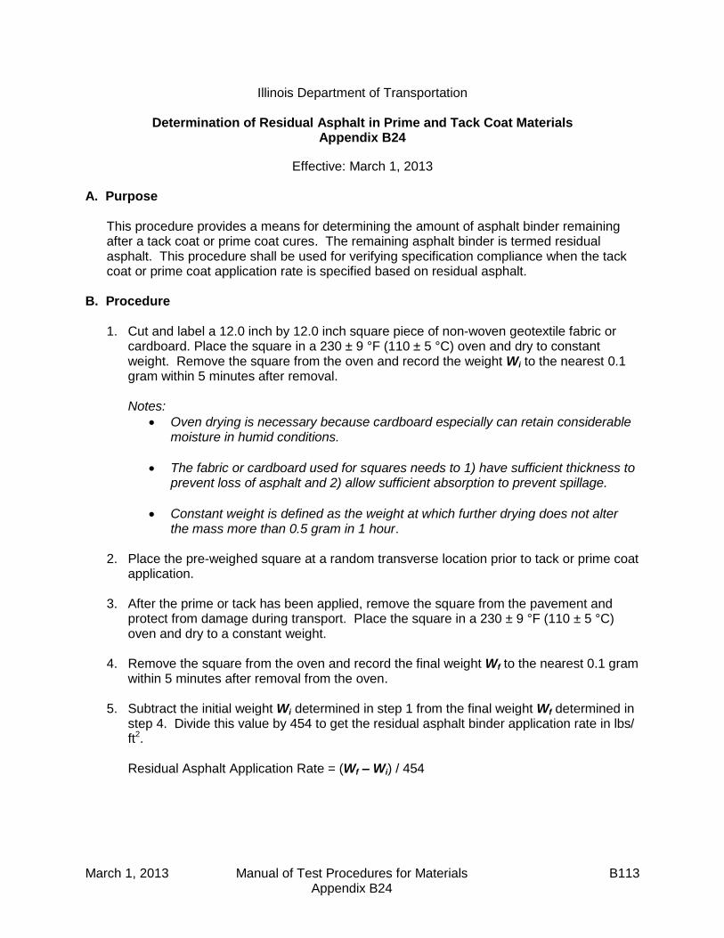
March 1, 2013 Manual of Test Procedures for Materials B113 Appendix B24
Illinois Department of Transportation
Determination of Residual Asphalt in Prime and Tack Coat Materials Appendix B24
Effective: March 1, 2013
A. Purpose
This procedure provides a means for determining the amount of asphalt binder remaining after a tack coat or prime coat cures. The remaining asphalt binder is termed residual asphalt. This procedure shall be used for verifying specification compliance when the tack coat or prime coat application rate is specified based on residual asphalt.
B. Procedure
1. Cut and label a 12.0 inch by 12.0 inch square piece of non-woven geotextile fabric or cardboard. Place the square in a 230 ± 9 °F (110 ± 5 °C) oven and dry to constant weight. Remove the square from the oven and record the weight Wi to the nearest 0.1 gram within 5 minutes after removal.
Notes:
Oven drying is necessary because cardboard especially can retain considerable moisture in humid conditions.
The fabric or cardboard used for squares needs to 1) have sufficient thickness to prevent loss of asphalt and 2) allow sufficient absorption to prevent spillage.
Constant weight is defined as the weight at which further drying does not alter the mass more than 0.5 gram in 1 hour.
2. Place the pre-weighed square at a random transverse location prior to tack or prime coat
application.
3. After the prime or tack has been applied, remove the square from the pavement and protect from damage during transport. Place the square in a 230 ± 9 °F (110 ± 5 °C) oven and dry to a constant weight.
4. Remove the square from the oven and record the final weight Wf to the nearest 0.1 gram
within 5 minutes after removal from the oven.
5. Subtract the initial weight Wi determined in step 1 from the final weight Wf determined in step 4. Divide this value by 454 to get the residual asphalt binder application rate in lbs/ ft2.
Residual Asphalt Application Rate = (Wf – Wi) / 454

March 1, 2013 Manual of Test Procedures for Materials B114 Appendix B24
This Page Reserved

SEQUENTIAL TABLE OF CONTENTS (continued)
MANUAL OF TEST PROCEDURES FOR MATERIALS
June 1, 2012 Manual of Test Procedures for Materials
E – End Result Specification Appendix E1
(Effective 04/01/10) (Revised 01/01/13)
PFP Quality Level Analysis ...................................... E 1
Appendix E2 (Effective 05/01/08)
PFP Hot-Mix Asphalt Random Plant Samples ......... E13
Appendix E3 (Effective 04/01/10) (Revised 01/01/13)
PFP Random Density Procedure ............................. E19
Appendix E4 (Effective 04/01/11) (Revised 01/01/13)
PFP Hot Mix Asphalt Random Jobsite Sampling ..... E25
Appendix E5 (Effective 04/01/10)
PFP Dispute Resolution Instructions ....................... E37
Appendix E6 (Effective 01/01/12) (Revised 01/01/13)
QCP Pay Calculation ............................................... E39
Appendix E7 (Effective 04/01/12)
Best Practices for PFP and QCP Implementation .... E45
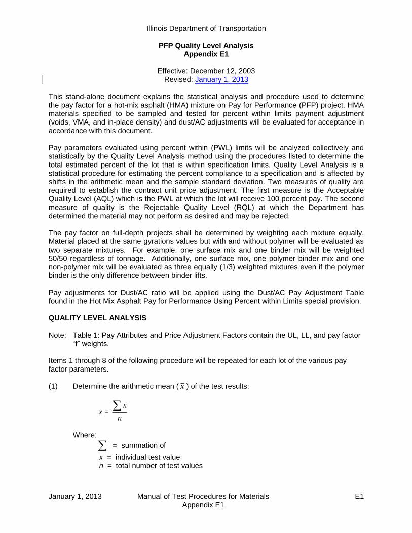
Illinois Department of Transportation
PFP Quality Level Analysis Appendix E1
Effective: December 12, 2003
Revised: January 1, 2013
January 1, 2013 Manual of Test Procedures for Materials E1 Appendix E1
This stand-alone document explains the statistical analysis and procedure used to determine the pay factor for a hot-mix asphalt (HMA) mixture on Pay for Performance (PFP) project. HMA materials specified to be sampled and tested for percent within limits payment adjustment (voids, VMA, and in-place density) and dust/AC adjustments will be evaluated for acceptance in accordance with this document. Pay parameters evaluated using percent within (PWL) limits will be analyzed collectively and statistically by the Quality Level Analysis method using the procedures listed to determine the total estimated percent of the lot that is within specification limits. Quality Level Analysis is a statistical procedure for estimating the percent compliance to a specification and is affected by shifts in the arithmetic mean and the sample standard deviation. Two measures of quality are required to establish the contract unit price adjustment. The first measure is the Acceptable Quality Level (AQL) which is the PWL at which the lot will receive 100 percent pay. The second measure of quality is the Rejectable Quality Level (RQL) at which the Department has determined the material may not perform as desired and may be rejected. The pay factor on full-depth projects shall be determined by weighting each mixture equally. Material placed at the same gyrations values but with and without polymer will be evaluated as two separate mixtures. For example: one surface mix and one binder mix will be weighted 50/50 regardless of tonnage. Additionally, one surface mix, one polymer binder mix and one non-polymer mix will be evaluated as three equally (1/3) weighted mixtures even if the polymer binder is the only difference between binder lifts. Pay adjustments for Dust/AC ratio will be applied using the Dust/AC Pay Adjustment Table found in the Hot Mix Asphalt Pay for Performance Using Percent within Limits special provision. QUALITY LEVEL ANALYSIS Note: Table 1: Pay Attributes and Price Adjustment Factors contain the UL, LL, and pay factor
“f” weights.
Items 1 through 8 of the following procedure will be repeated for each lot of the various pay factor parameters. (1) Determine the arithmetic mean ( x ) of the test results:
x = n
x
Where:
= summation of
x = individual test value n = total number of test values
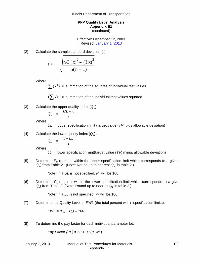
Illinois Department of Transportation
PFP Quality Level Analysis Appendix E1 (continued)
Effective: December 12, 2003
Revised: January 1, 2013
January 1, 2013 Manual of Test Procedures for Materials E2 Appendix E1
(2) Calculate the sample standard deviation (s): s = Where:
)( 2x = summation of the squares of individual test values
2)( x = summation of the individual test values squared
(3) Calculate the upper quality index (QU):
QU = s
xUL
Where: UL = upper specification limit (target value (TV) plus allowable deviation) (4) Calculate the lower quality index (QL):
QL = s
LLx
Where: LL = lower specification limit(target value (TV) minus allowable deviation) (5) Determine PU (percent within the upper specification limit which corresponds to a given
QU) from Table 2. (Note: Round up to nearest QU in table 2.) Note: If a UL is not specified, PU will be 100. (6) Determine PL (percent within the lower specification limit which corresponds to a give
QL) from Table 2. (Note: Round up to nearest QL in table 2.) Note: If a LL is not specified, PL will be 100. (7) Determine the Quality Level or PWL (the total percent within specification limits). PWL = (PU + PL) – 100
(8) To determine the pay factor for each individual parameter lot: Pay Factor (PF) = 53 + 0.5 (PWL)
n S x( )2. S x( )
2
n n 1( )
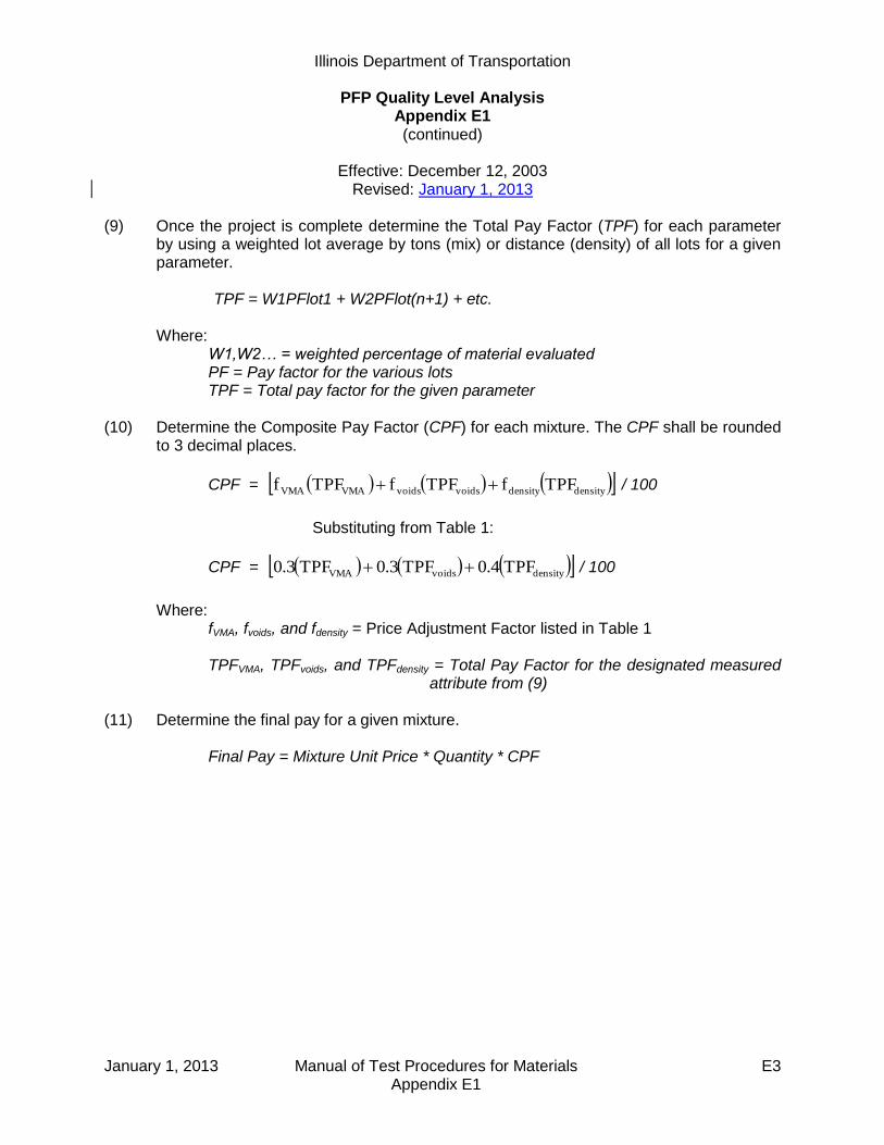
Illinois Department of Transportation
PFP Quality Level Analysis Appendix E1 (continued)
Effective: December 12, 2003
Revised: January 1, 2013
January 1, 2013 Manual of Test Procedures for Materials E3 Appendix E1
(9) Once the project is complete determine the Total Pay Factor (TPF) for each parameter by using a weighted lot average by tons (mix) or distance (density) of all lots for a given parameter. TPF = W1PFlot1 + W2PFlot(n+1) + etc. Where: W1,W2… = weighted percentage of material evaluated PF = Pay factor for the various lots TPF = Total pay factor for the given parameter
(10) Determine the Composite Pay Factor (CPF) for each mixture. The CPF shall be rounded to 3 decimal places.
CPF = densitydensityvoidsvoidsVMAVMA TPFfTPFfTPFf / 100
Substituting from Table 1:
CPF = densityvoidsVMA TPF0.4TPF0.3TPF0.3 / 100
Where: fVMA, fvoids, and fdensity = Price Adjustment Factor listed in Table 1 TPFVMA, TPFvoids, and TPFdensity = Total Pay Factor for the designated measured
attribute from (9) (11) Determine the final pay for a given mixture. Final Pay = Mixture Unit Price * Quantity * CPF

Illinois Department of Transportation
PFP Quality Level Analysis Appendix E1 (continued)
Effective: December 12, 2003
Revised: January 1, 2013
January 1, 2013 Manual of Test Procedures for Materials E4 Appendix E1
Table 1: Pay Attributes and Price Adjustment Factors
Measured Attribute
Factor “f”
UL
LL
VMA
0.3
MDR/1 + 3.0
MDR/1 – 0.7
Plant Voids
0.3
Design Voids +
1.35
Design Voids –
1.35
In-Place Density
0.4 97.0/2 91.5/2
IL 4.75 0.4 97.0 92.5
IL 9.5 FG Level Binder3/
0.4 97.0 90.5
IL 19.0 & 25.0 0.4 97.0 92.2
SMA 0.4 98.0 93.0
1. MDR = Minimum Design Requirement 2. Applies to all HMA mixes other than IL-4.75, IL-19.0, IL-25.0, SMA and IL 9.5 FG
Level Binder placed ≤ 1.25 in. (32 mm) thick 3. Placed at a thickness ≤ 1.25 in. (32 mm)
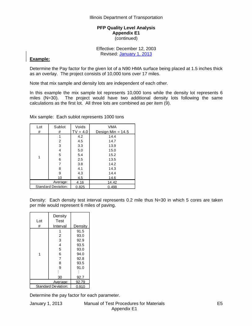
Illinois Department of Transportation
PFP Quality Level Analysis Appendix E1 (continued)
Effective: December 12, 2003
Revised: January 1, 2013
January 1, 2013 Manual of Test Procedures for Materials E5 Appendix E1
Example:
Determine the Pay factor for the given lot of a N90 HMA surface being placed at 1.5 inches thick as an overlay. The project consists of 10,000 tons over 17 miles.
Note that mix sample and density lots are independent of each other.
In this example the mix sample lot represents 10,000 tons while the density lot represents 6 miles (N=30). The project would have two additional density lots following the same calculations as the first lot. All three lots are combined as per item (9).
Mix sample: Each sublot represents 1000 tons
Lot Sublot Voids VMA
# # TV = 4.0 Design Min = 14.51 4.2 14.4
2 4.5 14.7
3 3.3 13.9
4 5.0 15.0
5 5.4 15.2
6 2.5 13.5
7 3.8 14.2
8 4.1 14.3
9 4.3 14.4
10 4.5 14.6
4.16 14.42
0.825 0.498
1
Average:
Standard Deviation:
Density: Each density test interval represents 0.2 mile thus N=30 in which 5 cores are taken per mile would represent 6 miles of paving.
Lot
# Density
1 91.52 93.0
3 92.9
4 93.55 93.0
6 94.0
7 92.88 93.5
9 91.0… …
30 92.7
92.79
0.910
1
Average: Standard Deviation:
Density
Test
Interval
Determine the pay factor for each parameter.

Illinois Department of Transportation PFP Quality Level Analysis
Appendix E1 (continued)
Effective: December 12, 2003
Revised: January 1, 2013
January 1, 2013 Manual of Test Procedures for Materials E6 Appendix E1
Voids:
Lot: Average = 4.16 Standard Deviation = 0.825
44.1
825.0
16.435.10.4
UQ
83.1
825.0
35.10.416.4
LQ
N = 10 sublots (from table) PU = 94 PL = 98 PWL = (94 + 98) - 100 PWL = 92 PF = 53 + 0.5 (92) PF = 99.0
Determine the pay factor for Voids.
PFVoids = 99.0

Illinois Department of Transportation
PFP Quality Level Analysis Appendix E1 (continued)
Effective: December 12, 2003
Revised: January 1, 2013
January 1, 2013 Manual of Test Procedures for Materials E7 Appendix E1
VMA:
Lot : Average = 14.42 Standard Deviation = 0.498
18.6
498.0
42.140.35.14
UQ
24.1
498.0
7.05.1442.14
LQ
N = 10 sublots (from table) PU = 100 PL = 90 PWL = (100 + 90) - 100 PWL = 90 PF = 53 + 0.5 (90) PF = 98
Determine the pay factor for VMA.
PFVMA = 98.0

Illinois Department of Transportation PFP Quality Level Analysis
Appendix E1 (continued)
Effective: December 12, 2003
Revised: January 1, 2013
January 1, 2013 Manual of Test Procedures for Materials E8 Appendix E1
Density:
Lot: Average = 92.79
Standard Deviation = 0.910
63.4910.0
79.920.97
UQ
42.1910.0
5.9179.92
LQ
N = 30 Density measurements (from table) PU = 100 PL = 93 PWL = (100 + 93) - 100 PWL = 93 PF = 53 + 0.5 (93) PF = 99.5
Determine the pay factor for Density. PFDensity = 99.5
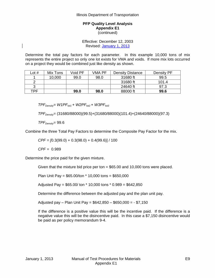
Illinois Department of Transportation
PFP Quality Level Analysis Appendix E1 (continued)
Effective: December 12, 2003
Revised: January 1, 2013
January 1, 2013 Manual of Test Procedures for Materials E9 Appendix E1
Determine the total pay factors for each parameter. In this example 10,000 tons of mix represents the entire project so only one lot exists for VMA and voids. If more mix lots occurred on a project they would be combined just like density as shown.
Lot # Mix Tons Void PF VMA PF Density Distance Density PF
1 10,000 99.0 98.0 31680 ft 99.5
2 31680 ft 101.4
3 24640 ft 97.3
TPF 99.0 98.0 88000 ft 99.6
TPFDensity= W1PFlot1 + W2PFlot2 + W3PFlot3 TPFDensity= (31680/88000)(99.5)+(31680/88000)(101.4)+(24640/88000)(97.3) TPFDensity= 99.6 Combine the three Total Pay Factors to determine the Composite Pay Factor for the mix.
CPF = [0.3(99.0) + 0.3(98.0) + 0.4(99.6)] / 100 CPF = 0.989
Determine the price paid for the given mixture.
Given that the mixture bid price per ton = $65.00 and 10,000 tons were placed.
Plan Unit Pay = $65.00/ton * 10,000 tons = $650,000
Adjusted Pay = $65.00/ ton * 10,000 tons * 0.989 = $642,850 Determine the difference between the adjusted pay and the plan unit pay. Adjusted pay – Plan Unit Pay = $642,850 – $650,000 = - $7,150 If the difference is a positive value this will be the incentive paid. If the difference is a negative value this will be the disincentive paid. In this case a $7,150 disincentive would be paid as per policy memorandum 9-4.
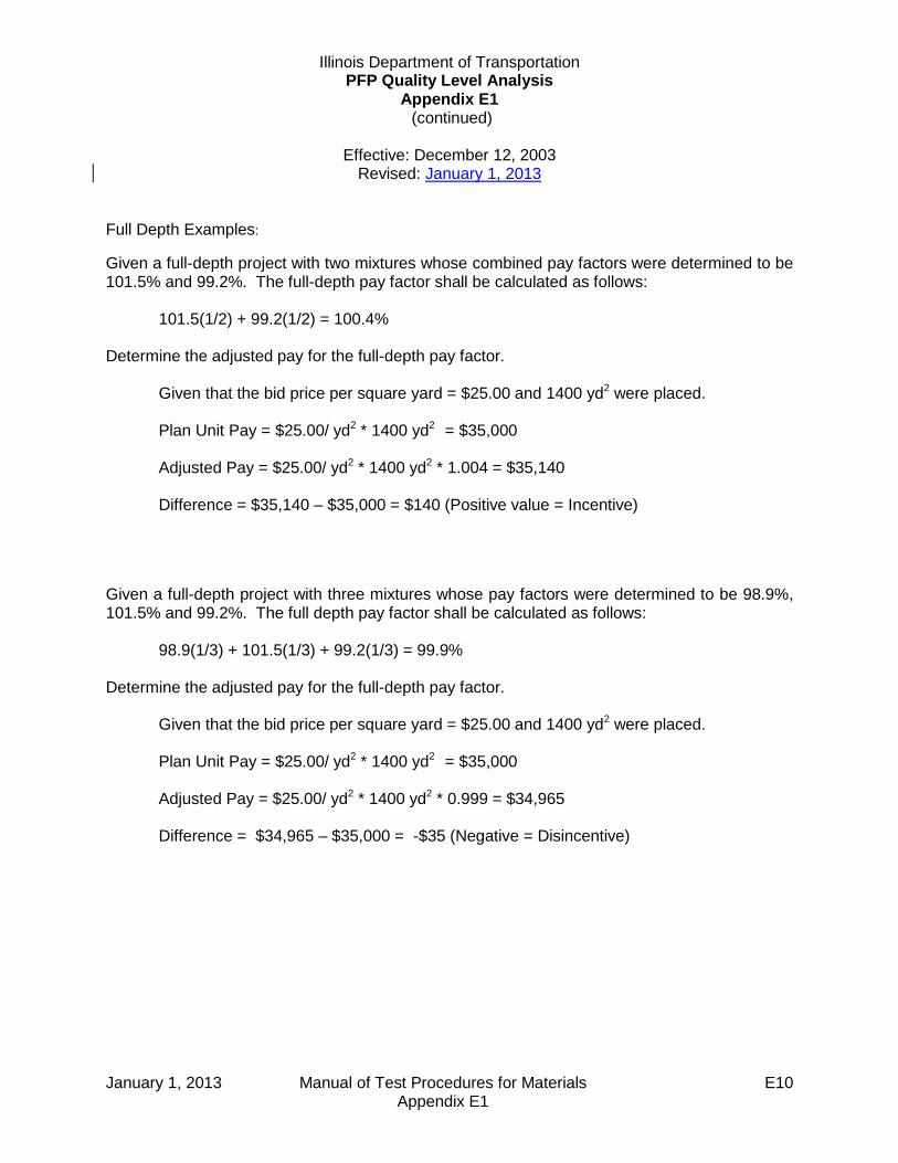
Illinois Department of Transportation PFP Quality Level Analysis
Appendix E1 (continued)
Effective: December 12, 2003
Revised: January 1, 2013
January 1, 2013 Manual of Test Procedures for Materials E10 Appendix E1
Full Depth Examples:
Given a full-depth project with two mixtures whose combined pay factors were determined to be 101.5% and 99.2%. The full-depth pay factor shall be calculated as follows:
101.5(1/2) + 99.2(1/2) = 100.4%
Determine the adjusted pay for the full-depth pay factor.
Given that the bid price per square yard = $25.00 and 1400 yd2 were placed. Plan Unit Pay = $25.00/ yd2 * 1400 yd2 = $35,000 Adjusted Pay = $25.00/ yd2 * 1400 yd2 * 1.004 = $35,140 Difference = $35,140 – $35,000 = $140 (Positive value = Incentive)
Given a full-depth project with three mixtures whose pay factors were determined to be 98.9%, 101.5% and 99.2%. The full depth pay factor shall be calculated as follows:
98.9(1/3) + 101.5(1/3) + 99.2(1/3) = 99.9%
Determine the adjusted pay for the full-depth pay factor.
Given that the bid price per square yard = $25.00 and 1400 yd2 were placed. Plan Unit Pay = $25.00/ yd2 * 1400 yd2 = $35,000 Adjusted Pay = $25.00/ yd2 * 1400 yd2 * 0.999 = $34,965 Difference = $34,965 – $35,000 = -$35 (Negative = Disincentive)

Illinois Department of Transportation
PFP Quality Level Analysis Appendix E1 (continued)
Effective: December 12, 2003
Revised: January 1, 2013
January 1, 2013 Manual of Test Procedures for Materials E11 Appendix E1
TABLE 2: QUALITY LEVELS
QUALITY LEVEL ANALYSIS BY STANDARD DEVIATION METHOD
PU OR PL
PERCENT UPPER QUALITY INDEX QU OR LOWER QUALITY INDEX QL
WITHIN
LIMITS FOR
n=10 n=12 n=15 n=19 n=26 n=38 n=70 n=201
POSITIVE n=3 n=4 n=5 n=6 n=7 n=8 n=9 to to to to to to to to VALUES
OF
n=11 n=14 n=18 n=25 n=37 n=69 n=200 infinity
QU OR QL
100 1.16 1.50 1.79 2.03 2.23 2.39 2.53 2.65 2.83 3.03 3.20 3.38 3.54 3.70 3.83
99 1.47 1.67 1.80 1.89 1.95 2.00 2.04 2.09 2.14 2.18 2.22 2.26 2.29 2.31
98 1.15 1.44 1.60 1.70 1.76 1.81 1.84 1.86 1.91 1.93 1.96 1.99 2.01 2.03 2.05
97 1.41 1.54 1.62 1.67 1.70 1.72 1.74 1.77 1.79 1.81 1.83 1.85 1.86 1.87
96 1.14 1.38 1.49 1.55 1.59 1.61 1.63 1.65 1.67 1.68 1.70 1.71 1.73 1.74 1.75
95 1.35 1.44 1.49 1.52 1.54 1.55 1.56 1.58 1.59 1.61 1.62 1.63 1.63 1.64
94 1.13 1.32 1.39 1.43 1.46 1.47 1.48 1.49 1.50 1.51 1.52 1.53 1.54 1.55 1.55
93 1.29 1.35 1.38 1.40 1.41 1.42 1.43 1.44 1.44 1.45 1.46 1.46 1.47 1.47
92 1.12 1.26 1.31 1.33 1.35 1.36 1.36 1.37 1.37 1.38 1.39 1.39 1.40 1.40 1.40
91 1.11 1.23 1.27 1.29 1.30 1.30 1.31 1.31 1.32 1.32 1.33 1.33 1.33 1.34 1.34
90 1.10 1.20 1.23 1.24 1.25 1.25 1.26 1.26 1.26 1.27 1.27 1.27 1.28 1.28 1.28
89 1.09 1.17 1.19 1.20 1.20 1.21 1.21 1.21 1.21 1.22 1.22 1.22 1.22 1.22 1.23
88 1.07 1.14 1.15 1.16 1.16 1.16 1.16 1.17 1.17 1.17 1.17 1.17 1.17 1.17 1.17
87 1.06 1.11 1.12 1.12 1.12 1.12 1.12 1.12 1.12 1.12 1.12 1.12 1.12 1.13 1.13
86 1.04 1.08 1.08 1.08 1.08 1.08 1.08 1.08 1.08 1.08 1.08 1.08 1.08 1.08 1.08
85 1.03 1.05 1.05 1.04 1.04 1.04 1.04 1.04 1.04 1.04 1.04 1.04 1.04 1.04 1.04
84 1.01 1.02 1.01 1.01 1.00 1.00 1.00 1.00 1.00 1.00 1.00 1.00 0.99 0.99 0.99
83 1.00 0.99 0.98 0.97 0.97 0.96 0.96 0.96 0.96 0.96 0.96 0.96 0.95 0.95 0.95
82 0.97 0.96 0.95 0.94 0.93 0.93 0.93 0.92 0.92 0.92 0.92 0.92 0.92 0.92 0.92
81 0.96 0.93 0.91 0.90 0.90 0.89 0.89 0.89 0.89 0.88 0.88 0.88 0.88 0.88 0.88
80 0.93 0.90 0.88 0.87 0.86 0.86 0.86 0.85 0.85 0.85 0.85 0.84 0.84 0.84 0.84
79 0.91 0.87 0.85 0.84 0.83 0.82 0.82 0.82 0.82 0.81 0.81 0.81 0.81 0.81 0.81
78 0.89 0.84 0.82 0.80 0.80 0.79 0.79 0.79 0.78 0.78 0.78 0.78 0.77 0.77 0.77
77 0.87 0.81 0.78 0.77 0.76 0.76 0.76 0.75 0.75 0.75 0.75 0.74 0.74 0.74 0.74
76 0.84 0.78 0.75 0.74 0.73 0.73 0.72 0.72 0.72 0.71 0.71 0.71 0.71 0.71 0.71
75 0.82 0.75 0.72 0.71 0.70 0.70 0.69 0.69 0.69 0.68 0.68 0.68 0.68 0.68 0.67
74 0.79 0.72 0.69 0.68 0.67 0.66 0.66 0.66 0.66 0.65 0.65 0.65 0.65 0.64 0.64
73 0.76 0.69 0.66 0.65 0.64 0.63 0.63 0.63 0.62 0.62 0.62 0.62 0.62 0.61 0.61
72 0.74 0.66 0.63 0.62 0.61 0.60 0.60 0.60 0.59 0.59 0.59 0.59 0.59 0.58 0.58
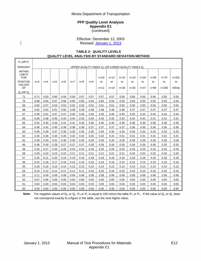
Illinois Department of Transportation
PFP Quality Level Analysis Appendix E1 (continued)
Effective: December 12, 2003
Revised: January 1, 2013
January 1, 2013 Manual of Test Procedures for Materials E12 Appendix E1
TABLE 2: QUALITY LEVELS
QUALITY LEVEL ANALYSIS BY STANDARD DEVIATION METHOD
PU OR PL
PERCENT UPPER QUALITY INDEX QU OR LOWER QUALITY INDEX QL
WITHIN
LIMITS FOR
n=10 n=12 n=15 n=19 n=26 n=38 n=70 n=201
POSITIVE n=3 n=4 n=5 n=6 n=7 n=8 n=9 to to to to to to to to VALUES
OF
n=11 n=14 n=18 n=25 n=37 n=69 n=200 infinity
QU OR QL
71 0.71 0.63 0.60 0.59 0.58 0.57 0.57 0.57 0.57 0.56 0.56 0.56 0.56 0.55 0.55
70 0.68 0.60 0.57 0.56 0.55 0.55 0.54 0.54 0.54 0.53 0.53 0.53 0.53 0.53 0.53
69 0.65 0.57 0.54 0.53 0.52 0.52 0.51 0.51 0.51 0.50 0.50 0.50 0.50 0.50 0.50
68 0.62 0.54 0.51 0.50 0.49 0.49 0.48 0.48 0.48 0.48 0.47 0.47 0.47 0.47 0.47
67 0.59 0.51 0.47 0.47 0.46 0.46 0.46 0.45 0.45 0.45 0.45 0.44 0.44 0.44 0.44
66 0.56 0.48 0.45 0.44 0.44 0.43 0.43 0.43 0.42 0.42 0.42 0.42 0.41 0.41 0.41
65 0.52 0.45 0.43 0.41 0.41 0.40 0.40 0.40 0.40 0.39 0.39 0.39 0.39 0.39 0.39
64 0.49 0.42 0.40 0.39 0.38 0.38 0.37 0.37 0.37 0.37 0.36 0.36 0.36 0.36 0.36
63 0.46 0.39 0.37 0.36 0.35 0.35 0.35 0.34 0.34 0.34 0.34 0.34 0.33 0.33 0.33
62 0.43 0.36 0.34 0.33 0.32 0.32 0.32 0.32 0.31 0.31 0.31 0.31 0.31 0.31 0.31
61 0.39 0.33 0.31 0.30 0.30 0.29 0.29 0.29 0.29 0.29 0.28 0.28 0.28 0.28 0.28
60 0.36 0.30 0.28 0.27 0.27 0.27 0.26 0.26 0.26 0.26 0.26 0.26 0.26 0.25 0.25
59 0.32 0.27 0.25 0.25 0.24 0.24 0.24 0.24 0.23 0.23 0.23 0.23 0.23 0.23 0.23
58 0.29 0.24 0.23 0.22 0.21 0.21 0.21 0.21 0.21 0.21 0.20 0.20 0.20 0.20 0.20
57 0.25 0.21 0.20 0.19 0.19 0.19 0.18 0.18 0.18 0.18 0.18 0.18 0.18 0.18 0.18
56 0.22 0.18 0.17 0.16 0.16 0.16 0.16 0.16 0.16 0.15 0.15 0.15 0.15 0.15 0.15
55 0.18 0.15 0.14 0.14 0.13 0.13 0.13 0.13 0.13 0.13 0.13 0.13 0.13 0.13 0.13
54 0.14 0.12 0.11 0.11 0.11 0.11 0.10 0.10 0.10 0.10 0.10 0.10 0.10 0.10 0.10
53 0.11 0.09 0.08 0.08 0.08 0.08 0.08 0.08 0.08 0.08 0.08 0.08 0.08 0.08 0.08
52 0.07 0.06 0.06 0.05 0.05 0.05 0.05 0.05 0.05 0.05 0.05 0.05 0.05 0.05 0.05
51 0.04 0.03 0.03 0.03 0.03 0.03 0.03 0.03 0.03 0.03 0.03 0.03 0.03 0.03 0.03
50 0.00 0.00 0.00 0.00 0.00 0.00 0.00 0.00 0.00 0.00 0.00 0.00 0.00 0.00 0.00
Note: For negative values of QU or QL, PU or PL is equal to 100 minus the table PU or PL. If the value of QU or QL does
not correspond exactly to a figure in the table, use the next higher value.

Illinois Department of Transportation
PFP Hot-Mix Asphalt Random Plant Samples Appendix E2
Effective Date: May 1, 2008
June 1, 2012 Manual of Test Procedures for Materials E13 Appendix E2
Samples shall be obtained at the frequency specified in the Hot Mix Asphalt Pay for Performance Using Percent within Limits special provision. A. The random plant samples shall be taken at the randomly selected tonnage within a sublot.
The random tonnage will be determined by the Engineer using the “Random Numbers” table as specified herein or an approved software program. The tonnage shall be calculated according to the following: 1. Unless otherwise known, determine the random locations for a tonnage in excess of
five percent over plan quantity by multiplying the plan quantity tonnage by 1.05 to determine an over-projected final quantity. If the over-projected final quantity is not achieved, disregard the additional random values.
2. Determine the maximum number of sublots needed for the given mixture by dividing
the over-projected tonnage calculated above by the sublot size in tons (metric tons). This will determine the maximum number of sublots for the given mixture.
3. Multiply the sublot tonnage by a three-digit random number, expressed as a decimal.
The number obtained (rounded to a whole number) shall be the random sampling tonnage within the given sublot.
4. The individual sublot random tonnages shall then be converted to the cumulative
random tonnages. This is accomplished by using the following equation for each sublot.
nRT)]1n(*)ST[(
nCT
Where: n = the sublot number CT = Cumulative tonnage RT = Random tonnage as determined in #3 above ST = Sublot tonnage (typically 1000 tons)
B. If the paving is completed for a particular mixture before the specified sampling tonnage for
the last sublot is achieved, the partial sublot shall be omitted.
C. Plant truck samples shall be taken of the mixture for testing. Two sampling platforms (one on each side of the truck) shall be provided for sampling of the mix. In order to obtain a representative sample of the entire truck, an equal amount of material shall be taken from each quarter point around the circumference of each pile in the truck to obtain a composite sample weighing approximately 200lbs. (95 kg). All truck samples shall be obtained by using a "D"-handled, square-ended shovel with built-up sides and back (1 to 1-1/2 in. [25 to 38 mm]). The sample shall be taken out of the truck containing the random tonnage as determined by the Engineer following the procedure described herein. The sample

Illinois Department of Transportation
PFP Hot-Mix Asphalt Random Plant Samples Appendix E2 (continued)
Effective Date: May 1, 2008
June 1, 2012 Manual of Test Procedures for Materials E14 Appendix E2
tonnage will be disclosed no more than 30 minutes prior to sampling. Sampling shall be performed by the Contractor under the supervision of the Engineer.
D. The truck sample shall be divided into three approximately equal size (split) samples by the
use of an approved mechanical sample splitter. The Engineer will witness all splitting. Two split samples for Department testing shall be placed in Department-approved sample containers provided by the Contractor and identified as per the Engineer's direction. The Engineer will gain immediate possession of both Department split samples. The Contractor may store, discard, or test the remaining split as described in Section 1030 of the Standard Specifications. However, the Contractor must test and provide the sample results in order to initiate the dispute resolution process as described in the Hot Mix Asphalt Pay for Performance Special Provision.
Example: Given: - Plan quantity = 10,000 tons for a given mixture. - Sublot = 1000 tons (725 metric tons). 1. Determine the over-projected final tonnage.
10,000 tons * 1.05 = 10,500 tons (Note: Always round up)
2. Determine the maximum number of sublots needed for the project based on the over-projected tonnage.
10,500 tons/1000 tons = 10.5 (Note: Always round up) Therefore, 11 maximum sublots
3. Obtain random numbers from the table and apply a different random number to each sublot.
1000 * 0.546 = 546 1000 * 0.123 = 123
Repeat for each sublot.
4. Convert individual tonnage to cumulative job tonnage.
[1000*(1-1)] + 546 = 546 [1000*(2-1)] + 123 = 1123
Repeat for each sublot.
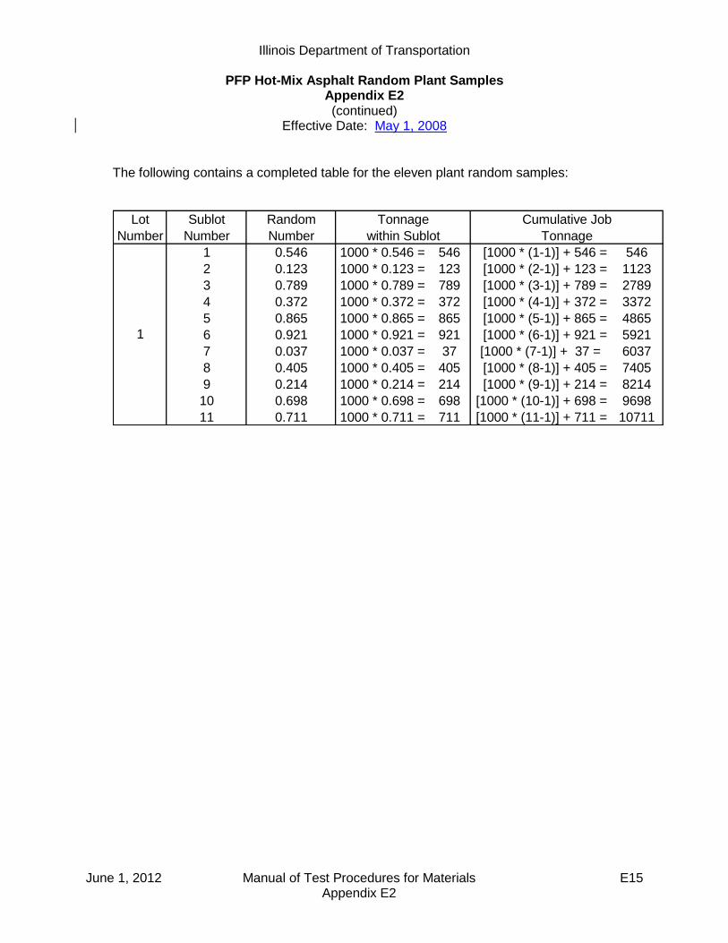
Illinois Department of Transportation
PFP Hot-Mix Asphalt Random Plant Samples Appendix E2 (continued)
Effective Date: May 1, 2008
June 1, 2012 Manual of Test Procedures for Materials E15 Appendix E2
The following contains a completed table for the eleven plant random samples:
Lot Sublot Random
Number Number Number
1 0.546 1000 * 0.546 = 546 [1000 * (1-1)] + 546 = 546
2 0.123 1000 * 0.123 = 123 [1000 * (2-1)] + 123 = 1123
3 0.789 1000 * 0.789 = 789 [1000 * (3-1)] + 789 = 2789
4 0.372 1000 * 0.372 = 372 [1000 * (4-1)] + 372 = 3372
5 0.865 1000 * 0.865 = 865 [1000 * (5-1)] + 865 = 4865
6 0.921 1000 * 0.921 = 921 [1000 * (6-1)] + 921 = 5921
7 0.037 1000 * 0.037 = 37 [1000 * (7-1)] + 37 = 6037
8 0.405 1000 * 0.405 = 405 [1000 * (8-1)] + 405 = 7405
9 0.214 1000 * 0.214 = 214 [1000 * (9-1)] + 214 = 8214
10 0.698 1000 * 0.698 = 698 [1000 * (10-1)] + 698 = 9698
11 0.711 1000 * 0.711 = 711 [1000 * (11-1)] + 711 = 10711
1
Tonnage
within Sublot
Cumulative Job
Tonnage

June 1, 2012 Manual of Test Procedures for Materials E16 Appendix E2
This Page Reserved
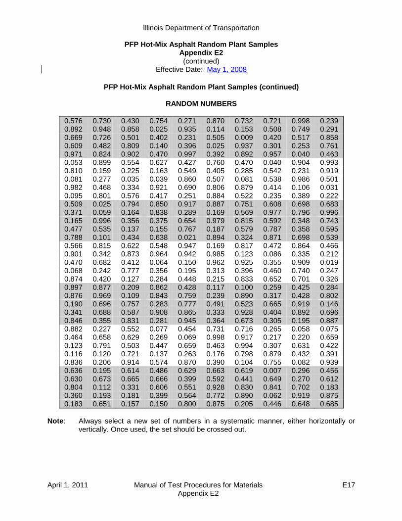
Illinois Department of Transportation
PFP Hot-Mix Asphalt Random Plant Samples Appendix E2 (continued)
Effective Date: May 1, 2008
April 1, 2011 Manual of Test Procedures for Materials E17 Appendix E2
PFP Hot-Mix Asphalt Random Plant Samples (continued)
RANDOM NUMBERS
0.576 0.730 0.430 0.754 0.271 0.870 0.732 0.721 0.998 0.239 0.892 0.948 0.858 0.025 0.935 0.114 0.153 0.508 0.749 0.291 0.669 0.726 0.501 0.402 0.231 0.505 0.009 0.420 0.517 0.858 0.609 0.482 0.809 0.140 0.396 0.025 0.937 0.301 0.253 0.761 0.971 0.824 0.902 0.470 0.997 0.392 0.892 0.957 0.040 0.463 0.053 0.899 0.554 0.627 0.427 0.760 0.470 0.040 0.904 0.993 0.810 0.159 0.225 0.163 0.549 0.405 0.285 0.542 0.231 0.919 0.081 0.277 0.035 0.039 0.860 0.507 0.081 0.538 0.986 0.501 0.982 0.468 0.334 0.921 0.690 0.806 0.879 0.414 0.106 0.031 0.095 0.801 0.576 0.417 0.251 0.884 0.522 0.235 0.389 0.222 0.509 0.025 0.794 0.850 0.917 0.887 0.751 0.608 0.698 0.683 0.371 0.059 0.164 0.838 0.289 0.169 0.569 0.977 0.796 0.996 0.165 0.996 0.356 0.375 0.654 0.979 0.815 0.592 0.348 0.743 0.477 0.535 0.137 0.155 0.767 0.187 0.579 0.787 0.358 0.595 0.788 0.101 0.434 0.638 0.021 0.894 0.324 0.871 0.698 0.539 0.566 0.815 0.622 0.548 0.947 0.169 0.817 0.472 0.864 0.466 0.901 0.342 0.873 0.964 0.942 0.985 0.123 0.086 0.335 0.212 0.470 0.682 0.412 0.064 0.150 0.962 0.925 0.355 0.909 0.019 0.068 0.242 0.777 0.356 0.195 0.313 0.396 0.460 0.740 0.247 0.874 0.420 0.127 0.284 0.448 0.215 0.833 0.652 0.701 0.326 0.897 0.877 0.209 0.862 0.428 0.117 0.100 0.259 0.425 0.284 0.876 0.969 0.109 0.843 0.759 0.239 0.890 0.317 0.428 0.802 0.190 0.696 0.757 0.283 0.777 0.491 0.523 0.665 0.919 0.146 0.341 0.688 0.587 0.908 0.865 0.333 0.928 0.404 0.892 0.696 0.846 0.355 0.831 0.281 0.945 0.364 0.673 0.305 0.195 0.887 0.882 0.227 0.552 0.077 0.454 0.731 0.716 0.265 0.058 0.075 0.464 0.658 0.629 0.269 0.069 0.998 0.917 0.217 0.220 0.659 0.123 0.791 0.503 0.447 0.659 0.463 0.994 0.307 0.631 0.422 0.116 0.120 0.721 0.137 0.263 0.176 0.798 0.879 0.432 0.391 0.836 0.206 0.914 0.574 0.870 0.390 0.104 0.755 0.082 0.939 0.636 0.195 0.614 0.486 0.629 0.663 0.619 0.007 0.296 0.456 0.630 0.673 0.665 0.666 0.399 0.592 0.441 0.649 0.270 0.612 0.804 0.112 0.331 0.606 0.551 0.928 0.830 0.841 0.702 0.183 0.360 0.193 0.181 0.399 0.564 0.772 0.890 0.062 0.919 0.875 0.183 0.651 0.157 0.150 0.800 0.875 0.205 0.446 0.648 0.685
Note: Always select a new set of numbers in a systematic manner, either horizontally or
vertically. Once used, the set should be crossed out.

April 1, 2011 Manual of Test Procedures for Materials E18 Appendix E2
This Page Reserved

Illinois Department of Transportation
PFP and QCP Random Density Procedure Appendix E3
Effective: April 1, 2009
Revised: January 1, 2013
January 1, 2013 Manual of Test Procedures for Materials E19 Appendix E3
Density tests using cores shall be obtained at the frequency specified in the Hot Mix Asphalt Quality Control for Performance (QCP) and Pay for Performance (PFP) Using Percent within Limits special provisions. The random test locations shall be determined as follows: A) The random core locations shall be taken at the randomly selected test location within each
density testing interval. The random test location will be determined by the Engineer using the “Random Numbers” table as specified herein or an approved software program. This may be performed each day or predetermined for the project. Regardless of when the values are determined, the values are to be considered confidential and are not to be disclosed to anyone outside of the Department. Disclosing the information prior to finish rolling would be in direct violation of federal regulations. Each core location shall be randomly located both longitudinally and transversely within each density testing interval. Each core location within the density testing interval shall be determined with two random numbers. The first random number is used to determine the longitudinal distance to the nearest 1 ft into the density testing interval. The second random number is used to determine the transverse offset to the nearest 0.1 ft from the left edge of the paving lane. To determine the longitudinal location of a core, multiply the length of the prescribed density interval by the random number selected from the Random Number table. Determine the random transverse offset as follows:
1. PFP. The effective lane width of the pavement shall be used in calculating the transverse offset. The effective lane width is determined by subtracting 1.0 ft for each unconfined edge from the entire paved lane width (i.e. If a 12.0 ft wide paved lane has two unconfined edges, the effective lane width would be 10.0 ft.) Determine the transverse offset by multiplying the effective width by the random number selected from the Random Number table. The transverse offset is measured from the left physical edge of the paved lane to locate the core on the pavement. If the left edge was unconfined, it will be omitted by adding 1.0 ft to the calculated transverse offset measurement. Random locations that fall within 4.0 inches of a confined edge shall be moved to 4.0 inches off the edge. Areas outside the mainline pavement that are paved concurrently with the mainline pavement (i.e. three-ft wide left shoulders, driveways, etc.) are not considered part of the paved mainline mat. See PFP example calculation herein. The core density location for the outer 1.0 ft of an unconfined edge will be randomly selected within each 0.5 mile section for each unconfined edge. Longitudinal joint testing shall be located at a distance equal to the lift thickness or a minimum of 4.0 in. (100 mm), from each pavement edge. (i.e. for a 5 in. (125 mm) lift the near edge of the core barrel shall be within 5.0 in. (125 mm) from the edge of pavement.)
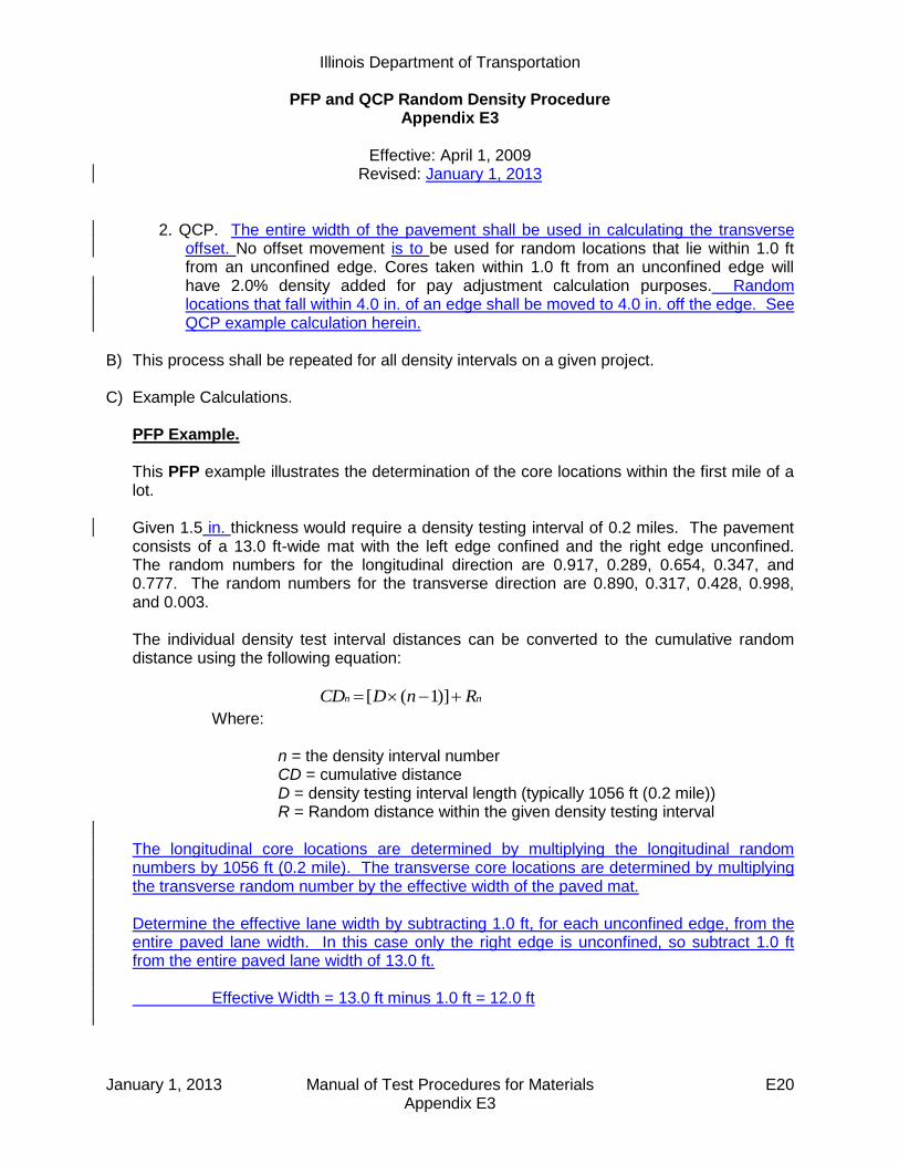
Illinois Department of Transportation
PFP and QCP Random Density Procedure Appendix E3
Effective: April 1, 2009
Revised: January 1, 2013
January 1, 2013 Manual of Test Procedures for Materials E20 Appendix E3
2. QCP. The entire width of the pavement shall be used in calculating the transverse
offset. No offset movement is to be used for random locations that lie within 1.0 ft from an unconfined edge. Cores taken within 1.0 ft from an unconfined edge will have 2.0% density added for pay adjustment calculation purposes. Random locations that fall within 4.0 in. of an edge shall be moved to 4.0 in. off the edge. See QCP example calculation herein.
B) This process shall be repeated for all density intervals on a given project.
C) Example Calculations.
PFP Example. This PFP example illustrates the determination of the core locations within the first mile of a lot. Given 1.5 in. thickness would require a density testing interval of 0.2 miles. The pavement consists of a 13.0 ft-wide mat with the left edge confined and the right edge unconfined. The random numbers for the longitudinal direction are 0.917, 0.289, 0.654, 0.347, and 0.777. The random numbers for the transverse direction are 0.890, 0.317, 0.428, 0.998, and 0.003. The individual density test interval distances can be converted to the cumulative random distance using the following equation:
nn RnDCD )]1([
Where: n = the density interval number CD = cumulative distance D = density testing interval length (typically 1056 ft (0.2 mile)) R = Random distance within the given density testing interval
The longitudinal core locations are determined by multiplying the longitudinal random numbers by 1056 ft (0.2 mile). The transverse core locations are determined by multiplying the transverse random number by the effective width of the paved mat. Determine the effective lane width by subtracting 1.0 ft, for each unconfined edge, from the entire paved lane width. In this case only the right edge is unconfined, so subtract 1.0 ft from the entire paved lane width of 13.0 ft. Effective Width = 13.0 ft minus 1.0 ft = 12.0 ft
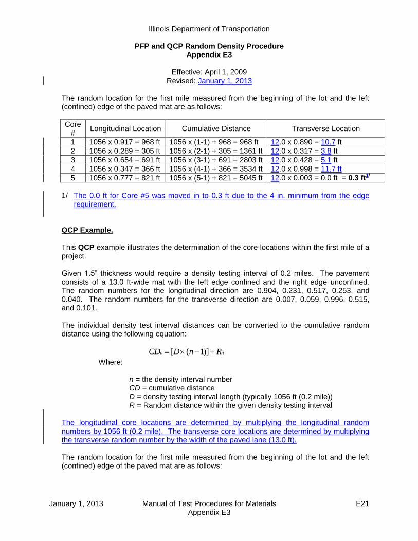
Illinois Department of Transportation
PFP and QCP Random Density Procedure Appendix E3
Effective: April 1, 2009
Revised: January 1, 2013
January 1, 2013 Manual of Test Procedures for Materials E21 Appendix E3
The random location for the first mile measured from the beginning of the lot and the left (confined) edge of the paved mat are as follows:
Core #
Longitudinal Location Cumulative Distance Transverse Location
1 1056 x 0.917 = 968 ft 1056 x (1-1) + 968 = 968 ft 12.0 x 0.890 = 10.7 ft
2 1056 x 0.289 = 305 ft 1056 x (2-1) + 305 = 1361 ft 12.0 x 0.317 = 3.8 ft
3 1056 x 0.654 = 691 ft 1056 x (3-1) + 691 = 2803 ft 12.0 x 0.428 = 5.1 ft
4 1056 x 0.347 = 366 ft 1056 x (4-1) + 366 = 3534 ft 12.0 x 0.998 = 11.7 ft
5 1056 x 0.777 = 821 ft 1056 x (5-1) + 821 = 5045 ft 12.0 x 0.003 = 0.0 ft = 0.3 ft1/
1/ The 0.0 ft for Core #5 was moved in to 0.3 ft due to the 4 in. minimum from the edge
requirement. QCP Example. This QCP example illustrates the determination of the core locations within the first mile of a project. Given 1.5” thickness would require a density testing interval of 0.2 miles. The pavement consists of a 13.0 ft-wide mat with the left edge confined and the right edge unconfined. The random numbers for the longitudinal direction are 0.904, 0.231, 0.517, 0.253, and 0.040. The random numbers for the transverse direction are 0.007, 0.059, 0.996, 0.515, and 0.101.
The individual density test interval distances can be converted to the cumulative random distance using the following equation:
nn RnDCD )]1([
Where: n = the density interval number CD = cumulative distance D = density testing interval length (typically 1056 ft (0.2 mile)) R = Random distance within the given density testing interval
The longitudinal core locations are determined by multiplying the longitudinal random numbers by 1056 ft (0.2 mile). The transverse core locations are determined by multiplying the transverse random number by the width of the paved lane (13.0 ft).
The random location for the first mile measured from the beginning of the lot and the left (confined) edge of the paved mat are as follows:

Illinois Department of Transportation
PFP and QCP Random Density Procedure Appendix E3
Effective: April 1, 2009
Revised: January 1, 2013
January 1, 2013 Manual of Test Procedures for Materials E22 Appendix E3
Core #
Longitudinal Location Cumulative Distance Transverse Location
1 1056 x 0.904 = 955 ft 1056 x (1-1) + 955 = 955 ft 13.0 x 0.007 = 0.1 ft = 0.3 ft1/
2 1056 x 0.231 = 244 ft 1056 x (2-1) + 244 = 1300 ft 13.0 x 0.059 = 0.8 ft
3 1056 x 0.517 = 546 ft 1056 x (3-1) + 546 = 2658 ft 13.0 x 0.996 = 13.0 ft = 12.7 ft2/
4 1056 x 0.253 = 267 ft 1056 x (4-1) + 267 = 3435 ft 13.0 x 0.515 = 6.7 ft
5 1056 x 0.040 = 42 ft 1056 x (5-1) + 42 = 4266 ft 13.0 x 0.101 = 1.3 ft
1/ The 0.1 ft offset for Core #1 was moved in to 0.3 ft due to the 4 in. minimum from the
edge requirement. 2/ The 13.0 ft offset for Core #3 was move in to 12.7 ft due the 4 in. minimum from the edge
requirement. Since this core is within 1 ft from an unconfined edge 2% will be added to the measured core density.
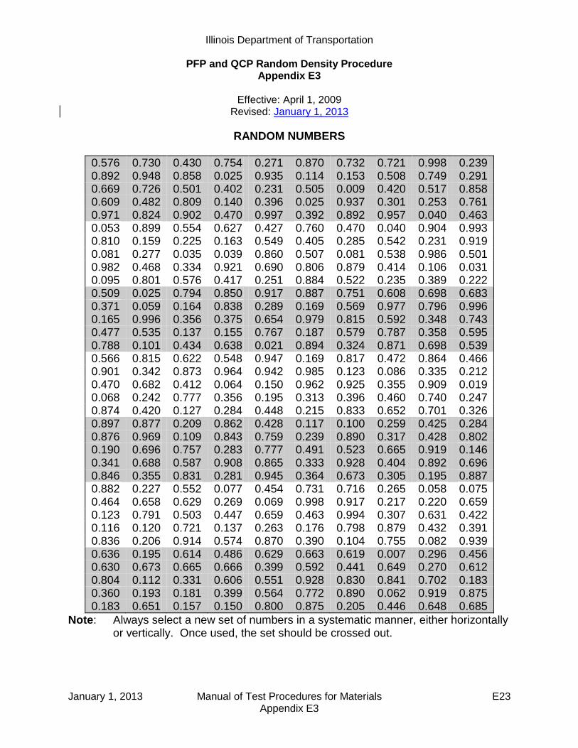
Illinois Department of Transportation
PFP and QCP Random Density Procedure Appendix E3
Effective: April 1, 2009
Revised: January 1, 2013
January 1, 2013 Manual of Test Procedures for Materials E23 Appendix E3
RANDOM NUMBERS
0.576 0.730 0.430 0.754 0.271 0.870 0.732 0.721 0.998 0.239 0.892 0.948 0.858 0.025 0.935 0.114 0.153 0.508 0.749 0.291 0.669 0.726 0.501 0.402 0.231 0.505 0.009 0.420 0.517 0.858 0.609 0.482 0.809 0.140 0.396 0.025 0.937 0.301 0.253 0.761 0.971 0.824 0.902 0.470 0.997 0.392 0.892 0.957 0.040 0.463 0.053 0.899 0.554 0.627 0.427 0.760 0.470 0.040 0.904 0.993 0.810 0.159 0.225 0.163 0.549 0.405 0.285 0.542 0.231 0.919 0.081 0.277 0.035 0.039 0.860 0.507 0.081 0.538 0.986 0.501 0.982 0.468 0.334 0.921 0.690 0.806 0.879 0.414 0.106 0.031 0.095 0.801 0.576 0.417 0.251 0.884 0.522 0.235 0.389 0.222 0.509 0.025 0.794 0.850 0.917 0.887 0.751 0.608 0.698 0.683 0.371 0.059 0.164 0.838 0.289 0.169 0.569 0.977 0.796 0.996 0.165 0.996 0.356 0.375 0.654 0.979 0.815 0.592 0.348 0.743 0.477 0.535 0.137 0.155 0.767 0.187 0.579 0.787 0.358 0.595 0.788 0.101 0.434 0.638 0.021 0.894 0.324 0.871 0.698 0.539 0.566 0.815 0.622 0.548 0.947 0.169 0.817 0.472 0.864 0.466 0.901 0.342 0.873 0.964 0.942 0.985 0.123 0.086 0.335 0.212 0.470 0.682 0.412 0.064 0.150 0.962 0.925 0.355 0.909 0.019 0.068 0.242 0.777 0.356 0.195 0.313 0.396 0.460 0.740 0.247 0.874 0.420 0.127 0.284 0.448 0.215 0.833 0.652 0.701 0.326 0.897 0.877 0.209 0.862 0.428 0.117 0.100 0.259 0.425 0.284 0.876 0.969 0.109 0.843 0.759 0.239 0.890 0.317 0.428 0.802 0.190 0.696 0.757 0.283 0.777 0.491 0.523 0.665 0.919 0.146 0.341 0.688 0.587 0.908 0.865 0.333 0.928 0.404 0.892 0.696 0.846 0.355 0.831 0.281 0.945 0.364 0.673 0.305 0.195 0.887 0.882 0.227 0.552 0.077 0.454 0.731 0.716 0.265 0.058 0.075 0.464 0.658 0.629 0.269 0.069 0.998 0.917 0.217 0.220 0.659 0.123 0.791 0.503 0.447 0.659 0.463 0.994 0.307 0.631 0.422 0.116 0.120 0.721 0.137 0.263 0.176 0.798 0.879 0.432 0.391 0.836 0.206 0.914 0.574 0.870 0.390 0.104 0.755 0.082 0.939 0.636 0.195 0.614 0.486 0.629 0.663 0.619 0.007 0.296 0.456 0.630 0.673 0.665 0.666 0.399 0.592 0.441 0.649 0.270 0.612 0.804 0.112 0.331 0.606 0.551 0.928 0.830 0.841 0.702 0.183 0.360 0.193 0.181 0.399 0.564 0.772 0.890 0.062 0.919 0.875 0.183 0.651 0.157 0.150 0.800 0.875 0.205 0.446 0.648 0.685
Note: Always select a new set of numbers in a systematic manner, either horizontally or vertically. Once used, the set should be crossed out.

January 1, 2013 Manual of Test Procedures for Materials E24 Appendix E3
This Page Reserved

Illinois Department of Transportation
PFP and QCP Hot Mix Asphalt Random Jobsite Sampling Appendix E4
Effective: April 1, 2008
Revised: January 1, 2013
January 1, 2013 Manual of Test Procedures for Materials E25 Appendix E4
Hot-mix asphalt (HMA) samples shall be obtained at the frequency specified in the Hot Mix Asphalt Quality Control for Performance (QCP) and Pay for Performance (PFP) Using Percent within Limits special provisions.
The random jobsite mixture samples shall be taken at the randomly selected test location within a sublot. The random test location will be determined by the Engineer using the “Random Numbers” table as specified herein or an approved software program. This may be performed each day or predetermined for the project as per the Engineer. Regardless of when the values are determined, the values are to be considered confidential and are not to be disclosed to anyone outside of the Department. Disclosing the information would violate the intent of this procedure and federal regulations.
The sample location shall be determined by calculating the longitudinal distance the truck would travel to produce the random sample tonnage. The starting station for the longitudinal distance measurement is the location of the paver where the truck begins to unload the mixture into the paver or Material Transfer Device (MTD). Computations are made to the nearest foot (see examples in appendix herein).
If the paving is completed for a mixture before the specified sampling test location for the last mixture sublot is completed, a test will not be taken and the tonnage will be added to the current lot.
The Contractor may select either sampling behind the paver or sampling from the MTD discharge chute. The Contractor shall provide the necessary equipment and HMA Level I personnel to obtain the required samples, for whatever method is chosen, as specified herein.
A. Behind Paver Sampling.
This method covers the procedures for sampling HMA paving mixtures at the point of delivery immediately behind the paver and before initial compaction. This method is intended to provide a single composite sample that is representative of the mixture as produced (i.e. excludes paver effects).
1. Equipment
a) IDOT Approved Sampling Shovel (Fig. 1).
b) Sample Containers (4 each). Metal sample buckets with a minimum capacity of 3.5 gallons (13 liters).
c) IDOT Approved HMA Sample Splitter. d) Plate/Shovel Sampling. The following additional equipment is needed when
sampling HMA placed directly over a milled surface, rubblized concrete or an aggregate base.
1) Sampling Plates (4 each). The sampling plates shall be rectangular and have a minimum size of 14 x 28 inches (360 x 720 mm). Plates shall have a hole

Illinois Department of Transportation
PFP and QCP Hot Mix Asphalt Random Jobsite Sampling Appendix E4
Effective: April 1, 2008
Revised: January 1, 2013
January 1, 2013 Manual of Test Procedures for Materials E26 Appendix E4
approximately 0.25 inches (6 mm) in diameter drilled through each of the four corners.
2) Lifting Handles and Wire Lead. A 24 inch (600 mm) length of wire shall be attached to the two holes on one side of the plate to serve as lifting handle. An additional wire lead shall be attached to one of the lifting handles for locating the buried plate in the pavement. This wire shall extend to the edge of the pavement.
3) Hammer and masonry nails for securing plates and wire lead.
Figure 1. Aluminum Sampling Shovel & Dimensions
2. Shovel Sample Sampling Procedure (Without Plates). This method shall be used when
sampling over smooth HMA and concrete surfaces.
a) The sampling shovel shall be used at each of the four offsets illustrated in Figure 2. to dig directly downward into pavement until it comes into contact with the previous pavement surface. When in contact, the shovel shall be pushed forward until it is full. The shovel shall be lifted up slowly and carefully place the mix into the sample container in order to prevent any loss of HMA.
Overall Length = 5 feet Shovel Width = 10 inches Shovel Length = 12 inches Shovel Sides = 4 inches

Illinois Department of Transportation
PFP and QCP Hot Mix Asphalt Random Jobsite Sampling Appendix E4
Effective: April 1, 2008
Revised: January 1, 2013
January 1, 2013 Manual of Test Procedures for Materials E27 Appendix E4
3. Shovel/Plate Sampling Procedure (With Plates). This method shall be used when
sampling HMA directly over aggregate base, stabilized subbase, rubblized concrete, or a milled surface. This method may not be appropriate for 3/4 in. level binder over a milled surface. In the case of IL-4.75 mm or IL-9.5 FG mixtures, if approved by the Engineer, these mixtures may be shovel sampled from the auger area at the designated random location. Intentions of sampling IL-4.75 mm or IL-9.5 FG mixtures in this manner shall be listed in the approved QC Plan.
a) Each plate with the wire lead attached to handle shall be placed at four locations
according for Figure 2. at the designated location ahead of the paver. If conditions on the project require restricting movement of the plate, a nail shall be driven through one of the holes in the plate and into the pavement.
b) The wire lead shall be extended beyond the edge of the pavement. Trucks, pavers,
and/or materials transfer devices will be allowed to cross over the pate and/or wire lead.
c) After the HMA is placed, the wire lead shall be used to locate the plate. Once
located, the wire handles shall be lifted out of the pavement. This will locate the four corners of the plate.
d) Once the plate edges are defined, the shovel shall be used to dig downward through
the thickness of the pavement until it is in contact with the plate. The shovel shall be pushed forward until it is full. The shovel shall be lifted up slowly and carefully place the mix into the sample container in order to prevent any loss of HMA.
e) Remove sampling plates from pavement.
Figure 2. Behind Paver Sampling Layout
Direction of Paving
10 feet
Paving Width
Illinois Department of Transportation
PFP and QCP Hot Mix Asphalt Random Jobsite Sampling Appendix E4
Effective: April 1, 2008
Revised: January 1, 2013
January 1, 2013 Manual of Test Procedures for Materials E28 Appendix E4
4. Composite/Lab Sample.
a) HMA samples shall be taken, blended and split, using an IDOT approved HMA splitter, onsite by the Contractor and witnessed by the Engineer. The sample shall be taken immediately behind the paver and before initial roller compaction. One composite sample consists of four increments collected within 10 feet longitudinally and diagonally across the width of the paving operation (Fig. 2). The four increments shall be blended according to HMA Level I procedures to provide a single composite sample.
b) Composite Sample.
1) PFP. If the contractor elects to have the option to dispute test results by the Engineer, a composite sample size shall be a minimum of 200 lbs. (90 kg), allowing 50 lbs (23 kg) for District testing, 50 lbs. (23 kg) for Contractor testing, 50 lbs (23 kg) for dispute resolution testing, and 50 lbs. (23 kg backup for Department testing).
2) QCP. A composite sample size shall be a minimum of 100 lbs. (45 kg), allowing
50 lbs. (23 kg) for District testing, and 50 lbs. (23 kg) for Contractor testing.
c) Lab Sample.
1) PFP. The minimum lab sample size of 50 lbs. (23 kg) shall be obtained by splitting the composite samples into four equal lab samples using an IDOT approved HMA splitter. The Engineer will secure three Department lab samples for the Contractor to transport to the District Materials Laboratory.
2) QCP. The minimum lab sample size of 50 lbs. (23 kg) shall be obtained by
splitting the composite samples into two equal lab samples using an IDOT approved HMA splitter. The Engineer will secure the Department lab sample for the Contractor to transport to the District Materials Laboratory.
5. Sample Site Repair
a) HMA from the paver auger system shall be used to fill the voids left in the pavement
from sampling. To reduce segregation and low density in the finished mat, buckets shall be used to fill the voids left by the samples.
1) HMA from the augers system shall be placed in clean metal buckets just prior to sampling the pavement.
2) The metal buckets shall be filled with approximately 25% more HMA than will be removed from the void.
b) The bucket shall be dumped directly over the void.
Illinois Department of Transportation
PFP and QCP Hot Mix Asphalt Random Jobsite Sampling Appendix E4
Effective: April 1, 2008
Revised: January 1, 2013
January 1, 2013 Manual of Test Procedures for Materials E29 Appendix E4
c) The HMA shall be slightly leveled to provide a gradual hump over the filled void to allow compression of the mix by the roller.
d) Unacceptable site repair shall be removed and replaced at the Contractors expense.
B. MTD Sampling.
This method covers the procedures for sampling HMA paving mixtures at the point of delivery from a material transfer device (MTD).
1. Equipment.
a) MTD Sampling Device. A portable device mounted either in the bed of a pickup truck or on a trailer. The device shall be equipped with a funnel large enough to capture the full stream of HMA from the MTD discharge chute without spillage and shall be capable of capturing a minimum composite HMA sample of 200 lbs (90 kg). See appendix for illustrations of various MTD sampling device configurations.
b) Sample Containers – Metal containers each capable of holding a minimum of 50 lbs. of HMA.
2. MTD Sampling Procedure.
The Engineer will identify the truck containing the sample tonnage immediately prior to sampling. Immediately after the truck containing the random HMA tonnage has finished unloading, the MTD shall pull forward away from the paver far enough to allow the sampling device to be positioned under the MTD discharge chute. The sampling device shall be positioned as level as possible in a safe location readily accessible by the MTD. The MTD shall discharge without spillage a minimum of 200 lbs. (90 kg) of HMA for PFP or 100 lbs. (45 kg) for QCP into the funnel of the sampling device.
3. Composite/Lab Sample.
a) Composite Sample. HMA from all four sample containers of the sampling device shall be blended into one composite sample and split to lab sample size by the Contractor onsite using an IDOT approved HMA splitter. The blending and splitting shall be according to HMA Level I procedures and will be witnessed by the Engineer.
1) PFP. If the contractor elects to have the option to dispute test results by the
Engineer, a composite sample size shall be a minimum of 200 lbs. (90 kg), allowing 50 lbs (23 kg) for District testing, 50 lbs. (23 kg) for Contractor testing, 50 lbs (23 kg) for dispute resolution testing, and 50 lbs. (23 kg backup for Department testing).
2) QCP. A composite sample size shall be a minimum of 100 lbs. (45 kg), allowing
50 lbs. (23 kg) for District testing, and 50 lbs. (23 kg) for Contractor testing.

Illinois Department of Transportation
PFP and QCP Hot Mix Asphalt Random Jobsite Sampling Appendix E4
Effective: April 1, 2008
Revised: January 1, 2013
January 1, 2013 Manual of Test Procedures for Materials E30 Appendix E4
b) Lab Sample.
1) PFP. The minimum lab sample size of 50 lbs. (23 kg) shall be obtained by splitting the composite samples into four equal lab samples using an IDOT approved HMA splitter. The Engineer will secure three Department lab samples for the Contractor to transport to the District Materials Laboratory.
2) QCP. The minimum lab sample size of 50 lbs. (23 kg) shall be obtained
by splitting the composite samples into two equal lab samples using an IDOT approved HMA splitter. The Engineer will secure the Department lab sample for the Contractor to transport to the District Materials Laboratory.
C. Documentation – After the sample has been obtained, the following information shall be
written on each sample bag or box with a felt tip marker. D. Sample Security – Each sample bag will be secured by the Engineer using a locking ID tag.
Sample boxes will be sealed/taped using a security ID label.
E. Sample Transportation – The Contractor shall deliver the secured sample to the district laboratory, during regular working hours, for testing within two days of sampling.
F. Examples:
1. Behind Paver Sampling. Determination of random sample location for behind paver
sampling.
This example illustrates the determination of the random behind the paver test location within a sublot:
Given a surface mix with a design Gmb of 2.400 is being placed 12 feet wide and 1.5 inches thick. The Engineer has elected to determine all the undisclosed random
Contract #: _______________
Lot #:__________ Sublot #:__________
Date: ___________ Time: ___________
Mix Type (binder, surface…): _________
Mix Design #: _____________________
Sampled By: ______________________

Illinois Department of Transportation
PFP and QCP Hot Mix Asphalt Random Jobsite Sampling Appendix E4
Effective: April 1, 2008
Revised: January 1, 2013
January 1, 2013 Manual of Test Procedures for Materials E31 Appendix E4
tonnages prior to production. The plan quantity on the project was 10,000 tons and enough random values were determined to allow for a 5% overrun assuring enough random tonnages were generated. Ignore any random tonnages beyond what was placed on the project.
Sublot Random Sublot Cummulative
Number Number Tonnage Job Tonnage
1 0.1669 167 167
2 0.5202 520 1520
3 0.3000 300 2300
4 0.6952 695 3695
5 0.4472 447 4447
6 0.2697 270 5270
7 0.5367 537 6537
8 0.7356 736 7736
9 0.4045 405 8405
10 0.3356 336 9336
11 0.0899 90 10090
The truck containing the mix representing the 167 tons shall be the first sublot tested. The truck in question contains 160 to 172 cumulative tonnage to be placed on the project. Determine the random location by dividing the value of the selected truck tonnage to determine the random distance value to 3 decimal places.
167 – 160 = 7 (where the random ton falls within the truck)
7/(172-160) = 7/12 = 0.583 (random distance value)
Determine the distance using 58.3% of the distance the truck will pave using the following formula:
Longitudinal DistancethicknesswidthGmb
RDTons
6.384
Where: Longitudinal Distance = Random distance from starting station (ft) Tons = total tons within the sample truck RD = random distance value as calculated above Gmb = design Gmb for the mix being placed Width = width of mat being paved (ft) Thickness = thickness of mat being paved (in)
Longitudinal Distance5.112400.2
583.126.384
Longitudinal Distance = 62.3 Ft = 62 Ft.

Illinois Department of Transportation
PFP and QCP Hot Mix Asphalt Random Jobsite Sampling Appendix E4
Effective: April 1, 2008
Revised: January 1, 2013
January 1, 2013 Manual of Test Procedures for Materials E32 Appendix E4
Measure the calculated longitudinal distance from the starting station where the truck began to unload. Determine and document the random sample station and obtain the random mix sample as outlined herein. Starting Station = 105 + 00 Random Sample Location = 105 + 00 + 62 = 105 + 62 This process shall be repeated for the subsequent sublots.
2. Examples of MTD Sampling Devices
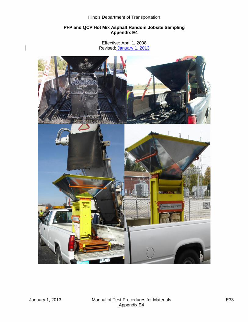
Illinois Department of Transportation
PFP and QCP Hot Mix Asphalt Random Jobsite Sampling Appendix E4
Effective: April 1, 2008
Revised: January 1, 2013
January 1, 2013 Manual of Test Procedures for Materials E33 Appendix E4

Illinois Department of Transportation
PFP and QCP Hot Mix Asphalt Random Jobsite Sampling Appendix E4
Effective: April 1, 2008
Revised: January 1, 2013
January 1, 2013 Manual of Test Procedures for Materials E34 Appendix E4

January 1, 2013 Manual of Test Procedures for Materials E35 Appendix E4
RANDOM NUMBERS
0.576 0.730 0.430 0.754 0.271 0.870 0.732 0.721 0.998 0.239 0.892 0.948 0.858 0.025 0.935 0.114 0.153 0.508 0.749 0.291 0.669 0.726 0.501 0.402 0.231 0.505 0.009 0.420 0.517 0.858 0.609 0.482 0.809 0.140 0.396 0.025 0.937 0.301 0.253 0.761 0.971 0.824 0.902 0.470 0.997 0.392 0.892 0.957 0.040 0.463 0.053 0.899 0.554 0.627 0.427 0.760 0.470 0.040 0.904 0.993 0.810 0.159 0.225 0.163 0.549 0.405 0.285 0.542 0.231 0.919 0.081 0.277 0.035 0.039 0.860 0.507 0.081 0.538 0.986 0.501 0.982 0.468 0.334 0.921 0.690 0.806 0.879 0.414 0.106 0.031 0.095 0.801 0.576 0.417 0.251 0.884 0.522 0.235 0.389 0.222 0.509 0.025 0.794 0.850 0.917 0.887 0.751 0.608 0.698 0.683 0.371 0.059 0.164 0.838 0.289 0.169 0.569 0.977 0.796 0.996 0.165 0.996 0.356 0.375 0.654 0.979 0.815 0.592 0.348 0.743 0.477 0.535 0.137 0.155 0.767 0.187 0.579 0.787 0.358 0.595 0.788 0.101 0.434 0.638 0.021 0.894 0.324 0.871 0.698 0.539 0.566 0.815 0.622 0.548 0.947 0.169 0.817 0.472 0.864 0.466 0.901 0.342 0.873 0.964 0.942 0.985 0.123 0.086 0.335 0.212 0.470 0.682 0.412 0.064 0.150 0.962 0.925 0.355 0.909 0.019 0.068 0.242 0.777 0.356 0.195 0.313 0.396 0.460 0.740 0.247 0.874 0.420 0.127 0.284 0.448 0.215 0.833 0.652 0.701 0.326 0.897 0.877 0.209 0.862 0.428 0.117 0.100 0.259 0.425 0.284 0.876 0.969 0.109 0.843 0.759 0.239 0.890 0.317 0.428 0.802 0.190 0.696 0.757 0.283 0.777 0.491 0.523 0.665 0.919 0.146 0.341 0.688 0.587 0.908 0.865 0.333 0.928 0.404 0.892 0.696 0.846 0.355 0.831 0.281 0.945 0.364 0.673 0.305 0.195 0.887 0.882 0.227 0.552 0.077 0.454 0.731 0.716 0.265 0.058 0.075 0.464 0.658 0.629 0.269 0.069 0.998 0.917 0.217 0.220 0.659 0.123 0.791 0.503 0.447 0.659 0.463 0.994 0.307 0.631 0.422 0.116 0.120 0.721 0.137 0.263 0.176 0.798 0.879 0.432 0.391 0.836 0.206 0.914 0.574 0.870 0.390 0.104 0.755 0.082 0.939 0.636 0.195 0.614 0.486 0.629 0.663 0.619 0.007 0.296 0.456 0.630 0.673 0.665 0.666 0.399 0.592 0.441 0.649 0.270 0.612 0.804 0.112 0.331 0.606 0.551 0.928 0.830 0.841 0.702 0.183 0.360 0.193 0.181 0.399 0.564 0.772 0.890 0.062 0.919 0.875 0.183 0.651 0.157 0.150 0.800 0.875 0.205 0.446 0.648 0.685
Note: Always select a new set of numbers in a systematic manner, either horizontally or vertically. Once used, the set should be crossed out.
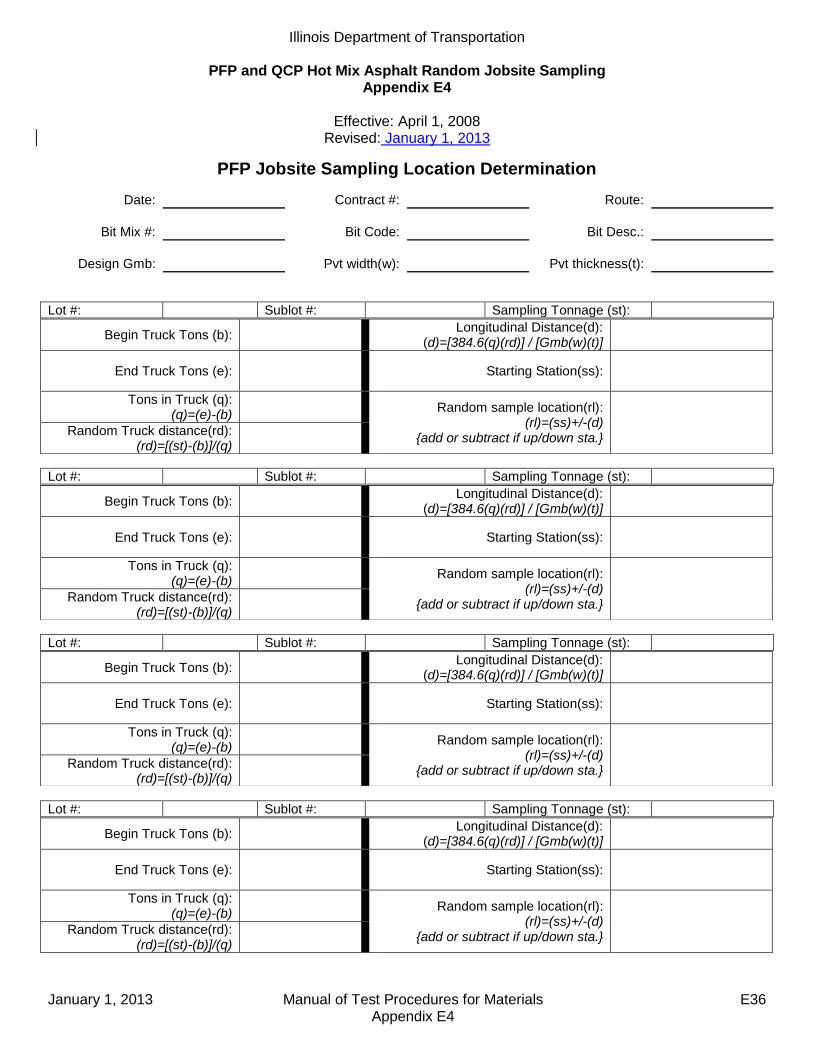
Illinois Department of Transportation
PFP and QCP Hot Mix Asphalt Random Jobsite Sampling Appendix E4
Effective: April 1, 2008
Revised: January 1, 2013
January 1, 2013 Manual of Test Procedures for Materials E36 Appendix E4
PFP Jobsite Sampling Location Determination
Date: Contract #: Route:
Bit Mix #: Bit Code: Bit Desc.:
Design Gmb: Pvt width(w): Pvt thickness(t):
Lot #: Sublot #: Sampling Tonnage (st):
Lot #: Sublot #: Sampling Tonnage (st):
Lot #: Sublot #: Sampling Tonnage (st):
Lot #: Sublot #: Sampling Tonnage (st):
Begin Truck Tons (b): Longitudinal Distance(d):
(d)=[384.6(q)(rd)] / [Gmb(w)(t)]
End Truck Tons (e): Starting Station(ss):
Tons in Truck (q): (q)=(e)-(b)
Random sample location(rl):
(rl)=(ss)+/-(d) {add or subtract if up/down sta.}
Random Truck distance(rd):
(rd)=[(st)-(b)]/(q)
Begin Truck Tons (b): Longitudinal Distance(d):
(d)=[384.6(q)(rd)] / [Gmb(w)(t)]
End Truck Tons (e): Starting Station(ss):
Tons in Truck (q): (q)=(e)-(b)
Random sample location(rl):
(rl)=(ss)+/-(d) {add or subtract if up/down sta.}
Random Truck distance(rd):
(rd)=[(st)-(b)]/(q)
Begin Truck Tons (b): Longitudinal Distance(d):
(d)=[384.6(q)(rd)] / [Gmb(w)(t)]
End Truck Tons (e): Starting Station(ss):
Tons in Truck (q): (q)=(e)-(b)
Random sample location(rl):
(rl)=(ss)+/-(d) {add or subtract if up/down sta.}
Random Truck distance(rd):
(rd)=[(st)-(b)]/(q)
Begin Truck Tons (b): Longitudinal Distance(d):
(d)=[384.6(q)(rd)] / [Gmb(w)(t)]
End Truck Tons (e): Starting Station(ss):
Tons in Truck (q): (q)=(e)-(b)
Random sample location(rl):
(rl)=(ss)+/-(d) {add or subtract if up/down sta.}
Random Truck distance(rd):
(rd)=[(st)-(b)]/(q)

June 1, 2012 Manual of Test Procedures for Materials E37 Appendix E5
Illinois Department of Transportation
Instructions for Submitting Pay for Performance Dispute Resolution Samples Appendix E5
Effective Date: April 1, 2010
A. Scope
The following guidelines are provided to clarify the district submittal requirements for dispute
resolution samples; and expedite the testing process for HMA mix and/or core samples.
B. Procedure
When submitting HMA mix and/or core samples include the following:
All District and Contractor split sample test results on attached “PFP Dispute Resolution Form”,
Submit entire dispute resolution HMA mix split sample,
Cores must be split or sawed to lift testing thickness,
QC Package template and dailies sent electronically for mix being tested.
Send sample and requested documentation to:
Illinois Department of Transportation
Bureau of Materials & Physical Research
Hot Mix Asphalt Laboratory
126 E. Ash Street
Springfield, Illinois 62704-4766
Attention: Joe Rechner [email protected]
Any sample sent to BMPR without the above listed information will not be processed until all
requested information is received.

June 1, 2012 Manual of Test Procedures for Materials E38 Appendix E5
BMPR Lab #: _________________________
Wt. for Gmb: _________________________ Sampled From: Truck ___ Mat ___ MTD ___
Sample Date: ________________________
Date Received: ________________________
CORES
1 This shall be the Gmm used for density calculation.
Contract # :
Dist. Lab ID # :
Mix Design # :
Mix Code # :
Producer # :
Mix Lot ___ Sublot ___
Sieve Size
District %
Passing
Contractor %
Passing
BMPR %
Passing 1 ½ in
(37.5 mm)
1 in (25 mm)
¾ in (19 mm)
½ in (12.5 mm)
3/8 in (9.5 mm)
#4 (4.75 mm)
#8 (2.36 mm)
#16 (1.18 mm)
#30 (.60 mm)
#50 (.30 mm)
#100 (.15 mm)
#200 (.075 mm)
Asphalt Binder %
Dust/Asphalt Binder Ratio
Gmm
Gmb
% Voids
Gsb
Field VMA
District Contractor BMPR
Core # Gmm1 Gmm Gmm
Core # Gmb Gmb Gmb
Core # Density %
Density %
Density %
PFP DISPUTE RESOLUTION

Illinois Department of Transportation
QCP Pay Calculation Appendix E6
Effective: January 1, 2012 Revised: January 1, 2013
January 1, 2013 Manual of Test Procedures for Materials E39 Appendix E6
This document explains the procedure used to determine the pay adjustment for a hot-mix asphalt (HMA) mixture for Quality Control for Performance (QCP) projects. The following steps are used to determine the pay deduction for each QCP mixture:
1. Determine sublot deviation from target for each pay parameter. 2. Determine the sublot pay factor for each sublot using the Table 1 and the deviation from
target. 3. Determine the average sublot Pay Factor for each pay parameter. 4. Calculate a Combined Pay Factor using the average sublot Pay Factors and Equation 1. 5. Determine the QCP pay deduction for the mixture using Equation 2. 6. The Combined Pay Factor shall not exceed 100%. 7. The 103% column only applies when the district conducts testing of all the sublots within
a given lot and all of the tests are within the Acceptable Limits. The 103% column also applies to density sublots where no individual density test is less than 90.0% or greater than 98.0% density. The average sublot Pay Factor for each pay parameter shall be capped at 100.0% prior to calculating the Combined Pay Factor.
Table 1
Parameter
Pay Factor
103% 100% 95% 90%
Voids1/ 3/
± 0.5% ± 1.2% ± 1.6% ± 2.0%
VMA 3/ 0% to +1.0% above minimum
specified
-0.7% to +2.0% -0.8% to +2.5% -1.0% to +3.0%
Density2/ 93.5% to 94.5% 92.5% to 96.5% 91.5% to 97.0% 90.0% to 98.0%
SMA 94.0% to 95.0% 93.5% to 96.5% 92.5% to 97.0% 92.0% to 98.0%
IL-9.5FG at < 1.25 in. 93.5% to 94.5% 91.0% to 96.5% 90.0% to 97.0% 89.0% to 98.0%
1/ Ranges based on deviation from the specified design percent Voids. 2/ If no density requirement applies the Contractor will receive 100% for the density pay
factor in Equation 1. 3/ If mixture testing is waived for small tonnage, the Contractor will receive 100% for the
Voids and VMA pay factors in Equation 1. Equation 1: CPF = 0.30(PF Voids) + 0.30(PFVMA) + 0.40(PFDensity)
Where: CPF = Combined Pay Factor
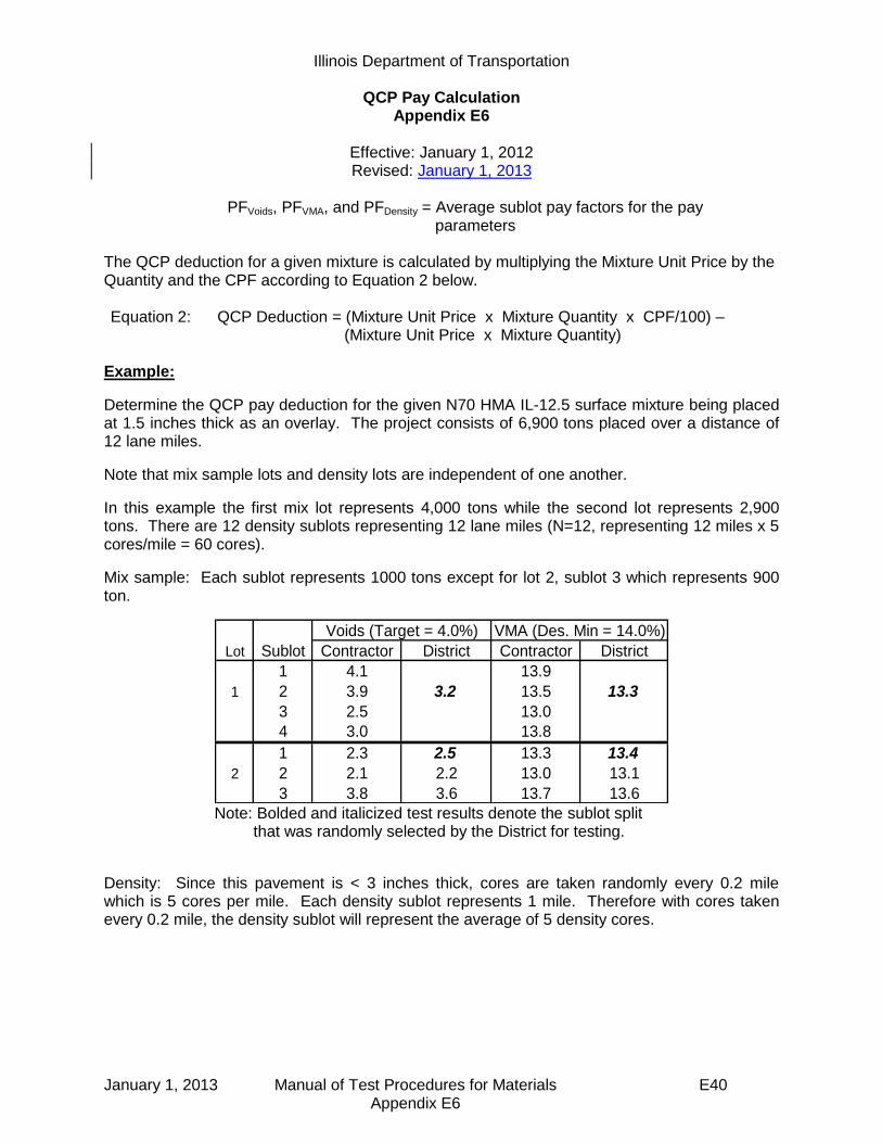
Illinois Department of Transportation
QCP Pay Calculation Appendix E6
Effective: January 1, 2012 Revised: January 1, 2013
January 1, 2013 Manual of Test Procedures for Materials E40 Appendix E6
PFVoids, PFVMA, and PFDensity = Average sublot pay factors for the pay parameters
The QCP deduction for a given mixture is calculated by multiplying the Mixture Unit Price by the Quantity and the CPF according to Equation 2 below. Equation 2: QCP Deduction = (Mixture Unit Price x Mixture Quantity x CPF/100) –
(Mixture Unit Price x Mixture Quantity)
Example:
Determine the QCP pay deduction for the given N70 HMA IL-12.5 surface mixture being placed at 1.5 inches thick as an overlay. The project consists of 6,900 tons placed over a distance of 12 lane miles.
Note that mix sample lots and density lots are independent of one another.
In this example the first mix lot represents 4,000 tons while the second lot represents 2,900 tons. There are 12 density sublots representing 12 lane miles (N=12, representing 12 miles x 5 cores/mile = 60 cores).
Mix sample: Each sublot represents 1000 tons except for lot 2, sublot 3 which represents 900 ton.
Lot Sublot Contractor District Contractor District
1 4.1 13.9
1 2 3.9 3.2 13.5 13.3
3 2.5 13.0
4 3.0 13.8
1 2.3 2.5 13.3 13.4
2 2 2.1 2.2 13.0 13.1
3 3.8 3.6 13.7 13.6
Voids (Target = 4.0%) VMA (Des. Min = 14.0%)
Note: Bolded and italicized test results denote the sublot split
that was randomly selected by the District for testing.
Density: Since this pavement is < 3 inches thick, cores are taken randomly every 0.2 mile which is 5 cores per mile. Each density sublot represents 1 mile. Therefore with cores taken every 0.2 mile, the density sublot will represent the average of 5 density cores.

Illinois Department of Transportation
QCP Pay Calculation Appendix E6
Effective: January 1, 2012 Revised: January 1, 2013
January 1, 2013 Manual of Test Procedures for Materials E41 Appendix E6
Determine the average sublot pay factor for each parameter: Voids: Since the District randomly selected and tested the split from sublot 2 in Lot 1, and the void results were 1) within the 100% pay factor tolerance and 2) within Precision Limits of the Contractor’s results, the District does not need to test the remaining sublots in Lot 1 and the entire Lot receives a Pay Factor of 100%. For the second Lot the District randomly selected and tested the split from sublot 1. Since the District void results were not within the 100% pay factor tolerance, the District had to test all of the remaining Sublot splits. (see completed table below): Calculate the void deviation from target for each of the District sublot split results. Lot 1:
Sublot 2: Deviation = 3.2% - 4.0% = -0.8%
Lot 2: Sublot 1: Deviation = 2.5% - 4.0% = -1.5% Sublot 2: Deviation = 2.2% - 4.0% = -1.8%
Sublot 3: Deviation = 3.6% - 4.0% = -0.4% Using Table 1 and the deviation from Target, determine the corresponding Void sublot Pay Factor for each District test result. Lot 1: Sublot 2: Pay Factor associated with -0.8% in Table 1 is 100%
1 2 3 4 5
1 90.4 90.8 91.6 92.4 92.1
2 93.8 94.1 92.3 92.1 92.6
3 91.8 93.5 93.9 92.8 92.5
4 93.7 94.2 93.5 93.3 92.8
5 92.1 94.1 92.6 93.8 92.3
6 94.1 94.3 93.2 94.5 93.9
7 93.6 93.3 92.5 91.9 92.7
8 92.8 93.3 94.2 93.5 93.7
9 90.0 90.2 91.9 91.8 90.9… … … … … …
12 91.5 93.5 92.7 93.8 92.1
Density
Sublot
Density Intervals (cores)
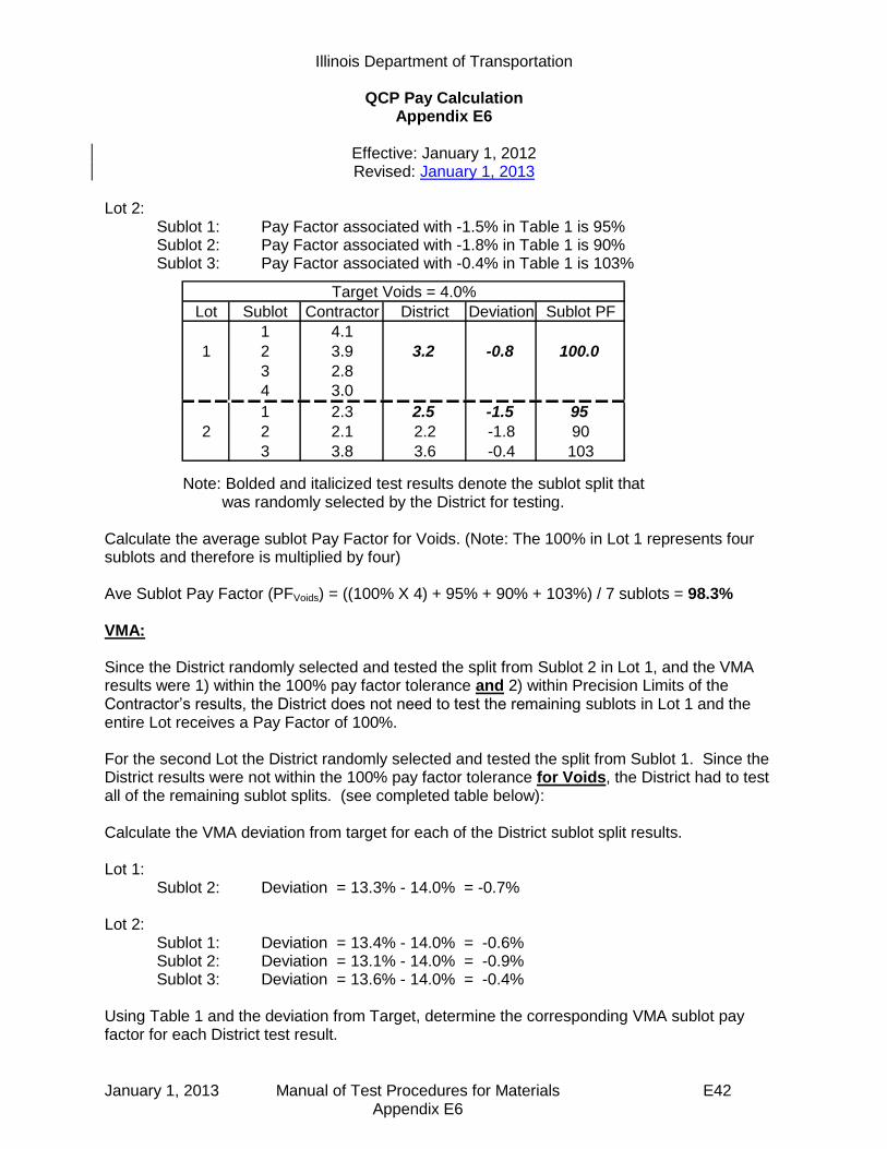
Illinois Department of Transportation
QCP Pay Calculation Appendix E6
Effective: January 1, 2012 Revised: January 1, 2013
January 1, 2013 Manual of Test Procedures for Materials E42 Appendix E6
Lot 2: Sublot 1: Pay Factor associated with -1.5% in Table 1 is 95% Sublot 2: Pay Factor associated with -1.8% in Table 1 is 90% Sublot 3: Pay Factor associated with -0.4% in Table 1 is 103%
Note: Bolded and italicized test results denote the sublot split that was randomly selected by the District for testing.
Calculate the average sublot Pay Factor for Voids. (Note: The 100% in Lot 1 represents four sublots and therefore is multiplied by four) Ave Sublot Pay Factor (PFVoids) = ((100% X 4) + 95% + 90% + 103%) / 7 sublots = 98.3% VMA:
Since the District randomly selected and tested the split from Sublot 2 in Lot 1, and the VMA results were 1) within the 100% pay factor tolerance and 2) within Precision Limits of the Contractor’s results, the District does not need to test the remaining sublots in Lot 1 and the entire Lot receives a Pay Factor of 100%. For the second Lot the District randomly selected and tested the split from Sublot 1. Since the District results were not within the 100% pay factor tolerance for Voids, the District had to test all of the remaining sublot splits. (see completed table below): Calculate the VMA deviation from target for each of the District sublot split results. Lot 1:
Sublot 2: Deviation = 13.3% - 14.0% = -0.7%
Lot 2: Sublot 1: Deviation = 13.4% - 14.0% = -0.6% Sublot 2: Deviation = 13.1% - 14.0% = -0.9%
Sublot 3: Deviation = 13.6% - 14.0% = -0.4% Using Table 1 and the deviation from Target, determine the corresponding VMA sublot pay factor for each District test result.
Lot Sublot Contractor District Deviation Sublot PF
1 4.1
1 2 3.9 3.2 -0.8 100.0
3 2.8
4 3.0
1 2.3 2.5 -1.5 95
2 2 2.1 2.2 -1.8 90
3 3.8 3.6 -0.4 103
Target Voids = 4.0%
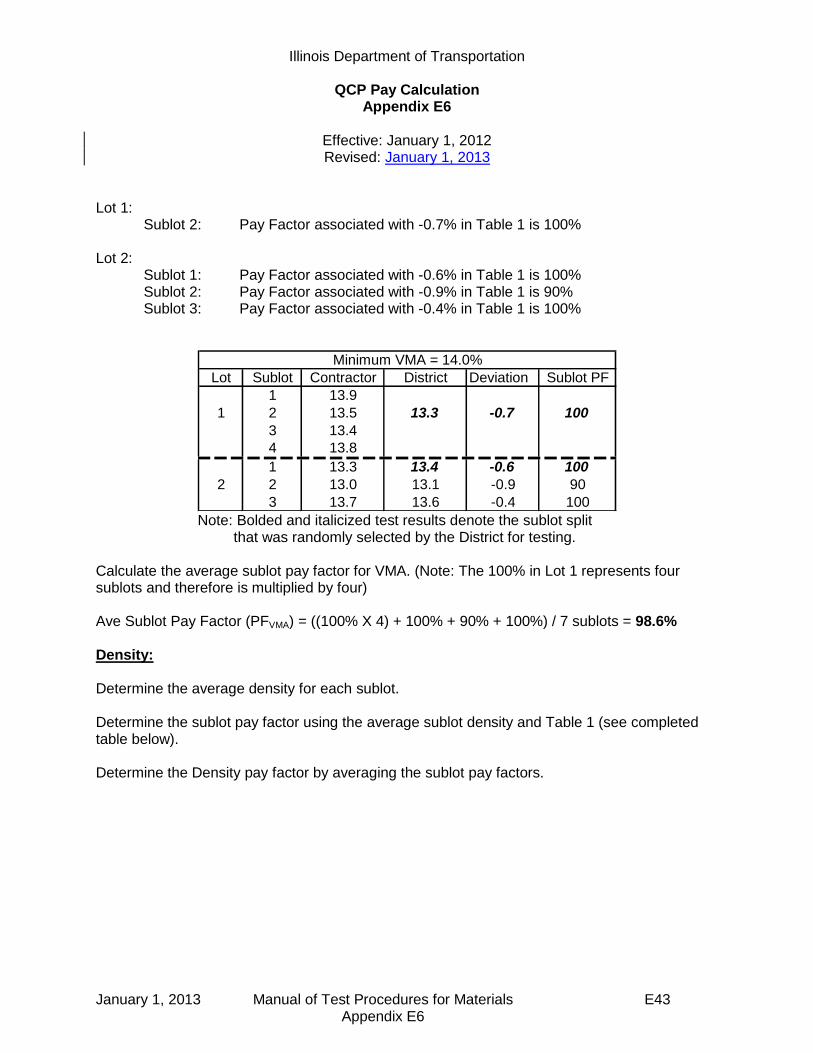
Illinois Department of Transportation
QCP Pay Calculation Appendix E6
Effective: January 1, 2012 Revised: January 1, 2013
January 1, 2013 Manual of Test Procedures for Materials E43 Appendix E6
Lot 1: Sublot 2: Pay Factor associated with -0.7% in Table 1 is 100% Lot 2: Sublot 1: Pay Factor associated with -0.6% in Table 1 is 100% Sublot 2: Pay Factor associated with -0.9% in Table 1 is 90% Sublot 3: Pay Factor associated with -0.4% in Table 1 is 100%
Lot Sublot Contractor District Deviation Sublot PF
1 13.9
1 2 13.5 13.3 -0.7 100
3 13.4
4 13.8
1 13.3 13.4 -0.6 100
2 2 13.0 13.1 -0.9 90
3 13.7 13.6 -0.4 100
Minimum VMA = 14.0%
Note: Bolded and italicized test results denote the sublot split
that was randomly selected by the District for testing.
Calculate the average sublot pay factor for VMA. (Note: The 100% in Lot 1 represents four sublots and therefore is multiplied by four) Ave Sublot Pay Factor (PFVMA) = ((100% X 4) + 100% + 90% + 100%) / 7 sublots = 98.6% Density:
Determine the average density for each sublot. Determine the sublot pay factor using the average sublot density and Table 1 (see completed table below). Determine the Density pay factor by averaging the sublot pay factors.

Illinois Department of Transportation
QCP Pay Calculation Appendix E6
Effective: January 1, 2012 Revised: January 1, 2013
January 1, 2013 Manual of Test Procedures for Materials E44 Appendix E6
Combined Pay Factor: Determine the Combined Pay Factor using Equation 1.
CPF = 0.30(PF Voids) + 0.30(PFVMA) + 0.40(PFDensity) = 0.30(98.3) + 0.30(98.6) + 0.4(99.9) CPF = 99.1%
QCP Deduction: Determine the QCP deduction pay for the given mixture using Equation 2. QCP Deduction = (Mixture Unit Price x Mixture Quantity x CPF/100) – (Mixture Unit Price x
Mixture Quantity)
Where: Mixture Unit Price = $65.00 Mixture Quantity = 6,900 tons placed.
QCP Deduction = ($65.00/ton x 6,900 tons x 99.1 / 100) – ($65.00/ton x 6,900 tons)
= - $4,036.50
In this case a $4,036.50 disincentive would be paid as per Construction Memorandum 10-4.
1 2 3 4 5
Sublot
Ave
Sublot
PF1 90.4 90.8 91.6 92.4 92.1 91.5 95
2 93.8 94.1 92.3 92.1 92.6 93.0 100
3 91.8 93.5 93.9 92.8 92.5 92.9 100
4 93.7 94.2 93.5 93.3 92.8 93.5 103
5 92.1 94.1 92.6 93.8 92.3 93.0 100
6 94.1 94.3 93.2 94.5 93.9 94.0 103
7 93.6 93.3 92.5 91.9 92.7 92.8 100
8 92.8 93.3 94.2 93.5 93.7 93.5 103
9 90.0 90.2 91.9 91.8 90.9 91.0 95… … … … … … … …
12 91.5 93.5 92.7 93.8 92.1 92.7 100
99.9
Density
Sublot
Density Intervals (cores)
Average Density Sublot PF =

June 1, 2012 Manual of Test Procedures for Materials E45 Appendix E7
Illinois Department of Transportation
Best Practices For
Pay-For-Performance (PFP) and Quality Control for Performance (QCP) Implementation
Appendix E7
Effective Date: April 1, 2012
Purpose
This document is intended to aid district personnel in successfully preparing for and implementing the Pay-For-Performance (PFP) and Quality Control for Performance (QCP) specifications.
Lab
Since payment on PFP and QCP projects is based on Department test results, attention to laboratory equipment, qualified lab personnel and laboratory efficiency becomes paramount. Review of results from recent “Annual Bituminous Uniformity Studies” (aka Round Robins) and dispute resolutions and addressing any district lab issues resulting in poor comparisons will prove beneficial.
1) Equipment - It is imperative to inspect and calibrate all laboratory testing equipment according to frequencies listed in Policy Memorandum 21-08.0 “Minimum Requirements For Construction Materials Testing Laboratories - Department Operated Laboratories” at a minimum. Inspection and calibration immediately prior to PFP and QCP testing is highly recommended. Always use the same gyratory compactor for a given PFP or QCP contract.
Assessment of existing and needed equipment should be performed to determine possible benefits of purchasing additional equipment to optimize productivity. Each district should also develop an action plan in the event key equipment breaks down.
2) Personnel – It is also imperative that all laboratory personnel intended to be involved in PFP and QCP testing, be qualified with successful completion of HMA Level I as a minimum. Keep technician assignments as consistent as possible. It is highly recommended to conduct an in-house round robin with the above mentioned laboratory personnel to ensure repeatability.
3) Sample Treatment – Inconsistent treatment of samples prior to testing has been identified as the leading reason for differences in test results between the contractor and the state. It is recommended that samples, for all parties involved, be allowed to cool to room temperature immediately after splitting. The samples should then be reheated and compacted as soon as the samples reach compaction temperature.
4) Efficiency – PFP and QCP are based on Department testing which results in a higher
testing frequency for the district laboratory. An internal audit of your district
laboratory for efficiency may help identify ways to improve productivity. This activity
should be conducted by district materials staff that are not involved in day-to-day
testing, or BMPR staff if requested.

June 1, 2012 Manual of Test Procedures for Materials E46 Appendix E7
While the specification allows a 14 working day test turnaround time for PFP and a 10 day turnaround for QCP, the district should attempt to reduce the turnaround time as much as possible. Nationally recognized successful programs have test turnaround results within 5 days.
Project Personnel
Key components of PFP and QCP which provide the necessary compliance with the Code of Federal Regulations are 1) undisclosed random mix and density sample locations, 2) Sample either taken by the Engineer or witnessed by the Engineer, and 3) sample security. The CFR is intended to assure that the sample is under control of the Engineer at all times to verify the quality of the product. Most districts will need to rely on project staff to determine random mix sample and density core locations. It will be important for project personnel to understand their role in witnessing and securing the sample. District Materials and Construction staff should meet prior to the start of a PFP or QCP project to discuss:
1) Responsibilities: a) Discuss who will be responsible for sample identifying undisclosed sample
location and sample layout b) Sample Security; discuss who will transport and / or store samples. c) Pay Calculations; discuss who will be responsible for entering data in software
and how communication regarding pay factors will occur. 2) Procedures:
a) Random sample locations i) Discuss when to disclose sampling location ii) Familiarize Construction personnel with random sample procedures detailed
in the Manual of Test Procedures b) Sample Layout (utilization of random number table)
i) Discuss how core densities will be: (1) transversely no closer than 1 foot to an unconfined longitudinal joint and 4
inches on a confined longitudinal joint for PFP. (2) transversely no closer than 4 inches from an edge for QCP.
ii) Discuss how to handle coring locations that will need to be opened immediately to traffic
Also, it will be important to make sure Construction personnel have copies of all the necessary supporting documents.

SEQUENTIAL TABLE OF CONTENTS (continued)
MANUAL OF TEST PROCEDURES FOR MATERIALS
June 1, 2012 Manual of Test Procedures for Materials
B—Hot Mix Asphalt (HMA) Appendix B1
(Effective 05/01/93) (Revised 01/01/08)
Model Annual Quality Control (QC) Plan for Hot-Mix Asphalt (HMA) Production .....................
B 1
Appendix B2 (Effective 07/01/95) (Revised 05/01/07)
Model Quality Control (QC) Addendum for Hot-Mix Asphalt (HMA) Production .....................
B11
Appendix B3 (Effective 05/01/01) (Revised 04/01/11)
Standard Test Method for Correlating Nuclear Gauge Densities with Core Densities ......................
B13
Appendix B4 (Effective 05/01/93) (Revised 01/01/14)
Hot-Mix Asphalt Concrete QC/QA Start-Up Procedures ................................................
B21
Appendix B5 (Effective 05/01/93) (Revised 05/01/07)
Hot-Mix Asphalt QC/QA QC Personnel Responsibilities and Duties Checklist ......................
B27
Appendix B6 (Effective 05/01/93) (Revised 05/01/07)
Hot-Mix Asphalt QC/QA Initial Daily Plant and Random Samples ....................................................
B37
Appendix B7 (Effective 05/01/93) (Revised 04/01/11)
Determination of Random Density Locations ........... B41
Appendix B8 (Effective 05/01/93) (Revised 01/01/08)
Control Charts / Rounding Test Values.................... B43
Appendix B9 (Effective 01/01/02) (Revised 01/01/13)
Hot-Mix Asphalt Mixture Design Verification Procedure ................................................................
B47
Appendix B10 (Effective 01/01/98) (Revised 05/01/07)
Illinois Test Procedure 401, Storage of Hot-Mix Asphalt Mixtures .......................
B53
Appendix B11 (Effective 01/01/02) (Revised 05/01/07)
Calibration of Equipment for Asphalt Binder Determination (Nuclear Gauge and Ignition Oven) ..
B55
Appendix B12 (Effective 01/01/98) (Revised 05/01/07)
Hot-Mix Asphalt Mix Design Procedure for Dust Correction Factor Determination ..............................
B59
SEQUENTIAL TABLE OF CONTENTS (continued)
MANUAL OF TEST PROCEDURES FOR MATERIALS
June 1, 2012 Manual of Test Procedures for Materials
Standard
Description Page
Appendix B13 (Effective 01/01/02) (Revised 05/01/07)
Illinois Test Procedure 403, Calibration of the Ignition Oven for the Purpose of Characterizing Reclaimed Asphalt Pavements (RAP) ......................................................................
B67
Appendix B14 (Effective 01/01/02) (Revised 05/01/07)
Truck Sample Splitting Diagram .............................. B71
Appendix B15 (Effective 05/01/04) (Revised 05/01/07)
Hot-Mix Asphalt (HMA) Production Gradation
Windage Procedure for Minus #200 (minus 75 µm) Material ...................................................................
B73
Appendix B16 (Effective 11/20/03) (Revised 01/01/14)
Stripping of Hot-Mix Asphalt Mixtures Visual Identification and Classification ....................
B75
Appendix B17 (Effective 03/07/05) (Revised 01/01/13)
Procedure for Introducing Additives to Hot Mix Asphalt Mixtures and Testing in the Lab ....
B79
Appendix B18 (Effective 05/01/05) (Revised 05/01/07)
Ignition Oven Aggregate Mass Loss Procedure ...... B93
Appendix B19 (Effective 05/01/05) (Revised 05/01/07)
Quick Reference Guides and Procedure for Internal Angle Calibration of Superpave Gyratory Compactors (SGC) Using the Dynamic Angle Validator (DAV-2) ....................................................
B95
Appendix B20 (Effective 05/01/07)
Segregation Control of Hot-Mix Asphalt .................. B101
Appendix B21 (Effective 05/01/07) (Revised 04/01/11)
Determination of Reclaimed Asphalt Pavement (RAP) Aggregate Bulk (Dry) Specific Gravity (Gsb) .
B103
Appendix B22 (Effective 01/31/08) (Revised 01/01/14)
Use of Correction Factors for Adjusting the Gradation of Cores to Estimate the Gradation of the In-Place Pavement ...................................................
B107
Appendix B23 (Effective 04/01/10)
Off-Site Preliminary Test Strip and Modified Start-Up Procedures .........................................................
B109
Appendix B24 (Effective 03/01/13)
Determination of Residual Asphalt in Prime and Tack Coat Materials .................................................
B113
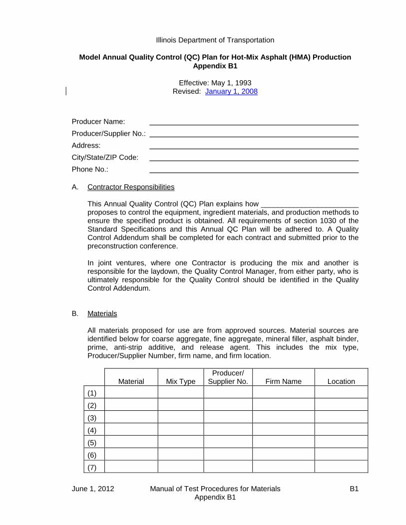
Illinois Department of Transportation
Model Annual Quality Control (QC) Plan for Hot-Mix Asphalt (HMA) Production
Appendix B1
Effective: May 1, 1993 Revised: January 1, 2008
June 1, 2012 Manual of Test Procedures for Materials B1 Appendix B1
Producer Name:
Producer/Supplier No.:
Address:
City/State/ZIP Code:
Phone No.:
A. Contractor Responsibilities This Annual Quality Control (QC) Plan explains how ________________________
proposes to control the equipment, ingredient materials, and production methods to ensure the specified product is obtained. All requirements of section 1030 of the Standard Specifications and this Annual QC Plan will be adhered to. A Quality Control Addendum shall be completed for each contract and submitted prior to the preconstruction conference.
In joint ventures, where one Contractor is producing the mix and another is
responsible for the laydown, the Quality Control Manager, from either party, who is ultimately responsible for the Quality Control should be identified in the Quality Control Addendum.
B. Materials All materials proposed for use are from approved sources. Material sources are
identified below for coarse aggregate, fine aggregate, mineral filler, asphalt binder, prime, anti-strip additive, and release agent. This includes the mix type, Producer/Supplier Number, firm name, and firm location.
Material
Mix Type
Producer/ Supplier No.
Firm Name
Location
(1)
(2)
(3)
(4)
(5)
(6)
(7)

Illinois Department of Transportation
Model Annual Quality Control (QC) Plan for Hot-Mix Asphalt (HMA) Production
Appendix B1 (continued)
Effective: May 1, 1993 Revised: January 1, 2008
June 1, 2012 Manual of Test Procedures for Materials B2 Appendix B1
Material
Mix Type
Producer/ Supplier No.
Firm Name
Location
(8)
(9)
(10)
1. Aggregates
The incoming aggregate gradation bands have been developed from the source gradation bands and are attached. Listed below are the contact persons for the aggregate sources furnishing mixture aggregates.
Name Firm Phone Number
Coarse Aggregate
CA/CM 07/11 (Binder)
CA/CM 13/16 (Binder)
CA/CM 13/16 (Surface)
Fine Aggregate
FA/FM 01/02
FA/FM 20/21
a. Aggregate Stockpile Procedures All aggregate stockpiles will be built using procedures that will minimize
segregation and degradation. All coarse and fine aggregate will be placed in single-layer truck-dumped stockpiles at the mix plant. QC personnel will pay special attention to the loadout, replenishing, and remixing of the aggregate stockpile.
If segregation/degradation becomes a problem, stockpiling procedures
will be altered to correct the problem. b. Incoming Aggregate Gradation Samples A washed gradation test will be performed for each 500 (tons 450 metric
tons) for the first 1,000 tons (900 metric tons) for each aggregate received. Additional gradation tests (every third test will be a washed
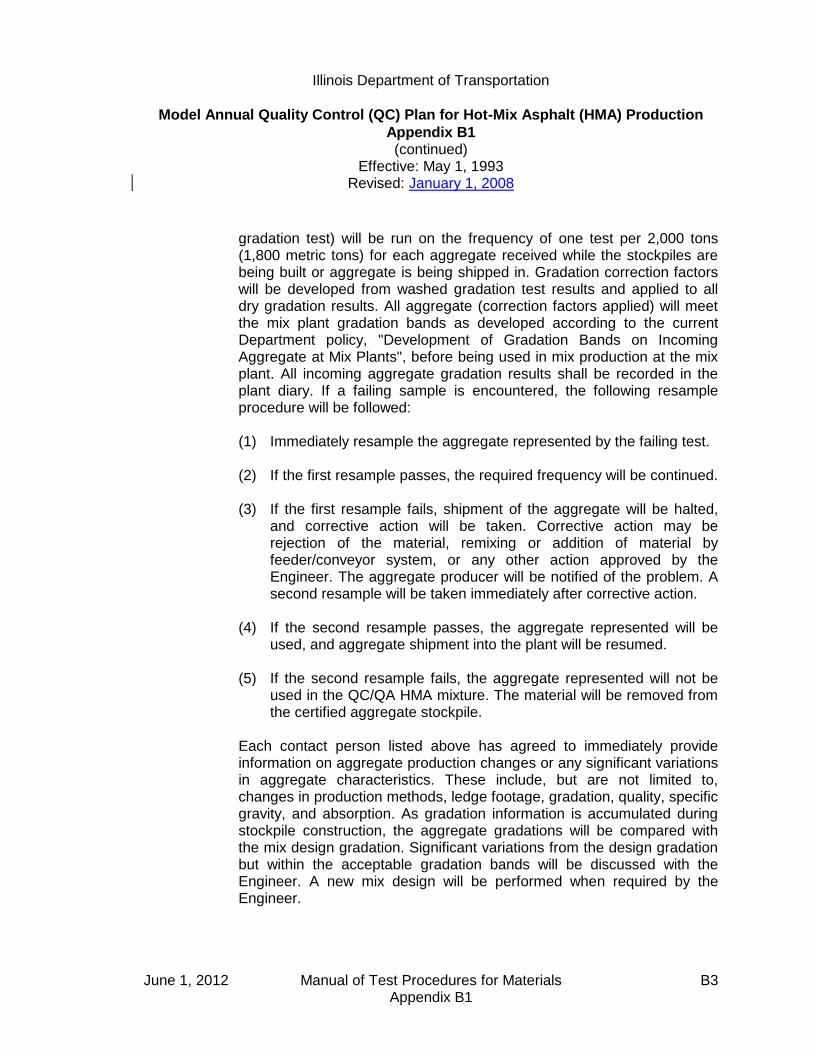
Illinois Department of Transportation
Model Annual Quality Control (QC) Plan for Hot-Mix Asphalt (HMA) Production
Appendix B1 (continued)
Effective: May 1, 1993 Revised: January 1, 2008
June 1, 2012 Manual of Test Procedures for Materials B3 Appendix B1
gradation test) will be run on the frequency of one test per 2,000 tons (1,800 metric tons) for each aggregate received while the stockpiles are being built or aggregate is being shipped in. Gradation correction factors will be developed from washed gradation test results and applied to all dry gradation results. All aggregate (correction factors applied) will meet the mix plant gradation bands as developed according to the current Department policy, "Development of Gradation Bands on Incoming Aggregate at Mix Plants", before being used in mix production at the mix plant. All incoming aggregate gradation results shall be recorded in the plant diary. If a failing sample is encountered, the following resample procedure will be followed:
(1) Immediately resample the aggregate represented by the failing test. (2) If the first resample passes, the required frequency will be continued. (3) If the first resample fails, shipment of the aggregate will be halted,
and corrective action will be taken. Corrective action may be rejection of the material, remixing or addition of material by feeder/conveyor system, or any other action approved by the Engineer. The aggregate producer will be notified of the problem. A second resample will be taken immediately after corrective action.
(4) If the second resample passes, the aggregate represented will be
used, and aggregate shipment into the plant will be resumed. (5) If the second resample fails, the aggregate represented will not be
used in the QC/QA HMA mixture. The material will be removed from the certified aggregate stockpile.
Each contact person listed above has agreed to immediately provide
information on aggregate production changes or any significant variations in aggregate characteristics. These include, but are not limited to, changes in production methods, ledge footage, gradation, quality, specific gravity, and absorption. As gradation information is accumulated during stockpile construction, the aggregate gradations will be compared with the mix design gradation. Significant variations from the design gradation but within the acceptable gradation bands will be discussed with the Engineer. A new mix design will be performed when required by the Engineer.

Illinois Department of Transportation
Model Annual Quality Control (QC) Plan for Hot-Mix Asphalt (HMA) Production
Appendix B1 (continued)
Effective: May 1, 1993 Revised: January 1, 2008
June 1, 2012 Manual of Test Procedures for Materials B4 Appendix B1
c. Required Gradation Sample After mix production has started, all aggregate stockpiles will be checked
with a required washed gradation sample on a weekly basis. This testing will be waived if the mixture is classified as a small tonnage item according to the special provision. The test results shall be compared to the mix plant gradation bands for compliance. These gradation results will be noted in the Plant Diary, and a copy will be provided to the District Engineer.
If a weekly required stockpile sample fails, the following resample
procedure will be followed:
(1) Immediately resample and test the new stockpile sample. (2) If the first resample passes, mix production may continue. Several
additional check samples will be taken to monitor the stockpile. (3) If the first resample fails, mix production will be halted, and
corrective action will be taken on the stockpile. Corrective action may include rejection of the material, remixing or addition of material by feeder/conveyor system before use in the plant, or any other action approved by the Engineer. The aggregate contact person will be notified of the problem. A second resample will be obtained immediately after corrective action.
(4) If the second resample passes, mix production will begin. Several
additional check samples will be taken to monitor the stockpile. (5) If the second resample fails, the stockpile will not be used in the
QC/QA HMA mixture.
Aggregate not meeting the mix plant gradation bands shall not be used in the QC/QA HMA mixtures.
d. Reclaimed Asphalt Pavement (RAP) RAP will meet the requirements of Sections 1030 of the Standard
Specifications and any Special Provision in the contract.

Illinois Department of Transportation
Model Annual Quality Control (QC) Plan for Hot-Mix Asphalt (HMA) Production
Appendix B1 (continued)
Effective: May 1, 1993 Revised: January 1, 2008
June 1, 2012 Manual of Test Procedures for Materials B5 Appendix B1
C. Mix Design Mix designs shall be completed according to the Department's Hot-Mix Asphalt
Level III Technician Course. All design data and material samples shall be submitted to the Department for verification a minimum of 30 calendar days prior to production.
D. Quality Control Personnel All requirements of the Standard Specifications Section 1030, and the items listed
in the Department's current "QC Personnel Responsibilities and Duties Checklist" will be met by the QC personnel. All personnel being utilized to run the Quality Control sampling and testing shall have taken and passed the appropriate HMA QC/QA level of training. The QC Manager will assign duties in accordance with the "QC Personnel Responsibilities and Duties Checklist". The QC Manager will assure the listed duties are performed and documented. Additional duties, when necessary, will be assigned and monitored by the QC Manager. Sufficient QC personnel will be provided to run the QC Plan. Additional QC personnel will be added when necessary.
E. Quality Control Laboratory/Equipment A QC laboratory will be provided and maintained in accordance with the
Department’s current "Hot-Mix Asphalt QC/QA Laboratory Equipment". Laboratory equipment meeting the requirements of the Department's current
"Hot-Mix Asphalt QC/QA Laboratory Equipment" will be provided and properly maintained at the QC laboratory. In the event of equipment failure, ________________________________ will be the source for backup equipment.
All equipment has been calibrated, and the supporting documentation is on file at
the QC laboratory. The QC Laboratory was approved by the Department's Bureau of Materials and Physical Research and by District __________ on ___________________________. The laboratory/equipment will be available for inspection by the Engineer.

Illinois Department of Transportation
Model Annual Quality Control (QC) Plan for Hot-Mix Asphalt (HMA) Production
Appendix B1 (continued)
Effective: May 1, 1993 Revised: January 1, 2008
June 1, 2012 Manual of Test Procedures for Materials B6 Appendix B1
F. Mix Plant/Production
Manufacturer
Model Number
Serial Number
Batch Size
Tons Per Hour
Approved By
Approval Date
It is our intent to run the day following start-up. Production will not begin until the
acceptable nuclear/core correlation is complete, all other required tests are acceptable, the targets are established, and the results are reviewed and agreed to by the Department.
The aggregate feeders will be calibrated prior to the start of production using the
aggregates and approximate percentages approved in the Job Mix Formula (JMF). At this time aggregate samples will be taken and compared with the JMF.
At the start of mix production or when adjustments are made to the mix, the QC
Manager will give the aggregate proportions to the plant operator, and then, periodically throughout the day, checks will be made of the actual proportions used. This will be especially noted and recorded when a nuclear asphalt and/or a mix sample is taken. The results will be immediately reported to the Resident Engineer and/or other designated Department personnel upon completion of the test.
All scale and sensitivity checks will be performed in accordance with the Hot-Mix
Asphalt Level II Technician Course manual. Surge bins may be utilized as part of the overall plant operation. The QC Manager shall contact the Department for approval when material will be stored overnight.
G. Sampling and Testing All sampling and testing, including all required plant tests, resamples, and
additional check tests (when necessary), will be performed in accordance with Department test methods in the time frame required in Section 1030 of the Standard Specifications. The "Radioactive Material License" required for nuclear density and asphalt binder content determinations are attached. District Materials or the Bureau of Materials and Physical Research personnel are welcome to observe all testing by the QC personnel. Time permitting, split samples will be

Illinois Department of Transportation
Model Annual Quality Control (QC) Plan for Hot-Mix Asphalt (HMA) Production
Appendix B1 (continued)
Effective: May 1, 1993 Revised: January 1, 2008
June 1, 2012 Manual of Test Procedures for Materials B7 Appendix B1
shared with Department personnel prior to start-up. Coring will be performed using a truck-mounted drill rig or by suitable equipment as approved by the Engineer. An adjustment of 1-1/2% to 2% for minus No. 200 (0.075 mm) material of washed samples vs. dry gradations will be used until a gradation correction factor is established based on preliminary aggregate sampling and testing.
All Department split samples will be stored on site. These samples will be identified with the date and time the material was sampled, Sequence Number, Contract Number, mix plant Producer/Supplier Number, aggregate source Producer/Supplier Number, and the initials of the individual who sampled the material.
H. Placement and Compaction Only approved equipment will be used in the placement and compaction of the mix
in accordance with the Standard Specification requirements. The QC Manager will verify that all laydown equipment conforms to Department
requirements prior to start-up. At the start of laydown, Two Growth Curves will be run on a test strip to determine the suitability of the mix. Mix samples shall be taken and tested from trucks representing material between both Growth Curves. From Growth Curve information, a rolling pattern will be established. Nuclear tests and cores will be taken from the start-up area to verify density and correlation of the nuclear density gauge. Temperatures of the mix will be taken and duly recorded. After the start-up data is approved by the Department and actual production has begun, daily nuclear density tests will be taken at the start of each day's production, along with temperature readings, to verify continued conformance with density requirements. Nuclear density tests according to the Section 1030 will be performed to assure compliance with specified density requirements. Testing will be conducted within the project traffic control, or by use of flaggers, as needed.
Start-up and construction of the test strip is planned to be performed in the morning
of the first day. If no problems are encountered, cores for nuclear/core correlation will be taken. The mat will be cooled with ice or dry ice. All tests will be completed for anticipated production the next day.
Should any adverse mix characteristics be observed, the QC Manager shall make
mix adjustments as needed to correct the situation. If segregation should occur, appropriate adjustments will be made in the aggregate
stockpiling/loadout, plant production, silo operation, truck loading, or paver operation to alleviate the condition. Only approved truck release agents will be used.

Illinois Department of Transportation
Model Annual Quality Control (QC) Plan for Hot-Mix Asphalt (HMA) Production
Appendix B1 (continued)
Effective: May 1, 1993 Revised: January 1, 2008
June 1, 2012 Manual of Test Procedures for Materials B8 Appendix B1
The QC Manager or his representative will check laydown equipment daily for
specification compliance and immediately repair or replace nonconforming equipment.
I. Corrective Action The QC Manager will initiate corrective action immediately according to Section
1030 of the Standard Specifications. Sufficient tests shall be taken to verify the corrective action has worked. Special care will be taken to assure that mix not complying with specifications is not placed on the road.
J. Reporting of Test Results All test results will be reported daily to the Resident Engineer and other designated
personnel as requested by the Department. The data will be reported on the following forms or on forms generated by the Department's current QC/QA software:
MI 504M Field/Lab Gradations (stockpile gradations)
MI 305 Bituminous Daily Plant Output (front) Plant Settings and Scale Checks (back)
MI 303C Bituminous Core Density Testing QC/QA
MI 303N QC Nuclear Density Report
MI 308 Nuclear Asphalt Content and Volumetric Testing
LM-6 Sample Identification (for liquid asphalt)
The completed forms will be forwarded to the District Engineer within three days of
test completion.

Illinois Department of Transportation
Model Annual Quality Control (QC) Plan for Hot-Mix Asphalt (HMA) Production
Appendix B1 (continued)
Effective: May 1, 1993 Revised: January 1, 2008
June 1, 2012 Manual of Test Procedures for Materials B9 Appendix B1
K. Control Charts In addition, control charts will be posted at the laboratory and kept updated for the
following test parameters in accordance with the Department's current "Hot-Mix Asphalt QC/QA Control Charts/Rounding Test Values".
1. Gradations Hot-Bins/Combined Belt
Percent Passing 1/2-in. (12.5-mm) Sieve
Percent Passing No. 4 (4.75-mm) Sieve
Percent Passing No. 8 (2.36-mm) Sieve
Percent Passing No. 30 (600-µm) Sieve
Percent Passing No. 200 (75-µm) Sieve
Ignition Oven
Total Dust Content 2. Gravities
a. Bulk specific gravity b. Maximum specific gravity
3. Marshall Air Voids 4. Density 5. Asphalt Binder Content 6. Stockpile Gradations
In the event the Total Dust Content is out of tolerance, measures will be taken to correct the problem, which may include adding Positive Dust Control Equipment.
Contractor's Signature Date
(Please type or print name) Title

June 1, 2012 Manual of Test Procedures for Materials B10 Appendix B1
This Page Reserved

Illinois Department of Transportation
Model Quality Control (QC) Addendum for Hot-Mix Asphalt (HMA) Production
Appendix B2
Effective: July 1, 1995 Revised: May 1, 2007
June 1, 2012 Manual of Test Procedures for Materials B11 Appendix B2
Contract No.:
Marked Route:
Route:
Section:
County:
Contractor:
Address:
City/State/ZIP Code:
Phone No.:
A. Contractor Responsibilities
This Quality Control Addendum to the Annual Quality Control Plan further explains
how ________________________________ proposes to control the equipment,
ingredient materials, and production methods to ensure the specified product is
obtained. All requirements in Section 1030, the Annual QC Plan, and this QC
Addendum will be adhered to.
In the case of joint ventures, ___________________________________________
of ________________________________________ will be the QC Manager and
will be ultimately responsible for the Quality Control on this Contract.
B. Reclaimed Asphalt Pavement (RAP)
RAP will meet the requirements of Sections 406, 1030 and 1102 of the Standard
Specifications and any Special Provisions in the Contract. ______ percent of RAP
is proposed for use in the ____________________________ course.

Illinois Department of Transportation
Model Quality Control (QC) Addendum for Hot-Mix Asphalt (HMA) Production
Appendix B2 (continued)
Effective: July 1, 1995 Revised: May 1, 2007
June 1, 2012 Manual of Test Procedures for Materials B12 Appendix B2
C. Mix Design Mix designs are attached for Department verification. D. Quality Control Personnel The project QC Manager will have overall responsibility and authority for Quality
Control at both the plant and on the road and will make the necessary adjustments in the mix production, placement, and compaction to assure conformance with the Standard Specifications and Contract Special Provisions.
The QC personnel and/or consulting firm that will be utilized, as well as the backup
QC personnel and/or consulting firm, are as follows:
Name
Level of Training
Firm
Phone Number
(1)
(2)
(3)
(4)
(5) (backup)
E. Mix Plant/Production The mix for this project will be produced by Producer/Supplier No. _____________. F. Control Charts A copy of the Control Charts will be submitted to the Engineer upon completion of
the Contract. Contractor's Signature Title (Please type or print name) Date
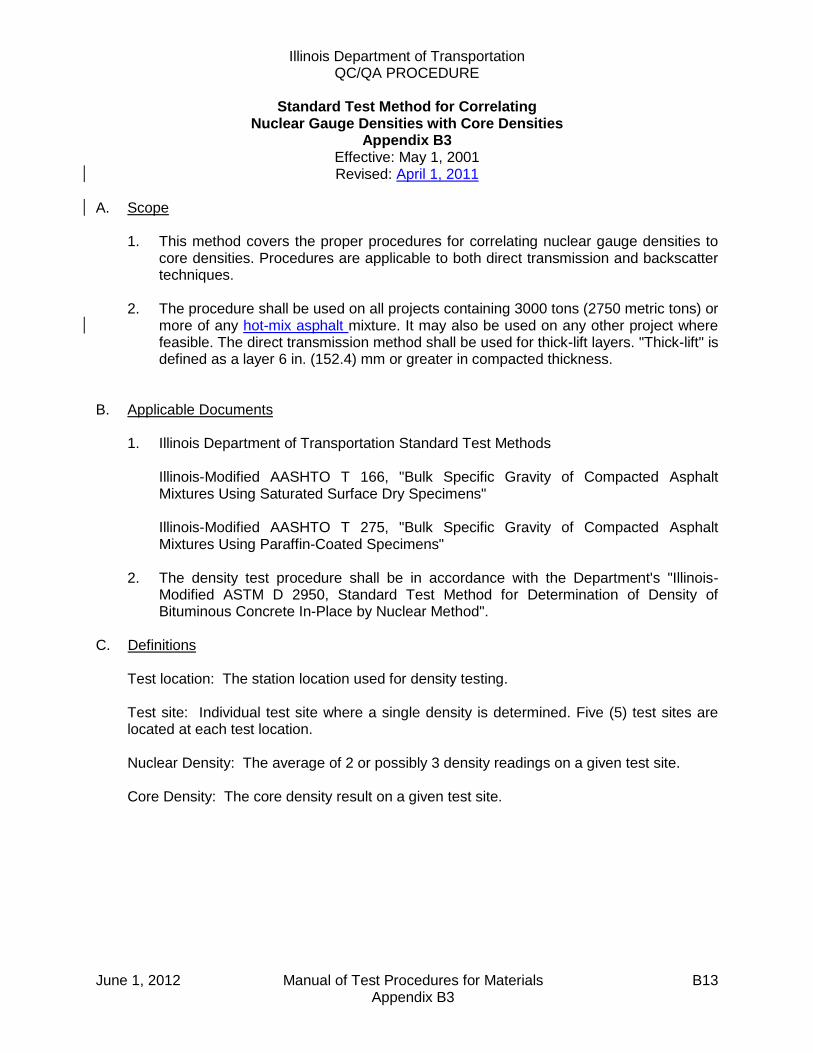
Illinois Department of Transportation QC/QA PROCEDURE
Standard Test Method for Correlating
Nuclear Gauge Densities with Core Densities Appendix B3
Effective: May 1, 2001 Revised: April 1, 2011
June 1, 2012 Manual of Test Procedures for Materials B13 Appendix B3
A. Scope
1. This method covers the proper procedures for correlating nuclear gauge densities to core densities. Procedures are applicable to both direct transmission and backscatter techniques.
2. The procedure shall be used on all projects containing 3000 tons (2750 metric tons) or
more of any hot-mix asphalt mixture. It may also be used on any other project where feasible. The direct transmission method shall be used for thick-lift layers. "Thick-lift" is defined as a layer 6 in. (152.4) mm or greater in compacted thickness.
B. Applicable Documents
1. Illinois Department of Transportation Standard Test Methods Illinois-Modified AASHTO T 166, "Bulk Specific Gravity of Compacted Asphalt
Mixtures Using Saturated Surface Dry Specimens" Illinois-Modified AASHTO T 275, "Bulk Specific Gravity of Compacted Asphalt
Mixtures Using Paraffin-Coated Specimens" 2. The density test procedure shall be in accordance with the Department's "Illinois-
Modified ASTM D 2950, Standard Test Method for Determination of Density of Bituminous Concrete In-Place by Nuclear Method".
C. Definitions
Test location: The station location used for density testing. Test site: Individual test site where a single density is determined. Five (5) test sites are located at each test location. Nuclear Density: The average of 2 or possibly 3 density readings on a given test site. Core Density: The core density result on a given test site.

Illinois Department of Transportation QC/QA PROCEDURE
Standard Test Method for Correlating
Nuclear Gauge Densities with Core Densities Appendix B3 (continued)
Effective: May 1, 2001 Revised: April 1, 2011
June 1, 2012 Manual of Test Procedures for Materials B14 Appendix B3
D. Significance and Use
1. Density results from a nuclear gauge are relative. If an approximation of core density results is required, a correlation must be developed to convert the nuclear density to core density.
2. A correlation developed in accordance with these procedures is applicable only to the
specific gauge being correlated, the specific mixture, each specific thickness (direct transmission only), and the specific project upon which it was correlated. A new correlation should be determined within a specific project if there is a significant change in the underlying material.
E. Site Selection
1. The nuclear density tests and cores necessary for nuclear/core correlation shall be obtained during the start-up of each specific mixture for which a density specification is applicable.
2. Three correlation locations shall be selected. Two sites will be located on the two
growth curves from the first acceptable test strip. The third location shall be chosen after an acceptable rolling pattern has been established and within the last 100 tons (90 metric tons) of material placed during start-up. The material from the third site shall correspond to the same material from which the second hot-mix sample was taken.
3. If a mixture start-up is not required, two of the three correlation locations shall be in an
area containing a growth curve. F. Procedures for Obtaining Nuclear Readings and Cores
1. Backscatter Mode
a. At each of the three correlation locations, five individual sites shall be chosen and identified as shown in Figure 1.
b. Two nuclear readings shall be taken at each of the 15 individual sites. (See
Figure 1.) The gauge shall be rotated 180 degrees between readings at each site. (The two uncorrected readings taken at a specific individual site shall be within 1.5 lbs/ft3 [23 kg/m3). If the two readings do not meet this criterion, one additional reading shall be taken in the desired direction. The nuclear densities are to be recorded on the correlation form (Figure 3).

Illinois Department of Transportation QC/QA PROCEDURE
Standard Test Method for Correlating
Nuclear Gauge Densities with Core Densities Appendix B3 (continued)
Effective: May 1, 2001 Revised: April 1, 2011
June 1, 2012 Manual of Test Procedures for Materials B15 Appendix B3
c. One core in good condition shall be obtained from each of 15 individual sites
(Figure 1). Care should be exercised that no additional compaction occurs between the nuclear testing and the coring. The cores shall be tested for density in accordance with Illinois-Modified AASHTO T 166 or T 275. The core densities are to be entered on the correlation form.
For quality assurance purposes, the Department may direct the Contractor to take additional cores adjacent to those above or to submit the quality control cores for Department testing.
d. Extreme care shall be taken in identifying which location each of the density
readings represents. The data points have to be paired accurately or the correlation process will be invalid.
2. Direct Transmission Mode
a. At each of the three correlation locations, five individual sites shall be chosen across the mat as shown on Figure 1.
b. A smooth hole in the pavement, slightly larger than the probe, shall be formed to
a depth 2 in. (50 mm) greater than the test depth. The probe shall be inserted so that the side of the probe facing the center of the gauge is in intimate contact with the side of the hole. Two nuclear readings shall be taken at each of the 15 individual sites. (See Figures 1 and 2)
The gauge shall be rotated 180 degrees (see Figure 2) around the core area at
each site. (The two uncorrected readings taken at a specific individual site shall be within 2.0 lbs/ft3 [30 kg/m3] (see Figure 2). If the two readings do not meet this criterion, one additional reading shall be taken in the desired direction. The nuclear densities are to be recorded on the correlation form (Figure 3).
c. One core in good condition shall be obtained from each of the 15 individual sites.
(See Figures 1 and 2) The cores shall be obtained from beneath the center of the gauge no closer than 3-1/2 in (87.5 mm) from either access hole. The thickness of the core should represent the thickness of the layer being tested. The layer shall be carefully separated for testing in accordance with Illinois-Modified AASHTO T 166. Care should be exercised that no additional compaction occurs between the nuclear testing and the coring. The cores shall be tested for density in accordance with Illinois-Modified AASHTO T 166 or T 275.

Illinois Department of Transportation QC/QA PROCEDURE
Standard Test Method for Correlating
Nuclear Gauge Densities with Core Densities Appendix B3 (continued)
Effective: May 1, 2001 Revised: April 1, 2011
June 1, 2012 Manual of Test Procedures for Materials B16 Appendix B3
For quality assurance purposes, the Department may direct the Contractor to
take additional cores adjacent to those above or to submit the quality control cores for Department testing.
The core densities are to be entered on the correlation form. d. Extreme care shall be taken in identifying which location each of the density
readings represents. The data points have to be paired accurately or the correlation process will be invalid.
G. Mathematical Correlation -- Linear Regression
1. The two (or possibly three) nuclear readings at each individual site shall be entered on the correlation form and then averaged. The core density taken at each individual site shall be entered on the correlation form. After the averaging, there will be 15 paired data points, each pair containing the average nuclear density and core density for each of the 15 individual sites.
2. The paired density values shall be correlated using the Department's linear regression
program. (Disks are available from the Bureau of Materials and Physical Research) or an approved and equivalent calculating method.
3. For the purpose of this procedure, standard statistical methods for measuring the
"best fit" of a line through a series of 15 paired data points consisting of core density and nuclear density shall be used.
4. It should be recognized that correlations obtained by this or similar procedures may or
may not be valid; each attempt should be judged on its merit. In general, a correlation coefficient for each correlation linear regression should be calculated.
5. Correlation coefficients (r) may range from minus 1.0 to plus 1.0. An "r" value greater than 0.715 is considered acceptable.
6. The correlation shall be stated and used in the form: y = mx + b
where: y = core density
x = nuclear gauge density
b = intercept
m = slope of linear regression ("best fit") line

Illinois Department of Transportation QC/QA PROCEDURE
Standard Test Method for Correlating
Nuclear Gauge Densities with Core Densities Appendix B3 (continued)
Effective: May 1, 2001 Revised: April 1, 2011
June 1, 2012 Manual of Test Procedures for Materials B17 Appendix B3
(BACKSCATTER)FIRST GROWTH CURVE IS BETWEEN 200 AND 225 METRIC TONS (225 AND 250
TONS), THE SECOND GROWTH CURVE IS BETWEEN 250 AND 275 METRIC TONS
(275 AND 300 TONS).
NUCLEAR/CORE CORRELATION TEST LOCATIONS
NUCLEAR SITE
PAVING DIRECTION
300 mm (1 FT.)
300 mm (1 FT.)
1 (6) B
3 (8) B
5 (10) A
CORE
300 mm (1 FT.)
300 mm (1 FT.)
12A
13A 13B
14A
15A
CORE
FIG
UR
E 1
11A1 (6) A
2 (7) A
3 (8) A
4 (9) A
5 (10) B
4 (9) B
2 (7) B
15B
14B
12B
11B
2 of 3 sites 1 of 3 sites
1 CORRELATION
LOCATION IN AN AREA
REPRESENTING A
REGULAR ROLLING
PATTERN.
2 CORRELATION LOCATIONS
IN GROWTH CURVE AREAS
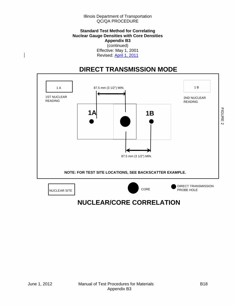
Illinois Department of Transportation QC/QA PROCEDURE
Standard Test Method for Correlating
Nuclear Gauge Densities with Core Densities Appendix B3 (continued)
Effective: May 1, 2001 Revised: April 1, 2011
June 1, 2012 Manual of Test Procedures for Materials B18 Appendix B3
FIG
UR
E 2
DIRECT TRANSMISSION MODE
DIRECT TRANSMISSION
PROBE HOLENUCLEAR SITE
1 A 1 B
1ST NUCLEAR
READING2ND NUCLEAR
READING
CORE
87.5 mm (3 1/2") MIN.
87.5 mm (3 1/2") MIN.
NOTE: FOR TEST SITE LOCATIONS, SEE BACKSCATTER EXAMPLE.
NUCLEAR/CORE CORRELATION
1A 1B
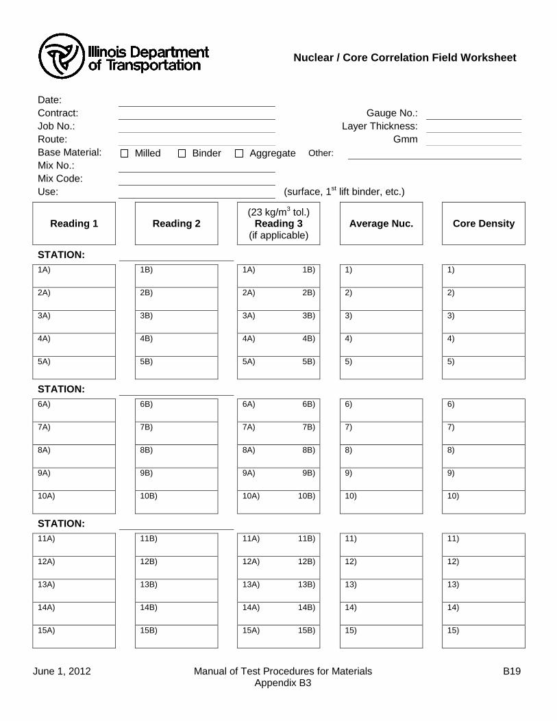
June 1, 2012 Manual of Test Procedures for Materials B19 Appendix B3
Nuclear / Core Correlation Field Worksheet
Date:
Contract: Gauge No.:
Job No.: Layer Thickness:
Route: Gmm
Base Material: Milled Binder Aggregate Other:
Mix No.:
Mix Code:
Use: (surface, 1st lift binder, etc.)
Reading 1 Reading 2 (23 kg/m3 tol.)
Reading 3 (if applicable)
Average Nuc. Core Density
STATION:
1A) 1B) 1A) 1B) 1) 1)
2A) 2B) 2A) 2B) 2) 2)
3A) 3B) 3A) 3B) 3) 3)
4A) 4B) 4A) 4B) 4) 4)
5A) 5B) 5A) 5B) 5) 5)
STATION:
6A) 6B) 6A) 6B) 6) 6)
7A) 7B) 7A) 7B) 7) 7)
8A) 8B) 8A) 8B) 8) 8)
9A) 9B) 9A) 9B) 9) 9)
10A) 10B) 10A) 10B) 10) 10)
STATION:
11A) 11B) 11A) 11B) 11) 11)
12A) 12B) 12A) 12B) 12) 12)
13A) 13B) 13A) 13B) 13) 13)
14A) 14B) 14A) 14B) 14) 14)
15A) 15B) 15A) 15B) 15) 15)

June 1, 2012 Manual of Test Procedures for Materials B20 Appendix B3
This Page Reserved
Illinois Department of Transportation
Hot Mix Asphalt Test Strip Procedures
Appendix B4
Effective: May 1, 1993 Revised: January 1, 2014
January 1, 2014 Manual of Test Procedures for Materials B21 Appendix B4
For mixtures where the quantity exceeds 3000 tons (2750 metric tons), the Contractor and the Department shall evaluate the mixture to be produced for each contract using a 300 ton test strip. The Contractor shall follow the following procedures for constructing a test strip. A. Contractor/Department Test Strip Team A team of both Contractor and Department personnel shall construct a test strip
and evaluate mix produced at the plant. The test strip team may consist of the following, as necessary:
1. Resident Engineer 2. District Construction Supervising Field Engineer, or representative 3. District Materials Mixtures Control Engineer, or representative 4. Contractor's QC Manager, required 5. Contractor's Density Tester 6. Bureau of Materials and Physical Research representative when requested 7. Bureau of Construction representative when requested
B. Communications The Contractor shall advise the team members of the anticipated start time of
production for the mix. The QC Manager shall direct the activities of the test strip team. A Department-appointed representative from the test strip team will act as spokesperson for the Department.
C. Acceptance Criteria
1. Mix Design and Plant Proportioning - The mix design shall be approved by the Department prior to the test strip. Target values shall be provided by the Contractor and will be approved by the Department prior to constructing the test strip.
2. Evaluation of Growth Curves - Mixtures which exhibit density potential less
than or greater than the density ranges specified in Article 1030.05(d)(4) shall be considered to have a potential density problem which is normally sufficient cause for mix adjustment.
If an adjustment has been made, the Engineer may require an additional test strip be constructed and evaluated. This information shall then be compared to the AJMF and required design criteria for acceptance.
Illinois Department of Transportation
Hot Mix Asphalt Test Strip Procedures
Appendix B4 (continued)
Effective: May 1, 1993 Revised: January 1, 2014
January 1, 2014 Manual of Test Procedures for Materials B22 Appendix B4
3. Evaluation of Required Plant Tests - If the results of the required plant tests exceed the JMF target value control limits, the Contractor shall make allowable mix adjustments/plant changes, resample, and retest. If the Engineer determines additional adjustments to the mix will not produce acceptable results, a new mix design may be required.
D. Test Strip Method
The Contractor shall produce 300 tons (275 metric tons) of mix for the test strip. The test strip will be included in the cost of the mix and will not be paid for separately since the Contractor may continue production, at their own risk, after the test strip has been completed.
The procedures listed below shall be followed to construct a test strip. a. Location of Test Strip - The test strip shall be located on a relatively flat
portion of the roadway. Descending/ascending grades or ramps should be avoided.
b. Constructing the Test Strip - After the Contractor has produced and
placed approximately 225 to 250 tons (200 to 225 metric tons) of mix, paving shall cease and a growth curve shall be constructed. After completion of the first growth curve, paving shall resume for the remaining 50 to 75 tons (45 to 70 metric tons), and the second growth curve shall be constructed within this area. The Contractor shall use normal rolling procedures for all portions of the test strip except for the growth curve areas which shall be compacted solely with a vibratory roller as directed by the QC Manager.
c. Required Plant Tests - A set of mixture samples shall be taken at such a
time as to represent the mixture in between the two growth curve trucks. The mixture sampled to represent the test strip shall also include material
sufficient for the Department to conduct a Hamburg Wheel test according to Illinois modified AASHTO T 324.
E. Compaction Requirements
1. Compaction Equipment - The Contractor shall provide a vibratory roller meeting the requirements of Article 1101.01(g) of the Standard Specifications. It shall be the responsibility of the test strip team to verify specification compliance before commencement of growth curve construction. An appropriate amplitude shall be selected on the basis of roller weight and mat
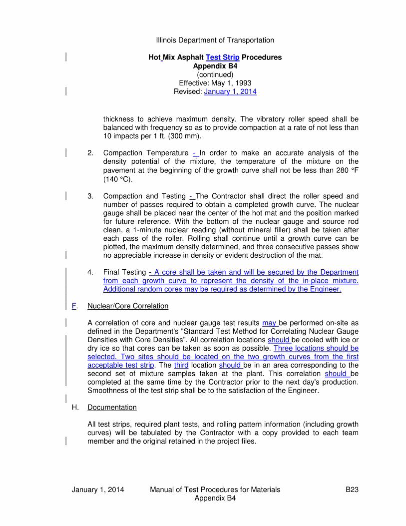
Illinois Department of Transportation
Hot Mix Asphalt Test Strip Procedures
Appendix B4 (continued)
Effective: May 1, 1993 Revised: January 1, 2014
January 1, 2014 Manual of Test Procedures for Materials B23 Appendix B4
thickness to achieve maximum density. The vibratory roller speed shall be balanced with frequency so as to provide compaction at a rate of not less than 10 impacts per 1 ft. (300 mm).
2. Compaction Temperature - In order to make an accurate analysis of the
density potential of the mixture, the temperature of the mixture on the
pavement at the beginning of the growth curve shall not be less than 280 °F
(140 °C). 3. Compaction and Testing - The Contractor shall direct the roller speed and
number of passes required to obtain a completed growth curve. The nuclear gauge shall be placed near the center of the hot mat and the position marked for future reference. With the bottom of the nuclear gauge and source rod clean, a 1-minute nuclear reading (without mineral filler) shall be taken after each pass of the roller. Rolling shall continue until a growth curve can be plotted, the maximum density determined, and three consecutive passes show no appreciable increase in density or evident destruction of the mat.
4. Final Testing - A core shall be taken and will be secured by the Department
from each growth curve to represent the density of the in-place mixture. Additional random cores may be required as determined by the Engineer.
F. Nuclear/Core Correlation A correlation of core and nuclear gauge test results may be performed on-site as
defined in the Department's "Standard Test Method for Correlating Nuclear Gauge Densities with Core Densities". All correlation locations should be cooled with ice or dry ice so that cores can be taken as soon as possible. Three locations should be selected. Two sites should be located on the two growth curves from the first acceptable test strip. The third location should be in an area corresponding to the second set of mixture samples taken at the plant. This correlation should be completed at the same time by the Contractor prior to the next day's production. Smoothness of the test strip shall be to the satisfaction of the Engineer.
H. Documentation All test strips, required plant tests, and rolling pattern information (including growth
curves) will be tabulated by the Contractor with a copy provided to each team member and the original retained in the project files.

January 1, 2014 Manual of Test Procedures for Materials B24 Appendix B4
This Page Reserved

January 1, 2014 Manual of Test Procedures for Materials B25 Appendix B4
This Page Reserved

January 1, 2014 Manual of Test Procedures for Materials B26 Appendix B4
This Page Reserved

Illinois Department of Transportation
Hot-Mix Asphalt QC/QA
QC Personnel Responsibilities and Duties Checklist
Appendix B5
Effective: May 1, 1993 Revised: May 1, 2007
June 1, 2012 Manual of Test Procedures for Materials B27 Appendix B5
The following checklists detail the required minimum duties of Contractor Quality Control (QC) personnel. The QC Manager has overall responsibility to ensure that the listed duties are performed and documented. The QC Manager shall not perform sampling and/or testing except in emergency situations or in any other situation approved by the Engineer. Additional duties, as necessary, may be required to control the quality of production and placement of the Hot-Mix Asphalt (HMA) mixtures. A Level II Technician may be used to perform any Level I Technician duties.
Note: Testing frequency denoted as "P" = "Prior to Start-up" and as "D" = "Daily". A. Level I Technician
1. Checklist a. Perform incoming aggregate gradations before start-up time. (PD) ___ b. Ensure lab equipment is on hand and in working order. (PD) ___ c. Run moisture samples daily (drum only). (PD) ___ d. Determine random sampling times one day in advance and inform the QC Manager and the Engineer of the sampling times. (D) ___ e. Take required samples when required using proper procedures. (D) ___ f. Split required sample and save the Department split; use proper identification. ___ g. Run required tests as soon as possible using proper QC/QA ___ procedures. h. Take resamples as required. ___ i. Plot all random and resample results on control charts as soon as test results are available. ___ j. Take check samples when necessary. (D) ___ k. Contact QC Manager immediately when tests fail or any time problems occur. (D) ___ l. Test cores for Nuclear/Core Correlation (after Start-up). ___
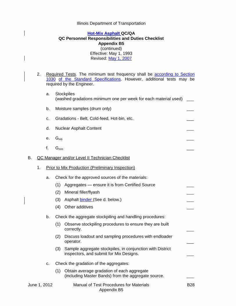
Illinois Department of Transportation
Hot-Mix Asphalt QC/QA
QC Personnel Responsibilities and Duties Checklist
Appendix B5 (continued)
Effective: May 1, 1993 Revised: May 1, 2007
June 1, 2012 Manual of Test Procedures for Materials B28 Appendix B5
2. Required Tests. The minimum test frequency shall be according to Section
1030 of the Standard Specifications. However, additional tests may be required by the Engineer. a. Stockpiles (washed gradations minimum one per week for each material used) ___ b. Moisture samples (drum only) ___ c. Gradations - Belt, Cold-feed, Hot-bin, etc. ___ d. Nuclear Asphalt Content ___ e. Gmb ___ f. Gmm ___
B. QC Manager and/or Level II Technician Checklist
1. Prior to Mix Production (Preliminary Inspection)
a. Check for the approved sources of the materials:
(1) Aggregates — ensure it is from Certified Source ___
(2) Mineral filler/flyash ___
(3) Asphalt binder (See d. below.) ___
(4) Other additives ___ b. Check the aggregate stockpiling and handling procedures:
(1) Observe stockpiling procedures to ensure they are built correctly. ___
(2) Discuss loadout and sampling procedures with endloader operator. ___
(3) Sample aggregate stockpiles, in conjunction with District inspectors, and submit for Mix Designs. ___
c. Check the gradation of the aggregates:
(1) Obtain average gradation of each aggregate (including Master Bands) from the aggregate source. ___

Illinois Department of Transportation
Hot-Mix Asphalt QC/QA
QC Personnel Responsibilities and Duties Checklist
Appendix B5 (continued)
Effective: May 1, 1993 Revised: May 1, 2007
June 1, 2012 Manual of Test Procedures for Materials B29 Appendix B5
(2) Compare aggregate source information to stockpile samples at the mix plant and with the design gradation. ___
d. Check asphalt binder:
(1) Source ___
(2) Grade ___
(3) Incoming temperatures ___
(4) Specific Gravity (drum only) ___ e. Verify that the laboratory and laboratory equipment have been inspected and approved by the Department and are in good working order. ___ f. Review Hot-Mix Asphalt Level I and Level II Technician Course manuals.
2. Prior to Production/During Start-Up/During Production a. Check the mix plant for the following:
(1) Approval and calibration (P) ___
(2) Asphalt binder storage (PD) ___
(3) Stockpiles (PD) ___
(a) correct loadout ___
(b) place in proper cold-feed bins ___
(4) Cold-feed bins or bulkheads and feeders (PD) ___
(5) Dust collecting systems (D) ___
(6) Screens and screening requirements (P) ___
(7) Hot-bin sampler (P) and hot-bin overflow (PD) ___
(8) Weigh belt 6-minute check (drum only) (D) ___
(9) Temperature recorders and thermometers (PD) ___
(10) Mixing timers (batch plant only) and pugmill dam gate (continuous plants) (PD) ___
(11) Surge and storage bins (PD) ___
(12) Platform scales or suspended weigh hopper (PD) ___

Illinois Department of Transportation
Hot-Mix Asphalt QC/QA
QC Personnel Responsibilities and Duties Checklist
Appendix B5 (continued)
Effective: May 1, 1993 Revised: May 1, 2007
June 1, 2012 Manual of Test Procedures for Materials B30 Appendix B5
(13) Anti-strip additive system (when required) (PD) ___
(14) Ticket printer (P) ___
(15) Computer and control systems (PD) ___ b. Check trucks for the following (QC Manager may assign these duties to a Level I Technician):
(1) Truck bed release agents (PD) ___
(2) Insulation (D) ___
(3) Tarps (D) ___
(4) Clean beds (D) ___
c. Coordinate any start-up per Department guidelines (QC Manager only). ___ d. Monitor sampling and testing procedures, density test, and laydown operations; contact man from aggregate producer (QC Manager only). ___ e. Check the mixtures for the following:
(1) Gradation test performed and bin percentages determined before start-up (P) ___
(2) Correct Job Mix Formula is being used (P) ___
(3) Moisture check (drum only) (PD) ___
(4) Temperature (D) ___
(5) Coating and segregation (D) ___
(6) Additives (D) ___ f. Laydown operation (QC Manager only) — Monitor the following field checks:
(1) Check for obvious defects in truck (segregation, uncoated, temperature, etc.) (D) ___
(2) Monitor paver operations (equipment, laydown procedures, etc.) (PD) ___
(3) Rollers and operations (equipment, pattern, procedure, etc.) (PD) ___

Illinois Department of Transportation
Hot-Mix Asphalt QC/QA
QC Personnel Responsibilities and Duties Checklist
Appendix B5 (continued)
Effective: May 1, 1993 Revised: May 1, 2007
June 1, 2012 Manual of Test Procedures for Materials B31 Appendix B5
(4) Mix characteristics on road (appearance, mat temperature, etc.) (D) ___
(5) Monitor densities as required (D) ___ g. Monitor all test results and make any adjustments necessary (QC Manager only) (D). ___ h. Perform scale checks (minimum one per
week per scale). Follow procedure in Construction Manual Documentation Section. ___ i. Prepare and store samples for the District laboratory as required. (D) ___ j. Ensure following records are kept and reports are submitted in a timely manner as required (QC Manager only): (D)
(1) Daily plant output ___
(2) Field gradation ___
(3) Density ___
(4) Marshall (stability and flow when required) ___
(5) Control charts ___
(6) Additives ___
(7) Scale checks ___
(8) Plant diary ___ C. Level I Technician, Level II Technician, and Quality Control Manager Duties
1. Material Source It is necessary to identify the source of the ingredients to ensure that they
have been inspected and the correct quality of aggregate, grade of asphalt binder, and anti-strip additive are being used in the specified mix. Sources shall be verified.
2. Aggregate Quality The Level II Technician may confirm the quality of the aggregate by requesting
current quality information from the District Materials office.

Illinois Department of Transportation
Hot-Mix Asphalt QC/QA
QC Personnel Responsibilities and Duties Checklist
Appendix B5 (continued)
Effective: May 1, 1993 Revised: May 1, 2007
June 1, 2012 Manual of Test Procedures for Materials B32 Appendix B5
3. Stockpiling Sites for stockpiles shall be grubbed and cleaned prior to storing the
aggregates. Separate stockpiles shall be provided for the various sources and kinds of
aggregates. Stockpiles shall be separated to prevent intermingling at the base (width of endloader bucket). If partitions are used, they shall be of sufficient heights to prevent intermingling. Aggregates for HMA mixtures shall be handled, in and out of the stockpiles, in such a manner that will prevent contamination and degradation.
Coarse aggregate stockpiles shall be built in layers not exceeding 1.5 m (5 ft)
in height and each layer shall be completely in place before the next layer is started. A stockpile may be expanded by again starting the expansion from the ground and building layers as before. End-dumping over the sides will not be permitted. Use of steel track equipment on Class B Quality, Class C Quality and all blast furnace slag aggregate stockpiles shall not be permitted where degradation is detected. When loading out of stockpiles, vertical faces shall be limited to reasonable heights to eliminate segregation due to tumbling. Segregation or degradation due to improper stockpiling or loading out of stockpiles shall be just cause for rejecting the material.
4. Gradations The Level II Technician shall obtain the average gradations as well as the
Master Bands from the aggregate source. He/She shall run the required gradation's test frequency on incoming aggregate as required in Section 1030 of the Standard Specifications.
5. Asphalt Binder
a. Incoming Asphalt Binder: The Level II Technician shall periodically check the grade and temperature of asphalt binder as received at the plant. If the asphalt binder is shipped by truck, the driver should have in his possession a numbered ticket showing the name and location of the refinery, the name of the material, date shipped, loading temperature, quantity, specific gravity or weight/L (weight/gal), and the number of the tank from which the asphalt was loaded. It is the responsibility of the refinery to load trucks only from tanks that have been tested and approved by the Department. If shipment is made by rail, a tag usually will

Illinois Department of Transportation
Hot-Mix Asphalt QC/QA
QC Personnel Responsibilities and Duties Checklist
Appendix B5 (continued)
Effective: May 1, 1993 Revised: May 1, 2007
June 1, 2012 Manual of Test Procedures for Materials B33 Appendix B5
be found on the top of the dome of the tank car indicating that it has been sampled at the refinery.
b. Asphalt Binder Storage: The Level II Technician shall check the
temperature of the asphalt binder in storage. The temperatures shall be maintained in accordance with the Standard Specifications. The Level II Technician should be aware of the grade of asphalt binder in each storage tank. Asphalt binders of different sources and grades shall not be intermixed in storage, and the tanks shall be identified.
6. Testing Equipment Care of the laboratory testing equipment is the responsibility of the Level I
Technician. Equipment shall be furnished by the Contractor or Consultant, kept clean, and kept in good working condition. At the start of the project, the technician shall check that all equipment required to be furnished is available and in good condition. Acceptance and, ultimately, performance of a mixture may be dependent on the accuracy of the field tests. Defective equipment could result in erroneous, as well as untimely, results.
7. Asphalt Plant
a. Plant Approval: Plant must be approved and calibrated prior to production
each construction season. The QC Manager shall review this information. If it is not available or current, the District Hot-Mix Asphalt Supervisor shall be notified.
b. Cold Aggregate Bins: The cold aggregate bins or bulkheads shall be
checked for aggregate intermingling. Each bin or compartment in a bin shall contain only one source and type of aggregate. The bins should be checked each day to ensure the charging of the compartments remains the same as it was for previous operations for the same mix. The QC Manager shall notify the state inspector of changes in aggregate source and gradation and/or gate settings.
c. Dust Collector: The Level II Technician shall check that the dust from the
primary collector is returned to the boot of the hot elevator by a metering system as required by Article 1102.01(a)(5) of the Standard Specifications. This metering system should be such as to require a few adjustments in maintaining a uniform rate of collected dust returned to the hot elevator. The primary dust-feed shall occur only when aggregate is being discharged from the drier.

Illinois Department of Transportation
Hot-Mix Asphalt QC/QA
QC Personnel Responsibilities and Duties Checklist
Appendix B5 (continued)
Effective: May 1, 1993 Revised: May 1, 2007
June 1, 2012 Manual of Test Procedures for Materials B34 Appendix B5
Plants having dry secondary collectors shall return this material to a storage silo or the mineral filler bin if it will meet the requirements of the mineral filler specifications (Section 1011 of the Standard Specifications).
d. Screens: Samples from the hot-bins shall be inspected for contamination.
An excess of coarse aggregate in the sand bin or sand in the coarse aggregate bins may indicate broken or clogged screens and/or a hole between the bins. The screens shall separate aggregate into sizes to produce a uniform gradation. If fluctuations in gradation occur, a change in screen size and/or aggregate flow rate may be required. Article 1102.01(b)(8) of the Standard Specifications shall be applied.
e. Hot-Bins: The Level II Technician is to ensure that each hot-bin overflow
pipe is working to prevent back-up of material into other compartments or bins. An overflow or sudden shortage of material in a bin may indicate a broken or clogged screen, a change in feeding rate, or a change in gradation of the aggregate being used. Overflow pipes shall not be discharged into the hot elevator.
f. Temperature Recording Device: The temperature recording devices shall
be checked for compliance with Article 1102.01(a)(7) of the Standard Specifications. A new chart shall be used each day.
g. Timers: The timers used for recycling the wet and dry mixing times for a
batch plant shall be checked and set at the required mixing times. On continuous plants, the pugmill dam gate shall be in the raised position. The required times are in the appropriate articles of the Standard Specifications.
h. Batching: The Level II Technician shall observe the batching operation to
ensure the approved batch weights are being met. Manually operated batch plants shall have markers on the scales to indicate the approved batch weight of each ingredient material. Automatic batching plants shall have posted near the scales the approved weights per bin. On continuous plants, the gate openings shall be checked for the proper setting. It is recommended that batch counters and/or ton counters be set at "zero" or that initial and final readings be taken and recorded each day.
i. Surge and Storage Bins: When a surge and storage bin are used,
approval and scale calibration information should be available. They shall be inspected for compliance with Article 1102.01(a)(6) of the Standard Specifications. Trucks shall be loaded in such a manner as to minimize segregation.
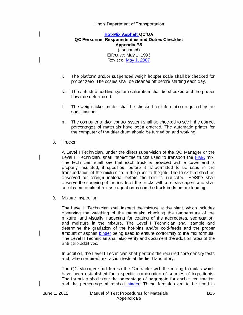
Illinois Department of Transportation
Hot-Mix Asphalt QC/QA
QC Personnel Responsibilities and Duties Checklist
Appendix B5 (continued)
Effective: May 1, 1993 Revised: May 1, 2007
June 1, 2012 Manual of Test Procedures for Materials B35 Appendix B5
j. The platform and/or suspended weigh hopper scale shall be checked for
proper zero. The scales shall be cleaned off before starting each day. k. The anti-strip additive system calibration shall be checked and the proper
flow rate determined. l. The weigh ticket printer shall be checked for information required by the
specifications. m. The computer and/or control system shall be checked to see if the correct
percentages of materials have been entered. The automatic printer for the computer of the drier drum should be turned on and working.
8. Trucks A Level I Technician, under the direct supervision of the QC Manager or the
Level II Technician, shall inspect the trucks used to transport the HMA mix. The technician shall see that each truck is provided with a cover and is properly insulated, if specified, before it is permitted to be used in the transportation of the mixture from the plant to the job. The truck bed shall be observed for foreign material before the bed is lubricated. He/She shall observe the spraying of the inside of the trucks with a release agent and shall see that no pools of release agent remain in the truck beds before loading.
9. Mixture Inspection The Level II Technician shall inspect the mixture at the plant, which includes
observing the weighing of the materials; checking the temperature of the mixture; and visually inspecting for coating of the aggregates, segregation, and moisture in the mixture. The Level I Technician shall sample and determine the gradation of the hot-bins and/or cold-feeds and the proper amount of asphalt binder being used to ensure conformity to the mix formula. The Level II Technician shall also verify and document the addition rates of the anti-strip additives.
In addition, the Level I Technician shall perform the required core density tests
and, when required, extraction tests at the field laboratory. The QC Manager shall furnish the Contractor with the mixing formulas which
have been established for a specific combination of sources of ingredients. The formulas shall state the percentage of aggregate for each sieve fraction and the percentage of asphalt binder. These formulas are to be used in

Illinois Department of Transportation
Hot-Mix Asphalt QC/QA
QC Personnel Responsibilities and Duties Checklist
Appendix B5 (continued)
Effective: May 1, 1993 Revised: May 1, 2007
June 1, 2012 Manual of Test Procedures for Materials B36 Appendix B5
proportioning the ingredient materials for HMA mixtures within the specified tolerances. Changes in the mix formulas are to be made only by the QC Manager.
It is important that the QC Manager observe the laying and compaction of the
mixture. Mixture variations are noticeable in the completed work, and variations that are
not apparent in the mixture at the plant sometimes show up as defects in the texture and uniformity of the surface. Flushing of the mixture is a defect that can be detected only on the road.
It is the duty of both the Level I and Level II Technicians to establish and
maintain an open line of communications. Timely and appropriate actions can be instituted by early detection of defects
or mixture variations. 10. Scale Checks When measurement of mixtures is on the basis of weights obtained from
batch weights or automatic printers, occasional scale checks shall be made by weighing full truckloads of the mixture on an approved platform scale at the plant site or on a commercial scale approved by the Engineer. The frequency and procedure for the check tests are described in the "Documentation" section of the [Bureau of] Construction Manual. The tests will be performed by the Level II Technician and reported on the "Daily Plant Output Report" and/or form BC 2367.
11. Samples The Level I Technician shall take check samples of the mixture in addition to
the required samples. He/She must also store split samples in a dry storage area for the Engineer. Section 1030 of the Standard Specifications discusses sampling procedures and sampling frequency.
12. Reports The Quality Control Manager is responsible for completion of a "Daily Plant
Output Report" (MI 305) for each day of production for each type of mix. Other reports, when required, are "Sample Identification" (LM-6), and Scale Checks.

Illinois Department of Transportation
Hot-Mix Asphalt QC/QA Initial Daily Plant and Random Samples
Appendix B6
Effective: May 1, 1993 Revised: May 1, 2007
June 1, 2012 Manual of Test Procedures for Materials B37 Appendix B6
Initial Daily Plant and Random Samples shall be obtained at the frequency specified in Section 1030 of the Standard Specifications. A. Truck samples shall be taken of the mixture for testing. Two sampling platforms
(one on each side of the truck) shall be provided for sampling of the mix. In order to obtain a representative sample of the entire truck, an equal amount of material shall be taken from each quarter point around the circumference of each pile in the truck to obtain a composite sample weighing approximately 150 lbs (70 kg). All truck samples shall be obtained by using a "D"-handled, square-ended shovel with built-up sides and back (1 to 1½ in. [25 to 37.5 mm]).
B. After the sample has been obtained, it shall be divided into two approximately equal
size (split) samples by the use of an approved mechanical sample splitter. One of the split samples shall be placed in a Department-approved sample container provided by the Contractor and shall be properly identified for use by the Department. These split samples shall be retained by the Contractor for assurance testing by the Engineer and may be disposed of only with the permission of the Engineer. The split samples shall be stored in a dry, protected location. The remaining split will be used for those tests described in Section 1030 of the Standard Specifications.
C. Starting with the first day of production (excluding start-up), the initial daily required
plant sample shall be obtained between the first ½ to 1½ hours of daily production of a particular mixture. These daily plant test samples shall be tested for, but not limited to, the following: 1. Bulk Specific Gravity, Gmb (d) 2. Maximum Theoretical Gravity, Gmm (D) 3. Asphalt Binder Content 4. Aggregate Gradations
a. Combined Belt
b. Individual Cold-Feeds
c. Hot-Bins
5. Total Dust Content of Mix from Ignition Oven or Solvent Extraction
D. The second daily required plant sample shall be taken at a randomly selected time within the third quarter of the anticipated production day using the "Random

Illinois Department of Transportation
Hot-Mix Asphalt QC/QA Initial Daily Plant and Random Samples
Appendix B6 (continued)
Effective: May 1, 1993 Revised: May 1, 2007
June 1, 2012 Manual of Test Procedures for Materials B38 Appendix B6
Numbers" table on the following page or the Department's QC/QA computer software. For HMA mixtures classified as “All Other” the Contractor shall use the anticipated full production day when calculating the random sampling time. The anticipated full production day shall be the time from a ½ hour after production begins to a ½ hour before production ends. The following procedure shall be used to calculate the second daily required plant sampling time.
1. Multiply the quarter production day (in minutes) by a three digit random
number, expressed as a decimal, selected from the "Random Numbers" table or the Department's QC/QA computer software.
2. The number obtained (rounded to a whole number) shall be added to the
starting time of the third quarter. The time represented by this addition is the randomly selected sampling time.
If the plant is producing HMA mixtures intermittently, the samples shall be
taken as close to the determined time as possible.
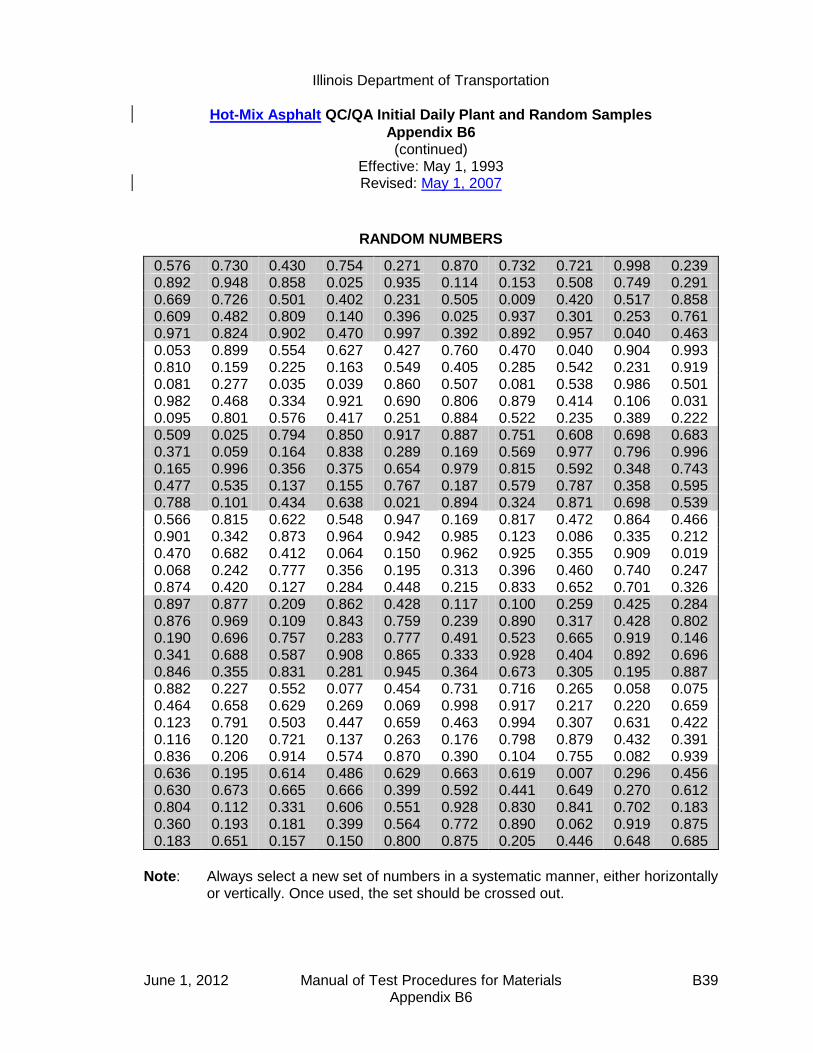
Illinois Department of Transportation
Hot-Mix Asphalt QC/QA Initial Daily Plant and Random Samples
Appendix B6 (continued)
Effective: May 1, 1993 Revised: May 1, 2007
June 1, 2012 Manual of Test Procedures for Materials B39 Appendix B6
RANDOM NUMBERS
0.576 0.730 0.430 0.754 0.271 0.870 0.732 0.721 0.998 0.239 0.892 0.948 0.858 0.025 0.935 0.114 0.153 0.508 0.749 0.291 0.669 0.726 0.501 0.402 0.231 0.505 0.009 0.420 0.517 0.858 0.609 0.482 0.809 0.140 0.396 0.025 0.937 0.301 0.253 0.761 0.971 0.824 0.902 0.470 0.997 0.392 0.892 0.957 0.040 0.463 0.053 0.899 0.554 0.627 0.427 0.760 0.470 0.040 0.904 0.993 0.810 0.159 0.225 0.163 0.549 0.405 0.285 0.542 0.231 0.919 0.081 0.277 0.035 0.039 0.860 0.507 0.081 0.538 0.986 0.501 0.982 0.468 0.334 0.921 0.690 0.806 0.879 0.414 0.106 0.031 0.095 0.801 0.576 0.417 0.251 0.884 0.522 0.235 0.389 0.222 0.509 0.025 0.794 0.850 0.917 0.887 0.751 0.608 0.698 0.683 0.371 0.059 0.164 0.838 0.289 0.169 0.569 0.977 0.796 0.996 0.165 0.996 0.356 0.375 0.654 0.979 0.815 0.592 0.348 0.743 0.477 0.535 0.137 0.155 0.767 0.187 0.579 0.787 0.358 0.595 0.788 0.101 0.434 0.638 0.021 0.894 0.324 0.871 0.698 0.539 0.566 0.815 0.622 0.548 0.947 0.169 0.817 0.472 0.864 0.466 0.901 0.342 0.873 0.964 0.942 0.985 0.123 0.086 0.335 0.212 0.470 0.682 0.412 0.064 0.150 0.962 0.925 0.355 0.909 0.019 0.068 0.242 0.777 0.356 0.195 0.313 0.396 0.460 0.740 0.247 0.874 0.420 0.127 0.284 0.448 0.215 0.833 0.652 0.701 0.326 0.897 0.877 0.209 0.862 0.428 0.117 0.100 0.259 0.425 0.284 0.876 0.969 0.109 0.843 0.759 0.239 0.890 0.317 0.428 0.802 0.190 0.696 0.757 0.283 0.777 0.491 0.523 0.665 0.919 0.146 0.341 0.688 0.587 0.908 0.865 0.333 0.928 0.404 0.892 0.696 0.846 0.355 0.831 0.281 0.945 0.364 0.673 0.305 0.195 0.887 0.882 0.227 0.552 0.077 0.454 0.731 0.716 0.265 0.058 0.075 0.464 0.658 0.629 0.269 0.069 0.998 0.917 0.217 0.220 0.659 0.123 0.791 0.503 0.447 0.659 0.463 0.994 0.307 0.631 0.422 0.116 0.120 0.721 0.137 0.263 0.176 0.798 0.879 0.432 0.391 0.836 0.206 0.914 0.574 0.870 0.390 0.104 0.755 0.082 0.939 0.636 0.195 0.614 0.486 0.629 0.663 0.619 0.007 0.296 0.456 0.630 0.673 0.665 0.666 0.399 0.592 0.441 0.649 0.270 0.612 0.804 0.112 0.331 0.606 0.551 0.928 0.830 0.841 0.702 0.183 0.360 0.193 0.181 0.399 0.564 0.772 0.890 0.062 0.919 0.875 0.183 0.651 0.157 0.150 0.800 0.875 0.205 0.446 0.648 0.685
Note: Always select a new set of numbers in a systematic manner, either horizontally or vertically. Once used, the set should be crossed out.

June 1, 2012 Manual of Test Procedures for Materials B40 Appendix B6
This Page Reserved

Illinois Department of Transportation
Determination of Random Density Locations
Appendix B7
Effective: May 1, 1993 Revised: April 1, 2011
June 1, 2012 Manual of Test Procedures for Materials B41 Appendix B7
Density tests (core or nuclear gauge) shall be performed at randomly located sites based on the frequency specified in Section 1030 of the Standard Specifications. The random test locations shall be determined as follows: A. The beginning station number shall be established daily and the estimated paving
distance computed for the day's production. The total distance to be paved shall then be subdivided into units representing 2640-ft. (800-m) or 1320-ft. (400-m) frequency.
B. The length of each unit shall be multiplied by the three digit random number
expressed as a decimal from the "Random Numbers" table on the following page or from the Department's QC/QA computer software. The number obtained shall be added to the beginning station number for the unit to determine the center of the test site location.
C. This process shall be repeated for the subsequent units for the day's production
using a new random number for each location. D. The partial unit at the end of each day shall be considered a whole unit, and the
test location shall be determined by multiplying the partial distance by the next available random number.

Illinois Department of Transportation
Determination of Random Density Locations
Appendix B7 (continued)
Effective: May 1, 1993 Revised: April 1, 2011
June 1, 2012 Manual of Test Procedures for Materials B42 Appendix B7
RANDOM NUMBERS
0.576 0.730 0.430 0.754 0.271 0.870 0.732 0.721 0.998 0.239 0.892 0.948 0.858 0.025 0.935 0.114 0.153 0.508 0.749 0.291 0.669 0.726 0.501 0.402 0.231 0.505 0.009 0.420 0.517 0.858 0.609 0.482 0.809 0.140 0.396 0.025 0.937 0.301 0.253 0.761 0.971 0.824 0.902 0.470 0.997 0.392 0.892 0.957 0.040 0.463 0.053 0.899 0.554 0.627 0.427 0.760 0.470 0.040 0.904 0.993 0.810 0.159 0.225 0.163 0.549 0.405 0.285 0.542 0.231 0.919 0.081 0.277 0.035 0.039 0.860 0.507 0.081 0.538 0.986 0.501 0.982 0.468 0.334 0.921 0.690 0.806 0.879 0.414 0.106 0.031 0.095 0.801 0.576 0.417 0.251 0.884 0.522 0.235 0.389 0.222 0.509 0.025 0.794 0.850 0.917 0.887 0.751 0.608 0.698 0.683 0.371 0.059 0.164 0.838 0.289 0.169 0.569 0.977 0.796 0.996 0.165 0.996 0.356 0.375 0.654 0.979 0.815 0.592 0.348 0.743 0.477 0.535 0.137 0.155 0.767 0.187 0.579 0.787 0.358 0.595 0.788 0.101 0.434 0.638 0.021 0.894 0.324 0.871 0.698 0.539 0.566 0.815 0.622 0.548 0.947 0.169 0.817 0.472 0.864 0.466 0.901 0.342 0.873 0.964 0.942 0.985 0.123 0.086 0.335 0.212 0.470 0.682 0.412 0.064 0.150 0.962 0.925 0.355 0.909 0.019 0.068 0.242 0.777 0.356 0.195 0.313 0.396 0.460 0.740 0.247 0.874 0.420 0.127 0.284 0.448 0.215 0.833 0.652 0.701 0.326 0.897 0.877 0.209 0.862 0.428 0.117 0.100 0.259 0.425 0.284 0.876 0.969 0.109 0.843 0.759 0.239 0.890 0.317 0.428 0.802 0.190 0.696 0.757 0.283 0.777 0.491 0.523 0.665 0.919 0.146 0.341 0.688 0.587 0.908 0.865 0.333 0.928 0.404 0.892 0.696 0.846 0.355 0.831 0.281 0.945 0.364 0.673 0.305 0.195 0.887 0.882 0.227 0.552 0.077 0.454 0.731 0.716 0.265 0.058 0.075 0.464 0.658 0.629 0.269 0.069 0.998 0.917 0.217 0.220 0.659 0.123 0.791 0.503 0.447 0.659 0.463 0.994 0.307 0.631 0.422 0.116 0.120 0.721 0.137 0.263 0.176 0.798 0.879 0.432 0.391 0.836 0.206 0.914 0.574 0.870 0.390 0.104 0.755 0.082 0.939 0.636 0.195 0.614 0.486 0.629 0.663 0.619 0.007 0.296 0.456 0.630 0.673 0.665 0.666 0.399 0.592 0.441 0.649 0.270 0.612 0.804 0.112 0.331 0.606 0.551 0.928 0.830 0.841 0.702 0.183 0.360 0.193 0.181 0.399 0.564 0.772 0.890 0.062 0.919 0.875 0.183 0.651 0.157 0.150 0.800 0.875 0.205 0.446 0.648 0.685
Note: Always select a new set of numbers in a systematic manner, either horizontally or vertically. Once used, the set should be crossed out.

Illinois Department of Transportation
Hot-Mix Asphalt QC/QA Control Charts / Rounding Test Values
Appendix B8
Effective: May 1, 1993 Revised: January 1, 2008
June 1, 2012 Manual of Test Procedures for Materials B43 Appendix B8
A. Scope
1. All required Contractor test results, including resample tests and mixture start-up, described in Article 1030.05(g) of the Standard Specification shall be split samples and plotted on Control Charts. (No check tests shall be plotted on these Control Charts.) In addition, the Engineer's "assurance" test results shall also be displayed. The minimum frequency of such tests shall be according to Section 1030 of the Standard Specifications.
2. Control Charts shall be maintained by the Contractor in the field laboratory.
Contractor test results shall be recorded within 24 hours of sampling. The Engineer shall be provided access to the location of the Control Charts at all times.
B. General Procedures
1. Control Charts shall be computer-printed or plotted in ink on standard cross-section paper (10 divisions per 1 in. [25 mm]). The vertical scale used shall conform to the following requirements in respect to rounded values of:
Gradation - 1% per 2.5 divisions (1 in [25 mm] = 4.0%). Air Voids, Field VMA, Minus No. 200 (Minus 75-µm), Field Density - 0.1% per division (1 in. [25 mm] = 1.0%). Asphalt Binder Content — 0.1% per 5 divisions (1 in. [25 mm] = 0.2%). Specific Gravity (Bulk or Maximum Theoretical) - 0.001 per division (1 in. [25 mm] = 0.01).
2. The horizontal scale shall be arranged such that each randomly selected test value obtained is plotted at ½ in. (12.5-mm) intervals. (See Figure 1.)
C. Symbols and Control Limits
1. Individual test values shall be represented on Control Charts by open circles centered on the correct test value except that washed ignition oven gradations shall be denoted by a solid circle. Moving average values shall be represented by open squares centered on the correct value. State assurance test values

Illinois Department of Transportation
Hot-Mix Asphalt QC/QA Control Charts / Rounding Test Values
Appendix B8
Effective: May 1, 1993 Revised: January 1, 2008
June 1, 2012 Manual of Test Procedures for Materials B44 Appendix B8
shall be represented by solid triangles for washed ignition gradations and by open triangles for dry gradations. All symbols shall be 0.1 in. (2.5 mm) in their largest dimension.
2. Individual test values shall be connected by dashed lines. Department
assurance test values shall not be connected with any other point. Moving average data points shall be connected by solid lines.
3. Target values shall be represented on Control Charts by horizontal solid lines.
Appropriate control limits (solid lines) for each control parameter shall extend horizontally across the chart and be identified with an appropriate solid symbol corresponding to the type of test it represents, i.e., individual or moving average.
D. Individual Test Values and Moving Average
1. Moving averages are applicable to all values except Department assurance split samples. The moving average is the average of four consecutive test values and is determined by starting with the fourth test value and averaging it with the three preceding test values. Plotting the average thereafter will be done in a similar manner starting with the test value just completed. Rounding procedures for the moving average are the same as used for the individual test values.
The moving average for minus 200 (minus 75 µm) for HMA production control shall include both washed ignition oven gradation and adjusted dry gradation individual results. When a given sublot includes both washed ignition and dry gradation test results for the minus 200 (minus 75 µm), only the washed ignition shall be used in the moving average.
The moving average for Gmm of a new mixture shall be established initially with the results from the start-up and shall include more tests in the moving average as they occur until the moving average of four is established. Unless otherwise specified by the Engineer, the moving average for Gmm of a previously placed mixture shall begin with the most recent moving average of four and shall be averaged with subsequent test results.

Illinois Department of Transportation
Hot-Mix Asphalt QC/QA Control Charts / Rounding Test Values
Appendix B8
Effective: May 1, 1993 Revised: January 1, 2008
June 1, 2012 Manual of Test Procedures for Materials B45 Appendix B8
2. At the bottom of the chart under the line on which the individual test data is plotted, the following information shall be listed:
a. Date and specific time (include a.m. or p.m.) of sampling. b. Lot Number. c. Test Sequence. d. Quantity of material represented (produced since previous test). e. Initials of person performing the test. f. Use "(rs)" to denote resample.
E. Mixture Start-Up Test Values
1. Test values obtained during start-up and the Job Mix Formula (JMF) adjustment period shall be placed at the beginning of the Control Charts. Once all these required tests have been completed and their values recorded, two vertical double black lines shall be drawn on the graph ½ in. (12.5 mm) apart. This constitutes the field verification process for the mixture.
2. At the completion of the field verification, production under QC/QA shall be
initiated with the agreed upon targets and appropriate limits being placed on the graph. Individual required plant test results shall be recorded from this point on with a moving average being established at the completion of the fourth test.
F. Adjusting Targets
1. If the adjustments in gradation or asphalt binder content are required in order to maintain proper voids, they shall be made according to Section 1030.06 of the Standard Specifications and shall be appropriately documented on the Control Charts.
2. When an adjustment to the Target value is made, two vertical double black
lines shall be drawn on the graph ½ in. (12.5 mm) apart. The new target value plus upper and lower control values will be placed on the chart. The moving average will continue as though the adjustment had not taken place.

Illinois Department of Transportation
Hot-Mix Asphalt QC/QA Control Charts / Rounding Test Values
Appendix B8
Effective: May 1, 1993 Revised: January 1, 2008
June 1, 2012 Manual of Test Procedures for Materials B46 Appendix B8
G. Resample Test Values The Contractor resample tests for a failed individual test shall be the only biased
process control test placed on the Control Chart. It shall be denoted by a circle (closed for washed gradations and open for all other tests) with its value placed on the vertical line which corresponds to the time or lot from which the resample was taken. A circle shall be drawn around this value and the failed test value which the resample represents. Both the failed test value and the resample test value shall be used as individual points in determining moving averages.
H. Rounding Test Values
1. The intent of rounding is to limit the number of digits in an observed or calculated value to those considered significant for the purpose of determining conformance with specification limits.
If improperly applied, rounding may contribute to loss of precision and result in
increased risk to either the Department or Contractor. The following are the appropriate significant digits to which test values are to
be rounded for parameters described in the Section 1030:
Test Significant Digit Gradation (% Passing);
Nearest whole percent (no decimal)
Field Density: Air Voids; Minus No. 200 (Minus 75-µm); Asphalt Binder Content
Nearest one-tenth percent (0.1%)
Bulk Gravity, Gmb; Maximum Gravity, Gmm
Nearest one-thousandth (0.001)
Rounding of test results shall be according to Illinois-Modified ASTM E 29,
"Standard Practice for Using Significant Digits in Test Data to Determine Conformance with Specifications", located in this manual.

Illinois Department of Transportation
Hot-Mix Asphalt Mixture Design Verification Procedure
Appendix B9
Effective Date: January 1, 2002 Revised: January 1, 2013
January 1, 2013 Manual of Test Procedures for Materials B47 Appendix B9
1.0 GENERAL Contractors shall provide all hot-mix asphalt (HMA) mix designs for use on
Department contracts. All mix designs must provide mixture meeting Department mix criteria. The Department will provide current aggregate bulk specific gravity. The Engineer reserves the right to be present for the sampling of all aggregates for mix designs. Once verified, a mix design will be approved for use for a three year period. After three years, the mix design shall be redesigned if necessary, and re-verified.
2.0 PURPOSE Establish a verification procedure to evaluate Contractor mix designs for use on
Department contracts. This procedure also allows for comparison of the test accuracy and precision between laboratories.
3.0 REQUIRED DESIGN DATA/MATERIAL SAMPLES 3.1 The Contractor shall provide a mix design prepared by a Hot-Mix Asphalt Level III
Technician in accordance with the Department's "Hot-Mix Asphalt Design Procedure" in the current Hot-Mix Asphalt Level III Technician Course manual. All testing shall be performed by Hot-Mix Asphalt Level I Technicians or higher. The mix design shall be submitted with the following design data:
A. The material name, material code number, source name, source
Producer/Supplier Number, and source location shall be provided for all materials used in the mix design.
B. The Contractor shall provide the average mix plant stockpile gradations and
aggregate blend percentages used to design the mix. Each of the individual aggregate gradations used in the Contractor design shall be an average of a minimum of 5 (five) stockpile gradations from existing stockpiles at the plant. Adjusted average aggregate source gradations (stockpile gradations preferred) may be substituted if aggregate has not been shipped to the mix plant. The adjustment shall be based on the amount of aggregate degradation during shipment to, and handling at, the mix plant. A design using gradation information not comparing to mix plant or aggregate source gradations shall be considered unacceptable.
Illinois Department of Transportation
Hot-Mix Asphalt Mixture Design Verification Procedure
Appendix B9 (continued)
Effective Date: January 1, 2002 Revised: January 1, 2013
January 1, 2013 Manual of Test Procedures for Materials B48 Appendix B9
C. The Contractor shall provide a summary of design test data and optimum design data utilizing a design package with the same output format as CARE-AC.
(1) Design sheet. The design shall contain a minimum of four design
points, two of which shall bracket the optimum design asphalt binder
(AB) content by at least 0.5%. Under remarks include: short-term aging time, dust correction factor, compaction temperature, and mixing temperature.
(2) Design summary data sheet (in CARE-AC format). (3) Actual graph paper from the stability machine and actual Gmm lab
worksheets (original copy unless otherwise specified). (4) Batching worksheet. (5) Dust correction worksheet (include an example packet, such as the
one from the Level III manual). (6) Batching sources sheet.
(7) Mix design graphs (full page).
(a) Gradation (45 power curve). (b) Asphalt Binder Content vs. Gmb/Gmm. (c) Asphalt Binder Content vs. VMA. (d) Asphalt Binder Content vs. Air Voids. (e) Asphalt Binder Content vs. Voids Filled with Asphalt (VFA).
(8) Recalculations and/or retested points (e.g., recalculated Gmm's using
average Gse).
(9) TSR worksheet.
The forms used shall be the Department's computer spreadsheet from CARE-AC, or other forms having the same format as CARE-AC.
Illinois Department of Transportation
Hot-Mix Asphalt Mixture Design Verification Procedure
Appendix B9 (continued)
Effective Date: January 1, 2002 Revised: January 1, 2013
January 1, 2013 Manual of Test Procedures for Materials B49 Appendix B9
3.2 The Contractor shall provide samples of blended aggregate, asphalt binder, and additives which represent the materials in the mix design. The representative samples shall be identified and submitted as follows:
A. Aggregate (including mineral filler/collected dust) -- Dried, split into the individual
sizes specified for the Batching Worksheet as stated in the current Hot-Mix Asphalt Level III Technician Course manual, and then blended to the chosen gradation. The amount submitted shall be two (2) 10,000-gram samples of dry aggregate, with an additional 2,000 grams for gradation testing if requested by the District. All material shall be bagged in plastic bags or other airtight containers. Each container shall be identified with the source names, source locations, source Producer/Supplier Numbers, material codes, sample location, and sample date.
B. Asphalt Binder -- A minimum of 4 qts (4,000 mL ). Identified with source name,
source location, source Producer/Supplier Number, material code, sample location, and sample date.
C. Additive(s) -- The same additive(s) as used in the Contractor's design, identified
by the additive source name, source location, brand name or number, material code, sample location, sample date, additive MSDS, the manufacturer's recommended dosage rate, and the rate used in the design if different than the manufacturer's recommended dosage rate. NOTE: Prior to submitting the additive(s), the Contractor shall contact the District Materials Engineer for the required sample size.
3.3 All design data and material samples shall be submitted to the Department a
minimum of 30 calendar days prior to production. 3.4 The Contractor shall certify in writing that all materials submitted for mix design
verification meet Department requirements and represent the materials to be used during mix production.
3.5 Previously verified mix designs shall be resubmitted for verifications as per
Section 4.1 herein. 4.0 DEPARTMENT VERIFICATION 4.1 At the option of the Department, mix designs may be verified using either Method A
or Method B listed below:
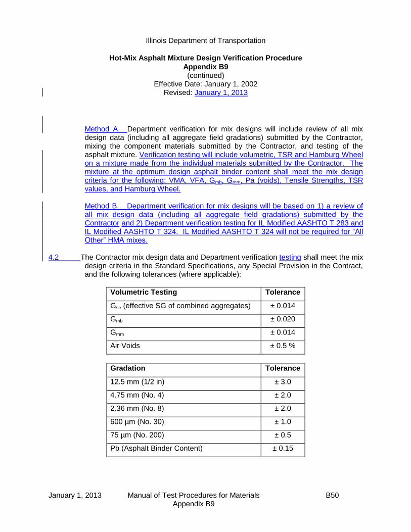
Illinois Department of Transportation
Hot-Mix Asphalt Mixture Design Verification Procedure
Appendix B9 (continued)
Effective Date: January 1, 2002 Revised: January 1, 2013
January 1, 2013 Manual of Test Procedures for Materials B50 Appendix B9
Method A. Department verification for mix designs will include review of all mix design data (including all aggregate field gradations) submitted by the Contractor, mixing the component materials submitted by the Contractor, and testing of the asphalt mixture. Verification testing will include volumetric, TSR and Hamburg Wheel on a mixture made from the individual materials submitted by the Contractor. The mixture at the optimum design asphalt binder content shall meet the mix design criteria for the following: VMA, VFA, Gmb, Gmm, Pa (voids), Tensile Strengths, TSR values, and Hamburg Wheel.
Method B. Department verification for mix designs will be based on 1) a review of
all mix design data (including all aggregate field gradations) submitted by the Contractor and 2) Department verification testing for IL Modified AASHTO T 283 and IL Modified AASHTO T 324. IL Modified AASHTO T 324 will not be required for “All Other” HMA mixes.
4.2 The Contractor mix design data and Department verification testing shall meet the mix
design criteria in the Standard Specifications, any Special Provision in the Contract, and the following tolerances (where applicable):
Volumetric Testing Tolerance
Gse (effective SG of combined aggregates) ± 0.014
Gmb ± 0.020
Gmm ± 0.014
Air Voids ± 0.5 %
Gradation Tolerance
12.5 mm (1/2 in) ± 3.0
4.75 mm (No. 4) ± 2.0
2.36 mm (No. 8) ± 2.0
600 µm (No. 30) ± 1.0
75 µm (No. 200) ± 0.5
Pb (Asphalt Binder Content) ± 0.15

Illinois Department of Transportation
Hot-Mix Asphalt Mixture Design Verification Procedure
Appendix B9 (continued)
Effective Date: January 1, 2002 Revised: January 1, 2013
January 1, 2013 Manual of Test Procedures for Materials B51 Appendix B9
All aggregate field gradations submitted by the Contractor will be compared to previous mix plant and/or Aggregate Gradation Control System gradations for validity.
4.3 The Department will notify the Contractor in writing within 30 calendar days of
receiving the design data/materials as to the acceptability of the submitted Contractor mix design. If the verification fails, the 30-calendar-day time for the Department to notify the Contractor starts over. Acceptable designs may be used in Department contracts, provided the design is reproducible in the mix plant.

January 1, 2013 Manual of Test Procedures for Materials B52 Appendix B9
This Page Reserved

Illinois Department of Transportation
Illinois Test Procedure 401
Storage of Hot-Mix Asphalt Mixtures
Appendix B10
Effective: January 1, 2002 Revised: May 1, 2007
June 1, 2012 Manual of Test Procedures for Materials B53 Appendix B10
1.0 SCOPE
1.1 The purpose of this procedure is to evaluate the effect of 20-hour storage on hot-mix asphalt.
1.2 Article 1102.01(a)(10) of the IDOT Standard Specifications for Road and
Bridge Construction allows for the storage of hot-mix asphalt in surge systems designed and operated to prevent segregation and loss of temperature. The specification allows for a maximum retention of eight hours. Longer retention times must be approved in writing by the Engineer.
2.0 REFERENCED DOCUMENTS
2.1 Illinois Modified AASHTO T 164, Method A or E 2.2 Illinois Modified AASHTO T 170
3.0 EQUIPMENT
3.1 One-quart (1-liter) and 1-gallon (4-liter) metal containers with lids for sample storage and transportation.
4.0 PROCEDURE 4.1 The Bureau of Materials and Physical Research will evaluate the effect of
additional storage time on the mixture. The Engineer will direct the Contractor to sample the mixture based on the following procedure. The Engineer reserves the right to witness the sampling.
4.2 The Contractor shall provide a minimum of 20 hours of uninterrupted
storage of the mixture to be sampled. 4.3 The bin must be filled with a binder mixture at a time mutually agreed
upon by the Contractor and Engineer. 4.4 A 1-quart (1-liter) sample of the asphalt binder shall be taken at this time. 4.5 A 1-gallon (4-liter) sample of the mixture shall be taken at this time.

Illinois Department of Transportation
Illinois Test Procedure 401
Storage of Hot-Mix Asphalt Mixtures
Appendix B10 (continued)
Effective: January 1, 2002 Revised: May 1, 2007
June 1, 2012 Manual of Test Procedures for Materials B54 Appendix B10
4.6 An additional 1-gallon (4-liter) mixture sample will be taken 20 hours after initial storage.
4.7 Samples shall be drawn from the silo by dumping the mixture into a truck
and sampling from the truck. All samples should be large enough to fill the metal container.
4.8 Each sample container shall be sealed immediately and marked with the
producer's or supplier's name and number, plant location, date, time, type of mixture, mixture temperature, and asphalt binder source and grade.
Note: If the sample container does not stay sealed, the container may
be cooled with the sample before sealing.
4.9 The samples should be immediately forwarded to the Bureau of Materials and Physical Research for evaluation.
4.10 Asphalt binder recovered from the mixture samples will be tested for the
effects of increased storage time on viscosity.
Grade Viscosity at 60 °C,
Pascal Seconds, Maximum
PG 64-28 125
PG 58-28 250
PG 58-22 500
PG 64-22 1000
PG 70-22 (neat) 2000
4.11 The test results of the initial mixture sample shall be used for
informational purposes only. 4.12 Approval will be based on the test results from the final mixture sample. 4.13 Test Method A or E of Illinois Modified AASHTO T 164, "Quantitative
Extraction of Bitumen from Bituminous Paving Mixtures," shall be used to extract asphalt binder from mixture samples.
4.14 The procedure for recovery of the extracted asphalt shall be Illinois
Modified AASHTO T 170, "Recovery of Asphalt from Solution by Abson Method."

Illinois Department of Transportation
Calibration of Equipment for Asphalt Binder Content Determination
(Nuclear Gauge and Ignition Oven)
Appendix B11
Effective Date: January 1, 2002 Revised: May 1, 2007
June 1, 2012 Manual of Test Procedures for Materials B55 Appendix B11
A. Scope The Contractor may be required to use the nuclear gauge or ignition oven to determine the asphalt binder content of a Hot-Mix Asphalt (HMA) mixture. To ensure consistency, both the Contractor and the Department shall calibrate the device(s) in the same manner using the same mixture.
B. Purpose To provide consistent calibration between the Contractor's and Department's asphalt binder content determination equipment. The procedure also applies to any third-party gauges used for Quality Control, Quality Assurance, Independent Assurance, or Acceptance testing.
C. Nuclear Asphalt Content Gauge 1. Department Verification
a. All HMA mixture designs shall be verified in accordance with the Department's "Hot-Mix Asphalt Design Verification Procedure" before submitting materials for the nuclear asphalt binder content gauge calibration.
b. The Contractor shall provide a mix design prepared by a Hot-Mix Asphalt
Level III Technician in accordance with the Department's current Hot-Mix Asphalt Level III Technician Course manual, "Hot-Mix Asphalt Design Procedure". All testing shall be performed by Hot-Mix Asphalt Level I Technicians or higher.
c. At the option of the Department, previously verified mixtures may be
accepted by reviewing the data listed in Section 11 of Illinois Modified AASHTO T 287, and provided a dry aggregate standard count is within
1.0% of the calibration aggregate count as outlined in Section 10.2 of Illinois Modified AASHTO T 287.
d. Testing shall include, at the option of the Engineer, one or both of the
following test procedures:
(1) The District has the option of witnessing the Contractor's calibration procedures as outlined in Section 7 of Illinois Modified AASHTO T 287.
Illinois Department of Transportation
Calibration of Equipment for Asphalt Binder Content Determination
(Nuclear Gauge and Ignition Oven)
Appendix B11 (continued)
Effective Date: January 1, 2002
Revised: May 1, 2007
June 1, 2012 Manual of Test Procedures for Materials B56 Appendix B11
After the Contractor has calibrated his/her nuclear asphalt binder content gauge, the calibration pans shall be covered with plastic bags (to prevent the introduction of moisture) and given to the Department's representative.
The Department will calibrate its nuclear asphalt binder content
gauge, with the same calibration pans as the Contractor used. (2) Prior to calibrating the nuclear asphalt binder content gauge, the
Contractor shall submit the following to the District office at least 2 weeks prior to production:
3 empty nuclear asphalt pans
22 lbs (10 kg) of the HMA mixture at the design optimum asphalt binder content
22 lbs (10 kg) of the HMA mixture at 1% below the optimum asphalt binder content
22 lbs (10 kg) of the HMA mixture at 1% above the optimum asphalt binder content
The actual blended aggregate, including the pan, used to determine the dry aggregate standard count
The Engineer may split out approximately 16.5-lb (7500-g ) and/or
4.4-lb (2000-g) samples out of the 22 lb (10 kg) mixture samples. The 16.5-lb (7500-g) samples shall be used in the calibration pans for both the Department and the Contractor. The 4.4-lb (2000-g) samples may be used by the Department to run extractions on the samples for verification. The extraction results shall be within the following tolerances:

Illinois Department of Transportation
Calibration of Equipment for Asphalt Binder Content Determination
(Nuclear Gauge and Ignition Oven)
Appendix B11 (continued)
Effective Date: January 1, 2002
Revised: May 1, 2007
June 1, 2012 Manual of Test Procedures for Materials B57 Appendix B11
Sieve Tolerance
12.5 mm (1/2 in.) 3.0
4.75 mm (No. 4) 2.0
2.36 mm (No. 8) 1.5
600 µm (No. 30) 1.0
75 µm (No. 200) 0.5
Pb (Asphalt Content) 0.15
If the extraction results lie outside the above tolerances Contractor
shall be required to resubmit new material as outlined above for this procedure.
The Engineer will calibrate the Department's nuclear asphalt binder
content gauges using the pans and mixture the Contractor submitted. The calibration pans will be covered with plastic bags (to prevent the introduction of moisture) and sent to the Contractor. This shall be done for all 3 points.
The Contractor shall calibrate his/her nuclear asphalt binder content
gauges, with the same calibrations pans as the Department used, within 24 hours of receiving the samples from the Department.
2. Calibration
a. The Contractor shall calibrate his/her nuclear asphalt binder content gauge only after the Department has verified the calibration samples as outlined above in Section C.1.
b. The Contractor shall retain the calibration pans. These pans shall be
covered with plastic bags and stored in a dry, secure place. c. Calibration shall be done after a mixture is designed, an approved Job
Mix Formula (JMF) is established, and the mixture has been verified by the Department. Calibration before the mixture is designed is not allowed since this would not necessarily allow for the proper range of asphalt binder content, and the job mix gradation would not be known. The calibration temperature for both the dry aggregate count and the HMA
mixture count shall be within 10 °F ( 6 °C ) of each other and be within
the range of 180 to 290 °F ( 82 to 143 °C).

Illinois Department of Transportation
Calibration of Equipment for Asphalt Binder Content Determination
(Nuclear Gauge and Ignition Oven)
Appendix B11 (continued)
Effective Date: January 1, 2002
Revised: May 1, 2007
June 1, 2012 Manual of Test Procedures for Materials B58 Appendix B11
D. Ignition Oven 1. Department Verification
a. All HMA mixture designs shall be verified in accordance with the Department's "Hot-Mix Asphalt Design Verification Procedure" before submitting materials for the ignition oven calibration.
b. The Contractor shall provide a mix design prepared by an Hot-Mix
Asphalt Level III Technician in accordance with the Department's current Hot-Mix Asphalt Level III Technician Course Manual, "Hot-Mix Asphalt Design Procedure". All testing shall be performed by Hot-Mix Asphalt Level I Technicians or higher who have also successfully completed the Superpave Field Control Course.
c. Calibrations shall consist of, at the option of the Engineer, one or both of
the following procedures:
(1) The District has the option to witness the mixing and burning of the calibration sample. The Contractor shall mix enough mixture to provide the Department with calibration samples.
(2) The Contractor shall submit the following to the District office at least
two weeks prior to production:
Four individually batched, combined aggregate samples meeting the JMF. Each sample shall meet the minimum mass requirements listed in Section 5.6 of Illinois Modified AASHTO T308.
1 L (1 qt.) asphalt binder
Two samples will be used to calibrate the District's ignition oven. If the difference between the measured asphalt binder content of the two samples exceeds 0.15%, the tests will be repeated using the two remaining samples.
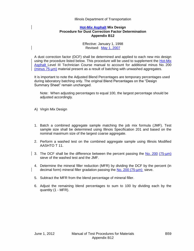
Illinois Department of Transportation
Hot-Mix Asphalt Mix Design
Procedure for Dust Correction Factor Determination
Appendix B12
Effective: January 1, 1998 Revised: May 1, 2007
June 1, 2012 Manual of Test Procedures for Materials B59 Appendix B12
A dust correction factor (DCF) shall be determined and applied to each new mix design using the procedure listed below. This procedure will be used to supplement the Hot-Mix Asphalt Level III Technician Course manual to account for additional minus No. 200 (minus 75-µm) material present as a result of batching with unwashed aggregates. It is important to note the Adjusted Blend Percentages are temporary percentages used during laboratory batching only. The original Blend Percentages on the “Design Summary Sheet” remain unchanged.
Note: When adjusting percentages to equal 100, the largest percentage should be adjusted accordingly.
A) Virgin Mix Design
1. Batch a combined aggregate sample matching the job mix formula (JMF). Test
sample size shall be determined using Illinois Specification 201 and based on the nominal maximum size of the largest coarse aggregate.
2. Perform a washed test on the combined aggregate sample using Illinois Modified
AASHTO T 11. 3. The DCF shall be the difference between the percent passing the No. 200 (75-µm)
sieve of the washed test and the JMF. 4. Determine the mineral filler reduction (MFR) by dividing the DCF by the percent (in
decimal form) mineral filler gradation passing the No. 200 (75-µm) sieve. 5. Subtract the MFR from the blend percentage of mineral filler. 6. Adjust the remaining blend percentages to sum to 100 by dividing each by the
quantity (1 - MFR).

Illinois Department of Transportation
Hot-Mix Asphalt Mix Design
Procedure for Dust Correction Factor Determination
Appendix B12 (continued)
Effective: January 1, 1998 Revised: May 1, 2007
June 1, 2012 Manual of Test Procedures for Materials B60 Appendix B12
Example
Bituminous Mixture Design
Design Number:-------> 50BITEXPL
Lab preparing the design?(PP,PL,IL ect.) IDOTProducer Name & Number--> 1111-01 Example Company Inc Somewhere 1, ILMaterial Code Number---> 17552 BITCONC BCS 1 B TONS
Agg No. #1 #2 #3 #4 #5 #6 ASPHALTSize 032CMM11 032CMM16 038FAM20 037FAM01 004MFM01 10124M
Source (PROD#) 51972-02 51972-02 51230-06 51790-04 51052-04
(NAME) MAT SER MAT SER MIDWEST CONICK LIVINGSTON 2260-01
(LOC) EMLSCOAT
Aggregate Blend 38.0 35.0 14.5 10.0 2.5 0.0 100.0
Agg No. #1 #2 #3 #4 #5 #6 Blend
Sieve Size1 100.0 100.0 100.0 100.0 100.0 100.0 100.0
3/4 88.0 100.0 100.0 100.0 100.0 100.0 95.4
1/2 45.0 100.0 100.0 100.0 100.0 100.0 79.13/8 19.0 97.0 100.0 100.0 100.0 100.0 68.2
#4 6.0 29.0 97.0 97.0 100.0 100.0 38.7
#8 2.0 7.0 80.0 85.0 100.0 100.0 25.8#16 2.0 4.0 50.0 65.0 100.0 100.0 18.4
#30 1.8 3.0 35.0 43.0 100.0 100.0 13.6
#50 1.7 3.0 19.0 16.0 100.0 100.0 8.6#100 1.5 3.0 10.0 5.0 90.0 100.0 5.8
#200 1.3 1.3 4.0 2.5 88.0 100.0 4.0
Step 1. Batch a combined aggregate sample meeting the JMF. Illinois
Specification 201 requires a 5000-gram sample when CM11 is present.
Step 2. Run a washed test using AASHTO T 11.
Step 3. Determine the Dust Correction Factor (DCF). The DCF is the difference in the percent passing the No. 200 (75-µm) sieve between the washed test and the JMF:
JMF Washed Test DCF
No. 200 (75 µm) 4.0% 5.6% 1.6%

Illinois Department of Transportation
Hot-Mix Asphalt Mix Design
Procedure for Dust Correction Factor Determination
Appendix B12 (continued)
Effective: January 1, 1998 Revised: May 1, 2007
June 1, 2012 Manual of Test Procedures for Materials B61 Appendix B12
Step 4. Determine the Mineral Filler Reduction (MFR) by dividing the DCF (%) by the percent (in decimal form) mineral filler gradation passing the No. 200 (75-µm) sieve:
MFR (%) = 1.6 / 0.88 = 1.8%
Step 5. Determine the adjusted mineral filler blend percentage by subtracting the MFR (%) from the blend percentage of mineral filler:
2.5% - 1.8% = 0.7%
Step 6. Adjust the remaining blend percentages to sum to 100 by dividing each by
the quantity [1 - MFR (in decimal form)]:
Blend
Percentage
Adjusted
Blend
Percentage1
032CMM11 38.0 38.7
032CMM16 35.0 35.6
038FAM20 14.5 14.8
037FAM01 10.0 10.2
004MFM01 2.5 0.7
100.0 100.0
Note 1: It is important to note the Adjusted Blend Percentages are temporary percentages used during laboratory batching only. The original Blend Percentages on the “Design Summary Sheet” remain unchanged.
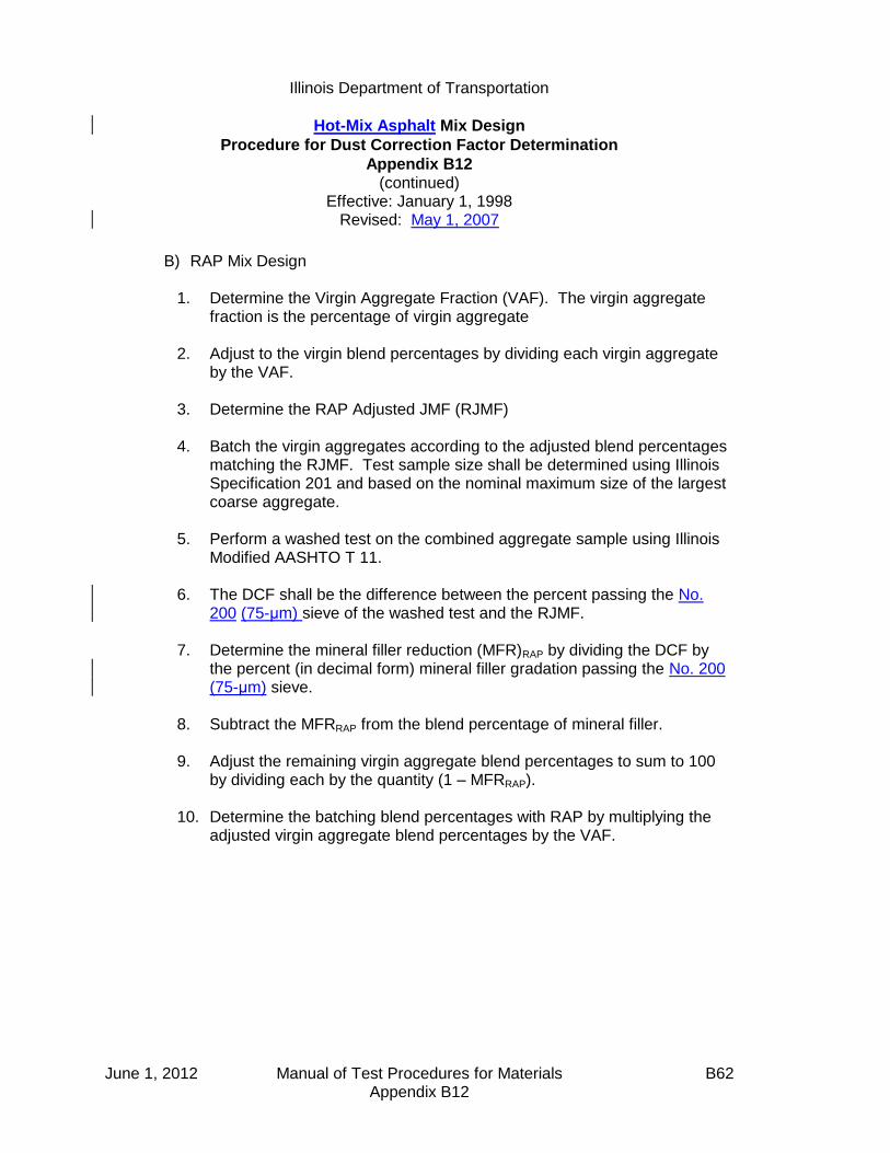
Illinois Department of Transportation
Hot-Mix Asphalt Mix Design
Procedure for Dust Correction Factor Determination
Appendix B12 (continued)
Effective: January 1, 1998 Revised: May 1, 2007
June 1, 2012 Manual of Test Procedures for Materials B62 Appendix B12
B) RAP Mix Design
1. Determine the Virgin Aggregate Fraction (VAF). The virgin aggregate fraction is the percentage of virgin aggregate
2. Adjust to the virgin blend percentages by dividing each virgin aggregate by the VAF.
3. Determine the RAP Adjusted JMF (RJMF)
4. Batch the virgin aggregates according to the adjusted blend percentages matching the RJMF. Test sample size shall be determined using Illinois Specification 201 and based on the nominal maximum size of the largest coarse aggregate.
5. Perform a washed test on the combined aggregate sample using Illinois Modified AASHTO T 11.
6. The DCF shall be the difference between the percent passing the No. 200 (75-μm) sieve of the washed test and the RJMF.
7. Determine the mineral filler reduction (MFR)RAP by dividing the DCF by the percent (in decimal form) mineral filler gradation passing the No. 200 (75-μm) sieve.
8. Subtract the MFRRAP from the blend percentage of mineral filler.
9. Adjust the remaining virgin aggregate blend percentages to sum to 100 by dividing each by the quantity (1 – MFRRAP).
10. Determine the batching blend percentages with RAP by multiplying the adjusted virgin aggregate blend percentages by the VAF.
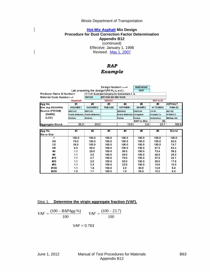
Illinois Department of Transportation
Hot-Mix Asphalt Mix Design
Procedure for Dust Correction Factor Determination
Appendix B12 (continued)
Effective: January 1, 1998 Revised: May 1, 2007
June 1, 2012 Manual of Test Procedures for Materials B63 Appendix B12
RAP
Example
Step 1. Determine the virgin aggregate fraction (VAF).
100
%)100( RAPAggVAF
100
)7.23100( VAF
VAF = 0.763
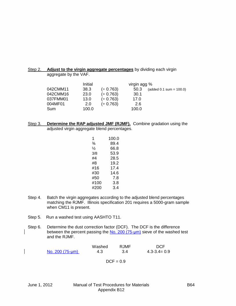
June 1, 2012 Manual of Test Procedures for Materials B64 Appendix B12
Step 2. Adjust to the virgin aggregate percentages by dividing each virgin aggregate by the VAF. Initial virgin agg % 042CMM11 38.3 (÷ 0.763) 50.3 (added 0.1 sum = 100.0) 042CMM16 23.0 (÷ 0.763) 30.1 037FMM01 13.0 (÷ 0.763) 17.0 004MF01 2.0 (÷ 0.763) 2.6 Sum 100.0 100.0
Step 3. Determine the RAP adjusted JMF (RJMF). Combine gradation using the adjusted virgin aggregate blend percentages.
1 100.0 ¾ 89.4 ½ 66.8 3/8 53.9 #4 28.5 #8 19.2 #16 17.4 #30 14.6 #50 7.8 #100 3.8 #200 3.4
Step 4. Batch the virgin aggregates according to the adjusted blend percentages matching the RJMF. Illinois specification 201 requires a 5000-gram sample when CM11 is present.
Step 5. Run a washed test using AASHTO T11. Step 6. Determine the dust correction factor (DCF). The DCF is the difference
between the percent passing the No. 200 (75-μm) sieve of the washed test and the RJMF. Washed RJMF DCF No. 200 (75-μm) 4.3 3.4 4.3-3.4= 0.9 DCF = 0.9

Illinois Department of Transportation
Hot-Mix Asphalt Mix Design
Procedure for Dust Correction Factor Determination
Appendix B12 (continued)
Effective: January 1, 1998 Revised: May 1, 2007
June 1, 2012 Manual of Test Procedures for Materials B65 Appendix B12
Step 7. Determine the mineral filler reduction (MFR)RAP. The (MFR)RAP is determined by dividing the DCF by the percent (in decimal form) mineral filler gradation passing the No. 200 (75-μm) sieve.
%1.185.0
9.0RAPMFR
Step 8. Determine the mineral filler blend percentage by subtracting the MFRRAP from
the blend percentage of mineral filler. 2.6 – 1.1 = 1.5%
Step 9. Adjust the remaining blend percentages to sum to 100% by dividing each by the quantity [1-MFRRAP (in decimal form)]: 1 – MFRRAP = 1 – 0.011 = 0.989 Virgin % Adj Virgin Blend% 042CMM11 50.3 (÷ 0.989) 50.9 042CMM16 30.1 (÷ 0.989) 30.4 037FMM01 17.0 (÷ 0.989) 17.2 004MF01 2.6 (from step 8) 1.5 Sum 100.0 100.0
Step 10. Determine the batching blend percentages with RAP by multiplying the adjusted virgin blend % by the VAF. VAF = 0.763 Adjusted Virgin % Batching Blend % 042CMM11 50.9 (x 0.763) 38.9 (added 0.1 sum = 100.0) 042CMM16 30.4 (x 0.763) 23.2 037FMM01 17.2 (x 0.763) 13.1 004MF01 1.5 (x 0.763) 1.1 RAPAgg 23.7 Sum 100.0

June 1, 2012 Manual of Test Procedures for Materials B66 Appendix B12
This Page Reserved
Illinois Department of Transportation
Illinois Test Procedure 403
Calibration of the Ignition Oven for the Purpose of Characterizing
Reclaimed Asphalt Pavements (RAP)
Appendix B13
Effective Date: January 1, 2002
Revised: May 1, 2007
June 1, 2012 Manual of Test Procedures for Materials B67 Appendix B13
1.0 GENERAL 1.1 This method covers the calibration of the ignition oven for
characterization of reclaimed asphalt pavement (RAP). Correction factors for both gradation and asphalt content are determined by conducting parallel ignition and extraction testing.
2.0 SIGNIFICANCE AND USE
2.1 The ignition oven may be used in place of solvent extractions at the frequency stated in Section 1031 of the Standard Specifications.
2.2 This method may be used only with the approval of the Engineer. 2.3 Each RAP stockpile shall require a separate ignition oven calibration. 2.4 All RAP stockpiles and sampling frequencies shall meet the requirements
stated in Section 1031 of the Standard Specifications.
3.0 REFERENCED DOCUMENTS
3.1 AASHTO Standards (as modified by Illinois): T 2 Sampling of Aggregates T 164 Quantitative Extraction of Bitumen from Bituminous Paving
Mixtures T 248 Reducing Field Samples of Aggregate to Testing Size T 308 Determining the Asphalt Binder Content of Hot-Mix Asphalt (HMA)
by the Ignition Method
4.0 PROCEDURE
4.1 Sample the RAP according to AASHTO T 2. Obtain an adequate amount of material to perform a minimum of two solvent extractions and four ignition oven burns. The minimum sample sizes shall be governed by the nominal maximum aggregate size of the mixture defined in Illinois Modified AASHTO T 164 and T 308. Reduce the samples to testing size according to Illinois Modified AASHTO T 248.
Illinois Department of Transportation
Illinois Test Procedure 403
Calibration of the Ignition Oven for the Purpose of Characterizing
Reclaimed Asphalt Pavements (RAP)
Appendix B13 (continued)
Effective January 1, 2002 Revised: May 1, 2007
June 1, 2012 Manual of Test Procedures for Materials B68 Appendix B13
4.2 Perform a minimum of two solvent extractions and a minimum of four ignition oven burns according to AASHTO T 164 and Illinois-Modified AASHTO T 308, respectively.
4.3 AB Binder Calibration 4.3.1 Calculate the average Asphalt Binder (AB) percentage of the two
extractions, Pext. Calculate the average AB percentage of the four ignition oven burns, Pign. Assuming the average AB content from the extraction to be correct, subtract the average extraction AB percentage from the average ignition oven AB percentage to determine the asphalt correction factor, Cf.
Cf = Pign - Pext
Use the asphalt correction factor to adjust the ignition oven asphalt
content on all subsequent testing of that stockpile.
4.4 Gradation Calibration 4.4.1 From the two extractions, calculate the average percent passing the
applicable sieve, Gext. Calculate the average percent passing each applicable sieve from the four ignition oven burns, Gign. Subtract the extraction average percent passing each sieve from the ignition oven average of the corresponding sieve to determine a correction factor, GCf, for gradation for each sieve.
GCf = Gign - Gext
5.0 REPORT 5.1 Report the correction factors to the nearest 0.1%
6.0 PRECISION AND BIAS 6.1 The estimates of precision and bias shall be considered those that apply
to the referenced documents.

Illinois Department of Transportation
Illinois Test Procedure 403
Calibration of the Ignition Oven for the Purpose of Characterizing
Reclaimed Asphalt Pavements (RAP)
Appendix B13 (continued)
Effective January 1, 2002 Revised: May 1, 2007
June 1, 2012 Manual of Test Procedures for Materials B69 Appendix B13
7.0 USE
7.1 Use the correction factor for percent passing the No. 200 (75-m) sieve
to adjust the minus No. 200 (75-m) material from the ignition oven on all subsequent testing of that stockpile.
7.2 Use the asphalt correction factor to adjust the ignition oven asphalt
content on all subsequent testing of that stockpile. 7.3 The ignition oven washed gradations may be used uncorrected for all
sieves except for the No. 200 (75-m) sieve.

June 1, 2012 Manual of Test Procedures for Materials B70 Appendix B13
This Page Reserved

Illinois Department of Transportation
Truck Sample Splitting Diagram Appendix B14
Effective: January 1, 2002 Revised: May 1, 2007
June 1, 2012 Manual of Test Procedures for Materials B71 Appendix B14
Truck Sample 150 lbs (68 kg)
lllcwerlbs)lbs.)
75 lbs. (34 kg) +/- State
Sample 75 lbs. (34 kg) +/-
38 lbs. (17 kg) +/- 38 lbs. (17 kg) +/-
19 lbs. (8.5 kg) +/- 19 lbs. (8.5 kg) +/-
9.5 lbs. (4.3 kg) +/- 9.5 lbs. (4.3 kg) +/-
48 lbs. (21 kg) +/-
24 lbs. (10.5 kg) +/-
24 lbs (10.5 kg) +/-
+/-
12 lbs. (5.3 kg) +/-
Gmb Sample
12 lbs. (5.3 kg)
+/-
Gmb Sample 12 lbs (5.3 kg) +/-
Backup
12 lbs (5.3 kg) +/-
6 lbs. (2.7 kg) +/-
Ignition Oven
Sample
6 lbs. (2.7 kg) +/-
1350 g +/-
Gmm Sample
1350 g +/-
Gmm Sample
This 48 lbs. (21 kg) sample will
produce
the following bituminous tests:
2 - Bulk Specific Gravity - Gmb
2 - Maximum Specific Gravity -
Gmm
1 - Ignition Oven
1 - Backup

June 1, 2012 Manual of Test Procedures for Materials B72 Appendix B14
This Page Reserved

Illinois Department of Transportation
Hot Mix Asphalt (HMA) Production Gradation Windage
Procedure for Minus #200 (minus 75m) Material
Appendix B15
Effective: May 1, 2004 Revised: May 1, 2007
June 1, 2012 Manual of Test Procedures for Materials B73 Appendix B15
A. Scope
The Contractor will be required to provide production gradation test results for both washed ignition oven gradations (WIOG) and dry combined belt / hot bin gradations on the same control chart according to Section 1030 of the Standard Specifications. In order for this data to be meaningful, the dry combined belt / hot bin gradations shall be calibrated to the WIOG using the windage factor established below.
B. Purpose
A windage factor (WF) shall be determined and applied to dry gradation production test results in order to establish a WIOG equivalency. The WF accounts for the
difference, in minus #200 (minus 75m) material, between dry combined belt/hot bin gradations and WIOG due to the following:
variability in the addition of Mineral Filler washed vs. dry gradation (cling-on dust) generation of dust through plant aggregate degradation
C. Procedure
The WF shall be determined during Start-up. During mix production, adjustments to the WF may be warranted. Therefore, a new WF may be established, according to the following procedure, anytime during the course of mix production.
1. Obtain two combined belt/hot bin aggregate samples and perform two dry gradation (DG) tests. The DG shall include the theoretical amount of mineral filler
to be added. Average the two test results for the minus #200 (minus 75m) material.
Average DG-#200 = (DG#1 + DG#2) / 2 2. Obtain two samples of HMA representing, near as possible, material from step
one. Perform WIOG testing on the HMA samples and average the two results
for minus the #200 (minus 75m) material.
Average WIOG-#200 = (WIOG#1 + WIOG#2) / 2
3. Determine WF by subtracting Average DG-#200 in step 1 from Average
WIOG-#200 in step 2.
WF = Average WIOG-#200 - Average DG-#200
Illinois Department of Transportation
Hot Mix Asphalt (HMA) Production Gradation Windage
Procedure for Minus #200 (minus 75m) Material
Appendix B15
(continued)
Effective: May 1, 2004 Revised: May 1, 2007
June 1, 2012 Manual of Test Procedures for Materials B74 Appendix B15
4. Add WF to all combined belt/hot bin gradation test results prior to plotting on
the Minus #200 (minus 75m) Control Chart. All, (including WIOG test results
used to establish WF, are plotted directly on the Minus #200 (minus 75m) Control Chart. When both the DG and WIOG test results represent the same material, the WIOG are the results to be included in the moving average.
Example: Given:
WIOG#1 (minus #200) = 4.8% (Truck sample taken between growth curves)
WIOG#2 (minus #200) = 4.6% (Truck sample taken from outside Test Strip area during startup)
DG#1 (minus #200) = 2.7% (Combined belt sample taken to correspond to
material sampled for WIOG#1)
DG#2 (minus #200) = 2.1% (Combined belt sample taken to correspond to
material sampled for WIOG#2)
Step 1. Average the two DG test results for the minus #200 (minus 75m) material.
Average DG-#200 = (2.7% + 2.1%) / 2 = 2.4%
Step 2. Average the two WIOG test results for the minus #200 (minus 75m) material.
Average WIOG-#200 = (4.8% + 4.6%) / 2 = 4.7%
Step 3. Determine WF by subtracting Average DG-#200 in step 1 from Average
WIOG-#200 in step 2.
WF = 4.7% - 2.4% = 2.3%
Step 4. Add WF = 2.3% to all combined belt/hot bin gradation test results prior to
plotting on the Minus #200 (minus 75m) Control Chart.

Illinois Department of Transportation
Stripping of Hot-Mix Asphalt Mixtures Visual Identification and Classification
Appendix B16
Effective: November 20, 2003 Revised: January 1, 2014
January 1, 2014 Manual of Test Procedures for Materials B75 Appendix B16
The following instructions describe the method to be used for visually identifying and classifying the effect of moisture damage on the adhesion of asphalt binder to the aggregate in Hot-Mix Asphalt (HMA) mixtures. This procedure provides the means to rate this phenomenon in numerical terms. This procedure is applicable to both laboratory compacted specimens and pavement cores1. INSTRUCTIONS 1. This procedure shall only be applied to freshly split specimen faces, such as those obtained
from split tensile testing. The observation of cored, sawed, or chiseled faces shall be avoided, as the true condition of the stripping will be obscured.
2. The rating shall be completed within 10 minutes of splitting for maximum clarity. When the
specimens dry out, they may look considerably different. The aggregate surfaces shall be examined carefully to determine if the asphalt binder was stripped from the aggregate as a result of being “washed” by water before the specimen was split or if the asphalt binder was “ripped apart” near the asphalt/aggregate interface during the split tensile test. Also, aggregate surfaces with small, relatively isolated, globules of asphalt binder are quite likely not stripped.
3. Special attention shall be given to fractured and broken aggregates. Fractured aggregates
are those that were cracked during compaction. These fractured aggregates will have a distinct face with a dull or discolored surface. Broken aggregates are those that were broken during the split tensile test. Broken aggregates often occur near the outside surface of the specimen where the compressive forces are greatest. These broken aggregates will also have a distinct broken face, but will have a bright, uncoated surface. The broken aggregates may be a continuation of a crack that was started during compaction. There is no evidence that a broken aggregate was broken entirely under the compressive force of the split tensile test.
4. Coarse aggregate particles shall be defined as those particles retained on the #8 sieve.
Fine aggregate particles shall be defined as those particles that will pass through a #8 sieve. 5. When examining the split face, use the entire face area of all the fine particles separately
from all the coarse particles on the split face to determine the percentage of the total area that is stripped. Do not use the percent of the area of each individual stone that is stripped to collectively determine the percentage of stripped aggregate particles on the entire split face of the specimen. Also, do not estimate the percentage of aggregate particles that are stripped based on the total number of aggregate particles. (i.e., a small stripped aggregate particle does not affect the entire specimen the same as a large stripped aggregate particle.)
1 Pavement cores taken from the field shall be sealed in plastic bags immediately after coring in order to retain their
in-situ moisture. Pavement cores shall be split and visually rated as soon as possible after coring to avoid any
“healing” of the asphalt to the aggregate surfaces.
Illinois Department of Transportation
Stripping of Hot-Mix Asphalt Mixtures Visual Identification and Classification
Appendix B16 (continued)
Effective: November 20, 2003 Revised: January 1, 2014
January 1, 2014 Manual of Test Procedures for Materials B76 Appendix B16
PROCEDURE 1. Obtain a freshly split face through the split tensile test. 2. Observe the coarse aggregate of the split face with the naked eye. Pay special attention to
the coarse aggregate that is broken or fractured. These particles are not stripped. 3. Assign a strip rating to the coarse aggregate of the split face based on the following
descriptions:
1 - Less than 10% of the entire area of all the coarse aggregate particles is stripped (no stripping to slight stripping).
2 - Between 10% and 40% of the entire area of all the coarse aggregate particles
is stripped (moderate stripping). 3 - More than 40% of the entire area of all the coarse aggregate particles is
stripped (severe stripping).
4. Observe the fine aggregate particles and rate the particles for percent of the area showing moisture damage. A microscope or magnifying glass with a total magnification of 10X shall be used to aid in viewing the specimens. Observe the fine aggregate particles and mentally rate the particles present in the field of view. Move the specimen to a new field of view and rate the particles present. Repeat this process once more, ensuring a new field of view is chosen. Average the three observations.
5. Assign a strip rating to the fine aggregate of the split face based on the following
descriptions:
1 - Less than 10% of the entire area of all the fine aggregate particles viewed is stripped (no stripping to slight stripping).
2 - Between 10% and 25% of the entire area of all the fine aggregate particles
viewed is stripped (moderate stripping). 3 - More than 25% of the entire area of all the fine aggregate particles viewed is
stripped (severe stripping). 6. Report the individual strip ratings for both the coarse and fine aggregate on the strip rating
form. Include any comments or special notes about the observations from that specimen. 7. Average all the individual strip ratings for the conditioned specimens (typically 3) for a given
test sample. Calculate a separate average for both coarse and fine aggregates. The average coarse and fine strip ratings for the unconditioned specimens (typically 3) may also

Illinois Department of Transportation
Stripping of Hot-Mix Asphalt Mixtures Visual Identification and Classification
Appendix B16 (continued)
Effective: November 20, 2003 Revised: January 1, 2014
January 1, 2014 Manual of Test Procedures for Materials B77 Appendix B16
be calculated for a given test sample. These average ratings give a quick overall appraisal of the moisture susceptibility of the sample. Note that the averaged ratings may not be simple whole numbers.

January 1, 2014 Manual of Test Procedures for Materials B78 Appendix B16
STRIP RATING FORM PROJECT DATE GENERAL COMMENTS
SPECIMEN NO.
TYPE OF CONDITIONING
COARSE RATING
FINE RATING
COMMENTS

Illinois Department of Transportation
Procedure for Introducing Additives to Hot Mix Asphalt Mixtures and Testing in the Lab
Appendix B17
Effective Date: March 7, 2005 Revised: January 1, 2013
January 1, 2013 Manual of Test Procedures for Materials B79 Appendix B17
1.0 GENERAL
Moisture damage or stripping is considered to be one of the main reasons for an asphalt pavement (especially full depth asphalt pavement) not lasting indefinitely. Stripping is the weakening and loss of the adhesive bond between aggregates and asphalt binder, in the presence of moisture. Various additives can be used to help reduce the stripping potential of an aggregate. In Illinois, liquid anti-strip additives are used almost exclusively. However, other states use or require adding hydrated lime in HMA. Hydrated Lime is considered, by many, as a superior additive for moisture damage control and prevention. It typically is added to the aggregate and asphalt mixture by one of three methods, the dry, the wet, or the slurry method.
Different levels of conditioning can be used in lab-prepared specimens to simulate the effect of the actual moisture conditions in the field. Four levels are described in this document. The level of conditioning actually used will be as specified in contract documents or as determined in the workplan for research.
2.0 PURPOSE
A. This procedure applies to using additives in hot mix asphalt (HMA) mixtures and testing those mixtures in the lab. This procedure includes the dry method of hydrated lime addition as well as the wet method and the slurry method. Also, this procedure includes specimens containing no additive, liquid anti-strip, polymer-modified asphalt, and polymer-modified asphalt with hydrated lime or liquid anti-strip.
B. Four levels of conditioning are included in this procedure and are used when
specified. These four levels are no conditioning (or control), submerging in a hot water bath, one cycle of freezing followed by submerging in the hot water bath, and five freeze and hot water bath cycles. The conditioned samples are all partially saturated with water before the freeze and hot water bath cycles begin.
C. Illinois-modified AASHTO T-283 and T-324 are the standard specifications in
Illinois that are required and used to test all HMA mixtures for moisture susceptibility. Only specimens with no conditioning and specimens conditioned in the hot water bath shall be tested according to Illinois-modified AASHTO T-283. In addition to the conditioning and testing specified in Illinois-modified AASHTO T-283 and T-324, this procedure also contains guidelines for conditioning and testing specimens using freeze/thaw conditioning cycles. Freeze/thaw cycles shall be used if specified and also may be used for research projects. Utilizing five freeze/thaw cycles is harsher than the other conditioning methods in this

Illinois Department of Transportation
Procedure for Introducing Additives to Hot Mix Asphalt Mixtures and Testing in the Lab
Appendix B17 (continued)
Effective Date: March 7, 2005
Revised Date: January 1, 2013
January 1, 2013 Manual of Test Procedures for Materials B80 Appendix B17
procedure and is considered to more effectively predict the long-term susceptibility to moisture damage of specific materials and mixtures.
D. Tensile strengths are determined and the tensile strength ratio (TSR) is
calculated. The tensile strength of the unconditioned specimens is compared with the tensile strength of the specimens from each of the applicable levels of conditioning to determine the TSR. The TSR is a measure of the relative effect that each additive type and conditioning method has on the moisture susceptibility of the samples. The results are used to compare the various additives and their effect on the stripping potential of each mix and to determine the best additive to be used for a specific mixture containing a specific blend of materials.
3.0 MATERIALS
A. The hydrated lime shall conform to Section 1012.01 of the Standard
Specifications for Road and Bridge Construction. Illinois-modified AASHTO T-27 shall be used to determine the maximum percent of the hydrated lime retained on specified sieves.
The HMA Mix Design shall be performed using the hydrated lime addition method and / or the liquid anti-strip type that will be used during actual production in the field.
B. The liquid anti-strip and / or hydrated lime method used must result in: 1) A conditioned tensile strength that is equal to, or greater than, the original
conditioned tensile strength for the same mixture without the additive, 2) A TSR value that is equal to, or greater than, 0.85 for 6-inch (150 mm)
diameter specimens, and 3) Hamburg Wheel test results for rut depth and number of wheel passes
according to Illinois modified AASHTO T-324.
4.0 SAMPLE PREPARATION
A. Dry Aggregates:
Dry the aggregate samples in a 230 9 F (110 5 C) oven so that the batch weights and additive amounts can be accurately determined.
B. Split Aggregates:
The aggregate samples will then be split according to Illinois-modified AASHTO T-248.

Illinois Department of Transportation
Procedure for Introducing Additives to Hot Mix Asphalt Mixtures and Testing in the Lab
Appendix B17 (continued)
Effective Date: March 7, 2005
Revised Date: January 1, 2013
January 1, 2013 Manual of Test Procedures for Materials B81 Appendix B17
C. Blend Aggregates:
The aggregates will be blended into the correct batch size. Because of the large size of the gyratory specimens, each batch will contain enough material for two gyratory specimens (approximately 8000 - 8500 grams for tensile strength and TSR and approximately 5000 – 5500 grams for the Hamburg Wheel test). Several batches will need to be prepared to produce the required number of gyratory specimens (six for strength and TSR and four for Hamburg Wheel testing as well as pilot specimens). Also, include sufficient material in one of the batches for a maximum specific gravity (Gmm) test run according to Illinois-modified AASHTO T-209 (approximately 2000 grams).
D. Mix Samples: 1. With No Additive:
a. Heat the asphalt binder and the dry aggregate blend to a mixing
temperature of 295 5 F (146 ± 2.8°C) for neat asphalt.
b. Remove the blend from the oven and make a small crater in the top of the hot, dry aggregates.
c. Add the correct amount of asphalt binder to the batch.
d. Mix the aggregates and asphalt binder.
2. Hydrated Lime – Dry Method:
a. List the hydrated lime in its own column on the Aggregate Blending Sheet and enter the percent passing each sieve in the corresponding line on the form.
b. 1.0% hydrated lime is added to the mix. The 1.0% hydrated lime is based on the total dry weight of aggregate in the mix and is added in addition to the mineral filler specified in the mix design.
NOTE: Theoretically when hydrated lime is added by the dry method, it is assumed that half of the hydrated lime (0.5%) adheres to the aggregate and that the other half (0.5%) of the hydrated lime acts like mineral filler and becomes part of the asphalt binder in the HMA mix. However, for design purposes (and to adapt to existing design software), the hydrated lime is all considered as a separate aggregate, similar to mineral filler, and the gradation of all of the hydrated lime contributes to the overall blend gradation.

Illinois Department of Transportation
Procedure for Introducing Additives to Hot Mix Asphalt Mixtures and Testing in the Lab
Appendix B17 (continued)
Effective Date: March 7, 2005
Revised Date: January 1, 2013
January 1, 2013 Manual of Test Procedures for Materials B82 Appendix B17
c. When hydrated lime is used in a mix design, it is important to include sufficient added mineral filler in the design. During plant production some of this mineral filler may need to be removed to compensate for the fines that are generated during production.
d. Calculate the dust correction factor (DCF) according to the “Hot-Mix Asphalt Mix Design Procedure for Dust Correction Factor Determination”, on each mix design with hydrated lime added. Include the hydrated lime in both the job mix formula (JMF) gradation and the washed gradation on the aggregate combined blend. The DCF procedure is performed to
account for additional minus 75-m (minus No. 200) material present as a result of batching with unwashed aggregates. Refer to the attached sheet which shows an example calculation of the DCF.

Illinois Department of Transportation
Procedure for Introducing Additives to Hot Mix Asphalt Mixtures and Testing in the Lab
Appendix B17 (continued)
Effective Date: March 7, 2005
Revised Date: January 1, 2013
January 1, 2013 Manual of Test Procedures for Materials B83 Appendix B17

Illinois Department of Transportation
Procedure for Introducing Additives to Hot Mix Asphalt Mixtures and Testing in the Lab
Appendix B17 (continued)
Effective Date: March 7, 2005
Revised Date: January 1, 2013
January 1, 2013 Manual of Test Procedures for Materials B84 Appendix B17
e. Heat the asphalt binder and the dry aggregates (not including mineral
filler) to a mixing temperature of 295 5 F (146 ± 2.8°C) for neat asphalt
or 325 5 F (163 ± 2.8°C) for polymer modified asphalt.
f. Make a small crater in the top of the hot, dry aggregates.
g. Add the correct amount of dry hydrated lime to the crater in the aggregates.
h. Mix the hydrated lime and aggregates until the aggregates are completely coated (approximately 10 to 15 seconds).
i. If the blend of aggregates and hydrated lime cools below the mixing temperature, place the blend back in the oven until the blend is returned to the mixing temperature (approximately 10 minutes).
j. Remove the blend from the oven and make a small crater in the top of the hot, dry aggregates and hydrated lime.
k. Add the correct amount of mineral filler, (if required in the mix design), to the crater in the aggregates.
l. Mix the mineral filler with the aggregates and hydrated lime until the mineral filler is uniformly dispersed in the blend (approximately 10 to 15 seconds).
m. If the blend of aggregates, hydrated lime, and mineral filler cools below the mixing temperature, place the blend back in the oven until the blend is returned to the mixing temperature (approximately 10 minutes).
n. Make a crater in the aggregates and add the correct amount of asphalt binder to aggregates, hydrated lime, and mineral filler.
o. Mix the asphalt binder with the blend of aggregates, hydrated lime, and mineral filler.
3. Hydrated Lime – Wet Method:
a. List the hydrated lime in its own column on the Aggregate Blending Sheet and enter the percent passing each sieve in the corresponding line on the form.
b. 1.0% hydrated lime is added to the mix. The 1.0% hydrated lime is based on the total dry weight of aggregate in the mix and is added in addition to the mineral filler specified in the mix design.
NOTE: Theoretically when hydrated lime is added by the wet method, it is assumed that all of the hydrated lime (1.0%) adheres to the aggregate and does not function like mineral filler which becomes mixed with the asphalt binder in the HMA mix. Accordingly, the lime is added in addition to the mineral filler specified in the mix design. For design purposes (and to adapt to existing design software), the hydrated lime is all considered as a separate

Illinois Department of Transportation
Procedure for Introducing Additives to Hot Mix Asphalt Mixtures and Testing in the Lab
Appendix B17 (continued)
Effective Date: March 7, 2005
Revised Date: January 1, 2013
January 1, 2013 Manual of Test Procedures for Materials B85 Appendix B17
aggregate, similar to mineral filler, and the gradation of all of the hydrated lime contributes to the overall blend gradation.
c. When hydrated lime is used in a mix design, it is important to include sufficient added mineral filler in the design. During plant production some of this mineral filler may need to be removed to compensate for the fines that are generated during production.
d. Calculate the dust correction factor (DCF) according to the “Hot-Mix Asphalt Mix Design Procedure for Dust Correction Factor Determination”, on each mix design with hydrated lime added to wet aggregates. Include the hydrated lime in both the job mix formula (JMF) gradation and the washed gradation on the aggregate combined blend. The DCF
procedure is performed to account for additional minus 75-m (minus No. 200) material present as a result of batching with unwashed aggregates. Perform the washed gradation on the combined aggregate blend containing the hydrated lime after it has been allowed to dry on the aggregates (step h.). Refer to the previously attached sheet which shows an example calculation of the DCF.
e. Add the amount of water that is equal to the aggregate’s water absorption capacity to the cooled and blended, oven-dried aggregates. The aggregates should be in their saturated surface dry (SSD) condition.
f. Add an additional three percent of water, based on the total dry weight of aggregates, to the aggregates in the SSD condition. Stir the aggregates and the additional water to ensure that the water is evenly mixed with the aggregates.
g. Add one percent dry hydrated lime to the wet aggregates, based on the total dry weight of the aggregates. Stir and mix until the hydrated lime coats the aggregates and the aggregates and hydrated lime make up a homogeneous mixture.
h. Dry the aggregates coated with the hydrated lime in a 230 9 F (110 ± 5°C) oven to constant mass, as defined in Illinois-modified AASHTO T-166.
i. Heat the hydrated lime-coated aggregates and the asphalt binder each to
a mixing temperature of 295 5 F (146 ± 2.8°C) for neat asphalt or 325
5 F (163 ± 2.8°C) for polymer modified asphalt.
j. Remove the blend from the oven and make a small crater in the top of the hot, dry, hydrated lime-covered aggregates.
k. Add the correct amount of mineral filler, (if required in the mix design), to the crater in the aggregates.
Illinois Department of Transportation
Procedure for Introducing Additives to Hot Mix Asphalt Mixtures and Testing in the Lab
Appendix B17 (continued)
Effective Date: March 7, 2005
Revised Date: January 1, 2013
January 1, 2013 Manual of Test Procedures for Materials B86 Appendix B17
l. Mix the mineral filler with the hydrated lime-covered aggregates until the mineral filler is uniformly dispersed in the blend (approximately 10 to 15 seconds).
m. If the blend of hydrated lime-coated aggregates and mineral filler cools below the mixing temperature, place the blend back in the oven until the blend is returned to the mixing temperature (approximately 10 minutes).
n. Make a crater in the aggregates and add the correct amount of asphalt binder to the mixture of hydrated lime-covered aggregates and mineral filler.
o. Mix the hydrated lime-coated aggregates, mineral filler, and asphalt binder together until the aggregates are completely coated with the asphalt binder.
4. Hydrated Lime – Slurry Method:
a. List the hydrated lime in its own column on the Aggregate Blending Sheet and enter the percent passing each sieve in the corresponding line on the form.
b. 1.0% hydrated lime is added to the mix. The 1.0% hydrated lime is based on the total dry weight of aggregate in the mix and is added in addition to the mineral filler specified in the mix design.
NOTE: Theoretically when hydrated lime is added by the slurry method, it is assumed that all of the hydrated lime (1.0%) adheres to the aggregate and does not function like mineral filler which becomes mixed with the asphalt binder in the HMA mix. Accordingly, the lime is added in addition to the mineral filler specified in the mix design. For design purposes (and to adapt to existing design software), the hydrated lime is all considered as a separate aggregate, similar to mineral filler, and the gradation of all of the hydrated lime contributes to the overall blend gradation.
c. When hydrated lime is used in a mix design, it is important to include sufficient added mineral filler in the design. During plant production some of this mineral filler may need to be removed to compensate for the fines that are generated during production.
d. Calculate the dust correction factor (DCF) according to the “Hot-Mix Asphalt Mix Design Procedure for Dust Correction Factor Determination”, on each mix design with hydrated lime slurry added. Include the hydrated lime in both the job mix formula (JMF) gradation and the washed gradation on the aggregate combined blend. The DCF procedure is
performed to account for additional minus 75-m (minus No. 200)

Illinois Department of Transportation
Procedure for Introducing Additives to Hot Mix Asphalt Mixtures and Testing in the Lab
Appendix B17 (continued)
Effective Date: March 7, 2005
Revised Date: January 1, 2013
January 1, 2013 Manual of Test Procedures for Materials B87 Appendix B17
material present as a result of batching with unwashed aggregates. Perform the washed gradation on the combined aggregate blend containing the hydrated lime slurry after it has been allowed to dry on the aggregates (step h.). Refer to the previously attached sheet which shows an example calculation of the DCF.
e. Add the amount of water that is equal to the aggregate’s water absorption capacity to the cooled and blended, oven-dried aggregates. The aggregates should be in their saturated surface dry (SSD) condition.
f. Mix one percent dry hydrated lime and three percent water together, each based on the total weight of aggregates, to form a slurry.
g. Add the slurry to the aggregates. Stir and mix until the aggregates and hydrated lime slurry make up a homogeneous mixture.
h. Dry the aggregates coated with the hydrated lime slurry in a 230 9 F (110 ± 5°C) oven to constant mass, as defined in Illinois-modified AASHTO T-166.
i. Heat the hydrated lime-coated aggregates and the asphalt binder each to
a mixing temperature of 295 5 F (146 ± 2.8°C) for neat asphalt or 325
5 F (163 ± 2.8°C) for polymer modified asphalt.
j. Remove the blend from the oven and make a small crater in the top of the hot, dry, hydrated lime-covered aggregates.
k. Add the correct amount of mineral filler, (if required in the mix design), to the crater in the aggregates.
l. Mix the mineral filler with the hydrated lime-covered aggregates until the mineral filler is uniformly dispersed in the blend (approximately 10 to 15 seconds).
m. If the blend of hydrated lime-coated aggregates and mineral filler cools below the mixing temperature, place the blend back in the oven until the blend is returned to the mixing temperature (approximately 10 minutes).
n. Make a crater in the aggregates and add the correct amount of asphalt binder to the mixture of hydrated lime-covered aggregates and mineral filler.
o. Mix the hydrated lime-coated aggregates, mineral filler, and asphalt binder together until the aggregates are completely coated with the asphalt binder.
5. Liquid Anti-strip
a. Add 0.5% of liquid anti-strip (by weight of asphalt) to the asphalt binder and mix together until the liquid anti-strip is distributed thoroughly in the asphalt binder.

Illinois Department of Transportation
Procedure for Introducing Additives to Hot Mix Asphalt Mixtures and Testing in the Lab
Appendix B17 (continued)
Effective Date: March 7, 2005
Revised Date: January 1, 2013
January 1, 2013 Manual of Test Procedures for Materials B88 Appendix B17
b. Heat the aggregates and asphalt binder each to a mixing temperature of
295 5 F (146 ± 2.8°C) for neat asphalt or 325 5 F (163 ± 2.8°C) for polymer modified asphalt.
c. Remove the aggregate blend from the oven and make a small crater in the top of the hot, dry aggregates.
d. Add the asphalt binder with liquid anti-strip to the dried aggregates.
e. Mix the aggregates and the asphalt binder.
6. Polymer
a. Heat the aggregates and asphalt binder each to a mixing temperature of
325 5 F (163 ± 2.8°C).
b. Remove the aggregate blend from the oven and make a small crater in the top of the hot, dry aggregates.
c. Add the correct amount of polymer-modified asphalt binder to aggregate blend.
d. Mix the aggregate blend and the polymer-modified asphalt binder.
7. Polymer with Hydrated Lime
a. Heat the polymer-modified asphalt binder to a mixing temperature of 325
5 F (163 ± 2.8°C).
b. Add the correct amount of hydrated lime to the dry aggregates. (1% based on the total weight of aggregates). Follow the instructions for adding hydrated lime dry method (section 2), hydrated lime wet method (section 3), or hydrated lime slurry method (section 4) above.
c. Heat the aggregates a mixing temperature of 325 5 F (163 ± 2.8°C).
d. Remove the blend from the oven and make a small crater in the top of the hot, dry aggregates and hydrated lime.
e. Add the correct amount of mineral filler (if required in the mix design) to the crater in the aggregates.
f. Mix the mineral filler with the aggregates and hydrated lime until the mineral filler is uniformly dispersed in the blend (approximately 10 to 15 seconds).
g. If the blend of aggregates, hydrated lime, and mineral filler cools below the mixing temperature, place the blend back in the oven until the blend is returned to the mixing temperature (approximately 10 minutes).
h. Make a crater in the aggregates and add the correct amount of polymer-modified asphalt binder to aggregates, hydrated lime, and mineral filler.
Illinois Department of Transportation
Procedure for Introducing Additives to Hot Mix Asphalt Mixtures and Testing in the Lab
Appendix B17 (continued)
Effective Date: March 7, 2005
Revised Date: January 1, 2013
January 1, 2013 Manual of Test Procedures for Materials B89 Appendix B17
i. Mix the hydrated lime-coated aggregates and the polymer-modified asphalt binder.
E. Split Samples:
Split the batches into the correct sample size which will make a gyratory specimen 3 ¾ in. (95 mm) high (approximately 4200 grams).
F. Compact Samples:
1. Run a maximum specific gravity (Gmm) for each of the additive mix types being evaluated.
2. Heat the mixture to a compaction temperature of 295 5 F (146 ± 2.8°C) for
neat asphalt or 305 5 F (152 ± 2.8°C) for polymer-modified asphalt. 3. Pilot bricks from the mixes for each type of additives being evaluated will be
made to determine the correct compaction level to achieve 7.0 0.5% air voids.
4. Run a bulk specific gravity (Gmb), according to Illinois-modified AASHTO
T-166, for each pilot brick to determine the air void content.
5. Compact samples to 7.0 0.5% air voids for each mix additive type using the number of gyrations determined above.
6. A total of 12 individual samples will be compacted for each additive mix type
for each complete round of testing. 7. Run a Gmb on each sample to verify that the air voids are within the range of
7.0 0.5%.
5.0 TESTING
Illinois Modified AASHTO T-283
For each set of samples for each additive type:
A. Control Sample Set – (Always use unless otherwise specified):
1. Three bricks will be tested with no conditioning.
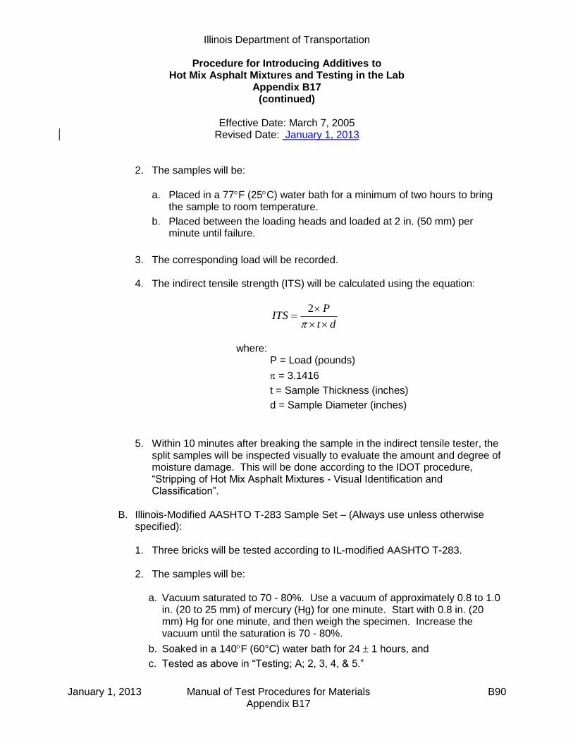
Illinois Department of Transportation
Procedure for Introducing Additives to Hot Mix Asphalt Mixtures and Testing in the Lab
Appendix B17 (continued)
Effective Date: March 7, 2005
Revised Date: January 1, 2013
January 1, 2013 Manual of Test Procedures for Materials B90 Appendix B17
2. The samples will be:
a. Placed in a 77F (25C) water bath for a minimum of two hours to bring the sample to room temperature.
b. Placed between the loading heads and loaded at 2 in. (50 mm) per minute until failure.
3. The corresponding load will be recorded. 4. The indirect tensile strength (ITS) will be calculated using the equation:
dt
PITS
2
where:
P = Load (pounds)
= 3.1416
t = Sample Thickness (inches)
d = Sample Diameter (inches)
5. Within 10 minutes after breaking the sample in the indirect tensile tester, the split samples will be inspected visually to evaluate the amount and degree of moisture damage. This will be done according to the IDOT procedure, “Stripping of Hot Mix Asphalt Mixtures - Visual Identification and Classification”.
B. Illinois-Modified AASHTO T-283 Sample Set – (Always use unless otherwise
specified):
1. Three bricks will be tested according to IL-modified AASHTO T-283. 2. The samples will be:
a. Vacuum saturated to 70 - 80%. Use a vacuum of approximately 0.8 to 1.0
in. (20 to 25 mm) of mercury (Hg) for one minute. Start with 0.8 in. (20 mm) Hg for one minute, and then weigh the specimen. Increase the vacuum until the saturation is 70 - 80%.
b. Soaked in a 140F (60°C) water bath for 24 1 hours, and
c. Tested as above in “Testing; A; 2, 3, 4, & 5.”

Illinois Department of Transportation
Procedure for Introducing Additives to Hot Mix Asphalt Mixtures and Testing in the Lab
Appendix B17 (continued)
Effective Date: March 7, 2005
Revised Date: January 1, 2013
January 1, 2013 Manual of Test Procedures for Materials B91 Appendix B17
C. AASHTO T-283 Sample Set (with one freeze-thaw cycle) – (Only use when specified):
1. Three bricks will be tested according to AASHTO T-283. 2. Each sample will be:
a. Vacuum saturated to 70 - 80%. Use a vacuum of approximately 0.8 to 1.0
in. (20 to 25 mm) of mercury (Hg) for one minute. Start with 0.8 in. (20 mm) Hg for one minute, and then weigh the specimen. Increase the vacuum until the saturation is 70 - 80%.
b. Wrapped in plastic wrap (Saran Wrap) placed in a plastic bag with 10 mL of water and sealed in a plastic bag.
c. Placed in a 0 5F (-18 ± 2.8°C) freezer for a minimum of 16 hours. (The exact time greater than 16 hours should be determined so that the testing can be done at approximately the same time each day).
d. After removal from the freezer, the samples will be placed in a 140F
(60C) water bath and soaked for 24 1 hours, with the plastic bag and plastic wrap removed as soon as possible after being placed in the bath.
e. After the freeze – thaw cycle is complete, follow the steps above in “Testing; A; 2, 3, 4, & 5.”
D. AASHTO T-283 Sample Set (with five freeze-thaw cycles) – (Only use when
specified):
1. Three bricks will be tested as in “Testing; C” above except that five complete freeze – thaw cycles will be completed instead of only one.
2. The plastic bag and plastic wrap should stay on the sample throughout the test and should not be removed until the beginning of the final thaw cycle in
the 140F (60C) bath. If the plastic bag tears or if the plastic wrap comes loose, replace them prior to the next freeze cycle and add 10 mL of water.
3. After the final thaw cycle is complete, follow the steps above in “Testing; A; 2,
3, 4, & 5.” Illinois Modified AASHTO T-324: Perform a Loaded Wheel test according to Illinois modified AASHTO T-324.
Illinois Department of Transportation
Procedure for Introducing Additives to Hot Mix Asphalt Mixtures and Testing in the Lab
Appendix B17 (continued)
Effective Date: March 7, 2005
Revised Date: January 1, 2013
January 1, 2013 Manual of Test Procedures for Materials B92 Appendix B17
6.0 DATA COLLECTION AND EVALUATION
A. All the data from testing will be collected and will/may include:
1. Gmm 2. Gmb
3. Voids 4. Indirect Tensile Strength
a. Unconditioned
b. Conditioned
i. 140°F (60°C) water bath
ii. One freeze / thaw cycle
iii. Five freeze / thaw cycles
5. The standard TSR, for each additive type (calculated with the unconditioned
strength in the denominator and with the conditioned strength in the numerator). For each additive type the TSR is calculated separately for each level of conditioning.
6. The combined TSR, which is similar to the standard TSR except that it is
calculated by always using the unconditioned strength from samples with no additive in the denominator, regardless of the additive type used.
7. Visual strip rating of each sample.
8. Rut depth and number of wheel passes.
B. Evaluate the strengths, TSRs, rut depths, and wheel passes for each additive
type, for each aggregate type tested, to determine if:
1. An anti-strip additive is needed and improves the performance of the mix. 2. One of the additive types consistently gives higher strengths, TSR ratings, rut
depths, and wheel passes.

June 1, 2012 Manual of Test Procedures for Materials B93 Appendix B18
Illinois Department of Transportation
Ignition Oven Aggregate Mass Loss Procedure Appendix B18
Effective: May 1, 2005 Revised: May 1, 2007
A. Purpose
Dolomite aggregates that contain significant amounts of Magnesium Carbonate, when used in Hot-Mix Asphalt, have been found to undergo mass loss during ignition oven testing, which causes highly variable results in asphalt binder content. This procedure utilizes the ignition oven to identify these types of aggregates.
B. Procedure
1. Obtain a 3000 gram sample of the aggregate to be tested and oven dry to a constant mass in an oven set at 110º C ± 5º (230º F ± 9º). Constant mass is achieved by drying sample until further drying does not alter the mass by more than 0.5 g in one hour as stated in IL Modified AASHTO T-30.
2. Split sample into 3 separate 1000 gram samples.
3. Place one of the 1000 gram samples into the ignition oven catch pan.
4. Record the initial weight of the sample and catch pan at room temperature to the nearest
0.1 gram.
5. Place the sample and catch pan into an ignition oven preheated to 625 °C. Do not push the start button on the oven. Allow sample to remain in ignition oven for one hour.
6. After one hour, remove the sample and catch pan, allow it to cool to room temperature
and record the weight to the nearest 0.1 gram.
7. Repeat steps 3 through 10 for the two remaining 1000 gram samples.
8. Calculate the aggregate mass loss for each run according to the following:
∆ 100
Wi
WfWiW
Where: ∆W = Aggregate mass loss in percent
Wi = Initial weight of the aggregate sample in grams
Wf = Final weight of the aggregate sample in grams after
exposure to 625 °C
9. Calculate the average of the three mass loss results.
10. Aggregates exhibiting average mass loss in excess of 4% are likely to contain significant amounts of Magnesium Carbonate and will likely cause high variability in ignition oven test results for asphalt content.

June 1, 2012 Manual of Test Procedures for Materials B94 Appendix B18
This Page Reserved

June 1, 2012 Manual of Test Procedures for Materials B95 Appendix B19
Procedure for Internal Angle Calibration of Superpave Gyratory Compactors (SGCs) using the Dynamic Angle Validator (DAV-2) Internal Angle Testing with HMS Nomenclature and DAV-2 orientation in the specimen mold
In the following sections, the terms “top” and “bottom” angles, “first position”, and “turned 90 degrees” will be used. This refers to the position where the DAV-2 will be collecting angle data. The following diagrams will display how the DAV-2 will be oriented in the gyratory specimen mold and will help avoid confusion in the midst of testing:
Basic method for all compactors (additional instructions included for early model Troxler 4140s)
1. Attach the HMS sphere to the top of the DAV-2 using the supplied bolt. Tighten the bolt enough so that the sphere will not turn, but do not over tighten as this could strip out the bolt. The HMS plates are referred to by their eccentricity, or how far (in mm) from the center of the sphere the load is applied. The 22 mm plate (the one labeled “21”, referring to the angle in degrees ground into the bottom of the plate) will be the only plate used in this calibration. Apply lubricant to the top of the sphere and to the angled surface on the bottom of the plate, as this will help to reduce wear from metal on metal contact. Petroleum jelly is the best lubricant to use with the DAV-2 and HMS.
2. Prior to testing, select two good, clean specimen molds to use for calibration. Make sure
these molds are not too worn, are within specifications, and are used for production testing. The molds will be referred to as mold “A” and mold “B”. Place molds “A” and “B” into an oven set at 305
o F / 154
o C for a minimum of 30 minutes. Connect the DAV-2 to a
CPU using the supplied interface cable. If the CPU doesn’t have a serial port, a serial to USB adapter may be used; these adapters, however, need software in order to function and this software must be installed before they will operate. There are three buttons in the Test Quip software that will be used. They are as follows:
3. Open the Test Quip DAV-2 software and start data collection in the DAV-2 (“Start Button”
in the illustration above). When data collection has been successfully initialized, disconnect the cable from the DAV-2. The DAV-2 has ~26 minutes of memory for data collection, so begin testing quickly so all test points will be collected within that time frame. Before placing the DAV-2 into a mold, apply lubricant to the bottom of the DAV-2. As the DAV-2 will spin during gyration, the lubricant will allow for free movement and help to reduce wear from metal on metal contact.
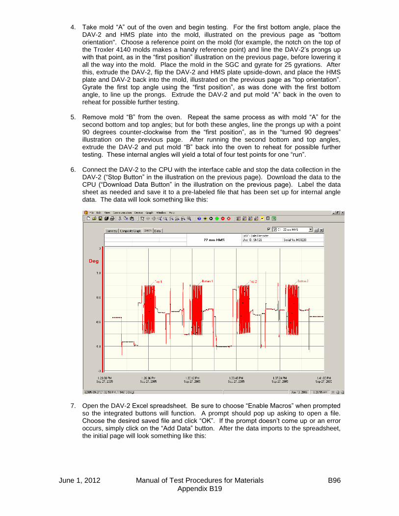
June 1, 2012 Manual of Test Procedures for Materials B96 Appendix B19
4. Take mold “A” out of the oven and begin testing. For the first bottom angle, place the DAV-2 and HMS plate into the mold, illustrated on the previous page as “bottom orientation". Choose a reference point on the mold (for example, the notch on the top of the Troxler 4140 molds makes a handy reference point) and line the DAV-2’s prongs up with that point, as in the “first position” illustration on the previous page, before lowering it all the way into the mold. Place the mold in the SGC and gyrate for 25 gyrations. After this, extrude the DAV-2, flip the DAV-2 and HMS plate upside-down, and place the HMS plate and DAV-2 back into the mold, illustrated on the previous page as “top orientation”. Gyrate the first top angle using the “first position”, as was done with the first bottom angle, to line up the prongs. Extrude the DAV-2 and put mold “A” back in the oven to reheat for possible further testing.
5. Remove mold “B” from the oven. Repeat the same process as with mold “A” for the
second bottom and top angles; but for both these angles, line the prongs up with a point 90 degrees counter-clockwise from the “first position”, as in the “turned 90 degrees” illustration on the previous page. After running the second bottom and top angles, extrude the DAV-2 and put mold “B” back into the oven to reheat for possible further testing. These internal angles will yield a total of four test points for one “run”.
6. Connect the DAV-2 to the CPU with the interface cable and stop the data collection in the
DAV-2 (“Stop Button” in the illustration on the previous page). Download the data to the CPU (“Download Data Button” in the illustration on the previous page). Label the data sheet as needed and save it to a pre-labeled file that has been set up for internal angle data. The data will look something like this:
7. Open the DAV-2 Excel spreadsheet. Be sure to choose “Enable Macros” when prompted so the integrated buttons will function. A prompt should pop up asking to open a file. Choose the desired saved file and click “OK”. If the prompt doesn’t come up or an error occurs, simply click on the “Add Data” button. After the data imports to the spreadsheet, the initial page will look something like this:
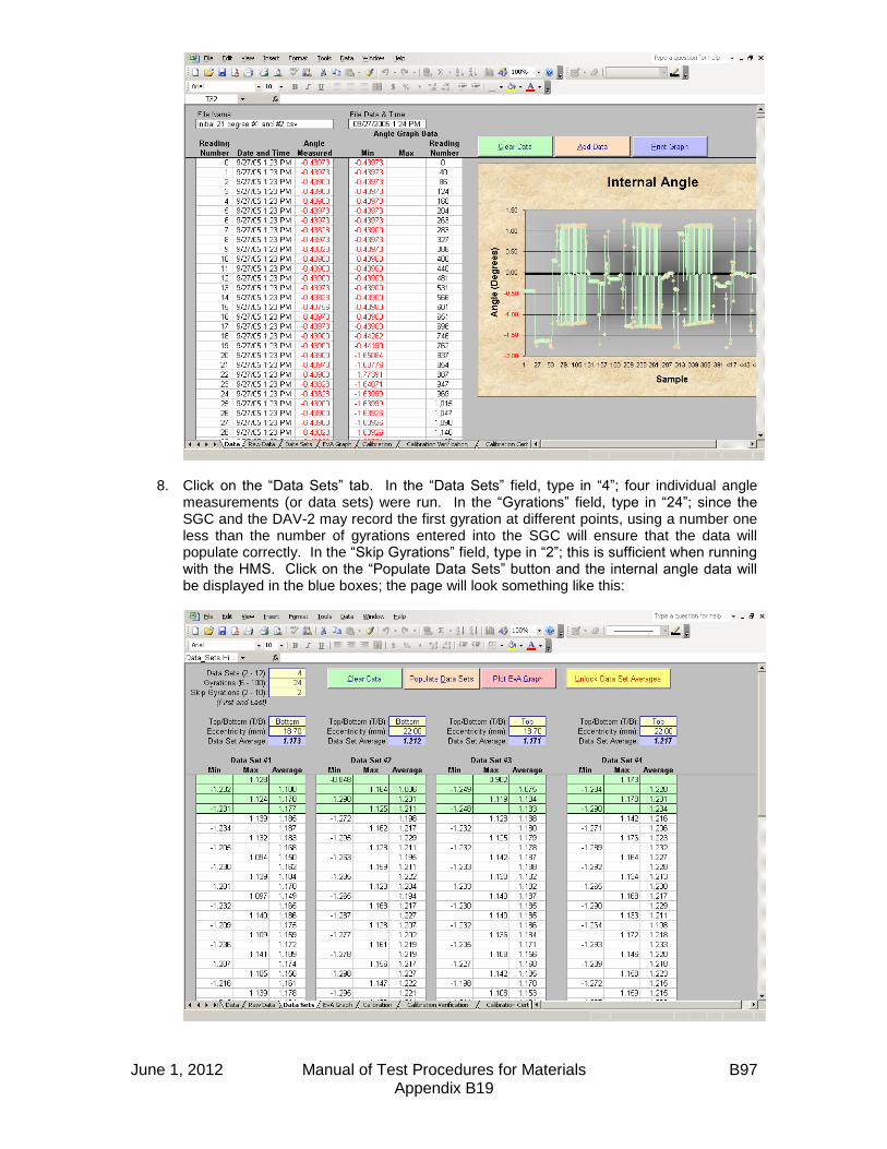
June 1, 2012 Manual of Test Procedures for Materials B97 Appendix B19
8. Click on the “Data Sets” tab. In the “Data Sets” field, type in “4”; four individual angle measurements (or data sets) were run. In the “Gyrations” field, type in “24”; since the SGC and the DAV-2 may record the first gyration at different points, using a number one less than the number of gyrations entered into the SGC will ensure that the data will populate correctly. In the “Skip Gyrations” field, type in “2”; this is sufficient when running with the HMS. Click on the “Populate Data Sets” button and the internal angle data will be displayed in the blue boxes; the page will look something like this:

June 1, 2012 Manual of Test Procedures for Materials B98 Appendix B19
9. Manually calculate the average of the four internal angles. This average represents the current internal angle of the SGC. In the example above, the internal angle of this SGC is about 1.19
o and is out of the specified range of 1.16
o +/- 0.02
o.
10. If the average internal angle is not within the specified 1.16
o +/- 0.02
o range, the SGC’s
angle must be physically adjusted accordingly using the manufacturer’s specified method. This adjustment often has to be done on a trial and error basis; some manufacturers have detailed documentation on changing the angle, so be sure to refer to that when possible. State personnel will not perform the physical angle adjustment to contractor or consultant SGCs under any circumstances.
11. When the angle is physically adjusted, repeat steps #2 – #10 after both molds have had a
minimum of 30 minutes to reheat in the oven. This may take more than one additional attempt to get to the desired internal angle. Adjust the SGC’s angle until the average of the four internal angles from the 22 mm HMS plate is at 1.16
o +/- 0.02
o. The SGC is now
within internal angle specifications. Gyratory Angle Calibration Frequency
The DAV-2 and HMS must be used a minimum of once every two years for gyratory angle calibration. It is suggested that this calibration take place during a material lab’s inspection, which may be annually or biennially depending on how the individual district conducts its inspections. Routine monthly angle calibration verification of SGCs may be performed one of two ways:
1. Using the DAV-2 and HMS. 2. After the final angle is set and calibrated with the DAV-2 and HMS, an external angle
verification procedure may be run according to the SGC manufacturer’s specifications. If HMA is needed for this procedure, an N90 surface mix commonly used in the testing lab’s area should be utilized. The external angle measurement from this procedure will become the reference angle for verification purposes. For example: the DAV-2 and HMS gives an internal angle of 1.16
o and the external angle procedure gives an external angle
of 1.23o. When verifying using the external angle from then on, the external angle should
measure 1.23o +/- 0.02
o. This method addresses concerns of possible mold wear due to
the use of the DAV-2 and HMS as well as giving labs that do not own a DAV-2 an accepted method of routine gyratory angle verification.
Additional Instructions for Early Model Troxler 4140 Compactors
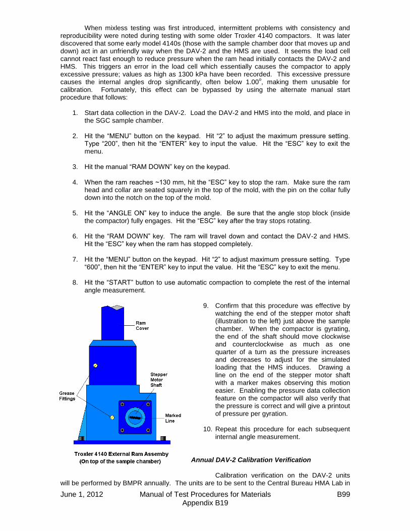
June 1, 2012 Manual of Test Procedures for Materials B99 Appendix B19
When mixless testing was first introduced, intermittent problems with consistency and reproducibility were noted during testing with some older Troxler 4140 compactors. It was later discovered that some early model 4140s (those with the sample chamber door that moves up and down) act in an unfriendly way when the DAV-2 and the HMS are used. It seems the load cell cannot react fast enough to reduce pressure when the ram head initially contacts the DAV-2 and HMS. This triggers an error in the load cell which essentially causes the compactor to apply excessive pressure; values as high as 1300 kPa have been recorded. This excessive pressure causes the internal angles drop significantly, often below 1.00
o, making them unusable for
calibration. Fortunately, this effect can be bypassed by using the alternate manual start procedure that follows:
1. Start data collection in the DAV-2. Load the DAV-2 and HMS into the mold, and place in the SGC sample chamber.
2. Hit the “MENU” button on the keypad. Hit “2” to adjust the maximum pressure setting. Type “200”, then hit the “ENTER” key to input the value. Hit the “ESC” key to exit the menu.
3. Hit the manual “RAM DOWN” key on the keypad.
4. When the ram reaches ~130 mm, hit the “ESC” key to stop the ram. Make sure the ram head and collar are seated squarely in the top of the mold, with the pin on the collar fully down into the notch on the top of the mold.
5. Hit the “ANGLE ON” key to induce the angle. Be sure that the angle stop block (inside the compactor) fully engages. Hit the “ESC” key after the tray stops rotating.
6. Hit the “RAM DOWN” key. The ram will travel down and contact the DAV-2 and HMS. Hit the “ESC” key when the ram has stopped completely.
7. Hit the “MENU” button on the keypad. Hit “2” to adjust maximum pressure setting. Type
“600”, then hit the “ENTER” key to input the value. Hit the “ESC” key to exit the menu. 8. Hit the “START” button to use automatic compaction to complete the rest of the internal
angle measurement.
9. Confirm that this procedure was effective by watching the end of the stepper motor shaft (illustration to the left) just above the sample chamber. When the compactor is gyrating, the end of the shaft should move clockwise and counterclockwise as much as one quarter of a turn as the pressure increases and decreases to adjust for the simulated loading that the HMS induces. Drawing a line on the end of the stepper motor shaft with a marker makes observing this motion easier. Enabling the pressure data collection feature on the compactor will also verify that the pressure is correct and will give a printout of pressure per gyration.
10. Repeat this procedure for each subsequent
internal angle measurement. Annual DAV-2 Calibration Verification Calibration verification on the DAV-2 units
will be performed by BMPR annually. The units are to be sent to the Central Bureau HMA Lab in

June 1, 2012 Manual of Test Procedures for Materials B100 Appendix B19
the late fall or early winter after the construction season ends. The calibration verification will be performed and the units will be returned to the districts in time for winter mix design verifications and lab inspections. Hints and Tips
1. Keep the DAV-2, the ram head, and the molds being used as clean as possible. Any debris on the bottom (or top) plate of the mold or on the ram head will have an effect on the angle when the bottom of the DAV-2 contacts it. A quick spray of WD-40 and a wipe down with a rag on the inside of the mold, the plate(s), and the ram head will ensure good angle data.
2. According to the DAV-2 manufacturer, mold temperature is important to collecting useful
angle data. After two runs with the DAV-2 and HMS at 25 gyrations (i.e. one bottom and one top), the mold will have cooled enough that it could affect angle data. This is the reason for using two molds for calibration as outlined in previous pages.
3. While the standard hydraulic jack set up may be used for extruding the DAV-2 and other
contents from the mold after testing, there is a more efficient way using Marshall molds. Start with a base plate, followed by a collar, then a mold, then another collar; then place your gyratory mold (with base plate) over the stack. This will give you enough height on most SGC molds to bring the gyratory mold base plate to the upper lip of the gyratory mold without coming out. Another Marshall base plate may be added to the top of the stack to give a little more height for taller gyratory molds (Troxler 4141, Pine compactors). This stack is also helpful in loading the DAV-2 into the mold without having to drop it down into the mold. Experiment to find the best setup to work with different models of SGCs.
4. Some early model Troxler 4140s have been noted to release the angle when the HMS is
used. This is attributed to a worn main bearing in the compactor. This causes the angle stop block inside the compactor to start moving away from the fixed angle screw block that is supposed to be “pushing” it to keep the angle “on”. As the angle stop block moves farther away from the fixed angle screw block, the angle is reduced. This is seen mostly when using the 25.8 mm HMS plate or when the SGC exhibits excessive pressure. This issue shouldn’t be a problem when calibrating with the 22 mm HMS plate at 600 kPa (using the alternate manual start procedure), but it is good to be aware of the potential for this problem. A symptom of a worn main bearing can be observed during compaction of hot mix when the angle stop block inside the compactor “chatters” (causing a rapping noise) and can physically be seen moving a little bit during gyration. It seems to not be a problem when compacting hot mix as the angle will stay engaged despite the “chattering”, but this can pose a problem with HMS testing. While not recommended, the following technique has been used as a way to continue testing until the main bearing could be replaced. To physically keep the angle block engaged, a shop rag was first folded in half twice. When the compactor induced the angle, the protruding collar inside the compactor was gripped with the rag. Pressure was then applied in the opposite direction of gyration. This held the angle block in place and kept the angle “on”.
5. When calibrating the angle on a contractor or consultant’s SGC, be sure to let their
personnel perform the physical angle adjustments when they are needed. This way the state is not held liable for any mechanical problems that may occur afterwards.

Illinois Department of Transportation
QC/QA Document Segregation Control of Hot-Mix Asphalt
Appendix B20
Effective: May 1, 2007
June 1, 2012 Manual of Test Procedures for Materials B101 Appendix B20
1.0 SCOPE 1.1 This work shall consist of the visual identification and corrective action to
prevent and/or correct segregation of hot-mix asphalt. 2.0 DEFINITIONS 2.1 Segregation. Areas of non-uniform distribution of coarse and fine aggregate
particles in a hot-mix asphalt pavement. 2.2 End-of-Load Segregation. A systematic form of segregation typically identified
by chevron-shaped segregated areas at either side of a lane of pavement, corresponding with the beginning and end of truck loads.
2.3 Longitudinal Segregation. A linear pattern of segregation that usually
corresponds to a specific area of the paver. 2.4 Severity of Segregation. 2.4.1 Low. A pattern of segregation where the mastic is in place between the
aggregate particles; however, there is slightly more coarse aggregate in comparison with the surrounding acceptable mat.
2.4.2 Medium. A pattern of segregation that has significantly more coarse
aggregate in comparison with the surrounding acceptable mat and which exhibits some lack of mastic.
2.4.3 High. A pattern of segregation what has significantly more coarse
aggregate in comparison with the surrounding acceptable mat and which contains little mastic.
3.0 PROCEDURE 3.1 When medium or high segregation of the mixture is identified by the Contractor,
the Engineer, or the daily evaluation, the following specific corrective actions shall be taken as soon as possible. The corrective actions shall be reported to the Engineer before the next day’s paving proceeds.
3.1.1 End of Load Segregation. When medium or high end of load segregation is
identified, the following actions as a minimum shall be taken.
Illinois Department of Transportation
QC/QA Document Segregation Control of Hot-Mix Asphalt
Appendix B20 (continued)
Effective: May 1, 2007
June 1, 2012 Manual of Test Procedures for Materials B102 Appendix B20
3.1.1.1 Trucks transporting the mixture shall be loaded in multiple dumps. The first against the front wall of the truck bed and the second against the tailgate in a manner which prevents the coarse aggregate from migrating to those locations.
3.1.1.2 The paver shall be operated so the hopper is never below 30
percent capacity between truck exchanges.
3.1.1.3 The “Head of Material” in the auger area shall be controlled to keep a constant level, with a 1 inch +25 mm tolerance.
3.1.2 Longitudinal Segregation. When medium or high longitudinal segregation is
identified, the Contractor shall make the necessary adjustment to the slats, augers or screeds to eliminate the segregation.
3.2 When the corrective actions initiated by the Contractor are insufficient in
controlling medium or high segregation, the Contractor and Engineer will investigate to determine the cause of the segregation.
When an investigation indicates additional corrective action is warranted, the
Contractor shall implement operational changes necessary to correct the segregation problems.
Any verification testing necessary for the investigation will be performed by the
Department according to the applicable project test procedures and specification limits.
3.3 The District Construction Engineer will represent the Department in any dispute
regarding the application of this procedure.

Illinois Department of Transportation
Determination of Reclaimed Asphalt Pavement (RAP) Aggregate Bulk (Dry) Specific Gravity (Gsb)
Appendix B21
Effective: May 1, 2007 Revised: April 1, 2011
June 1, 2012 Manual of Test Procedures for Materials B103 Appendix B21
1. GENERAL If the RAP consists of natural aggregates only, the RAP aggregate bulk specific gravity shall be as follows:
District RAP Gsb
1 & 2 2.660
3 - 9 2.630
If the RAP contains slag aggregate the following procedure shall be used by an independent AASHTO accredited laboratory to determine the RAP aggregate bulk specific gravity (Gsb). 2. SUMMARY of METHOD A representative slag RAP sample shall be thoroughly prepared prior to testing by reheating and remixing the reclaimed material. A solvent extraction, including washed gradation for Department comparison, and two maximum theoretical specific gravity (Gmm) tests are performed so that an effective specific gravity (Gse) can be calculated. The Gse value is used in the calculation to determine the bulk specific gravity (Gsb) of the RAP. 3. SAMPLING The slag RAP stockpile, in its final usable form, shall be sampled by obtaining a minimum of five representative samples from the slag RAP stockpile. The samples shall be thoroughly blended and split into two- 20,000 gram samples. One of the samples shall be submitted to an independent AASHTO accredited IDOT approved laboratory for the subsequent preparation and testing as specified herein. The other sample shall be submitted to the Department for optional verification testing. 4. EQUIPMENT Equipment including oven balances, HMA sample splitter, vacuum setup and solvent extractor shall be according to the HMA QC/QA Laboratory Equipment document in the Manual of Test Procedures for Materials. In addition the following equipment will also be required:
A. Sample pans - Large, flat and capable of holding 20,000 grams of RAP material. B. Chopping utensil – Blade trowel or other utensil used to separate the large
conglomerations of a RAP sample into a loose-flowing condition.
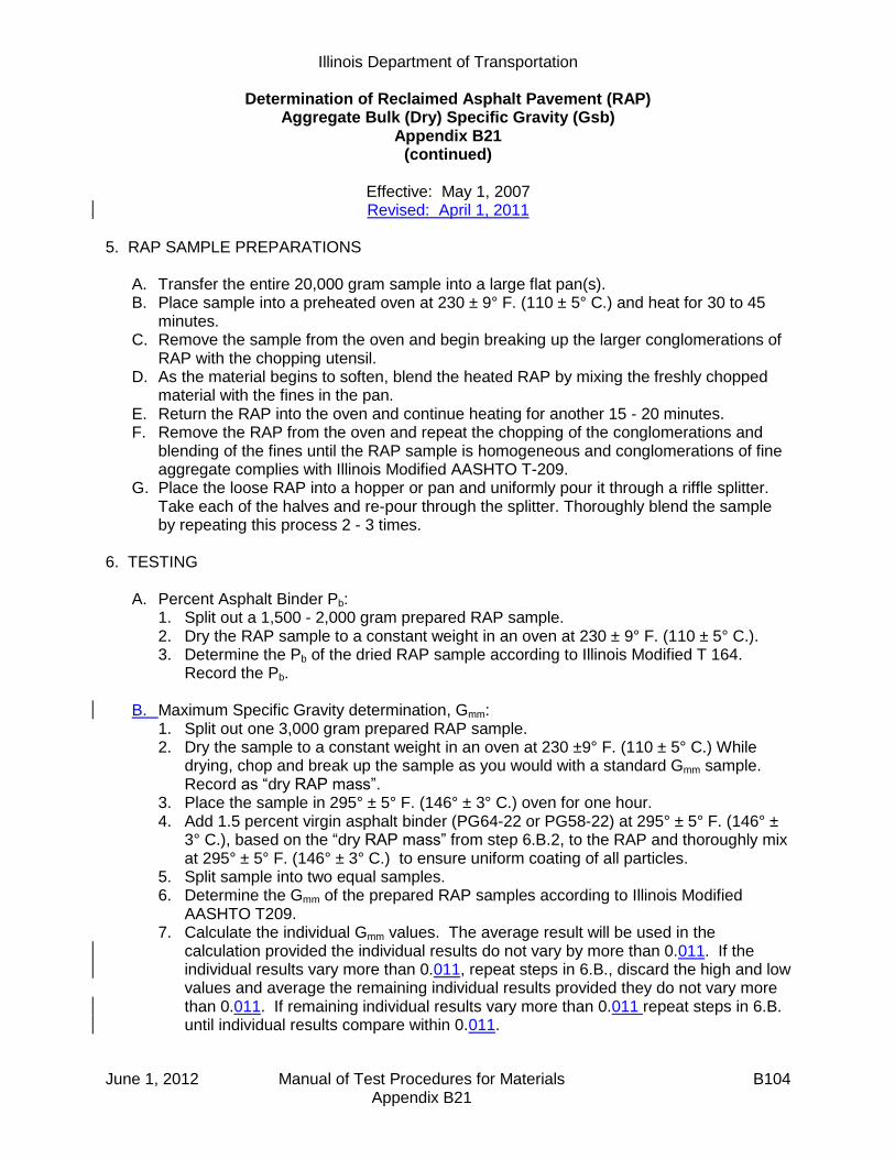
Illinois Department of Transportation
Determination of Reclaimed Asphalt Pavement (RAP) Aggregate Bulk (Dry) Specific Gravity (Gsb)
Appendix B21 (continued)
Effective: May 1, 2007 Revised: April 1, 2011
June 1, 2012 Manual of Test Procedures for Materials B104 Appendix B21
5. RAP SAMPLE PREPARATIONS
A. Transfer the entire 20,000 gram sample into a large flat pan(s). B. Place sample into a preheated oven at 230 ± 9° F. (110 ± 5° C.) and heat for 30 to 45
minutes. C. Remove the sample from the oven and begin breaking up the larger conglomerations of
RAP with the chopping utensil. D. As the material begins to soften, blend the heated RAP by mixing the freshly chopped
material with the fines in the pan. E. Return the RAP into the oven and continue heating for another 15 - 20 minutes. F. Remove the RAP from the oven and repeat the chopping of the conglomerations and
blending of the fines until the RAP sample is homogeneous and conglomerations of fine aggregate complies with Illinois Modified AASHTO T-209.
G. Place the loose RAP into a hopper or pan and uniformly pour it through a riffle splitter. Take each of the halves and re-pour through the splitter. Thoroughly blend the sample by repeating this process 2 - 3 times.
6. TESTING
A. Percent Asphalt Binder Pb: 1. Split out a 1,500 - 2,000 gram prepared RAP sample. 2. Dry the RAP sample to a constant weight in an oven at 230 ± 9° F. (110 ± 5° C.). 3. Determine the Pb of the dried RAP sample according to Illinois Modified T 164.
Record the Pb.
B. Maximum Specific Gravity determination, Gmm: 1. Split out one 3,000 gram prepared RAP sample. 2. Dry the sample to a constant weight in an oven at 230 ±9° F. (110 ± 5° C.) While
drying, chop and break up the sample as you would with a standard Gmm sample. Record as “dry RAP mass”.
3. Place the sample in 295° ± 5° F. (146° ± 3° C.) oven for one hour. 4. Add 1.5 percent virgin asphalt binder (PG64-22 or PG58-22) at 295° ± 5° F. (146° ±
3° C.), based on the “dry RAP mass” from step 6.B.2, to the RAP and thoroughly mix at 295° ± 5° F. (146° ± 3° C.) to ensure uniform coating of all particles.
5. Split sample into two equal samples. 6. Determine the Gmm of the prepared RAP samples according to Illinois Modified
AASHTO T209. 7. Calculate the individual Gmm values. The average result will be used in the
calculation provided the individual results do not vary by more than 0.011. If the individual results vary more than 0.011, repeat steps in 6.B., discard the high and low values and average the remaining individual results provided they do not vary more than 0.011. If remaining individual results vary more than 0.011 repeat steps in 6.B. until individual results compare within 0.011.
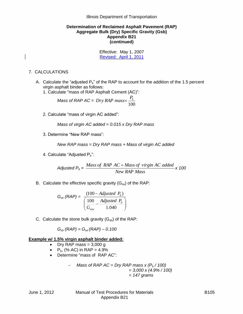
Illinois Department of Transportation
Determination of Reclaimed Asphalt Pavement (RAP) Aggregate Bulk (Dry) Specific Gravity (Gsb)
Appendix B21 (continued)
Effective: May 1, 2007 Revised: April 1, 2011
June 1, 2012 Manual of Test Procedures for Materials B105 Appendix B21
7. CALCULATIONS
A. Calculate the “adjusted Pb” of the RAP to account for the addition of the 1.5 percent virgin asphalt binder as follows: 1. Calculate “mass of RAP Asphalt Cement (AC)”:
Mass of RAP AC = 100
bPmassRAPDry
2. Calculate “mass of virgin AC added”:
Mass of virgin AC added = 0.015 x Dry RAP mass
3. Determine “New RAP mass”: New RAP mass = Dry RAP mass + Mass of virgin AC added 4. Calculate “Adjusted Pb”:
Adjusted Pb = MassRAPNew
addedACvirginofMassACRAPofMass x 100
B. Calculate the effective specific gravity (Gse) of the RAP:
Gse (RAP) =
040.1
100
)100(
b
mm
b
PAdjusted
G
PAdjusted
C. Calculate the stone bulk gravity (Gsb) of the RAP:
Gsb (RAP) = Gse (RAP) – 0.100 Example w/ 1.5% virgin asphalt binder added:
Dry RAP mass = 3,000 g
Pb, (% AC) in RAP = 4.9%
Determine “mass of RAP AC”:
- Mass of RAP AC = Dry RAP mass x (Pb / 100) = 3,000 x (4.9% / 100) = 147 grams
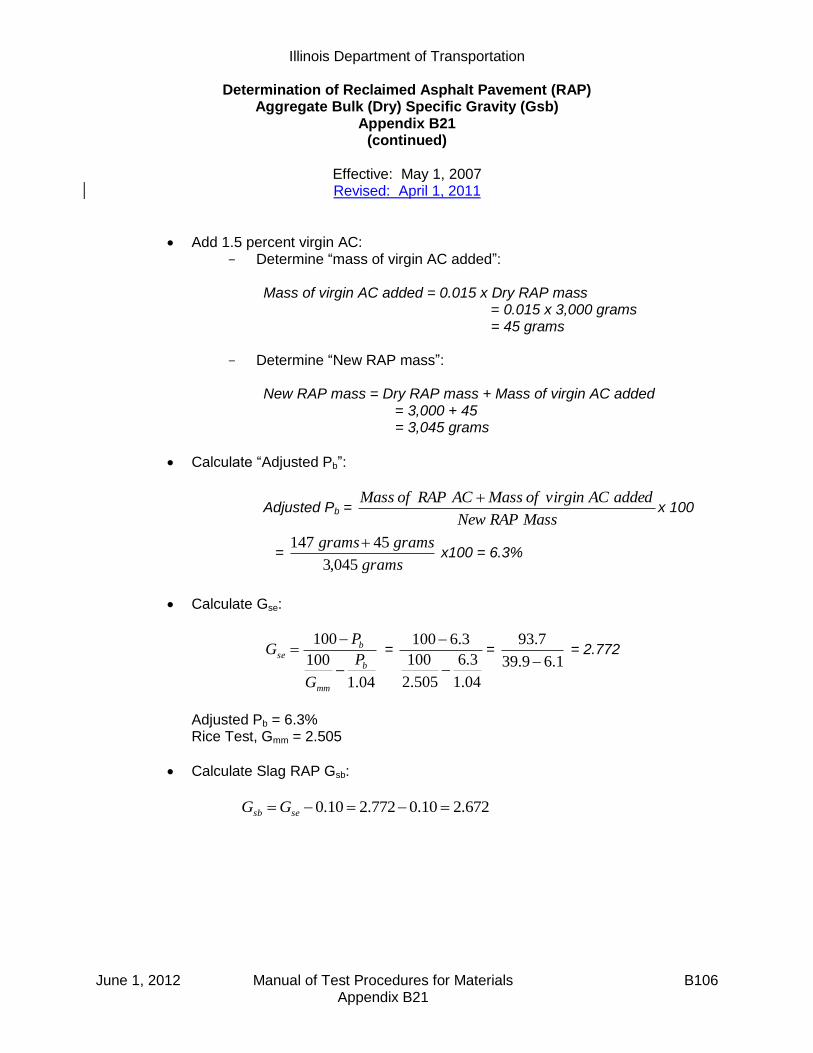
Illinois Department of Transportation
Determination of Reclaimed Asphalt Pavement (RAP) Aggregate Bulk (Dry) Specific Gravity (Gsb)
Appendix B21 (continued)
Effective: May 1, 2007 Revised: April 1, 2011
June 1, 2012 Manual of Test Procedures for Materials B106 Appendix B21
Add 1.5 percent virgin AC: - Determine “mass of virgin AC added”:
Mass of virgin AC added = 0.015 x Dry RAP mass
= 0.015 x 3,000 grams = 45 grams
- Determine “New RAP mass”:
New RAP mass = Dry RAP mass + Mass of virgin AC added = 3,000 + 45 = 3,045 grams
Calculate “Adjusted Pb”:
Adjusted Pb = MassRAPNew
addedACvirginofMassACRAPofMass x 100
= grams
gramsgrams
045,3
45147 x100 = 6.3%
Calculate Gse:
04.1
100
100
b
mm
bse P
G
PG
=
04.1
3.6
505.2
100
3.6100
=
1.69.39
7.93
= 2.772
Adjusted Pb = 6.3% Rice Test, Gmm = 2.505
Calculate Slag RAP Gsb:
672.210.0772.210.0 sesb GG
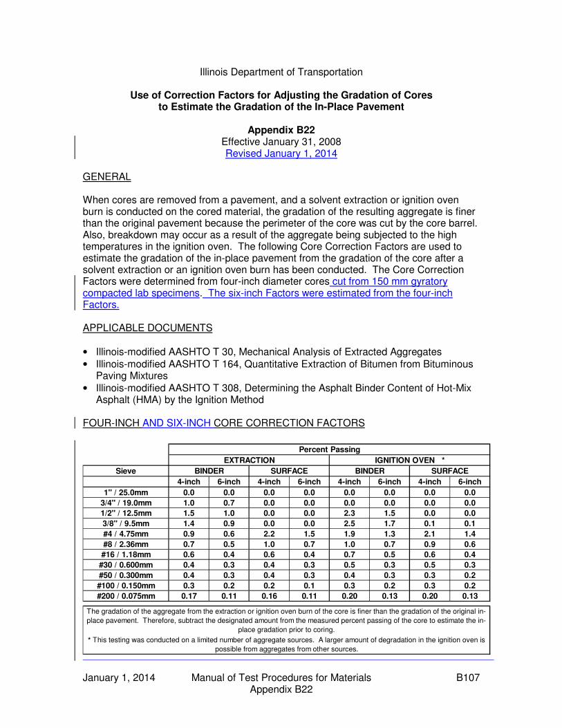
January 1, 2014 Manual of Test Procedures for Materials B107 Appendix B22
Illinois Department of Transportation
Use of Correction Factors for Adjusting the Gradation of Cores to Estimate the Gradation of the In-Place Pavement
Appendix B22
Effective January 31, 2008 Revised January 1, 2014
GENERAL When cores are removed from a pavement, and a solvent extraction or ignition oven burn is conducted on the cored material, the gradation of the resulting aggregate is finer than the original pavement because the perimeter of the core was cut by the core barrel. Also, breakdown may occur as a result of the aggregate being subjected to the high temperatures in the ignition oven. The following Core Correction Factors are used to estimate the gradation of the in-place pavement from the gradation of the core after a solvent extraction or an ignition oven burn has been conducted. The Core Correction Factors were determined from four-inch diameter cores cut from 150 mm gyratory compacted lab specimens. The six-inch Factors were estimated from the four-inch Factors. APPLICABLE DOCUMENTS
• Illinois-modified AASHTO T 30, Mechanical Analysis of Extracted Aggregates
• Illinois-modified AASHTO T 164, Quantitative Extraction of Bitumen from Bituminous Paving Mixtures
• Illinois-modified AASHTO T 308, Determining the Asphalt Binder Content of Hot-Mix Asphalt (HMA) by the Ignition Method
FOUR-INCH AND SIX-INCH CORE CORRECTION FACTORS
Sieve
4-inch 6-inch 4-inch 6-inch 4-inch 6-inch 4-inch 6-inch
1" / 25.0mm 0.0 0.0 0.0 0.0 0.0 0.0 0.0 0.0
3/4" / 19.0mm 1.0 0.7 0.0 0.0 0.0 0.0 0.0 0.0
1/2" / 12.5mm 1.5 1.0 0.0 0.0 2.3 1.5 0.0 0.0
3/8" / 9.5mm 1.4 0.9 0.0 0.0 2.5 1.7 0.1 0.1
#4 / 4.75mm 0.9 0.6 2.2 1.5 1.9 1.3 2.1 1.4
#8 / 2.36mm 0.7 0.5 1.0 0.7 1.0 0.7 0.9 0.6
#16 / 1.18mm 0.6 0.4 0.6 0.4 0.7 0.5 0.6 0.4
#30 / 0.600mm 0.4 0.3 0.4 0.3 0.5 0.3 0.5 0.3
#50 / 0.300mm 0.4 0.3 0.4 0.3 0.4 0.3 0.3 0.2
#100 / 0.150mm 0.3 0.2 0.2 0.1 0.3 0.2 0.3 0.2
#200 / 0.075mm 0.17 0.11 0.16 0.11 0.20 0.13 0.20 0.13
SURFACE
The gradation of the aggregate from the extraction or ignition oven burn of the core is finer than the gradation of the original in-
place pavement. Therefore, subtract the designated amount from the measured percent passing of the core to estimate the in-
place gradation prior to coring.
* This testing was conducted on a limited number of aggregate sources. A larger amount of degradation in the ignition oven is
possible from aggregates from other sources.
Percent Passing
EXTRACTION IGNITION OVEN *
BINDER SURFACE BINDER
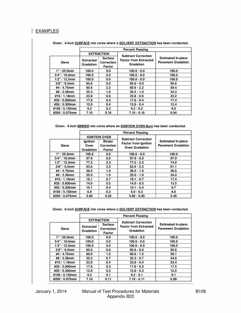
January 1, 2014 Manual of Test Procedures for Materials B108 Appendix B22
EXAMPLES
SieveExtracted
Gradation
Surface
Correction
Factor
1" / 25.0mm 100.0 0.0 100.0 - 0.0 100.0
3/4" / 19.0mm 100.0 0.0 100.0 - 0.0 100.0
1/2" / 12.5mm 100.0 0.0 100.0 - 0.0 100.0
3/8" / 9.5mm 95.6 0.0 95.6 - 0.0 95.6
#4 / 4.75mm 60.6 2.2 60.6 - 2.2 58.4
#8 / 2.36mm 35.3 1.0 35.3 - 1.0 34.3
#16 / 1.18mm 23.8 0.6 23.8 - 0.6 23.2
#30 / 0.600mm 17.8 0.4 17.8 - 0.4 17.4
#50 / 0.300mm 12.8 0.4 12.8 - 0.4 12.4
#100 / 0.150mm 9.2 0.2 9.2 - 0.2 9.0
#200 / 0.075mm 7.10 0.16 7.10 - 0.16 6.94
Sieve
Ignition
Oven
Gradation
Binder
Correction
Factor
1" / 25.0mm 100.0 0.0 100.0 - 0.0 100.0
3/4" / 19.0mm 97.9 0.0 97.9 - 0.0 97.9
1/2" / 12.5mm 77.2 2.3 77.2 - 2.3 74.9
3/8" / 9.5mm 63.6 2.5 63.6 - 2.5 61.1
#4 / 4.75mm 38.5 1.9 38.5 - 1.9 36.6
#8 / 2.36mm 25.0 1.0 25.0 - 1.0 24.0
#16 / 1.18mm 18.1 0.7 18.1 - 0.7 17.4
#30 / 0.600mm 14.0 0.5 14.0 - 0.5 13.5
#50 / 0.300mm 10.1 0.4 10.1 - 0.4 9.7
#100 / 0.150mm 6.9 0.3 6.9 - 0.3 6.6
#200 / 0.075mm 5.60 0.20 5.60 - 0.20 5.40
SieveExtracted
Gradation
Surface
Correction
Factor
1" / 25.0mm 100.0 0.0 100.0 - 0.0 100.0
3/4" / 19.0mm 100.0 0.0 100.0 - 0.0 100.0
1/2" / 12.5mm 100.0 0.0 100.0 - 0.0 100.0
3/8" / 9.5mm 95.6 0.0 95.6 - 0.0 95.6
#4 / 4.75mm 60.6 1.5 60.6 - 1.5 59.1
#8 / 2.36mm 35.3 0.7 35.3 - 0.7 34.6
#16 / 1.18mm 23.8 0.4 23.8 - 0.4 23.4
#30 / 0.600mm 17.8 0.3 17.8 - 0.3 17.5
#50 / 0.300mm 12.8 0.3 12.8 - 0.3 12.5
#100 / 0.150mm 9.2 0.1 9.2 - 0.1 9.1
#200 / 0.075mm 7.10 0.11 7.10 - 0.11 6.99
EXTRACTIONSubtract Correction
Factor from Extracted
Gradation
Estimated In-place
Pavement Gradation
Percent Passing
IGNITION OVENSubtract Correction
Factor from Ignition
Oven Gradation
Estimated In-place
Pavement Gradation
Given: 6-inch SURFACE mix cores where a SOLVENT EXTRACTION has been conducted.
Percent Passing
Given: 4-inch SURFACE mix cores where a SOLVENT EXTRACTION has been conducted.
Percent Passing
EXTRACTIONSubtract Correction
Factor from Extracted
Gradation
Estimated In-place
Pavement Gradation
Given: 4-inch BINDER mix cores where an IGNITION OVEN Burn has been conducted.

Illinois Department of Transportation
Off-Site Preliminary Test Strip and Modified Start-Up Procedures Appendix B23
June 1, 2012 Manual of Test Procedures for Materials B109 Appendix B23
Effective Date: April 1, 2010 When required, an off-site preliminary test strip and modified start-up shall be performed as follows:
(a) Team Members. The start-up team, if required, shall consist of the following: (1) Resident Engineer (2) District Construction Supervising Field Engineer, or representative (3) District Materials Mixtures Control Engineer, or representative (4) District Nuclear Density Gauge Tester (5) Contractor's QC Manager (6) Bureau of Materials and Physical Research representative (7) Bureau of Construction representative (8) Contractor's Density Tester (9) Asphalt Binder Supplier representative
(b) Communication. The Contractor shall advise the team members of the anticipated start
time of production for both the off-site preliminary test strip and subsequent modified start-up for both the surface and binder courses. The QC Manager shall direct the activities of the start-up team. A Department-appointed representative from the start-up team will act as spokesperson for the Department.
(c) Off-site Preliminary Test Strip. The off-site preliminary test strip shall consist of 272 metric tons (300 tons). It shall contain two growth curves which shall be tested as outlined herein. (1) Mix and Gradation Test Strip Samples. The first and second sets of mixture and
gradation samples shall be taken by the Contractor at such times as to represent the mixture of the two growth curves, respectively. All off-site preliminary test strip samples shall be processed by the Contractor for determination of mixture composition and air voids. This shall include washed ignition gradation and asphalt content test results. This information shall then be compared to the JMF and required design criteria.
(2) Compaction Equipment. It shall be the responsibility of the QC manager to verify
roller compliance before commencement of growth curve construction. All rolling equipment intended for use on a project shall be utilized on the off-site preliminary test strip.

Illinois Department of Transportation
Off-Site Preliminary Test Strip and Modified Start-Up Procedures Appendix B23
(continued)
June 1, 2012 Manual of Test Procedures for Materials B110 Appendix B23
(3) Constructing the Off-site Preliminary Test Strip. After the Contractor has produced
the mix, transported the mix, and placed approximately 90 to 140 metric tons (100 to 150 tons) of mix, placement of the mix shall stop, and a growth curve shall be constructed. After completion of the first growth curve, paving shall resume for 45 to 90 metric tons (50 to 100 tons) of mix, placement shall stop, and the second growth curve shall be constructed within this area. Additional growth curves may be required if an adjustment/plant change is made during the off-site preliminary test strip. The Contractor shall use the specified rolling procedures for all portions of the test strip except for the growth curve areas which shall be compacted as directed by the QC Manager.
(4) Location of Off-site Preliminary Test Strip. The off-site preliminary test strip shall be located on a pavement type similar to the contract pavement and acceptable to the Engineer. It shall be on a relatively flat portion of the roadway.
(5) Compaction Temperature. In order to make an accurate analysis of the density potential of the mixture, the temperature of the mixture on the pavement at the beginning of the growth curve shall be not less than the minimum mixture placement temperature specified herein. The mat temperature, at the location of the each growth curve, shall be monitored throughout the construction of each growth curve.
(6) Compaction and Testing. The QC manager shall specify the roller(s) speed and number of passes required to obtain a completed growth curve. The nuclear gauge shall be placed near the center of the hot mat and the position marked for future reference. With the bottom of the nuclear gauge and the source rod clean, a one-minute nuclear reading (without mineral filler) shall be taken after each pass of the roller. Rolling shall continue until the maximum density is achieved and three consecutive passes show no appreciable increase in density or no evidence of destruction of the mat. The growth curve shall be plotted. No testing of initial passes shall be taken until the third pass is completed.
(7) Final Testing. After the growth curve information is obtained, a final nuclear reading, using mineral filler to eliminate surface voids, shall be taken at the marked position. This reading is used to adjust the maximum density reading obtained during the growth curve.
(8) Evaluation of Growth Curves. Mixtures which exhibit density potential outside of the specified density range shall be considered as sufficient cause for mix adjustment. If a mix adjustment is made, an additional test strip may be constructed, and associated tests shall be performed. This information shall then be compared to the AJMF and required design criteria. If the density potential of the mixture not meet the minimum specified, the operation shall cease until all test data is analyzed or a new mix design is produced. In addition, other aspects of the mixture, such as appearance, segregation, texture, or other evidence of mix problems, should be noted and corrective action taken at this time.

Illinois Department of Transportation
Off-Site Preliminary Test Strip and Modified Start-Up Procedures Appendix B23
(continued)
June 1, 2012 Manual of Test Procedures for Materials B111 Appendix B23
(d) Documentation. All off-site preliminary test strip, modified start-up, and rolling pattern
information (including growth curves) will be tabulated by the QC manager with copies provided to each team member, and the original retained in the project files. Any changes to the rolling pattern shall be by the Contractor and the Engineer and recorded.
(e) Modified Start-Up. At the start of placement on the jobsite, the Contractor shall construct
a growth curve in between the first 90 to 140 metric tons (100 to 150 tons) for the purposes of evaluating the properties of the mixture and ensuring that the established rolling pattern was valid. The placement shall stop until the growth curve has been evaluated. A hot-bin or a combined aggregate belt sample and a mix sample representative of the growth curve shall be obtained and tested expediently for determination of mix composition and air voids. This information shall then be compared to the preliminary test strip data. If the growth curve and visual evaluation of the mix are satisfactory, the placement may be resumed. If the growth curve and visual evaluation of the mix are unsatisfactory, placement shall remain on hold until the plant samples are completed and reviewed by the QC Manager and the Engineer. If agreed by the Engineer, the Contractor shall make appropriate adjustments, resample and retest, construct another growth curve, and evaluate the mixture. This procedure will be followed until satisfactory test results are obtained.

June 1, 2012 Manual of Test Procedures for Materials B112 Appendix B23
This Page Reserved

March 1, 2013 Manual of Test Procedures for Materials B113 Appendix B24
Illinois Department of Transportation
Determination of Residual Asphalt in Prime and Tack Coat Materials Appendix B24
Effective: March 1, 2013
A. Purpose
This procedure provides a means for determining the amount of asphalt binder remaining after a tack coat or prime coat cures. The remaining asphalt binder is termed residual asphalt. This procedure shall be used for verifying specification compliance when the tack coat or prime coat application rate is specified based on residual asphalt.
B. Procedure
1. Cut and label a 12.0 inch by 12.0 inch square piece of non-woven geotextile fabric or cardboard. Place the square in a 230 ± 9 °F (110 ± 5 °C) oven and dry to constant weight. Remove the square from the oven and record the weight Wi to the nearest 0.1 gram within 5 minutes after removal.
Notes:
Oven drying is necessary because cardboard especially can retain considerable moisture in humid conditions.
The fabric or cardboard used for squares needs to 1) have sufficient thickness to prevent loss of asphalt and 2) allow sufficient absorption to prevent spillage.
Constant weight is defined as the weight at which further drying does not alter the mass more than 0.5 gram in 1 hour.
2. Place the pre-weighed square at a random transverse location prior to tack or prime coat
application.
3. After the prime or tack has been applied, remove the square from the pavement and protect from damage during transport. Place the square in a 230 ± 9 °F (110 ± 5 °C) oven and dry to a constant weight.
4. Remove the square from the oven and record the final weight Wf to the nearest 0.1 gram
within 5 minutes after removal from the oven.
5. Subtract the initial weight Wi determined in step 1 from the final weight Wf determined in step 4. Divide this value by 454 to get the residual asphalt binder application rate in lbs/ ft2.
Residual Asphalt Application Rate = (Wf – Wi) / 454

March 1, 2013 Manual of Test Procedures for Materials B114 Appendix B24
This Page Reserved

SEQUENTIAL TABLE OF CONTENTS (continued)
MANUAL OF TEST PROCEDURES FOR MATERIALS
June 1, 2012 Manual of Test Procedures for Materials
E – End Result Specification Appendix E1
(Effective 04/01/10) (Revised 01/01/13)
PFP Quality Level Analysis ...................................... E 1
Appendix E2 (Effective 05/01/08)
PFP Hot-Mix Asphalt Random Plant Samples ......... E13
Appendix E3 (Effective 04/01/10) (Revised 01/01/13)
PFP Random Density Procedure ............................. E19
Appendix E4 (Effective 04/01/11) (Revised 01/01/13)
PFP Hot Mix Asphalt Random Jobsite Sampling ..... E25
Appendix E5 (Effective 04/01/10)
PFP Dispute Resolution Instructions ....................... E37
Appendix E6 (Effective 01/01/12) (Revised 01/01/14)
QCP Pay Calculation ............................................... E39
Appendix E7 (Effective 04/01/12)
Best Practices for PFP and QCP Implementation .... E47

Illinois Department of Transportation
PFP Quality Level Analysis Appendix E1
Effective: December 12, 2003
Revised: January 1, 2013
January 1, 2013 Manual of Test Procedures for Materials E1 Appendix E1
This stand-alone document explains the statistical analysis and procedure used to determine the pay factor for a hot-mix asphalt (HMA) mixture on Pay for Performance (PFP) project. HMA materials specified to be sampled and tested for percent within limits payment adjustment (voids, VMA, and in-place density) and dust/AC adjustments will be evaluated for acceptance in accordance with this document. Pay parameters evaluated using percent within (PWL) limits will be analyzed collectively and statistically by the Quality Level Analysis method using the procedures listed to determine the total estimated percent of the lot that is within specification limits. Quality Level Analysis is a statistical procedure for estimating the percent compliance to a specification and is affected by shifts in the arithmetic mean and the sample standard deviation. Two measures of quality are required to establish the contract unit price adjustment. The first measure is the Acceptable Quality Level (AQL) which is the PWL at which the lot will receive 100 percent pay. The second measure of quality is the Rejectable Quality Level (RQL) at which the Department has determined the material may not perform as desired and may be rejected. The pay factor on full-depth projects shall be determined by weighting each mixture equally. Material placed at the same gyrations values but with and without polymer will be evaluated as two separate mixtures. For example: one surface mix and one binder mix will be weighted 50/50 regardless of tonnage. Additionally, one surface mix, one polymer binder mix and one non-polymer mix will be evaluated as three equally (1/3) weighted mixtures even if the polymer binder is the only difference between binder lifts. Pay adjustments for Dust/AC ratio will be applied using the Dust/AC Pay Adjustment Table found in the Hot Mix Asphalt Pay for Performance Using Percent within Limits special provision. QUALITY LEVEL ANALYSIS Note: Table 1: Pay Attributes and Price Adjustment Factors contain the UL, LL, and pay factor
“f” weights.
Items 1 through 8 of the following procedure will be repeated for each lot of the various pay factor parameters. (1) Determine the arithmetic mean ( x ) of the test results:
x = n
x
Where:
= summation of
x = individual test value n = total number of test values

Illinois Department of Transportation
PFP Quality Level Analysis Appendix E1 (continued)
Effective: December 12, 2003
Revised: January 1, 2013
January 1, 2013 Manual of Test Procedures for Materials E2 Appendix E1
(2) Calculate the sample standard deviation (s): s = Where:
)( 2x = summation of the squares of individual test values
2)( x = summation of the individual test values squared
(3) Calculate the upper quality index (QU):
QU = s
xUL
Where: UL = upper specification limit (target value (TV) plus allowable deviation) (4) Calculate the lower quality index (QL):
QL = s
LLx
Where: LL = lower specification limit(target value (TV) minus allowable deviation) (5) Determine PU (percent within the upper specification limit which corresponds to a given
QU) from Table 2. (Note: Round up to nearest QU in table 2.) Note: If a UL is not specified, PU will be 100. (6) Determine PL (percent within the lower specification limit which corresponds to a give
QL) from Table 2. (Note: Round up to nearest QL in table 2.) Note: If a LL is not specified, PL will be 100. (7) Determine the Quality Level or PWL (the total percent within specification limits). PWL = (PU + PL) – 100
(8) To determine the pay factor for each individual parameter lot: Pay Factor (PF) = 53 + 0.5 (PWL)
n S x( )2. S x( )
2
n n 1( )

Illinois Department of Transportation
PFP Quality Level Analysis Appendix E1 (continued)
Effective: December 12, 2003
Revised: January 1, 2013
January 1, 2013 Manual of Test Procedures for Materials E3 Appendix E1
(9) Once the project is complete determine the Total Pay Factor (TPF) for each parameter by using a weighted lot average by tons (mix) or distance (density) of all lots for a given parameter. TPF = W1PFlot1 + W2PFlot(n+1) + etc. Where: W1,W2… = weighted percentage of material evaluated PF = Pay factor for the various lots TPF = Total pay factor for the given parameter
(10) Determine the Composite Pay Factor (CPF) for each mixture. The CPF shall be rounded to 3 decimal places.
CPF = densitydensityvoidsvoidsVMAVMA TPFfTPFfTPFf / 100
Substituting from Table 1:
CPF = densityvoidsVMA TPF0.4TPF0.3TPF0.3 / 100
Where: fVMA, fvoids, and fdensity = Price Adjustment Factor listed in Table 1 TPFVMA, TPFvoids, and TPFdensity = Total Pay Factor for the designated measured
attribute from (9) (11) Determine the final pay for a given mixture. Final Pay = Mixture Unit Price * Quantity * CPF
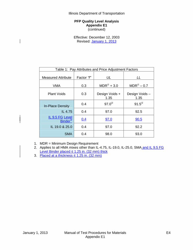
Illinois Department of Transportation
PFP Quality Level Analysis Appendix E1 (continued)
Effective: December 12, 2003
Revised: January 1, 2013
January 1, 2013 Manual of Test Procedures for Materials E4 Appendix E1
Table 1: Pay Attributes and Price Adjustment Factors
Measured Attribute
Factor “f”
UL
LL
VMA
0.3
MDR/1 + 3.0
MDR/1 – 0.7
Plant Voids
0.3
Design Voids +
1.35
Design Voids –
1.35
In-Place Density
0.4 97.0/2 91.5/2
IL 4.75 0.4 97.0 92.5
IL 9.5 FG Level Binder3/
0.4 97.0 90.5
IL 19.0 & 25.0 0.4 97.0 92.2
SMA 0.4 98.0 93.0
1. MDR = Minimum Design Requirement 2. Applies to all HMA mixes other than IL-4.75, IL-19.0, IL-25.0, SMA and IL 9.5 FG
Level Binder placed ≤ 1.25 in. (32 mm) thick 3. Placed at a thickness ≤ 1.25 in. (32 mm)

Illinois Department of Transportation
PFP Quality Level Analysis Appendix E1 (continued)
Effective: December 12, 2003
Revised: January 1, 2013
January 1, 2013 Manual of Test Procedures for Materials E5 Appendix E1
Example:
Determine the Pay factor for the given lot of a N90 HMA surface being placed at 1.5 inches thick as an overlay. The project consists of 10,000 tons over 17 miles.
Note that mix sample and density lots are independent of each other.
In this example the mix sample lot represents 10,000 tons while the density lot represents 6 miles (N=30). The project would have two additional density lots following the same calculations as the first lot. All three lots are combined as per item (9).
Mix sample: Each sublot represents 1000 tons
Lot Sublot Voids VMA
# # TV = 4.0 Design Min = 14.51 4.2 14.4
2 4.5 14.7
3 3.3 13.9
4 5.0 15.0
5 5.4 15.2
6 2.5 13.5
7 3.8 14.2
8 4.1 14.3
9 4.3 14.4
10 4.5 14.6
4.16 14.42
0.825 0.498
1
Average:
Standard Deviation:
Density: Each density test interval represents 0.2 mile thus N=30 in which 5 cores are taken per mile would represent 6 miles of paving.
Lot
# Density
1 91.52 93.0
3 92.9
4 93.55 93.0
6 94.0
7 92.88 93.5
9 91.0… …
30 92.7
92.79
0.910
1
Average: Standard Deviation:
Density
Test
Interval
Determine the pay factor for each parameter.
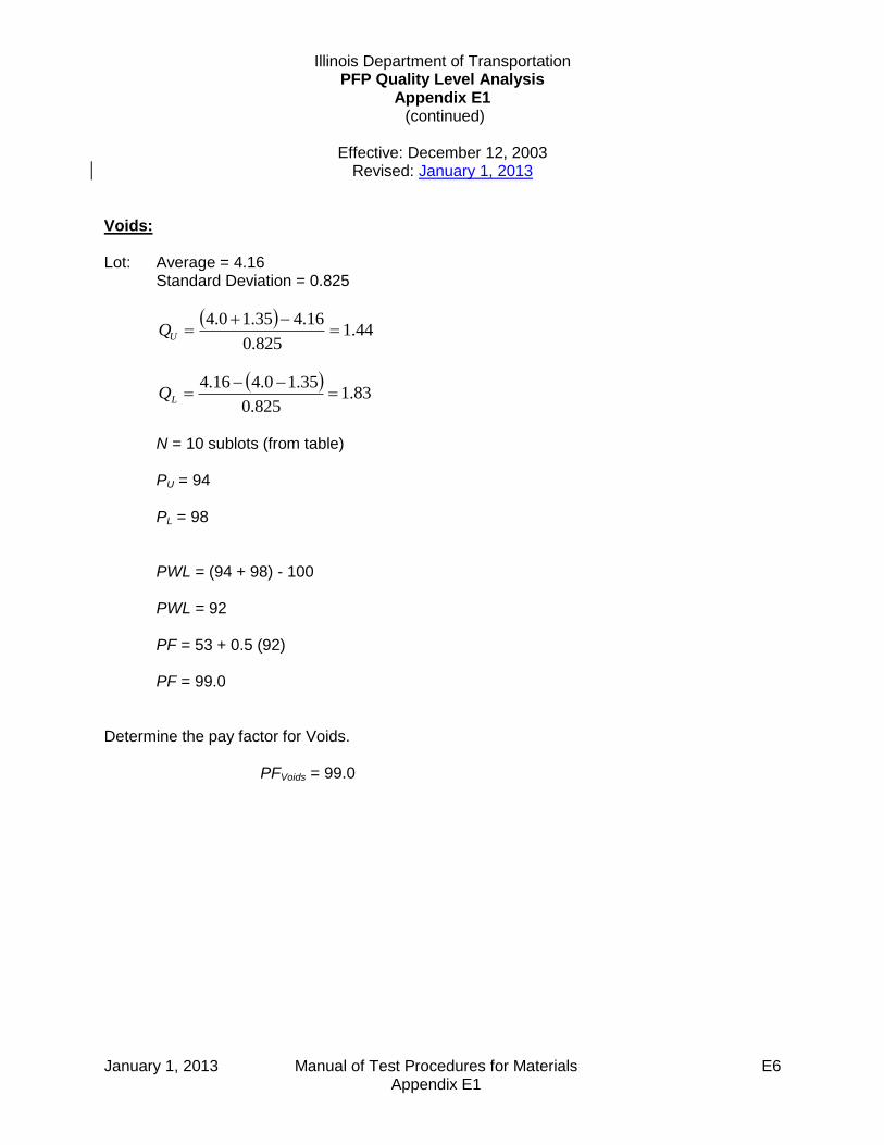
Illinois Department of Transportation PFP Quality Level Analysis
Appendix E1 (continued)
Effective: December 12, 2003
Revised: January 1, 2013
January 1, 2013 Manual of Test Procedures for Materials E6 Appendix E1
Voids:
Lot: Average = 4.16 Standard Deviation = 0.825
44.1
825.0
16.435.10.4
UQ
83.1
825.0
35.10.416.4
LQ
N = 10 sublots (from table) PU = 94 PL = 98 PWL = (94 + 98) - 100 PWL = 92 PF = 53 + 0.5 (92) PF = 99.0
Determine the pay factor for Voids.
PFVoids = 99.0
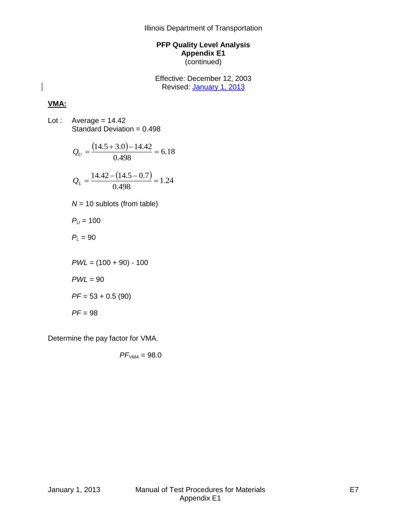
Illinois Department of Transportation
PFP Quality Level Analysis Appendix E1 (continued)
Effective: December 12, 2003
Revised: January 1, 2013
January 1, 2013 Manual of Test Procedures for Materials E7 Appendix E1
VMA:
Lot : Average = 14.42 Standard Deviation = 0.498
18.6
498.0
42.140.35.14
UQ
24.1
498.0
7.05.1442.14
LQ
N = 10 sublots (from table) PU = 100 PL = 90 PWL = (100 + 90) - 100 PWL = 90 PF = 53 + 0.5 (90) PF = 98
Determine the pay factor for VMA.
PFVMA = 98.0

Illinois Department of Transportation PFP Quality Level Analysis
Appendix E1 (continued)
Effective: December 12, 2003
Revised: January 1, 2013
January 1, 2013 Manual of Test Procedures for Materials E8 Appendix E1
Density:
Lot: Average = 92.79
Standard Deviation = 0.910
63.4910.0
79.920.97
UQ
42.1910.0
5.9179.92
LQ
N = 30 Density measurements (from table) PU = 100 PL = 93 PWL = (100 + 93) - 100 PWL = 93 PF = 53 + 0.5 (93) PF = 99.5
Determine the pay factor for Density. PFDensity = 99.5

Illinois Department of Transportation
PFP Quality Level Analysis Appendix E1 (continued)
Effective: December 12, 2003
Revised: January 1, 2013
January 1, 2013 Manual of Test Procedures for Materials E9 Appendix E1
Determine the total pay factors for each parameter. In this example 10,000 tons of mix represents the entire project so only one lot exists for VMA and voids. If more mix lots occurred on a project they would be combined just like density as shown.
Lot # Mix Tons Void PF VMA PF Density Distance Density PF
1 10,000 99.0 98.0 31680 ft 99.5
2 31680 ft 101.4
3 24640 ft 97.3
TPF 99.0 98.0 88000 ft 99.6
TPFDensity= W1PFlot1 + W2PFlot2 + W3PFlot3 TPFDensity= (31680/88000)(99.5)+(31680/88000)(101.4)+(24640/88000)(97.3) TPFDensity= 99.6 Combine the three Total Pay Factors to determine the Composite Pay Factor for the mix.
CPF = [0.3(99.0) + 0.3(98.0) + 0.4(99.6)] / 100 CPF = 0.989
Determine the price paid for the given mixture.
Given that the mixture bid price per ton = $65.00 and 10,000 tons were placed.
Plan Unit Pay = $65.00/ton * 10,000 tons = $650,000
Adjusted Pay = $65.00/ ton * 10,000 tons * 0.989 = $642,850 Determine the difference between the adjusted pay and the plan unit pay. Adjusted pay – Plan Unit Pay = $642,850 – $650,000 = - $7,150 If the difference is a positive value this will be the incentive paid. If the difference is a negative value this will be the disincentive paid. In this case a $7,150 disincentive would be paid as per policy memorandum 9-4.

Illinois Department of Transportation PFP Quality Level Analysis
Appendix E1 (continued)
Effective: December 12, 2003
Revised: January 1, 2013
January 1, 2013 Manual of Test Procedures for Materials E10 Appendix E1
Full Depth Examples:
Given a full-depth project with two mixtures whose combined pay factors were determined to be 101.5% and 99.2%. The full-depth pay factor shall be calculated as follows:
101.5(1/2) + 99.2(1/2) = 100.4%
Determine the adjusted pay for the full-depth pay factor.
Given that the bid price per square yard = $25.00 and 1400 yd2 were placed. Plan Unit Pay = $25.00/ yd2 * 1400 yd2 = $35,000 Adjusted Pay = $25.00/ yd2 * 1400 yd2 * 1.004 = $35,140 Difference = $35,140 – $35,000 = $140 (Positive value = Incentive)
Given a full-depth project with three mixtures whose pay factors were determined to be 98.9%, 101.5% and 99.2%. The full depth pay factor shall be calculated as follows:
98.9(1/3) + 101.5(1/3) + 99.2(1/3) = 99.9%
Determine the adjusted pay for the full-depth pay factor.
Given that the bid price per square yard = $25.00 and 1400 yd2 were placed. Plan Unit Pay = $25.00/ yd2 * 1400 yd2 = $35,000 Adjusted Pay = $25.00/ yd2 * 1400 yd2 * 0.999 = $34,965 Difference = $34,965 – $35,000 = -$35 (Negative = Disincentive)
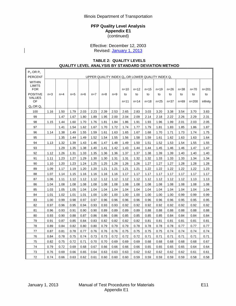
Illinois Department of Transportation
PFP Quality Level Analysis Appendix E1 (continued)
Effective: December 12, 2003
Revised: January 1, 2013
January 1, 2013 Manual of Test Procedures for Materials E11 Appendix E1
TABLE 2: QUALITY LEVELS
QUALITY LEVEL ANALYSIS BY STANDARD DEVIATION METHOD
PU OR PL
PERCENT UPPER QUALITY INDEX QU OR LOWER QUALITY INDEX QL
WITHIN
LIMITS FOR
n=10 n=12 n=15 n=19 n=26 n=38 n=70 n=201
POSITIVE n=3 n=4 n=5 n=6 n=7 n=8 n=9 to to to to to to to to VALUES
OF
n=11 n=14 n=18 n=25 n=37 n=69 n=200 infinity
QU OR QL
100 1.16 1.50 1.79 2.03 2.23 2.39 2.53 2.65 2.83 3.03 3.20 3.38 3.54 3.70 3.83
99 1.47 1.67 1.80 1.89 1.95 2.00 2.04 2.09 2.14 2.18 2.22 2.26 2.29 2.31
98 1.15 1.44 1.60 1.70 1.76 1.81 1.84 1.86 1.91 1.93 1.96 1.99 2.01 2.03 2.05
97 1.41 1.54 1.62 1.67 1.70 1.72 1.74 1.77 1.79 1.81 1.83 1.85 1.86 1.87
96 1.14 1.38 1.49 1.55 1.59 1.61 1.63 1.65 1.67 1.68 1.70 1.71 1.73 1.74 1.75
95 1.35 1.44 1.49 1.52 1.54 1.55 1.56 1.58 1.59 1.61 1.62 1.63 1.63 1.64
94 1.13 1.32 1.39 1.43 1.46 1.47 1.48 1.49 1.50 1.51 1.52 1.53 1.54 1.55 1.55
93 1.29 1.35 1.38 1.40 1.41 1.42 1.43 1.44 1.44 1.45 1.46 1.46 1.47 1.47
92 1.12 1.26 1.31 1.33 1.35 1.36 1.36 1.37 1.37 1.38 1.39 1.39 1.40 1.40 1.40
91 1.11 1.23 1.27 1.29 1.30 1.30 1.31 1.31 1.32 1.32 1.33 1.33 1.33 1.34 1.34
90 1.10 1.20 1.23 1.24 1.25 1.25 1.26 1.26 1.26 1.27 1.27 1.27 1.28 1.28 1.28
89 1.09 1.17 1.19 1.20 1.20 1.21 1.21 1.21 1.21 1.22 1.22 1.22 1.22 1.22 1.23
88 1.07 1.14 1.15 1.16 1.16 1.16 1.16 1.17 1.17 1.17 1.17 1.17 1.17 1.17 1.17
87 1.06 1.11 1.12 1.12 1.12 1.12 1.12 1.12 1.12 1.12 1.12 1.12 1.12 1.13 1.13
86 1.04 1.08 1.08 1.08 1.08 1.08 1.08 1.08 1.08 1.08 1.08 1.08 1.08 1.08 1.08
85 1.03 1.05 1.05 1.04 1.04 1.04 1.04 1.04 1.04 1.04 1.04 1.04 1.04 1.04 1.04
84 1.01 1.02 1.01 1.01 1.00 1.00 1.00 1.00 1.00 1.00 1.00 1.00 0.99 0.99 0.99
83 1.00 0.99 0.98 0.97 0.97 0.96 0.96 0.96 0.96 0.96 0.96 0.96 0.95 0.95 0.95
82 0.97 0.96 0.95 0.94 0.93 0.93 0.93 0.92 0.92 0.92 0.92 0.92 0.92 0.92 0.92
81 0.96 0.93 0.91 0.90 0.90 0.89 0.89 0.89 0.89 0.88 0.88 0.88 0.88 0.88 0.88
80 0.93 0.90 0.88 0.87 0.86 0.86 0.86 0.85 0.85 0.85 0.85 0.84 0.84 0.84 0.84
79 0.91 0.87 0.85 0.84 0.83 0.82 0.82 0.82 0.82 0.81 0.81 0.81 0.81 0.81 0.81
78 0.89 0.84 0.82 0.80 0.80 0.79 0.79 0.79 0.78 0.78 0.78 0.78 0.77 0.77 0.77
77 0.87 0.81 0.78 0.77 0.76 0.76 0.76 0.75 0.75 0.75 0.75 0.74 0.74 0.74 0.74
76 0.84 0.78 0.75 0.74 0.73 0.73 0.72 0.72 0.72 0.71 0.71 0.71 0.71 0.71 0.71
75 0.82 0.75 0.72 0.71 0.70 0.70 0.69 0.69 0.69 0.68 0.68 0.68 0.68 0.68 0.67
74 0.79 0.72 0.69 0.68 0.67 0.66 0.66 0.66 0.66 0.65 0.65 0.65 0.65 0.64 0.64
73 0.76 0.69 0.66 0.65 0.64 0.63 0.63 0.63 0.62 0.62 0.62 0.62 0.62 0.61 0.61
72 0.74 0.66 0.63 0.62 0.61 0.60 0.60 0.60 0.59 0.59 0.59 0.59 0.59 0.58 0.58

Illinois Department of Transportation
PFP Quality Level Analysis Appendix E1 (continued)
Effective: December 12, 2003
Revised: January 1, 2013
January 1, 2013 Manual of Test Procedures for Materials E12 Appendix E1
TABLE 2: QUALITY LEVELS
QUALITY LEVEL ANALYSIS BY STANDARD DEVIATION METHOD
PU OR PL
PERCENT UPPER QUALITY INDEX QU OR LOWER QUALITY INDEX QL
WITHIN
LIMITS FOR
n=10 n=12 n=15 n=19 n=26 n=38 n=70 n=201
POSITIVE n=3 n=4 n=5 n=6 n=7 n=8 n=9 to to to to to to to to VALUES
OF
n=11 n=14 n=18 n=25 n=37 n=69 n=200 infinity
QU OR QL
71 0.71 0.63 0.60 0.59 0.58 0.57 0.57 0.57 0.57 0.56 0.56 0.56 0.56 0.55 0.55
70 0.68 0.60 0.57 0.56 0.55 0.55 0.54 0.54 0.54 0.53 0.53 0.53 0.53 0.53 0.53
69 0.65 0.57 0.54 0.53 0.52 0.52 0.51 0.51 0.51 0.50 0.50 0.50 0.50 0.50 0.50
68 0.62 0.54 0.51 0.50 0.49 0.49 0.48 0.48 0.48 0.48 0.47 0.47 0.47 0.47 0.47
67 0.59 0.51 0.47 0.47 0.46 0.46 0.46 0.45 0.45 0.45 0.45 0.44 0.44 0.44 0.44
66 0.56 0.48 0.45 0.44 0.44 0.43 0.43 0.43 0.42 0.42 0.42 0.42 0.41 0.41 0.41
65 0.52 0.45 0.43 0.41 0.41 0.40 0.40 0.40 0.40 0.39 0.39 0.39 0.39 0.39 0.39
64 0.49 0.42 0.40 0.39 0.38 0.38 0.37 0.37 0.37 0.37 0.36 0.36 0.36 0.36 0.36
63 0.46 0.39 0.37 0.36 0.35 0.35 0.35 0.34 0.34 0.34 0.34 0.34 0.33 0.33 0.33
62 0.43 0.36 0.34 0.33 0.32 0.32 0.32 0.32 0.31 0.31 0.31 0.31 0.31 0.31 0.31
61 0.39 0.33 0.31 0.30 0.30 0.29 0.29 0.29 0.29 0.29 0.28 0.28 0.28 0.28 0.28
60 0.36 0.30 0.28 0.27 0.27 0.27 0.26 0.26 0.26 0.26 0.26 0.26 0.26 0.25 0.25
59 0.32 0.27 0.25 0.25 0.24 0.24 0.24 0.24 0.23 0.23 0.23 0.23 0.23 0.23 0.23
58 0.29 0.24 0.23 0.22 0.21 0.21 0.21 0.21 0.21 0.21 0.20 0.20 0.20 0.20 0.20
57 0.25 0.21 0.20 0.19 0.19 0.19 0.18 0.18 0.18 0.18 0.18 0.18 0.18 0.18 0.18
56 0.22 0.18 0.17 0.16 0.16 0.16 0.16 0.16 0.16 0.15 0.15 0.15 0.15 0.15 0.15
55 0.18 0.15 0.14 0.14 0.13 0.13 0.13 0.13 0.13 0.13 0.13 0.13 0.13 0.13 0.13
54 0.14 0.12 0.11 0.11 0.11 0.11 0.10 0.10 0.10 0.10 0.10 0.10 0.10 0.10 0.10
53 0.11 0.09 0.08 0.08 0.08 0.08 0.08 0.08 0.08 0.08 0.08 0.08 0.08 0.08 0.08
52 0.07 0.06 0.06 0.05 0.05 0.05 0.05 0.05 0.05 0.05 0.05 0.05 0.05 0.05 0.05
51 0.04 0.03 0.03 0.03 0.03 0.03 0.03 0.03 0.03 0.03 0.03 0.03 0.03 0.03 0.03
50 0.00 0.00 0.00 0.00 0.00 0.00 0.00 0.00 0.00 0.00 0.00 0.00 0.00 0.00 0.00
Note: For negative values of QU or QL, PU or PL is equal to 100 minus the table PU or PL. If the value of QU or QL does
not correspond exactly to a figure in the table, use the next higher value.
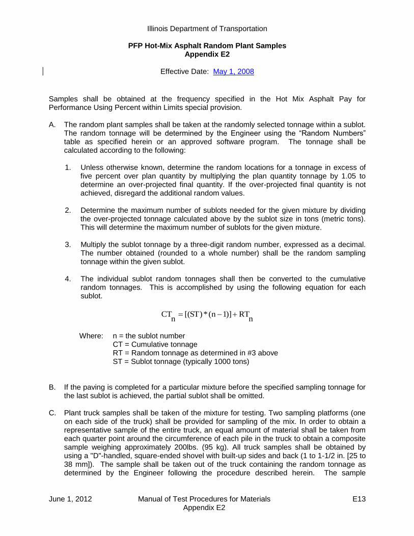
Illinois Department of Transportation
PFP Hot-Mix Asphalt Random Plant Samples Appendix E2
Effective Date: May 1, 2008
June 1, 2012 Manual of Test Procedures for Materials E13 Appendix E2
Samples shall be obtained at the frequency specified in the Hot Mix Asphalt Pay for Performance Using Percent within Limits special provision. A. The random plant samples shall be taken at the randomly selected tonnage within a sublot.
The random tonnage will be determined by the Engineer using the “Random Numbers” table as specified herein or an approved software program. The tonnage shall be calculated according to the following: 1. Unless otherwise known, determine the random locations for a tonnage in excess of
five percent over plan quantity by multiplying the plan quantity tonnage by 1.05 to determine an over-projected final quantity. If the over-projected final quantity is not achieved, disregard the additional random values.
2. Determine the maximum number of sublots needed for the given mixture by dividing
the over-projected tonnage calculated above by the sublot size in tons (metric tons). This will determine the maximum number of sublots for the given mixture.
3. Multiply the sublot tonnage by a three-digit random number, expressed as a decimal.
The number obtained (rounded to a whole number) shall be the random sampling tonnage within the given sublot.
4. The individual sublot random tonnages shall then be converted to the cumulative
random tonnages. This is accomplished by using the following equation for each sublot.
nRT)]1n(*)ST[(
nCT
Where: n = the sublot number CT = Cumulative tonnage RT = Random tonnage as determined in #3 above ST = Sublot tonnage (typically 1000 tons)
B. If the paving is completed for a particular mixture before the specified sampling tonnage for
the last sublot is achieved, the partial sublot shall be omitted.
C. Plant truck samples shall be taken of the mixture for testing. Two sampling platforms (one on each side of the truck) shall be provided for sampling of the mix. In order to obtain a representative sample of the entire truck, an equal amount of material shall be taken from each quarter point around the circumference of each pile in the truck to obtain a composite sample weighing approximately 200lbs. (95 kg). All truck samples shall be obtained by using a "D"-handled, square-ended shovel with built-up sides and back (1 to 1-1/2 in. [25 to 38 mm]). The sample shall be taken out of the truck containing the random tonnage as determined by the Engineer following the procedure described herein. The sample
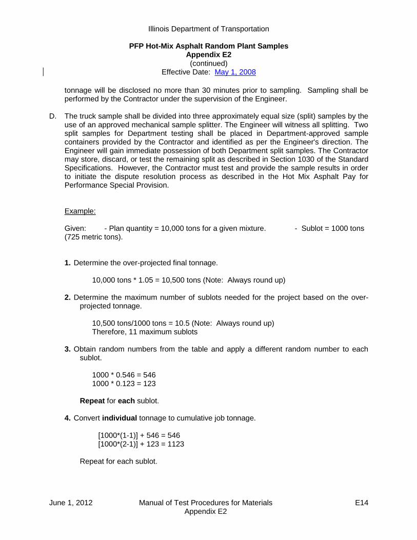
Illinois Department of Transportation
PFP Hot-Mix Asphalt Random Plant Samples Appendix E2 (continued)
Effective Date: May 1, 2008
June 1, 2012 Manual of Test Procedures for Materials E14 Appendix E2
tonnage will be disclosed no more than 30 minutes prior to sampling. Sampling shall be performed by the Contractor under the supervision of the Engineer.
D. The truck sample shall be divided into three approximately equal size (split) samples by the
use of an approved mechanical sample splitter. The Engineer will witness all splitting. Two split samples for Department testing shall be placed in Department-approved sample containers provided by the Contractor and identified as per the Engineer's direction. The Engineer will gain immediate possession of both Department split samples. The Contractor may store, discard, or test the remaining split as described in Section 1030 of the Standard Specifications. However, the Contractor must test and provide the sample results in order to initiate the dispute resolution process as described in the Hot Mix Asphalt Pay for Performance Special Provision.
Example: Given: - Plan quantity = 10,000 tons for a given mixture. - Sublot = 1000 tons (725 metric tons). 1. Determine the over-projected final tonnage.
10,000 tons * 1.05 = 10,500 tons (Note: Always round up)
2. Determine the maximum number of sublots needed for the project based on the over-projected tonnage.
10,500 tons/1000 tons = 10.5 (Note: Always round up) Therefore, 11 maximum sublots
3. Obtain random numbers from the table and apply a different random number to each sublot.
1000 * 0.546 = 546 1000 * 0.123 = 123
Repeat for each sublot.
4. Convert individual tonnage to cumulative job tonnage.
[1000*(1-1)] + 546 = 546 [1000*(2-1)] + 123 = 1123
Repeat for each sublot.

Illinois Department of Transportation
PFP Hot-Mix Asphalt Random Plant Samples Appendix E2 (continued)
Effective Date: May 1, 2008
June 1, 2012 Manual of Test Procedures for Materials E15 Appendix E2
The following contains a completed table for the eleven plant random samples:
Lot Sublot Random
Number Number Number
1 0.546 1000 * 0.546 = 546 [1000 * (1-1)] + 546 = 546
2 0.123 1000 * 0.123 = 123 [1000 * (2-1)] + 123 = 1123
3 0.789 1000 * 0.789 = 789 [1000 * (3-1)] + 789 = 2789
4 0.372 1000 * 0.372 = 372 [1000 * (4-1)] + 372 = 3372
5 0.865 1000 * 0.865 = 865 [1000 * (5-1)] + 865 = 4865
6 0.921 1000 * 0.921 = 921 [1000 * (6-1)] + 921 = 5921
7 0.037 1000 * 0.037 = 37 [1000 * (7-1)] + 37 = 6037
8 0.405 1000 * 0.405 = 405 [1000 * (8-1)] + 405 = 7405
9 0.214 1000 * 0.214 = 214 [1000 * (9-1)] + 214 = 8214
10 0.698 1000 * 0.698 = 698 [1000 * (10-1)] + 698 = 9698
11 0.711 1000 * 0.711 = 711 [1000 * (11-1)] + 711 = 10711
1
Tonnage
within Sublot
Cumulative Job
Tonnage

June 1, 2012 Manual of Test Procedures for Materials E16 Appendix E2
This Page Reserved

Illinois Department of Transportation
PFP Hot-Mix Asphalt Random Plant Samples Appendix E2 (continued)
Effective Date: May 1, 2008
April 1, 2011 Manual of Test Procedures for Materials E17 Appendix E2
PFP Hot-Mix Asphalt Random Plant Samples (continued)
RANDOM NUMBERS
0.576 0.730 0.430 0.754 0.271 0.870 0.732 0.721 0.998 0.239 0.892 0.948 0.858 0.025 0.935 0.114 0.153 0.508 0.749 0.291 0.669 0.726 0.501 0.402 0.231 0.505 0.009 0.420 0.517 0.858 0.609 0.482 0.809 0.140 0.396 0.025 0.937 0.301 0.253 0.761 0.971 0.824 0.902 0.470 0.997 0.392 0.892 0.957 0.040 0.463 0.053 0.899 0.554 0.627 0.427 0.760 0.470 0.040 0.904 0.993 0.810 0.159 0.225 0.163 0.549 0.405 0.285 0.542 0.231 0.919 0.081 0.277 0.035 0.039 0.860 0.507 0.081 0.538 0.986 0.501 0.982 0.468 0.334 0.921 0.690 0.806 0.879 0.414 0.106 0.031 0.095 0.801 0.576 0.417 0.251 0.884 0.522 0.235 0.389 0.222 0.509 0.025 0.794 0.850 0.917 0.887 0.751 0.608 0.698 0.683 0.371 0.059 0.164 0.838 0.289 0.169 0.569 0.977 0.796 0.996 0.165 0.996 0.356 0.375 0.654 0.979 0.815 0.592 0.348 0.743 0.477 0.535 0.137 0.155 0.767 0.187 0.579 0.787 0.358 0.595 0.788 0.101 0.434 0.638 0.021 0.894 0.324 0.871 0.698 0.539 0.566 0.815 0.622 0.548 0.947 0.169 0.817 0.472 0.864 0.466 0.901 0.342 0.873 0.964 0.942 0.985 0.123 0.086 0.335 0.212 0.470 0.682 0.412 0.064 0.150 0.962 0.925 0.355 0.909 0.019 0.068 0.242 0.777 0.356 0.195 0.313 0.396 0.460 0.740 0.247 0.874 0.420 0.127 0.284 0.448 0.215 0.833 0.652 0.701 0.326 0.897 0.877 0.209 0.862 0.428 0.117 0.100 0.259 0.425 0.284 0.876 0.969 0.109 0.843 0.759 0.239 0.890 0.317 0.428 0.802 0.190 0.696 0.757 0.283 0.777 0.491 0.523 0.665 0.919 0.146 0.341 0.688 0.587 0.908 0.865 0.333 0.928 0.404 0.892 0.696 0.846 0.355 0.831 0.281 0.945 0.364 0.673 0.305 0.195 0.887 0.882 0.227 0.552 0.077 0.454 0.731 0.716 0.265 0.058 0.075 0.464 0.658 0.629 0.269 0.069 0.998 0.917 0.217 0.220 0.659 0.123 0.791 0.503 0.447 0.659 0.463 0.994 0.307 0.631 0.422 0.116 0.120 0.721 0.137 0.263 0.176 0.798 0.879 0.432 0.391 0.836 0.206 0.914 0.574 0.870 0.390 0.104 0.755 0.082 0.939 0.636 0.195 0.614 0.486 0.629 0.663 0.619 0.007 0.296 0.456 0.630 0.673 0.665 0.666 0.399 0.592 0.441 0.649 0.270 0.612 0.804 0.112 0.331 0.606 0.551 0.928 0.830 0.841 0.702 0.183 0.360 0.193 0.181 0.399 0.564 0.772 0.890 0.062 0.919 0.875 0.183 0.651 0.157 0.150 0.800 0.875 0.205 0.446 0.648 0.685
Note: Always select a new set of numbers in a systematic manner, either horizontally or
vertically. Once used, the set should be crossed out.

April 1, 2011 Manual of Test Procedures for Materials E18 Appendix E2
This Page Reserved

Illinois Department of Transportation
PFP and QCP Random Density Procedure Appendix E3
Effective: April 1, 2009
Revised: January 1, 2013
January 1, 2013 Manual of Test Procedures for Materials E19 Appendix E3
Density tests using cores shall be obtained at the frequency specified in the Hot Mix Asphalt Quality Control for Performance (QCP) and Pay for Performance (PFP) Using Percent within Limits special provisions. The random test locations shall be determined as follows: A) The random core locations shall be taken at the randomly selected test location within each
density testing interval. The random test location will be determined by the Engineer using the “Random Numbers” table as specified herein or an approved software program. This may be performed each day or predetermined for the project. Regardless of when the values are determined, the values are to be considered confidential and are not to be disclosed to anyone outside of the Department. Disclosing the information prior to finish rolling would be in direct violation of federal regulations. Each core location shall be randomly located both longitudinally and transversely within each density testing interval. Each core location within the density testing interval shall be determined with two random numbers. The first random number is used to determine the longitudinal distance to the nearest 1 ft into the density testing interval. The second random number is used to determine the transverse offset to the nearest 0.1 ft from the left edge of the paving lane. To determine the longitudinal location of a core, multiply the length of the prescribed density interval by the random number selected from the Random Number table. Determine the random transverse offset as follows:
1. PFP. The effective lane width of the pavement shall be used in calculating the transverse offset. The effective lane width is determined by subtracting 1.0 ft for each unconfined edge from the entire paved lane width (i.e. If a 12.0 ft wide paved lane has two unconfined edges, the effective lane width would be 10.0 ft.) Determine the transverse offset by multiplying the effective width by the random number selected from the Random Number table. The transverse offset is measured from the left physical edge of the paved lane to locate the core on the pavement. If the left edge was unconfined, it will be omitted by adding 1.0 ft to the calculated transverse offset measurement. Random locations that fall within 4.0 inches of a confined edge shall be moved to 4.0 inches off the edge. Areas outside the mainline pavement that are paved concurrently with the mainline pavement (i.e. three-ft wide left shoulders, driveways, etc.) are not considered part of the paved mainline mat. See PFP example calculation herein. The core density location for the outer 1.0 ft of an unconfined edge will be randomly selected within each 0.5 mile section for each unconfined edge. Longitudinal joint testing shall be located at a distance equal to the lift thickness or a minimum of 4.0 in. (100 mm), from each pavement edge. (i.e. for a 5 in. (125 mm) lift the near edge of the core barrel shall be within 5.0 in. (125 mm) from the edge of pavement.)

Illinois Department of Transportation
PFP and QCP Random Density Procedure Appendix E3
Effective: April 1, 2009
Revised: January 1, 2013
January 1, 2013 Manual of Test Procedures for Materials E20 Appendix E3
2. QCP. The entire width of the pavement shall be used in calculating the transverse
offset. No offset movement is to be used for random locations that lie within 1.0 ft from an unconfined edge. Cores taken within 1.0 ft from an unconfined edge will have 2.0% density added for pay adjustment calculation purposes. Random locations that fall within 4.0 in. of an edge shall be moved to 4.0 in. off the edge. See QCP example calculation herein.
B) This process shall be repeated for all density intervals on a given project.
C) Example Calculations.
PFP Example. This PFP example illustrates the determination of the core locations within the first mile of a lot. Given 1.5 in. thickness would require a density testing interval of 0.2 miles. The pavement consists of a 13.0 ft-wide mat with the left edge confined and the right edge unconfined. The random numbers for the longitudinal direction are 0.917, 0.289, 0.654, 0.347, and 0.777. The random numbers for the transverse direction are 0.890, 0.317, 0.428, 0.998, and 0.003. The individual density test interval distances can be converted to the cumulative random distance using the following equation:
nn RnDCD )]1([
Where: n = the density interval number CD = cumulative distance D = density testing interval length (typically 1056 ft (0.2 mile)) R = Random distance within the given density testing interval
The longitudinal core locations are determined by multiplying the longitudinal random numbers by 1056 ft (0.2 mile). The transverse core locations are determined by multiplying the transverse random number by the effective width of the paved mat. Determine the effective lane width by subtracting 1.0 ft, for each unconfined edge, from the entire paved lane width. In this case only the right edge is unconfined, so subtract 1.0 ft from the entire paved lane width of 13.0 ft. Effective Width = 13.0 ft minus 1.0 ft = 12.0 ft

Illinois Department of Transportation
PFP and QCP Random Density Procedure Appendix E3
Effective: April 1, 2009
Revised: January 1, 2013
January 1, 2013 Manual of Test Procedures for Materials E21 Appendix E3
The random location for the first mile measured from the beginning of the lot and the left (confined) edge of the paved mat are as follows:
Core #
Longitudinal Location Cumulative Distance Transverse Location
1 1056 x 0.917 = 968 ft 1056 x (1-1) + 968 = 968 ft 12.0 x 0.890 = 10.7 ft
2 1056 x 0.289 = 305 ft 1056 x (2-1) + 305 = 1361 ft 12.0 x 0.317 = 3.8 ft
3 1056 x 0.654 = 691 ft 1056 x (3-1) + 691 = 2803 ft 12.0 x 0.428 = 5.1 ft
4 1056 x 0.347 = 366 ft 1056 x (4-1) + 366 = 3534 ft 12.0 x 0.998 = 11.7 ft
5 1056 x 0.777 = 821 ft 1056 x (5-1) + 821 = 5045 ft 12.0 x 0.003 = 0.0 ft = 0.3 ft1/
1/ The 0.0 ft for Core #5 was moved in to 0.3 ft due to the 4 in. minimum from the edge
requirement. QCP Example. This QCP example illustrates the determination of the core locations within the first mile of a project. Given 1.5” thickness would require a density testing interval of 0.2 miles. The pavement consists of a 13.0 ft-wide mat with the left edge confined and the right edge unconfined. The random numbers for the longitudinal direction are 0.904, 0.231, 0.517, 0.253, and 0.040. The random numbers for the transverse direction are 0.007, 0.059, 0.996, 0.515, and 0.101.
The individual density test interval distances can be converted to the cumulative random distance using the following equation:
nn RnDCD )]1([
Where: n = the density interval number CD = cumulative distance D = density testing interval length (typically 1056 ft (0.2 mile)) R = Random distance within the given density testing interval
The longitudinal core locations are determined by multiplying the longitudinal random numbers by 1056 ft (0.2 mile). The transverse core locations are determined by multiplying the transverse random number by the width of the paved lane (13.0 ft).
The random location for the first mile measured from the beginning of the lot and the left (confined) edge of the paved mat are as follows:
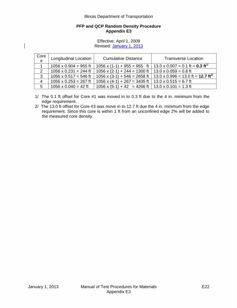
Illinois Department of Transportation
PFP and QCP Random Density Procedure Appendix E3
Effective: April 1, 2009
Revised: January 1, 2013
January 1, 2013 Manual of Test Procedures for Materials E22 Appendix E3
Core #
Longitudinal Location Cumulative Distance Transverse Location
1 1056 x 0.904 = 955 ft 1056 x (1-1) + 955 = 955 ft 13.0 x 0.007 = 0.1 ft = 0.3 ft1/
2 1056 x 0.231 = 244 ft 1056 x (2-1) + 244 = 1300 ft 13.0 x 0.059 = 0.8 ft
3 1056 x 0.517 = 546 ft 1056 x (3-1) + 546 = 2658 ft 13.0 x 0.996 = 13.0 ft = 12.7 ft2/
4 1056 x 0.253 = 267 ft 1056 x (4-1) + 267 = 3435 ft 13.0 x 0.515 = 6.7 ft
5 1056 x 0.040 = 42 ft 1056 x (5-1) + 42 = 4266 ft 13.0 x 0.101 = 1.3 ft
1/ The 0.1 ft offset for Core #1 was moved in to 0.3 ft due to the 4 in. minimum from the
edge requirement. 2/ The 13.0 ft offset for Core #3 was move in to 12.7 ft due the 4 in. minimum from the edge
requirement. Since this core is within 1 ft from an unconfined edge 2% will be added to the measured core density.

Illinois Department of Transportation
PFP and QCP Random Density Procedure Appendix E3
Effective: April 1, 2009
Revised: January 1, 2013
January 1, 2013 Manual of Test Procedures for Materials E23 Appendix E3
RANDOM NUMBERS
0.576 0.730 0.430 0.754 0.271 0.870 0.732 0.721 0.998 0.239 0.892 0.948 0.858 0.025 0.935 0.114 0.153 0.508 0.749 0.291 0.669 0.726 0.501 0.402 0.231 0.505 0.009 0.420 0.517 0.858 0.609 0.482 0.809 0.140 0.396 0.025 0.937 0.301 0.253 0.761 0.971 0.824 0.902 0.470 0.997 0.392 0.892 0.957 0.040 0.463 0.053 0.899 0.554 0.627 0.427 0.760 0.470 0.040 0.904 0.993 0.810 0.159 0.225 0.163 0.549 0.405 0.285 0.542 0.231 0.919 0.081 0.277 0.035 0.039 0.860 0.507 0.081 0.538 0.986 0.501 0.982 0.468 0.334 0.921 0.690 0.806 0.879 0.414 0.106 0.031 0.095 0.801 0.576 0.417 0.251 0.884 0.522 0.235 0.389 0.222 0.509 0.025 0.794 0.850 0.917 0.887 0.751 0.608 0.698 0.683 0.371 0.059 0.164 0.838 0.289 0.169 0.569 0.977 0.796 0.996 0.165 0.996 0.356 0.375 0.654 0.979 0.815 0.592 0.348 0.743 0.477 0.535 0.137 0.155 0.767 0.187 0.579 0.787 0.358 0.595 0.788 0.101 0.434 0.638 0.021 0.894 0.324 0.871 0.698 0.539 0.566 0.815 0.622 0.548 0.947 0.169 0.817 0.472 0.864 0.466 0.901 0.342 0.873 0.964 0.942 0.985 0.123 0.086 0.335 0.212 0.470 0.682 0.412 0.064 0.150 0.962 0.925 0.355 0.909 0.019 0.068 0.242 0.777 0.356 0.195 0.313 0.396 0.460 0.740 0.247 0.874 0.420 0.127 0.284 0.448 0.215 0.833 0.652 0.701 0.326 0.897 0.877 0.209 0.862 0.428 0.117 0.100 0.259 0.425 0.284 0.876 0.969 0.109 0.843 0.759 0.239 0.890 0.317 0.428 0.802 0.190 0.696 0.757 0.283 0.777 0.491 0.523 0.665 0.919 0.146 0.341 0.688 0.587 0.908 0.865 0.333 0.928 0.404 0.892 0.696 0.846 0.355 0.831 0.281 0.945 0.364 0.673 0.305 0.195 0.887 0.882 0.227 0.552 0.077 0.454 0.731 0.716 0.265 0.058 0.075 0.464 0.658 0.629 0.269 0.069 0.998 0.917 0.217 0.220 0.659 0.123 0.791 0.503 0.447 0.659 0.463 0.994 0.307 0.631 0.422 0.116 0.120 0.721 0.137 0.263 0.176 0.798 0.879 0.432 0.391 0.836 0.206 0.914 0.574 0.870 0.390 0.104 0.755 0.082 0.939 0.636 0.195 0.614 0.486 0.629 0.663 0.619 0.007 0.296 0.456 0.630 0.673 0.665 0.666 0.399 0.592 0.441 0.649 0.270 0.612 0.804 0.112 0.331 0.606 0.551 0.928 0.830 0.841 0.702 0.183 0.360 0.193 0.181 0.399 0.564 0.772 0.890 0.062 0.919 0.875 0.183 0.651 0.157 0.150 0.800 0.875 0.205 0.446 0.648 0.685
Note: Always select a new set of numbers in a systematic manner, either horizontally or vertically. Once used, the set should be crossed out.

January 1, 2013 Manual of Test Procedures for Materials E24 Appendix E3
This Page Reserved

Illinois Department of Transportation
PFP and QCP Hot Mix Asphalt Random Jobsite Sampling Appendix E4
Effective: April 1, 2008
Revised: January 1, 2013
January 1, 2013 Manual of Test Procedures for Materials E25 Appendix E4
Hot-mix asphalt (HMA) samples shall be obtained at the frequency specified in the Hot Mix Asphalt Quality Control for Performance (QCP) and Pay for Performance (PFP) Using Percent within Limits special provisions.
The random jobsite mixture samples shall be taken at the randomly selected test location within a sublot. The random test location will be determined by the Engineer using the “Random Numbers” table as specified herein or an approved software program. This may be performed each day or predetermined for the project as per the Engineer. Regardless of when the values are determined, the values are to be considered confidential and are not to be disclosed to anyone outside of the Department. Disclosing the information would violate the intent of this procedure and federal regulations.
The sample location shall be determined by calculating the longitudinal distance the truck would travel to produce the random sample tonnage. The starting station for the longitudinal distance measurement is the location of the paver where the truck begins to unload the mixture into the paver or Material Transfer Device (MTD). Computations are made to the nearest foot (see examples in appendix herein).
If the paving is completed for a mixture before the specified sampling test location for the last mixture sublot is completed, a test will not be taken and the tonnage will be added to the current lot.
The Contractor may select either sampling behind the paver or sampling from the MTD discharge chute. The Contractor shall provide the necessary equipment and HMA Level I personnel to obtain the required samples, for whatever method is chosen, as specified herein.
A. Behind Paver Sampling.
This method covers the procedures for sampling HMA paving mixtures at the point of delivery immediately behind the paver and before initial compaction. This method is intended to provide a single composite sample that is representative of the mixture as produced (i.e. excludes paver effects).
1. Equipment
a) IDOT Approved Sampling Shovel (Fig. 1).
b) Sample Containers (4 each). Metal sample buckets with a minimum capacity of 3.5 gallons (13 liters).
c) IDOT Approved HMA Sample Splitter. d) Plate/Shovel Sampling. The following additional equipment is needed when
sampling HMA placed directly over a milled surface, rubblized concrete or an aggregate base.
1) Sampling Plates (4 each). The sampling plates shall be rectangular and have a minimum size of 14 x 28 inches (360 x 720 mm). Plates shall have a hole

Illinois Department of Transportation
PFP and QCP Hot Mix Asphalt Random Jobsite Sampling Appendix E4
Effective: April 1, 2008
Revised: January 1, 2013
January 1, 2013 Manual of Test Procedures for Materials E26 Appendix E4
approximately 0.25 inches (6 mm) in diameter drilled through each of the four corners.
2) Lifting Handles and Wire Lead. A 24 inch (600 mm) length of wire shall be attached to the two holes on one side of the plate to serve as lifting handle. An additional wire lead shall be attached to one of the lifting handles for locating the buried plate in the pavement. This wire shall extend to the edge of the pavement.
3) Hammer and masonry nails for securing plates and wire lead.
Figure 1. Aluminum Sampling Shovel & Dimensions
2. Shovel Sample Sampling Procedure (Without Plates). This method shall be used when
sampling over smooth HMA and concrete surfaces.
a) The sampling shovel shall be used at each of the four offsets illustrated in Figure 2. to dig directly downward into pavement until it comes into contact with the previous pavement surface. When in contact, the shovel shall be pushed forward until it is full. The shovel shall be lifted up slowly and carefully place the mix into the sample container in order to prevent any loss of HMA.
Overall Length = 5 feet Shovel Width = 10 inches Shovel Length = 12 inches Shovel Sides = 4 inches

Illinois Department of Transportation
PFP and QCP Hot Mix Asphalt Random Jobsite Sampling Appendix E4
Effective: April 1, 2008
Revised: January 1, 2013
January 1, 2013 Manual of Test Procedures for Materials E27 Appendix E4
3. Shovel/Plate Sampling Procedure (With Plates). This method shall be used when
sampling HMA directly over aggregate base, stabilized subbase, rubblized concrete, or a milled surface. This method may not be appropriate for 3/4 in. level binder over a milled surface. In the case of IL-4.75 mm or IL-9.5 FG mixtures, if approved by the Engineer, these mixtures may be shovel sampled from the auger area at the designated random location. Intentions of sampling IL-4.75 mm or IL-9.5 FG mixtures in this manner shall be listed in the approved QC Plan.
a) Each plate with the wire lead attached to handle shall be placed at four locations
according for Figure 2. at the designated location ahead of the paver. If conditions on the project require restricting movement of the plate, a nail shall be driven through one of the holes in the plate and into the pavement.
b) The wire lead shall be extended beyond the edge of the pavement. Trucks, pavers,
and/or materials transfer devices will be allowed to cross over the pate and/or wire lead.
c) After the HMA is placed, the wire lead shall be used to locate the plate. Once
located, the wire handles shall be lifted out of the pavement. This will locate the four corners of the plate.
d) Once the plate edges are defined, the shovel shall be used to dig downward through
the thickness of the pavement until it is in contact with the plate. The shovel shall be pushed forward until it is full. The shovel shall be lifted up slowly and carefully place the mix into the sample container in order to prevent any loss of HMA.
e) Remove sampling plates from pavement.
Figure 2. Behind Paver Sampling Layout
Direction of Paving
10 feet
Paving Width

Illinois Department of Transportation
PFP and QCP Hot Mix Asphalt Random Jobsite Sampling Appendix E4
Effective: April 1, 2008
Revised: January 1, 2013
January 1, 2013 Manual of Test Procedures for Materials E28 Appendix E4
4. Composite/Lab Sample.
a) HMA samples shall be taken, blended and split, using an IDOT approved HMA splitter, onsite by the Contractor and witnessed by the Engineer. The sample shall be taken immediately behind the paver and before initial roller compaction. One composite sample consists of four increments collected within 10 feet longitudinally and diagonally across the width of the paving operation (Fig. 2). The four increments shall be blended according to HMA Level I procedures to provide a single composite sample.
b) Composite Sample.
1) PFP. If the contractor elects to have the option to dispute test results by the Engineer, a composite sample size shall be a minimum of 200 lbs. (90 kg), allowing 50 lbs (23 kg) for District testing, 50 lbs. (23 kg) for Contractor testing, 50 lbs (23 kg) for dispute resolution testing, and 50 lbs. (23 kg backup for Department testing).
2) QCP. A composite sample size shall be a minimum of 100 lbs. (45 kg), allowing
50 lbs. (23 kg) for District testing, and 50 lbs. (23 kg) for Contractor testing.
c) Lab Sample.
1) PFP. The minimum lab sample size of 50 lbs. (23 kg) shall be obtained by splitting the composite samples into four equal lab samples using an IDOT approved HMA splitter. The Engineer will secure three Department lab samples for the Contractor to transport to the District Materials Laboratory.
2) QCP. The minimum lab sample size of 50 lbs. (23 kg) shall be obtained by
splitting the composite samples into two equal lab samples using an IDOT approved HMA splitter. The Engineer will secure the Department lab sample for the Contractor to transport to the District Materials Laboratory.
5. Sample Site Repair
a) HMA from the paver auger system shall be used to fill the voids left in the pavement
from sampling. To reduce segregation and low density in the finished mat, buckets shall be used to fill the voids left by the samples.
1) HMA from the augers system shall be placed in clean metal buckets just prior to sampling the pavement.
2) The metal buckets shall be filled with approximately 25% more HMA than will be removed from the void.
b) The bucket shall be dumped directly over the void.

Illinois Department of Transportation
PFP and QCP Hot Mix Asphalt Random Jobsite Sampling Appendix E4
Effective: April 1, 2008
Revised: January 1, 2013
January 1, 2013 Manual of Test Procedures for Materials E29 Appendix E4
c) The HMA shall be slightly leveled to provide a gradual hump over the filled void to allow compression of the mix by the roller.
d) Unacceptable site repair shall be removed and replaced at the Contractors expense.
B. MTD Sampling.
This method covers the procedures for sampling HMA paving mixtures at the point of delivery from a material transfer device (MTD).
1. Equipment.
a) MTD Sampling Device. A portable device mounted either in the bed of a pickup truck or on a trailer. The device shall be equipped with a funnel large enough to capture the full stream of HMA from the MTD discharge chute without spillage and shall be capable of capturing a minimum composite HMA sample of 200 lbs (90 kg). See appendix for illustrations of various MTD sampling device configurations.
b) Sample Containers – Metal containers each capable of holding a minimum of 50 lbs. of HMA.
2. MTD Sampling Procedure.
The Engineer will identify the truck containing the sample tonnage immediately prior to sampling. Immediately after the truck containing the random HMA tonnage has finished unloading, the MTD shall pull forward away from the paver far enough to allow the sampling device to be positioned under the MTD discharge chute. The sampling device shall be positioned as level as possible in a safe location readily accessible by the MTD. The MTD shall discharge without spillage a minimum of 200 lbs. (90 kg) of HMA for PFP or 100 lbs. (45 kg) for QCP into the funnel of the sampling device.
3. Composite/Lab Sample.
a) Composite Sample. HMA from all four sample containers of the sampling device shall be blended into one composite sample and split to lab sample size by the Contractor onsite using an IDOT approved HMA splitter. The blending and splitting shall be according to HMA Level I procedures and will be witnessed by the Engineer.
1) PFP. If the contractor elects to have the option to dispute test results by the
Engineer, a composite sample size shall be a minimum of 200 lbs. (90 kg), allowing 50 lbs (23 kg) for District testing, 50 lbs. (23 kg) for Contractor testing, 50 lbs (23 kg) for dispute resolution testing, and 50 lbs. (23 kg backup for Department testing).
2) QCP. A composite sample size shall be a minimum of 100 lbs. (45 kg), allowing
50 lbs. (23 kg) for District testing, and 50 lbs. (23 kg) for Contractor testing.

Illinois Department of Transportation
PFP and QCP Hot Mix Asphalt Random Jobsite Sampling Appendix E4
Effective: April 1, 2008
Revised: January 1, 2013
January 1, 2013 Manual of Test Procedures for Materials E30 Appendix E4
b) Lab Sample.
1) PFP. The minimum lab sample size of 50 lbs. (23 kg) shall be obtained by splitting the composite samples into four equal lab samples using an IDOT approved HMA splitter. The Engineer will secure three Department lab samples for the Contractor to transport to the District Materials Laboratory.
2) QCP. The minimum lab sample size of 50 lbs. (23 kg) shall be obtained
by splitting the composite samples into two equal lab samples using an IDOT approved HMA splitter. The Engineer will secure the Department lab sample for the Contractor to transport to the District Materials Laboratory.
C. Documentation – After the sample has been obtained, the following information shall be
written on each sample bag or box with a felt tip marker. D. Sample Security – Each sample bag will be secured by the Engineer using a locking ID tag.
Sample boxes will be sealed/taped using a security ID label.
E. Sample Transportation – The Contractor shall deliver the secured sample to the district laboratory, during regular working hours, for testing within two days of sampling.
F. Examples:
1. Behind Paver Sampling. Determination of random sample location for behind paver
sampling.
This example illustrates the determination of the random behind the paver test location within a sublot:
Given a surface mix with a design Gmb of 2.400 is being placed 12 feet wide and 1.5 inches thick. The Engineer has elected to determine all the undisclosed random
Contract #: _______________
Lot #:__________ Sublot #:__________
Date: ___________ Time: ___________
Mix Type (binder, surface…): _________
Mix Design #: _____________________
Sampled By: ______________________
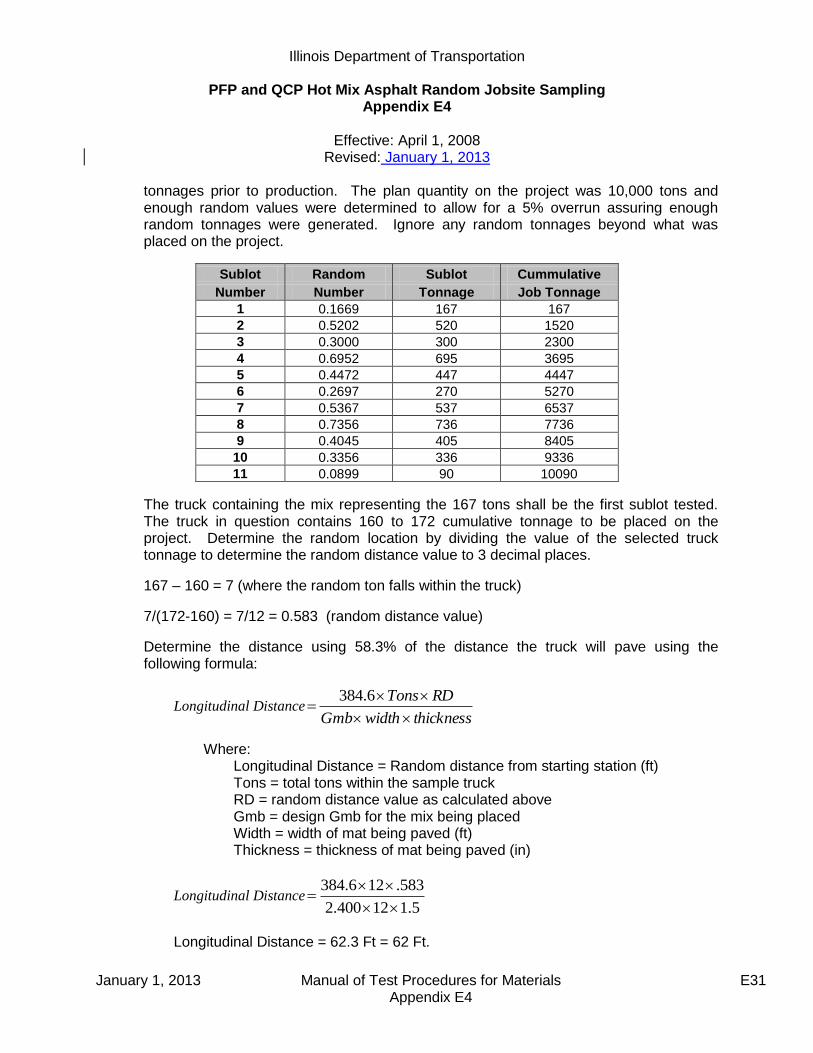
Illinois Department of Transportation
PFP and QCP Hot Mix Asphalt Random Jobsite Sampling Appendix E4
Effective: April 1, 2008
Revised: January 1, 2013
January 1, 2013 Manual of Test Procedures for Materials E31 Appendix E4
tonnages prior to production. The plan quantity on the project was 10,000 tons and enough random values were determined to allow for a 5% overrun assuring enough random tonnages were generated. Ignore any random tonnages beyond what was placed on the project.
Sublot Random Sublot Cummulative
Number Number Tonnage Job Tonnage
1 0.1669 167 167
2 0.5202 520 1520
3 0.3000 300 2300
4 0.6952 695 3695
5 0.4472 447 4447
6 0.2697 270 5270
7 0.5367 537 6537
8 0.7356 736 7736
9 0.4045 405 8405
10 0.3356 336 9336
11 0.0899 90 10090
The truck containing the mix representing the 167 tons shall be the first sublot tested. The truck in question contains 160 to 172 cumulative tonnage to be placed on the project. Determine the random location by dividing the value of the selected truck tonnage to determine the random distance value to 3 decimal places.
167 – 160 = 7 (where the random ton falls within the truck)
7/(172-160) = 7/12 = 0.583 (random distance value)
Determine the distance using 58.3% of the distance the truck will pave using the following formula:
Longitudinal DistancethicknesswidthGmb
RDTons
6.384
Where: Longitudinal Distance = Random distance from starting station (ft) Tons = total tons within the sample truck RD = random distance value as calculated above Gmb = design Gmb for the mix being placed Width = width of mat being paved (ft) Thickness = thickness of mat being paved (in)
Longitudinal Distance5.112400.2
583.126.384
Longitudinal Distance = 62.3 Ft = 62 Ft.
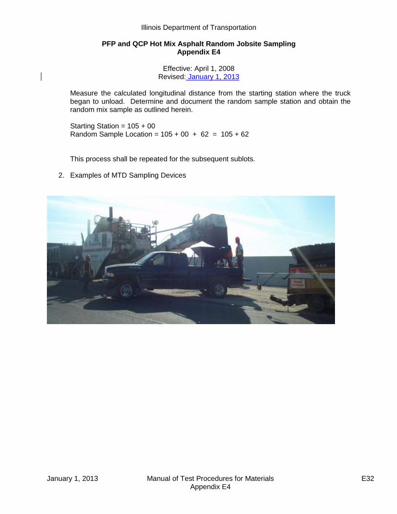
Illinois Department of Transportation
PFP and QCP Hot Mix Asphalt Random Jobsite Sampling Appendix E4
Effective: April 1, 2008
Revised: January 1, 2013
January 1, 2013 Manual of Test Procedures for Materials E32 Appendix E4
Measure the calculated longitudinal distance from the starting station where the truck began to unload. Determine and document the random sample station and obtain the random mix sample as outlined herein. Starting Station = 105 + 00 Random Sample Location = 105 + 00 + 62 = 105 + 62 This process shall be repeated for the subsequent sublots.
2. Examples of MTD Sampling Devices

Illinois Department of Transportation
PFP and QCP Hot Mix Asphalt Random Jobsite Sampling Appendix E4
Effective: April 1, 2008
Revised: January 1, 2013
January 1, 2013 Manual of Test Procedures for Materials E33 Appendix E4
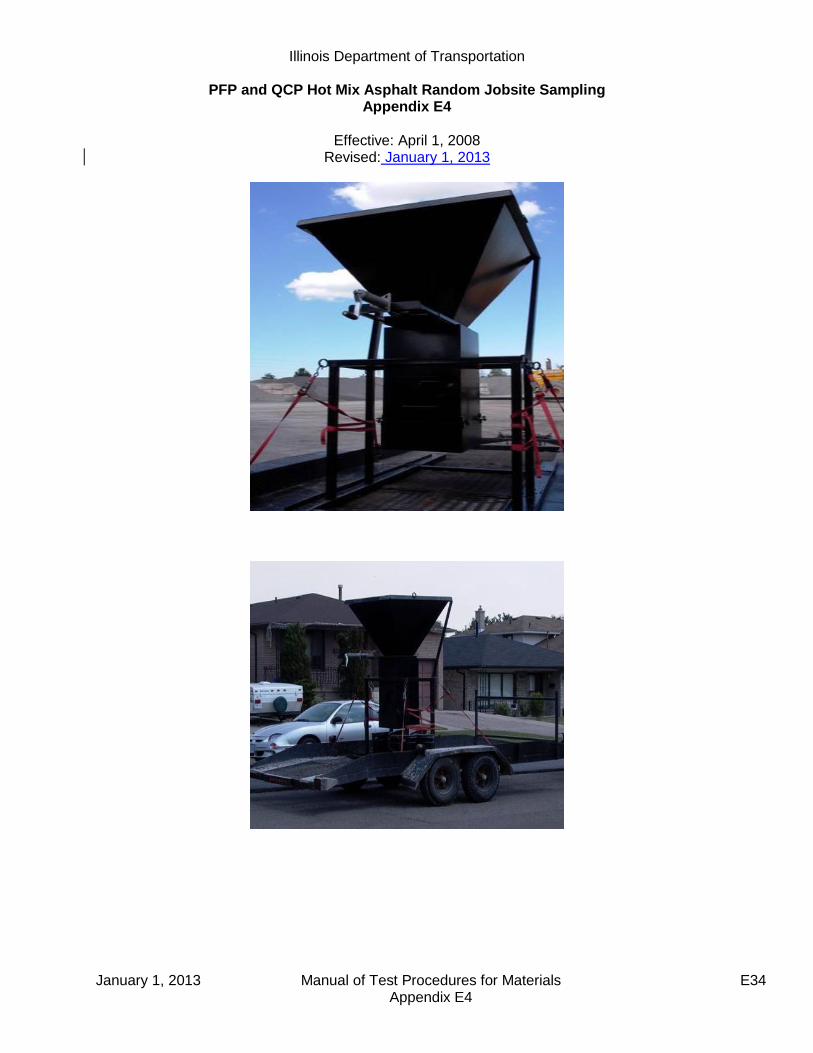
Illinois Department of Transportation
PFP and QCP Hot Mix Asphalt Random Jobsite Sampling Appendix E4
Effective: April 1, 2008
Revised: January 1, 2013
January 1, 2013 Manual of Test Procedures for Materials E34 Appendix E4
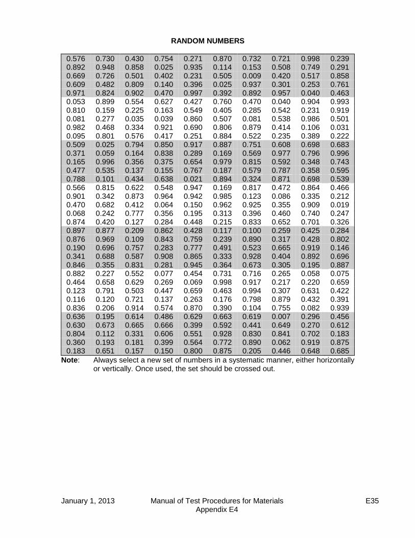
January 1, 2013 Manual of Test Procedures for Materials E35 Appendix E4
RANDOM NUMBERS
0.576 0.730 0.430 0.754 0.271 0.870 0.732 0.721 0.998 0.239 0.892 0.948 0.858 0.025 0.935 0.114 0.153 0.508 0.749 0.291 0.669 0.726 0.501 0.402 0.231 0.505 0.009 0.420 0.517 0.858 0.609 0.482 0.809 0.140 0.396 0.025 0.937 0.301 0.253 0.761 0.971 0.824 0.902 0.470 0.997 0.392 0.892 0.957 0.040 0.463 0.053 0.899 0.554 0.627 0.427 0.760 0.470 0.040 0.904 0.993 0.810 0.159 0.225 0.163 0.549 0.405 0.285 0.542 0.231 0.919 0.081 0.277 0.035 0.039 0.860 0.507 0.081 0.538 0.986 0.501 0.982 0.468 0.334 0.921 0.690 0.806 0.879 0.414 0.106 0.031 0.095 0.801 0.576 0.417 0.251 0.884 0.522 0.235 0.389 0.222 0.509 0.025 0.794 0.850 0.917 0.887 0.751 0.608 0.698 0.683 0.371 0.059 0.164 0.838 0.289 0.169 0.569 0.977 0.796 0.996 0.165 0.996 0.356 0.375 0.654 0.979 0.815 0.592 0.348 0.743 0.477 0.535 0.137 0.155 0.767 0.187 0.579 0.787 0.358 0.595 0.788 0.101 0.434 0.638 0.021 0.894 0.324 0.871 0.698 0.539 0.566 0.815 0.622 0.548 0.947 0.169 0.817 0.472 0.864 0.466 0.901 0.342 0.873 0.964 0.942 0.985 0.123 0.086 0.335 0.212 0.470 0.682 0.412 0.064 0.150 0.962 0.925 0.355 0.909 0.019 0.068 0.242 0.777 0.356 0.195 0.313 0.396 0.460 0.740 0.247 0.874 0.420 0.127 0.284 0.448 0.215 0.833 0.652 0.701 0.326 0.897 0.877 0.209 0.862 0.428 0.117 0.100 0.259 0.425 0.284 0.876 0.969 0.109 0.843 0.759 0.239 0.890 0.317 0.428 0.802 0.190 0.696 0.757 0.283 0.777 0.491 0.523 0.665 0.919 0.146 0.341 0.688 0.587 0.908 0.865 0.333 0.928 0.404 0.892 0.696 0.846 0.355 0.831 0.281 0.945 0.364 0.673 0.305 0.195 0.887 0.882 0.227 0.552 0.077 0.454 0.731 0.716 0.265 0.058 0.075 0.464 0.658 0.629 0.269 0.069 0.998 0.917 0.217 0.220 0.659 0.123 0.791 0.503 0.447 0.659 0.463 0.994 0.307 0.631 0.422 0.116 0.120 0.721 0.137 0.263 0.176 0.798 0.879 0.432 0.391 0.836 0.206 0.914 0.574 0.870 0.390 0.104 0.755 0.082 0.939 0.636 0.195 0.614 0.486 0.629 0.663 0.619 0.007 0.296 0.456 0.630 0.673 0.665 0.666 0.399 0.592 0.441 0.649 0.270 0.612 0.804 0.112 0.331 0.606 0.551 0.928 0.830 0.841 0.702 0.183 0.360 0.193 0.181 0.399 0.564 0.772 0.890 0.062 0.919 0.875 0.183 0.651 0.157 0.150 0.800 0.875 0.205 0.446 0.648 0.685
Note: Always select a new set of numbers in a systematic manner, either horizontally or vertically. Once used, the set should be crossed out.

Illinois Department of Transportation
PFP and QCP Hot Mix Asphalt Random Jobsite Sampling Appendix E4
Effective: April 1, 2008
Revised: January 1, 2013
January 1, 2013 Manual of Test Procedures for Materials E36 Appendix E4
PFP Jobsite Sampling Location Determination
Date: Contract #: Route:
Bit Mix #: Bit Code: Bit Desc.:
Design Gmb: Pvt width(w): Pvt thickness(t):
Lot #: Sublot #: Sampling Tonnage (st):
Lot #: Sublot #: Sampling Tonnage (st):
Lot #: Sublot #: Sampling Tonnage (st):
Lot #: Sublot #: Sampling Tonnage (st):
Begin Truck Tons (b): Longitudinal Distance(d):
(d)=[384.6(q)(rd)] / [Gmb(w)(t)]
End Truck Tons (e): Starting Station(ss):
Tons in Truck (q): (q)=(e)-(b)
Random sample location(rl):
(rl)=(ss)+/-(d) {add or subtract if up/down sta.}
Random Truck distance(rd):
(rd)=[(st)-(b)]/(q)
Begin Truck Tons (b): Longitudinal Distance(d):
(d)=[384.6(q)(rd)] / [Gmb(w)(t)]
End Truck Tons (e): Starting Station(ss):
Tons in Truck (q): (q)=(e)-(b)
Random sample location(rl):
(rl)=(ss)+/-(d) {add or subtract if up/down sta.}
Random Truck distance(rd):
(rd)=[(st)-(b)]/(q)
Begin Truck Tons (b): Longitudinal Distance(d):
(d)=[384.6(q)(rd)] / [Gmb(w)(t)]
End Truck Tons (e): Starting Station(ss):
Tons in Truck (q): (q)=(e)-(b)
Random sample location(rl):
(rl)=(ss)+/-(d) {add or subtract if up/down sta.}
Random Truck distance(rd):
(rd)=[(st)-(b)]/(q)
Begin Truck Tons (b): Longitudinal Distance(d):
(d)=[384.6(q)(rd)] / [Gmb(w)(t)]
End Truck Tons (e): Starting Station(ss):
Tons in Truck (q): (q)=(e)-(b)
Random sample location(rl):
(rl)=(ss)+/-(d) {add or subtract if up/down sta.}
Random Truck distance(rd):
(rd)=[(st)-(b)]/(q)

June 1, 2012 Manual of Test Procedures for Materials E35 Appendix E5
Illinois Department of Transportation
Instructions for Submitting Pay for Performance Dispute Resolution Samples Appendix E5
Effective Date: April 1, 2010
A. Scope
The following guidelines are provided to clarify the district submittal requirements for dispute
resolution samples; and expedite the testing process for HMA mix and/or core samples.
B. Procedure
When submitting HMA mix and/or core samples include the following:
All District and Contractor split sample test results on attached “PFP Dispute Resolution Form”,
Submit entire dispute resolution HMA mix split sample,
Cores must be split or sawed to lift testing thickness,
QC Package template and dailies sent electronically for mix being tested.
Send sample and requested documentation to:
Illinois Department of Transportation
Bureau of Materials & Physical Research
Hot Mix Asphalt Laboratory
126 E. Ash Street
Springfield, Illinois 62704-4766
Attention: Joe Rechner [email protected]
Any sample sent to BMPR without the above listed information will not be processed until all
requested information is received.

June 1, 2012 Manual of Test Procedures for Materials E36 Appendix E5
BMPR Lab #: _________________________
Wt. for Gmb: _________________________ Sampled From: Truck ___ Mat ___ MTD ___
Sample Date: ________________________
Date Received: ________________________
CORES
1 This shall be the Gmm used for density calculation.
Contract # :
Dist. Lab ID # :
Mix Design # :
Mix Code # :
Producer # :
Mix Lot ___ Sublot ___
Sieve Size
District %
Passing
Contractor %
Passing
BMPR %
Passing 1 ½ in
(37.5 mm)
1 in (25 mm)
¾ in (19 mm)
½ in (12.5 mm)
3/8 in (9.5 mm)
#4 (4.75 mm)
#8 (2.36 mm)
#16 (1.18 mm)
#30 (.60 mm)
#50 (.30 mm)
#100 (.15 mm)
#200 (.075 mm)
Asphalt Binder %
Dust/Asphalt Binder Ratio
Gmm
Gmb
% Voids
Gsb
Field VMA
District Contractor BMPR
Core # Gmm1 Gmm Gmm
Core # Gmb Gmb Gmb
Core # Density %
Density %
Density %
PFP DISPUTE RESOLUTION

Illinois Department of Transportation
QCP Pay Calculation Appendix E6
Effective: January 1, 2012 Revised: January 1, 2014
January 1, 2014 Manual of Test Procedures for Materials E39 Appendix E6
This document explains the procedure used to determine the pay adjustment for a hot-mix asphalt (HMA) mixture for Quality Control for Performance (QCP) projects. The following steps are used to determine the pay deduction for each QCP mixture:
1. Determine sublot deviation from target for each pay parameter. 2. Determine the sublot pay factor for each sublot using the Table 1 and the deviation from
target. 3. Determine the average sublot Pay Factor for each pay parameter. 4. Calculate a Combined Pay Factor using the average sublot Pay Factors and Equation 1. 5. Determine the QCP pay deduction for the mixture using Equation 2. 6. The Combined Pay Factor shall not exceed 100%. 7. The 103% column only applies when the district conducts testing of all the sublots within
a given lot and all of the tests are within the Acceptable Limits. The 103% column also applies to density sublots where no individual density test is outside the acceptable limits. The average sublot Pay Factor for each pay parameter shall be capped at 100.0% prior to calculating the Combined Pay Factor.
Table 1
Parameter
Pay Factor
103% 100% 95% 90%
Voids1/ 3/
± 0.5% ± 1.2% ± 1.6% ± 2.0%
VMA 3/ 0% to +1.0% above minimum
specified
-0.7% to +2.0% -0.8% to +2.5% -1.0% to +3.0%
Density2/ 93.5% to 94.5% 92.5% to 96.5% 91.5% to 97.0% 90.0% to 98.0%
SMA 94.0% to 95.0% 93.5% to 96.5% 92.5% to 97.0% 92.0% to 98.0%
IL-9.5FG at < 1.25 in. 93.5% to 94.5% 91.0% to 96.5% 90.0% to 97.0% 89.0% to 98.0%
1/ Ranges based on deviation from the specified design percent Voids. 2/ If no density requirement applies the Contractor will receive 100% for the density pay
factor in Equation 1. 3/ If mixture testing is waived for small tonnage, the Contractor will receive 100% for the
Voids and VMA pay factors in Equation 1. Equation 1: CPF = 0.30(PF Voids) + 0.30(PFVMA) + 0.40(PFDensity)
Where: CPF = Combined Pay Factor
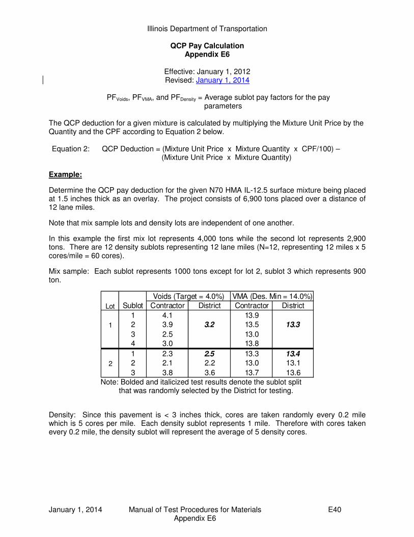
Illinois Department of Transportation
QCP Pay Calculation Appendix E6
Effective: January 1, 2012 Revised: January 1, 2014
January 1, 2014 Manual of Test Procedures for Materials E40 Appendix E6
PFVoids, PFVMA, and PFDensity = Average sublot pay factors for the pay parameters
The QCP deduction for a given mixture is calculated by multiplying the Mixture Unit Price by the Quantity and the CPF according to Equation 2 below. Equation 2: QCP Deduction = (Mixture Unit Price x Mixture Quantity x CPF/100) –
(Mixture Unit Price x Mixture Quantity)
Example:
Determine the QCP pay deduction for the given N70 HMA IL-12.5 surface mixture being placed at 1.5 inches thick as an overlay. The project consists of 6,900 tons placed over a distance of 12 lane miles.
Note that mix sample lots and density lots are independent of one another.
In this example the first mix lot represents 4,000 tons while the second lot represents 2,900 tons. There are 12 density sublots representing 12 lane miles (N=12, representing 12 miles x 5 cores/mile = 60 cores).
Mix sample: Each sublot represents 1000 tons except for lot 2, sublot 3 which represents 900 ton.
Lot Sublot Contractor District Contractor District
1 4.1 13.9
1 2 3.9 3.2 13.5 13.3
3 2.5 13.0
4 3.0 13.8
1 2.3 2.5 13.3 13.4
2 2 2.1 2.2 13.0 13.1
3 3.8 3.6 13.7 13.6
Voids (Target = 4.0%) VMA (Des. Min = 14.0%)
Note: Bolded and italicized test results denote the sublot split
that was randomly selected by the District for testing.
Density: Since this pavement is < 3 inches thick, cores are taken randomly every 0.2 mile which is 5 cores per mile. Each density sublot represents 1 mile. Therefore with cores taken every 0.2 mile, the density sublot will represent the average of 5 density cores.

Illinois Department of Transportation
QCP Pay Calculation Appendix E6
Effective: January 1, 2012 Revised: January 1, 2014
January 1, 2014 Manual of Test Procedures for Materials E41 Appendix E6
Determine the average sublot pay factor for each parameter: Voids: Since the District randomly selected and tested the split from sublot 2 in Lot 1, and the void results were 1) within the 100% pay factor tolerance and 2) within Precision Limits of the Contractor’s results, the District does not need to test the remaining sublots in Lot 1 and the entire Lot receives a Pay Factor of 100%. For the second Lot the District randomly selected and tested the split from sublot 1. Since the District void results were not within the 100% pay factor tolerance, the District had to test all of the remaining Sublot splits. (see completed table below): Calculate the void deviation from target for each of the District sublot split results. Lot 1:
Sublot 2: Deviation = 3.2% - 4.0% = -0.8%
Lot 2: Sublot 1: Deviation = 2.5% - 4.0% = -1.5% Sublot 2: Deviation = 2.2% - 4.0% = -1.8%
Sublot 3: Deviation = 3.6% - 4.0% = -0.4% Using Table 1 and the deviation from Target, determine the corresponding Void sublot Pay Factor for each District test result. Lot 1: Sublot 2: Pay Factor associated with -0.8% in Table 1 is 100%
1 2 3 4 5
1 90.4 90.8 91.6 92.4 92.1
2 93.8 94.1 92.3 92.1 92.6
3 91.8 93.5 93.9 92.8 92.5
4 93.7 94.2 93.5 93.3 92.8
5 92.1 94.1 92.6 93.8 92.3
6 94.1 94.3 93.2 94.5 93.9
7 93.6 93.3 92.5 91.9 92.7
8 92.8 93.3 94.2 93.5 93.7
9 90.0 90.2 91.9 91.8 90.9… … … … … …
12 91.5 93.5 92.7 93.8 92.1
Density
Sublot
Density Intervals (cores)
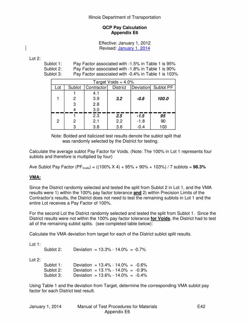
Illinois Department of Transportation
QCP Pay Calculation Appendix E6
Effective: January 1, 2012 Revised: January 1, 2014
January 1, 2014 Manual of Test Procedures for Materials E42 Appendix E6
Lot 2: Sublot 1: Pay Factor associated with -1.5% in Table 1 is 95% Sublot 2: Pay Factor associated with -1.8% in Table 1 is 90% Sublot 3: Pay Factor associated with -0.4% in Table 1 is 103%
Note: Bolded and italicized test results denote the sublot split that was randomly selected by the District for testing.
Calculate the average sublot Pay Factor for Voids. (Note: The 100% in Lot 1 represents four sublots and therefore is multiplied by four) Ave Sublot Pay Factor (PFVoids) = ((100% X 4) + 95% + 90% + 103%) / 7 sublots = 98.3% VMA:
Since the District randomly selected and tested the split from Sublot 2 in Lot 1, and the VMA results were 1) within the 100% pay factor tolerance and 2) within Precision Limits of the Contractor’s results, the District does not need to test the remaining sublots in Lot 1 and the entire Lot receives a Pay Factor of 100%. For the second Lot the District randomly selected and tested the split from Sublot 1. Since the District results were not within the 100% pay factor tolerance for Voids, the District had to test all of the remaining sublot splits. (see completed table below): Calculate the VMA deviation from target for each of the District sublot split results. Lot 1:
Sublot 2: Deviation = 13.3% - 14.0% = -0.7%
Lot 2: Sublot 1: Deviation = 13.4% - 14.0% = -0.6% Sublot 2: Deviation = 13.1% - 14.0% = -0.9%
Sublot 3: Deviation = 13.6% - 14.0% = -0.4% Using Table 1 and the deviation from Target, determine the corresponding VMA sublot pay factor for each District test result.
Lot Sublot Contractor District Deviation Sublot PF
1 4.1
1 2 3.9 3.2 -0.8 100.0
3 2.8
4 3.0
1 2.3 2.5 -1.5 952 2 2.1 2.2 -1.8 90
3 3.8 3.6 -0.4 103
Target Voids = 4.0%

Illinois Department of Transportation
QCP Pay Calculation Appendix E6
Effective: January 1, 2012 Revised: January 1, 2014
January 1, 2014 Manual of Test Procedures for Materials E43 Appendix E6
Lot 1: Sublot 2: Pay Factor associated with -0.7% in Table 1 is 100% Lot 2: Sublot 1: Pay Factor associated with -0.6% in Table 1 is 100% Sublot 2: Pay Factor associated with -0.9% in Table 1 is 90% Sublot 3: Pay Factor associated with -0.4% in Table 1 is 100%
Lot Sublot Contractor District Deviation Sublot PF
1 13.9
1 2 13.5 13.3 -0.7 100
3 13.4
4 13.8
1 13.3 13.4 -0.6 100
2 2 13.0 13.1 -0.9 90
3 13.7 13.6 -0.4 100
Minimum VMA = 14.0%
Note: Bolded and italicized test results denote the sublot split
that was randomly selected by the District for testing.
Calculate the average sublot pay factor for VMA. (Note: The 100% in Lot 1 represents four sublots and therefore is multiplied by four) Ave Sublot Pay Factor (PFVMA) = ((100% X 4) + 100% + 90% + 100%) / 7 sublots = 98.6% Density:
Determine the average density for each sublot. Determine the sublot pay factor using the average sublot density and Table 1 (see completed table below). Determine the Density pay factor by averaging the sublot pay factors.

Illinois Department of Transportation
QCP Pay Calculation Appendix E6
Effective: January 1, 2012 Revised: January 1, 2014
January 1, 2014 Manual of Test Procedures for Materials E44 Appendix E6
Combined Pay Factor: Determine the Combined Pay Factor using Equation 1.
CPF = 0.30(PF Voids) + 0.30(PFVMA) + 0.40(PFDensity) = 0.30(98.3) + 0.30(98.6) + 0.4(99.9) CPF = 99.1%
QCP Deduction: Determine the QCP deduction pay for the given mixture using Equation 2. QCP Deduction = (Mixture Unit Price x Mixture Quantity x CPF/100) – (Mixture Unit Price x
Mixture Quantity)
Where: Mixture Unit Price = $65.00 Mixture Quantity = 6,900 tons placed.
QCP Deduction = ($65.00/ton x 6,900 tons x 99.1 / 100) – ($65.00/ton x 6,900 tons)
= - $4,036.50
In this case a $4,036.50 disincentive would be paid as per Construction Memorandum 10-4.
1 2 3 4 5
Sublot
Ave
Sublot
PF1 90.4 90.8 91.6 92.4 92.1 91.5 95
2 93.8 94.1 92.3 92.1 92.6 93.0 100
3 91.8 93.5 93.9 92.8 92.5 92.9 100
4 93.7 94.2 93.5 93.3 92.8 93.5 103
5 92.1 94.1 92.6 93.8 92.3 93.0 100
6 94.1 94.3 93.2 94.5 93.9 94.0 103
7 93.6 93.3 92.5 91.9 92.7 92.8 100
8 92.8 93.3 94.2 93.5 93.7 93.5 103
9 90.0 90.2 91.9 91.8 90.9 91.0 95… … … … … … … …
12 91.5 93.5 92.7 93.8 92.1 92.7 100
99.9
Density
Sublot
Density Intervals (cores)
Average Density Sublot PF =

Illinois Department of Transportation
QCP Pay Calculation Appendix E6
Effective: January 1, 2012 Revised: January 1, 2014
January 1, 2014 Manual of Test Procedures for Materials E45 Appendix E6
Full Depth Examples:
Given a full-depth project with two mixtures whose combined pay factors were determined to be 100.0% and 98.2%. The full-depth pay factor shall be calculated as follows:
100.0(1/2) + 98.2(1/2) = 99.1%
Determine the adjusted pay for the full-depth pay factor.
Given that the bid price per square yard = $25.00 and 1400 yd2 were placed. Plan Unit Pay = $25.00/ yd2 * 1400 yd2 = $35,000 Adjusted Pay = $25.00/ yd2 * 1400 yd2 * 0.991 = $34,685 Difference = $34,685 – $35,000 = - $315
Given a full-depth project with three mixtures whose pay factors were determined to be 98.9%, 100.0% and 99.2%. The full depth pay factor shall be calculated as follows:
98.9(1/3) + 100.0(1/3) + 99.2(1/3) = 99.4%
Determine the adjusted pay for the full-depth pay factor.
Given that the bid price per square yard = $25.00 and 1400 yd2 were placed. Plan Unit Pay = $25.00/ yd2 * 1400 yd2 = $35,000 Adjusted Pay = $25.00/ yd2 * 1400 yd2 * 0.994 = $34,790 Difference = $34,790 – $35,000 = - $210

January 1, 2014 Manual of Test Procedures for Materials E46 Appendix E6
This Page Reserved
June 1, 2012 Manual of Test Procedures for Materials E47 Appendix E7
Illinois Department of Transportation
Best Practices For
Pay-For-Performance (PFP) and Quality Control for Performance (QCP) Implementation
Appendix E7
Effective Date: April 1, 2012
Purpose
This document is intended to aid district personnel in successfully preparing for and implementing the Pay-For-Performance (PFP) and Quality Control for Performance (QCP) specifications.
Lab
Since payment on PFP and QCP projects is based on Department test results, attention to laboratory equipment, qualified lab personnel and laboratory efficiency becomes paramount. Review of results from recent “Annual Bituminous Uniformity Studies” (aka Round Robins) and dispute resolutions and addressing any district lab issues resulting in poor comparisons will prove beneficial.
1) Equipment - It is imperative to inspect and calibrate all laboratory testing equipment according to frequencies listed in Policy Memorandum 21-08.0 “Minimum Requirements For Construction Materials Testing Laboratories - Department Operated Laboratories” at a minimum. Inspection and calibration immediately prior to PFP and QCP testing is highly recommended. Always use the same gyratory compactor for a given PFP or QCP contract.
Assessment of existing and needed equipment should be performed to determine possible benefits of purchasing additional equipment to optimize productivity. Each district should also develop an action plan in the event key equipment breaks down.
2) Personnel – It is also imperative that all laboratory personnel intended to be involved in PFP and QCP testing, be qualified with successful completion of HMA Level I as a minimum. Keep technician assignments as consistent as possible. It is highly recommended to conduct an in-house round robin with the above mentioned laboratory personnel to ensure repeatability.
3) Sample Treatment – Inconsistent treatment of samples prior to testing has been identified as the leading reason for differences in test results between the contractor and the state. It is recommended that samples, for all parties involved, be allowed to cool to room temperature immediately after splitting. The samples should then be reheated and compacted as soon as the samples reach compaction temperature.
4) Efficiency – PFP and QCP are based on Department testing which results in a higher
testing frequency for the district laboratory. An internal audit of your district
laboratory for efficiency may help identify ways to improve productivity. This activity
should be conducted by district materials staff that are not involved in day-to-day
testing, or BMPR staff if requested.

June 1, 2012 Manual of Test Procedures for Materials E48 Appendix E7
While the specification allows a 14 working day test turnaround time for PFP and a 10 day turnaround for QCP, the district should attempt to reduce the turnaround time as much as possible. Nationally recognized successful programs have test turnaround results within 5 days.
Project Personnel
Key components of PFP and QCP which provide the necessary compliance with the Code of Federal Regulations are 1) undisclosed random mix and density sample locations, 2) Sample either taken by the Engineer or witnessed by the Engineer, and 3) sample security. The CFR is intended to assure that the sample is under control of the Engineer at all times to verify the quality of the product. Most districts will need to rely on project staff to determine random mix sample and density core locations. It will be important for project personnel to understand their role in witnessing and securing the sample. District Materials and Construction staff should meet prior to the start of a PFP or QCP project to discuss:
1) Responsibilities: a) Discuss who will be responsible for sample identifying undisclosed sample
location and sample layout b) Sample Security; discuss who will transport and / or store samples. c) Pay Calculations; discuss who will be responsible for entering data in software
and how communication regarding pay factors will occur. 2) Procedures:
a) Random sample locations i) Discuss when to disclose sampling location ii) Familiarize Construction personnel with random sample procedures detailed
in the Manual of Test Procedures b) Sample Layout (utilization of random number table)
i) Discuss how core densities will be: (1) transversely no closer than 1 foot to an unconfined longitudinal joint and 4
inches on a confined longitudinal joint for PFP. (2) transversely no closer than 4 inches from an edge for QCP.
ii) Discuss how to handle coring locations that will need to be opened immediately to traffic
Also, it will be important to make sure Construction personnel have copies of all the necessary supporting documents.