qe90 installation and commissioning manual
TRANSCRIPT

LT0088QE90 Installation and
Commissioning Manual
DOCUMENT: LT0088
Issue 5.1 27/09/2011
The QE90 is a product ofTyco Fire Protection Products
17 Mary Muller DriveChristchurch 8022NEW ZEALAND
Phone +64-3-389 5096Fax +64-3-389 5938
© 2011 Tyco. All Rights Reserved.
Information contained in this document is subject to copyright, and shall not bereproduced in any form whatsoever, without the written consent of Tyco. Informationcontained in this document is believed to be accurate and reliable, however Tycoreserves the right to change the content without prior notice.

Tyco (the Company) and the User of this/these document(s) desire to share proprietary technical informationconcerning electronic systems.
For this reason the Company is disclosing to the User information in the form of this/these document(s). Inas much as the Company considers this information to be proprietary and desires that it be maintained inconfidence, it is hereby agreed by the User that such information shall be maintained in confidence by theUser for a period of TEN YEARS after the issue date and only be used for the purpose for which it wassupplied.
During this period, the User shall not divulge such information to any third party without the prior writtenconsent of the Company and shall take reasonable efforts to prevent any unauthorised disclosure by itsemployees. However, the User shall not be required to keep such information in confidence if it was in theirpossession prior to its receipt from the Company; if it is or becomes public knowledge without the fault of theUser; or the information becomes available on an unrestricted basis from a third party having a legal right todisclose such information.
The User's receipt and retention of this information constitutes acceptance of these terms.
This information is copyright and shall not be reproduced in any form whatsoever.
© 2011 Tyco. All Rights Reserved.
Non Disclosure Agreement
End User Liability Disclaimer
The QE90 provides a configuration facility via the settings of internal switches and programmable features. Thisfacility allows the user to define in detail the operation of the system and changes may be made which preventthe system from meeting statutory requirements.
The Company therefore cannot accept any responsibility as to the suitability of the functions generated by theuser using the configuration facility.
EMC Compliance
WARNING : This is a Class A product. In a domestic environment this product may cause radio interference inwhich case the user may be required to take adequate measures.
LT0088 Issue 5.1 27/09/2011ii
Tyco Fire Protection Products QE90 Installation and Commissioning Manual

iii
Table of Contents
LT0088 Issue 5.1 27/09/2011
Tyco Fire Protection Products QE90 Installation and Commissioning Manual
Table of Contents
Chapter 1 INTRODUCTION 2
................................................................................................................................... 21 Quick Reference Guide
................................................................................................................................... 22 Manual contents
................................................................................................................................... 33 Glossary
................................................................................................................................... 34 Amendment List
Chapter 2 CABINET INSTALLATION 6
................................................................................................................................... 61 Equipment Handling Precautions
................................................................................................................................... 62 Checking System After Transit
................................................................................................................................... 63 Cabinet Mounting
................................................................................................................................... 64 Mains Wiring
................................................................................................................................... 65 Inter-Cabinet Connections
................................................................................................................................... 76 EMC Compliance
Chapter 3 PANEL CONFIGURATION 10
................................................................................................................................... 101 General
................................................................................................................................... 102 Typical Cabinet Layout
................................................................................................................................... 123 System Design ......................................................................................................................................................... 12Configuration Printout (Common ECP/ECM) ......................................................................................................................................................... 16Configuration Printout (ECM) ......................................................................................................................................................... 18General Script Interpretation ......................................................................................................................................................... 19Non-ECM Script Inputs and Outputs ......................................................................................................................................................... 21ECM Script Inputs and Outputs ......................................................................................................................................................... 24Fault Output and other relay outputs ......................................................................................................................................................... 24IP Networked Systems
Chapter 4 TRANSFORMER MODULES 26
................................................................................................................................... 261 Panel Termination
................................................................................................................................... 262 Connection Points
................................................................................................................................... 293 Standby Amplifiers
................................................................................................................................... 294 Link Settings
................................................................................................................................... 295 Amplifier Numbering
................................................................................................................................... 306 Cable Size, Type, and Length
................................................................................................................................... 317 Termination to Each Speaker
................................................................................................................................... 328 Checking Speaker Loadings
................................................................................................................................... 339 Checking Speaker Wiring
................................................................................................................................... 3310 Zone Relays
................................................................................................................................... 3411 LEDs
................................................................................................................................... 3412 Music Switching Transformer Modules

iv
Table of Contents
LT0088 Issue 5.1 27/09/2011
Tyco Fire Protection Products QE90 Installation and Commissioning Manual
Chapter 5 AMPLIFIERS - EAMP9001,HAMP9308 and AMP200 36
................................................................................................................................... 361 Amplifier Types
................................................................................................................................... 362 Links ......................................................................................................................................................... 36Power Selection ......................................................................................................................................................... 37AMP200 Master / Slave Selection and Interconnection ......................................................................................................................................................... 37Default Input Selection ......................................................................................................................................................... 38Amplifier Monitoring Disable ......................................................................................................................................................... 38Local Inputs
................................................................................................................................... 383 Amplifier LEDs
................................................................................................................................... 394 Amplifier Adjustments
Chapter 6 WIP PHONE TERMINATIONMODULES 42
................................................................................................................................... 421 General
................................................................................................................................... 422 WTRM2000 Wiring ......................................................................................................................................................... 42General ......................................................................................................................................................... 43WTRM2000 End of Line Termination ......................................................................................................................................................... 44WTRM2000 Two Wire WIP / BGA Connection ......................................................................................................................................................... 44WTRM2000 Zone Manned Pushbutton ......................................................................................................................................................... 44WTRM2000 General Purpose Input
................................................................................................................................... 453 WTRM9007 Wiring ......................................................................................................................................................... 45General ......................................................................................................................................................... 46WIPS9007 End of Line Termination ......................................................................................................................................................... 46WIPS9007 Zone Manned Pushbutton ......................................................................................................................................................... 46WIPS9007 General Purpose Input
................................................................................................................................... 464 Vigilant® FP0938 WIP Phone Wiring
................................................................................................................................... 475 Altronics A2095/A2096 wiring
................................................................................................................................... 476 WLED9307 WIP Flashing LED PCB
................................................................................................................................... 477 WIP System Expansion
................................................................................................................................... 488 RWIF9803 Remote WIP Interface ......................................................................................................................................................... 48General Description ......................................................................................................................................................... 48Wiring Arrangement ......................................................................................................................................................... 51Link Settings ......................................................................................................................................................... 51Indicators
................................................................................................................................... 519 MWIP9903 8 Circuit WIP Module ......................................................................................................................................................... 51General ......................................................................................................................................................... 52LED Indicators ......................................................................................................................................................... 53DIP Switch 1 Settings ......................................................................................................................................................... 53DIP Switch 2 Settings ......................................................................................................................................................... 53System Expansion
Chapter 7 FIP / BGA / GP INPUT MODULES 56
................................................................................................................................... 561 FIP / BGA /GP Inputs - General
................................................................................................................................... 562 RFIB9511 Remote Rack FIP / BGA Input Module
................................................................................................................................... 573 Single FIP Input Connection
................................................................................................................................... 584 Multiple FIP and BGA Input Connections
................................................................................................................................... 585 Switch and Link Settings

v
Table of Contents
LT0088 Issue 5.1 27/09/2011
Tyco Fire Protection Products QE90 Installation and Commissioning Manual
................................................................................................................................... 596 Relays
................................................................................................................................... 607 LEDs
................................................................................................................................... 608 System Expansion
Chapter 8 STROBE RELAY DRIVERMODULE 62
................................................................................................................................... 621 General
................................................................................................................................... 622 Strobe Output Wiring
................................................................................................................................... 643 General Purpose Output Wiring
................................................................................................................................... 644 Links and DIP Switch Settings
................................................................................................................................... 665 Strobe Circuit Commissioning
................................................................................................................................... 666 LEDs
................................................................................................................................... 667 System Expansion
Chapter 9 BACKGROUND MUSIC INPUTFACILITY 68
................................................................................................................................... 681 Single Channel Music Input
................................................................................................................................... 682 Multiple Channel Music Inputs
................................................................................................................................... 683 Non-emergency zones
................................................................................................................................... 694 Music Input From Stereo Source
Chapter 10 PAGING CONSOLE 72
................................................................................................................................... 721 Paging Console Wiring
................................................................................................................................... 742 Paging Console Settings
Chapter 11 MICROPHONE PREAMPLIFIERMODULE 76
................................................................................................................................... 761 PA0688 Overview
................................................................................................................................... 762 PA0688 Wiring
................................................................................................................................... 783 PA0688 Power Supply
Chapter 12 BATTERIES AND POWERSUPPLIES 80
................................................................................................................................... 801 Battery Requirements and Wiring ......................................................................................................................................................... 80Battery Arrangements - Deep Cabinets ......................................................................................................................................................... 84Battery Arrangements - Shallow Cabinets ......................................................................................................................................................... 85Battery Wiring ......................................................................................................................................................... 85Battery Wiring - NZS4512 Multiple Chargers
................................................................................................................................... 862 Power Supplies
................................................................................................................................... 863 PSU2406 and PSU2412 ......................................................................................................................................................... 87Internal Control PCB ......................................................................................................................................................... 87Setup Using 8-Way DIPswitch ......................................................................................................................................................... 88Earlier Models Using Links ......................................................................................................................................................... 89Battery Testing ......................................................................................................................................................... 89Adjustments ......................................................................................................................................................... 89LEDs

vi
Table of Contents
LT0088 Issue 5.1 27/09/2011
Tyco Fire Protection Products QE90 Installation and Commissioning Manual
......................................................................................................................................................... 90Replacing Older Supply with PSU2406 or PSU2412 ................................................................................................................................... 904 PSU308
......................................................................................................................................................... 90ADJUSTMENTS
......................................................................................................................................................... 90LEDS ................................................................................................................................... 915 Adding an AMP Rack to an Existing Supply ................................................................................................................................... 916 Adding an Additional Power Supply
Chapter 13 SECP & REMOTE EQUIPMENTRACK INTERFACE 94
................................................................................................................................... 941 Wiring
................................................................................................................................... 972 Link and Switch Settings ......................................................................................................................................................... 97SPEECH BACKUP BUS Fitted / NOT FITTED ......................................................................................................................................................... 98SPEECH BUS MONITORING POINT ......................................................................................................................................................... 98NORMAL / ISOLATE / ADVANCED LINKS
................................................................................................................................... 993 RS232 (Printer) Interface ................................................................................................................................... 1004 SPIF LEDs ................................................................................................................................... 1005 SE9004 Signals Interface Module
Chapter 14 WIP SLAVE MODULE 102
................................................................................................................................... 1021 WIP Slave Overview
................................................................................................................................... 1022 LED Indicators - WIPS2000
................................................................................................................................... 1033 LED Indicators - WIPS9004
................................................................................................................................... 1034 DIP Switch Settings
................................................................................................................................... 1035 Link Settings
................................................................................................................................... 1036 WIP System Expansion.
Chapter 15 MULTIPLEXER MODULES -EMUX9601 & EMUX9002 106
................................................................................................................................... 1061 Multiplexer Overview
................................................................................................................................... 1072 EMUX9601 LED Indicators
................................................................................................................................... 1073 EMUX9601 DIP Switch Settings
................................................................................................................................... 1094 EMUX9601 Tones and Messages ......................................................................................................................................................... 110ISO Evacuation Signal and Voice Message ......................................................................................................................................................... 111AS2220 Evacuation Signal ......................................................................................................................................................... 111Alert Tones ......................................................................................................................................................... 112Balancing Tone and Speech Levels
................................................................................................................................... 1125 EMUX9601 Connectors
................................................................................................................................... 1136 EMUX9601 Customising Messages
................................................................................................................................... 1137 EMUX9601 Message Recording and Playback
................................................................................................................................... 1158 EMUX9601 Volume Control Adjustments
................................................................................................................................... 1169 EMUX9002 LED Indicators
................................................................................................................................... 11710 EMUX9002 DIP Switch Settings
................................................................................................................................... 11711 EMUX9002 Volume Control Adjustments
Chapter 16 ECP MODULE & DISPLAYEXTENDERS 120

vii
Table of Contents
LT0088 Issue 5.1 27/09/2011
Tyco Fire Protection Products QE90 Installation and Commissioning Manual
................................................................................................................................... 1201 Overview
................................................................................................................................... 1202 DIP Switch Settings
................................................................................................................................... 1223 ECP Revision Interchangeability ......................................................................................................................................................... 122ECP9702 and ECP9002 ......................................................................................................................................................... 123REPLACING AN OLDER ECP WITH A WIDGET BOARD ECP ......................................................................................................................................................... 124REPLACING A WIDGET BOARD ECP WITH AN OLDER ECP
................................................................................................................................... 1244 Software Locations
................................................................................................................................... 1255 Microphone Controls
................................................................................................................................... 1256 Master Phone Termination
................................................................................................................................... 1257 Master Phone Sound Level
................................................................................................................................... 1258 ECP LEDs
................................................................................................................................... 1279 Hidden ECP for Expanding Display Zones
................................................................................................................................... 12710 Fluorescent Light Output
................................................................................................................................... 12811 Display Extenders
Chapter 17 PLACING INTO OPERATION 130
................................................................................................................................... 1301 Placing Into Operation Overview
................................................................................................................................... 1302 Power Switches and Circuit Breakers
................................................................................................................................... 1303 Power Up
................................................................................................................................... 1334 Output Level Adjustment ......................................................................................................................................................... 133Location of Amplifier Controls ......................................................................................................................................................... 134ECP9002 Speech Microphone Adjustments
Chapter 18 SPARE PARTS LIST andINFORMATION 136
................................................................................................................................... 1361 General Spare parts list
................................................................................................................................... 1372 Bare Board Parts
................................................................................................................................... 1383 Module Earthing
Chapter 19 CABINET WIRING 140
................................................................................................................................... 1401 Drawings
Chapter 20 EVACUATION COMMUNICATIONSMODULE (ECM9603) 142
................................................................................................................................... 1421 Overview
................................................................................................................................... 1422 Modbus Interface
................................................................................................................................... 1423 Connection to ECP
................................................................................................................................... 1434 Wiring Between Locations
................................................................................................................................... 1475 Systems with Multiple PA / WIP Bus Segments
................................................................................................................................... 1486 Connection to IHUB
................................................................................................................................... 1497 ECM Links
................................................................................................................................... 1498 ECM On-site Settings ......................................................................................................................................................... 149Overview ......................................................................................................................................................... 150Procedure for adjusting on-site settings
................................................................................................................................... 1549 Charger Fault Connection at Amp Rack

viii
Table of Contents
LT0088 Issue 5.1 27/09/2011
Tyco Fire Protection Products QE90 Installation and Commissioning Manual
................................................................................................................................... 15410 Connection and Colour Graphics PC
................................................................................................................................... 15511 ECM Diagnostics and Event Log ......................................................................................................................................................... 155Overview ......................................................................................................................................................... 156Diagnostics Procedure ......................................................................................................................................................... 156Off Normal Display. ......................................................................................................................................................... 158Interpret Command
................................................................................................................................... 15812 Dial Out Alarm Log
................................................................................................................................... 15913 Diagnostic LEDs
................................................................................................................................... 15914 ECP Status LEDs
................................................................................................................................... 16015 ECP Diagnostic LEDs
................................................................................................................................... 16016 QE90 Module Address Switches
Chapter 21 AUDIO LINE ISOLATOR MODULE(ALIM9706) 162
................................................................................................................................... 1621 Overview
................................................................................................................................... 1622 ALIM9706 on Amplifier Local Inputs
................................................................................................................................... 1623 Providing Spurs in Network System Wiring
Chapter 22 HIGH LEVEL FIP INTERFACES 164
................................................................................................................................... 1641 Overview
................................................................................................................................... 1642 RZDU Interface ......................................................................................................................................................... 164RZDU - ECP ......................................................................................................................................................... 165RZDU - ECM
................................................................................................................................... 1663 Panel Link Interface
................................................................................................................................... 1664 MX1 Programming
................................................................................................................................... 1665 MX4428 Programming
................................................................................................................................... 1676 F3200 Programming
................................................................................................................................... 1677 QE90 Programming for PANEL-LINK / RZDU
................................................................................................................................... 1688 Simplex 4100 Interface
Chapter 23 PRINTER / TERMINALCONNECTION ANDDIAGNOSTICS 172
................................................................................................................................... 1721 Printer / Terminal Overview
................................................................................................................................... 1732 Off Normals Display ......................................................................................................................................................... 173ECM Off Normals Display ......................................................................................................................................................... 173ECP Off Normals Display
................................................................................................................................... 1743 Other Diagnostics on Non-ECM System
................................................................................................................................... 1754 Software Requirements
................................................................................................................................... 1755 Hardware Requirements - New Production
................................................................................................................................... 1766 Hardware Requirements - Older Production
................................................................................................................................... 1767 Connector Pinouts
Chapter 24 CASCADE AND OTHER ON-SITESETTINGS 182

ix
Table of Contents
LT0088 Issue 5.1 27/09/2011
Tyco Fire Protection Products QE90 Installation and Commissioning Manual
................................................................................................................................... 1821 General
................................................................................................................................... 1822 Cascade Sequences
................................................................................................................................... 1863 New Zealand Type 5/7 Apartment Zone Configuration
................................................................................................................................... 1864 NZS 4512:2003 Brigade Control Switches
................................................................................................................................... 1885 ECP on-site settings ......................................................................................................................................................... 189ECP on-site settings using keyboard ......................................................................................................................................................... 197ECP on-site settings using Terminal
.................................................................................................................................................. 197Setup of Computer and Connection to System
.................................................................................................................................................. 197Accessing On-site Setup Mode
.................................................................................................................................................. 198Edit Cascade Variables
.................................................................................................................................................. 198Read and Set Date
.................................................................................................................................................. 198Command Summary
.................................................................................................................................................. 198Change User Password
.................................................................................................................................................. 199Change Comms Baud Rate
.................................................................................................................................................. 199Read and Set Time
.................................................................................................................................................. 199Current Software Version
.................................................................................................................................................. 199Quit and Exit On-site Setup Mode................................................................................................................................... 1996 Master Phone Redirection ................................................................................................................................... 2007 Default Values
Chapter 25 WIDGET BOARD 202
................................................................................................................................... 2021 Widget Board Overview
................................................................................................................................... 2022 Fitting Widget Board
................................................................................................................................... 2033 Programming Widget Board Software
Chapter 26 PC PAGING CONSOLE 208
................................................................................................................................... 2081 Introduction
................................................................................................................................... 2092 Features
................................................................................................................................... 2093 Programmability
................................................................................................................................... 2104 Requirements
................................................................................................................................... 2105 Physical Characteristics
................................................................................................................................... 2106 Software Upgrades
Chapter 27 CONFIGURATIONPROGRAMMING WITH QEConfig 212
................................................................................................................................... 2121 Introduction
Chapter 28 IP NETWORKING 214
................................................................................................................................... 2141 General

27/09/2011xLT0088 Issue 5.1
Tyco Fire Protection Products QE90 Installation and Commissioning Manual

Chapter 1
INTRODUCTION

QE90 Installation and Commissioning Manual
INTRODUCTION
2LT0088 Issue 5.1
Tyco Fire Protection Products
27/09/2011
1.1 Quick Reference Guide
DIP Switches
ECP DIP Switches
EMUX DIP Switches
FIP/BGA Module DIP Switch
STRM DIP Switch
WIPS2000 DIP Switch
Field wiring terminations
10W/25W Amp Speaker Line terminations
50W/100W Amp Speaker Line terminations
200W Amp Speaker Line terminations
FIP/BGA Module terminations
STRM Module terminations
WTRM2000 Module terminations (including WIP circuitsand FIP inputs and BGA inputs)
Inter-Panel WiringSPIF Wiring (inter panel)
ECM Wiring (inter panel)
Cascade Sequences Cascade Sequence Illustrations
Non-networked system on-sitesettings
ECP on-site settings using keyboard
ECP on-site settings using terminal
Networked system on-sitesettings
ECM on-site settings
“Off Normals” Status DisplayECP “Off Normals” Display on terminal
ECM “Off Normals” Display on Terminal
1.2 Manual contents
This manual contains the information needed to install and commission a Vigilant® QE90 soundand intercommunication system for emergency purposes.
Related documents are -LT0087 : QE90 Operators ManualLT9002 : QE90 Technical ManualLT0114 : QE90 Paging Console Operation and Installation ManualLT0132 : QE90 Training Manual : Installation and CommissioningLT0455 : QEConfig User ManualLT0519 : PIB User ManualLT0528 : QE90 IP Networking & VIF User ManualLT0535 : QE90 IP Networking Applications / Design GuideAS2220 : Emergency warning and intercommunication systems in buildings
AS2220.1 : Equipment design and manufactureAS2220.2 : System design, installation, and commissioning (Applies to systems originally
installed to AS2220)AS1670.4 : Fire detection, warning, control and intercom systems – System design, installationand commissioning. Part 4: Sound systems and intercom systems for emergency purposes.
120
107
58
64
103
26
27
27
57
63
42
94
143
182
189
197
149
173
156

QE90 Installation and Commissioning Manual
INTRODUCTION
3LT0088 Issue 5.1
Tyco Fire Protection Products
27/09/2011
(Replaced AS2220.2 in 2004.)
LT0087 is supplied with every QE90 system, LT0114 is supplied with every Paging Console.LT9002 and LT0132 can be ordered separately when required.
This Manual also contains reference information about DIP switch and link settings. Thisinformation is usually not needed when installing a new system as it will have been set up correctlyin the factory, but is included here for completeness and for reference when fitting spare parts orupgrading systems.
1.3 Glossary
BGA Breakglass Alarm (Emergency Call Point)DIP Dual Inline PackageECP Emergency Control PanelECM Emergency Communications ModuleEWIS Emergency Warning and Intercommunication SystemFIP Fire Indicator PanelFRC Flat Ribbon CableGP General PurposeIC Integrated CircuitMECP Master Emergency Control PanelPCB Printed Circuit BoardSECP Secondary Emergency Control PanelWIP Warden Intercommunication Point
1.4 Amendment List
Issue 1 17/10/1990 Original.
Issue 2.0 1/3/1996 Rewritten.
Issue 2.1 12/8/1996 EMUX9601 added.
Issue 2.2 7/3/1997 ECM9603 added.
Issue 2.3 27/8/1997 Added TRAN9705 / 9706 and ALIM9706.Numerous other amendments - all pages reprinted
Issue 2.4 11/11/1997 Added description of HLL etc in config printout, details of WIP circuits used asFIP/BGA inputs,SPIF9709, master phone termination, DIN rail and standoffmounting versions of modules, isolated WIP/PA Bus segments, High Level FIPinterfaces.
Issue 2.5 19/6/1998 Added RWIF9803.
Issue 2.6 3/11/1998 Added further details of LEDs and links, Power Supplies, 200W amplifiers, Printer/ terminal connection, AS/NZS3548 Class A notice.
Issue 2.7 9/2/1999 Added earth warning.Updated for FIB8910/FIB1011 Issue E.Added Mylar keyboards to spare parts list, explained metal / plastic DIN railmounting hardware.
Issue 2.8 5/7/1999 Added MWIP9903.Fixed DIP switches for WIP ccts 180-199.
Issue 2.9 8/5/2000 MWIP9903 - added 10k to 24V
Issue 2.91 15/8/2000 Stereo Music Input and Cascade details added
Issue 2.92 9/7/2001 Added WTRM2000/WIPS2000, joined audio busses, SE9004, ECP Revision

QE90 Installation and Commissioning Manual
INTRODUCTION
4LT0088 Issue 5.1
Tyco Fire Protection Products
27/09/2011
Interchangeability.Spare Parts list amended.System Wiring Diagrams updated.
Issue 2.93 19/5/2003 PSU2406/12 ratings corrected.
Issue 3.00 12/11/2003 Added maximum cable lengths, script interpretation.STRM module - Added note re too short wiring, specified cable for 10% drop not5%. Added DIP switch settings for flashing incandescent lights. Expanded battery sizes which will fit.Expanded network wiring.Updated Spare Parts List.Expanded ECM programming and Off Normal Conditions.
Issue 3.01 19/8/2004 Added Safety Precautions, typical battery arrangements, ISO tone selection,Simplex High Level Link, Widget board fitting and programming.Expanded details of interconnecting ECMs via IHUBs.Other minor corrections.
Issue 3.02 29/11/2004 Added new speech message options, details of Widget Board ECPInterchangeability, reference to AS1670.4.Recommended amplifier volume controls set to maximum.Moved cascade sequences from LT0087.Removed reference to KT0465.
Issue 3.03 8/9/2005 Added T3 ISO8201 option to STRM module.Revised Widget programming.
Issue 4.00 8/11/2005 Updated for V6.00 Evac ECP software.Added details of Site Programmable Alert/No Alert Cascade.Added details of “Off Normals” Command for non-ECM system.Added details of testing Cascade in Isolate.Changed numbering of modules to start at 0 (i.e. refer to module addresses) tomatch event log, off-normals output, and zone labels. Made tables of DIP switchsettings consistent.Added quick reference.
Issue 5.00 29/06/2009 Revised battery fitting instructions.Revised description of configuration listing to match that produced by QEConfig.Revised Amplifier and EMUX volume adjustments.Added Vigilant FP0938 Phone.Added wiring diagram for Music Switching transformer modules.Added info on NZ Trial-Evac / Trial Alert / Cancel Alarms.Clarified in several places that adjustment of on-site settings using the serial portis not possible for ECPs with RZDU interface.Revised Widget Flashing instructions.Added PC Paging Console.Added QEConfig programming and renamed On-site Programming to On-sitesettings to clearly distinguish them from programming with QEConfig.Added more info on cable lengths and types for amplifiers and maximumcapacitive load.Added diagrams for making on-site settings via ECP keyboard.Added details of ECM terminal commands now requiring <Enter> key.Added instructions for checking system after transit.Added more detains on NZS4512-2003 operation.Added notes on paging console on-site settings.Multiple minor clarifications.
Issue 5.1 27/09/2011 Added FIB1011. Enhanced description of Modbus Interface.Corrected details for expansion ECP and power supplies.Added reference to IP Networking manuals.Manual brand changed to Vigilant & Tyco Fire Protection Products

Chapter 2
CABINET INSTALLATION

QE90 Installation and Commissioning Manual
CABINET INSTALLATION
6LT0088 Issue 5.1
Tyco Fire Protection Products
27/09/2011
2.1 Equipment Handling Precautions
Basic precautions should be observed at all times when working with any electronic circuits.Ensure you are earthed (e.g., with a wrist strap connected to the panel gearplate, or one handtouching the gearplate) before touching any components or connections.Never plug or unplug any cables when power is applied.
Never plug or unplug cards from a rack when power is applied.
Remove power from any module before making any changes to the module.
2.2 Checking System After Transit
After unpacking a newly received system, it should be carefully checked, and anything that hasmoved during transit should be corrected.
Check the following (and correct if necessary) :All plug-in ICs are fully plugged into their sockets.
All plug-in cards are fully plugged into the card cage.
All ribbon cable plugs are fully plugged into their sockets.
DIN rail modules are firmly clipped to the DIN rail.
2.3 Cabinet Mounting
The important aspects of mounting the cabinet are :To allow easy access for wiring.
To allow easy access for operation. AS1670.4 (Figure 2.1) requires at least 600mm of clearspace either side of the control panel and 1000mm of clear space in front of it.To ensure the controls are mounted as per AS1670.4 section 2.1.1 (f), i.e., between 750mmand 1850mm from floor level.
In general 18U, 21U and 28U Cabinets will need to be wall mounted to achieve the control heights.40U cabinets can be floor mounted, but if more than 34 display zones are fitted to a 40U cabinet itmay need to be fitted on a plinth.
2.4 Mains Wiring
Mains power must be permanently wired by an electrician to the GPO outlet inside the QE90cabinet. It must be ensured that the cabinet is earthed. If the installation is to comply with AS2220.2(rather than AS1670.4) no other load may be connected to the circuit, and the circuit must beseparately fused and labelled.
2.5 Inter-Cabinet Connections
If the system comprises more than one cabinet (at the same location), then some of the factoryfitted wiring between the cabinets will need to be restored at installation.
Connect the 26 way ribbon cable supplied between all the SIGNALS IN connectors on thebackplanes of all the cardcages.If only one power supply is fitted, connect the backplane power in the second cabinet to theunused heavy red and black cables from the power supply in the first cabinet.

QE90 Installation and Commissioning Manual
CABINET INSTALLATION
7LT0088 Issue 5.1
Tyco Fire Protection Products
27/09/2011
If two or more power supplies are fitted it is recommended that you wire the power suppliesand batteries as shown in Battery Wiring .If there are FIB8910/FIB1011 input modules or STRM9502 output modules in the secondcabinet, their power and comms connections will need to be daisy chained off power andcomms terminals on a similar module in the first cabinet. Refer to drawing 699-177 at the endof Drawings .If there are keyboard/display modules in the second cabinet, connect the 20 way ribbon cablessupplied from the connectors on each side of the bottom of the lowest display module in thesecond cabinet to the connectors on each side of the top of the highest display module in thefirst cabinet.
2.6 EMC Compliance
WARNING This is a Class A product. In a domestic environment this product may cause radiointerference in which case the user may be required to take adequate measures.
To maintain EMC compliance when replacing modules, ensure that module earthing arrangementsare maintained. Refer to Module Earthing for details.
85
140
138

Tyco Fire Protection Products QE90 Installation and Commissioning Manual
LT0088 Issue 5.1 8 27/09/2011

Chapter 3
PANEL CONFIGURATION

QE90 Installation and Commissioning Manual
PANEL CONFIGURATION
10LT0088 Issue 5.1
Tyco Fire Protection Products
27/09/2011
3.1 General
The cabinet layout will depend on the particular system’s configuration, and depending on thenumber of modules of various types required, the modules will be located differently.
3.2 Typical Cabinet Layout
The diagram below shows a typical cabinet layout.
Note that the transformer modules are numbered down the left side of the cabinet, then down theright side. The amplifier modules are numbered from left to right across the upper card cage, thenfrom left to right across the lower card cage. Also note that each amplifier module has fouramplifier numbers assigned to it, regardless of the actual number of amplifiers on the module.See Amplifier Numbering for more details on amplifier numbering.29

QE90 Installation and Commissioning Manual
PANEL CONFIGURATION
11LT0088 Issue 5.1
Tyco Fire Protection Products
27/09/2011
1
2
3
4
5
6
7
8
9
10
1 5 9 13 17
986 7 10
54321
EMUX0
WIP0
21 25 29 33 37
EMUX1
WIP0
FIP
WIP1
WIP1
100w
100w
50w
50w
25w
10w
10w
10w
10w
10w
100W
100W
50W
50W
25W 10W
10W
10W
10W
10W
Fluorescent Light
Larger numbers beside modules are module numbers.Smaller numbers are circuit or amplifier numbers.
STRM0
FIPE
FIPE
FIPE
Mains
SPIF
GroupAll123456789
10
11121314151617181920212223242526
Blanking Plate
Blanking Plate
PA Microphone
Master WIPPhone
InteriorExterior
Battery Space
PSU2412 PSU2412
Typical Cabinet Layout

QE90 Installation and Commissioning Manual
PANEL CONFIGURATION
12LT0088 Issue 5.1
Tyco Fire Protection Products
27/09/2011
3.3 System Design
3.3.1 Configuration Printout (Common ECP/ECM)
Although the panel inputs and outputs will be identified with labels attached during manufacture,subsequent reconfiguration may override that information. It is very important to retain the printoutof the system configuration. This is supplied with each new system and with any re-configuredsoftware. If the printout is lost, it may be downloaded by Tyco employees from http://www.tycosafetyproducts-anz.com/. Click Login. Enter your Tyco Fire and Security username andpassword. Click the Login button. Click the Download button. Click QE90. Click QE90Configuration Files. Alternatively an ECM controlled panel configuration may be listed to a terminalwith the F command, and with version 6 and later ECP software it may be possible for theconfiguration to be extracted from the panel with QEConfig .
A typical example of a configuration printout is made up of the following tables shown below. On atypical printout some table rows may be missing, or complete tables missing, when they areprogrammed entirely to default values.
Only basic information is given here about how to decode the printout. For further information referto QEConfig User Manual LT0455.
Zone Table
ZoneNumber
ZoneName
WIP1Label
WIP2Label
WIP3Label
Amps Watts Strobes FIPs BGAs WIP1 WIP2 WIP3 S/B Amp Not all orgroup
Combined withnext
1 Basement
BmNorth
BmSouth
Bm West 4 10 1 1 W1,W2,W3
1 2 3 No No
2 GroundFloor
G North G South G West 5,38 100,10 2,3,4 2 F26,W4 4 5 6 No No
3 1st Floor 1 North 1 South 1 West 9 50 5 3 W7,W8,W9
7 8 9 No No
4 2ndFloor
2 North 2 South 2 West 13 10 6 W10,W11,W12
10 11 12 No No
5 3rdFloor
3 North 3 South 3 West 17 25 7 W13,W14,W15
13 14 15 No No
The zone table lists the equipment assigned to each zone. A zone is a building zone that (usually)is controlled by a single row of controls and indicators on the MECP control panel, where thebottom row is zone 1, the next row above is zone 2 etc. However if there are more than 3addressable WIPs in a building zone, several consecutive rows of WIP controls on the ECP mayrelate to the building zone. The zone numbering in the QE90 configuration printouts is always 1number per display row.
Note the Zone Name and WIP labels are only for reference and printing labels. They are not usedby the QE90 software.
Using the above table as an example, Zone 2 controls amplifier 5 (100W) and 38 (10W), andstrobe circuits 2, 3, and 4. The zone 2 FIP input comes from FIP module circuit 2. Zone 2 BGAinputs come from FIP module circuit 26 and WIP circuit 4. WIP circuits 4, 5, and 6 are assigned tothe three buttons on zone 2. Note that WIP circuit 4 is both a WIP connection and a BGA input, soit must be a 2-wire WIP/BGA circuit.
212

QE90 Installation and Commissioning Manual
PANEL CONFIGURATION
13LT0088 Issue 5.1
Tyco Fire Protection Products
27/09/2011
WIP circuits used for BGA and/or FIP inputs are listed as Wxx (where xx is the WIP circuitnumber) under the headings BGAs or FIPs.
High level RZDU inputs will be listed as Hxx (where xx is the Fire Panel zone number). FIP moduleinputs used as BGA inputs are listed as Fxx where xx is the FIP module circuit number.
In the BGAs column, numbers listed by themselves are circuits on a BGA input module. In the FIPscolumn, numbers listed by themselves are circuits on a FIP input module.
MiscThe following items are self explanatory.
GeneralSystem Name QE3358 TSP CHRISTCHURCH
System Control ECP
Firmware Version V6.09
Display zones 8
WIP Different No
WIP ECP zones 8
First ECP zones
SECPs 0
One WIP per zone No
Has SPIF No
Shutdown if flat battery No
FIP/BGA/GP InputsIgnore FIP I/P Faults No
N/C FIP Module I/Ps No
Ignore BGA I/P Faults No
N/C BGA Module I/Ps No
No Cascade from BGA No
HLL isolated at FIP gives fault No
Number of inputs on FIP modules
Number of inputs on BGA modules
Number of inputs on GP modules/Paging Consoles
Use GP numbering (not paging console) No
Fault Relay Output Light O/P
Audio OutputsPaging zones different to evac zones No
Music uses paging zones (not evac zones) No
Music zones different to evac zones No
PABX Highest Priority No
PABX Higher Priority than tones No
Music Higher Priority than tones No
Music activates amp relays No
PABX Uses PA bus No
Digitised messages in Manual Yes
Programmed 'music' messages go to all zones No
Charger Fault

QE90 Installation and Commissioning Manual
PANEL CONFIGURATION
14LT0088 Issue 5.1
Tyco Fire Protection Products
27/09/2011
No Music shutdown if charger fault No
No PABX shutdown if charger fault No
Remote charger fault input None
Remote charger fault FIP input num 0
Simplex HLLSimplex HLL pseudozone base
Paging Console WIP ControllerMaster WIP cct
The next three tables describe the system's response to alarm inputs. Alternatively this responsemay be defined in scripts.
Global Alarm ActionCommon Response (This describes the initial response to alarm that is independent of the alarm zone)
Global alarm response None / as per zonal alarm action / as per script
Zonal alarm action starts Before Initial Delay
Cascade Table (This, in conjunction with the cascade table, describes the subsequent response to alarmwhen cascade is enabled on site)
Cascade table Alert:Evac applies to Alert / Evac, site setting
Cascade Disabled Response (This describes the subsequent response to alarm when cascade is disabledon site)
Action at end of initial delay All Alert if alert set on site, else All Evac
Action at end of subsequent delay All Evac
Zonal Alarm Action (This describes the initial alarm action that is dependent on the original zone)
Alarm Zone Alarm sets zones Alarm sets state
1 1, 2, 3 Evac
2 1, 2, 3, 4 Evac
3 2, 3, 4, 5 Evac
4 3, 4, 5, 6 Evac
CascadeThis describes the subsequent alarm action that is dependent on existing zone status. Alert:Evac cascades tozones is dependent only on the original zone status. What it applies to is set in "Global Alarm Action". Thenthere are two more advanced actions available that may be conditional on further statuses.

QE90 Installation and Commissioning Manual
PANEL CONFIGURATION
15LT0088 Issue 5.1
Tyco Fire Protection Products
27/09/2011
Zone Alert
:Evac
cascade
s to
zones
Evac
After
Alert
Cond 1
Enabled
Cond 1
Any/All
Cond
1
zone
s
Cond 1
zones
in state
Cond 1
sets
zones
Cond 1
sets zones
to state
Cond 2
Enabled
Cond 2
Any/All
Cond 2
zones
Cond 2
zones in
state
Cond
2
sets
zone
s
Cond 2 sets
zones to
state
1 2 No Never Any of Evac Evac Never Any of Alarm Alert
2 3 No If this
zone
Evac
Any of 10 Evac 1 Evac Never Any of Alarm Alert
3 4 No If this
zone
Evac
Any of 10 Evac 2 Evac Never Any of Alarm Alert
4 5 No If this
zone
Evac
Any of 10 Evac 3 Evac Never Any of Alarm Alert
5 6 No If this
zone
Evac
Any of 10 Evac 4 Evac Never Any of Alarm Alert
6 7 No If this
zone
Evac
Any of 10 Evac 5 Evac Never Any of Alarm Alert
7 8 No If this
zone
Evac
Any of 10 Evac 6 Evac Never Any of Alarm Alert
8 9 No If this
zone
Evac
Any of 10 Evac 7 Evac Never Any of Alarm Alert
9 10 No If this
zone
Evac
Any of 10 Evac 8 Evac Never Any of Alarm Alert
10 9 No Never Any of Evac Evac Never Any of Alarm Alert
Next in the printout are up to four free-format scripts. The contents of these is described under General Script Interpretation and Non-ECM Script Inputs and Outputs or ECM Script Inputs andOutputs .
Main ScriptThis script is run "continuously" and is used for controlling things that are not a result of an alarm input.
The next three scripts are an alternative way of specifying the system's response to an alarm.Alarm ScriptThis script is run continuously once an alarm occurs. It is used for setting outputs that happen immediately analarm occurs.
Cascade ScriptThis script is run at the end of each timeout, when cascade is enabled on-site. It is used to set the new zonestate at the end of each timeout.
Cascade Disabled ScriptThis script is run at the end of each timeout, when cascade is disabled on-site. It is used to set the new zonestate at the end of each timeout.
Paging ZonesThis can be used to make paging zones contain different sets of amplifiers to Evacuation zones, and to definewhat paging console input activates each paging zone. (Alternatively the paging console inputs activatingpaging zones can be programmed in the Main Script).
18 19
21

QE90 Installation and Commissioning Manual
PANEL CONFIGURATION
16LT0088 Issue 5.1
Tyco Fire Protection Products
27/09/2011
Paging Zone Number Paging Console Input Alt PC Input Amps
1 4
2 5,38
3 9
4 13
5 17
3.3.2 Configuration Printout (ECM)
A system controlled by ECM(s) (usually networked) has further information listed and describedbelow.
Zones TablePanel link FIP inputs are displayed as for example H3/100, for SID 3, zone 100.
Network / AdvancedNetworkProtocol Tyco
SID 247
Fibre No
Audio BussesAudio Bus Segment 1
Arbitrate Audio Bus swap No
Joined Audio BussesControl Audio Bus join No
Joined Audio Bus Segment 0
Arbitrate Joined Audio Bus swap No
External Audio Bus join No
Bus swap is global Yes
AdvancedEffect of Alert and Evac Tones
PTT input used for PTT
No cascade disabled option Yes
No speaker line monitoring No
Digitised Speech GenerationPlay Messages twice No
Prepend Message 15 No
External Speech generation No
Special WIP Keys / Display

QE90 Installation and Commissioning Manual
PANEL CONFIGURATION
17LT0088 Issue 5.1
Tyco Fire Protection Products
27/09/2011
WIP All / Group keys special usage No
WIP2 Call All Operation Toggle
WIP2 Call All Mirrors zone/wip
WIP3 Call All Operation Toggle
WIP3 Call All Mirrors zone/wip
WIP1 Group Call Operation Toggle
WIP1 Group Call Mirrors zone/wip
WIP2 Group Call Operation Toggle
WIP2 Group Call Mirrors zone/wip
WIP3 Group Call Operation Toggle
WIP3 Group Call Mirrors zone/wip
HistoricalMicrovacs 0
SPIF Type Normal
Printer MessagesMessage 1 On
Message 1 Off
Message 2 On
Message 2 Off
Message 3 On
Message 3 Off
Message 4 On
Message 4 Off
Message 5 On
Message 5 Off
CustomisationsPerformance Mode
Master wip won't ring if remote manual Yes
WIPs still ring after 1 answered No
SROM for each EMUX
EMUX Special Setup
Intercom local, remote
Remote SIDsThis describes the properties of remote panels on the network, and whether the panel listed willaccept/display All-Call, Ack and Reset, and System Fault from each remote panel.SID Number Panel ID Panel Description Audio
Segments toreach
Accept AllCall
Accept Ackand Reset
Accept SystemFault
249 QE3410 Colour Graphics 1 No Yes Yes
64 QE2335 Building 64 1 No Yes Yes
13 QE2308 Building 13E 1 No Yes Yes
131 QE2309 Building 13C 1 No Yes Yes
132 QE2310 Building 13D 1 No Yes Yes
133 QE2311 Building 13F 1 No Yes Yes
Remote Zone MappingThis describes the "group" each local zone is in, and what zones at other panels each local zonemaps to.The group is used in the next table, Control Priority.

QE90 Installation and Commissioning Manual
PANEL CONFIGURATION
18LT0088 Issue 5.1
Tyco Fire Protection Products
27/09/2011
Local Zone Zone Name Local Group Zones at SID 249 Zones at SID 64 Zones at SID 13
99 Building 64 2 99 1
100 Building 64 2 100 2
101 Building 64 2 101 3
102 Building 64 2 102
103 Building 64 2 103
104 Building 64 2 104
105 Building 13E 3 105 1
106 Building 13E 3 106 2
107 Building 13E 3 107 3
108 Building 13E 3 108 4
Control PriorityThis describes each of the groups defined above. The “arbitrating SID” arbitrates manual control orisolate according to the SID priority list, and takes automatic control if no manual control or isolateis requested. The arbitrating SID for a zone should be the zone where the amplifiers are, and thezones should be arranged into groups so that this is the case.
Group Arbitration andAuto Control here
SID priority ArbitratingSID
ModbusGroup
Ignore ECPKeyswitch
Alarm doesn'tstart cascadehere
Remote ampsat SIDs
0 Yes 247, 249 0 No No
1 No 249.1 1 No No
2 No 64 2 No No
3 No 13 3 No No
4 No 131 4 No No
5 No 132 5 No No
6 No 133 6 No No
3.3.3 General Script Interpretation
OverviewThe following information about the QE90 script language is given so that you can understandsome of the simpler logic equations in the scripts, e.g., for fault outputs and other relay outputs. Itis not meant to be a complete reference or a tutorial for the QE90 script language. For moredetails on the language, refer to the help file / manual provided with QEConfig . For moreinformation on the functions of a particular system, refer to the specifications that you supplied toTyco.
Operators. The following are the operators in order of priority (highest first)(..) Forces evaluation of the enclosed sub-expression at higher priority. May be nested -
innermost brackets are evaluated first.~ Negates the variable or bracketed expression to its right& Logical AND of the variables or bracketed expressions to its left and right| Logical OR of the variables or bracketed expressions to its left and right
= sets output if result of expression is true (1) clears output if result of expression is false (0)
|= sets output if result of expression is true (1), does nothing if the expression is false. X|=expris equivalent to X=X|expr.
&= clears output if result of expression is false (0), does nothing if the expression is true.X&=expr is equivalent to X=X&expr.
212

QE90 Installation and Commissioning Manual
PANEL CONFIGURATION
19LT0088 Issue 5.1
Tyco Fire Protection Products
27/09/2011
Multiple Outputs in one statement. This is best described by example -
An : evaluate expression for all values of n from 1 to MAX_ZONE, assign to An An5-30 : evaluate expression for all values of n from 5 to 30, assign to An V1n1-30 : evaluate expression for all values of n from 1 to 30, assign to V1
This latter could be used for example to find if any zone from 5 to 25 was in alert - V1=0 V1n5-25|=An
IF statementsIf the expression after the IF is true, statements between IF and ELSE are executed andstatements between ELSE and ENDIF are not executed. If the expression is false statementsbetween IF and ELSE are not executed and statements between ELSE and ENDIF are executed.
The ELSE statement is optional. If it is not present it is considered to be immediately before theENDIF.
These statements may be nested to any level. ELSE and ENDIF statements relate to the mostrecent IF statement which has not already been matched.
3.3.4 Non-ECM Script Inputs and Outputs
Destinations (the items on the LHS of assignments)
Ax Alert for zone x x is constant or 'n'Ex Evacuate for zone xPx PA for zone xMx Music for zone xGx PABX for zone xVx user variable x (Reset to 0 in Manual or Isolate)Ux another user variable x, not reset to 0 in manual or isolateQx Alert for Zone x if Alert Cascade is enabled, other Evacuate for Zone xSAx Speech msg x to be spliced with alert tonesSEx Speech msg x to be spliced with evac tonesSMx Speech msg x to be played once to music zones (or all zones see Misc options) (Note to
play the message again, 0 must be assigned before 1 is assigned again)
SCx Speech msg x to be played continuously to music zones (or all zones see Misc options)Kx When 1 is assigned, increments counter x. When 0 is assigned, resets counter x.RF1 FIP Relay 1RF2 FIP Relay 2RB1 BGA Relay 1RB2 BGA Relay 2RG1 GP Relay 1 (Also Paging Console active LED)RG2 GP Relay 2MA Select manual if keyswitch in auto for switch based "SECP"IS Select isolate if keyswitch in auto for switch based "SECP"PT Select PTT on for switch based "SECP"SI Silence buzzer (actioned on true going edge of SI)RES Reset latched faults & alarms (actioned on true going edge of RES)LI Fluorescent light output on ECPTA - TZ are timers, for example

QE90 Installation and Commissioning Manual
PANEL CONFIGURATION
20LT0088 Issue 5.1
Tyco Fire Protection Products
27/09/2011
TA30=1 (re)start timer TA for 30 secs,TA30=0 no effect TC0=1 terminate timer TC immediately (run for 0 secs)
Timers must use = form of assignment (NOT |= or &=). They are retriggerable and the timer willbe restarted every time the statement is executed.
Script INPUTS (items which may appear on the rhs of assignments)
Ax Alert for zone x x is constant or n, n+const, n-constBx BGA input x (Not necessarily assigned to a zone)Ex Evacuate for zone xFx FIP input x (Not necessarily assigned to a zone)Hx High level link (RZDU) FIP zone x (Not necessarily assigned to an EWIS zone)Ix GP input xKx>y The value of counter x is higher than (const) yKx<y The value of counter x is lower than (const) y Kx=y The value of counter x is equal to (const) yPx PA for zone xQx Alert for Zone x if Alert Cascade is enabled, other Evacuate for Zone xUx Another set of user variables, not cleared in MANUAL.Vx Set of user variables, cleared in MANUAL.
Wx WIP cct x off hook, or switch input is closedWBx BGA is active on two wire WIP/BGA, switch input is closed, or 4 state switch input has
1200 ohms connectedWQx WIP cct x switch input is closed, or 4 state switch input has 600 ohms connected.
Presence of WQx also signifies that cct x operates as a “quick” switch input.Zx FIP or BGA alarm for zone x in AUTO only. Latching in AUTO.AM Any alarm input in AUTO only. Latching in AUTO. (for non-latching use FA|BA)AU AutoBA Any BGA alarm inputBZ Unacked fault/alarm (buzzer operating)CF Charger fault including a remote charger fault if one is configuredEC “Evacuate Cascade” – The Cascade Alert Phase has been disabled on-site.FA Any FIP alarm inputFL Any Evac Fault (see also WIP fault below)IS IsolateKA Keyboard AutoLF Any evac line faultMF Any Module faultMA ManualRES Faults have been reset by pressing mute for 2 seconds Note RES is returned as true onceonly.T Press to talkTA - TZ Timer A - Z runningWF Wip Fault
WM Wip Master Ringing for longer than timeoutZA Any zone active (Alert/Evac/PA+PTT/PABX
The user variables Vx are all cleared in MANUAL, but the variables Ux are not.
Default Relay ProgrammingThe default programming for FIP, BGA, and GP relays (if you program none of them) is

QE90 Installation and Commissioning Manual
PANEL CONFIGURATION
21LT0088 Issue 5.1
Tyco Fire Protection Products
27/09/2011
RF1=ZARF2=FL|FA|BARB1=FLRB2=FA|BARG1=ZARG2=IS|MA
If you program any relay, there are no defaults and you must program all the relays you need.
3.3.5 ECM Script Inputs and Outputs
Script InputsAM latched alarmAUg auto for group gAn alert zone nAs/n alert sid s zone nBA any BGA alarmBZx BGA zone x activeBZLx BGA zone x latched or ackedBn BGA alarm circuit nCF charger faultCLg control currently local for group gCLg,s control for group g currently at SID sCn modbus bgm zone nDn modbus pabx zone nEBn EMUX n busy (still playing "once" messages) (If no "n", any EMUX)ET ECM PTT Input activeEn evac zone nEs/n evac sid s zone nESF external (doubletalk) speech generator faultES external speech generator is playing speechFA any fip alarmFL any fault excluding WIP line faults and Charger faultsFZx FIP zone x activeFZLx FIP zone x latched or ackedFn fip alarm circuit nGn pabx zone nHs/n high level input sid s zone n (RZDU = sid 0)JP join the other pa bus segmentJW join the other wip bus segmentISg isolate group gIn gp / paging input nICn paging input n has changed due to keypress
(returned TRUE only once for each keypress on paging console.Requires paging console V1.10+)
Kx>y The value of counter x is higher than (const) yKx<y The value of counter x is lower than (const) y Kx=y The value of counter x is equal to (const) yLF "line" fault - any zone faultMAg manual group gMF module faultMn music zone nNFn node fail for SID n

QE90 Installation and Commissioning Manual
PANEL CONFIGURATION
22LT0088 Issue 5.1
Tyco Fire Protection Products
27/09/2011
PBU PA Bus usedPBF PA Bus faultPHR Phone is ringingPHC Phone has call tonePn pa zone nPs/n pa zone n at sid sPIn parallel input n (1..16). Use of this also sets the pins direction to an input.PT local pttPTn ptt for group nSTAn strobe alert circuit nSTEn strobe evac circuit nSWB WIP / PA busses have swapped due to faultSWKn special wip key n //1=ALL_CALL2, 2=ALL_CALL3, 3=GROUP1, 4=GROUP2, 5=GROUP3TA..TZ timers a-zTx>y timer x (1..200) has been running for more than y secsTx<y timer x (1..200) has been running for less than y secsT ptt from local ECP or colour graphicsTx ptt for group x Un U variable nUs/n U variable n at sid SVn V variable nVs/n V variable n at sid SWBU Wip Bus usedWBF Wip Bus faultWF wip line faultWC0 any wip connected on 1st SPIFWC1 any wip connected on 2nd SPIFWMR0 wip master ringing due to wip on 1st SPIF groupWMR1 wip master ringing due to wip on 2nd SPIF groupWA wip auto answer mode selectedWx.y WIP zone x column y (y = 1,2, or 3)"off hook"WRx.y WIP zone x column y (y = 1,2, or 3)"ringing" (Being called or calling)WAx.y WIP zone x column y (y = 1,2, or 3) active "off hook" OR "ringing"Wn wip circuit n off hook, or closedXn X zone set zone nZA any zone active (alert/evac/pa&ptt/pabxZCx zone x clearedZMx zone x mannedZn zone n has latched alarmZn<x This is less than the nth time cascade script has been run with zone n in alarmZn=x This is the nth time cascade script has been run with zone n in alarmZn>x This is greater than the nth time cascade script has been run with zone n in alarm
Script OutputsAM force alarm processing to begin even though no alarm in a zone at this node.An alert zone nCn modbus music zone nCI use initial timeoutCM force connect microphoneCTx=1 within cascade script, change timeout to NEXT to x secsDC disable slave wip confidence toneDR disable master wip ringDn modbus pabx zone nEn evac zone n

QE90 Installation and Commissioning Manual
PANEL CONFIGURATION
23LT0088 Issue 5.1
Tyco Fire Protection Products
27/09/2011
ES set to 1 to start external (doubletalk) speech generator. It will reset by itself when finished.Gn pabx zone nISg request isolate for group gKx When 1 is assigned, increments counter x. When 0 is assigned, resets counter x.LI ECP fluorescent light output (requires ECP V3.19)MAg request manual for group gMn music for zone nMSn log (print) message nPBU Force PA Bus to appear usedPBF Force PA Bus to appear faultyPn PA for zone nPCn Controls LED n for paging console (V1.10+). For consoles other than first, add the number
of for previous consoles to nPOn parallel output n (1..16)PHR Force Phone to ringPHC Force call tone in PhonePJ force PA join to other buss segmentPX force PA external connectionRFn FIP relay n (relays 1,2 1st module, 3,4 2nd module etc)RBn BGA relay n (relays 1,2 1st module, 3,4 2nd module etc)RGn GP / Paging console relay n (relays 1,2 1st module, 3,4 2nd module etc)RE restore saved alert/evac if 1 assignedSAn enable msg n with alert tones if 1 assignedSEn enable msg n with evac tones if 1 assignedSMn play msg n once to Music zones if 1 assignedSCn play msg n continuously to Music zones if 1 assignedSTAn strobe alert circuit nSTEn strobe evac circuit nSV save current alert and evac state (for RE)SWB swap WIP / PA busses due to faultSWF show WIP faults on fault leds default TRUE. When false shows wip manned
SXAa=1 - Play msg a with alert tones to X zone set. To stop set zone set all false.SXEa=1 - Play msg a with evac tones to X zone set. To stop set zone set all false.SXOa=1 - Play msg a once to X zone setSXRa=1 - Play msg a repeatedly to X zone set. To stop set zone set all false.SXO0=1 - break once messages, wait for EMUX to be ready or 20secs
In all cases if the expression on the rhs evaluates to 0, the statementhas no effect.In all these cases it is the X zone set at the time which counts -the X zones can be changed between the above statements.
TAn(-TZn)=1 start timer A (-Z) running for n secondsTn=1 allow timer n (1..200) to run (increment)Tn=0 reset timer nUn U variable nVn V variable nWA enable WIP auto answer modeWBU Force Wip Bus to appear usedWBF Force Wip Bus to appear faultyWEx WIP_ENABLE for modbus group xWMAx Wip manned for WIP circuit xWX Force WIP external connectionXn X zone set, zone n

QE90 Installation and Commissioning Manual
PANEL CONFIGURATION
24LT0088 Issue 5.1
Tyco Fire Protection Products
27/09/2011
ZS enable zone faults/alarms to be simulatedZBn zone bga alarm simulationZFn zone fip alarm simulationZAn zone audio fault simulationZIn zone input fault (fip/bga fault) simulationZWn wip 1 off hook simulationZXn wip 2 off hook simulationZYn wip 3 off hook simulationZCn zone cleared (use only for zone which has local arbitration)ZMn zone manned (use only for zone which has local arbitration)ZTn wip 1 fault simulationZUn wip 2 fault simulationZVn wip 3 fault simulation
3.3.6 Fault Output and other relay outputs
A fault output will be provided by default (if there is hardware available). This will use a FIP / BGAmodule relay output, a spare STRM output, or a relay connected to the ECP fluorescent lightoutput if it is otherwise unused.
Other relay outputs will be provided if specified on the panel's configuration sheet.
3.3.7 IP Networked Systems
Refer to the site IP Networking configuration file provided for the system. This will detail IPaddressing, cable wiring from the VIF module(s) to SPA2102 VoIP adaptors, etc.

Chapter 4
TRANSFORMER MODULES

QE90 Installation and Commissioning Manual
TRANSFORMER MODULES
26LT0088 Issue 5.1
Tyco Fire Protection Products
27/09/2011
4.1 Panel Termination
The speaker line transformer modules, TRAN9705, TRAN9706, HTRN9308, and TRAN200 arelocated down the inner wall on each side of the cabinet(s) and contain the 100V line transformersand monitoring circuits, as well as providing termination points for speaker zone wiring. (Oldertransformer module types are TRAN8872 and TRAN9304.)
Speaker zone wiring must be terminated to the correct zone number designated by Tyco on thelabel on the speaker line transformer module at the time of manufacture. If subsequentmodifications are made to the configuration you must consult the latest configuration printout tolocate the correct output terminals to connect a given zone’s speaker line(s).
If a zone has more than one amplifier assigned, all amplifiers must have separate cables toseparate groups of speakers. It is not possible to parallel amplifier outputs.
Please note that the 26 way ribbon cables which run from the transformer modules to theBackplane have Pin 1 at one end connected to pin 26 at the other end. This is different to the 26way cable which runs from the backplane to the signals interface module. Be careful not to mixthese two cable types.
TRAN9304-2, TRAN9304-4, TRAN9705-2, TRAN9705-4, and TRAN9706-2 have relays fitted andcan switch in one or more standby amplifiers to replace any faulty amplifier(s). TRAN9304-2 andTRAN9304-4 can only be used in systems with standby amplifiers. TRAN9705-2, TRAN9705-4,and TRAN9706-2 can be used in systems with or without standby amplifiers, with appropriate linksettings. The HTRN9308 and TRAN200 always have standby relays fitted but do not requirejumpers to select whether or not they are used.
4.2 Connection Points
The diagrams below show the connection points for the speaker wiring on the different transformermodules.
Line 2
Standby AmpConnection to
Relay 1
Relay 4
Relay 3
Relay 2
Line 3
Line 1
Line 4
Line 3
Line 2
Line 4
Connection toStandby Amp
Relay 2
Relay 3
Relay 4
Relay 1
Line 1TRAN9705TRAN9706TRAN9304orTRAN8872
TRAN9705TRAN9706TRAN9304orTRAN8872
10 Watt and 25 Watt Transformer Modules

QE90 Installation and Commissioning Manual
TRANSFORMER MODULES
27LT0088 Issue 5.1
Tyco Fire Protection Products
27/09/2011
Relay 2
Connectionto StandbyAmplifier
Line 2
Line 1
Relay 1
Relay 1
Relay 2
Connectionto StandbyAmplifier
Line 2
Line 1
(Note for 100W Modules, use Line 1 and Relay 1)
Connectionto Amplifier
Connectionto Amplifier
HTRN9308 HTRN9308
Loop In
Loop Out
Loop In
Loop Out
50W and 100W Transformer Modules(See also Music Switching Transformer Modules
Connection
Connection
to Standby
to Standby
Amplifier orExt Music Amplifier
Amplifier orExt Music Amplifier
Relay
Relay
Speaker Line
Speaker Line
Connectionto Amplifier 2(Slave)
Connectionto Amplifier 2
(Slave)
Connectionto Amplifier 1(Master)
Connectionto Amplifier 1
(Master)
TRAN200TRAN200
Loop In
Loop In
Loop Out
Loop Out
200W Transformer Module
The following table shows the signal outputs and relay outputs available on each model.
34

QE90 Installation and Commissioning Manual
TRANSFORMER MODULES
28LT0088 Issue 5.1
Tyco Fire Protection Products
27/09/2011
Model Configuration AMP Modules Signal Outputs Relay Outputs
TRAN8872-1TRAN9304-1
4 * 10W 1 * EAMP 1,2,3,4 1,2,3,4
TRAN9304-2 4 * 10W with relays 1 * EAMP 1,2,3,4 None
TRAN8872-2TRAN9304-3
2 * 25W 1 * EAMP 2,4 1,3
TRAN9304-4 2 * 25W with relays 1 * EAMP 2,4 1,3
TRAN9706-1 orTRAN9706-2with LK1 - LK4removed
4 * 10W 1 * EAMP 1,2,3,4 1,2,3,4
TRAN9706-2with LK1 - LK4inserted
4 * 10W with relays 1 * EAMP 1,2,3,4 None
TRAN9705-3 orTRAN9705-4with links LK1 -LK2 removed
2 * 25W 1 * EAMP 1,2 1,2
TRAN9705-4with links LK1 -LK2 inserted
2 * 25W with relays 1 * EAMP 1,2 1,2
TRAN9705-1 orTRAN9705-2with links LK1 -LK2 removed
4 * 25W 2 * EAMP 1,2,3,4 1,2,3,4
TRAN9705-2with links LK1 -LK2 inserted
4 * 25W with relays 2 * EAMP 1,2,3,4 1,2,3,4
HTRN9308-1 2 * 50W 1 * HAMP 1,2 1,2
HTRN9308-2 1 * 100W 1 * HAMP 1 1
TRAN200 1 * 200W 2 * AMP200 1 1
The connections to the Amplifier (and Standby Amplifier if any) will be wired in the factory. Howeverif you are extending a system by adding more amplifiers, note the following required connections.
10W and 25W modulesFit a 26 way ribbon cable (LM0047) between the connector on the backplane behind the relatedamplifier and the transformer module. If you are adding a 4 * 25W TRAN9705-1 or TRAN9705-2,you will need two ribbon cables if both amplifier modules are used, one for each amplifier module.
50W and 100W modulesFit a 26 way ribbon cable (LM0047) between the connector on the backplane behind the relatedamplifier and the transformer module. Also wire the 4 pin removable plug on the amplifier to thesimilar plug on the related transformer module, pin 1 to pin 1, pin 2 to pin 2, pin 3 to pin 3 and pin 4to pin 4. Use 2.5mm2 wire and keep the length as short as possible.

QE90 Installation and Commissioning Manual
TRANSFORMER MODULES
29LT0088 Issue 5.1
Tyco Fire Protection Products
27/09/2011
200W modulesFit a 26 way ribbon cable (LM0047) between the connector on the backplane behind the “master”amplifier module and the 200W transformer module. Also wire the 4 pin removable plug on the”master” amplifier module to the HAMP1 IN plug on the 200W transformer module, and the 4 pinremovable plug on the ”slave” amplifier module to the HAMP2 IN plug on the 200W transformermodule. Both these cables should be connected pin 1 to pin 1, pin 2 to pin 2, pin 3 to pin 3 and pin4 to pin 4. Use 2.5mm2 wire and keep the length as short as possible.
4.3 Standby Amplifiers
If you are extending a system with standby amplifiers, note that the LINE OUTPUT of the standbyamplifier transformer module loops through the STANDBY terminals of all other transformermodules. If there are multiple groups of amplifiers each with their own standby amplifier, the LINEOUTPUT of each standby amplifier transformer module connects to the STANDBY terminals of alltransformer modules belonging to amplifiers in the same group. (The connector is labelled STBY/MUSIC on the TRAN200.)
4.4 Link Settings
On the TRAN9705-2, TRAN9705-4 and TRAN9706-2 there are links to select whether the systemhas standby amplifiers or not. Links LK1 and LK2 on the TRAN9705-2 and TRAN9705-4 and linksLK1, LK2, LK3, and LK4 on the TRAN9706-2 must be inserted if the system has standbyamplifiers and removed if the system has no standby amplifiers.
On the TRAN200, there are 3 links LK1, LK2, and LK3 which must all be installed in the S positionunless the transformer module is used to switch in the output of an external “Music” poweramplifier under non-emergency conditions. Refer to Music Switching Transformer Modules .
4.5 Amplifier Numbering
In order to find the termination point for a given amplifier it is necessary to relate the amplifiernumbers shown on the configuration printout with the amplifiers and transformer modules in thepanel. There are always 4 amplifier numbers per amplifier module. If the module is 4 * 10W, eachamplifier has a single number. If the module is 2 * 25W, each 25W amplifier is given 2 successivenumbers so that the two amplifiers make up a group of four numbers. If the module has 2 * 50W,the two amplifiers are given the first two numbers of a group of four, and the last two numbers inthe group of four are unused. If the module has 1 * 100W, the amplifier is given the first number ofa group of four, and the last three numbers in the group of four are unused. With a 200W amplifierthe first amplifier number on the “master” amplifier module is used, with the remaining 3 numberson the master module and all 4 numbers on the slave module being unused.
The amplifiers are numbered from left to right in each card cage, and the card cages arenumbered from top to bottom within each cabinet. Thus there are 20 amplifier numbers for eachcard cage.
With most transformer modules, there are 4 amplifier numbers per module. However with the 4 *25W TRAN9705 modules, there are two amplifier modules corresponding to it and there are eightamplifier numbers per transformer module. With the 200W transformer module, there are 8corresponding amplifier numbers.
The transformer modules are arranged in order down the left side of the gear plate then down theright side. It is possible to locate a given amplifier number by counting down the left side of thecabinet, then down the right side, counting eight for each 4 * 25W transformer module and four foreach other type of transformer module.
34

QE90 Installation and Commissioning Manual
TRANSFORMER MODULES
30LT0088 Issue 5.1
Tyco Fire Protection Products
27/09/2011
4.6 Cable Size, Type, and Length
The speaker cable cross section required can be obtained from the following table for variousloads. This table is calculated to keep voltage drops at about 5%.
CableLength
10 WattLoad
25 WattLoad
50 WattLoad
100 WattLoad
200 WattLoad
100m 0.75 mm2 0.75 mm2 0.75 mm2 1 mm2 1.5 mm2
200m 0.75 mm2 0.75 mm2 1 mm2 1.5 mm2 4 mm2
300m 0.75 mm2 0.75 mm2 1.5 mm2 2.5 mm2 6 mm2
500m 0.75 mm2 1 mm2 2.5 mm2 4 mm2 10 mm2
700m 0.75 mm2 1.5 mm2 4 mm2 6 mm2 15 mm2
1000m 1 mm2 1.5 mm2 4 mm2 10 mm2 20 mm2
The inherit capacitance of speaker cables presents a load to the amplifier that must beconsidered, particularly for long cables and small amplifier sizes. The table below shows themaximum cable capacitance that each amplifier size can support, and the equivalent cable lengthfor unshielded and shielded cable.
(The table is calculated to keep the capacitive load current with a full amplitude 3kHz signal at nomore than 30% of the full load resistive current.)
Amplifier Rating Maximum Cablecapacitance
Maximum cablelength withunshielded cable
Maximum cable lengthwith shielded cable
10W 15nF 150m 50m
25W 40nF 400m 125m
50W 80nF 800m 250m
100W 150nF 1000m 500m
200W 300nF 1000m 1000m
Segregation (Australia)As speaker wiring has a higher voltage than ELV, it is classed as LV communications wiring and tocomply with AS/ACIF S009:2006 it must be segregated from ELV wiring (detector loops,communications wiring, etc). There is little benefit in having it shielded and therefore it should beunshielded so as to minimise capacitance. Note speaker wiring must also be segregated frommains wiring. Refer to AS/ACIF S009:2006 for more details of the segregation requirements.
Segregation (New Zealand)As speaker wiring has a higher voltage than ELV, it must be double-insulated but may then be inthe same conduit as ELV wiring. If there is detector loop or communications signal wiring in thesame conduit, the speaker wiring should be shielded to minimise crosstalk from thecommunication signals to the speakers and vice versa. Otherwise, there is little benefit in having it

QE90 Installation and Commissioning Manual
TRANSFORMER MODULES
31LT0088 Issue 5.1
Tyco Fire Protection Products
27/09/2011
shielded and therefore it should be unshielded so as to minimise capacitance.
Note - using shielded cable may require a higher amplifier rating than would otherwise be needed.Therefore it may be worthwhile to make the speaker wiring unshielded and segregate it from ELVwiring (i.e., spaced 100mm or more away and probably in a separate conduit).
4.7 Termination to Each Speaker
Speakers must be wired in a parallel connection across the 100V zone speaker line as indicated inthe diagram below. The speakers must be designed for a 100 Volt line. This normally means thespeakers will have transformers fitted. Usually these transformers have tappings to select differentpower ratings. You must select the tapping required to give the required sound level. The total loadof all the speakers on a given amplifier must not exceed the amplifier’s rating. For example if thereare 50 speakers on a 50 watt amplifier, each one must be tapped at no more than 1 watt (or theymay be tapped at a mixture of different ratings so that the total load is less than or equal to 50watts).
Each speaker must have a Bi-polar capacitor fitted in series with the speaker as indicated in thediagram below. (Some speakers designed for EWIS systems come with capacitors already fitted).A suitable value is 1 - 5uF per watt of speaker power rating, e.g. for a speaker set to 0.5W acapacitor of 0.5uF to 2.5uF is required, while for a speaker of 10W a capacitor of 10uF to 50uF issuitable. Values up to 1uF may be obtainable in a polyester foil type, while for larger values Bi-polarElectrolytic types are required. The capacitor’s voltage rating must be 10V or higher. It is possibleto use a higher value capacitor for all speakers, e.g. 33uF, but if you do and there are a largenumber of low powered speakers on the circuit, the DC voltage on that circuit will be slow tostabilise and the panel may indicate a line fault shortly after power up. The fault will be able to becleared when the voltage has stabilised after a few minutes.
A 56k ohm 1/4W end-of-line resistor must be placed across the 100V line at the end of the speakerline.
It is also possible to have two branches on the speaker lines, with each one terminated in 150k for10W and 25W amplifiers, or 180k for 50W, 100W and 200W amplifiers. These values are higherthan 2 * 56k to ensure that a fault is generated if only one branch is open circuit.
This wiring is shown in the diagram below.
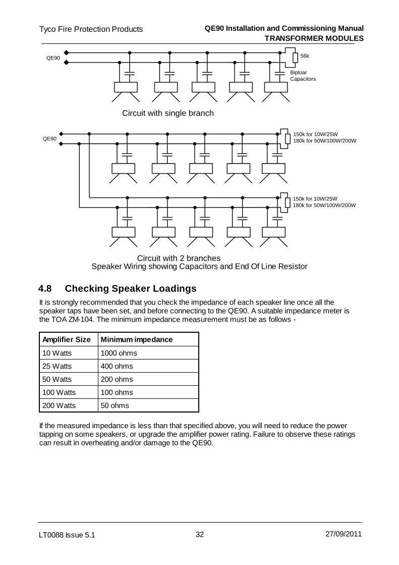
QE90 Installation and Commissioning Manual
TRANSFORMER MODULES
32LT0088 Issue 5.1
Tyco Fire Protection Products
27/09/2011
Circuit with single branch
Circuit with 2 branches
QE90
QE90
BiploarCapacitors
56k
150k for 10W/25W180k for 50W/100W/200W
150k for 10W/25W180k for 50W/100W/200W
Speaker Wiring showing Capacitors and End Of Line Resistor
4.8 Checking Speaker Loadings
It is strongly recommended that you check the impedance of each speaker line once all thespeaker taps have been set, and before connecting to the QE90. A suitable impedance meter isthe TOA ZM-104. The minimum impedance measurement must be as follows -
Amplifier Size Minimum impedance
10 Watts 1000 ohms
25 Watts 400 ohms
50 Watts 200 ohms
100 Watts 100 ohms
200 Watts 50 ohms
If the measured impedance is less than that specified above, you will need to reduce the powertapping on some speakers, or upgrade the amplifier power rating. Failure to observe these ratingscan result in overheating and/or damage to the QE90.

QE90 Installation and Commissioning Manual
TRANSFORMER MODULES
33LT0088 Issue 5.1
Tyco Fire Protection Products
27/09/2011
4.9 Checking Speaker Wiring
A quick check can be made of the speaker wiring by measuring the DC resistance across thespeaker lines at the MECP end. The resistance measured must be within 5% of 56 k for a single
branch circuit, or within 5% of 75 k for a two branch circuit on a 10W / 25W amplifier, or within
5% of 90 k for a two branch circuit on a 50W / 100W / 200W amplifier. (This DC resistance hasnothing to do with the AC impedance of the load discussed above.)Note that due to the capacitors connecting to the speakers, the reading may be slow to stabilise.To perform this check, each speaker line must be removed from its respective QE90 terminationpoint and a multimeter placed across the unconnected line.
Also check that both sides of the line are isolated from ground.
Alternatively once the system has been powered up, measure the DC voltage across the line. Itshould be 2.5V + 0.1V. This voltage will be slow to stabilise immediately after power up or afterremoval of a fault.
NOTE - If you have two branches wired as shown, the DC voltage across the line should be 2.86V + 0.1V for 10W and 25W amplifiers, and 3.08V + 0.1V for 50W, 100W and 200W amplifiers.
4.10 Zone Relays
The zone relay termination points provide a switched 24V DC output for emergency overridecontrol of local zone background music volume controls when fitted, or for silencing external nonemergency amplifiers.
This 24V output is normally energised and is switched off whenever the zone is emittingemergency tones or emergency public address or non-emergency paging. The zone relay outputis wired to the override relay of the local volume control so that when the relay output switches offthe relay de-energises and bypasses the local volume control. The diagram below shows how thiscan be arranged with an autotransformer type volume control. This arrangement preserves the linemonitoring regardless of whether the control is in circuit or not.
Zone Relay output
-
Zone Speaker output
RelayCoil
NC
NO
COM
1uF per watt of load10V or moreBipolar
+
-
+
To Speakers
Override relay for Music volume control

QE90 Installation and Commissioning Manual
TRANSFORMER MODULES
34LT0088 Issue 5.1
Tyco Fire Protection Products
27/09/2011
4.11 LEDs
The HTRN9308 modules have two red LEDs. Each LED, when ON, indicates that one of theamplifiers relating to that module has failed and that a standby amplifier is switched in to replace it.This will only occur on systems with one or more standby amplifiers configured.
The TRAN200 module has 1 red LED. This indicates that the circuit has a standby amplifierswitched in due to amplifier failure, or if the module is set up to switch in an external “music” poweramplifier under non-emergency conditions, the external amplifier is switched in.
4.12 Music Switching Transformer Modules
Special models of transformer module (HTMS9408-1 and HTMS9408-2) are available for 50W and100W amplifiers, which have the feature that a third party amplifier output may be connected to theterminals on the module labelled AUX MUSIC. These modules will route the third party amplifier tothe speakers at all times except for when there are emergency tones being generated by theQE90. However these module will allow the QE90 to monitor the speaker lines regardless of whichamplifier is “connected” to the speakers.
This module is wired up as a normal 50W / 100W module, except that the external amplifier isconnected to the AUX MUSIC 1 terminal pair (if 100W) , or the AUX MUSIC 1 and 2 terminal pairs if2 * 50W.
Standby Amplifiers cannot be used with these modules.
The 200W transformer module (TRAN200) can be configured to switch in the third party amplifieras above, by setting all three links LK1, LK2, and LK3 on the module to the “M” position. In thiscase a Standby Amplifier cannot be used for the circuit.
Relay 2
Aux Music 1
Aux Music 1
Speaker Line 2
Speaker Line 1
Relay 1
Relay 1
Relay 2
Speaker Line 2
Speaker Line 1
(Note for 100W Modules, use Line 1, Aux Music 1, and Relay 1)
Connectionto Amplifier
Connectionto Amplifier
HTMS9308 HTMS9308
Aux Music 2
Aux Music 2
Connection Points for 50W and 100W Music Switching Transformer Modules

Chapter 5
AMPLIFIERS - EAMP9001, HAMP9308 and AMP200

QE90 Installation and Commissioning Manual
AMPLIFIERS - EAMP9001, HAMP9308 and AMP200
36LT0088 Issue 5.1
Tyco Fire Protection Products
27/09/2011
5.1 Amplifier Types
There are three kinds of amplifier modules –EAMP9001 which can be configured as 4 * 10W or 2 * 25W (or now unused 1 * 50W)
HAMP9308 which can be configured as 2 * 50W or 1 * 100W
AMP200 which can be used in pairs as 1 * 200W per pairAll have a similar set of options which can be selected by links on the module.
5.2 Links
5.2.1 Power Selection
The number and power of the amplifiers are set with the links on the module.
EAMP9001
Link Position Description
5 Fitted 4 * 10 Watt
Removed 2 * 25 Watt
6 1-2 4 * 10 Watt
3-4 2 * 25 Watt
7 Fitted 4 * 10 Watt
Removed 2 * 25 Watt
8 1-2 4 * 10 Watt
3-4 2 * 25 Watt
9 1-2 4 * 10 Watt OR 2 * 25 Watt
3-4 Obsolete 1 * 50Watt
HAMP9308
Link Position Description
3 50W+50W 2 * 50 Watt
100W 1 * 100 Watt
5 Fitted 2 * 50 Watt
Removed 1 * 100 Watt
8 Removed 2 * 50 Watt
Fitted 1 * 100 Watt

QE90 Installation and Commissioning Manual
AMPLIFIERS - EAMP9001, HAMP9308 and AMP200
37LT0088 Issue 5.1
Tyco Fire Protection Products
27/09/2011
5.2.2 AMP200 Master / Slave Selection and Interconnection
The AMP200 has three links LK12, LK13, and LK14 which must all be fitted in the M position on themaster amplifier module, and in the S position on the slave amplifier module.
All the remaining link settings apply to the master module only. (The remaining link settings onthe slave module are immaterial.)Any local input must be connected to the master module.
The ribbon cable to the transformer module (TRAN200) must come from the backplaneconnector behind the master module. The ribbon cable connection behind the slave module isnot used.The volume control to be used is on the master module. The setting of the volume control onthe slave module is immaterial.Only the master module is listed on the configuration listing.
The slave module must be adjacent to the master module.
The master module and slave module are connected with a four wire cable connecting toconnector J4 on each module.
5.2.3 Default Input Selection
Each amplifier has a link to select the default input to be used when no other signal is selected, i.e.none of Alert Tone, Evacuate Tone, PA Speech, Non-emergency Paging (PABX) or Music areselected.
These are LK1 - 4 for the EAMP9001, LK1-2 for the HAMP9308 and LK1 for the AMP200.The following are the options for each of these links.
Position Selection
SILENCE No Audio Signal
AUX – BUS AUX input on the signals interface module. (Referto Background Music Input Facility and toSECP and Remote Equipment Rack Interface .
Removed Local Input connector on the amplifier module.(Refer to Local Inputs )
Amps Affected
Link 4 * 10W 2 * 25W 2 * 50W 1 * 100W 1 * 200W
1 Amp 1 Amps 1 + 2 Amp 1 Amp 1 Amp 1
2 Amp 2 Amp 2
3 Amp 3 Amps 3 + 4
4 Amp 4
68
97
38

QE90 Installation and Commissioning Manual
AMPLIFIERS - EAMP9001, HAMP9308 and AMP200
38LT0088 Issue 5.1
Tyco Fire Protection Products
27/09/2011
5.2.4 Amplifier Monitoring Disable
Links 10 and 11 on all types of amplifier module may be removed to disable the amplifier faultmonitoring in the software (but not the speaker line supervision). If the monitoring is disabled, youcan also turn off the test tone by removing LK5 and LK7 and resistors R2 and R30 on theEAMP9001, removing LK4 and LK5 on the HAMP9308, or removing LK4 on the AMP200. This isintended for very special purposes only, when it is done the system does not fully comply withAS2220.
5.2.5 Local Inputs
Each amplifier has its own local input which may be selected when no other signal is active. (SeeDefault Input Selection above). These are terminated on the 6 way connectors on the inside edgeof the module. Mating Connectors are available, Tyco part code CN0256 CONNECTOR,PHOENIX,6W,MSTB 1.5/6-ST,SNGL HT,FEMALE.
These inputs can be used for non-emergency Music or PA Signals from third party PA equipment,or non-emergency PA signals from the Tyco PA0688 Microphone Preamp module, when a numberof different channels are required for different zones, groups of zones, or sub zones. To havedifferent non-emergency signals fed to different parts of an Evacuation zone, it is necessary forthat zone to have more than one amplifier configured.
As these inputs are unbalanced they should normally be connected with line isolatingtransformers. Refer to ALIM9706 on Amplifier Local Inputs and PA0688 Wiring .The signalrequired at these inputs is 300mV RMS.
The Pin connections are as follows-
Input Pin EAMP9001 HAMP9308 AMP200
4 * 10W 2 * 25W 2 * 50W 1 * 100W 1 * 200W
1(Bottom) Input 1 Input 1 Input 2
2 Ground Ground Ground Ground
3 Input 2
4 Input 3 Input 2 Input 1 Input 1 Input 1
5 Ground Ground Ground Ground Ground
6 (Top) Input 4
5.3 Amplifier LEDs
EAMP9001 LEDs
Led Colour Position Indication when ON
D5 Red Top Power Available for amplifiers 1 and 2
D6 Red Bottom Power Available for amplifiers 3 and 4
162 76

QE90 Installation and Commissioning Manual
AMPLIFIERS - EAMP9001, HAMP9308 and AMP200
39LT0088 Issue 5.1
Tyco Fire Protection Products
27/09/2011
HAMP9308 LEDs
Led Colour Position Indication when ON
LD1 Green Top Power Available for amplifier 1
LD2 Red Top Amplifier 1 switched off due to overload
LD3 Red Bottom Amplifier 2 switched off due to overload
LD4 Green Bottom Power Available for amplifier 2
AMP200 LEDs
Led Colour Position Indication when ON
LD1 Green Top Power Available
LD2 Red Top Amplifier switched off due to overload
The red LEDs on the HAMP9308 and AMP 200 indicate that the speaker load is greater than theamplifier’s rating, or the output is short circuited, and the amplifier has briefly switched off toprevent damage. Both LEDs of the HAMP9308 will operate in unison in 1 * 100W mode, and theLEDs on both amplifier modules will operate in unison on the AMP200.
5.4 Amplifier Adjustments
All amplifier types have controls to adjust the power output. Note however in terms of efficiencyand battery capacity that it is preferable to reduce the volume by adjusting the speaker taps to alower setting and leaving the controls turned right up (fully clockwise), rather than by using thevolume controls.
EAMP9002 Controls
Control Location Amps affected 4 * 10W Amps affected 2 * 25W
VR1 Top 1 1 & 2
VR2 Second Top 2
VR3 Second Bottom 3 3 & 4
VR4 Bottom 4
HAMP9308 Controls
Control Location Amps affected 2 * 50W Amps affected 1 * 100W
VR1 Top 1 1
VR2 Bottom 2
AMP200 Control
Control Location Amps affected
VR1 Top of Master 1

QE90 Installation and Commissioning Manual
AMPLIFIERS - EAMP9001, HAMP9308 and AMP200
40LT0088 Issue 5.1
Tyco Fire Protection Products
27/09/2011
HAMP9308 and AMP200 sensitivity changeHAMP9308 Revision 9 and AMP200 Revision 3 had their sensitivity reduced slightly (comparedwith previous revisions) to match that of the EAMP9001. If you are replacing one of theseamplifiers and the sensitivity would have changed, the Volume control(s) should be re-adjusted,not simply set to the same physical rotation position as the controls were on the old card. If this isnot possible, rotate the control about 10% clockwise from the old position if changing to a lowersensitivity revision, or about 10% anticlockwise from the old position if changing to a highersensitivity revision.

Chapter 6
WIP PHONE TERMINATION MODULES

QE90 Installation and Commissioning Manual
WIP PHONE TERMINATION MODULES
42LT0088 Issue 5.1
Tyco Fire Protection Products
27/09/2011
6.1 General
The WTRM2000 WIP termination module is the latest module and is used for terminating up to 30WIP phones with an optional BGA device at the phone connected across the same two wires. Itmay also be used for FIP and general purpose inputs. The WTRM2000 connects to a WIPS2000module in the card cage.
The older WTRM9007 WIP termination module is primarily used for terminating up to 30 WIPphones, but as of November 1997 it can also be used for terminating FIP, BGA, and generalpurpose switch inputs. The WTRM9007 connects to a WIPS9004 module in the card cage.
The MWIP9903 terminates up to 8 circuits and is described in MWIP9903 8 Circuit WIP Module.
With appropriate software the WTRM9007 and MWIP9903 modules may be used for terminating amixture of WIP phones and FIP and/or BGA inputs. This is used mainly in small systems wherethere are spare WIP circuits which would otherwise be unused. This feature also allows acollocated WIP phone and BGA device to share a 3 wire cable. Using WIP circuits in this mannerrequires WIPS9004 software version 1.50 or higher, and for a system with no ECMs, ECPsoftware version 4.10 or higher, or for a system with ECMs, ECM software version 1.50 or higher.
The WTRM2000 / WTRM9007 WIP Phone Termination module is usually located on the left handmounting rail inside the system. Depending upon the number of WIP phones required, up to 6 WIPtermination modules may be fitted.
The WIPS2000 must connect to a WTRM2000 termination module. The WIPS9004 mustconnect to a WTRM9007 termination module. Do not swap them over.
Remote WIPs can be connected over derived signalling systems by using two RWIF9803 modules(refer RWIP9803 Remote WIP Interface ).
6.2 WTRM2000 Wiring
6.2.1 General
Each WTRM2000 termination module provides terminations for up to 30 WIP phones and/orswitch circuits. Compatible types are Vigilant FP0938, Aiphone TBRC, Aiphone TB-SE RED T,Altronics A2095 Firephone, and Altronics A2096 Firephone. For new installations the VigilantFP0938 is recommended as it is the only phone that complies with AS/ACIF S004.
The first termination module provides circuits 1 - 30, the second module circuits 31 - 60, and soon.
There may be 1, 3, or a variable number of WIPs per evacuation zone. The configuration printoutsupplied with the system has details of which circuits are assigned to which zones.
It is recommended that a 0.75mm2 shielded pair be used for each WIP circuit, however for shortcable runs unshielded cables can be used with slightly higher susceptibility to induced hum andnoise. The shields must be connected to the metal chassis at the MECP. Cables should be nolonger than 1000m.
Refer to the diagram below which shows the wiring for a normal WIP circuit (with an optional zone
51
48

QE90 Installation and Commissioning Manual
WIP PHONE TERMINATION MODULES
43LT0088 Issue 5.1
Tyco Fire Protection Products
27/09/2011
manned pushbutton), a FIP circuit, a WIP and BGA sharing a 3 wire cable, a WIP and BGA sharinga 2 wire circuit, and a two wire circuit which provides 2 General Purpose inputs.
Note the FP0938 phone is polarity sensitive, while the other models are not.
The terminals labelled 0V will be wired in the factory. When expanding a system wire one of themto the 0V terminal on the Backplane.
Note that the 3 wire WIP / BGA circuit is wired with the – terminal common on the WTRM2000.(The + terminal is common on the WTRM9007.)
Note - AS2220.1 prohibits connecting more than one phone to a circuit as they then cannot beindividually addressed. In any case it is recommended that you do not connect more than onephone to a circuit as there can be spurious fault indications when more than one phone is off-hook.
+
+
+
+
+
+
-+-
-
-
-
-
-
B
B
G
G
A
A
PHONE
PHONE
PHONE
10k 1% EOL
10k 1% EOL
10k 1% EOL
10k 1% EOL
FIP
10K 1% EOL
Optional N/OZone MannedSwitch
4k7 1%
0V
1
2
3
4
5
6
7
8
9
10
11
12
13
14
15
0V
30
29
28
27
26
25
24
23
22
21
20
19
18
17
16 WTRM2000
3 WireOld StyleWIP / BGA
1k2 1%
1k2 1%
600 ohms 1%
New Style 2 wire WIP / BGA
Two General Purpose Inputson one circuit
WTRM2000 Wiring
6.2.2 WTRM2000 End of Line Termination
When terminating the wiring to each remote device, the 10k ohm resistor fitted across each WIPterminal block must be removed and fitted across the line connection point at the remote phone orFIP/BGA switch. 1% resistors should be used in new installations (included on WTRM2000) (Tycopart number RR0045).
However the Vigilant FP0938 phone comes with an EOL resistor already fitted, so the resistor

QE90 Installation and Commissioning Manual
WIP PHONE TERMINATION MODULES
44LT0088 Issue 5.1
Tyco Fire Protection Products
27/09/2011
connected across the terminal block can be removed and discarded.
6.2.3 WTRM2000 Two Wire WIP / BGA Connection
With the WTRM2000 one normally open BGA device may be connected across the WIP circuit. A1.2K 0.25W 1% resistor (Tyco part number RR0034) must be wired in series with the BGA. These resistors will be provided with QE90 systems with WTRM2000 modules.
A two wire BGA device may not be used with a zone manned pushbutton on the same circuit.
Two wire WIP / BGA functionality must be programmed into the QE90 with QEConfig .
6.2.4 WTRM2000 Zone Manned Pushbutton
A pushbutton or switch can be fitted to a remote WIP phone so that when the switch is closedwhile the WIP is on hook, the appropriate ZONE MANNED indicator on the MECP front panel willlight. Wiring of the switch is shown in WTRM2000 General . It requires a 4k7 ohm, 0.25W Wattresistor to be wired to one side of the switch such that when the pushbutton is operated, the 4k7resistor is switched in parallel across the WIP line. 1% resistors (Tyco part number RR0041)should be used in new installations. Unlike the WTRM9007 which requires a pushbutton, a toggleswitch may be used with the WTRM2000. However note that operation of the switch cannot bedetected when the phone is off hook.
6.2.5 WTRM2000 General Purpose Input
A general purpose switch input may be wired like a FIP input. The 10k EOL resistor is optional.
On the WTRM2000 two general purpose input switches may be wired to a single circuit. Oneshould be wired with a 600 ohm 1% resistor (2 x 1k2 Tyco part number RR0034 in parallel) inseries and the other with a 1.2k 1% ohm resistor in series (Tyco part number RR0034).
The function of the inputs is determined by the software programmed into the QE90 with QEConfig.
212
42
212

QE90 Installation and Commissioning Manual
WIP PHONE TERMINATION MODULES
45LT0088 Issue 5.1
Tyco Fire Protection Products
27/09/2011
6.3 WTRM9007 Wiring
WTRM9007
+-+-
10k EOL
BGA
10K EOL
PHONE
PHONE
10k EOL
FIP
10K EOL
Optional N/OZone MannedPush Button
4k7
+24V
1
2
3
4
5
6
7
8
9
10
11
12
13
14
15
+24V
30
29
28
27
26
25
24
23
22
21
20
19
18
17
16
WTRM9007 Wiring
6.3.1 General
Each WTRM9007 termination module provides terminations for up to 30 WIP phones and/orswitch circuits. Compatible types are Vigilant FP0938, Aiphone TBRC, Aiphone TB-SE RED T,Altronics A2095 Firephone, and Altronics A2096 Firephone. The first module provides circuits 1 -30, the second module circuits 31 - 60, and so on.
There may be 1, 3, or a variable number of WIPs per evacuation zone. The configuration printoutsupplied with the system has details of which circuits are assigned to which zones.
It is recommended that a 0.75mm2 shielded pair be used for each WIP circuit, however for shortcable runs unshielded cables can be used with slightly higher susceptibility to induced hum andnoise. The shields must be connected to the metal chassis at the MECP.
Refer to the diagram below which shows the wiring for a normal WIP circuit (with an optional zonemanned pushbutton), a FIP circuit, and a WIP and BGA sharing a 3 wire cable.
Note that the 3 wire WIP / BGA circuit is wired with the + terminal common on the WTRM9007(and the - terminal common on the WTRM2000).

QE90 Installation and Commissioning Manual
WIP PHONE TERMINATION MODULES
46LT0088 Issue 5.1
Tyco Fire Protection Products
27/09/2011
The terminals labelled +24V will be wired in the factory. When expanding a system wire one ofthem to the +24V terminal on the backplane. Note the wiring to the Vigilant FP0938 WIP phone ispolarity sensitive.
6.3.2 WIPS9007 End of Line Termination
When terminating the wiring to each remote phone, the 10k ohm resistor fitted across each WIPterminal block must be removed and fitted across the line connection point at the remote phone orFIP/BGA switch. 1% resistors should be used in new installations.
However the Vigilant FP0938 WIP phone comes with an EOL resistor already fitted, so the resistorconnected across the terminal block can be removed and discarded.
6.3.3 WIPS9007 Zone Manned Pushbutton
A pushbutton can be fitted to a remote WIP phone so that when it is pressed while the WIP is onhook, the appropriate ZONE MANNED indicator on the MECP front panel will light. Wiring of thepushbutton is shown in WTRN9007 General . It requires a 4k7 ohm, ¼ Watt resistor to be wiredto one side of the switch such that when the pushbutton is operated, the 4k7 resistor is switched inparallel across the WIP line. 1% (Tyco part number RR0041) resistors should be used in newinstallations. It is not possible to use a toggle switch instead of a pushbutton, as when the switch isin the operated position it is not possible for the QE90 to detect when a WIP which has been offhook is placed on hook.
6.3.4 WIPS9007 General Purpose Input
A general purpose switch input may be wired like a FIP input. The 10k EOL resistor is optional. Thefunction of the inputs is determined by the software programmed into the QE90 with QEConfig .
6.4 Vigilant® FP0938 WIP Phone Wiring
Refer to the sheet supplied with the Vigilant® FP0938 WIP phone for full information. The followingis only a summary.
Note that the IN terminals are internally connected to the OUT terminals. Two pairs are provided tomake it easier to connect the EOL resistor, or loop onto an BGA.
Connect the line to the panel to the IN+ and IN- terminals. Note that these terminals are polaritysensitive. The + terminal on the phone must connect to the + terminal of the termination module.
The FP0938 will be supplied with an EOL resistor connected to the OUT+ and OUT- terminals, soit is not necessary to connect another EOL and the EOL resistor supplied connected to the WTRMmodule can be discarded.
If a connection to a BGA is required, the EOL resistor can be removed and the OUT terminalswired to a series combination of the BGA switch and a 1200 ohm resistor, with the EOL thenconnected in parallel.
If the ring is not loud enough (e.g. the phone has been installed in a cupboard), then an externalspeaker can be used to boost the ring volume, for example -
ME0468 ME, QE90 WIP External Ring Speaker
45
212

QE90 Installation and Commissioning Manual
WIP PHONE TERMINATION MODULES
47LT0088 Issue 5.1
Tyco Fire Protection Products
27/09/2011
If the batch code of the FP0938 is higher than 0812000Route the cable to the FP0938 phone, cut off the two pin connector and strip a length ofinsulation, and screw the two wires to the SPKR terminals.
Otherwise (i.e. the batch code of the phone is less than 0812000)Route the cable to the inside of the FP0938 (you may need to drill a hole in the underside of thebody). Plug the cable into the two pin plug of the PCB inside the FP0938, in place of the existingplug that goes to the internal speaker. Leave the existing internal speaker disconnected.
For wiring a Vigilant FP0938 to the ECP as a Master Phone, refer to Master Phone Termination .
6.5 Altronics A2095/A2096 wiring
The A2095/A2096 WIP should normally have its two internal jumpers in their default positions (i.e.JP1 1-2 and JP2 1-2).
However, link JP1 may be moved to position 2-3 to change ringing from using the speakermounted on the body to use the handset speaker. This results in a lower volume ring, but loadsthe line less and allows a WIP to be used when there is a second WIP on the same cable (whichis not recommended in any case). When using this option, the user should never hold theearpiece to their ear while holding down the “hook switch” on the phone body, as if thephone rings a very loud sound is emitted by the earpiece.
The QE90 connection is made to the external screw terminals labelled 1 and 2 (either polarity). The external screw terminals labelled 3 and 4 are normally joined, but can be separated for a lowervolume ring.
If, once the WIP has been installed the ring is not loud enough (e.g. it has been installed in acupboard), then an external speaker can be used to boost the ring volume. Disconnect the wireslabelled EXT-SP from the internal speaker and re-connect to the screw terminals S1 and S2instead. The external speaker (>20 ) should then be wired to these screw terminals andpositioned to give adequate ring volume. Note this is not possible if more than one WIP isconnected on the line.
6.6 WLED9307 WIP Flashing LED PCB
The WLED9307 PCB can be used to provide visual indication that a WIP phone is ringing. TheLINE+ and LINE- terminals are connected across the WIP line (either way around) and a LED isconnected to the LED+ and LED- terminals. The anode of the LED must be connected to theLED+ terminal. About 10mA will be passed through the LED when the phone is ringing. If you alsowant to stop the WIP from ringing, remove capacitor C6 from the circuit board inside theAIPHONE, or remove JP1 from the A2095.
6.7 WIP System Expansion
If you are expanding an existing system and adding a new WTRM module and WIPS module, notethe following
The WIPS module will need its jumpers set as described in WIP Slave Module .
Connect the WIP 1 OUT or WIP 2 OUT connector on the backplane adjacent to the new WIPSmodule to the WTRM module with the 34 way ribbon cable provided.With a WTRM9007 module, connect +24V from the screw terminals on the backplane near theWIPS module to a +24V terminal on the WTRM module.
125
102

QE90 Installation and Commissioning Manual
WIP PHONE TERMINATION MODULES
48LT0088 Issue 5.1
Tyco Fire Protection Products
27/09/2011
With a WTRM2000 module, connect 0V from the screw terminals on the backplane near theWIPS module to a 0V terminal on the WTRM module. If you have an older backplane with no0V terminals near the WIPS module, use the 0V power terminal on the backplane.
Within a panel, or even a within a card cage, WIPS9004 / WTRM9007 module pairs may be mixedwith WIPS2000 / WTRM2000 module pairs. However the WIPS2000 must connect to aWTRM2000 termination module. The WIPS9004 must connect to a WTRM9007 terminationmodule. Do not swap them over.
6.8 RWIF9803 Remote WIP Interface
This module is now obsolete. The following information is included for reference only.
6.8.1 General Description
The wiring to a field WIP is normally via a single copper cable pair. However where the WIP mustbe remotely located, or a derived signalling system is used, then two Remote WIP InterfaceModules (RWIF9803) can be used to convert the QE90's WIP circuit to a suitable format forsignalling over the derived circuit.
The RWIF9803 modules can be fitted to any WIP circuit without reprogramming the QE90 or itsconfiguration, unless the Master WIP redirection feature is to be used.
The connection to the Remote WIP is supervised by the QE90 only as far as the ECP endRWIF9803 module. To check the rest of the connection, lift the Remote WIP - check forconfidence tone, and call the remote WIP from the QE90 - ringing should be heard.
The RWIF9803 is available as either a stand-off mountable circuit board (PA0821) or a DIN Railmounted module (PA0621).
6.8.2 Wiring Arrangement
Two RWIF9803 modules are required for each remote WIP, one at each end of the connection.Link settings configure the RWIF for operation at each end.
The module at the QE90 end converts the QE90’s WIP connection into 2 outputs and 1 input - theoutputs are a 2-wire full duplex audio path and a contact closure to indicate ringing, and the input isto receive the WIP on/off hook status.
The module at the remote end has the opposite connections to the master - one contact closureinput to control the ring generation to the WIP and a 2-wire full duplex input for the audio, while acontact closure output indicates WIP off-hook.
At the remote end a 24Vdc power supply is required to power the module.
The diagram below shows the wiring arrangement of the RWIF. For the connection between thetwo RWIF modules three circuits are required:
Audio A 2 wire full duplex (bi-directional) audio path with unity gain.
Ring A contact closure input from the QE90 end should cause a contact closure outputat the remote end.
Off Hook A contact closure input at the remote end should cause a contact closure output atthe QE90 end.

QE90 Installation and Commissioning Manual
WIP PHONE TERMINATION MODULES
49LT0088 Issue 5.1
Tyco Fire Protection Products
27/09/2011
The audio connections should be made using screened cable, and the connection between theRING and RING IN terminals should be kept short (<15m).
Even though 3 circuits are described, it is sometimes possible for these to be combined into 2physical cable pairs - “E + M signalling” is a typical way this can be achieved. Refer to thetechnical details for the derived system you are using to determine the particular wiringarrangement necessary.

QE90 Installation and Commissioning Manual
WIP PHONE TERMINATION MODULES
50LT0088 Issue 5.1
Tyco Fire Protection Products
27/09/2011
AUDIO +
AUDIO -
C
NC
NO
SW +
SW -
WIP -
RING
RING IN
PHONE +
PHONE -
24V
0V
GND
LK1
Fit for ECP
RWIF9803
LK2
Remove
10k EOL
QE90
QE90 WIP- ON WTRM9007
QE90 +24V
QE90 0V
AUDIO +
AUDIO -
C
NC
NO
SW +
SW -
WIP -
RING
RING IN
PHONE +
PHONE -
24V
0V
GND
LK1
Fit for WIP
RWIF9803
REMOTE WIP
PSU +24V
PSU 0V
WIP
DERIVED CIRCUIT
(See text for details)
RING
OFF HOOK
LK2
Fit For WIP
Wiring of RWIF9803 Modules for Remote WIP on QE90

QE90 Installation and Commissioning Manual
WIP PHONE TERMINATION MODULES
51LT0088 Issue 5.1
Tyco Fire Protection Products
27/09/2011
6.8.3 Link Settings
The mode of operation of the RWIF9803 is configurable for where it is placed in the WIP circuit. The link settings are shown below:
Operation Mode Lk1 Lk2
WIP End 1-2 Fitted
ECP End 2-3 Not Fitted
6.8.4 Indicators
The RWIF9803 has a single 3mm red LED which is used to indicate when the relay is energised.
The function of the relay depends on the link settings. At the QE90 end the relay is activated whenthe RWIF9803 detects ring voltages from the QE90. At the WIP end the relay is activated whenthe WIP is lifted off-hook.
6.9 MWIP9903 8 Circuit WIP Module
6.9.1 General
The MWIP9903 is an 8 circuit WIP module that was used in small QE90 systems where there arefewer than 8 WIP circuits plus FIP, BGA, and GP inputs. It is now obsolete. The information in WTRM9007 Wiring , Vigilant FP0938 Wiring , Altronics A2095/A2096 Wiring , andWLED9307 WIP Flashing LED Board also generally applies to the MWIP9903 module.
Refer to the diagram below for details of wiring to the MWIP9903 module.
45 46 47
47

QE90 Installation and Commissioning Manual
WIP PHONE TERMINATION MODULES
52LT0088 Issue 5.1
Tyco Fire Protection Products
27/09/2011
PHONE
10k EOL
10k EOL
10k EOL
BGA
OptionalZone Manned
4k7FIP
1
2
3
4
5
6
7
8
+
+
+
+
+
+
+
+
+
-
-
-
-
-
-
-
-
- IN
65
4
3
2
1+
-+
-
BUS
24V
0V
BACKPLANEPHONE
FIP BUS
24V
+
-
+
-
FactoryWiring
MW IP9903
10k0.25W(* Seebelow)
* this resistor is required only on a panelwith no SPIF module ie with an SE9004module.
MWIP9903 Wiring
6.9.2 LED Indicators
Six LED Indicators are located on the MWIP9903 module and their functions are as follows:
LED NORMAL STATUS CONDITION INDICATED
+24V ILLUMINATED +24V SUPPLY OK
+12V ILLUMINATED +12V SUPPLY OK
+12VREF ILLUMINATED +12V REFERENCE SUPPLY OK
RUN ILLUMINATED MICROPROCESSOR RUNNING OK
COMMS PULSING COMMS OK, MODULE RESPONDING
FAULT OFF WHEN ON, A LINE FAULT EXISTS

QE90 Installation and Commissioning Manual
WIP PHONE TERMINATION MODULES
53LT0088 Issue 5.1
Tyco Fire Protection Products
27/09/2011
6.9.3 DIP Switch 1 Settings
Switch 1 is normally OFF in a QE90 system. The 8 circuits are then individually addressable bythe MECP. When switch 1 is ON, the circuits will be arranged into sets, with circuits 1-3 as oneset, circuits 4 and 5 as another set, and circuits 6-8 as the third set. Each of these 3 sets willbehave as a single circuit to the MECP. This option could be used to have multiple WIPs per ECPcontrol, with each WIP wired individually back to the MWIP9903 module.
Switch 2 must be ON in a QE90 system.
Switch 3 must be ON to enable all 8 circuits. When OFF only circuits 1–3 will be enabled.
Switches 4–8 must be OFF.
6.9.4 DIP Switch 2 Settings
Note that in a QE90 system, each MWIP9903 will address the first 8 of each multiple of 30 circuits.
MODULEAddress
WIPCIRCUITS
SW8 SW7 SW6 SW5 SW4 SW3 SW2 SW1
0 1-8 ON ON OFF OFF OFF OFF OFF OFF
1 31-38 ON ON OFF OFF OFF OFF OFF ON
2 61-68 ON ON OFF OFF OFF OFF ON OFF
3 91-98 ON ON OFF OFF OFF OFF ON ON
4 121-128 ON ON OFF OFF OFF ON OFF OFF
5 151-158 ON ON OFF OFF OFF ON OFF ON
6 181-188 ON ON OFF OFF OFF ON ON OFF
6.9.5 System Expansion
If a MWIP9903 board is to be added to a system, you will need to wire 24V DC Power, Comms,and the "Backplane Phone" circuit to the new module. Power is wired in RED (+24V) and BLACK(0V) 1.0mm 2 wire and Comms in YELLOW (+) and BLUE (–)1.0mm 2 wire.
POWER can be obtained from –The +24V / 0V terminals of another MWIP9903 module
The +24V / 0V terminals of a FIB8910/FIB1011 module
The +24V / 0V terminals of a STRM9502 module or STBM9008 module
The two pin Molex connector on a flying lead of the PSU2403 or PSU308
The +24V FIP and 0V screw terminals inside a PSU2406.
BUS +/– can be wired fromThe BUS +/– terminals of another MWIP9903 module
The COMMS +/– terminals of a FIB8910/FIB1011 module
The COMMS +/– terminals of a STRM9502 module or STBM9008 module
The FIP BUS +/– terminals of a Signals Interface Module (SE9004 or SPIF9506 or SPIF9709).
The IN + / – terminals will need wiring toThe IN + / – terminals of another MWIP9903 module
The MASTER PHONE +/- terminals of a SE9004 module

QE90 Installation and Commissioning Manual
WIP PHONE TERMINATION MODULES
54LT0088 Issue 5.1
Tyco Fire Protection Products
27/09/2011
The BACKPLANE PHONE testpoint and 0V terminal of a SPIF9506 or SPIF9709 module.

Chapter 7
FIP / BGA / GP INPUT MODULES

QE90 Installation and Commissioning Manual
FIP / BGA / GP INPUT MODULES
56LT0088 Issue 5.1
Tyco Fire Protection Products
27/09/2011
7.1 FIP / BGA /GP Inputs - General
The FIP input and expansion modules are usually located on the right hand mounting rail inside thecabinet.
These modules may be used for FIP inputs, BGA inputs, or General Purpose inputs. Althoughoriginally a separate FIB8910 module was necessary for each type of input, this is now rarelyused. One FIB8910 module, with FIPE9004 expansion modules as necessary, can provide FIPinputs, BGA inputs, and GP inputs.
The FIB1011 now replaces the FIB8910. It is fully compatible.
As from November 1997 WIP circuits can also be used to provide FIP / BGA /GP inputs - refer to WIP Phone Termination Modules for details. Also FIP inputs are available using a high level linkfrom Vigilant and selected other models of fire panels – refer to High Level FIP Interfaces .
The FIB8910/FIB1011 module provides up to 10 inputs. Additional inputs are provided by FIPE9004expansion modules and sometimes additional FIB8910/FIB1011 modules. See 7.4.
A separate FIB8910/FIB1011 module for BGA inputs is now used only when there are too manyinputs for one FIB8910/FIB1011 plus the 3 expansion modules, i.e., more than 58 inputs in total.
GP inputs are typically used to control zones for Music or Paging as an alternative to the VigilantFP0539 Paging Console.
FIP inputs may also be used for various input functions, e.g., to accept clean contact outputs froma time switch to invoke a different cascade sequence out of normal hours.
The connection for FIP or BGA inputs is for a normally open contact closing for alarm. The line isterminated with an end of line zener diode, type BZT03-C10, to maintain line monitoring. The diodemust be connected with the cathode (i.e. the end marked with a band) to the positive input. Referto the diagram below.
The termination diodes factory fitted to each input must be relocated to the end of the line whenterminating field wiring to the input. The termination diodes must remain on all inputs assigned tozones in the system configuration (refer configuration printout), even if there is no connection fromthe FIP or a BGA to those inputs.
Inputs programmed as GP inputs do not need the zener diode end of line.
Cables should have a wire gauge of at least 0.75mm2 and should not be longer than 1000m.
Refer to Widget Board for information on the “Widget Board” used to replace themicroprocessor on the FIB8910 from late 2004.
7.2 RFIB9511 Remote Rack FIP / BGA Input Module
A related module is the RFIB9511 which is fitted to distributed equipment racks without ECPs. Itprovides FIP and/or BGA inputs as usual, and also controls the SPIF module fitted in the rack. TheRFIB9511 does not have Relay Outputs. Refer to drawing 699-198 for details of the wiring betweenthe RFIB and SPIF modules.
Issue E of the FIB8910 module (available January 1999) and the FIB1011 module have a set of
42
164
202

QE90 Installation and Commissioning Manual
FIP / BGA / GP INPUT MODULES
57LT0088 Issue 5.1
Tyco Fire Protection Products
27/09/2011
links so that they may be used as an RFIB module. These replace the RFIB9511.
An RFIB9511 module, or a FIB8910/FIB1011 module set up as an RFIB, requires version 2.xxsoftware. Version 1.xx or version 2.xx software may be used for a FIB8910 not set up as an RFIB.
7.3 Single FIP Input Connection
When there is a common alarm for all zones from the FIP, this output from the FIP must beterminated to Input 1 on the FIP input module and the system set up for no cascade and a zeroinitial delay. (See ECP on-site settings or ECM on-site settings .) This will result in all zonesgenerating ALERT tones, and after a time delay EVACUATE tones, on receipt of a FIP alarm.
-
3
4
+-+-
+-
2
+-
7
8
-+-
+-
5
6
9
10
-
+-
+
+
FIB8910/FIB1011
BUS+BUS-
0V
+24V
BUS2+BUS2-
ComN/CN/OComN/CN/O
+-
3
4
-+-
+-
1
2
+-
7
8
-+-
+-
5
6+
+
+
-
+
-
+
-
+
-
+
-
+
-
+
-
+
-
FIPE9004
9
10
11
12
13
14
15
16
1+
BZT03-C10Zener EOL
N/OContacts
BUS 2 NOT FITTEDON ISSUE E and HIGHERor on FIB1011
DAT+5V0VCLK+24V
AlternativeConnectionsin RFIB mode
Relay 2
Relay 1
FIB8910/FIB1011, FIPE9004 Showing termination points and example wiring
188 149

QE90 Installation and Commissioning Manual
FIP / BGA / GP INPUT MODULES
58LT0088 Issue 5.1
Tyco Fire Protection Products
27/09/2011
7.4 Multiple FIP and BGA Input Connections
For staged evacuation, individual outputs for each evacuation zone must be provided by the FIPand be terminated to their programmed inputs on the relevant FIP input module. If BGA inputs areused they must also be terminated to their programmed inputs on the FIP input module or BGAinput module if fitted.
This will allow for a cascading or spreading evacuation sequence to be implemented, usuallystarting with the initial zone on which the FIP alarm is detected or where the BGA is operated.
The first 10 inputs are on the first FIB8910/FIB1011 module, and the next 16 on the first FIPE9004module, the next 16 on a second FIPE9004 module, and the next 16 on a third FIPE9004 module. Ifthere are more than 58 inputs the sequence starts again with a second FIB8910/FIB1011 moduleand possibly further FIPE9004 modules, and so on.
The inputs are normally assigned to zones on a one to one basis, but sometimes this will not bethe case e.g. if some equipment is located remotely. The configuration printout supplied with thesystem shows the assignment of inputs to zones.
7.5 Switch and Link Settings
FIB8910/FIB1011 DIP Switches 8 – 5
Module Function Switch 8 Switch 7 Switch 6 Switch 5
FIP Inputs Only, OrCombined FIP / BGA / GPinputs
OFF ON OFF OFF
FIP Inputs Only, OrCombined FIP / BGA / GPinputs – RFIB mode
ON ON OFF OFF
BGA Inputs Only OFF ON OFF ON
GP Inputs Only OFF ON ON ON
FIB8910/FIB1011 DIP Switches 4 - 1
ModuleAddress
Switch 4 Switch 3 Switch 2 Switch 1
0 OFF OFF OFF OFF
1 OFF OFF OFF ON
2 OFF OFF ON OFF
3 OFF OFF ON ON
4 OFF ON OFF OFF
FIB8910 (Issue E or later)/FIB1011 Links
Not RFIB mode RFIB mode
LK1 - LK6 “FIB” position “RFIB” position

QE90 Installation and Commissioning Manual
FIP / BGA / GP INPUT MODULES
59LT0088 Issue 5.1
Tyco Fire Protection Products
27/09/2011
Fit the links in the “FIB” position unless the module is being used in the RFIB mode in anequipment rack with no ECP or ECM, i.e., when connecting to the SPIF module to control the SPIFrelays.
FIPE9004 Switches
FIPE9004 Input range Module Switches
1st 11-26,68-83,126-141 1,2 On, Rest Off
2nd 27-42,84-99,142-157 3,4 On, Rest Off
3rd 43-58,100-116,158-174 5,6 On, Rest Off
7.6 Relays
There are two relays on each FIP or BGA module, except the RFIB9511, or when an FIB8910Issue E and later or FIB1011 are being used in RFIB mode. These relays are usually available forGeneral Purpose Outputs (normally closed contacts which open for fault or alarm) for connectionto external equipment. These and other functions of the relays are configured by the software inthe ECP module. The functions are listed in the system’s configuration printout, and can bechanged with QEConfig .
Each relay is normally energised whenever the system is powered up and the programmedfunction is not true. The terminals are connected to the relays as shown in the diagram below. Thetwo relays are wired similarly.
N/C
N/O
C
FIB8910/FIB1011 Relay
The Relay is shown in the energised position i.e. the position it will be in when the system ispowered up and the programmed function is false. When the programmed condition is true or thesystem is powered down, the relay will be in the opposite position to that shown.
The relay functions which can be programmed can include (but are not limited to) the following,and logical combinations thereof -
Any Alarm
Any Fault
FIP Alarm
BGA Alarm
Line Fault
Module Fault
Manual
Isolate
Any zone has tones or paging active
Particular inputs or outputs activeIf you require a relay to be normally de-energised this can also be programmed with QEConfig .(For example an “Alarm” relay which did not indicate an alarm in the powered down state.)
212
212

QE90 Installation and Commissioning Manual
FIP / BGA / GP INPUT MODULES
60LT0088 Issue 5.1
Tyco Fire Protection Products
27/09/2011
The relays are rated at 30V 1A.
7.7 LEDs
The FIB8910/FIB1011 and RFIB9511 modules both have two LEDs, the functions of which are asfollows –
LED Colour Normal State Indication
LD1 Green ON +5V supply OK when on steady
LD2 Yellow Flashing Responding to Comms when flashing
7.8 System Expansion
When adding a FIB8910/FIB1011 module to expand an existing system you will need to wire 24VDC Power and Comms to the new module. Power is wired in RED (+24V) and BLACK (0V)1.0mm 2 wire and Comms in YELLOW (+) and BLUE (–)1.0mm 2 wire. POWER can be obtainedfrom –
The +24V / 0V terminals of another FIB8910/FIB1011 module
The +24V / 0V terminals of a STRM9502 module or STBM9008 module
The two pin Molex connector on a flying lead of the PSU2403 or PSU308
The +24V FIP and 0V screw terminals inside a PSU2406.
COMMS +/– can be wired fromThe COMMS +/– terminals of another FIB8910/FIB1011 module
The COMMS +/– terminals of a STRM9502 module or STBM9008 module
The FIP BUS +/– terminals of a Signals Interface Module (SE9004 or SPIF9506 or SPIF9709).

Chapter 8
STROBE RELAY DRIVER MODULE

QE90 Installation and Commissioning Manual
STROBE RELAY DRIVER MODULE
62LT0088 Issue 5.1
Tyco Fire Protection Products
27/09/2011
8.1 General
The STRM9502 Strobe Relay Driver Module provides two types of outputs -
(1) Powered & supervised outputs designed to drive strobe lights. Polarity reversal is used sothat pairs of (possibly different coloured) strobes may be controlled, one for alert and theother for evacuate. Note – alert strobes may not be required by AS1670.4.
(2) General purpose unsupervised relay outputs (clean contacts).
The two types of outputs can be mixed on a module. It is necessary to distinguish between the twotypes of outputs by links on the module. These are identified on the silk-screen. Programming ofwhich evacuation zones control which outputs, and whether each output is a strobe output or ageneral purpose output is done with QEConfig according to customer requirements. The detailsare listed on the configuration printout.
The operation of the powered and supervised outputs can be switched betweenSteady operation for both evacuate and alert (generally used for self-flashing strobes)
ISO8201 T3 pattern for evacuate, steady output for alert
50/50 on/off duty cycle for both evacuate and alertThis selection applies to all outputs together, it is not possible to have one selection for someoutputs and another selection for other outputs.
The module is also compatible with the older STBM9008 module and can be used as a directreplacement. It is compatible with STBT9008 strobe terminator modules which can be used inplace of the diodes shown in the diagram below.
Refer to Widget Board for information on the “Widget Board” used to replace themicroprocessor on the STRM9502 from late 2004.
When used with 4906-9103 and 4906-9104 “Multi-Candela” strobes, the module can be switchedvia the DIP switch settings to produce a T3 pattern complying with ISO 8201. This applies to onlythe Evacuate state. Alert strobe lights (if any) must be self-flashing strobes as before. Note - theMulti-Candela strobe light is white. Although AS2220 specified amber strobes for alert and redstrobes for evacuate, AS1670.4 does not specify any colours.
8.2 Strobe Output Wiring
Strobe lights must be wired to the A and B terminals as shown in the diagram below.
The 2k7 resistor connected to each terminal pair when the system is shipped must be removedand connected to the end of the strobe line.
The maximum load on each output is 2.0 Amps. Higher loads than this could blow the fuses.
It is recommended that cables are no longer than 1000m.The following table shows the cable sizes required to keep the voltage drop at approximately 10%,for various loads and cable lengths –
212
202

QE90 Installation and Commissioning Manual
STROBE RELAY DRIVER MODULE
63LT0088 Issue 5.1
Tyco Fire Protection Products
27/09/2011
CableLength
100mALoad
250mALoad
500mALoad
1A Load 2A Load
100m 0.75 mm2 0.75 mm2 1.5 mm2 2.5 mm2 6 mm2
200m 0.75 mm2 1.5 mm2 2.5 mm2 4 mm2 10 mm2
300m 1 mm2 2.5 mm2 4 mm2 6 mm2 16 mm2
500m 1.5 mm2 4 mm2 6 mm2 10 mm2 25 mm2
700m 2.5 mm2 4 mm2 6 mm2 16 mm2 25 mm2
1000m 2.5 mm2 6 mm2 10 mm2 25 mm2 40 mm2
Do not use a wire gauge appreciably heavier than the gauges in the above table – there may beproblems with high inrush currents (which are required to charge the large electrolytic capacitorsin some strobe lights) welding the relay contacts. It is also recommended that you don't use cablesshorter than 100m, or if you do then add resistor(s) to make enough total resistance to give about10% voltage drop at the intended load current. Note – this paragraph does not apply if all strobesconnected to a cable pair are Multi-Candela strobes – they do not suffer from the inrush currentproblem.
+-
+-
BUS1
BUS21B
1C
1A
2B
2C
2A
3B
3C
3A
4B
4C
4A
0V
0V
+24V
+24V
5B
5C
5A
6B
6C
6A
7B
7C
7A
8B
8C
8A
STRM9502
2k7
Red
Amber
Amber
Red
Amber
Red
+
+
+
+
+
+
Thesefourstrobelampsmusthaveinternaldiodes
These twostrobe lampshave nointernaldiodes
Repeat this wiring for each zone.
Strobe Relay Driver Module and Strobe Light Connection

QE90 Installation and Commissioning Manual
STROBE RELAY DRIVER MODULE
64LT0088 Issue 5.1
Tyco Fire Protection Products
27/09/2011
Note – a system complying with AS1670.4 will usually not use Alert strobes, and white Multi-Candela strobes will be used for Evacuate instead of Red strobes.Many strobe lights (including the Multi-Candela Strobes) have internal diodes to prevent damage ifthey are connected around the wrong way. If the strobe lights you are using do have an internaldiode connected in series with the supply, then you will not need the diodes shown in the diagramabove, and you can just wire every strobe light directly across the output of the STRM9502. Wirethe alert strobe light positive terminal to A, and the evacuate strobe light positive to B.
8.3 General Purpose Output Wiring
If you are using some or all of the outputs as general purpose relay outputs, each unused strobeoutput can provide two separate relay outputs (with a shared common connection). For example, ifoutput 8 is used for general purpose relay outputs, there will be two relay contacts, one between8A and 8C and the other between 8B and 8C. The programming of these outputs must be donewith QEConfig .
8A
8B
8C
Internal Wiring of STRM9502 for pair of Relay Outputs
These relays are rated at 30V 1A, or 30V 2A for a resistive load.
8.4 Links and DIP Switch Settings
The link settings for each output are shown in the following table.
Strobe Output orGP output Pair
Links installed ifstrobe output
Links if GP output pair
1 1,9,17=2-3 1 removed, 9 removed, 17=1-2
2 2,10,18=2-3 2 removed, 10 removed, 18=1-2
3 3,11,19=2-3 3 removed, 11 removed, 19=1-2
4 4,12,20=2-3 4 removed, 12 removed, 20=1-2
5 5,13,21=2-3 5 removed, 13 removed, 21=1-2
6 6,14,22=2-3 6 removed, 14 removed, 22=1-2
7 7,15,23=2-3 7 removed, 15 removed, 23=1-2
8 8,16,24=2-3 8 removed, 16 removed, 24=1-2
DIP switch settings
DIP switches 5 – 8 are used to select the mode for powered (strobe) outputs. Voltage-free GPrelay outputs are unaffected by these DIP switches.
212

QE90 Installation and Commissioning Manual
STROBE RELAY DRIVER MODULE
65LT0088 Issue 5.1
Tyco Fire Protection Products
27/09/2011
DIP Switch Output Pattern Usage MinimumSTRMSoftwareVersion
5 6 7 8
OFF ON ON OFF Dual polarity, steady voltagefor both evacuate and alertsignals.
Standard self-flashingstrobes.
1.00
OFF ON ON ON Dual polarity, ISO 8201 T3pattern for evacuate signal,steady voltage for alertsignal.
Multi-Candela strobesfor evacuate, standardself-flashing strobesfor alert.
1.70
ON ON ON ON Dual Polarity, continuousflash (not T3) for bothevacuate and alert signals.450mS on, 450 ms off.
Incandescent or LEDlights for bothevacuate and alert.
1.49
Other Combinations Do not use
DIP Switches 1 – 4 select the card address as before.
StrobeModuleaddress
Switch 4 Switch 3 Switch 2 Switch 1
0 OFF OFF OFF OFF
1 OFF OFF OFF ON
2 OFF OFF ON OFF
3 OFF OFF ON ON
4 OFF ON OFF OFF
5 OFF ON OFF ON
6 OFF ON ON OFF
7 OFF ON ON ON
8 ON OFF OFF OFF
9 ON OFF OFF ON
10 ON OFF ON OFF
11 ON OFF ON ON
12 ON ON OFF OFF
13 ON ON OFF ON
14 ON ON ON OFF
15 ON ON ON ON

QE90 Installation and Commissioning Manual
STROBE RELAY DRIVER MODULE
66LT0088 Issue 5.1
Tyco Fire Protection Products
27/09/2011
8.5 Strobe Circuit Commissioning
Note that the strobe line is monitored at a voltage of 0.2 volts. The module will not attempt to putvoltage on a line which is in fault (i.e. is shorted or open or does not have a 2k7 resistorconnected.) If a short circuit occurs when an output is ON the fuse for the particular output on themodule could blow. After repairing the short circuit, the fuse must be replaced by a 20mm x 5mm2 Amp standard fuse (NOT slow blow).
8.6 LEDs
LED Colour Normal State Indication when ON
LD1 Green ON Microprocessor running when on steady
LD2 Yellow Flicking Responding to Comms when flicking on
LD3 Green ON +5V supply OK
LD4 Red OFF Flashing – current line faultSteady – latched line fault
If a fault was present but all strobe outputs are now normal, the Red LED will be steady. Thisfeature is designed to assist in determining if an "Audio fault” indication on the ECP is/was anamplifier fault/speaker line fault or a strobe line fault. To extinguish the steady red LED, switch theECP to Isolate and back to Manual or Auto (all software versions) or press and hold SILENCE for 2seconds (ECP Version 2.0 and later).
8.7 System Expansion
When adding a STRM9502 module to expand an existing system you will need to wire 24V DCPower and Comms to the new module.
Power is wired in RED (+24V) and BLACK (0V) wire from –An unused or lightly used AMP RACK output of the power supply. In the case where the totalstrobe load exceeds 25A with the PSU308, 4A with the PSU2403, or 10A with the PSU2406this is the only allowable source.The +24V / 0V terminals of another STRM9502 module or STBM9008 module
The +24V / 0V terminals of a FIB8910/FIB1011 module
The two pin Molex connector on a flying lead of the PSU2403 or PSU308
The +24V FIP and 0V screw terminals inside a PSU2406.The wire used should be at least 1.0mm 2 per 10 amps of strobe load. Ensure that this thicknesscontinues right back to the power supply.
Comms can be wired in YELLOW (+) and BLUE (–)1.0mm 2 wire fromThe COMMS terminals of another STRM9508 module or STBM9008 module
The COMMS terminals of a FIB8910/FIB1011 module
The FIP BUS terminals of a Signals Interface Module (SE9004 or SPIF9506 or SPIF9709).
Polarity is important for both Power and Comms.

Chapter 9
BACKGROUND MUSIC INPUT FACILITY

QE90 Installation and Commissioning Manual
BACKGROUND MUSIC INPUT FACILITY
68LT0088 Issue 5.1
Tyco Fire Protection Products
27/09/2011
9.1 Single Channel Music Input
This chapter refers to the “signals interface module”. This module will be the SE9004 on a basicQE90 system, the MEXP9103 on an older QE90 with a SECP, or the SPIF9506/SPIF9709 on anewer QE90 with an SECP or remote equipment rack.
Where a single channel of background music is required, the outputs from the background musicsource must be terminated to the "MUSIC" terminals on the signal interface module. Minimum linelevel required is 300mV RMS for full power output.
Zones can be setup for background music by using the facility described in ECP on-site settings. In a system with ECM modules, the background music zones are setup with a laptop/terminal
as described in ECM On-site settings .
9.2 Multiple Channel Music Inputs
If multiple channels of music are required for various zones the following methods may be used toachieve this -
One or more channels can be fed to the local inputs of individual amplifiers, as described in Amplifiers . These inputs are selected using the links on the amplifier module and NOTselecting background music for the corresponding zones in on-site setup.
Another channel can be fed to the AUX input of the signals interface module. This input isselected using the links on the amplifier module and NOT selecting background music for thecorresponding zones in on-site setup.
If there are no Paging Consoles and no other dynamic control of which zones have the PABX inputactivated, another music or Paging channel can be fed to the PABX input on the signals interfacemodule. The zones for this input must be selected for paging in on-site setup as described in ECPon-site settings , or in a system with ECM modules, the paging zones are selected with a laptop/terminal as described in ECM On-site settings .
9.3 Non-emergency zones
The zones for the PABX input and optionally the MUSIC input may contain different sets ofamplifiers from the evacuation zones. Thus a building may be split up in different ways forEmergency and Non-emergency functions. This facility will be programmed with QEConfigaccording to customer requirements.
The system can be configured with QEConfig so that the zones which are fed from the MUSICand/or PABX inputs on the signals interface module can be controlled by switch inputs to theQE90, or by a Paging Console, thereby providing a “run time” assignment of one or two channelsof music to various zones.
The MUSIC, AUX, and PABX inputs are balanced inputs and must be wired as shown in thediagram below. An audio line isolating transformer may be used to obtain a balanced output fromthe source, if it is unbalanced. The ALIM9706 module may be used for this. This will reduce noiseinduced into the cables.
188
149
36
188
149
212
212

QE90 Installation and Commissioning Manual
BACKGROUND MUSIC INPUT FACILITY
69LT0088 Issue 5.1
Tyco Fire Protection Products
27/09/2011
+
-
QE90
SignalSource(CD Playeretc)
BalancedOutput
Chassis
+
-
QE90
SignalSource(CD Playeretc)
Chassis
Wiring of Balanced Source to QE90 MUSIC, PABX,or AUX
UnbalancedOutput
Ground
Active
Wiring of Unbalanced Source to QE90 MUSIC, PABX,or AUX
+
-
QE90
SignalSource(CD Playeretc)
Chassis
UnbalancedOutput
Ground
Active
Improved Wiring of Unbalanced Source toQE90MUSIC, PABX, orAUX
INPUT
INPUT
INPUT
Wiring to QE90 MUSIC, PABX, and AUX Inputs
9.4 Music Input From Stereo Source
The stereo output from a source such as a CD Player may be fed into the mono BGM input of aQE90 using the wiring as given in the drawing below.

QE90 Installation and Commissioning Manual
BACKGROUND MUSIC INPUT FACILITY
70LT0088 Issue 5.1
Tyco Fire Protection Products
27/09/2011
LEFT
RIGHT
SCREEN
1k resistor
1k resistor
QE90 BGM (music) INPUT -
+
CD PLAYER
LINE OUTPUTS
Suggested Wiring For ConnectionOf Stereo CD Player to QE90 Music Input

Chapter 10
PAGING CONSOLE

QE90 Installation and Commissioning Manual
PAGING CONSOLE
72LT0088 Issue 5.1
Tyco Fire Protection Products
27/09/2011
10.1 Paging Console Wiring
One or more Vigilant® FP0539 Paging Consoles may be used with a QE90 system. Each consolegives selective zone paging to up to 30 zones. These zones do not need to be the same asevacuation zones. Programming of any combinations of amplifiers into paging zones can be donewith QEConfig . Refer to the configuration printout for details of the current configuration.
If the system has more than 30 paging zones, then more than one Paging Console can be used atthe same location to address the zones. Only one microphone is required.
The diagrams below show how to connect various systems. The top of the Paging Console isremoved to obtain access to the terminations.
QE90
SPIFModule
PABXAu
dio
Ou
t
24
V /
0V
COMMSBUS
+24V
0V
1A
Au
dio
Ou
t
24
V /
0V
BU
S
BU
S
Re
m S
pc
h I
n
Audio cables - 2 Core shielded, shield groundedat MECP and connected to Paging Console Chassisand Audio ground terminal. Unpolarised.
Power Cable - 2 core 0.75mm. Polarity important
Comms Cable - 2 Core 0.75mm shielded Fire Rated,shield grounded at MECP. Polarity important.
Note : First Paging Consolehas higher priority
Optional SecondPaging Console(Different Location)
Comms Cable
Power Cable
Audio Cable
Audio Cable
Power Cable
FirstPaging Console
CommsCable
Paging Console Wiring : Less than 30 Paging Zones
212

QE90 Installation and Commissioning Manual
PAGING CONSOLE
73LT0088 Issue 5.1
Tyco Fire Protection Products
27/09/2011
Paging Console
QE90
SPIFModule
PABXAu
dio
Ou
t
24
V /
0V
COMMSBUS
+24V
0V
1A
24
V /
0V
BU
S
BU
S
Audio cables - 2 Core shielded, shield groundedat MECP and connected to Paging Console Chassisand Audio ground terminal. Unpolarised.
Power Cable - 2 core 0.75mm. Polarity important
Comms Cable - 2 Core 0.75mm shielded Fire Rated,shield grounded at MECP. Polarity important.
Mic
Ptt
PttPaging Console(same location)
Power Cable
Comms Cable
Audio Cable
Paging Console Wiring : More than 30 Paging Zones
It is also possible to have multiple paging consoles at multiple locations where there are over 30paging zones. The wiring can be obtained by combining the above two diagrams.
Note that if the system has amplifiers in more than one location (e.g. remote equipment racks), it isnecessary to connect the audio output of the Paging Console to the PABX input at each locationwith amplifiers that require the paging function. The COMMS BUS of the Paging Console can beconnected to COMMS BUS of any SPIF module. It must not be connected to COMMS BKUP.
If the paging console is to be powered by equipment other than the QE90 panel, then it isrecommended to use the ALIM module (in 1:1 mode) in the audio path at the QE90 panel toprovide electrical isolation.
The DIP switches on the paging consoles must be set as follows.

QE90 Installation and Commissioning Manual
PAGING CONSOLE
74LT0088 Issue 5.1
Tyco Fire Protection Products
27/09/2011
Paging ConsoleAddress
SW 8 SW 7 SW 6 SW 5 SW 4 SW 3 SW2
SW 1
0 OFF ON ON ON OFF OFF OFF OFF
1 OFF ON ON ON OFF OFF OFF ON
2 OFF ON ON ON OFF OFF ON OFF
3 OFF ON ON ON OFF OFF ON ON
4 OFF ON ON ON OFF ON OFF OFF
5 OFF ON ON ON OFF ON OFF ON
6 OFF ON ON ON OFF ON ON OFF
7 OFF ON ON ON OFF ON ON ON
8 OFF ON ON ON ON OFF OFF OFF
9 OFF ON ON ON ON OFF OFF ON
10.2 Paging Console Settings
Many aspects of the paging console operation can be set up on-site, including:Which buttons require PTT for the button to have any effect in the QE90.
Which buttons are controlled by each Group key.
Whether the ALL key is latching or non-latching.
Which buttons are used for WIP controls.
Which buttons have no effect on the corresponding LEDs (i.e. the LEDs are used only forindication from the QE90).
Refer to LT0114 "QE90 Paging Console Operation and Installation" for details on how to make theabove settings.
Many of these settings must match the configuration of the QE90. Paging consoles supplied aspart of systems will be already suitably programmed. If you are replacing a paging console, refer tothe panel's configuration printout for notes on how the paging console must be set up.

Chapter 11
MICROPHONE PREAMPLIFIER MODULE

QE90 Installation and Commissioning Manual
MICROPHONE PREAMPLIFIER MODULE
76LT0088 Issue 5.1
Tyco Fire Protection Products
27/09/2011
11.1 PA0688 Overview
The PA0688 Microphone Preamplifier board is designed for use with Vigilant® EWIS and occupantwarning systems; QE90, T-GEN 50 and Microvac. It contains a microphone preamplifier withautomatic level control, and two relays which are operated by the PTT switch on the microphone.The first relay switches the line level output between line level input terminals and the output of thepreamplifier and can be used to allow several PA0688 preamps to be connected to the sameQE90 input. The second relay is a two pole changeover relay which can for example be used todisconnect speakers in close proximity to the microphone when the microphone is in use, (toprevent audio feedback) but can also be used for various other functions, e.g. to provide a switchinput to the QE90 to indicate that Paging is required.
SPEECH OUT
SPEECH IN
Relay Coils
+24V
0V
PTT Switch
PTT Out
MIC IN
SPARE
SPEAKER OUT
SPEAKER IN
PA0688 Preamp Block Diagram
11.2 PA0688 Wiring
The PA0688 microphone preamplifier can be connected to the QE90 in many ways. One exampleis to provide local paging to several QE90 amplifiers, using the QE90 amplifier local inputs. Referto Local Inputs and the diagram below.
Note that in this diagram, there are two preamps connected in a daisy chain so that either may beused. In the event of PTT being pressed on both at the same time, the one closest to the QE90 willhave priority. The connection to the QE90 amplifier local inputs has been isolated by a transformeras these inputs are unbalanced and the use of the transformer will provide a reduction in hum andnoise. The SPKR IN+ and SPARE+ terminals on the PA0688 have been used to obtain cleancontacts which close when PTT is operated, and these have been wired to a GP input (or spare
38
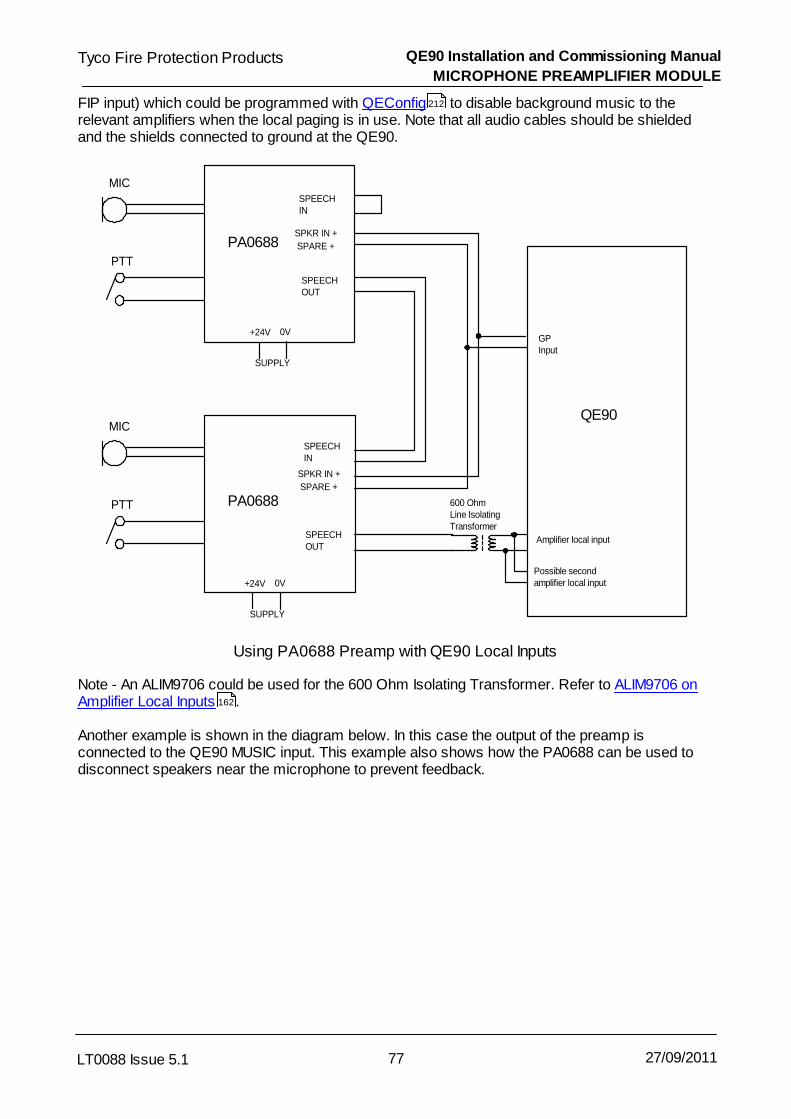
QE90 Installation and Commissioning Manual
MICROPHONE PREAMPLIFIER MODULE
77LT0088 Issue 5.1
Tyco Fire Protection Products
27/09/2011
FIP input) which could be programmed with QEConfig to disable background music to therelevant amplifiers when the local paging is in use. Note that all audio cables should be shieldedand the shields connected to ground at the QE90.
MIC
PTT
MIC
PTT
SPEECHOUT
QE90
Amplifier local inputSPEECHOUT
SPEECHIN
GPInput
PA0688SPKR IN +
SPARE +
SPKR IN +
SPARE +
PA0688
SPEECHIN
0V+24V
SUPPLY
0V+24V
SUPPLY
600 OhmLine IsolatingTransformer
Possible second amplifier local input
Using PA0688 Preamp with QE90 Local Inputs
Note - An ALIM9706 could be used for the 600 Ohm Isolating Transformer. Refer to ALIM9706 onAmplifier Local Inputs .
Another example is shown in the diagram below. In this case the output of the preamp isconnected to the QE90 MUSIC input. This example also shows how the PA0688 can be used todisconnect speakers near the microphone to prevent feedback.
212
162

QE90 Installation and Commissioning Manual
MICROPHONE PREAMPLIFIER MODULE
78LT0088 Issue 5.1
Tyco Fire Protection Products
27/09/2011
MIC
PTT
QE90
SPEECHOUT
PA0688
0V+24V
SUPPLY
MUSIC IN
SPEECHIN
Speaker Output
SpeakerMatchingTransformer
SPKR IN
SPEAKERNEARMICROPHONE
Other Speakers
SPKR OUT
Using PA0688 Preamp with QE90 Music Input
11.3 PA0688 Power Supply
In both the above examples, the 24V supply required by the PA0688s could be obtained from theQE90 or from local power packs with isolated outputs.

Chapter 12
BATTERIES AND POWER SUPPLIES

QE90 Installation and Commissioning Manual
BATTERIES AND POWER SUPPLIES
80LT0088 Issue 5.1
Tyco Fire Protection Products
27/09/2011
12.1 Battery Requirements and Wiring
The QE90 requires 24 Volt sealed lead acid batteries. Normally 2 x 12 Volt batteries will beconnected in series to give 24V. In many cases it may be useful to connect four or more batteriesin series/parallel as four smaller batteries will often fit in the cabinet better than two larger batteries.
The recommended battery capacity can be calculated as described in the Technical Manual(LT9002) or by the QE90 Costing / Design program QECOST. The Technical manual assumes allamplifiers are loaded to their rating, if your system has less loading you may allow for this andchoose smaller batteries. QECOST allows you to enter an average load percentage for amplifiersand load current for strobes, and bases the battery capacity on these figures.
12.1.1 Battery Arrangements - Deep Cabinets
The following diagrams show typical battery configurations and wiring for various sized systems.QECOST Version 3.5 or later can be used to obtain recommendations for particular systems. TheQECOST recommendations are tailored for the battery capacity required and the space availablein each system.
Refer to LT0437 (shipped with each panel) for further details. Only a summary of the information inLT0437 is given here.
2
FRONT VIEW
FromPSU
-+
Red
Black
LM0379
1-+
Black Red
Red
Black
Possible Inter-cabinetwiring
2 * 40AH Batteries (40AH) - Requires 4U of Battery space
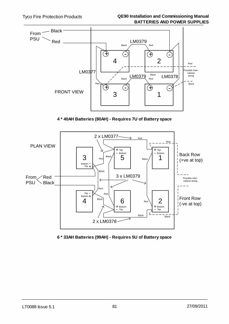
QE90 Installation and Commissioning Manual
BATTERIES AND POWER SUPPLIES
81LT0088 Issue 5.1
Tyco Fire Protection Products
27/09/2011
3FRONT VIEW
FromPSU
-+
Red
Black
LM0379
1-+
Black Red
4-+
LM0379
2-+
Black Red
LM0377LM0378
Red Black
Red
Black
Possible Inter-cabinetwiring
4 * 40AH Batteries (80AH) - Requires 7U of Battery space
5
+
3+
1
+
6-
4
-
2-
PLAN VIEW
FromPSU
RedBlack
2 x LM0377
2 x LM0378
Back Row(+ve at top)
Front Row (-ve at top)
- -
+
+
+
-
3 x LM0379
Top Top
Top
TopTop
Top
BottomBottom
Bottom Bottom
Bottom
Bottom
Red
Red
Black
Black
BlackBlack
Black
Red
Red
Red
Black
Red
Possible inter-cabinet wiring
6 * 33AH Batteries (99AH) - Requires 5U of Battery space

QE90 Installation and Commissioning Manual
BATTERIES AND POWER SUPPLIES
82LT0088 Issue 5.1
Tyco Fire Protection Products
27/09/2011
2
+
1
+PLAN VIEW
FromPSU
RedBlack
- -Top
Top Bottom
BottomBlack
RedRed
Black
Possible inter-
cabinet wiring
LM
037
9
2 * 75AH Batteries (75AH) - Requires 4U of Battery space

QE90 Installation and Commissioning Manual
BATTERIES AND POWER SUPPLIES
83LT0088 Issue 5.1
Tyco Fire Protection Products
27/09/2011
4
+
2
-
PLAN VIEW Top Layer
FromPSU
RedBlack
-
+
Top
Top Bottom
Bottom
Possible inter-cabinet
wiring
Black
3
+
1
-
PLAN VIEW Bottom Layer
-
+
Top
Top Bottom
Bottom
Black
LM0378Black
LM0377Red
LM0379LM0379
Black
RedRed
Black
4 * 75AH Batteries (150AH) - Requires 7U of Battery space
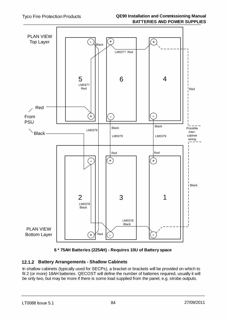
QE90 Installation and Commissioning Manual
BATTERIES AND POWER SUPPLIES
84LT0088 Issue 5.1
Tyco Fire Protection Products
27/09/2011
6 4
PLAN VIEWTop Layer
FromPSU
Red
+
Red
3 1
PLAN VIEWBottom Layer
Possible inter-
cabinet wiring
Black
5
2
+
+
++
+
--
-- --
--
-- --
LM0379LM0379
LM0379
BlackBlack
Black
Red
Red Red
LM0377 Red
LM0377 Red
LM0378 Black
LM0378 Black
Black
6 * 75AH Batteries (225AH) - Requires 10U of Battery space
12.1.2 Battery Arrangements - Shallow Cabinets
In shallow cabinets (typically used for SECPs), a bracket or brackets will be provided on which tofit 2 (or more) 18AH batteries. QECOST will define the number of batteries required, usually it willbe only two, but may be more if there is some load supplied from the panel, e.g. strobe outputs.

QE90 Installation and Commissioning Manual
BATTERIES AND POWER SUPPLIES
85LT0088 Issue 5.1
Tyco Fire Protection Products
27/09/2011
12.1.3 Battery Wiring
The batteries are connected to the heavy red and black cables from the charger(s). In a largesystem with more than one charger, it is recommended that the chargers are connected inparallel, as shown in the diagram below (for NZ systems see Section 12.1.4).
Charger 1
Charger 2(i f fitted)
_ _
+ +
++ + +
__
+ +
_ ___
12V 12V 12V 12V
12V 12V 12V 12V
Black
Red
Red
Black
Battery Connections
In a situation like this where there are multiple chargers, refer to drawing 699-180 at the end of Drawings for details on wiring the fault outputs.
The capacity of batteries connected in series MUST be the same for both batteries.
12.1.4 Battery Wiring - NZS4512 Multiple Chargers
The batteries are connected to the heavy red and black cables from the charger(s). In a large NZsystem with more than one charger, it is necessary to keep each charger and battery positivesseparate to allow each charger to do its battery capacity testing. The following diagram shows thisarrangement.
140

QE90 Installation and Commissioning Manual
BATTERIES AND POWER SUPPLIES
86LT0088 Issue 5.1
Tyco Fire Protection Products
27/09/2011
Large NZ System - Battery Connections (2 chargers)
If there are more chargers, each powers its own set of batteries and proportion of the total load.
12.2 Power Supplies
The following power supply models are currently in use –ME0330 24V 6A PSU2406 Brick
ME0331 24V 6A PSU2406 2U Rack Mounting
ME0333 24V 12A PSU2412 2U Rack Mounting
Section 12.3 describes the setup options for these PSUs.
The following power supply models have been used previously –ME0211 24V 12A PSU308 3U Rack Mounting
ME0212 24V 3A PSU2403 2U Rack Mounting
ME0210 SECP Power Supply 5U rack Mounting
ME0201 Original QE90 Power Supply.For details of these older supplies please refer to LT9002, QE90 Technical Manual.
When multiple power supplies are fitted in a cabinet, the AMP RACK outputs of the suppliesconnect individually to the amp racks in the panel.
12.3 PSU2406 and PSU2412

QE90 Installation and Commissioning Manual
BATTERIES AND POWER SUPPLIES
87LT0088 Issue 5.1
Tyco Fire Protection Products
27/09/2011
12.3.1 Internal Control PCB
The PSU2406 and PSU2412 PSUs (ME0330, ME0331, ME0333) have used a range of internalcontrol PCBs over time. The setup, operation and indication of these different PCBs is similar, butdifferent methods of configurations are provided:
8-Way DIPswitch - refer Section 12.3.2.
5-Way links - refer Section 12.3.3.
3-Way links - refer Section 12.3.3.
12.3.2 Setup Using 8-Way DIPswitch
Recent models of PSU2406/12 use an internal control PCB with an 8-way DIPswitch forconfiguration.
Table 12.3.1 shows the selection options for the DIPswitches. In general the settings for QE90panels should be:
1- OFF for 5A models (PSU2406); ON for 10A (PSU2412).2 - OFF for Australian use, ON for NZ use.3 - OFF for Australian use, ON for NZ use.4 - OFF5 - ON6 - ON7 - OFF8 - Doesn't matter.
Switch Function
1 12A select – this should be set ON for 10A versions only (factory set)
2 Switch ON to select NZ mode -(must also be switched ON for all MX4428/F4000 usage)Charger High, Charger Low, Mains Fail do not activate the general faultoutput.Self-timed battery tests every 24 hours after 72 hours with no externallyinitiated tests. Battery Capacity fault indication is non-latching.Switch OFF to select Standalone Australian mode -All fault conditions contribute to general fault output.Self-timed battery tests occur every hour until failure then every half hour untilsuccess. Battery Low capacity is latching until successful retest.
3 Switch ON to enable self-timed “Battery Disconnected” and “Battery LowCapacity” tests, e.g., when not being controlled by an MX4428 (AS 4428.1) orF4000 (AS 1603.4) FIP.
4 Switch ON to enable earth fault detection. Only for current production versionswith firmware (SF0445) version V1.1 or later. Switching this off will leave any other earth fault detection unaffected. (OFF asfactory default).

QE90 Installation and Commissioning Manual
BATTERIES AND POWER SUPPLIES
88LT0088 Issue 5.1
Tyco Fire Protection Products
27/09/2011
5 Switch ON to enable temperature-compensated output voltage (ON as factorydefault). Switching this off means that a temperature probe is not required.
6, 7 Switch 6 ON and 7 OFF to make the Fault output pull up to near +24V forNormal, switching low to near 0V on any fault. The Fault output is currentlimited, good for at least 20mA, suitable for driving a fault relay if desired.Switch 6 OFF and 7 ON to make the Fault output an open collector,switching to below 1V on any fault.
8 Not currently used. Has no effect.
Table 12.3.1
12.3.3 Earlier Models Using Links
Earlier models of PSU2406/12 have 5 links for configuration, and even earlier models have just 3links. Table 12.3.2 shows the link options - note links 4 and 5 are not present in those models withjust 3 links.
In general for QE90 systems the link settings should be:
1 - Fitted for Australian use, remove for NZ use.2 - Remove for Australia use, fit for NZ use.3 - Remove for 5A models (PSU2406); Fit for 10A models (PSU2412)4 - Fitted5 - Removed
Link Function
1 Fit to disable self timed “Battery Disconnected” and “Battery Low Capacity”tests.
2 Fit to select NZ mode -Charger High, Charger Low, Mains Fail do not activate the general fault output.Self timed battery tests every 24 hours after 72 hours with no externally initiatedtests. Battery Low capacity is non-latching.Remove to select Australian mode -All fault conditions contribute to general fault output.Self timed battery tests every hour until failure then every half hour. Battery Lowcapacity is latching.
3 Fitted in PSU2412, removed in PSU2406
4, 5 Fit Link 4 and remove Link 5 to make the Fault output pull up to near +24V forNormal, switching low to near 0V on any fault. The Fault output is currentlimited, good for at least 20mA, suitable for driving a fault relay if desired.Fit Link 5 and remove Link 4 to make the Fault output an open collector,switching to below 1V on any fault.
Table 12.3.2

QE90 Installation and Commissioning Manual
BATTERIES AND POWER SUPPLIES
89LT0088 Issue 5.1
Tyco Fire Protection Products
27/09/2011
Note: QE90 systems for Australia have Link 1 fitted to disable automatic testing of BatteryDisconnected and Battery Low Capacity, as these faults if discovered will cause a misleading“mains fail” indication on the ECP module. A later version of ECP module may be able to showthese conditions as “battery fail”, in which case Link 1 can be removed to enable BatteryDisconnected and Battery Low Capacity testing. These tests are primarily to comply withAS4428.5, which is not yet required for EWIS systems.
12.3.4 Battery Testing
“Battery Disconnected” (when enabled by DIP switch 3 ON or link 1 being removed) is checked atleast every 30 seconds. In the case of an extremely flat battery or one which is of insufficientcapacity for the load, “Battery Disconnected” may be indicated even though the battery isconnected.
“Battery Low Capacity” is checked automatically as described in the table above (when enabled byDIP switch 3 ON or link 1 being removed). It is also checked when the “battery test” terminals areshorted regardless of link 1. A latched “Battery Low Capacity” fault can be updated by shorting the“Battery Test” terminals for at least 1 second, or by briefly selecting NZ mode by switching DIPswitch 2 ON or inserting link 2.
12.3.5 Adjustments
To adjust the float voltage ensure that the load is minimal, eg by disconnecting the battery andload, and adjust VR1. This voltage should be set to the battery manufacturer’s recommended floatvoltage at the current temperature. The factory set voltage is 27.3V at 20 C.
To adjust the battery low threshold, disconnect the battery and load and wait until the outputvoltage stabilises if it is changing, then short the BATTERY TEST terminals, and adjust VR2 sothat the output voltage is 0.5V less than the threshold you want. For example for a threshold of24.0V, set the output voltage to 23.5V. Note – for compliance with AS4428.5 and NSZ4512 thethreshold voltage should be set to the 50% discharge point assuming an end point of 19V, with aload equal to the alarm load. You will need discharge graphs from the battery manufacturer todetermine this voltage. The factory set battery low threshold is 24.2V.
12.3.6 LEDs
LED Colour Function Indications
1 Green Operating /Current
This will flash at about 1.2 Hz. The amount of currentthe power supply is delivering is indicated by the dutycycle of the flashes - about 10% for 0 amps up toabout 80% for the rated current of the supply.
2 Yellow Fault When a fault is present, this will flash seven timesthen pause, repeatedly. Each flash will be short if aparticular fault is not present, or long if the fault ispresent, indicating the following in order - ChargerHigh, Charger Low, Battery Low, Battery Fail, BatteryDisconnected, Battery Low Capacity, Mains Failed. Athermistor open or short circuit is indicated by ChargerHigh and Charger Low at the same time

QE90 Installation and Commissioning Manual
BATTERIES AND POWER SUPPLIES
90LT0088 Issue 5.1
Tyco Fire Protection Products
27/09/2011
12.3.7 Replacing Older Supply with PSU2406 or PSU2412
The ME0331 can be used to replace an ME0212 in the field, or to replace an ME0211 in the casewhere 6 amps is sufficient for the system. The ME0333 can always be used to replace anME0211. The ME0331 and ME0333 have a lead with a 6 pin Phoenix connector which connectsdirectly to the ECP module. If the system has one or more FIP, STRM, or ECM modules, the 24Vsupply for these modules can be obtained from the +24V FIP and 0V screw terminals in the PSU. Itwill be necessary to remove the cover of the ME0331 or ME0333 to gain access to theseterminals. With the ME0211 and ME0212 this supply could be obtained from a flying leadterminated with a Molex connector.
Note that the continuous rating of the PSU2406 is 5A and the PSU2412 is 10A. However, theseunits will safely deliver 6A and 12A respectively for a short period, e.g., when recharging batteries.
12.4 PSU308
12.4.1 ADJUSTMENTS
To adjust the float voltage ensure that the load is minimal, eg by disconnecting the battery andload, and adjust VR2. This voltage should be set to the battery manufacturer’s recommended floatvoltage at the current temperature. The factory set voltage is 27.3V at 20 C.
12.4.2 LEDS
LED Colour Function Indications
1 Green Mains On Mains voltage is On.
2 Yellow Charger High The Charger Voltage is HIGHER than normal.
3 Yellow Charger Low The Charger Voltage is LOWER than normal.This may be due to a fault or a heavy load exceedingthe current rating of the charger
4 Yellow Battery Low The Battery Voltage is lower than the 50% dischargepoint.

QE90 Installation and Commissioning Manual
BATTERIES AND POWER SUPPLIES
91LT0088 Issue 5.1
Tyco Fire Protection Products
27/09/2011
12.5 Adding an AMP Rack to an Existing Supply
When an amp rack is added to an existing system, and no additional power supply is used, it willbe necessary to fit a further circuit breaker to the power supply if it is a PSU308 or PSU2412.The circuit breaker should be wired as shown in the diagram below.
CHARGER
BATTERY
+
Amp Rack 1
Amp Rack 2
-
+
-
+
-
Original Breaker
New Breaker
Addition of Circuit Breaker to PSU
Adding an amp rack to a system with a PSU2406 should only be done if the total amplifier loadcurrent is less than 50A, and then the supply to the two amp racks would be wired in parallel.
12.6 Adding an Additional Power Supply
When an additional power supply is added to a system, the following points should be notedEach Amp Rack should be wired to a separate AMP RACK circuit breaker.
The ECP, ECM if any, and any FIP Input modules should be wired to the ECP output of the firstPower Supply.Strobe Modules should be distributed across the power supplies, using the FIP/STROBEoutput of each supply, such that no output is loaded at more than its rating (10A for PSU2406,25A for PSU2412 and PSU308).
The CHARGER FAULT– outputs from each power supply need to be combined to a singleCHARGER FAULT– signal to feed to the ECP. This is done as shown in Drawing 699-180 in Drawings .140

Tyco Fire Protection Products QE90 Installation and Commissioning Manual
LT0088 Issue 5.1 92 27/09/2011

Chapter 13
SECP & REMOTE EQUIPMENT RACK INTERFACE

QE90 Installation and Commissioning Manual
SECP & REMOTE EQUIPMENT RACK INTERFACE
94LT0088 Issue 5.1
Tyco Fire Protection Products
27/09/2011
13.1 Wiring
Between ECPs and equipment racks it is necessary to run a minimum of four cables, eachconsisting of a fire rated shielded pair with each conductor 0.75mm2. There is a primary Commscable, a spare Comms cable, a PA speech cable, and a WIP speech cable. In the event of failureof one of the speech cables, the remaining speech cable will be used for either PA or WIP asrequired. If both PA and WIP are used at the same time (e.g. two operators are using the ECP),PA will have priority and WIP communications will be temporarily suspended. If this isunacceptable, and it is necessary to have PA and WIP fully functional at the same time even whenone of the cables is faulty, a fifth cable will need to be fitted. This is the Speech Backup cable.
If there are amplifiers at more than one location, and the system has Background Music or PagingConsoles, then additional cables may need to be run between all locations with amplifiers (oneadditional shielded pair per function).
The diagram below shows the wiring for a typical system (without ECMs). For a system withECMs, refer to Wiring Between Locations .143

QE90 Installation and Commissioning Manual
SECP & REMOTE EQUIPMENT RACK INTERFACE
95LT0088 Issue 5.1
Tyco Fire Protection Products
27/09/2011
PA SPCH
PA SPCH
PA SPCH
WIP SPCH
WIP SPCH
WIP SPCH
PABX
PABX
PABX
MUSIC
MUSIC
MUSIC
COMMS BUS
COMMS BUS
COMMS BUS
COMMS BKUP
COMMS BKUP
COMMS BKUP
Music Source
Paging Console
2+S
2+
S
2+
S
2+
S
2+
S
2+
S
2+
S
2+S
2+S
May Connectto any panel
May Connectto any panel
May Connectto any panel
Audio
Comms
Panel 1
Panel 2
Panel 3
M/S Linksset to M
M/S Linksremoved
M/S Linksset to S
Audio Monitoring
Maximum cable lengthplus
The panel with the M/S links in the M position (and no others) should have"Monitor Analog busses" set to with the ECP DIP switch.
The total bus length from Panel 1 to Panel 3 the length from Panel 2 to the Paging Console must be less than 1000m.
PABX and/or MUSIC wiring may not berequired, depending on the application
Comms
SPIF
SPIF
SPIF
2+S = 2 core 0.75mmcable with shield
2
ECP
ECP / SPIF InterPanel Wiring
Note that there is an advantage in running two sets of cables by different routes, so that if thecables in one route are completely broken by structural damage to the building, the system cancontinue to operate. This is shown in the diagram below.

QE90 Installation and Commissioning Manual
SECP & REMOTE EQUIPMENT RACK INTERFACE
96LT0088 Issue 5.1
Tyco Fire Protection Products
27/09/2011
Equipment
ECPplus
Equipment SECP
Comms
PA Speech
Backup Comms
Wip Speech
Wiring between ECPs and/or Equipment Racks
The diagram below shows the connections to the SPIF9506/SPIF9709 Interface module which willbe located at each ECP and equipment rack in a multiple location system. The connections arebussed between like terminals on the interface modules. Note that although the comms wiring canbe wired in a star or with spurs as desired, speech wiring must be bussed between locations - star/ spur wiring or looping is not permitted. Also one end of the speech cables must be an ECPmodule, and that ECP module and its SPIF module must be set up to monitor the cables. Refer to Link and Switch Settings and DIP switch Settings .
For networked systems with ECM modules at each location refer also to Wiring BetweenLocations .
97 120
143

QE90 Installation and Commissioning Manual
SECP & REMOTE EQUIPMENT RACK INTERFACE
97LT0088 Issue 5.1
Tyco Fire Protection Products
27/09/2011
EXTALARM
PASPEECH
MUSIC
WIPSPEECH
AUX
PABX
SPEECHBACKUP
COMMSBACKUP
COMMSBUS
FIPBUS
To Comms Busat other panels
To Comms Backupat other Panels
To PA Speechat other Panels
To WIp Speechat other PanelsSPIF9506/
SPIF9709
+_
+
_
SHIELDSGND
Connect shields together at allmodules, and to SHIELDS terminal at one module.
Connect GND terminal to Chassisas directly as possible.
To Speech Backupat other Panels(optional)
SPIF9506 / SPIF9709 Wiring
Notes - The shields of all cables should be connected together at each ECP or equipment rack. At one ofthese locations they should be connected to the SHIELDS terminal. The GND terminal should beconnected to the chassis at every ECP or equipment rack with a 2.5mm2 wire of maximum length300mm. If there are amplifiers at more than one location, and Music or Paging Consoles or other audioinputs are used, audio signals from these sources must be wired to all the locations with amplifiersthat require the function. However the communications cable for the Paging Console can be wiredto the most convenient SPIF9506/SPIF9709 module.
The EXT ALARM terminals provide a 24VDC 10mA output which operates in synchronism with theinternal beeper. This may be connected to a 24V DC external beeper, or a relay with suppressordiode, as required.
13.2 Link and Switch Settings
On the SPIF modules, fit the links as follows -
13.2.1 SPEECH BACKUP BUS Fitted / NOT FITTED
LK1, LK2, LK3, LK4 : Fit in SPEECH BACKUP BUS FITTED position if the speech backup bus iswired, and in the BACKUP = WIP / PA SWAP position if the speech backup bus is not wired.

QE90 Installation and Commissioning Manual
SECP & REMOTE EQUIPMENT RACK INTERFACE
98LT0088 Issue 5.1
Tyco Fire Protection Products
27/09/2011
13.2.2 SPEECH BUS MONITORING POINT
Choose one end of the speech busses as a monitoring point. This end must have an ECP orECM.
Links Monitoring End Other End IntermediatePoints
LK5, LK7, LK9 “M” “S” Removed
LK6, LK8, LK10 Fitted (“M”) Removed Removed
In a system with no ECMs and with no ECP at either end of the bus -
Links MonitoringPoint
All OtherPoints
Bus Ends
LK5, LK7, LK9 “M” Removed Fit 120k resistor across PASpeech and WIP SpeechBussesLK6, LK8, LK10 Fitted (“M”) Removed
For systems without ECMs it is also necessary to set some DIP switches on the ECP modules -Set DIP switch 7 of the Evac ECP DIP switches ON at all ECPs in the system, if the speechbackup bus is fitted, OFF otherwise.Set DIP switch 8 of the Evac ECP DIP switches ON at the one ECP with the links on the SPIFmodule in the M position, OFF otherwise.Refer also to ECP Module for more details of setting up the ECP module.
For systems with ECM modules, the ECM at the end of the bus with the links in the M positionmust be setup to monitor the analog busses, and all other ECMs setup to NOT monitor thebusses.
If you have multiple segments of the PA SPEECH and WIP SPEECH busses, isolated by havingtwo SPIF modules at one node or by an ALIM module, then each segment must be monitored asdescribed above ie M link settings at one end of the segment and monitoring enabled in On SiteProgramming mode at that node, and S link settings at the other end of the segment. (Note youcan’t monitor at the ALIM end of a segment, the ALIM end must have a 56k resistor installed inlieu of the S link setting.)
13.2.3 NORMAL / ISOLATE / ADVANCED LINKS
NORMAL / ISOLATE / ADVANCED LINKSLinks LK11, LK12, and LK13 are used to select normal, isolator or advanced modes as follows.
Link Normal Mode Isolate Mode Advanced Mode
LK11 Removed I A
LK12 A,N I A,N
LK13 N A,I A,I
Normal Mode should be selected in all systems without ECMs.
Current production ECM systems should be set to Advanced mode.
120

QE90 Installation and Commissioning Manual
SECP & REMOTE EQUIPMENT RACK INTERFACE
99LT0088 Issue 5.1
Tyco Fire Protection Products
27/09/2011
Older ECM Systems
Refer to the configuration listing supplied or downloaded from the FirePlace. If this is in the currentformat, then the required mode is defined in the Network / Advanced table, in the section"Historical", for example -
SPIF Type Advanced
If the configuration is in the older plain text format, or you use the configuration listing produced bythe panel itself with the Display Factory Configuration command, look forSPIF must be set to Advanced Mode LK11,LK12,LK13 set to 'A' or SPIF must be set to Isolate Mode LK11,LK12,LK13 set to 'I'
in the Networking Section. If either of these is found, select the appropriate mode, otherwise selectthe normal mode.
Note - some SPIF9506 modules were modified to give "Isolate Mode'. These will be so labelled. Nolink settings are required.
13.3 RS232 (Printer) Interface
Connector J4 on the SPIF9506/SPIF9709 module (and connector J15 on the SE9004 module afterearly 1999) provides a connection point for a printer or terminal.Refer to Printer / Terminal Connection for details of terminal and printer connection.By default this port will log events, but if a terminal or laptop with terminal emulator software isconnected it may also be used to set the time and date, set cascade on or off, set the cascadetimeouts, and change the baud rate. To use the port in this manner follow the following instructions-
Connect the terminal with settings as above.
Press <Enter>.
You should see a prompt, “Enter Password”. If you do not, it is possible the baud rate hasalready been set to something other than 9600. Try various settings.Enter QUINTRIX <Enter>. (This is the default password. You can change it, but if you do besure to record your new password.)Enter HE <Enter>. This will give you help, i.e. a list of commands, including commands to setthe cascade timeouts and baud rate.Enter the commands you require and follow the prompts.
When you have finished, enter QU <Enter>. This will switch the port back to event loggingmode.
156
175

QE90 Installation and Commissioning Manual
SECP & REMOTE EQUIPMENT RACK INTERFACE
100LT0088 Issue 5.1
Tyco Fire Protection Products
27/09/2011
13.4 SPIF LEDs
LED Colour Indication when ON Normal State
LD1 Red Relay 1 operated(Spare Comms Bus inuse)
No ECM – alternates every 60 seconds if nopaging console, or flicks on briefly once every60 seconds if there is a paging console.In ECM system – On if Comms bus short.
LD2 Red Relay 2 operated(ECP Microphoneselected)
No ECM – On if ECP is in control (in manual orall ECPs are in auto and this ECP was last inmanual).In ECM System – On if this ECP’s microphoneis required to drive local or remote amplifiersand PTT is pressed.
LD3 Red Relay 3 operated(Switched PA speechBuss)
PA Speech Buss faulty and switched to spare,Or PA and WIP speech busses swapped due tofault on required function.
LD4 Red Relay 4 operated(Switched WIP speechBuss)
WIP Speech Buss faulty and switched to spare,Or PA and WIP speech busses swapped due tofault on required function.
LD5 Red Relay 5 operated(Master phone enabledin Normal mode, localphone systemconnected to networkin Advanced / Isolatemodes)
No ECM, or ECM Normal Mode – Master Phoneis OFF HOOK.In ECM system Advanced and Isolate modes,ON when local phone audio buss must beconnected to network WIP SPEECH buss, OFFfor local WIP operation independent fromnetwork.
LD6 Red(SPIF9709only)
Relay 6 operated(Local PA bussdisconnected fromnetwork)
No ECM, or ECM Normal Mode – Always OFF.In ECM system Advanced and Isolate modes,ON when local PA audio buss must bedisconnected from network PA SPEECH bussdue to local PA independent from network.
LD7 Green +24V Supply (Note this is LD6 on SPIF9506)
LD8 Green +5V Supply (Note this is LD7 on SPIF9506)
13.5 SE9004 Signals Interface Module
The SE9004 is a very simplistic Signals Interface module. It is now used only in basic systemswhere there is no SECP, no remote equipment, and no paging console. (It was used in thesesystems before 1995, but does not provide full monitoring and redundancy of the WIP and PASPEECH cables.)
It does not allow the ECP phone to be transferred to another circuit, as can be done when theSPIF9709 module is fitted.
When Evac ECP software version 2.0 or higher is used on a system with a SE9004, the WIP Busand Evac Bus terminals must be looped together. WIP BUS+ is connected to EVAC BUS+, andWIP BUS– is connected to EVAC BUS–.

Chapter 14
WIP SLAVE MODULE

QE90 Installation and Commissioning Manual
WIP SLAVE MODULE
102LT0088 Issue 5.1
Tyco Fire Protection Products
27/09/2011
14.1 WIP Slave Overview
The WIPS2000 and WIPS9004 WIP Slave modules provide the following functions:
1) Provide the WIP phone signalling tones.2) Control the switching of the appropriate WIP phone lines.3) Monitor the WIP line for faults.4) Supervise the input circuits for activation / fault on FIP / BGA / GP inputs.
Each module can control up to 30 WIPs. Two modules can be located in each rack to control up to60 WIPS. A maximum number of six modules can be accommodated in a system for a total of180 WIP lines.
If the ECP has one WIP per zone, a WIP circuit may or may not be allocated to any given zone. Ifthe ECP has three WIPs per zone, any given zone may have zero, one, two, or three WIPsallocated to it. This allocation is performed with QEConfig , and is printed on the Panel’sconfiguration printout.
These modules do not have any field wiring themselves, but connect to the appropriate WIPtermination module WTRM2000 or WTRM9007 via a flat ribbon cable and the backplane.
The WIPS2000 must connect to a WTRM2000 termination module. The WIPS9004 mustconnect to a WTRM9007 termination module. Do not swap them over.
When a WIP phone is picked up it automatically calls the ECP. A confidence tone will be hearduntil the call is answered provided the WIPS2000 card is communicating with the ECP. (If theWIPS2000 software is version 1.66 or lower, the confidence tone will be heard regardless ofcommunication with the ECP.).
14.2 LED Indicators - WIPS2000
Eleven LED indicators are located on the front of the module and their function is as follows:
LED CONDITION INDICATED
V1 (green) On = 24V SUPPLY OK
V2 (green) On = +5V SUPPLY OK
COMMS (yellow) Flashing = Transmitting on COMMS CHANNEL
LD1 (green) Indicate the number of any circuit in fault. Thecircuit number is sum of the weightingsshown. For example, if leds 1 and 3 are on,circuit 20 is in fault (16 + 4).If more than one circuit is in fault, these LEDswill cycle around all such circuit numbers.
weighting = 16
LD2 (green) weighting = 8
LD3 (green) weighting = 4
LD4 (green) weighting = 2
LD5 (green) weighting = 1
LD6 (red) On steady when one or more phones are in talk mode
LD7 (yellow) Flashes when one or more circuits is ringing i.e. being called by theECP.
LD8 (green) Flashes when one or more circuits is off-hook i.e. calling the ECP.
212

QE90 Installation and Commissioning Manual
WIP SLAVE MODULE
103LT0088 Issue 5.1
Tyco Fire Protection Products
27/09/2011
14.3 LED Indicators - WIPS9004
Five LED indicators are located on the front of the module and their function is as follows:
LED NORMAL STATUS CONDITION INDICATED
V1 ILLUMINATED 24V SUPPLY OK
V2 ILLUMINATED +12V SWITCHING SUPPLY OK
V3 ILLUMINATED +12V REFERENCE SUPPLY OK
Sys ILLUMINATED MICROPROCESSOR RUNNING OK
Cm PULSING COMMS CHANNEL OK
14.4 DIP Switch Settings
MODULEAddress
WIPCIRCUITS
SW8 SW7 SW6 SW5 SW4 SW3 SW2 SW1
0 1-30 ON ON OFF OFF OFF OFF OFF OFF
1 31-60 ON ON OFF OFF OFF OFF OFF ON
2 61-90 ON ON OFF OFF OFF OFF ON OFF
3 91-120 ON ON OFF OFF OFF OFF ON ON
4 121-150 ON ON OFF OFF OFF ON OFF OFF
5 151-180 ON ON OFF OFF OFF ON OFF ON
6 181-199 ON ON OFF OFF OFF ON ON OFF
14.5 Link Settings
On the WIPS2000, there are 3 link settings to enable the Microprocessor (U1) to be programmed.These should normally be in the “RUN” position. They are set to the “PROG” position to programthe Microprocessor Flash. Currently, this is performed only by Tyco.
There is a further link setting LK4 which enables the EEPROM (U3) to be written to. Currently thisIC is not used, so the setting of LK4 is immaterial.
14.6 WIP System Expansion.
When fitting a new WIP Slave module be sure to set the DIP switches correctly as describedabove, and refer to WIPTERM System Expansion for details on fitting and wiring the terminationmodule.
The WIPS2000 must connect to a WTRM2000 termination module. The WIPS9004 mustconnect to a WTRM9007 termination module. Do not swap them over.
47

Tyco Fire Protection Products QE90 Installation and Commissioning Manual
LT0088 Issue 5.1 104 27/09/2011

Chapter 15
MULTIPLEXER MODULES - EMUX9601 & EMUX9002
QE90 Installation and Commissioning Manual
MULTIPLEXER MODULES - EMUX9601 & EMUX9002
106LT0088 Issue 5.1
Tyco Fire Protection Products
27/09/2011
15.1 Multiplexer Overview
The Multiplexer module provides the following functions:
1. Controls the audio source to the amplifiers in the same card cage.
2. Generates the emergency tones and digitised speech message(s) for those amplifiers it iscontrolling.
3. Performs the speaker line fault monitoring in conjunction with the amplifiers it is controlling.
4. Performs monitoring of the amplifiers it is controlling.
Each rack contains one EMUX module which can control up to 5 amplifier modules. This moduledoes not have any direct field wiring, but receives inputs from the signals interface module via a flatribbon cable and the backplane.
There are two types of Multiplexer Modules - EMUX9002 and EMUX9601.
The EMUX9002 is now obsolete for new production and is replaced by the EMUX9601, but theEMUX9002 information is presented here for use in the upgrading of existing systems that still useit.
The functionality of the EMUX9601 and EMUX9002 is essentially the same, except the EMUX9601provides additional facilities:
1. Field programmable messages recordable from 3 sources: PA Speech, Paging Console(PABX), and external line-level source.
2. Two versions are available - one with 16 seconds (4 messages) and the other with 60 seconds(15 messages) of stored speech.
3. Each unique message can be up to 4 seconds long. However a longer message can becreated by overlapping up to 4 consecutive message spaces, i.e. up to 16 seconds long.
4. A 3 LED recording level meter.
5. Message playback test facility, which can be listened to by connecting an 8 speaker directly tothe EMUX.
6. Messages can be played with the evacuation tones, with the alert tones, or standalonemessages can be played to zones for background music.
7. Standalone messages can be played on background music once only, or continuously.
8. Two different evacuate tones are available – the original AS2220 evacuate tone and a newerISO8201 evacuate tone. The ISO tone is only available with EMUX software version 1.16 or later(which requires the “Widget Board”).
Refer to Widget Board for information on the “Widget Board” used to replace themicroprocessor on the EMUX9601 from late 2004.
202

QE90 Installation and Commissioning Manual
MULTIPLEXER MODULES - EMUX9601 & EMUX9002
107LT0088 Issue 5.1
Tyco Fire Protection Products
27/09/2011
15.2 EMUX9601 LED Indicators
Ten LED indicators are located on the front of the EMUX9601. Their functions are as follows:
LED OPERATINGMODE
NORMALSTATUS
CONDITION INDICATED
V1 ALL ON STEADY 24V SUPPLY OK
V2 ALL ON STEADY +8V SWITCHING SUPPLY OK
V3 ALL ON STEADY -VE SWITCHING SUPPLY OK
SYS ALL ON STEADY MICROPROCESSOR RUNNING OK
CM RUN PULSING COMMS CHANNEL OK
PROG MODE PROGRAM OFF EMUX IN PROGRAM MODE
BUSY PROGRAM OFF MESSAGE PLAYING ORRECORDING IN PROGRAM MODE*
HIGH PROGRAM OFF RECORD SIGNAL TOO HIGH(CLIPPING)
OK PROGRAM OFF RECORD SIGNAL LEVEL OK
LOW PROGRAM OFF RECORD SIGNAL LEVEL TOO LOW
Note*: - The BUSY LED flashes 3 times during the last second of each 4 second period whenrecording or replaying a message.
15.3 EMUX9601 DIP Switch Settings
There are two sets of DIP switches on the EMUX9601; SW1 a block of 4 just in from the edge ofthe board for selecting the module and amplifiers, and SW2 a block of 8 on the edge of the boardfor selecting mode, messages, recording sources, speech chip type, and evacuate tone (AS2220or ISO).
MODULEADDRESS
AMPLIFIERS SW1 SWITCHES ON (REST OFF)
0 1 – 20 NONE
1 21 – 40 1
2 41 – 60 2
3 61 – 80 1, 2
4 81 – 100 3
5 101 – 120 1, 3
6 121 – 140 2, 3
7 141 – 160 1, 2, 3
8 161 – 180 4
9 181 – 200 1, 4

QE90 Installation and Commissioning Manual
MULTIPLEXER MODULES - EMUX9601 & EMUX9002
108LT0088 Issue 5.1
Tyco Fire Protection Products
27/09/2011
Note: - These amplifier numbers refer to those which appear on the configuration printout -- Each 10W amplifier is allocated a number.- Each 25W amplifier is allocated two successive amplifier numbers.- A pair of 50W amplifiers uses the first two numbers in a group of four, with the second two numbers being unused.- A 100W amplifier uses the first number in a group of four, with the next three numbers being unused.
In Program mode the following switches select which message will be recorded.
MESSAGE SW2 SWITCHES
NUMBER OFF ON
123456789101112131415
2, 3, 41, 3, 43, 41, 2, 42, 41, 441, 2, 32, 31, 331, 221
121, 231, 32, 31, 2, 341, 42, 41, 2, 43, 41, 3, 42, 3, 41, 2, 3, 4
Note: - The switch settings above are only used for the message number function in programmode. However they have additional functions when not in Program mode. Whenexiting program mode, be sure to set switches 1 – 4 to the required position to selectthe required message options.
- Message numbers 5 – 15 are not used in the 16 second (4 message) version of theEMUX9601.
- Message number 0 (SW2 - 1:4 all off) is not a valid message.
The following table shows the function of DIP switches 1 – 4 when not in program mode, and thefunction of switches 5 – 8.

QE90 Installation and Commissioning Manual
MULTIPLEXER MODULES - EMUX9601 & EMUX9002
109LT0088 Issue 5.1
Tyco Fire Protection Products
27/09/2011
SW2 SWITCH OFF FUNCTION ON FUNCTION
1 Play AS2220 Evacuation Signal Play ISO Evacuation signal with“Emergency” and “Evacuate Now”keywords.
2 Play the evacuation voice messagefrom the speech chip. Specialmessages can be recorded on siteor at the factory.
Play the evacuation voice messageselected by SW2:3 from the widgetboard instead of speech chipmessage 1.
3 When SW2:2 is on, play the fixed“Evacuate as directed, evacuate asdirected” voice message.
When SW2:2 is on, play the fixed“Evacuate the building using thenearest fire exit” voice message.
4 Alert tones (if any) include a voicemessage if so configured inFactory Programming.
If the default Alert message isconfigured in factory programming(i.e. speech chip message 3), itwill not be played.
5 PA speech not selected as therecording source.
* PA Speech selected as therecording source.
6 PABX not selected as therecording source.
* PABX selected as the recordingsource.
7 EMUX9601 in RUN mode. EMUX9601 In Program Mode
8 EMUX9601 is 16 second (4message) version (ISD1416 isfitted).
EMUX9601 is 60 second (15message) version (ISD2560 isfitted).
Note*: - Switches 5 and 6 must never both be on at the same time. If both are off theExt source (J3) input can be used.
- Switch 7 should only be in the on position when message recording or play-back is required. For normal QE90 operation switch 7 must be left in the offposition.
- The EMUX will be compatible with older revisions i.e. EMUX9601 up to Revision 5 and allrevisions of EMUX9002, provided switches 1 – 4 are all switched off. It can thus be usedfor replacements in older systems.
15.4 EMUX9601 Tones and Messages
The following diagrams show the effect of various combinations of the DIP switches 2-1 to 2-4.
These are new features introduced in November 2004. Boards supporting these features have Rev7 (or later) marked on the board, and have a label near U2 titled “SW2 Functions. (Note Rev 6supported the ISO tones, but did not support interspersing the Emergency and Evacuate keywordsin the 1.5 second gaps.)

QE90 Installation and Commissioning Manual
MULTIPLEXER MODULES - EMUX9601 & EMUX9002
110LT0088 Issue 5.1
Tyco Fire Protection Products
27/09/2011
15.4.1 ISO Evacuation Signal and Voice Message
S1 On; S2 Off; S3 Off
Speech Chip Message 1 – typically
“Evacuate as directed. Evacuate as directed”
AS1670.4 Tone
Emergency Evacuate Now
S1 On; S2 On; S3 Off
Fixed Message“Evacuate as directed. Evacuate as directed”
AS1670.4 Tone
Emergency Evacuate Now
S1 On; S2 On; S3 On
Fixed Message“Evacuate the building
using the nearest fire exit”
AS1670.4 Tone
Emergency Evacuate Now
8sRepeating sequence
8sRepeating sequence
8sRepeating sequence
(Australian Default)

QE90 Installation and Commissioning Manual
MULTIPLEXER MODULES - EMUX9601 & EMUX9002
111LT0088 Issue 5.1
Tyco Fire Protection Products
27/09/2011
15.4.2 AS2220 Evacuation Signal
S1 Off; S2 On; S3 Off
Fixed Message“Evacuate as directed. Evacuate as directed”
AS2220 Tone
S1 Off; S2 On; S3 On
Fixed Message“Evacuate the building
using the nearest Fire Exit”
AS2220 Tone
S1 Off; S2 Off; S3 Off
Speech Chip Message 1 – typically
“Evacuate as directed. Evacuate as directed”
AS2220 Tone
16sRepeating sequence
16sRepeating sequence
16sRepeating sequence
(New Zealand Default)
15.4.3 Alert Tones
Note that Alert tone is now not used in Australia unless the building has a specific emergency planrequiring it (see “Cascade Sequences and Alert Tones” below), therefore the following diagram isoften not relevant. However by default Alert speech will be programmed to message 3 in thefactory, so that if Alert tone is selected in the factory or on-site configuration, then the generation ofthe Alert message can be controlled by DIP switch 4. Note that the option to disable the alertmessage only applies when the default message (i.e. message 3) is programmed in the factoryconfiguration.

QE90 Installation and Commissioning Manual
MULTIPLEXER MODULES - EMUX9601 & EMUX9002
112LT0088 Issue 5.1
Tyco Fire Protection Products
27/09/2011
S4 Off
Speech Chip Message 3, typically“Warning, the fire alarm system
has operated, standby for further instructions”
Alert Tone
Assuming Alert Speech is programmed in factory -
S4 On
Alert Tone
No speech even though default speech is
configured in factory
Note – approximately 16 seconds of tones between messages if S1 is OFF and
approximately 8 seconds of tones between messages if S1 is ON
(New Zealand Default)
15.4.4 Balancing Tone and Speech Levels
The “Emergency” and “Evacuate Now” Keywords, and the fixed messages in the Widget boardselected when SW2-2 is ON, cannot have their volume adjusted. (The Digitised Speech controlonly affects the Site Recordable messages generated by the “Speech Chip” U2.)
Older Production - EMUX 9601 Rev up to 7.To ensure that the keywords and fixed messages are played at the highest level possible relativeto the tones, the volume controls on all amplifier cards should be turned right up (and adjustmentsin various building areas made with the tappings on speakers). If the amplifier volume controls areturned down the speech level will decrease more than the tone level decreases and the resultingspeech sound level may be significantly below the tone sound level. See also EMUX9601 VolumeControl Adjustments and Output Level Adjustment .
New Production - EMUX9601 Rev 8 and higher.The relative levels of speech and tones have been improved, and are not significantly affected bythe amplifier volume control settings. (However it is still desirable to have speaker tappings set tothe lowest power setting that gives enough sound level).
15.5 EMUX9601 Connectors
There are two connectors on the EMUX9601 for connection of the External Source recordingsignal (J3) and for an Ext Speaker (J2) (8 speaker) for listening to the recorded messages.
For successful recording, the External Source signal level should be at least 300mV RMS.
The pinouts are as follows:
Pin Number J2 Ext Speaker J3 Ext Source
1234
+ Speaker (8 )NCNC
- Speaker (8 )
NCSignal Input
0VNC
115 133

QE90 Installation and Commissioning Manual
MULTIPLEXER MODULES - EMUX9601 & EMUX9002
113LT0088 Issue 5.1
Tyco Fire Protection Products
27/09/2011
15.6 EMUX9601 Customising Messages
The standard EMUX9601 is supplied with pre-recorded messages for evacuation and alert. Themessage configuration is shown below.
Message Message Number Message Description
Type 16 Second 60 Second
Evacuation 1 1 “Evacuate as directed, evacuate as directed”
Alert 3,4 3,4 9,10*
“Warning, the fire alarm system has operated,standby for further instructions”.
Note*: - The 60 second version has an extra copy of the alert message stored at message number 9.- The alert message is just over 5 seconds long and hence uses 2 message numbers.
Standard ECP software shipped with each QE90 system is configured for playing of the evacuatemessage with evacuation tones only. Therefore the standard configuration does not include amessage with alert tones.
Thus with a standard configuration of ECP and EMUX9601 software (regardless of whether it isthe 16 or 60 second version) the user is only able to customize the evacuation message. Themessage duration can be between 100 milliseconds and 16 seconds, but must start at messagenumber 1.
Custom ECP / ECM software is required for any of the following features:
1. Messages with alert tones.2. Standalone messages to be played continuously to zones on background music.3. Standalone messages to be played once to zones on background music.4. Additional messages (e.g longer than 16 seconds, or multiple messages) to be played with the
evacuate tones.5. Messages to be played only in Auto and not Manual. (It is now the default for messages to be
played in both Manual and Auto).Contact your equipment supplier or Tyco if you require changes to the ECP / ECM software.
15.7 EMUX9601 Message Recording and Playback
The EMUX9601 provides field recording of the "speech chip" digitised speech messages (but not"Widget board" messages). The speech chip messages can be recorded / played back when theEMUX9601 is switched to PROGRAM mode (SW2-7).
There are two buttons provided at the front edge of the EMUX9601, labelled “PLAY” and“RECORD”.
To record a message:
1. Put the EMUX9601 in PROGRAM mode by setting switch SW2-7 in the PROG position(ON). The QE90 control panel will now indicate a module fault, which needs to beacknowledged to silence it.

QE90 Installation and Commissioning Manual
MULTIPLEXER MODULES - EMUX9601 & EMUX9002
114LT0088 Issue 5.1
Tyco Fire Protection Products
27/09/2011
2. Select the recording source by setting DIP switches SW2-5 and SW2-6.
Setting SW2-5 to the on position selects the ECP microphone (PA speech) as therecording source. Setting SW2-6 to the on position selects the paging microphone, orpaging console (PABX) as the recording source. If both SW2-5 and SW2-6 are set to theoff position the Ext Source (J3) is selected as the recording source. The external sourcecan be any line level input (CD, DAT, tape deck or microphone and pre-amp) and isconnected via the 4-way header J3 at the edge of the board.
NOTE: Only one recording source should ever be selected at a time i.e. only one of theDIP switches SW2-5 and SW2-6 should ever be in the on position and both must be in theoff position if an external recording source is connected. Always switch both recordingsource DIP switches to the off position first if changing between recording sources.
3. Adjust the source signal with the RECORD LEVEL potentiometer (VR7) so that the recordlevel meter has both green and yellow LEDs predominantly on, with the red LED flickeringoccasionally.
If for example, the ECP microphone is to be used as the recording source, speak into themicrophone with the press-to-talk button depressed and adjust the RECORD LEVELclockwise to increase the record level meter display (up from green to yellow to red), oranti-clockwise to decrease the meter level (back from red to yellow to green).
4. Select the message number that the recording is to start from by setting the first 4 DIPswitches on the SW2 to the appropriate message number. (Note message number 0 isinvalid).
5. Press and hold the RECORD button.
1. To start recording press and hold the PLAY button.
7. The message will continue recording for as long as the RECORD button is held down; or ifthe PLAY button is released before the end of a message number, recording will stop at theconclusion of the current message number. This is an ideal way of ensuring that therecording does not go over a message boundary and erase the next message. Messageduration can be between 100 milliseconds and a maximum of 16 seconds (4 consecutivemessage numbers).
If the message is to be greater than 4 seconds, the PLAY button must be held depressedat the end of each message (4 second period).
The BUSY LED will illuminate for the duration of the recording and will flash three timesduring the final second of each message, to indicate the pending message numbertransition. The recording will automatically cease after the recording of 4 consecutivemessage numbers or if there is not enough message space left.
Note: - Recording a message will erase whatever previously occupied that message.- A message recorded over the latter part of a multi-part message will delete the latter part
of the original message and add the new message to the end of the remaining part of theoriginal message.
- To delete a message entirely from playing during alert/evac, record a message for lessthan 100 milliseconds.- It may be easier to temporarily install EMUX9601 modules from remote equipment racks
in the MECP for message recording.

QE90 Installation and Commissioning Manual
MULTIPLEXER MODULES - EMUX9601 & EMUX9002
115LT0088 Issue 5.1
Tyco Fire Protection Products
27/09/2011
To replay a message for test purposes:
1. Put the EMUX9601 in program mode by setting DIP switch SW2-7 to the Program modeposition (ON).
2. Connect an 8 or higher speaker to the external speaker header J2.
3. Select the message number that the playback is to start from by setting the first 4 DIP switches(SW2-1:4) to the appropriate message number.
4. Press the PLAY button. The selected message will play to its conclusion, which could be up to16 seconds (4 consecutive messages).
If the PLAY button is held down at the end of a message then the next message will be played.By continually holding the PLAY button down the entire message content of the EMUX can beplayed. Once the last message has been played playback will continue from the first message. If the PLAY button is released, the playback will cease at the end of the current message. TheBusy LED will illuminate for the duration of the playback and will flash three times during thefinal second of each message number (4 second period) to indicate a pending messagenumber transition.
Playback will automatically cease after 16 seconds, or 4 message numbers of the samemessage.
After recording or playing messages ensure that the Program mode DIP switch (SW2-7) isreturned to the RUN position and that the PA Speech and PABX recording DIP switches areswitched off. Also, disconnect any external source and speaker. The module fault on the QE90can now be cleared.
15.8 EMUX9601 Volume Control Adjustments
Seven volume control adjustments are provided at the front edge of the EMUX9601 as shown inthe diagram below.
The record level control is used to adjust the level of the recording in Program mode. It is used inconjunction with the record level meter.
The other six controls give volume adjustments common to all amplifiers in the card cage, andmay be used to adjust the balance between Alert, PA Speech, Digitised Speech and Evacuate; orto reduce the Paging Console (PABX), auxiliary input (AUX) or background Music (BGM) levelsbelow the emergency tone levels. Note that there is no control for Evacuate tones. You should firstset up the amplifiers and speaker transformer taps to get the correct sound levels with Evacuatetones and then adjust the balance between Evacuate and all the other signals with the controls onthis module.
The PA SPEECH control on this module has a similar function to the microphone level control onthe ECP module, however the control on the ECP affects all outputs, while the control on anEMUX9601 affects only the outputs of the amplifiers in the card cage controlled by that EMUX9601.
Note the "Digitised Speech" control below does not affect the ISO keywords "Emergency" and"Evacuate now", or other messages set up to come from the Widget Board. (Refer to EMUX9601DIP switch settings )107

QE90 Installation and Commissioning Manual
MULTIPLEXER MODULES - EMUX9601 & EMUX9002
116LT0088 Issue 5.1
Tyco Fire Protection Products
27/09/2011
ALERT
AUX
BGM
PA SPEECH
PABX
DIGITISED SPEECH
RECORD LEVEL
EMUX9601 Module Volume Adjustments
Revision 8 Evacuation tone / speech level changeRevision 8 of the EMUX9601 has the Evacuation tone level slightly reduced, and thedigitised speech from the Widget board level slightly increased, relative to previousrevisions.
Generally it should be possible to replace an older EMUX9601 with a revision 8 later revisionwithout any noticeable adverse effects - in fact the increased speech level should bebeneficial. If the drop in the evacuation tone level is noticeable, increase the amplifier volumecontrols slightly.
15.9 EMUX9002 LED Indicators
Five LED indicators are located on the front of the EMUX9002. Their functions are as follows:
LED NORMAL STATUS CONDITION INDICATED
V1 ON STEADY 24V SUPPLY OK
V2 ON STEADY +8V SWITCHING SUPPLY OK
V3 ON STEADY -VE SWITCHING SUPPLY OK
SYS ON STEADY MICROPROCESSOR RUNNING OK
CM PULSING COMMS CHANNEL OK

QE90 Installation and Commissioning Manual
MULTIPLEXER MODULES - EMUX9601 & EMUX9002
117LT0088 Issue 5.1
Tyco Fire Protection Products
27/09/2011
15.10 EMUX9002 DIP Switch Settings
MODULEADDRESS
AMPLIFIERS SWITCHES ON (REST OFF)
0 1 - 20 6
1 21 - 40 6, 1
2 41 - 60 6, 2
3 61 - 80 6, 2, 1
4 81 - 100 6, 3
5 101 - 120 6, 3, 1
6 121 - 140 6, 3, 2
7 141 - 160 6, 3, 2, 1
8 161 - 180 6, 4
9 181 - 200 6, 4, 1
Note - these amplifier numbers refer to those which appear on the configuration printout -Each 10W amplifier is allocated a number.
Each 25W amplifier is allocated two successive amplifier numbers.
A pair of 50W amplifiers uses the first two numbers in a group of four, with the second twonumbers being unused.A 100W amplifier uses the first number in a group of four, with the next three numbers beingunused.A 200W amplifier uses the first number in a group of eight, with the next seven numbers beingunused. (In some cases the slave amplifier module may be mounted in a separate card cagewith no EMUX module, in which case the 200W amplifier uses the first number in a group offour.)
15.11 EMUX9002 Volume Control Adjustments
Five volume control adjustments are provided at the front edge of the EMUX9002 as shown in thediagram below.
These controls give a volume adjustment for all amplifiers in the card cage, and may be used toadjust the balance between the Alert, PA Speech and Evacuate; or to reduce the Paging Console(PABX), auxiliary input (AUX) or background Music (BGM) levels below the emergency tone levels.Note that there is no control for Evacuate tones, you should first set up the amplifiers and speakertransformer taps to get the correct sound levels with Evacuate tones and then adjust the balancebetween Evacuate and all the other signals with the controls on this module.
The PA SPEECH control on this module has a similar function to the microphone level control onthe ECP module, however the control on the ECP affects all outputs, while the control on anEMUX9002 affects only the outputs of the amplifiers controlled by that EMUX9002.

QE90 Installation and Commissioning Manual
MULTIPLEXER MODULES - EMUX9601 & EMUX9002
118LT0088 Issue 5.1
Tyco Fire Protection Products
27/09/2011
PABX
PA SPEECH
BGM
AUX
ALERT
EMUX9002 Module Volume Adjustments

Chapter 16
ECP MODULE & DISPLAY EXTENDERS

QE90 Installation and Commissioning Manual
ECP MODULE & DISPLAY EXTENDERS
120LT0088 Issue 5.1
Tyco Fire Protection Products
27/09/2011
16.1 Overview
The ECP module contains site specific software which defines the system configuration, andcontrols all the other modules.
If there is more than one ECP in the system, then only one is in control at any given time - theMECP if it is switched to manual, otherwise the SECP if it is switched to manual (the first SECP tobe switched to manual if there is more than one), otherwise if all ECPs are switched to automatic,the last ECP which was in manual.
For a networked system with ECM modules, the role of the ECP is reduced - it is basically acontrol module for only the LEDs and switches. The overall control of the system is vested in theECM modules.
The original ECP was the ECP9002. The ECP9702 is a newer revision of it with some additionalfeatures –
EEPROM instead of battery backed RAM for storage of the system’s on site setup information.
Alarm when ECP circuit breaker is opened.
Service jumper on the Beeper which reduces the volume.
Software has full control of SYSTEM FAULT LED.
Ring and confidence tone generation circuitry for Master Phone is on board, so the MasterPhone does not need a RING9006 PCB. There is a two wire connector for the master phoneinstead of a 10 way ribbon cable connector.It has a 4 way 0.1" connector for the ME0290 microphone, as well as the original DIN socket forthe ME0213.
Otherwise it is functionally compatible with and is interchangeable with the original ECP9002.(Refer to ECP Revision Interchangeability for details when changing ECP modules.)
Refer to Widget Board for information on the widget board used to replace the WIPmicroprocessor on the ECP9702 from late 2004. Also refer to ECP Revision Interchangeabilityfor details of the interchangeability of ECP boards which use the widget board and previousversions.
16.2 DIP Switch Settings
There are two DIP switches on the ECP module, which must be set to define -Whether the module is an MECP or SECP. In a system more than one ECP, the ECP which isto have master control if both are switched to Manual is the MECP. This is not necessarily theone with the equipment (amplifiers etc).If the module is an SECP, its address.
Whether a serial port is fitted for connection to a printer or diagnostic terminal.. (In addition, aMAX232 IC must be fitted in the socket U9 if a serial port is to be fitted.)If the system has SPIF9506/SPIF9709 modules, whether the SPARE SPEECH bus is wired ornot.If the system has SPIF9506/SPIF9709 modules whether this ECP is connected to the SPIF atone end of the bus with its links in the M position.Whether the hardware is one WIP per zone or three WIPs per zone.
On the ECP9002 (if manufactured during or after 1996) there is one jumper to select the EPROMsize. Select the positions shown for various software versions. Note that from August 1997onwards, all systems will require the 27512 position.
122
202
122

QE90 Installation and Commissioning Manual
ECP MODULE & DISPLAY EXTENDERS
121LT0088 Issue 5.1
Tyco Fire Protection Products
27/09/2011
On if serial port option fittedON for SECP, OFF for MECPSECP Address bit 3
SECP Address bit 0
SECP Address bit 1
SECP Address bit 2
SECP Address bit 0
SECP Address bit 3
SECP Address bit 2
SECP Address bit 1
On if spare audio bus fitted, off if WIP/PA swap or no SPIFOn if SPIF fitted & SPIF links in M position
Link here for 27C512 (S/W V 2.xx or 3.1x +)Link here for 27C256 (S/W V 1.xx or 3.0x)
ECP9002Switch Settingsand links.Note - if ECP isconnected toECM, all switchesshould be OFFexcept the ONEWIP PER ZONEshould be ON ifneeded.
On if 1 WIP per ZoneOffOff
On for SECP, Off for MECPFit MAX232for serial portoption
ECP9002 Module DIP Switches and Links
On the ECP9702 there are links for the RAM Size and EPROM size. These should be set asfollows -LK1 : 27C256 position if U10 is a 27C256 (used for version 1.xx software and 3.0x
software), otherwise 27C512/010 position (used for version 2.xx, and version 3.1xand higher software).
LK2 : 2k position if U14 is a MK48T02, MK48Z02, MK48T12, MK48Z12, or DS1220.Otherwise 8k/32k position.
LK3 : 2k/8k position with all ICs currently used.LK4 : 2k/8k position with all ICs currently used.
On if serial port option is fitted (default)ON for SECP, OFF for MECPSECP Address bit 3
SECP Address bit 0
SECP Address bit 1
SECP Address bit 2
SECP Address bit 0
SECP Address bit 3
SECP Address bit 2
SECP Address bit 1
On if spare audio bus fitted, off if WIP/PA swap or no SPIFOn if SPIF fitted & SPIF links in M position
ECP9702Switch Settingsand links.
Note - if the ECP is connected to an ECM, all switches should be OFF except the ONE WIP PER ZONE switch should be ON with a 1 WIP per zone facia, and Address bit 0 should be ON for a zone expansion ECP.
. On if 1 WIP per ZoneOffOff
On for SECP, Off for MECP
RAM LINKS
EPROM LINKS
Fit MAX232for serial portOption (default)
Switch Settings in ECP controlled system.
Switch Settings in ECPcontrolled system.
ECP9702 Module DIP Switches and Links

QE90 Installation and Commissioning Manual
ECP MODULE & DISPLAY EXTENDERS
122LT0088 Issue 5.1
Tyco Fire Protection Products
27/09/2011
Refer to Connection to ECP for information on systems which have full networking with ECMs.The address switches are coded as follows on both SW1 and SW2.
Switch label On=SECP
SECP A2 SECP A2 SECP A1 SECP A0
Type ofSystem
SwitchNumber
5 4 3 2 1
Networked(ECM)
StandardECP
OFF OFF OFF OFF OFF
HiddenExpansionECP
OFF OFF OFF OFF ON
NonNetworked(NON-ECM)
MECP OFF OFF OFF OFF OFF
SECP 0 ON OFF OFF OFF OFF
SECP 1 ON OFF OFF OFF ON
SECP 2 ON OFF OFF ON OFF
SECP 3 ON OFF OFF ON ON
SECP 4 ON OFF ON OFF OFF
SECP 5 ON OFF ON OFF ON
SECP 6 ON OFF ON ON OFF
SECP 7 ON OFF ON ON ON
On SW1, switch 6 enables the RS232 serial event logging and diagnostics in ECP controlledsystems. It should be ON, except in very old systems when the MAX232 U9 is not fitted and then itshould be OFF. In ECM controlled systems, this switch should be OFF, as the ECP serial portserves no useful purpose.
For ECP controlled systems with RZDU high level inputs, the serial port is automatically enabledregardless of the position of switch 6.
16.3 ECP Revision Interchangeability
16.3.1 ECP9702 and ECP9002
The new ECP9702 is interchangeable with the old ECP9002 with the following caveats -
On new QE90 systems using the ECP9702 the Master Phone will no longer have a RING9006board fitted inside, and it will be wired to the ECP module with two wires instead of a 10 wayflat ribbon cable. If an ECP9002 board is fitted into such a new system, it will be necessary toobtain a RING9006 board (PA0656) and ribbon cable (LM0084) and fit these into the masterphone.If an ECP9702 module is used to replace an ECP9002, then it will be necessary to remove theRING9006 PCB from the existing master phone and wire the master phone to the ECP boardwith a two wire cable.
142

QE90 Installation and Commissioning Manual
ECP MODULE & DISPLAY EXTENDERS
123LT0088 Issue 5.1
Tyco Fire Protection Products
27/09/2011
By default, the ECP9702 will not have a battery-backed clock IC fitted to U14, but will have astandard RAM IC instead. Version 4 and higher ECP software uses a EEPROM IC on theECP9702 for storage of on-site setup parameters. A battery-backed clock IC will only be fittedin new systems requiring a printer for event logging. Previously a battery backed clock IC orbattery backed RAM IC was required for storage of setup parameters in all ECP9002 moduleseven when there was no printer output. A battery backed RAM IC or battery backed clock ClockIC is required
1. In ECP9002 modules regardless of software versions.2. In ECP9702 modules when the evac ECP software version is 2.99 or less.
When replacing an ECP board in a system which requires a battery-backed clock or RAM IC, ifthe replacement board is not fitted with an IC of type MK48T02, MK48Z02, MK48T12,MK48Z12, MK48T08, DS1643 or DS1220, it is necessary to remove this IC from the boardbeing replaced and fit it into the replacement board. Of course it is always necessary toremove the Evac and WIP software ICs from the board being replaced and fit them to thereplacement ECP. Also note that the on site setup parameters should always be checked afteran ECP board is replaced. Refer to Software Locations for the locations of thesecomponents.If the ECP9702 has the Widget board fitted to U52 then refer to ECP RevisionInterchangeability .The ECP9702 includes the DIN microphone connector for the ME0213 microphone as used onthe ECP9002 along with a 4 way 0.1" connector for the ME0290 microphone.
Note that when you need to insert an IC into a socket which has more positions than there arepins on the IC, you should leave the blank positions at the pin 1 end of the IC (the end with theindentation).
Note If you are upgrading the Evac ECP software to version 2.0 or later from version 1.x whenchanging the ECP board (this is frequently done, but by no means essential) refer to SE9004Signals Interface Module for notes about the SE9004 module.
16.3.2 REPLACING AN OLDER ECP WITH A WIDGET BOARD ECP
Systems with Three WIP Per Zone FaciasThe latest ECP9702 (part number PA0643) (i.e. Revision C/5/2 or higher, with the widget board inplace of the TMS77C82 microprocessor) can be used to replace an older ECP9702 or ECP9002provided the existing WIP ECP Software version is Version 2.0 or higher. This version is generic, i.e. not site-specific, and it has been used for all panels with SECPs or Amp Racks manufacturedsince late 1995 and all other panels manufactured since late 1997. If the existing system has anECP9002 refer to ECP9702 and ECP9002 above for further information.
For older systems (i.e. with Version 1.x site specific WIP ECP Software) a specially-made serviceECP9702 is available, part number PA0623. This has a 40 pin socket into which you can plug thesite-specific WIP ECP software from the board being replaced. If the existing system has anECP9002 this ECP9702 can also be used to replace it - refer to ECP9702 and ECP9002 abovefor further information.
Systems with One WIP Per Zone FaciasOlder ECPs with a One WIP Per Zone facia, can be replaced with the PA0641. This has a 40 pinsocket into which you can plug the site-specific or generic WIP ECP software from the boardbeing replaced. If the existing system has an ECP9002 this ECP9702 can also be used to replaceit - refer to ECP9702 and ECP9002 above for further information.
124
122
100
122
122
122

QE90 Installation and Commissioning Manual
ECP MODULE & DISPLAY EXTENDERS
124LT0088 Issue 5.1
Tyco Fire Protection Products
27/09/2011
16.3.3 REPLACING A WIDGET BOARD ECP WITH AN OLDER ECP
An ECP9702 fitted with a Widget Board can theoretically be replaced by any ECP9702 as long asit is already fitted with version 2.x WIP ECP Software. However note that an ECP9702 fitted with aWidget Board cannot directly be replaced by the PA0623 service part, as the PA0623 has no WIPECP Software fitted since it is was designed as a replacement for PA0643s with plug in software,and to take the software from the board being replaced.
16.4 Software Locations
If you are supplied with new software for a system, the diagram below shows where it is to befitted in the ECP module.
WIP ECP Software
Evac ECP Software
ECP9002
WIP ECP Software
Evac ECP Software
ECP9702
Battery Backed Clock
Battery Backed Clock
U14U10
U52
ECP Key Components Location

QE90 Installation and Commissioning Manual
ECP MODULE & DISPLAY EXTENDERS
125LT0088 Issue 5.1
Tyco Fire Protection Products
27/09/2011
16.5 Microphone Controls
There are also controls on this module for the ECP Microphone level and (on the ECP9002 only)its Voice Operated Switch sensitivity. Refer to Speech Microphone Level Adjustment for moreinformation.
16.6 Master Phone Termination
On the ECP9702 a Master Phone of the same type as a WIP phone (refer to WTRM Wiring )needs to be connected across the two terminals on the demountable screw connector on the backof the right side of the ECP module (viewed from the front).
For all Altronics and AIPhone models, polarity is not important.
For the Vigilant® FP0938 WIP phone, correct polarity is required : the + terminal of the phone mustbe connected to the upper terminal on the ECP connector.
For all phones, no end of line component should be fitted. The resistor that comes with the FP0938must be removed.
16.7 Master Phone Sound Level
AS2220.1 (1989) requires a sound pressure level (SPL) of >= 80dB(A) at 1m in front of the ECPwith the door closed.
If this SPL cannot be achieved on site and it needs to be increased, order an external speaker in asmall plastic box -
ME0468 ME, QE90 WIP External Ring Speaker
Mount the box in the centre front of the top of the ECP cabinet, facing outwards. Drill 3 holes in theplastic box and top of the QE90 cabinet to (1) take the cable through and (2) bolt the plastic box tothe cabinet.
If the batch code of the master phone is higher than 0812000Route the cable to the master phone, cut off the two pin connector and strip a length ofinsulation, and screw the two wires to the SPKR terminals.
Otherwise (i.e. the batch code of the phone is less than 0812000)Route the cable to the inside of the master phone (you may need to drill a hole in the undersideof the phone body). Plug the cable into the the two pin plug of the PCB inside the master phone,in place of the existing plug that goes to the internal speaker. Leave the existing internal speakerdisconnected.
16.8 ECP LEDs
There are dedicated fault and alarm LEDs on the ECP module, and other LEDs are used to furtheridentify faults when BGM is pressed and held in Manual.
Note – in non-ECM systems with older software (versions before 2.00) it is not necessary to holdBGM and there are some other differences – refer to the QE90 Operator’s Manual LT0087.
The fault LEDs are identified in the diagrams below –
134
42

QE90 Installation and Commissioning Manual
ECP MODULE & DISPLAY EXTENDERS
126LT0088 Issue 5.1
Tyco Fire Protection Products
27/09/2011
All
Group
Zone 1
Zone 2
ALERT EVACCALLWIP
ZONEMANNED
ZONE
EVAC SYSTEM FAULT
PA
WIPS Module Failure(Affected Zones)
PA SpeechCable Fault
BGA FIP
WIP SYSTEM FAULT
Paging Console 1,2Failure
ChargerFault
BatteryLow
Spare SpeechCable Fault
CLEAREDFAULT
QE90 Version 2.xx / 4.xx : System Fault Display
Press and hold BGM/PagingKey in MANUAL to identifyfaults shown in this diagram
BGA ModuleFailure
WIP SpeechCable Fault
FIP ModuleFailure
Comms Cable Fault
Spare Comms Cable Fault
WIPS Module Failure or WIP Speech cable fault
WIP Line Fault,Spkr Line Fault,Strobe Line fault,Amp Fault,EMUX or STRMFailure (affected zones)
BGA or FIP Line Fault,BGA or FIP ModuleFailure (affected zones)
MECPFailure
WIP MECPFailure
Any Fault/Alarm(non latchingwith ECP9702 &V4.xx)
Any fault relating to more than one zone
Full Time Fault LED, flashes for unacked fault, steady for latched or acknowledged faultDisplays fault described only when BGM/PAGING held, then flashes for current or latched fault
SECP 1,2Failure
WIP SECP 2Failure
WIP SECP 1Failure
Versions 2.xx / 4.xx / V6.xx Fault Display

QE90 Installation and Commissioning Manual
ECP MODULE & DISPLAY EXTENDERS
127LT0088 Issue 5.1
Tyco Fire Protection Products
27/09/2011
All
Group
Zone 1
Zone 2
ALERT EVACCALLWIP
ZONEMANNED
ZONE
EVAC SYSTEM FAULT
PA
WIPS Module Failure(Affected Zones)
PA SpeechCable Fault
BGA FIP
WIP SYSTEM FAULT
Paging Console 1,2Failure
ChargerFault
BatteryLow
Spare SpeechCable Fault
CLEAREDFAULT
QE90 ECM Networked System : System Fault Display
Press and hold BGM/PagingKey in MANUAL to identifyfaults shown in this diagram
BGA ModuleFailure
WIP SpeechCable Fault
FIP ModuleFailure
Comms Cable A Fault Comms Cable
B Fault
WIPS Module Failure or WIP Speech cable fault
WIP Line Fault,Spkr Line Fault,Strobe Line fault,Amp Fault,EMUX or STRMFailure (affected zones)
BGA or FIP Line Fault,BGA or FIP ModuleFailure (affected zones)
Local ECP latched Failure
Link Integ errorChannel B(1st, 2nd node)
Link Integ errorChannel A(1st, 2nd node)
Remote Sysfault (1st, 2ndnode)
Local ECPlatched Failure
Any Fault(non latching)
Any fault relating to more than one zone
Full Time Fault LED, flashes for unacked fault, steady for latched or acknowledged faultDisplays fault described only when BGM/PAGING held, then flashes for current or latched fault
ECM Networked System – Fault Display
16.9 Hidden ECP for Expanding Display Zones
In systems with ECMs, it is possible to expand the display zones at a node above the normal limitof 98 @ 1 WIPs / Zone or 82 @ 3 WIPs per zone, by the use of one or more hidden ECPs tocontrol some of the display extender modules.
The address switches (Evac and WIP) on these hidden ECPs should be set as follows -
Expansion ECP MECP/SECP SECP A2 SECP A1 SECP A0
1 OFF OFF OFF ON
2 OFF OFF ON OFF
3 OFF OFF ON ON
4 OFF ON OFF OFF
16.10 Fluorescent Light Output
The QE90 panel can be ordered with an optional Fluorescent light fitted. This light will turn on if themains is failed and the Auto / Manual / Isolate keyswitch is switched to Manual.
The light output (J3-5 and J3-6) can control one light directly. If there is more than one cabinet withdisplays, and each cabinet has a fluorescent light, the light output of the ECP module must beconnected to a relay, and the relay contacts used to drive the lights. Refer to drawing 699-180 in Drawings .140

QE90 Installation and Commissioning Manual
ECP MODULE & DISPLAY EXTENDERS
128LT0088 Issue 5.1
Tyco Fire Protection Products
27/09/2011
If the panel does not have a fluorescent light, and does not have any relays available for a faultoutput (for example it does not have a FIB module or any spare strobe relay outputs), then thefluorescent light output can be used to drive an external relay and programmed to operate whenthere is a fault condition. In fact it can be programmed with any other logic equation just like otherrelay outputs.
The output can be wired to a PA0730 relay board as shown the diagram below. Note that if therelay is programmed as a fault output, it will be programmed to be energised when there is nofault, so the C and N/O contacts will be connected when there is no fault.
+V
0V
ECP
LIGHT+
LIGHT-
J3-5
J3-6
PA0730 24V Relay Board
C
N/C
N/O
Relay Connected to light output
16.11 Display Extenders
Expansion of zone displays and keyboards above the two zones on the ECP module is achievedby adding 8-Zone Display Extender Modules. These daisy-chain on from the ECP via two FRCs ina bus in-bus out fashion.
The original display extender used the EMSP8911-2 PCB and a membrane keyboard (sold as acomplete module assembly using part number ME0205).
The latest display extender uses the EMSP0804 PCB (which has SMD components andpushbuttons mounted on the PCB) and a mylar overlay (also sold as a complete module assemblyME0205).
These two versions are inter-changeable at the complete module level (all assembled on themetalwork), but are incompatible at the PCB level.
The only exception to using the complete ME0205 spare for replacement or expansion is in early21U cabinet panels that used a "3-in-1" door. The spare part Display Extender board for these isPA0653.
The LEDs on the new version may appear brighter and sharper than those on both the olderversion and on the ECP. This is not a fault, and is usually noticeable only during lamp test.

Chapter 17
PLACING INTO OPERATION

QE90 Installation and Commissioning Manual
PLACING INTO OPERATION
130LT0088 Issue 5.1
Tyco Fire Protection Products
27/09/2011
17.1 Placing Into Operation Overview
Before undertaking any activities ensure that all cards, plugs, and ICs are fully plugged in asdescribed in Checking system after transit .
Refer to AS1670.4 section 6.
You should now fit zone labels to the front of the ECP using the pockets in the mylar, and by typinglabels to fit inside the pockets.
Before powering up, check the loading on the speaker lines as described in Checking SpeakerLoadings if this has not already been done.
17.2 Power Switches and Circuit Breakers
Several Power Supply Models are in use -The 3 Amp PSU2403 has a Mains switch on the left and two 24V DC switches on the right, onelabelled ECP and one labelled AMP RACK.The 6 Amp PSU2406 has a Mains switch on the left and a 24V DC switch on the right, labelledECP and a circuit breaker labelled AMP RACK. In 21U cabinets an internal “brick” model isused, while in other cabinets a 2U rack mounting version is used.The 12 Amp PSU2412 has a Mains switch on the left and a number of 24V DC breakers on theright, labelled ECP and AMP RACK 1, AMP RACK 2, AMP RACK 3 etc..The 12 Amp PSU308. The mains switch is on a GPO outlet mounted on the gear plate abovethe top card frame. The system DC circuit breakers / switches are located on the left handside of the power supply/charger unit. Up to four circuit breakers may be fitted depending uponthe system configuration. The left-most circuit breaker switches power to the ECP, while theremaining breakers switch power to the amplifier racks.
The ECP switch supplies the ECP module, FIP Input modules, and Strobe output modules, whileAMP RACK switch(es) supply the amplifiers, EMUX module, and WIPS module. (Note, sometimesheavily loaded strobe cards are supplied via a circuit breaker rather than the ECP switch).
The mains switch controls the 240V input to the battery charger, and this should be ON at all timesexcept when testing that the system will run on its batteries alone, or when required formaintenance.
The normal position of the 24V DC switches is ON. Turning all switches to the OFF position willcompletely remove 24V DC power to the equipment.
In some cases it may be useful to switch the amplifiers off but leave the ECP on, e.g. to check theconnections from a Fire Panel or Breakglass inputs and the resulting Evacuation cascadesequence without disturbing the building occupants. The ECP will indicate several faults if this isdone, however the indications of alarms and the indications of cascading of Alert and Evacuatetones will still occur normally.
17.3 Power Up
To place a correctly installed system into operation, perform the following steps:
STEP 1 Ensure that the Mains Isolate Switch is OFFEnsure that all the DC circuit breakers or switches are switched OFFEnsure that all cards, plugs, and ICs are fully plugged in as described in Checking
6
32

QE90 Installation and Commissioning Manual
PLACING INTO OPERATION
131LT0088 Issue 5.1
Tyco Fire Protection Products
27/09/2011
system after transit .
STEP 2 Ensure that 240 VAC is available and connected to the system from the mainsdistribution switchboard.
STEP 3 Connect the batteries, ensuring correct polarity. When connected the system fault LED may illuminate.
STEP 4 Turn the panel keyswitch to the ISOLATE position.Turn Mains Isolate Switch to the ON position. The charger indicators/meters shouldregister.
Switch ON the DC circuit breakers starting with right most breaker and thenprogressing to through to the left most breaker (i.e.. power the amp racks firstbefore the ECP).
The sounder may operate and audio fault LEDs may be flashing. Press theSILENCE key to mute the sounder if it is on. Wait about 45 seconds for any audioline faults to be detected.
Then press and hold the SILENCE key for 2 seconds to clear the system faultindicator.
STEP 5 Check the panel to ensure that no fault indicators are illuminated. Check andremedy those that are (refer Operator Manual).
STEP 6 With the keyswitch in the ISOLATE position, confirm the operation of all panelswitches and their associated indicators.
Press the LAMP TEST button on both the evacuation system panel and fire phonesystem panel to ensure that all non-switch indicators are operational.
STEP 7 Turn keyswitch to the MANUAL position. Operate an ALERT switch and check that the alert tone is generated in the selectedzone. While the alert tone is being generated, operate the EVAC switch and ensurethat the EVAC tone is generated, overriding the alert tone.
STEP 8 While the EVAC tone is present, press the zone P/A SPEECH switch and thenoperate the push-to-talk switch on the microphone. Talk into the microphone andcheck that the EVAC tone is overridden with speech.
Release the push-to-talk switch on the microphone and check the output returns tothe EVAC tone.
Repeat steps 7 and 8 for each zone fitted.
STEP 9 Enter on-site setup mode (refer to ECP on-site settings or ECM on-site settings) and check that the delay before action timeout, initial timeout and subsequent
timeout periods have been set correctly, and cascade has been enabled ordisabled as required.
6
188
149

QE90 Installation and Commissioning Manual
PLACING INTO OPERATION
132LT0088 Issue 5.1
Tyco Fire Protection Products
27/09/2011
Turn the keyswitch to the AUTO position, wait 10 seconds, and generate an alarmsignal on a FIP input. The relevant zone FIP LED should illuminate and the systemshould automatically generate the ALERT tone (after the delay before action, if any),for the set period after which it should switch to the EVAC tone interspersed with avoice message.
If the system has been set for cascade operation check that the cascade sequencefunctions correctly. If Cascade is disabled check that all alert tones are generated inall zones, then after the set delay, evacuate tones are generated in all zones.
Note that when many zones are generating tones a Charger Low fault may begenerated. This is to be expected as the batteries are supplying the full load to thesystem and the charger is only required to supply the quiescent current pluscharging current.
Repeat the alarm activation for each connected FIP input.
STEP 10 Generate an alarm signal on each BGA input. The relevant zone BGA status LEDshould illuminate and the system should automatically generate the ALERT TONEfor the set period after which it should switch to a continuous EVAC toneinterspersed with a voice message. Repeat for each BGA input.
STEP 11 Lift the intercom master handset and verify that a pulsed confidence tone is heard.(Continuous confidence tone with Software version 2.)
STEP 12 Press a zone WIP FIRE PHONE key on the front panel and check the zone WIP isnow ringing. (On the ECP phone, a pulsed tone will be heard with software Version2 and no tone with version 1.x software.) Pick up the ringing WIP handset.
When the selected WIP is answered the indicator should go steady. Verify thatconversation can take place clearly. Hang up the zone handset.
Repeat step 12 with each fitted WIP.
STEP 13 Verify that a ring tone is generated at the master handset when a remote WIP callsthe MECP by lifting the handset.
STEP 14 Press the WIP CALL ALL key on the front panel. Confirm that the WIP statusindicators are flashing for all enabled WIPs and that a ring tone is being generatedat each WIP.
Confirm that when each WIP is answered, the respective WIP status indicator goessteady and that speech from the master handset can be heard at the remote WIP.Verify that no speech generated at a remote WIP can be heard at the master WIPor at other remote WIPs.
STEP 15 Check that the float charge voltage at the battery terminals is 27.3V (less at highertemperatures, more at lower temperatures). If not adjust the float voltage to thecorrect value (refer LT9002 QE90 Technical Manual).

QE90 Installation and Commissioning Manual
PLACING INTO OPERATION
133LT0088 Issue 5.1
Tyco Fire Protection Products
27/09/2011
STEP 16 When the batteries are fully charged turn the "mains" switch OFF. Check that acharger fault is indicated after a few seconds. Check that the fluorescent lightoperates when the ECP is switched to MANUAL. Place all zones into ALERT usingthe ALL ALERT key and confirm that the system functions correctly under full loadon the standby batteries.
Place all zones in EVAC using the ALL EVAC key and confirm that the systemfunctions correctly under full load on the standby batteries.
STEP 17 Check the operation of any optional equipment (e.g. Paging Consoles) and anyspecial functions.
17.4 Output Level Adjustment
The general method of output level adjustment is as follows-
Set all amplifier volume controls to their maximum position. Refer to Location of AmplifierControls .
For each zone, select Evacuate tones and adjust the speaker tap settings in the zone to theminimum power rating required to achieve the required sound level. If required, adjust thecontrols on the amplifiers to achieve more precisely the level required, or to reduce the level if itis too loud even with speakers on their lowest tapping. However, if the EMUX9601 Revisionnumber is less than 8, refer to Balancing Tone and Speech Levels .
Adjust the SPEECH control on the EMUX(es) to about 75% clockwise position.
Adjust the control on the ECP module to achieve loud, clear and undistorted speech. (For theformer ECP9002 model, refer to ECP9002 Speech Microphone Level Adjustments .)
For each EMUX module, adjust the controls shown in EMUX9601 Volume Control Adjustments or EMUX9002 Volume Control Adjustments to achieve balance between the various
emergency signals and the required level for any non-emergency signals, for those amplifierscontrolled by that EMUX i.e. those amplifiers in the same card cage. Normally, if there are twocard cages in a cabinet, the upper card cage is terminated in the transformer modules downthe left side of the cabinet, and the lower card cage is terminated in the transformer modulesdown the right hand side of the cabinet.
17.4.1 Location of Amplifier Controls
The location of the controls is shown in the diagram below.
4 x 10W AMPLIFIER
If the EAMP9001 module is configured as 4 x 10W amplifiers, all four controls are used.
2 x 25 WATT AMPLIFIER MODULE
If the EAMP9001 module is configured as two 25 Watt amplifiers then only volume controls 1 and 3are used.
2 x 50 WATT AMPLIFIER MODULE
If the HAMP9308 module is configured as two 50 Watt amplifiers then both volume controls 1 and2 are used.
1 x 100 WATT AMPLIFIER MODULE
133
112
134
115 117

QE90 Installation and Commissioning Manual
PLACING INTO OPERATION
134LT0088 Issue 5.1
Tyco Fire Protection Products
27/09/2011
If the HAMP9308 module is configured as one 100 Watt amplifier then only volume control 1 isused.
200 WATT AMPLIFIER MODULE
The volume control on the “Master” module is used. Refer to AMP200 Master / SlaveInterconnection .
Volume Control Amp 2
Volume Control Amp 1
Volume Control Amp 3
Volume Control Amp 4
EAMP9001(4 * 10W or 2 * 25W)
Volume Control Amp 1
Volume Control Amp 2
HAMP9308(2 * 50W or 1 * 100W)
Volume Controls for EAMP9001 and HAMP9308 Amplifiers
17.4.2 ECP9002 Speech Microphone Adjustments
Two adjustment potentiometers are located on the rear of the older ECP9002 module.
- The TOP pot (50K ohm) provides microphone level adjustment. (Rotate clockwiseto increase level.)
- The BOTTOM pot (10k ohm) provides Voice Operated Switch (VOX) leveladjustment. (Rotate anticlockwise to increase sensitivity.) Adjust the VOX level potsuch that the speech attack time is not too long i.e. speech is heard as soon as theperson speaks into the microphone and not halfway through a word.
(NOTE: On modules manufactured before 1993, rotation direction may be reversed fromthat stated above for each pot.)
37

Chapter 18
SPARE PARTS LIST and INFORMATION

QE90 Installation and Commissioning Manual
SPARE PARTS LIST and INFORMATION
136LT0088 Issue 5.1
Tyco Fire Protection Products
27/09/2011
18.1 General Spare parts list
The following is a list of the modules used in QE90. It provides a cross reference between thedrawing number referred to in this manual and printed on the module (e.g. EAMP9001), and thepart number to be used for ordering (e.g. PA0650).
Some modules are available in two forms, one to mount on a DIN rail, and the other to be screwedto standoffs. The former is identified by (DIN RAIL) in the description.
One WIP per zone modules and membrane keyboards are no longer manufactured or available. Ifrequired, a system can be upgraded to 3 WIPs per zone.
Membrane keyboards - 4 zone size – obsolete - use 8 zone keyboard cut in half if necessary.
Membrane keyboards - 8 zone size –
FA2027 FAB,699-237,QE90 ECP+2Z KEYBOARD,NO NAME,3WIP/ZONE
FA2029 FAB,699-238,QE90 8Z EXTENDER KEYBOARD,3WIP/ZONE
FP0539 QE90 PAGING CONSOLE
FP0546 FP,F4000 THERMAL PRINTER
FP0752 FP,QE90,PRINTER OPTION KIT,699-244
KT0169 KIT,QE90 ECP,ICs FOR RS232/PRINTER
LM0043 LOOM,699-090-1,FRC,20W,0.07m,QE90 FIP EXTENDER
LM0047 LOOM,699-089,FRC,26W,1.3m,TWISTED,QE90 TRAN
LM0048 LOOM,699-090-2,FRC,20W,0.25m,QE90 DISPLAY EXTDR
LM0060 LOOM,699-087,FRC,34W,1.2m,QE90
LM0063 LOOM,699-228,QE90 ECP POWER LOOM,UP TO 21U
LM0065 LOOM,1901-174,RS485 COMMS BD(also ECM),10 W FRC TO DB9 CABLE
LM0076 LOOM,1922-25,ECM PROG,DB9(FEM)-DB9(FEM),NULL MODEM
LM0077 LOOM,1922-26,RZDU RS232-ECP HIGH LEVEL LINK,2.9M
LM0078 LOOM,1922-27,RZDU RS232-ECM HIGH LEVEL LINK,3M
LM0098 LOOM,699-087,FRC,34W,0.8m,QE90
LM0100 LOOM,699-087,FRC,34W,1.5m,QE90
LM0101 LOOM,699-241,FRC,26W,0.45m + 0.9m,QE90
LM0131 LOOM,SERIAL PRINTER CABLE,DB9(M)to(x)DB9(M)+DB9(F)
ME0202 QE90 DISPLAY ASSEMBLY 1 WIP PER ZONE, 8 ZONE obsolete
ME0204 QE90 ECP ASSEMBLY 1 WIP PER ZONEobsolete
ME0205 QE90 DISPLAY ASSEMBLY 3 WIP PER ZONE, 8 ZONE
ME0207 QE90 ECP ASSEMBLY 3 WIP PER ZONE
ME0208 QE90 FLUORESCENT LIGHT
ME0211 QE90 24V 12A PSU, PSU308 superseded by ME0333
ME0212 QE90 24V 3A PSU, PSU2403 superseded by ME0331
ME0213 QE90 NOISE CANCELLING MICROPHONE INCLUDING DIN PLUG (as used on ECP9002)
ME0290 QE90/T-GEN/MVAC DYNAMIC MIC C/W 4 WAY PLUG (as used on ECP9702)
ME0330 MECH ASSY,1966-6,PSU2406,BRICK
ME0331 MECH ASSY,1966-21,PSU2406,2U RACK MTG
ME0333 MECH ASSY,1966-22,PSU2412,2U RACK MTG
ME0381 MECH ASSY,QE90 ECP + 2Z KEYBOARD REPLACE,3W
ME0382 MECH ASSY,QE90 ECP 8 ZONE KEYBOARD REPLACE,3W
PA0623 PCB ASSY,QE90 ECP9702-2 EVAC CNTL PANEL 3WIP/ZONE with socket for site-specific
WIP s/w
PA0631 PCB ASSY,QE90 RFIB9511 FIP/BGA MASTER (REMOTE RACK) (DIN RAIL) obsolete, use
PA0651 Issue E or later
PA0641 PCB ASSY,QE90 ECP9702-1 EVAC CNTL PANEL 1WIP/ZONE obsolete
PA0642 PCB ASSY,QE90 WIPS2000 WIP SLAVE,0V REF
PA0643 PCB ASSY,QE90 ECP9702-2 EVAC CNTL PANEL 3WIP/ZONE see also PA0623
PA0646 PCB ASSY,QE90 ALIM9706,AUDIO LINE ISOLATOR MODULE
PA0647 PCB ASSY,QE90 AMP200 200W AMPLIFIER MODULE
PA0648 PCB ASSY,QE90 TRAN200 200W TRANSFORMER MODULE

QE90 Installation and Commissioning Manual
SPARE PARTS LIST and INFORMATION
137LT0088 Issue 5.1
Tyco Fire Protection Products
27/09/2011
PA0649 PCB ASSY,QE90 SPIF9709 SECONDARY PANEL INTERFACE (DIN RAIL)
PA0650 PCB ASSY,QE90 EAMP9001 4 ZONE POWER AMP
PA0651 PCB ASSY,QE90 FIB8910 FIP/BGA MASTER (DIN RAIL)
PA0652 PCB ASSY,QE90 FIPE9004 FIP/BGA EXTENSION (DIN RAIL)
PA0653 PCB ASSY,QE90 EMSP8911-2 DISPLAY KBD 3WIP/ZN
PA0654 PCB ASSY,QE90 EMUX9002 MULTIPLEXER superseded by PA0758
PA0655 PCB ASSY,699-033,QE90,TRAN8872-1,4 10W superseded by PA0795 or PA0796
PA0656 PCB ASSY,QE90 RING9006 MASTER PHONE RING
PA0657 PCB ASSY,QE90 SE9004 SIGNAL INTERFACE (DIN RAIL)
PA0658 PCB ASSY,QE90 WTRM9007 WIP TERMINATION (DIN RAIL)
PA0659 PCB ASSY,QE90 EMSP8911-1 DISPLAY KBD 1WIP/ZN obsolete
PA0660 PCB ASSY,QE90 BPLN9001 BACKPLANE
PA0661 PCB ASSY,QE90 ECP9002-1 EVAC CTRL PNL 1WIP/ZN obsolete
PA0662 PCB ASSY,QE90 WIPS9004 WIP SLAVE use PA0642 with PA0916
PA0663 PCB ASSY,QE90 ECP9002-2 EVAC CTRL PNL 3WIP/ZN superseded by PA0643
PA0664 PCB ASSY,699-075,QE90,TRAN8872-2,2x25W superseded by PA0793
PA0667 PCB ASSY,QE90,STBM9008,STROBE DRIVER MASTER superseded by PA0697
PA0668 PCB ASSY,QE90 STBT9008 STROBE TERMINATOR(not used in new systems)
PA0677 PCB ASSY,QE90 MEXP9103,MECP SIGNAL INTERFACE update system to use PA0649
PA0681 PCB ASSY,1923-2,MICROVAC DISPLAY KEYBOARD obsolete
PA0682 PCB ASSY,1923-1,MICROVAC MAIN BOARD obsolete
PA0684 PCB ASSY,TRAN9304-1,4 X 10W MODULE WITHOUT RELAYS superseded by PA0795 or
PA0796
PA0685 PCB ASSY,TRAN9304-2,4 X 10W MODULE WITH RELAYS superseded by PA0796
PA0686 PCB ASSY,TRAN9304-3,2 X 25W MODULE WITHOUT RELAYS superseded by PA0794
PA0687 PCB ASSY,TRAN9304-4,2 X 25W MODULE WITH RELAYS superseded by PA0794
PA0688 PCB ASSY,1923-19,MICROVAC MICROPHONE PRE-AMP obsolete
PA0689 PCB ASSY,QE90,WLED9307,WIP FLASHING LED
PA0690 PCB ASSY,QE90 HAMP9308 2 X 50W AMPLIFIER MODULE
PA0691 PCB ASSY,QE90 HTRN9308-1 2X50W TRANSFORMER MODULE
PA0692 PCB ASSY,QE90 HTRN9308-2 1X100W TRANSFORMER MODULE
PA0695 PCB ASSY,QE90 HTMS9408-1,2*50W XFMR MOD MUSIC SWCH
PA0696 PCB ASSY,QE90 HTMS9408-2,100W XFRMR MOD MUSIC SWCH
PA0697 PCB ASSY,QE90 STRM9502 STROBE/RELAY MODULE (DIN RAIL)
PA0698 PCB ASSY,QE90 ECM9603 EVAC COMMUNICATION MODULE (DIN RAIL)
PA0699 PCB ASSY,QE90 SPIF9506 SECONDARY PANEL INTERFACE superseded by PA0649
PA0730 PCB ASSY,1922-11-2,24V GENERAL PURPOSE RELAY BD
PA0758 PCB ASSY,QE90,EMUX9601,MULTIPLEXER 16SEC SPEECH
PA0759 PCB ASSY,QE90,EMUX9601,MULTIPLEXER 60SEC SPEECH
PA0791 PCB ASSY,TRAN9705-1,4x25W MODULE WITHOUT RELAYS use PA0792
PA0792 PCB ASSY,TRAN9705-2,4x25W MODULE C/W RELAYS
PA0793 PCB ASSY,TRAN9705-3,2x25W MODULE WITHOUT RELAYS use PA0794
PA0794 PCB ASSY,TRAN9705-4,2x25W MODULE C/W RELAYS
PA0795 PCB ASSY,TRAN9706-1,4x10W MODULE WITHOUT RELAYS (can also use PA0796)
PA0796 PCB ASSY,TRAN9706-2,4x10W MODULE C/W RELAYS
PA0822 PCB ASSY,QE90 MWIP9903 8 CIRCUIT WIP MODULE
PA0916 PCB ASSY,QE90 WTRM2000,WIP TERMINATION (DIN)
RR0038 RESISTOR,0.6W,1%,50PPM,D2.5mm,P10mm,2K70
RR0045 RESISTOR,0.6W,1%,50PPM,D2.5mm,P10mm,10K0
RR0054 RESISTOR,0.6W,1%,50PPM,D2.5mm,P10mm,56K0
SF0131 SOFTWARE,QE90,EMUX9601,ALERT/EVAC 16SEC SPEECH
SU0168 SUNDRY,MICROPHONE,GOOSENECK DM521B
SU0169 SUNDRY,MICROPHONE,DESK PM600D
18.2 Bare Board Parts
The following parts in the PA08xx series are the same as the corresponding PA06xx modules butwithout the DIN Rail mounting hardware. The PCB has mounting holes so that the PCB may bescrew mounted onto metal standoffs.
PA0849 PCB ASSY,QE90 SPIF9709 SECONDARY PANEL INTERFACE

QE90 Installation and Commissioning Manual
SPARE PARTS LIST and INFORMATION
138LT0088 Issue 5.1
Tyco Fire Protection Products
27/09/2011
PA1082 PCB ASSY,QE90 FIB1011 FIP/BGA MASTER
PA0852 PCB ASSY,QE90 FIPE9004 FIP/BGA EXTENSION
PA0857 PCB ASSY,QE90 SE9004 SIGNAL INTERFACE
PA0858 PCB ASSY,QE90 WTRM9007 WIP TERMINATION
PA0897 PCB ASSY,QE90 STRM9502 STROBE/RELAY MODULE
PA0898 PCB ASSY,QE90 ECM9603 EVAC COMMUNICATION MODULE
PA0922 PCB ASSY,QE90 WTRM2000 WIP TERMINATION
If you require a replacement “Bare Board” part, please order the corresponding “DIN RAIL” part.When you receive it, remove the plastic holders or metal plate from the new PCB and assemblethe FAULTY PCB into the plastic holders or metal plate. This has effectively converted the newpart from “DIN RAIL” to “Bare Board” and converted the faulty part from “Bare Board” to “DINRAIL”. Return the faulty part for repair complete with the DIN RAIL components just fitted.
18.3 Module Earthing
From early 1999, most DIN RAIL modules will be supplied with metal hardware instead of theplastic holders previously used. This is to ensure compliance with EMC emission requirements.These modules with metal hardware are interchangeable with the old modules with plastichardware. When fitting a part with a metal frame ensure the tips of the screws underneath it makegood electrical contact with the DIN rail, if necessary by bending out the tabs on which the screwsare mounted.
When mounting a bare board directly to a 21U cabinet ensure that steel mounting hardware isused so that the earth connection points on the board connect to the chassis.

Chapter 19
CABINET WIRING

QE90 Installation and Commissioning Manual
CABINET WIRING
140LT0088 Issue 5.1
Tyco Fire Protection Products
27/09/2011
19.1 Drawings
The following drawings show the wiring inside a typical QE90 cabinet for reference. Thisinformation will be useful when you need to fit additional parts to expand the QE90 beyond thecapacity it was delivered with.
699-177 QE90 Generalised Wiring Diagram699-180 QE90 Optional Panel Wiring699-198 QE90 Generalised Wiring Diagram - Remote Equipment Rack
Note - these drawings are inserted into printed manuals, but, in order to reduce the file size, notinto the PDF manual. If you have a PDF manual, the drawings can be downloaded from "TheFireplace" http://www.tycosafetyproducts-anz.com/, or obtained from a Tyco or Simplex salesrepresentative.
For IP Networked systems there is a generalised wiring diagram:
699-295 QE90 Generalised IP Networking Wiring Diagram
This shows the general wiring arrangement between VIF modules and SPA2102 VoIP Adaptors. The particular details for a system can be determined from QECost V3.7 onwards. Enter thesystem details and refer to the VoIP wiring tab.
This information will usually be included in a site-specific document pack that contains othersystem information such as IP addresses, module programming, etc.

Chapter 20
EVACUATION COMMUNICATIONS MODULE (ECM9603)

QE90 Installation and Commissioning Manual
EVACUATION COMMUNICATIONS MODULE (ECM9603)
142LT0088 Issue 5.1
Tyco Fire Protection Products
27/09/2011
20.1 Overview
The Evacuation Communications Module (ECM9603) is used:In networked systems, where there are multiple ECPs, some of which control only somezones;In systems where there is a Panel Link or Simplex high level link to a fire panel.
When a Modbus interface is required, e.g., for interface to colour graphics;
In large systems, i.e., systems which would otherwise have in total more than 16 slavemodules.
The ECM provides a high speed RS485 communications bus between networked locations. TheQE90 communications bus connecting the modules within each location becomes a local bus.The ECM also provides the RS232 ports used for communicating at a high level with Fire Panelsor colour graphics PCs.
The ECM EPROM contains the site and panel specific information, and is programmed with QEConfig specifically for each panel. In a panel with an ECM, the ECM provides most of thesystem processing, with the ECP reverting to a simpler control and display panel.
20.2 Modbus Interface
The ECM Modbus interface provides a status output from the QE90 and also allows some control.It is often used for connection to a Colour Graphics system (Overview, or XL Graphics), or to aBosch PA system.
It can also be used for connection to a B.M.S. (Building Management System). Full details of theinterface are contained in the document "QE90 ECM - MODBUS INTERFACE Reference Manual".(A non-disclosure agreement is required for distribution outside Tyco.)
The modbus interface cannot be used in conjunction with a Simplex or RZDU high level link asthey share the same serial ports. The modbus interface can be enabled on-site - refer to ECMOn-site Settings .
20.3 Connection to ECP
In a system with no ECM, the ECP connects directly to its SPIF with a 34 way cable. When anECM is used the ECP connects to the ECM with a 34 way cable, and the ECM connects to theSPIF with a second 34 way cable.
The ECP needs generic software to be fitted, i.e. the ECP software is no longer site-specific. Forthe EVAC ECP the EPROM will be labelled GENERIC ECP Ver 3.xx, and for the WIP ECP it will belabelled WIP ECP V2.06 or greater. The EPROM for the Evac ECP is a 27C256 for versions 3.00to 3.09, and a 27C512 for version 3.10 and higher – be sure the link on the ECP is set correctly.(Refer to DIP Switch Settings )
The ECP address switches should be set as if the Evac ECP and Wip ECP are MECPs,regardless of their function in the network. I.e. All switches off for the evac DIP switch, all switchesoff for the WIP DIP switch except switch 1 on for a 1 wip per zone system. (In the special casewhere there are 3 wips per zone and more than 66, 74 or 82 zones there will be an additionalhidden ECP for zones above the cut-off point. This ECP should have the evac DIP switch 1 on andWIP DIP switch 8 on with all other switches off.)
Refer DIP Switch Settings for further information on DIP switch settings, noting that thefollowing switches have no effect if the ECP is connected to an ECM.
212
149
120
120

QE90 Installation and Commissioning Manual
EVACUATION COMMUNICATIONS MODULE (ECM9603)
143LT0088 Issue 5.1
Tyco Fire Protection Products
27/09/2011
The switch labelled “On if printer option fitted”.
The switch labelled “On if spare audio bus fitted, off if WIP/PA swap or no SPIF”.
The switch labelled “On if SPIF fitted and SPIF links in M position”All these switches should be OFF.
The diagram below shows the arrangement of the ECM in the QE90 panel.
ECP
ECM
SPIF
FIP, Colour
Graphics PC etc Laptop
+24V 0V
34 way 34 wayECP /SPIF 2
SPIF1
RS232PORT B
RS232PORT A
ECPMODULE
For Programming& Diagnostics
J13
J2
J5 J6
J1
ECM Wiring to ECP and SPIF
20.4 Wiring Between Locations
The RS485 cables (A and B) and the WIP Speech and PA Speech must be connected between alllocations. This can be done in a bussed mode, or a bus with spurs. The RS485 ports on all the ECMs must be bussed together. There is no connection to theCOMMS and COMMS BKUP on the SPIF modules. (Except that if there is a Paging Console itshould be connected to COMMS). It is possible to program which SPIF/ECM(s) monitor theSPEECH cables and whether or not there is a dedicated SPEECH buss fitted, in the ECMprogramming mode (see later). Refer to Link and Switch Settings for more information on linksettings on the SPIF.
Refer to the diagram below for a typical topology.
Further down the diagram "Network Wiring At SPIF9506/SPIF9709 and ECM" shows in more detailhow each panel is wired, and shows the wiring via the ALIM9706 at the location where the spurjoins the main bus (Location 2 in the diagram below). Other locations will not have a spur and willnot require the ALIM9706.
It was previously recommended that termination resistors / capacitors were fitted to the ends ofthe bus. This has been found to provide no advantage (usually at least), and it is nowrecommended that they are not fitted.
In some cases where very long cables are used, Tyco Fire Protection Products may providespecific alternative details for particular systems. These system specific details override theinformation given in this manual.
97

QE90 Installation and Commissioning Manual
EVACUATION COMMUNICATIONS MODULE (ECM9603)
144LT0088 Issue 5.1
Tyco Fire Protection Products
27/09/2011
In the case where the RX and TX pins must be separate (for example connection via a modem,fibre-optic interface, or 4 wire per port interface to another ECM), links 11 and 13 must be removedfor port 1, and links 12 and 14 removed for port 2. The RX pins are then the INPUT to the ECM, andthe TX pins are the OUTPUT of the ECM.

QE90 Installation and Commissioning Manual
EVACUATION COMMUNICATIONS MODULE (ECM9603)
145LT0088 Issue 5.1
Tyco Fire Protection Products
27/09/2011
2+
S
2+
S
2+
S
2+
S
2+
S
2+
S
2+
S
2+
S
2+
S
2+
S
2+
S
2+
S
PA SPCH
PA SPCH
PA SPCH
PA SPCH PA SPCH
PA SPCH PA SPCH
WIP SPCH
WIP SPCH
WIP SPCH
WIP SPCH WIP SPCH
WIP SPCH WIP SPCH
PABX
PABX
PABX
PABX PABX
PABX PABX
MUSIC
MUSIC
MUSIC
MUSIC MUSIC
MUSIC MUSIC
RS485A
RS485A
RS485A
RS485A RS485A
RS485A RS485A
RS485B
RS485B
RS485B
RS485B RS485B
RS485B RS485B
ALIM
Music Source
Paging Console
2+S
2+S
2+S
May Connectto any panel
May Connectto any panel
Audio
Comms
Must Connect toconfigured panel
Panel 1
Panel 2
Panel 3
Panel 4
Panel 5
Panel 6
Panel 7
M/S Linksset to M
M/S Linksremoved
M/S Linksremoved
M/S Linksremoved
M/S Linksset to S
M/S Linksset to M
M/S Linksremoved
Max length 500m
Audio Monitoring
Maxim um cable length
The two panels with the M/S links in the M position (and no others) should have"Monitor Analog busses from this ECM" set to "Yes" (in ECM Programming mode).
The total bus length including spurs should be less than 1200mi.e. Panel 1 to Panel 5 plus Panel 3 to Panel 7 must be less than 1200m.The maximum length of a stub (Panel 3 to Panel 7) must be less than 200m.
PABX and/or MUSIC wiring may not berequired, depending on the application
Comms
SPIF
SPIF
SPIF
SPIF
SPIF SPIF
SPIF
ECM
ECM
ECM
ECM
ECM ECM
ECM
2+S = 2 core 0.75mmcable with shield
2
General Wiring Topology of ECM networked QE90s

QE90 Installation and Commissioning Manual
EVACUATION COMMUNICATIONS MODULE (ECM9603)
146LT0088 Issue 5.1
Tyco Fire Protection Products
27/09/2011
EXTALARM
PASPEECH
MUSIC
WIPSPEECH
AUX
PABX
SPEECHBACKUP
COMMSBACKUP
COMMSBUS
FIPBUS
SPIF
+_
+
_
SHIELDSGND
Connect GND terminal to Chassis
as directly as possible at all locations.
Connect Shields to SHIELDSterminal at one location only
ECM Issue BTX B-
TX A-
RX B-
RX A-
TX B+
TX A+
RX B+
RX A+
SHIELD
SHIELD
Connect Shields to SHIELD terminalat all locations, and to chassis at onelocation
2 * 56kIN+
IN-
OUT+
OUT-
IN-
IN+
OUT-
OUT+
ALIM9706
To Paging ConsoleComms
To PA Speechat previous panel
To PA Speechat next panel
To WIP Speechat next panel
To WIP Speechat previous panel
To PA Speechon bus spur if any(other end connectsdirectly)
To WIP Speechon bus spur if any(other end connectsdirectly)
To RS485B atnext panel
To RS485A atnext panel
To RS485B atprevious panel
To RS485A atprevious panel
To RS485B onbus spur if any
To RS485A onbus spur if any
LK14 installedLK12 installed
LK13 installedLK11 installed
Note : with LK 11-14 installed as shown, the RX and TXterminals are connected together and are equivalent..
Notes for Issue A boards -1. The TX and RX terminals are combined.
There is only one pair for Bus A and one pair for Bus B.
2. LK11, LK12, LK13, and LK14 have a different function and should all be removed.
3. The + and - terminals are around the other way.
Network Wiring At SPIF9506/SPIF9709 and ECM

QE90 Installation and Commissioning Manual
EVACUATION COMMUNICATIONS MODULE (ECM9603)
147LT0088 Issue 5.1
Tyco Fire Protection Products
27/09/2011
20.5 Systems with Multiple PA / WIP Bus Segments
On some complex systems the PA and WIP busses may be broken into segments, in order toallow more than one PA broadcast or WIP conversation at a time. For example in a system with anumber of MECPs and corresponding SECPs there may be a bus segment between each MECPand its corresponding SECP, and another global segment which joins the MECPs. At the locationswhere two segments join, there will be two SPIF modules. One of these modules will connect tothe local bus segment and the other module to the global bus segment. A system of this type isshown in the diagram "Segmented PA/WIP Speech Wiring". In this example MECP1 and MECP2will have two SPIF modules as shown in the diagram "Wiring at Panel With Network Join". Theconfiguration listing will list which segments connect to each location and each SPIF module.
ECM
ECP
SPIF1
SPIF2
BACKPLANE
34 waySPIF1
ECP/SPIF2
ECP
ECP
34 way
SIGNALS IN
26 WAY
BACKPLANE
BACKPLANE
PA Speech / WIP SpeechMain Network
PA Speech / WIP SpeechLocal Network
Wiring at Panel With Network Join
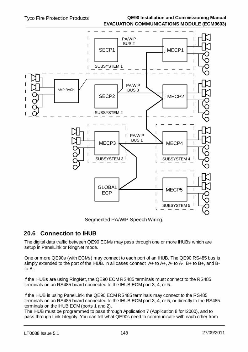
QE90 Installation and Commissioning Manual
EVACUATION COMMUNICATIONS MODULE (ECM9603)
148LT0088 Issue 5.1
Tyco Fire Protection Products
27/09/2011
PA/WIP BUS 2
SUBSYSTEM 1
SECP1 MECP1
PA/WIP BUS 3
SUBSYSTEM 2
SECP2 MECP2
MECP4MECP3
SUBSYSTEM 3 SUBSYSTEM 4
MECP5GLOBAL ECP
SUBSYSTEM 5
PA/WIP BUS 1
AMP RACK
Segmented PA/WIP Speech Wiring.
20.6 Connection to IHUB
The digital data traffic between QE90 ECMs may pass through one or more IHUBs which aresetup in PanelLink or RingNet mode.
One or more QE90s (with ECMs) may connect to each port of an IHUB. The QE90 RS485 bus issimply extended to the port of the IHUB. In all cases connect A+ to A+, A- to A-, B+ to B+, and B-to B-.
If the IHUBs are using RingNet, the QE90 ECM RS485 terminals must connect to the RS485terminals on an RS485 board connected to the IHUB ECM port 3, 4, or 5. If the IHUB is using PanelLink, the QE90 ECM RS485 terminals may connect to the RS485terminals on an RS485 board connected to the IHUB ECM port 3, 4, or 5, or directly to the RS485terminals on the IHUB ECM (ports 1 and 2).The IHUB must be programmed to pass through Application 7 (Application 8 for I2000), and topass through Link Integrity. You can tell what QE90s need to communicate with each other from

QE90 Installation and Commissioning Manual
EVACUATION COMMUNICATIONS MODULE (ECM9603)
149LT0088 Issue 5.1
Tyco Fire Protection Products
27/09/2011
the Networking / Related Nodes section of the configuration printout.
The IHUB must be programmed to NOT use concatenated messages if the ECM software versionis before version 1.50 or between versions 5.19 to 5.35 inclusive. If the ECM software version ishigher than 5.35 and the IHUB does have CONCAT MSG enabled, the ECM must not have"Optimise Panel link RX for no concat or split msgs" set to Y.
The QE90s must be setup to Disable Cyclic Addressing when QE90 data must pass through anIHUB. Then the IHUB should usually be programmed to acknowledge broadcasts on each port thatQE90s connect to. The most distant (or only) QE90 on each IHUB port should be programmed toacknowledge broadcasts from the IHUB. Refer to ECM On-site settings .
When the connection of a QE90 network to an IHUB, is only to provide high level FIP inputs to theQE90, it is not necessary to Disable Cyclic Addressing on the QE90 network. The IHUB portwhich connects to the QE90 must still be setup to not use message concatenation with the ECMsoftware versions mentioned above. The most distant QE90 from the IHUB should be set toAcknowledge broadcasts from the IHUB. In this case, the IHUB must pass through Link Integrityand the Status Transfer Application (not Application 7 or 8). Refer to High Level FIP Interfacesfor further information on High Level FIP Inputs to QE90.
20.7 ECM Links
The links on the ECM should be set as follows
LK1 : (EEPROM SIZE) 1-3 & 4-5LK2 : (Issue A only) (EPROM SIZE) 1/4MLK3 : (RAM SIZE) 62256/628128LK4 : (EEPROM Write Enable) Removed, write disabled. (However it must be temporarily installed
when exiting on-site setup mode if something has been changed.)LK5 : (DIGITAL I/O VOLTAGE) Don’t care.LK6 : (RS232 PORT B CTS/DCD SELECT) CTSLK7 : RemovedLK8 : (SPIF 2 Power) Removed, unless SPIF rather than ECP connected in ECP/SPIF2 positionLK9 : (SPIF 2 Power) Removed, unless SPIF rather than ECP connected in ECP/SPIF2 positionLK10 : (ENABLE QE90 COMMS) : Fitted.LK11 : Issue A - Do not Fit.
Issue B - Fit if RX and TX common for RS485 port 1.LK12 : Issue A - Do not fit.
Issue B - Fit if RX and TX common for RS485 port 1.LK13 : Issue B - Fit if RX and TX common for RS485 port 2.LK14 : Issue B - Fit if RX and TX common for RS485 port 2.
20.8 ECM On-site Settings
20.8.1 Overview
The ECM can be setup from a laptop running terminal emulation software (e.g. the terminal ofQEConfig, or WinComms). It is not possible to change any setup from an ECP. The laptop/terminal needs to be connected to the ECM with (1) a ribbon cable adaptor LM0065 and (2) a nullmodem cable LM0076. Refer to Printer / Terminal Connection for more details of connecting aprinter or terminal.
The terminal or terminal emulation software should be set for 9600 baud, 8 data bits, no parity, 1
149
164
172

QE90 Installation and Commissioning Manual
EVACUATION COMMUNICATIONS MODULE (ECM9603)
150LT0088 Issue 5.1
Tyco Fire Protection Products
27/09/2011
stop bit.
The ECM requires on-site setup to select Cascade timeouts and Background Music Zones inEEPROM. It is also possible to set network parameters but as these default to the normal values,it is seldom necessary to change them. To setup the Cascade or Background Music zones, or tochange a network parameter, it is necessary to have a laptop connected and running a terminalemulator program.
The cascade timeouts and background music zones must be set at the ECM(s) where theamplifiers are located, and not at a node which contains an ECP only. The values set only affectthe cascading at the node where they are setup and they can be different at different nodes.(However often correct operation of the site-wide cascade will require the delays to be set thesame at each node.)
The adjustment of on-site settings described here allows a few frequently changed items, or itemsthat will be unknown in the factory, to be set on site without any special program. For fullprogramming of the configuration see Configuration Programming with QEConfig .
20.8.2 Procedure for adjusting on-site settings
<Enter> represents the Enter key. For all entries, the current value will be displayed. To leave thevalue as is just type <Enter>.
Connect the laptop as described above, and start up the terminal emulation program.
Power Up the ECM, and within 5 seconds type a lower case e three times.
The main menu will be displayed as follows -Set Date & Time (D)Configure Network (C)Tune Network (T)Print Config(P)QE90 Configure (Q)Display QE90 Factory Configuration (F)Exit Configuration (X)
Type D, C, T, P, Q, F, or X as required.
Q Menu
Delay after alarm before any tones (secs) Currently 0 :
Enter the required delay (See “Delay Before Action” in Cascade Sequences ).
Initial cascade time delay (secs) Currently 30 :
Enter the delay between the first tones being generated and tones first spreading to other zones orchanging from Alert to Evacuate. (See “Initial Delay” in Cascade Sequences .)
Subsequent cascade time delay (secs) Currently 30 :
Enter the delay between each subsequent cascade stage. (See “Subsequent Delay” in CascadeSequences .)
Cascade Disabled (Y / N) Currently N :Enter Y to disable the Cascade at this node (and select an alternative more rapid evacuation plan).Note that this option is only available with software version 5.50 or later, and even then the optionmay not be available, for example if the cascade at each node is part of an overall cascade spreadover several nodes.
212
182
182
182

QE90 Installation and Commissioning Manual
EVACUATION COMMUNICATIONS MODULE (ECM9603)
151LT0088 Issue 5.1
Tyco Fire Protection Products
27/09/2011
Cascade includes Alert phase (Y / N) Currently N :Enter the Y if you want the cascade to include Alert, N if it is proceed straight to Evacuate(see Cascade Sequences ) (Note, available only in software version 5.40 and later.)
Monitor analog busses from this ECM (Y / N) Currently N :
Enter Y if this ECM is at the end of a bus or spur and its links are in the M position.
Monitor joined analog busses from this ECM (Y / N) Currently N :
(Only presented if there are joined analog busses, connected to a second SPIF.) Enter Y if thisECM is at the end of a the joined bus or spur and the links on the second SPIF links are in the Mposition.
Spare speech bus is fitted (Y / N) Currently N :
Enter Y if there are 3 audio busses fitted, and redundancy is provided by switching in the sparebus. Enter N if there are only two audio busses fitted, and redundancy is provided by swappingWIP and PA busses.
Zones for Background Music
Enter zones which are to receive background music if there is no run-time control of such zones.Use commands like ADD 3 6-8 <Enter> to add zones 3 and 6 to 8, or DEL 5 22 <Enter> to deletezones 5 and 22. When finished just type <Enter>
Zones for Alert/Evac/PA Group Keys
Enter zones which are controlled by the Alert, Evac, and PA Group keys. The format is the sameas for adding or deleting Background music zones.
Default Zones for non-emergency paging default (PABX)(relevant if the PABX input is used but there is no paging console)
Enter zones which are to receive the PABX audio input if there is no run-time control of suchzones. Use commands like ADD 3 6-8 <Enter> to add zones 3 and 6 to 8, or DEL 5 22 <Enter>to delete zones 5 and 22. When finished just type <Enter>
Current modem dial string []To change, type a new string <Enter> eg ATDT1,12345678To disable dial out facility, type / <Enter>
Enter the dial string for the modem as described in 20.11. If there is no modem to dial out and printalarms remotely, and a string is already defined, type /<Enter> which will remove the string.
Current modem initialise string []To leave as is type <Enter>To change, type a new string <Enter>This string should disable echo and result codes eg ATE0Q0To disable modem initialisation, type / <Enter>
Enter the initialisation string for the modem as described in 20.11. If these is no modem to dial outand print alarms remotely, and a string is already defined, type /<Enter> which will remove thestring.
Modbus Zone Address (0 to disable) Currently 0 :
Enter the lower of the two slave addresses to be used for Modbus (typically colour graphics)communications. This address is the Zone address. The Group address is one higher.
Maximum time between modbus polls (255 to disable fault) Currently 5 :
(Only presented if the modbus zone address is not 0). Enter the maximum time in secondsbetween modbus polls before a fault is raised.
182

QE90 Installation and Commissioning Manual
EVACUATION COMMUNICATIONS MODULE (ECM9603)
152LT0088 Issue 5.1
Tyco Fire Protection Products
27/09/2011
Control via modbus disallowed Currently N :
(Only presented if the modbus zone address is not 0). Enter Y to disable control over modbus.
Zones isolated on FIP display fault on EWIS Currently N :
(Only presented if there is a high level FIP input.) Enter Y to generate a fault for disabled inputzones.
Baud rate for printer / terminal port Currently 9600 :
Enter the baud rate for the port you are using. Any change will take effect after you exit on-sitesetup mode and restart the ECM.
Use hardware handshaking on printer/terminal port (Y / N) Currently N :
Enable or disable hardware handshake for the port you are using. Any change will take effect afteryou exit on-site setup mode and restart the ECM.
Baud rate for colour graphics / modbus port Currently 19200 :
Enter the baud rate for the colour graphics / modbus / high level FIP port. Any change will takeeffect after you exit on-site setup mode and restart the ECM.
C Menu
Set everything to default (Y / N) :
Enter Y to set all site configurable data to its default. This includes setting all items in the Qand T menus to their default values.
Your address is 5
This is for your information, you can't change it.
Acknowledge Broadcasts from which SIDs0 = None, 255 = All, Other = Single specific SID Currently 0 :
Set to 0 unless you are connecting to other QE90s through IHUB(s) and therefore you have set"Disable Cyclic Addressing" to Y. Then you should enable one node on the network spur toAcknowledge messages from all panels on that spur (typically the IHUB), and one node toacknowledge messages from the IHUB. So in this case you would enter the IHUBs address here.See also Connection to IHUB .
Point to point mode (Y / N) Currently N :
Enter Y only if there is only one other node on the network and you have separate cables fortransmit and receive to that other node, or you are connecting through a modem or similar and youcan transmit and receive at the same time. That other node must also be set to Y.
Tx all link integrity on both channels (Y / N) Currently N :
Entering Y will transmit link integrity messages for channels A and B on each channel (instead oftransmitting channel A link integrity on channel A only and transmitting channel B link integrity onchannel B only). This avoids getting fault indications when there is only a single channel(connecting to a non-essential part of the system).
Disable Cyclic Addressing (Y / N) Currently N :
Enter Y if data between QE90s must pass through one or more IHUBs. In this case see also"Acknowledge broadcasts from which SIDs" above.
Optimise Panel link RX for no concat or split msgs (Y / N) Currently N:The Y setting is largely to optimise processing time in very large QE90 only networks. Enter Y onlyif you are sure that the QE90 will not be receiving concatenated messages e.g. there are only
148

QE90 Installation and Commissioning Manual
EVACUATION COMMUNICATIONS MODULE (ECM9603)
153LT0088 Issue 5.1
Tyco Fire Protection Products
27/09/2011
QE90s and/or MX4428 panels on the network and no data passes through an IHUB, or if there isan IHUB the port that the QE90 connects to does not have CONCAT MSG enabled. If in doubt setto N.
Additional Refresh Interval (Additional to basic interval of 60 - 120secs ) Currently 0 :
Enter a number usually in the range of 60 - 200 on large systems. This reduces network traffic atthe expense of increasing the time between refreshing data which has not changed.
T menu
Network tuning - set to default (D), modify/view (M), leave as is :
Self explanatory. Setting to default applies only to this menu.
Network baud Currently 9600 :
Enter the baud rate for the network.
Rx Timeout * 3.3msec Currently 2 :
Leave at this default unless instructed otherwise by Tyco Fire Protection Products.
Tx delay * 3.3msec Currently 1 :
Leave at this default unless instructed otherwise by Tyco Fire Protection Products.
Ack Time * 33msec Currently 40 :
Leave at this default unless instructed otherwise by Tyco Fire Protection Products.
Dup Periods * 33msec Currently 45 :
Leave at this default unless instructed otherwise by Tyco Fire Protection Products.
Leading FF Currently 1 :
Leave at this default unless instructed otherwise by Tyco Fire Protection Products.
Trailing FF Currently 1 :
Leave at this default unless instructed otherwise by Tyco Fire Protection Products.
Link Integrity Rx interval * 1sec (0 = disabled) Currently 25 :
Leave at the default of 25, or set to 50 on larger systems.
Link Integrity Tx interval * 1sec (0 = disabled) Currently 5 :
Leave at the default of 5, or set to 10 on larger systems. If you set to 10 also set the RX intervalabove to 50.
Multicast Tx times Currently 2 :
Leave at this default unless instructed otherwise by Tyco Fire Protection Products.
Point to point mode (Y / N) Currently N :
Another way of selecting point to point mode as described in the C menu.
Network Tuning OK ? (Y / N) : y
Enter Y if you are happy with your changes, or N to go through the menu again.
ExitIf any changes have been made install the EEPROM write enable link (LK4). Type X<Enter> tosave your changes and exit. Remove the write enable link (LK4). On older systems it may benecessary to power down and up for the changes to take effect.

QE90 Installation and Commissioning Manual
EVACUATION COMMUNICATIONS MODULE (ECM9603)
154LT0088 Issue 5.1
Tyco Fire Protection Products
27/09/2011
20.9 Charger Fault Connection at Amp Rack
At a location with a power supply but no ECP e.g. a remote amplifier rack, the PTT input is used tomonitor the power supply “charger fault” output and signal it to ECPs. If “PTT” is open it will betaken as a charger fault, if closed no fault. This will normally be wired in the factory. A suitable relaymounted on a PCB is the Tyco part number PA0730.
ECM
PTT +
PTT -
PSU1 CHARGER FAULT -
PSU2 CHARGER FAULT -
0V
Relay 1 Relay 2
Charger Fault Wiring at Amplifier Rack
20.10 Connection and Colour Graphics PC
If the ECM is acting as an interface to a colour graphics PC acting as an ECP, the RING9006 PCBis connected to the FRC connector J10 on the ECM. The PTT switch on the microphone isconnected to the ECM screw terminals J9 through the PA0688 Preamp. See the diagram below"Colour Graphics Wiring".

QE90 Installation and Commissioning Manual
EVACUATION COMMUNICATIONS MODULE (ECM9603)
155LT0088 Issue 5.1
Tyco Fire Protection Products
27/09/2011
ECM
SPIF
Colour Graphics
PC
Laptop
+24V 0V
34 way
34 way
SPIF1
SPIF2
RS232PORT B
RS232PORT A
ECPMODULE
For Programming& Diagnostics
J13
J5 J6
J1J1
J2
J1
LM0065 + LM0076
LM0065 +LM0076
PA0688 Preamp
SE9004
MICSPEECH
SPCHOUT
J1
PTT
J4/J5
MIC
PTT
RING9006
J10
J9
RING9006
+24V0V
Colour Graphics Wiring
Wiring of the ECM and SPIF is otherwise the same as at a QE90 Panel.
20.11 ECM Diagnostics and Event Log
20.11.1 Overview
The ECM has a diagnostic facility which can be used to print events on a printer, or using aterminal emulator, list all off normal conditions, control alert and evacuation tones for zones, andlog various comms messages. The logs of the communications messages are intended forTyco’s use, normally Tyco will advise what to do to diagnose a problem.
Refer to Printer / Terminal Connection for more details of connecting to a printer or terminal.
The facility to display off normal conditions, and to control zones, means that most of thecommissioning of an “amp rack” (i.e. a panel with no ECP containing amplifiers, possibly strobeoutputs, possibly FIP/BGA inputs, and possibly WIP circuits), can be done at the amp rack, with orwithout the remote ECP powered up.
172

QE90 Installation and Commissioning Manual
EVACUATION COMMUNICATIONS MODULE (ECM9603)
156LT0088 Issue 5.1
Tyco Fire Protection Products
27/09/2011
20.11.2 Diagnostics Procedure
Connect the laptop/terminal emulator as described in Printer / Terminal Connection .Type 'h' (then <Enter> with ECM software version 5.57 and later) and you will get a list ofcommands like the following -
Terminal commands within '' below - ALL NOW REQUIRE ENTER KEY'f' Display factory configuration and some site programmed values'o' (letter) Display status by displaying all off normal conditions'e' Toggle Event Log On/Off'q' Toggle Local (QE90) Comms Diagnostic Log On/Off'm' Toggle Brief Modbus Comms Diagnostic Log On/Off'M' Toggle Detailed Modbus Comms Diagnostic Log On/Off'p' Toggle Brief RS485 Panel Link Comms Diagnostic Log On/Off'P' Toggle Detailed RS485 Panel Link Comms Diagnostic Log On/Off'l' Toggle RS485 Link Integrity Comms Diagnostic Log On/Off's' Toggle Simplex FIP HLL Comms Diagnostic Log On/Off'r' Toggle RZDU FIP HLL Comms Diagnostic Log On/Off'x' Toggle External Speech Generator Log' ' (Space) Turn Off all Comms Diagnostic Logs'd' Display Diagnostic Counters'0' (digit) Clear Diagnostic Counters'<' Display Memory Usage'===RESET_ECM===' Reset (Restart) ECM'===PROGRAM_ECM===' Reset ECM and go into on-site setup mode'date 25/12/2001' for example : set date'time 23:15:00' for example : set time'E20=1' for example : any script language statement'?E20|E21' for example : evaluate expression in script languageNote log of most events is suspended while entering lines
With ECM software version 5.57 and later, all the above commands must be followed by the<Enter> key.
With version 5.56 and before, the above keys were typed by themselves and the date, time, scriptstatements, reset, and program commands had to be preceded by typing 'i'. The availablecommands varied somewhat by version - type <Enter> to see what commands are available.
Much of the above is self explanatory, some commands are expanded below -e enables/disables the event log. This log is enabled by default and will display changes in theAlert and Evacuate status for each zone, and most kinds of faults. The display is generallysimilar to output of the "Off Normals" command, but each condition is listed as it happensalong with the time and date.o lists all off normal conditions as described in Off Normal Display .
20.11.3 Off Normal Display.
The o command will give a display like the following with explanations added in this font
Off Normal conditions Tyco Demo V1.13 Mar 06 1997. SID 120
(The name of the system is Tyco Demo, the software version is 1.13, the date it was programmed is March06 1997, and the network SID (address) is 120.)
Alert Zone(s) 1 2 3 4 (Zones 1, 2, 3,and 4 are generating Alert Tones.)
Speaker Line Faults on circuits *4 (Speaker circuit 4 has a line fault.)
172
156

QE90 Installation and Commissioning Manual
EVACUATION COMMUNICATIONS MODULE (ECM9603)
157LT0088 Issue 5.1
Tyco Fire Protection Products
27/09/2011
BGA Alarms on circuits *2 3 (BGA circuit 2 has an alarm. BGA circuit 3 has a latched alarm, i.e.
there has been an alarm but it has now cleared.)
WIP Line Faults on circuits *7 *10 WIP circuits 7 and 10 have line faults
Speaker Line Faults on zones *4 There is a speaker line fault on zone 4.
WIP circuits active as BGA/FIP/GP inputs *15 WIP circuit 15 is active as a BGA, FIP, or
switch input.
BGA Alarms on zones *2 3 *5. There are BGA alarms on zones 2 and 5. There has been a BGA
alarm on zone 3.
WIP1 Line Faults on zones *7 *10 There are WIP line faults on the WIP1 connection for zones 7
and 10.
Card Failures (Hexadecimal addresses) *70 c0 (QE90 Card address hex 70 is not responding.
Card address hex c0 has been not responding but now is responding.)
SIDs not responding *6 (SID 6 is not acknowledging messages addressed to it. Note that only SIDs
listed under Related Nodes in the configuration listing can generate this condition.)
Link Integ Ch A not received here from SIDs *6 (This means that this node is not receiving
link integrity transmissions on channel A from SID 6. Note that only SIDs listed under Related Nodes in theconfiguration listing can generate this condition.)
QE90 SIDs which have detected Link Integ Error, Channel A *7 (This means that SID 7 is
not receiving link integrity transmissions on channel A from at least one expected SID. Note that only SIDslisted under Related Nodes in the configuration listing can generate this condition)
Note that a * precedes circuit and zone numbers where the fault or alarm is current, except forAlert and Evacuate conditions for zones which never have a * and are not latched. If there is no *preceding the circuit or zone number, the condition is latched, i.e. the abnormal condition hasoccurred and subsequently returned to normal. These latched conditions are reset when faults arereset at an ECP, i.e. the SILENCE key is pressed and held for 2 seconds.
The local information is displayed for “circuits” and again for “zones”. A circuit refers to the circuitnumber on the I/O termination module, or to an amplifier number. A zone refers to the zone thecircuit is mapped to.
The relationship between local circuits and zones can be obtained from the factory configurationprintout. A zone may have zero, one, or more than one circuit of each type assigned to it.
Remote Information is given only for zones. Circuit data is not transmitted across the network.
OFF NORMAL DISPLAY NOTES
The QE90 card addresses are as follows00 Evac ECP2x EMUX module x4x FIP module x5x BGA module x6x Strobe module x

QE90 Installation and Commissioning Manual
EVACUATION COMMUNICATIONS MODULE (ECM9603)
158LT0088 Issue 5.1
Tyco Fire Protection Products
27/09/2011
7x Paging Console x80 WIP ECPcx WIP slave module x.
20.11.4 Interpret Command
After typing i it is possible to enter the commands to turn Alert and Evacuate On and Off for eachzone. It is necessary to type i before each command. Commands have the general formA(range)=0 or A(range)=1 or E(range)=0 or E(range)=1.A corresponds to Alert, E to Evacuate. Setting Alert or Evacuate to 1 turns it on, setting it to 0 turnsit off. The (range) is best described by examples. Note that the case (upper/lower) of the letters issignificant and must be as in the following examples.A5=1 Set alert for zone 5E12=0 Reset evacuate for zone 12An=1 Set alert for all zonesAn5-12=0 Reset alert for zones 5 to 12Any powered up ECPs at other locations which could control the zones must be switched toAUTO or their controls may override the commands typed in.
20.12 Dial Out Alarm Log
The ECM can be configured to dial out using a modem when an alarm occurs and display/print thealarm message remotely. The modem is connected to RS232 PORT B (J6), i.e. the same port asthe laptop/terminal for diagnostics. In on-site setup mode under QE90 programming you can entera modem initialisation string and a modem dial command string. The baud rate used to conversewith the modem is 9600 baud. Most modern modems will auto detect this. Most modern modemswill also automatically determine a suitable baud rate with which to converse with the remotemodem. The initialisation string should reset the modem to the factory defaults then NO ECHO,NO RESULT CODES and GENUINE CARRIER DETECT (if this is not the default). For examplefor the US Robotics Sportster VI, AT&F0E0Q1. If the modem is required to auto answer so that theECM can be called from a remote terminal, then command it to do so eg AT&F0E0Q1S0=1. TheECM will add a carriage return character to the strings it sends to the modem. The dial stringshould be whatever is needed to dial the remote system eg ATDT1,,96460001. After entering thecodes with the laptop and exiting on-site setup mode, the ECM should be powered down and themodem connected to RS232 PORT B (J6) and the ECM powered up. The modem can beconnected using the Tyco loom LM0065 which provides 9 way male and female DB9 connectors,and then a standard 9 pin to 9 pin or 9 pin to 25 pin cable as required to suit the modem. Mostmodems will come with a suitable cable.
The remote system should run a terminal emulator program and initialise its modem to autoanswer. If required the terminal emulator program can be configured to automatically print data asit is received - if this is the case it is suggested that the remote computer should run DOS and notWindows as it is not possible for a Windows program to print line by line.
The remote system can do all of the diagnostics listed under ECM DIAGNOSTICS, either whenautomatically dialled as a result of an alarm, or by manually dialling in. When the ECM dials out itwill terminate the call 1 minute after the last activity, however if the remote system dials the ECM,then the call must be terminated by the remote system.

QE90 Installation and Commissioning Manual
EVACUATION COMMUNICATIONS MODULE (ECM9603)
159LT0088 Issue 5.1
Tyco Fire Protection Products
27/09/2011
20.13 Diagnostic LEDs
There are some diagnostic LEDs on the ECM which may be useful -
LD1 (red) will flash with every communications error with QE90 modules (i.e. Evac and WIPECPs, FIP/BGA modules, EMUX modules, Strobe and WIP modules).
LD2 (yellow) will flash with every successful communications message with QE90 modules. Itshould be flashing very rapidly.
LD3 (green) should be always on if the ECM is powered up. If it flicks off briefly it indicates theECM is being reset.
LD4 (yellow) (RS485 A Transmit) flicks on whenever the ECM transmits on the channel A RS485bus. It should do this at least once every 5 seconds, transmitting its link integrity message.Whenever anything changes, and about once per minute, this LED and LD6 flash togetherindicating transmissions on both A and B busses.
LD5 (yellow) (RS485 A Receive) flicks on whenever the ECM receives on the channel A RS485bus. This should include whenever it transmits, and whenever it receives from anotherECM. This LED should be normally off, blinking on with data reception. If it is on steady ornot blinking there is something wrong.
LD6 (yellow) (RS485 B Transmit) flicks on whenever the ECM transmits on the channel B RS485bus. It should do this at least once every 5 seconds, transmitting its link integrity message.Whenever anything changes, and about once per minute, this LED and LD4 flash togetherindicating transmissions on both A and B busses.
LD7 (yellow) (RS485 B Receive) flicks on whenever the ECM receives on the channel B RS485bus. This should include whenever it transmits, and whenever it receives from anotherECM. This LED should be normally off, blinking on with data reception. If it is on steady ornot blinking there is something wrong.
20.14 ECP Status LEDs
All the status LEDs on the bottom of the ECP module will flash when it is powered up, untilcommunication is established with the ECM.
The AUTO, MANUAL, and ISOLATE LEDs on the ECP display in various combinations to indicatevarious conditions.AUTO Some or all zones are in AUTO.Steady MANUAL All zones are under manual control at this ECPSteady ISOLATE All zones are in ISOLATE and under the control of this ECPContinuous flash MANUAL Some zones are under manual control at this ECP.Continuous flash ISOLATE Some zones are in ISOLATE and under the control of this
ECP.Flash-flash-pause MANUAL Some zones are under manual control of another ECP.Flash-flash-pause ISOLATE Some zones are in ISOLATE and under the control of
another ECP.
It is possible for there to be more than one LED on at a time. For example if this ECP is in AUTObut some zones are under manual control at another ECP, the AUTO LED will be steady and theMANUAL LED will be flashing with a flash flash pause cadence.
Some but not all of the above also apply to non-networked systems and are described in LT0087,QE90 Operators Manual.
The EVACUATION SYSTEM OPERATING LED always flashes with a flash-flash-pause cadence.
The FIRE PHONE SYSTEM OPERATING LED will flash continuously when there is no call in

QE90 Installation and Commissioning Manual
EVACUATION COMMUNICATIONS MODULE (ECM9603)
160LT0088 Issue 5.1
Tyco Fire Protection Products
27/09/2011
progress, or when there is a call between that ECP phone and a WIP connected to that panel. TheLED will flash with a flash-flash-pause cadence when there is a call between a WIP connected tothat panel and a remote ECP phone, indicating that the call has been initiated or answered at aremote ECP.
20.15 ECP Diagnostic LEDs
The fault LEDs on the ECP function in a similar manner to those for non networked software, withsome additions. Refer to Networked Fault Display for more details. In the diagram the “first”remote node is the one in the leftmost Sid_xx_Zone column in the NETWORK INTERFACEsection of the configuration printout. The “second” remote node is the one in the secondSid_xx_Zone column in the NETWORK INTERFACE section of the configuration printout. Similarlyfor the other remote nodes.
All these faults are displayed as flashing indications for current or latched faults. The “off normal”command on the laptop gives much more detailed information.
20.16 QE90 Module Address Switches
Each node on the network is self contained and the module addresses (FIP, BGA, EMUX, STRM,WIPS, and ECP) restart from their base address at each node. If upgrading from an older systemwithout ECMs the addresses would have incremented across the whole system, and may needadjusting.
127

Chapter 21
AUDIO LINE ISOLATOR MODULE (ALIM9706)

QE90 Installation and Commissioning Manual
AUDIO LINE ISOLATOR MODULE (ALIM9706)
162LT0088 Issue 5.1
Tyco Fire Protection Products
27/09/2011
21.1 Overview
The Audio Line Isolator Module (ALIM9706) is used:As an isolation transformer (with optional volume control) for background music inputsconnecting to the Local Inputs of Amplifiers (refer to Local Inputs ) (Note to connect a 100Vline to a QE90 input, refer to PBQ0065A).To allow spurs on the WIP speech and PA speech busses in a networked system.
21.2 ALIM9706 on Amplifier Local Inputs
The ALIM9706 should be wired as shown in the diagram below to provide isolation, balancedinputs, and optional volume controls for amplifier local inputs.
MUSICSOURCE 1
MUSICSOURCE 2
IN+ IN+
IN+IN+
IN-
IN-
AMPLIFIER
AMPLIFIER
ALIM9706
OUT+
OUT+
OUT-
OUT-
GND
CHASSIS
ALIM9706 Providing Isolation for Amplifier Local Inputs
There are two circuits per ALIM9706 - each module can provide isolation for two music sources.
If no individual zone volume controls are required, links LK1 and LK2 on the ALIM9706 should beinstalled, and LK3 not installed. In this mode the ALIM9706 has unity gain, and the input voltagerequired for maximum output is 300mV RMS.
When individual zone volume controls are required, links LK1 and LK2 should be removed, andlink LK3 installed in the 2-3 position. In this mode the ALIM9706 has a maximum gain of about 0.3 ,and the input voltage required for maximum output is 1V RMS.
21.3 Providing Spurs in Network System Wiring
The ALIM9706 can be used in a networked QE90 system (one with ECMs) to allow spurs in thewiring to the various panels. This is achieved as described in Wiring Between Locations .
38
143

Chapter 22
HIGH LEVEL FIP INTERFACES

QE90 Installation and Commissioning Manual
HIGH LEVEL FIP INTERFACES
164LT0088 Issue 5.1
Tyco Fire Protection Products
27/09/2011
22.1 Overview
High Level FIP interfaces are available for Vigilant® MX1, F3200, MX4428, and F4000 panels usingthe Panel Link protocol (except MX1) and/or the RZDU protocol, and from some Simplex panelsusing the Simplex 4100 protocol.
The RZDU protocol is available on QE90 systems with or without ECM modules. All otherprotocols require ECM modules in the QE90 systems.
The Simplex protocol replaces hard-wired FIP inputs and is subject to the same restrictions ashard-wired FIP inputs. Each Simplex Pseudozone can map to only one evacuation zone. However,one evacuation zone may have multiple FIP zones mapped to it.
The RZDU and Panel Link inputs can be used in conjunction with hard-wired inputs. On the highlevel inputs, one FIP zone may map to one or more evacuation zones, and one evacuation zonemay map to one or more FIP zones.
22.2 RZDU Interface
An RZDU - RS232 interface (PA0481) is required at the QE90.
As there is only a single cable carrying data for multiple zones the FIP and the QE90 must belocated together.
The QE90 panel automatically determines whether non-LCD or LCD protocol is being used, andso does not require programming of which protocol to use. However if the protocol is changed atthe FIP, the QE90 must be powered down and up so it will re-establish the correct protocol.
Note: for a QE90 without an ECM, that has ECP version 4.41 or earlier and is connected to aF4000 FIP version 2.99 or earlier, that is not in NZ mode, only LCD protocol is supported. I.e. donot use the LED protocol on the F4000.
The jumpers on the PA0481 must be set to the RZDU position.
Note: when the RZDU bus is being used for a QE90 link, the bus must not be extended beyond theQE90 cabinet, since the RZDU-RS232 Interface (PA0481) does not provide any protection againsta fault in the field wiring halting the FIP communications to the QE90.
On an ECP based MECP/SECP network, one and only one FIP can connect to either the MECP orthe SECP but not both.
On an ECM network, one or multiple FIPs may be connected, but only one to each ECM.
22.2.1 RZDU - ECP
When connecting the PA0481 to an ECP module a LM0077 loom will be required. The ECP musthave a MAX232 IC installed in the U9 position. (Fitted by default after early 1999.) If a printer outputis required at the same time as the RZDU input, then the printer is connected to the female DB9socket at the double header end of the cable (LM0077). The pinout of the DB9 socket on LM0077 isas follows –
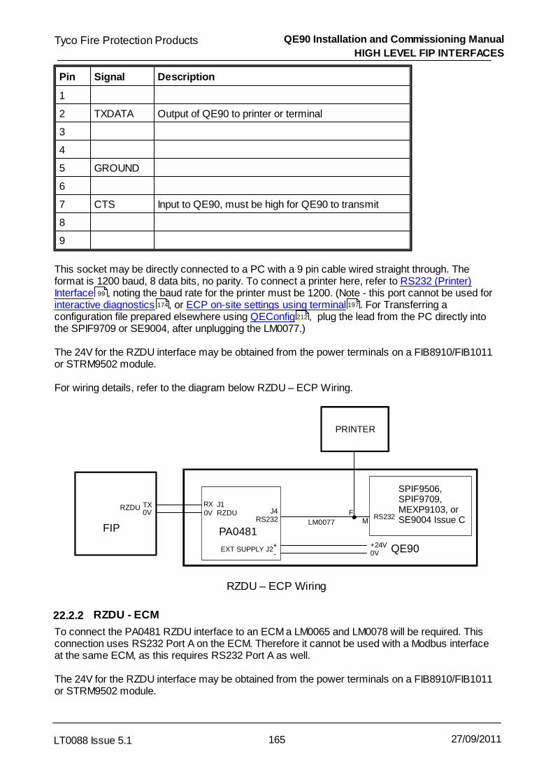
QE90 Installation and Commissioning Manual
HIGH LEVEL FIP INTERFACES
165LT0088 Issue 5.1
Tyco Fire Protection Products
27/09/2011
Pin Signal Description
1
2 TXDATA Output of QE90 to printer or terminal
3
4
5 GROUND
6
7 CTS Input to QE90, must be high for QE90 to transmit
8
9
This socket may be directly connected to a PC with a 9 pin cable wired straight through. Theformat is 1200 baud, 8 data bits, no parity. To connect a printer here, refer to RS232 (Printer)Interface , noting the baud rate for the printer must be 1200. (Note - this port cannot be used forinteractive diagnostics , or ECP on-site settings using terminal . For Transferring aconfiguration file prepared elsewhere using QEConfig , plug the lead from the PC directly intothe SPIF9709 or SE9004, after unplugging the LM0077.)
The 24V for the RZDU interface may be obtained from the power terminals on a FIB8910/FIB1011or STRM9502 module.
For wiring details, refer to the diagram below RZDU – ECP Wiring.
RX0V
RS232
EXT SUPPLY J2 +-
+24V0V
FIP PA0481
RZDU TX0V
QE90
PRINTER
FM
J1RZDU J4
RS232
SPIF9506,SPIF9709,MEXP9103, orSE9004 Issue CLM0077
RZDU – ECP Wiring
22.2.2 RZDU - ECM
To connect the PA0481 RZDU interface to an ECM a LM0065 and LM0078 will be required. Thisconnection uses RS232 Port A on the ECM. Therefore it cannot be used with a Modbus interfaceat the same ECM, as this requires RS232 Port A as well.
The 24V for the RZDU interface may be obtained from the power terminals on a FIB8910/FIB1011or STRM9502 module.
99
174 197
212
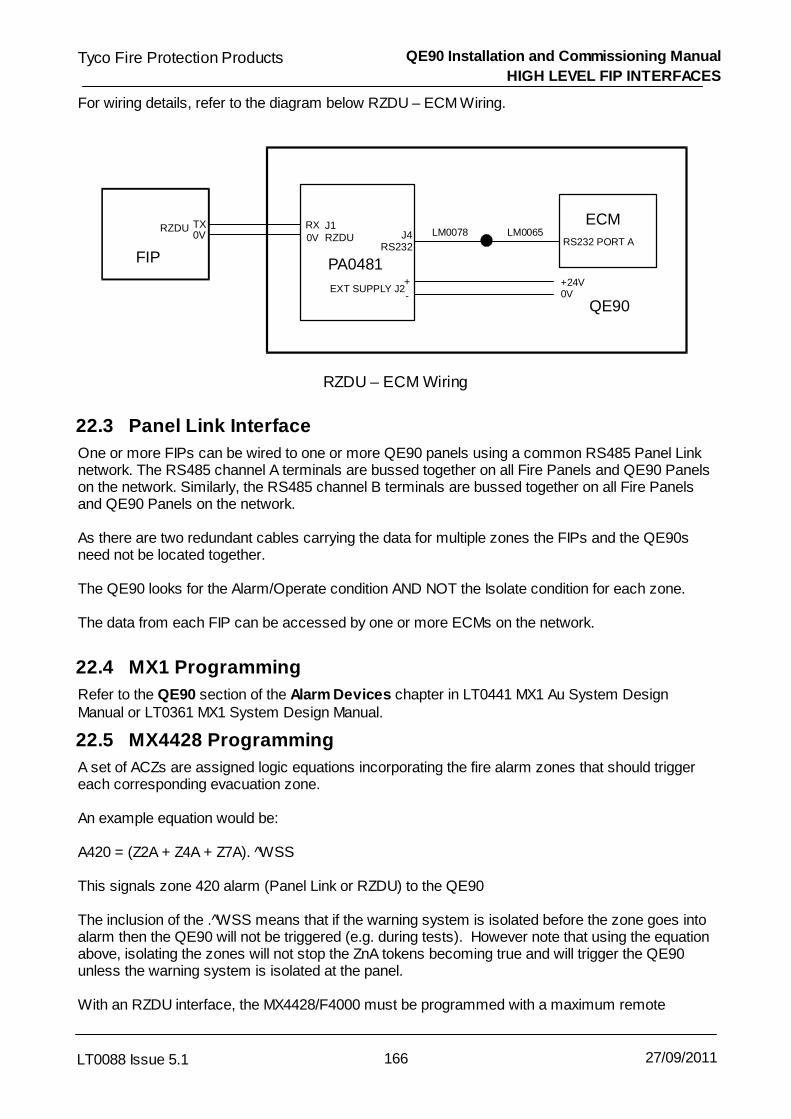
QE90 Installation and Commissioning Manual
HIGH LEVEL FIP INTERFACES
166LT0088 Issue 5.1
Tyco Fire Protection Products
27/09/2011
For wiring details, refer to the diagram below RZDU – ECM Wiring.
RS232 PORT ALM0065LM0078
+24V0V
FIP
ECMRZDU TX
0V
QE90
RX
0V
EXT SUPPLY J2 +
-
PA0481
J1RZDU J4
RS232
RZDU – ECM Wiring
22.3 Panel Link Interface
One or more FIPs can be wired to one or more QE90 panels using a common RS485 Panel Linknetwork. The RS485 channel A terminals are bussed together on all Fire Panels and QE90 Panelson the network. Similarly, the RS485 channel B terminals are bussed together on all Fire Panelsand QE90 Panels on the network.
As there are two redundant cables carrying the data for multiple zones the FIPs and the QE90sneed not be located together.
The QE90 looks for the Alarm/Operate condition AND NOT the Isolate condition for each zone.
The data from each FIP can be accessed by one or more ECMs on the network.
22.4 MX1 Programming
Refer to the QE90 section of the Alarm Devices chapter in LT0441 MX1 Au System DesignManual or LT0361 MX1 System Design Manual.
22.5 MX4428 Programming
A set of ACZs are assigned logic equations incorporating the fire alarm zones that should triggereach corresponding evacuation zone.
An example equation would be: A420 = (Z2A + Z4A + Z7A). ^WSS This signals zone 420 alarm (Panel Link or RZDU) to the QE90
The inclusion of the .^WSS means that if the warning system is isolated before the zone goes intoalarm then the QE90 will not be triggered (e.g. during tests). However note that using the equationabove, isolating the zones will not stop the ZnA tokens becoming true and will trigger the QE90unless the warning system is isolated at the panel.
With an RZDU interface, the MX4428/F4000 must be programmed with a maximum remote

QE90 Installation and Commissioning Manual
HIGH LEVEL FIP INTERFACES
167LT0088 Issue 5.1
Tyco Fire Protection Products
27/09/2011
display zone of at least the highest zone number sent to the QE90. For the Panel Link interface, the MX4428/F4000 must be programmed to enable the StatusTransfer Application and set with its Refresh TX Period (or TX rate) much less than 60 seconds.
For further details, refer to the programming manuals for the F4000/MX4428. F4000 softwaremust be version 2.25N or later. .
22.6 F3200 Programming
A set of relays are assigned logic equations incorporating the fire alarm zones that should triggereach corresponding evacuation zone
Two choices are available: Relays 1-64 can be used to enter the equations in the F3200 and the “active” status will be sentto the QE90 as RZDU Alarm LEDs on zones 65-128, or Alarm/Operate on Panel Link zones 65-128. However, using relays 1-64 uses up physical relay numbers that cannot then be used foractual relay outputs for other purposes. Note: in F3200 panels with software prior to V2.07 therelays must be physically present to allow programming of logic equations.Dummy Relays 65-128 can be used to enter the equations in the F3200, and the “active” statuswill be sent to the QE90 as RZDU Alarm LEDs on zones 129-192, or Alarm/Operate on PanelLink zones 129-192. However these “relay outputs” also directly control the alarm LEDs in zonerange 1-64 on any LED display boards fitted into the F3200. So it is not possible to have bothLED displays fitted for zone displays and use the corresponding relay outputs to control theQE90 (unless the LEDs are used to indicate the equation status being sent to the QE90). Acommon arrangement is to not fit the high zone LEDs (zones 49-64) to the F3200 and to usethese (dummy relays 113-128) to control the EWIS.
An example equation would be: R117 = (Z2A + Z4A + Z7A). ^WSS This signals RZDU zone alarm 181 to the QE90 (the zone alarm is the relay number plus 64).
The inclusion of the .^WSS means that if the warning system is isolated before the zone goes intoalarm then the QE90 will not be triggered (e.g. during tests). However note that using the equationabove, isolating the zones will not stop the ZnA tokens becoming true and will trigger the QE90unless the warning system is isolated at the panel.
For further details, refer to the programming manuals for the F3200.
22.7 QE90 Programming for PANEL-LINK / RZDU
On QE90 systems using ECM modules, you can set up on-site whether zones isolated at the FIPshould give a fault indication at the QE90. This is done in on-site setup mode as described in ECMOn-site Settings , when prompted "Zones isolated on FIP display fault on EWIS Y/N".
With standard QE90 software if the warning system is isolated (on the FIP) after the alarm hasoccurred, then the QE90 will NOT stop its tones and will continue the evacuation sequence. Thisis because AS2220 requires the EWIS to latch alarm conditions until it is switched to the manualstate. If required, special QE90 software can be ordered so that fire alarm inputs do not latch,allowing a warning system isolate to stop the QE90 tones. (The QE90 should still be switched toManual, and reset by holding SILENCE for 2 seconds, so that the alarm LEDs go out and thecascade sequence timers reset).
149

QE90 Installation and Commissioning Manual
HIGH LEVEL FIP INTERFACES
168LT0088 Issue 5.1
Tyco Fire Protection Products
27/09/2011
22.8 Simplex 4100 Interface
An interface to a Simplex 4100 series fire panel is available for QE90 systems with ECM modulesfitted. These modules are normally fitted only to networked QE90 systems, but can also be fitted instand-alone panels to provide the interface to the 4100 FIP.
The 4100 and QE90 panels must be co-located as there is only a single connection between thetwo panels.
On QE90 the 4100 interface cannot be used in conjunction with FIP module inputs at the sameECM, but can be used in conjunction with WIP circuits used as FIP inputs. You must allocate acontiguous series of pseudo points on the 4100 to map to FIP inputs. You can then map these FIPinputs to Evac zones in the normal way for switch inputs (i.e., you can have more than 1 FIP zonemapping to a QE90 zone, but one FIP zone cannot map to more than 1 QE90 zone). Normallyyou would have the sequence of FIP pseudo points mapping 1 to 1 to QE90 zones. It isrecommended that this range of pseudo points be P451 – P511 (covering 60 zones).
The 4100 must be programmed so that this range of pseudo points reflect the EVAC trigger points. The QE90 is programmable in the factory to set the starting point (e.g., 451) and to map the pointsto EVAC zones (however point to zone mapping other than 1:1 would normally be unnecessary asit can be done in the FIP).
In the 4100U Programmer, this configuration is required:
In the Hardware window of the Programmer, add a RS232/2120 module (4100-0113/6038)o In the Properties window for this device, on the Port A or Port B tab as appropriate, set
the Port Type to RS232, and the Communication Settings to 9600 bps, EVEN parity, 8data bits, 1 stop bit.
o Select the Port Data window for this port.In the Gen Info tab, set the Device Type as COMPUTER, and the Port ID as"QE90". In the Port Options tab: set all options OFF except for PROTOCOL, STATUS,BPREFIX, SUPV, POLL, ATTRIB, LF.
In the Port Vectoring window of the Programmer, select the QE90 port and disable allEvent Reporting except PSEUDO Events.
If the connection is broken, both the FIP and the QE90 will indicate faults after 30 - 60 seconds.The FIP will indicate “RS232 Interface Port B Abnormal”, while the QE90 will indicate a FIP/BGAfault for all the affected zones. Similarly the QE90 will indicate a fault if the FIP is powered down ornot producing supervisory messages. The FIP will indicate a fault if the QE90 is powered down ornot replying to the supervisory messages.
The connection to the QE90 is into RS232 port A on the ECM module. A LM0065 should be usedfrom the ECM RS232 Port A to provide a 9 pin connector, and LM0277 used to provide a 3mconnection to the DB25 port on the Dual RS232 module in the 4100 panel. The wiring for LM0277is as follows:

QE90 Installation and Commissioning Manual
HIGH LEVEL FIP INTERFACES
169LT0088 Issue 5.1
Tyco Fire Protection Products
27/09/2011
1 DCD
6 DSR
2 RXD
7 RTS
3 TXD
8 CTS
4 DTR
9 RI
5 GND
2 TXD
3 RXD
7 GND
4 RTS
5 CTS
20 DTR
8 DCD
6 DSR
4100 FIP DB25-MECM DB9-F
If zones go into alarm while the connection is broken, the QE90 will be updated within a couple ofminutes of the connection being restored. However if zones go out of alarm while the connection isbroken, the QE90 will never be informed of the fact and the zones will continue to indicate Alarmon the QE90. This situation can be overcome by powering down (and up) either the FIP or theQE90.

Tyco Fire Protection Products QE90 Installation and Commissioning Manual
LT0088 Issue 5.1 170 27/09/2011

Chapter 23
PRINTER / TERMINAL CONNECTION AND DIAGNOSTICS

QE90 Installation and Commissioning Manual
PRINTER / TERMINAL CONNECTION AND DIAGNOSTICS
172LT0088 Issue 5.1
Tyco Fire Protection Products
27/09/2011
23.1 Printer / Terminal Overview
The QE90 EWIS system has an RS232 Port configured for a Terminal or Printer. (9600 baud, 8data bits, no parity.)
The port can be used to attach a printer, terminal, or laptop computer with terminal emulationsoftware, so that events and fault conditions can be logged in more detail than is available throughthe ECP front panel LEDs. This is particularly useful during commissioning or fault finding asspecific fault conditions will be identified.
The printer / terminal will log all events as they occur, be they front panel activations by theoperator or automatic operations initiated by FIP or BGA inputs. If a terminal is used, it can also beused to display an “Off normals” list including all alarm and fault conditions, to set up the Cascadevariables, to set the date and time, and to change the baud rate from the default of 9600, and alsoadjust many additional items on ECM networked systems.
An example of the log follows. The format will vary slightly depending on the software version andwhether the system has ECM networking or not. Tue 28-07-92 16:31:19 keyswitch turned to Manual Tue 28-07-92 16:31:37 All EVAC on Tue 28-07-92 16:31:40 All EVAC off Tue 28-07-92 16:31:42 Zone 1 ALERT on Tue 28-07-92 16:31:46 Zone 1 ALERT off Tue 28-07-92 16:31:50 keyswitch turned to Auto Tue 28-07-92 16:31:59 Zone 13 Amplifier in fault Tue 28-07-92 16:32:20 Zone 2 BGA active Tue 28-07-92 16:32:30 Zone 2 ALERT on Tue 28-07-92 16:33:30 Zone 2 EVAC on Tue 28-07-92 16:33:30 Zone 1 ALERT on Tue 28-07-92 16:33:30 Zone 3 ALERT on Tue 28-07-92 16:33:30 Zone 4 ALERT on Tue 28-07-92 16:33:48 keyswitch turned to Manual Tue 28-07-92 16:33:53 All ALERT on Tue 28-07-92 16:33:54 All ALERT off Tue 28-07-92 16:33:55 All EVAC on Tue 28-07-92 16:33:56 All EVAC off Tue 28-07-92 16:34:01 FIB Card Adr 0 off line Tue 28-07-92 16:34:08 Zone 2 BGA cleared Tue 28-07-92 16:34:16 Zone 5 BGA in fault
In a non networked system with an SECP the printer may be connected at the MECP or SECP,and it will log all events as they occur including manual operations carried out at any ECP.
In an ECM networked system, the printer may connected to any ECM. It will log events relating toall zones mapped to that ECM. Thus, for a system-wide event log the printer should be connectedto an ECM at an ECP or SECP/VDU interface which controls all zones in the system.
The events logged include:1. Manual operations of Alert, Evac and PA.2. Alarm inputs from FIP and BGA inputs.3. Automatic activations of Alert and Evac due to an alarm input.4. FIP, BGA, Strobe, and Speaker Line Faults.

QE90 Installation and Commissioning Manual
PRINTER / TERMINAL CONNECTION AND DIAGNOSTICS
173LT0088 Issue 5.1
Tyco Fire Protection Products
27/09/2011
5. Amplifier supervision fault.6. Fault Silence and Reset operations from the front panel.7. Changes to cascade settings from the front panel.8. Changes to the position of the AUTO/MANUAL/ISOLATE keyswitch, and any resulting
changes to the ECP in control (for a system with an SECP).9. WIP Faults – logged on non-networked systems with ECP Version 4.00 and higher, and
logged on all versions of ECM Networked systems.10. WIP Calls – logged on non-networked systems with ECP version 4.00 and higher, and
optionally logged on ECM Networked systems with ECM version 5.36 and higher.
23.2 Off Normals Display
23.2.1 ECM Off Normals Display
Typing ‘o’ at the diagnostic terminal will produce a display of all off-normal conditions. (with ECMsoftware version 5.57 and later type 'o' then <Enter>.) Refer to Off Normal Display .
23.2.2 ECP Off Normals Display
This section applies to only ECP Software version 6.00 and later.
Typing the <Enter> key at the diagnostic terminal will display the followingEnter password for programming mode, or one of these commands =OF off normals; =Ax simulate zone x alarm; =NC next cascade; =RE Reset
Typing =OF will then display the off-normal conditions as in the following example
Condition displayed Explanation
Wed 01-01-92 01:23:17 Current time and date
QE2826 Evac ECP V6.00 File name created from, and softwareversion
QE2826 Moon Flights Inc CRC=5604 Title, and CRC of config data
Created by SmartConfig 1.4.0.1 on Tue Nov08 12:14:43 2005
Program version created by
Mode = Manual Auto, Manual, or Isolate
This ECP has control This ECP or Another ECP “in Control”
This is SECP 0 MECP, or SECP and address
Not Monitoring Audio busses here Identifies whether this ECP is set up tomonitor Audio busses between panels
*** Off Normals (excluding latched faults)***
Alert Zones <1,3,6-12> Zones which receive Alert if no higherpriority signal is selected
156

QE90 Installation and Commissioning Manual
PRINTER / TERMINAL CONNECTION AND DIAGNOSTICS
174LT0088 Issue 5.1
Tyco Fire Protection Products
27/09/2011
Evac Zones <None> Zones which receive Evac if no higherpriority signal is selected
PA Zones <None> Zones which receive PA if Press To Talkbutton is pressed.
Music Zones <1-30> Zones which receive Music if no higherpriority signal is selected
Non emerg paging Zones <None> Zones which receive non-emergencypaging if no higher priority signal isselected
FIP Alarm in Zones <None>
BGA Alarm in Zones <None>
Speaker Line Fault on Amp 2 (MUX Adr 0; AmpCard 1; Amp 2 on card) Zone 6
WIP Fault WIP 4 (WIP Card Adr 0 cct 4)Zone4 WIP 1
Input conditions and output faults are displayed by circuit number, then this is expanded into themodule address and input number on the module, and finally the zone the input or output ismapped to is listed. For amplifier cards, the EMUX address (0 – 9), amplifier card number for thatcard cage (1 – 5), and amplifier number on the card (1 – 4) are displayed.
Note - Addressable modules are always described by address (starting at 0 for each module type),while input numbers and other card numbers (e.g. amplifier cards) start at 1.
On a system with a High Level link to a FIP RZDU port, it is not possible to “type” any input data,although it is possible to connect a printer or terminal to the RS232 output. Therefore an alternativemethod of triggering the “Off normals” output is provided. Press the hidden key under the “LINEFAULT” text for zone 1. Note - the baud rate of the terminal must be set to 1200.
23.3 Other Diagnostics on Non-ECM System
This section applies to only ECP Software version 6.00 and later.
Typing the <Enter> key at the diagnostic terminal will display the followingEnter password for programming mode, or one of these commands =OF off normals; =Ax simulate zone x alarm; =NC next cascade; =RE Reset
Note that all these commands start with = so that they can be distinguished from passwords, andare thus echoed to the screen as you type them.
ECP software version 6 and later allows cascade sequences to run with the MECP switched toIsolate, so that the cascade sequence resulting from alarms on various zones can be testedwithout alerting building occupants.

QE90 Installation and Commissioning Manual
PRINTER / TERMINAL CONNECTION AND DIAGNOSTICS
175LT0088 Issue 5.1
Tyco Fire Protection Products
27/09/2011
The Ax, NC, and RE commands are useful for testing Cascade sequences in Isolate mode.
=Ax is used to simulate an alarm in zone x. This can be used when it is difficult to generate realalarm input conditions. However the best test is to simulate or otherwise produce the alarms onthe FIP, or operate BGA inputs (MCPs). The =Ax command is provided only as an alternativewhere this is not feasible. =A32 for instance simulates an alarm on zone 32. This will be indicatedon the FIP LED for zone 32. Note that the simulated alarm is a general alarm input condition (neitherspecifically FIP nor BGA) and in rare cases where the QE90 is programmed to take different action depending on
whether an alarm input is a BGA alarm or FIP alarm, the simulated alarm may not be useful.
=NC bypasses the remainder of the initial or subsequent timeout and proceeds to the nextcascade phase. This command can be used to speed up the testing process.
=RE resets simulated alarms, and resets latched genuine alarm inputs (FIP and BGA). This is thesame operation as you get by holding the SILENCE button for 2 seconds. =RE does not reset anyzones that might be in the Alert or Evacuate state, you will need to do this from the MECP controlpanel.
Note - when testing the effect of alarms in different zones, you will have to reset all the conditionsresulting from the test of an alarm in one zone before proceeding to testing an alarm in the nextzone. This includes resetting the alarm input source (so that all FIP and BGA LEDs are off), andresetting any Alert and Evacuation states in zones.
Note - these "Other Diagnostics" are not possible at an ECP which has an RZDU interfaceconnected.
23.4 Software Requirements
The Event Log is supported on non networked systems with ECP software version 1.65 or later,and on systems with ECM networking ECM version 1.50 and later. Earlier versions may provide apartial event log and should preferably have upgraded software fitted.
23.5 Hardware Requirements - New Production
From early 1999, all QE90s built have the required hardware to allow the printer / terminal to beused. However additional hardware may be required if non volatile date and time identification isrequired. All ECM systems, and Non-ECM systems with ECP Version 6.00 and later maintain thetime and date. However, unless special battery backed hardware is fitted, the time and date mustbe re-entered every time the panel is powered up.

QE90 Installation and Commissioning Manual
PRINTER / TERMINAL CONNECTION AND DIAGNOSTICS
176LT0088 Issue 5.1
Tyco Fire Protection Products
27/09/2011
QE90 System Terminal / Printer
Requirements CableConnects to
DIP Switch 1:6on ECP
Non-ECM Terminal LM0138 (Std Cable DB9 Plugto DB9 socket)KT0169 if non volatile time/daterequired
DB9 socketon SPIF9709or SE9004
ON
Non-ECM Printer FP0546 PrinterFP0752 Printer cable / powersupplyKT0169 if non volatile time/daterequired
DB9 socketon SPIF9709or SE9004
ON
ECM Terminal LM0065 Ribbon Cable(supplied)LM0076 Null Modem Cable(supplied)IC0412 if non volatile time/daterequired
RS232 PORTB on ECM
OFF
ECM Printer FP0546 PrinterFP0752 Printer cable / powersupplyIC0412 if non volatile time/daterequired
RS232 PORTB on ECM
OFF
FP0546 is a small printer capable of operating from a DC supply. FP0752 contains a supply for theFP0546 so that it can be powered from the QE90, and an LM0131 cable for connecting the printerto the QE90.
The diagrams "Wiring to PC / Terminal" and "Wiring to Printer" at the end of this chapter show howthe various systems are wired.
The 28 pin IC in KT0169 is fitted into the ECP by removing U14 from its socket and fitting the new28 pin IC. There is also a 14 pin MAX232 IC in KT0169 – this is fitted into the U9 socket on the ECPif there is no IC there already. Also ensure that Evac DIP switch 6 on the ECP board is ON withnon ECM networked systems. Refer to the diagram "Location of MAX232 and Battery BackedClock" at the end of this chapter.
The IC0412 part is fitted into an ECM by removing IC U5 from its socket, inserting IC0412 into theU5 socket, and then reinserting U5 into the socket on IC0412.
23.6 Hardware Requirements - Older Production
Some older systems may require extra hardware to be fitted to provide a printer / terminal port.Refer to Product Bulletin PBQ0016A for details.
23.7 Connector Pinouts
For users wishing to use their own printers or cables, the following tables show the pinout of thevarious ports.
SE9004 Issue C, MEXP, and SPIF (Used on system without ECM)(Also connection on LM0077 on system with RZDU High Level Link)
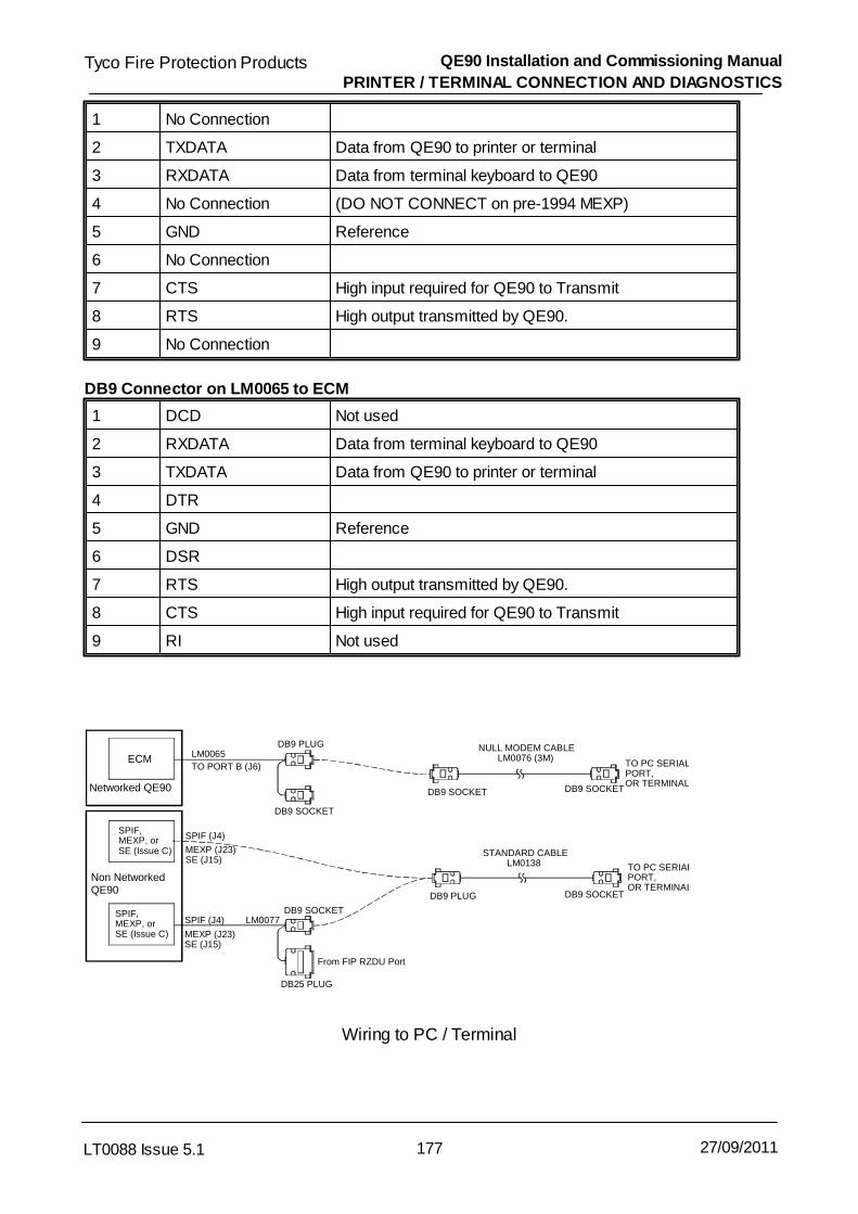
QE90 Installation and Commissioning Manual
PRINTER / TERMINAL CONNECTION AND DIAGNOSTICS
177LT0088 Issue 5.1
Tyco Fire Protection Products
27/09/2011
1 No Connection
2 TXDATA Data from QE90 to printer or terminal
3 RXDATA Data from terminal keyboard to QE90
4 No Connection (DO NOT CONNECT on pre-1994 MEXP)
5 GND Reference
6 No Connection
7 CTS High input required for QE90 to Transmit
8 RTS High output transmitted by QE90.
9 No Connection
DB9 Connector on LM0065 to ECM
1 DCD Not used
2 RXDATA Data from terminal keyboard to QE90
3 TXDATA Data from QE90 to printer or terminal
4 DTR
5 GND Reference
6 DSR
7 RTS High output transmitted by QE90.
8 CTS High input required for QE90 to Transmit
9 RI Not used
ECM
SPIF, MEXP, or SE (Issue C)
SPIF, MEXP, or SE (Issue C)
DB9 SOCKET
DB25 PLUG
From FIP RZDU Port
DB9 PLUG
DB9 SOCKET
DB9 PLUG
TO PC SERIAL PORT, OR TERMINAL
TO PC SERIAL PORT, OR TERMINAL
DB9 SOCKET
LM0065 TO PORT B (J6)
SPIF (J4)
SPIF (J4)
MEXP (J23) SE (J15)
MEXP (J23) SE (J15)
Non Networked QE90
Networked QE90
LM0077
NULL MODEM CABLE LM0076 (3M)
STANDARD CABLE LM0138
DB9 SOCKET
DB9 SOCKET
Wiring to PC / Terminal

QE90 Installation and Commissioning Manual
PRINTER / TERMINAL CONNECTION AND DIAGNOSTICS
178LT0088 Issue 5.1
Tyco Fire Protection Products
27/09/2011
PC
ECM
SPIF, MEXP, or SE (Issue C)
SPIF, MEXP, or SE (Issue C)
DB9 SOCKET
DB25 PLUG
From FIP RZDU Port
DB9 PLUG
DB9 PLUG DB9 PLUG
TO DPU-414 SERIAL PORT
DB9 SOCKET
DB9 SOCKET
LM0131 (3M)
TO DB9 SERIAL PORT
LM0065 TO PORT B (J6)
SPIF (J4)
SPIF (J4)
MEXP (J23) SE (J15)
MEXP (J23) SE (J15)
Non Networked QE90
Networked QE90
LM0077
Use this connection for printing out files or captured data
Wiring to Printer

QE90 Installation and Commissioning Manual
PRINTER / TERMINAL CONNECTION AND DIAGNOSTICS
179LT0088 Issue 5.1
Tyco Fire Protection Products
27/09/2011
WIP ECP Software
Evac ECP Software
ECP9002
WIP ECP Software
Evac ECP Software
ECP9702
Battery Backed Clock
Battery Backed Clock
U14
U14
U10
U52
Fit MAX232
Fit MAX232U9
U9
SWITCH6 ON
SWITCH6 ON
Location of MAX232 and Battery Backed Clock

Tyco Fire Protection Products QE90 Installation and Commissioning Manual
LT0088 Issue 5.1 180 27/09/2011

Chapter 24
CASCADE AND OTHER ON-SITE SETTINGS

QE90 Installation and Commissioning Manual
CASCADE AND OTHER ON-SITE SETTINGS
182LT0088 Issue 5.1
Tyco Fire Protection Products
27/09/2011
24.1 General
The QE90 EWIS panel can be set-up on-site to adjust the following settings:
a) Cascade Enabled / Disabled
b) Cascade has Alert phase or not (available only for software version 6.00 andhigher). Note that this option also requires that the configuration program isdesigned to use this feature.
c) Cascade Time Periods- Delay before action- Initial time out- Subsequent time out
d) - Zones belonging to GROUP Alert, Evacuate and PA Speech Commands.
e) - Zones that background music is enabled for.
f) - Zones to be isolated. ( Service function only, not available on ECM )
g) - Time and date for the real time clock (if present)
h) - WIP Master Phone redirection.
For systems with an ECM, the on-site setup is done using a laptop connected to the ECM. Referto ECM On site settings for details.
For systems without an ECM there are two methods of setting up the information in the QE90.
Front panel via keyboard – refer to ECP on-site settings using keyboard .
PC via serial port – refer to ECP on-site settings using terminal .
Note the WIP Master phone redirection can be setup only via the front panel – Refer to MasterPhone Redirection .
The default values for the on-site settings are given in Default Values .
A description of the effect of the cascade settings follows.
The adjustment of on-site settings described here allows a few frequently changed items, or itemsthat will usually be unknown in the factory, to be set on site without any special program. For fullprogramming of the configuration see Configuration Programming with QEConfig .
24.2 Cascade Sequences
The following tables illustrate the Cascade Time delays, the effect of the on-site settable CascadeEnabled / Disabled switch, and the effect of the on-site settable Alert Enabled / Disabled switch.
Note the “Standard 2 up 1 down” sequences are only defaults and many sites have site specificsequences. The Cascade Disabled sequences are generally as shown and are not customised.
149
189
197
199
200
212

QE90 Installation and Commissioning Manual
CASCADE AND OTHER ON-SITE SETTINGS
183LT0088 Issue 5.1
Tyco Fire Protection Products
27/09/2011
The “Delay before Action” is usually set to zero. When non-zero, during this time no tones aregenerated by the QE90, however its alarm relay output (if any) will be activated and its beeper willbe sounding.
It may often be useful to set the “Initial Delay” to zero to obtain a particular effect. Less frequently, itmay also be useful to set the “Subsequent Delay” to zero (generally to evacuate the whole buildingat once).
Note that the New Zealand “Two Up One Down” cascades begin two zones up and one down fromthe alarm zone, then continue one zone up after each timeout until the top floor is reached, andfinally continue below the alarm zone one zone down after each timeout.
Australian Standard 2 up 1 down, Alert Disabled. Alarm in Zone N
Zone N + 6 Evacuate
Zone N + 5 Evacuate
Zone N + 4 Evacuate Evacuate
Zone N + 3 Evacuate Evacuate
Zone N + 2 Evacuate Evacuate Evacuate
Zone N + 1 Evacuate Evacuate Evacuate
Zone N Evacuate Evacuate Evacuate Evacuate
Zone N – 1 Evacuate Evacuate Evacuate
Zone N – 2 Evacuate Evacuate
Zone N – 3 Evacuate
Delay BeforeAction
Initial Delay SubsequentDelay
SubsequentDelay
SubsequentDelay
--> Time
Australian Standard 2 up 1 down, Alert Enabled. Alarm in Zone N
Zone N + 6 Alert
Zone N + 5 Alert
Zone N + 4 Alert Evacuate
Zone N + 3 Alert Evacuate
Zone N + 2 Alert Evacuate Evacuate
Zone N + 1 Alert Evacuate Evacuate
Zone N Alert Evacuate Evacuate Evacuate
Zone N – 1 Alert Evacuate Evacuate
Zone N – 2 Alert Evacuate
Zone N – 3 Alert
Delay BeforeAction
Initial Delay SubsequentDelay
SubsequentDelay
SubsequentDelay
--> Time

QE90 Installation and Commissioning Manual
CASCADE AND OTHER ON-SITE SETTINGS
184LT0088 Issue 5.1
Tyco Fire Protection Products
27/09/2011
Australian Cascade Disabled, Alert Disabled. Alarm in Zone N
Zone N + 6 Evacuate Evacuate Evacuate
Zone N + 5 Evacuate Evacuate Evacuate
Zone N + 4 Evacuate Evacuate Evacuate
Zone N + 3 Evacuate Evacuate Evacuate
Zone N + 2 Evacuate Evacuate Evacuate
Zone N + 1 Evacuate Evacuate Evacuate
Zone N Evacuate Evacuate Evacuate Evacuate
Zone N – 1 Evacuate Evacuate Evacuate
Zone N – 2 Evacuate Evacuate Evacuate
Zone N – 3 Evacuate Evacuate Evacuate
Delay BeforeAction
Initial Delay SubsequentDelay
SubsequentDelay
SubsequentDelay
--> Time
Australian Cascade Disabled, Alert Enabled. Alarm in Zone N
Zone N + 6 Alert Evacuate Evacuate
Zone N + 5 Alert Evacuate Evacuate
Zone N + 4 Alert Evacuate Evacuate
Zone N + 3 Alert Evacuate Evacuate
Zone N + 2 Alert Evacuate Evacuate
Zone N + 1 Alert Evacuate Evacuate
Zone N Alert Alert Evacuate Evacuate
Zone N – 1 Alert Evacuate Evacuate
Zone N – 2 Alert Evacuate Evacuate
Zone N – 3 Alert Evacuate Evacuate
Delay BeforeAction
Initial Delay SubsequentDelay
SubsequentDelay
SubsequentDelay
--> Time
New Zealand Standard 2 up 1 down, Alert Disabled. Alarm in zone N
Zone N + 5(Top Zone)
Evacuate Evacuate
Zone N + 4 Evacuate Evacuate Evacuate
Zone N + 3 Evacuate Evacuate Evacuate Evacuate
Zone N + 2 Evacuate Evacuate Evacuate Evacuate Evacuate
Zone N + 1 Evacuate Evacuate Evacuate Evacuate Evacuate
Zone N Evacuate Evacuate Evacuate Evacuate Evacuate Evacuate
Zone N – 1 Evacuate Evacuate Evacuate Evacuate Evacuate
Zone N – 2 Evacuate
Delay BeforeAction
Initial Delay SubsequentDelay
SubsequentDelay
SubsequentDelay
SubsequentDelay
SubsequentDelay
--> Time

QE90 Installation and Commissioning Manual
CASCADE AND OTHER ON-SITE SETTINGS
185LT0088 Issue 5.1
Tyco Fire Protection Products
27/09/2011
New Zealand Standard 2 up 1 down, Alert Enabled. Alarm in zone N
Zone N + 5(Top Zone)
Alert Alert Alert Alert Evacuate Evacuate
Zone N + 4 Alert Alert Alert Evacuate Evacuate Evacuate
Zone N + 3 Alert Alert Evacuate Evacuate Evacuate Evacuate
Zone N + 2 Alert Evacuate Evacuate Evacuate Evacuate Evacuate
Zone N + 1 Alert Evacuate Evacuate Evacuate Evacuate Evacuate
Zone N Alert Evacuate Evacuate Evacuate Evacuate Evacuate
Zone N – 1 Alert Evacuate Evacuate Evacuate Evacuate Evacuate
Zone N – 2 Alert Alert Alert Alert Alert Evacuate
Delay BeforeAction
Initial Delay SubsequentDelay
SubsequentDelay
SubsequentDelay
SubsequentDelay
SubsequentDelay
--> Time
New Zealand Cascade Disabled, Alert Disabled. Alarm in Zone N
Zone N + 5(Top Zone)
Evacuate Evacuate Evacuate Evacuate Evacuate
Zone N + 4 Evacuate Evacuate Evacuate Evacuate Evacuate
Zone N + 3 Evacuate Evacuate Evacuate Evacuate Evacuate
Zone N + 2 Evacuate Evacuate Evacuate Evacuate Evacuate
Zone N + 1 Evacuate Evacuate Evacuate Evacuate Evacuate
Zone N Evacuate Evacuate Evacuate Evacuate Evacuate Evacuate
Zone N – 1 Evacuate Evacuate Evacuate Evacuate Evacuate
Zone N – 2 Evacuate Evacuate Evacuate Evacuate Evacuate
Delay BeforeAction
Initial Delay SubsequentDelay
SubsequentDelay
SubsequentDelay
Subsequent Delay
SubsequentDelay
--> Time
New Zealand Cascade Disabled, Alert Enabled, Alarm in zone N
Zone N + 5(Top Zone)
Alert Alert Evacuate Evacuate Evacuate Evacuate
Zone N + 4 Alert Alert Evacuate Evacuate Evacuate Evacuate
Zone N + 3 Alert Alert Evacuate Evacuate Evacuate Evacuate
Zone N + 2 Alert Evacuate Evacuate Evacuate Evacuate Evacuate
Zone N + 1 Alert Evacuate Evacuate Evacuate Evacuate Evacuate
Zone N Alert Evacuate Evacuate Evacuate Evacuate Evacuate
Zone N – 1 Alert Evacuate Evacuate Evacuate Evacuate Evacuate
Zone N – 2 Alert Alert Evacuate Evacuate Evacuate Evacuate
Delay BeforeAction
Initial Delay SubsequentDelay
SubsequentDelay
SubsequentDelay
Subsequent Delay
SubsequentDelay
--> Time

QE90 Installation and Commissioning Manual
CASCADE AND OTHER ON-SITE SETTINGS
186LT0088 Issue 5.1
Tyco Fire Protection Products
27/09/2011
24.3 New Zealand Type 5/7 Apartment Zone Configuration
A QE90 may be used in a NZ Building Code Type 5 or Type 7 installation. Typically, this hasmultiple apartments in each evacuation zone, with each apartment being a separate detectionzone. The loudspeakers in each apartment can be selectively connected by the fire panel to theQE90 via an AZM800 Apartment Zone Module, to provide local smoke alarm warnings or generalevacuation warnings as required.
As well as the cascade sequences described above, such QE90 systems will require additionalconfiguration scripting to provide these functions:
For each evacuation zone in the QE90, there will typically be two inputs. These could be FIP/BGAinputs or zones in a high level link:
1. Alerting input: a. When this input is active, the QE90 will produce Alerting tone only in the corresponding
evacuation zone, and any normal Alerting speech message will be suppressed.b. The activation will not cascade to other zones.c. The zone will reset when the input resets to normal, i.e., be non-latching.
2. Evacuation input:a. When this input is active, the QE90 will produce the pre-programmed cascade, as
described above.b. The zone will stay latched if the input resets to normal (see also NZS 4512:2003
Brigade Control Switches below for unlatching mechanism).
24.4 NZS 4512:2003 Brigade Control Switches
New Zealand QE90 systems typically have extra inputs programmed for:(Trial) Alert keyswitch
(Trial) Evacuate keyswitch
(Brigade) Silence Alarms keyswitch
QE90 cabinet door interlock switchThe keyswitch functions are specified by NZS 4512:2003 in sections 205, 207 and 218, and wouldusually be wired to Bulgin key switches accessible by Fire Service personnel without opening theEWIS cabinet door.
Keyswitch Operation
Trial Alert sets all EWIS zones to Alert, regardless of the Auto / Manual state of the system. WhenTrial Alert returns to normal, all zones will return to their state before Trial Alert was asserted.
Trial Evacuate sets all EWIS zones to Evacuate, regardless of the Auto / Manual state of thesystem. Cascading is suspended. When Trial Evacuate returns to normal, all zones will return totheir state before Trial Evacuate was asserted, and any cascade in progress will resume.
Silence Alarms operates as follows:When Silence Alarms is asserted, Alert and Evacuate are turned off for all zones if thepanel is in Auto.When the panel is in Manual, Silence Alarms has no immediate effect, but the next pointstill applies.For 15 seconds after Silence Alarms returns to normal, FIP inputs are made non-latchingand any FIP inputs that have returned to normal, or return to normal during this 15 secondinterval, will be reset.
186

QE90 Installation and Commissioning Manual
CASCADE AND OTHER ON-SITE SETTINGS
187LT0088 Issue 5.1
Tyco Fire Protection Products
27/09/2011
15 Seconds after Silence Alarms returns to normal, cascading will restart from thebeginning based on any currently-active FIP inputs.
This allows for the QE90 to be reset completely during the 15 second interval after removal ofSilence Alarms, provided that the fire panel removes all FIP input signals to the QE90 during that15 second window. Any remaining FIP alarms will be treated as new alarms at the end of the 15second interval and a new cascade will commence.Operation of Trial Alert or Trial Evacuate switches overrides Silence Alarms.
Alternative - FIP Controls Alert and Evacuate DirectlyAnother (less common) configuration is to have two separate (non-latching) FIP inputs per EWISzone, one to select Alert and one to select Evacuate, with the FIP controlling all cascadingfunctions. Trial Evacuate, Trial Alert, and Silence Alarms inputs are then simply active for as longas they are asserted, with Trial Evacuate overriding.
Older SystemsNZ systems prior to NZS 4512:2003 had simple Trial Evacuate / Silence Alarms functions thatwere active for as long as the switches were operated, and restored the remembered state priorwhen the switches were restored, again with Trial Evacuate overriding Silence Alarms.
Relay OutputsThe two relays on the FIB8910/FIB1011 module should be used to signal QE90 status back to theFIP for indication and remote signalling. The relays are configured to be energised in the Normalstate, and de-energised in the active state. There are two common configurations:
Common QE90o RL1 signals any fault in the QE90.o RL2 signals that the QE90 door is closed and the QE90 is not in Auto mode.
Type 5 or Type 7 Apartment QE90 Systems using AZM800 Apartment Zone Moduleso RL1 signals any fault in the QE90, or that the QE90 door is closed and the QE90 is not
in Auto mode.o RL2 signals that the QE90 is not in Auto mode, or that Trial Evacuation or Trial Alert
keyswitches are operated. This signal directs the FIP to activate all the switchedloudspeakers connected to AZM800 modules.
These relay outputs would be connected to the FIP as normally-closed circuits, going open circuitwhen active. Note that the relay contact labelling on the FIB8910/FIB1011 reflects the relay statewhen it is normally energised, which is different to most other relay labelling.
Keyswitch ConnectionThe keyswitches and door interlock switch should be wired to FIP/BGA inputs on the FIB8910/FIB1011 or FIPE9004 modules in the QE90. These switches should be wired to the last availablepositions on the FIP/BGA inputs, leaving the first positions for use as ordinary FIP inputs.NOTE: In general, these switches will need to be 2-pole types since both the QE90 and the FIP willneed to know that a switch is operated.The QE90 inputs can be wired to unused switch poles on the brigade keyswitches in the FIP asshown below.

QE90 Installation and Commissioning Manual
CASCADE AND OTHER ON-SITE SETTINGS
188LT0088 Issue 5.1
Tyco Fire Protection Products
27/09/2011
BULGIN
WH
ITEBROWN
ORANGE
BROWN
VIOLET
TRIAL EVAC
SERVICES RESTORE
SILENCE ALARMS
-+
10V Zener ELD
To MX1 Inputs
Replace Bulgin SM320 switches with Bulgin SM324/2 (2-pole)
QE90 FIP Module
Inputs
BULGIN
+
10V Zener ELD
Connecting QE90 to MX1 Brigade Keyswitch Assembly
The Bulgin SM324/2 keyswitches are available from Tyco as part SW0078.
BULGIN
WHITE
GREYVIOLET
TRIAL EVAC
SILENCE ALARMS
-+
10V Zener ELD To MX4428 Inputs
QE90 FIP Module
Inputs
BULGIN
+
Bulgin SM324/2 switches (2-pole)
Connecting QE90 to MX4428 Brigade Keyswitch Assembly (ME0433)
Alternatively, or as well, a dedicated set of brigade keyswitches could be located on the QE90cabinet, using the ME0433 keyswitch assembly.
24.5 ECP on-site settings
Use one of the following methods to adjust the on-site settings for a system with no ECM. Thesesettings should be made at the MECP (and not at any SECPs). (For a system with an ECM, everypanel will need the settings made as described in ECM on-site settings .)149

QE90 Installation and Commissioning Manual
CASCADE AND OTHER ON-SITE SETTINGS
189LT0088 Issue 5.1
Tyco Fire Protection Products
27/09/2011
24.5.1 ECP on-site settings using keyboard
On site settings can be adjusted at the MECP when the keyswitch is in Isolate and no zones havebeen selected for Alert, Evacuate or PA Speech.
Note the complete Evacuation System is disabled during on-site setup mode and only the keysthat are valid at each position in the setup sequence will work at that position.
The following steps work through each of the programmable items. This process is also shownas a flowchart below.
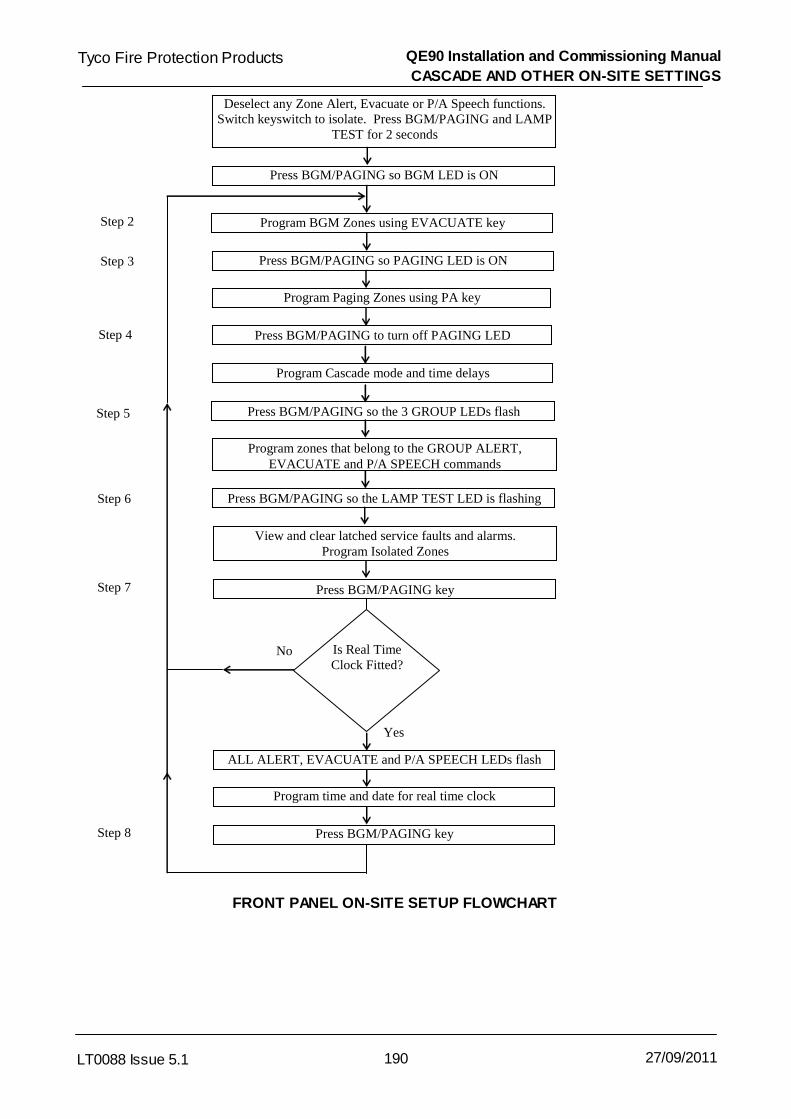
QE90 Installation and Commissioning Manual
CASCADE AND OTHER ON-SITE SETTINGS
190LT0088 Issue 5.1
Tyco Fire Protection Products
27/09/2011
Deselect any Zone Alert, Evacuate or P/A Speech functions. Switch keyswitch to isolate. Press BGM/PAGING and LAMP
TEST for 2 seconds
Press BGM/PAGING so BGM LED is ON
Program BGM Zones using EVACUATE key
Press BGM/PAGING so PAGING LED is ON
Program Paging Zones using PA key
Press BGM/PAGING to turn off PAGING LED
Program Cascade mode and time delays
Press BGM/PAGING so the 3 GROUP LEDs flash
Program zones that belong to the GROUP ALERT, EVACUATE and P/A SPEECH commands
Press BGM/PAGING so the LAMP TEST LED is flashing
View and clear latched service faults and alarms. Program Isolated Zones
Press BGM/PAGING key
Is Real Time Clock Fitted?
ALL ALERT, EVACUATE and P/A SPEECH LEDs flash
Program time and date for real time clock
Press BGM/PAGING key
Step 2
Step 3
Step 4
Step 5
Step 6
Step 7
Step 8
No
Yes
FRONT PANEL ON-SITE SETUP FLOWCHART

QE90 Installation and Commissioning Manual
CASCADE AND OTHER ON-SITE SETTINGS
191LT0088 Issue 5.1
Tyco Fire Protection Products
27/09/2011
STEP 1: On-Site Setup Mode Entry.
At the MECP de-select any zones in Alert, Evacuate, or PA Speech. Turn the keyswitch to theISOLATE position. Press and hold the BGM/PAGING key for 2 seconds until the PROGRAM LEDturns on. (Note during this 2 second period, faults will be shown on Zone LEDs as described in ECP LEDs .) (Please note, on very old versions of ECP Software, it is necessary to hold theLAMPTEST and BGM/PAGING keys together for 2 seconds.)
GROUPP/A
SPEECH
GROUPEVACUATE
GROUPALERT
LAMPTEST
PROGRAM
ALLP/A
SPEECH
ALLEVACUATE
ALLALERT
BGM
PAGING
Press and hold for 2 seconds
LED turns on
STEP 2: Select Zones for Background Music (BGM).
Press the BGM/PAGING key so that the BGM LED is on to indicate that BGM zones can be set.Select the zones to have BGM present by pressing the EVACUATE key for that zone so that theEVACUATE LED is on. Similarly, pressing the EVACUATE key so the LED is off will disable BGMfor that zone.
GROUPP/A
SPEECH
GROUPEVACUATE
GROUPALERT
LAMPTEST
PROGRAM
ALLP/A
SPEECH
ALLEVACUATE
ALLALERT
BGM
PAGING
P/ASPEECH
EVACUATEALERT
ALERT EVACUATEP/A
SPEECHLED On
Zone 2
Zone 1
Enable / Disable BGM for each zoneLED On = BGM Enabled : LED Off = BGM Disabled
LED on
125
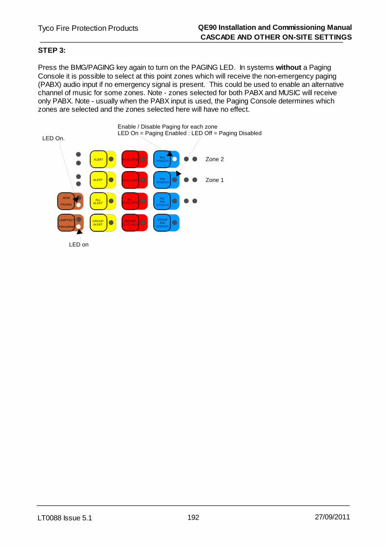
QE90 Installation and Commissioning Manual
CASCADE AND OTHER ON-SITE SETTINGS
192LT0088 Issue 5.1
Tyco Fire Protection Products
27/09/2011
STEP 3:
Press the BMG/PAGING key again to turn on the PAGING LED. In systems without a PagingConsole it is possible to select at this point zones which will receive the non-emergency paging(PABX) audio input if no emergency signal is present. This could be used to enable an alternativechannel of music for some zones. Note - zones selected for both PABX and MUSIC will receiveonly PABX. Note - usually when the PABX input is used, the Paging Console determines whichzones are selected and the zones selected here will have no effect.
GROUPP/A
SPEECH
GROUPEVACUATE
GROUPALERT
LAMPTEST
PROGRAM
ALLP/A
SPEECH
ALLEVACUATE
ALLALERT
BGM
PAGING
P/ASPEECH
EVACUATEALERT
ALERT EVACUATEP/A
SPEECH
LED On.
Zone 2
Zone 1
Enable / Disable Paging for each zoneLED On = Paging Enabled : LED Off = Paging Disabled
LED on

QE90 Installation and Commissioning Manual
CASCADE AND OTHER ON-SITE SETTINGS
193LT0088 Issue 5.1
Tyco Fire Protection Products
27/09/2011
STEP 4: Select Cascade/No Cascade, Alert / No Alert, and Cascade Times.See Cascade Sequences for the meanings of the 3 cascade delays, enabling / disabling the
cascade, and enabling / disabling the alert phase.
Press the BGM/PAGING key again to just turn off the PAGING LED. The ALL ALERT, ALLEVACUATE, ALL PA SPEECH, GROUP EVACUATE, and ZONE 1 ALERT LEDs may or may notbe on, depending on the current setup.
In the Select Cascade setup mode the following keys and actions are available. Note Initial andSubsequent Delays may not be set to more than 10 minutes for compliance with AS2220, andmay not be set to more than 42.5 minutes in any case. "Delay Before Action" should be set to zerounless the Evacuation Plan specifies otherwise.
GROUPP/A
SPEECH
GROUPEVACUATE
GROUPALERT
LAMPTEST
PROGRAM
ALLP/A
SPEECH
ALLEVACUATE
ALLALERT
BGM
PAGING
P/ASPEECH
EVACUATEALERT
ALERT EVACUATEP/A
SPEECH
Press to enable / disable Alert.LED On = Alert EnabledLED Off = Alert Skipped
Press to increment “Initial Delay”by 10 Secs.
Press to increment “Subsequent Delay” by 10 Secs.
Press to increment“Delay Before Action”by 10 Secs.
Press to confirm delays. Each of the three ALL LEDs will flash once for each 10 seconds of delay programmed.
Press to turn Cascade On or Off.LED On = Cascade EnabledLED Off = Cascade Disabled (All-Out selected)Changing this also clears ALL THREE delays, so toreset the delays press this key once, then once more if needed to select the correct Cascade On / Off mode.
LED On
182
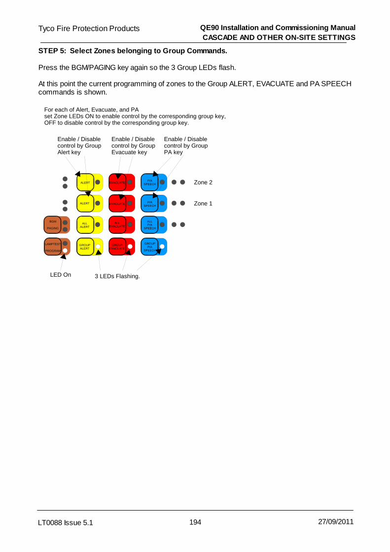
QE90 Installation and Commissioning Manual
CASCADE AND OTHER ON-SITE SETTINGS
194LT0088 Issue 5.1
Tyco Fire Protection Products
27/09/2011
STEP 5: Select Zones belonging to Group Commands.
Press the BGM/PAGING key again so the 3 Group LEDs flash.
At this point the current programming of zones to the Group ALERT, EVACUATE and PA SPEECHcommands is shown.
GROUPP/A
SPEECH
GROUPEVACUATE
GROUPALERT
LAMPTEST
PROGRAM
ALLP/A
SPEECH
ALLEVACUATE
ALLALERT
BGM
PAGING
P/ASPEECH
EVACUATEALERT
ALERT EVACUATEP/A
SPEECH
3 LEDs Flashing.
Zone 2
Zone 1
Enable / Disable control by Group Alert key
For each of Alert, Evacuate, and PAset Zone LEDs ON to enable control by the corresponding group key,OFF to disable control by the corresponding group key.
Enable / Disable control by Group Evacuate key
Enable / Disable control by Group PA key
LED On

QE90 Installation and Commissioning Manual
CASCADE AND OTHER ON-SITE SETTINGS
195LT0088 Issue 5.1
Tyco Fire Protection Products
27/09/2011
STEP 6: Select Service Fault Table Display.
Press the BGM/PAGING key again so that the LAMP TEST LED flashes.
At this point zones that have been into fault or alarm and/or modules that have been in fault will beshown with the appropriate fault or alarm LED(s) illuminated. This gives the engineer/serviceperson a separate latched fault/alarm memory in addition to the operator one. WIP faults are notstored in this memory.
GROUPP/A
SPEECH
GROUPEVACUATE
GROUPALERT
LAMPTEST
PROGRAM
ALLP/A
SPEECH
ALLEVACUATE
ALLALERT
BGM
PAGING
P/ASPEECH
EVACUATEALERT
ALERT EVACUATEP/A
SPEECH
LED On
LED Flashing
Zone 2
Zone 1
EVACUATEALERT
ALERT EVACUATEP/A
SPEECH Zone 4
Zone 3P/A
SPEECH
AUDIO -LINE FAULTBGA/FIP -
AUDIO -LINE FAULTBGA/FIP -
AUDIO -LINE FAULTBGA/FIP -
AUDIO -LINE FAULTBGA/FIP -
Press Hidden Keys to isolate / de-isolate zones. Isolated zones indicate with ALERT, EVACUATE, and PA all flashing.
Fault and Alarm LEDs show evacuation faults/alarms latched for the Service person.Alert LEDs for zones 3 – 18 show the communications error count in binary : zone 3 = 1; zone 4 = 2; zone 5 = 4; zone 6 = 8; zone 7 = 16; etcPress “SILENCE” button for 2 seconds to reset these items.
Press to completely reset panel, setting all On-site settings to their default values.
SYSTEM FAULT
SILENCE
The "communications error count" mentioned above should be investigated if it is higher than say10 per hour.
Holding the SILENCE key (on the bottom right of the keyboard) for 2 seconds while this informationis being displayed, will clear it.
STEP 7: Set the time and date for the real time clock.
The ECP module can contain an optional battery-backed real time clock (RTC) that is used togenerate the date and time for the event printout on the optional logging printer. Newer versions ofECP software will maintain the time and date even without the RTC, but it will be lost on power-down.
Press the BGM/PAGING key again so that the ALL ALERT, ALL EVACUATE and ALL PASPEECH LEDs flash in unison. If this cannot be obtained then the RTC is not fitted and the ECPsoftware version does not support the non-volatile time and date.

QE90 Installation and Commissioning Manual
CASCADE AND OTHER ON-SITE SETTINGS
196LT0088 Issue 5.1
Tyco Fire Protection Products
27/09/2011
Setting the date
GROUPP/A
SPEECH
GROUPEVACUATE
GROUPALERT
LAMPTEST
PROGRAM
ALLP/A
SPEECH
ALLEVACUATE
ALLALERT
BGM
PAGING
Press to increment the day of the month. (After clearing, it will need incrementing at least once)
Press to increment the month. (After clearing it will need incrementing at least once)
Press to increment the year. (After clearing press it 19 times for 2009, for example)
Press to confirm the date.The ALL ALERT LED will flash “day of month” times.The ALL EVACUATE LED will flash “month” times (e.g. once for January).The ALL PA SPEECH LED will flash “years since 1990” times (e.g. 19 times for 2009).
Press to clear the date (set it to 0/0/90)
FIRST Press (if needed) so that the LED is ON to set the date(When the LED is off the time is being set)
LED On
Setting the time
GROUPP/A
SPEECH
GROUPEVACUATE
GROUPALERT
LAMPTEST
PROGRAM
ALLP/A
SPEECH
ALLEVACUATE
ALLALERT
BGM
PAGING
Press to increment the hours (0 - 23).
Press to increment the 10s of minutes (0 - 5).
Press to increment the units of minutes (0 - 9)
Press to confirm the time.The ALL ALERT LED will flash “hours” times.The ALL EVACUATE LED will flash “tens of minutes” times.The ALL PA SPEECH LED will flash “units of minutes” times.
Press to clear the time(set it to 00:00 = midnight)
FIRST Press if needed so that the LED is OFF to set the time(When the LED is on the date is being set)
LED On
Flashing Flashing
Flashing
STEP 8: Cycle through steps 2 - 7 repeatedlyThe BGM/PAGING key can be pressed repeatedly to cycle through steps 2 to 7 and to verify all thesetup information.
STEP 9: Save Setup Information & Exit.
At any point during the sequence it is possible to exit on-site setup mode and save all changes byturning the keyswitch out of ISOLATE.

QE90 Installation and Commissioning Manual
CASCADE AND OTHER ON-SITE SETTINGS
197LT0088 Issue 5.1
Tyco Fire Protection Products
27/09/2011
24.5.2 ECP on-site settings using Terminal
Note - on-site setup via the serial port is not possible for systems with an RZDU high levellink.
The computer needs to be running a Terminal Emulator program, such as HYPERTERMINAL,WINCOMMS, ACCUTERM, or the terminal in QEConfig, and setup as follows:-
9600 baud rate (unless the QE90 is setup otherwise)8 data bits1 stop bitNo ParityXon/Xoff Flow Control
Connect the serial port of the computer to the connection point listed below, depending on theSignals Interface Board fitted to the system.
Signals Interface PCB Connection Point
SE9004 Issue C or later J15SPIF9709 J4SPIF9506 J4MEXP9103 J23SE9004 Issue A or B No serial port connection is provided.Tyco loom LM0138 (DB9M – DB9F, 1.8 long), or a "straight through" third party DB9M – DB9Fcable may be used. A DB9 to DB25 converter will be required for computers with a 25 pin serialport.
Note If an ECP is connected to a FIP via a RZDU Interface, the serial port cannot be used for on-site setup. The ECP must be setup using the keyboard. See ECP on-site settings using keyboard
.
Normally the QE90 serial port is operating in printer mode logging events as they occur. To enteron-site setup mode press the Enter key to obtain the “Enter Password” prompt.
Enter the password (QUINTRIX by default) followed by the Enter key. Note the keys are echoed as*, and if the password is correct a “QE90 programming mode:” message will be shown.
If nothing happens check that the ECP serial port is fitted and enabled. Refer to ECP DIP SwitchSettings .
Type HE <Enter> to give a summary of the available commands. They are as follows:
CA edit cascade variablesDA read and set dateHE command summaryPW change user passwordSP change comms baud rateTI read and set timeVE current software versionQ quit and exit programming
189
120
198
198
198
198
199
199
199
199

QE90 Installation and Commissioning Manual
CASCADE AND OTHER ON-SITE SETTINGS
198LT0088 Issue 5.1
Tyco Fire Protection Products
27/09/2011
The Cascade variables that can be edited are described in Cascade Sequences .
Type CA <Enter> and the screen will show:
Delay before action 0 secondsNew time in seconds -->
Enter the new time followed by <Enter>, or just <Enter> to leave the current value unchanged.Next the Initial Timeout and Subsequent Timeout are shown and can be altered in the samemanner.
Initial time out of 0 secondsNew time in seconds -->
Then the subsequent timeout is shown.
Subsequent time out of 180 secondsNew time in seconds -->
Next, whether the cascade has an Alert phase is shown. Press Y to change the setting to theopposite, or just <Enter> to leave it unchanged.
Cascade has No AlertChange cascade has alert or not y/n -->
Finally, whether cascade is enabled (on) or disabled (off) is shown. Press Y to change the valueto the opposite, or just <Enter> to leave it unchanged.
Cascade offChange cascade on or off y/n -->
The date can be read and optionally changed by entering DA <Enter> at the main prompt.
The current date is displayed and a prompt given for the new date e.g.
Current date is Fri 15-09-00.Enter new date (dd-mm-yy):
The new date can now be entered, e.g. 17-08-00, then press <Enter>, or just press <Enter> toskip changing the date. If a new date is entered then the new date entered is shown as the currentdate (including the day of the week) and so can be checked. Enter the correct date if it is stillwrong, or just <Enter> to exit the command.
The HE <Enter> command will show the available commands – refer to Accessing On-site SetupMode .
The PW <Enter> command allows the serial port on-site setup password to be changed. DONOT enter this command unless you intend to change the password. If you do enter it un-intentionally, re-enter the existing password to get out.
The PW command will display a prompt:
Enter new user password (max 8 characters) -->
182
197
QE90 Installation and Commissioning Manual
CASCADE AND OTHER ON-SITE SETTINGS
199LT0088 Issue 5.1
Tyco Fire Protection Products
27/09/2011
Type in the new password followed by <Enter>. Do not use = as the first character of a password,because = is used as the first character of serial port commands, refer to ECP Off normalsdisplay .
With ECP software versions before 4.32 use only UPPER CASE characters for passwords,otherwise it can be impossible to enter a matching password.
This command allows the Baud rate of the on-site setup / printer serial port to be changed (e.g. tosuit a particular printer). The newly set value takes effect immediately, so the PC will need to haveits settings changed to the new baud rate in order to re-establish communications.
Type SP <Enter> and the screen will show:
Enter new baud rate -->
Type in the required baud rate followed by <Enter>. The values allowed are 300, 600, 1200, 2400,4800 & 9600. If no change is required just press <Enter>.
This command allows the current time to be displayed and changed if necessary.
Type TI <RETURN>
The screen will show the current time and a prompt to enter the new time in 24 hour format.
Current time is (e.g.) 12:47:30Enter new time (24 hour format):
The new time can now be entered, e.g. 15:30:00, then press <Enter>, or just <Enter> to exit thecommand. The screen will display the new time if one is entered.
Type VE <Enter> to display the software version on the screen eg:
QUINTRIX version V6.01
Typing Q <Enter> will exit from on-site setup mode and return to printer event logging mode.
24.6 Master Phone Redirection
The QE90 can be setup so that a field WIP will ring whenever the master WIP rings. Picking upeither handset will stop both handsets ringing. Picking up the remote WIP will automaticallyanswer the call and enable voice communication to occur between the calling WIP and theredirected WIP.
Picking up the master WIP still requires the calling WIP button to be pressed to enable voicecommunication.
This feature enables WIP calls to be answered at a remote location when the MECP is notmanned.
This WIP redirection can be setup on the QE90 front panel at any time. Simply press the WIP-side PROGRAM key (the LED turns on) and then the WIP key that calls should be redirected to(the PROGRAM LED turns off). If redirection is to be cancelled simply press the WIP-sidePROGRAM key twice (LED turns on then off).
173

QE90 Installation and Commissioning Manual
CASCADE AND OTHER ON-SITE SETTINGS
200LT0088 Issue 5.1
Tyco Fire Protection Products
27/09/2011
On an ECM networked system, with firmware versions less than 5.57, the master phone can beredirected only to a WIP terminated at the ECP where the redirection is done.
24.7 Default Values
On the very initial factory power up of an ECP system the following default values are set. For anECP controlled systems, These default parameters can also be restored in ECP on-site settingsusing keyboard while in the Service Fault Table Display.
Cascade Disabled.No Alert Phase.Zero delay before action.3 Minute subsequent time out.Zero initial time out.Group Commands include all zones.No zones are selected for BGM.No zones isolated.
However, factory or pre-commission testing may result in some values being changed. Thereforeit is necessary to ensure all values are set correctly during commissioning of each EWIS system.
189

Chapter 25
WIDGET BOARD

QE90 Installation and Commissioning Manual
WIDGET BOARD
202LT0088 Issue 5.1
Tyco Fire Protection Products
27/09/2011
25.1 Widget Board Overview
The WIDG2004 adaptor board is a small PCB for use on the ECP9702, EMUX9601, FIB8910, andSTRM9502 modules, and the Paging Console PCB. These four modules were all originallydesigned to use the TMS77C82 microcontroller. As of mid 2004, this microcontroller becameobsolete, so the WIDG2004 assembly was created as a substitute.
The WIDG2004 module (“Widget”) has pins on the underside designed to fit into the IC socket orPCB footprint of the TMS77C82 controller. The Widget mimics the operation of this controller, butinstead runs using a Renesas M16C62A controller.
In new production, the Widget boards are soldered in place. Their firmware can be upgraded in situas described later.
For field upgrades of older TMS77C82 software in the FIB8910 and STRM9502, the Widget boardcan be plugged into the existing socket. However this cannot be done on the ECP9702 or PagingConsole as there is not enough space and cannot be done with the EMUX9601 as othermodifications are also required.
25.2 Fitting Widget Board
Upgrading the software in the STRM9502 or FIB8910 to the following versions or later will require aWidget board to be fitted:
STRM9502 V1.60 SF0313FIB8910 V2.10 SF0314
No change is required to the ECP/ECM or other software when upgrading these modules to useWIDG2004 boards.
Two kits are available to provide upgrade parts for each of the STRM9502 and FIB8910:KT0466 KIT, QE90, STRM, UPGRADE WIDGET BOARDKT0467 KIT, QE90, FIB, UPGRADE WIDGET BOARD
Each kit contains a WIDG2004 adaptor board programmed with the latest version of SF0313 orSF0314 respectively. In addition, each kit contains connector strips to fit narrower pins onto theexisting pins on the underside of the Widget board. These allow the Widget board to fit into an ICsocket more easily.
NOTE: Use anti-static (ESD) precautions when handling the circuit boards.
1. Power down the QE90. If necessary, remove the parent module (STRM or FIB) from the QE90to allow access to the TMS77C82 IC. It may be possible to upgrade these modules withoutremoving them.
2. Remove the TMS77C82 microcontroller from its socket. The relevant IC for each board is:STRM9502 U1FIB8910 U11
3. If not already fitted, fit the connector strips (CN0474) to the pins on the underside of the Widgetboard (PA1023). Carefully insert the Widget board into the vacated socket. The Widget shouldbe oriented with its black FRC box header located over the pin 1 end of the IC socket.
4. Check the fitting of the Widget to see that it is oriented correctly and that no pins are bentunderneath or outside the socket. Also check that the link LK1 on the Widget is not fitted.Check that all DIP switches on the parent board are set as desired.
5. Refit the parent board to the QE90 if required, and power up and test the QE90 system.

QE90 Installation and Commissioning Manual
WIDGET BOARD
203LT0088 Issue 5.1
Tyco Fire Protection Products
27/09/2011
6. Field upgrading of an EMUX9601 or an ECP9702 to use the Widget is not practical.
25.3 Programming Widget Board Software
On occasion Tyco may supply updated software for an ECP, EMUX, STRM, or FIP module whichalready has a Widget board fitted. The new microprocessor has its firmware in internal FLASHmemory, and this can be updated in the field as described below.
Equipment required :
A computer (e.g. laptop) with an on-board RS232 serial port or USB to RS232 adaptor
LM0065 cable
LM0076 cable
The program FlashStart.exe (this will be supplied with the software upgrade, or can bedownloaded from www.tycosafetyproducts-anz.com under Download) or obtained from aTyco or Simplex sales representative.The new File to be programmed into the Widget board e.g. SF0312_V1.18.MOT.
An ID file e.g. SF0312_V1.18.ID.
Notes :While the microprocessor is being programmed, its outputs will be indeterminate. This could resultin outputs of the board behaving randomly. In particular LEDs on the ECP9702 board, Relayoutputs on the STRM9502 and FIB8910/FIB1011 boards, and sound outputs of amplifier boardsconnected to the EMUX9601 could be activated randomly during the programming.
To prevent flash programming from activating any external outputs, disconnect external wiring orequipment as noted below in step 1.
Steps :
1. Power down the QE90 and insert the FWE jumper (LK1) on the Widget board. STRM9502 board – remove all wiring except power and optionally comms.FIB8910 board – remove wiring connected to the relay outputs.FIB1011 board - remove wiring connected to the relay outputs. Note the FWE link ismounted directly on the FIB1011, there is no separate Widget board.ECP9702 board – remove the board from the panel, and remove all wiring to it except forpower.EMUX9601 board – unplug all amplifiers from the card cage.
2. Connect the LM0076 to the appropriate COM port on the PC, and the other end to theWidget using the LM0065 cable.
3. Power up the part of the QE90 that powers the module being programmed. Run theFlashStart application by double clicking the file FlashStart.exe. When the Flashstart startscreen appears, select the “Internal flash memory” radio button at the top, and select theCOM port you are using from the drop down control at the bottom. Click OK.

QE90 Installation and Commissioning Manual
WIDGET BOARD
204LT0088 Issue 5.1
Tyco Fire Protection Products
27/09/2011
FlashStart start screen
4. The Software selection screen shown below should appear. Click the “Refer…” button, andlocate and select the supplied file XXXXXX.mot. The ID fields should be filled inautomatically with zeroes if the .id file is present. Otherwise, they can be manually filled inwith fourteen zeroes in total. Select the “M16C/20 62” radio button at the bottom, and clickOK.
Software selection screen
5. If the Software selection screen window below does not appear and an error message"Timeout, Push RESET" is given instead, this means that there has been a communicationfailure to the Widget board. Click “Cancel” to close FlashStart. Check that the LK1 jumperis fitted on the Widget, the cable connections from the PC to the Widget have been madecorrectly, and the correct COM port has been selected. Power down the module andrestart from Step 3.

QE90 Installation and Commissioning Manual
WIDGET BOARD
205LT0088 Issue 5.1
Tyco Fire Protection Products
27/09/2011
6. The Programming Menu shown below will appear. Click the “Setting…” button. Select abaud rate of 38400 with a program interval of 40ms and click “OK”. Click “E.P.R.” to eraseany previous software from the Widget’s memory, program the new software, and thenread back and verify the software.
Programming menu
7. Click OK when prompted "Erase?". Check that a programming phase then a Read Checkphase occurs, each with its own progress bar.
8. When programming has completed, check that the message “Program OK” appears. Click“OK” to close the popup and click “Exit” to quit FlashStart. Wait for the window to closebefore continuing. Switch off power to the QE90 and remove the FWE jumper (LK1) on theWidget board. Unplug the LM0065 ribbon cable.
9. Update the software version label on the Widget board.
10. Reconnect the wiring removed in step 1. Power up the QE90 and test the system.

Tyco Fire Protection Products QE90 Installation and Commissioning Manual
LT0088 Issue 5.1 206 27/09/2011

Chapter 26
PC PAGING CONSOLE

QE90 Installation and Commissioning Manual
PC PAGING CONSOLE
208LT0088 Issue 5.1
Tyco Fire Protection Products
27/09/2011
26.1 Introduction
A PC-based paging console is available for the QE90 evacuation system. This allowspaging announcements to be made to a large number of QE90 zones from a single Windows2000 or XP workstation, without requiring a separate physical Paging Console.
The PC Paging Console connects the PC and a microphone to the QE90 system. Awindows software program running on the PC allows paging control of individual or groupedevacuation zones. To the QE90 system the PC-based Paging Console behaves in a similarway to standard paging consoles.
Ordering Codes
FP0902 FP, PC PAGING CONSOLE, INTERFACE UNITThis includes an Interface Unit and the software for installing on the PC.
Like the standalone paging console, one of two microphones may be used:SU0169 SUNDRY, PAGING MICROPHONE
OR SU0168 SUNDRY, MICROPHONE, GOOSENECK, 600 OHM, C/W MTG KIT
An Example QE90 PC Paging Console Display
When the SU0168 gooseneck microphone is used (it does not have a talk button), it will benecessary to make two small changes to the PC Paging Console internal wiring. Refer tothe Wiring Diagram (LT0346) for details. In this case, the “Press To Talk’ button on the PC

QE90 Installation and Commissioning Manual
PC PAGING CONSOLE
209LT0088 Issue 5.1
Tyco Fire Protection Products
27/09/2011
screen is used when a paging announcement is to be made.
When using the SU0169 desktop microphone it is necessary to use the PTT button on themicrophone, as the switch alters the internal wiring of the microphone.
26.2 Features
Consists of a microphone (purchased separately), interface unit, and a Windowssoftware program.Hosted on a PC running Windows 2000 or XP (95/98 not supported).Communicates with the QE90 system to switch the microphone audio signal ontoselected amplifier zones. Compatible with standalone ECP-based panel or ECM networked system. Fully field configurable to match QE90 system programming.Supports up to 480 zones. In practice this will be limited to the number of zones that canbe shown on the one screen.Supports up to 10 groups of zones. Zones may be assigned to groups with totalflexibility.Can support two QE90 communications networks (requires some additional hardware).Allows custom arrangement of the zone controls and names on the screen by usingcolumn breaks and blank lines.Supports microphones with or without a push-to-talk switch.Zone selectors can be used for background music control (PTT switch does not need tobe operated).
26.3 Programmability
The PC Paging Console appears to the QE90 system as one or more paging consoles (upto 16 total), each of which supports 30 zones (giving the 480 zone limit). These ‘logicalpaging consoles’ numbered from 1 to 16 can then have the individual zones added to them.
Groups provide a method for activating or deactivating a number of zones at a time.
Each zone can be programmed with a name and one or more groups that it belongs to.
Zones are shown in columns, however ‘new column’ markers and blank lines may be used tocontrol the layout of the zones on the screen. The zone layout is automatically adjusted as theapplication window is resized.
All configuration of the PC Paging Console is done within a Config.ini file stored on the PC.
Note the PC Paging Consoles must be specifically programmed into the QE90’sconfiguration. They require different configuration programming to standard pagingconsoles, so a new configuration will be required if changing from a standard paging consoleto a PC Paging Console or vice versa.

QE90 Installation and Commissioning Manual
PC PAGING CONSOLE
210LT0088 Issue 5.1
Tyco Fire Protection Products
27/09/2011
26.4 Requirements
For the PC:PC running Windows 2000 or XP, with 1 available serial port (or USB to RS232 serialadapter) (2 if running two separate QE90 networks).
For the QE90 system:The PC Paging console and zone-to-amplifier mapping must be included in the QE90configuration. Note that a PC Paging console cannot directly replace a standardPaging console in an existing configuration.
26.5 Physical Characteristics
The PC Paging Console Interface Unit is housed in a steel cabinet measuring 310 mm 238mm 105 mm. It should be located somewhere dry, and close to the PC it will operate with.It requires a 230/240V power point as it includes a “plug pack” for powering the Interfaceelectronics.
Holes need to be drilled at appropriate places for cable entry and cable glands fitted.
Cable types to be used for external wiring:Audio cable 2 core shielded, shield grounded at QE90 and connected to
Paging Console Chassis and Audio ground terminal.Unpolarised.
Comms Cable 2 core 0.75mm shielded Fire Rated, shield grounded at QE90.Polarity important.
A DB9 female to DB9 female straight through serial cable (length 2m) is also included forconnecting to the serial port on the PC.
The PC Paging Console is shipped with a Wiring Diagram LT0346 (1953-141). This showsthe internal screw terminals of the Interface Unit and how they should be wired.
26.6 Software Upgrades
The PC Paging Console Software (for the PC) is included with the FP0902 unit.SF0299 SOFTWARE, QE90, PC PAGING CONSOLE
If a future upgrade to the software is released, it will be available to Tyco employees on theFireplace, http://www.tycosafetyproducts-anz.com/, in the Downloads page, under the QE90category, using the SF0299 part number.
Note that before installing a new software version, first re-name the existing Config.ini file inthe directory as, for example, Config.txt. Then do the install, check the new Config.ini file tosee if there are new features present. If not, delete the new Config.ini file and re-name thesaved one as Config.ini. If there are new features the existing Config.txt details will need tobe merged with the new Config.ini file to create a new setup

Chapter 27
CONFIGURATION PROGRAMMING WITH QEConfig

QE90 Installation and Commissioning Manual
CONFIGURATION PROGRAMMING WITH QEConfig
212LT0088 Issue 5.1
Tyco Fire Protection Products
27/09/2011
27.1 Introduction
A software tool “QEConfig” (SF0367) is used for configuring QE90 systems, and/ortransferring a configuration file prepared elsewhere (e.g., in the factory) into compatibleQE90 panels.
Note - this "Configuration Programming" is separate from "On-site set-up" (see ECP on-sitesettings and ECM On-site Settings) . The on-site settings are a few items that frequentlyneed to be changed on-site and often require information not available beforecommissioning (and do not need any special tools or programs). Configuration programmingis everything else that is site specific.
Note that changing an ECM's On-site settings requires a laptop. You can use QEConfig'sterminal or any other terminal emulator program. This does not require QEConfig.
For further information on QEConfig, refer to PBQ0099A, LT0455 - QEConfig User Manual,and/or the on-line help associated with QEConfig.
188 149

Chapter 28
IP NETWORKING

QE90 Installation and Commissioning Manual
IP NETWORKING
214LT0088 Issue 5.1
Tyco Fire Protection Products
27/09/2011
28.1 General
QE90 ECM networked systems may use IP (Internet Protocol) for some or all of the network. Thisreduces the number of cables required, and allows the use of many types of media such as FibreOptic cables. It also allows the limited use of T-GEN 50 based occupant warning systems on aQE90 network.
For further information refer to:LT0528 QE90 IP Networking & VIF User ManualLT0535 QE90 IP Networking Applications/Design GuideLT0519 PIB User Manual
plus the configuration file prepared for the specific site. This will detail the specific information (IPaddressing, VIF cable wiring, etc,) for the system.
Included in this will be wiring details for connecting the VIF modules to SPA2102 VoIP adaptors. Ifthis is not present, it can be re-created from QECost V3.7 onwards, by entering the panel detailsand viewing the VoIP Wiring page.
Drawing 699-295 shows the general wiring arrangement for IP Networked QE90 systems.
The manuals for the third-party IP Networking equipment are available for Tyco employees on theFireplace, http://www.tycosafetyproducts_anz.com/.