qt® conference room edition - cambridge sound
TRANSCRIPT

Qt® Conference Room EditionA Speech Protection System Designed for Conference Rooms
Installation and Operations Guide

3
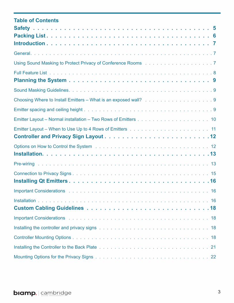
Table of ContentsSafety 5Packing List 6Introduction 7
General . . . . . . . . . . . . . . . . . . . . . . . . . . . . . . . . . . . . . . . . . . . . . . . . 7
Using Sound Masking to Protect Privacy of Conference Rooms . . . . . . . . . . . . . . . . . . 7
Full Feature List . . . . . . . . . . . . . . . . . . . . . . . . . . . . . . . . . . . . . . . . . . . 8Planning the System 9
Sound Masking Guidelines . . . . . . . . . . . . . . . . . . . . . . . . . . . . . . . . . . . . . . 9
Choosing Where to Install Emitters – What is an exposed wall? . . . . . . . . . . . . . . . . . . 9
Emitter spacing and ceiling height . . . . . . . . . . . . . . . . . . . . . . . . . . . . . . . . . . 9
Emitter Layout – Normal installation – Two Rows of Emitters . . . . . . . . . . . . . . . . . . . 10
Emitter Layout – When to Use Up to 4 Rows of Emitters . . . . . . . . . . . . . . . . . . . . . 11Controller and Privacy Sign Layout 12
Options on How to Control the System . . . . . . . . . . . . . . . . . . . . . . . . . . . . . . 12Installation 13
Pre-wiring . . . . . . . . . . . . . . . . . . . . . . . . . . . . . . . . . . . . . . . . . . . . . 13
Connection to Privacy Signs . . . . . . . . . . . . . . . . . . . . . . . . . . . . . . . . . . . . 15Installing Qt Emitters 16
Important Considerations . . . . . . . . . . . . . . . . . . . . . . . . . . . . . . . . . . . . . 16
Installation . . . . . . . . . . . . . . . . . . . . . . . . . . . . . . . . . . . . . . . . . . . . . 16Custom Cabling Guidelines 18
Important Considerations . . . . . . . . . . . . . . . . . . . . . . . . . . . . . . . . . . . . . 18
Installing the controller and privacy signs . . . . . . . . . . . . . . . . . . . . . . . . . . . . . 18
Controller Mounting Options . . . . . . . . . . . . . . . . . . . . . . . . . . . . . . . . . . . . 18
Installing the Controller to the Back Plate . . . . . . . . . . . . . . . . . . . . . . . . . . . . . 21
Mounting Options for the Privacy Signs . . . . . . . . . . . . . . . . . . . . . . . . . . . . . . 22
4
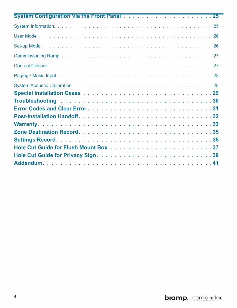
System Configuration Via the Front Panel 25
System Information . . . . . . . . . . . . . . . . . . . . . . . . . . . . . . . . . . . . . . . . . 25
User Mode . . . . . . . . . . . . . . . . . . . . . . . . . . . . . . . . . . . . . . . . . . . . . 26
Set-up Mode . . . . . . . . . . . . . . . . . . . . . . . . . . . . . . . . . . . . . . . . . . . . 26
Commissioning Ramp . . . . . . . . . . . . . . . . . . . . . . . . . . . . . . . . . . . . . . . 27
Contact Closure . . . . . . . . . . . . . . . . . . . . . . . . . . . . . . . . . . . . . . . . . . 27
Paging / Music Input . . . . . . . . . . . . . . . . . . . . . . . . . . . . . . . . . . . . . . . . 28
System Acoustic Calibration . . . . . . . . . . . . . . . . . . . . . . . . . . . . . . . . . . . . 28Special Installation Cases 29Troubleshooting 30Error Codes and Clear Error 31Post-Installation Handoff 32Warranty 33Zone Destination Record 35Settings Record 35Hole Cut Guide for Flush Mount Box 37Hole Cut Guide for Privacy Sign 39Addendum 41

5
Safety
Important Safety Instructions:1 . Read these instructions .
2 . Keep these instructions .
3 . Heed all warnings .
4 . Follow all instructions .
5 . Do not use this apparatus near water . Indoor use only .
6 . Clean only with dry cloth .
7 . Do not block any ventilation openings . Install in accordance with the manufacturer’s instructions .
8 . Do not install near any heat sources such as radiators, heat registers, stoves, or other apparatus (including amplifiers) that produce heat.
9 . Do not defeat the safety purpose of the polarized or grounding-type plug . A polarized plug has two blades with one wider than the other . A grounding type plug has two blades and a third grounding prong . The wide blade or the third prong is provided for your safety. If the provided plug does not fit into your outlet, consult an electrician for replacement of the obsolete outlet .
10 . Protect the power cord from being walked on or pinched, particularly at plugs, convenience receptacles, and the point where they exit from the apparatus .
11 . Only use attachments/accessories specified by the manufacturer.
12 . Unplg this apparatus during lightning storms or when unused for long periods of time .
13 . Refer all servicing to qualified service personnel. Servicing is required when:
• the apparatus has been damaged in any way
• liquid has been spilled or objects have fallen into the apparatus
• the apparatus has been exposed to rain or moisture
• the apparatusdoes not operate normally, or has been dropped
6
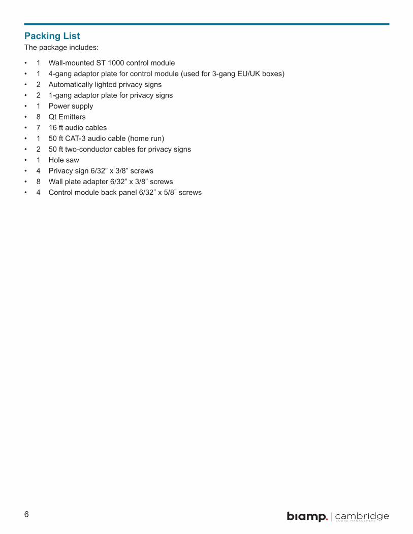
Packing ListThe package includes:
• 1 Wall-mounted ST 1000 control module• 1 4-gang adaptor plate for control module (used for 3-gang EU/UK boxes)• 2 Automatically lighted privacy signs• 2 1-gang adaptor plate for privacy signs• 1 Power supply• 8 Qt Emitters• 7 16 ft audio cables• 1 50 ft CAT-3 audio cable (home run)• 2 50 ft two-conductor cables for privacy signs• 1 Hole saw• 4 Privacy sign 6/32” x 3/8” screws• 8 Wall plate adapter 6/32” x 3/8” screws• 4 Control module back panel 6/32” x 5/8” screws
7
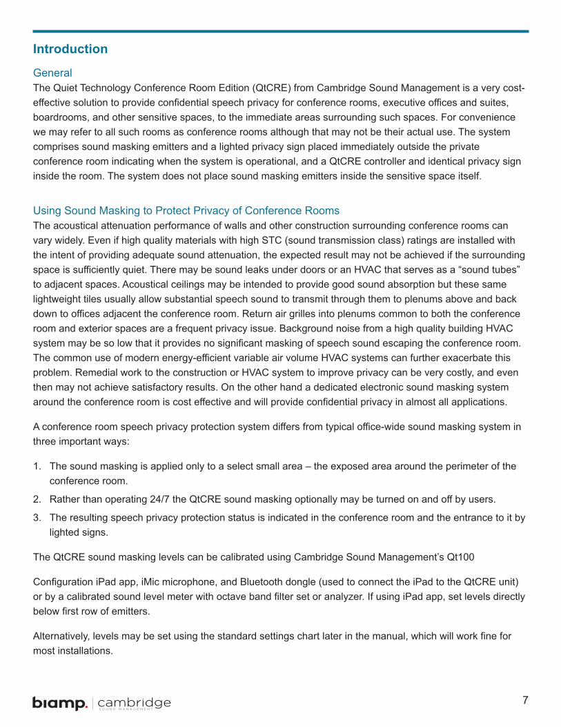
Introduction
GeneralThe Quiet Technology Conference Room Edition (QtCRE) from Cambridge Sound Management is a very cost-effective solution to provide confidential speech privacy for conference rooms, executive offices and suites, boardrooms, and other sensitive spaces, to the immediate areas surrounding such spaces . For convenience we may refer to all such rooms as conference rooms although that may not be their actual use . The system comprises sound masking emitters and a lighted privacy sign placed immediately outside the private conference room indicating when the system is operational, and a QtCRE controller and identical privacy sign inside the room . The system does not place sound masking emitters inside the sensitive space itself .
Using Sound Masking to Protect Privacy of Conference RoomsThe acoustical attenuation performance of walls and other construction surrounding conference rooms can vary widely. Even if high quality materials with high STC (sound transmission class) ratings are installed with the intent of providing adequate sound attenuation, the expected result may not be achieved if the surrounding space is sufficiently quiet. There may be sound leaks under doors or an HVAC that serves as a “sound tubes” to adjacent spaces . Acoustical ceilings may be intended to provide good sound absorption but these same lightweight tiles usually allow substantial speech sound to transmit through them to plenums above and back down to offices adjacent the conference room. Return air grilles into plenums common to both the conference room and exterior spaces are a frequent privacy issue. Background noise from a high quality building HVAC system may be so low that it provides no significant masking of speech sound escaping the conference room. The common use of modern energy-efficient variable air volume HVAC systems can further exacerbate this problem. Remedial work to the construction or HVAC system to improve privacy can be very costly, and even then may not achieve satisfactory results . On the other hand a dedicated electronic sound masking system around the conference room is cost effective and will provide confidential privacy in almost all applications.
A conference room speech privacy protection system differs from typical office-wide sound masking system in three important ways:
1 . The sound masking is applied only to a select small area – the exposed area around the perimeter of the conference room .
2 . Rather than operating 24/7 the QtCRE sound masking optionally may be turned on and off by users.
3 . The resulting speech privacy protection status is indicated in the conference room and the entrance to it by lighted signs .
The QtCRE sound masking levels can be calibrated using Cambridge Sound Management’s Qt100
Configuration iPad app, iMic microphone, and Bluetooth dongle (used to connect the iPad to the QtCRE unit) or by a calibrated sound level meter with octave band filter set or analyzer. If using iPad app, set levels directly below first row of emitters.
Alternatively, levels may be set using the standard settings chart later in the manual, which will work fine for most installations .
8
The QtCRE control module supports one zone of sound masking with 2 cable home runs . Each run supports up to 60 emitters. The maximum coverage area for the QtCRE is 12,000 sq. ft. (1,115 m²) although typical conference room speech privacy installations will not require coverage for such a large area .
Full Feature List• Comes standard with: two automatically-lighted privacy signs with cables; one wall-mounted control module
(controller) and power supply; mounting brackets; eight emitters; seven 16-ft. (4.8m) audio cables; one 50-ft. (15.2m) CAT distribution line (for the home run cable); and a hole saw
• Sound masking level adjustable in 1/2 dB steps• Out of the box support for conference rooms with up to 40 ft. (12m) of exposed walls• Optional add-on emitters for larger areas• Simplified software for easy customer operation• More advanced functions accessible by installer• Premium, minimalist design style to fit in with other conference room AV equipment• Smooth ramp up and down sound masking level function to inhibit disruption outside the conference room• Controllable from in-room Crestron and AMX control systems via contact closure; also offers 5V trigger
output• Straightforward, low-impact installation• Can be left on 24/7 or turned on as needed during confidential meetings• Less than 7 watts power consumption• Power supply compatible with 100VAC to 240VAC power mains

9
Planning the System
Sound Masking GuidelinesThis manual covers system installation of the controller, privacy signs and emitters, as well as masking level setting and system maintenance. This introduction section discusses guidelines to ensure effective sound masking coverage .
Generally the layout and calibration of emitters outside a conference room follow the standards for an open office design. It is important that the masking volume be set correctly to achieve the full effectiveness of the system . If volume levels are set too low, speech privacy for the conference room occupants will be reduced and people outside the conference room may find audio leakage to be more distracting. If volume levels are set too high, the masking sound itself could become a source of distraction .
In a given open office design, including ceiling height, ceiling material, and workstation panel height, we can define the masking volume required to achieve “normal acoustic privacy,” between offices (i.e., normal voices are audible but not easily understood). In an open office environment, the target background sound level is typically in the 45 - 48 dBA range, as measured 3 - 4 ft. (0.9 m) above floor level.
Ceiling Height Volume Level Intended Result (at listener ear level)8 ft. (2.4m) 13 - 16 45 - 48 dBA10 ft. (3m) 15 - 18 45 - 48 dBA12 ft. (3.6m) 16 - 19 45 - 48 dBA
Choosing Where to Install Emitters – What is an exposed wall?The goal of the system is to lower the listener’s speech-to-masking noise ratio to the point that people outside cannot understand any speech originating in the conference room, even from persons using a raised voice . Technically this is known as Confidential Privacy or having an Articulation Index (AI) of 0.05 or below, and is comparable to a Speech Transmission Index (STI) of 0.12 or below.
In order to achieve this goal, the emitters should be installed in rows parallel to all exposed walls of the conference room, that is, along any wall party (common) to both the conference room and any adjacent office spaces, including open plan or private enclosed offices, corridors, storage or utility rooms, etc.
Emitter spacing and ceiling heightSpacing between emitters generally should follow the same rules as for other Cambridge Sound Management (CSM) direct field masking systems, i.e. should be not less than the ceiling height above the finished floor. The English dimensions are based on America drop ceiling tile sizes (24x24”, 24x48”). The metric dimensions are based on international tile sizes (300x300mm).
Ceiling Height SpacingCeiling heights less than 10 ft. (2.4m) 8 ft. spacing (2.4m)Ceiling height is 10 ft. to 12 ft. (3m) 10 ft. spacing (3m)Ceiling height is 12 ft. and above (3.6m) 12 ft. spacing (3.6m)

10
Emitter Layout – Normal installation – Two Rows of EmittersPlace the first row adjacent any party wall between the conference room and exterior spaces at 1/2 the height of the ceiling or less. For example, a 10 ft. (3m) ceiling, place the first row no more than 4 or 5 ft. (1.2 to 1.5m) from the wall . Continue both rows one spacing beyond both ends of party walls . However, for party walls that are adjacent a narrow corridor or room, one row on or near the center is sufficient.
Example: Conference room with one exposed wall – two rows of emitters .
Example: Conference room with two exposed walls and an open area extending away from the area in one direction . One row of emitters in side cubicle area .
11
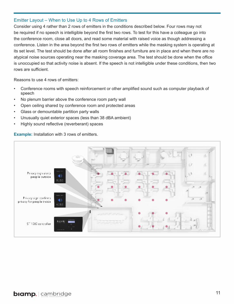
Emitter Layout – When to Use Up to 4 Rows of EmittersConsider using 4 rather than 2 rows of emitters in the conditions described below . Four rows may not be required if no speech is intelligible beyond the first two rows. To test for this have a colleague go into the conference room, close all doors, and read some material with raised voice as though addressing a conference. Listen in the area beyond the first two rows of emitters while the masking system is operating at its set level. The test should be done after all room finishes and furniture are in place and when there are no atypical noise sources operating near the masking coverage area. The test should be done when the office is unoccupied so that activity noise is absent . If the speech is not intelligible under these conditions, then two rows are sufficient.
Reasons to use 4 rows of emitters:
• Conference rooms with speech reinforcement or other amplified sound such as computer playback of speech
• No plenum barrier above the conference room party wall• Open ceiling shared by conference room and protected areas• Glass or demountable partition party walls• Unusually quiet exterior spaces (less than 38 dBA ambient)• Highly sound reflective (reverberant) spaces
Example: Installation with 3 rows of emitters .
12
Controller and Privacy Sign Layout
Options on How to Control the SystemIt is important to understand how the system will be used and controlled to decide the location of the controller and privacy signs .
The controller unit is self-contained and can be operated by the end-user directly from the front panel . The set-up features are hidden from the end user to prevent accidental changes .
The signs indicate that the system is fully on only when lit steadily . They blink while ramping up or down
(the gentle increase or decrease of sound level).
Optionally the system can also be controlled via contact closure (such as by an automation control system). In this case the controller should be placed out of the way, such as in a closet or IT closet, to reduce any confusion about the active control point. The system also features a nominal 5V trigger out for status confirmation to a control system.
An external contact closure can also be used to allow control from a remote switch such as a light switch or single-pole, single-throw (SPST) low voltage switch.
In an operating scenario in which contact closure is used, emergency cutoff can only be achieved if the low level is MUTE and CC ramp down time is 0 .
Optionally the system may be installed similar to standard sound masking (which is normally on 24/7),
with the controller visible or hidden .
Placing the controller:
• In a place easy to reach for occupants of the room, such as near light switches near the room entrance, or at a convenient place accessible during presentations .
• Can be visible or hidden, but remember people may not know how or where to operate it if it is completely out of sight .
Placing the privacy signs:
• Two privacy signs are provided, one for the room occupants and the other for people outside the room . Typically one sign is mounted inside the conference room to alert the occupants to status and the other is mounted outside conference room, adjacent to the main door .
• Use of both signs is not required or both may be installed inside or outside the room . Coordinate with Owner .

13
Installation
Pre-wiring
Home RunThe 50’ CAT distribution line supplied with the base kit should be sufficient as the home run for almost all installations. It may be replaced by a longer CAT cable to the first emitter without excessive loss or impact privacy signal level difference between the first and last emitters on the line . Theoretically a CAT coupler and additional cable could be used rather than a longer home run but this is not the preferred method due to the coupler most likely being located in an inaccessible and/or undocumented location, possibly complicating future servicing .
Emitter Cable (Interconnects) ConfigurationThe interconnects should be connected the same as in a conventional CSM Qt masking system, i .e . in a series serpentine layout . This will assure that adjacent emitters are on different channels to minimize any phase interference issues.
CSM’s Quiet Technology uses four distinct non-correlated sounds that repeat every fourth emitter automatically. The home run from the controller to the first emitter may be concealed in a wall stud space.
How CSM Emitter Cabling Works – Homeruns and Daisy ChainingEmitters on each line are daisy-chained in series during installation . Each emitter has passive internal logic which rolls over its input channel to a different channel at its output port. Thus every fourth emitter is actually operated in parallel with the first.
Four Channel Distribution
14
Power SupplyIn most cases the 24V power supply will need to be located remotely, with a cable run from the power supply to the controller. In some cases a wall plate such as the Vanco 120614X permits in-wall running of the power wire to an AC plug on the exterior of the wall .
The power supply wire may be extended using appropriate cable and connectors . The cable should be UL rated and plenum rated if routed through any plenum space .
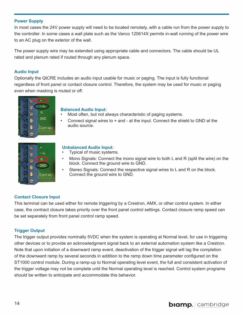
Audio InputOptionally the QtCRE includes an audio input usable for music or paging . The input is fully functional regardless of front panel or contact closure control . Therefore, the system may be used for music or paging even when masking is muted or off.
Contact Closure InputThis terminal can be used either for remote triggering by a Crestron, AMX, or other control system . In either case, the contract closure takes priority over the front panel control settings . Contact closure ramp speed can be set separately from front panel control ramp speed .
Trigger OutputThe trigger output provides nominally 5VDC when the system is operating at Normal level, for use in triggering other devices or to provide an acknowledgment signal back to an external automation system like a Crestron . Note that upon initiation of a downward ramp event, deactivation of the trigger signal will lag the completion of the downward ramp by several seconds in addition to the ramp down time parameter configured on the ST1000 control module . During a ramp-up to Normal operating level event, the full and consistent activation of the trigger voltage may not be complete until the Normal operating level is reached . Control system programs should be written to anticipate and accommodate this behavior .
Balanced Audio Input: • Most often, but not always characteristic of paging systems . • Connect signal wires to + and - at the input . Connect the shield to GND at the
audio source .
Unbalanced Audio Input: • Typical of music systems .• Mono Signals: Connect the mono signal wire to both L and R (split the wire) on the
block . Connect the ground wire to GND .• Stereo Signals: Connect the respective signal wires to L and R on the block .
Connect the ground wire to GND .
15
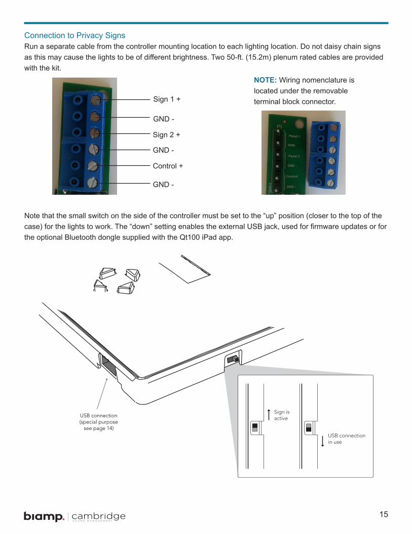
Connection to Privacy SignsRun a separate cable from the controller mounting location to each lighting location . Do not daisy chain signs as this may cause the lights to be of different brightness. Two 50-ft. (15.2m) plenum rated cables are provided with the kit .
Note that the small switch on the side of the controller must be set to the “up” position (closer to the top of the case) for the lights to work. The “down” setting enables the external USB jack, used for firmware updates or for the optional Bluetooth dongle supplied with the Qt100 iPad app .
Sign 1 +
GND -
Sign 2 +
GND -
Control +
GND -
NOTE: Wiring nomenclature is located under the removable terminal block connector .

16
Installing Qt Emitters
Important Considerations• Each run has a maximum of 60 emitters .• Each run supports a maximum cable length of 1000 ft .• Each home run cable attached to the control module should be labeled by Zone # and Run # . Adding
a logical name (e.g. Marketing, Private Offices) is suggested. In addition, fill out the “Zone Destination Record” at the end of this Guide .
• The module has two identical outputs, Run 1 and Run 2 . All emitters on Run 1 and Run 2 are controlled equally .
• Each job-made cable should be manufactured according to ANSI/TIA/EIA Standard 568-B . See custom cabling guidelines on page 18 .
• Before installation, job-made cables should be tested with a LAN cable tester .
Installation1 . Set the masking output level to the maximum level of 30 . (Set sound masking volume levels using either of
the front panel controls.)
2 . Refer to the emitter layout and wiring diagram provided by the dealer for cable run connections .
3 . Run home run cables from control module to the location of the first emitter for all runs.
4 . Gather all ceiling tiles (per layout drawing) that are to receive emitters. Use the supplied hole saw to cut holes in designated tiles. Cut all tiles from the front. (Different types of emitter housings are available to attach in areas where there are no suspended ceiling tiles.)
5 . Push the emitter through the front of the hole in tile and secure it by pushing down and twisting the locking ring at the back of the emitter .
NOTE:• The “tombstone” hook on the back of each emitter is next to the INPUT jack.• This can help you find the INPUT jack by touch.• To adjust for unexpected obstacles such as sprinkler heads, each emitter may be moved up
to 2 ft. (one tile or 0.6 m) in any direction.

17
6 . Connect a run cable from the specified OUTPUT jack on the module to the INPUT jack of the first emitter. Listen to each emitter as it is connected. If you cannot hear its “whooshing” sound:
• Try a different emitter.
• Test all four previous cables for continuity and shorts . Repair any faulty cables .
• If a short is detected, the masking will shut off until the short is physically fixed. The error on the control module will
remain until the error is cleared. (see Error Codes and Clearing Errors, page 31) Set the masking output level to the
maximum level of 30 .
7 . Connect the next OUTPUT cable to the emitter OUTPUT jack .
8 . Run the cable to next designated tile specified on emitter layout and wiring diagram. Tie cables up to structure or suspend from deck as required by local building code .
9 . On the next emitter, connect this cable to the INPUT jack
10 . Repeat Steps 4 through 9 for the remaining emitters on the home run .
! DO NOT put the input cable into the output port of the emitter . If sound is only heard by putting the
cable in the output, there is a problem earlier in the cable run. Be sure to fix any problems and hear the “whooshing” sound before installing the next emitter.
NOTE:• The input jack of each emitter bears this symbol and is located near the safety tie off.• The output jack of each emitter bears this symbol .

18
Custom Cabling Guidelines
Important Considerations1 . Use solid conductor 24 AWG CAT-13 cable that meets local code requirements .
2 . If the system is installed in a return air plenum, the cable must be plenum rated .
3 . Shielding is not required. Unshielded twisted pair (UTP) cable is acceptable.
4 . Snagless boots are not required .
5 . RJ-45 plugs must use the “bent 3-tine” RJ-45 plugs intended for use with solid core CAT wire. Three-tine plugs can be purchased at a hardware store and from most CAT cable suppliers . DO NOT USE the “aligned two-tine” type intended for stranded wire, as they provide improper contact and may yield intermittent system operation . The diagram below shows the cross section view of both types .
6 . Field test each cable after fabrication with the RJ-45 connectors (before final installation), using a standard network LAN cable tester, to check for continuity, shorts, and 1:1 (straight through) connection.
Installing the controller and privacy signsInstallation of the controller requires separating the front panel from the rear of the case – simply done by pulling one from the other. All installation options require attaching the case rear first, then getting cables attached to the controller, then snapping the controller into place .
Controller Mounting Options• Best practices: If installing the controller on a wall known to have sound transmission issues into an
adjacent space, it is recommended to use surface mounting . Be careful to seal airtight any cabling holes to minimize sound transmission . Avoid back-to-back mounting of electrical or other wall components within a single stud space .
• Best practices: On walls separating the conference room from an area with masking, don’t use gang boxes with big holes as these are prone to passing sound . Whenever feasible, don’t install the box on a wall requiring masking protection as it may exacerbate sound transmission problems .
CORRECTRJ-45 Connector with bent type
INCORRECTRJ-45 Connector with aligned type
19
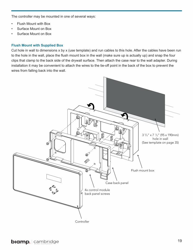
The controller may be mounted in one of several ways:
• Flush Mount with Box• Surface Mount on Box• Surface Mount on Box
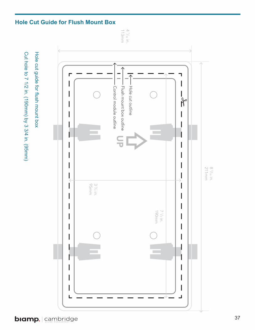
Flush Mount with Supplied BoxCut hole in wall to dimensions x by x (use template) and run cables to this hole. After the cables have been run to the hole in the wall, place the flush mount box in the wall (make sure up is actually up) and snap the four clips that clamp to the back side of the drywall surface . Then attach the case rear to the wall adapter . During installation it may be convenient to attach the wires to the tie-off point in the back of the box to prevent the wires from falling back into the wall .

20
Surface Mount on a Suitable 4-gang Electrical Box (3-gang Using EU/UK Hardware)4-gang electrical box (pre-installed or retrofitted) – after the cables have been run to the box, use four supplied screws to attach the wall plate adapter . (In the case of EU 3-gang boxes, use M3 or M3 .5 screws as needed – these are not included.) Then attach the system back to the wall adapter.
NOTE: The wall plate adaptor is ABS plastic and may be painted to match wall color . Use a standard
spray primer (Krylon) before painting.
21
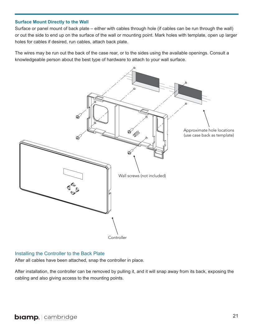
Surface Mount Directly to the WallSurface or panel mount of back plate – either with cables through hole (if cables can be run through the wall) or out the side to end up on the surface of the wall or mounting point . Mark holes with template, open up larger holes for cables if desired, run cables, attach back plate .
The wires may be run out the back of the case rear, or to the sides using the available openings . Consult a knowledgeable person about the best type of hardware to attach to your wall surface .
Installing the Controller to the Back PlateAfter all cables have been attached, snap the controller in place .
After installation, the controller can be removed by pulling it, and it will snap away from its back, exposing the cabling and also giving access to the mounting points .
22
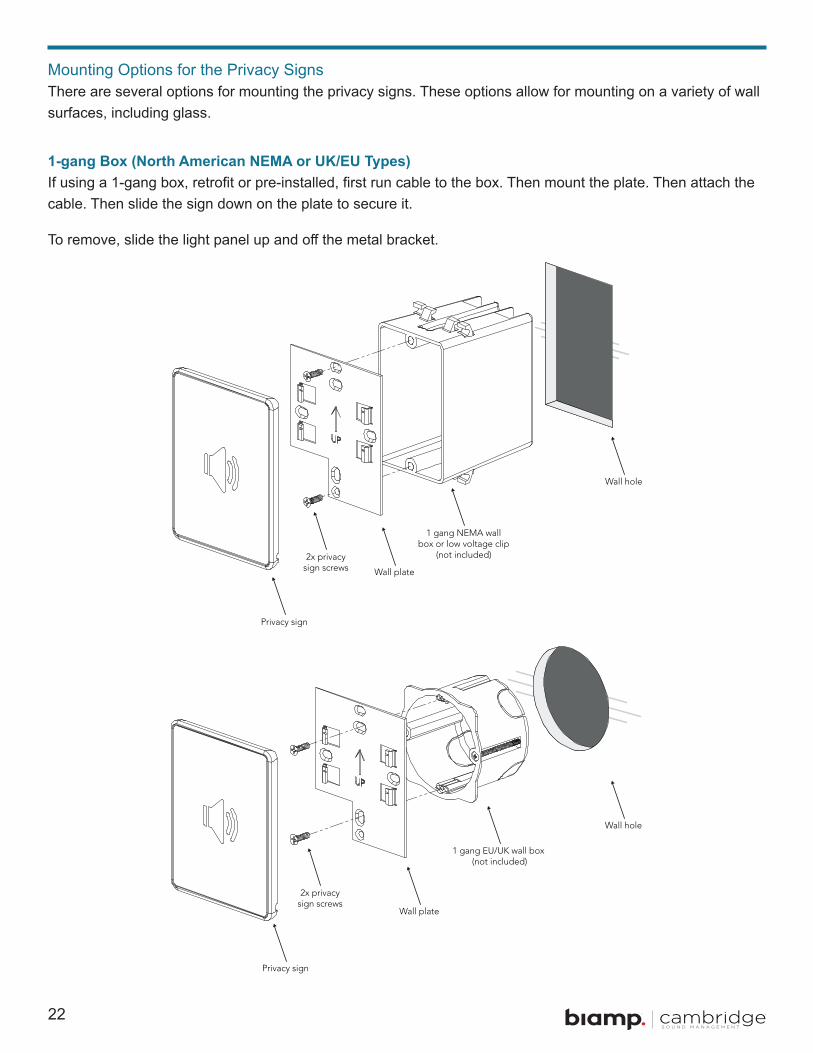
Mounting Options for the Privacy SignsThere are several options for mounting the privacy signs . These options allow for mounting on a variety of wall surfaces, including glass .
1-gang Box (North American NEMA or UK/EU Types)If using a 1-gang box, retrofit or pre-installed, first run cable to the box. Then mount the plate. Then attach the cable . Then slide the sign down on the plate to secure it .
To remove, slide the light panel up and off the metal bracket.

23
Surface Mount (Double-Sided Tape), with Cabling Running Through Wall or on Surface of WallIf running a cable through the wall, get this into position first. Note that the exit point for the cable on the back of the sign is centered across the bottom .
Connect the cable using the push terminals . Peel the double sided tape and attach the panel .
REMEMBER TO CHECK ALL CONNECTIONS AND CONFIRM PRIVACY SIGN OPERATION BEFORE ATTACHING TO WALL . !

24
Mounting on Glass Plus Using “Hider” Plate for Other Side of Glass SurfaceBest practices: it’s best to use self-adhesive tape, NOT a 1-gang box (because of sound transmission issues).
If mounting the signs to either side of the same wall, don’t locate the boxes closer than 2 ft . from each other .
The self-adhesive pads are very strong - take care in placing as moving after placement may be difficult. Also note, special care may be required if mounting to glass with an adhesive film coating.
NOTE: The hider plate is ABS plastic and may be painted to a desired color if needed . Use a standard spray primer (Krylon) before painting.
!
25
System Configuration Via the Front PanelAfter the Qt CRE is mounted and the emitters have been tested, it is time to configure the Qt CRE for general operation . The front panel display shows system information and allows for adjustment of the masking and the auxiliary audio input levels .
The Qt CRE controller has two operating modes:
• User Mode – Simple controls, no adjustment or set-up access .• Set-up Mode – Installer set-up adjustments . Accessible only by special key press (holding down the OFF
and ON buttons for 5 seconds).
System InformationInitial display of the front panel, shown below, shows the software version and system status .
This display is followed with this:
The system always boots up into User Mode, and will always return to the last used setting on power up (on/off/low/high).
26
User ModeUser Mode gives minimal functionality and simple intuitive display read-outs . It has the following options:
• NORMAL Correct level for speech privacy in the conference room• LOW Optional lower level masking
• ON Turns system on to last used level (normal or low)• OFF Mutes masking
In all cases the level ramps to the new level over an installer settable time span (“ramp time” in seconds). While ramping the displayed characters and the panel lights blink . After ramp, masking is played at NORMAL or LOW level based on what was set during installation .
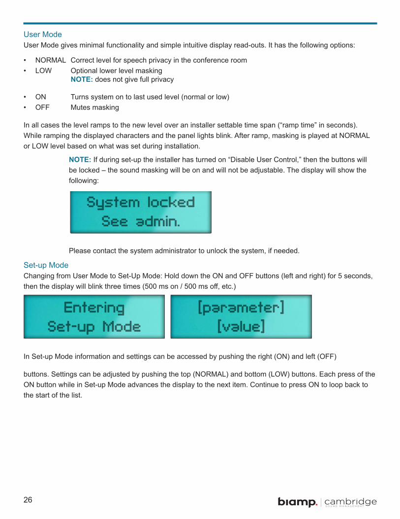
Set-up ModeChanging from User Mode to Set-Up Mode: Hold down the ON and OFF buttons (left and right) for 5 seconds, then the display will blink three times (500 ms on / 500 ms off, etc.)
In Set-up Mode information and settings can be accessed by pushing the right (ON) and left (OFF)
buttons. Settings can be adjusted by pushing the top (NORMAL) and bottom (LOW) buttons. Each press of the ON button while in Set-up Mode advances the display to the next item . Continue to press ON to loop back to the start of the list .
NOTE: does not give full privacy
NOTE: If during set-up the installer has turned on “Disable User Control,” then the buttons will be locked – the sound masking will be on and will not be adjustable . The display will show the following:
Please contact the system administrator to unlock the system, if needed .
27
Setting Default Value OptionsGeneral InfoNormal Masking Level 18 range up to 30Low Masking Level 8 rangle up to current Normal Masking Level
settingInput a Level 15 range up to 30Ramp Up Speed (seconds) 30 seconds range 0 to 120 secondsRamp Down Speed (seconds) 5 seconds range 0 to 120 secondsContact Closure Ramp Up Speed (seconds) 30 seconds range 0 to 120 secondsContact Closure Ramp Down Speed (seconds) 0 seconds range 0 to 120 secondsDisable User Control OFF OFF or ON -- enables/disables front panel
controls -- if Default value is ON, then sound masking runs all the time .
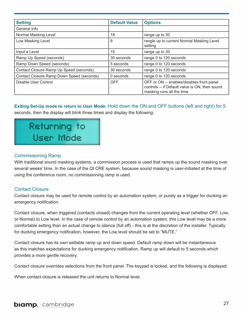
Exiting Set-Up mode to return to User Mode: Hold down the ON and OFF buttons (left and right) for 5seconds, then the display will blink three times and display the following:
Commissioning RampWith traditional sound masking systems, a commission process is used that ramps up the sound masking over several weeks’ time . In the case of the Qt CRE system, because sound masking is user-initiated at the time of using the conference room, no commissioning ramp is used .
Contact ClosureContact closure may be used for remote control by an automation system, or purely as a trigger for ducking an emergency notification.
Contact closure, when triggered (contacts closed) changes from the current operating level (whether OFF, Low, or Normal) to Low level. In the case of remote control by an automation system, this Low level may be a more comfortable setting than an actual change to silence (full off) - this is at the discretion of the installer. Typically for ducking emergency notification, however, the Low level should be set to “MUTE.”
Contact closure has its own settable ramp up and down speed . Default ramp down will be instantaneous as this matches expectations for ducking emergency notification. Ramp up will default to 5 seconds which provides a more gentle recovery .
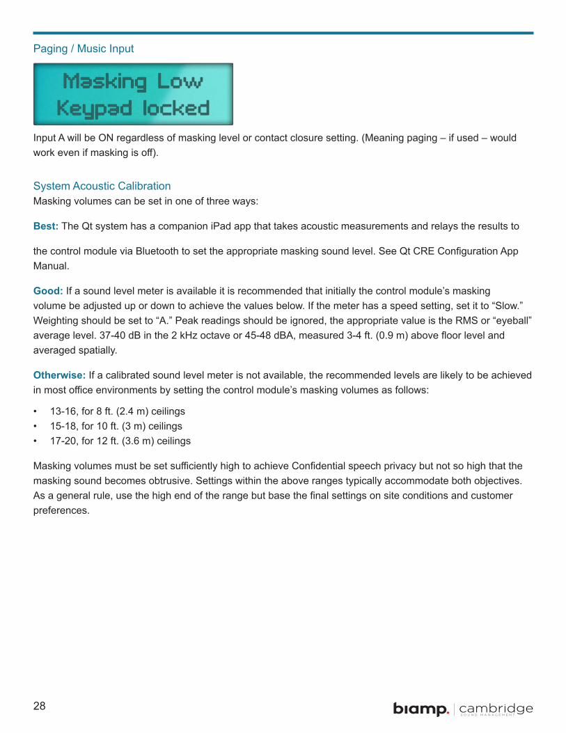
Contact closure overrides selections from the front panel . The keypad is locked, and the following is displayed:
When contact closure is released the unit returns to Normal level .
28
Paging / Music Input
Input A will be ON regardless of masking level or contact closure setting . (Meaning paging – if used – would work even if masking is off).
System Acoustic CalibrationMasking volumes can be set in one of three ways:
Best: The Qt system has a companion iPad app that takes acoustic measurements and relays the results to
the control module via Bluetooth to set the appropriate masking sound level. See Qt CRE Configuration App Manual .
Good: If a sound level meter is available it is recommended that initially the control module’s masking volume be adjusted up or down to achieve the values below. If the meter has a speed setting, set it to “Slow.” Weighting should be set to “A.” Peak readings should be ignored, the appropriate value is the RMS or “eyeball” average level. 37-40 dB in the 2 kHz octave or 45-48 dBA, measured 3-4 ft. (0.9 m) above floor level and averaged spatially .
Otherwise: If a calibrated sound level meter is not available, the recommended levels are likely to be achieved in most office environments by setting the control module’s masking volumes as follows:
• 13-16, for 8 ft. (2.4 m) ceilings• 15-18, for 10 ft. (3 m) ceilings• 17-20, for 12 ft. (3.6 m) ceilings
Masking volumes must be set sufficiently high to achieve Confidential speech privacy but not so high that the masking sound becomes obtrusive . Settings within the above ranges typically accommodate both objectives . As a general rule, use the high end of the range but base the final settings on site conditions and customer preferences .
29
Special Installation CasesWhen to leave sound masking on continuously: There are cases where leaving the masking on continuously will minimize awareness of its operation . If the masking level in the emitter-covered area needed to adequately mask speech from the conference room into adjacent space is determined to be below 40 dBA we suggest leaving it on 24/7 . This normally will be feasible only with very good sound isolating construction between the conference room and adjoining spaces. Likewise, if a separate office-wide masking system is already in place and the QtCRE is intended merely to provide an extra margin of confidentiality around the sensitive space it can normally be left on continuously .
Adjacent conference rooms: If adjacent conference rooms are separated solely by sufficiently poor sound isolating construction (lightweight “accordion” doors or those with poor or no seals at the top and bottom or low quality lightweight or sound “leaky” demountable walls) it may not be feasible to obtain adequate privacy between them, whether or not sound masking is installed around their perimeter . The solution in these cases is to upgrade the party construction, not to add sound masking within or outside the rooms . If a listener can understand speech easily in one room from a strong voiced talker in the other with no masking, it is a good indication that confidential speech probably will not be attainable between the two rooms. However, in some cases involving only small conference rooms separated by at least fair isolating construction, sound masking within the rooms may provide an adequate solution . Other markers for poor isolating construction are low density glass fiber acoustical ceilings within the rooms, especially if their party walls don’t extend completely to the deck above or if there is no other plenum barrier above the party wall, and air return plenums common to both rooms. Another is unlined inside air ducts serving both rooms which act as “speaking” tubes. Ducts with exterior lining only will still act as speaking tubes since speech sound is transmitted through the interior of the ducts, not along the exterior .
Conference rooms with open walls or open conference areas: It is not feasible to assure confidential privacy in an open plan office if a source room where speech originates has open or partial height walls. The best that should be expected is Normal privacy, meaning freedom from distraction and that conversations still may be overheard by an intentional eavesdropper .
Adjacent private offices: In cases where masking is applied to a private office near a conference room, it may be appropriate to keep the same sound masking levels in that office. However, if lower levels are required, use the level trim settings on the back of the emitters in that office – typically the -6 dB setting would be used. Check to make sure the lower level is not compromising the privacy of the conference room .
30
Troubleshooting
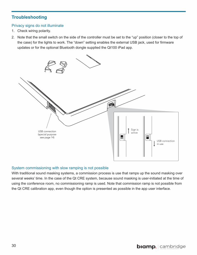
Privacy signs do not illuminate1 . Check wiring polarity .
2 . Note that the small switch on the side of the controller must be set to the “up” position (closer to the top of the case) for the lights to work. The “down” setting enables the external USB jack, used for firmware updates or for the optional Bluetooth dongle supplied the Qt100 iPad app .
System commissioning with slow ramping is not possibleWith traditional sound masking systems, a commission process is use that ramps up the sound masking over several weeks’ time . In the case of the Qt CRE system, because sound masking is user-initiated at the time of using the conference room, no commissioning ramp is used . Note that commission ramp is not possible from the Qt CRE calibration app, even though the option is presented as possible in the app user interface .

31
Error Codes and Clear ErrorSystem errors are shown on the control module front panel display. If an error occurs, the message “Status: Error” will be displayed. To determine the cause of the error, press NEXT (right arrow button), to display the error code .
Error CodesIf one or more errors exist in the sound masking system, an eight-digit error code is displayed on the LCD display (scroll forward to the “Error” screen):
Where a number other than 0 indicates an error .
ExamplesError: 0_000001: Short sensed in the wiring of the zone . Error: 0-000004: Emitter not working Error: 2_000000: Over temperature Error: 4-000000: Intermittent fault Error: 8-000000: Contact the Manufacturer
Clearing Error CodesTo clear an error that is currently shown on the display:
1 . Press the right arrow button on the front panel to see the error code .
2 . Press the up arrow to clear the error code .
3 . If the error still persists, the problem has not been resolved .
4 . If you are not sure how to resolve the problem, contact support@cambridgesound .com .
Error: 0_000000
Error Code for Zone 1
Reserved
Error Code for Control Module

32
Post-Installation HandoffPerform a final walk through to satisfy all aspects of the system performance:
1 . Fill out the settings record .
2 . Store guide with completed settings record near the control module . If there is a hard module failure, the recorded values can be used to reconfigure the system. System settings are retained after a power outage.
3 . Lock the control module panel by holding down the left and right buttons for 5 seconds .
If you need assistance installing or commissioning this Qt 100 sound masking system, please contact CSM support at:
1 800 219 8199 (Toll free within US & Canada)
617 349 3779 (Outside US & Canada)
support@cambridgesound com
www.cambridgesound.com/support
33
WarrantyNote: This equipment has been tested and found to comply with the limits for a Class A digital device, pursuant to part 15 of the FCC Rules . These limits are designed to provide reasonable protection against harmful interference when the equipment is operated in a commercial environment . This equipment generates, uses, and can radiate radio frequency energy and, if not installed and used in accordance with the instruction manual, may cause harmful interference to radio communications . Operation of this equipment in a residential area is likely to cause harmful interference in which case the user will be required to correct the interference at his own expense .
Modifications not expressly approved by the manufacturer could void the user’s authority to operate the equipment under FCC rules .
Warranty Coverage — Qt® Emitters
Cambridge Sound Management, Inc. (the “warrantor”) will, for a period of five (5) years, starting with the date of purchase, warrant that the Qt® Emitters (the “speakers”) will be free of defects in materials and workmanship that interfere with proper operation as a sound masking, paging and music speaker system . During that period, the warrantor will, at its option, either (a) repair the speaker, or (b) replace the speaker. The decision to repair or replace will be made by the warrantor .
Warranty Coverage — ST 1000 control unit
The warrantor will, for a period of five (5) years, starting with the date of purchase, warrant that the Qt control unit (the “system”) will be free of defects in materials and workmanship that interfere with its proper operation as a sound masking, paging and music distribution control system . During that period, the warrantor will, at its option, either (a) repair the system, with new or refurbished parts, or (b) replace the system with a new or refurbished system of equal functionality at no charge . The decision to repair or replace will be made by the warrantor .
All software installed in the Qt system is warranted to substantially conform to its published specifications. In no event does the warrantor warrant that the software is error free or that the customer will be able to operate the software without problems or interruptions . The warrantor will, from time to time, make available software bug fixes. It is the responsibility of the purchaser to download and install these software modifications.
Except for the forgoing, all software and software upgrades are provided AS IS .
The following terms apply to all purchases:
These warranty terms are extended only to the original purchaser of a new product . A purchase order or other proof of the original purchase date and purchaser is required for warranty service .
Obtaining warranty repairs:
Please access and review online help resources for the product before requesting warranty service . If the product is still not functioning properly after making use of these resources, please contact Cambridge Sound Management for a return authorization number . All returns are to be prepaid . The warrantor will pay return surface freight within the continental United States on warranty repairs . All customs and freight charges in excess of surface freight within the United States will be borne by the purchaser .

34
Warranty Limits and Exclusions
This warranty ONLY COVERS failures due to defects in materials or workmanship, and DOES NOT COVER normal wear and tear or cosmetic damage. THIS WARRANTY DOES NOT COVER USE OF THE SYSTEM WITH ANY OTHER SPEAKER OR EMITTER MANUFACTURED BY ANY ENTITY, ORGANIZATION OR COMPANY OTHER THAN CAMBRIDGE SOUND MANAGEMENT, INC. OR USE OF THE SYSTEM FOR ANY PURPOSE OTHER THAN SOUND MASKING AND/OR PAGING AND/OR MUSIC DISTRIBUTION. THIS WARRANTY DOES NOT COVER THE USE OF ANYTHING OTHER THAN CAT-3 OR EQUIVALENT, 24 GAUGE CABLING. The warranty ALSO DOES NOT COVER damages that occurred in shipment, failures that are caused by products not supplied by the warrantor (e.g., replacement power supplies) or failures that result from accidents, misuse, abuse, neglect, mishandling, misapplication, alteration of any sort, installation, use as a system driver during speaker installation, set-up adjustments, misadjustment of controls, improper maintenance, power line surge, lightning damage, power surges, modification, rental use, service by anyone other than the warrantor or damage that is attributable to acts of God .
THERE ARE NO EXPRESS OR IMPLIED WARRANTIES EXCEPT AS LISTED UNDER “WARRANTY COVERAGE.” THE WARRANTOR IS NOT LIABLE FOR ANY INCIDENTAL OR CONSEQUENTIAL DAMAGES RESULTING FROM THE USE OF THE PRODUCT OR ARISING OUT OF ANY BREACH OF THIS WARRANTY. As an example, this specifically excludes damages for lost time, lost use of the system, cost of removal or reinstallation of the system or travel to and from the purchaser’s location . ALL EXPRESS AND IMPLIED WARRANTIES ARE LIMITED TO THE PERIOD OF THE WARRANTY.
This warranty provides specific legal rights, and there may be others that vary from state to state or in the country of compliant use .
Therefore, certain additional exclusions may apply .
35
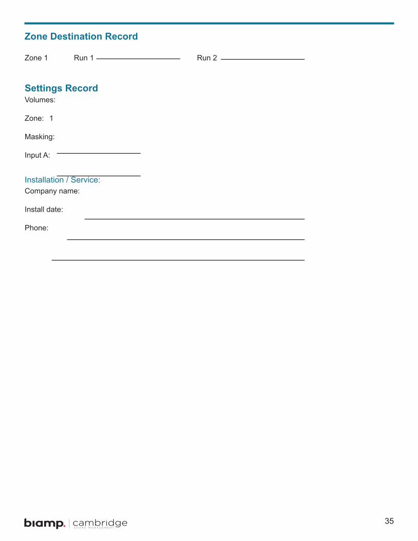
Zone Destination Record Zone 1 Run 1 Run 2
Settings RecordVolumes:
Zone: 1
Masking:
Input A:
Installation / Service:Company name:
Install date:
Phone:

37
Hole Cut Guide for Flush Mount Box
Hole cut guide for flush m
ount box
Cut hole to 7 1/2 in. (190m
m) by 3 3/4 in. (95m
m)


39
Hole Cut Guide for Privacy Sign
Cut hole wire 1/4 in (6mm) from lower edge of sign.
Hole shape is not important, but be careful to stay within area to be covered by sign .
REMEMBER TO CHECK ALL CONNECTIONS AND CONFIRM PRIVACY SIGN OPERATION BEFORE ATTACHING TO WALL .!


41
AddendumThis two page document is an addendum to the Qt® Conference Room Edition manual . Please read .
NOTE: Below are supplemental images for the content contained on page 15 of the Qt® Conference Room Edition manual .
Connection to privacy signsRun a separate cable from the controller mounting location to each lighting location . Do not daisy chain signs as this may cause the light to be of different brightness. Two 50-ft. (15.2 m) plenum rated cables are provided with the kit .
Panel 1
GND
Panel 2
GND -
Control
GND -
42
cambridgesound.com 800.218.8199
Qt and QtPro are either trademarks or registered trademarks of Biamp Systems, LLC in the United States and other countries. Other product names referenced may be trademarks or registered marks of their respective owners and Biamp Systems is not affiliated with or sponsored by these companies. All specifications are subject to change.
Visit cambridgesound.com for the latest specification information.
NOTE: Two new options have been added to the program menu of the Qt® Conference Room Edition . These options are outlined below:
1 . Contact Closure = Normal/Off or Normal/Low. When this option is set to “Normal/Off”, the contact switch will toggle between Normal Volume (Contact Open) and Off (Contact Closed). When this option is set to “Normal/Low”, the contact switch will toggle between Normal Volume (Contact Open) and Low Volume (Contact Closed).
2 . Disable OFF Button = On or Off. This option allows the user to disable the Off Button on the front panel of the Qt-CRE .