quadguard installation manual - winnipeg · tension strut backup installation (figure 16) locate...
TRANSCRIPT

The City of Winnipeg Bid Opportunity No. 516-2014 Template Version: C420131129 - RW
APPENDIX ‘C’
QUADGUARD II PRODUCT MANUAL

QuadGuard® System
The World Wide Standard In Crash Cushions
Inst
alla
tion M
anual
Corporate Offices:35 East Wacker Dr., 11th FloorChicago, IL 60601-2076Telephone: (312) 467-6750FAX: (312) 467-1356http://www.energyabsorption.com/
Engineering and Manufacturing Facilities:Rocklin, CAPell City, AL
A Quixote CompanySaving Lives By Design
ENERGY ABSORPTIONSYSTEMS, INC.

QuadGuard® System
2
ImporImporImporImporImportant Intrtant Intrtant Intrtant Intrtant Introductoroductoroductoroductoroductory Notesy Notesy Notesy Notesy NotesProper installation of the QuadGuard System is essentialto assure maximum performance. Take the time to re-view the installation instructions and product limitationsthoroughly before performing the necessary work. Donot attempt to install any crash cushion without the properplans and installation manual from the manufacturer.
If you need additional information, or have questionsabout the QuadGuard System, please call Energy Absorp-tion Systems’ Customer Service Department at(888) 323-6374.
TTTTTable of Contentsable of Contentsable of Contentsable of Contentsable of Contents
System Overview ......................................................................................................................................... 2Installation ................................................................................................................................................... 3
Required Tools ....................................................................................................................................... 3QuadGuard Systems for Narrow Hazards .............................................................................................. 7
Site Preparation/Foundation ............................................................................................................ 8Installation Procedures .................................................................................................................... 9
QuadGuard Systems for Wide Hazards ................................................................................................ 27Site Preparation/Foundation .......................................................................................................... 28Installation Procedures .................................................................................................................. 29
MP-3® Polyester Anchoring System .................................................................................................... 51Vertical Installations ...................................................................................................................... 51Horizontal Installations .................................................................................................................. 52MP-3 Installation Cautions ............................................................................................................ 53
Maintenance and Repair ............................................................................................................................ 54Limitations And Warnings ......................................................................................................................... 62
SSSSSystem Ovystem Ovystem Ovystem Ovystem OvererererervievievievieviewwwwwThe QuadGuard System is a highly efficient, redirective,non-gating crash cushion for hazards ranging in widthfrom 610 mm to 3200 mm (2' to 10.5'). It consists ofcrushable, energy-absorbing cartridges surrounded by aframework of Quad-BeamTM panels.
The QuadGuard System utilizes two types of cartridges ina "staged” configuration to address both lighter cars andheavier, high center-of-gravity vehicles. Its modular de-sign allows the System length to be tailored to the designspeed of a site. Refer to the QuadGuard Product Manualto determine the appropriate length System for a givendesign speed.
Crash PCrash PCrash PCrash PCrash PerferferferferformanceormanceormanceormanceormanceThe 6 bay QuadGuard System has successfully passedthe NCHRP 350, Test Level 3 tests with both the light carand pickup truck at speeds up to 100 km/h (62 mph) atangles up to 20 degrees.
During head-on impacts, the QuadGuard System tele-scopes rearward and crushes to absorb the energy of im-pact. When impacted from the side, it safely redirects thevehicle back toward its original travel path and away fromthe hazard.
RETURN GOODS POLICY
Before returning any goods for credit please contactEnergy Absorption Systems Inc. Customer Service De-partment at 1-888-323-6374 or your local distributorfor proper instructions.

3
QuadGuard® System
ReqReqReqReqRequired uired uired uired uired TTTTToolsoolsoolsoolsoolsDocumentation
• Manufacturer’s Installation Manual
• Manufacturer's Drawing Package
Cutting equipment
• Rebar Cutting Bit
• 22 mm (7/8") Concrete Drill Bits (*Two Fluted)
• Grinder, Hacksaw or Torch (optional)
• Drill Motor
• Drill Bits: 1/16" through 7/8"
* Energy Absorption Systems recommends using twofluted drills to achieve optimum tensile strength wheninstalling the MP-3 anchoring system.
Hammers
• Roto Hammer
• Sledgehammer
• Standard Hammer
Wrenches
• Heavy Duty Impact Wrench
• Standard adjustable wrench
• 1/2" drive sockets: 9/16", 11/16", 3/4", 15/16",1 1/8", 1 1/4"
• Deep Sockets: 5/16", 1 1/4"
• Ratchet and attachments for the above sockets
• Breaker Bar: 1/2" x 24"
• Torque Wrench: 200 ft-lbs.
• Crescent Wrench: 300 mm [12"]
• Allen Wrench: 3/8"
• Impact Wrench: 1/2"
Personal protective equipment
• Protective Eyewear
• Gloves
Miscellaneous
• Traffic Control Equipment
• Lifting and Moving Equipment (A lifting deviceis preferred although a forklift can be used.) Mini-mum 5,000 lb. capacity required.
• Compressor (100 psi) and Generator (5 KW)
• Long Pry Bar
• Drift Pin 300 mm [12"]
• Center Punch
• Tape Measure 7.5 m (25')
• Chalk Line
• Concrete Marking Pencil
• Nylon bottle brush for cleaning 7/8" drilled holes
• Rags, Water, and Solvent for Touch-up
Note: The above list of tools is a general recommen-dation. The actual number of tools required willdepend on specific site conditions and the com-plexity of the installation.
InstallationInstallationInstallationInstallationInstallation

QuadGuard® System
4
Installation (cont’Installation (cont’Installation (cont’Installation (cont’Installation (cont’d.)d.)d.)d.)d.)
1 Cartridge
2 Diaphragm
3 Quad-Beam™ Fender Panel
Figure 1 - Plans & Elevation
QU
AD
GU
AR
D S
YS
TE
MF
OR
NA
RR
OW
HA
ZA
RD
SQ
UA
DG
UA
RD
SY
ST
EM
FO
R W
IDE
HA
ZA
RD
S
4 Nose Cover
5 Monorail
6 Backup
61616161610 mm [24"]0 mm [24"]0 mm [24"]0 mm [24"]0 mm [24"]
760 mm [30"]
915 mm [36"]
1755 mm [69"]
Key
2285 mm [90"]
(Six bay Systems with Tension Strut Backups shown)
6740 mm [22'-1 3/8"]
3200 mm [126"]
5
QuadGuard® System
Figure 2
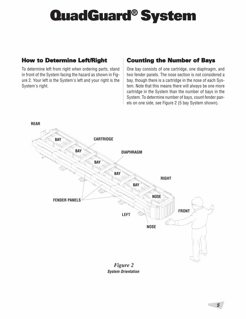
HoHoHoHoHow to Determine Lefw to Determine Lefw to Determine Lefw to Determine Lefw to Determine Left/Rightt/Rightt/Rightt/Rightt/RightTo determine left from right when ordering parts, standin front of the System facing the hazard as shown in Fig-ure 2. Your left is the System's left and your right is theSystem's right.
Counting the Number of BaCounting the Number of BaCounting the Number of BaCounting the Number of BaCounting the Number of BaysysysysysOne bay consists of one cartridge, one diaphragm, andtwo fender panels. The nose section is not considered abay, though there is a cartridge in the nose of each Sys-tem. Note that this means there will always be one morecartridge in the System than the number of bays in theSystem. To determine number of bays, count fender pan-els on one side, see Figure 2 (5 bay System shown).
FRONT
RIGHT
LEFT
REAR
FENDER PANELS
NOSE
System Orientation
BAY
BAY
BAY
BAY
BAY
NOSE
CARTRIDGE
DIAPHRAGM

QuadGuard® System
6
Installation (cont’Installation (cont’Installation (cont’Installation (cont’Installation (cont’d.)d.)d.)d.)d.)
The nominal width of a System with tension strutbackup is the width between side panels behind thebackup (see Figure 3).
The nominal width of a System with concrete backupis the width of the concrete backup at location shownin Figure 4.
The outside width of the System is approximately150 mm [6"] to 230 mm [9"] wider than the nominalwidth. The width of the System is not the same asthe width of the backup.
Figure 4
TENSION STRUT BACKUP
Figure 3
CONCRETE BACKUP
Width of System with Concrete BackupWidth of System with Tension Strut Backup
Measuring Measuring Measuring Measuring Measuring The The The The The WidthWidthWidthWidthWidthThe QuadGuard System is available in six nominal widths:
• 610 mm [24"]
• 760 mm [30"]
• 915 mm [36"]
• 1755 mm [69"]
• 2285 mm [90"]
• 3200 mm [126"]

7
QuadGuard® System
QUQUQUQUQUADGUADGUADGUADGUADGUARD SARD SARD SARD SARD SYYYYYSSSSSTEMSTEMSTEMSTEMSTEMSFOR NARROW HAZARDS
610 mm [24"] MODEL NO. QS24_ _
762 mm [30"] MODEL NO. QS30_ _
914 mm [36"] MODEL NO. QS36_ _

QuadGuard® System
8
Site PSite PSite PSite PSite Preparation/Freparation/Freparation/Freparation/Freparation/FoundationoundationoundationoundationoundationA QuadGuard System should be installed only on an ex-isting or freshly placed and cured concrete base (28 MPa[4000 psi] minimum). Location and orientation of theconcrete base and attenuator must comply with projectplans or as otherwise determined by the resident projectengineer.
Recommended dimension and reinforcement specifica-tions for new concrete pads are provided in Energy Ab-sorption Systems, Inc. concrete pad drawings, suppliedwith the System. System may be installed on concreteroadway (minimum 200 mm [8"] thick). Installation crossslope shall not exceed 8% (see figure 5) and should notvary (twist) more than 2% over the length of the System;the pad surface shall have a light broom finish.
Caution: Accurate placement of all steel re-bar is critical to avoid interference with theconcrete Anchor Bolts.
WARNING!Location of the backup in relation to nearby objects willaffect the operation of the attenuator. Upon impact, thefender panels telescope toward and extend beyond therigid backup as much as 760 mm [30"] from their pre-impact location. Position the backup so that the rearends of the last fender panels are a minimum of 760 mm[30"] forward of objects that would otherwise interferewith movement of the panels. Failure to comply withthis requirement may result in impaired Systemperformance offering motorists less protection andcause component damage.
Installation fInstallation fInstallation fInstallation fInstallation for Narror Narror Narror Narror Narrooooow Hazards (cont’w Hazards (cont’w Hazards (cont’w Hazards (cont’w Hazards (cont’d.)d.)d.)d.)d.)
Figure 5
LEVELING PAD(SHOWN EXAGGERATEDFOR CLARITY)
8% (5O) (12:1)MAXIMUM
Cross-Slope

9
QuadGuard® System
Inspect ShippingInspect ShippingInspect ShippingInspect ShippingInspect ShippingBefore installing the QuadGuard System, check the re-ceived parts against the shipping list supplied with Sys-tem. Make sure all parts have been received.
Figure 6
WIDTHVARIES*
Tension Strut Backup
WIDTHVARIES*
*610 mm [24"]*760 mm [30"]*915 mm [36"]
QUAD-BEAM™ TO W-BEAMTRANSITION PANEL
Figure 8Transitioning the QuadGuard System
Figure 7Concrete Backup
Installation PInstallation PInstallation PInstallation PInstallation PrrrrroceduresoceduresoceduresoceduresoceduresNote: The drawing package supplied with theQuadGuard System must be used with these in-structions for proper assembly and should takeprecedence over these general instructions.
1) Determine Backup and Transition TypeThe System is available with a tension strut backupor a concrete backup. Refer to figures 6 and 7, alongwith the backup assembly drawing to determinewhich type of backup is being installed.
A transition panel or side panel will be used on eachside of the backup. A side panel is not needed when atransition panel is used. Several types of transitionsare available for use with the QuadGuard System. Re-fer to figures 8 through 13 and the drawing packageto determine which type of panels are being installed.
*610 mm [24"]*760 mm [30"]*915 mm [36"]
Installation fInstallation fInstallation fInstallation fInstallation for Narror Narror Narror Narror Narrooooow Hazards (cont’w Hazards (cont’w Hazards (cont’w Hazards (cont’w Hazards (cont’d.)d.)d.)d.)d.)
QuadGuard® System
10
Installation fInstallation fInstallation fInstallation fInstallation for Narror Narror Narror Narror Narrooooow Hazards (cont’w Hazards (cont’w Hazards (cont’w Hazards (cont’w Hazards (cont’d.)d.)d.)d.)d.)
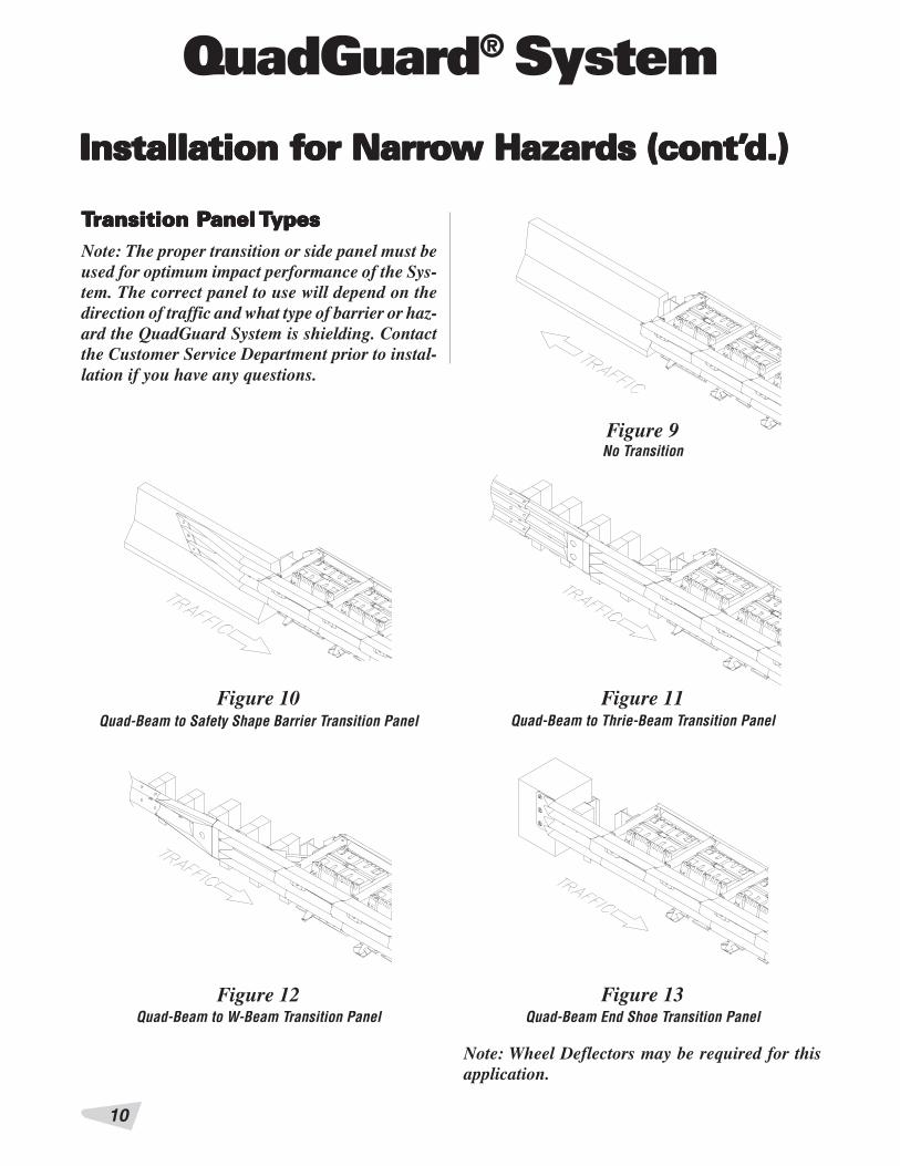
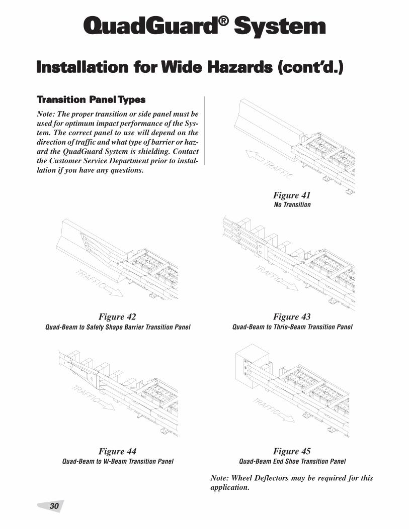
TTTTTransition Pransition Pransition Pransition Pransition Panel anel anel anel anel TTTTTypesypesypesypesypesNote: The proper transition or side panel must beused for optimum impact performance of the Sys-tem. The correct panel to use will depend on thedirection of traffic and what type of barrier or haz-ard the QuadGuard System is shielding. Contactthe Customer Service Department prior to instal-lation if you have any questions.
Figure 11
Figure 12 Figure 13
Figure 10
Note: Wheel Deflectors may be required for thisapplication.
Figure 9No Transition
Quad-Beam to Thrie-Beam Transition PanelQuad-Beam to Safety Shape Barrier Transition Panel
Quad-Beam End Shoe Transition PanelQuad-Beam to W-Beam Transition Panel

11
QuadGuard® System
2) Mark System LocationLocate the centerline of the System by measuringthe proper offset from the hazard. Refer to the draw-ing package supplied with the System. Place chalkline to mark the centerline of the System. Mark aconstruction line parallel to the center line and offset165 mm [6.5"] to one side as shown in Figure 14.The edge of the monorail will be placed on this line.
Note: The concrete pad should be installed per theproject plans supplied with the System.
Figure 14(Top view of concrete pad)Locating Construction Line
165 mm [6.5"]CENTERLINE OF SYSTEM
CONSTRUCTION LINE
WARNING!Location of System with respect to the hazard iscritical and dependent on the type of transitionpanel used. See the project plans supplied with theSystem for details.
Installation fInstallation fInstallation fInstallation fInstallation for Narror Narror Narror Narror Narrooooow Hazards (cont’w Hazards (cont’w Hazards (cont’w Hazards (cont’w Hazards (cont’d.)d.)d.)d.)d.)

QuadGuard® System
12
3a) Anchor the BackupConcrete Backup Installation (Figure 15)
Locate front face plate using the backup assemblydrawing. Drill anchor holes in the concrete backupusing the face plate as a template. Anchor the faceplate to the concrete backup using the MP-3® An-choring System (horizontal kit) supplied with theQuadGuard System (see MP-3 Polyester Anchoring,page 47).
Figure 15Anchoring Backup Face Plate to Concrete Backup
BACKUP FACE PLATE
HORIZONTAL MP-3 KITWITH 3/4" X 6 1/2" STUD
VERTICAL MP-3 KITWITH 3/4" X 7" STUD
TENSION STRUT BACKUP
Figure 16Anchoring Tension Strut Backup to Foundation
Installation fInstallation fInstallation fInstallation fInstallation for Narror Narror Narror Narror Narrooooow Hazards (cont’w Hazards (cont’w Hazards (cont’w Hazards (cont’w Hazards (cont’d.)d.)d.)d.)d.)
FULLY CURED CONCRETE BACKUPSEE DRAWING PACKAGE
3b) Anchor the BackupTension Strut Backup installation (Figure 16)
Locate tension strut backup and monorail on pad withside of monorail on the construction line (see Fig-ure 18). Verify that any applicable transition panelsfit properly before anchoring backup. Drill anchorholes in pad using the backup as template. Anchorthe backup to the concrete pad using the MP-3 verti-cal kits provided. (See “MP-3 Polyester AnchoringSystem” on page 47).
13
QuadGuard® System
WARNING!Every hole and slot in backup and monorail must havean MP-3 stud anchoring it.
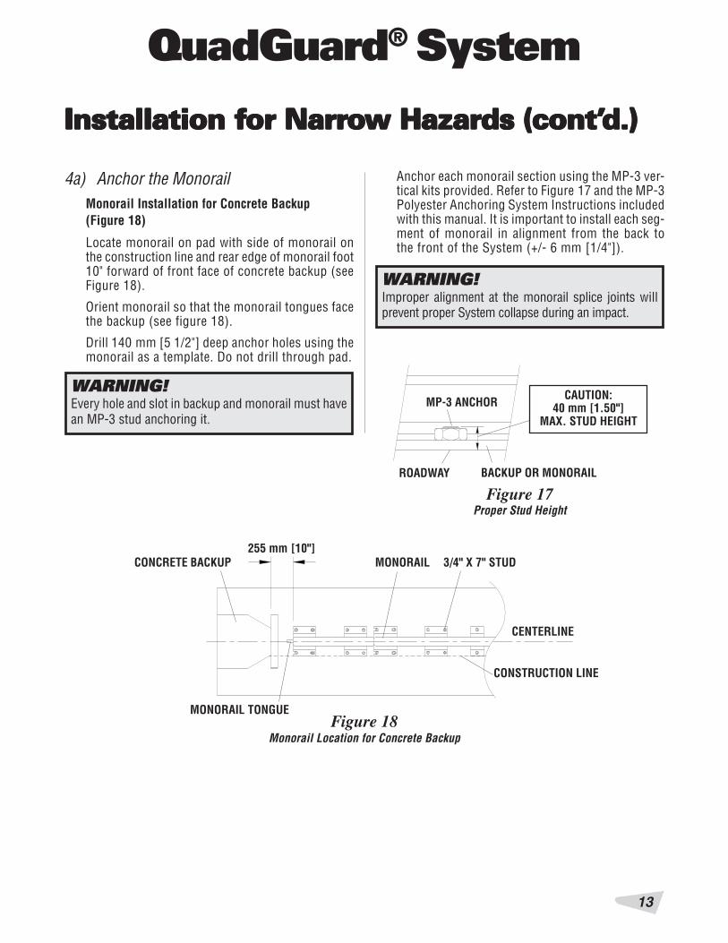
4a) Anchor the MonorailMonorail Installation for Concrete Backup(Figure 18)
Locate monorail on pad with side of monorail onthe construction line and rear edge of monorail foot10" forward of front face of concrete backup (seeFigure 18).
Orient monorail so that the monorail tongues facethe backup (see figure 18).
Drill 140 mm [5 1/2"] deep anchor holes using themonorail as a template. Do not drill through pad.
Figure 18Monorail Location for Concrete Backup
255 mm [10"]CONCRETE BACKUP MONORAIL 3/4" X 7" STUD
CENTERLINE
CONSTRUCTION LINE
CAUTION:40 mm [1.50"]
MAX. STUD HEIGHT
Figure 17
MP-3 ANCHOR
BACKUP OR MONORAILROADWAY
WARNING!Improper alignment at the monorail splice joints willprevent proper System collapse during an impact.
Proper Stud Height
MONORAIL TONGUE
Anchor each monorail section using the MP-3 ver-tical kits provided. Refer to Figure 17 and the MP-3Polyester Anchoring System Instructions includedwith this manual. It is important to install each seg-ment of monorail in alignment from the back tothe front of the System (+/- 6 mm [1/4"]).
Installation fInstallation fInstallation fInstallation fInstallation for Narror Narror Narror Narror Narrooooow Hazards (cont’w Hazards (cont’w Hazards (cont’w Hazards (cont’w Hazards (cont’d.)d.)d.)d.)d.)
QuadGuard® System
14
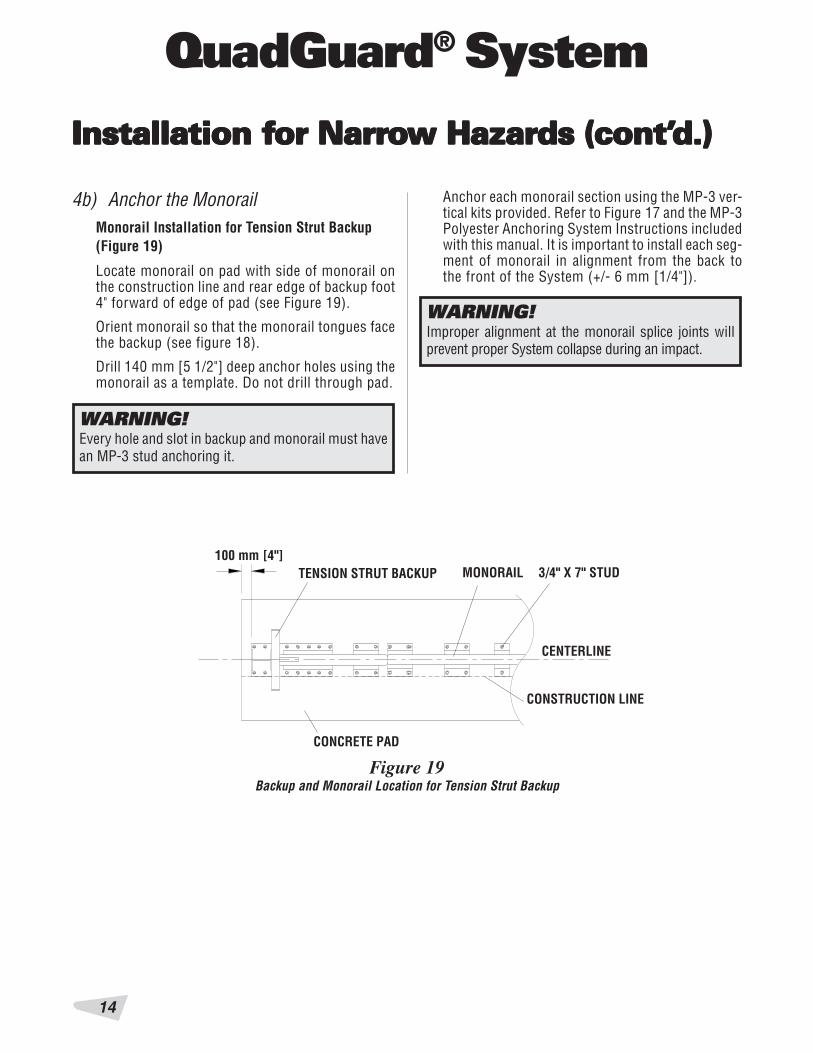
Figure 19Backup and Monorail Location for Tension Strut Backup
100 mm [4"]TENSION STRUT BACKUP MONORAIL 3/4" X 7" STUD
CENTERLINE
CONSTRUCTION LINE
WARNING!Every hole and slot in backup and monorail must havean MP-3 stud anchoring it.
4b) Anchor the MonorailMonorail Installation for Tension Strut Backup(Figure 19)
Locate monorail on pad with side of monorail onthe construction line and rear edge of backup foot4" forward of edge of pad (see Figure 19).
Orient monorail so that the monorail tongues facethe backup (see figure 18).
Drill 140 mm [5 1/2"] deep anchor holes using themonorail as a template. Do not drill through pad.
WARNING!Improper alignment at the monorail splice joints willprevent proper System collapse during an impact.
Anchor each monorail section using the MP-3 ver-tical kits provided. Refer to Figure 17 and the MP-3Polyester Anchoring System Instructions includedwith this manual. It is important to install each seg-ment of monorail in alignment from the back tothe front of the System (+/- 6 mm [1/4"]).
CONCRETE PAD
Installation fInstallation fInstallation fInstallation fInstallation for Narror Narror Narror Narror Narrooooow Hazards (cont’w Hazards (cont’w Hazards (cont’w Hazards (cont’w Hazards (cont’d.)d.)d.)d.)d.)
15
QuadGuard® System
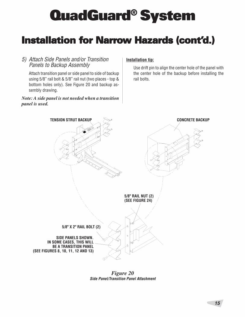
5) Attach Side Panels and/or TransitionPanels to Backup AssemblyAttach transition panel or side panel to side of backupusing 5/8” rail bolt & 5/8” rail nut (two places - top &bottom holes only). See Figure 20 and backup as-sembly drawing.
Note: A side panel is not needed when a transitionpanel is used.
Figure 20Side Panel/Transition Panel Attachment
CONCRETE BACKUP
5/8" RAIL NUT (2)(SEE FIGURE 24)
SIDE PANELS SHOWN.IN SOME CASES, THIS WILL
BE A TRANSITION PANEL(SEE FIGURES 8, 10, 11, 12 AND 13)
TENSION STRUT BACKUP
5/8" X 2" RAIL BOLT (2)
Installation fInstallation fInstallation fInstallation fInstallation for Narror Narror Narror Narror Narrooooow Hazards (cont’w Hazards (cont’w Hazards (cont’w Hazards (cont’w Hazards (cont’d.)d.)d.)d.)d.)
Installation tip:
Use drift pin to align the center hole of the panel withthe center hole of the backup before installing therail bolts.

QuadGuard® System
16
Installation fInstallation fInstallation fInstallation fInstallation for Narror Narror Narror Narror Narrooooow Hazards (cont’w Hazards (cont’w Hazards (cont’w Hazards (cont’w Hazards (cont’d.)d.)d.)d.)d.)
6) Attach Monorail GuidesAttach monorail guides to diaphragm as follows:
Insert 3/4" x 2” G8 hex bolt through monorail guide anddiaphragm, oriented as shown in Figure 21. Secure with3/4" lock washer & 3/4" hex nut (typical 4 places). Seealso diaphragm assembly drawing.
Repeat for each diaphragm.
Figure 21Monorail Guide Attachment
3/4" HEX NUT
3/4" LOCK WASHER
3/4" X 2” G8 HEX BOLTMONORAIL GUIDE
DIAPHRAGM
Figure 23Diaphragm spacing
915 mm [36"] DIAPHRAGMS915 mm [36"]TYPICAL
7) Install DiaphragmsOrient a diaphragm so that the front face of theQuad-Beam shape faces toward the nose of theSystem as shown in Figure 22. Slide one dia-phragm all the way to the backup to ensure theSystem is able to collapse properly during impact.Once this has been verified, slide the diaphragmforward to approximately 915 mm [36"] in frontof the backup. Orient and slide all other diaphragmsonto monorail and position each approximately asshown in Figure 23.
TOWARD NOSE
FRONTBACK
Figure 22Diaphragm Orientation
QUAD-BEAM
FRONT FACE OF BACKUP MONORAIL

17
QuadGuard® System
8) Install Fender PanelsNote: Do not mix the 5/8" rail nuts (large) withthe 5/8" hex nuts (small). See Figure 24.
32 mm [1.25"] 24 mm [0.94"]
Figure 24Rail Nuts are Oversize
5/8" RAIL NUT (LARGE) 5/8" HEX NUT (SMALL)
Figure 25Fender Panel Assembly
DIAPHRAGM
BACKUP OR DIAPHRAGM
5/8" RAIL BOLT
5/8" FLATHEADSOCKET SCREW
MUSHROOM WASHER
FENDER PANEL
SIDE PANEL,FENDER PANEL, ORTRANSITION PANEL
KEEP CENTER HOLE EMPTYFOR NEXT PANEL
SPRING
5/8" FLAT WASHER
5/8" RAIL NUT (LARGE)5/8" RAIL BOLT
Starting at the backup, install left and right fenderpanels as shown in Figure 25, Detail 25a and fenderpanel assembly drawing.
Step 1
Place the fender panel so that the center of the slotof the rearward diaphragm is lined up with the ap-proximate center of the slot in the fender panel.
Attach mushroom washer assembly as shownin Figure 25 and Detail 25a, but do not torque atthis time. (This helps to balance the fender panel.)
Step 2
Slide the fender panel forward until the holes inthe fender panel line up with the holes in the for-ward diaphragm.
Step 3
Use a drift pin to align thecenter hole of the fenderpanel with the center holeof the diaphragm.
Step 4
Attach the front of thefender panels to the nextdiaphragm using two railbolts and large hex nutsper side. Use only the topand bottom holes, leavethe center hole open un-til the next fender panelis installed.
5/8" HEX NUT (SMALL)
5/8" RAIL NUT (LARGE)
Installation fInstallation fInstallation fInstallation fInstallation for Narror Narror Narror Narror Narrooooow Hazards (cont’w Hazards (cont’w Hazards (cont’w Hazards (cont’w Hazards (cont’d.)d.)d.)d.)d.)
QuadGuard® System
18
Installation fInstallation fInstallation fInstallation fInstallation for Narror Narror Narror Narror Narrooooow Hazards (cont’w Hazards (cont’w Hazards (cont’w Hazards (cont’w Hazards (cont’d.)d.)d.)d.)d.)
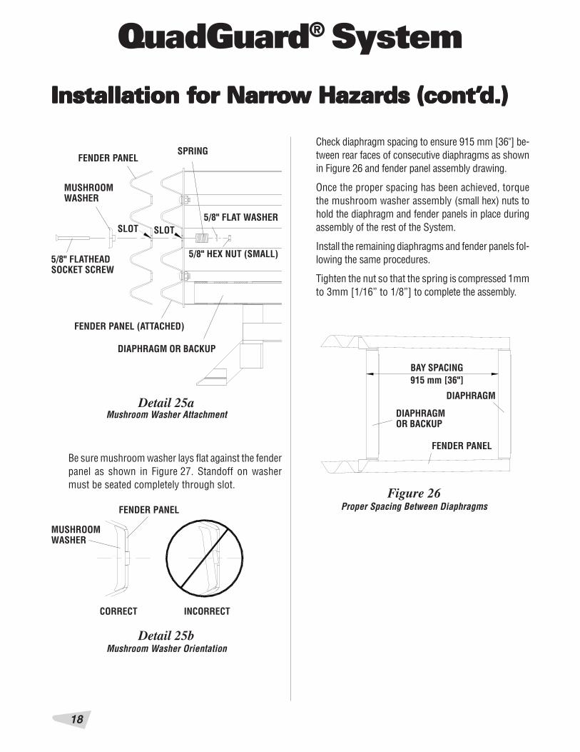
Be sure mushroom washer lays flat against the fenderpanel as shown in Figure 27. Standoff on washermust be seated completely through slot.
Detail 25aMushroom Washer Attachment
FENDER PANEL (ATTACHED)
DIAPHRAGM OR BACKUP
Detail 25bMushroom Washer Orientation
CORRECT INCORRECT
SLOT
BAY SPACING915 mm [36"]
DIAPHRAGMOR BACKUP
DIAPHRAGM
FENDER PANEL
Figure 26Proper Spacing Between Diaphragms
Check diaphragm spacing to ensure 915 mm [36"] be-tween rear faces of consecutive diaphragms as shownin Figure 26 and fender panel assembly drawing.
Once the proper spacing has been achieved, torquethe mushroom washer assembly (small hex) nuts tohold the diaphragm and fender panels in place duringassembly of the rest of the System.
Install the remaining diaphragms and fender panels fol-lowing the same procedures.
Tighten the nut so that the spring is compressed 1mmto 3mm [1/16” to 1/8”] to complete the assembly.
MUSHROOMWASHER
FENDER PANEL
5/8" FLATHEADSOCKET SCREW
MUSHROOMWASHER
FENDER PANELSPRING
5/8" FLAT WASHER
5/8" HEX NUT (SMALL)
SLOT

19
QuadGuard® System
10) Install Cartridge Support BracketsAttach lower cartridge support bracket to front and backof all diaphragms and front of backup as shown in fig-ures 29, 30, diaphragm assembly drawing & backupassembly drawing.
Note: 610 mm [24"] wide Systems do not have sidecartridge support brackets; 762 mm [30"] and914 mm [36"] wide Systems have side cartridge sup-port brackets welded to the backup and diaphragms.
SIDE CARTRIDGESUPPORT BRACKETS
Figure 28Side Cartridge Support Brackets
Figure 29Lower Cartridge Support Bracket Installation
LOWER CARTRIDGESUPPORT BRACKET
LOWER CARTRIDGESUPPORT BRACKET
DIAPHRAGM
DIAPHRAGM
610 mm [24"] WIDE 762 mm [30"] AND915 [36"] WIDE
9) Install End CapUsing 5/8" x 3 1/2" G5 hex bolt, 5/8" hex nut and 5/8"lock washer, attach the end cap to the front of thefirst monorail segment as shown in Figure 27 andmonorail assembly drawing.
Figure 27Monorail End Cap Installation
5/8" X 3 1/2"G5 HEX BOLT
5/8" LOCK WASHER
5/8" HEX NUTEND CAP
MONORAIL
Installation fInstallation fInstallation fInstallation fInstallation for Narror Narror Narror Narror Narrooooow Hazards (cont’w Hazards (cont’w Hazards (cont’w Hazards (cont’w Hazards (cont’d.)d.)d.)d.)d.)

QuadGuard® System
20
Installation fInstallation fInstallation fInstallation fInstallation for Narror Narror Narror Narror Narrooooow Hazards (cont’w Hazards (cont’w Hazards (cont’w Hazards (cont’w Hazards (cont’d.)d.)d.)d.)d.)
Figure 30Lower Cartridge Support Bracket Installation
(Tension Strut Backup)
Figure 31Lower Cartridge Support Bracket
(Concrete Backup)
CARTRIDGE SUPPORTBRACKET IS WELDEDTO FACE PLATE OFCONCRETE BACKUP
FACE PLATE
CONCRETE BACKUP
TENSION STRUT BACKUP
STEP IIINSTALL “KEEPER”
STEP IINSTALL LOWER CARTRIDGESUPPORT BRACKET
LOWER CARTRIDGESUPPORT BRACKET
TENSION STRUT BACKUP
LOWER CARTRIDGESUPPORT BRACKET

21
QuadGuard® System
Installation fInstallation fInstallation fInstallation fInstallation for Narror Narror Narror Narror Narrooooow Hazards (cont’w Hazards (cont’w Hazards (cont’w Hazards (cont’w Hazards (cont’d.)d.)d.)d.)d.)
Detail 32
CARTRIDGE STYLE A CARTRIDGE STYLE B
Adjustable Bracket Locations
11a) Install Nose AssemblyDetermine which style of cartridges your system has.
If your system has cartridge style A as shown in De-tail 32, install cartridge support in the upper two slotsas shown.
If your system has cartridge style B as shown in De-tail 32, install cartridge support in the lower two slotsas shown.
ADJUSTABLEBRACKET TYPE 1
ADJUSTABLEBRACKET TYPE 2
UPPER SLOTS (FOR CARTRIDGE STYLE A)
LOWER SLOTS (FOR CARTRIDGE STYLE B)
UPPER SLOTS (FOR CARTRIDGE STYLE A)
LOWER SLOTS (FOR CARTRIDGE STYLE B)

QuadGuard® System
22
Detail 32c
Detail 32d
Detail 32e
As shown in Detail 32c, cartridge style A is installedwith the adjustable cartridge support bracket incor-rectly in the lower position.
As shown in Detail 32d, cartridge style B is installedwith the adjustable cartridge support bracket incor-rectly in the upper position.
Detail 32e shows the adjustable cartridge supportbracket installed correctly.
Incorrect Installation ofAdjustable Cartridge Support Bracket
Incorrect Installation ofAdjustable Cartridge Support Bracket
Correct Installation ofAdjustable Cartridge Support Bracket
Installation fInstallation fInstallation fInstallation fInstallation for Narror Narror Narror Narror Narrooooow Hazards (cont’w Hazards (cont’w Hazards (cont’w Hazards (cont’w Hazards (cont’d.)d.)d.)d.)d.)

23
QuadGuard® System
Figure 33
PLACE A BOARD OVER THE FIRST TWO DIAPHRAGMS ASSHOWN TO FACILITATE PROPER ALIGNMENT OF NOSE
TIGHTEN NUTS TO 35 mm [25 FT-LBS ]AFTER ALIGNING NOSE AS SHOWN
Adjust Nose
Figure 32
EXISTING5/8" RAIL NUT
NOSE COVER
EXISTING5/8" X 2" RAIL BOLT
1 1/4" X 2" BAR WASHER
FRONT DIAPHRAGM
Nose Assembly
Bolt the nose directly to the front diaphragm,as shown in figures 32, 33 and the nose as-sembly drawing, using six rail bolts whichalso hold the front two fender panels to thediaphragm with bar washer under each bolt.
Place pullout brackets under center nuts.
The top and bottom holes of the nose areslotted to provide adjustment. Adjust sothe top edge of the nose is level with thetop edge of the fender panels, then torqueall six nuts to 35 Nm [25 ft-lbs].
Installation fInstallation fInstallation fInstallation fInstallation for Narror Narror Narror Narror Narrooooow Hazards (cont’w Hazards (cont’w Hazards (cont’w Hazards (cont’w Hazards (cont’d.)d.)d.)d.)d.)

QuadGuard® System
24
Installation fInstallation fInstallation fInstallation fInstallation for Narror Narror Narror Narror Narrooooow Hazards (cont’w Hazards (cont’w Hazards (cont’w Hazards (cont’w Hazards (cont’d.)d.)d.)d.)d.)
11b) For Systems with Optional Nose BeltAssembly
a. Using 5/8" x 5" hex bolt, two 5/8" x 1 3/4" flatwashers and 5/8" hex nut, attach fender panel tofront diaphragm top and bottom as shown in Fig-ure 34 (two places per side).
b. Using 5/8" x 5" hex bolt and 5/8" hex nut, attachpullout bracket to front diaphragm and fenderpanel middle as shown (one place per side).
c. Thread second 5/8" nuts onto the installed bolts.Be sure the face of the nuts are flush with humpson fender panels (see detail 34a). Slide third 5/8"
Figure 34
5/8" X 1 3/4" FLAT WASHER
BELT CLAMP
5/8" X 1 3/4" FLAT WASHER
5/8" X 5" G5 ALLTHREAD HEX BOLT
QUADGUARD NOSE BELT
5/8" HEX NUT
FRONT DIAPHRAGM
e. Align holes in belt clamps with bolts and slidebelt clamps onto bolts.
f. Using fourth 5/8" x 1 3/4" flat washer and third5/8" hex nut, secure the belt clamps and nosebelt (three places per side).
Refer also to nose belt assembly drawing.
x 1 3/4" flat washers onto bolts(three places per side).
d. Align holes in each end of the nosebelt with the installed bolts (threeper side) and slide nose belt ontobolts.
Optional Nose Belt Assembly
Detail 34a
Note: Nose of System may be delineated tocomply with local codes (chevron, reflectivematerial, signs, etc. supplied by others).
THE FACE OF THE NUT TOBE FLUSH WITH HUMPSON FENDER PANEL
Note: Nose alignment shown in figure 33 notnecessary with nose belt assembly.
5/8" X 1 3/4"FLAT WASHER
5/8" HEX NUT
25
QuadGuard® System
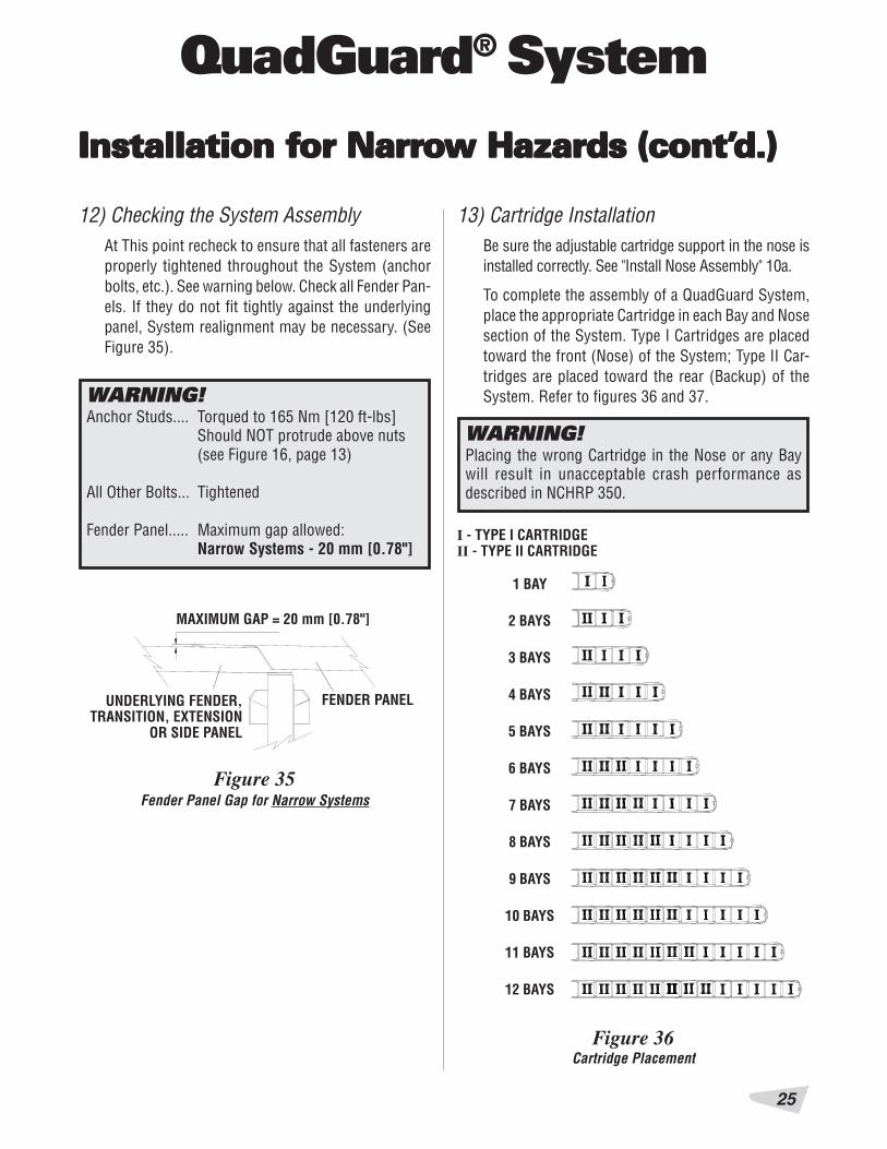
12) Checking the System AssemblyAt This point recheck to ensure that all fasteners areproperly tightened throughout the System (anchorbolts, etc.). See warning below. Check all Fender Pan-els. If they do not fit tightly against the underlyingpanel, System realignment may be necessary. (SeeFigure 35).
WARNING!Anchor Studs.... Torqued to 165 Nm [120 ft-lbs]
Should NOT protrude above nuts(see Figure 16, page 13)
All Other Bolts... Tightened
Fender Panel..... Maximum gap allowed:Narrow Systems - 20 mm [0.78"]
FENDER PANEL
MAXIMUM GAP = 20 mm [0.78"]
UNDERLYING FENDER,TRANSITION, EXTENSION
OR SIDE PANEL
Figure 35
WARNING!Placing the wrong Cartridge in the Nose or any Baywill result in unacceptable crash performance asdescribed in NCHRP 350.
13) Cartridge InstallationBe sure the adjustable cartridge support in the nose isinstalled correctly. See "Install Nose Assembly" 10a.
To complete the assembly of a QuadGuard System,place the appropriate Cartridge in each Bay and Nosesection of the System. Type I Cartridges are placedtoward the front (Nose) of the System; Type II Car-tridges are placed toward the rear (Backup) of theSystem. Refer to figures 36 and 37.
I - TYPE I CARTRIDGEII - TYPE II CARTRIDGE
1 BAY
2 BAYS
3 BAYS
4 BAYS
5 BAYS
6 BAYS
7 BAYS
8 BAYS
9 BAYS
10 BAYS
11 BAYS
12 BAYS
Figure 36
Fender Panel Gap for Narrow Systems
Cartridge Placement
Installation fInstallation fInstallation fInstallation fInstallation for Narror Narror Narror Narror Narrooooow Hazards (cont’w Hazards (cont’w Hazards (cont’w Hazards (cont’w Hazards (cont’d.)d.)d.)d.)d.)

QuadGuard® System
26
Figure 37
REAR
TYPE II
TYPE I
FRONT
Typical Cartridge Layout5 Bay System Shown
Installation fInstallation fInstallation fInstallation fInstallation for Narror Narror Narror Narror Narrooooow Hazards (cont’w Hazards (cont’w Hazards (cont’w Hazards (cont’w Hazards (cont’d.)d.)d.)d.)d.)

27
QuadGuard® System
QUQUQUQUQUADGUADGUADGUADGUADGUARDARDARDARDARD®®®®® S S S S SYYYYYSSSSSTEMS TEMS TEMS TEMS TEMS FORWIDE HAZARDS
1755 mm [69"] MODEL NO. QS69_ _
2285 mm [90"] MODEL NO. QS90_ _
Varies - 6 Bay System Shown:3200 mm [126"] MODEL NO. QN12606
10 Deg.

QuadGuard® System
28
Site PSite PSite PSite PSite Preparation/Freparation/Freparation/Freparation/Freparation/FoundationoundationoundationoundationoundationA QuadGuard System should be installed only on anexisting or freshly placed and cured concrete base(28 MPa [4000 psi] minimum). Location and orienta-tion of the concrete base and attenuator must complywith project plans or as otherwise determined by theresident project engineer.
Recommended dimension and reinforcement specifica-tions for new concrete pads are provided in Energy Ab-sorption Systems, Inc. concrete pad drawings, suppliedwith the System. System may be installed on concreteroadway (minimum 200 mm [8"] thick). Installation crossslope shall not exceed 8% and should not vary (twist)more than 2% over the length of the System; the padsurface shall have a light broom finish.
WARNING!Location of the backup in relation to nearby objectswill affect the operation of the attenuator. Upon impact,the fender panels telescope toward and extend beyondthe rigid backup as much as 760 mm [30"] from theirpre-impact location. Position the backup so that therear ends of the last fender panels are a minimum of760 mm [30"] forward of objects that would otherwiseinterfere with movement of the panels. Failure tocomply with this requirement will result in impairedSystem performance offering motorists less protectionand cause component damage.
Caution: Accurate placement of all steel rebaris critical to avoid interference with the con-crete Anchor Bolts.
Installation fInstallation fInstallation fInstallation fInstallation for or or or or Wide Hazards (cont’Wide Hazards (cont’Wide Hazards (cont’Wide Hazards (cont’Wide Hazards (cont’d.)d.)d.)d.)d.)

29
QuadGuard® System
Inspect ShippingInspect ShippingInspect ShippingInspect ShippingInspect ShippingBefore installing the QuadGuard System, check the re-ceived parts against the shipping list supplied with Sys-tem. Make sure all parts have been received.
Figure 38
1620 mm [67"] FOR1755 mm [69"] WIDE SYSTEM
WIDTH VARIES*
Tension Strut Backup
Figure 39
1755 mm [69"]2285 mm [90"]
WIDTH VARIES
Concrete Backup
QUAD-BEAM™ TO W-BEAMTRANSITION PANEL
Figure 40Transitioning the QuadGuard System
2100 mm [83"] FOR2285 mm [90"] WIDE SYSTEM
Installation PInstallation PInstallation PInstallation PInstallation PrrrrroceduresoceduresoceduresoceduresoceduresNote: The Drawing Package supplied with theQuadGuard System must be used with these in-structions for proper assembly and should take pre-cedence over these general instructions.
1) Determine Backup and Transition TypeThe System is available with a tension strut backupor a concrete backup. Refer to Figures 38 and 39,along with the backup assembly drawing to deter-mine which type of backup is being installed.
A transition panel or side panel will be used on eachside of the backup. A side panel is not needed whena transition panel is used. Several types of transi-tions are available for use with the QuadGuard® Sys-tem. Refer to Figures 40 through 45 and the drawingpackage to determine which type of panels are beinginstalled.
3050 mm [120"] FOR3200 mm [126"] WIDE SYSTEM
*
*
*
Installation fInstallation fInstallation fInstallation fInstallation for or or or or WideWideWideWideWide Hazards (cont’ Hazards (cont’ Hazards (cont’ Hazards (cont’ Hazards (cont’d.)d.)d.)d.)d.)
QuadGuard® System
30
Installation fInstallation fInstallation fInstallation fInstallation for or or or or Wide Hazards (cont’Wide Hazards (cont’Wide Hazards (cont’Wide Hazards (cont’Wide Hazards (cont’d.)d.)d.)d.)d.)
TTTTTransition Pransition Pransition Pransition Pransition Panel anel anel anel anel TTTTTypesypesypesypesypesNote: The proper transition or side panel must beused for optimum impact performance of the Sys-tem. The correct panel to use will depend on thedirection of traffic and what type of barrier or haz-ard the QuadGuard System is shielding. Contactthe Customer Service Department prior to instal-lation if you have any questions.
Figure 43
Figure 44 Figure 45
Figure 42
Note: Wheel Deflectors may be required for thisapplication.
Figure 41No Transition
Quad-Beam to Thrie-Beam Transition PanelQuad-Beam to Safety Shape Barrier Transition Panel
Quad-Beam End Shoe Transition PanelQuad-Beam to W-Beam Transition Panel

31
QuadGuard® System
2) Mark System LocationLocate the centerline of the System by measuringthe proper offset from the hazard. Refer to the draw-ing package supplied with the System. Place chalkline to mark the centerline of the System. Mark aconstruction line parallel to the center line and offset165 mm [6.5"] to one side as shown in Figure 46.The edge of the monorail will be placed on this line.
Note: The concrete pad should be installed per theproject plans supplied with the System.
Figure 46(Top view of Concrete Pad)Locating Construction Line
165 mm [6.5"]CENTERLINE OF SYSTEM
CONSTRUCTION LINE
WARNING!Location of System with respect to the hazard iscritical and dependent on the type of transitionpanel used. See the project plans supplied with theSystem for details.
Installation fInstallation fInstallation fInstallation fInstallation for or or or or Wide Hazards (cont’Wide Hazards (cont’Wide Hazards (cont’Wide Hazards (cont’Wide Hazards (cont’d.)d.)d.)d.)d.)

QuadGuard® System
32
3a) Anchor the BackupConcrete Backup Installation (figure 47)
Locate front face plate using the backup assemblydrawing. Drill anchor holes in the concrete backupusing the face plate as a template. Anchor the faceplate to the concrete backup using the MP-3® An-choring System (horizontal kit) supplied with theQuadGuard System (see MP-3 Polyester Anchoring,page 43).
3b) Anchor the BackupTension Strut Backup Installation (figure 48)
Locate tension strut backup and monorail on pad withside of monorail on the construction line (see Fig-ure 51). Verify that any applicable transition panelsfit properly before anchoring backup. Drill anchorholes in pad using the backup as template. Anchorthe backup to the foundation using the MP-3 verticalkits provided. (See “MP-3 Polyester Anchoring Sys-tem” on page 43).
Figure 47Anchoring Backup Face Plate to Concrete Backup
BACKUP FACE PLATE
HORIZONTAL MP-3 KITWITH 3/4" X 6 1/2" STUD
VERTICAL MP-3 KITWITH 3/4" X 7" STUD
TENSION STRUT BACKUP
Figure 48Anchoring Tension Strut Backup to Foundation
Installation fInstallation fInstallation fInstallation fInstallation for or or or or WideWideWideWideWide Hazards (cont’ Hazards (cont’ Hazards (cont’ Hazards (cont’ Hazards (cont’d.)d.)d.)d.)d.)
FULLY CURED CONCRETE BACKUP(SEE DRAWING PACKAGE)
Caution: Every hole and slot in backup andmonorail must have an MP-3 bolt anchoring it.
Caution: Every hole and slot in backup andmonorail must have an MP-3 bolt anchoring it.
33
QuadGuard® System
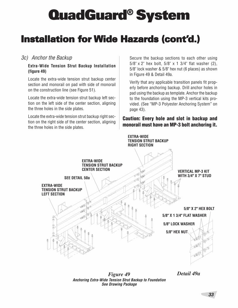
Figure 49Anchoring Extra-Wide Tension Strut Backup to Foundation
See Drawing Package
EXTRA-WIDETENSION STRUT BACKUPCENTER SECTION
3c) Anchor the BackupExtra-Wide Tension Strut Backup Installation(figure 49)
Locate the extra-wide tension strut backup centersection and monorail on pad with side of monorailon the construction line (see Figure 51).
Locate the extra-wide tension strut backup left sec-tion on the left side of the center section, aligningthe three holes in the side plates.
Locate the extra-wide tension strut backup right sec-tion on the right side of the center section, aligningthe three holes in the side plates.
EXTRA-WIDETENSION STRUT BACKUPRIGHT SECTION
EXTRA-WIDETENSION STRUT BACKUPLEFT SECTION
Detail 49a
SEE DETAIL 50a
VERTICAL MP-3 KITWITH 3/4" X 7" STUD
5/8" X 2" HEX BOLT
5/8" X 1 3/4" FLAT WASHER
5/8" HEX NUT
5/8" LOCK WASHER
Secure the backup sections to each other using5/8" x 2" hex bolt, 5/8" x 1 3/4" flat washer (2),5/8" lock washer & 5/8" hex nut (6 places) as shownin Figure 49 & Detail 49a.
Verify that any applicable transition panels fit prop-erly before anchoring backup. Drill anchor holes inpad using the backup as template. Anchor the backupto the foundation using the MP-3 vertical kits pro-vided. (See “MP-3 Polyester Anchoring System” onpage 43).
Caution: Every hole and slot in backup andmonorail must have an MP-3 bolt anchoring it.
Installation fInstallation fInstallation fInstallation fInstallation for or or or or Wide Hazards (cont’Wide Hazards (cont’Wide Hazards (cont’Wide Hazards (cont’Wide Hazards (cont’d.)d.)d.)d.)d.)
QuadGuard® System
34
Installation fInstallation fInstallation fInstallation fInstallation for or or or or WideWideWideWideWide Hazards (cont’ Hazards (cont’ Hazards (cont’ Hazards (cont’ Hazards (cont’d.)d.)d.)d.)d.)
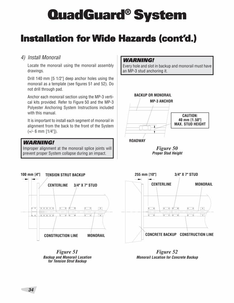
WARNING!Every hole and slot in backup and monorail must havean MP-3 stud anchoring it.
4) Install MonorailLocate the monorail using the monorail assemblydrawings.
Drill 140 mm [5 1/2"] deep anchor holes using themonorail as a template (see figures 51 and 52). Donot drill through pad.
Anchor each monorail section using the MP-3 verti-cal kits provided. Refer to Figure 50 and the MP-3Polyester Anchoring System Instructions includedwith this manual.
It is important to install each segment of monorail inalignment from the back to the front of the System(+/- 6 mm [1/4"]).
255 mm [10"]100 mm [4"] TENSION STRUT BACKUP
MONORAIL
3/4" X 7" STUDCENTERLINE
CONSTRUCTION LINE
CAUTION:40 mm [1.50"]
MAX. STUD HEIGHT
Figure 50
MP-3 ANCHOR
BACKUP OR MONORAIL
ROADWAYWARNING!Improper alignment at the monorail splice joints willprevent proper System collapse during an impact.
Figure 52Monorail Location for Concrete Backup
Figure 51Backup and Monorail Location
for Tension Strut Backup
CONCRETE BACKUP
MONORAIL
3/4" X 7" STUD
CENTERLINE
CONSTRUCTION LINE
Proper Stud Height

35
QuadGuard® System
5) Install Side Panels and/orTransition Panels to Backup Assemblya. Attach hinge plate to the transition panel or side
panel using 5/8” rail bolt & 5/8” rail nut (twoplaces - top & bottom holes only).
b. Attach transition panel or side panel assemblyto side of backup using 5/8” hex bolt, 5/8” lockwasher & 5/8” hex nut (three places each side ofbackup). See Figure 53.
c. Attach diagonal brace to fender panel and backupusing 3/8” hex bolt, 3/8” lock washer & 3/8” hexnut (two places per brace; 4 places per side).
Figure 53Side Panel/Transition Panel Attachment
TENSION STRUT BACKUP
5/8" X 4" HEX BOLT
3/8" X 3 1/2" HEX BOLT
CONCRETE BACKUP
5/8" LOCK WASHER
5/8" HEX NUT (SMALL)
5/8" RAIL NUT (LARGE)(SEE FIGURE 61)
HINGE PLATE
3/8" LOCK WASHERWIDE SIDE PANEL
5/8" RAIL BOLT3/8" HEX NUT
3/8" LOCK WASHER
3/8" HEX NUT
d. Secure each diagonal brace with 3/8” hex bolt,3/8” lock washer & 3/8” hex nut (two places perbrace) as shown in Figure 53.
Note: A side panel is not needed when a transitionpanel is used. Diagonal braces not used with sometransition panels. See drawing package.
3/8" X 3 1/2"HEX BOLT
DIAGONAL BRACE (INNER)
DIAGONAL BRACE (OUTER)
Installation tip:
Use drift pin to align the center hole of the panel withthe center hole of the backup before installing therail bolts.
Installation fInstallation fInstallation fInstallation fInstallation for or or or or Wide Hazards (cont’Wide Hazards (cont’Wide Hazards (cont’Wide Hazards (cont’Wide Hazards (cont’d.)d.)d.)d.)d.)

QuadGuard® System
36
Figure 54Monorail Guide Attachment
3/4" HEX NUT GR DH
3/4" LOCK WASHER
3/4" X 2" G8 HEX BOLTMONORAIL GUIDE
DIAPHRAGM
Figure 55
3/4" HEX NUT
3/4" X 4 G5 HEX BOLT
MONORAIL GUIDE
EXTRA-WIDE FIRST DIAPHRAGM
Monorail Guide Attachment(Extra-Wide First Diaphragm)
6b) Install Monorail GuidesExtra-Wide Systems
Attach monorail guides to diaphragms as follows:
6a) Install Monorail GuidesWide Systems
Attach monorail guides to diaphragm as follows:
Insert 3/4" x 2” G8 hex bolt through monorail guideand diaphragm, oriented as shown in Figure 54. Se-cure with 3/4" lock washer & 3/4" hex nut (typicaltwo places per guide). See also diaphragm assemblydrawing.
Repeat for each diaphragm.
Second through Last Diaphragms
Insert 3/4" x 2” G8 hex bolt through monorail guideand diaphragm, oriented as shown in Figure 54. Se-cure with 3/4" lock washer & 3/4" hex nut (typicaltwo places per guide).
Repeat for all diaphragms except the first.
First Diaphragm
Slide monorail guide up between the monorail guidebrackets at the bottom of the first diaphragm, align-ing the two holes. See Figure 55.
Insert 3/4" x 4” G5 hex bolt through monorail guidebracket on diaphragm and through monorail guide,oriented as shown in Figure 55. Secure with 3/4" lockwasher & 3/4" hex nut (typical two places per guide).See also diaphragm assembly drawing.
Installation fInstallation fInstallation fInstallation fInstallation for or or or or Wide Hazards (cont’Wide Hazards (cont’Wide Hazards (cont’Wide Hazards (cont’Wide Hazards (cont’d.)d.)d.)d.)d.)
3/4" LOCK WASHER

37
QuadGuard® System
7a) Install DiaphragmsWide Systems
Orient the widest diaphragm so that the front face ofthe Quad-BeamTM shape faces toward the nose of theSystem as shown in Figure 56. The widest diaphragmmust be installed closest to the backup with eachsubsequent diaphragm being progressively nar-rower.
Slide the widest diaphragm onto the monorail and allthe way to the backup to ensure System is able tocollapse properly during impact. Once this has beenverified, slide the diaphragm forward to approximately915 mm [36"] in front of the backup.
Orient and slide all other diaphragms onto mono-rail and position each approximately as shown inFigure 57.
FRONT
TOWARD NOSE
BACK
Figure 56Diaphragm Orientation
QUAD-BEAM
Figure 57Diaphragm spacing
915 mm [36"] DIAPHRAGMS915 mm [36"]TYPICAL
FRONT FACE OF BACKUP MONORAIL
Installation fInstallation fInstallation fInstallation fInstallation for or or or or Wide Hazards (cont’Wide Hazards (cont’Wide Hazards (cont’Wide Hazards (cont’Wide Hazards (cont’d.)d.)d.)d.)d.)

QuadGuard® System
38
Installation fInstallation fInstallation fInstallation fInstallation for or or or or WideWideWideWideWide Hazards (cont’ Hazards (cont’ Hazards (cont’ Hazards (cont’ Hazards (cont’d.)d.)d.)d.)d.)
7b) Install DiaphragmsExtra-Wide Systems
Quad-Beam Diaphragms
Orient the widest diaphragm so that the front face ofthe Quad-Beam shape faces toward the nose of theSystem as shown in figure 58. The widest diaphragmmust be installed closest to the backup with eachsubsequent diaphragm being progressively nar-rower.
Slide the widest diaphragm all the way to the backupto ensure the System is able to collapse properly
Figure 58Quad-Beam Diaphragm Orientation
(Diaphragms 2 through the last)
Figure 59Extra Wide Diaphragm
(Diaphragm 1)
Figure 60Diaphragm spacing
915 [36"] 915 [36"]TYPICAL
QUAD-BEAM DIAPHRAGMSEXTRA WIDEFIRST DIAPHRAGM
during impact. Once this has been verified then slidethe diaphragm forward to approximately 915mm[36"] in front of the backup.
Orient and slide all other Quad-Beam diaphragmsonto monorail and position each approximately asshown in figure 60.
Extra-Wide First Diaphragm
Orient the first diaphragm so the hinges are towardthe rear of the system. Slide the extra-wide first dia-phragm (see figure 59) onto the monorail and posi-tion approximately 915 mm [36"] forward of the pre-vious diaphragm as shown in Figure 60.
FRONT
TOWARD NOSE
BACK
QUAD-BEAM
TOWARD NOSE
BACK FRONT
HINGES

39
QuadGuard® System
8) Install Hinge Plates onto Fender PanelsNote: Do not mix the 5/8" rail nuts (large) withthe 5/8" hex nuts (small). See Figure 61.
32 mm [1.25"] 24 mm [0.94"]
Figure 61Rail Nuts are Oversize
FENDER PANEL
Figure 62
Note: For proper impact performance, Systems forwide hazards must have hinge plates.Install a hinge plate on each fender panel using two 5/8"rail bolts & two 5/8" rail nuts, using top and bottom holesonly, leaving the center hole open as shown in Figure 62.
Hinge Plate Assembly
5/8" HEX NUT (SMALL)5/8" RAIL NUT (LARGE)
5/8" RAIL NUT (LARGE)
5/8" RAIL BOLTS
HINGE PLATE
Installation fInstallation fInstallation fInstallation fInstallation for or or or or Wide Hazards (cont’Wide Hazards (cont’Wide Hazards (cont’Wide Hazards (cont’Wide Hazards (cont’d.)d.)d.)d.)d.)

QuadGuard® System
40
5/8" X 8 1/2", G8FLATHEAD SOCKET SCREW
1 1/2" DIE SPRING
5/8" LOCK WASHER
BACKUP LAST DIAPHRAGM
5/8" RAIL NUT (LARGE)
FIGURE 63
Detail 63a
1 1/2" DIE SPRING
PANEL ALREADY ATTACHEDTO DIAPHRAGM OR BACKUP
5/8" RAIL NUT (LARGE)DIAPHRAGMOR BACKUP
17.5 mm [11/16"]ROUND HOLE
LONG SLOT INFENDER PANEL
MUSHROOM WASHER
QUAD-BEAMFENDER PANEL
HINGE PLATE
Mushroom Washer Assembly
Detail 63bMushroom Washer Orientation
CORRECT INCORRECT
MUSHROOMWASHER
FENDER PANEL
9) Install Fender PanelsStarting at the last bay, install left and right fenderpanels as shown in Figure 63. Attach the hinge plateat the front of the fender panels to the diaphragm infront using three 5/8" hex bolts, nuts and washers.
Attach mushroom washer assembly as shown inFigures Figure 63 & Detail 63a but do not torqueat this time.
Be sure mushroom washer lays flat against the fenderpanel as shown in Detail 63b. Standoff on washermust be seated completely through slot.
MUSHROOM WASHER
FENDER PANEL5/8" HEX NUT (SMALL)
5/8" X 4" G5 HEX BOLT
Fender Panel Assembly
Installation fInstallation fInstallation fInstallation fInstallation for or or or or Wide Hazards (cont’Wide Hazards (cont’Wide Hazards (cont’Wide Hazards (cont’Wide Hazards (cont’d.)d.)d.)d.)d.)

41
QuadGuard® System
Installation fInstallation fInstallation fInstallation fInstallation for or or or or WideWideWideWideWide Hazards (cont’ Hazards (cont’ Hazards (cont’ Hazards (cont’ Hazards (cont’d.)d.)d.)d.)d.)
BAY SPACING915 mm [36"]
DIAPHRAGMOR BACKUP
FENDER PANEL
Figure 64Proper Spacing Between Diaphragms
Check diaphragm spacing to ensure 915 mm [36"]between rear faces of consecutive diaphragms asshown in Figure 64. Once the proper spacing hasbeen achieved, torque the mushroom washer assem-bly nut until it reaches the end of the threads. Installthe remaining diaphragms and fender panels follow-ing the same procedures.
DIAPHRAGM
10) Install End CapUsing 5/8" x 3 1/2" G5 hex bolt, 5/8" hex nut and 5/8"lock washer, attach the end cap to the front of thefirst monorail segment as shown in Figure 65.
Figure 65Monorail End Cap Installation
5/8" X 3 1/2" G5 HEX BOLT
5/8" LOCK WASHER
5/8" HEX NUTEND CAP
MONORAIL

QuadGuard® System
42
Installation fInstallation fInstallation fInstallation fInstallation for or or or or WideWideWideWideWide Hazards (cont’ Hazards (cont’ Hazards (cont’ Hazards (cont’ Hazards (cont’d.)d.)d.)d.)d.)
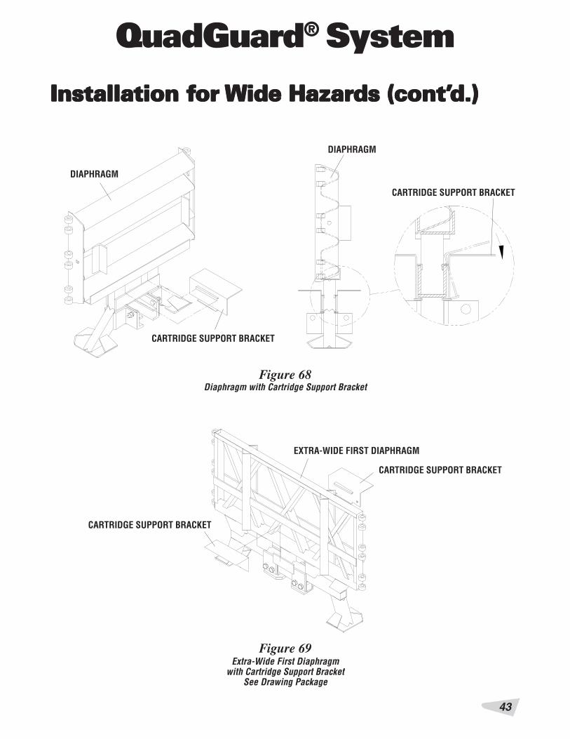
11) Install Cartridge Support BracketsAttach cartridge support bracket to all diaphragmsand backup as shown in Figures 66, 67, 68, 69, thebackup assembly drawing and the diaphragm assem-bly drawing.
Figure 66Tension Strut Backup with Cartridge Support Bracket
CARTRIDGE SUPPORT BRACKET Figure 67Concrete Backup with Cartridge Support Bracket
CARTRIDGE SUPPORT BRACKETIS WELDED TO FACE PLATE
STEP IIINSTALL “KEEPER”
STEP IINSTALL LOWER CARTRIDGESUPPORT BRACKET
43
QuadGuard® System
DIAPHRAGM
CARTRIDGE SUPPORT BRACKET
DIAPHRAGM
Figure 68Diaphragm with Cartridge Support Bracket
CARTRIDGE SUPPORT BRACKET
Figure 69Extra-Wide First Diaphragm
with Cartridge Support BracketSee Drawing Package
EXTRA-WIDE FIRST DIAPHRAGM
CARTRIDGE SUPPORT BRACKET
CARTRIDGE SUPPORT BRACKET
Installation fInstallation fInstallation fInstallation fInstallation for or or or or Wide Hazards (cont’Wide Hazards (cont’Wide Hazards (cont’Wide Hazards (cont’Wide Hazards (cont’d.)d.)d.)d.)d.)

QuadGuard® System
44
Installation fInstallation fInstallation fInstallation fInstallation for or or or or WideWideWideWideWide Hazards (cont’ Hazards (cont’ Hazards (cont’ Hazards (cont’ Hazards (cont’d.)d.)d.)d.)d.)
12a) Install Nose AssemblyInstall the nose assembly (see Figures 70 through 74and the nose assembly drawing) in the following order:
Step 1. (Figure 70) Attach pullout brackets to diaphragmwith 5/8" x 1 1/2" hex bolts & 5/8" nuts 1 placeeach side.
Step 2. (Figure 71) Bolt nose attachment bracket be-tween hinge and fender panel with 5/8" x 1 1/2"hex bolts, 5/8" nuts and 5/8" flat washers.
Step 3. (Figure 72) Bolt fender panel assembly to dia-phragm with 5/8" x 4" hex bolts, 5/8" nuts and5/8" lock washers 3 places each side.
PULLOUT BRACKET
5/8" RAIL NUT
5/8" X 1 1/2"G5 HEX BOLT
FRONT DIAPHRAGM
Figure 70Attach Pullout Brackets to Diaphragm
Figure 71Bolt Nose Attachment Bracket
between Hinge and Fender Panel
EXISTING 5/8" X 2"RAIL BOLT
5/8" RAIL NUT (LARGE)
5/8" X 1 3/4"FLAT WASHER
FENDER PANEL
Figure 72
FRONT DIAPHRAGM
5/8" HEX NUT (SMALL)
FENDER PANEL ASSEMBLY
5/8" LOCK WASHER
5/8" X 4" G5 HEX BOLT
Bolt Fender Panel Assembly to Diaphragm
5/8" X 1 1/2"G5 HEX BOLT
5/8" X 1 3/4"FLAT WASHER
NOSE ATTACHMENT BRACKET
5/8" HEX NUT (SMALL)
45
QuadGuard® System
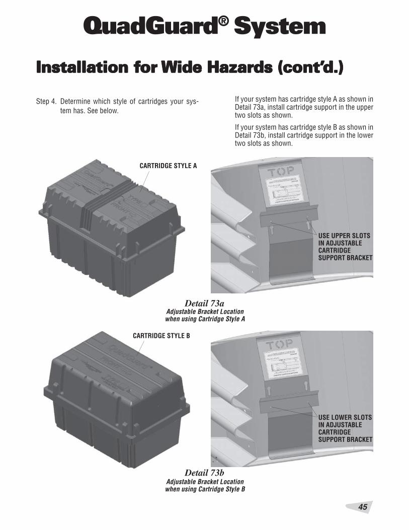
Detail 73aAdjustable Bracket Locationwhen using Cartridge Style A
Detail 73bAdjustable Bracket Locationwhen using Cartridge Style B
Step 4. Determine which style of cartridges your sys-tem has. See below.
If your system has cartridge style A as shown inDetail 73a, install cartridge support in the uppertwo slots as shown.
If your system has cartridge style B as shown inDetail 73b, install cartridge support in the lowertwo slots as shown.
Installation fInstallation fInstallation fInstallation fInstallation for or or or or Wide Hazards (cont’Wide Hazards (cont’Wide Hazards (cont’Wide Hazards (cont’Wide Hazards (cont’d.)d.)d.)d.)d.)
USE UPPER SLOTSIN ADJUSTABLECARTRIDGESUPPORT BRACKET
USE LOWER SLOTSIN ADJUSTABLECARTRIDGESUPPORT BRACKET
CARTRIDGE STYLE A
CARTRIDGE STYLE B
QuadGuard® System
46
Detail 73c
Detail 73d
Detail 73e
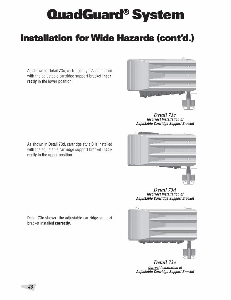
As shown in Detail 73c, cartridge style A is installedwith the adjustable cartridge support bracket incor-rectly in the lower position.
As shown in Detail 73d, cartridge style B is installedwith the adjustable cartridge support bracket incor-rectly in the upper position.
Detail 73e shows the adjustable cartridge supportbracket installed correctly.
Incorrect Installation ofAdjustable Cartridge Support Bracket
Incorrect Installation ofAdjustable Cartridge Support Bracket
Correct Installation ofAdjustable Cartridge Support Bracket
Installation fInstallation fInstallation fInstallation fInstallation for or or or or Wide Hazards (cont’Wide Hazards (cont’Wide Hazards (cont’Wide Hazards (cont’Wide Hazards (cont’d.)d.)d.)d.)d.)
47
QuadGuard® System
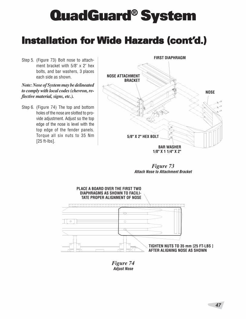
Figure 73
BAR WASHER1/8" X 1 1/4" X 2"
5/8" X 2" HEX BOLT
FIRST DIAPHRAGM
Figure 74
PLACE A BOARD OVER THE FIRST TWODIAPHRAGMS AS SHOWN TO FACILI-TATE PROPER ALIGNMENT OF NOSE
TIGHTEN NUTS TO 35 mm [25 FT-LBS ]AFTER ALIGNING NOSE AS SHOWN
Adjust Nose
Step 5. (Figure 73) Bolt nose to attach-ment bracket with 5/8" x 2" hexbolts, and bar washers, 3 placeseach side as shown.
Note: Nose of System may be delineatedto comply with local codes (chevron, re-flective material, signs, etc.).
Attach Nose to Attachment Bracket
Step 6. (Figure 74) The top and bottomholes of the nose are slotted to pro-vide adjustment. Adjust so the topedge of the nose is level with thetop edge of the fender panels.Torque all six nuts to 35 Nm[25 ft-lbs].
NOSE ATTACHMENTBRACKET
NOSE
Installation fInstallation fInstallation fInstallation fInstallation for or or or or Wide Hazards (cont’Wide Hazards (cont’Wide Hazards (cont’Wide Hazards (cont’Wide Hazards (cont’d.)d.)d.)d.)d.)
QuadGuard® System
48
Figure 75
BELT CLAMP
5/8" HEX NUT
5/8" X 1 3/4" FLAT WASHER
QUADGUARD NOSE BELT
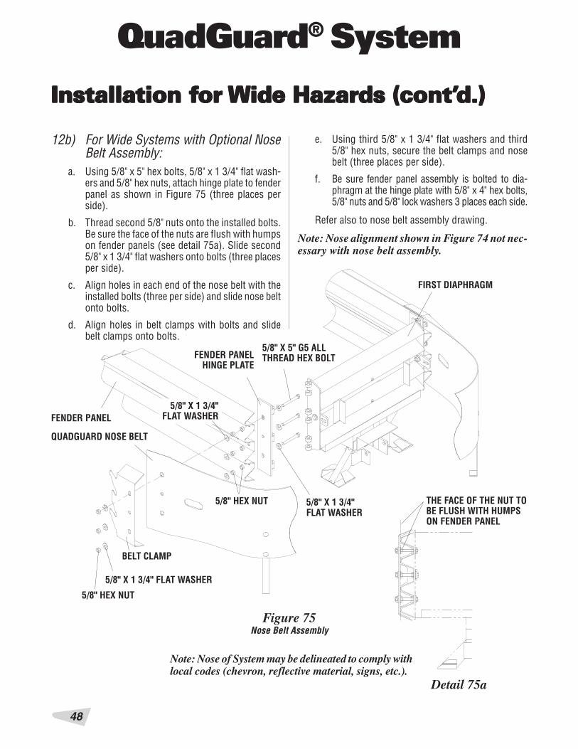
12b) For Wide Systems with Optional NoseBelt Assembly:
a. Using 5/8" x 5" hex bolts, 5/8" x 1 3/4" flat wash-ers and 5/8" hex nuts, attach hinge plate to fenderpanel as shown in Figure 75 (three places perside).
b. Thread second 5/8" nuts onto the installed bolts.Be sure the face of the nuts are flush with humpson fender panels (see detail 75a). Slide second5/8" x 1 3/4" flat washers onto bolts (three placesper side).
c. Align holes in each end of the nose belt with theinstalled bolts (three per side) and slide nose beltonto bolts.
d. Align holes in belt clamps with bolts and slidebelt clamps onto bolts.
5/8" X 1 3/4"FLAT WASHER
5/8" X 1 3/4"FLAT WASHER
5/8" HEX NUT
Nose Belt Assembly
e. Using third 5/8" x 1 3/4" flat washers and third5/8" hex nuts, secure the belt clamps and nosebelt (three places per side).
f. Be sure fender panel assembly is bolted to dia-phragm at the hinge plate with 5/8" x 4" hex bolts,5/8" nuts and 5/8" lock washers 3 places each side.
Refer also to nose belt assembly drawing.
Note: Nose alignment shown in Figure 74 not nec-essary with nose belt assembly.
Detail 75a
Note: Nose of System may be delineated to comply withlocal codes (chevron, reflective material, signs, etc.).
THE FACE OF THE NUT TOBE FLUSH WITH HUMPSON FENDER PANEL
5/8" X 5" G5 ALLTHREAD HEX BOLTFENDER PANEL
HINGE PLATE
Installation fInstallation fInstallation fInstallation fInstallation for or or or or Wide Hazards (cont’Wide Hazards (cont’Wide Hazards (cont’Wide Hazards (cont’Wide Hazards (cont’d.)d.)d.)d.)d.)
FIRST DIAPHRAGM
FENDER PANEL

49
QuadGuard® System
Installation fInstallation fInstallation fInstallation fInstallation for or or or or Wide Hazards (cont’Wide Hazards (cont’Wide Hazards (cont’Wide Hazards (cont’Wide Hazards (cont’d.)d.)d.)d.)d.)
13) Checking the System AssemblyAt This point recheck to ensure that all fasteners areproperly tightened throughout the System (anchorbolts, etc.). See warning below. Check all fender pan-els. If they do not fit tightly against the underlyingpanel, System realignment may be necessary. (SeeFigure 76).
WARNING!Anchor Studs.... Torqued to 165 Nm [120 ft-lbs]
Should NOT protrude above nuts(see Figure 17, page 13)
All Other Bolts... Tightened
Fender Panel..... Maximum gap allowed:Wide Systems - 25 mm [1.00"]
FENDER PANEL
MAXIMUM GAP = 25 mm [1.00"]
UNDERLYING FENDER,TRANSITION, EXTENSION
OR SIDE PANEL
Figure 76
WARNING!Placing the wrong Cartridge in the Nose or any Baywill result in unacceptable crash performance asdescribed in NCHRP 350.
14) Cartridge InstallationBe sure the adjustable cartridge support in the nose isinstalled correctly. See "Install Nose Assembly" 11a.
To complete the assembly of a QuadGuard System,place the appropriate cartridge in each bay and nosesection of the System. Type I cartridges are placedtoward the front (nose) of the System; Type II car-tridges are placed toward the rear (backup) of theSystem. Refer to figures 77 and 78.
I - TYPE I CARTRIDGEII - TYPE II CARTRIDGE
3 BAYS
4 BAYS
5 BAYS
6 BAYS
7 BAYS
8 BAYS
9 BAYS
10 BAYS
11 BAYS
12 BAYS
Figure 77
Fender Panel Gap for Wide Systems
Cartridge Placement

QuadGuard® System
50
Figure 78
REARTYPE II
TYPE I
FRONT
Typical Cartridge Layout - 6 Bay System Shown
Installation fInstallation fInstallation fInstallation fInstallation for or or or or Wide Hazards (cont’Wide Hazards (cont’Wide Hazards (cont’Wide Hazards (cont’Wide Hazards (cont’d.)d.)d.)d.)d.)

51
QuadGuard® System
MPMPMPMPMP-3-3-3-3-3®®®®® P P P P Polololololyyyyyester ester ester ester ester AncAncAncAncAnchoring Shoring Shoring Shoring Shoring Systemystemystemystemystem
The MP-3 Polyester Anchoring System is a quick and easyway to securely anchor crash cushions and other com-mon highway devices. MP-3 features high pullout strength,superior vibration resistance, and exceptional durability.
Each MP-3 kit contains a can of MP-3 resin, hardener, coldweather promotor, studs, washers, and a complete safetysheet. The cold weather promoter shortens hardening timeby as much as seven hours. Both vertical and horizontalinstallations are possible using the MP-3 System.
VVVVVererererertical Installationstical Installationstical Installationstical Installationstical InstallationsNote: Read MP-3 Instructions before starting.1) Prepare the concrete pad
WARNING!Wear safety goggles and gloves during installation.
MP-3 Anchoring Information
WARNING!Do not allow the MP-3 Resin or Hardener to contactskin or eyes. See material safety data sheet suppliedwith the MP-3 kit for first-aid procedures. Use only inwell-ventilated area. Do not use near open flame.
The anchor bolts (Studs) that anchor theQuadGuard® System to the concrete pad must bethose shipped in the kit or of high strength steel(830 MPa [120,000 psi] minimum tensile strengthor equal.) These Studs must be set in minimum28 MPa [4000 psi] concrete. Allow the concrete tocure a minimum of 7 days before installing MP-3.
2) Drill holes
Note: Energy Absorption Systems recommends us-ing two fluted drills to achieve optimum tensilestrength when installing the MP-3 anchoring system.
Use the part that is to be anchored as a drilling tem-plate. Drill the holes 3 mm [1/8"] larger than the studdiameter to the recommended depth, using a rotarypercussive drill. Full strength will not be achieved if adiamond drill is used. Refer to the MP-3 installationinstructions provided with your kit. Check to be sureall the holes are drilled to the proper depth and alignedwith the part to be anchored. Refer to Table A.
Stud size
3/4" x 6 1/2"
3/4" x 7"3/4" x 7 1/2"3/4" x 8 1/2"
3/4" x 18"
Concretebit size
22 mm[7/8"]
22 mm[7/8"]
22 mm[7/8"]
MinimumDepth
125 mm[5"]
140 mm[5 1/2"]
420 mm[16 1/2"]
RecommendedTorque
165 Nm[120 ft-lbs]
165 Nm[120 ft-lbs]
<15 Nm[<10 ft-lbs]
WARNING!Do not use Promoter when the temperature is above15 degrees Celsius (60 degrees Fahrenheit). Grout willharden too quickly.
3) Clean the holes
Blow the concrete dust from the hole, using oil-freecompressed air. Thoroughly brush it with a stiff-bristled brush, and then blow it out again If the holeis wet, completely flush it with water while brushing.Then blow it clean, using oil-free compressed air.
4) Mix the resin and hardener
Wearing gloves and safety goggles, remove the lidsfrom the MP-3 Part A-Resin and Part B-Hardener con-tainers. Pour Part B into Part A, then mix vigorouslyfor 30 seconds to form MP-3 grout (an anchor studmay serve as a stirring rod).
5) Add cold weather promotor (in cold weather)
For faster hardening in cold weather, Promoter maybe used. Add the entire contents of the partially filledPromoter container to the MP-3 grout; then mix foran additional 30 seconds. Use immediately becausethe MP-3 grout will thicken quickly. Refer to Table Bfor hardening times.
6) Pour grout into holes
Table A
QuadGuard® System
52
MPMPMPMPMP-3-3-3-3-3®®®®® P P P P Polololololyyyyyester ester ester ester ester AncAncAncAncAnchoring Shoring Shoring Shoring Shoring System (cont’ystem (cont’ystem (cont’ystem (cont’ystem (cont’d.)d.)d.)d.)d.)
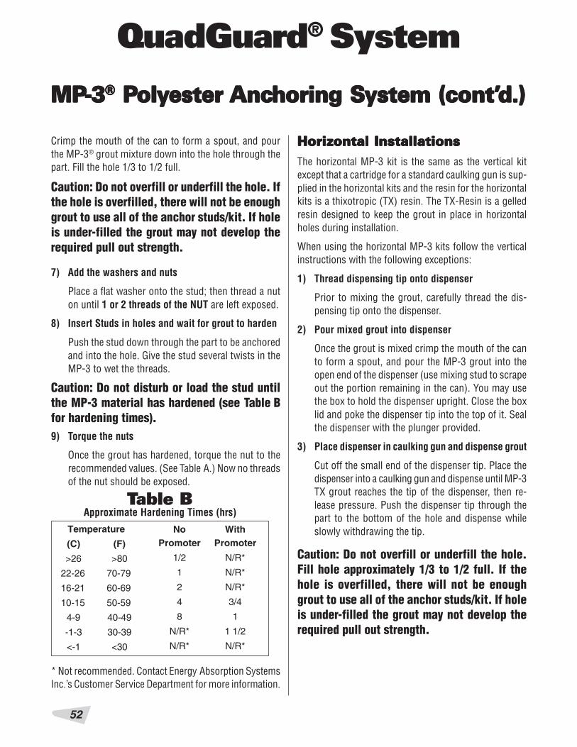
Approximate Hardening Times (hrs)
Temperature
(F)
>80
70-79
60-69
50-59
40-49
30-39
<30
NoPromoter
1/2
1
2
4
8
N/R*
N/R*
WithPromoter
N/R*
N/R*
N/R*
3/4
1
1 1/2
N/R*
(C)
>26
22-26
16-21
10-15
4-9
-1-3
<-1
Crimp the mouth of the can to form a spout, and pourthe MP-3® grout mixture down into the hole through thepart. Fill the hole 1/3 to 1/2 full.
HorizHorizHorizHorizHorizontal Installationsontal Installationsontal Installationsontal Installationsontal InstallationsThe horizontal MP-3 kit is the same as the vertical kitexcept that a cartridge for a standard caulking gun is sup-plied in the horizontal kits and the resin for the horizontalkits is a thixotropic (TX) resin. The TX-Resin is a gelledresin designed to keep the grout in place in horizontalholes during installation.
When using the horizontal MP-3 kits follow the verticalinstructions with the following exceptions:
1) Thread dispensing tip onto dispenser
Prior to mixing the grout, carefully thread the dis-pensing tip onto the dispenser.
2) Pour mixed grout into dispenser
Once the grout is mixed crimp the mouth of the canto form a spout, and pour the MP-3 grout into theopen end of the dispenser (use mixing stud to scrapeout the portion remaining in the can). You may usethe box to hold the dispenser upright. Close the boxlid and poke the dispenser tip into the top of it. Sealthe dispenser with the plunger provided.
3) Place dispenser in caulking gun and dispense grout
Cut off the small end of the dispenser tip. Place thedispenser into a caulking gun and dispense until MP-3TX grout reaches the tip of the dispenser, then re-lease pressure. Push the dispenser tip through thepart to the bottom of the hole and dispense whileslowly withdrawing the tip.
* Not recommended. Contact Energy Absorption SystemsInc.’s Customer Service Department for more information.
Caution: Do not overfill or underfill the hole. Ifthe hole is overfilled, there will not be enoughgrout to use all of the anchor studs/kit. If holeis under-filled the grout may not develop therequired pull out strength.
7) Add the washers and nuts
Place a flat washer onto the stud; then thread a nuton until 1 or 2 threads of the NUT are left exposed.
8) Insert Studs in holes and wait for grout to harden
Push the stud down through the part to be anchoredand into the hole. Give the stud several twists in theMP-3 to wet the threads.
Caution: Do not disturb or load the stud untilthe MP-3 material has hardened (see Table Bfor hardening times).9) Torque the nuts
Once the grout has hardened, torque the nut to therecommended values. (See Table A.) Now no threadsof the nut should be exposed.
Table B
Caution: Do not overfill or underfill the hole.Fill hole approximately 1/3 to 1/2 full. If thehole is overfilled, there will not be enoughgrout to use all of the anchor studs/kit. If holeis under-filled the grout may not develop therequired pull out strength.

53
QuadGuard® System
4) Add the washers and nuts
Put washer and nut on stud leaving nut flush withend of stud. See figure 79.
5) Insert Studs into holes
Push stud through part to be anchored and into hole.Twist the stud in the MP-3® grout to wet the threads.
Note: In Horizontal Applications the stud shouldbe flush with the top of the nut. See Figure 79.
CORRECT
INCORRECT
MP-3MP-3MP-3MP-3MP-3®®®®® Installation Cautions Installation Cautions Installation Cautions Installation Cautions Installation Cautions1) Shelf life
If the shelf life of the MP-3 has expired (see MP-3 kitfor expiration information), mix a small amount ofMP-3 in the proportions of one part A to two parts Bby volume. If the material does not set according tothe instructions, contact Energy Absorption Systems,Inc. for guidance.
Figure 79
WARNING!Do not use the MP-3 if the material fails to set up, PartA-Resin has gelled (for vertical applications), or TX-Resin is NOT gelled (for horizontal applications).
2) Steel rebar
If steel rebar is encountered while drilling an MP-3anchor bolt hole, apply one of the following solu-tions:
A. Using a diamond core drill or rebar drilling tool,drill through the rebar only, then switch back tothe concrete bit and drill into the underlying con-crete until the proper hole depth is reached.
Caution: Do not drill through rebar without firstobtaining permission to do so from the localproject engineer.
B. Drill a new hole down at an angle past the rebarto the proper depth. Anchor the stud by com-pletely filling both holes with MP-3.
MP-3 Horizontal Installation
Caution: Do not disturb or load the stud untilthe MP-3 material has hardened (see Table Bfor hardening times).
6) Torque the nuts
Once the grout has hardened, torque the nut to165 Nm [120 ft-lbs.].
MPMPMPMPMP-3-3-3-3-3®®®®® P P P P Polololololyyyyyester ester ester ester ester AncAncAncAncAnchoring Shoring Shoring Shoring Shoring System (cont’ystem (cont’ystem (cont’ystem (cont’ystem (cont’d.)d.)d.)d.)d.)
QuadGuard® System
54
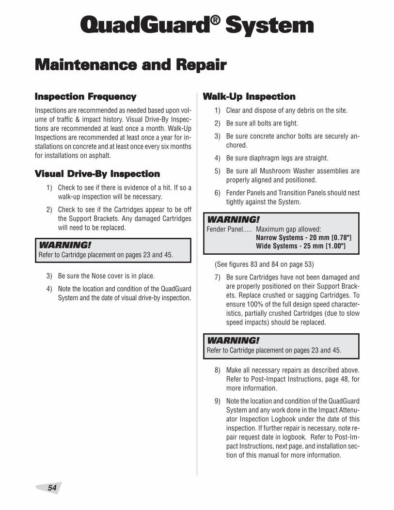
Inspection FInspection FInspection FInspection FInspection FreqreqreqreqrequencuencuencuencuencyyyyyInspections are recommended as needed based upon vol-ume of traffic & impact history. Visual Drive-By Inspec-tions are recommended at least once a month. Walk-UpInspections are recommended at least once a year for in-stallations on concrete and at least once every six monthsfor installations on asphalt.
VVVVVisual Drivisual Drivisual Drivisual Drivisual Drive-By Inspectione-By Inspectione-By Inspectione-By Inspectione-By Inspection1) Check to see if there is evidence of a hit. If so a
walk-up inspection will be necessary.
2) Check to see if the Cartridges appear to be offthe Support Brackets. Any damaged Cartridgeswill need to be replaced.
WWWWWalk-Up Inspectionalk-Up Inspectionalk-Up Inspectionalk-Up Inspectionalk-Up Inspection1) Clear and dispose of any debris on the site.
2) Be sure all bolts are tight.
3) Be sure concrete anchor bolts are securely an-chored.
4) Be sure diaphragm legs are straight.
5) Be sure all Mushroom Washer assemblies areproperly aligned and positioned.
6) Fender Panels and Transition Panels should nesttightly against the System.
3) Be sure the Nose cover is in place.
4) Note the location and condition of the QuadGuardSystem and the date of visual drive-by inspection.
WARNING!Refer to Cartridge placement on pages 23 and 45.
WARNING!Refer to Cartridge placement on pages 23 and 45.
8) Make all necessary repairs as described above.Refer to Post-Impact Instructions, page 48, formore information.
9) Note the location and condition of the QuadGuardSystem and any work done in the Impact Attenu-ator Inspection Logbook under the date of thisinspection. If further repair is necessary, note re-pair request date in logbook. Refer to Post-Im-pact Instructions, next page, and installation sec-tion of this manual for more information.
Maintenance and RepairMaintenance and RepairMaintenance and RepairMaintenance and RepairMaintenance and Repair
WARNING!Fender Panel..... Maximum gap allowed:
Narrow Systems - 20 mm [0.78"]Wide Systems - 25 mm [1.00"]
(See figures 83 and 84 on page 53)
7) Be sure Cartridges have not been damaged andare properly positioned on their Support Brack-ets. Replace crushed or sagging Cartridges. Toensure 100% of the full design speed character-istics, partially crushed Cartridges (due to slowspeed impacts) should be replaced.

55
QuadGuard® System
PPPPPost-Impact Instructionsost-Impact Instructionsost-Impact Instructionsost-Impact Instructionsost-Impact Instructions(Wide Hazards)(Wide Hazards)(Wide Hazards)(Wide Hazards)(Wide Hazards)
1. Deploy the appropriate traffic-control devices toprotect your crew.
2. Check to see that all Anchor Bolts have remainedfirmly anchored in the roadway surface. Replaceany that are loose, broken, or pulled out.
The proper performance of the System duringan angle impact depends on the Monorail An-chors being properly anchored.
Note: QuadGuard Systems for Wide Hazardsshould never be anchored to asphalt.
PPPPPost-Impact Instructionsost-Impact Instructionsost-Impact Instructionsost-Impact Instructionsost-Impact Instructions(Narr(Narr(Narr(Narr(Narrooooow Hazards)w Hazards)w Hazards)w Hazards)w Hazards)
1. Deploy the appropriate traffic-control devices toprotect your crew.
2. Check to see that all Anchor Bolts have remainedfirmly anchored in the roadway surface. Failedanchor bolts are those found to be loose, bro-ken, or showing signs of pull-out and are to bereplaced.
If the System is anchored to asphalt, up to 20%of the total anchors may be replaced if damaged.If more than 20% of the anchors are damaged,the system should be relocated to fresh, undis-turbed asphalt and reinstalled using the 460 mm[18"] threaded rods.
The proper performance of the System duringan angle impact depends on the monorail an-chors being properly anchored.
3. Clear and dispose of any debris on the site.
4. Check the System to be certain that the Mush-room Washer Assemblies holding the fenderpanels together are still intact and that the Sys-tem has not been deformed in a way that wouldprevent pulling it back to its original position.
5. Be sure that the Diaphragm Support Legs areall properly attached to the Monorail.
3. Clear and dispose of any debris on the site.
4. Check the System to be certain that the Mush-room Washer Assemblies holding the fenderpanels together are still intact and that the Sys-tem has not been deformed in a way that wouldprevent pulling it back to its original position.
5. Be sure that the Diaphragm support legs are allproperly attached to the Monorail.
Caution: Use safety goggles and gloves whenrefurbishing the mushroom spring assembly. Donot place fingers underneath an assembledmushroom washer. Parts may suddenly shiftand fingers may be pinched. If the spring isstill under compression as the nut is nearingthe end of the bolt, to prevent injury, make surethat the spring is restrained with a clamp so itdoes not suddenly release when nut is removedfrom the mushroom bolt.
Maintenance and Repair (cont'd.)Maintenance and Repair (cont'd.)Maintenance and Repair (cont'd.)Maintenance and Repair (cont'd.)Maintenance and Repair (cont'd.)

QuadGuard® System
56
Maintenance and Repair (cont’Maintenance and Repair (cont’Maintenance and Repair (cont’Maintenance and Repair (cont’Maintenance and Repair (cont’d.)d.)d.)d.)d.)
Figure 80
CLAMP
PIPE WRENCH
BACKUP
Figure 81
FIRST DIAPHRAGM
PULLOUT BRACKETS
CARTRIDGE SUPPORT BRACKET
Pull the QuadGuard System forward slowly un-til the System reaches its original length. Havesomeone watch the System during reposition-ing to be certain previously undetected damagedoes not cause the diaphragms to bind or pullout improperly.
7. Remove all crushed Cartridges from within theSystem.
8. Check to see that the Diaphragms are in usablecondition. Diaphragms which are bowed or havebent legs must be replaced.
9. Check that the Fender Panels are properly at-tached with the Mushroom Washer Assemblies.Damaged Fender Panels and Transition Panels
must be replaced. Often, Cartridge Support Brack-ets with minor damage can be straightened andreused by doing the following:
A. Remove damaged Cartridge Support Bracketfrom diaphragm.
B. Clamp Cartridge Support Bracket to backupand begin bending using pipe wrench asshown in Figure 81.
WARNING!Stand clear in case chain breaks or becomesdisconnected.
Figure 82
BACKUP
SLEDGE HAMMERCARTRIDGE SUPPORT BRACKET
C. Then, using a sledge hammer andQuad-BeamTM shape on backup as an anvil,form Cartridge Support Bracket back into 90°shape (see Figure 82).
6. Attach chain to Pullout Brackets on first Dia-phragm (see Figure 80). Attach both ends of chainto a heavy vehicle (such as a 1 ton pickup).
Pullout
Form Cartridge Support Bracket
Straighten Cartridge Support Bracket

57
QuadGuard® System
NarrNarrNarrNarrNarrooooow Hazardsw Hazardsw Hazardsw Hazardsw Hazards10. Check gaps between Fender Panels. The maxi-
mum gap allowed for these overlapping parts (in-cluding Fender Panels overlapping panels behindthe System) is 20 mm [.78"] (see figure 83).
Wide HazardsWide HazardsWide HazardsWide HazardsWide Hazards10. Check gaps between Fender Panels. The maxi-
mum gap allowed for these overlapping parts (in-cluding Fender Panels overlapping panels behindthe System) is 25 mm [1.00"] (see figure 84).
WARNING!Fender Panel..... Maximum gap allowed:
Narrow Systems - 20 mm [0.78"]Wide Systems - 25 mm [1.00"]
FENDER PANEL
MAXIMUM GAP = 25 mm [1.00"]
UNDERLYING FENDER,TRANSITION, EXTENSION
OR SIDE PANEL
Figure 84Figure 83
FENDER PANEL
MAXIMUM GAP = 20 mm [0.78"]
UNDERLYING FENDER,TRANSITION, EXTENSION
OR SIDE PANEL
Be sure the Mushroom Washer Assemblies aretorqued so that the spring is compressed. If thegaps between the Fender Panels are still too largeit may be necessary to replace bent parts.
Be sure the Mushroom Washer Assemblies aretorqued to 80 Nm [60 ft-lbs]. If the gaps betweenthe Fender Panels are still too large it may benecessary to replace bent parts.
Fender Panel Gap for Narrow Hazards Fender Panel Gap for Wide Hazards
Maintenance and Repair (cont’Maintenance and Repair (cont’Maintenance and Repair (cont’Maintenance and Repair (cont’Maintenance and Repair (cont’d.)d.)d.)d.)d.)

QuadGuard® System
58
Maintenance and Repair (cont’Maintenance and Repair (cont’Maintenance and Repair (cont’Maintenance and Repair (cont’Maintenance and Repair (cont’d.)d.)d.)d.)d.)
WARNING!Anchor Studs.... Torqued to 165 Nm [120 ft-lbs]
Should NOT protrude above nuts(see figure 17, page 13)
All Other Bolts... Tightened
Fender Panel..... Maximum gap allowed:Narrow - 20 mm [0.78"]Wide - 25 mm [1.0"]
11. Replace all crushed Cartridges. Refer to Car-tridge Placement on pages 25 & 49.
12. Remove damaged plastic Nose Cover. Attach thenew nose cover to the first diaphragm, using thesix rail bolts, rail nuts, and bar washers that holdthe front fender panels to the first diaphragm.The top and bottom holes of the nose cover areslotted to provide adjustment. Adjust nose toalign with fender panels, then torque all six nutsto 35 Nm [25 ft-lbs]. See Figure 85, Nose Ad-justment.
FOR SYSTEMS FITTED WITH OPTIONAL NOSE BELT
Normally, with a design speed impact, the nose beltwill not need replacement. After pulling System outand replacing the nose cartridge, it may be neces-sary to adjust nuts attaching nose belt to diaphragmand/or legs to 35 Nm [25 ft-lbs]. Nose belt assemblyis available for replacement or retrofit by calling theCustomer Service Department at 1-888-32-ENERG.
13. Check the torque of all bolts on the System (seeTable C).
14. Check to be certain that the site is free from anydebris. The QuadGuard System is once againready for use.
Table C
Figure 85
PLACE A BOARD OVER THE FIRST TWO DIAPHRAGMS ASSHOWN TO FACILITATE PROPER ALIGNMENT OF NOSE
TIGHTEN NUTS TO 35 NM [25 FT-LBS]AFTER ALIGNING NOSE AS SHOWN
Figure 86
Nose Adjustment
Optional Nose Assembly
QuadGuard System Bolt Torque Specifications

59
QuadGuard® System
DESCRIPTION
What is the Width of System?(refer to "Measuring theWidth" page 6.)
What is the Number of Bays?(refer to "Counting The Numberof Bays" page 5.)
What Type of Backup Doesthe System Have?
Table D
PPPPParararararts Ordering Pts Ordering Pts Ordering Pts Ordering Pts Ordering PrrrrrocedureocedureocedureocedureocedureMake a list of all damaged parts using part descriptions shown on pages 56 and 57. Answer the following questionsin the spaces provided. This information is necessary to receive the proper parts.
What Type of Transition Panel?(Refer to “Side Panel &Transition Panel Types”page 10.) Be sure to note rightside, left side, both sides (referto “How to Determine Left/Right”page 5) or no transitions.
QuadGuard System Ordering Information Chart
610 mm [24"]760 mm [30"]915 mm [36"]1755 mm [69"]2285 mm [90"]Extra-Wide[specify width]
Narrow Hazards:1 through 12Wide Hazards:3 through 12
ConcreteTension Strut
• Quad to W• Quad to Thrie• Quad to Safety
Shape Barrier• Quad to End Shoe• 4" Offset Panel
CHOICES FILL IN THIS SECTION
Maintenance and Repair (cont’Maintenance and Repair (cont’Maintenance and Repair (cont’Maintenance and Repair (cont’Maintenance and Repair (cont’d.)d.)d.)d.)d.)

QuadGuard® System
60
Maintenance and Repair (cont’Maintenance and Repair (cont’Maintenance and Repair (cont’Maintenance and Repair (cont’Maintenance and Repair (cont’d.)d.)d.)d.)d.)
Figure 87
TRAN
SITI
ON P
ANEL
(NUM
EROU
S TY
PES)
BACK
UP(T
ENSI
ON S
TRUT
SHO
WN)
TYPE
II C
ARTR
IDGE
S
DIAP
HRAG
M
DIAP
HRAG
M
CART
RIDG
ESU
PPOR
TBR
ACKE
TS
TYPE
I CA
RTRI
DGES
MON
ORAI
L (U
NDER
SYS
TEM
)AN
CHOR
ED W
ITH
MP-
3 AN
CHOR
KIT
FIRS
T DI
APHR
AGM
NOSE
COV
ER A
SSEM
BLY
5/8"
X 1
3/4
"FL
AT W
ASHE
R
QUAD
-BEA
M F
ENDE
R PA
NEL
MUS
HROO
M W
ASHE
R AS
SEM
BLY
5/8"
HEX
NUT
SPRI
NGVE
RTIC
AL M
P-3
ANCH
OR K
ITW
ITH
3/4"
X 7
" STU
D
MUS
HROO
M W
ASHE
R
5/8"
X 5
" FLA
T SC
REW
MON
ORAI
L SE
CTIO
N
MON
ORAI
L GU
IDE
QuadGuard for Narrow Hazards

61
QuadGuard® System
Figure 88
TRAN
SITI
ON P
ANEL
(NUM
EROU
S TY
PES)
BACK
UP(T
ENSI
ON S
TRUT
SHO
WN)
TYPE
II C
ARTR
IDGE
S
DIAP
HRAG
M
DIAP
HRAG
M
CART
RIDG
ESU
PPOR
TBR
ACKE
TS
TYPE
I CA
RTRI
DGES
MON
ORAI
L (U
NDER
SYS
TEM
)AN
CHOR
ED W
ITH
MP-
3 AN
CHOR
KIT
FIRS
T DI
APHR
AGM
NOSE
COV
ER A
SSEM
BLY
QUAD
-BEA
M F
ENDE
R PA
NEL
MUS
HROO
M W
ASHE
R AS
SEM
BLY
VERT
ICAL
MP-
3 AN
CHOR
KIT
WIT
H 3/
4" X
7" S
TUD
MON
ORAI
L SE
CTIO
N
MON
ORAI
L GU
IDE
5/8"
RAI
L
DIE
SPRI
NG
MUS
HROO
M W
ASHE
R
5/8"
X 5
" FLA
T SC
REW
HING
E
5/8”
X2”
RAIL
BOL
T
QuadGuard for Wide Hazards
Maintenance and Repair (cont’Maintenance and Repair (cont’Maintenance and Repair (cont’Maintenance and Repair (cont’Maintenance and Repair (cont’d.)d.)d.)d.)d.)

QuadGuard® System
62
Limitations Limitations Limitations Limitations Limitations And And And And And WWWWWarningsarningsarningsarningsarnings
The 6 bay QuadGuard® System has been tested and evalu-ated per the recommendations of the NCHRP 350 Guide-lines* for Test Level 3 (TL-3) terminals and crash cush-ions. The impact conditions recommended in this guide-line are intended to encompass the majority but not all,of the possible in-service collisions.
Properly installed and maintained, the QuadGuard Sys-tem is capable of performing its function of stopping orcontaining and redirecting the test vehicles in a predictableand safe manner under the nominal NCHRP 350 TL-3terminal and crash cushion impact conditions of:
Vehicles: Small car and pickup
Mass: 820 and 2000 kg [1808 and 4409 lb.]
Speed: 100 km/h [62 mph]
Angle: 15 degrees for small vehicle20 degrees for pickup
Impact conditions which differ from those described inNCHRP 350 test matrix for non-gating, redirecting crashcushions may result in different crash results than thoseencountered in testing. Furthermore, impacts in excessof TL-3 impact severity, or the existence (at the site ofthe installation) of curbs or cross slopes in excess of 8%may yield crash performance which does not meetNCHRP 350 evaluation criteria relative to structural ad-equacy, occupant risk and vehicle trajectory factors.
* Copy may be obtained from:
Transportation Research BoardNational Research Council2101 Constitution Avenue, N.W.Washington, D.C. 20418

63
QuadGuard® System
NotesNotesNotesNotesNotes

Customer Service Department
USAPhone 1-888-323-6374 Fax 1-312-467-1356
Asia PacificPhone +65 6276 3398 Fax +65 6276 6218
EuropePhone +44-1473-221-105 Fax +44-1473-221-106
35 East Wacker Dr., 11th FloorChicago, IL 60601-2076Engineering and Manufacturing Facilities:Rocklin, California and Pell City, Alabama
A Quixote CompanySaving Lives By Design
ENERGY ABSORPTIONSYSTEMS, INC.
http://www.energyabsorption.com/Part No. 2750871-0000
©2007 Energy Absorption Systems, Inc.Rev. 12/6/07
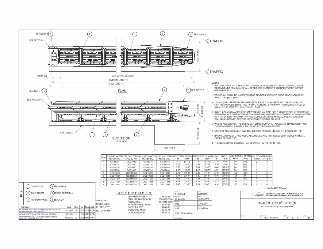
ELEVATIONLEFT SIDE
PLAN
SCALE: DRAWING: SHEET: REV
DRAWN:
DESIGNED:
CHECKED:
NEXT ASSEMBLY:
DATE:
DATE:
DATE:
DATE:APPROVED:
FILE:
of
D. Kohfeld
M. Buehler
JME
MJB
QG2TSCVR-U.idw
2/25/2009
12/30/2008
3/4/2009
3/19/2009
QG2TSCVR-U 1 1 D
QUADGUARD II SYSTEM
UNIDIRECTIONALMONORAIL
NOSE ASSEMBLY2 DIAPHRAGM
1 CARTRIDGE
3 FENDER PANEL
5
4
BACKUP6
BAYS610 [24"] WIDTH
MODEL NO.762 [30"] WIDTH
MODEL NO.914 [36"] WIDTH
MODEL NO.EFFECTIVE LENGTH
m ft-inPAD LENGTHm ft-in
MAX DESIGN SPEEDKm/h [MPH]
NO. OF CARTRIDGESTYPE I TYPE II
5 QG210024 QG210030 QG210036 5.79 [19'-0"] 5.38 [17'-8"] 5.49 [18'-0"] 100 [62] 3 3
1270 [43]2.74 [9'-0"]2.64 [8'-8"]3.05 [10'-0"]QG27030QG270242
SYSTEM LENGTHm ft-in
1220 [48"] WIDTHMODEL NO.
QG27048
QG210048
1 QG24024 QG24030 QG24036 QG24048 2.13 [7'-0"] 1.73 [5'-8"] 2.74 [9'-0"] 40 [25] 2 0
QG29024 QG29030 QG29036 QG29048
QG28024 QG28030 QG28036 QG28048
QG27036
QG210524 QG210530 QG210536 QG210548
QG211024 QG211030 QG211036 QG211048
QG211524 QG211530 QG211536 QG211548
QG212024 QG212030 QG212036 QG212048
3
4
6
7
8
9
3.66 [12'-0"]
4.57 [15'-0"]
6.40 [21'-0"]
7.32 [24'-0"]
8.23 [27'-0"]
9.14 [30'-0"]
3.96 [13'-0"]
4.87 [16'-0"]
6.71 [22'-0"]
7.63 [25'-0"]
8.53 [28'-0"]
9.45 [31'-0"]
3.56 [11'-8"]
4.47 [14'-8"]
6.30 [20'-8"]
7.21 [23'-8"]
8.13 [26'-8"]
9.04 [29'-8"]
80 [50]
90 [56]
105 [65]
110 [68]
115 [71]
120 [75]
2 2
3 2
4 3
4 4
4 5
4 6
TRAFFIC
TRAFFIC
NOTES:1. IN COMPLIANCE WITH THE AASHTO 2002 ROADSIDE DESIGN GUIDE, MANUFACTURER RECOMMENDS REMOVAL OF ALL CURBS AND ISLANDS TO ENSURE PROPER IMPACT PERFORMANCE.
2. PROVISION SHALL BE MADE FOR REAR FENDER PANELS TO SLIDE REARWARD UPON IMPACT 762 [30.00] MIN.
3. 150 [6.00] MIN. REINFORCED 28 MPa [4000 PSI] P.C. CONCRETE PAD OR 200 [8.00] MIN. NON-REINFORCED 28MPa [4000 PSI] P.C. CONCRETE ROADWAY, MEASURING AT LEAST 3.66 m [12'-0"] WIDE BY 15.24 m [50'-0"] LONG.
4. SEE THE "QUADGUARD II SYSTEM PRODUCT MANUAL" FOR A DESCRIPTION OF ITS IMPACT PERFORMANCE CHARACTERISTICS AND DESIGN LIMITATIONS BEFORE PLACING A SYSTEM AT A GIVEN SITE. INFORMATION AND COPIES OF ABOVE MANUAL ARE AVAILABLE BY CALLING CUSTOMER SERVICE DEPARTMENT AT (888) 323-6374.
5. WHERE NECESSARY, THE CUSTOMER SHALL SUPPLY AN ADEQUATE TRANSITION FROM THE QUADGUARD II SYSTEM TO THE OBJECT BEING SHIELDED.
6. UNITS OF MEASUREMENT ARE MILLIMETERS [INCHES] UNLESS OTHERWISE NOTED.
7. BACKUP, MONORAIL, AND NOSE ASSEMBLIES ARE NOT INCLUDED IN MODEL NUMBER, ORDER SEPARATELY.
8. THE QUADGUARD II SYSTEM HAS BEEN TESTED TO NCHRP 350.
Revision Date Rev By Chk. App.
KE
Y
R E F E R E N C E S
DIAPHRAGM ASSY. 35-40-07
SHIM KIT, DIAPHRAGM 3540078-0000
NOSE ASSY. 3540042-0000
FENDER PANEL ASSY. 35-40-04
BACKUP ASSY. 35-40-03
MONORAIL ASSY. 35-40-75
CONCRETE PAD 35-40-76
EH PROJECT
SERIAL NO.
SALES ORDER
NO. OF UNITS
(EFFECTIVE LENGTH)
(SYSTEM LENGTH)
(PAD LENGTH)
12
20
[48.0
3]
102 [4.00]
210
[8.2
8]
816
[32
.14
]
915
[36
.02
]
1220 [48.03]
WITH TENSION STRUT BACKUP
®
53126
536
1 4 2
SEE NOTE 7
SEE NOTE 2
SEE NOTE 3
SEE NOTE 5
SEE NOTE 7 SEE NOTE 7
SEE NOTE 7
UPDATED SYSTEM LENGTH AND EFFECTIVE LENGTH COLUMNS IN TABLE
10/23/09 D DDS JME FJP
MONORAIL ASSY IN REFERENCES WAS 35-40-06, CONCRETE PAD WAS 35-40-11
6/22/09 B DDS STT RCB
REVISED DESIGN SPEED COLUMN IN TABLE. 8/31/09 C DK JME RCB
