quantitative risk assessment - egasegas.com.eg/corporate_overview/quantitative_risk.pdf · 9.2...
TRANSCRIPT

TOWN GAS COMPANY QUANTITATIVE RISK ASSESSMENT
PS-GZT-TG-001 Revision (1) Jan 2006
QUANTITATIVE RISK ASSESSMENT - QRA
FOR TOWN GAS COMPANY
PART - II
Pressure Reduction and Odorant Station
at Greater Cairo
Jan 2006
Report # PS-GZT-TG 001 Rev.0

TOWN GAS COMPANY QUANTITATIVE RISK ASSESSMENT
PS-GZT-TG-001 Revision (1) Jan 2006
Table of Contents
1.0 Executive Summary
2.0 Background
3.0 Project Description
4.0 Scope of Work
4.1 Objectives
4.2 Terms of Reference
5.0 Technical Definitions
6.0 Assessment of Risks
7.0 Methodology
8.0 Process Description
9.0 Operations of The System
9.1 Operations and Controls
9.2 Filling the Odorant Main Storage Tank
9.3 Gas Odorant - (Spot-leak 1009)
10.0 Weather Data
11.0 General Release Scenarios
12.0 Results of Consequences Modelling
13.0 Risk Evaluation

TOWN GAS COMPANY QUANTITATIVE RISK ASSESSMENT
PS-GZT-TG-001 Revision (1) Page 1 December 2006
1.0 EXECUTIVE SUMMARY
Quantitative risk assessment has been performed for a Pressure Reduction
Station with odorant as a typical model for Town Gas Company.
This PRS with odorant facilities has been considered as the typical PRS
for consequence modelling and risk assessment and representative to all
other stations proposed within Greater Cairo Natural Gas Plan.
For the purpose of the analysis it has been assumed that the Pressure
Reduction Stations are within restricted entry open area.
For the PRS leak scenario, the release rate has been simulated based on 3-
hole sizes.
• 0.25 inch representing instrument fitting failure (pin hole leak).
• 1.0 inch representing small pipe leak (minor leak).
• 4.0 inches leak representing a 4-inch pipe full bore rupture or 4-inch
hole size in a larger pipe diameter (major leak or catastrophic
failure).
Weather conditions have been selected based on wind speed and stability
class. The worst case weather conditions for gas dispersion is the stable
weather conditions, represented by wind speed of 1 m/s and stability class
“F” representing “very stable” weather conditions, in order to obtain
conservative results.

TOWN GAS COMPANY QUANTITATIVE RISK ASSESSMENT
PS-GZT-TG-001 Revision (1) Page 2 December 2006
The PRS comprises two types of pressures, the first is the upstream
pressure, which is high pressure ranging from 30 to 70 bars, while the
second pressure is the downstream pressure which is low pressure ranging
from 4 to 7 bars.
• For the purpose of the consequence modelling, the maximum of the
two types of pressures have been simulated to represent the worst
case and mild case respectively (70 bars as HP and 7 Bars as LP).
• The gas dispersion distances have been calculated in meters in
concentration terms of lower Flammability Limits (LFL) and Upper
Flammability Limits (UFL) presented in Parts Per Million (PPM)
concentrations in order to represent flammability range of release
gas cloud; however the extent of damage is presented by LFL only.
• The heat radiation from flash fires will not significantly affect
humans, equipment or structures due to the short duration of flash
fires.
• Fire consequence analysis has been described in details in fire
consequence effects section, which details the hazardous effects
from different types of fires.
• The following table presents the generic extent of damage distances
as a result from the consequence modelling simulation analysis
performed.

TOWN GAS COMPANY QUANTITATIVE RISK ASSESSMENT
PS-GZT-TG-001 Revision (1) Page 3 December 2006
Table 1 - Generic Extent of Damage Distances From PRS Leaks in Meters
High Pressure Side
70 Bar
Low Pressure Side 7 Bar Case
No. Leak Type Leak Sizein Meters
Leak Sizein Inches
Jet Flame
Gas Cloud
Jet Flame
Gas Cloud
1 Pin Hole 0.005 0.25 6.5 3.5 2.2 1.2
2 Minor Leak 0.025 1.0 25 11.2 6.5 5.5
3 Major Leak 0.1 4.0 70 30 30 11
The damage distances have been calculated by SHELL’s FRED version (4.0) consequence modelling software with the following conditions:
1- The released gas is Standard Natural Gas.
2- Wind Speed of 1m/sec.
3- Weather stability of “F” representing very stable wind conditions.
4- Damage distances are based on the maximum damage contours.
• From the extent of damage distances calculated, it can be seen that
the major or catastrophic equipment failure has the maximum
potential extent of damage due to increased leak size. Maximum
extent of damage is 70 meters in the worst case conditions.
• The minor leak has a localized extent of damage within the PRS
boundary due to medium leak size. Expected extent of damage is 25
meters.
• While the pin hole leak has the minimum localized extent of damage
due to small leak size. Minimum extent of damage is 6.5 meters in
the mild case conditions.

TOWN GAS COMPANY QUANTITATIVE RISK ASSESSMENT
PS-GZT-TG-001 Revision (1) Page 4 December 2006
• But on the other hand the probability of occurrence or failure
frequency of major leak or catastrophic equipment failure is deemed
to be much lower than a pin hole leak.
• Release from the odorant storage tank, is one of the critical events.
A release from the tank pressure relief valve as a result of overfilling
or over-pressure was modelled. Dispersion down-wind from the
PSV will extend a distance greater than 250m for lower
concentration (10 ppm) while the higher concentration (1000 ppm)
will extend about 120m.
• The jet flame associated with ignition of the release from the
odorant tank PSV would be of 20m in length, and the 12kw/m2 heat
radiation contour would extend 17m down-wind, while the 25kw/m2
contours would extend 13m down-wind.
1.1 Risk Reduction Measures
Risk reduction measures (recommendations) have been proposed as points
of improvement in order to enhance the PRS safety standards. These risk
reduction measures (recommendations) are summarized as follows:
1. There is a need to develop a safe system of work, based on risk
assessment for dealing with potential gas leaks.
2. Consideration should be given to the remote actuation of isolation
and slam-shut valves by Town Gas for different PRS's as well as the
transmission pipelines.

TOWN GAS COMPANY QUANTITATIVE RISK ASSESSMENT
PS-GZT-TG-001 Revision (1) Page 5 December 2006
3. There is a need to produce Hazardous Area Classification drawings
for all Pressure Reduction )n Stations.
4. Planned preventive maintenance policy should be in place for the
new PRSs.
5. There is a need to produce a 'Station Manual' for each PRS. This
manual should include formalized procedures, including precautions
and a site scenario specific emergency plan.
6. Site emergency plans must take into account wind direction and
stability and should consider interfaces with others, e.g. GASCO as
well as the public living nearby.
7. Town Gas needs to consider the security arrangements for all un-
manned stations.
8. There is a need that Town Gas should apply risk assessment to all
activities and to formalize procedures and permit-to-work systems.
9. The control room inlet door should be located in the upwind
direction away from the station (Inlet door should not face the PRS
station).
10. Alternatively, the control room should be provided by a secondary
means of escape at the back side of the room, which shall be used in
case of blockage of the main escape route by jet.
11. Self contained breathing apparatus (2 units at least) to be provided
at each PRS for handling odorant releases.

TOWN GAS COMPANY QUANTITATIVE RISK ASSESSMENT
PS-GZT-TG-001 Revision (1) Page 6 December 2006
12. It is recommended that a jet fire rated passive fire protection system to be applied to all safety critical shutdown valves ESDVs or Solenoid valves in order to maintain small isolatable inventories. (As applicable)
13. It is recommended to have pipeline marking signs indicating in Arabic and in English "Do Not . Dig" and "High Pressure Pipeline Underneath" in order to prevent such extreme hazardous situation.
14. 1t is recommended to include the prevailing wind direction on the PRS site plan.
15. It is recommended to have an elevated wind sock installed in the PRS site, which can be seen - from distance and from outside the fence to determine the direction of gas migration in case of major gas leak.
16. The design should fully comply with IGE TD/3 code requirements.

TOWN GAS COMPANY QUANTITATIVE RISK ASSESSMENT
PS-GZT-TG-001 Revision (1) Page 7 December 2006
2.0 BACKGROUND
Greater Cairo is surrounded by a ring of high pressure main feeders with
pressures ranging between 30 bar and 70 bar. These mains are fed from
two sources, one from Abu-madi gas field and the second from Abu El
Gharadik.
These mains are extending at the outskirts of the town to feed the pressure
reduction stations, factories power stations and domestic networks with
outlet pressures ranging between 7 bar and 0.025 bar.
Town Gas managing and operated the distribution network, installations
and pressure reduction stations to supply natural gas to the domestic,
commercial and industrial customers in the greater Cairo Areas.
3.0 PROJECT DESCRIPTION
Town Gas established a leadership in transporting and marketing of
natural gas for domestic, commercial and industrial customers. A large gas
network covering most of Greater Cairo city was laid years ago.
Since this time many vacant areas were developed and requested gas
supply. These developments were chosen after a survey and cost
evaluation was made to justify expenditure. Accordingly, a natural gas
plan was established for greater Cairo areas supply through the installation
of more six pressure reduction stations to cover new loads.

TOWN GAS COMPANY QUANTITATIVE RISK ASSESSMENT
PS-GZT-TG-001 Revision (1) Page 8 December 2006
These pressure reduction and odorant stations are as follows:
1. El Haram PRS, with a capacity of 40.000m3/hr.
2. New Cairo city PRS, with a capacity of 60.000m3/hr.
3. El Mokattam PRS, with a capacity of 20.000m3/hr
4. El Tebeen (Domestic) PRS, with a capacity of 10.000m3/hr
5. El Shorouk PRS, with a capacity of 20.000 m3/hr
4.0 SCOPE OF WORK
The risk assessment technical proposal is based on the fact that the
pressure reduction stations are all identical I design and operating
conditions. Accordingly and in addition to the QRA study made before for
a pressure reduction station without odorant (Tebeen - Industrial), this
study report presents the quantitative risk assessment - QRA study carried
out for a typical pressure reduction station and odorant station that can be
applied to all other typical ones at greater Cairo City (Cairo / Giza).
4.1 Objectives
Town Gas has set out the main objectives of the risk assessment to include
the following:
1. To identify, assess and quantify risks to people (the general public,
town Gas operations staffed other associated groups).

TOWN GAS COMPANY QUANTITATIVE RISK ASSESSMENT
PS-GZT-TG-001 Revision (1) Page 9 December 2006
2. To identify, assess and quantify risks arising from pressure reduction
and odorizing stations.
3. To comprehensively examine the ways in which the identified risks
can be eliminated or reduced.
4. To recommended practical risk reduction and control measures for
consideration.
4.2 Terms of Reference
• Town Gas identified specific parts of the pressure reduction
stations for the proposed risk assessment study. These are:
1. The inlet stage
2. The filtration stage
3. The heating stage
4. The reduction stage
5. The measuring stage
6. The odorizing stage
7. The outlet stage
• A risk assessment will be performed to identify the major risk
issues and contributors with a best estimate of the associated
levels of risk.

TOWN GAS COMPANY QUANTITATIVE RISK ASSESSMENT
PS-GZT-TG-001 Revision (1) Page 10 December 2006
• This work will be designed to perform two main functions:
1. To provide town Gas with a clear risk knowledge and
awareness such that investment decisions can be well
formed.
2. To act as a coherent stage in, and to define the final scope
of the full risk assessment.
In general, the work will cover, but not necessarily be limited to the
following:
• Review town Gas data provided
• Perform physical survey of the proposed location of each
station.
• Define possible accident scenarios and events.
• Conduct a full consequence analysis in relation to gas leaks
and fire/explosion.
• Conduct qualitative / quantitative risk assessment.
• Define possible risk elimination / reduction measures.

TOWN GAS COMPANY QUANTITATIVE RISK ASSESSMENT
PS-GZT-TG-001 Revision (1) Page 11 December 2006
5.0 TECHNICAL DEFINITIONS:
Confinement A qualitative or quantitative measures of the enclosure or partial enclosure areas where vapours cloud may be contained.
Congestion
A qualitative or quantitative measure of the physical layout, spacing, and obstructions within a facility that promote development of a vapour cloud explosion.
EERA Escape, Evacuation and Rescue Assessment
ESD Emergency Shut Down
FRA Fire Risk Assessment
Gas cloud dispersion
Gas cloud air dilution naturally reduces the concentration to below the LEL or no longer considered ignitable (typically defined as 50%> of the LEL).
Hazard An inherent physical or chemical characteristic (flammability, toxicity, corrosively, stored chemical or mechanical energy) or set of conditions that has the potential for causing harm to people, property, or the environment.

TOWN GAS COMPANY QUANTITATIVE RISK ASSESSMENT
PS-GZT-TG-001 Revision (1) Page 12 December 2006
Individual risk The risk to a single person inside a particular building. Maximum individual risk is the risk to the most-exposed person and assumes that the person is exposed.
QRA Quantitative Risk Assessment
Risk Relates to the probability of exposure to a hazard, which could result in harm to personnel, the environment or general public. Risk is a measure of potential for human injury or economic loss in terms of both the incident likelihood and the magnitude of the injury or loss.
Risk Assessment
The identification and analysis, either qualitative or quantitative, of the likelihood and outcome of specific events or scenarios with judgments of probability and consequences.
Vapour cloud explosion (VCE)
An explosion in air of a flammable material cloud

TOWN GAS COMPANY QUANTITATIVE RISK ASSESSMENT
PS-GZT-TG-001 Revision (1) Page 13 December 2006
6.0 ASSESSMENT OF RISKS This part of the study would address the identification, analysis and
subsequent assessment of major hazards associated with the relevant gas
pressure reduction stations in addition to the associated part of the gas
pipeline.
They are categorised, and makes judgement on the tolerability of risks to
personnel associated with these hazards. British Gas criteria for risk
tolerability are used to base such judgements.
Scenarios that could result in major hazards will be identified and
evaluated using semi-quantified and Quantified Risk Assessment 'QRA'.
This technique is used to establish the expected frequency of such
incidents occurring on each facility and their consequences. Several
commercial software tools are available to Petrosafe are available for
consequences modelling of dispersion, fire and explosion will be selected
for modelling pipeline gas leaks.
Detailed risk profile to different individuals on the facility will be
estimated, which in turn becomes an important input in determining the
requirements for any remedial work.
This section will be linked to the rest of the proposed study in order to tie
together the logic of the arguments and bring the findings into better
context. It will encompass:
• Town Gas Policy, Standards and Criteria,

TOWN GAS COMPANY QUANTITATIVE RISK ASSESSMENT
PS-GZT-TG-001 Revision (1) Page 14 December 2006
• The sources of hazards,
• Hazardous substances, and their inventories,
• Events which are capable to cause major accidents,
• Analysis of the consequences and their effects on employees, third parties and the public,
• Evaluation of individual and societal risks, using BG Risk Tolerability Criterion,
• Measures to prevent, control or minimise likely consequences,
• Emergency procedures and emergency systems, derived from consideration of the above issues, including evacuation fire-fighting procedures.
From these studies, risk reduction measures are identified, and
improvements to hardware and management systems are considered.
7.0 METHODOLOGY
Maximum use should be made of all studies and reports produced for the
project so far.
A list of all-relevant studies and reports relevant to all gas facilities should
be identified by The Company and made available to the Consultant.

TOWN GAS COMPANY QUANTITATIVE RISK ASSESSMENT
PS-GZT-TG-001 Revision (1) Page 15 December 2006
The proposed study will examine the contents of existing documents
relating to The Company- HSE Management System. This will cover such
documents as:
• The Company HSE Policy.
• Details of the pipeline design, PFD and PlD's.
• Codes and Standards used for the design and construction of the pipeline and relevant stations.
• Fire and gas detection/protection systems and procedures of the facilities in question.
• Operations manuals, procedures and standing orders relating to the pipeline and stations.
• Engineering:
1. Change control procedures
2. Relevant stations latest PFDs and PIDs
3. Maintenance philosophy & control
4. Inspections and planned preventive maintenance
5. Shut-down and blow-down philosophies
6. Design and locations of sectionalizing valves
7. Procedures for pigging operations.

TOWN GAS COMPANY QUANTITATIVE RISK ASSESSMENT
PS-GZT-TG-001 Revision (1) Page 16 December 2006
The proposed study will examine the relationship between relevant documents and management procedures to establish that these are adequate to demonstrate that all reasonable steps have been taken to ensure that the design, construction, operation and maintenance of the facility and its equipment are adequate to provide a safe working environment.
Furthermore, the Company should demonstrate that, in the event of an incident, which may escalate and lead to the requirement for personnel to evacuate the facility, such arrangements are in place and are adequate.
8.0 PROCESS DESCRIPTION:
The process would include the following stages.
8.1 Inlet Stage
The PRS must be completely isolated from the Cathodic system applied to
the feeding gas steel pipes, there for an isolating joint with protection is
installed.
The main station valve is installed to shut off the station in case of
emergency; this valve has the facility to be close either locally or
remotely.
The pressure gauges, temperature indicator, pressure & temperature
transmitters shall be exists for local and remote purposes.

TOWN GAS COMPANY QUANTITATIVE RISK ASSESSMENT
PS-GZT-TG-001 Revision (1) Page 17 December 2006
8.2 The Filtration Stage
At least 2 Filter & separator are installed to remove dust, rust and other
Solid contaminants and any traces of liquids.
The gas goes through filters, cleaned, become nearly dry and free of dust.
This stage is consists of at least two filter lines, each line has full capacity
of station. Each filter has the safety devices for safe operation (differential
pressure gauge, relief valves, liquid indicator, … etc.)
Each filter has filtration rate 2 - 5 micron for 100 % capacity, for the
separator 8 10 micron for 100 % capacity In the operation one filter stream
is always on duty, and the other is standby
8.3 The Heating Stage
Due to the high pressure of coming gas, and because the gas lost it s'
temperature during reduction stage specially when the range between the
inlet and outlet pressure is wide, in this case icing may be formed
surrounding the outlet pies after reduction, also to avoid any blocking
inside the control pilots may lead to stop the flow of gas, there for the
heater should be installed to heat the gas and maintain the temperature
after reduction not less than 7 degree centigrade.
It is preferable to install 2 he1ters, each 100 % of full capacity for
maintenance proposes.

TOWN GAS COMPANY QUANTITATIVE RISK ASSESSMENT
PS-GZT-TG-001 Revision (1) Page 18 December 2006
8.4 The Reduction Stage
The reduction unit shall be installed in well ventilation-closed area or in
open area under protected shelled.
Two reduction streams at least should be installed, each stream has the full
capacity of the station.
Each stream consists of slam shut - active & monitors reduce regulators
and relief valve Each stream should has the necessary all gauges,
indicators and transmitters
8.5 The Measuring Stage
After the gas be reduced to adjusted outlet pressure, the quantities must be
measured for two reasons, first to know the consumption gas, second for
add the suitable amount of odorant which is proportional to the gas flow
For these reasons at least tow measuring line are installed, each line has a
measuring device for 100 % of the full capacity
Sometimes when the station at the beginning and due to the low flow
because of low number of customers using gas it is better for the accuracy
of measuring to install a low flow measuring device ( 20 % of the total
capacity)

TOWN GAS COMPANY QUANTITATIVE RISK ASSESSMENT
PS-GZT-TG-001 Revision (1) Page 19 December 2006
8.6 The Odorizing Stage
After the gas filtered, heated, reduced wd measured -, odorant is added to
give the specific smell
The additional rate for Odorant is normally between 12 - 24 MG/CM
The system is consists of stainless steel storage tank with all necessary
safety devices, day tanks, electrical injection pumps and mechanical
pump.
Pumps should cover all low flow conditions as well as high flow
conditions.
Pumps could be operating automatically or manually.
The control unit is controlled the amount of odour which it should be
proportional to the gas flow.
8.7 The Outlet Stage
Consist as well as inlet stage from isolating joint, outlet valve gauge,
temperature indicator, pressure & temperature transmitters and non return
valve to protect the station from the back pressure.

TOWN GAS COMPANY QUANTITATIVE RISK ASSESSMENT
PS-GZT-TG-001 Revision (1) Page 20 December 2006
9.0 OPERATIONS OF THE SYSTEM
9.1 Operations and Controls
The system of operations all Town Gas pressure reduction stations relies
on a high degree of flexibility in terms of supply that ensures multiple gas
inlet sources and effective monitoring system in accordance with the
following:
• These stations operates three shift system/dry reduces gas pressure
and adds odorant to the gas.
• The company operates a monitoring and control “SCADA” system
that monitors all mains and pressure stations in greater Cairo as well
as the main gas transmission lines (30 bar and 70 bar) with the
following function:
- Monitoring of inlet gas pressure for main sources, giving in the case of high and low gas pressures.
- Monitoring of the odourization units in the stations in terms of rate of filling and giving alarms if the storage tanks odorant level and pressure increases or decreases.
- Monitoring of all stations outlet gas pressure and flow rates.
- Monitoring of the effects of gas output on the transmission line pressure.
- Controlling bridges isolation valves remotely in cases of emergency.

TOWN GAS COMPANY QUANTITATIVE RISK ASSESSMENT
PS-GZT-TG-001 Revision (1) Page 21 December 2006
- The SCADA system should also remotely control the change-
over gas reduction streams to auxiliary lines at all stations in
case of emergency or due to failures.
9.2 Filling The Odorant Main Storage Tank
• The odorant (spot leak 1009) storage tank is filled when the liquid
level drops below the minimum level.
The liquid level is monitored via two level measuring systems, the
first is based on a manometer and the second is electrical device.
• The tank is pressurized by blanket gas to minimize vaporization of
the odorant. This gas is used to transfer the odorant from its drum
into the storage tank. The odorant vaporizes at about 1-45 bar, so
that the blanket gas pressure is increases from 1-5 bar to 1-6bar.
• The pressure inside the tank is equated with atmospheric by means
of burning blanket gas saturated with spot-leak through a temporary
gas burner. Blanket gas inside the tank forms 20% of the volume
above spot-leak level when the tank is full.
9.3 Gas Odorant (Spot-leak 1009)
• The odorant is supplied with a safety Data sheet (see appendix-1).
The odorant is identified as spot-leak 1009. this is based on aliphatic
mercaptan mixtures in clear liquid form that is extremely flammable
with the following characteristics:

TOWN GAS COMPANY QUANTITATIVE RISK ASSESSMENT
PS-GZT-TG-001 Revision (1) Page 22 December 2006
• Colour Colourless
• Odour Stinking
• Boiling Point / Range 62°C
• Melting Point / range <-10 (Freezing Point - 45°C)
• Decomposition temperature 425°C
• Flush point Closed Cup - 27°C
• Auto-ignition temperature 245°C
• Vapour pressure [email protected]°C
• Vapour density (Air = 1) 3.0
• Specific gravity (water = 1) 0.812@15-5°C
• Solubility - Water Insoluble (20°C)
- Solvent Soluble in Alcohols, Hydrocarbons
• Composition:
TERTIOBUTYL MERCAPTAN 77%
ISOPROPYL MERCAPTAN 14%
N-PROPYL MERCAPTAN 5.5%
* Specific Hazards: - Highly Flammable
- Irritating to respiratory system
- May cause sensitization by skin contact

TOWN GAS COMPANY QUANTITATIVE RISK ASSESSMENT
PS-GZT-TG-001 Revision (1) Page 23 December 2006
10.0 WEATHER DATA:
The weather data relevant to this study consists of a list of weather conditions in the form of different combinations of wind-speed, temperature, humidity and atmospheric stability.
Met oceanographic data gathered for greater Cairo over a period of 5 years. This data included wind-speed and direction, air temperature, as well as current speed.
The general climatic conditions at Cairo are summarized as follows:
• Air temperature °C -1-1
- Minimum recorded 25.2
- Yearly average 28
• Relative humidity %
- Average Daily maximum 82%
- Average Daily Minimum 54%
- Annual Average 78%
The recorded annual wind speeds at Cairo are:
Wind Speeds at Cairo (Knots) Month Jan Feb Mar Apr May June July Aug Sep Oct Nov Dec
Wind Speed 4.7 5.6 6.3 6.2 5.6 5.2 4.4 3.4 3.6 4.0 3.8 4.4
Average wind speed = 2.44 m/sec.

TOWN GAS COMPANY QUANTITATIVE RISK ASSESSMENT
PS-GZT-TG-001 Revision (1) Page 24 December 2006
• Sets of weather conditions initially selected for this study:
Set 1 Set 2 Set 3 Set 4
Wind Speed Stability Wind
speed Stability Wind speed Stability Wind
Speed Stability
3m/S B 1m/S D 2m/S D 4m/S F
The wind speed range between 1 to 5m/S was considered to be reasonable
representation of typical conditions of Cairo. This would overcome some
of the uncertainty of the meteorological data provided. Wind speed of
8m/s is likely to disperse the cloud over long distances to well below LFL.
The weather set 3 was eventually Considered to represent the most likely
conditions, however the worst case conditions shall be defined by a
sensitivity analysis study>
For worst case conditions, Set 4 would be selected for QRA Study
Modelling of gas releases and, fire, while Set 3 shall be considered in case
of odorant release for conservative results under the most prevailing
weather conditions.

TOWN GAS COMPANY QUANTITATIVE RISK ASSESSMENT
PS-GZT-TG-001 Revision (1) Page 25 December 2006
11.0 GENERIC RELEASE SCENARIOS
Events associated with release, dispersion and ignition of flammable
releases considered in this study can be summarized in the following
figure.
Release
More obstaclesGreater confinementFlame acceleration
Ignites?
Jet fire Internal explosion Pool fire Cloud fire Fast flame
Safedispersion
Dispersing cloud
Ignites?
No
Yes No
Yes
BLEVE
Impinge?
Yes
Structural Failure
Figure 11.1 Hazardous events

TOWN GAS COMPANY QUANTITATIVE RISK ASSESSMENT
PS-GZT-TG-001 Revision (1) Page 26 December 2006
These events can be more detailed as follows:
Jet fires A jet fire will result from an ignited pressurized hydrocarbon gas
release. The consequence of jet fires is directional depending on
the on release orientation. Jet fires typically have flame
temperature of about 2,200 oF and can produce high intensity
thermal radiation. The high temperature poses a hazard from
direct effects of heat on humans and also from possibility of
escalation. If a jet flame impinges upon a target such as a vessel,
pipe or structural member, it can cause failure of the item to fail
within several minutes.
Jet (spray) fire will also result from ignited continuous releases of
pressurized flammable liquid. The momentum of the release
carries the material forwards in a plume entraining air to give a
flammable mixture as gas is released from the plume.
Flash fires If flammable gas accumulates in an unconfined area and is
ignited, then the result will be a flash fire within the flammable
limits of the vapour cloud.
Explosions Ignition of accumulated gas in semi-confined areas may also be
accompanied by an explosion; the overpressure generated will
depend on the degree of congestion and confinement of the
process area, and the gas cloud size.

TOWN GAS COMPANY QUANTITATIVE RISK ASSESSMENT
PS-GZT-TG-001 Revision (1) Page 27 December 2006
Pool fires If a liquid release is ignited after it has time to form a pool, a pool
fire results. Because they are less well aerated, pool fires tend to
have lower flame temperatures and produce lower levels of
thermal radiation than jet fires. They also produce more smoke.
Although a pool fire can still lead to structure failure of items
within the flame, this would take longer than in a jet fire.
An additional hazard of pool fires is their ability to flow. A
burning liquid pool can spread along horizontal surface or run
down a vertical surface to give a running fire.
BLEVE
(Fire Ball)
BLEVE stands for Boiling Liquid Expanding Vapour Explosion.
A fire ball can occur if a vessel containing fuel ruptures in the
presence of an ignition source (usually a jet or pool fire). A
fraction of the liquefied fuel subsequently released will evaporate
immediately and take part in a huge fireball, which has the shape
of a hemispherical burning cloud or ball of fire. High degree of
turbulent mixing and rapid air entrainment allows large quantities
of fuel to be consumed in a short period of time.
Structural
failure
Loss of structure integrity due to overheating of structure
members. The structure shall collapse under much lower load
than the designed due to increased temperature.
Safe
dispersion
Dilution of the released gases beyond the lower flammability
limits (LFL) leading to safe dispersion situation.

TOWN GAS COMPANY QUANTITATIVE RISK ASSESSMENT
PS-GZT-TG-001 Revision (1) Page 28 December 2006
12.0 RESULTS OF CONSEQUENCES MODELLING 12.1 High Pressure Release from 100-mm (4-Inch) Leak
Upstream PRS (1A)
General:
This case model considers the scenario of a full bore rupture of 4 inch
piping or 4 inch hole in a larger diameter piping, which represents the
worst case scenario as the release source is a high pressure major leak.
Gas Cloud / Flash Fire:
The proposed hazardous area resulting from the gas cloud shall be limited
by the upper flammability limit (UFL) and the lower flammability limit
(LFL), which if ignited results in flash fire.
The following figure represents the side view of the gas cloud (Plume) as
a graphical display illustrating the LFL/UFL limits and the maximum
plume height.

TOWN GAS COMPANY QUANTITATIVE RISK ASSESSMENT
PS-GZT-TG-001 Revision (1) Page 29 December 2006
The following table represents the LFL and UFL limits and heights of the
gas cloud (Plume) in figures.
Concentration LFL UFL
Contour value (ppm) 47226.4 148597.8
Downwind distance (m) 32.28 10.12
Height above ground (m) 0.8994 0

TOWN GAS COMPANY QUANTITATIVE RISK ASSESSMENT
PS-GZT-TG-001 Revision (1) Page 30 December 2006
Jet Fire:
The following figure represents the side view of the jet fire (Torch Flame)
as a graphical display illustrating the heat radiation levels.

TOWN GAS COMPANY QUANTITATIVE RISK ASSESSMENT
PS-GZT-TG-001 Revision (1) Page 31 December 2006
12.2 High Pressure Release from 25-mm (1-Inch) Leak
Upstream PRS (1B)
General:
This case model considers the scenario of a leak of 1 inch hole size in a
larger diameter piping, which represents the medium case scenario as the
release source is a high pressure minor leak.
Gas Cloud / Flash Fire:
The proposed hazardous area resulting from the gas cloud shall be limited
by the upper flammability limit (UFL) and the lower flammability limit
(LFL), which if ignited results in flash fire.
The following figure represents the side view of the gas cloud (Plume) as
a graphical display illustrating the LFL/UFL limits and the maximum
plume height.

TOWN GAS COMPANY QUANTITATIVE RISK ASSESSMENT
PS-GZT-TG-001 Revision (1) Page 32 December 2006
The following table represents the LFL and UFL limits and heights of the
gas cloud (Plume) in figures.
Concentration LFL UFL
Contour value (ppm) 47226.4 148597.8
Downwind distance (m) 12.08 5.5
Height above ground (m) 0 0.7974

TOWN GAS COMPANY QUANTITATIVE RISK ASSESSMENT
PS-GZT-TG-001 Revision (1) Page 33 December 2006
Jet Fire:
The following figure represents the side view of the jet fire (Torch Flame)
as a graphical display illustrating the heat radiation levels.

TOWN GAS COMPANY QUANTITATIVE RISK ASSESSMENT
PS-GZT-TG-001 Revision (1) Page 34 December 2006
12.3 High Pressure Release from 5-mm (1/4-Inch) Leak
Upstream PRS (1C)
General:
This case model considers the scenario of a pin hole leak of 1/4 inch hole
size in a larger diameter piping, which represents the mildest case scenario
as the release source is from a pin hole leak.
Gas Cloud / Flash Fire:
The proposed hazardous area resulting from the gas cloud shall be limited
by the upper flammability limit (UFL) and the lower flammability limit
(LFL), which if ignited results in flash fire.
The following figure represents the side view of the gas cloud (Plume) as
a graphical display illustrating the LFL/UFL limits and the maximum
plume height.

TOWN GAS COMPANY QUANTITATIVE RISK ASSESSMENT
PS-GZT-TG-001 Revision (1) Page 35 December 2006
The following table represents the LFL and UFL limits and heights of the
gas cloud (Plume) in figures.
Concentration LFL UFL
Contour value (ppm) 47226.4 148597.8
Downwind distance (m) 4 1.2
Height above ground (m) 0.9443 0.9764

TOWN GAS COMPANY QUANTITATIVE RISK ASSESSMENT
PS-GZT-TG-001 Revision (1) Page 36 December 2006
Jet Fire:
The following figure represents the side view of the jet fire (Torch Flame)
as a graphical display illustrating the heat radiation levels.
TOWN GAS COMPANY QUANTITATIVE RISK ASSESSMENT
PS-GZT-TG-001 Revision (1) Page 37 December 2006
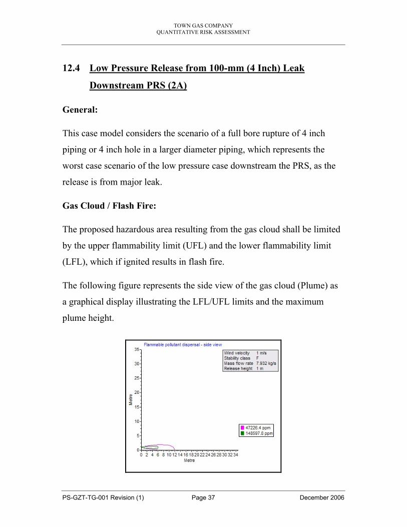
12.4 Low Pressure Release from 100-mm (4 Inch) Leak
Downstream PRS (2A)
General:
This case model considers the scenario of a full bore rupture of 4 inch
piping or 4 inch hole in a larger diameter piping, which represents the
worst case scenario of the low pressure case downstream the PRS, as the
release is from major leak.
Gas Cloud / Flash Fire:
The proposed hazardous area resulting from the gas cloud shall be limited
by the upper flammability limit (UFL) and the lower flammability limit
(LFL), which if ignited results in flash fire.
The following figure represents the side view of the gas cloud (Plume) as
a graphical display illustrating the LFL/UFL limits and the maximum
plume height.

TOWN GAS COMPANY QUANTITATIVE RISK ASSESSMENT
PS-GZT-TG-001 Revision (1) Page 38 December 2006
The following table represents the LFL and UFL limits and heights of the
gas cloud (Plume) in figures.
Concentration LFL UFL
Contour value (ppm) 47226.4 148597.8
Downwind distance (m) 12.06 6.001
Height above ground (m) 0 0.675

TOWN GAS COMPANY QUANTITATIVE RISK ASSESSMENT
PS-GZT-TG-001 Revision (1) Page 39 December 2006
Jet Fire:
The following figure represents the side view of the jet fire (Torch Flame)
as a graphical display illustrating the heat radiation levels.
TOWN GAS COMPANY QUANTITATIVE RISK ASSESSMENT
PS-GZT-TG-001 Revision (1) Page 40 December 2006
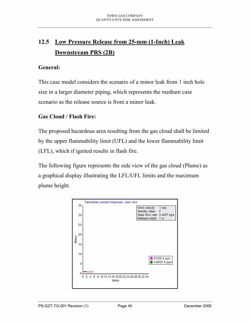
12.5 Low Pressure Release from 25-mm (1-Inch) Leak
Downstream PRS (2B)
General:
This case model considers the scenario of a minor leak from 1 inch hole
size in a larger diameter piping, which represents the medium case
scenario as the release source is from a minor leak.
Gas Cloud / Flash Fire:
The proposed hazardous area resulting from the gas cloud shall be limited
by the upper flammability limit (UFL) and the lower flammability limit
(LFL), which if ignited results in flash fire.
The following figure represents the side view of the gas cloud (Plume) as
a graphical display illustrating the LFL/UFL limits and the maximum
plume height.

TOWN GAS COMPANY QUANTITATIVE RISK ASSESSMENT
PS-GZT-TG-001 Revision (1) Page 41 December 2006
The following table represents the LFL and UFL limits and heights of the
gas cloud (Plume) in figures.
Concentration LFL UFL
Contour value (ppm) 47226.4 148597.8
Downwind distance (m) 5.5 1.8
Height above ground (m) 0.8138 0.9689

TOWN GAS COMPANY QUANTITATIVE RISK ASSESSMENT
PS-GZT-TG-001 Revision (1) Page 42 December 2006
Jet Fire:
The following figure represents the side view of the jet fire (Torch Flame)
as a graphical display illustrating the heat radiation levels.

TOWN GAS COMPANY QUANTITATIVE RISK ASSESSMENT
PS-GZT-TG-001 Revision (1) Page 43 December 2006
12.6 Low Pressure Release from 5-mm (1/4-Inch) Leak
Downstream PRS (2C)
General:
This case model considers the scenario of a pin hole leak of 1/4 inch hole
size in a larger diameter piping, which represents the mildest case scenario
as the release source is from a pin hole leak.
Gas Cloud / Flash Fire:
The proposed hazardous area resulting from the gas cloud shall be limited
by the upper flammability limit (UFL) and the lower flammability limit
(LFL), which if ignited results in flash fire.
The following figure represents the side view of the gas cloud (Plume) as
a graphical display illustrating the LFL/UFL limits and the maximum
plume height.

TOWN GAS COMPANY QUANTITATIVE RISK ASSESSMENT
PS-GZT-TG-001 Revision (1) Page 44 December 2006
The following table represents the LFL and UFL limits and heights of the
gas cloud (Plume) in figures.
Concentration LFL UFL
Contour value (ppm) 47226.4 148597.8
Downwind distance (m) 1.2 0.3
Height above ground (m) 0.9803 0.984

TOWN GAS COMPANY QUANTITATIVE RISK ASSESSMENT
PS-GZT-TG-001 Revision (1) Page 45 December 2006
Jet Fire:
The following figure represents the side view of the jet fire (Torch Flame)
as a graphical display illustrating the heat radiation levels.

TOWN GAS COMPANY QUANTITATIVE RISK ASSESSMENT
PS-GZT-TG-001 Revision (1) Page 46 December 2006
12.7 Release from The Odorant Tank
Release of vapour from the odorizing storage tank is one of the critical
events. This tank is filled about once every two months. A release from
the tank pressure relief valve as a result of overfilling or over-pressure was
modelled. Fig. 12-A & B show the modelling results.
From the sensitivity analysis, the following parameters have been selected
to represent the worst case scenario parameters and utilized to present a
conservative approach in case of odorant release:
- Maximum ambient temp. 40 c - Weather stability 2.4m/s class D - Source of release PSV vent - 1 inch diameter - Operating pressure 1.5 to 1.6 Bar g
Fig. 12-A shows the vertical section of the gas/vapour (gas containing
80% spot-leak dispersion down-wind from the PSV. Lower concentration
taken as 10ppm will extend a distance greater than 250m, while the higher
concentration 1000ppm will extend about 120m. Spot-leak vapour is three
times heavier than air.
Fig. 12-B gives the horizontal cross-section of the release.
Fig. 12-C shows the jet flame associated with ignition of the release from
the odorant tank PSV. A flame length of 20m would result and 12kw/m2
heat radiation contours would extend 17m down-wind, while the 25kw/m2
contours would extend 13m down-wind.

TOWN GAS COMPANY QUANTITATIVE RISK ASSESSMENT
PS-GZT-TG-001 Revision (1) Page 47 December 2006
FIGURE 12-A Release From Odorant Tank PSV – Side View
FIGURE 12-B Gas Release From Odorant Tank PSV – Top View
Release from odorant tank PSVHorizontal Cross Section
-100
-80
-60
-40
-20
0
20
40
60
80
100
0 50 100 150 200 250
Downwind Distance (m)Material : Methane with 80% Spotleak
Higher Concentration 0.1000 % vol/vol
Lower Concentration 0.0010 % vol/vol
Windspeed is 2.4 m/s
Stability is D
Release from odorant tank PSVVertical Section
0
20
40
60
80
100
120
140
160
-50 0 50 100 150 200 250
Downwind Distance (m)Material : Methane with 80% Spotleak
Lower Concentration 0.0010 % vol/volHigher Concentration 0.1000 % vol/vol Windspeed is 2.4 m/s
Stability is D

TOWN GAS COMPANY QUANTITATIVE RISK ASSESSMENT
PS-GZT-TG-001 Revision (1) Page 48 December 2006
Je t fla me from odorant ta nk
0
10
20
30
40
50
60
-30 -20 -10 0 10 20 30
6 kW/m212 kW/m225 kW/m2UnusedUnusedUnusedFLAME
Ve rtica l Se ction through Origin
Heat Flux
Down Wind
2.4 m/s
FIGURE 12-C Jet Flame From Odorant Tank PSV
• Accidental Release Measures:
• For environmental protection, do not release into the environment. PSV
vent should be connected to the flare provided on site.
• In case of spill, destroy the product by oxidation using dilute solutions of
Hydrogen peroxide or Sodium Hypochlorite.
• In case of leak, use self-contained breathing apparatus avoid contact with
the skin by using PPE.

TOWN GAS COMPANY QUANTITATIVE RISK ASSESSMENT
PS-GZT-TG-001 Revision (1) Page 49 December 2006
13.0 RISK EVALUATION The risks assessed shall be evaluated based on the international risk acceptance criteria.
The ALARP principle has been adopted for risk evaluation. The ALARP region is that point at which the time, effort difficulty and cost of further risk reduction become out of proportion compared with the amount of risk reduction achieved.
Risks lower than the ALARP region risks will be considered minor risk and consequently they will not be considered.
Risks higher than the ALARP region risks will be considered major risk and consequently they will be not acceptable and further reduction measures are required.
The international risk acceptance criteria are presented in the following figure.
UN ACC EPTA BLE REGION
AC CEPTABLE REGION
AC CEPTABLE REGION
(Risk must be dem onstrated to have been reduced to a level which is
practicable with a view to cost/benefit)
IN DIV IDU AL RISK TO W OR KER S(including contractor em ployees)
IN DIV IDU AL RISK TO TH E PUBLIC(all those not directly involved w ith company
activities)
ALA RP Benchm ark existing insta llations
1 in 5,000 per year
ALA RP Benchmark new insta lla tions
1 in 50,000 per year
AL ARP OR TO LERA BILITY REG IO NAL ARP OR TO LERA BILITY
R EG IO N
M aximum tolerable limit1 in 1000 per year
M aximum tolerable limit
1 in 10,000 per year
M inim um tolerable lim it
1 in 1 million per year
M inim um tolerable lim it1 in 100,000 per year
W orkers
Public
TOWN GAS COMPANY QUANTITATIVE RISK ASSESSMENT
PS-GZT-TG-001 Revision (1) Page 50 December 2006
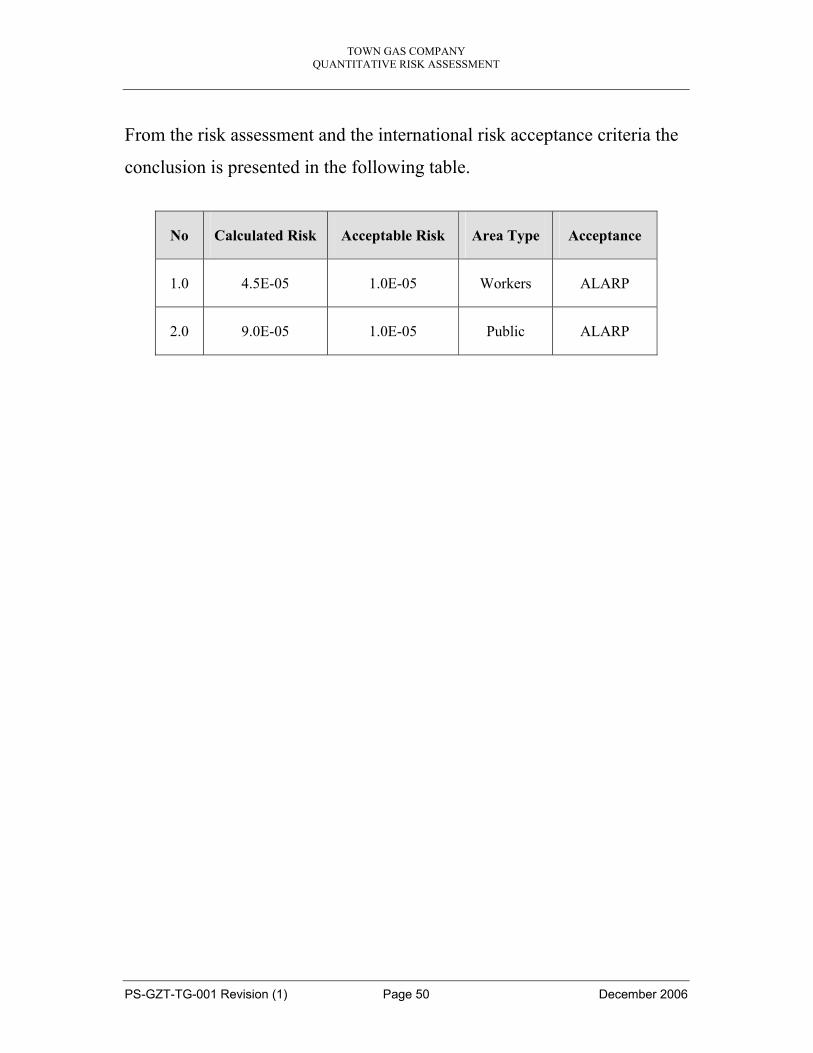
From the risk assessment and the international risk acceptance criteria the
conclusion is presented in the following table.
No Calculated Risk Acceptable Risk Area Type Acceptance
1.0 4.5E-05 1.0E-05 Workers ALARP
2.0 9.0E-05 1.0E-05 Public ALARP

TOWN GAS COMPANY QUANTITATIVE RISK ASSESSMENT
PS-GZT-TG-001 Revision (1) Page 51 December 2006
13.1 Individual Risks ‘IR’ to Workers
In order to calculate Individual Risk ‘IR’ for workers, there is a need to
identify who is exposed to the fire and explosion hazards from all hazards
at the PRS station, not just as a result of gas leaks. The proportion of time
individuals is exposed to the hazards and their vulnerability should be
considered in estimating this risk. Vulnerability is the probability that
exposure to the fire/explosion hazards will result in fatality. The following
calculations relate to the most vulnerable individuals on site, identified to
be workers involved in fire-fighting.
‘IR’ is calculated using the following model:
IR = S (frequency of fires/explosions) X Vulnerability
IR (Workers) = 1.5E-04 X 0.3 X 1.0 = 4.5E-05 per year
The major contributory factor for the increased level of ‘IR’ is the
potential gas vapour cloud explosion due to the confined conditions of the
pressure reduction streams and the Odomatic system.
Evaluation of Individual Risks as shown in FIGURE 22.1 indicates that
individual risk to workers at the PRS to be within the ALARP region. This
should be reduced to a level that is as low as reasonably practicable, taking
cost into account.

TOWN GAS COMPANY QUANTITATIVE RISK ASSESSMENT
PS-GZT-TG-001 Revision (1) Page 52 December 2006
FIGURE 13-A Evaluation of IR to Town Gas Workers
1.2E - 03/yr
1.0E - 05/year
1.0E - 03/year
ALARP
-
-
ALARP
1.0E-03 per person/yr
1.0E-05 per person/yr
2.2E-05 per yr
1.2E - 03/yr
1.0E - 05/year
1.0E - 03/year
ALARP
-
-
ALARP
1.0E-03 per person/yr
1.0E-05 per person/yr
4.5E-05 per yr

TOWN GAS COMPANY QUANTITATIVE RISK ASSESSMENT
PS-GZT-TG-001 Revision (1) Page 53 December 2006
13.2 Individual Risk to the Public
The general public exposed to major hazards as a result of the PRS
activities are road users around the site and residents in buildings nearby.
Modelling of the consequences identified gas/odorant releases to affect the
public outside the station. The station is surrounded by busy roads, as well
as the public buildings.
‘IR’ is calculated using the following model:
IR = S (frequency of fires/explosions) X Occupancy X Vulnerability
IR (Public) = 1.5E-04 X 2 X 0.3 X 1.0 = 9.0E-05 per year
Evaluation of IR to the public is shown in FIGURE 22.2.
FIGURE 13-B Evaluation of IR to the public
1.2E - 03/yr
1.0E - 05/year
1.0E - 03/year
ALARP
-
-
ALARP
1.0E-03 per person/yr
1.0E-05 per person/yr
2.2E-05 per yr
1.2E - 03/yr
1.0E - 05/year
1.0E - 03/year
ALARP
-
-
ALARP
1.0E-03 per person/yr
1.0E-05 per person/yr
9.0E-05 per yr

TOWN GAS COMPANY QUANTITATIVE RISK ASSESSMENT
PS-GZT-TG-001 Revision (1) Page 54 December 2006
It is therefore concluded that, Individual Risk to the public is also within
the ALARP region and should be reduced to a level as low as reasonably
practicable.
These risks shall be evaluated against the international risk acceptance
criteria.

TOWN GAS COMPANY QUANTITATIVE RISK ASSESSMENT
PS-GZT-TG-001 Revision (1) Page 55 December 2006