questions? 08457 089 009 - iconsupport.eu · longer than 1.5 m (5 ft.). 12. ... repeat this step on...
TRANSCRIPT

USER'S MANUALSerial Number
Decal
Model No. WETL12706.0Serial No.
CAUTIONRead all precautions and instruc-tions in this manual before usingthis equipment. Save this manualfor future reference.
QUESTIONS?As a manufacturer, we are com-mitted to providing completecustomer satisfaction. If youhave questions, or if there aremissing or damaged parts,please call:
or write:ICON Health & Fitness, Ltd.Customer Service DepartmentUnit 4Revie Road Industrial EstateRevie RoadBeestonLeeds, LS118JGUK
email: [email protected]
08457 089 009

TABLE OF CONTENTS
IMPORTANT PRECAUTIONS . . . . . . . . . . . . . . . . . . . . . . . . . . . . . . . . . . . . . . . . . . . . . . . . . . . . . . . . . . . . . . . . .3BEFORE YOU BEGIN . . . . . . . . . . . . . . . . . . . . . . . . . . . . . . . . . . . . . . . . . . . . . . . . . . . . . . . . . . . . . . . . . . . . . . .5ASSEMBLY . . . . . . . . . . . . . . . . . . . . . . . . . . . . . . . . . . . . . . . . . . . . . . . . . . . . . . . . . . . . . . . . . . . . . . . . . . . . . . .6OPERATION AND ADJUSTMENT . . . . . . . . . . . . . . . . . . . . . . . . . . . . . . . . . . . . . . . . . . . . . . . . . . . . . . . . . . . .10HOW TO FOLD AND MOVE THE TREADMILL . . . . . . . . . . . . . . . . . . . . . . . . . . . . . . . . . . . . . . . . . . . . . . . . . .15MAINTENANCE AND TROUBLESHOOTING . . . . . . . . . . . . . . . . . . . . . . . . . . . . . . . . . . . . . . . . . . . . . . . . . . . .17CONDITIONING GUIDELINES . . . . . . . . . . . . . . . . . . . . . . . . . . . . . . . . . . . . . . . . . . . . . . . . . . . . . . . . . . . . . . .19ORDERING REPLACEMENT PARTS . . . . . . . . . . . . . . . . . . . . . . . . . . . . . . . . . . . . . . . . . . . . . . . . . .Back Cover
Note: A PART IDENTIFICATION CHART, an EXPLODED DRAWING, and a PART LIST are attached in thecenter of this manual.
WESLO is a registered trademark of ICON IP, Inc.
2

3
WARNING: To reduce the risk of burns, fire, electric shock, or injury to persons, read thefollowing important precautions and information before operating the treadmill.
IMPORTANT PRECAUTIONS
1. It is the responsibility of the owner to ensurethat all users of this treadmill are adequatelyinformed of all warnings and precautions.
2. Use the treadmill only as described in thismanual.
3. Place the treadmill on a level surface, with atleast 2.5 m (8 ft.) of clearance behind it and 0.5 m (2 ft.) on each side. Do not place thetreadmill on a surface that blocks any airopenings. To protect the floor or carpet fromdamage, place a mat under the treadmill.
4. Keep the treadmill indoors, away from mois-ture and dust. Do not put the treadmill in agarage or covered patio, or near water.
5. Do not operate the treadmill where aerosolproducts are used or where oxygen is beingadministered.
6. Keep children under the age of 12 and petsaway from the treadmill at all times.
7. The treadmill should be used only by personsweighing 115 kg (250 lbs.) or less.
8. Never allow more than one person on thetreadmill at a time.
9. Wear appropriate exercise clothes whileusing the treadmill. Do not wear loose clothesthat could become caught in the treadmill.Athletic support clothes are recommended forboth men and women. Always wear athleticshoes; never use the treadmill with bare feet,wearing only stockings, or in sandals.
10. When connecting the power cord (see page10), plug the power cord into an earthed cir-cuit. No other appliance should be on thesame circuit. When replacing the fuse, anASTA approved BS1362 type should be fittedto the fuse carrier. A 13 amp fuse should beused.
11. If an extension cord is needed, use only a 3-conductor, 1mm2 (14-gauge) cord that is nolonger than 1.5 m (5 ft.).
12. Keep the power cord away from heated sur-faces.
13. Never move the walking belt while the poweris turned off. Do not operate the treadmill ifthe power cord or plug is damaged, or if thetreadmill is not working properly. (See MAIN-TENANCE AND TROUBLESHOOTING on page17 if the treadmill is not working properly.)
14. Read, understand, and test the emergencystop procedure before using the treadmill (seeHOW TO TURN THE POWER ON on page 11).
15. Never start the treadmill while you are stand-ing on the walking belt. Always hold thehandrails while using the treadmill.
16. The treadmill is capable of high speeds.Adjust the speed in small increments to avoidsudden jumps in speed.
17. Never leave the treadmill unattended while it isrunning. Always remove the key and unplugthe power cord when the treadmill is not in use.
18. The pulse sensor is not a medical device.Various factors, including your movement, mayaffect the accuracy of heart rate readings. Thepulse sensor is intended only as an exerciseaid in determining heart rate trends in general.
19. Do not attempt to raise, lower, or move thetreadmill until it is properly assembled. (SeeASSEMBLY on page 6, and HOW TO FOLDAND MOVE THE TREADMILL on page 15.)You must be able to safely lift 20 kg (45 lbs.) toraise, lower, or move the treadmill.
20. When folding or moving the treadmill, makesure that the frame is securely held by thelock pin.
4
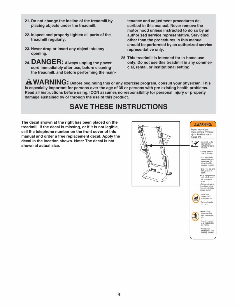
The decal shown at the right has been placed on thetreadmill. If the decal is missing, or if it is not legible,call the telephone number on the front cover of thismanual and order a free replacement decal. Apply thedecal in the location shown. Note: The decal is notshown at actual size.
Hungarian Russian Polish Portugese English:
232971
21. Do not change the incline of the treadmill byplacing objects under the treadmill.
22. Inspect and properly tighten all parts of thetreadmill regularly.
23. Never drop or insert any object into any opening.
24. DANGER: Always unplug the powercord immediately after use, before cleaningthe treadmill, and before performing the main-
tenance and adjustment procedures de-scribed in this manual. Never remove themotor hood unless instructed to do so by anauthorized service representative. Servicingother than the procedures in this manualshould be performed by an authorized servicerepresentative only.
25. This treadmill is intended for in-home useonly. Do not use this treadmill in any commer-cial, rental, or institutional setting.
WARNING: Before beginning this or any exercise program, consult your physician. Thisis especially important for persons over the age of 35 or persons with pre-existing health problems.Read all instructions before using. ICON assumes no responsibility for personal injury or propertydamage sustained by or through the use of this product.
SAVE THESE INSTRUCTIONS
5
Thank you for selecting the new WESLO® CADENCEM5 treadmill. The CADENCE M5 treadmill combinesadvanced technology with innovative design to makeyour workouts at home more effective and enjoyable.And when you’re not exercising, the CADENCE M5treadmill can be folded up, requiring less than half thefloor space of other treadmills.
For your benefit, read this manual carefully beforeusing the treadmill. If you have questions after read-
ing this manual, please see the front cover of this man-ual. To help us assist you, please note the productmodel number and serial number before contacting us.The model number of the treadmill is WETL12706.0.The serial number can be found on a decal attached tothe treadmill (see the front cover of this manual for thelocation).
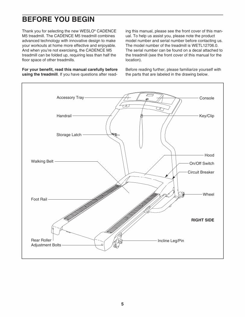
Before reading further, please familiarize yourself withthe parts that are labeled in the drawing below.
BEFORE YOU BEGIN
Handrail
Storage Latch
Console
Key/Clip
Circuit Breaker
Incline Leg/Pin
Walking Belt
Hood
WheelFoot Rail
Rear Roller Adjustment Bolts
Accessory Tray
RIGHT SIDE
On/Off Switch

6
ASSEMBLYAssembly requires two persons. Set the treadmill in a cleared area and remove all packing materials; do notdispose of the packing materials until assembly is completed. Note: The underside of the treadmill walkingbelt is coated with high-performance lubricant. During shipping, a small amount of lubricant may be transferred tothe top of the walking belt or the shipping carton. This does not affect treadmill performance. If there is lubricanton top of the walking belt, simply wipe off the lubricant with a soft cloth and a mild, non-abrasive cleaner.
In addition to the included hex key , assembly requires a phillips screwdriver , a spanner , and wire cutters .
Note: To identify small parts during assembly, see the PART IDENTIFICATION CHART in the center of thismanual. Some parts may be preassembled.
1. Make sure that the power cord is unplugged.
Have a second person hold the Base (52) in theposition shown.
Identify the Right Handrail (54), which has a largehole near the lower end. Hold the Right Handrailso the bend is in the position shown. Attachthe Right Handrail to the Base (52) with twoHandrail Bolts (2), two Handrail Washers (14) andtwo Nuts (16). Do not tighten the Handrail Boltsyet.
Attach the Left Handrail (53) to the Base (52)in the same way.
1
54
16LargeHole
52
2
2
14
53
Bend
2. With the help of a second person, raise theHandrails (53, 54) so the Base (52) is flat on thefloor as shown.
Attach the Wheels (70) to the outer sides of theBase (52) with two Wheel Bolts (35) and twoNuts (16) as shown. Do not overtighten theNuts; the Wheels should turn freely.
Position the front end of the treadmill Frame (51)between the Handrails (53, 54) as shown. Next,locate the long wire inside the lower end of theRight Handrail (see the inset drawing). Securelytie the end of the wire to the end of the WireHarness (98).
Then, pull the opposite end of the wire until theWire Harness (98) is extending from the upperend of the Right Handrail (54).
2
98
52
1670
35
54
51
53
98
98
54
Wire

3. Have a second person lift and hold the front endof the Frame (51). Hold a Frame Spacer (11) be-tween the Right Handrail (54) and the Frame.Attach the Right Handrail to the Frame with aFrame Pivot Bolt (1), a Frame Washer (14), and aHandrail Star Washer (9). Do not tighten theFrame Pivot Bolts yet.
Repeat this step on the left side of the tread-mill.
3
7
51
1
54
11
14
9
4. Hold the Console Assembly (91) near the RightHandrail (54). Touch the Right Handrail to dis-charge any static.
Next, remove the wire from the end of the WireHarness (98). Insert the end of the Wire Harnessthrough the two looped plastic ties.
Then, press the end of the Wire Harness (98) intothe connector on the back of the ConsoleAssembly (91) in the location shown. The end ofthe Wire Harness should slide easily into theconnector and snap into place. If it does not,turn the end of the Wire Harness and then tryagain. IF THE CONNECTORS ARE NOT CON-NECTED PROPERLY, THE CONSOLE MAY BEDAMAGED WHEN THE POWER IS TURNEDON.
4
5. Set the Console Assembly (91) on the RightHandrail (54) and the Left Handrail (not shown).Partially tighten two Crossbar Screws (5) with twoCrossbar Star Washers (12) (only one of each isshown) into the Handrails and the ConsoleAssembly. Then, partially tighten four ConsoleScrews (7) (only two are shown) into theHandrails and the Console Assembly. Then,tighten all six Screws.
Insert the excess Wire Harness (98) down intothe Right Handrail (54). Tighten the two plasticties around the Wire Harness, and then cut off theends of the plastic ties.
5
PlasticTies
Connector91
54
98
91
9854
7
7
12
5
PlasticTies
98
8
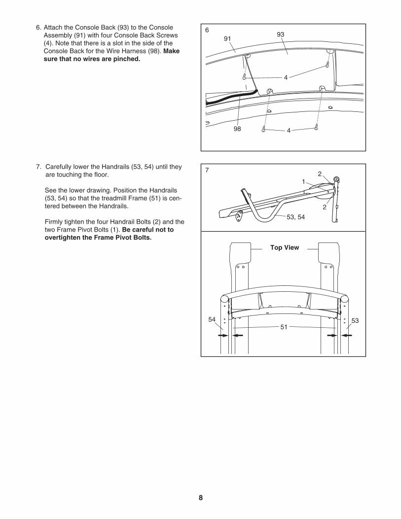
6. Attach the Console Back (93) to the ConsoleAssembly (91) with four Console Back Screws(4). Note that there is a slot in the side of theConsole Back for the Wire Harness (98). Makesure that no wires are pinched.
693
98
4
4
91
7. Carefully lower the Handrails (53, 54) until theyare touching the floor.
See the lower drawing. Position the Handrails(53, 54) so that the treadmill Frame (51) is cen-tered between the Handrails.
Firmly tighten the four Handrail Bolts (2) and thetwo Frame Pivot Bolts (1). Be careful not toovertighten the Frame Pivot Bolts.
7 2
2
53, 54
1
5351
54
Top View
9
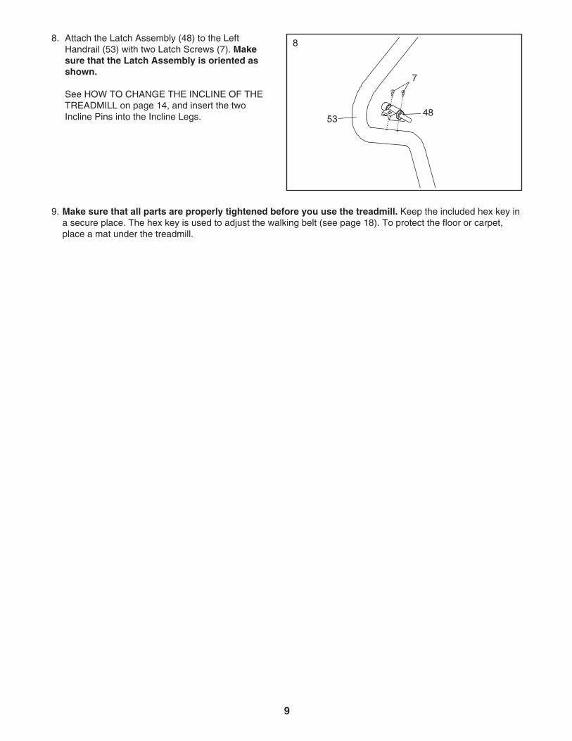
9. Make sure that all parts are properly tightened before you use the treadmill. Keep the included hex key ina secure place. The hex key is used to adjust the walking belt (see page 18). To protect the floor or carpet,place a mat under the treadmill.
8. Attach the Latch Assembly (48) to the LeftHandrail (53) with two Latch Screws (7). Makesure that the Latch Assembly is oriented asshown.
See HOW TO CHANGE THE INCLINE OF THETREADMILL on page 14, and insert the twoIncline Pins into the Incline Legs.
8
7
4853
10
THE PRE-LUBRICATED WALKING BELT
Your treadmill features a walking belt coated with high-performance lubricant. IMPORTANT: Never apply sili-cone spray or other substances to the walking belt or the walking platform. Such substances will deterio-rate the walking belt and cause excessive wear.
HOW TO PLUG IN THE POWER CORD
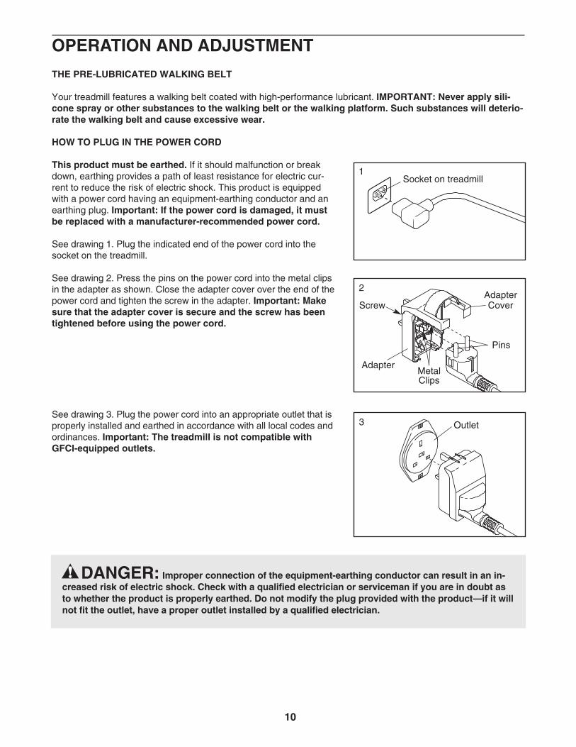
This product must be earthed. If it should malfunction or breakdown, earthing provides a path of least resistance for electric cur-rent to reduce the risk of electric shock. This product is equippedwith a power cord having an equipment-earthing conductor and anearthing plug. Important: If the power cord is damaged, it mustbe replaced with a manufacturer-recommended power cord.
See drawing 1. Plug the indicated end of the power cord into thesocket on the treadmill.
See drawing 2. Press the pins on the power cord into the metal clipsin the adapter as shown. Close the adapter cover over the end of thepower cord and tighten the screw in the adapter. Important: Makesure that the adapter cover is secure and the screw has beentightened before using the power cord.
See drawing 3. Plug the power cord into an appropriate outlet that isproperly installed and earthed in accordance with all local codes andordinances. Important: The treadmill is not compatible withGFCI-equipped outlets.
DANGER: Improper connection of the equipment-earthing conductor can result in an in-creased risk of electric shock. Check with a qualified electrician or serviceman if you are in doubt asto whether the product is properly earthed. Do not modify the plug provided with the product—if it willnot fit the outlet, have a proper outlet installed by a qualified electrician.
FR/SP
IT
GR
FR/SP
IT
Socket on treadmill
Metal Clips
1
2
Pins
Screw
Adapter
FR/SP
Outlet3
AdapterCover
OPERATION AND ADJUSTMENT

11
FEATURES OF THE CONSOLE
The treadmill console offers a selection of featuresdesigned to make your workouts more effective.
While the manual mode of the console is selected, thespeed of the treadmill can be changed with the touchof a button. As you exercise, the displays will providecontinuous exercise feedback. You can even measureyour heart rate using the built-in pulse sensor.
The console also offers four speed programs. Eachprogram automatically controls the speed of the tread-mill as it guides you through an effective workout.
To prevent damage to the walking platform, alwayswear clean athletic shoes while using the treadmill.During the first few minutes that the treadmill isused, inspect the alignment of the walking belt, andcenter the walking belt if necessary (see page 18).
HOW TO TURN ON THE POWER
Plug in the power cord (seepage 10). Next, locate theon/off switch on the treadmillframe near the right upright.Make sure that the switch isin the “on” position.
Next, stand on the foot rails of the treadmill. Find theclip attached to the key (see the drawing above), andslide the clip onto the waistband of your clothes. Then,insert the key into the console. After a moment, thethree displays will light. Important: In an emergencysituation, the key can be pulled from the console,causing the walking belt to slow to a stop. Test theclip by carefully taking a few steps backward; if thekey is not pulled from the console, adjust the posi-tion of the clip.
CONSOLE DIAGRAM
OnPosition
KeyClipNote: If there are thin sheets of plastic
on the console, remove the plastic.

12
HOW TO USE THE MANUAL MODE
Insert the key into the console.
See HOW TO TURN ON THE POWER on page11.
Select the manual mode.
When the key is in-serted, the manualmode will be selected.If you have selected aspeed program, rese-lect the manual modeby pressing the Programs button repeatedly untilonly zeros appear in the displays.
Press the Start button or the Speed increasebutton to start the walking belt.
When either button is pressed, the walking belt willbegin to move at 2 km/h. Hold the handrails andbegin walking. As you exercise, change the speedof the walking belt as desired by pressing theSpeed buttons. Each time a button is pressed, thespeed setting will change by 0.1 km/h; if a buttonis held down, the speed setting will change in in-crements of 0.5 km/h. Note: After the buttons arepressed, it may take a moment for the walking beltto reach the selected speed setting.
To stop the walking belt, press the Stop button.The time will begin to flash in one of the displays.To restart the walking belt, press the Start button orthe Speed increase button.
Follow your progress with the displays.
The lower leftdisplay—As you exer-cise, the lower left dis-play can show theelapsed time and thedistance that you havewalked or run.
The lower rightdisplay—The lower rightdisplay can show thespeed of the walking beltand the approximatenumber of calories thatyou have burned. The display also shows yourheart rate when you use the handgrip pulse sen-sor (see step 5).
The upper display—The upper display canshow the elapsed time,the distance that youhave walked or run, thespeed of the walkingbelt, or the approximate number of calories youhave burned. Press the Display button repeatedlyuntil the upper display shows the information thatyou are most interested in viewing. Note: While in-formation is shown in the upper display, the sameinformation will not be shown in the lower left orright display.
To reset the displays, press the Stop button, re-move the key, and then reinsert the key.
Note: The console candisplay speed and dis-tance in either kilome-ters or miles. To seewhich unit of measure-ment is selected, first re-move the key, hold down the Stop button, andthen reinsert the key into the console; after youhear a tone, release the Stop button. An “M” formetric kilometers or an “E” for English miles willappear in the upper display. Press the Speed in-crease button to change the unit of measurementif desired. When the desired unit of measurementis selected, remove the key and then reinsert it.
4
3
2
1

13
Measure your heart rate if desired.
Before using the hand-grip pulse sensor, re-move the sheets ofclear plastic from themetal contacts. In addi-tion, make sure thatyour hands are clean.
To measure your heart rate, stand on the footrails and hold the metal contacts—avoid movingyour hands. When your pulse is detected, thesmall heart symbol in the lower right display willflash, one or two dashes will appear, and thenyour heart rate will be shown. For the most accu-rate heart rate reading, continue to hold thecontacts for about 15 seconds.
When you are finished exercising, remove thekey from the console.
Step onto the foot rails, press the Stop button, andremove the key from the console. Keep the key in asecure place. Then, switch the on/off switch to the“off” position and unplug the power cord.
HOW TO USE A SPEED PROGRAM
Insert the key into the console.
See HOW TO TURN ON THE POWER on page11.
Select one of the four speed programs.
To select a speed pro-gram, press thePrograms button re-peatedly; “P-1,” “P-2,”“P-3,” or “P-4” will ap-pear in the upper dis-play for a few seconds to show which program isselected. The maximum speed setting of the se-lected program will also flash in one of the dis-plays for a few seconds.
Each program consists of 30 one-minute periods.One speed setting is programmed for each period.Note: The same speed setting may be pro-grammed for two or more consecutive periods.The profiles on the console show how the speedof the walking belt will change during the pro-grams.
Press the Start button or the Speed increasebutton to start the program.
When either button is pressed, the treadmill willautomatically adjust to the speed setting that isprogrammed for the first period of the program.Hold the handrails and begin walking.
When the first period ends, a series of tones willsound. If a different speed setting is programmedfor the second period, the speed setting will flashin one of the displays to alert you, and then thespeed of the walking belt will change. The pro-gram will continue until all 30 periods are com-pleted. The walking belt will then slow to a stop.
If the speed setting is too high or too low duringthe program, you can manually override the settingby pressing the Speed buttons. However, whenthe next period begins, the speed of the walk-ing belt will change if a different speed settingis programmed for the next period.
To stop the program, press the Stop button. Thetime will begin to flash in one of the displays. Torestart the program, press the Start button or theSpeed increase button. The walking belt will beginto move at 2 km/h. When the next period begins,the speed of the walking belt will change if a differ-ent speed setting is programmed for the next pe-riod.
Follow your progress with the displays.
See step 4 on page 12.
When you are finished exercising, remove thekey.
See step 6 on this page.
5
4
3
2
1
6
5
MetalContacts
14
HOW TO CHANGE THE INCLINE OF THE TREADMILL
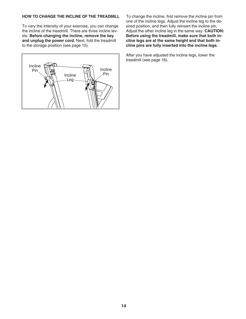
To vary the intensity of your exercise, you can changethe incline of the treadmill. There are three incline lev-els. Before changing the incline, remove the keyand unplug the power cord. Next, fold the treadmillto the storage position (see page 15).
To change the incline, first remove the incline pin fromone of the incline legs. Adjust the incline leg to the de-sired position, and then fully reinsert the incline pin.Adjust the other incline leg in the same way. CAUTION:Before using the treadmill, make sure that both in-cline legs are at the same height and that both in-cline pins are fully inserted into the incline legs.
After you have adjusted the incline legs, lower thetreadmill (see page 16).
InclineLeg
InclinePin Incline
Pin

15
HOW TO FOLD AND MOVE THE TREADMILL
HOW TO FOLD THE TREADMILL FOR STORAGE
Unplug the power cord. CAUTION: You must be able tosafely lift 20 kg (45 lbs.) to raise, lower, or move thetreadmill.
1. Hold the metal frame firmly in the location shown bythe arrow at the right. CAUTION: To decrease the pos-sibility of injury, do not lift the frame by the plasticfoot rails. Make sure to bend your legs and keep yourback straight. As you raise the frame, make sure to liftwith your legs rather than your back. Raise the frameabout halfway to the vertical position.
2. Move your right hand to the position shown and hold thetreadmill firmly. Using your left hand, pull the latch knobto the left and hold it. Raise the frame until the catch ispast the latch pin. Then, slowly release the latch knob;make sure that the latch pin is resting against thecatch.
To protect the floor or carpet from damage, place amat under the treadmill. Keep the treadmill out of di-rect sunlight. Do not leave the treadmill in the stor-age position in temperatures above 30°C (85°F).
HOW TO MOVE THE TREADMILL
Before moving the treadmill, convert the treadmill to the stor-age position as described above. Make sure that the latchpin is fully inserted into the catch.
1. Hold the handrails and place one foot against one of thewheels. Do not pull back on the frame.
2. Tilt the treadmill back until it rolls freely on the wheels, andcarefully move the treadmill to the desired location. Nevermove the treadmill without tipping it back. To reducethe risk of injury, use extreme caution while movingthe treadmill. Do not attempt to move the treadmillover an uneven surface.
3. Place one foot against one of the wheels, and carefullylower the treadmill until it is in the storage position.
LatchPin
Frame
LatchKnob
Catch
Handrail
Wheel
1
2
HOW TO LOWER THE TREADMILL FOR USE
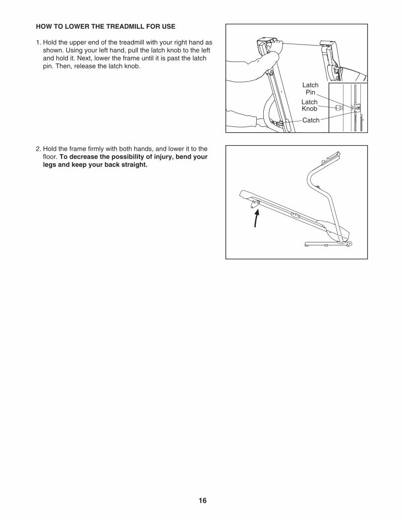
1. Hold the upper end of the treadmill with your right hand asshown. Using your left hand, pull the latch knob to the leftand hold it. Next, lower the frame until it is past the latchpin. Then, release the latch knob.
2. Hold the frame firmly with both hands, and lower it to thefloor. To decrease the possibility of injury, bend yourlegs and keep your back straight.
16
LatchPin
LatchKnob
Catch
MAINTENANCE AND TROUBLESHOOTING
Most treadmill problems can be solved by following the steps below. Find the symptom that applies, andfollow the steps listed. If further assistance is needed, please see the front cover of this manual.
PROBLEM: The power does not turn on
SOLUTION: a. Make sure that the power cord is plugged into a properly earthed outlet (see page 10). If an exten-sion cord is needed, use only a 3-conductor, 1 mm2 (14-gauge) cord that is no longer than 1.5 m(5 ft.). Important: The treadmill is not compatible with GFCI-equipped outlets.
b. After the power cord has been plugged in, make sure that the key is inserted into the console.
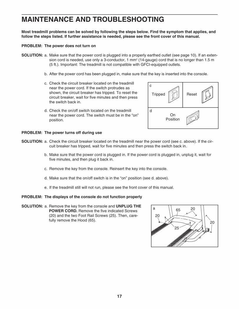
c. Check the circuit breaker located on the treadmillnear the power cord. If the switch protrudes asshown, the circuit breaker has tripped. To reset thecircuit breaker, wait for five minutes and then pressthe switch back in.
d. Check the on/off switch located on the treadmillnear the power cord. The switch must be in the “on”position.
PROBLEM: The power turns off during use
SOLUTION: a. Check the circuit breaker located on the treadmill near the power cord (see c. above). If the cir-cuit breaker has tripped, wait for five minutes and then press the switch back in.
b. Make sure that the power cord is plugged in. If the power cord is plugged in, unplug it, wait forfive minutes, and then plug it back in.
c. Remove the key from the console. Reinsert the key into the console.
d. Make sure that the on/off switch is in the “on” position (see d. above).
e. If the treadmill still will not run, please see the front cover of this manual.
PROBLEM: The displays of the console do not function properly
SOLUTION: a. Remove the key from the console and UNPLUG THEPOWER CORD. Remove the five indicated Screws(20) and the two Foot Rail Screws (25). Then, care-fully remove the Hood (65).
25
20
20
20
65a
Tripped
c
Reset
OnPosition
d
17
18
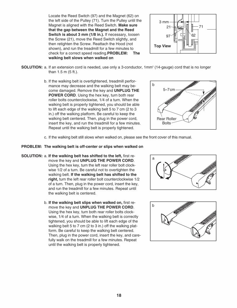
Locate the Reed Switch (97) and the Magnet (62) onthe left side of the Pulley (71). Turn the Pulley until theMagnet is aligned with the Reed Switch. Make surethat the gap between the Magnet and the ReedSwitch is about 3 mm (1/8 in.). If necessary, loosenthe Screw (21), move the Reed Switch slightly, andthen retighten the Screw. Reattach the Hood (notshown), and run the treadmill for a few minutes tocheck for a correct speed reading.PROBLEM: Thewalking belt slows when walked on
SOLUTION: a. If an extension cord is needed, use only a 3-conductor, 1mm2 (14-gauge) cord that is no longerthan 1.5 m (5 ft.).
b. If the walking belt is overtightened, treadmill perfor-mance may decrease and the walking belt may be-come damaged. Remove the key and UNPLUG THEPOWER CORD. Using the hex key, turn both rearroller bolts counterclockwise, 1/4 of a turn. When thewalking belt is properly tightened, you should be ableto lift each edge of the walking belt 5 to 7 cm (2 to 3in.) off the walking platform. Be careful to keep thewalking belt centered. Then, plug in the power cord,insert the key, and run the treadmill for a few minutes.Repeat until the walking belt is properly tightened.
c. If the walking belt still slows when walked on, please see the front cover of this manual.
PROBLEM: The walking belt is off-center or slips when walked on
SOLUTION: a. If the walking belt has shifted to the left, first re-move the key and UNPLUG THE POWER CORD.Using the hex key, turn the left rear roller bolt clock-wise 1/2 of a turn. Be careful not to overtighten thewalking belt. If the walking belt has shifted to theright, turn the left rear roller bolt counterclockwise 1/2of a turn. Then, plug in the power cord, insert the key,and run the treadmill for a few minutes. Repeat untilthe walking belt is centered.
b. If the walking belt slips when walked on, first re-move the key and UNPLUG THE POWER CORD.Using the hex key, turn both rear roller bolts clock-wise, 1/4 of a turn. When the walking belt is correctlytightened, you should be able to lift each edge of thewalking belt 5 to 7 cm (2 to 3 in.) off the walking plat-form. Be careful to keep the walking belt centered.Then, plug in the power cord, insert the key, and care-fully walk on the treadmill for a few minutes. Repeatuntil the walking belt is properly tightened.
b
a
b5–7cm
Rear RollerBolts
62
21
97
Top View
3 mm71
19
CONDITIONING GUIDELINES
The following guidelines will help you to plan your ex-ercise program. For more detailed exercise informa-tion, obtain a reputable book or consult your physician.
EXERCISE INTENSITY
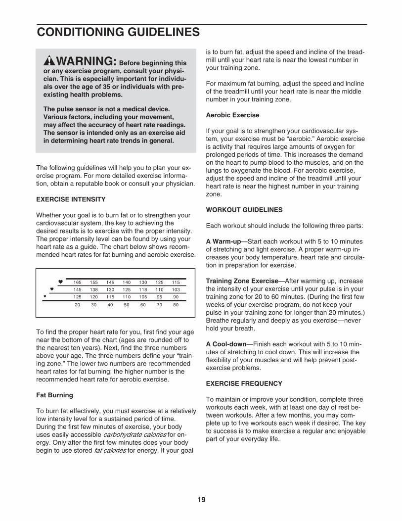
Whether your goal is to burn fat or to strengthen yourcardiovascular system, the key to achieving the desired results is to exercise with the proper intensity.The proper intensity level can be found by using yourheart rate as a guide. The chart below shows recom-mended heart rates for fat burning and aerobic exercise.
To find the proper heart rate for you, first find your agenear the bottom of the chart (ages are rounded off tothe nearest ten years). Next, find the three numbersabove your age. The three numbers define your “train-ing zone.” The lower two numbers are recommendedheart rates for fat burning; the higher number is therecommended heart rate for aerobic exercise.
Fat Burning
To burn fat effectively, you must exercise at a relativelylow intensity level for a sustained period of time.During the first few minutes of exercise, your bodyuses easily accessible carbohydrate calories for en-ergy. Only after the first few minutes does your bodybegin to use stored fat calories for energy. If your goal
is to burn fat, adjust the speed and incline of the tread-mill until your heart rate is near the lowest number inyour training zone.
For maximum fat burning, adjust the speed and inclineof the treadmill until your heart rate is near the middlenumber in your training zone.
Aerobic Exercise
If your goal is to strengthen your cardiovascular sys-tem, your exercise must be “aerobic.” Aerobic exerciseis activity that requires large amounts of oxygen forprolonged periods of time. This increases the demandon the heart to pump blood to the muscles, and on thelungs to oxygenate the blood. For aerobic exercise,adjust the speed and incline of the treadmill until yourheart rate is near the highest number in your trainingzone.
WORKOUT GUIDELINES
Each workout should include the following three parts:
A Warm-up—Start each workout with 5 to 10 minutesof stretching and light exercise. A proper warm-up in-creases your body temperature, heart rate and circula-tion in preparation for exercise.
Training Zone Exercise—After warming up, increasethe intensity of your exercise until your pulse is in yourtraining zone for 20 to 60 minutes. (During the first fewweeks of your exercise program, do not keep yourpulse in your training zone for longer than 20 minutes.)Breathe regularly and deeply as you exercise—neverhold your breath.
A Cool-down—Finish each workout with 5 to 10 min-utes of stretching to cool down. This will increase theflexibility of your muscles and will help prevent post-exercise problems.
EXERCISE FREQUENCY
To maintain or improve your condition, complete threeworkouts each week, with at least one day of rest be-tween workouts. After a few months, you may com-plete up to five workouts each week if desired. The keyto success is to make exercise a regular and enjoyablepart of your everyday life.
WARNING: Before beginning thisor any exercise program, consult your physi-cian. This is especially important for individu-als over the age of 35 or individuals with pre-existing health problems.
The pulse sensor is not a medical device.Various factors, including your movement,may affect the accuracy of heart rate readings.The sensor is intended only as an exercise aidin determining heart rate trends in general.
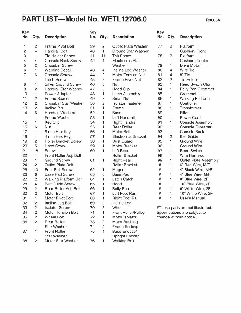
PART LIST—Model No. WETL12706.0 R0606A
Key No. Qty. Description
Key No. Qty. Description
Key No. Qty. Description
1 2 Frame Pivot Bolt2 4 Handrail Bolt3 1 Tie Holder Screw4 4 Console Back Screw5 2 Crossbar Screw6 1 Warning Decal7 6 Console Screw/
Latch Screw8 1 Silver Ground Screw9 2 Handrail Star Washer10 1 Power Adapter11 2 Frame Spacer12 2 Crossbar Star Washer13 2 Incline Pin14 6 Handrail Washer/
Frame Washer15 1 Key/Clip16 6 Nut17 1 6 mm Hex Key 18 1 4 mm Hex Key 19 2 Roller Bracket Screw20 5 Hood Screw21 18 Screw22 1 Front Roller Adj. Bolt23 1 Ground Screw24 2 Outlet Plate Bolt25 10 Foot Rail Screw26 6 Base Pad Screw27 2 Walking Platform Bolt28 4 Belt Guide Screw29 2 Rear Roller Adj. Bolt30 2 Motor Bolt31 1 Motor Pivot Bolt32 2 Incline Leg Bolt33 2 Isolator Screw34 2 Motor Tension Bolt35 2 Wheel Bolt36 2 Rear Roller
Star Washer37 1 Front Roller
Star Washer38 2 Motor Star Washer
39 2 Outlet Plate Washer40 1 Ground Star Washer41 11 Tek Screw42 4 Electronics Star
Washer43 4 Incline Leg Washer44 2 Motor Tension Nut45 2 Frame Pivot Nut46 5 Nut47 5 Hood Clip48 1 Latch Assembly49 3 Small Nut50 2 Isolator Fastener51 1 Frame52 1 Base53 1 Left Handrail54 1 Right Handrail55 1 Rear Roller56 1 Motor Belt57 1 Electronics Bracket58 1 Dust Guard59 1 Motor Bracket60 1 Left Rear
Roller Bracket61 1 Right Rear
Roller Bracket62 1 Magnet63 6 Base Pad64 1 Latch Catch65 1 Hood66 1 Belly Pan67 1 Left Foot Rail68 1 Right Foot Rail69 2 Incline Leg70 2 Wheel71 1 Front Roller/Pulley72 1 Motor Isolator73 2 Motor Bushing74 2 Frame Endcap75 4 Base Endcap/
Upright Endcap76 1 Walking Belt
77 2 Platform Cushion, Front
78 2 Platform Cushion, Center
79 1 Drive Motor80 4 Wire Tie81 4 8” Tie82 2 Tie Holder83 1 Reed Switch Clip84 1 Belly Pan Grommet85 1 Grommet86 1 Walking Platform87 1 Controller88 1 Transformer89 1 Filter90 1 Power Cord91 1 Console Assembly92 1 Console Crossbar93 1 Console Back94 2 Belt Guide95 1 Ground Wire96 1 Ground Wire97 1 Reed Switch98 1 Wire Harness99 1 Outlet Plate Assembly# 1 6” Red Wire, M/F# 1 4” Black Wire, M/F# 1 4” Blue Wire, M/F# 1 8” Blue Wire, 2F# 1 10” Blue Wire, 2F# 1 6” White Wire, 2F# 1 10” White Wire, 2F# 1 User’s Manual
#These parts are not illustrated. Specifications are subject tochange without notice.

Frame Pivot Bolt (1)–2
Wheel Bolt (35)–2
Console BackScrew (4)–4
NHandrail StarWasher (9)–2Handrail Washer/
Frame Washer (14)–6
Handrail Bolt (2)–4
Console Screw/Latch Screw (7)–6
CrossbarScrew (5)–2
4 Bolt (120)–2
F
Nut (16)–6Crossbar StarWasher (12)–2
Remove this chart and use it to identify small parts during assembly. Save this chart and the EXPLODEDDRAWING/PART LIST for future reference.
PART IDENTIFICATION CHART
802121
94
17
81
86
51
27
76
67
28
62
9721
83
94
15
54
65
6
11
53
141
9
45
45
29
98
1
1114
9
75
3438
44
31
79
46
25
21
21
25
25
25
25
29
25
25
56
7
48
34
25
77
77
41
30
74
74
59
38
71
68
61
60
3722
28
18
46
19
55 36
36
691332
46 43
4369
1346
3243
43
42
19
42
6690
84
24
20
41
41
20
20
2158
39
39
49
20
27
57
87
88 21
89
98
75
99
10
41
7
21
21
21
21
21
96
23 4042
42
46
47
47
47
47
49
85
91
95
73
72
8221
41
41
24
33
2
2
33
78
50
50
78
20
47
64
41
2663
266363 26
63 26
75
70
16
35
35
16
70
75
7
7
7
16
16
14
14
8
512
512
41
41
41
92
934
4
4
4
3
82
63 26
63 26
52
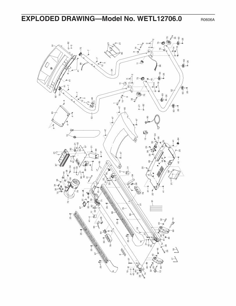
EXPLODED DRAWING—Model No. WETL12706.0 R0606A

Part No. 240057 R0606A Printed in China © 2006 ICON IP, Inc.
ORDERING REPLACEMENT PARTS
To order replacement parts, contact the ICON Health & Fitness, Ltd. office, or write:
ICON Health & Fitness, Ltd.Customer Service DepartmentUnit 4, Revie Road Industrial EstateRevie RoadBeestonLeeds, LS118JGUK
Tel:
Outside the UK: (44) 0113 387 7133Fax: (44) 0113 387 7125
To help us assist you, please be prepared to provide the following information:
• the MODEL NUMBER of the product (WETL12706.0)
• the NAME of the product (WESLO CADENCE M5 treadmill)
• the SERIAL NUMBER of the product (see the front cover of this manual)
• the KEY NUMBER and DESCRIPTION of the needed part(s) (see the PART LIST and the EXPLODEDDRAWING in the centre of this manual)
08457 089 009