questions about transfer functionshibp.ecse.rpi.edu/~connor/education/transferfunctions.pdf ·...
TRANSCRIPT

Questions about Transfer Functions These questions should help you with question 3 of quiz 1. Fall 2004 Question I – Transfer functions of RLC, RL and RC Circuits (52 points) Circuit A: Answer 1-8 for the RC circuit below
1. Find the transfer function for the above circuit. (2 points)
H(jω) =
2. Find the function to describe the behavior of the circuit at very low frequencies. Also
determine the magnitude and phase of this circuit at very low frequencies. (3 points)
HLO(jω) =
|HLO| = ∠HLO =
3. Find the function to describe the behavior of the circuit at very high frequencies. Also determine the magnitude and phase of this circuit at very high frequencies. (3 points)
HHI(jω) =
| HHI| = ∠HHI = 4. What is the expression for the corner frequency of the circuit? (1 point)
ωc =

5. Find the transfer function which governs the behavior of the circuit at the corner
frequency, ωc. Also find the magnitude and phase of the function at the corner frequency. (3 points)
HC =
| HC | = ∠ HC =
6. If C=0.047µF and R=500 ohms, find the numerical values for the following. Indicate the units. (8 points)
ωc = fc=
Magnitude Phase Very low frequencies Very high frequencies Corner frequency 7. Sketch a plot of the magnitude of the transfer function vs frequency (in Hertz).
Clearly indicate the value at very high frequencies, very low frequencies and the corner frequency. Mark the corner frequency on the sketch. (3 points)
8. Sketch a plot of the phase of the transfer function (in degrees or radians). Clearly
indicate the value at very high frequencies, very low frequencies and the corner frequency. Mark the corner frequency on the sketch. (3 points)

Circuit B: Answer 9-16 for the RLC circuit below
9. Find the transfer function for the above circuit. (2 points) H(jω) =
10. Find the function to describe the behavior of the circuit at very low frequencies. Also determine the magnitude and phase of this circuit at very low frequencies. (3 points)
HLO(jω) =
|HLO| = ∠HLO =
11. Find the function to describe the behavior of this circuit at very high frequencies. Also determine the magnitude and phase of this circuit at very high frequencies. (3 points)
HHI(jω) =
| HHI| = ∠HHI =
12. What is the expression for the resonant frequency of the circuit? (1 point)
ω0 =

13. Find the transfer function which governs the behavior of the circuit at the resonant frequency, ω0. Also find the magnitude and phase of the function at the resonant frequency. (3 points)
H0 =
| H0 | = ∠ H0 =
14. If C=0.063µF , L=10mH and R=800 ohms, find the numerical values for the following. Indicate the units. (8 points)
ω0 = f0 =
Magnitude Phase Very low frequencies Very high frequencies Resonant frequency 15. Sketch a plot of the magnitude of the transfer function vs frequency in Hertz. Clearly
indicate the value at very high frequencies, very low frequencies and the resonant frequency. Mark the resonant frequency on the sketch. (3 points)
16. Sketch a plot of the phase of the transfer function (in degrees or radians). Clearly
indicate the value at very high frequencies, very low frequencies and the corner frequency. Mark the resonant frequency on the sketch. (3 points)

Fall 2004 Solution Circuit A: Answer 1-8 for the RC circuit below
1. Find the transfer function for the above circuit. (2 points)
H(jω) = [R] / [1/jωC+R] = [jωRC] / [1+jωRC]
4. Find the function to describe the behavior of the circuit at very low frequencies. Also
determine the magnitude and phase of this circuit at very low frequencies. (3 points)
HLO(jω) = [jωRC] / [1] = jωRC
|HLO| = 0 ∠HLO = π/2
5. Find the function to describe the behavior of the circuit at very high frequencies. Also determine the magnitude and phase of this circuit at very high frequencies. (3 points)
HHI(jω) = [jωRC] / [jωRC] = 1
| HHI| = 1 ∠HHI = 0 4. What is the expression for the corner frequency of the circuit? (1 point)
ωc = [1]/[RC] 9. Find the transfer function which governs the behavior of the circuit at the corner
frequency. Also find the magnitude and phase of the function at the corner frequency. (3 points)
HC = [j(1/RC)RC] / [1+j(1/RC)RC] = [ j ] / [ 1+j ]
| HC | = 1 / √2 ∠ HC = π/2 - π/4 = π/4

10. If C=0.047µF and R=500 ohms, find the numerical values for the following. Indicate
the units. (8 points)
ωc = 1/[ (0.047µ)(500) ] = 42553 rad/s fc=42553/2π = 6773 Hz
Magnitude Phase Very low frequencies 0 π/2 Very high frequencies 1 0 Corner frequency 1/√2 π/4 11. Sketch a plot of the magnitude of the transfer function vs frequency (in Hertz).
Clearly indicate the value at very high frequencies, very low frequencies and the corner frequency. Mark the corner frequency on the sketch. (3 points)
12. Sketch a plot of the phase of the transfer function (in degrees or radians). Clearly
indicate the value at very high frequencies, very low frequencies and the corner frequency. Mark the corner frequency on the sketch. (3 points)

Circuit B: Answer 9-16 for the RLC circuit below
9. Find the transfer function for the above circuit. (2 points) H(jω) = [ 1/jωC ] / [ R + jωL + 1/jωC ] = [ 1 ] / [ jωRC - ω2LC + 1 ]
12. Find the function to describe the behavior of the circuit at very low frequencies. Also
determine the magnitude and phase of this circuit at very low frequencies. (3 points)
HLO(jω) = [ 1 ] / [ 1 ] = 1
|HLO| = 1 ∠HLO = 0
13. Find the function to describe the behavior of this circuit at very high frequencies. Also determine the magnitude and phase of this circuit at very high frequencies. (3 points)
HHI(jω) = [ 1 ] / [- ω2LC ]
| HHI| = 0 ∠HHI = - π 12. What is the expression for the resonant frequency of the circuit? (1 point)
ω0 = 1/ (√LC) 13. Find the transfer function which governs the behavior of the circuit at the resonant frequency. Also find the magnitude and phase of the function at the resonant frequency. (3 points)
H0 = [ 1 ] / [ j (1/√LC)RC – (1/LC)(LC) + 1 ] = [ -j√LC ] / [RC]
| H0| = [ √LC ] / [RC] ∠ H0 = - π/2

17. If C=0.063µF , L=10mH and R=800 ohms, find the numerical values for the
following. Indicate the units. (8 points)
ω0 = [1]/[√(0.063µ)(10m)] = 39841 rad/s f0 = 39841/2π = 6341 Hz | H0| = [ √LC ] / [RC] = [√(0.063µ)(10m)] / [(800)( 0.063µ)] = 0.5
Magnitude Phase Very low frequencies 1 0 Very high frequencies 0 - π Resonant frequency 0.5 - π/2 18. Sketch a plot of the magnitude of the transfer function vs frequency in Hertz. Clearly
indicate the value at very high frequencies, very low frequencies and the resonant frequency. Mark the resonant frequency on the sketch. (3 points)
19. Sketch a plot of the phase of the transfer function (in degrees or radians). Clearly
indicate the value at very high frequencies, very low frequencies and the corner frequency. Mark the resonant frequency on the sketch. (3 points)

Fall 2004 Question II – Filters (16 points) Consider the following three input signals:
Signal 1:
Signal 2:
Signal 3:
1. What is the frequency of each of the signals above (in Hertz)? (6 points)
Signal 1: Signal 2: Signal 3:

2. What type of filter is circuit A from question I ? (2 point) 3. What type of filter is circuit B from question I ? (2 point) 4. Fill out the following chart. Enter “lower” if the amplitude of the output of the
given circuit will be substantially lower than the input amplitude. Enter “higher” if the amplitude of the output of the given circuit will be substantially higher than the input amplitude. Enter “same” if the amplitude of the output of the given circuit will be about the same as the input amplitude. Note that the circuits are the ones you analyzed in question I (with the component values we gave you) and the signals are those pictured on the previous page. You can assume the filter transitions are close to ideal. (6 points)
Signal 1 Signal 2 Signal 3
Circuit A
Circuit B

Fall 2004 solution Question II – Filters (16 points) Consider the following three input signals:
Signal 1:
Signal 2:
Signal 3:
5. What is the frequency of each of the signals above (in Hertz)? (6 points)
Signal 1: T = 5µs f = 200,000 Hz Signal 2: T = 50µs f = 20,000 Hz Signal 3: T = 0.5ms f =2000 Hz

6. What type of filter is circuit A from question I ? (2 point)
High pass filter 7. What type of filter is circuit B from question I ? (2 point)
Low pass filter 8. Fill out the following chart. Enter “lower” if the amplitude of the output of the
given circuit will be substantially lower than the input amplitude. Enter “higher” if the amplitude of the output of the given circuit will be substantially higher than the input amplitude. Enter “same” if the amplitude of the output of the given circuit will be about the same as the input amplitude. Note that the circuits are the ones you analyzed in question I (with the component values we gave you) and the signals are those pictured on the previous page. You can assume the filter transitions are close to ideal. (6 points)
200K 20K 2K
Signal 1 Signal 2 Signal 3
Circuit A same same lower
Circuit B lower lower same
(see dots marked on plots in answers to question I)

Spring 2004 Question 1 – Transfer Functions (32 points) Consider a variety of filter configurations that can be analyzed with PSpice. All the resistors (except one) shown are 1k, all the inductors are 1mH and all the capacitors are 0.1uF. In general the components can assume any realistic value. Thus, in most of this problem, we will only assume that they have some unknown value. For each of these circuits, assume that the input and output voltages are measured at the two locations where we have added a voltage marker.
a) First, identify which type of filter these are: (6 points)
Which is a low pass filter (list all): Which is a high pass filter (list all): Which is a band pass filter (list all): Which is a band reject filter (list all):

b) The complex transfer functions for all of these filters are given below. Identify
which circuit goes with each transfer function. (6 points)
LjRLjω
ω+
CjLjR
LjCj
ωω
ωω1
1
++
+
CjRR
ω1+
LjRR
ω+
CjLjCjLj
R
CjLjCjLj
ωωωω
ωωωω
1
1
++
+
CjRCj
ω
ω1
1
+
c) The voltage and phase vs frequency for each of these filters is shown on the
following two pages. Identify which plot goes with each transfer function. Show your work below for partial credit: (12 points)

Frequency
100Hz 1.0KHz 10KHz 100KHz 1.0MHz 10MHz 100MHz 1.0GHzV(V1:+) V(R1:2)
0V
0.5V
1.0Vp( V(R1:2))
-100d
-50d
0d
SEL>>
Frequency
100Hz 1.0KHz 10KHz 100KHz 1.0MHz 10MHz 100MHz 1.0GHzV(V2:+) V(R4:1)
0V
0.5V
1.0Vp( V(R4:1))
0d
50d
100d
SEL>>

Frequency
100Hz 1.0KHz 10KHz 100KHz 1.0MHz 10MHz 100MHz 1.0GHzV(R7:1) V(R7:2)
0V
0.5V
1.0Vp( V(R7:2))
-100d
0d
100d
SEL>>
Frequency
100Hz 1.0KHz 10KHz 100KHz 1.0MHz 10MHz 100MHz 1.0GHzV(V10:+) V(C10:1)
0V
0.5V
1.0Vp( V(C10:1))
-100d
0d
100d
SEL>>
Frequency
100Hz 1.0KHz 10KHz 100KHz 1.0MHz 10MHz 100MHz 1.0GHzV(V7:+) V(R6:2)
0V
0.5V
1.0Vp( V(R6:2))
0d
50d
100d
SEL>>

Frequency
100Hz 1.0KHz 10KHz 100KHz 1.0MHz 10MHz 100MHz 1.0GHzV(V3:+) V(L1:2)
0V
0.5V
1.0Vp( V(L1:2))
-100d
-50d
0d
SEL>>
d) Find the transfer function for the following circuit. (Hint- it is a combination of
two of the circuits we have seen above.) (4 points)
V
FREQ = 1kVAMPL = 1VOFF = 0
V
Rx
1k
0
Cy
.1uV
Lx
1mHRy
1k
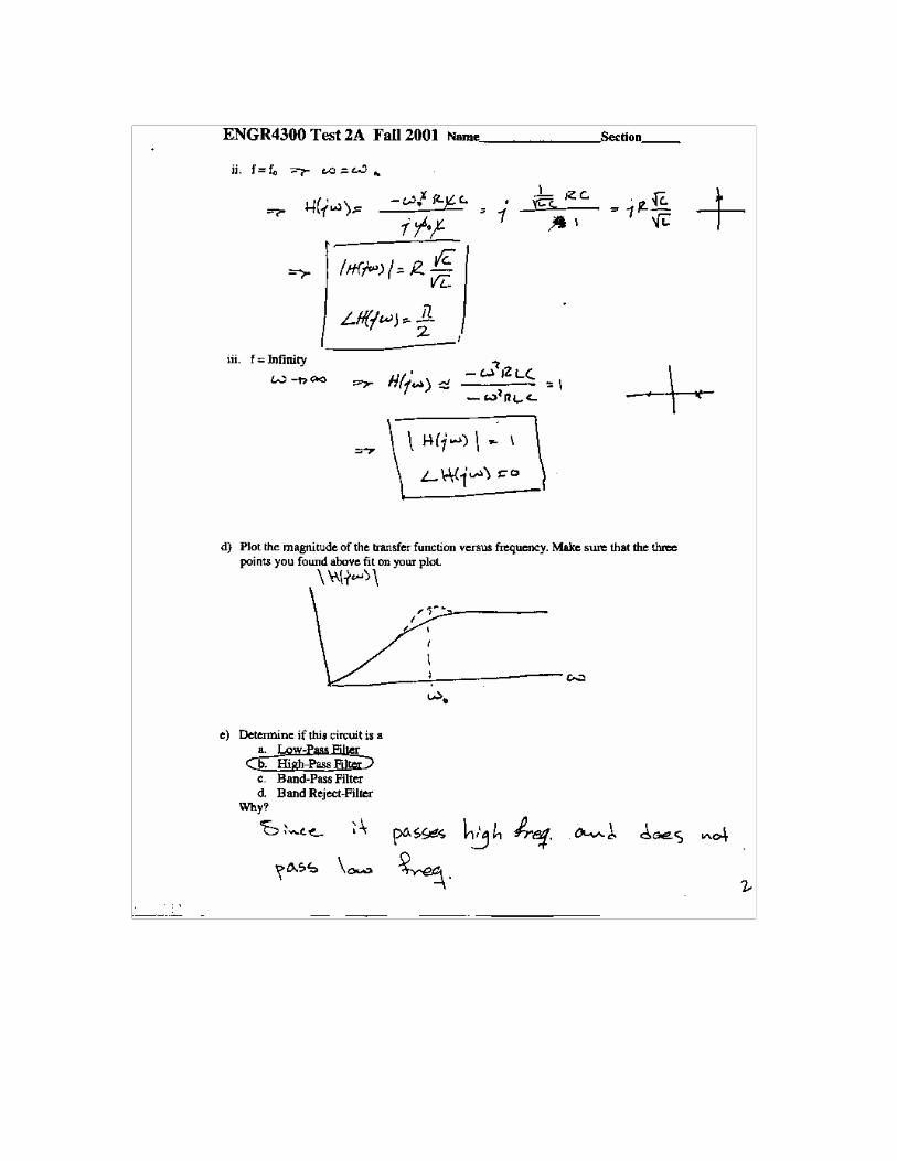
e) Simplify this transfer function at very low frequencies and very high frequencies
and show that your results are consistent with the voltage magnitude and phase plot below. What kind of a filter is this combined circuit? (4 points)
Frequency
100Hz 1.0KHz 10KHz 100KHz 1.0MHz 10MHz 100MHz 1.0GHzV(Lx:2) V(V2:+)
0V
0.5V
1.0Vp( V(Lx:2))
-100d
0d
100d
SEL>>
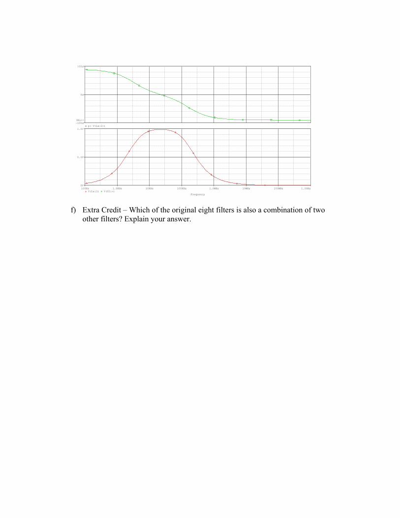
f) Extra Credit – Which of the original eight filters is also a combination of two
other filters? Explain your answer.

Spring 2004 solution Question 1 – Transfer Functions (32 points) Consider a variety of filter configurations that can be analyzed with PSpice. All the resistors (except one) shown are 1k, all the inductors are 1mH and all the capacitors are 0.1uF. In general the components can assume any realistic value. Thus, in most of this problem, we will only assume that they have some unknown value. For each of these circuits, assume that the input and output voltages are measured at the two locations where we have added a voltage marker.
g) First, identify which type of filter these are: (6 points)
Which is a low pass filter (list all): A, C Which is a high pass filter (list all): B, D Which is a band pass filter (list all): F Which is a band reject filter (list all): E

h) The complex transfer functions for all of these filters are given below. Identify which circuit goes with each transfer function. (6 points)
LjRLjω
ω+
D CjLjR
LjCj
ωω
ωω1
1
++
+ E
CjRR
ω1+
B
LjRR
ω+ C
CjLjCjLj
R
CjLjCjLj
ωωωω
ωωωω
1
1
++
+ F
CjRCj
ω
ω1
1
+A
i) The voltage and phase vs frequency for each of these filters is shown on the
following two pages. Identify which plot goes with each transfer function. Show your work below for partial credit: (12 points)
The easiest way to distinguish between the plots is as follows:
F is the only band pass filter E is the only band reject filter A and C are both low pass filters. Find the corner frequency of each to determine
which one is which (see below). B and D are both high pass filters. Find the corner frequency of each to determine which one is which (see below). Here is the complete analysis of each circuit. Note how each corresponds to the plots.
A:
LPFHzfFKRC
HHRCj
HHHHRCj
CjRCj
ccc
HIHIHILOLOLO
16002
10000)1)(.1(
11
201011
11
1
1
≈====
−=∠===∠==+
=+
πω
µω
πωω
ω
ω

B:
HPFHzfFKRC
HHRCjRCjHHHRCjH
RCjRCj
CjRR
ccc
HIHIHILOLOLO
16002
10000)1)(.1(
11
0112
011
≈====
=∠====∠==+
=+
πω
µω
ωωπω
ωω
ω
C:
LPFHzfmHK
LR
HHLj
RHHHRRH
LjRR
ccc
HIHIHILOLOLO
1600002
1000000)1(
12
0011
≈====
−=∠===∠===+
πω
ω
πωω
D:HPFHzf
mHK
LR
HHLjLjHHH
RLjH
LjRLj
ccc
HIHIHILOLOLO
1600002
1000000)1(
1
0112
0
≈====
=∠====∠==+
πω
ω
ωωπω
ωω
E:
BRFHzfmLC
HHLCLCH
HHHLCRCj
LC
CjLjR
LjCj
HIHIHI
LOLOLO
160002
100000)1.0)(1(
11
011
0111
11
1
1
000
2
2
2
2
≈====
=∠==−−
=
=∠==−+
−=
++
+
πω
µω
ωω
ωωω
ωω
ωω

F:
BPFHzfmLC
HHRC
jRLCLjH
HHR
LjH
LjLCRLj
LCLjR
LCLj
CjLjCjLj
R
CjLjCjLj
HIHIHI
LOLOLO
160002
100000)1.0)(1(
112
0
20
)1(1
1
1
1
000
2
2
2
2
≈====
−=∠=−
=−
=
=∠==
+−=
+−+
+−=
++
+
πω
µω
πωω
ω
πω
ωωω
ωω
ωω
ωωωω
ωωωω

Frequency
100Hz 1.0KHz 10KHz 100KHz 1.0MHz 10MHz 100MHz 1.0GHzV(V1:+) V(R1:2)
0V
0.5V
1.0Vp( V(R1:2))
-100d
-50d
0d
SEL>>
A
Frequency
100Hz 1.0KHz 10KHz 100KHz 1.0MHz 10MHz 100MHz 1.0GHzV(V2:+) V(R4:1)
0V
0.5V
1.0Vp( V(R4:1))
0d
50d
100d
SEL>>
B

Frequency
100Hz 1.0KHz 10KHz 100KHz 1.0MHz 10MHz 100MHz 1.0GHzV(R7:1) V(R7:2)
0V
0.5V
1.0Vp( V(R7:2))
-100d
0d
100d
SEL>>
E
Frequency
100Hz 1.0KHz 10KHz 100KHz 1.0MHz 10MHz 100MHz 1.0GHzV(V10:+) V(C10:1)
0V
0.5V
1.0Vp( V(C10:1))
-100d
0d
100d
SEL>>
F
Frequency
100Hz 1.0KHz 10KHz 100KHz 1.0MHz 10MHz 100MHz 1.0GHzV(V7:+) V(R6:2)
0V
0.5V
1.0Vp( V(R6:2))
0d
50d
100d
SEL>>
D
Frequency
100Hz 1.0KHz 10KHz 100KHz 1.0MHz 10MHz 100MHz 1.0GHzV(V3:+) V(L1:2)
0V
0.5V
1.0Vp( V(L1:2))
-100d
-50d
0d
SEL>>
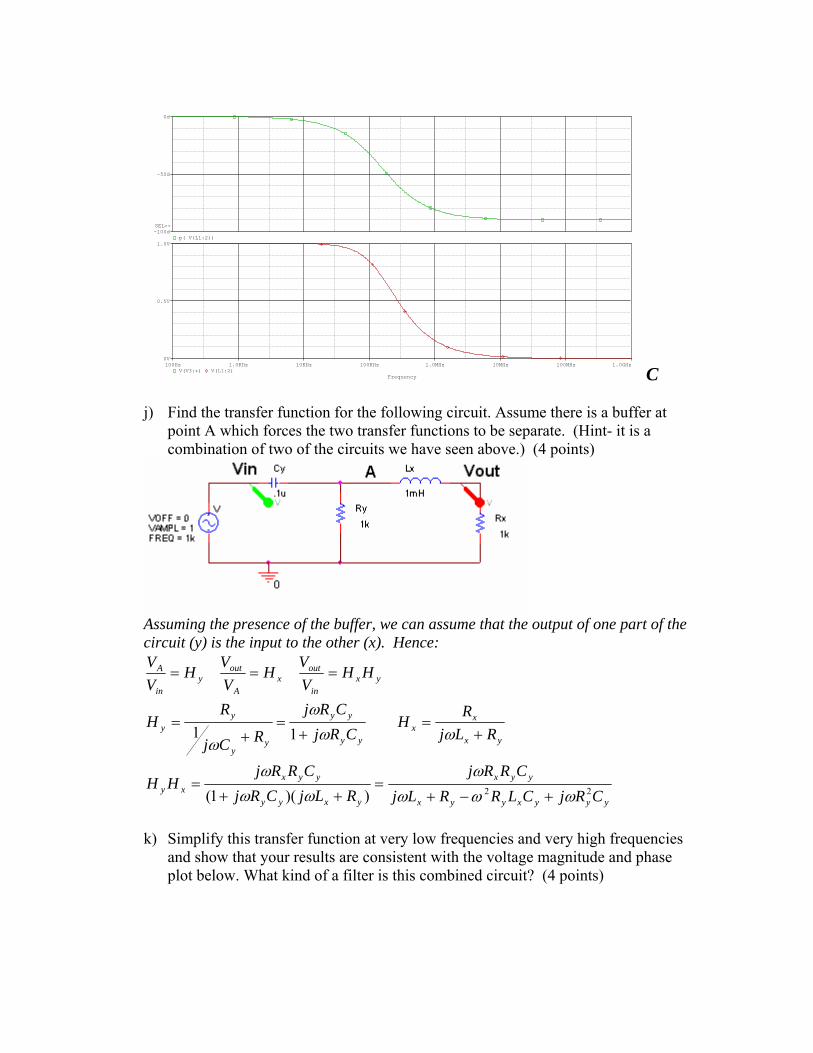
C j) Find the transfer function for the following circuit. Assume there is a buffer at
point A which forces the two transfer functions to be separate. (Hint- it is a combination of two of the circuits we have seen above.) (4 points)
Assuming the presence of the buffer, we can assume that the output of one part of the circuit (y) is the input to the other (x). Hence:
yyyxyyx
yyx
yxyy
yyxxy
yx
xx
yy
yy
yy
yy
yxin
outx
A
outy
in
A
CRjCLRRLjCRRj
RLjCRjCRRj
HH
RLjR
HCRj
CRj
RCj
RH
HHVV
HVV
HVV
22))(1(
11
ωωωω
ωωω
ωωω
ω
+−+=
++=
+=
+=
+=
===
k) Simplify this transfer function at very low frequencies and very high frequencies
and show that your results are consistent with the voltage magnitude and phase plot below. What kind of a filter is this combined circuit? (4 points)

20
20 2
22
πωω
ωπωω
ωωωω
−=∠=−
=−
==∠===
+−+=
HIHIx
x
yxy
yyxHILOLOyx
y
yyxLO
yyyxyyx
yyxxy
HHL
jR
CLRCRRj
HHHCRjR
CRRjH
CRjCLRRLjCRRj
HH
The magnitude is zero at both high and low frequencies, as seen in the plot. The phase is 90 degrees (pi/2) at low frequencies and –90 degrees (-pi/2) at high frequencies.
Frequency
100Hz 1.0KHz 10KHz 100KHz 1.0MHz 10MHz 100MHz 1.0GHzV(Lx:2) V(V2:+)
0V
0.5V
1.0Vp( V(Lx:2))
-100d
0d
100d
SEL>>
l) Extra Credit – Which of the original six filters is also a combination of two other
filters? Explain your answer. The band reject filter, E, is a combination of two other filters. A high pass filter with a corner frequency of 160000 Hertz and a low pass filter with a corner frequency of 1.600 Hertz. This makes it a combination of A and D. You can see this by looking at the plots for both phase and magnitude. When the magnitude of each goes to zero, the other dominates. Mathematically, this can be shown, but it is not that obvious and you should read the links below if you want to understand it fully....This was not required for the extra point.
LCRCjLCH E 2
2
11
ωωω
−+−
= There is a zero at the resonant frequency. To examine the
function below resonance, we throw out the terms that dominate at the highest frequencies. This would be –ω2LC. This means that at frequencies below resonance, the function simplifies to
11
+=− RCj
H LOE ω. This is HA, the filter that determines low frequency behavior. At
frequencies above the resonant frequency, we simplify the function by throwing out the terms that dominate at low frequency. Therefore the function becomes

LjRLj
LjRLj
LjRL
LCRCjLCH E ω
ωω
ωω
ωωω
ω+
=−−
−=
−−
=−
−= 2
2
. This is HD, the filter that
determines high frequency behavior. The band pass filter, F, is also a combination of two filters. A high pass filter with a corner frequency of around 160000 Hertz and a low pass filter with about the same corner frequency. These are not any of the filters we have here, however, the question is vague about whether you need to combine two filters that are pictured, or just two filters. For more details on why this is true, see the Gingrich notes: http://www.phys.ualberta.ca/%7Egingrich/phys395/notes/node48.html#SECTION00450000000000000000 and http://www.phys.ualberta.ca/%7Egingrich/phys395/notes/node50.html#SECTION00461000000000000000 Filter design is not always an exact science. Notice how he uses limits to decide the behavior of his circuit elements instead of the exact transfer functions.

Fall 2003 Question 1 -- RLC, RL and RC Circuits (30 points) Shown below are 5 circuits. Assume the input voltage (Vin) is applied across the left-most terminals and the output voltage (Vout) is measures across the rightmost terminals.
Given below are several possible expressions for generic transfer functions for such circuits. Indicate which circuit goes with which function. (1 point each)

Find the approximate resonant frequency ω0 for the RLC circuits and the corner frequency ωc for the other circuits. That is, write the general expression for each frequency. (1 point each) A. B. C. D. E. Determine the complex transfer function for two of the five circuits (A and B) at the resonant frequency or corner frequency. Be sure your answer is given in terms of R, L, and/or C and does not contain ω. This may seem like an obvious comment, but we want to make sure you have the simplest possible expression. Identify the magnitude and the phase of the transfer function at this frequency. A. (4 points) Vout/Vin = Hc = |Hc| = ∠Hc = B. (4 points) Vout/Vin = H0 = |H0| = ∠H0 =

Determine the transfer function, magnitude of the transfer function, and phase of the transfer function at low frequencies for C and D. These should be simplified and expressed these in terms of ω where appropriate. C. (4 points) Vout/Vin = Hlo(jω) = |Hlo| = ∠Hlo = D. (4 points) Vout/Vin = Hlo(jω) = |Hlo| = ∠Hlo = Finally, find the transfer function, magnitude of the transfer function, and phase of the transfer function as ω approaches infinity for E. These should be simplified and expressed in terms of ω where appropriate. E. (4 points) Vout/Vin = Hhi(jω) =
|Hhi| = ∠Hhi =

Fall 2003 Solution Question 1 -- RLC, RL and RC Circuits (30 points) Shown below are 5 circuits. Assume the input voltage (Vin) is applied across the left-most terminals and the output voltage (Vout) is measures across the rightmost terminals.
Given below are several possible expressions for generic transfer functions for such circuits. Indicate which circuit goes with which function. (1 point each)

Find the approximate resonant frequency ω0 for the RLC circuits and the corner frequency ωc for the other circuits. That is, write the general expression for each frequency. (1 point each) A. ωc=1/RC B. ω0=1/(LC)½ C. ωc=R/L D. ω0=1/(LC)½ E. ω0=1/(LC)½ Determine the complex transfer function for two of the five circuits (A and B) at the resonant frequency or corner frequency. Be sure your answer is given in terms of R, L, and/or C and does not contain ω. This may seem like an obvious comment, but we want to make sure you have the simplest possible expression. Identify the magnitude and the phase of the transfer function at this frequency.
A. (4 points) Vout/Vin = Hc = j ωCRC/( j ωCRC+1) = j(RC/RC)/(j(RC/RC)+1) = j/(j+1) Hc = j/(j+1)
|Hc| = 1/(1+1) ½ ∠Hc = π/2 - π/4
|Hc| = 1/(2) ½ ∠Hc = π/4 B. (4 points) Vout/Vin = H0 = 1/(jω0RC+1-ω0
2LC)=1/(j(RC/(LC) ½)=-j(LC) ½/RC
H0 = -j(LC) ½/RC |H0| = (LC) ½/RC ∠H0 = -π/2
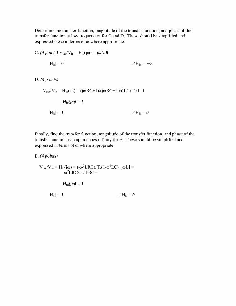
Determine the transfer function, magnitude of the transfer function, and phase of the transfer function at low frequencies for C and D. These should be simplified and expressed these in terms of ω where appropriate. C. (4 points) Vout/Vin = Hlo(jω) = jωL/R |Hlo| = 0 ∠Hlo = π/2 D. (4 points) Vout/Vin = Hlo(jω) = (jωRC+1)/(jωRC+1-ω2LC)=1/1=1
Hlo(jω) = 1 |Hlo| = 1 ∠Hlo = 0 Finally, find the transfer function, magnitude of the transfer function, and phase of the transfer function as ω approaches infinity for E. These should be simplified and expressed in terms of ω where appropriate. E. (4 points) Vout/Vin = Hhi(jω) = (-ω2LRC)/[R(1-ω2LC)+jωL] =
-ω2LRC/-ω2LRC=1 Hhi(jω) = 1
|Hhi| = 1 ∠Hhi = 0
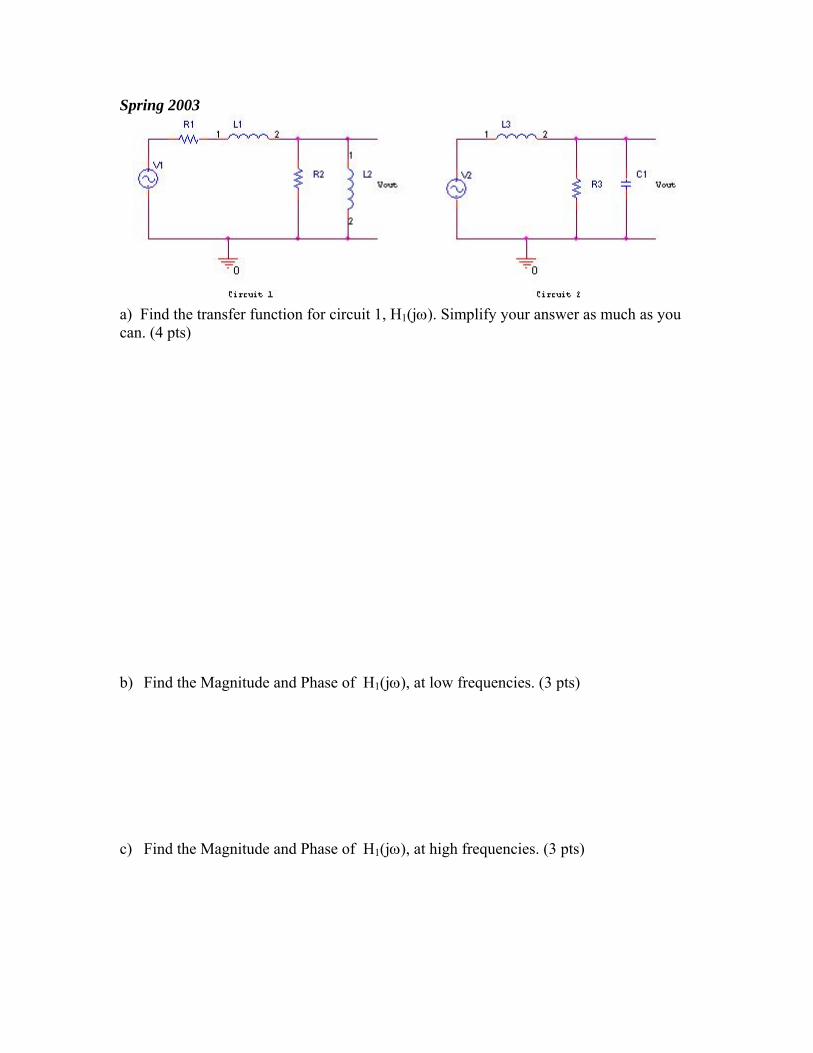
Spring 2003
a) Find the transfer function for circuit 1, H1(jω). Simplify your answer as much as you can. (4 pts) b) Find the Magnitude and Phase of H1(jω), at low frequencies. (3 pts) c) Find the Magnitude and Phase of H1(jω), at high frequencies. (3 pts)

d) Based of what you found, what type of filter is this? (1pts) e) Find the transfer function for circuit 2, H2(jω). Simplify as much as you can. (4 pts) f) Find the Magnitude and Phase of H2(jω), at low frequencies. (3 pts) g) Find the Magnitude and Phase of H2(jω), at high frequencies. (3 pts) h) Find the Magnitude and Phase of H2(jω), at resonance frequency. (3 pts) i) Based of what you found, what type of filter is this? (1pts)
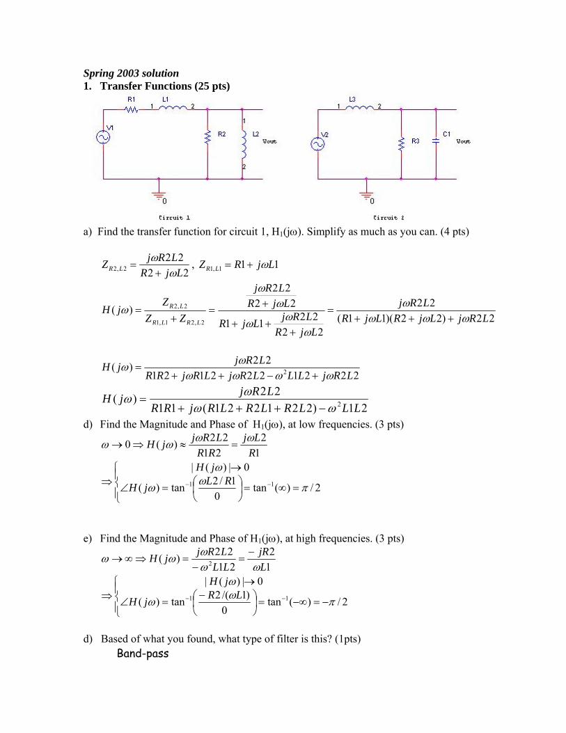
Spring 2003 solution 1. Transfer Functions (25 pts)
a) Find the transfer function for circuit 1, H1(jω). Simplify as much as you can. (4 pts)
2222
2,2 LjRLRjZ LR ω
ω+
= , 111,1 LjRZ LR ω+=
22)22)(11(22
222211
2222
)(2,21,1
2,2
LRjLjRLjRLRj
LjRLRjLjR
LjRLRj
ZZZ
jHLRLR
LR
ωωωω
ωωω
ωω
ω+++
=
+++
+=+
=
222122212122)( 2 LRjLLLRjLRjRR
LRjjHωωωω
ωω+−++
=
21)221221(1122)( 2 LLLRLRLRjRR
LRjjHωω
ωω−+++
=
d) Find the Magnitude and Phase of H1(jω), at low frequencies. (3 pts)
12
2122)(0
RLj
RRLRjjH ωωωω =≈⇒→
⎪⎩
⎪⎨⎧
=∞=⎟⎠⎞
⎜⎝⎛=∠
→⇒ −− 2/)(tan
01/2tan)(
0|)(|11 πωω
ωRLjH
jH
e) Find the Magnitude and Phase of H1(jω), at high frequencies. (3 pts)
12
2122)( 2 L
jRLLLRjjH
ωωωωω −
=−
=⇒∞→
⎪⎩
⎪⎨⎧
−=−∞=⎟⎠⎞
⎜⎝⎛ −
=∠
→⇒ −− 2/)(tan
0)1/(2tan)(
0|)(|11 πωω
ωLRjH
jH
d) Based of what you found, what type of filter is this? (1pts)
Band-pass

e) Find the transfer function for circuit 2, H2(jω). Simplify as much as you can. (4 pts)
1313
113
13
3,1 CRjR
CjR
CjR
Z RC ωω
ω+
=+
=
3)131)(3(3
13133
1313
)(3,13
3,1
RCRjLjR
CRjRLj
CRjR
ZZZ
jHRCL
RC
++=
++
+=+
=ωω
ωω
ωω
313333)( 2 RCRLLj
RjH+−
=ωω
ω
h) Find the Magnitude and Phase of H2(jω), at low frequencies. (3 pts)
133)(0 =≈⇒→
RRjH ωω
⎩⎨⎧
=∠=
⇒0)(1|)(|
ωωjHjH
The phase is 0, since H is a real and positive number.
i) Find the Magnitude and Phase of H2(jω), at high frequencies. (3 pts)
1333)( 2 CRL
RjHω
ωω−
≈⇒∞→
⎩⎨⎧
−=∠→
⇒ππω
ωorjH
jH)(
0|)(|
The phase is π or -π , since H is a real and negative number.
h) Find the Magnitude and Phase of H2(jω), at resonance frequency. (3 pts)
313
3133
333
13313
33)(
131
LCjR
jLCLR
RRL
CRLCL
Lj
RjHCL
−==
+−=⇒= ωω
⎪⎩
⎪⎨⎧
−=∠
=⇒2/)(
313|)(|
πω
ω
jHL
CRjH
The phase is 2/π− , since H is an imaginary and negative number. (We now know that it must be -π at high frequencies.)
i) Based of what you found, what type of filter is this? (1pts)
Low-Pass
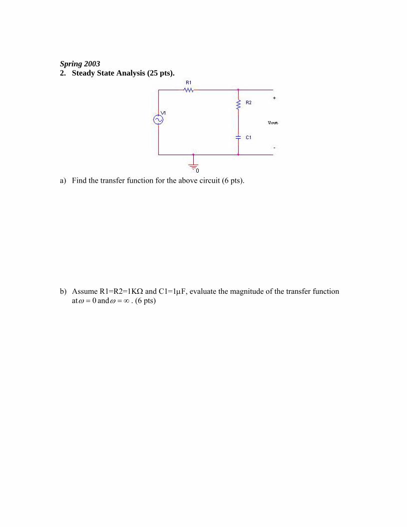
Spring 2003 2. Steady State Analysis (25 pts).
a) Find the transfer function for the above circuit (6 pts).
b) Assume R1=R2=1KΩ and C1=1µF, evaluate the magnitude of the transfer function
at 0=ω and ∞=ω . (6 pts)

c) If )4/12(5)(1 ππ +××= tKHzvCostv , what is the phasor 1V
r? (4 pts)
d) Given R1=2KΩ, R2=2KΩ and C1=1µF, what is the output phasor outV
r? (6 pts)
e) Based on your answer in part d, write the out put voltage in the form of
)cos()( φω += tAtvout , i.e. find A, ω and φ. (3 pts)

Spring 2003 solution 3. Steady State Analysis (25 pts).
a) Find the transfer function for the above circuit (6 pts).
1112
1121,2 Cj
CRjCj
RZ CR ωω
ω+
=+=
11211112
11121
1112
)(1,21
1,2
+++
=+
+
+
=+
=CRjRCj
CRj
CjCRjR
CjCRj
ZZZ
jHCRR
CR
ωωω
ωωω
ω
ω
11)21(112)(
1,21
1,2
+++
=+
=CRRj
CRjZZ
ZjH
CRR
CR
ωωω
b) Assume R1=R2=1KΩ and C1=1µF, evaluate the magnitude of the transfer function at 0=ω and ∞=ω . (6 pts)
1102110
11010211010)( 3
3
63
63
+××+×
=+×××
+××= −
−
−
−
ωω
ωωω
jj
jjjH
111)(0 ==⇒→ ωω jH
21
10210)( 3
3
=××
×=⇒∞→ −
−
ωωωω
jjjH

c) If )4/12(5)(1 ππ +××= tKHzvCostv , what is the phasor 1Vr
? (4 pts)
79.041 55 jj
eeV ==πr
d) Given R1=2KΩ, R2=2KΩ and C1=1µF, what is the output phasor outV
r? (6 pts)
KHz12 ×= πω
radiansorH
H
jjjH
20.608.049.141.1)4(tan)2(tan
505.06.12
36.61)4(
1)2(
1412)(
11
2
2
−=−=−=∠
==+
+=
++
=
−− ππ
π
π
ππω
71.0)08.079.0(
1 5.25505.0)( jjout eeVjHV =×== −
rrω
e) Based on your answer in part d, write the out put voltage in the form
)()( φω += tACostvout , i.e. find A, ω and φ. (3 pts) )71.02(5.2)( +×= tKHzvCostvout π
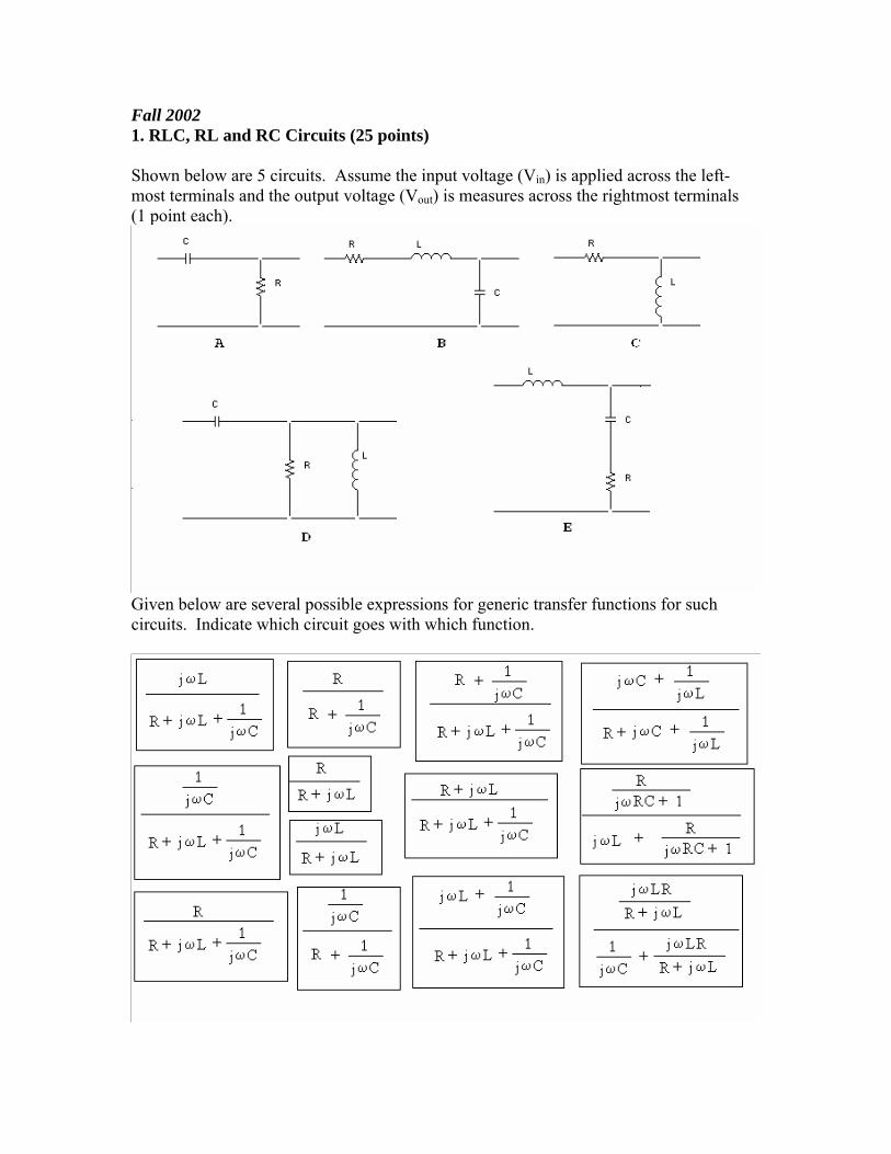
Fall 2002 1. RLC, RL and RC Circuits (25 points) Shown below are 5 circuits. Assume the input voltage (Vin) is applied across the left-most terminals and the output voltage (Vout) is measures across the rightmost terminals (1 point each).
Given below are several possible expressions for generic transfer functions for such circuits. Indicate which circuit goes with which function.

Find the approximate resonant frequency ω0 for the RLC circuits and the corner frequency ωc for the other circuits. That is, write the general expression for each frequency (1 point each). A. B. C. D. E. Determine the complex transfer function for two of the five circuits (A and B) at the resonant frequency or corner frequency. Be sure your answer is given in terms of R, L, and/or C and does not contain ω. This may seem like an obvious comment, but we want to make sure you have the simplest possible expression. Identify the magnitude and the phase of the transfer function at this frequency (6 points). A. Vout/Vin = Hc = |Hc| = ∠Hc = B. Vout/Vin = H0 = |H0| = ∠H0 =

Determine the transfer function, magnitude of the transfer function, and phase of the transfer function at low frequencies for C and D. These should be simplified and expressed these in terms of ω where appropriate (6 points). C. Vout/Vin = Hlo(jω) = |Hlo| = ∠Hlo = D. Vout/Vin = Hlo(jω) = |Hlo| = ∠Hlo = Finally, find the transfer function, magnitude of the transfer function, and phase of the transfer function as ω approaches infinity for E. These should be simplified and expressed in terms of ω where appropriate (3 points). E. Vout/Vin = Hhi(jω) =
|Hhi| = ∠Hhi =

Fall 2002 Solution (not available)

Spring 2002 1. RLC, RL and RC Circuits (25 points) Shown below are 5 circuits. Assume the input voltage (Vin) is applied across the left-most terminals and the output voltage (Vout) is measures across the rightmost terminals (1 point each).
Given below are several possible expressions for generic transfer functions for such circuits. Indicate which circuit goes with which function.

Find the resonant frequency ω0 for the RLC circuits and the corner frequency ωc for the other circuits. That is, write the general expression for each frequency (1 point each). A. B. C. D. E. Determine the complex transfer function for each of the five circuits at the resonant or corner frequency. (1 point each) Be sure your answer is given in terms of R, L, and/or C and does not contain ω. This may seem like an obvious comment, but we want to make sure you have the simplest possible expression. Identify the magnitude and the phase of the transfer function at this frequency. (1 point for each magnitude, 1 point for each phase) A. Vout/Vin = H0 = |H0| = ∠H0 = B. Vout/Vin = Hc = |Hc| = ∠Hc =

C. Vout/Vin = Hc = |Hc| = ∠Hc = D. Vout/Vin = H0 = |H0| = ∠H0 = E. Vout/Vin = H0 = |H0| = ∠H0 =

Spring 2002 solution (not available)

Fall 2001 Solution