"an efficient analytic signal generator", turner - clay s. turner's
TRANSCRIPT

IEEE SIGNAL PROCESSING MAGAZINE [91] JULY 2009
[dsp TIPS&TRICKS]
Digital Object Identifier 10.1109/MSP.2009.932794
An Efficient Analytic Signal Generator
Sometimes in digital signal pro-cessing (DSP) applications, one has a real-valued signal and needs to transform it into an analytic signal. Interest in
analytic signals stems from the signals having one-sided Fourier transforms and the ease with which one may calculate their instantaneous amplitudes and fre-quencies. Traditionally, generating ana-lytic signals is done by augmenting the real signal with its Hilbert transform, as shown in Figure 1(a). Specifically if our real signal is i 1t 2 and its Hilbert trans-form is q 1t 2 , then our analytic signal is simply i 1t 2 1 jq 1t 2 , where j 2521 [1].
One shortcoming of the analytic signal generation scheme in Figure 1(a) is that the Hilbert transformer cannot be designed to have exactly unity gain, as we desire, over its full passband. Therefore the two paths exhibit unmatched frequency magni-tude responses. (For completeness, we mention that [2] proposed an analytic signal generation scheme where both its i 1t 2 and q 1t 2 channels have identi-cal frequency magnitude responses; however that scheme does not exhibit a linear-phase frequency response.) Since the absolute phase associated with a true analytic signal is rarely needed, we
can generate a pseudoanalytic signal by using a pair of unity gain filters having a phase response difference of 90º. This generality suggests that there are many such possible pairs of filters and there are! Reference [3] presents an analytic signal generation method where a half-band filter is created via a Remez algo-rithm, and the result is modulated by a complex sinusoid. A limitation of their method applies to the length of filters because the design algorithm encoun-ters numerical problems for large filter lengths.
This article presents a simple way to construct a pair of quasi-linear-phase bandpass filters that have identical mag-nitude responses and differ in phase by 90º that can be used for analytic signal generation as shown in Figure 1(b). Furthermore, these filters have useful symmetry properties that significantly reduce their computational complexity and coefficient storage requirements, and there is no inherent length limita-tion to the size of the filters.
ANALYTIC SIGNAL GENERATION APPROACHSince the filter pair’s phase difference is key to the design, we will elect to use finite impulse response (FIR) filters with linear phase. And as is well known, to have linear phase, FIR filters must have impulse responses that are either odd or even
symmetric about their midpoint [4]. This fact will prove very useful momentarily.
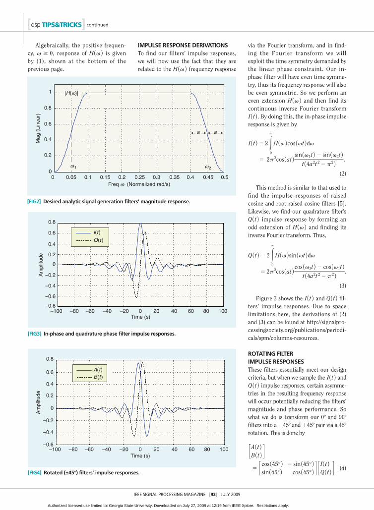
DEFINING THE FREQUENCY RESPONSEWe start by defining our two filters’ iden-tical frequency magnitude response for positive frequencies. Then we will exploit the aforementioned symmetry rules of linear phase filters to find their impulse responses. We construct our bandpass response using two pieces of a sinusoid joined together with a horizontal line as shown in Figure 2.
In this filter design we will specify three parameters: The two half ampli-tude points v1 and v2 and the transition half bandwidth a. For this example they are, respectively, 0.05, 0.45, and 0.05 rad/s. The transition region width is 2a5 0.1 rad/s.
Clay S. Turner
1053-5888/09/$25.00©2009IEEE
“DSP Tips and Tricks” introduces practical design and implementa-tion signal processing algorithms that you may wish to incorporate into your designs. We welcome readers to submit their contribu-tions to Associate Editors Rick Lyons ([email protected]) or Britt Rorabaugh ([email protected]).
H 1v 2 5 g0, v , v12 a
sin2b p4a 3v2 1v12 a 2 4 r , v12 a # v # v11 a
1, v11 a # v # v22 a
cos2b p4a
v2 1v22 a 23 4 r , v22 a # v # v21 a
0, v . v21 a.
(1)
HilbertTransformer
A(k)
i(t )i (t )
x (t )
q(t)
a(t)
b(t)B(k)
(a)
(b)
[FIG1] Analytic signal generation methods: (a) traditional and (b) proposed.
Authorized licensed use limited to: Georgia State University. Downloaded on July 27, 2009 at 12:19 from IEEE Xplore. Restrictions apply.
IEEE SIGNAL PROCESSING MAGAZINE [92] JULY 2009
[dsp TIPS&TRICKS] continued
Algebraically, the positive frequen-cy, v $ 0, response of H 1v 2 is given by (1), shown at the bottom of the previous page.
IMPULSE RESPONSE DERIVATIONSTo find our filters’ impulse responses, we will now use the fact that they are related to the H 1v 2 frequency response
via the Fourier transform, and in find-ing the Fourier transform we will exploit the time symmetry demanded by the linear phase constraint. Our in-phase filter will have even time symme-try, thus its frequency response will also be even symmetric. So we perform an even extension H 1v 2 and then find its continuous inverse Fourier transform I 1t 2 . By doing this, the in-phase impulse response is given by
I 1t 2 5 2 3`
0
H 1v 2cos 1vt 2dv 5 2p2cos 1at 2 sin 1v1t 2 2 sin 1v2t 2
t 14a2t 22p2 2 .
(2)
This method is similar to that used to find the impulse responses of raised cosine and root raised cosine filters [5]. Likewise, we find our quadrature filter’s Q 1t 2 impulse response by forming an odd extension of H 1v 2 and finding its inverse Fourier transform. Thus,
Q 1t 2 5 2 3`
0
H 1v 2sin 1vt 2dv 5 2p2cos 1at 2 cos 1v2t 2 2 cos 1v1t 2
t 14a2t 22p2 2 .
(3)
Figure 3 shows the I 1t 2 and Q 1t 2 fil-ters’ impulse responses. Due to space limitations here, the derivations of (2) and (3) can be found at http://signalpro-cessingsociety.org/publications/periodi-cals/spm/columns-resources.
ROTATING FILTER IMPULSE RESPONSESThese filters essentially meet our design criteria, but when we sample the I 1t 2 and Q 1t 2 impulse responses, certain asymme-tries in the resulting frequency response will occur potentially reducing the filters’ magnitude and phase performance. So what we do is transform our 0º and 90º filters into a 245º and 145º pair via a 45º rotation. This is done by
cA 1t 2B 1t 2 d
5 ccos 145° 2 2 sin 145° 2sin 145° 2 cos 145° 2 d c
I 1t 2Q 1t 2 d (4)
0 0.05 0.1 0.15 0.2 0.25 0.3 0.35 0.4 0.45 0.50
0.2
0.4
0.6
0.8
1
Mag
(Li
near
)
Freq ω (Normalized rad/s)
ω1 ω2
aa
|H(ω)|
[FIG2] Desired analytic signal generation filters’ magnitude response.
–100 –80 –60 –40 –20 0 20 40 60 80 100
–0.4
–0.6
–0.8
–0.2
0.2
0
0.4
0.8
0.6
Am
plitu
de
Time (s)
I(t )
Q(t )
[FIG3] In-phase and quadrature phase filter impulse responses.
[FIG4] Rotated (±45°) filters’ impulse responses.
–100 –80 –60 –40 –20 0 20 40 60 80 100
–0.4
–0.6
–0.2
0.2
0
0.4
0.8
0.6
Am
plitu
de
Time (s)
A(t)B(t)
Authorized licensed use limited to: Georgia State University. Downloaded on July 27, 2009 at 12:19 from IEEE Xplore. Restrictions apply.
IEEE SIGNAL PROCESSING MAGAZINE [93] JULY 2009
where A 1t 2 and B 1t 2 are the rotated in-phase and quadrature phase impulse responses. This simplifies to
A 1t 2 5 I 1t 2 2Q 1t 2"2
(5)
B 1t 2 5 I 1t 2 1Q 1t 2"2
. (6)
The resulting A 1t 2 and B 1t 2 impulse responses are shown in Figure 4.
If we apply the transformations, (5) and (6), to (2) and (3) respectively, we obtain
A 1t 2 5 2p2cos 1at 2t 14t 2a22p2 2
3 3sin 1v1t1p@4 2
2 sin 1v2t1p@4 2 4 (7)
B 1t 2 5 2p2cos 1at 2t 14t 2a22p2 2
3 3sin 1v1t2p@4 2
2 sin 1v2t2p@4 2 4. (8)
This transformation allows us to eliminate half the coefficients. Both fil-ters will now share the same set of coeffi-cients because B 1t 2 5 A 1 2 t 2 . Filter B’s coefficients are just a time-reversed ver-sion of filter A’s coefficients, and this “mirrored in time” relation will cut the coefficient memory requirement in half as well as making the two frequency magnitude responses identical.
COMPUTING FIR FILTER COEFFICIENTSWhen using (7) to compute the filter coefficients, one may encounter a divide by zero error, which we resolve by apply-ing L’Hospital’s rule. Doing this, we
obtain the complete formulation for A 1t 2 in (9), shown at the bottom of the page.
Now we need to temporally sample A 1t 2 to generate our filters’ coefficients. Using N to denote the length of the FIR filters’ impulse responses, and k5 0, 1, 2, ..., N21 as the index of the impulse response samples (note that N can be either even or odd), we find our in-phase filter coefficients by evaluating the continuous expression in (9) at the time instants defined by
A 3k 45 A c2pak2N2 1
2b d . (10)
Again, the quadrature phase coeffi-cients, B 3k 4, are a reversed-order version of the in-phase A 3k 4 coefficients in (10).
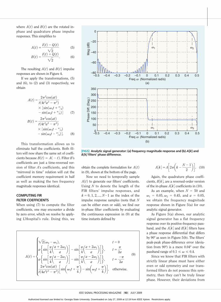
As an example, when N 5 50 and v1 5 0.05, v2 5 0.45, and a 5 0.05, we obtain the frequency magnitude response shown in Figure 5(a) for our analytic signal generator.
As Figure 5(a) shows, our analytic signal generator has a flat frequency response over its positive-frequency pass-band, and the A 3k 4 and B 3k 4 filters have a phase response differential that differs by 90º as seen in Figure 5(b). The filters’ peak-peak phase-difference error (devia-tion from 90º) is a mere 0.04º over the passband range of 0.1 # v # 0.4.
Since we know that FIR filters with strictly linear phase must have either even or odd symmetry and our trans-formed filters do not possess this sym-metry, then they can’t be truly linear phase. However, their deviations from
A 1t 2 5 h"2 1v22v1 2 , t5 0
a e sin cp4aa1 2v2
ab d 2 sin cp
4aa1 2v1
ab d f , t5
p
2a
a e sin cp4aa2 2v1
ab d 2 sin cp
4aa2 2v2
ab d f , t5
2p
2a2p2cos 1at 2
t 14a2t 22p2 2 csinav1t1p
4b 2 sinav2t1
p
4b d , otherwise.
(9)
[FIG5] Analytic signal generator: (a) frequency magnitude response and (b) A[k] and B[k] filters’ phase difference.
ω1 ω2
–0.5 –0.4 –0.3 –0.2 –0.1 0 0.1 0.2 0.3 0.4 0.5
–60
–80
–40
–20
0
Mag
(dB
)
Freq ω (Normalized rad/s)(a)
–0.5 –0.4 –0.3 –0.2 –0.1 0 0.1 0.2 0.3 0.4 0.5Freq ω (Normalized rad/s)
(b)
ω1 ω2
Pha
se D
iff. (
Deg
.)
0
50
100
150
200
250
300
350
Authorized licensed use limited to: Georgia State University. Downloaded on July 27, 2009 at 12:19 from IEEE Xplore. Restrictions apply.

IEEE SIGNAL PROCESSING MAGAZINE [94] JULY 2009
[dsp TIPS&TRICKS] continued
linear phase are small and only occur for frequencies around dc and at half of the sampling-rate places where the magnitude response is nearly zero.
Our filter transformations also bring about a neat property. When the desired frequency response is chosen to be symmetric about one-fourth of the sampling rate, and our filter lengths are chosen to be even, then half of the filter’s coefficients will be zero! So this, in combination with the mirror property, means our pair of fil-ters will have one-half of computational effort of a pair of arbitrary filters of the same length.
CONCLUSIONWe proposed a simple method for gen-erating a pair of high-performance, phase-orthogonal FIR filters used to generate analytic signals. The filters have a 90º-phase differential, quasi-linear
phase responses and flat magnitude responses in their passbands. Due to their time reversal symmetries, only one set of filter coefficients need be stored in memory. If the frequency response of even-length filters is chosen to be centered at one-fourth the sam-pling rate, then half of the coefficients will be zero. And, finally, because the filters coefficients are defined by a closed-form formula, there is no filter length limitation imposed by a numeri-cal process that fails to converge.
MathCAD and MATLAB code, model-ing this dual quadrature filters tech-nique, is available for downloading at http://signalprocessingsociety.org/pub-lications/periodicals/spm/columns-resources.
AUTHORClay S. Turner ([email protected]) is chief scientist for Pace-O-Matic,
Inc. He has over 30 years of experience in digital signal processing and mathe-matical and embedded programming. When not busy, he likes to photograph, scuba, backpack, cycle, and go horse-back riding with his wife.
REFERENCES[1] D. Gabor, “Theory of communications,” Trans. Inst. Electr. Eng., vol. 93, no. 26, pp. 429–456, 1946.
[2] C. Rader, “A simple method for sampling in-phase and quadrature components,” IEEE Trans. Aero-space Electron. Syst., vol. 20, no. 6, pp. 821–824, Nov. 1984.
[3] A. Reilly, G. Frazer, and B. Boashash, “Analytic signal generation—Tips and traps,” IEEE Trans. Signal Processing, vol. 42, no. 11, Nov. 1994, pp. 3241–3245.
[4] J. McClellan and T. Parks, “A unified approach to the design of optimal FIR linear-phase digital filters,” IEEE Trans. Circuit Theory, vol. CT-20, no. 6, pp. 697–701, Nov. 1973.
[5] C. Turner. (2007 May). “Raised cosine and root raised cosine formulae,” [Online]. Available: http://www.claysturner.com/dsp/Raised%20Co-sine%20and%20Root%20Raised%20Cosine%20Formulae.pdf [SP]
Discover the benefitsof IEEE membership.
Join todaywww.ieee.org/join
My profession.My organization.My IEEE.
Access the latest technical informationand research, gain global networkingand career opportunities, and takeadvantage of exclusive discounts oneducation and insurance productswhen you become an IEEE member.
Authorized licensed use limited to: Georgia State University. Downloaded on July 27, 2009 at 12:19 from IEEE Xplore. Restrictions apply.