qx modular crane assembly instructions · r&m materials handling, inc spacemaster sx hoist...
TRANSCRIPT
R&M Materials Handling, Inc Spacemaster SX Hoist Springfield, Ohio USA QX Crane Assembly Instructions �: 800 955-9967 Single Girder Under Running web: www.rmhoist.com Revision 2
12/04/02 RM-QX-CA-SGUR-1H-2001-2-ENG.doc
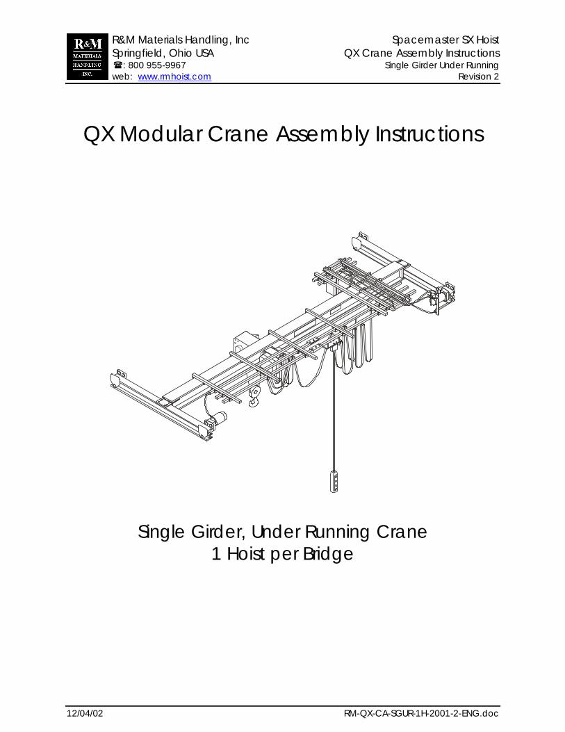
QX Modular Crane Assembly Instructions
Single Girder, Under Running Crane1 Hoist per Bridge
R&M Materials Handling, Inc Spacemaster SX Hoist Springfield, Ohio USA QX Crane Assembly Instructions �: 800 955-9967 Single Girder Under Running web: www.rmhoist.com Revision 2
12/04/02 Bulletin: RM-QX-CA-SGUR-1H-2001-2-ENG.doc2
The QX Modular Crane Assembly Instructions have been prepared to acquaint you with the proceduresnecessary for assembling of the QX Modular Crane that you will install.
Installation, Operation, and Maintenance Instructions for the hoist and bridge drives are also provided.
Proper installation is important to the performance of this equipment. Careful study of and adherence tothe instructions will help ensure safe, dependable operation. It is also recommended that you keep themanuals for the equipment readily accessible to operators as well as maintenance and safety personnel.
Information in this manual is subject to change without notice.
R&M Materials Handling, Inc4501 Gateway BoulevardSpringfield, Ohio USAPhone: 800 955-9967Fax: 800 955-5162
Visit us on the web: www.rmhoist.com
R&M Materials Handling, Inc Spacemaster SX Hoist Springfield, Ohio USA QX Crane Assembly Instructions �: 800 955-9967 Single Girder Under Running web: www.rmhoist.com Revision 2
12/04/02 Bulletin: RM-QX-CA-SGUR-1H-2001-2-ENG.doc3
CONTENTS
GENERAL ..........................................................................................................................4
POWER CONNECTIONS.....................................................................................................4
BRIDGE BEAM ...................................................................................................................5
BRIDGE TRAVEL LIMIT SWITCH.............................................................................................5
BRIDGE BEAM CONNECTION ............................................................................................6
MAIN CRANE COMPONENTS.............................................................................................8
BRIDGE DRIVE ASSEMBLY – UT16 END TRUCK ...................................................................10
BRIDGE DRIVE ASSEMBLY - UC END TRUCK ......................................................................12
CRANE POWER TOW ARM ASSEMBLY...............................................................................14
HOIST TOW ARM ASSEMBLY .............................................................................................16
HOIST TOW ARM ASSEMBLY .............................................................................................17
HOIST TOW ARM ASSEMBLY .............................................................................................18
BUMPER STOP ASSEMBLY < 3 TON [3200 KG] ..................................................................19
BUMPER STOP ASSEMBLY > 3 TON [3200 KG] ..................................................................20
BRIDGE PANEL ASSEMBLY ................................................................................................22
FESTOON ASSEMBLY........................................................................................................24
PLUG IDENTIFICATION AND LAYOUT .................................................................................26

R&M Materials Handling, Inc Spacemaster SX Hoist Springfield, Ohio USA QX Crane Assembly Instructions �: 800 955-9967 Single Girder Under Running web: www.rmhoist.com Revision 2
12/04/02 Bulletin: RM-QX-CA-SGUR-1H-2001-2-ENG.doc4
GeneralA QX Modular Crane Package includes:� Spacemaster SX hoist,� Bridge end trucks including beam connection plates (except for UT type under running trucks),� Bridge drives,� Bridge panel that includes a thru-door mainline disconnect, mainline fuses, mainline contactor and a
control transformer (for both hoist & crane),� Complete festoon package featuring plugs for quick connections,� Festoon tow arm for hoist,� Bridge tow arm for main power,� Bridge travel limit switch,� Sliding pendant on its own festoon rail,� Suggested beam for bridge girder for capacity and span that the user specifies (beam furnished by
others),� Crane assembly instructions,� Installation, Operation & Maintenance manuals for components such as the hoist and the bridge
drives
Prior to permanent installation, the equipment shall be checked by qualified personnel for damage duringshipment or handling at the job site. Particular attention shall be taken to make sure that the hoist wirerope and the limit switch mechanism have not been damaged by improper use of forklifts or sling chains.
IMPORTANTHoists/cranes are designed for lifting and transporting of materials only. Under noconditions or circumstances, either during initial installation or in regular use, arethe hoists/cranes to be used for lifting or transporting of personnel.
Only trained and competent personnel may handle the hoist/crane. When using slings, chains or hook tohandle the hoist/crane, use the designated lifting points or lugs. Never suspend the hoist by the drum,counterweight, control enclosure or motors.
Before installing trolley mounted hoists, rail stops must be installed for all trolleys mounted on open-endbeams. These stops must be positioned such that only the trolley frames absorb any impact forces. Donot allow the trolley wheels to impact rail stops.
Power ConnectionsAccording to CMAA Specification #74, a minimum of two collectors for each runway conductor shall beused with inverter use.
In addition, the use of a ground shall be utilized, either through the frame ground or a conductor ground.
Proper grounding is important with inverter use. A poor ground could cause damage to the inverter orcould create a shock hazard to personnel.
Proper Crane MotionCrane traveling motions are set for when the operator is standing on the push button side of the bridge,facing the load. If the direction of the bridge drive travel does not correctly correspond with respect to thebridge button being depressed, check the following possibilities:1. If all motions are opposite with respect to the pushbutton markings, swap two of the main power leads
at the bridge panel (for hoist and trolley motion checks see start-up section in the hoist’s Installation,Operation and Maintenance manual).
2. Then, if necessary, change the bridge travel direction by switching plugs X-211 and X-221 at thebridge panel.
R&M Materials Handling, Inc Spacemaster SX Hoist Springfield, Ohio USA QX Crane Assembly Instructions �: 800 955-9967 Single Girder Under Running web: www.rmhoist.com Revision 2
12/04/02 Bulletin: RM-QX-CA-SGUR-1H-2001-2-ENG.doc5
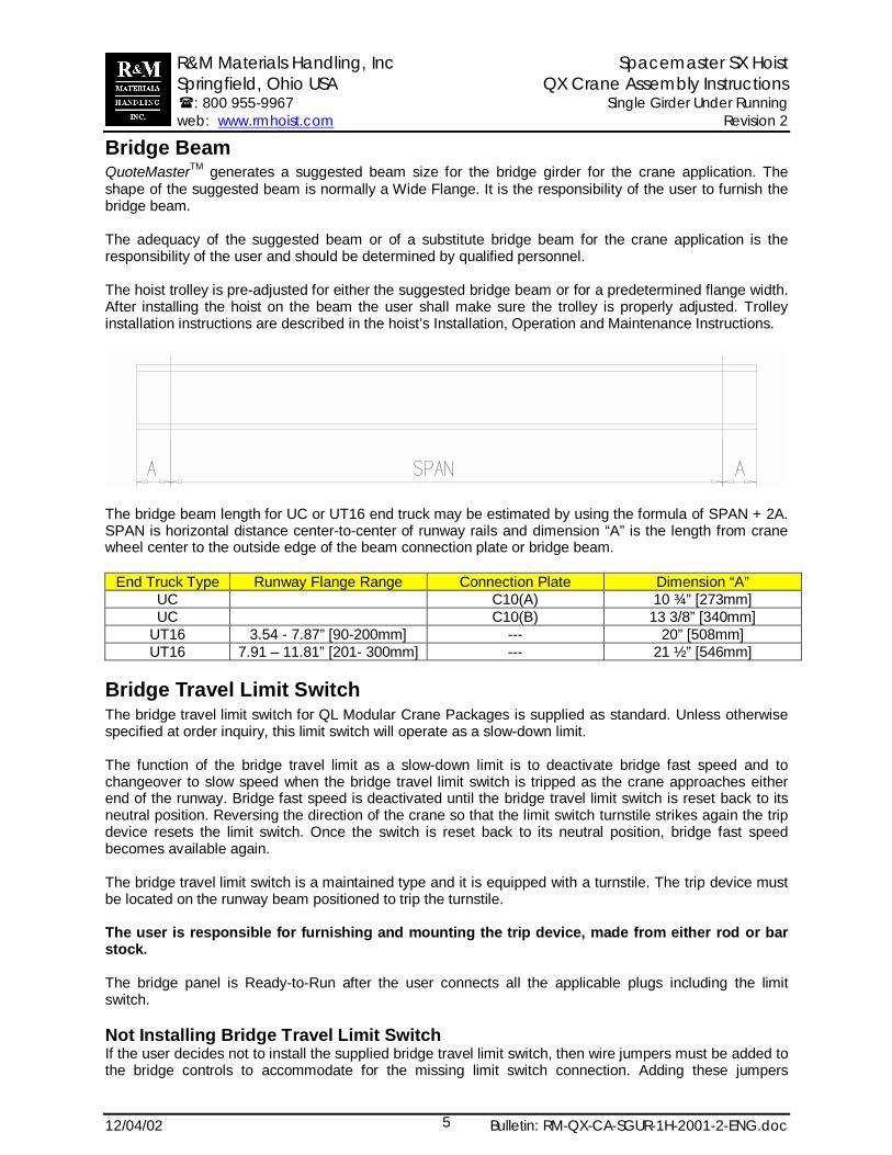
Bridge BeamQuoteMasterTM generates a suggested beam size for the bridge girder for the crane application. Theshape of the suggested beam is normally a Wide Flange. It is the responsibility of the user to furnish thebridge beam.
The adequacy of the suggested beam or of a substitute bridge beam for the crane application is theresponsibility of the user and should be determined by qualified personnel.
The hoist trolley is pre-adjusted for either the suggested bridge beam or for a predetermined flange width.After installing the hoist on the beam the user shall make sure the trolley is properly adjusted. Trolleyinstallation instructions are described in the hoist’s Installation, Operation and Maintenance Instructions.
The bridge beam length for UC or UT16 end truck may be estimated by using the formula of SPAN + 2A.SPAN is horizontal distance center-to-center of runway rails and dimension “A” is the length from cranewheel center to the outside edge of the beam connection plate or bridge beam.
End Truck Type Runway Flange Range Connection Plate Dimension “A”UC C10(A) 10 ¾” [273mm]UC C10(B) 13 3/8” [340mm]
UT16 3.54 - 7.87” [90-200mm] --- 20” [508mm]UT16 7.91 – 11.81” [201- 300mm] --- 21 ½” [546mm]
Bridge Travel Limit SwitchThe bridge travel limit switch for QL Modular Crane Packages is supplied as standard. Unless otherwisespecified at order inquiry, this limit switch will operate as a slow-down limit.
The function of the bridge travel limit as a slow-down limit is to deactivate bridge fast speed and tochangeover to slow speed when the bridge travel limit switch is tripped as the crane approaches eitherend of the runway. Bridge fast speed is deactivated until the bridge travel limit switch is reset back to itsneutral position. Reversing the direction of the crane so that the limit switch turnstile strikes again the tripdevice resets the limit switch. Once the switch is reset back to its neutral position, bridge fast speedbecomes available again.
The bridge travel limit switch is a maintained type and it is equipped with a turnstile. The trip device mustbe located on the runway beam positioned to trip the turnstile.
The user is responsible for furnishing and mounting the trip device, made from either rod or barstock.
The bridge panel is Ready-to-Run after the user connects all the applicable plugs including the limitswitch.
Not Installing Bridge Travel Limit SwitchIf the user decides not to install the supplied bridge travel limit switch, then wire jumpers must be added tothe bridge controls to accommodate for the missing limit switch connection. Adding these jumpers
R&M Materials Handling, Inc Spacemaster SX Hoist Springfield, Ohio USA QX Crane Assembly Instructions �: 800 955-9967 Single Girder Under Running web: www.rmhoist.com Revision 2
12/04/02 Bulletin: RM-QX-CA-SGUR-1H-2001-2-ENG.doc6
bypasses the limit switch circuit and brings online bridge fast speed that otherwise is disabled becausethe limit switch was not installed.
Refer to the wiring diagrams, in particular the bridge panel wiring diagram, that are included with yourmanuals before making any jumper connections.
Install a jumper from terminal X1: 50 to limit switch input(s) on the inverter in the bridge panel. Dependingon the inverter type, there could be more than one limit switch input on the inverter. Each one of theselimit switch connections on the inverter must be jumper connected. For example, if multiple switch inputson the inverter are being used, then add a jumper from terminal X1: 50 to Input “A”, then from Input “A” toInput “ B” and so on.
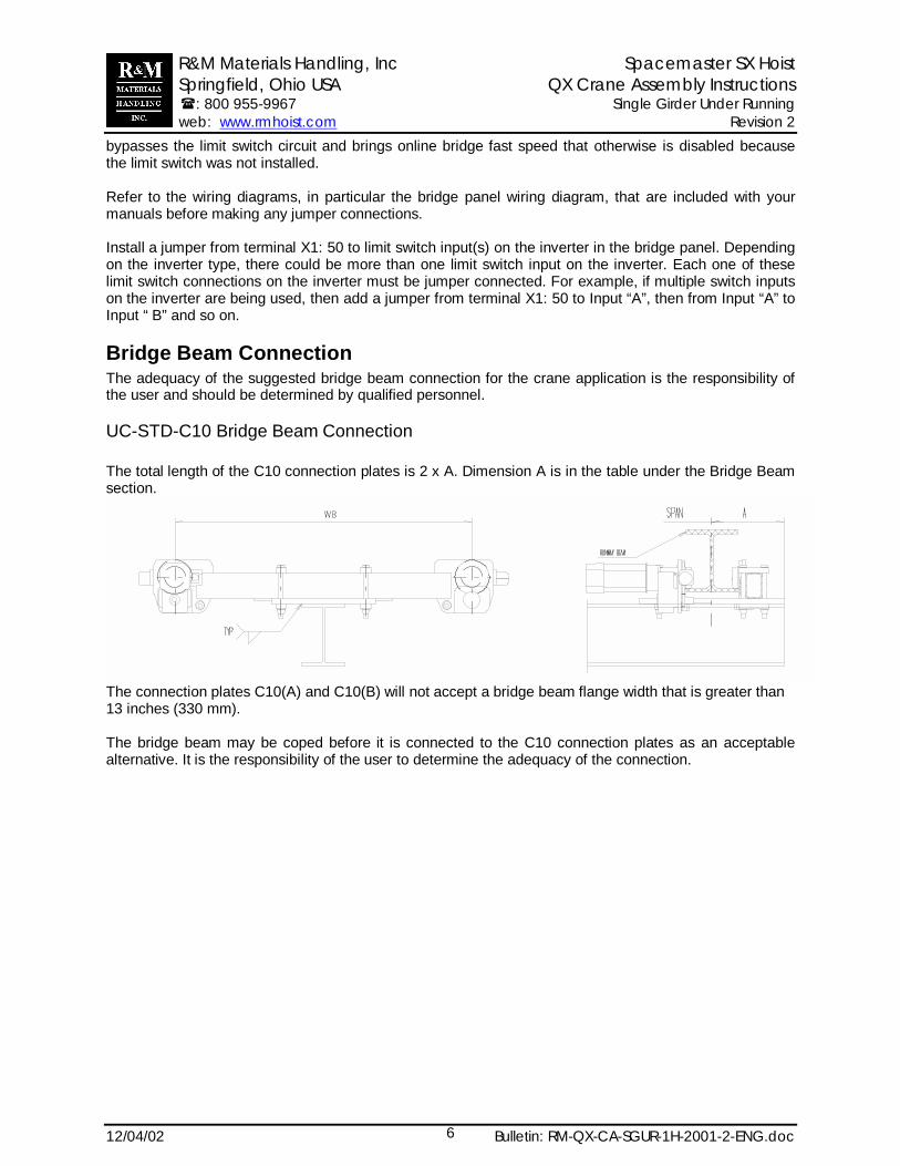
Bridge Beam ConnectionThe adequacy of the suggested bridge beam connection for the crane application is the responsibility ofthe user and should be determined by qualified personnel.
UC-STD-C10 Bridge Beam Connection
The total length of the C10 connection plates is 2 x A. Dimension A is in the table under the Bridge Beamsection.
The connection plates C10(A) and C10(B) will not accept a bridge beam flange width that is greater than13 inches (330 mm).
The bridge beam may be coped before it is connected to the C10 connection plates as an acceptablealternative. It is the responsibility of the user to determine the adequacy of the connection.
R&M Materials Handling, Inc Spacemaster SX Hoist Springfield, Ohio USA QX Crane Assembly Instructions �: 800 955-9967 Single Girder Under Running web: www.rmhoist.com Revision 2
12/04/02 Bulletin: RM-QX-CA-SGUR-1H-2001-2-ENG.doc7
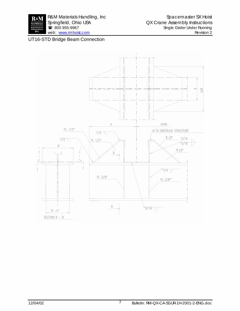
UT16-STD Bridge Beam Connection
R&M Materials Handling, Inc Spacemaster SX Hoist Springfield, Ohio USA QX Crane Assembly Instructions �: 800 955-9967 Single Girder Under Running web: www.rmhoist.com Revision 2
12/04/02 Bulletin: RM-QX-CA-SGUR-1H-2001-2-ENG.doc8
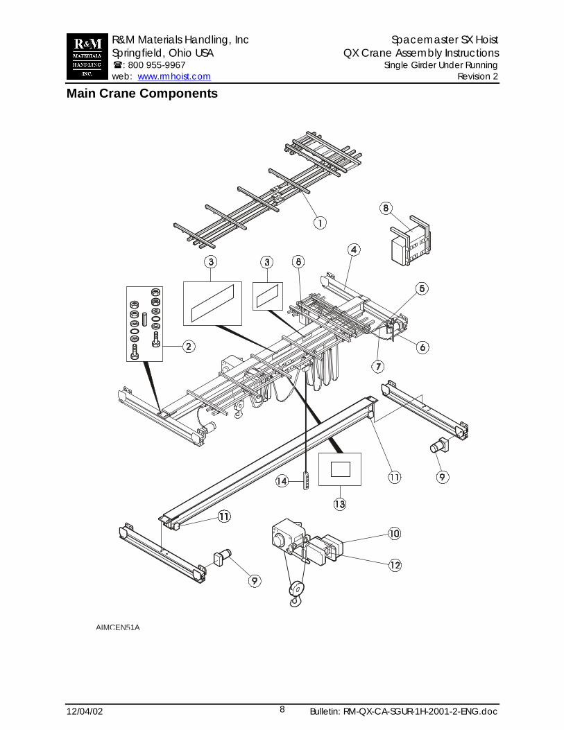
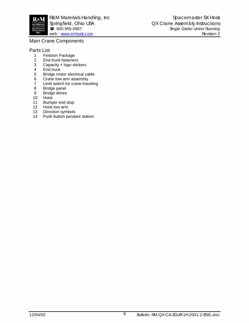
Main Crane Components
AIMCEN51A
R&M Materials Handling, Inc Spacemaster SX Hoist Springfield, Ohio USA QX Crane Assembly Instructions �: 800 955-9967 Single Girder Under Running web: www.rmhoist.com Revision 2
12/04/02 Bulletin: RM-QX-CA-SGUR-1H-2001-2-ENG.doc9
Main Crane Components
Parts List12
Festoon PackageEnd truck fasteners
3 Capacity + logo stickers4 End truck5 Bridge motor electrical cable6 Crane tow arm assembly7 Limit switch for crane traveling8 Bridge panel9 Bridge drives
10 Hoist11 Bumper end stop12 Hoist tow arm13 Direction symbols14 Push button pendant station
R&M Materials Handling, Inc Spacemaster SX Hoist Springfield, Ohio USA QX Crane Assembly Instructions �: 800 955-9967 Single Girder Under Running web: www.rmhoist.com Revision 2
12/04/02 Bulletin: RM-QX-CA-SGUR-1H-2001-2-ENG.doc10
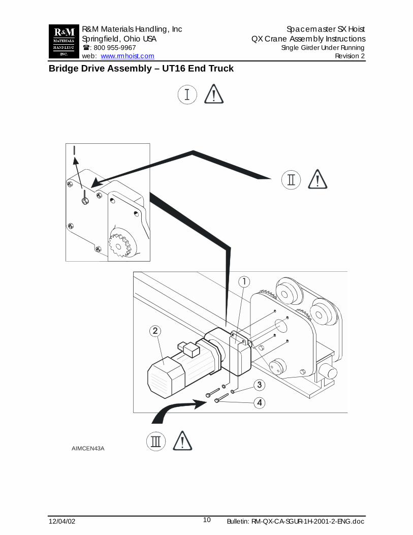
Bridge Drive Assembly – UT16 End Truck
AIMCEN43A
R&M Materials Handling, Inc Spacemaster SX Hoist Springfield, Ohio USA QX Crane Assembly Instructions �: 800 955-9967 Single Girder Under Running web: www.rmhoist.com Revision 2
12/04/02 Bulletin: RM-QX-CA-SGUR-1H-2001-2-ENG.doc11
Bridge Drive Assembly – UT End TruckParts List
1 Bridge drive2 Motor3 Bolt4 Washer
Explanations for NOTES in the drawingClean the spline and mounting flanges of dirt and rustprotection wax and grease the spline lightly beforeassembly. You can use a plastic hammer to slide drivein. Do not use a metal or lead hammer.M10 Tightening torque 30 ft-lb (40 Nm)Remove the protection pin from the breather plug ondrives.
R&M Materials Handling, Inc Spacemaster SX Hoist Springfield, Ohio USA QX Crane Assembly Instructions �: 800 955-9967 Single Girder Under Running web: www.rmhoist.com Revision 2
12/04/02 Bulletin: RM-QX-CA-SGUR-1H-2001-2-ENG.doc12
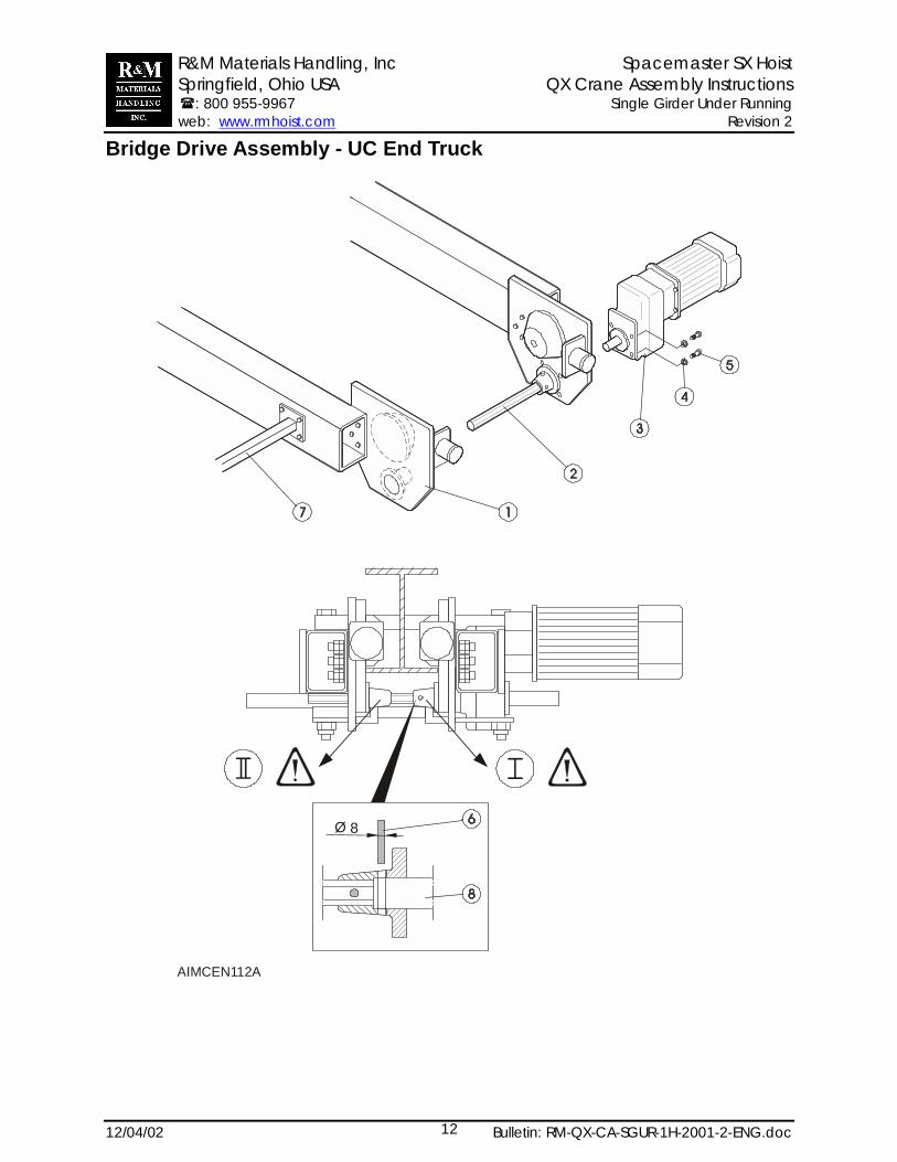
Bridge Drive Assembly - UC End Truck
8Ø
AIMCEN112A
R&M Materials Handling, Inc Spacemaster SX Hoist Springfield, Ohio USA QX Crane Assembly Instructions �: 800 955-9967 Single Girder Under Running web: www.rmhoist.com Revision 2
12/04/02 Bulletin: RM-QX-CA-SGUR-1H-2001-2-ENG.doc13
Bridge Drive Assembly - UC End TruckParts List
1 End truck2 Shaft3 Bridge drive45678
WasherBoltPinCrane tow armCross shaft
Explanations for NOTES in the drawingDrill 8mm hole for pin through pinion shoulder andcross shaft together. Use the existing pilot hole. Installsplit pin. Typical for both pinions
R&M Materials Handling, Inc Spacemaster SX Hoist Springfield, Ohio USA QX Crane Assembly Instructions �: 800 955-9967 Single Girder Under Running web: www.rmhoist.com Revision 2
12/04/02 Bulletin: RM-QX-CA-SGUR-1H-2001-2-ENG.doc14
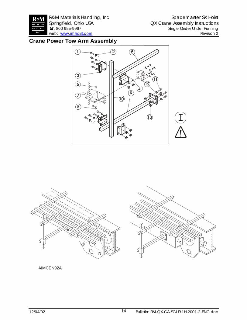
Crane Power Tow Arm Assembly
AIMCEN92A

R&M Materials Handling, Inc Spacemaster SX Hoist Springfield, Ohio USA QX Crane Assembly Instructions �: 800 955-9967 Single Girder Under Running web: www.rmhoist.com Revision 2
12/04/02 Bulletin: RM-QX-CA-SGUR-1H-2001-2-ENG.doc15
Crane Power Tow Arm Assembly
Parts list1 Bolt2 Washer3 Clamp4 Tube5 Nut6789
10111213
BoltLimit switch (optional)BoltTubeTubeBoltWasherNut
Explanations for NOTES in the drawingIf necessary, cut off excess length of square tubes.
R&M Materials Handling, Inc Spacemaster SX Hoist Springfield, Ohio USA QX Crane Assembly Instructions �: 800 955-9967 Single Girder Under Running web: www.rmhoist.com Revision 2
12/04/02 Bulletin: RM-QX-CA-SGUR-1H-2001-2-ENG.doc16
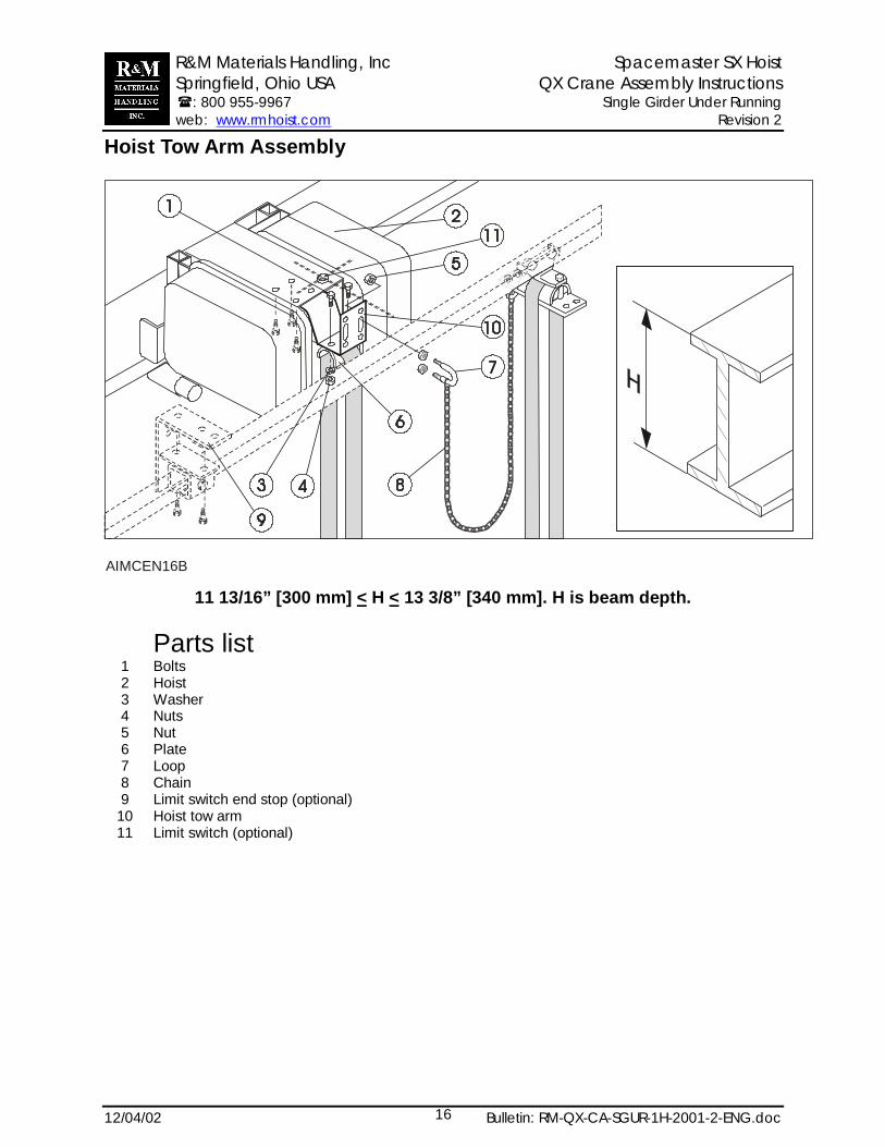
Hoist Tow Arm Assembly
AIMCEN16B
11 13/16” [300 mm] < H < 13 3/8” [340 mm]. H is beam depth.
Parts list1 Bolts2 Hoist3 Washer4 Nuts5 Nut6 Plate7 Loop8 Chain9 Limit switch end stop (optional)
10 Hoist tow arm11 Limit switch (optional)

R&M Materials Handling, Inc Spacemaster SX Hoist Springfield, Ohio USA QX Crane Assembly Instructions �: 800 955-9967 Single Girder Under Running web: www.rmhoist.com Revision 2
12/04/02 Bulletin: RM-QX-CA-SGUR-1H-2001-2-ENG.doc17
Hoist Tow Arm Assembly
AIMCEN45A
12 ½” [340 mm] < H < 19 5/8” [500 mm]. H is beam depth.Parts list
1 Bolts2 Hoist3 Washer4 Nuts5 Nut6 Plate7 Loop8 Chain9 Limit switch end stop (optional)
10 Hoist tow arm11 Limit switch (optional)12 C-track13 Square nut14 Screw
R&M Materials Handling, Inc Spacemaster SX Hoist Springfield, Ohio USA QX Crane Assembly Instructions �: 800 955-9967 Single Girder Under Running web: www.rmhoist.com Revision 2
12/04/02 Bulletin: RM-QX-CA-SGUR-1H-2001-2-ENG.doc18
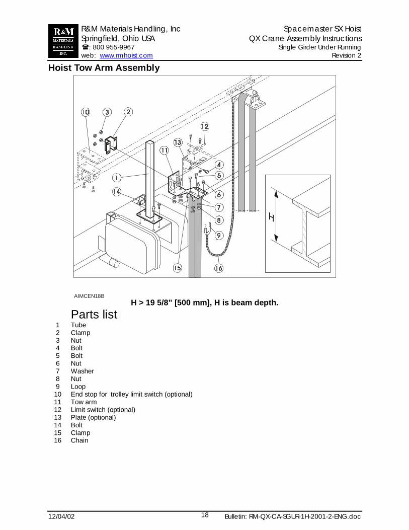
Hoist Tow Arm Assembly
AIMCEN18BH > 19 5/8” [500 mm], H is beam depth.
Parts list1 Tube2 Clamp3 Nut4 Bolt5 Bolt6 Nut7 Washer8 Nut9 Loop
10 End stop for trolley limit switch (optional)11 Tow arm12 Limit switch (optional)13 Plate (optional)14 Bolt15 Clamp16 Chain
R&M Materials Handling, Inc Spacemaster SX Hoist Springfield, Ohio USA QX Crane Assembly Instructions �: 800 955-9967 Single Girder Under Running web: www.rmhoist.com Revision 2
12/04/02 Bulletin: RM-QX-CA-SGUR-1H-2001-2-ENG.doc19
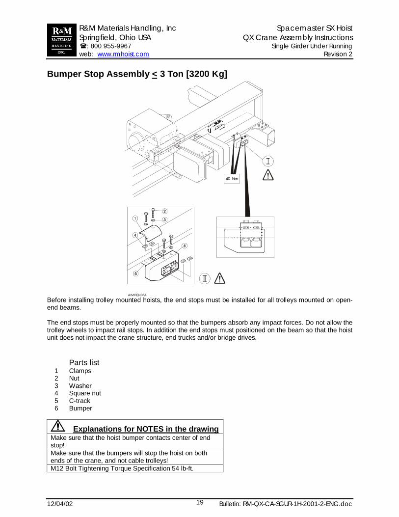
Bumper Stop Assembly < 3 Ton [3200 Kg]
AIMCEN06A
Before installing trolley mounted hoists, the end stops must be installed for all trolleys mounted on open-end beams.
The end stops must be properly mounted so that the bumpers absorb any impact forces. Do not allow thetrolley wheels to impact rail stops. In addition the end stops must positioned on the beam so that the hoistunit does not impact the crane structure, end trucks and/or bridge drives.
Parts list1 Clamps2 Nut3 Washer4 Square nut5 C-track6 Bumper
Explanations for NOTES in the drawingMake sure that the hoist bumper contacts center of endstop!Make sure that the bumpers will stop the hoist on bothends of the crane, and not cable trolleys!M12 Bolt Tightening Torque Specification 54 lb-ft.
R&M Materials Handling, Inc Spacemaster SX Hoist Springfield, Ohio USA QX Crane Assembly Instructions �: 800 955-9967 Single Girder Under Running web: www.rmhoist.com Revision 2
12/04/02 Bulletin: RM-QX-CA-SGUR-1H-2001-2-ENG.doc20
Bumper Stop Assembly > 3 Ton [3200 Kg]
2
5
5 66
7
1
3
4
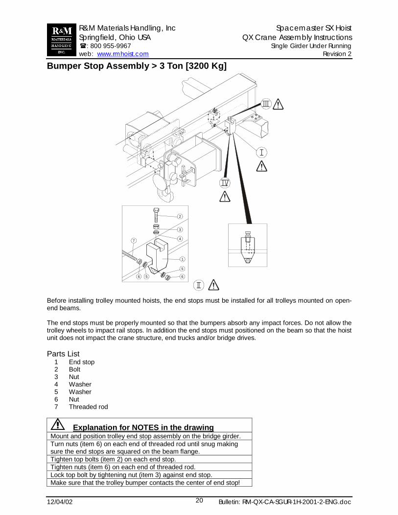
Before installing trolley mounted hoists, the end stops must be installed for all trolleys mounted on open-end beams.
The end stops must be properly mounted so that the bumpers absorb any impact forces. Do not allow thetrolley wheels to impact rail stops. In addition the end stops must positioned on the beam so that the hoistunit does not impact the crane structure, end trucks and/or bridge drives.
Parts List1 End stop2 Bolt3 Nut4 Washer5 Washer6 Nut7 Threaded rod
Explanation for NOTES in the drawingMount and position trolley end stop assembly on the bridge girder.Turn nuts (item 6) on each end of threaded rod until snug makingsure the end stops are squared on the beam flange.Tighten top bolts (item 2) on each end stop.Tighten nuts (item 6) on each end of threaded rod.Lock top bolt by tightening nut (item 3) against end stop.Make sure that the trolley bumper contacts the center of end stop!

R&M Materials Handling, Inc Spacemaster SX Hoist Springfield, Ohio USA QX Crane Assembly Instructions �: 800 955-9967 Single Girder Under Running web: www.rmhoist.com Revision 2
12/04/02 Bulletin: RM-QX-CA-SGUR-1H-2001-2-ENG.doc21
This page is intentionally left blank.
R&M Materials Handling, Inc Spacemaster SX Hoist Springfield, Ohio USA QX Crane Assembly Instructions �: 800 955-9967 Single Girder Under Running web: www.rmhoist.com Revision 2
12/04/02 Bulletin: RM-QX-CA-SGUR-1H-2001-2-ENG.doc22
Bridge Panel Assembly
AIMCEN03C
R&M Materials Handling, Inc Spacemaster SX Hoist Springfield, Ohio USA QX Crane Assembly Instructions �: 800 955-9967 Single Girder Under Running web: www.rmhoist.com Revision 2
12/04/02 Bulletin: RM-QX-CA-SGUR-1H-2001-2-ENG.doc23
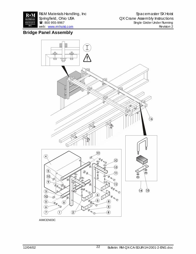
Bridge Panel Assembly
Parts List1 Support bracket2 Plate3 C-track4 Bridge panel5 Washer6 Spring washer7 Bolt8 Bolt9 Nut
10 Square nut11 Washer12 Bolt13 Spring washer14 Clamp15 Rubber spacer16 Ladder frame & C-rail
Explanation for NOTES in the drawingMount the support brackets to bridge panel before mounting bridge panel to crane.Slide bridge panel assembly onto the C-rails of the ladder frame assembly.
The bridge panel ladder frame assembly does not support any festoon C-rails that run parallel to bridgegirder.

R&M Materials Handling, Inc Spacemaster SX Hoist Springfield, Ohio USA QX Crane Assembly Instructions �: 800 955-9967 Single Girder Under Running web: www.rmhoist.com Revision 2
12/04/02 Bulletin: RM-QX-CA-SGUR-1H-2001-2-ENG.doc24
Festoon Assembly
R&M Materials Handling, Inc Spacemaster SX Hoist Springfield, Ohio USA QX Crane Assembly Instructions �: 800 955-9967 Single Girder Under Running web: www.rmhoist.com Revision 2
12/04/02 Bulletin: RM-QX-CA-SGUR-1H-2001-2-ENG.doc25
Festoon Assembly
Parts list1 Pendant trolley2 Support arm3 C-track4 Track coupler5 Track support bracket6 Beam clip7 Control unit trolley8 Cable for drive motor 29 Cable trolley
10 End stop11 End clamp12 Clip for cable attachment13 Towing trolley
Explanation for NOTES in the drawingMake sure that the C-rails are positioned into the track coupler so the rail joint is visible at the centerholes of the coupler.After properly positioning the C-rail into the track coupler, tighten each bolt on coupler. Lock each couplerbolt by tightening the nut against the coupler.Make sure that the C-rail joint is smooth for tow trolley travelFasten each C-rail to each support arm by using the bracket. Tighten the bolts.The bridge panel ladder frame assembly does not support any festoon C-rails that run parallel to bridgegirder. See Bridge Panel Assembly.Tighten the strain relief wires on both sides of the plug so that pendant cable is making a loop as shown.Tighten each wire clamp.
R&M Materials Handling, Inc Spacemaster SX Hoist Springfield, Ohio USA QX Crane Assembly Instructions �: 800 955-9967 Single Girder Under Running web: www.rmhoist.com Revision 2
12/04/02 Bulletin: RM-QX-CA-SGUR-1H-2001-2-ENG.doc26
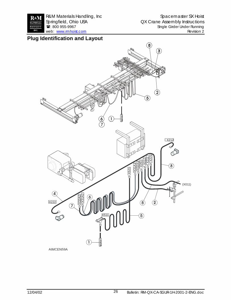
Plug Identification and Layout
AIMCEN59A
X222
X511
X212
(X011)
X31A
2X3
2A2
X521 X3
1A1
X32A
1X2
51 X012
X211 X2
21
R&M Materials Handling, Inc Spacemaster SX Hoist Springfield, Ohio USA QX Crane Assembly Instructions �: 800 955-9967 Single Girder Under Running web: www.rmhoist.com Revision 2
12/04/02 Bulletin: RM-QX-CA-SGUR-1H-2001-2-ENG.doc27
Plug Identification and Layout
Parts List1 Pendant2 Cable for limit switch3 Cable for bridge motor4 Cable from bridge motor 25 Cable for pendant trolley6 Cable for hoist power7 Cable for hoist control8 Cable for crane main power supply