r-scrub 90 d-c
TRANSCRIPT
ORIGINAL INSTRUCTION DOC. 10068683 - Ver. AA - 02-2017
SCRUBBING MACHINES
USE AND MAINTENANCE MANUAL
R-SCRUB 90 D-C
The descriptions contained in this document are not binding. The company therefore reserves the right to make any modifications at any time to elements, details, or accessory supply, as considered necessary for reasons of improvement or manufacturing/commercial requirements. The reproduction, even partial, of the text and drawings contained in this document is prohibited by law.
The company reserves the right to make any technical and/or supply modifications. The images are for reference purposes only, and are not binding in terms of design and supply.
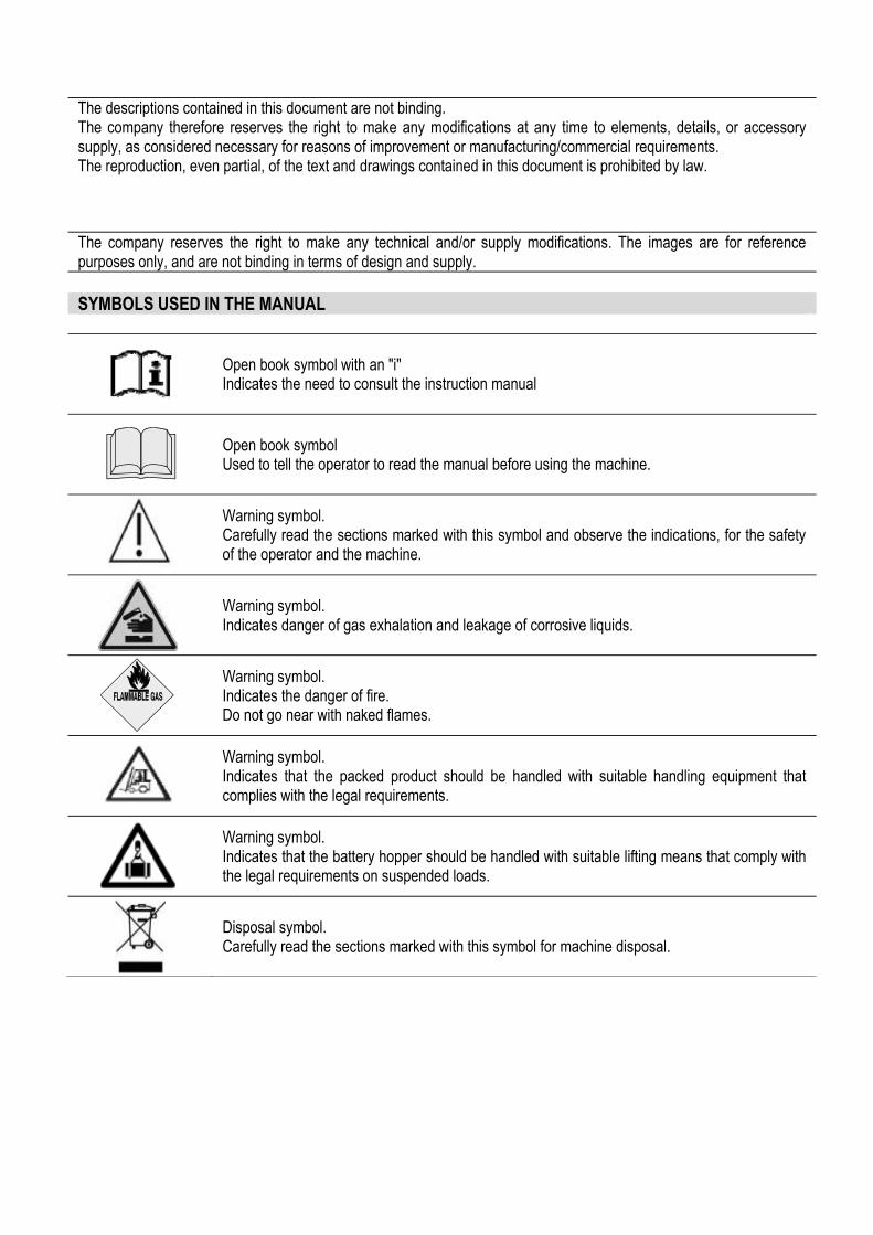
SYMBOLS USED IN THE MANUAL
Open book symbol with an "i" Indicates the need to consult the instruction manual
Open book symbol Used to tell the operator to read the manual before using the machine.
Warning symbol. Carefully read the sections marked with this symbol and observe the indications, for the safety of the operator and the machine.
Warning symbol. Indicates danger of gas exhalation and leakage of corrosive liquids.
Warning symbol. Indicates the danger of fire. Do not go near with naked flames.
Warning symbol. Indicates that the packed product should be handled with suitable handling equipment that complies with the legal requirements.
Warning symbol. Indicates that the battery hopper should be handled with suitable lifting means that comply with the legal requirements on suspended loads.
Disposal symbol. Carefully read the sections marked with this symbol for machine disposal.
33
CONTENTS
ON CONSIGNMENT OF THE MACHINE ............................................................................................................................................. 5 INTRODUCTORY COMMENT ............................................................................................................................................................ 5 INTENDED USE ................................................................................................................................................................................ 5 SERIAL NUMBER PLATE .................................................................................................................................................................. 5 TECHNICAL DESCRIPTION ............................................................................................................................................................... 6 SYMBOLS USED ON THE MACHINE ................................................................................................................................................. 7 GENERAL SAFETY REGULATIONS ................................................................................................................................................. 12 MACHINE PREPARATION ............................................................................................................................................................... 14
1. HANDLING THE PACKED MACHINE ......................................................................................................................... 14 2. HOW TO UNPACK THE MACHINE ............................................................................................................................. 14 3. HOW TO MOVE THE MACHINE ................................................................................................................................. 17 4. CONTROL PANEL COMPONENTS ............................................................................................................................ 17 5. STEERING COLUMN COMPONENTS ....................................................................................................................... 18 6. FOOTBOARD COMPONENTS .................................................................................................................................... 18 7. SIDE COMPONENTS OF THE MACHINE .................................................................................................................. 18 8. REAR COMPONENTS OF THE MACHINE ................................................................................................................. 19 9. SEAT SUPPORT COMPONENTS ............................................................................................................................... 19 10. FRONT MACHINE COMPONENTS ............................................................................................................................ 20 11. MACHINE SAFETY ..................................................................................................................................................... 20 12. TYPE OF BATTERY .................................................................................................................................................... 21 13. BATTERY HOPPER MAINTENANCE AND DISPOSAL .............................................................................................. 21 14. FITTING THE BATTERIES INTO THE MACHINE ....................................................................................................... 21 15. CONNECTING THE BATTERIES AND BATTERY CONNECTOR .............................................................................. 22 16. CONNECTING THE BATTERY CHARGER ................................................................................................................ 22 17. HOUR COUNTER ........................................................................................................................................................ 24 18. BATTERY CHARGE LEVEL INDICATOR ................................................................................................................... 24 19. WORKING FORWARD SPEED ................................................................................................................................... 24 20. FILLING THE SOLUTION TANK WITH WATER ......................................................................................................... 24 21. DETERGENT SOLUTION ........................................................................................................................................... 26 22. ASSEMBLING THE SQUEEGEE ................................................................................................................................ 26 23. ASSEMBLING THE DISK BRUSHES (only for R-SCRUB 90D versions) .................................................................... 27 24. SERVICE BRAKE ........................................................................................................................................................ 27 25. FRONT HEADLIGHTS ................................................................................................................................................. 28 26. BLINKING LIGHT (OPTIONAL) ................................................................................................................................... 28 27. SEAT ADJUSTMENT ................................................................................................................................................. 28
PREPARING TO WORK ................................................................................................................................................................... 29 1. PREPARING TO WORK .............................................................................................................................................. 29 2. WATER SYSTEM ENGAGEMENT .............................................................................................................................. 30
WORK ............................................................................................................................................................................................ 31 1. STARTING WORK ....................................................................................................................................................... 31 2. EMERGENCY BUTTON .............................................................................................................................................. 34 3. SERVICE BRAKE ALARM ENGAGED ........................................................................................................................ 34 4. ELECTRIC BRAKE FAULT ALARM ............................................................................................................................ 34 5. DETERGENT ADJUSTMENT ...................................................................................................................................... 35 6. REGULATING THE FORWARD MOVEMENT WORK SPEED ................................................................................... 36 7. "ECO" DEVICE ............................................................................................................................................................ 36 8. BRUSH HEAD UNIT EXTRA PRESSURE .................................................................................................................. 37 9. FRONT HEADLIGHTS ................................................................................................................................................. 38 10. BUZZER ...................................................................................................................................................................... 38 11. OVERFLOW DEVICE .................................................................................................................................................. 38
AT THE END OF WORK .................................................................................................................................................................. 39 DAILY MAINTENANCE ................................................................................................................................................................... 41
1. EMPTYING THE RECOVERY TANK .......................................................................................................................... 41 2. EMPTYING OF THE SOLUTION TANK ...................................................................................................................... 41 3. EMPTYING THE DEBRIS HOPPER (valid only for R-SCRUB 90C versions) ............................................................. 42 4. CLEANING THE SQUEEGEE BODY .......................................................................................................................... 42 5. CLEANING THE DISK BRUSHES (valid only for R-SCRUB 90D versions) ................................................................ 43 6. CLEANING THE CYLINDRICAL BRUSHES (valid only for R-SCRUB 90C versions) ................................................. 44
4 54 5
7. CLEANING THE VACUUM MOTOR FILTER FLOAT .................................................................................................. 46 8. CLEANING THE DEBRIS HOPPER (valid only for R-SCRUB 90C versions) ............................................................. 47
WEEKLY MAINTENANCE ................................................................................................................................................................ 48 1. CLEANING THE RECOVERY TANK ........................................................................................................................... 48 2. CLEANING THE SOLUTION TANK ............................................................................................................................. 48 3. CLEANING THE WATER SYSTEM FILTER................................................................................................................ 49 4. CLEANING THE VACUUM HOSE (valid only for R-SCRUB 90D versions) ................................................................ 50 5. CLEANING THE VACUUM HOSE (valid only for R-SCRUB 90C versions) ................................................................ 50
EMERGENCY MAINTENANCE ......................................................................................................................................................... 52 1. REPLACING THE SQUEEGEE RUBBERS ................................................................................................................. 52 2. ADJUSTING THE SQUEEGEE ................................................................................................................................... 53 3. REPLACING THE DISK BRUSHES (valid only for R-SCRUB 90D versions) .............................................................. 54 4. REPLACING THE CYLINDRICAL BRUSHES (valid only for R-SCRUB 90C versions) ............................................... 55 5. REPLACING THE SPLASHGUARD BLADES (valid only for R-SCRUB 90C versions) .............................................. 57 6. ADJUSTING THE SPLASHGUARD BLADES (valid only for R-SCRUB 90C versions) ............................................... 59
TROUBLESHOOTING ...................................................................................................................................................................... 60 1. AN ALARM MESSAGE APPEARS ON THE CONTROL DISPLAY ............................................................................. 60 2. THE MACHINE DOES NOT START ............................................................................................................................ 60 3. THE BATTERIES ARE NOT CHARGED CORRECTLY .............................................................................................. 60 4. THE MACHINE HAS A VERY LOW WORK AUTONOMY ........................................................................................... 61 5. THE MACHINE DOES NOT MOVE ............................................................................................................................. 61 6. INSUFFICIENT WATER ON THE BRUSHES.............................................................................................................. 61 7. THE MACHINE DOES NOT CLEAN CORRECTLY ..................................................................................................... 62 8. THE SQUEEGEE DOES NOT DRY PERFECTLY ...................................................................................................... 63 9. EXCESSIVE FOAM PRODUCTION ............................................................................................................................ 63 10. THE SUCTION MOTOR DOES NOT FUNCTION ....................................................................................................... 63 11. IT IS IMPOSSIBLE TO RAISE OR LOWER THE BASE OR SQUEEGEE .................................................................. 63
DISPOSAL ..................................................................................................................................................................................... 64 CHOOSING AND USING THE BRUSHES .......................................................................................................................................... 65
INDICE2
55
ON CONSIGNMENT OF THE MACHINE When the machine is consigned to the customer, an immediate check must be performed to ensure all the material mentioned in the shipping documents has been received, and also to check the machine has not suffered damage during transportation. If this is the case, the carrier must note the extent of the damage at once, informing our customer service office at the same time. It is only by prompt action of this type that the missing material can be obtained, and compensation for damage successfully claimed. INTRODUCTORY COMMENT Optima is a scrubbing machine that is able to clean a wide variety of types of flooring and types of dirt by using the mechanical action of two disc or cylindrical brushes and the chemical action of a water-detergent solution. As it advances, it also collects the dirt removed and the detergent solution not absorbed by the floor. The machine must be used only for this purpose. Even the best machines will only work well if used correctly and kept in good working order. We therefore suggest you read this instruction booklet carefully and read it again whenever difficulties arise while using the machine. If necessary, remember that our customer assistance service (organised in collaboration with our dealers) is always available for advice or direct intervention. INTENDED USE The floor scrubbing machine is designed exclusively for the professional cleaning of surfaces and floors in industrial, commercial and public environments. The machine is only suitable for use in closed (or at least covered) places. The machine is not suitable for use in the rain, or under water jets. It is FORBIDDEN to use the machine to pick up dangerous dusts or inflammable liquids in places with an explosive atmosphere. In addition, it is not suitable as a means of transport for people or objects.
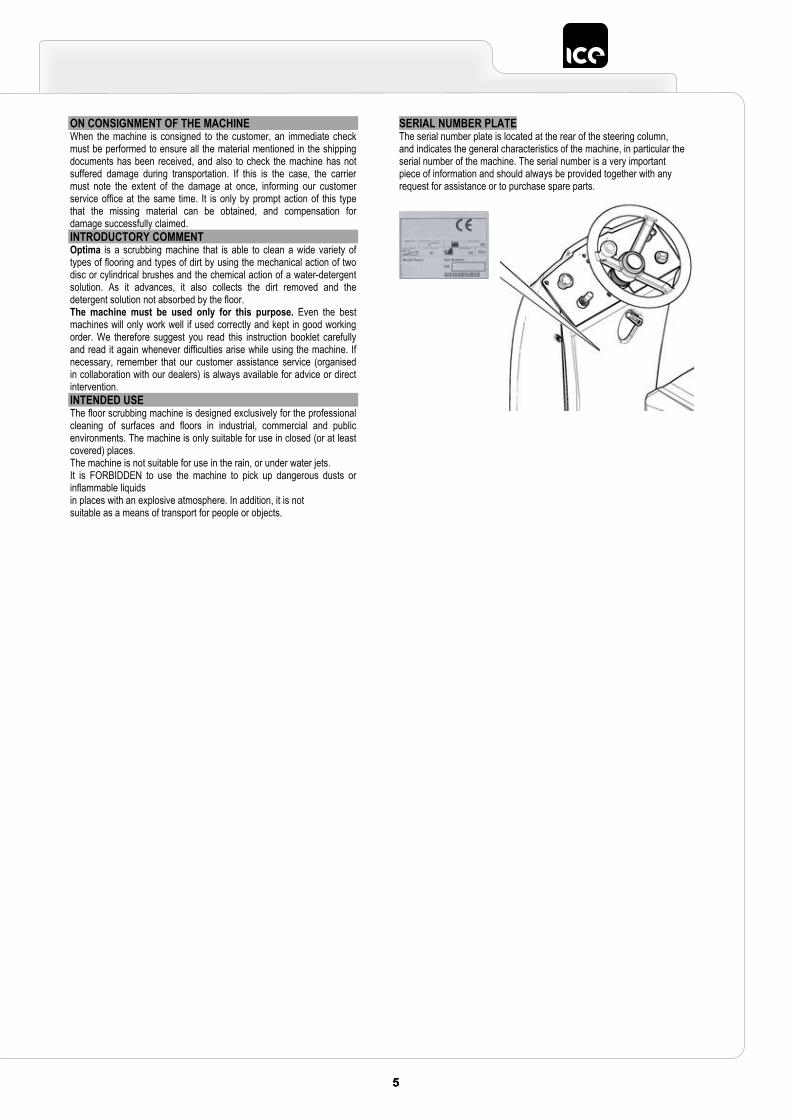
SERIAL NUMBER PLATE The serial number plate is located at the rear of the steering column, and indicates the general characteristics of the machine, in particular the serial number of the machine. The serial number is a very important piece of information and should always be provided together with any request for assistance or to purchase spare parts.
6 76 7
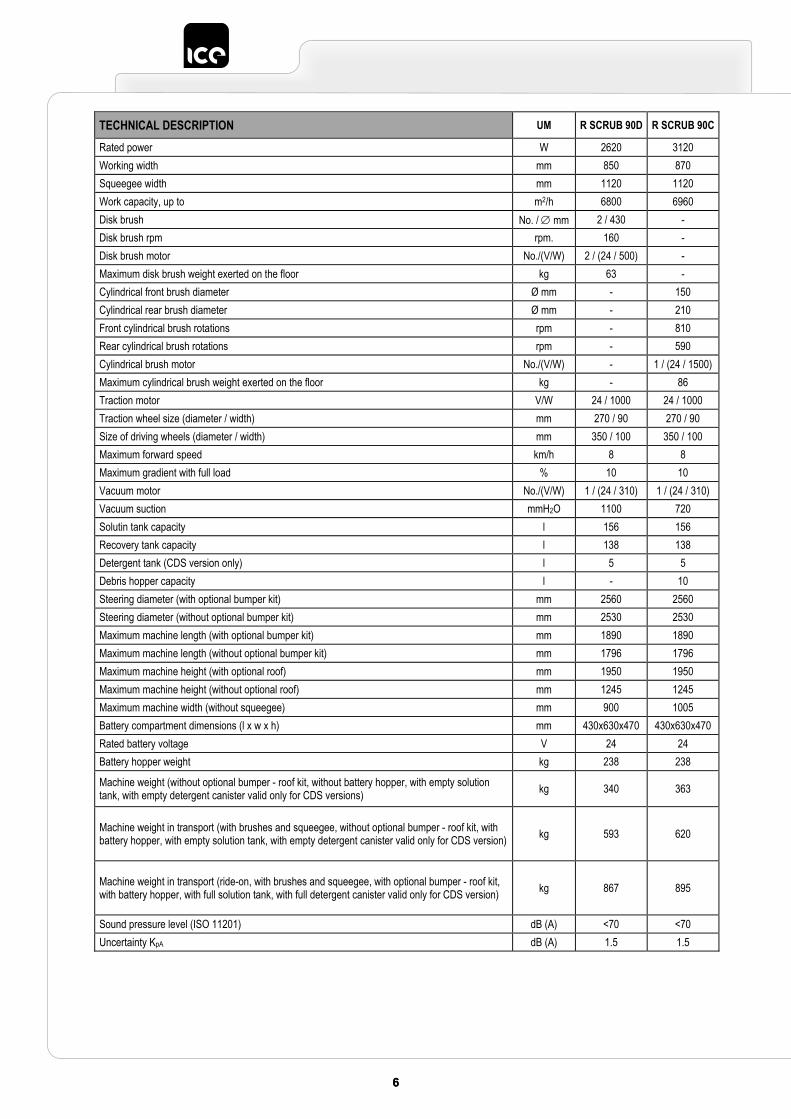
TECHNICAL DESCRIPTION UM R SCRUB 90D R SCRUB 90C
Rated power W 2620 3120 Working width mm 850 870 Squeegee width mm 1120 1120 Work capacity, up to m2/h 6800 6960 Disk brush No. / mm 2 / 430 - Disk brush rpm rpm. 160 - Disk brush motor No./(V/W) 2 / (24 / 500) - Maximum disk brush weight exerted on the floor kg 63 - Cylindrical front brush diameter Ø mm - 150 Cylindrical rear brush diameter Ø mm - 210 Front cylindrical brush rotations rpm - 810 Rear cylindrical brush rotations rpm - 590 Cylindrical brush motor No./(V/W) - 1 / (24 / 1500) Maximum cylindrical brush weight exerted on the floor kg - 86 Traction motor V/W 24 / 1000 24 / 1000 Traction wheel size (diameter / width) mm 270 / 90 270 / 90 Size of driving wheels (diameter / width) mm 350 / 100 350 / 100 Maximum forward speed km/h 8 8 Maximum gradient with full load % 10 10 Vacuum motor No./(V/W) 1 / (24 / 310) 1 / (24 / 310) Vacuum suction mmH2O 1100 720 Solutin tank capacity l 156 156 Recovery tank capacity l 138 138 Detergent tank (CDS version only) l 5 5 Debris hopper capacity l - 10 Steering diameter (with optional bumper kit) mm 2560 2560 Steering diameter (without optional bumper kit) mm 2530 2530 Maximum machine length (with optional bumper kit) mm 1890 1890 Maximum machine length (without optional bumper kit) mm 1796 1796 Maximum machine height (with optional roof) mm 1950 1950 Maximum machine height (without optional roof) mm 1245 1245 Maximum machine width (without squeegee) mm 900 1005 Battery compartment dimensions (l x w x h) mm 430x630x470 430x630x470 Rated battery voltage V 24 24 Battery hopper weight kg 238 238
Machine weight (without optional bumper - roof kit, without battery hopper, with empty solution tank, with empty detergent canister valid only for CDS versions) kg 340 363
Machine weight in transport (with brushes and squeegee, without optional bumper - roof kit, with battery hopper, with empty solution tank, with empty detergent canister valid only for CDS version) kg 593 620
Machine weight in transport (ride-on, with brushes and squeegee, with optional bumper - roof kit, with battery hopper, with full solution tank, with full detergent canister valid only for CDS version) kg 867 895
Sound pressure level (ISO 11201) dB (A) <70 <70 Uncertainty KpA dB (A) 1.5 1.5
77
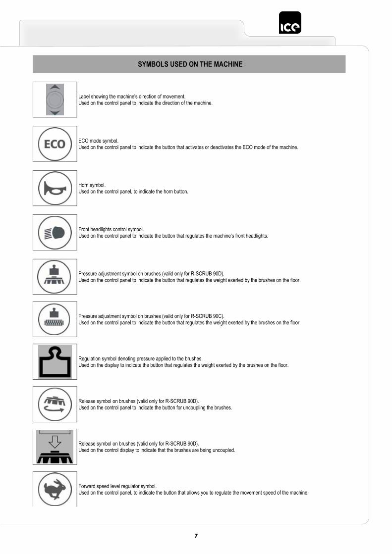
SYMBOLS USED ON THE MACHINE
Label showing the machine's direction of movement. Used on the control panel to indicate the direction of the machine.
ECO mode symbol. Used on the control panel to indicate the button that activates or deactivates the ECO mode of the machine.
Horn symbol. Used on the control panel, to indicate the horn button.
Front headlights control symbol. Used on the control panel to indicate the button that regulates the machine's front headlights.
Pressure adjustment symbol on brushes (valid only for R-SCRUB 90D). Used on the control panel to indicate the button that regulates the weight exerted by the brushes on the floor.
Pressure adjustment symbol on brushes (valid only for R-SCRUB 90C). Used on the control panel to indicate the button that regulates the weight exerted by the brushes on the floor.
Regulation symbol denoting pressure applied to the brushes. Used on the display to indicate the button that regulates the weight exerted by the brushes on the floor.
Release symbol on brushes (valid only for R-SCRUB 90D). Used on the control panel to indicate the button for uncoupling the brushes.
Release symbol on brushes (valid only for R-SCRUB 90D). Used on the control display to indicate that the brushes are being uncoupled.
Forward speed level regulator symbol. Used on the control panel, to indicate the button that allows you to regulate the movement speed of the machine.
8 98 9
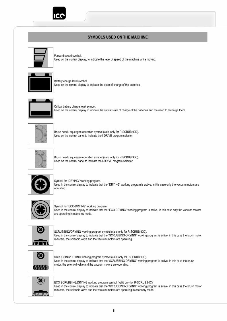
SYMBOLS USED ON THE MACHINE
Forward speed symbol. Used on the control display, to indicate the level of speed of the machine while moving.
Battery charge level symbol. Used on the control display to indicate the state of charge of the batteries.
Critical battery charge level symbol. Used on the control display to indicate the critical state of charge of the batteries and the need to recharge them.
Brush head / squeegee operation symbol (valid only for R-SCRUB 90D). Used on the control panel to indicate the I-DRIVE program selector.
Brush head / squeegee operation symbol (valid only for R-SCRUB 90C). Used on the control panel to indicate the I-DRIVE program selector.
Symbol for “DRYING” working program. Used in the control display to indicate that the “DRYING” working program is active, in this case only the vacuum motors are operating.
Symbol for “ECO-DRYING” working program. Used in the control display to indicate that the “ECO DRYING” working program is active, in this case only the vacuum motors are operating in economy mode.
SCRUBBING/DRYING working program symbol (valid only for R-SCRUB 90D). Used in the control display to indicate that the “SCRUBBING-DRYING” working program is active, in this case the brush motor reducers, the solenoid valve and the vacuum motors are operating.
SCRUBBING/DRYING working program symbol (valid only for R-SCRUB 90C). Used in the control display to indicate that the “SCRUBBING-DRYING” working program is active, in this case the brush motor, the solenoid valve and the vacuum motors are operating.
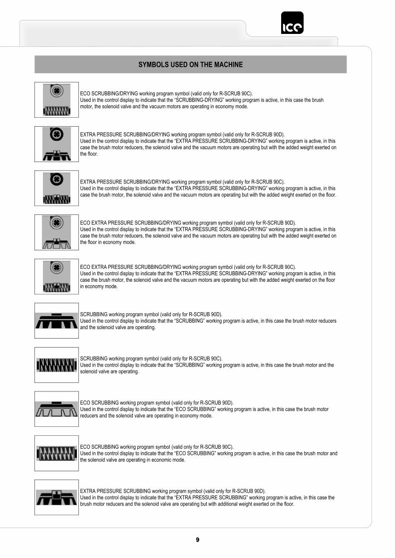
ECO SCRUBBING/DRYING working program symbol (valid only for R-SCRUB 90C). Used in the control display to indicate that the “SCRUBBING-DRYING” working program is active, in this case the brush motor reducers, the solenoid valve and the vacuum motors are operating in economy mode.
99
SYMBOLS USED ON THE MACHINE
ECO SCRUBBING/DRYING working program symbol (valid only for R-SCRUB 90C). Used in the control display to indicate that the “SCRUBBING-DRYING” working program is active, in this case the brush motor, the solenoid valve and the vacuum motors are operating in economy mode.
EXTRA PRESSURE SCRUBBING/DRYING working program symbol (valid only for R-SCRUB 90D). Used in the control display to indicate that the “EXTRA PRESSURE SCRUBBING-DRYING” working program is active, in this case the brush motor reducers, the solenoid valve and the vacuum motors are operating but with the added weight exerted on the floor.
EXTRA PRESSURE SCRUBBING/DRYING working program symbol (valid only for R-SCRUB 90C). Used in the control display to indicate that the “EXTRA PRESSURE SCRUBBING-DRYING” working program is active, in this case the brush motor, the solenoid valve and the vacuum motors are operating but with the added weight exerted on the floor.
ECO EXTRA PRESSURE SCRUBBING/DRYING working program symbol (valid only for R-SCRUB 90D). Used in the control display to indicate that the “EXTRA PRESSURE SCRUBBING-DRYING” working program is active, in this case the brush motor reducers, the solenoid valve and the vacuum motors are operating but with the added weight exerted on the floor in economy mode.
ECO EXTRA PRESSURE SCRUBBING/DRYING working program symbol (valid only for R-SCRUB 90C). Used in the control display to indicate that the “EXTRA PRESSURE SCRUBBING-DRYING” working program is active, in this case the brush motor, the solenoid valve and the vacuum motors are operating but with the added weight exerted on the floor in economy mode.
SCRUBBING working program symbol (valid only for R-SCRUB 90D). Used in the control display to indicate that the “SCRUBBING” working program is active, in this case the brush motor reducers and the solenoid valve are operating.
SCRUBBING working program symbol (valid only for R-SCRUB 90C). Used in the control display to indicate that the “SCRUBBING” working program is active, in this case the brush motor and the solenoid valve are operating.
ECO SCRUBBING working program symbol (valid only for R-SCRUB 90D). Used in the control display to indicate that the “ECO SCRUBBING” working program is active, in this case the brush motor reducers and the solenoid valve are operating in economy mode.
ECO SCRUBBING working program symbol (valid only for R-SCRUB 90C). Used in the control display to indicate that the “ECO SCRUBBING” working program is active, in this case the brush motor and the solenoid valve are operating in economic mode.
EXTRA PRESSURE SCRUBBING working program symbol (valid only for R-SCRUB 90D). Used in the control display to indicate that the “EXTRA PRESSURE SCRUBBING” working program is active, in this case the brush motor reducers and the solenoid valve are operating but with additional weight exerted on the floor.
10 1110 11
SYMBOLS USED ON THE MACHINE
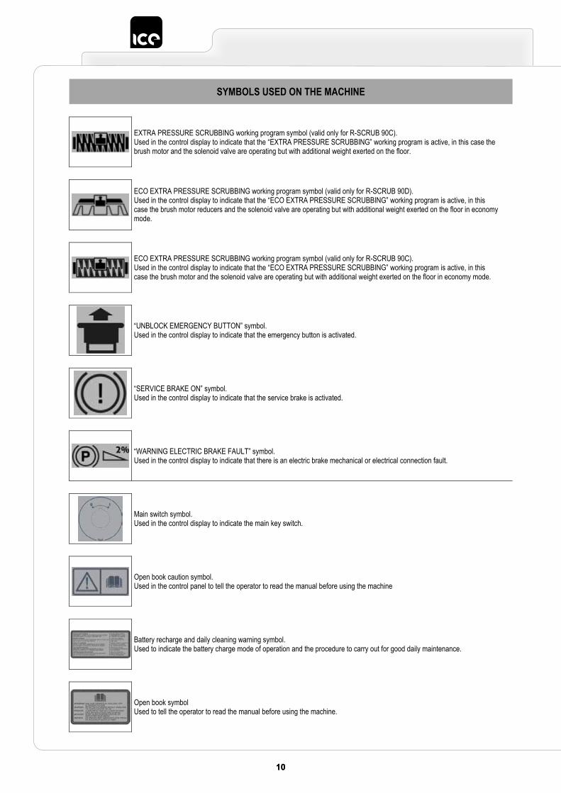
EXTRA PRESSURE SCRUBBING working program symbol (valid only for R-SCRUB 90C). Used in the control display to indicate that the “EXTRA PRESSURE SCRUBBING” working program is active, in this case the brush motor and the solenoid valve are operating but with additional weight exerted on the floor.
ECO EXTRA PRESSURE SCRUBBING working program symbol (valid only for R-SCRUB 90D). Used in the control display to indicate that the “ECO EXTRA PRESSURE SCRUBBING” working program is active, in this case the brush motor reducers and the solenoid valve are operating but with additional weight exerted on the floor in economy mode.
ECO EXTRA PRESSURE SCRUBBING working program symbol (valid only for R-SCRUB 90C). Used in the control display to indicate that the “ECO EXTRA PRESSURE SCRUBBING” working program is active, in this case the brush motor and the solenoid valve are operating but with additional weight exerted on the floor in economy mode.
“UNBLOCK EMERGENCY BUTTON” symbol. Used in the control display to indicate that the emergency button is activated.
“SERVICE BRAKE ON” symbol. Used in the control display to indicate that the service brake is activated.
“WARNING ELECTRIC BRAKE FAULT” symbol. Used in the control display to indicate that there is an electric brake mechanical or electrical connection fault.
Main switch symbol. Used in the control display to indicate the main key switch.
Open book caution symbol. Used in the control panel to tell the operator to read the manual before using the machine
Battery recharge and daily cleaning warning symbol. Used to indicate the battery charge mode of operation and the procedure to carry out for good daily maintenance.
Open book symbol Used to tell the operator to read the manual before using the machine.
1111
SYMBOLS USED ON THE MACHINE
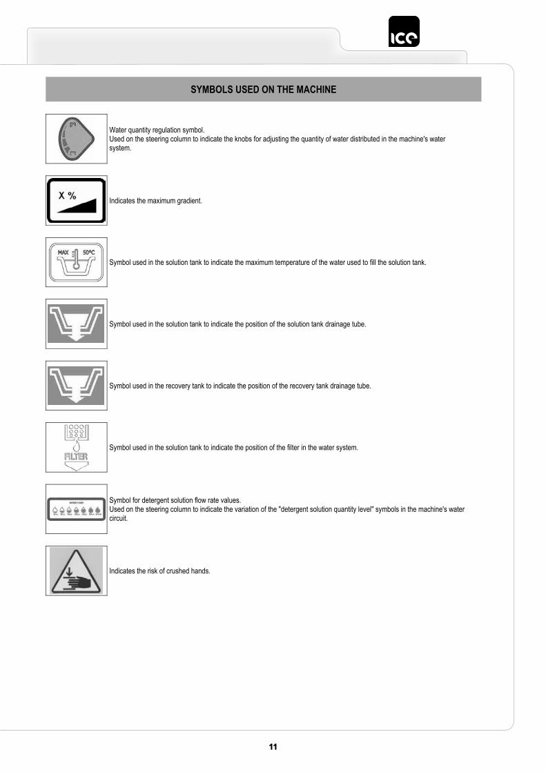
Water quantity regulation symbol. Used on the steering column to indicate the knobs for adjusting the quantity of water distributed in the machine's water system.
Indicates the maximum gradient.
Symbol used in the solution tank to indicate the maximum temperature of the water used to fill the solution tank.
Symbol used in the solution tank to indicate the position of the solution tank drainage tube.
Symbol used in the recovery tank to indicate the position of the recovery tank drainage tube.
Symbol used in the solution tank to indicate the position of the filter in the water system.
Symbol for detergent solution flow rate values. Used on the steering column to indicate the variation of the "detergent solution quantity level" symbols in the machine's watercircuit.
Indicates the risk of crushed hands.
12 1312 13
GENERAL SAFETY REGULATIONS
The regulations below must be carefully followed in order to avoid harm to the operator and damage to the machine.
WARNING: Read the labels on the machine carefully. Do not cover them for any reason and replace them immediately if they
become damaged. The machine must be exclusively used by authorised, trained personnel. Do not use the machine on surfaces with an inclination greater than the one shown on the serial number plate. The machine is not suitable for cleaning rough or uneven floors. Do not use the machine on slopes. If you encounter a damaged cable used for recharging the batteries, immediately contact an authorised service
centre. In case of danger, promptly activate the emergency button (located on the control panel) or the lever on the
battery connector (located under the recovery tank). For any maintenance operations, shut down the machine using the main key switch and remove the key from the
control panel, and disconnect the battery connector from the connector on the general system. Children must be supervised to ensure they do not play with the machine. During the working of the machine, pay attention to other people and especially to children. Only use the brushes supplied with the machine, or those specified in the "CHOOSING AND USING THE
BRUSHES" paragraph of the instruction manual. The use of other brushes could compromise safety levels. The machine must only be powered with a voltage equal to that shown on the serial number plate.
WARNING: The machine is not suitable for use by children and persons with reduced physical, mental and sensory
capabilities, or people who lack experience and knowledge. The machine must not be used or stored outdoors, in damp conditions or directly exposed to rain. The storage temperature must be between -25C and +55C; do not store outdoors in damp conditions. Conditions of use: room temperature between 0C and 40C with relative humidity between 30 and 95%. The socket for the battery charger cable must have a prescribed earth connection. Adapt the speed to the adhesion conditions. Do not use the machine as a means of transport. The machine does not cause harmful vibrations. Do not use the machine in an explosive atmosphere. Do not vacuum inflammable liquids. Do not use the machine to collect dangerous powders. Do not mix different types of detergent as this may produce harmful gases. The machine is not suitable for cleaning carpets. Do not place any liquid containers on the machine. Avoid working with the brushes when the machine is standing still, so as not to damage the floor. In the event of a fire, use a powder extinguisher. Do not use water. Do not knock against shelving or scaffolding, where there is a danger of falling objects. The operator must always
be equipped with the appropriate safety devices (gloves, shoes, helmet, goggles, etc.). The machine is designed to carry out the scrubbing and drying operations simultaneously. Different operations
should only be carried out in areas where the passage of unauthorised persons is prohibited. Signal the presence of damp floors with suitable signs.
If the machine does not work properly, check this is not caused by failure to carry out routine maintenance. Otherwise, ask for intervention of the authorised technical assistance centre.
If you need to replace any components, request the ORIGINAL spare parts from an Authorised dealer and/or Retailer.
Restore all electrical connections after any maintenance interventions.
1313
Before using the machine, check that all the hatches and covers are positioned as shown in this Use and Maintenance Manual.
Do not remove the guards that can only be removed with the aid of tools, except for maintenance work (see the relevant paragraphs)
Do not wash the machine with direct water jets or with pressurised water, nor with corrosive substances. To prevent scaling in the solution tank filter, do not fill the tank with detergent solution many hours before using
the machine. Do not use acid or basic solutions that could damage the machine and/or harm people. Have the machine checked by an authorised technical assistance centre every year. When disposing of consumable materials, observe the laws and regulations in force. When your machine has reached the end of its long working life, dispose of the materials it contains (especially
oils, batteries and electronic components) in an appropriate manner, taking into account that the machine itself was constructed using 100% recyclable materials.
The batteries must be removed from the machine before its disposal. The batteries must be disposed of in a safe manner, fully observing the laws and regulations in force.
14 1514 15
MACHINE PREPARATION
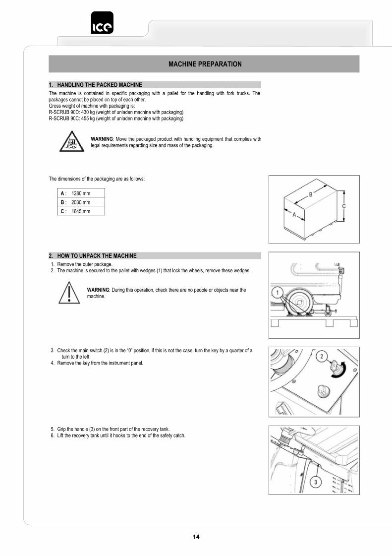
1. HANDLING THE PACKED MACHINE The machine is contained in specific packaging with a pallet for the handling with fork trucks. The packages cannot be placed on top of each other. Gross weight of machine with packaging is: R-SCRUB 90D: 430 kg (weight of unladen machine with packaging) R-SCRUB 90C: 455 kg (weight of unladen machine with packaging)
WARNING: Move the packaged product with handling equipment that complies with legal requirements regarding size and mass of the packaging.
The dimensions of the packaging are as follows:
A : 1280 mm B : 2030 mm C : 1645 mm
2. HOW TO UNPACK THE MACHINE 1. Remove the outer package. 2. The machine is secured to the pallet with wedges (1) that lock the wheels, remove these wedges.
WARNING: During this operation, check there are no people or objects near the machine.
3. Check the main switch (2) is in the “0” position, if this is not the case, turn the key by a quarter of a turn to the left.
4. Remove the key from the instrument panel.
5. Grip the handle (3) on the front part of the recovery tank. 6. Lift the recovery tank until it hooks to the end of the safety catch.
1515
MACHINE PREPARATION
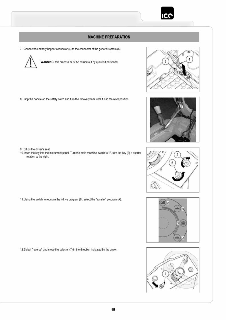
7. Connect the battery hopper connector (4) to the connector of the general system (5).
WARNING: this process must be carried out by qualified personnel.
8. Grip the handle on the safety catch and turn the recovery tank until it is in the work position.
9. Sit on the driver’s seat. 10.Insert the key into the instrument panel. Turn the main machine switch to "I", turn the key (2) a quarter
rotation to the right.
11.Using the switch to regulate the i-drive program (6), select the "transfer" program (A).
12.Select "reverse" and move the selector (7) in the direction indicated by the arrow.
16 1716 17
MACHINE PREPARATION
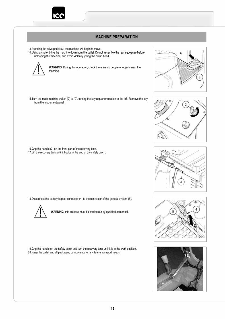
13.Pressing the drive pedal (8), the machine will begin to move.14.Using a chute, bring the machine down from the pallet. Do not assemble the rear squeegee before
unloading the machine, and avoid violently jolting the brush head.
WARNING: During this operation, check there are no people or objects near the machine.
15.Turn the main machine switch (2) to "0", turning the key a quarter rotation to the left. Remove the key from the instrument panel.
16.Grip the handle (3) on the front part of the recovery tank. 17.Lift the recovery tank until it hooks to the end of the safety catch.
18.Disconnect the battery hopper connector (4) to the connector of the general system (5).
WARNING: this process must be carried out by qualified personnel.
19.Grip the handle on the safety catch and turn the recovery tank until it is in the work position.20.Keep the pallet and all packaging components for any future transport needs.
1717
MACHINE PREPARATION
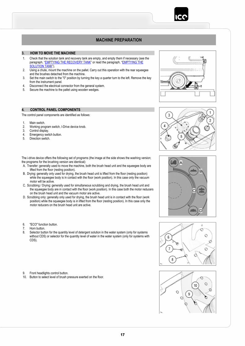
3. HOW TO MOVE THE MACHINE 1. Check that the solution tank and recovery tank are empty, and empty them if necessary (see the
paragraph, “EMPTYING THE RECOVERY TANK” or read the paragraph, “EMPTYING THE SOLUTION TANK”).
2. Using a chute, mount the machine on the pallet. Carry out this operation with the rear squeegee and the brushes detached from the machine.
3. Set the main switch to the "0" position by turning the key a quarter turn to the left. Remove the key from the instrument panel.
4. Disconnect the electrical connector from the general system. 5. Secure the machine to the pallet using wooden wedges.
4. CONTROL PANEL COMPONENTS The control panel components are identified as follows:
1. Main switch. 2. Working program switch, I-Drive device knob. 3. Control display. 4. Emergency switch button. 5. Direction switch.
The i-drive device offers the following set of programs (the image at the side shows the washing version; the programs for the brushing version are identical): A. Transfer: generally used to move the machine, both the brush head unit and the squeegee body are
lifted from the floor (resting position). B. Drying: generally only used for drying, the brush head unit is lifted from the floor (resting position)
while the squeegee body is in contact with the floor (work position). In this case only the vacuum motor will be active.
C. Scrubbing / Drying: generally used for simultaneous scrubbing and drying, the brush head unit and the squeegee body are in contact with the floor (work position). In this case both the motor reducers on the brush head unit and the vacuum motor are active.
D. Scrubbing only: generally only used for drying, the brush head unit is in contact with the floor (work position) while the squeegee body is in lifted from the floor (resting position). In this case only the motor reducers on the brush head unit are active.
6. "ECO" function button. 7. Horn button. 8. Selector button for the quantity level of detergent solution in the water system (only for systems
without CDS) or selector for the quantity level of water in the water system (only for systems with CDS).
9. Front headlights control button. 10. Button to select level of brush pressure exerted on the floor.
18 1918 19
MACHINE PREPARATION
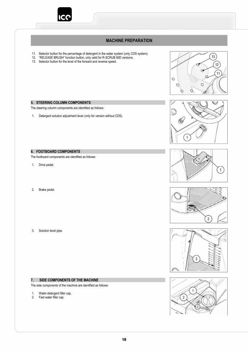
11. Selector button for the percentage of detergent in the water system (only CDS system).12. “RELEASE BRUSH” function button, only valid for R-SCRUB 90D versions. 13. Selector button for the level of the forward and reverse speed.
5. STEERING COLUMN COMPONENTS The steering column components are identified as follows:
1. Detergent solution adjustment lever (only for version without CDS).
6. FOOTBOARD COMPONENTS The footboard components are identified as follows:
1. Drive pedal.
2. Brake pedal.
3. Solution level pipe.
7. SIDE COMPONENTS OF THE MACHINE The side components of the machine are identified as follows:
1. Water-detergent filler cap. 2. Fast water filler cap.
1919
MACHINE PREPARATION
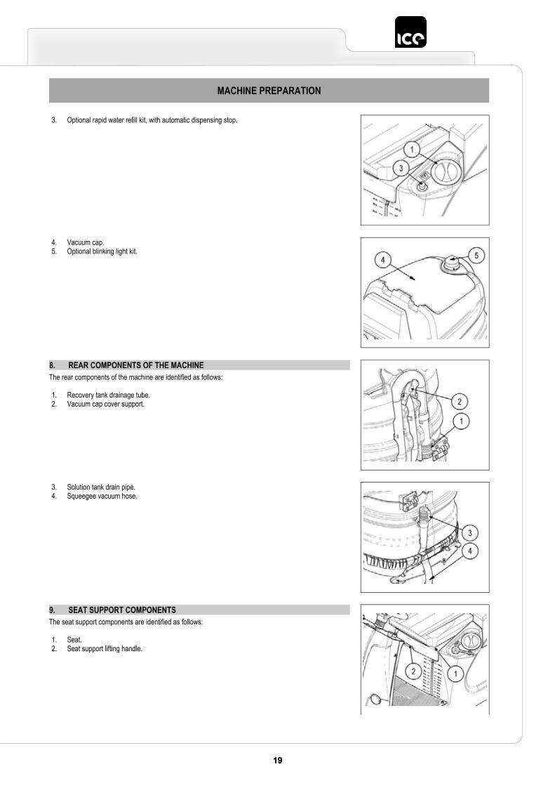
3. Optional rapid water refill kit, with automatic dispensing stop.
4. Vacuum cap. 5. Optional blinking light kit.
8. REAR COMPONENTS OF THE MACHINE The rear components of the machine are identified as follows:
1. Recovery tank drainage tube. 2. Vacuum cap cover support.
3. Solution tank drain pipe. 4. Squeegee vacuum hose.
9. SEAT SUPPORT COMPONENTS The seat support components are identified as follows:
1. Seat. 2. Seat support lifting handle.
20 2120 21
MACHINE PREPARATION
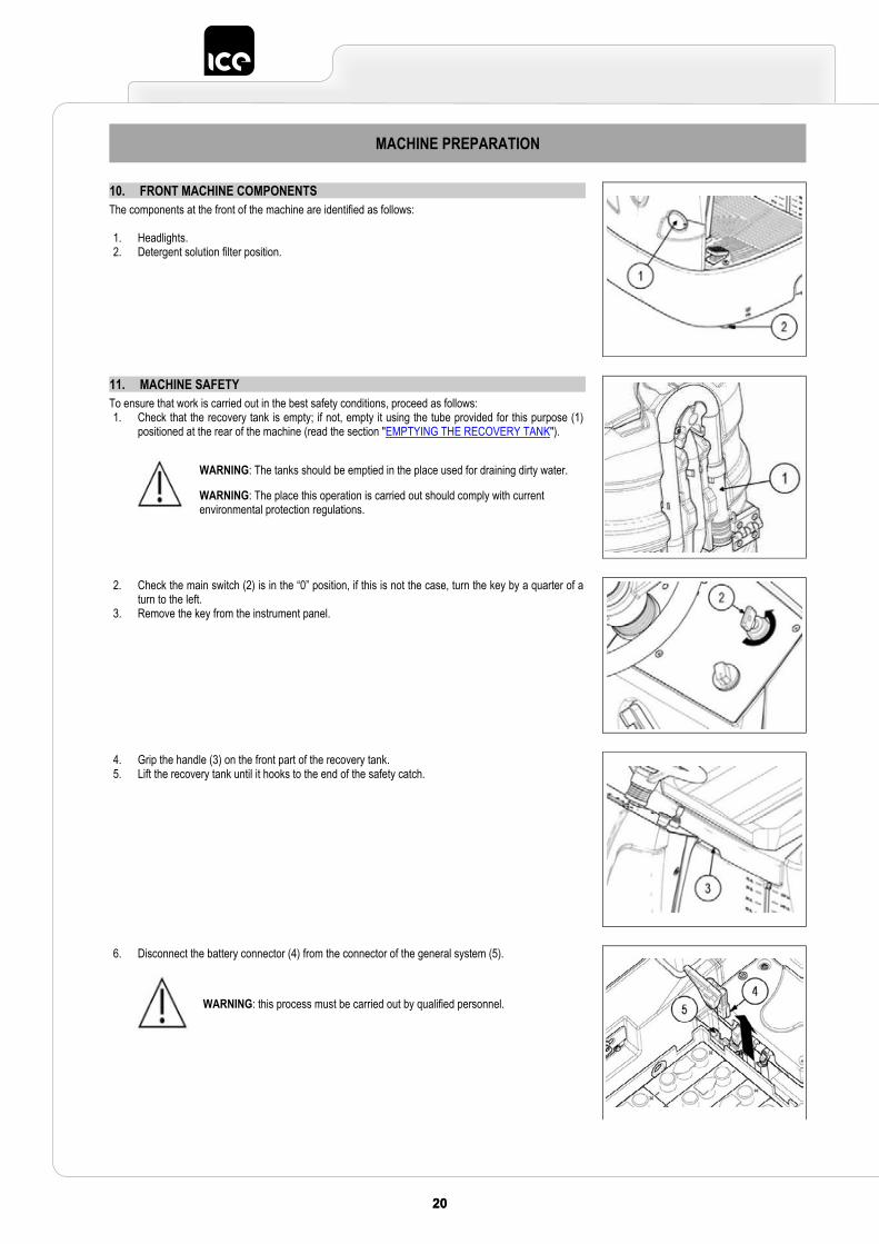
10. FRONT MACHINE COMPONENTS The components at the front of the machine are identified as follows:
1. Headlights. 2. Detergent solution filter position.
11. MACHINE SAFETY To ensure that work is carried out in the best safety conditions, proceed as follows: 1. Check that the recovery tank is empty; if not, empty it using the tube provided for this purpose (1)
positioned at the rear of the machine (read the section "EMPTYING THE RECOVERY TANK").
WARNING: The tanks should be emptied in the place used for draining dirty water.
WARNING: The place this operation is carried out should comply with current environmental protection regulations.
2. Check the main switch (2) is in the “0” position, if this is not the case, turn the key by a quarter of a turn to the left.
3. Remove the key from the instrument panel.
4. Grip the handle (3) on the front part of the recovery tank.5. Lift the recovery tank until it hooks to the end of the safety catch.
6. Disconnect the battery connector (4) from the connector of the general system (5).
WARNING: this process must be carried out by qualified personnel.
2121
MACHINE PREPARATION
12. TYPE OF BATTERY To power the machine it is necessary to use: liquidelectrolyte lead traction batteries hopper liquidelectrolyte lead traction batteries;
OTHER TYPES MUST NOT BE USED. The batteries must meet the requirements laid out in the norms: CEI EN 60254-1:2005-12 (CEI 21-5) + CEI EN 60254-2:2008-06 (CEI 21-7) The battery compartment can hold a battery hopper with twelve 2V elements or four 6V batteries. For a good working performance, we suggest the use of the battery hopper with twelve 2V elements.
13. BATTERY HOPPER MAINTENANCE AND DISPOSALFor maintenance and recharging, respect the instructions provided by the battery manufacturer. Special attention must be paid to the choice of battery charger, which differs according to the battery type and capacity. When the battery elements in the battery hopper are exhausted, the battery hopper needs to be disconnected by specialised and trained staff, and lifted and removed from the battery compartment using suitable lifting devices. BATTERY HOPPER BATTERY ELEMENTS ARE CLASSIFIED AS DANGEROUS WASTE AND MUST BE CONSIGNED TO THE AUTHORISED BODIES FOR CORRECT DISPOSAL.
WARNING: you are advised to always wear protective gloves, to avoid the risk of serious injury to your hands.
WARNING: You are advised to only lift and move the battery hopper with lifting and transportation means suitable for the specific weight and size.
14. FITTING THE BATTERIES INTO THE MACHINE The battery hopper must be housed in the special compartment beneath the recovery tank and should be handled using lifting equipment that is suitable in terms of both weight and coupling system. The battery hopper must also satisfy the requirements of Standard CEI 21-5. The dimensions of the battery compartment are: 430 x 630 x H470 mm.
WARNING: For battery hopper maintenance and daily recharging, you must carefully follow the instructions provided by the manufacturer or retailer. All installation and maintenance operations must be carried out by specialised personnel.
WARNING: Ensure that you comply with the accident prevention regulations in force in the country where you work or with DIN EN 50272-3 and DIN EN 50110-1, before any handling of the battery hopper. WARNING: To prevent an accidental short circuit use insulated tools to connect battery hopper, and do not place or drop metal objects on the single battery element. Remove rings, watches and any clothing with metal parts that may come into contact with the terminals of the single battery element.
To insert the batteries into the compartment proceed as follows:1. Make sure the machine is in a safe condition (read “MACHINE SAFETY”).
22 2322 23
MACHINE PREPARATION
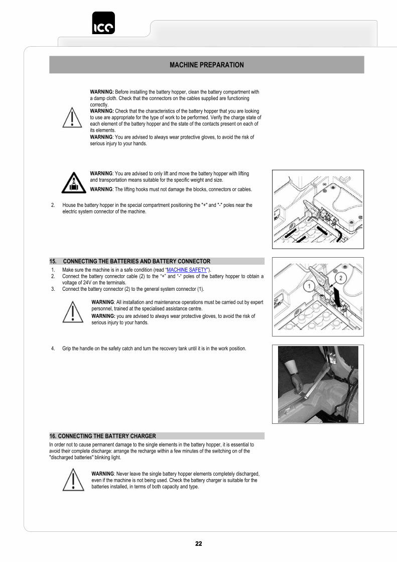
WARNING: Before installing the battery hopper, clean the battery compartment with a damp cloth. Check that the connectors on the cables supplied are functioning correctly. WARNING: Check that the characteristics of the battery hopper that you are looking to use are appropriate for the type of work to be performed. Verify the charge state of each element of the battery hopper and the state of the contacts present on each of its elements.WARNING: You are advised to always wear protective gloves, to avoid the risk of serious injury to your hands.
WARNING: You are advised to only lift and move the battery hopper with lifting and transportation means suitable for the specific weight and size.WARNING: The lifting hooks must not damage the blocks, connectors or cables.
2. House the battery hopper in the special compartment positioning the "+" and "-" poles near the electric system connector of the machine.
15. CONNECTING THE BATTERIES AND BATTERY CONNECTOR 1. Make sure the machine is in a safe condition (read “MACHINE SAFETY”). 2. Connect the battery connector cable (2) to the “+” and “-“ poles of the battery hopper to obtain a
voltage of 24V on the terminals. 3. Connect the battery connector (2) to the general system connector (1).
WARNING: All installation and maintenance operations must be carried out by expert personnel, trained at the specialised assistance centre. WARNING: you are advised to always wear protective gloves, to avoid the risk of serious injury to your hands.
4. Grip the handle on the safety catch and turn the recovery tank until it is in the work position.
16. CONNECTING THE BATTERY CHARGER In order not to cause permanent damage to the single elements in the battery hopper, it is essential to avoid their complete discharge: arrange the recharge within a few minutes of the switching on of the "discharged batteries" blinking light.
WARNING: Never leave the single battery hopper elements completely discharged, even if the machine is not being used. Check the battery charger is suitable for the batteries installed, in terms of both capacity and type.
2323
MACHINE PREPARATION
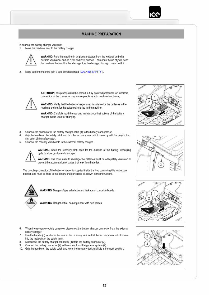
To connect the battery charger you must: 1. Move the machine near to the battery charger.
WARNING: Park the machine in an place protected from the weather and with suitable ventilation, and on a flat and level surface. There must be no objects near the machine that could either damage it, or be damaged through contact with it.
2. Make sure the machine is in a safe condition (read “MACHINE SAFETY”).
ATTENTION: this process must be carried out by qualified personnel. An incorrect connection of the connector may cause problems with machine functioning.
WARNING: Verify that the battery charger used is suitable for the batteries in the machine and set for the batteries installed in the machine.
WARNING: Carefully read the use and maintenance instructions of the battery charger that is used for charging.
3. Connect the connector of the battery charger cable (1) to the battery connector (2).4. Grip the handle on the safety catch and turn the recovery tank until it hooks up with the prop in the
first point of the safety catch. 5. Connect the recently wired cable to the external battery charger.
WARNING: Keep the recovery tank open for the duration of the battery recharging cycle to allow gas fumes to escape.
WARNING: The room used to recharge the batteries must be adequately ventilated to prevent the accumulation of gases that leak from batteries.
The coupling connector of the battery charger is supplied inside the bag containing this instruction booklet, and must be fitted to the battery charger cables as shown in the instructions.
WARNING: Danger of gas exhalation and leakage of corrosive liquids.
WARNING: Danger of fire: do not go near with free flames
6. When the recharge cycle is complete, disconnect the battery charger connector from the external battery charger.
7. Use the handle (3) located in the front of the recovery tank and lift the recovery tank until it hooks into the last point of the safety latch.
8. Disconnect the battery charger connector (1) from the battery connector (2). 9. Connect the battery connector (2) to the connector of the general system (4). 10. Grip the handle on the safety catch and lower the recovery tank until it is in the work position.
24 2524 25
MACHINE PREPARATION
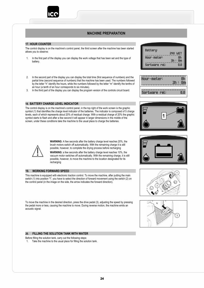
17. HOUR COUNTER The control display is on the machine's control panel, the third screen after the machine has been started allows you to observe:
1. In the first part of the display you can display the work voltage that has been set and the type of battery.
2. In the second part of the display you can display the total time (first sequence of numbers) and the partial time (second sequence of numbers) that the machine has been used. The numbers followed by the letter “h” identify the hours, while the numbers followed by the letter “m” identify the tenths of an hour (a tenth of an hour corresponds to six minutes).
3. In the third part of the display you can display the program version of the controls circuit board.
18. BATTERY CHARGE LEVEL INDICATORThe control display is on the machine's control panel, in the top right of the work screen is the graphic symbol (1) that identifies the charge level indicator of the batteries. The indicator is composed of 5 charge levels, each of which represents about 20% of residual charge. With a residual charge of 20% the graphic symbol starts to flash and after a few second it will appear in larger dimensions in the middle of the screen, under these conditions take the machine to the usual place to charge the batteries.
WARNING: A few seconds after the battery charge level reaches 20%, the brush motors switch off automatically. With the remaining charge it is still possible, however, to complete the drying process before recharging WARNING: a few seconds after the battery charge level reaches 10%, the vacuum motor switches off automatically. With the remaining charge, it is still possible, however, to move the machine to the location designated for its recharging
19. WORKING FORWARD SPEED This machine is equipped with electronic traction control. To move the machine, after putting the main switch (1) into position "I", you have to select the direction of forward movement using the switch (2) on the control panel (in the image on the side, the arrow indicates the forward direction).
To move the machine in the desired direction, press the drive pedal (3), adjusting the speed by pressing the pedal more or less, causing the machine to move. During reverse motion, the machine emits an acoustic signal.
20. FILLING THE SOLUTION TANK WITH WATERBefore filling the solution tank, carry out the following steps: 1. Take the machine to the usual place for filling the solution tank.
1
2525
MACHINE PREPARATION
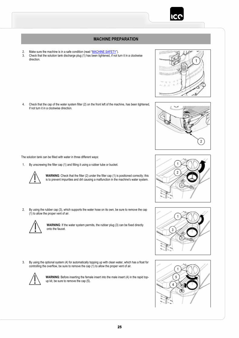
2. Make sure the machine is in a safe condition (read “MACHINE SAFETY”).3. Check that the solution tank discharge plug (1) has been tightened, if not turn it in a clockwise
direction.
4. Check that the cap of the water system filter (2) on the front left of the machine, has been tightened, if not turn it in a clockwise direction.
The solution tank can be filled with water in three different ways:
1. By unscrewing the filler cap (1) and filling it using a rubber tube or bucket.
WARNING: Check that the filter (2) under the filler cap (1) is positioned correctly; this is to prevent impurities and dirt causing a malfunction in the machine's water system.
2. By using the rubber cap (3), which supports the water hose on its own, be sure to remove the cap (1) to allow the proper vent of air.
WARNING: If the water system permits, the rubber plug (3) can be fixed directly onto the faucet.
3. By using the optional system (4) for automatically topping up with clean water, which has a float for controlling the overflow, be sure to remove the cap (1) to allow the proper vent of air.
WARNING: Before inserting the female insert into the male insert (4) in the rapid top-up kit, be sure to remove the cap (5).
26 2726 27
MACHINE PREPARATION
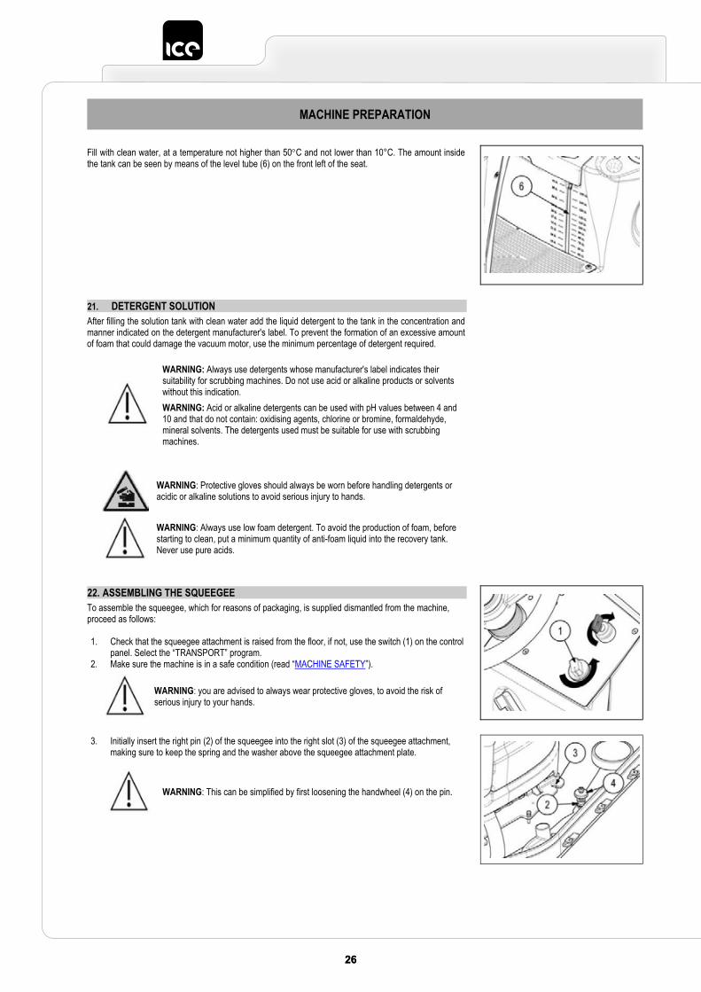
Fill with clean water, at a temperature not higher than 50C and not lower than 10°C. The amount inside the tank can be seen by means of the level tube (6) on the front left of the seat.
21. DETERGENT SOLUTIONAfter filling the solution tank with clean water add the liquid detergent to the tank in the concentration and manner indicated on the detergent manufacturer's label. To prevent the formation of an excessive amount of foam that could damage the vacuum motor, use the minimum percentage of detergent required.
WARNING: Always use detergents whose manufacturer's label indicates their suitability for scrubbing machines. Do not use acid or alkaline products or solvents without this indication. WARNING: Acid or alkaline detergents can be used with pH values between 4 and 10 and that do not contain: oxidising agents, chlorine or bromine, formaldehyde, mineral solvents. The detergents used must be suitable for use with scrubbing machines.
WARNING: Protective gloves should always be worn before handling detergents or acidic or alkaline solutions to avoid serious injury to hands.
WARNING: Always use low foam detergent. To avoid the production of foam, before starting to clean, put a minimum quantity of anti-foam liquid into the recovery tank. Never use pure acids.
22. ASSEMBLING THE SQUEEGEE To assemble the squeegee, which for reasons of packaging, is supplied dismantled from the machine, proceed as follows:
1. Check that the squeegee attachment is raised from the floor, if not, use the switch (1) on the control panel. Select the “TRANSPORT” program.
2. Make sure the machine is in a safe condition (read “MACHINE SAFETY”).
WARNING: you are advised to always wear protective gloves, to avoid the risk of serious injury to your hands.
3. Initially insert the right pin (2) of the squeegee into the right slot (3) of the squeegee attachment, making sure to keep the spring and the washer above the squeegee attachment plate.
WARNING: This can be simplified by first loosening the handwheel (4) on the pin.
2727
MACHINE PREPARATION
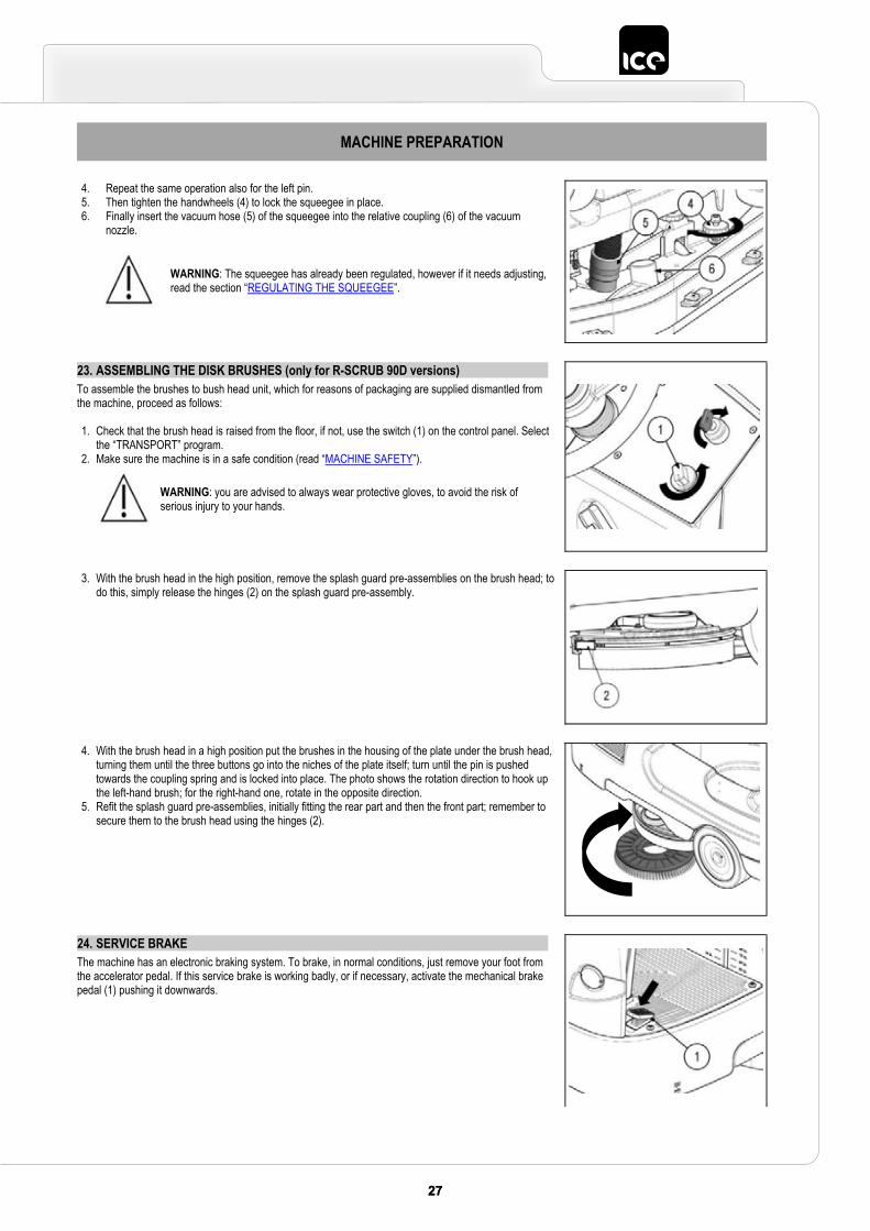
4. Repeat the same operation also for the left pin. 5. Then tighten the handwheels (4) to lock the squeegee in place. 6. Finally insert the vacuum hose (5) of the squeegee into the relative coupling (6) of the vacuum
nozzle.
WARNING: The squeegee has already been regulated, however if it needs adjusting, read the section “REGULATING THE SQUEEGEE”.
23. ASSEMBLING THE DISK BRUSHES (only for R-SCRUB 90D versions) To assemble the brushes to bush head unit, which for reasons of packaging are supplied dismantled from the machine, proceed as follows:
1. Check that the brush head is raised from the floor, if not, use the switch (1) on the control panel. Select the “TRANSPORT” program.
2. Make sure the machine is in a safe condition (read “MACHINE SAFETY”).
WARNING: you are advised to always wear protective gloves, to avoid the risk of serious injury to your hands.
3. With the brush head in the high position, remove the splash guard pre-assemblies on the brush head; to do this, simply release the hinges (2) on the splash guard pre-assembly.
4. With the brush head in a high position put the brushes in the housing of the plate under the brush head, turning them until the three buttons go into the niches of the plate itself; turn until the pin is pushed towards the coupling spring and is locked into place. The photo shows the rotation direction to hook up the left-hand brush; for the right-hand one, rotate in the opposite direction.
5. Refit the splash guard pre-assemblies, initially fitting the rear part and then the front part; remember to secure them to the brush head using the hinges (2).
24. SERVICE BRAKE The machine has an electronic braking system. To brake, in normal conditions, just remove your foot from the accelerator pedal. If this service brake is working badly, or if necessary, activate the mechanical brake pedal (1) pushing it downwards.
28 2928 29
MACHINE PREPARATION
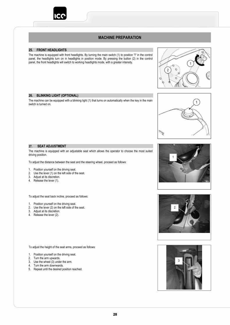
25. FRONT HEADLIGHTS The machine is equipped with front headlights. By turning the main switch (1) to position "I" in the control panel, the headlights turn on in headlights in position mode. By pressing the button (2) in the control panel, the front headlights will switch to working headlights mode, with a greater intensity.
26. BLINKING LIGHT (OPTIONAL) The machine can be equipped with a blinking light (1) that turns on automatically when the key in the main switch is turned on.
27. SEAT ADJUSTMENTThe machine is equipped with an adjustable seat which allows the operator to choose the most suited driving position.
To adjust the distance between the seat and the steering wheel, proceed as follows:
1. Position yourself on the driving seat. 2. Use the lever (1) on the left side of the seat. 3. Adjust at its discretion. 4. Release the lever (1).
To adjust the seat back incline, proceed as follows:
1. Position yourself on the driving seat. 2. Use the lever (2) on the left side of the seat. 3. Adjust at its discretion. 4. Release the lever (2).
To adjust the height of the seat arms, proceed as follows:
1. Position yourself on the driving seat. 2. Turn the arm upwards. 3. Use the wheel (3) under the arm. 4. Turn the arm downwards. 5. Repeat until the desired position reached.
1
2
3
2929
PREPARING TO WORK
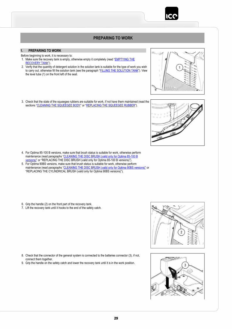
1. PREPARING TO WORK Before beginning to work, it is necessary to: 1. Make sure the recovery tank is empty, otherwise empty it completely (read “EMPTYING THE
RECOVERY TANK”). 2. Verify that the quantity of detergent solution in the solution tank is suitable for the type of work you wish
to carry out, otherwise fill the solution tank (see the paragraph “FILLING THE SOLUTION TANK”). View the level tube (1) on the front left of the seat.
3. Check that the state of the squeegee rubbers are suitable for work, if not have them maintained (read the sections “CLEANING THE SQUEEGEE BODY” or “REPLACING THE SQUEEGEE RUBBER”).
4. For Optima 85-100 B versions, make sure that brush status is suitable for work, otherwise perform maintenance (read paragraphs “CLEANING THE DISC BRUSH (valid only for Optima 85-100 B versions)” or “REPLACING THE DISC BRUSH (valid only for Optima 85-100 B versions)”).
5. For Optima 90BS versions, make sure that brush status is suitable for work, otherwise perform maintenance (read paragraphs “CLEANING THE DISC BRUSH (valid only for Optima 90BS versions)” or “REPLACING THE CYLINDRICAL BRUSH (valid only for Optima 90BS versions)”).
6. Grip the handle (2) on the front part of the recovery tank. 7. Lift the recovery tank until it hooks to the end of the safety catch.
8. Check that the connector of the general system is connected to the batteries connector (3), if not, connect them together.
9. Grip the handle on the safety catch and lower the recovery tank until it is in the work position.
30 3130 31
PREPARING TO WORK
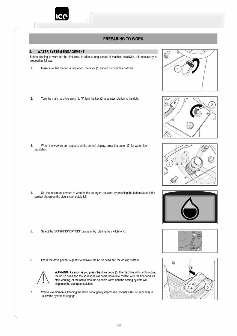
2. WATER SYSTEM ENGAGEMENT Before starting to work for the first time, or after a long period of machine inactivity, it is necessary to proceed as follows:
1. Make sure that the tap is fully open, the lever (1) should be completely down.
2. Turn the main machine switch to "I", turn the key (2) a quarter rotation to the right.
3. When the work screen appears on the control display, press the button (3) for water flow regulation.
4. Set the maximum amount of water in the detergent solution, by pressing the button (3) until the symbol shown on the side is completely full.
5. Select the “WASHING/ DRYING” program, by rotating the switch to “C”.
6. Press the drive pedal (5) gently to activate the brush head and the dosing system.
7. Wait a few moments, keeping the drive pedal gently depressed (normally 40 - 60 seconds) to allow the system to engage.
WARNING: As soon as you press the drive pedal (5) the machine will start to move, the brush head and the squeegee will come down into contact with the floor and will start working, at the same time the solenoid valve and the dosing system will dispense the detergent solution.
3131
WORK
1. STARTING WORK To start working, do as follows:
1. Perform all the checks in the chapter “PREPARING TO WORK (only for version without CDS) or PREPARING TO WORK (only for system with CDS)”.
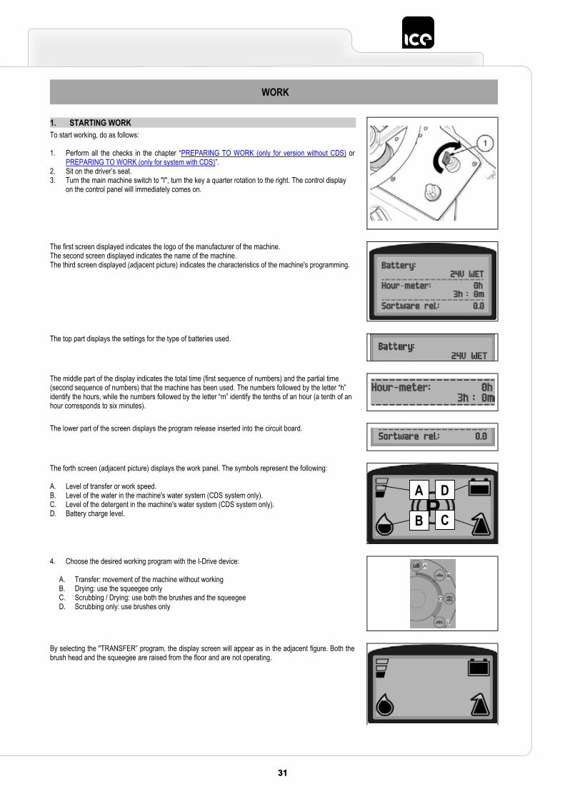
2. Sit on the driver’s seat. 3. Turn the main machine switch to "I", turn the key a quarter rotation to the right. The control display
on the control panel will immediately comes on.
The first screen displayed indicates the logo of the manufacturer of the machine.The second screen displayed indicates the name of the machine. The third screen displayed (adjacent picture) indicates the characteristics of the machine's programming.
The top part displays the settings for the type of batteries used.
The middle part of the display indicates the total time (first sequence of numbers) and the partial time (second sequence of numbers) that the machine has been used. The numbers followed by the letter “h” identify the hours, while the numbers followed by the letter “m” identify the tenths of an hour (a tenth of an hour corresponds to six minutes).
The lower part of the screen displays the program release inserted into the circuit board.
The forth screen (adjacent picture) displays the work panel. The symbols represent the following:
A. Level of transfer or work speed. B. Level of the water in the machine's water system (CDS system only). C. Level of the detergent in the machine's water system (CDS system only). D. Battery charge level.
4. Choose the desired working program with the I-Drive device:
A. Transfer: movement of the machine without working B. Drying: use the squeegee only C. Scrubbing / Drying: use both the brushes and the squeegee D. Scrubbing only: use brushes only
By selecting the "TRANSFER” program, the display screen will appear as in the adjacent figure. Both the brush head and the squeegee are raised from the floor and are not operating.
A
B
D
C
32 3332 33
WORK
By selecting the "DRYING” program, the display screen shown on the side will appear. The brush head is raised from the floor and is not operating. The squeegee will position itself in contact with the floor as soon as the drive pedal is pressed, in that moment the vacuum motor will start working.
WARNING: this program should only be used to collect the dirty solution after a pre-wash, and should never be used for the work of vacuuming liquids.
If during the “DRYING” program the machine is stopped and the drive pedal is released, the squeegee body will remain in contact with the floor for a few seconds, after which it will raise up from the ground to go back to its rest position. For all these phases the vacuum motor will continue to operate, only after a few seconds that it has returned to its work position will it switch off, this is to allow the motor to collect all the liquid in the vacuum hose. During these phases, the symbol of the vacuum motor (2) on the instrument panel display will blink, and it will only stop when the squeegee is in its work position and the vacuum motor is off.
WARNING: by pressing the forward movement pedal it will start working with the same program and with the same parameters that were set before it stopped.WARNING: if reverse is carried out with this program active, the brush head unit will raise up from the floor, the motor will keep working for a pre-set time and then it will switch off.WARNING: By pressing the drive pedal again, drying will start working again normally.
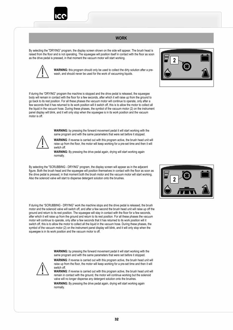
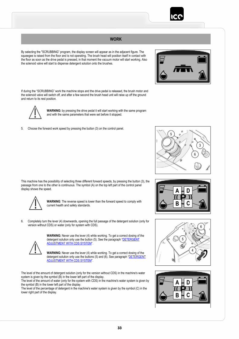
By selecting the "SCRUBBING - DRYING” program, the display screen will appear as in the adjacent figure. Both the brush head and the squeegee will position themselves in contact with the floor as soon as the drive pedal is pressed, in that moment both the brush motor and the vacuum motor will start working. Also the solenoid valve will start to dispense detergent solution onto the brushes.
If during the “SCRUBBING - DRYING” work the machine stops and the drive pedal is released, the brush motor and the solenoid valve will switch off, and after a few second the brush head unit will raise up off the ground and return to its rest position. The squeegee will stay in contact with the floor for a few seconds, after which it will raise up from the ground and return to its rest position. For all these phases the vacuum motor will continue to operate, only after a few seconds that it has returned to its work position will it switch off, this is to allow the motor to collect all the liquid in the vacuum hose. During these phases, the symbol of the vacuum motor (2) on the instrument panel display will blink, and it will only stop when the squeegee is in its work position and the vacuum motor is off.
WARNING: by pressing the forward movement pedal it will start working with the same program and with the same parameters that were set before it stopped.WARNING: if reverse is carried out with this program active, the brush head unit will raise up from the floor, the motor will keep working for a pre-set time and then it will switch off. WARNING: if reverse is carried out with this program active, the brush head unit will remain in contact with the ground, the motor will continue working but the solenoid valve will no longer dispense any detergent solution onto the brushes.WARNING: By pressing the drive pedal again, drying will start working again normally.
2
2
3333
WORK
By selecting the "SCRUBBING” program, the display screen will appear as in the adjacent figure. The squeegee is raised from the floor and is not operating. The brush head will position itself in contact with the floor as soon as the drive pedal is pressed, in that moment the vacuum motor will start working. Also the solenoid valve will start to dispense detergent solution onto the brushes.
If during the “SCRUBBING” work the machine stops and the drive pedal is released, the brush motor and the solenoid valve will switch off, and after a few second the brush head unit will raise up off the ground and return to its rest position.
WARNING: by pressing the drive pedal it will start working with the same program and with the same parameters that were set before it stopped.
5. Choose the forward work speed by pressing the button (3) on the control panel.
This machine has the possibility of selecting three different forward speeds, by pressing the button (3), the passage from one to the other is continuous. The symbol (A) on the top left part of the control panel display shows the speed.
WARNING: The reverse speed is lower than the forward speed to comply with current health and safety standards.
6. Completely turn the lever (4) downwards, opening the full passage of the detergent solution (only for version without CDS) or water (only for system with CDS).
WARNING: Never use the lever (4) while working. To get a correct dosing of the detergent solution only use the button (5). See the paragraph “DETERGENTADJUSTMENT WITH CDS SYSTEM”.
WARNING: Never use the lever (4) while working. To get a correct dosing of the detergent solution only use the buttons (5) and (6). See paragraph “DETERGENT ADJUSTMENT WITH CDS SYSTEM”.
The level of the amount of detergent solution (only for the version without CDS) in the machine's water system is given by the symbol (B) in the lower left part of the display. The level of the amount of water (only for the system with CDS) in the machine's water system is given by the symbol (B) in the lower left part of the display. The level of the percentage of detergent in the machine's water system is given by the symbol (C) in the lower right part of the display.
A
B
D
C
A
B
D
C
34 3534 35
WORK
7. Select "forward", move the selector (7) to the desired direction.
8. Pressing the drive pedal (8), the machine will begin to move.
If the program selected is “SCRUBBING– DRYING” the squeegee and the brush head lower until they touch the ground. As soon as the drive pedal is pushed the brush head motor and the vacuum motor will start working, and as a result also the solenoid valve will start its work and detergent solution will be dispensed onto the brushes. During the first metres, check there is sufficient solution and that the squeegee dries perfectly. The machine will now begin to work with full efficiency until the battery is flat or until the detergent solution has finished.
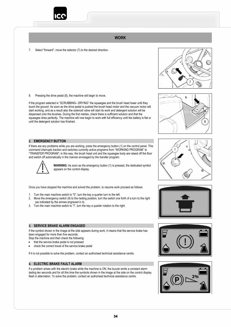
2. EMERGENCY BUTTONIf there are any problems while you are working, press the emergency button (1) on the control panel. This command interrupts traction and switches currently active programs from “WORKING PROGRAM” to “TRANSFER PROGRAM”; in this way, the brush head unit and the squeegee body are raised off the floor and switch off automatically in the manner envisaged by the transfer program.
WARNING: As soon as the emergency button (1) is pressed, the dedicated symbol appears on the control display.
Once you have stopped the machine and solved the problem, to resume work proceed as follows:
1. Turn the main machine switch to "0", turn the key a quarter turn to the left. 2. Move the emergency switch (9) to the resting position, turn the switch one forth of a turn to the right
(as indicated by the arrows engraved in it). 3. Turn the main machine switch to "I", turn the key a quarter rotation to the right.
3. SERVICE BRAKE ALARM ENGAGEDIf the symbol shown in the image at the side appears during work, it means that the service brake has been engaged for more than five seconds. Stop the machine and then check the following: that the service brake pedal is not pressed check the correct travel of the service brake pedal
If it is not possible to solve the problem, contact an authorised technical assistance centre.
4. ELECTRIC BRAKE FAULT ALARMIf a problem arises with the electric brake while the machine is ON, the buzzer emits a constant alarm lasting ten seconds and for all this time the symbols shown in the image at the side on the control display flash in alternation. To solve the problem, contact an authorised technical assistance centre.
3535
WORK
5. DETERGENT ADJUSTMENTTo regulate the amount of detergent solution on the brushes, proceed as follows:
1. Fully open the flow coming from the tap on the front of the machine by moving the lever (1) on the rear of the steering column down.
2. Choose the desired working program with the I-Drive device, either "SCRUBBING - DRYING" or "SCRUBBING".
3. By pressing the drive pedal (2) the brush head and the squeegee, or just the brush head (depending on the program selected), will lower into a work position and the machine starts to move. Both the brush motor and the vacuum motor (depending on the program selected) will start to work and the solenoid valve will distribute detergent solution to the brushes.
During the first few meters, check that the quantity of solution is enough to wet the floor, but not so much as to come out of the splash guard; regulation of detergent leakage is carried out by means of the button (3) on the control panel.
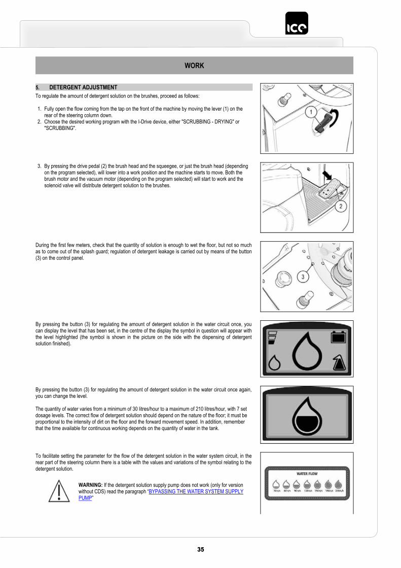
By pressing the button (3) for regulating the amount of detergent solution in the water circuit once, you can display the level that has been set, in the centre of the display the symbol in question will appear with the level highlighted (the symbol is shown in the picture on the side with the dispensing of detergent solution finished).
By pressing the button (3) for regulating the amount of detergent solution in the water circuit once again, you can change the level.
The quantity of water varies from a minimum of 30 litres/hour to a maximum of 210 litres/hour, with 7 set dosage levels. The correct flow of detergent solution should depend on the nature of the floor; it must be proportional to the intensity of dirt on the floor and the forward movement speed. In addition, remember that the time available for continuous working depends on the quantity of water in the tank.
To facilitate setting the parameter for the flow of the detergent solution in the water system circuit, in the rear part of the steering column there is a table with the values and variations of the symbol relating to the detergent solution.
WARNING: If the detergent solution supply pump does not work (only for version without CDS) read the paragraph “BYPASSING THE WATER SYSTEM SUPPLY PUMP”
36 3736 37
WORK
6. REGULATING THE FORWARD MOVEMENT WORK SPEEDThis machine allows you to choose from three different forward speeds using the button (1) on the instrument panel. The selection is continuous cycle, by pressing the button you pass from one level to another.
WARNING! The reverse speed is lower than the forward speed to comply with current health and safety standards.
To display the speed level that has been set, just look at the symbol (2) on the display.
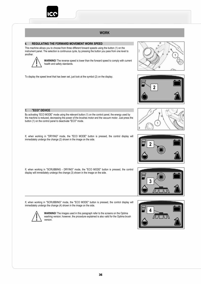
7. "ECO" DEVICEBy activating “ECO MODE” mode using the relevant button (1) on the control panel, the energy used by the machine is reduced, decreasing the power of the brushes motor and the vacuum motor. Just press the button (1) on the control panel to deactivate "ECO" mode.
If, when working in "DRYING" mode, the "ECO MODE" button is pressed, the control display will immediately undergo the change (2) shown in the image on the side.
If, when working in "SCRUBBING - DRYING" mode, the "ECO MODE" button is pressed, the control display will immediately undergo the change (3) shown in the image on the side.
If, when working in "SCRUBBING" mode, the "ECO MODE" button is pressed, the control display will immediately undergo the change (4) shown in the image on the side.
WARNING! The images used in this paragraph refer to the screens on the Optima washing version; however, the procedure explained is also valid for the Optima brush version.
2
2
3
4
3737
WORK
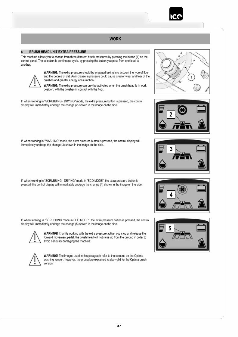
8. BRUSH HEAD UNIT EXTRA PRESSUREThis machine allows you to choose from three different brush pressures by pressing the button (1) on the control panel. The selection is continuous cycle, by pressing the button you pass from one level to another.
WARNING: The extra pressure should be engaged taking into account the type of floor and the degree of dirt. An increase in pressure could cause greater wear and tear of the brushes and greater energy consumption. WARNING: The extra pressure can only be activated when the brush head is in work position, with the brushes in contact with the floor.
If, when working in "SCRUBBING - DRYING" mode, the extra pressure button is pressed, the control display will immediately undergo the change (2) shown in the image on the side.
If, when working in "WASHING" mode, the extra pressure button is pressed, the control display will immediately undergo the change (3) shown in the image on the side.
If, when working in "SCRUBBING - DRYING" mode in "ECO MODE", the extra pressure button is pressed, the control display will immediately undergo the change (4) shown in the image on the side.
If, when working in "SCRUBBING mode in ECO MODE", the extra pressure button is pressed, the control display will immediately undergo the change (5) shown in the image on the side.
WARNING! If, while working with the extra pressure active, you stop and release the forward movement pedal, the brush head will not raise up from the ground in order to avoid seriously damaging the machine.
WARNING! The images used in this paragraph refer to the screens on the Optima washing version; however, the procedure explained is also valid for the Optima brush version.
2
3
4
5
38 3938 39
WORK
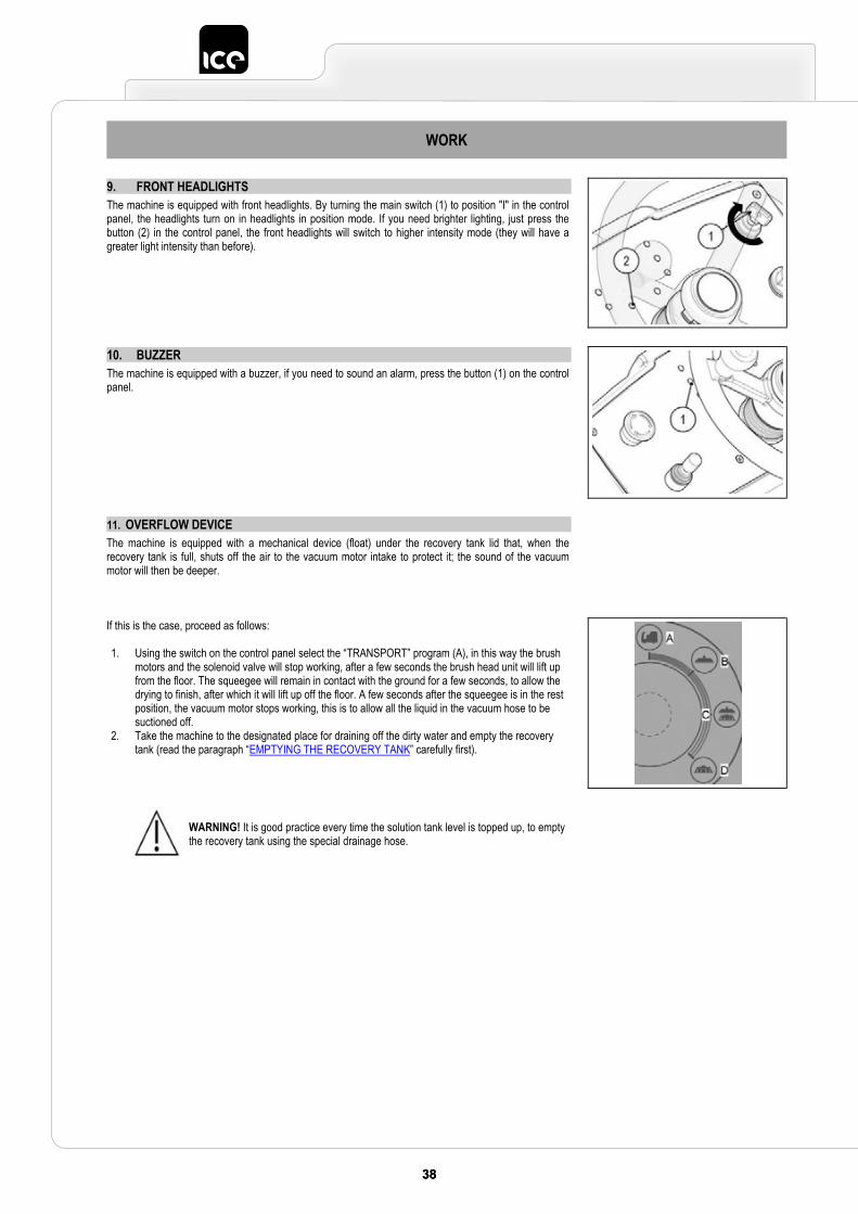
9. FRONT HEADLIGHTS The machine is equipped with front headlights. By turning the main switch (1) to position "I" in the control panel, the headlights turn on in headlights in position mode. If you need brighter lighting, just press the button (2) in the control panel, the front headlights will switch to higher intensity mode (they will have a greater light intensity than before).
10. BUZZER The machine is equipped with a buzzer, if you need to sound an alarm, press the button (1) on the control panel.
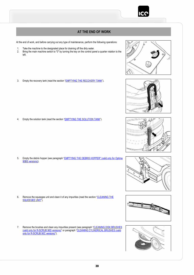
11. OVERFLOW DEVICEThe machine is equipped with a mechanical device (float) under the recovery tank lid that, when the recovery tank is full, shuts off the air to the vacuum motor intake to protect it; the sound of the vacuum motor will then be deeper.
If this is the case, proceed as follows:
1. Using the switch on the control panel select the “TRANSPORT” program (A), in this way the brush motors and the solenoid valve will stop working, after a few seconds the brush head unit will lift up from the floor. The squeegee will remain in contact with the ground for a few seconds, to allow the drying to finish, after which it will lift up off the floor. A few seconds after the squeegee is in the rest position, the vacuum motor stops working, this is to allow all the liquid in the vacuum hose to be suctioned off.
2. Take the machine to the designated place for draining off the dirty water and empty the recovery tank (read the paragraph “EMPTYING THE RECOVERY TANK” carefully first).
WARNING! It is good practice every time the solution tank level is topped up, to empty the recovery tank using the special drainage hose.
3939
AT THE END OF WORK
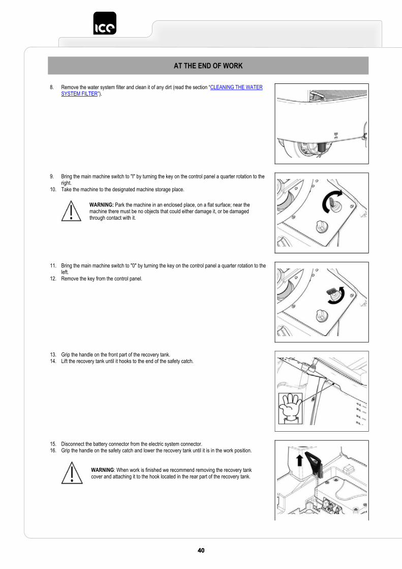
At the end of work, and before carrying out any type of maintenance, perform the following operations:
1. Take the machine to the designated place for draining off the dirty water. 2. Bring the main machine switch to "0" by turning the key on the control panel a quarter rotation to the
left.
3. Empty the recovery tank (read the section “EMPTYING THE RECOVERY TANK”).
4. Empty the solution tank (read the section “EMPTYING THE SOLUTION TANK”).
5. Empty the debris hopper (see paragraph “EMPTYING THE DEBRIS HOPPER" (valid only for Optima 90BS versions)).
6. Remove the squeegee unit and clean it of any impurities (read the section “CLEANING THE SQUEEGEE UNIT”).
7. Remove the brushes and clean any impurities present (see paragraph “CLEANING DISK BRUSHES (valid only for R-SCRUB 90D versions)” or paragraph “CLEANING CYLINDRICAL BRUSHES (valid only for R-SCRUB 90C versions)”).
40 4140 41
AT THE END OF WORK
8. Remove the water system filter and clean it of any dirt (read the section “CLEANING THE WATER SYSTEM FILTER”).
9. Bring the main machine switch to "I" by turning the key on the control panel a quarter rotation to the right.
10. Take the machine to the designated machine storage place.
WARNING: Park the machine in an enclosed place, on a flat surface; near the machine there must be no objects that could either damage it, or be damaged through contact with it.
11. Bring the main machine switch to "0" by turning the key on the control panel a quarter rotation to the left.
12. Remove the key from the control panel.
13. Grip the handle on the front part of the recovery tank. 14. Lift the recovery tank until it hooks to the end of the safety catch.
15. Disconnect the battery connector from the electric system connector.16. Grip the handle on the safety catch and lower the recovery tank until it is in the work position.
WARNING: When work is finished we recommend removing the recovery tank cover and attaching it to the hook located in the rear part of the recovery tank.
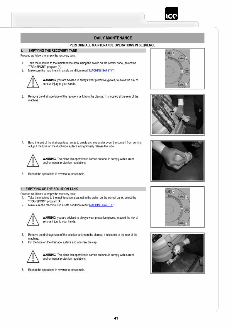
4141
DAILY MAINTENANCE PERFORM ALL MAINTENANCE OPERATIONS IN SEQUENCE
1. EMPTYING THE RECOVERY TANKProceed as follows to empty the recovery tank:
1. Take the machine to the maintenance area, using the switch on the control panel, select the "TRANSPORT” program (A).
2. Make sure the machine is in a safe condition (read “MACHINE SAFETY”).
WARNING: you are advised to always wear protective gloves, to avoid the risk of serious injury to your hands.
3. Remove the drainage tube of the recovery tank from the clamps, it is located at the rear of the machine.
4. Bend the end of the drainage tube, so as to create a choke and prevent the content from coming out, put the tube on the discharge surface and gradually release the tube.
5. Repeat the operations in reverse to reassemble.
WARNING: The place this operation is carried out should comply with current environmental protection regulations.
2. EMPTYING OF THE SOLUTION TANK Proceed as follows to empty the recovery tank: 1. Take the machine to the maintenance area, using the switch on the control panel, select the
"TRANSPORT” program (A). 2. Make sure the machine is in a safe condition (read “MACHINE SAFETY”).
WARNING: you are advised to always wear protective gloves, to avoid the risk of serious injury to your hands.
3. Remove the drainage tube of the solution tank from the clamps, it is located at the rear of the machine.
4. Put the tube on the drainage surface and unscrew the cap.
5. Repeat the operations in reverse to reassemble.
WARNING: The place this operation is carried out should comply with current environmental protection regulations.
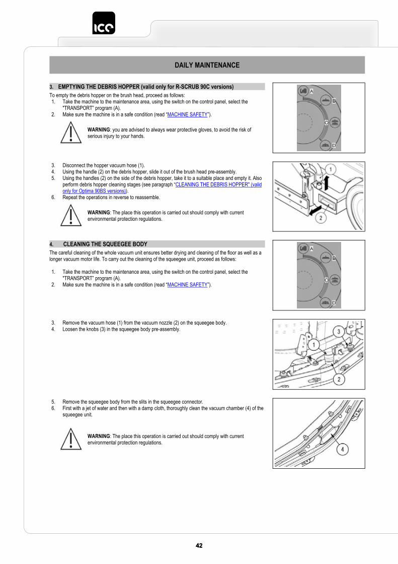
42 4342 43
DAILY MAINTENANCE
3. EMPTYING THE DEBRIS HOPPER (valid only for R-SCRUB 90C versions)To empty the debris hopper on the brush head, proceed as follows: 1. Take the machine to the maintenance area, using the switch on the control panel, select the
"TRANSPORT” program (A). 2. Make sure the machine is in a safe condition (read “MACHINE SAFETY”).
WARNING: you are advised to always wear protective gloves, to avoid the risk of serious injury to your hands.
3. Disconnect the hopper vacuum hose (1). 4. Using the handle (2) on the debris hopper, slide it out of the brush head pre-assembly. 5. Using the handles (2) on the side of the debris hopper, take it to a suitable place and empty it. Also
perform debris hopper cleaning stages (see paragraph “CLEANING THE DEBRIS HOPPER" (valid only for Optima 90BS versions)).
6. Repeat the operations in reverse to reassemble.
WARNING: The place this operation is carried out should comply with current environmental protection regulations.
4. CLEANING THE SQUEEGEE BODYThe careful cleaning of the whole vacuum unit ensures better drying and cleaning of the floor as well as a longer vacuum motor life. To carry out the cleaning of the squeegee unit, proceed as follows:
1. Take the machine to the maintenance area, using the switch on the control panel, select the "TRANSPORT” program (A).
2. Make sure the machine is in a safe condition (read “MACHINE SAFETY”).
3. Remove the vacuum hose (1) from the vacuum nozzle (2) on the squeegee body.4. Loosen the knobs (3) in the squeegee body pre-assembly.
5. Remove the squeegee body from the slits in the squeegee connector.6. First with a jet of water and then with a damp cloth, thoroughly clean the vacuum chamber (4) of the
squeegee unit.
WARNING: The place this operation is carried out should comply with current environmental protection regulations.
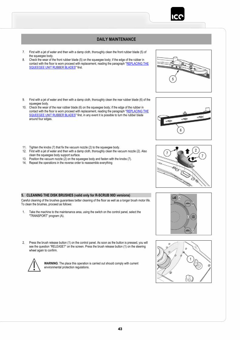
4343
DAILY MAINTENANCE
7. First with a jet of water and then with a damp cloth, thoroughly clean the front rubber blade (5) of the squeegee body.
8. Check the wear of the front rubber blade (5) on the squeegee body; if the edge of the rubber in contact with the floor is worn proceed with replacement, reading the paragraph "REPLACING THE SQUEEGEE UNIT RUBBER BLADES" first.
9. First with a jet of water and then with a damp cloth, thoroughly clean the rear rubber blade (6) of the squeegee body.
10. Check the wear of the rear rubber blade (6) on the squeegee body; if the edge of the rubber in contact with the floor is worn proceed with replacement, reading the paragraph "REPLACING THE SQUEEGEE UNIT RUBBER BLADES" first, in any event it is possible to turn the rubber blade around four edges.
11. Tighten the knobs (7) that fix the vacuum nozzle (2) to the squeegee body.12. First with a jet of water and then with a damp cloth, thoroughly clean the vacuum nozzle (2). Also
clean the squeegee body support surface. 13. Position the vacuum nozzle (2) on the squeegee body and fasten with the knobs (7). 14. Repeat the operations in the reverse order to reassemble everything
5. CLEANING THE DISK BRUSHES (valid only for R-SCRUB 90D versions) Careful cleaning of the brushes guarantees better cleaning of the floor as well as a longer brush motor life. To clean the brushes, proceed as follows:
1. Take the machine to the maintenance area, using the switch on the control panel, select the "TRANSPORT” program (A).
2. Press the brush release button (1) on the control panel. As soon as the button is pressed, you will see the question “RELEASE?” on the screen. Press the brush release button (1) on the steering wheel again to confirm.
WARNING: The place this operation is carried out should comply with current environmental protection regulations.
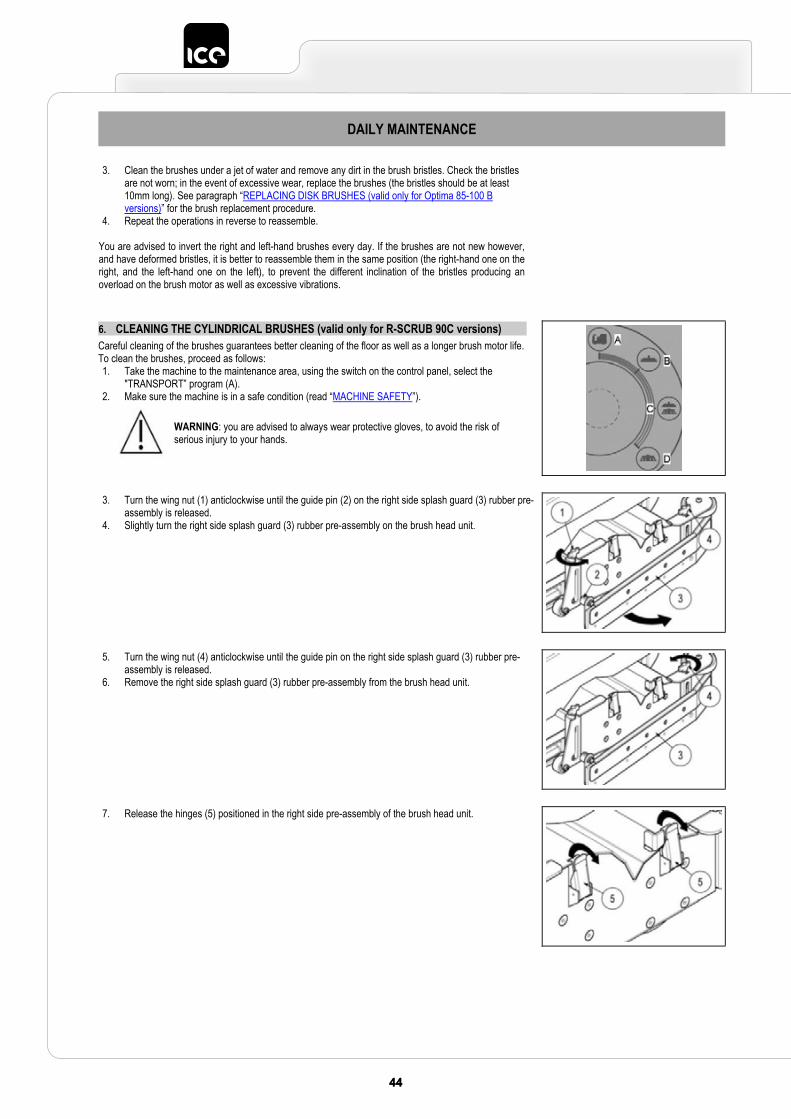
44 4544 45
DAILY MAINTENANCE
3. Clean the brushes under a jet of water and remove any dirt in the brush bristles. Check the bristles are not worn; in the event of excessive wear, replace the brushes (the bristles should be at least 10mm long). See paragraph “REPLACING DISK BRUSHES (valid only for Optima 85-100 B versions)” for the brush replacement procedure.
4. Repeat the operations in reverse to reassemble.
You are advised to invert the right and left-hand brushes every day. If the brushes are not new however, and have deformed bristles, it is better to reassemble them in the same position (the right-hand one on the right, and the left-hand one on the left), to prevent the different inclination of the bristles producing an overload on the brush motor as well as excessive vibrations.
6. CLEANING THE CYLINDRICAL BRUSHES (valid only for R-SCRUB 90C versions)Careful cleaning of the brushes guarantees better cleaning of the floor as well as a longer brush motor life. To clean the brushes, proceed as follows: 1. Take the machine to the maintenance area, using the switch on the control panel, select the
"TRANSPORT” program (A). 2. Make sure the machine is in a safe condition (read “MACHINE SAFETY”).
WARNING: you are advised to always wear protective gloves, to avoid the risk of serious injury to your hands.
3. Turn the wing nut (1) anticlockwise until the guide pin (2) on the right side splash guard (3) rubber pre-assembly is released.
4. Slightly turn the right side splash guard (3) rubber pre-assembly on the brush head unit.
5. Turn the wing nut (4) anticlockwise until the guide pin on the right side splash guard (3) rubber pre-assembly is released.
6. Remove the right side splash guard (3) rubber pre-assembly from the brush head unit.
7. Release the hinges (5) positioned in the right side pre-assembly of the brush head unit.
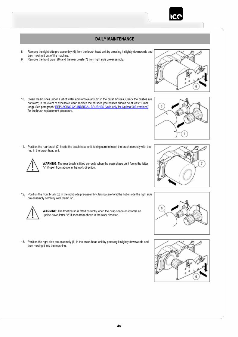
4545
DAILY MAINTENANCE
8. Remove the right side pre-assembly (6) from the brush head unit by pressing it slightly downwards and then moving it out of the machine.
9. Remove the front brush (8) and the rear brush (7) from right side pre-assembly.
10. Clean the brushes under a jet of water and remove any dirt in the brush bristles. Check the bristles are not worn; in the event of excessive wear, replace the brushes (the bristles should be at least 10mm long). See paragraph “REPLACING CYLINDRICAL BRUSHES (valid only for Optima 90B versions)”for the brush replacement procedure.
11. Position the rear brush (7) inside the brush head unit, taking care to insert the brush correctly with the hub in the brush head unit.
WARNING: The rear brush is fitted correctly when the cusp shape on it forms the letter “V” if seen from above in the work direction.
12. Position the front brush (8) in the right side pre-assembly, taking care to fit the hub inside the right side pre-assembly correctly with the brush.
WARNING: The front brush is fitted correctly when the cusp shape on it forms an upside-down letter “V” if seen from above in the work direction.
13. Position the right side pre-assembly (6) in the brush head unit by pressing it slightly downwards and then moving it into the machine.
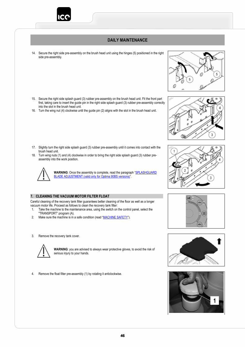
46 4746 47
DAILY MAINTENANCE
14. Secure the right side pre-assembly on the brush head unit using the hinges (5) positioned in the right side pre-assembly.
15. Secure the right side splash guard (3) rubber pre-assembly on the brush head unit. Fit the front part first, taking care to insert the guide pin in the right side splash guard (3) rubber pre-assembly correctly into the slot in the brush head unit.
16. Turn the wing nut (4) clockwise until the guide pin (2) aligns with the slot in the brush head unit.
17. Slightly turn the right side splash guard (3) rubber pre-assembly until it comes into contact with the brush head unit.
18. Turn wing nuts (1) and (4) clockwise in order to bring the right side splash guard (3) rubber pre-assembly into the work position.
WARNING: Once the assembly is complete, read the paragraph “SPLASHGUARDBLADE ADJUSTMENT (valid only for Optima 90BS versions)”.
7. CLEANING THE VACUUM MOTOR FILTER FLOAT Careful cleaning of the recovery tank filter guarantees better cleaning of the floor as well as a longer vacuum motor life. Proceed as follows to clean the recovery tank filter: 1. Take the machine to the maintenance area, using the switch on the control panel, select the
"TRANSPORT” program (A). 2. Make sure the machine is in a safe condition (read “MACHINE SAFETY”).
3. Remove the recovery tank cover.
WARNING: you are advised to always wear protective gloves, to avoid the risk of serious injury to your hands.
4. Remove the float filter pre-assembly (1) by rotating it anticlockwise.
1
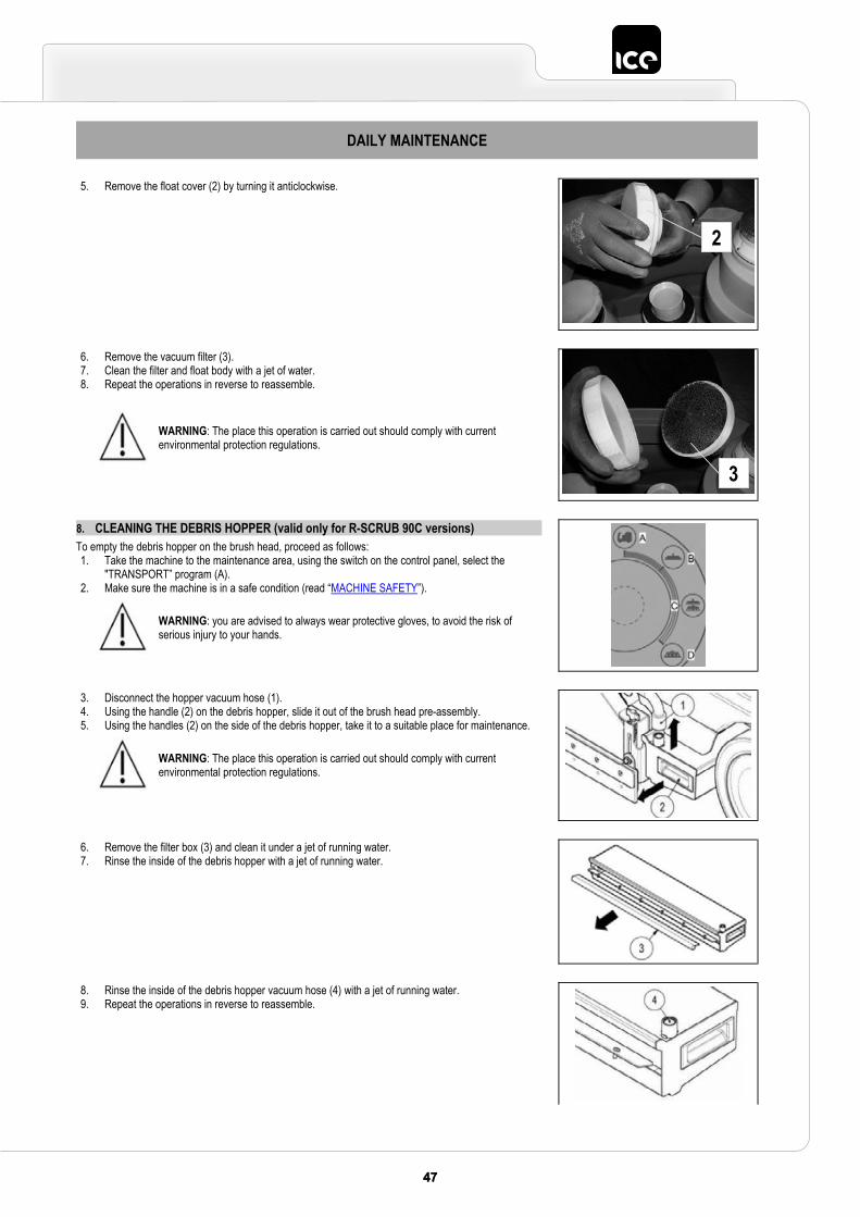
4747
DAILY MAINTENANCE
5. Remove the float cover (2) by turning it anticlockwise.
6. Remove the vacuum filter (3). 7. Clean the filter and float body with a jet of water. 8. Repeat the operations in reverse to reassemble.
WARNING: The place this operation is carried out should comply with current environmental protection regulations.
8. CLEANING THE DEBRIS HOPPER (valid only for R-SCRUB 90C versions)To empty the debris hopper on the brush head, proceed as follows: 1. Take the machine to the maintenance area, using the switch on the control panel, select the
"TRANSPORT” program (A). 2. Make sure the machine is in a safe condition (read “MACHINE SAFETY”).
WARNING: you are advised to always wear protective gloves, to avoid the risk of serious injury to your hands.
3. Disconnect the hopper vacuum hose (1). 4. Using the handle (2) on the debris hopper, slide it out of the brush head pre-assembly. 5. Using the handles (2) on the side of the debris hopper, take it to a suitable place for maintenance.
WARNING: The place this operation is carried out should comply with current environmental protection regulations.
6. Remove the filter box (3) and clean it under a jet of running water.7. Rinse the inside of the debris hopper with a jet of running water.
8. Rinse the inside of the debris hopper vacuum hose (4) with a jet of running water.9. Repeat the operations in reverse to reassemble.
2
3
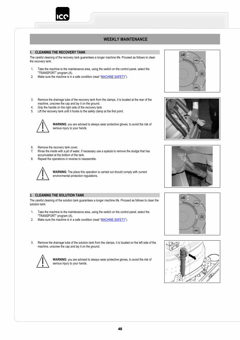
48 4948 49
WEEKLY MAINTENANCE
1. CLEANING THE RECOVERY TANKThe careful cleaning of the recovery tank guarantees a longer machine life. Proceed as follows to clean the recovery tank:
1. Take the machine to the maintenance area, using the switch on the control panel, select the "TRANSPORT” program (A).
2. Make sure the machine is in a safe condition (read “MACHINE SAFETY”).
3. Remove the drainage tube of the recovery tank from the clamps, it is located at the rear of the machine, unscrew the cap and lay it on the ground.
4. Grip the handle on the right side of the recovery tank. 5. Lift the recovery tank until it hooks to the safety clamp at the first point.
WARNING: you are advised to always wear protective gloves, to avoid the risk of serious injury to your hands.
6. Remove the recovery tank cover. 7. Rinse the inside with a jet of water, if necessary use a spatula to remove the sludge that has
accumulated at the bottom of the tank. 8. Repeat the operations in reverse to reassemble.
WARNING: The place this operation is carried out should comply with current environmental protection regulations.
2. CLEANING THE SOLUTION TANKThe careful cleaning of the solution tank guarantees a longer machine life. Proceed as follows to clean the solution tank:
1. Take the machine to the maintenance area, using the switch on the control panel, select the "TRANSPORT” program (A).
2. Make sure the machine is in a safe condition (read “MACHINE SAFETY”).
3. Remove the drainage tube of the solution tank from the clamps, it is located on the left side of the machine, unscrew the cap and lay it on the ground.
WARNING: you are advised to always wear protective gloves, to avoid the risk of serious injury to your hands.

4949
WEEKLY MAINTENANCE
4. Remove the filling cap (1) and the filter (2) on the left side of the machine. Clean the filter (2) with a jet of water and remove any dirt.
5. Clean the inside of the solution tank with a jet of water. 6. Repeat the operations in the reverse order to reassemble everything.
WARNING: The place this operation is carried out should comply with current environmental protection regulations.
3. CLEANING THE WATER SYSTEM FILTERThe careful cleaning of the water system guarantees a better cleaning of the floor as well as a longer life for all the components that make up the water system. To clean the water system filter, proceed as follows:
1. Take the machine to the maintenance area, using the switch on the control panel, select the "TRANSPORT” program (A).
2. Make sure the machine is in a safe condition (read “MACHINE SAFETY”).
3. Turn the faucet lever (1) in the upper part of the machine steering column upwards.
4. Unscrew the filter cap of the water system, filter is located on the front of the machine.5. Remove the filter cartridge and clean it under a jet of water, remove any dirt that might be attached. 6. Repeat the operations in reverse to reassemble.
WARNING: You are advised to always wear protective gloves, to avoid the risk of serious injury to your hands.WARNING: The place this operation is carried out should comply with current environmental protection regulations.
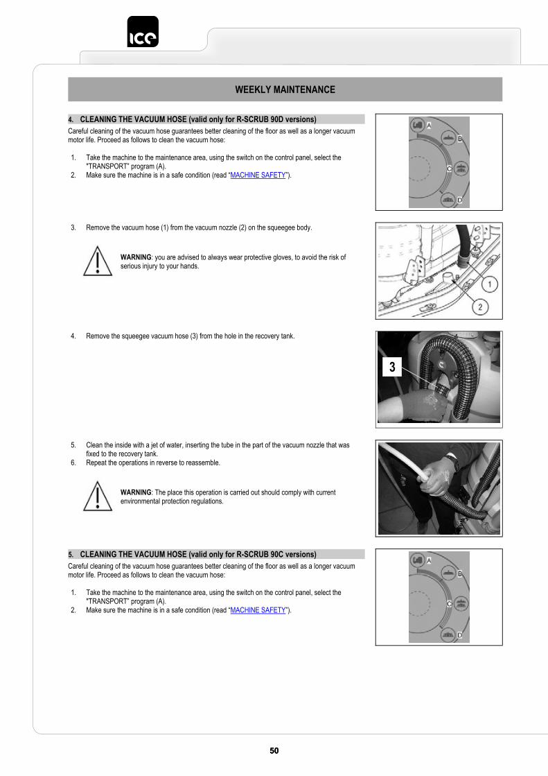
50 5150 51
WEEKLY MAINTENANCE
4. CLEANING THE VACUUM HOSE (valid only for R-SCRUB 90D versions)Careful cleaning of the vacuum hose guarantees better cleaning of the floor as well as a longer vacuum motor life. Proceed as follows to clean the vacuum hose:
1. Take the machine to the maintenance area, using the switch on the control panel, select the "TRANSPORT” program (A).
2. Make sure the machine is in a safe condition (read “MACHINE SAFETY”).
3. Remove the vacuum hose (1) from the vacuum nozzle (2) on the squeegee body.
WARNING: you are advised to always wear protective gloves, to avoid the risk of serious injury to your hands.
4. Remove the squeegee vacuum hose (3) from the hole in the recovery tank.
5. Clean the inside with a jet of water, inserting the tube in the part of the vacuum nozzle that was fixed to the recovery tank.
6. Repeat the operations in reverse to reassemble.
WARNING: The place this operation is carried out should comply with current environmental protection regulations.
5. CLEANING THE VACUUM HOSE (valid only for R-SCRUB 90C versions)Careful cleaning of the vacuum hose guarantees better cleaning of the floor as well as a longer vacuum motor life. Proceed as follows to clean the vacuum hose:
1. Take the machine to the maintenance area, using the switch on the control panel, select the "TRANSPORT” program (A).
2. Make sure the machine is in a safe condition (read “MACHINE SAFETY”).
3
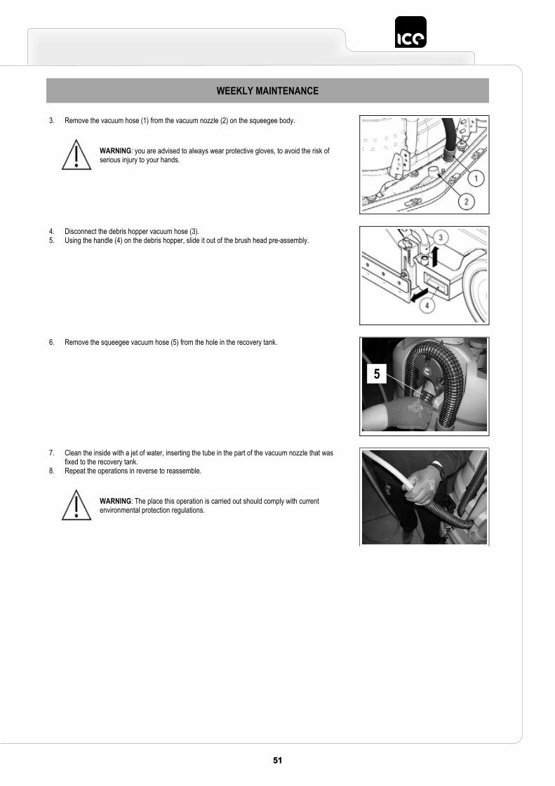
5151
WEEKLY MAINTENANCE
3. Remove the vacuum hose (1) from the vacuum nozzle (2) on the squeegee body.
WARNING: you are advised to always wear protective gloves, to avoid the risk of serious injury to your hands.
4. Disconnect the debris hopper vacuum hose (3). 5. Using the handle (4) on the debris hopper, slide it out of the brush head pre-assembly.
6. Remove the squeegee vacuum hose (5) from the hole in the recovery tank.
7. Clean the inside with a jet of water, inserting the tube in the part of the vacuum nozzle that was fixed to the recovery tank.
8. Repeat the operations in reverse to reassemble.
WARNING: The place this operation is carried out should comply with current environmental protection regulations.
5
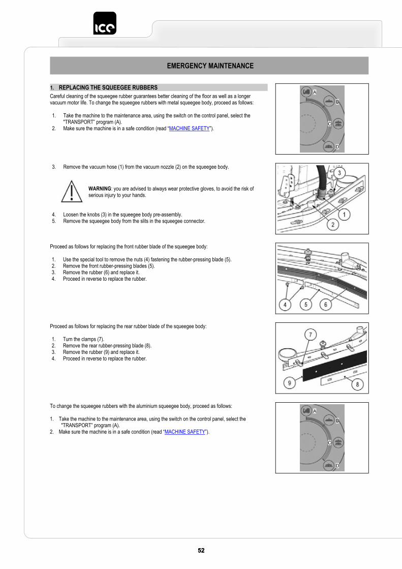
52 5352 53
EMERGENCY MAINTENANCE
1. REPLACING THE SQUEEGEE RUBBERSCareful cleaning of the squeegee rubber guarantees better cleaning of the floor as well as a longer vacuum motor life. To change the squeegee rubbers with metal squeegee body, proceed as follows:
1. Take the machine to the maintenance area, using the switch on the control panel, select the "TRANSPORT” program (A).
2. Make sure the machine is in a safe condition (read “MACHINE SAFETY”).
3. Remove the vacuum hose (1) from the vacuum nozzle (2) on the squeegee body.
4. Loosen the knobs (3) in the squeegee body pre-assembly. 5. Remove the squeegee body from the slits in the squeegee connector.
WARNING: you are advised to always wear protective gloves, to avoid the risk of serious injury to your hands.
Proceed as follows for replacing the front rubber blade of the squeegee body:
1. Use the special tool to remove the nuts (4) fastening the rubber-pressing blade (5). 2. Remove the front rubber-pressing blades (5). 3. Remove the rubber (6) and replace it. 4. Proceed in reverse to replace the rubber.
Proceed as follows for replacing the rear rubber blade of the squeegee body:
1. Turn the clamps (7). 2. Remove the rear rubber-pressing blade (8). 3. Remove the rubber (9) and replace it. 4. Proceed in reverse to replace the rubber.
To change the squeegee rubbers with the aluminium squeegee body, proceed as follows:
1. Take the machine to the maintenance area, using the switch on the control panel, select the "TRANSPORT” program (A).
2. Make sure the machine is in a safe condition (read “MACHINE SAFETY”).
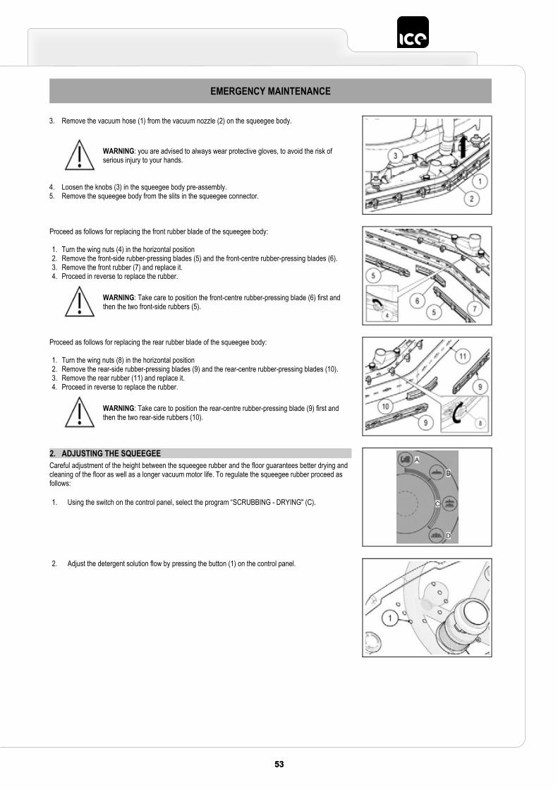
5353
EMERGENCY MAINTENANCE
3. Remove the vacuum hose (1) from the vacuum nozzle (2) on the squeegee body.
4. Loosen the knobs (3) in the squeegee body pre-assembly. 5. Remove the squeegee body from the slits in the squeegee connector.
WARNING: you are advised to always wear protective gloves, to avoid the risk of serious injury to your hands.
Proceed as follows for replacing the front rubber blade of the squeegee body:
1. Turn the wing nuts (4) in the horizontal position 2. Remove the front-side rubber-pressing blades (5) and the front-centre rubber-pressing blades (6). 3. Remove the front rubber (7) and replace it. 4. Proceed in reverse to replace the rubber.
WARNING: Take care to position the front-centre rubber-pressing blade (6) first and then the two front-side rubbers (5).
Proceed as follows for replacing the rear rubber blade of the squeegee body:
1. Turn the wing nuts (8) in the horizontal position 2. Remove the rear-side rubber-pressing blades (9) and the rear-centre rubber-pressing blades (10). 3. Remove the rear rubber (11) and replace it. 4. Proceed in reverse to replace the rubber.
WARNING: Take care to position the rear-centre rubber-pressing blade (9) first and then the two rear-side rubbers (10).
2. ADJUSTING THE SQUEEGEE Careful adjustment of the height between the squeegee rubber and the floor guarantees better drying and cleaning of the floor as well as a longer vacuum motor life. To regulate the squeegee rubber proceed as follows:
1. Using the switch on the control panel, select the program “SCRUBBING - DRYING" (C).
2. Adjust the detergent solution flow by pressing the button (1) on the control panel.
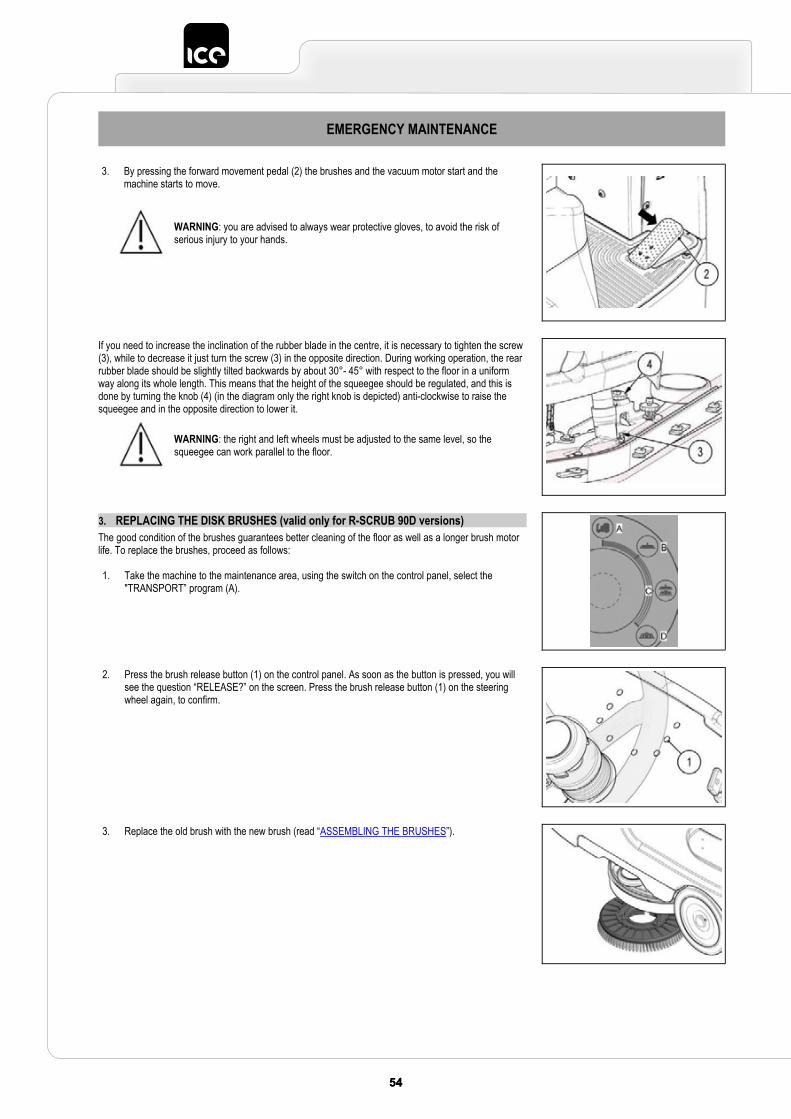
54 5554 55
EMERGENCY MAINTENANCE
3. By pressing the forward movement pedal (2) the brushes and the vacuum motor start and the machine starts to move.
WARNING: you are advised to always wear protective gloves, to avoid the risk of serious injury to your hands.
If you need to increase the inclination of the rubber blade in the centre, it is necessary to tighten the screw (3), while to decrease it just turn the screw (3) in the opposite direction. During working operation, the rear rubber blade should be slightly tilted backwards by about 30°- 45° with respect to the floor in a uniform way along its whole length. This means that the height of the squeegee should be regulated, and this is done by turning the knob (4) (in the diagram only the right knob is depicted) anti-clockwise to raise the squeegee and in the opposite direction to lower it.
WARNING: the right and left wheels must be adjusted to the same level, so the squeegee can work parallel to the floor.
3. REPLACING THE DISK BRUSHES (valid only for R-SCRUB 90D versions)The good condition of the brushes guarantees better cleaning of the floor as well as a longer brush motor life. To replace the brushes, proceed as follows:
1. Take the machine to the maintenance area, using the switch on the control panel, select the "TRANSPORT” program (A).
2. Press the brush release button (1) on the control panel. As soon as the button is pressed, you will see the question “RELEASE?” on the screen. Press the brush release button (1) on the steering wheel again, to confirm.
3. Replace the old brush with the new brush (read “ASSEMBLING THE BRUSHES”).
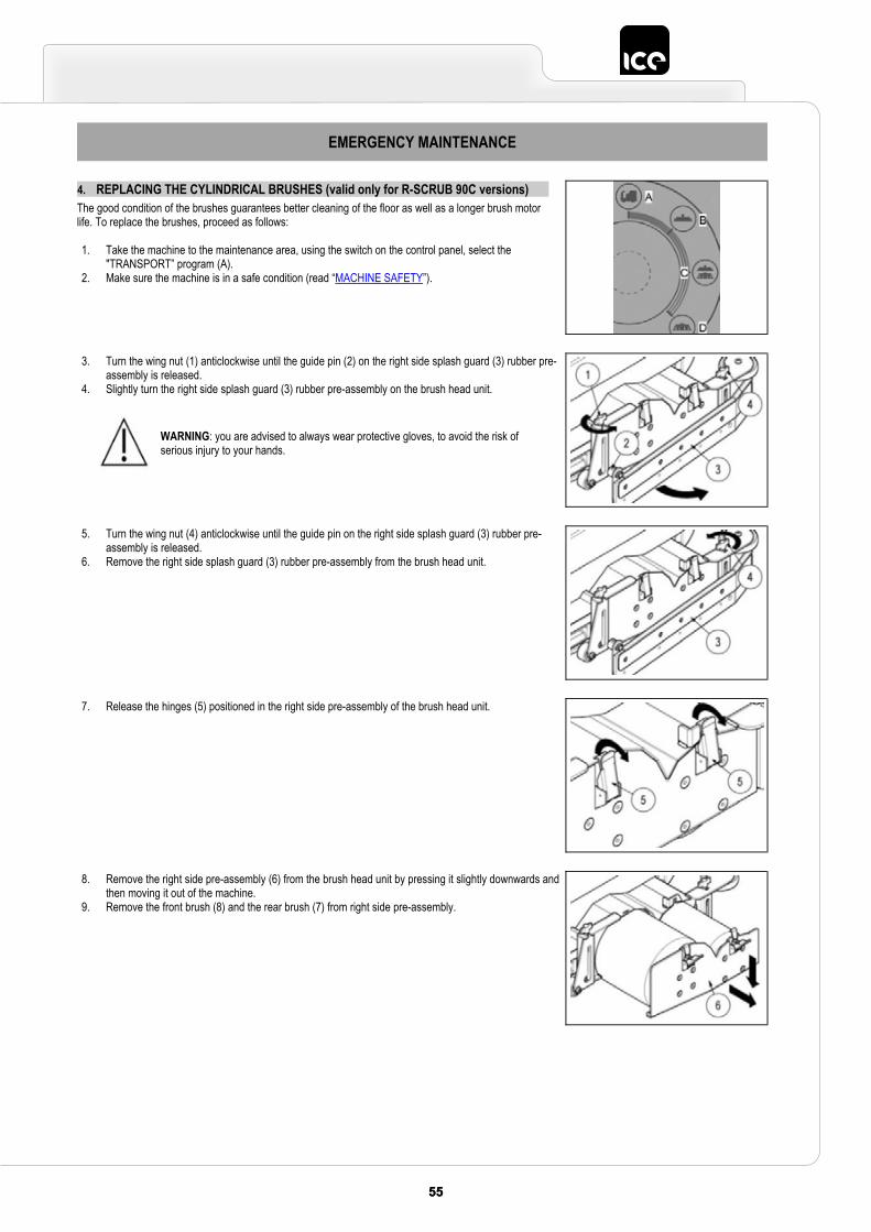
5555
EMERGENCY MAINTENANCE
4. REPLACING THE CYLINDRICAL BRUSHES (valid only for R-SCRUB 90C versions)The good condition of the brushes guarantees better cleaning of the floor as well as a longer brush motor life. To replace the brushes, proceed as follows:
1. Take the machine to the maintenance area, using the switch on the control panel, select the "TRANSPORT” program (A).
2. Make sure the machine is in a safe condition (read “MACHINE SAFETY”).
3. Turn the wing nut (1) anticlockwise until the guide pin (2) on the right side splash guard (3) rubber pre-assembly is released.
4. Slightly turn the right side splash guard (3) rubber pre-assembly on the brush head unit.
WARNING: you are advised to always wear protective gloves, to avoid the risk of serious injury to your hands.
5. Turn the wing nut (4) anticlockwise until the guide pin on the right side splash guard (3) rubber pre-assembly is released.
6. Remove the right side splash guard (3) rubber pre-assembly from the brush head unit.
7. Release the hinges (5) positioned in the right side pre-assembly of the brush head unit.
8. Remove the right side pre-assembly (6) from the brush head unit by pressing it slightly downwards and then moving it out of the machine.
9. Remove the front brush (8) and the rear brush (7) from right side pre-assembly.
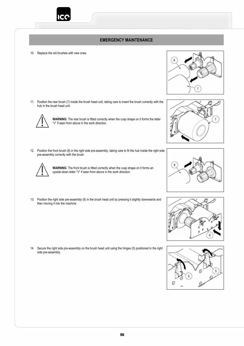
56 5756 57
EMERGENCY MAINTENANCE
10. Replace the old brushes with new ones.
11. Position the rear brush (7) inside the brush head unit, taking care to insert the brush correctly with the hub in the brush head unit.
WARNING: The rear brush is fitted correctly when the cusp shape on it forms the letter “V” if seen from above in the work direction.
12. Position the front brush (8) in the right side pre-assembly, taking care to fit the hub inside the right side pre-assembly correctly with the brush.
WARNING: The front brush is fitted correctly when the cusp shape on it forms an upside-down letter “V” if seen from above in the work direction.
13. Position the right side pre-assembly (6) in the brush head unit by pressing it slightly downwards and then moving it into the machine.
14. Secure the right side pre-assembly on the brush head unit using the hinges (5) positioned in the right side pre-assembly.
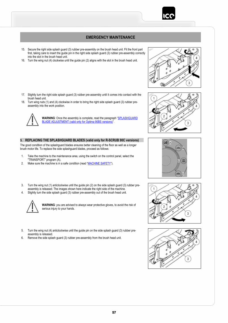
5757
EMERGENCY MAINTENANCE
15. Secure the right side splash guard (3) rubber pre-assembly on the brush head unit. Fit the front part first, taking care to insert the guide pin in the right side splash guard (3) rubber pre-assembly correctly into the slot in the brush head unit.
16. Turn the wing nut (4) clockwise until the guide pin (2) aligns with the slot in the brush head unit.
17. Slightly turn the right side splash guard (3) rubber pre-assembly until it comes into contact with the brush head unit.
18. Turn wing nuts (1) and (4) clockwise in order to bring the right side splash guard (3) rubber pre-assembly into the work position.
WARNING: Once the assembly is complete, read the paragraph “SPLASHGUARDBLADE ADJUSTMENT (valid only for Optima 90BS versions)”.
5. REPLACING THE SPLASHGUARD BLADES (valid only for R-SCRUB 90C versions)The good condition of the splashguard blades ensures better cleaning of the floor as well as a longer brush motor life. To replace the side splashguard blades, proceed as follows:
1. Take the machine to the maintenance area, using the switch on the control panel, select the "TRANSPORT” program (A).
2. Make sure the machine is in a safe condition (read “MACHINE SAFETY”).
3. Turn the wing nut (1) anticlockwise until the guide pin (2) on the side splash guard (3) rubber pre-assembly is released. The images shown here indicate the right side of the machine.
4. Slightly turn the side splash guard (3) rubber pre-assembly out of the brush head unit.
WARNING: you are advised to always wear protective gloves, to avoid the risk of serious injury to your hands.
5. Turn the wing nut (4) anticlockwise until the guide pin on the side splash guard (3) rubber pre-assembly is released.
6. Remove the side splash guard (3) rubber pre-assembly from the brush head unit.
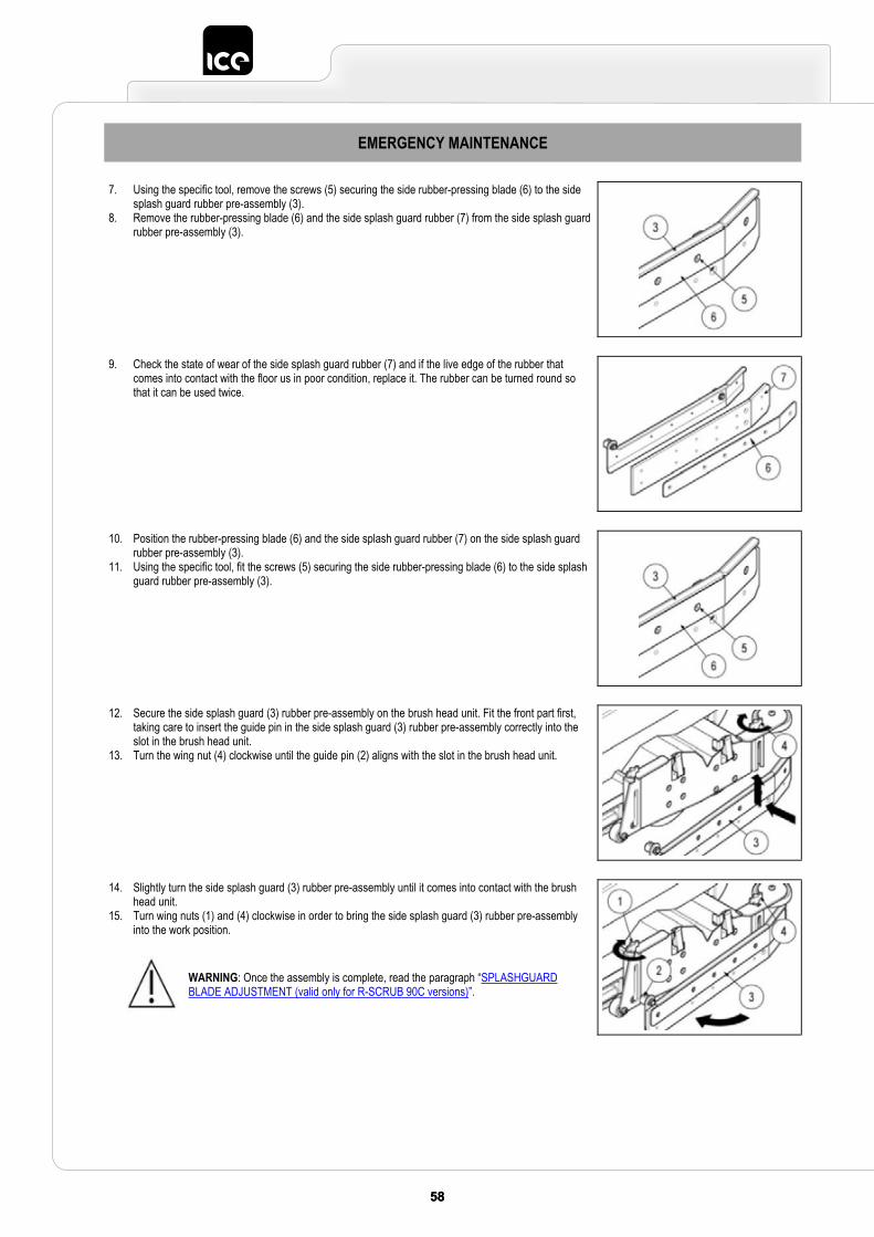
58 5958 59
EMERGENCY MAINTENANCE
7. Using the specific tool, remove the screws (5) securing the side rubber-pressing blade (6) to the side splash guard rubber pre-assembly (3).
8. Remove the rubber-pressing blade (6) and the side splash guard rubber (7) from the side splash guard rubber pre-assembly (3).
9. Check the state of wear of the side splash guard rubber (7) and if the live edge of the rubber that comes into contact with the floor us in poor condition, replace it. The rubber can be turned round so that it can be used twice.
10. Position the rubber-pressing blade (6) and the side splash guard rubber (7) on the side splash guard rubber pre-assembly (3).
11. Using the specific tool, fit the screws (5) securing the side rubber-pressing blade (6) to the side splash guard rubber pre-assembly (3).
12. Secure the side splash guard (3) rubber pre-assembly on the brush head unit. Fit the front part first, taking care to insert the guide pin in the side splash guard (3) rubber pre-assembly correctly into the slot in the brush head unit.
13. Turn the wing nut (4) clockwise until the guide pin (2) aligns with the slot in the brush head unit.
14. Slightly turn the side splash guard (3) rubber pre-assembly until it comes into contact with the brush head unit.
15. Turn wing nuts (1) and (4) clockwise in order to bring the side splash guard (3) rubber pre-assembly into the work position.
WARNING: Once the assembly is complete, read the paragraph “SPLASHGUARDBLADE ADJUSTMENT (valid only for R-SCRUB 90C versions)”.
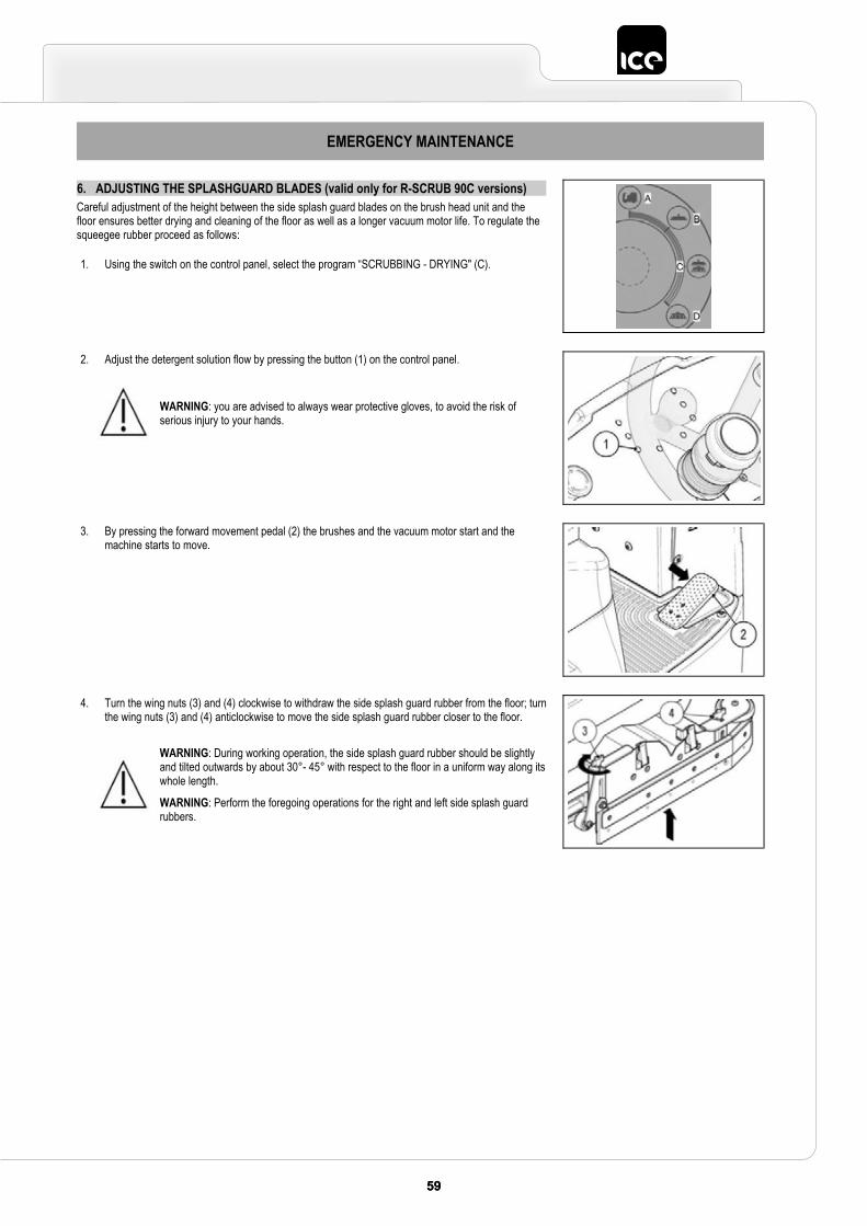
5959
EMERGENCY MAINTENANCE
6. ADJUSTING THE SPLASHGUARD BLADES (valid only for R-SCRUB 90C versions) Careful adjustment of the height between the side splash guard blades on the brush head unit and the floor ensures better drying and cleaning of the floor as well as a longer vacuum motor life. To regulate the squeegee rubber proceed as follows:
1. Using the switch on the control panel, select the program “SCRUBBING - DRYING" (C).
2. Adjust the detergent solution flow by pressing the button (1) on the control panel.
WARNING: you are advised to always wear protective gloves, to avoid the risk of serious injury to your hands.
3. By pressing the forward movement pedal (2) the brushes and the vacuum motor start and the machine starts to move.
4. Turn the wing nuts (3) and (4) clockwise to withdraw the side splash guard rubber from the floor; turn the wing nuts (3) and (4) anticlockwise to move the side splash guard rubber closer to the floor.
WARNING: During working operation, the side splash guard rubber should be slightly and tilted outwards by about 30°- 45° with respect to the floor in a uniform way along its whole length.
WARNING: Perform the foregoing operations for the right and left side splash guard rubbers.
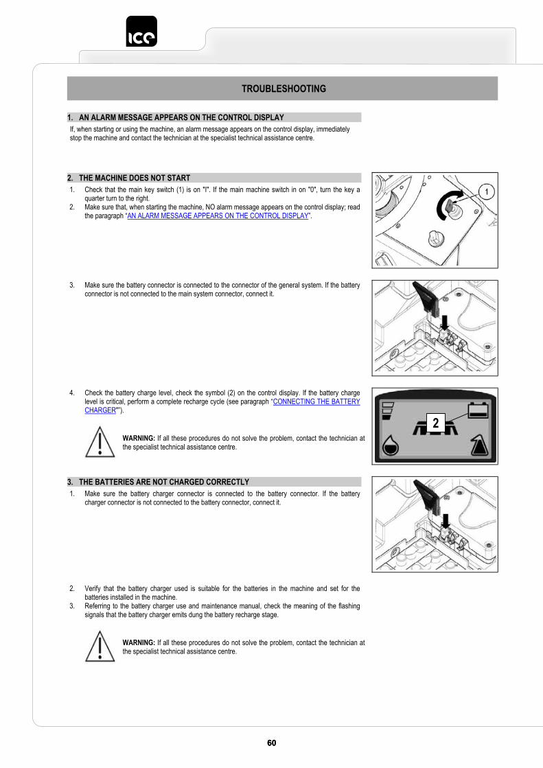
60 6160 61
TROUBLESHOOTING
1. AN ALARM MESSAGE APPEARS ON THE CONTROL DISPLAY If, when starting or using the machine, an alarm message appears on the control display, immediately stop the machine and contact the technician at the specialist technical assistance centre.
2. THE MACHINE DOES NOT START 1. Check that the main key switch (1) is on "I". If the main machine switch in on "0", turn the key a
quarter turn to the right. 2. Make sure that, when starting the machine, NO alarm message appears on the control display; read
the paragraph “AN ALARM MESSAGE APPEARS ON THE CONTROL DISPLAY”.
3. Make sure the battery connector is connected to the connector of the general system. If the battery connector is not connected to the main system connector, connect it.
4. Check the battery charge level, check the symbol (2) on the control display. If the battery charge level is critical, perform a complete recharge cycle (see paragraph “CONNECTING THE BATTERY CHARGER"”).
WARNING: If all these procedures do not solve the problem, contact the technician at the specialist technical assistance centre.
3. THE BATTERIES ARE NOT CHARGED CORRECTLY 1. Make sure the battery charger connector is connected to the battery connector. If the battery
charger connector is not connected to the battery connector, connect it.
2. Verify that the battery charger used is suitable for the batteries in the machine and set for the batteries installed in the machine.
3. Referring to the battery charger use and maintenance manual, check the meaning of the flashing signals that the battery charger emits dung the battery recharge stage.
WARNING: If all these procedures do not solve the problem, contact the technician at the specialist technical assistance centre.
2
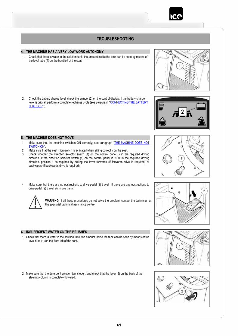
6161
TROUBLESHOOTING
4. THE MACHINE HAS A VERY LOW WORK AUTONOMY 1. Check that there is water in the solution tank, the amount inside the tank can be seen by means of
the level tube (1) on the front left of the seat.
2. Check the battery charge level, check the symbol (2) on the control display. If the battery charge level is critical, perform a complete recharge cycle (see paragraph “CONNECTING THE BATTERY CHARGER"”).
5. THE MACHINE DOES NOT MOVE 1. Make sure that the machine switches ON correctly; see paragraph “THE MACHINE DOES NOT
SWITCH ON”. 2. Make sure that the seat microswitch is activated when sitting correctly on the seat. 3. Check whether the direction selector switch (1) on the control panel is in the required driving
direction. If the direction selector switch (1) on the control panel is NOT in the required driving direction, position it as required by pulling the lever forwards (if forwards drive is required) or backwards (if backwards drive is required).
4. Make sure that there are no obstructions to drive pedal (2) travel. If there are any obstructions to drive pedal (2) travel, eliminate them.
WARNING: If all these procedures do not solve the problem, contact the technician at the specialist technical assistance centre.
6. INSUFFICIENT WATER ON THE BRUSHES 1. Check that there is water in the solution tank, the amount inside the tank can be seen by means of the
level tube (1) on the front left of the seat.
2. Make sure that the detergent solution tap is open, and check that the lever (2) on the back of the steering column is completely lowered.
2
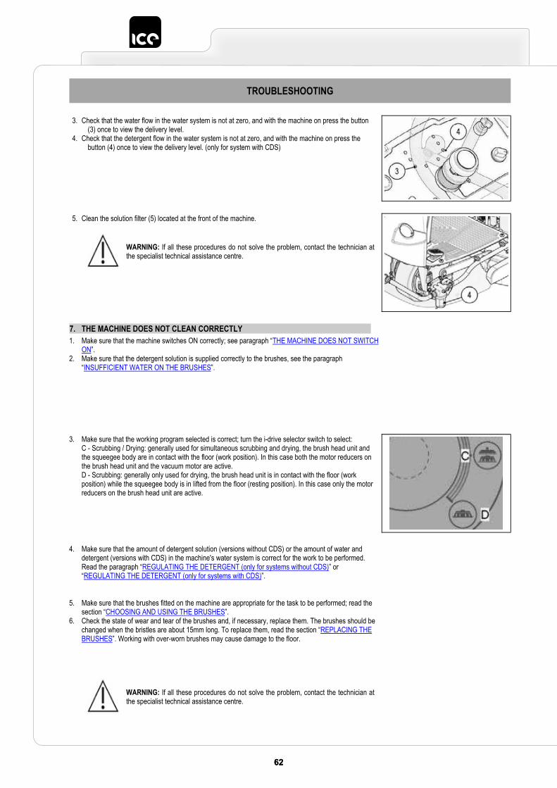
62 6362 63
TROUBLESHOOTING
3. Check that the water flow in the water system is not at zero, and with the machine on press the button (3) once to view the delivery level.
4. Check that the detergent flow in the water system is not at zero, and with the machine on press the button (4) once to view the delivery level. (only for system with CDS)
5. Clean the solution filter (5) located at the front of the machine.
WARNING: If all these procedures do not solve the problem, contact the technician at the specialist technical assistance centre.
7. THE MACHINE DOES NOT CLEAN CORRECTLY 1. Make sure that the machine switches ON correctly; see paragraph “THE MACHINE DOES NOT SWITCH
ON”. 2. Make sure that the detergent solution is supplied correctly to the brushes, see the paragraph
“INSUFFICIENT WATER ON THE BRUSHES”.
3. Make sure that the working program selected is correct; turn the i-drive selector switch to select:C - Scrubbing / Drying: generally used for simultaneous scrubbing and drying, the brush head unit and the squeegee body are in contact with the floor (work position). In this case both the motor reducers on the brush head unit and the vacuum motor are active. D - Scrubbing: generally only used for drying, the brush head unit is in contact with the floor (work position) while the squeegee body is in lifted from the floor (resting position). In this case only the motor reducers on the brush head unit are active.
4. Make sure that the amount of detergent solution (versions without CDS) or the amount of water and detergent (versions with CDS) in the machine's water system is correct for the work to be performed. Read the paragraph “REGULATING THE DETERGENT (only for systems without CDS)” or “REGULATING THE DETERGENT (only for systems with CDS)”.
5. Make sure that the brushes fitted on the machine are appropriate for the task to be performed; read the section “CHOOSING AND USING THE BRUSHES”.
6. Check the state of wear and tear of the brushes and, if necessary, replace them. The brushes should be changed when the bristles are about 15mm long. To replace them, read the section “REPLACING THE BRUSHES”. Working with over-worn brushes may cause damage to the floor.
WARNING: If all these procedures do not solve the problem, contact the technician at the specialist technical assistance centre.
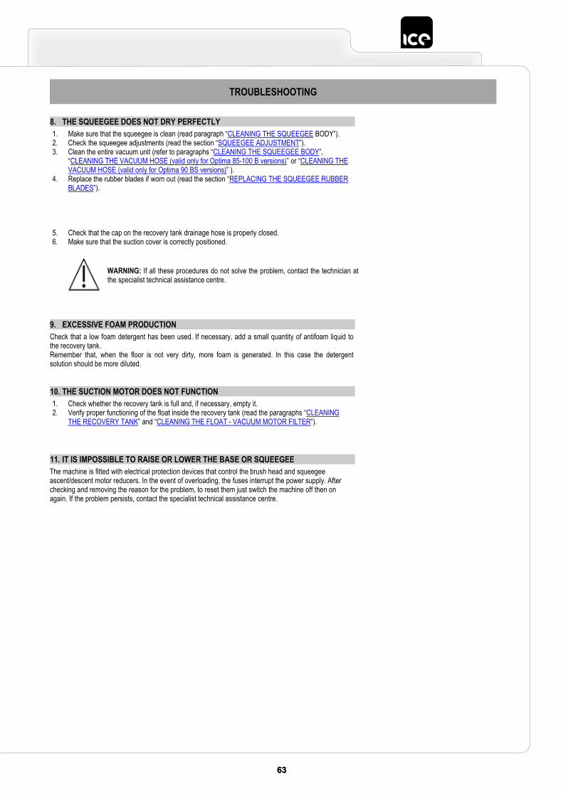
6363
TROUBLESHOOTING
8. THE SQUEEGEE DOES NOT DRY PERFECTLY 1. Make sure that the squeegee is clean (read paragraph “CLEANING THE SQUEEGEE BODY”). 2. Check the squeegee adjustments (read the section “SQUEEGEE ADJUSTMENT”). 3. Clean the entire vacuum unit (refer to paragraphs “CLEANING THE SQUEEGEE BODY”,
“CLEANING THE VACUUM HOSE (valid only for Optima 85-100 B versions)” or “CLEANING THE VACUUM HOSE (valid only for Optima 90 BS versions)” ).
4. Replace the rubber blades if worn out (read the section “REPLACING THE SQUEEGEE RUBBER BLADES”).
5. Check that the cap on the recovery tank drainage hose is properly closed.6. Make sure that the suction cover is correctly positioned.
WARNING: If all these procedures do not solve the problem, contact the technician at the specialist technical assistance centre.
9. EXCESSIVE FOAM PRODUCTION Check that a low foam detergent has been used. If necessary, add a small quantity of antifoam liquid to the recovery tank. Remember that, when the floor is not very dirty, more foam is generated. In this case the detergent solution should be more diluted.
10. THE SUCTION MOTOR DOES NOT FUNCTION 1. Check whether the recovery tank is full and, if necessary, empty it. 2. Verify proper functioning of the float inside the recovery tank (read the paragraphs “CLEANING
THE RECOVERY TANK” and “CLEANING THE FLOAT - VACUUM MOTOR FILTER”).
11. IT IS IMPOSSIBLE TO RAISE OR LOWER THE BASE OR SQUEEGEE The machine is fitted with electrical protection devices that control the brush head and squeegee ascent/descent motor reducers. In the event of overloading, the fuses interrupt the power supply. After checking and removing the reason for the problem, to reset them just switch the machine off then on again. If the problem persists, contact the specialist technical assistance centre.
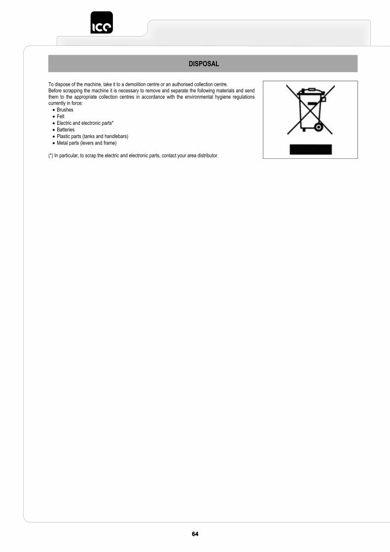
64 6564 65
DISPOSAL
To dispose of the machine, take it to a demolition centre or an authorised collection centre.Before scrapping the machine it is necessary to remove and separate the following materials and send them to the appropriate collection centres in accordance with the environmental hygiene regulations currently in force: Brushes Felt Electric and electronic parts* Batteries Plastic parts (tanks and handlebars) Metal parts (levers and frame)
(*) In particular, to scrap the electric and electronic parts, contact your area distributor.
6565
CHOOSING AND USING THE BRUSHES
POLYPROPYLENE BRUSH (PPL) Used on all types of floor, it has good resistance to wear and tear and hot water (no greater than 60°C). PPL is non-hygroscopic and therefore retains its characteristics even when working in wet conditions.
NYLON BRUSH Used on all types of floors. Excellent resistance to wear and tear, and hot water (even over 60°C). The nylon is hygroscopic and so tends to lose its characteristics over time when working in wet conditions.
ABRASIVE BRUSH The bristles of this type of brush are charged with highly aggressive abrasives. It is used to clean very dirty floors. To avoid floor damage, work only with the pressure strictly necessary.
THICKNESS OF THE BRISTLES Thicker bristles are more rigid and are therefore used on smooth floors or floors with small joints. On uneven floors or those with deep joints, it is advisable to use softer bristles which can enter the gaps more easily. Remember that when the bristles are worn and therefore too short, they will become rigid and are no longer able to penetrate and clean deep down, also because, like with over-large bristles, the brush tends to jump.
PAD HOLDER The pad holder is recommended for cleaning shiny surfaces. There are two types of pad holder: 1. The traditional pad holder is fitted with a series of anchor points that allow the abrasive floor pad to be held and dragged while working. 2. The CENTER LOCK type pad holder not only has anchor points, but also a snap-type central locking system in plastic that allows the abrasive floor
pad to be perfectly centred and held without any risk of it becoming detached. This type of holder is especially suitable for machines with several brushes, where the centring of the abrasive floor pads is difficult.
TABLE FOR CHOOSING THE BRUSHES
Machine No. of brushes.
Code Type of bristles
Bristles Brush Length Notes
R-SCRUB 90D 2
405562405563405564405565421819
PPLPPLPPL
ABRASIVE
0.3 0.6 0.9 1
430
BLUE BRUSH WHITE BRUSH BLACK BRUSH
PAD HOLDER + CENTER LOCK
R-SCRUB 90C
1 439098439099
PPLPPL
0,7 1 150 855 WHITE FRONT BRUSH
BLACK FRONT BRUSH
1404628404630404631
PPLPPL
ABRASIVE
0,7 11
210 862 WHITE REAR BRUSH BLACK REAR BRUSH
66 6666 66
The undersigned company:Industrial Cleaning Equipment Ltd.
Sauber House, Unit 3, Rushington Business ParkChapel Lane, Totton, Hampshire, SO40 9AH
Declares under its sole responsibility that the products
FLOOR SCRUBBING MACHINESmod. R-SCRUB 90D - R-SCRUB 90C
comply with the requirements of the following Directives:
• 2006/42/EC: Machinery Directive.• 2014/35/EC: Low Voltage Directive.• 2014/30/EC: Electromagnetic compatibility directive.
They also comply with the following standards:• EN 60335-1: Household and similar electrical appliances - Safety. Part 1: Generic standards.• EN 60335-2-72: Household and similar electrical appliances. Part 2: Specific standards for automatic machines for
floor treatment for commercial and industrial use.• EN 60335-2-29: Household and similar electrical appliances. Part 2: Special standards for battery chargers.• EN 12100-1: Safety of Machinery - Basic concepts, general principles for design - Part 1: Basic terminology and
methodology.• EN 12100-2: Safety of Machinery - Basic concepts, general principles for design - Part 2: Technical principles.• EN 61000-6-2: Electromagnetic compatibility (EMC) - Part 6-2: Generic standards – Immunity for industrial environments.• EN 61000-6-3: Electromagnetic compatibility (EMC) - Part 6-3: Generic standards — Standard emission for residential,
commercial and light-industrial environments.• EN 61000-3-2: Electromagnetic compatibility (EMC) - Part 3-2: Limits – Limits for harmonic current emissions
(Equipment with input current ≤ 16 A per phase).• EN 61000-3-3: Electromagnetic compatibility (EMC) - Part 3-3: Limits – Restriction of voltage variations and flicker in
low voltage power supply systems for devices with a rated current ≤ 16 A.• EN 55014-1: Electromagnetic compatibility - Regulations for household appliances, electrical devices and similar
equipment. Part 1: Emission - Regulation for product family.• EN 55014-2: Electromagnetic compatibility - Regulations for household appliances, electrical devices and similar
equipment. Part 2: Immunity - Regulation for product family.• EN 62233: Household and similar electrical appliances - Electromagnetic fields - Methods for evaluation and
measurement.
The person authorised to compile the technical file:
Mr. Mark BresnihanSauber House, Unit 3, Rushington Business ParkChapel Lane, Totton, Hampshire, SO40 9AH
Chapel Lane, 01/02/2017
Industrial Cleaning Equipment Ltd.Legal representative
Mark Bresnihan
EC DECLARATION OF CONFORMITY
Manufacturer:COMAC S.p.A.Via Maestri del Lavoro, n°13c.a.p. 37059 - S. Maria di Zevio (VR) - Verona - ItaliaTel. +39 045 8774222 - Fax. +39 045 8750303E-mail: [email protected]: www.comac.it
Mandatory:Industrial Cleaning Equipment Ltd.
Sauber House, Unit 3, Rushington Business ParkChapel Lane, Totton, Hampshire, SO40 9AH
Tel. 0800 389 3869 - Fax. 023 8042 8318E-mail: [email protected]
Web: www.ice-clean.com


Industrial Cleaning Equipment Ltd.Sauber House, Unit 3, Rushington Business Park - Chapel Lane, Totton, Hampshire, SO40 9AH
Service 0800 389 3869 - Facsmile 023 8042 8318 - Email [email protected]