?r=19710028059 2018-03-04t11:44:19+00:00z · pdf filement in aeronautical and space...
TRANSCRIPT

https://ntrs.nasa.gov/search.jsp?R=19710028059 2018-05-26T06:49:47+00:00Z

1. Report No. 2. Government Accession No. 3. Recipient's Catalog No.NASA CR-1734
4.TitleandSubtitle ADVANCED STRUCTURAL GEOMETRY
STUDIES PART I - POLYHEDRAL SUBDIVISION
CONCEPTS FOR STRUCTURAL APPLICATIONS
7. Author(s) Joseph D. Clinton
9. Performing Organization Name and Address
Southern Illinois University
Carbondale, Illinois
12. Sponsoring Agency Name and Address
National Aeronautics and Space Administration
Washington, D. C. 20546
5. Report Date
September 1971
6. Performing Organiza:tion Code
8. Performing Organization Report No.
10. Work Unit No.
11. Contract ,or Gran.J No.NGR-14-O0_-O02
13. Type of Report and Period Covered
Contractor Report
14. Sponsoring Agency Code
15. Supplementary Notes
16. Abstract
A study leading to the formulation of computer-oriented
mathematical models pertaining to methods of subdividing
polyhedra into triangulated spherical space frames. The models
perform the truncations and transformations of the polyhedral
forms and calculate the geometrical properties of the generated
space frames (spheres, hemispheres, and domes).
17. Key Words (Selected by Author(s))
Geodesic Domes
Structural Domes
Polyhedral Subdivision
Structural Spheres, Spaceframes
18. Distribution Statement
Unclassified - unlimited
19. Security Classif. (of this report)
Unclassified
20. Security Classif. (of this page)
Unclassified
21. No. of Pages 22. Price
iii $3.00
For sale by the National Technical Information Service, Springfield, Virginia 22151
FOREWORD
This final report was prepared by the School of
Technology at Southern Illinois University, Carbondale,
Illinois under NASA Contract NGR 14-008-002. The contract
was administered by the NASA Office of Advanced Research
and Technology.
Personnel participating in the research included:
Julian H. Lauchner, principal investigator; Joseph D.
Clinton, prime investigator; R. Buckminster Fuller,
research consultant; Wayne Boo%h, Ann C. Garrison,
Michael Keeling, Allen Kilty, Mark B. Mabee, and
Richard M. Moeller, computer programmers.
iii
PART I
POLYHEDRAL SUBDIVISION CONCEPTS
FOB STRUCTURAL APPLICATIONS
i.i Introduction ............. 1-2
1.2 Polyhedron .............. 1-7
1.3 Structural Orientation ........ I-ll
1.4 Definitions ............. 1-16
1.5 Method of Subdivision ........ 1-18
1.6 Method 1 ............... 1-36
1.7 Methods 2 & 3 ............ 1-76
1.8 Methods 4 & 5 ............ 1-145
1.9 Methods 6 & 7 ............ 1-185
v
Computer Software Managementand Information Center
The documentation and program developed for theadvanced structural geometry studies will bemade available to the public through COSMIC.
COSMIC (Computer Software Management and InformationCenter) was established early in 1966 at theUniversity of Georgia to collect and disseminateto the public computer software developed by govern-
ment agencies. Since that time thousands of computerprograms in all areas of aerospace engineering, mathe-matics, business, and industry have been distributed
to requesters throughout the United States.
The Technology Utilization Division of NASA,designed to enlarge the return on the public invest-ment in aeronautical and space activities, was the
first government agency to participate formally._In July 1968 the Atomic Energy Commission and inNovember 1968 the Department of Defense joined inthe COSMIC endeavor. With the addition of these two
major agencies, the original concept of making tax-paid developments available to the public was expandedto make COSMIC a transfer point between and within
government agencies as well.
Requests for documentation or information concerningthis program should be directed to:
COSMICThe University of GeorgiaBarrow HallAthens, Georgia 30601
REF: HQN-10677
I-i
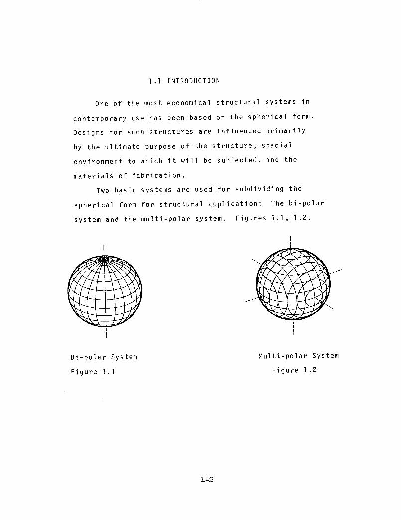
I.I INTRODUCTION
One of the most economical structural systems in
cohtemporary use has been based on the spherical form.
Designs for such structures are influenced primarily
by the ultimate purpose of the structure, spacial
environment to which it will be subjected, and the
materials of fabrication.
Two basic systems are used for subdividing the
spherical form for structural application: The bi-polar
system and the multi-polar system. Figures I.I, 1.2.
I
!
I
i I
Bi-polar System
Figure I.I
Multi-polar System
Figure 1.2
Z-2

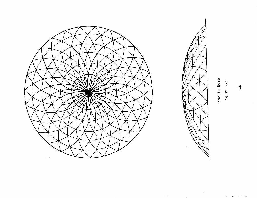
The bi-polar system is related to the familiar
latitude-longitude approach to subdividing a sphere. Two
commonexamples of this system are the ribbed dome (Figure-
1.3) and the lamella dome (Figure 1.4).
Ribbed Dome
Figure 1.3
T- 3
\
\
\\
0C:_ w--
I:::: • r-I_1_
,,_1
!I-4

The multi-polar system is related to the spherical form
of polyhedra. Perhaps the most familiar example of this
system is the geodesic dome discoverd by R. Buckminster
Fuller. Figure 1.5
Geodesic Dome
Figure 1.5
A typical design problem with the bi-polar system is
with the geometrical relationships of the frame configura-
tion. Computer aids in the design investigation may be
initiated to handle the great number of variables in the
determination of lengths, frequency of members, total
number of joints, number of members intersectinq at a
single joint, relationship of members to each other, etc.
This portion of the report will concern itself with
a mathematical and computer model for determining the
geometrical properties of the multi-polar system for sub-
dividing a spherical form for structural applications. The
model has been limited to the three polyhedral forms made
up completely of regular triangles: the tetrachedron,
octahedron and icosahedron.
I-G
1.2 POLYHEDRON
Hoppe, in 1882, coined the word polytope: a geo-
metrical figure bounded by portions of lines, planes, or
hyperplanes; in two dimensions it is a polygon; in three a
polyhedron.* However, the Greeks studied polyhedra over
two thousand years ago with the findings of Euclid. Others
such as Klein, Schi_fli and Coxeter, introduced much to the
study and concepts of the polytope. In this section of
the report: the structural configurations discussed are
based on several of the polyhedral forms, specifically the
regular (Platonic) polyhedra; the Tetrahedron, Octahedron,
and Icosahedron.
In Euclid's writings, The Elements, explanation and
definition is give to the f_ve regular solids as known
to the ancient world. The convex polyhedra are said to
be regular if each have regular and egual faces, if they
are congruent, and if they are of regular polyhedral angles.
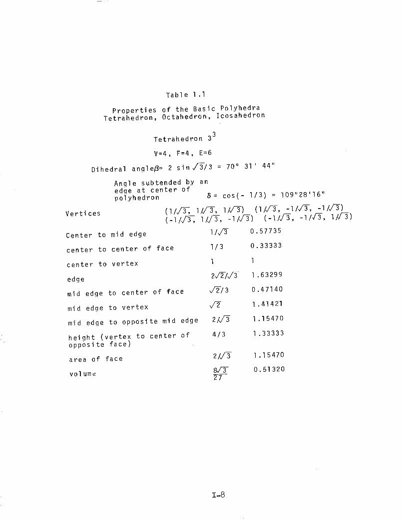
Table I.I list the properties of the Tetrahedron, Octahedron,
and Icosahedron which are considered as three of the five
regular polyhedral forms.
*Coxeter, N. S. M. 1
T- 7
Vertices
Table 1 .I
Properties of the Basic PolyhedraTetrahedron, Octahedron, Icosahedron
3Tetrahedron 3
V=4, F=4, E=6
Dihedral angle# = 2 sin_/3 = 70 ° 31' 44"
Angle subtended by anedge at center ofpolyhedron 8= cos(- I/3) = 109°28'16 ''
(llV_, llY_, llV_) (liVe,-llVT,-11v_)(-li#_, iI_, -iI_) (-iI_, -llJ-%, llJ-_)
I/_ O .57735Center to mid edge
center to center of face
center to vertex
edge
mid edge to center of face
mid edge to vertex
mid edge to opposite mid edge
height (vertex to center ofopposite face)
area of face
vol ume
I/3 0.33333
1 1
2_IJ-3 1 .63299
_/-{/3 0.47140
1 .41421
2/_/-3 1.15470
4/3 1 .33333
2/_ 1.15470
0.5132027
T-8
Vertices
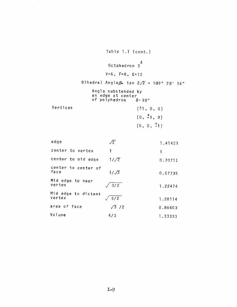
Table 1 .I (cont.)
4Octahedron 3
V=6, F:8, E=I2
Dihedral Angle/3= tan 2_/2-= 109 ° 28' 16"
Angle substended byan edge at centerof polyhedron 8=90 °
(-+I, o, o)
(o, -+l, o)
(o, o, -+I)
edge
center to vertex 1
center to mid edge I/v/2
center to center offace I/_
Mid edge to nearvertex _3/2
Mid edge to distantvertex F 5/2
area of face v_ /2
Volume 4/3
1.41421
1
0.70711
0.57735
1.22474
1.58114
0.86603
1.33333
T- 9
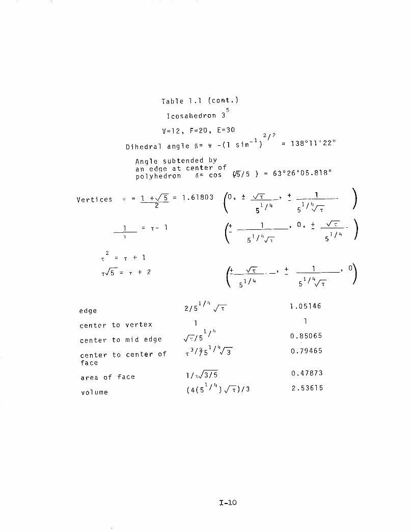
Table 1 .I (cont.)5
Icosahedron 3
V=I2, F=20, E=302/2
_1
Dihedral angle 6= _ -(I sin ) = 138o11,22 ''
Angle subtended byan edge at center ofpolyhedron 6= cos (f5-/5 ) = 63o26 '05.818''
Vertices : 1 +v/-5 - = 1.618032
1 = T- 1T
2m = -_ + 1
md/-5-= T + 2
1 f4 115 J 5
51/4/-_ - 51/4
_+ ,/7- , _+ 151/4 51/4V/T
o)edge
center to vertex
center to mid edge
center to center offace
area of face
volume
1142/5
1
i/4
31_5114d-_
I/_vi3/5
I 4)(4(5 1 d_)13
1.05146
1
0.85065
o.79465
0.47873
2.53615
I-i0

1.3 STRUCTURAL ORIENTATION
The structural configuration desired is acquired
through a three-way gridding of the faces of the polyhedral
form chosen from one of the three trianqular faced regular
polyhedra. The grid is then tY.:islated onto the surface
of a circumscribed sphere. A three dimensional rectangular
coordinate system was chosen for the basis of the compu-
tations. Due to the symmetries existing in the polyhedral
forms only one face of the polyhedron is used in calculation
of the geometrical properties of the structure. Figure
1.6 shows the orientation of the polyhedral form with
respect to the x, y, z axis with the vertices of the face
chosen for the geometrical computations. The intersection
of the x, y, z axis is located at the origin (0,0,0) of
the polyhedron, this point being the center of the cir-
cumscribed sphere. Table 1.2 list the coordinates of the
vertices of the faces chosen as the PPT.
Z
5 z
\,
Y
P3
Octahedron
Figure 1 .6Tetrahedron
I-ll

x
I
Icosahedron
Figure 1.6 (cont.)
Table 1.2
Coordinates of the Principal Polyhedral Triangles
P_ = (-l/d-3-,-lldT, lid-3-)
P2 = (lld-%, -IIdY, -lld3)
P3 : (-lld_, lld_, -lld_)
nl : (l, o, o)
P2 : (o, I, o)
P3 : (o, o, I)
Tetrahedron
= (-.57735027,-.57735027, .57735027)
= (.57735027,-.57735027,-.57735027)
= (-.57735027, .57735027,-.57735027)
0ctahedron
Icosahedron1
= , d_-) = (0, .85065081, .52573111)P1 ( 0 ,d-_-I5114 115 14
P2 = (I/51/4_ 0' _/T/51/4) - (.52573111, 0, .85065081)
P3 = (_-/51/4 1/51/4v/-_- , 0) = (.85065081 52573111 O)
t
L .,
1-12

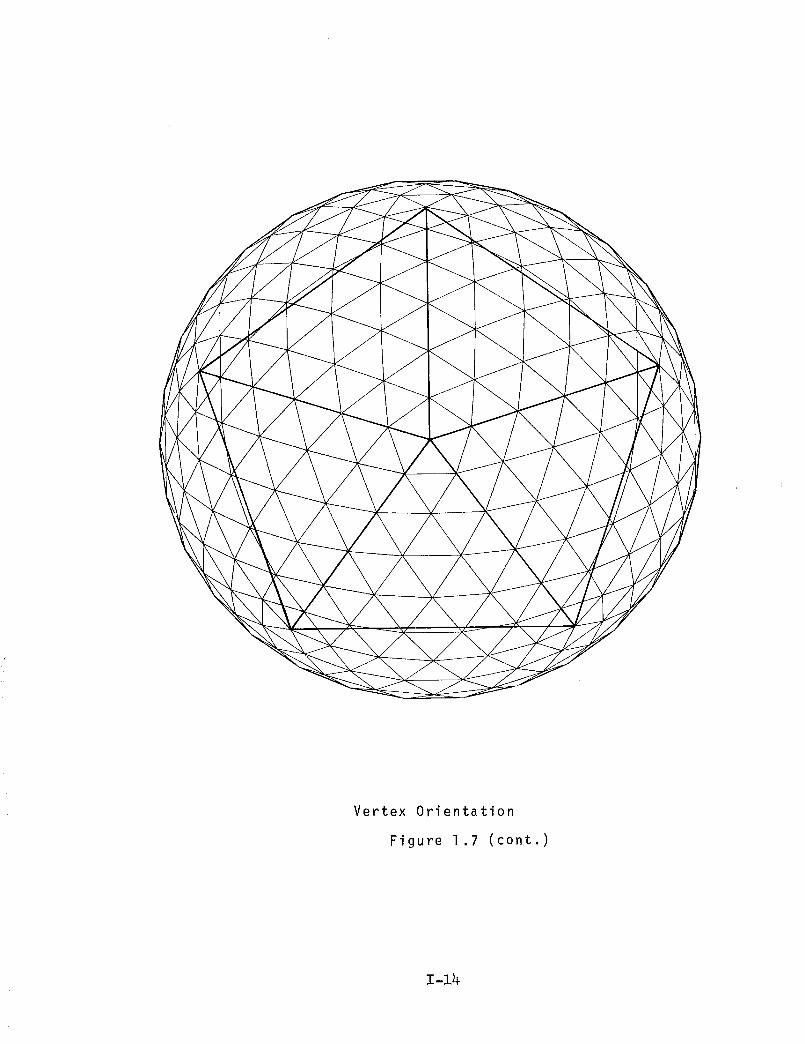
Throughout the discussion of the methods of sub-
division of the polyhedral forms the Icosahedron will be
used with examples of computer maps of the spherical forms
derived using the three traditional orientations: edge,
vertex, and face. Figure 1.7.
Edge Orientation
Fi qure 1 . 7
1-13
/ /
Vertex Orientation
Figure 1.7 (cont.)
1-14
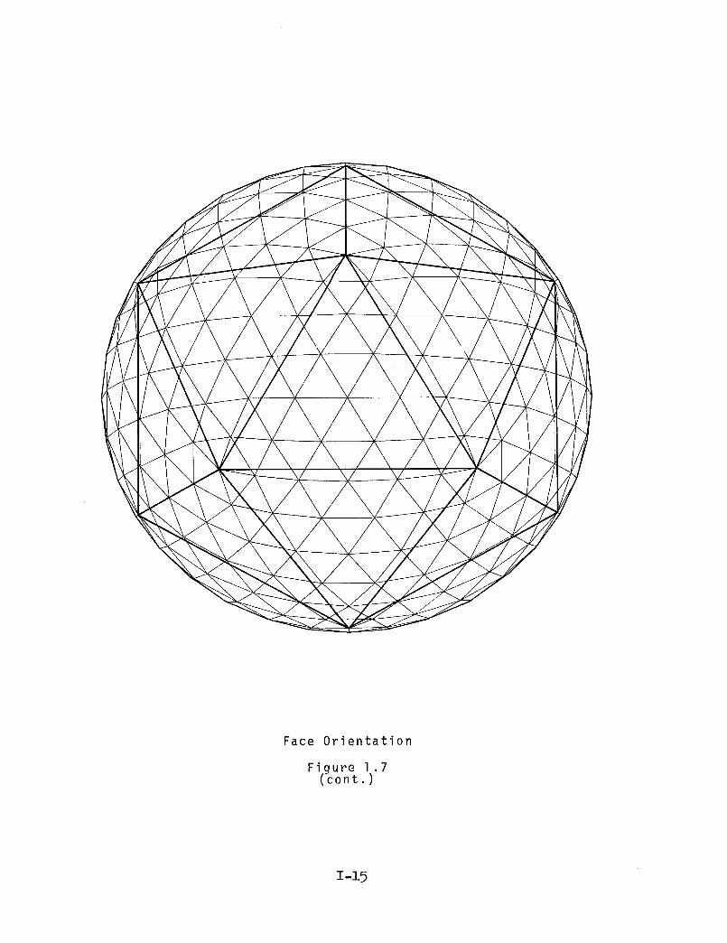
Face Orientation
__(_o_./_'_
1-15

1.4 DEFINITIONS
AXIAL ANGLE (_) = an angle formed by an element and a
radius from the center of the polyhedron meeting in a
common point and the vertex of the axial angle sharing
a vertex of the polyhedron.
CENTRAL ANGLE (6) = an angle formed by two radii of the
polyhedron passing through the end points of a principal
side.
CHORD FACTOR (cf) = the element lengths calculated based
upon a radius of a non-dimensional unit 1 for the
spherical form. The length of any element for larger
structures may be found by the equation:
cf x r = 1
where cf = chord facto_
r = the radius of the desiredstructural forms
1 = the length of the elementsought
DIHEDRAL ANGLE (8) = an angle formed by two planes meeting
in a common line. The planes themselves are the faces
of the dihedral angle, and the common line is the element.
To measure the dihedral angle measure the angle whose
vertex is on the element of the dihedral angle and whose
sides are perpendicular to the element and lie one in
each face of the dihedral angle.
1-16

FACE ANGLE (_) - an angle formed by two elements meeting
in a common point and lying in a plane that is one of
the faces of the polyhedron.
FACES = the triangles making up the "exploded" structural
form.
FREQUENCY (_) = the number of parts or segments into which
a principle side is subdivided.
PRINCIPLE POLYHEDRAL TRIANGLE (PPT) = any one of the equal
equilaterial triangles which forms the face of the
regular Polyhedron.
PRINCIPLE SIDE (PS) = any one of the three sides of the
principle polyhedral triangle.
1-17

1.5 METHODS OF SUBDIVISION
Upon using the spherical form as a structural unit,
it is readily apparent that the basic polyhedral form,
in its pure state, can not satisfy the range of conditions
that must be geometrically and structurally met. Seven
methods will be discussed for reducing the basic poly-
hedral form into a larger number of components from which
the geometrical properties may be made to remain within the
structural fabrication and erection limits for a desired
configuration.
Due to the symmetrical characteristics of the basic
polyhedral form only one face of the polyhedron is used
for calculating the geometrical properties of the struc-
tural configuration. The remaining faces may be found by
rotations or reflections of the principal polyhedral tri-
angle and its transformations.
Attention is given here to the seven methods of sub-
dividina the PPT in a broad sense and will be treated in
detail in the following section.
Method 1 :
The PPT is subdivided into n frequency, with the parts
chosen as equal divisions along the three principal sides.
Figure 1.8A
i | ! J I
NOTE: A1 =
Figure 1.8
12
1-18
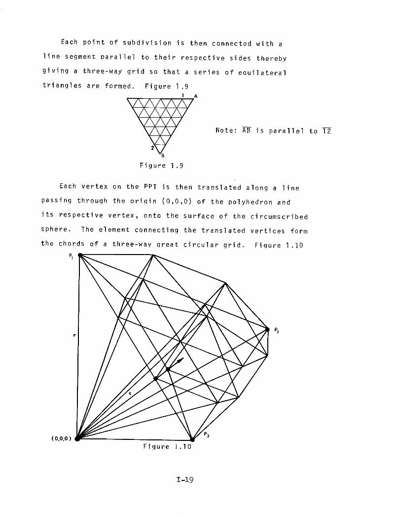
Each point of subdivision is then connected with a
line segment parallel to their respective sides thereby
giving a three-way grid so that a series of equilateral
triangles are formed. Figure 1.9
I A
B
Figure 1 .9
Note: AB is parallel to 12
Each vertex on the PPT is then translated along a line
passing through the origin (0,0,0) of the polyhedron and
its respective vertex, onto the surface of the circumscribed
sphere. The element connecting the translated vertices form
the chords of a three-way great circular grid. Fiqure I.I0
( o,o,o )
Figure I.I0
P3
P_
1-19

Methods 2 & 3:
The PPT is subdivided into n frequency with the parts
therein as equal arc divisions of the central angles of
the polyhedron. Figure I.II.
A
2
B
(o,o,o)
Figure I.II
Note: A-i- # I_
The points of subdivision on each principal side of
the PPT are connected with line segments parallel to their
respective sides. Each line segment intersects at a number
of points which define a qrid of subdivision. Due to the
method of subdivision, small equilateral trianqular "windows"
occur in the grid. Figure 1.12.
I A
b Q
B
Figure 1.12
NOTE: A--B is parallelto 12
Aa _ ab
Windows are equilateraltriangles
1-20
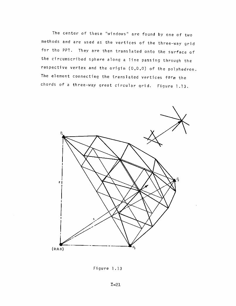
The center of these "windows" are found by one of two
methods and are used as the vertices of the three-way grid
for the PPT. They are then translated onto the surface of
the circumscribed sphere along a line passing through the
respective vertex and the origin (0,0,0) of the polyhedron.
The element connecting the translated vertices form the
chords of a three-way great circular grid. Figure 1.13.
(0,0,0
Figure 1.13
1-21

Method 4:
The PPT is subdivided into n frequency, with the parts
chosen as equal divisions along the three principal sides.
Figure 1.14.
No te : A--I = I--2
Figure 1.14
Each point of subdivisions is then connected with line
segments perpendicular to their respective principal side
thus giving a three-way grid comprised of equilateral and
right triangles. Fiqure 1.15.
2 A
Note: A-B _L 1 2
Figure 1 .15
1-22
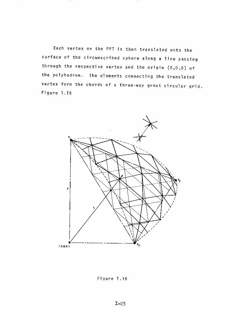
Each vertex on the PPT is then translated onto the
surface of the circumscribed sphere along a line passing
through the respective vertex and the origin (0,0,0) of
the polyhedron. The elements connecting the translated
vertex form the chords of a three-way great circular grid.
Figure 1.16
//
//
//
I
/I
I
( o,o,o )
Figure 1.16
1-23
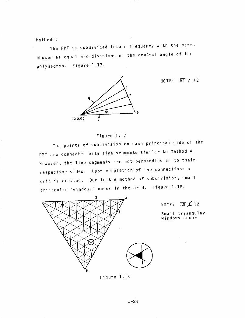
Method 5
The PPT is subdivided into n frequency with the parts
chosen as equal arc divisions of the central angle of the
polyhedron. Figure 1.17.
B
( 0,0,0 )
NOTE: AT _ I--2
Figure 1.17
The points of subdivision on each principal side of the
PPT are connected with line segments similar to Method 4.
However, the line segments are not perpendicular to their
respective sides. Upon completion of the connections a
grid is created. Due to the method of subdivision, small
triangular "windows" occur in the grid. Figure 1.18.
fI i >
> >
Figure 1.18
NOTE: A-B-/_T2
Small triangularwindows occur
1-24

The centers of these "windows" are found and are used
as the vertices ef a three-way grid for the PPT. The ver-
tices are then translated onto the surface of the circum-
scribed sphere along a line passing through the respective
vertex and the origin (0,0,0) of the polyhedron. The
elements joining the translated vertices form the chords
Of a three-way great circle grid. Figure 1.19.
PI
//
//
//
/
P2
I
( 0,0,0 )
Figure 1.19
1-29
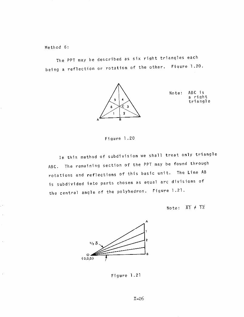
Method 6:
The PPT may be described as six right triangles each
being a reflection or rotation of the other. Fiqure 1.20.
A B
Note: ABC isa righttriangle
Fiqure 1.20
In this method of subdivision we shall treat only triangle
ABC. The remaining section of the PPT may be found through
rotations and reflections of this basic unit. The Line AB
is subdivided into parts chosen as equal arc divisions of
the central angle of the polyhedron. Figure 1.21.
No te : A--I _ I--2
A
0 B
(o,o,o)
Figure 1.21
1-26
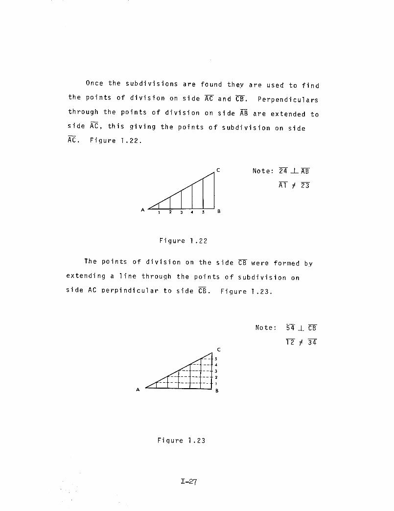
Once the subdivisions are found they are used to find
the points of division on side A-C and C--B. Perpendiculars
through the points of division on side A--B are extended to
side AC, this giving the points of subdivision on side
AC. Figure 1.22.
1 2 3 4 5
Note: 2_IA-B
A1 _ 23
Figure 1 .22
The points of division on the side CB were formed by
extending a line through the points of subdivision on
side AC perpindicular to side C_. Figure 1 .23.
C
4
3
2
1
B
Note: 54 _J_ CB
12 # 34
Fiqure 1.23
1-27

Having acquired the points of subdivision along the
three sides of the triangle, diagonals are drawn from each
point on side A-Cto alternate points of sides A--Band B--C.
Figure 1.24.
A
C
B
Figure 1.24
To complete the three-way qrid connect alternate
points of subdivision of side A--@to alternate points of
division of side B--C. Figure 1.25
C
Figure 1.25
1-28
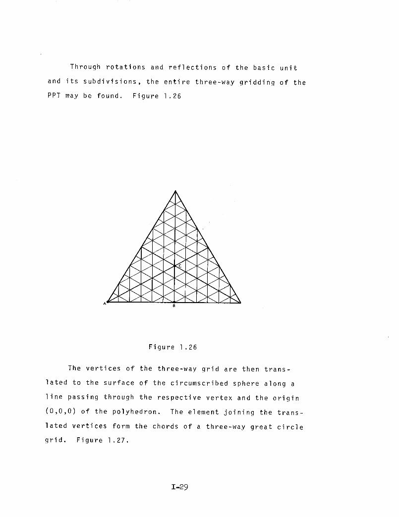
Through rotations and reflections of the basic unit
and its subdivisions, the entire three-way gridding of the
PPT may be found. Figure 1.26
J
J
J
J
J
J
A-B
Figure 1.26
The vertices of the three-way grid are then trans-
lated to the surface of the circumscribed sphere along a
line passing through the respective vertex and the origin
(0,0,0) of the polyhedron. The element joining the trans-
lated vertices form the chords of a three-way great circle
grid. Figure 1.27.
1-29

/!
!
( 0,0,0 )
Figure 1.27
1-30
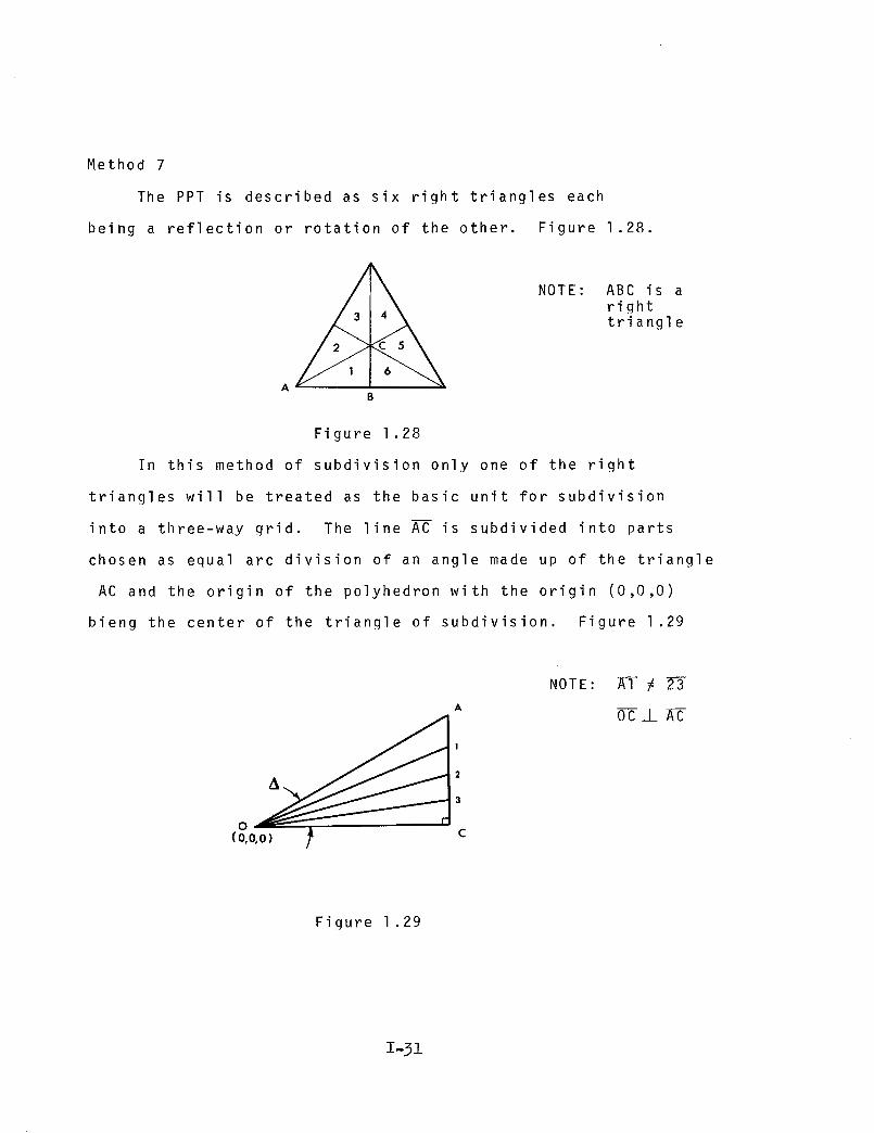
Method 7
The PPT is described as six right triangles each
being a reflection or rotation of the other. Figure 1.28.
3 triangle
AB
Figure 1.28
In this method of subdivision only one of the right
triangles will be treated as the basic unit for subdivision
into a three-way grid. The line AC is subdivided into parts
chosen as equal arc division of an angle made up of the triangle
AC and the origin of the polyhedron with the origin (0,0,0)
bieng the center of the triangle of subdivision. Figure 1.29
1
2
3
o(o,o,o) c
NOTE: A1 # 23
oc _L _-C
Figure 1 .29
1-31
u
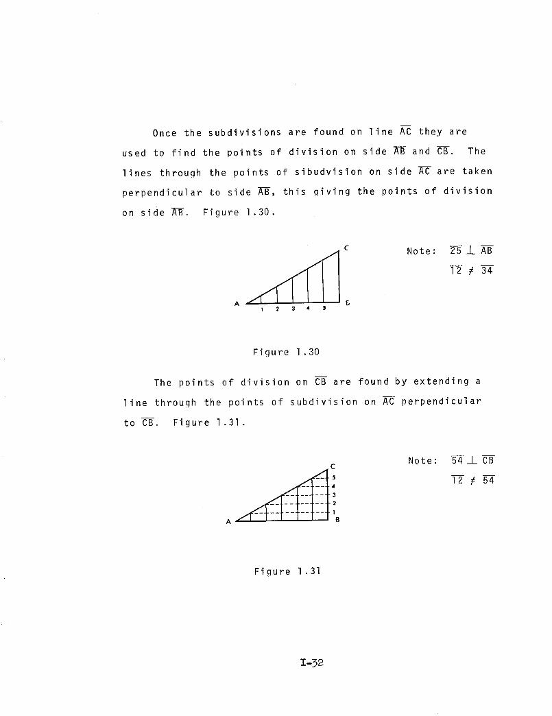
Once the subdivisions are found on line AC they are
used to find the points of division on side AB and CB. The
lines through the points of sibudvision on side AC are taken
perpendicular to side _-B, this giving the points of division
on side A--B. Figure 1.30.
C
1 2 3 4 $
Note: 2--5 _I_ AB
12 _ 34
Figure 1.30
The points of division on CB are found by extending a
line through the points of subdivision on AC perpendicular
to CB. Figure 1.31.
C
A
Note: 5__LC_
12 # 54
Figure 1.31
1-32

Having acquired the points of subdivision along the
three sides of the triangle, diagonals are drawn from each
point on AC to alternate points on AB and BC. Figure 1.32.
Figure 1 .32
To complete the three-way grid connect alternate points
on AB to alternate points on BC. Figure 1.33.
C
A B
Figure 1.33
1-33

Through rotations and reflections of the basic unit
found and it's subdivison, the entire three-way grid of
the PPT may be found. Figure 1.34.
J
J_J
J_J
J_J_J
A-
_J
Figure 1.34
The vertices of the three-way grid are then translated
to the surface of the circumscribed sphere along a line
passing through the respective vertex and the origin (0,0,0)
of the polyhedron. The elements joining the translated ver-
tices form the chords of a three-way great circle grid.
Figure 1.35.
1-34

P_
//
/
//
//
( o,o.o )
Figure 1.35
1-35
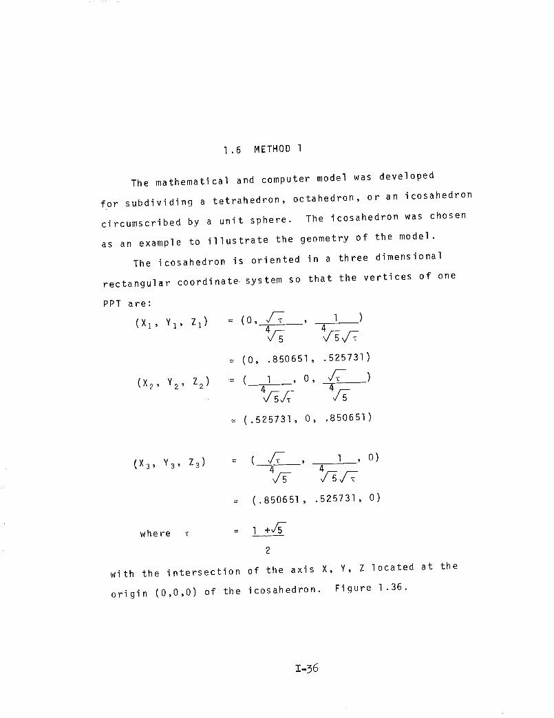
1.6 METHOD 1
The mathematical and computer model was developed
for subdividing a tetrahedron, octahedron, or an icosahedron
circumscribed by a unit sphere. The icosahedron was chosen
as an example to illustrate the geometry of the model.
The icosahedron is oriented in a three dimensional
rectangul_r coordinate, system so that the vertices of one
PPT are:
(X1' YI' Z1)
(X2' Y2' Z2)
: (o, d-T , I )
= (0, .850651, .525731)
:( 1 , o, dT-_ )
= (.525731, O, .850651)
o)
(.850651, .525731, O)
= 1 +d5-where
2
with the intersection of the axis X, Y, Z located at the
origin (0,0,0) of the icosahedron. Figure 1.36.
I136

(X2,Y2,Z 2)
Figure 1.36
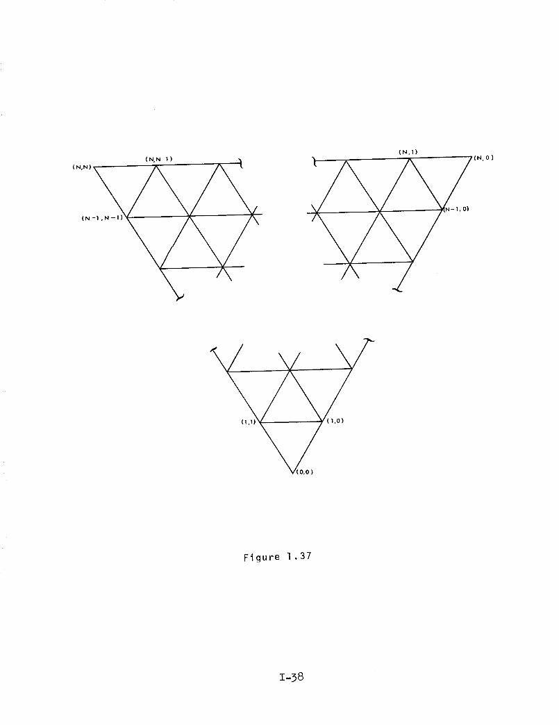
This PPT is divided into smaller equilateral triangles
where the vertices of the triangles are of the form
X2 - Xl X3 - X 2 Y2 - Y1 Y3 - Y2X I + I + J Y1 + I + a
N N N N
Z2 - ZI Z3 - Z2 \ I.IZl + I + J )N N
where N is the frequency of the structure and I and J are
integers such that O<J<I<N. The values of I and J are unique
for each vertex and are used to identify each vertex as shown
in Figure 1.37.
1-37
( N,N-! ) •
(N
(N,1)
A _/-
o_
V( o,o )
Figure 1.37
1-38
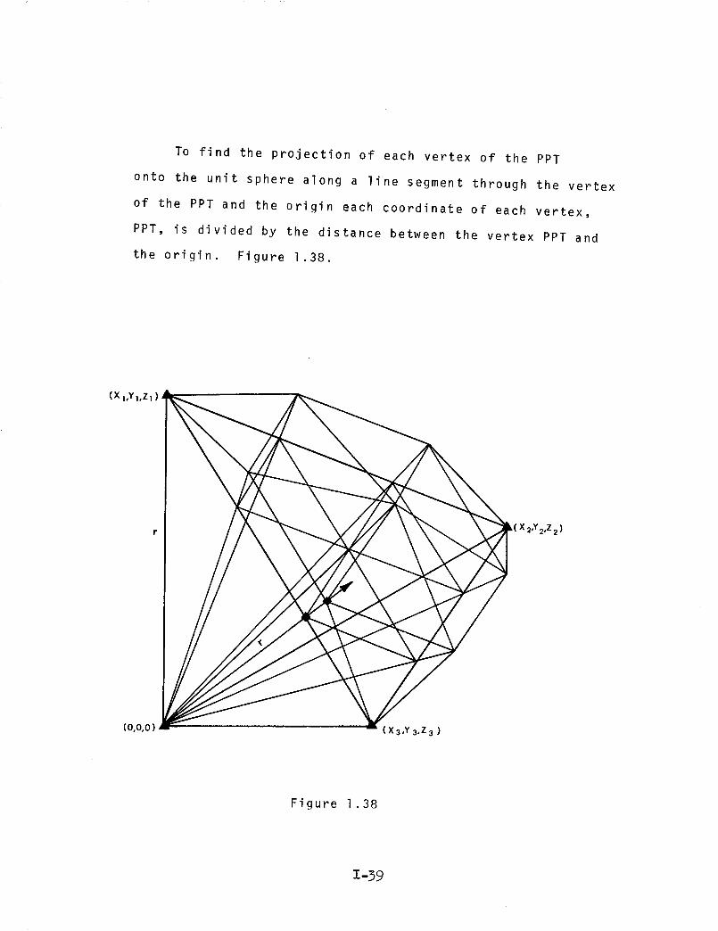
To find the projection of each vertex of the PPT
onto the unit sphere along a line segment through the vertex
of the PPT and the origin each coordinate of each vertex,
PPT, is divided by the distance between the vertex PPT and
the origin. Figure 1.38.
(X 1,Yl,Z z )
r k(X 2'Y2'z 2)
(0,0,0) (X3,Y 3,Z 3 )
Figure 1.38
1-39
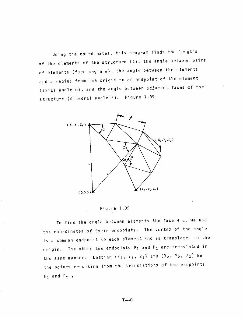
Using the coordinates, this program finds the lengths
of the elements of the structure (_), the angle between pairs
of elements (face angle _), the angle between the elements
and a radius from the origin to an endpoint of the element
(axial angle _), and the angle between adjacent faces of the
structure (dihedral angle 8). Figure 1.39
(XI,YI,ZI)
( 0,0,0
'"Z
,Y2,z2)
/
/) 3'Y3'Z3)
Figure 1.39
To find the angle between elements the face _ _, we use
the coordinates of their endpoints. The vertex of the angle
is a common endpoint to each element and is translated to the
origin. The other two endpoints Pl and P2 are translated in
the same manner. Letting (Xl, Y_, Zl) and (X2, Y2, Z2) be
the points resulting from the translations of the endpoints
P1 and P2 ,
1-40
COS _ =
where dl =
and d2 =
XlX 2 + Y1Y2 + Z1Z
dld2
/_2 2 2+ Y + Z 11 I
x_X 2 2 22 + Y2 + Z 2
1.2
is the desired angle.
To find axial angles the above method is used except
that the vertex is established at one end of an element and the
origin is used with the other endpoint to define the angle.
The desired angle is _.
The angle between two adjacent faces, the dihedral C _,
is found using
cos 8 = A1A 2 +BIB 2 + ClC 2
2 2 2 2 2 2
A1 + B1 + C1 A2 + B2 + C2 1.3
where
is the desired angle.
AIX + BIY + ClZ + DI = 0 defines the plane containing
one face and A2X + B2Y + C2Z + D2 = 0 defines the plane con-
taining the other face.
The negative sign is used because the obtuse angle is desired.
The A, B, and C fcr each plane are computed as
Y1 Zl 1
A = Y2 Z2 1
Y3 Z3 1
1-41
X1 Z1 1
= X2 Z2 1
X3 Z 3 1
1.4
X1 Y1 1C = X2 Y2 1
X3 Y_ 1
where (Xl, YI, Z1)' (X2' Y2' Z2)' and (X 3 , Y3, Z3) lie in
the plane. In particular the three vertices of each face
are used. For the special case where the two faces used lie
above separate faces of the polyhedron, the assumption is
made that the plane containing the element common to each
face and the origin bisects the angle. This angle is found
in the same manner and doubled. This method is used because
the structural face above the polyhedral face is not generated
properly.
The length of the elements, _, are found by using the
general equation
_ p )2 + (p p )2 + (pzl _ pz z )2= Px I x 2 yl Y21.5
is the desired length.
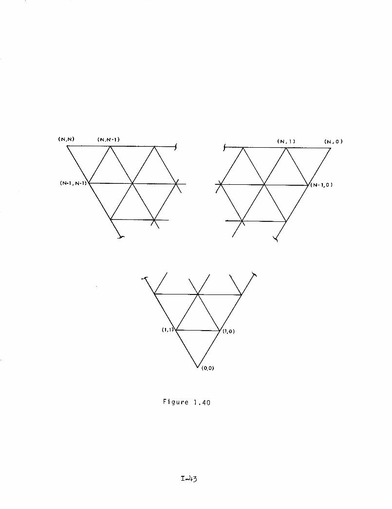
To reduce total output, this program takes into account
certain symmetries and outputs only a part of the total angles
and lengths. The rest of the values are the same as at least
one outputed value and can easily be found using the following
symmetries. Figure 1.40.
1-42
(N,N) (N,N-1)
J
(N- , -
(N,I) (N,O)
Figure 1.40
1-43

FACE ANGLES
For every face angle opening directly towards (or
away from) the point (0,0), there are equal angles opening
towards (or away from) the point (N,O) and (N,N). For
example, the angle (l,l), (0,0), (l,O) with vertex at (0,0)
is equal to the angle (N-l,O), (N,O), (N,l) and the angle
(N,N-I), (N,N), (N,l, N-l). Thus, only the face angles
facing directly towards or away from (0,0) are computed.
If the vertex is to lie at (I,J), the angle will be either
(I + I, J + l), (I,J), (I +l, J) or (I-l, J-l), (I,J),
(I-I,J). Also, only the face angles falling on the right
of or on a line passing through (Xi, Yi, Zi,) and the mid-
point of the opposite side are computed.
The elements of the structure can be put into one-to-
one correspondence with the lengths and dihedral angles.
The dihedral angle associated with an element is the angle
between the two faces containing the element. For each
element, there are two axial angles, one at each end, but
since the element is a cord of the circle, the two angles
are equal and may be considered one. In this case, we
have a one-to-one correspondence between elements and axial
angles. This program will only compute values around
elements parallel to the side opposite (X i, Yi, Zi) and on
the right side of a line through (X i, Yi' Z1) and the
midpoint of the opposite side. All other lengths and angles
are symmetric to one of the lengths and angles computed in
this manner.
1-44

THE COMPUTER PROGBAM DESCBIBED ON
PAGES 1-45 to 1-75
IS AVAILABLE FBOM COSMIC
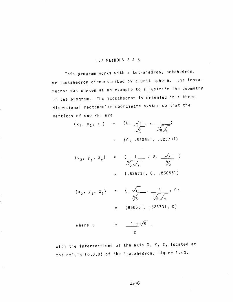
1.7 METHODS 2 & 3
This program works with a tetrahedron, octahedron,
or icosahedron circumscribed by a unit sphere. The icosa-
hedron was chosen as an example to illustrate the qeometry
of the program. The icosahedron is oriented in a three
dimensional rectanqular coordinate system so that the
vertices of one PPT are
(x_, y_, z ) = (o, _ , I )
= (0, .850651, .525731)
z) = ( l(x2' Y2' 2, O, v/_-T )
(.525731, O, .850651)
(x3' Y3' z3) = ( _ , 1 , O)
(850651, .525731, O)
where T = 1 +v_-
with the intersections of the axis X, Y, Z, located at
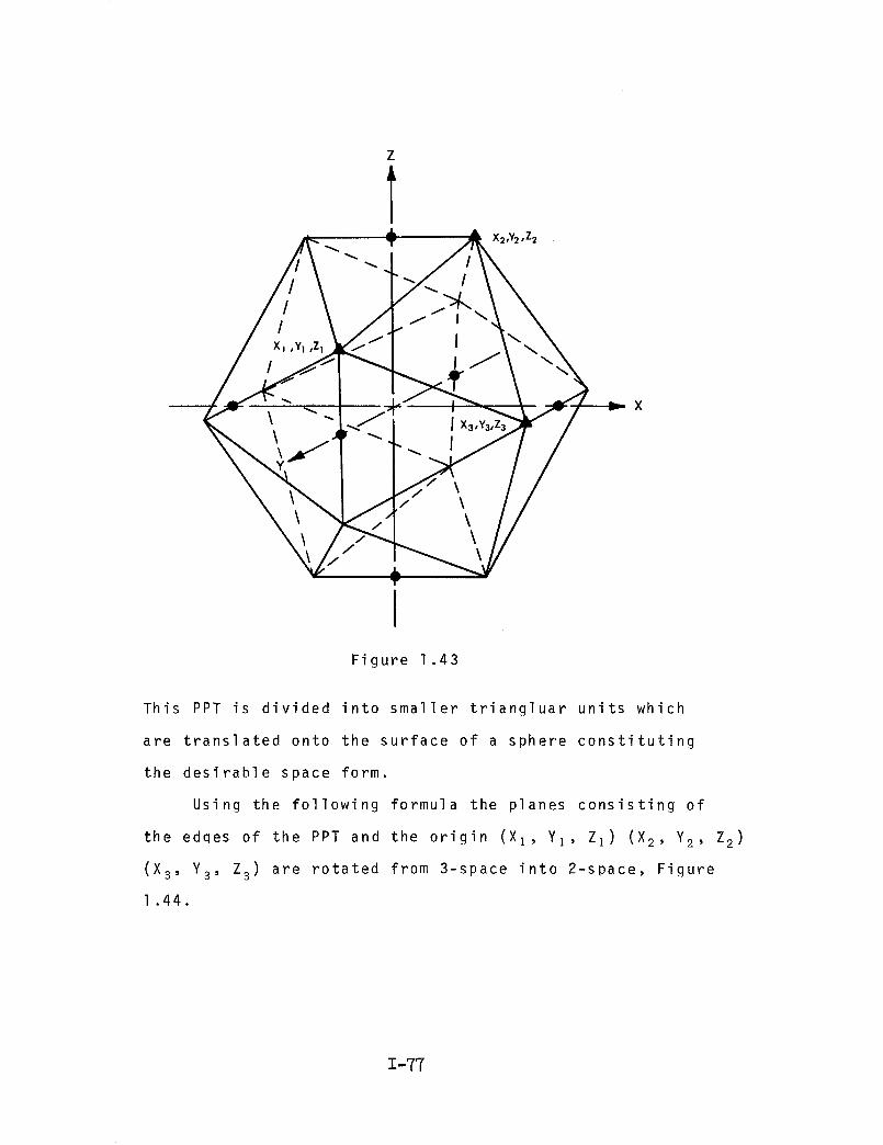
the origin (0,0,0) of the icosahedron, Figure 1 .43.
I_76
Z
X2,Y2 ,Z2
X
IFigure 1.43
This PPT is divided into smaller triangluar units which
are translated onto the surface of a sphere constituting
the desirable space form.
Using the following formula the planes consisting of
the edqes of the PPT and the origin (XI, YI, ZI) (X2, Y2, Z2)
(X3' Y3' Z3) are rotated from 3-space into 2-space, Figure
1.44.
1-77

x
Figure 1.44
X' = %1 x + _1 y + Ul z 1.6
y' = _2x + u2y + _ z2
Z' = X3X + P3W + _3 z
Where x, _, u are direction cosines of the X -axis, and Y'-axis,
and Z'-axis respectively with respect to the old axis and
are found by:// 2 2 2
%1 = Xl/_ Xl + Yl + Z 1
V 2 2 2Pl = Yl Xl + Yl + Zl
// 2 2 2
= /_/ + Z_)1 Zl Xl + Yl 1
X 2 , X3; !J2,P3; and_2,_3 are found similarly.
1-78
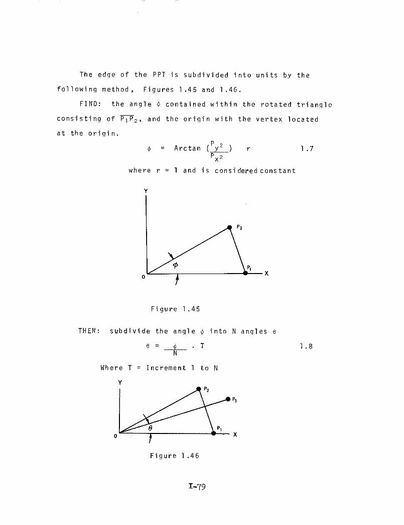
The edge of the PPT is subdivided into units by the
following method, Figures 1.45 and 1.46.
FIND: the angle _ contained within the rotated triangle
consisting of PIP 2, and the origin with the vertex located
at the origin.
= Arctan (Py2) r 1.7
Px 2
where r = 1 and is considered constant
Y
• P2
x
Figure 1.45
THEN: subdivide the angle _ into N angles e
e = _ TN
Where T = Increment 1 to N
Y
_ X° t
Figure 1 .46
1.8
1-79
oo
c-
O4-
c_
e.-
14-
o
c-
o
"5U
0r.-
O
.g
c-I---
fc,lX
II
X
I
X
0r-
t O
I
X
II
i
X
0r-
÷
e,I
X
I
Xv
IIII
c,,I
_ ,O4- x _
0 _ _ II II "t- II
o _ _ "-" "-" % 24- i x x
i{_ _ I I t I
.,_ _ v _ X x
_ X _ v v v ×
4-_ or-
°r-- _
O
C-
O
._. e4
0r--
CX
e-
e"4-_
@4 e,l @4
0II II II 4-
co co
X C)I 0
"5
_ _ e4
e-
_g ,-,
• IH
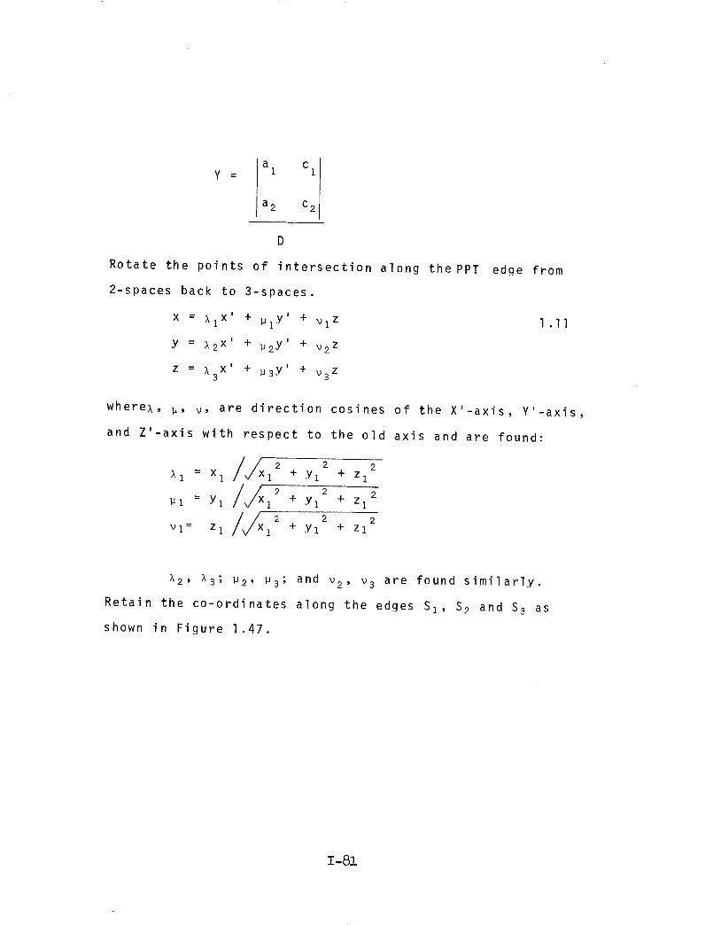
a c Iy = I
a 2 c2
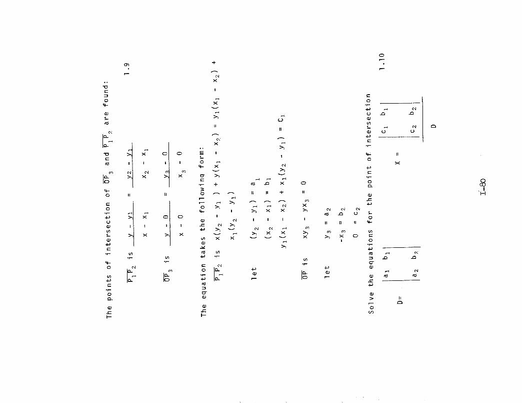
Rotate the points of intersection along the PPT edge from
2-spaces back to 3-spaces.
X = _i x' + pl.y _ + _1 z
y = _2 x' + _2y' + v2Z
X I + I +z = _3 u3Y v3 z
1 .II
where,, p, v, are direction cosines of the X'-axis, Y'-axis,
and Z'-axis with respect to the old axis and are found:
/x 2 2 2_-1 = Xl 1 + v1 + Zl
//xPl = Yl 12 + Yl + Zl
/X 2 2 2Vl= Zl 1 + Yl + Zl
_2, _3; P2, P3; and _2, v3 are found similarly.
Retain the co-ordinates along the edges Sl, S 2 and S 3 as
shown in Figure 1.47.
1-81
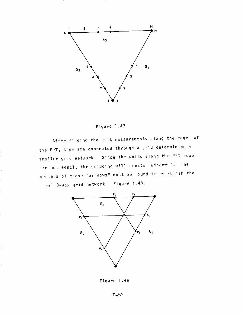
1 2 3 4 N
N-- = ; $3 = _N
3 3
2 2
Figure 1.47
After findinq the unit measurements along the edges of
the PPT, they are connected through a grid determining a
smaller grid network. Since the units alonq the PPT edge
are not equal, the gridding will create "windows" The
centers of these "windows" must be found to establish the
final 3-way grid network. Fiqure 1 .48.
P2 P4
Figure 1.48
1-82
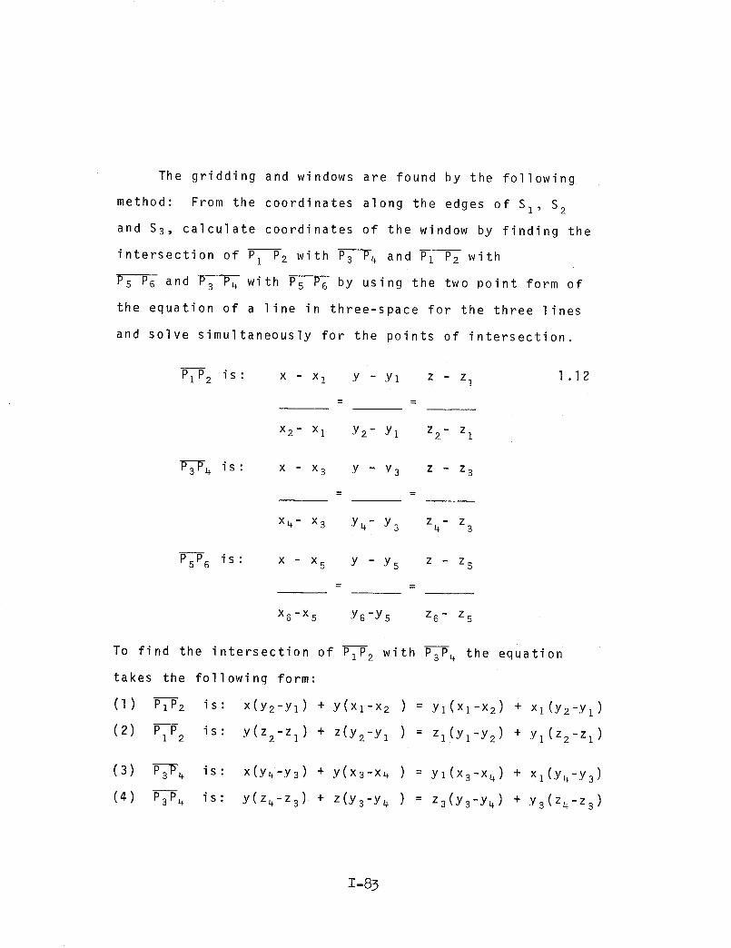
The gridding and windows are found by the following
method: From the coordinates along the edges of Sl, S2
and $3, calculate coordinates of the window by finding the
intersection of Pz P2 with P-3--P-4 and P1 P2 with
PsT6 and P3 P4 with Ps-_G by using the two point form of
the equation of a line in three-space for the three lines
and solve simultaneously for the points of intersection.
PIP2 is: x - x I Y -Yl z - z I 1.12
X2- Xl Y2- Yl Z2- Zl
P-_4 is: x - x 3 Y " ,Y3 z - z 3
X4- X3 Y_+-Y3 z4- z3
PsP6 is: x - x s Y -Y5 z - z s
x6-x5 Y6-Ys z6- Zs
To find the intersection of PIP2 with P3P4 the equation
takes the following form:
(I) PIP2 is: x(y2-yl) + y(xl-x 2 ) = Yl(Xl-X2) + x1(Y2_Yl)
(2) PIP2 is: y(z2-zl) + z(y2-y I ) = zl(Yl-Y2) + yl(z2_zl )
(3) P3P4
(4) P3P_
is: x(y4-Y3) + Y(x3-x4 ) : Y1(X3-X 4) + xl(y4-y3)
is: y(z4-z3) + z(y3-y 4 ) = z3(Y3,y4) + y3(z4_z3 )
1-83
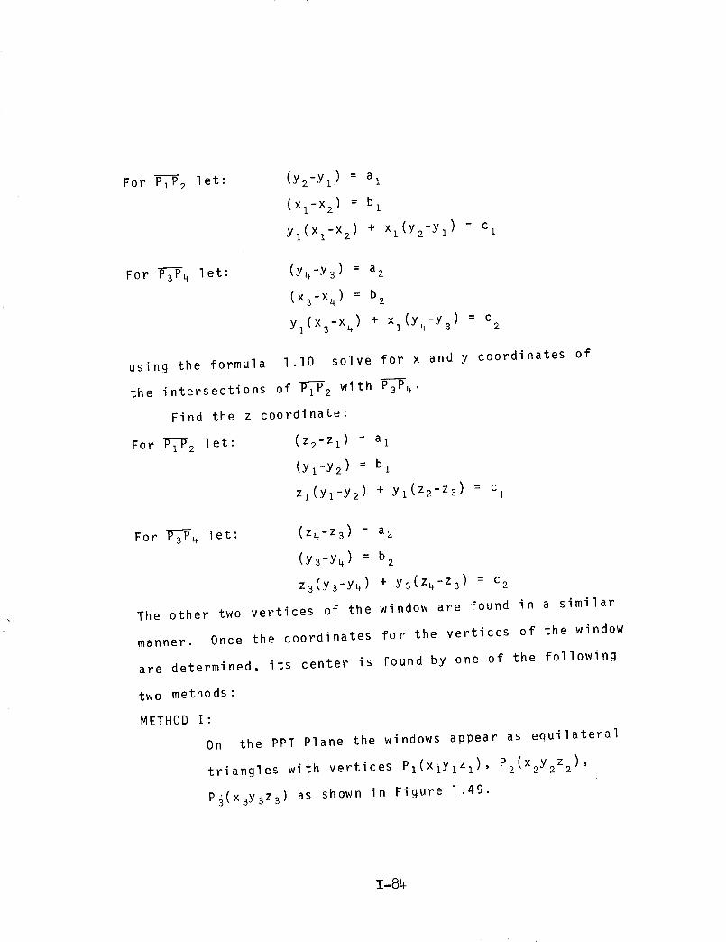
For PI_2 let: (y2-yl) : a I
(Xl-X2) = b I
yl(x1_x2 ) + x1(y2-yl) = c
For P--_4 let: (y4-y3) = a 2
(x3-x4) = b 2
y1(x3-x4) + xI(Y4-Y 3) : c 2
using the formula I,I0 solve for x and y coordinates of
the intersections of P-_2 with P--_-4"
Find the z coordinate:
For P--_2 let: (Z2-ZI) = al
(yl-Y2) = b 1
Zl(Yl-y 2) + yl(z2-z3) = c I
For P--_4 let: (z4-z3) : a2
(y_-y4) = b 2
z3(y3-y 4) + y3(z4-z3) = c 2
The other two vertices of the window are found in a similar
manner. Once the coordinates for the vertices of the window
are determined, its center is found by one of the following
two methods:
METHOD I:
On the PPT Plane the windows appear as equilateral
triangles with vertices P1(xiYlZl) , P2(x2Y2Z2 )'
p_(x3y3z3) as shown in Figure 1.49.
1-84

P
P!
"x
Figure 1.49
The center C(cx,cy,cz) is found with the following
formula:
CX = Xz+ x2+ x 3 1.13
3
CY = y1+ y2 + Y3
3
CZ = zz+ z2+ z
3
METHOD II:
The coordinates of the window found on the surface
of the PPT are first "exploded" to the surface of
the sphere. The center of the exploded window is
then found by the intersection of angle bisectors.
To find the projection of each vertex of the window
Z-89
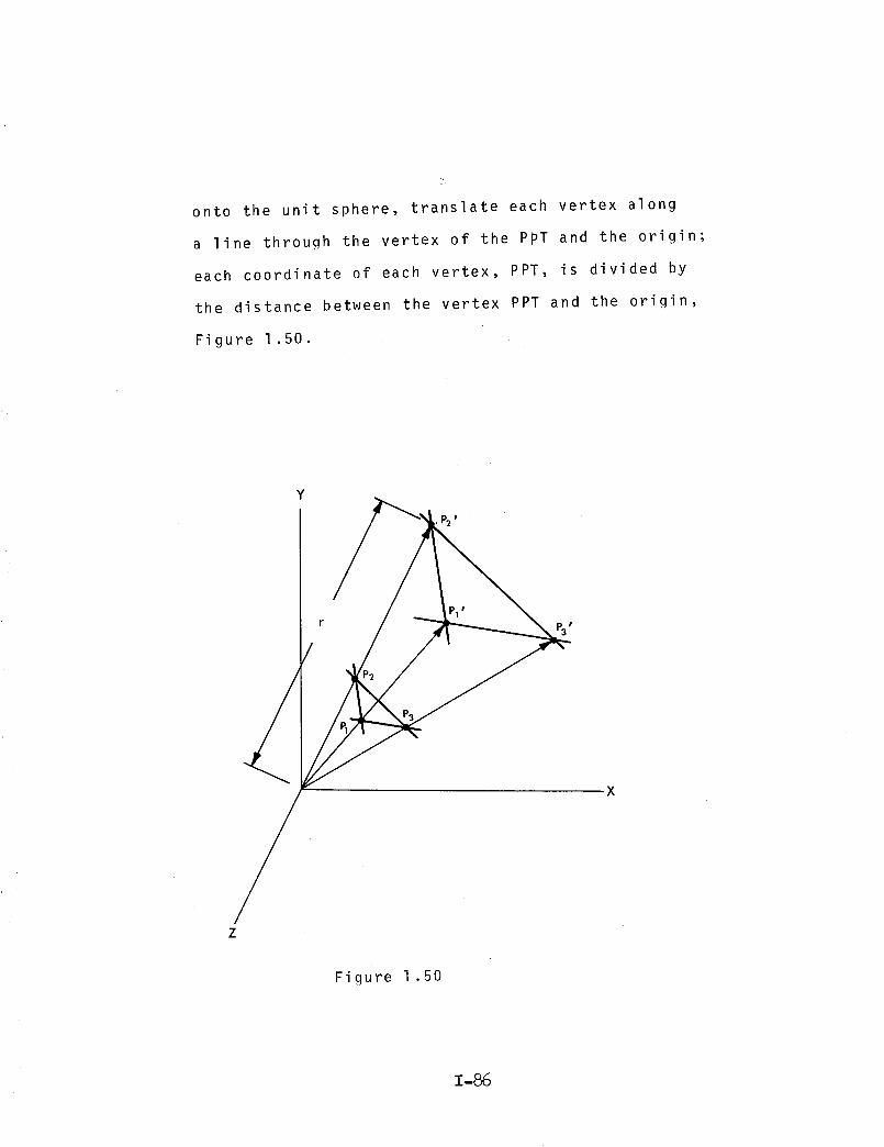
onto the unit sphere, translate each vertex along
a line throuqh the vertex of the PpT and the origin;
each coordinate of each vertex, PPT, is divided by
the distance between the vertex PPT and the origin,
Figure 1.50.
Y
-X
z
Figure 1.50
I'86

2 2 2
d = x I + Yl + zl where d = distance 1 .14from origin to P
lwhere r = radius ofthe sphere to be ex-ploded upon and isconsidered constant
r = 1
X ' 1 -- rx1
d
y ' = ry 11 .
d
1 .15
z' = rz1 1
Translate "window" with vertice P3 at the origin, Figure 1 .51.
P2 T
Figure 1.51
1-87

P1Tx P1 P3X X1 .16
PiTy = Ply P3y
PIT z PI P3Z Z
P2Tx P2 x P3 x
: - P3P2Ty P2x x
P2Tz P2 z P3 z
P3Ty , P3P3Txl' t Tzl= 0
Rotate plane PI, P2, P3 so that PIP3 will fall on the X-axis
and P3 is at the origin using equation 1.6
The center is found with the intersection of two angle
bisectors of the triangular window PIP2P3, Figure 1.52.
Y
x
Z
Figure 1.52
1-88

The angles _ and _ are found:
Arctan
Arctan
Y2
X2
Y2
X 1 -X 2
= -,f
= 6
1 .17
rotate P2 about P3 toward P1, 1/2 Y degrees
x 4 = x 2 cos 1/2 Y + Y2 sin 1/2 y
Y4 = Y2 cos 1/2 y - x 2 sin I/2 y
1 .18
locate the origin at PI' then rotate P2 about Pl toward
P3 I/2 _ degrees
x s = (x2-xl) c0sl/2 8- Y2 sin 1/2 a + x I 1.19
Y5 = Y2 cos I/2 a + (x 2- Xl) sin I/2
thus defining PIP s and P3P4
With P3 at the origin formula 1.9 may be used to solve
for the intersection of line P3P4, PIPs findinq center C.
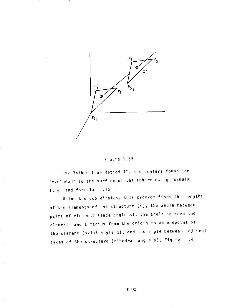
Rotate C back to three space using formula I.II Then
translate center C back to three space ("C" is located in
the previously "exploded" window), figure 1.53.
C'x = Cx + P3 x
C'y = Cy + P3Y
C'z = Cz + P z3
1 .20
T-89 "
P1 P2
C'
P3 TP2
P3 T
Fiqure 1.53
For Method I or Method II, the centers found are
"exploded" to the surface of the sphere using formula
1.14 and formula 1.15
Using the coordinates, this program finds the lengths
of the elements of the structure (_), the anqle between
pairs of elements (face angle _), the angle between the
elements and a radius from the origin to an endpoint of
the element (axial angle _), and the angle between adjacent
faces of the structure (dihedral angle _), Figure 1.54.
1-90
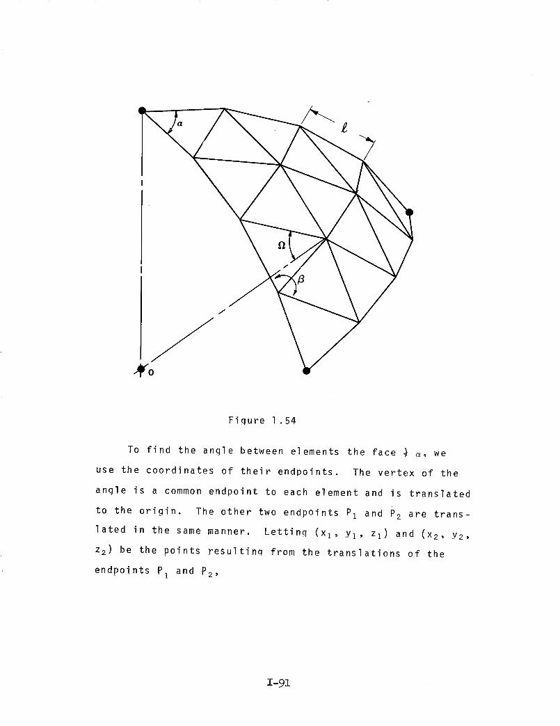
Figure 1.54
To find the angle between elements the face } m, we
use the coordinates of their endpoints. The vertex of the
angle is a common endpoint to each element and is translated
to the origin. The other two endpoints Pz and P2 are trans-
lated in the same manner. Letting (xi, Yi, zi) and (x2, Y2,
z 2) be the points resultina from the translations of the
endpoints P1 and P2,
1-91

COS e¢ = _XlX 2 + YlY2 + zlz
dld 2
v//X 2 2 2where d I = 1 + Yl + Zl
v_X 2 2 2and d 2 = 2 + Y2 + z2
1 .21
is the desired angle.
To find axial angles the above method is used except
that the vertex is established at one end of an element
and the origin is used with the other endpoint to define
the angle. The desired angle is _.
The angle between two adjacent faces, the dihedral
6, is found using
cos 6
I+ C C I 1 22
= -AIA 2 +BIB 2 I 2 I
2 2 2// 2 2 2
1 + B1 + C 1 _/A2 + Be + C2
where
B is the desired angle.
AI x + BIY + ClZ + DI = 0 defines the planecontaining
one face and A2X + B2Y + C2Z + D2 = 0 defines the
plane containinq the other face. The negative sign is
used because the obtuse angle is desired.
The A,B, and C for each plane are computed as
a
Yl Zl 1
Y Z l2 2
y_ Z3 l
1 .23
B
Z 1 1
XI
X2 Z 2 1
X3 Z 3 1
1-92

C =
Xl Y1 1X2 Y2 1
X3 Y3 1
where (X 1 , Y1, Zl)' (X2' Y2, Z2), and (X3, Y3, Z3) lie in
the plane. In particular the three vertices of each face
are used.
The length of the elements_ are found by using the
general equation:
)2 )2 )2(P - p + (P - P + (P - px I x2 Yl Y2 zl z2
1 .24
is the desired length.
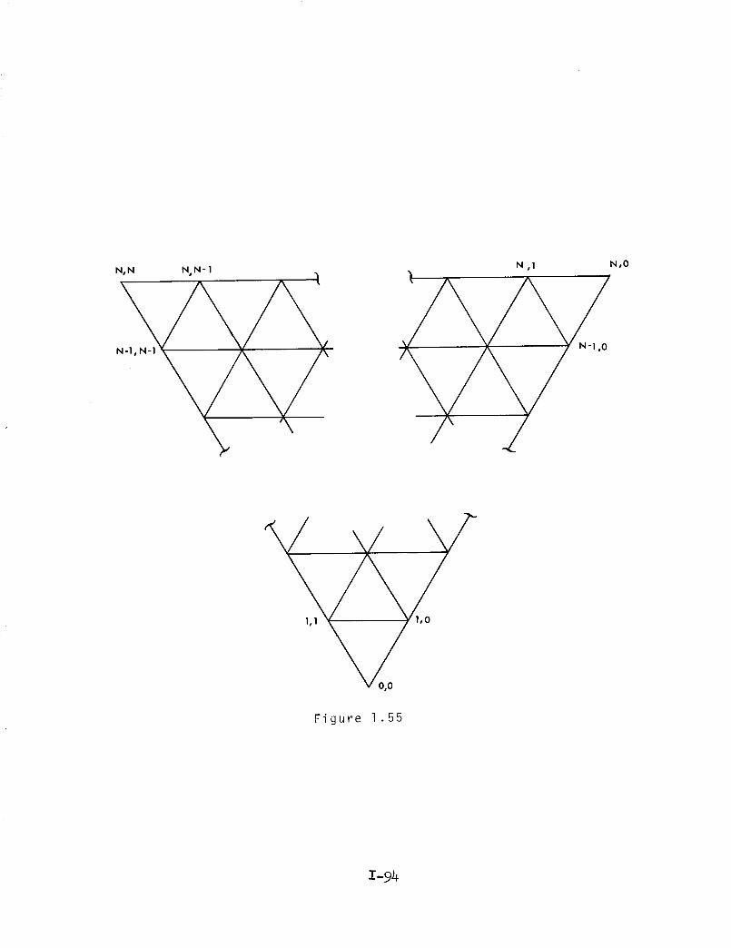
To reduce total output, this program takes into
account certain symmetries and outputs only a part of the
total angles and lengths. The rest of the values are the
same as at least one outputed value and can easily be
found using the following symmetries, Figure 1.55.
1-93
N ,1 N,O
v 0,0
Figure 1.55
1-94
FACE ANGLES
For every face angle opening directly towards (or
away from) the point (0,0), there are equal angles opening
towards (or away from) the point (N,O) and (N,N). For
example, the angle (I,I), (0,0), (I,0) with vertex at (0,0)
is equal to the angle (N-I,O), (N,O), (N,I) and the angle
(N,N-I), (N,N), (N-I, N-I). Thus, only the face angles
facing directly towards or away from (0,0) are computed.
If the vertex is to lie at (l,J), the angle will be either
(I + I, J + I), (l,J), (I + I, J) or (I-I, J-l), (l,J),
(l-l,J). Also, only the face angles falling on the right
of or on a line passing through (X I, YI, Z1,) and the mid-
point of the opposite side are computed.
The elements of the structure can be put into one-
to-one correspondence with the lengths and dihedral angles.
The dihedral angle associated with an element is the angle
between the two faces containing the element. For each
element, there are two axial angles, one at each end, but
since the element is a cord of the circle, the two anglesJ
are equal and may be considered one. In this case, we have
a one-to-one correspondence between elements and axial
angles. This program will only compute values around elements
parallel to the side opposite (X 1, YI, Z1) and on the right
side of a line through (X I , Y1,Z1) and the midpoint of the
opposite side. All other lengths and angles are symmetric
to one of the lengths and angles computed in this manner.
I-9_
The computer program here contained was written
for the IBM 7040/7044 computer, utilizing FORTRAN IV
language. The program may be used for a Tetrahedron,
Octahedron, or Icosahedron, depending upon the coordinates
chosen as input data. The output is given in units based
upon a radius of 1 for the spherical form and therefore,
may be used as a basis for determining large structures.
The example of input data is given in Table 1.6. The
example of output data is given for a six frenuency Icosa-
hedral sphere, and may be read as in Table 1.7. The output
takes advantage of symmetries within the spherical Icosa-
hedron as discussed in the text material. Figure 1.56
1-96
THE COMPUTER PROGRAM DESCRIBED ON
PAGES 1-97 _o 1-144
IS AVAILABLE FROM COSMIC

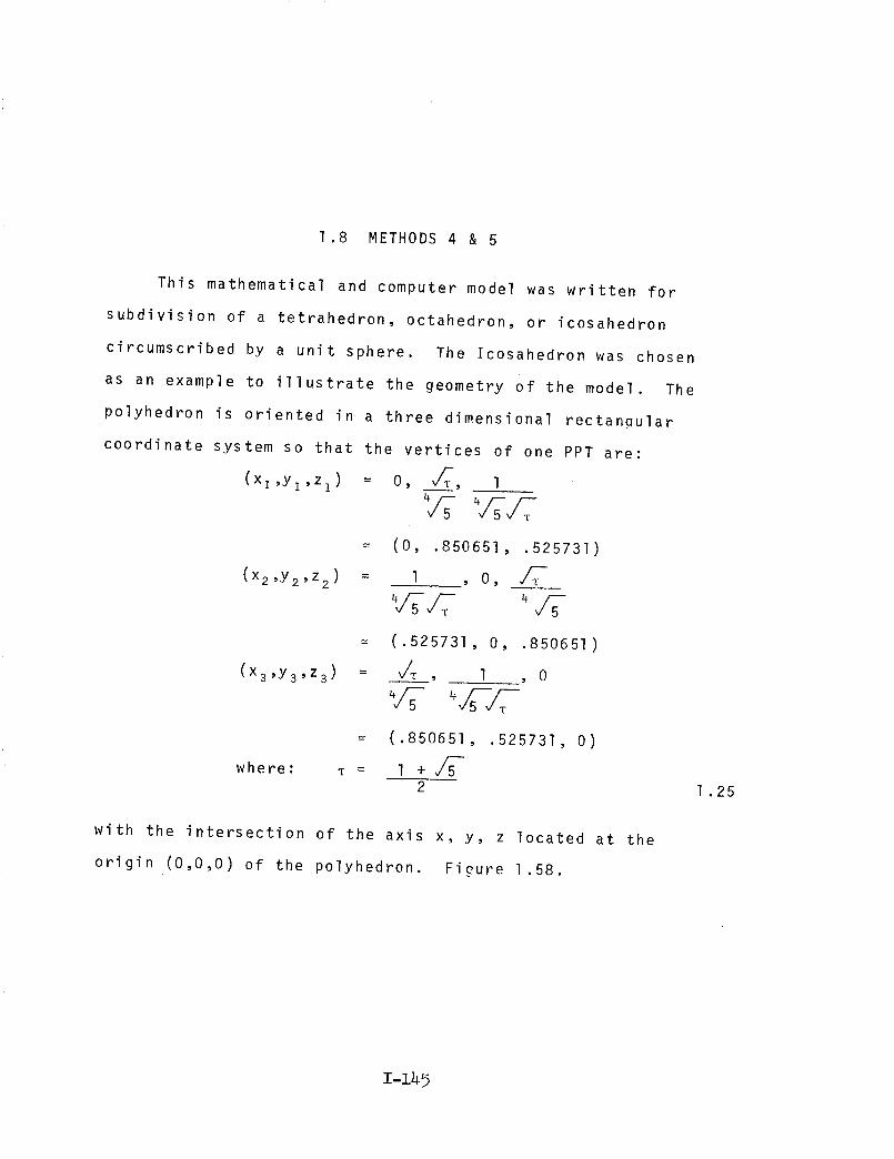
1.8 METHODS 4 & 5
This mathematical and computer model was written for
subdivision of a tetrahedron, octahedron, or icosahedron
circumscribed by a unit sphere. The Icosahedron was chosen
as an example to illustrate the geometry of the model. The
polyhedron is oriented in a three dimensional rectangular
coordinate system so that the vertices of one PPT are:
(xl 'Yl 'zl) = O, v/T-T, 1
(x2,Y2,Z 2 )
--- (0, .850651, .525731)
= 1 O,
(x3 'Y3 ,z
= (.525731, O, .850651)
: ,/T, 1 ,o
where:
= (.850651, .525731, O)
m = l + v/_-2
with the intersection of the axis x, y, z located at the
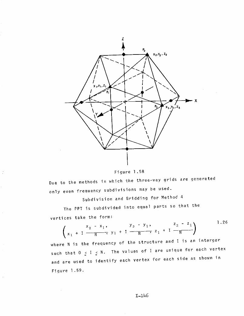
origin (0,0,0) of the polyhedron. Figure 1.58.
1 .25
1-149
Z
&
/X I,YI, Zl
/
X
,Y3, Z3
/
Figure 1.58
Due to the methods in which the three-way grids are generated
only even frequency subdivisions may be used.
Subdivision and Gridding for Method 4
The PPT is subdivided into equal parts so that the
vertices take the form:
z - z 1.26
x I + I N , Yl + I w- N , Zl + I N
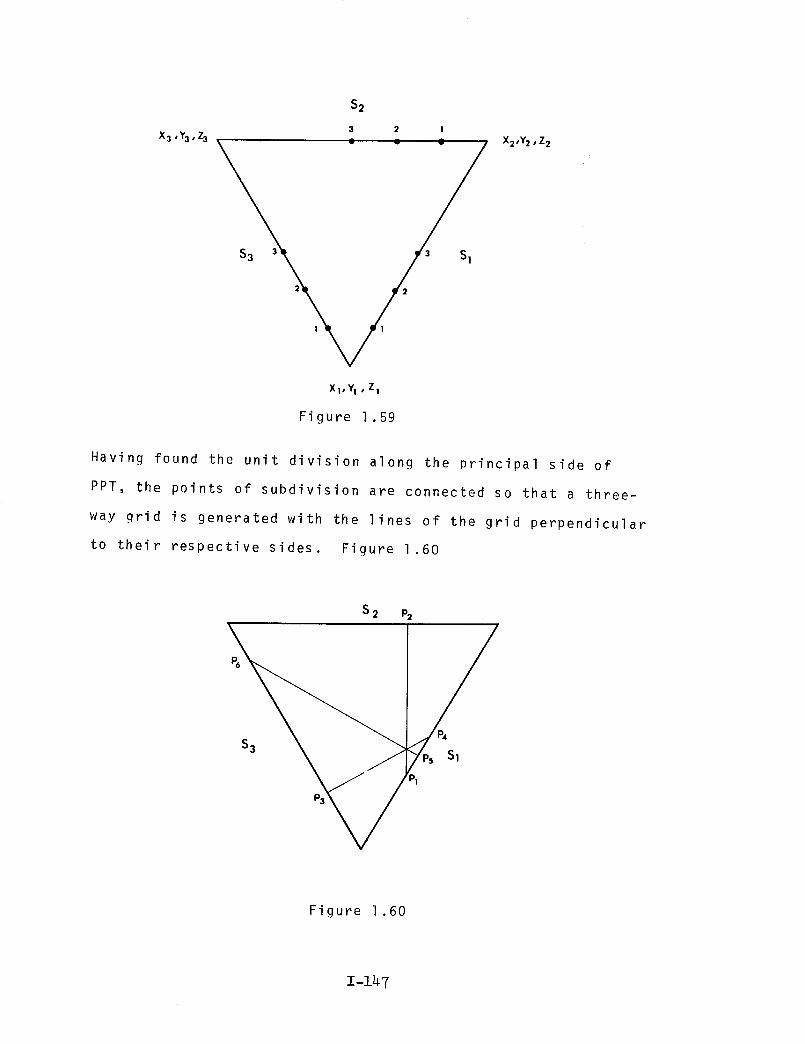
where N is the frequency of the structure and I is an interger
such that 0 } I _ N. The values of I are unique for each vertex
and are used to identify each vertex for each side as shown in
Figure 1 .59.
z-z46
x3 ,Y3, z3
S2
3 2 I
_\ /, _
XI,YI • Zl
Figure 1.59
X2'Y2 • Z2
Having found the unit division along the principal side of
PPT, the points of subdivision are connected so that a three-
way grid is generated with the lines of the grid perpendicular
to their respective sides. Figure 1 .60
S 2 P2
P_
S3Sl
P1
Figure 1.60
1-147

t_
v
c-O
°lI
..i.a
_J
co .._
iN
II c-.i.a
I
/>_. 4--II 0
I
X
°,
°r-
>_ N >,, NI I I I
>, N _ N
CO
+ + + +
c_ cqX _ X >_
I I I Io3,-4
II II II II
(xl ,--I
x >_ = >_I I X
c_l 1 I
-t- +
c- + +
°_'- m
I m _ _ N
(1# c_ cN I II::: >._ N
.io 4- X
e-°r-- I_'_ ,° "" °" "" ,_
•r-- .I-- °r-- ._-- .r-"
4-_ 0 Cq 0.] ._"
_- 13-
I-- _ _ v v v
_DII
II
>_ _
_ >_e4
_ .._ +
r_ _ +II II "'"
II IIe4 _ _ X
C_I I >_ X I
X '_I I X I I X
cO
..
(1.1
0
4-
cO
,-4I
H
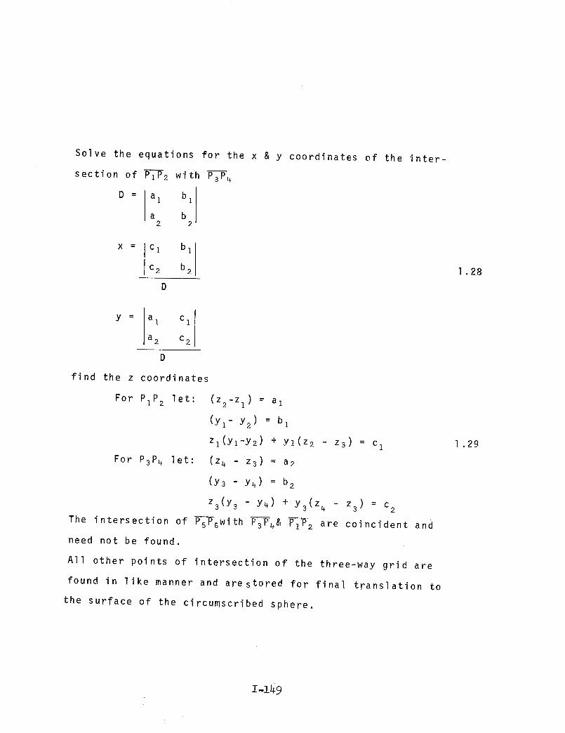
Solve the equations for the x & y coordinates ef the inter-
section of PIP2 with P--_4
D = a bi 1
a b2 2
X = C I b 1
c2 b 2
D
1 .28
y : a I C 1
a 2 c 2
find the z coordinates
For PIP2 let: (z2-zl) = a 1
(Yz- Y2 ) : bl
zl(Yl-Y2) + Y1(Z2 - z 3) = c
For P3P4 let: (z4 - z3) = a2
(Y3 - Y4) = b2
z3(Y 3 - Y4) + Y3(Z_ - z 3) = c 2
The intersection of P-_P-6with P--_4& F_F 2 are coincident and
need not be found,
All other points of intersection of the three-way grid are
found in like manner and are stored for final translation to
the surface of the circumscribed sphere,
1 .29
z-z49

Subdivision and Gridding for Method 5
With the following equations the planes consisting of
the edge of the PPT and the origin (0,0,0)are rotated from
3-space, Figure 1.61.
y,Y
/
Figure 1.61
x _ = XlX + PlY + VlZ
y : x2x + p2 y + v2z
z _ x3x + u3Y + _3 z
1 .30
Where x, _, _ are direction cosines of the X'-axis, Y_-axis, and
Z'-axis respectively with respect to the old axis and are found by:
JX 2 2 2X1 = i / xl + Yl + zl
y 2 2 2_I = 1 / xl + Yl + zl
_Z 2 2D1 = 1 / Xl 2 + Yl + Zl
X2' X3; _2' _3;and 92' _3
are found similarly.
I-zSo
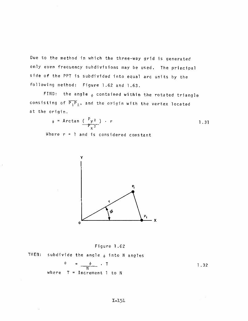
Due to the method in which the three-way grid is generated
only even frequency subdivisions may be used. The principal
side of the PPT is subdivided into equal arc units by the
following method: Figure 1,62 and 1.63.
FIND: the angle 6 contained within the rotated triangle
consisting of PIP2, and the origin with the vertex located
at the origin.
= Arctan ( Py2 ) rP2
x
Where r = 1 and is considered constant
l .31
¥
v
TH EN:
Figure 1.62
subdivide the angle _ into N angles
e = _ T
Nwhere T = Increment l to N
l .32
1-19i

Y
P2
P3
X
Figure 1.63
The points of intersection of O--P3 and PIP2 are found:
PIP 2 is Y - Yl = Y2 Yl
- X 1 X2 - X 1
0-_ 3 is y - 0 = Y3 - 0
X - 0 X 3 - 0
1 .33
The equation takes the following form:
PzP2 is x(y 2 - Yz) + Y(Xl - x2) = Yl(Xl - x2) + x (y2 - yl)
let (Y2 - Yl ) = al
(x 2 - Xl) : b I
Yl(Xl - x2) + Xl(Y2 - Yl) = ci
- = 0xy 3 yx 3
= aY._ 2
-X 3 = b 2
0 = C 2
I-1_2

Solve the equations for the point of intersection:
D_ i bbi[2
X=
C 1 b I
C2 b 2
DV_ a c
I i
a 2 c2
1 .34
Rotate the points of intersection along the PPT edge from
2-spaces back to 3-spaces.
X = %1 x" + ply" + Vl z
y = %2 x " + p2y" + _2 z
z = _ x" + _3Y" + _3 z3
where %, _, _, are direction cosines of the X'-axis, Y'-axis,
and Z'-axis with respect to the old axis and are found:
jJ2%1 = X 1 X I
/xI_I = Yl / I
= Z //X 2] 1 1
2 2
+ Yl + Zl
2 2
+Yl + z1
2 2
+ Yl + Zl
% , % ; P2, P ; and _2, _3 are found similarly.2 3 3
Retain the co-ordinates along the edges Sl, S 2
in Figure 1.64.
and S as shown3
1 .35
Z-Z93
X3,Y3, Z3
N 3 2 I
1 _" _" = /NX2'Y2'
2
3 2 3
X! ,YI, Z1
Z 2
Figure 1.64
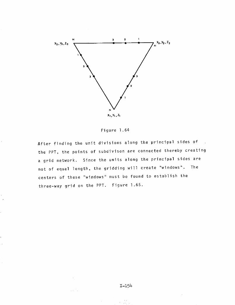
After finding the unit divisions along the principal sides of .
the PPT, the points of subdivison are connected thereby creating
a grid network. Since the units along the principal sides are
not of equal length, the gridding will create "windows" The
centers of these "windows" must be found to establish the
three-way grid on the PPT. Figure 1.65.
1-19_
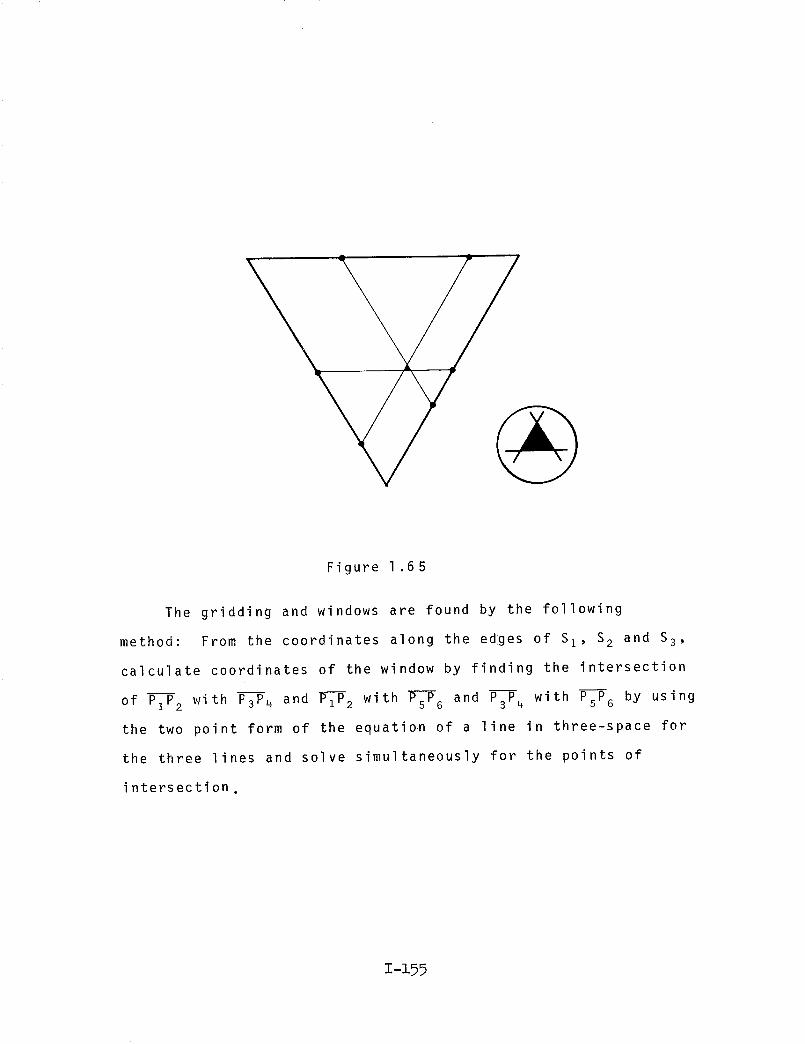
Figure 1.65
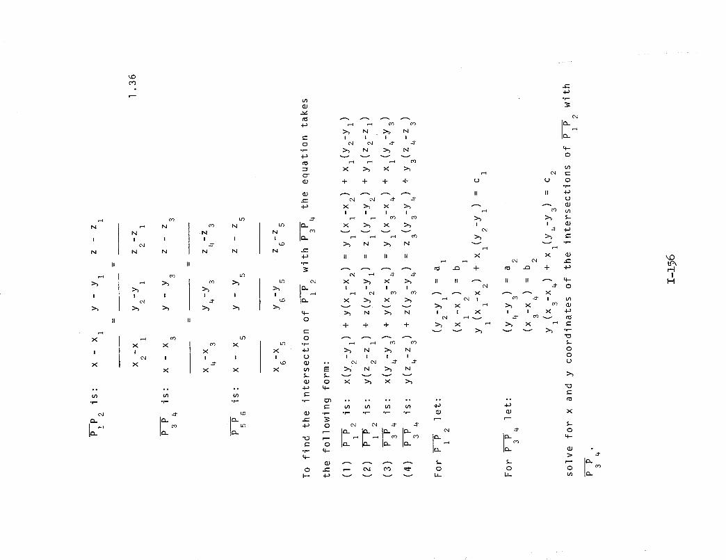
The gridding and windows are found by the following
method: From the coordinates along the edlges of S I, S2 and S3,
calculate coordinates of the window by finding the intersection
of PIP2 with P3P4 and PIP2 with PsPG and P3P4 with PsP_ by using
the two point form of the equation of a line in three-space for
the three lines and solve simultaneously for the points of
intersection,
I-i55
N
I
N
II
I
II
X
I
X
o°
°_
Q_
_O
CO
co
N
N
I I
c-I
N N
I I
c-I
.if co
x xI
c_ I
X
X
°°
°r-
I-o
co N
N
I I
._-
N N
II
I I
II
co X
X
I I
_1"
X X
o°
¢/)
.lII
_io
Iio
N
I
_o
N
I
_D
xI
_o
x
_J
r_
o
°_
_J
c-
°r--
e,l
0
N _ N
I I I I
>_ N _ N
x _ x >_
-I- -I- -I- -l-
x _ xI I I I
r-I CO CO
x _ x
_,, N _ N
II II II II
X _ X _ II III I I I cxl
_._ _ CO c_ _ _ X
X _ X _, _ _1 I
O
II
I
e,l
X
e-
4-_
('4
v v v v
N _ N
-I- -I- -I- -I-c-
._ _, N _, NU I I I I
I=:: _ N _ N
eJ o x _ xel.,.
c"
•;-- _ *° °° °° °° .°
•r=- *r- .r- °r-" ,_
• r- 4--
4-
0
e4 _
_ 0
*e-
ll iia
_3J
co
I _j
-_ ,la
:_, t-•i-I-
c,,I e,I
II II _ 4--
O
co _ i tPI
_ X _ _ X -I_
X ,_ _ X '_......_ _ .--.-..._. _ .,-
0
0
_._
c-
°°
0
L_-
X
S-
O
°
',.0
r-II
I-I
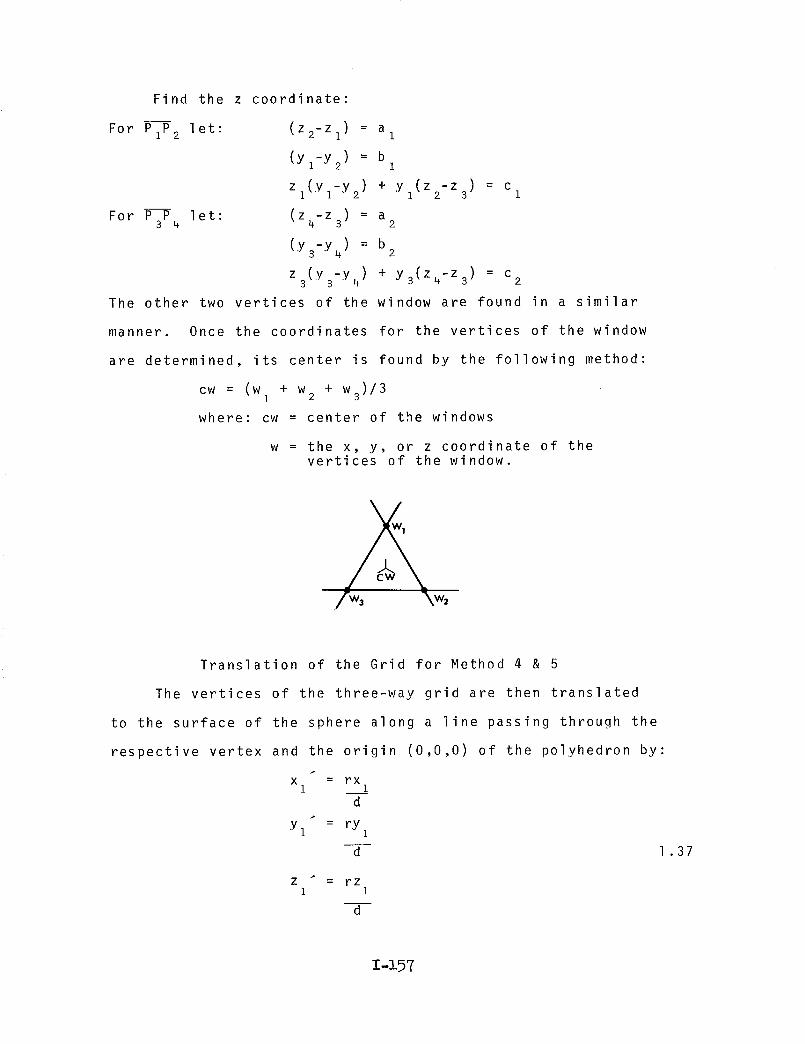
Find the z coordinate:
For P P let:1 2
For P P 1 et :3 4
(Z2-Zl) = a I
(yz-y2) = b I
Zz(yl-y 2) + yz(Z2-Z3) = c 1
(z4-z3) = a 2
(y -y ) = b3 4 2
z (y3-y) + y (z4-z) = c3 4 3 3 2
The other two vertices of the window are found in a similar
manner. Once the coordinates for the vertices of the window
are determined, its center is found by the following method:
cw = (w + w + w )/3I 2 3
where: cw = center of the windows
w = the x, y, or z coordinate of thevertices of the window.
Translation of the Grid for Method 4 & 5
The vertices of the three-way grid are then translated
to the surface of the sphere along a line passing through the
respective vertex and the origin (0,0,0) of the polyhedron by:
X = rxi 1
d
Yl = rYl
d 1 .37
Z _ = rz1 1
d
I-i57

Where:
and
and
where :
iX 2 2 2d I + Yl + zi
d = distance from origin to P1
r = the radius of the unit sphere
r = 1
Using the translated coordinates, this program finds the
lengths of the elements of the structure (_), the angle between
pairs of elements (face angle _), the angle between the elements
and a radius from the origin to an endpoint of the element
(axial angle _), and the angle between adjacent faces of the
structure (dihedral angle 8), Figure 1.66
T-i58

\ i//
//
\
/
!/
Figure 1.66
To find the angle between elements the face _ _, we use the
coordinates of their endpoints. The vertex of the angle is a
common endpoint to each element and is translated to the origin.
The other two endpoints PI and P2 are translated in the same
manner. Letting (Xz, Yl, Zl) and (xl, Yl, zl) be the points
resulting from the translations of the endpoints P and P1 2'
Z-z59
COS o_ = +z, 1XlX 2 + YlY2 1 2
-- d d1 2
v_X 2where dl= 1 2 + Yl 2 + Zl
/xx 2 2= 2 + Y + zand d 2 2 2 2
1 .38
is the desired angle.
To find axial angles the above method is used except that
the vertex is established at one end of an element and the
origin is used with the other endpoint to define the angle.
The desired angle is _.
The angle between two adjacent faces, the dihedral ), B,
is found using
COS B =-I AIA2 + BIB2 + CIc21
V/A J'A 2 22 + B 2 + C 2 2 + B + C1 1 1 2 2 2
1 .39
where
B is the desired angle.
AI X + B1Y + CI Z + D 1 = 0 defines the plane containing one
face and A2X + B2Y + C2Z + D2 = 0 defines the plane containing
the other face. The negative sign is used because the obtuse
angle is desired.
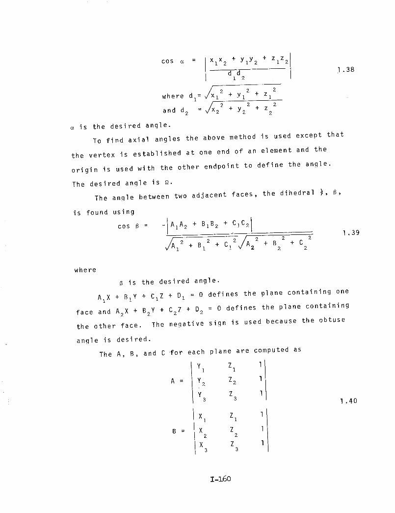
The A, B, and C for each plane are computed as
a
y Z 1I I
Y2 Z2 1
y Z 13 8 1 .40
B _
X Z l1 1
X Z 12 2
X Z 13 3
1-160
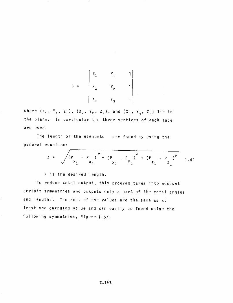
C
Xl Y1 1
X2 Y2 1
X3 Y3 1
where (Xl, Yz' Zl)' (X2, Y2, Z2), and (X 3, Y3' Z3) lie in
the plane. In particular the three vertices of each face
are used.
The length of the elements are found by using the
general equation:
= p _ p ) + (p _ p ) + (p _ p )2 1.41Xl X2 Yl V Z Z• "2 1 2
is the desired length.
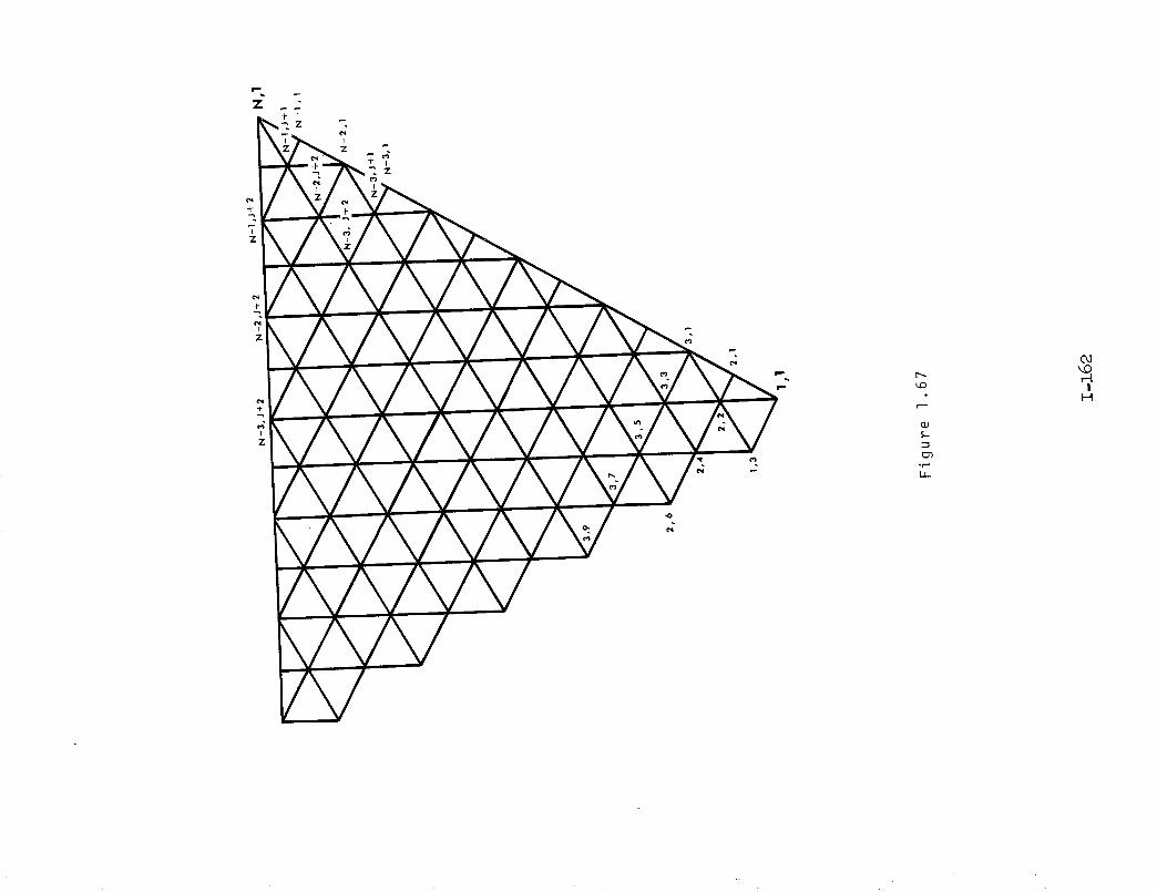
To reduce total outDut, this program takes into account
certain symmetries and outputs only a part of the total angles
and lengths. The rest of the values are the same as at
least one outputed value and can easily be found using the
following symmetries, Figure 1.67.
1-161
+
-i-
I
Z
I"--
',.0
S,-
L2
0,1_0r-4
II--I

THE COMPUTER PBOGP..a_4 DESCRIBED ON
PAGES 1-163 to 1-184
IS AVAILABLE FROM COSMIC


1.9 Methods 6 & 7
This mathematical and computer model was written for
subdivision of a tetrahedron, octahedron, or icosahedron
circumscribed by a unit sphere. The icosahedron was chosen
as an example to illustrate the geometry of the model.
The polyhedron is oriented in a three dimensional rec-
tangular coordinate system so that the vertices of one
PPT are:
(Xl' Yl' ZI)
(x2, Y2, z2)
(X3' Y3' Z3)
whe re : T
=( o, __g ' 4v_v__)
: (0, .850651 , .525731)
= (,850651, .525731, 0)
= (.525731, 0,.850651)
= 1 + _rg
2
1-189

The intersections of the axis X, Y, Z is located at
the origin (0,0,0)of the polyhedron. Figure 1.68.
(X3,Y3,Z3)
\\\y
/
/ \\\
X
X2,Y2,Z2 )
Figure 1.68
1-186

NIl-
l
N
II
"N
c-
% =0
Cl _0 k---•r- c-
O EO m
•r-" _--
°r- _'-
_ N O
= :5°r-- _-"
O _ _
e- O
c-"
•r-- _ °r-
>_ +._
t'-- _ c- m
"0 0
Ill-- 0 _V _ C"
"t-
O
°°0
IlL
°r-
Zr_
X
I--
O
e-I
N
+
O
N C'4
t,,- >_
°t-- N
C,l
| °r-
N C-I
I'-- Xv I
O
C-I
XI
v
e-"
4_
II
X
F--
N
F'-
N t'-
"I-
N
I-'-"
O
X
c-
-I-:'(..)
o_ II
"x :_
>-
r_
N
4._
II
N
I'--
b-COr--t
I
H

11 II
Xv
II
N
Xv
k-- I.--v v
_ _ 0
oI
b- I---v v
_ _ 0
0 .r-
CO
CO_-_
I
H
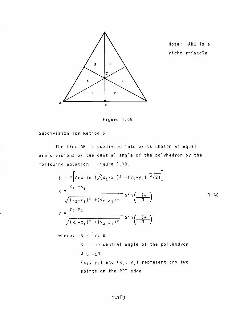
A w
C 4
Note: ABC is a
right triangle
Figure 1.69
Subdivision for Method 6
The Line AB is subdivied into parts chosen as equal
are divisions of the central angle of the polyhedron by the
following equation. Figure 1.70.
¢ = 2[Arcsin (J(x2-xl) 2 +(Y2-Yl)2/2)]
2 2 -x 1x -
J(X2-Xl)2 +(y2-Yl )2 N
Y2-Y ly =
J(x2-xl)2 +(Y2-Yl )2
Sin
where: 0 i/= 2_
= the central angle of the polyhedron
0 < I<N
(xl, YI) and (x 2, y2) represent any two
points on the PPT edqe
1.46
I-z89

(x2 ,v2)B
(X1,¥1) I/
//
//
//
-- 8 .._//
//
//
/o,o,o)
Figure 1.70
Subdivision for Method 7
The Line AC is subdivided into parts chose as equal
arc divisions of an angle made up of the triangle AC and
the origin of the polyhedron with the origin (0, O, O) being
the center of the triangle of subdivision. The following
equations are used for this subdivision. Figure 1.71
A: Arcsin [ 2, / ]3 (xl-x2)2 +(Yl-Y2 )2
2 (x2-x I )
x = Sin(NIA)
y =
3 /(x2-x I)2 +(Y2-Yz)2
2 (Y2-Yl)
3 /(X2-Xl)2 +(Y2-Yz )2 Sin ( N
1 .47
1-19o
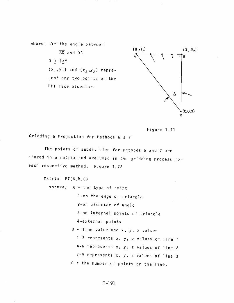
where: z_= the angle between
AO and OC
0 < I<N
(xl,Y 1) and (x2,y2) repre-
sent any two points on the
PPT face bisector.
(X1,Y1) (X2,Y 2)
'_ Le
0
Gridding & Projection for Methods 6 & 7
Figure 1.71
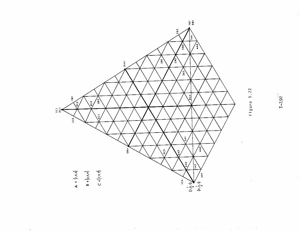
The points of subdivision for methods 6 and 7 are
stored in a matrix and are used in the gridding process for
each respective method. Figure 1.72
Matrix PT(A,B,C)
sphere: A = the type of point
l-on the edge of triangle
2-on bisector of angle
3-on internal points of triangle
4-external points
B = line value and x, y, z values
I-3 represents x, y, z values of line 1
4-6 represents x, y, z values of line 2
7-9 represents x, y, z values of line 3
C = the number of points on the line.
z-z9z
_ pa_ ao
C',d
r'--"
5-
olin
ii
fJO, iIc_
II--I

Once the subdivisions are found, they are used to find
points of divisions on the other two sides of the right
triangle by the following equations. Figures 1.73 & 1.74.
x : (Y1 +Xl [M21]) - ( l/3 -x 3 [M34])
M34 M21
y = x(M21 ) + yl-xz(M2z )
where:M21 =-x2-x I (neg. reciprocal of slope) 1 ,48
Y2-Yl
M34 = y3-y4 (slope)
X3-X 2
X4,Y4)
("_,h) (,,,,v,) (,,_,_'_)
A
Figure 1.73
1-193

and: x : (Y3 +Mix3) - (Yl +M2Xl)
where :
(M 2 - M
y = xM; +Y3 +x3M1
M1 - (--_--2)
M2 = Y2 -Yz
X 2 -X 1
1)
(neg. reciprocal of slope)
(slope)
1 .49
(xa,*a)
( X 2_'Y2)
F
(x,_)
(x,,,1)
I
i iA
Figure 1.74
1-194
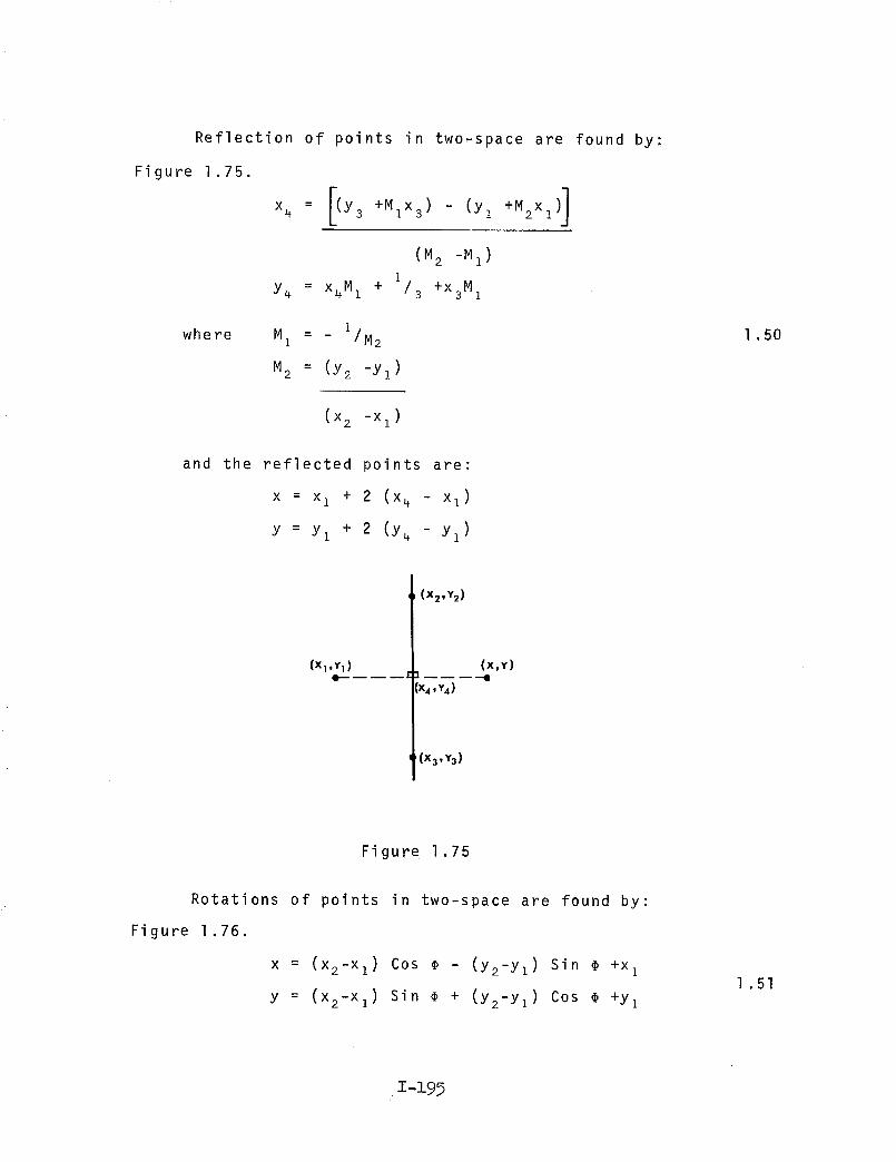
Reflection of points in two-space are found by;
Figure 1.75.
x4 = [(Y3 +Mix3) - (Yl +M2x1) ]
(M 2 -M 1 )1
Y4 = x4M1 + /3 +x3M1
where M1 = _ 1/M 2
M2 = (Y2 -Yl )
1 .50
(X 2 -X 1 )
and the reflected points are:
x = x I + 2 (x_ - x1)
Y = Yl + 2 (Y4 - Yl )
(X1 ,Y1 )
(X2,Y 2 )
'x4,Y.)
(X3,Y 3)
(X,Y)
Figure 1.75
Rotations of points in two-space are found by:
Figure 1.76.
X = (X2-Xl) Cos @ - (y2-yz) Sin _ +x I
y = (x2-xl) Sin _ + (y2-Yl) COS _ +Yl
1 .51
1-199
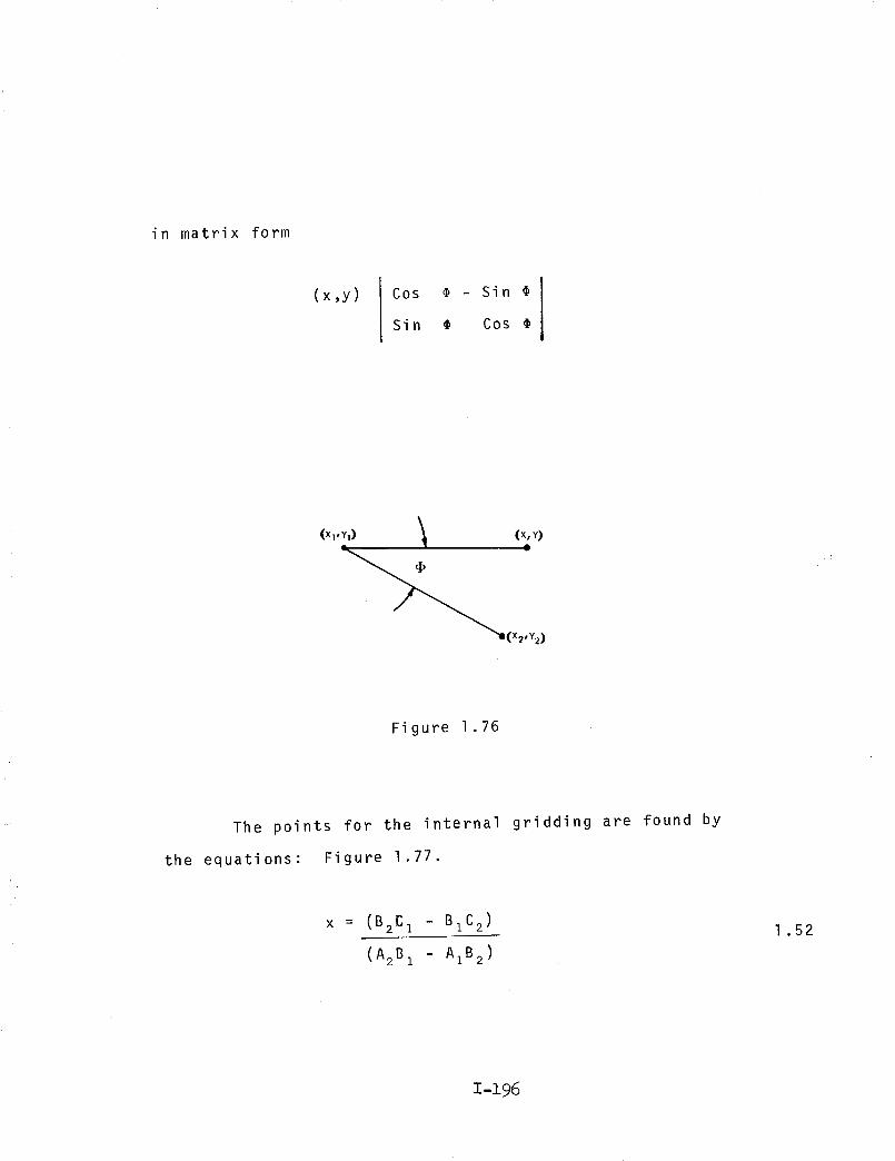
in matrix form
(x,y) Cos @ - Sin
Sin _ Cos
(XI,YI) _ (X, Y)
I
Figure 1.76
The points for the internal gridding are found by
the equations: Figure 1.77.
x = (B2C I - BIC 2)
(A2B 1 - A1B 2)
l .52
T_196

where :
y = (A2C I AIC 2)
(AIB 2 - BIA2)
AI= Y2 Yl
BI= x I - x 2
CI= Xl (Yl - Y2 )
A2= Y4 - y3
B2= x3 - x4
C2= x3 (Y3 -
+ Yl (x2 - Xl)
Y4) + Y3 (x4 - x3)
(x,,Y,)
A
Figure 1,77
Through rotations and reflections (equations 1,50, 1.51)
of the basic unit, the entire PPT three-way grid is found.
Figure 1.78
z-z9?

, j
p_J
J_J
A
"_JA
JJ
B
Figure 1.78
The external points of the PPT are found by equation
1.52 and are rotated into their respective plane by equation
1.44 where: the angles of rotation are found by equation
1.43. The external points are rotated by equation 1.51
to their respective positions.
All points of the three-way grid are then rotated into
three-space using equation 1,45
where : T z = 211 T z
Ty = 211 - Ty
T = 211-TX X
are the angles of rotation.
The origin is then retranslated to its original
position by:
1 .53
z-z98

where :
s
x = x+TX
' Tyy : y +
z' = z + T z
(Tx, Ty, T z)
the coordinates to which the origin was
originally translated to.
All points of the three,way grid are then projected
to the surface of the sphere by: Figure 1.79
XX J =
Dis
Yy' -
Dis
ZZ t =
Dis
where: Dis = j(x) 2 + (y)2 + (z)2
1 .54
1 .54
/!
!
Figure 1.79
1-199
For the PPT, the number of:
edges = 3_(3_ - 2)
8
half edges = 3_
2
faces = 3_(_ - 2)
4
half faces = 3_
vertices = 3_(_ + 2)
+ 1
8
where:_ = frequency and must be even
For the total spherical form, the number of:
2E_
Edges = 34
2
Faces = E_
2
Vertices = E_4
+ 2
where: E = no. of edges in polyhedral unit.
Using the coordinates, the lengths of the elements of
the structure (_), the angle between pairs of elements
(face angle _), the angle between the elements and a radius
from the origin to an endpoint of the element (axial angle _),
and the angle between adjacent faces of the structure
(dihedral angle 8), are calculated. Figure 1.80
1 .55
1-200

\
\
Figure 1.80
To find the angle between elements, the face _ _, we use
the coordinates of their endpoints. The vertex of the angle is
a common endpoint to each element and is translated to the
origin. The other two endpoints, PI and P2 are translated
in the same manner. Letting (x l, Yl, Zz) and (x 2, Y2' z2)
be the points resulting from the translations of the end-
points P1 and P2'
COS o_ =
where d =1
xlx2 + YlY2 + ziz2
did 2
_Xl 2 + yl 2 + ZI2 1 .57
1-201

and d2 = v/x2 2 + Y2 2 + Z2 2
is the desired angle.
To find axial angles, the above method is used except
that the vertex is established at one end of an element and
the origin is used with the other endpoint to define the
angle. The desired angle is _.
The angle between two adjacent faces, the dihedral_ B,
cos 8 =
is found using
where
-IA A2 + BIB 2 + CIC21
2+ C222+ C12 J A22+ B2AI2+ B I
l .58
8 is the desired angle.
AI x + BIy + CIZ + D1 = 0 defines the plane containing
one face and
A2X + B2Y + C2Z + D2 = 0 defines the plane containing
the other face.
The negative sign is used because the obtuse angle is desired.
The A, B, and C for each plane are computed as
A
Y Z l1 I
Y2 Z2 1
Y_ Z 3 1
B
X l Z I 1
X2 Z2 1
X3 Z 3 1
1 .59
1-202

C
X Y 1I 1
X Y l2 2
X Y l3 3
where (X , Y , Z ), (X , Y , Z ), and (X , Y , Z ) lie in1 1 1 2 2 2 3 3 3
the plane. In particular, the three vertices of each face
are used.
The length of the elements _ are found by using the
general equation:
/(p _ p )2 + (p _ p )2 + (p _ pxl x2 Y2 Y2 z 3 z 3
is the desired length
)2
1 .60
At the time of publication, the computer programs for
these methods had not been completed and therefore, have not
been included in this report.
NASA-Langley, 1971 -- 32 0R-1734 1-203
