search.jsp?r=19930093875 2019-07-23t19:04:25+00:00z · where wh = kwu' is the flh is the...
TRANSCRIPT

https://ntrs.nasa.gov/search.jsp?R=19930093875 2019-08-12T15:48:37+00:00Z

NATIONAL ADVISORY COMMITTEE FOR AERONAUTICS
TECHNICAL MEMORANDUM 1355
STUDY OF THE SUPERSONIC PROPELLER*
By Jean Fabri and Raymond Siestrunck
1. INTRODUCTION
The successful development of the turbo jet does not necessarily e n t a i l the abandonment of the propeller a t high subsonic speeds. In fac t , both originate from the same principle: increasing the momentum of the air which they pass through. propeller, i n s t i r r ing up a large amount of air, furnishes only a slight increase of speed, the j e t at the ex i t of the j e t engine must be greatly accelerated t o comgensate the lack of quantity. Thus, there i s a dis- proportion between the speed of advance and the speed of the j e t which prevents the efficiency from reaching i t s maximum value.
t o furnish a thrust by While the
This lack of proportion does not ex is t f o r the supersonic propeller; i n reality, the three speeds involved i n its operation - speed of air at inf ini ty downstream, speed of a i r at in f in i ty upstream, and speed of rotation - are of the same order of magnitude.
A s regards the losses due t o compressibility, they are especially important f o r the transonic speeds; by a suitable choice of the propeller di&nsions so as t o obtain a supersonic relative flow along the blade, these losses are likewise eliminated.
Lastly, direct mounting of the propeller on the turbine shaft gives the supersonic-turbopropeller group the s h p l i c i t y that characterizes the supercharger.
2. SUMMARY ANALYSIS OF THE EFFICIENCY OF A PROPELLER-JET
SYSTEM ( R e f . 1)
2.1. Consider an airplane driven by a propeller and a jet simultane- ously. The performance of such an aircraf t , moving at forward speed V,
*"&ude de L ' g l i c e Supersonique ." E x t r a i t des Actes du Colloque International de Mf?canique, Poitiers 1950, V o l . I. Scientifiques e t Techniques du Minist'ere de l'Air, No. 248.)
(Publications

2 NACA 'I'M 1355
can be characterized by the thermodynamic power
Wth = W,' + m
where Wul i s the s t a t i c power furnished conditions of pressure and density and m by the propulsive horsepower
where wh = kWu' i s the flh i s the efficiency of
= Nwh + m" (VI' -
mechanical power
v2 2
by the engine under identical i s the mass flow of fuel, and
V)V + mv2
absorbed by the propeller, the employed propeller, mrl is the t o t a l mass
ejected by the j e t engine, and V" = h"V simplification a l l velocities are assumed parallel t o the forward direction).
i s the j e t velocity (for
In these conditions, the propulsive efficiency of the propeller- j e t system, defined as ra t io of the propulsive power t o the thermodynamic power, reads
k%Wu' + V2(mt'X" - m" + m) wP
? ? = - = Wul + m V2 - 2
'th
unit fue l
v VU' In defining a velocity coefficient = - where - the m ' E' horsepower of the engine, characterizes a t the same time the uti l ized and the thermal efficiency of the engine, and a dilution coefficient
m" p, = - 0 the efficiency reads m '
A s the r a t i o between the power absorbed by the propeller and that remaining in the j e t i s characterized by the relation

NACA TM 1355 3
which becomes with the above notations
the propulsion efficiency takes the form
(3) 1
b = l . p
For given conditions of flight, $ becomes maximm when the r a t i o coefficient k has the value
with
2.2. Example.
Consider the case of a propulsor driven a t a speed of 208 m/sec (close t o 750 km/h) . The propeller driven by an ordinary gas turbine (y = 4.4 x lo7 'J, p = 60 has an efficiency of = 0.7.
/
t
According t o figure 1, which represents the efficiency cycle i n relation t o the coefficient of ra t io k, the maximum efficiency differs very l i t t l e from that of the propeller alone, whereas the efficiency of the j e t i s even lower in the contemplated conditions of f l igh t .
This example shows that the supersonic propeller should be practical i n the transonic and slightly supersonic speed range, provided that i t s efficiency i s satisfactory (N = 0.7 for example), which seems t o have been accomplished, according t o the data given la te r .

4 NACA TI4 1355
For higher speeds (superspeed range), the j e t engine having a higher efficiency is of greater interest.
3. GENERAL ASPECTS OF SUPERSONIC PROPEUXRS
3.1. The aerodynamic study of propellers i n the low-speed range has been faci l i ta ted by the identification of the helicoidal symmetry of the turbulent wake (ref. 2); reduction of the variables t o two permitted the study of the performance by various methods, producing homogeneous results and confirmed by experiment (ref. 3) .
No comparable t e s t data are available i n the supersonic speed range and the general equation of helicoidal potentials i n compressible f lu id (ref. 4) i s not amenable t o calculation even in i ts linearized f om.
3.2. Being unable t o comgute the induced velocities, we content ourselves w i t h approximations obtained from general considerations the use of which up t o now seems justif ied only by reason of i t s simplicity.
Distinction should be made between (a ) the propeller slips-bream which has the effect of modifying the true incidence of the blade profiles and (b) the interference of the divers sections and particularly the effect of the t i p and the huk.
The f i r s t effect, extremely important a t take-off (low forward speed), must not be neglected even in n o m 1 operation. As t o the second, i t s effect is considerably l e s s as the relative speed, supersonic, i s greater.
3.3. The performance of the propeller is characterized by the thrust coefficient
the power coefficient
and the efficiency

NACA TM 1355 5
These coefficients depend, at the same t i m e , on the Mach number m v of translation V = forward speed, a = speed of sound i n air at
\ / n u and on the Mach number M of rotation M = fin a, n = revolutions
) \
per second and D = outside diameter of propeller . The conventional. formulas of propeller theory are generalized by
taking h = as performance parameter, the compressibility being
characterized by M. M
The following formal equations give the performance factors
8 - X = p s (A + v)Etcz\lh2 + 5' d5 + p s ( E + u ) t c , { m 5 d5 fi 3
J
where 5 is the radius of a blade section, u,v i s the induced taxgentid. and axial velocities, and p i s the number of propeller blades. (The lengths are referred t o the propeller radius and the speeds t o the peripheral speeds.)
t i s the relative chord of the particular section,
4. UNIQUE SECTION METHOD
4.1. This method, which gives excellent results i n the case of the classical propeller, can be adapted t o the case in point. In t h i s study, it i s assumed that the performance parameter X has a satisfactory value so that the induced velocities may be disregarded i n the over-all forces, without appreciable error. In the subsequent chapter, these induced velocities are introduced i n the geometric determination of the blades and i n the analysis of the operating speeds a t low values of h.
Since, i n order t o assure satisfactory aerodynamic blade performance, the entire relative f low must be supersonic, the hub radius i s always
very important 50 > - where 50 is the relative hub radius . In these
conditions, the blades are s m a l l , so that t c z i m and t c , / n ' ) 1 ( MY

6 NACA TM 1355
can be assumed constant and equal t o the values i n the m e a n blade section
defined by Em = {- Overlining these mean values
the other integrations, the system (4) becomes (u,v - 0).
effecting
4.2. From the values of T and X deduced from the system ( 5 ) , the propeller efficiency follows as
and, w i t h T denoting the fineness of the mean profile
l + S o - f - h
- The equation (6) shows that t o each couple of values of f and 50,
there corresponds an optimum value of performance coefficient

NACA 'I'M 1355 7
Figure 2 represents the variation of hop* and the corresponding efficiency plotted against efficiency against h for f = 8 corresponding t o a supersonic a i r f o i l of about 6-percent thickness. efficiency exceeds 70 percent fo r
f o r go = 0.6, and figure 3 the change i n
It w i l l be noted that the propeller X > 0.3.
4.3. Use of theoretical. polars.
In the absence of experimental data on the supersonic a i r fo i l s , recourse is had t o the theoretical polars given by the linearized method
where M = /M2Em2 + m2 i s the relative Mach number i n the mean section, i is the incidence ( in radians), and where 6 differs very l i t t l e with the thickness of the employed profile.
In these conditions, the system (5) becomes
The value of the efficiency i s
G
1 + 5 0 i + 1 + 50 + 50 2 (i2 + $) x
2 3
which, i n the specified performance conditions i s maximum f o r (profile set a t incidence of maximum efficiency) . i = 6

8 NACA TM 1355
4.4. Example (similar t o a case studied a t the request of the S.N.E.C.M.A.).
Determination of a propeller in the following conditions:
Power absorbed . . . . . . . . . . . . . . . . . . . . . . Wn = 2080 kW Altitude of f l igh t . . . . . . . . . . . . . . . . . . . . . Z = 9000 m Velocity of sound . . . . . . . . . . . . . . . . . . . a = 300 m/sec Specific mass of the a i r . . . . . . . . . . . . . t /m3 Flying speed . . . . . . . . . . . . . . . . . . . . . . . V = 208 m/s Rate of rotation . . . . . . . . . . . . . . . . . . . . N = 5600 t/mn Diameter of hub . . . . . . . . . . . . . . . . . . . . . Do = 1.33 m
P = 4.65 x
The choice of the peripheral speed determines the outside diameter, thus, f o r 700 m/s (or I4 = 2.33) D = 2.39 m, hence
50 = 0.56 5, = 0.81 A = 0.3
The corresponding power coefficient i s
x = 0.071
Taking for X the expression ( 7 ) , the incidence i s located at the relative chord by the following equation (profile set a t incidence of maximum efficiency)
0.00124 t
= o 2 0.551 + 0.102i -
i n the case of a propeller with s ix blades (p = 6).
Figure 4 shows the variation of the efficiency and the mean incidence plotted against the chord t.
As the relative thickness of the profile cannot f a l l below a certain l i m i t , we take, fo r e x q l e
p = 6 t = 0.168 i = 6 = O.O67(3.8')
hence
T = 700kg and = 0.70

NACA TM 1355
5 . CORRECTION FOR SLIPSTREAM
9
5.1. In the absence of an exact method of evaluating the velocities induced by the free vortices, a generalized approximation of that used fo r the conventional propellers i s applied.
Limiting the study t o propellers with subsonic forward speed (m < l), the absolute speed i s subsonic a t every point. And then it can be assumed that the evaluation of the induced velocities i s similar t o that observed on ordinary propellers, and particularly, t o those which assume, in the propeller plane, a value half of that assumed at infinity downstream i n the wake.
Applying the classical reasoning gives, in this case, the usual values
r = e being the circulation of the mean section and 2
X* = 5 the real speed of the streamline a t the crossing of the
plane of the propeller. E. + u
The axial velocity v, very important a t the fixed point, is involved in a l l conditions f o r the determination of the setting; whereas, the tangential velocity u is generally negligible, hence
h * - h + v
5.2. Operation at the fixed point.
The Induced velocities are very important in the study of fixed point operation ( h = 0, M - = ME ) . In calling 2 the particular value of X* corresponding t o the fixed point, - v, according t o equa- t ion (8)

10 NACA !L'M 1355
and the system (7) becomes
8 2
- - r - A
8 - x - A 3
J -l
5.3. ExampleL.
Performance of supersonic propeller a t the fixed point:
Power absorbed . . . . . . . . . . . . . . . . . . . . . . . Wh = 74 kW Rate of rotation . . . . . . . . . . . . . . . . . . . . . N = 12000 rpm Speed of sound . . . . . . . . . . . . . . . . . . . . . . . a = 340 m/s Air density . . . . . . . . . . . . . . . . . . . P = 12.25 X lom4 t / m 3
Tak ing M = 2 and 5 0 = 0.6 we get
Outside diameter . . . . . . . . . . . . . . . . . . . . . D = 1.08 m Power coefficient t o be realized . . . . . . . . . . . . . . x = 0.00514
The results obtained with a two-blade propeller are given i n f ig- ure 5; since the thickness of the profile cannot drop below 0.06, the two-blader is defined by
t = 0.1 i = 6 = 0.061(3.5')
which i s most interesting.
5.4. Setting of profiles.
The induced velocities determine the setting of the profiles. In fact , incidence i, setting a and performance parameter X are limited by the relation
i = a - arc tan - h v - - (10) 5 5
%'his case corresponds t o tests contemplated; the propeller i s t o be driven by a Turbomeca gas turbine.

NACA TM 1355 Ll
Thus, i n the exanrple 4.4, the induced velocity, the root of the equation
o r
? + h v + i P t f W = o
sh i f t s the setting from
a = i + arc tan = 23.94' !
t o
h v a = i + arc tan + - = 25.12' F 5
Similarly, in example 5.3, the setting i s
A
h a = i 4- - - 5.90 5
instead of
i = 3.50 if the induced velocities are neglected.
5.5. Performance curves.
We are now prepared t o study the performance curves of a given propeller as function of A, M and sett ing a (a supersonic propeller must, of course, be of the variable pitch type). join t o the system (7) the relations
It is sufficient t o

12 NACA TM 1355
which combined give an equation of the second degree defining the incidence and the induced axial velocity. t i o n i n relation t o A, T, X, and for the case of the propeller 4.4, near i t s design conditions.
Figure 6 shows the varia-
6 . INTERFERENCE OF DIVERS SECTIONS
6.1. Effect of t i p and of hub.
Aside from the velocities induced by the slipstream, the interference of various sections must also be taken into consideration. This inter- ference, due t o the nonunifomity of the flow, has no appreciable effect except at the blade t i p and near the hub.
There i s no exact theory on the interference of blade sections, but the following considerations make it possible t o determine the order of magnitude of the corresponding correction (ref. 5).
It should be noted that, since the relative f l o w i s supersonic, any disturbance created a t one point i s transmitted only t o the inside of a zone of action, the characteristic conoid of the equation satisfied by the potential of perturbation.
In addition, the method of load distribution over a l i f t i ng surface in supersonic translation (ref. 6), which gives satisfactory results f o r rectangular w i n g s , i s also generalized. By considering only blades w i t h leading edge normal t o the relative sound (a nonrestrictive condition which i s a result of the form imposed by the strength of the materials), it i s assumed that any local variation of the slope of the contour of each profile induced inside of the characteristic conoid of f low issues from the point considered; value of the velocity i s supplied by the two- dimensional theory of forward f low, the Mach number of the comparative flow being, of course, the Mach number of the profile in i t s relative motion. t o the velocities induced by all the disturbances sent out t o the inside of i t s characteristic forecone: (6,~) of the blade is given by
The pressure a t a point i s the mean of the pressures corresponding
the pressure coefficient a t the point

NACA 'I'M 1355 13
where M - = d w , and 5 , - 52 coordinate in question.
6(5,~) denote the slope of the profile contour the parallel portion a t the leading edge comprises the
7 a t the inside of the characteristic forecone of the point
6.2. zone of influence.
As said before, a disturbance sent for th . makes i t se l f f e l t only a t the inside of the characteristic cone of t h i s point. camber line of the blades as reference surface, the l i m i t of the zone of influence can be defined as the curve forming in each point the Mach angle, arc s i n 1/K with the velocity. This l fmit is thus defined as integral curve of-the differentia3 equation
U s i n g the mean
passing through the particular point, that is
2 rn +/i@xK-i - log M ME, + /M-
Figure 7 represents the family of characteristic curves corresponding t o the following conditions
M = 2.33 m = 0.7
It i s readily seen that the interference assumes significance only f o r slightly supersonic speeds.

14
6.3. Corrections f o r nonuniform f l o w .
NACA !l'M 1355
The integral (11) represents the mean value of cp i n the char- acter is t ic forecone of the point ( 5 , ?). a uniformly increasing function of and the slope variations remaining small, t h i s mean value of cp differs very l i t t l e from the value of cp in the medium section; that is, i n a l l sections that are not influenced by the blade t ips, the pressure coefficient can be computed as if that section were located i n a two-dimensional flow of Mach number M, = I/-.
The relative Mach number being
6.4. Effect of free blade t i p . i
The decrease in lift a t the blade t i p (cz = 0 f o r 5 = 1) i s taken into consideration by a generalization of the classical mthod of images, that is, by extending the blade by a symmetric f ic t i t ious geometric surface of the mean camber l ine of the blade w i t h respect t o the relative upstream velocity of the marginal section and placed w i t h the incidence
opposite t o that of the blade in a flow of Mach number M - = /M2(2 - E ) z + m2.
This reduces the problem t o that of considering f ic t i t ious pressure coefficients a t the inside of the marginal characteristic conoid corre- sponding t o this new l i f t i ng surface and additive t o the real pressure coefficients due t o the velocities induced by the blade i t s e l f .
With + referring t o quantities relating t o top camber and - t o bottom .camber, this f ic t i t ious l i f t i n g surface i s defined by
2
the incidence i and the local slopes 6, and 6, b ing me sured i n the symmetrical section of the particular section w i t h respect t o the t i p of the blade.
6.5. Effect of hub.
A similar image takes care of the condition a t the hub; that i s , 5 = 5 0 , the due t o the fac t that the radial velocities cancel out f o r
blade i s prolonged by a f ic t i t ious wing defined by
NACA TM 1355 15
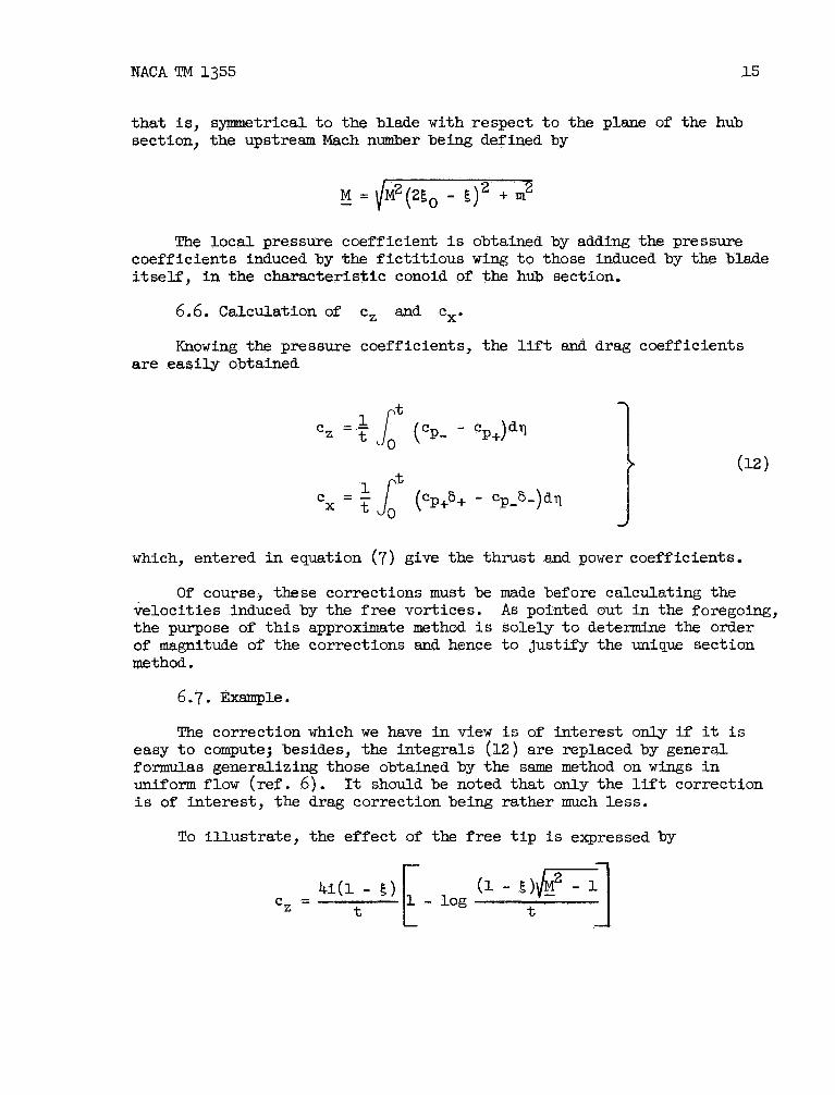
that is, symmetrical t o the blade with respect t o the plane of the hub section, the upstream Mach number being defined by
"he local pressure coefficient i s obtained by adding the pressure coefficients induced by the f ic t i t ious wing t o those induced by the blade i tself , i n the characteristic conoid of the hub section.
6.6. Calculation of cz and e,.
Knowing the pressure coefficients, the l i f t and drag coefficients are easily obtained
J
which, entered i n equation (7) give the thrust and power coefficients.
Of course, these corrections must be made before calculating the Tielocities induced by t h e f ree vortices. the purpose of this approximate method is solely t o determine the order of magnitude of the corrections and hence t o justify the unique section method.
As pointed out i n the foregoing,
6.7. Exanrple.
The correction which we have in view i s of interest only if it i s easy t o compute; besides, the integrals (12) are replaced by general formulas generalizing those obtained by the same method on wings i n uniform f l o w ( ref . 6). i s of interest, the drag correction being rather much less.
It should be noted that only the l i f t correction
To i l lustrate , the effect of the free t i p i s expressed by
4 i ( l - E ) E (' ~ ) ~ ] t - - log cz - t

16
f o r
NACA TM 1355
In the part not disturbed by the t ips we simply get
4 i cz =
A s regards the effect of the reflection on the cylindrical wall of the hub, it i s relatively unimportant and the approximate l i m i t value i s simply written as
with
Figure 8 shows the evolution of the l i f t coefficient obtained.by th i s method, by coqaring it t o the i n the case of the propeller 4.4, where k* - X + v w a s assumed constant over the blade, the setting of the profiles being such that the incidence i s constant and equal t o 4 O .
cz of the two-dimensional method,
7 . CONCLUSION
This study of the supersonic propeller i s merely an attempt t o determine the order of magnitude and the direction of variation of the performance characteristics.
The results obtained indicate that, i n a reasonably wide speed range (transonic and slightly supersonic), the propulsive efficiency of the supersonic propeller can be as high as 70 percent, a t least , when assuming that the a i r fo i l characteristics are comparable f o r rota- t ion and fo r translation.

NACA TM 1355 17
To be sure, the mechanical difficulties should not be underestimated, particularly those concerned with pitch-changing devices as w e l l as those arising from high rotational speeds.
Nevertheless, direct mounting of the supersonic propeller on the turbine shaft is possible and the propeller can certainly provide appreciable service in the propulsion range considered.
Tanslated by J. Vanier National Advisory Committee for Aeronautics

18 NACA TM 1355
1. Roy, M.: Thermodynamique des systkmes propulsifs 'a rgaction. Cours -profess& au C.E.S.M., Dunod, Paris, 1947.
2. Siestrunck, R.:
3, Siestrunck, R.: &oulements potentiel dans l e s machines hdlicoydales
Le d6veloppement moderne de l a thdorie de l 'h6lice. Gauthier-Villars, Paris, 1947.
simples, O.N.E.R.A., 32, Paris, 1949.
4. Siestrunck, R., and Fabri, J.: Sur l'e'quation ggdrale des potentiels h6lico'idaux en fluide compressible. Sciences, 226, 1948, p. 1430.
Comptes rendus Acadgmie des
5. Siestrunck, R., and Fabri, J. : dues a m vitesses induites dans l e s machines axiales a'vitesse relative supersonique. 1948, p. 1795.
Dktermination approachge des corrections
Comptes rendus Acaddmie des Sciences, 226,
6. Fabri, J.: Sur une me'thode approch6e de calcul des r6partitions de es 8, bord d'attaque supersonique. charges sur des surfaces port
Comptes rendus Acadkmie des Sciences, 226, 1948, p. 1172.

NACA TM 1355
Figure 1

20 NACA TM 1355
Figure 3

NACA TM 1355 21
Figure 4
Figure 5

22 NACA !I'M 1355

NACA 'I'M 1355
I Leading edge ...
Trailing edge..- .
t = 0.17
Figure 7
Figure 8
NACA-Langley - 3-13-53 - 1000