racegr ade technical note remote battery...can be turned on or off at will without invoking the kill...
TRANSCRIPT

Technical Note
Document Number RG_TN-0014
Title Remote Battery Disconnect
Revision Date Prepared By Change History
0.9 10/02/2013 Chris Brown Beta release
© RaceGrade, a division of JGM Automotive Tooling Page 1 of 5
MoTeC is a registered trademark of MoTeC Pty..
RaceGrade
Introduction
The RBD-190 PRO is designed to be the main battery isolator / switching element in a control system
utilizing a MoTeC PDM power distribution module which is sold separately. It safely disconnects the
battery using simple toggle switches that can be mounted anywhere.
Specifications
Max Continuous Current: 190 amps
Max Peak Current: 1000 amps
RBD-190 PRO
Dual Battery Disconnect

RaceGrade RG_TN-0014 Remote Battery Disconnect
© RaceGrade, a division of JGM Automotive Tooling Page 2 of 5
Switch Panel Installation
Use the provided plastic template for accurate cutout of the panel
where you wish to install the faceplate. Feed the harness through the
completed opening and secure with 4-40 screws and locking nuts.
(not provided)
Switch Panel Information
The switch faceplates are available for either
horizontal or vertical orientation. The kit is supplied
with one faceplate of your choice.
Note: Indicator LEDs turns off when battery voltage
falls below 9.8 volts, indicating a low battery.
Note: One battery must maintain enough power in
for the selector to switch on or off either battery. If
both batteries are dead, the electronic control
selector can not turn either battery on.
Battery Select Switches
The switch panel has two switches with lock-out toggles, one each for each battery labeled A and B.
Each switch has three positions; a center lock-out and two momentary
positions to activate On and Off. To turn on either battery simply move the
respective toggle to On. If the battery has more than 9.8 volts, an indicator
will illuminate. To turn a battery off, toggle the respective switch to Off.
Master Switch
The master switch determines which one of the two battery select switches will kill the engine when
toggled off.
Assuming both batteries have a usable charge, either battery can be chosen as master. You may
want to alternate back and forth between batteries at selected intervals. To select a battery as
master, flip the master toggle lever toward the respective battery. The battery selected as master will
automatically shutoff four seconds after a kill sequence is initiated. The battery Not selected as master
can be turned on or off at will without invoking the kill function.
Attach any other parallel emergency switches as required per drawing. In order for the external
switches to provide simultaneous battery shutdown, dual pole switches should be chosen.
Connection to MoTeC PDM
Attach purple wire to any MoTeC PDM input and program the PDM to use that input as the master kill
switch to control which devices turn off in a specific sequence if required.
Toggle switches must
be pulled out of their
detent to move.
Horizontal Plate
Vertical Plate
Cut Out Template
RaceGrade RG_TN-0014 Remote Battery Disconnect
© RaceGrade, a division of JGM Automotive Tooling Page 3 of 5
Kill Function
In case of an emergency or accident, additional switches (not provided) may be added in parallel to
the driver operated battery selector switches. These additional switches maybe be used to allow
course workers or bystanders to shutoff the engine and electrical system manually. Alternatively a roll-
over or inertia switch may be fitted to compliment the kill function.
Note: These additional kill switches should be double pole variety to allow both batteries to be
disconnected at once irrespective of master switch position. All such switches should be wired active
low.
To Test: With engine running, start a Kill sequence by momentarily toggling the battery (which has
been chosen as master) to Off. If the PDM kill function is set correctly, the engine will stop immediately
and that battery will disconnect within 4 seconds. To disconnect the remaining (non-master) battery,
toggle Its respective switch Off.
Operation During Emergency
During an emergency simply turn off any battery in use with the battery select switches. Engine should
quit running immediately. Batteries will disconnect four seconds later.
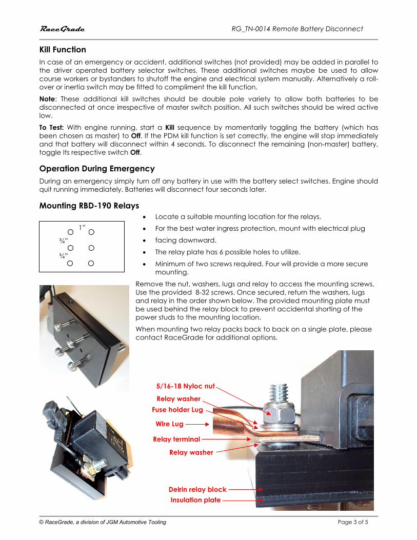
Mounting RBD-190 Relays
• Locate a suitable mounting location for the relays.
• For the best water ingress protection, mount with electrical plug
• facing downward.
• The relay plate has 6 possible holes to utilize.
• Minimum of two screws required. Four will provide a more secure
mounting.
Remove the nut, washers, lugs and relay to access the mounting screws.
Use the provided 8-32 screws. Once secured, return the washers, lugs
and relay in the order shown below. The provided mounting plate must
be used behind the relay block to prevent accidental shorting of the
power studs to the mounting location.
When mounting two relay packs back to back on a single plate, please
contact RaceGrade for additional options.
¾”
1”
¾”
Relay washer
Delrin relay block
Insulation plate
Relay terminal
Fuse holder Lug
Wire Lug
Relay washer
5/16-18 Nyloc nut

RaceGrade RG_TN-0014 Remote Battery Disconnect
© RaceGrade, a division of JGM Automotive Tooling Page 4 of 5
Attach Battery–side Power Cables to RBD-190
Slip one of the provided red boots onto the lead from battery positive. Attach battery positive lead to
the B+ side of the RBD-190 block using a 5/16” eye terminal. For best electrical performance the
terminal should sit directly on the relay without a washer in between. Place a washer over the eye
terminal and tighten down a nut on top. It is not permitted to run the ground wire through this relay.
Maintain the positive polarity across relay as shown.
Attach Car-side Power Cables to RBD-190
Slip a red boot over the main power lead from the car’s wiring harness, (Usually the starter lead).
Attach lead to the other side of the RBD-190 with another 5/16” eye terminal. Place a washer over the
eye terminal and tighten down a nut on top.
Note: Batteries turned off will not receive charging from alternator.
Attach control cables to RBD-190
Control cables are attached via polarized plugs to each relay package. Be mindful that connections
are not inadvertently mixed up such as A vs B.
Storage notes
With both batteries turned off, the control circuitry draws about one milliamp of current out of each
battery. To temporarily eliminate this draw, pull the fuse out of the fuse holder. Replace the fuse in
order to restore normal operation.
Car side Battery side
Control ground

RaceGrade RG_TN-0014 Remote Battery Disconnect
© RaceGrade, a division of JGM Automotive Tooling Page 5 of 5
Optional Accessories
Kill Switches
Master Red Shut Down Switch
Hood Pin Switch
Switch Pancake Seal