radioactive ion sources - arxiv
TRANSCRIPT

Radioactive Ion Sources
T. Stora CERN, Geneva, Switzerland
Abstract This chapter provides an overview of the basic requirements for ion sources designed and operated in radioactive ion beam facilities. The facilities where these sources are operated exploit the isotope separation online (ISOL) technique, in which a target is combined with an ion source to maximize the secondary beam intensity and chemical element selectivity. Three main classes of sources are operated, namely surface-type ion sources, arc discharge-type ion sources, and finally radio-frequency-heated plasma-type ion sources.
1 Introduction Radioactive ion sources are used in facilities that deliver radioactive ion beams. These beams are exploited by a large community of physicists active in nuclear physics, astrophysics, atomic physics, material science and life science. The production of the radioactive ions is based on two generic principles: a heavy-ion beam fragmented by a thin target and mass-separated ‘in flight’ in a series of large-acceptance dipole magnets; and online mass separation of nuclear products diffused out of thick targets impinged by light ion beams, this being referred to as the ‘ISOL technique’ [1]. In the in-flight technique, the fragments are charged and thus do not require the exploitation of ion sources; while in ISOL production, the fragments diffuse out of a production target or catcher as neutral species.
While ion sources are intimately related to the history and developments of stable particle accelerators, radioactive ion sources are likewise linked to the development of ISOL facilities. In such facilities, ion sources are one of the important links in the full production chain of the secondary radioactive ion beams. The first generation of radioactive ion sources were those developped for stable ions in accelerators such as cyclotrons and mass separators. At a later stage they were adapted to match the specific needs for the production and acceleration of radioisotopes, which are produced with several orders of magnitude less intensities than their stable counterparts, and have, by definition, a finite lifetime before radioactive decay.
The lecture given during the school could not cover all the required aspects in an exhaustive manner. This chapter will introduce some additional aspects such as some historical elements concerned with the development of the sources used in radioactive beam facilities, and some references will be provided to those which need information at an expert level. The chapter is organized in the following manner. In a first part, a brief technical description of a radioactive ion beam facility and the main requirements for a radioactive ion source are introduced. The different classes of ion sources are then reviewed. The sources are split into three main categories; surface-type ion sources, the forced electron beam sources, and finally the RF-heated plasma sources. For each of these categories, historical developments are reported first, followed by the theoretical considerations underlying their operation, and finally the main operational parameters. An outlook for the on-going and future needs in our facilities will finally be reported.

2 Radioactive ion beam facilities The first report of the online production of a radioactive ion beam dates back to the 1950s, when exotic krypton fission fragments (of a few tens of seconds half-life) were produced from large UO2 targets heated and connected to an isotope mass separator [1]. The ion source was of a glow discharge Nielsen type (Fig. 1) [2]. About 15 years after, a number of so-called first-generation facilities came into operation in different laboratories across the world, amongst which was ISOLDE at CERN, still in operation today after a series of major upgrades and evolutions. The family of ion sources used throughout the facilities was enlarged over the years with new members, namely forced electron beam-induced arc discharge (FEBIAD) ion sources, surface ion sources, and later on RF-driven ion sources, more particularly electron cyclotron resonance (ECR) ion sources [3]. A schematic layout of an ISOL-type facility is shown in Fig. 2. The main components present in such facilities are:
– a primary particle driver; – a target station with standard interfaces (vacuum, electrical power, cooling circuit) and the
first optical elements of the secondary isotope beam line; – a target and ion source unit, which is mechanically tight to the station and regularly
exchanged, often by remote handling exploiting robot and piloted cranes; – a magnetic dipole where the different components of the isotope secondary beam are selected
according to mass over charge figures; – additional electrostatic optical elements to steer the beam along the beam lines.
Fig. 1: Ion source used in the first online separation of a radioactive ion beam at the Niels Bohr Institute in 1951 [1] (reprinted from Ref. [2]). The ion source was said to be of ‘magnetic type’ by Nielsen, and is known today to be of the Nielsen type. The temperature of the arc discharge chamber could be held up to 1100°C. The 0.4 mm diameter tungsten filament lifetime was 50–100 h, operated at 0.1 mbar gas pressure. Components: 1, brass anode block; 2, Cu water cooling tube; 3, magnet coil; 4, filament; 5, Cu rods; 6, water-cooled brass tubes; 8, ‘vacuum lock’; 9, needle valve for controlling the gas inlet; 10, stainless-steel bottom plate. Operating parameters (5% efficiency on Kr): anode voltage, 100–200 V; arc current, 1–2 A; magnetic field, 0–400 G; diameter of outlet opening, 2–5 mm; beam current for krypton, 50–150 µA.

The figure of merit of a given radioactive ion beam facility comes from the folding of the following parameters:
– number of available radioactive ion beams; – intensity of the beam; – beam quality, for instance its purity and emittance; – non-degradation of the beam performance over time, like intensity, purity, energy; – facility up-time; – (post)-accelerated beam characteristics.
Fig. 2: General view of an isotope online facility such as ISOLDE at CERN. The buildings and shielding structure are not represented.
In a given facility, the characteristics of the primary beam, often a large particle accelerator, are defined in the design and construction phases. The rest of the infrastructures is also determined at the conception of the facility, such as the buildings or services. The parts that deal with the design of the target units, and to a lesser extent the beam lines, on the other hand, can still be and mostly are developed over time, to meet the evolving needs of the experiments. These developments more particularly focus on the different types of target materials to generate the isotopes, on the engineering aspects of the target production unit design, and – in the focus here – on the development of the ion sources. For a given facility, several combinations of target materials and ion sources are integrated into compact units, and are regularly exchanged in order to deliver the required isotope beams during a year of operation. The integration of the source into a compact unit dates back to the 1970s at ISOLDE (Fig. 3). A contemporary target and ion source unit is shown in Fig. 4.
3 Requirements for a radioactive ion source An ideal ion source for ISOL radioactive ion beam facilities must fulfil a set of basic criteria. The development of any existing source or the design of a new one will therefore consist in satisfying the maximum number of these requirements. Often compromises have to be made, i.e., increasing the heating power of a source to achieve high ionization efficiency could affect the source stability over time.

Fig. 3: Top: target and glow discharge ion source used at ISOLDE until the 1970s. Bottom: integrated MK-IV target and ion source unit in 1972.
Fig. 4: Modern target and ion source unit at ISOLDE. The diameter of the confinement box (seen in transparency) is 30 cm.

An ideal source must:
– be compact; – have radiation-hard components to withstand a predefined dose (e.g., 1 MGy for an
installation like ISOLDE); – be compatible with the predefined interfaces and first beam optical elements, i.e., the
electrostatic extraction puller; – provide a maximum ionization efficiency, if possible approaching 100%; – operate in a stable manner with varying gas loads coming from the target heated at high
temperatures and impacted by the primary beam (i.e., there should be no drift in performance during operation which requires a retuning of its parameters);
– be element-selective, i.e., ionize only isotopes from one element amongst a gas phase made up of other isotopes, stable impurities and molecules with several orders higher concentrations;
– produce a total extracted beam intensity compatible with the low-energy beam-line elements, i.e., typically of about 100 µA or less;
– have a perfect beam quality, i.e., no energy spread and a minimal transverse emittance; – have small residence time with respect to the isotope of interest, i.e., in the millisecond range
for the most exotic isotopes produced by the ISOL method.
It is clear that no source is universal, and since a facility aims to deliver as many different elements and isotopes as possible, sources need to be developed over the years, and, during operation, be exchanged from one production unit to the next one, typically once a week or once a month, to meet the requirements for the production of the element under consideration.
It is easy to understand that ion sources need very different characteristics to ionize noble gases such as argon, metallic elements such as nickel, or chemically reactive atoms such as boron. To help provide a more rational view, some key properties are reported in Fig. 5. A periodic table of the chemical elements is displayed, showing their ionization potential, their electron affinity and their melting and boiling points.
In the following section, the three important categories of radioactive ion sources for ISOL facilities are introduced, namely those based on surface ionization processes, on electron beam impact, and on RF-heated plasma.
4 Surface ion sources
4.1 Historical elements
Surface ion sources are used in most present-day ISOL-type facilities. They were developed in the early days of the isotope separation technique, being simple, robust, fast and selective ion sources. A layout of the target and ion source unit first developed and used in Orsay before being transferred to the Proton Synchrotron (PS) beam at CERN is shown in Fig. 6 [4]. In this configuration, the target, with direct interaction of the primary particle beam, for the production and recoil of the reaction products, is located inside an oven. It is made of graphite or refractory metal and brought up to a high temperature of 1500°C. The surfaces of the oven act as the ion source itself, exploiting the well-known surface ionization phenomenon first identified and described by Saha and Langmuir for heated metallic filaments [5]. The ions are then emitted through a vertical slit before acceleration and injection in the magnetic dipole mass spectrometer. The ionization efficiency for alkali isotope beams was reported to be small, but beams of 9Li of 180 ms half-life could already be extracted [6]. Ten years later, the concept had been improved, and 11Li and 32Na beams with half-lives in the 10 ms range could be produced with a rhenium foil inserted in the oven as an ionizing surface [7]. Efficiencies in the few per cent range were reported.
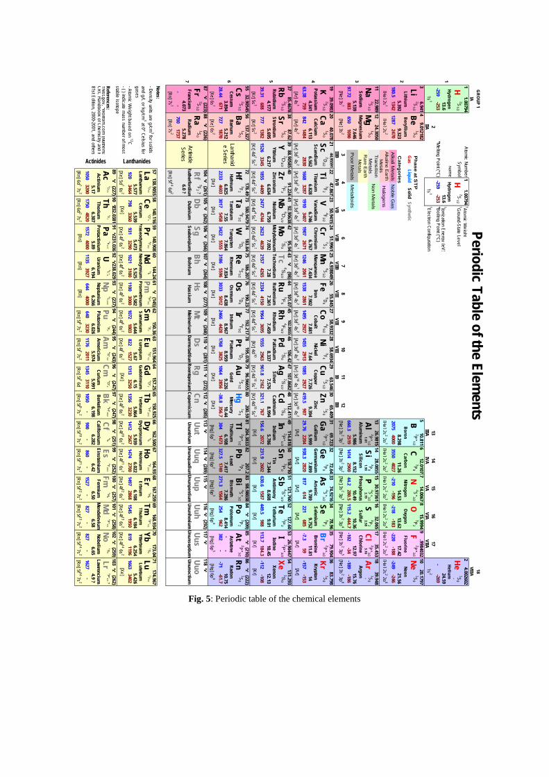
Fig. 5: Periodic table of the chemical elements
Atomic Num
ber†Atom
ic Weight
Symbol
†Ground-State Level
Name
†Ionization Energy (eV)*M
elting Point (°C)*Boiling Point (°C)†Electron Configuration
Ph
ase at ST
P
Categ
ories
[42]{42}
References:†Nist.gov, *W
olfram.com
(Mathem
aCRC Handbook of Chem
istry and P81st Edition, 2000-2001, and others A
lkali Metals
Alkaline E
arth M
etalsTransition
Metals
Rare E
arth M
etals
Poor M
etals
Bh
18VIIIA
Notes:- Density units are g/cm
3 for solids and g/L or kg/cm
3 at 0° Celsius for gases- Atom
ic Weight based on 12C
- ( ) indicate mass num
ber of most
stable isotope
CnDb
Sg
Li
Periodic Table of the Elements
GRO
UP 1IA
11.00794
24.002602
1
11.00794
13.6
He1S
0-
H2S
1/2H
2S1/2
HydrogenHydrogen
Helium
2IIA
13.6-269
-259-253
-13
IIIA14
IVA15VA
16VIA
1s1
1s1
1s2
17VIIA
24.59-259
-253
9.0121825
10.8116
2
36.941
4
2075
15.99949
.998403210
12.01077
14.00678
20.17972S
1/2Be
1S0
B2P°1/2
C3P
0N
3P2
F4S°3/2
O2P°3/2Ne
1S0
GasLiquid
SolidSynthetic
LithiumBeryllium
BoronCarbon
NitrogenO
xygenFluorine
Neon5.392
9.3238.298
17.4211.26
14.5321.56
180.51342
12872470
Noble G
as13.62
-246-196
-218-188
-249-183
-2204000
35504027
-210
[He] 2s2 2p
1[He] 2s
1[He] 2s
2H
alogens[He] 2s
2 2p2
[He] 2s2 2p
3[He] 2s
2 2p4
[He] 2s2 2p
5[He] 2s
2 2p6
3
1122.989
1224.3050
Non M
etals18
39.94815
30.9736116
32.065
SiNa
2S1/2
Mg
1S0
1735.453
1326.9815
1428.0855
3P0
P4S°3/2
Al2P°1/2
S3P
2Cl
2P°3/22.58
3.16Ar
1S0
1.611.90
2.19-
SodiumM
agnesiumAlum
inumSilicon
PhosphorusSulfur
ChlorineArgon
5.1397.646
Metalloids
10.4910.36
5.9868.152
12.9715.76
97.72883
6501090
660.3280.5
115.2444.7
-1022519
14142900
44.2-34
-189-186
3IIIB4IVB
5VB11IB
12IIB6VIB
7VIIB8VIII
9VIII[Ne] 3s
1[Ne] 3s
2[Ne] 3s
2 3p1
[Ne] 3s2 3p
2[Ne] 3s
2 3p3
[Ne] 3s2 3p
4[Ne] 3s
2 3p5
[Ne] 3s2 3p
610
VIII
4
1939.0983
20
63.38759
842
40.078
K2S
1/2
2350.9415
2451.9961
2144.95591
2247.867
2758.9332
2858.6934
254.938049
2655.845
3169.723
3272.64
2963.546
3065.409
3579.904
3683.798
3374.9216
3478.96
Ti3F
2V
4F3/2
Ca1S
0Sc
2D3/2
Fe5D
4Co
Cr7S
3M
n6S
5/24F
9/2Ni
3F4
Cu2S
1/2Zn
1S0
Ga
2P°1/2Ge
3P0
As4S°3/2Se
3P2
Br2P°3/2
Kr1S
0
PotassiumCalcium
ScandiumTitanium
VanadiumChrom
iumM
anganeseIron
6.828Gallium
Germanium
ArsenicSelenium
CobaltNickel
CopperZinc
4.3416.113
6.5626.746
6.767Brom
ineKrypton
7.8817.64
7.4347.902
5.9997.899
7.7269.394
11.8114
9.7899.752
32871910
34071907
14842830
16682861
14952927
14552671
12462061
1538907
29.762204
938.32913
10852927
419.5685
-7.359
-1572820
817614
221-153
[Ar] 4s1
[Ar] 4s2
[Ar] 3d1 4s
2[Ar] 3d
2 4s2
[Ar] 3d3 4s
2[Ar] 3d
5 4s1
[Ar] 3d5 4s
2[Ar] 3d
10 4s2
[Ar]
[Ar]
[Ar]
[Ar] 3d
6 4s2
[Ar] 3d7 4s
2[Ar] 3d
8 4s2
[Ar] 3d10 4s
1[Ar]
[Ar]
[Ar]
5
3785.4678
3887.62
3988.90585
4091.224
4192.90638
44101.07
45102.9055
4295.94
43(98)
48112.411
49114.818
46106.42
47107.8682
52127.60
5326.90447
50118.710
51121.760
54131.293
Rb2S
1/2Sr
1S0
Y2D
3/2Zr
3F2
Nb6D
1/2Mo
7S3
Tc6S
5/2Ru
5F5
Rh4F
9/2Pd
1S0
Ag2S
1/2Cd
1S0
In2P
°1/2Sn3P
0Sb
4S°3/2Te
3P2
I2P
°3/2Xe1S
0
RubidiumStrontium
YttriumZirconium
6.634Indium
TinAntim
onyTellurium
RhodiumPalladium
SilverCadm
ium4.177
5.6956.217
6.7597.092
IodineXenon
NiobiumM
olybdenumTechnetium
Ruthenium7.459
8.3377.28
7.3615.786
7.3447.576
8.99410.45
12.138.608
9.011526
33451855
440939.31
688777
13822157
42652334
41502477
47442623
4639961.8
2162321.1
7671964
36951555
2963-112
-108630.6
1587449.5
988113.7
184.3156.6
2072231.9
2602
[Kr] 4d4 5s
1[Kr] 4d
5 5s1
[Kr] 4d5 5s
2[Kr] 4d
7 5s1
[Kr] 5s1
[Kr] 5s2
[Kr] 4d1 5s
2[Kr] 4d
2 5s2
[Kr] [Kr]
[Kr] [Kr]
[Kr] 4d8 5s
1[Kr] 4d
10[Kr] 4d
10 5s1
[Kr] 4d10 5s
2[Kr]
[Kr] 72
178.49
6
5532.90545
56137.327
Lanthanide Series
73180.9479
74183.84
77192.217
78195.078
75186.207
76190.23
81204.3833
82207.2
7996.96655
80200.59
85(210)86
(222)83
208.9803884
(209)
Hf3F
2Ta
4F3/2
Cs2S
1/2Ba
1S0
Os
5D4
Ir4F
9/2W
5D0
Re6S
5/2Pt
3D3
Au2S
1/2Hg
1S0
Tl2P°1/2Pb
3P0
Bi4S°3/2Po
3P2
At2P°3/2Rn
1S0
CesiumBarium
HafniumTantalum
TungstenRhenium
Osmium
IridiumPlatinum
Bismuth
PoloniumAstatine
RadonGold
Mercury
ThalliumLead
6.8257.55
3.8945.212
8.4388.967
7.8647.834
10.446.108
8.9599.226
8.414-
-7.417
7.28610.75
28.44671
7271870
22334603
30175458
30335012
24664428
34225555
31865596
-38.8356.7
3041473
17683825
10642856
254962
302-
327.51749
271.31564
-71-61.7
[Xe] 6s1
[Xe] 6s2
[Xe]
[Xe]
[Xe]
[Xe]
[Xe]
[Xe]
[Hg] 6p
2[Hg] 6p
3[Hg] 6p
4[Hg] 6p
5[Xe]
[Xe]
[Xe]
[Hg] 6p
1[Hg] 6p
6
7
87(223)88
Fr2S
1/2
Francium
(226)
ActinideSeries
104(261)
Ra1S
0Rf
3F2 ?
RadiumRutherfordium
107(264)108
(277)105
(262)106(266)
111(272)112
(285)109
(268)110(281)
118115
116(292)
Hs
M
t117
113114
(289)
UuhUus
Uut
Uuq
Uup
Ds
RgDubnium
SeaborgiumBohrium
HassiumUuo
UnuntriumUnunquadiumUnunpentium
UnunhexiumM
eitneriumDarm
stadtiumRoentgenium
CoperniciumUnunseptium
Ununoctium4.073
5.2786.0 ?
--
7001737
[Rn] 7s1
[Rn] 7s2
[Rn] 5f 14 6d2
59140.908
60144.24
61(145)
57138.9055
La2D
3/2
Lanthanum
62150.36
63151.964
Actinides
89
58140.116
Cerium
Lanthanides
66162.500
67164.93
64157.25
65158.925
70173.04
71174.967
68167.259
69168.934
Ce1G
°4Pr
4I°9/2Nd
5I4Pm
6H°5/2Sm
7F0
Eu8S
°7/2G
d9D
°2Tb
6H°15/2
Dy5I8
Ho4I°15/2
Er3H
6Tm
2F°7/2Yb
1S0
Lu2D
3/2
ThuliumYtterbium
EuropiumGadolinium
TerbiumDysprosium
5.4735.525
Holmium
ErbiumPraseodym
iumNeodym
iumProm
ethiumSam
arium5.582
5.644Lutetium
5.5775.539
5.8645.939
5.676.15
6.1846.254
6.0226.108
5.426920
3464798
3360931
32901021
31001100
15271313
32501356
30001072
1803822
11961663
27001497
28681545
1950819
32301412
25671474
3402
[Xe] 5d1 6s
2[Xe]
[Xe] 4f 3 6s2
[Xe] 4f 4 6s2
[Xe] 4f 5 6s2
[Xe] 4f 6 6s2
[Xe] 4f 7 6s2
[Xe]
[Xe] 4f 9 6s
2[Xe] 4f 10 6s
2[Xe] 4f 11 6s
2[Xe] 4f 12 6s
2[Xe] 4f 13 6s
2[Xe] 4f 14 6s
2[Xe]
(227)90
232.038191
231.03692
238.02995
(243)96(247)
93(237)94
(244)
U5L°6
101(258)102
(259)99
(252)100(257)
Ac2D
3/2
Th3F
2
Pa4K
11/2
Np6L
11/2
Pu7F
0
103(262)
97(247)98
(251)
FmBk
6H°15/2
Cf5I8
Am8S
°7/2Cm9D
°21S
0
Lr3H
6
Md
2F°7/2No
Es4I°15/2
PlutoniumAm
ericiumCurium
Berkelium
2P°1/2 ?
CaliforniumEinsteinium
Fermium
Mendelevium
ActiniumThorium
ProtactiniumUranium
NeptuniumNobelium
Lawrencium5.17
6.3075.89
6.1945.974
5.9916.266
6.0261135
39276.58
6.656.42
6.501050
32001750
48201572
4000644
4000640
32304.9 ?
6.1986.282
1050-
900-
11762011
13453110
827-
827-
860-
1527-
1627-
[Rn] 5f 7 7s2
[Rn] 5f 7 6d [Rn] 6d
1 7s2
[Rn] 6d2 7s
2[Rn]
[Rn]
[Rn]
[Rn] 5f 6 7s2
[Rn] 5f 9 7s2
[Rn] 5f 10 7s2
[Rn] 5f 11 7s2
[Rn] 5f 12 7s2
[Rn] 5f 13 7s2
[Rn] 5f 14 7s2
[Rn] 5f 14 7s2

Surface ion sources made of hollow tubes were introduced in the 1970s [8]. They were heated by electron bombardment. A version adapted for online operation at ISOLDE was available soon after [9] (Fig. 7). In this last version, the source is connected to a large target container via a transfer line, in such a way that the beam irradiation and target heating are spatially decoupled from the operating source. Heating was provided either by electron bombardment or by ohmic current. Efficiencies in the several tens of per cent for lanthanides were reported in this configuration. Later on, other developments took place, for instance providing negative surface sources and investigating different materials [10]. They are based on similar processes as their positive counterparts for singly negative ions. Some examples of such sources are shown in Fig. 8.
Fig. 6: Surface ion source developed at Orsay to ionize alkali metal beams and used at CERN PS in the 1960s (from Ref. [4]).

Fig. 7: Surface ion source used at CERN-ISOLDE (from Ref. [9])
Fig. 8: MK4 negative surface ion source developed at ISOLDE and some prototype tubular geometries (from Ref. [10]).

4.2 Mode of operation and underlying physics principles
The principle of operation is rather simple. It is based on the following well-known Saha–Langmuir equation, which describes the ionization degree α and efficiency ε for weak plasmas [5] and for heated surfaces, where g+ and g0 are the quantum degeneracy from the charged and neutral states, W is the work function of the ionizing material, and φi is the ionization potential of the atoms under consideration: surface 0 i( / )exp[( )/ ]g g W kTα φ+= − , (1)
* *surface i i i 0exp[( )/ ] with ln( / )W kT kT g gα φ φ φ += − = − , (2)
surfacesurface
11 1/
εα
=+
. (3)
Eqs. (1) and (3) were established in 1925 and were used to describe the measured efficiencies of ion sources of simple geometries, such as heated surfaces and filaments. Eq. (2) is a convenient form in which the pre-factor originating from multiple quantum states of the neutral atom and the charged ion are already included in a normalized ionization potential parameter φi
*.
However, this model was found to be inaccurate in properly describing the behaviour of the source in a hollow-tube configuration. Corrections to account for the proper plasma parameters in such heated tubes or capillaries had to be included.
It took ten years to develop a satisfactory model and to test it against experimental data. More details can be found in two review articles written by R. Kirchner [11]. In a hollow-tube configuration, correction factors are required to properly describe the observed ionization efficiencies. In this case, a very low-density plasma is created in the tube; this introduces a first correction factor κ, which accounts for the average number of collisions that the isotope experiences with the hot surface of the tube before being extracted, and a second one ω, the trapping efficiency of the emitted ion inside the plasma potential well. Some arguments based on the geometry and plasma properties can be given to estimate these two factors; however, in practice, the product ωκ is used as a free parameter to fit a set of experimental data obtained with a series of chemical elements that span a relevant range of ionization potentials and efficiencies. The model in Eq. (4) is therefore now accepted to describe ionization efficiencies for hollow-tube ionizers as found in most of the present ISOL-type facilities:
ionizersurface
11 1/
εωκα
=+
. (4)
A graph plotting εionizer versus φi* for a source made of tungsten with two different partial pressures of
neutral xenon gas is shown in Fig. 9. A similar graph has been obtained very recently at JAEA-ARSC with a hot tantalum cavity as shown in Fig. 10 [12].

Fig. 9: Efficiency plotted versus ionization potential of different condensable chemical elements. Two sets of data recorded at different partial pressure in the hollow cavities are reported. The fit of the data using Eq. (4) and different values for ωκ (referred to as N in the figure) are also shown. From Ref. [11].
Fig. 10: Tantalum surface ion source developed at ASRC-JAEA heated by electron bombardment with two filaments. The ionization efficiencies are reported for a set of exotic radio-lanthanides for a cavity operated at 2600 K [12].

4.3 Specific applications, future developments
Surface ion sources are used in most ISOL-type facilities in operation or in construction. They are exploited to produce the most intense alkali and alkaline-earth isotope beams, and provide in addition some chemical selectivity. Besides their utilization as selective ionizers, they are nowadays combined with RILIS lasers to ionize metallic elements. This last mode of ionization is described elsewhere in this present volume by B. Marsh [13]. In this case, choices of materials with lower work functions are generally preferred, with a successful demonstration of using ceramics of GdB6 to suppress isobaric contaminants [10]. Surface ion sources have been used to produce molecular beams with suitable ionization potentials. This is mainly lanthanide oxide and fluorine compounds, and alkaline-earth fluoride molecules [9, 14]. In that case the theoretical treatment to account for the operational behaviour of the source has not been investigated in great detail. The main elements required to account for evolving intensities and efficiencies of atomic versus molecular ions have been reported in the case of Ba and O atoms for Ba+ and BaO+ ion production [15]. The interested reader should refer to that publication for more details.
5 FEBIAD ion sources
5.1 Historical elements
Forced electron beam-induced arc discharge (FEBIAD) ion sources were developed to overcome some of the drawbacks observed while operating the previous generation of sources equipped with a heated cathode emitting electrons in a high-pressure plasma chamber. In that previous generation, the configuration of the filament, the magnetic field, the polarization of the plasma chamber walls, i.e., anode, and the layout of the ion extraction led to different versions referred to as the Nielsen, Bernas–Nier or hollow-cathode ion sources [11].
One version of the Nielsen source was shown in Fig. 1 and another one is shown in Fig. 11. Reported drawbacks are a finite lifetime of the cathodes, which could be dependent on the chemical reactivity of the gas phases, operation under high pressures of 10−2 mbar, high total extracted beam intensities, and difficulties in reaching and maintaining stable modes of operation.
The principal technical modifications of the previous source designs were the change of the cathode, from coiled wire geometry to a flat disc, and the insertion of a polarized grid in front to stabilize the electron emission current. The first development and application of these sources were reported by R. Kirchner at GSI and S. Sundell at Isolde in the 1970s [16]. Different versions of the FEBIAD sources were developed, exploiting various structural materials for the cathode, the accelerating grid, the anode chamber or the heat screens. Figure 12 shows the three FEBIAD sources MK3, MK5 and MK7 out of a larger series developed at ISOLDE and used until 2009 [17]. The different models were combined with different types of targets and connected via transfer lines kept at different temperatures.
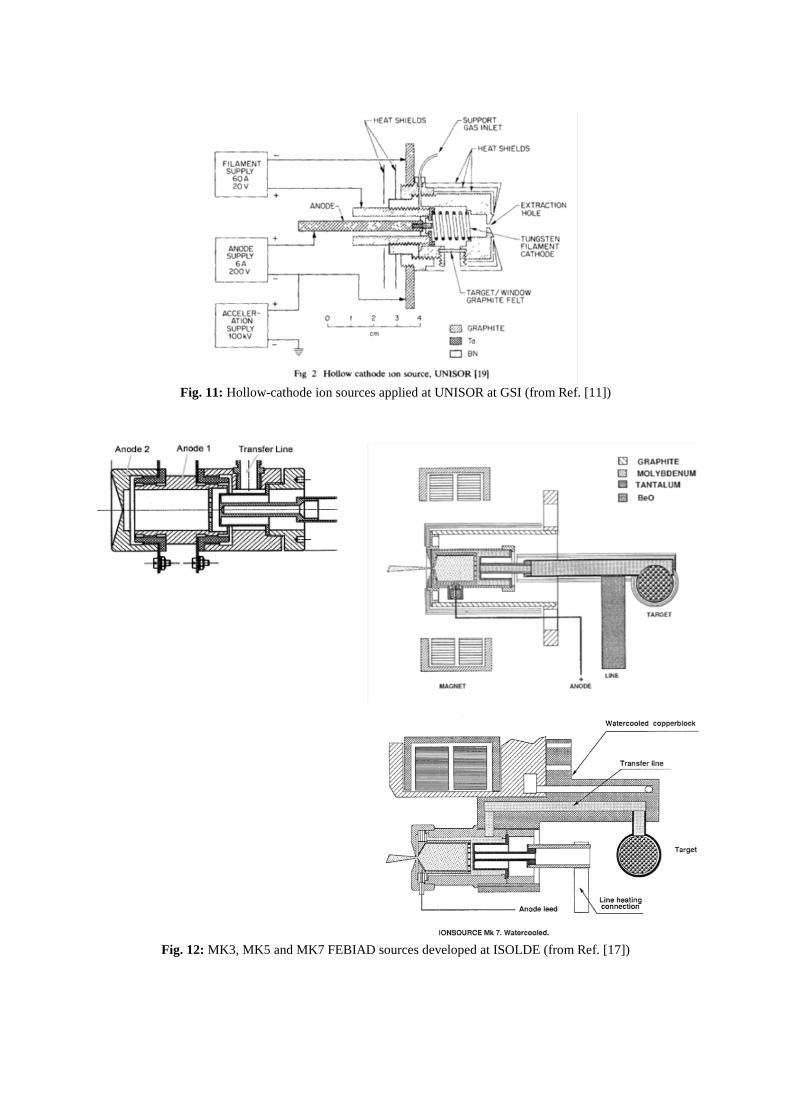
Fig. 11: Hollow-cathode ion sources applied at UNISOR at GSI (from Ref. [11])
Fig. 12: MK3, MK5 and MK7 FEBIAD sources developed at ISOLDE (from Ref. [17])

5.2 Mode of operation and underlying physics principles
None of the theoretical models put forward could well describe the reported experimental efficiencies of the FEBIAD sources over extended ranges of operational parameters. In addition, some of the used parameters were not physically sound. During his PhD, L. Penescu proposed a new model that seemed to provide a reasonably good description of the observed ion beam currents using simple physical parameters [18]. This model and detailed experimental investigation of the three FEBIAD sources in operation at ISOLDE led to a new generation of such sources, which we named VADIS for versatile arc discharge ion source.
The proposed ionization efficiency model for FEBIAD sources is the following:
ion source extr e n ion rel source extr
n_in n_in
( )R V f n n v V fI I
σε = = . (5)
The model described by Eq. (5) is a linear combination of a set of parameters that can be calculated from an experimentally accessible set of data, such as the emitted electron current from the cathode or the injected neutral buffer gas from the calibrated leak rate. Indeed, the different terms in Eq. (5) can be explicitly computed:
rel ee
2eUv vm
≈ = (6)
is the average relative speed between the neutral isotopes and the electrons emitted from the cathode and accelerated by the anode grid at a potential U, typically at 30–250 V;
ee e
e
jnv
ε= , (7)
1/2 2/3
2e 0 2
e
4 2 [mA mm ]9
e Ujm d
ε− =
, (8)
with ne the electron density in the source, εe a scaling factor that accounts for the grid transparency and electron reaching the drift plasma chamber, and je the electron current emitted from the cathode, described by the Child–Langmuir equation (8) when space charged limited, with U the acceleration potential of the grid and d the distance between the cathode and the grid. This is for sources operated typically at temperatures above 2000°C in the configuration of a VADIS source. For low temperatures, the electron emission is then limited by the Richardson–Dushmann electron emission from a cathode: 2 2 2 2
e [mA mm ] exp( / ) with 1200 mA mm Kj AT W kT A− − −= − ≅ . (9) Here the work function W of the cathode is in eV and A is the Dushman constant, which can adopt different values for different materials. In Fig. 13 the current measured at the anode power supply is recorded, and can as a first approximation be compared to Eqs. (8) and (9), using the recorded temperature of the cathode and the anode potential. The neutral atom density is expressed by Eq. (10), in which the gas leak rate Qin has been measured with a tracer gas, M is the mass of the isotope, the temperature T is assumed homogeneous and is that of the cathode, and Sout is the surface area of the extraction hole of the source:
18n in 3/2
out
2 10 Mn QT S
= × . (10)
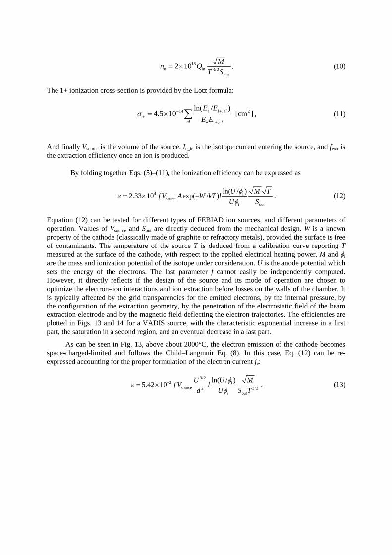
The 1+ ionization cross-section is provided by the Lotz formula:
e 1 ,14 2
e 1 ,
ln( / )4.5 10 [cm ]nl
nl nl
E EE E
σ +−+
+
= × ∑ , (11)
And finally Vsource is the volume of the source, In_in is the isotope current entering the source, and fextr is the extraction efficiency once an ion is produced.
By folding together Eqs. (5)–(11), the ionization efficiency can be expressed as
4 isource
i out
ln( / )2.33 10 exp( / ) U M Tf V A W kT lU S
φεφ
= × − . (12)
Equation (12) can be tested for different types of FEBIAD ion sources, and different parameters of operation. Values of Vsource and Sout are directly deduced from the mechanical design. W is a known property of the cathode (classically made of graphite or refractory metals), provided the surface is free of contaminants. The temperature of the source T is deduced from a calibration curve reporting T measured at the surface of the cathode, with respect to the applied electrical heating power. M and φi are the mass and ionization potential of the isotope under consideration. U is the anode potential which sets the energy of the electrons. The last parameter f cannot easily be independently computed. However, it directly reflects if the design of the source and its mode of operation are chosen to optimize the electron–ion interactions and ion extraction before losses on the walls of the chamber. It is typically affected by the grid transparencies for the emitted electrons, by the internal pressure, by the configuration of the extraction geometry, by the penetration of the electrostatic field of the beam extraction electrode and by the magnetic field deflecting the electron trajectories. The efficiencies are plotted in Figs. 13 and 14 for a VADIS source, with the characteristic exponential increase in a first part, the saturation in a second region, and an eventual decrease in a last part.
As can be seen in Fig. 13, above about 2000°C, the electron emission of the cathode becomes space-charged-limited and follows the Child–Langmuir Eq. (8). In this case, Eq. (12) can be re-expressed accounting for the proper formulation of the electron current je:
3/2
2source 2 3/2
out
i
i
ln( /10 )5.42 UU Mf V ld U S T
ε φφ
−×= . (13)

Fig. 13: Left: efficiencies measured for a series of noble gases in a VADIS source, electron emission from the cathode, and theoretical limitation predicted from Child–Langmuir space-charged emission (from Ref. [18]). Right: electron emission superimposed upon the theoretical prediction of Eq. (9), with A = 600 mA mm−2 K−2, W = 4.12 eV and Scathode = 1.13 cm2.
Fig. 14: Efficiencies measured in a MK5 source, and f factor deduced from Eq. (12). The dashed lines are obtained when the cathode emission is space-charge-limited, Eq. (13) [18].
The deduced f factors are also shown in Fig. 14. When the electron emission is properly measured or computed with appropriate models, this factor gives important insights into the quality of the design, and an optimal range of operational parameters. In particular, it shows if the design of the source can be improved and what are the elements that need modification.
5.3 Specific applications, future developments
The FEBIAD sources are versatile sources, compact, fast, and provide high ionization efficiencies for condensable elements. They have also been used to produce molecular beams of condensable elements such as SnS+, SeCO+ and AlF+ [19]. They can be adapted to match specific requirements such as an improved beam quality from a reduced extraction hole surface area, a reduction of CO2
+ beam impurities replacing graphite parts, and so forth. Interesting developments are the on-going coupling of these cavities with laser sources, and should provide exciting developments in the near future.
5.E-04
5.E-03
5.E-02
5.E-01
1550 1650 1750 1850 1950
Emitt
ed c
urre
nt [A
]
Temperature [°C]
theoreticalemission

6 RF heated sources
6.1 Historical elements
This last section covers radio-frequency-heated sources applied for radioactive ion beams. This type of source was applied for radioactive ion beam production much more recently than the other two preceding classes. For instance, ECR sources, extensively described in these series of lectures for stable beams, have been proposed and developed for operation in different facilities. Such sources were developed for stable beams in the 1970s. They were applied for radioactive beam generation about 20 years after, at GANIL in France, in Louvain-La-Neuve in Belgium and at the TISOL facility in Canada [20, 21]. These sources are mostly used to ionize molecular beams that are volatile at room temperature. The source operated in Louvain-La-Neuve to produce intense beams of oxygen and nitrogen isotopes is shown in Fig. 15. This type of source, however, presents a number of challenges for operation in the harsh environments found at target stations of the ISOL facilities. As can be seen in Fig. 15, this was avoided by positioning the source in a remote position with respect to the target position. However, this is at the expenses of the speed of transport of the radioactive isotopes from the target to the ion source. The combined graphite target and Nanogan 3 ion source is shown in Fig. 16.
Fig. 15: Top: ECR source operated at CRC, Louvain-La-Neuve (from Ref. [20]). Bottom: layout of the facility [21].

Fig. 16: Target and Nanogan III ECR source operated at SPIRAL I, GANIL facility
While these sources have demonstrated the production of noble gases, molecular oxygen, carbon and nitrogen isotope beams, the main factors that affect the ionization efficiencies are the distribution along different charge states, the residence time in a larger plasma volume, and possible losses of the isotopes on the chamber walls. Two different lines of development have since been followed. One is the development of compact 1+, 2.45 GHz ECR sources, such as those reported in Ref. [22]. The second line of development was the implementation of a so-called charge breeding scheme, in which a 1+ beam is injected in an ECRIS or EBIS charge booster or charge breeder device. This second line of development is specifically described in the course given by F. Wenander; the interested reader should therefore refer to his contribution on charge breeding.
6.2 Mode of operation and underlying physics principles
These sources are operated following the same principles as their counterpart operated for stable beams. Here also the interested reader is advised to look in publications describing ECR ion sources, one of those is R. Geller Electron Cyclotron Resonance ion Source and ECR Plasmas, (IOP Bristol and Philadelphia, 1996). The main point of interest when applied to the production of radioactive ion beams is the residence time of the isotopes, coupled to the ionization efficiency. Studies have been performed in an attempt to link plasma chamber volume, residence time and ionization efficiency dependent on isotope half-life, as shown in Fig. 17 for Ne isotopes. Obviously more systematic studies are required, especially for molecular beams of short-lived isotopes.
6.3 Specific applications, future developments
Development of RF-heated plasma sources for radioactive ion beams is a very active field in our community. Production of radiation-hard ECR sources is progressing well. Furthermore, new concepts of plasma sources have appeared during the past few years, for instance, low-frequency inductively coupled RF sources or Helicon-type RF sources. These compact and robust sources are expected to provide interesting results for the production of different molecular beams, in an attempt to produce plasmas that are more appropriate for the ionization of the molecules without destruction of the molecular bonds [24].
7 Conclusion I hope I have been able to share some of the exciting recent developments that our field has witnessed over the past few years. Many new facilities are under conception or construction around the world. At the same time, new types of radioactive beams are produced each year by the ISOL method, reflecting the progress in the various fields linked to beam production. The family of robust, compact, simple, rapid and efficient sources suited for these facilities will almost certainly continue its expansion.

Progress in the understanding of the basic physical phenomena and the development of new concepts will probably lead to increases in quality and intensity of the beams.
Fig. 17: Comparison of the different 2.45 GHz ECR sources at GANIL and TRIUMF (from Ref. [23])
References [1] O. Kofoed-Hansen and K.O. Nielsen, Dan. Mat. Fys. Medd. 26 (1951) 7. [2] K.O. Nielsen, Nucl. Instrum. 1(6) (1957) 289. [3] J. Lettry, Review of ion-source developments for radioactive ion-beam facilities, in Proc. 1999
Particle Accelerator Conference, New York (1999), pp. 92–96. [4] R. Klapish et al., Nucl. Instrum. Meth. 53 (1967) 216. [5] I. Langmuir and K.H. Kingdom, Proc. R. Soc. Lond. A107 (1925) 61. [6] R. Klapish et al., Nucl. Instrum. Meth. 38 (1965) 291. [7] R. Klapish et al., Phys. Rev. C12 (1975) 644; Phys. Rev. Lett. 29 (1972) 1254. [8] G.J. Beyer et al., Nucl. Instrum. Meth. 96 (1971) 437; M. Remy and R. Haug, Rev. Sci. Instrum.
41 (1970) 650; P.G. Johnson, Nucl. Instrum. Meth. 106 (1973) 83. [9] H.L. Ravn et al., Nucl. Instrum. Meth. 123 (1975) 131.
[10] B. Vosicki et al., Nucl. Instrum. Meth. 186 (1981) 307; M. Menna et al., Nucl. Instrum. Meth. B266 (2008) 4391; F. Schwellnus et al., Nucl. Instrum. Meth. B267 (2009) 1856.
[11] R. Kirchner, Nucl. Instrum. Meth. 186 (1981) 275; R. Kirchner, Nucl. Instrum. Meth. A292 (1990) 203.
[12] N. Sato et al., Rev. Sci. Instrum. 84 (2013) 023304. [13] B. Marsh, these proceedings. [14] H.L. Ravn et al., J. Inorg. Nucl. Chem. 123 (1975) 131. [15] R. Mueller and H. Wagner, in Proc. Int. Conf. on Electromagnetic Isotope Separators and the
Techniques of Their Applications, Marburg, 1970, p. 461. [16] R. Kirchner and E. Roeckl, Nucl. Instrum. Meth. 139 (1976) 276. [17] S. Sundell and H. Ravn, Nucl. Instrum. Meth. B70 (1992) 160. [18] L. Penescu, PhD thesis, Universitatea Politehnica, Bucharest (2009); L. Penescu et al., Rev. Sci.
Instrum. 81 (2010) 02A906. [19] E. Hagebo et al., Nucl. Instrum. Meth. B70 (1992) 165. [20] P. Decrock et al., Nucl. Instrum. Meth. B58 (1991) 252; P. Bricault et al., Rev. Sci. Instrum. 63
(1992) 2494; K. Jayamanna et al., Rev. Sci. Instrum. 69 (1998) 756. [21] D. Darquennes et al., Phys. Rev. C42 (1990) R804. [22] P. Jardin et al., Nucl. Instrum. Meth. B204 (2003) 377. [23] C. Huet-Equilbec et al., Nucl. Instrum. Meth. B240 (2005) 752. [24] P. Suominen and T. Stora, Target and ion source development, Isolde Newsletter (2011), p. 20,
http://isolde.web.cern.ch/sites/isolde.web.cern.ch/files/April%202011.pdf; M. Kronberger et al., Nucl. Instrum. Meth. B (2013), available online.