isobar separators for radioactive ion beam facilities/67531/metadc681036/m2/1/high... · isobar...
TRANSCRIPT
Isobar Separators for Radioactive Ion Beam Facilities
H. Wollnik* and J. Garrett+
11. Physikalisches Institut, Universitiit Giessen, 35392 Giessen, Germany Physics Division, Oak Ridge National Laboratory, Oak Ridge, Tennessee, 37831, US
Abstract. A radioactive ion beam facility - in short a RIB facility - produces ions of short-lived nuclei and accelerates them to energies of 0.1.. . 10 MeV per nucleon or even higher. In this process it is impor- tant that the resulting RIB beams are free from nuclei of neighboring isobars or of neighboring elements. This task requires the production and ionization of the nuclei of interest as well as separating them from all others with a high-mass resolving power and small-mass cross contaminations. When constructing such a facility it also is very important to find ways that allow the accelerated ions to be provided to different experiments at least quasi simultaneously.
Introduction
To produce radioactive ion beams one usually fragments heavy nuclei by reacting ener- getic protons or neutrons with a thick target, diffuses the fragments out of the target at elevated temperatures, and then ionizes and accelerates them to the required energies. In the initial fragmentation process usually not only the desired nuclei of 2 0 protons and NO neutrons are formed. Therefore, it is necessary to remove the nuclei with neigh- boring 2- and N-values. Since the unwanted neighboring nuclei are often produced abundantly, this task-can be difficult. In some cases this separation can be achieved by the accelerator itself, which in case of a linear accelerator acts as a multiple velocity analyzer or in case of a cyclotron as a multiple time-of-flight mass analyzer. However, this method is problematic for the acceleration of ions of short-lived nuclei because:
1. the precise tuning of an accelerator to the ions of interest becomes difficult if the intensity of these ions is small as compared to the intensity of undesired ions of neighboring nuclei. In this case it is not simple to record the intensity of the ions of interest. Thus no signal or at least no good signal is available for optimization.
2. In a RIB facility the undesired neighboring nuclei are radioactive and will conta- minate the accelerator structure considerably.
For these reasons it is advantageous to precede the accelerator by a high performance isotope separator which, not only effectively removes all undesired neighboring nuclei and delivers a pure ion beam to the accelerator, but also does this with only small mass cross contaminations.
The submined manuscript has tsn authaed by a contractor ot me U.S. Government urler conlracl No. DE- ACE-%OR22464. Axmlii, the U.S. Government retains a mexclusiv8, myalty-free licanse to pubw ar reproduce me prwkhej fotm of mis c~nbbulion. Q abw omen to h so. for us. Govement purposes'

DISC LA1 M ER
This report was prepared as an account of work sponsored by an agency of the United States Government. Neither the United States Government nor any agency thereof, nor any of their employees, make any warranty, express or implied, or assumes any legal liability or responsibility for the accuracy, completeness, or usefulness of any information, apparatus, product, or process disclosed, or represents that its use would not infringe privately owned rights. Reference herein to any specific commercial product, process, or service by trade name, trademark, manufacturer, or otherwise does not necessarily constitute or imply its endorsement, recommendation, or favoring by the United States Government or any agency thereof. The views and opinions of authors expressed herein do not necessarily state or reflect those of the United States Government or any agency thereof.

DISCLAIMER
Portions of this document may be iilegible in electronic image products. Images are produced from the best available original document.
The isotope separation is usually made using singly-charged ions because on-line ion sources provide only singly-charged ions efficiently. However, it could be useful to feed the purified beam of singly-charged ions into a special ion source [ 11 a “charge booster” which increases the charge states of these ions so that they can be accelerated more efficiently. For such multi-charged ions the acceleration to ground already can yield high ion energies.
The structure of a RIB isobar separator
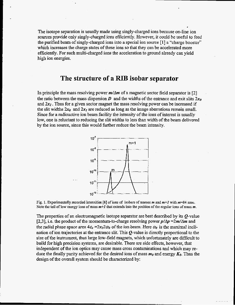
In principle the mass resolving power dh of a magnetic sector field separator is [2] the ratio between the mass dispersion D and the widths of the entrance and exit slits 2 x 0
and 2x1. Thus for a given sector magnet the mass resolving power can be increased if the slit widths 2x0 and 2x1 are reduced as long as the image aberrations remain small. Since for a radioactive ion beam facility the intensity of the ions of interest is usually low, one is reluctant to reducing the slit widths to less than width of the beam delivered by the ion source, since this would further reduce the beam intensity.
IO-’ I
Fig. 1. Experimentally recorded intensities [8] of ions of isobars of masses m and m+I with m=84 amu. Note the tail of low energy ions of mass m+I that extends into the position of the regular ions of mass m.
The properties of an electromagnetic isotope separator are best described by its Q-value [2,3], i.e. the product of the momentum-to-charge resolving powerp/dp = 2 d h and the radial phase space area 4~, =2xo2ao of the ion beam. Here a0 is the maximal incli- nation of ion trajectories at the entrance slit. This Q-value is directly proportional to the size of the instrument, thus large low-field magnets, which unfortunately are difficult to build for high precision systems, are desirable. There are side effects, however, that independent of the ion optics may cause mass cross contaminations and which may re- duce the finally purity achieved for the desired ions of mass m~ and energy KO, Thus the: design of the overall system should be characterized by:
1.
2.
3.
Small lateral image aberrations. Here it usually is better to choose a system design that has low aberrations from the beginning [4] than to choose an otherwise advan- tageous design whose aberrations must be corrected by multipole elements. Such multipole elements will usually cause other higher-order image aberrations. To separate neighboring elements of the same isobar fiom each other, one must postu- late resolving powers at and above m/dm =20,000 (see Fig.4) if one assumes that the isobar under consideration contains elements of mass =lo0 amu and if the mass difference between the two elements is @SMeV. Though 5MeV is a very high QF value for nuclei near Pstability, even higher Qgvalues are quite common for short- lived nuclei.
The reduction of the background of ions with energy KO and undesired mass values ml=mo&lm. Such ions can cause mass cross contaminations after they have been scattered on residual gas atoms or on slits giving rise to long tails of intense mass lines. The magnitude of such tails is often [SI about 0.01% of the peak intensity even at the position of a neighboring isobar. This can be very detrimental if - as is often the case - the undesired ions are lo6 or more times abundant [6] than the ions of interest. However, undesired ions can be removed efficiently by the use of mul- tiple separator stages [7] whose purification factors multiply.
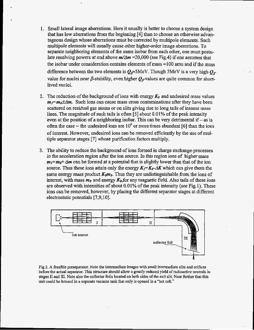
The ability to reduce the background of ions formed in charge exchange-processes in the acceleration region after the ion source. In this region ions of higher mass ml=mo+Am can be formed at a potential that is slightly lower than that of the ion source. Thus these ions attain only the energy KI=Ko-AK which can give them the same energy mass product Komo. Thus they are undistinguishable fiom the ions of interest, with mass mo and energy &,for any magnetic field. Also tails of these ions are observed with intensities of about 0.01% of the peak intensity (see Fig.1). These ions can be removed, however, by placing the different separator stages at different electrostatic potentials [7,9,10].
collector foil
1- Fig.2. A feasible preseparator. Note the intermediate images with small intermediate slits and orifices before the actual separator. This structure should allow a greatly reduced yield of radioactive neutrals in stages I1 and 111. Note also the collector foils located on both sides of the exit slit. Note further that this unit could be housed in a separate vacuum tank that only is opened in a “hot cell.”

A feasible RIB isobar separator design
One way to build an efficient isobar separator installation is to construct it from three stages at different electrostatic potentials [7,9, lo]. The first three stages should each contain a sector field separator (see also ref [ 1 11) while the fourth stage should contain the first section of the RIB accelerator [9,10]. In detail such a system (see Fig.3) would contain:
1. A “preseparator” at potential VO that achieves a mass resolving power m/dm ~400 . In order that the ions form a reasonably good beam in this preseparator, one should place the ion source at some potential VOO so that VOO -V0=20-60 kV. The main task of this preseparator is to extract the ion beam fiom the source, separate the ions of mass mu and energy KO roughly fi-om the ions of neighboring isobars and at the same time ensure that the radioactive but neutral atoms are retained in the system efficiently. One way to do this is shown in Fig.2. Note here that 1.1 there are intermediate images formed by electrostatic quadrupoles that allow all
ions to pass through narrow orifices and slits which efficiently retain the neutral atoms, the bulk of the produced radioactivity
preseparator exit slit. 1.2 the ions of neighboring isobars are implanted into foils on both sides of the
t I
i t
acceleration column
Fig. 3 An energy-achromatic arrangement of a double-stage separator with the two separator stages being at different electrostatic potentials VI and Vt. The ion trajectories are shown projected both onto the plane of symmetry and onto a perpendicular surface. Note that ions of equal masses but different energies are refocused to the same position, as illustrated in Fig. 4. Note further that the arrangement of two separator stages shown also can be reversed.

2.
3.
A “beam cooler” at a potential =50 V below VOO. Such “beam coolers” are not common features in on-line isotope separators yet. However, for special applications gas-filled RF-quadrupoles have been used as beam coolers [ 121 in which the ions are dragged through a gas of =O.lmbar and thus equilibrate with the gas atoms. This not only reduces the energy distributions but also the full phase-space area of the ion beam. After a new acceleration thus quite narrow ion beams can be formed.
The main isotope separator, consisting of two stages (see Fig.3) 3.1 the lSt-stage separator at potential VI that achieves a mass resolving power
m/dm ~2000. The task of this separator is to purify the beam of ions of mass r n o and energy KO reasonably well fiom the undesired ions of neighboring isobars.
d’ =20,000. The task of this separator is to further purify the beam of ions of mass mo and energy KO from the undesired ions of neighboring elements within the same isobar.
3.2 the 2”’-stage separator at potential VZ that achieves a mass resolving power
By adjusting the potential difference V’-Vl properly, it is possible to achieve an energy-achromatic mass separation as outlined in ref. [ 131 (see also refs. [ 1 1 141) like in a classical Aston mass spectrometer [ 151. Fig. 4 indicates that this really can be expected. Here mass lines of ions are shown whose mass-to-charge values differ by 0.005% and whose kinetic energies vary by 50.005% in Fig. 4a and by +0.05% in Fig.4b. Both cases have been calculated with an initial phase-space area of -It-xo& =+0.2mm*20mrad.
Note here also that the order of the two separator stages can also be reversed.
-1mm 0 l m m - l m m 0 1 m m
Fig. 4 The calculated mass spectrum of ions whose masses differ by 0.005% and whose phase space area is ~,=x~cq,+0.2mm*20mrad. For Figs. 4a and 4b it was assumed that the ions have energy spreads of 0.005% and 0.05%, respectively. This would correspond to energy spreads of +3eV and +30eV for Voo -

V ~ 6 0 , 0 0 0 V. Note that even for these relatively large energy spreads a mass resolving power of =20,000 is calculated.
4. A “charge booster” [ 13 at a potential of =IO V below VOO which will increase the charge states of the ions of interest considerably and thus make any subsequent acceleration more efficient.
5. The first accelerator section at potential V’. This potential must be chosen such that the ion velocity is always the same whatever ion mass value mo has been chosen, since only ions of a fixed velocity can be accelerated in the RFQ-accelerator pro- bably used here.
Fig. 5. Overview of a multi-user RIB-isobar separator. Note that two ion sources and two preseparators are assumed feeding the double-stage main separator at potentials VI and VZ. Note also that the first-stage of the RIB-accelerator is at a potential V3. Also note the “beam cooler [ 121” located before the entrance to the double-stage separator and the “charge booster [I]’’ after the exit slit of this separator. Note finally that the beam is assumed to be switchable to some experiments immediately after the 2&-stage separator and after the first accelerator section but that this beam also can be provided to other accelerator sections.
A multi-user RIB facility In order to use the beams of a RIB facility most efficiently, it may be advisable to distribute the ion beam to different experiments in a time-shared fashion. This may re- quire that at least for the first part of the accelerator structure be based on non- superconducting technology to allow for fast switching. Furthermore it may be advisable to feed ions into the system from different “pulsed” ion sources and possibly different preseparators. Perhaps this can be accomplished with no (or minimal) ion losses, since it has been shown [ 161 that between extraction pulses the ions can be stored in the ion source plasma for =10msec before they are extracted during =2msec. One can do this in an interweaved fashion for two on-line sources. Perhaps a third or

even fourth properly pulsed ion source providing, for instance a stable ion beam,,could be integrated into such a multi-user facility.
Fig. 6 An illustration of the interweaved operation of two ion sources. At the beginning of each extraction pulse of possibly 2msec the intensity is considerably higher than at the end of this pulse at which time the ion intensity has been reduced to approximately the dc-extraction value. In total the ion intensity extrac- ted in 2msec can even be higher than that extracted in IOmsec [ 151.
Acknowledgements Discussions with G. D. Alton, J.R.Beene, F.E.Bertrand, J.D.Fox as well as with W.Talbert and M.Winkler are acknowledged. This research was sponsored by the German Minister fiir Forschung und Technologie under contract GI 849 I, the Laboratory Directed Research, the Development Program of the Oak Ridge National Laboratory, managed by Lockheed Martin Research Corporation for the U.S. Department of Energy under contract DE-AC05-96- OR22464, and the Joint Institute for Heavy Ion Research in Oak Ridge.
-.
References 1. R. Geller, in these proceedings 2. H.Wolln&, “Optics of Charged Particles”, 1987 Acad. Press, Orlando 3. H.Wollnik, Nucl. Instr. and Meth., 95(1971)453 4. H.Wollnik, Nucl. Instr. and Meth., 56/57(1991)1096 5. H.J.Freeman, Nucl. Instr. and Meth., 28(1965)49 6. H.L.Ravn et al., Nucl. Instr. and Meth., B126(1997)176 7. H.Wollnik, in “Radioactive Beams”, ed. J.D. Garrett, 1992, p. 213 8. E.P. Chamberlin, private communication 9. H.Wollnik, Particle Accelerators, 47( 1994)241 10. H.Wollnik, Nucl. Instr. and Meth., A363(1995)393 11. G.Ciavola et al., Nucl. Instr. and Meth. B126(1996)17 12. V.Koslowsky et al., Int. J. Mass Spectr. And Ion Proc, in print 13. H.Wollnik, Nucl.Instr. and Meth., in print 14. M.Yavor, Nucl. Instr. and Meth. B126(1996)266
.. , , . -: . . . . . .. . . . , - . . - . . .

15. F.W.Aston, Philosoph. Mag. 38( 1919)709 16. Y.Shirakabe et al., Nucl. Instr. and Meth. A 337(1993)11
,
. .. . ., . . . . .. . .. ., .. , - . .. . . . . - .. . . .,._,-.- .-- . .