radioactive waste tank ventilation system … · radioactive waste tank ventilation system...
TRANSCRIPT

RADIOACTIVE WASTE TANK VENTILATION SYSTEM INCORPORATING TRITIUM CONTROL
Paul D. Rice, P.E. ICF Kaiser Hanford Company Richland, Washington 99352
Abstraa
This paper describes the development of a ventilation system for radioactive waste tanks at the U.S. Department of Energy’s (DOE) Hanford Site in Richland, Washington. The unique design of the system is aimed at cost- effective control of tritiated water vapor.
The system includes recirculation ventilation and cooling for each tank in the facility and a central exhaust air clean-up train that includes a low-temperature vapor condenser and high-efficiency mist eliminator (HEME). A one-seventh scale pilot plant was built and tested to verify predicted performance of the low-temperature tritium removal system. Tests were conducted to determine the effectiveness of the removal of condensible vapor and soluble and insoluble aerosols and to estimate the operating life of the mist eliminator. Definitive design of the ventilation system relied heavily on the test data.
The unique design features of the ventilation system will result in far less release of tritium to the atmosphere than from conventional high-volume dilution systems and will greatly reduce operating costs. NESHAPs and TAPS NOC applications have been approved, and field construction is nearly complete. Start-up is scheduled for late 1996.
Introductioq
Safe storage of radioactive waste resulting from reprocessing nuclear reactor spent fuel can be a special challenge when large amounts of tritium are present. High tritium concentrations have been a concern at the Aging Waste Tank Farm (AWTF) at the Hanford Site in Richland, Washington. The AWTF is a complex of four 3800-m3 (1 ,OOO,OOO-gallon) underground double-shell tanks (DST) identified as 24 1 -AY- 10 1 and - 102, and 24 1 -AZ - 10 1 and - 102. Although the aging waste volume is small compared to the total waste in the 177 underground tanks at Hanford, its activity level is high. The AWTF tanks have the potential to operate at significantly higher temperatures and can generate large quantities of tritiated water vapor at the waste surface as a natural consequence of heat and mass transfer to the ventilation flow through the tank head space. The ventilation system design for heat removal alone presents no great challenge. The fact that tritium is present changes the entire direction of the design.
In 1986 a conceptual design was begun by Kaiser Engineers Hanford (KEH; renamed ICF Kaiser Hanford Company in 1994) to upgrade the AWTF facility (then operated by Rockwell Hanford Operations) to current codes and standards, to achieve compliance with new environmental release criteria, and to handle unusually high heat from future fuel reprocessing campaigns.
The design criteria imposed on the project greatly restricted allowable radionuclide concentrations in the ventilation system exhaust stack and also identified deficiencies in the existing system. In particular, the HEPA filters had lifetimes that varied from two days to two years, depending on waste processing operations.
51
The initial conceptual design of the new system included two stages of HEPA filters to control (primarily) strontium, cesium, and plutonium particulate, and a refrigerated wet scrubber to control tritium, ruthenium, and other condensible vapors and to protect the HEPA filters from various soluble compounds such as ammonium salts.
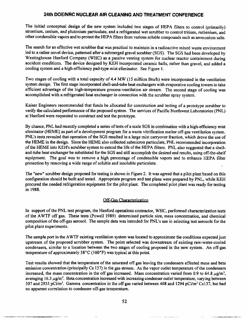
The search for an effective wet scrubber that was practical to maintain in a radioactive mixed waste environment led to a rather novel device, patterned after a submerged gravel scrubber (SGS). The SGS had been developed by Westinghouse Hanford Company (WHC) as a passive venting system for nuclear reactor containment during accident conditions. The device designed by KEH incorporated ceramic balls, rather than gravel, and added a cooling system and a high-efficiency pad-type mist eliminator. See Figure 1.
Two stages of cooling with a total capacity of 4.4 MW (15 million Btu/h) were incorporated in the ventilation system design. The first stage incorporated shell-and-tube heat exchangers with evaporative cooling towers to take efficient advantage of the high-temperature process-ventilation air stream. The second stage of cooling was accomplished with a refrigerated heat exchanger in connection with the scrubber spray system.
Kaiser Engineers recommended that funds be allocated for construction and testing of a prototype scrubber to verify the calculated performance of the proposed system. The services of Pacific Northwest Laboratories (PNL) at Hanford were requested to construct and test the prototype.
By chance, PNL had recently completed a series of tests of a scale SGS in combination with a high-efftciency mist eliminator (HEME) as part of a development program for a waste vitrification melter off-gas ventilation system. PNL’s tests revealed that operation of the SGS resulted in a large mist carryover fraction, which drove the use of the HEME in the design. Since the HEME also collected submicron particulate, PNL recommended incorporation of the HEME into KEH’s scrubber system to extend the life of the HEPA filters. PNL also suggested that a sheil- and-tube heat exchanger be substituted for the SGS and still accomplish the desired end results, using off-the-shelf equipment. The goal was to remove a high percentage of condensible vapors and to enhance HEPA filter protection by removing a wide range of soluble and insoluble particulate. :
The “new” scrubber design proposed for testing is shown in Figure 2. It was agreed that a pilot plant based on this configuration should be built and tested. Appropriate program and test plans were prepared by PNL, while KEH procured the needed refrigeration equipment for the pilot plant. The completed pilot plant was ready for testing in 1988.
. . Off-Gas Characterlzatlon
In support of the PNL test program, the Hanford operations contractor, WHC, performed characterization tests of the AWTF off gas. These tests (Powell 1989) determined particle size, mass concentration, and chemical composition of the off-gas aerosol. The sample data was intended for PNL’s use in selecting test aerosols for the pilot plant experiments.
The sample port in the AWTF existing ventilation system was located to approximate the conditions expected just upstream of the proposed scrubber system. The point selected was downstream of existing raw-water-cooled condensers, similar to a location between the two stages of cooling proposed in the new system. An off-gas temperature of approximately 38°C (100°F) was typical at this point.
Test results showed that the temperature of the saturated off gas leaving the condensers affected mass and beta emission concentration (principally Cs 137) in the gas stream. As the vapor outlet temperature of the condensers increased, the mass concentration in the off gas increased. Mass concentration varied from 0.9 to 64.8 &m’, averaging 16.5 &m’. Beta concentration increased with increasing condenser outlet temperature, varying between 507 and 2935 pCi/m3. Gamma concentration in the off gas varied between 408 and 1294 pCi/m3 Cs137, but had no apparent correlation to condenser off-gas temperature.
52
24th DOE/NRC NUCLEAR AIR CLEANING AND TREATMENT CONFERENCE
-
-
I
-
Figure 1 Scrubber/deentrainer/filter.
53

24th DOE/NRC NUCLEAR AIR CLEANING AND TREATMENT CONFERENCE
CONOENSATE CONDENSATE RECEIVER RECEIVER
=
i ELEMENT -
?-
iri 1560 L/s
+
@ 2°C WASHDOWN NOZZLE
3
-I HA 156OLh TO . . HEATERS AND
HEPA FILTERS
HIGH EFFICIENCY MIST ELIMINATOR AND VESSEL ITYP 4)
tORAIN TO CONOENSATE
RECEIVER
Figure 2 Primary vent scrubber.
54
24th DOE/NRC NUCLEAR AIR CLEANING AND TREATMENT CONFERENCE
The off-gas stream was found to have two separate mass size distributions (bimodal). Both mass and beta activity readings confirmed that the bimodal size distribution existed. Most of the mass loading and beta/gamma activity was concentrated in the smaller aerodynamic diameter size range of 0.4 to 0.05 pm. The average mass mean aerodynamic diameter (MMAD) of the particulate in the gas stream was 0.073pm. The beta mean aerodynamic diameter (BMAD) of particulate containing beta activity was 0.084 km. The established mean of the larger diameter mass and beta distribution was about 2 pm. Statistical analysis indicated that the mean particle size was a function of the temperature of the off gas and location of the sample point in the duct. The larger particulate size distribution was found in the high velocity center of the off-gas duct at higher off-gas temperatures.
Experime
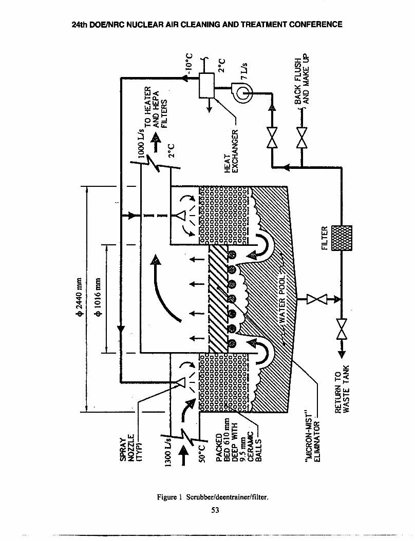
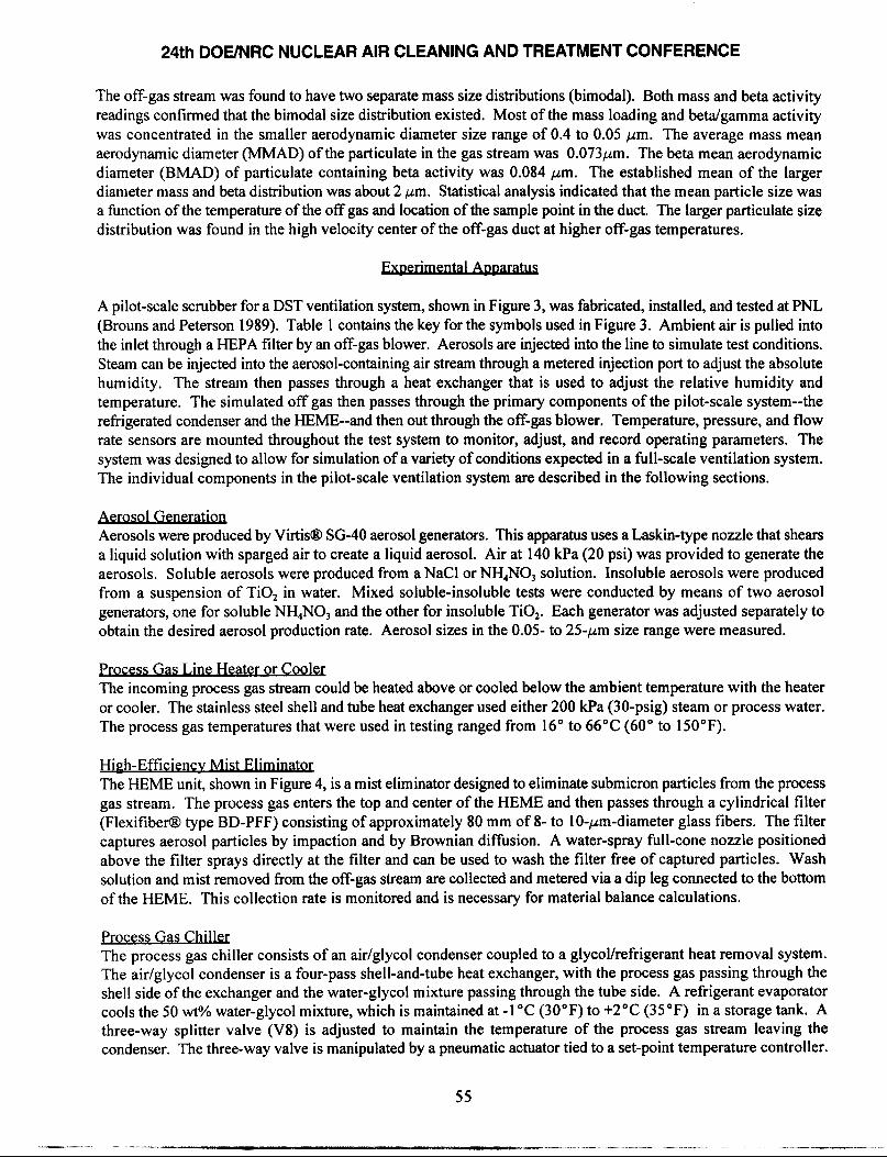
A pilot-scale scrubber for a DST ventilation system, shown in Figure 3, was fabricated, installed, and tested at PNL (Brouns and Peterson 1989). Table 1 contains the key for the symbols used in Figure 3. Ambient air is pulled into the inlet through a HEPA filter by an off-gas blower. Aerosols are injected into the line to simulate test conditions. Steam can be injected into the aerosol-containing air stream through a metered injection port to adjust the absolute humidity. The stream then passes through a heat exchanger that is used to adjust the relative humidity and temperature. The simulated off gas then passes through the primary components of the pilot-scale system--the refrigerated condenser and the HEME--and then out through the off-gas blower. Temperature, pressure, and flow rate sensors are mounted throughout the test system to monitor, adjust, and record operating parameters. The system was designed to allow for simulation of a variety of conditions expected in a full-scale ventilation system. The individual components in the pilot-scale ventilation system are described in the following sections.
Aerosol Generation Aerosols were produced by Virtis@ SG-40 aerosol generators. This apparatus uses a Laskin-type nozzle that shears a liquid solution with sparged air to create a liquid aerosol. Air at 140 kPa (20 psi) was provided to generate the aerosols. Soluble aerosols were produced from a NaCl or NH,NO, solution. Insoluble aerosols were produced from a suspension of TiO, in water. Mixed soluble-insoluble tests were conducted by means of two aerosol generators, one for soluble NH,NO, and the other for insoluble TiO,. Each generator was adjusted separately to obtain the desired aerosol production rate. Aerosol sizes in the 0.05- to 25-pm size range were measured.
Process Gas Line Heater or Cookx The incoming process gas stream could be heated above or cooled below the ambient temperature with the heater or cooler. The stainless steel shell and tube heat exchanger used either 200 kPa (30-psig) steam or process water. The process gas temperatures that were used in testing ranged from 16” to 66°C (60” to 150°F).
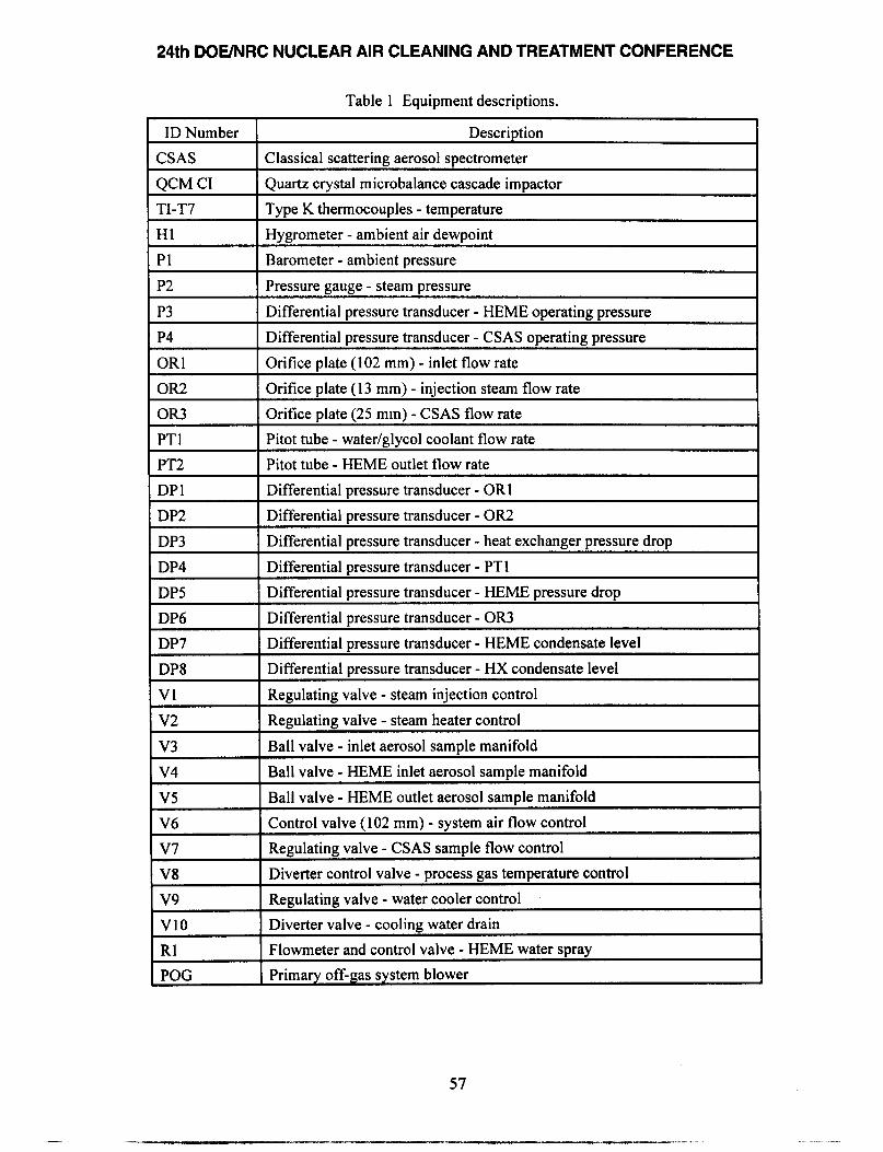
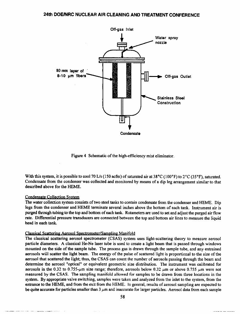
High-Efficiencv Mist Eli&&~ The I-IEME unit, shown in Figure 4, is a mist eliminator designed to eliminate submicron particles from the process gas stream. The process gas enters the top and center of the HEME and then passes through a cylindrical filter (FlexitiberO type BD-PFF) consisting of approximately 80 mm of 8- to lo-pm-diameter glass fibers. The filter captures aerosol particles by impaction and by Brownian diffusion. A water-spray full-cone nozzle positioned above the filter sprays directly at the filter and can be used to wash the filter free of captured particles. Wash solution and mist removed from the off-gas stream are collected and metered via a dip leg connected to the bottom of the HEME. This collection rate is monitored and is necessary for material balance calculations.
Process Gas Chiller The process gas chiller consists of an air/glycol condenser coupled to a glycol/refrigerant heat removal system. The air/glycol condenser is a four-pass shell-and-tube heat exchanger, with the process gas passing through the shell side of the exchanger and the water-glycol mixture passing through the tube side. A refrigerant evaporator cools the 50 wt?/o water-glycol mixture, which is maintained at -1 “C (30°F) to +2”C (35 “F) in a storage tank. A three-way splitter valve (V8) is adjusted to maintain the temperature of the process gas stream leaving the condenser. The three-way valve is manipulated by a pneumatic actuator tied to a set-point temperature controller.
55

24th DOE/NRC NUCLEAR AIR CLEANING AND TREATMENT CONFERENCE
T ---- To
T TmwEfwTuRE DRAIN
P PRESSWIE
DP DlFFEFlENMl PRESSURE
H HUhmlY
c CQNcmm
Figure 3 Schematic of the pilot-scale scrubber (from Brouns and Peterson 1989).
56
24th DOE/NRC NUCLEAR AIR CLEANING AND TREATMENT CONFERENCE
Table 1 Equipment descriptions.
ID Number Description
CSAS Classical scattering aerosol spectrometer
QCM CI
TI-T7
Hl
Pl
Quartz crystal microbalance cascade impactor
Type K thermocouples - temperature
Hygrometer - ambient air dewpoint
Barometer - ambient pressure
P2
P3
P4
OR1
OR2
OR3
PTl
PT2
DPl
DP2
DP3
DP4
DP5
DP6
DP7
DP8
Vl
v2
v3
v4
v5
V6
v7
V8
Pressure gauge - steam pressure
Differential pressure transducer - HEME operating pressure
Differential pressure transducer - CSAS operating pressure
Orifice plate (102 mm) - inlet flow rate
Orifice plate (13 mm) - injection steam flow rate
Orifice plate (25 mm) - CSAS flow rate
Pitot tube - water/glycol coolant flow rate
Pitot tube - HEME outlet flow rate
Differential pressure transducer - OR1
Differential pressure transducer - OR2
Differential pressure transducer - heat exchanger pressure drop
Differential pressure transducer - PTl
Differential pressure transducer - HEME pressure drop
Differential pressure transducer - OR3
Differential pressure transducer - HEME condensate level
Differential pressure transducer - HX condensate level
Regulating valve - steam iniection control
Regulating valve - steam heater control
Ball valve - inlet aerosol sample manifold
Ball valve - HEME inlet aerosol sample manifold
Ball valve - HEME outlet aerosol sample manifold
Control valve (102 mm) - system air flow control
Regulating valve - CSAS sample flow control
Diverter control valve - process gas temperature control
Regulating valve - water cooler control
Diverter valve - cooling water drain
Flowmeter and control valve - HEME water spray
Primary off-gas system blower
v9
VlO
Rl
POG
57
Off-gas Inlet
,+* Water spray
/ nozzle
80 mm layer of 8-10 pm fibers --W Off-gas Outlet
\ Stainless Steel Construction
Condensate
Figure 4 Schematic of the high-efficiency mist eliminator.
With this system, it is possible to cool 70 L/s (150 acfm) of saturated air at 38°C (100°F) to 2°C (35”F), saturated. Condensate from the condenser was collected and monitored by means of a dip leg arrangement similar to that described above for the HEME.
ctton Svsta The water collection system consists of two steel tanks to contain condensate from the condenser and HEME. Dip legs from the condenser and HEME terminate several inches above the bottom of each tank. Instrument air is purged through tubing to the top and bottom of each tank. Rotameters are used to set and adjust the purged air flow rate. Differential pressure transducers are connected between the top and bottom air lines to measure the liquid head in each tank.
eter/Sam&nP Manifold The classical scattering aerosol spectrometer (CSAS) system uses light-scattering theory to measure aerosol particle diameters. A classical He-Ne laser tube is used to create a light beam that is passed through windows mounted on the side of the sample tube. The process gas is drawn through the sample tube, and any entrained aerosols will scatter the light beam. The energy of the pulse of scattered light is proportional to the size of the aerosol that scattered the light; thus, the CSAS can count the number of aerosols passing through the beam and determine the aerosol “optical” or equivalent geometric size distribution. The instrument was calibrated for aerosols in the 0.32 to 0.755~pm size range; therefore, aerosols below 0.32 pm or above 0.755 ,um were not measured by the CSAS. The sampling manifold allowed for samples to be drawn from three locations in the system. By appropriate valve switching, samples were taken and analyzed from the inlet to the system, from the entrance to the HEME, and from the exit from the HEME. In general, results of aerosol sampling are expected to be quite accurate for particles smaller than 3 pm and inaccurate for larger particles. Aerosol data from each sample
58

24th DOE/NRC NUCLEAR AIR CLEANING AND TREATMENT CONFERENCE
port were used to determine the efficiency and the DF for the heat exchanger, the HEME, and the overall system. It was necessary to maintain the temperature of the gas flowing through the sampling chamber above saturation in order to avoid condensation on the optics of the CSAS. Data were not collected when sample lines were at a temperature lower than that of the process gas.
Ouartz Crvstal Microwce Cascade ImDactor In addition to the CSAS, a quartz microbalance cascade impactor (QCM CI) was used to measure aerosol particle size distribution and concentration. While the CSAS measures a particle number distribution, the QCM CI measures a mass concentration distribution. Use of the QCM CI in series with the CSAS allowed comparison between the two methods and obtained data that could be compared directly to field data.
The QCM Cl pulls process gas from the CSAS sampling manifold through an isokinetic sampling probe into the sensing stack, which comprises 10 impactor stages. Particles of sufficient size and mass strike a piezoelectric crystal microbalance (PCM) present on each stage of the impactor. Smaller particles escape impaction on the first stages but are captured later as the velocity of the process gas is increased through smaller orifices. The sensing stack segregates particles into ten 50%-efficiency cut-off sizes (Dp50) between aerodynamic diameters of 25 and 0.05 pm. With an assumed particle density of 2 g/mL, the Dp5Os are shown in Table 2. The impacted particles on each stage result in a change in frequency of the quartz crystal that is proportional to the mass of particles collected. Because the QCM CI measures particle size distribution over a wider size range than the CSAS, it is better suited to broadly distributed aerosols. The CSAS is more precise in a narrower distribution but inaccurate for broadly distributed aerosols.
Table 2 QCM CI 50% cut-off sizes.
I Stage I Dp50, pm I
I 3 1 6.40 I 4 3.20
5 1.60
6 0.80
7 0.40
8 0.20
9 0.10
10 0.05
. .* Data AcqldlSltlon Svstem The data acquisition system consists of a Hewlett-Packard 9000/200 computer system interfaced to a Fluke 2240B data logger, a Validyne SPM 380 digital scanning panel meter, and the CSAS. All temperature measurements were provided by Type K thermocouples interfaced to the Fluke logger. Flow rates were measured by means of orifice plates and pitot tubes with all pressure drops, and all operating pressure measurements were determined with Validyne pressure transducers interfaced to the Validyne panel meter. Temperatures, pressure drops, flow rates, and aerosol size and count in each of the 15 channels of the CSAS were collected by the HP 9000/200 computer
59
.,.--.-I -- _-11-1_._ ll-,.--l, -..
24th DOE/NRC NUCLEAR AIR CLEANING AND TREATMENT CONFERENCE
system and stored on its hard disc. QCM CI measurements were printed on thermal paper, referenced in the laboratory record book, and stored for later analysis.
Exnerimental Test Results
ble Vapor Removal The pilot-scale ventilation system effectively removed 100% of the water that theoretically could be condensed with a saturated stream at the HEME outlet conditions. Condensed water not collected by the condenser was removed by the HEME. When the flow rate was at the high test level (70 L/s or 150 scfm) and the absolute humidity was high, condensate was collected by the condenser. At the low humidity, the condensate was carried to the HEME before collection. At the low test flow rate of 38 L/s (80 scfm), condensate was collected by the condenser at all absolute humidities. The condenser was operated with a coolant temperature of 2’ to 3 “C (35’ to 37°F). Lower temperatures resulted in ice formation and a subsequent decrease in the heat transfer coefficient.
SQluble Aerosol Removal Removal of sodium chloride (NACl) and ammonium nitrate (NH,NO,) soluble aerosols occurred in both the condenser and the HEME. At high absolute humidity (0.07 to 0.08 kg H,O/kg air), condenser DFs ranged from 3 to 16 with a feed concentration of 30 to 5 1 pg/m’. Condenser DFs generally increased with the off-gas flow rate. At a lower absolute humidity, condenser DFs ranged from 1 to 2, and decontamination was primarily controlled by the HEME. System DFs for soluble NH4N03 aerosols based on total mass concentrations were between 5.8 and 37 with an average of 19. System DFs averaged 18 for NH,NO, aerosols in the 0.05- to 0. l- pm size range and 7.1 for aerosols in the 1.6- to 3.2- pm size range at an inlet concentration of 120 ,ug/m3.
Insoluble Aerosol Removal Removal of insoluble titanium dioxide (TiO,) aerosols was controlled primarily by the HEME and appeared to be affected by the aerosol concentration. HEME DFs for insoluble aerosols averaged 5.9 at an inlet concentration of 68 pglm3. At a higher inlet concentration of 188 ,ug/m3, the average HEME DF increased to 25. An average system DF of 13 was obtained during tests with a system inlet concentration of 153 &rn’ and a HEME inlet concentration of 68 pg/m3. System DFs averaged 22 for TiO, aerosols in the 0.05- to 0. l- pm size range and 12 for aerosols in the 1.6- to 3.2-pm size range at an inlet concentration of 153 pg/m3.
HEME Jife Expectancy
HEME life expectancy tests with soluble, insoluble, and mixed soluble-insoluble aerosols resulted in an increase in pressure drop of less than 15% over the 30-day test periods. The results of the mixed soluble-insoluble aerosol test indicated that increase in the pressure drop through the HEME of less than 8% was achieved with a system inlet concentration of 537 &m’. Based on these results, an estimated average full-scale aerosol concentration of 16.5 &m’, and similar operating conditions (i.e., I-IEME face velocity of 122 mm/s to 244 mm/s [0.4 to 0.8 ft/sec], and >80% RI-I), we conclude that the HEME will operate for more than 900 days ((537/16.5)(30 days)) without an appreciable (>15%) increase in the pressure drop. Water spray was effective at washing soluble aerosols from the HEME filter and partially effective at washing insoluble aerosols. Intermittent washing of the HEME filter with a water spray would be beneficial in removing collected aerosol and regenerating the filter, especially during periods of low absolute humidity. A spray flow rate of 10 L/(h*m*) (0.25 gph/IY2) filter surface was effective during testing.
The detailed report of the pilot-plant experiment was published by PNL in December 1989, in time for use by KEH in definitive design of the AWTF ventilation system.
wulation Ventilation Concept
Definitive design of the new AWTF ventilation system (Project W-030) was approved to start in 1989. However, changes in the project scope had occurred since the original conceptual design, creating growth in the project cost
60
estimate. The scope changes were related to changes in the Hanford mission, closure of the PUREX spent fuel reprocessing facility, interfaces with other projects, and previously hidden problems in the existing AWTF ventilation system.
A Value Engineering team was assigned to investigate methods of cutting costs. One major outcome of the investigation was the recommendation by KEH that a detailed study of a recirculation ventilation and cooling concept be performed. An engineering report (KEH 1992) comparing three alternative recirculation schemes was completed in 1992. All three schemes resulted in cost savings, mainly from the reduction in size of facilities required to house smaller equipment in a recirculation ventilation system. The report recommended a tank farm ventilation system that incorporated a small central ventilation exhaust system with individual air recirculation loops to cool each tank.
The proposed central ventilation exhaust system was sized for a 190- to 480-L/s (400- to 1 000-scfm) flow rate and allowed a minimum ventilation flow of 50 L/s (100 scfm) for each of four tanks for gas dilution and pressure control. The additional 280 L/s (600 scfm) capacity provided operational flexibility for existing airlift circulator (waste mixing) operation or additional inleakage if desired. Each tank ventilation system recirculated and cooled an airflow of 240 L/s (500 scfm).
A major environmental benefit will be realized by using recirculation for cooling in lieu of the once-through system. The total discharge to the environment will be reduced from about 1400 L/s (3000 scfm) to 190 to 480 L/s (400 to 1000 s&n). Recirculation not only reduces the total discharge, but also reduces material collected in the air cleanup train which reduces operational and maintenance costs.
A side benefit of the reduced size exhaust system was to effectively change the pilot plant scale factor from l/20 to l/7 scale, thus boosting credibility of the test data.
The project cost for the recirculation ventilation concept was estimated at $24.6 million. The project cost for the facility incorporating a once-through system was estimated at $30 million. This considerable cost savings, as well as the environmental advantages, drove the definitive design to incorporate the recirculation ventilation concept.
Environmental Imp&
Process flow diagrams were developed by using the pilot plant test results to predict environmental discharge for four different operating scenarios. These operating scenarios resulted from different assumptions about heat generated in the waste tanks and variations in waste composition and from operation with failed cooling systems.
During normal operation (current waste composition, no mechanical waste agitation, and operating cooling systems), the annual radioactive release was calculated to be 18 Ci, of which tritium is more than 99%. By comparison, calculated tritium release from the existing system under the same operating scenario amounts to 840 Ci/yr. This gross reduction in tritium release achieved with the new system depends heavily on reliable operation of the cooling system. It should be noted that failure of the cooling system, or for that matter, continued operation of the existing system, will result in a dose to the public that is less than 1% of the exposure permitted by DOE guidelines.
The TAP and NESHAP applications were approved in 1994, and permission to construct the project was granted by the Washington Department of Health, the Washington Department of Ecology, and the U.S. Environmental Protection Agency.

Conclusion
A unique ventilation system has been developed and constructed at the AWTF at DOE’s Hanford Site. The new system includes recirculation ventilation and cooling for each tank in the facility, followed by a central exhaust air clean-up train that includes a low-temperature vapor condenser and an HEME.
The system is capable of reducing the atmospheric release of tritium to only 2% of the existing system capability. The condenser and HEME will reduce loading of the final HEPA filters in the air clean-up train by a factor of 20 for soluble aerosols, and by a factor of 13 for insoluble aerosols. The operating life of the remotely replaceable HEME cartridge is predicted to be approximately three years.
The new ventilation system, along with the support facilities, is scheduled to begin full-time operation in late 1996.
References
Brouns, T. M., and M. E. Peterson, 1989, “Performance Evaluation of the Pilot-Scale, Double-Shell Tank Ventilation System Using Simulated Aerosol Streams,” PNL-7188, Pacific Northwest Laboratory, Richland, Washington.
KEH 1992, “Tank Farm Recirculation and Ventilation,” W03OER, Kaiser Engineers Hanford Company, Richland, Washington.
Powell, W. J., 1989, “Aging Waste Off-Gas Sampling Status Report,” Internal memo 133 14-89-032, Westinghouse Hanford Company, Richland, Washington.
62
24th DOE/NRC NUCLEAR AIR CLEANING AND TREATMENT CONFERENCE
DISCUSSION
BELLAMY: The comment I would like to make is that it took me a little while to understand exactly what you meant by HEME. I think, as an industry, we are falling into a very poor habit of using acronyms for everything. Some of the things that we discussed last week at our ASME standards committee meeting were HEMA’s versus HEPA’s, high efftciency metal filters versus high efficiency particulate filters, and what do these terms really mean. I think you were understood, but it took me a couple of minutes to realize exactly what you were talking about. You will notice that in the summary that we prepare for this Conference for publication in Nuclear Safety there is a very detailed list of acronyms in the beginning. I would just caution all of us to pay attention to explaining acronyms.
WILHELM: At one of the earlier Air Cleaning Conferences, we published results identified as a HEME, a metallic filter with a layer of glass fibers; in this case around twenty microns thick. The real decontamination factor measured was around 3,000 for all the aerosols together.
RICE: I might have forgotten to mention the decontamination factors that we achieved. I should have mentioned that the system of the condenser and the HEME together gave us a decontamination factor of about thirteen for insoluble particles, and about twenty for soluble particles. We really did a pretty good job of relieving the load on the HEPA filters.
CONKLIN: I am with the Washington State Department of Health, and I regulate radioactive air emissions from Hanford. Since you are already below 0.1 millirem per year to the maximally exposed individual, what was the reason to put in this system? I am not sure I caught how efficient it is for tritium. The third question is, do you consider this system cost-effective?
RICE: Yes, it was definitely cost-effective compared to other methods that might be used to reduce tritium. Of course, we are taking advantage of the fact that tritium is basically tritiated water vapor, so we are really just handling water vapor. The concentration off-site is, in fact, quite low and you asked, why did we bother to do this in the first place? I tried to point out that we engaged in this upgrading project for several reasons: one was that we were anticipating adding extra heat to the tanks by operating mixer pumps in order to keep the waste mixed. Other methods of mixing, such as the air lifl circulators that are now in those tanks have given us problems. The mixer pump demonstration program will greatly impact the heat load in the tanks. That is a reason for the upgrades, plus the fact that spent fuel intended to be processed in the PUREX plant still remains in storage, and there would be a whole new load of hot fuel that we would have to handle. As it turned out, that fuel probably never will be reprocessed because the PUREX plant has been shut down. However, we do have a cooling system in the tanks that is able to handle extra heat loads. The cooling system also had to meet new codes and standards, plus the Derived Concentration Guides, at the point of release. So you see, our criteria were telling us that it did not matter what the off-site projected dose was; design-wise, we had a problem at the point of release and had to face up to it. It was kind of unrealistic in a way because the off-site impact is so terribly small. Nevertheless, it is just one of many release points at Hanford and you always do the best you can. We felt that using the refrigeration system would be very cost-effective, which it turned out to be. So, we did our job.
CONKLIN: What was the efficiency for tritium?
63

RICE: The existing system, under more or less standard operating conditions, releases to the atmosphere 840 curies per year. That is more than 99% of the total radioactivity released from the entire tank farm. The new system, i.e., the recirculation and refrigeration system together, will release 18 curies, a 50: 1 reduction.
WEBER; This apparently is the same HEME which was used in the Zone -1 melter offgas test. As you mentioned, it was also used upstream of a HEPA-grade filter, in fact a metallic filter. If you have not already done so you may be interested in speaking with Greg Whyatt at Battelle who did this study, and who documented the performance of the HEME and the downstream HEPA life in that study.
RICE: Yes, I know Greg Whyatt. The work for this project started back in ‘89. It’s been a long time, and there were three different scientists at Battelle that worked on this project.
WEBER; Apparently there is a completed report by Greg and his co-authors which has now been awaiting DOE approval for issue for something like two years.
RICE: Maybe that is a different report. One of my references is a report that was done by Brouns and Peterson. They were the last two individuals that worked on the development of the HEME for this particular project. The BEME that was in the laboratory was, in fact, used for a melter off-gas experiment.
WEBER; That would put it back to Greg.
64